Volume 5 IBook
37826-Attachment 37826-Attachment 37826-Attachment 782114 Batch8 unilog cesco-content
37826-Attachment 37826-Attachment 37826-Attachment 782116 Batch8 unilog cesco-content
37826-Attachment 37826-Attachment 37826-Attachment 786685 Batch8 unilog cesco-content
127520-Brochure 127520-Brochure 127520-Brochure Batch9 unilog cesco-content
108540-Attachment 108540-Attachment 108540-Attachment 782114 Batch10 unilog cesco-content
2014-10-17
: Pdf 108540-Attachment 108540-Attachment 782113 Batch10 unilog
Open the PDF directly: View PDF ![]() .
.
Page Count: 750 [warning: Documents this large are best viewed by clicking the View PDF Link!]
Electrical Sector Solutions
Volume 5:
Motor Control
and Protection
Volume 1—Residential and Light Commercial
Volume 2—Commercial Distribution
Volume 3—Power Distribution and Control Assemblies
Volume 4—Circuit Protection
Volume 5—Motor Control and Protection
Tab 1—IEC Contactors and Starters . . . . . . . . . . . . . . . . . . . V5-T1-1
Tab 2—NEMA Contactors and Starters . . . . . . . . . . . . . . . . V5-T2-1
Tab 3—NEMA Manual Starters . . . . . . . . . . . . . . . . . . . . . . . V5-T3-1
Tab 4—Definite Purpose Contactors and Starters . . . . . . . . V5-T4-1
Tab 5—Motor Protection and Monitoring . . . . . . . . . . . . . . V5-T5-1
Tab 6—Lighting Contactors . . . . . . . . . . . . . . . . . . . . . . . . . . V5-T6-1
Tab 7—Vacuum Contactors and Starters . . . . . . . . . . . . . . . V5-T7-1
Tab 8—Rotary Disconnects . . . . . . . . . . . . . . . . . . . . . . . . . . V5-T8-1
Appendix 1—Eaton Terms & Conditions . . . . . . . . . . . . . . . V5-A1-1
Appendix 2—Catalog Parent Number Index . . . . . . . . . . . . V5-A2-1
Appendix 3—Alphabetical Product Index . . . . . . . . . . . . . . V5-A3-1
Volume 6—Solid-State Motor Control
Volume 7—Logic Control, Operator Interface
and Connectivity Solutions
1
2
3
4
5
6
7

Copyright
Dimensions, Weights and Ratings
Dimensions, weights and ratings given in this catalog are approximate and should not
be used for construction purposes. Drawings containing exact dimensions are available
upon request. All listed product specifications and ratings are subject to change without
notice. Photographs are representative of production units.
Terms and Conditions
All prices and discounts are subject to change without notice. When price changes
occur, they are published in Eaton’s Price and Availability Digest (PAD). All orders
accepted by Eaton’s Electrical Sector are subject to the general terms and conditions
as set forth in Appendix 1—Eaton Terms & Conditions.
Technical and Descriptive Publications
This catalog contains brief technical data for proper selection of products. Further
information is available in the form of technical information publications and illustrated
brochures. If additional product information is required, contact your local Eaton
Products Distributor, call 1-800-525-2000 or visit our website at www.eaton.com.
Compliance with Nuclear Regulation 10 CFR 21
Eaton products are sold as commercial grade products not intended for application in
facilities or activities licensed by the United States Nuclear Regulatory Commission
for atomic purposes, under 10 CFR 21. Further certification will be required for use of
these products in a safety-related application in any nuclear facility licensed by the
U.S. Nuclear Regulatory Commission.
WARNING
The installation and use of Eaton products should be in accordance with the provisions
of the U.S. National Electrical Code® and/or other local codes or industry standards that
are pertinent to the particular end use. Installation or use not in accordance with these
codes and standards could be hazardous to personnel and/or equipment.
Copyright ©2014 Eaton, All Rights Reserved
These catalog pages do not purport to cover all details or variations in equipment, nor to provide for
every possible contingency to be met in connection with installation, operation or maintenance.
Should further information be desired or should particular problems arise which are not covered
sufficiently for the purchaser’s purposes, the matter should be referred to the local Eaton Products
Distributor or Sales Office. The contents of this catalog shall not become part of or modify any prior
or existing agreement, commitment or relationship. The sales contract contains the entire
obligation of Eaton’s Electrical Sector. The warranty contained in the contract between the parties
is the sole warranty of Eaton. Any statements contained herein do not create new warranties or
modify the existing warranty.

Volume 5—Motor Control and Protection CA08100006E—May 2014 www.eaton.com i
Introduction
Eaton is a global leader in power distribution, power quality,
control and automation, and monitoring products.
At Eaton, we believe a reliable, efficient and safe power system is the foundation of every
successful enterprise. Through innovative technologies, cutting-edge products and our highly
skilled services team, we empower businesses around the world to achieve a powerful advantage.
In addition, Eaton is committed to creating and maintaining powerful customer relationships built
on a foundation of excellence. From the products we manufacture to our dedicated customer
service and support, we know what’s important to you.
Solutions
Eaton takes the complexity out of power systems management with a holistic and strategic
approach, leveraging our industry-leading technology, solutions and services. We focus on
the following three areas in all we do:
●Reliability—maintain the
appropriate level of power
continuity without
disruption or unexpected
downtime
●Efficiency—minimize
energy usage, operating
costs, equipment footprint
and environmental impact
●Safety—identify and
mitigate electrical hazards
to protect what you value
most
Using the Eaton Catalog Library
As we grow, it becomes increasingly difficult to include all products in one or two comprehensive
catalogs. Knowing that each user has their specific needs, we have created a library of catalogs for our
products that when complete, will contain 15 volumes. Since the volumes will continuously be a work
in progress and updated, each volume will stand alone. Refer to our volume directory, MZ08100001E,
for a quick glance of where to look for the products you need. The 15 volumes include:
●Volume 1—Residential
and Light Commercial
(CA08100002E)
●Volume 2—Commercial
Distribution (CA08100003E)
●Volume 3—Power
Distribution and Control
Assemblies (CA08100004E)
●Volume 4—Circuit
Protection (CA08100005E)
●Volume 5—Motor Control
and Protection
(CA08100006E)
●Volume 6—Solid-State
Motor Control
(CA08100007E)
●Volume 7—Logic Control,
Operator Interface and
Connectivity Solutions
(CA08100008E)
●Volume 8—Sensing
Solutions (CA08100010E)
●Volume 9—Original
Equipment Manufacturer
(CA08100011E)
●Volume 10—Enclosed
Control (CA08100012E)
●Volume 11—Vehicle and
Commercial Controls
(CA08100013E)
●Volume 12—Aftermarket,
Renewal Parts and Life
Extension Solutions
(CA08100014E)
●Volume 13—Counters,
Timers and Tachometers
(CA08100015E)—Available
in electronic format only
●Volume 14—Fuses
(CA08100016E)—Available
in electronic format only
●Volume 15—Solar Inverters
and Electrical Balance of
System (CA08100018E)
These volumes are not all-inclusive of every product, but they are meant to be an overview
of our product lines. For our full range of product solutions and additional product information,
consult Eaton.com/electrical and other catalogs and product guides in our literature library.
These references include:
●The Consulting Application
Guide (CA08104001E)
●The Eaton Power Quality
Product Guide (COR01FYA)
If you don’t have the volume that contains the product or information that you are looking for,
not to worry. You can access every volume of the catalog library at Eaton.com/electrical in the
Literature Library.
By installing our Automatic Tab Updater (ATU), you can be sure you always have the most recent
version of each volume and tab.

ii Volume 5—Motor Control and Protection CA08100006E—May 2014 www.eaton.com
Introduction
Icons
Green Leaf
Eaton Green Solutions are products, systems or solutions that represent Eaton
benchmarks for environmental performance. The green leaf symbol is our
promise that the solution has been reviewed and documented as offering
exceptional, industry-leading environmental benefits to customers, consumers
and our communities. Though all of Eaton's products and solutions are
designed to meet or exceed applicable government standards related to
protecting the environment, our products with the Green Leaf designation
further provide “exceptional environmental benefit”.
Learn Online
When you see the Learn Online icon, go to Eaton.com/electrical and search for
the product or training page. There you will find 100-level training courses,
podcasts, webcasts or games and puzzles to learn more.
Drawings Online
When you see the Drawings Online icon, go to Eaton.com/electrical and find the
products page. There you will find a tab that includes helpful product drawings
and illustrations.
Contact Us
If you need additional help, you can find contact information
under the Customer Care heading of Eaton.com/electrical.
Volume 5—Motor Control and Protection CA08100006E—February 2014 www.eaton.com V5-T1-1
1
1
1
1
1
1
1
1
1
1
1
1
1
1
1
1
1
1
1
1
1
1
1
1
1
1
1
1
1
1
IEC Contactors and Starters
IEC Contactors and Starters
1.1 XT IEC Power Control
Product Overview . . . . . . . . . . . . . . . . . . . . . . . . . . . . . . . . . . . . . . . . V5-T1-2
Relays and Timers . . . . . . . . . . . . . . . . . . . . . . . . . . . . . . . . . . . . . . . . V5-T1-3
Miniature Controls . . . . . . . . . . . . . . . . . . . . . . . . . . . . . . . . . . . . . . . . V5-T1-18
Contactors and Starters . . . . . . . . . . . . . . . . . . . . . . . . . . . . . . . . . . . . V5-T1-35
Thermal Overload Relays . . . . . . . . . . . . . . . . . . . . . . . . . . . . . . . . . . . V5-T1-128
C440/XT Electronic Overload Relay . . . . . . . . . . . . . . . . . . . . . . . . . . . V5-T1-141
Manual Motor Protectors . . . . . . . . . . . . . . . . . . . . . . . . . . . . . . . . . . . V5-T1-157
Combination Motor Controllers . . . . . . . . . . . . . . . . . . . . . . . . . . . . . . V5-T1-193
XT Electronic Manual Motor Protector . . . . . . . . . . . . . . . . . . . . . . . . V5-T1-216
Reference Data . . . . . . . . . . . . . . . . . . . . . . . . . . . . . . . . . . . . . . . . . . V5-T1-229
V5-T1-2 Volume 5—Motor Control and Protection CA08100006E—February 2014 www.eaton.com
1
1
1
1
1
1
1
1
1
1
1
1
1
1
1
1
1
1
1
1
1
1
1
1
1
1
1
1
1
1
1.1
IEC Contactors and Starters
XT
IEC Power Control
XT IEC Power Control
Contents
Description Page
Relays and Timers . . . . . . . . . . . . . . . . . . . . . . . . . V5-T1-3
Miniature Controls . . . . . . . . . . . . . . . . . . . . . . . . . V5-T1-18
Contactors and Starters . . . . . . . . . . . . . . . . . . . . V5-T1-35
Thermal Overload Relays . . . . . . . . . . . . . . . . . . . V5-T1-128
C440/XT Electronic Overload Relay . . . . . . . . . . . V5-T1-141
Manual Motor Protectors . . . . . . . . . . . . . . . . . . . V5-T1-157
Combination Motor Controllers . . . . . . . . . . . . . . . V5-T1-193
XT Electronic Manual Motor Protector . . . . . . . . . V5-T1-216
Reference Data . . . . . . . . . . . . . . . . . . . . . . . . . . . V5-T1-229
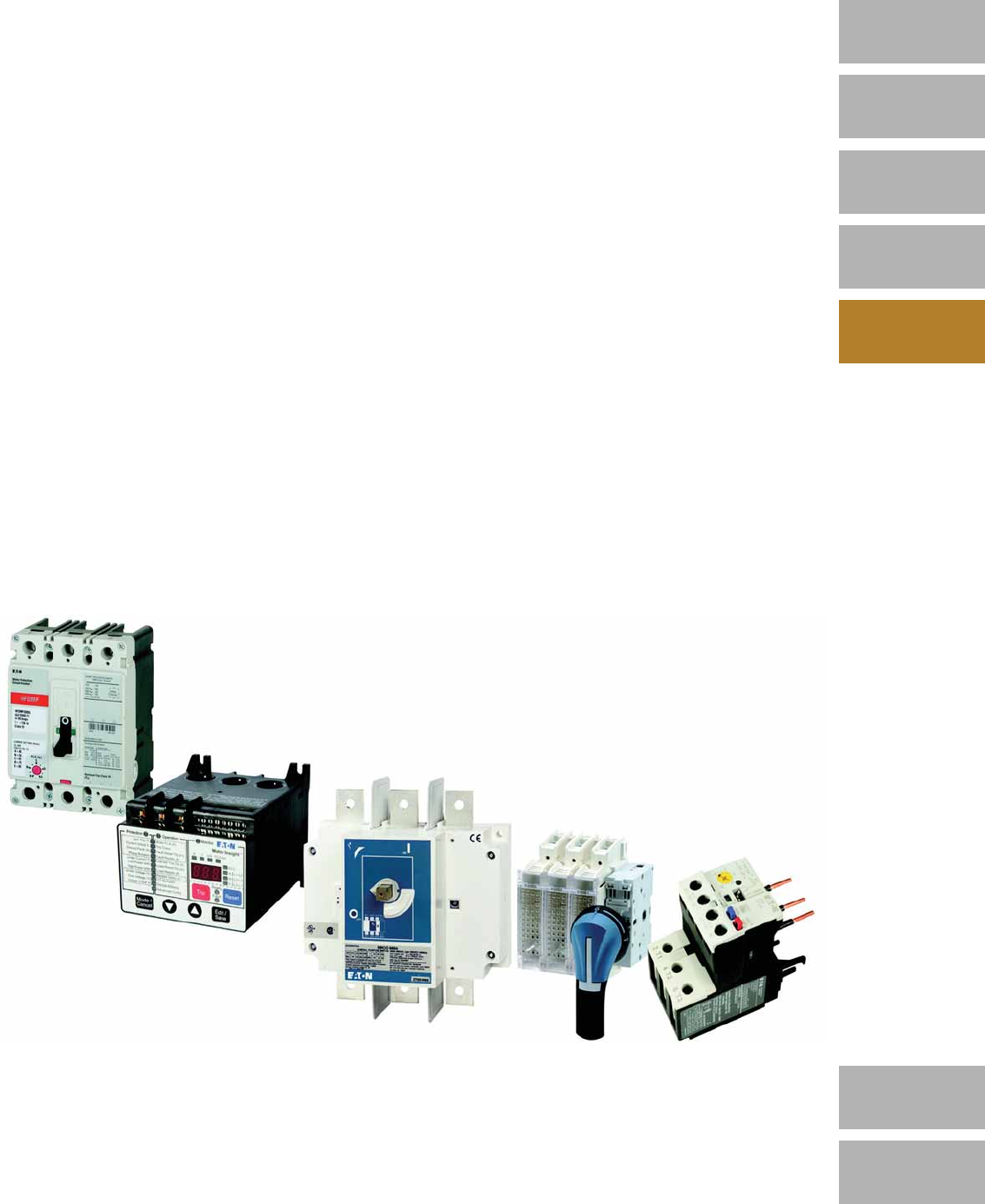
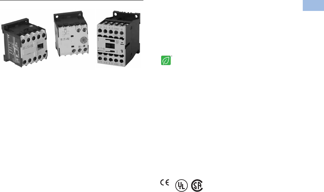
Product Overview
The XT line of IEC power
control offers starting and
protection solutions ideal for
control panels.
Innovations in the design and
development allow users to
reduce material costs, reduce
installation effort, and
enhance panel safety and
performance all in a compact
design. Some of these key
innovations include:
●Toolless assembly of
manual motor controllers
and reversing contactors
●Low coil consumption
●Front accessibility to coil
terminations
●Built-in surge suppression
on electronic coils
●Built-in auxiliary contact for
contactors up to 32A in a
45 mm frame
●Finger-safe and back-of-
hand proof ratings
●Direct PLC control on
185A–2000A contactors
The XT line includes a large
offering of power control
components and accessories
that cover a broad range of
applications and ratings:
●Three-pole contactors to
2000A
●Four-pole contactors to
200A
●Capacitor contactors to
680 kVAR
●Mini contactors to 9A
●Relays to 16A
●Thermal overload relays to
630A
●Electronic overload relays
to 1500A
●Manual motor protectors
to 65A
●Manual motor controllers
and combination motor
controllers to 65A
Volume 5—Motor Control and Protection CA08100006E—February 2014 www.eaton.com V5-T1-3
1
1
1
1
1
1
1
1
1
1
1
1
1
1
1
1
1
1
1
1
1
1
1
1
1
1
1
1
1
1
1.1
IEC Contactors and Starters
XT
IEC Power Control
Relays and Timers
Contents
Description Page
Relays and Timers
Catalog Number Selection . . . . . . . . . . . . . . . . V5-T1-4
Product Selection . . . . . . . . . . . . . . . . . . . . . . . V5-T1-5
Accessories . . . . . . . . . . . . . . . . . . . . . . . . . . . V5-T1-6
Technical Data and Specifications . . . . . . . . . . V5-T1-12
Dimensions . . . . . . . . . . . . . . . . . . . . . . . . . . . V5-T1-16
An Eaton
Green Solution
Miniature Controls . . . . . . . . . . . . . . . . . . . . . . . . . V5-T1-18
Contactors and Starters . . . . . . . . . . . . . . . . . . . . V5-T1-35
Thermal Overload Relays . . . . . . . . . . . . . . . . . . . . V5-T1-128
C440/XT Electronic Overload Relay . . . . . . . . . . . . V5-T1-141
Manual Motor Protectors . . . . . . . . . . . . . . . . . . . V5-T1-157
Combination Motor Controllers . . . . . . . . . . . . . . . V5-T1-193
XT Electronic Manual Motor Protector . . . . . . . . . V5-T1-216
Reference Data . . . . . . . . . . . . . . . . . . . . . . . . . . . V5-T1-229
Relays and Timers
Product Description
Eaton’s new line of XT relays
and timers includes mini and
standard frame control relays
and auxiliary contacts, mini
electronic on-delay and
multi-function timers and
an electronic star-delta
(wye-delta) timer for use
in star-delta (wye-delta)
combinations. Because XT
meets UL®, CSA® and CE
standards, it is the perfect
product solution for IEC
applications all over the
world. The compact, space
saving and easy to install XT
line of IEC contactors and
starters is the efficient and
effective solution for
customer applications.
Features
●For use with mini and
standard frame size
contactors and starters
●Control relays
●AC control from 12V to
550V 50 Hz, 600V 60 Hz
●DC control from
12V to 220V
●On-delay and multi-
function timers
●24–240 Vac/Vdc control
●Available with screw or
spring cage terminals
●Four-pole configurations
●IP20 finger and back-of-
hand proof
●Large ambient temperature
range: –25° to 50°C [–13°
to 122°F]
●The XTRE control relays
have positively driven
contacts between the relay
and the auxiliary contact
modules as well as within
the auxiliary contact
modules
Standards and Certifications
●IEC EN 60947
●CE approved
●UL
●CSA
Instructional Leaflets
Pub51219 XTRM Mini Control Relays
Pub51210 XTRE Control Relays
Pub51244 XTTR Electronic Star-Delta (Wye-Delta) Timer
Pub51245 XTMT Mini Electronic On-Delay and
Multi-Function Timers
V5-T1-4 Volume 5—Motor Control and Protection CA08100006E—February 2014 www.eaton.com
1
1
1
1
1
1
1
1
1
1
1
1
1
1
1
1
1
1
1
1
1
1
1
1
1
1
1
1
1
1
1.1
IEC Contactors and Starters
XT
IEC Power Control
Catalog Number Selection
XT—Relays
XT—Timers
XT RE C10 B22 AD
Product Family Code
RM = Mini IEC control
relay
RE = IEC control relay
Coil Code
See table on Page V5-T1-5.
Product Line Prefix
XT = XT IEC power control
Terminations
Blank =Screw
terminals
C= Spring cage
terminals
Conventional Thermal
Current Rating
10 = 10A
Frame
XTRM
A = 45 mm—mini
XTRE
B = 45 mm—standard
Contact
Configuration
40 = 4NO
31 = 3NO-1NC
22 = 2NO-2NC
Product Family Code
MT = Mini IEC timing
relay
TR = Electronic timing
relay star-delta
(wye-delta)
Coil Code
B = 24–240 Vac/Vdc
Product Line Prefix
XT = XT IEC power control Function
XTMT
11 = On-delay
70 = Adjustable
XTTE
51 = Star-delta
Time Range Max.
XTMT
30S = 1.5–30s
60H = 05–1s
0.15–3s
0.5–10s
3–60s
0.15–3 min
0.5–3 min
3–60 min
0.15–3h
0.5–3h
3–60h
XTTR
60S =3–60s
XT MT 6 B 30S 11 B
Conventional
Thermal Current
Rating
6 = 6A
Frame
A = 45 mm
Volume 5—Motor Control and Protection CA08100006E—February 2014 www.eaton.com V5-T1-5
1
1
1
1
1
1
1
1
1
1
1
1
1
1
1
1
1
1
1
1
1
1
1
1
1
1
1
1
1
1
1.1
IEC Contactors and Starters
XT
IEC Power Control
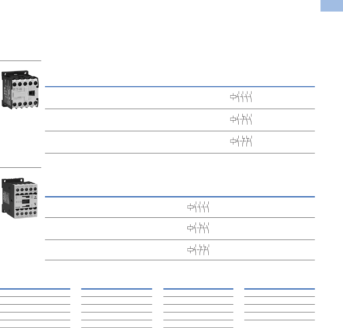
Product Selection
When Ordering
●Orders must be placed in multiples of the package quantity listed
●DC operated control relays have a built-in suppressor circuit
●Contact terminal numbers to EN50011
●Coil terminal numbers to EN50005
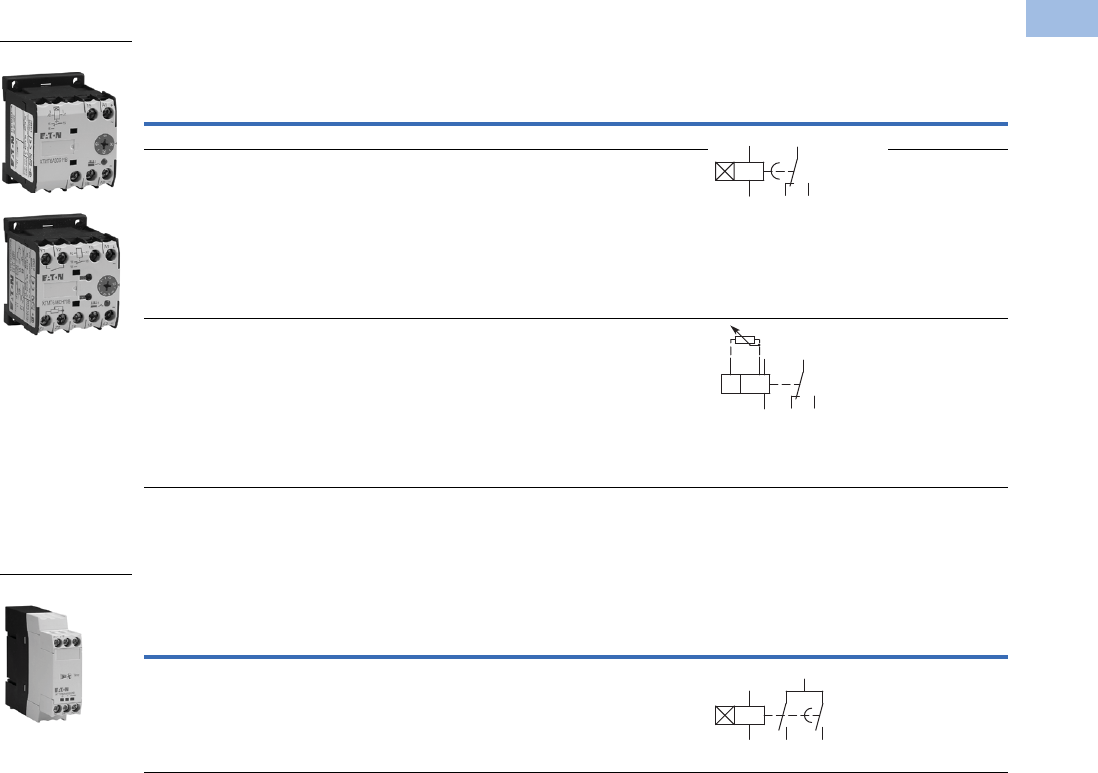
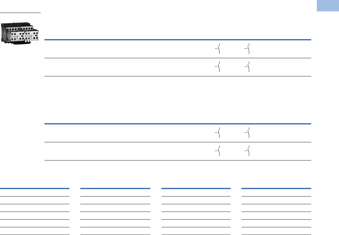
Mini Control Relays
Control Relays
Coil Voltage Suffix
Notes
1Underscore (_) indicates magnet coil suffix required. See Coil Voltage Suffix table above.
2DC operated control relays XTRM(C)10A22_ cannot be used with front mount auxiliary contacts.
3DC operated control relays XTRE(C)10B22_ can only be combined with two-pole auxiliary contacts.
Conventional
Thermal
Current Ith (A)
Contact
Configuration
Rated Operational Current
AC-15 Ie (A) Circuit
Symbol
Screw Terminal
Catalog Number 1
220–240V 380–415V 500V
10 4NO 6 3 1.5 XTRM10A40_
10 3NO-1NC 6 3 1.5 XTRM10A31_
10 2NO-2NC 6 3 1.5 XTRM10A22_ 2
Conventional
Thermal
Current Open
at 60°C Ith
(A)
Contact
Configuration
Rated Operational Current
AC-15 Ie (A)
Circuit
Symbol
Screw Terminal
Catalog Number 1
Spring Cage
Terminal
Catalog Number 1
220–240V 380–415V 500V
16 4NO 6 4 1.5 XTRE10B40_ XTREC10B40_
16 3NO-1NC 6 4 1.5 XTRE10B31_ XTREC10B31_
16 2NO-2NC 6 4 1.5 XTRE10B22_ 3XTREC10B22_ 3
Coil Voltage Suffix Code Coil Voltage Suffix Code Coil Voltage Suffix Code Coil Voltage Suffix Code
110V 50 Hz, 120V 60 Hz
A
415V 50 Hz, 480V 60 Hz
C
380V 50 Hz, 440V 60 Hz
L
120 Vdc
AD
220V 50 Hz, 240V 60 Hz
B
550V 50 Hz, 600V 60 Hz
D
380V 60 Hz
P
220 Vdc
BD
230V 50 Hz
F
208V 60 Hz
E
12V 50/60 Hz
R
12 Vdc
RD
24V 50/60 Hz
T
190V 50 Hz, 220V 60 Hz
G
42V 50 Hz, 48V 60 Hz
W
48 Vdc
WD
24 Vdc
TD
240V 50 Hz, 277V 60 Hz
H
48V 50 Hz
Y
XTRM10A_
14
13 33
34
43
44
A1
A2
23
24
14
13 21
22
33
34
43
44
A1
A2
14
13 21
22
31
32
43
44
A1
A2
XTREC10_
14
13 33
34
43
44
A1
A2
23
24
14
13 21
22
33
34
43
44
A1
A2
14
13 21
22
31
32
43
44
A1
A2
V5-T1-6 Volume 5—Motor Control and Protection CA08100006E—February 2014 www.eaton.com
1
1
1
1
1
1
1
1
1
1
1
1
1
1
1
1
1
1
1
1
1
1
1
1
1
1
1
1
1
1
1.1
IEC Contactors and Starters
XT
IEC Power Control
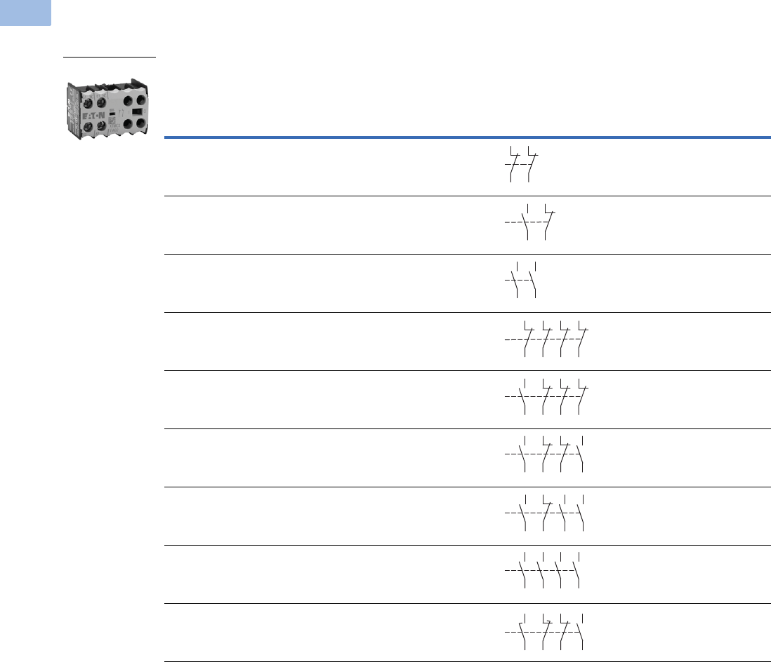
Accessories
Auxiliary Contacts
Front-Mount Auxiliary Contacts for Use with XTRM Mini Control Relays
Notes
1 Orders must be placed in multiples of package quantity listed.
2 One early-make contact (NOE), one late-break contact (NCL).
Conventional
Thermal Current,
Ith
Open (A)
Rated Operational Current
AC-15 Ie (A)
Contact
Configuration Contact Sequence
Pkg.
Qty. 1
Screw Terminal
Catalog Number
220V
230V
240V
380V
400V
415V 500V
10 4 2 1.5 2NC 5 XTMCXFA02
10 4 2 1.5 1NO-1NC 5 XTMCXFA11
10 4 2 1.5 2NO 5 XTMCXFA20
10 4 2 1.5 4NC 5 XTMCXFA04
10 4 2 1.5 1NO-3NC 5 XTMCXFA13
10 4 2 1.5 2NO-2NC 5 XTMCXFA22
10 4 2 1.5 3NO-1NC 5 XTMCXFA31
10 4 2 1.5 4NO 5 XTMCXFA40
10 4 2 1.5 1NO-1NC
1NOE-1NCL
5XTMCXFAL22 2
XTMCXF_
51
52
61
62
54
53 61
62
54
63
64
53
51
52
61
62
71
72 82
81
53 61 71 81
82
72
62
54
54
53 61
62
71
72
83
84
54
53 61
62
73
74
83
84
54
63 73
64 74
53 83
84
58
57 65
66
71
72
83
84
Volume 5—Motor Control and Protection CA08100006E—February 2014 www.eaton.com V5-T1-7
1
1
1
1
1
1
1
1
1
1
1
1
1
1
1
1
1
1
1
1
1
1
1
1
1
1
1
1
1
1
1.1
IEC Contactors and Starters
XT
IEC Power Control
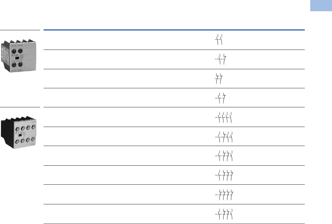
Front-Mount Auxiliary Contacts for Use with XTRE Control Relays 1
Notes
1 Interlocked opposing contacts, to IEC/EN 60947-5-1 Annex L (positively driven), within the auxiliary contact modules (not NOE and NCL contacts) and between the
auxiliary contacts and built-in contacts of the XTRE control relays.
2 Orders must be placed in multiples of package quantity listed.
3 Catalog number is shown with screw type terminal. For spring cage, add a “C” before the last 2 digits. For example, to order a spring cage version of the XTCEXFAC22,
change the catalog number to XTCEXFACC22.
4 One early-make contact (NOE), one late-break contact (NCL).
Conventional
Thermal Current,
Ith (A), Open at 60°C Poles
Rated Operational Current AC-15 Ie (A)
Contact
Configuration Circuit Symbol
Pkg.
Qty. 2
Screw Terminal
Catalog Number
220V
230V
240V
380V
400V
415V 500V
16 2 6 3 1.5 2NO 5 XTCEXFAC20
16 2 6 3 1.5 1NO-1NC 5 XTCEXFAC11 3
16 2 6 3 1.5 2NC 5 XTCEXFAC02
16 2 6 3 1.5 1NOE-1NCL5XTCEXFALC11 4
16 4 6 3 1.5 4NO 5 XTCEXFAC40 3
16 4 6 3 1.5 3NO-1NC 5 XTCEXFAC31 3
16 4 6 3 1.5 2NO-2NC 5 XTCEXFAC22 3
16 4 6 3 1.5 1NO-3NC 5 XTCEXFAC13
16 4 6 3 1.5 4NC 5 XTCEXFAC04
16 4 6 3 1.5 1NO-1NC
1NOE-1NCL
5XTCEXFCLC22 4
Two-Pole
Four-Pole
54
63
6
4
53
54
53 61
62
51
52
61
62
58
57 6
5
66
54
63 73
64 74
53 83
84
54
53 61
62
73
74
83
84
54
53 61
62
71
72
83
84
53 61 71 81
82
72
62
54
51
52
61
62
71
72 82
81
58
5765
66
71
72
83
84
V5-T1-8 Volume 5—Motor Control and Protection CA08100006E—February 2014 www.eaton.com
1
1
1
1
1
1
1
1
1
1
1
1
1
1
1
1
1
1
1
1
1
1
1
1
1
1
1
1
1
1
1.1
IEC Contactors and Starters
XT
IEC Power Control
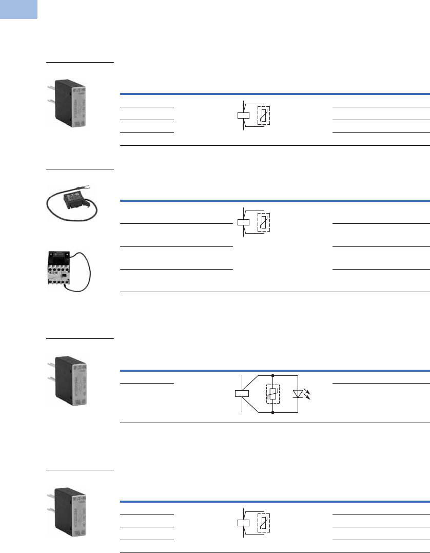
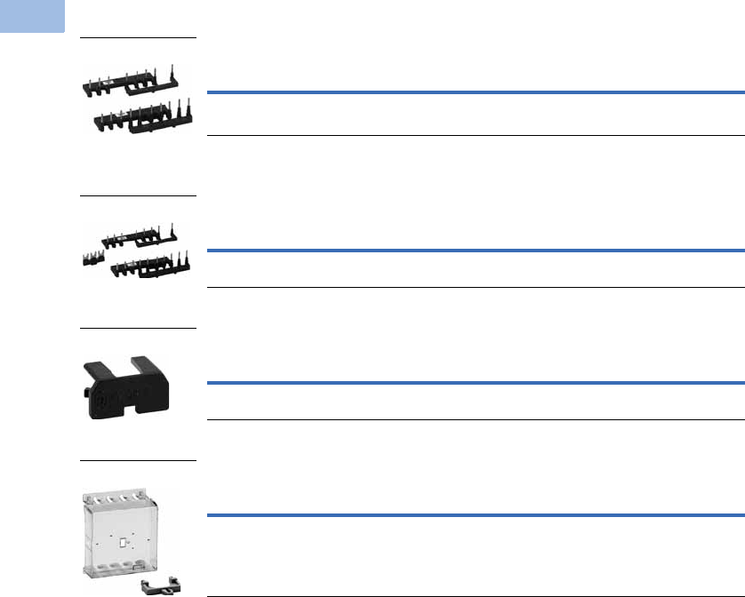
Suppressors
For AC operated contactors 50–60 Hz. On DC operated contactor relays and on XTRE10B, the
suppressor circuit is built-in. Note dropout delay.
Varistor Suppressor 12
Varistor Suppressor for XTRE
Varistor Suppressor for XTRM
Varistor Suppressor with Integrated LED 12
Varistor Suppressor for XTRE
RC Suppressor 12
RC Suppressor for XTRE
Notes
1 Note dropout delay.
2 For AC operated contactors, 50/60 Hz. DC operated contactors have an integrated suppressor.
3 Orders must be placed in multiples of package quantity listed.
Voltage
For Use
with… Contact Sequence
Pkg.
Qty.
3
Catalog Number
24–48 XTRE(C)10B 10 XTCEXVSBW
48–130 10 XTCEXVSBA
130–240 10 XTCEXVSBB
240–500 10 XTCEXVSBC
Voltage
For Use
with… Circuit Symbol
Pkg.
Qty.
3
Catalog Number
24–48 XTRM6A_,
XTRM9A_
10 XTMCXVSW
48–130 XTRM6A_,
XTRM9A_
10 XTMCXVSA
110–250 XTRM6A_,
XTRM9A_
10 XTMCXVSB
380–415 XTRM6A_,
XTRM9A_
10 XTMCXVSN
Voltage
For Use
with… Contact Sequence
Pkg.
Qty.
3
Catalog Number
24–48 XTRE(C)10B 10 XTCEXVSLBW
130–240 10 XTCEXVSLBB
Voltage
For Use
with… Contact Sequence
Pkg.
Qty.
3
Catalog Number
24–48 XTRE(C)10B 10 XTCEXRSBW
48–130 10 XTCEXRSBA
110–240 10 XTCEXRSBB
240–500 10 XTCEXRSBC
XTCEXVSB_
A1
A2
XTMCXVS_
XTRM Relay with
Installed Suppressor
A1
A2
XTCEXVSLB_
A1
A2
XTCEXRSB_
A1
A2
Volume 5—Motor Control and Protection CA08100006E—February 2014 www.eaton.com V5-T1-9
1
1
1
1
1
1
1
1
1
1
1
1
1
1
1
1
1
1
1
1
1
1
1
1
1
1
1
1
1
1
1.1
IEC Contactors and Starters
XT
IEC Power Control
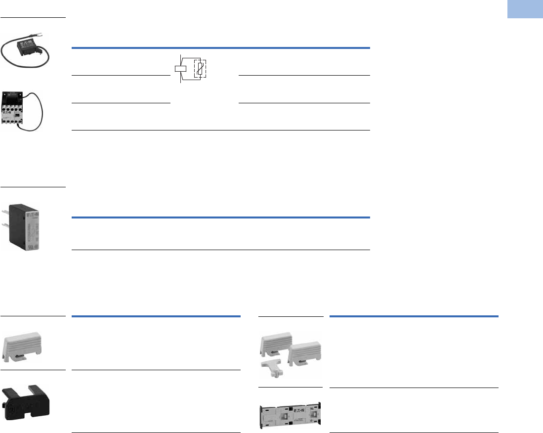
RC Suppressor 12
RC Suppressor for XTRM 3
Free-Wheel Diode Suppressor
In addition to the built-in suppressor circuit for DC actuated contactors. Prevents negative breaking
voltage when contactors are used in combination with a safety PLC.
Free-Wheel Diode Suppressor for XTRE
Connector 5
Connector
Mechanical Interlock 6
Mechanical Interlock
Notes
1 Note dropout delay.
2 For AC operated contactors, 50/60 Hz. DC operated contactors have an integrated suppressor.
3 For AC operated contactors, 50/60 Hz. Note dropout delay.
4 Orders must be placed in multiples of package quantity listed.
5 For mechanically arranging contactors in combinations. Distance between contactors is 0 mm.
6 For two contactors with AC or DC operated magnet system that are horizontally or vertically mounted.
For Frame B, mechanical lifespan is 2.5 x 10⁶ operations and the distance between contactors is 0 mm.
Voltage
For Use
with…
Circuit
Symbol
Pkg.
Qty.
4
Catalog Number
24–48 XTRM6A_,
XTRM9A_
10 XTMCXRSW
48–130 XTRM6A_,
XTRM9A_
10 XTMCXRSA
110–250 XTRM6A_,
XTRM9A_
10 XTMCXRSB
XTMCXRS_
XTRM Relay with
Installed Suppressor
A1
A2
Voltage
For Use
with…
Pkg.
Qty.
4
Catalog Number
130–240
XTRE10B
10 XTCEXVSLBB
XTCEXVSLBB
For Use
with…
Pkg.
Qty.
4
Catalog Number
XTRE(C)10B 50 XTCEXCNC
XTRM10A 50 XTMCXCN
XTCEXCNC
XTMCXCN
For Use
with…
Pkg.
Qty.
4
Catalog Number
XTRE10B_ 5 XTCEXMLB
XTRM10A_ 5 XTMCXML
XTCEXMLB
XTMCXML
V5-T1-10 Volume 5—Motor Control and Protection CA08100006E—February 2014 www.eaton.com
1
1
1
1
1
1
1
1
1
1
1
1
1
1
1
1
1
1
1
1
1
1
1
1
1
1
1
1
1
1
1.1
IEC Contactors and Starters
XT
IEC Power Control
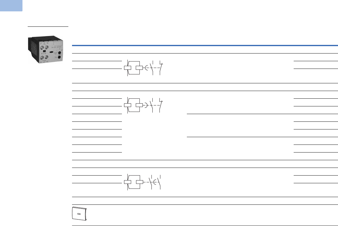
Electronic Timer Modules
Front- (top-) mounted timer modules for use with XTRE10B control relays. Can not be combined with top-mount auxiliary
contacts, XTCEXF_.
Electronic Timer Modules for XTRE
Note
1 Orders must be placed in multiples of package quantity listed.
Voltage Contact Sequence Timing Range
For Use
with…
Pkg.
Qty. 1Catalog Number
On-Delay
24 Vac/Vdc 0.05–1s
0.5–10s
15–100s
XTRE10B_ 1 XTCEXTEEC11T
100–130 Vac XTCEXTEEC11A
200–240 Vac XTCEXTEEC11B
Off-Delay
24 Vac/Vdc 0.05–1s XTRE10B_ 1 XTCEXTED1C11T
100–130 Vac XTCEXTED1C11A
200–240 Vac XTCEXTED1C11B
24 Vac/Vdc 0.5–10s XTRE10B_ 1 XTCEXTED10C11T
100–130 Vac XTCEXTED10C11A
200–240 Vac XTCEXTED10C11B
24 Vac/Vdc 5–100s XTRE10B_ 1 XTCEXTED100C11T
100–130 Vac XTCEXTED100C11A
200–240 Vac XTCEXTED100C11B
Star-Delta
24 Vac/Vdc 1–30s XTRE10B_ 1 XTCEXTEYC20T
100–130 Vac XTCEXTEYC20A
200–240 Vac XTCEXTEYC20B
Sealable Shroud
Transparent sealable shroud used to protect
electronic timer modules from unwanted access.
XTCEXTEE,
XTCEXTED,
XTCEXTEY
1XTCEXTESHRD
XTCEXT_
57
58
65
66
A1
A2
57
58
65
66
A1
A2
57
58
67
68
A1
A2
Volume 5—Motor Control and Protection CA08100006E—February 2014 www.eaton.com V5-T1-11
1
1
1
1
1
1
1
1
1
1
1
1
1
1
1
1
1
1
1
1
1
1
1
1
1
1
1
1
1
1
1.1
IEC Contactors and Starters
XT
IEC Power Control
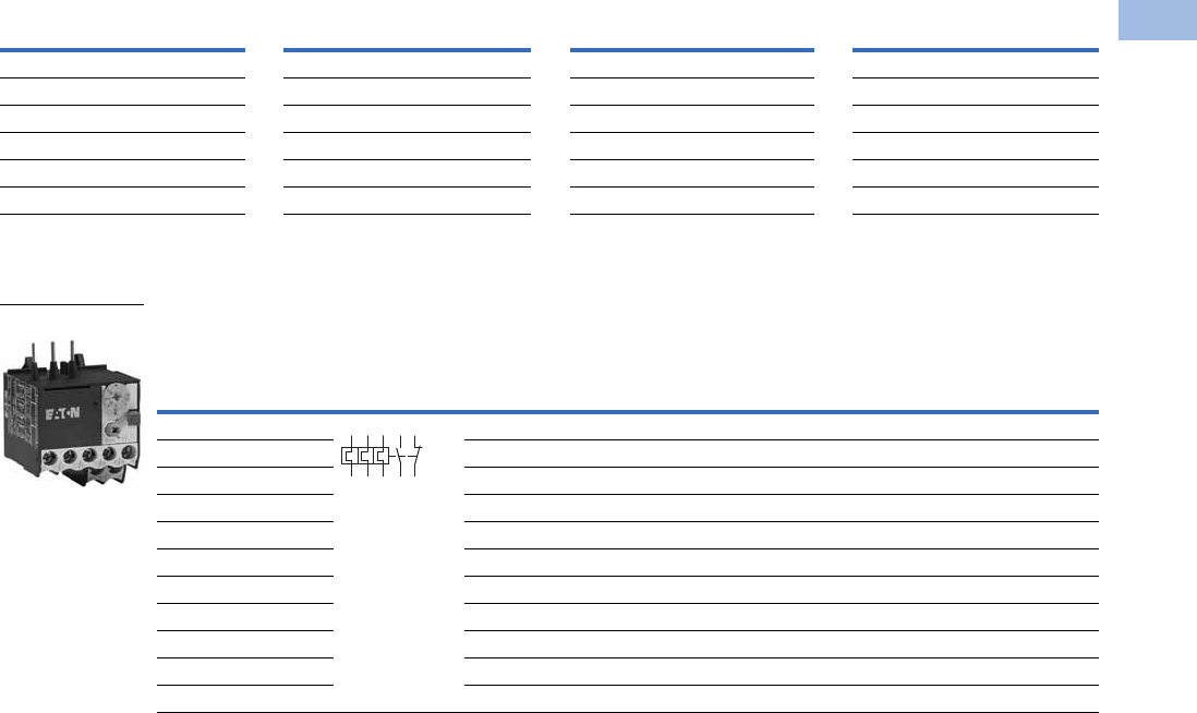
Mini Electronic Timers
Mini Electronic On-Delay Timers
Electronic Star-Delta (Wye-Delta) Timers
Electronic Star-Delta (Wye-Delta) Timers
Actuating Voltage
24–240 50/60 Hz
24–240 Vdc
Admissible Cable Length Connection to
Cable unscreened, with cable cross-section 0.5–1.5 mm2Y1/Y2, Z1/Z2
Two-core cable M250
Two-core cable in the same cable duct with the main cable, 50/60 Hz M50
Conventional
Thermal Current
Ie (A)
Rated Operational Current
Ie AC-11 Amps Time
Range Function
Terminal Marking
According to
EN 50042 Catalog Number 220/230/240V 380/400/440V
6 3 3 1.5–30 sec Fixed, on-delay XTMT6A30S11B
6 3 6 0.05–1 sec
0.15–3 sec
0.5–10 sec
3–60 sec
0.15–3 min
0.5–10 min
3–60 min
0.15–3h
0.5–10h
3–60h
Fixed, on-delay XTMT6A60H11B
6 3 3 0.05–1 sec
0.15–3 sec
0.5–10 sec
3–60 sec
0.15–3 min
0.5–10 min
3–60 min
0.15–3h
0.5–10h
3–60h
Adjustable:
on-delay;
fleeting contact
on energization;
flashing; pulse
generating;
ON-OFF
XTMT6A60H70B
Conventional
Thermal Current
Ie (A)
Rated Operational Current
Ie AC-11 Amps Time
Range Function
Terminal Marking
According to
EN 50042 Catalog Number 230V 400V
6 3 3 3–60 sec Fixed, star-delta XTTR6A60S51B
XTMT6A_
A1
A2
15
16 18
A1
A2
Z2Z1
15
16 18
XTTR6A60S51
A1
A2 18
17
28
V5-T1-12 Volume 5—Motor Control and Protection CA08100006E—February 2014 www.eaton.com
1
1
1
1
1
1
1
1
1
1
1
1
1
1
1
1
1
1
1
1
1
1
1
1
1
1
1
1
1
1
1.1
IEC Contactors and Starters
XT
IEC Power Control
Technical Data and Specifications
Relays and Timers
Note
1Damp heat, constant, to IEC 60068-2-78; damp heat, cyclical, to IEC 60068-2-30.
Description XTRE XTCEXFAC_ XTCEXTE_ XTRM XTMCXFA_
General
Standards IEC/EN 60947,
VDE 0660,
UL, CSA
IEC/EN 60947,
VDE 0660,
UL, CSA
DIN EN 61812,
IEC/EN 60947,
VDE 060, UL, CSA
IEC/EN 60947,
VDE 0660,
UL, CSA
IEC/EN 60947,
VDE 0660,
UL, CSA
Lifespan, mechanical—operations
AC operated 20,000,000 10,000,000 3,000,000 10,000,000 10,000,000
DC operated 20,000,000 10,000,000 3,000,000 20,000,000 20,000,000
Maximum operating frequency (ops/hr) 9000 9000 — 9000 9000
Climatic proofing 11 1 11
Ambient temperature
Open (°C, min./max.) –25/60 –25/60 –40/80 –25/50 –25/50
Enclosed (°C, min./max.) –25/40 –25/40 –25–60 –25/40 –25/40
Ambient temperature for storage (°C, min./max.) –40/80 –40/80 –25–40 — —
Mounting position As required,
not suspended
As required, except
vertically A1/A2 at
the bottom
As required, except
vertically A1/A2 at
the bottom
Mechanical shock resistance (IEC/EN 60068-2-27)
Half-sinusoidal shock 10 ms
Base unit with auxiliary contact module
Make contact 7g 7g 6g 10g 10g
Break contact 5g 5g 6g 8g 8g
Degree of protection IP20 IP20 IP20 IP20 IP20
Protection against direct contact from the front
when actuated by a perpendicular test finger (IEC 536)
Finger and
back-of-hand proof
Finger and
back-of-hand proof
Finger and
back-of-hand proof
Finger and
back-of-hand proof
Finger and
back-of-hand proof
Weight
AC operated (kg) 0.23 0.05 0.08 0.17 —
DC operated (kg) 0.28 0.05 0.08 0.20 —
Terminal capacity
Screw terminals
Solid (mm2) 1 x (0.75–4)0.
2 x (0.75–2.5)
1 x (0.75–4)0.
2 x (0.75–2.5)
1 x (0.75–2.5)
2 x (0.75–1.5)
1 x (0.75–2.5)
2 x (0.75–2.5)
1 x (0.75–2.5)
2 x (0.75–2.5)
Flexible with ferrule (mm2) 1 x (0.75–2.5)
2 x (0.75–2.5)
1 x (0.75–2.5)
2 x (0.75–2.5)
1 x (0.75–1.5)
2 x (0.75–1.5)
1 x (0.75–1.5)
2 x (0.75–1.5)
1 x (0.75–1.5)
2 x (0.75–1.5)
Solid or stranded (AWG) 18–14 18–14 18–14
Terminal screw M3.5 M3.5 M3.5 M3.5 M3.5
Pozidriv screwdriver Size 2 Size 2 Size 2 Size 2 Size 2
Standard screwdriver (mm) 0.8 x 5.5
1 x 6
0.8 x 5.5
1 x 6
0.8 x 5.5
1 x 6
0.8 x 5.5
1 x 6
0.8 x 5.5
1 x 6
Max. tightening torque (Nm) 1.2 1.2 1.2 1.2 1.2
Spring cage terminals
Solid (mm2) 1 x (0.75–2.5)
2 x (0.75–2.5)
1 x (0.75–2.5)
2 x (0.75–2.5)
—
—
1 x (0.75–2.5)
2 x (0.75–2.5)
1 x (0.75–2.5)
2 x (0.75–2.5)
Flexible with or without ferrule DIN 46228 (mm2) 1 x (0.75–2.5)
2 x (0.75–2.5)
1 x (0.75–2.5)
2 x (0.75–2.5)
—
—
1 x (0.75–2.5)
2 x (0.75–2.5)
1 x (0.75–2.5)
2 x (0.75–2.5)
Solid or stranded (AWG) 18–14 18–14 — 18–14 18–14
Standard screwdriver (mm) 0.6 x 3.5 0.6 x 3.5 — 0.6 x 3.5 0.6 x 3.5
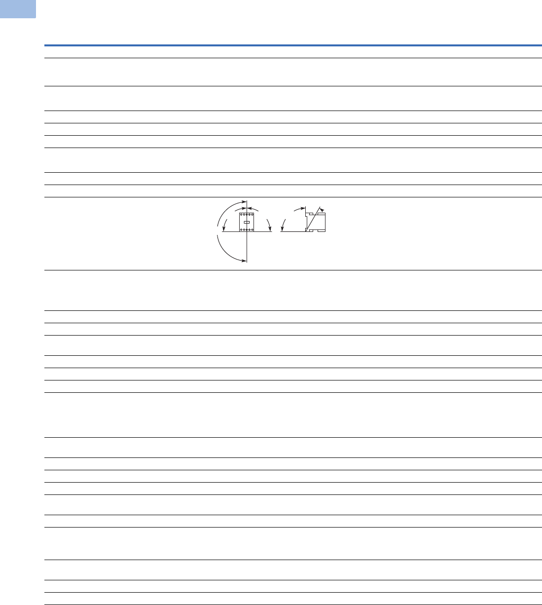
180°
30°
90°90°90°

Volume 5—Motor Control and Protection CA08100006E—February 2014 www.eaton.com V5-T1-13
1
1
1
1
1
1
1
1
1
1
1
1
1
1
1
1
1
1
1
1
1
1
1
1
1
1
1
1
1
1
1.1
IEC Contactors and Starters
XT
IEC Power Control
Relays and Timers, continued
Note
1Making and breaking conditions to DC13, time constant as stated.
Description XTRE XTCEXFAC_ XTCEXTE_ XTRM XTMCXFA_
Contacts
Interlocked opposing contacts to ZH 1/457,
including auxiliary contact module
Yes Yes No Yes Yes
Rated impulse withstand voltage (Uimp) Vac 6000 6000 6000 6000 6000
Overvoltage category/pollution degree III/3 III/3 III/3 III/3 III/3
Rated insulation voltage (Ui) Vac 690 690 600 690 690
Rated operational voltage (Ue) Vac 690 500 400 600 600
Safe isolation to VDE 0106 Part 101 and Part 101/A1
Between coil and auxiliary contacts (Vac) 400 400 250 300 300
Between the auxiliary contacts (Vac) 400 400 250 300 300
Rated operational current
AC-15 220/240V Ie6 6 Please inquire 6 4
380/415V Ie4 3 Please inquire 3 2
500V Ie1.5 — — 1.5 1.5
DC-13
1
DC13 L/R
<
15 ms
Contacts in series—voltage:
1—24V 10
10 —
2.5 2.5
1—60V
66
———
2—60V 10 10 — 2.5 2.5
1—110V 3 3 — — —
3—110V 6 6 — 1.5 1.5
1—220V 1 1 — — —
3—220V
55
—
0.5 0.5
DC13 L/R
<
50 ms
Contacts in series—voltage:
3—24V 4
——
——
3—60V 4
——
——
3—110V 2
——
——
3—220V 1
——
——
Control circuit reliability
(at Ue = 24 Vdc, Umin = 17, Imin = 5.4 mA)
Failure rate = <10–8, <1 failure
in 100 million operations
— Failure rate = <10–8, <1 failure
in 100 million operations
Conventional thermal current (Ith) 16 16 6 10 10
Short-circuit rating without welding
Maximum overcurrent protective device
220/240V–XTPR Frame B 4 — — 4 4
380/415V–XTPR Frame B 4 — — 4 4
Short-circuit protection, max. fuse
500V (A gG/gL) 10 10 6 6 6
500V (A fast) — — — 10 10
Current heat losses at load of I
th
AC operated (W) 0.3 0.3 — 0.2 0.2
DC operated (W) 0.3 0.3 — 0.3 0.3

V5-T1-14 Volume 5—Motor Control and Protection CA08100006E—February 2014 www.eaton.com
1
1
1
1
1
1
1
1
1
1
1
1
1
1
1
1
1
1
1
1
1
1
1
1
1
1
1
1
1
1
1.1
IEC Contactors and Starters
XT
IEC Power Control
Relays and Timers, continued
Note
1Smoothed DC or three-phase bridge rectifier.
Description XTRE XTCEXFAC_ XTCEXTE_ XTRM XTMCXFA_
Magnet Systems
Pickup and dropout values
AC operated
Single-voltage coil 50 Hz and dual-voltage coil 50 Hz,
60 Hz (pickup x U
c
)
0.8–1.1 — 0.85–11 0.8–1.1 —
Dual-frequency coil 50/60 Hz (pickup x U
c
) 0.8–1.1 — — 0.85–1.1 —
DC operated
1
Pickup voltage (pickup x U
c
) 0.8–1.1 — 0.7–1.2 0.85–1.3 —
At 24V: without auxiliary contact module (40°C) (pickup x U
c
) 0.7–1.3 — — 0.7–1.3 —
Power consumption
Single-voltage coil 50 Hz and dual-voltage coil 50 Hz, 60 Hz
Pickup VA 24 — — 25 —
Pickup W 19 — — 22 —
Sealing VA 3.4 — 2 4.6 —
Sealing W 1.2 — 1.8 1.3 —
Dual-frequency coil 50/60 Hz at 50 Hz
Pickup VA 27 — — 30 —
Pickup W 22 — — 26 —
Sealing VA 4.2 — — 5.4 —
Sealing W 1.4 — — 1.6 —
Dual-frequency coil 50/60 Hz at 60 Hz
Pickup VA 25 — — 29 —
Pickup W 21 — — 24 —
Sealing VA 3.3 — — 3.9 —
Sealing W 1.2 — — 1.2 —
DC operated
Pull-in = sealing (W) 3 — — 2.6 —
Duty factor (% DF) 100 — 100 100 —
Switching times at 100% U
c
(approximate values)
AC operated closing delay (ms)
<
21 — — 14–21 —
AC operated NO contact opening delay (ms)
<
18 — — 8–18 —
AC operated with auxiliary contact module,
max. closing delay (ms)
—— — 4545
DC operated closing delay (ms)
<
31 — — 26–35 —
DC operated NO contact opening delay (ms)
<
12 — — 15–25 —
DC operated with auxiliary contact module,
max. closing delay (ms)
—— — 7070
Volume 5—Motor Control and Protection CA08100006E—February 2014 www.eaton.com V5-T1-15
1
1
1
1
1
1
1
1
1
1
1
1
1
1
1
1
1
1
1
1
1
1
1
1
1
1
1
1
1
1
1.1
IEC Contactors and Starters
XT
IEC Power Control
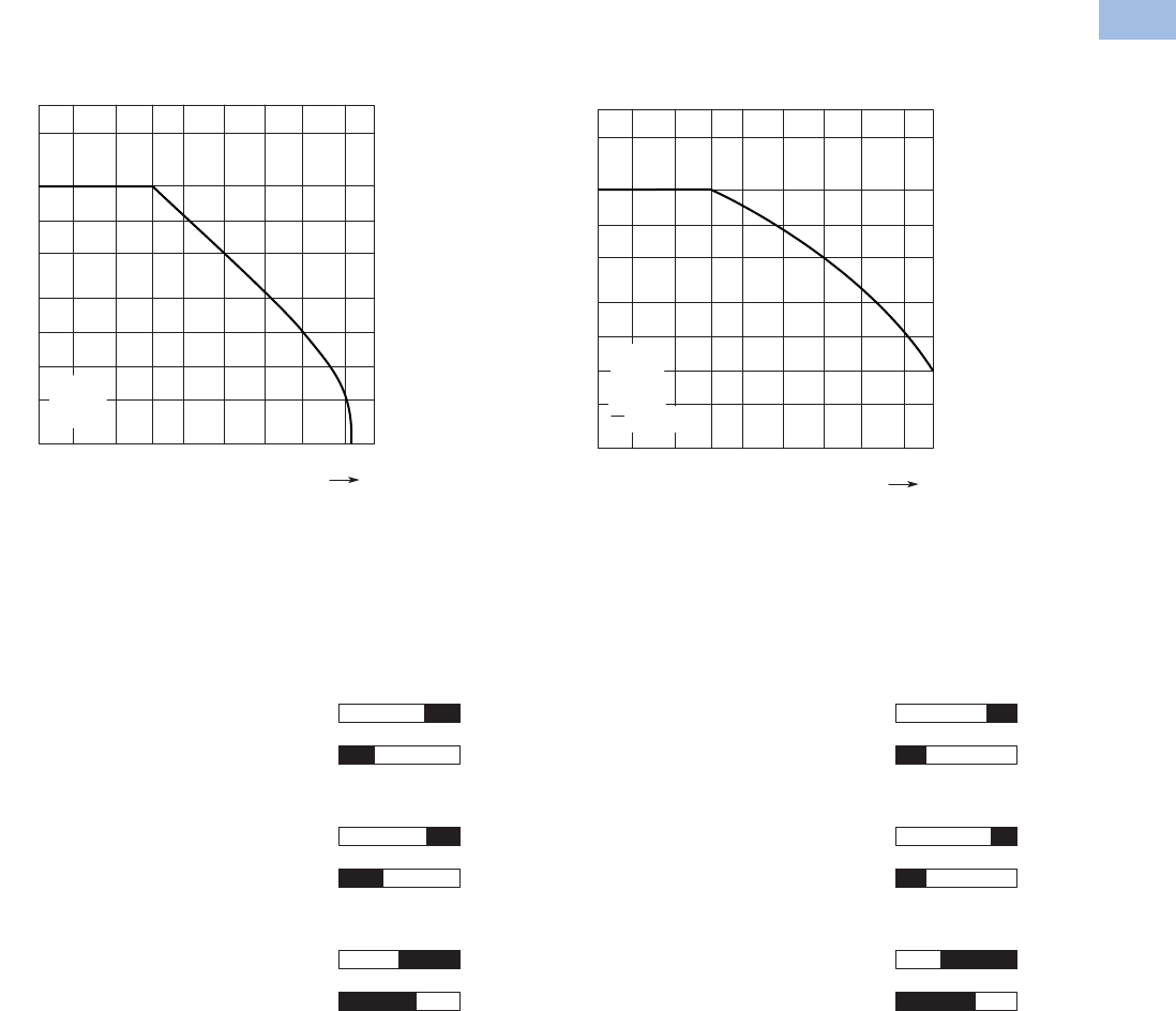
Control Relays—Characteristic Curves
XTRE (AC-15) XTRE (DC-13) 1
The diagrams show the closing and opening travel of the contact of the contactor relays and auxiliary contacts at no load.
Tolerances are not taken into consideration.
Contact Travel Diagrams
XTRE
Note
1Making and breaking conditions to DC-13, time constant as stated.
Component lifespan (operations)
Ie = Rated operational current
AC-15
240 V
0.01 0.050.02 20.1 0.5 152.0 10 A
20
10
5
2
1
0.5
0.2
0.1
106
Ie
L
R
DC-13
24 V
= 50 ms
Component lifespan (operations)
Ie = Rated operational current
0.01 0.050.02 20.1 0.5 150.2 10 A
20
10
5
2
1
0.5
0.2
0.1
106
Ie
4.5
4.5
3.30
01.0 2.9
2.9
2.10
00.7
4.5
4.5
3.20
01.6 2.9
2.9
2.30
00.7
4.5
4.5
2.00
02.8 2.9
2.9
1.10
01.9
Normally open contact
XTRE_ — AC Operation
XTCEXFALC_ — AC Operation
XTCEXFAC_ — AC Operation
Normally closed contact
Normally open contact
Normally closed contact
Normally open contact (early make)
Normally closed contact (late make)
Normally open contact
XTRE — DC Operation
XTCEXFALC_ — DC Operation
XTCEXFAC_ — DC Operation
Normally closed contact
Normally open contact
Normally closed contact
Normally open contact (early make)
Normally closed contact (late make)
V5-T1-16 Volume 5—Motor Control and Protection CA08100006E—February 2014 www.eaton.com
1
1
1
1
1
1
1
1
1
1
1
1
1
1
1
1
1
1
1
1
1
1
1
1
1
1
1
1
1
1
1.1
IEC Contactors and Starters
XT
IEC Power Control
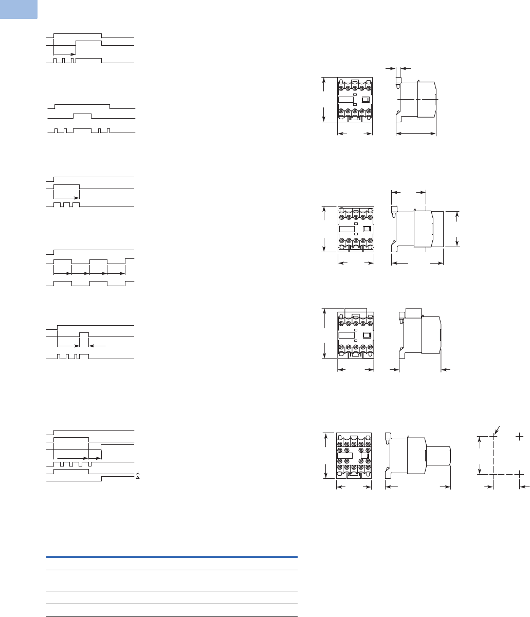
Flow Diagrams—Electronic Timers, XTMT Mini Timers
On-Delay
ON-OFF Function
Fleeting Contact on Energization
Flashing, Pulse Initiating
Pulse Generating
Star-Delta (Wye-Delta) Timer
Star-Delta
Rating Data
Rating Data for Approved Types
Pilot Duty General Use
Control Relays—XTMR
A600, P300 10A–600 Vac
0.5A–250 Vdc
Timers—XTMT, XTTR
B300 6A–250 Vac
LED
A1-A2
15-18
t
A1-A2
15-18
OFFONOFF
LED
A1-A2
15-18
t
LED
LED
tttt
A1-A2
15-18
LED
A1-A2
15-18
0.5 s
t
17-18
ttu
A1-A2
17-28
Power LED
LED
LED
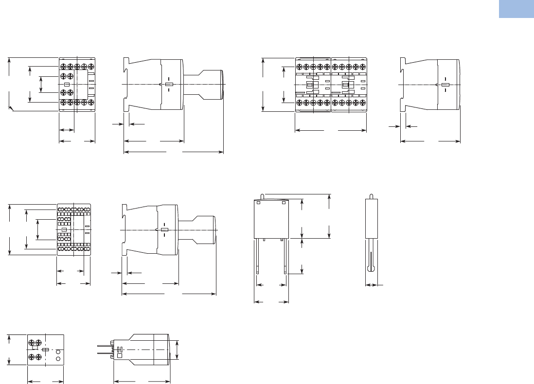
Dimensions
Approximate Dimensions in mm [in.]
Mini Contactor Relays
Mini Control Relay XTRM
XTRM Mini Control Relay with IP40 XTMCX Shroud
XTRM Mini Control Relay with RC or Varistor Suppressor
XTRM Mini Control Relay with XTMCXFA Auxiliary Contact
45
[1.77]
58
[2.28]
52 – 54
[2.05] – [2.13]
5.5 [.22]
45
[1.77]
58
[2.28]
65.3
[2.57]
43
[1.69]
45
[1.77]
52 – 54
[2.05] – [2.13]
45
[1.77]
62.5
[2.46]
45
[1.77] 83 – 86
[3.27] – [3.39]
58
[2.28] 50
[1.97]
35
[1.38]
M4
Volume 5—Motor Control and Protection CA08100006E—February 2014 www.eaton.com V5-T1-17
1
1
1
1
1
1
1
1
1
1
1
1
1
1
1
1
1
1
1
1
1
1
1
1
1
1
1
1
1
1
1.1
IEC Contactors and Starters
XT
IEC Power Control
Approximate Dimensions in mm [in.]
Control Relays
Control Relay XTRE with XTCEXFA Auxiliary Contact
Control Relay with Spring Cage Terminals XTREC
with XTCEXFA Auxiliary Contact
Electronic Timer Module XTCEXTE
18
[.71]
45
[1.77]
6.5
[.26]
75
[2.95] 117
[4.61]
68
[2.68]
45
[1.77]
18
[.71]
26.4
[1.04]
52.3
[2.06]
45
[1.77]
36
[1.42] 6.5
[.26] 75
[2.95] 125
[4.92]
68
[2.68]
38
[1.50]
25
[.98]
70
[2.76]
45
[1.77]
Control Relay XTRE with XTCEXMLB Mechanical Interlock
Coil Suppressors for Use with XTRE Control Relays
6.5
[.26]
75
[2.95]
45
[1.77]
68
[2.68]
90
[3.54]
Approx.
32 [1.26]
25
[.98]
19.2
[.76]
25.9
[1.02]
28
[1.10]
9
[.35]
V5-T1-18 Volume 5—Motor Control and Protection CA08100006E—February 2014 www.eaton.com
1
1
1
1
1
1
1
1
1
1
1
1
1
1
1
1
1
1
1
1
1
1
1
1
1
1
1
1
1
1
1.1
IEC Contactors and Starters
XT
IEC Power Control
XTMC Miniature Contactor
Contents
Description Page
Relays and Timers . . . . . . . . . . . . . . . . . . . . . . . . . V5-T1-3
Miniature Controls
Catalog Number Selection . . . . . . . . . . . . . . . . V5-T1-19
Product Selection . . . . . . . . . . . . . . . . . . . . . . . V5-T1-20
Accessories. . . . . . . . . . . . . . . . . . . . . . . . . . . . V5-T1-24
Technical Data and Specifications . . . . . . . . . . . V5-T1-27
Wiring Diagrams . . . . . . . . . . . . . . . . . . . . . . . . V5-T1-32
Dimensions. . . . . . . . . . . . . . . . . . . . . . . . . . . . V5-T1-34
An Eaton
Green Solution
Contactors and Starters . . . . . . . . . . . . . . . . . . . . V5-T1-35
Thermal Overload Relays . . . . . . . . . . . . . . . . . . . V5-T1-128
C440/XT Electronic Overload Relay . . . . . . . . . . . V5-T1-141
Manual Motor Protectors . . . . . . . . . . . . . . . . . . . V5-T1-157
Combination Motor Controllers . . . . . . . . . . . . . . . V5-T1-193
XT Electronic Manual Motor Protector . . . . . . . . . V5-T1-216
Reference Data . . . . . . . . . . . . . . . . . . . . . . . . . . . V5-T1-229
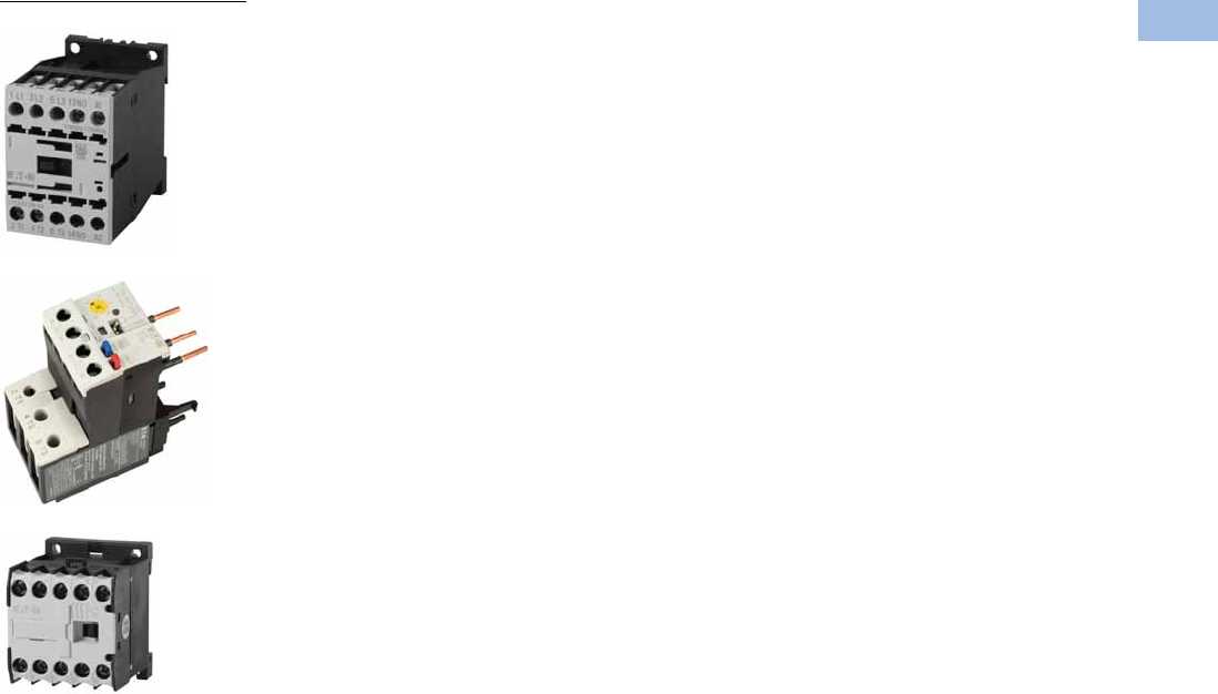
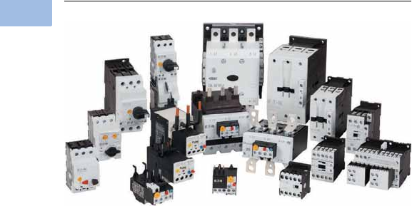
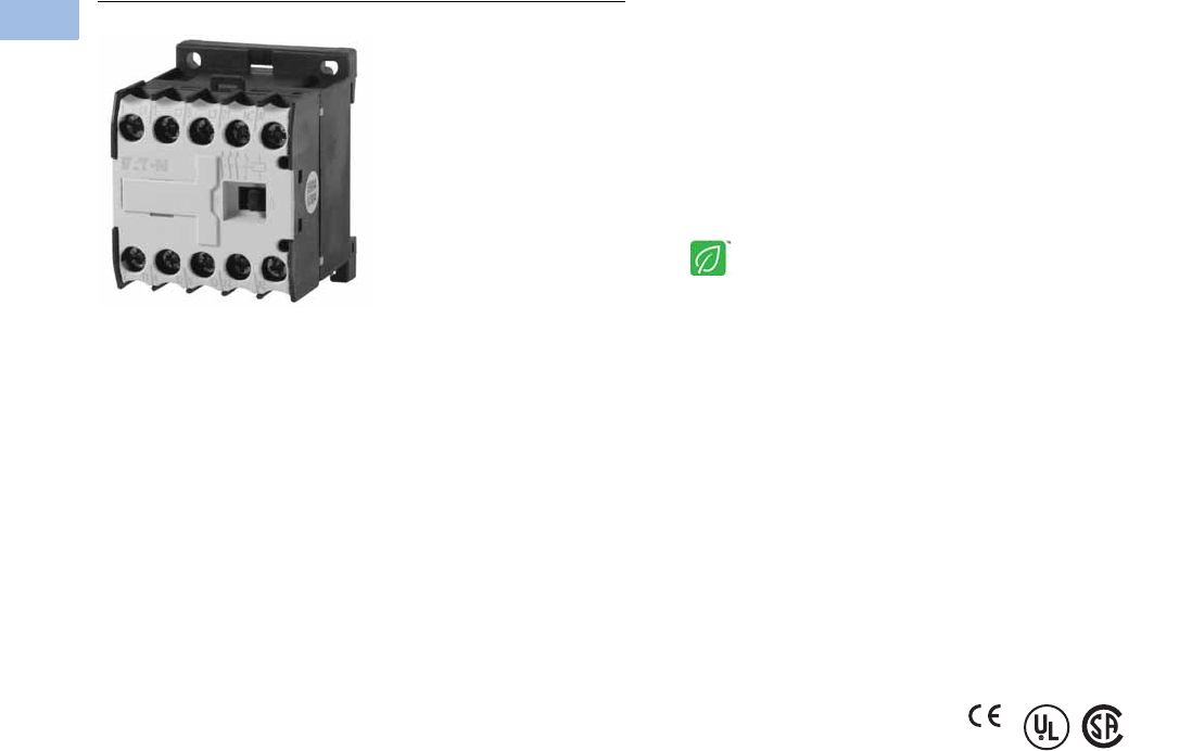
Miniature Controls
Product Description
Eaton’s new line of
XT
miniature controls includes
non-reversing and reversing
mini contactors, mini overload
relays and snap-on
accessories. A wide range of
applications is possible,
including small electrical
motors from fractional to 5 hp
(460 Vac) or up to 4 kW (400
Vac).
Application Description
Due to its compact size, the
XT line of mini controls is
best suited to be applied in
light-duty loads, such as
hoisting, packaging, material
handling, heating, lighting and
automation systems. XT mini
contactors are a particularly
compact, economic and
environmentally friendly
solution wherever control
of small motors or loads
is required.
Features
Mini Contactors—Types XTMC
and XTMF, 6–9A
●AC control from 12V to
550V 50 Hz, 600V 60 Hz
●DC control from
12V to 220V
●Reversing or non-reversing
●Three- and four-pole
configurations
●Three-pole XTMC
●Four-pole XTMF
●Panel or DIN rail mounting
●IP20 finger and back-of-
hand proof
●Low noise operation
●High degree of climatic
proofing
●Large ambient temperature
range –25° to 50°C [–13° to
122°F]
Mini Overload Relays—
Bimetallic
Type XTOM
●Phase failure sensitivity
●Direct mount to XTMC and
XTMF mini contactors
●Trip Class 10
●11 s e tt i n gs t o c ove r
0.1 to 12A
●Ambient temperature
compensated –5° to 50°C
[23° to 122°F]
●Manual and automatic
reset by selector switch
●One make (NO) or one
break (NC) auxiliary contact
as standard
●Test/Off button
●Trip-free release
Standards and Certifications
●IEC EN 60947
●CE approved
●UL
●CSA
●CCC
●ATEX
Volume 5—Motor Control and Protection CA08100006E—February 2014 www.eaton.com V5-T1-19
1
1
1
1
1
1
1
1
1
1
1
1
1
1
1
1
1
1
1
1
1
1
1
1
1
1
1
1
1
1
1.1
IEC Contactors and Starters
XT
IEC Power Control
Instructional Leaflets
Pub51219 XTMC, XTMF Mini Contactors, XTRM Mini
Control Relay and Accessories
Pub51243 XTOM Mini Overload Relays
Pub51206 Mini Reversing Link Kits
MN03402002E XTOM Mini Overload Relays Installation
and User Manual
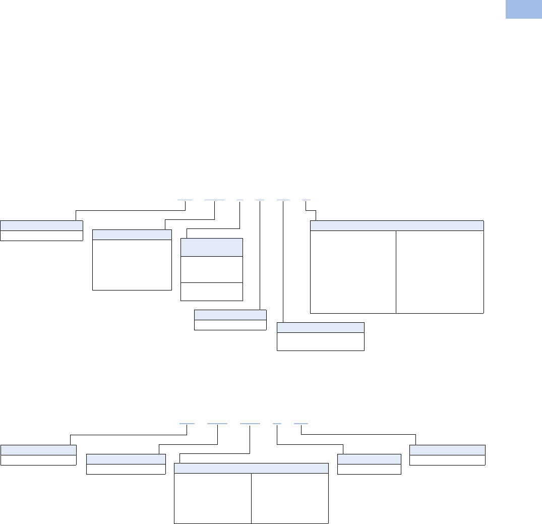
Catalog Number Selection
XT IEC Miniature Contactors
XT IEC Miniature Overload Relays
XT MC 6 A 10 A
Type
MC = Three-pole FVNR
mini IEC contactor
MF = Four-pole FVNR mini
IEC contactor
MR = Three-pole FVR mini
IEC contactor
Designation
XT = XT IEC power control
Current Rating,
AC-3
XTMC
6 = 6.6A
9 = 8.8A
XTMF
9 = 8.8A
Integral Auxiliary Contact
01 = 1NC
10 = 1NO
Coil Codes
A= 110V 50 Hz, 120V 60 Hz
B= 220V 50 Hz, 240V 60 Hz
F= 230V 50 Hz
T= 24V 50/60 Hz
TD = 24 Vdc
C= 415V 50 Hz, 480V 60 Hz
D= 550V 50 Hz, 600V 60 Hz
E= 208V 60 Hz
G= 190V 50 Hz, 220V 60 Hz
H= 240V 50 Hz, 277V 60 Hz
L= 380V 50 Hz, 440V 60 Hz
N= 400V 50 Hz
P= 380V 60 Hz
R= 12V 50/60 Hz
W= 42V 50 Hz, 48V 60 Hz
Y= 48V 50 Hz
AD = 120 Vdc
BD = 220 Vdc
RD = 12 Vdc
WD = 48 Vdc
Frame Size
A = 45 mm mini
Type
OM = Mini overload relay
Trip Class
C1 = Class 10A
Designation
XT = XT IEC power control Frame Size
A = 45 mm mini
XT OM P16 AC1
Overload Release
P16 = 0.1–0.16A
P24 = 0.16–0.24A
P40 = 0.24–0.4A
P60 = 0.4–0.6A
001 = 0.6–1A
1P6 = 1–1.6A
2P4 = 1.6–2.4A
004 =2.4–4A
006 = 4–6A
009 = 6–9A
012 = 9–12A
V5-T1-20 Volume 5—Motor Control and Protection CA08100006E—February 2014 www.eaton.com
1
1
1
1
1
1
1
1
1
1
1
1
1
1
1
1
1
1
1
1
1
1
1
1
1
1
1
1
1
1
1.1
IEC Contactors and Starters
XT
IEC Power Control
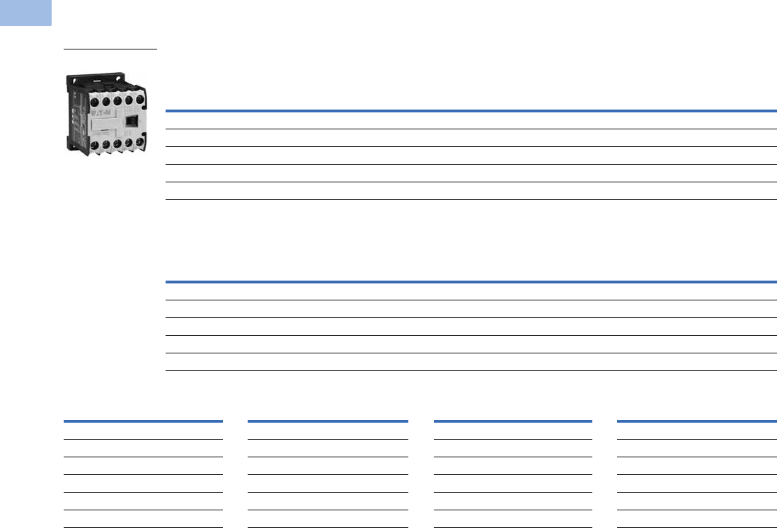
Product Selection
Full Voltage Non-Reversing Miniature Contactors
Maximum UL Ratings—Single-Phase and Three-Phase
Maximum IEC Ratings AC-3
Magnet Coil Suffix
Notes
IEC Utilization Categories, see Page V5-T1-242.
AC-1: Non-inductive or slightly inductive loads.
AC-3: Squirrel cage motors—starting, switching of motors during running.
AC-4: Squirrel cage motors—starting, plugging, inching.
1Underscore (_) indicates magnetic coil suffix required.
2With DC operation: Integrated diode resistor combination, coil rating 2.6W.
3XTMF four-pole contactor not available with “D” or “R” coil voltage suffix.
Horsepower Ratings
Number of
Power Poles
Auxiliary
Contacts
Screw Terminal
Catalog Number 1
Single-Phase Three-Phase
115V 200V 230V 200V 230V 460V 575V
1/43/411-1/22333 1NO XTMC6A10_
1/43/411-1/22333 1NC XTMC6A01_
1/211-1/223553 1NO XTMC9A10_
1/211-1/223553 1NC XTMC9A01_
1/211-1/223554 — XTMF9A00_
Operational Current
AC-3 Amp Rating
380/400V
Conventional Free
Air Thermal Current
AC-1 at 50°C
Three-Phase Motors 50–60 Hz
Number of
Power Poles
Auxiliary
Contacts
Screw Terminal
Catalog Number 1
220–
240V
380–
400V 550V
660/
690V
6.6 20 1.53333 1NO XTMC6A10_
6.6 20 1.53333 1NC XTMC6A01_
8.8 20 2.24443 1NO XTMC9A10_
8.8 20 2.24443 1NC XTMC9A01_
8.8 20 2.24444 — XTMF9A00_
Coil Voltage Suffix Code Coil Voltage Suffix Code Coil Voltage Suffix Code Coil Voltage Suffix Code
110V 50 Hz, 120V 60 Hz A415V 50 Hz, 480V 60 Hz C380V 60 Hz P120 Vdc AD
220V 50 Hz, 240V 60 Hz B550V 50 Hz, 600V 60 Hz D 312V 50/60 Hz R 3220 Vdc BD
230V 50 Hz F208V 60 Hz E42V 50 Hz, 48V 60 Hz W12 Vdc RD
24V 50/60 Hz T190V 50 Hz, 220V 60 Hz G48V 50 Hz Y48 Vdc WD
24 Vdc TD 2240V 50 Hz, 277V 60 Hz H——— —
— — 380V 50 Hz, 440V 60 Hz L——— —
XTMC_
Volume 5—Motor Control and Protection CA08100006E—February 2014 www.eaton.com V5-T1-21
1
1
1
1
1
1
1
1
1
1
1
1
1
1
1
1
1
1
1
1
1
1
1
1
1
1
1
1
1
1
1.1
IEC Contactors and Starters
XT
IEC Power Control
Full Voltage Reversing Miniature Contactors
Maximum UL Ratings—Single-Phase and Three-Phase
Maximum IEC Ratings AC-3
Magnet Coil Suffix
Notes
IEC Utilization Categories, see Page V5-T1-242.
AC-1: Non-inductive or slightly inductive loads.
AC-3: Squirrel cage motors—starting, switching of motors during running.
AC-4: Squirrel cage motors—starting, plugging, inching.
1Underscore (_) indicates magnetic coil suffix required. See Magnet Coil Suffix table above.
2The factory-installed reversing mini contactor includes (2) XTMC…01 contactors, (2) XTMCXFA20 2NO front-mount auxiliary contacts
(1) XTMCXRL reversing link kit and (1) XTMCXML mechanical interlock.
3XTMF four-pole contactor not available with “D” or “R” coil voltage suffix.
Horsepower Ratings
Catalog Number 12
Single-Phase Three-Phase Spare Auxiliary Contacts
115V 200V 230V 200V 230V 460V 575V K1M K2M
1/4 3/4 1 1-1/2 2 3 3 XTMR6A21_
1/211-1/22355 XTMR9A21_
Operational Current
AC-3 Amp Rating
380/400V
Conventional Free
Air Thermal Current
AC-1 at 50°C
Three-Phase Motors 50–60 Hz
Catalog Number 12
220/
230/
240V
380/
400/
440V 500V
660/
690V
Spare Auxiliary Contacts
K1M K2M
6.6 20 1.5333 XTMR6A21_
8.8 20 2.2444 XTMR9A21_
Coil Voltage Suffix Code Coil Voltage Suffix Code Coil Voltage Suffix Code Coil Voltage Suffix Code
110V 50 Hz, 120V 60 Hz A415V 50 Hz, 480V 60 Hz C380V 60 Hz P120 Vdc AD
220V 50 Hz, 240V 60 Hz B550V 50 Hz, 600V 60 Hz D 312V 50/60 Hz R 3220 Vdc BD
230V 50 Hz F208V 60 Hz E42V 50 Hz, 48V 60 Hz W12 Vdc RD
24V 50/60 Hz T190V 50 Hz, 220V 60 Hz G48V 50 Hz Y48 Vdc WD
24 Vdc TD 2240V 50 Hz, 277V 60 Hz H——— —
— — 380V 50 Hz, 440V 60 Hz L——— —
XTMR_
64
63
64
63
64
63
64
63
64
63
64
63
64
63
64
63

V5-T1-22 Volume 5—Motor Control and Protection CA08100006E—February 2014 www.eaton.com
1
1
1
1
1
1
1
1
1
1
1
1
1
1
1
1
1
1
1
1
1
1
1
1
1
1
1
1
1
1
1.1
IEC Contactors and Starters
XT
IEC Power Control
Star-Delta (Wye-Delta) Miniature Contactors
Maximum Current UL Ratings—Single-Phase and Three-Phase 1
Maximum IEC Ratings AC-3 1
Mini Overload Relay Settings (A)
Notes
Depending on the coordination type required (that is, Type 1 or Type 2) it must be established
whether the fuse protection and the input wiring for the main and delta contactors are to be
common or separate.
1Operating frequency: 30 starts/hour. See Magnet Coil Suffix table on following page.
2Underscore (_) indicates magnet coil suffix required.
Horsepower Ratings Maximum
Changeover
Time (sec.)
Spare Auxiliary Contacts
K1M
Component
Description Catalog Number 2
Single-Phase Three-Phase
115V 200V 230V 200V 230V 460V 575V
1/211-1/22357-1/230 K1M main contactorXTMC9A10_
K1M auxiliary contact XTMCXFC22
K5M delta contactor XTMC9A01_
K3M star contactor XTMC9A10_
K3M auxiliary contact XTMCXFC02
K1T timing relay XTTR6A60S51B
Horsepower Ratings Maximum
Changeover
Time (sec.)
Spare Auxiliary Contacts
K1M
Component
Description Catalog Number 2
Three-Phase Motors 50–60 Hz
220/230/240V 380/400/440V 500V
4 5.5 5.5 30 K1M main contactor XTMC9A10_
K1M auxiliary contact XTMCXFC22
K5M delta contactor XTMC9A01_
K3M star contactor XTMC9A10_
K3M auxiliary contact XTMCXFC02
K1T timing relay XTTR6A60S51B
Setting Starting
A: IN x 0.58
Motor protection in the Y and delta configurations.
<
15 sec
B: IN x 1
Only partial motor protection in star position
15–40 sec
C: IN x 0.58
Motor not protected in star position.
>40 sec
Timing relay set to approximately 10 sec.
XTMC_
21
22
31
32
53
54
21
22
31
32
53
54
Volume 5—Motor Control and Protection CA08100006E—February 2014 www.eaton.com V5-T1-23
1
1
1
1
1
1
1
1
1
1
1
1
1
1
1
1
1
1
1
1
1
1
1
1
1
1
1
1
1
1
1.1
IEC Contactors and Starters
XT
IEC Power Control
Magnet Coil Suffix
Mini Overload Relays
Mini Overload Relays 23
Notes
1 With DC operation: Integrated diode resistor combination, coil rating 2.6W.
2 Short-circuit protection: Observe the maximum permissible fuse of the contactor with direct device mounting. See MN03402002E for more information.
3 When fitted directly to the contactor, a clearance of at least 5 mm is required between the overload relays.
Coil Voltage Suffix Code Coil Voltage Suffix Code Coil Voltage Suffix Code Coil Voltage Suffix Code
110V 50 Hz, 120V 60 Hz A415V 50 Hz, 480V 60 Hz C400V 50 Hz N120 Vdc AD
220V 50 Hz, 240V 60 Hz B550V 50 Hz, 600V 60 Hz D380V 60 Hz P220 Vdc BD
230V 50 Hz F208V 60 Hz E12V 50/60 Hz R12 Vdc RD
24V 50/60 Hz T190V 50 Hz, 220V 60 Hz G24V 50 Hz U48 Vdc WD
24 Vdc TD 1240V 50 Hz, 277V 60 Hz H42V 50 Hz, 48V 60 Hz W——
— — 380V 50 Hz, 440V 60 Hz L48V 50 Hz Y——
Overload
Release It
Trip
Class
Contact
Sequence
Contact
Configuration
Short-Circuit Protection (A)
Catalog Number
Type 1
Coordination,
gG/gL
Type 2
Coordination,
gG/gL
Circuit
Breaker
CEC/NEC
Fuse
0.1–0.16A 10A 1NO-1NC 20 0.5 15 — XTOMP16AC1
0.16–0.24A 10A 1NO-1NC 20 1 15 — XTOMP24AC1
0.24–0.4A 10A 1NO-1NC 20 2 15 — XTOMP40AC1
0.4–0.6A 10A 1NO-1NC 20 2 15 — XTOMP60AC1
0.6–1A 10A 1NO-1NC 20 4 15 3 XTOM001AC1
1–1.6A 10A 1NO-1NC 20 6 15 6 XTOM1P6AC1
1.6–2.4A 10A 1NO-1NC 20 6 15 6 XTOM2P4AC1
2.4–4A 10A 1NO-1NC 20 15 15 XTOM004AC1
4–6A 10A 1NO-1NC 20 15 20 XTOM006AC1
6–9A 10A 1NO-1NC 20 15 35 XTOM009AC1
9–12A 10A 1NO-1NC — — 45 XTOM012AC1
XTOM_
6429896
97 95
V5-T1-24 Volume 5—Motor Control and Protection CA08100006E—February 2014 www.eaton.com
1
1
1
1
1
1
1
1
1
1
1
1
1
1
1
1
1
1
1
1
1
1
1
1
1
1
1
1
1
1
1.1
IEC Contactors and Starters
XT
IEC Power Control
Accessories
Auxiliary Contacts
Front-mounted snap-on auxiliary contacts for mini contactors are available with screw terminals in a
variety of contact configurations. Auxiliary contact modules are standard with interlocked opposing
contacts, except in the case of early-make or late-break contacts.
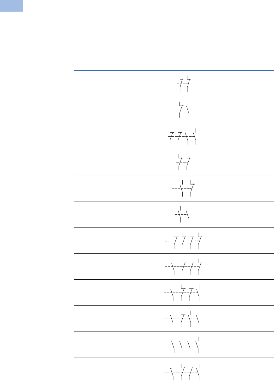
Front-Mount Auxiliary Contacts for Use with Mini Contactors
Notes
1 Orders must be placed in multiples of package quantity listed.
2 One early-make contact (NOE), one late-break contact (NCL).
Conventional Free Air
Thermal Current,
Ith = Ie, AC-1 in Amps
Contact
Configuration Contact Sequence
Pkg.
Qty. 1
Screw Terminal
Catalog Number
10 2NC 5 XTMCXFC02
10 1NO-1NC 5 XTMCXFD11
10 2NO-2NC 5 XTMCXFC22
10 2NC 5 XTMCXFA02
10 1NO-1NC 5 XTMCXFA11
10 2NO 5 XTMCXFA20
10 4NC 5 XTMCXFA04
10 1NO-3NC 5 XTMCXFA13
10 2NO-2NC 5 XTMCXFA22
10 3NO-1NC 5 XTMCXFA31
10 4NO 5 XTMCXFA40
10 1NO-1NC
1NOE-1NCL
5XTMCXFAL22 2
21
22
31
32
21
22
33
34
21
22
31
32
43
44
53
54
51
52
61
62
54
53 61
62
54
63
64
53
51
52
61
62
71
72 82
81
53 61 71 81
82
72
62
54
54
53 61
62
71
72
83
84
54
53 61
62
73
74
83
84
54
63 73
64 74
53 83
84
58
57 65
66
71
72
83
84
Volume 5—Motor Control and Protection CA08100006E—February 2014 www.eaton.com V5-T1-25
1
1
1
1
1
1
1
1
1
1
1
1
1
1
1
1
1
1
1
1
1
1
1
1
1
1
1
1
1
1
1.1
IEC Contactors and Starters
XT
IEC Power Control
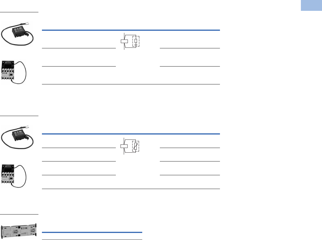
Suppressors
RC Suppressor 1
Varistor Suppressor 3
Mechanical Interlock
Mechanical Interlock
Notes
For two contactors with AC or DC operated magnet system that are horizontally or vertically mounted,
the distance between contactors is 0 mm and the mechanical lifespan is 2.5 x 10⁶ operations.
1 For AC operated contactors, 50/60 Hz. Note dropout delay.
2 Orders must be placed in multiples of package quantity listed.
3 For AC operated contactors, 50/60 Hz. DC operated contactors have integrated varistor suppressors.
Voltage
For Use
with…
Circuit Symbol
Pkg.
Qty.
2
Catalog Number
24–48 XTMC6A_,
XTMC9A_
10 XTMCXRSW
48–130 XTMC6A_,
XTMC9A_
10 XTMCXRSA
110–250 XTMC6A_,
XTMC9A_
10 XTMCXRSB
Voltage
For Use
with…
Circuit Symbol
Pkg.
Qty.
2
Catalog Number
24–48 XTMC6A_,
XTMC9A_
10 XTMCXVSW
48–130 XTMC6A_,
XTMC9A_
10 XTMCXVSA
110–250 XTMC6A_,
XTMC9A_
10 XTMCXVSB
380–415 XTMC6A_,
XTMC9A_
10 XTMCXVSN
Description
Pkg.
Qty. 2Catalog Number
Mechanical interlock 5 XTMCXML
XTMCXR_
XTMC Relay with
Installed Suppressor
A1
A2
XTMCX_
XTMC Relay with
Installed Suppressor
A1
A2
XTMCXML
V5-T1-26 Volume 5—Motor Control and Protection CA08100006E—February 2014 www.eaton.com
1
1
1
1
1
1
1
1
1
1
1
1
1
1
1
1
1
1
1
1
1
1
1
1
1
1
1
1
1
1
1.1
IEC Contactors and Starters
XT
IEC Power Control
Additional Accessories
Reversing Link Kit 12
Star-Delta (Wye-Delta) Link Kit 45
Connector
IP40 Sealable Transparent Shroud
Notes
1 The following control cables are integrated as part of the electrical interlock: K1M: A1–K2M: 21; K1M: 21–K2M: A1
2 Reversing link kit does not include mechanical interlock. See Mechanical Interlock.
3 Orders must be placed in multiples of package quantity listed.
4 The following control cables are integrated in addition to the electrical interlock: K3M: A1–K5M: 21; K3M: 21–K5M: A1; K3M: A2–K5M: A2
5 When combined with overload relay, use separate mounting.
6 0 mm distance between contactors.
Description
Pkg.
Qty. 3Catalog Number
Main current wiring for reversing contactors and starters 1 XTMCXRL
Description
Pkg.
Qty. 3Catalog Number
Main current wiring for star-delta (wye-delta) combinations.
Includes the star-delta bridge
1XTMCXSDL
Description
Pkg.
Qty. 3Catalog Number
For mechanically arranging contactors and timing relays in
combinations
50 XTMCXCN 6
Description
Pkg.
Qty. 3Catalog Number
IP40 sealable transparent shroud, snap fitting on mini contactor 1 XTMCXSHROUD
XTMCXRL
XTMCXSDL
XTMCXCN
XTMCXSHROUD

Volume 5—Motor Control and Protection CA08100006E—February 2014 www.eaton.com V5-T1-27
1
1
1
1
1
1
1
1
1
1
1
1
1
1
1
1
1
1
1
1
1
1
1
1
1
1
1
1
1
1
1.1
IEC Contactors and Starters
XT
IEC Power Control
Technical Data and Specifications
XT Miniature Controls—General
Note
1As required, except vertical with terminals A1/A2 at the bottom.
Description
XTMC6A_ XTMC9A_ XTMF9A_
AC Coils DC Coils AC Coils DC Coils AC Coils DC Coils
Physical and Electrical
Standards IEC/EN 60947,
VDE 0660, CSA,
UL, CCC
IEC/EN 60947,
VDE 0660, CSA,
UL, CCC
IEC/EN 60947,
VDE 0660, CSA,
UL, CCC
IEC/EN 60947,
VDE 0660, CSA,
UL, CCC
IEC/EN 60947,
VDE 0660, CSA,
UL, CCC
IEC/EN 60947,
VDE 0660, CSA,
UL, CCC
Weights in kg [lb] 0.2 [0.44] 0.17 [0.37] 0.2 [0.44] 0.17 [0.34] 0.2 [0.44] 0.17 [0.37]
Mechanical life—operations 10,000,000 20,000,000 10,000,000 20,000,000 10,000,000 10,000,000
Mechanical life—coil at 50 Hz 7 — 7 — 7 —
Maximum mechanical operating frequency (ops/hr) 9000 9000 9000 9000 9000 9000
Insulation voltage (Ui) Vac 690 690 690 690 690 690
Impulse withstand voltage (Uimp) Vac 6000 6000 6000 6000 6000 6000
Operational Voltage (Ue) Vac 690 690 690 690 690 690
Safe isolation to VDE 0106 Part 101 and Part 101/A1
Between coil and contacts (Vac) 300 300 300 300 300 300
Between contacts (Vac) 300 300 300 300 300 300
Making capacity (amps) 110 110 110 110 110 110
Breaking capacity (amps)
220/230V 90 90 90 90 90 90
380/400V 90 90 90 90 90 90
500V 64 64 64 64 64 64
660/690V 54 54 54 54 54 54
Short-circuit protection rating maximum fuse (gL/gG)
Type 2 coordination (A) 10 10 10 10 10 10
Type 1 coordination (A) 20 20 20 20 20 20
Degree of protection IP20 IP20 IP20 IP20 IP20 IP20
Flexible with ferrule (mm2) 1 x (0.75–1.5)
2 x (0.75–1.5)
1 x (0.75–1.5)
2 x (0.75–1.5)
1 x (0.75–1.5)
2 x (0.75–1.5)
1 x (0.75–1.5)
2 x (0.75–1.5)
1 x (0.75–1.5)
2 x (0.75–1.5)
1 x (0.75–1.5)
2 x (0.75–1.5)
Solid or stranded (AWG) 18–14 18–14 18–14 18–14 18–14 18–14
Terminal screw M3.5 M3.5 M3.5 M3.5 M3.5 M3.5
Pozidriv screwdriver Size 2 Size 2 Size 2 Size 2 Size 2 Size 2
Standard screwdriver (mm) 0.8 x 5.5
1 x 6
0.8 x 5.5
1 x 6
0.8 x 5.5
1 x 6
0.8 x 5.5
1 x 6
0.8 x 5.5
1 x 6
0.8 x 5.5
1 x 6
Max. tightening torque
Nm 1.21.21.21.21.21.2
Lb-in 10.6 10.6 10.6 10.6 10.6 10.6
Terminal capacity of spring cage main terminals
Solid (mm2) 1 x (1–2.5)
2 x (1–2.5)
1 x (1–2.5)
2 x (1–2.5)
1 x (1–2.5)
2 x (1–2.5)
1 x (1–2.5)
2 x (1–2.5)
1 x (1–2.5)
2 x (1–2.5)
1 x (1–2.5)
2 x (1–2.5)
Flexible with ferrule (mm2) 1 x (1–2.5)
2 x (1–2.5)
1 x (1–2.5)
2 x (1–2.5)
1 x (1–2.5)
2 x (1–2.5)
1 x (1–2.5)
2 x (1–2.5)
1 x (1–2.5)
2 x (1–2.5)
1 x (1–2.5)
2 x (1–2.5)
Standard screwdriver (mm) 0.6 x 3.5 0.6 x 3.5 0.6 x 3.5 0.6 x 3.5 0.6 x 3.5 0.6 x 3.5
Mounting position 111111
A2
A1

V5-T1-28 Volume 5—Motor Control and Protection CA08100006E—February 2014 www.eaton.com
1
1
1
1
1
1
1
1
1
1
1
1
1
1
1
1
1
1
1
1
1
1
1
1
1
1
1
1
1
1
1.1
IEC Contactors and Starters
XT
IEC Power Control
XT Miniature Controls—General, continued
Note
1Damp heat, constant, to IEC 60 068-2-78; damp heat, cyclic, to IEC 60 068-2-30.
Description
XTMC6A_ XTMC9A_ XTMF9A_
AC Coils DC Coils AC Coils DC Coils AC Coils DC Coils
Environmental
Ambient temperature –25° to 50°C
[–13° to 122°F]
–25° to 50°C
[–13° to 122°F]
–25° to 50°C
[–13° to 122°F]
–25° to 50°C
[–13° to 122°F]
–25° to 50°C
[–13° to 122°F]
–25° to 50°C
[–13° to 122°F]
Mechanical shock resistance (IEC/EN 60068-2-27)
Half-sinusoidal shock 10 ms
Contactor without auxiliary contact module
Main contact—make contact 10g 10g 10g 10g 10g 10g
Main contact—break/make contact 10/8g 10/8g 10/8g 10/8g — —
Contactor with auxiliary contact module
Main contact—make contact 10g 10g 10g 10g 10g 10g
Main contact—make/break contact 20/20g 20/20g 20/20g 20/20g 20/20g 20/20g
Climatic proofing 111111
Pollution degree III/3 III/3 III/3 III/3 III/3 III/3

Volume 5—Motor Control and Protection CA08100006E—February 2014 www.eaton.com V5-T1-29
1
1
1
1
1
1
1
1
1
1
1
1
1
1
1
1
1
1
1
1
1
1
1
1
1
1
1
1
1
1
1.1
IEC Contactors and Starters
XT
IEC Power Control
XT Miniature Controls—Magnet Systems
Note
1Smoothed DC or three-phase bridge rectifier.
Description
XTMC6A_ XTMC9A_ XTMF9A_
AC Coils DC Coils AC Coils DC Coils AC Coils DC Coils
Voltage Toleran ce
Pickup (x Uc)
Single-voltage coil 50 Hz and dual-voltage coil 50 Hz, 60 Hz
0.8–1.1 — 0.8–1.1 — 0.8–1.1 —
Dual frequency coil 50/60 Hz 0.85–1.1 — 0.85–1.1 — 0.85–1.1 —
DC operated 1— 0.8–1.1 — 0.8–1.1 — 0.85–1.1
Power Consumption
AC operation
Pickup VA
Single-voltage coil 50 Hz and dual-voltage coil 50 Hz, 60 Hz 25 — 25 — 25 —
Dual frequency coil 50/60 Hz at 50 Hz 30 — 30 — 30 —
Dual frequency coil 50/60 Hz at 60 Hz 29 — 29 — 29 —
Pickup W
Single-voltage coil 50 Hz and dual-voltage coil 50 Hz, 60 Hz 22 — 22 — 22 —
Dual frequency coil 50/60 Hz at 50 Hz 26 — 26 — 26 —
Dual frequency coil 50/60 Hz at 60 Hz 24 — 24 — 24 —
Sealing VA
Single-voltage coil 50 Hz and dual-voltage coil 50 Hz, 60 Hz 4.6 — 4.6 — 4.6 —
Dual frequency coil 50/60 Hz at 50 Hz 5.4 — 5.4 — 5.4 —
Dual frequency coil 50/60 Hz at 60 Hz 3.9 — 3.9 — 3.9 —
Sealing W
Single-voltage coil 50 Hz and dual-voltage coil 50 Hz, 60 Hz 1.3 — 1.3 — 1.3 —
Dual frequency coil 50/60 Hz at 50 Hz 1.6 — 1.6 — 1.6 —
Dual frequency coil 50/60 Hz at 60 Hz 1.1 — 1.1 — 1.1 —
DC operated 1
Power consumption pickup = sealing (VA/W) — 2.6 — 2.6 — 2.6
Duty factor (%) 100 100 100 100 100 100
Switching Time at 100% Uc
Make contact
Closing delay min. (ms) 14 26 14 26 14 26
Closing delay max. (ms) 21 35 21 35 21 35
Opening delay min. (ms) 8 15 8 15 8 15
Opening delay max. (ms) 18 25 18 25 18 25
Closing delay with top-mounting auxiliary contact (ms) Max. 45 Max. 70 Max. 45 Max. 70 Max. 45 Max. 70
Reversing Contactors
Changeover time at 100% Uc
Minimum (ms) 16 40 16 40 16 40
Maximum (ms) 21 50 21 50 21 50
Arcing time at 690 Vac (ms) Max. 12 Max. 12 Max. 12 Max. 12 Max. 12 Max. 12

V5-T1-30 Volume 5—Motor Control and Protection CA08100006E—February 2014 www.eaton.com
1
1
1
1
1
1
1
1
1
1
1
1
1
1
1
1
1
1
1
1
1
1
1
1
1
1
1
1
1
1
1.1
IEC Contactors and Starters
XT
IEC Power Control
XT Miniature Controls
Notes
1At maximum permissible ambient temperature.
2Rated operation current (le) in amperes, at maximum permissible ambient temperature.
Description
XTMC6A_ XTMC9A_ XTMF9A_
AC Coils DC Coils AC Coils DC Coils AC Coils DC Coils
AC-1 Operation
Conventional free air thermal current, three-pole, 50–60 Hz (A)
at 40°C (Ith) 222222222222
at 50°C (Ith) 202020202020
at 55°C (Ith) 191919191919
Conventional free air thermal current, single-pole (Ith)505050506060
AC-3 Operation
Rated operational current, 50/60 Hz 1 (Ie) in amperes (A)
220/230V 6.6 6.6 9.0 9.0 9.0 9.0
240V 6.6 6.6 9.0 9.0 9.0 9.0
380/400V 6.6 6.6 9.0 9.0 9.0 9.0
415V 6.6 6.6 9.0 9.0 9.0 9.0
440V 6.6 6.6 9.0 9.0 9.0 9.0
500V 5.0 5.0 6.4 6.4 6.4 6.4
660/690V 3.5 3.5 4.8 4.8 4.8 4.8
Rated power (P) in kilowatts (kW)
220/230V 1.5 1.5 2.2 2.2 2.2 2.2
240V 1.8 1.8 2.5 2.5 2.5 2.5
380/400V 3.0 3.0 4.0 4.0 4.0 4.0
415V 3.1 3.1 4.3 4.3 4.3 4.3
440V 3.3 3.3 4.6 4.6 4.6 4.6
500V 3.0 3.0 4.0 4.0 4.0 4.0
660/690V 3.0 3.0 4.0 4.0 4.0 4.0
AC-4 Operation
Rated operational current, 50/60 Hz 1 (Ie) in amperes (A)
220/230V 5.0 5.0 6.6 6.6 6.6 6.6
240V 5.0 5.0 6.6 6.6 6.6 6.6
380/400V 5.0 5.0 6.6 6.6 6.6 6.6
415V 5.0 5.0 6.6 6.6 6.6 6.6
440V 5.0 5.0 6.6 6.6 6.6 6.6
500V 3.7 3.7 5.0 5.0 5.0 5.0
660/690V 2.9 2.9 3.4 3.4 3.4 3.4
Rated power (P) in kilowatts (kW)
220/230V 1.1 1.1 1.5 1.5 1.5 1.5
240V 1.3 1.3 1.8 1.8 1.8 1.8
380/400V 2.2 2.2 3.0 3.0 3.0 3.0
415V 2.3 2.3 3.1 3.1 3.1 3.1
440V 2.4 2.4 3.3 3.3 3.3 3.3
500V 2.2 2.2 3.0 3.0 3.0 3.0
660/690V 2.2 2.2 3.0 3.0 3.0 3.0
DC-1 Operation 2
12V 20202020——
24V 20202020——
60V 20202020——
110V 20 20 20 20 — —
220V 20 20 20 20 — —

Volume 5—Motor Control and Protection CA08100006E—February 2014 www.eaton.com V5-T1-31
1
1
1
1
1
1
1
1
1
1
1
1
1
1
1
1
1
1
1
1
1
1
1
1
1
1
1
1
1
1
1.1
IEC Contactors and Starters
XT
IEC Power Control
XT Miniature Controls, continued
XT Miniature Controls—Auxiliary Contacts
Note
1Rated operation current (le) in amperes, at maximum permissible ambient temperature.
Description
XTMC6A_ XTMC9A_ XTMF9A_
AC Coils DC Coils AC Coils DC Coils AC Coils DC Coils
DC-3 Operation 1
12V 6688——
24V 6688——
60V 3344——
110V 2233——
220V — — — — 1.0 1.0
DC-4 Operation 1
12V 1.8 1.8 2.5 2.5 — —
24V 1.8 1.8 2.5 2.5 — —
60V 1.8 1.8 2.5 2.5 — —
110V 1.1 1.1 1.5 1.5 2.5 2.5
220V 0.2 0.2 0.3 0.3 1.0 1.0
Current Heat Loss (Three- or Four-Pole) in Watts
at Ith 2.0 3.5 2.0 3.5 2.7 4.7
at Ie to AC-3/400V 0.3 0.4 0.5 0.7 — —
Description
Built-In Auxiliary
XTMC
Add-On Auxiliary
XTMCXF_
Interlocked opposing contacts to ZH1/457, including auxiliary contact module Yes Yes
Rated impulse withstand voltage, Uimp (Vac) 6000 6000
Overvoltage category/pollution degree III/3 III/3
Rated insulation voltage, Ui (Vac) 690 690
Rated operational voltage, Ue (Vac) 600 600
Safe isolation to VDE 0106 Part 101 and Part 101(A) in Vac
Between coil and auxiliary contacts 300 300
Between the auxiliary contacts 300 300
Rated operational current
AC-15, Ie
220/240V 6A 4A
380/415V 3A 2A
500V 1.5A 1.5A
DC-13 (contacts in series)
1: 24V 2.5A 2.5A
2: 60V 2.5A 2.5A
3: 100V 1.5A 1.5A
3: 220V 0.5A 0.5A
Conventional thermal current, Ith 10A 10A
Control circuit reliability (at Ue = 24 Vdc, Umin = 17V, I min = 5.4 mA) <10–8, <1 failure at 100 million operations <10–8, <1 failure at 100 million operations
Component lifespan at Ue = 240V
AC-15, operations x 1060.2 0.2
DC-13 L/R = 50 ms: 2 contacts in series at Ie = 0.5A, operations x 1060.15 0.15
Short-circuit rating without welding
Short-circuit protection rating maximum fuse, 500V gG/gL 6A 6A
Short-circuit protection rating maximum fuse, 500V fast 10A 10A
Current heat loss at conventional free air thermal current Ith per contact, W 0.2 0.2
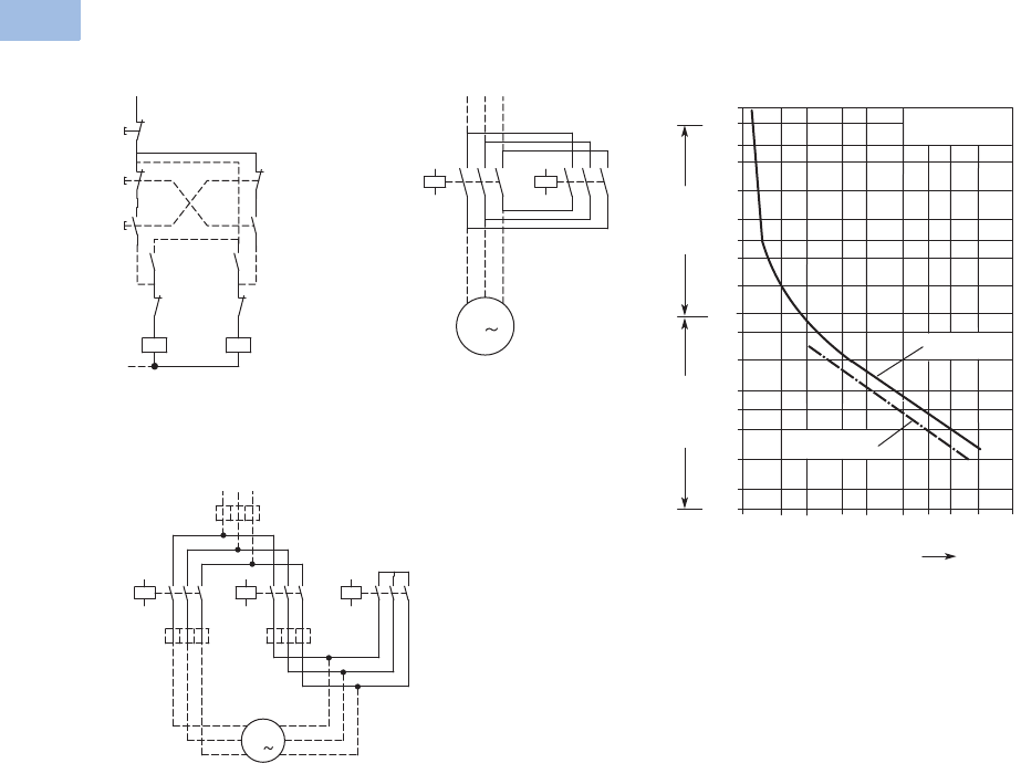
V5-T1-32 Volume 5—Motor Control and Protection CA08100006E—February 2014 www.eaton.com
1
1
1
1
1
1
1
1
1
1
1
1
1
1
1
1
1
1
1
1
1
1
1
1
1
1
1
1
1
1
1.1
IEC Contactors and Starters
XT
IEC Power Control
Wiring Diagrams
XTMR Reversing Contactor
Control Circuit
XTMR Reversing Contactor
Power Circuit
XT Mini Star-Delta (Wye-Delta)
Contactor Power Circuit
K2M
54
K1M 54
53 53
K2M
22
21 K1M 22
21
K1M
A1
A2
K2M A1
A2
I54
53
53
II 21
22
22
21
21
22
0
54
UVW
K1M
M
M1
K2M
1
64
2
5
6
4
2
353
1
3
K1M
5
642
31
K5M
5
642
31
K3M
642
351
U1
V1
W1
M1
3
M1
V2
W2
U2
AC
B
Tripping Characteristics
Tripping Characteristics Chart
These tripping characteristics
are mean values of the
spread at 20°C ambient
temperature in a cold state.
Tripping time depends on
response current. With
devices at operating
temperature, the tripping
time of the overload relay
reduces to approximately
25% of the read off value.
Specific characteristics for
each individual setting range
can be found on Page
V5-T1-33.
2h
100
60
40
20
10
6
4
2
1
40
20
10
6
4
2
1
0.6
XTOM
1 1.5 2 3 4 68 10 15 20
x Setting Current
2-Phase
Seconds Minutes
3-Phase
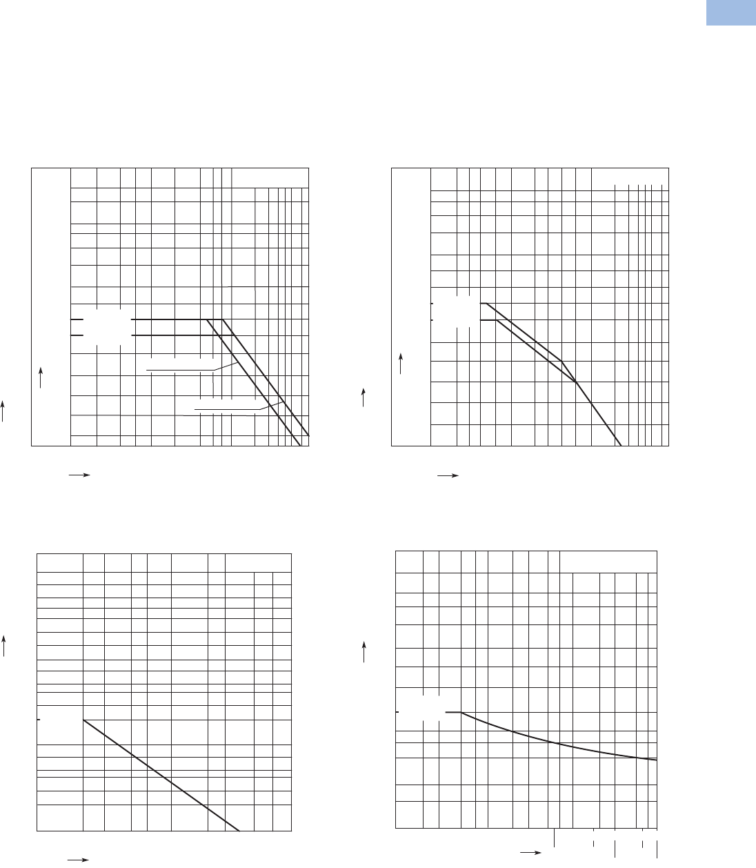
Volume 5—Motor Control and Protection CA08100006E—February 2014 www.eaton.com V5-T1-33
1
1
1
1
1
1
1
1
1
1
1
1
1
1
1
1
1
1
1
1
1
1
1
1
1
1
1
1
1
1
1.1
IEC Contactors and Starters
XT
IEC Power Control
Electrical Switching Operation Charts
Squirrel cage motors
Operating characteristics
Starting: from rest
Stopping: after attaining a full running speed
Electrical characteristics
Make (NO): Up to 6x rated motor current
Breaking (NC): 1x rated motor current
Normal Switching Duty—AC-3/400V
Switching Duty for Non-Motor Loads, Three- and
Four-Pole—AC-1/400V
Squirrel cage motors
Operating characteristics
Jogging, plugging, reversing
Electrical characteristics
Make (NO): 6x rated motor current
Breaking (NC): 6x rated motor current
Extreme Switching Duty—AC-4/400V
Short Time Loading, Three-Pole—AC-1/400V
(time interval between two loading cycles: 15 minutes)
XTMC 6A
kW A
0.01 0.02 0.04
0.06 0.1 0.2 0.40.6
0.751234568
10
8.8
12
16
23
30
36
43
58
6.5
5
3.5
2.5
2
1.6
30
22
18.5
15
11
7. 5
5.5
4
3
2.2
1.5
1.1
0.8
0.55
XTMC AC Coil
XTMC 9A
XTMC DC Coil
AC-3/400V
Component lifespan (millions of operations)
Rated output of three-phase motors, 50 – 60 Hz
Rated operational current le 50 – 60 Hz
AC-1/400V
0.1 0.2 0.5 0.7 713510
2
1
3
4
0.3 2
5
1400
1000
700
500
275
350
160
100
55
35
20
10
7
XTMC 9A
XTMC 6A
Component lifespan (millions of operations)
Breaking current
kW A
0.01
0.02 0.04
0.06
0.1
0.2 0.4
0.6
1
62
3
4
58
10
22
18.5
15
11
7. 5
5.5
4
3
2.2
1.5
1.1
0.8
0.55
0.37
0.03
0.3
0.25
43
36
30
23
16
12
8.8
6.5
3.5
2.5
2
1.6
1.2
0.8
XTMC 9A
5
AC-4/400V
Component lifespan (millions of operations)
Rated output of three-phase motors, 50 – 60 Hz
Rated operational current le 50 – 60 Hz
XTMC 6A
AC-1/400V
70 100
5020
537 30
102
A
700
500
400
300
15
200
100
70
50
40
30
150
10 min
15 min
900
200 300
1 min 3 min
5 min
500
20
700
XTMC 9A
XTMC 6A
Seconds
Duration of load
Short-time current
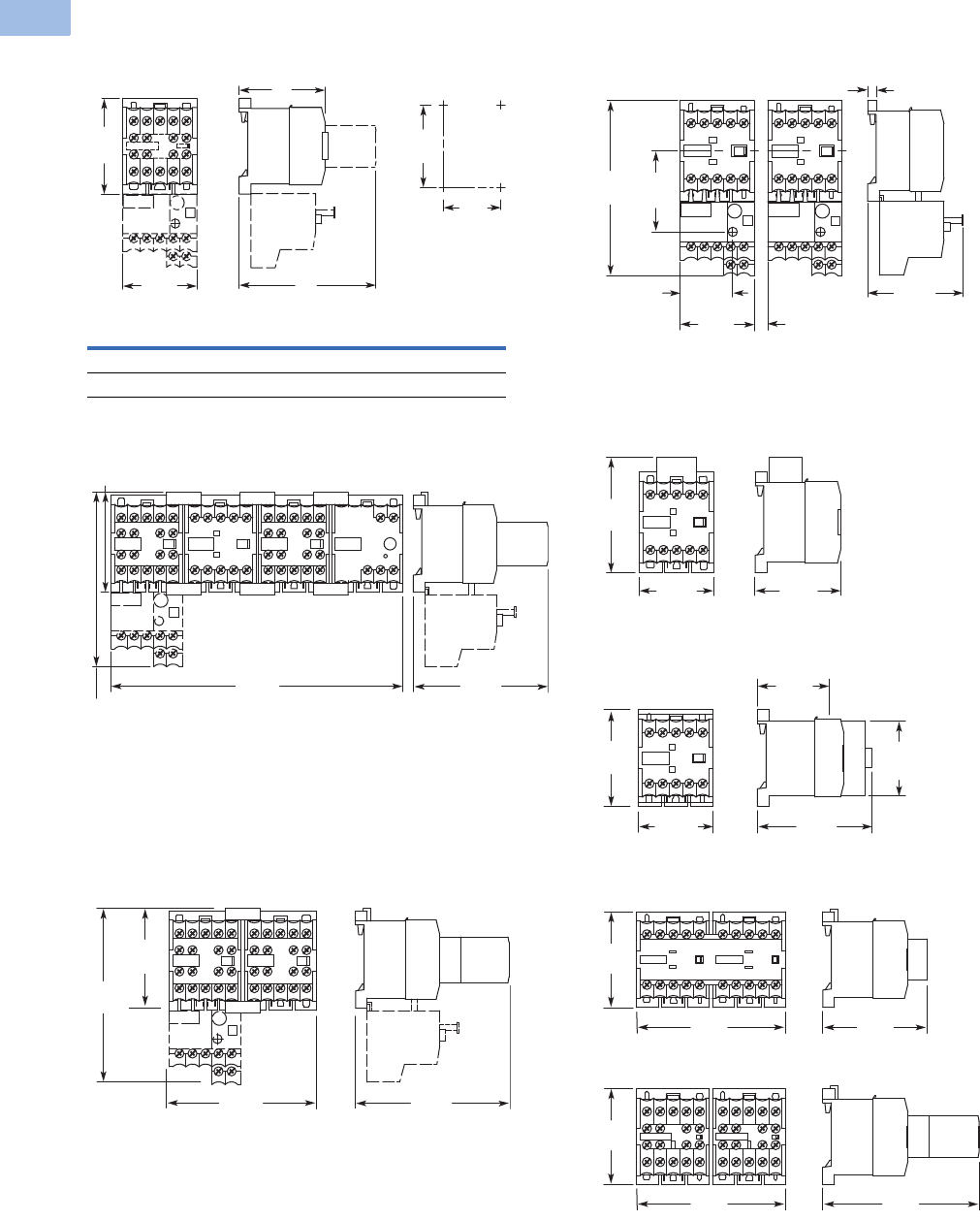
V5-T1-34 Volume 5—Motor Control and Protection CA08100006E—February 2014 www.eaton.com
1
1
1
1
1
1
1
1
1
1
1
1
1
1
1
1
1
1
1
1
1
1
1
1
1
1
1
1
1
1
1.1
IEC Contactors and Starters
XT
IEC Power Control
Dimensions
Approximate Dimensions in mm [in.]
Non-Reversing Mini Contactor
Star-Delta Starter Combinations
Reversing Mini Contactor
Non-Reversing Mini Contactor with Overload Relay
XTMCXRSA, XTMCXVSA Mini Suppressors
XTMCXTSA Mini Sealable Shroud
XTMCXML Mechanical Interlock
XTMC XTMCC
D 52 [2.05] 54 [2.13]
D1 83 [3.27] 86 [3.39]
35
[1.38]
58
[2.28]
D1
D
50
[1.97]
M4
45
[1.77]
61
[2.40]
108
[4.25]
180
[7.09] 83
[3.27]
90
[3.54] 94
[3.70]
61
[2.40]
108
[4.25]
5.5 [.22]
58
[2.28]
≥ 5 [.20]
45
[1.77]
32
[1.26]
49
[1.93]
106
[4.17]
52
[2.05]
45
[1.77]
62.5
[2.46]
43
[1.69]
45
[1.77]
58
[2.28]
69
[2.72]
45
[1.77]
90
[3.54]
94
[3.70]
63
[2.48]
90
[3.54]
58
[2.28]
58
[2.28]
Volume 5—Motor Control and Protection CA08100006E—February 2014 www.eaton.com V5-T1-35
1
1
1
1
1
1
1
1
1
1
1
1
1
1
1
1
1
1
1
1
1
1
1
1
1
1
1
1
1
1
1.1
IEC Contactors and Starters
XT
IEC Power Control
XT Family of Contactors
Contents
Description Page
Relays and Timers . . . . . . . . . . . . . . . . . . . . . . . . . V5-T1-3
Miniature Controls . . . . . . . . . . . . . . . . . . . . . . . . . V5-T1-18
Contactors and Starters
Product Identification . . . . . . . . . . . . . . . . . . . . V5-T1-36
Catalog Number Selection . . . . . . . . . . . . . . . . V5-T1-38
Product Selection . . . . . . . . . . . . . . . . . . . . . . . V5-T1-39
Accessories . . . . . . . . . . . . . . . . . . . . . . . . . . . . V5-T1-65
Technical Data and Specifications . . . . . . . . . . . V5-T1-78
Wiring Diagrams . . . . . . . . . . . . . . . . . . . . . . . . V5-T1-109
Dimensions . . . . . . . . . . . . . . . . . . . . . . . . . . . . V5-T1-114
An Eaton
Green Solution
Thermal Overload Relays . . . . . . . . . . . . . . . . . . . . V5-T1-128
C440/XT Electronic Overload Relay . . . . . . . . . . . V5-T1-141
Manual Motor Protectors . . . . . . . . . . . . . . . . . . . V5-T1-157
Combination Motor Controllers . . . . . . . . . . . . . . . V5-T1-193
XT Electronic Manual Motor Protector . . . . . . . . . V5-T1-216
Reference Data . . . . . . . . . . . . . . . . . . . . . . . . . . . V5-T1-229
Contactors and Starters
Product Description
The Eaton XT contactors
and starters includes non-
reversing and reversing
contactors, overload relays
and a variety of related
accessories. Because XT
meets IEC, UL®, CSA® and
CE standards, it is the perfect
product solution for IEC
applications all over the
world. The compact, space
saving and easy to install
XT
line of IEC
contactors and
starters is the efficient
and
effective solution for
customer applications from
7A to 2450A.
Application Description
The XT line of IEC power
control was engineered to
provide highly effective
control and protection for a
variety of loads, including
motors, compressors,
pumps, resistive, capacitor
banks, isolation, and others.
XT also includes IEC ratings
for lighting applications as
well.
XT contactors can be used in
safety applications according
to EN 954-1, EN ISO 13849-1
and IEC 62061 up to Category
4, Pl e and SIL 3. Information
concerning safety related
characteristics (B10 and B10d
values) is available online. The
auxiliary contact modules and
built-in auxiliary contacts
meet IEC EN 60947-5-1
Annex L (positively driven)
and IEC EN 60947-4-1
Annex F (mirror contacts).
Reference
Refer to Volume 10—Enclosed Control, CA08100012E,
Tab 3, section 3.1 for additional Product information on
IEC Non-Metallic Enclosed Contactors and Starters.
Features and Benefits
●AC control from
12V to 600V 50/60 Hz
●DC control from
12V to 220V
●Available with screw or
spring cage terminals
●Reversing or non-reversing
contactors and starters
●AC-3 contactor ratings to
1000A and AC-1 contactor
ratings to 2000A
●Non-reversing starters
to 650A
●Panel or DIN rail mounting
to 65A
●IP20 finger and back-of-
hand proof
●Large ambient temperature
range, –25 to 50°C
[–13 to 122°F]
●AC and DC controlled
contactors in the same
compact frame
●Low power consumption
AC and DC coils
●Built-in NO or NC auxiliary
contacts to 32A
●Plug-in accessories for
reduced installation time
●Coil replacement on
Frames C–N (18–820A)
●Contact replacement on
Frames D–N (40 –820A)
●Integrated suppressor
7–150A DC operated
contactors and 185–2000A
AC and DC operated
contactors
Standards and Certifications
●IEC EN 60947
●CE approved
●UL
●CSA
●ATEX
●RoHS
Note: For Type 2 Coordination,
see Page V5-T1-230.
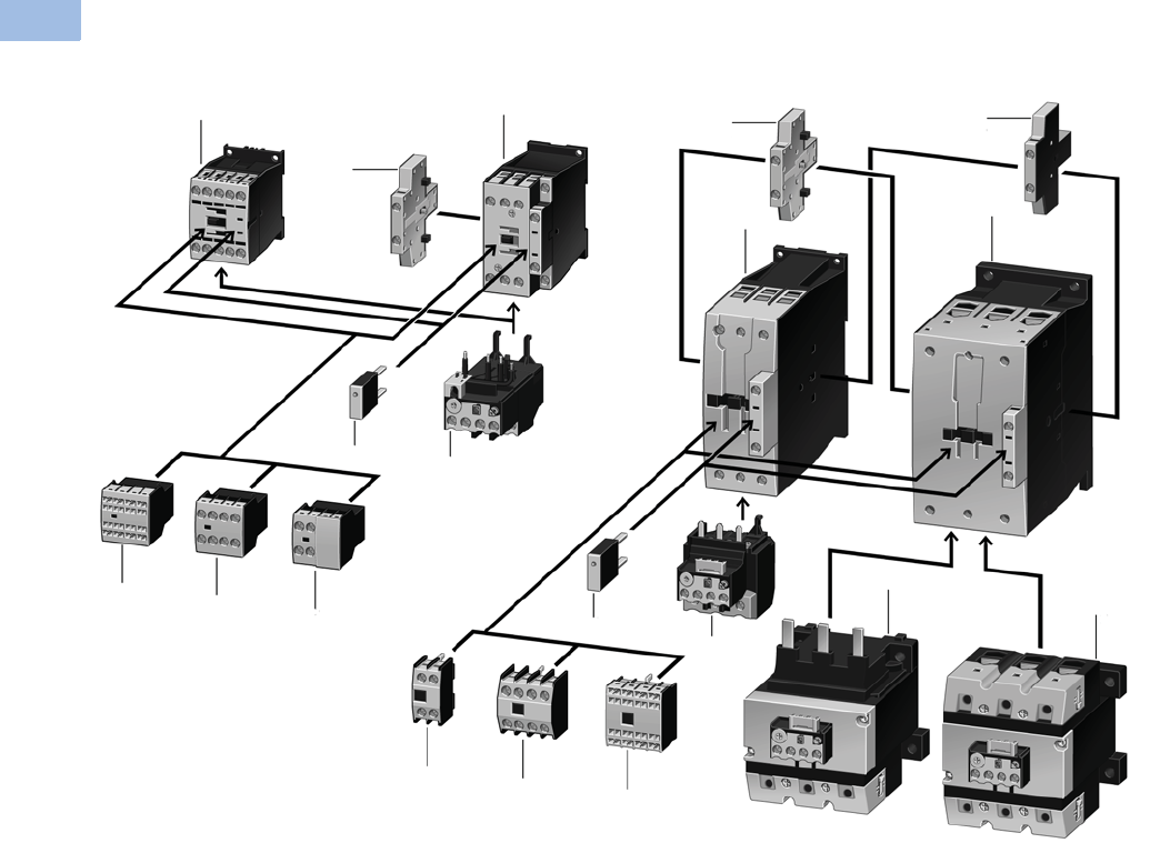
V5-T1-36 Volume 5—Motor Control and Protection CA08100006E—February 2014 www.eaton.com
1
1
1
1
1
1
1
1
1
1
1
1
1
1
1
1
1
1
1
1
1
1
1
1
1
1
1
1
1
1
1.1
IEC Contactors and Starters
XT
IEC Power Control
Product Identification
XTCE007B to XTCE170G (7 to 170A) Contactors
Notes
1Contactor up to 170A AC-3 (see Page V5-T1-39)
AC: 12–600V, 50, 60, 50/60 Hz
0.8–1.1 x Uc)
DC: 12–250V
XTCE…B_ (7–15A): 0.8–1.1 x Uc
XTCE…C_–XTCE…G_(18–150A): 0.7–1.2 x Uc
24V: 0.7–1.3 x Uc at 40°C without additional auxiliary contacts
Coils for special voltages
“Safe Isolation” to IEC 536 between coil and contacts
2Suppressors (see Page V5-T1-71)
RC suppressor
Varistor suppressor
Free-wheel diode suppressor
3Overload Relays (see Page V5-T1-130)
Can be mounted directly
Separate mounting, possible
Protection of EEx e-motors
4Auxiliary Contact Modules (see Page V5-T1-24)
Two-pole, plug-in type
Four-pole, plug-in type
Overlapping contacts
Two-pole, side-mounting
11
4
23
4
4
4
4
4
4
44
1
1
2
3
3
3
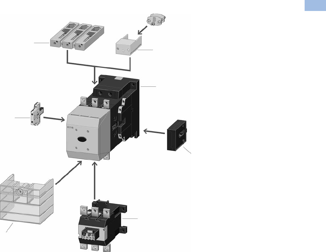
Volume 5—Motor Control and Protection CA08100006E—February 2014 www.eaton.com V5-T1-37
1
1
1
1
1
1
1
1
1
1
1
1
1
1
1
1
1
1
1
1
1
1
1
1
1
1
1
1
1
1
1.1
IEC Contactors and Starters
XT
IEC Power Control
XTCE185–XTCE20 Contactors
Notes
1XTCE Contactors for 185–2000A
(see Page V5-T1-46)
Multi-voltage coils:
24–48 Vdc
48–110 Vac/Vdc
110–250 Vac/Vdc
250–500 Vac
0.7–1.15 x Uc
Actuation options:
Directly
From the PLC
With low-consumption contact
XTCS Contactors for 185–570A AC-3
(see Page V5-T1-42)
Control voltages:
110–120V 50/60 Hz
220–240V 50/60 Hz
Conventional operation
2Cable Terminal Block
(see Page V5-T1-97)
One or two conductors per phase
Round and flat conductor connectable
Finger-proof
3Flat Strip Conductor Terminals
(see Page V5-T1-97)
One or two strips per phase
Control circuit terminal
Cover for fingerproofing
4Mechanical Interlock
(see Page V5-T1-73)
Fits between contactors
5Overload Relays
(see Page V5-T1-130)
Can be mounted directly
Separate mounting, possible
Protection of EEx e-motors
PTB certificate
6Terminal Shroud
(see Page V5-T1-75)
Finger-proof
7Auxiliary Contact Modules
(see Page V5-T1-24)
Two-pole, side-mounting
3
1
2
7
4
5
6
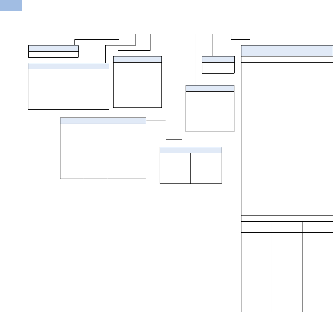
V5-T1-38 Volume 5—Motor Control and Protection CA08100006E—February 2014 www.eaton.com
1
1
1
1
1
1
1
1
1
1
1
1
1
1
1
1
1
1
1
1
1
1
1
1
1
1
1
1
1
1
1.1
IEC Contactors and Starters
XT
IEC Power Control
Catalog Number Selection
XT IEC Contactors and Starters
XTAE, XTAS and XTAR Starters Only—
Maximum Overload Relay
XTOB Maximum Overload Rating
Frame B
P16 = 0.1–0.16A
P24 = 0.16–0.24A
P40 = 0.24–0.4A
P60 = 0.4–0.6A
001 = 0.6–1A
1P6 = 1.0–1.6A
2P4 = 1.6–2.4A
004 = 2.4–4A
006 =4–6A
010 =6–10A
012 =9–12A
016 = 12–16A
Frame C
P16 = 0.1–0.16A
P24 = 0.16–0.24A
P40 = 0.24–0.4A
P60 = 0.4–0.6A
001 = 0.6–1A
1P6 = 1.0–1.6A
2P4 = 1.6–2.4A
004 = 2.4–4A
006 =4–6A
010 =6–10A
016 = 10–16A
024 = 16–24A
032 = 24–32A
Frame D
010 =6–10A
016 = 10–16A
024 = 16–24A
040 = 24–40A
057 = 40–57A
065 = 50–65A
075 = 65–75A
Frame F
035 = 25–35A
050 = 35–50A
070 = 50–70A
100 = 70–100A
Frame G
035 = 25–35A
050 = 35–50A
070 = 50–70A
100 = 70–100A
125 = 95–125A
150 = 120–150A
175 = 145–175A
Frame L
070 = 50–70A
100 = 70–100A
125 = 95–125A
160 = 120–160A
220 = 160–220A
250 = 200–250A
Type
CE = Three-pole FVNR IEC contactor
CS = Three-pole FVNR S Series IEC contactor
CF = Four-pole FVNR IEC contactor
CR = Three-pole FVR IEC contactor
CC = IEC capacitor contactor
AE = FVNR IEC starter
AS = FVNR S-Series IEC starter
AR = FVR IEC starter
Designation
XT = XT line of IEC control
Terminations
Blank = Screw terminals
(6–65A);
5 mm (80–150A);
no lugs
(185–2000A)
C= Spring cage
terminals consult
local sales office
for availability
XTOE Maximum Overload Rating
Standard
Type Suffix
Ground Fault
Type Suffix
Frame B
0.33–1.65A
1–5A
4–20A
Frame C
0.33–1.65A
1–5A
4–20A
9–45A
Frame D
9–45A
20–100A
Frame F, G
20–100A
Frame G, H
35–175A
5E1P6
5E005
5E020
5E1P6
5E005
5E020
5E045
5E045
5E100
5E100
5E175
5G1P6
5G005
5G020
5G1P6
5G005
5G020
5G045
5G045
5G100
5G100
5G175
Frame Size Designation
B= 45 mm
C= 45 mm
D= 55 mm
F= 90 mm
G= 90 mm
H= 140 mm
L= 140 mm
M= 160 mm
N= 250 mm
P= 260 mm
R= 515 mm
Built-In Auxiliary Contact
01 =1NC
10 =1NO
00 = 0NO–0NC
S1 = 1NO–1NC
side-mount auxiliary
11 = 1NO–1NC
top-mount auxiliary
22 = 2NO–2NC
Current Ratings, AC-3
007 = 7A
009 = 9A
012 = 12A
015 = 15A
018 = 18A
025 = 25A
032 = 32A
040 = 40A
050 = 50A
065 = 65A
072 = 72A
080 = 80A
095 = 95A
115= 115A
150 = 150A
170 = 170A
185 = 185A
225 = 225A
250 = 250A
300 = 300A
400 = 400A
500 = 500A
570 = 570A
580 = 580A
650 = 650A
750 = 750A
820 = 820A
C10 = 1000A
C14 = 1400A, AC-1
C16 = 1600A, AC-3
C20 = 2000A, AC-1
XT CE C007 B01 AD P16
Coil Codes
See Page
V5-T1-53.
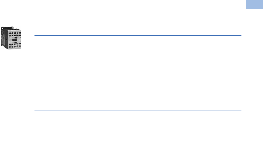
Volume 5—Motor Control and Protection CA08100006E—February 2014 www.eaton.com V5-T1-39
1
1
1
1
1
1
1
1
1
1
1
1
1
1
1
1
1
1
1
1
1
1
1
1
1
1
1
1
1
1
1.1
IEC Contactors and Starters
XT
IEC Power Control
Product Selection
Full Voltage, Non-Reversing Contactors
Three-Pole Contactors, Frame B—UL/CSA Ratings
Three-Pole Contactors, Frame B—IEC Ratings
Notes
The 7–32A XTCE contactors have positively driven contacts between the integrated auxiliary contact and
the auxiliary contact module as well as within the auxiliary contact modules.
DC operated contactors (Frames B–G, 7–150A) have a built-in suppressor circuit.
1 Underscore (_) indicates magnet coil suffix required. See Page V5-T1-53.
2 For spring cage terminals, insert C after the fourth digit of the catalog number. Example: XTCEC007B10A.
For 7–12A XTCEC contactors, the power, auxiliary and coil terminals are spring cage.
For 18–32A XTCEC contactors, the auxiliary and coil terminals are spring cage.
For 40–150A XTCEC contactors, the coil terminals only are spring cage.
3 For electrical life contactor application data. See Page V5-T1-45.
UL General Purpose
Ampere Rating
Single-Phase hp Ratings Three-Phase hp Ratings Auxiliary
Contacts
Screw Terminal
Catalog Number 12
115V 200V 230V 200V 230V 460V 575V
20 1/4 3/4 1 1-1/2 2 3 5 1NO XTCE007B10_
20 1/4 3/4 1 1-1/2 2 3 5 1NC XTCE007B01_
20 1/211-1/23357-1/21NO XTCE009B10_
20 1/211-1/23357-1/21NC XTCE009B01_
20 1223 3 10
310 1NO XTCE012B10_
20 1223 3 10
310 1NC XTCE012B01_
20 1235 5 10
310 1NO XTCE015B10_
20 1235 5 10
310 1NC XTCE015B01_
AC-3
Ie (A)
AC-1 (40°C)
Ie = Ith (A)
Maximum kW Ratings AC-3/Three-Phase Motors 50–60 Hz Auxiliary
Contacts
Screw Terminal
Catalog Number 12
220/230V 380/400V 415V 660/690V
722 2.2 3 43.5 1NOXTCE007B10_
722 2.2 3 43.5 1NCXTCE007B01_
922 2.5 4 5.54.5 1NOXTCE009B10_
922 2.5 4 5.54.5 1NCXTCE009B01_
12 22 3.5 5.5 7 6.5 1NO XTCE012B10_
12 22 3.5 5.5 7 6.5 1NC XTCE012B01_
15.5 22 4 7.5 8 7 1NO XTCE015B10_
15.5 22 4 7.5 8 7 1NC XTCE015B01_
Frame B
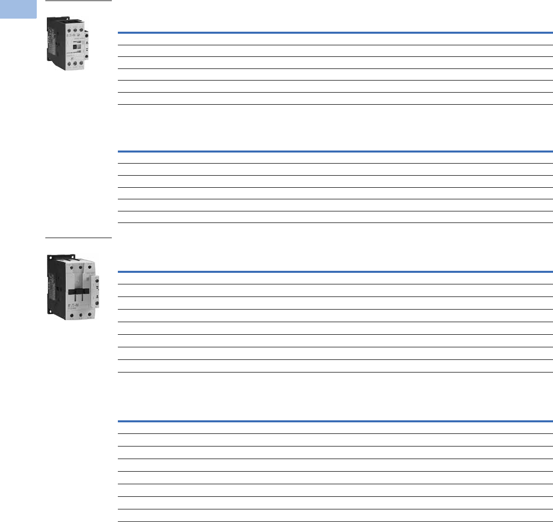
V5-T1-40 Volume 5—Motor Control and Protection CA08100006E—February 2014 www.eaton.com
1
1
1
1
1
1
1
1
1
1
1
1
1
1
1
1
1
1
1
1
1
1
1
1
1
1
1
1
1
1
1.1
IEC Contactors and Starters
XT
IEC Power Control
Three-Pole Contactors, Frame C—UL/CSA Ratings
Three-Pole Contactors, Frame C—IEC Ratings
Three-Pole Contactors, Frame D—UL/CSA Ratings
Three-Pole Contactors, Frame D—IEC Ratings
Notes
The 7–32A XTCE contactors have positively driven contacts between the integrated auxiliary contact and
the auxiliary contact module as well as within the auxiliary contact modules.
The 40–65A XTCE contactors have positively driven contacts within the auxiliary contact module.
Six auxiliary contacts are possible with a combination of side-mounted and front-mount auxiliary contacts.
DC operated contactors (Frames B–G, 7–150A) have a built-in suppressor circuit.
1 Underscore (_) indicates magnet coil suffix required. See Page V5-T1-53.
2 For spring cage terminals, insert C after the fourth digit of the catalog number. Example: XTCEC007B10A.
For 7–12A XTCEC contactors, the power, auxiliary and coil terminals are spring cage.
For 18–32A XTCEC contactors, the auxiliary and coil terminals are spring cage.
For 40–150A XTCEC contactors, the coil terminals only are spring cage.
UL General Purpose
Ampere Rating
Single-Phase hp Ratings Three-Phase hp Ratings Auxiliary
Contacts
Screw Terminal
Catalog Number 12
115V 200V 230V 200V 230V 460V 575V
40 2235 5 10151NO XTCE018C10_
40 2235 5 10151NC XTCE018C01_
40 2357-1/21015201NO XTCE025C10_
40 2357-1/21015201NC XTCE025C01_
40 355101020251NO XTCE032C10_
40 355101020251NC XTCE032C01_
AC-3
Ie (A)
AC-1 (40°C)
Ie = Ith (A)
Maximum kW Ratings AC-3/Three-Phase Motors 50–60 Hz Auxiliary
Contacts
Screw Terminal
Catalog Number 12
220/230V 380/400V 415V 660/690V
18 40 5 7.5 10 11 1NO XTCE018C10_
18 40 5 7.5 10 11 1NC XTCE018C01_
25 45 7.5 11 14.5 14 1NO XTCE025C10_
25 45 7.5 11 14.5 14 1NC XTCE025C01_
32 45 10 15 18 17 1NO XTCE032C10_
32 45 10 15 18 17 1NC XTCE032C01_
UL General Purpose
Ampere Rating
Single-Phase hp Ratings Three-Phase hp Ratings Auxiliary
Contacts
Screw Terminal
Catalog Number 12
115V 200V 230V 200V 230V 460V 575V
63 3 5 7-1/2 10 15 30 40 — XTCE040D00_
63 3 5 7-1/2 10 15 30 40 1NO-1NC XTCE040DS1_
80 3 7-1/2 10 15 20 40 50 — XTCE050D00_
80 3 7-1/2 10 15 20 40 50 1NO-1NC XTCE050DS1_
88 5 101520255060 — XTCE065D00_
88 5 101520255060 1NO-1NCXTCE065DS1_
88 5 101520255060 — XTCE072D00_
88 5 101520255060 1NO-1NCXTCE072DS1_
AC-3
Ie (A)
AC-1 (40°C)
Ie = Ith (A)
Maximum kW Ratings AC-3/Three-Phase Motors 50–60 Hz Auxiliary
Contacts
Screw Terminal
Catalog Number 12
220/230V 380/400V 415V 660/690V
40 60 12.5 18.5 24 23 — XTCE040D00_
40 60 12.5 18.5 24 23 1NO-1NC XTCE040DS1_
50 80 15.5 22 30 30 — XTCE050D00_
50 80 15.5 22 30 30 1NO-1NC XTCE050DS1_
65 98 20 30 39 35 — XTCE065D00_
65 98 20 30 39 35 1NO-1NC XTCE065DS1_
72 98 22 37 41 35 — XTCE072D00_
72 98 22 37 41 35 1NO-1NC XTCE072DS1_
Frame C
Frame D
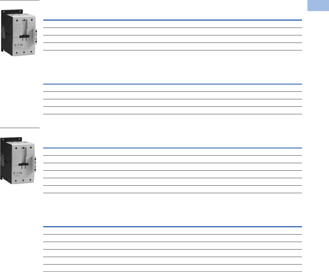
Volume 5—Motor Control and Protection CA08100006E—February 2014 www.eaton.com V5-T1-41
1
1
1
1
1
1
1
1
1
1
1
1
1
1
1
1
1
1
1
1
1
1
1
1
1
1
1
1
1
1
1.1
IEC Contactors and Starters
XT
IEC Power Control
Three-Pole Contactors, Frame F—UL/CSA Ratings
Three-Pole Contactors, Frame F—IEC Ratings
Three-Pole Contactors, Frame G—UL/CSA Ratings
Three-Pole Contactors, Frame G—IEC Ratings
Notes
The 40–65A XTCE contactors have positively driven contacts within the auxiliary contact module.
Six auxiliary contacts are possible with a combination of side-mounted and front-mount auxiliary contacts.
DC operated contactors (Frames B–G, 7–150A) have a built-in suppressor circuit.
1 Underscore (_) indicates magnet coil suffix required. See Page V5-T1-53.
2 For spring cage terminals, insert C after the fourth digit of the catalog number. Example: XTCEC007B10A.
For 7–12A XTCEC contactors, the power, auxiliary and coil terminals are spring cage.
For 18–32A XTCEC contactors, the auxiliary and coil terminals are spring cage.
For 40–150A XTCEC contactors, the coil terminals only are spring cage.
UL General Purpose
Ampere Rating
Single-Phase hp Ratings Three-Phase hp Ratings Auxiliary
Contacts
Screw Terminal
Catalog Number 12
115V 200V 230V 200V 230V 460V 575V
125 7-1/2 15 15 25 30 60 75 — XTCE080F00_
125 7-1/2 15 15 25 30 60 75 1NO-1NC XTCE080FS1_
125 7-1/2 15 15 25 40 75 100 — XTCE095F00_
125 7-1/2 15 15 25 40 75 100 1NO-1NC XTCE095FS1_
AC-3
Ie (A)
AC-1 (40°C)
Ie = Ith (A)
Maximum kW Ratings AC-3/Three-Phase Motors 50–60 Hz Auxiliary
Contacts
Screw Terminal
Catalog Number 12
220/230V 380/400V 415V 660/690V
80 110 25 37 48 63 — XTCE080F00_
80 110 25 37 48 63 1NO-1NC XTCE080FS1_
95 130 30 45 57 75 — XTCE095F00_
95 130 30 45 57 75 1NO-1NC XTCE095FS1_
UL General Purpose
Ampere Rating
Single-Phase hp Ratings Three-Phase hp Ratings Auxiliary
Contacts
Screw Terminal
Catalog Number 12
115V 200V 230V 200V 230V 460V 575V
160 10252540 50 100100— XTCE115G00_
160 10252540 50 1001001NO-1NCXTCE115GS1_
180 10253040 60 125125— XTCE150G00_
180 10253040 60 1251251NO-1NCXTCE150GS1_
180 10253040 60 125125— XTCE170G00_
180 10253040 60 1251251NO-1NCXTCE170GS1_
AC-3
Ie (A)
AC-1 (40°C)
Ie = Ith (A)
Maximum kW Ratings AC-3/Three-Phase Motors 50–60 Hz Auxiliary
Contacts
Screw Terminal
Catalog Number 12
220/230V 380/400V 415V 660/690V
115 160 37 55 70 90 — XTCE115G00_
115 160 37 55 70 90 1NO-1NC XTCE115GS1_
150 190 48 75 91 96 — XTCE150G00_
150 190 48 75 91 96 1NO-1NC XTCE150GS1_
170 225 52 90 100 96 — XTCE170G00_
170 225 52 90 100 96 1NO-1NC XTCE170GS1_
Frame F
Frame G

V5-T1-42 Volume 5—Motor Control and Protection CA08100006E—February 2014 www.eaton.com
1
1
1
1
1
1
1
1
1
1
1
1
1
1
1
1
1
1
1
1
1
1
1
1
1
1
1
1
1
1
1.1
IEC Contactors and Starters
XT
IEC Power Control
Three-Pole Contactors, Frame H (Electronic Coil)—UL/CSA Ratings
Three-Pole Contactors, Frame H (Electronic Coil)—IEC Ratings
Three-Pole Contactors, Frame L—UL/CSA Ratings
Three-Pole Contactors, Frame L—IEC Ratings
Notes
1 Underscore (_) indicates magnet coil suffix required. See Page V5-T1-53. Terminals not included. See Page V5-T1-75 for terminal accessories.
2 Does not include lugs.
3 For 185–500A contactors at 660/690V or 1000V: Do not reverse directly.
UL General Purpose
Ampere Rating
Three-Phase hp Ratings Auxiliary
Contacts
Catalog
Number 12
200V 240V 480V 600V
250 50601251502NO-2NCXTCE185H22_
250 60751502002NO-2NCXTCE225H22_
AC-3
Ie (A)
AC-1 (40°C)
Ie = Ith (A)
Maximum kW Ratings AC-3/Three-Phase Motors 50–60 Hz Auxiliary
Contacts
Catalog
Number 12
220/230V 380/400V 660/690V 31000V 3
185 337 55 90 140 108 2NO-2NC XTCE185H22_
225 386 70 110 215 108 2NO-2NC XTCE225H22_
UL General Purpose Three-Phase hp Ratings Auxiliary
Contacts
Catalog
Number 12
Ampere Rating 200V 230V 460V 575V
Standard Coil (110/120V, 230/240 Vac Coil Only)
300 75 100 200 250 2NO-2NC XTCS250L22_
350 100 125 250 300 2NO-2NC XTCS300L22_
Electronic Coil
300 75 100 200 250 2NO-2NC XTCE250L22_
350 100 125 250 300 2NO-2NC XTCE300L22_
AC-3
Ie (A)
AC-1 (40°C)
Ie = Ith (A)
Maximum kW Ratings AC-3/Three-Phase Motors 50–60 Hz Auxiliary
Contacts
Catalog
Number 12
220/230V 380/400V 660/690V 31000V 3
Standard Coil (110/120V, 230/240 Vac Coil Only)
250 429 75 132 240 108 2NO-2NC XTCS250L22_
300 490 90 160 195 132 2NO-2NC XTCS300L22_
Electronic Coil
250 429 75 132 240 108 2NO-2NC XTCE250L22_
300 490 90 160 195 132 2NO-2NC XTCE300L22_
Frame H
Frame L
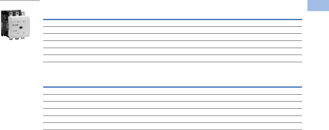
Volume 5—Motor Control and Protection CA08100006E—February 2014 www.eaton.com V5-T1-43
1
1
1
1
1
1
1
1
1
1
1
1
1
1
1
1
1
1
1
1
1
1
1
1
1
1
1
1
1
1
1.1
IEC Contactors and Starters
XT
IEC Power Control
Three-Pole Contactors, Frame M—UL/CSA Ratings
Three-Pole Contactors, Frame M—IEC Ratings
Notes
1 Underscore (_) indicates magnet coil suffix required. See Page V5-T1-53. Terminals not included. See Page V5-T1-75 for terminal accessories.
2 Does not include lugs.
3 For 185–500A contactors at 660/690V or 1000V: Do not reverse directly.
UL General Purpose
Ampere Rating
Three-Phase hp Ratings Auxiliary
Contacts
Catalog
Number 12
200V 230V 460V 575V
Standard Coil (110/120V, 230/240 Vac Coil Only)
450 125 150 300 400 2NO-2NC XTCS400M22_
550 150 200 400 500 2NO-2NC XTCS500M22_
Electronic Coil
450 125 150 300 400 2NO-2NC XTCE400M22_
550 150 200 400 500 2NO-2NC XTCE500M22_
AC-3
Ie (A)
AC-1 (40°C)
Ie = Ith (A)
Maximum kW Ratings AC-3/Three-Phase Motors 50–60 Hz Auxiliary
Contacts
Catalog
Number 12
220/230V 380/400V 415V 660/690V 31000V 3
Standard Coil (110/120V, 230/240 Vac Coil Only)
400 612 125 200 240 344 132 2NO-2NC XTCS400M22_
500 800 155 250 300 344 132 2NO-2NC XTCS500M22_
Electronic Coil
400 612 125 200 240 344 132 2NO-2NC XTCE400M22_
500 800 155 250 300 344 132 2NO-2NC XTCE500M22_
Frame M
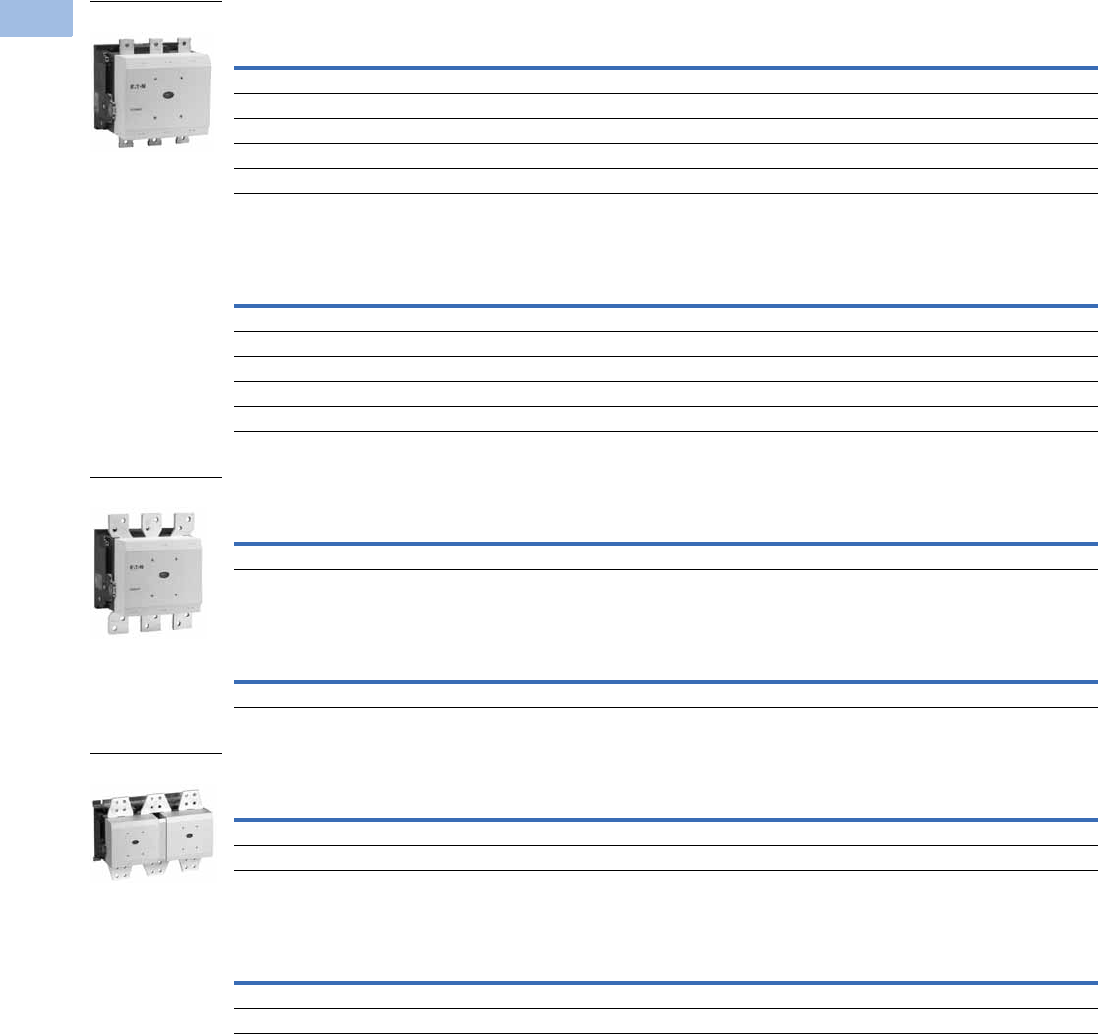
V5-T1-44 Volume 5—Motor Control and Protection CA08100006E—February 2014 www.eaton.com
1
1
1
1
1
1
1
1
1
1
1
1
1
1
1
1
1
1
1
1
1
1
1
1
1
1
1
1
1
1
1.1
IEC Contactors and Starters
XT
IEC Power Control
Three-Pole Contactors, Frame N (Electronic Coil)—UL/CSA Ratings
Three-Pole Contactors, Frame N (Electronic Coil)—IEC Ratings
Three-Pole Contactors, Frame P (Electronic Coil)—UL/CSA Ratings
Three-Pole Contactors, Frame P (Electronic Coil)—IEC Ratings
Three-Pole Contactors, Frame R (Electronic Coil)—UL/CSA Ratings
Three-Pole Contactors, Frame R (Electronic Coil)—IEC Ratings
Notes
1 Underscore (_) indicates magnet coil suffix required. See Page V5-T1-53. Terminals not included. See Page V5-T1-75 for terminal accessories.
2 Does not include lugs.
3 When operating the 580–2000A XTCE contactors with frequency inverters, the suppressor on the load side must be removed. The load side suppressor must also be
removed when performing a high-voltage test—see Pub51204, Pub51209.
4 For 185–500A contactors at 660/690V or 1000V: do not reverse directly.
UL General Purpose
Ampere Rating
Three-Phase hp Ratings Auxiliary
Contacts Catalog Number 12
200V 230V 460V 575V
630 200 200 400 600 2NO-2NC XTCE580N22_ 3
700 200 250 500 600 2NO-2NC XTCE650N22_ 3
800 250 300 600 700 2NO-2NC XTCE750N22_ 3
850 290 350 700 860 2NO-2NC XTCE820N22_ 3
1100 350 420 850 980 2NO-2NC XTCEC10N22_ 3
AC-3
Ie (A)
AC-1 (40°C)
Ie = Ith (A)
Maximum kW Ratings AC-3/Three-Phase Motors 50–60 Hz Auxiliary
Contacts Catalog Number 12
220/230V 380/400V 415V 660/690V 41000V 4
580 980 185 315 348 560 600 2NO-2NC XTCE580N22_ 3
650 1041 205 355 390 630 600 2NO-2NC XTCE650N22_ 3
750 1102 240 400 455 720 800 2NO-2NC XTCE750N22_ 3
820 1225 260 450 500 750 800 2NO-2NC XTCE820N22_ 3
1000 1225 315 560 610 1000 1000 2NO-2NC XTCEC10N22_ 3
UL General Purpose
Ampere Rating
Three-Phase hp Ratings Auxiliary
Contacts Catalog Number 12
200V 230V 460V 575V
1400 — — — — 2NO-2NC XTCEC14P22_ 3
AC-3
Ie (A)
AC-1 (40°C)
Ie = Ith (A)
Maximum kW Ratings AC-3/Three-Phase Motors 50–60 Hz Auxiliary
Contacts Catalog Number 12
220/230V 380/400V 415V 660/690V 41000V 4
— 1714 — — — — — 2NO-2NC XTCEC14P22_ 3
UL General Purpose
Ampere Rating
Three-Phase hp Ratings Auxiliary
Contacts Catalog Number 12
200V 230V 460V 575V
1600 560 640 1200 1300 2NO-2NC XTCEC16R22_ 3
2000 — — — — 2NO-2NC XTCEC20R22_ 3
AC-3
Ie (A)
AC-1 (40°C)
Ie = Ith (A)
Maximum kW Ratings AC-3/Three-Phase Motors 50–60 Hz Auxiliary
Contacts Catalog Number 12
220/230V 380/400V 415V 660/690V 41000V 4
1600 2200 500 900 900 1600 1700 2NO-2NC XTCEC16R22_ 3
— 2450 — — — — — 2NO-2NC XTCEC20R22_ 3
Frame N
Frame P
Frame R
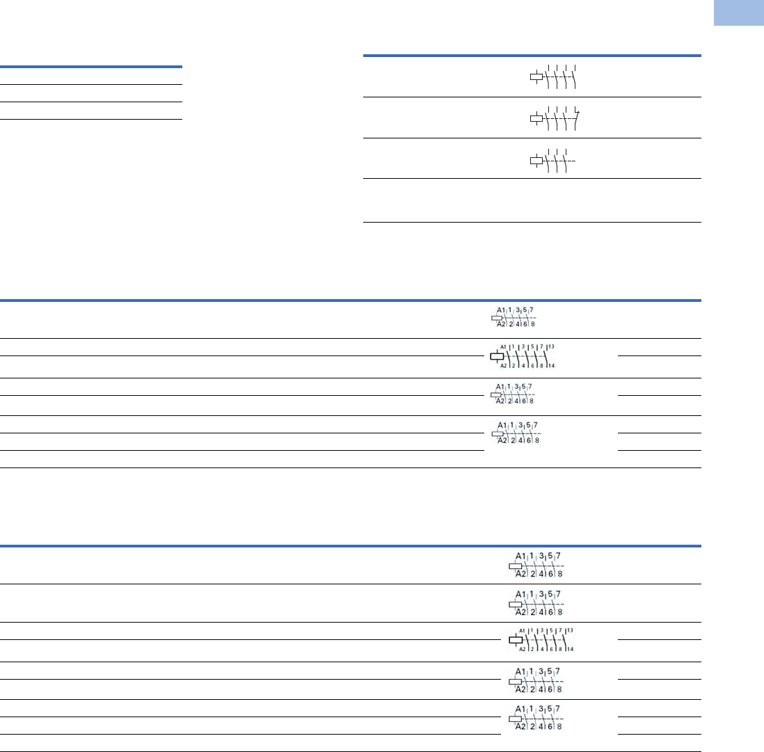
Volume 5—Motor Control and Protection CA08100006E—February 2014 www.eaton.com V5-T1-45
1
1
1
1
1
1
1
1
1
1
1
1
1
1
1
1
1
1
1
1
1
1
1
1
1
1
1
1
1
1
1.1
IEC Contactors and Starters
XT
IEC Power Control
Contactor
Application Data 12
Full Voltage Non-Reversing Three-Pole Contactors—
Contact Sequence (Circuit Symbols)—Standard Offering
Four-Pole Contactors with Screw Terminals—Maximum UL/CSA Motor Ratings
Four-Pole Contactors with Screw Terminals—Maximum IEC Ratings
Notes
1See Page V5-T1-111 for electrical life curves.
2AC and DC operated contactors have a built-in suppressor circuit (Frames L–R, 185–2000A).
3Underscore (_) indicates magnet coil suffix required. See Page V5-T1-53.
Catalog
Prefix
Electrical Life (Operations)
for 10 hp, 480V (14.2A)
Applications
XTCE012B 1 million
XTCE015B 1.2 million
XTCE018C 2 million
Contactor
Frame
Auxiliary
Contacts Contact Sequence
B–C 1NO
B–C 1NC
D–G —
L–R 2NO-2NC
2
35
46
A1
A2
113
14
2
35
46
A1
A2
121
22
2
35
46
A1
A2
1
Single-Phase hp Ratings Three-Phase hp Ratings Auxiliary
Contacts
Contact
Sequence Catalog Number 3
115V 230V 200V 230V 460V 575V
12331010— XTCF020B00_
——7.57.510151NO XTCF032C10_
— — 7.5 10 15 20 1NO XTCF045C10_
——10153040— XTCF063D00_
——15204050— XTCF080D00_
——25306075— XTCF125G00_
——254075100— XTCF160G00_
——4050100125— XTCF200G00_
AC-3
Ie (A)
AC-1
(40°C)
Three-Phase hp Ratings Auxiliary
Contacts
Contact
Sequence Catalog Number 3
200V 230V 460V 575V
12 22 3 3 10 10 — XTCF020B00_
12 22 3.5 5.5 7 6.5 — XTCF020B00_
18 32 5 7.5 10 11 1NO XTCF032C10_
25 45 7.5 11 14.5 14 1NO XTCF045C10_
40 63 12.5 18.5 24 23 — XTCF063D00_
50 80 15.5 22 30 30 — XTCF080D00_
8012525374863— XTCF125G00_
9516030455775— XTCF160G00_
115 200 37 55 70 90 — XTCF200G00_
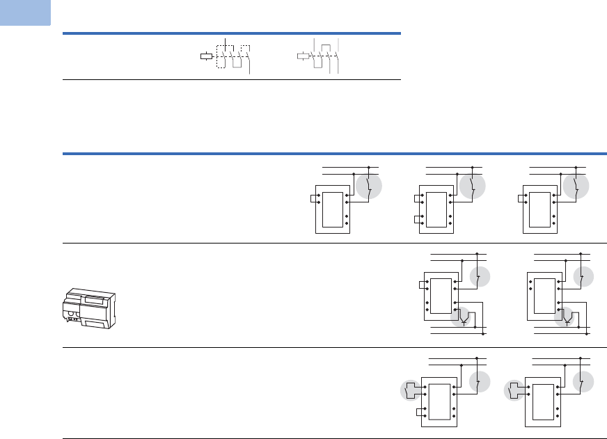
V5-T1-46 Volume 5—Motor Control and Protection CA08100006E—February 2014 www.eaton.com
1
1
1
1
1
1
1
1
1
1
1
1
1
1
1
1
1
1
1
1
1
1
1
1
1
1
1
1
1
1
1.1
IEC Contactors and Starters
XT
IEC Power Control
Switching of DC Currents 1
Controlling XTCS and XTCE Contactors Frames L–R (185–2000A)
Notes
1When necessary, cable to be supplied by customer.
2Standstill in an emergency (emergency-stop).
3Command device connection.
Description Single-Pole Two-Pole
XTCF020B–XTCF200G
>60 Vdc
Description
XTCS250L–XTCS500M,
XTCE_H XTCEC16R, XTCEC20R XTCE250L–XTCEC14P
Conventional
A1/A2 are applied to voltage in the usual manner.
Direct from the PLC
A 24V output from the PLC can be connected directly to
connections A3/A4.
—
From Low-Consumption Command Devices
Command devices, which can only be subject to minimal loads
such as circuit board relays, control circuit devices or position
switches can be connected directly to A10/A11.
—
A10
A11
A2
A1
A3
A4
(+) L1
(–) N
b
A10
A11
A2
A1
A3
A4
TY
TX
(+) L1
(–) N
b
A10
A11
A2
A1
A3
A4
(+) L1
(–) N
b
A2
A1
A3
A4
24V
GND
(+) L1
(–) N
b
A10
A11
TY
TX
A10
A11
A2
A1
A3
A4
24V
GND
(+) L1
(–) N
b
A10
A11
A2
A1
A3
A4
c
b
(+) L1
(–) N
TY
TX
A10
A11
A2
A1
A3
A4
c
b
(+) L1
(–) N
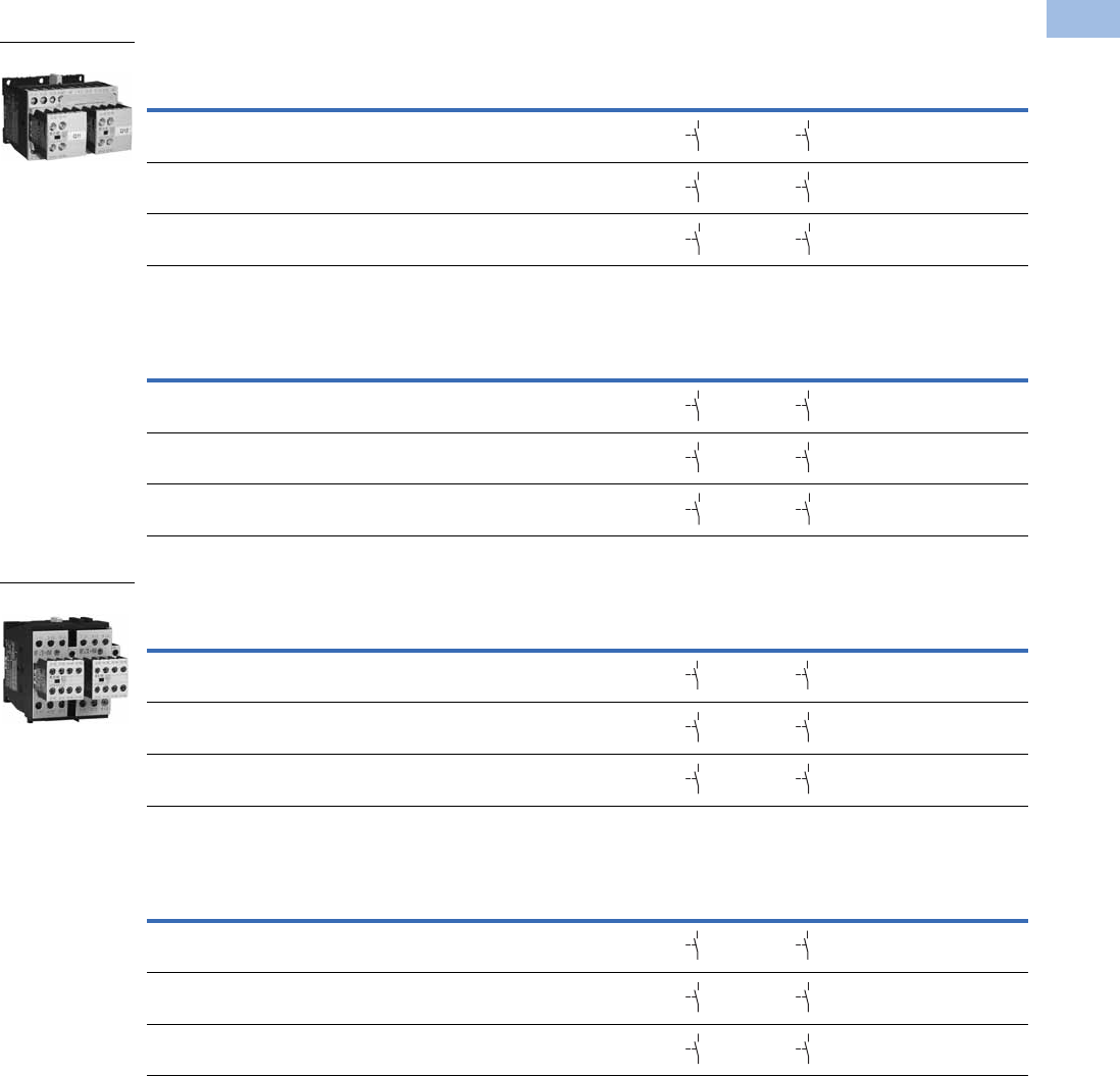
Volume 5—Motor Control and Protection CA08100006E—February 2014 www.eaton.com V5-T1-47
1
1
1
1
1
1
1
1
1
1
1
1
1
1
1
1
1
1
1
1
1
1
1
1
1
1
1
1
1
1
1.1
IEC Contactors and Starters
XT
IEC Power Control
Full Voltage, Reversing Contactors
Contactors with Screw Terminals, Frame B—Maximum UL/CSA Ratings
Contactors with Screw Terminals, Frame B—Maximum IEC Ratings
Contactors with Screw Terminals, Frame C—Maximum UL/CSA Ratings
Contactors with Screw Terminals, Frame C—Maximum IEC Ratings
Note
1 Underscore (_) indicates magnet coil suffix required. See Page V5-T1-53.
Single-Phase hp Ratings Three-Phase hp Ratings Spare Auxiliary Contacts
Catalog Number 1
115V 230V 200V 230V 460V 575V K1M K2M
1/4 1 1-1/2 2 3 5 XTCR007B21_
1/21-1/22357-1/2 XTCR009B21_
1/2 2 3 3 7-1/2 10 XTCR012B21_
AC-3
Ie (A)
Three-Phase Motors 50–60 Hz Spare Auxiliary Contacts
Catalog Number 1
220/230V 380/400V 415V 660/690V K1M K2M
72.2343.5 XTCR007B21_
92.5 4 5.5 4.5 XTCR009B21_
12 3.5 5.5 7 6.5 XTCR012B21_
Single-Phase hp Ratings Three-Phase hp Ratings Spare Auxiliary Contacts
Catalog Number 1
115V 230V 200V 230V 460V 575V K1M K2M
23 551015 XTCR018C21_
2 5 7-1/2 7-1/2 15 20 XTCR025C21_
3 5 10 10 20 25 XTCR032C21_
AC-3
Ie (A)
Three-Phase Motors 50–60 Hz Spare Auxiliary Contacts
Catalog Number 1
220/230V 380/400V 415V 660/690V K1M K2M
1857.5811 XTCR018C21_
25 7.5 11 14.5 14 XTCR025C21_
32 10 15 18 17 XTCR032C21_
Frame B
64
63
64
63
64
63
64
63
64
63
64
63
64
63
64
63
64
63
64
63
64
63
64
63
Frame C
64
63
64
63
64
63
64
63
64
63
64
63
64
63
64
63
64
63
64
63
64
63
64
63
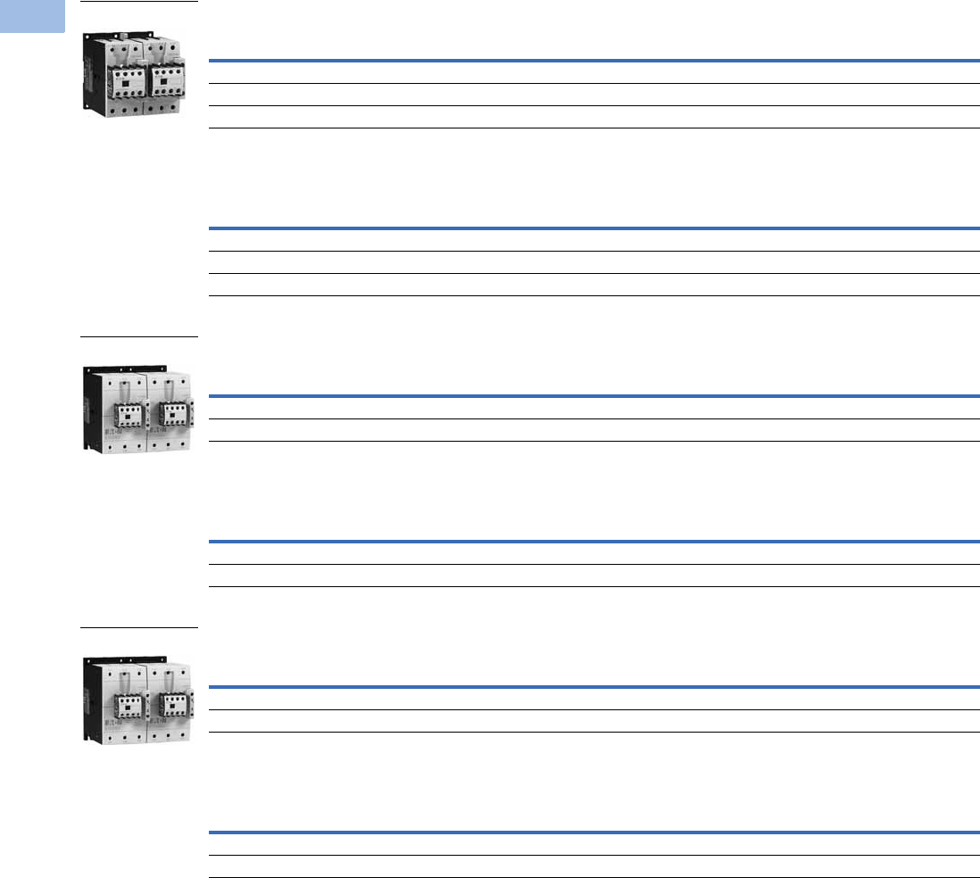
V5-T1-48 Volume 5—Motor Control and Protection CA08100006E—February 2014 www.eaton.com
1
1
1
1
1
1
1
1
1
1
1
1
1
1
1
1
1
1
1
1
1
1
1
1
1
1
1
1
1
1
1.1
IEC Contactors and Starters
XT
IEC Power Control
Contactors with Screw Terminals, Frame D—Maximum UL/CSA Ratings
Contactors with Screw Terminals, Frame D—Maximum IEC Ratings
Contactors with Screw Terminals, Frame F—Maximum UL/CSA Ratings
Contactors with Screw Terminals, Frame F—Maximum IEC Ratings
Contactors with Screw Terminals, Frame G—Maximum UL/CSA Ratings
Contactors with Screw Terminals, Frame G—Maximum IEC Ratings
Note
1 Underscore (_) indicates magnet coil suffix required. See Page V5-T1-53.
Single-Phase hp Ratings Three-Phase hp Ratings Spare Auxiliary Contacts
Catalog Number 1
115V 230V 200V 230V 460V 575V K1M K2M
3 7-1/2 10 15 30 40 — — XTCR040D11_
3 10 15204050 — — XTCR050D11_
5 15 20255060 — — XTCR065D11_
AC-3
Ie (A)
Three-Phase Motors 50–60 Hz Spare Auxiliary Contacts
Catalog Number 1
220/230V 380/400V 415V 660/690V K1M K2M
40 12.5 18.5 24 23 — — XTCR040D11_
50 15.5 22 30 30 — — XTCR050D11_
65 20 30 39 35 — — XTCR065D11_
Single-Phase hp Ratings Three-Phase hp Ratings Spare Auxiliary Contacts
Catalog Number 1
115V 230V 200V 230V 460V 575V K1M K2M
7-1/215 25306075 — — XTCR080F11_
7-1/215 254075100 — — XTCR095F11_
AC-3
Ie (A)
Three-Phase Motors 50–60 Hz Spare Auxiliary Contacts
Catalog Number 1
220/230V 380/400V 415V 660/690V K1M K2M
80 25 37 48 63 — — XTCR080F11_
95 30 45 57 75 — — XTCR095F11_
Single-Phase hp Ratings Three-Phase hp Ratings Spare Auxiliary Contacts
Catalog Number 1
115V 230V 200V 230V 460V 575V K1M K2M
10 25 40 50 100 100 — — XTCR115G11_
15 30 40 60 100 100 — — XTCR150G11_
AC-3
Ie (A)
Three-Phase Motors 50–60 Hz Spare Auxiliary Contacts
Catalog Number 1
220/230V 380/400V 415V 660/690V K1M K2M
11537557090— — XTCR115G11_
15048759196— — XTCR150G11_
Frame D
Frame F
Frame G

Volume 5—Motor Control and Protection CA08100006E—February 2014 www.eaton.com V5-T1-49
1
1
1
1
1
1
1
1
1
1
1
1
1
1
1
1
1
1
1
1
1
1
1
1
1
1
1
1
1
1
1.1
IEC Contactors and Starters
XT
IEC Power Control
XTCR Reversing Contactor Components
Magnet Coil Suffix
Note
1Frames L–M only.
Quantity Frame B C D F G
2 Contactor XTCE…B01_ XTCE…C01_ XTCE…D00_ XTCE…F00_ XTCE…G00_
2 Auxiliary contact XTCEXFAC20 XTCEXFAC20 XTCEXFBG11 XTCEXFBG11 XTCEXFBG11
1 Mechanical interlock XTCEXMLB XTCEXMLC XTCEXMLD XTCEXMLG XTCEXMLG
1 Reversing link kit XTCEXRLB XTCEXRLC XTCEXRLD XTCEXRLG XTCEXRLG
Coil Voltage Suffix Code Coil Voltage Suffix Code Coil Voltage Suffix Code Coil Voltage Suffix Code
Frames A–B Frames C–F Frame G Frames L–N
110V 50 Hz, 120V 60 Hz A110V 50 Hz, 120V 60 Hz A100–120V 50/60 Hz A110–250 Vdc 40–60 Hz A
220V 50 Hz, 240V 60 Hz B220V 50 Hz, 240V 60 Hz B190–240V 50/60 Hz B250–500V 40–60 Hz C
230V 50 Hz F230V 50 Hz F24V 50/60 Hz T48–110 Vdc 40–60 Hz Y
24V 50/60 Hz T24V 50/60 Hz T24–27 Vdc TD 24–48 Vdc TD 1
24 Vdc TD 24–27 Vdc TD 480–500V 50/60 Hz CFrames L–M, S-Series
415V 50 Hz, 480V 60 Hz C415V 50 Hz, 480V 60 Hz C380–440V 50/60 Hz L110–120V 50/60 Hz A
600V 60 Hz D600V 60 Hz D42–48V 50/60 Hz W220–240V 50/60 Hz B
208V 60 Hz E208V 60 Hz E110–130 Vdc AD Frames P–R
190V 50 Hz, 220V 60 Hz G 190V 50 Hz, 220V 60 Hz G200–240 Vdc BD 230–250 Vdc 50–60 Hz B
240V 50 Hz, 277V 60 Hz H240V 50 Hz, 277V 60 Hz H48–60 Vdc WD
380V 50 Hz, 440V 60 Hz L380V 50 Hz, 440V 60 Hz LFrame H
400V 50 Hz N 400V 50 Hz N100–120V 50/60 Hz A
380V 60 Hz P380V 60 Hz P190–240V 50/60 Hz B
12V 50/60 Hz R 12V 50/60 Hz R480–500V 50/60 Hz C
42V 50 Hz, 48V 60 Hz W42V 50 Hz, 48V 60 Hz W380–440V 50/60 Hz L
48V 50 Hz Y48V 50 Hz Y24V 50/60Hz T
120 Vdc AD 110–130 Vdc AD 42–48V 50/60Hz W
220 Vdc BD 200–240 Vdc BD 110–130 Vdc AD
12 Vdc RD 48–60 Vdc WD 200–240 Vdc BD
48 Vdc WD 24–27 Vdc TD
48–60 Vdc WD
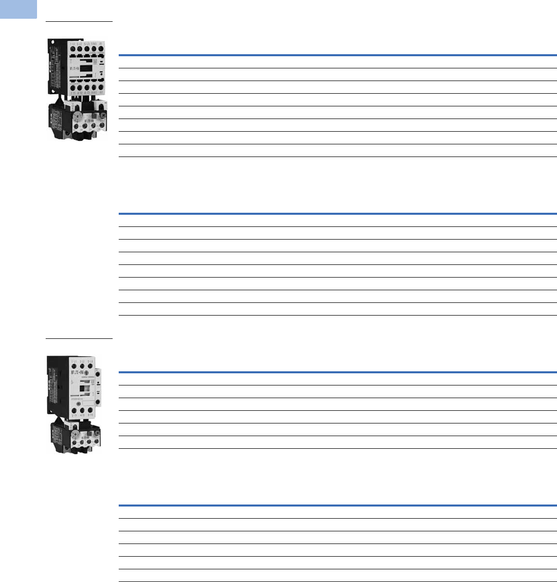
V5-T1-50 Volume 5—Motor Control and Protection CA08100006E—February 2014 www.eaton.com
1
1
1
1
1
1
1
1
1
1
1
1
1
1
1
1
1
1
1
1
1
1
1
1
1
1
1
1
1
1
1.1
IEC Contactors and Starters
XT
IEC Power Control
Full Voltage, Non-Reversing Starters, with Bimetallic or Electronic Overload
Three-Pole Starters, Frame B—Maximum UL/CSA Ratings 1
Three-Pole Starters, Frame B—Maximum IEC Ratings 1
Three-Pole Starters, Frame C—Maximum UL/CSA Ratings 1
Three-Pole Starters, Frame C—Maximum IEC Ratings 1
Notes
1 Products shown are with the bimetallic overload relay.
2 Underscore (_) indicates magnet coil suffix required. See Page V5-T1-53.
3 Underscore (_) indicates overload relay suffix required. See Page V5-T1-54.
4 For electrical life contactor application data. See Page V5-T1-53.
Single-Phase hp Ratings Three-Phase hp Ratings Auxiliary
Contacts Catalog Number 23
115V 230V 200V 230V 460V 575V
1/4 1 1-1/2 2 3 5 1NO XTAE007B10_ _
1/4 1 1-1/2 2 3 5 1NC XTAE007B01_ _
1/21-1/23357-1/21NOXTAE009B10_ _
1/21-1/23357-1/21NCXTAE009B01_ _
12 3310
410 1NO XTAE012B10_ _
12 3310
410 1NC XTAE012B01_ _
13 5510
410 1NO XTAE015B10_ _
13 5510
410 1NC XTAE015B01_ _
AC-3
Ie (A) AC-1
Three-Phase Motors 50–60 Hz Auxiliary
Contacts Catalog Number 23
220/230V 380/400V 415V 660/690V
7202.2343.5 1NOXTAE007B10_ _
7202.2343.5 1NCXTAE007B01_ _
920 2.5 4 5.5 4.5 1NO XTAE009B10_ _
920 2.5 4 5.5 4.5 1NC XTAE009B01_ _
12 20 3.5 5.5 7 6.5 1NO XTAE012B10_ _
12 20 3.5 5.5 7 6.5 1NC XTAE012B01_ _
15.5 20 4 7.5 8 7 1NO XTAE015B10_ _
15.5 20 4 7.5 8 7 1NC XTAE015B01_ _
Single-Phase hp Ratings Three-Phase hp Ratings Auxiliary
Contacts Catalog Number 23
115V 230V 200V 230V 460V 575V
23 5510
415 1NO XTAE018C10_ _
23 5510
415 1NC XTAE018C01_ _
2 5 7-1/2 7-1/2 15 20 1NO XTAE025C10_ _
2 5 7-1/2 7-1/2 15 20 1NC XTAE025C01_ _
3 5 10 10 20 25 1NO XTAE032C10_ _
3 5 10 10 20 25 1NC XTAE032C01_ _
AC-3
Ie (A) AC-1
Three-Phase Motors 50–60 Hz Auxiliary
Contacts Catalog Number 23
220/230V 380/400V 415V 660/690V
18 35 5 7.5 10 11 1NO XTAE018C10_ _
18 35 5 7.5 10 11 1NC XTAE018C01_ _
25 40 7.5 11 14.5 14 1NO XTAE025C10_ _
25 40 7.5 11 14.5 14 1NC XTAE025C01_ _
32 40 10 15 18 17 1NO XTAE032C10_ _
32 40 10 15 18 17 1NC XTAE032C01_ _
Frame B
Frame C
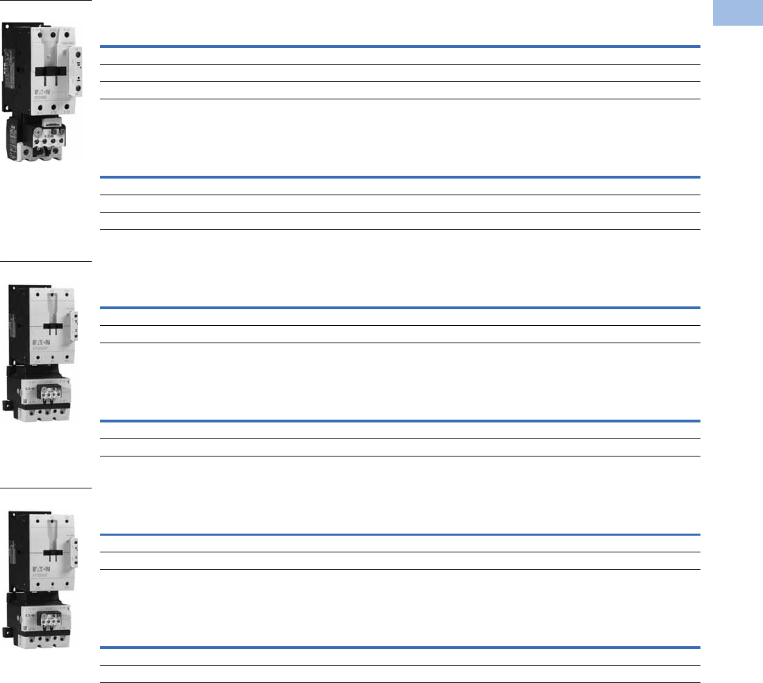
Volume 5—Motor Control and Protection CA08100006E—February 2014 www.eaton.com V5-T1-51
1
1
1
1
1
1
1
1
1
1
1
1
1
1
1
1
1
1
1
1
1
1
1
1
1
1
1
1
1
1
1.1
IEC Contactors and Starters
XT
IEC Power Control
Three-Pole Starters, Frame D—Maximum UL/CSA Ratings 1
Three-Pole Starters, Frame D—Maximum IEC Ratings 1
Three-Pole Starters, Frame F—Maximum UL/CSA Ratings 1
Three-Pole Starters, Frame F—Maximum IEC Ratings 1
Three-Pole Starters, Frame G—Maximum UL/CSA Ratings 1
Three-Pole Starters, Frame G—Maximum IEC Ratings 1
Notes
1 Products shown are with the bimetallic overload relay.
2 Underscore (_) indicates magnet coil suffix required. See Page V5-T1-53.
3 Underscore (_) indicates overload relay suffix required. See Page V5-T1-54.
Single-Phase hp Ratings Three-Phase hp Ratings Auxiliary
Contacts Catalog Number 23
115V 230V 200V 230V 460V 575V
3 7-1/2 10 15 30 40 — XTAE040D00_ _
3 10 15204050 — XTAE050D00_ _
5 15 20255060 —XTAE065D00_ _
AC-3
Ie (A) AC-1
Three-Phase Motors 50–60 Hz Auxiliary
Contacts Catalog Number 23
220/230V 380/400V 415V 660/690V
40 50 12.5 18.5 24 23 — XTAE040D00_ _
50 60 15.5 22 30 30 — XTAE050D00_ _
65 72 20 30 39 35 — XTAE065D00_ _
Single-Phase hp Ratings Three-Phase hp Ratings Auxiliary
Contacts Catalog Number 23
115V 230V 200V 230V 460V 575V
7-1/215 25306075 — XTAE080F00_ _
7-1/215 254075100 — XTAE095F00_ _
AC-3
Ie (A) AC-1
Three-Phase Motors 50–60 Hz Auxiliary
Contacts Catalog Number 23
220/230V 380/400V 415V 660/690V
80 110 25 37 48 63 — XTAE080F00_ _
95 110 30 45 57 75 — XTAE095F00_ _
Single-Phase hp Ratings Three-Phase hp Ratings Auxiliary
Contacts Catalog Number 23
115V 230V 200V 230V 460V 575V
10 25 40 50 100 125 — XTAE115G00_ _
15 30 40 60 125 125 — XTAE150G00_ _
AC-3
Ie (A) AC-1
Three-Phase Motors 50–60 Hz Auxiliary
Contacts Catalog Number 23
220/230V 380/400V 415V 660/690V
115 160 37 55 70 105 — XTAE115G00_ _
150 160 48 75 91 125 — XTAE150G00_ _
Frame D
Frame F
Frame G

V5-T1-52 Volume 5—Motor Control and Protection CA08100006E—February 2014 www.eaton.com
1
1
1
1
1
1
1
1
1
1
1
1
1
1
1
1
1
1
1
1
1
1
1
1
1
1
1
1
1
1
1.1
IEC Contactors and Starters
XT
IEC Power Control
Full Voltage, Reversing Starters, with Bimetallic or Electronic Overload
Reversing Starters with Screw Terminals, Frame B—Maximum UL/CSA Ratings
Reversing Starters with Screw Terminals, Frame B—Maximum IEC Ratings
Reversing Starters with Screw Terminals, Frame C—Maximum UL/CSA Ratings
Reversing Starters with Screw Terminals, Frame C—Maximum IEC Ratings
Reversing Starters with Screw Terminals, Frame D—Maximum UL/CSA Ratings
Reversing Starters with Screw Terminals, Frame D—Maximum IEC Ratings
Notes
1 Underscore (_) indicates magnet coil suffix required. See Page V5-T1-53.
2 Underscore (_) indicates overload relay suffix required. See Page V5-T1-54.
Single-Phase hp Ratings Three-Phase hp Ratings
Catalog Number 12
115V 230V 200V 230V 460V 575V
1/4 1 1-1/2 2 3 5 XTAR007B21_ _
1/21-1/23357-1/2XTAR009B21_ _
12 331010 XTAR012B21_ _
AC-3
Ie (A)
Three-Phase Motors 50–60 Hz
Catalog Number 12
220/230V 380/400V 415V 660/690V
72.2343.5XTAR007B21_ _
92.5 4 5.5 4.5 XTAR009B21_ _
12 3.5 5.5 7 6.5 XTAR012B21_ _
Single-Phase hp Ratings Three-Phase hp Ratings
Catalog Number 12
115V 230V 200V 230V 460V 575V
23 551015 XTAR018C21_ _
2 5 7-1/2 7-1/2 15 20 XTAR025C21_ _
3 5 10 10 20 25 XTAR032C21_ _
AC-3
Ie (A)
Three-Phase Motors 50–60 Hz
Catalog Number 12
220/230V 380/400V 415V 660/690V
1857.5811XTAR018C21_ _
25 7.5 11 14.5 14 XTAR025C21_ _
32 10 15 18 17 XTAR032C21_ _
Single-Phase hp Ratings Three-Phase hp Ratings
Catalog Number 12
115V 230V 200V 230V 460V 575V
3 7-1/2 10 15 30 40 XTAR040D11_ _
3 10 15204050 XTAR050D11_ _
5 15 20255060 XTAR065D11_ _
AC-3
Ie (A)
Three-Phase Motors 50–60 Hz
Catalog Number 12
220/230V 380/400V 415V 660/690V
40 12.5 18.5 24 23 XTAR040D11_ _
50 15.5 22 30 30 XTAR050D11_ _
65 20 30 39 35 XTAR065D11_ _

Volume 5—Motor Control and Protection CA08100006E—February 2014 www.eaton.com V5-T1-53
1
1
1
1
1
1
1
1
1
1
1
1
1
1
1
1
1
1
1
1
1
1
1
1
1
1
1
1
1
1
1.1
IEC Contactors and Starters
XT
IEC Power Control
Starter Application Data 1
Magnet Coil Suffix
Notes
1See Page V5-T1-111 for electrical life curves.
2Frames L–M only.
Catalog Prefix AC-3 Electrical Life (Operations)
XTAE012B 12A 1 million
XTAE015B 15A 1.2 million
XTAE018C 18A 2 million
Coil Voltage Suffix Code Coil Voltage Suffix Code Coil Voltage Suffix Code Coil Voltage Suffix Code
Frames A–B Frames C–F Frame G Frames L–N
110V 50 Hz, 120V 60 Hz A110V 50 Hz, 120V 60 Hz A100–120V 50/60 Hz A110–250 Vdc 40–60 Hz A
220V 50 Hz, 240V 60 Hz B220V 50 Hz, 240V 60 Hz B190–240V 50/60 Hz B250–500V 40–60 Hz C
230V 50 Hz F230V 50 Hz F24V 50/60 Hz T48–110 Vdc 40–60 Hz Y
24V 50/60 Hz T24V 50/60 Hz T24–27 Vdc TD 24–48 Vdc TD 2
24 Vdc TD 24–27 Vdc TD 480–500V 50/60 Hz CFrames L–M, S-Series
415V 50 Hz, 480V 60 Hz C415V 50 Hz, 480V 60 Hz C380–440V 50/60 Hz L110–120V 50/60 Hz A
600V 60 Hz D600V 60 Hz D42–48V 50/60 Hz W220–240V 50/60 Hz B
208V 60 Hz E208V 60 Hz E110–130 Vdc AD Frames P–R
190V 50 Hz, 220V 60 Hz G 190V 50 Hz, 220V 60 Hz G200–240 Vdc BD 230–250 Vdc 50–60 Hz B
240V 50 Hz, 277V 60 Hz H240V 50 Hz, 277V 60 Hz H48–60 Vdc WD
380V 50 Hz, 440V 60 Hz L380V 50 Hz, 440V 60 Hz LFrame H
400V 50 Hz N 400V 50 Hz N100–120V 50/60 Hz A
380V 60 Hz P380V 60 Hz P190–240V 50/60 Hz B
12V 50/60 Hz R 12V 50/60 Hz R480–500V 50/60 Hz C
42V 50 Hz, 48V 60 Hz W42V 50 Hz, 48V 60 Hz W380–440V 50/60 Hz L
48V 50 Hz Y48V 50 Hz Y24V 50/60Hz T
120 Vdc AD 110–130 Vdc AD 42–48V 50/60Hz W
220 Vdc BD 200–240 Vdc BD 110–130 Vdc AD
12 Vdc RD 48–60 Vdc WD 200–240 Vdc BD
48 Vdc WD 24–27 Vdc TD
48–60 Vdc WD

V5-T1-54 Volume 5—Motor Control and Protection CA08100006E—February 2014 www.eaton.com
1
1
1
1
1
1
1
1
1
1
1
1
1
1
1
1
1
1
1
1
1
1
1
1
1
1
1
1
1
1
1.1
IEC Contactors and Starters
XT
IEC Power Control
Bimetallic Overload Relay Suffix
Electronic Overload Relay Suffix
Note
1Catalog number refers to direct mount overload relay. Add an S to the end of the catalog number for separate mount.
Motor Full
Load Amperes Suffix Code
For Use with
Contactor
Ampere Range
Overload Relay
Catalog Number
Motor Full
Load Amperes Suffix Code
For Use with
Contactor
Ampere Range
Overload Relay
Catalog Number
Frame B Frame D
0.1–0.16 P16 7–15A XTOBP16BC1 6–10 010 40–72A XTOB010DC1
0.16–0.24 P24 7–15A XTOBP24BC1 10–16 016 40–72A XTOB016DC1
0.24–0.4 P40 7–15A XTOBP40BC1 16–24 024 40–72A XTOB024DC1
0.4–0.6 P60 7–15A XTOBP60BC1 24–40 04 40–72A XTOB040DC1
0.6–1 001 7–15A XTOB001BC1 40–57 057 50–72A XTOB057DC1
1–1.6 1P6 7–15A XTOB1P6BC1 50–65 065 65–72A XTOB065DC1
1.6–2.4 2P4 7–15A XTOB2P4BC1 65–75 075 65–72A XTOB075DC1
2.4–4 004 7–15A XTOB004BC1 Frame F
4–6 006 7–15A XTOB006BC1 25–35 035 80–95A XTOB055GC1 1
6–10 010 7–15A XTOB010BC1 35–50 050 80–95A XTOB050GC1 1
9–12 012 9–15A XTOB012BC1 50–70 070 80–95A XTOB070GC1 1
12–16 016 12–15A XTOB016BC1 70–100 100 80–95A XTOB100GC1 1
Frame C Frame G
0.1–0.16 P16 18–32A XTOBP16CC1 25–35 035 115–170A XTOB055GC1 1
0.16–0.24 P24 18–32A XTOBP24CC1 35–50 050 115–170A XTOB050GC1 1
0.24–0.4 P40 18–32A XTOBP40CC1 50–70 070 115–170A XTOB070GC1 1
0.4–0.6 P60 18–32A XTOBP60CC1 70–100 100 115–170A XTOB100GC1 1
0.6–1 001 18–32A XTOB001CC1 95–125 125 115–170A XTOB125GC1 1
1–1.6 1P6 18–32A XTOB1P6CC1 120–150 150 150–170A XTOB150GC1 1
1.6–2.4 2P4 18–32A XTOB2P4CC1 145–175 175 150–170A XTOB175GC1 1
2.4–4 004 18–32A XTOB004CC1
4–6 006 18–32A XTOB006CC1
6–10 010 18–32A XTOB010CC1
10–16 016 18–32A XTOB016CC1
16–24 024 18–32A XTOB024CC1
24–32 032 25–32A XTOB032CC1
XTOE Maximum Overload Rating
Standard Type Suffix Ground Fault Type Suffix
Frame B
0.33–1.65A 5E1P6 5G1P6
1–5A 5E005 5G005
4–20A 5E020 5G020
Frame C
0.33–1.65A 5E1P6 5G1P6
1–5A 5E005 5G005
4–20A 5E020 5G020
9–45A 5E045 5G045
Frame D
9–45A 5E045 5G045
20–100A 5E100 5G100
Frame F, G
20–100A 5E100 5G100
Frame G
35–175A 5E175 5G175

Volume 5—Motor Control and Protection CA08100006E—February 2014 www.eaton.com V5-T1-55
1
1
1
1
1
1
1
1
1
1
1
1
1
1
1
1
1
1
1
1
1
1
1
1
1
1
1
1
1
1
1.1
IEC Contactors and Starters
XT
IEC Power Control
Star-Delta (Wye-Delta) Starters
Frame B—Maximum UL/CSA Ratings
Frame B—Maximum IEC Ratings
Note
1 Underscore (_) indicates magnet coil suffix required. See Page V5-T1-62.
Three-Phase hp Ratings Max. Changeover
Time (sec)
Component
Description Catalog Number 1
200V 230V 460V 575V
3 3 2-1/2 10 <20 K1M main contactor XTCE007B10_
K5M delta contactor XTCE007B01_
K3M star contactor XTCE007B01_
Mechanical interlock XTCEXMLB
K1T timing relay XTTR6A60S51B
Overload relay XTOB…BC1
(3) auxiliary contacts XTCEXFAC20
Star-delta link kit XTCEXSDLB
3 5 7-1/2 10 <20 K1M main contactor XTCE009B10_
K5M delta contactor XTCE009B01_
K3M star contactor XTCE009B01_
Mechanical interlock XTCEXMLB
K1T timing relay XTTR6A60S51B
Overload relay XTOB…BC1
(3) auxiliary contacts XTCEXFAC20
Star-delta link kit XTCEXSDLB
5 5 10 15 <20 K1M main contactor XTCE012B10_
K5M delta contactor XTCE012B01_
K3M star contactor XTCE012B01_
Mechanical interlock XTCEXMLB
K1T timing relay XTTR6A60S51B
Overload relay XTOB…BC1
(3) auxiliary contacts XTCEXFAC20
Star-delta link kit XTCEXSDLB
AC-3
Ie (A)
Three-Phase Motors 50–60 Hz Max. Changeover
Time (sec)
Component
Description Catalog Number 1
220/230V 380/400V 415V 500V 660/690V 1000V
12 3 5.5 7 5.5 5.5 — <20 K1M main contactor XTCE007B10_
K5M delta contactor XTCE007B01_
K3M star contactor XTCE007B01_
Mechanical interlock XTCEXMLB
K1T timing relay XTTR6A60S51B
Overload relay XTOB…BC1
(3) auxiliary contacts XTCEXFAC20
Star-delta link kit XTCEXSDLB
16 4 7.5 8 7.5 7.5 — <20 K1M main contactor XTCE009B10_
K5M delta contactor XTCE009B01_
K3M star contactor XTCE009B01_
Mechanical interlock XTCEXMLB
K1T timing relay XTTR6A60S51B
Overload relay XTOB…BC1
(3) auxiliary contacts XTCEXFAC20
Star-delta link kit XTCEXSDLB
22 5.5 11 14.5 11 11 — <20 K1M main contactor XTCE012B10_
K5M delta contactor XTCE012B01_
K3M star contactor XTCE012B01_
Mechanical interlock XTCEXMLB
K1T timing relay XTTR6A60S51B
Overload relay XTOB…BC1
(3) auxiliary contacts XTCEXFAC20
Star-delta link kit XTCEXSDLB

V5-T1-56 Volume 5—Motor Control and Protection CA08100006E—February 2014 www.eaton.com
1
1
1
1
1
1
1
1
1
1
1
1
1
1
1
1
1
1
1
1
1
1
1
1
1
1
1
1
1
1
1.1
IEC Contactors and Starters
XT
IEC Power Control
Frame C—Maximum UL/CSA Ratings
Frame C—Maximum IEC Ratings
Note
1 Underscore (_) indicates magnet coil suffix required. See Page V5-T1-62.
Three-Phase hp Ratings Max. Changeover
Time (sec)
Component
Description Catalog Number 1
200V 230V 460V 575V
7-1/2 7-1/2 15 20 <20 K1M main contactor XTCE018C10_
K5M delta contactor XTCE018C01_
K3M star contactor XTCE018C01_
Mechanical interlock XTCEXMLC
K1T timing relay XTTR6A60S51B
Overload relay XTOB…CC1
(3) auxiliary contacts XTCEXFAC20
Star-delta link kit XTCEXSDLC
10 15 30 40 <20 K1M main contactor XTCE025C10_
K5M delta contactor XTCE025C01_
K3M star contactor XTCE025C01_
Mechanical interlock XTCEXMLC
K1T timing relay XTTR6A60S51B
Overload relay XTOB…CC1
(3) auxiliary contacts XTCEXFAC20
Star-delta link kit XTCEXSDLC
15 20 40 50 <20 K1M main contactor XTCE032C10_
K5M delta contactor XTCE032C01_
K3M star contactor XTCE032C01_
Mechanical interlock XTCEXMLC
K1T timing relay XTTR6A60S51B
Overload relay XTOB…CC1
(3) auxiliary contacts XTCEXFAC20
Star-delta link kit XTCEXSDLC
AC-3
Ie (A)
Three-Phase Motors 50–60 Hz Max. Changeover
Time (sec)
Component
Description Catalog Number 1
220/230V 380/400V 415V 500V 660/690V 1000V
30 7.5 15 19 18.5 18.5 — <20 K1M main contactor XTCE018C10_
K5M delta contactor XTCE018C01_
K3M star contactor XTCE018C01_
Mechanical interlock XTCEXMLC
K1T timing relay XTTR6A60S51B
Overload relay XTOB…CC1
(3) auxiliary contacts XTCEXFAC20
Star-delta link kit XTCEXSDLC
45 11 22 30 30 22 — <20 K1M main contactor XTCE025C10_
K5M delta contactor XTCE025C01_
K3M star contactor XTCE025C01_
Mechanical interlock XTCEXMLC
K1T timing relay XTTR6A60S51B
Overload relay XTOB…CC1
(3) auxiliary contacts XTCEXFAC20
Star-delta link kit XTCEXSDLC
55 15 30 39 37 30 — <20 K1M main contactor XTCE032C10_
K5M delta contactor XTCE032C01_
K3M star contactor XTCE032C01_
Mechanical interlock XTCEXMLC
K1T timing relay XTTR6A60S51B
Overload relay XTOB…CC1
(3) auxiliary contacts XTCEXFAC20
Star-delta link kit XTCEXSDLC

Volume 5—Motor Control and Protection CA08100006E—February 2014 www.eaton.com V5-T1-57
1
1
1
1
1
1
1
1
1
1
1
1
1
1
1
1
1
1
1
1
1
1
1
1
1
1
1
1
1
1
1.1
IEC Contactors and Starters
XT
IEC Power Control
Frame D—Maximum UL/CSA Ratings
Frame D—Maximum IEC Ratings
Note
1 Underscore (_) indicates magnet coil suffix required. See Page V5-T1-62.
Three-Phase hp Ratings Max. Changeover
Time (sec)
Component
Description Catalog Number 1
200V 230V 460V 575V
20 25 50 60 <20 K1M main contactor XTCE040D00_
K5M delta contactor XTCE040D00_
K3M star contactor XTCE040D00_
Mechanical interlock XTCEXMLD
K1T timing relay XTTR6A60S51B
Overload relay XTOB…DC1
(2) auxiliary contacts (K1M, K3M) XTCEXFBG11
(1) auxiliary contact (K5M) XTCEXFBG31
Star-delta link kit XTCEXSDLD
25 30 60 75 <20 K1M main contactor XTCE050D00_
K5M delta contactor XTCE050D00_
K3M star contactor XTCE040D00_
Mechanical interlock XTCEXMLD
K1T timing relay XTTR6A60S51B
Overload relay XTOB…DC1
(2) auxiliary contacts (K1M, K3M) XTCEXFBG11
(1) auxiliary contact (K5M) XTCEXFBG31
Star-delta link kit XTCEXSDLD
40 50 100 125 <20 K1M main contactor XTCE065D00_
K5M delta contactor XTCE065D00_
K3M star contactor XTCE040D00_
Mechanical interlock XTCEXMLD
K1T timing relay XTTR6A60S51B
Overload relay XTOB…DC1
(2) auxiliary contacts (K1M, K3M) XTCEXFBG11
(1) auxiliary contact (K5M) XTCEXFBG31
Star-delta link kit XTCEXSDLD
AC-3
Ie (A)
Three-Phase Motors 50–60 Hz Max. Changeover
Time (sec)
Component
Description Catalog Number 1
220/230V 380/400V 415V 500V 660/690V 1000V
70 18.5 37 37 45 37 — <20 K1M main contactor XTCE040D00_
K5M delta contactor XTCE040D00_
K3M star contactor XTCE040D00_
Mechanical interlock XTCEXMLD
K1T timing relay XTTR6A60S51B
Overload relay XTOB…DC1
(2) auxiliary contacts (K1M, K3M) XTCEXFBG11
(1) auxiliary contact (K5M) XTCEXFBG31
Star-delta link kit XTCEXSDLD
90 22 45 45 55 45 — <20 K1M main contactor XTCE050D00_
K5M delta contactor XTCE050D00_
K3M star contactor XTCE040D00_
Mechanical interlock XTCEXMLD
K1T timing relay XTTR6A60S51B
Overload relay XTOB…DC1
(2) auxiliary contacts (K1M, K3M) XTCEXFBG11
(1) auxiliary contact (K5M) XTCEXFBG31
Star-delta link kit XTCEXSDLD
115 30 55 55 75 55 — <20 K1M main contactor XTCE065D00_
K5M delta contactor XTCE065D00_
K3M star contactor XTCE040D00_
Mechanical interlock XTCEXMLD
K1T timing relay XTTR6A60S51B
Overload relay XTOB…DC1
(2) auxiliary contacts (K1M, K3M) XTCEXFBG11
(1) auxiliary contact (K5M) XTCEXFBG31
Star-delta link kit XTCEXSDLD

V5-T1-58 Volume 5—Motor Control and Protection CA08100006E—February 2014 www.eaton.com
1
1
1
1
1
1
1
1
1
1
1
1
1
1
1
1
1
1
1
1
1
1
1
1
1
1
1
1
1
1
1.1
IEC Contactors and Starters
XT
IEC Power Control
Frame F—Maximum UL/CSA Ratings
Frame F—Maximum IEC Ratings
Notes
1 Underscore (_) indicates magnet coil suffix required. See Page V5-T1-62.
2 If mechanical interlock of star contactor is required, it must be the same frame size of the delta contactor or use the same
mechanical interlock, see Page V5-T1-73 for mechanical interlocks. (Example: XTCE…L22_ and XTCE…M22_ both use
mechanical interlock XTCEXMLM.)
Three-Phase hp Ratings Max. Changeover
Time (sec)
Component
Description Catalog Number 1
200V 230V 460V 575V
40 60 125 150 <20 K1M main contactor XTCE080F00_
K5M delta contactor XTCE080F00_
K3M star contactor XTCE080F00_
Mechanical interlock 2XTCEXMLG
K1T timing relay XTTR6A60S51B
Overload relay XTOB…FC1
(2) auxiliary contacts (K1M, K3M) XTCEXFBG11
(1) auxiliary contact (K5M) XTCEXFBG31
Star-delta link kit XTCEXSDLF
40 60 125 150 <20 K1M main contactor XTCE095F00_
K5M delta contactor XTCE095F00_
K3M star contactor XTCE080F00_
Mechanical interlock 2XTCEXMLG
K1T timing relay XTTR6A60S51B
Overload relay XTOB…FC1
(2) auxiliary contacts (K1M, K3M) XTCEXFBG11
(1) auxiliary contact (K5M) XTCEXFBG31
Star-delta link kit XTCEXSDLF
AC-3
Ie (A)
Three-Phase Motors 50–60 Hz Max. Changeover
Time (sec)
Component
Description Catalog Number 1
220/230V 380/400V 415V 500V 660/690V 1000V
140 37 75 75 90 90 — <20 K1M main contactor XTCE080F00_
K5M delta contactor XTCE080F00_
K3M star contactor XTCE080F00_
Mechanical interlock 2XTCEXMLG
K1T timing relay XTTR6A60S51B
Overload relay XTOB…FC1
(2) auxiliary contacts (K1M, K3M) XTCEXFBG11
(1) auxiliary contact (K5M) XTCEXFBG31
Star-delta link kit XTCEXSDLF
165 45 90 110 110 132 — <20 K1M main contactor XTCE095F00_
K5M delta contactor XTCE095F00_
K3M star contactor XTCE080F00_
Mechanical interlock 2XTCEXMLG
K1T timing relay XTTR6A60S51B
Overload relay XTOB…FC1
(2) auxiliary contacts (K1M, K3M) XTCEXFBG11
(1) auxiliary contact (K5M) XTCEXFBG31
Star-delta link kit XTCEXSDLF

Volume 5—Motor Control and Protection CA08100006E—February 2014 www.eaton.com V5-T1-59
1
1
1
1
1
1
1
1
1
1
1
1
1
1
1
1
1
1
1
1
1
1
1
1
1
1
1
1
1
1
1.1
IEC Contactors and Starters
XT
IEC Power Control
Frame G—Maximum UL/CSA Ratings
Frame G—Maximum IEC Ratings
Note
1 Underscore (_) indicates magnet coil suffix required. See Page V5-T1-62.
Three-Phase hp Ratings Max. Changeover
Time (sec)
Component
Description Catalog Number 1
200V 230V 460V 575V
50 60 125 150 <20 K1M main contactor XTCE115G00_
K5M delta contactor XTCE115G00_
K3M star contactor XTCE080F00_
Mechanical interlock XTCEXMLG
K1T timing relay XTTR6A60S51B
Overload relay XTOB…GC1
(2) auxiliary contacts XTCEXFBG11
(1) auxiliary contact (K5M) XTCEXFBG31
Star-delta link kit XTCEXSDLG
75 100 200 250 <20 K1M main contactor XTCE150G00_
K5M delta contactor XTCE150G00_
K3M star contactor XTCE080F00_
Mechanical interlock XTCEXMLG
K1T timing relay XTTR6A60S51B
Overload relay XTOB…GC1
(2) auxiliary contacts XTCEXFBG11
(1) auxiliary contact (K5M) XTCEXFBG31
Star-delta link kit XTCEXSDLG
AC-3
Ie (A)
Three-Phase Motors 50–60 Hz Max. Changeover
Time (sec)
Component
Description Catalog Number 1
220/230V 380/400V 415V 500V 660/690V 1000V
200 55 110 132 132 160 — <20 K1M main contactor XTCE115G00_
K5M delta contactor XTCE115G00_
K3M star contactor XTCE080F00_
Mechanical interlock XTCEXMLG
K1T timing relay XTTR6A60S51B
Overload relay XTOB…GC1
(2) auxiliary contacts XTCEXFBG11
(1) auxiliary contact (K5M) XTCEXFBG31
Star-delta link kit XTCEXSDLG
260 75 132 148 160 160 — <20 K1M main contactor XTCE150G00_
K5M delta contactor XTCE150G00_
K3M star contactor XTCE080F00_
Mechanical interlock XTCEXMLG
K1T timing relay XTTR6A60S51B
Overload relay XTOB…GC1
(2) auxiliary contacts XTCEXFBG11
(1) auxiliary contact (K5M) XTCEXFBG31
Star-delta link kit XTCEXSDLG

V5-T1-60 Volume 5—Motor Control and Protection CA08100006E—February 2014 www.eaton.com
1
1
1
1
1
1
1
1
1
1
1
1
1
1
1
1
1
1
1
1
1
1
1
1
1
1
1
1
1
1
1.1
IEC Contactors and Starters
XT
IEC Power Control
Frame L—Maximum UL/CSA Ratings
Frame L—Maximum IEC Ratings
Frame M—Maximum UL/CSA Ratings
Frame M—Maximum IEC Ratings
Notes
1 Underscore (_) indicates magnet coil suffix required. See Page V5-T1-62.
2 If mechanical interlock of star contactor is required, it must be the same frame size of the delta contactor or use the same
mechanical interlock, see Page V5-T1-73 for mechanical interlocks. (Example: XTCE…L22_ and XTCE…M22_ both use
mechanical interlock XTCEXMLM.)
Three-Phase hp Ratings Max. Changeover
Time (sec)
Component
Description Catalog Number 1
200V 230V 460V 575V
125 150 300 400 <30 K1M main contactor XTCS250L22_
K5M delta contactor XTCS250L22_
K3M star contactor XTCS250L22_
Mechanical interlock XTCEXMLM
K1T timing relay XTTR6A60S51B
Overload relay XTOB…LC1
AC-3
Ie (A)
Three-Phase Motors 50–60 Hz Max. Changeover
Time (sec)
Component
Description Catalog Number 1
220/230V 380/400V 415V 500V 660/690V 1000V
430 132 250 300 315 400 200 <30 K1M main contactor XTCS250L22_
K5M delta contactor XTCS250L22_
K3M star contactor XTCS250L22_
Mechanical interlock XTCEXMLM
K1T timing relay XTTR6A60S51B
Overload relay XTOB…LC1
Three-Phase hp Ratings Max. Changeover
Time (sec)
Component
Description Catalog Number 1
200V 230V 460V 575V
200 250 500 600 <20 K1M main contactor XTCS400M22_
K5M delta contactor XTCS400M22_
K3M star contactor XTCS250L22_
Mechanical interlock XTCEXMLM
K1T timing relay XTTR6A60S51B
Overload relay XTOT…C3S
290 350 700 860 <30 K1M main contactor XTCS500M22_
K5M delta contactor XTCS500M22_
K3M star contactor XTCS300M22_
Mechanical interlock XTCEXMLM
K1T timing relay XTTR6A60S51B
Overload relay XTOT…C3S
AC-3
Ie (A)
Three-Phase Motors 50–60 Hz Max. Changeover
Time (sec)
Component
Description Catalog Number 1
220/230V 380/400V 415V 500V 660/690V 1000V
685 200 355 390 450 560 220 <20 K1M main contactor XTCS400M22_
K5M delta contactor XTCS400M22_
K3M star contactor XTCS250L22_
Mechanical interlock XTCSXMLM
K1T timing relay XTTR6A60S51B
Overload relay XTOT…C3S
860 250 450 500 560 600 220 <30 K1M main contactor XTCS500M22_
K5M delta contactor XTCS500M22_
K3M star contactor XTCS300M22_
Mechanical interlock XTCEXMLM
K1T timing relay XTTR6A60S51B
Overload relay XTOT…C3S

Volume 5—Motor Control and Protection CA08100006E—February 2014 www.eaton.com V5-T1-61
1
1
1
1
1
1
1
1
1
1
1
1
1
1
1
1
1
1
1
1
1
1
1
1
1
1
1
1
1
1
1.1
IEC Contactors and Starters
XT
IEC Power Control
Frame N—Maximum UL/CSA Ratings are not applicable.
Frame N—Maximum IEC Ratings
Notes
Main circuit: Depending on the coordination type required (that is, Type 1 or Type 2) it must be established whether the fuse protection and the input wiring for the main and
delta contactors are to be common or separate.
Control circuit: If the combinations are used in the scope of the IEC/EN 60 204-1, VDE 0113 part 1, point 9.1.1 regarding the supply of control circuits is to be observed.
1 Underscore (_) indicates magnet coil suffix required. See Page V5-T1-62.
2 If mechanical interlock of star contactor is required, it must be the same frame size of the delta contactor or use the same mechanical interlock,
see Page V5-T1-73 for mechanical interlocks. (Example: XTCE…L22_ and XTCE…M22_ both use mechanical interlock XTCEXMLM.)
AC-3
Ie (A)
Three-Phase Motors 50–60 Hz Max. Changeover
Time (sec)
Component
Description Catalog Number 1
220/230V 380/400V 415V 500V 660/690V 1000V
1000 300 560 610 710 900 355 <30 K1M main contactor XTCE580N22_
K5M delta contactor XTCE580N22_
K3M star contactor XTCE580N22_
Mechanical interlock 2XTCEXMLN
K1T timing relay XTTR6A60S51B
Overload relay XTOT…C3S
1120 350 630 680 750 950 355 <30 K1M main contactor XTCE650N22_
K5M delta contactor XTCE650N22_
K3M star contactor XTCE580N22_
Mechanical interlock 2XTCEXMLN
K1T timing relay XTTR6A60S51B
Overload relay XTOT…C3S
1290 400 710 760 900 1200 1400 <30 K1M main contactor XTCE750N22_
K5M delta contactor XTCE750N22_
K3M star contactor XTCE580N22_
Mechanical interlock XTCEXMLN
K1T timing relay XTTR6A60S51B
Overload relay XTOT…C3S
1400 450 800 850 950 1300 1400 <30 K1M main contactor XTCE820N22_
K5M delta contactor XTCE820N22_
K3M star contactor XTCE580N22_
Mechanical interlock XTCEXMLN
K1T timing relay XTTR6A60S51
Overload relay XTOT…C3S
1700 560 1000 1050 1200 1700 1700 <20 K1M main contactor XTCEC10N22_
K5M delta contactor XTCEC10N22_
K3M star contactor XTCE650N22_
Mechanical interlock XTCEXMLN
K1T timing relay XTTR6A60S51B
Overload relay XTOT…C3S
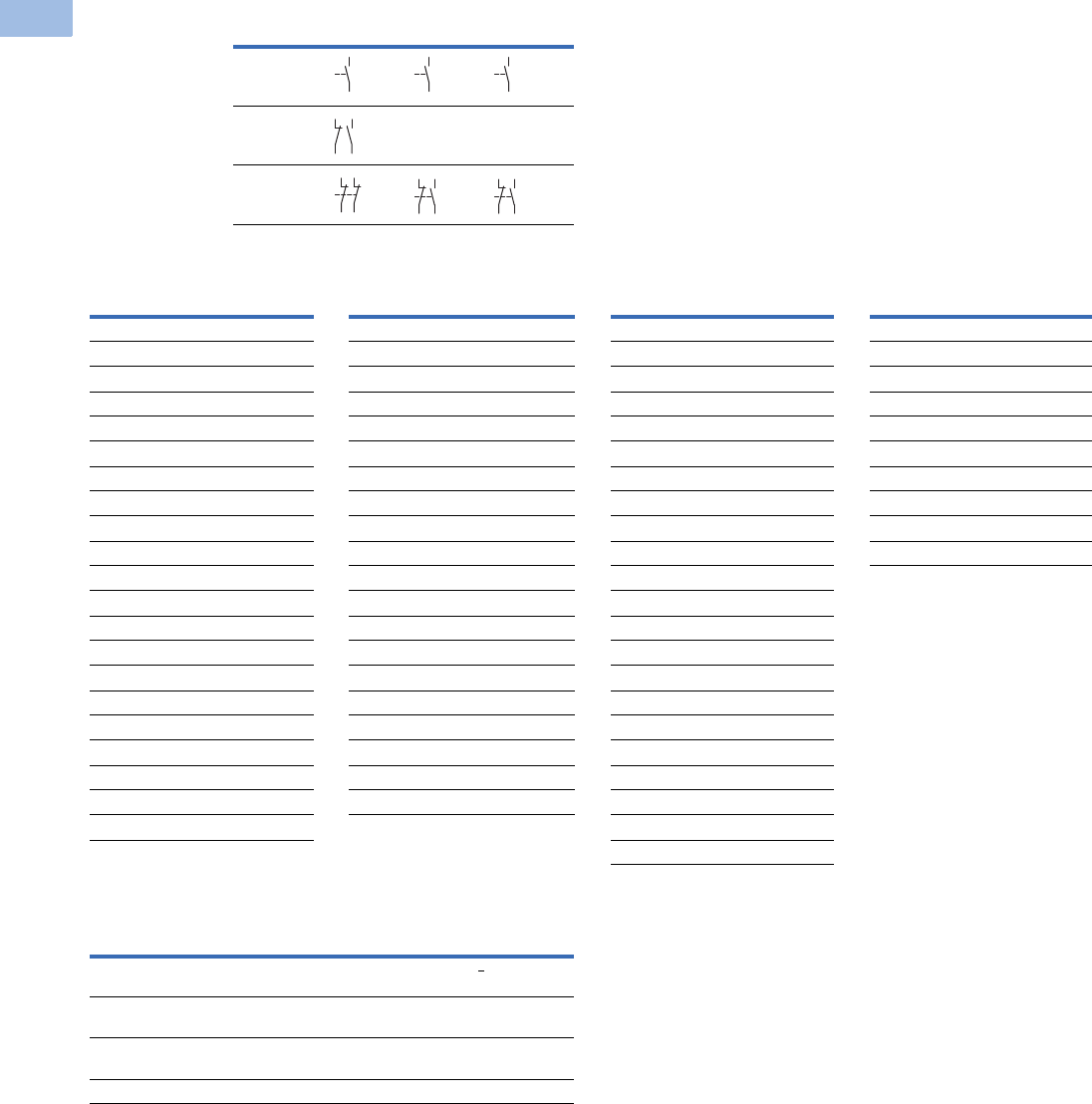
V5-T1-62 Volume 5—Motor Control and Protection CA08100006E—February 2014 www.eaton.com
1
1
1
1
1
1
1
1
1
1
1
1
1
1
1
1
1
1
1
1
1
1
1
1
1
1
1
1
1
1
1.1
IEC Contactors and Starters
XT
IEC Power Control
Spare Auxiliary Contacts
Magnet Coil Suffix
Overload Relay Settings (A)
Note
1Frames L–M only.
AC-3 K1M K3M K5M
12–55
90–260 — —
315–1700
Coil Voltage Suffix Code Coil Voltage Suffix Code Coil Voltage Suffix Code Coil Voltage Suffix Code
Frames A–B Frames C–F Frame G Frames L–N
110V 50 Hz, 120V 60 Hz A110V 50 Hz, 120V 60 Hz A100–120V 50/60 Hz A110–250 Vdc 40–60 Hz A
220V 50 Hz, 240V 60 Hz B220V 50 Hz, 240V 60 Hz B190–240V 50/60 Hz B250–500V 40–60 Hz C
230V 50 Hz F230V 50 Hz F24V 50/60 Hz T48–110 Vdc 40–60 Hz Y
24V 50/60 Hz T24V 50/60 Hz T24–27 Vdc TD 24–48 Vdc TD 1
24 Vdc TD 24–27 Vdc TD 480–500V 50/60 Hz CFrames L–M, S-Series
415V 50 Hz, 480V 60 Hz C415V 50 Hz, 480V 60 Hz C380–440V 50/60 Hz L110–120V 50/60 Hz A
600V 60 Hz D600V 60 Hz D42–48V 50/60 Hz W220–240V 50/60 Hz B
208V 60 Hz E208V 60 Hz E110–130 Vdc AD Frames P–R
190V 50 Hz, 220V 60 Hz G 190V 50 Hz, 220V 60 Hz G200–240 Vdc BD 230–250 Vdc 50–60 Hz B
240V 50 Hz, 277V 60 Hz H240V 50 Hz, 277V 60 Hz H48–60 Vdc WD
380V 50 Hz, 440V 60 Hz L380V 50 Hz, 440V 60 Hz LFrame H
400V 50 Hz N 400V 50 Hz N100–120V 50/60 Hz A
380V 60 Hz P380V 60 Hz P190–240V 50/60 Hz B
12V 50/60 Hz R 12V 50/60 Hz R480–500V 50/60 Hz C
42V 50 Hz, 48V 60 Hz W42V 50 Hz, 48V 60 Hz W380–440V 50/60 Hz L
48V 50 Hz Y48V 50 Hz Y24V 50/60Hz T
120 Vdc AD 110–130 Vdc AD 42–48V 50/60Hz W
220 Vdc BD 200–240 Vdc BD 110–130 Vdc AD
12 Vdc RD 48–60 Vdc WD 200–240 Vdc BD
48 Vdc WD 24–27 Vdc TD
48–60 Vdc WD
Setting Starting
A: IN x 0.58
Motor protection in the star (wye) and delta configurations
<
15 sec
B: IN x 1
Only partial motor protection in star position
15–40 sec
C: IN x 0.58
Motor not protected in star (wye) position
>40 sec
Timing relay set to approximately 10 sec
64
63
64
63
64
63
21
22
33
34
21
22
31
32
31
32
43
44
31
32
43
44
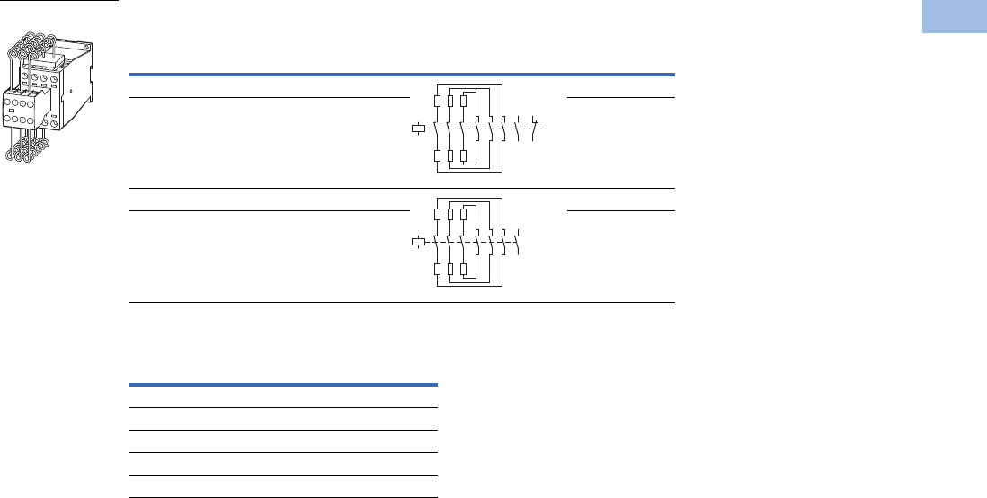
Volume 5—Motor Control and Protection CA08100006E—February 2014 www.eaton.com V5-T1-63
1
1
1
1
1
1
1
1
1
1
1
1
1
1
1
1
1
1
1
1
1
1
1
1
1
1
1
1
1
1
1.1
IEC Contactors and Starters
XT
IEC Power Control
XTCC Contactors for Three-Phase Capacitors
Magnet Coil Suffix
Notes
Weld-resistant for capacitors with inrush current peaks up to 180 x IN.
1 With series resistors, without quick-discharge resistor.
2 Underscore (_) indicates magnet coil suffix required.
Three-Phase Capacitors, 50–60 Hz
Open kVAR Ratings 1
Contact Sequence Catalog Number 2
230V 400V 525V 690V
11 20 25 33.3 XTCC020C11_
15 25 33.3 40 XTCC025C11_
20 33.3 40 55 XTCC033D10_
25 50 65 85 XTCC050D10_
Coil Voltage Suffix Code
110V 50 Hz, 120V 60 Hz A
220V 50 Hz, 240V 60 Hz B
230V 50 Hz, 240V 60 Hz F
400V 50 Hz, 440V 60 Hz N
24V 50/60 Hz T
XTCC0_
A1
A2
1
2
3
4
5
6
21
22
13
14
A1
A2
1
2
3
4
5
6
13
14

V5-T1-64 Volume 5—Motor Control and Protection CA08100006E—February 2014 www.eaton.com
1
1
1
1
1
1
1
1
1
1
1
1
1
1
1
1
1
1
1
1
1
1
1
1
1
1
1
1
1
1
1.1
IEC Contactors and Starters
XT
IEC Power Control
Engineering Notes for XTCC and XTCE Contactors for Power Factor Correction
Individual Compensation, Open Version Group Compensation, with Reactor, Open Version
Group Compensation, without Reactor, Open Version
Catalog
Number
Switching Duty in kVAR
230V 400V, 420V, 440V 525V 690V
XTCE007B 1.5 3 3.5 5
XTCE009B 24 4.56
XTCE012B 2.5 4.5 5.5 7
XTCE015B 2.5 4.5 5.5 7
XTCE018C 6.5 12 14.5 19
XTCE025C 713.5 1621
XTCE032C 7.5 14.5 17 22.5
XTCE040D 11 20.5 24.5 32
XTCE050D 11.5 22 26 34.5
XTCE065D 12.5 23.5 28 37
XTCE080F 16 30.5 36.5 48
XTCE095F 18 34 41 54
XTCE115G 24 46 54.5 72
XTCE150G 28 53 63.5 83.5
XTCE580N 175 300 400 300
Catalog
Number
Switching Duty in kVAR
230V 400V, 420V, 440V 525V 690V
XTCE007B 47 7.512
XTCE009B 5 8 10 14
XTCE012B 5.5 1 12 16
XTCE015B 5.5 10 12 16
XTCE018C 7.5 16 20 28
XTCE025C 918 2330
XTCE032C 10 20 24 32
XTCE040D 13 25 30 40
XTCE050D 16 30 36 48
XTCE065D 19 36 43 57
XTCE080F 30 58 68 90
XTCE095 34 6 7 10
XTCE115G 44 8 100 125
XTCE150 5 97 115 152
XTCE250L 110 190 260 340
XTCE400M 160 280 370 480
XTCE500M 220 390 500 680
Catalog
Number
Switching Duty in kVAR
230V 400V, 420V, 440V 525V 690V
XTCC020C 11 20 25 33.3
XTCC025C 15 25 33.3 40
XTCC033D 20 33.3 40 55
XTCC050D 25 50 65 85
XTCE580N 145 250 333 250
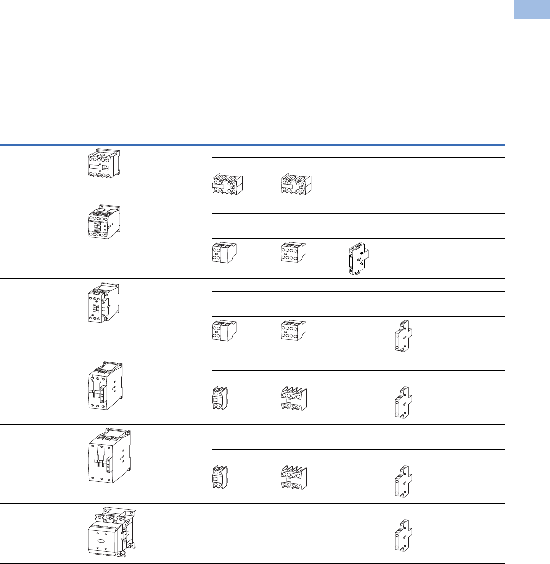
Volume 5—Motor Control and Protection CA08100006E—February 2014 www.eaton.com V5-T1-65
1
1
1
1
1
1
1
1
1
1
1
1
1
1
1
1
1
1
1
1
1
1
1
1
1
1
1
1
1
1
1.1
IEC Contactors and Starters
XT
IEC Power Control
Accessories
Auxiliary Contacts
Front-mounted snap-on
auxiliary contacts for XT
contactors are available
with screw or spring cage
terminals in a variety of
contact configurations.
Auxiliary Contacts Possible Combinations
Notes
Forced operation contact to IEC/EN 60947-5-1 Appendix L (positively driven), inside the auxiliary contact unit
(not early close and late opening).
Auxiliary normally closed contact can be used as mirror contact to IEC/EN 60947-4-1 Appendix F (not late opening).
No auxiliary contacts can be fitted between two contactors.
Frame
Size
Catalog
Number Contactor
Built-In
Auxiliary
Front (Top) Mount Side-Mount Total Auxiliary
Contacts AvailableTwo-Pole Four-Pole Single-Pole Two-Pole
AXTMC6A_ –
XTMC9A_
1NO or 1NC 1 — — — 3
—1 ——5
—— —
BXTCE007B_ –
XTCE015B_
1NO or 1NC 1 — — — 3
—1 ——5
——1—2
——
CXTCE018C_ –
XTCE032C_
1NO or 1NC 1 — — — 3
—1 ——5
———13
——
DXTCE040D00_ –
XTCE065D00_
—1 — — 2 6
—1 —16
——
F–G XTCE080F00_ –
XTCE150G00_
—1 — — 2 6
—1 —28
———48
——
L–R XTCE185H22_ –
XTCEC20R22_
2NO–2NC — — 2 8
—— —
V5-T1-66 Volume 5—Motor Control and Protection CA08100006E—February 2014 www.eaton.com
1
1
1
1
1
1
1
1
1
1
1
1
1
1
1
1
1
1
1
1
1
1
1
1
1
1
1
1
1
1
1.1
IEC Contactors and Starters
XT
IEC Power Control
Auxiliary Contact Combinations
XTMC6A_–XTMC9A_
XTMCXF...A_
Two-Pole or Four-Pole
XTCE018C_–XTCE032C_
XTCEXSCC11
or +
XTCE007B_– XTCE032C_
XTCEXF...C_
Two-Pole or Four-Pole
XTCE040D_– XTCE065D_
XTCEXF...G_
Two-Pole
XTCEXSBN11
or +
XTCEXSBN11
+
XTCEXSBN11
+
XTCEXSBN11
+
XTCE040D_– XTCE065D_
XTCEXF...G_
Four-Pole
XTCE080F_–XTCE150G_
XTCEXF...G_
Two-Pole or Four-Pole XTCE080F_–XTCE150G_
XTCEXSBN11
XTCEXSBN11
XTCEXSCN11
or +
XTCEXSCN11
+
+
XTCEXSBN11
XTCEXSBN11
+
++
XTCE185H_–XTCEC20R_
XTCEXSBR11 (Built-In)
XTCEXSBR11 (Built-In)
XTCEXSCR11
+
XTCEXSCR11
+
++
Frames L–R
Frames F–G
Frame D
Frame C
Frame A
XTCE007B_–XTCE015B_
XTCEXSAB_
or+
XTCE007B_–XTCE015B_
XTCEXF...C_
Two-Pole or Four-Pole
Frame B
Not for use with mechanical interlock.
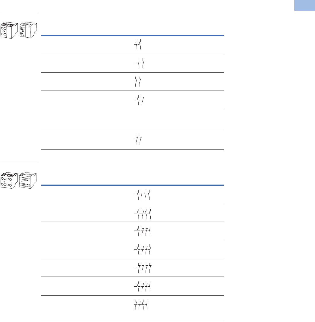
Volume 5—Motor Control and Protection CA08100006E—February 2014 www.eaton.com V5-T1-67
1
1
1
1
1
1
1
1
1
1
1
1
1
1
1
1
1
1
1
1
1
1
1
1
1
1
1
1
1
1
1.1
IEC Contactors and Starters
XT
IEC Power Control
Auxiliary Contacts
Frames B–C, Front (Top) Mount—Two-Pole
Frames B–C, Front (Top) Mount—Four-Pole
Notes
1 Orders must be placed in multiples of package quantity listed.
2 1 early-make contact (1NOE), 1 late-break contact (1NCL).
3 To avoid duplicate terminal numbers in contact sequence, these auxiliary contacts should only be used with contactors
having a built-in 1NO contact (XTCE…B10_, XTCE…C10_).
4 Catalog number is shown with screw type terminal. For spring cage, add a “C” before the last 2 digits. For example,
to order a spring cage version of the XTCEXFAC22, change the catalog number to XTCEXFACC22.
Conventional Thermal Current,
Open at 60°C
Ith = Ie, AC-1 in Amps
Contact
Configuration
Circuit
Symbol
Pkg.
Qty. 1
Screw Terminal
Catalog Number
16 2NO 5 XTCEXFAC20
16 1NO-1NC 5 XTCEXFAC11 4
16 2NC 5 XTCEXFAC02
16 1NOE-1NCL5XTCEXFALC11 2
16 1NO-1NC 5 XTCEXFDC11 3
16 2NC 5 XTCEXFCC02 3
Conventional Thermal Current,
Open at 60°C
Ith = Ie, AC-1 in Amps
Contact
Configuration
Circuit
Symbol
Pkg.
Qty. 1
Screw Terminal
Catalog Number
16 4NO 5 XTCEXFAC40 4
16 3NO-1NC 5 XTCEXFAC31 4
16 2NO-2NC 5 XTCEXFAC22 4
16 1NO-3NC 5 XTCEXFAC13
16 4NC 5 XTCEXFAC04
16 1NOE-1NCL5XTCEXFCLC22 2
16 2NO-2NC 5 XTCEXFCC22 3
XTCEXF_
54
63
64
53
54
53 61
62
51
52
61
62
58
57 6
5
66
21
22
31
32
XTCEXF_
54
63 73
64 74
53 83
8
4
54
53 61
62
73
74
83
84
54
53 61
62
71
72
83
84
53 61 71 81
82
72
62
54
51
52
61
62
71
72 82
81
58
5765
66
71
72
83
84
21
22
31
32
43
44
53
54
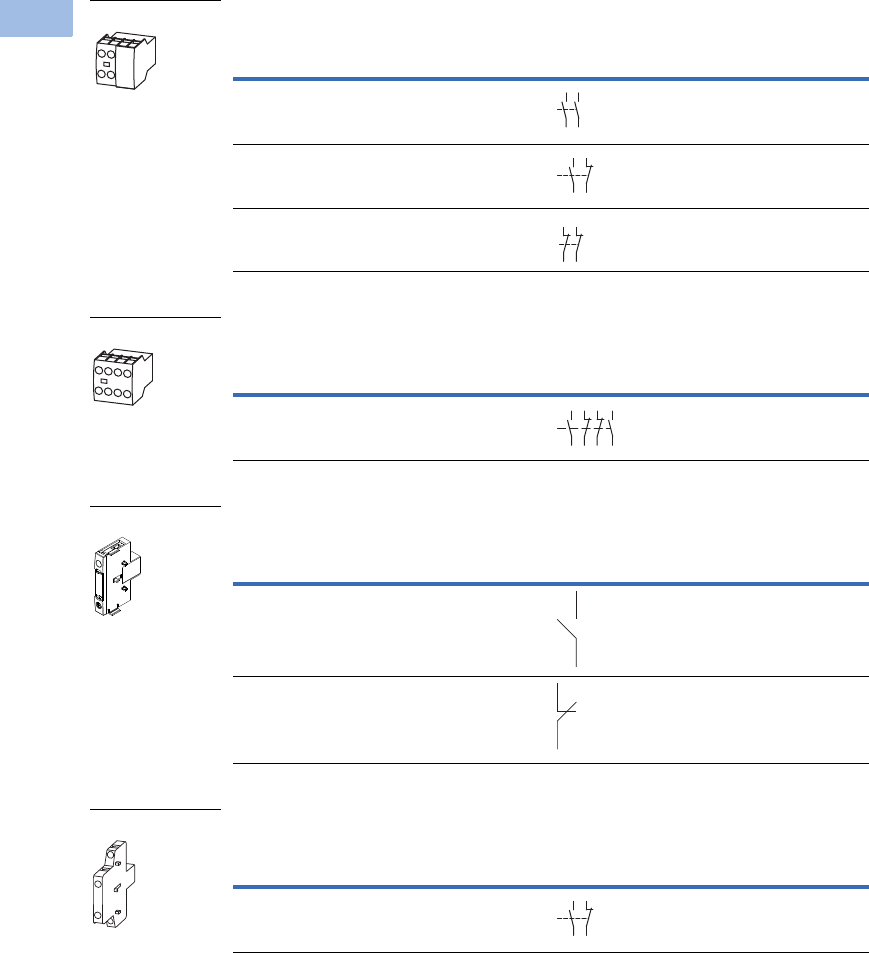
V5-T1-68 Volume 5—Motor Control and Protection CA08100006E—February 2014 www.eaton.com
1
1
1
1
1
1
1
1
1
1
1
1
1
1
1
1
1
1
1
1
1
1
1
1
1
1
1
1
1
1
1.1
IEC Contactors and Starters
XT
IEC Power Control
Frames B–C, Front (Top) Mount—Tall Version Two-Pole 1
Frames B–C, Front (Top) Mount—Tall Version Four-Pole 1
Frame B, Side-Mount—Single-Pole
Frame C, Side-Mount—Two-Pole
Notes
Interlocked opposing contacts, to IEC/EN 60947-5-1 Annex L (positively driven), within the auxiliary contact modules
(not NO [early make] and NC [late break] contacts) and for the built-in auxiliary contacts of the XTCE007B_–XTCE032C_.
Auxiliary break contact can be used as mirror contact to IEC/EN 60947-4-1 Annex F (not NC [late break] contact).
No auxiliary contacts can be fitted between two contactors.
1 Front (top) mount tall version is for use with Frame B electrical wire bridges and link kits (see Page V5-T1-74) and
toolless plug combination connection kits: XTCEXRLB, XTCEXSDLB, XTPAXTPCB, XTPAXTPCRB, XTPAX.
2 Orders must be placed in multiples of package quantity listed.
3 Can be mounted to the left side of contactor only. Cannot be used in combination with front (top) mount auxiliary
contacts or mechanical interlocks.
Conventional Thermal Current,
Open at 60°C
Ith = Ie, AC-1 in Amps
Contact
Configuration
Circuit
Symbol
Pkg.
Qty. 2
Screw Terminal
Catalog Number
16 2NO 5 XTCEXFATC20
16 1NO-1NC 5 XTCEXFATC11
16 2NC 5 XTCEXFATC02
Conventional Thermal Current,
Open at 60°C
Ith = Ie, AC-1 in Amps
Contact
Configuration
Circuit
Symbol
Pkg.
Qty. 2
Screw Terminal
Catalog Number
16 2NO-2NC 5 XTCEXFATC22
Conventional Thermal Current,
Open at 60°C
Ith = Ie, AC-1 in Amps
Contact
Configuration
Circuit
Symbol
Pkg.
Qty. 2
Screw Terminal
Catalog Number
16 1NO 1 XTCEXSAB10 3
16 1NC 1 XTCEXSAB01 3
Conventional Thermal Current,
Open at 60°C
Ith = Ie, AC-1 in Amps
Contact
Configuration
Circuit
Symbol
Pkg.
Qty. 2
Screw Terminal
Catalog Number
10 1NO-1NC 1 XTCEXSCC11 3
XTCEXFATC_
54
63
64
53
54
53 61
62
51
52
61
62
XTCEXFATC22
54
53 61
62
71
72
83
8
4
XTCEXSAB_
53
54
51
52
XTCEXSCC11
54
53 61
62
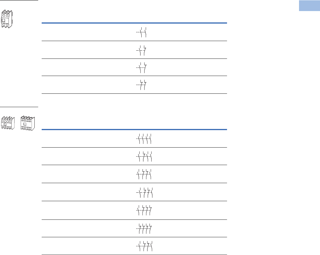
Volume 5—Motor Control and Protection CA08100006E—February 2014 www.eaton.com V5-T1-69
1
1
1
1
1
1
1
1
1
1
1
1
1
1
1
1
1
1
1
1
1
1
1
1
1
1
1
1
1
1
1.1
IEC Contactors and Starters
XT
IEC Power Control
Frames D–G—Two-Pole
Frames D–G—Four-Pole
Notes
Interlocked opposing contacts, to IEC/EN 60947-5-1 Annex L (positively driven), within the auxiliary contact modules
(not NO (early make) and NC (late break) contacts) and for the built-in auxiliary contacts of the XTCE007B_–XTCE032C_.
Auxiliary break contact can be used as mirror contact to IEC/EN 60947-4-1 Annex F (not NC (late break) contact).
No auxiliary contacts can be fitted between two contactors.
1 Orders must be placed in multiples of package quantity listed.
2 A “_” denotes catalog numbers are incomplete. To complete the catalog number for ordering a spring cage terminal,
insert a C in the “_” position or remove “_” for screw type terminal.
3 One early-make contact (1NOE), one late-break contact (1NCL).
Conventional Thermal Current,
Open at 60°C
Ith = Ie, AC-1 in Amps
Contact
Configuration
Circuit
Symbol
Pkg.
Qty. 1
Screw Terminal
Catalog Number
16 2NO 5 XTCEXFBG20
16 1NO-1NC 5 XTCEXFAG11
16 1NO-1NC 5 XTCEXFBG11
16 2NC 5 XTCEXFBG02
Conventional Thermal Current,
Open at 60°C
Ith = Ie, AC-1 in Amps
Contact
Configuration
Circuit
Symbol
Pkg.
Qty. 1
Screw Terminal
Catalog Number
16 4NO-0NC 5 XTCEXFBG40
16 3NO-1NC 5 XTCEXFBG31
16 2NO-2NC 5 XTCEXFBG22
16 2NO-2NC 5 XTCEXFAG_22 2
16 1NO-3NC 5 XTCEXFBG13
16 0NO-4NC 5 XTCEXFBG04
16 1NOE-1NCL5XTCEXFBLG22 3
XTCEXF_
14 24
13 23
54
53 61
62
14
13 21
22
12
11 21
22
XTCEXF_
14
13 23
24
33
34
43
44
14
13 21
22
33
34
43
44
14
13 21
22
31
32
43
4
4
54
53 61
62
71
72
8
3
84
14
13 21
22
31
32
41
42
12
11 21
22
31
32
41
42
14
13 21
22
35
36
47
48
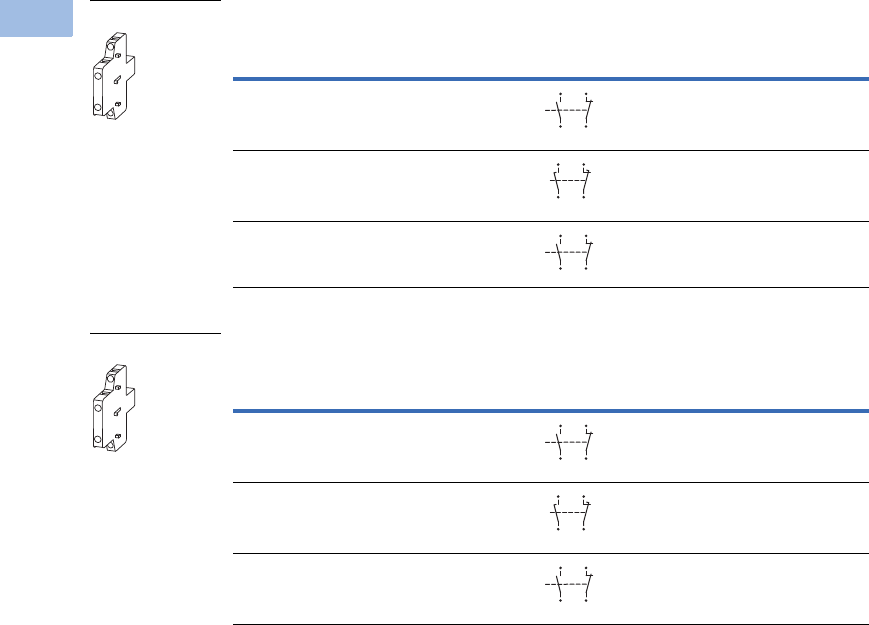
V5-T1-70 Volume 5—Motor Control and Protection CA08100006E—February 2014 www.eaton.com
1
1
1
1
1
1
1
1
1
1
1
1
1
1
1
1
1
1
1
1
1
1
1
1
1
1
1
1
1
1
1.1
IEC Contactors and Starters
XT
IEC Power Control
Frames D–H, Side Mount (Snap-On)—Two-Pole
Frames L–R, Side Mount (Screw Mount)—Two-Pole
Notes
1 Orders must be placed in multiples of package quantity listed.
2 1 early-make contact (1NOE), 1 late-break contact (1NCL).
3 To avoid duplicate terminal numbers in contact sequence, the XTCEXSCN11 should be used with Frame D
when a top mount auxiliary is also installed.
4 For replacement only. XTCEXSBR11 and XTCEXSBLR11 cannot be added onto side mount auxiliaries that come with
the Frames L–R contactors as standard. To add auxiliaries onto the included side auxiliaries on Frames L–R
contactors, use XTCEXSCR11.
Conventional Free Air
Thermal Current,
Ith = Ie, AC-1 in Amps
Contact
Configuration
Circuit
Symbol
Pkg.
Qty. 1
Screw Terminal
Catalog Number
10 1NO–1NC 1 XTCEXSBN11
10 1NOE–1NCL1XTCEXSBLN11 2
10 1NO–1NC 1 XTCEXSCN11 3
Conventional Free Air
Thermal Current,
Ith = Ie, AC-1 in Amps
Contact
Configuration
Circuit
Symbol
Pkg.
Qty. 1
Screw Terminal
Catalog Number
10 1NO–1NC 1 XTCEXSBR11 4
10 1NOE–1NCL1XTCEXSBLR11
10 1NO–1NC 1 XTCEXSCR11
XTCEXS_
13
44
14
43
21
32
31
22
17
48
18
47
25
36
26
35
53
84
54
83
61
72
71
62
XTCEXS_
13
44
14
43
21
32
31
22
17
48
18
47
25
36
26
35
53
84
54
83
61
72
71
62
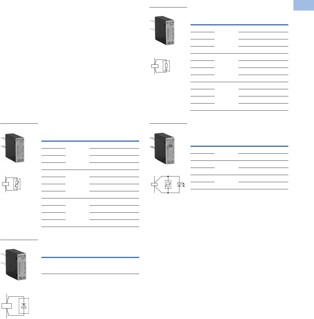
Volume 5—Motor Control and Protection CA08100006E—February 2014 www.eaton.com V5-T1-71
1
1
1
1
1
1
1
1
1
1
1
1
1
1
1
1
1
1
1
1
1
1
1
1
1
1
1
1
1
1
1.1
IEC Contactors and Starters
XT
IEC Power Control
Suppressors
The switching of contactor
coils can generate voltage
transients that may cause
arching on switch contacts
and/or damage electronics on
the control line. Either an RC
or varistor suppressor is
recommended in these types
of applications. All XT DC
contactor coils have built-in
suppression.
Varistor suppressors clamp
the voltage transient above
the maximum coil voltage and
are recommended when the
level of the transient is
known to not exceed the coil
voltage. RC suppressors slow
and reduce the level of the
voltage transient but do not
clamp them at a specific
level. The slowing of the
transient can reduce
electrical interference.
These are recommended in
applications where operating
rates are high.
Varistor Suppressor 12
Free-Wheel Diode Suppressor 4
Voltage
For Use
with…
Pkg.
Qty. 3Catalog Number
24–48 XTCE007B–
XTCE015B,
XTCF020B
10 XTCEXVSBW
48–130 10 XTCEXVSBA
130–240 10 XTCEXVSBB
240–500 10 XTCEXVSBC
24–48 XTCE018C–
XTCE032C
10 XTCEXVSCW
48–130 10 XTCEXVSCA
130–240 10 XTCEXVSCB
240–500 10 XTCEXVSCC
24–48 XTCE040D–
XTCE095F
10 XTCEXVSFW
48–130 10 XTCEXVSFA
130–240 10 XTCEXVSFB
240–500 10 XTCEXVSFC
Voltage
DC
For Use
with…
Pkg.
Qty. 3Catalog Number
12–250 XTCE007B–
XTCE015B,
XTCF020B
10 XTCEXDSB
XTCEXVS_
Contact Sequence
A2
A1
XTCEXDSB
Contact Sequence
A1
A2
RC Suppressor 12
Varistor Suppressor with
Integrated LED 12
Notes
1Note dropout delay.
2For AC operated contactors, 50–60 Hz. DC operated contactors and XTCE115G_
to XTCE170G_ have a built-in suppressor circuit.
3Orders must be placed in multiples of package quantity listed.
4In addition to the built-in suppressor circuit for DC actuated contactors. Prevents
negative breaking voltage when contactors are used in combination with a safety PLC.
Voltage
For Use
with…
Pkg.
Qty. 3Catalog Number
24–48 XTCE007B–
XTCE015B,
XTCF020B
10 XTCEXRSBW
48–130 10 XTCEXRSBA
110–240 10 XTCEXRSBB
240–500 10 XTCEXRSBC
24–48 XTCE018C–
XTCE032C
10 XTCEXRSCW
110–130 10 XTCEXRSCA
130–240 10 XTCEXRSCB
240–500 10 XTCEXRSCC
24–48
XTCE040D–
XTCE095F
10 XTCEXRSFW
110–130
10 XTCEXRSFA
130–240
10 XTCEXRSFB
240–500
10 XTCEXRSFC
Voltage
AC
For Use
with…
Pkg.
Qty. 3Catalog Number
24–48 XTCE007B–
XTCE015B
10 XTCEXVSLBW
130–240 10 XTCEXVSLBB
24–48 XTCE018C–
XTCE032C
10 XTCEXVSLCW
130–240 10 XTCEXVSLCB
24–48 XTCE040D–
XTCE095F
10 XTCEXVSLFW
130–240 10 XTCEXVSLFB
XTCEXRS_
Contact Sequence
A1
A2
XTCEXVSL_
Contact Sequence
A1
A2
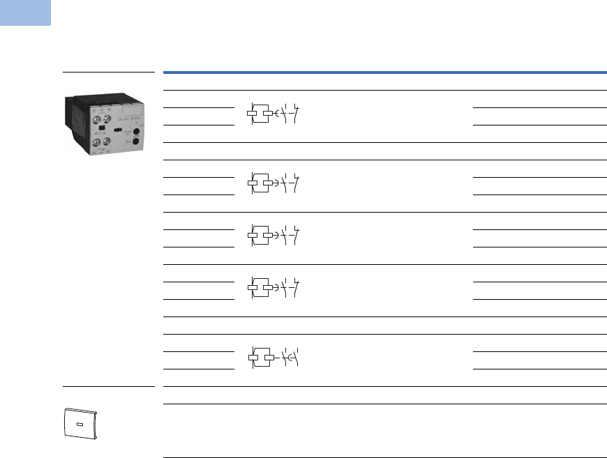
V5-T1-72 Volume 5—Motor Control and Protection CA08100006E—February 2014 www.eaton.com
1
1
1
1
1
1
1
1
1
1
1
1
1
1
1
1
1
1
1
1
1
1
1
1
1
1
1
1
1
1
1.1
IEC Contactors and Starters
XT
IEC Power Control
Electronic Timer Modules
Frames B–C Contactors (7–32A) 1
Notes
1 Front (top) mounted timer modules for use with XTCE…B and XTCE…C contactors.
Cannot be combined with top-mount auxiliary contacts, XTCEXF…C_.
2 Orders must be placed in multiples of package quantity listed.
Voltage
Contact
Sequence
Timing
Range
For Use
with…
Pkg.
Qty. 2Catalog Number
On-Delay
24 Vac/Vdc 0.05s–1s
0.5s–10s
5s–100s
XTCE…B_
XTCE…C_
1XTCEXTEEC11T
100–130 Vac 1 XTCEXTEEC11A
200–240 Vac 1 XTCEXTEEC11B
Off-Delay
24 Vac/Vdc 0.05s–1s XTCE…B_
XTCE…C_
1XTCEXTED1C11T
100–130 Vac 1 XTCEXTED1C11A
200–230 Vac 1 XTCEXTED1C11B
24 Vac/Vdc 0.5s–10s XTCE…B_
XTCE…C_
1XTCEXTED10C11T
100–130 Vac 1 XTCEXTED10C11A
200–240 Vac 1 XTCEXTED10C11B
24 Vac/Vdc 5s–100s XTCE…B_
XTCE…C_
1XTCEXTED100C11T
100–130 Vac 1 XTCEXTED100C11A
200–240 Vac 1 XTCEXTED100C11B
Star-Delta
24 Vac/Vdc 1s–30s XTCE…B_
XTCE…C_
1XTCEXTEYC20T
100–130 Vac 1 XTCEXTEYC20A
200–240 Vac 1 XTCEXTEYC20B
Sealable Shroud
— Transparent sealable shroud used to
protect electronic timer modules from
unwanted access
XTCEXTEE,
XTCEXTED,
XTCEXTEY
1XTCEXTESHRD
XTCEXTE_
XTCEXTESHRD
57
58
65
66
A1
A2
57
58
65
66
A1
A2
57
58
65
66
A1
A2
57
58
65
66
A1
A2
57
58
67
68
A1
A2
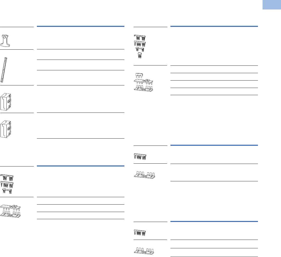
Volume 5—Motor Control and Protection CA08100006E—February 2014 www.eaton.com V5-T1-73
1
1
1
1
1
1
1
1
1
1
1
1
1
1
1
1
1
1
1
1
1
1
1
1
1
1
1
1
1
1
1.1
IEC Contactors and Starters
XT
IEC Power Control
Additional Accessories
Mechanical Interlock 1
Reversing Link Kits
Main current wiring for reversing combinations. Includes
paralleling bridge and reversing bridge. Does not include
mechanical interlock, see table on this page.
Star-Delta (Wye-Delta) Link Kits
Main current wiring for star-delta (wye-delta) combinations.
includes paralleling bridge, reversing bridge and star-delta
bridge. Does not include mechanical interlock, see table on
this page.
Paralleling Bridge
Component part of reversing link kit (XTCEXRL_). Parallels the
phases on the line-side of two contactors.
Reversing Bridge
Component part of reversing link kit (XTCEXRL_). Reverses the
phases on the load-side of two contactors.
Notes
1For two contactors with AC or DC operated magnet system which are horizontally or vertically mounted. For Frames B–G, mechanical lifespan is 2.5 x 10⁶ operations
and the distance between contactors is 0 mm. For Frames L–N, mechanical lifespan is 5 x 10⁶ operations and no auxiliary contact can be mounted between the
mechanical interlock and the contactor—the distance between contactors is 15 mm.
2Orders must be placed in multiples of package quantity listed.
3XTCEXMLG and XTCEXMLN consist of an interlock element and mounting plate.
4Also includes interlocking bridge (XTCEXLBB). The following control cables are integrated
for electrical interlock: K1M: A1–K2M: 21; K1M: 21–K2M: A1; K1M: A2–K2M: A2.
For Use
with…
Pkg.
Qty. 2Catalog Number
XTCE007B–XTCE015B,
XTCF020B
5XTCEXMLB
XTCE018C–XTCE032C,
XTCF032C–XTCF045C
1XTCEXMLC
XTCE040D–XTCE072D,
XTCF063D–XTCF080D
1XTCEXMLD
XTCE080F–XTCE170G,
XTCF125G–XTCF200G
1XTCEXMLG 3
XTCE185H–XTCE570M 1 XTCEXMLM
XTCE580N–XTCEC10N 1 XTCEXMLN 3
For Use
with…
Pkg.
Qty. 2Catalog Number
XTCE007B–XTCE015B 1 XTCEXRLB 4
XTCE018C–XTCE032C 1 XTCEXRLC
XTCE040D–XTCE065D 1 XTCEXRLD
XTCE080F–XTCE150G 1 XTCEXRLG
XTCEXMLB
XTCEXML_
XTCEXMLM
XTCEXMLN
XTCEXRLB
XTCEXRL_
For Use
with…
Pkg.
Qty. 2Catalog Number
XTCE007B–XTCE015B 1 XTCEXSDLB 3
XTCE018C–XTCE032C 1 XTCEXSDLC
XTCE040D–XTCE065D 1 XTCEXSDLD
XTCE080F–XTCE095F 1 XTCEXSDLF
XTCE115G–XTCE150G 1 XTCEXSDLG
For Use
with…
Pkg.
Qty. 2Catalog Number
XTCE007B–XTCE015B 20 XTCEXPBB
XTCE018C–XTCE032C 20 XTCEXPBC
For Use
with…
Pkg.
Qty. 2Catalog Number
XTCE007B–XTCE015B 20 XTCEXRBB
XTCE018C–XTCE032C 20 XTCEXRBC
XTCE040D–XTCE065D 10 XTCEXRBD
XTCEXSDLB
XTCEXSDL_
XTCEXPBB
XTCEXPBC
XTCEXRBB
XTCEXRB_
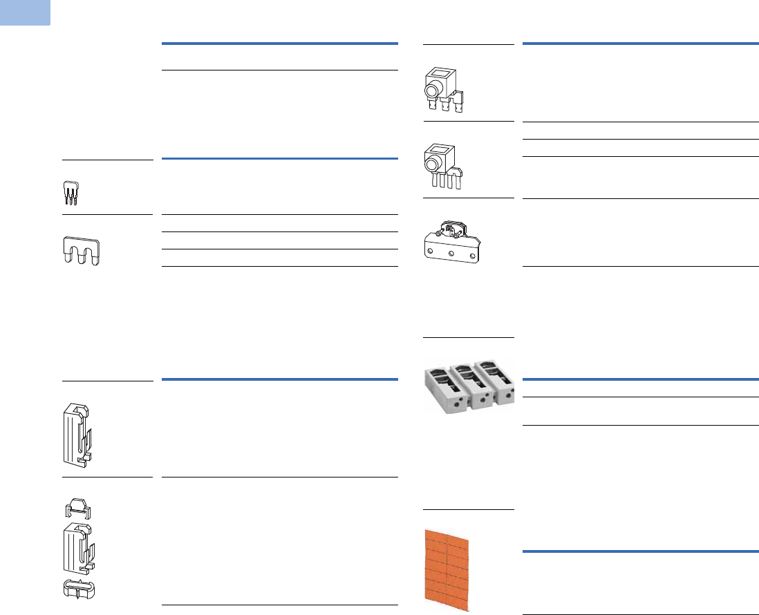
V5-T1-74 Volume 5—Motor Control and Protection CA08100006E—February 2014 www.eaton.com
1
1
1
1
1
1
1
1
1
1
1
1
1
1
1
1
1
1
1
1
1
1
1
1
1
1
1
1
1
1
1.1
IEC Contactors and Starters
XT
IEC Power Control
Electrical Interlocking Bridge
Star-Delta (Wye-Delta) Bridge
Component part of star-delta link kit (XTCEXSDL_). Commons
the three phases on the line side of shorting contactor.
Connector
Parallel Link 456
For using one contactor per phase. Each package comes with
two links for line: load.
Terminal Lug Assembly
For connection of: round conductor, flexible and stranded,
flat strip conductor, with control circuit terminal. See Page
V5-T1-97 for terminal capacities.
Contactor Labels
Notes
1Orders must be placed in multiples of package quantity listed.
2Frame B is toolless connection type.
3For mechanically arranging contactors in combinations. Distance between contactors is 0 mm.
4Fourth pole can be broken off: four-pole: Ith = 60A; three-pole: Ith = 50A.
5AC-1 current carrying capacity of the contactor increases by a factor of 2.5. For XTCEXPLKL185, one shroud
is included for protection against accidental contact.
6Protected against accidental contact in accordance with IEC 536.
7Quantity 1 equals one sheet. One sheet contains 240 labels.
For Use
with…
Pkg.
Qty. 1Catalog Number
XTCE007B–XTCE015B 20 XTCEXLBB
For Use
with…
Pkg.
Qty. 1Catalog Number
XTCE007B–XTCE015B 20 XTCEXSDBB 2
XTCE080F–XTCE170G 1 XTCEXSDBG
XTCE185L–XTCE400M 1 XTCEXSDB400
XTCE500M 1 XTCEXSDB500
For Use
with…
Pkg.
Qty. 1Catalog Number
XTCE007B–XTCE032C 50 XTCEXCNC
XTCE040D–XTCE170G 10 XTCEXCNG
XTCEXSDB
XTCEXSDB_
XTCEXCNC
XTCEXCNG
For Use
with…
Pkg.
Qty. 1Catalog Number
XTCE007B –XTCE015B 5 XTCEXPLKB
XTCE018C –XTCE032C 5 XTCEXPLKC
XTCE040D –XTCE072D 1 XTCEXPLKD
XTCE080F–XTCE170G 1 XTCEXPLKG
XTCE185L 1 XTCEXPLKL185
For Use
with…
Pkg.
Qty. 1Catalog Number
XTCE185–XTCE225H 1 XTCEXTLA225A
XTCS250L–XTCS400M,
XTCE250L_–XTCE400M_
2XTCEXTLA400
For Use
with…
Pkg.
Qty. Catalog Number
XTC… 25 XGKE-GE 7
XTCEXPLKB
XTCEXPLK_
XTCEXPLKL185
XTCEXTLA400
XGKE-GE
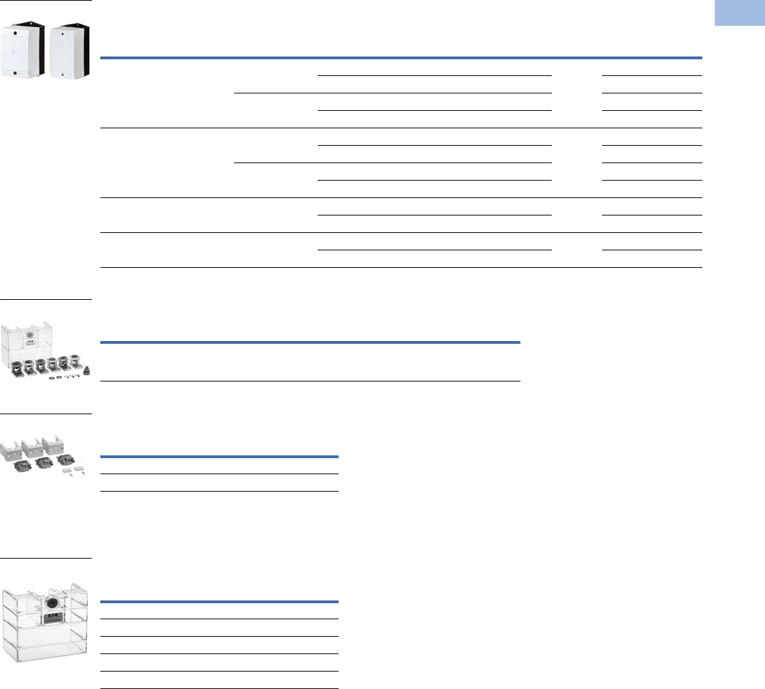
Volume 5—Motor Control and Protection CA08100006E—February 2014 www.eaton.com V5-T1-75
1
1
1
1
1
1
1
1
1
1
1
1
1
1
1
1
1
1
1
1
1
1
1
1
1
1
1
1
1
1
1.1
IEC Contactors and Starters
XT
IEC Power Control
CI-K Basic Enclosures 12
Terminal Lug Kit—Set of Three Lugs
Terminal Flat Bar 6
For connection of a flat strip conductor. Comes with control
circuit terminal (consisting of three flat strip conductor terminals).
Te r m i n a l S h r o u d
Protection against direct contact with connection lugs when
touched vertically from the front.
Notes
1Enclosure base RAL 9005, black/enclosure top only RAL 7035. light gray.
2Degree of protection—IEC: IP65; UL/CSA: Type 1, 3R, 4X, 12, 13—indoor and outdoor use.
3CI-K2X_: 4 x 1/2 inch knockouts.
4CI-K3X_, CI-K4X_, CI-K5X_: Smooth overall with sharp corners.
5Orders must be placed in multiples of package quantity listed.
6Not UL listed.
Dimensions in Inches (mm)
Pkg.
Qty. Width Height
External
Depth
Internal
Depth Internal Mounting Type Catalog Number
3.94 (100.0) 6.30 (160.0) 3.94 (100.0) 2.87 (73.0) With mounting rail 1 CI-K2X-100-TS-NA 3
3.11 (79.0) With mounting plate CI-K2X-100-M-NA 3
5.71 (145.0) 4.65 (118.0) With mounting rail CI-K2X-145-TS-NA 3
4.88 (124.0) With mounting plate CI-K2X-145-M-NA 3
4.72 (120.0) 7.87 (200.0) 4.92 (125.0) 3.66 (93.0) With mounting rail 1 CI-K3X-125-TS-NA 4
3.86 (98.0) With mounting plate CI-K3X-125-M-NA 4
6.30 (160.0) 5.04 (128.0) With mounting rail CI-K3X-160-TS-NA 4
5.24 (133.0) With mounting plate CI-K3X-160-M-NA 4
6.30 (160.0) 9.45 (240.0) 6.30 (160.0) 5.04 (128.0) With mounting rail 1 CI-K4X-160-TS-NA 4
5.24 (133.0) With mounting plate CI-K4X-160-M-NA 4
7.87 (200.0) 11.02 (280.0) 6.30 (160.0) 5.04 (128.0) With mounting rail 1 CI-K5X-160-TS-NA 4
5.24 (133.0) With mounting plate CI-K5X-160-M-NA 4
For Use
with… Description
Pkg.
Qty. 5Catalog Number
XTCE500M, XTCE570M #4-500 kcmil two-phase Cu/Al 500A 1 XTCEXTL500
For Use
with…
Pkg.
Qty. 5Catalog Number
XTCE500M–XTCE570M 1 XTCEXTFB650
XTCE750N–XTCE820N 1 XTCEXTFB820
For Use
with…
Pkg.
Qty. 5Catalog Number
XTCE185H–XTCE225H 1 XTCEXTS225
XTCE250L–XTCE400M 1 XTCEXTS400
XTCE500M–XTCE570M 1 XTCEXTS500
XTCE580N–XTCE650N 1 XTCEXTS650
XTCE750N–XTCEC10N 1 XTCEXTS820
CI-K Basic Enclosures
XTCEXCN_
XTCEXTFB6_
XTCEXTS_
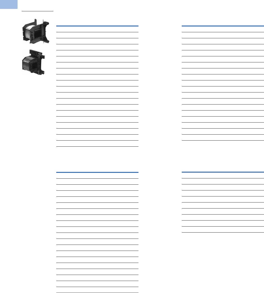
V5-T1-76 Volume 5—Motor Control and Protection CA08100006E—February 2014 www.eaton.com
1
1
1
1
1
1
1
1
1
1
1
1
1
1
1
1
1
1
1
1
1
1
1
1
1
1
1
1
1
1
1.1
IEC Contactors and Starters
XT
IEC Power Control
Renewal Parts
Replacement Coil—Frame C
Replacement Coil—Frame D
Replacement Coil—Frame F 1
Replacement Coil—Frame G 2
Notes
1Frame F replacement coils can only be used with contactors having the
following date codes:
DC coils, 2706 or later; AC coils, 4706 or later.
2Frame G replacement coils can only be used with contactors having date codes of 2706 or
later.
Voltage
Coil
Suffix Catalog Number
110/50 120/60 A XTCERENCOILCA
110–130 Vdc AD XTCERENCOILCAD
220/50 240/60 B XTCERENCOILCB
200–240 Vdc BD XTCERENCOILCBD
415/50 480/60 C XTCERENCOILCC
600/60 D XTCERENCOILCD
208/60 E XTCERENCOILCE
230/50 F XTCERENCOILCF
190/50 220/60 G XTCERENCOILCG
240/50 277/60 H XTCERENCOILCH
380/50 440/60 L XTCERENCOILCL
400/50 N XTCERENCOILCN
380/60 P XTCERENCOILCP
12/50 12/60 R XTCERENCOILCR
12–14 Vdc RD XTCERENCOILCRD
24/50 24/60 T XTCERENCOILCT
24–27 Vdc TD XTCERENCOILCTD
42/50 48/60 W XTCERENCOILCW
48–60 Vdc WD XTCERENCOILCWD
48/50 Y XTCERENCOILCY
Voltage
Coil
Suffix Catalog Number
110/50 120/60 A XTCERENCOILDA
110–130 Vdc AD XTCERENCOILDAD
220/50 240/60 B XTCERENCOILDB
200–240 Vdc BD XTCERENCOILDBD
415/50 480/60 C XTCERENCOILDC
600/60 D XTCERENCOILDD
208/60 E XTCERENCOILDE
230/50 F XTCERENCOILDF
190/50 220/60 G XTCERENCOILDG
240/50 277/60 H XTCERENCOILDH
380/50 440/60 L XTCERENCOILDL
400/50 N XTCERENCOILDN
380/60 P XTCERENCOILDP
12/50 12/60 R XTCERENCOILDR
12–14 Vdc RD XTCERENCOILDRD
24/50 24/60 T XTCERENCOILDT
24–27 Vdc TD XTCERENCOILDTD
42/50 48/60 W XTCERENCOILDW
48–60 Vdc WD XTCERENCOILDWD
48/50 Y XTCERENCOILDY
XTCERENC_
Voltage
Coil
Suffix Catalog Number
110/50 120/60 A XTCERENCOILFA
110–130 Vdc AD XTCERENCOILFAD
220/50 240/60 B XTCERENCOILFB
200–240 Vdc BD XTCERENCOILFBD
415/50 480/60 C XTCERENCOILFC
600/60 D XTCERENCOILFD
208/60 E XTCERENCOILFE
230/50 F XTCERENCOILFF
190/50 220/60 G XTCERENCOILFG
240/50 277/60 H XTCERENCOILFH
380/50 440/60 L XTCERENCOILFL
400/50 N XTCERENCOILFN
380/60 P XTCERENCOILFP
12/50 12/60 R XTCERENCOILFR
24/50 24/60 T XTCERENCOILFT
24–27 Vdc TD XTCERENCOILFTD
42/50 48/60 W XTCERENCOILFW
48–60 Vdc WD XTCERENCOILFWD
48/50 Y XTCERENCOILFY
Voltage
Coil
Suffix Catalog Number
100–120V 50/60 A XTCERENCOILGA
110–130 Vdc AD XTCERENCOILGAD
190–240V 50/60 B XTCERENCOILGB
200–240 Vdc BD XTCERENCOILGBD
480–500V 50/60 C XTCERENCOILGC
380–440V 50/60 L XTCERENCOILGL
4/50 24/60 T XTCERENCOILGT
24–27 Vdc TD XTCERENCOILGTD
42–48V 50/60 W XTCERENCOILGW
48–60 Vdc WD XTCERENCOILGWD

Volume 5—Motor Control and Protection CA08100006E—February 2014 www.eaton.com V5-T1-77
1
1
1
1
1
1
1
1
1
1
1
1
1
1
1
1
1
1
1
1
1
1
1
1
1
1
1
1
1
1
1.1
IEC Contactors and Starters
XT
IEC Power Control
Replacement Coil—Frame H
Replacement Coil—Frame L 1
Replacement Coil—Frame L, S-Series
Replacement Coil—Frame M 1
Replacement Coil—Frame M, S-Series
Replacement Coil—Frame N 1
Replacement Contact Kit
Replacement Vacuum Tube Assembly
Replacement Arc Chamber
Note
1Electronic modules including coils.
Voltage
Coil
Suffix Catalog Number
100–120V 50/60 Hz A XTCERENCOILHA
190–240V 50/60 Hz B XTCERENCOILHB
480–500V 50/60 Hz C XTCERENCOILHC
380–440V 50/60 Hz L XTCERENCOILHL
24V 50/60Hz T XTCERENCOILHT
42–48V 50/60Hz W XTCERENCOILHW
110–130 Vdc AD XTCERENCOILHAD
200–240 Vdc BD XTCERENCOILHBD
24–27 Vdc TD XTCERENCOILHTD
48–60 Vdc WD XTCERENCOILHWD
Voltage
Coil
Suffix Catalog Number
110–250 Vac/Vdc A XTCERENCOILLA
250–500V 40–60 C XTCERENCOILLC
24–48 Vdc TD XTCERENCOILLTD
48–110 Vac/Vdc Y XTCERENCOILLY
Voltage
Coil
Suffix Catalog Number
110–120V 50/60 Hz A XTCSRENCOILLA
220–240V 50/60 Hz B XTCSRENCOILLB
Voltage
Coil
Suffix Catalog Number
110–250 Vac/Vdc A XTCERENCOILMA
250–500V 40–60 C XTCERENCOILMC
24–48 Vdc TD XTCERENCOILMTD
48–110 Vac/Vdc Y XTCERENCOILMY
Voltage
Coil
Suffix Catalog Number
110–120V 50/60 Hz A XTCSRENCOILMA
220–240V 50/60 Hz B XTCSRENCOILMB
Voltage
Coil
Suffix Catalog Number
110–250 Vac/Vdc A XTCERENCOILNA
250–500V 40–60 C XTCERENCOILNC
48–110 Vac/Vdc Y XTCERENCOILNY
For Use with… Catalog Number
XTCE040D–XTCE065D XTCERENCONTACTD
XTCE085F–XTCE095F XTCERENCONTACTF
XTCE115G–XTCE150G XTCERENCONTACTG
XTCE185H–XTCE225H XTCERENCONTACTH
XTCE250L–XTCE300L XTCERENCONTACTL
XTCE300M XTCERENCONTACTM300
XTCE400M XTCERENCONTACTM400
XTCE500M XTCERENCONTACTM500
For Use with… Catalog Number
XTCE580N XTCERENVACT580
XTCE650N XTCERENVACT650
XTCE750N XTCERENVACT750
XTCE820N XTCERENVACT820
For Use with… Catalog Number
XTCE250L XTCERENARC250
XTCE300M XTCERENARC300
XTCE400M XTCERENARC400
XTCE500M–XTCE570M XTCERENARC500

V5-T1-78 Volume 5—Motor Control and Protection CA08100006E—February 2014 www.eaton.com
1
1
1
1
1
1
1
1
1
1
1
1
1
1
1
1
1
1
1
1
1
1
1
1
1
1
1
1
1
1
1.1
IEC Contactors and Starters
XT
IEC Power Control
Technical Data and Specifications
XT Contactors—Frame B
Notes
1Rated operational current: Making and breaking conditions to DC-13, L/R constant as stated.
2IEC 60947 Standard.
3Damp heat, constant, to IEC 60068-2-78; damp heat, cyclical, to IEC 60068-2-30.
Description XTCE007B XTCE009B XTCE012B XTCE015B
General
Standards IEC/EN 60947, VDE 0660,
UL, CSA, CCC, RoHS
IEC/EN 60947, VDE 0660,
UL, CSA, CCC, RoHS
IEC/EN 60947, VDE 0660,
UL, CSA, CCC, RoHS
IEC/EN 60947, VDE 0660,
UL, CSA, CCC, RoHS
Weights in kg [lb]
AC operated 0.23 [0.51] 0.23 [0.51] 0.23 [0.51] 0.23 [0.51]
DC operated 0.28 [0.62] 0.28 [0.62] 0.28 [0.62] 0.28 [0.62]
Mechanical life—operations 10,000,000 10,000,000 10,000,000 10,000,000
Mechanical operating frequency (ops/hr)
AC operated 9000 9000 9000 5000
DC operated 9000 9000 9000 5000
Electrical life See Curves,
Page V5-T1-111
See Curves,
Page V5-T1-111
See Curves,
Page V5-T1-111
See Curves,
Page V5-T1-111
Electrical operating frequency (ops/hr)—see Curves, Page V5-T1-111
AC-1; 400V Ie800 800 800 800
AC-3; 400V Ie1000 1000 1000 1000
AC-4; 400V Ie300 300 300 300
Climatic proofing 3333
Insulation voltage (Ui) Vac 690 690 690 690
Impulse withstand voltage (Uimp) Vac 8000 8000 8000 8000
Operational voltage (Ue) Vac 690 690 690 690
Safe isolation to VDE 0106 Part 101 and Part 101/A1
Between coil and contacts (Vac) 400 400 400 400
Between contacts (Vac) 400 400 400 400
Making capacity up to 690V (amps) 1112 112 144 155
Breaking capacity (amps)
220/230V 70 90 120 124
380/400V 70 90 120 124
500V 50 70 100 100
660/690V 40 50 70 70
Short-circuit protection rating maximum fuse
Type 2 coordination 2
400V; gG/gL 500V 20 20 20 20
690V; gG/gL 690V 16 16 20 20
Type 1 coordination 2
400V; gG/gL 500V 35 35 35 63
690V; gG/gL 690V 20 20 20 50
Degree of protection IP20 IP20 IP20 IP20
Protection against direct contact when actuated from front (IEC 536) Finger and
back-of-hand proof
Finger and
back-of-hand proof
Finger and
back-of-hand proof
Finger and
back-of-hand proof
Terminal capacity main cable—screw terminals
Solid (mm2) 1 x (0.75–4)
2 x (0.75–2.5)
1 x (0.75–4)
2 x (0.75–2.5)
1 x (0.75–4)
2 x (0.75–2.5)
1 x (0.75–4)
2 x (0.75–2.5)
Flexible with ferrule (mm2) 1 x (0.75–2.5)
1 x (0.75–2.5)
1 x (0.75–2.5)
1 x (0.75–2.5)
1 x (0.75–2.5)
1 x (0.75–2.5)
1 x (0.75–2.5)
1 x (0.75–2.5)
Solid or stranded (AWG) 18–14 18–14 18–14 18–14
Terminal capacity control circuit cable—screw terminals
Solid (mm2) 1 x (0.75–4)
2 x (0.75–2.5)
1 x (0.75–4)
2 x (0.75–2.5)
1 x (0.75–4)
2 x (0.75–2.5)
1 x (0.75–4)
2 x (0.75–2.5)
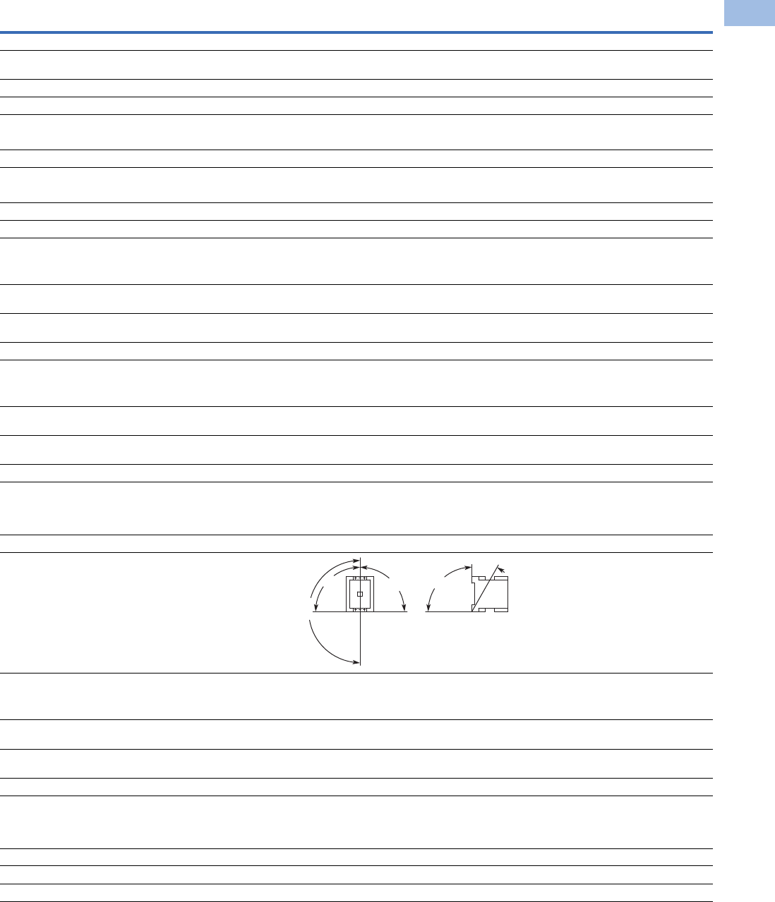
Volume 5—Motor Control and Protection CA08100006E—February 2014 www.eaton.com V5-T1-79
1
1
1
1
1
1
1
1
1
1
1
1
1
1
1
1
1
1
1
1
1
1
1
1
1
1
1
1
1
1
1.1
IEC Contactors and Starters
XT
IEC Power Control
XT Contactors—Frame B, continued
Description XTCE007B XTCE009B XTCE012B XTCE015B
General, continued
Flexible with ferrule (mm2) 1 x (0.75–2.5)
1 x (0.75–2.5)
1 x (0.75–2.5)
1 x (0.75–2.5)
1 x (0.75–2.5)
1 x (0.75–2.5)
1 x (0.75–2.5)
1 x (0.75–2.5)
Solid or stranded (AWG) 18–14 18–14 18–14 18–14
Main cable and control circuit cable connection screw/bolt M3.5 M3.5 M3.5 M3.5
Tightening torque
Nm 1.2 1.2 1.2 1.2
Lb-in 10.6 10.6 10.6 10.6
Tools
Main and control circuit cable—screw terminals Size 2 Size 2 Size 2 Size 2
Pozidriv screwdriver 0.8 x 5.5 0.8 x 5.5 0.8 x 5. 0.8 x 5.5
Standard screwdriver 1 x 6 1 x 6 1 x 6 1 x 6
Terminal capacity main circuit cable—spring cage terminals
Solid (mm2) 1 x (0.75–2.5)
1 x (0.75–2.5)
1 x (0.75–2.5)
1 x (0.75–2.5)
1 x (0.75–2.5)
1 x (0.75–2.5)
1 x (0.75–2.5)
1 x (0.75–2.5)
Flexible (mm2) 1 x (0.75–2.5)
1 x (0.75–2.5)
1 x (0.75–2.5)
1 x (0.75–2.5)
1 x (0.75–2.5)
1 x (0.75–2.5)
1 x (0.75–2.5)
1 x (0.75–2.5)
Flexible with ferrule (mm2) 1 x (0.75–2.5)
1 x (0.75–2.5)
1 x (0.75–2.5)
1 x (0.75–2.5)
1 x (0.75–2.5)
1 x (0.75–2.5)
1 x (0.75–2.5)
1 x (0.75–2.5)
Solid or stranded (AWG) 18–14 18–14 18–14 18–14
Terminal capacity control circuit cable—spring cage terminals
Solid (mm2) 1 x (0.75–2.5)
1 x (0.75–2.5)
1 x (0.75–2.5)
1 x (0.75–2.5)
1 x (0.75–2.5)
1 x (0.75–2.5)
1 x (0.75–2.5)
1 x (0.75–2.5)
Flexible (mm2) 1 x (0.75–2.5)
1 x (0.75–2.5)
1 x (0.75–2.5)
1 x (0.75–2.5)
1 x (0.75–2.5)
1 x (0.75–2.5)
1 x (0.75–2.5)
1 x (0.75–2.5)
Flexible with ferrule (mm2) 1 x (0.75–2.5)
1 x (0.75–2.5)
1 x (0.75–2.5)
1 x (0.75–2.5)
1 x (0.75–2.5)
1 x (0.75–2.5)
1 x (0.75–2.5)
1 x (0.75–2.5)
Solid or stranded (AWG) 18–14 18–14 18–14 18–14
Tools
Main and control circuit cable—spring cage terminals
Stripping length (mm) 10 10 10 10
Screwdriver blade width (mm) 3.5 3.5 3.5 3.5
Mounting position, AC and DC operated
Ambient temperature
Open –25 to 60°C
[–13 to 140°F]
–25 to 60°C
[–13 to 140°F]
–25 to 60°C
[–13 to 140°F]
–25 to 60°C
[–13 to 140°F]
Enclosed –25 to 40°C
[–13 to 104°F]
–25 to 40°C
[–13 to 104°F]
–25 to 40°C
[–13 to 104°F]
–25 to 40°C
[–13 to 104°F]
Ambient storage temperature –40 to 80°C
[–40 to 176°F]
–40 to 80°C
[–40 to 176°F]
–40 to 80°C
[–40 to 176°F]
–40 to 80°C
[–40 to 176°F]
Environmental
Mechanical shock resistance (IEC/EN 60068-2-27)
Half-sinusoidal shock 10 ms
Main contact—NO contact 10g 10g 10g 10g
Auxiliary contact—NO contact 7g 7g 7g 7g
Auxiliary contact—NC contact 5g 5g 5g 5g
Overvoltage category/pollution degree III/3 III/3 III/3 III/3
180°
90°
90°
90°
30°

V5-T1-80 Volume 5—Motor Control and Protection CA08100006E—February 2014 www.eaton.com
1
1
1
1
1
1
1
1
1
1
1
1
1
1
1
1
1
1
1
1
1
1
1
1
1
1
1
1
1
1
1.1
IEC Contactors and Starters
XT
IEC Power Control
XT Contactors—Frames C–D
Notes
1IEC 60947 Standard.
2Damp heat, constant, to IEC 60068-2-78; damp heat, cyclic, to IEC 60 068-2-30.
Description XTCE018C XTCE025C XTCE032C XTCE040D XTCE050D XTCE065D, XTCE072D
General
Standards IEC/EN 60947,
VDE 0660, UL, CSA,
CCC, RoHS
IEC/EN 60947,
VDE 0660, UL, CSA,
CCC, RoHS
IEC/EN 60947,
VDE 0660, UL, CSA,
CCC, RoHS
IEC/EN 60947,
VDE 0660, UL, CSA,
CCC, RoHS
IEC/EN 60947,
VDE 0660, UL, CSA,
CCC, RoHS
IEC/EN 60947,
VDE 0660, UL, CSA,
CCC, RoHS
Weights in kg [lb]
AC operated 0.42 [0.93] 0.42 [0.93] 0.42 [0.93] 0.9 [2.0] 0.9 [2.0] 0.9 [2.0]
DC operated 0.48 [1.06] 0.48 [1.06] 0.48 [1.06] 1.1 [2.4] 1.1 [2.4] 1.1 [2.4]
Mechanical life—operations 10,000,000 10,000,000 10,000,000 10,000,000 10,000,000 10,000,000
Mechanical operating frequency (ops/hr)
AC operated 5000 5000 5000 5000 5000 5000
DC operated 5000 5000 5000 5000 5000 5000
Electrical mechanical operating frequency (ops/hr)—
see Curves, Page V5-T1-111
AC-1; 400V Ie800 800 800 800 800 800
AC-3; 400V Ie800 800 800 800 800 800
AC-4; 400V Ie300 300 300 300 300 300
Climatic proofing 222222
Insulation voltage (Ui) Vac 690 690 690 690 690 690
Impulse withstand voltage (Uimp) Vac 8000 8000 8000 8000 8000 8000
Operating voltage (Ue) Vac 690 690 690 690 690 690
Safe isolation to VDE 0106 Part 101 and Part 101/A1
Between coil and contacts (Vac) 440 440 440 440 440 440
Between contacts (Vac) 238 440 440 440 440 440
Making capacity (amps) 238 350 384 560 700 910
Breaking capacity (amps)
220/230V 170 250 320 400 500 650
380/400V 170 250 320 400 500 650
500V 170 250 320 400 500 650
660/690V 120 150 180 250 320 370
Short-circuit protection rating maximum fuse (amps)
Type 2 coordination 1
400V; gG/gL 500V 25 35 63 63 80 125
690V; gG/gL 690V 25 35 35 50 63 80
Type 1 coordination 1
400V; gG/gL 500V 63 100 125 125 160 250
690V; gG/gL 690V 50 50 63 80 80 100
Degree of protection IP00 IP00 IP00 IP00 IP00 IP00
Protection against direct contact when
actuated from front (IEC 536)
Finger and
back-of-hand proof
Finger and
back-of-hand proof
Finger and
back-of-hand proof
Finger and
back-of-hand proof
Finger and
back-of-hand proof
Finger and
back-of-hand proof
Terminal capacity main cable—screw terminals
Solid (mm2) 1 x (0.75–16)
2 x (0.75–10)
1 x (0.75–16)
2 x (0.75–10)
1 x (0.75–16)
2 x (0.75–10)
1 x (0.75–16)
2 x (0.75–10)
1 x (0.75–16)
2 x (0.75–10)
1 x (0.75–16)
2 x (0.75–10)
Flexible with ferrule (mm2) 1 x (0.75–16)
2 x (0.75–10)
1 x (0.75–16)
2 x (0.75–10)
1 x (0.75–16)
2 x (0.75–10)
1 x (2.5–35)
2 x (2.5–25)
1 x (2.5–35)
2 x (2.5–25)
1 x (2.5–35)
2 x (2.5–25)
Stranded (mm2) 1 x 16 1 x 16 1 x 16 1 x (16–50)
2 x (16–35)
1 x (16–50)
2 x (16–35)
1 x (16–50)
2 x (16–35)
Solid or stranded (AWG) 18–6 18–6 18–6 12–2 12–2 12–2
Flat conductor
(number of segments x width x thickness) (mm)
———2 x (6 x 9 x 0.8)2 x (6 x 9 x 0.8)2 x (6 x 9 x 0.8)
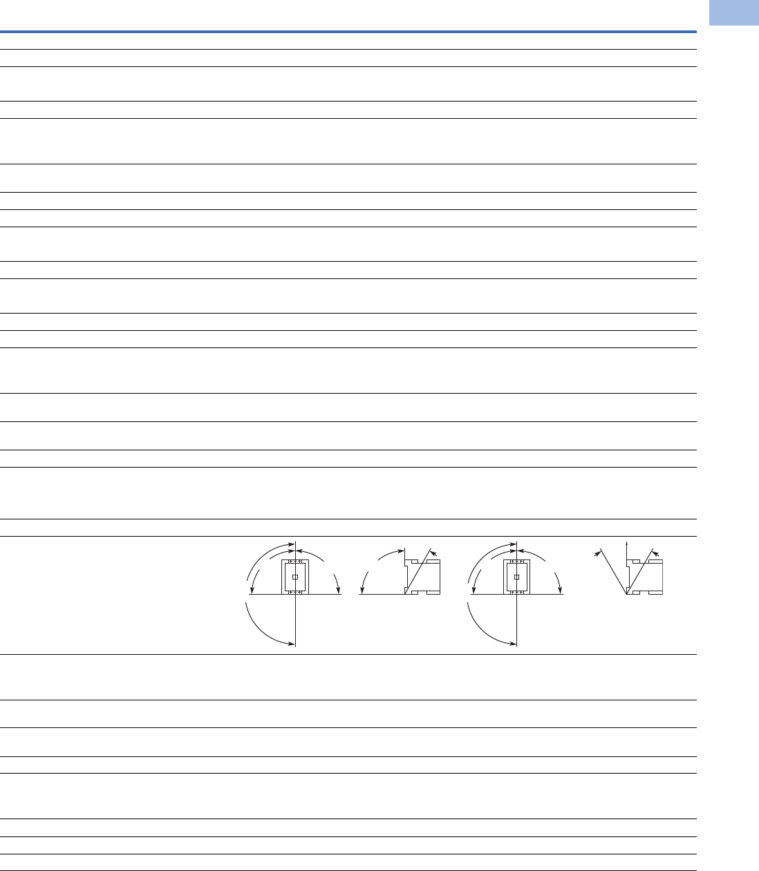
Volume 5—Motor Control and Protection CA08100006E—February 2014 www.eaton.com V5-T1-81
1
1
1
1
1
1
1
1
1
1
1
1
1
1
1
1
1
1
1
1
1
1
1
1
1
1
1
1
1
1
1.1
IEC Contactors and Starters
XT
IEC Power Control
XT Contactors—Frames C–D, continued
Description XTCE018C XTCE025C XTCE032C XTCE040D XTCE050D XTCE065D, XTCE072D
General, continued
Main cable connection screw/bolt M5 M5 M5 M6 M6 M6
Tightening torque
Nm 3333.33.33.3
Lb-in 26.6 26.6 26.6 29.2 29.2 29.2
Terminal capacity control circuit cable—screw terminals
Solid (mm2) 1 x (0.75–4)
2 x (0.75–4)
1 x (0.75–4)
2 x (0.75–4)
1 x (0.75–4)
2 x (0.75–4)
1 x (0.75–4)
2 x (0.75–4)
1 x (0.75–4)
2 x (0.75–4)
1 x (0.75–4)
2 x (0.75–4)
Flexible with ferrule (mm2) 1 x (0.75–2.5)
2 x (0.75–2.5)
1 x (0.75–2.5)
2 x (0.75–2.5)
1 x (0.75–2.5)
2 x (0.75–2.5)
1 x (0.75–2.5)
2 x (0.75–2.5)
1 x (0.75–2.5)
2 x (0.75–2.5)
1 x (0.75–2.5)
2 x (0.75–2.5)
Solid or stranded (AWG) 18–14 18–14 18–14 18–14 18–14 18–14
Control circuit cable connection screw/bolt M3.5 M3.5 M3.5 M3.5 M3.5 M3.5
Tightening torque
Nm 1.2 1.2 1.2 1.2 1.2 1.2
Lb-in 10.6 10.6 10.6 10.6 10.6 10.6
Tools
Main and control circuit cable—screw terminals Size 2 Size 2 Size 2 Size 2 Size 2 Size 2
Pozidriv screwdriver 0.8 x 5.5 0.8 x 5.5 0.8 x 5.5 0.8 x 5.5 0.8 x 5.5 0.8 x 5.5
Standard screwdriver 1 x 6 1 x 6 1 x 6 1 x 6 1 x 6 1 x 6
Terminal capacity control circuit cable—spring cage terminals
Solid (mm2) 1 x (0.75–2.5)
2 x (0.75–2.5)
1 x (0.75–2.5)
2 x (0.75–2.5)
1 x (0.75–2.5)
2 x (0.75–2.5)
1 x (0.75–2.5)
2 x (0.75–2.5)
1 x (0.75–2.5)
2 x (0.75–2.5)
1 x (0.75–2.5)
2 x (0.75–2.5)
Flexible (mm2) 1 x (0.75–2.5)
2 x (0.75–2.5)
1 x (0.75–2.5)
2 x (0.75–2.5)
1 x (0.75–2.5)
2 x (0.75–2.5)
1 x (0.75–2.5)
2 x (0.75–2.5)
1 x (0.75–2.5)
2 x (0.75–2.5)
1 x (0.75–2.5)
2 x (0.75–2.5)
Flexible with ferrule (mm2) 1 x (0.75–2.5)
2 x (0.75–2.5)
1 x (0.75–2.5)
2 x (0.75–2.5)
1 x (0.75–2.5)
2 x (0.75–2.5)
1 x (0.75–2.5)
2 x (0.75–2.5)
1 x (0.75–2.5)
2 x (0.75–2.5)
1 x (0.75–2.5)
2 x (0.75–2.5)
Solid or stranded (AWG) 18–14 18–14 18–14 18–14 18–14 18–14
Tools
Main and control circuit cable—spring cage terminals
Stripping length (mm) 10 10 10 10 10 10
Screwdriver blade width (mm) 3.5 3.5 3.5 3.5 3.5 3.5
Mounting position, AC and DC operated
Ambient temperature
Open –25 to 60°C
[–13 to 140°F]
–25 to 60°C
[–13 to 140°F]
–25 to 60°C
[–13 to 140°F]
–25 to 60°C
[–13 to 140°F]
–25 to 60°C
[–13 to 140°F]
–25 to 60°C
[–13 to 140°F]
Enclosed –25 to 40°C
[–13 to 104°F]
–25 to 40°C
[–13 to 104°F]
–25 to 40°C
[–13 to 104°F]
–25 to 40°C
[–13 to 104°F]
–25 to 40°C
[–13 to 104°F]
–25 to 40°C
[–13 to 104°F]
Ambient storage temperature –40 to 80°C
[–40 to 176°F]
–40 to 80°C
[–40 to 176°F]
–40 to 80°C
[–40 to 176°F]
–40 to 80°C
[–40 to 176°F]
–40 to 80°C
[–40 to 176°F]
–40 to 80°C
[–40 to 176°F]
Environmental
Mechanical shock resistance
(IEC/EN 60068-2-27)
Main contact—NO Contact 101010101 1
Auxiliary contact—NO Contact 777777
Auxiliary contact—NC Contact 555555
Overvoltage category/pollution degree III/3 III/3 III/3 III/3 III/3 III/3
180°
90°
90°
90°
30°
180°
90°
90°
30° 30°

V5-T1-82 Volume 5—Motor Control and Protection CA08100006E—February 2014 www.eaton.com
1
1
1
1
1
1
1
1
1
1
1
1
1
1
1
1
1
1
1
1
1
1
1
1
1
1
1
1
1
1
1.1
IEC Contactors and Starters
XT
IEC Power Control
XT Contactors—Frames F–G
Notes
1IEC 60947 Standard.
2Damp heat, constant, to IEC 60068-2-78; damp heat, cyclic, to IEC 60 068-2-30.
Description XTCE080F XTCE095F XTCE115G XTCE150G XTCE170G
General
Standards IEC/EN 60947,
VDE 0660, UL, CSA,
CCC, RoHS
IEC/EN 60947,
VDE 0660, UL, CSA,
CCC, RoHS
IEC/EN 60947,
VDE 0660, UL, CSA,
CCC, RoHS
IEC/EN 60947,
VDE 0660, UL, CSA,
CCC, RoHS
IEC/EN 60947,
VDE 0660, UL, CSA,
CCC, RoHS
Weights in kg [lb]
AC operated 2 [4.41] 2 [4.41] 2 [4.41] 2 [4.41] 2 [4.41]
DC operated 2.1 [4.63] 2.1 [4.63] 2.1 [4.63] 2.1 [4.63] 2.1 [4.63]
Mechanical life—operations 10,000,000 10,000,000 10,000,000 10,000,000 10,000,000
Mechanical operating frequency (ops/hr)
AC operated 3600 3600 3600 3600 3600
DC operated 3600 3600 3600 3600 3600
Electrical mechanical operating frequency (ops/hr)—
see Curves, Page V5-T1-111
AC-1; 400V Ie800 800 800 800 800
AC-3; 400V Ie800 800 800 800 800
AC-4; 400V Ie300 300 300 300 300
Climatic proofing 22222
Insulation voltage (Ui) Vac 690 690 690 690 690
Impulse withstand voltage (Uimp) Vac 8000 8000 8000 8000 8000
Operational voltage (Ue) Vac 690 690 690 690 690
Safe isolation to VDE 0106 Part 101 and Part 101/A1
Between coil and contacts (Vac) 690 690 690 690 690
Between contacts (Vac) 690 690 690 690 690
Making capacity (amps) 1120 1330 1610 2100 2100
Breaking capacity (amps)
220/230V 800 950 1150 1500 1500
380/400V 800 950 1150 1500 1500
500V 800 950 1150 1500 1500
660/690V 650 800 1100 1200 1320
1000V —————
Short-circuit protection rating maximum fuse
Type 2 coordination 1
400V; gG/gL 500V 160 160 250 25 400
690V; gG/gL 690V 160 160 25 250 25
Type 1 coordination 1
400V; gG/gL 500V 250 25 250 250 400
690V; gG/gL 690V 200 200 250 250 250
Degree of protection IP00 IP00 IP00 IP00 IP00
Protection against direct contact when actuated from front (IEC 536) Finger and
back-of-hand proof
Finger and
back-of-hand proof
Finger and
back-of-hand proof
Finger and
back-of-hand proof
Finger and
back-of-hand proof
Terminal capacity main cable—screw terminals
Solid (mm2) —————
Flexible with ferrule (mm2) 1 x (10–95)
2 x (10–70)
1 x (10–95)
2 x (10–70)
1 x (10–95)
2 x (10–70)
1 x (10–95)
2 x (10–70)
1 x (10–95)
2 x (10–70)
Stranded (mm2) 1 x (16–95)
2 x (16–70)
1 x (16–95)
2 x (16–70)
1 x (16–95)
2 x (16–70)
1 x (16–95)
2 x (16–70)
1 x (16–95)
2 x (16–70)
Flat conductor
(number of segments x width x thickness) (mm)
2 x (6 x 16 x 0.8) 2 x (6 x 16 x 0.8) 2 x (6 x 16 x 0.8) 2 x (6 x 16 x 0.8) 2 x (6 x 16 x 0.8)
Solid or stranded (AWG) 8–3/0 8–3/0 8–3/0 8–3/0 8–3/0
Main cable connection screw/bolt M10 M10 M10 M10 M10
Tightening torque
Nm 14 14 14 14 14
Lb-in 123.9 123.9 123.9 123.9 123.9
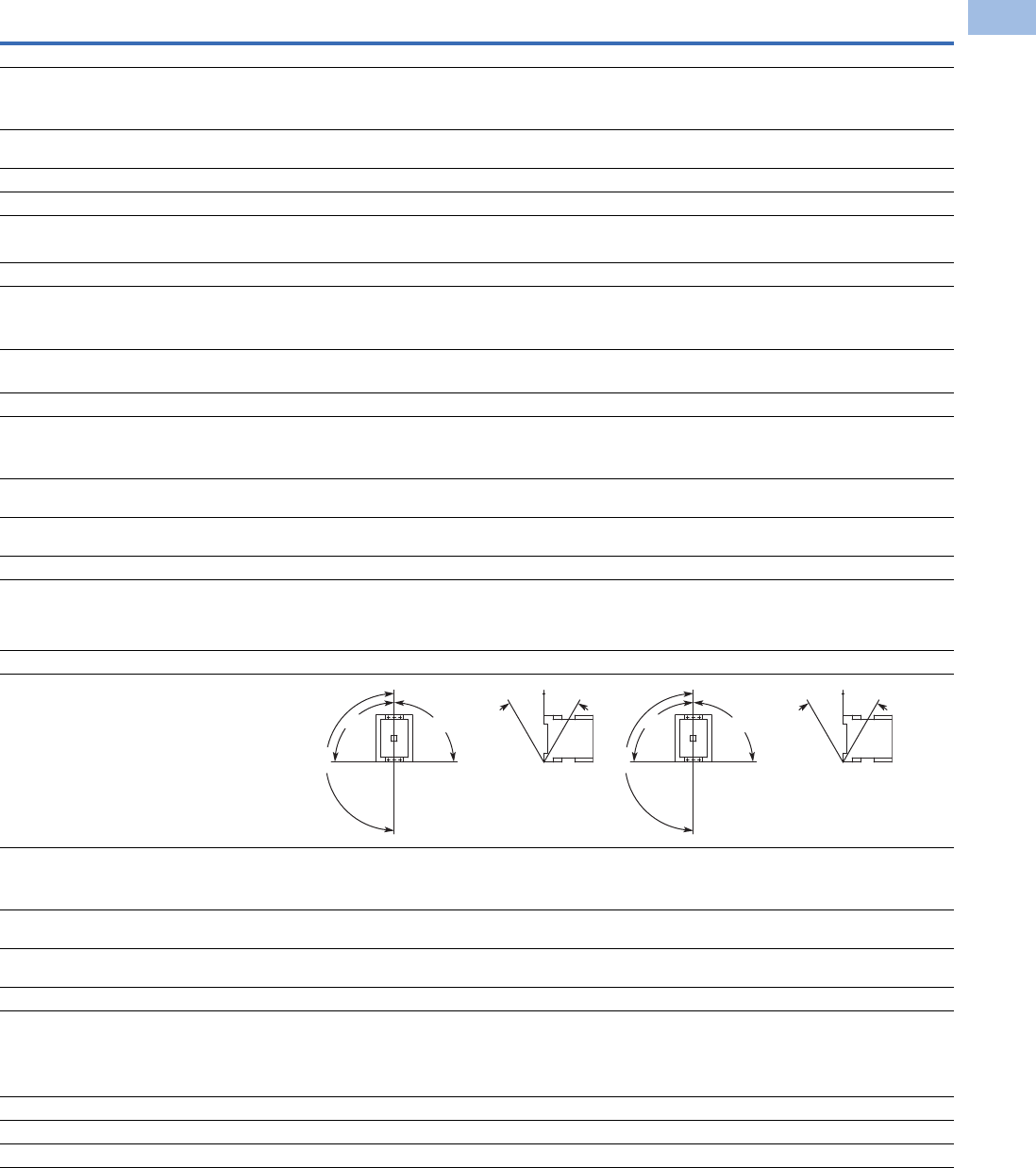
Volume 5—Motor Control and Protection CA08100006E—February 2014 www.eaton.com V5-T1-83
1
1
1
1
1
1
1
1
1
1
1
1
1
1
1
1
1
1
1
1
1
1
1
1
1
1
1
1
1
1
1.1
IEC Contactors and Starters
XT
IEC Power Control
XT Contactors—Frames F–G, continued
Description XTCE080F XTCE095F XTCE115G XTCE150G XTCE170G
General, continued
Terminal capacity control circuit cable—screw terminals
Solid (mm2) 1 x (0.75–4)
1 x (0.75–4)
1 x (0.75–4)
1 x (0.75–4)
1 x (0.75–4)
1 x (0.75–4)
1 x (0.75–4)
1 x (0.75–4)
1 x (0.75–4)
1 x (0.75–4)
Flexible with ferrule (mm2) 1 x (0.75–2.5)
2 x (0.75–2.5)
1 x (0.75–2.5)
2 x (0.75–2.5)
1 x (0.75–2.5)
2 x (0.75–2.5)
1 x (0.75–2.5)
2 x (0.75–2.5)
1 x (0.75–2.5)
2 x (0.75–2.5)
Solid or stranded (AWG) 18–14 18–14 18–14 18–14 18–14
Control circuit cable connection screw/bolt M3.5 M3.5 M3.5 M3.5 M3.5
Tightening torque
Nm 1.2 1.2 1.2 1.2 1.2
Lb-in 10.6 10.6 10.6 10.6 10.6
Tools
Main circuit cable—screw terminals
Hexagon socket-head spanner (mm) 5 5 5 5 5
Control circuit cable—screw terminals
Pozidriv screwdriver Size 2 Size 2 Size 2 Size 2 Size 2
Standard screwdriver 1 x 6, 0.8 x 5.5 1 x 6, 0.8 x 5.5 1 x 6, 0.8 x 5.5 1 x 6, 0.8 x 5.5 1 x 6, 0.8 x 5.5
Terminal capacity control circuit cable—spring cage terminals
Solid (mm2) 1 x (0.75–2.5)
2 x (0.75–2.5)
1 x (0.75–2.5)
2 x (0.75–2.5)
1 x (0.75–2.5)
2 x (0.75–2.5)
1 x (0.75–2.5)
2 x (0.75–2.5)
1 x (0.75–2.5)
2 x (0.75–2.5)
Flexible (mm2) 1 x (0.75–2.5)
2 x (0.75–2.5)
1 x (0.75–2.5)
2 x (0.75–2.5)
1 x (0.75–2.5)
2 x (0.75–2.5)
1 x (0.75–2.5)
2 x (0.75–2.5)
1 x (0.75–2.5)
2 x (0.75–2.5)
Flexible with ferrule (mm2) 1 x (0.75–2.5)
2 x (0.75–2.5)
1 x (0.75–2.5)
2 x (0.75–2.5)
1 x (0.75–2.5)
2 x (0.75–2.5)
1 x (0.75–2.5)
2 x (0.75–2.5)
1 x (0.75–2.5)
2 x (0.75–2.5)
Solid or stranded (AWG) 18–14 18–14 18–14 18–14 18–14
Tools
Control circuit cable—spring cage terminals
Stripping length (mm) 10 10 10 10 10
Screwdriver blade width (mm) 3.5 3.5 3.5 3.5 3.5
Mounting position, AC and DC operated
Ambient temperature
Open –25 to 60°C
[–13 to 140°F]
–25 to 60°C
[–13 to 140°F]
–25 to 60°C
[–13 to 140°F]
–25 to 60°C
[–13 to 140°F]
–25 to 60°C
[–13 to 140°F]
Enclosed –25 to 40°C
[–13 to 104°F]
–25 to 40°C
[–13 to 104°F]
–25 to 40°C
[–13 to 104°F]
–25 to 40°C
[–13 to 104°F]
–25 to 40°C
[–13 to 104°F]
Ambient storage temperature –40 to 80°C
[–40 to 176°F]
–40 to 80°C
[–40 to 176°F]
–40 to 80°C
[–40 to 176°F]
–40 to 80°C
[–40 to 176°F]
–40 to 80°C
[–40 to 176°F]
Environmental
Mechanical shock resistance
(IEC/EN 60068-2-27)
Half-sinusoidal shock 10 ms
Main contact—NO contact 10g 10g 10g 10g 10g
Auxiliary contact—NO contact 7g 7g 7g 7g 7g
Auxiliary contact—NC contact 5g 5g 5g 5g 5g
Overvoltage category/pollution degree III/3 III/3 III/3 III/3 III/3
180°
90°
90°
30° 30°
180°
90°
90°
30° 30°

V5-T1-84 Volume 5—Motor Control and Protection CA08100006E—February 2014 www.eaton.com
1
1
1
1
1
1
1
1
1
1
1
1
1
1
1
1
1
1
1
1
1
1
1
1
1
1
1
1
1
1
1.1
IEC Contactors and Starters
XT
IEC Power Control
XT Contactors—Frames H–M
Notes
1IEC 60947 Standard.
2Damp heat, constant, to IEC 60068-2-78; damp heat, cyclic, to IEC 60 068-2-30.
3Screw tightening with flat cable terminal or cable terminal blocks. See terminal capacity for cable terminal blocks.
Description XTCE185H XTCE225H
XTCE250L,
XTCS250L
XTCE300L,
XTCS300L
XTCE400M
XTCS400M
XTCE500M,
XTCS500M
XTCE570M
XTCS570M
General
Standards IEC/EN 60947,
VDE 0660,
UL, CSA
IEC/EN 60947,
VDE 0660,
UL, CSA
IEC/EN 60947,
VDE 0660,
UL, CSA
IEC/EN 60947,
VDE 0660,
UL, CSA
IEC/EN 60947,
VDE 0660,
UL, CSA
IEC/EN 60947,
VDE 0660,
UL, CSA
IEC/EN 60947,
VDE 0660,
UL, CSA
Weights in kg [lb] 3.2 [7.1] 3.2 [7.1] 6.5 [14.3] 6.5 [14.3] 8 [18] 8 [18] 8 [18]
Mechanical life—operations 10,000,000 10,000,000 10,000,000 10,000,000 7,000,000 7,000,000 7,000,000
Mechanical operating frequency (ops/hr)
AC operated 3000 3000 3000 3000 2000 2000 2000
DC operated 3000 3000 3000 3000 2000 2000 2000
Mechanical operating frequency (ops/hr) See Page V5-T1-93
Climatic proofing 2222222
Insulation voltage (Ui) Vac 1000 1000 1000 1000 1000 1000 1000
Impulse withstand voltage (Uimp) Vac 8000 8000 8000 8000 8000 8000 8000
Operating voltage (Ue) Vac 1000 1000 1000 1000 1000 1000 1000
Safe isolation to VDE 0106 Part 101 and Part 101/A1
Between coil and contacts (Vac) 500 500 500 500 500 500 500
Between contacts (Vac) 500 500 500 500 500 500 500
Making capacity (amps) 2700 2700 3000 3600 5500 5500 5500
Breaking capacity (amps)
Between coil and contacts (Vac)
220/230V 2250 2250 2500 3000 5000 5000 5000
380/400V 2250 2250 2500 3000 5000 5000 5000
500V 2250 2250 2500 3000 5000 5000 5000
660/690V 2250 2250 2500 3000 5000 5000 5000
1000V 760 760 760 950 950 950 950
Short-circuit protection rating maximum fuse
Type 2 coordination 1
400V; gG/gL 500V 315 315 315 315 500 500 500
690V; gG/gL 690V 250 250 315 315 500 500 500
1000V; gG/gL 1000V 160 160 160 160 200 200 200
Degree of protection IP00 IP00 IP00 IP00 IP00 IP00 IP00
Protection against direct contact when
actuated from front (IEC 536)
Finger and back-of-hand proof with terminal shroud or terminal block
Main cable cross-section
Flexible with cable lug (mm2) 50–185 50–185 50–240 50–240 50–240 50–240 50–240
Stranded with cable lug (mm2) 50–185 70–185 70–240 70–240 70–240 70–240 70–240
Solid or stranded (AWG) 1/0–350 kcmil 2/0–250 kcmil 1/0–250 kcmil 2/0–500 kcmil 1/0–250 kcmil 1/0–250 kcmil 1/0–250 kcmil
Flat conductor (mm) 3333333
Busbar—width in mm 32 32 25 25 25 30 30
Main cable connection screw/bolt M10 M10 M10 M10 M10 M10 M10
Tightening torque
Nm 24 24 24 24 2 2 2
Lb-in 213 213 213 213 213 213 213
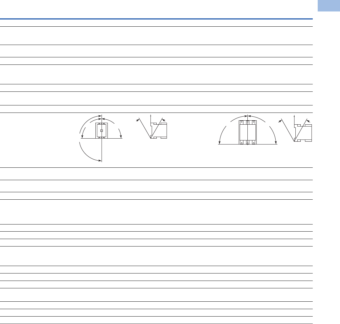
Volume 5—Motor Control and Protection CA08100006E—February 2014 www.eaton.com V5-T1-85
1
1
1
1
1
1
1
1
1
1
1
1
1
1
1
1
1
1
1
1
1
1
1
1
1
1
1
1
1
1
1.1
IEC Contactors and Starters
XT
IEC Power Control
XT Contactors—Frames H–M, continued
Note
1When using contactors for group compensation, a minimum inductance of approx. 6 uh per capacitor must be available to limit the high
inrush current peaks. This corresponds to an air-cored coil with five windings and a coil diameter of approximately 140 mm. The conductor
cross-section must be selected according to the rated current per phase.
Description XTCE185H XTCE225H
XTCE250L,
XTCS250L
XTCE300L,
XTCS300L
XTCE400M
XTCS400M
XTCE500M,
XTCS500M
XTCE570M
XTCS570M
General, continued
Control circuit cable cross-sections
Solid (mm2) 1 x (0.75–2.5)
2 x (0.75–2.5)
1 x (0.75–2.5)
2 x (0.75–2.5)
1 x (0.75–2.5)
2 x (0.75–2.5)
1 x (0.75–2.5)
2 x (0.75–2.5)
1 x (0.75–2.5)
2 x (0.75–2.5)
1 x (0.75–2.5)
2 x (0.75–2.5)
1 x (0.75–2.5)
2 x (0.75–2.5)
Flexible with ferrule (mm2) 1 x (0.75–2.5)
2 x (0.75–2.5)
1 x (0.75–2.5)
2 x (0.75–2.5)
1 x (0.75–2.5)
2 x (0.75–2.5)
1 x (0.75–2.5)
2 x (0.75–2.5)
1 x (0.75–2.5)
2 x (0.75–2.5)
1 x (0.75–2.5)
2 x (0.75–2.5)
1 x (0.75–2.5)
2 x (0.75–2.5)
Solid or stranded (AWG) 2 x (18–12) 2 x (18–12) 2 x (18–12) 2 x (18–12) 2 x (18–12) 2 x (18–12) 2 x (18–12)
Control circuit cable connection screw/bolt M3.5 M3.5 M3.5 M3.5 M3.5 M3.5 M3.5
Tightening torque
Nm 1.2 1.2 1.2 1.2 1.2 1.2 1.2
Lb-in 10.6 10.6 10.6 10.6 10.6 10.6 10.6
Tools
Main cable wrench 16 mm 16 mm 16 mm 16 mm 16 mm 16 mm 16 mm
Control circuit cable pozidriv screwdriver Size 2 Size 2 Size 2 Size 2 Size 2 Size 2 Size 2
Mounting position, AC and DC operated
Ambient temperature –25 to 60°C
[–13 to 140°F]
–25 to 60°C
[–13 to 140°F]
–25 to 60°C
[–13 to 140°F]
–25 to 60°C
[–13 to 140°F]
–25 to 60°C
[–13 to 140°F]
–25 to 60°C
[–13 to 140°F]
–25 to 60°C
[–13 to 140°F]
Ambient storage temperature –40 to 80°C
[–40 to 176°F]
–40 to 80°C
[–40 to 176°F]
–40 to 80°C
[–40 to 176°F]
–40 to 80°C
[–40 to 176°F]
–40 to 80°C
[–40 to 176°F]
–40 to 80°C
[–40 to 176°F]
–40 to 80°C
[–40 to 176°F]
Environmental
Mechanical shock
Resistance (IEC/EN 60068-2-27)
Half-sinusoidal shock 10 ms
Main contact—NO contact 10g 10g 10g 10g 10g 10g 10g
Auxiliary contact—NO contact 10g 10g 10g 10g 10g 10g 10g
Auxiliary contact—NC contact 8g 8g 8g 8g 8g 8g 8g
Overvoltage category/pollution degree III/3 III/3 III/3 III/3 III/3 III/3 III/3
Switching capacity, kVAR 1
Individual compensation
230V — — — — — — —
400/420/440V — — — — — — —
525V 220 220 — 307 — — —
690V 133 133 — 177 — — —
Group compensation, with choke
230V — — 100 — 160 160 160
400/420/440V — — 190 — 280 280 280
525V — — 260 — 370 370 370
690V — — 340 — 480 480 480
180°
90°
90°
30° 30°
90° 90°
30°30°

V5-T1-86 Volume 5—Motor Control and Protection CA08100006E—February 2014 www.eaton.com
1
1
1
1
1
1
1
1
1
1
1
1
1
1
1
1
1
1
1
1
1
1
1
1
1
1
1
1
1
1
1.1
IEC Contactors and Starters
XT
IEC Power Control
XT Contactors—Frames N–R
Notes
1IEC 60947 Standard.
2Damp heat, constant, to IEC 60068-2-78; damp heat, cyclic, to IEC 60 068-2-30.
3Screw tightening with flat cable terminal or cable terminal blocks. See terminal capacity for cable terminal blocks.
Description XTCE580N XTCE650N
XTCE750N,
XTCE820N XTCEC10N XTCEC14P
XTCEC16R,
XTCEC20R
General
Standards IEC/EN 60947,
VDE 0660, UL, CSA
IEC/EN 60947,
VDE 0660, UL, CSA
IEC/EN 60947,
VDE 0660, UL, CSA
IEC/EN 60947,
VDE 0660, UL, CSA
IEC/EN 60947,
VDE 0660, UL, CSA
IEC/EN 60947,
VDE 0660, UL, CSA
Weights in kg [lb] 15 [33] 15 [33] 15 [33] 15 [33] 15, [33] 32 [70]
Mechanical life—operations 5,000,000 5,000,000 5,000,000 5,000,000 5,000,000 5,000,000
Mechanical operating frequency (ops/hr)
AC operated 1000 1000 1000 1000 1000 1000
DC operated 1000 1000 1000 1000 1000 1000
Maximum operating frequency (ops/hr) See Page V5-T1-113
Climatic proofing 222222
Insulation voltage (Ui) Vac 1000 1000 1000 1000 1000 1000
Impulse withstand voltage (Uimp) Vac 8000 8000 8000 8000 8000 8000
Operating voltage (Ue) Vac 1000 1000 1000 1000 1000 1000
Safe isolation to VDE 0106 Part 101 and Part 101/A1
Between coil and contacts (Vac) 500 500 500 500 500 500
Between contacts (Vac) 500 500 500 500 500 500
Making capacity (amps) 7800 7800 9840 9840 9840 19000, 9840
Breaking capacity (amps)
220/230V 6500 6500 8200 8200 8200 16000, 8200
380/400V 6500 6500 8200 8200 8200 16000, 8200
500V 6500 6500 8200 8200 8200 16000, 8200
660/690V 6500 6500 8200 8200 8200 16000, 8200
1000V 4350 4350 5800 5800 5800 5800
Short-circuit protection rating maximum fuse
Type 2 coordination 1
400V; gG/gL 500V 630 630 630 630 — —
690V; gG/gL 690V 630 630 630 630 — —
1000V; gG/gL 1000V 500 500 630 630 — —
Type 1 coordination 1
400V; gG/gL 500V 1000 1000 1200 1200 — —
690V; gG/gL 690V 1000 1000 1200 1200 — —
1000V; gG/gL 1000V 630 630 800 800 — —
Degree of protection IP00 IP00 IP00 IP00 IP00 IP00
Protection against direct contact when actuated
from front (IEC 536)
Finger and back-of-
hand proof with
terminal shroud or
terminal block
Finger and back-of-
hand proof with
terminal shroud or
terminal block
Finger and back-of-
hand proof with
terminal shroud or
terminal block
Finger and back-of-
hand proof with
terminal shroud or
terminal block
Finger and back-of-
hand proof with
terminal shroud or
terminal block
Finger and back-of-
hand proof with
terminal shroud or
terminal block
Main cable cross-section
Flexible with cable lug (mm2) 50-240 50-240 50-240 50-240 50-240 50-240
Stranded with cable lug (mm2) 70-240 70-240 70-240 70-240 70-240 70-240
Solid or stranded (AWG) 2/0–500 kcmil 2/0–500 kcmil 2/0–500 kcmil 2/0–500 kcmil 2/0–500 kcmil 2/0–500 kcmil
Flat conductor (mm) 333333
Busbar—width in mm 50 50 50 50 50 50
Main cable connection screw/bolt M10 M10 M12 M12 M12 M1
Tightening torque
Nm 24 24 35 35 35 35
Lb-in 213 213 311 311 311 311
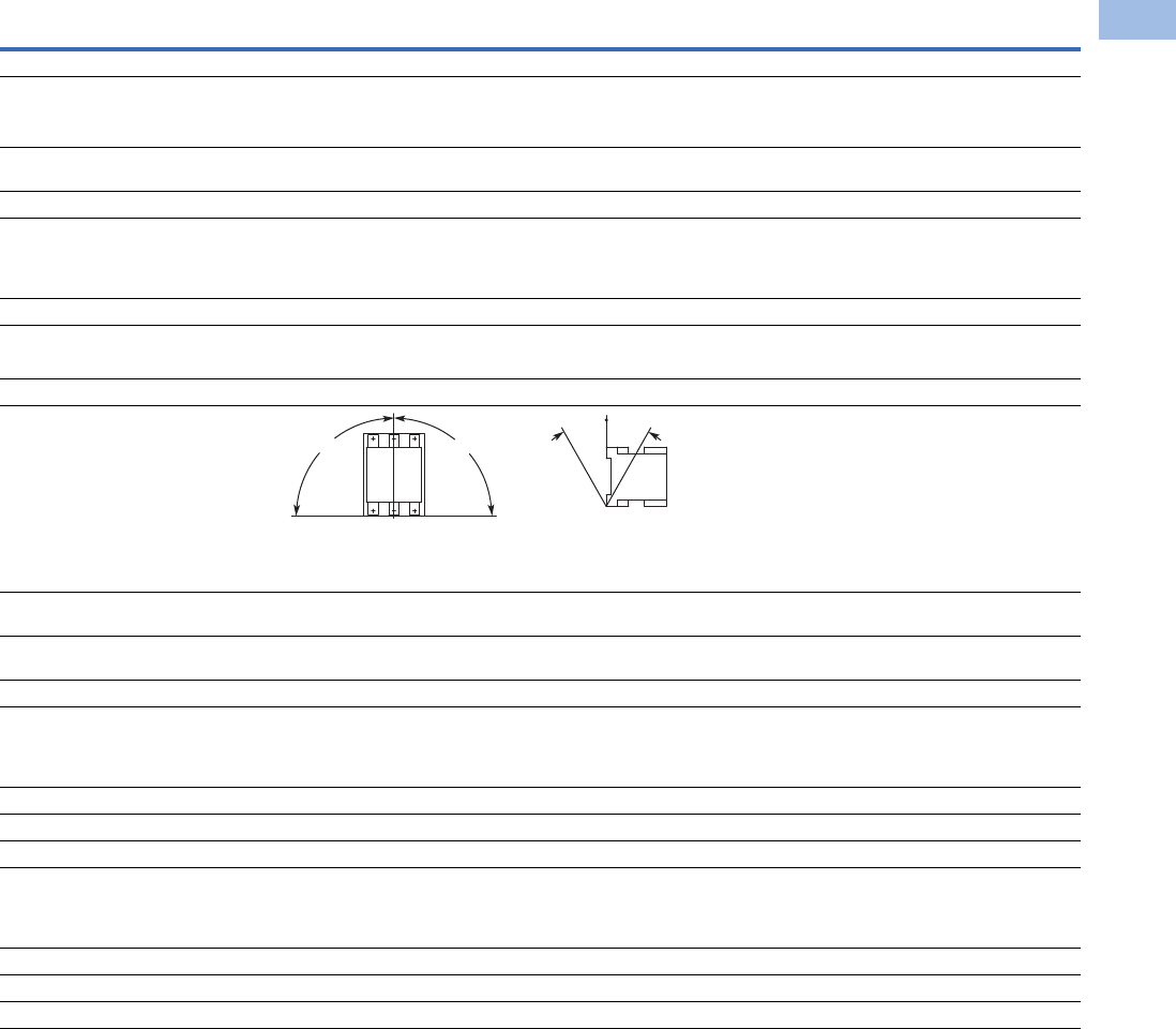
Volume 5—Motor Control and Protection CA08100006E—February 2014 www.eaton.com V5-T1-87
1
1
1
1
1
1
1
1
1
1
1
1
1
1
1
1
1
1
1
1
1
1
1
1
1
1
1
1
1
1
1.1
IEC Contactors and Starters
XT
IEC Power Control
XT Contactors—Frames N–R, continued
Note
1When using contactors for group compensation, a minimum inductance of approx. 6 uh per capacitor must be available to limit the high
inrush current peaks. This corresponds to an air-cored coil with five windings and a coil diameter of approximately 140 mm. The conductor
cross-section must be selected according to the rated current per phase.
Description XTCE580N XTCE650N XTCE750N, XTCE820N XTCEC10N XTCEC14P XTCEC16R, XTCEC20R
General, continued
Control circuit cable cross-sections
Solid (mm2) 1 x (0.75–2.5)
2 x (0.75–2.5)
1 x (0.75–2.5)
2 x (0.75–2.5)
1 x (0.75–2.5)
2 x (0.75–2.5)
1 x (0.75–2.5)
2 x (0.75–2.5)
1 x (0.75–2.5)
2 x (0.75–2.5)
1 x (0.75–2.5)
2 x (0.75–2.5)
Flexible with ferrule (mm2) 1 x (0.75–2.5)
2 x (0.75–2.5)
1 x (0.75–2.5)
2 x (0.75–2.5)
1 x (0.75–2.5)
2 x (0.75–2.5)
1 x (0.75–2.5)
2 x (0.75–2.5)
1 x (0.75–2.5)
2 x (0.75–2.5)
1 x (0.75–2.5)
2 x (0.75–2.5)
Solid or stranded (AWG) 2 x (18–12) 2 x (18–12) 2 x (18–12) 2 x (18–12) 2 x (18–12) 2 x (18–12)
Control circuit cable connection screw/bolt M3.5 M3.5 M3.5 M3.5 M3.5 M3.5
Tightening torque
Nm 1.2 1.2 1.2 1.2 1.2 1.2
Lb-in 10.6 10.6 10.6 10.6 10.6 10.6
Tools
Main cable wrench 16 mm 16 mm 18 mm 18 mm 18 mm 18 mm
Control circuit cable pozidriv screwdriver Size 2 Size 2 Size 2 Size 2 Size 2 Size 2
Mounting position, AC and DC operated
Ambient temperature –25 to 60°C
[–13 to 140°F]
–25 to 60°C
[–13 to 140°F]
–25 to 60°C
[–13 to 140°F]
–25 to 60°C
[–13 to 140°F]
–25 to 60°C
[–13 to 140°F]
–25 to 60°C
[–13 to 140°F]
Ambient storage temperature –40 to 80°C
[–40 to 176°F]
–40 to 80°C
[–40 to 176°F]
–40 to 80°C
[–40 to 176°F]
–40 to 80°C
[–40 to 176°F]
–40 to 80°C
[–40 to 176°F]
–40 to 80°C
[–40 to 176°F]
Environmental
Mechanical shock resistance (IEC/EN 60068-2-27)
Half-sinusoidal shock 10 ms (g)
Main contact—NO contact 10 10 10 10 10 10
Auxiliary contact—NO contact 10 10 10 10 10 10
Auxiliary contact—NC contact 8 8 8 8 8 8
Overvoltage category/pollution degree III/3 III/3 III/3 III/3 III/3 III/3
Switching capacity, kVAR 1
Individual compensation
230V 175 — — — — —
400/420/440V 300 — — — — —
525V 400 — — — — —
690V 300 — — — — —
30°30°
90° 90°

V5-T1-88 Volume 5—Motor Control and Protection CA08100006E—February 2014 www.eaton.com
1
1
1
1
1
1
1
1
1
1
1
1
1
1
1
1
1
1
1
1
1
1
1
1
1
1
1
1
1
1
1.1
IEC Contactors and Starters
XT
IEC Power Control
Coil Data—Frames B–D
Notes
10.7–1.3 without additional auxiliary contact modules and ambient temperature +40°C [104°F].
2Coil Suffix TD: Umin 24 Vdc/Umax 27 Vdc.
Coil Suffix WD: Umin 48 Vdc/Umax 60 Vdc.
Coil Suffix AD: Umin 110 Vdc/Umax 130 Vdc.
Coil Suffix BD: Umin 200 Vdc/Umax 240 Vdc.
Example:
Uc = 0.7 x Umin—1.2 x Umax
Uc = 0.7 x 24V—1.2 x 27 Vdc
Description XTCE007B XTCE009B
XTCE012B,
XTCF020B XTCE015B XTCE018C XTCE025C XTCE032C XTCE040D XTCE050D
XTCE065D,
XTCE072D
Voltage Toleran ce
Pickup (x Uc)
AC operated 0.8–1.1 0.8–1.1 0.8–1.1 0.8–1.1 0.8–1.1 0.8–1.1 0.8–1.1 0.8–1.1 0.8–1.1 0.8–1.1
DC operated 0.8–1.1 10.8–1.1 10.8–1.1 10.8–1.1 10.7–1.2 20.7–1.2 20.7–1.2 20.7–1.2 20.7–1.2 20.7–1.2 2
Dropout (x Uc)
AC operated 0.3–0.6 0.3–0.6 0.3–0.6 0.3–0.6 0.3–0.6 0.3–0.6 0.3–0.6 0.3–0.6 0.3–0.6 0.3–0.6
DC operated 0.15–0.6 0.15–0.6 0.15–0.6 0.15–0.6 0.15–0.6 0.15–0.6 0.15–0.6 0.15–0.6 0.15–0.6 0.15–0.6
Power Consumption of the Coil at Cold State and 1.0 x Uc
AC operated
Single-voltage coil 50 Hz
Pickup VA 24 24 24 24 52 52 52 149 149 149
Pickup W 19191919404040808080
Sealing VA 3.4 3.4 3.4 3.4 7.1 7.1 7.1 16 16 16
Sealing W 1.2 1.2 1.2 1.2 2.1 2.1 2.1 4.3 4.3 4.3
Single-voltage coil 60 Hz
Pickup VA 30 30 30 30 67 67 67 178 178 178
Pickup W 23232323505050117117117
Sealing VA 4.4 4.4 4.4 4.4 8.7 8.7 8.7 19 19 19
Sealing W 1.4 1.4 1.4 1.4 2.6 2.6 2.6 5.3 5.3 5.3
50/60 Hz
Pickup VA 27
25
27
25
27
25
27
25
62
58
62
58
62
58
168
154
168
154
168
154
Pickup W 22
21
22
21
22
21
22
21
48
43
48
43
48
43
120
43
120
43
120
43
Sealing VA 4.2
3.3
4.2
3.3
4.2
3.3
4.2
3.3
9.1
6.5
9.1
6.5
9.1
6.5
22
14
22
14
22
14
Sealing W 1.4
1.2
1.4
1.2
1.4
1.2
1.4
1.2
2.5
2
2.5
2
2.5
2
5.3
4.3
5.3
4.3
5.3
4.3
DC operated
Pickup W 3 3 4.5 4.5 12 at 24V 12 at 24V 12 at 24V 24 at 24V 24 at 24V 24 at 24V
Sealing W 3 3 4.5 4.5 0.5 at 24V 0.5 at 24V 0.5 at 24V 0.5 at 24V 0.5 at 24V 0.5 at 24V
Duty factor (%DF) 100 100 100 100 100 100 100 100 100 100
Switching Time at 100% Uc (Approximate Values)
Main contact
AC operated
Closing delay (ms) <21 <21 <21 <21 <22 <22 <22 <18 <18 <18
Opening delay (ms) <18 <18 <18 <18 <14 <14 <14 <13 <13 <13
DC operated
Closing delay (ms) <31 <31 <31 <31 <47 <47 <47 <54 <54 <54
Opening delay (ms) <12 <12 <12 <12 <30 <30 <30 <24 <24 <24
Arcing time (ms) 10 10 10 10 10 10 10 10 10 10
Electromagnetic Compatibility (EMC)
Emitted interference To EN-60947-1 To EN-60947-1 To EN-60947-1 To EN-60947-1 To EN-60947-1 To EN-60947-1 To EN-60947-1 To EN-60947-1 To EN-60947-1 To EN-60947-1
Noise immunity To EN-60947-1 To EN-60947-1 To EN-60947-1 To EN-60947-1 To EN-60947-1 To EN-60947-1 To EN-60947-1 To EN-60947-1 To EN-60947-1 To EN-60947-1

Volume 5—Motor Control and Protection CA08100006E—February 2014 www.eaton.com V5-T1-89
1
1
1
1
1
1
1
1
1
1
1
1
1
1
1
1
1
1
1
1
1
1
1
1
1
1
1
1
1
1
1.1
IEC Contactors and Starters
XT
IEC Power Control
Coil Data—Frames F–G
Note
1At 24V: 0.7–1.3 without additional auxiliary contact modules and ambient temperature +40°C [104°F].
Description XTCE80F XTCE95F XTCE115G XTCE150G XTCE170G
Voltage Toleran ce
Pickup (x Uc)
AC operated 0.8–1.1 0.8–1.1 0.8–1.1 0.8–1.1 0.8–1.1
DC operated 0.7–1.2 10.7–1.2 10.7–1.2 10.7–1.2 10.7–1.2 1
Dropout (x Uc)
AC operated 0.3–0.6 0.3–0.6 0.25–0.6 0.25–0.6 0.25–0.6
DC operated 0.15–0.6 0.15–0.6 0.15–0.6 0.15–0.6 0.15–0.6
Power Consumption of the Coil at Cold State and 1.0 x Uc
AC operated
Single-voltage coil 50 Hz
Pickup VA 310 310 180 180 180
Pickup W 165 165 130 130 130
Sealing VA 26 26 3.1 3.1 3.1
Sealing W 5.8 5.8 2.1 2.1 2.1
Single-voltage coil 60 Hz
Pickup VA 345 345 170 170 170
Pickup W 190 190 130 130 130
Sealing VA 30 30 3.1 3.1 3.1
Sealing W 7.1 7.1 2.1 2.1 2.1
50/60 Hz
Pickup VA 372 328 170 170 170
Pickup W 190 190 130 130 130
Sealing VA 37.1 22.6 3.1 3.1 3.1
Sealing W 7.5 6.1 2.1 2.1 2.1
DC operated
Pickup W 90 at 24V 90 at 24V 149 at 24V 149 at 24V 149 at 24V
Sealing W 1.3 at 24V 1.3 at 24V 2.1 at 24V 2.1 at 24V 2.1 at 24V
Duty factor (%DF) 100 100 100 100 100
Switching Time at 100% Uc (Approximate Values)
Main contact
AC operated
Closing delay (ms) <20 <20 <33 <33 <33
Opening delay (ms) <14 <14 <41 <41 <41
DC operated
Closing delay (ms) <45 <45 <35 <35 <35
Opening delay (ms) <34 <34 <30 <30 <30
Arcing time (ms) 15 15 15 15 15
Permissible residual current with actuation of
A1–A2 by the electronics (with 0 signal) (mA)
<
1
<
1
<
1
<
1
<
1
Electromagnetic Compatibility (EMC)
Emitted interference To EN60947-1 To EN60947-1 To EN60947-1 To EN60947-1 To EN60947-1
Noise immunity To EN60947-1 To EN60947-1 To EN60947-1 To EN60947-1 To EN60947-1

V5-T1-90 Volume 5—Motor Control and Protection CA08100006E—February 2014 www.eaton.com
1
1
1
1
1
1
1
1
1
1
1
1
1
1
1
1
1
1
1
1
1
1
1
1
1
1
1
1
1
1
1.1
IEC Contactors and Starters
XT
IEC Power Control
Coil Data—Frames H–R
Note
1Control transformer with Uk
<
6%.
Description XTCE185H, XTCE225H XTCE250L, XTCS250L XTCE300L, XTCS300L
XTCE400M, XTCS400M, XTCE500M,
XTCS500M, XTCE570M, XTCS570M
Voltage Toleran ce
Pickup (x Uc)
XTCE185H–XTCEC20R 0.8 x Ucmin–1.15 x Ucmax 0.7 x Ucmin–1.15 x Ucmax 0.7 x Ucmin–1.15 x Ucmax 0.7 x Ucmin–1.15 x Ucmax
XTCS250L–XTCS500M — 0.85 x Ucmin–1.1 x Ucmax 0.85 x Ucmin–1.1 x Ucmax 0.85 x Ucmin–1.1 x Ucmax
Dropout (x Uc)
XTCE185H–XTCEC20R 0.2 x Ucmin–0.6 x Ucmax 0.2 x Ucmin–0.6 x Ucmax 0.2 x Ucmin–0.6 x Ucmax 0.2 x Ucmin–0.6 x Ucmax
XTCS250L–XTCS500M — 0.2 x Ucmin–0.4 x Ucmax 0.2 x Ucmin–0.4 x Ucmax 0.2 x Ucmin–0.4 x Ucmax
Power Consumption of the Coil at Cold State and 1.0 x Uc
XTCE185H–XTCEC20R
Pickup VA 210 1250 1380 1450 1
Pickup W 180 200 250 350
Sealing VA 2.6 4.3 4.3 4.3
Sealing W 2.1 3.3 3.3 3.3
XTCS250L–XTCS500M
Pickup VA — 360 360 715
Pickup W — 325 625 645
Sealing VA — 4.3 4.3 4.3
Sealing W — 3.3 3.3 3.3
Duty factor (%DF) — 100 100 100
Switching Time at 100% Main Contact Uc (Approximate Values)
XTCE185H–XTCEC20R
Closing delay (ms) <60 <100 <80 <80
Opening delay (ms) <40 <80 <110 <80
XTCS250L–XTCS500M
Closing delay (ms) — <50 <55 <50
Opening delay (ms) — <40 <40 <40
Reaction in Threshold and Sealing State Transition Range (XTCE185H–XTCEC20R)
Voltage interruptions
(0–0.2 x Ucmin)
<
10 ms Time is bridged successfully Time is bridged successfully Time is bridged successfully Time is bridged successfully
(0–0.2 x Ucmin) >10 ms Dropout of the contactor Dropout of the contactor Dropout of the contactor Dropout of the contactor
Voltage dips
(0.2–0.6 x Ucmin)
<
12 ms Time is bridged successfully Time is bridged successfully Time is bridged successfully Time is bridged successfully
(0.2–0.6 x Ucmin) >12 ms Contactor remains switched on Contactor remains switched on Dropout of the contactor Contactor remains switched on
(0.6–0.7 x Ucmin) Contactor remains switched on Contactor remains switched on Contactor remains switched on Contactor remains switched on
Excess voltage
(1.15–1.3 x Ucmax) Contactor remains switched on Contactor remains switched on Contactor remains switched on Contactor remains switched on
(>1.3 x Ucmax)
<
3s Contactor remains switched on Contactor remains switched on Contactor remains switched on Contactor remains switched on
(>1.3 x Ucmax) >3s Dropout of the contactor Dropout of the contactor Dropout of the contactor Dropout of the contactor
Pickup phase
(0–0.7 x Ucmin) Contactor does not switch on Contactor does not switch on Contactor does not switch on Contactor does not switch on
(0.7 x Ucmin –1.15 x Ucmax) Contactor switches on with certainty Contactor switches on with certainty Contactor switches on with certainty Contactor switches on with certainty
(>1.15 x Ucmax) Contactor switches on with certainty Contactor switches on with certainty Contactor switches on with certainty Contactor switches on with certainty

Volume 5—Motor Control and Protection CA08100006E—February 2014 www.eaton.com V5-T1-91
1
1
1
1
1
1
1
1
1
1
1
1
1
1
1
1
1
1
1
1
1
1
1
1
1
1
1
1
1
1
1.1
IEC Contactors and Starters
XT
IEC Power Control
Coil Data—Frames H–R, continued
Coil Data—Frames N–R
Note
1Control transformer with Uk
<
7%.
Description XTCE185H, XTCE225H XTCE250L, XTCS250L XTCE300L, XTCS300L
XTCE400M, XTCS400M,
XTCE500M, XTCS500M,
XTCE570M, XTCS570M
Reaction in Threshold and Sealing State Transition Range (XTCE185H–XTCEC20R), continued
Permissible contact resistance (of the external command
device with actuation of A11), ohms
— ≤500 ≤500 ≤500
Permissible residual current (with actuation of A11
by the electronics with 0 signal)
—≤1≤1≤1
SPS signal level (A3–A4) to IEC/EN 61131-2 (Type 2)
High 15V 15V 15V 15V
Low 5V5V5V5V
Electromagnetic compatibility (EMC) This product is designed for operation in industrial environments (environment 2). The use in residential environments
(environment 1) could cause electrical interference so that addition suppression must be planned.
Description XTCE580N
XTCE750N,
XTCE820N XTCEC10N XTCEC14P
XTCE16R,
XTCEC20R
Voltage Toleran ce
Pickup (x Uc)
XTCE185L–XTCEC20R 0.7 x Ucmin–1.15 x Ucmax 0.7 x Ucmin–1.15 x Ucmax 0.7 x Ucmin–1.15 x Ucmax 0.7 x Ucmin–1.15 x Ucmax 0.7 x Ucmin–1.15 x Ucmax
XTCS185L–XTCS500M 0.85 x Ucmin–1.1 x Ucmax 0.85 x Ucmin–1.1 x Ucmax 0.85 x Ucmin–1.1 x Ucmax 0.85 x Ucmin–1.1 x Ucmax 0.85 x Ucmin–1.1 x Ucmax
Dropout (x Uc)
XTCE185L–XTCEC20R 0.2 x Ucmin–0.6 x Ucmax 0.2 x Ucmin–0.6 x Ucmax 0.2 x Ucmin–0.6 x Ucmax 0.2 x Ucmin–0.6 x Ucmax 0.2 x Ucmin–0.6 x Ucmax
XTCS185L–XTCS500M 0.2 x Ucmin–0.4 x Ucmax 0.2 x Ucmin–0.4 x Ucmax 0.2 x Ucmin–0.4 x Ucmax 0.2 x Ucmin–0.4 x Ucmax 0.2 x Ucmin–0.4 x Ucmax
Power Consumption of the Coil at Cold State and 1.0 x Uc
XTCE185L–XTCEC20R
Pickup VA 800 1800 1800 1800 11600 1
Pickup W 700 700 700 700 1400
Sealing VA 7.5 7.5 7.5 7.5 15
Sealing W 6.5 6.5 6.5 6.5 13
XTCS185L–XTCS500M
Pickup VA — — — — —
Pickup W — — — — —
Sealing VA — — — — —
Sealing W — — — — —
Duty factor (%DF) 100 100 100 100 100
Switching Time at 100% Main Contact Uc (Approximate Values)
XTCE185L–XTCEC20R
Closing delay (ms) <70 <70 <70 <70 <70
Opening delay (ms) <70 <70 <70 <40 <40
XTCS185L–XTCS500M
Closing delay (ms) — — — — —
Opening delay (ms) — — — — —

V5-T1-92 Volume 5—Motor Control and Protection CA08100006E—February 2014 www.eaton.com
1
1
1
1
1
1
1
1
1
1
1
1
1
1
1
1
1
1
1
1
1
1
1
1
1
1
1
1
1
1
1.1
IEC Contactors and Starters
XT
IEC Power Control
Coil Data—Frames N–R, continued
Note
1This product is designed for operation in industrial environments. Usage in domestic areas can cause radio frequency interference (RFI).
Noise suppression measures must be provided for the additional interference.
Description XTCE580N
XTCE750N,
XTCE820N XTCEC10N XTCEC14P
XTCE16R,
XTCEC20R
Reaction in Threshold and Sealing State Transition Range (XTCE185L–XTCEC20R)
Voltage interruptions
(0–0.2 x Ucmin)
<
10 ms Time is bridged
successfully
Time is bridged
successfully
Time is bridged
successfully
Time is bridged
successfully
Time is bridged
successfully
(0–0.2 x Ucmin) >10 ms Dropout of the contactor Dropout of the contactor Dropout of the contactor Dropout of the contactor Dropout of the contactor
Voltage dips
(0.2–0.6 x Ucmin)
<
12 ms Time is bridged
successfully
Time is bridged
successfully
Time is bridged
successfully
Time is bridged
successfully
Time is bridged
successfully
(0.2–0.6 x Ucmin) >12 ms Dropout of the contactor Dropout of the contactor Dropout of the contactor Dropout of the contactor Dropout of the contactor
(0.6–0.7 x Ucmin) Contactor remains
switched on
Contactor remains
switched on
Contactor remains
switched on
Contactor remains
switched on
Contactor remains
switched on
Excess voltage
(1.15–1.3 x Ucmax) Contactor remains
switched on
Contactor remains
switched on
Contactor remains
switched on
Contactor remains
switched on
Contactor remains
switched on
(>1.3 x Ucmax)
<
3s Contactor remains
switched on
Contactor remains
switched on
Contactor remains
switched on
Contactor remains
switched on
Contactor remains
switched on
(>1.3 x Ucmax) >3s Dropout of the contactor Dropout of the contactor Dropout of the contactor Dropout of the contactor Dropout of the contactor
Pickup phase
(0–0.7 x Ucmin) Contactor does not
switch on
Contactor does not
switch on
Contactor does not
switch on
Contactor does not
switch on
Contactor does not
switch on
(0.7 x Ucmin –1.15 x Ucmax) Contactor switches on
with certainty
Contactor switches on
with certainty
Contactor switches on
with certainty
Contactor switches on
with certainty
Contactor switches on
with certainty
(>1.15 x Ucmax) Contactor switches on
with certainty
Contactor switches on
with certainty
Contactor switches on
with certainty
Contactor switches on
with certainty
Contactor switches on
with certainty
Permissible contact resistance (of the external
command device with actuation of A11), ohms
<
500
<
500
<
500
<
500
<
500
Permissible residual current (with actuation of A11
by the electronics with 0 signal)
<
1
<
1
<
1
<
1
<
1
SPS signal level (A3–A4) to IEC/EN 61131-2 (Type 2)
High 15V 15V 15V 15V 15V
Low 5V5V5V5V5V
Electromagnetic compatibility (EMC) 11111

Volume 5—Motor Control and Protection CA08100006E—February 2014 www.eaton.com V5-T1-93
1
1
1
1
1
1
1
1
1
1
1
1
1
1
1
1
1
1
1
1
1
1
1
1
1
1
1
1
1
1
1.1
IEC Contactors and Starters
XT
IEC Power Control
XT Contactors—Four-Pole
Notes
1Damp heat, constant, to IEC 60068-2-3.
2Damp heat, cyclical, to IEC 60068-2-30.
Description XTCF020B XTCF032C XTCF045C XTCF063D XTCF080D XTCF125G XTCF160G XTCF200G
General
Standards IEC/EN 60947,
VDE 0660, UL,
CSA
IEC/EN 60947,
VDE 0660, UL,
CSA
IEC/EN 60947,
VDE 0660, UL,
CSA
IEC/EN 60947,
VDE 0660, UL,
CSA
IEC/EN 60947,
VDE 0660, UL,
CSA
IEC/EN 60947,
VDE 0660, UL,
CSA
IEC/EN 60947,
VDE 0660, UL,
CSA
IEC/EN 60947,
VDE 0660, UL,
CSA
Weights in kg [lb]
AC operated 0.22 [0.49] 0.49 [1.1] 0.49 [1.1] 1.0 [2.3] 1.0 [2.3] 2.8 [6.2] 2.8 [6.2] 2.8 [6.2]
DC operated 0.29 [0.64] 0.49 [1.1] 0.49 [1.1] 1.0 [2.3] 1.0 [2.3] 2.8 [6.2] 2.8 [6.2] 2.8 [6.2]
Mechanical life—operations 10,000,000 10,000,000 10,000,000 10,000,000 10,000,000 10,000,000 10,000,000 10,000,000
Mechanical operating frequency (ops/hr)
AC operated 5000 5000 5000 5000 5000 3600 3600 3600
DC operated 5000 5000 5000 5000 5000 3600 3600 3600
Electrical life See Curves,
Page
V5-T1-111
See Curves,
Page
V5-T1-111
See Curves,
Page
V5-T1-111
See Curves,
Page
V5-T1-111
See Curves,
Page
V5-T1-111
See Curves,
Page
V5-T1-111
See Curves,
Page
V5-T1-111
See Curves,
Page
V5-T1-111
Electrical operating frequency (ops/hr) 600 600 600 600 600 600 600 600
Climatic proofing 11111111
22222222
Insulation voltage (Ui) Vac 690 690 690 690 690 690 690 690
Impulse withstand voltage (Uimp) Vac 8000 8000 8000 8000 8000 8000 8000 8000
Operation voltage (Ue) Vac 690 690 690 690 690 690 690 690
Safe isolation to VDE 0106 Part 101 and Part 101/A1
Between coil and contacts (Vac) 400 440 440 440 440 440 440 440
Between contacts (Vac) 400 440 440 440 440 440 440 440
Making capacity up to 690V (amps) 144 238 350 560 700 1120 1330 1800
Breaking capacity (amps)
220/230V 120 180 250 00 00 800 950 1150
380/400V 120 180 250 400 500 800 950 1150
500V 100 180 250 400 500 800 950 1150
660/690V 70 120 144 250 296 650 750 800
Short-circuit protection rating maximum fuse
Type 2 coordination
400V; gG/gL 500V 20 35 35 63 80 160 160 250
690V; gG/gL 690V 2 35 35 50 63 160 160 200
Type 1 coordination
400V; gG/gL 500V 35 6 100 125 160 250 250 250
690V; gG/gL 690V 25 50 50 80 80 200 200 200
Degree of protection with accessories IP20 IP00 IP00 IP00 IP00 IP00 IP00 IP00
———IP20IP20IP20IP20IP20
Protection against direct contact when
actuated from front (IEC 536)
Finger and
back-of-hand
proof
Finger and
back-of-hand
proof
Finger and
back-of-hand
proof
Finger and
back-of-hand
proof
Finger and
back-of-hand
proof
Finger and
back-of-hand
proof
Finger and
back-of-hand
proof
Finger and
back-of-hand
proof
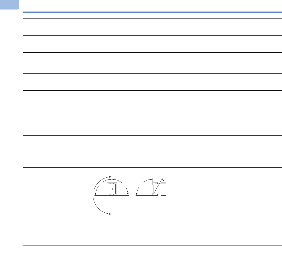
V5-T1-94 Volume 5—Motor Control and Protection CA08100006E—February 2014 www.eaton.com
1
1
1
1
1
1
1
1
1
1
1
1
1
1
1
1
1
1
1
1
1
1
1
1
1
1
1
1
1
1
1.1
IEC Contactors and Starters
XT
IEC Power Control
XT Contactors—Four-Pole, continued
Description XTCF020B XTCF032C XTCF045C XTCF063D XTCF080D XTCF125G XTCF160G XTCF200G
General, continued
Terminal capacity main cable—screw terminals
Solid (mm2) 1 x (0.75–4)
2 x (0.75–2.5)
1 x (0.75–16)
2 x (0.75 –10)
1 x (0.75–16)
2 x (0.75 –10)
1 x (2.5 –16)
2 x (2.5 –16)
1 x (2.5 –16)
2 x (2.5 –16)
———
Flexible with ferrule (mm2) 1 x (0.75–2.5)
2 x (0.75–2.5)
1 x (0.75–16)
2 x (0.75–10)
1 x (0.75–16)
2 x (0.75–10)
1 x (2.5–35)
2 x (2.5–25)
1 x (2.5–35)
2 x (2.5–25)
1 x (10 –95)
2 x (10–70)
1 x (10 –95)
2 x (10–70)
1 x (10 –95)
2 x (10–70)
Solid or stranded (AWG) 18–14 18–6 18–6 12–2 12–2 8–250 kcmil 8–250 kcmil 8–250 kcmil
Terminal capacity control circuit cable—screw
terminals
Solid (mm2) 1 x (0.75–4)
2 x (0.75–2.5)
1 x (0.75–4)
2 x (0.75–2.5)
1 x (0.75–4)
2 x (0.75–2.5)
1 x (0.75–4)
2 x (0.75–2.5)
1 x (0.75–4)
2 x (0.75–2.5)
1 x (0.75–4)
2 x (0.75–2.5)
1 x (0.75–4)
2 x (0.75–2.5)
1 x (0.75–4)
2 x (0.75–2.5)
Flexible with ferrule (mm2) 1 x (0.75–2.5)
2 x (0.75–2.5)
1 x (0.75–2.5)
2 x (0.75–2.5)
1 x (0.75–2.5)
2 x (0.75–2.5)
1 x (0.75–2.5)
2 x (0.75–2.5)
1 x (0.75–2.5)
2 x (0.75–2.5)
1 x (0.75–2.5)
2 x (0.75–2.5)
1 x (0.75–2.5)
2 x (0.75–2.5)
1 x (0.75–2.5)
2 x (0.75–2.5)
Solid or stranded (AWG) 18–14 18–14 18–14 18–14 18–14 18–14 18–14 18–14
Main cable connection screw/bolt
Tightening torque
Nm 1.2 3 3 3.3 3.3 14 14 14
Lb-in 10.6 26.6 26.6 29.2 29.2 123.9 123.9 123.9
Control circuit cable connection screw/bolt
Tightening torque
Nm 1.2 1.2 1.2 1.2 1.2 1.2 1.2 1.2
Lb-in 10.6 10.6 10.6 10.6 10.6 10.6 10.6 10.6
Tools
Main and control circuit cable—
Screw terminals 22222———
Pozidriv screwdriver 0.8 x 5.5 0.8 x 5.5 0.8 x 5.5 0.8 x 5.5 0.8 x 5.5 — — —
Standard screwdriver 1 x 6 1 x 6 1 x 6 1 x 6 1 x 6 — — —
Mounting position, AC and DC operated
Ambient temperature
Open –25 to 60°C
(–13 to 140°F)
–25 to 60°C
(–13 to 140°F)
–25 to 60°C
(–13 to 140°F)
–25 to 60°C
(–13 to 140°F)
–25 to 60°C
(–13 to 140°F)
–25 to 60°C
(–13 to 140°F)
–25 to 60°C
(–13 to 140°F)
–25 to 60°C
(–13 to 140°F)
Enclosed –25 to 40°C
(–13 to 104°F)
–25 to 40°C
(–13 to 104°F)
–25 to 40°C
(–13 to 104°F)
–25 to 40°C
(–13 to 104°F)
–25 to 40°C
(–13 to 104°F)
–25 to 40°C
(–13 to 104°F)
–25 to 40°C
(–13 to 104°F)
–25 to 40°C
(–13 to 104°F)
Ambient storage temperature –40 to 80°C
(–40 to 176°F)
–40 to 80°C
(–40 to 176°F)
–40 to 80°C
(–40 to 176°F)
–40 to 80°C
(–40 to 176°F)
–40 to 80°C
(–40 to 176°F)
–40 to 80°C
(–40 to 176°F)
–40 to 80°C
(–40 to 176°F)
–40 to 80°C
(–40 to 176°F)
180°
90°
90°
90°
30°

Volume 5—Motor Control and Protection CA08100006E—February 2014 www.eaton.com V5-T1-95
1
1
1
1
1
1
1
1
1
1
1
1
1
1
1
1
1
1
1
1
1
1
1
1
1
1
1
1
1
1
1.1
IEC Contactors and Starters
XT
IEC Power Control
XT Contactors—Four-Pole, continued
Description XTCF020B XTCF032C XTCF045C XTCF063D XTCF080D XTCF125G XTCF160G XTCF200G
Environmental
Mechanical shock resistance (IEC/EN 60068-2-27)
Half-sinusoidal shock 10 ms
Main contact—NO contact 10g 10g 10g 10g 10g 10g 10g 10g
Auxiliary contact—NO contact 7g 7g 7g 7g 7g 7g 7g 7g
Auxiliary contact—NC contact 5g 5g 5g 5g 5g 5g 5g 5g
Overvoltage category/pollution degree III/3 III/3 III/3 III/3 III/3 III/3 III/3 III/3
Coil Data Voltage Tolerance
Pickup (x Uc)
AC operated 0.8–1.1 0.8–1.1 0.8–1.1 0.8–1.1 0.8–1.1 0.8–1.1 0.8–1.1 0.8–1.1
DC operated 0.8–1.1 0.7–1.2 0.7–1.2 0.7–1.2 0.7–1.2 0.7–1.2 0.7–1.2 0.7–1.2
Dropout (x Uc)
AC operated 0.4–0.6 0.4–0.6 0.4–0.6 0.4–0.6 0.4–0.6 0.4–0.6 0.4–0.6 0.4–0.6
DC operated 0.2–0.6 0.2–0.6 0.2–0.6 0.2–0.6 0.2–0.6 0.2–0.6 0.2–0.6 0.2–0.6
Power Consumption of the Coil at Cold State and 1.0 x Uc
AC operated 50/50Hz
Pickup VA 24 50 50 150 150 180 180 180
Pickup W 19 40 40 95 95 150 150 150
Sealing VA 4 8 8 16 16 3.1 3.1 3.1
Sealing W 1.2 2.4 2.4 4 4 2.1 2.1 2.1
DC operated
Pickup W 4.5 12 12 24 24 149 149 149
Sealing W 4.5 0.5 0.5 0.5 0.5 2.1 2.1 2.1
Duty factor (%DF) 100 100 100 100 100 100 100 100
Switching Time at 100% Uc (Approximate Values)
Main contact
AC operated
Closing delay (ms) 15 to 21 6 to 22 6 to 22 12 to 18 12 to 18 28 to 33 28 to 33 28 to 33
Opening delay (ms) 9 to 18 8 to 14 8 to 14 8 to 13 8 to 13 35 to 41 35 to 41 35 to 41
DC operated
Closing delay (ms) 31 47 47 54 54 35 35 35
Opening delay (ms) 12 30 30 24 24 30 30 30
Arcing time (ms) 10 10 10 10 10 15 15 15

V5-T1-96 Volume 5—Motor Control and Protection CA08100006E—February 2014 www.eaton.com
1
1
1
1
1
1
1
1
1
1
1
1
1
1
1
1
1
1
1
1
1
1
1
1
1
1
1
1
1
1
1.1
IEC Contactors and Starters
XT
IEC Power Control
Auxiliary Contacts
Notes
1Making and breaking conditions to DC-13, time L/R contact as stated.
2See fuses overlay for time/current characteristic (on request).
3Conventional thermal current (Ith) of XTCEXSCC_ is 10A.
Description
XTCE007B_–
XTCE032C
XTCEXFAC_
XTCEXFATC_
XTCEXFCC_
XTCEXSCC_ XTCEXFAG_
XTCEXSBLN_
XTCEXSBN_
XTCEXSBNC_
XTCEXSCN_
XTCEXSCNC_
Interlocked opposing contacts with an auxiliary contact
module (to IEC 60947-5 -1 Annex L)
— Yes Yes Yes Yes
Break contact (not late-break contact) suitable as a mirror
contact (to IEC/EN 60947-4 -1 Annex F)
XTCE007B_–
XTCE032C
XTCE007B_–XTCE032C XTCE007B_–XTCE032C XTCE040D_–XTCE065D_ XTCE040D_–XTCE065D_
XTCE185L_–XTCEC10N_
Rated impulse withstand voltage, (Uimp) Vac 6000 6000 6000 6000 6000
Overvoltage category/pollution degree III/3 III/3 III/3 III/3 III/3
Rated insulation voltage, (Ui) Vac 690 690 690 690 690
Rated operational voltage, (Ue) Vac 500 500 500 500 500
Safe isolation to VDE 0106 Part 101 and Part 101(A) in Vac
Between coil and auxiliary contacts 400 400 400 440 440
Between the auxiliary contacts 400 400 400 440 440
Rated operational current, le
AC-15
230V 6A 6A 6A 6A 6A
380/415V 4A 3A 4A 4A 4A
500V 1.5A — 1.5A 1.5A 1.5A
DC-3 L/R
<
5 ms 1
24V 10A 10A 10A 10A 10A
60V 6A6A6A6A6A
110V 3A 3A 3A 3A 3A
220V 1A 1A 1A 1A 1A
Conventional thermal current, Ith 16A 16A 16A 310A 10A
Control circuit reliability
(at Ue = 24 Vdc, Umin = 17 V, Imin = 5.4 mA)
<10-8, <1 failure at
100 million operations
<10-8, <1 failure at
100 million operations
<10-8, <1 failure at
100 million operations
<10-8, <1 failure at
100 million operations
<10-8, <1 failure at
100 million operations
Component lifespan, operations x 106
at Ue = 230V, AC-15, 3A
1.3 1.3 1.3 1.3 1.3
Short-circuit rating without welding 2
Maximum fuse, gG/gL 10A 10A 10A 16A 16A

Volume 5—Motor Control and Protection CA08100006E—February 2014 www.eaton.com V5-T1-97
1
1
1
1
1
1
1
1
1
1
1
1
1
1
1
1
1
1
1
1
1
1
1
1
1
1
1
1
1
1
1.1
IEC Contactors and Starters
XT
IEC Power Control
Parallel Link
Cable Terminal Block, Flat Cable Terminal
AC Ratings—AC-1 Operation
Description XTCEXPLKB XTECXPLKC XTCEXPLKD XTCEXPLKG XTCEXPLK185
Terminal capacity
Solid (mm2) 1–161616——
Flexible with ferrule (mm2) 1 x (0.5–25)
2 x (0.5–16)
1 x (16–35) 1 x (16–120) — —
Stranded (mm2) 1 x (0.5–25)
2 x (0.5–16)
1 x (16–50) 1 x (16–120) 1 x (35–300)
2 x (35–120)
—
Flat conductor—number of segments x width x thickness (mm) 6 x 9 x 0.8 — — 2 x (11 x 21 x 1) 1 x (6 x 16 x 0.8)
2 x (20 x 32 x 0.5)
2 x (11 x 21 x 1)
Tightening torque (Nm) 4 4 14 — —
Tools
Pozidriv screwdriver Size 2 Size 2 — — —
Hexagon socket head spanner—SW (mm) — — 5 6 —
Conventional thermal current
Three-pole (Ith) A 50 100 180 400 —
Four-pole (Ith) A 60————
Description XTCEXTLA225A XTCEXTLA400 XTCEXPLK185 XTCEXTFB650 XTCEXTFB820
Terminal capacity
Stranded (mm2) 1 x (16–185)
2 x (16–150)
1 x (120–300)
2 x (70–240)
———
Stranded (AWG) 1 x (6–350 kcmil)
2 x (6–350 kcmil)
1 x (250–600 kcmil)
2 x (2/0–500 kcmil)
———
Flat conductor—number of segments x width x thickness (mm) — — 1 x (6 x 16 x 0.8)
2 x (20 x 32 x 0.5)
2 x (11 x 21 x 1)
1 x (6 x 16 x 0.8)
2 x (20 x 32 x 0.5)
2 x (11 x 21 x 1)
1 x (6 x 16 x 0.8)
2 x (10 x 40 x 1)
2 x (20 x 40 x 0.5)
Description XTCE007B XTCE009B XTCE012B XTCE015B XTCE018C XTCE025C XTCE032C
Conventional free air thermal current, three-pole, 50–60 Hz
Open
at 40°C (Ith) 22A 22A 22A 22A 40A 45A 45A
at 50°C (Ith) 21A 21A 21A 21A 38A 43A 43A
at 55°C (Ith) 21A 21A 21A 21A 37A 42A 42A
at 60°C (Ith) 20A 20A 20A 20A 35A 40A 40A
Enclosed 18A 18A 18A 18A 32A 36A 36A
Conventional free air thermal current, single-pole (Ith)
Open 50A 50A 50A 50A 88A 100A 100A
Enclosed 45A 45A 45A 45A 80A 90A 90A

V5-T1-98 Volume 5—Motor Control and Protection CA08100006E—February 2014 www.eaton.com
1
1
1
1
1
1
1
1
1
1
1
1
1
1
1
1
1
1
1
1
1
1
1
1
1
1
1
1
1
1
1.1
IEC Contactors and Starters
XT
IEC Power Control
AC Ratings—AC-3 Operation
AC Ratings—AC-4 Operation
Notes
1At maximum permissible ambient temperature.
2Example—
The transformer has a nominal current of 10A with an inrush current of 18 times the nominal current. So, the contactor must have an
AC-3 current of 18/6 x 10A = 30A. Using an XTCE032C (32A AC-3) contactor is recommended.
Description XTCE007B XTCE009B XTCE012B XTCE015B XTCE018C XTCE025C XTCE032C
Rated operational current, 50/60 Hz 1 (Ie) in amperes
220/230V 7 9 12 15.5 18 25 32
240V 7 9 12 15.5 18 25 32
380/400V 7 9 12 15.5 18 25 32
415V 7 9 12 15.5 18 25 32
440V 7 9 12 15.5 18 25 32
500V 5 7 10 12.5 18 25 32
660/690V 4 5 7 9 12 15 18
1000V — — — — — — —
Rated power (P) in kilowatts
220/230V 2.2 2.5 3.5 4 5 7.5 10
240V 2.2 3 4 4.6 5.5 8.5 11
380/400V 3 4 5.5 7.5 7.5 11 15
415V 4 5.5 7 8 10 14.5 19
440V 4.5 5.5 7.5 8.4 10.5 15.5 20
500V 3.5 4.5 7 7.5 12 17.5 23
660/690V 3.5 4.5 6.5 7 11 14 17
1000V — — — — — — —
Description XTCE007B XTCE009B XTCE012B XTCE015B XTCE018C XTCE025C XTCE032C
Rated operational current, 50/60 Hz 2 (Ie) in amperes
220/230V 5 6 7 7 10 13 15
240V 5 6 7 7 10 13 15
380/400V 5 6 7 7 10 13 15
415V 5 6 7 7 10 13 15
440V 5 6 7 7 10 13 15
500V 4.5 5 6 6 1 13 1
660/690V 4 4.5 5 5 8 10 12
1000V — — — — — — —
Rated power (P) in kilowatts
220/230V 1 1.5 2 2 2.5 3.5 4
240V 1.5 1.6 2.2 2.2 3 4 4.5
380/400V 2.2 2.5 3 3 4.5 6 7
415V 2.3 2.8 3.4 3.4 5 6.5 7.5
440V 2.4 3 3.6 3.6 5.5 7 8
500V 2.5 2.8 3.5 3.5 6 8 9
660/690V 2.9 3.6 4.4 4.4 6.5 8.5 10
1000V — — — — — — —

Volume 5—Motor Control and Protection CA08100006E—February 2014 www.eaton.com V5-T1-99
1
1
1
1
1
1
1
1
1
1
1
1
1
1
1
1
1
1
1
1
1
1
1
1
1
1
1
1
1
1
1.1
IEC Contactors and Starters
XT
IEC Power Control
AC Ratings—AC-6A Operation
AC Ratings—AC-6B Operation
AC Ratings—AC-1 Operation
Notes
1Example—
The transformer has a nominal current of 10A with an inrush current of 18 times the nominal current. So, the contactor must have an
AC-3 current of 18/6 x 10A = 30A. Using an XTCE032C (32A AC-3) contactor is recommended.
2For 225–275A, use 2X 70 mm2 wire.
3At maximum permissible ambient temperature.
Description XTCE007B XTCE009B XTCE012B XTCE015B XTCE018C XTCE025C XTCE032C
Transformer loads Values are
application specific
Values are
application specific
Values are
application specific
Values are
application specific
Values are
application specific
Values are
application specific
Values are
application specific
Calculation is Ie AC-3 = X / 6 * Ie transformer where X is the inrush current of the transformer and Ie transformer is the nominal current. 1
Description XTCE007B XTCE009B XTCE012B XTCE015B XTCE018C XTCE025C XTCE032C
Capacitor loads
Individual compensation rated operational current Ie
of three-phase capacitors in amperes
Up to 525V See Page V5-T1-63 for capacitor ratings
690V See Page V5-T1-63 for capacitor ratings
Maximum inrush current peak (x Ie) 30303030303030
Component lifesaving (operations) — — — — — — —
Maximum operating frequency (ops/hr) — — — — — — —
Description XTCE040D XTCE050D XTCE065D XTCE072D XTCE080F XTCE095F XTCE115G XTCE150G XTCE170G
Conventional free air thermal current,
three-pole, 50–60 Hz
Open
at 40°C (Ith) 60A 80A 98A 98A 110A 130A 160A 190A 275A 2
at 50°C (Ith) 57A 71A 88A 88A 98A 125A 142A 180A 200A
at 55°C (Ith) 55A 68A 83A 83A 94A 115A 135A 170A 190A
at 60°C (Ith) 50A 65A 80A 80A 90A 110A 130A 160A 185A
Enclosed 45A 58A 72A 72A 80A 100A 115A 144A 166A
Conventional free air thermal current,
single-pole (Ith)
Open 125A 162A 200A 200A 225A 275A 325A 400A 460A
Enclosed 112A 145A 180A 180A 200A 250A 285A 360A 415A

V5-T1-100 Volume 5—Motor Control and Protection CA08100006E—February 2014 www.eaton.com
1
1
1
1
1
1
1
1
1
1
1
1
1
1
1
1
1
1
1
1
1
1
1
1
1
1
1
1
1
1
1.1
IEC Contactors and Starters
XT
IEC Power Control
AC Ratings—AC-3 Operation
AC Ratings—AC-4 Operation
Note
1At maximum permissible ambient temperature.
Description XTCE040D XTCE050D XTCE065D XTCE072D XTCE080F XTCE095F XTCE115G XTCE150G XTCE170G
Rated operational current, 50/60 Hz 1 (Ie) in amperes
220/230V 40 50 65 72 80 95 115 150 170
240V 40 50 65 72 80 95 115 150 170
380/400V 40 50 65 7 80 95 115 150 170
415V 40 50 65 72 80 95 115 150 170
440V 40 50 65 72 80 95 115 15 170
500V 40 50 65 72 80 95 115 150 170
660/690 25 32 37 37 65 80 93 100 150
1000V — — — — — — — — —
Rated power (P) in kilowatts
220/230V 12.5 15.5 20 22 25 30 37 48 52
240V 13.5 17 22 35 27.5 34 40 52 57
380/400V 18.5 22 30 37 37 45 55 75 90
415V 24 30 39 41 43 57 70 91 100
440V 25 32 41 44 51 60 75 95 105
500V 28 36 47 45 58 70 85 110 120
660/690V 23 30 35 35 63 75 90 96 140
1000V — — — — — — — — —
Description XTCE040D XTCE050D XTCE065D XTCE072D XTCE080F XTCE095F XTCE115G XTCE150G XTCE170G
Rated operational current, 50/60 Hz 1 (Ie) in amperes
220/230V 18 21 25 25 40 50 55 65 65
240V 18 21 25 25 40 50 55 65 65
380/400V 18 21 25 25 40 50 55 65 65
415V 18 21 25 25 40 50 55 65 65
440V 18 21 25 25 40 50 55 65 65
500V 18 21 25 25 40 50 55 65 65
660/690V 14 17 20 20 40 50 45 50 50
1000V — — — — — — — — —
Rated power (P) in kilowatts
220/230V 5 6 7 7 12 16 17 20 20
240V 5.5 6.5 7.5 7.5 13 17 19 22 22
380/400V 9 10 12 12 20 26 28 33 33
415V 9.51113132430333939
440V 10 12 14 14 25 32 35 41 41
500V 11 13 16 16 29 36 40 47 47
660/690V 12 14 17 17 26 35 43 48 48
1000V — — — — — — — — —

Volume 5—Motor Control and Protection CA08100006E—February 2014 www.eaton.com V5-T1-101
1
1
1
1
1
1
1
1
1
1
1
1
1
1
1
1
1
1
1
1
1
1
1
1
1
1
1
1
1
1
1.1
IEC Contactors and Starters
XT
IEC Power Control
AC Ratings—AC6-A Operation
AC Ratings—AC6-B Operation
AC Ratings—AC-1 Operation
Note
1Example—The transformer has a nominal current of 10A with an inrush current of 18 times the nominal current. So, the contactor must have an
AC-3 current of 18/6 x 10A = 30A. Using an XTCE032C (32A AC-3) contactor is recommended.
Description XTCE040D XTCE050D XTCE065D XTCE072D XTCE080F XTCE095F XTCE115G XTCE150G XTCE170G
Transformer loads Values are
application
specific
Values are
application
specific
Values are
application
specific
Values are
application
specific
Values are
application
specific
Values are
application
specific
Values are
application
specific
Values are
application
specific
Values are
application
specific
Calculation is Ie AC-3 = X / 6 * Ie transformer where X is the inrush current of the transformer and Ie transformer is the nominal current. 1
Description XTCE040D XTCE050D XTCE065D XTCE072D XTCE080F XTCE095F XTCE115G XTCE150G XTCE170G
Capacitor loads
Individual compensation rated operational current Ie of
three-phase capacitors in amperes
Up to 525V See Page V5-T1-63 for capacitor ratings
690V See Page V5-T1-63 for capacitor ratings
Maximum inrush current peak (x Ie) 303030303030303030
Component lifesaving (operations) — — — — — — — — —
Maximum operating frequency (ops/hr) — — — — — — — — —
Description XTCE185H XTCE225L XTCE250L XTCE300L XTCE400M XTCE500M XTCE570M XTCE580N
Conventional free air thermal current, three-pole, 50–60 Hz
at 40°C (Ith) 337 356 429 490 612 857 857 980
at 50°C (Ith)301 310 383 438 548 767 767 876
at 55°C (Ith)287 295 366 418 522 731 731 836
at 60°C (Ith)275 285 350 400 500 700 700 800
Conventional free air thermal current, single-pole (Ith)245 275 875 315 1250 1750 1750 2000

V5-T1-102 Volume 5—Motor Control and Protection CA08100006E—February 2014 www.eaton.com
1
1
1
1
1
1
1
1
1
1
1
1
1
1
1
1
1
1
1
1
1
1
1
1
1
1
1
1
1
1
1.1
IEC Contactors and Starters
XT
IEC Power Control
AC Ratings—AC-3 Operation
AC Ratings—AC-4 Operation
Note
1At maximum permissible ambient temperature.
Description XTCE185H XTCE225L XTCE250L XTCE300L XTCE400M XTCE500M XTCE570M XTCE580N
Rated operational current, 50/60 Hz 1 (Ie) in amperes
220/230V 185 225 250 300 400 500 580 580
240V 185 225 250 300 400 500 580 580
380/400V 185 225 250 300 400 500 580 580
415V 185 225 250 300 400 500 580 580
440V 185 225 250 300 400 500 580 580
500V 185 225 250 300 400 500 580 580
660/690V 150 160 250 210 400 500 580 580
1000V 76 76 76 95 95 95 95 435
Rated power (P) in kilowatts
220/230V 55 70 75 90 125 155 185 185
240V 62 75 85 100 132 170 200 200
380/400V 90 110 132 160 200 250 315 315
415V 110 132 148 180 240 300 348 348
440V 115 138 157 185 255 345 370 370
500V 132 160 180 215 290 360 420 420
660/690V 140 150 240 195 344 344 344 560
1000V 108 108 108 132 132 132 132 600
Description XTCE185H XTCE225L XTCE250L XTCE300L XTCE400M XTCE500M XTCE570M XTCE580N
Rated operational current, 50/60 Hz 1 (Ie) in amperes
220/230V 136 164 200 200 296 360 360 456
240V 136 164 200 200 296 360 360 456
380/400V 136 164 200 200 296 360 360 456
415V 136 164 200 200 296 360 360 456
440V 136 164 200 200 296 360 360 456
500V 136 164 200 200 296 360 360 456
660/690V 110 120 200 200 296 360 360 456
1000V 55 55 76 76 95 95 95 348
Rated power (P) in kilowatts
220/230V 41 51 62 75 92 112 112 143
240V 45 54 68 82 101 122 122 156
380/400V 75 90 110 132 160 200 200 250
415V 80 96 117 142 176 216 216 274
440V 85 102 125 150 186 229 229 290
500V 96 116 143 172 214 260 260 330
660/690V 102 110 189 160 283 344 344 440
1000V 77 77 108 109 132 132 132 509

Volume 5—Motor Control and Protection CA08100006E—February 2014 www.eaton.com V5-T1-103
1
1
1
1
1
1
1
1
1
1
1
1
1
1
1
1
1
1
1
1
1
1
1
1
1
1
1
1
1
1
1.1
IEC Contactors and Starters
XT
IEC Power Control
AC Ratings—AC-1 Operation
AC Ratings—AC-3 Operation
Notes
1Up to 690V.
2At maximum permissible ambient temperature.
Description XTCE650N XTCE750N XTCE820N XTCEC10N XTCEC14P XTCEC16R XTCEC20R
Conventional free air thermal current, three-pole,
50–60 Hz
at 40°C (Ith) 1041 1102 1225 1225 1714 12200 2450
1
at 50°C (Ith) 931 986 1095 1095 1533 11970 2190 1
at 55°C (Ith) 888 940 1044 1044 1462 11800 2089
1
at 60°C (Ith) 850 900 1000 1000 1400 11800 2000
1
Conventional free air thermal current,
single-pole (Ith)
2125 2250 2500 2500 3500 4500 5000
Description XTCE650N XTCE750N XTCE820N XTCEC10N XTCEC14P XTCEC16R XTCEC20R
Rated operational current, 50/60 Hz 2 (Ie) in amperes
220/230V 650 750 820 1000 — 1600 —
240V 650 750 820 1000 — 1600 —
380/400V 650 750 820 1000 — 1600 —
415V 650 750 820 1000 — 1600 —
440V 650 750 820 1000 — 1600 —
500V 650 750 820 1000 — 1600 —
660/690V 650 750 820 1000 — 1600 —
1000V 435 580 580 700 — — —
Rated power (P) in kilowatts
220/230V 205 240 260 315 — 500 —
240V 225 260 285 340 — 550 —
380/400V 355 400 450 560 — 900 —
415V 390 455 500 610 — 930 —
440V 420 480 525 650 — 1000 —
500V 470 550 600 730 — 1180 —
660/690V 630 720 750 1000 — 1600 —
1000V 600 800 800 1000 — — —

V5-T1-104 Volume 5—Motor Control and Protection CA08100006E—February 2014 www.eaton.com
1
1
1
1
1
1
1
1
1
1
1
1
1
1
1
1
1
1
1
1
1
1
1
1
1
1
1
1
1
1
1.1
IEC Contactors and Starters
XT
IEC Power Control
AC Ratings—AC-4 Operation
AC Ratings—AC-6A Operation
Notes
1At maximum permissible ambient temperature.
2Example—The transformer has a nominal current of 10A with an inrush current of 18 times the nominal current. So, the contactor must have an
AC-3 current of 18/6 x 10A = 30A. Using an XTCE032C (32A AC-3) contactor is recommended.
Description XTCE650N XTCE750N XTCE820N XTCEC10N XTCEC14P XTCEC16R XTCEC20R
Rated operational current, 50/60 Hz 1 (Ie) in amperes
220/230V 512 576 656 800 — 1280 —
240V 512 576 656 800 — 1280 —
380/400V 512 576 656 800 — 1280 —
415V 512 576 656 800 — 1280 —
440V 512 576 656 800 — 1280 —
500V 512 576 656 800 — 1280 —
660/690V 512 576 656 800 — 1280 —
1000V 348 464 464 700 — — —
Rated power (P) in kilowatts
220/230V 161 181 209 260 — 30 —
240V 176 200 228 280 — 450 —
380/400V 280 315 355 450 — 750 —
415V 307 346 394 490 — 770 —
440V 32 367 41 520 — 830 —
500V 370 417 474 590 — 940 —
660/690V 494 556 633 780 — 1300 —
1000V 509 678 678 1000 — — —
Description XTCE650N XTCE750N XTCE820N XTCEC10N XTCEC14P XTCEC16R XTCEC20R
Transformer loads Values are
application
specific
Values are
application
specific
Values are
application
specific
Values are
application
specific
Values are
application
specific
Values are
application
specific
Values are
application
specific
Calculation is Ie AC-3 = X / 6 * Ie transformer where X is the inrush current of the transformer and Ie transformer is the nominal current. 2

Volume 5—Motor Control and Protection CA08100006E—February 2014 www.eaton.com V5-T1-105
1
1
1
1
1
1
1
1
1
1
1
1
1
1
1
1
1
1
1
1
1
1
1
1
1
1
1
1
1
1
1.1
IEC Contactors and Starters
XT
IEC Power Control
AC Ratings—AC-6B Operation
AC Ratings—Four-Pole—AC-1 Operation
AC Ratings—Four-Pole—AC-3 Operation
Description XTCE650N XTCE750N XTCE820N XTCEC10N XTCEC14P XTCEC16R XTCEC20R
Capacitor loads
Individual compensation rated operational
current Ie of three-phase capacitors in amperes
Up to 525V 463 463 463 463 — — —
690V 265 265 265 265 — — —
Maximum inrush current peak (x Ie) 30303030— — —
Component lifesaving (operations) 100,000 100,000 100,000 100,000 — — —
Maximum operating frequency (ops/hr) 200 200 200 200 — — —
Description XTCF020B XTCF032C XTCF045C XTCF063D XTCF080D XTCF125G XTCF160G XTCF200G
Conventional free air thermal current, three-pole, 50-60 Hz
Open (amps)
at 40°C (Ith) 22 32 45 3 80 125 160 200
at 50°C (Ith) 213041607611615188
at 60°C (Ith) 2028395469108138172
Enclosed (amps) 18 27 36 50 64 100 128 160
Conventional free air thermal current, single-pole
Open (amps) 60 84 117 162 207 325 415 516
Enclosed (amps) 54 76 105 146 186 292 373 464
Description XTCF020B XTCF032C XTCF045C XTCF063D XTCF080D XTCF125G XTCF160G XTCF200G
Rated operational current, 50/60 Hz (Ie) in amperes
220/230V 12 18 25 40 50 80 95 115
240V 12 18 25 40 50 80 95 115
380/400V 12 18 25 40 50 80 95 115
415V 12 18 25 40 50 80 95 115
440V 12 18 25 40 50 80 95 115
500V 10 18 25 40 50 80 95 115
660/690V 7 12152532658093
Rated power, (P) in kilowatts
220/230V 3.5 5 7.5 2.5 15.5 25 30 37
240V 4 5.5 8.5 13.5 17 27.5 33 40
380/400V 5.5 7.5 11 18.5 22 37 45 55
415V 7 1014.52430485770
440V 7.510.515.52532516075
500V 47 12 17.5 28 36 58 70 85
660/690V 6.511142330637590

V5-T1-106 Volume 5—Motor Control and Protection CA08100006E—February 2014 www.eaton.com
1
1
1
1
1
1
1
1
1
1
1
1
1
1
1
1
1
1
1
1
1
1
1
1
1
1
1
1
1
1
1.1
IEC Contactors and Starters
XT
IEC Power Control
DC Ratings—DC-1
DC Ratings—DC-3
Description
Rated Operation
Current {1} (Ie) in
Amperes XTCE007B XTCE009B
XTCE012B,
XTCF020B XTCE015B XTCE018C XTCE025C XTCE032C XTCE040D XTCE050D XTCE065D
60V 20202020354040506072
110V 20 20 20 20 35 40 40 50 50 72
220V 15 15 15 15 3 4 40 45 45 65
440V 1 1.3 1.3 1.3 2.9 2.9 2.9 2.9 2.9 2.9
XTCE080F XTCE095F XTCE115G XTCE150G XTCE185H XTCE225H XTCE250L XTCE300L XTCE400M XTCE500M
60V 110 110 160 160 300 300 300 300 400 400
110V 110 110 16 160 300 300 300 300 400 400
220V 70 70 90 90 300 300 300 300 400 400
440V 4.5 4.5 4.5 4.5 11 11 11 11 11 11
XTCE580N XTCE650N XTCE750N XTCE820N XTCEC10N XTCEC14P XTCEC20R XTCEC16R
60V — — — — — — — —
110V — — — — — — — —
220V — — — — — — — —
440V ————————
Description
Rated Operation
Current {1} (Ie) in
Amperes XTCE007B XTCE009B XTCE012B XTCE015B XTCE018C XTCE025C XTCE032C XTCE040D XTCE050D XTCE065D
60V 20202020353540506072
110V 20 20 20 20 35 35 40 50 50 72
220V 1.5 1.5 1.5 1.5 10 10 25 25 25 35
440V 0.2 0.2 0.2 0.2 0.6 0.6 0.6 0.6 0.6 0.6
XTCE080F XTCE095F XTCE115G XTCE150G XTCE185H XTCE225H XTCE250L XTCE300L XTCE400M XTCE500M
60V 110 110 160 160 300 300 300 300 400 400
110V 110 110 160 160 300 300 300 300 400 400
220V 35 35 40 40 300 300 300 300 400 400
440V 1111— — — — — —
XTCE580N XTCE650N XTCE750N XTCE820N XTCEC10N XTCEC14P XTCEC20R XTCEC16R
60V — — — — — — — —
110V — — — — — — — —
220V — — — — — — — —
440V — — — — — — — —

Volume 5—Motor Control and Protection CA08100006E—February 2014 www.eaton.com V5-T1-107
1
1
1
1
1
1
1
1
1
1
1
1
1
1
1
1
1
1
1
1
1
1
1
1
1
1
1
1
1
1
1.1
IEC Contactors and Starters
XT
IEC Power Control
DC Ratings—DC-5
DC Ratings—Four-Pole—DC-1 Operation
DC Ratings—Four-Pole—DC-3 Operation
DC Ratings—Four-Pole—DC-5 Operation
Description
Rated Operation
Current {1} (Ie) in
Amperes XTCE007B XTCE009B XTCE012B XTCE015B XTCE018C XTCE025C XTCE032C XTCE040D XTCE050D XTCE065D
60V 20202020353540506072
110V 20 20 20 20 35 35 40 50 50 72
220V 1.5 1.5 1.5 1.5 10 10 25 25 25 35
440V 0.2 0.2 0.2 0.2 0.6 0.6 0.6 0.6 0.6 0.6
XTCE080F XTCE095F XTCE115G XTCE150G XTCE185H XTCE225H XTCE250L XTCE300L XTCE400M XTCE500M
60V 110 110 160 160 300 300 300 300 400 400
110V 110 110 160 160 300 300 300 300 400 400
220V 35 35 40 40 300 300 300 300 400 400
440V 1111— — — — — —
XTCE580N XTCE650N XTCE750N XTCE820N XTCEC10N XTCEC14P XTCEC20R
60V — — — — — — —
110V — — — — — — —
220V — — — — — — —
440V — — — — — — —
Description
Rated Operation
Current {1} (Ie) in
Amperes XTCF020B XTCF032C XTCF045C XTCF063D XTCF080D XTCF125G XTCF160G XTCF200G
60V 2232456380125160200
110V 22 32 45 6 80 125 160 200
220V 6 32456380125160200
440V 1.33355100125150
Description
Rated Operation
Current {1} (Ie) in
Amperes XTCF020B XTCF032C XTCF045C XTCF063D XTCF080D XTCF125G XTCF160G XTCF200G
60V 2032456380125160200
110V 20 32 45 63 80 125 160 200
220V 1.532456380125160200
440V 0.266887595115
Description
Rated Operation
Current {1} (Ie) in
Amperes XTCF020B XTCF032C XTCF045C XTCF063D XTCF080D XTCF125G XTCF160G XTCF200G
60V 2032456380125160200
110V 20 25 32 508 80 125 160 200
220V 1.515223870100125150
440V 0.24488607590

V5-T1-108 Volume 5—Motor Control and Protection CA08100006E—February 2014 www.eaton.com
1
1
1
1
1
1
1
1
1
1
1
1
1
1
1
1
1
1
1
1
1
1
1
1
1
1
1
1
1
1
1.1
IEC Contactors and Starters
XT
IEC Power Control
Current Heat Loss (Three-Pole) in Watts
Current Heat Loss (Four-Pole) in Watts
Description XTCE007B XTCE009B
XTCE012B,
XTCF020B XTCE015B XTCE018C XTCE025C XTCE032C XTCE040D
Current heat loss (three-pole) in watts
at Ith 33337.39.612.111.3
at Ie to AC-3/400V 0.37 0.6 1.1 1.8 1.9 3.8 6.1 7.2
Impedance per pole, megohms2.52.52.52.52221.5
XTCE050D XTCE065D XTCE072D XTCE080F XTCE095F XTCE115G XTCE150G XTCE170G
Current heat loss (three-pole) in watts
at Ith 19 28.8 28.8 12.2 18.2 20.3 30.7 41.1
at Ie to AC-3/400V 11.3 19 23 9.6 13.5 15.9 27.0 34.7
Impedance per pole, megohms 1.5 1.5 1.5 0.5 0.5 0.4 0.4 0.4
XTCE185H XTCE225H XTCE250L XTCE300L XTCE400M XTCE500M XTCE580N XTCE650N
Current heat loss (three-pole) in watts
at Ith 34 45 55 37 58 113 61 69
at Ie to AC-3/400V 16 23 28 21 37 58 32 41
Impedance per pole, megohms — — — — — — — —
XTCE750N XTCE820N XTCEC10N XTCEC14P XTCEC20R XTCEC16R
Current heat loss (three-pole) in watts
at Ith 78 96 96 188 192 155
at Ie to AC-3/400V 54 65 96 — — 123
Impedance per pole, megohms — — — — — —
Description XTCF020B XTCF032C XTCF045C XTCF063D XTCF080D XTCF125G XTCF160G XTCF200G
Current heat loss (four-pole) in watts
at Ith 4.7 8.2 12 16 23 29 46 60
Impedance per pole, megohms 2.5 2 1.5 1 0.7 0.6 0.6 0.5
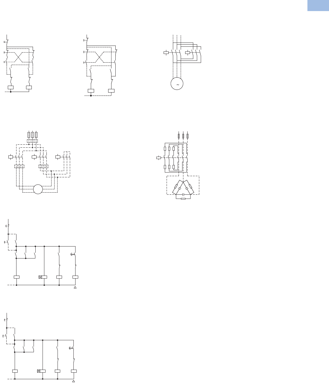
Volume 5—Motor Control and Protection CA08100006E—February 2014 www.eaton.com V5-T1-109
1
1
1
1
1
1
1
1
1
1
1
1
1
1
1
1
1
1
1
1
1
1
1
1
1
1
1
1
1
1
1.1
IEC Contactors and Starters
XT
IEC Power Control
Wiring Diagrams
7–150A XTCR Reversing Contactors
Control Circuit—7–32A Control Circuit—40–170A
Star-Delta (Wye-Delta) Starters
Power Circuit—12–385A AC-3
Control Circuit—12–55A AC-3
Control Circuit—70–1700A AC-3
K2M 54
K1M 54
53 53
K2M 22
21 K1M 22
21
K1M A1
A2 K2M A1
A2
I14
13
13
II 21
22
22
21
21
22
0
14
K2M 14
K1M 14
13 13
K2M 22
21 K1M 22
21
K1M A1
A2 K2M A1
A2
(-)N
I14
13
13
II 21
22
22
21
21
22
0
14
K1M 15
642 K5M 15
642 K3M 1
33
35
642
U1
V1
W1 M1
3~
M1
V2
W2
U2
AC
B
0.58 x ln
0.58 x ln
L1L2 L3
F1
1 x l
n
S11
0
(–)N
K1M
K3M
K3M
K5M
K1
I
K1M
K1M
K5M
K3M
K1
K5M
NY
K1T
21
22
13
14
A2
A1
A2
A1
53
54
22
21
28
17
17
18
14
13
53
54
53
54
A2
A1
A2
A1
22
21
S11
0
(–)N
K1M
K3M
K3M
K5M
K1
I
K1M
K1M
K5M
K3M
K1
K5M
NY
K1T
21
22
13
14
A2
A1
A2
A1
13
14
22
21
28
17
17
18
14
13
13
14
43
44
A2
A1
A2
A1
22
21
Power Circuit—7–150A with
Mechanical Interlock 80–
150A on Mounting Plate
XTCC Contactors for Three-Phase Capacitors
Power Circuit—11–85 kVAR
In the case of group
compensation, multi-stage
capacitor banks are
connected to the mains, as
required. In the process,
transient currents of up to
180 x Ie can flow between
the capacitors. The capacitors
are pre-charged via the early-
make auxiliary contacts and
the fitted wire resistors,
thereby reducing the inrush
current. The main contacts
then close after a time lag
and carry the uninterrupted
current. The contactors for
capacitors are weld-resistant
with inrush current peaks up
to 180 x 1 Ie due to their
special contacts. For
switching reactive-power
compensation equipment
with chokes, observe
design notes.
For switching of power factor
connection with reactors,
please observe engineering
notes, Page V5-T1-64. Use of
the contactors XTCE without
series resistor for centralized
power factor correction—
when using contactors for
group compensation, a
minimum inductance of
approximately 6 μH per
capacitor must be available to
limit the high inrush current
peaks. This corresponds to an
air-cored coil with 5 windings
and a coil diameter of
approximately 140 mm
diameter. The conductor
cross-section must be
selected according to the
rated current per phase.
UVW
K1M
M
M1
K2M
135
64
2
13 5
6
4
2
3
A1
A2
R11 R11
R11
C1
1
2
3
4
5
L1 L2 L3
6
V5-T1-110 Volume 5—Motor Control and Protection CA08100006E—February 2014 www.eaton.com
1
1
1
1
1
1
1
1
1
1
1
1
1
1
1
1
1
1
1
1
1
1
1
1
1
1
1
1
1
1
1.1
IEC Contactors and Starters
XT
IEC Power Control
Contactor Contact Travel Diagrams
Note: The diagrams indicate the closing and travel of the contacts of the contactors and auxiliary
contacts at no-load. Tolerances are not taken into consideration.
4.5
4.5
3.30
01.0 2.9
2.9
2.10
00.7 4.4
4.4
3.30
01.0
4.5
4.5
3.20
01.6 2.9
2.9
2.30
00.7 4.4
4.4
3.20
01.6
4.5
4.5
2.00
02.8 2.9
2.9
1.10
01.9 4.4
4.4
2.00
02.8
6.040
1.8
3.2
7. 5
5.10 1180
7. 5
7. 5
5.7
3.9
0
0
11
11
9.20
07. 4
6
6
3.20
01.6
7. 5
5.40
7. 5
3.8
0
11
11
7. 30
08.9
6
6
2.00
02.8
7. 5
7. 5
5.45
3.6
0
0
11
11
8.950
07. 1
7. 5
4.950
7. 5
4.1
011
11
7. 60
08.45
XTCE 7–15A, XTC—AC
Frame B
Frame C Frame D Frames F and G
XTCEXSAC11
XTCEXF...LC_
XTCE 15–32A
XTCEXSBLN11 XTCEXSBLN11
XTCEXS...N_
XTCEXF...G_
XTCEXF...LG_
XTCE 80–170A
XTCEXF...LC_
XTCEXSAC11
XTCE 12–15A, XTCF—DC
XTCEXS...N_
XTCEXF...LG_
XTCEXF...G_
XTCE 40–72A
XTCEXF...LC_
XTCEXSAC11
XTCE 7–9A—DC
NO contact
NC contact
NO contact
NC contact
NO contact
NC contact
NO contact
NC contact
NO contact
NC contact
NO contact
NC contact
NO contact
NC contact
NO contact
NC contact
NO contact
NC contact
NO contact
Auxiliary NC
Auxiliary NO
NO contactNO contact
NO contact
NC contact
NO contact
NC contact
XTCEXSAC11, XTCEXF...C_
NO contact
NC contact
NO contact
NC contact
NO contact
NC contact
XTCEXF...LC_
NO contact
NC contact
NO contact
NC contact
NO contact
NC contact
NO contact
NC contact
NO contact
NC contact
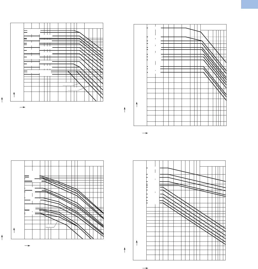
Volume 5—Motor Control and Protection CA08100006E—February 2014 www.eaton.com V5-T1-111
1
1
1
1
1
1
1
1
1
1
1
1
1
1
1
1
1
1
1
1
1
1
1
1
1
1
1
1
1
1
1.1
IEC Contactors and Starters
XT
IEC Power Control
Electrical Life Curves
Normal Switching Duty
XTCE007B–XTCE170G XTCE185H–XTCEC16R
Extreme Switching Duty
XTCE007B–XTCE170G XTCE185H–XTCEC16R
Rated Output of Three-phase Motors 50 – 60 Hz
Rated Operational Current Ie 50 – 60 Hz
Component Lifespan (millions of operations)
A
kW
150
115
95
80
65
50
40
32
25
18
12
9
7
5
4
3
2
AC-3/400V
75
55
45
37
30
22
18.5
15
11
7. 5
5.5
4
3
0.01 0.02 0.04 0.06 0.1 0.2 0.4 0.6 1 2 4 6 10
XTCE032C
XTCE050D
XTCE025C
XTCE015B
XTCE040D
XTCE065D
XTCE080F
XTCE115G
XTCE095F
XTCE150G
170
90 XTCE170G
XTCE018C
XTCE012B
XTCE009B, XTMC9A
XTCE007B
XTMC9A
XTMC9A
Rated Output of Three-phase Motors 50 – 60 Hz
Rated Operational Current Ie 50 – 60 Hz
Component Lifespan (millions of operations)
AC-3/400 V
kW
132
110
90
75
55
45
37
30
22
18.5
15
11
7. 5
A
820
750
650
580
500
400
300
250
450
900
400
355
315
250
200
160
225
185
145
104
85
72
58
43
36
30
23
16
XTCE185H
XTCE225H
XTCE250L
XTCE300L
XTCE400M
XTCE500M
XTCE580N
XTCE650N
XTCE750N
XTCE820N
0.01 0.02 0.04 0.06 0.1 0.2 0.4 0.6 1 2 3 4 5 6 8 10
1600
XTCEC10N
XTCEC16R
560 1000
Rated Output of Three-phase Motors 50 – 60 Hz
Rated Operational Current Ie 50 – 60 Hz
Component Lifespan (millions of operations)
A
kW
100
90
80
66
40
35
32
20
17
13
9
8.3
6.5
52
47
41
33
19
17
15
9
7. 5
5.5
4
3.5
2.5
5
4
3
2
AC-4/400V
0.01 0.02 0.04 0.06 0.1 0.2 0.4 0.6 1 2 4 6 10
XTCE150G,
XTCE170G
XTCE065D
XTCE032C
XTCE012B,
XTCE015B
XTCE007B
XTCE115G
XTCE080F
XTCE050D
XTCE025C
XTCE009B
XTMC9A
XTCE095F
XTCE040D
Rated Output of Three-phase Motors 50 – 60 Hz
Rated Operational Current I
e
50 – 60 Hz
Component Lifespan (millions of operations)
XTCE185H
kW
315
280
200
160
110
90
75
55
45
37
30
22
18.5
15
11
7. 5
5.5
4
3
2.2
1.5
576
355
450
750
656
512
360
250 456
296
200
132 240
164
140
104
85
72
58
43
36
30
23
16
12
8.8
6.5
5
3.5
XTCE225H
XTCE250L
XTCE300L
XTCE750N
XTCE820N
800 XTCEC10N
1280 XTCEC16R
XTCE650N
XTCE580N
XTCE500M
XTCE400M
AC-4/400 V
A
0.01 0.02 0.03 0.04 0.06 0.1 0.2 0.3 0.4 0.6 1 2 3 4 5 6 8 10
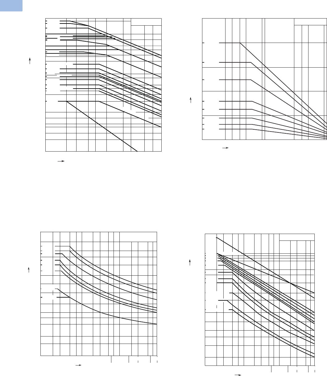
V5-T1-112 Volume 5—Motor Control and Protection CA08100006E—February 2014 www.eaton.com
1
1
1
1
1
1
1
1
1
1
1
1
1
1
1
1
1
1
1
1
1
1
1
1
1
1
1
1
1
1
1.1
IEC Contactors and Starters
XT
IEC Power Control
Switching Duty for Non-Motor Loads
Three-Pole—XTCE007B–XTCEC20R Four-Pole—XTCF020B–XTCF200G
Short-Time Loading
Three-Pole—XTCE007B–XTCEC20R Three-Pole—XTCE080F–XTCEC16R
2000
1800
XTCEC16R
XTCEC14P
AC-1/400 V
0.1 0.2 75.0 0.7 1 3510
2
1
3
4
23.0
5
900 850
1400
1000
700
800
500
400
275
300
350
160
10
7
XTCE185H
XTCE225H
XTCE400M
XTCE300L
XTCE250L
XTCE750N
XTCE650N
XTCE500M XTCE580N
XTCEC20R
XTCE820N, XTCEC10N
130
XTCE115G
110
XTCE095F
90
XTCE080F
80
XTCE065D
65
XTCE050D
50
XTCE040D
40
35
XTCE018C
20
XTMC9A
XTCE007B, XTCE009B, XTCE012B, XTCE015B
XTCE150G, XTCE170G
XTCE025C, XTCE032C
Breaking Current A
Component Lifespan (millions of operations)
AC-1/400 V
Breaking Current A
Component Lifespan (millions of operations)
XTCF020B
XTCF032C
XTCF045C
XTCF063D
XTCF080D
XTCF125G
XTCF160G
XTCF200G
0.2 0.4 0.6 1 2 4 6 100.1
200
160
125
80
63
45
32
22
Operating characteristics:
Non-inductive and slightly inductive loads
Electrical characteristics:
Switch on: 1 x Rated current
Switch off: 1 x Rated current
Utilization category:
10 0% AC-1
Typical applications:
Electrical heating
10 min 15 min
1 min 3 min 5 min
AC-1/400 V
70 100
5072030
35102
A
700
500
600
400
300
250
15
200
120
100
70
50
40
30
150
900
200 300 500
20
700
XTCE018C
90
XTCE007B,
XTCE009B
XTCE050D
XTCE065D
450 XTCE040D
350 XTCE032C
XTCE025C
Seconds
XTCE012B,
XTCE015B
Short-time Current
Duration of load
10 min 15 min1 min 3 min 5 min
XTCEC10N, XTCEC14P
90030070 100507203035 102
A
8000
10000
19000
6000
5000
4000
3000
2500
2000
1800
110 0
1000
700
500
400
300
1500
XTCE080F, XTCE095F
XTCE185H, XTCE225H
XTCE250L
700200 500
200
AC-1/400 V
XTCEC16R
XTCE115G,
XTCE150G,
XTCE170G
Seconds
XTCE300L
XTCE500M
XTCE580N
XTCE650N
XTCE750N
XTCE820N
XTCE400M
XTCEC20R
Short-time Current
Duration of load
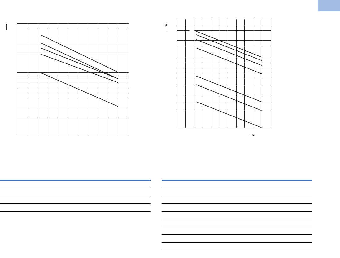
Volume 5—Motor Control and Protection CA08100006E—February 2014 www.eaton.com V5-T1-113
1
1
1
1
1
1
1
1
1
1
1
1
1
1
1
1
1
1
1
1
1
1
1
1
1
1
1
1
1
1
1.1
IEC Contactors and Starters
XT
IEC Power Control
Maximum Operating Frequency—Related to Rating and Utilization Category (400V)
7 to 150 hp
Utilization Category 1
185 to 820 hp
Utilization Category 1
Note
1PN = max. motor rating (kW/hp) of the relevant contactor.
ops./h = max. number of operations per hour.
Type
Characteristic Curve Above
AC-1 AC-3 AC-2, AC-4
XTCE007B–XTCE015B 3 1 5
XTCE018C–XTCE032C 3 2 5
XTCE040D–XTCE065D 3 2 5
XTCE080F–XTCE150G 3 4 5
6000
4000
2000
1000
800
600
400
200
100
010 20 30 40 50 60 70 80 90 100 %
PN [kW/hp]
a
b
e
c
d
Ops./h
Type
Characteristic Curve Above
AC-1 AC-3 AC-2, AC-4
XTCE185H 2 1 6
XTCE225H 2 1 6
XTCE250L 2 1 6
XTCE300L 3 2 7
XTCE400M 3 2 7
XTCE500M 3 2 7
XTCE580N 3 4 5
XTCE650N 3 4 5
XTCE750N 3 4 5
XTCE820N 3 4 5
P
N
[kW/hp]
Ops./h
4000
3000
2000
600
500
400
300
200
150
100
50
010 20 30 40 50 60 70 80 90 100 %
1500
1000
800
a
b
d
c
e
f
g
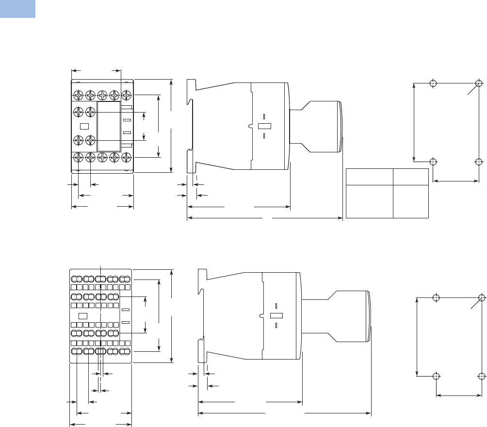
V5-T1-114 Volume 5—Motor Control and Protection CA08100006E—February 2014 www.eaton.com
1
1
1
1
1
1
1
1
1
1
1
1
1
1
1
1
1
1
1
1
1
1
1
1
1
1
1
1
1
1
1.1
IEC Contactors and Starters
XT
IEC Power Control
Dimensions
Approximate Dimensions in mm [in]
XTCE Contactors (Three-Pole)
Frame B, XTCE007B and XTCE015B Contactors with Screw Terminals (7–15A) XTCF020B
Frame B, XTCEC007B–XTCEC012B Contactors with Spring Cage Terminals (7–12A)
18
[.71] 45
[1.77]
68
[2.68]
45 [1.77]
36 [1.42]
8.7 [.34]
Typ. 5.1 [.20] 6.5 [.26]
75 [2.95]
C
3.2 [.13]
Auxiliary
Type
XTCEXFAC_
XTCEXFCC_
XTCEXFATC_
C
117 [4.61]
117 [4.61]
125 [4.92]
35 [1.38]
4 x M4 Dia.
60 [2.36]
68
[2.68]
6.5 [.26]
3.2 [.13]
75 [2.95]
125.2 [4.93]
26.4
[1.04]
52.3
[2.06]
45 [1.77]
5.1 [.20]
1.8
[.07]
1.8
[.07]
8.7 [.34]
Typ.
35 [1.38]
4 x M4 Dia.
60 [2.36]
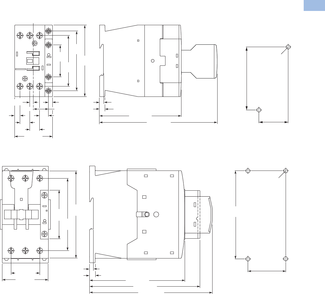
Volume 5—Motor Control and Protection CA08100006E—February 2014 www.eaton.com V5-T1-115
1
1
1
1
1
1
1
1
1
1
1
1
1
1
1
1
1
1
1
1
1
1
1
1
1
1
1
1
1
1
1.1
IEC Contactors and Starters
XT
IEC Power Control
Approximate Dimensions in mm [in]
Frame C, XTCE018C–XTCE032C Contactors (18–32A)
Frame D, XTCE040D–XTCE072D Contactors (72A)
11. 6
[.46] 11. 6
[.46]
4.5 [.17]
17.7 [.70]
10.6
[.42]
6.4
[.25]
38
[1.50]
71
[2.80]
60.4
[2.38]
85
[3.46]
45 [1.77]
4.8 [.19]
138.7 [5.46]
6.5 [.26]
97.4 [3.83]
Note: Sideways distance to grounded parts: 6 mm [.39 in]
4.5 [.17]
35 [1.38]
2 x M4 Dia.
75 [2.95]
6.9 [.27]
4.7 [.19]
34.4 [1.35]
113.8 [4.48]
132.1 [5.20]
146.8 [5.78]
Note: Sideways distance to
grounded parts: 6 mm [.39 in]
55 [2.17]
57
[2.24]
86.4
[3.40]
104
[4.09]
45 [1.77]
4 x M4 Dia.
105 [4.13]
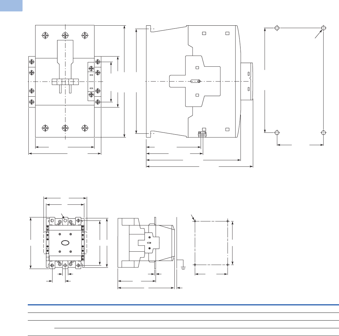
V5-T1-116 Volume 5—Motor Control and Protection CA08100006E—February 2014 www.eaton.com
1
1
1
1
1
1
1
1
1
1
1
1
1
1
1
1
1
1
1
1
1
1
1
1
1
1
1
1
1
1
1.1
IEC Contactors and Starters
XT
IEC Power Control
Approximate Dimensions in mm [in]
Frames F–G, XTCE080F–XTCE170G Contactors (80–170A)
Frames H–M, XTCE185H–XTCE570M Contactors (185–580A)
Note: Sideways distance to
grounded parts: 10 mm [.39 in]
90 [3.54]
111 [4.37]
82.5 [3.25]
85.5 [3.37]
142 [5.59]
160 [6.30]
76.5 [3.01]
57 [2.24]
170 [6.69]
156 [6.14]
4 x M6 Dia.
156 [6.14]
70 [2.79]
W W1W2W3W4H H1 H2 H3 D D1 D2
Frame H 140 [5.51] 160 [6.30] 120 [4.72] 20 [.79] 41 [1.61] 180 [7.09] 165 [6.50] 190 [7.48] 160 [6.30] 158 [6.22] 4 [.16] 83 [3.27]
Frame L 140 [5.51] 160 [6.30] 120 [4.72] 20 [.79] 48 [1.89] 180 [7.09] 164 [6.46] 189 [7.44] 160 [6.30] 208 [8.19] 5 [.20] 140 [5.51]
Frame M 160 [6.30] 180 [7.09] 130 [5.12] 25 [.98] 48 [1.89] 200 [7.87] 184 [7.24] 209 [8.23] 180 [7.09] 216 [8.50] 6 [.24] 140 [5.51]
160 [6.30] 180 [7.09] 130 [5.12] 38 [1.50] 57 [2.24] 200 [7.87] 189 [7.44] 219 [8.62] 180 [7.09] 216 [8.50] 6 [.24] 140 [5.51]
D8 [.31]
D2
H3
W2
M6 Dia.
D1
W3
H1 H
W4
W
11 [.43] Dia.
W1
H2
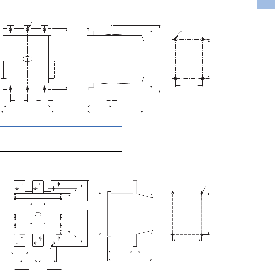
Volume 5—Motor Control and Protection CA08100006E—February 2014 www.eaton.com V5-T1-117
1
1
1
1
1
1
1
1
1
1
1
1
1
1
1
1
1
1
1
1
1
1
1
1
1
1
1
1
1
1
1.1
IEC Contactors and Starters
XT
IEC Power Control
Approximate Dimensions in mm [in]
Frame N, XTCE580N–XTCEC10N Contactors (580–1000A)
Frame P, XTCEC14P Contactor (1400A, AC-1)
W H D1 A (Dia.)
XTCE580N 45 [1.77] 296 [11.65] 6 [.24] 13.5 [.53]
XTCE650N 45 [1.77] 296 [11.65] 6 [.24] 13.5 [.53]
XTCE750N 45 [1.77] 296 [11.65] 6 [.24] 13.5 [.53]
XTCE820N 45 [1.77] 296 [11.65] 6 [.24] 13.5 [.53]
XTCEC10N 45 [1.77] 296 [11.65] 10 [.40] 13.5 [.53]
250 [9.84]
80
[3.15] W
A Dia.
232
[9.13]
232 [9.13]
H
140 [5.51]
256
[10.08]
270 [10.63]
D1
165 [6.50]
215
[8.46]
M6
Dia.
100
[3.94]
60
[2.36]
100
[3.94]
210
[8.27]
232
[9.13]
256
[10.08]
342
[13.46]
308
[12.13]
260 [10.24]
14 [.55]
Dia.
232 [9.13]
130 [5.12] 10
[.39]
165 [6.50]
215
[8.46]
M6 Dia.
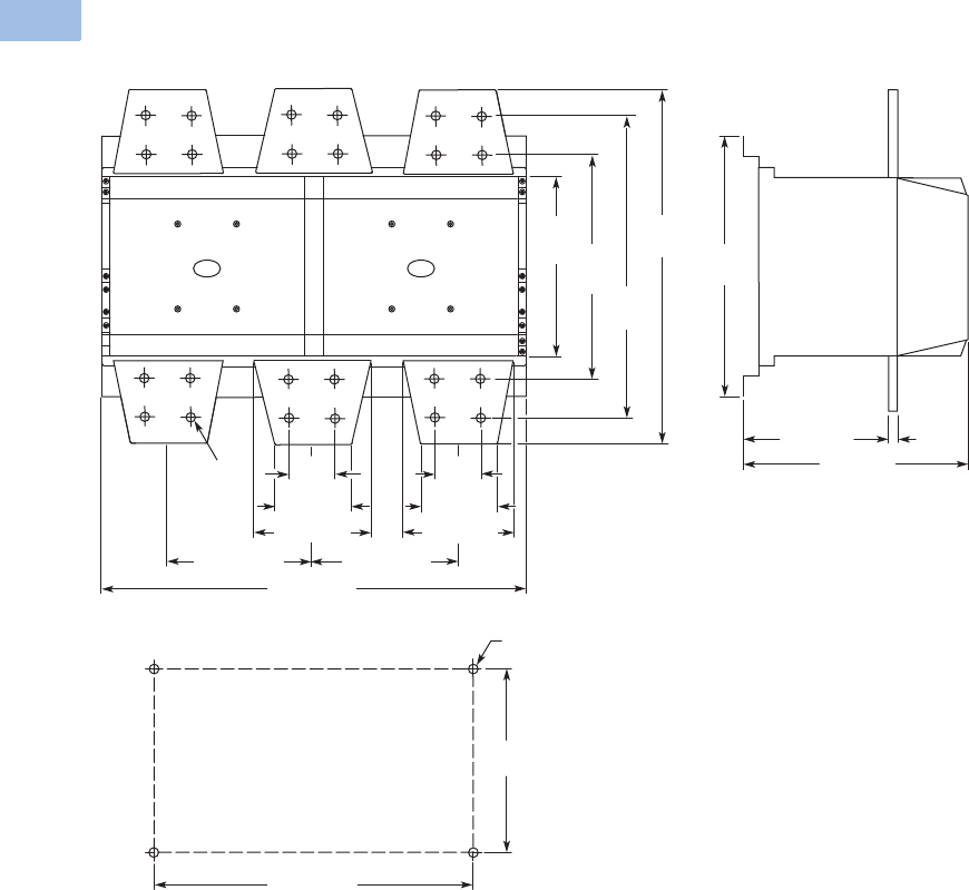
V5-T1-118 Volume 5—Motor Control and Protection CA08100006E—February 2014 www.eaton.com
1
1
1
1
1
1
1
1
1
1
1
1
1
1
1
1
1
1
1
1
1
1
1
1
1
1
1
1
1
1
1.1
IEC Contactors and Starters
XT
IEC Power Control
Approximate Dimensions in mm [in]
Frame R, XTCEC16R, XTCEC20R Contactors
125 [4.92]
172.5 [6.79]172.5 [6.79]
210
[8.27] 272
10.71]
352
[13.86]
392
[15.43]
14 [.55]
Dia.
300
[11.81]
252 [9.92]
150 [5.91] 10 [.39]
80 [3.15]
40
[1.57]
80 [3.15]
150 [5.90]
515 [20.28]
430 [16.93]
270
[10.63]
M6 Dia.
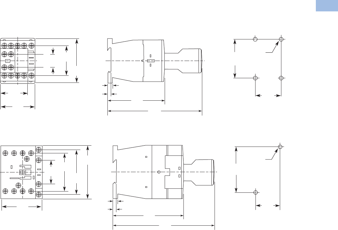
Volume 5—Motor Control and Protection CA08100006E—February 2014 www.eaton.com V5-T1-119
1
1
1
1
1
1
1
1
1
1
1
1
1
1
1
1
1
1
1
1
1
1
1
1
1
1
1
1
1
1
1.1
IEC Contactors and Starters
XT
IEC Power Control
Approximate Dimensions in mm [in]
XTCF Contactors (Four-Pole)
Frame B, XTCF020B Contactors
Frame C, XTCF032C–XTCF045C Contactors
35.0
[1.38]
60.0
[2.36]
2 x M4
36.0
[1.42]
45.0
[1.77]
6.5
[0.26]
3.2
[0.13] 75.0
[2.95]
11 7. 0
[4.61]
45.0
[1.77]
18.0
[0.71]
68.0
[2.68]
35.0
[1.38]
75.0
[2.95]
2 x M4
58.0
[2.28]
6.5
[0.26]
4.5
[0.18] 97.4
[3.83]
138.0
[5.43]
71.0
[2.80]
60.0
[2.36]
85.0
[3.35]
38.0
[1.50]
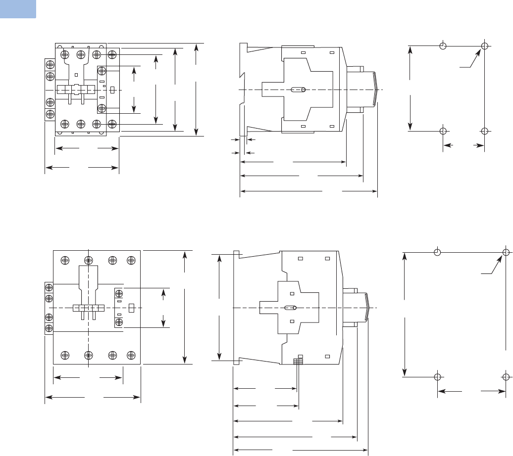
V5-T1-120 Volume 5—Motor Control and Protection CA08100006E—February 2014 www.eaton.com
1
1
1
1
1
1
1
1
1
1
1
1
1
1
1
1
1
1
1
1
1
1
1
1
1
1
1
1
1
1
1.1
IEC Contactors and Starters
XT
IEC Power Control
Approximate Dimensions in mm [in]
Frame D, XTCF063D–XTCF080D Contactors
Frame G, XTCF125G–XTCF200G Contactors
45.0
[1.77]
105.0
[4.13]
2 x M4
74.0
[2.91]
6.9
[0.27]
4.7
[0.19] 114.0
[4.49] 132.1
[5.20]
85.0
[3.35]
104.0
[4.09]
86.4
[3.40]
115.0
[4.53]
57.0
[2.24]
147.0
[5.79]
70.0
[2.76]
156.0
[6.14]
4 x M6
122.0
[4.80]
133.0
[5.24]
170.0
[6.69]
57.0
[2.24]
82.5
[3.25]
142.0
[5.59]
160.0
[6.30]
85.5
[3.37]
175.0
[6.89]
156.0
[6.14]
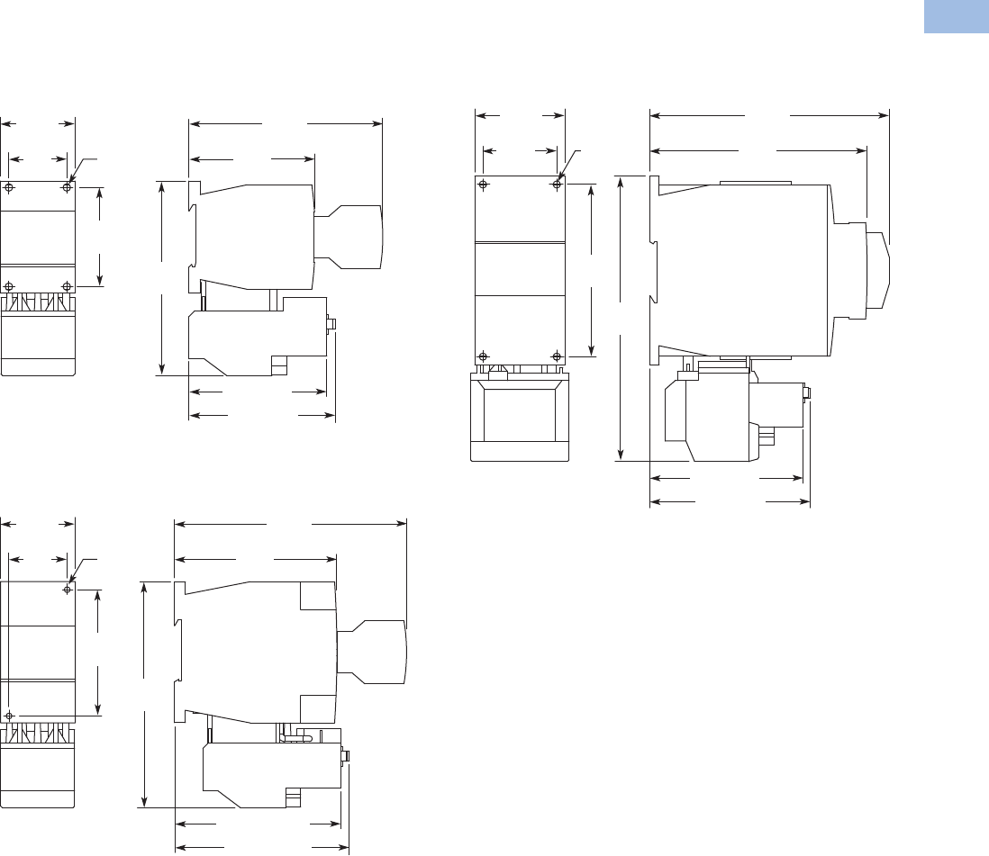
Volume 5—Motor Control and Protection CA08100006E—February 2014 www.eaton.com V5-T1-121
1
1
1
1
1
1
1
1
1
1
1
1
1
1
1
1
1
1
1
1
1
1
1
1
1
1
1
1
1
1
1.1
IEC Contactors and Starters
XT
IEC Power Control
Approximate Dimensions in mm [in]
XTAE Starters with XTOB Overload Relay
Frame B, XTAE007B–XTAE015B Starters with
XTOB (7–12A)
Frame C, XTAE018C–XTAE032C Starters with
XTOB (18–32A)
Frame D, XTAE040D–XTAE065D Starters with XTOB
(40–65A)
88.4 [3.48]
To Reset
83.3 [3.28]
75.8
[2.98]
35
[1.38]
Mounting
Holes for
M4 or #8
Screws
(4 Places)
11 7. 8
[4.64]
60
[2.36]
11 7. 1
[4.61]
45.3
[1.78]
105.3 [4.15]
To Reset
100.2 [3.94]
136.4
[5.37]
75
[2.95]
97.8
[3.85]
35
[1.38]
Mounting
Holes for
M4 or #8
Screws
(2 Places)
139.8
[5.50]
45
[1.77]
98 [3.86]
To Reset
93.6 [3.69]
174
[6.85]
105
[4.13]
132.5
[5.22]
45
[1.77]
Mounting
Holes for
M4 or #8
Screws
(4 Places)
146
[5.75]
60
[2.36]
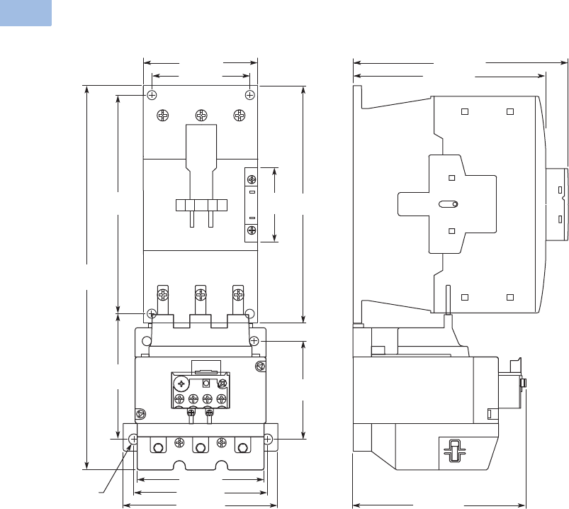
V5-T1-122 Volume 5—Motor Control and Protection CA08100006E—February 2014 www.eaton.com
1
1
1
1
1
1
1
1
1
1
1
1
1
1
1
1
1
1
1
1
1
1
1
1
1
1
1
1
1
1
1.1
IEC Contactors and Starters
XT
IEC Power Control
Approximate Dimensions in mm [in]
Frames F–G, XTAE080F–XTAE150G Starters with XTOB (80–150A)
91
[3.58]
90 [3.54]
150 [5.91]
57
[2.24]
170
[6.69]
156
[6.14]
160 [6.30]
277
[10.91]
70 [2.76]
7 [.276]
Dia.
100 [3.94]
134 [5.28]
74
[2.91]
118 [4.65]
95 [3.74]
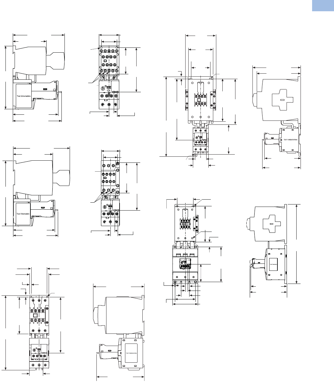
Volume 5—Motor Control and Protection CA08100006E—February 2014 www.eaton.com V5-T1-123
1
1
1
1
1
1
1
1
1
1
1
1
1
1
1
1
1
1
1
1
1
1
1
1
1
1
1
1
1
1
1.1
IEC Contactors and Starters
XT
IEC Power Control
Approximate Dimensions in mm [in]
XTAE Starters with XTOE Overload Relay
Frame B, XTAE007B–XTAE012B Starters
with XTOE (0.35–20A)
Frame C, XTAE018C–XTAE032C Starters
with XTOE (0.35–45A)
Frame D, XTAE040D–XTAE065D Starters
with XTOE (20–100A)
Frames F–G, XTAE080F–XTAE115G Starters
with XTOE (20–100A)
Frame G, XTAE115G–XTAE150G Starters
with XTOE (100–175A)
117.0 [4.61]
75.8 [2.98]
110.4 [4.35]
102.7 [4.04]
143.2
[5.64] 1.2 Nm
[11 lb-in]
18.2 [0.71]
Trip/Test
10.6 [0.42]
Reset
35.0 [1.38]
Mounting
Holes for
M4 or #8
Screws
(4 places)
100.6
[3.96]
60.0
[2.36]
45.3 [1.78]
140.0 [5.50]
98.0 [3.80]
110.4 [4.35]
102.7 [4.04]
161.0
[6.30] 2.5–3.0 Nm
[22–26 lb-in]
18.2 [0.71]
Trip/Test
10.6 [0.42]
Reset
35.0 [1.38]
Mounting
Holes for
M4 or #8
Screws
(2 places)
117.3
[4.62]
75.0
[2.95]
45.0 [1.77]
55.0 [2.17]
136.2 [5.36]
To Reset
38.7 [1.52]
To Reset
146.1 [5.75]
159.7
[6.29]
To Reset
5.0 [0.20]
105.0
[4.13]
Mtg.
213.6
[8.41]
Mtg. Holes for
(4) #8 Screws or
M4 Screws
5.0 [0.20]
45.0 [1.77] Mtg.
132.4 [5.21]
To Reset
Mtg. Holes
for (2) M4
or #8 Screws 140.2 [5.52]
175.0 [6.89]
160.0 [6.30]
Mtg. Holes for
(4) M6 or #10
Screws
156.0
[6.14]
Mtg. 167.3
[6.59]
Mtg.
108.4
[4.27]
Mtg.
41.2 [1.62] Mtg.
56.0 [2.20]
222.3
[8.75]
To Reset
291.1
[11.46]
7.8
[0.31]
70.0
[2.76]
90.0
[3.54]
Mtg.
111.8
[4.40]
345.0
[13.6]
89.0
[3.50]
Terminal
Torque:
14 Nm
[124 lb-in]
77.0
[3.00]
152.0
[6.00]
161.0 [6.30]
157.0 [6.18]
156.0
[6.14]
M6 [#10] Screws
70.0
[2.76]
21.3 [0.84]
5.0
[0.20]
18.2 [0.71] Trip/Test
10.6 [0.42] Reset
36.0 [1.42]
110.0 [4.30]
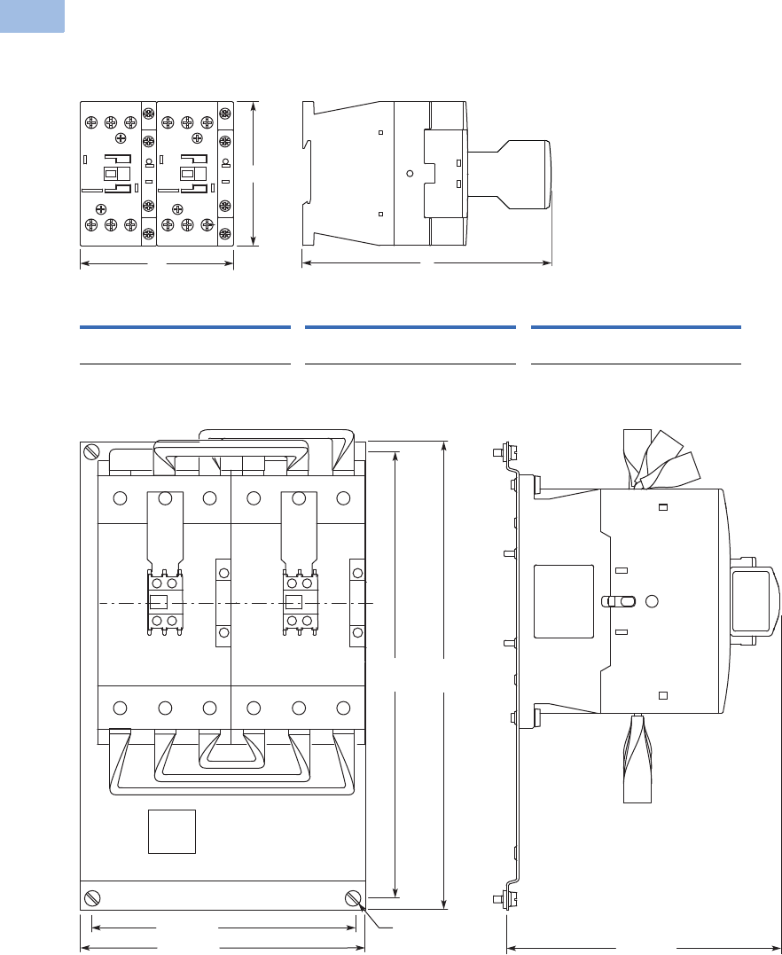
V5-T1-124 Volume 5—Motor Control and Protection CA08100006E—February 2014 www.eaton.com
1
1
1
1
1
1
1
1
1
1
1
1
1
1
1
1
1
1
1
1
1
1
1
1
1
1
1
1
1
1
1.1
IEC Contactors and Starters
XT
IEC Power Control
Approximate Dimensions in mm [in]
XTCR Reversing Combination
Frames B–D
Frames F–G
Frame B (7–15A) Frame C (18–32A) Frame D (40–65A)
WH D WH D WH D
90
[3.54]
68
[2.68]
117
[4.61]
90
[3.54]
85
[3.34]
138
[5.43]
110
[4.33]
115
[4.53]
146.8
[5.78]
H
D
W
314
[12.36]
299
[11.77]
M6
176 [6.93]
196 [7.72] 183 [7.20]
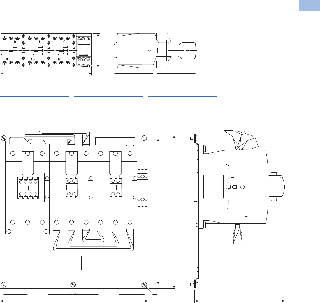
Volume 5—Motor Control and Protection CA08100006E—February 2014 www.eaton.com V5-T1-125
1
1
1
1
1
1
1
1
1
1
1
1
1
1
1
1
1
1
1
1
1
1
1
1
1
1
1
1
1
1
1.1
IEC Contactors and Starters
XT
IEC Power Control
Approximate Dimensions in mm [in]
Star-Delta Combination
Frames B–D
Frames F–G
Frame B Frame C Frame D
WH D WH D WH D
158
[6.22]
68
[2.68]
117
[4.61]
158
[6.22]
85
[3.34]
138
[5.43]
188
[7.40]
115
[4.53]
146.8
[5.78]
H
D
W
M6
314
[12.36]
299
[11.77]
144 [5.67] 144 [5.67]
308 [12.13] 183 [7.20]
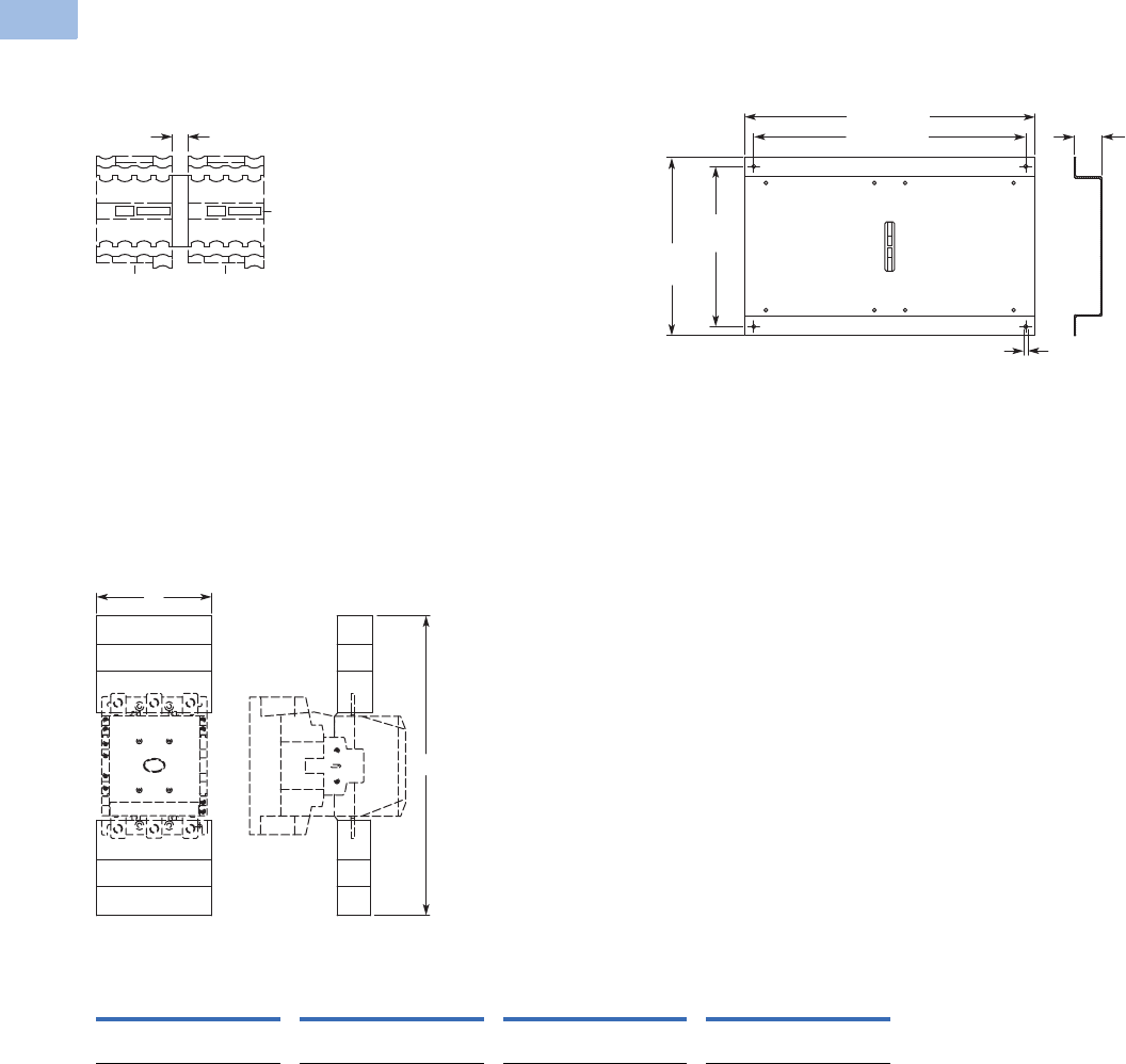
V5-T1-126 Volume 5—Motor Control and Protection CA08100006E—February 2014 www.eaton.com
1
1
1
1
1
1
1
1
1
1
1
1
1
1
1
1
1
1
1
1
1
1
1
1
1
1
1
1
1
1
1.1
IEC Contactors and Starters
XT
IEC Power Control
Approximate Dimensions in mm [in]
Mechanical Interlock
Frames H–M—XTCEXMLM XTCEXMLN
Contactor with Terminal Shroud
Frames L–N Contactors, XTCE250L–XTCEC10N,
with Terminal Shroud XTLEXTS
15
[.59]
9 [.35]
515 [20.28]
430 [16.93]
270
[10.63]
300
[11.81]
20
[.79]
XTCE250L XTCE400M XTCE500M, XTCE570M
XTCE580N, XTCE650N,
XTCE750N, XTCE820N,
XTCEC10N
WH WH WH WH
150
[5.91]
384
[15.12]
150
[5.91]
404
[15.91]
174
[6.85]
426
[16.77]
236
[9.29]
506
[19.92]
W
H
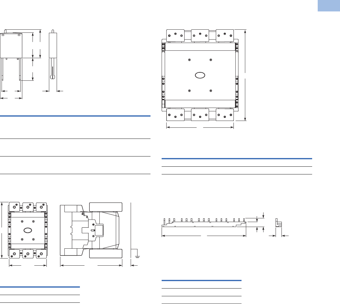
Volume 5—Motor Control and Protection CA08100006E—February 2014 www.eaton.com V5-T1-127
1
1
1
1
1
1
1
1
1
1
1
1
1
1
1
1
1
1
1
1
1
1
1
1
1
1
1
1
1
1
1.1
IEC Contactors and Starters
XT
IEC Power Control
Approximate Dimensions in mm [in]
Suppressor
XTCE_ Suppressor
Cable Terminal Block
XTCEXTLA
Flat Strip Conductor Terminals
XTCEXTFB
Three-Phase Commoning Link
Frame B
W1 W2 H1 H2 H3 D
XTCEXRSB_
XTCEXVSB_
XTCEXVSLB_
XTCEXDSB_
25
[.98]
9.2
[.36]
25.9
[1.02]
28
[1.10]
32
[1.26]
9
[.35]
XTCEXRSC_
XTCEXVSC_
XTCEXVSLC_
25
[.98]
9.2
[.36]
16
[.63]
28
[1.10]
32
[1.26]
9
[.35]
XTCEXRSF_
XTCEXVSF_
XTCEXVSLF_
25
[.98]
20
[.79]
18.5
[.73]
28
[1.10]
32
[1.26]
9
[.35]
H
XTCE250L 198 [7.80]
XTCE400M 218 [8.58]
W2 D
W1
H2
H3
H1
135
[5.31] 222
[8.74]
H
30
[1.18]
WH
XTCE500M–XTCE570M 171 [6.73] 232 [9.13]
XTCE750N–XTCE820N 231 [9.09] 310 [12.20]
W
XTCEXCLK3B 112 [4.41]
XTCEXCLK4B 157 [6.18]
XTCBXCLK5B 202 [7.95]
W
H
13.1
[.52]
W
18.1
[.71]
12.5
[.49]
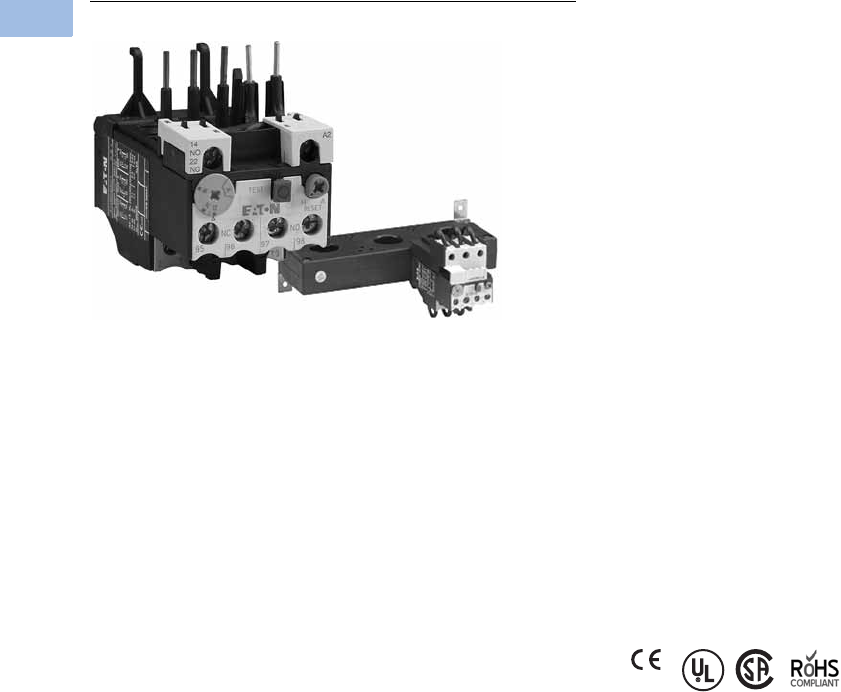
V5-T1-128 Volume 5—Motor Control and Protection CA08100006E—February 2014 www.eaton.com
1
1
1
1
1
1
1
1
1
1
1
1
1
1
1
1
1
1
1
1
1
1
1
1
1
1
1
1
1
1
1.1
IEC Contactors and Starters
XT
IEC Power Control
XTOB, XTOT Overload Relays
Contents
Description Page
Relays and Timers . . . . . . . . . . . . . . . . . . . . . . . . . V5-T1-3
Miniature Controls . . . . . . . . . . . . . . . . . . . . . . . . . V5-T1-18
Contactors and Starters . . . . . . . . . . . . . . . . . . . . V5-T1-35
Thermal Overload Relays
Catalog Number Selection . . . . . . . . . . . . . . . . V5-T1-129
Product Selection . . . . . . . . . . . . . . . . . . . . . . . V5-T1-130
Accessories . . . . . . . . . . . . . . . . . . . . . . . . . . . V5-T1-133
Technical Data and Specifications . . . . . . . . . . V5-T1-136
Dimensions . . . . . . . . . . . . . . . . . . . . . . . . . . . V5-T1-138
C440/XT Electronic Overload Relay . . . . . . . . . . . V5-T1-141
Manual Motor Protectors . . . . . . . . . . . . . . . . . . . . V5-T1-157
Combination Motor Controllers . . . . . . . . . . . . . . . V5-T1-193
XT Electronic Manual Motor Protector . . . . . . . . . V5-T1-216
Reference Data . . . . . . . . . . . . . . . . . . . . . . . . . . . V5-T1-229
Thermal Overload Relays
Product Description
The XT line of IEC motor
thermal overload relays
provides an efficient motor
protection solution, available
up to 630A. XTOB units can
be directly mounted to the
contactor or mounted
separately.
Features and Benefits
●Direct connect up to 250A
●Stand alone and CT type
up to 630A
●Large thermal overcurrent
range
●Test button
●Manual/automatic
selectable reset
●NO-NC auxiliary as
standard
●Class 10A (to 250A)
●Class 30 (CT type)
Standards and Certifications
●IEC EN 60947
●CE approved
●UL
●CSA
●ATEX
●RoHS
Notes
Short-circuit protection: Observe the maximum permissible fuse of the contactor with direct
device mounting. See MN03402001E for more information on overload relays for Frames B–G.
Trip Class: 10A
Suitable for protection of EEx e-motors. EC prototype test certificate available upon request.
See manuals MN03402001E and MN03407001E, Page V5-T1-133.
Instructional Leaflets
Pub51221 XTOB, D Frame overload relays
(inside of packaging)
Pub51222 XTOB, B–C Frame overload relays
(inside of packaging)
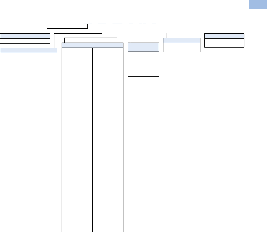
Volume 5—Motor Control and Protection CA08100006E—February 2014 www.eaton.com V5-T1-129
1
1
1
1
1
1
1
1
1
1
1
1
1
1
1
1
1
1
1
1
1
1
1
1
1
1
1
1
1
1
1.1
IEC Contactors and Starters
XT
IEC Power Control
Catalog Number Selection
XT IEC Overload Relays
XT OB P16 BC1 S
Type
OB = Bimetallic overload relay
OT = Current transformer overload relay
Device Type
XT = XT line of IEC control Trip Class
C1 = Class 10A (XTOB)
C3 = Class 30 (XTOT)
Mounting
Blank = Direct to contactor
S= Separate mount
Frame Size
Designation
B = 45 mm
C = 45 mm
D = 55 mm
G = 90 mm
L = 140 mm
Blank = XTOT only
Overload Release
Frame B
P16 = 0.1–0.16A
P24 = 0.16–0.24A
P40 = 0.24–0.4A
P60 = 0.4–0.6A
001 = 0.6–1A
1P6 = 1.0–1.6A
2P4 = 1.6–2.4A
004 = 2.4–4A
006 = 4–6A
010 = 6–10A
012 = 9–12A
016 = 12–16A
Frame C
P16 = 0.1–0.16A
P24 = 0.16–0.24A
P40 = 0.24–0.4A
P60 = 0.4–0.6A
001 = 0.6–1A
1P6 = 1.0–1.6A
2P4 = 1.6–2.4A
004 = 2.4–4A
006 = 4–6A
010 = 6–10A
016 = 12–16A
024 = 16–24A
032 = 24–32A
Frame D
010 = 6–10A
016 = 12–16A
024 = 16–24A
040 = 24–40A
057 = 40–57A
065 = 50–65A
075 = 65–75A
Frame F
035 = 25–35A
050 = 35–50A
070 = 50–70A
100 = 70–100A
Frame G
035 = 25–35A
050 = 35–50A
070 = 50–70A
100 = 70–100A
125 = 95–125A
150 = 120–150A
175 = 145–175A
Frame H
070 = 50–70A
100 = 70–100A
125 = 95–125A
160 = 120–160A
220 = 160–220A
250 = 200–250A
Frame L
070 = 50–70A
100 = 70–100A
125 = 95–125A
160 = 120–160A
220 = 160–220A
250 = 200–250A
300 = 200–300A
Frame M
063 = 42–63A
090 = 60–90A
125 = 85–125A
160 = 110–160A
240 = 160–240A
290 = 190–290A
400 = 170–400A
540 = 360–540A
Frame N
063 = 42–63A
090 = 60–90A
125 = 85–125A
160 = 110–160A
240 = 160–240A
290 = 190–290A
400 = 170–400A
540 = 360–540A
630 = 420–630A
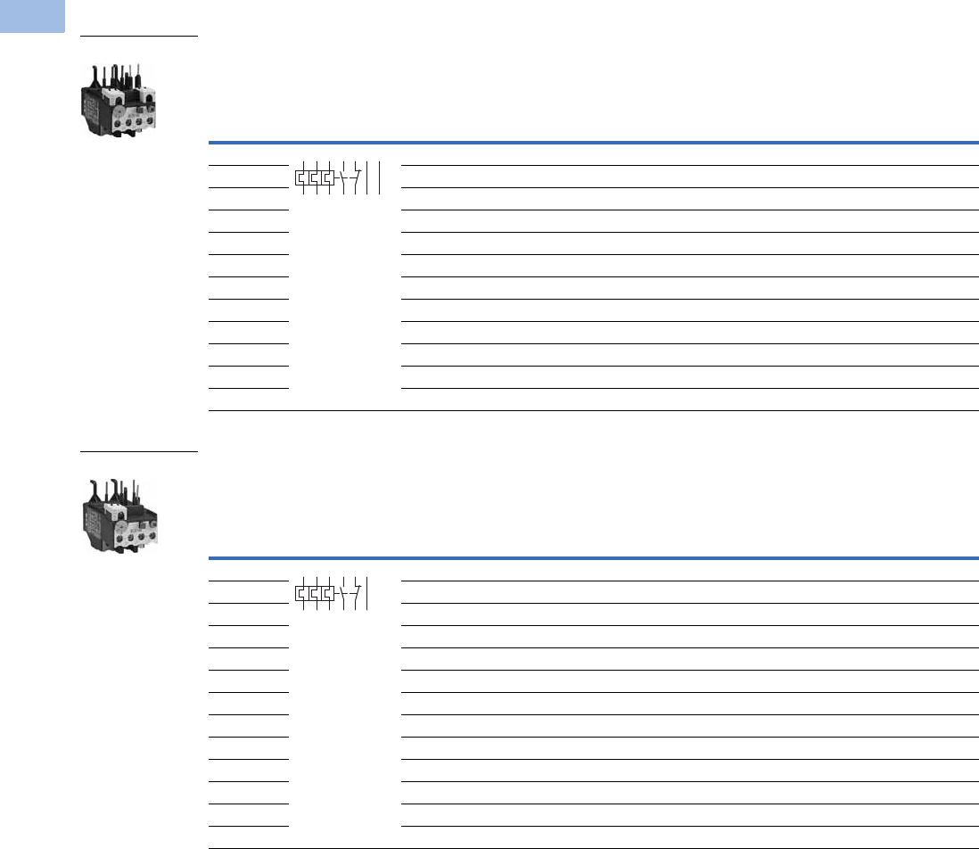
V5-T1-130 Volume 5—Motor Control and Protection CA08100006E—February 2014 www.eaton.com
1
1
1
1
1
1
1
1
1
1
1
1
1
1
1
1
1
1
1
1
1
1
1
1
1
1
1
1
1
1
1.1
IEC Contactors and Starters
XT
IEC Power Control
Product Selection
Overload Relay, Direct Mount—Frame B
Overload Relay, Direct Mount—Frame C
Overload
Releases, Ir
Contact
Sequence
Contact
Configuration
For Use
with
Contactor
Amp Range
Short-Circuit Protection (A)
Catalog Number
Fuse
Maximum
Circuit
Breaker
CEC/NEC
Fuse
Type 1
Coordination,
gG/gL
Type 2
Coordination,
gG/gL
0.1–0.16 1NO-1NC 7–15A 25 0.5 25 3 XTOBP16BC1
0.16–0.24 1NO-1NC 7–15A 25 1 25 3 XTOBP24BC1
0.24–0.4 1NO-1NC 7–15A 25 2 25 3 XTOBP40BC1
0.4–0.6 1NO-1NC 7–15A 25 4 25 3 XTOBP60BC1
0.6–1 1NO-1NC 7–15A 25 4 25 3 XTOB001BC1
1–1.6 1NO-1NC 7–15A 25 6 25 6 XTOB1P6BC1
1.6–2.4 1NO-1NC 7–15A 25 10 25 6 XTOB2P4BC1
2.4–4 1NO-1NC 7–15A 25 16 25 15 XTOB004BC1
4–6 1NO-1NC 7–15A 25 20 25 20 XTOB006BC1
6–10 1NO-1NC 7–15A 50 25 25 35 XTOB010BC1
9–12 1NO-1NC 9–15A 50 25 25 45 XTOB012BC1
12–16 1NO-1NC 12–15A 50 25 30 45 XTOB016BC1
Overload
Releases, Ir
Contact
Sequence
Contact
Configuration
For Use
with
Contactor
Amp Range
Short-Circuit Protection (A)
Catalog Number
Fuse
Maximum
Circuit
Breaker
CEC/NEC
Fuse
Type 1
Coordination,
gG/gL
Type 2
Coordination,
gG/gL
0.1–0.16 1NO-1NC 18–32A 25 0.5 25 3 XTOBP16CC1
0.16–0.24 1NO-1NC 18–32A 25 1 25 3 XTOBP24CC1
0.24–0.4 1NO-1NC 18–32A 25 2 25 3 XTOBP40CC1
0.4–0.6 1NO-1NC 18–32A 25 4 25 3 XTOBP60CC1
0.6–1 1NO-1NC 18–32A 25 4 25 3 XTOB001CC1
1–1.6 1NO-1NC 18–32A 25 6 25 6 XTOB1P6CC1
1.6–2.4 1NO-1NC 18–32A 25 10 25 6 XTOB2P4CC1
2.4–4 1NO-1NC 18–32A 25 16 25 15 XTOB004CC1
4–6 1NO-1NC 18–32A 25 20 25 20 XTOB006CC1
6–10 1NO-1NC 18–32A 50 25 25 25 XTOB010CC1
10–16 1NO-1NC 18–32A 63 35 30 25 XTOB016CC1
16–24 1NO-1NC 18–32A 100 35 30 25 XTOB024CC1
24–32 1NO-1NC 25–32A 125 63 30 25 XTOB032CC1
Frame B
2 4 6 98 96A2 14/
22
97 95
Frame C
2 4 6 98 96 14/
22
97 95
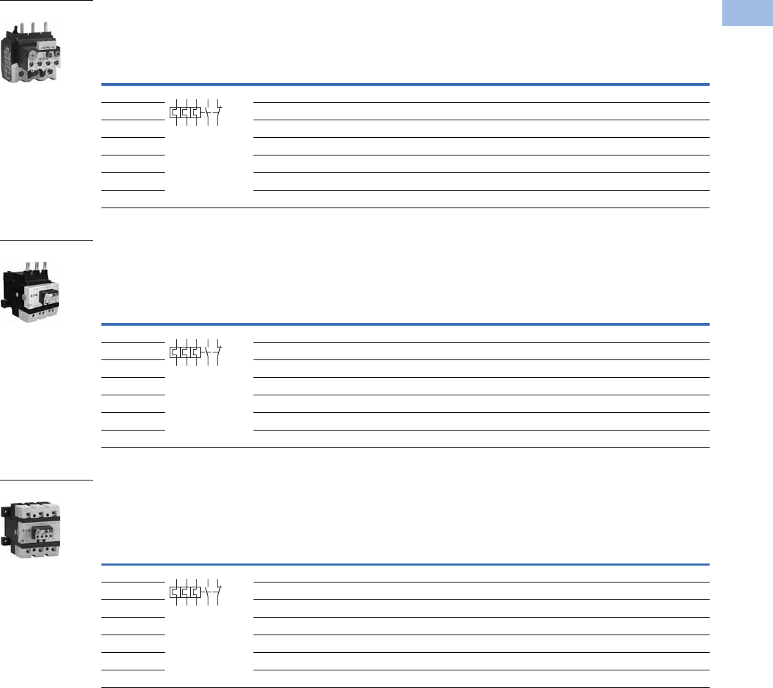
Volume 5—Motor Control and Protection CA08100006E—February 2014 www.eaton.com V5-T1-131
1
1
1
1
1
1
1
1
1
1
1
1
1
1
1
1
1
1
1
1
1
1
1
1
1
1
1
1
1
1
1.1
IEC Contactors and Starters
XT
IEC Power Control
Overload Relay, Direct Mount—Frame D
Overload Relay, Direct Mount—Frames F–G
Overload Relay, Separate Mount—Frames F–G
Overload
Releases, Ir
Contact
Sequence
Contact
Configuration
For Use
with
Contactor
Amp Range
Short-Circuit Protection (A)
Catalog Number
Fuse
Maximum
Circuit
Breaker
CEC/NEC
Fuse
Type 1
Coordination,
gG/gL
Type 2
Coordination,
gG/gL
6–10 1NO-1NC 40–72A 50 25 25 25 XTOB010DC1
10–16 1NO-1NC 40–72A 63 35 25 25 XTOB016DC1
16–24 1NO-1NC 40–72A 63 50 30 25 XTOB024DC1
24–40 1NO-1NC 40–72A 125 63 125 125 XTOB040DC1
40–57 1NO-1NC 50–72A 160 80 150 150 XTOB057DC1
50–65 1NO-1NC 65–72A 160 100 150 200 XTOB065DC1
65–75 1NO-1NC 72A 200 125 150 200 XTOB075DC1
Overload
Releases, Ir
Contact
Sequence
Contact
Configuration
For Use
with
Contactor
Amp Range
Short-Circuit Protection (A)
Catalog Number
Fuse
Maximum
Circuit
Breaker
CEC/NEC
Fuse
Type 1
Coordination,
gG/gL
Type 2
Coordination,
gG/gL
25–35 1NO-1NC 80–170A 125 100 125 125 XTOB035GC1
35–50 1NO-1NC 80–170A 160 125 150 200 XTOB050GC1
50–70 1NO-1NC 80–170A 250 160 150 200 XTOB070GC1
70–100 1NO-1NC 80–170A 315 200 400 400 XTOB100GC1
95–125 1NO-1NC 80–170A 315 200 500 400 XTOB125GC1
120–150 1NO-1NC 80–170A 315 200 600 600 XTOB150GC1
145–175 1NO-1NC 150–170A 315 200 600 600 XTOB175GC1
Overload
Releases, Ir
Contact
Sequence
Contact
Configuration
For Use
with
Contactor
Amp Range
Short-Circuit Protection (A)
Catalog Number
Fuse
Maximum
Circuit
Breaker
CEC/NEC
Fuse
Type 1
Coordination,
gG/gL
Type 2
Coordination,
gG/gL
25–35 1NO-1NC 80–170A 125 100 125 125 XTOB035GC1S
35–50 1NO-1NC 80–170A 160 125 150 200 XTOB050GC1S
50–70 1NO-1NC 80–170A 250 160 150 200 XTOB070GC1S
70–100 1NO-1NC 80–170A 315 200 400 400 XTOB100GC1S
95–125 1NO-1NC 80–170A 315 250 500 400 XTOB125GC1S
120–150 1NO-1NC 80–170A 315 250 600 600 XTOB150GC1S
145–175 1NO-1NC 150–170A 315 250 600 600 XTOB175GC1S
Frame D
2 4 6 98 96
97 95
Frames F–G
2 4 6 98 96
97 95
Frames F–G
2 4 6 98 96
97 95
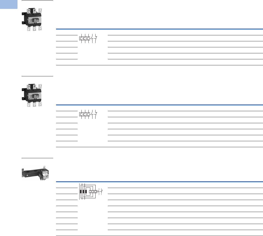
V5-T1-132 Volume 5—Motor Control and Protection CA08100006E—February 2014 www.eaton.com
1
1
1
1
1
1
1
1
1
1
1
1
1
1
1
1
1
1
1
1
1
1
1
1
1
1
1
1
1
1
1.1
IEC Contactors and Starters
XT
IEC Power Control
Overload Relay, Separate Mount—Frame H
Overload Relay, Separate Mount—Frame L
Current Transformer Operated Overload Relays, Separate Mount—Frames M–N 2
Notes
1 For separate mounting, short-circuit Type 1 rating is 500A and short-circuit Type 2 rating is 400A.
2 The main current parameters are defined by the main current wiring that is used.
Overload
Releases, Ir
Contact
Sequence
Contact
Configuration
For Use
with
Contactor
Amp Range
Short-Circuit Protection (A)
Catalog Number
Fuse
Maximum
Circuit
Breaker
CEC/NEC
Fuse
Type 1
Coordination,
gG/gL
Type 2
Coordination,
gG/gL
50–70 1NO-1NC 185–250A 250 160 150 200 XTOB070HC1
70–100 1NO-1NC 185–250A 315 200 400 400 XTOB100HC1
95–125 1NO-1NC 185–250A 315 250 500 400 XTOB125HC1
120–160 1NO-1NC 185–250A 400 250 600 600 XTOB160HC1
160–220 1NO-1NC 185–250A 400 1315 1600 800 XTOB220HC1
200–250 1NO-1NC 225–250A 400 1315 1600 700 XTOB250HC1
Overload
Releases, Ir
Contact
Sequence
Contact
Configuration
For Use
with
Contactor
Amp Range
Short-Circuit Protection (A)
Catalog Number
Fuse
Maximum
Circuit
Breaker
CEC/NEC
Fuse
Type 1
Coordination,
gG/gL
Type 2
Coordination,
gG/gL
50–70 1NO-1NC 185–250A 250 160 150 200 XTOB070LC1
70–100 1NO-1NC 185–250A 315 200 400 400 XTOB100LC1
95–125 1NO-1NC 185–250A 315 250 500 400 XTOB125LC1
120–160 1NO-1NC 185–250A 400 250 600 600 XTOB160LC1
160–220 1NO-1NC 185–250A 400 1315 1600 800 XTOB220LC1
200–250 1NO-1NC 225–250A 400 1315 1600 700 XTOB250LC1
200–300 1NO-1NC 225–300A 630 1630 1600 700 XTOB300LC1
Overload
Releases, Ir
Contact
Sequence
Contact
Configuration
For Use
with
Contactor
Amp Range
Short-Circuit Protection (A)
Catalog Number
Type 1
Coordination,
gG/gL
Type 2
Coordination,
gG/gL
Circuit
Breaker
CEC/NEC
Fuse
42–63 1NO-1NC 300–500A — — 150 200 XTOT063C3S
60–90 1NO-1NC 300–500A — — 250 250 XTOT090C3S
85–125 1NO-1NC 300–500A — — 500 400 XTOT125C3S
110–160 1NO-1NC 300–500A — — 600 600 XTOT160C3S
160–240 1NO-1NC 300–500A — — 600 700 XTOT240C3S
190–290 1NO-1NC 300–500A — — 600 700 XTOT290C3S
270–400 1NO-1NC 300–500A — — 1000 1000 XTOT400C3S
360–540 1NO-1NC 500A — — 600 1000 XTOT540C3S
420–630 1NO-1NC 630A — — 600 1000 XTOT630C3S
Frame H
1359795
2469896
Frame L
1359795
2469896
Frames M-N
9698
9597
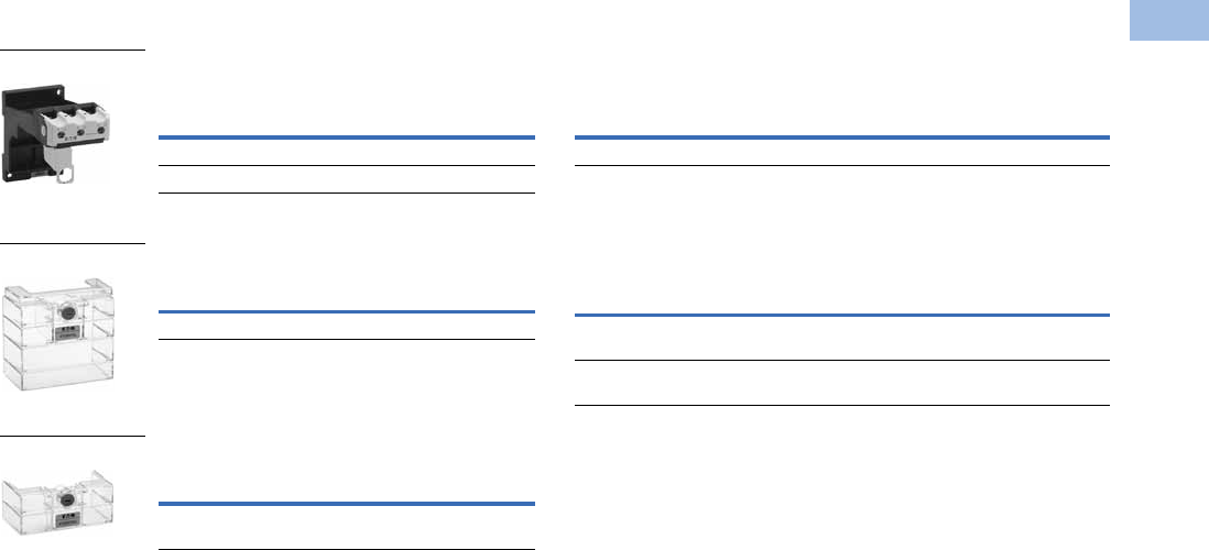
Volume 5—Motor Control and Protection CA08100006E—February 2014 www.eaton.com V5-T1-133
1
1
1
1
1
1
1
1
1
1
1
1
1
1
1
1
1
1
1
1
1
1
1
1
1
1
1
1
1
1
1.1
IEC Contactors and Starters
XT
IEC Power Control
Accessories
DIN Rail or Panel Mount Adapter,
Frames C–D 1
Te r m i n a l S h r o u d
Te r m i n a l S h r o u d
Terminal Lug Kit—Set of Three Lugs
Documentation—Manuals for Overload Monitoring
of EEX e-motors
Notes
1Can be snap fitted on a top hat rail (DIN rail) to IEC/EN 60715 or can be screw fitted.
2Orders must be placed in multiples of package quantity listed.
For Use
with…
Pkg.
Qty. 2Catalog Number
XTOB…CC1 5 XTOBXDINC
XTOB…DC1 2 XTOBXDIND
For Use
with… Catalog Number
XTOB…LC1 XTOBXTSL
For Direct
Mounting of … Catalog Number
XTOB…LC1 to XTCE250L
or XTCE300L
XTOBXTSCL
XTOBXDIN_
XTOBXTSL
XTOBXTSCL
Description
For Use
with…
Pkg.
Qty. 2Catalog Number
#6 AWG-350 kcmil XTOB…LC1 1 XTOBXTLL
Publication Number For Use with…
MN03402001E XTOB…BC1
XTOB…CC1
MN03407001E XTOB…DC1
XTOB…GC1
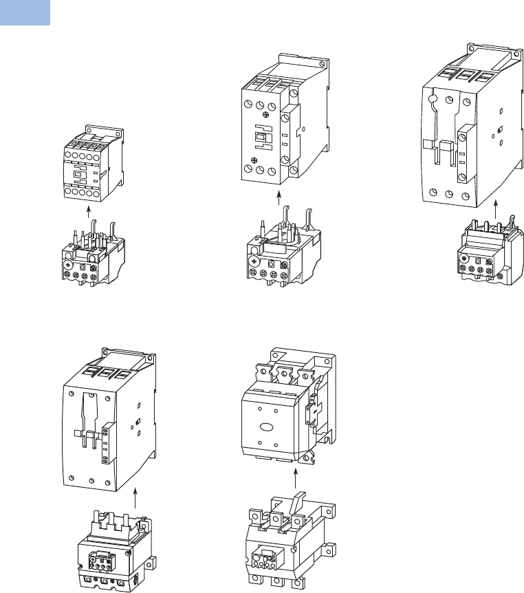
V5-T1-134 Volume 5—Motor Control and Protection CA08100006E—February 2014 www.eaton.com
1
1
1
1
1
1
1
1
1
1
1
1
1
1
1
1
1
1
1
1
1
1
1
1
1
1
1
1
1
1
1.1
IEC Contactors and Starters
XT
IEC Power Control
Overload Fitted Directly to the Contactor
Frame B (7–15A) Frame C (18–32A) Frame D (40–72A)
Frames F–G (80–170A) Frames H–L (185–250A)
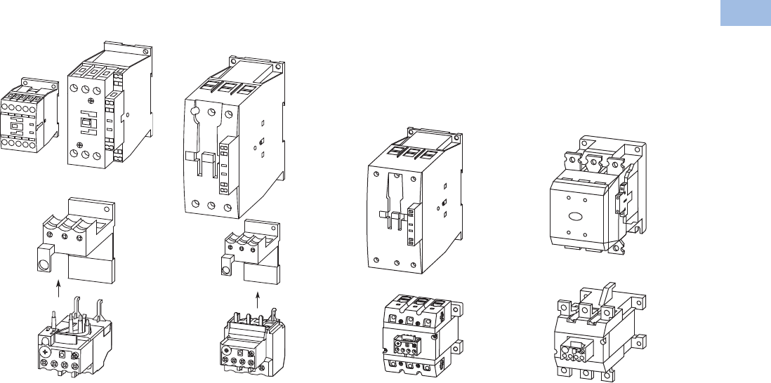
Volume 5—Motor Control and Protection CA08100006E—February 2014 www.eaton.com V5-T1-135
1
1
1
1
1
1
1
1
1
1
1
1
1
1
1
1
1
1
1
1
1
1
1
1
1
1
1
1
1
1
1.1
IEC Contactors and Starters
XT
IEC Power Control
Overload Mounted Separately from the Contactor
Frame C (18–32A) Frame D (40–72A) Frames F–G (80–170A) Frames H–L (185–250A)

V5-T1-136 Volume 5—Motor Control and Protection CA08100006E—February 2014 www.eaton.com
1
1
1
1
1
1
1
1
1
1
1
1
1
1
1
1
1
1
1
1
1
1
1
1
1
1
1
1
1
1
1.1
IEC Contactors and Starters
XT
IEC Power Control
Technical Data and Specifications
XTOB Overload Relay—General
Notes
1Damp heat, constant, to IEC 60068-2-78; damp heat, cyclic, to IEC 60068-2-30.
2Ambient temperature operating range to IEC/EN 60947, PTB: –5°C to 50°C.
36 mm2 flexible with ferrules to DIN 46228.
4Main contact terminal capacity, solid and stranded conductors with ferrules: When using two conductors use identical cross-section.
Description XTOB…BC1, XTOB…CC1 XTOB…DC1 XTOB…GC1, XTOB…GC1S XTOB…HC1, XTOB…LC1
Standards IEC/EN 60947, VDE 0660,
UL, CSA
IEC/EN 60947, VDE 0660,
UL, CSA
IEC/EN 60947, VDE 0660,
UL, CSA
IEC/EN 60947, VDE 0660,
UL, CSA
Climate proofing 111 1
Ambient temperature 2–25°C to 55°C
[–13°F to 131°F]
–25°C to 55°C
[–13°F to 131°F]
–25°C to 55°C
[–13°F to 131°F]
–25°C to 50°C
[–13°F to 122°F]
Temperature compensation Continuous Continuous Continuous Continuous
Mechanical shock resistance (IEC/EN 60068-2-27)
half-sinusoidal shock 10 ms
10g 10g 10g 10g
Degree of protection IP20 IP20 IP20 P00
Protection against direct contact when actuated
from front (IEC 536)
Finger and
back-of-hand proof
Finger and
back-of-hand proof
Finger and
back-of-hand proof
Finger and
back-of-hand proof
Insulation voltage (Ui) Vac 690 690 690 1000
Overvoltage category/pollution degree III/3 III/3 III/3 III/3
Impulse withstand voltage (Uimp) Vac 6000 6000 6000 8000
Operational voltage (Ue) Vac 690 690 690 1000
Safe isolation to VDE 0106 Part 101 and part 101/A1
between auxiliary contacts and main contacts (Vac) 440 440 440 500
between main contacts (Vac) 440 440 440 500
Overload release setting range 0.1–32A 6–75A 25–150A 50–300A
Short-circuit protection maximum fuse See overload relay tables starting on Page V5-T1-144.
Temperature compensation residual error >40°C <0.25 <0.25 <0.25 <0.25
Current heat loss (three conductors)
Lower value of setting range, W 2.5 3 16 16
Upper value of setting range 6 7.5 28 28
Terminal capacity
Solid, mm22 x (1–6) 2 x (1–16) 2 x (4–16) —
Flexible with ferrule, mm22 x (1–4)
2 x (1–6) 3
1 x 25
2 x (1–10) 4
1 x (4–70)
2 x (4–50)
—
—
Flexible with cable lug, mm2— — — 50–240
Stranded with cable lug, mm2— — — 50–240
Solid or stranded, AWG 14 - 8 14 - 2 3 / 0 250 kcmil
Flat conductor (number of segments x width x thickness, mm2) — — — 6 x 16 x 0.8
Busbar—width (mm) — — — 25
Terminal screw M4 M6 M10 M10 x 35
Tightening torque
Nm 1.8 3.5 10 18
Lb-in 16 31 88.5 159.31
Tools
Pozidriv screwdriver Size 2 Size 2 — —
Standard screwdriver 1 x 6 1 x 6 — —
Hexagon socket head spanner (SW) — — 5 mm 16 mm

Volume 5—Motor Control and Protection CA08100006E—February 2014 www.eaton.com V5-T1-137
1
1
1
1
1
1
1
1
1
1
1
1
1
1
1
1
1
1
1
1
1
1
1
1
1
1
1
1
1
1
1.1
IEC Contactors and Starters
XT
IEC Power Control
XTOB Overload Relay—Auxiliary and Control Circuit Connections
Note
1Rated operational current: Making and breaking conditions to DC-13, L/R constant as stated.
Description XTOB…BC1, XTOB…CC1 XTOB…DC1 XTOB…GC1, XTOB…GC1S XTOB…HC1, XTOB…LC1
Impulse withstand voltage (Uimp) Vac 6000 6000 6000 4000
Overvoltage category/pollution degree III/3 III/3 III/3 III/3
Terminal capacity
Solid, mm22 x (0.75–4) 2 x (0.75–4) 2 x (0.75–4) 2 x (0.75–4)
Flexible with ferrule, mm22 x (0.75–2.5) 2 x (0.75–2.5) 2 x (0.75–2.5) 2 x (0.75–2.5)
Solid or stranded (AWG) 2 x (18–12) 2 x (18–12) 2 x (18–12) 2 x (18–12)
Terminal screw M3.5 M3.5 M3.5 M3.5
Tightening torque
Nm 0.8–1.2 0.8–1.2 0.8–1.2 0.8–1.2
Lb-in 7–10.6 7–10.6 7–10.6 7–10.6
Tools
Pozidriv screwdriver Size 2 Size 2 Size 2 Size 2
Standard screwdriver 1 x 6 1 x 6 1 x 6 1 x 6
Rated insulated voltage (Ui) Vac 500 500 500 500
Rated operational voltage 500 500 500 500
Safe isolation to VDE 0106 Part 101 and part 101/A1
between auxiliary contacts
240 240 240 240
Conventional thermal current, Ith 666 6
Rated operational current—AC-15
Make contact
120V 1.5 1.5 1.5 1.5
240V 1.5 1.5 1.5 1.5
415V 0.5 0.5 0.5 0.5
500V 0.5 0.5 0.5 0.5
Break contact
120V 1.5 1.5 1.5 1.5
240V 1.5 1.5 1.5 1.5
415V 0.9 0.9 0.9 0.9
500V 0.8 0.8 0.8 0.8
Rated operational current—DC-13 L/R
<
15 ms 1
24V 0.9 0.9 0.9 0.9
60V 0.75 0.75 0.75 0.75
110V 0.4 0.4 0.4 0.4
220V 0.2 0.2 0.2 0.2
Short-circuit rating without welding maximum fuse, A gG/gl 6 6 6 6
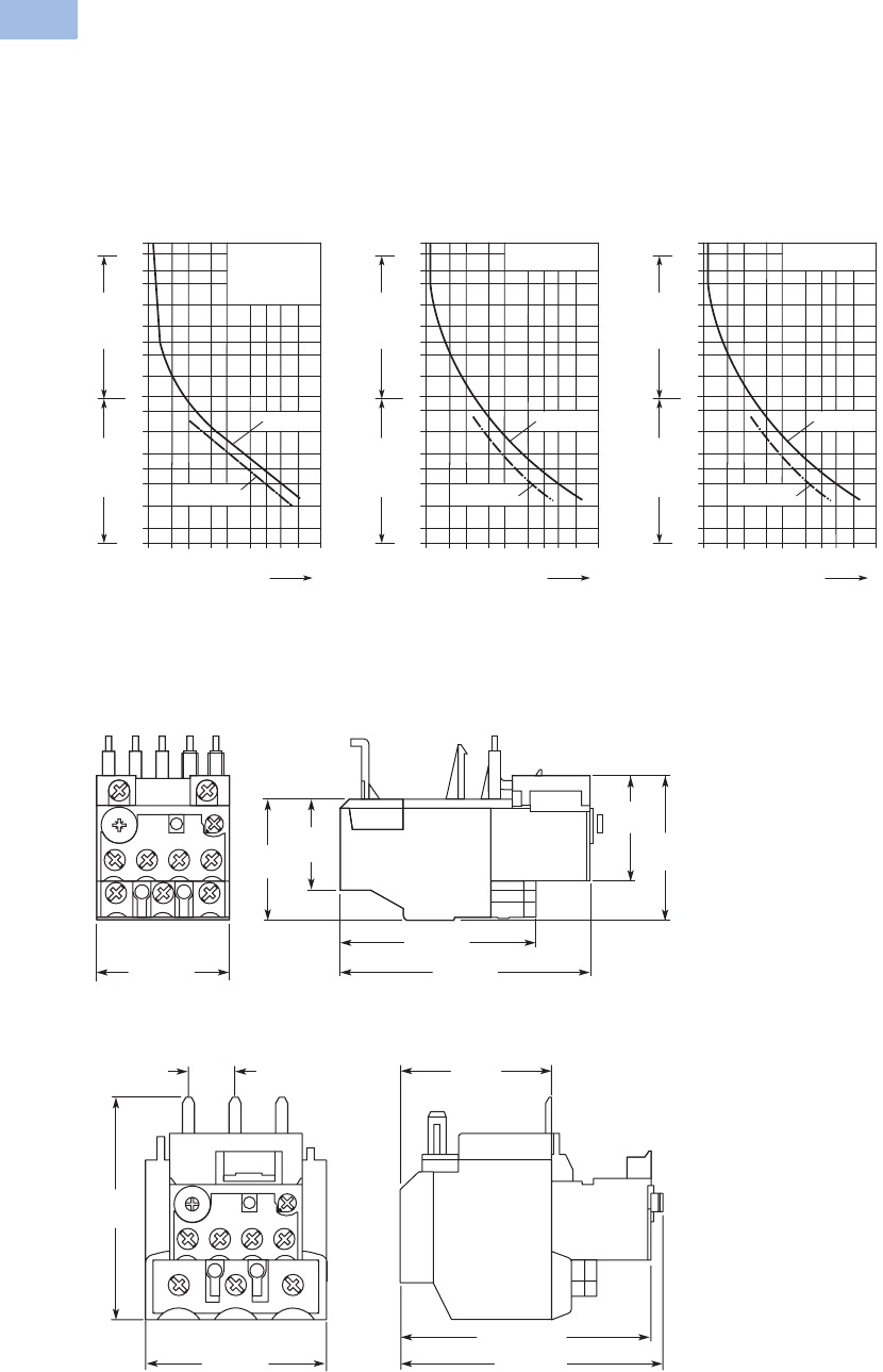
V5-T1-138 Volume 5—Motor Control and Protection CA08100006E—February 2014 www.eaton.com
1
1
1
1
1
1
1
1
1
1
1
1
1
1
1
1
1
1
1
1
1
1
1
1
1
1
1
1
1
1
1.1
IEC Contactors and Starters
XT
IEC Power Control
Tripping Characteristics
These tripping characteristics
are the mean values of the
spread at 20°C ambient
temperature in a cold state.
Tripping time depends on
response current. With
devices at operating
temperature, the tripping
time of the overload relay
reduces to approximately
25% of the read off value.
Specific characteristics for
each individual setting
range can be found in
MN03402001E.
XTOB...BC1, XTOB...CC1,
XTOB...DC1 XTOB...GC1 XTOB...HC1, XTOB...LC1
Dimensions
Approximate Dimensions in mm [in]
Frames B–C, XTOB…BC1 and XTOB…CC1 Overload Relays
Frame D, XTOB…DC1 Overload Relay
2h
100
60
40
20
10
6
4
2
1
40
20
10
6
4
2
1
0.6
XTOB...BC1,
XTOB...CC1,
XTOB...DC1
1 1.5 2 3 4 68 10 15 20
x Setting Current
2-Phase
Seconds Minutes
3-Phase
2h
100
60
40
20
10
6
4
2
1
40
20
10
6
4
2
1
0.6
XTOB...GC1
1 1.5 2 3 4 68 10 15 20
x Setting Current
2-Phase
Seconds Minutes
3-Phase
2h
100
60
40
20
10
6
4
2
1
40
20
10
6
4
2
1
0.6
XTOB...HC1,
XTOB...LC1
1 1.5 2 3 4 68 10 15 20
x Setting Current
2-Phase
Seconds Minutes
3-Phase
45 [1.77] 83 [3.27]
65 [2.56]
48
[1.89]
35.5
[1.40]
39.5
[1.56]
29.5
[1.16]
60 [2.36] 102 [4.02]
95.5 [3.76]
51.5
[2.03]
79.2
[3.12]
20.3
[.80]
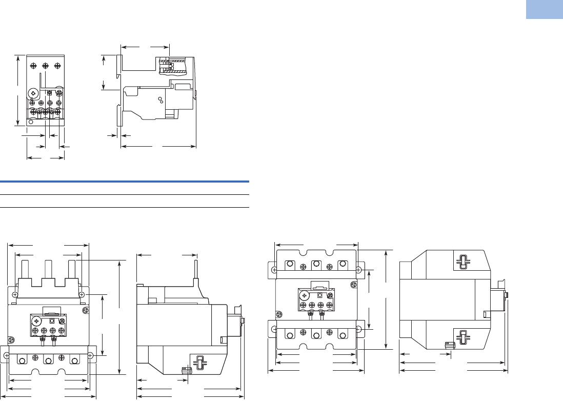
Volume 5—Motor Control and Protection CA08100006E—February 2014 www.eaton.com V5-T1-139
1
1
1
1
1
1
1
1
1
1
1
1
1
1
1
1
1
1
1
1
1
1
1
1
1
1
1
1
1
1
1.1
IEC Contactors and Starters
XT
IEC Power Control
Approximate Dimensions in mm [in]
Frames B–C, XTOBXDINC DIN Rail or Panel Mount Adapter
and Frame D, XTOBXDIND DIN Rail or Panel Mount Adapter
Frames F–G, XTOB…GC1 Overload Relay Frames F–G, XTOB…G1CS Overload Relay
HWDD1D2
XTOB…CC1 85 [3.46] 45 [1.77] 90.5 [3.56] 58.3 [2.30] 3.8 [.15]
XTOB…DC1 86 [3.39] 60 [2.36] 112 [4.41] 80.5 [3.17] 4.7 [.19]
5 [.20]
H
16.5 [.65]
D2
42.5
[1.67]
W
D
D1
138
[5.43]
63 [2.48]
129 [5.08]
100 [3.94]
134 [5.28]
74
[2.91]
118 [4.65]
99 [3.90]
80 [3.15]
95 [3.74]
73 [2.87]
63 [2.48]
129 [5.08]
134 [5.28]
121
[4.76]
74
[2.91]
100 [3.94]
99 [3.90]
118 [4.65]
95 [3.74]
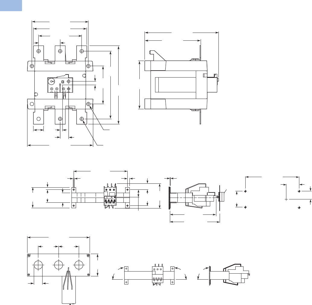
V5-T1-140 Volume 5—Motor Control and Protection CA08100006E—February 2014 www.eaton.com
1
1
1
1
1
1
1
1
1
1
1
1
1
1
1
1
1
1
1
1
1
1
1
1
1
1
1
1
1
1
1.1
IEC Contactors and Starters
XT
IEC Power Control
Approximate Dimensions in mm [in]
Frames L and H, XTOB…LC1, HC1 Overload Relay
XTOT…C3S Current Transformer Operated Overload Relay
121 [4.76]
110 [4.33]
96 [3.78]
128 [5.04]
74
[2.91]
144
[5.67]
169
[6.65]
48 [1.89]
25
[.98]
5
[.20] 16.5
[.65]
144 [5.67]
111 [4.37]
94
[3.70]
7 [.28]
7 [.28] Dia.
11 [.43] Dia.
*
**
*
** * = OFF
** = RESET/ON
7.5 [.30]
26
[1.02]
55
[2.17]
21 [.83]
85
[3.35]
185 [7.28]
71
[2.80] 44 [1.73] 33
[1.30]
8 [.31] 4.3 [.17] 185 [7.28]
M4
44
[1.73]
26 [1.02]
55
[2.17]
1.5 [.06]
159 [6.26]
172 – 250
[6.77 – 9.84]
*
*
* = RESET/ON
90° 90°
200 [7.87]
65
[2.56] 65
[2.56]
71
[2.80]
27
[1.06]
90°
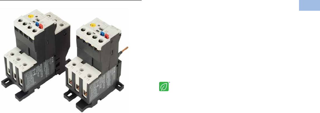
Volume 5—Motor Control and Protection CA08100006E—February 2014 www.eaton.com V5-T1-141
1
1
1
1
1
1
1
1
1
1
1
1
1
1
1
1
1
1
1
1
1
1
1
1
1
1
1
1
1
1
1.1
IEC Contactors and Starters
XT
IEC Power Control
C440/XT Electronic Overload Relay
Contents
Description Page
Relays and Timers . . . . . . . . . . . . . . . . . . . . . . . . . V5-T1-3
Miniature Controls . . . . . . . . . . . . . . . . . . . . . . . . . V5-T1-18
Contactors and Starters . . . . . . . . . . . . . . . . . . . . V5-T1-35
Thermal Overload Relays . . . . . . . . . . . . . . . . . . . . V5-T1-128
C440/XT Electronic Overload Relay
Standards and Certifications . . . . . . . . . . . . . . V5-T1-142
Catalog Number Selection . . . . . . . . . . . . . . . . V5-T1-143
Product Selection . . . . . . . . . . . . . . . . . . . . . . . V5-T1-144
Accessories . . . . . . . . . . . . . . . . . . . . . . . . . . . V5-T1-146
Technical Data and Specifications . . . . . . . . . . V5-T1-149
Dimensions . . . . . . . . . . . . . . . . . . . . . . . . . . . V5-T1-155
An Eaton
Green Solution
Manual Motor Protectors . . . . . . . . . . . . . . . . . . . V5-T1-157
Combination Motor Controllers . . . . . . . . . . . . . . . V5-T1-193
XT Electronic Manual Motor Protector . . . . . . . . . V5-T1-216
Reference Data . . . . . . . . . . . . . . . . . . . . . . . . . . . V5-T1-229
C440/XT Electronic Overload Relay
Product Description
Eaton’s new electronic
overload relay (EOL) is
the most compact, high-
featured, economical product
in its class. Designed on a
global platform, the new
EOL covers the entire power
control spectrum including
NEMA, IEC and
DP contactors. The NEMA
and DP versions are offered
with the C440 designation
while the IEC offering has the
XT designation. The
electronic design provides
reliable, accurate and value
driven protection and
communications capabilities
in a single compact device. It
is the flexible choice for any
application requiring easy-to-
use, reliable protection.
Eaton has a long history of
innovations and product
development in motor control
and protection, including both
traditional NEMA, as well as
IEC control. It was from this
experience that the C440 was
developed, delivering new
solutions to meet today’s
demands.
C440 is a self-powered
electronic overload relay
available up to 175A as a
self contained unit. With
external CTs, C440 can
protect motor up to
1500 FLA. Available add-on
accessories include remote
reset capability and
communication modules
with I/O for DeviceNet,
PROFIBUS, and Modbus.
Features and Benefits
Features
●Reliable, accurate, electronic motor protection
●Easy to select, install and maintain
●Compact size
●Flexible, intelligent design
●Global product offering—available with NEMA, IEC and DP
power control
Size/Range
●Broad FLA range
(0.33–1500A)
●Selectable trip class
(10A, 10, 20, 30)
●Direct mounting to NEMA,
IEC and DP contactors
●Most compact electronic
overload in its class
Motor Control
●Two B600 alarm (NO) and
fault (NC) contacts
●Test/Trip button
Motor Protection
●Thermal overload
●Phase loss
●Selectable (ON/OFF)
phase unbalance
●Selectable (ON/OFF)
ground fault
User Interface
●Large FLA selection dial
●Trip status indicator
●Operating mode LED
●DIP switch selectable trip
class, phase unbalance and
ground fault
●Selectable Auto/Manual
reset
Feature Options
●Remote reset
●120 Vac
●24 Vac
●24 Vdc
●Tamper-proof cover
●Communications modules
●Modbus RTU RS-485
●DeviceNet with I/O
●PROFIBUS with I/O
●Modbus RTU with I/O
●Ethernet IP with I/O
●Modbus TCP with I/O

V5-T1-142 Volume 5—Motor Control and Protection CA08100006E—February 2014 www.eaton.com
1
1
1
1
1
1
1
1
1
1
1
1
1
1
1
1
1
1
1
1
1
1
1
1
1
1
1
1
1
1
1.1
IEC Contactors and Starters
XT
IEC Power Control
Benefits
Reliability and Improved
Uptime
●C440 provides the users
with peace of mind
knowing that their
assets are protected
with the highest level
of motor protection and
communication capability
in its class
●Extends the life of plant
assets with selectable
motor protection features
such as trip class, phase
unbalance and ground fault
●Protects against
unnecessary downtime
by discovering changes
in your system (line/load)
with remote monitoring
capabilities
●Status LED provides
added assurance that
valuable assets are
protected by indicating the
overload operational status
Flexibility
●Available with NEMA,
IEC and DP contactors
●Improves return on
investment by reducing
inventory carrying costs
with wide FLA adjustment
(5:1) and selectable
trip class
●Design incorporates built-in
ground fault protection
thus eliminating the need
for separate CTs and
modules
●Flexible communication
with optional I/O enables
easy integration into plant
management systems for
remote monitoring and
control
●Available as an open
component and in
enclosed control and motor
control center assemblies
Monitoring Capabilities
●Individual phase
currents RMS
●Average three-phase
current RMS
●Thermal memory
●Fault indication (overload,
phase loss, phase
unbalance, ground fault)
Safety
●IP 20 rated terminal blocks
●Available in Eaton’s
industry leading FlashGard
MCCs
●Tested to the highest
industry standards such
as UL, CSA, CE and IEC
●RoHS compliant
Standards and Certifications
●UL
●CSA
●CE
●NEMA
●IEC/EN 60947 VDE 0660
●ISO 13849-1 (EN954-1)
●RoHS
●ATEX directive 94/9/EC
●Equipment Group 2,
Category 2
Electronic Overload Education
Description Definition Cause Effect if not Protected C440/XT Protection
Motor Protection
Thermal overload Overload is a condition in which
current draw exceeds 115% of
the full load amperage rating for
an inductive motor.
• An increase in the load or torque that is
being driven by the motor.
• A low voltage supply to the motor
causes the current to go high to
maintain the power needed.
• A poor power factor causing above
normal current draw.
• Increase in current draw leads to heat
and insulation breakdown, which can
cause system failure.
• Increase in current can increase
power consumption and waste
valuable energy.
• Thermal trip behavior is defined by
UL, CSA and IEC standards.
• Trip class is settable from 10A,
10, 20, 30
Ground fault A line to ground fault. A current leakage path to ground. An undetected ground fault can burn
through multiple insulation windings,
ultimately leading to motor failure, not to
mention risk to equipment or personnel
Fixed protective setting that takes the
starter offline if ground fault current
exceeds 50% of the FLA dial setting,
that is, if the FLA dial is set to 12A, the
overload relay will trip if the ground
current exceeds 6A.
Unbalanced phases
(voltage and current)
Uneven voltage or current between
phases in a three-phase system.
When a three-phase load is powered with
a poor quality line, the voltage per phase
may be unbalanced.
Unbalanced voltage causes large
unbalanced currents and as a result this
can lead to motor stator windings being
overloaded, causing excessive heating,
reduced motor efficiency and reduced
insulation life.
Fixed protective setting that takes the
starter offline if a phase drops below
50% of the other two phases.
Phase loss—current
(single-phasing)
One of the three-phase voltages is
not present.
Multiple causes, loose wire, improper
wiring, grounded phase, open fuse, etc.
Single-phasing can lead to unwanted
motor vibrations in addition to the results
of unbalanced phases as listed above.
Fixed protective setting that takes the
starter offline if a phase is lost.
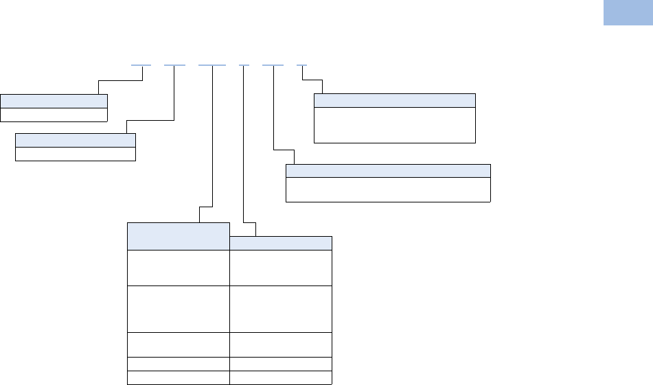
Volume 5—Motor Control and Protection CA08100006E—February 2014 www.eaton.com V5-T1-143
1
1
1
1
1
1
1
1
1
1
1
1
1
1
1
1
1
1
1
1
1
1
1
1
1
1
1
1
1
1
1.1
IEC Contactors and Starters
XT
IEC Power Control
Catalog Number Selection
XT Electronic Overload Relay—IEC 1
Note
1See Page V5-T1-144 for Product Selection.
Designation
XT = XT line of IEC control
Type
OE = Electronic overload relay
Mounting
Blank = Direct to contactor
P = Pass-through
S = Separate mount (Frames C and G only)
Trip Type
CS = Selectable Class 10A, 10, 20, 30
GS = Ground fault with selectable Class 10, 20
Overload Range
Contactor Frame
1P6 = 0.33–1.65A
005 = 1–5A
020 =4–20A
B = 45 mm
1P6 = 0.33–1.65A
005 = 1–5A
020 =4–20A
045 =9–45A
C = 45 mm
045 =9–45A
100 = 20–100A
D = 55 mm
100 = 20–100A F, G = 105 mm
175 = 35–175A G, H = 110 mm
XT OE 1P6 C CS S
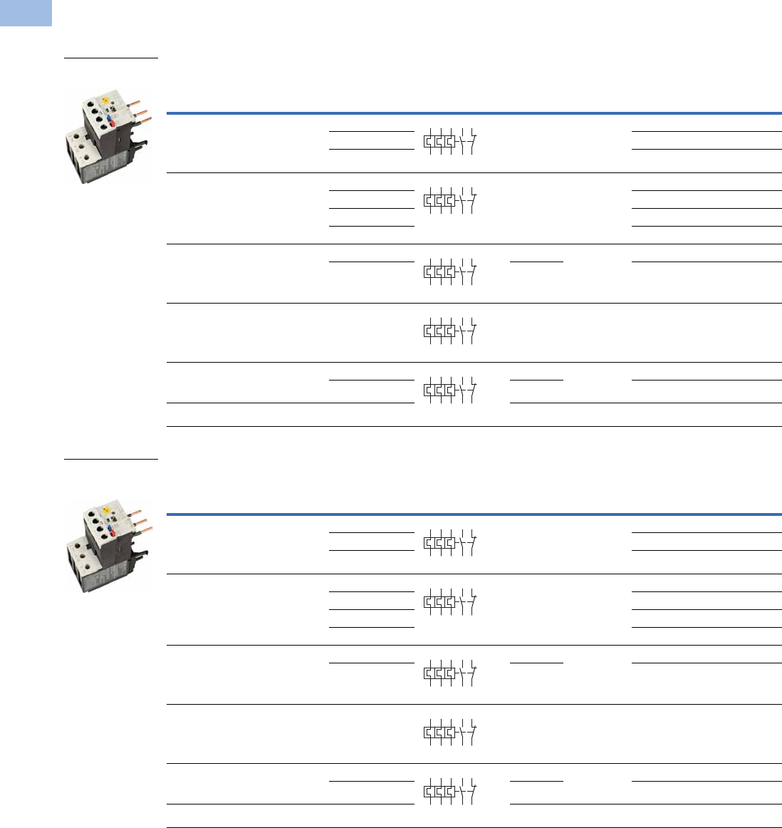
V5-T1-144 Volume 5—Motor Control and Protection CA08100006E—February 2014 www.eaton.com
1
1
1
1
1
1
1
1
1
1
1
1
1
1
1
1
1
1
1
1
1
1
1
1
1
1
1
1
1
1
1.1
IEC Contactors and Starters
XT
IEC Power Control
Product Selection
XT Electronic Overload Relays
XT Electronic Overload Relays for Direct Mount to XT Contactors
XT Electronic Overload Relays with Ground Fault for Direct Mount to XT Contactors
For Use with
XT Contactor
Frame
For Use with
Contactor
Overload
Range (Amps)
Contact
Sequence
Frame
Size
Auxiliary
Contact
Configuration Type Catalog Number
B XTCE007B…,
XTCE009B…,
XTCE012B…,
XTCE015B…
0.33–1.65 45 mm NO-NC ZEB12-1,65 XTOE1P6BCS
1–5 ZEB12-5 XTOE005BCS
4–20 ZEB12-20 XTOE020BCS
C XTCE018C…,
XTCE025C…,
XTCE032C
0.33–1.65 45 mm NO-NC ZEB32-1,65 XTOE1P6CCS
1–5 ZEB32-5 XTOE005CCS
4–20 ZEB32-20 XTOE020CCS
9–45 ZEB32-45 XTOE045CCS
D XTCE040D…,
XTCE050D…,
XTCE065D…,
XTCE072D…
9–45 45 mm NO-NC ZEB65-45 XTOE045DCS
20–100 55 mm ZEB65-100 XTOE100DCS
F XTCE080F…,
XTCE095F…
20–100 55 mm NO-NC ZEB150-100 XTOE100GCS
G XTCE115G…,
XTCE150G…,
XTCE170G…
20–100 55 mm NO-NC ZEB150-100 XTOE100GCS
35–175 110 mm ZEB150-175 XTOE175GCS
H XTCE185H… 35–175 110 mm NO-NC ZEB225-175 XTOE175HCS
For Use with
XT Contactor
Frame
For Use with
Contactor
Overload
Range (Amps)
Contact
Sequence
Frame
Size
Auxiliary
Contact
Configuration Type Catalog Number
B XTCE007B…,
XTCE009B…,
XTCE012B…,
XTCE015B…
0.33–1.65 45 mm NO-NC ZEB12-1,65-GF XTOE1P6BGS
1–5 ZEB12-5-GF XTOE005BGS
4–20 ZEB12-20-GF XTOE020BGS
C XTCE018C…,
XTCE025C…,
XTCE032C
0.33–1.65 45 mm NO-NC ZEB32-1,65-GF XTOE1P6CGS
1–5 ZEB32-5-GF XTOE005CGS
4–20 ZEB32-20-GF XTOE020CGS
9–45 ZEB32-45-GF XTOE045CGS
D XTCE040D…,
XTCE050D…,
XTCE065D…,
XTCE072D…
9–45 45 mm NO-NC ZEB65-45-GF XTOE045DGS
20–100 55 mm ZEB65-100-GF XTOE100DGS
F XTCE080F…,
XTCE095F…
20–100 55 mm NO-NC ZEB150-100-GF XTOE100GGS
GXTCE115G…,
XTCE150G…,
XTCE170G…
20–100 55 mm NO-NC ZEB150-100-GF XTOE100GGS
35–175 110 mm ZEB150-175-GF XTOE175GGS
H XTCE185H… 35–175 110 mm NO-NC ZEB225-175-GF XTOE175HGS
45 mm XT for
Direct Mount
2 4 6 98 96
97 95
2 4 6 98 96
97 95
2 4 6 98 96
97 95
2 4 6 98 96
97 95
2 4 6 98 96
97 95
45 mm XT for
Direct Mount
with Ground Fault
2 4 6 98 96
97 95
2 4 6 98 96
97 95
2 4 6 98 96
97 95
2 4 6 98 96
97 95
2 4 6 98 96
97 95
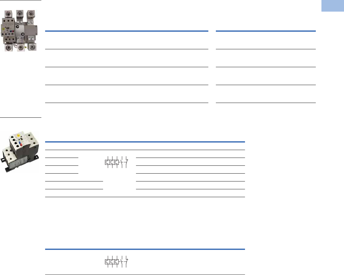
Volume 5—Motor Control and Protection CA08100006E—February 2014 www.eaton.com V5-T1-145
1
1
1
1
1
1
1
1
1
1
1
1
1
1
1
1
1
1
1
1
1
1
1
1
1
1
1
1
1
1
1.1
IEC Contactors and Starters
XT
IEC Power Control
XT Electronic Overload Relays for use with Large Frame XT Contactors (L–R)
Use CTs and 1-5A XT overload relay. CT kit does not include overload relay (order separately).
XT Electronic Overload Relays for Separate Mount
XT Electronic Overload Relay for Pass-Through Design
Pass-through design does not include any lugs to land wires.
Terminate motor leads directly on contactor.
XT
Contactor
Frame
For Use with IEC
Contactor Amp
Range (AC-3)
CT Range
(Amps) Description
CT Kit
Catalog Number
Terminal
Size
Overload Relay
Catalog Number
Overload Relay
with Ground Fault
Catalog Number
L, M 185–500A 60-300 300: 5 panel-mount CT kit
with integrated lugs
ZEB-XCT300 750 kcmil
(2) 250 kcmil
3/0 Cu/Al
XTOE005CCSS XTOE005CGSS
M, N 300–820A 120-600 600: 5 panel-mount CT kit
with integrated,
pass through holes
ZEB-XCT600 (2) 750 kcmil
3/0 Cu/Al
XTOE005CCSS XTOE005CGSS
N 580–1000A 200-1000 1000: 5 panel-mount CT kit
with integrated,
pass through holes
ZEB-XCT1000 (3) 750 kcmil
3/0 Cu/Al
XTOE005CCSS XTOE005CGSS
R 1600A 300-1500 1500: 5 panel-mount CT kit
with integrated,
pass through holes
ZEB-XCT1500 (4) 750 kcmil
1/0 Cu/Al
XTOE005CCSS XTOE005CGSS
Overload
Range (Amps)
Frame
Size
Contact
Sequence Type
Overload Relay
Catalog Number
Overload Relay
with Ground Fault
Catalog Number
Overload Relay
0.33–1.65 45 mm ZEB32-1,65/KK XTOE1P6CCSS XTOE1P6CGSS
1–5 ZEB32-5/KK XTOE005CCSS XTOE005CGSS
4–20 ZEB32-20/KK XTOE020CCSS XTOE020CGSS
9–45 ZEB32-45/KK XTOE045CCSS XTOE045CGSS
20–100 55 mm ZEB150-100/KK XTOE100GCSS XTOE100GGSS
35–175 110 mm ZEB150-175/KK XTOE175GCSS XTOE175GGSS
Overload
Range (Amps)
Frame
Size
Contact
Sequence Type
Overload Relay
Catalog Number
Overload Relay
with Ground Fault
Catalog Number
35–175 110 mm ZEB150-175/PT XTOE175GCSP XTOE175GGSP
1–5A OL with CTs
45 mm XT for
Separate Mount
1359795
2469896
1359795
2469896
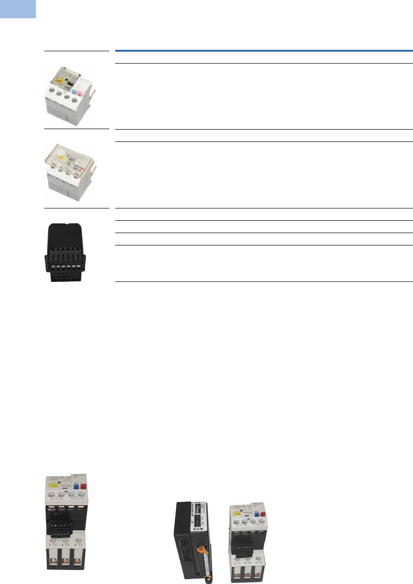
V5-T1-146 Volume 5—Motor Control and Protection CA08100006E—February 2014 www.eaton.com
1
1
1
1
1
1
1
1
1
1
1
1
1
1
1
1
1
1
1
1
1
1
1
1
1
1
1
1
1
1
1.1
IEC Contactors and Starters
XT
IEC Power Control
Accessories
CT Kits
Accessories
Communication
The C440 is provided with two levels of communication capability.
Basic Communication via
Expansion Module—
Monitoring Only
Basic communication on
the C440 is accomplished
using an expansion module.
The expansion module plugs
into the expansion bay on
the C440 overload relay,
enabling communications
with the overload via their
Modbus RTU (RS-485)
network. No additional parts
are required. See
figure below.
Basic Communication—
Modbus
Advanced
Communication—
Monitoring and Control
C440 also has the ability to
communicate on industrial
protocols such as DeviceNet,
PROFIBUS, Modbus RTU and
Modbus TCP, and Ethernet
(planned) while providing
control capability using I/O.
An expansion module
(mentioned earlier) combined
with a communication
adapter and a communication
module allows easy
integration onto the
customer’s network. See
figure below.
Advanced Communication—
Communication Adapter with
Communication Module
Advanced
Communication—
Communication Module
The communication adapter
comes standard with four
inputs and two outputs
(24 Vdc or 120 Vac) while
providing the customer with
flexible mounting options
(DIN rail or panel). See
figure below,
Note
1Customer can wire remote mounted button to reset module (that is, 22 mm pushbutton, catalog number M22-D-B-GB14-K10).
Description Catalog Number
Safety Cover
Clear Lexan cover that mounts on top of the FLA dial and DIP switches when closed. ZEB-XSC
Reset Bar
Assembles to the top of the overload to provide a larger target area for door
mounted reset operators.
ZEB-XRB
Remote Reset
Remote reset module (24 Vdc) 1C440-XCOM
Remote reset module (120 Vac) 1ZEB-XRR-120
Remote reset module (24 Vac) 1ZEB-XRR-24
Safety Cover
Reset Bar
Remote Reset
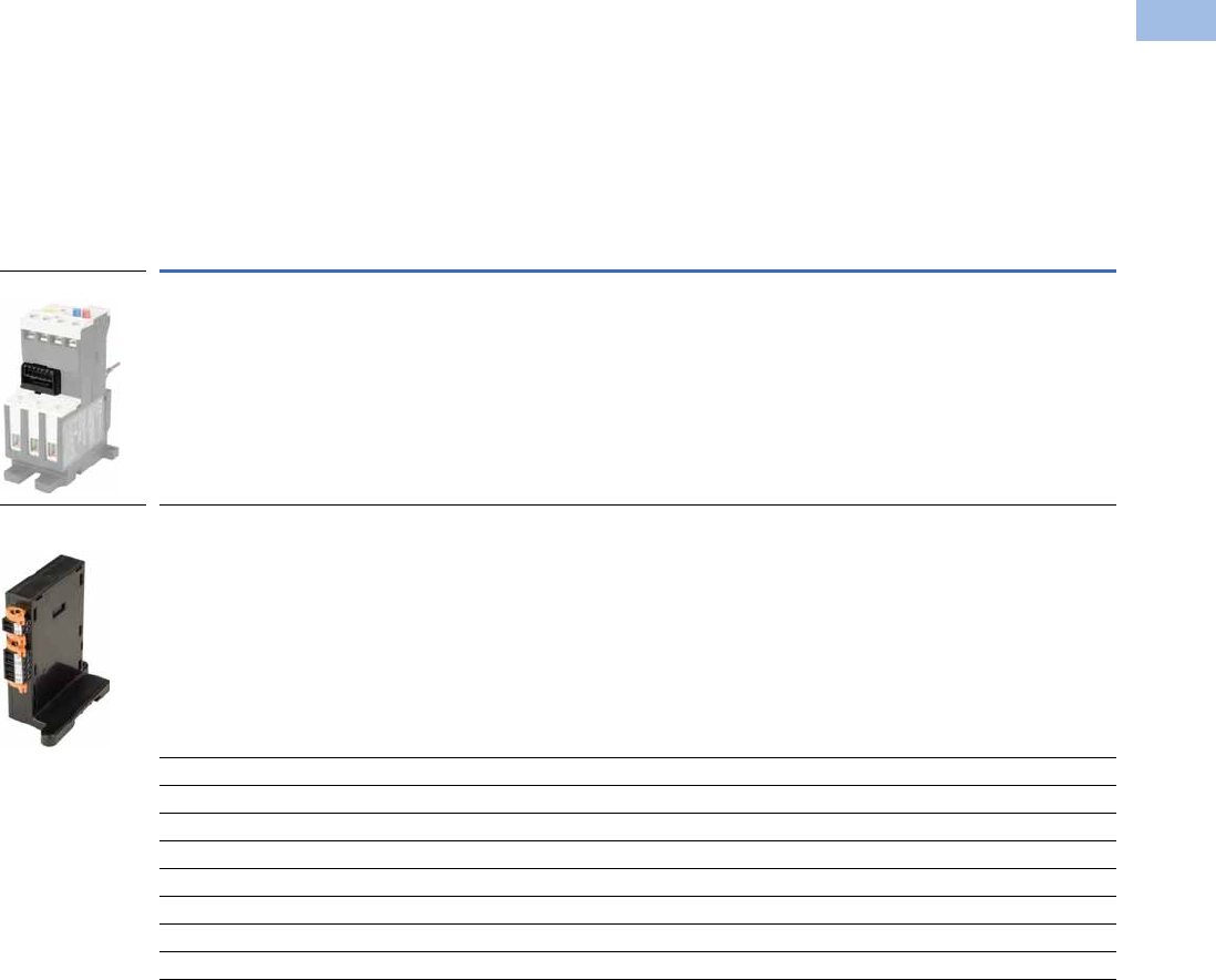
Volume 5—Motor Control and Protection CA08100006E—February 2014 www.eaton.com V5-T1-147
1
1
1
1
1
1
1
1
1
1
1
1
1
1
1
1
1
1
1
1
1
1
1
1
1
1
1
1
1
1
1.1
IEC Contactors and Starters
XT
IEC Power Control
The following information can be viewed using the communication option:
●Motor status—running,
stopped, tripped or
resetting
●Individual rms phase
currents (A, B, C)
●Average of three-phase
rms current
●Percent thermal capacity
●Fault codes (only available
prior to reset)
●Percent phase unbalance
●Ground fault current and
percent
●Overload relay settings—
trip class, DIP switch
selections, reset selections
●Modbus address (can be
set over the network)
Communication Accessories
Description Catalog Number
Expansion module (Remote Reset/Modbus RTU, RS-485 Communication) C440-XCOM
Communication adapter kit (DIN C Panel mounted adapter, required for advance communication option) C440-COM-ADP
DeviceNet communication module kit—120V I/O (consists of C440-XCOM + C441K + C440-COM-ADP) C440-DN-120
DeviceNet communication module kit—24 Vdc I/O (consists of C440-XCOM + C441L + C440-COM-ADP) C440-DN-24
PROFIBUS communication module kit—120V I/O (consists of C440-XCOM + C441S + C440-COM-ADP) C440-DP-120
PROFIBUS communication module kit—24V I/O (consists of C440-XCOM + C441Q + C440-COM-ADP) C440-DP-24
Modbus communication module kit—120V I/O (consists of C440-XCOM + C441N + C440-COM-ADP) C440-MOD-120
Modbus communication module kit—24 Vdc I/O (consists of C440-XCOM + C441P + C440-COM-ADP) C440-MOD-24
Modbus TCP/Ethernet IP communication module kit—120V I/O (consists of C440-XCOM + C441U) C440-ET-120
Modbus TCP/Ethernet IP communication module kit—24V I/O (consists of C440-XCOM + C441V) C440-ET-24
Expansion Module
Communication
Adapter
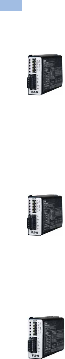
V5-T1-148 Volume 5—Motor Control and Protection CA08100006E—February 2014 www.eaton.com
1
1
1
1
1
1
1
1
1
1
1
1
1
1
1
1
1
1
1
1
1
1
1
1
1
1
1
1
1
1
1.1
IEC Contactors and Starters
XT
IEC Power Control
Modbus Communication Module
The Modbus module
combined with an expansion
module and a communication
adapter provide Modbus
communication capability to
the C440 electronic overload
relay.
Features and Benefits
●The Modbus
communication module is
capable of baud rates
up to 115K
●The Modbus address and
baud rate configuration can
be easily changed using
the HMi user interface
●Modbus address and baud
rate are set via convenient
DIP switches; LEDs are
provided to display
Modbus traffic
●Configuration with
common Modbus
configuration tools
●Terminals
●Unique locking
mechanism provides for
easy removal of the
terminal block with the
field wiring installed
●Each terminal is marked
for ease of wiring and
troubleshooting
●Selectable I/O assemblies
●4IN/2OUT
●Signal types include
24 Vdc I/O and
120 Vac I/O
●Each I/O module is
optically isolated
between the field I/O
and the network adapter
to protect the I/O and
communication circuits
from possible damage
due to transients and
ground loops
●Input Module features a
user-definable input
debounce, which limits
the effects of transients
and electrical noise
●Output Module supports
a user-definable safe
state for loss of
communication; hold
last state, ON or OFF
DeviceNet Communication Modules
The DeviceNet
Communication Module
provides monitoring and
control for the C440 overload
relay from a single DeviceNet
node. These modules also
offer convenient I/O in two
voltage options,
24 Vdc and 120 Vac.
Features and Benefits
●Communication to
DeviceNet uses only one
DeviceNet MAC ID
●Configuration
●DeviceNet MAC ID and
Baud rate are set via
convenient DIP switches
with an option to set
from the network
●Advanced configuration
available using common
DeviceNet tools
●Terminals
●Unique locking
mechanism provides for
easy removal of the
terminal block with the
field wiring installed
●Each terminal is marked
for ease of wiring and
troubleshooting
●Selectable I/O assemblies
●4IN/2OUT
●Signal types include
24 Vdc I/O and
120 Vac I/O
●Each I/O module is
optically isolated
between the field I/O
and the network adapter
to protect the I/O and
communication circuits
from possible damage
due to transients and
ground loops
●Input Module features a
user-definable input
debounce, which limits
the effects of transients
and electrical noise
●Output Module supports
a user-definable safe
state for loss of
communication; hold
last state, ON or OFF
●Combined status LED
PROFIBUS Communication Modules
The PROFIBUS module
combined with an expansion
module and a communication
adapter provide Modbus
communication capability to
the C440 electronic overload
relay.
Features and Benefits
●The PROFIBUS
communication module is
capable of baud rates
up to 12 Mb
●PROFIBUS address is
set via convenient DIP
switches; LEDs are
provided to display
PROFIBUS status
●Intuitive configuration
with common PROFIBUS
configuration tools
●Terminals
●Unique locking
mechanism provides for
easy removal of the
terminal block with the
field wiring installed
●Each terminal is marked
for ease of wiring and
troubleshooting
●Selectable I/O assemblies
●4IN/2OUT
●Signal types include
24 Vdc I/O and
120 Vac I/O
●Each I/O module is
optically isolated
between the field I/O
and the network adapter
to protect the I/O and
communication circuits
from possible damage
due to transients and
ground loops
●Input Module features a
user-definable input
debounce, which limits
the effects of transients
and electrical noise
●Output Module supports
a user-definable safe
state for loss of
communication; hold
last state, ON or OFF
Modbus
Communication Module
DeviceNet
Communication Module
PROFIBUS
Communication Module

Volume 5—Motor Control and Protection CA08100006E—February 2014 www.eaton.com V5-T1-149
1
1
1
1
1
1
1
1
1
1
1
1
1
1
1
1
1
1
1
1
1
1
1
1
1
1
1
1
1
1
1.1
IEC Contactors and Starters
XT
IEC Power Control
Technical Data and Specifications
Electronic Overload Relays up to 1500A
Specification
Description 45 mm 55 mm 110 mm
Electrical Ratings Range Range Range
Operating voltage (three-phase) and frequency 690 Vac (60/50 Hz) 690 Vac (60/50 Hz) 690 Vac (60/50 Hz)
FLA Range
0.33–1.65A
1–5A
4–20A
9–45A
20–100A 28–140A (NEMA)
35–175A (IEC)
Use with Contactors
XT IEC frames B, C, D F, G G, H
Freedom NEMA sizes 00, 0, 1, 2 3 4
Tri p C l a s s
10A, 10, 20, 30
Selectable
10A, 10, 20, 30
Selectable
10A, 10, 20, 30
Selectable
Motor Protection
Thermal overload setting 1.05 x FLA: does not trip
1.15 x FLA: overload trip
1.05 x FLA: does not trip
1.15 x FLA: overload trip
1.05 x FLA: does not trip
1.15 x FLA: overload trip
Feature Range Range Range
Phase loss Fixed threshold 50% Fixed threshold 50% Fixed threshold 50%
Phase unbalance (selectable: enable/disable) Fixed threshold 50% Fixed threshold 50% Fixed threshold 50%
Ground fault (selectable: enable/disable) 50% of FLA dial setting
>150% = 2 sec
>250% = 1 sec
50% of FLA dial setting
>150% = 2 sec
>250% = 1 sec
50% of FLA dial setting
>150% = 2 sec
>250% = 1 sec
Reset Manual/automatic Manual/automatic Manual/automatic
Indicators
Trip status Orange flag Orange flag Orange flag
Mode LED One flash: Overload operating properly
Two flashes: Current is above FLA dial
setting—pending trip
One flash: Overload operating properly
Two flashes: Current is above FLA dial
setting—pending trip
One flash: Overload operating properly
Two flashes: Current is above FLA dial
setting—pending trip
Options
Remote reset Yes Yes Yes
Reset bar Yes Yes Yes
Communication expansion module Yes Yes Yes
Communication adapter Yes Yes Yes
Capacity
Load terminals
Terminal capacity 12–10 AWG (4–6 mm2)
8–6 AWG (6–16 mm2)
6–1 AWG (16–50 mm2) 8–4/0 AWG (10–95 mm2)
Tightening torque 20–25 lb-in (2.3–2.8 Nm)
25–30 lb-in (2.8–3.4 Nm)
25–30 lb-in (2.8–3.4 Nm) 124 lb-in (14 Nm)
Input, auxiliary contact and remote reset terminals
Terminal capacity 2 x (18–12) AWG 2 x (18–12) AWG 2 x (18–12) AWG
Tightening torque 7–11 lb-in (0.8–1.2 Nm) 7–11 lb-in (0.8–1.2 Nm) 7–11 lb-in (0.8–1.2 Nm)
Voltages
Insulation voltage Ui (three-phase) 690 Vac 690 Vac 690 Vac
Insulation voltage Ui (control) 500 Vac 500 Vac 500 Vac
Rated impulse withstand voltage 6000 Vac 6000 Vac 6000 Vac
Overvoltage category/pollution degree III/3 III/3 III/3

V5-T1-150 Volume 5—Motor Control and Protection CA08100006E—February 2014 www.eaton.com
1
1
1
1
1
1
1
1
1
1
1
1
1
1
1
1
1
1
1
1
1
1
1
1
1
1
1
1
1
1
1.1
IEC Contactors and Starters
XT
IEC Power Control
Electronic Overload Relays up to 1500A, continued
Specification
Description 45 mm 55 mm 110 mm
Auxiliary and Control Circuit Ratings
Conventional thermal continuous current 5A 5A 5A
Rated operational current—IEC AC-15
Make contact (1800 VA)
120V 15A 15A 15A
240V 15A 15A 15A
415V 0.5A 0.5A 0.5A
500V 0.5A 0.5A 0.5A
Break contact (180 VA)
120V 1.5A 1.5A 1.5A
240V 1.5A1.5A1.5A
415V 0.9A 0.9A 0.9A
500V 0.8A 0.8A 0.8A
IEC DC-13 (L/R F 15 ms1)
0–250V 1.0A 1.0A 1.0A
Rated operational current—UL B600
Make contact (3600 VA)
120V 30A 30A 30A
240V 15A 15A 15A
480V 7.5A 7.5A 7.5A
600V 6A 6A 6A
Break contact (360 VA)
120V 3A 3A 3A
240V 1.5A1.5A1.5A
480V 0.75A 0.75A 0.75A
600V 0.6A 0.6A 0.6A
R300—Vdc ratings (28 VA)
0–120V 0.22A 0.22A 0.22A
250V 0.11A 0.11A 0.11A
Short-Circuit Rating without Welding
Maximum fuse 6A gG/gL 6A gG/gL 6A gG/gL
Environmental Ratings
Ambient temperature (operating) –13° to 149°F (–25° to 65°C) –13° to 149°F (–25° to 65°C) –13° to 149°F (–25° to 65°C)
Ambient temperature (storage) –40° to 185°F (–40° to 85°C) –40° to 185°F (–40° to 85°C) –40° to 185°F (–40° to 85°C)
Operating humidity UL 991 (H3) 5% to 95% non-condensing 5% to 95% non-condensing 5% to 95% non-condensing
Altitude (no derating) NEMA ICS1 2000m 2000m 2000m
Shock (IEC 600068-2-27) 15g any direction 15g any direction 15g any direction
Vibration (IEC 60068-2-6) 3g any direction 3g any direction 3g any direction
Pollution degree per IEC 60947-4-1 3 for product (2 for pcb) 3 for product (2 for pcb) 3 for product (2 for pcb)
Ingress protection IP20 IP20 IP20
Protection against direct contact when actuated from
front (IEC 536)
Finger- and back-of-hand proof Finger- and back-of-hand proof Finger- and back-of-hand proof
Mounting position Any Any Any
Climatic proofing Damp heat, constant to IEC 60068-2-30 Damp heat, constant to IEC 60068-2-30 Damp heat, constant to IEC 60068-2-30

Volume 5—Motor Control and Protection CA08100006E—February 2014 www.eaton.com V5-T1-151
1
1
1
1
1
1
1
1
1
1
1
1
1
1
1
1
1
1
1
1
1
1
1
1
1
1
1
1
1
1
1.1
IEC Contactors and Starters
XT
IEC Power Control
Electronic Overload Relays up to 1500A, continued
Specification
Description 45 mm 55 mm 110 mm
Electrical/EMC
Radiated emissions
IEC 60947-4-1-Table 15
EN 55011 (CISPIR 11) Group 1, Class A, ISM
30 mHz to 1000 mHz 30 mHz to 1000 mHz 30 mHz to 1000 mHz
Conducted emissions
IEC 60947-4-1-Table 14
EN 55011 (CISPIR 11) Group 1; Class ISM
0.15 mHz to 30 mHz 0.15 mHz to 30 mHz 0.15 mHz to 30 mHz
ESD immunity
IEC 60947-4-1 (Table 13)
±8 kV air, ±6 kV contact ±8 kV air, ±6 kV contact ±8 kV air, ±6 kV contact
Radiated immunity
IEC 60947-4-1
IEC 61000-4-3
10 V/m 80 mHz–1000 mHz
3 V/m from 1.4 to 2.7 gHz
80% amplitude modulated
1 kHz sine wave
10 V/m 80 mHz–1000 mHz
3 V/m from 1.4 to 2.7 gHz
80% amplitude modulated
1 kHz sine wave
10 V/m 80 mHz–1000 mHz
3 V/m from 1.4 to 2.7 gHz
80% amplitude modulated
1 kHz sine wave
Conducted immunity
IEC 60947-4-1, IEC 61000-4-6
140 dub (10V rms)
150 kHz–100 mHz
140 dub (10V rms)
150 kHz–100 mHz
140 dub (10V rms)
150 kHz–100 mHz
Fast transient immunity
IEC 60947-4-1 (Table 13)
IEC 61000-4-4
±4 kV using direct method
with accessory installed in expansion bay
±2 kV using direct method
±4 kV using direct method
with accessory installed in expansion bay
±2 kV using direct method
±4 kV using direct method
with accessory installed in expansion bay
±2 kV using direct method
Surge immunity
IEC 60947-4-1 (Table 13)
IEC 61000-4-5 a Class 4
Three-phase power inputs:
±4 kV line-to-line (DM)
±4 kV line-to-ground (CM)
Three-phase power inputs:
±4 kV line-to-line (DM)
±4 kV line-to-ground (CM)
Three-phase power inputs:
±4 kV line-to-line (DM)
±4 kV line-to-ground (CM)
With accessory installed in expansion bay:
±2 kV line-to-line (DM) –>1.2/50 us;
2 kV line-to-earth, 1 kV line-to-line
±4 kV line-to-ground (CM)
With accessory installed in expansion bay:
±2 kV line-to-line (DM) –>1.2/50 us;
2 kV line-to-earth, 1 kV line-to-line
±4 kV line-to-ground (CM)
With accessory installed in expansion bay:
±2 kV line-to-line (DM) –>1.2/50 us;
2 kV line-to-earth, 1 kV line-to-line
±4 kV line-to-ground (CM)
Power freq. magnetic field immunity
IEC 60947-4-1, IEC 61000-4-8
30 A/m, 50 Hz 30 A/m, 50 Hz 30 A/m, 50 Hz
Electromagnetic field
IEC 60947-4-1 Table 13, IEC 61000-4-3
10 V/m 10 V/m 10 V/m
Distortion IEEE 519 5% THD max., 5th harmonic 3% max. 5% THD max., 5th harmonic 3% max. 5% THD max., 5th harmonic 3% max.
Electrostatic discharge (ESD)
IEC 61000-4-2, EN 61131-2
4 kV contact
8 kV air discharge
4 kV contact
8 kV air discharge
4 kV contact
8 kV air discharge
Electrical fast transient (EFT)
IEC 61000-4-4, EN 61131-2
±2 kV using direct method ±2 kV using direct method ±2 kV using direct method
Surge immunity
IEC 61000-4-5, EN 61131-2
±2 kV line-to-ground (CM) ±2 kV line-to-ground (CM) ±2 kV line-to-ground (CM)

V5-T1-152 Volume 5—Motor Control and Protection CA08100006E—February 2014 www.eaton.com
1
1
1
1
1
1
1
1
1
1
1
1
1
1
1
1
1
1
1
1
1
1
1
1
1
1
1
1
1
1
1.1
IEC Contactors and Starters
XT
IEC Power Control
Communication Modules
Note
1Relates to C441M only.
Description Modbus DeviceNet PROFIBUS Ethernet
Electrical/EMC
Radiated emissions
IEC 60947-4-1—Table 15, EN 55011
(CISPIR 11) Group 1, Class A
30–1000 mHz 30–1000 mHz 30–1000 mHz 30–1000 mHz
Conducted emissions
IEC 60947-4-1—Table 14, EN 55011
(CISPIR 11) Group 1, Class A
0.15–30 mHz 0.15–30 mHz 0.15–30 mHz 0.15–30 mHz
ESD immunity
IEC 60947-4-1 (Table 13)
±8 kV air, ±4 kV contact ±8 kV air, ±4 kV contact ±8 kV air, ±4 kV contact ±8 kV air, ±4 kV contact
Radiated immunity
IEC 60947-4-1
10 V/m 80–1000 mHz
80% amplitude modulated
1 kHz sine wave
10 V/m 80–1000 mHz
80% amplitude modulated
1 kHz sine wave
10 V/m 80–1000 mHz
80% amplitude modulated
1 kHz sine wave
10 V/m 80–1000 mHz
80% amplitude modulated
1 kHz sine wave
Conducted immunity
IEC 60947-4-1
140 dBuV (10V rms)
150 kHz–80 mHz
140 dBuV (10V rms)
150 kHz–80 mHz
140 dBuV (10V rms)
150 kHz–80 mHz
140 dBuV (10V rms)
150 kHz–80 mHz
Fast transient immunity
IEC 60947-4-1 (Table 13) IEC 6100-4-4
±2 kV using direct method ±2 kV supply and control,
±1 kV communication
±2 kV supply and control,
±1 kV communication
±2 kV supply and control,
±1 kV communication
Surge immunity
IEC 60947-4-1 (Table 13)
IEC 61000-4-5 Class 3
User IO and communication lines 1:
±1 kV line-to-line (DM)
±2 kV line-to-ground (CM)
User IO and communication lines:
±0.5 kV line-to-line (DM)
±1 kV line-to-ground (CM)
User IO and communication lines:
±0.5 kV line-to-line (DM)
±1 kV line-to-ground (CM)
User IO and communication lines:
±0.5 kV line-to-line (DM)
±1 kV line-to-ground (CM)
Electromagnetic field 1
IEC 60947-4-1 (Table 13) IEC 61000-4-3
10 V/m 10 V/m 10 V/m 10 V/m
Environmental Ratings
Ambient temperature (operating) –4° to 122°F (–20° to 50°C) –13° to 122°F (–25° to 50°C) –13° to 122°F (–25° to 50°C) –13° to 122°F (–25° to 50°C)
Ambient temperature (storage) –40° to 185°F (–40° to 85°C) –40° to 185°F (–40° to 85°C) –40° to 185°F (–40° to 85°C) –40° to 185°F (–40° to 85°C)
Operating humidity 5–95% noncondensing 5–95% noncondensing 5–95% noncondensing 5–95% noncondensing
Altitude (no derating) 2000m 2000m 2000m 2000m
Shock (IEC 600068-2-27) 15G any direction 15G any direction 15G any direction 15G any direction
Vibration (IEC 60068-2-6) 3G any direction 3G any direction 3G any direction 3G any direction
Pollution degree per IEC 60947-1 3 3 3 3
Degree of protection IP20 IP20 IP20 IP20
Overvoltage category per UL 508 III III III III
DeviceNet
DeviceNet connections — Group 2, polling, bit strobe,
explicit, no UCMM
— Group 2, polling, bit strobe,
explicit, no UCMM
DeviceNet baud rate — 125K, 250K, 500K — 125K, 250K, 500K
Ethernet
Ethernet connections — — — Integrated two-port switch with dual
RJ45 Ethernet connections
Ethernet type — — — Ethernet 10/100 Mbs, AutoMDX,
Auto Negotiation
PROFIBUS
PROFIBUS connections — — Group 2, polling, bit strobe,
explicit, no UCMM
—
PROFIBUS baud rate — — 9.6K, 19.2K, 45.45K, 93.75K, 187.5K,
500K, 1.5M, 3M, 6M, 12M
—

Volume 5—Motor Control and Protection CA08100006E—February 2014 www.eaton.com V5-T1-153
1
1
1
1
1
1
1
1
1
1
1
1
1
1
1
1
1
1
1
1
1
1
1
1
1
1
1
1
1
1
1.1
IEC Contactors and Starters
XT
IEC Power Control
Communication Modules, continued
Note
1Relates to C441M only.
Description Modbus DeviceNet PROFIBUS Ethernet
C441_ 24 Vdc Input
Nominal input voltage 24 Vdc 24 Vdc 24 Vdc 24 Vdc
Operating voltage 18–30 Vdc 18–30 Vdc 18–30 Vdc 18–30 Vdc
Number of inputs 4 4 4 4
Signal delay 5 ms (programmable to 65 sec) 5 ms (programmable to 65 sec) 5 ms (programmable to 65 sec) 5 ms (programmable to 65 sec)
OFF-state voltage <6 Vdc <6 Vdc <6 Vdc <6 Vdc
ON-state voltage >18 Vdc >18 Vdc >10 Vdc >18 Vdc
Nominal input current 5 mA 5 mA 5 mA 5 mA
Isolation 1500V 1500V 1500V 1500V
Terminal screw torque 7–9 in-lb 7–9 in-lb 7–9 in-lb 7–9 in-lb
24V source current 50 mA 50 mA 50 mA 50 mA
Operating Voltage Range—DC Input Modules
OFF state 0–6 Vdc 0–6 Vdc 0–6 Vdc 0–6 Vdc
Transition region 6–18 Vdc 6–18 Vdc 6–18 Vdc 6–18 Vdc
ON state 18–30 Vdc 18–30 Vdc 18–30 Vdc 18–30 Vdc
C441_ 120 Vac Input
Nominal input voltage 120 Vac 120 Vac 120 Vac 120 Vac
Operating voltage 80–140 Vac 80–140 Vac 80–140 Vac 80–140 Vac
Number of inputs 4 4 4 4
OFF-state voltage <30 Vac <30 Vac <20 Vac <30 Vac
ON-state voltage >80 Vac >80 Vac >70 Vac >80 Vac
Nominal input current 15 mA 15 mA 15 mA 15 mA
Signal delay 1/2 cycle 1/2 cycle 1/2 cycle 1/2 cycle
Isolation 1500V 1500V 1500V 1500V
Terminal screw torque 7–9 in-lb 7–9 in-lb 7–9 in-lb 7–9 in-lb
Operating Voltage Range—AC Input Modules
OFF state 0–30 Vac 0–30 Vac 0–30 Vac 0–30 Vac
Transition region 30–80 Vac 30–80 Vac 30–80 Vac 30–80 Vac
ON state 80–140 Vac 80–140 Vac 80–140 Vac 80–140 Vac
Output Modules
Nominal voltage 120 Vac
24 Vdc
120 Vac
24 Vdc
120 Vac
24 Vdc
120 Vac
24 Vdc
Number of outputs (2) 1NO Form A
1NO/NC Form C
(2) 1NO Form A
1NO/NC Form C
(2) 1NO Form A
1NO/NC Form C
(2) 1NO Form A
1NO/NC Form C
Relay OFF time 3 ms 3 ms 3 ms 3 ms
Relay ON time 7 ms 7 ms 7 ms 7 ms
Max. current per point 15A (B300 rated) 5A (B300 rated) 5A (B300 rated) 5A (B300 rated)
Electrical life 100,000 cycles 100,000 cycles 100,000 cycles 100,000 cycles
Mechanical life 1,000,000 cycles 1,000,000 cycles 1,000,000 cycles 1,000,000 cycles

V5-T1-154 Volume 5—Motor Control and Protection CA08100006E—February 2014 www.eaton.com
1
1
1
1
1
1
1
1
1
1
1
1
1
1
1
1
1
1
1
1
1
1
1
1
1
1
1
1
1
1
1.1
IEC Contactors and Starters
XT
IEC Power Control
Short Circuit Ratings (North America CSA, cUL)
Changes to UL 508A and NEC in recent years have brought a focus to control panel safety with
regard to short-circuit current ratings (SCCR). Eaton’s C440 electronic overload relays combined
with XT series IEC and Freedom Series NEMA contactors provide a wide variety of SCCR
solutions needed for a variety of applications. The SCCR data in this document reflects the
latest information as of April 2010.
C440/XT Standalone Overload Relays (XT, C440)
IEC XT Starters with XT Electronic Overload Relays
Overload
FLA Range
Maximum
Operating
Voltage
Standard-Fault Short Circuit Data High-Fault Short Circuit Data
600V (kA)
Maximum
Fuse Size (A)
(RK5)
Maximum
Breaker
Size (A)
Fuses (RK5, J, CC) Thermal-Magnetic Circuit Breakers
480V (kA) 600V (kA)
Maximum
Fuse Size 480V (kA) 600V (kA)
Maximum
Breaker Size
0.33–1.65A600 Vac1 6 15 ——————
1–5A 600 Vac 5 20 20 100 100 30 100 35 20
4–20A 600 Vac 5 80 80 100 100 100 100 35 80
9–45A 600 Vac 5 175 175 100 100 100 100 35 100/175 (480/600)
20–100A 600 Vac 10 400 400 100 100 200 150 35 250/400 (480/600)
28–140A 600 Vac 10 450 500 100 100 400 100 65 400
35–175A 690 Vac 10 500 (gG) 350 (690 Vac)
320 (415 Vac)
100 100 500 (gG) 100 (415 Vac) — 350 (LGC3350)
320 (NZMH3)
Contactor
Frame Size
Maximum
Operating
Voltage
High-Fault Short Circuit Data Thermal-Magnetic Circuit Breakers
Fuses (RK5, J, CC)
480V 600V
Maximum
Fuse Size 480V 600V
Maximum
Breaker Size
B 1–5A 100 100 30 ———
4–20A 100 100 30 — — —
C 1–5A 100 100 60 — — —
4–20A 100 100 60 — — —
9–45A 100 100 60 — — —
D 9–45A 100 100 200 65 35 175
20–100A 100 100 200 65 35 175
F 20–100A 100 100 200 65 65 350
G 20–100A 100 100 200 65 65 350
35–175A 100 100 400 65 30 250 (480 Vac)
350 (600 Vac)
H 35–175A 100 100 400 65 30 400
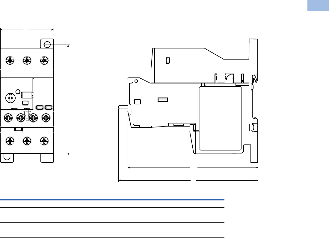
Volume 5—Motor Control and Protection CA08100006E—February 2014 www.eaton.com V5-T1-155
1
1
1
1
1
1
1
1
1
1
1
1
1
1
1
1
1
1
1
1
1
1
1
1
1
1
1
1
1
1
1.1
IEC Contactors and Starters
XT
IEC Power Control
Dimensions
Approximate Dimensions in Inches (mm)
45 mm C440/XT Electronic Overload Relays
Width
A
Depth
B1 B
Mounting Holes
(Height) C
NEMA Starter Size
00–2 1.80 (45.7) 4.32 (109.7) 4.63 (117.5) 3.68 (93.5)
XT IEC Frame Size
B, C, D 1.80 (45.7) 4.00 (101.6) 4.30 (109.2) 3.68 (93.5)
Standalone
0.35–45A 1.80 (45.7) 4.30 (109.2) 4.60 (116.8) 3.68 (93.5)
Text Orientation
B1
B
C
A
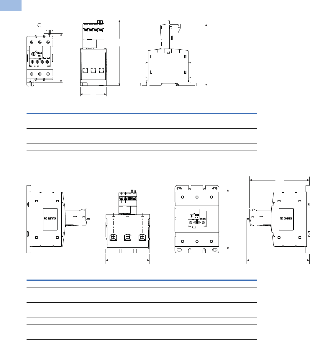
V5-T1-156 Volume 5—Motor Control and Protection CA08100006E—February 2014 www.eaton.com
1
1
1
1
1
1
1
1
1
1
1
1
1
1
1
1
1
1
1
1
1
1
1
1
1
1
1
1
1
1
1.1
IEC Contactors and Starters
XT
IEC Power Control
Approximate Dimensions in Inches (mm)
55 mm C440/XT Electronic Overload Relays
110 mm C440/XT Electronic Overload Relays
Width
A
Height To Reset
BB1
Mounting Depth
C
NEMA Starter Size
3 2.21 (56.0) 5.52 (140.2) 5.21 (132.4) 4.13 (104.8)
XT IEC Frame Size
D, F, G 2.21 (56.0) 5.52 (140.2) 5.21 (132.4) 4.13 (104.8)
Standalone
20–100A 2.21 (56.0) 5.52 (140.2) 5.21 (132.4) 4.13 (104.8)
Width
A
Height To Reset
BB1
Mounting Depth
C
NEMA Starter Size
4 4.33 (110.0) 6.20 (157.0) 5.90 (150.0) 6.00 (152.0)
XT IEC Frame Size
G 4.33 (110.0) 6.20 (157.0) 5.90 (150.0) 6.00 (152.0)
H 4.33 (110.0) 6.20 (157.0) 5.90 (150.0) 6.00 (152.0)
Standalone
4.33 (110.0) 6.20 (157.0) 5.90 (150.0) 6.00 (152.0)
Pass-Through
4.33 (110.0) 5.90 (149.0) 5.60 (142.0) 4.00 (102.0)
C
B
A
B1
C
B
B1
A
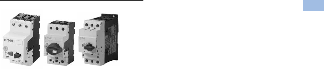
Volume 5—Motor Control and Protection CA08100006E—February 2014 www.eaton.com V5-T1-157
1
1
1
1
1
1
1
1
1
1
1
1
1
1
1
1
1
1
1
1
1
1
1
1
1
1
1
1
1
1
1.1
IEC Contactors and Starters
XT
IEC Power Control
Manual Motor Protectors
Contents
Description Page
Relays and Timers . . . . . . . . . . . . . . . . . . . . . . . . . V5-T1-3
Miniature Controls . . . . . . . . . . . . . . . . . . . . . . . . . V5-T1-18
Contactors and Starters . . . . . . . . . . . . . . . . . . . . V5-T1-35
Thermal Overload Relays . . . . . . . . . . . . . . . . . . . . V5-T1-128
C440/XT Electronic Overload Relay . . . . . . . . . . . V5-T1-141
Manual Motor Protectors
Features and Benefits . . . . . . . . . . . . . . . . . . . V5-T1-158
Standards and Certifications . . . . . . . . . . . . . . V5-T1-158
Product Identification . . . . . . . . . . . . . . . . . . . . V5-T1-159
Catalog Number Selection . . . . . . . . . . . . . . . . V5-T1-160
Product Selection . . . . . . . . . . . . . . . . . . . . . . . V5-T1-161
Accessories . . . . . . . . . . . . . . . . . . . . . . . . . . . V5-T1-164
Technical Data and Specifications . . . . . . . . . . V5-T1-176
Dimensions . . . . . . . . . . . . . . . . . . . . . . . . . . . V5-T1-185
Combination Motor Controllers . . . . . . . . . . . . . . . V5-T1-193
XT Electronic Manual Motor Protector . . . . . . . . . V5-T1-216
Reference Data . . . . . . . . . . . . . . . . . . . . . . . . . . . V5-T1-229
Manual Motor Protectors
Product Description
Eaton’s new XT family of
manual motor protectors
(MMPs) features a
pushbutton or rotary ON/OFF
manual disconnect, Class 10
adjustable bimetallic overload
relay and fixed magnetic
short-circuit trip capability
in one compact unit. Two
frame sizes are available:
Frame B (45 mm) for motors
with FLA ratings up to 32A
and Frame D (55 mm) covers
motor FLA ratings up to 65A.
Application Description
The XTPB and XTPR MMPs
can be used in the following
applications.
Motor Protective Circuit Breaker
In many countries outside
of the United States and
Canada, especially Europe,
the MMPs are tested and
classified as thermal-
magnetic circuit breakers
for use in motor branch
circuits. This can be an
important consideration for all
companies who export their
equipment and machines
internationally. Both the XTPB
and XTPR conform to IEC/EN
60947 and have the CE Mark.
Manual Motor Protectors
The XTPB and XTPR MMPs
are UL listed under UL 508 as
manual motor protectors. They
provide an economical solution
for applications requiring
simple manual starting and
stopping of motors. When
used as a manual starter, they
are typically installed in an
enclosure. Many enclosures
are offered as accessories for
the MMPs. Separate short-
circuit protective devices, such
as circuit breakers or fuses, are
wired ahead of the MMPs. The
short-circuit protective device
should be sized per the NEC
and should not exceed 400%
of the maximum FLA dial
setting of the MMP.
Group Motor Installations
A group motor installation
can be defined as more than
one motor circuit protected
by a single set of fuses or
circuit breaker on a motor
branch circuit. This eliminates
the need for individual fuses
or circuit breakers for each
motor circuit. Substantial
component cost savings,
panel space savings and
reduced wiring installation
time can be achieved in
group motor installations.
The MMPs are tested and
listed for group installation
.
If remote operation is required,
a magnetic contactor can be
wired in series with the MMP.
Article 430.53 of the NEC
contains the rules and
requirements for group motor
installations.
Refer to
application note AP03402001E
for NEC requirement for
group motor installation.
Individual Branch Motor
Applications
A UL 508 Type E self-
protected manual
combination starter/motor
controller consists of a single
device possessing four
essential elements:
disconnect, short circuit
protection, motor controller,
and motor overload
protection. Some MMPs
require use of a lineside
adapter for this type of
approval. When tested as an
official combination by UL,
this device takes the place of
a fuse-starter or breaker-
starter, XT Type E MMPs are
self-protected, meaning they
do not need additional short
circuit protection of a fuse or
breaker. Type E devices can
also be used with a contactor
or other types of UL approved
controllers. If tested with a
contactor, the combination
motor controller becomes a
Type F device. See Page
V5-T1-199 for XTFC Type F
devices.
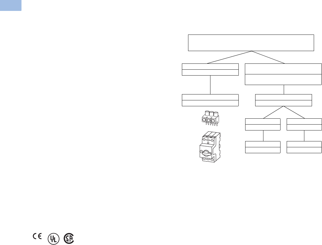
V5-T1-158 Volume 5—Motor Control and Protection CA08100006E—February 2014 www.eaton.com
1
1
1
1
1
1
1
1
1
1
1
1
1
1
1
1
1
1
1
1
1
1
1
1
1
1
1
1
1
1
1.1
IEC Contactors and Starters
XT
IEC Power Control
Features and Benefits
●ON/OFF rotary handle with
lockout provision
●Visible trip indication
●Class 10 overload
protection
●Phase loss sensitivity
●Ambient temperature
compensation to IEC/EN
60947, VDE 0660
●Fixed short-circuit trip—
14 times maximum setting
of overload FLA dial
●Type 2 coordination per IEC
947
●Identification markers
standard on starter
faceplate
●Motor applications from
0.1A to 65A
●Built-in heater and
magnetic trip elements
to protect the motor
●Adjustment dial for setting
motor FLA
●DIN rail mount
●Terminal types available:
●Screw terminals
●Screw (line) and spring
cage (load) terminals
●Spring cage terminals
●Accessories include:
●Front and side auxiliary
contacts
●Trip indicating contacts
●Tamperproof cover for
OLR dial
●Undervoltage release
●Shunt trip
●Through-the-door
operators
●Enclosures
●
Three-phase line side
connecting links
Standards and Certifications
●CE approved
●UL listed File No. E245398
●UL 508 group motor and
Type E compliant
●IEC/EN 60947
●CSA File 229767, Class
3211-05
●DIN VDE 0660 Part 100,
Part 101 and Part 102
Note: For Type 2 Coordination
of MMCs, see Page V5-T1-230.
Line Side Adapters—When to Use Them
Note: Line side adapters are not required for non-US applications.
Most countries outside of the US classify the MMP as a thermal
magnetic circuit breaker.
Line Side Adapter (LSA)
Required
Manual Motor Protector
and Line Side Adapter
Manual Motor Protectors
Self-Protected Manual Combination Starters
Line Side Adapter (LSA)
Not required
Group Installation
Upstream SCPD required.
UL 508 Type E Self-Protected Manual
Combination Starter
Self-protected. No additional SCPD needed in
branch circuit.
Line Side Adapter
XTPAXLSA
Line Side Adapter
XTPAXLSAD
MMP
XTPR…BC1
MMP
XTPR…DC1
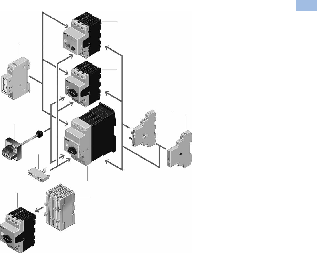
Volume 5—Motor Control and Protection CA08100006E—February 2014 www.eaton.com V5-T1-159
1
1
1
1
1
1
1
1
1
1
1
1
1
1
1
1
1
1
1
1
1
1
1
1
1
1
1
1
1
1
1.1
IEC Contactors and Starters
XT
IEC Power Control
Product Identification
Notes
Basic Units
1XTPB pushbutton manual motor
protectors (see Page V5-T1-161)
Rated operational current up to 25A
Switching capacity 50 kA/415V
Short-circuit release, adjustable
0.6–1 x lu
Single-phasing sensitive
2XTPR rotary manual motor protectors
(see Page V5-T1-162)
Rated operational current up to
32A, 65A
Switching capacity 150/50 kA/415V
Short-circuit release, fixed setting to
14 x lu
Overload release, adjustable 0.6–1 x lu
Single-phasing sensitive
With screws or spring-loaded
terminals
Mounting Accessories
3Rotary handle mechanism
(see Page V5-T1-167)
ON/OFF/tripped switch position indication
Lockable door/cover interlock
Extendable y plug fit extension shaft
Handle latched in switch positions
Optionally also without locking and
door interlock function
Insulated enclosures
(see Page V5-T1-171)
Surface mounting, enclosures, IP40,
IP55 and IP40 and IP55 front flush
mounting enclosure
Mounting/wiring (see Page V5-T1-167)
Component adapter for busbar mounting
Three-phase commoning link for
side-by-side-mounting
Mounting kits for rapid mounting of
direct-on-line, reversing and star-
delta starters
Add-On Functions
4Voltage releases (see Page V5-T1-166)
Undervoltage release
Shunt releases
With screws or spring-loaded terminals
5Standard auxiliary contacts
(see Page V5-T1-164)
ON/OFF indication
Differential fault indication overload/
short-circuit release
ON/OFF for (high capacity) contact
module
ON/OFF for starter combination
With early-make contacts
With screws or spring-loaded terminals
6Current limiter (see Page V5-T1-166)
Increases the switching capacity of the
10–25A manual motor protectors to
100 kA/440V
Can be used for individual group
protection
4
1
2
3
2
5
6
5
5
6
2
V5-T1-160 Volume 5—Motor Control and Protection CA08100006E—February 2014 www.eaton.com
1
1
1
1
1
1
1
1
1
1
1
1
1
1
1
1
1
1
1
1
1
1
1
1
1
1
1
1
1
1
1.1
IEC Contactors and Starters
XT
IEC Power Control
Catalog Number Selection
XT Manual Motor Protectors
XT PR 012 BC1
Type
PB = Manual motor protector—
pushbutton
PR = Manual motor protector—
rotary
PM = Manual motor protector—
magnetic only
PT = Manual transformer
protector (high mag.)
Designation
XT = XT IEC power control
Trip Class
C1 =Class 10
Blank = Magnetic only (no thermal trip)
Frame Size
B= 45 mm
D= 55 mm
Current Ratings
Frame B
P16 = 0.16A
P25 = 0.25A
P40 = 0.40A
P63 = 0.63A
001 = 1A
1P6 = 1.6A
2P5 = 2.5A
004 = 4A
6P3 = 6.3A
010 = 10A
012 = 12A
016 = 16A
020 = 20A
025 = 25A
032 = 32A
Frame D
016 = 16A
025 = 25A
032 = 32A
040 = 40A
050 = 50A
058 = 58A
063 = 63A
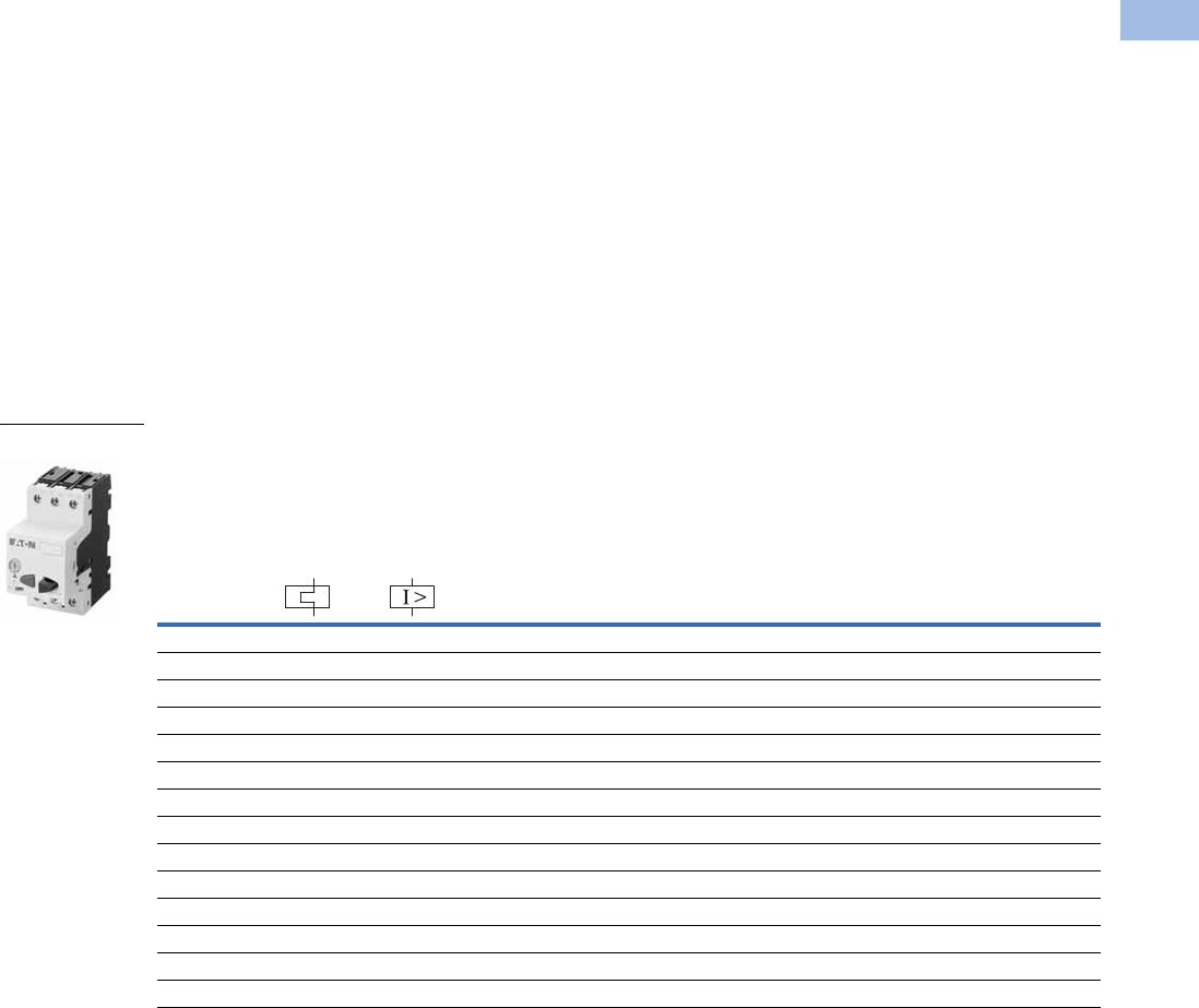
Volume 5—Motor Control and Protection CA08100006E—February 2014 www.eaton.com V5-T1-161
1
1
1
1
1
1
1
1
1
1
1
1
1
1
1
1
1
1
1
1
1
1
1
1
1
1
1
1
1
1
1.1
IEC Contactors and Starters
XT
IEC Power Control
Product Selection
Product Selection for Manual Motor Starter Applications
When ordering, specify catalog numbers according to the following stipulations:
XT manual motor protectors
are selected based on the
overload current range
required for a given motor.
This current range is
determined from the motor
full load ampere rating and
motor service factor usually
found on the motor
nameplate.
For motors with service
factors less than 1.15,
multiply the motor FLA by
0.90 to select appropriate
MMP.
Example: For motor having
FLA of 6.4A and service
factor of 1.0 (6.4A x 0.90 =
5.76A) select catalog number
XTPB6P3B01.
See Application Note—
AP03402001E.
For motor with service
factor of 1.15 or greater,
use motor nameplate full load
amperes to select the
appropriate MMP.
Example: For motor having
FLA of 11A and service factor
of 1.15, select catalog
number XTPR012BC1.
XTPB Pushbutton Manual Motor Protectors—Global and North American Ratings—Frame B
Type 1 and Type 2 Coordination Motor Protective Device with Thermal and Magnetic Trip
Notes
Single-phasing sensitivity to IEC/EN 60947-4-1, VDE 0660 Part 102.
Can be snap-fit to IEC/EN 60715 top-hat (DIN) with 7.5 or 15 mm height.
Service Factor (SF)—Setting Ir of current scale in dependence of load factor:
SF = 1.15 → Ir = 1 x In mot
SF = 1 → Ir = 0.9 x In mot
For manual motor protective circuit breaker switching capacity, see Page V5-T1-181.
1 Select manual motor protectors by full load amperes. Maximum motor ratings (kW, hp) are for reference only.
2 In this range, calculate motor rating according to rated current. Specified values to NEC 430.6(A)(1).
Rated
Uninterrupted
Current—
Iu = Ie (Amps)
FLA
Adjustment
Range/
Overload
Release—
Ir (Amps)
Short
Circuit
Release—
Irm (Amps)
Screw Terminal
Catalog Number
Maximum Motor Ratings 1
Maximum kW Rating
AC-3—P (kW)
Maximum hp Rating—P (hp)
UL 508/CSA C22.2 No. 14
Three-Phase Three-Phase
220–
240V
380–
415V 440V 500V
660–
690V 200V 240V 480V 600V
0.16 0.1–0.16 2.2 ————0.06
2222XTPBP16BC1
0.25 0.16–0.25 3.5 — 0.06 0.06 0.06 0.12 2222XTPBP25BC1
0.4 0.25–0.4 5.6 0.06 0.09 0.12 0.12 0.18 2222XTPBP40BC1
0.63 0.4–0.63 8.8 0.09 0.12 0.18 0.25 0.25 2222XTPBP63BC1
1 0.63–1 14 0.12 0.25 0.25 0.37 0.55 2221/2XTPB001BC1
1.6 1–1.6 22 0.25 0.55 0.55 0.75 1.1 223/4 3/4 XTPB1P6BC1
2.5 1.6–2.5 35 0.37 0.75 1.1 1.1 1.5 1/2 1/2 1 1-1/2 XTPB2P5BC1
4 2.5–4 56 0.75 1.5 1.5 2.2 3 3/4 3/4 2 3 XTPB004BC1
6.3 4–6.3 88 1.12.233411-1/235XTPB6P3BC1
10 6.3–10 140 2.24447.5337-1/210XTPB010BC1
12 8–12 168 3 5.5 5.5 5.5 11 3 3 7-1/2 10 XTPB012BC1
16 10–16 224 47.59912.5351010XTPB016BC1
20 16–20 280 5.5 9 11 12.5 15 5 — — 15 XTPB020BC1
25 20–25 350 5.5 12.5 12.5 15 22 — 7-1/2 15 20 XTPB025BC1
Frame B
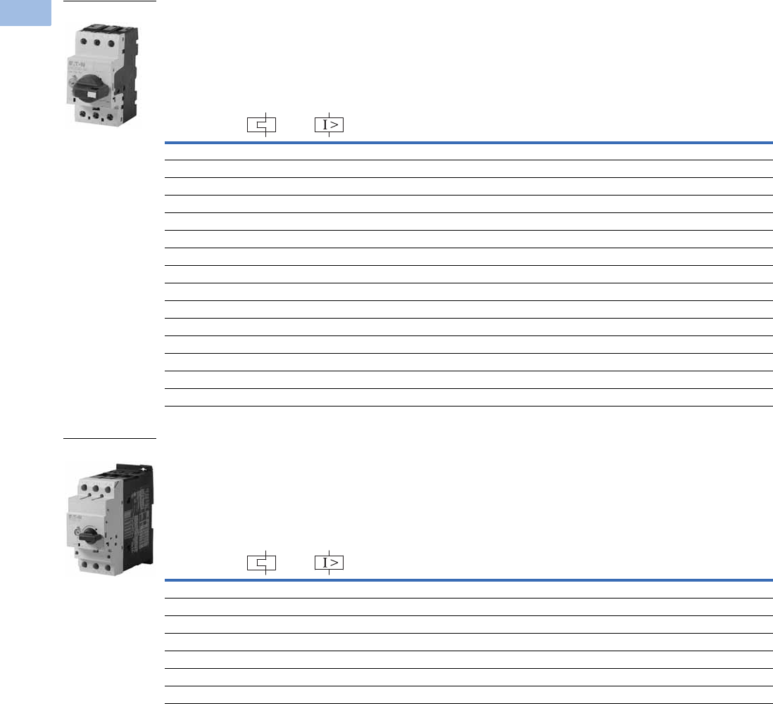
V5-T1-162 Volume 5—Motor Control and Protection CA08100006E—February 2014 www.eaton.com
1
1
1
1
1
1
1
1
1
1
1
1
1
1
1
1
1
1
1
1
1
1
1
1
1
1
1
1
1
1
1.1
IEC Contactors and Starters
XT
IEC Power Control
XTPR Rotary Manual Motor Protectors with Screw Terminals—
Global Ratings and North American Ratings—Frame B
Type 1 and Type 2 Coordination Motor Protective Device with Thermal and Magnetic Trip
XTPR Rotary Manual Motor Protectors with Screw Terminals—
Global Ratings and North American Ratings—Frame D
Type 1 and Type 2 Coordination Motor Protective Device with Thermal and Magnetic Trip
Notes
Single-phasing sensitivity to IEC/EN 60947-4-1, VDE 0660 Part 102.
Can be snap-fit to IEC/EN 60715 top-hat (DIN) with 7.5 or 15 mm height.
Service Factor (SF)—Setting Ir of current scale in dependence of load factor:
SF = 1.15 → Ir = 1 x In mot
SF = 1 → Ir = 0.9 x In mot
For manual motor protective circuit breaker switching capacity, see Page V5-T1-181.
1 Select manual motor protectors by full load amperes. Maximum motor ratings (kW, hp) are for reference only.
2 In this range, calculate motor rating according to rated current. Specified values to NEC 430.6(A)(1).
Rated
Uninterrupted
Current—
Iu = Ie (Amps)
FLA
Adjustment
Range/
Overload
Release—
Ir (Amps)
Short
Circuit
Release—
Irm (Amps)
Screw Terminal
Catalog Number
Maximum Motor Ratings 1
Maximum kW Rating
AC-3—P (kW)
Maximum hp Rating—P (hp)
UL 508/CSA C22.2 No. 14
Three-Phase Three-Phase
220–
240V
380–
415V 440V 500V
660–
690V 200V 240V 480V 600V
0.16 0.1–0.16 2.2 ————0.06
2222XTPRP16BC1
0.25 0.16–0.25 3.5 — 0.06 0.06 0.06 0.12 2222XTPRP25BC1
0.4 0.25–0.4 5.6 0.06 0.09 0.12 0.12 0.18 2222XTPRP40BC1
0.63 0.4–0.63 8.8 0.09 0.12 0.18 0.25 0.25 2222XTPRP63BC1
1 0.63–1 14 0.12 0.25 0.25 0.37 0.55 2222XTPR001BC1
1.6 1–1.6 22 0.25 0.55 0.55 0.75 1.1 223/4 3/4 XTPR1P6BC1
2.5 1.6–2.5 35 0.37 0.75 1.1 1.1 1.5 1/2 1/2 1 1-1/2 XTPR2P5BC1
4 2.5–4 56 0.75 1.5 1.5 2.2 3 3/4 3/4 2 3 XTPR004BC1
6.3 4–6.3 88 1.12.233411-1/235XTPR6P3BC1
10 6.3–10 140 2.24447.5337-1/210XTPR010BC1
12 8–12 168 3 5.5 5.5 5.5 11 3 3 7-1/2 10 XTPR012BC1
16 10–16 224 47.59912.5351010XTPR016BC1
20 16–20 280 5.5 9 11 12.5 15 5 — — 15 XTPR020BC1
25 20–25 350 5.5 12.5 12.5 15 22 — 7-1/2 15 20 XTPR025BC1
32 25–32 448 7.5 15 15 22 30 7-1/2 10 20 25 XTPR032BC1
Rated
Uninterrupted
Current—
Iu = Ie (Amps)
FLA
Adjustment
Range/
Overload
Release—
Ir (Amps)
Short
Circuit
Release—
Irm (Amps)
Screw Terminal
Catalog Number
Maximum Motor Ratings 1
Maximum kW Rating
AC-3—P (kW)
Maximum hp Rating—P (hp)
UL 508/CSA C22.2 No. 14
Three-Phase Three-Phase
220–
240V
380–
415V 440V 500V
660–
690V 200V 240V 480V 600V
16 10–16 224 47.59912.5351015XTPR016DC1
25 16–25 350 5.5 12.5 12.5 15 22 7-1/2 7-1/2 15 20 XTPR025DC1
32 25–32 448 7.51517.5222210102030XTPR032DC1
40 32–40 560 11 20 22 24 30 10 15 30 30 XTPR040DC1
50 40–50 700 14 25 30 30 45 10 15 30 40 XTPR050DC1
58 50–58 812 17 30 37 37 55 15 15 40 50 XTPR058DC1
65 55–65 882 18.5 34 37 45 55 15 15 40 50 XTPR063DC1
Frame B
Frame D
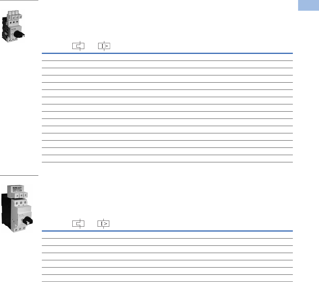
Volume 5—Motor Control and Protection CA08100006E—February 2014 www.eaton.com V5-T1-163
1
1
1
1
1
1
1
1
1
1
1
1
1
1
1
1
1
1
1
1
1
1
1
1
1
1
1
1
1
1
1.1
IEC Contactors and Starters
XT
IEC Power Control
XTPR Manual Self-Protected Motor Starters—North American Ratings, UL 508 Type E—Frame B 1
Motor Protective Device with Thermal and Magnetic Trip
XTPR Manual Self-Protected Motor Starters—North American Ratings, UL 508 Type E—Frame D 1
Motor Protective Device with Thermal and Magnetic Trip
Notes
A UL 508 Type E self-protected manual combination starter (XTPR) consists of a manual motor protector (XTPR) and a UL Listed line side adapter (for example, XTPAXLSA).
The Type E self-protected manual combination starter alone is a legitimate short-circuit protective device and disconnect means for the downstream motor,
while the contactor has been added to provide remote operation of the motor circuit. Conductor size for XTPAXLSA is 14–6 AWG, XTPAXLSAD is 8 AWG–1/0.
1 UL 508 Type E starters are assembled from a standard XTPR and a special incoming terminal line side adapter (XTPAXLSA or XTPAXLSAD).
2 Select manual motor protectors by full load amperes. Maximum motor ratings (kW, hp) are for reference only.
3 In this range, calculate motor rating according to rated current. Specified values to NEC 430.6(A)(1).
Rated
Uninterrupted
Current—
Iu (Amps)
FLA
Adjustment
Range/
Overload
Release—
Ir (Amps)
Short
Circuit
Release—
Irm (Amps) Line Side
Adapter 1
Catalog Number
Manual Motor
Protector—
Screw Terminal
Catalog Number
Maximum Motor Ratings 2
Maximum hp Rating—P (hp)
Three-Phase
Rated Short-Circuit
Breaking Capacity (kA)
200V 240V
480V/
277V
600V/
247V
480/
277V
600/
347V
0.16 0.1–0.16 2.2 331/2 1/2 50 50 XTPAXLSA XTPRP16BC1
0.25 0.16–0.25 3.4 331/2 1/2 50 50 XTPAXLSA XTPRP25BC1
0.4 0.25–0.4 5.6 331/2 1/2 50 50 XTPAXLSA XTPRP40BC1
0.63 0.4–0.63 8.8 331/2 1/2 50 50 XTPAXLSA XTPRP63BC1
1 0.63–1 14 331/2 1/2 50 50 XTPAXLSA XTPR001BC1
1.6 1–1.6 22 333/4 3/4 50 50 XTPAXLSA XTPR1P6BC1
2.5 1.6–2.5 35 1/2 1/2 1 1-1/2 50 50 XTPAXLSA XTPR2P5BC1
4 2.5–4 56 3/412350 50 XTPAXLSA XTPR004BC1
6.3 4–6.3 88 11-1/23565 50 XTPAXLSA XTPR6P3BC1
10 6.3–11 140 3 3 7-1/2 10 65 50 XTPAXLSA XTPR010BC1
12 8–12 168 3 3 7-1/2 — 65 — XTPAXLSA XTPR012BC1
16 10–16 224 3 5 10 — 42 — XTPAXLSA XTPR016BC1
20 16–20 280 5 5 — — 18 — XTPAXLSA XTPR020BC1
25 20–25 350 5 7-1/2 15 — 18 — XTPAXLSA XTPR025BC1
32 25–32 448 7-1/2 10 25 — 18 — XTPAXLSA XTPR032BC1
Rated
Uninterrupted
Current—
Iu (Amps)
FLA
Adjustment
Range/
Overload
Release—
Ir (Amps)
Short
Circuit
Release—
Irm (Amps) Line Side
Adapter 1
Catalog Number
Manual Motor
Protector—
Screw Terminal
Catalog Number
Maximum Motor Ratings 2
Maximum hp Rating—P (hp)
Three-Phase
Rated Short-Circuit
Breaking Capacity (kA)
200V 240V
480V/
277V
600V/
247V
240V
480/
277V
600/
347V
16 10–16 224 3 5 1010656525XTPAXLSAD XTPR016DC1
25 16–25 350 7-1/2 7-1/2 20 25 65 65 25 XTPAXLSAD XTPR025DC1
32 25–32 448 10 10 25 30 65 65 25 XTPAXLSAD XTPR032DC1
40 32–40 560 10—3030656525XTPAXLSAD XTPR040DC1
50 40–50 700 — 15 30 — 65 65 — XTPAXLSAD XTPR050DC1
58 50–58 812 — — 40 — 65 65 — XTPAXLSAD XTPR058DC1
65 55–65 882 — — 40 — 65 65 — XTPAXLSAD XTPR063DC1
Frame B
Frame D

V5-T1-164 Volume 5—Motor Control and Protection CA08100006E—February 2014 www.eaton.com
1
1
1
1
1
1
1
1
1
1
1
1
1
1
1
1
1
1
1
1
1
1
1
1
1
1
1
1
1
1
1.1
IEC Contactors and Starters
XT
IEC Power Control
Accessories
Auxiliary Contacts
Side-Mount Auxiliary Contacts
Can be fitted on the right side of manual motor protectors (XTPB, XTPR, XTPM) and
manual transformer protectors (XTPT) and can be combined with XTPAXSATR_ and
XTPAXFA_ trip indicating auxiliary contact.
Front-Mount Auxiliary Contacts
Can be fitted to manual motor protectors (XTPB, XTPR, XTPM) and manual
transformer protectors (XTPT). 45 mm
(XTPR…B and XTPB) or 55 mm (XTPR…D)
widths of manual motor protectors remain unchanged.
Note
1
Orders must be placed in multiples of package quantity listed.
Contact
Configuration Contact Sequence
Pkg.
Qty. 1
Screw Terminal
Catalog Number
1NO-1NC 5 XTPAXSA11
1NO-2NC 5 XTPAXSA12
2NO-1NC 5 XTPAXSA21
Contact
Configuration Contact Sequence
Pkg.
Qty. 1
Screw Terminal
Catalog Number
1NO-1NC 5 XTPAXFA11
XTPAXSA_
L1 L2 L3
XTPAXSA11
1.14 1.22
1.13 1.21
1.14 1.22 1.32
1.13 1.21 1.31
L1 L2 L3
XTPAXSA12
1.14 1.22 1.34
1.13 1.21 1.33
L1 L2 L3
XTPAXSA21
XTPAXFA11
1.54 1.62
1.53 1.61
L1 L2 L3
XTPAXFA11
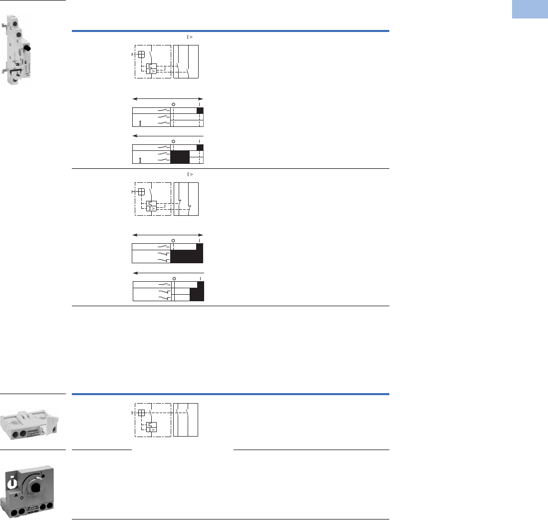
Volume 5—Motor Control and Protection CA08100006E—February 2014 www.eaton.com V5-T1-165
1
1
1
1
1
1
1
1
1
1
1
1
1
1
1
1
1
1
1
1
1
1
1
1
1
1
1
1
1
1
1.1
IEC Contactors and Starters
XT
IEC Power Control
Side-Mount Trip Indicating Auxiliary Contacts
Can be fitted on the right side of manual motor protectors. Can be combined with
standard auxiliary contacts. Trip indication: A. General trip indication (overload) B.
Short-circuit trip. Local short-circuit indication by red indicator, manually resettable.
Early-Make Front-Mount Auxiliary Contacts
For use with XTPB_, Frame B XTPR and XTPT. Can be fitted to the front of a manual
motor protector. 45 mm width of manual motor protector remains unchanged. For
early energization of undervoltage release, for example, in emergency-stop circuits to
EN 60204
.
Notes
1
Orders must be placed in multiples of package quantity listed.
2 Not for use with rotary handle mechanism.
Contact
Configuration Contact Sequence
Pkg.
Qty. 1
For Use
with… Catalog Number
2 x 1NO 2 XTPB, XTPR,
XTPM, XTPT
XTPAXSATR20
2 x 1NC 2 XTPB, XTPR,
XTPM, XTPT
XTPAXSATR02
Contact
Configuration Contact Sequence
Pkg.
Qty. 1
For Use
with… Catalog Number
2NO 5 XTPB XTPBXFAEM20
2NO 2 XTPR, XTPM,
XTPT
XTPAXFAEM20 2
XTPAXSATR_
4.44 4.14
“+”
4.43 “ ”
4.13
“+”
“ >”
On/Off
“+”
“ >”
Trip “+”
L1L2 L3
L1L2 L3
4.32 4.22
“+”
4.31 “ ”
4.21
On/Off
“+”
“ >”
Trip “+”
L1L2 L3
“+”
“ >”
L1L2 L3
XTPBXFAEM20
XTPAXFAEM20
3.14 3.24
3.13 3.23
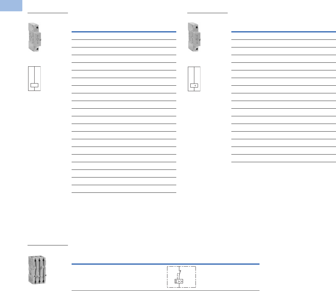
V5-T1-166 Volume 5—Motor Control and Protection CA08100006E—February 2014 www.eaton.com
1
1
1
1
1
1
1
1
1
1
1
1
1
1
1
1
1
1
1
1
1
1
1
1
1
1
1
1
1
1
1.1
IEC Contactors and Starters
XT
IEC Power Control
Additional Accessories
Shunt Release
Can be used to trip the manual motor
protector from a remote location. Can
be fitted on the left side of manual
motor protectors. Cannot be combined
with the XTPAXUVR. DC: Intermittent
operation 5 sec.
Undervoltage Release
Can be used to trip the manual motor
protector from a remote location. Can
be fitted on left side manual motor
protectors. Cannot be combined with
XTPAXSR. When combined with a circuit
breaker, it can be used as emergency-stop
device to IEC/EN 60204.
Current Limiter 2
The XTPAXCL enhances the switching capacity of the XT manual motor
protectors. It can be used with the XTPB, XTPR…BC1, XTPR…DC1 for
individual or group protections. The rated uninterrupted current is 63A for IEC
and 25A for UL/CSA. It can be mounted next to or behind the manual motor
protector. See Page V5-T1-181 for ratings when using the current limiter.
Notes
1 Orders must be placed in multiples of package quantity listed.
2 Max. rated operation voltage Ue = 690V, rated uninterrupted current Iu = 63A. Can be used for individual and
group protection. For group protection and in combination with the XTPR…D order additional XTPAXIT incoming
terminal if required. Mounting next to or behind the manual motor protector. 16–63A XTPR…D: 100 kA/400V, 10 kA/690V.
Pkg.
Qty. 1
Screw Terminal
Catalog Number
2XTPAXSR24V50H
2XTPAXSR48V50H
2XTPAXSR110V50H
2XTPAXSR120V60H
2XTPAXSR208V60H
2XTPAXSR220V50H
2XTPAXSR230V50H
2XTPAXSR240V50H
2XTPAXSR240V60H
2XTPAXSR380V50H
2XTPAXSR400V50H
2XTPAXSR415V50H
2XTPAXSR440V60H
2XTPAXSR480V60H
2XTPAXSR24VDC
2XTPAXSR48VDC
2XTPAXSR60VDC
2XTPAXSR110VDC
2XTPAXSR125VDC
2XTPAXSR220VDC
2XTPAXSR250VDC
XTPAXSR_
Contact Sequence
C1
C2
Pkg.
Qty. 1
Screw Terminal
Catalog Number
2XTPAXUVR24V50H
2XTPAXUVR24V60H
2XTPAXUVR48V50H
2XTPAXUVR60V50H
2XTPAXUVR110V50H
2XTPAXUVR120V60H
2XTPAXUVR208V60H
2XTPAXUVR220V50H
2XTPAXUVR230V50H
2XTPAXUVR240V50H
2XTPAXUVR240V60H
2XTPAXUVR380V50H
2XTPAXUVR400V50H
2XTPAXUVR415V50H
2XTPAXUVR440V60H
2XTPAXUVR480V60H
2XTPAXUVR600V60H
XTPAXUVR_
Contact Sequence
D1
D2
U
Description
Contact
Sequence
Pkg.
Qty. 1Catalog Number
To enhance the switching capacity of non-inherently
safe 10–25A manual motor protectors to 150 kA/440V
1XTPAXCL
XTPAXCL
L
T
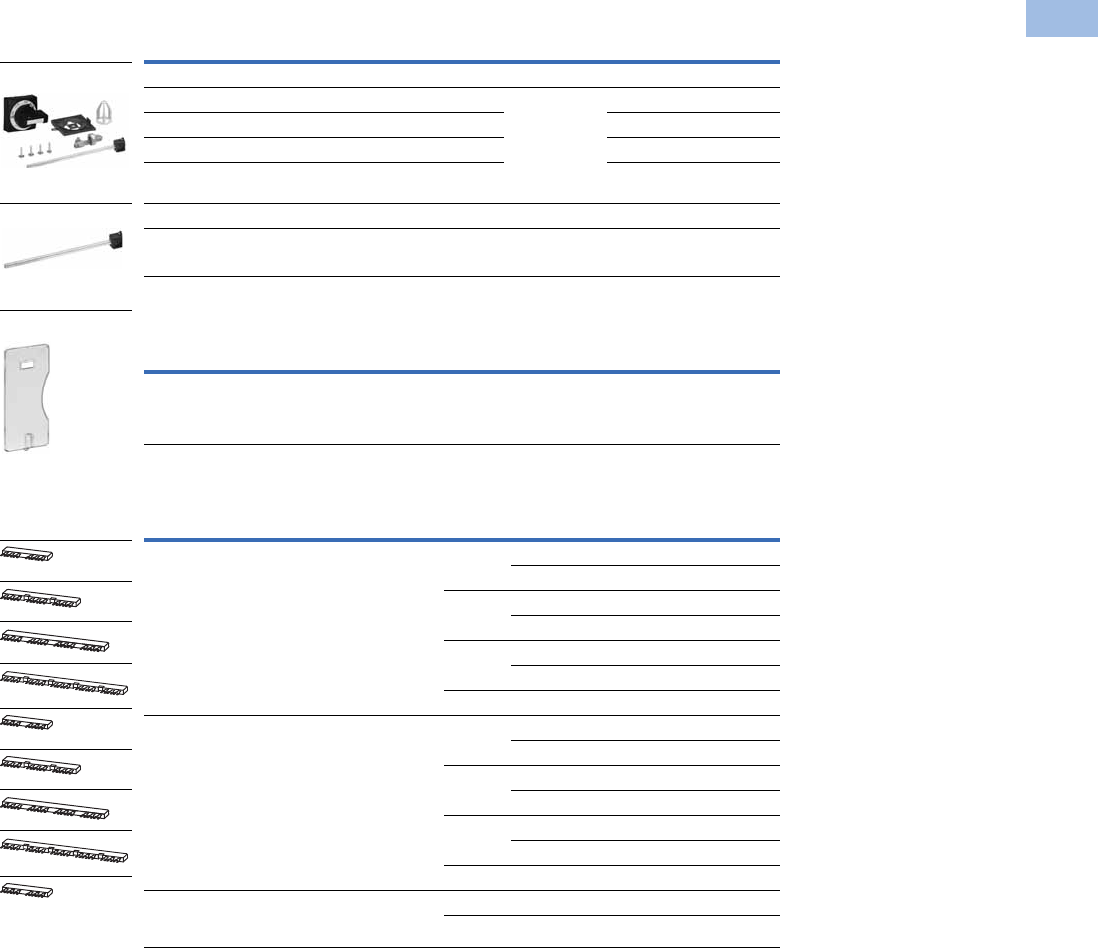
Volume 5—Motor Control and Protection CA08100006E—February 2014 www.eaton.com V5-T1-167
1
1
1
1
1
1
1
1
1
1
1
1
1
1
1
1
1
1
1
1
1
1
1
1
1
1
1
1
1
1
1.1
IEC Contactors and Starters
XT
IEC Power Control
IP65 Rotary Handle Mechanism 1234
Sealing Facility
Three-Phase Commoning Links 8
For parallel power feed to several manual motor protectors on terminals
1, 3 and 5.
Notes
1 Plug-in connection shafts, XTPAXRHMSFT_ can be cut to desired length for mounting depths of 100–240 mm. Carrier
with extension shaft included.
2 With ON/OFF switch position and “+” (tripped), lockable with 3 padlocks, 4–8 mm hasp. Can be locked in the
OFF position, if required.
3 Rotary handle mechanisms ship with door interlock disabled. See instruction publication with product for how to
enable door interlock.
4 Not for use with XTPAXFAEM20 early-make front-mount auxiliary contact.
5 Orders must be placed in multiples of package quantity listed.
6 For use on main switches to IEC/EN 60204.
7 For use on main switches with emergency-stop function to IEC/EN 60204.
8 Protected against accidental contact. Frame B short-circuit proof Ue = 690V, Iu = 63A.
Frame B links can be combined by
rotating mounting.
Description
Enclosure
Rating
Pkg.
Qty. 5Catalog Number
Complete Kits—Includes Handle, Shaft and Required Hardware
Rotary handle mechanism—black 6IP65
NEMA 12
UL/CSA 4X
1XTPAXRHMB
Rotary handle mechanism—red/yellow 71XTPAXRHMRY
Rotary handle mechanism—black—rotated 90° from vertical 61XTPAXRHM90B
Rotary handle mechanism—red/yellow—rotated 90° from
vertical 7
1XTPAXRHM90RY
Separate Parts
Shaft only—includes shaft to mount to XTPR, 175 mm length — 10 XTPAXRHMSFT
Description
Pkg.
Qty. 5Catalog Number
To prevent tampering with the overload release and the test function.
It can be sealed using industry standard sealing wire. For use with
XTPR manual motor protectors.
5XTPAXSW
For Use with…
Qty.
MMP
MMP
Frame Size
Pkg.
Qty. 5Catalog Number
MMP with no side-mounted auxiliaries or voltage
releases
2B 10XTPAXCLKA2
D1XTPAXCLKA2D
3B 10XTPAXCLKA3
D1XTPAXCLKA3D
4B 10XTPAXCLKA4
D1XTPAXCLKA4D
5B 10XTPAXCLKA5
Each MMP with one auxiliary contact or trip-indicating
auxiliary contact fitted on the right
2B 10XTPAXCLKB2
D1XTPAXCLKB2D
3B 10XTPAXCLKB3
D1XTPAXCLKB3D
4B 10XTPAXCLKB4
D1XTPAXCLKB4D
5B 10XTPAXCLKB5
Each MMP with an auxiliary contact and trip-indicating
auxiliary contact mounted on the right or a voltage
release mounted on the left.
2B 10XTPAXCLKC2
4D 1XTPAXCLKC4D
XTPAXRHM_
XTPAXRHMSFT
XTPAXSW
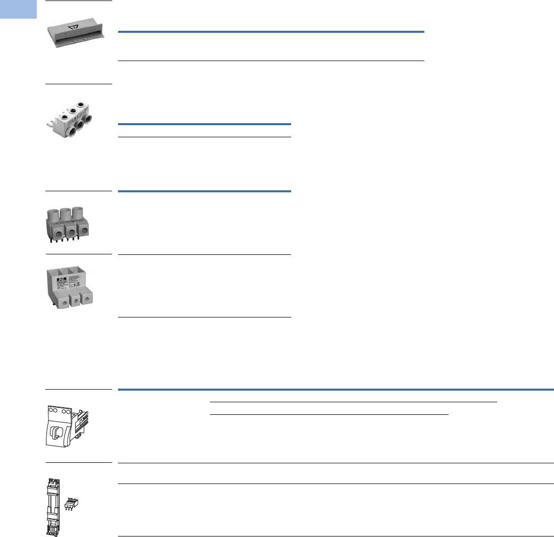
V5-T1-168 Volume 5—Motor Control and Protection CA08100006E—February 2014 www.eaton.com
1
1
1
1
1
1
1
1
1
1
1
1
1
1
1
1
1
1
1
1
1
1
1
1
1
1
1
1
1
1
1.1
IEC Contactors and Starters
XT
IEC Power Control
Shroud for Unused Terminals of Three-Phase Commoning Links
Incoming Terminals for Three-Phase
Commoning Link 2
Line-Side Adapter 3
Combination Connection Kits
Non-Reversing Starters
Notes
1 Orders must be placed in multiples of package quantity listed.
2 For three-phase commoning link, protected against accidental contact, Ue = 690V, Iu = 63A;
For conductor cross-sections: 2.5–25 mm2 stranded; 2.5–16 mm2 flexible with ferrules, AWG 14-6.
3 XTPAXLSA is for three-phase commoning link, finger and back-of-hand proof,
Ue = 690V, Iu = 60A for conductor cross sections: 2.5–25 mm2 stranded,
2.5–16 mm2 flexible with ferrule, AWG 14-6.
4 XTPAXLSAD cannot be combined with three-phase commoning links. Conductor size 8 AWG–1/0.
For Use with… Description
Pkg.
Qty. 1Catalog Number
Frame B
XTPR
To cover unused terminals on three-phase
commoning link. Protected against direct
contact.
20 XTPAXUTS
For Use with…
Pkg.
Qty. 1Catalog Number
Frame B XTPR, XTPB 5 XTPAXIT
For Use with…
Pkg.
Qty. 1Catalog Number
Frame B XTPR to create a
UL 508 Type E/F manual
combination starter
5XTPAXLSA
Frame D XTPR to create a
UL 508 Type E/F manual
combination starter
1XTPAXLSAD 4
For Use with… Description/Comprised of …
Std.
Pack 1Catalog Number
XTPR…B + XTCE…B Mechanical connection element for XTPR…B and contactor 1 XTPAXTPCB
Main current wiring between XTPR…B and contactor in toolless plug connection 1
Use contactor auxiliary switch XTCEXFAT_. Control cable guidance: max. six cables
up to 2.5 mm2 external diameter or four cables up to 3.5 mm2 external diameter.
XTPR…B + XTCE…C DIN rail adapter plate
Main current wiring between XTPR and contactor
1XTPAXTPCC
XTPR…D + XTCE…D DIN rail adapter plate
Main current wiring between XTPR and contactor
1XTPAXTPCD
XTPAXUTS
XTPAXIT
XTPAXLSA
XTPAXLSAD
XTPAXTPCB
XTPAXTPC_
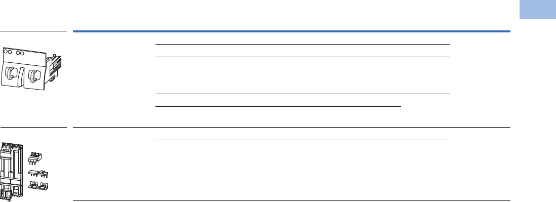
Volume 5—Motor Control and Protection CA08100006E—February 2014 www.eaton.com V5-T1-169
1
1
1
1
1
1
1
1
1
1
1
1
1
1
1
1
1
1
1
1
1
1
1
1
1
1
1
1
1
1
1.1
IEC Contactors and Starters
XT
IEC Power Control
Reversing Starters
Note
1 Orders must be placed in multiples of package quantity listed.
For Use with… Description/Comprised of …
Std.
Pack 1Catalog Number
XTPR…B + XTCE…B01_ Mechanical connection element for XTPR…B and contactor 1 XTPAXTPCRB
Reversing starter main current wiring in toolless plug connection 1
Control cables for electrical interlocking in toolless plug connection:
– K1M: A1–K2M: 21
– K1M: 21–K2M: A1
– K1M: A2–K2M: A2
1
Cable guidance 1
Use contactor auxiliary switch XTCEXFAT_. Control cable guidance: max. six cables
up to 2.5 mm2 external diameter or four cables up to 3.5 mm2 external diameter.
XTPR…B + XTCE…C DIN rail adapter plate 1 XTPAXTPCRC
Reversing starter main current wiring 1
XTPAXTPCRB
XTPAXTPCRC
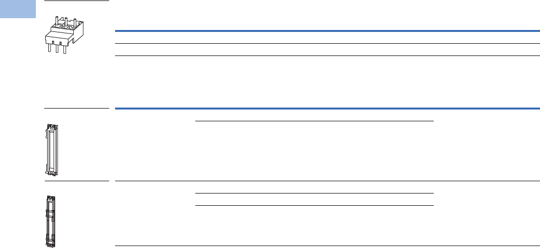
V5-T1-170 Volume 5—Motor Control and Protection CA08100006E—February 2014 www.eaton.com
1
1
1
1
1
1
1
1
1
1
1
1
1
1
1
1
1
1
1
1
1
1
1
1
1
1
1
1
1
1
1.1
IEC Contactors and Starters
XT
IEC Power Control
Electrical Connection Module
DIN Rail Adapter Plates
Note
1 Orders must be placed in multiples of package quantity listed.
For Use with… Description/Comprised of …
Std.
Pack 1Catalog Number
XTPR…B + XTCE…C Main current wiring between XTPR…B and contactor 5 XTPAXECMC
XTPR…D + XTCE…D Main current wiring between XTPR…D and contactor 5 XTPAXECMD
For Use with… Description/Comprised of …
Std.
Pack 1Catalog Number
XTPAXTPCB
XTPAXTPCRB
45 mm wide adapter plate with one DIN rail 4 XTPAXTPCPB
Connection element for side-by-side positioning of further plates
XTPAXECMD
XTPR…D + XTCE…C
XTPR…D + XTCE…D
55 mm wide adapter plate with two DIN rails 4 XTPAXTPCPD
Connection cams for further plates
For use with reversing and star-delta starters
XTPAXECM_
XTPAXTPCPB
XTPAXTPCPD
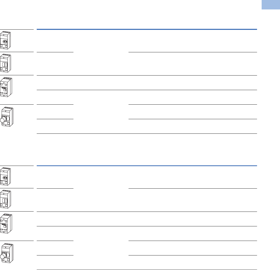
Volume 5—Motor Control and Protection CA08100006E—February 2014 www.eaton.com V5-T1-171
1
1
1
1
1
1
1
1
1
1
1
1
1
1
1
1
1
1
1
1
1
1
1
1
1
1
1
1
1
1
1.1
IEC Contactors and Starters
XT
IEC Power Control
Pushbutton MMP Enclosures
Insulated Enclosures for Surface Mounting of XTPB Pushbutton
Motor-Protective Circuit Breakers—Global Usage 1
Insulated Enclosures for Surface Mounting of XTPB Pushbutton
Manual Motor Protectors—North American Usage 23
Notes
1 Integrated terminal for PE(N) connection, two M25 cable entry knockouts at top and at bottom.
2 Built-in terminal for PE(N).
3 North American enclosures come with conduit adapters for use with 1/2 in NPT.
Degree of
Protection
For Use
with… Description Catalog Number
IP40
NEMA 1
XTPB MMP only or with:
XTPAXFA_, XTPBXFAEM20,
XTPAXSA_, XTPAXUVR_,
XTPAXSR_
—XTPBXENCS40
IP65
NEMA
3R, 4X, 12, 13
With actuation membrane. XTPBXENCS65
IP65
NEMA
3R, 4X, 12, 13
XTPB MMP only or with:
XTPAXFA_, XTPAXUVR_,
XTPAXSR_, XTPAXCL
Lockable in OFF position. XTPBXENCSLO65
IP65
NEMA
3R, 4X, 12, 13
XTPB MMP only or with:
XTPAXFA_, XTPBXFAEM20,
XTPAXUVR_, XTPAXSR_,
XTPAXCL
Lockable in OFF position in combination with XTPBXFAEM20
early-make front-mount auxiliary contact
XTPBXENCSLE65
IP65
NEMA
3R, 4X, 12, 13
With emergency-stop (e-stop) pushbutton actuator, red-yellow XTPBXENCSES65
IP65
NEMA
3R, 4X, 12, 13
With emergency-stop (e-stop) pushbutton actuator, red-yellow
key release
XTPBXENCSEK65
Degree of
Protection
For Use
with… Description Catalog Number
IP41
NEMA 1
XTPB MMP only or with:
XTPAXFA_, XTPBXFAEM20,
XTPAXSA_, XTPAXUVR_,
XTPAXSR_
—XTPBXENAS41
IP65
NEMA
3R, 4X, 12, 13
With actuating diaphragm XTPBXENAS65
IP65
NEMA
3R, 4X, 12, 13
XTPB MMP only or with:
XTPAXFA_, XTPAXUVR_,
XTPAXSR_, XTPAXCL
Lockable in OFF position XTPBXENASLO65
IP65
NEMA
3R, 4X, 12, 13
XTPB MMP only or with:
XTPAXFA_, XTPBXFAEM20,
XTPAXUVR_, XTPAXSR_,
XTPAXCL
Lockable in OFF position in combination with XTPBXFAEM20
early-make front-mount auxiliary contact
XTPBXENASLE65
IP65
NEMA
3R, 4X, 12, 13
With emergency-stop (e-stop) pushbutton actuator, red-yellow XTPBXENASES65
IP65
NEMA
3R, 4X, 12, 13
With emergency-stop (e-stop) pushbutton actuator, red-yellow
key release
XTPBXENASEK65

V5-T1-172 Volume 5—Motor Control and Protection CA08100006E—February 2014 www.eaton.com
1
1
1
1
1
1
1
1
1
1
1
1
1
1
1
1
1
1
1
1
1
1
1
1
1
1
1
1
1
1
1.1
IEC Contactors and Starters
XT
IEC Power Control
Insulated Enclosures for Surface Mounting of XTPB Pushbutton
Manual Motor Protectors—North American Usage 1
Note
1 Integrated terminal for PE(N) connection.
Degree of
Protection
For Use
with… Description Catalog Number
Front IP40
NEMA 1
XTPB MMP only or with:
XTPAXFA_, XTPBXFAEM20,
XTPAXSA_, XTPAXUVR_,
XTPAXSR_
—XTPBXENCF40
Front IP65
NEMA
3R, 4X, 12, 13
With actuating diaphragm XTPBXENCF55
Front IP65
NEMA
3R, 4X, 12, 13
XTPB MMP only or with:
XTPAXFA_, XTPAXUVR_,
XTPAXSR_, XTPAXCL
Lockable in OFF position XTPBXENCFLO55
Front IP65
NEMA
3R, 4X, 12, 13
XTPB MMP only or with:
XTPAXFA_, XTPBXFAEM20,
XTPAXUVR_, XTPAXSR_,
XTPAXCL
Lockable in OFF position in combination with XTPBXFAEM20
early-make front-mount auxiliary contact
XTPBXENCFLE55
Front IP65
NEMA
3R, 4X, 12, 13
With emergency-stop (e-stop) pushbutton actuator, red-yellow XTPBXENCFES55
Front IP65
NEMA
3R, 4X, 12, 13
With emergency-stop (e-stop) pushbutton actuator, red-yellow
key release
XTPBXENCFEK55

Volume 5—Motor Control and Protection CA08100006E—February 2014 www.eaton.com V5-T1-173
1
1
1
1
1
1
1
1
1
1
1
1
1
1
1
1
1
1
1
1
1
1
1
1
1
1
1
1
1
1
1.1
IEC Contactors and Starters
XT
IEC Power Control
Rotary MMP Enclosures
Insulated Enclosures for Surface Mounting of Frame B (0.1–32A)
XTPR Motor-Protective Circuit Breakers—Global Usage
Insulated Enclosures for Surface Mounting of Frame B (0.1–32A)
XTPR Rotary Manual Motor Protectors—North American Usage 3
Insulated Enclosures for Surface Mounting of Frame B XTPR (0.1–32A) Rotary Motor-Protective Circuit
Breakers with XTPAXFAEM20 Early-Make Front-Mount Auxiliary Contact—Global Usage
Notes
1 M25 metric cable entry knock-out, top and bottom. Cable push-through membrane, top and bottom, in the back plate and as a control line entry.
Includes N and PE terminals.
2 Integrated terminal for PE(N) connection, two M25 cable entry knockouts at the top and bottom.
3 Built-in N and PE terminal, lower part without knockouts.
Degree of
Protection
For Use
with… Description Catalog Number
IP41 with vertical
mounting
Frame B XTPR only or with:
XTPAXFA_, XTPAXSA_,
XTPAXSATR_, XTPAXUVR_,
XTPAXSR_, XTPAXCL
Cover with aperture dimensioned to accommodate front of
MMP. IP40, when mounted turned through 90° to left/right
XTPAXENCS41 1
IP65 With black/grey rotary handle XTPAXENCS65B 1
IP65 With red/yellow rotary handle for use as emergency-stop
switches to IEC/EN 60204
XTPAXENCS65RY 1
IP40 Frame B XTPR only or with:
XTPAXSA_, XTPAXUVR_,
XTPAXSR_, XTPAXCL
Cover with aperture dimensioned to accommodate front of MMP XTPAXENCS40 2
IP55 Frame B XTPR only or with:
XTPAXFA_, XTPAXSA_,
XTPAXUVR_, XTPAXSR_,
XTPAXCL
With black/gray rotary handle XTPAXENCS55B 2
IP55 With red/yellow rotary handle for use as emergency-stop
switches to IEC/EN 60204
XTPAXENCS55RY 2
Degree of
Protection
For Use
with… Description Catalog Number
IP55
NEMA 1, 12, 3R
Frame B XTPR only or with:
XTPAXSA_ and XTPAXFA_,
XTPAXUVR_ and XTPAXFA_,
XTPAXSR_ and XTPAXFA_,
XTPAXCL
With black/gray rotary handle XTPAXENAS55B
With red/yellow rotary handle for use as emergency-stop
switch to VDE 0113
XTPAXENAS55RY
Degree of
Protection
For Use
with… Description Catalog Number
IP65 Frame B XTPR and XTPAXFAEM20
only or with: XTPAXFA_,
XTPAXSA_, XTPAXSATR_,
XTPAXUVR_, XTPAXSR_,
XTPAXCL
With black/gray rotary handle XTPAXENCSEM65B
IP65 With red/yellow rotary handle for use as emergency-stop
switches to IEC/EN 60204
XTPAXENCSEM65RY
IP55 Frame B XTPR and XTPAXFAEM20
only or with: XTPAXFA_,
XTPAXUVR_, XTPAXSR_,
XTPAXCL
With black/gray rotary handle XTPAXENCSEM55B
IP55 With red/yellow rotary handle for use as emergency-stop
switches to IEC/EN 60204
XTPAXENCSEM55RY

V5-T1-174 Volume 5—Motor Control and Protection CA08100006E—February 2014 www.eaton.com
1
1
1
1
1
1
1
1
1
1
1
1
1
1
1
1
1
1
1
1
1
1
1
1
1
1
1
1
1
1
1.1
IEC Contactors and Starters
XT
IEC Power Control
Insulated Enclosures for Surface Mounting of Frame B XTPR (0.1–32A) Rotary Manual Motor Protectors
with XTPAXFAEM20 Early-Make Front-Mount Auxiliary Contact—North American Usage 1
Insulated Enclosures for Flush Mounting of Frame B (0.1–32A)
XTPR Rotary Manual Motor Protectors—Global Usage 2
Insulated Enclosures for Surface Mounting of Frame D (10–65A)
Rotary Motor-Protective Circuit Breakers
Notes
1 Built-in N and PE terminal, lower part without knockouts.
2 Integrated terminal for PE(N) connection.
Degree of
Protection
For Use
with… Description Catalog Number
IP55
NEMA 1, 12, 3R
Frame B XTPR only or with:
XTPAXSA_, XTPAXUVR_,
XTPAXCL
With black/grey rotary handle XTPAXENASEM55B
With red/yellow rotary handle for use as emergency-stop
switch to VDE 0113
XTPAXENASEM55RY
Degree of
Protection
For Use
with… Description Catalog Number
Front IP40 Frame B XTPR only or with:
XTPAXSA_, XTPAXUVR_,
XTPAXSR_, XTPAXCL
Cover with aperture dimensioned to accommodate front of MMP XTPAXENCF40
Front IP55 Frame B XTPR only or with:
XTPAXSA_, XTPAXUVR_,
XTPAXSR_, XTPAXFA_,
XTPAXCL
With black/gray rotary handle XTPAXENCF55B
With red/yellow rotary handle for use as emergency-stop
switches to IEC/EN 60204
XTPAXENCF55RY
Degree of
Protection
For Use
with… Description Catalog Number
IP65
NEMA 1, 12,
3R, 4X
Frame D XTPR only or with:
XTPAXFA_, XTPAXFAEM20,
XTPAXSA_, XTPAXSATR_,
XTPAXUVR_, XTPAXSR_,
XTPAXCL
With black/gray rotary handle XTPAXENCSD65B
IP65
NEMA 1, 12,
3R, 4X
With red/yellow rotary handle for use as emergency-stop
switches to IEC/EN 60204
XTPAXENCSD65RY
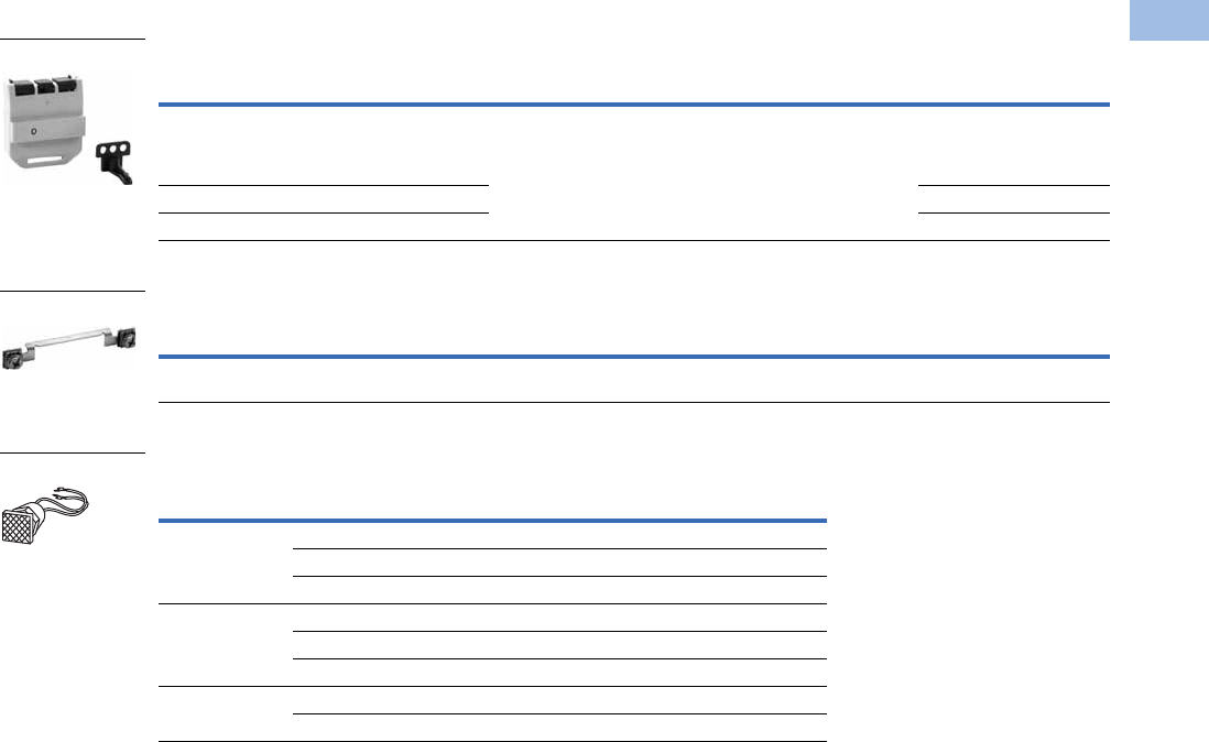
Volume 5—Motor Control and Protection CA08100006E—February 2014 www.eaton.com V5-T1-175
1
1
1
1
1
1
1
1
1
1
1
1
1
1
1
1
1
1
1
1
1
1
1
1
1
1
1
1
1
1
1.1
IEC Contactors and Starters
XT
IEC Power Control
MMP Enclosure Accessories
XTPR Manual Motor Protector Enclosure Padlock Attachment
Neutral Terminal for Use with XTPB and Frame B XTPR Flush-Mount Enclosures
Indicating Lights with Neon Bulb 4
For use with XTPR and XTPB enclosures.
Lights do not carry individual IP or NEMA rating. All enclosure ratings remain
valid when using indicating lights.
Notes
1 Orders must be placed in multiples of package quantity listed.
2 Lockable in the 0-position of the XTPR manual motor protector.
3 Lockable in the OFF position of the Frame B XTPR manual motor protector.
4 Product is not UL Listed/Registered.
For Use
with… Description
Pkg.
Qty. 1Catalog Number
XTPAXENCS65B, XTPAXENCS65RY,
XTPAXENCSEM65B, XTPAXENCSEM65RY,
XTPAXENCS55B, XTPAXENCS55RY,
XTPAXENCSEM55B, XTPAXENCSEM55RY
Padlocking feature. Up to three padlocks with 3–6 mm hasp thickness.
For use as main switch to IEC/EN 60204
3XTPAXPL1 2
XTPAXENCSD65B, XTPAXENCSD65RY 1XTPAXPL2 2
XTPAXENCF55B, XTPAXENCF55RY 3XTPAXPL3 3
For Use
with… Description
Pkg.
Qty. 1Catalog Number
XTPBXENCF40, XTPBXENCF55, XTPAXENCF40,
XTPAXENCF55B, XTPAXENCF55RY
For connection of a fifth conductor 20 XTPAXNT
Color
Description—
Indicating Light
Pkg.
Qty. 1Catalog Number
White 110–230V 10 XTPAXILWB
230–400V 10 XTPAXILWN
415–500V 10 XTPAXILWC
Green 110–230V 10 XTPAXILGB
230–400V 10 XTPAXILGN
415–500V 10 XTPAXILGC
Red 110–230V 10 XTPAXILRB
230–400V 10 XTPAXILRN
XTPAXPL_
XTPAXNT
XTPAXIL_
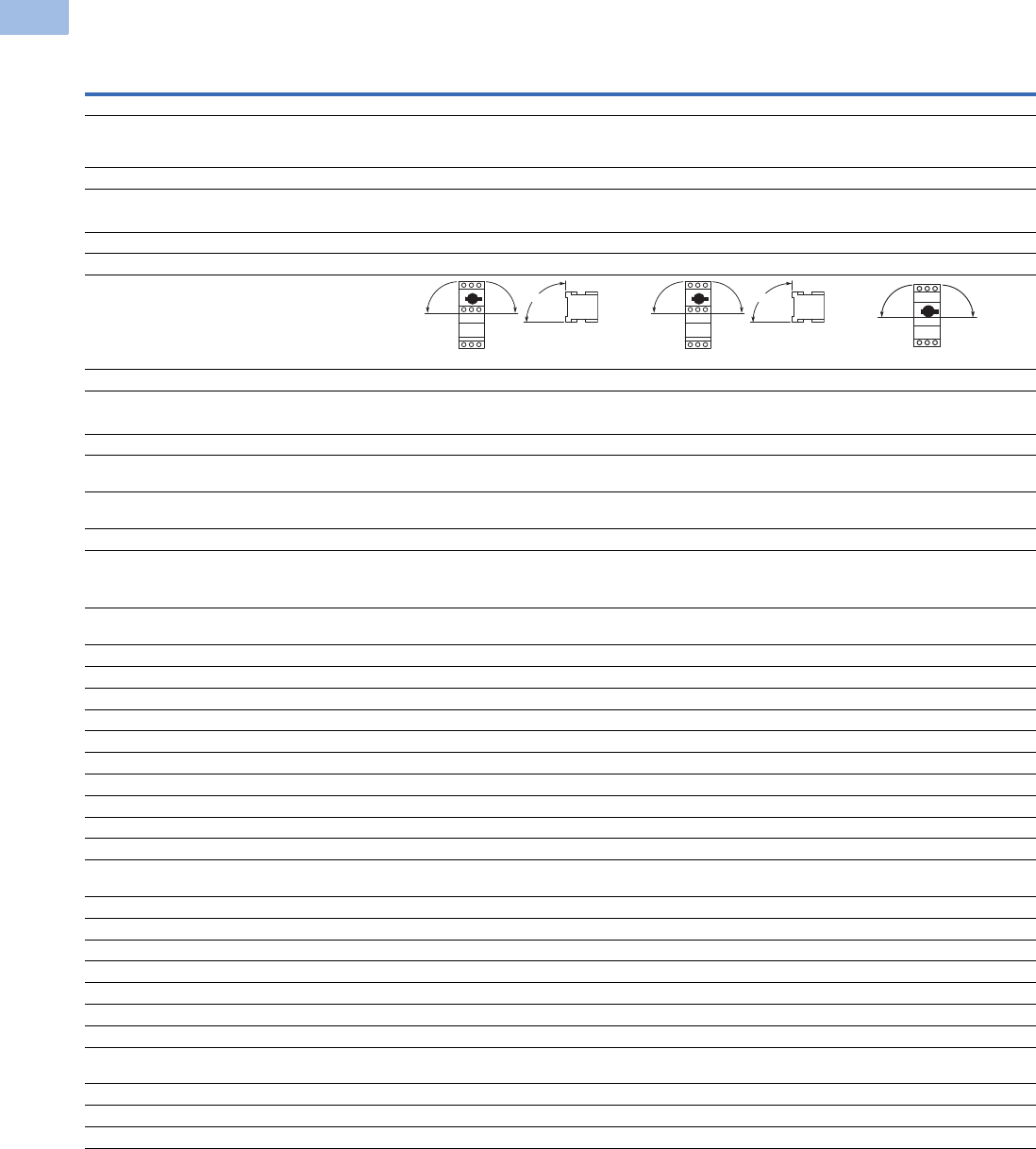
V5-T1-176 Volume 5—Motor Control and Protection CA08100006E—February 2014 www.eaton.com
1
1
1
1
1
1
1
1
1
1
1
1
1
1
1
1
1
1
1
1
1
1
1
1
1
1
1
1
1
1
1.1
IEC Contactors and Starters
XT
IEC Power Control
Technical Data and Specifications
XT Manual Motor Protectors
Note
1Damp heat, constant, to IEC 60068-2-78; damp heat, cyclic, to IEC 60068-2-30.
Description
XTPBP16B–
XTPB025B
XTPRP16B–
XTPR032B
XTPR016D–
XTPR063D
General
Standards IEC/EN 60947,
VDE 0660, UL 508,
CSA C22.2 No. 14
IEC/EN 60947,
VDE 0660, UL 508,
CSA C22.2 No. 14
IEC/EN 60947,
VDE 0660, UL 508,
CSA C22.2 No. 14
Climatic proofing 111
Ambient temperature, °C
Storage –25/80 –25/80 –25/70
Open –25/55 –25/55 –25/55
Enclosed –25/40 –25/40 –25/40
Mounting position
Direction of incoming supply As required As required As required
Degree of protection
Device IP20 IP20 IP20
Terminals IP00 IP00 IP00
Protection against direct contact Finger and
back-of-hand proof
Finger and
back-of-hand proof
Finger and
back-of-hand proof
Shock resistance half-sinusoidal shock
10 ms to IEC 60068-2-27 (g)
25 25 15
Altitude (m), maximum 2000 2000 2000
Terminal capacity
Solid (mm2)1 x (1–6)
2 x (1–6)
1 x (1–6)
2 x (1–6)
1 x (1–50)
2 x (1–35)
Flexible with ferrule to DIN 46228, (mm2)1 x (1–6)
2 x (1–6)
1 x (1–6)
2 x (1–6)
1 x (1–35)
2 x (1–35)
Solid or stranded (AWG) 18–10 18–10 14–2
Terminal screw tightening torque
Main cable, Nm 1.7 1. 3
Main cable, lb-in 15.0 15.0 26.6
Control circuit cable, Nm 1 1 1
Control circuit cable, lb-in 8.9 8.9 8.9
Main Contacts
Rated impulse withstand voltage (Uimp), Vac 6000 6000 6000
Overvoltage category/pollution degree III/3 III/3 III/3
Rated operational voltage (Ue), Vac 690 690 690
Rated uninterrupted current = rated operational
current (Iu = Ie) in amperes
25 or current setting of
the overcurrent release
25 or current setting of
the overcurrent release
25 or current setting of
the overcurrent release
Rated frequency, Hz 40–60 40–60 40–60
Current heat loss (three-pole at operating temperature), W 6 6 22
Lifespan, mechanical (ops) 50,000 100,000 30,000
Lifespan, electrical (AC-3 at 400V) (ops) 50,000 100,000 30,000
Maximum operating frequency, operations/hr 25 40 40
Short-circuit rating
AC See Page V5-T1-181 See Page V5-T1-181 See Page V5-T1-181
DC (kA) 60 60 (up to XTPR016B)
40 (XTPR020B–XTPR032B)
60
Motor switching capacity
AC-3 (up to 690V) in amperes 25 32 65
DC-5 (up to 250V) in amperes 25 25 (3 contacts in series) 63 (3 contacts in series)
90 90
90
90 90
90
90 90

Volume 5—Motor Control and Protection CA08100006E—February 2014 www.eaton.com V5-T1-177
1
1
1
1
1
1
1
1
1
1
1
1
1
1
1
1
1
1
1
1
1
1
1
1
1
1
1
1
1
1
1.1
IEC Contactors and Starters
XT
IEC Power Control
XT Manual Motor Protectors, continued
Auxiliary Contacts
Description
XTPBP16B–
XTPB025B
XTPRP16B–
XTPR032B
XTPR016D–
XTPR063D
Releases
Overload release setting range (x Iu) 0.6–1.0 0.6–1.0 0.6–1.0
Fixed short-circuit release (x Iu)141414
Short-circuit release tolerance ± 20% ± 20% ± 20%
Phase-failure sensitivity IEC/EN 60947-1-1,
VDE 0660 Part 102
IEC/EN 60947-1-1,
VDE 0660 Part 102
IEC/EN 60947-1-1,
VDE 0660 Part 102
Temperature compensation
to IEC/EN 60947, VDE 0660, °C –5/40 –5/40 –5/40
operating range, °C –25/55 –25/55 –25/55
Temperature compensation residual error for T >20°C, %/K
<
0.25
<
0.25
<
0.25
Description XTPAXSA_ _ XTPAXFA_ _ XTPA(B)XFAEM_ _ XTPAXSATR_ _
Rated impulse withstand voltage, Uimp (Vac) 6000 4000 4000 6000
Overvoltage category/pollution degree III/3 III/3 III/3 III/3
Rated operational voltage
Ue (Vac) 500 440 440 500
Ue (Vdc) 250 250 250 250
Safe isolation to VDE 0106 Part 101 and
Part 101/A1 between auxiliary contacts
and main contacts (Vac)
690 690 690 690
Rated operational current
AC-15
220–240 V, Ie (A) 3.5 1 1 3.5
380–415 V, Ie (A) 2 — — 2
440–500 V, Ie (A) 1 — — 1
DC-13 L/R <100 ms
24 V, Ie (A) 2 2 2 2
60 V, Ie (A) 1.5 — — 1.5
110 V, Ie (A) 1 — — 1
220 V, Ie (A) 0.25 — — 0.25
Lifespan
Mechanical, operations (x 106) 0.1 0.1 0.1 0.01
Electrical, operations (x 106) 0.05 0.1 0.1 0.005
Contact reliability (at Ue = 24 Vdc, Umin–17V,
Imin = 5.4 mA, fault probability
<10–8 <1 fault
at 1 x 10⁸ operations
<10–8 <1 fault
at 1 x 10⁸ operations
<10–8 <1 fault
at 1 x 10⁸ operations
<10–8 <1 fault
at 1 x 10⁸ operations
Positively driven contacts to ZH 1/457 Yes — — —
Short-Circuit Rating without Welding
Fuseless FAZ-B4/1-HI — — FAZ-B4/1-HI
Fuse (A gG/gL) 10 10 10 10
Terminal Capacity
Solid or flexible conductor with ferrule (mm2) 0.75–2.5 0.75–1.5 0.75–1.5 0.75–2.5
Solid or stranded (AWG) 18–14 18–16 18–16 18–14
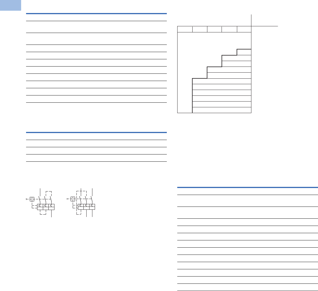
V5-T1-178 Volume 5—Motor Control and Protection CA08100006E—February 2014 www.eaton.com
1
1
1
1
1
1
1
1
1
1
1
1
1
1
1
1
1
1
1
1
1
1
1
1
1
1
1
1
1
1
1.1
IEC Contactors and Starters
XT
IEC Power Control
Undervoltage Release
Current Limiter
XTPB, XTPR Single- and Two-Pole Circuits with DC
and AC Current
Protection of PVC Insulated Cables Against Thermal
Overload at Short-Circuit
The chart above indicates which minimum cable cross-sections
are protected by XTPR motor protective circuit breakers up to
their rated conditional short-circuit current Iq.
Shunt Release
Description XTPAXUVR_
Cross-Section
Solid or flexible conductor with ferrule (mm2) 1 x (0.75–2.5)
2 x (0.75–2.5)
Solid or stranded (AWG) 1 x (18–14)
2 x (18–14)
Main Contact
Rated operational voltage, Ue (Vac) 42–480
Rated operational voltage, Ue (Vdc) 24–250
Pickup voltage, x Us0.85–1.1
Dropout voltage, x Us0.7–0.35
Power Consumption
Pickup AC (VA) 5
Sealing AC (VA) 3
Description XTPAXCL
Rated impulse withstand voltage (Uimp), Vac 6000
Overvoltage category/pollution degree III/3
Rated operational voltage, Ue (Vac) 690
Rated interrupted current = Rated operational current (lu = le) in amperes 63
135
246
I > I > I >
135
246
I > I > I >
Description XTPAXSR __
Cross-Section
Solid or flexible conductor with ferrule (mm2) 1 x (0.75–2.5)
2 x (0.75–2.5)
Solid or stranded (AWG) 1 x (18–14)
2 x (18–14)
Main Contact
Rated operational voltage, Ue (Vac) 42–480
Rated operational voltage, Ue (Vdc) 24–250
AC operating range, x Us0.7–1.1
DC operating range, x Us (intermittent operation 5s) 0.7–1.1
Power Consumption
Pickup AC (VA) 5
Sealing AC (VA) 3
Pickup DC (VA) 3
Sealing DC (VA) 3
Min. Cross-Section Protected
380-415V, 50 Hz, Cu mm2
Device
Type
4 2.5 1.5 1 0.75
XTPRP16BC1
...
XTPR6P3BC1
XTPR010BC1
XTPR016BC1
XTPR020BC1
XTPR025BC1
XTPR016DC1
XTPR025DC1
XTPR032DC1
XTPR040DC1
XTPR050DC1
XTPR058DC1
XTPR063DC1
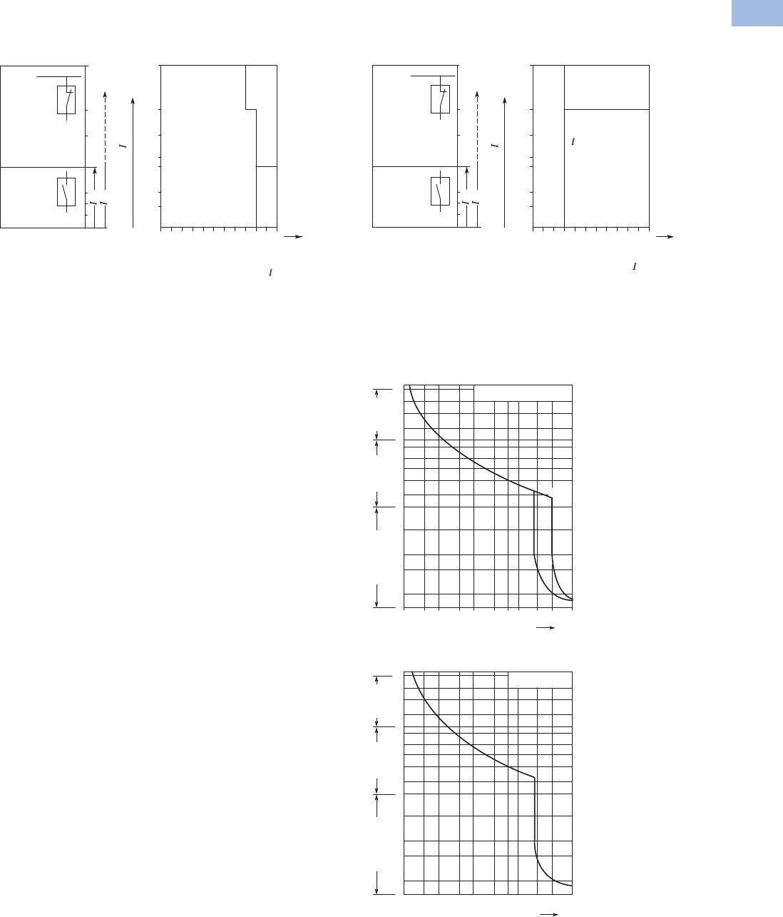
Volume 5—Motor Control and Protection CA08100006E—February 2014 www.eaton.com V5-T1-179
1
1
1
1
1
1
1
1
1
1
1
1
1
1
1
1
1
1
1
1
1
1
1
1
1
1
1
1
1
1
1.1
IEC Contactors and Starters
XT
IEC Power Control
Wiring Diagrams
Fuseless Installation with XTPR
Backup Protection Diagram—XTPR…B
Time/Current Curves
Characteristics
The time/current
characteristic, the current
limiting characteristics and
the I2t characteristics were
determined in accordance
with DIN VDE 0660 and IEC
60 947.
The tripping characteristic of
the inverse-time delayed
overload releases (thermal
overload releases or “a”
releases) for DC and AC with
a frequency of 0 to 400 Hz
also apply to the time/current
characteristic.
The characteristics apply to
the cold state. At operating
temperature, the tripping
times of the thermal releases
are reduced to approximately
25%.
Under normal operating
conditions, all three-poles of
the device must be loaded.
The three main conducting
paths must be connected in
series in order to protect
single-phase or DC loads.
With three-pole loading, the
maximum deviation in the
tripping time for 3 times the
setting current and upwards
is ±20% and thus in
accordance with DIN VDE
0165.
The tripping characteristics
for the instantaneous,
electromagnetic overcurrent
releases (short-circuit
releases or “n” releases) are
based on the rated current In,
which is also the maximum
value of the setting range for
circuit breakers with
adjustable overload releases.
If the current is set to a lower
value, the tripping current of
the “n” release is increased
by a corresponding factor.
The characteristics of the
electromagnetic overcurrent
releases apply to frequencies
of 50/60 Hz. Appropriate
correction factors must be
used for lower frequencies up
to 16-2/3 Hz, for higher
frequencies up to 400 Hz and
for DC.
Time/current characteristics,
current limiting characteristics
and I2t characteristics are
available on request.
XTPR…B
XTPR…B
415 Vac
Inherently short-circuit proof
Back-up
protection
range
with XTPAXCL
Rated
short-circuit
breaking
capacity
range
100
50
30
20
16
10
6
0.16... 101620 25
XTPR…B + XTPAXCL
XTPR…B
XTPR...B
Rated
Current
Inherently
short-circuit-proof
cn
cc
n [A]
cc rms [kA]
Backup Protection Diagram—XTPR…D
MMP Tripping Characteristics
XTPB, XTPR Frame B
XTPR Frame D
100
50
30
20
16
10
6
XTPR…D
XTPR…D
Back-up
protection
range
with XTPAXCL
Rated
short-circuit
breaking
capacity
range
16... 3225 40 50 63
XTPR...D + XTPAXCL
XTPR…D
Inherently
short-circuit-proof
415 Vac
Inherently short-circuit proof
cn
cc
cc rms [kA]
Rated
Current
n [A]
Rated
Current
n [A]
2
5
20
50
200
1
2
5
10
20
40
1
2
5
10
20
2h
1.5 2346810 15 20 30
XTPB, XTPR Frame B
XTPT
Seconds
Milli-seconds Minutes
x Rated Operational Current
XTPR Frame D
2
5
20
50
200
1
2
5
10
20
40
1
2
5
10
20
2h
1.5 2346810 15 20 30
Seconds
Milli-seconds Minutes
x Rated Operational Current
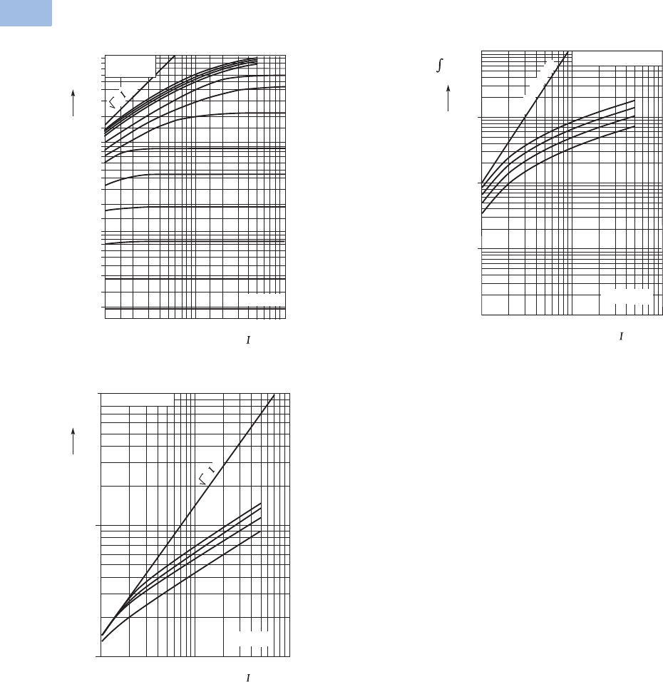
V5-T1-180 Volume 5—Motor Control and Protection CA08100006E—February 2014 www.eaton.com
1
1
1
1
1
1
1
1
1
1
1
1
1
1
1
1
1
1
1
1
1
1
1
1
1
1
1
1
1
1
1.1
IEC Contactors and Starters
XT
IEC Power Control
MMP Let-Through Tripping Characteristics
XTPB, XTPR Frame B XTPR Frame D
XTPR Frame D
1
2
3
6
4
8
10
4.0 A
6.3 A
2.5 A
1.6 A
0.25 A
10 A/12 A
0.1
0.2
0.3
0.4
0.6
0.8
0.01
0.02
0.015
0.03
0.04
0.06
0.08
12
1.5 3 4 6 8 10 2015 3040 60 80100
XTPB
XTPR Frame B
XTPM
16 A
20 A
25 A
32 A
1 A
0.4 A
0.63 A
Ue
= 400 V
2 • cc
cc rms[kA]
[kA]
I
D
^
63/58 A
50/40/32 A
25 A
16 A
XTPR Frame D
Ue
= 400 V
100101
cc rms[kA]
102
103
104
105
106
1st half-wave
i
2
dt
[A
2
s]
10
10 100
63/58 A
50/40/32 A
25 A
16 A
1
1
100
2 •
cc
XTPR Frame D
Ue
= 400 V
cc rms[kA]
[kA]
I
D
^

Volume 5—Motor Control and Protection CA08100006E—February 2014 www.eaton.com V5-T1-181
1
1
1
1
1
1
1
1
1
1
1
1
1
1
1
1
1
1
1
1
1
1
1
1
1
1
1
1
1
1
1.1
IEC Contactors and Starters
XT
IEC Power Control
Manual Motor Protector Short-Circuit Ratings
Rated uninterrupted current Iu = Rated operational current Ie.
Rated conditional short-circuit current Iq—IEC/EN 60947-4-1.
Rated ultimate short-circuit breaking capacity Icu — IEC/EN 60947-2.
Rated operational short-circuit breaking capacity Ics — IEC/EN 60947-2.
Global Use, IEC/EN 60947—XTPB with Classification Type “1” and Type “2”
Global Use, IEC/EN 60947—XTPR…BC1 with Classification Type “1” and Type “2”
Notes
1N = Not required.
2XTPR…BC1, XTPT, XTPM—Required back-up fuse if the short-circuit current exceeds the rated conditional
short-circuit current (Icc > Iq); XTPB, XTPR…DC1—Fuse (A gG/gL) for enhancing the switching capacity of the
motor protective circuit breaker to 100 kA.
3No upstream protective device required, as it is the auto-protected range (100/150 kA—Frame B, 150 kA—Frame D).
Iu
230V 400V 440V 500V 690V
IqIcu Ics Fuse 12 IqIcu Ics Fuse 12 IqIcu Ics Fuse 12 IqIcu Ics Fuse 12 IqIcu Ics Fuse 12
A kA kA kA A kA kA kA A kA kA kA A kA kA kA A kA kA kA A
0.16–1 50505050 50505050 50505050 ———— ————
1.6 50505050 50505050 50505050 ———— ————
2.5 50505050 50505050 50505050 ———— ————
4 50505050 50505050 50505050 ———— ————
6.3 50505050 50505050 50505050 ———— ————
10 50 50 50 50 50 50 50 50 42 42 10 50 — — — — — — — —
12 50 50 10 50 50 50 10 50 15 15 10 50 — — — — — — — —
16 50 50 10 50 50 50 10 50 15 15 10 50 — — — — — — — —
20 50 50 10 50 50 50 10 50 10 10 10 50 — — — — — — — —
25 50 50 10 50 50 50 10 50 10 10 10 50 — — — — — — — —
Iu
230V 400V 440V 500V 690V
IqIcu Ics Fuse 12 IqIcu Ics Fuse 12 IqIcu Ics Fuse 12 IqIcu Ics Fuse 12 IqIcu Ics Fuse 12
A kA kA kA A kA kA kA A kA kA kA A kA kA kA A kA kA kA A
0.16–1 150 3150 3150 3N150
3150 3150 3N33 3N33 3N33 3N
1.6 150 3150 3150 3N150
3150 3150 3N33 3N33 3N33 3N
2.5 150 3150 3150 3N150
3150 3150 3N33 3N33 3N55550
4 150 3150 3150 3N150
3150 3150 3N33 3N33 3N33350
6.3 150 3150 3150 3N150
3150 3150 3N33 3N 4242650 33 250
10 150 3150 3150 3N150
3150 3150 3N 4242 1050 4242 6 50 3 3 2 50
12 50 50 10 50 50 50 10 50 15 15 10 50 15 15 6 50 3 3 2 50
16 50 50 10 50 50 50 10 50 15 15 10 50 15 15 6 50 3 3 2 50
20 50 50 10 50 50 50 10 50 15 15 10 50 6 6 6 50 3 3 2 50
25 50 50 10 50 50 50 10 50 10 10 10 50 6 6 6 50 3 3 2 50
32 50 50 10 50 50 50 10 50 10 10 10 50 6 6 6 50 3 3 2 50

V5-T1-182 Volume 5—Motor Control and Protection CA08100006E—February 2014 www.eaton.com
1
1
1
1
1
1
1
1
1
1
1
1
1
1
1
1
1
1
1
1
1
1
1
1
1
1
1
1
1
1
1.1
IEC Contactors and Starters
XT
IEC Power Control
Global Use, IEC/EN 60947—XTPR…DC1 with Classification Type “1” and Type “2”
Ratings for Group Motor Applications
UL 508/CSA C22.2 No. 14—XTPB—Frame B, Manual Motor Protector with Thermal and Magnetic Trip
Notes
1N = Not required.
2XTPR…BC1, XTPT, XTPM—Required back-up fuse if the short-circuit current exceeds the rated conditional short-circuit current (Icc > Iq); XTPB, XTPR…DC1—Fuse (A gG/gL) for enhancing the
switching capacity of the motor protective circuit breaker to 100 kA.
3No upstream protective device required, as it is the auto-protected range (100/150 kA—Frame B, 150 kA—Frame D).
4IEC/EN 60947-4-1.
522 kA 600 Vac.
Iu
230V 400V 440V 500V 690V
IqIcu Ics Fuse 12 IqIcu Ics Fuse 12 IqIcu Ics Fuse 12 IqIcu Ics Fuse 12 IqIcu Ics Fuse 12
A kA kA kA A kA kA kA A kA kA kA A kA kA kA A kA kA kA A
16 150 3150 325 N 150 3150 325 N 45 45 25 100 15 15 100 8 8 2.5 100
25 150 3150 325 N 150 3150 325 N 45 45 25 100 15 15 100 8 8 2.5 100
32 50 50 25 100 50 50 25 100 45 45 25 100 15 15 100 5 5 2.5 100
40 50 50 25 100 50 50 25 100 45 45 25 100 15 15 100 5 5 2.5 100
50 50 50 25 100 50 50 25 100 45 45 25 100 15 15 100 5 5 2.5 100
58 50 50 25 160 50 50 25 160 45 45 25 160 15 15 160 5 5 2.5 160
63 50 50 25 160 50 50 25 160 45 45 25 160 15 15 160 5 5 2.5 160
Catalog Number
Rated
Uninterrupted
Current—
Iu (Amps)
FLA
Adjustment
Range/Overload
Release—
Ir (Amps)
Short
Circuit
Release—
Irm (Amps) Maximum Protective Device for UL/CSA Group Protection
Maximum rms
Sym Current—
480V (kA)
w/Current
Limiter—
XTPAXCL
Maximum Fuse
Rating (A)
w/Current
Limiter—
XTPAXCL
Circuit Breaker
Maximum (A)
w/Current
Limiter—
XTPAXCL
XTPBP16BC1 0.16 0.1–0.16 2.2 50 — 600 — 600 —
XTPBP25BC1 0.25 0.16–0.25 3.5 50 — 600 — 600 —
XTPBP40BC1 0.4 0.25–0.4 5.6 50 — 600 — 600 —
XTPBP63BC1 0.63 0.4–0.63 8.8 50 — 600 — 600 —
XTPB001BC1 1 0.63–1 14 50 — 600 — 600 —
XTPB1P6BC1 1.6 1–1.6 22 50 — 600 — 600 —
XTPB2P5BC1 2.5 1.6–2.5 35 50 — 600 — 600 —
XTPB004BC1 4 2.5–4 56 50 — 600 — 600 —
XTPB6P3BC1 6.3 4–6.3 88 50 — 600 — 600 —
XTPB010BC1 10 6.3–10 140 30 50 600 600 600 600
XTPB012BC1 12 8–12 168 10 50 150 600 125 5600
XTPB016BC1 16 10–16 224 10 50 150 600 125 5600
XTPB020BC1 420 16–20 280 10 18 150 600 125 600
XTPB025BC1 425 20–25 350 10 18 150 600 125 600

Volume 5—Motor Control and Protection CA08100006E—February 2014 www.eaton.com V5-T1-183
1
1
1
1
1
1
1
1
1
1
1
1
1
1
1
1
1
1
1
1
1
1
1
1
1
1
1
1
1
1
1.1
IEC Contactors and Starters
XT
IEC Power Control
UL 508/CSA C22.2 No. 14—XTPR—Frame B (all Screw and Spring Cage Terminal Options),
Manual Motor Protector with Thermal and Magnetic Trip
UL 508/CSA C22.2 No. 14—XTPR—Frame D, Manual Motor Protector with Thermal and Magnetic Trip
Note
122 kA 600 Vac.
Catalog Number
Rated
Uninterrupted
Current—
Iu (Amps)
FLA
Adjustment
Range/Overload
Release—
Ir (Amps)
Short
Circuit
Release—
Irm (Amps) Maximum Protective Device for UL/CSA Group Protection
Maximum rms
Sym Current—
480V (kA)
w/Current
Limiter—
XTPAXCL
Maximum Fuse
Rating (A)
w/Current
Limiter—
XTPAXCL
Circuit Breaker
Maximum (A)
w/Current
Limiter—
XTPAXCL
XTPRP16BC1 0.16 0.1–0.16 2.2 50 — 600 — 600 —
XTPRP25BC1 0.25 0.16–0.25 3.5 50 — 600 — 600 —
XTPRP40BC1 0.4 0.25–0.4 5.6 50 — 600 — 600 —
XTPRP63BC1 0.63 0.4–0.63 8.8 50 — 600 — 600 —
XTPR001BC1 1 0.63–1 14 50 — 600 — 600 —
XTPR1P6BC1 1.6 1–1.6 22 50 — 600 — 600 —
XTPR2P5BC1 2.5 1.6–2.5 35 50 — 600 — 600 —
XTPR004BC1 4 2.5–4 56 50 — 600 — 600 —
XTPR6P3BC1 6.3 4–6.3 88 50 — 600 — 600 —
XTPR010BC1 10 6.3–10 140 30 50 600 600 600 600
XTPR012BC1 12 8–12 168 10 50 150 600 125 600
XTPR016BC1 16 10–16 224 10 50 150 600 125 1600
XTPR032BC1 32 25–32 448 10 18 150 600 125 600
XTPR025BC1 25 20–25 350 10 18 150 600 125 600
XTPR032BC1 32 25–32 448 10 18 150 600 125 600
Catalog Number
Rated
Uninterrupted
Current—
Iu (Amps)
FLA
Adjustment
Range/Overload
Release—
Ir (Amps)
Short
Circuit
Release—
Irm (Amps) Maximum Protective Device for UL/CSA Group Protection
Maximum rms
Sym Current—
480V (kA)
w/Current
Limiter—
XTPAXCL
Maximum Fuse
Rating (A)
w/Current
Limiter—
XTPAXCL
Circuit Breaker
Maximum (A)
w/Current
Limiter—
XTPAXCL
XTPR016DC1 16 10–16 224 65 — 600 — 600 —
XTPR025DC1 25 16–25 350 65 — 600 — 600 —
XTPR032DC1 32 25–32 448 65 — 600 — 600 —
XTPR040DC1 40 32–40 560 65 — 600 — 600 —
XTPR050DC1 50 40–50 700 65 — 600 — 600 —
XTPR058DC1 58 50–58 812 65 — 600 — 600 —
XTPR063DC1 65 55–63 882 65 — 600 — 600 —

V5-T1-184 Volume 5—Motor Control and Protection CA08100006E—February 2014 www.eaton.com
1
1
1
1
1
1
1
1
1
1
1
1
1
1
1
1
1
1
1
1
1
1
1
1
1
1
1
1
1
1
1.1
IEC Contactors and Starters
XT
IEC Power Control
UL 508 Type E Ratings—XTPR Frame B + XTPAXLSA
UL 508 Type E Ratings—XTPR Frame D + XTPAXLSAD
Note
1For UL 508 Type E applications, the manual motor protector assembly does not require a dedicated upstream protective
device in the panel, thus a maximum rating is not required.
Manual Motor
Protector—
Screw Terminal
Catalog Number
Line Side Adapter
Catalog Number
FLA Adjustment
Range/Overload
Release—
Ir (Amps)
Short Circuit
Release—
Irm (Amps)
UL 508 Type E Application
Maximum rms Symmetrical
Short-Circuit Ratings (kA)
Maximum Upstream
Protective Device (A) 1
Maximum Fuse
600V
Maximum
Circuit Breaker
600V480/277V 600/347V
XTPRP16BB1 XTPAXLSA 0.1–0.16 2.2 50 50 Not required Not required
XTPRP25BC1 XTPAXLSA 0.16–0.25 3.5 50 50 Not required Not required
XTPRP40BC1 XTPAXLSA 0.25–0.4 5.6 50 50 Not required Not required
XTPRP63BC1 XTPAXLSA 0.4–0.63 8.82 50 50 Not required Not required
XTPR001BC1 XTPAXLSA 0.63–1 14 50 50 Not required Not required
XTPR1P6BC1 XTPAXLSA 1–1.6 22.4 50 50 Not required Not required
XTPR2P5BC1 XTPAXLSA 1.6–2.5 35 50 50 Not required Not required
XTPR004BC1 XTPAXLSA 2.5–4 56 50 50 Not required Not required
XTPR6P3BC1 XTPAXLSA 4–6.3 88.2 65 50 Not required Not required
XTPR010BC1 XTPAXLSA 6.3–10 140 65 50 Not required Not required
XTPR012BC1 XTPAXLSA 8–12 168 65 — Not required Not required
XTPR016BC1 XTPAXLSA 10–16 224 42 — Not required Not required
XTPR020BC1 XTPAXLSA 16–20 280 18 — Not required Not required
XTPR025BC1 XTPAXLSA 20–25 350 18 — Not required Not required
XTPR032BC1 XTPAXLSA 25–32 448 18 — Not required Not required
Manual Motor
Protector—
Screw Terminal
Catalog Number
Line Side
Adapter
Catalog Number
FLA
Adjustment
Range/Overload
Release—
Ir (Amps)
Short
Circuit
Release—
Irm (Amps)
Maximum Upstream
Protective Device (A) 1
UL 508 Type E Application
Maximum rms Symmetrical Short-Circuit Ratings (kA) Maximum Fuse
600V
Maximum
Circuit Breaker
600V240V 480/277V 600/347V
XTPR016DC1 XTPAXLSAD 10–16 224 65 65 25 Not required Not required
XTPR025DC1 XTPAXLSAD 16–25 350 65 65 25 Not required Not required
XTPR032DC1 XTPAXLSAD 25–32 448 65 65 25 Not required Not required
XTPR040DC1 XTPAXLSAD 32–40 560 65 65 25 Not required Not required
XTPR050DC1 XTPAXLSAD 40–50 700 65 65 — Not required Not required
XTPR058DC1 XTPAXLSAD 50–58 812 65 65 — Not required Not required
XTPR063DC1 XTPAXLSAD 55–65 882 65 65 — Not required Not required
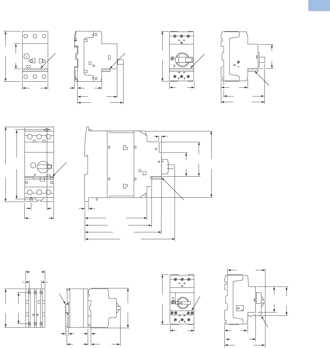
Volume 5—Motor Control and Protection CA08100006E—February 2014 www.eaton.com V5-T1-185
1
1
1
1
1
1
1
1
1
1
1
1
1
1
1
1
1
1
1
1
1
1
1
1
1
1
1
1
1
1
1.1
IEC Contactors and Starters
XT
IEC Power Control
Dimensions
Approximate Dimensions in mm [in]
Manual Motor Protectors—XTPB
Manual Motor Protectors, Manual Transformer
Protectors—XTPR…B
Manual Motor Protector—XTPR…DC1
Current Limiter—XTPAXCL
MMPs with Early-Make Auxiliary Contacts—
XTPR…BC1 + XTPAXFAEM20
5.5
[.22]
45
[1.77]
45
[1.77]
93
[3.66]
44
[1.73]
74 [2.91]
85 [3.35]
XTPAXFA _XTPAXFA _
45
[1.77]
93
[3.66] 45
[1.77]
50
[1.97]
88 [3.46]
94 [3.70]
XTPAXFA _
XTPAXFA _
30
[1.18] 7.5 [.30]
118 [4.65]
127 [5.00]
145 [5.71]
171 [6.73]
55 [2.17]
130
[5.12]
140
[5.57]
125
[4.92]
65
[2.56]
45
[1.77]
4 [.16]
XTPAXFA _
XTPAXFA _
*
93
[3.66]
28
[1.10]
45
[1.77]
* IEC/EN 60715 DIN Rail
90
[3.54] 73
[2.87]
7.5
[.30] 7.5
[.30]
44
[1.73]
70
[2.76]
49.5
[1.95]
XTPAXFAEM20
XTPAXFAEM20
45
[1.77]
45
[1.77] 55
[2.17]
93
[3.66]
50
[1.97]
68 [2.68]
86 [3.39]
80 [3.15]
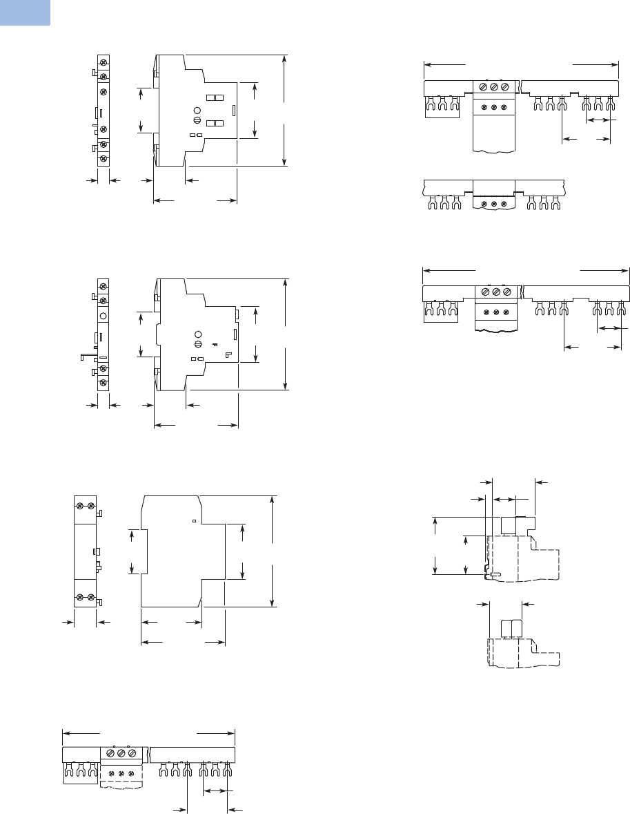
V5-T1-186 Volume 5—Motor Control and Protection CA08100006E—February 2014 www.eaton.com
1
1
1
1
1
1
1
1
1
1
1
1
1
1
1
1
1
1
1
1
1
1
1
1
1
1
1
1
1
1
1.1
IEC Contactors and Starters
XT
IEC Power Control
Approximate Dimensions in mm [in]
Standard Auxiliary Contact—XTPAXSA_
Trip Indicating Auxiliary Contact—XTPAXSATR_
Undervoltage/Shunt Release—XTPAXUVR_, XTPAXSR_
Three-Phase Commoning Link—XTPAXCLKA4, XTPAXCLKA2
Three-Phase Commoning Link—XTPAXCLKB5,
XTPAXCLKB4, XTPAXCLKB3 and XTPAXCLKB2
Three-Phase Commoning Link—XTPAXCLKC4, XTPAXCLKC2
Incoming Terminal, Line Side Adapter—XTPAXIT, XTPAXLSA
45
[1.77]
36
[1.42] 90
[3.54]
26
[1.02]
68 [2.68]
9
[.35]
36
[1.42]
45
[1.77] 90
[3.54]
26
[1.02]
68 [2.68]
9
[.35]
36
[1.42]
45
[1.77] 90
[3.54]
18
[.71] 49
[1.93]
68 [2.68]
180 [7.09] (90 [3.54])
27
[1.06]
45
[1.77]
Overlapping Mounting
to Extend the Three-Phase
Commoning Link
261 [10.28] (207 [8.15],
153 [6.02], 99 [3.90])
27
[1.06]
54
[2.13]
234 [9.21] (108 [4.25])
27
[1.06]
63
[2.48]
XTPAXLSA
73
[2.87] 48
[1.89]
XTPAXIT
31
[1.22]
7.5
[.30]
41
[1.61]
56
[2.20]
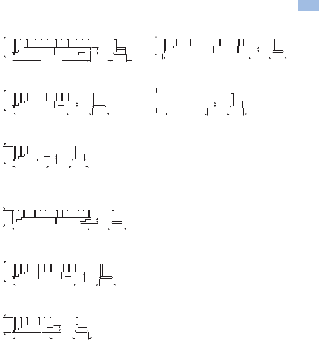
Volume 5—Motor Control and Protection CA08100006E—February 2014 www.eaton.com V5-T1-187
1
1
1
1
1
1
1
1
1
1
1
1
1
1
1
1
1
1
1
1
1
1
1
1
1
1
1
1
1
1
1.1
IEC Contactors and Starters
XT
IEC Power Control
Approximate Dimensions in mm [in]
Three-Phase Commoning Link
XTPAXCLKA4D, XTPAXCLKA3D and XTPAXCLKA2D
XTPAXCLKA4D
XTPAXCLKA3D
XTPAXCLKA2D
XTPAXCLKB4D, XTPAXCLKB3D and XTPAXCLKB2D
XTPAXCLKB4D
XTPAXCLKB3D
XTPAXCLKB2D
XTPAXCLKC4D and XTPAXCLKC2D
XTPAXCLKC4D
XTPAXCLKC2D
14
[.55]
205 [8.07] 33
[1.30]
36
[1.42]
151 [5.94] 14
[.55]
36
[1.42]
33
[1.30]
98 [3.86] 14
[.55]
36
[1.42]
33
[1.30]
232 [9.13] 14
[.55]
36
[1.42]
33
[1.30]
170 [6.69] 14
[.55]
36
[1.42]
33
[1.30]
117 [4.6] 14
[.55]
36
[1.42]
33
[1.30]
260 [10.24] 14
[.55]
36
[1.42]
33
[1.30]
115 [4.53] 14
[.55]
36
[1.42]
33
[1.30]
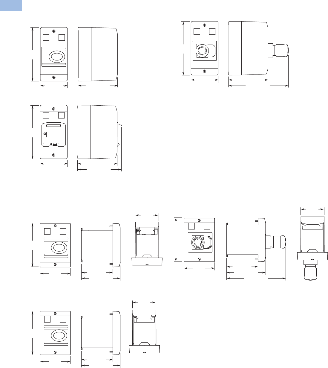
V5-T1-188 Volume 5—Motor Control and Protection CA08100006E—February 2014 www.eaton.com
1
1
1
1
1
1
1
1
1
1
1
1
1
1
1
1
1
1
1
1
1
1
1
1
1
1
1
1
1
1
1.1
IEC Contactors and Starters
XT
IEC Power Control
Approximate Dimensions in mm [in]
Insulated Enclosures for Surface Mounting of XTPB Manual Motor Protectors
Insulated Enclosures for Flush Mounting of XTPB Manual Motor Protectors
158
[6.22]
80 [3.15] 116.5 [4.59]
158
[6.22]
80 [3.15] 116.5 [4.59]
177.2 [6.98]
158
[6.22]
80 [3.15] 116.5 [4.59]
129.5 [5.10]
XTPBXENCS40, XTPBXENCS65, XTPBXENAS41, XTPBXENAS65 XTPBXENCSEK65, XTPBXENCSES65, XTPBXENASEK65, XTPBXENASES65
XTPBXENCSLE65, XTPBXENCSLO65, XTPBXENASLE65, XTPBXENASO065
129
[5.08]
90.2
[3.55]
69
[2.72]
93 [3.66]
115.2 [4.54]
129
[5.08]
90.2
[3.55]
69
[2.72]
93 [3.66]
115.2 [4.54]
175.9 [6.93]
129
[5.08]
90.2
[3.55]
69
[2.72]
93 [3.66]
115.2 [4.54]
XTPBXENCF40, XTPBXENCF55 XTPBXENCFEK55, XTPBXENCFES55
XTPBXENCFLE55, XTPBXENCFLO55
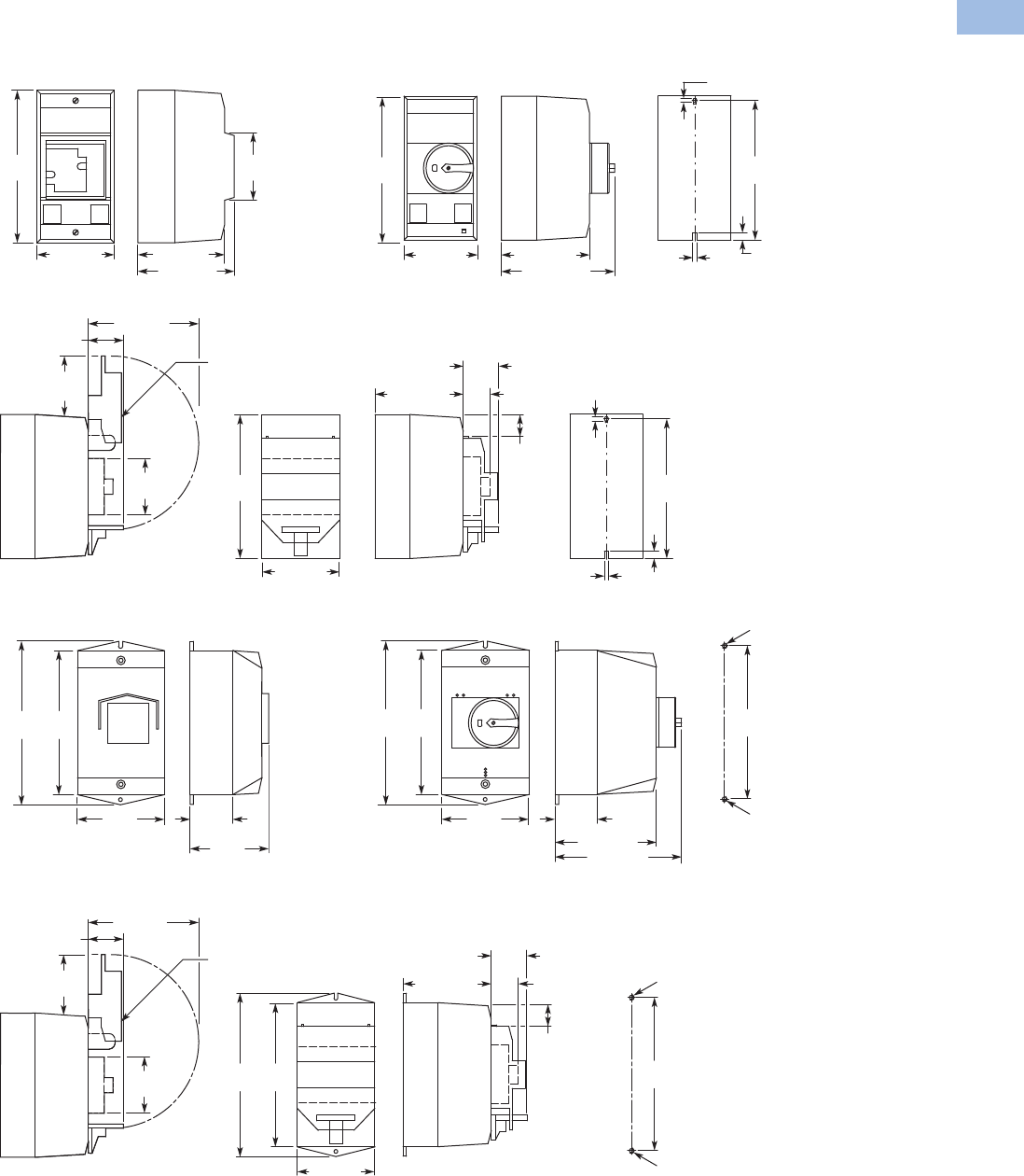
Volume 5—Motor Control and Protection CA08100006E—February 2014 www.eaton.com V5-T1-189
1
1
1
1
1
1
1
1
1
1
1
1
1
1
1
1
1
1
1
1
1
1
1
1
1
1
1
1
1
1
1.1
IEC Contactors and Starters
XT
IEC Power Control
Approximate Dimensions in mm [in]
Insulated Enclosures for Surface Mounting of XTPR…B Manual Motor Protectors
158
[6.22]
70
[2.76]
80 [3.15] 90 [3.54]
100 [3.94]
44
[1.73]
55
[2.17]
98 [3.86]
SVB-PKZ0-CI
30 [1.18]
33
[1.30]
80 [3.15]
158
[6.22]
97.5 [3.84] 28
[1.10]
30
[1.18] 4.5
[.18]
4.5
[.18] 8
[.31]
153
[6.02]
Drilling Dimensions
160
[6.30]
181
[7.13]
100
[3.94]
47.5
[1.87]
104
[4.09]
33
[1.30]
55
[2.17]
SVB-PKZ0-CI
97 [3.82]
160
[6.30]
181
[7.13]
44
[1.73]
98 [3.86]
30 [1.18]
114 [4.49] 28
[1.10]
30
[1.18]
M4
M4
171
[6.73]
Drilling Dimensions
XTPAXENCS40
158
[6.22]
80 [3.15] 97.5 [3.84]
125.5 [4.94]
4.5 [.18]
4.5
[.18]
8 [.31]
153
[6.02]
Drilling Dimensions
160
[6.30]
181
[7.13]
100
[3.94]
47.5
[1.87]
103 [4.06]
130 [5.12]
M4
M4
171
[6.73]
Drilling Dimensions
XTPAXENCS65B, XTPAXENCS65RY, XTPAXENCSEM65B, XTPAXENCSEM65RY,
XTPAXENAS55B, XTPAXENAS55RY, XTPAXENASEM55B, XTPAXENASEM55RY,
XTPAXENCSH65B, XTPAXENCSH65RY, XTPAXENCSEMH65B, XTPAXENCSEMH65RY
XTPAXENCS55B, XTPAXENCS55RY, XTPAXENCSEM55B, XTPAXENCSEM55RY
XTPAXENCS55_ + XTPAXPL1, XTPAXENCSEM55_ + XTPAXPL1
XTPAXENCSH41, XTPAXENCS41, XTPAXENAS41
XTPAXENCS65_ + XTPAXPL1, XTPAXENCSEM65_ + XTPAXPL1
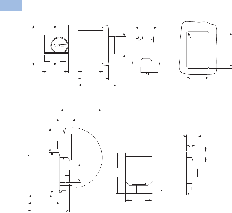
V5-T1-190 Volume 5—Motor Control and Protection CA08100006E—February 2014 www.eaton.com
1
1
1
1
1
1
1
1
1
1
1
1
1
1
1
1
1
1
1
1
1
1
1
1
1
1
1
1
1
1
1.1
IEC Contactors and Starters
XT
IEC Power Control
Approximate Dimensions in mm [in]
Insulated Enclosures for Flush Mounting of XTPR…B Manual Motor Protectors
69
[2.72]
85 [3.35]
129
[5.08]
96 [3.78]
80 [3.15]
124 [4.88]
55
[2.17]
4 [.16]
R
70 – 72
[2.76 – 2.83]
116 – 118
[4.57 – 4.64]
98
[3.86]
30
[1.18]
58
[2.28]
55
[2.17]
96 [3.78]
80 [3.15]
124 [4.88]
XTPAXENCF40, XTPAXENCF55B, XTPAXENCF55RY Mounting Cutout XTPAXENCF_
XTPAXENCF55_ + XTPAXPL3
85
[3.35]
129
[5.08]
30
[1.18]
28 [1.10]
21
[.83]
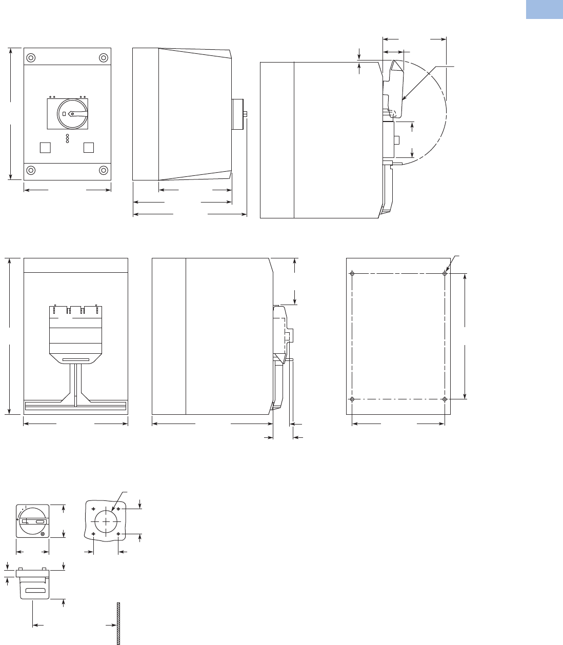
Volume 5—Motor Control and Protection CA08100006E—February 2014 www.eaton.com V5-T1-191
1
1
1
1
1
1
1
1
1
1
1
1
1
1
1
1
1
1
1
1
1
1
1
1
1
1
1
1
1
1
1.1
IEC Contactors and Starters
XT
IEC Power Control
Approximate Dimensions in mm [in]
Insulated Enclosures for Surface Mounting of XTPR…D Manual Motor Protectors
Rotary Handle Mechanism—XTPAXRHM_
160 [6.30]
240
[9.45]
134 [5.28]
181 [7.13]
197 [7.76]
32 [1.26]
SVB-PKZ4-CI
98 [3.86]
72
[2.83]
3 [.12]
160 [6.30] 186 [7.32] 28 [1.10]
30
[1.18]
193
[7.60]
142 [5.60]
5.6 [.22]
Dia.
72
[2.83]
240
[9.45]
Drilling Dimensions
XTPAXENCSD65_ + XTPAXPL2XTPAXENCSD65B, XTPAXENCSD65RY
XTPAXENCSD65
48
[1.89]
At least 100 [3.94]
up to Cover Hinge
Mounting Depth:
100 – 240 [3.94 – 9.45]
from the top edge of
the mounting rail to the
front edge of the panel
door/cover
48
[1.89]
43 [1.69] Dia.
64
[2.52]
64
[2.52]
19.5
[.77]
62
[2.44]

V5-T1-192 Volume 5—Motor Control and Protection CA08100006E—February 2014 www.eaton.com
1
1
1
1
1
1
1
1
1
1
1
1
1
1
1
1
1
1
1
1
1
1
1
1
1
1
1
1
1
1
1.1
IEC Contactors and Starters
XT
IEC Power Control
Approximate Dimensions in mm [in]
Pushbutton MMP Enclosures
Insulated Enclosures for
Surface Mounting
XTPB Pushbutton Motor-
Protective Circuit Breakers
XTPB Pushbutton Manual
Motor Protectors
Frame B (0.1–32A) XTPR
Motor-Protective Circuit
Breakers
Frame B (0.1–32A) XTPR
Rotary Manual Motor
Protectors
Frame B XTPR (0.1–32A)
Rotary Motor-Protective
Circuit Breakers with
XTPAXFAEM20 Early-Make
Front-Mount Auxiliary Contact
Frame B XTPR (0.1–32A)
Rotary Manual Motor
Protectors with
XTPAXFAEM20 Early-Make
Front-Mount Auxiliary Contact
Frame D (10–65A) Rotary
Motor-Protective Circuit
Breakers
Insulated Enclosures for
Flush Mounting
XTPB Pushbutton Manual
Motor Protectors
Frame B (0.1–32A) XTPR
Rotary Manual Motor
Protectors
Catalog Number H x W x D
Global Usage
XTPBXENCS40 158 x 80 x 116.5
[6.22 x 3.15 x 4.59]
XTPBXENCS65 158 x 80 x 116.5
[6.22 x 3.15 x 4.59]
XTPBXENCSLO65 158 x 80 x 129.5
[6.22 x 3.15 x 5.10]
XTPBXENCSLE65 158 x 80 x 129.5
[6.22 x 3.15 x 5.10]
XTPBXENCSES65 158 x 80 x 177.2
[6.22 x 3.15 x 6.98]
XTPBXENCSEK65 158 x 80 x 177.2
[6.22 x 3.15 x 6.98]
Catalog Number H x W x D
North American Usage
XTPBXENAS41 158 x 80 x 116.5
[6.22 x 3.15 x 4.59]
XTPBXENAS65 158 x 80 x 116.5
[6.22 x 3.15 x 4.59]
XTPBXENASLO65 158 x 80 x 129.5
[6.22 x 3.15 x 5.10]
XTPBXENASLE65 158 x 80 x 129.5
[6.22 x 3.15 x 5.10]
XTPBXENASES65 158 x 80 x 177.2
[6.22 x 3.15 x 6.98]
XTPBXENASEK65 158 x 80 x 177.2
[6.22 x 3.15 x 6.98]
Catalog Number H x W x D
Global Usage
XTPAXENCS41 160 x 100 x 104
[6.30 x 3.94 x 4.09]
XTPAXENCS65B 160 x 100 x 130
[6.30 x 3.94 x 5.12]
XTPAXENCS65RY 160 x 100 x 130
[6.30 x 3.94 x 5.12]
XTPAXENCS40 158 x 80 x 100
[6.22 x 3.15 x 3.94]
XTPAXENCS55B 158 x 80 x 125.5
[6.22 x 3.15 x 4.94]
XTPAXENCS55RY 158 x 80 x 125.5
[6.22 x 3.15 x 4.94]
Catalog Number H x W x D
North American Usage
XTPAXENAS55B 160 x 100 x 130
[6.30 x 3.94 x 5.12]
XTPAXENAS55RY 160 x 100 x 130
[6.30 x 3.94 x 5.12]
Catalog Number H x W x D
Global Usage
XTPAXENCSEM65B
160 x 100 x 130
[6.30 x 3.94 x 5.12]
XTPAXENCSEM65RY
160 x 100 x 130
[6.30 x 3.94 x 5.12]
XTPAXENCSEM55B
158 x 80 x 100
[6.22 x 3.15 x 3.94]
XTPAXENCSEM55RY
158 x 80 x 100
[6.22 x 3.15 x 3.94]
Catalog Number H x W x D
North American Usage
XTPAXENCSEM55B
160 x 100 x 130
[6.30 x 3.94 x 5.12]
XTPAXENCSEM55RY
160 x 100 x 130
[6.30 x 3.94 x 5.12]
Catalog Number H x W x D
Global and
North American Usage
XTPAXENCSD65B 240 x 160 x 197
[9.45 x 6.30 x 7.76]
XTPAXENCSD65RY 240 x 160 x 197
[9.45 x 6.30 x 7.76]
Catalog Number H x W x D
Global and
North American Usage
XTPBXENCF40 129 x 90.2 x 115.2
[5.08 x 3.55 x 4.54]
XTPBXENCF55 129 x 90.2 x 115.2
[5.08 x 3.55 x 4.54]
XTPBXENCFLO55 129 x 90.2 x 115.2
[5.08 x 3.55 x 4.54]
XTPBXENCFLE55 129 x 90.2 x 115.2
[5.08 x 3.55 x 4.54]
XTPBXENCFES55 129 x 90.2 x 175.9
[5.08 x 3.55 x 6.93]
XTPBXENCFEK55 129 x 90.2 x 175.9
[5.08 x 3.55 x 6.93]
Catalog Number H x W x D
Global Usage
XTPAXENCF40 129 x 85 x 96
[5.08 x 3.35 x 3.78]
XTPAXENCF55B 129 x 85 x 124
[5.08 x 3.35 x 4.88]
XTPAXENCF55RY 129 x 85 x 124
[5.08 x 3.35 x 4.88]
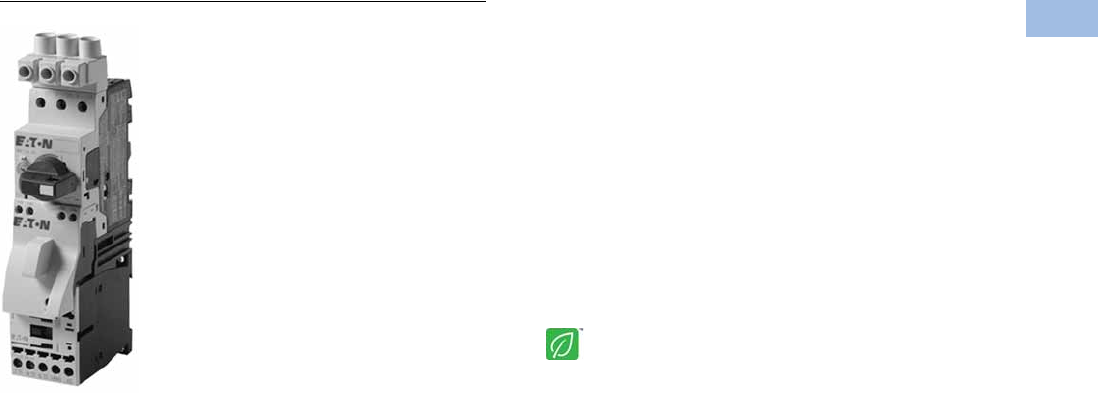
Volume 5—Motor Control and Protection CA08100006E—February 2014 www.eaton.com V5-T1-193
1
1
1
1
1
1
1
1
1
1
1
1
1
1
1
1
1
1
1
1
1
1
1
1
1
1
1
1
1
1
1.1
IEC Contactors and Starters
XT
IEC Power Control
Combination Motor Controllers
Contents
Description Page
Relays and Timers . . . . . . . . . . . . . . . . . . . . . . . . . V5-T1-3
Miniature Controls . . . . . . . . . . . . . . . . . . . . . . . . . V5-T1-18
Contactors and Starters . . . . . . . . . . . . . . . . . . . . V5-T1-35
Thermal Overload Relays . . . . . . . . . . . . . . . . . . . . V5-T1-128
C440/XT Electronic Overload Relay . . . . . . . . . . . V5-T1-141
Manual Motor Protectors . . . . . . . . . . . . . . . . . . . V5-T1-157
Combination Motor Controllers
Features . . . . . . . . . . . . . . . . . . . . . . . . . . . . . . V5-T1-194
Standards and Certifications . . . . . . . . . . . . . . V5-T1-194
Catalog Number Selection . . . . . . . . . . . . . . . . V5-T1-195
Product Selection . . . . . . . . . . . . . . . . . . . . . . . V5-T1-195
Accessories . . . . . . . . . . . . . . . . . . . . . . . . . . . V5-T1-203
Technical Data and Specifications . . . . . . . . . . V5-T1-205
Dimensions . . . . . . . . . . . . . . . . . . . . . . . . . . . V5-T1-211
An Eaton
Green Solution
XT Electronic Manual Motor Protector . . . . . . . . . V5-T1-216
Reference Data . . . . . . . . . . . . . . . . . . . . . . . . . . . V5-T1-229
Combination Motor Controllers
Product Description
Eaton’s XT IEC open non-
reversing and reversing
manual motor controllers
combine a manual motor
protector with an IEC
contactor(s) to provide a
complete motor protection
solution by combining motor
disconnect function, thermal
overload protection, magnetic
short-circuit protection and
remote control operation in
one compact, assembled
unit. these assembled
manual motor controllers
cover motors with FLA
ratings from 0.10A to 65A.
The UL 508 Type F labeled
combination motor controller
(CMC) includes a line side
adapter (LSA). These
assembled combination
motor controllers cover
motors with FLA ratings
from 0.10A to 65A.
Application Description
The XT IEC non-reversing and
reversing manual
and combination motor
controllers can be used in
the following applications:
Group Motor Control
Manual motor controllers
(MMCs) are ideal for group
motor applications where an
upstream breaker or fuse
provides protection for two or
more motors. XT manual
motor controllers (MMC)
combine a manual motor
protector, a wiring connector
link and IEC contactor.
Individual Branch Circuit for Motor Loads
Combination motor controller
(CMC), consisting of a line
side adapter, manual motor
protector, wiring connector
link and IEC contactor,
provide an efficient means to
build an entire branch circuit.
The XT CMC is UL 508 Type
F approved, meaning it is
“self-protected” and doesn’t
require the use of an
additional fuse or breaker for
short circuit protection. This
approval means CMC’s can
be used in place of a
traditional fuse-starter and
breaker-starter motor circuit.
Based around two key
functional components (MMP
and contactor), the CMC is a
very cost effective means to
build a branch circuit. Fuses
and breakers must be
oversized to prevent tripping
during motor start up, and
thus these oversized devices
can no longer protect the
motor. To compensate for
this, a motor overload relay is
necessary to protect the
motor.
The manual motor protector
was invented in Germany by
Moeller to correct this
inefficiency. The MMP
operates similarly to a circuit
breaker, except the inrush
(magnetic) protection is set to
14 times the running current,
thus accounting for motor
start-up current without the
necessity to oversize. A
overcurrent dial was added to
the face of the MMP to serve
as the motor overload
protection. This “motor
protective circuit breaker”, as
it is referred to in Europe,
now accomplishes all four
key functions of a motor
branch circuit: disconnect,
short circuit, motor controller
and motor overload
protection. With the addition
of a contactor, users have the
ability to remotely control the
starter device.
Whether a single motor
application or a multiple
motor application, CMC’s are
an ideal solution for
machinery OEMs and panel
builders.

V5-T1-194 Volume 5—Motor Control and Protection CA08100006E—February 2014 www.eaton.com
1
1
1
1
1
1
1
1
1
1
1
1
1
1
1
1
1
1
1
1
1
1
1
1
1
1
1
1
1
1
1.1
IEC Contactors and Starters
XT
IEC Power Control
Features
●ON/OFF rotary handle
with lockout provision
●Visible trip indication
●Test trip function
●Motor applications
from 0.10A to 65A
●Class 10 overload
protection
●Built-in heater and
magnetic trip elements
to protect the motor
●Phase loss sensitivity
●Type 2 coordination
●Ambient compensated
up to 55°C [140°F]
●Control inputs located at
front of starter for easy
access and wiring
●Wide range of coils
●DIN rail mount—
XTSC…BB_
●Mounting plates—
XTSC…BC_, XTSC…D
motor controllers
●Adjustment dial for setting
motor FLA
●Short-circuit trip at
14 times the maximum
setting of the FLA
adjustment dial
●UL 508 Type F CMC high
fault short-circuit ratings
●1NO-1NC auxiliary contact
as standard on manual
motor controller and
combination motor
controller
Standards and Certifications
UL 508 Type F combination
motor controller
●IEC Type 2 Approved per
IEC 60947-4-1
●UL Listed File No. E245398
●CE Mark
Note: For Type 2 Coordination of
MMCs, see Page V5-T1-230.
Protection in different controller
types
MMC and CMC Applications
Notes
Technical Paper AP03402001E.
Line side adapters are not required for non-U.S. applications.
Most countries outside of the U.S. classify the MMP as a
motor-protective circuit breaker.
1SCPD = Short-circuit protective device (circuit breaker, fuses).
2MMC = Manual motor controller
Combination Motor Controller
XTFC/XTFR
Line Side Adapter (LSA)
Not required Line Side Adapter (LSA)
Required—factory assembled
XTIEC Manual and Combination Motor Controllers
Manual Motor Controller
Use in group installation
applications. Upstream
SCPD 1 is required and must
be sized smaller than the
maximum upstream SCPD 1
rating on each MMC 2 used.
Tap rules should also be
observed.
UL 508 Type F Combination
Motor Controller
Use for single motor branch circuits or use
multiple CMC’s for a multiple motor panel
applications. No additional SCPD 1 is required
in the branch, as these devices are “self-
protected”.
Manual Motor Controller
XTSC/XTSR
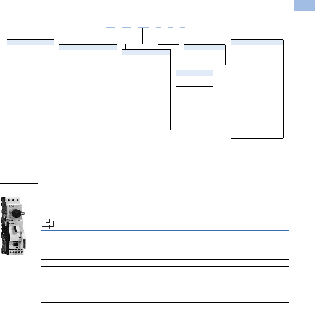
Volume 5—Motor Control and Protection CA08100006E—February 2014 www.eaton.com V5-T1-195
1
1
1
1
1
1
1
1
1
1
1
1
1
1
1
1
1
1
1
1
1
1
1
1
1
1
1
1
1
1
1.1
IEC Contactors and Starters
XT
IEC Power Control
Catalog Number Selection
Combination Motor Controllers
Product Selection
XTSC and XTSR Manual Motor Controllers (MMC)/Starter Combinations
Factory-Assembled Manual Motor Controller—Frame B MMP + Frame B Contactor—
Maximum UL Ratings 1
Notes
1 Select manual motor controllers by full load amperes. Maximum motor ratings (kW, hp) are for reference only.
2 Underscore (_) indicates magnetic coil suffix required. See Page V5-T1-198.
3 In this range, calculate motor rating according to rated current. Specified values to NEC 430.6(A)(1).
FLA Adjustment
Range/Overload
Release—Ir
(Amps) Short-Circuit
Release—
Irm (Amps)
Assembled Manual Motor Controller 2
Three-Phase
200V 240V 480V 600V
Non-Reversing
Catalog Number
Reversing
Catalog Number
0.1–0.16 3.2 33
1/2 1/2
XTSCP16BB_ XTSRP16BB_
0.16–0.25 3.5 33
1/2 1/2
XTSCP25BB_ XTSRP25BB_
0.25–0.4 5.6 33
1/2 1/2
XTSCP40BB_ XTSRP40BB_
0.4–0.63 8.82 33
1/2 1/2
XTSCP63BB_ XTSRP63BB_
0.63–1 14 331/2 1/2 XTSC001BB_ XTSR001BB_
1–1.6 22.4 333/4 1 XTSC1P6BB_ XTSR1P6BB_
1.6–2.5 35 1/2 1/2 1 1-1/2 XTSC2P5BB_ XTSR2P5BB_
2.5–4 56 1123XTSC004BB_ XTSR004BB_
4–6.3 88.2
1-1/2 1-1/2 3 5
XTSC6P3BB_ XTSR6P3BB_
6.3–10 140
337-1/23
XTSC010BB_ XTSR010BB_
8–12 168
337-1/23
XTSC012BB_ XTSR012BB_
10–16 224
33103
XTSC016BB_ —
XT SC 012 BBA
Type
SC = Manual motor controller—
FVNR
SR = Manual motor controller—
FVR
FC =
Combination motor controller,
UL 508 Type F—FVNR
FR =
Combination motor controller,
UL 508 Type F—FVR
Designation
XT = XT IEC power control
Coil Voltage
A= 110V 50 Hz, 120V 60 Hz
B= 220V 50 Hz, 240V 60 Hz
C= 415V 50 Hz, 480V 60 Hz
D= 600V 60 Hz
E= 208V 50 Hz
F= 230V 50 Hz
G= 190V 50 Hz, 220V 60 Hz
H= 240V 50 Hz, 277V 60 Hz
L= 380V 50 Hz, 440V 60 Hz
N= 400V 50 Hz
P= 380V 60 Hz
R= 12V 50/60 Hz
T= 24V 50/60 Hz
W= 42V 50 Hz, 48V 60 Hz
Y= 48V 50 Hz
AD = 120 Vdc
BD = 220 Vdc
RD =12 Vdc
TD =24 Vdc
WD =48 Vdc
Frame Size—Contactor
B = 45 mm, 7 to 15A
C = 45 mm, 18 to 32A
D = 55 mm, 40 to 65A
Rated Current of MMP
Frame B
P16 = 0.16A
P25 = 0.25A
P40 = 0.40A
P63 = 0.63A
001 = 1A
1P6 = 1.6A
2P5 = 2.5A
004 = 4A
6P3 = 6.3A
010 = 10A
012 = 12A
016 = 16A
020 = 20A
025 = 25A
032 = 32A
Frame D
016 = 16A
025 = 25A
032 = 32A
040 = 40A
050 = 50A
058 = 58A
063 = 63A
Frame Size—MMP
B = 45 mm, 0.1 to 32A
D = 55 mm, 16 to 63A
Frame B MMP +
Frame B Contactor
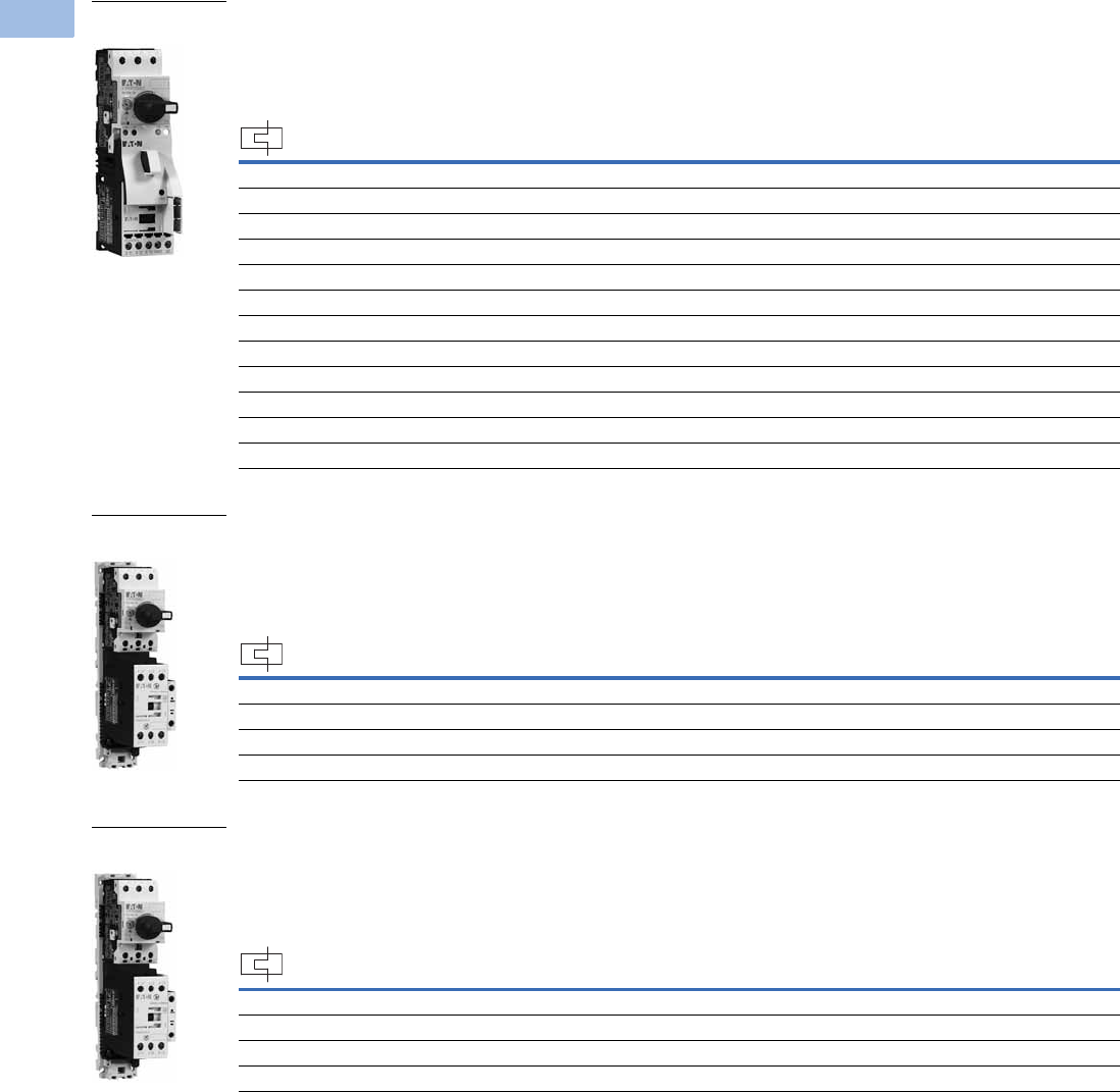
V5-T1-196 Volume 5—Motor Control and Protection CA08100006E—February 2014 www.eaton.com
1
1
1
1
1
1
1
1
1
1
1
1
1
1
1
1
1
1
1
1
1
1
1
1
1
1
1
1
1
1
1.1
IEC Contactors and Starters
XT
IEC Power Control
Factory-Assembled Motor Protective Device with Thermal and Magnetic Trip + Contactor—
Maximum IEC Ratings1
Factory-Assembled Manual Motor Controller—Frame B MMP + Frame C Contactor—
Maximum UL Ratings 1
Factory-Assembled Manual Motor Controller—Frame B MMP + Frame C Contactor—
Maximum IEC RatingS 1
Notes
1 Select manual motor controllers by full load amperes. Maximum motor ratings (kW, hp) are for reference only.
2 Underscore (_) indicates magnetic coil suffix required. See Page V5-T1-198.
FLA Adjustment
Range/Overload
Release—Ir
(Amps)
Short-Circuit
Release—
Irm (Amps)
Three-Phase Assembled Manual Motor Controller 2
220–
240V
380–
415V 500V
660–
690V
Non-Reversing
Catalog Number
Reversing
Catalog Number
0.1–0.16 3.2 ———0.06XTSCP16BB_ XTSRP16BB_
0.16–0.25 3.5 — 0.06 0.06 0.12 XTSCP25BB_ XTSRP25BB_
0.25–0.4 5.6 0.06 0.09 0.12 0.18 XTSCP40BB_ XTSRP40BB_
0.4–0.63 8.82 0.09 0.18 0.25 0.25 XTSCP63BB_ XTSRP63BB_
0.63–1 14 0.120.250.370.55XTSC001BB_ XTSR001BB_
1–1.6 22.4 0.250.550.751.1 XTSC1P6BB_ XTSR1P6BB_
1.6–2.5 35 0.37 0.75 1.1 1.5 XTSC2P5BB_ XTSR2P5BB_
2.5–4 56 0.75 1.5 2.2 3 XTSC004BB_ XTSR004BB_
4–6.3 88.2 1.1 2.2 3 4 XTSC6P3BB_ XTSR6P3BB_
6.3–10 140 2.2 4 4 7.5 XTSC010BB_ XTSR010BB_
8–12 168 3 5.5 5.5 11 XTSC012BB_ XTSR012BB_
10–16 224 47.5912.5XTSC016BB_ —
FLA Adjustment
Range/Overload
Release—Ir
(Amps)
Short-Circuit
Release—
Irm (Amps)
Assembled Manual Motor Controller 2
Three-Phase Non-Reversing
Catalog Number
Reversing
Catalog Number200V 240V 480V 600V
10–16 224 331010XTSC016BC_ XTSR016BC_
16–20 280 551015XTSC020BC_ XTSR020BC_
20–25 350 5 7-1/2 15 20 XTSC025BC_ XTSR025BC_
25–32 448 7-1/2 10 20 25 XTSC032BC_ XTSR032BC_
FLA Adjustment
Range/Overload
Release—Ir
(Amps)
Short-Circuit
Release—
Irm (Amps)
Three-Phase Assembled Manual Motor Controller 2
220–
240V
380–
415V 500V
660–
690V
Non-Reversing
Catalog Number
Reversing
Catalog Number
10–16 224 47.5912.5XTSC016BC_ XTSR016BC_
16–20 280 5.5 9 12.5 15 XTSC020BC_ XTSR020BC_
20–25 350 5.5 11 15 22 XTSC025BC_ XTSR025BC_
25–32 448 7.5 15 22 30 XTSC032BC_ XTSR032BC_
Frame B MMP +
Frame B Contactor
Frame B MMP +
Frame C Contactor
Frame B MMP +
Frame C Contactor
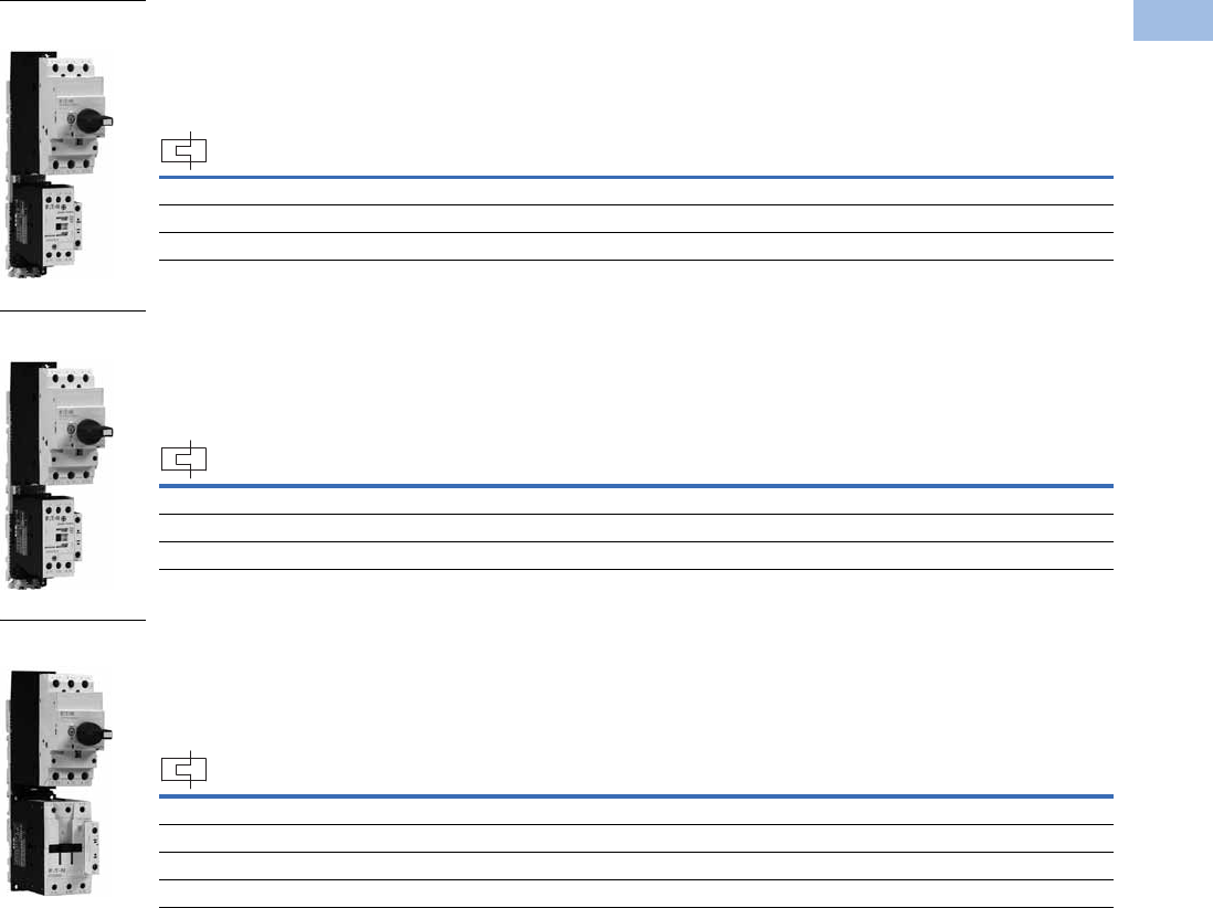
Volume 5—Motor Control and Protection CA08100006E—February 2014 www.eaton.com V5-T1-197
1
1
1
1
1
1
1
1
1
1
1
1
1
1
1
1
1
1
1
1
1
1
1
1
1
1
1
1
1
1
1.1
IEC Contactors and Starters
XT
IEC Power Control
Factory-Assembled Manual Motor Controller—Frame D MMP + Frame C Contactor—
Maximum UL Ratings 1
Factory-Assembled Manual Motor Controller—Frame D MMP + Frame C Contactor—
Maximum IEC Ratings 1
Factory-Assembled Manual Motor Controller—Frame D MMP + Frame D Contactor—
Maximum UL Ratings 1
Notes
1 Select manual motor controllers by full load amperes. Maximum motor ratings (kW, hp) are for reference only.
2 Underscore (_) indicates magnetic coil suffix required. See Page V5-T1-198.
FLA Adjustment
Range/Overload
Release—Ir
(Amps)
Short-Circuit
Release—
Irm (Amps)
Assembled Manual Motor Controller 2
Three-Phase Non-Reversing
Catalog Number
Reversing
Catalog Number200V 240V 480V 600V
10–16 224 351015XTSC016DC_ XTSR016DC_
16–25 350 5 7-1/2 15 20 XTSC025DC_ XTSR025DC_
25–32 448 7-1/2 10 20 30 XTSC032DC_ XTSR032DC_
FLA Adjustment
Range/Overload
Release—Ir
(Amps)
Short-Circuit
Release—
Irm (Amps)
Three-Phase Assembled Manual Motor Controller 2
220–
240V
380–
415V 500V
660–
690V
Non-Reversing
Catalog Number
Reversing
Catalog Number
10–16 224 47.5912.5XTSC016DC_ XTSR016DC_
16–25 350 5.5 12.5 12.5 22 XTSC025DC_ XTSR025DC_
25–32 448 7.5 15 17.5 22 XTSC032DC_ XTSR032DC_
FLA Adjustment
Range/Overload
Release—Ir
(Amps)
Short-Circuit
Release—
Irm (Amps)
Assembled Manual Motor Controller 2
Three-Phase Non-Reversing
Catalog Number
Reversing
Catalog Number200V 240V 480V 600V
32–40 560
10 15 30 30
XTSC040DD_ XTSR040DD_
40–50 700
15 15 30 —
XTSC050DD_ XTSR050DD_
50–58 812
15 15 40 —
XTSC058DD_ XTSR058DD_
55–65 882
15 15 40 —
XTSC063DD_ XTSR063DD_
Frame D MMP +
Frame C Contactor
Frame D MMP +
Frame C Contactor
Frame D MMP +
Frame D Contactor
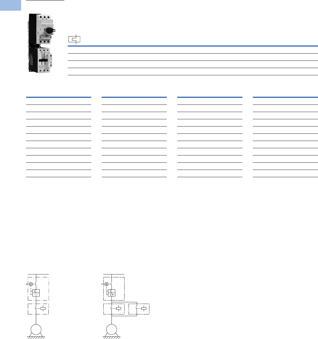
V5-T1-198 Volume 5—Motor Control and Protection CA08100006E—February 2014 www.eaton.com
1
1
1
1
1
1
1
1
1
1
1
1
1
1
1
1
1
1
1
1
1
1
1
1
1
1
1
1
1
1
1.1
IEC Contactors and Starters
XT
IEC Power Control
Factory-Assembled Manual Motor Controller—Frame D MMP + Frame D Contactor—
Maximum IEC Ratings 1
AC and DC Coil Suffixes
Notes
The assembled manual motor controller (MMC) consists of an XTPR manual motor protector (MMP) and an XTCE contactor. For Frame B MMP +
Frame B contactor assemblies, the XTSC and XTSR can be mounted directly on DIN rail without an adapter. The contactors are supported
mechanically with a mechanical connection element (included in XTPAXTPCB, XTPAXRPCRB). For MMCs using a Frame C or Frame D contactor,
the assembly is mounted via a DIN rail adapter plate (XTPAXTPCPC, XTPAXTPCPD) and the electrical connection is made with electrical contact modules
(XTPAXECMC, XTPAXECMD), both included in XTPAXTPCC and XTPAXTPCD.
Service Factor (SF)—Setting Ir of current scale in dependence of load factor:
SF = 1.15 → Ir = 1 x In mot
SF = 1 → Ir = 0.9 x In mot
Single-phasing sensitivity to IEC/EN 60947-4-1, VDE 0660 Part 102.
1Select manual motor controllers by full load amperes. Maximum motor ratings (kW, hp) are for reference only.
2Underscore (_) indicates magnetic coil suffix required. See AC and DC coil suffixes above.
3With DC operation: Integrated diode-resistor combination, coil rating 2.6W.
Non-Reversing Manual
Motor Controller Power
Circuit
Reversing Manual
Motor Controller Power
Circuit
FLA Adjustment
Range/Overload
Release—Ir
(Amps)
Short-Circuit
Release—
Irm (Amps)
Three-Phase Assembled Manual Motor Controller 2
220–
240V
380–
415V 500V
660–
690V
Non-Reversing
Catalog Number
Reversing
Catalog Number
32–40 560 11 20 22 30 XTSC040DD_ XTSR040DD_
40–50 700 14 25 30 45 XTSC050DD_ XTSR050DD_
50–58 812 17 30 37 55 XTSC058DD_ XTSR058DD_
55–65 882 18.5 34 37 55 XTSC063DD_ XTSR063DD_
Frame D MMP +
Frame D Contactor
Coil Voltage Suffix Code
Frame B Contactors
110V 50 Hz, 120V 60 Hz A
220V 50 Hz, 240V 60 Hz B
230V 50 Hz F
24V 50/60 Hz T
24 Vdc TD 3
415V 50 Hz, 480V 60 Hz C
600V 60 Hz D
208V 60 Hz E
190V 50 Hz, 220V 60 Hz G
240V 50 Hz, 277V 60 Hz H
Coil Voltage Suffix Code
380V 50 Hz, 440V 60 Hz L
400V 50 Hz N
380V 60 Hz P
12V 50/60 Hz R
42V 50 Hz, 48V 60 Hz W
48V 50 Hz Y
120 Vdc AD 3
220 Vdc BD 3
12 Vdc RD 3
48 Vdc WD 3
Coil Voltage Suffix Code
Frame C and D Contactors
110V 50 Hz, 120V 60 Hz A
220V 50 Hz, 240V 60 Hz B
230V 50 Hz F
24V 50/60 Hz T
24–27 Vdc TD 3
415V 50 Hz, 480V 60 Hz C
550V 50 Hz, 600V 60 Hz D
208V 60 Hz E
190V 50 Hz, 220V 60 Hz G
240V 50 Hz, 277V 60 Hz H
Coil Voltage Suffix Code
380V 50 Hz, 440V 60 Hz L
400V 50 Hz N
380V 60 Hz P
12V 50/60 Hz R
42V 50 Hz, 48V 60 Hz W
48V 50 Hz Y
110–130 Vdc AD 3
200–240 Vdc BD 3
12–14 Vdc RD 3
48–60 Vdc WD 3
M
3 ~
M
3 ~
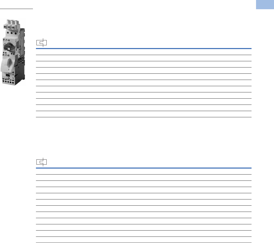
Volume 5—Motor Control and Protection CA08100006E—February 2014 www.eaton.com V5-T1-199
1
1
1
1
1
1
1
1
1
1
1
1
1
1
1
1
1
1
1
1
1
1
1
1
1
1
1
1
1
1
1.1
IEC Contactors and Starters
XT
IEC Power Control
XTFC and XTFR Combination Motor Controllers (CMC), UL 508 Type F
Factory-Assembled Type F Combination Motor Controller—Frame B MMP + Frame B Contactor—
Maximum UL Ratings 1
Factory-Assembled Type F Combination Motor Controller—Frame B MMP + Frame B Contactor—
Maximum IEC Ratings 1
Notes
1 Select combination motor controllers by full load amperes. Maximum motor ratings (kW, hp) are for reference only.
2 Underscore (_) indicates magnetic coil suffix required. See Page V5-T1-202.
3 In this range, calculate motor rating according to rated current. Specified values to NEC 430.6(A)(1).
FLA Adjustment
Range/Overload
Release—Ir
(Amps)
Short-Circuit
Release—
Irm (Amps)
Assembled Manual Motor Controller 2
Three-Phase Non-Reversing
Catalog Number
Reversing
Catalog Number200V 240V 480V 600V
0.16–0.25 3.5 33 1/2 1/2 XTFCP25BB_ XTFRP25BB_
0.25–0.4 5.6 33 1/2 1/2 XTFCP40BB_ XTFRP40BB_
0.4–0.63 8.82 33 1/2 1/2 XTFCP63BB_ XTFRP63BB_
0.63–1 14 33 1/2 1/2 XTFC001BB_ XTFR001BB_
1–1.6 22.4 33 3/4 1 XTFC1P6BB_ XTFR1P6BB_
1.6–2.5 35 1/2 1/2 1 1-1/2 XTFC2P5BB_ XTFR2P5BB_
2.5–4 56 1123XTFC004BB_ XTFR004BB_
4–6.3 88.2 1-1/2 1-1/2 3 5 XTFC6P3BB_ XTFR6P3BB_
6.3–10 140 3 3 7-1/2 10 XTFC010BB_ XTFR010BB_
8–12 168 3 3 7-1/2 — XTFC012BB_ XTFR012BB_
10–16 224 3510—XTFC016BB_ —
FLA Adjustment
Range/Overload
Release—Ir
(Amps)
Short-Circuit
Release—
Irm (Amps)
Three-Phase Assembled Manual Motor Controller 2
220–
240V
380–
415V 500V
660–
690V
Non-Reversing
Catalog Number
Reversing
Catalog Number
0.1–0.16 2.2 ———0.06XTFCP16BB_ XTFRP16BB_
0.16–0.25 3.5 — 0.06 0.06 0.12 XTFCP25BB_ XTFRP25BB_
0.25–0.4 5.6 0.06 0.09 0.12 0.18 XTFCP40BB_ XTFRP40BB_
0.4–0.63 8.82 0.09 0.18 0.25 0.25 XTFCP63BB_ XTFRP63BB_
0.63–1 14 0.12 0.25 0.37 0.55 XTFC001BB_ XTFR001BB_
1–1.6 22.4 0.25 0.55 0.75 1.1 XTFC1P6BB_ XTFR1P6BB_
1.6–2.5 35 0.37 0.75 1.1 1.5 XTFC2P5BB_ XTFR2P5BB_
2.5–4 56 0.75 1.5 2.2 3 XTFC004BB_ XTFR004BB_
4–6.3 88.2 1.1 2.2 3 4 XTFC6P3BB_ XTFR6P3BB_
6.3–10 140 2.2 4 4 7.5 XTFC010BB_ XTFR010BB_
8–12 168 3 5.5 5.5 11 XTFC012BB_ XTFR012BB_
10–16 224 47.5912.5XTFC016BB_ —
Frame B MMP + Two
Frame B Contactors

V5-T1-200 Volume 5—Motor Control and Protection CA08100006E—February 2014 www.eaton.com
1
1
1
1
1
1
1
1
1
1
1
1
1
1
1
1
1
1
1
1
1
1
1
1
1
1
1
1
1
1
1.1
IEC Contactors and Starters
XT
IEC Power Control
Factory-Assembled Type F Combination Motor Controller—Frame B MMP + Frame C Contactor—
Maximum UL Ratings 1
Factory-Assembled Type F Combination Motor Controller—Frame B MMP + Frame C Contactor—
Maximum IEC Ratings 1
Notes
1 Select combination motor controllers by full load amperes. Maximum motor ratings (kW, hp) are for reference only.
2 Underscore (_) indicates magnetic coil suffix required. See Page V5-T1-202.
FLA Adjustment
Range/Overload
Release—Ir
(Amps)
Short-Circuit
Release—
Irm (Amps)
Assembled Manual Motor Controller 2
Three-Phase Non-Reversing
Catalog Number
Reversing
Catalog Number200V 240V 480V 600V
10–16 224 3510—XTFC016BC_ XTFR016BC_
16–20 280 55——XTFC020BC_ XTFR020BC_
20–25 350 5 7-1/2 15 — XTFC025BC_ XTFR025BC_
25–32 448 7-1/2 10 20 — XTFC032BC_ XTFR032BC_
FLA Adjustment
Range/Overload
Release—Ir
(Amps)
Short-Circuit
Release—
Irm (Amps)
Three-Phase Assembled Manual Motor Controller 2
220–
240V
380–
415V 500V
660–
690V
Non-Reversing
Catalog Number
Reversing
Catalog Number
10–16 224 47.5912.5XTFC016BC_ XTFR016BC_
16–20 280 5.5 9 12.5 15 XTFC020BC_ XTFR020BC_
20–25 350 5.5 11 15 22 XTFC025BC_ XTFR025BC_
25–32 448 7.5 15 22 30 XTFC032BC_ XTFR032BC_

Volume 5—Motor Control and Protection CA08100006E—February 2014 www.eaton.com V5-T1-201
1
1
1
1
1
1
1
1
1
1
1
1
1
1
1
1
1
1
1
1
1
1
1
1
1
1
1
1
1
1
1.1
IEC Contactors and Starters
XT
IEC Power Control
Factory-Assembled Type F Combination Motor Controller—Frame D MMP + Frame C Contactor—
Maximum UL Ratings 1
Factory-Assembled Type F Combination Motor Controller—Frame D MMP + Frame C Contactor—
Maximum IEC Ratings 1
Factory-Assembled Type F Combination Motor Controller—Frame D MMP + Frame D Contactor—
Maximum UL Ratings 1
Notes
1 Select combination motor controllers by full load amperes. Maximum motor ratings (kW, hp) are for reference only.
2 Underscore (_) indicates magnetic coil suffix required. See Page V5-T1-202.
FLA Adjustment
Range/Overload
Release—Ir
(Amps)
Short-Circuit
Release—
Irm (Amps)
Assembled Manual Motor Controller 2
Three-Phase Non-Reversing
Catalog Number
Reversing
Catalog Number200V 240V 480V 600V
10–16 224 351010XTFC016DC_ XTFR016DC_
16–25 350 5 7-1/2 15 20 XTFC025DC_ XTFR025DC_
25–32 448 7-1/2 10 25 30 XTFC032DC_ XTFR032DC_
FLA Adjustment
Range/Overload
Release—Ir
(Amps)
Short-Circuit
Release—
Irm (Amps)
Three-Phase Assembled Manual Motor Controller 2
220–
240V
380–
415V 500V
660–
690V
Non-Reversing
Catalog Number
Reversing
Catalog Number
10–16 224 47.5912.5XTFC016DC_ XTFR016DC_
16–25 350 5.5 12.5 12.5 22 XTFC025DC_ XTFR025DC_
25–32 448 7.5 15 17.5 22 XTFC032DC_ XTFR032DC_
FLA Adjustment
Range/Overload
Release—Ir
(Amps)
Short-Circuit
Release—
Irm (Amps)
Assembled Manual Motor Controller 2
Three-Phase Non-Reversing
Catalog Number
Reversing
Catalog Number200V 240V 480V 600V
32–40 560 10 15 30 30 XTFC040DD_ XTFR040DD_
40–50 700 10 15 30 — XTFC050DD_ XTFR050DD_
50–58 812 15 15 40 — XTFC058DD_ XTFR058DD_
55–65 882 15 15 40 — XTFC063DD_ XTFR063DD_
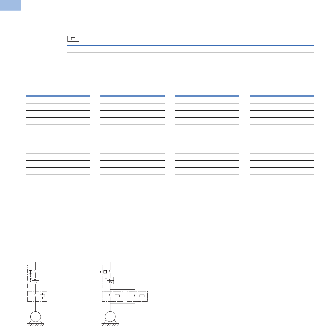
V5-T1-202 Volume 5—Motor Control and Protection CA08100006E—February 2014 www.eaton.com
1
1
1
1
1
1
1
1
1
1
1
1
1
1
1
1
1
1
1
1
1
1
1
1
1
1
1
1
1
1
1.1
IEC Contactors and Starters
XT
IEC Power Control
Factory-Assembled Type F Combination Motor Controller—Frame D MMP + Frame D Contactor—
Maximum IEC Ratings 1
AC and DC Coil Suffixes
Notes
The assembled manual motor controller (MMC) consists of an XTPR manual motor protector (MMP) and an XTCE contactor. For Frame B MMP +
Frame B contactor assemblies, the XTSC and XTSR can be mounted directly on DIN rail without an adapter. The contactors are supported
mechanically with a mechanical connection element (included in XTPAXTPCB, XTPAXRPCRB). For 16A and above, the assembly is mounted via a
DIN rail adapter plate (XTPAXTPCPC, XTPAXTPCPD) and the electrical connection is made with electrical contact modules (XTPAXECMC,
XTPAXECMD), both included in XTPAXTPCC and XTPAXTPCD.
Service Factor (SF)—Setting Ir of current scale in dependence of load factor:
SF = 1.15 → Ir = 1 x In mot
SF = 1 → Ir = 0.9 x In mot
Single-phasing sensitivity to IEC/EN 60947-4-1, VDE 0660 Part 102.
1Select combination motor controllers by full load amperes. Maximum motor ratings (kW, hp) are for reference only.
2Underscore (_) indicates magnetic coil suffix required. See AC and DC coil suffixes above.
3With DC operation: Integrated diode-resistor combination, coil rating 2.6W.
XTFC Manual Motor
Controller
XTFR Manual Motor
Controller
FLA Adjustment
Range/Overload
Release—Ir
(Amps)
Short-Circuit
Release—
Irm (Amps)
Three-Phase Assembled Manual Motor Controller 2
220–
240V
380–
415V 500V
660–
690V
Non-Reversing
Catalog Number
Reversing
Catalog Number
32–40 560 11 20 22 30 XTFC040DD_ XTFR040DD_
40–50 700 14 25 30 45 XTFC050DD_ XTFR050DD_
50–58 812 17 30 37 55 XTFC058DD_ XTFR058DD_
55–65 882 18.5 34 37 55 XTFC063DD_ XTFR063DD_
Coil Voltage Suffix Code
Frame B Contactors
110V 50 Hz, 120V 60 Hz A
220V 50 Hz, 240V 60 Hz B
230V 50 Hz F
24V 50/60 Hz T
24 Vdc TD 3
415V 50 Hz, 480V 60 Hz C
600V 60 Hz D
208V 60 Hz E
190V 50 Hz, 220V 60 Hz G
240V 50 Hz, 277V 60 Hz H
Coil Voltage Suffix Code
380V 50 Hz, 440V 60 Hz L
400V 50 Hz N
380V 60 Hz P
12V 50/60 Hz R
42V 50 Hz, 48V 60 Hz W
48V 50 Hz Y
120 Vdc AD 3
220 Vdc BD 3
12 Vdc RD 3
48 Vdc WD 3
Coil Voltage Suffix Code
Frame C and D Contactors
110V 50 Hz, 120V 60 Hz A
220V 50 Hz, 240V 60 Hz B
230V 50 Hz F
24V 50/60 Hz T
24–27 Vdc TD 3
415V 50 Hz, 480V 60 Hz C
550V 50 Hz, 600V 60 Hz D
208V 60 Hz E
190V 50 Hz, 220V 60 Hz G
240V 50 Hz, 277V 60 Hz H
Coil Voltage Suffix Code
380V 50 Hz, 440V 60 Hz L
400V 50 Hz N
380V 60 Hz P
12V 50/60 Hz R
42V 50 Hz, 48V 60 Hz W
48V 50 Hz Y
110–130 Vdc AD 3
200–240 Vdc BD 3
12–14 Vdc RD 3
48–60 Vdc WD 3
M
3 ~
M
3 ~
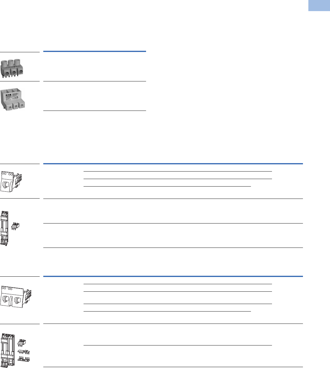
Volume 5—Motor Control and Protection CA08100006E—February 2014 www.eaton.com V5-T1-203
1
1
1
1
1
1
1
1
1
1
1
1
1
1
1
1
1
1
1
1
1
1
1
1
1
1
1
1
1
1
1.1
IEC Contactors and Starters
XT
IEC Power Control
Accessories
Line Side Adapters
Line side adapters are required for use with XTPR MMPs only when used as Type E
self-protected
manual combination starters or as part of XTFC or XTFR Type F combination motor controllers.
Not required for group installation.
Line Side Adapters
Combination Connection Kits
Combination connection kits include the necessary components to field assemble a manual motor
controller with an MMP (XTPR) and contactor (XTCE).
Non-Reversing Starters
Reversing Starters
Note
1 Orders must be placed in multiples of package quantity listed.
Description Catalog Number
For use with Frame B MMPs (up to 32A) XTPAXLSA
For use with Frame D MMPs (up to 40A) XTPAXLSAD
For Use with … Description/Composed of …
Std.
Pack 1Catalog Number
XTPR
…
B + XTCE
…
B Mechanical connection element for XTPR…B and contactor 1 XTPAXTPCB
Main current wiring between XTPR…B and contactor in toolless plug connection 1
Cable guidance 1
Use as contactor auxiliary switch XTCEXFAT_. Control cable guidance: max. six cables up to 2.5 mm2
external diameter or four cables up to 3.5 mm2 external diameter
XTPR
…
B + XTCE
…
C DIN rail adapter plate 1XTPAXTPCC
XTPR
…
D + XTCE
…
D Main current wiring between XTPR and contactor 1 XTPAXTPCD
For Use with … Description/Composed of …
Std.
Pack 1Catalog Number
XTPR
…
B + XTCE
…
B01_ Mechanical connection element for XTPR
…
B and contactor 1 XTPAXTPCRB
Reversing starter main current wiring in toolless plug connection 1
Control cables for electrical interlocking in toolless plug connection—
K1M: A1–K2M: 21, K1M: 21–K2M: A1, K1M: A2–K2M: A2
1
Cable guidance 1
Use as contactor auxiliary switch XTCEXFAT_. Control cable guidance: max. six cables up to 2.5 mm2
external diameter or four cables up to 3.5 mm2 external diameter.
XTPR
…
B + XTCE
…
C DIN rail adapter plate 1XTPAXTPCRB
Reversing starter main current wiring 1
XTPAXLSA
XTPAXLSA
XTPAXTPCB
XTPAXTPCC and
XTPAXTPCD
XTPAXTPCRB
XTPAXTPCRC

V5-T1-204 Volume 5—Motor Control and Protection CA08100006E—February 2014 www.eaton.com
1
1
1
1
1
1
1
1
1
1
1
1
1
1
1
1
1
1
1
1
1
1
1
1
1
1
1
1
1
1
1.1
IEC Contactors and Starters
XT
IEC Power Control
Electric Contact Module
DIN Rail Adapter Plates
Lateral Module
Connection Element
Note
1 Orders must be placed in multiples of package quantity listed.
For Use with … Description/Composed of …
Std.
Pack 1Catalog Number
XTPR
…
B + XTCE
…
C Main current wiring between XTPR
…
B and contactor 5 XTPAXECMC
Use only in combination with busbar adapter
XTPR
…
D + XTCE
…
D Main current wiring between XTPR
…
D and contactor 5 XTPAXECMD
Use only in combination with busbar adapter
For Use with … Description/Composed of …
Std.
Pack 1Catalog Number
XTPAXTPCB
XTPAXTPCRB
45 mm wide adapter plate with one DIN rail 4 XTPAXTPCPB
Connection element for side-by-side positioning of further plates
XTPR
…
B + XTCE
…
C
XTPAXECMC
45 mm wide adapter plate with one DIN rail 4 XTPAXTPCRPB
Connection element for side-by-side positioning of further plates
XTPAXECMD
XTPR
…
D + XTCE
…
C
XTPR
…
D + XTCE
…
D
55 mm wide adapter plate with two DIN rails 4 XTPAXTPCPD
Connection cams for further plates 4
For use with reversing and star-delta starters
For Use with … Description/Composed of …
Std.
Pack 1Catalog Number
— Can be grouped on the DIN rail adapter 10 XTPAXLM
Expansion of the mounting width by 9 mm
For Use with … Description/Composed of …
Std.
Pack 1Catalog Number
— For connection of several DIN rail adapters 50 XTPAXCNE
XTPAXEC_
XTPAXTPCPB
XTPAXTPCRPB
XTPAXTPCPD

Volume 5—Motor Control and Protection CA08100006E—February 2014 www.eaton.com V5-T1-205
1
1
1
1
1
1
1
1
1
1
1
1
1
1
1
1
1
1
1
1
1
1
1
1
1
1
1
1
1
1
1.1
IEC Contactors and Starters
XT
IEC Power Control
Technical Data and Specifications
XTSC Non-Reversing Manual Motor Controllers (MMC)—Component Bill of Material
Notes
1Underscore (_) indicates magnetic coil suffix required. See Page V5-T1-202.
2The connection between the XTPR…DC1 and the XTCE…C
_
contactor will be made with flexible wire and mounted to the DIN rail adapter plate (XTPAXTPCPD).
3The reversing connection between the XTPR…DC1 and the (2) XTCE…C_ contactors will be accomplished by using the non-reversing combination connection kit (XTPAXTPCD),
Frame D reversing link kit (XTCEXRLD), additional DIN rail adapter plate (XTPAXTPCPD) and DIN adapter connection element (XTPAXCNE).
Factory Assembled Manual Motor Protector + Contactor
Assembled Manual
Motor Controller 1
FLA Adjustment
Range/Overload
Release—Ir (Amps)
Component Catalog Numbers
Manual Motor
Protector
Combination
Connection Kit Contactor 1
Manual Motor Protector
Auxiliary Contact
XTSC Frame B MMP + Frame B Contactor
XTSCP16BB_ 0.1–0.16 XTPRP16BC1 XTPAXTPCB XTCE007B10_ XTPAXFA11
XTSCP25BB_ 0.16–0.25 XTPRP25BC1 XTPAXTPCB XTCE007B10_ XTPAXFA11
XTSCP40BB_ 0.25–0.4 XTPRP40BC1 XTPAXTPCB XTCE007B10_ XTPAXFA11
XTSCP63BB_ 0.4–0.63 XTPRP63BC1 XTPAXTPCB XTCE007B10_ XTPAXFA11
XTSC001BB_ 0.63–1 XTPR001BC1 XTPAXTPCB XTCE007B10_ XTPAXFA11
XTSC1P6BB_ 1–1.6 XTPR1P6BC1 XTPAXTPCB XTCE007B10_ XTPAXFA11
XTSC2P5BB_ 1.6–2.5 XTPR2P5BC1 XTPAXTPCB XTCE007B10_ XTPAXFA11
XTSC004BB_ 2.5–4 XTPR004BC1 XTPAXTPCB XTCE007B10_ XTPAXFA11
XTSC6P3BB_ 4–6.3 XTPR6P3BC1 XTPAXTPCB XTCE007B10_ XTPAXFA11
XTSC010BB_ 6.3–10 XTPR010BC1 XTPAXTPCB XTCE009B10_ XTPAXFA11
XTSC012BB_ 8–12 XTPR012BC1 XTPAXTPCB XTCE012B10_ XTPAXFA11
XTSC016BB_ 10–16 XTPR016BC1 XTPAXTPCB XTCE015B10_ XTPAXFA11
XTSC Frame B MMP + Frame C Contactor
XTSC016BC_ 10–16 XTPR016BC1 XTPAXTPCC XTCE018C10_ XTPAXFA1
XTSC020BC_ 16–20 XTPR020BC1 XTPAXTPCC XTCE025C10_ XTPAXFA11
XTSC025BC_ 20–25 XTPR025BC1 XTPAXTPCC XTCE025C10_ XTPAXFA11
XTSC032BC_ 25–32 XTPR032BC1 XTPAXTPCC XTCE032C10_ XTPAXFA11
XTSC Frame D MMP + Frame C Contactor
XTSC016DC_ 10–16 XTPR016DC1 2XTCE018C10_ XTPAXFA1
XTSC025DC_ 16–25 XTPR025DC1 2XTCE025C10_ XTPAXFA11
XTSC032DC_ 25–32 XTPR032DC1 2XTCE032C10_ XTPAXFA11
XTSC Frame D MMP + Frame D Contactor
XTSC040DD_ 32–40 XTPR040DC1 XTPAXTPCD 3XTCE040D00_ XTPAXFA11
XTSC050DD_ 40–50 XTPR050DC1 XTPAXTPCD 3XTCE050D00_ XTPAXFA11
XTSC058DD_ 50–58 XTPR058DC1 XTPAXTPCD 3XTCE065D00_ XTPAXFA11
XTSC063DD_ 55–65 XTPR063DC1 XTPAXTPCD 3XTCE065D00_ XTPAXFA11

V5-T1-206 Volume 5—Motor Control and Protection CA08100006E—February 2014 www.eaton.com
1
1
1
1
1
1
1
1
1
1
1
1
1
1
1
1
1
1
1
1
1
1
1
1
1
1
1
1
1
1
1.1
IEC Contactors and Starters
XT
IEC Power Control
XTSR Reversing Manual Motor Controllers (MMC)—Component Bill of Material
Notes
1Underscore (_) indicates magnetic coil suffix required. See Page V5-T1-202.
2The connection between the XTPR…DC1 and the XTCE…C
_
contactor will be made with flexible wire and mounted to the DIN rail adapter plate (XTPAXTPCPD).
3The reversing connection between the XTPR…DC1 and the (2) XTCE…C_ contactors will be accomplished by using the non-reversing combination connection kit (XTPAXTPCD),
Frame D reversing link kit (XTCEXRLD), additional DIN rail adapter plate (XTPAXTPCPD) and DIN adapter connection element (XTPAXCNE).
Factory Assembled Manual Motor Protector + Contactor
Assembled Manual
Motor Controller 1
FLA Adjustment
Range/Overload
Release—Ir (Amps)
Component Catalog Numbers
Manual Motor
Protector
Combination
Connection Kit Contactor 1
Manual Motor Protector
Auxiliary Contact
XTSR Frame B MMP + Frame B Contactor
XTSRP16BB_ 0.1–0.16 XTPRP16BC1 XTPAXTPCRB (2) XTCE007B01_ XTPAXFA11
XTSRP25BB_ 0.16–0.25 XTPRP25BC1 XTPAXTPCRB (2) XTCE007B01_ XTPAXFA11
XTSRP40BB_ 0.25–0.4 XTPRP40BC1 XTPAXTPCRB (2) XTCE007B01_ XTPAXFA11
XTSRP63BB_ 0.4–0.63 XTPRP63BC1 XTPAXTPCRB (2) XTCE007B01_ XTPAXFA11
XTSR001BB_ 0.63–1 XTPR001BC1 XTPAXTPCRB (2) XTCE007B01_ XTPAXFA11
XTSR1P6BB_ 1–1.6 XTPR1P6BC1 XTPAXTPCRB (2) XTCE007B01_ XTPAXFA11
XTSR2P5BB_ 1.6–2.5 XTPR2P5BC1 XTPAXTPCRB (2) XTCE007B01_ XTPAXFA11
XTSR004BB_ 2.5–4 XTPR004BC1 XTPAXTPCRB (2) XTCE007B01_ XTPAXFA11
XTSR6P3BB_ 4–6.3 XTPR6P3BC1 XTPAXTPCRB (2) XTCE007B01_ XTPAXFA11
XTSR010BB_ 6.3–10 XTPR010BC1 XTPAXTPCRB (2) XTCE009B01_ XTPAXFA11
XTSR012BB_ 8–12 XTPR012BC1 XTPAXTPCRB (2) XTCE012B01_ XTPAXFA11
XTSR Frame B MMP + Frame C Contactor
XTSR016BC_ 10–16 XTPR016BC1 XTPAXTPCRC (2) XTCE018C01 XTPAXFA11
XTSR020BC_ 16–20 XTPR020BC1 XTPAXTPCRC (2) XTCE025C01_ XTPAXFA11
XTSR025BC_ 20–25 XTPR025BC1 XTPAXTPCRC (2) XTCE025C01_ XTPAXFA11
XTSR032BC_ 25–32 XTPR032BC1 XTPAXTPCRC (2) XTCE032C01_ XTPAXFA11
XTSR Frame D MMP + Frame C Contactor
XTSR016DC_ 10–16 XTPR016DC1 2(2) XTCE018C01 XTPAXFA11
XTSR025DC_ 16–25 XTPR025DC1 2(2) XTCE025C01_ XTPAXFA11
XTSR032DC_ 25–32 XTPR032DC1 2(2) XTCE032C01_ XTPAXFA11
XTSR Frame D MMP + Frame D Contactor
XTSR040DD_ 32–40 XTPR040DC1 3(2) XTCE040D00_ XTPAXFA11
XTSR050DD_ 40–50 XTPR050DC1 3(2) XTCE050D00_ XTPAXFA11
XTSR058DD_ 50–58 XTPR058DC1 3(2) XTCE065D00_ XTPAXFA11
XTSR063DD_ 55–65 XTPR063DC1 3(2) XTCE065D00_ XTPAXFA11

Volume 5—Motor Control and Protection CA08100006E—February 2014 www.eaton.com V5-T1-207
1
1
1
1
1
1
1
1
1
1
1
1
1
1
1
1
1
1
1
1
1
1
1
1
1
1
1
1
1
1
1.1
IEC Contactors and Starters
XT
IEC Power Control
XTFC Non-Reversing Combination Motor Controllers—Component Bill of Material
Notes
1Underscore (_) indicates magnetic coil suffix required. See Page V5-T1-202.
2The connection between the XTPR…DC1 and the XTCE…C
_
contactor will be made with flexible wire and mounted to the DIN rail adapter plate (XTPAXTPCPD).
3The reversing connection between the XTPR…DC1 and the (2) XTCE…C
_
contactors will be accomplished by using the non-reversing combination connection kit (XTPAXTPCD),
Frame D reversing link kit (XTCEXRLD), additional DIN rail adapter plate (XTPAXTPCPD) and DIN adapter connection element (XTPAXCNE).
Factory Assembled Manual Motor Protector + Contactor + Line Side Adapter
Assembled
Combination
Motor Controller 1
FLA Adjustment Range/
Overload Release—Ir
(Amps)
Component Catalog Numbers
Line Side
Adapter
Manual Motor
Protector
Combination
Connection Kit Contactor 1
Manual Motor Protector
Auxiliary Contact
XTFC Frame B MMP + Frame B Contactor
XTFCP16BB_ 0.1–0.16 XTPAXLSA XTPRP16BC1 XTPAXTPCB XTCE007B10_ XTPAXFA11
XTFCP25BB_ 0.16–0.25 XTPAXLSA XTPRP25BC1 XTPAXTPCB XTCE007B10_ XTPAXFA11
XTFCP40BB_ 0.25–0.4 XTPAXLSA XTPRP40BC1 XTPAXTPCB XTCE007B10_ XTPAXFA11
XTFCP63BB_ 0.4–0.63 XTPAXLSA XTPRP63BC1 XTPAXTPCB XTCE007B10_ XTPAXFA11
XTFC001BB_ 0.63–1 XTPAXLS XTPR001BC1 XTPAXTPCB XTCE007B10_ XTPAXFA11
XTFC1P6BB_ 1–1.6 XTPAXLSA XTPR1P6BC1 XTPAXTPCB XTCE007B10_ XTPAXFA11
XTFC2P5BB_ 1.6–2.5 XTPAXLSA XTPR2P5BC1 XTPAXTPCB XTCE007B10_ XTPAXFA11
XTFC004BB_ 2.5–4 XTPAXLSA XTPR004BC1 XTPAXTPCB XTCE007B10_ XTPAXFA11
XTFC6P3BB_ 4–6.3 XTPAXLSA XTPR6P3BC1 XTPAXTPCB XTCE007B10_ XTPAXFA11
XTFC010BB_ 6.3–10 XTPAXLSA XTPR010BC1 XTPAXTPCB XTCE009B10_ XTPAXFA11
XTFC012BB_ 8–12 XTPAXLSA XTPR012BC1 XTPAXTPCB XTCE012B10_ XTPAXFA11
XTFC016BB_ 10–16 XTPAXLSA XTPR016BC1 XTPAXTPCB XTCE015B10_ XTPAXFA11
XTFC Frame B MMP + Frame C Contactor
XTFC016BC_ 10–16 XTPAXLSA XTPR016BC1 XTPAXTPCC XTCE018C10_ XTPAXFA11
XTFC020BC_ 16–20 XTPAXLSA XTPR020BC1 XTPAXTPCC XTCE025C10_ XTPAXFA11
XTFC025BC_ 20–25 XTPAXLSA XTPR025BC1 XTPAXTPCC XTCE025C10_ XTPAXFA11
XTFC032BC_ 25–32 XTPAXLSA XTPR032BC1 XTPAXTPCC XTCE032C10_ XTPAXFA11
XTFC Frame D MMP + Frame C Contactor
XTFC016DC_ 10–16 XTPAXLSAD XTPR016DC1 2XTCE018C10_ XTPAXFA11
XTFC025DC_ 16–25 XTPAXLSAD XTPR025DC1 2XTCE025C10_ XTPAXFA11
XTFC032DC_ 25–32 XTPAXLSAD XTPR032DC1 2XTCE032C10_ XTPAXFA11
XTFC Frame D MMP + Frame D Contactor
XTFC040DD_ 32–40 XTPAXLSAD XTPR040DC1 XTPAXTPCD 3XTCE040D00_ XTPAXFA11
XTFC050DD_ 40–50 XTPAXLSAD XTPR050DC1 XTPAXTPCD 3XTCE050D00_ XTPAXFA11
XTFC058DD_ 50–58 XTPAXLSAD XTPR058DC1 XTPAXTPCD 3XTCE065D00_ XTPAXFA11
XTFC063DD_ 55–65 XTPAXLSAD XTPR063DC1 XTPAXTPCD 3XTCE065D00_ XTPAXFA11

V5-T1-208 Volume 5—Motor Control and Protection CA08100006E—February 2014 www.eaton.com
1
1
1
1
1
1
1
1
1
1
1
1
1
1
1
1
1
1
1
1
1
1
1
1
1
1
1
1
1
1
1.1
IEC Contactors and Starters
XT
IEC Power Control
XTFR Reversing Combination Motor Controllers—Component Bill of Material
Notes
1Underscore (_) indicates magnetic coil suffix required. See Page V5-T1-202.
2The connection between the XTPR…DC1 and the XTCE…C
_
contactor will be made with flexible wire and mounted to the DIN rail adapter plate (XTPAXTPCPD).
3The reversing connection between the XTPR…DC1 and the (2) XTCE…C
_
contactors will be accomplished by using the non-reversing combination connection kit (XTPAXTPCD), Frame D reversing
link kit (XTCEXRLD), additional DIN rail adapter plate (XTPAXTPCPD) and DIN adapter connection element (XTPAXCNE).
Factory Assembled Manual Motor Protector + Contactor + Line Side Adapter
Assembled Combination
Motor Controller 1
FLA Adjustment Range/
Overload Release—Ir
(Amps)
Component Catalog Numbers
Line Side
Adapter
Manual Motor
Protector
Combination
Connection Kit Contactor 1
Manual Motor Protector
Auxiliary Contact
XTFR Frame B MMP + Frame B Contactor
XTFRP16BB_ 0.1–0.16 XTPAXLSA XTPRP16BC1 XTPAXTPCRB (2) XTCE007B01_ XTPAXFA11
XTFRP25BB_ 0.16–0.25 XTPAXLSA XTPRP25BC1 XTPAXTPCRB (2) XTCE007B01_ XTPAXFA11
XTFRP40BB_ 0.25–0.4 XTPAXLSA XTPRP40BC1 XTPAXTPCRB (2) XTCE007B01_ XTPAXFA11
XTFRP63BB_ 0.4–0.63 XTPAXLSA XTPRP63BC1 XTPAXTPCRB (2) XTCE007B01_ XTPAXFA11
XTFR001BB_ 0.63–1 XTPAXLSA XTPR001BC1 XTPAXTPCRB (2) XTCE007B01_ XTPAXFA11
XTFR1P6BB_ 1–1.6 XTPAXLSA XTPR1P6BC1 XTPAXTPCRB (2) XTCE007B01_ XTPAXFA11
XTFR2P5BB_ 1.6–2.5 XTPAXLSA XTPR2P5BC1 XTPAXTPCRB (2) XTCE007B01_ XTPAXFA11
XTFR004BB_ 2.5–4 XTPAXLSA XTPR004BC1 XTPAXTPCRB (2) XTCE007B01_ XTPAXFA11
XTFR6P3BB_ 4–6.3 XTPAXLSA XTPR6P3BC1 XTPAXTPCRB (2) XTCE007B01_ XTPAXFA11
XTFR010BB_ 6.3–10 XTPAXLSA XTPR010BC XTPAXTPCRB (2) XTCE009B01_ XTPAXFA11
XTFR012BB_ 8–12 XTPAXLSA XTPR012BC1 XTPAXTPCRB (2) XTCE012B01_ XTPAXFA11
XTFR Frame B MMP + Frame C Contactor
XTFR016BC_ 10–16 XTPAXLSA XTPR016BC1 XTPAXTPCRC (2) XTCE018C01_ XTPAXFA11
XTFR020BC_ 16–20 XTPAXLSA XTPR020BC1 XTPAXTPCRC (2) XTCE025C01_ XTPAXFA11
XTFR025BC_ 20–25 XTPAXLSA XTPR025BC1 XTPAXTPCRC (2) XTCE025C01_ XTPAXFA11
XTFR032BC_ 25–32 XTPAXLSA XTPR032BC1 XTPAXTPCRC (2) XTCE032C01_ XTPAXFA11
XTFR Frame D MMP + Frame C Contactor
XTFR016DC_ 10–16 XTPAXLSAD XTPR016DC1 2(2) XTCE018C01_ XTPAXFA11
XTFR025DC_ 16–25 XTPAXLSAD XTPR025DC1 2(2) XTCE025C01_ XTPAXFA11
XTFR032DC_ 25–32 XTPAXLSAD XTPR032DC1 2(2) XTCE032C01_ XTPAXFA11
XTFR Frame D MMP + Frame D Contactor
XTFR040DD_ 32–40 XTPAXLSAD XTPR040DC1 3(2) XTCE040D00_ XTPAXFA11
XTFR050DD_ 40–50 XTPAXLSAD XTPR050DC1 3(2) XTCE050D00_ XTPAXFA11
XTFR058DD_ 50–58 XTPAXLSAD XTPR058DC1 3(2) XTCE065D00_ XTPAXFA11
XTFR063DD_ 55–65 XTPAXLSAD XTPR063DC1 3(2) XTCE065D00_ XTPAXFA11

Volume 5—Motor Control and Protection CA08100006E—February 2014 www.eaton.com V5-T1-209
1
1
1
1
1
1
1
1
1
1
1
1
1
1
1
1
1
1
1
1
1
1
1
1
1
1
1
1
1
1
1.1
IEC Contactors and Starters
XT
IEC Power Control
Manual Motor Controllers Short-Circuit Ratings for UL/CSA Group Installations
Note
1Underscore (_) indicates magnetic coil suffix required. See Page V5-T1-202.
XTSC and XTSR Manual Motor Controllers (MMC)
FLA Adjustment
Range/Overload
Release—
Ir (Amps)
Short-Circuit
Release—
Irm (Amps)
Group Installation, UL/CSA
Assembled Controller 1
Max. rms Symmetrical Short-Circuit
Ratings (kA/kA with Current Limiter)
Maximum Upstream Protective Device
(A/A with Current Limiter)
Non-Reversing Reversing 240V 480V 600V
Maximum Fuse
600V
Maximum Circuit
Breaker 600V
XTSC and XTSR Frame B MMP + Frame B Contactor
XTSCP16BB_ XTSRP16BB_ 0.1–0.16 2.2 50 50 50 600 600
XTSCP25BB_ XTSRP25BB_ 0.16–0.25 3.5 50 50 50 600 600
XTSCP40BB_ XTSRP40BB_ 0.25–0.4 5.6 50 50 50 600 600
XTSCP63BB_ XTSRP63BB_ 0.4–0.63 8.82 50 50 50 600 600
XTSC001BB_ XTSR001BB_ 0.63–1 14 50 50 50 600 600
XTSC1P6BB_ XTSR1P6BB_ 1–1.6 22.4 50 50 50 600 600
XTSC2P5BB_ XTSR2P5BB_ 1.6–2.5 35 50 50 50 600 600
XTSC004BB_ XTSR004BB_ 2.5–4 56 505050600 600
XTSC6P3BB_ XTSR6P3BB_ 4–6.3 88.2 50 50 50 600 600
XTSC010BB_ XTSR010BB_ 6.3–10 140 22 22 22 150/600 125/600
XTSC012BB_ XTSR012BB_ 8–12 168 10/50 10/50 10/50 150/600 125/600
XTSC016BB_ — 10–16 224 10/50 10/50 10/50 150/600 125/600
XTSC and XTSR Frame B MMP + Frame C Contactor
XTSC016BC_ XTSR016BC_ 10–16 224 10/50 10/50 10/50 150/600 125/600
XTSC020BC_ XTSR020BC_ 16–20 280 10/18 10/18 10/18 150/600 125/600
XTSC025BC_ XTSR025BC_ 20–25 350 10/18 10/18 10/18 150/600 125/600
XTSC032BC_ XTSR032BC_ 25–32 448 5/18 5/18 5/18 150/600 125/600
XTSC and XTSR Frame D MMP + Frame C Contactor
XTSC016DC_ XTSR016DC_ 10–16 224 50 50 10 600 600
XTSC025DC_ XTSR025DC_ 16–25 350 50 50 10 600 600
XTSC032DC_ XTSR032DC_ 25–32 448 50 50 10 600 600
XTSC and XTSR Frame D MMP + Frame D Contactor
XTSC040DD_ XTSR040DD_ 32–40 560 50 50 10 600 600
XTSC050DD_ XTSR050DD_ 40–50 700 50 50 10 600 600
XTSC058DD XTSR058DD_ 50–58 812 50 50 — — —
XTSC063DD_ XTSR063DD_ 55–65 882 50 50 — — —

V5-T1-210 Volume 5—Motor Control and Protection CA08100006E—February 2014 www.eaton.com
1
1
1
1
1
1
1
1
1
1
1
1
1
1
1
1
1
1
1
1
1
1
1
1
1
1
1
1
1
1
1.1
IEC Contactors and Starters
XT
IEC Power Control
Combination Motor Controllers Short-Circuit Ratings for UL 508 Type F Application
Notes
1Underscore (_) indicates magnetic coil suffix required. See Page V5-T1-202.
2For UL 508 Type F applications, the combination motor controller assembly does not require a dedicated upstream protective device in the panel, thus a maximum rating is not required.
XTFC and XTFR Combination Motor Controllers (CMC), UL 508 Type F
FLA Adjustment
Range/Overload
Release—
Ir (Amps)
Short-Circuit
Release—
Irm (Amps)
UL 508 Type F Application
Assembled Controller 1
Max. rms Symmetrical Short-Circuit
Ratings (kA)
Maximum Upstream
Protective Device (A) 2
Non-Reversing Reversing 240V 480/277V 600/347V
Maximum Fuse
600V
Maximum Circuit
Breaker 600V
XTFC and XTFR Frame B MMP + Frame B Contactor
XTFCP16BB_ XTFRP16BB_ 0.1–0.16 2.2 65 65 — Not required Not required
XTFCP25BB_ XTFRP25BB_ 0.16–0.25 3.5 65 65 — Not required Not required
XTFCP40BB_ XTFRP40BB_ 0.25–0.4 5.6 65 65 — Not required Not required
XTFCP63BB_ XTFRP63BB_ 0.4–0.63 8.82 65 65 — Not required Not required
XTFC001BB_ XTFR001BB_ 0.63–1 14 65 65 — Not required Not required
XTFC1P6BB_ XTFR1P6BB_ 1–1.6 22.4 65 65 — Not required Not required
XTFC2P5BB_ XTFR2P5BB_ 1.6–2.5 35 65 65 — Not required Not required
XTFC004BB_ XTFR004BB_ 2.5–4 56 65 65 — Not required Not required
XTFC6P3BB_ XTFR6P3BB_ 4–6.3 88.2 65 65 — Not required Not required
XTFC010BB_ XTFR010BB_ 6.3–10 140 65 65 — Not required Not required
XTFC012BB_ XTFR012BB_ 8–12 168 50 50 — Not required Not required
XTFC016BB_ — 10–16 224 50 50 — Not required Not required
XTFC and XTFR Frame B MMP + Frame C Contactor
XTFC016BC_ XTFR016BC_ 10–16 224 18 18 — Not required Not required
XTFC020BC_ XTFR020BC_ 16–20 280 18 18 — Not required Not required
XTFC025BC_ XTFR025BC_ 20–25 350 18 18 — Not required Not required
XTFC032BC_ XTFR032BC_ 25–32 448 18 18 — Not required Not required
XTFC and XTFR Frame D MMP + Frame C Contactor
XTFC016DC_ XTFR016DC_ 10–16 224 65 65 50 Not required Not required
XTFC025DC_ XTFR025DC_ 16–25 350 65 65 50 Not required Not required
XTFC032DC_ XTFR032DC_ 25–32 448 65 65 50 Not required Not required
XTFC and XTFR Frame D MMP + Frame D Contactor
XTFC040DD_ XTFR040DD_ 32–40 560 65 65 50 Not required Not required
XTFC050DD_ XTFR050DD_ 40–50 700 65 65 — Not required Not required
XTFC058DD_ XTFR058DD_ 50–58 812 65 65 — Not required Not required
XTFC063DD_ XTFR063DD_ 55–65 882 65 65 — Not required Not required
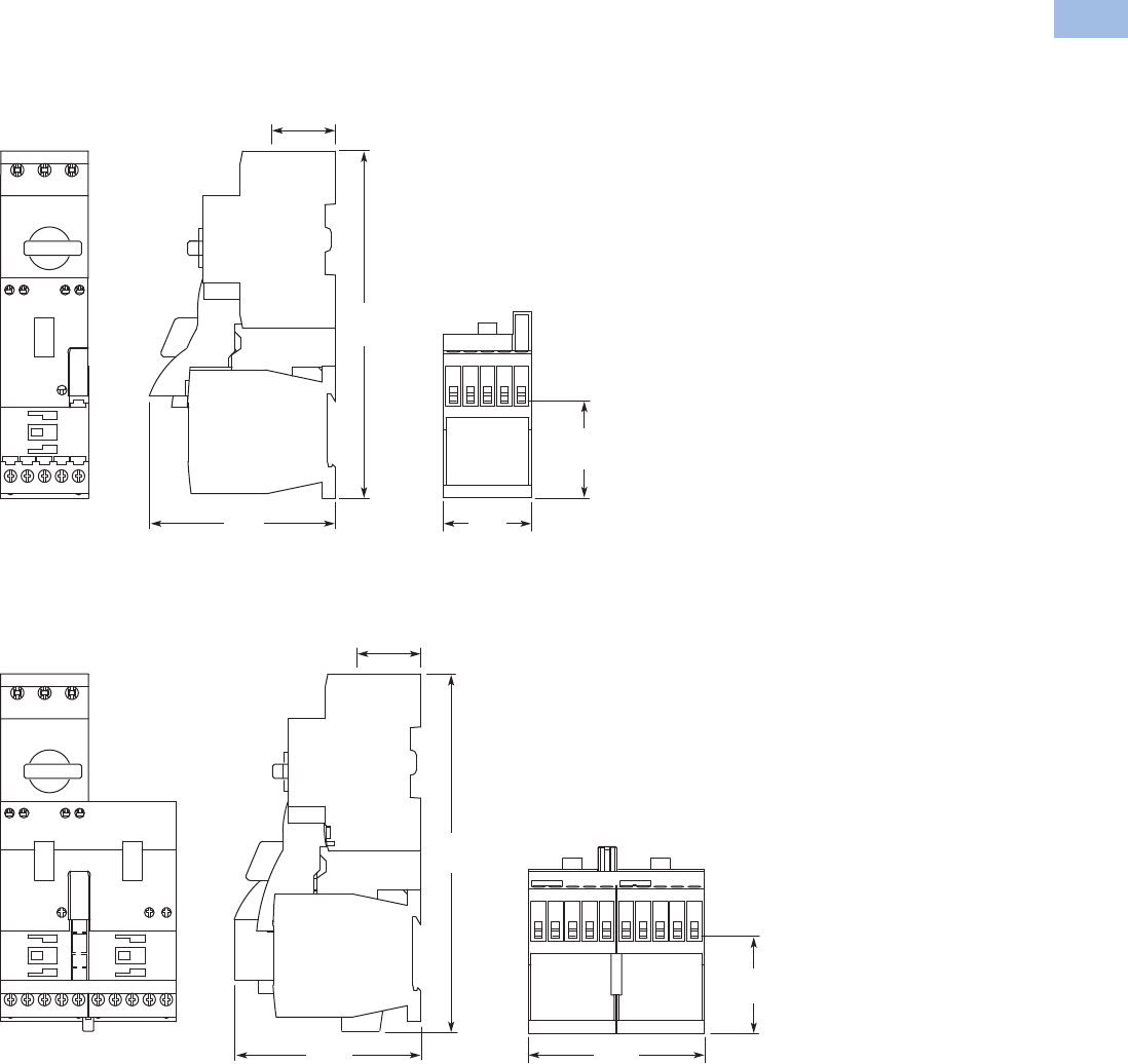
Volume 5—Motor Control and Protection CA08100006E—February 2014 www.eaton.com V5-T1-211
1
1
1
1
1
1
1
1
1
1
1
1
1
1
1
1
1
1
1
1
1
1
1
1
1
1
1
1
1
1
1.1
IEC Contactors and Starters
XT
IEC Power Control
Dimensions
Approximate Dimensions in mm [in]
XTSC…BB_
XTSR…BB_
49.7 [1.96]
To Terminals
45
[1.77]
95.7
[3.77]
178.5
[7.03]
32.5 [1.28]
To Terminals
49.7 [1.96]
To Terminals
90.3
[3.55]
32.5 [1.28]
To Terminals
95.3
[3.75]
183.4
[7.22]
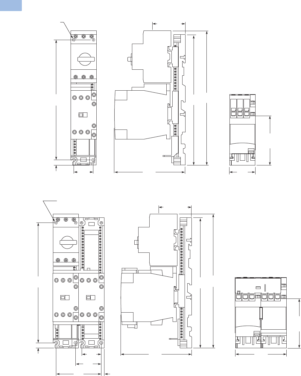
V5-T1-212 Volume 5—Motor Control and Protection CA08100006E—February 2014 www.eaton.com
1
1
1
1
1
1
1
1
1
1
1
1
1
1
1
1
1
1
1
1
1
1
1
1
1
1
1
1
1
1
1.1
IEC Contactors and Starters
XT
IEC Power Control
Approximate Dimensions in mm [in]
XTSC…BC_
XTSR…BC_
Mounting Holes
for M4 Screws
or #8 Screws
(4 Places)
34
[1.34]
210.8 [8.30]
Mounting
9 [.35]
86.8
[3.42]
To Terminals
45.2
[1.78]
57.5 [2.26]
To Terminals
124.3
[4.89]
228.8
[9.01]
235.7
[9.28]
86.8 [3.42]
To
Terminals
89.6
[3.53]
34
[1.34]
45
[1.77]
79
[3.11] 5.3
[.21]
210.8 [8.30]
Mounting
9 [.35]
124.3
[4.89]
228.8
[9.01]
235.4
[9.27]
Mounting Holes for
M4 Screws or #8 Screws
(4 Places) 57.5 [2.26]
To Terminals
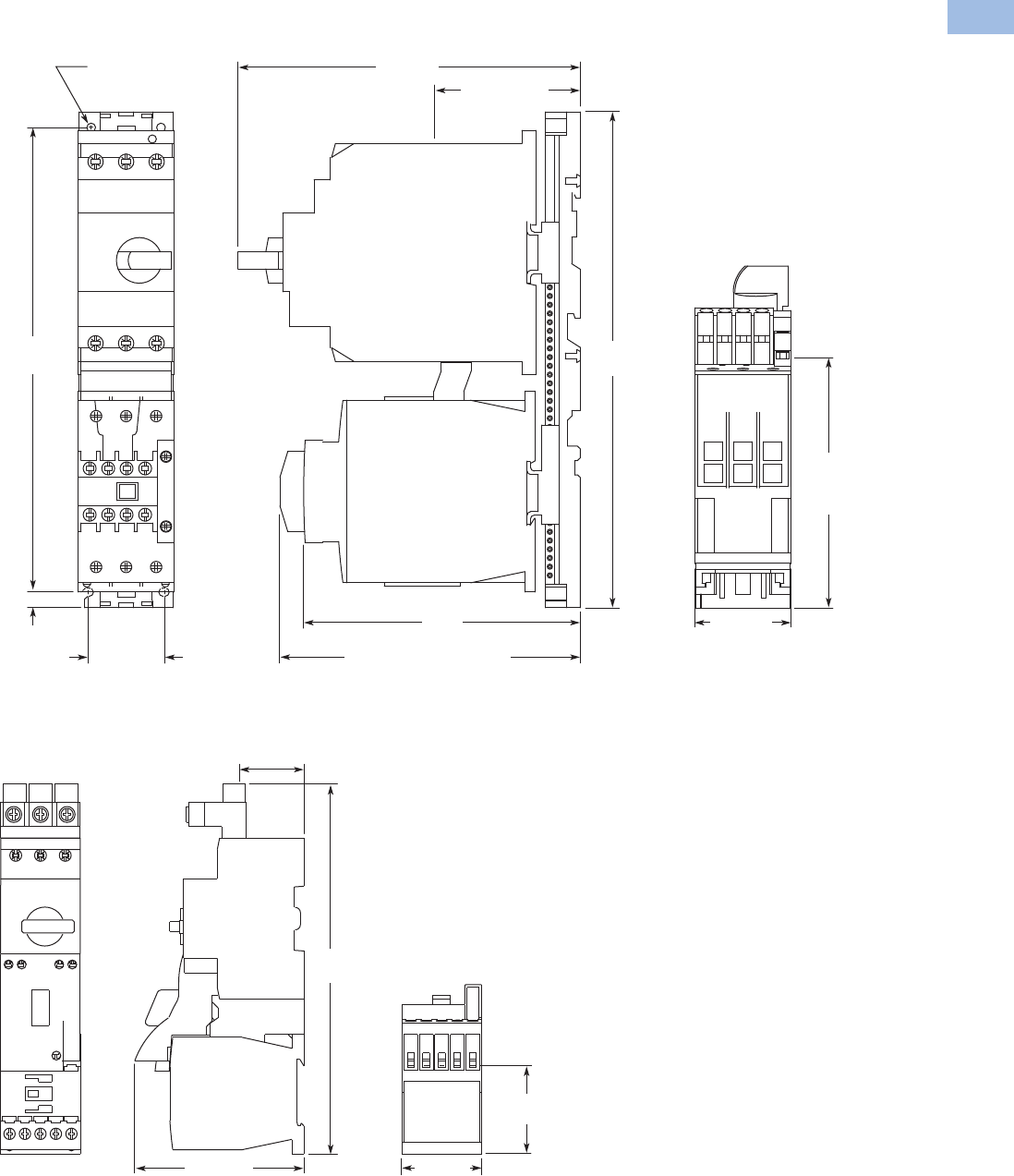
Volume 5—Motor Control and Protection CA08100006E—February 2014 www.eaton.com V5-T1-213
1
1
1
1
1
1
1
1
1
1
1
1
1
1
1
1
1
1
1
1
1
1
1
1
1
1
1
1
1
1
1.1
IEC Contactors and Starters
XT
IEC Power Control
Approximate Dimensions in mm [in]
XTSC…DD_
XTFC…BB_
142.8
[5.62]
To Coil
Terminals
83.4 [3.28]
To Terminals
196 [7.72]
158.5
[6.24]
172.1 [6.78]
To Optional Aux. Contacts
Mounting Holes for
M5 Screws or #10 Screws
(4 Places)
55 [2.17]
43.4 [1.71]
Mounting
266 [10.47]
Mounting
9 [.35]
284
[11.18]
49.7 [1.96]
To Terminals
45 [1.77]
36.3 [1.43]
To Terminals
95.7 [3.77]
209.2
[8.24]
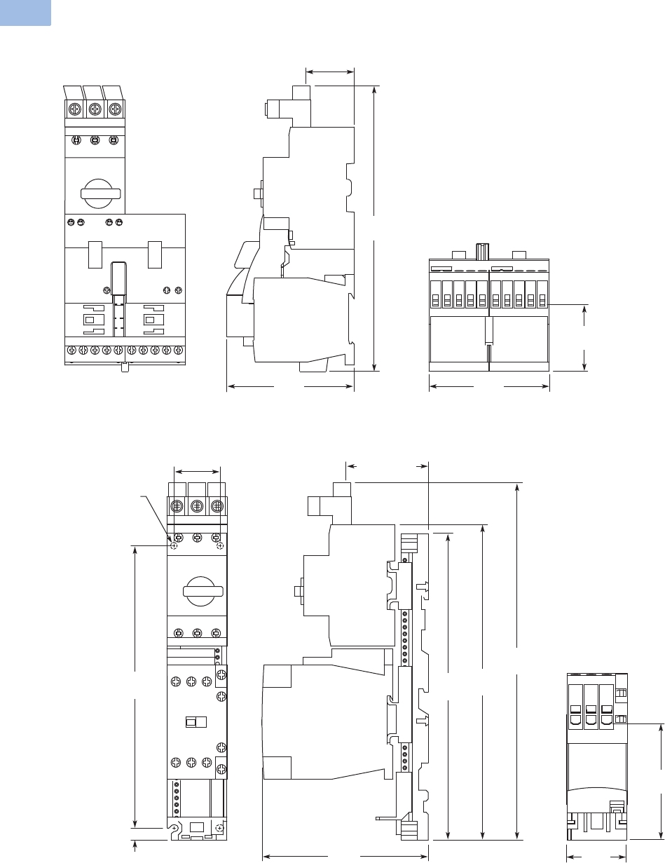
V5-T1-214 Volume 5—Motor Control and Protection CA08100006E—February 2014 www.eaton.com
1
1
1
1
1
1
1
1
1
1
1
1
1
1
1
1
1
1
1
1
1
1
1
1
1
1
1
1
1
1
1.1
IEC Contactors and Starters
XT
IEC Power Control
Approximate Dimensions in mm [in]
XTFR…BB_
XTFC…BC_
49.7 [1.96]
To Terminals
90.3
[3.55]
36.3 [1.43]
To Terminals
95.3
[3.75]
214.2
[8.43]
86.8 [3.42]
To Terminals
45.2
[1.78]
61.3 [2.41]
To Terminals
Mounting Holes
for M4 Screws
or #8 Screws
(4 Places)
124.3
[4.89]
34 [1.34]
Mounting
210.8 [8.30]
Mounting
9 [.35]
228.8
[9.01]
235.7
[9.28]
266.7
[10.50]
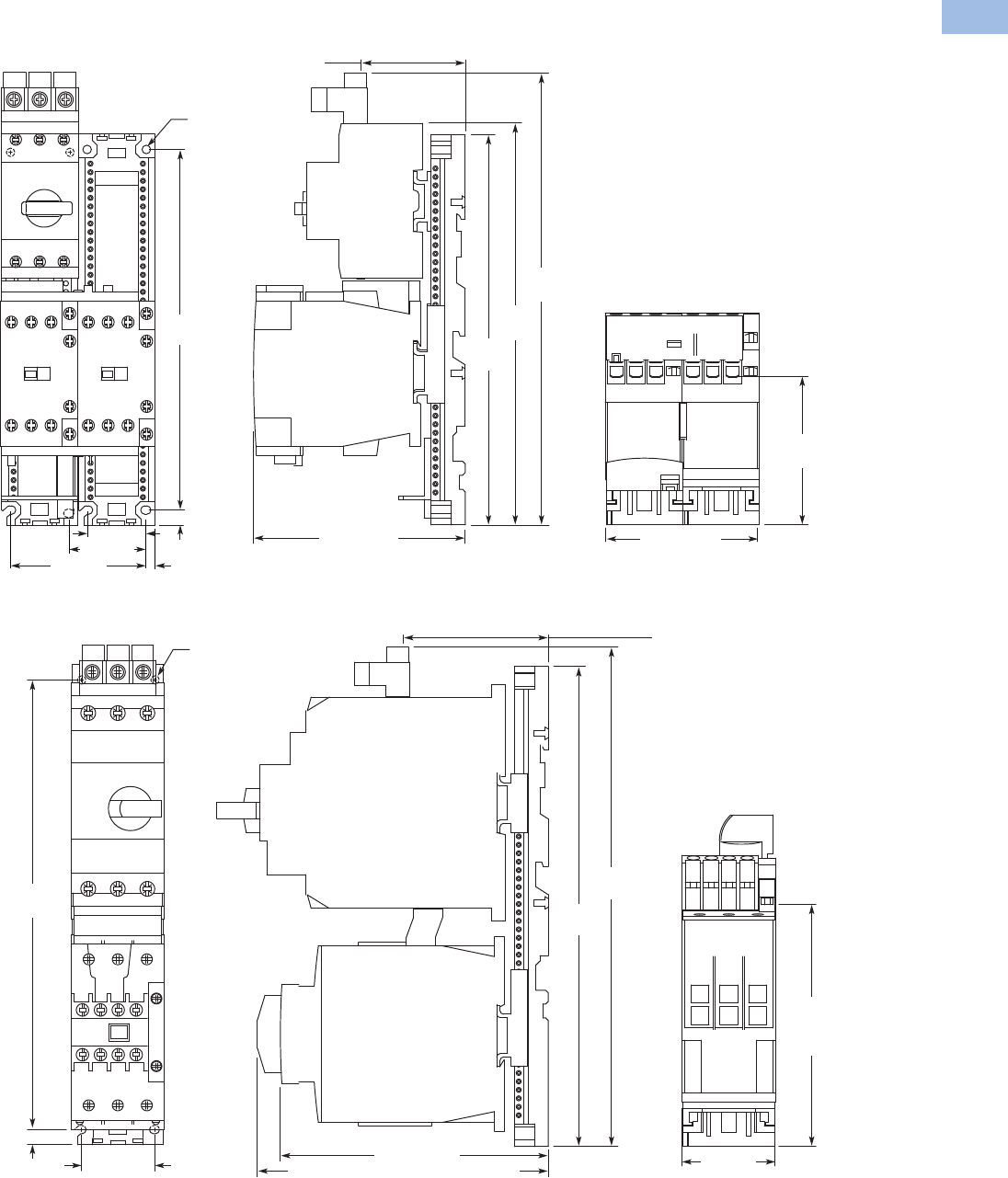
Volume 5—Motor Control and Protection CA08100006E—February 2014 www.eaton.com V5-T1-215
1
1
1
1
1
1
1
1
1
1
1
1
1
1
1
1
1
1
1
1
1
1
1
1
1
1
1
1
1
1
1.1
IEC Contactors and Starters
XT
IEC Power Control
Approximate Dimensions in mm [in]
XTFR…BC_
XTFC…DD_
86.8 [3.42]
To Terminals
89.6 [3.53]
61.3 [2.41]
To Terminals
124.3 [4.89]
228.8
[9.01]
235.4
[9.27]
266.4
[10.49]
Mounting Holes for
M4 Screws or #8 Screws
(8 Places)
45 [1.77]
79 [3.11] 5.3 [.21]
210.8
[8.30]
9 [.35]
34 [1.34]
142.8
[5.62]
To Coil
Terminals
55 [2.17]
158.5 [6.24]
172.1 [6.78] To Optional Aux. Contacts
86 [3.39]
To Line Side
Connector
Mounting Holes for
M5 Screws or #10 Screws
(4 Places)
284
[11.18]
266 [10.47]
Mounting
43.4 [1.71]
Mounting
9 [.35]
297
[11.69]
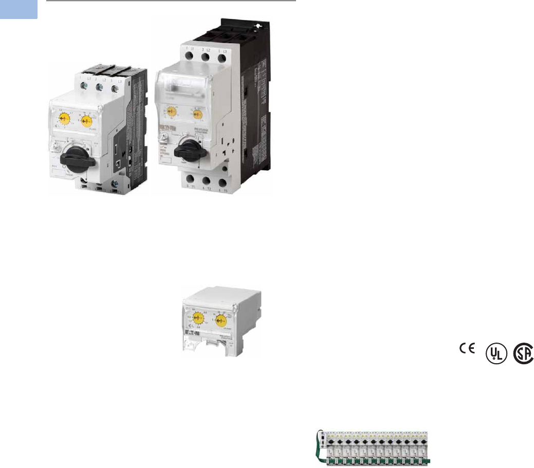
V5-T1-216 Volume 5—Motor Control and Protection CA08100006E—February 2014 www.eaton.com
1
1
1
1
1
1
1
1
1
1
1
1
1
1
1
1
1
1
1
1
1
1
1
1
1
1
1
1
1
1
1.1
IEC Contactors and Starters
XT
IEC Power Control
XT Electronic Manual Motor Protector
Contents
Description Page
Relays and Timers . . . . . . . . . . . . . . . . . . . . . . . . . V5-T1-3
Miniature Controls . . . . . . . . . . . . . . . . . . . . . . . . . V5-T1-18
Contactors and Starters . . . . . . . . . . . . . . . . . . . . V5-T1-35
Thermal Overload Relays . . . . . . . . . . . . . . . . . . . V5-T1-128
C440/XT Electronic Overload Relay . . . . . . . . . . . V5-T1-141
Manual Motor Protectors . . . . . . . . . . . . . . . . . . . V5-T1-157
Combination Motor Controllers . . . . . . . . . . . . . . . V5-T1-193
XT Electronic Manual Motor Protector
Catalog Number Selection . . . . . . . . . . . . . . . . V5-T1-217
Product Selection . . . . . . . . . . . . . . . . . . . . . . . V5-T1-218
Accessories . . . . . . . . . . . . . . . . . . . . . . . . . . . V5-T1-220
Technical Data and Specifications . . . . . . . . . . V5-T1-226
Dimensions . . . . . . . . . . . . . . . . . . . . . . . . . . . V5-T1-228
Reference Data . . . . . . . . . . . . . . . . . . . . . . . . . . . V5-T1-229
XT Electronic Manual Motor Protector
Product Description
The XT Electronic Manual
Motor Protector provides the
same functionality as the XT
thermal manual motor
protector, but with an added
level of flexibility and
selectability. The XTPE
incorporates electronic
control technology to enable
more options and larger dial
setting ranges. The trip units
are interchangeable, allowing
users to exchange as needed
using the same base. The
reduced number of part
numbers decreases bill of
material complexity while
reducing inventory demands.
The XTPE electronic manual
motor protector includes the
following features:
●4:1 max to min overcurrent
dial setting range
●Selectable trip class (5, 10,
15, 20)
●Interchangeable trip units
●Three base units (12, 32
and 65A)
●Common accessories with
the XTPR
Features and Benefits
Advanced Trip Unit
In addition to the selectability,
the XTPE is also available
with an advanced trip unit
that can communicate
system data and protector
data thru SmartWire-DT.
SmartWire-DT is an
innovative cost effective
connection technology that
enables quick installation of
control wiring to the starter
through a single green cable.
When on SmartWire-DT, the
XTPE can communicate the
following:
●Current Values
●Maximum phase current
●Overload warning
●Diagnostics Data
●Overload fault
●Cause of trip
(overcurrent or short
circuit)
●Phase loss
●Trip via TEST
●Status Messages
●Control unit type
●Overload setting
●Time-lag
●Switching status
XTPE Electronic MMP
The XTPE Electronic MMP
provides the selectability,
control, and insight options
that give panel builders and
OEMs the solutions
necessary to enhance motor
control designs while
reducing total costs.
Standards and Certifications
●CE approved
●UL Listed File No. E36332
●UL 508 group motor and
Type E
●IEC/EN 60947
●CSA File 012528,
Class 3211-05
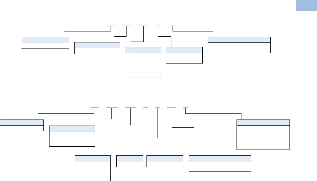
Volume 5—Motor Control and Protection CA08100006E—February 2014 www.eaton.com V5-T1-217
1
1
1
1
1
1
1
1
1
1
1
1
1
1
1
1
1
1
1
1
1
1
1
1
1
1
1
1
1
1
1.1
IEC Contactors and Starters
XT
IEC Power Control
Catalog Number Selection
XT—Manual Motor Protector
XT—Combinations
XT PE 004 BCS
Type
PE = Electronic MMP
Designation
XT = XT line of IEC control
Overload Release
1P2 = 0.3–1.2A
004 = 1–4A
012 = 3–12A
032 = 8–32A
065 = 16–65A
Trip Type
CS = Standard
CA = Advanced (SmartWire-DT)
MMP Frame
B = 45 mm
D = 55 mm
Type
FCE = Electronic
combination motor
controller
Designation
XT = XT line of IEC control
Contactor Frame
C = 45 mm
XT FCE 004 B C CS A
Overload Release
1P2 = 0.3–1.2A
004 = 1–4A
012 = 3–12A
032 = 8–32A
MMP Frame
B = 45 mm
Trip Type
CS = Selectable class 5, 10, 15, 20
CA = Selectable, advanced
Coil Voltage
A= 110V 50 Hz, 120V 60 Hz
B= 220V 50 Hz, 240V 60 Hz
F= 230V 50 Hz
T= 24V 50/60 Hz
TD = 24 Vdc
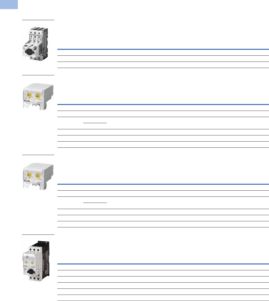
V5-T1-218 Volume 5—Motor Control and Protection CA08100006E—February 2014 www.eaton.com
1
1
1
1
1
1
1
1
1
1
1
1
1
1
1
1
1
1
1
1
1
1
1
1
1
1
1
1
1
1
1.1
IEC Contactors and Starters
XT
IEC Power Control
Product Selection
XT Electronic Manual Motor Protector
MMP Base
MMP Trip Units
MMP Advanced Trip Units Used with SmartWire-DT
MMP Complete Assembly
Note
1 In this range, calculate motor rating according to rated current. Specified values to NEC 430.6 (A) (1).
Maximum
Amperage
UL/CSA
IEC
Base Unit
Maximum Motor kW Ratings
220V
230V
240V
380V
400V
415V 440V 500V
600V
690V
Maximum Three-Phase hp Ratings
200V 240V 480V 600V Type Number Catalog Number
12 3 3 7.5 10 3 5.5 5.5 5.5 7.5 PKE12 XTPE012B
32 5 7.5 15 20 7.5 15 15 18.5 30 PKE32 XTPE032B
65 15 15 40 40 18.5 30 37 45 55 PKE65 XTPE065D
Overload
Release Setting
Amp Range
For Use with
Base Catalog
Number
UL/CSA
IEC
Trip Unit
Maximum Motor kW Ratings
Maximum Three-Phase hp Ratings 220V
230V
240V
380V
400V
415V 440V 500V
600V
690V200V 240V 480V 600V Type Number Catalog Number
0.3–1.2 XTPE012B 11
0.5 0.5 0.18 0.37 0.37 0.37 0.75 PKE-XTU-1,2 XTPEXT1P2B
1–4 XTPE012B 0.75 0.75 2 3 0.75 1.5 1.5 2.2 3 PKE-XTU-4 XTPEXT004B
3–12 XTPE012B 3 3 7.5 10 3 5.5 5.5 5.5 7.5 PKE-XTU-12 XTPEXT012B
XTPE032B
8–32 XTPE032B 5 7.5 15 20 7.5 15 15 18.5 30 PKE-XTU-32 XTPEXT032B
8–32 XTPE065D 7.5 7.5 20 25 7.5 15 15 18.5 30 PKE-XTUW-32 XTPEXT032D
16–65 XTPE065D 15 15 40 40 18.5 30 37 45 55 PKE-XTU-65 XTPEXT065D
Overload
Release Setting
Amp Range
For Use with
Base Catalog
Number
UL/CSA
IEC
Trip Unit
Maximum Motor kW Ratings
Maximum Three-Phase hp Ratings 220V
230V
240V
380V
400V
415V 440V 500V
600V
690V200V 240V 480V 600V Type Number Catalog Number
0.3–1.2 XTPE012B 11
0.5 0.5 0.18 0.37 0.37 0.37 0.75 PKE-XTUA-1,2 XTPEXTA1P2B
1–4 XTPE012B 0.75 0.75 2 3 0.75 1.5 1.5 2.2 3 PKE-XTUA-4 XTPEXTA004B
3–12 XTPE012B 3 3 7.5 10 3 5.5 5.5 5.5 7.5 PKE-XTUA-12 XTPEXTA012B
XTPE032B
8–32 XTPE032B 5 7.5 15 20 7.5 15 15 18.5 30 PKE-XTUA-32 XTPEXTA032B
8–32 XTPE065D 7.5 7.5 20 25 7.5 15 15 18.5 30 PKE-XTUWA-32 XTPEXTA032D
16–65 XTPE065D 15 15 40 40 18.5 30 37 45 55 PKE-XTUA-65 XTPEXTA065D
Overload
Release Setting
Amp Range
UL/CSA
IEC
Complete Manual Motor Protector
Maximum Motor kW Ratings
Maximum Three-Phase hp Ratings 220V
230V
240V
380V
400V
415V 440V 500V
600V
690V200V 240V 480V 600V Type Number Catalog Number
0.3–1.2 110.5 0.5 0.18 0.37 0.37 0.37 0.75 PKE12/XTU-1,2 XTPE1P2BCS
1–4 0.75 0.75 2 3 0.75 1.5 1.5 2.2 3 PKE12/XTU-4 XTPE004BCS
3–12 3 3 7.5 10 3 5.5 5.5 5.5 7.5 PKE12/XTU-12 XTPE012BCS
8–32 5 7.5 15 20 7.5 15 15 18.5 30 PKE32/XTU-32 XTPE032BCS
8–32 7.5 7.5 20 25 7.5 15 15 18.5 30 PKE65/XTUW-32 XTPE032DCS
16–65 1515404018.530 374555 PKE65/XTU-65XTPE065DCS
B Frame
B Frame
B Frame
D Frame
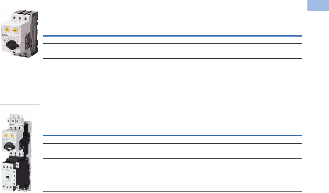
Volume 5—Motor Control and Protection CA08100006E—February 2014 www.eaton.com V5-T1-219
1
1
1
1
1
1
1
1
1
1
1
1
1
1
1
1
1
1
1
1
1
1
1
1
1
1
1
1
1
1
1.1
IEC Contactors and Starters
XT
IEC Power Control
MMP Used with SmartWire-DT—Complete Assembly
UL 508 Type E XT Electronic Combination Motor Controllers—Complete Assembly Including Trip Unit
B Frame Electronic MMP with C Frame Contactor
Notes
1 In this range, calculate motor rating according to rated current. Specified values to NEC 430.6 (A) (1).
2 Complete the catalog number by replacing the underscore (_) with the coil suffix from Page V5-T1-238.
3 SCCR: 14 kA, 600 Vac
4 SCCR: 18 kA, 480 Vac
Overload
Release Setting
Amp Range
UL/CSA
IEC
Complete Manual Motor Protector
Maximum Motor kW Ratings
Maximum Motor hp Ratings 220V
230V
240V
380V
400V
415V 440V 500V
600V
690V200V 230V 460V 575V Type Number Catalog Number
0.3–1.2 110.5 0.5 0.18 0.37 0.37 0.37 0.75 PKE12/XTUA-1,2 XTPE1P2BCA
1–4 0.75 0.75 2 3 0.75 1.5 1.5 2.2 3 PKE12/XTUA-4 XTPE004BCA
3–12 3 3 7.5 10 3 5.5 5.5 5.5 7.5 PKE12/XTUA-12 XTPE012BCA
8–32 5 7.5 15 20 7.5 15 15 18.5 30 PKE32/XTUA-32 XTPE032BCA
Overload
Release Setting
Amp Range
UL/CSA
Catalog Number
Standard
Catalog Number
With SmartWire-DT
Maximum Three-Phase hp Ratings Maximum Single-Phase hp Ratings
200V 240V
380Y/
415V
480Y/
277V
600Y/
347V 115V 200V 240V
0.3–1.2 11110.5 111XTFCE1P2BCCS_ 3XTFCE1P2BCCATD 3
1–4 0.75 0.75 1.5 2 — 0.125 0.25 0.33 XTFCE004BCCS_ 4XTFCE004BCCATD 4
3–12 3357.5—0.5 1 1.5 XTFCE012BCCS_ 4XTFCE012BCCATD 4
8–32 5 5 10 15 — 1.5 3 3 XTFCE032BCCS_ 4XTFCE032BCCATD 4
B Frame
B Frame
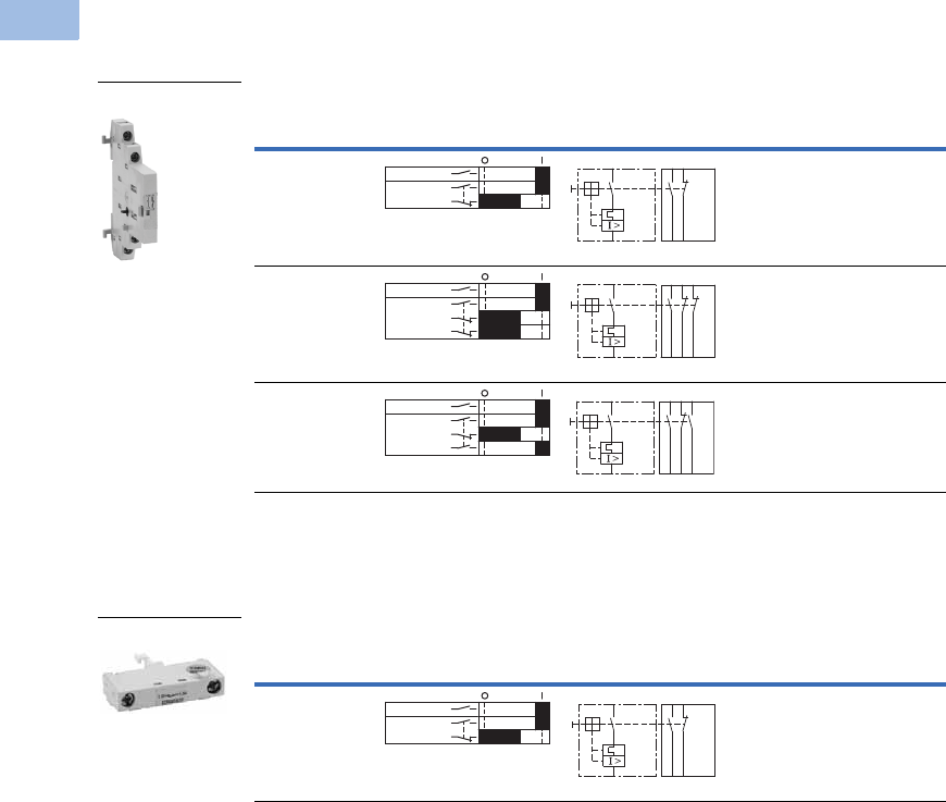
V5-T1-220 Volume 5—Motor Control and Protection CA08100006E—February 2014 www.eaton.com
1
1
1
1
1
1
1
1
1
1
1
1
1
1
1
1
1
1
1
1
1
1
1
1
1
1
1
1
1
1
1.1
IEC Contactors and Starters
XT
IEC Power Control
Accessories
Auxiliary Contacts
Side-Mount Auxiliary Contacts
Can be fitted on the right side of manual motor protectors (XTPB, XTPR, XTPM) and
manual transformer protectors (XTPT) and can be combined with XTPAXSATR_ and
XTPAXFA_ trip indicating auxiliary contact.
Front-Mount Auxiliary Contacts
Can be fitted to manual motor protectors (XTPB, XTPR, XTPM) and manual
transformer protectors (XTPT). 45 mm
(XTPR…B and XTPB) or 55 mm (XTPR…D)
widths of manual motor protectors remain unchanged.
Note
1
Orders must be placed in multiples of package quantity listed.
Contact
Configuration Contact Sequence
Pkg.
Qty. 1
Screw Terminal
Catalog Number
1NO-1NC 5 XTPAXSA11
1NO-2NC 5 XTPAXSA12
2NO-1NC 5 XTPAXSA21
Contact
Configuration Contact Sequence
Pkg.
Qty. 1
Screw Terminal
Catalog Number
1NO-1NC 5 XTPAXFA11
XTPAXSA_
L1 L2 L3
XTPAXSA11
1.14 1.22
1.13 1.21
1.14 1.22 1.32
1.13 1.21 1.31
L1 L2 L3
XTPAXSA12
1.14 1.22 1.34
1.13 1.21 1.33
L1 L2 L3
XTPAXSA21
XTPAXFA11
1.54 1.62
1.53 1.61
L1 L2 L3
XTPAXFA11
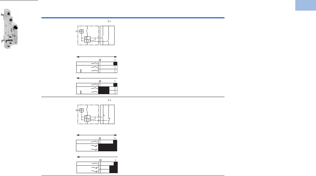
Volume 5—Motor Control and Protection CA08100006E—February 2014 www.eaton.com V5-T1-221
1
1
1
1
1
1
1
1
1
1
1
1
1
1
1
1
1
1
1
1
1
1
1
1
1
1
1
1
1
1
1.1
IEC Contactors and Starters
XT
IEC Power Control
Side-Mount Trip Indicating Auxiliary Contacts
Can be fitted on the right side of manual motor protectors. Can be combined with
standard auxiliary contacts. Trip indication: A. General trip indication (overload) B.
Short-circuit trip. Local short-circuit indication by red indicator, manually resettable.
Note
1
Orders must be placed in multiples of package quantity listed.
Contact
Configuration Contact Sequence
Pkg.
Qty. 1
For Use
with… Catalog Number
2 x 1NO 2 XTPE XTPAXSATR20
2 x 1NC 2 XTPE XTPAXSATR02
XTPAXSATR_
4.44 4.14
“+”
4.43 “ ”
4.13
“+”
“ >”
On/Off
“+”
“ >”
Trip “+”
L1L2 L3
L1L2 L3
4.32 4.22
“+”
4.31 “ ”
4.21
On/Off
“+”
“ >”
Trip “+”
L1L2 L3
“+”
“ >”
L1L2 L3
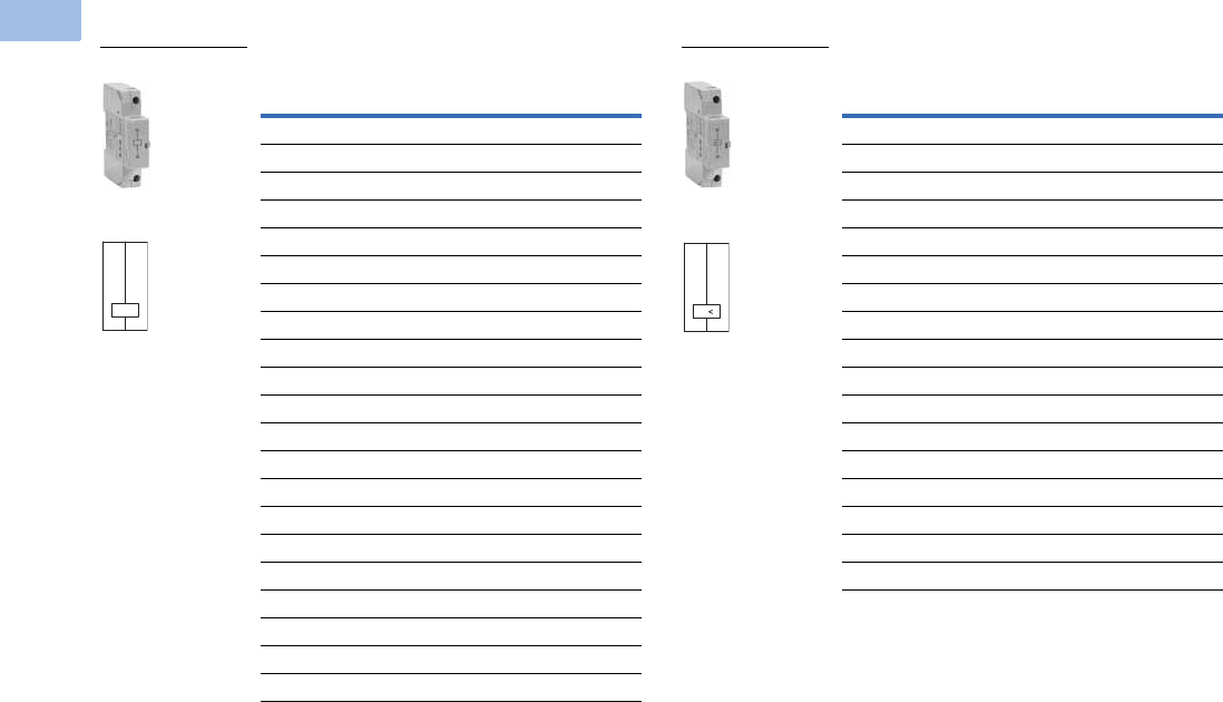
V5-T1-222 Volume 5—Motor Control and Protection CA08100006E—February 2014 www.eaton.com
1
1
1
1
1
1
1
1
1
1
1
1
1
1
1
1
1
1
1
1
1
1
1
1
1
1
1
1
1
1
1.1
IEC Contactors and Starters
XT
IEC Power Control
Additional Accessories
Shunt Release
Can be used to trip the manual motor protector from a remote
location. Can be fitted on the left side of manual motor
protectors. Cannot be combined with the XTPAXUVR. DC:
Intermittent operation 5 sec.
Undervoltage Release
Can be used to trip the manual motor protector from a remote
location. Can be fitted on left side manual motor protectors.
Cannot be combined with XTPAXSR. When combined with a
circuit breaker, it can be used as emergency-stop device to
IEC/EN 60204.
Note
1Orders must be placed in multiples of package quantity listed.
Pkg.
Qty. 1
Screw Terminal
Catalog Number
2XTPAXSR24V50H
2XTPAXSR48V50H
2XTPAXSR110V50H
2XTPAXSR120V60H
2XTPAXSR208V60H
2XTPAXSR220V50H
2XTPAXSR230V50H
2XTPAXSR240V50H
2XTPAXSR240V60H
2XTPAXSR380V50H
2XTPAXSR400V50H
2XTPAXSR415V50H
2XTPAXSR440V60H
2XTPAXSR480V60H
2XTPAXSR24VDC
2XTPAXSR48VDC
2XTPAXSR60VDC
2XTPAXSR110VDC
2XTPAXSR125VDC
2XTPAXSR220VDC
2XTPAXSR250VDC
XTPAXSR_
Contact Sequence
C1
C2
Pkg.
Qty. 1
Screw Terminal
Catalog Number
2XTPAXUVR24V50H
2XTPAXUVR24V60H
2XTPAXUVR48V50H
2XTPAXUVR60V50H
2XTPAXUVR110V50H
2XTPAXUVR120V60H
2XTPAXUVR208V60H
2XTPAXUVR220V50H
2XTPAXUVR230V50H
2XTPAXUVR240V50H
2XTPAXUVR240V60H
2XTPAXUVR380V50H
2XTPAXUVR400V50H
2XTPAXUVR415V50H
2XTPAXUVR440V60H
2XTPAXUVR480V60H
2XTPAXUVR600V60H
XTPAXUVR_
Contact Sequence
D1
D2
U
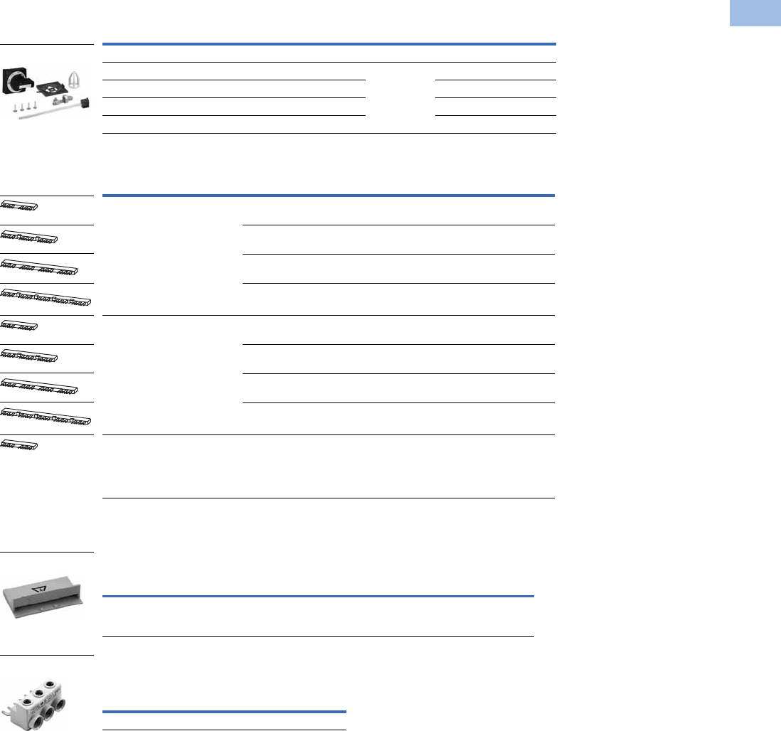
Volume 5—Motor Control and Protection CA08100006E—February 2014 www.eaton.com V5-T1-223
1
1
1
1
1
1
1
1
1
1
1
1
1
1
1
1
1
1
1
1
1
1
1
1
1
1
1
1
1
1
1.1
IEC Contactors and Starters
XT
IEC Power Control
IP65 Rotary Handle Mechanism 123
Three-Phase Commoning Links 7
For parallel power feed to several manual motor protectors on terminals
1, 3 and 5.
Shroud for Unused Terminals of Three-Phase Commoning Links
Incoming Terminals for Three-Phase
Commoning Link 8
Notes
1 Plug-in connection shafts, XTPAXRHMSFT_ can be cut to desired length for mounting depths of 100–240 mm. Carrier
with extension shaft included.
2 With ON/OFF switch position and “+” (tripped), lockable with 3 padlocks, 4–8 mm hasp. Can be locked in the
OFF position, if required.
3 Rotary handle mechanisms ship with door interlock disabled. See instruction publication with product for how to
enable door interlock.
4 Orders must be placed in multiples of package quantity listed.
5 For use on main switches to IEC/EN 60204.
6 For use on main switches with emergency-stop function to IEC/EN 60204.
7 Protected against accidental contact. Frame B short-circuit proof Ue = 690V, Iu = 63A.
Frame B links can be combined by
rotating mounting.
8 For three-phase commoning link, protected against accidental contact, Ue = 690V, Iu = 63A;
For conductor cross-sections: 2.5–25 mm2 stranded; 2.5–16 mm2 flexible with ferrules, AWG 14-6.
Description
Enclosure
Rating
Pkg.
Qty. 4Catalog Number
Complete Kits—Includes Handle, Shaft and Required Hardware
Rotary handle mechanism—black 5IP65
NEMA 12
UL/CSA 4X
1XTPEXRHMB
Rotary handle mechanism—red/yellow 61XTPEXRHMRY
Rotary handle mechanism—black—rotated 90° from vertical 51XTPEXRHM90B
Rotary handle mechanism—red/yellow—rotated 90° from vertical 61XTPEXRHM90RY
For Use with…
Qty.
MMP
Length of
Link (mm)
Unit
Width (mm)
Pkg.
Qty. 4Catalog Number
MMP with no side-mounted
auxiliaries or voltage releases
290 45 10XTPAXCLKA2
3 135 45 10 XTPAXCLKA3
4 180 45 10 XTPAXCLKA4
5 225 45 10 XTPAXCLKA5
Each MMP with one auxiliary
contact or trip-indicating auxiliary
contact fitted on the right
299 45 + 9 10XTPAXCLKB2
3 153 45 + 9 10 XTPAXCLKB3
4 207 45 + 9 10 XTPAXCLKB4
5 261 45 + 9 10 XTPAXCLKB5
Each MMP with an auxiliary
contact and trip-indicating
auxiliary contact mounted on
the right or a voltage release
mounted on the left.
2 108 45 + 18 10 XTPAXCLKC2
For Use with… Description
Pkg.
Qty. 4Catalog Number
Frame B
XTPE
To cover unused terminals on three-phase
commoning link. Protected against direct
contact.
20 XTPAXUTS
For Use with…
Pkg.
Qty. 4Catalog Number
Frame B XTPE 5 XTPAXIT
XTPAXRHM_
XTPAXUTS
XTPAXIT
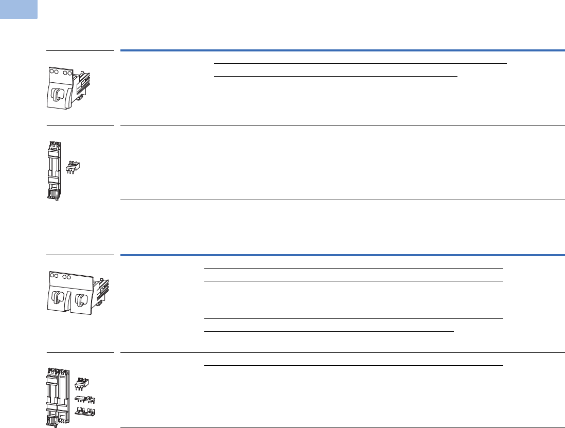
V5-T1-224 Volume 5—Motor Control and Protection CA08100006E—February 2014 www.eaton.com
1
1
1
1
1
1
1
1
1
1
1
1
1
1
1
1
1
1
1
1
1
1
1
1
1
1
1
1
1
1
1.1
IEC Contactors and Starters
XT
IEC Power Control
Combination Connection Kits
Non-Reversing Starters
Reversing Starters
Note
1 Orders must be placed in multiples of package quantity listed.
For Use with… Description/Comprised of …
Std.
Pack 1Catalog Number
XTPE…B + XTCE…B Mechanical connection element for XTPR…B and contactor 1 XTPAXTPCB
Main current wiring between XTPR…B and contactor in toolless plug connection 1
Use contactor auxiliary switch XTCEXFAT_. Control cable guidance: max. six cables
up to 2.5 mm2 external diameter or four cables up to 3.5 mm2 external diameter.
XTPR…B + XTCE…C DIN rail adapter plate
Main current wiring between XTPR and contactor
1XTPAXTPCC
For Use with… Description/Comprised of …
Std.
Pack 1Catalog Number
XTPE…B + XTCE…B01_ Mechanical connection element for XTPR…B and contactor 1 XTPAXTPCRB
Reversing starter main current wiring in toolless plug connection 1
Control cables for electrical interlocking in toolless plug connection:
– K1M: A1–K2M: 21
– K1M: 21–K2M: A1
– K1M: A2–K2M: A2
1
Cable guidance 1
Use contactor auxiliary switch XTCEXFAT_. Control cable guidance: max. six cables
up to 2.5 mm2 external diameter or four cables up to 3.5 mm2 external diameter.
XTPE…B + XTCE…C DIN rail adapter plate 1 XTPAXTPCRC
Reversing starter main current wiring 1
XTPAXTPCB
XTPAXTPC_
XTPAXTPCRB
XTPAXTPCRC
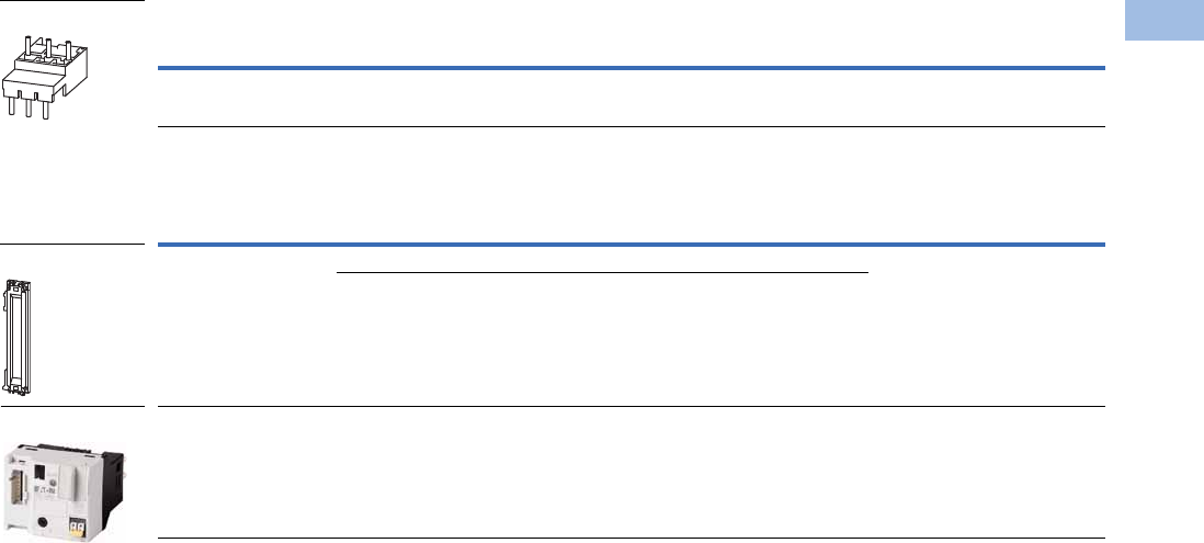
Volume 5—Motor Control and Protection CA08100006E—February 2014 www.eaton.com V5-T1-225
1
1
1
1
1
1
1
1
1
1
1
1
1
1
1
1
1
1
1
1
1
1
1
1
1
1
1
1
1
1
1.1
IEC Contactors and Starters
XT
IEC Power Control
Electrical Connection Module
DIN Rail Adapter Plates
Note
1 Orders must be placed in multiples of package quantity listed.
For Use with… Description/Comprised of …
Std.
Pack 1Catalog Number
XTPE…B + XTCE…C Main current wiring between XTPR…B and contactor 5 XTPAXECMC
For Use with… Description/Comprised of …
Std.
Pack 1Catalog Number
XTPAXTPCB
XTPAXTPCRB
45 mm wide adapter plate with one DIN rail 4 XTPAXTPCPB
Connection element for side-by-side positioning of further plates
XTPE…B +
XTCE…B or C
SmartWire-DT communication link 1 PKE-SWD-32
XTPAXECM_
XTPAXTPCPB
PKE-SWD-32

V5-T1-226 Volume 5—Motor Control and Protection CA08100006E—February 2014 www.eaton.com
1
1
1
1
1
1
1
1
1
1
1
1
1
1
1
1
1
1
1
1
1
1
1
1
1
1
1
1
1
1
1.1
IEC Contactors and Starters
XT
IEC Power Control
Technical Data and Specifications
XT Electronic Manual Motor Controllers
Description Specification XTPE012B XTPE032B XTPE065D
General
Standards and regulations IEC/EN 60947-4-1, VDE 0600, UL 508, CSA C 22.2 No. 14
Climatic proofing Damp heat, constant, to IEC 60068-2-78
Damp heat, cyclic, to IEC 60068-2-30
Ambient temperature
Storage –40° to 80°C –40° to 80°C –40° to 80°C
Open –25° to 55°C –25° to 55°C –25° to 55°C
Enclosed –25° to 40°C –25° to 40°C –25° to 40°C
Direction of incoming supply Any Any Any
Degree of protection Device IP20 IP20 IP20
Terminals IP00 IP00 IP00
Touch protection
Mechanical shock resistance half-sinusoidal shock,
10 ms to IEC 60068-2-27
25g 25g 25g
Altitude Max. 2000m Max. 2000m Max. 2000m
Conductor Cross-Sections
Screw terminals Solid 1 x (1–6) mm21 x (1–6) mm21 x (0.75–16) mm2
2 x (1–6) mm22 x (1–6) mm22 x (0.75–16) mm2
Stranded with ferrule
to DIN 46228
1 x (1–6) mm21 x (1–6) mm21 x (0.75–35) mm2
2 x (1–6) mm22 x (1–6) mm22 x (0.75–25) mm2
Solid or stranded 18–10 AWG 18–10 AWG 14–2 AWG
Screw Terminal Tightening Torque
Main conductor 1.7 Nm 1.7 Nm 3.3 Nm
Auxiliary conductor 1 Nm 1 Nm 1 Nm
Main Circuit
Rated impulse withstand voltage Ump 6,000 Vac 6,000 Vac 6,000 Vac
Overvoltage category/pollution degree III/3 III/3 III/3
Rated operational voltage Ue690V 690V 690V
Rated uninterrupted current = rated output current Iu = Ie12A 32A 65A
Rated frequency 40–60 Hz 40–60 Hz 40–60 Hz
Current heating losses (three-pole at operating
temperature)
6W 6W 6W
Lifespan, mechanical Operations 0.05 x 1060.05 x 1060.05 x 106
Lifespan, electrical (AC-3 at 400V) Operations 0.05 x 1060.05 x 1060.05 x 106
Maximum operating frequency Operations/h 60 60 60
Short-Circuit Rating
Motor switching capacity AC AC-3 up to 690V 12A 32A 65A
Trip Unit
Temperature compensation to IEC/EN 60947, VDE 0660 –5° to 40°C –5° to 40°C –5° to 40°C
Operating range –25° to 55°C –25° to 55°C –25° to 55°C
Temperature compensation residual error for T >40°C <0.1%/K <0.1%/K <0.1%/K
Overload release setting range 0.25–1 xlu0.25–1 xlu0.25–1 xlu
Fixed short-circuit trip setting 12 x lr (trip unit),14 x lu (base) 12 x lr (trip unit),14 x lu (base) 12 x lr (trip unit),14 x lu (base)
Short circuit release tolerance ±20% ±20% ±20%
Phase failure sensitivity Yes Yes Yes
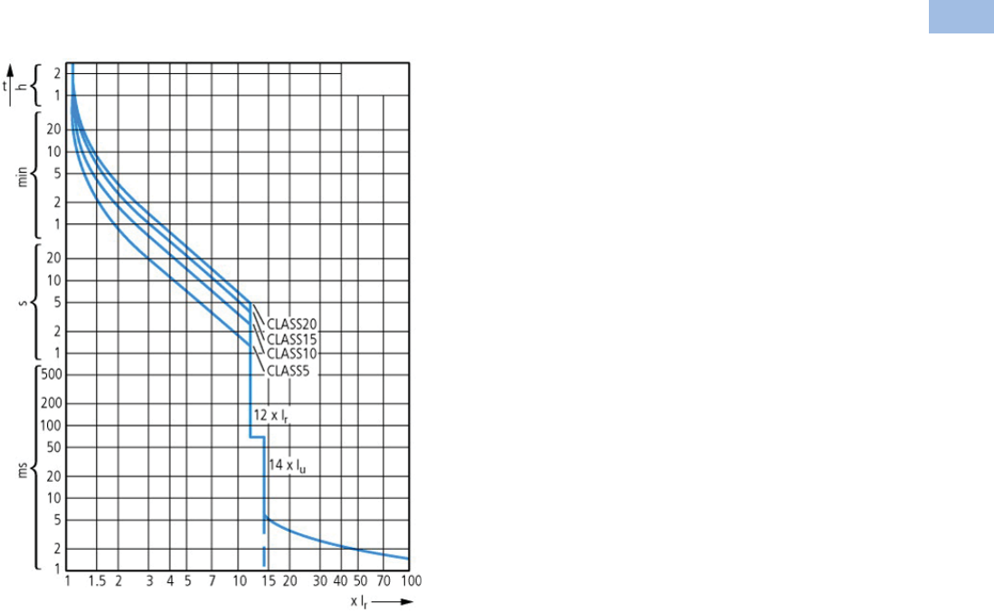
Volume 5—Motor Control and Protection CA08100006E—February 2014 www.eaton.com V5-T1-227
1
1
1
1
1
1
1
1
1
1
1
1
1
1
1
1
1
1
1
1
1
1
1
1
1
1
1
1
1
1
1.1
IEC Contactors and Starters
XT
IEC Power Control
Trip Characteristics
XT Electronic Manual Motor Controllers
XTPE …
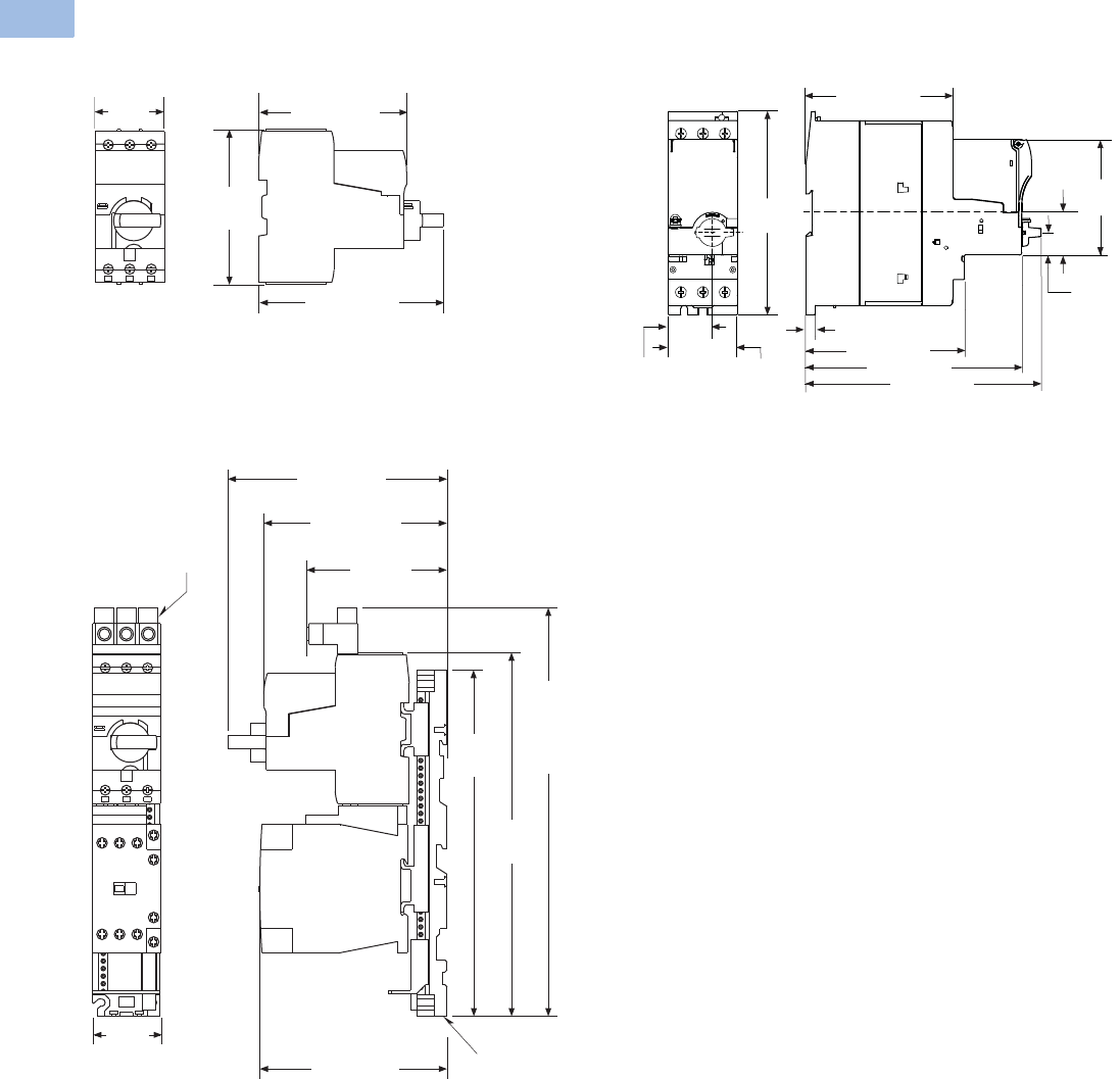
V5-T1-228 Volume 5—Motor Control and Protection CA08100006E—February 2014 www.eaton.com
1
1
1
1
1
1
1
1
1
1
1
1
1
1
1
1
1
1
1
1
1
1
1
1
1
1
1
1
1
1
1.1
IEC Contactors and Starters
XT
IEC Power Control
Dimensions
Approximate Dimensions in Inches (mm)
XT Electronic MMP—B Frame
XT Electronic CMC With C Frame Contactor
XT Electronic MMP—D Frame
1.77
(45.0)
4.72 (120.0)
3.79 (96.2)
3.98
(101.0)
5.71 (145.0)
4.77 (121.2)
3.66 (92.9)
To Line
Side Adapter
10.63
(269.9)
To Line
Side
Adapter
9.46
(240.3)
9.01
(228.8)
Mounting
Rail
4.87 (123.8)
Line Side
Adapter
1.76
(44.6)
4.65 (118.0)
2.22
(56.5)
2.17
(55.0)
1.38
(35.0)
6.30
(160.0)
0.57
(14.5)
1.28
(32.5)
0.22 (5.5)
5.00 (127.0)
6.77 (172.0)
7.36 (187.0)

Volume 5—Motor Control and Protection CA08100006E—February 2014 www.eaton.com V5-T1-229
1
1
1
1
1
1
1
1
1
1
1
1
1
1
1
1
1
1
1
1
1
1
1
1
1
1
1
1
1
1
1.1
IEC Contactors and Starters
XT
IEC Power Control
Reference Data
Type 2 Coordination . . . . . . . . . . . . . . . . . . . . . . . V5-T1-230
Approvals for World Markets . . . . . . . . . . . . . . . . V5-T1-239
IEC Utilization Categories . . . . . . . . . . . . . . . . . . V5-T1-242
Motor Ratings Data . . . . . . . . . . . . . . . . . . . . . . . V5-T1-245
Ampacities of Insulated Conductors
(Based on 2005 NEC) . . . . . . . . . . . . . . . . . . . . V5-T1-249
Type 1 and Type 2 Coordination
What is it?
The International
Electrotechnical Commission
(IEC) developed short-circuit
performance criteria for
contactors and starters called
Type 1 coordination and Type
2 coordination. This defines
motor controller protection
levels following a short-circuit
fault. In order to achieve this
performance, the
combination of a motor
controller (contactor or
starter) and short-circuit
protective device (manual
motor protector, circuit
breaker or fuse) must meet
the following criteria as
specified by IEC 60947-4-1—
Low voltage switchgear and
controlgear—Part 4-1:
Contactors and motor-
starters—Electromechanical
contactors and motor-
starters:
Type 1 Coordination
Type 1 Coordination requires
that under short-circuit
conditions, the contactor or
starter shall cause no danger
to persons or installation and
may not be suitable for
further service without repair
and replacement of parts.
In this case, significant
damage is allowed to the
contactor/starter (for example,
contact welding, burning or
disintegration) and the
overload relay (for example,
component harm or heater
element burn-out).
Type 2 Coordination
Type 2 Coordination requires
that under short-circuit
conditions, the contactor or
starter shall cause no danger
to persons or installation and
shall be suitable for further
use. The risk of contact
welding is recognized, in
which case the manufacturer
shall indicate the measures to
be taken as regards to the
maintenance of the
equipment.

V5-T1-230 Volume 5—Motor Control and Protection CA08100006E—February 2014 www.eaton.com
1
1
1
1
1
1
1
1
1
1
1
1
1
1
1
1
1
1
1
1
1
1
1
1
1
1
1
1
1
1
1.1
IEC Contactors and Starters
XT
IEC Power Control
Type 2 Coordination
400, xx415V Type 2 Coordination—MMC
Notes
See Page V5-T1-238 for more information on wye-delta (star delta) applications.
1Values in parentheses ( ) are for Type 1 Coordination.
2Underscore (_) indicates magnet coil suffix required. See Page V5-T1-238.
P
(kW)
Ie
(A)
Iq
(kA)
MMP
Catalog Number
Contactor
Catalog Number 2
MMC
Catalog Number 2
0.06 0.21 50 (150) 1XTPRP25BC1 XTCE007B10_ XTSCP25BB_
0.09 0.31 50 (150) 1XTPRP40BC1 XTCE007B10_ XTSCP40BB_
0.12 0.41 50 (150) 1XTPRP63BC1 XTCE007B10_ XTSCP63BB_
0.18 0.60 50 (150) 1XTPRP63BC1 XTCE007B10_ XTSCP63BB_
0.25 0.80 50 (150) 1XTPR001BC1 XTCE007B10_ XTSC001BB_
0.37 1.10 50 (150) 1XTPR1P6BC1 XTCE007B10_ XTSC1P6BB_
0.55 1.50 50 (150) 1XTPR1P6BC1 XTCE007B10_ XTSC1P6BB_
0.75 1.90 50 (150) 1XTPR2P5BC1 XTCE007B10_ XTSC2P5BB_
1.10 2.60 50 (150) 1XTPR004BC1 XTCE007B10_ XTSC004BB_
1.50 3.60 50 (150) 1XTPR004BC1 XTCE007B10_ XTSC004BB_
2.20 5.00 50 (150) 1XTPR6P3BC1 XTCE007B10_ XTSC6P3BB_
3.00 6.60 50 (150) 1XTPR010BC1 XTCE018C10_ XTSC010BC_
4.00 8.50 50 (150) 1XTPR010BC1 XTCE018C10_ XTSC010BC_
5.50 11.3 50 XTPR012BC1 XTCE018C10_ XTSC012BC_
7.50 16.0 50 XTPR016BC1 XTCE018C10_ XTSC016BC_
11.0 21.7 50 XTPR025BC1 XTCE025C10_ XTSC025BC_
15.0 29.3 50 XTPR032BC1 XTCE032C10_ XTSC032BC_
5.50 11.3 50 XTPR016DC1 XTCE018C10_ XTSC016DC_
7.50 16.0 50 XTPR016DC1 XTCE018C10_ XTSC016DC_
11.0 21.7 50 XTPR025DC1 XTCE025C10_ XTSC025DC_
15.0 29.3 50 XTPR032DC1 XTCE032C10_ XTSC032DC_
18.5 36.0 50 XTPR040DC1 XTCE040D00_ XTSC040DD_
22.0 41.0 50 XTPR050DC1 XTCE050D00_ XTSC050DD_
30.0 55.0 50 XTPR058DC1 XTCE065D00_ XTSC058DD_
34.0 63.0 50 XTPR063DC1 XTCE065D00_ XTSC063DD_

Volume 5—Motor Control and Protection CA08100006E—February 2014 www.eaton.com V5-T1-231
1
1
1
1
1
1
1
1
1
1
1
1
1
1
1
1
1
1
1
1
1
1
1
1
1
1
1
1
1
1
1.1
IEC Contactors and Starters
XT
IEC Power Control
480V Type 2 Coordination—MMC
600V Type 2 Coordination—MMC
Notes
See Page V5-T1-238 for more information on wye-delta (star delta) applications.
1Values in parentheses ( ) are achieved without the current limiter.
2Underscore (_) indicates magnet coil suffix required. See Page V5-T1-238.
P
(hp)
Ie
(A)
Iq
(kA)
MMP
Catalog Number
Current Limiter
Catalog Number
Contactor
Catalog Number 2
MMC
Catalog Number 2
1/2 0.24 65 XTPRP25BC1 — XTCE007B10_ XTSCP25BB_
1/2 0.32 65 XTPRP40BC1 — XTCE007B10_ XTSCP40BB_
1/2 0.51 65 XTPRP63BC1 — XTCE007B10_ XTSCP63BB_
1/2 0.74 65 XTPR001BC1 — XTCE007B10_ XTSC001BB_
1/2 0.94 65 XTPR001BC1 — XTCE007B10_ XTSC001BB_
3/4 1.32 65 XTPR1P6BC1 — XTCE007B10_ XTSC1P6BB_
1 1.72 65 XTPR2P5BC1 — XTCE018C10_ XTSC2P5BC_
2 2.55 65 XTPR004BC1 — XTCE018C10_ XTSC004BC_
2 3.10 65 XTPR004BC1 — XTCE018C10_ XTSC004BC_
34.5565 (50) 1XTPR6P3BC1 XTPAXCL XTCE018C10_ XTSC6P3BC_
36.1565 (50) 1XTPR6P3BC1 XTPAXCL XTCE018C10_ XTSC6P3BC_
7-1/2 8.40 65 (50) 1XTPR010BC1 XTPAXCL XTCE018C10_ XTSC010BC_
7-1/2 11.0 65 (50) 1XTPR012BC1 XTPAXCL XTCE018C10_ XTSC012BC_
10 14.5 65 (50) 1XTPR016BC1 XTPAXCL XTCE018C10_ XTSC016BC_
10 20.0 65 (50) 1XTPR020BC1 XTPAXCL XTCE025C10_ XTSC020BC_
20 20.0 65 XTPR025DC1 — XTCE040D00_ XTSC025DD_
25 27.0 65 XTPR032DC1 — XTCE040D00_ XTSC032DD_
25 32.0 65 XTPR032DC1 — XTCE040D00_ XTSC032DD_
30 37.5 65 XTPR040DC1 — XTCE040D00_ XTSC040DD_
40 40.5 65 XTPR050DC1 — XTCE050D00_ XTSC050DD_
40 50.5 65 XTPR058DC1 — XTCE065D00_ XTSC058DD_
40 64.0 65 XTPR063DC1 — XTCE065D00_ XTSC063DD_
P
(hp)
Ie
(A)
Iq
(kA)
MMP
Catalog Number
Current Limiter
Catalog Number
Contactor
Catalog Number 2
MMC
Catalog Number 2
1/2 0.19 50 XTPRP25BC1 — XTCE007B10_ XTSCP25BB_
1/2 0.26 50 XTPRP40BC1 — XTCE007B10_ XTSCP40BB_
1/2 0.41 50 XTPRP63BC1 — XTCE007B10_ XTSCP63BB_
1/2 0.59 50 XTPRP63BC1 — XTCE007B10_ XTSCP63BB_
1/2 0.75 50 XTPR001BC1 — XTCE007B10_ XTSC001BB_
1 1.06 50 XTPR1P6BC1 — XTCE007B10_ XTSC1P6BB_
1 1.38 50 XTPR1P6BC1 — XTCE007B10_ XTSC1P6BB_
1-1/2 2.04 50 XTPR2P5BC1 — XTCE018C10_ XTSC2P5BC_
1-1/2 2.48 50 XTPR2P5BC1 — XTCE018C10_ XTSC2P5BC_
3 3.64 50 XTPR004BC1 — XTCE018C10_ XTSC004BC_
54.9250 (18) 1XTPR6P3BC1 XTPAXCL XTCE018C10_ XTSC6P3BC_
10 6.72 50 (18) 1XTPR010BC1 XTPAXCL XTCE018C10_ XTSC010BC_
10 8.60 50 (18) 1XTPR010BC1 XTPAXCL XTCE018C10_ XTSC010BC_
10 11.5 50 (18) 1XTPR012BC1 XTPAXCL XTCE018C10_ XTSC012BC_
10 16.0 50 (18) 1XTPR016BC1 XTPAXCL XTCE018C10_ XTSC016BC_
25 21.5 50 XTPR025DC1 — XTCE040D00_ XTSC025DD_
30 25.5 50 XTPR032DC1 — XTCE040D00_ XTSC032DD_
30 30.0 50 XTPR032DC1 — XTCE040D00_ XTSC032DD_
30 37.5 50 XTPR040DC1 — XTCE040D00_ XTSC050DD_
40 40.5 50 XTPR050DC1 — XTCE050D00_ XTSC050DD_
40 51.0 42 XTPR058DC1 — XTCE065D00_ XTSC058DD_
50 61.0 42 XTPR063DC1 — XTCE065D00_ XTSC063DD_

V5-T1-232 Volume 5—Motor Control and Protection CA08100006E—February 2014 www.eaton.com
1
1
1
1
1
1
1
1
1
1
1
1
1
1
1
1
1
1
1
1
1
1
1
1
1
1
1
1
1
1
1.1
IEC Contactors and Starters
XT
IEC Power Control
400, 415V Type 2 Coordination—Contactor and Overload Relay (Motor Starter) with Fused Disconnect
Notes
See Page V5-T1-238 for more information on wye-delta (star delta) applications.
1Underscore (_) indicates magnet coil code required. See Page V5-T1-238.
P
(kW)
Ie
(A)
Iq
(kA)
Fuses
Class gG/gL
Contactor
Catalog Number 1
Overload Relay
Catalog Number
Assembled Starter
Catalog Number 1
0.12 0.41 100 2 XTCE007B10_ XTOBP60BC1 XTAE007B10_P60
0.18 0.60 100 2 XTCE007B10_ XTOB001BC1 XTAE007B10_001
0.25 0.80 100 4 XTCE007B10_ XTOB001BC1 XTAE007B10_001
0.37 1.10 100 4 XTCE007B10_ XTOB1P6BC1 XTAE007B10_1P6
0.55 1.50 100 4 XTCE007B10_ XTOB1P6BC1 XTAE007B10_1P6
0.75 1.90 100 6 XTCE007B10_ XTOB2P4BC1 XTAE007B10_2P4
1.10 2.60 100 6 XTCE007B10_ XTOB004BC1 XTAE007B10_004
1.50 3.60 100 6 XTCE007B10_ XTOB004BC1 XTAE007B10_004
2.20 5.00 100 10 XTCE007B10_ XTOB006BC1 XTAE007B10_006
3.00 6.60 100 16 XTCE007B10_ XTOB010BC1 XTAE007B10_010
4.00 8.50 100 20 XTCE009B10_ XTOB010BC1 XTAE009B10_010
5.50 11.3 100 25 XTCE018C10_ XTOB016CC1 XTAE018C10_016
7.50 16.0 100 32 XTCE018C10_ XTOB016CC1 XTAE018C10_016
11.0 21.7 100 40 XTCE025C10_ XTOB024CC1 XTAE032C10_024
15.0 29.3 100 63 XTCE032C10_ XTOB032CC1 XTAE032C10_032
18.5 36.0 100 63 XTCE040D00_ XTOB040DC1 XTAE040D00_040
22.0 41.0 100 80 XTCE050D00_ XTOB057DC1 XTAE065D00_057
30.0 55.0 100 100 XTCE065D00_ XTOB057DC1 XTAE065D00_057
37.0 68.0 100 125 XTCE080F00_ XTOB070GC1 XTAE080F00_070
45.0 81.0 100 160 XTCE095F00_ XTOB100GC1 XTAE095F00_100
55.0 99.0 100 200 XTCE115G00_ XTOB100GC1 XTAE115G00_100
75.0 134.0 100 200 XTCE150G00_ XTOB150GC1 XTAE150G00_150
90.0 161.0 100 250 XTCE185L22_ XTOB220LC1 XTAE185L22_220
110.0 196.0 100 315 XTCE225L22_ XTOB220LC1 XTAE225L22_220
132.0 231.0 100 400 XTCE250L22_ XTOB250LC1 XTAE250L22_250
160.0 279.0 100 400 XTCE300M22_ XTOT290C35 XTAE300M22_290
200.0 349.0 100 500 XTCE400M22_ XTOT400C35 XTAE400M22_400
250.0 437.0 100 630 XTCE500M22_ XTOT540C35 XTAE500M22_540

Volume 5—Motor Control and Protection CA08100006E—February 2014 www.eaton.com V5-T1-233
1
1
1
1
1
1
1
1
1
1
1
1
1
1
1
1
1
1
1
1
1
1
1
1
1
1
1
1
1
1
1.1
IEC Contactors and Starters
XT
IEC Power Control
500V Type 2 Coordination—Contactor and Overload Relay (Motor Starter) with Fused Disconnect
Notes
See Page V5-T1-238 for more information on wye-delta (star delta) applications.
1Underscore (_) indicates magnet coil code required. See Page V5-T1-238.
P
(kW)
Ie
(A)
Iq
(kA)
Fuses
Class gG/gL
Contactor
Catalog Number 1
Overload Relay
Catalog Number
Assembled Starter
Catalog Number 1
0.12 0.33 100 2 XTCE007B10_ XTOBP40BC1 XTAE007B10_P40
0.18 0.48 100 2 XTCE007B10_ XTOBP60BC1 XTAE007B10_P60
0.25 0.70 100 2 XTCE007B10_ XTOB001BC1 XTAE007B10_001
0.37 0.90 100 2 XTCE007B10_ XTOB001BC1 XTAE007B10_001
0.55 1.20 100 4 XTCE007B10_ XTOB1P6BC1 XTAE007B10_1P6
0.75 1.50 100 4 XTCE007B10_ XTOB1P6BC1 XTAE007B10_1P6
1.10 2.10 100 6 XTCE007B10_ XTOB2P4BC1 XTAE007B10_2P4
1.50 2.90 100 6 XTCE007B10_ XTOB004BC1 XTAE007B10_004
2.20 4.00 100 10 XTCE007B10_ XTOB006BC1 XTAE007B10_006
3.00 5.30 100 16 XTCE009B10_ XTOB006BC1 XTAE009B10_006
4.00 6.80 100 16 XTCE009B10_ XTOB010BC1 XTAE009B10_010
5.50 9.00 100 20 XTCE012B10_ XTOB010BC1 XTAE012B10_010
7.50 12.1 100 25 XTCE018C10_ XTOB016CC1 XTAE018C10_016
11.0 17.4 100 32 XTCE025C10_ XTOB024CC1 XTAE025C10_024
15.0 23.4 100 50 XTCE040D00_ XTOB024DC1 XTAE040D00_024
18.5 28.9 100 50 XTCE040D00_ XTOB040DC1 XTAE040D00_040
22.0 33.0 100 63 XTCE050D00_ XTOB040DC1 XTAE050D00_040
30.0 44.0 100 80 XTCE065D00_ XTOB057DC1 XTAE065D00_057
37.0 54.0 100 100 XTCE080F00_ XTOB070GC1 XTAE080F00_070
45.0 65.0 100 125 XTCE095F00_ XTOB070GC1 XTAE095F00_070
55.0 79.0 100 160 XTCE115G00_ XTOB100GC1 XTAE115G00_100
75.0 107.0 100 200 XTCE185L22_ XTOB125LC1 XTAE185L22_125
90.0 129.0 100 200 XTCE185L22_ XTOB125LC1 XTAE185L22_125
110.0 157.0 100 250 XTCE185L22_ XTOB160LC1 XTAE185L22_160
132.0 184.0 100 250 XTCE185L22_ XTOB220LC1 XTAE185L22_220
160.0 224.0 100 315 XTCE225L22_ XTOB250LC1 XTAE225L22_250

V5-T1-234 Volume 5—Motor Control and Protection CA08100006E—February 2014 www.eaton.com
1
1
1
1
1
1
1
1
1
1
1
1
1
1
1
1
1
1
1
1
1
1
1
1
1
1
1
1
1
1
1.1
IEC Contactors and Starters
XT
IEC Power Control
690V Type 2 Coordination—Contactor and Overload Relay (Motor Starter) with Fused Disconnect
Notes
See Page V5-T1-238 for more information on wye-delta (star delta) applications.
1Underscore (_) indicates magnet coil code required. See Page V5-T1-238.
P
(kW)
Ie
(A)
Iq
(kA)
Fuses
Class gG/gL
Contactor
Catalog Number 1
Overload Relay
Catalog Number
Assembled Starter
Catalog Number 1
0.12 0.24 100 1 XTCE007B10_ XTOBP40BC1 XTAE007B10_P40
0.18 0.35 100 2 XTCE007B10_ XTOBP40BC1 XTAE007B10_P40
0.25 0.50 100 2 XTCE007B10_ XTOBP60BC1 XTAE007B10_P60
0.37 0.70 100 2 XTCE007B10_ XTOB001BC1 XTAE007B10_001
0.55 0.90 100 4 XTCE007B10_ XTOB001BC1 XTAE007B10_001
0.75 1.10 100 4 XTCE007B10_ XTOB1P6BC1 XTAE007B10_1P6
1.10 1.50 100 4 XTCE007B10_ XTOB1P6BC1 XTAE007B10_1P6
1.50 2.10 100 6 XTCE007B10_ XTOB2P4BC1 XTAE007B10_2P4
2.20 2.90 100 10 XTCE007B10_ XTOB004BC1 XTAE007B10_004
3.00 3.80 100 10 XTCE007B10_ XTOB004BC1 XTAE007B10_004
4.00 4.90 100 16 XTCE009B10_ XTOB006BC1 XTAE009B10_006
5.50 6.50 100 16 XTCE012B10_ XTOB010BC1 XTAE012B10_010
7.50 8.80 100 20 XTCE018C10_ XTOB010CC1 XTAE018C10_010
11.0 12.6 100 25 XTCE025C10_ XTOB016CC1 XTAE025C10_016
15.0 17.0 100 32 XTCE032C10_ XTOB024CC1 XTAE032C10_024
18.5 20.9 100 32 XTCE040D00_ XTOB024DC1 XTAE040D00_024
22.0 23.8 100 50 XTCE040D00_ XTOB040DC1 XTAE040D00_040
30.0 32.0 100 63 XTCE065D00_ XTOB040DC1 XTAE065D00_040
37.0 39.0 100 80 XTCE080F00_ XTOB050GC1 XTAE080F00_050
45.0 47.0 100 80 XTCE080F00_ XTOB050GC1 XTAE080F00_050
55.0 58.0 100 100 XTCE080F00_ XTOB070GC1 XTAE080F00_070
75.0 78.0 100 160 XTCE095F00_ XTOB100GC1 XTAE095F00_100
90.0 93.0 100 160 XTCE115G00_ XTOB100GC1 XTAE115G00_100
110.0 114.0 100 200 XTCE185L22_ XTOB125LC1 XTAE185L22_125
132.0 134.0 100 250 XTCE185L22_ XTOB160LC1 XTAE185L22_160
160.0 162.0 100 250 XTCE185L22_ XTOB220LC1 XTAE185L22_220

Volume 5—Motor Control and Protection CA08100006E—February 2014 www.eaton.com V5-T1-235
1
1
1
1
1
1
1
1
1
1
1
1
1
1
1
1
1
1
1
1
1
1
1
1
1
1
1
1
1
1
1.1
IEC Contactors and Starters
XT
IEC Power Control
400, 415V Type 2 Coordination—Contactor and Overload Relay (Motor Starter) with Fused Disconnect
Notes
See Page V5-T1-238 for more information on wye-delta (star delta) applications.
1GEC/Alstom “Red Spot.”
2Underscore (_) indicates magnet coil code required. See Page V5-T1-238.
P
(kW)
Ie
(A)
Iq
(kA)
Fuses 1
Class BS88
Contactor
Catalog Number 2
Overload Relay
Catalog Number
Assembled Starter
Catalog Number 2
0.12 0.41 80 4 XTCE007B10_ XTOBP60BC1 XTAE007B10_P60
0.18 0.60 80 4 XTCE007B10_ XTOBP60BC1 XTAE007B10_P60
0.25 0.80 80 4 XTCE007B10_ XTOB001BC1 XTAE007B10_001
0.37 1.10 80 6 XTCE007B10_ XTOB1P6BC1 XTAE007B10_1P6
0.55 1.50 80 10 XTCE007B10_ XTOB1P6BC1 XTAE007B10_1P6
0.75 1.90 80 16 XTCE007B10_ XTOB2P4BC1 XTAE007B10_2P4
1.10 2.60 80 16 XTCE007B10_ XTOB004BC1 XTAE007B10_004
1.50 3.60 80 20 XTCE007B10_ XTOB004BC1 XTAE007B10_004
2.20 5.00 80 20 XTCE007B10_ XTOB006BC1 XTAE007B10_006
3.00 6.60 80 20 XTCE007B10_ XTOB010BC1 XTAE007B10_010
4.00 8.50 80 25 XTCE009B10_ XTOB010BC1 XTAE009B10_010
5.50 11.3 80 25 XTCE018C10_ XTOB016CC1 XTAE018C10_016
7.50 16.0 80 25 XTCE018C10_ XTOB016CC1 XTAE018C10_016
11.0 21.7 80 35 and 32M35 XTCE025C10_ XTOB024CC1 XTAE032C10_024
15.0 29.3 80 50 XTCE032C10_ XTOB032CC1 XTAE032C10_032
18.5 36.0 80 63 XTCE040D00_ XTOB040DC1 XTAE040D00_040
22.0 41.0 80 80 XTCE050D00_ XTOB057DC1 XTAE065D00_057
30.0 55.0 80 100 XTCE065D00_ XTOB065DC1 XTAE065D00_065

V5-T1-236 Volume 5—Motor Control and Protection CA08100006E—February 2014 www.eaton.com
1
1
1
1
1
1
1
1
1
1
1
1
1
1
1
1
1
1
1
1
1
1
1
1
1
1
1
1
1
1
1.1
IEC Contactors and Starters
XT
IEC Power Control
400, 415V Type 2 Coordination—Contactor and Overload Relay (Motor Starter) with Circuit Breaker
Notes
See Page V5-T1-238 for more information on wye-delta (star delta) applications.
1Underscore (_) indicates magnet coil code required. See Page V5-T1-238.
2Use MMP contactor combination. See Page V5-T1-230.
P
(kW)
Ie
(A)
Iq
(kA)
Circuit
Breaker
Contactor
Catalog Number 1
Overload Relay
Catalog Number
Assembled Starter
Catalog Number 1
0.12 0.41 15 2222
0.18 0.60 15 2222
0.25 0.80 15 2222
0.37 1.10 15 2222
0.55 1.50 15 2222
0.75 1.90 15 2222
1.10 2.60 15 2222
1.50 3.60 15 2222
2.20 5.00 15 2222
3.00 6.60 15 2222
4.00 8.50 15 HMCPE015E0C XTCE018C10_ XTOB010CC1 XTAE018C10_010
5.50 11.3 15 HMCPE015E0C XTCE018C10_ XTOB016CC1 XTAE018C10_016
7.50 16.0 15 2222
11.0 21.7 15 2222
15.0 29.3 15 2222
18.5 36.0 50 2222
22.0 41.0 50 HMCPE100R3C XTCE050D00_ XTOB057DC1 XTAE050D00_057
30.0 55.0 50 HMCPE100R3C XTCE065D00_ XTOB065DC1 XTAE065D00_065
37.0 68.0 80 HMCPJ250D5L XTCE080F00_ XTOB070GC1 XTAE080F00_070
45.0 81.0 80 HMCPJ250F5L XTCE095F00_ XTOB100GC1 XTAE095F00_100
55.0 99.0 80 HMCPJ250G5L XTCE115G00_ XTOB125GC1 XTAE115G00_125
75.0 134.0 80 HMCPJ250J5L XTCE150G00_ XTOB150GC1 XTAE150G00_150
90.0 161.0 80 HMCPJ250W5L XTCE185L22_ XTOB220LC1 XTAE185L22_220
110.0 196.0 70 HMCPJ250W5L XTCE225L22_ XTOB220LC1 XTAE225L22_220
132.0 231.0 70 HMCPL600R6G XTCE300M22_ XTOT240C3S XTAE300M22_240
160.0 279.0 70 HMCPL600X6G XTCE300M22_ XTOT400C3S XTAE300M22_400
200.0 349.0 70 HMCPL600P6G XTCE400M22_ XTOT400C3S XTAE400M22_400
250.0 430.0 70 HMCPL600M XCE500M22_ XTOT540C3S XTAE500M22_540

Volume 5—Motor Control and Protection CA08100006E—February 2014 www.eaton.com V5-T1-237
1
1
1
1
1
1
1
1
1
1
1
1
1
1
1
1
1
1
1
1
1
1
1
1
1
1
1
1
1
1
1.1
IEC Contactors and Starters
XT
IEC Power Control
525V Type 2 Coordination—Contactor and Overload Relay (Motor Starter) with Circuit Breaker
480V Type 2 Coordination—Contactor and Overload Relay (Motor Starter) with Circuit Breaker
Notes
See Page V5-T1-238 for more information on wye-delta (star delta) applications.
1Underscore (_) indicates magnet coil code required. See Page V5-T1-238.
2Use MMP contactor combination.
P
(kW)
Ie
(A)
Iq
(kA)
Circuit
Breaker
Contactor
Catalog Number 1
Overload Relay
Catalog Number
Assembled Starter
Catalog Number 1
0.37 1.02 50 2222
0.55 1.22 50 2222
0.75 1.66 50 2222
1.10 2.22 50 2222
1.50 3.16 50 2222
2.20 4.25 50 2222
3.00 5.60 50 2222
4.00 7.50 50 2222
5.50 9.90 50 2222
7.50 14.1 50 2222
11.0 19.3 50 2222
15.0 23.5 50 2222
18.5 27.2 50 2222
22.0 37.0 50 2222
30.0 45.0 50 2222
37.0 54.0 50 HMCP100R3C XTCE080F00_ XTOB070GC1 XTAE080F00_070
45.0 66.0 50 HMCPJ250D5L XTCE080F00_ XTOB070GC1 XTAE080F00_070
55.0 79.0 50 HMCPJ250F5L XTCE115G00_ XTOB100GC1 XTAE115G00_100
75.0 111.0 50 HMCPJ250J5L XTCE115G00_ XTOB125GC1 XTAE115G00_125
90.0 130.0 50 HMCPJ250K5L XTCE185L00_ XTOB160LC1 XTAE185L00_160
110.0 159.0 50 HMCPJ250W5L XTCE185L00_ XTOB160LC1 XTAE185L00_160
132.0 185.0 50 HMCPL600N6G XTCE185L22_ XTOB220LC1 XTAE185L22_220
160.0 225.0 50 HMCPL600R6G XTCE225L22_ XTOB250LC1 XTAE225L22_250
200.0 270.0 50 HMCPL600X6G XTCE300M22_ XTOT290C3S XTAE300M22_290
P
(hp)
Ie
(A)
Iq
(kA)
Circuit
Breaker
Contactor
Catalog Number 1
Overload Relay
Catalog Number
Assembled Starter
Catalog Number 1
50.0 65.0 65 HMCPJ250D5L XTCE080F00_ XTOB070GC1 XTAE080F00_070
60.0 77.0 65 HMCPJ250G5L XTCE080F00_ XTOB100GC1 XTAE080F00_100
75.0 96.0 25 HMCPJ250J5L XTCE115G00_ XTOB125GC1 XTAE115G00_125
100.0 124.0 50 HMCPJ250K5L XTCE185L22_ XTOB160LC1 XTAE185L22_160
125.0 156.0 50 HMCPJ250W5L XTCE185L22_ XTOB160LC1 XTAE185L22_160
150.0 180.0 25 HMCPL600N6G XTCE225L22_ XTOB220LC1 XTAE225L22_220
200.0 240.0 50 HMCPL600N XTCE300M22_ XTOB240C3S XTAE300M22_240
250.0 290.0 50 HMCPL600R XTCE300M22_ XTOB290C3S XTAE300M22_290
300.0 361.0 50 HMCPL600Y XTCE400M22_ XTOB400C3S XTAE400M22_400
350.0 414.0 50 HMCPL600M XTCE500M22_ XTOB540C3S XTAE500M22_540

V5-T1-238 Volume 5—Motor Control and Protection CA08100006E—February 2014 www.eaton.com
1
1
1
1
1
1
1
1
1
1
1
1
1
1
1
1
1
1
1
1
1
1
1
1
1
1
1
1
1
1
1.1
IEC Contactors and Starters
XT
IEC Power Control
400, 415V Type 2 Coordination—Contactor with
Circuit Breaker 1
Magnet Coil Suffix
Frames A–B Frames C–F
P
(kW)
Ie
(A)
Iq
(kA)
Circuit
Breaker—MCP
Contactor
Catalog Number 2
1.50 3.60 50 HMCPE015E0C XTCE018C10_
2.20 5.00 50 HMCPE015E0C XTCE018C10_
3.00 6.60 50 HMCPE015E0C XTCE018C10_
4.00 8.50 50 HMCPE015E0C XTCE018C10_
5.50 11.3 50 HMCPE015E0C XTCE018C10_
7.50 16.0 50 HMCPE015E0C XTCE018C10_
11.0 21.7 50 HMCPE100R3C XTCE040D00_
15.0 29.3 50 HMCPE100R3C XTCE040D00_
18.5 36.0 50 HMCPE100R3C XTCE040D00_
22.0 41.0 50 HMCPE100R3C XTCE050D00_
30.0 55.0 50 HMCPE100R3C XTCE065D00_
37.0 68.0 80 HMCPJ250D5L XTCE080F00_
45.0 81.0 80 HMCPJ250F5L XTCE095F00_
55.0 99.0 80 HMCPJ250G5L XTCE115G00_
75.0 134.0 80 HMCPJ250J5L XTCE150G00_
90.0 161.0 80 HMCPJ250W5L XTCE185L22_
110.0 196.0 80 HMCPJ250W5L XTCE225L22_
132.0 231.0 70 HMCPL600R XTCE300M22_
160.0 279.0 70 HMCPL600X XTCE300M22_
200.0 350.0 70 HMCPL600P XTCE400M22_
250.0 430.0 70 HMCPL600M XTCE500M22_
Coil Voltage Suffix Code
110V 50 Hz, 120V 60 Hz A
220V 50 Hz, 240V 60 Hz B
230V 50 Hz F
24V 50/60 Hz T
24 Vdc TD 3
415V 50 Hz, 480V 60 Hz C
600V 60 Hz
D
208V 60 Hz
E
190V 50 Hz, 220V 60 Hz
G
240V 50 Hz, 277V 60 Hz
H
380V 50 Hz, 440V 60 Hz
L
400V 50 Hz
N
380V 60 Hz
P
12V 50/60 Hz
R
24V 50 Hz
U
42V 50 Hz, 48V 60 Hz
W
48V 50 Hz
Y
120 Vdc
AD
3
220 Vdc
BD
3
12 Vdc
RD
3
48 Vdc
WD
3
Coil Voltage Suffix Code
110V 50 Hz, 120V 60 Hz A
220V 50 Hz, 240V 60 Hz B
230V 50 Hz F
24V 50/60 Hz T
24–27 Vdc TD 3
415V 50 Hz, 480V 60 Hz C
600V 60 Hz D
208V 60 Hz E
190V 50 Hz, 220V 60 Hz G
240V 50 Hz, 277V 60 Hz H
380V 50 Hz, 440V 60 Hz L
400V 50 Hz N
380V 60 Hz P
12V 50/60 Hz R
24V 50 Hz U
42V 50 Hz, 48V 60 Hz W
48V 50 Hz Y
110–130 Vdc AD 3
200–240 Vdc BD 3
12–14 Vdc RD 3
48–60 Vdc WD 3
480V Type 2 Coordination—Contactor with
Circuit Breaker 1
Frame G Frames L–M
Wye-Delta (Star-Delta) Applications
If Type 2 Coordination is
required when using wye-
delta starters, the full voltage
(direct on-line) test data that
is included in this document
is valid. To ensure proper
protection, the K1M (main),
K3M (star) and K5M (delta)
contactors must all be the
same size (amperage). For
wye-delta starter kits, please
see Page V5-T1-55.
Notes
1For use with magnetic sensing means to monitor motor current.
2Underscore (_) indicates magnet coil code required. See magnet coil suffix tables on
this page.
3With DC operation: integrated diode-resistor combination, coil rating 2.6W.
P
(hp)
Ie
(A)
Iq
(kA)
Circuit
Breaker—MCP
Contactor
Catalog Number 2
50.0 65.0 65 HMCPJ250G5L XTCE080F00_
60.0 77.0 65 HMCPJ250G5L XTCE080F00_
150.0 180.0 50 HMCPL600N XTCE300M00_
200.0 240.0 50 HMCPL600N XTCE300M22__
250.0 300.0 50 HMCPL600R XTCE300M22_
300.0 361.0 50 HMCPL600Y XTCE400M00_
350.0 414.0 50 HMCPL600M XTCE500M00_
Coil Voltage Suffix Code
100–120V 50/60 Hz A
190–240V 50/60 Hz B
24V 50/60 Hz T
24–27 Vdc TD 3
480–500V 50/60 Hz C
380–440V 50/60 Hz L
42–48V 50/60 Hz W
110–130 Vdc AD 3
200–240 Vdc BD 3
48–60 Vdc WD 3
Coil Voltage Suffix Code
110–250V 40–60 Hz/DC A
250–500V 40–60 Hz/DC C
48–110V 40–60 Hz/DC Y 3
24–48 Vdc TD 3
Volume 5—Motor Control and Protection CA08100006E—February 2014 www.eaton.com V5-T1-239
1
1
1
1
1
1
1
1
1
1
1
1
1
1
1
1
1
1
1
1
1
1
1
1
1
1
1
1
1
1
1.1
IEC Contactors and Starters
XT
IEC Power Control
Approvals for World Markets
Overview
The XT line of products is
approved for use throughout
the world, including the USA
and Canada. As such, they
can be used without
restriction as devices for
world markets.
The majority of countries
permit the import of devices
on the manufacturer’s
undertaking that they have
been constructed in
accordance with the pertinent
specifications. In the USA and
Canada, however, there is a
legal obligation to obtain
official approval. In these
countries, devices and
enclosures—sometimes
even complete control
systems—are tested and
approved by independent
bodies.
In Europe, there also used to
be a legal obligation to obtain
official approval for low-
voltage switchgear and
controlgear. For industrial
control gear, this legal
obligation has now been
abolished, provided the
devices have been
manufactured and tested in
accordance with harmonized
European standards (such as
IEC/EN 60947). There is then
no longer a requirement for
them to carry their country’s
own approval mark.
Since January 1997, all
devices must conform to the
European Low-Voltage
Directive and, where
intended for sale within the
European Union, must carry
the CE mark.
This mark denotes that the
device carrying it conforms
to all relevant requirements
and specifications. The
mandatory application of this
mark therefore enables the
unrestricted use of marked
devices within the European
economic area.
Since January 1996, all
devices sold within the
European union must comply
with the Electromagnetic
Compatibility (EMC)
Directive. XT has passed the
required tests to these
Directives and the devices
carry the CE mark,
demonstrating compliance
with the EMC Directive.
Because devices bearing the
CE mark comply with the
harmonized standards,
approval and the associated
marking is no longer required
in the following countries:
Devices in the USA and
Canada have UL and CSA
approval.
Recently introduced is the
mandatory approval of
electrical products for:
●Slovakia
●Poland
●South Africa
●China
●Russia
●Tur k ey
●Argentina
Marking is partly mandatory
for these countries. The IEC
rating data is accepted as in
other European countries.
Approval is not mandatory
in the Czech Republic and
Hungary. The manufacturer’s
declaration of conformity is
sufficient here.
Romania requires that
components that are to be
used in public buildings must
be approved by the Romanian
test authority ICECON.
Selection of Devices
”Selection appropriate for
export” does not mean
merely meeting the requisite
approvals and conformity to
relevant specifications. The
meaning of the term goes a
great deal further by even
including that equipment
and installations must be
designed to a concept with
export in mind.
Europe
Conformité
Européen
(CE)
Belgium
Comité Electro-
technique Belge
Belgisch Elektro-
technisch Comité
(CEBEC)
Denmark
Danmarks
Elektriske
Materielkontrol
(DEMKO)
Finland
(FIMKO)
France
Union Technique
de l’Electricité
(UTE)
Netherlands
Naamloze
Vennootschap
tot Keuring van
Electrotechnische
Materialien
(KEMA)
Norway
Norges Elektriske
Materiellkontrol
(NEMKO)
Sweden
Svenska
Elektriska Materiel-
Kontrollanstalten
(SEMKO)
Switzerland
Schweizerischer
Elektrotechischer
Verein
(SEV)
Canada
Canadian
Standards
Association
(CSA)
USA
Underwriters
Laboratories
(UL)
Listing
Recognition
Russia
Devices for Russia
must bear the
appropriate
marking.
Russia
Goststandart
(GOST-R)
South Africa
ZA
SABS
Argentina

V5-T1-240 Volume 5—Motor Control and Protection CA08100006E—February 2014 www.eaton.com
1
1
1
1
1
1
1
1
1
1
1
1
1
1
1
1
1
1
1
1
1
1
1
1
1
1
1
1
1
1
1.1
IEC Contactors and Starters
XT
IEC Power Control
The following are important criteria for selecting switchgear suitable
for export:
For motor-protective circuit
breakers
Use inherently short-circuit
proof switches capable
of controlling the highest
prospective fault levels at
the point of installation
without the need for back-
up protection.
Advantage:
●No restrictions whatsoever
for installation
●Complete independence
from the on-site protective
system
●No problems getting
spare parts
For circuit breakers
Use types with visible
contacts, quick-make and
quick-break operation as
standard. Use current-limiting
circuit breakers for high short-
circuit levels. Selective
switches are recommended
for the selective graduation
of networks.
Advantage:
●Independence from local
accident prevention
regulations requiring visible
contacts and safety faults
caused by inexperienced
operating personnel.
●The effects of short-circuits
are kept to a minimum.
●Fuseless installations
offer greater safety and
reliability in plant operation.
In the event of a fault, only
the faulty section of the
system is isolated.
For contactors
Use contactors whose entire
range provides consistently
reliable operation in the event
of voltage drops (consistently
down to 80% Un should be
aimed for) and whose contact
system will not assume an
indeterminate position either
on closing or on opening in
such conditions.
Advantage:
●During electrification
work in areas such as
Africa and the Middle East,
an insufficient voltage
stability is—at least for a
certain time—likely in
many applications (for
example due to long spur
lines or small local
generators). The use of
devices that fulfill the
above requirements will
eliminate one of the main
failure causes related to
contactors.
For enclosures
Use insulated enclosures
with transparent covers
(that is, “totally insulated”
enclosures).
Advantage:
●Total insulation is the best
possible protective
measure from the user’s
point of view, avoiding
reliance on the possibly
doubtful skills of unknown
installation personnel.
Furthermore, protective
measures based on
earthing are often
extremely difficult, if not
impossible (in the Middle
East, for example, due to
the dryness of the ground).
●Insulated enclosures
completely eliminate the
need for any additional
protection against
corrosion. The transparent
covers contribute
significantly to the correct
operation of a system,
because switchgear
operation can be
monitored even with the
doors or covers closed,
thus virtually eliminating
the possibility of these
being left open through
carelessness. The
transparent cover is an
important contribution to
safety, especially where
exports to areas of
uncertain skills are
concerned.
For overcurrent protective
devices
Always use circuit breakers
and motor-protective circuit
breakers. Avoid fuses as
much as possible.
Advantage:
●The operational reliability of
a system is especially
important for export
contracts. Circuit breakers
and motor-protective circuit
breakers provide this
reliability in full measure
since they can be
immediately reclosed once
a fault has been cleared,
they disconnect all poles,
they have ideal protection
through high tripping
accuracy and they can be
used for selective
operation. Because they
have no fuses or other
consumables, they also
greatly reduce the problem
of obtaining replacement
parts. The advantages of
fuseless design for export
are especially evident in
this case. No complicated
investigation is needed to
find out which fusing
system is used in the
respective location and
which specifications have
to be followed to select the
correct fuses. Often
several different fuse
systems with widely
varying characteristics are
used side-by-side in the
same country. For the
uninitiated, it may be
almost impossible to find
the right fuse in these
circumstances. These
problems do not arise
where a circuit breaker
is used.
Volume 5—Motor Control and Protection CA08100006E—February 2014 www.eaton.com V5-T1-241
1
1
1
1
1
1
1
1
1
1
1
1
1
1
1
1
1
1
1
1
1
1
1
1
1
1
1
1
1
1
1.1
IEC Contactors and Starters
XT
IEC Power Control
For main switches and
safety switches
Use devices with positive
contact separation and clear
switch position indication.
Advantage:
●The mechanical coupling
of the actuating element
with the contacts ensues
that the OFF position is
indicated only when all
main contacts are
separated by the
prescribed distance and
only in this position can the
switch be padlocked. This
ensures safety when
carrying out maintenance
and repair work on the
installation or machinery.
Test Authorities
Approvals for North America
In the U.S., the legally
established OSHA
(Occupational Safety and
Health Act) and the NEC
(National Electrical Code)
require the use of approved
devices and systems.
In Canada, all electrical
apparatus must comply with
the CEC (Canadian Electrical
Code), which requires that all
equipment and installations
have CSA approval.
In addition to the normal UL
and CSA approvals, the trade
regulations originating from
the NAFTA agreements allow
the application for a joint
UL and CSA approval. The
devices then carry a logo
that is recognized in both
countries.
Some local inspectors and
end users still refuse to
accept the joint listing.
USA
USA
UL
Canada
CDN
CSA
Romania
RO
ICECON
Russia
RUS
GOST-R
South Africa
ZA
SABS
Slovakia
SK
SKTC
Poland
PL
BBJ-SEP
Tu r k e y
TR
TSE
China
PRC
CCC
Ukraine
UA
Ukrain-GOST
Shipping Classifications
Approvals for North America
Germany
Germanischer Lloyd (GL)
Great Britain
Lloyd‘s Register of Shipping (LR)
France
Bureau Veritas (BV)
Russia
Russian Maritime Register of Shipping (RS)
Italy
Registro Italiano Navale (RINA)
Norway
Det Norske Veritas(DNV)
Poland
Polski Rejestr Statkow (PRS)
Type of Approval Approval Mark
The device is UL- and CSA-approved as discrete device.
The device is CSA-approved as discrete device.
The device is UL-approved as discrete device.
The device contains UL-approved components; its approval
conditions must be maintained in use (UL Recognized). The
device is CSA-approved as discrete device.

V5-T1-242 Volume 5—Motor Control and Protection CA08100006E—February 2014 www.eaton.com
1
1
1
1
1
1
1
1
1
1
1
1
1
1
1
1
1
1
1
1
1
1
1
1
1
1
1
1
1
1
1.1
IEC Contactors and Starters
XT
IEC Power Control
IEC Utilization Categories
(See also IEC/EN 60947-1; 2.1.18/IEV 441-17-19)
A combination of specified
requirements relating to the
condition in which the
switching device or fuse
fulfills its purpose and
selected to represent a
characteristic group of
real-life applications. The
specified requirements may,
for example, relate to the
values of making and
breaking capacity and other
characteristic values, data
concerning associated
circuits and the applicable
conditions of use and
operational behavior.
Used in Technical Data and Formula
Code Description
DF Duty factory
IDn Response value of earth-fault release
Icm Rated short-circuit making capacity
Icn Rated short-circuit breaking capacity
Ics Rated service short-circuit breaking capacity
Icu Rated ultimate short-circuit breaking capacity
Icw Rated short-time withstand current
IeRated operational current
IkTransformer initial short-circuit AC current
ILLoad monitoring response value
InRated current
INT Transformer rated current
IPK Rated peak withstand current
IqRated conditional short-circuit current
IrOvercurrent release set value
Irm Response value of non-delayed short-circuit release
IiResponse value of non-delayed short-circuit release
Irmf Response value of fixed, non-delayed short-circuit release
Code Description
Irmv Response value of short-time delayed short-circuit release
Isd Response value of short-time delayed short-circuit release
ITResponse value of earth-fault release
IgResponse value of earth-fault release
Ith Conventional free air thermal current
Ithe Conventional thermal current of enclosed devices
IuRated uninterrupted current
SNT Transformer rating
trTime delay of overload release response
tTTime delay of earth-fault release response
tgTime delay of earth-fault release response
tvTime delay of short-circuit release response
UcRated actuating voltage
UeRated operational voltage
UiRated insulation voltage
Uimp Rated impulse withstand voltage
UkTransformer short-circuit voltage
UsRated control voltage

Volume 5—Motor Control and Protection CA08100006E—February 2014 www.eaton.com V5-T1-243
1
1
1
1
1
1
1
1
1
1
1
1
1
1
1
1
1
1
1
1
1
1
1
1
1
1
1
1
1
1
1.1
IEC Contactors and Starters
XT
IEC Power Control
Annex A (informative)
Examples of Utilization Categories for Low Voltage Switchgear and Controlgear 1
Notes
160947-1 © IEC: 2004.
2Plugging is stopping or reversing the motor rapidly by reversing motor primary connections while the motor is running.
3Inching (jogging) is energizing a motor once or repeatedly for short periods to obtain small movements of the driven mechanism.
Category Typical Application Relevant IEC Product Standard
Nature of Current—AC
AC-1 Non-inductive or slightly inductive loads, resistance furnaces 60947-4-1
AC-2 Slip-ring motors: starting, switching off 60947-4-1
AC-3 Squirrel cage motors: starting, switching off motors during running 60947-4-1
AC-4 Squirrel cage motors: starting, plugging 2, inching 360947-4-1
AC-5a Switching of electric discharge lamp controls 60947-4-1
AC-5b Switching of incandescent lamps 60947-4-1
AC-6a Switching of transformers 60947-4-1
AC-6b Switching of capacitor banks 60947-4-1
AC-7a Slightly inductive loads for household appliances and similar applications 61095
AC-7b Motor-loads for household applications 61095
AC-8a Hermetic refrigerant compressor motor control with manual resetting of overload releases 60947-4-1
AC-8b Hermetic refrigerant compressor motor control with automatic resetting of overload releases 60947-4-1
AC-12 Control of resistive loads and solid-state loads with isolation by optocouplers 60947-5-1
AC-12 Control of resistive loads and solid-state loads with optical isolation 60947-5-2
AC-13 Control of solid-state loads with transformer isolation 60947-5-1
AC-14 Control of small electromagnetic loads 60947-5-1
AC-15 Control of AC electromagnetic loads 60947-5-1
AC-20 Connecting and disconnecting under no-load conditions 60947-3
AC-21 Switching of resistive loads, including moderate overloads 60947-3
AC-22 Switching of mixed resistive and inductive loads, including moderate overloads 60947-3
AC-23 Switching of motor loads or other highly inductive loads 60947-3
AC-31 Non-inductive or slightly inductive loads 60947-6-1
AC-33 Motor loads or mixed loads including motors, resistive loads and up to 30% incandescent lamp loads 60947-6-1
AC-35 Electric discharge lamp loads 60947-6-1
AC-36 Incandescent lamp loads 60947-6-1
AC-40 Distribution circuits comprising mixed resistive and reactive loads having a resultant inductive reactance 60947-6-2
AC-41 Non-inductive or slightly inductive loads, resistance furnaces 60947-6-2
AC-42 Slip-ring motors: starting, switching off 60947-6-2
AC-43 Squirrel cage motors: starting, switching off motors during running 60947-6-2
AC-44 Squirrel cage motors: starting, plugging 2, inching 360947-6-2
AC-45a Switching of electric discharge lamp controls 60947-6-2
AC-45b Switching of incandescent lamps 60947-6-2
AC-51 Non-inductive or slightly inductive loads, resistance furnaces 60947-4-3
AC-52a Control of slip ring motor stators: 8 h duty with on-load currents for start, acceleration, run 60947-4-2
AC-52b Control of slip ring motor stators: intermittent duty 60947-4-2
AC-53a Control of squirrel cage motors: 8 h duty with on-load currents for start, acceleration, run 60947-4-2
AC-53b Control of squirrel cage motors: intermittent duty 60947-4-2
AC-55a Switching of electric discharge lamp controls 60947-4-3
AC-55b Switching of incandescent lamps 60947-4-3
AC-56a Switching of transformers 60947-4-3
AC-56b Switching of capacitor banks 60947-4-3

V5-T1-244 Volume 5—Motor Control and Protection CA08100006E—February 2014 www.eaton.com
1
1
1
1
1
1
1
1
1
1
1
1
1
1
1
1
1
1
1
1
1
1
1
1
1
1
1
1
1
1
1.1
IEC Contactors and Starters
XT
IEC Power Control
Examples of Utilization Categories for Low-Voltage Switchgear and Controlgear, continued 1
Notes
160947-1 © IEC: 2004.
2Plugging is stopping or reversing the motor rapidly by reversing motor primary connections while the motor is running.
3Inching (jogging) is energizing a motor once or repeatedly for short periods to obtain small movements of the driven mechanism.
Category Typical Application Relevant IEC Product Standard
Nature of Current—AC, continued
AC-58a Control of hermetic refrigerant compressor motors with automatic resetting of overload releases:
h duty with on-load currents for start, acceleration, run
60947-4-2
AC-58b Control of hermetic refrigerant compressor motors with automatic resetting of overload releases: intermittent duty 60947-4-2
AC-140 Control of small electromagnetic loads with holding (closed) current
<
0,2 A, for example, contactor relays 60947-5-2
Nature of Current—AC and DC
A Protection of circuits, with no rated short-time withstand current 60947-2
B Protection of circuits, with a rated short-time withstand current 60947-2
Nature of Current—DC
DC-1 Non-inductive or slightly inductive loads, resistance furnaces 60947-4-1
DC-3 Shunt-motors: starting, plugging 2, inching 3, dynamic breaking of motors 60947-4-1
DC-5 Series-motors: starting, plugging 2, inching 3, dynamic breaking of motors 60947-4-1
DC-6 Switching of incandescent lamps 60947-4-1
DC-12 Control of resistive loads and solid-state loads with isolation by optocouplers 60947-5-1
DC-12 Control of resistive loads and solid-state loads with optical isolation 60947-5-2
DC-13 Control of electromagnets 60947-5-1
DC-13 Control of electromagnets 60947-5-2
DC-14 Control of electromagnetic loads having economy resistors in circuit 60947-5-1
DC-20 Connecting and disconnecting under no-load conditions 60947-3
DC-21 Switching of resistive loads, including moderate overloads 60947-3
DC-22 Switching of mixed resistive and inductive loads, including moderate overloads (for example, shunt motors) 60947-3
DC-23 Switching of motor loads or other highly inductive loads (for example, series motors) 60947-3
DC-31 Resistive loads 60947-6-1
DC-33 Motor loads or mixed loads including motors 60947-6-1
DC-36 Incandescent lamp loads 60947-6-1
DC-40 Distribution circuits comprising mixed resistive and reactive loads having a resultant inductive reactance 60947-6-2
DC-41 Non-inductive or slightly inductive loads, resistance furnaces 60947-6-2
DC-43 Shunt-motors: starting, plugging 2, inching 3, dynamic breaking of DC 60947-6-2
DC-45 Series-motors: starting, plugging 2, inching 3, dynamic breaking of DC 60947-6-2
DC-46 Switching of incandescent lamps 60947-6-2

Volume 5—Motor Control and Protection CA08100006E—February 2014 www.eaton.com V5-T1-245
1
1
1
1
1
1
1
1
1
1
1
1
1
1
1
1
1
1
1
1
1
1
1
1
1
1
1
1
1
1
1.1
IEC Contactors and Starters
XT
IEC Power Control
Motor Ratings Data
Ampere Rating of AC and DC Motors
Ampere ratings of motors
vary somewhat, depending
upon the type of motor. The
values given below are for
drip-proof, Class B insulated
(T Frame) where available,
1.15 service factor, NEMA
Design B motors. These
values represent an average
full load motor current that
was calculated from the
motor performance data
published by several motor
manufacturers. In the case
of high torque squirrel cage
motors, the ampere ratings
will be at least 10% greater
than the values given below.
Caution—These average
ratings could be high or low
for a specific motor
and therefore heater coil
selection on this basis
always involves risk.
For fully reliable motor
protection, select heater
coils on the basis of full
load current rating as
shown on the motor
nameplate.
Ampere Ratings of Three-Phase, 60 Hz,
AC Induction Motor
Note
1380V 50 Hz.
hp
Syn.
Speed
RPM
Current in Amperes
200V 230V 380V 1460V 575V
1/4 1800 1.09 0.95 0.55 0.48 0.38
1200 1.61 1.40 0.81 0.70 0.56
900 1.84 1.60 0.93 0.80 0.64
1/3 1800 1.37 1.19 0.69 0.60 0.48
1200 1.83 1.59 0.92 0.80 0.64
900 2.07 1.80 1.04 0.90 0.72
1/2 1800 1.98 1.72 0.99 0.86 0.69
1200 2.47 2.15 1.24 1.08 0.86
900 2.74 2.38 1.38 1.19 0.95
3/4 1800 2.83 2.46 1.42 1.23 0.98
1200 3.36 2.92 1.69 1.46 1.17
900 3.75 3.26 1.88 1.63 1.30
1 3600 3.22 2.80 1.70 1.40 1.12
1800 4.09 3.56 2.06 1.78 1.42
1200 4.32 3.76 2.28 1.88 1.50
900 4.95 4.30 2.60 2.15 1.72
1-1/2 3600 5.01 4.36 2.64 2.18 1.74
1800 5.59 4.86 2.94 2.43 1.94
1200 6.07 5.28 3.20 2.64 2.11
900 6.44 5.60 3.39 2.80 2.24
2 3600 6.44 5.60 3.39 2.80 2.24
1800 7.36 6.40 3.87 3.20 2.56
1200 7.87 6.84 4.14 3.42 2.74
900 9.09 7.90 4.77 3.95 3.16
3 3600 9.59 8.34 5.02 4.17 3.34
1800 10.8 9.40 5.70 4.70 3.76
1200 11.7 10.2 6.20 5.12 4.10
900 13.1 11.4 6.90 5.70 4.55
5 3600 15.5 13.5 8.20 6.76 5.41
1800 16.6 14.4 8.74 7.21 5.78
1200 18.2 15.8 9.59 7.91 6.32
900 18.3 15.9 9.60 7.92 6.33
7-1/2 3600 22.4 19.5 11.8 9.79 7.81
1800 24.7 21.5 13.0 10.7 8.55
1200 25.1 21.8 13.2 10.9 8.70
900 26.5 23.0 13.9 11.5 9.19
10 3600 29.2 25.4 15.4 12.7 10.1
1800 30.8 26.8 16.3 13.4 10.7
1200 32.2 28.0 16.9 14.0 11.2
900 35.1 30.5 18.5 15.2 12.2

V5-T1-246 Volume 5—Motor Control and Protection CA08100006E—February 2014 www.eaton.com
1
1
1
1
1
1
1
1
1
1
1
1
1
1
1
1
1
1
1
1
1
1
1
1
1
1
1
1
1
1
1.1
IEC Contactors and Starters
XT
IEC Power Control
Ampere Ratings of Three-Phase, 60 Hz,
AC Induction Motor, continued
Single-Phase AC Motors
The following values of full-
load currents are for motors
running at usual speeds and
motors with normal torque
characteristics. Motors built
for especially low speeds or
high torques may have higher
full-load currents and
multispeed motors will have
full-load current varying with
speed, in which case the
nameplate current ratings
shall be used.
The voltages listed are rated
motor voltages. The currents
listed shall be permitted for
system voltage ranges of 110
to 120 and 220 to 240V.
hp
Syn.
Speed
RPM
Current in Amperes
200V 230V 380V 1460V 575V
15 3600 41.9 36.4 22.0 18.2 14.5
1800 45.1 39.2 23.7 19.6 15.7
1200 47.6 41.4 25.0 20.7 16.5
900 51.2 44.5 26.9 22.2 17.8
20 3600 58.0 50.4 30.5 25.2 20.1
1800 58.9 51.2 31.0 25.6 20.5
1200 60.7 52.8 31.9 26.4 21.1
900 63.1 54.9 33.2 27.4 21.9
25 3600 69.9 60.8 36.8 30.4 24.3
1800 74.5 64.8 39.2 32.4 25.9
1200 75.4 65.6 39.6 32.8 26.2
900 77.4 67.3 40.7 33.7 27.0
30 3600 84.8 73.7 44.4 36.8 29.4
1800 86.9 75.6 45.7 37.8 30.2
1200 90.6 78.8 47.6 39.4 31.5
900 94.1 81.8 49.5 40.9 32.7
40 3600 111 96.4 58.2 48.2 38.5
1800 116 101 61.0 50.4 40.3
1200 117 102 61.2 50.6 40.4
900 121 105 63.2 52.2 41.7
50 3600 138 120 72.9 60.1 48.2
1800 143 124 75.2 62.2 49.7
1200 145 126 76.2 63.0 50.4
900 150 130 78.5 65.0 52.0
60 3600 164 143 86.8 71.7 57.3
1800 171 140 90.0 74.5 59.4
1200 173 150 91.0 75.0 60.0
900 177 154 93.1 77.0 61.5
Full-Load Currents in Amperes, Single-Phase
Alternating-Current Motor
Note
1380V 50 Hz.
hp
Syn.
Speed
RPM
Current in Amperes
200V 230V 380V 1460V 575V
75 3600 206 179 108 89.6 71.7
1800 210 183 111 91.6 73.2
1200 212 184 112 92.0 73.5
900 222 193 117 96.5 77.5
100 3600 266 231 140 115 92.2
1800 271 236 144 118 94.8
1200 275 239 145 120 95.6
900 290 252 153 126 101
125 3600 — 292 176 146 116
1800 — 293 177 147 117
1200 — 298 180 149 119
900 — 305 186 153 122
150 3600 — 343 208 171 137
1800 — 348 210 174 139
1200 — 350 210 174 139
900 — 365 211 183 146
200 3600 — 452 257 226 181
1800 — 458 265 229 184
1200 — 460 266 230 184
900 — 482 279 241 193
250 3600 — 559 338 279 223
1800 — 568 343 284 227
1200 — 573 345 287 229
900 — 600 347 300 240
300 1800 — 678 392 339 271
1200 — 684 395 342 274
400 1800 — 896 518 448 358
500 1800 — 1110 642 555 444
hp 115V 200V 208V 230V
1/6 4.4 2.5 2.4 2.2
1/4 5.8 3.3 3.2 2.9
1/3 7.2 4.1 4.0 3.6
1/2 9.8 5.6 5.4 4.9
3/4 13.8 7.9 7.6 6.9
1169.28.88
1-1/2 20 11.5 11 10
2 24 13.8 13.2 12
3 34 19.6 18.7 17
5 56 32.2 30.8 28
7-1/280464440
10 100 57.5 55 50

Volume 5—Motor Control and Protection CA08100006E—February 2014 www.eaton.com V5-T1-247
1
1
1
1
1
1
1
1
1
1
1
1
1
1
1
1
1
1
1
1
1
1
1
1
1
1
1
1
1
1
1.1
IEC Contactors and Starters
XT
IEC Power Control
Three-Phase AC Motors
The following values of full-
load currents are typical for
motors running at speeds
usual for belted motors and
motors with normal torque
characteristics.
Motors built for low speeds
(1,200 RPM or less) or high
torques may require more
running current and multi-
speed motors will have full-
load current varying with
speed. In these cases the
nameplate current rating shall
be used.
The voltages listed are rated
motor voltages. The currents
listed shall be permitted for
system voltage ranges of 110
to 120, 220 to 240, 440 to
480 and 550 to 600V.
Full-Load Current Three-Phase Alternating-Current Motors
Note
1For 90 and 80 percent power factor, the above figures shall be multiplied by 1.1 and 1.25 respectively.
hp
Induction Type Squirrel Cage and Wound-Rotor Amperes Synchronous Type Unity Power Factor 1 Amperes
115V 200V 208V 230V 460V 575V 230V 460V 575V
1/2 4.4 2.5 2.4 2.2 1.1 .9 — — —
3/4 6.4 3.7 3.5 3.2 1.6 1.3 — — —
1 8.4 4.8 4.6 4.2 2.1 1.7 — — —
1-1/2 12.0 6.9 6.6 6.0 3.0 2.4 — — —
2 13.6 7.8 7.5 6.8 3.4 2.7 — — —
3 — 11.0 10.6 9.6 4.8 3.9 — — —
5 — 17.5 16.7 15.2 7.6 6.1 — — —
7-1/2 — 25.3 24.2 22 11 9 — — —
10 — 32.2 30.8 28 14 11 — — —
15 — 48.3 46.2 42 21 17 — — —
20 — 62.1 59.4 54 27 22 — — —
25 — 78.2 74.8 68 34 27 53 26 21
30 —928880403263 32 26
40 — 120 114 104 52 41 83 41 33
50 — 150 143 130 65 52 104 52 42
60 — 177 169 154 77 62 123 61 49
75 — 221 211 192 96 77 155 78 62
100 — 285 273 248 124 99 202 101 81
125 — 359 343 312 156 125 253 126 101
150 — 414 396 360 180 144 302 151 121
200 — 552 528 480 240 192 400 201 161
250 ————302242— — —
300 ————361289— — —
350 ————414336— — —
400 ————477382— — —
450 ————515412— — —
500 ————590472— — —

V5-T1-248 Volume 5—Motor Control and Protection CA08100006E—February 2014 www.eaton.com
1
1
1
1
1
1
1
1
1
1
1
1
1
1
1
1
1
1
1
1
1
1
1
1
1
1
1
1
1
1
1.1
IEC Contactors and Starters
XT
IEC Power Control
DC Motors
The following values of full-
load currents are for motors
running at base speed.
Full-Load Current in Amperes, Direct-Current Motors
Note
1These are average direct-current quantities.
hp
Armature Voltage Rating 1
Ampere Capacity of Fuses for Motors
Recommended Values
120V 240V 120V 240V
1/4 3.1 1.6 5 3
1/3 4.1 2.0 5 3
1/2 5.4 2.7 7 3
3/4 7.6 3.8 10 5
19.5 4.7 15 7
1-1/2 13.2 6.6 20 10
2 17 8.5 25 12
325 12.2 30 15
5402050 25
7-1/2 58 29 80 40
10 76 38 100 50
15 — 55 — 75
20 — 72 — 100
25 — 89 — 125
30 — 106 — 150
40 — 140 — 200
50 — 173 — 250
60 — 206 — 275
75 — 255 — 350
100 — 341 — 500
125 — 425 — 600
150 — 506 — —
200 — 675 — —

Volume 5—Motor Control and Protection CA08100006E—February 2014 www.eaton.com V5-T1-249
1
1
1
1
1
1
1
1
1
1
1
1
1
1
1
1
1
1
1
1
1
1
1
1
1
1
1
1
1
1
1.1
IEC Contactors and Starters
XT
IEC Power Control
Ampacities of Insulated Conductors (Based on 2005 NEC)
Table 310.16. Allowable Ampacities of Insulated Conductors Rated 0–2000V, 60°–90°C [140°–194°F],
Not More Than Three Current-Carrying Conductors in Raceway or Cable or Earth (Directly Buried),
Based on Ambient Temperature of 30°C [86°F] 1
Notes
1Reprinted by permission from NFPA 70-2005. National Electrical Code®, Copyright© 2005. National Fire Protection Association, Batterymarch Park, Quincy, MA 02269.
2Unless otherwise specifically permitted elsewhere in this Code, the overcurrent protection for conductor types marked with an obelisk (†) shall not exceed 15A for No. 14, 20A for No. 12 and 30A
for No. 10 copper; or 15A for No. 12 and 25A for No. 10 aluminum and copper-clad aluminum after any correction factors for ambient temperature and number of conductors have been applied.
Size
AWG
kcmil
Temperature Rating of Conductor. See NEC Table 310-13.
Size
AWG
kcmil
Copper Aluminum or Copper-Clad Aluminum
60°C [140°F] 75°C [167°F] 90°C [194°F] 60°C [140°F] 75°C [167°F] 90°C [194°F]
Types
TW†, UF 2
Ty pe s
FEPW 2, RH 2, RHW 2,
THHW 2, THW 2,
THWN 2, XHHW 2,
USE 2, ZW 2
Types
TBS, SA, SIS, FEP 2, FEPB 2, MI,
RHH 2, RHW-2, THHN 2, THHW 2,
THW-2 2, THWN-2 2, USE-2,
XHH, XHHW 2, XHHW-2, ZW-2
Types
TW 2, UF 2
Types
RH 2, RHW 2,
THHW 2, THW 2,
THWN 2, XHHW 2,
USE 2
Types
TBS, SA, SIS, THHN 2,
THHW 2, THW-2, THWN-2,
RHH 2, RHW-2, USE-2, XHH,
XHHW, XHHW-2, ZW-2
18 — — 14 — — — —
16 — — 18 — — — —
14 20✝20✝25† — — — —
12 25✝25✝30† 20† 20† 25† 12
10 30 35✝40† 25 30† 35† 10
840 50 55 30 40 45 8
655 65 75 40 50 60 6
70 85 95 55 65 75 4 70
85 100 110 65 75 85 3 85
95 115 130 75 90 100 2 95
110 130 150 85 100 115 1 110
1/0 125 150 170 100 120 135 1/0
2/0 145 175 195 115 135 150 2/0
3/0 165 200 225 130 155 175 3/0
4/0 195 230 260 150 180 205 4/0
250 215 255 290 170 205 230 250
300 240 285 320 190 230 255 300
350 260 310 350 210 250 280 350
400 280 335 380 225 270 305 400
500 320 380 430 260 310 350 500
600 355 420 475 285 340 385 600
700 385 460 520 310 375 420 700
750 400 475 535 320 385 435 750
800 410 490 555 330 395 450 800
600 355 420 475 285 340 385 600
700 385 460 520 310 375 420 700
750 400 475 535 320 385 435 750
800 410 490 555 330 395 450 800
900 435 520 585 355 425 480 900
1000 455 545 615 375 445 500 1000
1250 495 590 665 405 485 545 1250
1500 520 625 705 435 520 585 1500
1750 545 650 735 455 545 615 1750
2000 560 665 750 470 560 630 2000

V5-T1-250 Volume 5—Motor Control and Protection CA08100006E—February 2014 www.eaton.com
1
1
1
1
1
1
1
1
1
1
1
1
1
1
1
1
1
1
1
1
1
1
1
1
1
1
1
1
1
1
1.1
IEC Contactors and Starters
XT
IEC Power Control
Table 310.16. Allowable Ampacities of Insulated Conductors Rated 0–2000V, 60°–90°C [140°–194°F],
Not More Than Three Current-Carrying Conductors in Raceway or Cable or Earth (Directly Buried),
Based on Ambient Temperature of 30°C [86°F]—Correction Factors 1
Where the number of current-carrying conductors in a raceway or
cable exceeds three, the allowable ampacities shall be reduced
as shown in the following table:
Table 310.15 (B)(2)(a). Adjustment Factor for More Than
Three Current-Carrying Conductors in Raceway or Cable
Where single conductors or multiconductor cables are stacked
or bundled longer than 24 in (610 mm) without maintaining
spacing and are not installed in raceways, the allowable
ampacity of each conductor shall be reduced as shown in
the above table.
Notes
1Reprinted by permission from NFPA 70-2005. National Electrical Code®, Copyright© 2005.
National Fire Protection Association, Batterymarch Park, Quincy, MA 02269.
2Unless otherwise specifically permitted elsewhere in this Code, the overcurrent protection
for conductor types marked with an obelisk (†) shall not exceed 15A for No. 14, 20A for No.
12 and 30A for No. 10 copper; or 15A for No. 12 and 25A for No. 10 aluminum and copper-
clad aluminum after any correction factors for ambient temperature and number of conductors
have been applied.
Temperature Rating of Conductor. See NEC Table 310-13.
Size
AWG
kcmil
Copper Aluminum or Copper-Clad Aluminum
Size
AWG
kcmil
60°C [140°F] 75°C [167°F] 90°C [194°F] 60°C [140°F] 75°C [167°F] 90°C [194°F]
Types
TW†, UF 2
Ty pe s
FEPW 2, RH 2, RHW 2,
THHW 2, THW 2,
THWN 2, XHHW 2,
USE 2, ZW 2
Types
TBS, SA, SIS, FEP 2, FEPB 2, MI,
RHH 2, RHW-2, THHN 2, THHW 2,
THW-2 2, THWN-2 2, USE-2,
XHH, XHHW 2, XHHW-2, ZW-2
Types
TW 2, UF 2
Types
RH 2, RHW 2,
THHW 2, THW 2,
THWN 2, XHHW 2,
USE 2
Types
TBS, SA, SIS, THHN 2,
THHW 2, THW-2, THWN-2,
RHH 2, RHW-2, USE-2, XHH,
XHHW, XHHW-2, ZW-2
Ambient
Temp. °C
For Ambient Temperatures Other Than 30°C [86°F], Multiply the
Allowable Ampacities Shown in the Table on Page V5-T1-249
by the Appropriate Factor Shown Below
For Ambient Temperatures Other Than 30°C [86°F], Multiply the
Allowable Ampacities Shown in the Table on Page V5-T1-249
by the Appropriate Factor Shown Below
Ambient
Temp. °F
21–25 1.08 1.05 1.04 1.08 1.05 1.04 70–77
26–30 1.00 1.00 1.00 1.00 1.00 1.00 78–86
31–35 0.91 0.94 0.96 0.91 0.94 0.96 87–95
36–40 0.82 0.88 0.91 0.82 0.88 0.91 96–104
41–45 0.71 0.82 0.87 0.71 0.82 0.87 105–113
46–50 0.58 0.75 0.82 0.58 0.75 0.82 114–122
51–55 0.41 0.67 0.76 0.41 0.67 0.76 123–131
56–60 — 0.58 0.71 — 0.58 0.71 132–140
61–70 — 0.33 0.58 — 0.33 0.58 141–158
71–80 — — 0.41 — — 0.41 159–176
Number of Current-Carrying
Conductors
Percent of Values in Tables as Adjusted
for Ambient Temperature if Necessary
4–6 80
7–9 70
10–20 50
21–30 45
31–40 40
41 and above 35

Volume 5—Motor Control and Protection CA08100006E—February 2014 www.eaton.com V5-T1-251
1
1
1
1
1
1
1
1
1
1
1
1
1
1
1
1
1
1
1
1
1
1
1
1
1
1
1
1
1
1
1.1
IEC Contactors and Starters
XT
IEC Power Control
Table 310.18. Allowable Ampacities of Three Single Insulated Conductors Rated 0–2000V,
150°–250°C [302°–482°F], in Raceway or Cable Based on Ambient Air Temperature of 40°C [104°F] 1
Note
1Reprinted by permission from NFPA 70-2005. National Electrical Code®, Copyright© 2005. National Fire Protection Association, Batterymarch Park, Quincy, MA 02269.
Size
AWG
kcmil
Temperature Rating of Conductor. See NEC Table 310-13.
Size
AWG
kcmil
150°C [302°F] 200°C [392°F] 250°C [482°F] 150°C [302°F]
Type Z Types FEP, FEPB, PFA Types PFAH, TFE Type Z
Copper Nickel or Nickel-Coated Copper Aluminum or Copper-Clad Aluminum
14 34 36 39 — 14
12 43 45 54 30 12
10 55 60 73 44 10
8768393 57 8
696 110 117 75 6
4 120 125 148 94 4
3 143 152 166 109 3
2 160 171 191 124 2
1 186 197 215 145 1
1/0 215 229 244 169 1/0
2/0 251 260 273 198 2/0
3/0 288 297 308 227 3/
4/0 332 346 361 260 4/0
250 — — — — 250
300 — — — — 300
350 — — — — 350
400 — — — — 400
500 — — — — 500
600 — — — — 600
700 — — — — 700
750 — — — — 750
800 — — — — 800
1000 — — — — 1000
1500 — — — — 1500
2000 — — — — 2000
Correction Factors
Ambient
Temp. °C For Ambient Temperatures Other Than 40°C [104°F], Multiply the Allowable Ampacities Shown Above By the Appropriate Factor Shown Below
Ambient
Temp. °F
41–50 0.95 0.97 0.98 0.95 105–122
51–60 0.90 0.94 0.95 0.90 123–140
61–70 0.85 0.90 0.93 0.85 141–158
71–80 0.80 0.87 0.90 0.80 159–176
81–90 0.74 0.83 0.87 0.74 177–194
91–100 0.67 0.79 0.85 0.67 195–212
101–120 0.52 0.71 0.79 0.52 213–248
121–140 0.30 0.61 0.72 0.30 249–284
141–160 — 0.50 0.65 — 285–320
161–180 — 0.35 0.58 — 321–356
181–200 — — 0.49 — 357–392
201–225 — — 0.35 — 393–437
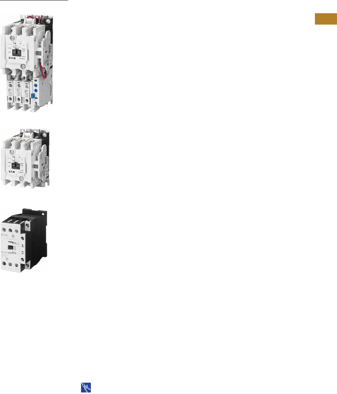
Volume 5—Motor Control and Protection CA08100006E—August 2014 www.eaton.com V5-T2-1
2
2
2
2
2
2
2
2
2
2
2
2
2
2
2
2
2
2
2
2
2
2
2
2
2
2
2
2
2
2
NEMA Contactors and Starters
NEMA AN16DN0AB
NEMA Size 1 Starter
NEMA Size 1 Contactor
NEMA Space-Savings
Size 1C Contactor
2.1 Freedom Series
Product Overview . . . . . . . . . . . . . . . . . . . . . . . . . . . . . . . . . . . . . . . . V5-T2-2
Features, Benefits and Functions . . . . . . . . . . . . . . . . . . . . . . . . . . . . V5-T2-2
Standards and Certifications . . . . . . . . . . . . . . . . . . . . . . . . . . . . . . . . V5-T2-3
Catalog Number Selection . . . . . . . . . . . . . . . . . . . . . . . . . . . . . . . . . . V5-T2-3
Contactors—Non-Reversing and Reversing . . . . . . . . . . . . . . . . . . . . . V5-T2-4
Starters—Three-Phase Non-Reversing and Reversing,
Full Voltage . . . . . . . . . . . . . . . . . . . . . . . . . . . . . . . . . . . . . . . . . . . . V5-T2-10
Starters—Single-Phase Non-Reversing, Full Voltage,
Bi-Metallic Overload . . . . . . . . . . . . . . . . . . . . . . . . . . . . . . . . . . . . . V5-T2-15
Accessories . . . . . . . . . . . . . . . . . . . . . . . . . . . . . . . . . . . . . . . . . . . . . V5-T2-21
Renewal Parts . . . . . . . . . . . . . . . . . . . . . . . . . . . . . . . . . . . . . . . . . . . V5-T2-30
Technical Data and Specifications . . . . . . . . . . . . . . . . . . . . . . . . . . . . V5-T2-34
Relays—Thermal Overload . . . . . . . . . . . . . . . . . . . . . . . . . . . . . . . . . V5-T2-38
C440/XT Electronic Overload Relay . . . . . . . . . . . . . . . . . . . . . . . . . . . V5-T2-48
2.2 Space-Savings Series
Contactors and Starters
Product Description . . . . . . . . . . . . . . . . . . . . . . . . . . . . . . . . . . . . . V5-T2-65
Product Selection. . . . . . . . . . . . . . . . . . . . . . . . . . . . . . . . . . . . . . . V5-T2-66
Technical Data and Specifications . . . . . . . . . . . . . . . . . . . . . . . . . . V5-T2-73
XTOE/XT Electronic Overload Relay
Product Description . . . . . . . . . . . . . . . . . . . . . . . . . . . . . . . . . . . . . V5-T2-80
Product Selection. . . . . . . . . . . . . . . . . . . . . . . . . . . . . . . . . . . . . . . V5-T2-83
Technical Data and Specifications . . . . . . . . . . . . . . . . . . . . . . . . . . V5-T2-89
2.3 A200 Series
Contactors—Non-Reversing and Reversing . . . . . . . . . . . . . . . . . . . . . V5-T2-101
Starters—Non-Reversing and Reversing . . . . . . . . . . . . . . . . . . . . . . . V5-T2-107
Relays—Thermal and Fast Trip . . . . . . . . . . . . . . . . . . . . . . . . . . . . . . . V5-T2-128
Thermal Type B, Class 20, Manual Reset . . . . . . . . . . . . . . . . . . . . . . . V5-T2-130
Thermal Type A, Class 20, Auto/Manual Reset. . . . . . . . . . . . . . . . . . . V5-T2-133
Type FT Fast Trip, Class 10 . . . . . . . . . . . . . . . . . . . . . . . . . . . . . . . . . . V5-T2-136
Heater Selection . . . . . . . . . . . . . . . . . . . . . . . . . . . . . . . . . . . . . . . . . . V5-T2-139
Relays—Current Sensing Protective. . . . . . . . . . . . . . . . . . . . . . . . . . . V5-T2-141
2.4 Solenoids—Alternating Current
Product Description . . . . . . . . . . . . . . . . . . . . . . . . . . . . . . . . . . . . . . . V5-T2-144
Product Selection . . . . . . . . . . . . . . . . . . . . . . . . . . . . . . . . . . . . . . . . . V5-T2-145
Dimensions . . . . . . . . . . . . . . . . . . . . . . . . . . . . . . . . . . . . . . . . . . . . . V5-T2-146
2.5 Shoe Brakes—AC and DC Magnetic
Product Description . . . . . . . . . . . . . . . . . . . . . . . . . . . . . . . . . . . . . . . V5-T2-147
Product Selection . . . . . . . . . . . . . . . . . . . . . . . . . . . . . . . . . . . . . . . . . V5-T2-148
Dimensions . . . . . . . . . . . . . . . . . . . . . . . . . . . . . . . . . . . . . . . . . . . . . V5-T2-150
2.6 Reference Data
IEC Utilization Categories . . . . . . . . . . . . . . . . . . . . . . . . . . . . . . . . . . V5-T2-152
Annex A (informative) . . . . . . . . . . . . . . . . . . . . . . . . . . . . . . . . . . . . . V5-T2-153
Motor Ratings Data . . . . . . . . . . . . . . . . . . . . . . . . . . . . . . . . . . . . . . . V5-T2-155
Drawings
Online
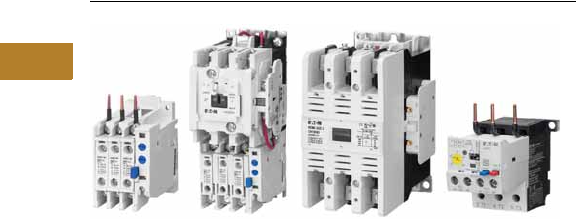
V5-T2-2 Volume 5—Motor Control and Protection CA08100006E—August 2014 www.eaton.com
2
2
2
2
2
2
2
2
2
2
2
2
2
2
2
2
2
2
2
2
2
2
2
2
2
2
2
2
2
2
2.1
NEMA Contactors and Starters
Freedom Series
Freedom Series
Contents
Description Page
Technical Data and Specifications
Standards and Certifications . . . . . . . . . . . . . . . V5-T2-3
Catalog Number Selection . . . . . . . . . . . . . . . . V5-T2-3
Contactors—Non-Reversing and Reversing . . . V5-T2-4
Starters—Three-Phase Non-Reversing and
Reversing, Full Voltage . . . . . . . . . . . . . . . . . . V5-T2-10
Starters—Single-Phase Non-Reversing,
Full Voltage, Bi-Metallic Overload . . . . . . . . . . V5-T2-15
Accessories. . . . . . . . . . . . . . . . . . . . . . . . . . . . V5-T2-21
Renewal Parts . . . . . . . . . . . . . . . . . . . . . . . . . . V5-T2-30
Technical Data and Specifications . . . . . . . . . . . V5-T2-34
Relays—Thermal Overload . . . . . . . . . . . . . . . . V5-T2-38
C440/XT Electronic Overload Relay . . . . . . . . . V5-T2-48
Product Overview
Freedom Series starters and
contactors
feature a compact,
space-saving design, using
state-of-the-art technology
and the latest in high
strength, impact and
temperature resistant
insulating materials.
Features, Benefits and Functions
Freedom NEMA
●Adjustable bimetallic
ambient compensated
overload relays with
interchangeable heater
packs—available in three
basic sizes, covering
applications up to
900 hp—reducing the
number of different
contactor/overload relay
combinations that have to
be stocked. Fixed heater
overloads are optional
●Electronic overload relay
(C440) available as a stand-
alone unit and assembled
with Freedom Contactor
●A full line of snap-on
accessories— top and side
mounted auxiliary contacts,
solid-state and pneumatic
timers, and so on
●Straight-through wiring—
line lugs at top, load lugs
at bottom
●Horizontal or vertical
mounting on upright panel
for application freedom
●Screw type power
terminals have captive,
backed-out self-lifting
pressure plates with
± screws—reduced
wiring time
●Accessible terminals for
easy wiring. Optional
fingerproof shields
available to prevent
electrical shock
●Top located coil terminals
convenient and readily
accessible. 45 mm
contactor magnet coils
have three terminals,
permitting either top or
diagonal wiring—easy to
replace European or U.S.
style starters or contactors
without changing wiring
layout
●Designed to meet or
exceed NEMA, UL, CSA,
VDE, BS and other
international standards
and listings
●American engineering—
built by Eaton, using the
latest in statistical process
control methods to
produce high quality,
reliable products
●Sized based on standard
NEMA classifications
●Easy coil change and
inspectable/replaceable
contacts
●Available in open and
NEMA Type 1, 3R, 4/4X
and 12 enclosures
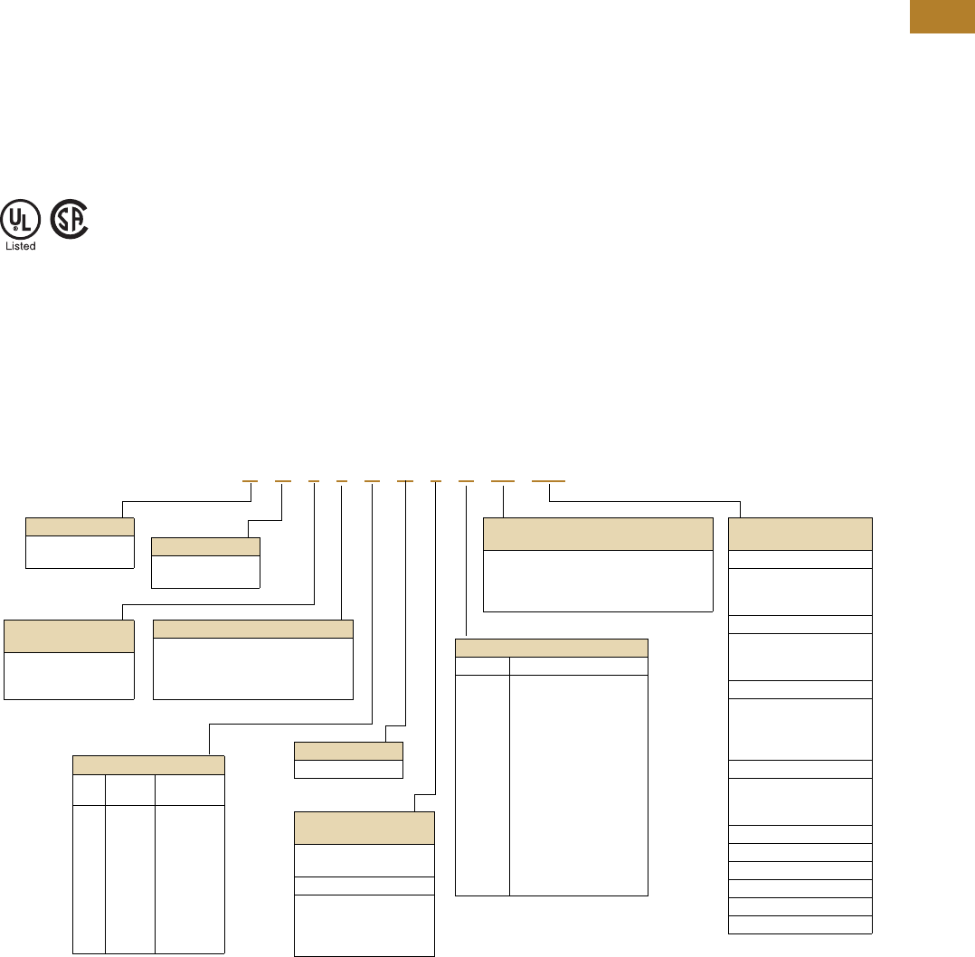
Volume 5—Motor Control and Protection CA08100006E—August 2014 www.eaton.com V5-T2-3
2
2
2
2
2
2
2
2
2
2
2
2
2
2
2
2
2
2
2
2
2
2
2
2
2
2
2
2
2
2
2.1
NEMA Contactors and Starters
Freedom Series
Standards and Certifications
●Standard: designed to
meet or exceed UL,
NEMA, IEC, CSA, VDE
and BS
●UL listed: UL File #E1491,
Guide #NLDX—Open and
NEMA 1, 4, 12 Enclosed
●CSA Certified: CSA File
#LR353, Class #321104
Open and NEMA 1
Enclosed
ISO 9000 Certification
When you turn to Eaton’s
products, you turn to quality.
The International Standards
Organization (ISO) has
established a series of
standards acknowledged
by 91 industrialized nations
to bring harmony to the
international quest for quality.
The ISO certification process
covers 20 quality system
elements in design,
production and installation
that must conform to
achieve registration. This
commitment to quality will
result in increased product
reliability and total customer
satisfaction.
Short Circuit Protection
Fuses
and
Inverse-Time
Circuit Breakers
may be
selected per Article 430,
Part D of the National
Electrical Code to protect
motor branch circuits from
fault conditions. If higher
ratings or settings are required
to start the motor, do not
exceed the maximum as listed
in Exception No. 2, Article
430-52.
Catalog Number Selection
Freedom Series
Notes
1For contactor only orders, add B to end of catalog number if NEMA Size 00–2, 6.
2NEMA Sizes 00 and 0 only.
3NEMA Sizes 00 and 0 only. Sizes 1–8 are 24/60 only.
4NEMA Size 5 requires the use of CTs with 1-5A OL relay.
A N 1 9 A N 0 A 5E 005
Device Type
A = Starter
C = Contactor
Contactor Frame Size 1
NEMA
Size
Continuous
Amperes
A=
B=
D=
G=
K=
N=
S=
T=
U=
V=
00
0
1
2
3
4
5
6
7
8
9
18
27
45
90
135
270
540
810
1215
Device Assembly
Configuration
70 = Multi-speed
1= Non-reversing
5= Reversing
Standard
E = IEC
N = NEMA
C440 FLA Range
(FVNR and FVR only)
NEMA Size 00
1P6 = 0.33–1.65A
005 =1–5A
020 =4–20A
NEMA Size 0
1P6 = 0.33–1.65A
005 =1–5A
020 =4–20A
NEMA Size 1
1P6 = 0.33–1.65A
005 =1–5A
020 =4–20A
045 =9–45A
NEMA Size 2
005 =1–5A
020 =4–20A
045 =9–45A
NEMA Size 3
100 = 20–100A
NEMA Size 4
140 = 28–140A
NEMA Size 5 4
300 = 60–300A
AC Coil Suffix
Suffix Coil Volts and Hertz
A
B
C
D
E
H
J
K
L
N
T
U
V
W
Y
= 120/60 or 110/50
= 240/60 or 220/50
= 480/60 or 440/50
= 600/60 or 550/50
= 208/60
= 277/60
= 208 – 240/60 2
= 240/50
= 380 – 415/50
= 550/50
= 24/60, 24/50 3
= 24/50
= 32/50
= 48/60
= 48/50
C440 OLR Designation
(FVNR and FVR only)
5E = Standard feature set
SEL Reset, SEL Class (10A, 10, 20, 30)
5G = Ground fault feature set
SEL Reset, SEL Class (10, 20)
OLR Type
5 = Contactor only—no overload relay
6 = Starter w/C306 bi-metal OLR
9 = Starter w/C440 electronic
overload
NEMA Enclosure
N = Open
For Starters
Starter
Mounting Option
0 = Horizontal
V = Vertical
For Contactors Only
2 = Two-pole
3 = Three-pole
4 = Four-pole
5 = Five-pole
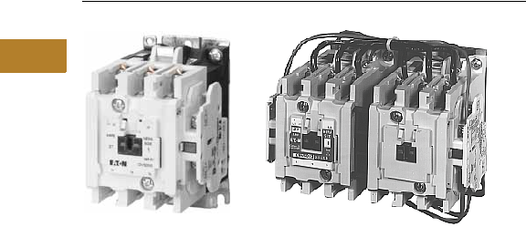
V5-T2-4 Volume 5—Motor Control and Protection CA08100006E—August 2014 www.eaton.com
2
2
2
2
2
2
2
2
2
2
2
2
2
2
2
2
2
2
2
2
2
2
2
2
2
2
2
2
2
2
2.1
NEMA Contactors and Starters
Freedom Series
Non-Reversing and Reversing Contactors
Contents
Description Page
Contactors—Non-Reversing and Reversing
Product Selection . . . . . . . . . . . . . . . . . . . . . . . V5-T2-5
Kits and Accessories. . . . . . . . . . . . . . . . . . . . . V5-T2-6
Renewal Parts Publication Numbers. . . . . . . . . V5-T2-6
Technical Data and Specifications . . . . . . . . . . . V5-T2-7
Dimensions. . . . . . . . . . . . . . . . . . . . . . . . . . . . V5-T2-8
Starters—Three-Phase Non-Reversing and
Reversing, Full Voltage . . . . . . . . . . . . . . . . . . . . V5-T2-10
Starters—Single-Phase Non-Reversing,
Full Voltage, Bi-Metallic Overload . . . . . . . . . . . . V5-T2-15
Accessories . . . . . . . . . . . . . . . . . . . . . . . . . . . . . . V5-T2-21
Renewal Parts . . . . . . . . . . . . . . . . . . . . . . . . . . . . V5-T2-30
Technical Data and Specifications . . . . . . . . . . . . . V5-T2-34
Relays—Thermal Overload. . . . . . . . . . . . . . . . . . . V5-T2-38
Contactors—Non-Reversing and Reversing
Product Description
Non-Reversing
Contactors are most
commonly used to switch
motor loads in applications
where running overcurrent
protection is either not
required or is provided
separately. Contactors consist
of a magnetically actuated
switch which can be remotely
operated by a pushbutton
station or pilot device such
as a proximity switch, limit
switch, float switch, auxiliary
contacts, and so on.
Reversing
Reversing contactors are
used primarily for reversing
single- or three-phase motors
in applications where running
overcurrent protection is
either not required or is
provided separately. They
consist of two contactors
mechanically and electrically
interlocked to prevent line
shorts and energization of
both contactors
simultaneously.
Features, Benefits and Functions
●Designed specifically for
use in applications
requiring NEMA ratings.
Contactors meet or
exceed NEMA standards
ICS 2-1993
●Long life twin break,
silver cadmium oxide
contacts—provide
excellent conductivity and
superior resistance to
welding and arc erosion
●Designed to 3,000,000
electrical operations at
maximum hp ratings up
through 25 hp at 600V
●Steel mounting plate
standard on all open
type contactors
Non-Reversing
●Holding circuit contact(s)
supplied as standard:
●Sizes 00–3 have NO
auxiliary contact block
mounted on right hand
side (on Size 00, contact
occupies 4th power pole
position—no increase
in width)
●Sizes 4–5 have a
NO contact block
mounted on left side
●Sizes 6–7 have a
2NO/2NC contact
block on top left
●Size 8 has a NO/NC
contact block on top left
back and a NO contact
block on top right back
Reversing
●One NO-NC side mounted
interlock supplied as
standard on each
contactor for Sizes 00–8
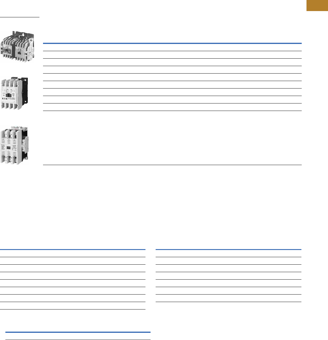
Volume 5—Motor Control and Protection CA08100006E—August 2014 www.eaton.com V5-T2-5
2
2
2
2
2
2
2
2
2
2
2
2
2
2
2
2
2
2
2
2
2
2
2
2
2
2
2
2
2
2
2.1
NEMA Contactors and Starters
Freedom Series
Product Selection
Three-Pole Contactors
Type CN15/CN55 NEMA Contactors—Non-Reversing and Reversing
Magnet Coils—AC and DC
Contactor coils listed in this
section also have a 50 Hz
rating as shown in the
adjacent table. Select
required contactor by
catalog number and replace
the magnet coil alpha
designation in the catalog
number (_) with the proper
code suffix from the table.
For Sizes 00–2, the magnet
coil alpha designation will be
the next to the last digit of
the listed catalog number.
EXAMPLE: For a 380V, 50 Hz
coil, change CN15AN3_B
to CN15AN3LB. For all
other sizes, the magnet
coil alpha designation will
be the last digit of the listed
catalog number.
For DC Magnet Coils,
see Accessories, Pages
V5-T2-28 and V5-T2-29.
AC Suffix
Notes
1Maximum horsepower rating of starters for 380V 50 Hz applications:
2Common control. For separate 120V control, insert letter D in 7th position of listed catalog number.
Example:CN15VND3C.
3NEMA Sizes 00 and 0 only.
4NEMA Sizes 00 and 0 only. Sizes 1–8 are 24/60 only.
NEMA
Size
Continuous
Ampere Rating
Maximum UL Horsepower 1
Non-Reversing ReversingSingle-Phase Three-Phase
115V 230V 208V 240V 480V 600V Catalog Number Catalog Number
00 9 1/3 1 1-1/2 1-1/2 2 2 CN15AN3_B CN55AN3_B
018 123355CN15BN3_B CN55BN3_B
1 27 2 3 7-1/2 7-1/2 10 10 CN15DN3_B CN55DN3_B
245 3 7-1/210152525CN15GN3_B CN55GN3_B
390 25305050CN15KN3_ CN55KN3_
4 135 40 50 100 100 CN15NN3_ CN55NN3_
5 270 75 100 200 200 CN15SN3_ CN55SN3_
6 540 150 200 400 400 CN15TN3_B CN55TN3_B
7 810 200 300 600 600 CN15UN3_ CN55UN3_
8 21215 400 450 900 900 CN15VN3_ CN55VN3_
NEMA Size 00
CN55AN3AB
NEMA Size 0
CN15BN3AB
NEMA Size 3
CN15KN3A
Coil Volts and Hertz Code Suffix Coil Volts and Hertz Code Suffix
120/60 or 110/50 A380–415/50 L
240/60 or 220/50 B550/50 N
480/60 or 440/50 C24/60, 24/50 4T
600/60 or 550/50 D24/50 U
208/60 E32/50 V
277/60 H48/60 W
208–240/60 3J48/50 Y
240/50 K
NEMA Size00012345678
Horsepower 1-1/2 5 10 25 50 75 150 300 600 900
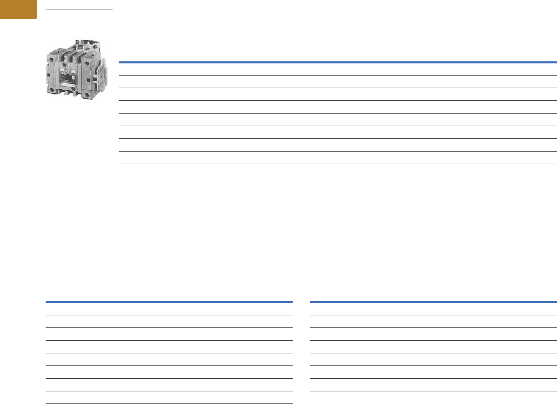
V5-T2-6 Volume 5—Motor Control and Protection CA08100006E—August 2014 www.eaton.com
2
2
2
2
2
2
2
2
2
2
2
2
2
2
2
2
2
2
2
2
2
2
2
2
2
2
2
2
2
2
2.1
NEMA Contactors and Starters
Freedom Series
Two-, Four- and Five-Pole Contactors
Type CN15 NEMA Contactors—Non-Reversing
Magnet Coils—AC and DC
Select required starter by
catalog number and replace
the magnet coil alpha
designation in the catalog
number (_) with the proper
code suffix from the table.
For Sizes 00–2, the magnet
coil alpha designation will be
the next to the last digit of
the listed catalog number.
EXAMPLE: For a 380V, 50 Hz
coil, change CN15BN3_B
to CN15BN3LB. For all
other sizes, the magnet
coil alpha designation will
be the last digit of the listed
catalog number.
For DC Magnet Coils,
see Accessories, Pages
V5-T2-28 and V5-T2-29.
AC Suffix
Kits and Accessories
●Auxiliary contacts,
contactor mounted—
Pages V5-T2-25 to
V5-T2-27
●Transient suppressor, for
magnet coil—Page
V5-T2-24
●Timers—solid-state and
pneumatic, mount on
contactor—Page
V5-T2-22
Renewal Parts
Publication Numbers
●See Page V5-T2-30
Notes
1NEMA Sizes 00 and 0 only.
2NEMA Sizes 00 and 0 only. Sizes 1–8 are 24/60 only.
NEMA
Size
Continuous
Ampere
Rating
Maximum UL Horsepower
Two-Pole
Non-Reversing
Four-Pole
Non-Reversing
Five-Pole
Non-Reversing
Single-Phase (Two-Pole) Three-Phase Catalog
Number
Catalog
Number
Catalog
Number115V 230V 208V 240V 480V 600V
00 9 1/3 1 1-1/2 1-1/2 2 2 CN15AN2_B CN15AN4_B —
018 1 2 2355CN15BN2_B — —
127 2 3 7-1/27-1/21010CN15DN2_B CN15DN4_B CN15DN5_B
2 45 3 7-1/2 10152525CN15GN2_B CN15GN4_B CN15GN5_B
3 90 25305050CN15KN2_ — —
4 135 40 50 100 100 CN15NN2_ — —
5 270 75 100 200 200 CN15SN2_ — —
6 540 150 200 400 400 CN15TN2_B — —
NEMA Size 2
Five-Pole Contactor
CN15GN5AB
Coil Volts and Hertz Code Suffix Coil Volts and Hertz Code Suffix
120/60 or 110/50 A380–415/50 L
240/60 or 220/50 B550/50 N
480/60 or 440/50 C24/60, 24/50 2T
600/60 or 550/50 D24/50 U
208/60 E32/50 V
277/60 H48/60 W
208–240/60 1J48/50 Y
240/50 K

Volume 5—Motor Control and Protection CA08100006E—August 2014 www.eaton.com V5-T2-7
2
2
2
2
2
2
2
2
2
2
2
2
2
2
2
2
2
2
2
2
2
2
2
2
2
2
2
2
2
2
2.1
NEMA Contactors and Starters
Freedom Series
Technical Data and Specifications
Wire (75°C) Sizes—AWG or kcmil—Open and Enclosed
Plugging and Jogging Service Horsepower Ratings 2
Notes
1Two compartment box lug.
2Maximum horsepower where operation is interrupted more than 5 times per minute or more than 10 times in a 10 minute period.
NEMA standard ICS 2-1993 table 2-4-3.
NEMA Size Power Terminals Line or Load Control Terminals Cu Only
00 12–16 stranded; 12–14 solid Cu 12–16 stranded
12–14 solid
0 8–16 stranded; 10–14 solid Cu
1 8–14 stranded or solid Cu
2 3–14 (upper) and/or 6–14 (lower) stranded or solid 1 Cu
3 1/0–14 Cu/Al
4 250 mcm–6
5 750 kcmil–2, or (2) 250 kcmil–3/0 Cu/Al
6 (2) 750 kcmil–3/0 Cu/Al
7 (3) 750 kcmil–3/0 Cu/Al
8 (4) 750 kcmil–4/0 Cu/Al
NEMA Size 200V 230V 460V 575V
00 — 1/2 1/2 1/2
0 1-1/2 1-1/2 2 2
13355
2 7-1/2 10 15 15
3 15203030
4 25306060
5 6075150150
6 125 150 300 300
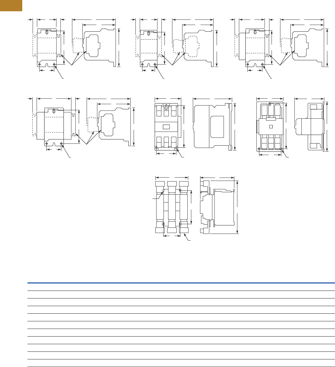
V5-T2-8 Volume 5—Motor Control and Protection CA08100006E—August 2014 www.eaton.com
2
2
2
2
2
2
2
2
2
2
2
2
2
2
2
2
2
2
2
2
2
2
2
2
2
2
2
2
2
2
2.1
NEMA Contactors and Starters
Freedom Series
Dimensions
Approximate Dimensions in Inches (mm)
Non-Reversing Contactors—Open Type
Dimensions and Shipping Weights
Note
1Center mounting slot at bottom supplied only on Size 00 and 0 contactors.
NEMA
Size
Number
of Poles
Wide
A
High
B
Deep
C
Mounting
D
Mounting
EFG
Shipping Weight
Lbs (kg)
00 2–4 1.75 (44.5) 3.88 (98.6) 3.49 (88.6) 1.50 (38.1) 13.38 (85.9) 4.62 (117.3) 0.54 (13.7) 1.7 (0.7)
0 2–3 1.75 (44.5) 3.88 (98.6) 3.49 (88.6) 1.50 (38.1) 13.38 (85.9) 4.62 (117.3) 0.54 (13.7) 1.8 (0.8)
1–2 2–3 2.56 (65.0) 5.05 (128.3) 4.44 (112.8) 2.00 (50.8) 14.50 (114.3) 5.80 (147.3) 0.54 (13.7) 3.1 (1.4)
1–2 4 3.44 (87.4) 5.05 (128.3) 4.44 (112.8) 2.00 (50.8) 14.50 (114.3) 5.80 (147.3) 0.54 (13.7) 3.6 (1.6)
1–2 5 4.32 (109.7) 5.05 (128.3) 4.44 (112.8) 2.00 (50.8) 14.50 (114.3) 5.80 (147.3) 0.54 (13.7) 4.0 (1.8)
3 2–3 4.08 (103.6) 7.17 (182.1) 5.94 (150.9) 3.00 (76.2) 6.63 (168.4) — — 8.5 (3.9)
4 2–3 7.05 (179.1) 9.11 (231.4) 7.25 (184.2) 6.00 (152.4) 8.50 (215.9) — — 20.0 (9.1)
5 2–3 7.05 (179.1) 13.12 (333.2) 7.78 (197.6) 6.00 (152.4) 12.50 (317.5) — — 23.0 (10.4)
6 3 8.63 (219.2) 13.54 (343.9) 8.88 (225.6) 4.33 (110.0) 8.63 (219.2) — — 35.0 (15.9)
7 3 11.02 (279.9) 19.30 (490.2) 11.46 (291.1) 6.89 (175.0) 11.02 (279.9) — — 100.0 (45.4)
8 3 13.00 (330.2) 24.50 (622.3) 13.63 (346.2) 4.22 (107.2) 14.86 (377.4) — — 160.0 (72.6)
Mtg. Holes for
#10-32 Screws
A
U
X
A
U
X
AGGF
C
D
Top
Mtd.
Aux.
Auxiliary
Contacts
Top
Mtd.
Aux.
Side
Mtd.
Aux.
EB
Mtg. Holes for
#10-32 Screws
A
U
X
A
U
X
AGGF
C
D
Top
Mtd.
Aux.
Auxiliary
Contacts
Top
Mtd.
Aux.
Side
Mtd.
Aux.
EB
Mtg. Holes for
#10-32 Screws
A
U
X
A
U
X
AGGF
C
D
Top
Mtd.
Aux.
Auxiliary
Contacts
Top
Mtd.
Aux.
Side
Mtd.
Aux.
EB
Sizes 00, Two- to Four-Pole
Mtg. Holes for
#10-32 Screws
A
U
X
A
U
X
AGGF
C
D
Top
Mtd.
Aux.
Auxiliary
Contacts
Top
Mtd.
Aux.
Side
Mtd.
Aux.
Side
Mtd.
Aux.
EB
Sizes 1–2, Five-Pole
Mtg. Holes for (3)
1/4-20 Screws
ACAC
D
BE
Size 3
Mtg. Holes for
(3) Screws
D
B
E
Sizes 4–5
Sizes 0–2, Two- and Three-Pole Sizes 0–2, Two- and Three-Pole
C
Mtg. Slots for (2)
5/16-18 Screws
Mtg. Holes for (2)
5/16-18 Screws
D
A
B
E
Size 6
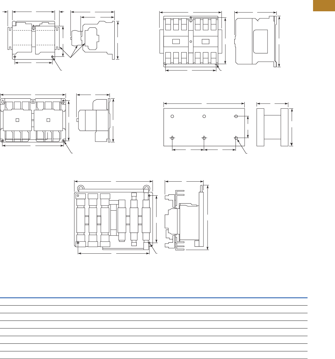
Volume 5—Motor Control and Protection CA08100006E—August 2014 www.eaton.com V5-T2-9
2
2
2
2
2
2
2
2
2
2
2
2
2
2
2
2
2
2
2
2
2
2
2
2
2
2
2
2
2
2
2.1
NEMA Contactors and Starters
Freedom Series
Approximate Dimensions in Inches (mm)
Reversing Contactors—Open Type
Dimensions and Shipping Weights
Note
1Includes cross wiring.
NEMA
Size
Wide
A
High
B
Deep
C
Mounting
D
Mounting
EFG
Shipping Weight
Lbs (kg)
00–0 4.20 (106.7) 4.35 (110.5) 3.52 (89.4) 3.50 (88.9) 3.86 (98.0) 4.90 (124.5) 0.54 (13.7) 3.3 (1.5)
1–2 5.71 (145.0) 5.05 (128.3) 4.44 (112.8) 5.25 (133.4) 3.63 (92.2) 5.80 (147.3) 0.54 (13.7) 7.8 (3.5)
3 8.70 (221.0) 7.17 (182.1) 5.94 (150.9) 7.00 (177.8) 6.63 (168.4) — — 17.0 (7.7)
4 14.68 (372.9) 9.11 (231.4) 7.25 (184.2) 13.50 (342.9) 8.50 (215.9) — — 47.0 (21.3)
5 14.50 (368.3) 12.25 (311.2) 7.78 (197.6) 13.50 (342.9) 11.50 (292.1) — — 63.0 (28.6)
6 19.77 (502.2) 16.61 (421.9) 9.90 (251.5) 18.00 (457.2) 12.00 (304.8) — — 80.0 (36.3)
7 28.00 (711.2) 26.75 (679.5) 112.75 (323.9) 12.75 (323.9) 11.00 (279.4) — — 260.0 (118.0)
8 30.13 (765.3) 39.00 (990.6) 114.69 (373.1) 14.13 (358.9) 15.00 (381.0) — — 350.0 (158.9)
Mtg. Holes for (3)
#10-32 Screws
A
U
X
A
U
X
AGGF
C
D
Top
Mtd.
Aux.
Top
Mtd.
Aux.
Auxiliary
Contacts
Top
Mtd.
Aux.
Side
Mtd.
Aux.
EB
Sizes 00–2 Size 3
Mtg. for (4)
1/4-20 Screws
AC
D
EB
CA
Sizes 4–5
Mtg. Holes for (3)
1/4-20 Screws
CA
D
EB
Mtg. Holes for (6)
1/2-13 Screws
DD
EB
Open Type—Sizes 7–8 Horizontal
Mtg. Holes for (4)
3/8-16 Screws
D
AC
EB
Size 6
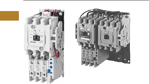
V5-T2-10 Volume 5—Motor Control and Protection CA08100006E—August 2014 www.eaton.com
2
2
2
2
2
2
2
2
2
2
2
2
2
2
2
2
2
2
2
2
2
2
2
2
2
2
2
2
2
2
2.1
NEMA Contactors and Starters
Freedom Series
Three-Phase Non-Reversing and Reversing, Full Voltage Starters
Contents
Description Page
Contactors—Non-Reversing and Reversing . . . . . . V5-T2-4
Starters—Three-Phase Non-Reversing and
Reversing, Full Voltage
Product Selection . . . . . . . . . . . . . . . . . . . . . . . V5-T2-11
Kits and Accessories. . . . . . . . . . . . . . . . . . . . . V5-T2-13
Renewal Parts Publication Numbers. . . . . . . . . V5-T2-13
Technical Data and Specifications . . . . . . . . . . . V5-T2-13
Wiring Diagrams . . . . . . . . . . . . . . . . . . . . . . . . V5-T2-14
Starters—Single-Phase Non-Reversing,
Full Voltage, Bi-Metallic Overload . . . . . . . . . . . . V5-T2-15
Accessories . . . . . . . . . . . . . . . . . . . . . . . . . . . . . . V5-T2-21
Renewal Parts . . . . . . . . . . . . . . . . . . . . . . . . . . . . V5-T2-30
Technical Data and Specifications . . . . . . . . . . . . . V5-T2-34
Relays—Thermal Overload. . . . . . . . . . . . . . . . . . . V5-T2-38
C440/XT Electronic Overload Relay . . . . . . . . . . . . V5-T2-48
Starters—Three-Phase Non-Reversing and Reversing, Full Voltage
Product Description
Non-Reversing
Three-phase, full voltage
magnetic starters are most
commonly used to switch AC
motor loads. Starters consist
of a magnetically actuated
switch (contactor) and an
overload relay assembled
together.
Reversing
Three-phase, full voltage
magnetic starters are used
primarily for reversing of
three-phase squirrel cage
motors. They consist of two
contactors and a single
overload relay assembled
together. The contactors are
mechanically and electrically
interlocked to prevent line
shorts and energization of
both contactors
simultaneously.
Features, Benefits and
Functions
●Bimetallic ambient
compensated overload
relays—available in three
basic sizes covering
applications up to 900 hp—
reducing number of
different contactor/overload
relay combinations that
have to be stocked
These overload relays
feature:
●Selectable manual
or automatic reset
operation
●Interchangeable heater
packs adjustable ±24%
to match motor FLA and
calibrated for 1.0 and
1.15 service factors.
Heater packs for smaller
overload relay will mount
in larger overload relay—
useful in derating
applications such as
jogging
●Load lugs built into
relay base
●Single-phase protection,
Class 20 or Class 10
trip time
●Overload trip indication
●Electrically isolated
NO-NC contacts (pull
RESET button to test)
●The C440 is a self-
powered, robust
electronic overload
designed for integrated
use with Freedom
NEMA contactors
●Tiered feature set to
provide coverage
specific to your
application
●Broad 5: 1 FLA range
for maximum flexibility
●Coverage from
0.05–1500A to meet
all your needs
●Long life twin break,
silver cadmium oxide
contacts—provide
excellent conductivity
and superior resistance
to welding and arc erosion.
Generously sized for low
resistance and cool
operation
●Designed to 3,000,000
electrical operations at
maximum hp ratings up
through 25 hp at 600V
●Steel mounting plate
standard on all open
type starters
●Wired for separate or
common control
Non-Reversing
●Holding circuit contact(s)
supplied as standard:
●Sizes 00–3 have a NO
auxiliary contact block
mounted on right-hand
side (on Size 00, contact
occupies 4th power pole
position—no increase
in width)
●Sizes 4–5 have a
NO contact block
mounted on left side
●Sizes 6–7 have a
2NO/2NC contact
block on top left
●Size 8 has a NO/NC
contact block on top
left back and a NO on
top right back
Reversing
●Each contactor (Size 00–8)
supplied with one NO-NC
side mounted contact
block as standard. NC
contacts are wired as
electrical interlocks
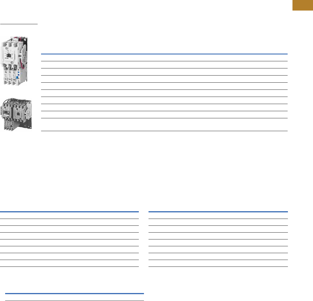
Volume 5—Motor Control and Protection CA08100006E—August 2014 www.eaton.com V5-T2-11
2
2
2
2
2
2
2
2
2
2
2
2
2
2
2
2
2
2
2
2
2
2
2
2
2
2
2
2
2
2
2.1
NEMA Contactors and Starters
Freedom Series
Product Selection
When Ordering Supply
●Catalog number
●Heater pack number (see selection table, Pages V5-T2-40 to V5-T2-42) or full load current
Type AN16/AN56 NEMA—Manual or Automatic Reset Overload Relay—Non-Reversing and Reversing 1
Magnet Coils—AC or DC
Starter coils listed in this
section also have a 50 Hz
rating as shown in the
adjacent table. Select
required starter by catalog
number and replace the
magnet coil alpha designation
in the catalog number (_) with
the proper code suffix from
the table.
For Sizes 00–2 and 5–8, the
magnet coil alpha designation
will be the next to last digit
of the listed catalog number.
EXAMPLE: For a 380V, 50 Hz
coil, change AN16BN0_C
to AN16BN0LC. For all
other sizes, the magnet
coil alpha designation will
be the last digit of the listed
catalog number.
For DC Magnet Coils,
see Accessories, Pages
V5-T2-28 and V5-T2-29.
AC Suffix
Notes
1Starter catalog numbers do not include heater packs. Select one carton of three heater packs. Heater pack selection, Pages V5-T2-40 to V5-T2-42.
2Maximum horsepower rating of starters for 380V 50 Hz applications:
3Underscore (_) indicates coil suffix required, see AC Suffix table.
4The service-limit current ratings represent the maximum rms current, in amperes, which the controller shall be permitted to carry for protracted periods in normal service. At service-limit current
ratings, temperature rises shall be permitted to exceed those obtained by testing the controller at its continuous current rating. The current rating of overload relays or trip current of other motor
protective devices used shall not exceed the service-limit current rating of the controller.
5Common control. For separate 120V control, insert letter D in 7th position of listed catalog number. Example: AN56VND0CB.
6NEMA Sizes 00 and 0 only.
7NEMA Sizes 00 and 0 only. Sizes 1–8 are 24/60 only.
NEMA
Size
Continuous
Ampere
Rating
Service-Limit
Current Rating
(Amperes) 4
Maximum UL Horsepower 2Three-Pole
Non-Reversing 3
Three-Pole
Reversing 3
Vertical
Reversing 3
Single-Phase Three-Phase
115V 230V 208V 240V 480V 600V
Catalog
Number
Catalog
Number
Catalog
Number
00 9 11 1/3 1 1-1/2 1-1/2 2 2 AN16AN0_C AN56AN0_C —
0 18 21 123355AN16BN0_C AN56BN0_C AN56BNV0_
1 27 32 237-1/27-1/21010AN16DN0_B AN56DN0_B AN56DNV0_
2 45 52 3 7-1/2 10 15 25 25 AN16GN0_B AN56GN0_B AN56GNV0_
3 90 104 ——25305050AN16KN0_ AN56KN0_ AN56KNV0_
4 135 156 — — 40 50 100 100 AN16NN0_ AN56NN0_ AN56NNV0_
5 270 311 — — 75 100 200 200 AN16SN0_B AN56SN0_B —
6 540 621 — — 150 200 400 400 AN16TN0_C AN56TN0_C —
7 810 932 — — 200 300 600 600 AN16UN0_B AN56UN0_B —
8 51215 1400 — — 400 450 900 900 AN16VN0_B AN56VN0_B —
Size 0
Non-Reversing Starter
Size 1
Reversing Starter
Coil Volts and Hertz Code Suffix Coil Volts and Hertz Code Suffix
120/60 or 110/50 A380–415/50 L
240/60 or 220/50 B550/50 N
480/60 or 440/50 C24/60, 24/50 7T
600/60 or 550/50 D24/50 U
208/60 E32/50 V
277/60 H48/60 W
208–240/60 6J48/50 Y
240/50 K48/50 Y
NEMA Size00012345678
Horsepower 1-1/2 5 10 25 50 75 150 300 600 900
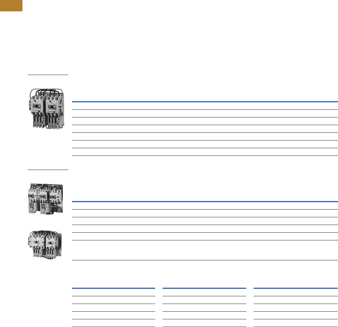
V5-T2-12 Volume 5—Motor Control and Protection CA08100006E—August 2014 www.eaton.com
2
2
2
2
2
2
2
2
2
2
2
2
2
2
2
2
2
2
2
2
2
2
2
2
2
2
2
2
2
2
2.1
NEMA Contactors and Starters
Freedom Series
Two-Speed Selective Control
When Ordering Supply
●Catalog number plus
magnet coil code suffix.
Example: Size 0—
AN700BN022B
●Heater pack number or full
load current for each speed
For two-speed other than
selective control:
●Catalog number plus
magnet coil code suffix and
option required. Example:
AN700BN022B except
compelling
●Heater pack number or full
load current for each speed
Note: Two-speed starters
are designed for starting and
controlling both separate
(two-winding) and reconnectable
(one-winding) motors. Separate
winding, WYE-WYE motors
have a separate winding for
each speed. Reconnectable,
consequent pole motors use the
same winding for both speeds. All
standard starters are wired
for selective control.
Separate Winding 1
Reconnectable Winding 1
Magnetic Coils—AC or DC
Notes
1 If branch circuit protective device is 45A or greater, C320FBR1 fuse kit(s) may be required for circuit protection per NEC 530-072.
2 NEMA Sizes 00 and 0 only. Sizes 1–5 are 24/60 only.
Maximum Horsepower—60/50 Hertz
NEMA
Size
Open Type
Catalog Number
Constant or Variable Torque Constant Horsepower
115V 200V 230V 460V/575V 115V 200V 230V 460/575V
1-1/233512230AN700BN022_
3 7-1/2 7-1/2 10 2 5 5 7-1/2 1 AN700DN022_
—101525—7-1/210202 AN700GN022_
—253050—2025403 AN700KN022_
—4050100—3040754 AN700NN022_
— 75 100 200 — 60 75 150 5 AN700SN022_
Prices of starters do not include heater packs. Select two packs (two overload relays, one for each speed). Heater pack selection, Pages V5-T2-40 to V5-T2-42.
Maximum Horsepower—60/50 Hertz
NEMA
Size
Open Type
Constant or Variable Torque Constant Horsepower
Constant or
Variable Torque
Constant
Horsepower
115V 200V 230V 460V/575V 115V 200V 230V 460/575V Catalog Number Catalog Number
1-1/2335 12230AN700BN0218_ AN700BN0219_
37-1/27-1/2102557-1/21AN700DN0218_ AN700DN0219_
—101525 —7-1/210202 AN700GN0218_ AN700GN0219_
— 25 30 50 — 20 25 40 3 AN700KN0218_ AN700KN0219_
—4050100—3040754 AN700NN0218_ AN700NN0219_
Prices of starters do not include heater packs. Select two packs (two overload relays, one for each speed). Heater pack selection, Pages V5-T2-40 to V5-T2-42.
Coil Voltage and Hz Code Suffix Coil Voltage and Hz Code Suffix Coil Voltage and Hz Code Suffix
120/60 or 110/50 A277/60 H24/60, 24/50 2T
240/60 or 220/50 B208–240/60 J24/50 U
480/60 or 440/50 C240/50 K32/50 V
600/60 or 550/50 D380–415/50 L48/60 W
208/60 E550/50 N48/50 Y
Two-Winding
AN700DN022
One-Winding
AN700BN0218
One-Winding
AN700DN0218

Volume 5—Motor Control and Protection CA08100006E—August 2014 www.eaton.com V5-T2-13
2
2
2
2
2
2
2
2
2
2
2
2
2
2
2
2
2
2
2
2
2
2
2
2
2
2
2
2
2
2
2.1
NEMA Contactors and Starters
Freedom Series
Kits and Accessories
●Auxiliary contacts,
contactor mounted—
Pages V5-T2-25 to
V5-T2-27
●Transient suppressor, for
magnet coil—Page
V5-T2-24
●Timers—solid-state and
pneumatic, mount on
contactor—Page
V5-T2-22
Renewal Parts
Publication Numbers
●See Page V5-T2-30
Technical Data and Specifications
Wire (75°C) Sizes—AWG or kcmil—NEMA Sizes 00–2—Open and Enclosed
Wire (75°C) Sizes—AWG or kcmil—NEMA Sizes 3–8—Open and Enclosed
Plugging and Jogging Service Horsepower Ratings 3
Notes
1Minimum per NEC. Maximum wire size: Sizes 00 and 0 to 8 AWG and Sizes 1–2 to 2 AWG.
2Two compartment box lug.
3Maximum horsepower where operation is interrupted more than 5 times per minute, or more than 10 times in a 10 minute period.
NEMA Standard ICS2-1993 table 2-4-3.
NEMA Size Wire Size 1 Cu Only
Power Terminals—Line
00 12–16 AWG stranded, 12–14 AWG solid
0 8–16 AWG stranded, 10–14 AWG solid
1 8–14 AWG stranded or solid
2 3–14 AWG (upper) and/or 6–14 AWG (lower) stranded or solid 2
Power Terminals—Load—Cu Only (stranded or solid)
00–0 14–6 AWG stranded or solid
1–2 14–2 AWG stranded or solid
Control Terminals—Cu Only
12–16 AWG stranded, 12–14 AWG solid
NEMA Size Wire Size 2
Power Terminals—Line and Load
3 1/0–14 AWG Cu/Al
4 Open—3/0–8 AWG Cu; Enclosed—250 kcmil—6 AWG Cu/Al
5 750 kcmil—2 AWG; or (2) 250 kcmil—3/0 AWG Cu/Al
6 (2) 750 kcmil—3/0 AWG Cu/Al
7 (3) 750 kcmil—3/0 AWG Cu/Al
8 (4) 750 kcmil—1/0 AWG Cu/Al
Control Terminals—Cu Only
12–16 AWG stranded, 12–14 AWG solid
NEMA Size 200V 230V 460V 575V
00 — 1/2 1/2 1/2
0 1-1/2 1-1/2 2 2
13355
2 7-1/2 10 15 15
3 15203030
4 25306060
5 60 75 150 150
6 125 150 300 300
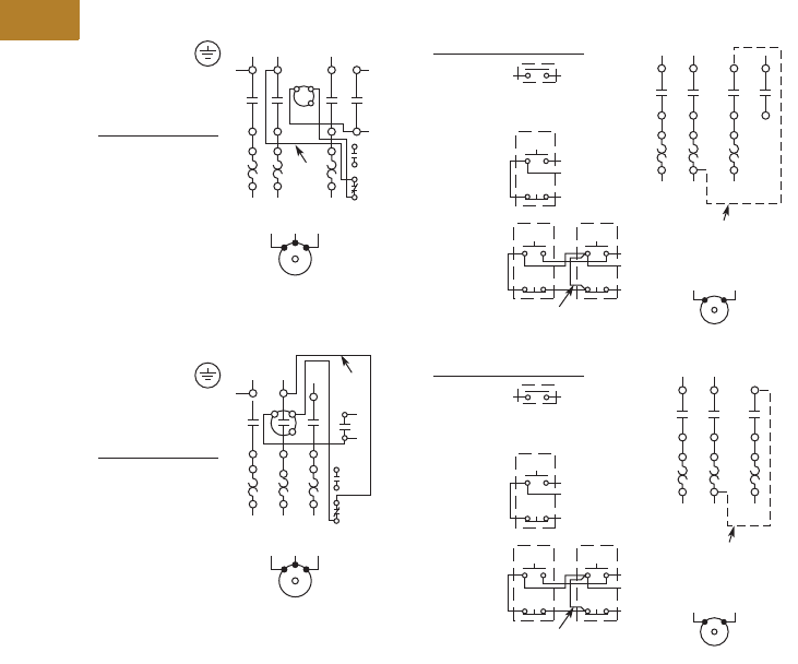
V5-T2-14 Volume 5—Motor Control and Protection CA08100006E—August 2014 www.eaton.com
2
2
2
2
2
2
2
2
2
2
2
2
2
2
2
2
2
2
2
2
2
2
2
2
2
2
2
2
2
2
2.1
NEMA Contactors and Starters
Freedom Series
Wiring Diagrams
Three-Phase and Single-Phase Applications
Not for Use with
Auto Reset OL Relays
Separate Control
Remove Wire “c”
when it is supplied.
Connect separate
control lines to the
No. 1 Terminal on
the remote pilot
device and Terminal
96 on the overload
relay.
“c”
“A”
When more than
one pushbutton
station is used,
omit Connector
“A” and connect
per sketch.
Field Conversion
to Single-Phase, Add
Dotted Connections
Remote Pilot Devices
NEMA Size 00
Two-Wire
Control
L1 L2 L3
T1 T2 T3
T1 T2 T3
1A1 A2
A2
2
3
98
97
96
95
13
3
3
2
1
2
L1
T1 T2
T1 T2
L2
1
Start
Start Start
Stop
Stop Stop
Three-Wire
Control
Motor
Motor
Not for Use with
Auto Reset OL Relays
Separate Control
Remove Wire “c”
when it is supplied.
Connect separate
control lines to the
No. 1 Terminal on
the remote pilot
device and Terminal
96 on the overload
relay.
“A”
When more than
one pushbutton
station is used,
omit Connector
“A” and connect
per sketch.
Field Conversion
to Single-Phase, Add
Dotted Connections
Remote Pilot Devices
NEMA Sizes 0, 1 and 2
Two-Wire
Control
T1 T2 T3
“c”
L1 L2 L3
T1 T2 T3
1A1 A2 2
3
98
97
96
95
13
3
3
2
1
2
L1
T1 T2
T1 T2
L2
1
Start
Start Start
Stop
Stop Stop
Three-Wire
Control
Motor
Motor
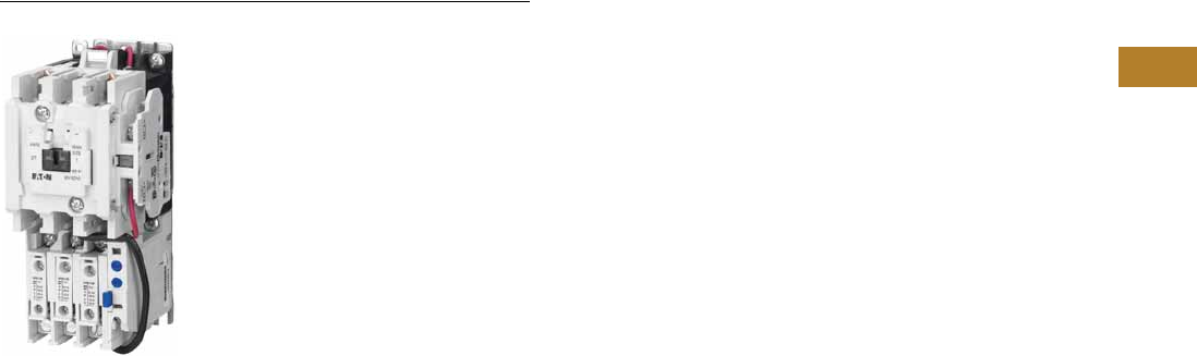
Volume 5—Motor Control and Protection CA08100006E—August 2014 www.eaton.com V5-T2-15
2
2
2
2
2
2
2
2
2
2
2
2
2
2
2
2
2
2
2
2
2
2
2
2
2
2
2
2
2
2
2.1
NEMA Contactors and Starters
Freedom Series
NEMA Size 1—BN15DN0AB
Contents
Description Page
Contactors—Non-Reversing and Reversing . . . . . . V5-T2-4
Starters—Three-Phase Non-Reversing and
Reversing, Full Voltage. . . . . . . . . . . . . . . . . . . . . V5-T2-10
Starters—Single-Phase Non-Reversing,
Full Voltage, Bi-Metallic Overload
Product Selection . . . . . . . . . . . . . . . . . . . . . . . V5-T2-16
Wiring Diagrams . . . . . . . . . . . . . . . . . . . . . . . . V5-T2-16
Dimensions . . . . . . . . . . . . . . . . . . . . . . . . . . . . V5-T2-17
Accessories . . . . . . . . . . . . . . . . . . . . . . . . . . . . . . V5-T2-21
Renewal Parts. . . . . . . . . . . . . . . . . . . . . . . . . . . . . V5-T2-30
Technical Data and Specifications. . . . . . . . . . . . . . V5-T2-34
Relays—Thermal Overload . . . . . . . . . . . . . . . . . . . V5-T2-38
C440/XT Electronic Overload Relay . . . . . . . . . . . . V5-T2-48
Starters—Single-Phase Non-Reversing, Full Voltage, Bi-Metallic Overload
Product Description
Single-phase, full voltage
magnetic starters connect
the motor directly across the
line, allowing it to draw full
inrush current during start-up.
These starters are most
commonly used for control of
self-starting single-phase
motors up to 15 hp at 230V.
They consist of a two-pole
electromagnetic contactor to
make and break the motor
power circuit and an overload
relay to provide running
overload protection. Starters
listed in the table include:
●Two-pole Freedom Series
contactor with long life
twin break, silver cadmium
oxide contacts. Generously
sized for low resistance
and cool operation.
Designed to 3 million
electrical operations
at maximum hp and
30 million mechanical
operations to Size 0,
10 million operations
to Size 2 and 6 million
operations to Size 3
●Three-pole Freedom Series
overload with poles two
and three wired in series
for motor overload
protection. This overload
is ambient compensated,
selectable manual or
automatic reset,
interchangeable Class 10 or
20 heater packs, 1.0
or 1.15 service factor
selectability, overload trip
indication and electrically
isolated NO-NC contacts
(pull RESET button to test)
●Holding circuit NO auxiliary
contact supplied as
standard. On Size 00, the
contact occupies the 4th
power pole position. Sizes
0–3 have the NO auxiliary
mounted on the right side
of the contactor
●Steel mounting plate as
standard on all open type
starters. Wired for separate
or common control
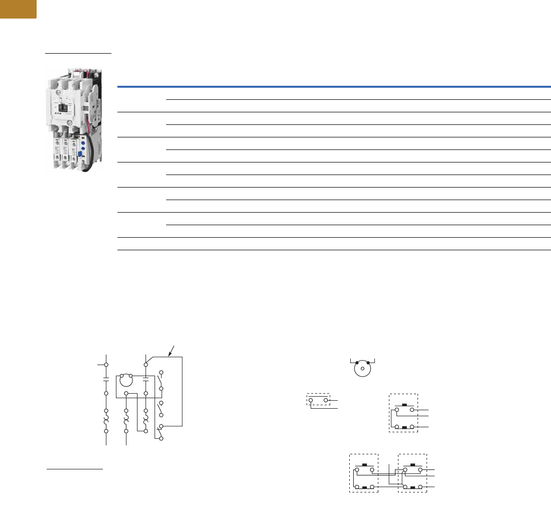
V5-T2-16 Volume 5—Motor Control and Protection CA08100006E—August 2014 www.eaton.com
2
2
2
2
2
2
2
2
2
2
2
2
2
2
2
2
2
2
2
2
2
2
2
2
2
2
2
2
2
2
2.1
NEMA Contactors and Starters
Freedom Series
Product Selection
When Ordering Specify
●Catalog number
●Heater pack number (see selection table, Pages V5-T2-40 to V5-T2-42) or full load current
Type BN16 NEMA—Manual or Automatic Reset Overload Relay
Note
1 For separate 120V control circuit. For maximum hp at listed motor voltages, use the rating of other starters of same size.
Wiring Diagrams
Single-Phase Applications (Factory Wired)
NEMA
Size
Maximum Horsepower Magnet Coil Voltage
(60 Hz)
Open Type Two-Pole
Motor Voltage Single-Phase Catalog Number
00 115 1/3 120 1BN16AN0AC
230 1 240 BN16AN0BC
0 115 1 120 1BN16BN0AC
230 2 240 BN16BN0BC
1 115 2 120 1BN16DN0AB
230 3 240 BN16DN0BB
1P 115 3 120 1BN16PN0AB
230 5 240 BN16PN0BB
2 115 3 120 1BN16GN0AB
230 7-1/2 240 BN16GN0BB
3 115 7-1/2 120 1BN16KN0A
230 15 240 BN16KN0B
Starter catalog numbers do not include heater packs. Select one carton of three heater packs. Heater pack selection, Pages V5-T2-40 to V5-T2-42.
BN16DM0AB
Front View of Panel
Single-Phase Motor
When more than
one pushbutton
station is used,
omit Connector “A”
and connect per
sketch at right.
Two-Wire Control
Not for Use with
Auto Reset OL Relays
Three-Wire Control
START
STOP
AC Lines
1
L1
1
M
OL
A1 A2 2/13
3/14
98
97
96
95
2/T1 4/T2 6/T3 Reset
3
L2
T1
2T2
4
T1 T2
“C”
3/14
Separate Control
Remove Wire “C” if supplied and connect separate control
lines to the Number 1 Terminal on the remote pilot device
and to the Number 96 Terminal on the overload relay.
13/14
2/13
1
START “A”
STOP
START
STOP
3/14
2/13
1
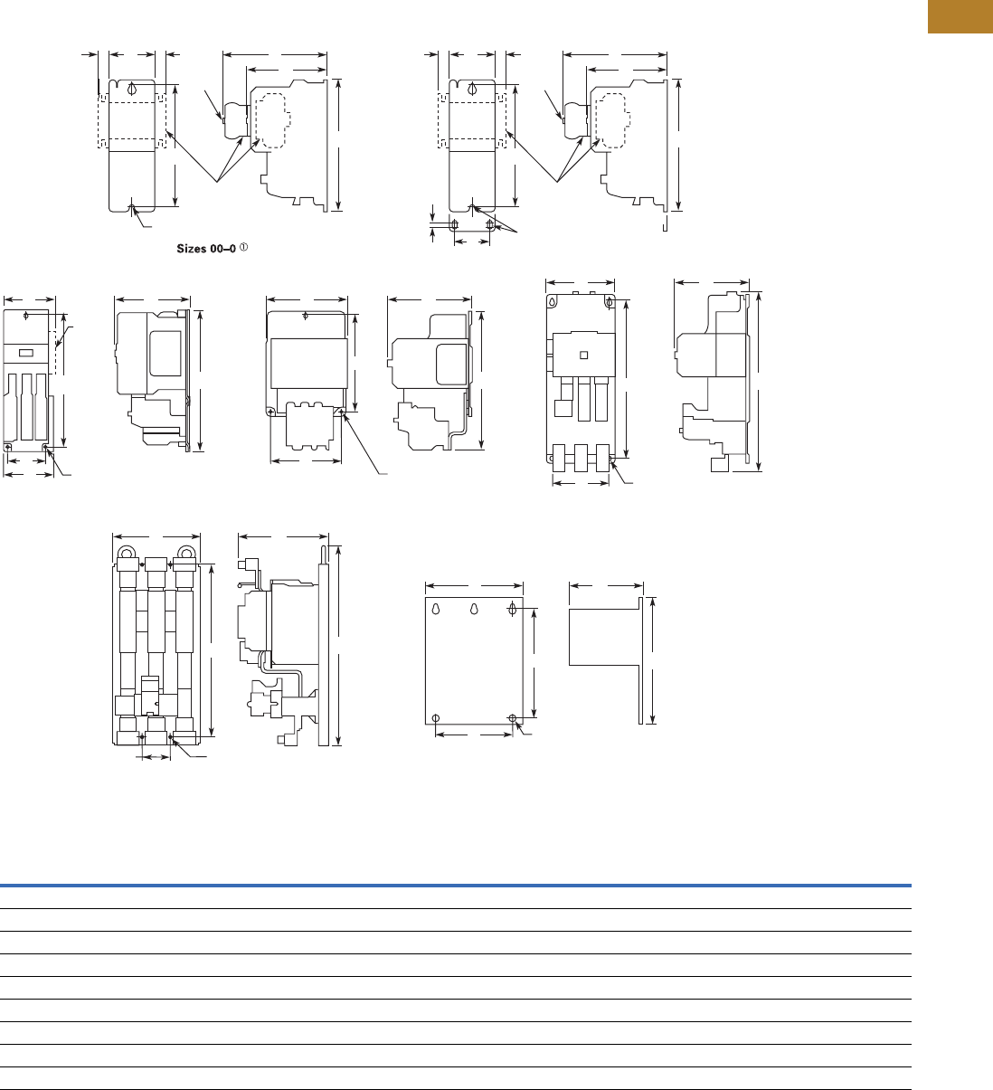
Volume 5—Motor Control and Protection CA08100006E—August 2014 www.eaton.com V5-T2-17
2
2
2
2
2
2
2
2
2
2
2
2
2
2
2
2
2
2
2
2
2
2
2
2
2
2
2
2
2
2
2.1
NEMA Contactors and Starters
Freedom Series
Dimensions
Approximate Dimensions in Inches (mm)
Non-Reversing Starters, Bi-Metallic Overload—Open Type
Dimensions and Shipping Weights
Note
1Holding circuit contact for Size 00 occupies 4th power pole position—no increase in width.
NEMA
Size
Wide
A
High
B
Deep
C
Mounting
D
Mounting
EFG
Shipping Weight
Lbs (kg)
00–0 1.80 (45.7) 6.60 (167.6) 3.52 (89.4) — 6.07 (154.2) 4.90 (124.5) 0.54 (13.7) 2.2 (1.0)
1–1P 2.56 (65.0) 7.08 (179.8) 4.44 (112.8) 2.00 (50.8) 6.63 (168.4) 5.80 (147.3) 0.54 (13.7) 4.5 (2.0)
2 2.56 (65.0) 8.08 (205.2) 4.44 (112.8) 2.00 (50.8) 7.63 (193.8) 5.80 (147.3) 0.54 (13.7) 4.7 (2.1)
3 4.08 (103.6) 11.35 (288.3) 5.94 (150.9) 3.00 (76.2) 10.81 (274.6) — — 11.0 (5.0)
4 7.05 (179.1) 12.06 (306.3) 7.25 (184.2) 6.00 (152.4) 8.50 (215.9) — — 23.0 (10.4)
5 7.00 (177.8) 17.77 (451.4) 7.76 (197.1) 6.00 (152.4) 16.00 (406.4) — — 36.0 (16.3)
6 9.47 (240.5) 21.69 (550.9) 9.90 (251.5) 3.10 (78.7) 18.00 (457.2) — — 75.0 (34.1)
7 15.13 (384.3) 29.13 (739.9) 12.64 (321.1) 13.25 (336.6) 21.25 (539.8) — — 120.0 (54.5)
8 15.13 (384.3) 34.50 (876.3) 15.00 (381.0) 13.25 (336.6) 16.75 (425.5) — — 210.0 (95.3)
Side
Mtd.
Aux.
D
A
U
X
Aux.
Cont.
Aux.
A
U
X
AGG
C
F
Top
Mtd.
Aux.
Auxiliary
Contacts
Mtg. Holes for #10-32 Screws
Top
Mtd.
Aux.
E
C
LC
L
B
CACG
EB
Mtg. Holes for
#10-32 Screws
Sizes 1–2
D
AMtg. Holes for (3)
1/4-20 Screws
Size 3
E
B
AC
B
D
Mtg. Holes for
1/4-20 Screws
Size 4
E
DMtg. Holes for
1/4-20 Screws
Size 5
AC
B
E
DMtg. Holes for
1/2-13 Screws
Sizes 7–8
Size 6
AC
B
E
DMtg. Holes for (4)
3/8-16 Screws
Side
Mtd.
Aux.
A
U
X
A
U
X
AGGF
C
Top
Mtd.
Aux.
Auxiliary
Contacts
Top
Mtd.
Aux.
E
0.13
(3.3)
B
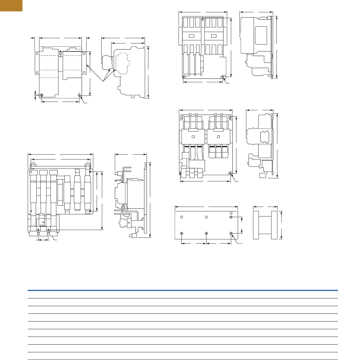
V5-T2-18 Volume 5—Motor Control and Protection CA08100006E—August 2014 www.eaton.com
2
2
2
2
2
2
2
2
2
2
2
2
2
2
2
2
2
2
2
2
2
2
2
2
2
2
2
2
2
2
2.1
NEMA Contactors and Starters
Freedom Series
Approximate Dimensions in Inches (mm)
Reversing Starters, Bi-Metallic Overload—Open Type
Dimensions and Shipping Weights
Notes
1Includes cross wiring overhang.
2See catalog listings for type and location of auxiliary contacts supplied with a particular starter.
NEMA
Size
Wide
A
High
B
Deep
C
Mounting
D
Mounting
ED1E1FG
Shipping Weight
Lbs (kg)
00–0 4.20 (106.7) 7.38 (187.5) 3.52 (89.4) 3.50 (88.9) 6.87 (174.5) — — 4.90 (124.5) 0.54 (13.7 3.6 (1.6)
1 5.71 (145.0) 7.08 (179.8) 4.44 (112.8) 5.25 (133.4) 5.75 (146.1) — — 5.80 (147.3) 0.54 (13.7) 8.3 (3.8)
2 5.71 (145.0) 8.08 (205.2) 4.44 (112.8) 5.25 (133.4 6.75 (171.5) — — 5.80 (147.3) 0.54 (13.7) 8.5 (3.9)
3 8.70 (221.0) 11.35 (288.3) 5.94 (150.9) 7.00 (177.8) 10.81 (274.6) — — — — 20.0 (9.1)
4 14.68 (372.9) 12.06 (306.3) 7.25 (184.2) 13.50 (342.9) 8.50 (215.9) — — — — 49.0 (22.2)
5 14.50 (368.3) 17.77 (451.4) 7.76 (197.1) 13.50 (342.9) 16.00 (406.4) — — — — 68.0 (30.9)
6 19.77 (502.2) 22.63 (574.8) 9.90 (251.5) 18.00 (457.2) 12.00 (304.8) 3.10 (78.7) 18.00 (457.2) — — 90.0 (40.9)
7 28.06 (712.7) 32.13 (816.1) 112.70 (322.6) 12.75 (323.9) 21.25 (539.8) — — — — 175.0 (79.5)
8 30.38 (771.7) 41.50 (1054.1) 114.70 (373.4) 14.13 (358.9) 16.75 (425.5) — — — — 430.0 (195.2)
Side
Mtd.
Aux.
A
U
X
A
U
X
A
D
.13
(3.3)
G
GF
C
Top
Mtd.
Aux.
Top
Mtd.
Aux.
Auxiliary
Contacts
b
Mtg. Holes for (3)
#10-32 Screws
Top
Mtd.
Aux.
EB
Sizes 00 – 2
A
D1
C
D
Mtg. Holes for (6)
3/8-16 Screws
E
E1 B
Size 6
DMtg. Holes for (3)
1/4-20 Screws
E
C
A
B
Size 3
DMtg. Holes for (4)
1/4-20 Screws
E
CA
B
Sizes 4 – 5
DD Mtg. Holes for (6)
1/2-13 Screws
E
AC
B
Open Type — Sizes 7 – 8 Horizontal
C
L
C
L
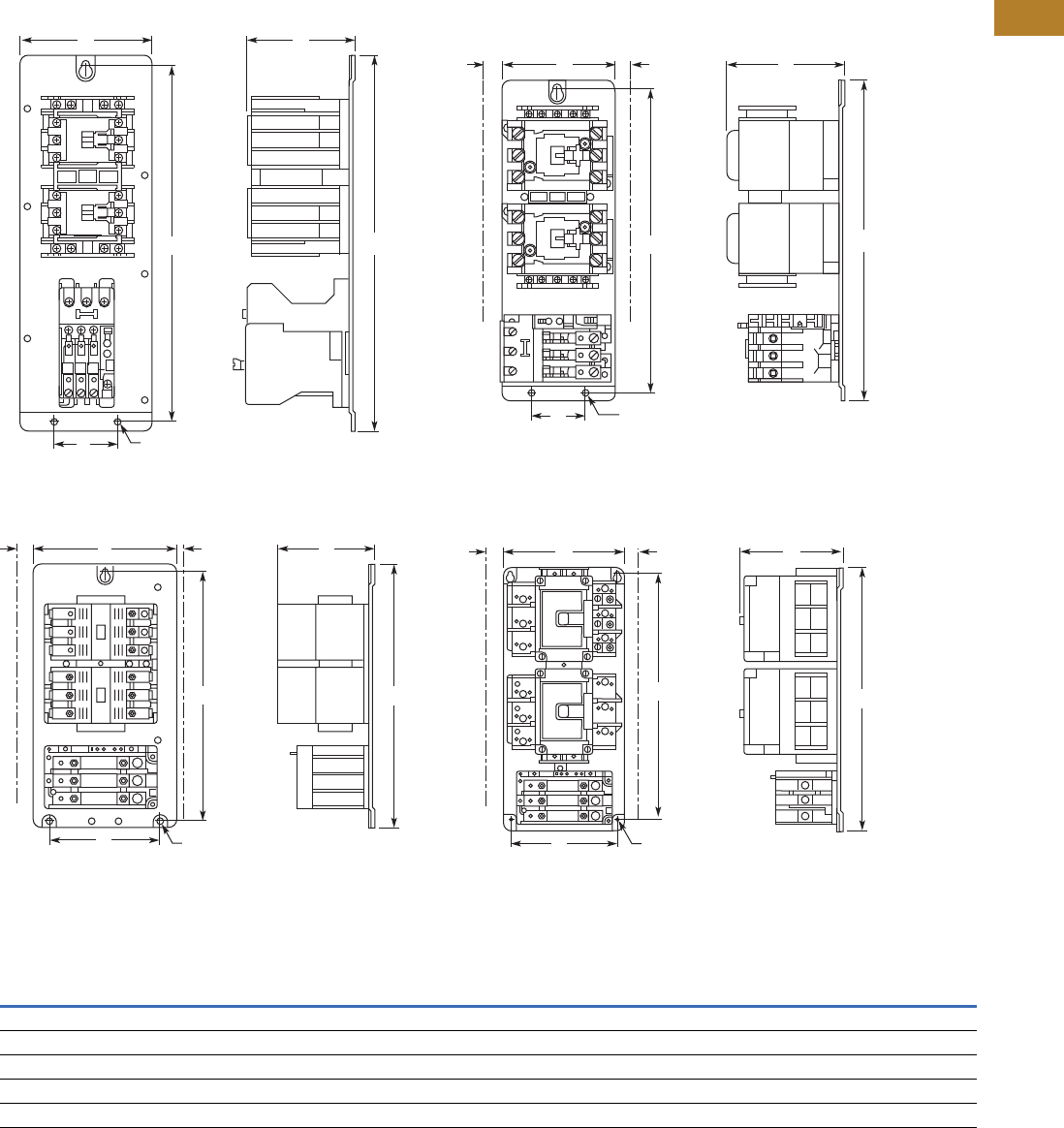
Volume 5—Motor Control and Protection CA08100006E—August 2014 www.eaton.com V5-T2-19
2
2
2
2
2
2
2
2
2
2
2
2
2
2
2
2
2
2
2
2
2
2
2
2
2
2
2
2
2
2
2.1
NEMA Contactors and Starters
Freedom Series
Approximate Dimensions in Inches (mm)
Reversing Starters—Vertical Construction, Bi-Metallic Overload—AN56V Open Vertical Starter
Dimensions and Shipping Weights
Note
1Wire overhang 1.00 mm left, 50 mm right.
NEMA
Size
Wide
A
High
B
Deep
C
Mounting
Wide
D
Mounting
HIgh
E Wire Zone
Shipping Weight
Lbs (kg)
0 4.25 (108.0) 12.05 (306.1) 3.84 (97.5) 2.00 (50.8) 11.50 (292.1) — 4.0 (1.8)
1 4.25 (108.0) 12.05 (306.1) 3.86 (98.0) 2.00 (50.8) 11.50 (292.1) 1.00 (25.4) 9.0 (4.1)
2 4.25 (108.0) 12.05 (306.1) 3.86 (98.0) 2.00 (50.8) 11.50 (292.1) 1.00 (25.4) 9.5 (4.3)
3 9.25 (235.0) 16.75 (425.5) 5.18 (131.6) 7.15 (181.6) 16.07 (408.2) 121.0 (9.5)
4 9.08 (230.6) 19.84 (503.9) 5.18 (131.6) 8.00 (203.2) 18.51 (470.2) 1.50 (38.1) 50.0 (22.7)
Mtg. Holes for (3)
#10-32 Screws
NEMA Size 0
D
E
A
B
C
Mtg. Holes for (3)
#10-32 Screws
NEMA Sizes 1 – 2
D
E
ACFF
B
Mtg. Holes for (3)
1/4-20 Screws
NEMA Size 3
D
E
ACFF
B
Mtg. Holes for (4)
1/4-20 Screws
NEMA Size 4
D
E
AC
FF
B
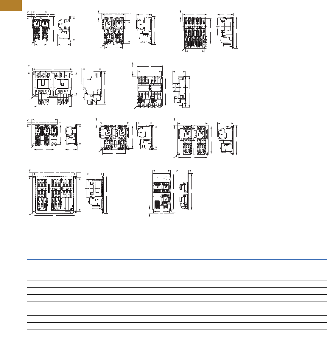
V5-T2-20 Volume 5—Motor Control and Protection CA08100006E—August 2014 www.eaton.com
2
2
2
2
2
2
2
2
2
2
2
2
2
2
2
2
2
2
2
2
2
2
2
2
2
2
2
2
2
2
2.1
NEMA Contactors and Starters
Freedom Series
Approximate Dimensions in Inches (mm)
Multispeed Starters, Bi-Metallic Overload—AN700 Open Vertical Starter
Dimensions and Shipping Weights
Notes
1Mounting holes for (3) #10 screws.
2Mounting holes for (3) 1/4-20 screws.
3Mounting holes for (4) 1/4-20 screws.
4Mounting holes for (4) 5/16 screws.
5Mounting holes for (4) 3/8 screws.
NEMA
Size
Wide
A
High
B
Deep
C
Mounting
Wide
D
Mounting
High
E
Wire
Zone F
Shipping Weight
Lbs (kg)
Two-Speed—Selective Control—Separate Winding
0 5.19 (132) 7.38 (188) 3.52 (89) 3.50 (89) 6.87 (175) 0.89 (23) 4.5 (2.0)
1 5.66 (144) 7.08 (180) 4.42 (112) 5.25 (133) 5.75 (146) 1.23 (31) 9.0 (4.1)
2 5.66 (144) 8.08 (205) 4.42 (112) 5.25 (133) 6.75 (165) 1.63 (41) 10.0 (4.5)
3 8.72 (221) 11.35 (288) 5.89 (150) 7.00 (178) 10.81 (275) 1.77 (45) 24.0 (10.9)
4 14.68 (373) 12.06 (306) 7.25 (184) 13.50 (343) 8.50 (216) 1.95 (50) 53.0 (24.1)
5 14.50 (368) 17.82 (453) 7.76 (197) 13.50 (343) 16.00 (406) 4.56 (116) 73.0 (33.1)
Two-Speed—Selective Control—Reconnectable Winding
0 8.62 (219) 7.06 (179) 3.82 (81) 6.62 (168) 6.50 (165) 0.50 (13) 6.0 (2.7)
1 8.97 (228) 7.12 (181) 4.72 (120) 6.62 (168) 6.50 (165) 1.04 (26) 10.0 (4.5)
2 8.90 (226) 8.62 (219) 4.75 (121) 8.40 (213) 8.12 (206) 1.03 (26) 11.0 (5.0)
3 16.00 (406) 13.46 (342) 6.38 (162) 15.00 (381) 12.25 (311) 1.24 (31) 31.0 (14.1)
4 15.46 (393) 31.00 (787) 7.74 (197) 13.50 (343) 30.00 (762) 1.84 (47) 72.0 (32.7)
aa
b
EB
A
DC
F
EB
A
D
C
F
EB
A
D
C
F
Size “3” Multispeed Starter
2-Speed, 2-Winding
Size “1 – 2” Multispeed Starter
2-Speed, 2-Winding
Size “0” Multispeed Starter
2-Speed, 2-Winding
E
B
A
D
C
F
EB
A
FDC
c
Size “4” Multispeed Starter
2-Speed, 2-Winding
cSize “5” Multispeed Starter
2-Speed, 2-Winding
EB
A
DC
F
EB
A
D
C
F
EB
A
D
C
F
a
a
a
Size “2” Multispeed Starter
2-Speed, 1-Winding
Size “1” Multispeed Starter
2-Speed, 1-Winding
Size “0” Multispeed Starter
2-Speed, 1-Winding
EB
A
D
C
F
E B
A
D
C
F햶
d
Size “4” Multispeed Starter
2-Speed, 1-Winding
Size “3” Multispeed Starter
2-Speed, 1-Winding
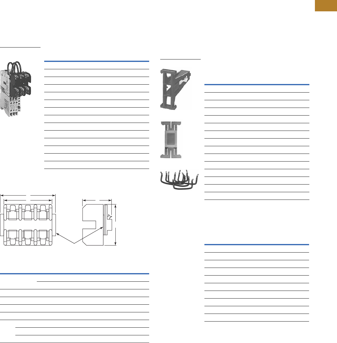
Volume 5—Motor Control and Protection CA08100006E—August 2014 www.eaton.com V5-T2-21
2
2
2
2
2
2
2
2
2
2
2
2
2
2
2
2
2
2
2
2
2
2
2
2
2
2
2
2
2
2
2.1
NEMA Contactors and Starters
Freedom Series
Accessories
Three-Pole Top Mounted Fuse Block Kit
IEC Sizes A–K, NEMA Sizes 00–2
Field mount to Freedom
Series starters and contactors.
Designed to save space and
reduce installation costs. They
provide short circuit protection
for branch circuits.
Fuse Block Kits
Three-Pole Top Mounted Fuse Block Kit
Fuse Type Catalog Number
Class H—30A 250V C350KH21
Class R—30A 250V C350KR21
Class G—15A 300V C350KG37
Class G—20A 300V C350KG38
Class G—30A 300V C350KG31
Class G— 60A 300V C350KG32
Class T— 30A 300V C350KT31
Class T— 60A 300V C350KT32
Class J—30A 600V C350KJ61
Class J—60A 600V C350KJ62
Type M—30A 600V 1C350KM61
Class CC—30A 600V C350KC63
Class T—30A 600V C350KT61
Class T—60A 600V C350KT62
Fuse Block Approximate Dimensions in Inches (mm)
Class Amperes Volts Wide A High B Deep C D
G 15, 20, 30
60
300 2.40 (61.0) 3.00 (76.2) 2.04 (51.8) —
300 2.62 (66.5) 4.25 (108.0) 2.08 (52.8) —
H 30 250 3.00 (76.2) 3.10 (78.7) 2.23 (56.6) 3.62 (91.9)
J 30, 60 600 4.81 (122.2) 4.12 (104.6) 2.82 (71.6) —
M, CC 30 600 2.40 (61.0) 3.00 (76.2) 2.04 (51.8) —
R 30 250 3.00 (76.2) 3.10 (78.7) 2.23 (56.6) 3.62 (91.9)
T 30, 60 300 3.44 (87.4) 3.00 (76.2) 2.33 (59.2) —
30 600 3.75 (95.3) 3.31 (84.1) 2.26 (57.4) —
60 600 4.87 (123.7) 3.00 (76.2) 2.58 (65.5) —
Mounted Fuse
Block Kit
A C
Mounting
Plate
D
B
Mechanical Interlock and Reversing Kits
Mechanical interlocks and
reversing kits are designed
for field assembly of
reversing contactors or
starters from Freedom Series
components. The reversing
kits include a mechanical
interlock, stabilizer bar and
a pre-cut, trimmed and
formed wire set. Auxiliary
contacts, if required, must
be ordered separately. See
Pages V5-T2-25 and
V5-T2-26.
Mechanical Interlock Only 23
Reversing Kits (Horizontal Contactor
Mounting Only)
Notes
1Type M fuse block not approved for branch circuit protection.
2Without cross-wiring.
3For use with latest series product.
4Kit includes (2) NC auxiliary contacts.
Application
Catalog
Number
NEMA
Size IEC Size
Contactor
Mounting
00–2 A–K Horizontal C321KM60B
3 L–N Horizontal C321KM30
3 to 4 N to P Horizontal C321KM43
4 P–S Horizontal C321KM40
4 to 5 — Horizontal C321KM45
4 to 6 S to T/U Horizontal C321KM80
5 — Horizontal C321KM50
5 to 6 — Horizontal C321KM56
6 T and U Horizontal C321KM70
6 to 7 T/U to V–X Horizontal C321KM90
7 V, W and X Horizontal C321KM34
4 or 5 to 5 P–S to 5 Vertical C321KM55
5 to 6 — Vertical C321KM65
6 T and U Vertical C321KM66
6 to 7 T/U to V–X Vertical C321KM67
Application
Catalog
Number
NEMA
Size IEC Size
00 A–C C321KM60K14B
0D–FC321KM60K13B
1—C321KM60K15B
2G–KC321KM60K16B
3—C321KM60K17 4
— L and M C321KM60K21 4
—N C321KM60K18 4
4—C321KM60K19 4
5—C321KM60K20 4
—P–SC321KM60K44 4
C321KM60B
Part No. 23-7165
Wire Set
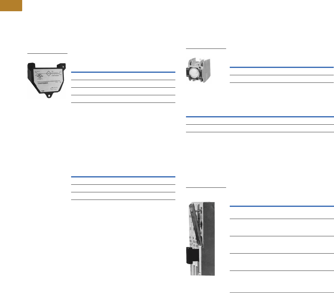
V5-T2-22 Volume 5—Motor Control and Protection CA08100006E—August 2014 www.eaton.com
2
2
2
2
2
2
2
2
2
2
2
2
2
2
2
2
2
2
2
2
2
2
2
2
2
2
2
2
2
2
2.1
NEMA Contactors and Starters
Freedom Series
Solid-State Timers
Solid-State ON DELAY Timer—Side Mounted on Freedom Series NEMA
00–2, IEC A–K and C25D, C25E and C25F Frame
This timer is designed to be
wired in series with the
load (typically a coil). When
the START button is pushed
(power applied to timer), the
ON DELAY timing function
starts. At the completion of
the set timing period, timer
and series wired load will
both be energized.
Mounted Timer Product Selection
Shorting Bar Kits
These kits provide phase-to-
phase power connections of
contactors for field assembly.
The kits include bus
connections and mounting
hardware. The shorting bars
connect all three phases of a
single contactor.
Shorting Bar Kits
Timing Range
Catalog
Number 123
0.1–1.0 seconds C320TDN1_
1–30 seconds C320TDN30_
30–300 seconds C320TDN300_
5–30 minutes C320TDN3000_ 4
Solid-State Timer
Description
Catalog
Number
NEMA Size 3, IEC Sizes L–N C321SB18
NEMA Size 4, IEC Sizes A–S C321SB19
NEMA Size 6, IEC Sizes T and U C321SB22
Pneumatic Timers—Top Mounted
Attachment mounts on top of
any NEMA Size 00–2 or IEC
Size A–K Freedom Series
starter or contactor (top
mounted auxiliary contacts
cannot be installed on device
when timer is used). Timer
unit has 1NO-1NC isolated
timed contacts—circuits in
each pole must be the same
polarity. Units are convertible
from OFF to ON DELAY or
vice-versa.
Pneumatic Timers
Maximum Ampere Ratings
Locking Cover for Overload Relay—C306 Only
Snap-on transparent or
opaque plastic panel for
covering access port to the
overload relay trip setting
dial—helps prevent accidental
or unauthorized changes to
trip and reset setting.
Locking Cover for Overlay Relay
Notes
1Add operating voltage suffix to catalog number.
A = 120V, B = 240V, E = 208V
2Rated 0.5 ampere pilot duty—not to be used on larger contactors.
3Terminal connections are quick connects only. Two per side.
4240V operating voltage not available for C320TDN3000_.
Timing Range
Catalog
Number
0.1 to 30 seconds C320TP1
10 to 180 seconds C320TP2
Description
Vac
120 240 480 600
Make 30 15 7.5 6
Break 3 1.5 0.75 0.6
Pneumatic Timers
Description
Min. Ordering
Quantity (Std. Pkg.)
Catalog
Number
Clear cover, no
accessibility
50 C320PC3
Gray cover, no
accessibility, with
Auto only nib
50 C320PC4
Gray cover, no
accessibility, with
Manual only nib
50 C320PC5
Gray cover with FLA dial
accessibility, A, B, C, D
positions and Auto only nib
50 C320PC6
Gray cover with FLA dial
accessibility, A, B, C, D
positions and Manual
only nib
50 C320PC7
Locking Cover for
Overlay Relay
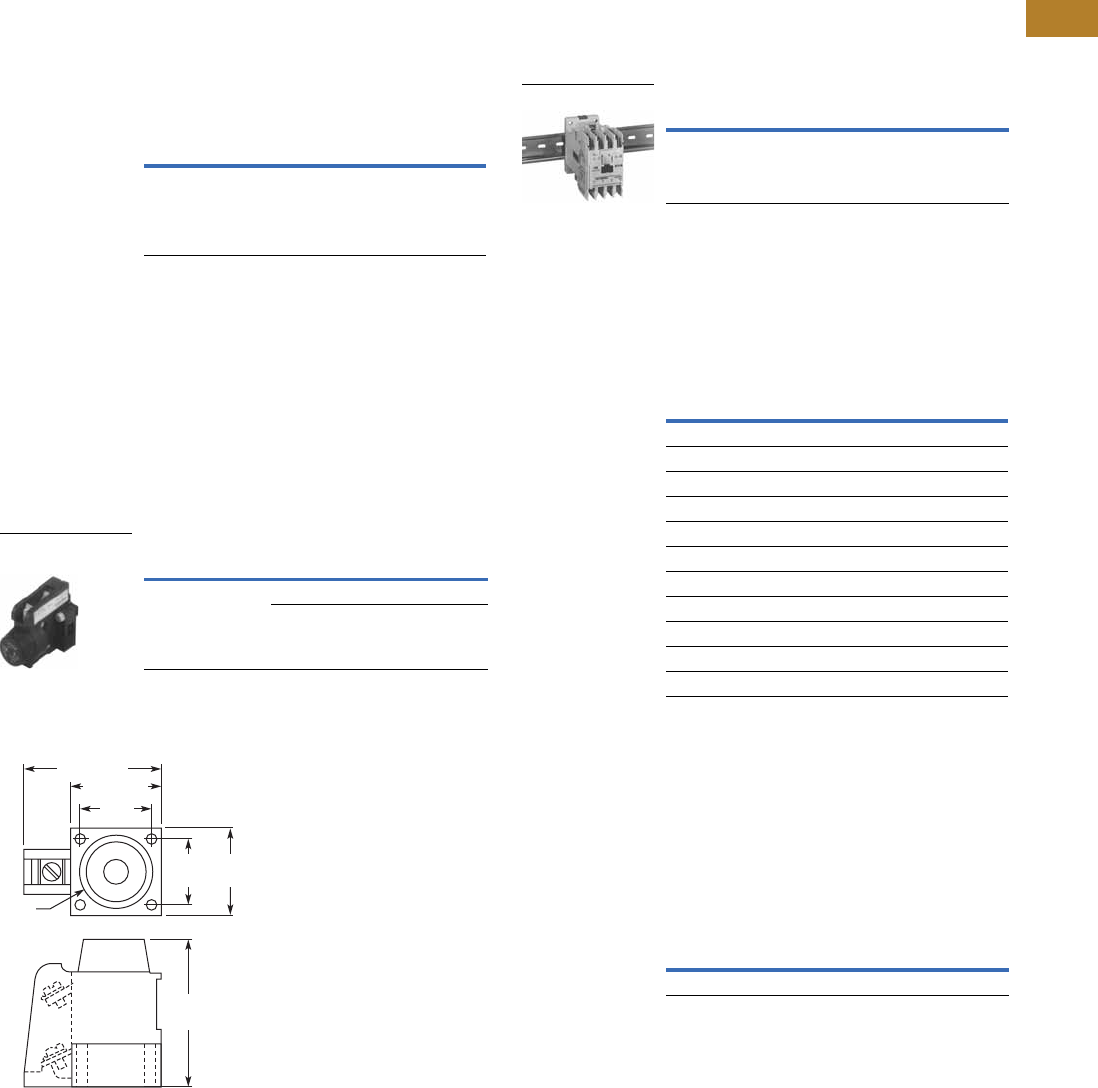
Volume 5—Motor Control and Protection CA08100006E—August 2014 www.eaton.com V5-T2-23
2
2
2
2
2
2
2
2
2
2
2
2
2
2
2
2
2
2
2
2
2
2
2
2
2
2
2
2
2
2
2.1
NEMA Contactors and Starters
Freedom Series
Identification Markers
IEC Sizes A–K, NEMA Sizes 00–2
Designed to snap on the face
of contactor for easy,
personalized identification of
individual devices. Includes
holder and labels.
Identification Markers
Control Circuit Fuse Block
These panel mounted
fuse holders, designed for
control circuit protection or
other similar low current
requirements, have extractor
type fuse caps. The Class CC
rejection type fuses (KTK-R)
used in these holders are
intended for use with
equipment designated as
being suitable for use on
systems having high available
fault currents. If branch
circuit protective device is
45A or greater, C320FBR
fuse kit may be required for
control circuit protection per
NEC 430-72.
Control Circuit Fuse Block
Dimensions
Approximate Dimensions in Inches (mm)
Description Catalog Number
Identification marker C320DL2
Type Max. Amperes Catalog Number
Fuse holder only 15 C320FB 1
30 C320FBR 2
Control Circuit
Fuse Block
0.97
(24.6)
1.25 (31.8)
1.88 (47.8)
1.19
(30.2)
0.88
(22.4)
2.06
(52.3)
Fuse
DIN Rail Mounting Channel—35 mm
Designed for DIN rail
mounting of IEC style
contactors and starters.
DIN Rail
Finger Protection Shields
Snap-on shields for both
contactors and starters
provide IEC Type IP20 finger
protection. Prevents
accidental contact with
line/load terminals.
Finger Protection Shields
Adapter to DIN Rail Mount
NEMA 1–2 and IEC G–K Contactors
Designed to allow DIN rail
mounting of NEMA 1–2 and
IEC G–K contactors. Includes
all hardware required to
convert contactors from
panel mounting to 35 mm
DIN rail mounting.
Adapter to DIN Rail Mount
Notes
1A fuse is not supplied, but holder will accept a Bussman Type KTK or KTK-R
(13/32 in x 1-1/2 in) fuse, 600V maximum.
2Includes a 5A, 600V KTK-R fuse.
Description Catalog Number
1 meter length MC382MA1
DIN Rail
Application Catalog Number
NEMA Size 00, IEC Sizes A–C C320LS1
NEMA Size 0, IEC Sizes D–F C320LS2
NEMA Sizes 1–2, IEC Sizes G–K
Contactors C320LS3
Reversing contactors C320LS4
NEMA Size 1
Starters C320LS5
Reversing starters C320LS6
NEMA Size 2, IEC Sizes G–K
Starters C320LS7
Reversing starters C320LS8
Catalog Number
C320DN65
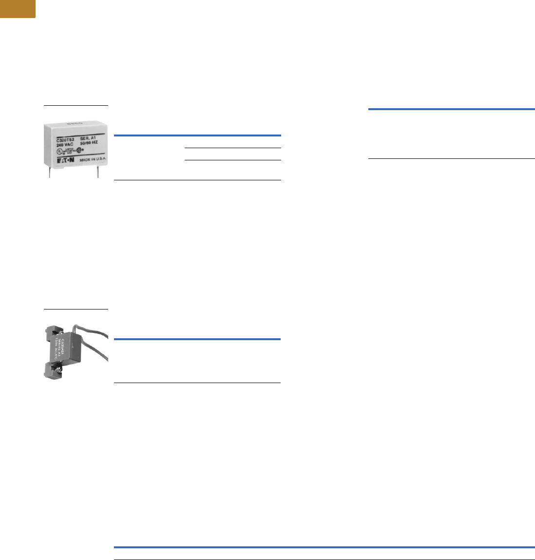
V5-T2-24 Volume 5—Motor Control and Protection CA08100006E—August 2014 www.eaton.com
2
2
2
2
2
2
2
2
2
2
2
2
2
2
2
2
2
2
2
2
2
2
2
2
2
2
2
2
2
2
2.1
NEMA Contactors and Starters
Freedom Series
Transient Suppressor Kits
NEMA Sizes 00–2, IEC Sizes A–K
These kits limit high voltage
transients produced in the
control circuit when power is
removed from the contactor
or starter coil. There are three
separate suppressors for use
on 24–120V, 208–240V or
277–480V coils respectively.
These devices mount directly
to the coil terminals of
Freedom Series contactors
or starters NEMA Sizes 00–2,
IEC Sizes A–K and lighting
contactors 10–60A.
Reversing devices will
require two.
NEMA Sizes 00–2, IEC Sizes A–K
NEMA Sizes 3–5, IEC Sizes L–S
This device mounts on top
of any side mounted auxiliary
contact on Freedom Series
NEMA Sizes 3–5, IEC Sizes
L–S and lighting contactors
100–300A. It connects across
coil terminals on any 120V
contactor or starter magnet
coil (reversing starters or
contactors require 2).
Limits high voltage
transients produced in
the circuit when power is
removed from the coil.
NEMA Sizes 3–5, IEC Sizes L–S
Add-On Power Pole Kit 2
NEMA Sizes 00–0, IEC Sizes A–F
This device mounts on the
side of Freedom NEMA Size
00–0 and IEC Sizes A–F
contactors. One unit can be
mounted on each side and
carries UL, cUL and IEC
ratings. The device is rated
for resistive, inductive and
lighting applications.
NEMA Sizes 00–0, IEC Sizes A–F
Notes
1Suppressor is compatible with coil voltages/ranges as shown, both 50 and 60 Hz.
2Power pole kits sold for replacement purposes only. For new applications, order the correct
four-pole and five-pole contactor catalog numbers.
Description
Coil
Voltage 1
Catalog
Number
Transient suppressor 24/120V C320TS1
208/240V C320TS2
277/480V C320TS3
C320TS2
Description
Coil
Voltage
Catalog
Number
Transient suppressor 120V C320AS1
C320AS1
UL Ampere Rating IEC 947 Ampere Rating
1NO Power Pole
Catalog
Number
Inductive
600V
Resistive
600V
Horsepower Single-Phase Locked
Rotor
240V
Lighting Ballast
Tungsten
480V
AC-1
600V
AC-3
600V
AC-5a
AC-5b
480V115V 230V
15 20 1/2 2 96 20 20 12 18 C320PPD10
Adhesive Dust Cover
NEMA Sizes 00–2, IEC Sizes A–K
These adhesive stickers
come 25 to a package and
provide extra protection from
contaminants when applied
to the sides of Freedom
NEMA Sizes 00–2 and IEC
Sizes A–K. Adhesive covers
are easily applied to side
opening where auxiliaries
are not installed and provide
extra protection from metal
filings and other debris.
NEMA Sizes 00–2, IEC Sizes A–K
Description Catalog Number
25 to a package C320DSTCVR
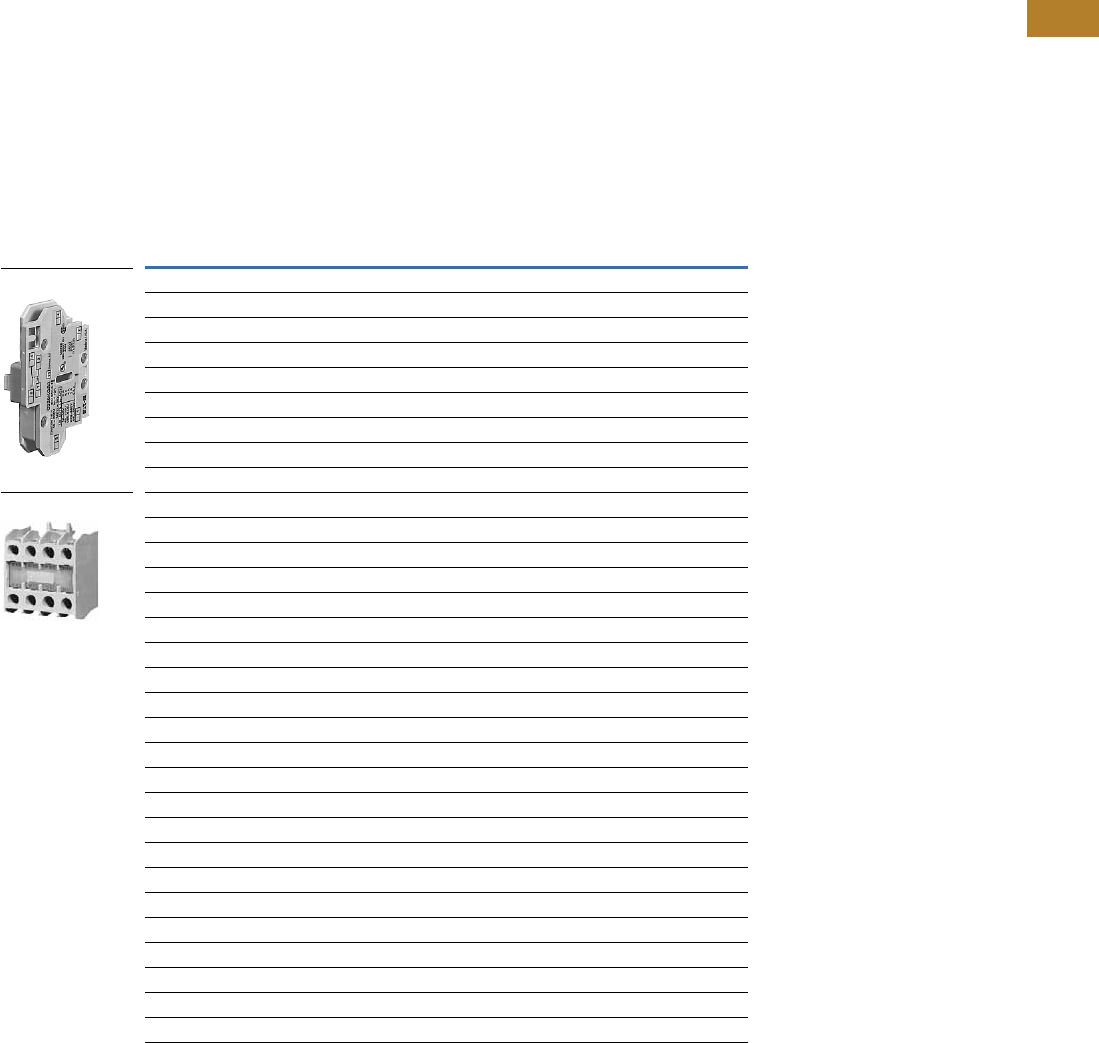
Volume 5—Motor Control and Protection CA08100006E—August 2014 www.eaton.com V5-T2-25
2
2
2
2
2
2
2
2
2
2
2
2
2
2
2
2
2
2
2
2
2
2
2
2
2
2
2
2
2
2
2.1
NEMA Contactors and Starters
Freedom Series
Auxiliary Contacts
Contact Configuration Code
This two-digit code is found
on the auxiliary contact to
assist in identifying the
specific contact configuration.
The first digit indicates the
quantity of NO contacts and
the second indicates the
quantity of NC contacts.
NEMA Sizes 00–2—IEC Sizes A–K
The auxiliary contacts listed
on this page are designed
for installation on Freedom
Series starters and
contactors. Snap-on
design facilitates quick,
easy installation.
These bifurcated design
contact blocks, featuring
silver cadmium alloy
contacts, are well suited
for use in very low energy
(logic level) circuits.
NEMA Sizes 00–2—IEC Sizes A–K 1
Notes
1 NCI = Normally Closed early opening designed for use in reversing applications. EC = Early Closing. LO = Late Opening.
2 For reference only—not part of catalog number.
Description
Contact
Configuration Code 2Catalog Number
Side Mounted
1NO 10 C320KGS1
1NC 01 C320KGS2
1NO-1NC 11 C320KGS3
2NO 20 C320KGS4
2NC 02 C320KGS5
1NO-1NCI N/A C320KGS6
1NO (EC)-1NC (LO) N/A C320KGS7
1NCI N/A C320KGS8
Top Mounted
1NO 10 C320KGT1
1NC 01 C320KGT2
1NO-1NC 11 C320KGT3
2NO 20 C320KGT4
2NC 02 C320KGT5
1NO-1NCI N/A C320KGT6
1NO (EC)-1NC (LO) N/A C320KGT7
1NCI N/A C320KGT8
3NO 30 C320KGT9
2NO-1NC 21 C320KGT10
1NO-2NC 12 C320KGT11
3NC 03 C320KGT12
4NO 40 C320KGT13
3NO-1NC 31 C320KGT14
2NO-2NC 22 C320KGT15
1NO-3NC 13 C320KGT16
4NC 04 C320KGT17
3NO-1NCI N/A C320KGT18
2NO-1NCI-1NC N/A C320KGT19
2NO-1NO (EC)-1NC (LO) N/A C320KGT20
1NO-1NC-1NO (EC)-1NC (LO) N/A C320KGT21
Side Mounted
Top Mounted
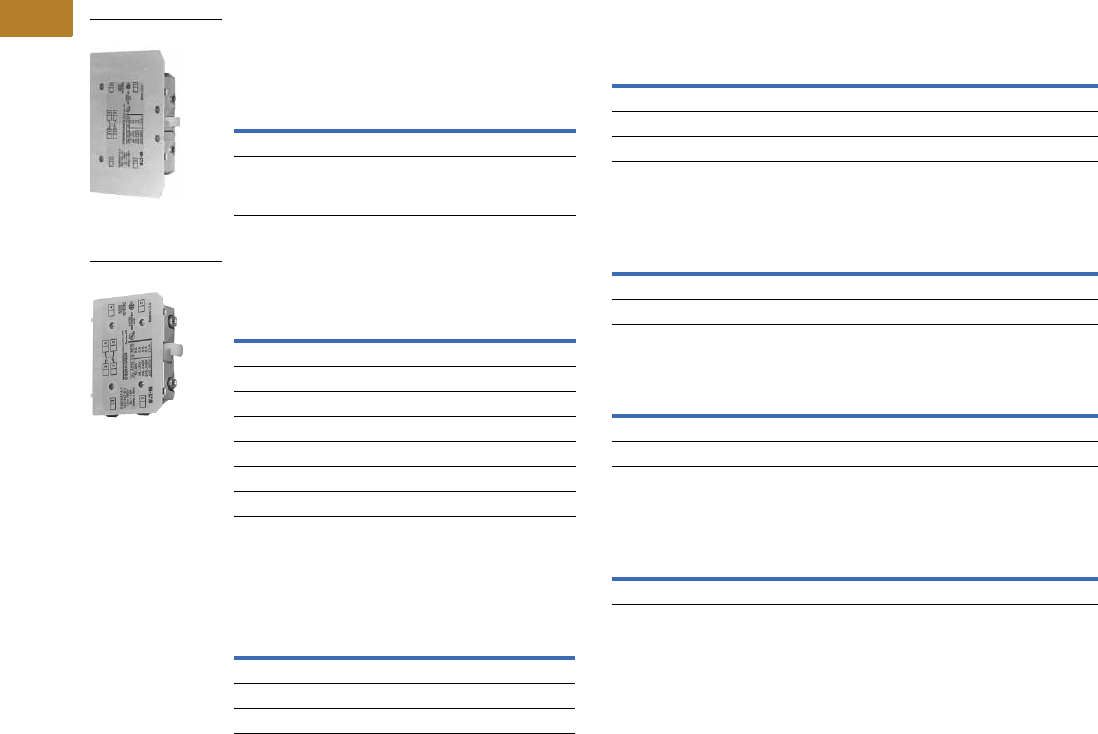
V5-T2-26 Volume 5—Motor Control and Protection CA08100006E—August 2014 www.eaton.com
2
2
2
2
2
2
2
2
2
2
2
2
2
2
2
2
2
2
2
2
2
2
2
2
2
2
2
2
2
2
2.1
NEMA Contactors and Starters
Freedom Series
NEMA Sizes 3–8—IEC Sizes L–Z
Base Auxiliary Contacts—
NEMA Sizes 3–5, IEC Sizes L–S
Auxiliary Contacts—NEMA Sizes 3–5,
IEC Sizes L–S
Auxiliary Contacts—NEMA Sizes 6–8,
IEC Sizes T–Z
Circuit
Contact
Configuration
Code 1
NEMA Size 3
IEC Sizes L –N
Catalog
Number
NEMA Sizes 4–5
IEC Sizes P–S
Catalog
Number
NO 10 C320KGS31 C320KGS41
NO-NC 11 C320KGS32 C320KGS42
Circuit
Contact
Configuration Code 1
Catalog
Number
NO 10 C320KGS20
NC 01 C320KGS21
NO-NC 211 C320KGS22
Sealed Logic Level
NO 10 C320KGS20L
NC 01 C320KGS21L
NO-NC 311 C320KGS22L
Circuit
Contact
Configuration
Code 1Size
Catalog
Number
NO-NC 11 NEMA 8, IEC Z C320KA5
2NO-2NC 22 NEMA 6–7 C320KA6
2NO-2NC 22 IEC T–X C320KA8
C320KGS42
C320KGS22
Auxiliary Contact Ratings (Amperes)
Ratings—NEMA A600
Ratings—NEMA P300
Ratings—Logic Level
Ratings C320KGS20L, C320KGS21L, C320KGS22L
Notes
1For reference only—not part of catalog number.
2NO-NC occupies two position—L2 and L3, or R2 and R3. See figure on Page V5-T2-27.
3Form C contacts.
Current
AC Volts
120V 240V 480V 600V
Make 60 30 15 12
Break 631.51
Continuous 10 10 10 10
Continuous Thermal Rating: 5A
DC Volts Make/Break Amperes
125 1.10
250 0.55
Minimum Ratings for Logic Level and Hostile Atmosphere Application
Minimum Amperes 20 mA
Minimum Volts 24 Vac/Vdc
DC-12 AC-12
UeIeUeIe
80 0.1 250 0.1
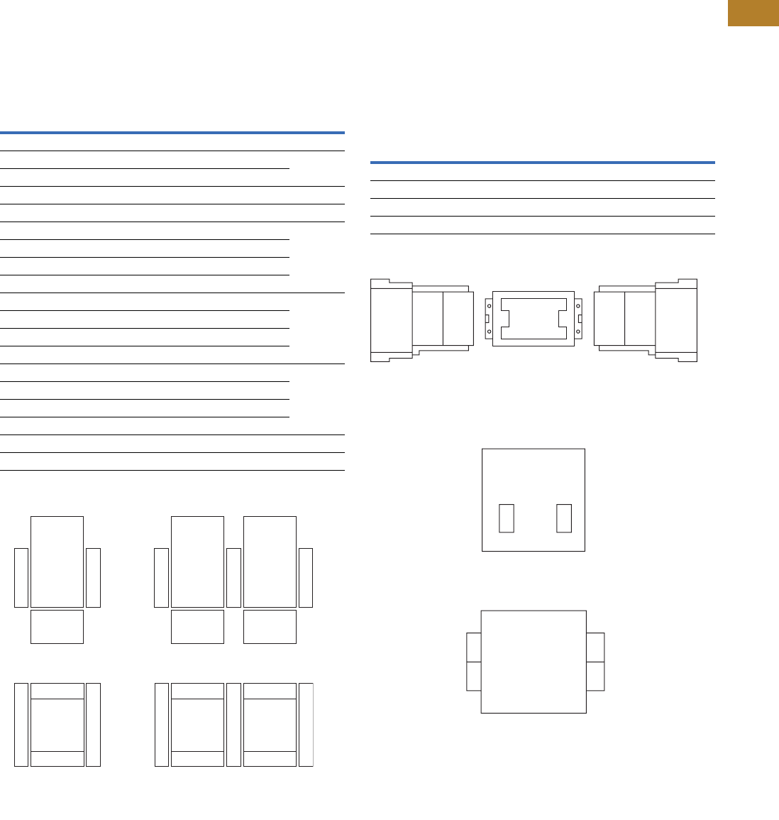
Volume 5—Motor Control and Protection CA08100006E—August 2014 www.eaton.com V5-T2-27
2
2
2
2
2
2
2
2
2
2
2
2
2
2
2
2
2
2
2
2
2
2
2
2
2
2
2
2
2
2
2.1
NEMA Contactors and Starters
Freedom Series
Auxiliary Contact Location
NEMA Sizes 00–2, IEC Sizes A–K
The sketches below illustrate
the maximum number of
auxiliary contacts that can be
assembled to a contactor or
starter and their locations.
Auxiliary Contacts
Auxiliary Contact Location
Size Poles
Available Mounting Positions 12 Catalog
NumberOpen Type Enclosed
A–K 3 T1, L1 L1 AE16
00 3 T1, L1, R1 L1 AN16
0–2 3 T1, L1 L1
A–K 3 L1, R1 L1, R1 AE56
00–2 3 T1, T2 — AN56
A–C 2–4 T1, L1, R1 L1, R1 CE15
D–K 3 T1, L1 L1
G–J 4 T1, R1 —
G–J 5 T1 —
00 2–4 T1, L1, R1 L1 CN15
0–2 2–3 T1, L1 L1
1, 2 4 T1, L1 —
1, 2 5 T1, L1 —
10A 2–4 T1, L1, R1 L1 CN35
20–60A 2–3 T1, L1 L1
60A 4 T1, L1 —
60A 5 T1, L1 —
A–K 3 L1, R1 L1, R1 CE55
00–2 3 T1, T2 — CN55
L1
T1 T2
R1
L1 T1 T2 R1
L1
T1
Top View
Front View
L1 T1 R1
Front View
Reversing
Contactors and Starters
Non-Reversing
Contactors and Starters
Top View
R1
NEMA Sizes 3–8, IEC Sizes L–Z
The sketches below illustrate
the maximum number of
auxiliary contacts that can be
assembled to a contactor and
their locations.
Note: A base auxiliary contact
must be added in position R1
before additional auxiliary
contacts can be mounted on
NEMA Size 3 and IEC Sizes L–N,
or in L1 on NEMA Sizes 4–5 and
IEC Sizes P–S.
Mounting Positions
Auxiliary Contact Location
Notes
1Available positions on contactors or starters other than what is factory installed.
2When a pneumatic timer is mounted on contactor, only side mounted auxiliary contact
positions are available. The solid-state timer, when added, takes up side mounted auxiliary
contact position.
Size Available Mounting Positions 1
NEMA Size 3, IEC Sizes L–N R2, R3, L1, L2, L3
NEMA Sizes 4–5, IEC Sizes P–S L2, L3, R1, R2, R3
NEMA Sizes 6–7, IEC Sizes T–X R1
NEMA Size 8, IEC Size Z L2, R2
NEMA Sizes 6–7
IEC Sizes T, U, V, W and X
NEMA Sizes 3–5
IEC Sizes L–S
NEMA Size 8
IEC Size Z
L1 R1
L1
Front
of Contactor
Left Side
of Contactor
L2
Aux.
Cont.
L3
Aux.
Cont.
R2
Aux.
Cont.
R3
Aux.
Cont.
L1
Base
Aux.
Cont.
R1
Base
Aux.
Cont.
Rear
Rear
Right Side
of Contactor
R1
L2 R2

V5-T2-28 Volume 5—Motor Control and Protection CA08100006E—August 2014 www.eaton.com
2
2
2
2
2
2
2
2
2
2
2
2
2
2
2
2
2
2
2
2
2
2
2
2
2
2
2
2
2
2
2.1
NEMA Contactors and Starters
Freedom Series
DC Magnet Coils
When Ordering Specify
Conversion Kit for
Field Assembly
●Catalog number
Factory Installed DC Coil
●For factory installed DC
magnet coil on AC
contactors or non-
combination starters (open
type only), substitute the
code suffix from the table
on this page for the
magnet coil identifier in
the device catalog number.
EXAMPLE: For Size 0 AC
contactor with a 24 Vdc
coil, change AN16BN0AC
to AN16BN0T1C
Application
●Connect for separate
control
●Not for use with cover
control switch operators
●Use twin break, heavy-
duty pilot devices
●Designed for +10%, –20%
rated voltage, continuous
duty operation
Non-Reversing Kit Consists of:
●One encapsulated DC
magnet coil
●One NCI or NO/NCI side
mounted auxiliary contact
Note: These kits are supplied
with a NO/NCI side mounted
auxiliary contact in place of the
NCI contact.
●Two blue colored
connection wires
●One instruction publication
Operation
See next page for operation
details.
DC Magnet Coils
Notes
1These kits are supplied with a NO/NCI side mounted auxiliary contact in place of the NCI contact.
2Kit does not include mechanical interlock or crossover wiring. Two NO/NCI top mounted auxiliary contacts are supplied for electrical interlocking.
3Factory installed DC coils on NEMA contactors and starters include a NO/NC top mounted auxiliary contact on each contactor for electrical
interlocking. On IEC contactors and starters, a NC top mounted auxiliary contact is supplied on each contactor for electrical interlocking.
4Available factory assembled only.
Contactor or
Starter Size
Conversion Data
Complete Conversion Kit
Factory
Installed
Volts
Magnet Coil
NCI
InterlockNEMA IEC
Coil
Number
Amps
P.U./Seal
Watts
P.U./Seal
Catalog
Number
Ship Wt.
Lbs (kg)
Code
Suffix
Non-Reversing—Kit Includes NCI Side Mounted Auxiliary Contact
00 and 0
CN35–A, B, D
D15 Relays
A–F 12 9-2988-11 6.4/0.28 76.8/3.36 C320KGD1 C335KD3R1 1.0 (0.5) R1
24 9-2988-12 3.2/0.14 76.8/3.36 C320KGD1 C335KD3T1 T1
48 9-2988-13 1.6/0.07 76.8/3.36 C320KGD1 C335KD3W1 W1
120 9-2988-14 0.64/0.028 76.8/3.36 C320KGD1 C335KD3A1 A1
1
00 and 0
CN35–A, B, D
D15 Relays
A–F 12 9-2988-11 6.4/0.28 76.8/3.36 C320KGD2 1C335KD3R4 1.0 (0.5) R4
24 9-2988-12 3.2/0.14 76.8/3.36 C320KGD2 1C335KD3T4 T4
48 9-2988-13 1.6/0.07 76.8/3.36 C320KGD2 1C335KD3W4 W4
120 9-2988-14 0.64/0.028 76.8/3.36 C320KGD2 1C335KD3A4 A4
1 and 2
CN35–G
G–K 12 9-2990-1 15.4/0.42 185/4.98 C320KGD5 C335KD4R4 1.0 (0.5) R4
24 9-2990-2 7.7/0.021 185/4.96 C320KGD5 C335KD4T4 T4
48 9-2990-3 3.9/0.11 185/5.04 C320KGD5 C335KD4W4 W4
120 9-2990-4 1.5/0.041 185/4.87 C320KGD5 C335KD4A4 A4
3
CN35–K
L–N 12 9-3002-1 24/0.40 293/4.84 C320KGD3 C335KD5R1 2.0 (0.9) R1
24 9-3002-2 12/0.20 288/4.75 C320KGD3 C335KD5T1 T1
48 9-3002-3 6.1/0.097 295/4.67 C320KGD3 C335KD5W1 W1
120 9-3002-4 2.5/0.038 298/4.57 C320KGD3 C335KD5A1 A1
4 and 5
CN35–N, S
P–S 24 9-2026-4 18/0.22 400/5.3 C320KGD3 C335KA3T1 2.5 (1.1) T1B
48 9-2026-3 9/0.11 400/5.2 C320KGD3 C335KA3W1 W1B
120 9-2026-2 3.3/0.05 450/5.4 C320KGD3 C335KA3A1 A1B
240 9-2026-1 1.7/0.02 440/4.9 C320KGD3 C335KA3B1 B1B
Reversing
00 and 0
CN35–A, B, D
D15 relays
A–F 12 (2) 9-2988-1 6.4/0.28 76.8/3.36 (2) C320KGD1 C335RD3R1 21.0 (0.5) R1 3
24 (2) 9-2988-2 3.2/0.14 76.8/3.36 (2) C320KGD1 C335RD3T1 2T1 3
48 (2) 9-2988-3 1.6/0.07 76.8/3.36 (2) C320KGD1 C335RD3W1 2W1 3
120 (2) 9-2988-4 0.64/0.028 76.8/3.36 (2) C320KGD1 C335RD3A1 2A1 3
1 and 2
CN35–G
G–K 12 (2) 9-2990-1 15.4/0.42 185/4.98 (2) C320KGD3 4—R1 3
24 (2) 9-2990-2 7.7/0.21 185/4.96 (2) C320KGD3 4T1 3
48 (2) 9-2990-3 3.9/0.11 185/5.04 (2) C320KGD3 4W1 3
120 (2) 9-2990-4 1.5/0.041 185/4.87 (2) C320KGD3 4A1 3
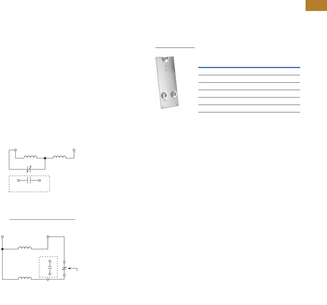
Volume 5—Motor Control and Protection CA08100006E—August 2014 www.eaton.com V5-T2-29
2
2
2
2
2
2
2
2
2
2
2
2
2
2
2
2
2
2
2
2
2
2
2
2
2
2
2
2
2
2
2.1
NEMA Contactors and Starters
Freedom Series
Operation
These DC coil kits have
separate pick-up and seal
windings. A special (side
mounted) early-break NCI
auxiliary contact is used to
either disconnect the pick-up
winding or insert the seal
winding in series with the
pick-up winding, depending
on the frame size of the
contactor. DC coil kits come
in two styles, a suffix 1 and a
suffix 4. Suffix 1 contains only
the special (side mounted)
early break NCI auxiliary
contact. Suffix 4 contains
a NO contact in the same
package as the special
(side mounted) early-break
NCI auxiliary contact.
Note: For NEMA Sizes 00 and 0
and IEC Sizes A–F, contactors
may utilize either suffix 1 or 4 DC
coil kits; starters may utilize suffix
4 DC coil kits only. For NEMA
Sizes 1 and 2 and IEC Sizes G–K,
both contactors and starters may
utilize a suffix 4 DC coil kit only.
On the above sizes only,
when the special auxiliary
package is mounted on the
side of a contactor or starter,
no standard auxiliary contact
may be mounted on the
same side.
Note: For NEMA Sizes 3–5 and
IEC Sizes L–S, special coil NCI
clearing contact is an add-on
auxiliary (must mount on a base
mount auxiliary contact; normally
a 1NO). This arrangement will
normally account for two of the
three contact positions on the
side of each contactor or starter.
Elementary Diagrams
Auxiliary
Contact
Important
Incoming DC must be connected
between A1 and Top A2 T erminal.
A1 A2
A1 A2 T op
A2 Bottom
3
NCI
NO a
a
3
2
3
NCI
NO
2
Hold Pick-Up
Hold
Pick-Up
DC Coil Elementary Diagram
for NEMA Sizes 1–3 and IEC Sizes G–N
Contactors and Starters
DC Coil Elementary Diagram
for NEMA Sizes 00, 0, 4 and 5
and IEC Sizes A–F and P–S
Contactors and Starters
Competitive Mounting Plates
The C321 adapter plates
permit direct replacement of
competitive starters with
Freedom Series starters
without drilling and tapping
new mounting holes. Allen-
Bradley 509, Eaton’s A10
(adapter plate not required for
replacing A10 Starter Sizes 1,
4 and 5), Furnas 14, ESP100,
General Electric CR206,
CR306, Siemens SXL,
Square D 8536,
Westinghouse A200, B200.
Competitive Mounting Plates
Note
11NO available in Suffix 4 kits only.
2Handling number only—does not appear on product. The handling number is stamped
on the carton label only.
Freedom
NEMA Size
Index Number 2
Catalog Number
00, 0 C321CMP0
1C321CMP1
2C321CMP2
3C321CMP3
4C321CMP4
5C321CMP5
C321CMP1

V5-T2-30 Volume 5—Motor Control and Protection CA08100006E—August 2014 www.eaton.com
2
2
2
2
2
2
2
2
2
2
2
2
2
2
2
2
2
2
2
2
2
2
2
2
2
2
2
2
2
2
2.1
NEMA Contactors and Starters
Freedom Series
Special Modifications
For Catalog Numbers AN16, AN56, CE15, CN15, CN35, CN55
Renewal Parts
For a complete listing of parts, refer to the Renewal Parts Publication Number referenced below.
For Catalog Numbers AN16, AN30, AN40, AN56, AN70, AN80, AN800, CN15,
CN35 3 and CN55 Contactors and Starters (Size 00, 0)
Notes
1These modifications are generally available in kit form at lower cost. See specific product sections for kit listings.
2The T16 modifications are only available on C306 overloads and the following three-pole devices: CN15, CN55, AN16, AN56 and AN700 (separate winding only).
The 45 mm and 65 mm frames (NEMA Size 0–2) reversing devices (CN55B, CN55D, CN55G, AN56B, AN56D, AN56G, AN700 and AN700G) with the T16 modification
are supplied without crossover wires.
3CN35A = Size 00, CN35B and CN35D = Size 0, CN35G = Size 2, CN35K = Size 3, CN35N = Size 4, and CN35S = Size 5.
4Replace with complete contactor.
Addition or Special Feature
Starter Size —NEMA
0001/—2345678
Control Circuit
Extra auxiliary circuit, factory installed NO or NC—each contact 1Consult sales office for pricing adders.
Transient suppressor 1Consult sales office for pricing adders.
Power Circuit
Contactor/starter for ring lug capability—add Mod Code T16 to catalog number 2
(Power terminals only, control terminals as standard)
Standalone overload relays can not accept ring lugs on line side
Consult sales office for pricing adders.
Factory Installed Dust Covers
Factory installed C320DSTCVR—add Mod Code -53 to catalog number 1NA NA NA NA NA NA
Description
NEMA Size 00 NEMA Size 0
Series B1 Series C1 Series B1 Series C1
Part No.Part No.Part No.Part No.
Renewal Parts Publication Number 22177 22177 22177 22177
Contact Kits
Two-pole 4444
Three-pole 4444
Four-pole 4444
Five-pole 4444
Magnet Coils Coil Suffix
120V 60 Hz or 110V 50 Hz A 9-2875-1 9-2875-1 9-2876-1 9-2876-1
240V 60 Hz or 220V 50 Hz B 9-2875-2 9-2875-2 9-2876-2 9-2876-2
480V 60 Hz or 440V 50 Hz C 9-2875-3 9-2875-3 9-2876-3 9-2876-3
600V 60 Hz or 550V 50 Hz D 9-2875-4 9-2875-4 9-2876-4 9-2876-4
208V 60 Hz E 9-2875-5 9-2875-5 9-2876-5 9-2876-5
277V 60 Hz H 9-2875-12 9-2875-12 9-2876-12 9-2876-12
208/240V 60 Hz J 9-2875-37 9-2875-37 9-2876-17 9-2876-17
240V 50 Hz K 9-2875-11 9-2875-11 9-2876-11 9-2876-11
380–415V 50 Hz L 9-2875-6 9-2875-6 9-2876-6 9-2876-6
380V 50 Hz L — — — —
415V 50 Hz M — — — —
550V 50 Hz N — — — —
24V 60 Hz–24V 50 Hz T 9-2875-36 9-2875-36 9-2876-36 9-2876-36
24V 60 Hz T — — — —
24V 50 Hz U 9-2875-36 9-2875-36 9-2876-36 9-2876-36
32V 50 Hz V 9-2875-16 9-2875-16 9-2876-16 9-2876-16
48V 60 Hz W 9-2875-8 9-2875-8 9-2876-8 9-2876-8
48V 50 Hz Y 9-2875-9 9-2875-9 9-2876-9 9-2876-9
Magnet Frame Armature
Lower magnet frame 4444
Upper magnet frame 4444

Volume 5—Motor Control and Protection CA08100006E—August 2014 www.eaton.com V5-T2-31
2
2
2
2
2
2
2
2
2
2
2
2
2
2
2
2
2
2
2
2
2
2
2
2
2
2
2
2
2
2
2.1
NEMA Contactors and Starters
Freedom Series
For Catalog Numbers AN16, AN30, AN40, AN56, AN70, AN80, AN800, CN15, CN35 1
and CN55 Contactors and Starters (Size 1, 2)
Note
1CN35A = Size 00, CN35B and CN35D = Size 0, CN35G = Size 2, CN35K = Size 3, CN35N = Size 4, and CN35S = Size 5.
Description
NEMA Size 1 NEMA Size 2
NEMA Size 3Series A1 Series B1 Series A1 Series B1
Part No. Part No. Part No. Part No. Part No.
Renewal Parts Publication Number 20861 22177 20861 22177 20426
Contact Kits
Two-pole 6-65 6-65 6-65-7 6-65-7 6-43-5
Three-pole 6-65-2 6-65-2 6-65-8 6-65-8 6-43-6
Four-pole 6-65-9 6-65-9 6-65-15 6-65-15 —
Five-pole 6-65-10 6-65-10 6-65-16 6-65-16 —
Magnet Coils Coil Suffix
120V 60 Hz or 110V 50 Hz A 9-3285-1 9-3285-1 9-3285-1 9-3285-1 9-2756-1 KIT
240V 60 Hz or 220V 50 Hz B 9-2703-2 KIT 9-2703-2 KIT 9-2703-2 KIT 9-2703-2 KIT 9-2756-2 KIT
480V 60 Hz or 440V 50 Hz C 9-2703-3 KIT 9-2703-3 KIT 9-2703-3 KIT 9-2703-3 KIT 9-2756-3 KIT
600V 60 Hz or 550V 50 Hz D 9-2703-4 KIT 9-2703-4 KIT 9-2703-4 KIT 9-2703-4 KIT 9-2756-4 KIT
208V 60 Hz E 9-2703-9 KIT 9-2703-9 KIT 9-2703-9 KIT 9-2703-9 KIT 9-2756-5 KIT
277V 60 Hz H 9-2703-7 KIT 9-2703-7 KIT 9-2703-7 KIT 9-2703-7 KIT 9-2756-9 KIT
208/240V 60 Hz J—————
240V 50 Hz K 9-2703-14 KIT 9-2703-14 KIT 9-2703-14 KIT 9-2703-14 KIT 9-2756-13 KIT
380–415V 50 Hz L 9-2703-8 KIT 9-2703-8 KIT 9-2703-8 KIT 9-2703-8 KIT —
380V 50 Hz L — — — — 9-2756-12 KIT
415V 50 Hz M — — — — 9-2756-8 KIT
550V 50 Hz N — — — — 9-2756-14 KIT
24V 60 Hz–24V 50 Hz T—————
24V 60 Hz T 9-2703-6 KIT 9-2703-6 KIT 9-2703-6 KIT 9-2703-6 KIT 9-2756-6 KIT
24V 50 Hz U 9-2703-12 KIT 9-2703-12 KIT 9-2703-12 KIT 9-2703-12 KIT 9-2756-11 KIT
32V 50 Hz V 9-2703-10 KIT 9-2703-10 KIT 9-2703-10 KIT 9-2703-10 KIT 9-2756-10 KIT
48V 60 Hz W 9-2703-11 KIT 9-2703-11 KIT 9-2703-11 KIT 9-2703-11 KIT 9-2756-15 KIT
48V 50 Hz Y 9-2703-13 KIT 9-2703-13 KIT 9-2703-13 KIT 9-2703-13 KIT 9-2756-7 KIT
Magnet Frame Armature
Lower magnet frame 17-18200 17-18200 17-18200 17-18200 KIT 17-8955-2 KIT
Upper magnet frame 48-1936 48-1936 48-1936 48-1936 KIT 48-1902 KIT

V5-T2-32 Volume 5—Motor Control and Protection CA08100006E—August 2014 www.eaton.com
2
2
2
2
2
2
2
2
2
2
2
2
2
2
2
2
2
2
2
2
2
2
2
2
2
2
2
2
2
2
2.1
NEMA Contactors and Starters
Freedom Series
For a complete listing of parts, refer to the Renewal Parts Publication Number referenced below.
For Catalog Numbers AN16, AN30, AN40, AN56, AN70, AN80, AN800, CN15, CN35 1 and CN55
Contactors and Starters (Size 4, 5, 6)
Feeder Group Renewal 3
Notes
1CN35A = Size 00, CN35B and CN35D = Size 0, CN35G = Size 2, CN35K = Size 3, CN35N = Size 4, and CN35S = Size 5.
2Consult factory.
3Voltage ratings of the main coils must match those of the feeder group for proper operation of the starter/contactor.
Description
NEMA Size 4 NEMA Size 5 NEMA Size 6
Series A1 Series B1 Series A1 Series B1
Contactor and Starter
Series A1, Starter Series B1
Contactor and Starter
Series B1, Starter Series C1
Part No. Part No. Part No. Part No. Part No. Part No.
Renewal Parts Publication Number 20428 20428 20429 20429 20146 23349
Contact Kits
Two-pole 6-44 6-26 6-45 6-45 6-601-2 —
Three-pole 6-44-2 6-26-2 6-45-2 6-45-2 6-601 6-648
Magnet Coils Coil Suffix
120V 60 Hz or 110V 50 Hz A 9-1891-1 KIT 9-1891-1 KIT 9-1891-1 KIT 9-1891-1 KIT 9-2698 9-3006
240V 60 Hz or 220V 50 Hz B 9-1891-2 KIT 9-1891-2 KIT 9-1891-2 KIT 9-1891-2 KIT 9-2698-2 9-3006-2
480V 60 Hz or 440V 50 Hz C 9-1891-3 KIT 9-1891-3 KIT 9-1891-3 KIT 9-1891-3 KIT 9-2698-3 9-3006-3
600V 60 Hz or 550V 50 Hz D 9-1891-4 KIT 9-1891-4 KIT 9-1891-4 KIT 9-1891-4 KIT 9-2698-4 9-3006-4
208V 60 Hz E 9-1891-13 KIT 9-1891-13 KIT 9-1891-13 KIT 9-1891-13 KIT 9-2698-5 —
277V 60 Hz H 9-1891-26 KIT 9-1891-26 KIT 9-1891-26 KIT 9-1891-26 KIT — —
208/240V 60 Hz J————— —
240V 50 Hz K 9-1891-20 KIT 9-1891-20 KIT 9-1891-20 KIT 9-1891-20 KIT — —
380–415V 50 Hz L — — — — 9-2698-6 9-3006-7
380V 50 Hz L 9-1891-14 KIT 9-1891-14 KIT 9-1891-14 KIT 9-1891-14 KIT — —
415V 50 Hz M 9-1891-21 KIT 9-1891-21 KIT 9-1891-21 KIT 9-1891-21 KIT — —
550V 50 Hz N 9-1891-8 KIT 9-1891-8 KIT 9-1891-8 KIT 9-1891-8 KIT — —
24V 60 Hz–24V 50 Hz T — — — — — 9-3006-8
24V 60 Hz T 9-1891-15 KIT 9-1891-15 KIT 9-1891-15 KIT 9-1891-15 KIT — —
24V 50 Hz U 9-1891-16 KIT 9-1891-16 KIT 9-1891-16 KIT 9-1891-16 KIT — —
48V 60 Hz W — — — — 9-2698-8 9-3006-9
48V 50 Hz Y 9-1891-18 KIT 9-1891-18 KIT 9-1891-18 KIT 9-1891-18 KIT — —
Overload Relays
For replacement on existing starters three-pole—ambient
compensated bimetallic
10-6530-4 10-6530-4 C306DN3B C306DN3B C306DN3B C306DN3B
Current Transformer — — 42-3564 42-3564 42-3598 42-3598
Magnet Frame Armature 2
Lower Magnet Frame 48-1030-2 48-1030-2 48-1030-2 48-1030-2 — —
Upper Magnet Frame 48-1029-4 48-1029-4 48-1029-4 48-1029-4 — —
Volts Hertz
NEMA Size 4 NEMA Size 5 NEMA Size 6
Series A1 Series B1 Series A1 Series B1
Contactor and Starter
Series A1, Starter Series B1
Contactor and Starter
Series B1, Starter Series C1
110–120 50/60 — — — — 9-2705 9-3007
220–240 50/60 — — — — 9-2705-2 9-3007-2
440–480 50/60 — — — — 9-2705-3 9-3007-3
550–600 50/60 — — — — 9-2705-4 9-3007-4
208 50/60 — — — — 9-2705-5 9-3007-5
380–415 50/60 — — — — 9-2705-6 9-3007-7
48–52 50/60 — — — — 9-2705-8 9-3007-9
24 50/60 — — — — 9-2705-9 9-3007-8

Volume 5—Motor Control and Protection CA08100006E—August 2014 www.eaton.com V5-T2-33
2
2
2
2
2
2
2
2
2
2
2
2
2
2
2
2
2
2
2
2
2
2
2
2
2
2
2
2
2
2
2.1
NEMA Contactors and Starters
Freedom Series
For a complete listing of parts, refer to the Renewal Parts Publication Number referenced below.
For Catalog Numbers AN16, AN30, AN40, AN56, AN70, AN80, AN800, CN15, CN35 1
and CN55 Contactors and Starters (Size 7, 8)
Notes
1CN35A = Size 00, CN35B and CN35D = Size 0, CN35G = Size 2, CN35K = Size 3, CN35N = Size 4, and CN35S = Size 5.
2Consult factory.
Description
NEMA Size 7 NEMA Size 8
Series A1 Series B1 Series A1 Series B1
Part No. Part No. Part No. Part No.
Renewal Parts Publication Number 20848 20848 20849 20849
Contact Kits
Two-pole ————
Three-pole 6-613 6-613 6-571 6-571
Magnet Coils Coil Suffix
120V 60 Hz or 110V 50 Hz A 9-2698 9-2698 9-2654 9-2654
240V 60 Hz or 220V 50 Hz B 9-2698-2 9-2698-2 9-2654-2 9-2654-2
480V 60 Hz or 440V 50 Hz C 9-2698-3 9-2698-3 9-2654-3 9-2654-3
600V 60 Hz or 550V 50 Hz D 9-2698-4 9-2698-4 9-2654-4 9-2654-4
208V 60 Hz E 9-2698-5 9-2698-5 9-2654-6 9-2654-6
277V 60 Hz H————
208/240V 60 Hz J————
240V 50 Hz K————
380–415V 50 Hz L————
380V 50 Hz L 9-2698-6 9-2698-6 9-2654-5 9-2654-5
415V 50 Hz M————
550V 50 Hz N————
24V 60 Hz–24V 50 Hz T————
24V 60 Hz T————
24V 50 Hz U————
32V 50 Hz V————
48V 60 Hz W————
48V 50 Hz Y————
Overload Relays
For replacement on existing starters three-pole—ambient compensated bimetallic C306DN3B C306DN3B C306DN3B C306DN3B
Current Transformer 42-3598-2 42-3598-2 42-3598-3 42-3598-3
Magnet Frame Armature 2
Lower magnet frame ————
Upper magnet frame ————

V5-T2-34 Volume 5—Motor Control and Protection CA08100006E—August 2014 www.eaton.com
2
2
2
2
2
2
2
2
2
2
2
2
2
2
2
2
2
2
2
2
2
2
2
2
2
2
2
2
2
2
2.1
NEMA Contactors and Starters
Freedom Series
Feeder Group Renewal 1
Technical Data and Specifications
All data is based on a standard
contactor with no auxiliary
devices and a 120 Vac or
24 Vdc magnet coil. Coil data
has a ±5% range depending
on the application, therefore
specific data may vary.
Coil Data Notes
Note
1Voltage ratings of the main coils must match those of the feeder group for proper operation of the starter/contactor.
Volts Hertz
NEMA Size 7 NEMA Size 8
Series A1 Series B1 Series A1 Series B1
110–120 50/60 9-2705 9-2705 — —
220–240 50/60 9-2705-2 9-2705-2 — —
440–480 50/60 9-2705-3 9-2705-3 — —
550–600 50/60 9-2705-4 9-2705-4 — —
208 50/60 9-2705-5 9-2705-5 — —
380–415 50/60 9-2705-6 9-2705-6 — —
48–52 50/60 9-2705-8 9-2705-8 — —
120 50/60 — — 9-2664 9-2664
240 50/60 — — 9-2664-2 9-2664-2
480 50/60 — — 9-2664-3 9-2664-3
600 50/60 — — 9-2664-4 9-2664-4
380 50/60 — — 9-2664-5 9-2664-5
208 50/60 — — 9-2664-6 9-2664-6
415 50/60 — — 9-2664-7 9-2664-7
110 50/60 — — 9-2664-8 9-2664-8
220 50/60 — — 9-2664-9 9-2664-9
550 50/60 — — 9-2664-10 9-2664-10
440 50/60 — — 9-2664-11 9-2664-11
P.U. Pick-up time is the average time taken from closing of the coil circuit
to main contact touch
D.O. Drop-out time is the average time taken from opening of the coil circuit
to main contact separation
Cold Coil data with a cold coil
Hot Coil data with a hot coil

Volume 5—Motor Control and Protection CA08100006E—August 2014 www.eaton.com V5-T2-35
2
2
2
2
2
2
2
2
2
2
2
2
2
2
2
2
2
2
2
2
2
2
2
2
2
2
2
2
2
2
2.1
NEMA Contactors and Starters
Freedom Series
Specifications—Sizes 00–3
Description
Contactor Catalog Number/Size
CN15A
NEMA Size 00
CN15B
NEMA Size 0
CN15D
NEMA Size 1
CN15G
NEMA Size 2
CN15K
NEMA Size 3
Configuration
Number of poles 2, 3, 4 2, 3 2, 3, 4, 5 2, 3, 4, 5 2, 3
Auxiliary contacts, standard 4th pole NO (1) Side NO (1) Side NO (1) Side NO (1) Side NO (1)
Add-on auxiliary contacts Top (4) or side (4) Top (4) or side (3) Top (4) or side (3) Top (4) or side (3) Left side (4) or right side (3)
Frame size 45 mm 45 mm 65 mm 65 mm 90 mm
Maximum voltage rating 600 Vac 600 Vac 600 Vac 600 Vac 600 Vac
Continuous ampere ratings (I) 9A 18A 27A 45A 90A
Maximum Horsepower (hp)
Single-phase
115V 1/3 1 2 3 7-1/2
230V 1 2 3 7-1/2 15
Three-phase
200V 1-1/2 3 7-1/2 10 25
230V 1-1/2 3 7-1/2 15 30
460V 2 5 10 25 50
575V 2 5 10 25 50
AC Magnet Coil Data
Pick-up volts—cold 85% 85% 85% 85% 85%
Pick-up volts—hot 85% 85% 85% 85% 85%
Pick-up voltamperes 80 100 230 230 390
Pick-up watts 49659595112
Sealed voltamperes 7.5 10 28 28 49.8
Sealed watts 2.4 3.1 7.8 7.8 13
Drop-out volts—cold 75% 75% 75% 75% 75%
Drop-out volts—hot 75% 75% 75% 75% 75%
Maximum operation rate—ops/hour 12,000 12,000 12,000 12,000 7,200
Pick-up time (ms) 12 12 20 20 14
Drop-out time (ms) 12 12 14 14 11
Coil operating range % of rated voltage –15% to +10% –15% to +10% –15% to +10% –15% to +10% –15% to +10%
DC magnet coil data For DC magnet coils (and
coil data), see Accessories,
Pages V5-T2-28 and
V5-T2-29.
For DC magnet coils (and
coil data), see Accessories,
Pages V5-T2-28 and
V5-T2-29.
For DC magnet coils (and
coil data), see Accessories,
Pages V5-T2-28 and
V5-T2-29.
For DC magnet coils (and
coil data), see Accessories,
Pages V5-T2-28 and
V5-T2-29.
For DC magnet coils (and
coil data), see Accessories,
Pages V5-T2-28 and
V5-T2-29.
Operating temperature –20° to 65°C –20° to 65°C –20° to 65°C –20° to 65°C –20° to 65°C
Maximum operating altitude (ft) 6000 6000 6000 6000 6000
Mechanical life 20,000,000 20,000,000 10,000,000 10,000,000 6,000,000
Electrical Life (480V/60 Hz)
AC-3 4,000,000 3,000,000 5,000,000 3,500,000 1,700,000
AC-4 90,000 85,000 200,000 62,000 80,000
Wire Range
Power terminals 12–16 stranded,
12–14 solid Cu
8–16 stranded,
10–14 solid Cu
8–14 stranded or
solid Cu
2–14 (upper) and/or
6–14 (lower) stranded
or solid Cu
1/0–14 Cu
Control terminals 12–16 stranded,
12–14 solid Cu
12–16 stranded,
12–14 solid Cu
12–16 stranded,
12–14 solid Cu
12–16 stranded,
12–14 solid Cu
12–16 stranded,
12–14 solid Cu
Power terminal torque
Line and load—lb-in
715 20 40 (14–8 AWG) 35 (14–10 AWG)
45 (6–4 AWG) 40 (8 AWG)
50 (3 AWG) 45 (6–4 AWG)
50 (3–1/0 AWG)
Auxiliary contact rating A600, P300 A600, P300 A600, P300 A600, P300 A600, P300

V5-T2-36 Volume 5—Motor Control and Protection CA08100006E—August 2014 www.eaton.com
2
2
2
2
2
2
2
2
2
2
2
2
2
2
2
2
2
2
2
2
2
2
2
2
2
2
2
2
2
2
2.1
NEMA Contactors and Starters
Freedom Series
Specifications—Sizes 4–8
Note
120–30% of rated coil voltage.
Description
Contactor Catalog Number/Size
CN15N
NEMA Size 4
CN15S
NEMA Size 5
CN15T
NEMA Size 6
CN15U
NEMA Size 7
CN15V
NEMA Size 8
Configuration
Number of poles 2, 3 2, 3 3 3 3
Auxiliary contacts, standard Side NO (1) Side NO (1) Top left 2NO/2NC (1) Top left 2NO/2NC (1) Side 2NO/NC (1)
Add-on auxiliary contacts Left side (3) or right side (4) Left side (3) or right side (4) Top right 2NO/2NC (1) Top right 2NO/2NC (1) NO/NC (2)
Frame size 180 mm 180 mm 280 mm 280 mm 334 mm
Maximum voltage rating 600 Vac 600 Vac 600 Vac 600 Vac 600 Vac
Continuous ampere ratings (I) 135A 270A 540A 810A 1215A
Maximum Horsepower (hp)
Single-phase
115V —————
230V —————
Three-phase
200V 40 75 150 200 400
230V 50 100 200 300 450
460V 100 200 400 600 900
575V 100 200 400 600 900
AC Magnet Coil Data
Pick-up volts—cold 85% 85% 85% 85% 85%
Pick-up volts—hot 85% 85% 85% 85% 85%
Pick-up voltamperes 1158 1158 1600 1600 2450
Pick-up watts 240 240 1345 1345 2060
Sealed voltamperes 100 100 25 25 75
Sealed watts 27.2 27.2 22 22 60
Drop-out volts—cold 75% 75% 111
Drop-out volts—hot 75% 75% 111
Maximum operation rate—ops/hour 2400 2400 N/A N/A N/A
Pick-up time (ms) 28 25 105 105 70
Drop-out time (ms) 14 13 200 200 50
Coil operating range % of rated voltage –15% to +10% –15% to +10% –15% to +10% –15% to +10% –15% to +10%
DC magnet coil data For DC magnet coils (and
coil data), see Accessories,
Pages V5-T2-28 and
V5-T2-29.
For DC magnet coils (and
coil data), see Accessories,
Pages V5-T2-28 and
V5-T2-29.
For DC magnet coils (and
coil data), see Accessories,
Pages V5-T2-28 and
V5-T2-29.
For DC magnet coils (and
coil data), see Accessories,
Pages V5-T2-28 and
V5-T2-29.
For DC magnet coils (and
coil data), see Accessories,
Pages V5-T2-28 and
V5-T2-29.
Operating temperature –20° to 65°C –20° to 65°C –20° to 65°C –20° to 65°C –20° to 65°C
Maximum operating altitude (ft) 6000 6000 6000 6,00 6000
Mechanical life 5,000,000 5,000,000 5,000,000 5,000,000 5,000,000
Electrical Life (480V/60 Hz)
AC-3 800,000 500,000 590,000 450,000 420,000
AC-4 70,000 34,000 7400 5000 4200
Wire Range
Power terminals Open—3/0–8 Cu;
Enclosed—250 kcmil–
6 Cu/Al
750 kcmil—2 or
(2) 250 kcmil–3/0 Cu/Al
(2) 750 kcmil–3/0 Cu/Al (3) 750 kcmil–3/0 Cu/Al (4) 750 kcmil–1/0 Cu/Al
Control Terminals 12–16 stranded,
12–14 solid Cu
12–16 stranded,
12–14 solid Cu
12–16 stranded,
12–14 solid Cu
12–16 stranded,
12–14 solid Cu
12–16 stranded,
12–14 solid Cu
Power terminal torque line and load—lb-in 200 550 550 550 500
Auxiliary contact rating A600, P300 A600, P300 A600, P300 A600, P300 A600, P300
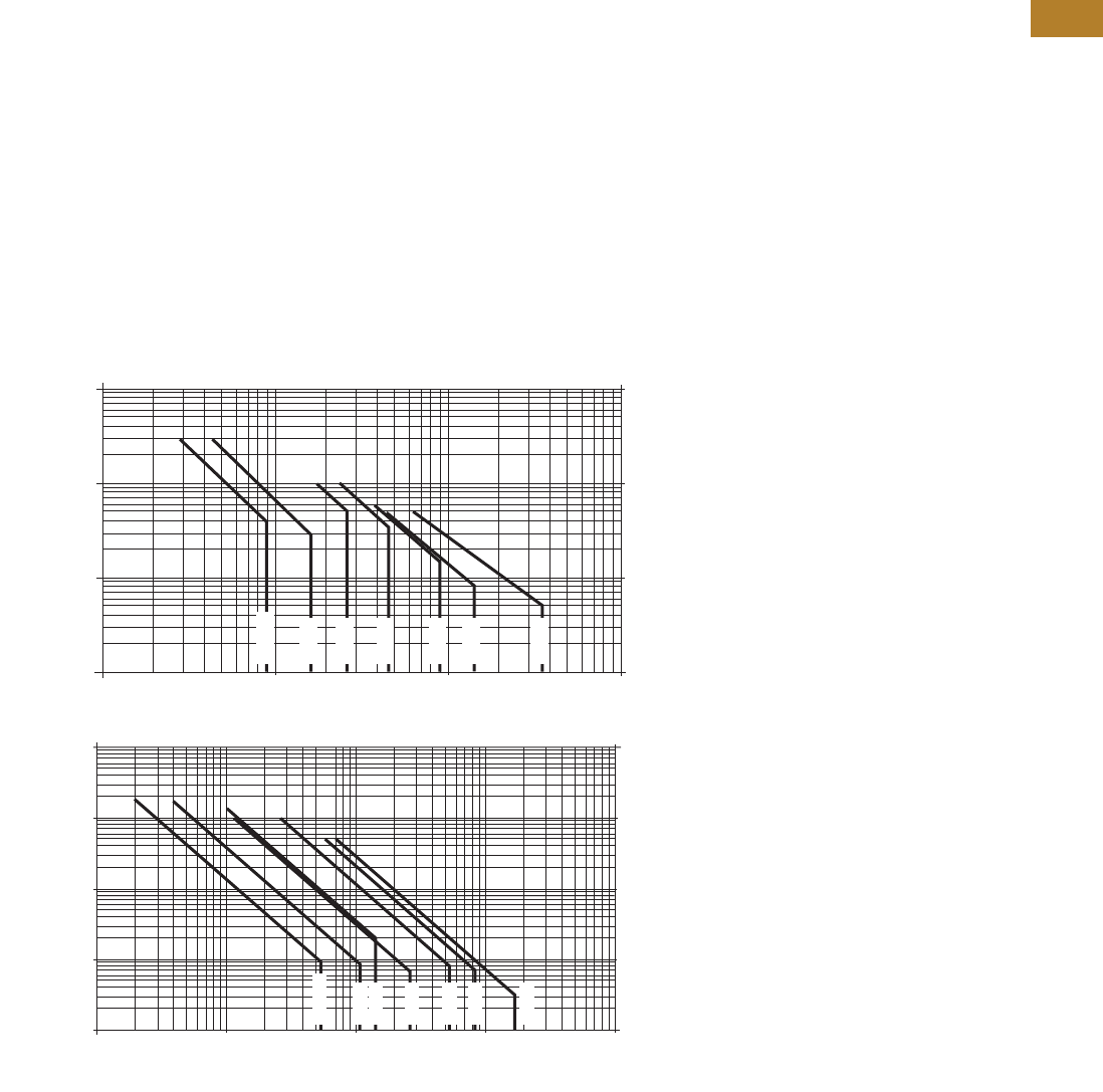
Volume 5—Motor Control and Protection CA08100006E—August 2014 www.eaton.com V5-T2-37
2
2
2
2
2
2
2
2
2
2
2
2
2
2
2
2
2
2
2
2
2
2
2
2
2
2
2
2
2
2
2.1
NEMA Contactors and Starters
Freedom Series
Electrical Life—AC-3 and AC-4 Utilization Categories
Life Load Curves
Eaton’s Freedom Series
NEMA contactors have been
designed and manufactured
for superior life performance
in any worldwide application.
All testing has been based on
requirements as found in
NEMA and UL standards and
conducted by Eaton. Actual
application life may vary
depending on environmental
conditions and application
duty cycle.
Utilization Categories
The International
Electrotechnical Commission
(IEC) has developed utilization
categories for contactors and
auxiliary contacts. The IEC
utilization categories are used
to define the type of electrical
load for estimating electrical
life, and do not imply the
devices are IEC rated.
AC-1—Non-inductive or
slightly inductive loads,
such as resistance furnaces
and heating.
AC-2—Starting of slip-ring
motors.
AC-3—Squirrel cage motors;
starting, switching off motors
during running.
AC-4—Squirrel cage motors;
starting, plugging, inching
or jogging.
Note: AC-3 tests are conducted at
rated device currents and AC-4
tests are conducted at six times
rated device currents. All tests
have been run at 460V, 60 Hz.
Contactor Choice
●Decide what utilization
category your application
is and choose the
appropriate curve
●Locate the intersection of
the life-load curve of the
appropriate contactor with
the applications operational
current (Ie), as found on the
horizontal axis
●Read the estimated
contact life along the
vertical axis in number
of operational cycles
AC-3 and AC-4 Utilization Categories
NEMA AC-3 Load Life, Sizes 00–5, 480V 60 Hz
100,000,000
10,000,000
1,000,000
100,000 9
110
Break Amperes 100 1000
18 27 45 90 135 270
Size 00
Size 0
Size 1
Size 2
Size 3
Size 4
Size 5
Operations Operations
NEMA AC-4 Load Life, Sizes 00–5, 480V 60 Hz
100,000,000
Size 00
Size 0
Size 1
Size 2
Size 3
Size 4
Size 5
10,000,000
1,000,000
100,000
10,000 10854
110
Break Amperes
100 1000 10,000
153 270 540 822 1620
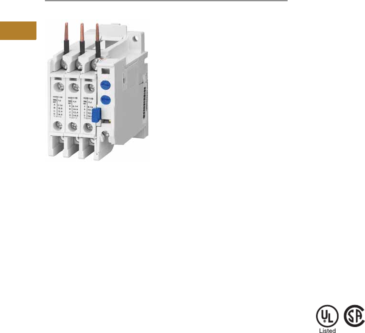
V5-T2-38 Volume 5—Motor Control and Protection CA08100006E—August 2014 www.eaton.com
2
2
2
2
2
2
2
2
2
2
2
2
2
2
2
2
2
2
2
2
2
2
2
2
2
2
2
2
2
2
2.1
NEMA Contactors and Starters
Freedom Series
32A Overload—C306DN3B
Contents
Description Page
Contactors—Non-Reversing and Reversing . . . . . . V5-T2-4
Starters—Three-Phase Non-Reversing and
Reversing, Full Voltage . . . . . . . . . . . . . . . . . . . . V5-T2-10
Starters—Single-Phase Non-Reversing,
Full Voltage, Bi-Metallic Overload . . . . . . . . . . . . V5-T2-15
Accessories . . . . . . . . . . . . . . . . . . . . . . . . . . . . . . V5-T2-21
Renewal Parts . . . . . . . . . . . . . . . . . . . . . . . . . . . . V5-T2-30
Technical Data and Specifications . . . . . . . . . . . . . V5-T2-34
Relays—Thermal Overload
Product Selection . . . . . . . . . . . . . . . . . . . . . . . V5-T2-39
Accessories. . . . . . . . . . . . . . . . . . . . . . . . . . . . V5-T2-43
Modifications . . . . . . . . . . . . . . . . . . . . . . . . . . V5-T2-43
Replacement Parts . . . . . . . . . . . . . . . . . . . . . . V5-T2-44
Technical Data and Specifications . . . . . . . . . . . V5-T2-45
Dimensions. . . . . . . . . . . . . . . . . . . . . . . . . . . . V5-T2-47
C440/XT Electronic Overload Relay . . . . . . . . . . . . V5-T2-48
Relays—Thermal Overload
Product Description
C306 Overload Relays are
designed for use with CE
or CN non-reversing and
reversing contactors. Four
sizes are available for
overload protection up
to 144A.
Features
●Selectable manual or
automatic reset operation
●Interchangeable heater
packs adjustable ±24%
to match motor FLA and
calibrated for use with
1.0 and 1.15 service factor
motors. Heater packs for
32A overload relay will
mount in 75A overload
relay—useful in derating
applications such as
jogging
●Class 10 or 20
heater packs
●Load lugs built into
relay base
●Bimetallic, ambient
compensated operated.
Trip free mechanism
●Electrically isolated NO-NC
contacts (pull RESET
button to test). (Electrical
ratings see table on
Page V5-T2-46)
●Overload trip indication
●Shrouded or fingerproof
terminals to reduce
possibility of electrical
shock
Standards and Certifications
●Meets UL 508 single-
phasing requirements
●UL listed, CSA certified and
NEMA compliance
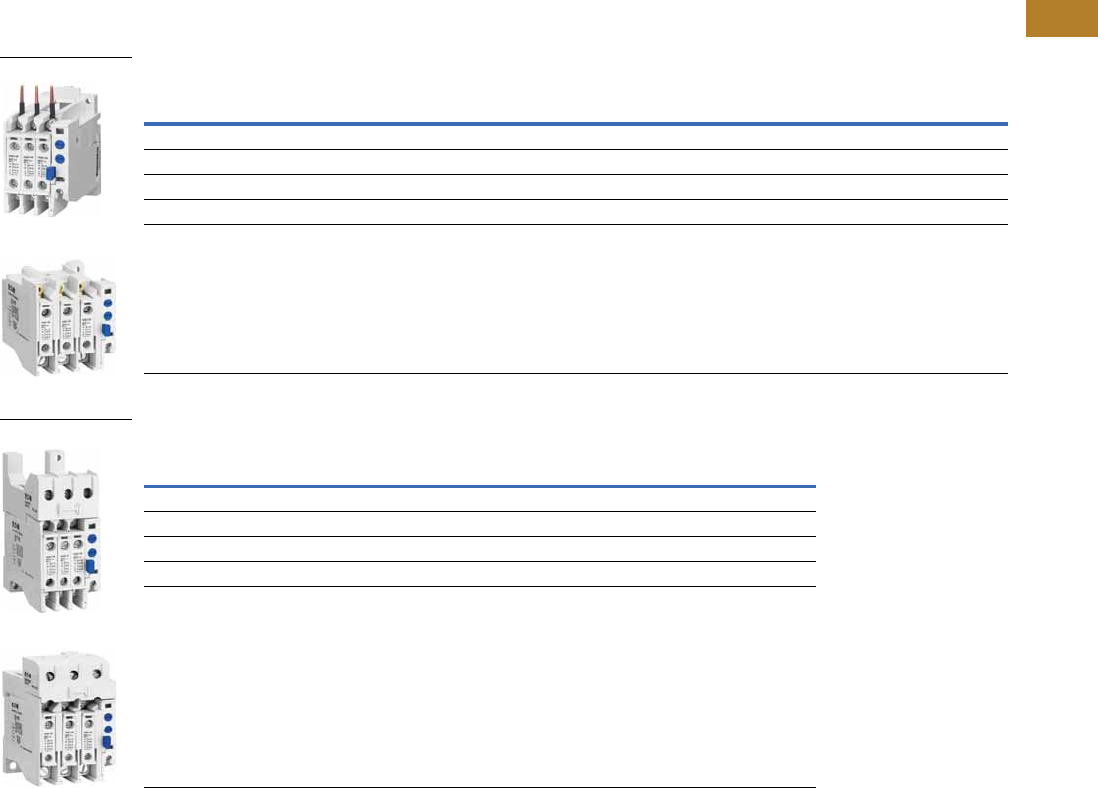
Volume 5—Motor Control and Protection CA08100006E—August 2014 www.eaton.com V5-T2-39
2
2
2
2
2
2
2
2
2
2
2
2
2
2
2
2
2
2
2
2
2
2
2
2
2
2
2
2
2
2
2.1
NEMA Contactors and Starters
Freedom Series
Product Selection
C306 Thermal Overload Relays
Contactors
Standalone Applications
Notes
1 NEMA Sizes 5–8 use the 32A overload in conjunction with CTs.
2 Series B overload relays have load lugs built into relay base and will only accept Series B heater packs. These relays
can be directly attached to contactor or they can be DIN rail or panel mounted using adapter on Page V5-T2-44.
3 These relays can be panel mounted only.
4 Overload relay assembled with mounting adapter for DIN rail or panel mount.
5 Panel mount only.
6 NEMA Sizes 5–8 use the 32A overload in conjunction with CTs.
NEMA Size
Maximum
Ampere Rating
Number
of Poles
Open Type NEMA 1 Enclosed
Catalog Number Catalog Number
00, 0 32 23C306DN3B C306DG3B
1, 2 75 23C306GN3B C306GG3B
3105
33C306KN3 —
4144
33C306NN3 —
5–8 1————
NEMA Size
Maximum
Ampere Rating
Number
of Poles
Open Type
Catalog Number
00, 0, 1 432 3 C306DT3B
1 475 3 C306GT3B
3 5105 3 C306KN3
4 5144 3 C306NN3
5–8 6———
C306DN3B
C306GN3B
C306DT3B
C306GT3B
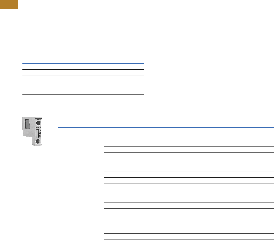
V5-T2-40 Volume 5—Motor Control and Protection CA08100006E—August 2014 www.eaton.com
2
2
2
2
2
2
2
2
2
2
2
2
2
2
2
2
2
2
2
2
2
2
2
2
2
2
2
2
2
2
2.1
NEMA Contactors and Starters
Freedom Series
Heater Pack Selection
Heater packs H2001B to
H2017B and H2101B to
H2117B are to be used only
with Series B overload relays
Catalog Numbers C306DN3B
(Part No. 10-7016) and
C306GN3B (Part No.
10-7020). The load lugs are
built into the overload relay
base to allow load wiring prior
to heater pack installation.
The previous heater design
had integral load lugs. The
Series B heater packs are
electrically equivalent to the
previous heater design.
Heaters H2018-3 to H2024-3
have not changed.
Starters with Series B Overload Relays 1
Standard Trip—Class 20 Heater
Notes
1 The series of a starter is the last digit of the listed catalog number. Example: AN16DN0AB.
2 Heater packs are shipped three to a carton. catalog numbers are for three heater packs.
NEMA—AN Type IEC—AE Type
Size Series Size Series
00–0 CA–F C
1–2 BG–K B
5BG–K B
6CG–K B
7–8 BG–K B
Overload Relay Size
Motor Full Load Ampere Rating
Catalog Number 2
Dial Position
ABCD
For Use with NEMA Sizes 00–0 Series C, NEMA Sizes 1–2 Series B; IEC Sizes A–F Series C, IEC Sizes G–K Series B
32A or 75A 0.254 0.306 0.359 0.411 H2001B-3
0.375 0.452 0.530 0.607 H2002B-3
0.560 0.676 0.791 0.907 H2003B-3
0.814 0.983 1.15 1.32 H2004B-3
1.20 1.45 1.71 1.96 H2005B-3
1.79 2.16 2.53 2.90 H2006B-3
2.15 2.60 3.04 3.49 H2007B-3
3.23 3.90 4.56 5.23 H2008B-3
4.55 5.50 6.45 7.40 H2009B-3
6.75 8.17 9.58 11.0 H2010B-3
9.14 10.8 12.4 14.0 H2011B-3
14.0 16.9 19.9 22.8 H2012B-3
18.7 22.7 26.7 30.7 H2013B-3
23.5 28.5 33.5 38.5 H2014B-3
For Use with NEMA Size 2, IEC Sizes G–K Only, Series B
75A 29.0 34.0 39.1 44.1 H2015B-3
39.6 45.5 51.5 57.4 H2016B-3
53.9 60.9 67.9 74.9 H2017B-3
Heater Pack
H2001B–H2017B
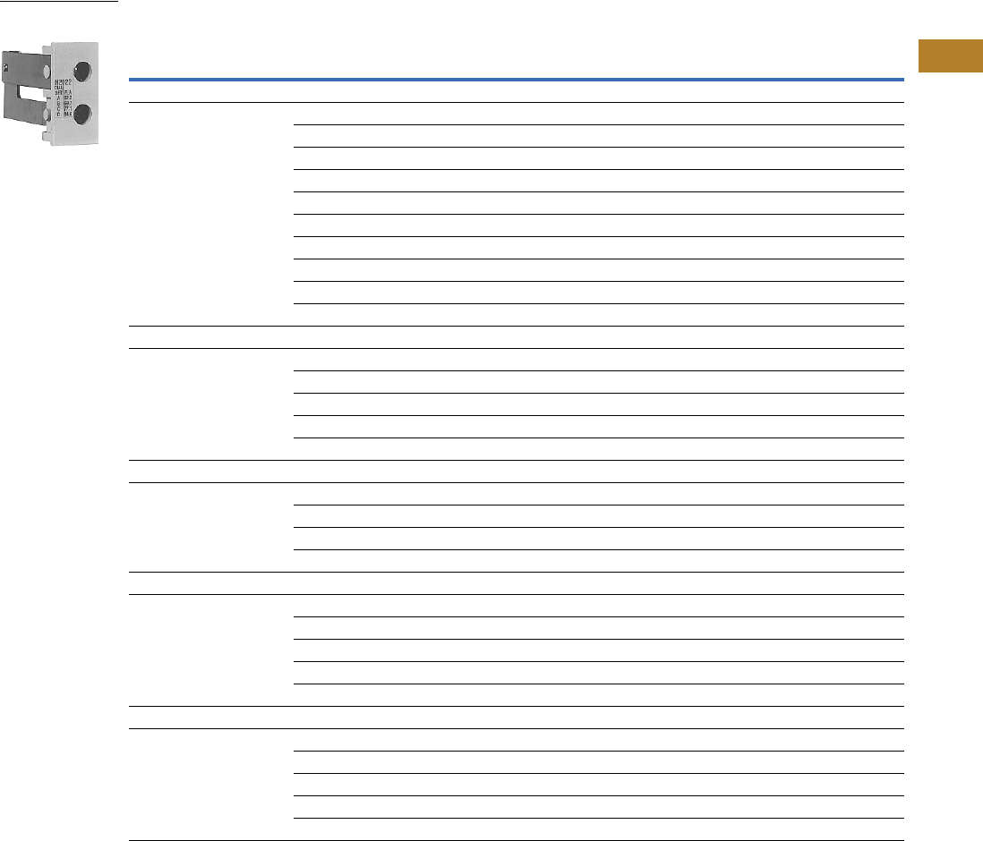
Volume 5—Motor Control and Protection CA08100006E—August 2014 www.eaton.com V5-T2-41
2
2
2
2
2
2
2
2
2
2
2
2
2
2
2
2
2
2
2
2
2
2
2
2
2
2
2
2
2
2
2.1
NEMA Contactors and Starters
Freedom Series
Standard Trip—Class 20 Heater, continued
Notes
1 Heater packs are shipped three to a carton. catalog numbers are for three heater packs.
2 Sizes 5–8 and IEC P–Z use the 32A overload relay with current transformers.
Overload Relay Size
Motor Full Load Ampere Rating
Catalog Number 1
Dial Position
ABCD
For Use with NEMA Sizes 3–4, IEC Sizes L–N Only—Series A
105A or 144A 8.0 9.2 10.3 11.5 H2025-3
11.4 12.8 14.3 15.7 H2026-3
14.3 15.7 17.4 19.0 H2027-3
18.0 20.2 22.3 24.5 H2018-3
24.6 27.6 30.5 33.4 H2019-3
33.5 37.5 41.5 45.6 H2020-3
45.7 51.2 56.7 62.1 H2021-3
62.2 69.7 77.1 84.6 H2022-3
84.7 95.0 105.0 115.0 H2023-3
106.0 118.0 131.0 144.0 H2024-3
For Use with Size 5 Starters—Series B and IEC P, R and S with 300/5 CT
32A 249 59 69 79 H2004B-3
72 87 103 118 H2005B-3
107 130 152 174 H2006B-3
129 156 182 209 H2007B-3
194 234 274 — H2008B-3
For Use with Size 6 Starters Only—Series B and IEC T–V with 600/5 CT
32A 2144 174 205 235 H2005B-3
215 259 304 348 H2006B-3
258 312 365 419 H2007B-3
388 468 547 627 H2008B-3
For Use with Size 7 Starters Only—Series B and IEC W–X with 1000/5 CT
32A 2163 197 230 264 H2004B-3
240 290 342 392 H2005B-3
358 432 506 580 H2006B-3
430 520 608 698 H2007B-3
646 780 912 — H2008B-3
For Use Size 8 Starters Only—Series B and IEC Z with 1500/5 CT
32A 2244 295 345 396 H2004B-3
360 435 513 588 H2005B-3
537 648 759 870 H2006B-3
645 780 912 1047 H2007B-3
969 1170 1368 — H2008B-3
Heater Pack
H2018–H2024
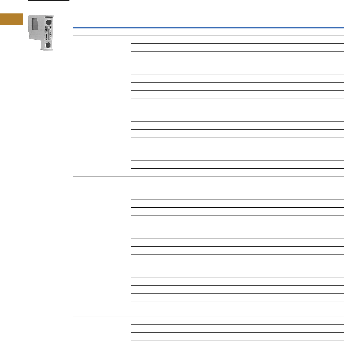
V5-T2-42 Volume 5—Motor Control and Protection CA08100006E—August 2014 www.eaton.com
2
2
2
2
2
2
2
2
2
2
2
2
2
2
2
2
2
2
2
2
2
2
2
2
2
2
2
2
2
2
2.1
NEMA Contactors and Starters
Freedom Series
Fast Trip—Class 10 Heater
Notes
1 Heater packs are shipped three to a carton. catalog numbers are for three heater packs.
2 Sizes 5–8 and IEC P–Z use the 32A overload relay with current transformers.
Overload Relay Size
Motor Full Load Ampere Rating
Catalog Number 1
Dial Position
AB C D
For Use with NEMA Sizes 00–0 Series C, NEMA Sizes 1–2 Series B; IEC Sizes A–F Series C, IEC Sizes G–K Series B
32A or 75A 0.260 0.313 0.367 0.420 H2101B-3
0.384 0.464 0.543 0.623 H2102B-3
0.570 0.688 0.806 0.924 H2103B-3
0.846 1.02 1.20 1.37 H2104B-3
1.28 1.55 1.83 2.10 H2105B-3
1.92 2.33 2.74 3.15 H2106B-3
2.30 2.79 3.28 3.77 H2107B-3
3.38 4.10 4.82 5.54 H2108B-3
4.96 6.03 7.09 8.16 H2109B-3
7.07 8.58 10.1 11.6 H2110B-3
9.60 11.2 12.8 14.4 H2111B-3
14.4 17.5 20.7 23.8 H2112B-3
18.7 21.8 25.0 28.1 H2113B-3
23.5 27.3 31.0 34.8 H2114B-3
For Use with Size 2, IEC Sizes G–K Only—Series B
75A 28.3 32.6 37.0 41.3 H2115B-3
36.6 42.3 48.1 53.8 H2116B-3
53.8 60.8 67.9 74.9 H2117B-3
For Use with Size 5 Starters Only—Series B and IEC P, R and S with 300/5 CT
32A 251 61 72 82 H2104B-3
77 93 110 126 H2105B-3
115 140 164 189 H2106B-3
138 167 197 226 H2107B-3
203 246 289 — H2108B-3
For Use with Size 6 Starters Only—Series B and IEC T–V with 600/5 CT
32A 2154 186 220 252 H2105B-3
230 280 329 378 H2106B-3
276 335 394 452 H2107B-3
406 492 578 — H2108B-3
For Use with Size 7 Starters Only—Series B and IEC W–X with 1000/5 CT
32A 2169 204 240 274 H2104B-3
256 310 366 420 H2105B-3
384 466 543 630 H2106B-3
460 558 656 754 H2107B-3
676 820 — — H2108B-3
For Use with Size 8 Starters Only—Series B and IEC Z with 1500/5 CT
32A 2254 306 360 411 H2104B-3
384 465 549 630 H2105B-3
576 699 822 945 H2106B-3
690 837 984 1131 H2107B-3
1014 1230 — — H2108B-3
Heater Pack
H2101B–H2117B
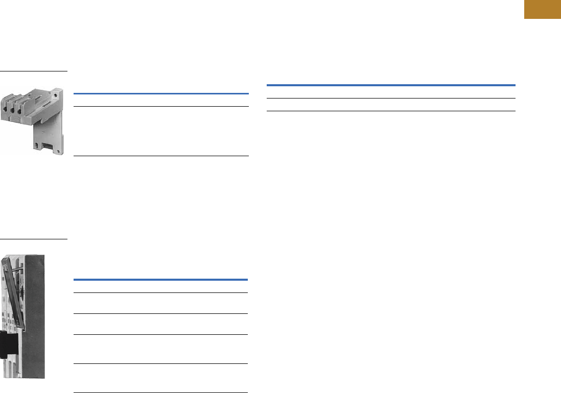
Volume 5—Motor Control and Protection CA08100006E—August 2014 www.eaton.com V5-T2-43
2
2
2
2
2
2
2
2
2
2
2
2
2
2
2
2
2
2
2
2
2
2
2
2
2
2
2
2
2
2
2.1
NEMA Contactors and Starters
Freedom Series
Accessories
DIN Rail and Panel Mounting Adapter
These adapters are required
when component overload
relays are to be separately
mounted. The terminal base
adapter includes line
terminals and connects
with the overload relays
on Page V5-T2-39.
DIN Rail and Panel Mounting Adapter
Locking Cover for Overload Relay—C306 Only
Snap-on transparent or
opaque plastic panel for
covering access port to the
overload relay trip setting
dial—helps prevent accidental
or unauthorized changes to
trip and reset setting.
Locking Cover for Overload Relay—
C306 Only
Note
1This Series B adapter will accept Series A or B overload relays (C306GN3 or C306GN3B),
C306TB2 can only be used with C306GN3.
Description Catalog Number
For 32A overload relay C306TB1
For 75A overload relay C306TB2B 1
C306TB1
Description
Min. Order Qty.
(Std. Pkg.)
Catalog
Number
Clear cover, no accessibility 50 C320PC3
Gray cover, no accessibility with
auto only nib
50 C320PC4
Gray cover, no accessibility with
manual only nib
50 C320PC5
Gray cover with FLA dial
accessibility, A, B, C, D positions
and auto only nib
50 C320PC6
Gray cover with FLA dial
accessibility, A, B, C, D positions
and manual only nib
50 C320PC7
Overload Relay Cover
Modifications
C306 Thermal Overload Relays with Mounting Adapter
Consists of a thermal
overload relay mounted to a
terminal base adapter—
permits fast and easy
installation.
C306 Thermal Overload Relays with Mounting Adapter
Description Catalog Number
C306DN3B + C306TB1 C306DT3B
C306GN3B + C306TB2B C306GT3B
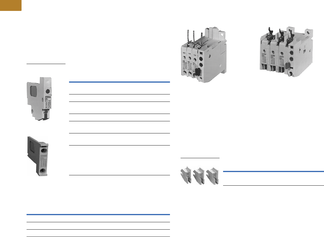
V5-T2-44 Volume 5—Motor Control and Protection CA08100006E—August 2014 www.eaton.com
2
2
2
2
2
2
2
2
2
2
2
2
2
2
2
2
2
2
2
2
2
2
2
2
2
2
2
2
2
2
2.1
NEMA Contactors and Starters
Freedom Series
Replacement Parts
Heater Pack Replacement
The heater pack series is
determined by the 6th
character of the catalog
number. Series A or prior
heater packs (identified by
either “A” or “-” as the 6th
character) have built-in load
lugs. Series B or later heater
packs do not (load lugs are on
overload relay). Replacement
of Series A or earlier heater
packs with Series B or later
heater packs, requires the
one time addition of Lug
Adapter Kit C306KAL1-3B to
the Series A1 overload relay.
Heater Pack Replacement Requirements
Heater Pack Ratings
Existing Heater Pack
Catalog Numbers Replacement Product Required
H2001-3–H2013-3
H2001A-3–H2013A-3
Lug adapter kit C306KAL1-3B and
Series B heater pack
H2001B-3–H2013B-3 Series B heater pack
H2014-3
H2014A-3
Replace with lug adapter kit
C306KAL1-3B and Series B heater pack
H2014B-3 Series B heater pack
H2015-3–H2017-3 Replace with heater pack chosen from
table below
H2015A-3–H2017A-3 Replace with lug adapter kit
C306KAL1-3B and Series B heater pack
H2015B-3–H2017B-3 Series B heater pack
Motor Full Load Ampere Rating
Order Heater Pack
Catalog Number
Dial Position
ABCD
29.0 32.5 36.0 39.5 H2015B-3
39.6 44.3 49.1 53.8 H2016B-3
53.9 60.4 66.8 74.9 H2017B-3
Superseded Series A
Heater Pack
Series B
Heater Pack
Overload Relay Lug Adapter Kit
Superseded 32A Series A Superseded 75A Series A
Overload Relay—C306DN3 Overload Relay—C306GN3
These kits are used in
conjunction with Catalog
Numbers H2001B–H2014B or
H2101B–H2114B heater
packs as a means of utilizing
these Series B heater packs
in Catalog Numbers
C306DN3 and C306GN3
Series Al overload relays. The
kit consists of three lug
adapters and installation
instructions. When installing
Series B heater packs plus
lug adapters in Series A
overload relays, refer to
heater pack FLA adjustment
tables originally supplied with
equipment (also supplied
with kit).
Overload Relay Lug
Overload Relay Replacement—
Series A Only
When replacing a Catalog
Number C306DN3 (Part No.
10-6044) or C306GN3 (10-
6319) Series A overload relay
on a starter, order a Series B
overload relay and Series B
heater packs.
Description Catalog Number
Series Al overload relay lug adapter kit C306KAL1-3B
C306KAL1
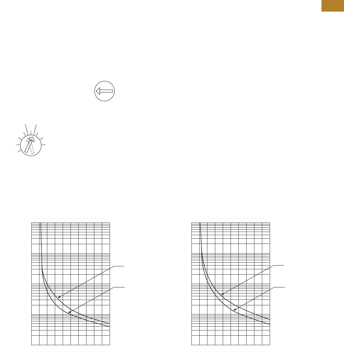
Volume 5—Motor Control and Protection CA08100006E—August 2014 www.eaton.com V5-T2-45
2
2
2
2
2
2
2
2
2
2
2
2
2
2
2
2
2
2
2
2
2
2
2
2
2
2
2
2
2
2
2.1
NEMA Contactors and Starters
Freedom Series
Technical Data and Specifications
Operation
C306 Overload Relay Setting
For motors having a 1.15
service factor, rotate the
FLA (Full Load Amperes)
adjustment dial to correspond
to the motor’s FLA rating.
Estimate the dial position
when the motor FLA falls
between two letter values as
shown in the example.
For motors having a 1.0
service factor, rotate the
FLA dial one-half position
counterclockwise (CCW).
FLA Dial Adjustment
The overload relay is factory
set at M for manual reset
operation. For automatic
reset operation, turn the reset
adjustment dial to the
A position as shown in the
illustration.
Automatic reset is not
intended for two-wire
control devices.
Manual/Automatic Reset
Test for Trip Indication
To test overload relay for trip
indication when in manual
reset, pull out the blue reset
button. An orange flag will
appear indicating that the
device has tripped. Push
reset button in to reset.
Warning—To provide
continued protection against
fire or shock hazard, the
complete overload relay must
be replaced if burnout of the
heater element occurs.
General
“Overload relays are provided
to protect motors, motor
control apparatus and motor-
branch circuit conductors
against excessive heating
due to motor overloads and
failure to start. This definition
does not include: 1) motor
circuits over 600V, 2) short
circuits, 3) ground faults
and 4) fire pump control.”
(NEC Art. 430-31)
Time Current Characteristics
The time-current
characteristics of an overload
relay is an expression of
performance which defines
its operating time at various
multiples of its current
setting. Tests are run at
Underwriters Laboratories
(UL) in accordance with
NEMA Standards and the
NEC. UL requires:
●When tested at 100
percent of its current
rating, the overload relay
shall trip ultimately
●When tested at 200
percent of its current rating,
the overload relay shall trip
in not more than 8 minutes
●When tested at 600 percent
of the current rating, the
overload relay shall trip
in not more than 10 or
20 seconds, depending
on the Class of the relay
“Current Rating” is defined
as the minimum current at
which the relay will trip. Per
NEC, an overload must
ultimately trip at 125% of FLA
current (heater) setting for a
1.15 service factor motor and
115% FLA for a 1.0 service
factor motor.
“Current Setting” is defined
as the FLA of the motor and
thus the overload heater
pack setting.
Example: 600% of current
rating is defined as 750%
(600 x 1.25) of FLA current
(heater) setting for a 1.15
service factor motor. A 10A
heater setting must trip in 20
seconds or less at 75A motor
current for a Class 20 relay.
Class 10 and Class 20 Trip Curves
1.0
Service
Factor
1.15
Service
Factor
A
BC
D
Example of 12.0 FLA setting
for heater pack number H2011B
showing position for
1.0 or 1.15 service
factor motors.
A
M
Example of setting for
manual reset.
0
1
2
3
4
5
10
20
30
40
50
100
200
300
400
500
1000
2000
3000
4000
5000
10,000
246810
From
Hot Start
From
Cold Start
Multiples of Current Setting
Trip Time
(Seconds)
Class 10 Overload Relay 25C Open Rating
0
1
2
3
4
5
10
20
30
40
50
100
200
300
400
500
1000
2000
3000
4000
5000
10,000
246810
From
Hot Start
From
Cold Start
Multiples of Current Setting
Trip Time
(Seconds)
Class 20 Overload Relay 25C Open Rating

V5-T2-46 Volume 5—Motor Control and Protection CA08100006E—August 2014 www.eaton.com
2
2
2
2
2
2
2
2
2
2
2
2
2
2
2
2
2
2
2
2
2
2
2
2
2
2
2
2
2
2
2.1
NEMA Contactors and Starters
Freedom Series
Wire (75°C) Sizes—AWG or kcmil—NEMA Sizes 00–2, IEC A–K—Open
Power Terminals—Line
Power Terminals—Load—Cu Only (Stranded or Solid)
Wire (75°C) Sizes—AWG or kcmil—NEMA Sizes 3–8, IEC L–N—Open
Power Terminals—Line and Load
Power Terminal Torque Line and Load Terminals
Plugging and Jogging Service Horsepower Ratings 2
Overload Relay UL/CSA Contact Ratings Control Circuit 3
Notes
1Two compartment box lug.
2Maximum horsepower where operation is interrupted more than 5 times per minute or more
than 10 times in a 10 minute period. NEMA standard ICS 2-1993 table 2-4-3.
3DC ratings cover Freedom Series coils only.
IEC Size NEMA Size Cu Only
A, B, C 00 12–16 stranded, 12–14 solid
D, E, F 0 8 –16 stranded, 10–14 solid
1 8–14 stranded or solid
G, H, J, K 2 3–14 (upper) and/or 6–14 (lower) stranded or solid 1
Catalog Number Terminal Wire Size
C306DN3B 32A 14–6 AWG
C306GN3B 75A 14–2 AWG
Control Terminals—Cu Only
12–16 AWG stranded, 12–14 AWG solid
IEC Size NEMA Size Wire Size
L 3 1/0–14 Cu/Al
M — 14–2/0 Cu/Al
N — 3/0–8 Cu/Al
— 4 Open—3/0–8 Cu
Enclosed—250 kcmil—6 Cu/Al
— 5 750 kcmil—2 or (2) 250 kcmil—3/0 Cu/Al
6–7 (2) 750 kcmil—3/0 Cu/Al
8 (2) 750 kcmil—1/0 Cu/Al
Control Terminals—Cu Only
12–16 AWG stranded, 12–14 AWG solid
Catalog Number Terminal Torque in lb-in
C306DT3B 32A 20
C306GT3B 75A 35 (14–10 AWG)
40 (8 AWG)
45 (6–4 AWG)
50 (3–2 AWG)
C306KN3
(socket head screw)
105A 120 (3/16)
200 (1/4)
250 (5/16)
C306NN3
(socket head screw)
144A 120 (3/16)
200 (1/4)
250 (5/16)
C306NN3
(slotted head screw)
35 (14–10 AWG)
40 (8 AWG)
45 (6–4 AWG)
50 (3–1/0 AWG)
NEMA Size 200V 230V 460V 575V
00 — 1/2 1/2 1/2
0 1-1/2 1-1/2 2 2
13355
2 7-1/2 10 15 15
3 15203030
4 25306060
5 6075150150
6 125 150 300 300
AC Volts 120V 240V 480V 600V
NC Contact B600
Make and break amperes 30 15 7.5 6
Break amperes 3 1.5 0.75 0.6
Continuous amperes5555
NO Contact C600
Make and break amperes 15 7.5 3.375 3
Break amperes 1.5 0.75 0.375 0.3
Continuous amperes 2.5 2.5 2.5 2.5
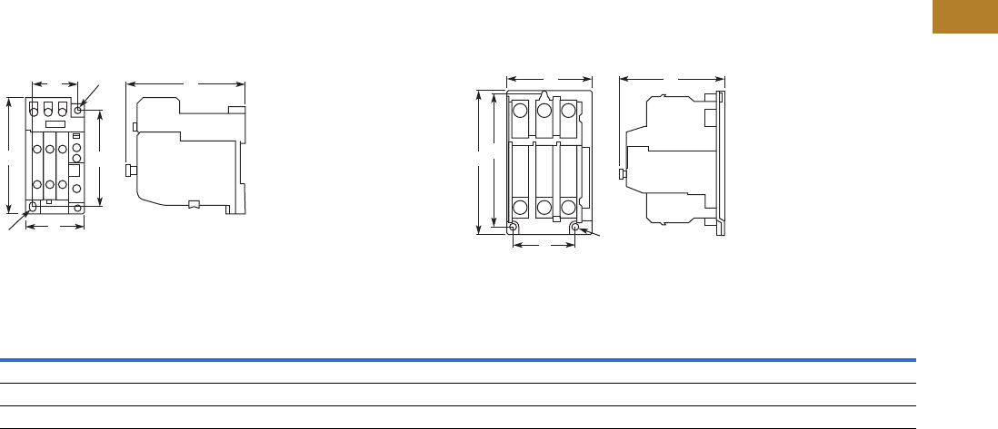
Volume 5—Motor Control and Protection CA08100006E—August 2014 www.eaton.com V5-T2-47
2
2
2
2
2
2
2
2
2
2
2
2
2
2
2
2
2
2
2
2
2
2
2
2
2
2
2
2
2
2
2.1
NEMA Contactors and Starters
Freedom Series
Dimensions
Approximate Dimensions in Inches (mm)
Stand-Alone Overload Relays
32A and 75A Sizes—C306DT38 and C306GT3B 105A and 144A Sizes—C306KN38 and C306NN3B
Dimensions and Shipping Weights
D C
E
B
A
F
G
A C
E
B
DMtg. Holes for (3)
1/4-20 Screws
Ampere
Size
Wide
A
High
B
Deep
C
Mounting Shipping Weight
Lbs (kg)D E F (Slot) G (Hole)
32A 1.77 (45.0) 4.13 (104.9) 3.69 (93.7) 1.36 (34.5) 3.74 (95.0) 0.18 x 0.30 (4.6 x 7.6) 0.18 (4.6) dia. 0.8 (0.4)
75A 2.54 (64.5) 4.69 (119.1) 3.74 (95.0) 2.00 (50.8) 3.45 (87.6) 0.22 x 0.26 (5.6 x 6.6) 0.21 (5.3) dia. 1.4 (0.6)
105 and 144A 4.00 (101.6) 7.17 (182.1) 4.91 (124.7) 3.00 (76.2) 6.62 (168.1) — — 4.0 (1.8)
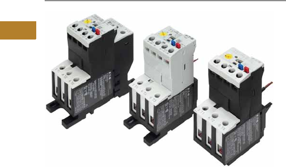
V5-T2-48 Volume 5—Motor Control and Protection CA08100006E—August 2014 www.eaton.com
2
2
2
2
2
2
2
2
2
2
2
2
2
2
2
2
2
2
2
2
2
2
2
2
2
2
2
2
2
2
2.1
NEMA Contactors and Starters
Freedom Series
C440/XT Electronic Overload Relay
Contents
Description Page
Contactors—Non-Reversing and Reversing . . . . . . V5-T2-4
Starters—Three-Phase Non-Reversing and
Reversing, Full Voltage . . . . . . . . . . . . . . . . . . . . V5-T2-10
Starters—Single-Phase Non-Reversing,
Full Voltage, Bi-Metallic Overload . . . . . . . . . . . . V5-T2-15
Accessories . . . . . . . . . . . . . . . . . . . . . . . . . . . . . . V5-T2-21
Renewal Parts . . . . . . . . . . . . . . . . . . . . . . . . . . . . V5-T2-30
Technical Data and Specifications . . . . . . . . . . . . . V5-T2-34
Relays—Thermal Overload. . . . . . . . . . . . . . . . . . . V5-T2-38
C440/XT Electronic Overload Relay
Standards and Certifications . . . . . . . . . . . . . . V5-T2-49
Catalog Number Selection . . . . . . . . . . . . . . . . V5-T2-50
Product Selection . . . . . . . . . . . . . . . . . . . . . . . V5-T2-51
Accessories . . . . . . . . . . . . . . . . . . . . . . . . . . . V5-T2-53
Technical Data and Specifications . . . . . . . . . . V5-T2-57
Dimensions . . . . . . . . . . . . . . . . . . . . . . . . . . . V5-T2-63
C440/XT Electronic Overload Relay
Product Description
Eaton’s new electronic
overload relay (EOL) is
the most compact, high-
featured, economical product
in its class. Designed on a
global platform, the new
EOL covers the entire power
control spectrum including
NEMA, IEC and
DP contactors. The NEMA
and DP versions are offered
with the C440 designation
while the IEC offering has the
XT designation. The
electronic design provides
reliable, accurate and value
driven protection and
communications capabilities
in a single compact device. It
is the flexible choice for any
application requiring easy-to-
use, reliable protection.
Eaton has a long history of
innovations and product
development in motor control
and protection, including both
traditional NEMA, as well as
IEC control. It was from this
experience that the C440 was
developed, delivering new
solutions to meet today’s
demands.
C440 is a self-powered
electronic overload relay
available up to 175A as a
self contained unit. With
external CTs, C440 can
protect motor up to
1500 FLA. Available add-on
accessories include remote
reset capability and
communication modules
with I/O for DeviceNet,
PROFIBUS, and Modbus.
Features and Benefits
Features
●Reliable, accurate, electronic motor protection
●Easy to select, install and maintain
●Compact size
●Flexible, intelligent design
●Global product offering—available with NEMA, IEC and DP
power control
Size/Range
●Broad FLA range
(0.33–1500A)
●Selectable trip class
(10A, 10, 20, 30)
●Direct mounting to NEMA,
IEC and DP contactors
●Most compact electronic
overload in its class
Motor Control
●Two B600 alarm (NO) and
fault (NC) contacts
●Test/Trip button
Motor Protection
●Thermal overload
●Phase loss
●Selectable (ON/OFF)
phase unbalance
●Selectable (ON/OFF)
ground fault
User Interface
●Large FLA selection dial
●Trip status indicator
●Operating mode LED
●DIP switch selectable trip
class, phase unbalance and
ground fault
●Selectable Auto/Manual
reset
Feature Options
●Remote reset
●120 Vac
●24 Vac
●24 Vdc
●Tamper-proof cover
●Communications modules
●Modbus RTU RS-485
●DeviceNet with I/O
●PROFIBUS with I/O
●Modbus RTU with I/O
●Ethernet IP with I/O
●Modbus TCP with I/O

Volume 5—Motor Control and Protection CA08100006E—August 2014 www.eaton.com V5-T2-49
2
2
2
2
2
2
2
2
2
2
2
2
2
2
2
2
2
2
2
2
2
2
2
2
2
2
2
2
2
2
2.1
NEMA Contactors and Starters
Freedom Series
Benefits
Reliability and Improved
Uptime
●C440 provides the users
with peace of mind
knowing that their
assets are protected
with the highest level
of motor protection and
communication capability
in its class
●Extends the life of plant
assets with selectable
motor protection features
such as trip class, phase
unbalance and ground fault
●Protects against
unnecessary downtime
by discovering changes
in your system (line/load)
with remote monitoring
capabilities
●Status LED provides
added assurance that
valuable assets are
protected by indicating the
overload operational status
Flexibility
●Available with NEMA,
IEC and DP contactors
●Improves return on
investment by reducing
inventory carrying costs
with wide FLA adjustment
(5:1) and selectable
trip class
●Design incorporates built-in
ground fault protection
thus eliminating the need
for separate CTs and
modules
●Flexible communication
with optional I/O enables
easy integration into plant
management systems for
remote monitoring and
control
●Available as an open
component and in
enclosed control and motor
control center assemblies
Monitoring Capabilities
●Individual phase
currents RMS
●Average three-phase
current RMS
●Thermal memory
●Fault indication (overload,
phase loss, phase
unbalance, ground fault)
Safety
●IP 20 rated terminal blocks
●Available in Eaton’s
industry leading FlashGard
MCCs
●Tested to the highest
industry standards such
as UL, CSA, CE and IEC
●RoHS compliant
Standards and Certifications
●UL
●CSA
●CE
●NEMA
●IEC/EN 60947 VDE 0660
●ISO 13849-1 (EN954-1)
●RoHS
●ATEX directive 94/9/EC
●Equipment Group 2,
Category 2
Electronic Overload Education
Description Definition Cause Effect if not Protected C440/XT Protection
Motor Protection
Thermal overload Overload is a condition in which
current draw exceeds 115% of
the full load amperage rating for
an inductive motor.
• An increase in the load or torque that is
being driven by the motor.
• A low voltage supply to the motor
causes the current to go high to
maintain the power needed.
• A poor power factor causing above
normal current draw.
• Increase in current draw leads to heat
and insulation breakdown, which can
cause system failure.
• Increase in current can increase
power consumption and waste
valuable energy.
• Thermal trip behavior is defined by
UL, CSA and IEC standards.
• Trip class is settable from 10A,
10, 20, 30
Ground fault A line to ground fault. A current leakage path to ground. An undetected ground fault can burn
through multiple insulation windings,
ultimately leading to motor failure, not to
mention risk to equipment or personnel
Fixed protective setting that takes the
starter offline if ground fault current
exceeds 50% of the FLA dial setting,
that is, if the FLA dial is set to 12A, the
overload relay will trip if the ground
current exceeds 6A.
Unbalanced phases
(voltage and current)
Uneven voltage or current between
phases in a three-phase system.
When a three-phase load is powered with
a poor quality line, the voltage per phase
may be unbalanced.
Unbalanced voltage causes large
unbalanced currents and as a result this
can lead to motor stator windings being
overloaded, causing excessive heating,
reduced motor efficiency and reduced
insulation life.
Fixed protective setting that takes the
starter offline if a phase drops below
50% of the other two phases.
Phase loss—current
(single-phasing)
One of the three-phase voltages is
not present.
Multiple causes, loose wire, improper
wiring, grounded phase, open fuse,
and so on.
Single-phasing can lead to unwanted
motor vibrations in addition to the results
of unbalanced phases as listed above.
Fixed protective setting that takes the
starter offline if a phase drops below
50% of the other two phases.
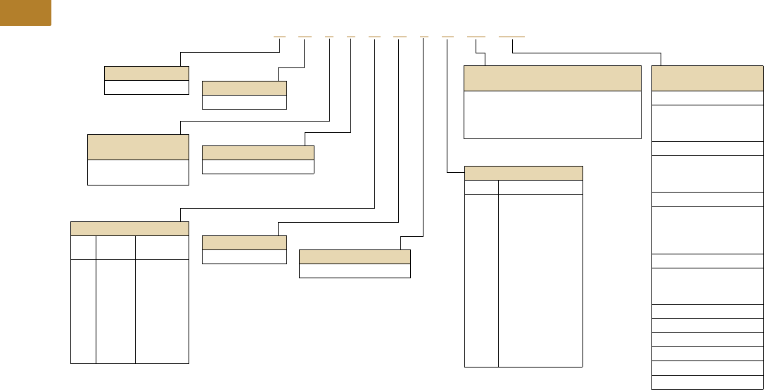
V5-T2-50 Volume 5—Motor Control and Protection CA08100006E—August 2014 www.eaton.com
2
2
2
2
2
2
2
2
2
2
2
2
2
2
2
2
2
2
2
2
2
2
2
2
2
2
2
2
2
2
2.1
NEMA Contactors and Starters
Freedom Series
Catalog Number Selection
Freedom Series NEMA Starters with C440 Electronic Overload Relays 1
Notes
1See Page V5-T2-51 for Product Selection.
2NEMA Sizes 00 and 0 only.
3NEMA Sizes 00 and 0 only. Sizes 1–3 are 24/60 only.
4NEMA Size 5 starter available with 60-300A panel mounted CTs. Starter shipped as an assembled unit with
1–5A C440 overload relay (C440A1A005SELAX or C440A2A005SELAX).
A N 1 9 A N 0 A 5E 005
Device Type
A = Starter
Contactor Frame Size
NEMA
Size
Continuous
Amperes
A =
B =
C =
D =
G =
K =
M =
N =
S =
00
0
1C
1
2
3
4C
4
5
9
18
27
27
45
90
135
135
270
Device Assembly
Configuration
1 = Non-reversing
5 = Reversing
Standard
N = NEMA
OLR Type
9 = Starter w/C440 EOLR
NEMA Enclosure
N = Open
For Starters
Starter Mounting Option
0 = Horizontal
AC Coil Suffix
Suffix Volts and Hertz
A=
B=
C=
D=
E=
H=
J=
K=
L=
N=
T=
U=
V=
W=
Y=
120/60 or 110/50
240/60 or 220/50
480/60 or 440/50
600/60 or 550/50
208/60
277/60
208–240/60 2
240/50
380–415/50
550/50
24/60, 24/50 3
24/50
32/50
48/60
48/50
C440 OLR Designation
(FVNR and FVR only)
5E = Standard feature set
SEL Reset, SEL Class (10A, 10, 20, 30)
5G = Ground fault feature set
SEL Reset, SEL Class (10, 20)
C440 FLA Range
(FVNR and FVR only)
NEMA Size 00
1P6 = 0.33–1.65A
005 =1–5A
020 =4–20A
NEMA Size 0
1P6 = 0.33–1.65A
005 =1–5A
020 =4–20A
NEMA Size 1/1C
1P6 = 0.33–1.65A
005 =1–5A
020 =4–20A
045 =9–45A
NEMA Size 2
005 =1–5A
020 =4–20A
045 =9–45A
NEMA Size 3
100 = 20–100A
NEMA Size 4/4C
140 = 28–140A
NEMA Size 5 4
300 = 60–300A
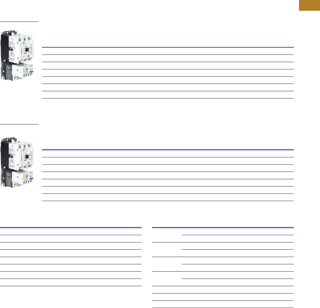
Volume 5—Motor Control and Protection CA08100006E—August 2014 www.eaton.com V5-T2-51
2
2
2
2
2
2
2
2
2
2
2
2
2
2
2
2
2
2
2
2
2
2
2
2
2
2
2
2
2
2
2.1
NEMA Contactors and Starters
Freedom Series
Product Selection
Type AN19/59 Freedom Series Starters
Type AN19/59 Freedom Series Starters with C440 Electronic Overload Relays
Non-Reversing and Reversing
Type AN19/59 Freedom Series Starters with C440 with Ground Fault Electronic Overload Relays
Non-Reversing and Reversing
Coil Suffix Codes C440 FLA Range (FVNR and FVR Starters Only)
Notes
1Underscore (_) indicates coils suffix required, see Coil Suffix table above.
2Underscore (_) indicates OLR designation required, see C440 FLA Range table above.
3NEMA Size 5 starter available with 60-300A panel mounted CTs. Starter shipped as an assembled unit with
1–5A C440 overload relay (C440A1A005SELAX or C440A2A005SELAX).
NEMA
Size
Continuous
Ampere
Rating
Service Limit
Current Rating
(Amps)
Maximum UL Horsepower Three-Pole
Non-Reversing 12
Three-Pole
Reversing 12
Single-Phase Three-Phase
115V 230V 208V 240V 480V 600V Catalog Number Catalog Number
00 9 11 1/3 1 1-1/2 1-1/2 2 2 AN19AN0_ 5E _ AN59AN0_ 5E _
018 21 123355AN19BN0_ 5E _ AN59BN0_ 5E _
127 32 237-1/27-1/21010AN19DN0_ 5E _ AN59DN0_ 5E _
2 45 52 3 7-1/210152525AN19GN0_ 5E _ AN59GN0_ 5E _
3 90 104 ——25305050AN19KN0_ 5E _ AN59KN0_ 5E _
4 135 156 — — 40 50 100 100 AN19NN0_ 5E _ AN59NN0_ 5E _
5 3270 311 — — 75 100 200 200 AN19SN0_ 5E _ AN59SN0_ 5E _
NEMA
Size
Continuous
Ampere
Rating
Service Limit
Current Rating
(Amps)
Maximum UL Horsepower Three-Pole
Non-Reversing 12
Three-Pole
Reversing 12
Single-Phase Three-Phase
115V 230V 208V 240V 480V 600V Catalog Number Catalog Number
00 9 11 1/3 1 1-1/2 1-1/2 2 2 AN19AN0_ 5G _ AN59AN0_ 5G _
018 21 123355AN19BN0_ 5G _ AN59BN0_ 5G _
127 32 237-1/27-1/21010AN19DN0_ 5G _ AN59DN0_ 5G _
2 45 52 3 7-1/210152525AN19GN0_ 5G _ AN59GN0_ 5G _
3 90 104 ——25305050AN19KN0_ 5G _ AN59KN0_ 5G _
4 135 156 — — 40 50 100 100 AN19NN0_ 5G _ AN59NN0_ 5G _
5 3270 311 — — 75 100 200 200 AN19SN0_ 5G _ AN59SN0_ 5G _
NEMA Starter
NEMA Starter with
Ground Fault
Suffix Coil Volts and Hertz Suffix Coil Volts and Hertz
A120/60 or 110/50 L380–415/50
B240/60 or 220/50 N550/50
C480/60 or 440/50 T24/60, 24/50
D600/60 or 550/50 U24/50
E208/60 V32/50
H277/60 W48/60
J208–240/60 Y48/50
K240/50
NEMA Size OLR Code FLA Range OLR Code FLA Rating
00 1P6 0.33–1.65A 020 4.0–20A
005 1.0–5.0A ——
01P6 0.33–1.65A 020 4.0–20A
005 1.0–5.0A ——
11P6 0.33–1.65A 020 4.0–20A
005 1.0–5.0A 045 9.0–45A
2005 1.0–5.0A 045 9.0–45A
020 4.0–20A ——
3100 20–100A ——
4140 28–140A ——
5 3300 60–300A ——

V5-T2-52 Volume 5—Motor Control and Protection CA08100006E—August 2014 www.eaton.com
2
2
2
2
2
2
2
2
2
2
2
2
2
2
2
2
2
2
2
2
2
2
2
2
2
2
2
2
2
2
2.1
NEMA Contactors and Starters
Freedom Series
Compact NEMA Size 1 and 4 Starters
New Compact NEMA Size 1 and 4 starters—available with electronic overload relay only.
Non-Reversing
Electrical Life at Rated Continuous Current
NEMA
Size
Continuous
Ampere
Rating
Service Limit
Current Rating
(Amps)
Maximum UL Horsepower Three-Pole
Non-Reversing Single-Phase Three-Phase
115V 230V 208V 240V 480V 600V Catalog Number
Standard Fault Overload
1C 27 32 2 3 7.5 7.5 10 10 AN19CN0_5E_
4C 135 156 — — 40 50 100 100 AN19MN0_5E_
Ground Fault Overload
1C 27 32 2 3 7.5 7.5 10 10 AN19CN0_5G_
4C 135 156 — — 40 50 100 100 AN19MN0_5G_
NEMA
Size
Rated Current
(Amperage)
AC3/AC4 Operations
1C 27/150 2,500,000/40,000
1 27/153 5,000,000/110,000
4C 135/516 500,000/40,000
4 135/822 800,000/70,000
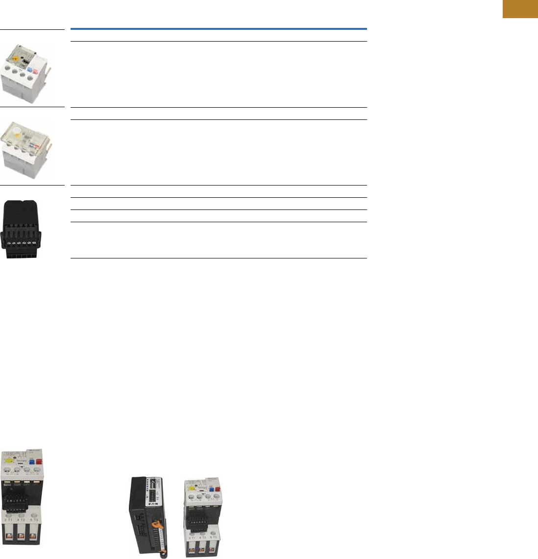
Volume 5—Motor Control and Protection CA08100006E—August 2014 www.eaton.com V5-T2-53
2
2
2
2
2
2
2
2
2
2
2
2
2
2
2
2
2
2
2
2
2
2
2
2
2
2
2
2
2
2
2.1
NEMA Contactors and Starters
Freedom Series
Accessories
CT Kits
Accessories
Communication
The C440/XTOE is provided with two levels of communication capability.
Basic Communication via
Expansion Module—
Monitoring Only
Basic communication on
the C440 is accomplished
using an expansion module
(C440-XCOM). The expansion
module plugs into the
expansion bay on the C440
overload relay, enabling
communications with the
overload via their Modbus
RTU (RS-485) network. No
additional cards or modules are
required. See figure below.
Basic Communication—
Modbus
Advanced
Communication—
Monitoring and Control
C440 also has the ability to
communicate on industrial
protocols such as Modbus
RTU, DeviceNet, PROFIBUS,
Modbus TCP, and EtherNet/IP
while providing control
capability using I/O.
An expansion module (C440-
XCOM) combined with a
communication adapter
(C440-COM-ADP) and a
communication module
allows easy integration onto
the customer's network.
Seefigurebelow.
2
Advanced Communication—
Communication Adapter with
Communication Module
Advanced
Communication—
Communication Adapter 2
The communication adapter
(C440-COM-ADP) is required
for obtaining control capability
via communications within
the C440 family. Combined
with a communication
module, the customer is
provided with flexible
mounting options (DIN rail or
panel) along with four inputs
and two outputs (24 Vdc or
120 Vac) as standard.
Notes
1Customer can wire remote mounted button to reset module (that is, 22 mm pushbutton, catalog number M22-D-B-GB14-K10).
2Modbus TCP and EtherNet/IP communication modules do not require the C440-COM-ADP communication adapter.
Description Catalog Number
Safety Cover
Clear Lexan cover that mounts on top of the FLA dial and DIP switches when closed. ZEB-XSC
Reset Bar
Assembles to the top of the overload to provide a larger target area for door
mounted reset operators.
ZEB-XRB
Remote Reset
Remote reset module (24 Vdc) 1C440-XCOM
Remote reset module (120 Vac) 1ZEB-XRR-120
Remote reset module (24 Vac) 1ZEB-XRR-24
Safety Cover
Reset Bar
Remote Reset
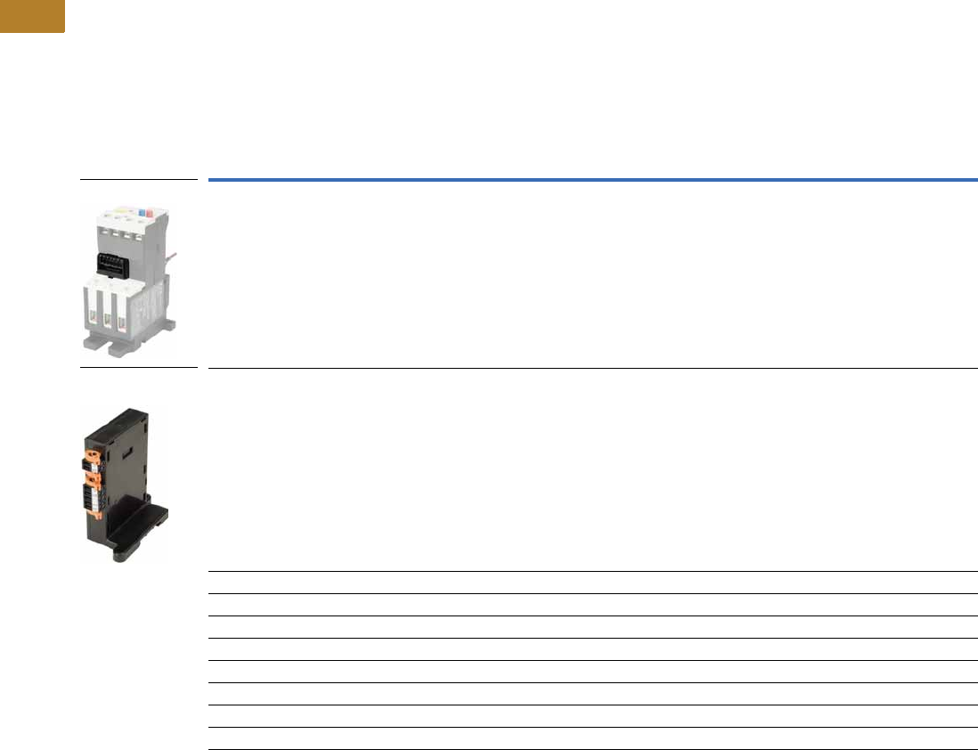
V5-T2-54 Volume 5—Motor Control and Protection CA08100006E—August 2014 www.eaton.com
2
2
2
2
2
2
2
2
2
2
2
2
2
2
2
2
2
2
2
2
2
2
2
2
2
2
2
2
2
2
2.1
NEMA Contactors and Starters
Freedom Series
The following information can be viewed using the communication option:
●Motor status—running,
stopped, tripped or
resetting
●Individual rms phase
currents (A, B, C)
●Average of three-phase
rms current
●Percent thermal capacity
●Fault codes (only available
prior to reset)
●Percent phase unbalance
●Ground fault current and
percent
●Overload relay settings—
trip class, DIP switch
selections, reset selections
●Modbus address (can be
set over the network)
Communication Accessories
Description Catalog Number
Expansion module (Remote Reset/Modbus RTU, RS-485 Communication) C440-XCOM
Communication adapter kit (DIN C Panel mounted adapter, required for advance communication option) C440-COM-ADP
DeviceNet communication module kit—120V I/O (consists of C440-XCOM + C441K + C440-COM-ADP) C440-DN-120
DeviceNet communication module kit—24 Vdc I/O (consists of C440-XCOM + C441L + C440-COM-ADP) C440-DN-24
PROFIBUS communication module kit—120V I/O (consists of C440-XCOM + C441S + C440-COM-ADP) C440-DP-120
PROFIBUS communication module kit—24V I/O (consists of C440-XCOM + C441Q + C440-COM-ADP) C440-DP-24
Modbus communication module kit—120V I/O (consists of C440-XCOM + C441N + C440-COM-ADP) C440-MOD-120
Modbus communication module kit—24 Vdc I/O (consists of C440-XCOM + C441P + C440-COM-ADP) C440-MOD-24
Modbus TCP/Ethernet IP communication module kit—120V I/O (consists of C440-XCOM + C441U) C440-ET-120
Modbus TCP/Ethernet IP communication module kit—24V I/O (consists of C440-XCOM + C441V) C440-ET-24
Expansion Module
Communication
Adapter

Volume 5—Motor Control and Protection CA08100006E—August 2014 www.eaton.com V5-T2-55
2
2
2
2
2
2
2
2
2
2
2
2
2
2
2
2
2
2
2
2
2
2
2
2
2
2
2
2
2
2
2.1
NEMA Contactors and Starters
Freedom Series
Modbus Communication Module
The Modbus communication
module combined with an
expansion module and a
communication adapter
provides monitoring and
control capability to the
C440/XTOE electronic
overload relay via Modbus
RTU communications.
These modules also provide
convenient I/O with 24 Vdc or
120 Vac options.
Features and Benefits
●The Modbus
communication module is
capable of baud rates
up to 115K
●The Modbus address and
baud rate configuration can
be easily changed using
the HMi user interface
●Modbus address and baud
rate are set via convenient
DIP switches; LEDs are
provided to display
Modbus traffic
●Configuration with
common Modbus
configuration tools
●Terminals
●Unique locking
mechanism provides for
easy removal of the
terminal block with the
field wiring installed
●Each terminal is marked
for ease of wiring and
troubleshooting
●Selectable I/O assemblies
●4IN/2OUT
●Signal types include
24 Vdc I/O and
120 Vac I/O
●Each I/O module is
optically isolated
between the field I/O
and the network adapter
to protect the I/O and
communication circuits
from possible damage
due to transients and
ground loops
●Input Module features a
user-definable input
debounce, which limits
the effects of transients
and electrical noise
●Output Module supports
a user-definable safe
state for loss of
communication; hold
last state, ON or OFF
DeviceNet Communication Modules
The DeviceNet communication
module combined with an
expansion module and a
communication adapter
provides monitoring and
control capability to the
C440/XTOE electronic
overload relay via DeviceNet
communications. These
modules also provide
convenient I/O with 24 Vdc
or 120 Vac options.
Features and Benefits
●Communication to
DeviceNet uses only one
DeviceNet MAC ID
●Configuration
●DeviceNet MAC ID and
Baud rate are set via
convenient DIP switches
with an option to set
from the network
●Advanced configuration
available using common
DeviceNet tools
●Terminals
●Unique locking
mechanism provides for
easy removal of the
terminal block with the
field wiring installed
●Each terminal is marked
for ease of wiring and
troubleshooting
●Selectable I/O assemblies
●4IN/2OUT
●Signal types include
24 Vdc I/O and
120 Vac I/O
●Each I/O module is
optically isolated
between the field I/O
and the network adapter
to protect the I/O and
communication circuits
from possible damage
due to transients and
ground loops
●Input Module features a
user-definable input
debounce, which limits
the effects of transients
and electrical noise
●Output Module supports
a user-definable safe
state for loss of
communication; hold
last state, ON or OFF
●Combined status LED
Modbus
Communication Module
DeviceNet
Communication Module
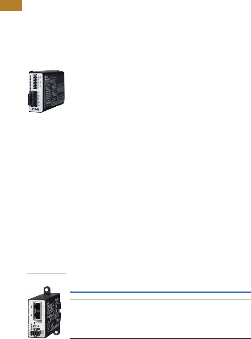
V5-T2-56 Volume 5—Motor Control and Protection CA08100006E—August 2014 www.eaton.com
2
2
2
2
2
2
2
2
2
2
2
2
2
2
2
2
2
2
2
2
2
2
2
2
2
2
2
2
2
2
2.1
NEMA Contactors and Starters
Freedom Series
PROFIBUS Communication Modules
The PROFIBUS
communication module
combined with an expansion
module and a communication
adapter provides monitoring
and control capability to the
C440 / XTOE electronic
overload relay via PROFIBUS
communications. These
modules also provide
convenient I/O with 24 Vdc or
120 Vac options.
Features and Benefits
●The PROFIBUS
communication module is
capable of baud rates
up to 12 Mb
●PROFIBUS address is
set via convenient DIP
switches; LEDs are
provided to display
PROFIBUS status
●Intuitive configuration
with common PROFIBUS
configuration tools
●Terminals
●Unique locking
mechanism provides for
easy removal of the
terminal block with the
field wiring installed
●Each terminal is marked
for ease of wiring and
troubleshooting
●Selectable I/O assemblies
●4IN/2OUT
●Signal types include
24 Vdc I/O and
120 Vac I/O
●Each I/O module is
optically isolated
between the field I/O
and the network adapter
to protect the I/O and
communication circuits
from possible damage
due to transients and
ground loops
●Input Module features a
user-definable input
debounce, which limits
the effects of transients
and electrical noise
●Output Module supports
a user-definable safe
state for loss of
communication; hold
last state, ON or OFF
Ethernet Communication Modules
The Ethernet communication
module combined with an
expansion module provides
both Modbus TCP and
EtherNet/IP communication
capabilities with built-in HTTP
web services to the C440/
XTOE overload relay. Unlike
the other communications
modules, a communication
adapter (C440-COM-ADP) is
not required when using the
Ethernet communication
module in C440/XTOE
applications.
The Ethernet communication
module has built-in I/O
providing communication,
monitoring and control for the
C440/XTOE overload relay.
Features and Benefits
●Supports Modbus TCP or
EtherNet/IP in a single
device
●Contains an internal
embedded switch which
provides two Ethernet
ports allowing linear or ring
network configurations
●Embedded web services
allow for simple
configuration and
monitoring through
Internet Explorer
●IP Address is set via
convenient DIP Switches
located on the device
●Terminals
●Unique locking
mechanism provides for
easy removal of the
terminal block with the
field wiring installed
●Each terminal is marked
for ease of wiring and
troubleshooting
●Selectable I/O assemblies
●4IN/2OUT
●Signal types include
24 Vdc I/O and
120 Vac I/O
●Each I/O module is
optically isolated
between the field I/O
and the network adapter
to protect the I/O and
communication circuits
from possible damage
due to transients and
ground loops
●Input Module features a
user-definable input
debounce, which limits
the effects of transients
and electrical noise
●Output Module supports
a user-definable safe
state for loss of
communication; hold
last state, ON or OFF
Ethernet Communication Module
PROFIBUS
Communication Module
Description I/O
Catalog
Number
Modbus TCP / EtherNet/IP Communication Module, 4IN/2OUT (DIN/Panel) 120 Vac C441U
Modbus TCP / EtherNet/IP Communication Module, 4IN/2OUT (DIN/Panel) 24 Vdc C441V
Ethernet with
I/O Module

Volume 5—Motor Control and Protection CA08100006E—August 2014 www.eaton.com V5-T2-57
2
2
2
2
2
2
2
2
2
2
2
2
2
2
2
2
2
2
2
2
2
2
2
2
2
2
2
2
2
2
2.1
NEMA Contactors and Starters
Freedom Series
Technical Data and Specifications
Electronic Overload Relays up to 1500A
Specification
Description 45 mm 55 mm 110 mm
Electrical Ratings Range Range Range
Operating voltage (three-phase) and frequency 690 Vac (60/50 Hz) 690 Vac (60/50 Hz) 690 Vac (60/50 Hz)
FLA Range
0.33–1.65A
1–5A
4–20A
9–45A
20–100A 28–140A (NEMA)
35–175A (IEC)
Use with Contactors
XT IEC frames B, C, D F, G G, H
Freedom NEMA sizes 00, 0, 1, 2 3 4
Tri p C l a s s
10A, 10, 20, 30
Selectable
10A, 10, 20, 30
Selectable
10A, 10, 20, 30
Selectable
Motor Protection
Thermal overload setting 1.05 x FLA: does not trip
1.15 x FLA: overload trip
1.05 x FLA: does not trip
1.15 x FLA: overload trip
1.05 x FLA: does not trip
1.15 x FLA: overload trip
Feature Range Range Range
Phase loss Fixed threshold 50% Fixed threshold 50% Fixed threshold 50%
Phase unbalance (selectable: enable/disable) Fixed threshold 50% Fixed threshold 50% Fixed threshold 50%
Ground fault (selectable: enable/disable) 50% of FLA dial setting
>150% = 2 sec
>250% = 1 sec
50% of FLA dial setting
>150% = 2 sec
>250% = 1 sec
50% of FLA dial setting
>150% = 2 sec
>250% = 1 sec
Reset Manual/automatic Manual/automatic Manual/automatic
Indicators
Trip status Orange flag Orange flag Orange flag
Mode LED One flash: Overload operating properly
Two flashes: Current is above FLA dial
setting—pending trip
One flash: Overload operating properly
Two flashes: Current is above FLA dial
setting—pending trip
One flash: Overload operating properly
Two flashes: Current is above FLA dial
setting—pending trip
Options
Remote reset Yes Yes Yes
Reset bar Yes Yes Yes
Communication expansion module Yes Yes Yes
Communication adapter Yes Yes Yes
Capacity
Load terminals
Terminal capacity 12–10 AWG (4–6 mm2)
8–6 AWG (6–16 mm2)
6–1 AWG (16–50 mm2) 8–4/0 AWG (10–95 mm2)
Tightening torque 20–25 lb-in (2.3–2.8 Nm)
25–30 lb-in (2.8–3.4 Nm)
25–30 lb-in (2.8–3.4 Nm) 124 lb-in (14 Nm)
Input, auxiliary contact and remote reset terminals
Terminal capacity 2 x (18–12) AWG 2 x (18–12) AWG 2 x (18–12) AWG
Tightening torque 7–11 lb-in (0.8–1.2 Nm) 7–11 lb-in (0.8–1.2 Nm) 7–11 lb-in (0.8–1.2 Nm)
Voltages
Insulation voltage Ui (three-phase) 690 Vac 690 Vac 690 Vac
Insulation voltage Ui (control) 500 Vac 500 Vac 500 Vac
Rated impulse withstand voltage 6000 Vac 6000 Vac 6000 Vac
Overvoltage category/pollution degree III/3 III/3 III/3

V5-T2-58 Volume 5—Motor Control and Protection CA08100006E—August 2014 www.eaton.com
2
2
2
2
2
2
2
2
2
2
2
2
2
2
2
2
2
2
2
2
2
2
2
2
2
2
2
2
2
2
2.1
NEMA Contactors and Starters
Freedom Series
Electronic Overload Relays up to 1500A, continued
Specification
Description 45 mm 55 mm 110 mm
Auxiliary and Control Circuit Ratings
Conventional thermal continuous current 5A 5A 5A
Rated operational current—IEC AC-15
Make contact (1800 VA)
120V 15A 15A 15A
240V 15A 15A 15A
415V 0.5A 0.5A 0.5A
500V 0.5A 0.5A 0.5A
Break contact (180 VA)
120V 1.5A 1.5A 1.5A
240V 1.5A1.5A1.5A
415V 0.9A 0.9A 0.9A
500V 0.8A 0.8A 0.8A
IEC DC-13 (L/R F 15 ms1)
0–250V 1.0A 1.0A 1.0A
Rated operational current—UL B600
Make contact (3600 VA)
120V 30A 30A 30A
240V 15A 15A 15A
480V 7.5A 7.5A 7.5A
600V 6A 6A 6A
Break contact (360 VA)
120V 3A 3A 3A
240V 1.5A1.5A1.5A
480V 0.75A 0.75A 0.75A
600V 0.6A 0.6A 0.6A
R300—Vdc ratings (28 VA)
0–120V 0.22A 0.22A 0.22A
250V 0.11A 0.11A 0.11A
Short-Circuit Rating without Welding
Maximum fuse 6A gG/gL 6A gG/gL 6A gG/gL
Environmental Ratings
Ambient temperature (operating) –13° to 149°F (–25° to 65°C) –13° to 149°F (–25° to 65°C) –13° to 149°F (–25° to 65°C)
Ambient temperature (storage) –40° to 185°F (–40° to 85°C) –40° to 185°F (–40° to 85°C) –40° to 185°F (–40° to 85°C)
Operating humidity UL 991 (H3) 5% to 95% non-condensing 5% to 95% non-condensing 5% to 95% non-condensing
Altitude (no derating) NEMA ICS1 2000m 2000m 2000m
Shock (IEC 600068-2-27) 15g any direction 15g any direction 15g any direction
Vibration (IEC 60068-2-6) 3g any direction 3g any direction 3g any direction
Pollution degree per IEC 60947-4-1 3 for product (2 for pcb) 3 for product (2 for pcb) 3 for product (2 for pcb)
Ingress protection IP20 IP20 IP20
Protection against direct contact when actuated from
front (IEC 536)
Finger- and back-of-hand proof Finger- and back-of-hand proof Finger- and back-of-hand proof
Mounting position Any Any Any
Climatic proofing Damp heat, constant to IEC 60068-2-30 Damp heat, constant to IEC 60068-2-30 Damp heat, constant to IEC 60068-2-30

Volume 5—Motor Control and Protection CA08100006E—August 2014 www.eaton.com V5-T2-59
2
2
2
2
2
2
2
2
2
2
2
2
2
2
2
2
2
2
2
2
2
2
2
2
2
2
2
2
2
2
2.1
NEMA Contactors and Starters
Freedom Series
Electronic Overload Relays up to 1500A, continued
Specification
Description 45 mm 55 mm 110 mm
Electrical/EMC
Radiated emissions
IEC 60947-4-1-Table 15
EN 55011 (CISPIR 11) Group 1, Class A, ISM
30 mHz to 1000 mHz 30 mHz to 1000 mHz 30 mHz to 1000 mHz
Conducted emissions
IEC 60947-4-1-Table 14
EN 55011 (CISPIR 11) Group 1; Class ISM
0.15 mHz to 30 mHz 0.15 mHz to 30 mHz 0.15 mHz to 30 mHz
ESD immunity
IEC 60947-4-1 (Table 13)
±8 kV air, ±6 kV contact ±8 kV air, ±6 kV contact ±8 kV air, ±6 kV contact
Radiated immunity
IEC 60947-4-1
IEC 61000-4-3
10 V/m 80 mHz–1000 mHz
3 V/m from 1.4 to 2.7 gHz
80% amplitude modulated
1 kHz sine wave
10 V/m 80 mHz–1000 mHz
3 V/m from 1.4 to 2.7 gHz
80% amplitude modulated
1 kHz sine wave
10 V/m 80 mHz–1000 mHz
3 V/m from 1.4 to 2.7 gHz
80% amplitude modulated
1 kHz sine wave
Conducted immunity
IEC 60947-4-1, IEC 61000-4-6
140 dub (10V rms)
150 kHz–100 mHz
140 dub (10V rms)
150 kHz–100 mHz
140 dub (10V rms)
150 kHz–100 mHz
Fast transient immunity
IEC 60947-4-1 (Table 13)
IEC 61000-4-4
±4 kV using direct method
with accessory installed in expansion bay
±2 kV using direct method
±4 kV using direct method
with accessory installed in expansion bay
±2 kV using direct method
±4 kV using direct method
with accessory installed in expansion bay
±2 kV using direct method
Surge immunity
IEC 60947-4-1 (Table 13)
IEC 61000-4-5 a Class 4
Three-phase power inputs:
±4 kV line-to-line (DM)
±4 kV line-to-ground (CM)
Three-phase power inputs:
±4 kV line-to-line (DM)
±4 kV line-to-ground (CM)
Three-phase power inputs:
±4 kV line-to-line (DM)
±4 kV line-to-ground (CM)
With accessory installed in expansion bay:
±2 kV line-to-line (DM) –>1.2/50 us;
2 kV line-to-earth, 1 kV line-to-line
±4 kV line-to-ground (CM)
With accessory installed in expansion bay:
±2 kV line-to-line (DM) –>1.2/50 us;
2 kV line-to-earth, 1 kV line-to-line
±4 kV line-to-ground (CM)
With accessory installed in expansion bay:
±2 kV line-to-line (DM) –>1.2/50 us;
2 kV line-to-earth, 1 kV line-to-line
±4 kV line-to-ground (CM)
Power freq. magnetic field immunity
IEC 60947-4-1, IEC 61000-4-8
30 A/m, 50 Hz 30 A/m, 50 Hz 30 A/m, 50 Hz
Electromagnetic field
IEC 60947-4-1 Table 13, IEC 61000-4-3
10 V/m 10 V/m 10 V/m
Distortion IEEE 519 5% THD max., 5th harmonic 3% max. 5% THD max., 5th harmonic 3% max. 5% THD max., 5th harmonic 3% max.
Electrostatic discharge (ESD)
IEC 61000-4-2, EN 61131-2
4 kV contact
8 kV air discharge
4 kV contact
8 kV air discharge
4 kV contact
8 kV air discharge
Electrical fast transient (EFT)
IEC 61000-4-4, EN 61131-2
±2 kV using direct method ±2 kV using direct method ±2 kV using direct method
Surge immunity
IEC 61000-4-5, EN 61131-2
±2 kV line-to-ground (CM) ±2 kV line-to-ground (CM) ±2 kV line-to-ground (CM)

V5-T2-60 Volume 5—Motor Control and Protection CA08100006E—August 2014 www.eaton.com
2
2
2
2
2
2
2
2
2
2
2
2
2
2
2
2
2
2
2
2
2
2
2
2
2
2
2
2
2
2
2.1
NEMA Contactors and Starters
Freedom Series
Communication Modules
Note
1Relates to C441M only.
Description Modbus DeviceNet PROFIBUS Ethernet
Electrical/EMC
Radiated emissions
IEC 60947-4-1—Table 15, EN 55011
(CISPIR 11) Group 1, Class A
30–1000 mHz 30–1000 mHz 30–1000 mHz 30–1000 mHz
Conducted emissions
IEC 60947-4-1—Table 14, EN 55011
(CISPIR 11) Group 1, Class A
0.15–30 mHz 0.15–30 mHz 0.15–30 mHz 0.15–30 mHz
ESD immunity
IEC 60947-4-1 (Table 13)
±8 kV air, ±4 kV contact ±8 kV air, ±4 kV contact ±8 kV air, ±4 kV contact ±8 kV air, ±4 kV contact
Radiated immunity
IEC 60947-4-1
10 V/m 80–1000 mHz
80% amplitude modulated
1 kHz sine wave
10 V/m 80–1000 mHz
80% amplitude modulated
1 kHz sine wave
10 V/m 80–1000 mHz
80% amplitude modulated
1 kHz sine wave
10 V/m 80–1000 mHz
80% amplitude modulated
1 kHz sine wave
Conducted immunity
IEC 60947-4-1
140 dBuV (10V rms)
150 kHz–80 mHz
140 dBuV (10V rms)
150 kHz–80 mHz
140 dBuV (10V rms)
150 kHz–80 mHz
140 dBuV (10V rms)
150 kHz–80 mHz
Fast transient immunity
IEC 60947-4-1 (Table 13) IEC 6100-4-4
±2 kV using direct method ±2 kV supply and control,
±1 kV communication
±2 kV supply and control,
±1 kV communication
±2 kV supply and control,
±1 kV communication
Surge immunity
IEC 60947-4-1 (Table 13)
IEC 61000-4-5 Class 3
User IO and communication lines 1:
±1 kV line-to-line (DM)
±2 kV line-to-ground (CM)
User IO and communication lines:
±0.5 kV line-to-line (DM)
±1 kV line-to-ground (CM)
User IO and communication lines:
±0.5 kV line-to-line (DM)
±1 kV line-to-ground (CM)
User IO and communication lines:
±0.5 kV line-to-line (DM)
±1 kV line-to-ground (CM)
Electromagnetic field 1
IEC 60947-4-1 (Table 13) IEC 61000-4-3
10 V/m 10 V/m 10 V/m 10 V/m
Environmental Ratings
Ambient temperature (operating) –4° to 122°F (–20° to 50°C) –13° to 122°F (–25° to 50°C) –13° to 122°F (–25° to 50°C) –13° to 122°F (–25° to 50°C)
Ambient temperature (storage) –40° to 185°F (–40° to 85°C) –40° to 185°F (–40° to 85°C) –40° to 185°F (–40° to 85°C) –40° to 185°F (–40° to 85°C)
Operating humidity 5–95% noncondensing 5–95% noncondensing 5–95% noncondensing 5–95% noncondensing
Altitude (no derating) 2000m 2000m 2000m 2000m
Shock (IEC 600068-2-27) 15G any direction 15G any direction 15G any direction 15G any direction
Vibration (IEC 60068-2-6) 3G any direction 3G any direction 3G any direction 3G any direction
Pollution degree per IEC 60947-1 3 3 3 3
Degree of protection IP20 IP20 IP20 IP20
Overvoltage category per UL 508 III III III III
DeviceNet
DeviceNet connections — Group 2, polling, bit strobe,
explicit, no UCMM
——
DeviceNet baud rate — 125K, 250K, 500K — —
Ethernet
Ethernet connections — — — Integrated two-port switch with dual
RJ45 Ethernet connections
Ethernet type — — — Ethernet 10/100 Mbs, AutoMDX,
Auto Negotiation
PROFIBUS
PROFIBUS connections — — Group 2, polling, bit strobe,
explicit, no UCMM
—
PROFIBUS baud rate — — 9.6K, 19.2K, 45.45K, 93.75K, 187.5K,
500K, 1.5M, 3M, 6M, 12M
—

Volume 5—Motor Control and Protection CA08100006E—August 2014 www.eaton.com V5-T2-61
2
2
2
2
2
2
2
2
2
2
2
2
2
2
2
2
2
2
2
2
2
2
2
2
2
2
2
2
2
2
2.1
NEMA Contactors and Starters
Freedom Series
Communication Modules, continued
Note
1Relates to C441M only.
Description Modbus DeviceNet PROFIBUS Ethernet
C441_ 24 Vdc Input
Nominal input voltage 24 Vdc 24 Vdc 24 Vdc 24 Vdc
Operating voltage 18–30 Vdc 18–30 Vdc 18–30 Vdc 18–30 Vdc
Number of inputs 4 4 4 4
Signal delay 5 ms (programmable to 65 sec) 5 ms (programmable to 65 sec) 5 ms (programmable to 65 sec) 5 ms (programmable to 65 sec)
OFF-state voltage <6 Vdc <6 Vdc <6 Vdc <6 Vdc
ON-state voltage >18 Vdc >18 Vdc >10 Vdc >18 Vdc
Nominal input current 5 mA 5 mA 5 mA 5 mA
Isolation 1500V 1500V 1500V 1500V
Terminal screw torque 7–9 in-lb 7–9 in-lb 7–9 in-lb 7–9 in-lb
24V source current 50 mA 50 mA 50 mA 50 mA
Operating Voltage Range—DC Input Modules
OFF state 0–6 Vdc 0–6 Vdc 0–6 Vdc 0–6 Vdc
Transition region 6–18 Vdc 6–18 Vdc 6–18 Vdc 6–18 Vdc
ON state 18–30 Vdc 18–30 Vdc 18–30 Vdc 18–30 Vdc
C441_ 120 Vac Input
Nominal input voltage 120 Vac 120 Vac 120 Vac 120 Vac
Operating voltage 80–140 Vac 80–140 Vac 80–140 Vac 80–140 Vac
Number of inputs 4 4 4 4
OFF-state voltage <30 Vac <30 Vac <20 Vac <30 Vac
ON-state voltage >80 Vac >80 Vac >70 Vac >80 Vac
Nominal input current 15 mA 15 mA 15 mA 15 mA
Signal delay 1/2 cycle 1/2 cycle 1/2 cycle 1/2 cycle
Isolation 1500V 1500V 1500V 1500V
Terminal screw torque 7–9 in-lb 7–9 in-lb 7–9 in-lb 7–9 in-lb
Operating Voltage Range—AC Input Modules
OFF state 0–30 Vac 0–30 Vac 0–30 Vac 0–30 Vac
Transition region 30–80 Vac 30–80 Vac 30–80 Vac 30–80 Vac
ON state 80–140 Vac 80–140 Vac 80–140 Vac 80–140 Vac
Output Modules
Nominal voltage 120 Vac
24 Vdc
120 Vac
24 Vdc
120 Vac
24 Vdc
120 Vac
24 Vdc
Number of outputs (2) 1NO Form A
1NO/NC Form C
(2) 1NO Form A
1NO/NC Form C
(2) 1NO Form A
1NO/NC Form C
(2) 1NO Form A
1NO/NC Form C
Relay OFF time 3 ms 3 ms 3 ms 3 ms
Relay ON time 7 ms 7 ms 7 ms 7 ms
Max. current per point 15A (B300 rated) 5A (B300 rated) 5A (B300 rated) 5A (B300 rated)
Electrical life 100,000 cycles 100,000 cycles 100,000 cycles 100,000 cycles
Mechanical life 1,000,000 cycles 1,000,000 cycles 1,000,000 cycles 1,000,000 cycles

V5-T2-62 Volume 5—Motor Control and Protection CA08100006E—August 2014 www.eaton.com
2
2
2
2
2
2
2
2
2
2
2
2
2
2
2
2
2
2
2
2
2
2
2
2
2
2
2
2
2
2
2.1
NEMA Contactors and Starters
Freedom Series
Short Circuit Ratings (North America CSA, cUL)
Changes to UL 508A and NEC in recent years have brought a focus to control panel safety with
regard to short-circuit current ratings (SCCR). Eaton’s C440 electronic overload relays combined
with XT series IEC and Freedom Series NEMA contactors provide a wide variety of SCCR
solutions needed for a variety of applications. The SCCR data in this document reflects the
latest information as of April 2010.
C440/XT Standalone Overload Relays (XT, C440)
NEMA Freedom Series Starters with C440 Electronic Overload Relays
Overload
FLA Range
Maximum
Operating
Voltage
Standard-Fault Short Circuit Data High-Fault Short Circuit Data
600V (kA)
Maximum
Fuse Size (A)
(RK5)
Maximum
Breaker
Size (A)
Fuses (RK5, J, CC) Thermal-Magnetic Circuit Breakers
480V (kA) 600V (kA)
Maximum
Fuse Size 480V (kA) 600V (kA)
Maximum
Breaker Size
0.33–1.65A600 Vac1 6 15 ——————
1–5A 600 Vac 5 20 20 100 100 30 100 35 20
4–20A 600 Vac 5 80 80 100 100 100 100 35 80
9–45A 600 Vac 5 175 175 100 100 100 100 35 100/175 (480/600)
20–100A 600 Vac 10 400 400 100 100 200 150 35 250/400 (480/600)
28–140A 600 Vac 10 450 500 100 100 400 100 65 400
35–175A 690 Vac 10 500 (gG) 350 (690 Vac)
320 (415 Vac)
100 100 500 (gG) 100 (415 Vac) — 350 (LGC3350)
320 (NZMH3)
NEMA
Size
Maximum
Operating
Voltage
High-Fault Short Circuit Data
Maximum
Fuse Size
Thermal-Magnetic Circuit Breakers
Fuses (RK5, J, CC)
480V 600V 480V 600V
Maximum
Breaker Size
00 0.33–1.65A 100 100 30 — — —
1–5A 100 100 30 100 35 35
4–20A 100 100 30 100 35 35
0 0.33–1.65A 100 100 60 — — —
1–5A 100 100 60 100 35 70
4–20A 100 100 60 100 35 70
1 0.33–1.65A 100 100 100 — — —
1–5A 100 100 100 100 35 100
4–20A 100 100 100 100 35 100
9–45A 100 100 100 100 35 100
2 1–5A 100 100 100 100 35 175
4–20A 100 100 100 100 35 175
9–45A 100 100 100 100 35 175
3 20–100A 100 100 200 50 50 250
4 28–140A 100 100 400 100 65 300
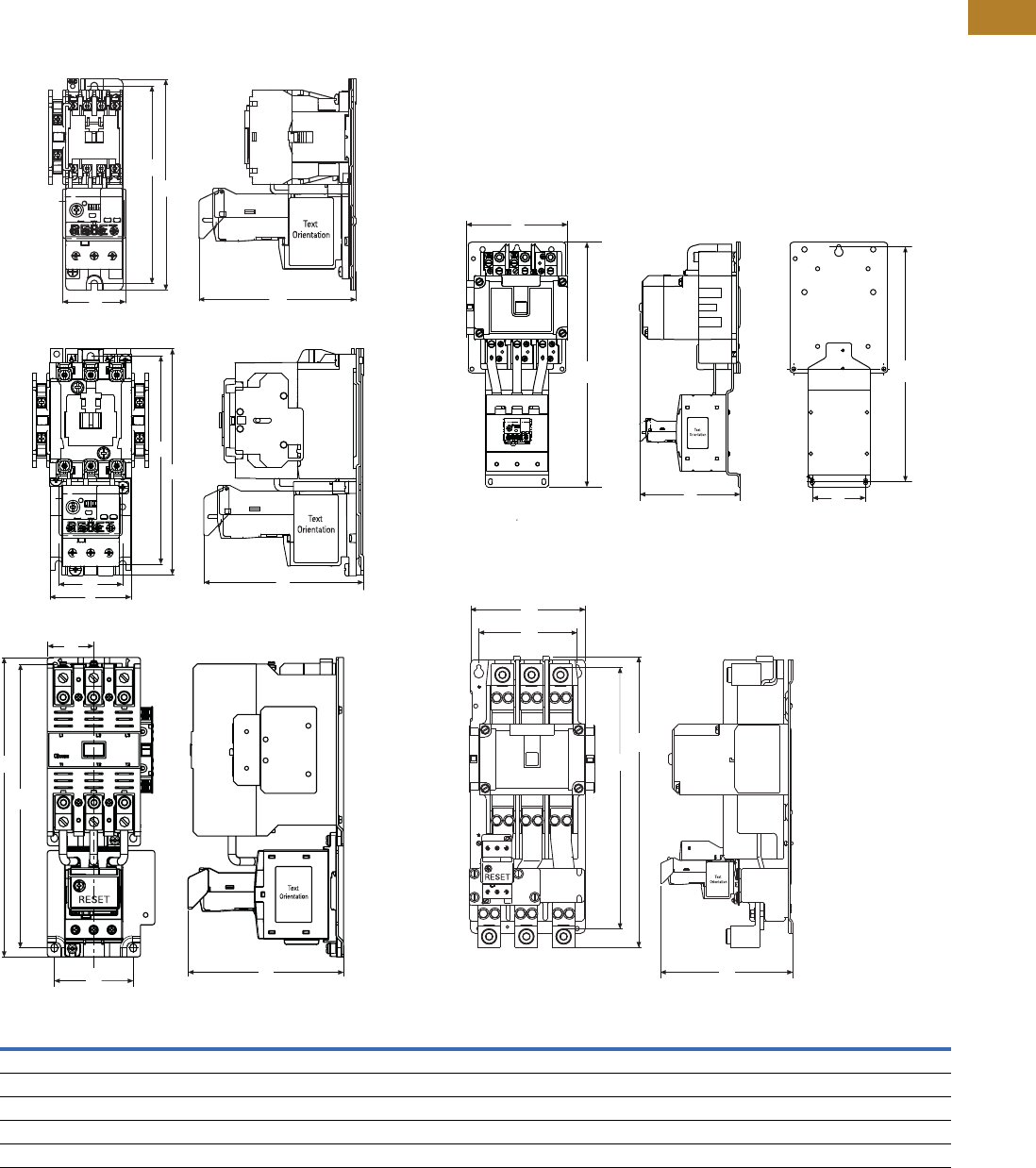
Volume 5—Motor Control and Protection CA08100006E—August 2014 www.eaton.com V5-T2-63
2
2
2
2
2
2
2
2
2
2
2
2
2
2
2
2
2
2
2
2
2
2
2
2
2
2
2
2
2
2
2.1
NEMA Contactors and Starters
Freedom Series
Dimensions
Approximate Dimensions in Inches (mm)
NEMA Starters
Full Voltage Non-Reversing Starters
NEMA SizeABCDE
00, 0 1.97 (50.0) 6.60 (167.6) 4.90 (124.5) — 6.18 (157.0)
1, 2 2.60 (65.0) 7.10 (180.0) 4.98 (126.5) 2.00 (50.8) 6.50 (165.0)
3 4.09 (103.8) 11.40 (289.6) 5.92 (150.3) 1.77 (44.9) 10.81 (274.6)
4 7.10 (179.0) 17.00 (432.0) 7.00 (177.0) 3.70 (94.0) 16.30 (415.0)
5 7.00 (177.8) 17.81 (452.3) 8.08 (205.2) 6.00 (152.4) 16.01 (406.6)
A
B
C
E
Sizes 00, 0
A
B
CD
E
A
B
C
D
E
A
B
C
D
E
A
B
C
D
E
Sizes 1, 2
Size 4
Size 5Size 3
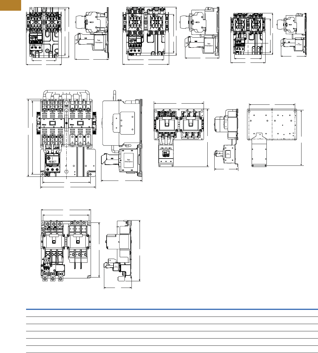
V5-T2-64 Volume 5—Motor Control and Protection CA08100006E—August 2014 www.eaton.com
2
2
2
2
2
2
2
2
2
2
2
2
2
2
2
2
2
2
2
2
2
2
2
2
2
2
2
2
2
2
2.1
NEMA Contactors and Starters
Freedom Series
Approximate Dimensions in Inches (mm)
Full Voltage Reversing Starters
NEMA SizeABCDE
00, 0 5.20 (132.0) 7.40 (187.0) 4.90 (125.0) 3.50 (89.0) 6.90 (174.0)
1 6.70 (171.0) 7.10 (180.0) 4.98 (126.5) 5.25 (133.0) 5.70 (144.0)
2 6.70 (171.0) 8.10 (205.0) 4.98 (126.5) 5.25 (133.0) 6.70 (170.0)
3 8.08 (205.2) 11.35 (288.3) 6.00 (152.0) 7.00 (177.8) 10.77 (273.6)
4 14.60 (371.0) 17.10 (433.0) 7.00 (177.0) 13.50 (343.0) 16.30 (145.0)
5 14.50 (368.3) 17.81 (452.3) 8.06 (204.8) 13.50 (342.9) 16.00 (406.6)
Sizes 00, 0
A
B
C
D
E
A
B
C
D
E
Size 5
Size 1
A
B
C
D
E
A
B
C
D
E
Size 3
A
B
C
D
E
Size 2
A
B
C
D
E
Size 4
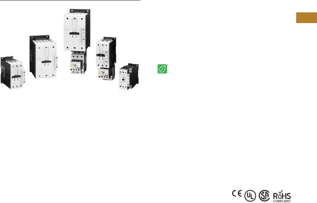
Volume 5—Motor Control and Protection CA08100006E—August 2014 www.eaton.com V5-T2-65
2
2
2
2
2
2
2
2
2
2
2
2
2
2
2
2
2
2
2
2
2
2
2
2
2
2
2
2
2
2
2.2
NEMA Contactors and Starters
Space-Savings Series
NEMA Space-Savings Family of Contactors and Starters
Contents
Description Page
Contactors and Starters
Catalog Number Selection . . . . . . . . . . . . . . . . V5-T2-66
Product Selection . . . . . . . . . . . . . . . . . . . . . . . V5-T2-66
Accessories . . . . . . . . . . . . . . . . . . . . . . . . . . . V5-T2-68
Renewal Parts . . . . . . . . . . . . . . . . . . . . . . . . . V5-T2-72
Technical Data and Specifications . . . . . . . . . . V5-T2-73
Dimensions . . . . . . . . . . . . . . . . . . . . . . . . . . . V5-T2-97
An Eaton
Green Solution
Contactors and Starters
Product Description
The Eaton NEMA® Space-
Savings line of contactors
and starters includes non-
reversing and reversing
contactors, electronic
overload relays and a variety
of related accessories.
Because the Space-Savings
family meets IEC, UL®, CSA®
and CE standards, it is the
perfect product solution for
applications all over the
world. The compact and easy
to install Space-Savings line
of NEMA contactors and
starters is the efficient and
effective solution for
customer applications from
Size 0 through Size 5.
Application Description
The Space-Savings line of
NEMA power control was
engineered to provide highly
effective control and
protection for a variety of
loads, including motors,
compressors, pumps,
resistive, capacitor banks,
isolation and others.
The Space-Savings
contactors are perfectly
suited for use in Motor
Control Center applications
where bucket space sizing is
critical. With both AC and DC
control and flexible
communication options, the
Space-Savings family can be
easily integrated into various
customer applications.
Features and Benefits
●AC control from
120V to 600V 50/60 Hz
●24 Vdc control
●Reversing or non-reversing
contactors and starters
●XTOE self-powered
electronic overload relay
●Non-reversing starters
to NEMA Size 5
●Panel or DIN rail mounting
to NEMA Size 2
●IP20 finger and back-of-
hand proof
●Large ambient temperature
range, –25 to 50°C
[–13 to 122°F]
●AC and DC controlled
contactors in the same
compact frame
●Low power consumption
AC and DC coils
●Built-in NO or NC auxiliary
contacts to 32A
●Plug-in accessories for
reduced installation time
●Coil replacement on NEMA
Size 0–5
●Contact replacement on
NEMA Size 1–5
●Integrated suppressor
NEMA Size 0–4 DC
operated contactors and
NEMA Size 5 AC and DC
operated contactors
Standards and Certifications
●IEC EN 60947
●CE approved
●UL
●CSA
●ATEX
●RoHS
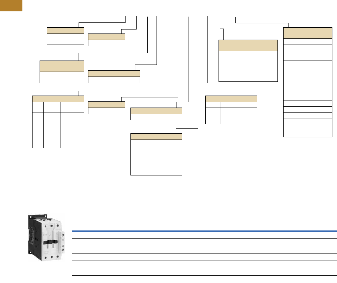
V5-T2-66 Volume 5—Motor Control and Protection CA08100006E—August 2014 www.eaton.com
2
2
2
2
2
2
2
2
2
2
2
2
2
2
2
2
2
2
2
2
2
2
2
2
2
2
2
2
2
2
2.2
NEMA Contactors and Starters
Space-Savings Series
Catalog Number Selection
Space-Savings NEMA Starters with XTOE Electronic Overload Relays
Product Selection
Type CN13/53 Space-Savings NEMA Contactors
Non-Reversing and Reversing
Notes
1Available on Compact Size 1 starter only.
2Underscore (_) indicates coils suffix required, see Coil Suffix table above.
3NEMA Size 5 starter available with 60-300A panel mounted CTs. Starter shipped as an assembled unit with
1–5A C440 overload relay (C440A1A005SELAX or C440A2A005SELAX).
NEMA
Size
Continuous
Ampere
Rating
Service Limit
Current Rating
(Amps)
Maximum UL Horsepower Three-Pole
Non-Reversing 2
Three-Pole
Reversing 2
Single-Phase Three-Phase
115V 230V 208V 240V 480V 600V Catalog Number Catalog Number
0 18 21 123355CN13BN010_ —
1C 27 32 2 3 7-1/2 7-1/2 10 10 CN13CN010_ CN53CN011_
1 27 32 2 3 7-1/2 7-1/2 10 10 CN13DN000_ CN53DN011_
2 45 52 3 7-1/210152525CN13GN000_ CN53GN011_
3 90 104 7.51525305050CN13KN000_ CN53KN011_
4 135 156 — — 40 50 100 100 CN13MN000_ —
5 3270 311 — — 75 100 200 200 CN13SN022_ —
A N 1 3 C N 0 1 A 5E 005
Device Type
A = Starter
C = Contactor
Contactor Frame Size
NEMA
Size
Continuous
Amperes
B =
C =
D =
G =
K =
M =
S =
0
1C
1
2
3
4
5
18
27
27
45
90
135
270
Device Assembly
Configuration
1 = Non-reversing
5 = Reversing
Standard
N = NEMA
OLR Type
3 = Starter w/XTOE EOLR
NEMA Enclosure
N = Open
For Starters
Starter Mounting Option
0 = Horizontal
Coil Suffix
Suffix Volts and Hertz
A =
B =
TD =
120/60 or 110/50
240/60 or 220/50
24 Vdc
XTOE OLR Designation
(FVNR and FVR only)
5E = Standard feature set
SEL Reset,
SEL Class (10A, 10, 20, 30)
5G = Ground fault feature set
SEL Reset,
SEL Class (10, 20)
XTOE FLA Range
(FVNR and FVR only)
NEMA Size 0
1P6 = 0.33–1.65A
005 = 1–5A
020 = 4–20A
NEMA Size 1C/1
1P6 = 0.33–1.65A 1
005 = 1–5A
020 = 4–20A
045 = 9–45A
NEMA Size 2
045 = 9–45A
NEMA Size 3
100 = 20–100A
NEMA Size 4/4C
175 = 35–175A
NEMA Size 5
300 = 60–300A
For Contactors Only
Starter Mounting Option
10 = 1 normally open
01 = 1 normally closed
11 = 1 normally open,
1 normally closed
00 = No auxiliary contacts
22 = 2 normally open,
2 normally closed
NEMA Contactor
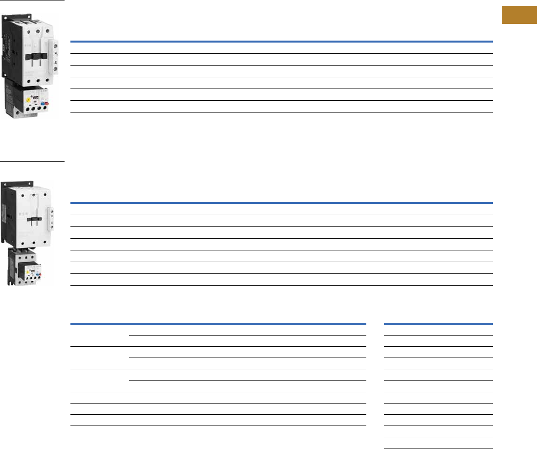
Volume 5—Motor Control and Protection CA08100006E—August 2014 www.eaton.com V5-T2-67
2
2
2
2
2
2
2
2
2
2
2
2
2
2
2
2
2
2
2
2
2
2
2
2
2
2
2
2
2
2
2.2
NEMA Contactors and Starters
Space-Savings Series
Type AN13/53 Space-Savings Starters with XTOE Electronic Overload Relays
Non-Reversing and Reversing
Type AN13/53 Space-Savings Starters with XTOE Ground Fault Electronic Overload Relays
Non-Reversing and Reversing
XTOE Overload FLA Range (FVNR and FVR Starters Only) Magnet Coil Suffix
Notes
1 Underscore (_) indicates coils suffix required, see Coil Suffix table above.
2 Underscore (_) indicates OLR designation required, see XTOE FLA Range table above.
3 For MCC replacement needs, contact MCC Aftermarket.
4 NEMA Size 5 starter available with 60-300A panel mounted CTs. Starter shipped as an assembled unit with
1–5A C440 overload relay (C440A1A005SELAX or C440A2A005SELAX).
5 Not available on AN13DN or AN53DN starters.
NEMA
Size
Continuous
Ampere
Rating
Service Limit
Current Rating
(Amps)
Maximum UL Horsepower Three-Pole
Non-Reversing 12
Three-Pole
Reversing 12
Single-Phase Three-Phase
115V 230V 208V 240V 480V 600V Catalog Number 3Catalog Number 3
0 18 21 123355AN13BN0_ 5E _ AN53BN0_ 5E _
1C 27 32 2 3 7-1/2 7-1/2 10 10 AN13CN0_ 5E _ AN53CN0_ 5E _
1 27 32 2 3 7-1/2 7-1/2 10 10 AN13DN0_ 5E _ AN53DN0_ 5E _
2 45 52 3 7-1/210152525AN13GN0_ 5E _ AN53GN0_ 5E _
3 90 104 ——25305050AN13KN0_ 5E _ AN53KN0_ 5E _
4 135 156 — — 40 50 100 100 AN13MN0_ 5E _ AN53MN0_ 5E _
5 4270 311 — — 75 100 200 200 AN13SN0_ 5E _ AN53SN0_ 5E _
NEMA
Size
Continuous
Ampere
Rating
Service Limit
Current Rating
(Amps)
Maximum UL Horsepower Three-Pole
Non-Reversing 12
Three-Pole
Reversing 12
Single-Phase Three-Phase
115V 230V 208V 240V 480V 600V Catalog Number 3Catalog Number 3
0 18 21 123355AN13BN0_ 5G _ AN53BN0_ 5G _
1C 27 32 2 3 7-1/2 7-1/2 10 10 AN13CN0_ 5G _ AN53CN0_ 5G _
1 27 32 2 3 7-1/2 7-1/2 10 10 AN13DN0_ 5G _ AN53DN0_ 5G _
2 45 52 3 7-1/210152525AN13GN0_ 5G _ AN53GN0_ 5G _
3 90 104 ——25305050AN13KN0_ 5G _ AN53KN0_ 5G _
4 135 156 — — 40 50 100 100 AN13NN0_ 5G_ AN53NN0_ 5G _
5 4270 311 — — 75 100 200 200 AN13SN0_ 5G _ AN53SN0_ 5G _
NEMA Size OLR Code FLA Range OLR Code FLA Rating Coil Voltage Suffix Code
01P6 0.33–1.65A 020 4.0–20A. Sizes 0–2
005 1.0–5.0A —— 110V 50 Hz, 120V 60 Hz A
1C/1 1P6 50.33–1.65A 020 4.0–20A 220V 50 Hz, 240V 60 Hz B
005 1.0–5.0A 045 9.0–45A 24–27 Vdc TD
2——045 9.0–45A Sizes 3, 4
———— 100–120V 50/60 Hz A
3100 20–100A —— 190–240V 50/60 Hz B
4175 35–175A —— 24–27 Vdc TD
5 4300 60–300A ——Sizes 5
100–120V 50/60 Hz A
24–48 Vdc TD
NEMA Starter
NEMA Starter with
Ground Fault
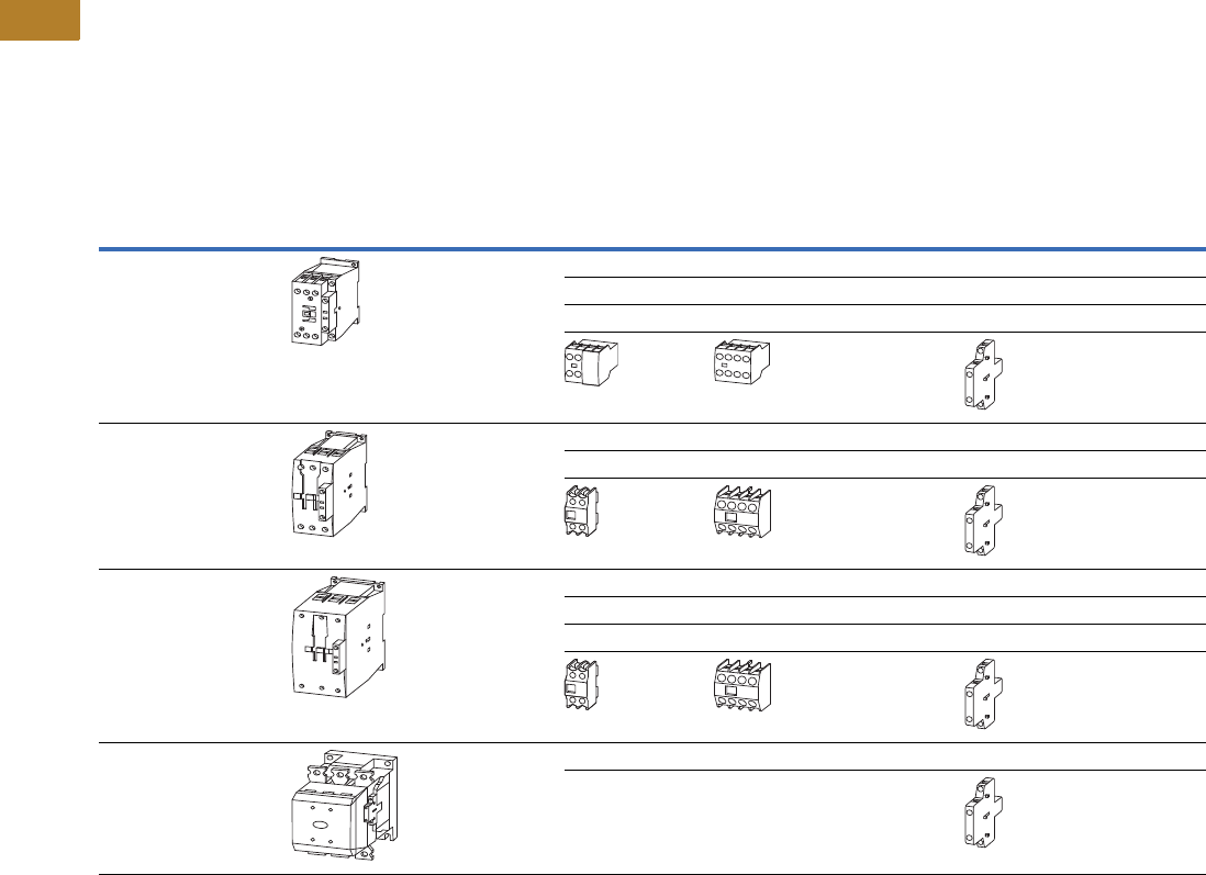
V5-T2-68 Volume 5—Motor Control and Protection CA08100006E—August 2014 www.eaton.com
2
2
2
2
2
2
2
2
2
2
2
2
2
2
2
2
2
2
2
2
2
2
2
2
2
2
2
2
2
2
2.2
NEMA Contactors and Starters
Space-Savings Series
Accessories
Auxiliary Contacts—Overview
Front-mounted snap-on
auxiliary contacts for Space-
Savings contactors are
available with screw
terminals in a variety of
contact configurations.
Auxiliary Contacts Possible Combinations
Frame
Size
Catalog
Number Contactor
Built-In
Auxiliary
Front (Top) Mount Side-Mount Total Auxiliary
Contacts AvailableTwo-Pole Four-Pole Single-Pole Two-Pole
0, 1C CN13BN0_ –
CN13CN0_
1NO or 1NC 1 — — — 3
—1 ——5
———13
——
1, 2 CN13DN0_ –
CN13GN0_
—1 — — 2 6
—1 —16
——
3, 4 CN13KN0_ –
CN13MN0_
—1 — — 2 6
—1 —28
———48
——
5CN13SN0 2NO–2NC — — 2 8
—— —
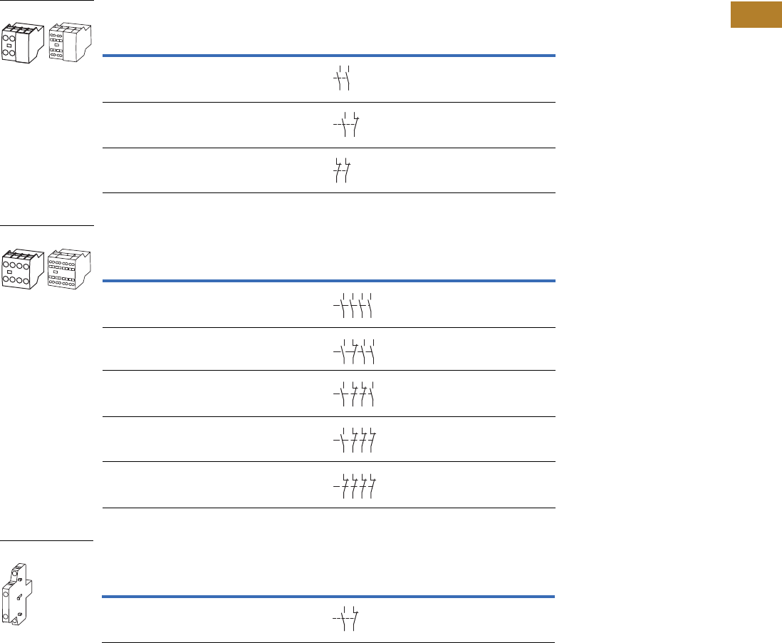
Volume 5—Motor Control and Protection CA08100006E—August 2014 www.eaton.com V5-T2-69
2
2
2
2
2
2
2
2
2
2
2
2
2
2
2
2
2
2
2
2
2
2
2
2
2
2
2
2
2
2
2.2
NEMA Contactors and Starters
Space-Savings Series
Auxiliary Contacts
NEMA Size 0, 1C— Front (Top) Mount—Two-Pole
NEMA Size 0, 1C— Front (Top) Mount—Four-Pole
NEMA Size 0, 1C—Side-Mount—Two-Pole
Notes
No auxiliary contacts can be fitted between two contactors.
1 Orders must be placed in multiples of package quantity listed.
2 To avoid duplicate terminal numbers in contact sequence, these auxiliary contacts should only be used with contactors
having a built-in 1NO contact (XTCE…B10_, XTCE…C10_).
3 Can be mounted to the left side of contactor only. Cannot be used in combination with front (top) mount auxiliary
contacts or mechanical interlocks.
Conventional Thermal Current,
Open at 60°C
Ith = Ie, AC-1 in Amps
Contact
Configuration
Circuit
Symbol
Pkg.
Qty. 1
Screw Terminal
Catalog Number
16 2NO 5 XTCEXFAC20
16 1NO-1NC 5 XTCEXFAC11 2
16 2NC 5 XTCEXFAC02
Conventional Thermal Current,
Open at 60°C
Ith = Ie, AC-1 in Amps
Contact
Configuration
Circuit
Symbol
Pkg.
Qty. 1
Screw Terminal
Catalog Number
16 4NO 5 XTCEXFAC40 2
16 3NO-1NC 5 XTCEXFAC31 2
16 2NO-2NC 5 XTCEXFAC22 2
16 1NO-3NC 5 XTCEXFAC13
16 4NC 5 XTCEXFAC04
Conventional Thermal Current,
Open at 60°C
Ith = Ie, AC-1 in Amps
Contact
Configuration
Circuit
Symbol
Pkg.
Qty. 1
Screw Terminal
Catalog Number
10 1NO-1NC 1 XTCEXSCC11 3
XTCEXF_
54
63
64
53
54
53 61
62
51
52
61
62
XTCEXF_
54
63 73
64 74
53 83
8
4
54
53 61
62
73
74
83
84
54
53 61
62
71
72
83
84
53 61 71 81
82
72
62
54
51
52
61
62
71
72 82
81
XTCEXSCC11
54
53 61
62
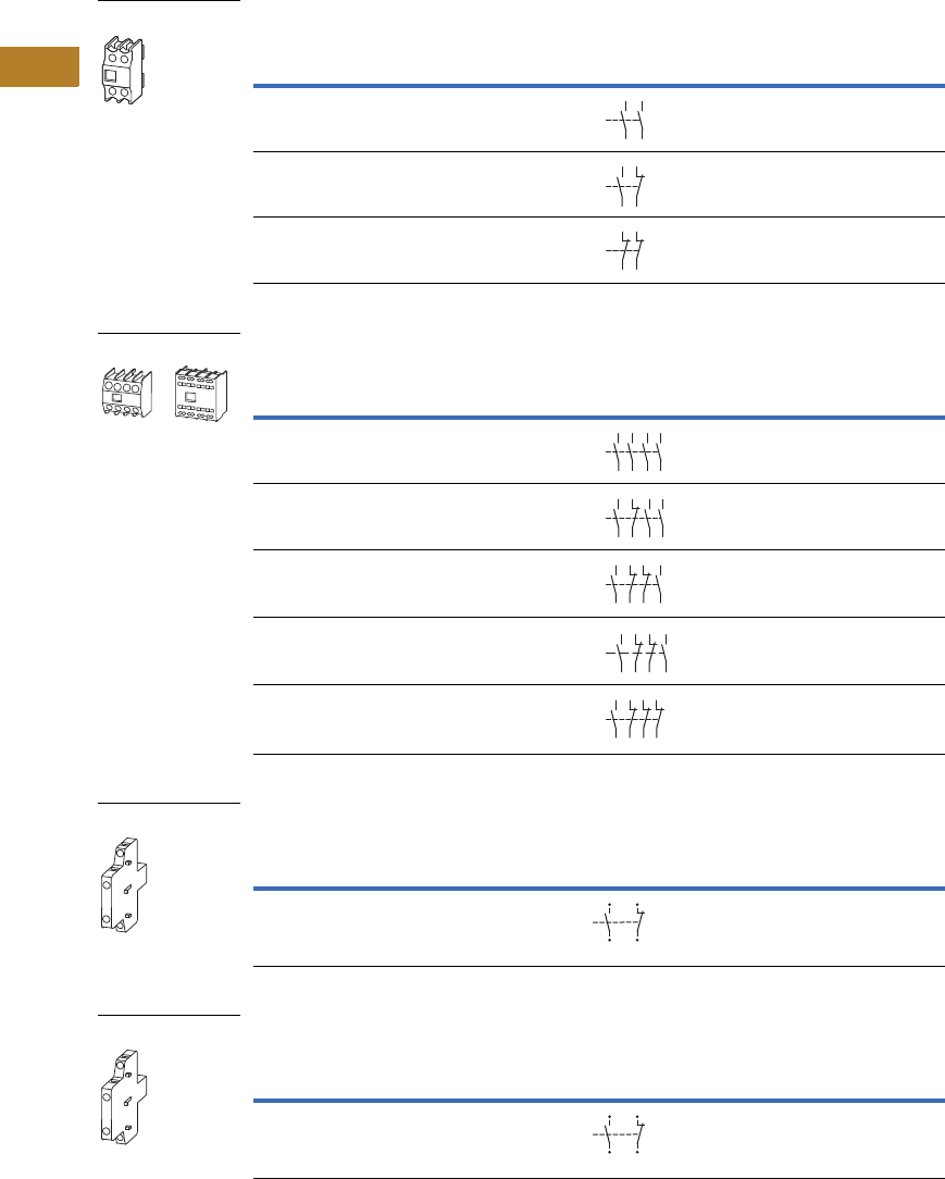
V5-T2-70 Volume 5—Motor Control and Protection CA08100006E—August 2014 www.eaton.com
2
2
2
2
2
2
2
2
2
2
2
2
2
2
2
2
2
2
2
2
2
2
2
2
2
2
2
2
2
2
2.2
NEMA Contactors and Starters
Space-Savings Series
NEMA Sizes 1–4—Two-Pole
NEMA Sizes 1–4—Four-Pole
NEMA Sizes 1–4, Side Mount (Snap-On)—Two-Pole
NEMA Size 5, Side Mount (Screw Mount)—Two-Pole
Notes
No auxiliary contacts can be fitted between two contactors.
1 Orders must be placed in multiples of package quantity listed.
2 For replacement only. XTCEXSBR11 and XTCEXSBLR11 cannot be added onto side mount auxiliaries that come with
the Size 5 contactors as standard. To add auxiliaries onto the included side auxiliaries on Size 5 contactors, use
XTCEXSCR11.
Conventional Thermal Current,
Open at 60°C
Ith = Ie, AC-1 in Amps
Contact
Configuration
Circuit
Symbol
Pkg.
Qty. 1
Screw Terminal
Catalog Number
16 2NO 5 XTCEXFBG20
16 1NO-1NC 5 XTCEXFBG11
16 2NC 5 XTCEXFBG02
Conventional Thermal Current,
Open at 60°C
Ith = Ie, AC-1 in Amps
Contact
Configuration
Circuit
Symbol
Pkg.
Qty. 1
Screw Terminal
Catalog Number
16 4NO-0NC 5 XTCEXFBG40
16 3NO-1NC 5 XTCEXFBG31
16 2NO-2NC 5 XTCEXFBG22
16 2NO-2NC 5 XTCEXFAG22
16 1NO-3NC 5 XTCEXFBG13
Conventional Free Air
Thermal Current,
Ith = Ie, AC-1 in Amps
Contact
Configuration
Circuit
Symbol
Pkg.
Qty. 1
Screw Terminal
Catalog Number
10 1NO–1NC 1 XTCEXSBN11
Conventional Free Air
Thermal Current,
Ith = Ie, AC-1 in Amps
Contact
Configuration
Circuit
Symbol
Pkg.
Qty. 1
Screw Terminal
Catalog Number
10 1NO–1NC 1 XTCEXSBR11 2
XTCEXF_
14 24
13 23
14
13 21
22
12
11 21
22
XTCEXF_
14
13 23
24
33
34
43
4
4
14
13 21
22
33
34
43
44
14
13 21
22
31
32
43
4
4
54
53 61
62
71
72
8
3
84
14
13 21
22
31
32
41
42
XTCEXS_
13
44
14
43
21
32
31
22
XTCEXS_
13
44
14
43
21
32
31
22
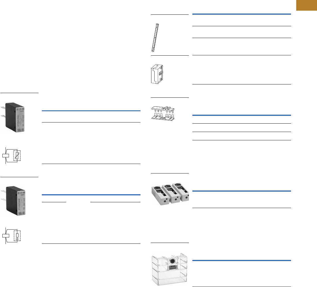
Volume 5—Motor Control and Protection CA08100006E—August 2014 www.eaton.com V5-T2-71
2
2
2
2
2
2
2
2
2
2
2
2
2
2
2
2
2
2
2
2
2
2
2
2
2
2
2
2
2
2
2.2
NEMA Contactors and Starters
Space-Savings Series
Suppressors
The switching of contactor
coils can generate voltage
transients that may cause
arching on switch contacts
and/or damage electronics on
the control line. Either an RC
or varistor suppressor is
recommended in these types
of applications. All Space-
Savings DC contactor coils
have built-in suppression.
Varistor suppressors clamp
the voltage transient above
the maximum coil voltage and
are recommended when the
level of the transient is
known to not exceed the coil
voltage. RC suppressors slow
and reduce the level of the
voltage transient but do not
clamp them at a specific
level. The slowing of the
transient can reduce
electrical interference.
These are recommended in
applications where operating
rates are high.
Varistor Suppressor 12
RC Suppressor 12
Notes
1Note dropout delay.
2For AC operated contactors, 50–60 Hz. Sizes 0–5 DC operated contactors and Size 5 AC
operated contactors have a built-in suppressor circuit.
3Orders must be placed in multiples of package quantity listed.
4In addition to the built-in suppressor circuit for DC actuated contactors. Prevents
negative breaking voltage when contactors are used in combination with a safety PLC.
5For two contactors with AC or DC operated magnet system which are horizontally or vertically
mounted. For Sizes 0–4, mechanical lifespan is 2.5 x 10⁶ operations
and the distance between contactors is 0 mm. For Size 5, mechanical lifespan is 5 x 10⁶
operations and no auxiliary contact can be mounted between the
mechanical interlock and the contactor—the distance between contactors is 15 mm.
6XTCEXMLG and XTCEXMLN consist of an interlock element and mounting plate.
Voltage
For Use
with…
Pkg.
Qty. 3Catalog Number
48–130 CN13BN0_
CN13CN0_
10 XTCEXVSCA
48–130 CN13DN0_
CN13GN0_
10 XTCEXVSFA
Voltage
For Use
with…
Pkg.
Qty. 3Catalog Number
24–48
CN13DN0_
CN13GN0_
—XTCEXRSFW
110–130
—XTCEXRSFA
XTCEXVS_
Contact Sequence
A2
A1
XTCEXRS_
Contact Sequence
A1
A2
Additional Accessories
Mechanical Interlock 5
Reversing Link Kits
Main current wiring for reversing combinations. Includes
paralleling bridge and reversing bridge. Does not include
mechanical interlock, see table on this page.
Terminal Lug Assembly
For connection of: round conductor, flexible and stranded,
flat strip conductor, with control circuit terminal. See Page
V5-T2-74 for terminal capacities.
Terminal Shroud
Protection against direct contact with connection lugs when
touched vertically from the front.
For Use
with…
Pkg.
Qty. 3Catalog Number
CN13BN0_,
CN13CN0_
1XTCEXMLC
CN13DN0_,
CN13GN0_
1XTCEXMLD
CN13KN0_,
CN13MN0_
1XTCEXMLG 6
CN13SN0_ 1 XTCEXMLM
For Use
with…
Pkg.
Qty. 3Catalog Number
CN13BN0_, CN13CN0_ 1 XTCEXRLC
CN13DN0_, CN13GN0_ 1 XTCEXRLD
CN13KN0_, CN13MN0_ 1 XTCEXRLG
For Use
with…
Pkg.
Qty. 3Catalog Number
CN13SN0_ 1 XTCEXTLA400
For Use
with…
Pkg.
Qty. 3Catalog Number
CN13SN0_ 1 XTCEXTS400
XTCEXML_
XTCEXMLM
XTCEXRL_
XTCEXTLA400
XTCEXTS_
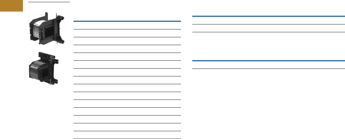
V5-T2-72 Volume 5—Motor Control and Protection CA08100006E—August 2014 www.eaton.com
2
2
2
2
2
2
2
2
2
2
2
2
2
2
2
2
2
2
2
2
2
2
2
2
2
2
2
2
2
2
2.2
NEMA Contactors and Starters
Space-Savings Series
Renewal Parts
Replacement Coils Replacement Contact Kit
Replacement Arc Chamber
Voltage
Coil
Suffix Catalog Number
Size 0, 1C
110/50 120/60 A XTCERENCOILCA
220/50 240/60 B XTCERENCOILCB
24–27 Vdc TD XTCERENCOILCTD
Size 1, 2
110/50 120/60 A XTCERENCOILDA
220/50 240/60 B XTCERENCOILDB
24–27 Vdc TD XTCERENCOILDTD
Size 3, 4
100–120V 50/60 A XTCERENCOILGA
190–240V 50/60 B XTCERENCOILGB
24–27 Vdc TD XTCERENCOILGTD
Size 5
110–250 Vac/Vdc A XTCERENCOILLA
24–48 Vdc TD XTCERENCOILLTD
XTCERENC_
For Use with… Catalog Number
CN13DN0_, CN13GN0_ XTCERENCONTACTD
CN13SN0_ XTCERENCONTACTL
For Use with… Catalog Number
CN13SN0_ XTCERENARC250

Volume 5—Motor Control and Protection CA08100006E—August 2014 www.eaton.com V5-T2-73
2
2
2
2
2
2
2
2
2
2
2
2
2
2
2
2
2
2
2
2
2
2
2
2
2
2
2
2
2
2
2.2
NEMA Contactors and Starters
Space-Savings Series
Technical Data and Specifications
Auxiliary Contacts
Notes
1Making and breaking conditions to DC-13, time L/R contact as stated.
2See fuses overlay for time/current characteristic (on request).
3Conventional thermal current (Ith) of XTCEXSCC_ is 10A.
Description
CN13BN0_,
CN13CN0_
XTCEXFAC_
XTCEXFATC_
XTCEXFCC_
XTCEXSCC_ XTCEXFAG_
XTCEXSBLN_
XTCEXSBN_
XTCEXSBNC_
XTCEXSCN_
XTCEXSCNC_
Interlocked opposing contacts with an auxiliary contact
module (to IEC 60947-5 -1 Annex L)
— Yes Yes Yes Yes
Break contact (not late-break contact) suitable as a mirror
contact (to IEC/EN 60947-4 -1 Annex F)
CN13BN0_, CN13CN0_ CN13BN0_, CN13CN0_ CN13BN0_, CN13CN0_ CN13DN0_, CN13GN0_ CN13DN0_, CN13GN0_,
CN13SN0_
Rated impulse withstand voltage, (Uimp) Vac 6000 6000 6000 6000 6000
Overvoltage category/pollution degree III/3 III/3 III/3 III/3 III/3
Rated insulation voltage, (Ui) Vac 690 690 690 690 690
Rated operational voltage, (Ue) Vac 500 500 500 500 500
Safe isolation to VDE 0106 Part 101 and Part 101(A) in Vac
Between coil and auxiliary contacts 400 400 400 440 440
Between the auxiliary contacts 400 400 400 440 440
Rated operational current, le
AC-15
230V 6A 6A 6A 6A 6A
380/415V 4A 3A 4A 4A 4A
500V 1.5A — 1.5A 1.5A 1.5A
DC-3 L/R
<
5 ms 1
24V 10A 10A 10A 10A 10A
60V 6A6A6A6A6A
110V 3A 3A 3A 3A 3A
220V 1A 1A 1A 1A 1A
Conventional thermal current, Ith 16A 16A 16A 310A 10A
Control circuit reliability
(at Ue = 24 Vdc, Umin = 17 V, Imin = 5.4 mA)
<10-8, <1 failure at
100 million operations
<10-8, <1 failure at
100 million operations
<10-8, <1 failure at
100 million operations
<10-8, <1 failure at
100 million operations
<10-8, <1 failure at
100 million operations
Component lifespan, operations x 106
at Ue = 230V, AC-15, 3A
1.3 1.3 1.3 1.3 1.3
Short-circuit rating without welding 2
Maximum fuse, gG/gL 10A 10A 10A 16A 16A

V5-T2-74 Volume 5—Motor Control and Protection CA08100006E—August 2014 www.eaton.com
2
2
2
2
2
2
2
2
2
2
2
2
2
2
2
2
2
2
2
2
2
2
2
2
2
2
2
2
2
2
2.2
NEMA Contactors and Starters
Space-Savings Series
Parallel Link
Cable Terminal Block, Flat Cable Terminal
AC Ratings—AC-1 Operation
Description XTCEXPLKB XTECXPLKC XTCEXPLKD XTCEXPLKG XTCEXPLK185
Terminal capacity
Solid (mm2) 1–161616——
Flexible with ferrule (mm2) 1 x (0.5–25)
2 x (0.5–16)
1 x (16–35) 1 x (16–120) — —
Stranded (mm2) 1 x (0.5–25)
2 x (0.5–16)
1 x (16–50) 1 x (16–120) 1 x (35–300)
2 x (35–120)
—
Flat conductor—number of segments x width x thickness (mm) 6 x 9 x 0.8 — — 2 x (11 x 21 x 1) 1 x (6 x 16 x 0.8)
2 x (20 x 32 x 0.5)
2 x (11 x 21 x 1)
Tightening torque (Nm) 4 4 14 — —
Tools
Pozidriv screwdriver Size 2 Size 2 — — —
Hexagon socket head spanner—SW (mm) — — 5 6 —
Conventional thermal current
Three-pole (Ith) A 50 100 180 400 —
Four-pole (Ith) A 60————
Description XTCEXTLA400 XTCEXPLK185 XTCEXTFB650 XTCEXTFB820
Terminal capacity
Stranded (mm2) 1 x (120–300)
2 x (70–240)
———
Stranded (AWG) 1 x (250–600 kcmil)
2 x (2/0–500 kcmil)
———
Flat conductor—number of segments x width x thickness (mm) — 1 x (6 x 16 x 0.8)
2 x (20 x 32 x 0.5)
2 x (11 x 21 x 1)
1 x (6 x 16 x 0.8)
2 x (20 x 32 x 0.5)
2 x (11 x 21 x 1)
1 x (6 x 16 x 0.8)
2 x (10 x 40 x 1)
2 x (20 x 40 x 0.5)
Description CN13B CN13C CN13D CN13G CN13K CN13M CN13S
Conventional free air thermal current, three-pole, 50–60 Hz
Open
at 40°C (Ith) 40A 45A 60A 80A 130A 190A 490
at 50°C (Ith) 38A 43A 57A 71A 125A 180A 438
at 55°C (Ith) 37A 42A 55A 68A 115A 170A 418
at 60°C (Ith) 35A 40A 50A 65A 110A 160A 400
Enclosed 32A 36A 45A 58A 100A 144A 315
Conventional free air thermal current, single-pole (Ith)
Open 88A 100A 125A 162A 275A 400A —
Enclosed 80A 90A 112A 145A 250A 360A —

Volume 5—Motor Control and Protection CA08100006E—August 2014 www.eaton.com V5-T2-75
2
2
2
2
2
2
2
2
2
2
2
2
2
2
2
2
2
2
2
2
2
2
2
2
2
2
2
2
2
2
2.2
NEMA Contactors and Starters
Space-Savings Series
Space-Savings Contactors—NEMA Sizes 0–2
Notes
1Damp heat, constant, to IEC 60068-2-78; damp heat, cyclic, to IEC 60 068-2-30.
2IEC 60947 Standard.
Description
Size 0
CN13BN010_
Size 1C
CN13CN010_
Size 1
CN13DN000_
Size 2
CN13GN000_
General
Standards IEC/EN 60947,
VDE 0660, UL, CSA,
CCC, RoHS
IEC/EN 60947,
VDE 0660, UL, CSA,
CCC, RoHS
IEC/EN 60947,
VDE 0660, UL, CSA,
CCC, RoHS
IEC/EN 60947,
VDE 0660, UL, CSA,
CCC, RoHS
Weights in kg [lb]
AC operated 0.42 [0.93] 0.42 [0.93] 0.9 [2.0] 0.9 [2.0]
DC operated 0.48 [1.06] 0.48 [1.06] 1.1 [2.4] 1.1 [2.4]
Mechanical life—operations 10,000,000 10,000,000 10,000,000 10,000,000
Climatic proofing 1111
Insulation voltage (Ui) Vac 690 690 690 690
Impulse withstand voltage (Uimp) Vac 8000 8000 8000 8000
Operating voltage (Ue) Vac 690 690 690 690
Safe isolation to VDE 0106 Part 101 and Part 101/A1
Between coil and contacts (Vac) 440 440 440 440
Between contacts (Vac) 238 440 440 440
Making capacity (amps) 238 384 560 910
Breaking capacity (amps)
220/230V 170 320 400 650
380/400V 170 320 400 650
500V 170 320 400 650
660/690V 120 180 250 370
Short-circuit protection rating maximum fuse (amps)
Type 2 coordination 2
400V; gG/gL 500V 25 63 63 125
690V; gG/gL 690V 25 35 50 80
Type 1 coordination 2
400V; gG/gL 500V 63 125 125 250
690V; gG/gL 690V 50 63 80 100
Degree of protection IP00 IP00 IP00 IP00
Protection against direct contact when
actuated from front (IEC 536)
Finger and
back-of-hand proof
Finger and
back-of-hand proof
Finger and
back-of-hand proof
Finger and
back-of-hand proof
Terminal capacity main cable—screw terminals
Solid (mm2) 1 x (0.75–16)
2 x (0.75–10)
1 x (0.75–16)
2 x (0.75–10)
1 x (0.75–16)
2 x (0.75–10)
1 x (0.75–16)
2 x (0.75–10)
Flexible with ferrule (mm2) 1 x (0.75–16)
2 x (0.75–10)
1 x (0.75–16)
2 x (0.75–10)
1 x (2.5–35)
2 x (2.5–25)
1 x (2.5–35)
2 x (2.5–25)
Stranded (mm2) 1 x 16 1 x 16 1 x (16–50)
2 x (16–35)
1 x (16–50)
2 x (16–35)
Solid or stranded (AWG) 18–6 18–6 12–2 12–2
Flat conductor
(number of segments x width x thickness) (mm)
— — 2 x (6 x 9 x 0.8) 2 x (6 x 9 x 0.8)
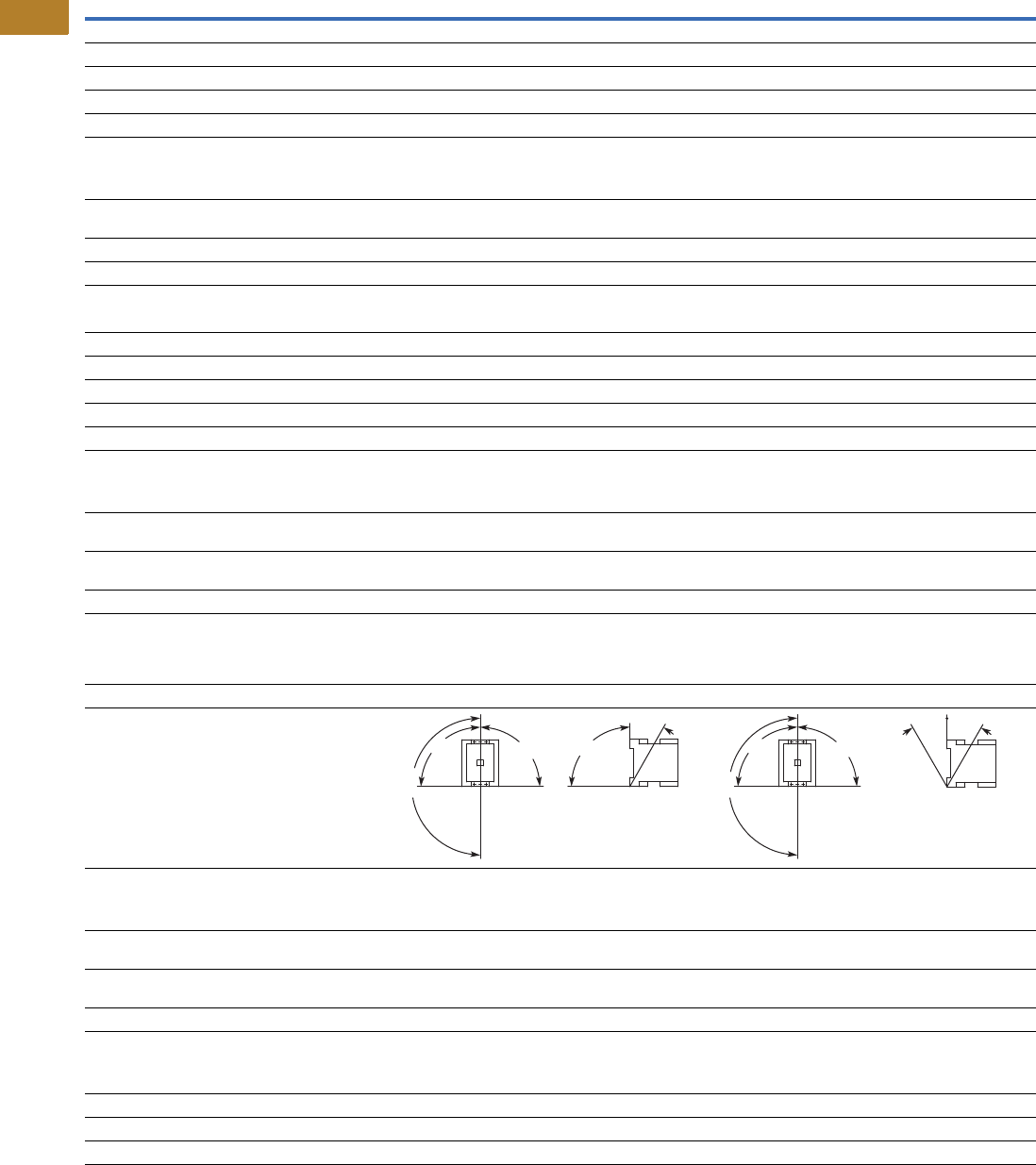
V5-T2-76 Volume 5—Motor Control and Protection CA08100006E—August 2014 www.eaton.com
2
2
2
2
2
2
2
2
2
2
2
2
2
2
2
2
2
2
2
2
2
2
2
2
2
2
2
2
2
2
2.2
NEMA Contactors and Starters
Space-Savings Series
Space-Savings Contactors—NEMA Sizes 0–2, continued
Description
Size 0
CN13BN010_
Size 1C
CN13CN010_
Size 1
CN13DN000_
Size 2
CN13GN000_
General, continued
Main cable connection screw/bolt M5 M5 M6 M6
Tightening torque
Nm 333.33.3
Lb-in 26.6 26.6 29.2 29.2
Terminal capacity control circuit cable—screw terminals
Solid (mm2) 1 x (0.75–4)
2 x (0.75–4)
1 x (0.75–4)
2 x (0.75–4)
1 x (0.75–4)
2 x (0.75–4)
1 x (0.75–4)
2 x (0.75–4)
Flexible with ferrule (mm2) 1 x (0.75–2.5)
2 x (0.75–2.5)
1 x (0.75–2.5)
2 x (0.75–2.5)
1 x (0.75–2.5)
2 x (0.75–2.5)
1 x (0.75–2.5)
2 x (0.75–2.5)
Solid or stranded (AWG) 18–14 18–14 18–14 18–14
Control circuit cable connection screw/bolt M3.5 M3.5 M3.5 M3.5
Tightening torque
Nm 1.2 1.2 1.2 1.2
Lb-in 10.6 10.6 10.6 10.6
Tools
Main and control circuit cable—screw terminals Size 2 Size 2 Size 2 Size 2
Pozidriv screwdriver 0.8 x 5.5 0.8 x 5.5 0.8 x 5.5 0.8 x 5.5
Standard screwdriver 1 x 6 1 x 6 1 x 6 1 x 6
Terminal capacity control circuit cable—spring cage terminals
Solid (mm2) 1 x (0.75–2.5)
2 x (0.75–2.5)
1 x (0.75–2.5)
2 x (0.75–2.5)
1 x (0.75–2.5)
2 x (0.75–2.5)
1 x (0.75–2.5)
2 x (0.75–2.5)
Flexible (mm2) 1 x (0.75–2.5)
2 x (0.75–2.5)
1 x (0.75–2.5)
2 x (0.75–2.5)
1 x (0.75–2.5)
2 x (0.75–2.5)
1 x (0.75–2.5)
2 x (0.75–2.5)
Flexible with ferrule (mm2) 1 x (0.75–2.5)
2 x (0.75–2.5)
1 x (0.75–2.5)
2 x (0.75–2.5)
1 x (0.75–2.5)
2 x (0.75–2.5)
1 x (0.75–2.5)
2 x (0.75–2.5)
Solid or stranded (AWG) 18–14 18–14 18–14 18–14
Tools
Main and control circuit cable—spring cage terminals
Stripping length (mm) 10 10 10 10
Screwdriver blade width (mm) 3.5 3.5 3.5 3.5
Mounting position, AC and DC operated
Ambient temperature
Open –25 to 60°C
[–13 to 140°F]
–25 to 60°C
[–13 to 140°F]
–25 to 60°C
[–13 to 140°F]
–25 to 60°C
[–13 to 140°F]
Enclosed –25 to 40°C
[–13 to 104°F]
–25 to 40°C
[–13 to 104°F]
–25 to 40°C
[–13 to 104°F]
–25 to 40°C
[–13 to 104°F]
Ambient storage temperature –40 to 80°C
[–40 to 176°F]
–40 to 80°C
[–40 to 176°F]
–40 to 80°C
[–40 to 176°F]
–40 to 80°C
[–40 to 176°F]
Environmental
Mechanical shock resistance
(IEC/EN 60068-2-27)
Main contact—NO Contact 10 10 10 1
Auxiliary contact—NO Contact 7777
Auxiliary contact—NC Contact 5555
Overvoltage category/pollution degree III/3 III/3 III/3 III/3
180°
90°
90°
90°
30°
180°
90°
90°
30° 30°

Volume 5—Motor Control and Protection CA08100006E—August 2014 www.eaton.com V5-T2-77
2
2
2
2
2
2
2
2
2
2
2
2
2
2
2
2
2
2
2
2
2
2
2
2
2
2
2
2
2
2
2.2
NEMA Contactors and Starters
Space-Savings Series
Space-Savings Contactors—NEMA Sizes 3, 4
Notes
1Damp heat, constant, to IEC 60068-2-78; damp heat, cyclic, to IEC 60 068-2-30.
2IEC 60947 Standard.
Description
Size 3
CN13KN000_
Size 4
CN13MN000_
General
Standards IEC/EN 60947,
VDE 0660, UL, CSA,
CCC, RoHS
IEC/EN 60947,
VDE 0660, UL, CSA,
CCC, RoHS
Weights in kg [lb]
AC operated 2 [4.41] 2 [4.41]
DC operated 2.1 [4.63] 2.1 [4.63]
Mechanical life—operations 10,000,000 10,000,000
Climatic proofing 11
Insulation voltage (Ui) Vac 690 690
Impulse withstand voltage (Uimp) Vac 8000 8000
Operational voltage (Ue) Vac 690 690
Safe isolation to VDE 0106 Part 101 and Part 101/A1
Between coil and contacts (Vac) 690 690
Between contacts (Vac) 690 690
Making capacity (amps) 1610 2100
Breaking capacity (amps)
220/230V 1150 1500
380/400V 1150 1500
500V 1150 1500
660/690V 1100 1200
1000V — —
Short-circuit protection rating maximum fuse
Type 2 coordination 2
400V; gG/gL 500V 250 25
690V; gG/gL 690V 25 250
Type 1 coordination 2
400V; gG/gL 500V 250 250
690V; gG/gL 690V 250 250
Degree of protection IP00 IP00
Protection against direct contact when actuated from front (IEC 536) Finger and
back-of-hand proof
Finger and
back-of-hand proof
Terminal capacity main cable—screw terminals
Solid (mm2)——
Flexible with ferrule (mm2) 1 x (10–95)
2 x (10–70)
1 x (10–95)
2 x (10–70)
Stranded (mm2) 1 x (10–95)
2 x (10–20)
1 x (10–95)
2 x (10–20)
Flat conductor
(number of segments x width x thickness) (mm)
2 x (6 x 16 x 0.8) 2 x (6 x 16 x 0.8)
Solid or stranded (AWG) 8–3/0 8–3/0
Main cable connection screw/bolt M10 M10
Tightening torque
Nm 14 14
Lb-in 123.9 123.9
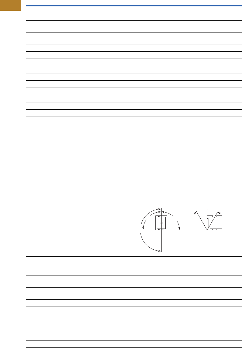
V5-T2-78 Volume 5—Motor Control and Protection CA08100006E—August 2014 www.eaton.com
2
2
2
2
2
2
2
2
2
2
2
2
2
2
2
2
2
2
2
2
2
2
2
2
2
2
2
2
2
2
2.2
NEMA Contactors and Starters
Space-Savings Series
Space-Savings Contactors—NEMA Sizes 3, 4, continued
Description
Size 3
CN13KN000_
Size 4
CN13MN000_
General, continued
Terminal capacity control circuit cable—screw terminals
Solid (mm2) 1 x (0.75–4)
1 x (0.75–4)
1 x (0.75–4)
1 x (0.75–4)
Flexible with ferrule (mm2) 1 x (0.75–2.5)
2 x (0.75–2.5)
1 x (0.75–2.5)
2 x (0.75–2.5)
Solid or stranded (AWG) 18–14 18–14
Control circuit cable connection screw/bolt M3.5 M3.5
Tightening torque
Nm 1.2 1.2
Lb-in 10.6 10.6
Tools
Main circuit cable—screw terminals
Hexagon socket-head spanner (mm) 5 5
Control circuit cable—screw terminals Size 2 Size 2
Pozidriv screwdriver 0.8 x 5.5 0.8 x 5.5
Standard screwdriver 1 x 6 1 x 6
Terminal capacity control circuit cable—spring cage terminals
Solid (mm2) 1 x (0.75–2.5)
2 x (0.75–2.5)
1 x (0.75–2.5)
2 x (0.75–2.5)
Flexible (mm2) 1 x (0.75–2.5)
2 x (0.75–2.5)
1 x (0.75–2.5)
2 x (0.75–2.5)
Flexible with ferrule (mm2) 1 x (0.75–2.5)
2 x (0.75–2.5)
1 x (0.75–2.5)
2 x (0.75–2.5)
Solid or stranded (AWG) 18–14 18–14
Tools
Control circuit cable—spring cage terminals
Stripping length (mm) 10 10
Screwdriver blade width (mm) 3.5 3.5
Mounting position, AC and DC operated
Ambient temperature
Open –25 to 60°C
[–13 to 140°F]
–25 to 60°C
[–13 to 140°F]
Enclosed –25 to 40°C
[–13 to 104°F]
–25 to 40°C
[–13 to 104°F]
Ambient storage temperature –40 to 80°C
[–40 to 176°F]
–40 to 80°C
[–40 to 176°F]
Environmental
Mechanical shock resistance
(IEC/EN 60068-2-27)
Half-sinusoidal shock 10 ms
Main contact—NO contact 10g 10g
Auxiliary contact—NO contact 7g 7g
Auxiliary contact—NC contact 5g 5g
Overvoltage category/pollution degree III/3 III/3
180°
90°
90°
30° 30°

Volume 5—Motor Control and Protection CA08100006E—August 2014 www.eaton.com V5-T2-79
2
2
2
2
2
2
2
2
2
2
2
2
2
2
2
2
2
2
2
2
2
2
2
2
2
2
2
2
2
2
2.2
NEMA Contactors and Starters
Space-Savings Series
Space-Savings Contactors—NEMA Size 5
Notes
1Damp heat, constant, to IEC 60068-2-78; damp heat, cyclic, to IEC 60 068-2-30.
2IEC 60947 Standard.
3Screw tightening with flat cable terminal or cable terminal blocks. See terminal capacity for cable terminal blocks.
4When using contactors for group compensation, a minimum inductance of approx. 6 uh per capacitor must be available to limit the high
inrush current peaks. This corresponds to an air-cored coil with five windings and a coil diameter of approximately 140 mm. The conductor
cross-section must be selected according to the rated current per phase.
Description
Size 5
CN13SN022_
General
Standards IEC/EN 60947,
VDE 0660, UL, CSA
Weights in kg [lb] 6.5 [14.3]
Mechanical life—operations 10,000,000
Mechanical operating frequency (ops/hr)
AC operated 3000
DC operated 3000
Climatic proofing 1
Insulation voltage (Ui) Vac 1000
Impulse withstand voltage (Uimp) Vac 8000
Operating voltage (Ue) Vac 1000
Safe isolation to VDE 0106 Part 101
and Part 101/A1
Between coil and contacts (Vac) 500
Between contacts (Vac) 500
Making capacity (amps) 3000
Breaking capacity (amps)
220/230V 2500
380/400V 2500
500V 2500
660/690V 2500
1000V 760
Short-circuit protection rating maximum fuse
Type 2 coordination 2
400V; gG/gL 500V 315
690V; gG/gL 690V 315
1000V; gG/gL 1000V 160
Type 1 coordination 2
400V; gG/gL 500V 400
690V; gG/gL 690V 400
1000V; gG/gL 1000V 200
Degree of protection IP00
Protection against direct contact when actuated
from front (IEC 536)
Finger and back-of-hand proof with
terminal shroud or terminal block
Main cable cross-section
Flexible with cable lug (mm2) 50–240
Stranded with cable lug (mm2) 70–240
Solid or stranded (AWG) 1/0–250 kcmil
Flat conductor (mm) 3
Bus bar—width in mm 25
Main cable connection screw/bolt M10
Tightening torque
Nm 24
Lb-in 213
Description
Size 5
CN13SN022_
General, continued
Control circuit cable cross-sections
Solid (mm2) 1 x (0.75–2.5)
2 x (0.75–2.5)
Flexible with ferrule (mm2) 1 x (0.75–2.5)
2 x (0.75–2.5)
Solid or stranded (AWG) 2 x (18–12)
Control circuit cable connection screw/bolt M3.5
Tightening torque
Nm 1.2
Lb-in 10.6
Tools
Main cable wrench 16 mm
Control circuit cable pozidriv screwdriver Size 2
Mounting position, AC and DC operated
Ambient temperature –25 to 60°C
[–13 to 140°F]
Ambient storage temperature –40 to 80°C
[–40 to 176°F]
Environmental
Mechanical shock
Resistance (IEC/EN 60068-2-27)
Half-sinusoidal shock 10 ms
Main contact—NO contact 10g
Auxiliary contact—NO contact 10g
Auxiliary contact—NC contact 8g
Overvoltage category/pollution degree III/3
Switching capacity, kVAR 4
Individual compensation
230V —
400/420/440V —
525V —
690V —
Group compensation, with choke
230V 100
400/420/440V 190
525V 260
690V 340
Group compensation, without choke
230V —
400/420/440V —
525V —
690V —
180°
90°
90°
30° 30°
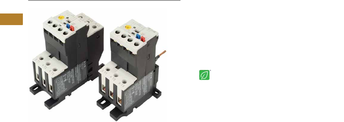
V5-T2-80 Volume 5—Motor Control and Protection CA08100006E—August 2014 www.eaton.com
2
2
2
2
2
2
2
2
2
2
2
2
2
2
2
2
2
2
2
2
2
2
2
2
2
2
2
2
2
2
2.2
NEMA Contactors and Starters
Space-Savings Series
XTOE/XT Electronic Overload Relay
Contents
Description Page
XTOE/XT Electronic Overload Relay
Standards and Certifications . . . . . . . . . . . . . . V5-T2-81
Catalog Number Selection . . . . . . . . . . . . . . . . V5-T2-82
Product Selection . . . . . . . . . . . . . . . . . . . . . . . V5-T2-83
Accessories . . . . . . . . . . . . . . . . . . . . . . . . . . . V5-T2-85
Technical Data and Specifications . . . . . . . . . . V5-T2-89
Dimensions . . . . . . . . . . . . . . . . . . . . . . . . . . . V5-T2-97
An Eaton
Green Solution
XTOE/XT Electronic Overload Relay
Product Description
Eaton’s new electronic
overload relay (EOL) is the
most compact, high-featured,
economical product in its
class. Designed on a global
platform, the new EOL covers
the entire power control
spectrum including NEMA,
IEC and DP Contactors. The
standard NEMA and DP
versions are offered with the
C440 designation while the
Space-Savings NEMA and
IEC versions have the XTOE
designation. The electronic
design provides reliable,
accurate and value driven
protection and communications
capabilities in a single
compact device. It is the
flexible choice for any
application requiring easy-to-
use, reliable protection.
Eaton has a long history of
innovations and product
development in motor control
and protection, including both
traditional NEMA, as well as
IEC control. It was from this
experience that the XTOE
was developed, delivering
new solutions to meet
today’s demands.
XTOE is a self-powered
electronic overload relay
available up to 175A as a
self contained unit. With
external CTs, XTOE can
protect motor up to
1500 FLA. Available add-on
accessories include remote
reset capability and
communication modules
with I/O for DeviceNet,
PROFIBUS, Modbus,
EtherNet/IP, and Modbus TCP.
Features and Benefits
Features
●Reliable, accurate, electronic motor protection
●Easy to select, install and maintain
●Compact size
●Flexible, intelligent design
●Global product offering—available with NEMA, IEC and DP
power control
Size/Range
●Broad FLA range
(0.33–1500A)
●Selectable trip class
(10A, 10, 20, 30)
●Direct mounting to NEMA,
IEC and DP contactors
●Most compact electronic
overload in its class
Motor Control
●Two B600 alarm (NO) and
fault (NC) contacts
●Test/Trip button
Motor Protection
●Thermal overload
●Phase loss
●Selectable (ON/OFF)
phase unbalance
●Selectable (ON/OFF)
ground fault
User Interface
●Large FLA selection dial
●Trip status indicator
●Operating mode LED
●DIP switch selectable trip
class, phase unbalance and
ground fault
●Selectable Auto/Manual
reset
Feature Options
●Remote reset
●120 Vac
●24 Vac
●24 Vdc
●Tamper-proof cover
●Communications modules
●Modbus RTU RS-485
●DeviceNet with I/O
●PROFIBUS with I/O
●Modbus RTU with I/O
●Ethernet IP with I/O
●Modbus TCP with I/O

Volume 5—Motor Control and Protection CA08100006E—August 2014 www.eaton.com V5-T2-81
2
2
2
2
2
2
2
2
2
2
2
2
2
2
2
2
2
2
2
2
2
2
2
2
2
2
2
2
2
2
2.2
NEMA Contactors and Starters
Space-Savings Series
Benefits
Reliability and Improved
Uptime
●XTOE provides the users
with peace of mind
knowing that their
assets are protected
with the highest level
of motor protection and
communication capability
in its class
●Extends the life of plant
assets with selectable
motor protection features
such as trip class, phase
unbalance and ground fault
●Protects against
unnecessary downtime
by discovering changes
in your system (line/load)
with remote monitoring
capabilities
●Status LED provides
added assurance that
valuable assets are
protected by indicating the
overload operational status
Flexibility
●Available with NEMA,
IEC and DP contactors
●Improves return on
investment by reducing
inventory carrying costs
with wide FLA adjustment
(5:1) and selectable
trip class
●Design incorporates built-in
ground fault protection
thus eliminating the need
for separate CTs and
modules
●Flexible communication
with optional I/O enables
easy integration into plant
management systems for
remote monitoring and
control
●Available as an open
component and in
enclosed control and motor
control center assemblies
Monitoring Capabilities
●Individual phase
currents RMS
●Average three-phase
current RMS
●Thermal memory
●Fault indication (overload,
phase loss, phase
unbalance, ground fault)
Safety
●IP 20 rated terminal blocks
●Available in Eaton’s
industry leading FlashGard
MCCs
●Tested to the highest
industry standards such
as UL, CSA, CE and IEC
●RoHS compliant
Standards and Certifications
●UL
●CSA
●CE
●NEMA
●IEC/EN 60947 VDE 0660
●ISO 13849-1 (EN954-1)
●RoHS
●ATEX directive 94/9/EC
●Equipment Group 2,
Category 2
Electronic Overload Education
Description Definition Cause Effect if not Protected XTOE/XT Protection
Motor Protection
Thermal overload Overload is a condition in which
current draw exceeds 115% of
the full load amperage rating for
an inductive motor.
• An increase in the load or torque that is
being driven by the motor.
• A low voltage supply to the motor
causes the current to go high to
maintain the power needed.
• A poor power factor causing above
normal current draw.
• Increase in current draw leads to heat
and insulation breakdown, which can
cause system failure.
• Increase in current can increase
power consumption and waste
valuable energy.
• Thermal trip behavior is defined by
UL, CSA and IEC standards.
• Trip class is settable from 10A,
10, 20, 30
Ground fault A line to ground fault. A current leakage path to ground. An undetected ground fault can burn
through multiple insulation windings,
ultimately leading to motor failure, not to
mention risk to equipment or personnel
Fixed protective setting that takes the
starter offline if ground fault current
exceeds 50% of the FLA dial setting,
i.e., if the FLA dial is set to 12A, the
overload relay will trip if the ground
current exceeds 6A.
Unbalanced phases
(voltage and current)
Uneven voltage or current between
phases in a three-phase system.
When a three-phase load is powered with
a poor quality line, the voltage per phase
may be unbalanced.
Unbalanced voltage causes large
unbalanced currents and as a result this
can lead to motor stator windings being
overloaded, causing excessive heating,
reduced motor efficiency and reduced
insulation life.
Fixed protective setting that takes the
starter offline if a phase drops below
50% of the other two phases.
Phase loss—current
(single-phasing)
One of the three-phase voltages is
not present.
Multiple causes, loose wire, improper
wiring, grounded phase, open fuse, etc.
Single-phasing can lead to unwanted
motor vibrations in addition to the results
of unbalanced phases as listed above.
Fixed protective setting that takes the
starter offline if a phase is lost.
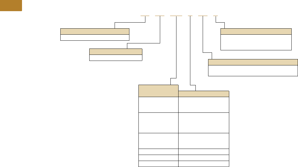
V5-T2-82 Volume 5—Motor Control and Protection CA08100006E—August 2014 www.eaton.com
2
2
2
2
2
2
2
2
2
2
2
2
2
2
2
2
2
2
2
2
2
2
2
2
2
2
2
2
2
2
2.2
NEMA Contactors and Starters
Space-Savings Series
Catalog Number Selection
XT Electronic Overload Relay—NEMA Space-Savings
Designation
XT = NEMA Space-Savings control
Type
OE = Electronic overload relay
Mounting
Blank = Direct to contactor
P = Pass-through
S = Separate mount (Frames C and G only)
Trip Type
CS = Selectable Class 10A, 10, 20, 30
GS = Ground fault with selectable Class 10, 20
Overload Range
Contactor Frame
1P6 = 0.33–1.65A
005 =1–5A
020 =4–20A
C = Space-Savings Size 0
1P6 = 0.33–1.65A
005 =1–5A
020 =4–20A
045 =9–45A
C = Space-Savings Size 1C
1P6 = 0.33–1.65A
005 =1–5A
020 =4–20A
D = Space-Savings Size 1
045 =9–45A D = Space-Savings Size 2
100 = 20–100A G = Space-Savings Size 3
175 = 35–175A G = Space-Savings Size 4
XT OE 1P6 C CS S
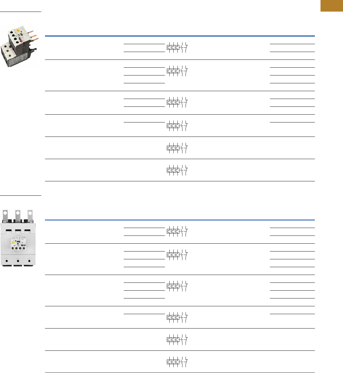
Volume 5—Motor Control and Protection CA08100006E—August 2014 www.eaton.com V5-T2-83
2
2
2
2
2
2
2
2
2
2
2
2
2
2
2
2
2
2
2
2
2
2
2
2
2
2
2
2
2
2
2.2
NEMA Contactors and Starters
Space-Savings Series
Product Selection
XT Electronic Overload Relays
XT Electronic Overload Relays for Direct Mount to NEMA Space-Savings Contactors
XT Electronic Overload Relays with Ground Fault for Direct Mount to NEMA Space-Savings Contactors
NEMA
Space-Savings
Size
For Use with
Contactor
Overload
Range (Amps)
Contact
Sequence
Frame
Size
Auxiliary
Contact
Configuration Catalog Number
0 CN13BN010_ 0.35–1.65 45 mm NO-NC XTOE1P6CCS
1–5 XTOE005CCS
4–20 XTOE020CCS
1C CN13CN010_ 0.35–1.65 45 mm NO-NC XTOE1P6CCS
1–5 XTOE005CCS
4–20 XTOE020CCS
9–45 XTOE045CCS
1 CN13DN000_ 1–5 55 mm NO-NC XTOE005DCS
4–20 XTOE020DCS
9–45 XTOE045DCS
2 CN13GN000_ 9–45 55 mm NO-NC XTOE045DCS
20–100 XTOE100DCS
3 CN13KN000_ 20–100 55 mm NO-NC XTOE100GCS
4 CN13MN000_ 35–175 110 mm NO-NC XTOE175GCS
NEMA
Space-Savings
Size
For Use with
Contactor
Overload
Range (Amps)
Contact
Sequence
Frame
Size
Auxiliary
Contact
Configuration Catalog Number
0 CN13BN010_ 0.33–1.65 45 mm NO-NC XTOE1P6CGS
1–5 XTOE005CGS
4–20 XTOE020CGS
1C CN13CN010_ 0.33–1.65 45 mm NO-NC XTOE1P6CGS
1–5 XTOE005CGS
4–20 XTOE020CGS
9–45 XTOE045CGS
1 CN13DN000_ 0.33–1.65 55 mm NO-NC XTOE1P6DGS
1–5 XTOE005DGS
4–20 XTOE020DGS
9–45 XTOE045DGS
2 CN13GN000_ 9–45 55 mm NO-NC XTOE045DGS
20–100 XTOE100DGS
3 CN13KN000_ 20–100 55 mm NO-NC XTOE100GGS
4 CN13MN000_ 35–175 110 mm NO-NC XTOE175GGS
XTOE for Direct Mount
to NEMA Size 1
2 4 6 98 96
97 95
2 4 6 98 96
97 95
2 4 6 98 96
97 95
2 4 6 98 96
97 95
2 4 6 98 96
97 95
2 4 6 98 96
97 95
XTOE for Direct Mount
to NEMA Size 4
2 4 6 98 96
97 95
2 4 6 98 96
97 95
2 4 6 98 96
97 95
2 4 6 98 96
97 95
2 4 6 98 96
97 95
2 4 6 98 96
97 95
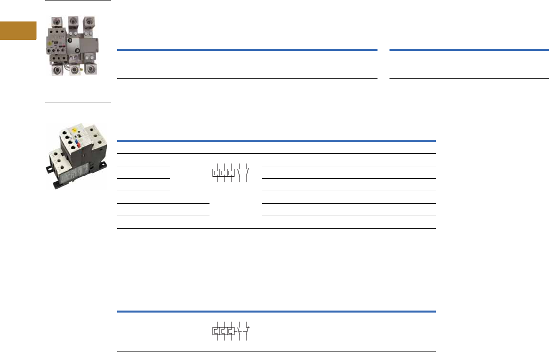
V5-T2-84 Volume 5—Motor Control and Protection CA08100006E—August 2014 www.eaton.com
2
2
2
2
2
2
2
2
2
2
2
2
2
2
2
2
2
2
2
2
2
2
2
2
2
2
2
2
2
2
2.2
NEMA Contactors and Starters
Space-Savings Series
XT Electronic Overload Relays for use with Size 5 NEMA Space-Savings Contactors
Use CTs and 1-5A XT overload relay. CT kit does not include overload relay (order separately).
XT Electronic Overload Relays for Separate Mount
XT Electronic Overload Relay for Pass-Through Design
Pass-through design does not include any lugs to land wires.
Terminate motor leads directly on contactor.
Space-Savings
Contactor Size
For Use with
Contactor
CT Range
(Amps) Description
CT Kit
Catalog Number
Terminal
Size
Overload Relay
Catalog Number
Overload Relay
with Ground Fault
Catalog Number
1 CN13SN022_ 60-300 300: 5 panel-mount CT kit
with integrated lugs
ZEB-XCT300 750 kcmil
(2) 250 kcmil
3/0 Cu/Al
XTOE005CCSS XTOE005CGSS
Overload
Range (Amps)
Frame
Size
Contact
Sequence Type
Overload Relay
Catalog Number
Overload Relay
with Ground Fault
Catalog Number
Overload Relay
0.33–1.65 45 mm ZEB32-1,65/KK XTOE1P6CCSS XTOE1P6CGSS
1–5 ZEB32-5/KK XTOE005CCSS XTOE005CGSS
4–20 ZEB32-20/KK XTOE020CCSS XTOE020CGSS
9–45 ZEB32-45/KK XTOE045CCSS XTOE045CGSS
20–100 55 mm ZEB150-100/KK XTOE100GCSS XTOE100GGSS
35–175 110 mm ZEB150-175/KK XTOE175GCSS XTOE175GGSS
Overload
Range (Amps)
Frame
Size
Contact
Sequence Type
Overload Relay
Catalog Number
Overload Relay
with Ground Fault
Catalog Number
35–175 110 mm ZEB150-175/PT XTOE175GCSP XTOE175GGSP
1–5A OL with CTs
45 mm XT for
Separate Mount
1359795
2469896
1359795
2469896

Volume 5—Motor Control and Protection CA08100006E—August 2014 www.eaton.com V5-T2-85
2
2
2
2
2
2
2
2
2
2
2
2
2
2
2
2
2
2
2
2
2
2
2
2
2
2
2
2
2
2
2.2
NEMA Contactors and Starters
Space-Savings Series
Accessories
CT Kits
Accessories
Communication
The XTOE is provided with two levels of communication capability.
Basic Communication via
Expansion Module—
Monitoring Only
Basic communication on
the XTOE is accomplished
using an expansion module.
The expansion module plugs
into the expansion bay on
the XTOE overload relay,
enabling communications
with the overload via their
Modbus RTU (RS-485)
network. No additional parts
are required. See
figure below.
Basic Communication—
Modbus
Advanced
Communication—
Monitoring and Control
XTOE also has the ability to
communicate on industrial
protocols such as DeviceNet,
PROFIBUS, Modbus RTU
and Modbus TCP, and
EtherNet/IP while providing
control capability using I/O.
An expansion module
(mentioned earlier) combined
with a communication
adapter and a communication
module allows easy
integration onto the
customer’s network. See
figure below.
Advanced Communication—
Communication Adapter with
Communication Module
Advanced
Communication—
Communication Module
The communication adapter
comes standard with four
inputs and two outputs
(24 Vdc or 120 Vac) while
providing the customer with
flexible mounting options
(DIN rail or panel). See
figure below,
Note
1Customer can wire remote mounted button to reset module (i.e., 22 mm pushbutton, catalog number M22-D-B-GB14-K10).
Description Catalog Number
Safety Cover
Clear Lexan cover that mounts on top of the FLA dial and DIP switches when closed. ZEB-XSC
Reset Bar
Assembles to the top of the overload to provide a larger target area for door
mounted reset operators.
ZEB-XRB
Remote Reset
Remote reset module (24 Vdc) 1C440-XCOM
Remote reset module (120 Vac) 1ZEB-XRR-120
Remote reset module (24 Vac) 1ZEB-XRR-24
Safety Cover
Reset Bar
Remote Reset

V5-T2-86 Volume 5—Motor Control and Protection CA08100006E—August 2014 www.eaton.com
2
2
2
2
2
2
2
2
2
2
2
2
2
2
2
2
2
2
2
2
2
2
2
2
2
2
2
2
2
2
2.2
NEMA Contactors and Starters
Space-Savings Series
The following information can be viewed using the communication option:
●Motor status—running,
stopped, tripped or
resetting
●Individual rms phase
currents (A, B, C)
●Average of three-phase
rms current
●Percent thermal capacity
●Fault codes (only available
prior to reset)
●Percent phase unbalance
●Ground fault current and
percent
●Overload relay settings—
trip class, DIP switch
selections, reset selections
●Modbus address (can be
set over the network)
Communication Accessories
Note
1 C440-COM-ADP Din C Panel adapter not required for ModbusTCP / EtherNet/IP communication module.
Description Catalog Number
Expansion module (Remote Reset/Modbus RTU, RS-485 Communication) C440-XCOM
Communication adapter kit (DIN C Panel mounted adapter, required for advance communication option) C440-COM-ADP 1
DeviceNet communication module kit—120V I/O (consists of C440-XCOM + C441K + C440-COM-ADP) C440-DN-120
DeviceNet communication module kit—24 Vdc I/O (consists of C440-XCOM + C441L + C440-COM-ADP) C440-DN-24
PROFIBUS communication module kit—120V I/O (consists of C440-XCOM + C441S + C440-COM-ADP) C440-DP-120
PROFIBUS communication module kit—24V I/O (consists of C440-XCOM + C441Q + C440-COM-ADP) C440-DP-24
Modbus communication module kit—120V I/O (consists of C440-XCOM + C441N + C440-COM-ADP) C440-MOD-120
Modbus communication module kit—24 Vdc I/O (consists of C440-XCOM + C441P + C440-COM-ADP) C440-MOD-24
Modbus TCP/Ethernet IP communication module kit—120V I/O (consists of C440-XCOM + C441U) C440-ET-120
Modbus TCP/Ethernet IP communication module kit—24V I/O (consists of C440-XCOM + C441V) C440-ET-24
Expansion Module
Communication
Adapter

Volume 5—Motor Control and Protection CA08100006E—August 2014 www.eaton.com V5-T2-87
2
2
2
2
2
2
2
2
2
2
2
2
2
2
2
2
2
2
2
2
2
2
2
2
2
2
2
2
2
2
2.2
NEMA Contactors and Starters
Space-Savings Series
Modbus Communication Module
The Modbus module
combined with an expansion
module and a communication
adapter provide Modbus
communication capability to
the XTOE electronic overload
relay.
Features and Benefits
●The Modbus
communication module is
capable of baud rates
up to 115K
●The Modbus address and
baud rate configuration can
be easily changed using
the HMi user interface
●Modbus address and baud
rate are set via convenient
DIP switches; LEDs are
provided to display
Modbus traffic
●Configuration with
common Modbus
configuration tools
●Terminals
●Unique locking
mechanism provides for
easy removal of the
terminal block with the
field wiring installed
●Each terminal is marked
for ease of wiring and
troubleshooting
●Selectable I/O assemblies
●4IN/2OUT
●Signal types include
24 Vdc I/O and
120 Vac I/O
●Each I/O module is
optically isolated
between the field I/O
and the network adapter
to protect the I/O and
communication circuits
from possible damage
due to transients and
ground loops
●Input Module features a
user-definable input
debounce, which limits
the effects of transients
and electrical noise
●Output Module supports
a user-definable safe
state for loss of
communication; hold
last state, ON or OFF
DeviceNet Communication Modules
The DeviceNet
Communication Module
provides monitoring and
control for the XTOE overload
relay from a single DeviceNet
node. These modules also
offer convenient I/O in two
voltage options,
24 Vdc and 120 Vac.
Features and Benefits
●Communication to
DeviceNet uses only one
DeviceNet MAC ID
●Configuration
●DeviceNet MAC ID and
Baud rate are set via
convenient DIP switches
with an option to set
from the network
●Advanced configuration
available using common
DeviceNet tools
●Terminals
●Unique locking
mechanism provides for
easy removal of the
terminal block with the
field wiring installed
●Each terminal is marked
for ease of wiring and
troubleshooting
●Selectable I/O assemblies
●4IN/2OUT
●Signal types include
24 Vdc I/O and
120 Vac I/O
●Each I/O module is
optically isolated
between the field I/O
and the network adapter
to protect the I/O and
communication circuits
from possible damage
due to transients and
ground loops
●Input Module features a
user-definable input
debounce, which limits
the effects of transients
and electrical noise
●Output Module supports
a user-definable safe
state for loss of
communication; hold
last state, ON or OFF
●Combined status LED
Modbus
Communication Module
DeviceNet
Communication Module
V5-T2-88 Volume 5—Motor Control and Protection CA08100006E—August 2014 www.eaton.com
2
2
2
2
2
2
2
2
2
2
2
2
2
2
2
2
2
2
2
2
2
2
2
2
2
2
2
2
2
2
2.2
NEMA Contactors and Starters
Space-Savings Series
PROFIBUS Communication Modules
The PROFIBUS module
combined with an expansion
module and a communication
adapter provide Modbus
communication capability to
the XTOE electronic overload
relay.
Features and Benefits
●The PROFIBUS
communication module is
capable of baud rates
up to 12 Mb
●PROFIBUS address is
set via convenient DIP
switches; LEDs are
provided to display
PROFIBUS status
●Intuitive configuration
with common PROFIBUS
configuration tools
●Terminals
●Unique locking
mechanism provides for
easy removal of the
terminal block with the
field wiring installed
●Each terminal is marked
for ease of wiring and
troubleshooting
●Selectable I/O assemblies
●4IN/2OUT
●Signal types include
24 Vdc I/O and
120 Vac I/O
●Each I/O module is
optically isolated
between the field I/O
and the network adapter
to protect the I/O and
communication circuits
from possible damage
due to transients and
ground loops
●Input Module features a
user-definable input
debounce, which limits
the effects of transients
and electrical noise
●Output Module supports
a user-definable safe
state for loss of
communication; hold
last state, ON or OFF
Modbus TCP / EtherNet/IP Communication Modules
The Ethernet module
combines user selectable
Modbus TCP and EtherNet/IP
protocols in a single device.
A communication adapter is
not required for this module
as it is designed for DIN/
Panel-Mounting. Combined
with an expansion module,
Modbus TCP and EtherNet/IP
capability are added to the
XTOE overload relay.
Features and Benefits
●Supports EtherNet/IP
Protocol
●Supports Modbus TCP
Protocol
●Integrated web page for
device monitoring and
configuration
●Dual Ethernet ports with
integrated switch
●Can simultaneously
support data access from
EtherNet/IP originators and
Modbus TCP clients
PROFIBUS
Communication Module
Modbus TCP / EtherNet/IP
Communication Module

Volume 5—Motor Control and Protection CA08100006E—August 2014 www.eaton.com V5-T2-89
2
2
2
2
2
2
2
2
2
2
2
2
2
2
2
2
2
2
2
2
2
2
2
2
2
2
2
2
2
2
2.2
NEMA Contactors and Starters
Space-Savings Series
Technical Data and Specifications
Electronic Overload Relays up to 1500A
Specification
Description 45 mm 55 mm 110 mm
Electrical Ratings Range Range Range
Operating voltage (three-phase) and frequency 690 Vac (60/50 Hz) 690 Vac (60/50 Hz) 690 Vac (60/50 Hz)
FLA Range
0.33–1.65A
1–5A
4–20A
9–45A
20–100A 28–140A (NEMA)
35–175A (IEC)
Use with Contactors
Space-Savings NEMA Size 0, 1C 1, 2, 3 4
Tri p C l a s s
10A, 10, 20, 30
Selectable
10A, 10, 20, 30
Selectable
10A, 10, 20, 30
Selectable
Motor Protection
Thermal overload setting 1.05 x FLA: does not trip
1.15 x FLA: overload trip
1.05 x FLA: does not trip
1.15 x FLA: overload trip
1.05 x FLA: does not trip
1.15 x FLA: overload trip
Feature Range Range Range
Phase loss Fixed threshold 50% Fixed threshold 50% Fixed threshold 50%
Phase unbalance (selectable: enable/disable) Fixed threshold 50% Fixed threshold 50% Fixed threshold 50%
Ground fault (selectable: enable/disable) 50% of FLA dial setting
>150% = 2 sec
>250% = 1 sec
50% of FLA dial setting
>150% = 2 sec
>250% = 1 sec
50% of FLA dial setting
>150% = 2 sec
>250% = 1 sec
Reset Manual/automatic Manual/automatic Manual/automatic
Indicators
Trip status Orange flag Orange flag Orange flag
Mode LED One flash: Overload operating properly
Two flashes: Current is above FLA dial
setting—pending trip
One flash: Overload operating properly
Two flashes: Current is above FLA dial
setting—pending trip
One flash: Overload operating properly
Two flashes: Current is above FLA dial
setting—pending trip
Options
Remote reset Yes Yes Yes
Reset bar Yes Yes Yes
Communication expansion module Yes Yes Yes
Communication adapter Yes Yes Yes
Capacity
Load terminals
Terminal capacity 12–10 AWG (4–6 mm2)
8–6 AWG (6–16 mm2)
6–1 AWG (16–50 mm2) 8–4/0 AWG (10–95 mm2)
Tightening torque 20–25 lb-in (2.3–2.8 Nm)
25–30 lb-in (2.8–3.4 Nm)
25–30 lb-in (2.8–3.4 Nm) 124 lb-in (14 Nm)
Input, auxiliary contact and remote reset terminals
Terminal capacity 2 x (18–12) AWG 2 x (18–12) AWG 2 x (18–12) AWG
Tightening torque 7–11 lb-in (0.8–1.2 Nm) 7–11 lb-in (0.8–1.2 Nm) 7–11 lb-in (0.8–1.2 Nm)
Voltages
Insulation voltage Ui (three-phase) 690 Vac 690 Vac 690 Vac
Insulation voltage Ui (control) 500 Vac 500 Vac 500 Vac
Rated impulse withstand voltage 6000 Vac 6000 Vac 6000 Vac
Overvoltage category/pollution degree III/3 III/3 III/3

V5-T2-90 Volume 5—Motor Control and Protection CA08100006E—August 2014 www.eaton.com
2
2
2
2
2
2
2
2
2
2
2
2
2
2
2
2
2
2
2
2
2
2
2
2
2
2
2
2
2
2
2.2
NEMA Contactors and Starters
Space-Savings Series
Electronic Overload Relays up to 1500A, continued
Specification
Description 45 mm 55 mm 110 mm
Auxiliary and Control Circuit Ratings
Conventional thermal continuous current 5A 5A 5A
Rated operational current—IEC AC-15
Make contact (1800 VA)
120V 15A 15A 15A
240V 15A 15A 15A
415V 0.5A 0.5A 0.5A
500V 0.5A 0.5A 0.5A
Break contact (180 VA)
120V 1.5A 1.5A 1.5A
240V 1.5A1.5A1.5A
415V 0.9A 0.9A 0.9A
500V 0.8A 0.8A 0.8A
IEC DC-13 (L/R F 15 ms1)
0–250V 1.0A 1.0A 1.0A
Rated operational current—UL B600
Make contact (3600 VA)
120V 30A 30A 30A
240V 15A 15A 15A
480V 7.5A 7.5A 7.5A
600V 6A 6A 6A
Break contact (360 VA)
120V 3A 3A 3A
240V 1.5A1.5A1.5A
480V 0.75A 0.75A 0.75A
600V 0.6A 0.6A 0.6A
R300—Vdc ratings (28 VA)
0–120V 0.22A 0.22A 0.22A
250V 0.11A 0.11A 0.11A
Short-Circuit Rating without Welding
Maximum fuse 6A gG/gL 6A gG/gL 6A gG/gL
Environmental Ratings
Ambient temperature (operating) –13° to 149°F (–25° to 65°C) –13° to 149°F (–25° to 65°C) –13° to 149°F (–25° to 65°C)
Ambient temperature (storage) –40° to 185°F (–40° to 85°C) –40° to 185°F (–40° to 85°C) –40° to 185°F (–40° to 85°C)
Operating humidity UL 991 (H3) 5% to 95% noncondensing 5% to 95% noncondensing 5% to 95% noncondensing
Altitude (no derating) NEMA ICS1 2000m 2000m 2000m
Shock (IEC 600068-2-27) 15g any direction 15g any direction 15g any direction
Vibration (IEC 60068-2-6) 3g any direction 3g any direction 3g any direction
Pollution degree per IEC 60947-4-1 3 for product (2 for pcb) 3 for product (2 for pcb) 3 for product (2 for pcb)
Ingress protection IP20 IP20 IP20
Protection against direct contact when actuated from
front (IEC 536)
Finger- and back-of-hand proof Finger- and back-of-hand proof Finger- and back-of-hand proof
Mounting position Any Any Any
Climatic proofing Damp heat, constant to IEC 60068-2-30 Damp heat, constant to IEC 60068-2-30 Damp heat, constant to IEC 60068-2-30

Volume 5—Motor Control and Protection CA08100006E—August 2014 www.eaton.com V5-T2-91
2
2
2
2
2
2
2
2
2
2
2
2
2
2
2
2
2
2
2
2
2
2
2
2
2
2
2
2
2
2
2.2
NEMA Contactors and Starters
Space-Savings Series
Electronic Overload Relays up to 1500A, continued
Specification
Description 45 mm 55 mm 110 mm
Electrical/EMC
Radiated emissions
IEC 60947-4-1-Table 15
EN 55011 (CISPIR 11) Group 1, Class A, ISM
30 MHz to 1000 MHz 30 MHz to 1000 MHz 30 MHz to 1000 MHz
Conducted emissions
IEC 60947-4-1-Table 14
EN 55011 (CISPIR 11) Group 1; Class ISM
0.15 MHz to 30 MHz 0.15 MHz to 30 MHz 0.15 MHz to 30 MHz
ESD immunity
IEC 60947-4-1 (Table 13)
±8 kV air, ±6 kV contact ±8 kV air, ±6 kV contact ±8 kV air, ±6 kV contact
Radiated immunity
IEC 60947-4-1
IEC 61000-4-3
10 V/m 80 MHz–1000 MHz
3 V/m from 1.4 to 2.7 GHz
80% amplitude modulated
1 kHz sine wave
10 V/m 80 MHz–1000 MHz
3 V/m from 1.4 to 2.7 GHz
80% amplitude modulated
1 kHz sine wave
10 V/m 80 MHz–1000 MHz
3 V/m from 1.4 to 2.7 GHz
80% amplitude modulated
1 kHz sine wave
Conducted immunity
IEC 60947-4-1, IEC 61000-4-6
140 dub (10V rms)
150 kHz–100 MHz
140 dub (10V rms)
150 kHz–100 MHz
140 dub (10V rms)
150 kHz–100 MHz
Fast transient immunity
IEC 60947-4-1 (Table 13)
IEC 61000-4-4
±4 kV using direct method
with accessory installed in expansion bay
±2 kV using direct method
±4 kV using direct method
with accessory installed in expansion bay
±2 kV using direct method
±4 kV using direct method
with accessory installed in expansion bay
±2 kV using direct method
Surge immunity
IEC 60947-4-1 (Table 13)
IEC 61000-4-5 a Class 4
Three-phase power inputs:
±4 kV line-to-line (DM)
±4 kV line-to-ground (CM)
Three-phase power inputs:
±4 kV line-to-line (DM)
±4 kV line-to-ground (CM)
Three-phase power inputs:
±4 kV line-to-line (DM)
±4 kV line-to-ground (CM)
With accessory installed in expansion bay:
±2 kV line-to-line (DM) –>1.2/50 us;
2 kV line-to-earth, 1 kV line-to-line
±4 kV line-to-ground (CM)
With accessory installed in expansion bay:
±2 kV line-to-line (DM) –>1.2/50 us;
2 kV line-to-earth, 1 kV line-to-line
±4 kV line-to-ground (CM)
With accessory installed in expansion bay:
±2 kV line-to-line (DM) –>1.2/50 us;
2 kV line-to-earth, 1 kV line-to-line
±4 kV line-to-ground (CM)
Power freq. magnetic field immunity
IEC 60947-4-1, IEC 61000-4-8
30 A/m, 50 Hz 30 A/m, 50 Hz 30 A/m, 50 Hz
Electromagnetic field
IEC 60947-4-1 Table 13, IEC 61000-4-3
10 V/m 10 V/m 10 V/m
Distortion IEEE 519 5% THD max., 5th harmonic 3% max. 5% THD max., 5th harmonic 3% max. 5% THD max., 5th harmonic 3% max.
Electrostatic discharge (ESD)
IEC 61000-4-2, EN 61131-2
4 kV contact
8 kV air discharge
4 kV contact
8 kV air discharge
4 kV contact
8 kV air discharge
Electrical fast transient (EFT)
IEC 61000-4-4, EN 61131-2
±2 kV using direct method ±2 kV using direct method ±2 kV using direct method
Surge immunity
IEC 61000-4-5, EN 61131-2
±2 kV line-to-ground (CM) ±2 kV line-to-ground (CM) ±2 kV line-to-ground (CM)

V5-T2-92 Volume 5—Motor Control and Protection CA08100006E—August 2014 www.eaton.com
2
2
2
2
2
2
2
2
2
2
2
2
2
2
2
2
2
2
2
2
2
2
2
2
2
2
2
2
2
2
2.2
NEMA Contactors and Starters
Space-Savings Series
Communication Modules
Note
1Relates to C441M only.
Description Modbus DeviceNet PROFIBUS Ethernet
Electrical/EMC
Radiated emissions
IEC 60947-4-1—Table 15, EN 55011
(CISPIR 11) Group 1, Class A
30–1000 MHz 30–1000 MHz 30–1000 MHz 30–1000 MHz
Conducted emissions
IEC 60947-4-1—Table 14, EN 55011
(CISPIR 11) Group 1, Class A
0.15–30 MHz 0.15–30 MHz 0.15–30 MHz 0.15–30 MHz
ESD immunity
IEC 60947-4-1 (Table 13)
±8 kV air, ±4 kV contact ±8 kV air, ±4 kV contact ±8 kV air, ±4 kV contact ±8 kV air, ±4 kV contact
Radiated immunity
IEC 60947-4-1
10 V/m 80–1000 MHz
80% amplitude modulated
1 kHz sine wave
10 V/m 80–1000 MHz
80% amplitude modulated
1 kHz sine wave
10 V/m 80–1000 MHz
80% amplitude modulated
1 kHz sine wave
10 V/m 80–1000 MHz
80% amplitude modulated
1 kHz sine wave
Conducted immunity
IEC 60947-4-1
140 dBuV (10V rms)
150 kHz–80 MHz
140 dBuV (10V rms)
150 kHz–80 MHz
140 dBuV (10V rms)
150 kHz–80 MHz
140 dBuV (10V rms)
150 kHz–80 MHz
Fast transient immunity
IEC 60947-4-1 (Table 13) IEC 6100-4-4
±2 kV using direct method ±2 kV supply and control,
±1 kV communication
±2 kV supply and control,
±1 kV communication
±2 kV supply and control,
±1 kV communication
Surge immunity
IEC 60947-4-1 (Table 13)
IEC 61000-4-5 Class 3
User IO and communication lines 1:
±1 kV line-to-line (DM)
±2 kV line-to-ground (CM)
User IO and communication lines:
±0.5 kV line-to-line (DM)
±1 kV line-to-ground (CM)
User IO and communication lines:
±0.5 kV line-to-line (DM)
±1 kV line-to-ground (CM)
User IO and communication lines:
±0.5 kV line-to-line (DM)
±1 kV line-to-ground (CM)
Electromagnetic field 1
IEC 60947-4-1 (Table 13) IEC 61000-4-3
10 V/m 10 V/m 10 V/m 10 V/m
Environmental Ratings
Ambient temperature (operating) –4° to 122°F (–20° to 50°C) –13° to 122°F (–25° to 50°C) –13° to 122°F (–25° to 50°C) –13° to 122°F (–25° to 50°C)
Ambient temperature (storage) –40° to 185°F (–40° to 85°C) –40° to 185°F (–40° to 85°C) –40° to 185°F (–40° to 85°C) –40° to 185°F (–40° to 85°C)
Operating humidity 5–95% noncondensing 5–95% noncondensing 5–95% noncondensing 5–95% noncondensing
Altitude (no derating) 2000m 2000m 2000m 2000m
Shock (IEC 600068-2-27) 15G any direction 15G any direction 15G any direction 15G any direction
Vibration (IEC 60068-2-6) 3G any direction 3G any direction 3G any direction 3G any direction
Pollution degree per IEC 60947-1 3 3 3 3
Degree of protection IP20 IP20 IP20 IP20
Overvoltage category per UL 508 III III III III
DeviceNet
DeviceNet connections — Group 2, polling, bit strobe,
explicit, no UCMM
— Group 2, polling, bit strobe,
explicit, no UCMM
DeviceNet baud rate — 125K, 250K, 500K — 125K, 250K, 500K
Ethernet
Ethernet connections — — — Integrated two-port switch with dual
RJ45 Ethernet connections
Ethernet type — — — Ethernet 10/100 Mbs, AutoMDX,
Auto Negotiation
PROFIBUS
PROFIBUS connections — — Group 2, polling, bit strobe,
explicit, no UCMM
—
PROFIBUS baud rate — — 9.6K, 19.2K, 45.45K, 93.75K, 187.5K,
500K, 1.5M, 3M, 6M, 12M
—

Volume 5—Motor Control and Protection CA08100006E—August 2014 www.eaton.com V5-T2-93
2
2
2
2
2
2
2
2
2
2
2
2
2
2
2
2
2
2
2
2
2
2
2
2
2
2
2
2
2
2
2.2
NEMA Contactors and Starters
Space-Savings Series
Communication Modules, continued
Note
1Relates to C441M only.
Description Modbus DeviceNet PROFIBUS Ethernet
C441_ 24 Vdc Input
Nominal input voltage 24 Vdc 24 Vdc 24 Vdc 24 Vdc
Operating voltage 18–30 Vdc 18–30 Vdc 18–30 Vdc 18–30 Vdc
Number of inputs 4 4 4 4
Signal delay 5 ms (programmable to 65 sec) 5 ms (programmable to 65 sec) 5 ms (programmable to 65 sec) 5 ms (programmable to 65 sec)
OFF-state voltage <6 Vdc <6 Vdc <6 Vdc <6 Vdc
ON-state voltage >18 Vdc >18 Vdc >10 Vdc >18 Vdc
Nominal input current 5 mA 5 mA 5 mA 5 mA
Isolation 1500V 1500V 1500V 1500V
Terminal screw torque 7–9 in-lb 7–9 in-lb 7–9 in-lb 7–9 in-lb
24V source current 50 mA 50 mA 50 mA 50 mA
Operating Voltage Range—DC Input Modules
OFF state 0–6 Vdc 0–6 Vdc 0–6 Vdc 0–6 Vdc
Transition region 6–18 Vdc 6–18 Vdc 6–18 Vdc 6–18 Vdc
ON state 18–30 Vdc 18–30 Vdc 18–30 Vdc 18–30 Vdc
C441_ 120 Vac Input
Nominal input voltage 120 Vac 120 Vac 120 Vac 120 Vac
Operating voltage 80–140 Vac 80–140 Vac 80–140 Vac 80–140 Vac
Number of inputs 4 4 4 4
OFF-state voltage <30 Vac <30 Vac <20 Vac <30 Vac
ON-state voltage >80 Vac >80 Vac >70 Vac >80 Vac
Nominal input current 15 mA 15 mA 15 mA 15 mA
Signal delay 1/2 cycle 1/2 cycle 1/2 cycle 1/2 cycle
Isolation 1500V 1500V 1500V 1500V
Terminal screw torque 7–9 in-lb 7–9 in-lb 7–9 in-lb 7–9 in-lb
Operating Voltage Range—AC Input Modules
OFF state 0–30 Vac 0–30 Vac 0–30 Vac 0–30 Vac
Transition region 30–80 Vac 30–80 Vac 30–80 Vac 30–80 Vac
ON state 80–140 Vac 80–140 Vac 80–140 Vac 80–140 Vac
Output Modules
Nominal voltage 120 Vac
24 Vdc
120 Vac
24 Vdc
120 Vac
24 Vdc
120 Vac
24 Vdc
Number of outputs (2) 1NO Form A
1NO/NC Form C
(2) 1NO Form A
1NO/NC Form C
(2) 1NO Form A
1NO/NC Form C
(2) 1NO Form A
1NO/NC Form C
Relay OFF time 3 ms 3 ms 3 ms 3 ms
Relay ON time 7 ms 7 ms 7 ms 7 ms
Max. current per point 15A (B300 rated) 5A (B300 rated) 5A (B300 rated) 5A (B300 rated)
Electrical life 100,000 cycles 100,000 cycles 100,000 cycles 100,000 cycles
Mechanical life 1,000,000 cycles 1,000,000 cycles 1,000,000 cycles 1,000,000 cycles

V5-T2-94 Volume 5—Motor Control and Protection CA08100006E—August 2014 www.eaton.com
2
2
2
2
2
2
2
2
2
2
2
2
2
2
2
2
2
2
2
2
2
2
2
2
2
2
2
2
2
2
2.2
NEMA Contactors and Starters
Space-Savings Series
Short Circuit Ratings (North America CSA, cUL)
Changes to UL 508A and NEC in recent years have brought a focus to control panel safety with
regard to short-circuit current ratings (SCCR). Eaton’s XTOE electronic overload relays combined
with XT Series IEC, Freedom Series NEMA and XT NEMA contactors provide a wide variety of
SCCR solutions needed for a variety of applications. The SCCR data in this document reflects
the latest information as of April 2010.
XTOE Standalone Overload Relays (XTOE)
NEMA Space-Savings Starters with XTOE Electronic Overload Relays
Overload
FLA Range
Maximum
Operating
Voltage
Standard-Fault Short Circuit Data High-Fault Short Circuit Data
600V (kA)
Maximum
Fuse Size (A)
(RK5)
Maximum
Breaker
Size (A)
Fuses (RK5, J, CC) Thermal-Magnetic Circuit Breakers
480V (kA) 600V (kA)
Maximum
Fuse Size 480V (kA) 600V (kA)
Maximum
Breaker Size
0.33–1.65A600 Vac1 6 15 ——————
1–5A 600 Vac 5 20 20 100 100 30 100 35 20
4–20A 600 Vac 5 80 80 100 100 100 100 35 80
9–45A 600 Vac 5 175 175 100 100 100 100 35 100/175 (480/600)
20–100A 600 Vac 10 400 400 100 100 200 150 35 250/400 (480/600)
28–140A 600 Vac 10 450 500 100 100 400 100 65 400
35–175A 690 Vac 10 500 (gG) 350 (690 Vac)
320 (415 Vac)
100 100 500 (gG) 100 (415 Vac) — 350 (LGC3350)
320 (NZMH3)
High-Fault Short Circuit Data
Fuses (RK5, J, CC) Thermal-Magnetic Circuit Breakers
Contactor
Frame Size
Overload
FLA Range 480V 600V
Maximum
Fuse Size 480V 600V
Maximum
Breaker Size
B 1–5A 100 100 30 ———
4–20A 100 100 30 — — —
C 1–5A 100 100 60 — — —
4–20A 100 100 60 — — —
9–45A 100 100 60 — — —
D 9–45A 100 100 200 65 35 175
20–100A 100 100 200 65 35 175
F 20–100A 100 100 200 65 65 350
G 20–100A 100 100 200 65 65 350
35–175A 100 100 400 65 30 250 (480 Vac)
350 (600 Vac)
H 35–175A 100 100 400 65 30 400

Volume 5—Motor Control and Protection CA08100006E—August 2014 www.eaton.com V5-T2-95
2
2
2
2
2
2
2
2
2
2
2
2
2
2
2
2
2
2
2
2
2
2
2
2
2
2
2
2
2
2
2.2
NEMA Contactors and Starters
Space-Savings Series
Coil Data—Frames B–D
Note
1Coil Suffix TD: Umin 24 Vdc/Umax 27 Vdc.
Coil Suffix WD: Umin 48 Vdc/Umax 60 Vdc.
Coil Suffix AD: Umin 110 Vdc/Umax 130 Vdc.
Coil Suffix BD: Umin 200 Vdc/Umax 240 Vdc.
Example:
Uc = 0.7 x Umin—1.2 x Umax
Uc = 0.7 x 24V—1.2 x 27 Vdc
Description
CN13B_
NEMA Size 0
CN13C_
NEMA Size 1C
CN13D_
NEMA Size 1
CN13G_
NEMA Size 2
Voltage Toleran ce
Pickup (x Uc)
AC operated 0.8–1.1 0.8–1.1 0.8–1.1 0.8–1.1
DC operated 0.7–1.2 10.7–1.2 10.7–1.2 10.7–1.2 1
Dropout (x Uc)
AC operated 0.3–0.6 0.3–0.6 0.3–0.6 0.3–0.6
DC operated 0.15–0.6 0.15–0.6 0.15–0.6 0.15–0.6
Power Consumption of the Coil at Cold State and 1.0 x Uc
AC operated
Single-voltage coil 50 Hz
Pickup VA 52 52 149 149
Pickup W 40408080
Sealing VA 7.1 7.1 16 16
Sealing W 2.1 2.1 4.3 4.3
Single-voltage coil 60 Hz
Pickup VA 67 67 178 178
Pickup W 50 50 117 117
Sealing VA 8.7 8.7 19 19
Sealing W 2.6 2.6 5.3 5.3
50/60 Hz
Pickup VA 62
58
62
58
168
154
168
154
Pickup W 48
43
48
43
120
43
120
43
Sealing VA 9.1
6.5
9.1
6.5
22
14
22
14
Sealing W 2.5
2
2.5
2
5.3
4.3
5.3
4.3
DC operated
Pickup W 12 at 24V 12 at 24V 24 at 24V 24 at 24V
Sealing W 0.5 at 24V 0.5 at 24V 0.5 at 24V 0.5 at 24V
Duty factor (%DF) 100 100 100 100
Switching Time at 100% Uc (Approximate Values)
Main contact
AC operated
Closing delay (ms) <22 <22 <18 <18
Opening delay (ms) <14 <14 <13 <13
DC operated
Closing delay (ms) <47 <47 <54 <54
Opening delay (ms) <30 <30 <24 <24
Arcing time (ms) 10 10 10 10
Electromagnetic Compatibility (EMC)
Emitted interference To EN-60947-1 To EN-60947-1 To EN-60947-1 To EN-60947-1
Noise immunity To EN-60947-1 To EN-60947-1 To EN-60947-1 To EN-60947-1

V5-T2-96 Volume 5—Motor Control and Protection CA08100006E—August 2014 www.eaton.com
2
2
2
2
2
2
2
2
2
2
2
2
2
2
2
2
2
2
2
2
2
2
2
2
2
2
2
2
2
2
2.2
NEMA Contactors and Starters
Space-Savings Series
Coil Data—Frames F–G Coil Data—Frames L–R
Notes
1At 24V: 0.7–1.3 without additional auxiliary contact modules and ambient
temperature +40°C [104°F].
2Control transformer with Uk <6%.
Description
CN13K_
NEMA Size 3
CN13M_
NEMA Size 4
Voltage Toleran ce
Pickup (x Uc)
AC operated 0.8–1.1 0.8–1.1
DC operated 0.7–1.2 10.7–1.2 1
Dropout (x Uc)
AC operated 0.25–0.6 0.25–0.6
DC operated 0.15–0.6 0.15–0.6
Power Consumption of the Coil at Cold State and 1.0 x Uc
AC operated
Single-voltage coil 50 Hz
Pickup VA 180 180
Pickup W 130 130
Sealing VA 3.1 3.1
Sealing W 2.1 2.1
Single-voltage coil 60 Hz
Pickup VA 170 170
Pickup W 130 130
Sealing VA 3.1 3.1
Sealing W 2.1 2.1
50/60 Hz
Pickup VA 170 170
Pickup W 130 130
Sealing VA 3.1 3.1
Sealing W 2.1 2.1
DC operated
Pickup W 149 at 24V 149 at 24V
Sealing W 2.1 at 24V 2.1 at 24V
Duty factor (%DF) 100 100
Switching Time at 100% Uc (Approximate Values)
Main contact
AC operated
Closing delay (ms) <33 <33
Opening delay (ms) <41 <41
DC operated
Closing delay (ms) <35 <35
Opening delay (ms) <30 <30
Arcing time (ms) 15 15
Permissible residual current with actuation of
A1–A2 by the electronics (with 0 signal) (mA)
<
1
<
1
Electromagnetic Compatibility (EMC)
Emitted interference To EN60947-1 To EN60947-1
Noise immunity To EN60947-1 To EN60947-1
Description
CN13S_
NEMA Size 5
Voltage Tolerance
Pickup (x Uc)
XTCE185L–XTCEC20R 0.7 x Ucmin–1.15 x Ucmax
XTCS185L–XTCS500M 0.85 x Ucmin–1.1 x Ucmax
Dropout (x Uc)
XTCE185L–XTCEC20R 0.2 x Ucmin–0.6 x Ucmax
XTCS185L–XTCS500M 0.2 x Ucmin–0.4 x Ucmax
Power Consumption of the Coil at Cold State and 1.0 x Uc
XTCE185L–XTCEC20R
Pickup VA 250 2
Pickup W 200
Sealing VA 4.3
Sealing W 3.3
XTCS185L–XTCS500M
Pickup VA 360
Pickup W 325
Sealing VA 4.3
Sealing W 3.3
Duty factor (%DF) 100
Switching Time at 100% Main Contact Uc (Approximate Values)
XTCE185L–XTCEC20R
Closing delay (ms) <100
Opening delay (ms) <80
XTCS185L–XTCS500M
Closing delay (ms) <50
Opening delay (ms) <40
Reaction in Threshold and Sealing State Transition Range
(XTCE185L–XTCEC20R)
Voltage interruptions
(0–0.2 x Ucmin)
<
10 ms Time is bridged successfully
(0–0.2 x Ucmin) >10 ms Dropout of the contactor
Voltage dips
(0.2–0.6 x Ucmin)
<
12 ms Time is bridged successfully
(0.2–0.6 x Ucmin) >12 ms Dropout of the contactor
(0.6–0.7 x Ucmin) Contactor remains switched on
Excess voltage
(1.15–1.3 x Ucmax) Contactor remains switched on
(>1.3 x Ucmax)
<
3s Contactor remains switched on
(>1.3 x Ucmax) >3s Dropout of the contactor
Pickup phase
(0–0.7 x Ucmin) Contactor does not switch on
(0.7 x Ucmin –1.15 x Ucmax) Contactor switches on with certainty
(>1.15 x Ucmax) Contactor switches on with certainty
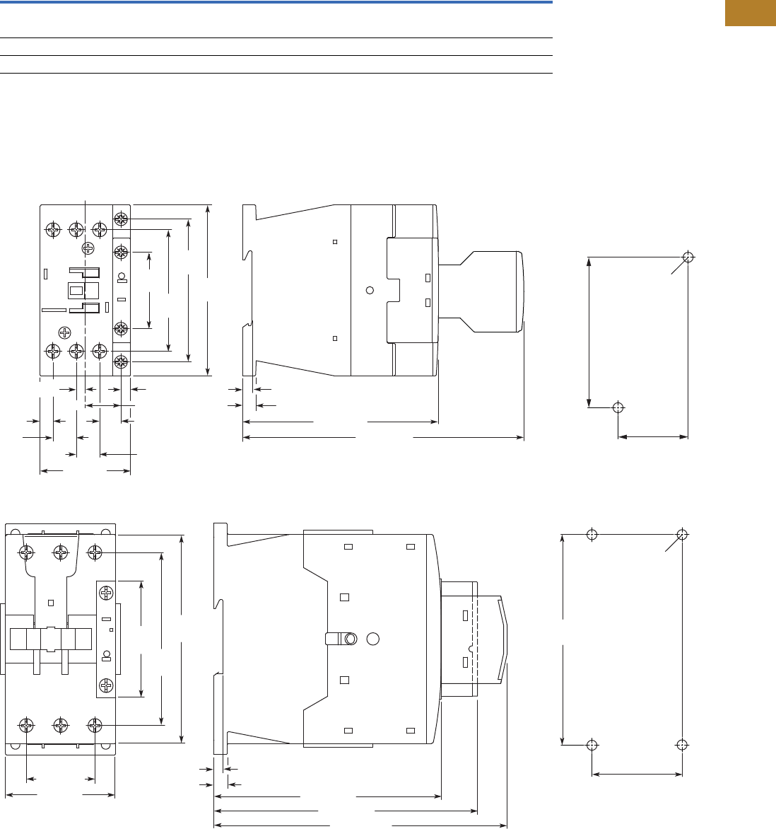
Volume 5—Motor Control and Protection CA08100006E—August 2014 www.eaton.com V5-T2-97
2
2
2
2
2
2
2
2
2
2
2
2
2
2
2
2
2
2
2
2
2
2
2
2
2
2
2
2
2
2
2.2
NEMA Contactors and Starters
Space-Savings Series
Current Heat Loss (Three-Pole) in Watts
Dimensions
Approximate Dimensions in mm [in]
Contactors
Type CN13 NEMA Size 0 and 1C
Type CN13 NEMA Size 1 and 2
Description CN13BN0_ CN13CN0_ CN13DN0_ CN13GN0_ CN13KN0_ CN13MN0_
Current heat loss (three-pole) in watts
at Ith 7.3 12.1 11.3 28.8 20.3 30.7
at Ie to AC-3/400V 1.9 6.1 7.2 19 15.9 27.0
Impedance per pole, megohms 2 2 1.5 1.5 0.4 0.4
11. 6
[0.46] 11.6 [0.46]
4.5 [0.17]
17.7 [0.70]
10.6 [0.42]
6.4
[0.25]
38
[1.50]
71
[2.80]
60.4
[2.38]
85
[3.46]
45 [1.77]
4.8 [0.19]
138.7 [5.46]
6.5 [0.26]
97.4 [3.83]
Note: Sideways distance to grounded parts: 6 mm [0.39 in]
4.5 [0.17]
35 [1.38]
2 x M4 Dia.
75 [2.95]
6.9 [0.27]
4.7 [0.19]
34.4 [1.35]
113.8 [4.48]
132.1 [5.20]
146.8 [5.78]
Note: Sideways distance to
grounded parts: 6 mm [0.39 in]
55 [2.17]
57
[2.24]
86.4
[3.40]
104
[4.09]
45 [1.77]
4 x M4 Dia.
105 [4.13]

V5-T2-98 Volume 5—Motor Control and Protection CA08100006E—August 2014 www.eaton.com
2
2
2
2
2
2
2
2
2
2
2
2
2
2
2
2
2
2
2
2
2
2
2
2
2
2
2
2
2
2
2.2
NEMA Contactors and Starters
Space-Savings Series
Approximate Dimensions in mm [in]
Type CN13 NEMA Size 3 and 4
Type CN13 NEMA Size 5
Note: Sideways distance to
grounded parts: 10 mm [0.39 in]
90 [3.54]
111 [4.37]
82.5 [3.25]
85.5 [3.37]
142 [5.59]
160 [6.30]
76.5 [3.01]
57 [2.24]
170 [6.69]
156 [6.14]
4 x M6 Dia.
156 [6.14]
70 [2.79]
208 [8.19] 8 [0.31]
140 [5.51]
160
[6.30]
120 [4.72]
M6 Dia.
5 [0.20]
20 [0.79]
164
[6.46] 180
[7.09]
48 [1.89]
140 [5.51]
11 [0.43] Dia.
160 [6.30]
189
[7.44]
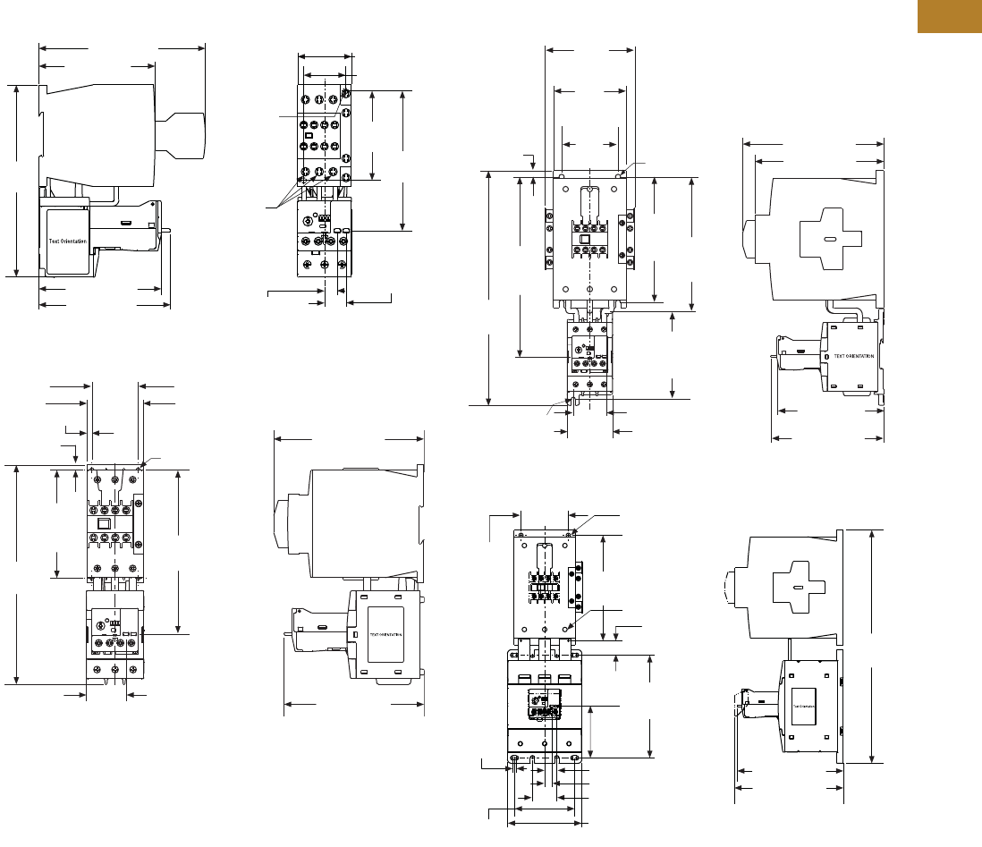
Volume 5—Motor Control and Protection CA08100006E—August 2014 www.eaton.com V5-T2-99
2
2
2
2
2
2
2
2
2
2
2
2
2
2
2
2
2
2
2
2
2
2
2
2
2
2
2
2
2
2
2.2
NEMA Contactors and Starters
Space-Savings Series
Approximate Dimensions in mm [in]
XTAE Starters with XTOE Overload Relay
Type AN13 NEMA Size 0 and 1C
Type AN13 NEMA Size 1 and 2
Type AN13 NEMA Size 3
Type AN13 NEMA Size 4
140.0 [5.50]
98.0 [3.80]
110.4 [4.35]
102.7 [4.04]
161.0
[6.30] 2.5–3.0 Nm
[22–26 lb-in]
18.2 [0.71]
Trip/Test
10.6 [0.42]
Reset
35.0 [1.38]
Mounting
Holes for
M4 or #8
Screws
(2 places)
117.3
[4.62]
75.0
[2.95]
45.0 [1.77]
55.0 [2.17]
136.2 [5.36]
To Reset
38.7 [1.52]
To Reset
146.1 [5.75]
159.7
[6.29]
To Reset
5.0 [0.20]
105.0
[4.13]
Mtg.
213.6
[8.41]
Mtg. Holes for
(4) #8 Screws or
M4 Screws
5.0 [0.20]
45.0 [1.77] Mtg.
132.4 [5.21]
To Reset
Mtg. Holes
for (2) M4
or #8 Screws 140.2 [5.52]
175.0 [6.89]
160.0 [6.30]
Mtg. Holes for
(4) M6 or #10
Screws
156.0
[6.14]
Mtg. 167.3
[6.59]
Mtg.
108.4
[4.27]
Mtg.
41.2 [1.62] Mtg.
56.0 [2.20]
222.3
[8.75]
To Reset
291.1
[11.46]
7.8
[0.31]
70.0
[2.76]
90.0
[3.54]
Mtg.
111.8
[4.40]
345.0
[13.6]
89.0
[3.50]
Terminal
Torque:
14 Nm
[124 lb-in]
77.0
[3.00]
152.0
[6.00]
161.0 [6.30]
157.0 [6.18]
156.0
[6.14]
M6 [#10] Screws
70.0
[2.76]
21.3 [0.84]
5.0
[0.20]
18.2 [0.71] Trip/Test
10.6 [0.42] Reset
36.0 [1.42]
110.0 [4.30]
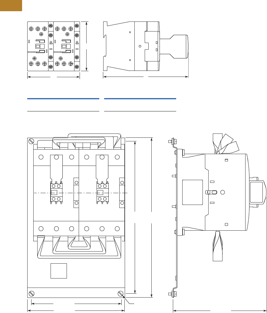
V5-T2-100 Volume 5—Motor Control and Protection CA08100006E—August 2014 www.eaton.com
2
2
2
2
2
2
2
2
2
2
2
2
2
2
2
2
2
2
2
2
2
2
2
2
2
2
2
2
2
2
2.2
NEMA Contactors and Starters
Space-Savings Series
Approximate Dimensions in mm [in]
Reversing Contactors
Type CN53 Size 0, 1C, 1 and 2
Type CN53 Size 3 and 4
Size 0 and 1C Size 1 and 2
WH D WH D
90
[3.54]
85
[3.34]
138
[5.43]
110
[4.33]
115
[4.53]
146.8
[5.78]
H
D
W
314
[12.36]
299
[11.77]
M6
176 [6.93]
196 [7.72] 183 [7.20]
Volume 5—Motor Control and Protection CA08100006E—August 2014 www.eaton.com V5-T2-101
2
2
2
2
2
2
2
2
2
2
2
2
2
2
2
2
2
2
2
2
2
2
2
2
2
2
2
2
2
2
2.3
NEMA Contactors and Starters
A200 Series
Contactors—Non-Reversing and Reversing
Contents
Description Page
A200 Series
Contactors—Non-Reversing and Reversing
Starters—Non-Reversing and Reversing . . . . . . V5-T2-107
Relays—Thermal and Fast Trip . . . . . . . . . . . . . V5-T2-128
Thermal Type B, Class 20, Manual Reset . . . . . V5-T2-130
Thermal Type A, Class 20, Auto/Manual
Reset . . . . . . . . . . . . . . . . . . . . . . . . . . . . . . . V5-T2-133
Type FT Fast Trip, Class 10 . . . . . . . . . . . . . . . . V5-T2-136
Heater Selection . . . . . . . . . . . . . . . . . . . . . . . . V5-T2-139
Relays—Current Sensing Protective . . . . . . . . . V5-T2-141
Contactors—Non-Reversing and Reversing
Product Description
Class A201 Contactors,
Sizes 00–4; Three-Phase,
1-1/2–100 hp
A201 Magnetic Contactors
from Eaton’s Electrical Sector
are 600V rated devices
available in NEMA Sizes 00–
4, 10A through 150A (open
rating). Product features
include:
●Straight-through wiring
to line and load terminals
located up front for ease
of installation
●Moving and stationary
contacts are front
accessible, simplifying
inspection and
maintenance
●Reliable U-shaped magnet
for reduced power
consumption
●Coil design reduces
inventory/maintenance
expenses. For a given
voltage, one size coil fits
all contactors Sizes 00–2,
and a second coil fits three-
pole Model J Sizes 3 and 4.
Model K coils are different
design
A201 contactors have
normally open holding circuit
interlocks which are supplied
as standard.
Panel layout and drilling are
simplified through the use
of common backplates, one
for Sizes 00–2 and one for
Sizes 3–4. In addition, panel
space is reduced dramatically
through the use of unique
corner cavities for mounting
the wide variety of
modifications shown on
Page V5-T2-120.
For reversing applications,
two contactors are supplied
on a common base with
electrical and mechanical
interlocks which prevent both
contactors from being closed
at the same time.
Class A201 Contactors,
Sizes 5–9; Three-Phase,
Over 100 hp
These AC magnetic
contactors utilize clapper
design and feature straight-
through wiring.
Contacts are silver alloy for
longer life. The contacts close
with optimum wiping action
which serves to keep the
contacting surfaces clean.
De-ion® arc quenchers draw
the arc away from the
contacts at opening, which
reduces burning and pitting
and increases contact life.
All of the contactors are
complete with one unwired,
normally-open (NO) auxiliary
contact mounted and have
accommodations for
additional auxiliary contacts.
No control circuit wiring or
terminal markings are included.
Size 5, 300A, 600V, Open
Size 6, 600A, 600V, Open
Class A201 Size 5 and 6
contactors are front clapper
design, AC operated with the
armature pivoting on dual
needle bearings which assure
accurate contact alignment.
The contactor base is molded
of a high impact, non-
tracking, non-hygroscopic
glass polyester material
permitting front mounting
and wiring on a steel panel.
Floating magnet assures
quiet operation.
Size 5 and 6 contactors must
be mounted with the line
terminals directly above the
load terminals.
Multi-voltage coil ratings
allow selection of the voltage
which closely matches the
actual system voltage to assure
optimum contactor operation.
Each contactor
accommodates two Type J11
auxiliary contacts, providing
up to four auxiliary circuits,
normally-open or normally-
closed (NO and NC).
A201 Size 5 and 6
contactors and starters are
UL recognized when supplied
without terminals. When
supplied with terminals, the
devices are UL listed.
Two special configurations of
the Class A201 Size 5 and 6
contactors are available:
●Latched Design—
This is a mechanically
held, electrically released
device. It is applied where
the contactor must remain
closed during extreme
voltage fluctuations or
power failure. It is also
suitable for applications
requiring quiet operation
since the operating coil is
de-energized when the
contactor is closed. The
latch assembly consists
of a mechanical latch
mechanism, electrically
operated AC trip solenoid
and a clearing contact
●DC Operated—This device
is DC operated. It is used
where low dropout voltage
or exceptionally quiet
operation is desired. The
DC assembly consists of a
DC operating coil, integrally
mounted rectifier and
shorting contact

V5-T2-102 Volume 5—Motor Control and Protection CA08100006E—August 2014 www.eaton.com
2
2
2
2
2
2
2
2
2
2
2
2
2
2
2
2
2
2
2
2
2
2
2
2
2
2
2
2
2
2
2.3
NEMA Contactors and Starters
A200 Series
Size 7, 900A, 600V, Open
Size 8, 1350A, 600V, Open
Size 9, 2500A, 600V, Open
Class A201 Size 7 and 8
contactors are DC operated
side clapper design with the
shaft mounted on dual needle
bearings to ensure positive
contact alignment and long
contact life.
A steel panel base permits
mounting on angle or channel
without additional support,
for versatile low cost
installation.
Each stationary contact
assembly is mounted on an
individual molded insulator.
Each pair of contacts is
surrounded by a De-ion grid
type arc quencher for rapid
and confined arc interruption
and long contact life.
The shunt for each pole is
made of flexible, braided
copper cable for freedom of
movement and long life.
The rugged DC operating
coils are designed to operate
at high temperature and
insulated to meet Class H
service.
An integrally mounted
avalanche type silicon
rectifier supplies DC coil
voltage from the AC
control circuit.
Sizes 7 and 8 accommodate
three Type L-63 auxiliary
contacts which are easily
converted from normally-
open to normally-closed,
providing auxiliary circuit
flexibility. Size 9 uses L-64
auxiliary contacts with a total
of four circuits.
A201 Size 7, 8 and 9
contactors and starters are
UL recognized when supplied
without terminals. When
supplied with terminals, the
devices are UL listed.
Application Description
Magnetic contactors are
used to switch transformers
and capacitors and to control
electrical power circuits
such as heating, lighting
and motors that require
no overload protection, or
where overload protection
is separately provided. They
can be operated remotely
by manual or automatic
pilot devices.
Standards and Certifications
A201 contactors are UL listed
components and also have
CSA certification.
Instructional Leaflets
16960B Sizes 00–1 Magnetic
Contactor,
Non-reversing
or Reversing
16961E Size 2 Magnetic
Contactor,
Non-reversing
or Reversing
13238G Size 3 Magnetic
Contactor,
Non-reversing
or Reversing
17001C Size 4 Magnetic
Contactor,
Non-reversing
or Reversing
17049D Size 5 Magnetic
Contactor,
Non-reversing
or Reversing
17053B Size 6 Magnetic
Contactor,
Non-reversing
or Reversing
17048 Sizes 7–8 Magnetic
Contactor,
Non-reversing
or Reversing
16978 Size 9 Magnetic
Contactor,
Non-reversing
or Reversing
Volume 5—Motor Control and Protection CA08100006E—August 2014 www.eaton.com V5-T2-103
2
2
2
2
2
2
2
2
2
2
2
2
2
2
2
2
2
2
2
2
2
2
2
2
2
2
2
2
2
2
2.3
NEMA Contactors and Starters
A200 Series
Product Selection
Non-Reversing, Sizes 00–9
When Ordering Specify
Order by catalog number from the table below, plus suffix for
coil voltages, verifying usage of appropriate sizes.
Front Connected Contactors
Rear Connected Contactors Coil Suffix
Notes
1Sizes 7–9 use rectifier with DC coil.
2For Size 9, only available coil voltage is 120V.
3Supplied without terminal lugs.
Size Amps
Max. UL Horsepower Two Poles Open Three Poles Open Four Poles Open Five Poles Open
Single-Phase Three-Phase Catalog
Number
Catalog
Number
Catalog
Number
Catalog
Number115V 230V 208V 240V 480V 600V
Sizes 00–6
00 9 1/3 1 1-1/2 1-1/2 2 2 A201KAB_ A201KAC_ A201KAD_ A201KAE_
018123355A201K0B_ A201K0C_ A201K0D_ A201K0E_
1 27 2 3 7-1/2 7-1/2 10 10 A201K1B_ A201K1C_ A201K1D_ A201K1E_
245 3 7-1/210152525A201K2B_ A201K2C_ A201K2D_ A201K2E_
390 ——25305050A201K3B_ A201K3C_ A201K3D_ A201K3E_
4 135 — — 40 50 100 100 A201K4B_ A201K4C_ A201K4D_ A201K4E_
5 270 — — 75 100 200 200 A201K5B_ A201K5C_ — —
6 540 — — 150 200 400 400 A201K6B_ A201K6C_ — —
Sizes 7–9
7 1810 — — 200 300 600 600 A201K7B_ A201K7C_ — —
8 11215 — — 400 450 900 900 A201K8B_ A201K8C_ — —
9 12250 — — — 800 1600 — A201K9B_ A201K9C_Z1 23 ——
A201 Size 1 Contactor
120V Rectified Coil/Open Only
Size Catalog Number
7A201K7CJZ1Z4
8A201K8CJZ1Z4
9A201K9CJZ1Z4
Coil Volts and Hz Code Suffix
Sizes 00–6
120/60 or 110/50 A
200–208/60 B
240/60 W
Sizes 7, 8 and 9 2
480/60 X
600/60 E
110–120/50 or 60 J
220–240/50 or 60 K
440–480/50 or 60 U
600/60 E

V5-T2-104 Volume 5—Motor Control and Protection CA08100006E—August 2014 www.eaton.com
2
2
2
2
2
2
2
2
2
2
2
2
2
2
2
2
2
2
2
2
2
2
2
2
2
2
2
2
2
2
2.3
NEMA Contactors and Starters
A200 Series
Reversing, Sizes 00–9
When Ordering Specify
Order by catalog number from the table below, plus suffix for
coil voltages, verifying usage of appropriate sizes.
Class A211—Horizontally Mounted and Class A251—Vertically Mounted Reversing Contactors
Coil Suffix
Notes
1 Sizes 7–9 use rectifier with DC coil.
2 For Size 9, only available coil voltage is 120V.
Size Amps
Max. UL Horsepower Horizontal Design Vertical Design
Single-Phase Three-Phase Catalog
Number
Catalog
Number115V 230V 208V 240V 480V 600V
Sizes 0–6
018 123 3 5 5A211K0C_ A251K0C_
1 27 2 3 7-1/2 7-1/2 10 10 A211K1C_ A251K1C_
2 45 3 7-1/2 10 15 25 25 A211K2C_ A251K2C_
390 ——25 30 50 50 A211K3C_ A251K3C_
4 135 — — 40 50 100 100 A211K4C_ A251K4C_
5 270 — — 75 100 200 200 A211K5C_ A251K5C_
6 540 — — 150 200 400 400 A211K6C_ A251K6C_
Sizes 7–9
7 1810 — — 200 300 600 600 — A251K7C_
8 11215 — — 400 450 900 900 — A251K8C_
9 12250 — — — 800 1600 — — A251K9C_ 2
Coil Volts and Hz Code Suffix
Sizes 00–6
120/60 or 110/50 A
200–208/60 B
240/60 W
480/60 X
600/60 E
Sizes 7, 8 and 9 2
110–120/50 or 60 J
220 –240/50 or 60 K
440–480/50 or 60 U
600/60 E
Size 1 Horizontal
Reversing Contactor
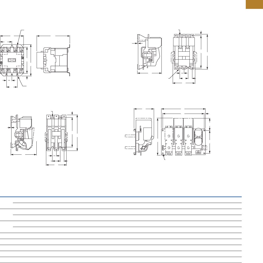
Volume 5—Motor Control and Protection CA08100006E—August 2014 www.eaton.com V5-T2-105
2
2
2
2
2
2
2
2
2
2
2
2
2
2
2
2
2
2
2
2
2
2
2
2
2
2
2
2
2
2
2.3
NEMA Contactors and Starters
A200 Series
Dimensions
Approximate Dimensions in Inches (mm)
Not to be used for construction purposes unless approved.
Non-Reversing Open Contactors
Figure A—Sizes 00–4 A210
Figure C—Size 6
Figure B—Size 5
Figure D—Sizes 7–9
Dimensions and Shipping Weights
AC
E
0.20 (5.1) 4
Mounting Slots
0.22 (5.6)
Dia. Hole
E
2G
D
B
F
C
0.12
(3.0)
0.38 x 0.5 (9.7 x 12.7)
2 Mounting Slots
E
A
H
B
D
G
E
2
C
0.12
(3.0)
0.38 x 0.5 (9.7 x 12.7)
2 Mounting Slots
A
E H
B
D
G
E
2
0.38 (9.7) Dia. Open End
Mounting Slot
(2 Places)
C A
EH
D
B
G
4 Holes for 0.38 (9.7) Dia.
Mounting Hardware
NEMA
Size
No. of
Poles Fig.
Mounting Screws
ABCDEFGH
Weight,
Lbs (kg)No. Size
00, 0, 1 2–4 A 3 #10 3.31 (84.1) 4.38 (111.3) 4.61 (117.1) 3.95 (100.3) 1.50 (38.1) 1.66 (42.2) 0.45 (11.5) — 2.6 (1.2)
5 A 3 #10 4.19 (106.4) 4.38 (111.3) 4.61 (117.1) 3.95 (100.3) 1.50 (38.1) 2.09 (53.1) 0.45 (11.5) — 3.2 (1.5)
2 2, 3 A 3 #10 3.31 (84.1) 4.38 (111.3) 4.94 (125.5) 3.95 (100.3) 1.50 (38.1) 1.66 (42.2) 0.45 (11.5) — 3.3 (1.5)
4, 5 A 3 #10 5.06 (128.5) 4.38 (111.3) 4.94 (125.5) 3.95 (100.3) 1.50 (38.1) 2.53 (64.3) 0.45 (11.5) — 4.5 (2.0)
3, 4 2, 3 A 3 1/4 in. 4.63 (117.6) 6.63 (168.4) 6.75 (171.5) 6.00 (152.4) 1.88 (47.8) 2.31 (58.7) 0.38 (9.7) — 9.3 (4.2)
4, 5 A 3 1/4 in. 7.25 (184.2) 6.63 (168.4) 6.75 (171.5) 6.00 (152.4) 1.88 (47.8) 3.63 (92.2) 0.38 (9.7) — 13.0 (5.9)
5 2, 3 B 4 3/8 in. 7.22 (183.4) 12.00 (304.8) 7.75 (196.9) 11.00 (279.4) 2.75 (69.9) — 0.59 (15.0) 2.22 (56.4) 25.0 (11.4)
6 2, 3 C 4 3/8 in. 7.22 (183.4) 13.50 (342.9) 9.50 (251.3) 11.00 (279.4) 2.75 (69.9) — 0.59 (15.0) 2.22 (56.4) 42.0 (19.1)
7 3 D 4 3/8 in. 23.50 (596.9) 18.63 (473.2) 11.00 (279.4) 12.00 (304.8) 22.00 (558.8) — 5.63 (143.0) 0.75 (19.1) 215.0 (97.6)
8 3 D 4 3/8 in. 23.50 (596.9) 19.25 (489.0) 11.00 (279.4) 12.00 (304.8) 22.00 (558.8) — 5.63 (143.0) 0.75 (19.1) 265.0 (120.3)
9 3 D 4 1/2 in. 33.00 (838.2) 29.75 (755.7) 12.94 (328.7) 8.00 (203.2) 30.75 (781.1) — 14.50 (368.3) 1.63 (41.4) 315.0 (143.0)
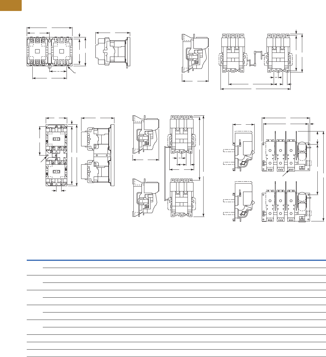
V5-T2-106 Volume 5—Motor Control and Protection CA08100006E—August 2014 www.eaton.com
2
2
2
2
2
2
2
2
2
2
2
2
2
2
2
2
2
2
2
2
2
2
2
2
2
2
2
2
2
2
2.3
NEMA Contactors and Starters
A200 Series
Approximate Dimensions in Inches (mm)
Not to be used for construction purposes unless approved.
Reversing Open Contactors
Figure A—Sizes 00–4 Horizontal Figure C—Sizes 5, 6 Horizontal
Figure B—Sizes 00–4 Vertical Figure D—Sizes 5, 6 Vertical Figure E—Sizes 7–9 Vertical
Dimensions and Shipping Weights
E
C
A
F
B
D
G
E
20.20 (5.1) Dia.
3 Mounting
Slots
CF E H
A
B
D
G
E
2
NEMA
Size
No. of
Poles Fig.
Mounting Screws Weight,
Lbs (kg)No. Size A B C D E F G H
00, 0, 1 3 x 3 H. A 3 #10 7.13 (181.1) 4.45 (113.0) 5.05 (128.3) 3.95 (100.3) 5.31 (134.9) 3.56 (90.4) 0.25 (6.4) — 7.8 (3.5)
3 x 3 V. B 3 #10 3.33 (84.6) 9.61 (244.1) 5.05 (128.3) 9.08 (230.6) 2.16 (54.9) 0.75 (19.1) 0.25 (6.4) 4.52 (114.8) 8.9 (4.0)
2 3 x 3 H. A 3 #10 7.13 (181.1) 4.45 (113.0) 5.38 (136.7) 3.95 (100.3) 5.31 (134.9) 3.56 (90.4) 0.25 (6.4) — 9.1 (4.1)
3 x 3 V. B 3 #10 3.33 (84.6) 9.61 (244.1) 5.38 (136.7) 9.08 (230.6) 2.16 (54.9) 0.75 (19.1) 0.25 (6.4) 4.52 (114.8) 10.0 (4.5)
3, 4 3 x 3 H. A 3 1/4 in. 9.75 (247.7) 6.88 (174.8) 7.25 (184.2) 6.00 (152.4) 7.00 (177.8) 4.88 (124.0) 0.44 (11.2) — 24.0 (10.9)
3 x 3 V. B 3 1/4 in. 4.63 (117.6) 16.56 (420.6) 7.25 (184.2) 15.69 (398.5) 2.75 (69.9) 0.94 (23.9) 0.44 (11.2) 7.78 (197.6) 25.0 (11.4)
5 3 x 3 H. C 8 3/8 in. 17.22 (437.4) 12.00 (304.8) 7.75 (196.9) 11.00 (279.4) 2.75 (69.9) 10.00 (254.0 0.59 (15.0) 1.38 (35.1) 55.0 (25.0)
3 x 3 V. D 8 3/8 in. 8.25 (209.6) 30.00 (762.0) 7.75 (196.9) 18.00 (457.8) 2.75 (69.9) — — 1.38 (35.1) 55.0 (25.0)
6 3 x 3 H. C 8 3/8 in. 17.22 (437.4) 13.50 (342.9) 8.75 (222.3) 11.00 (279.4) 2.75 (69.9) 10.00 (254.0) 0.59 (15.0) 1.38 (35.1) 90.0 (40.9)
3 x 3 V. D 8 3/8 in. 8.25 (209.6) 41.50 (1054.1) 8.75 (222.3) 28.00 (711.2) 2.75 (69.9) — — 1.38 (35.1) 90.0 (40.9)
7 3 x 3 V. E 8 3/8 in. 23.50 (596.9) 38.63 (981.2) 11.00 (279.4) 20.00 (508.0) 22.00 (558.8) — 5.63 (143.0) 0.75 (19.1) 450.0 (204.3)
8 3 x 3 V. E 8 3/8 in. 23.50 (596.9) 39.25 (997.0) 11.00 (279.4) 20.00 (508.0) 22.00 (558.8) — 5.63 (143.0) 0.75 (19.1) 550.0 (249.7)
9 3 x 3 V. E 8 1/2 in. 33.00 (838.2) 62.75 (1593.9) 12.94 (328.7) 33.00 (838.2) 30.75 (781.1) — 14.50 (368.3) 1.63 (41.4) 650.0 (295.1)
A
F
C
B
D
H
G
0.20 (5.1)
Dia.
3 Mtg.
Holes
C
B
D
A
E H
E
2
C
A
EH
D
G
B
0.53 (13.5) Dia.—3 Holes
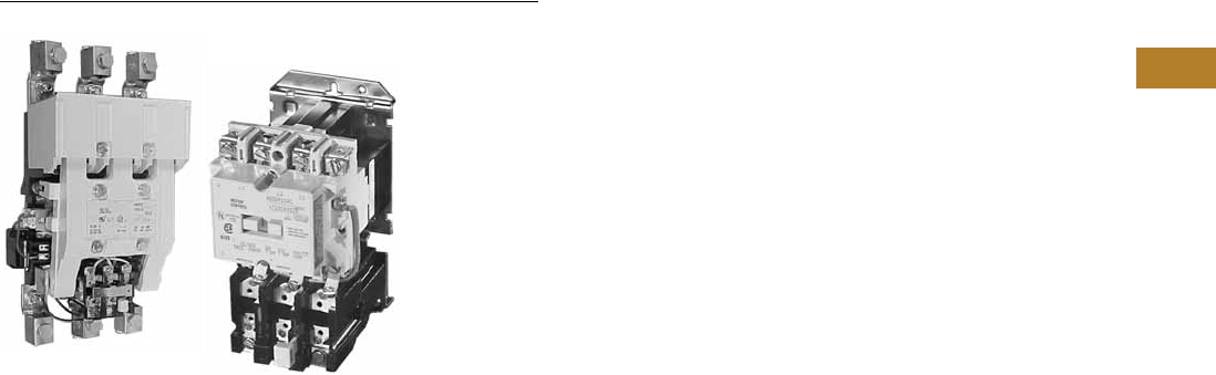
Volume 5—Motor Control and Protection CA08100006E—August 2014 www.eaton.com V5-T2-107
2
2
2
2
2
2
2
2
2
2
2
2
2
2
2
2
2
2
2
2
2
2
2
2
2
2
2
2
2
2
2.3
NEMA Contactors and Starters
A200 Series
Starters—Non-Reversing and Reversing
Contents
Description Page
Contactors—Non-Reversing and Reversing . . . . . . V5-T2-101
Starters—Non-Reversing and Reversing
Application Description . . . . . . . . . . . . . . . . . . . V5-T2-108
Features and Benefits . . . . . . . . . . . . . . . . . . . . V5-T2-108
Standards and Certifications . . . . . . . . . . . . . . . V5-T2-108
Instructional Leaflets . . . . . . . . . . . . . . . . . . . . . V5-T2-108
Product Selection . . . . . . . . . . . . . . . . . . . . . . . V5-T2-109
Accessories . . . . . . . . . . . . . . . . . . . . . . . . . . . . V5-T2-112
Renewal Parts . . . . . . . . . . . . . . . . . . . . . . . . . . V5-T2-115
Modifications. . . . . . . . . . . . . . . . . . . . . . . . . . . V5-T2-120
Technical Data and Specifications . . . . . . . . . . . V5-T2-121
Mechanical Characteristics . . . . . . . . . . . . . . . . V5-T2-123
Dimensions . . . . . . . . . . . . . . . . . . . . . . . . . . . . V5-T2-125
Relays—Thermal and Fast Trip . . . . . . . . . . . . . . . . V5-T2-128
Thermal Type B, Class 20, Manual Reset . . . . . . . . V5-T2-130
Thermal Type A, Class 20, Auto/Manual Reset . . . V5-T2-133
Type FT Fast Trip, Class 10 . . . . . . . . . . . . . . . . . . . V5-T2-136
Heater Selection. . . . . . . . . . . . . . . . . . . . . . . . . . . V5-T2-139
Relays—Current Sensing Protective. . . . . . . . . . . . V5-T2-141
Starters—Non-Reversing and Reversing
Product Description
NEMA Sizes 00–4; Three-Phase,
1-1/2–100 hp
These Starters from Eaton’s
Electrical Sector use Class
A201 contactors as described
on Page V5-T2-101.
Contactor features are
enhanced through the ability
to provide positive motor
protection in the form of
several types of overload
relays. See Pages V5-T2-128
to V5-T2-140.
Type B Overload Relay,
Manual Reset Only
Supplied as standard on
Class A200 and A900 starters
(two-speed). The bi-metallic
overload relay offers ambient
compensation and trip-to-test
feature (relay contact status
check) as standard. In
addition, an isolated normally-
open contact is available in kit
form for customer mounting.
Type B overload relays are
manual reset only.
Type A Overload Relay,
Manual or Automatic Reset
This is an optional overload
relay, offering the capability
of field conversion to
automatic reset. It is available
as an ambient compensated
or non-compensated type.
Non-Reversing Starters
Non-reversing starters are
supplied as open devices. All
starters are supplied with a
normally-open holding circuit
interlock.
Reversing Starters
For reversing applications
(Class A210), a starter and a
contactor electrically and
mechanically interlocked are
supplied on a common
baseplate. Reversing starters
are used to start, stop and
reverse AC squirrel cage
motors and for primary
control of reversing wound-
rotor motors.
For plugging or inching, when
operations exceed five times
per minute, decreased
horsepower ratings in
accordance with NEMA
Standard ICS 2-321 are
recommended.
Two-Speed Starters, A900s
For across-the-line starting of
two-speed constant hp,
constant torque and variable
torque squirrel cage motors,
two-speed starters (Class
A900) are available. These
starters consist of two
starters, one for each motor
speed, mechanically and
electrically interlocked and
wired for manual speed
selection by means of
pushbuttons. Auxiliary relays
may be added to provide
automatic acceleration or
deceleration.
Starters for two-speed, two
independent winding motors
consist of two-, three- or four-
pole starters electrically and
mechanically interlocked.
Starters for two-speed, single
reconnectable winding
motors consist of one three-
pole and one five-pole starter
mechanically and electrically
interlocked.

V5-T2-108 Volume 5—Motor Control and Protection CA08100006E—August 2014 www.eaton.com
2
2
2
2
2
2
2
2
2
2
2
2
2
2
2
2
2
2
2
2
2
2
2
2
2
2
2
2
2
2
2.3
NEMA Contactors and Starters
A200 Series
NEMA Sizes 5–9; Three-Phase
75 to 1600 hp
Non-reversing (Class A200),
and reversing (Classes A210,
A250) full voltage starters
are used for across-the-line
starting of squirrel cage
induction motors. They are
used with motors rated above
50 hp at 230V, and above
100 hp at 460 through 600V.
Sizes 5 and 6 starters use
Class A201 contactors as
described on Page V5-T2-101.
In addition to standard motor
starters, special application
devices are available: Sizes 5
and 6 starters with integrally
rectified AC to DC coils for
applications where low
voltage problems are
prevalent are available.
Front Removable Parts—
All operating parts can be
removed quickly and easily
from the front. Straight-
through wiring and
conveniently located
connection points for external
wires and cables minimize
installation time.
Type B Block Type
Thermal Overload Relay—
Dependable overload
protection is assured by
these snap-action, manual
reset relays. Automatic reset
Type A relays are available as
an option.
Types of Starters
Class A200, Sizes 5 and 6—
Non-reversing starters
contain an AC magnetically-
operated Size 5 or Size 6 line
contactor and block Type B
three-pole overload relay,
along with three current
transformers. A control relay
whose contacts handle the
coil current of the starter is
provided with Size 6 starters.
Class A200, Sizes 7, 8
and 9—Non-reversing
starters contain a DC
operated line contactor, DC
power supply, block Type B
three-pole overload relay with
three current transformers
and a control relay.
Class A960/A970/A980
Multi-Speed Starters:
Refer to Page V5-T2-111.
Application Description
Magnetic starters are used
for full-voltage, across-the-
line starting and stopping of
squirrel cage motors. They
can be operated locally or
remotely by manual or
automatic pilot devices.
Features and Benefits
Sizes 00–4
●Straight-Through Wiring,
Up-Front, Out-Front
Te rm i n a l s for ease in
installation
●Unique Accessory
Mounting Cavities reduce
panel space requirements
●Snap-in Accessories for
application flexibility
●Vertical and Horizontal
Interlocking capability
increases application
flexibility
●Ambient Compensated
Overload Relays available
as standard, offering
superior motor protection
in variable motor/controller
environments
●Isolated Normally Open
Relay Contact available in
kit mounting form on Type
B Overload Relay
Sizes 5–9
●Rectified AC/DC Coils
available to reduce
premature drop-out or
“kiss” problems due to
inherent low voltage
conditions
●Clapper Design armature
assembly pivots on needle
bearings resulting in quick,
smooth opening and
closing of the magnet
●Stainless Steel Kick-Out
Spring assures quick,
positive drop-out time
●Front Removable Parts all
current carrying parts front
removable for easy
inspection and
maintenance
Standards and Certifications
Class A200 starters are UL
listed and recognized and also
carry CSA certification.
Instructional Leaflets
16958 Sizes 00–1, 3-Pole
Motor Controller
16956 Sizes 00–1, 2-Pole,
Single-Phase Motor
Controller
16959 Size 2, 3-Pole
Motor Controller
16957 Size 2, 2-Pole,
Single-Phase
Motor Controller
15465C Sizes 3 and 4J
Motor Controller
17000C Size 4, Model K
Motor Controller
17054C Size 5
Motor Controller
17055C Size 6
Motor Controller

Volume 5—Motor Control and Protection CA08100006E—August 2014 www.eaton.com V5-T2-109
2
2
2
2
2
2
2
2
2
2
2
2
2
2
2
2
2
2
2
2
2
2
2
2
2
2
2
2
2
2
2.3
NEMA Contactors and Starters
A200 Series
Product Selection
Non-Reversing, Sizes 00–9
When Ordering Specify
Order by catalog number
from the tables to the right,
plus suffix for coil voltages,
verifying usage of appropriate
sizes.
Heaters
Enter heaters as separate
item by listing catalog
number from the tables
on Pages V5-T2-139 and
V5-T2-140, as required per
starter.
Non-Reversing Starters
Coil Suffix
Notes
1 For ambient compensated overload relay with auto-reset, add Suffix D.
2 Single-phase with one single-pole overload relay.
3 Sizes 7–9 use rectifier with DC coil.
4 For Size 9, only available coil voltage is 120V.
Size Amperes
Max. UL Horsepower
Open
Catalog Number 1
Single-Phase Three-Phase
115V 230V 208V 240V 480V 600V
Tw o - P o l e s 2 —Sizes 00–2
00 9 1/3 — 1-1/2 1-1/2 2 2 A200MABR
018 1 —3 3 5 5 A200M0BR
127 2 —7-1/2 7-1/2 1010A200M1BR
1-1/2 36 3 — — — — — A200MDBR
2 45 7-12 — 10 15 25 25 A200M2BR
Three Poles—Sizes 00–6
00 9 1/3 — 1-1/2 1-1/2 2 2 A200MAC_
018 1 —3 3 5 5 A200M0C_
127 2 —7-1/2 7-1/2 1010A200M1C_
2 45 7-12 — 10 15 25 25 A200M2C_
3 90 ——25 30 5050A200M3C_
4 135 — — 40 50 100 100 A200M4C_
5 270 — — 75 100 200 200 A200M5C_
6 540 — — 150 200 400 400 A200M6C_
Three Poles—Sizes 7–9
7 3810 — — 200 300 600 600 A200M7C_
8 31215 — — 400 450 900 900 A200M8C_
9 32250 — — — 800 1600 — A200M9C_ 4
Coil Volts and Hz Code Suffix
Sizes 00–6
120/60 or 110/50 AC
200–208/60 B
240/60 W
480/60 X
600/60 E
Sizes 7, 8 and 9 4
110–120/50 or 60 J
220–240/50 or 60 W
440–480/50 or 60 X
600/60 E
Size 3 Starter
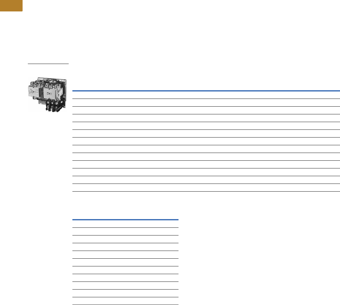
V5-T2-110 Volume 5—Motor Control and Protection CA08100006E—August 2014 www.eaton.com
2
2
2
2
2
2
2
2
2
2
2
2
2
2
2
2
2
2
2
2
2
2
2
2
2
2
2
2
2
2
2.3
NEMA Contactors and Starters
A200 Series
Reversing, Sizes 00–9
When Ordering Specify
Order by catalog number
from table below, plus suffix
for coil voltages, verifying
usage of appropriate sizes.
Heaters
Enter heaters as separate
item by listing catalog
number from the tables on
Pages V5-T2-139 and
V5-T2-140, as required per
starter.
Reversing Starters
Coil Suffix
Notes
1 For ambient compensated overload relay with auto-reset, add Suffix D.
2 Sizes 7–9 use rectifier with DC coil.
3 For Size 9, only available coil voltage is 120V.
Size Amps
Max. UL Horsepower Horizontal Design Vertical Design
Single-Phase Three-Phase Catalog
Number 1
Catalog
Number 1
115V 230V 208V 240V 480V 600V
Sizes 00–6
00 9 1/3 1 1-1/2 1-1/2 2 2 A210MAC_ A250MAC_
018123355A210M0C_ A250M0C_
1 27 2 3 7-1/2 7-1/2 10 10 A210M1C_ A250M1C_
24537-1/210152525A210M2C_ A250M2C_
390——25305050A210M3C_ A250M3C_
4 135 — — 40 50 100 100 A210M4C_ A250M4C_
5 270 — — 75 100 200 200 A210M5C_ A250M5C_
6 540 — — 150 200 400 400 A210M6C_ A250M6C_
Sizes 7–9
7 2810 — — 200 300 600 600 — A250M7C_
8 21215 — — 400 450 900 900 — A250M8C_
9 22250 — — — 800 1600 — — A250M9C_ 3
Coil Volts and Hz Code Suffix
Sizes 00–6
120/60 or 110/50 AC
200–208/60 B
240/60 W
480/60 X
600/60 E
Sizes 7, 8 and 9 3
110–120/50 or 60 J
220–240/50 or 60 W
440–480/50 or 60 X
600/60 E
Size 1 Horizontal
Reversing Starter

Volume 5—Motor Control and Protection CA08100006E—August 2014 www.eaton.com V5-T2-111
2
2
2
2
2
2
2
2
2
2
2
2
2
2
2
2
2
2
2
2
2
2
2
2
2
2
2
2
2
2
2.3
NEMA Contactors and Starters
A200 Series
For Separate Two-Winding Motors
Heaters
Enter heaters as separate
item by listing catalog
number from the tables
on Pages V5-T2-139 and
V5-T2-140, as required per
starter.
Three-Phase, Non-Reversing, Reversing 60 Hz Starters—Heater Selection
For Single-Winding Motors
Sizes 0–6
Coil Suffix
Note
1 For ambient compensated overload relay with auto-reset, add Suffix D.
NEMA Amperes
Constant or Variable Torque Constant Horsepower Three Poles Open
208V 240V 480V 600V 208V 240V 480V 600V Catalog Number 1
Sizes 0–6
0 18 33552 23 3 A960M0C_
1 27 7-1/2 7-1/2 10 10 5 5 7-1/2 7-1/2 A960M1C_
2 45 10 15 25 25 7-1/2 10 20 20 A960M2C_
3 90 25 30 505020 25 40 40 A960M3C_
4 135 40 50 100 100 30 40 75 75 A960M4C_
5 270 75 100 200 200 60 75 150 150 A960M5C_
6 540 150 200 400 400 100 150 300 300 A960M6C_
NEMA Amperes 208V 240V 480V 600V
Three Poles Open
Catalog Number 1
Constant Horsepower
018 3 3 5 5 A970M0C_
1 27 7-1/2 7-1/2 10 10 A970M1C_
24510152525A970M2C_
39025305050A970M3C_
4 135 40 50 100 100 A970M4C_
5 270 75 100 200 200 A970M5C_
6 540 150 200 400 400 A970M6C_
Constant or Variable Torque
018 2 2 3 3 A980M0C_
1 27 5 5 7-1/2 7-1/2 A980M1C_
2 45 7-1/2 10 20 20 A980M2C_
39020254040A980M3C_
4 135 30 40 75 75 A980M4C_
5 270 60 75 150 150 A980M5C_
6 540 100 150 300 300 A980M6C_
Coil Volts and Hz Coil Suffix
Sizes 0–6
120/60 or 110/50 AC
200–208/60 B
240/60 W
480/60 X
600/60 E
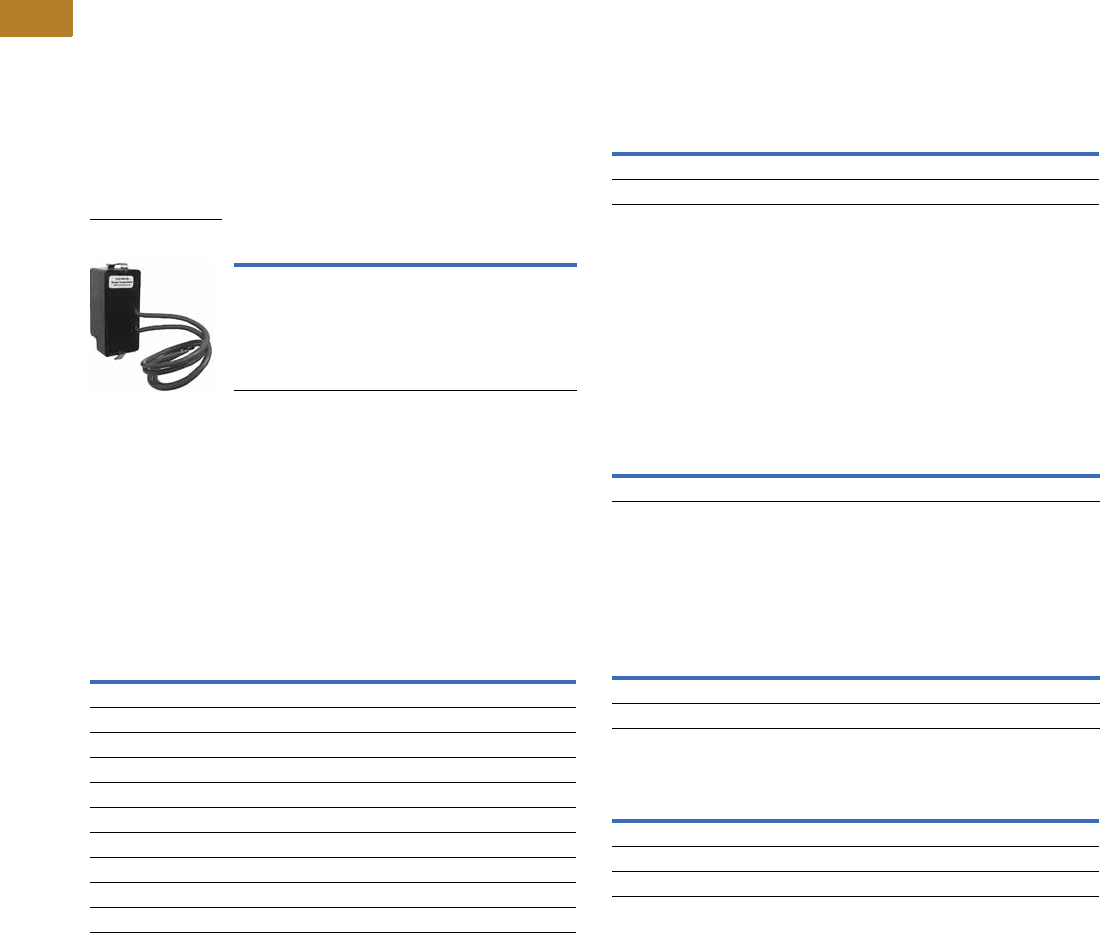
V5-T2-112 Volume 5—Motor Control and Protection CA08100006E—August 2014 www.eaton.com
2
2
2
2
2
2
2
2
2
2
2
2
2
2
2
2
2
2
2
2
2
2
2
2
2
2
2
2
2
2
2.3
NEMA Contactors and Starters
A200 Series
Accessories
SS-56 Surge Suppressor
●Designed to be used with
magnetic motor controllers
through Size 4 in 120V,
60 Hz control circuit
applications where
electronic equipment
is used
●Steady state coil volts: 120,
60 Hz, rms
●Peak input volts: 169.6,
60 Hz, max. amplitude
●Max. ambient temperature:
65°C
●Nominal limiting volts:
270 peak
●Nominal rate of volt rise:
0.5 per ms
Surge Suppressor 1
Mechanical Interlock
●Prevents closing of one
member of a reversing or
multi-speed contactor until
the opposite member is
completely open
●Lever type mechanism
assures positive action
●Can be factory assembled
or field mounted on A200
and A900 starters and
contactors
Mechanical Interlock
Type Mounting Kit Catalog Number
Starter SS-56
SS-56 Surge
Suppressor
Contactor Arrangement
(Number of Poles, Horizontal or Vertical)
Continuous
Size
Interlock
Catalog Number
3 x 3 horizontal 0, 1 M-33-1B
4 x 4 horizontal 0, 1 M-33-1B
5 x 3 horizontal 0, 1 M-33-1B
All pole combination, vertical 0, 1 M-34-1A
3 x 3 horizontal reversing 2 M-33-2B
3 x 3 vertical reversing 2 M-34-2A
5 x 3 horizontal 2 M-35-2A
4 x 4 horizontal 2 M-36-2A
All pole combination horizontal 3, 4 M-33-3B
All pole combination vertical 3, 4 M-34-3
F-56 Fuse Block
●Facilitates installation of
fuses (15A, 600V max.) in
control circuits
●Utilizes Bussman type KTK
fuses, or equivalent
●Mounts in same cavity as
Type J auxiliary contact
●No tools or mounting
hardware needed
●Fuse not included
Fuse Block
R-56 Interposing Relay
The R-56AA interposing relay
is a low energy solid-state
device with a single NO solid-
state contact. It can be used
as a 120 Vac control relay, and
will operate on as little as 40
Vac input. Is useful in
applications requiring long
control wiring runs where
excessive voltage drop would
prevent the contactor or relay
from energizing. Will operate a
Size 4 contactor from 10,000
feet using 18 AWG wire.
Interposing Relay
B3NO Bell Alarm Contact
●Isolated normally open bell
alarm contact
●Mounts in Type B block-
type overload relay
Bell Alarm Contact
Control Contact Ratings (B600)
Overload Relay Reset Extension
●Used to adjust overload
reset rod depth of Class
A200 Model J starters
and current design
overload relays to same
dimensions as obsolete
B200 starters and overloads
identified by suffix B, for
example, BA13B
When replacing obsolete
B200 device with Class A200
starter and Type B overload,
order Style 6710C11H03.
No charge.
When replacing obsolete
B200 device with Class A200
starter and Type A overload,
order Style 1490C15H10.
No charge.
Notes
1Can be used on Sizes 5 and 6 with 120V coil. Mounting bracket required—order separately.
Mounting bracket 177C043G04.
2For Size 3 and 4.
Mounting Kit Catalog Number
Starter F56
Panel F56-P
Type Mounting Kit Catalog Number
Starter or panel R56-AA
Kit Catalog Number
B3NO-2
B3NO-4 2
AC Volts
Maximum Amperes
Make Break
24–120 30 3.00
121–600 3600 VA 360 VA
Continuous current rating: 5A

Volume 5—Motor Control and Protection CA08100006E—August 2014 www.eaton.com V5-T2-113
2
2
2
2
2
2
2
2
2
2
2
2
2
2
2
2
2
2
2
2
2
2
2
2
2
2
2
2
2
2
2.3
NEMA Contactors and Starters
A200 Series
Power Pole Kit
●Adds 1NO or 1NC power
pole to Size 00–1 A201
Class contactors
●Factory installed or field
mountable in load side
auxiliary cavities
●600 Vac
●Continuous current rating
of 18A for Size 0, 27A for
Size 1
Power Pole Kit 1
Replacement Auxiliary Contacts
Extra Auxiliary Contact Kits
All starters include an auxiliary
contact with 1NO and 1NC
contact. These kits include an
auxiliary contact with contacts
as shown, plus operating arm
and mounting bracket when
required.
Extra Auxiliary Contact Kits
Continuous Current Rating Kit Size Kit Catalog Number
Normally Open
18 0 PNO-0
27 1 PNO-1
Normally Closed
18 0 PNC-0
27 1 PNC-1
Contactor
Size
Contact
Arrangement
Auxiliary Elect. Contact
Catalog
Number
Style
Number
5, 6 1NO + 1NC J11 9084A17G01
2NO J20 9084A17G02
2NC J02 9084A17G03
7, 8 1NO — 578D461G01
1NC — 578D461G03
91NO + 1NC— 843D943G04
2NO — 843D943G05
2NC — 843D943G06
Contactor Size Contact Arrangement Style Number
5, 6 1NO + 1NC 3463D94G18
2NO 3463D94G04
2NC 3463D94G19
7, 8 22NO 818D498G06
1NO 818D498G04
DC Coil Conversion Kits
Kits listed below include all
necessary parts to convert
from AC to DC control
including the DC coil with
built-in diode, rectifier,
auxiliary interlock and all
mounting hardware.
DC Coil Conversion Kits
Mechanical Interlocks
Notes
1Do not use with DC operated contactors.
2Size 7 and larger use DC coils as standard.
Size Voltage Kit Style Number
5 110-120 7864A28G01
220-240 7864A28G02
440-480 7864A28G03
6 110-120 7864A29G01
220-240 7864A29G02
440-480 7864A29G03
Contactor Sizes
Style Numbers
Horizontal Vertical
3, 4 and 5 2050A11G75 2050A11G65
5 and 5 2050A11G27 2050A11G17
5 and 6 2050A11G26 2050A11G16
6 and 7, 8 — 2050A11G55
7, 8 and 7, 8 No (rear conn.) 567D624G01
7, 8 and 9 No (rear conn.) 9944D56G06
9 and 9 No (rear conn.) 9944D56G01

V5-T2-114 Volume 5—Motor Control and Protection CA08100006E—August 2014 www.eaton.com
2
2
2
2
2
2
2
2
2
2
2
2
2
2
2
2
2
2
2
2
2
2
2
2
2
2
2
2
2
2
2.3
NEMA Contactors and Starters
A200 Series
Overload Protection
Overload Protection
Size 5 Starters
Type B overload relay is a
three-pole, block type, thermal
ambient compensated device
with manual reset mounted
integrally. Current
transformers are enclosed in a
protective case and integrally
mounted to save panel space.
Standard ratio is 300:5.
Overload Protection
Size 6 Starters
Overload protection assembly
consists of three current
transformers, Type B three-
pole block overload relay and
an optional interposing relay.
These parts are mounted on a
panel which connects
directly to the load terminal
of the contactor. Current
transformers are 600:5 ratio
as standard.
If automatic reset is required,
the Type A, three-pole block,
ambient compensated relay
is available upon request.
Overload Relay Kits
Each kit includes three
current transformers
(standard ratio) and one
Type B, three-pole block
overload relay, ambient
compensated with
manual reset.
Overload Relay Kits
Replacement Terminal Lugs 1
Note
1All mounting hardware is included in kit.
Kit Size Kit Part Number
52057A34G01
66379D80G10
Contactor
Size
Cable
Size
Terminals
Kit Style
Number
Quantity
in Kit
Quantity Required
per Pole
5 1-500 MCM 6 2 2119A76G01
6 2-500 MCM 6 2 7858A96G01
7 4-500 MCM 12 4 7858A96G02
8 4-500 MCM 12 4 7858A96G03

Volume 5—Motor Control and Protection CA08100006E—August 2014 www.eaton.com V5-T2-115
2
2
2
2
2
2
2
2
2
2
2
2
2
2
2
2
2
2
2
2
2
2
2
2
2
2
2
2
2
2
2.3
NEMA Contactors and Starters
A200 Series
Renewal Parts
When Ordering Specify
Use this renewal parts data
to identify device by style
number, catalog number
and/or description.
Select style number of
replacement part from the
following pages.
For clarification of ordering
procedure, pricing and
discounts, contact the
Customer Support Center.
General Information
This renewal parts data
will provide the proper
identification of standard
parts which may be required
for maintenance of Eaton’s
components.
It is the intent of this catalog
section to make it possible
to quickly select the parts
needed.
An investment in
renewal parts and regular
maintenance program will
protect against downtime
and ensure a proper duty
cycle for your equipment.
To maintain maximum
operating efficiency and
dependability of your
equipment, only genuine
Eaton replacement parts
should be used.
This section identifies the
replacements parts which
are available. Order by style
number.
JF Autostarters
JF Autostarter Kits 1
Solenoid Assembly with Coil (All Sizes) 2
Notes
1Kits contain a complete set of moving contacts, stationary contacts and springs.
2When replacing solenoid assembly series 416C160 use adapter plate style 9917D02H01—
one required.
3These styles replace coil style 296B892G__. When ordering new style as replacement,
customer must order adapter plate 9917D02H01, one required.
Frame Size
Start Contacts Run Contacts Grid Stack Kit
Required Style Number Required Style Number Required Style Number
2–3 1 38A7018G12 138A7018G13 13354D90G10
4–5 5L 1 550D409G18 1550D409G19 13354D90G10
5M–5MM 1 3354D90G08 13354D90G09 23354D90G10
Volt Hz Style Number 3
115 60 5264C05H01
230 60 5264C05H02
460 60 5264C05H03
575 60 5264C05H04

V5-T2-116 Volume 5—Motor Control and Protection CA08100006E—August 2014 www.eaton.com
2
2
2
2
2
2
2
2
2
2
2
2
2
2
2
2
2
2
2
2
2
2
2
2
2
2
2
2
2
2
2.3
NEMA Contactors and Starters
A200 Series
AC Starters, Contactors A200, A201
AC Contactors Model J Sizes 00, 0, 1, 2 Kits 1
AC Coils
DC Coil 7
Notes
1Model C contact tips and coils 00-4, two-, three-, four- and five-pole contactors are same as
Model J. All other parts are unavailable.
2Mounting hardware included.
3Use one each of 373B331G11 and 373B331G12.
4Two-, three-pole.
5Four-, five-pole.
6Dual voltage coils. Use only on contactors or starters originally supplied with a dual
voltage coil.
7Use only on contactors originally supplied with a DC coil.
Part Poles
Size 00 Size 0 Size 1 Size 2
Style Number Style Number Style Number Style Number
Contact kit 2 373B331G17 373B331G02 373B331G07 373B331G11
3373B331G18 373B331G04 373B331G09 373B331G12
4373B331G18 373B331G04 373B331G09 373B331G13 3
5373B331G19 373B331G05 373B331G10 —
Arc box 22, 3, 4 6714C74G01 6714C74G02 6714C74G03 6714C74G07 4
56714C74G04 6714C74G05 6714C74G06 6714C74G08 5
Cross bar 2, 3 N/AN/AN/A672B788G32
4, 5 N/AN/AN/A672B788G34
Upper base (for single rated coils only) 2, 3 N/AN/AN/A672B788G33
4, 5 N/AN/AN/A672B788G35
Lower base 2, 3 N/A N/A N/A 1250C33G09
4, 5 N/A N/A N/A 1250C33G05
KO spring (package of 10) All N/A N/A N/A 503C796G01
Terminal line/load (package of 3) All N/AN/AN/A371B870G03
Voltage Hz
Size 00, 0, 1 Size 2
Two-, Three-, Four-Pole Five-Pole Two-, Three-Pole Four-, Five-Pole
Style Number Style Number Style Number Style Number
120/110 60/50 505C806G01 505C808G01 505C806G01 505C818G01
208 60 505C806G02 505C808G02 505C806G02 505C818G02
600/550 60/50 505C806G05 505C808G05 505C806G05 505C818G05
380 50 505C806G07 505C808G07 505C806G07 505C818G07
240/220 60/50 505C806G12 505C808G12 505C806G12 505C818G12
480/440 60/50 505C806G13 505C808G13 505C806G13 505C818G13
24 60 505C806G16 N/A 505C806G16 505C818G15
277 60 505C806G18 505C808G16 505C806G18 505C818G16
240/480 660/60 505C806G03 505C808G03 505C806G03 505C818G03
120/240 760/60 505C806G10 505C808G10 505C806G10 505C818G10
Voltage
Size 0, 1
Single-, Two-, Three-, Four-Pole
Style Number
Size 2
Single-, Two-, Three-Pole
Style Number
12 1268C86G07 1268C86G07
24 1268C86G04 1268C86G04
48 1268C86G05 1268C86G05
125 1268C86G02 1268C86G02
250 1268C86G01 1268C86G01
125/250 61268C86G03 1268C86G03

Volume 5—Motor Control and Protection CA08100006E—August 2014 www.eaton.com V5-T2-117
2
2
2
2
2
2
2
2
2
2
2
2
2
2
2
2
2
2
2
2
2
2
2
2
2
2
2
2
2
2
2.3
NEMA Contactors and Starters
A200 Series
Accessories for Size 5–9 AC Contactors
A rectifier circuit converts the AC supply to DC supply. This
conversion provides pick up and drop out characteristics. All
necessary parts are included in the kit.
AC-DC Coil Conversion Kits
Replacement Coils for AC-DC Coil Conversion Kit
Auxiliary Electrical Interlocks Size 7–9 AC and All DC Units
Accessories for Size 00–6 AC Contactors
Auxiliary Electrical Interlocks
Model J–K, Sizes 3 and 4
Sizes 3 and 4 Kits 1
Notes
1Model C contact tips and coils 00-4, two-, three-, four- and five-pole contactors are same as Model J. All other parts are unavailable.
2For 200A A202 magnetically latched lighting contactors order three-pole contact kit style 672B788G07.
3Model K replaces Model J, offering superior design life characteristics. Renewal parts are different. Use parts for proper model only.
4Use quantity two of 626B187G12.
5Use quantity one each of 626B187G12 and 626B187G13.
6Use quantity two of 626B187G16.
7Use quantity one each of 626B187G16 and 626B187G17.
Voltage
Size 5 Size 6
Style Number Style Number
120 Vac 7864A28G01 7864A29G01
240 Vac 7864A28G02 7864A29G02
480 Vac 7864A28G03 7864A29G03
Voltage
Size 5 Size 6
Style Number Style Number
120 Vac 7856A15G05 7856A16G05
240 Vac 7856A15G10 7856A16G10
480 Vac 7856A15G15 7856A16G15
Type Circuits Application Style Number
L63 NO Size 7–8 578D461G01
L63 NC Size 7–8 578D461G03
L64 NO-NC Size 9 843D943G04
L64 2NO Size 9 843D943G05
L64 2NC Size 9 843D943G06
Catalog
Number
(Obsolete)
Style
Number
(Obsolete) Circuits
Catalog
Number
Current
Style
Number
Current
(L-56) (2609D01G01) 1NO and 1NC J11 9084A17G01
(L-56D) (2609D01G02) 2NO J20 9084A17G02
(L-56E) (2609D01G03) 1NO and 1NC J11 9084A17G01
(L-56B) (2609D01G04) 2NO J20 9084A17G02
(L-56H) (2609D01G05) 2NO J20 9084A17G02
(L-56J) (2609D01G06) 1NO and1NC DB J1C 9084A17G04
(L-56A) (2609D01G07) N/A N/A N/A
(L-56B) (2609D01G08) N/A N/A N/A
(L-56F) (2609D01G09) N/A N/A N/A
(L-56G) (2609D01G10) 1NO and 1NC DB J1C 9084A17G04
(L-56C) (2609D01G11) 2NC J02 9084A17G03
(L-56M) (2609D01G12) N/A N/A N/A
(L-56P) (2609D01G17) 1NO and 1NC J11 9084A17G01
(L-56R) (2609D01G18) 2NC J02 9084A17G03
(L-56S) (2609D01G19) 1NO and 1NC J11 9084A17G01
Part Poles
Size 3–Model J
Style Number
Size 4–Model J 2
Style Number
Size 4–Model K 3
Style Number
Contact kit 2 626B187G12 626B187G16 5250C81G16
3626B187G13 626B187G17 5250C81G17
4465250C81G18
5575250C81G19
Arc box 2, 3 6714C74G09 6714C74G11 6714C74G11
4, 5 6714C74G10 6714C74G12 6714C74G12
Cross bar 2, 3 672B788G36 672B788G36 672B788G40
4, 5 672B788G38 672B788G38 —
Upper base 2, 3 672B788G37 672B788G37 672B788G52
4, 5 672B788G39 672B788G39 —
Lower base 2, 3 1250C33G03 1250C33G03 1250C33G10
4, 5 1250C33G06 1250C33G06 —
KO spring (package of 10) All 503C796G02 503C796G02 672B788G50
Terminal line/load (package of 3) All 372B357G12 372B357G18 372B357G18

V5-T2-118 Volume 5—Motor Control and Protection CA08100006E—August 2014 www.eaton.com
2
2
2
2
2
2
2
2
2
2
2
2
2
2
2
2
2
2
2
2
2
2
2
2
2
2
2
2
2
2
2.3
NEMA Contactors and Starters
A200 Series
Accessories for Model J–K, Series 3, 4
DC Coils 1
AC Coils
A201 Contactors—Size 5–9
GCA 530/630—GPD 7, 8, 9 Kits 4
Notes
1Use only on units originally supplied with DC coil.
2Dual voltage coils. Use only on contactors or starters originally supplied with dual voltage coil.
3Model K replaces Model J, offering superior design life characteristics. Renewal parts are
different. Use parts for proper model only.
4Catalog Number A201/A200 Series replaces GCA/GPD series. Renewal parts are the same.
5Use 477B477G06 for silver tungsten applications.
6R.C.
7F.C .
8C.T. kit which replaces the single molded 1 C.T. assembly used on the old size 6 airbreak. The kit
includes a single molded 3 C.T. assembly, 2 bus bar and hardware. This C.T. kit also replaces the
single molded 3 C.T. assembly used on the present size 6 airbreak and size vacuum.
9Set of three.
jSet of four.
Voltage
Model J Size 3, 4
Two-, Three-Pole
Style Number
24 1255C68G04
48 1255C68G05
125 1255C68G01
250 1255C68G02
125/250 21255C68G03
Voltage Hz
Model J Size 3, 4 Model K Size 4 3
Two-, Three-Pole Four-, Five-Pole Two-, Three-Pole Four-, Five-Pole
Style Number Style Number Style Number Style Number
120/110 60/50 505C633G01 505C635G01 5250C79G01 5250C80G01
208 60 505C633G02 505C635G02 5250C79G02 5250C80G02
600/550 60/50 505C633G05 505C635G05 5250C79G05 5250C80G05
380 50 505C633G07 505C635G07 5250C79G07 5250C80G07
240/220 60/50 505C633G12 505C635G12 5250C79G12 5250C80G12
480/440 60/50 505C633G13 505C635G13 5250C79G13 5250C80G13
24 60 505C633G34 N/A 5250C79G34 N/A
277 60 505C633G14 N/A 5250C79G14 N/A
240/480 260/60 505C633G03 505C635G03 5250C79G03 5250C80G03
120/244 260/60 505C633G10 505C635G10 5250C79G10 5250C80G10
Part
Size 5 Size 6 Size 7 Size 8 Size 9
Style Number Style Number Style Number Style Number Style Number
Contact kit (one per pole) 477B477G05 52066A10G11 461A757G17 646C829G05 5264C42G01 6
5264C42G02 7
Arc box 2050A15G45 2066A10G45 831D580G01 831D580G01 9917D69G02
Magnet assembly 2050A15G46 2050A15G46 N/A N/A N/A
Mag. spg. kit 2050A15G47 2050A15G47 N/A N/A N/A
Acr cup kit 2050A15G48 N/A N/A N/A N/A
Load conversion kit 2050A15G49 2066A10G49 N/A N/A N/A
Line conversion kit 2050A15G50 2066A10G50 N/A N/A N/A
K.O. spring–6 2050A15G51 2066A10G46 N/A N/A N/A
C.T. 300/5 655C285H03 N/A N/A N/A N/A
C.T. 400/5 655C285H04 N/A N/A N/A N/A
C.T. 600/5 8N/A 2066A10G18 N/A N/A N/A
C.T. 800/5 8N/A 2066A10G19 N/A N/A N/A
Phase barrier N/A N/A 640C441G01 640C441G01 5264C35G03 6
Cross bar 2050A15G12 2066A10G15 N/A N/A N/A
Shunt N/A 2066A10G48 650C129G01 646C831G02 95264C39G02 j

Volume 5—Motor Control and Protection CA08100006E—August 2014 www.eaton.com V5-T2-119
2
2
2
2
2
2
2
2
2
2
2
2
2
2
2
2
2
2
2
2
2
2
2
2
2
2
2
2
2
2
2.3
NEMA Contactors and Starters
A200 Series
Accessories for A201 Contactors—Size 5–9
Coils (Sizes 5 and 6)
Coils (Sizes 7–9)
Notes
1Rectifier 125V 2018A40G01 (one required).
2Rectifier 250V 2018A40G02 (one required).
3Rectifier 600V 2018A40G03 (one required).
4These coils require an external rectifier. If the rectifier needs replacement, order by the
appropriate style number.
5Contains coil and resistor.
Voltage Hz
Size 5 Size 6
Style Number Style Number
Sizes 5 and 6
110/120 60 2050A14G05 2050A12G05
110/120 50 2050A14G06 2050A12G06
200/208 50 2050A14G07 2050A12G07
220/240 50 2050A14G08 2050A12G08
200/208 60 2050A14G09 2050A12G09
220/240 60 2050A14G10 2050A12G10
277/303 60 2050A14G12 2050A12G12
380/415 50 2050A14G14 2050A12G14
440/480 60 2050A14G15 2050A12G15
440/480 50 2050A14G16 2050A12G16
550/600 60 2050A14G17 2050A12G17
550/600 50 2050A14G18 2050A12G18
380/415 60 2050A14G19 2050A12G19
120/240 60 2050A14G20 2050A12G20
24 DC — 2050A14G21 2050A12G21
48 DC — 2050A14G22 2050A12G22
125 DC — 2050A14G25 2050A12G25
250 DC — 2050A14G27 2050A12G27
Line Voltage Style Number Required
Sizes 7 and 8
125 Vdc 438C805G04 2
230 Vdc 438C805G02 2
250 Vdc 438C805G03 2
110/120 Vac 14 438C805G12 2
220/240 Vac 24 438C805G11 2
380 Vac 34 438C805G15 2
440/480 Vac 34 438C805G10 2
550/575 Vac 34 438C805G13 2
Size 9
110 Vdc 5264C34G01 5—
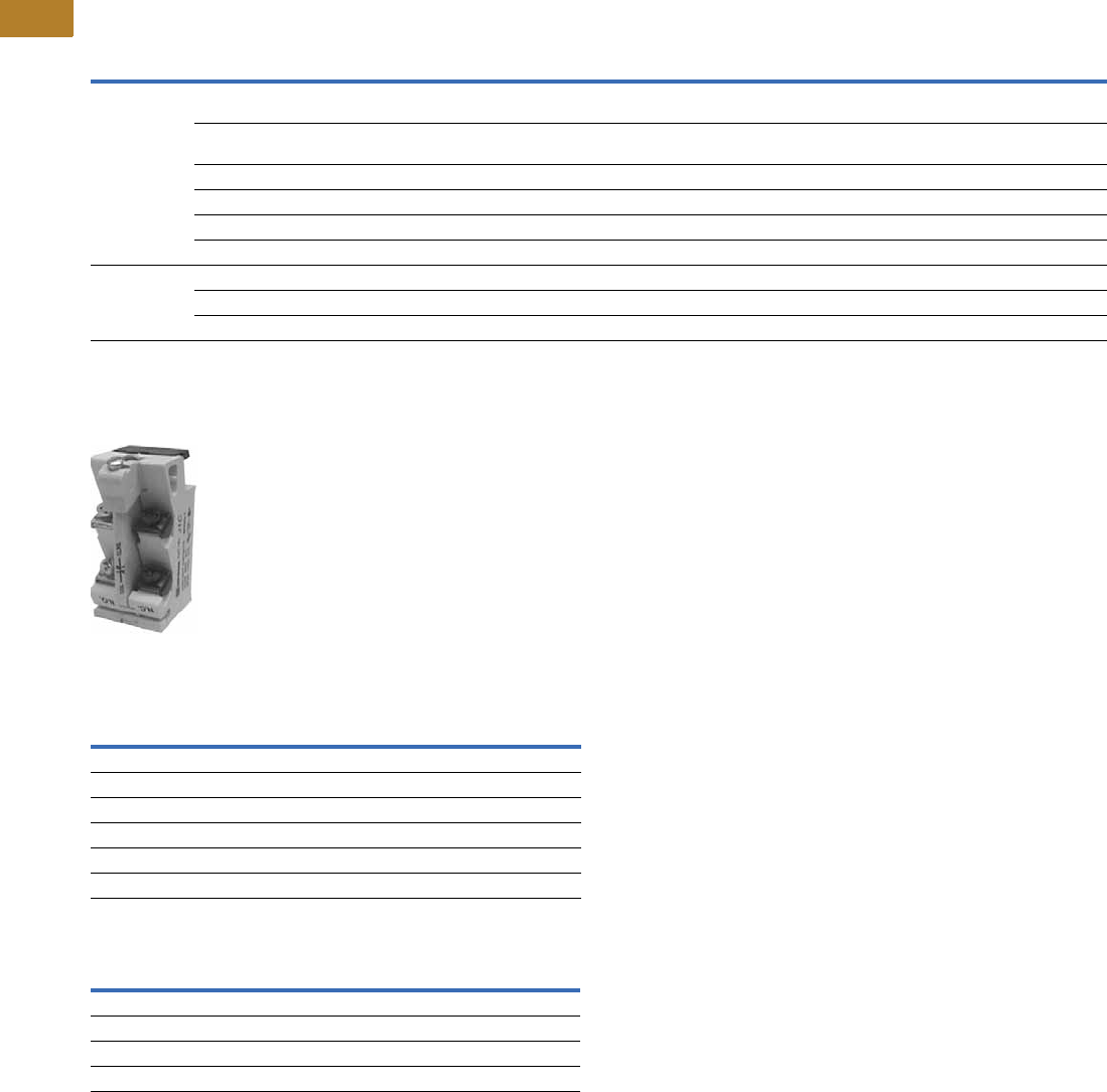
V5-T2-120 Volume 5—Motor Control and Protection CA08100006E—August 2014 www.eaton.com
2
2
2
2
2
2
2
2
2
2
2
2
2
2
2
2
2
2
2
2
2
2
2
2
2
2
2
2
2
2
2.3
NEMA Contactors and Starters
A200 Series
Modifications
Factory Modifications
Accessories and Field Modification Kits
Type J Auxiliary Contact ●Capable of being field
mounted in a contactor or
starter (Classes A200,
A900 Sizes 00–6, V200,
V201 vacuum and definite
purpose controllers)
●Provides two separate
electrical contact sets
which wire vertically and
are color coded; black
designates NC and silver
designates NO. Please
note that the vertical wiring
is contrary to the horizontal
wiring of the L-56 auxiliary
contacts
●Designed to fit within
dimensions of starter; no
additional panel space is
required
●Provides circuit isolation
(no polarity restrictions)
and single break bifurcated
contacts
Auxiliary Contact Ratings
Auxiliary Contact Types
Modification Description
Catalog
Number
Suffix
NEMA Size
00–123456789
Control circuit 1 Extra auxiliary contact (1NO-1NC) non-reversing,
reversing, 2-speed unwired
J1 Consult sales office for pricing adders.
2 Extra auxiliary contact non-reversing, reversing,
2-speed unwired
J2 Consult sales office for pricing adders.
3 Extra auxiliary contact non-reversing, unwired J3 Consult sales office for pricing adders.
4 Extra auxiliary contact non-reversing, unwired J4 Consult sales office for pricing adders.
Wired for separate control (NC) CConsult sales office for pricing adders.
Omit control wiring (NC) XConsult sales office for pricing adders.
Overload relays
(substitutions)
Ambient compensated with auto reset (NC) DConsult sales office for pricing adders.
Fast trip—ambient compensated (specify motor FLA) D7 Consult sales office for pricing adders.
Overload relay alarm contact (NO) per overload EConsult sales office for pricing adders.
Voltage Make Break
NEMA A600
120–600 Vac 7200 VA 720 VA
72–120 Vac 60A 720 VA
28–72 Vac 60 VA 10A
NEMA R300
28–300 Vdc 28 VA 28 VA
Contact Type Max. Catalog Number
1NO and 1NC 4 J11
2NC 4 J02
2NO 4 J20
1 coil clearing NC and 1NO 4 J1C

Volume 5—Motor Control and Protection CA08100006E—August 2014 www.eaton.com V5-T2-121
2
2
2
2
2
2
2
2
2
2
2
2
2
2
2
2
2
2
2
2
2
2
2
2
2
2
2
2
2
2
2.3
NEMA Contactors and Starters
A200 Series
Technical Data and Specifications
Electrical Characteristics
Sizes 00–4 Sizes 5–9
Notes
1Resistive loads having inrush currents not exceeding 1.5 times continuous rating.
2These ratings are for transformers having inrush currents not more than 20 times peak of
continuous current ratings. For inrush currents greater than 20 times, refer to factory.
3For ratings refer to factory.
Size 00Size 0Size 1Size 2Size 3Size 4
Max. voltage rating 600V 600V 600V 600V 600V 600V
Ampere rating
(Open) 10A 20A 30A 50A 100A 150A
(Enclosed) 9A 18A 27A 45A 90A 135A
Squirrel Cage Motor
Maximum horsepower at:
200V/60 Hz 1-1/2 hp 3 hp 7-1/2 hp 10 hp 25 hp 40 hp
230V/ 60 Hz 1-1/2 hp 3 hp 7-1/2 hp 15 hp 30 hp 50 hp
380V/50 Hz 1-1/2 hp 5 hp 10 hp 25 hp 50 hp 75 hp
460V–575V/60 Hz 2 hp 5 hp 10 hp 25 hp 50 hp 100 hp
Resistive Heating kW 1
Single-phase, two-pole
120V — — 3 kW 5 kW 10 kW 15 kW
240V — — 6 kW 10 kW 20 kW 30 kW
480V — — 12 kW 20 kW 40 kW 60 kW
600V — — 15 kW 25 kW 50 kW 75 kW
Three-phase, three-pole
120V — — 5 kW 8.5 kW 17 kW 26 kW
240V — — 10 kW 17 kW 34 kW 68 kW
480V — — 20 kW 34 kW 68 kW 105 kW
600V — — 25 kW 43 kW 86 kW 130 kW
Capacitor Switching kVAR, Three-Phase
240V — — — 12 kVAR 27 kVAR 40 kVAR
480V — — — 25 kVAR 53 kVAR 80 kVAR
600V — — — 31 kVAR 67 kVAR 100 kVAR
Transformer Switching kVA 2
Single-phase, two-pole
120V — 0.6 kVA 1.2 kVA 2.1 kVA 4.1 kVA 6.8 kVA
240V — 1.2 kVA 2.4 kVA 4.1 kVA 8.1 kVA 14 kVA
480V — 2.4 kVA 4.9 kVA 8.3 kVA 16 kVA 27 kVA
600V — 3 kVA 6.2 kVA 10 kVA 20 kVA 34 kVA
Three-phase, three-pole
120V — 1.8 kVA 3.6 kVA 6.3 kVA 12 kVA 20 kVA
240V — 2.1 kVA 4.3 kVA 7.2 kVA 14 kVA 23 kVA
480V — 4.2 kVA 8.5 kVA 14 kVA 28 kVA 47 kVA
600V — 5.2 kVA 11 kVA 18 kVA 35 kVA 59 kVA
Size 5Size 6Size 7Size 8Size 9
Max. voltage rating 600V 600V 600V 600V 600V
Ampere rating
(Open) 300A 600A 900A 1350A 2500A
(Enclosed) 270A 540A 810A 1215A 2250A
Squirrel Cage Motor
Maximum horsepower at:
200V/60 Hz 75 hp 150 hp — — —
230V/60 Hz 100 hp 200 hp 300 hp 450 hp 800 hp
380V/50 Hz 150 hp 300 hp — — —
460V–575V/60 Hz 200 hp 400 hp 600 hp 900 hp 1600 hp
Resistive Heating kW 1
Single-phase, two-pole
120V 30 kW 60 kW 90 kW 33
240V 60 kW 120 kW 180 kW 33
480V 120 kW 240 kW 360 kW 33
600V 150 kW 300 kW 450 kW 33
Three-phase, three-pole
120V 52 kW 105 kW 155 kW 33
240V 105 kW 210 kW 315 kW 33
480V 210 kW 415 kW 625 kW 33
600V 260 kW 515 kW 775 kW 33
Capacitor Switching kVAR, Three-Phase
240V 80 kVAR 160 kVAR 240 kVAR 360 kVAR 665 kVAR
480V 160 kVAR 320 kVAR 480 kVAR 720 kVAR 1325 kVAR
600V 200 kVAR 400 kVAR 600 kVAR 900 kVAR 1670 kVAR
Transformer Switching kVA 2
Single-phase, two-pole
120V 14 kVA 27 kVA 41 kVA 61 kVA 112 kVA
240V 27 kVA 54 kVA 81 kVA 122 kVA 225 kVA
480V 54 kVA 108 kVA 162 kVA 244 kVA 450 kVA
600V 68 kVA 135 kVA 203 kVA 304 kVA 562 kVA
Three-phase, three-pole
120V 41 kVA 81 kVA 122 kVA 182 kVA 337 kVA
240V 47 kVA 94 kVA 140 kVA 210 kVA 342 kVA
480V 94 kVA 188 kVA 280 kVA 420 kVA 783 kVA
600V 117 kVA 234 kVA 351 kVA 526 kVA 975 kVA

V5-T2-122 Volume 5—Motor Control and Protection CA08100006E—August 2014 www.eaton.com
2
2
2
2
2
2
2
2
2
2
2
2
2
2
2
2
2
2
2
2
2
2
2
2
2
2
2
2
2
2
2.3
NEMA Contactors and Starters
A200 Series
DC Power Pole Ratings
The following represent typical production test values and should
not be interpreted as a guarantee of actual performance.
DC Operated 120 and 240V Coils
380V, 50 Hz Starter Maximum Horsepower Ratings
Horsepower Ratings
Operating Coil Characteristics at Rated Coil Volts, Sizes 00–9
The following represent typical production test values and should not be interpreted as a guarantee of actual performance.
Operating Coil Characteristics
Notes
1Non-inductive load.
2AC coil data pertains to Model K, DC coil data pertains to Model J.
3DC operated only.
4Percent of rated coil voltage.
5At 60 Hz base.
6To contact touch.
7Lower figure when coil is cold. Higher figure when coil is hot.
8Drop-out time to clear arc. Time varies with type of load and contact wear.
Contactor Size
DC Contact Ampere Rating
Two Poles in Series 1
120V 240V
0——
12010
24530
37540
49070
NEMA Size00012345678
Maximum
horsepower
1-1/2 5 10 25 50 75 150 300 450 700
Sizes 00, 0, 1 Size 2 Size 3 Size 4 2Size 5 Size 6 Size 7 Size 8 Size 9
AC Coil
Burden
(Open VA) 160 VA 160 VA 625 VA 700 VA 1700 VA 2900 VA 333
(Closed VA) 25 VA 25 VA 50 VA 64 VA 180 VA 220 VA 333
(Closed Watts) 7.8 W 7.8 W 18 W 21 W 32 W 42 W — — —
Pick-up volts 485% 85% 85% 85% 78% 70% — — —
Drop-out volts 440–60% 40–60% 40–60% 40–60% 65 to 75% 60 to 70% — — —
Pick-up time Hz 56 1–1-1/2 1-1/2–2 2–2-1/2 1–1-1/2 1.5 4.0 — — —
Drop-out time Hz 53/4–1 3/4–1 3/4–1 3/4–1 0.75 0.75 — — —
DC Coil
Burden
(Open VA) 17 VA 17 VA 35 VA 35 VA 600 VA 2120 VA 400 VA 400 VA 2100 VA
(Closed VA) 17 VA 17 VA 35 VA 35 VA 22 VA 21 VA 400 VA 400 VA 350 VA
(Closed Watts) 18 W 18 W 35 W 35 W 20 W 20 W 400 W 400 W 350 W
Pick-Up Volts 480% 80% 80% 80% 64% 73% 45%–65% 745%–65% 750%–65% 7
Drop-Out Volts 45–10% 5–10% 5–10% 5–10% 18% 13% 30%–45% 730%–45% 740%–50% 7
Pick-Up Time Hz 6— 25–75 ms 25–75 ms 25–75 ms 2.7 Hz 53 Hz 521–41 Hz 75 17–29 Hz 75 16–18 75
Drop-Out Time Hz 5— 16–25 ms 16–25 ms 16–25 ms 9.3 Hz 517.5 Hz 57–12 Hz 85 7–12 Hz 85 18–20 Hz 75

Volume 5—Motor Control and Protection CA08100006E—August 2014 www.eaton.com V5-T2-123
2
2
2
2
2
2
2
2
2
2
2
2
2
2
2
2
2
2
2
2
2
2
2
2
2
2
2
2
2
2
2.3
NEMA Contactors and Starters
A200 Series
Mechanical Characteristics
NEMA Standard ICS 2-110
Direct-current operated
contactors shall withstand
110% of their rated voltage
continuously without injury to
the operating coils and shall
close successfully at 80% of
their rated voltage.
Alternating-current operated
contactors shall withstand
110% of their rated voltage
continuously without injury to
the operating coils and shall
close successfully at 85% of
their rated voltage.
Mechanical Characteristics, Sizes 00–9
Data from Tables 430—147 Through 150 of 1996 NEC: Motor Amperes at Full Load 2, Three-Phase AC
Notes
1For Sizes 5–9 contactors only; for starter Sizes 5–9, refer to factory.
2These current values are for motors running at usual speeds and with normal torque characteristics. Motors for special low speed or high torque may require higher current. In all cases, heaters
should be selected on basis of information on motor nameplate or motor card data.
Sizes 00, 0, 1 Size 2 Size 3 Size 4 Size 5 Size 6 Size 7 Size 8 Size 9
Dimensions in inches (mm)
Height 6.45 (163.8) 7.16 (181.9) 9.93 (252.2) 9.93 (252.2) 12.00 (304.8) 113.50 (342.9) 118.62 (472.9) 119.25 (489) 125.00 (635) 1
Width 3.31 (84.1) 3.31 (84.1) 4.62 (117.3) 4.62 (117.3) 7.00 (177.8) 17.00 (177.8) 123.50 (596.9) 123.50 (596.9) 132.00 (812.8) 1
Depth 4.61 (117.1) 4.96 (126) 6.75 (171.5) 6.75 (171.5) 7.75 (196.9) 18.75 (222.3) 111.00 (279.4) 111.00 (279.4) 113.00 (330.2) 1
Panel area—square inches 21.35 23.7 46.0 46.0 84.0 94.5 437.5 452.4 800
Weight—pounds 3.5 3.5 11.5 11.5 25 42 215 265 315
Cable connection — — — — Front Front Front/rear Front/rear Front/rear
Maximum cable size/phase
copper (AWG/MCM)
6 AWG 3 AWG 1/0 4/0 1–500 MCM 2–500 MCM 3–500 MCM 4–500 MCM 8–500 MCM
Auxiliary electrical circuits
available
8 66644334
Latched version available Yes Yes Yes Yes Yes Yes No No No
Mechanical interlock combinations available
Sizes
00, 0, 1, 2, 3, 4 Vert., Horiz.Vert., Horiz.Vert., Horiz.Vert., Horiz.Vert., Horiz.————
5 — — — — Vert., Horiz. Vert., Horiz. — — —
6 — — — — Vert., Horiz. Vert., Horiz. Vertical Vertical —
7, 8 — — — — — Vertical Vertical Vertical Vertical
9 — — — — — — Vertical Vertical Vertical
hp
Single-Phase
AC
Induction Type Squirrel Cage
and Wound-Rotor Amperes DC
hp
Single-Phase
AC
Induction Type Squirrel Cage
and Wound-Rotor Amperes DC
115V 230V 200V 230V 460V 575V 120V 240V 115V 230V 200V 230V 460V 575V 120V 240V
1/64.42.2—————— 30 ——92804032—106
1/45.82.9————3.11.6 40 ——1201045241 —140
1/37.23.6————4.12.0 50 ——1501306552 —173
1/2 9.8 4.9 2.5 2.2 1.1 0.9 5.4 2.7 60 — — 177 154 77 62 — 206
3/4 13.8 6.9 3.7 3.2 1.6 1.3 7.6 3.8 75 — — 221 192 96 77 — 255
1 16 8 4.8 4.2 2.1 1.7 9.5 4.7 100 — — 285 248 124 99 — 341
1-1/2 20 10 6.9 6.0 3.0 2.4 13.2 6.6 125 — — 359 312 156 125 — 425
2 24 12 7.8 6.8 3.4 2.7 17 8.5 150 — — 414 360 180 144 — 506
3 34 17 11.0 9.6 4.8 3.9 25 12.2 200 — — 552 480 240 192 — 675
5 56 28 17.5 15.2 7.6 6.1 40 20 250 — — — — 302 242 — —
7-1/2 80 40 25.3 22 11 9 58 29 300 — — — — 361 289 — —
10 100 50 32.2 28 14 11 76 38 350 — — — — 414 336 — —
15 — — 48.3 42 21 17 — 55 400 — — — — 477 382 — —
20 — — 62.1 54 27 22 — 72 450 — — — — 515 412 — —
25 — — 78.2 68 34 27 — 89 500 — — — — 590 472 — —

V5-T2-124 Volume 5—Motor Control and Protection CA08100006E—August 2014 www.eaton.com
2
2
2
2
2
2
2
2
2
2
2
2
2
2
2
2
2
2
2
2
2
2
2
2
2
2
2
2
2
2
2.3
NEMA Contactors and Starters
A200 Series
Combination Ratings
Sizes 00–2
Coil Suffix
Other Available Coil Voltages—AC and DC Coils 7
Sizes 3 and 4
Notes
1Instantaneous adjustable trip.
2Circuit breaker.
3Inverse time circuit breaker.
4Instantaneous adjustable trip with current limiting attachment.
5Inverse time with built-in current limiting attachment.
6Inverse time current limiting breaker.
7Availability may be limited.
8DC coils for Size 5 and 6 contactors and starters are intermittent duty rated only.
A mechanical latch is required.
9DC coils. Use only on contactors originally supplied with a DC coil.
Short-Circuit
Protective Device
(SCPD)
Max.
Rating
SCPD
Circuit Breaker
Interrupting
Rating
Short-Circuit
Withstand Capability
Current Voltage
Sizes 00, 0, 1
Class H fuse 60A — 5000A 600V
Class J fuse 60A — 100,000A 600V
Class R fuse 60A — 100,000A 600V
Class T fuse 60A — 100,000A 600V
Magnetic only 1
Type CB 2
30A Marked HMCP 100,000A 480V
50,000A 600V
Thermal/magnetic
Type CB 3
50A 65,000A 65,000A 480V
25,000A 25,000A 600V
100,000A 100,000A 480V
35,000A 35,000A 600V
Magnetic only
Type CB + CL 4
30A HMCP + current
limiter
100,000A 600V
Thermal/magnetic
Type CLB 5
50A 150,000A 100,000A 480V
Size 2
Class H fuse 100A — 5000A 600V
Class J fuse 100A — 100,000A 600V
Class R fuse 100A — 100,000A 600V
Class T fuse 100A — 100,000A 600V
Magnetic only 1
Type CB 2
50A Marked HMCP 100,000A 480V
50,000A 600V
Thermal/magnetic
Type CB 3
90A 65,000A 65,000A 480V
25,000A 25,000A 600V
100,000A 100,000A 480V
35,000A 35,000A 600V
Magnetic only
Type CB + CL 4
50A HMCP + current
limiter
100,000A 600V
Thermal/magnetic
Type CLB 5
50A 150,000A 100,000A 480V
Coils
Catalog
Number
Suffix
Coil Rating
(Volts/Hertz)
Catalog
Number
Suffix
Coil Rating
(Volts/Hertz)
AC A 120/60, 110/50 N110/50
B200-208/60 P48/60
C 240/60 and 480/60 R 120/60 and 240/60
D440/50 U440-480/50 or 60 Rect. to DC
E600/60 Hz V110/60
G220/50 W240/60
H380/50 X480/60
I24/60 Y415/50
J110-120/50 or 60 Rect. to DC Z277/60
K220-240/50 or 60 Rect. to DC — —
DC 89 L24 Vdc S125 Vdc
M48 Vdc T250 Vdc
Short-Circuit
Protective Device
(SCPD)
Max.
Rating
SCPD
Circuit Breaker
Interrupting
Rating
Short-Circuit
Withstand Capability
Current Voltage
Size 3
Class H fuse 60A — 5000A 600V
Class J fuse 60A — 100,000A 600V
Class R fuse 60A — 100,000A 600V
Class T fuse 60A — 100,000A 600V
Magnetic only 1
Type CB 2
100A Marked HMCP 100,000A 480V
50,000A 600V
Thermal/magnetic
Type CB 3
150A 65,000A 65,000A 480V
25,000A 25,000A 600V
100,000A 100,000A 480V
35,000A 35,000A 600V
Magnetic only
Type CB + CL 4
100A HMCP + current
limiter
100,000A 600V
Thermal/magnetic
Type CLB 5
150A 50,000A 100,000A 480V
Size 4
Class H fuse 400A — 10,000A 600V
Class J fuse 400A — 100,000A 600V
Class R fuse 400A — 100,000A 600V
Class T fuse 400A — 100,000A 600V
Magnetic only 1
Type CB 2
150A Marked HMCP 100,000A 480V
50,000A 600V
Thermal/magnetic
Type CB 3
250A 65,000A 65,000A 480V
25,000A 25,000A 600V
100,000A 100,000A 480V
35,000A 35,000A 600V
Magnetic only
Type CB + CL 4
150A HMCP + current
limiter
100,000A 600V
Thermal/magnetic
Type CB + CL 5
250A 200,000A 100,000A 600V
Thermal/magnetic
Type CLB 6
250A 150,000A 100,000A 480V
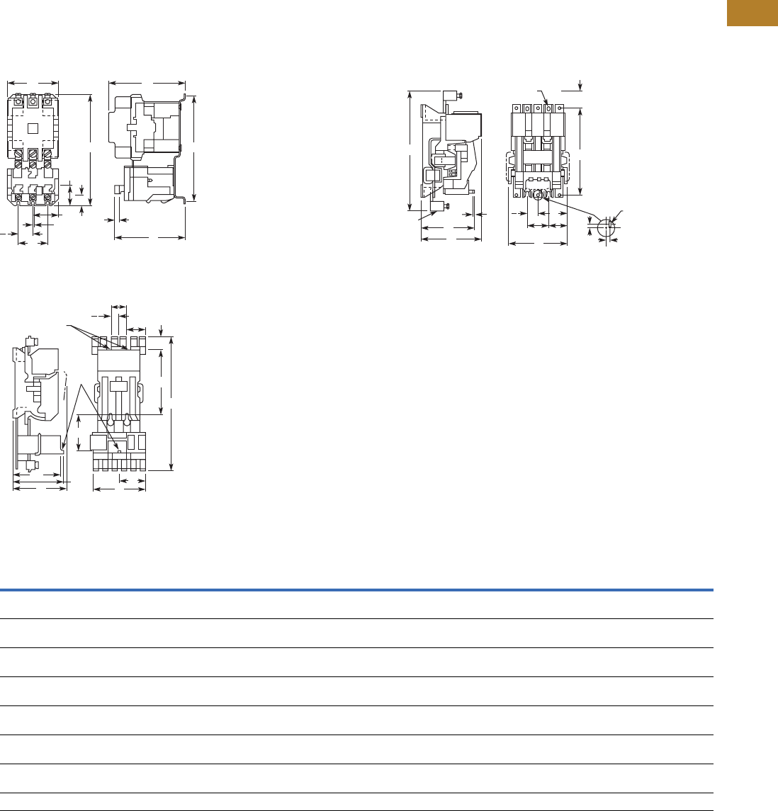
Volume 5—Motor Control and Protection CA08100006E—August 2014 www.eaton.com V5-T2-125
2
2
2
2
2
2
2
2
2
2
2
2
2
2
2
2
2
2
2
2
2
2
2
2
2
2
2
2
2
2
2.3
NEMA Contactors and Starters
A200 Series
Dimensions
Approximate Dimensions in Inches (mm)
Not to be used for construction purposes unless approved.
Open Non-Reversing Starters
Figure A—Sizes 00–4
Figure C—Size 6
Figure B—Size 5
Dimensions and Shipping Weights
Note
1Refer to factory.
EL
Reset Travel
M
JF
C
A
BD
K
G
E
2
CAF
H
E
M
Reset
Rod
L
K
B
D
G
E
2
0.38 (9.7) Wide
4 Mtg. Slots
CA
L
MF
HE KJ
Reset Rod
BD
G
E
2
C
L
C
L
of Cont’r
Cont’r Mtg.
Holes
0.38 x .5 (9.7 x 12.7)
(2 Mtg. Slots)
Term. Lug
Supplied
When
Ordered
NEMA
Size
No. of
Poles Fig.
Mounting
Screws Weight,
Lbs (kg)No. SizeABCDEF GHJKL M
00, 0, 1 2, 3 A 3 #10 3.31
(84.1)
6.42
(163.1)
4.61
(117.1)
6.00
(152.4)
1.88
(47.8)
1.66
(42.2)
0.23
(5.8)
—0.39
(9.9)
0.59
(15.0)
4.48
(113.8)
0.27
(6.9)
35.0
(15.9)
2 2, 3 A 3 #10 3.31
(84.1)
7.17
(182.1)
4.94
(125.5)
6.75
(171.5)
1.88
(47.8)
1.66
(42.2)
0.23
(5.8)
—0.41
(10.4)
0.77
(19.6)
4.53
(115.1)
0.27
(6.9)
43.0
(19.5)
3, 4 2, 3 A 3 1/4 in. 4.63
(117.6)
9.94
(252.5)
6.75
(171.5)
9.25
(235.0)
2.88
(73.2)
.94
(23.9)
0.38
(9.7)
—0.55
(14.0)
0.80
(20.3)
6.36
(161.5)
0.27
(6.9)
115.0
(52.2)
5 3 B 4 3/8 in. 7.59
(192.8)
16.22
(412.0)
7.75
(196.9)
11.00
(279.4)
2.75
(69.9)
3.81
(96.8)
2.69
(68.3)
2.42
(61.5)
0.33
(8.4)
0.33
(8.4)
7.00
(177.8)
0.27
(6.9)
29.0
(13.2)
6 3 C 4 3/8 in. 9.25
(235.0)
23.50
(596.9)
9.50
(241.3)
11.00
(279.4)
2.75
(69.9)
4.81
(122.2)
2.75
(69.9)
3.06
(77.7)
—6.50
(165.1)
8.44
(214.4)
0.27
(6.9)
55.0
(25.0)
73
11 1 37.88
(962.2)
21.50
(546.1)
11.75
(298.5)
——————————
83
11 137.88
(962.2)
21.50
(546.1)
11.75
(298.5)
——————————
93
1111111111111111
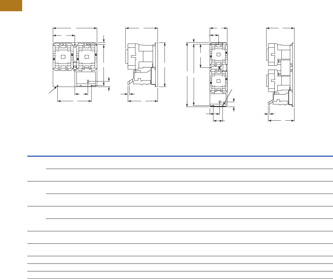
V5-T2-126 Volume 5—Motor Control and Protection CA08100006E—August 2014 www.eaton.com
2
2
2
2
2
2
2
2
2
2
2
2
2
2
2
2
2
2
2
2
2
2
2
2
2
2
2
2
2
2
2.3
NEMA Contactors and Starters
A200 Series
Approximate Dimensions in Inches (mm)
Not to be used for construction purposes unless approved.
Open Reversing Starters
Figure A—Sizes 00–4 Horizontal Figure B—Sizes 00–4 Vertical
Dimensions and Shipping Weights
Note
1Refer to factory.
E
0.28 (7.1) Dia.
3 Mtg. Holes L
JM
Reset
Travel
A C
F
B
D
K
G
L
E
JM
AC
F
BD
N
G
K
0.28 (7.1) Dia.
3 Mtg. Holes
Reset Travel
NEMA
Size
Number
of Poles Fig.
Mounting
Screws Weight,
Lbs (kg)No. SizeABCDEF GJKL MN
00, 0, 1 3 x 3 Horiz. A 3 #10 7.13
(181.1)
6.50
(165.1)
5.05
(128.3)
6.00
(152.4)
5.69
(144.5)
3.56
(90.4)
0.25
(6.4)
2.3
(58.4)
0.59
(15.0)
4.92
(125.0
0.27
(6.9)
—9.0
(4.0)
3 x 3 Vert. B 3 #10 3.33
(84.6)
11.63
(295.4)
5.05
(128.3)
11.13
(282.7)
1.88
(47.8)
1.66
(42.2)
0.25
(6.4)
0.39
(9.9)
0.59
(15.0)
4.92
(125.0)
0.27
(6.9)
4.52
(114.8)
9.8
(4.4)
2 3 x 3 Horiz. A 3 #10 7.13
(181.1)
7.25
(184.2)
5.38
(136.7)
6.75
(171.5)
5.69
(144.5)
3.56
(90.4)
0.25
(6.4)
2.31
(58.7)
0.77
(19.6)
4.97
(126.2)
0.27
(6.9)
— 10.8
(4.9)
3 x 3 Vert. B 3 #10 3.33
(84.6)
12.38
(314.5)
5.38
(136.7)
11.88
(301.8)
1.88
(47.8)
1.66
(42.2)
0.25
(6.4)
0.39
(9.9)
0.77
(19.6)
4.97
(126.2)
0.27
(6.9)
4.52
(114.8)
12.2
(5.5)
3, 4 3 x 3 Horiz. A 3 1/4 in. 9.75
(247.7)
10.13
(257.3)
7.25
(184.2)
9.25
(235.0)
8.00
(203.2)
4.88
(124.0)
0.44
(11.2)
3.11
(79.0)
0.80
(20.3)
6.86
(174.2)
0.27
(6.9)
— 26.0
(11.8)
3 x 3 Vert. B 3 1/4 in. 4.63
(117.6)
19.81
(503.2)
7.25
(184.2)
18.94
(481.1)
2.88
(73.2)
2.94
(74.7)
0.44
(11.2)
0.55
(14.0)
0.80
(20.3)
6.86
(174.2)
0.27
(6.9)
7.91
(200.9)
28.0
(12.7)
5 3 x 3 Horiz. — 4 3/8 in. 35.25
(895.4)
25.50
(647.7)
8.75
(222.3)
—————————73.0
(33.1)
6 3 x 3 Horiz. — 4 3/8 in. 35.25
(895.4)
25.50
(647.7)
10.50
(266.7)
—————————127.0
(57.7)
71 1111111111111111
81 1111111111111111
91 1111111111111111
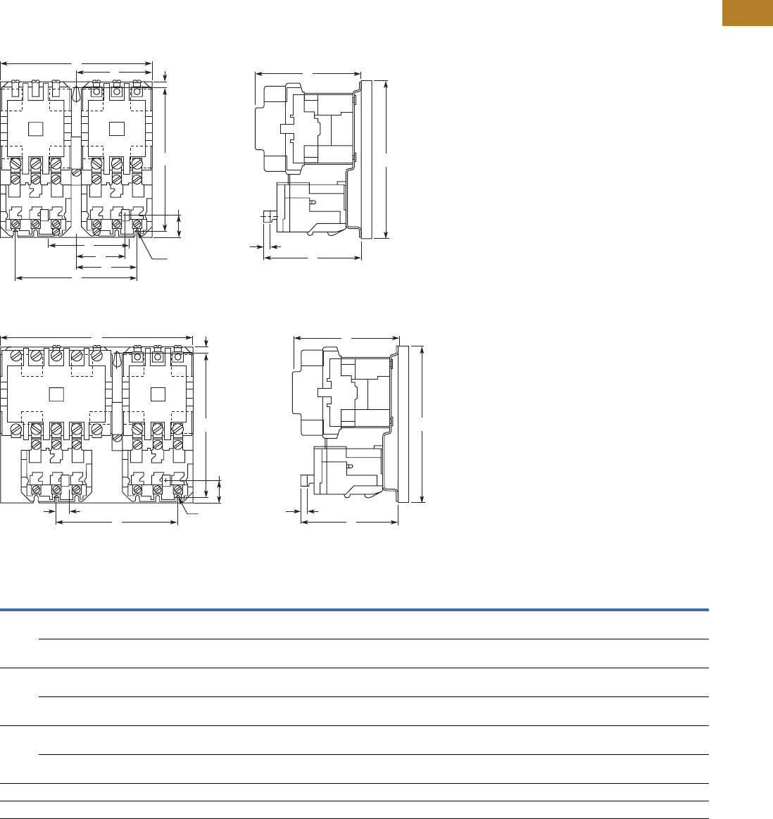
Volume 5—Motor Control and Protection CA08100006E—August 2014 www.eaton.com V5-T2-127
2
2
2
2
2
2
2
2
2
2
2
2
2
2
2
2
2
2
2
2
2
2
2
2
2
2
2
2
2
2
2.3
NEMA Contactors and Starters
A200 Series
Approximate Dimensions in Inches (mm)
Not to be used for construction purposes unless approved.
Open Multi-Speed Starters
Figure A—Sizes 00–4
Figure B—Sizes 2
Dimensions and Shipping Weights
Notes
Three-pole x three-pole devices are for Wye-Wye two-winding motors only.
1Refer to factory.
NEMA
Size
Number
of
Poles Fig.
Mounting
Screws Weight,
Lbs (kg) No. Size A B C D E F G J K L M N P R
00, 0, 1 3 x 3 Horiz. A 3 #10 7.13
(181.1)
6.50
(165.1)
5.05
(128.3)
6.00
(152.4)
5.69
(144.5)
3.56
(90.4)
0.25
(6.4)
2.30
(58.4)
0.33
(8.4)
4.92
(125.0)
0.27
(6.9)
3.81
(96.8)
—2.91
(73.9)
10.0
(4.5)
5 x 3 Horiz. B 3 #10 8.00
(203.2)
6.50
(165.1)
5.05
(128.3)
6.00
(152.4)
6.53
(165.9)
3.56
(90.4)
0.25
(6.4)
2.30
(58.4)
0.48
(12.2)
4.92
(125.0)
0.27
(6.9)
4.66
(118.4)
—2.91
(73.9)
11.0
(5.0)
2 3 x 3 Horiz. A 3 #10 7.13
(181.1)
7.25
(184.2)
5.38
(136.7)
6.75
(171.5)
5.69
(144.5)
3.56
(90.4)
0.25
(6.4)
2.69
(68.3)
0.69
(17.5)
4.97
(126.2)
0.27
(6.9)
3.81
(96.8)
—2.91
(73.9)
11.0
(5.0)
5 x 3 Horiz. B 3 #10 8.88
(225.6)
7.25
(184.2)
5.38
(136.7)
6.75
(171.5)
6.56
(166.6)
3.56
(90.4)
0.25
(6.4)
2.69
(68.3)
0.69
(17.5)
4.97
(126.2)
0.27
(6.9)
4.66
(118.4)
—2.84
(72.1)
13.0
(5.9)
3, 4 3 x 3 Horiz. A 3 1/4 in. 9.75
(247.7)
10.13
(257.3)
7.25
(184.2)
9.25
(235.0)
8.00
(203.2)
4.88
(124.0)
0.44
(11.2)
3.11
(79.0)
0.80
(20.3)
6.86
(174.2)
0.27
(6.9)
5.13
(130.3)
—4.00
(101.6)
28.0
(12.7)
5 x 3 Horiz. B 3 1/4 in. 12.38
(314.5)
10.13
(257.3)
7.25
(184.2)
9.25
(235.0)
9.31
(236.5)
4.88
(124.0)
0.44
(11.2)
3.11
(79.0)
0.80
(20.3)
6.86
(174.2)
0.27
(6.9)
6.44
(163.6)
—4.00
(101.6)
33.5
(15.2)
51 111111111111111111
61 111111111111111111
A
D
G
B
K
FC
J0.2 (5.1) Dia.
3 Mounting Slots
R
E
N
L
Reset TravelM
A
D
G
B
K
C
0.2 (5.1) Dia.
3 Mounting Slots
E
J
L
Reset TravelM
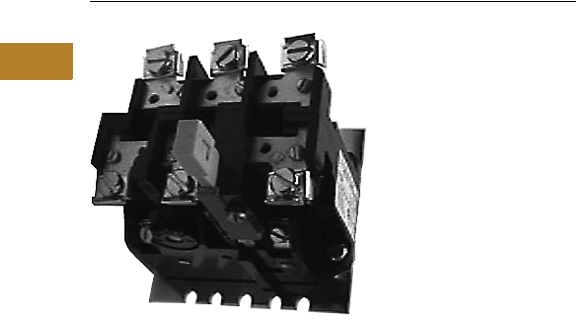
V5-T2-128 Volume 5—Motor Control and Protection CA08100006E—August 2014 www.eaton.com
2
2
2
2
2
2
2
2
2
2
2
2
2
2
2
2
2
2
2
2
2
2
2
2
2
2
2
2
2
2
2.3
NEMA Contactors and Starters
A200 Series
Relays—Thermal and Fast Trip
Contents
Description Page
Contactors—Non-Reversing and Reversing . . . . . . V5-T2-101
Starters—Non-Reversing and Reversing . . . . . . . . V5-T2-107
Relays—Thermal and Fast Trip
Standards and Certifications . . . . . . . . . . . . . . . V5-T2-129
Instruction Leaflets . . . . . . . . . . . . . . . . . . . . . . V5-T2-129
Thermal Type B, Class 20, Manual Reset. . . . . . . . V5-T2-130
Thermal Type A, Class 20, Auto/Manual Reset . . . V5-T2-133
Type FT Fast Trip, Class 10 . . . . . . . . . . . . . . . . . . . V5-T2-136
Heater Selection . . . . . . . . . . . . . . . . . . . . . . . . . . V5-T2-139
Relays—Current Sensing Protective . . . . . . . . . . . V5-T2-141
Relays—Thermal and Fast Trip
Product Overview
Type B and Type A, Class 20
Thermal Overload Relays
from Eaton’s Electrical Sector
will protect the motor against
abnormal
overload conditions.
Bimetallic actuated, they are
available as either ambient
compensated or non-
compensated in either single-
pole or block type three-pole
design. Type B use one pole
of the three-pole block for
single-phase.
Single-pole relays are also
available as Fast Trip Class 10
ambient compensated type,
which provides approximately
125% motor protection with
a tripping time of less than
10 seconds, at 600% of
heater current rating.
Fast trip relays can be
identified by the green reset
rods. They are available for
panel or starter mounting.
The three-pole fast trip design
is composed of
three single-pole relays
on a common baseplate,
with a common reset bar.
The bimetal element is
actuated by precisely
calibrated heater elements
which are connected directly
in the circuit to be protected.
Thermal actuation of this
device opens the contacts in
the coil circuit of a contactor
or relay which results in the
disconnection of power to the
overloaded circuit.
Interchangeable thermal
heater elements for single-
pole standard trip and block
type overload relays are
available to cover motor full
load currents from 0.29 to
133A in approximately 10%
steps (see Heater Application
Table). Fast trip overload
relays do not have
interchangeable heater
elements but are available
in a series of ratings to cover
motor full load currents from
1.6 to 150A in approximately
50% steps.
Features
Manual or Automatic Reset
Type B is furnished with a
manual reset. Type A is
normally furnished set for
manual reset operation and
may be quickly adjusted
for automatic reset when
required. Automatic reset
should not be used with
two-wire control or where
automatic restarting would
endanger either personnel
or equipment.
Trip Indication
An immediate visible
indication of trip is provided
on the overload relay. When
an overload occurs, which
causes the relay to operate,
a trip indicator projects out
and thus shows positive
visual indication of trip.
Type B has a mechanical
trip bar to manually check
the NC contact operation on
the overload relay.
Adjustable Trip
On Type A, the trip rating of a
specific heater element can
be adjusted over a range of
approximately 85% to 115%
of its respective rating to
permit the desired close
protection.
This is accomplished by
turning the adjusting knob
on the relay to the respective
stop position.
Positive Contact Break
A follow-through contact,
provided on the stationary
terminal of the snap action
control switch, provides
reliable electrical continuity
during toggling, thus
eliminating false trip
sometimes prevalent
with thermally operated
switches. This contact also
allows contact wipe for
further reliability.

Volume 5—Motor Control and Protection CA08100006E—August 2014 www.eaton.com V5-T2-129
2
2
2
2
2
2
2
2
2
2
2
2
2
2
2
2
2
2
2
2
2
2
2
2
2
2
2
2
2
2
2.3
NEMA Contactors and Starters
A200 Series
Ambient Compensation
Motor overload protection
can be provided with the
same trip characteristics in
ambient temperature from
–40° to 77°C (–40° to 167°F).
A compensating bimetal
maintains a constant “travel
to trip” distance independent
of ambient conditions.
The compensating feature
is fully automatic and no
adjustments are required
over wide fluctuations in
ambient temperatures.
Compensated relays are
identified by black reset rods
on Type A and light gray reset
rods on Type B, while non-
compensated relays use red
reset rods. AA three-pole
units have gray reset rods.
AA one-pole units have black
reset rods.
Control Contact
Single-pole and block
type relays are supplied as
standard with a SPST NC
control contact. A SPDT
NO-NC with common is
available as a factory
modification on Type A.
An isolated NO contact can
be supplied on Type B as
either a factory modification
or as a field kit.
Standards and Certifications
●UL 508
●CSA
●ANSI/NEMA ICS 2-222
Instruction Leaflets
14885B Fast Trip A
Sizes 0–4, 3-Pole
OL Relay
14567E Type A Sizes 1–2,
1-Pole OL Relay
Mod A
14568 Type A Sizes 1–2,
3-Pole OL Relay
Mod J
14570D Type A Sizes 3–4,
3-Pole OL Relay
Mod J
14569C Type A Sizes 3–4,
1-Pole OL Relay
Mod A
17093A Type B OLR for
Sizes 7, 8 and
9 Contactors
16955A Type B Sizes 1–2,
1-Pole OL Relay
16954A Type B Sizes 1–2,
3-Pole OL Relay
15392B Type B Sizes 3–4,
3-Pole OL Relay
13676F Fast Trip Sizes 0–4,
1-Pole OL Relay
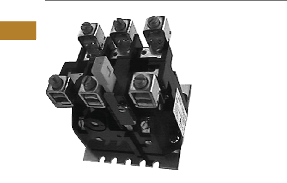
V5-T2-130 Volume 5—Motor Control and Protection CA08100006E—August 2014 www.eaton.com
2
2
2
2
2
2
2
2
2
2
2
2
2
2
2
2
2
2
2
2
2
2
2
2
2
2
2
2
2
2
2.3
NEMA Contactors and Starters
A200 Series
Thermal Type B, Class 20, Manual Reset
Contents
Description Page
Contactors—Non-Reversing and Reversing . . . . . . V5-T2-101
Starters—Non-Reversing and Reversing . . . . . . . . V5-T2-107
Relays—Thermal and Fast Trip . . . . . . . . . . . . . . . . V5-T2-128
Thermal Type B, Class 20, Manual Reset
Product Selection . . . . . . . . . . . . . . . . . . . . . . . V5-T2-131
Accessories. . . . . . . . . . . . . . . . . . . . . . . . . . . . V5-T2-131
Technical Data . . . . . . . . . . . . . . . . . . . . . . . . . . V5-T2-132
Dimensions. . . . . . . . . . . . . . . . . . . . . . . . . . . . V5-T2-132
Thermal Type A, Class 20, Auto/Manual Reset . . . V5-T2-133
Type FT Fast Trip, Class 10 . . . . . . . . . . . . . . . . . . . V5-T2-136
Heater Selection . . . . . . . . . . . . . . . . . . . . . . . . . . V5-T2-139
Relays—Current Sensing Protective . . . . . . . . . . . V5-T2-141
Thermal Type B, Class 20, Manual Reset
Application Description
The Type B overload relay is
designed to protect industrial
motors against overload
conditions. Using modern
block type, bimetallic design,
this relay will provide
Class 20 operation in either
single-phase or three-phase
applications.
Operation
The Type B overload relay
is a bimetallic actuated
device. The bimetal elements
are operated by precisely
calibrated heaters. The heater
elements are connected
either directly in the circuit
to be measured, or through
current transformers on
applications NEMA Size 5
and larger.
As the bimetals are heated
by motor current flow, a
deflection force is produced.
Upon a sustained level of
abnormal current flow, the
deflection becomes great
enough to open the snap-
action output contact.
Ambient Compensation
The Type B ambient
compensated design is
supplied as standard on
all A200 starters. This design
uses a second compensating
bimetal responsive to
ambient air temperature in
the surrounding enclosure.
This feature reduces
nuisance tripping in
applications using compact
control panels and motor
control centers where
internal temperature rise
is significant compared to
motor ambient temperature.
The compensating
characteristic is maintained
in ambient temperatures
from 40° to 77°C.
Features
●Ambient compensation
standard
●Alarm contact field
mountable
●Class 20—600V design
●Inverse time delay trip
●Test trip device for weld
check
●Hi-visibility up-front trip
indication
●Trip-free reset mechanism
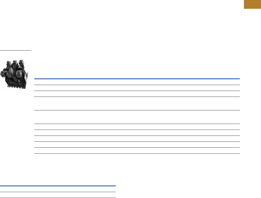
Volume 5—Motor Control and Protection CA08100006E—August 2014 www.eaton.com V5-T2-131
2
2
2
2
2
2
2
2
2
2
2
2
2
2
2
2
2
2
2
2
2
2
2
2
2
2
2
2
2
2
2.3
NEMA Contactors and Starters
A200 Series
Product Selection
Heaters
Enter heaters as separate
item by listing catalog
number from tables,
Pages V5-T2-139 and
V5-T2-140, as required per
starter.
Relays
Thermal Type B Overload Relay
Accessories
Alarm Contact Kit Selection 1
Notes
1Includes contactor mounting bracket, overload relay and connection straps to contactor.
2For replacement on B200 size 00, 0, 1 use BA23A instead of BA13A and use BN23A instead
of BN13A.
Motor Full
Load Amps
Panel Mounted
Starter Mounted
Replacement for
Type B Overload Relays
Replacement for Type A Overload Relays in
Manual Reset Mode (Three-Pole Only) 1
Ambient Comp.
Catalog Number
Non-Comp.
Catalog Number
Ambient Comp.
Catalog Number
Non-Comp.
Catalog Number
Ambient Comp.
Catalog Number
Non-Comp.
Catalog Number
Single-Pole (One NC Contact)
0.25–26.2 BA11JP BN11JP BA11A BN11A ——
26.3–45 BA21JP BN21JP BA21A BN21A ——
19–90 Use three-pole
design, wire three
poles in series
Use three-pole
design, wire three
poles in series
Use three-pole
design, wire three
poles in series
Use three-pole
design, wire three
poles in series
Use three-pole
design, wire three
poles in series
Use three-pole
design, wire three
poles in series
19–135 Use three-pole
design, wire three
poles in series
Use three-pole
design, wire three
poles in series
Use three-pole
design, wire three
poles in series
Use three-pole
design, wire three
poles in series
Use three-pole
design, wire three
poles in series
Use three-pole
design, wire three
poles in series
Three-Pole (One NC Contact)
0.25–26.2 BA13JP BN13JP BA13A 2BN13A 2BA13J BN13J
26.3–45 BA23JP BN23JP BA23A BN23A BA23J BN23J
19–90 BA33P BN33P BA33A BN33A BA33A BN33A
19–135 BA43P BN43P BA43A BN43A BA43A BN43A
Type B Overload Relay Size Catalog Number
1, 2 B3NO-2
3, 4 B3NO-4
Type B Overload Relay
Panel Mounting
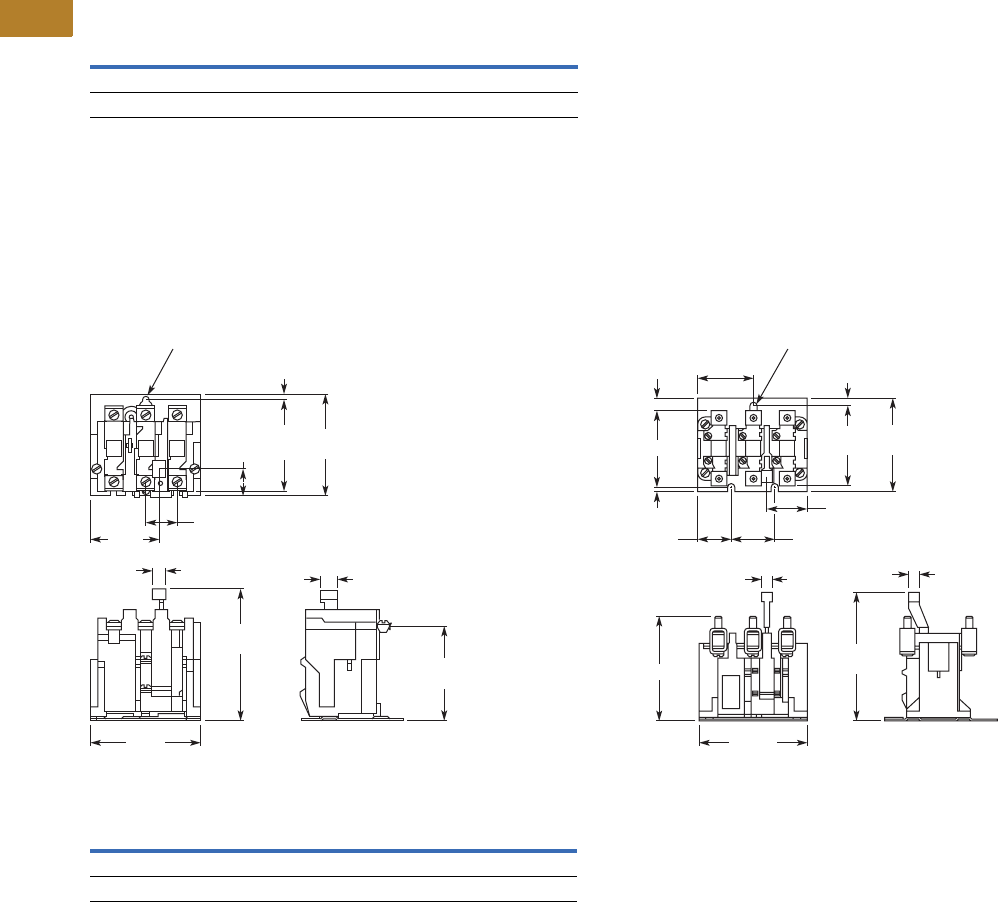
V5-T2-132 Volume 5—Motor Control and Protection CA08100006E—August 2014 www.eaton.com
2
2
2
2
2
2
2
2
2
2
2
2
2
2
2
2
2
2
2
2
2
2
2
2
2
2
2
2
2
2
2.3
NEMA Contactors and Starters
A200 Series
Technical Data
Control Contact Ratings—NEMA B600 NO and
NC Control Contact Rating
Dimensions
Approximate Dimensions in Inches (mm)
Not to be used for construction purposes unless approved.
Thermal Type B Overload Relays
Sizes 1 and 2—Three-Pole, Panel Mounted Sizes 3 and 4—Three-Pole, Panel Mounted
Dimensions
Note
1Alarm contact available as factory modification of field mountable. For factory modification,
add suffix B.
AC Volts Make Break
24–120 30A 3A
120–600 3600 VA 360 VA
0.94 (23.9)
1.98
(50.3)
0.8
(20.3)
3.14
(79.8)
2.81
(71.4)
.17
(4.3)
0.41 (10.4) 0.53
(13.5)
4.00
(101.6)
3.31
(84.1)
2.22
(56.4)
0.2 (5.1) Dia.
6 Mtg. Slots
C
D
A
1.38 (35.1)
1.75 (44.5)
0.47 (11.9)
0.47
(11.9)
4.44
(112.8)
5.28
(134.1)
3.88
(98.6)
3.38
(85.9)
2.22
(56.4)
1.34 (34.0)
B
0.25
(6.4)
0.28 (7.1) Dia.
3 Mtg. Slots
Relay Size A B C D
3 3.13 (79.5) 4.06 (103.1) 044 (11.2) 0.31 (7.9)
4 3.38 (85.9) 4.38 (111.3) 0.31 (7.9) 0.19 (4.8)
Volume 5—Motor Control and Protection CA08100006E—August 2014 www.eaton.com V5-T2-133
2
2
2
2
2
2
2
2
2
2
2
2
2
2
2
2
2
2
2
2
2
2
2
2
2
2
2
2
2
2
2.3
NEMA Contactors and Starters
A200 Series
Thermal Type A, Class 20, Auto/Manual Reset
Contents
Description Page
Contactors—Non-Reversing and Reversing . . . . . . V5-T2-101
Starters—Non-Reversing and Reversing . . . . . . . . V5-T2-107
Relays—Thermal and Fast Trip . . . . . . . . . . . . . . . . V5-T2-128
Thermal Type B, Class 20, Manual Reset . . . . . . . . V5-T2-130
Thermal Type A, Class 20, Auto/Manual Reset
Product Selection . . . . . . . . . . . . . . . . . . . . . . . V5-T2-134
Technical Data and Specifications . . . . . . . . . . . V5-T2-134
Dimensions . . . . . . . . . . . . . . . . . . . . . . . . . . . . V5-T2-135
Type FT Fast Trip, Class 10 . . . . . . . . . . . . . . . . . . . V5-T2-136
Heater Selection. . . . . . . . . . . . . . . . . . . . . . . . . . . V5-T2-139
Relays—Current Sensing Protective. . . . . . . . . . . . V5-T2-141
Thermal Type A, Class 20, Auto/Manual Reset
Application Description
The Type A overload relay is
designed to protect industrial
motors against overload
conditions. Using modern
block type, bimetallic design,
this relay will provide Class
20 operation in either single-
or three-phase applications.
Features
●Field selectable manual/
auto reset
●Alarm contract factory
available
●Class 20—600V design
●Inverse time delay trip
●Adjustable trip rating ±15%
●Color coded reset rod:
●Compensated (gray)
●Non-compensated (red)
Operation
The Type A overload relay is
a bimetallic actuated device.
The bimetal elements are
operated by precisely
calibrated heaters. The
heater elements are
connected either directly in
the circuit to be measured, or
through current transformers
on applications NEMA Size 5
and larger.
As the bimetals are heated
by motor current flow, a
deflection force is produced.
Upon a sustained level of
abnormal current flow, the
deflection becomes great
enough to open the snap-
action output contact.
Automatic Reset
The Type A overload relay can
be supplied as an option on all
A200 starters to provide
automatic reset operation.
The overload relay is always
shipped in the non-automatic
mode. To set up auto
operation, reposition the
reset rod by loosening and re-
tightening a hold-down clamp
at the base of overload relay.
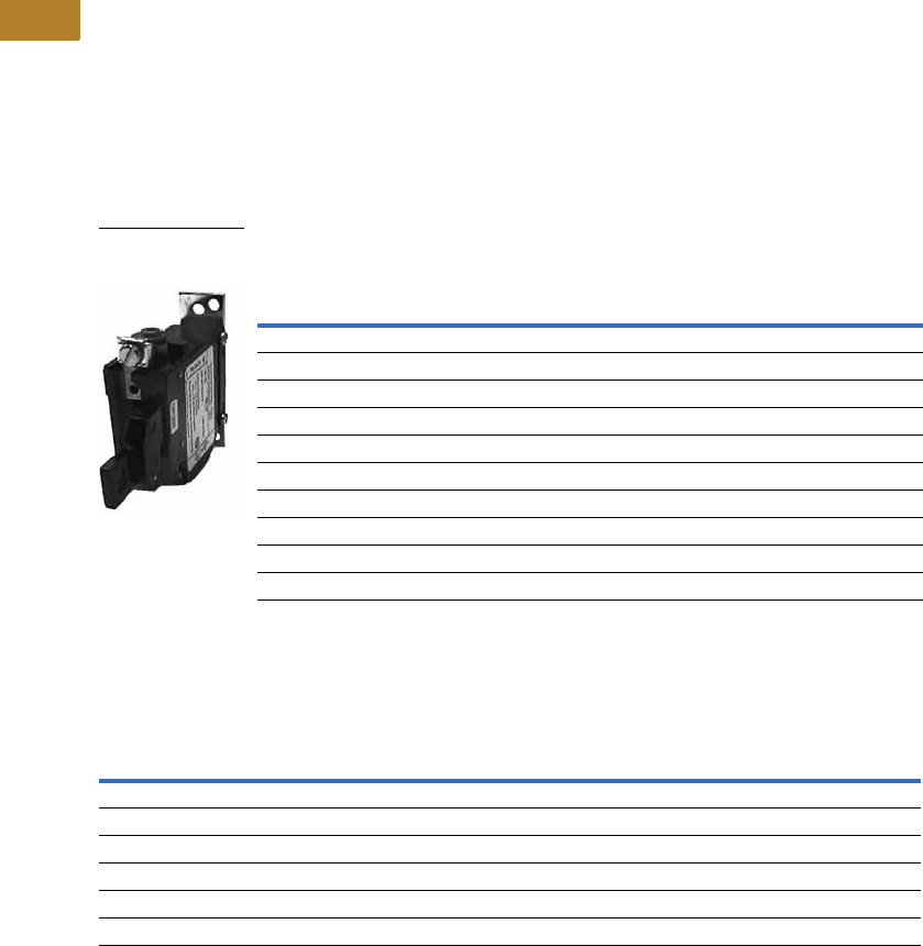
V5-T2-134 Volume 5—Motor Control and Protection CA08100006E—August 2014 www.eaton.com
2
2
2
2
2
2
2
2
2
2
2
2
2
2
2
2
2
2
2
2
2
2
2
2
2
2
2
2
2
2
2.3
NEMA Contactors and Starters
A200 Series
Product Selection
Heaters
Enter heaters as separate
item by listing catalog
number from tables,
Pages V5-T2-139 and
V5-T2-140, as required per
starter.
Relays
Thermal Type A Overload Relay 1
Technical Data and Specifications
Control Contact Ratings
Notes
1For alarm contact (Form C), add Suffix B. Available only as factory modification on Type A relay.
2Three-pole Type B overload relay is a suitable alternative to a three-pole Type A overload relay in
manual reset mode. For example, BA13JP for AA13P, BN23J for AN23A, and so on. (See Page V5-T2-131.)
Motor Full
Load Amps
Panel Mounted Starter Replacement
Ambient Comp. Non-Comp. Ambient Comp. Non-Comp.
Catalog Number Catalog Number Catalog Number Catalog Number
Single-Pole (One NC Contact)
0.25–26.2 AA11P AN11P AA11A AN11A
26.3–45 AA21P AN21P AA21A AN21A
19–90 AA31P AN31P AA31A AN31A
19–135 AA41P AN41P AA41A AN41A
Three-Pole (One NC Contact)
0.25–26.2 AA13P 2AN13P 2AA13A 2AN13A 2
26.3–45 AA23P 2AN23P 2AA23A 2AN23A 2
19–90 AA33P 2AN33P 2AA33A 2AN33A 2
19–135 AA43P 2AN43P 2AA43A 2AN43A 2
AC
Volts
Normally Closed Normally Open
Make Break Make Break
Three-Pole Control Contact Ratings
24–120 20A 2A 0.5A 0.5A
120–600 2400 VA 240 VA 600 VA 60 VA
Single-Pole Control Contact Ratings
24–120 30A 3A 10A 1A
120–600 3600 VA 360 VA 1200 VA 120 VA
Type A Overload Relay
Single-Pole Panel
Mounting
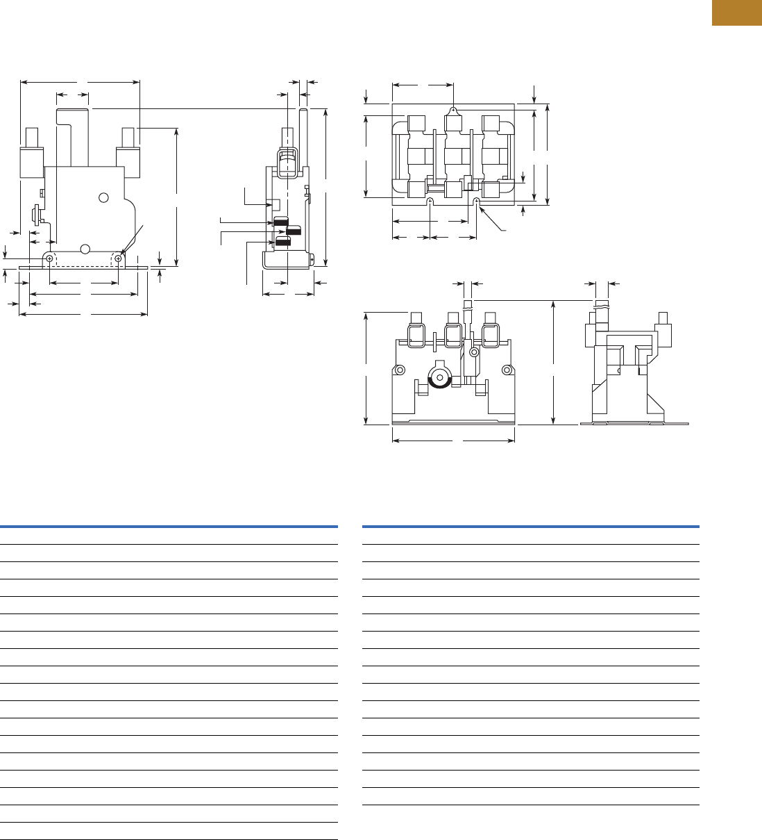
Volume 5—Motor Control and Protection CA08100006E—August 2014 www.eaton.com V5-T2-135
2
2
2
2
2
2
2
2
2
2
2
2
2
2
2
2
2
2
2
2
2
2
2
2
2
2
2
2
2
2
2.3
NEMA Contactors and Starters
A200 Series
Dimensions
Approximate Dimensions in Inches (mm)
Not to be used for construction purposes unless approved.
Type A
Single-Pole (Sizes 4 Shown)
Dimensions
Three-Pole (Size 4 Shown)
Dimensions
Dimension
Relay Size
1234
A 2.72 (69.1) 3.48 (88.4) 4.19 (106.4) 4.5 (114.3)
B 0.94 (23.9) 0.67 (17.0) 0.25 (6.4) 0.38 (9.7)
C 2.75 (69.9) 3.5 (88.9) 3.53 (89.7) 3.78 (96.0)
D 3.25 (82.6) 3.25 (82.6) 4.13 (104.9) 4.13 (104.9)
E 2.63 (66.8) 2.63 (66.8) 3.38 (85.9) 3.38 (85.9)
F 1.34 (34.0) 1.34 (34.0) 2.19 (55.6) 2.19 (55.6)
G 0.25 (6.4) 0.25 (6.4) 0.28 (7.1) 0.28 (7.1)
H 0.31 (7.9) 0.31 (7.9) 0.38 (9.7) 0.38 (9.7)
J 0.06 (1.5) 0.06 (1.5) 0.06 (1.5) 0.06 (1.5)
K 0.22 (5.6) 0.22 (5.6) 0.27 (6.8) 0.27 (6.8)
L 1.34 (34.0) 1.34 (34.0) 1.69 (42.9) 1.69 (42.9)
M 0.66 (16.8) 0.66 (16.8) 0.88 (22.4) 0.88 (22.4)
N 0.16 (4.1) 0.16 (4.1) 0.27 (6.8) 0.27 (6.8)
P 0.22 (5.6) 0.22 (5.6) 0.34 (8.6) 0.34 (8.6)
Q 0.06 (1.5) 0.06 (1.5) 0.69 (17.5) 0.69 (17.5)
R 4.00 (101.6) 4.00 (101.6) 5.19 (131.8) 5.19 (131.8)
S 0.47 (11.9) 0.47 (11.9) 0.59 (15.0) 0.59 (15.0)
T 1.11 (28.2) 1.11 (28.2) 0.69 (17.5) 0.69 (17.5)
C
Q P
N
F
T
B
MS
E L
H
D
A
J
G
R
Trip
Indicator
Common
Terminal
No Terminal
(When
Supplied)
NC Terminal
K Dia.
2 Mtg.
Holes
Dimension
Relay Size
1234
A 2.38 (60.5) 2.44 (62.0) 3.13 (79.5) 3.38 (85.9)
B 3.13 (79.5) 3.17 (80.5) 4.06 (103.1) 4.38 (111.3)
C 0.36 (9.1) 0.33 (8.4) 0.44 (11.2) 0.31 (7.9)
D 1.66 (42.2) 1.66 (42.2) 2.22 (56.4) 2.22 (56.4)
E 0.17 (4.3) 0.17 (4.3) 0.25 (6.4) 0.25 (6.4)
F 2.81 (71.4) 2.81 (71.4) 3.38 (85.9) 3.38 (85.9)
G 3.08 (78.2) 3.08 (78.2) 3.88 (98.6) 3.88 (98.6)
H 0.47 (11.9) 0.47 (11.9) 0.47 (11.9) 0.47 (11.9)
J 0.20 (5.1) 0.20 (5.1) 0.28 (7.1) 0.28 (7.1)
K 0.28 (7.1) 0.28 (7.1) 0.47 (11.9) 0.47 (11.9)
L 4.00 (101.6) 4.00 (101.6) 5.28 (134.1) 5.28 (134.1)
M 3.31 (84.1) 3.31 (84.1) 4.44 (112.8) 4.44 (112.8)
N 1.80 (45.7) 1.80 (45.7) 2.77 (70.4) 2.77 (70.4)
P 1.89 (48.0) 1.89 (48.0) 1.75 (44.5) 1.75 (44.5)
Q 1.00 (25.4) 1.00 (25.4) 1.34 (34.0) 1.34 (34.0)
R — — 1.03 (26.2) 1.03 (26.2)
D
N
Q P
K
J Dia.—3 Mtg. Slots
H
M
FG
A
C
B L
E
R
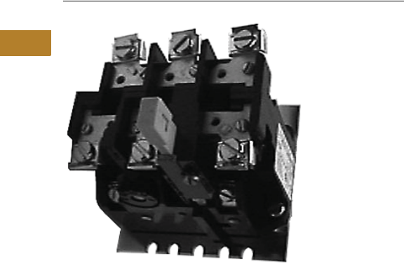
V5-T2-136 Volume 5—Motor Control and Protection CA08100006E—August 2014 www.eaton.com
2
2
2
2
2
2
2
2
2
2
2
2
2
2
2
2
2
2
2
2
2
2
2
2
2
2
2
2
2
2
2.3
NEMA Contactors and Starters
A200 Series
Type FT Fast Trip, Class 10
Contents
Description Page
Contactors—Non-Reversing and Reversing . . . . . . V5-T2-101
Starters—Non-Reversing and Reversing . . . . . . . . V5-T2-107
Relays—Thermal and Fast Trip . . . . . . . . . . . . . . . . V5-T2-128
Thermal Type B, Class 20, Manual Reset. . . . . . . . V5-T2-130
Thermal Type A, Class 20, Auto/Manual Reset . . . V5-T2-133
Type FT Fast Trip, Class 10
Product Selection . . . . . . . . . . . . . . . . . . . . . . . V5-T2-137
Technical Data and Specifications . . . . . . . . . . . V5-T2-137
Dimensions. . . . . . . . . . . . . . . . . . . . . . . . . . . . V5-T2-138
Heater Selection . . . . . . . . . . . . . . . . . . . . . . . . . . V5-T2-139
Relays—Current Sensing Protective . . . . . . . . . . . V5-T2-141
Type FT Fast Trip, Class 10
Application Description
The Type FT overload relay is
designed to protect special
purpose motors having
restricted thermal and locked
rotor capabilities. Using
modern block type, bimetallic
design, this relay will provide
Class 10 operation in single-
or three-phase applications.
Operation
The Type FT overload relay is
a bimetallic actuated device.
The bimetal elements are
operated directly from line
current, thus separate
calibrating heater elements
are not utilized. The overload
relay may be wired directly in
the motor circuit, or through-
current transformers on
applications larger than 150A.
As the bimetals are heated by
motor current flow, a
deflection force is produced.
Upon a sustained level of
abnormal current flow, the
deflection becomes great
enough to open the snap
action output contact.
Features
●Class 10—600V design
●Inverse time delay trip
●Color coded reset rod—
green
●Alarm contact factory
available
●Field selectable manual/
auto reset
●Adjustable trip rating
±20%
●Ambient compensation
included

Volume 5—Motor Control and Protection CA08100006E—August 2014 www.eaton.com V5-T2-137
2
2
2
2
2
2
2
2
2
2
2
2
2
2
2
2
2
2
2
2
2
2
2
2
2
2
2
2
2
2
2.3
NEMA Contactors and Starters
A200 Series
Product Selection
Type FT Single-Pole (One NC Contact); Three-Phase (Three NC Contacts in Series) 1
Technical Data and Specifications
Control Contact Ratings
Note
1Single-pole (1NO-NC contact): add suffix B. Three-pole (3NO-NC contacts): add suffix B. Example: FT13PB-12.
Motor Full Load
Amperes
Panel Mounted Starter Replacement
Single-Pole Three-Pole
NEMA Size
Single-Pole
Catalog Number Catalog Number Catalog Number
0.76–1.1 FT11P-1.1 FT13P-1.1 —FT11A-1.1
1.1–1.6 FT11P-1.6 FT13P-1.6 —FT11A-1.6
1.6–2.4 FT11P-2.4 FT13P-2.4 0, 1 FT11A-2.4
2.4–3.6 FT11P-3.6 FT13P-3.6 0, 1 FT11A-3.6
3.6–5.4 FT11P-5.4 FT13P-5.4 0, 1 FT11A-5.4
5.4–8.0 FT11P-8.0 FT13P-8 0, 1 FT11A-8
8.0–12 FT11P-12 FT13P-12 0, 1 FT11A-12
12–18 FT11P-18 FT13P-18 1FT11A-18
16–24 —FT13P-24 —
22–32 FT11P-32 FT13P-32 0, 1 FT11A-32
24–36 FT21P-36 FT23P-36 2FT21A-36
36–54 FT21P-54 FT23P-54 12 FT21A-54
22–32 FT31P-32 FT33P-32 3FT31A-32
32–48 FT31P-48 FT33P-48 3FT31A-48
48–72 FT31P-72 FT33P-72 3FT31A-72
72–110 FT41P-110 FT43P-110 4FT41A-110
100–150 FT41P-150 FT43P-150 4FT41A-150
AC Volts
Normally Closed Normally Open
Make Break Make Break
24–120 30A 3A 10A 1A
120–600 3600 VA 360 VA 1200 VA 120 VA
Type FT Single-Pole
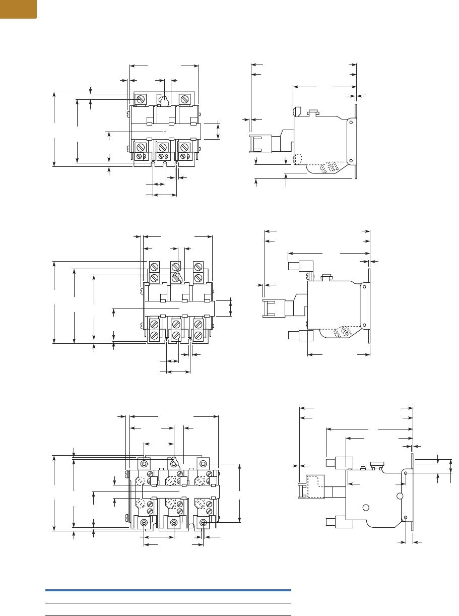
V5-T2-138 Volume 5—Motor Control and Protection CA08100006E—August 2014 www.eaton.com
2
2
2
2
2
2
2
2
2
2
2
2
2
2
2
2
2
2
2
2
2
2
2
2
2
2
2
2
2
2
2.3
NEMA Contactors and Starters
A200 Series
Dimensions
Approximate Dimensions in Inches (mm)
Not to be used for construction purposes unless approved.
Type FT Overload Relays
Three-Pole, Size 1
Three-Pole, Size 2
Three-Pole, Sizes 3, 4
Dimensions
Relay Size A B C D E
3 4.25 (108.0) 0.53 (13.5) 2.91 (73.9) 0.09 (2.3) 0.06 (1.5)
4 4.50 (114.3) 0.59 (15.0) 3.03 (77.0) 0.22 (5.6) 0.19 (4.8)
4.49 (114) Hand Reset Pos.
4.38 (111.3) Auto Reset Pos.
1.00 (25.4)
0.50
(12.7)
2.72
(69.1)
1.6 4
(41.7)
2.81
(71.4)
3.28 (83.3)
3.25
(82.6)
0.17 (4.3)
3 Mtg.
Holes
1.30
(33.0)
0.19
(4.8)
0.69
(17.5)
0.63
(16.0) 0.38
(9.7)
0.17
(4.3)
0.11
(2.8) 0.22
(5.6)
0.06
(1.5)
0.06
(1.5)
0.19
(4.8)
4.49 (114) Hand Reset Pos.
4.38 (111.3) Auto Reset Pos.
1.00 (25.4)
0.50 (12.7)
3.48
(88.4)
1.64
(41.7)
2.81
(71.4)
3.28 (83.3)
3.28 (83.3)
3.25
(82.6)
3.61
(91.7)
0.17 (4.3)
3 Mtg.
Holes
1.30
(33.0)
0.06
(1.5)
0.69
(17.5)
0.11
(2.8) 0.22
(5.6) 0.06
(1.5)
0.06
(1.5)
0.25
(6.4)
3.38
(85.9)
D
3.88
(98.6)
1.75
(44.5)
C
E
0.69
(17.5)
5.63 (143) Hand Reset Pos.
5.52 (140.2) Auto Reset Pos.
3.31 (84.1)
A
0.28 (7.1)
2.81 (71.4)
0.06
(1.5)
0.74
(18.8)
B
0.06
(1.5)
1.75 (44.5)
4.41 (112)
2.20
(55.9) 0.48
(12.2)
1.42
(36.1)
0.16 (4.1)
0.88 (22.4)
0.28 (7.1)
3 Mtg.
Holes
Volume 5—Motor Control and Protection CA08100006E—August 2014 www.eaton.com V5-T2-139
2
2
2
2
2
2
2
2
2
2
2
2
2
2
2
2
2
2
2
2
2
2
2
2
2
2
2
2
2
2
2.3
NEMA Contactors and Starters
A200 Series
Heater Selection
General Information on Heater Coil Selection
For maximum motor
protection and compliance
with Article 430-32 of the
National Electrical Code,
select heater coils from the
tables in this section on the
basis of motor nameplate
full load current.
When the full load current is
unknown, selection may be
made on the basis of average
full load currents as shown on
Pages V5-T2-155 and
V5-T2-156. Caution—The
average ratings could be
high or low for a specific
motor and therefore
selection on this basis
always involves risk. For
fully reliable motor
protection, select heater
coils on the basis of full
load current rating as
shown on the motor
nameplate.
Heater coils are rated to
protect 40°C rise motors, and
open and drip-proof motors
having a service factor of
1.15 where the motor and
the controller are at the same
ambient temperature.
Type A and B Overload Relays, Sizes 3 and 4
Size
Starter
Ambient Compensated
Enclosed Starters
Non-Compensating
Enclosed Starters Heater (One Heater
per Catalog Number)
Catalog Number
All Applications
Full Load Current of Motor Amps
12.8–14.1 11.9–13.0 FH68
14.2–15.5 13.1–14.3 FH69
15.6–17.1 14.4–15.9 FH70
17.2–18.9 16.0–17.4 FH71
19.0–20.8 17.5–19.1 FH72
20.9–22.9 19.2–21.1 FH73
23.0–25.2 21.2–23.2 FH74
25.3–27.8 23.3–25.6 FH75
27.9–30.6 25.7–28.1 FH76
30.7–33.5 28.2–30.8 FH77
33.6–37.5 30.9–34.5 FH78
37.6–41.5 34.6–38.2 FH79
41.6–56.3 38.3–42.6 FH80
46.4–50 42.7–46 FH81
51–55 47–51 FH82
56–61 52–56 FH83
62–66 57–61 FH84
67–73 62–67 FH85
74–78 68–72 FH86
79–84 73–77 FH87
85–92 78–84 FH88
93–101 85–91 FH89
102–110 92–99 FH90
111–122 100–110 FH91
123–129 111–122 FH92
130–133 123–128 FH93
— 129–133 FH94
For Size 4 Starters
For Size 3 Starters
For other conditions:
1. For 50°C, 55°C, 75°C rise
motors and enclosed
motors having a
service factor of 1.0,
select one
size smaller coil.
2. Ambient temperature of
controller lower than
motor by 26°C (47°F),
use one size smaller coil.
3. Ambient temperature of
controller higher than
motor by 26°C (47°F),
use one size larger coil.
Ultimate tripping current of
heater coils is approximately
1.25 times the minimum
current rating listed in the
tables.
Type A and B Overload Relays, Sizes 5 and 6 1
Note
1Size 7 and larger—advise full load current.
Compensated Overload Relay Heater (One Heater per
Catalog Number)
Catalog Number
Open Starter Enclosed Starter
Full Load Current of Motor (Amps)
Size 5 (with 300/5 Current Transformers)
—— FH23
118–129 118–129 FH24
130–141 130–141 FH25
142–155 142–155 FH26
156–170 156–170 FH27
171–187 171–187 FH28
188–205 188–205 FH29
206–224 206–224 FH30
225–244 225–244 FH31
245–263 245–263 FH32
264–292 264–292 FH33
293–300 — FH34
Size 6 (with 600/5 Current Transformers)
—— FH23
236–259 236–259 FH24
260–283 260–283 FH25
284–310 284–310 FH26
311–340 311–340 FH27
341–374 341–374 FH28
375–411 375–411 FH29
412–448 412–448 FH30
449–489 449–489 FH31
490–527 490–527 FH32
528–585 528–540 FH33
586–600 — FH34

V5-T2-140 Volume 5—Motor Control and Protection CA08100006E—August 2014 www.eaton.com
2
2
2
2
2
2
2
2
2
2
2
2
2
2
2
2
2
2
2
2
2
2
2
2
2
2
2
2
2
2
2.3
NEMA Contactors and Starters
A200 Series
Type A and B Overload Relays, Sizes 0, 1 and 2
Size
Starter
Non-Compensated Open Starters and
Ambient Comp. Open and Enclosed Starters Heater (One Heater
per Catalog Number)
Catalog Number
Non-Compensating
Enclosed Starters
Heater
Catalog Number
Block Type Overload
sing Three Heaters
Single-Pole Type
Overload
Block Type Overload
Using Three Heaters
Single-Pole Type
Overload
Full Load Current of Motor (Amps)
0.25–0.27 0.29–0.31 FH03 0.24–0.25 0.28–0.30 FH03
0.28–0.31 0.32–0.35 FH04 0.26–0.28 0.31–0.34 FH04
0.32–0.34 0.36–0.39 FH05 0.29–0.31 0.35–0.37 FH05
0.35–0.38 0.40–0.43 FH06 0.32–0.35 0.38–0.42 FH06
0.39–0.42 0.44–0.48 FH07 0.36–0.39 0.43–0.47 FH07
0.43–0.46 0.49–.053 FH08 0.40–0.43 0.48–0.52 FH08
0.47–0.50 0.54–0.58 FH09 0.44–0.47 0.53–0.56 FH09
0.51–0.55 0.59–0.64 FH10 0.48–0.51 0.57–0.63 FH10
0.56–0.62 0.65–0.71 FH11 0.52–0.57 0.64–0.70 FH11
0.63–0.68 0.72–0.79 FH12 0.58–0.63 0.71–0.77 FH12
0.69–0.75 0.80–0.87 FH13 0.64–0.70 0.78–0.85 FH13
0.76–0.83 0.88–0.96 FH14 0.71–0.77 0.86–0.94 FH14
0.84–0.91 0.97–1.06 FH15 0.78–0.85 0.95–1.03 FH15
0.92–1.00 1.07–1.16 FH16 0.86–0.93 1.04–1.13 FH16
1.01–1.11 1.17–1.28 FH17 0.94–1.03 1.14–1.25 FH17
1.12–1.22 1.29–1.41 FH18 1.04–1.13 1.26–1.38 FH18
1.23–1.34 1.42–1.55 FH19 1.14–1.25 1.39–1.52 FH19
1.35–1.47 1.56–1.71 FH20 1.26–1.37 1.53–1.67 FH20
1.48–1.62 1.72–1.87 FH21 1.38–1.51 1.68–1.83 FH21
1.63–1.78 1.88–2.06 FH22 1.52–1.65 1.84–2.01 FH22
1.79–1.95 2.07–2.26 FH23 1.66–1.81 2.02–2.21 FH23
1.96–2.15 2.27–2.48 FH24 1.82–1.99 2.22–2.43 FH24
2.16–2.35 2.49–2.72 FH25 2.00–2.19 2.44–2.66 FH25
2.36–2.58 2.73–2.99 FH26 2.20–2.39 2.67–2.92 FH26
2.59–2.83 3.00–3.28 FH27 2.40–2.63 2.93–3.21 FH27
2.84–3.11 3.29–3.60 FH28 2.64–2.89 3.22–3.53 FH28
3.12–3.42 3.61–3.95 FH29 2.90–3.17 3.54–3.87 FH29
3.43–3.73 3.96–4.31 FH30 3.18–3.47 3.88–4.22 FH30
3.74–4.07 4.32–4.71 FH31 3.48–3.79 4.23–4.61 FH31
4.08–4.39 4.72–5.14 FH32 3.80–4.11 4.62–4.9 FH32
4.40–4.87 5.15–5.6 FH33 4.12–4.55 5.0–5.5 FH33
4.88–5.3 5.7–6.2 FH34 4.56–5.0 5.6–6.0 FH34
5.4–5.9 6.3–6.8 FH35 5.1–5.5 6.1–6.6 FH35
6.0–6.4 6.9–7.5 FH36 5.6–5.9 6.7–7.3 FH36
6.5–7.1 7.6–8.2 FH37 6.0–6.6 7.4–8.0 FH37
7.2–.78 8.3–9.0 FH38 6.7–7.2 8.1–8.7 FH38
7.9–8.5 9.1–9.9 FH39 7.3–7.9 8.8–9.7 FH39
8.6–9.4 10.0–10.8 FH40 8.0–8.7 9.8–10.5 FH40
9.5–10.3 10.9–11.9 FH41 8.8–9.5 10.6–11.7 FH41
10.4–11.3 12.0–13.1 FH42 9.6–10.5 11.8–12.7 FH42
11.4–12.4 13.2–14.3 FH43 10.6–11.5 12.8–14.0 FH43
12.5–13.5 14.4–15.7 FH44 11.6–12.6 14.1–15.3 FH44
13.6–14.9 15.8–17.2 FH45 12.7–13.8 15.4–16.6 FH45
15.0–16.3 17.3–18.9 FH46 13.9–15.1 16.7–18.3 FH46
16.4–18.0 19.0–20.8 FH47 15.2–16.7 18.4–20.0 FH47
18.1–19.8 20.9–22.9 FH48 16.8–18.3 20.1–21.9 FH48
19.9–21.7 23.0–25.2 FH49 18.4–20.2 22.0–23.9 FH49
21.8–23.9 25.3–27.6 FH50 20.3–22.2 24.0–26.2 FH50
24.0–26.2 27.7–30.3 FH51 22.3–24.3 26.3–28.8 FH51
26.3–28.7 30.4–33.3 FH52 24.4–26.6 28.9–31.4 FH52
28.8–31.4 33.4–36.4 FH53 26.7–29.1 31.5–34.5 FH53
31.5–34.5 36.5–39.9 FH54 29.2–32.0 34.6–37.9 FH54
34.6–37.9 40.0–43.9 FH55 32.1–35.2 3.80–41.9 FH55
38.0–41.5 FH56 35.3–38.5 42.0–45.0 FH56
41.6–45.0 FH57 38.6–42.3 FH57
For Size 2 Starters
For Size 1 Starters
For Size 0 Starters
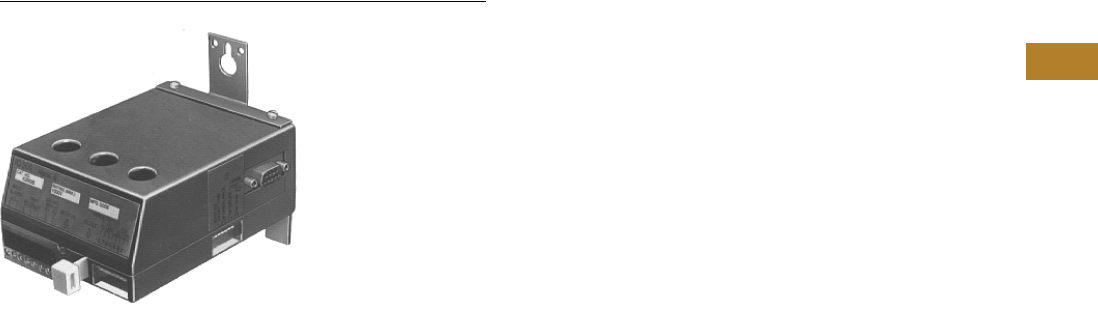
Volume 5—Motor Control and Protection CA08100006E—August 2014 www.eaton.com V5-T2-141
2
2
2
2
2
2
2
2
2
2
2
2
2
2
2
2
2
2
2
2
2
2
2
2
2
2
2
2
2
2
2.3
NEMA Contactors and Starters
A200 Series
Relays—Current Sensing Protective
Contents
Description Page
Contactors—Non-Reversing and Reversing . . . . . . V5-T2-101
Starters—Non-Reversing and Reversing . . . . . . . . V5-T2-107
Relays—Thermal and Fast Trip . . . . . . . . . . . . . . . . V5-T2-128
Thermal Type B, Class 20, Manual Reset . . . . . . . . V5-T2-130
Thermal Type A, Class 20, Auto/Manual Reset . . . V5-T2-133
Type FT Fast Trip, Class 10 . . . . . . . . . . . . . . . . . . . V5-T2-136
Heater Selection. . . . . . . . . . . . . . . . . . . . . . . . . . . V5-T2-139
Relays—Current Sensing Protective
Features. . . . . . . . . . . . . . . . . . . . . . . . . . . . . . . V5-T2-142
Standards and Certifications . . . . . . . . . . . . . . . V5-T2-142
Product Selection . . . . . . . . . . . . . . . . . . . . . . . V5-T2-142
Dimensions . . . . . . . . . . . . . . . . . . . . . . . . . . . . V5-T2-143
Relays—Current Sensing Protective
Product Description
The IQ500 is a heaterless,
current-sensing, solid-state
motor protective relay with
optional communications
capabilities. Several functions
are incorporated into the base
relay (IQ502/IQ504) as
standard:
●Overload (overcurrent)
protection
●Phase unbalance and
phase loss protection
●Ground current protection
(Class II)
The base relay can serve as
the initial building block for a
motor protection system by
adding the IQ500M Special
Function Module. The
module can address
application related motor load
functions with the additional
features:
●Underload protection
●Long acceleration
●Jam protection
●Load control
The IQ500 can provide a cost-
effective alternative to
conventional protective relays
such as current relays,
ground fault relays and phase
loss or phase unbalance
relays. Used with the
PowerNet system, a low-
cost, local area
communication network,
information such as current
values, status, setpoint
values and cause of trip can
be displayed remotely. The
IQ500 relay is ideal for a
variety of industrial
applications such as mining,
timber, material handling, air
conditioning compressors,
wastewater treatment plants
and petrochemical industries.

V5-T2-142 Volume 5—Motor Control and Protection CA08100006E—August 2014 www.eaton.com
2
2
2
2
2
2
2
2
2
2
2
2
2
2
2
2
2
2
2
2
2
2
2
2
2
2
2
2
2
2
2.3
NEMA Contactors and Starters
A200 Series
Features
●Overload class is
adjustable using DIP
switches for 5, 10, 20 or 30
seconds, maximum trip
times at six times rated
current
●Designed for 1000V and
less distribution systems
●Form C (NO/NC) contact on
output relay
●Isolated alarm relay output
contact
●Communications capability
using IMPACC network
●Manual or automatic reset
(either a true manual or
remote electrical reset)—
selectable
●Overload, Class II ground
current, phase unbalance
and single-phase
protection are standard
●LED indication (bi-
colored—red/green) for
device status, including
overload, phase unbalance
or ground current trip
●Special Function Module
adds protection for
underload and jam
conditions, also provides
for long acceleration
●Optional load control
feature available with
special function module
●Feed-through current
transformer windows for
contactors, NEMA Sizes 1–
4 (for Size 5 and larger,
external current
transformers can be used)
●Fits mounting footprint of
Eaton’s MORA relay
●Panel or starter mountable
●Cause of trip is held in
memory through a power
loss
●Bell alarm contact available
for remote status
indication
●DIP switch provided for
setting operating
frequency—50 or 60 Hz
●Plug-in terminal block for
control power, trip relay
and bell alarm relay
connections
●Operating temperature:
–20° to 60°C (–4° to 140°F)
Benefits
●No external current
transformers are required
since they are internal to
the IQ500
●DIP switches used to
select functions and
settings on base relay are
clearly marked and covered
with screw-on plastic
covers
●On the automatic reset,
the reset times can be
selected for long (90
second) or short (10
second) delay
●Device can be set for
different motor full load
currents without additional
parts or modules
Optional Benefits
●With the addition of the
IQ500M Special Function
Module, the enhanced
protection includes jam
(overtorque) and underload
and provides long
acceleration time (high
inertia load)
●The underload and jam
protection functions each
have independent Form C
output relays as part of the
module. In addition, the
underload and jam
functions each have their
own LEDs for status
indication
●The underload and jam
functions also have
separate selectable trip
levels and adjustable trip-
delay and start-delay
settings
●The IQ500M can be used
as a load control module
that allows “shedding and
restoring” a particular load
that contributes to the load
being monitored
●The PONI (Product
Operated Network
Interface) card attaches
directly to the base relay or
special function module for
interfacing with the Eaton’s
PowerNet communications
system
●Localized display can be
achieved with the Central
Monitoring Unit
Standards and Certifications
●UL File No. E19223
Product Selection
Current Sensing Protective Relay
Note
1 Can be used with external CTs having 5A secondary.
Maximum Horsepower Control Voltage
200V 230V 460–475V
Ampere
Rating
110/120V 50/60 Hz
Catalog Number
220/240V 50/60 Hz
Catalog Number
20 25 50 3.4–66A IQ502A IQ502B
60 75 150 10.8–207A IQ504A IQ504B
— — — 0.32–5.4A IQ500LA 1IQ500LB 1
Special function module IQ500M IQ500M
IQ502A
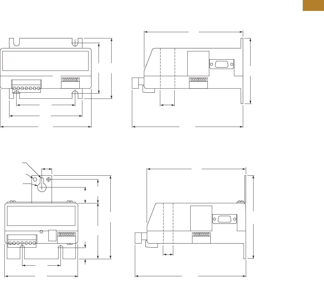
Volume 5—Motor Control and Protection CA08100006E—August 2014 www.eaton.com V5-T2-143
2
2
2
2
2
2
2
2
2
2
2
2
2
2
2
2
2
2
2
2
2
2
2
2
2
2
2
2
2
2
2.3
NEMA Contactors and Starters
A200 Series
Dimensions
Approximate Dimensions in Inches (mm)
Current Sensing Protective Relays
IQ504
IQ500L and IQ502
2.5
(63.5)
2.88
(73.2)
3.0
(76.2) 3.25
(82.6)
3.59
(91.2)
4.5
(114.3)
4.88
(124.0)
0.81
(20.6)
Dia.
5.47
(138.9)
0.53
(13.5)
1.88
(47.8)
2.75
(69.9)
0.78
(19.8)
1.19
(30.2)
4.13
(104.9)
4.13
(104.9)
3.59
(91.2)
4.88
(124.0)
0.5
(12.7)
0.44 (11.2)
Dia.
0.164-32 Tap
2 Holes
0.19 (4.8)
Dia.
0.5
(12.7)
Dia.
5.47
(138.9)

V5-T2-144 Volume 5—Motor Control and Protection CA08100006E—August 2014 www.eaton.com
2
2
2
2
2
2
2
2
2
2
2
2
2
2
2
2
2
2
2
2
2
2
2
2
2
2
2
2
2
2
2.4
NEMA Contactors and Starters
Solenoids—Alternating Current
Solenoids—Alternating Current
Contents
Description Page
Solenoids—Alternating Current
Product Selection . . . . . . . . . . . . . . . . . . . . . . . V5-T2-145
Dimensions. . . . . . . . . . . . . . . . . . . . . . . . . . . . V5-T2-146
Product Description
Solenoids from Eaton’s
Electrical Sector are used for
a wide variety of applications
where straight line motion is
to be obtained automatically
or at a remote point.
Features
●Plunger and frame are
machined to ensure
quiet operation
●Push- and pull-type
operation
●With and without
terminal box
●Plunger provided with
connecting pin
●Size C and D solenoids
are provided with special
bearing to minimize
wear in clevis under
severe service

Volume 5—Motor Control and Protection CA08100006E—August 2014 www.eaton.com V5-T2-145
2
2
2
2
2
2
2
2
2
2
2
2
2
2
2
2
2
2
2
2
2
2
2
2
2
2
2
2
2
2
2.4
NEMA Contactors and Starters
Solenoids—Alternating Current
Product Selection
When Ordering Specify
●Catalog number
AC Solenoids—60 Hz, Continuous Duty
Notes
1 Mounting of solenoids “with conduit box”—Size A are for wall mounting—Size B, C and D are for floor mounting.
2 Recommended selection of solenoids on basis of 85% voltage values.
3 Part numbers are now obsolete.
Size Volt.
Operating Data 1
Without
Conduit Box
Floor Mtg.
Catalog
Number
Wall Mtg.
Catalog
Number
With
Conduit Box
Mtg. 2
Catalog
Number
Magnetic Force in Lbs
Max.
Stroke in
Inches (mm)
Current
Horizontal Position With Gravity Against Gravity
At 100%
Voltage
At 85%
Voltage
At 100%
Voltage
At 85%
Voltage
At 100%
Voltage
At 85%
Voltage Inrush Sealed
60 Hertz Pull Type
A 110 0.72 0.50 0.90 0.68 0.55 0.33 1 (25.4) 1.83 0.34 — 10370H1 10370H610
220 0.72 0.50 0.90 0.68 0.55 0.33 1 (25.4) 0.92 0.17 — 10370H2 10370H611
440 0.72 0.50 0.90 0.68 0.55 0.33 1 (25.4) 0.45 0.08 — 10370H3 10370H612
B 110 4.2 3 4.5 3.3 3.9 2.7 1 (25.4) 5.4 0.87 10370H57 10370H694 10370H69
220 4.2 3 4.5 3.3 3.9 2.7 1 (25.4) 2.6 0.42 10370H58 10370H696 10370H70
440 4.2 3 4.5 3.3 3.9 2.7 1 (25.4) 1.29 0.20 10370H59 10370H697 10370H71
C 110 7 5.25 8 6.25 6 4.25 1.25 (31.8) 10.4 1.07 10370H244 — 10370H256
220 7 5.25 8 6.25 6 4.25 1.25 (31.8) 5.2 0.52 10370H245 — 10370H257
440 7 5.25 8 6.25 6 4.25 1.25 (31.8) 2.5 0.26 10370H246 — 10370H258
D 110 12.4 10 13.65 11.25 11.15 8.75 1.25 (31.8) 18 1.58 10370H356 10370H814 10370H368
220 12.4 10 13.65 11.25 11.15 8.75 1.25 (31.8) 9.3 0.81 10370H357 10370H816 10370H369
440 12.4 10 13.65 11.25 11.15 8.75 1.25 (31.8) 4.4 0.40 10370H358 10370H817 10370H370
60 Hertz Push Type
A 110 0.72 0.50 0.90 0.68 0.55 0.33 1 (25.4) 1.83 0.34 — 10370H13 10370H25
220 0.72 0.50 0.90 0.68 0.55 0.33 1 (25.4) 0.92 0.17 — 10370H14 310370H26
440 0.72 0.50 0.90 0.68 0.55 0.33 1 (25.4) 0.45 0.08 — 10370H15 10370H27
B 110 4.2 3 4.5 3.3 3.9 2.7 1 (25.4) 5.4 0.87 10370H81 10370H708 10370H93
220 4.2 3 4.5 3.3 3.9 2.7 1 (25.4) 2.6 0.42 10370H82 10370H710 10370H94
440 4.2 3 4.5 3.3 3.9 2.7 1 (25.4) 1.29 0.20 10370H83 10370H711 10370H95
C 110 7 5.25 8 6.25 6 4.25 1.25 (31.8) 10.4 1.07 10370H268 — 10370H280
220 7 5.25 8 6.25 6 4.25 1.25 (31.8) 5.2 0.52 — 10370H774 10370H281
440 7 5.25 8 6.25 6 4.25 1.25 (31.8) 2.5 0.26 — 10370H775 10370H282
D 110 12.4 10 13.65 11.25 11.15 8.75 1.25 (31.8) 18 1.58 10370H380 10370H828 310370H392
220 12.4 10 13.65 11.25 11.15 8.75 1.25 (31.8) 9.3 0.81 10370H381 10370H830 310370H393
440 12.4 10 13.65 11.25 11.15 8.75 1.25 (31.8) 4.4 0.40 10370H382 10370H831 310370H394
10370
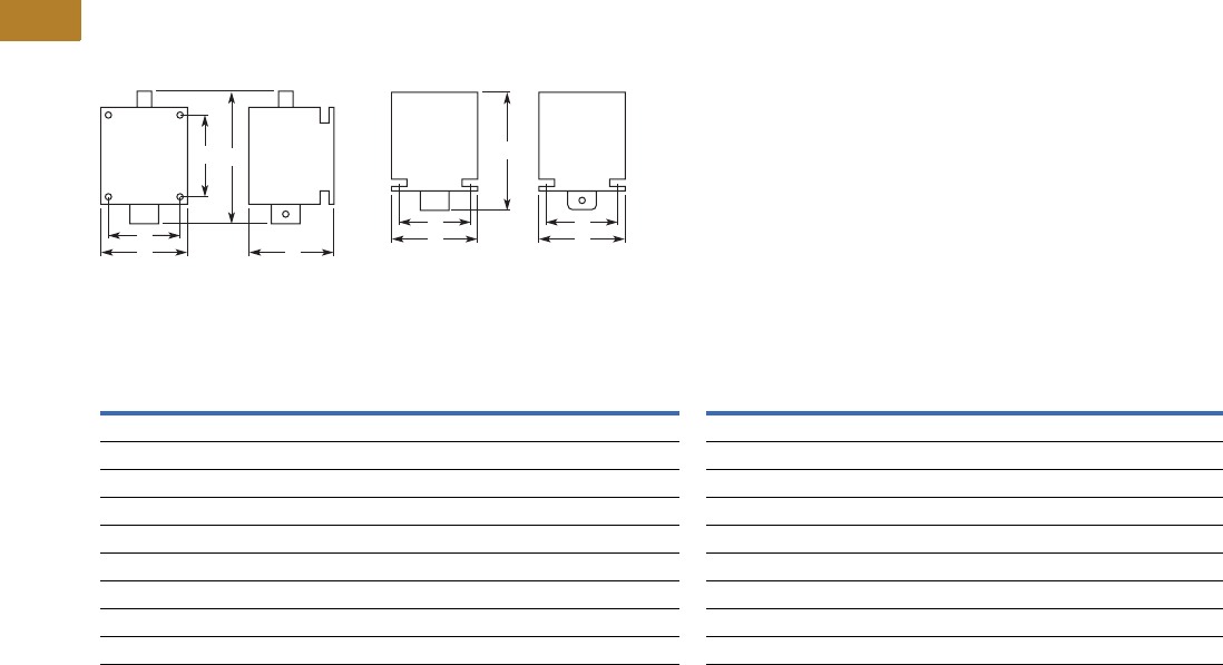
V5-T2-146 Volume 5—Motor Control and Protection CA08100006E—August 2014 www.eaton.com
2
2
2
2
2
2
2
2
2
2
2
2
2
2
2
2
2
2
2
2
2
2
2
2
2
2
2
2
2
2
2.4
NEMA Contactors and Starters
Solenoids—Alternating Current
Dimensions
Approximate Dimensions in Inches (mm)
AC Solenoids
Wall Mounted Floor Mounted
Dimensions and Shipping Weights
Note
1In sealed state.
D
A
B
C
E
D
A
E
C
B
Size
Push Type Mounting Shipping
Weight
Lbs (kg)
Pull Type Mounting Shipping
Weight
Lbs (kg)
Wide
A
High
B 1
Deep
CDE
Wide
A
High
B 1
Deep
CDE
Wall Mounted
A 2.38 (60.5) 3.63 (92.2) 2.25 (57.2) 1.13 (28.7) 1.63 (41.4) 2.0 (0.9) 2.38 (60.5) 2.63 (66.8) 2.25 (57.2) 1.13 (28.7) 1.63 (41.4) 2.0 (0.9)
B 2.63 (66.8) 4.88 (124.0) 3.00 (76.2) 2.00 (50.8) 2.13 (54.1) 2.5 (1.1) 2.63 (66.8) 3.63 (92.2) 3.00 (76.2) 2.00 (50.8) 2.13 (54.1) 2.5 (1.1)
C 3.00 (76.2) 6.13 (155.7) 4.13 (104.9) 2.38 (60.5) 3.13 (79.5) 5.0 (2.3) 3.00 (76.2) 4.88 (124.0) 4.13 (104.9) 2.38 (60.5) 3.13 (79.5) 5.0 (2.3)
D 4.00 (101.6) 6.13 (155.7) 4.13 (104.9) 2.75 (69.9) 3.13 (79.5) 7.0 (3.2) 4.00 (101.6) 4.88 (124.0) 4.13 (104.9) 2.75 (69.9) 3.13 (79.5) 7.0 (3.2)
Floor Mounted
B 3.13 (79.5) 4.88 (124.0) 3.00 (76.2) 1.50 (38.1) 2.25 (57.2) 2.5 (1.1) 3.13 (79.5) 3.88 (98.6) 3.00 (76.2) 1.50 (38.1) 2.25 (57.2) 2.5 (1.1)
C 3.50 (88.9) 6.13 (155.7) 3.75 (95.3) 1.75 (44.5) 3.13 (79.5) 5.0 (2.3) 3.50 (88.9) 4.88 (124.0) 3.75 (95.3) 1.75 (44.5) 3.13 (79.5) 5.0 (2.3)
D 3.88 (98.6) 6.13 (155.7) 3.75 (95.3) 2.25 (57.2) 3.13 (79.5) 7.0 (3.2) 3.88 (98.6) 4.88 (124.0) 3.75 (95.3) 2.25 (57.2) 3.13 (79.5) 7.0 (3.2)
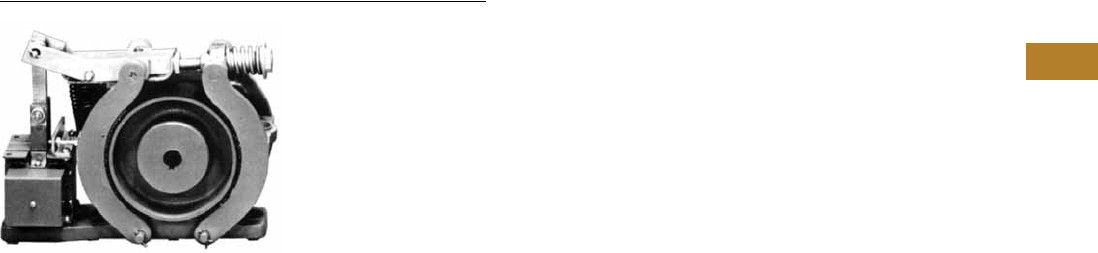
Volume 5—Motor Control and Protection CA08100006E—August 2014 www.eaton.com V5-T2-147
2
2
2
2
2
2
2
2
2
2
2
2
2
2
2
2
2
2
2
2
2
2
2
2
2
2
2
2
2
2
2.5
NEMA Contactors and Starters
Shoe Brakes—AC and DC Magnetic
Shoe Brakes—AC and DC, 511 Series
Contents
Description Page
Shoe Brakes—AC and DC Magnetic
Product Selection . . . . . . . . . . . . . . . . . . . . . . . V5-T2-148
Dimensions . . . . . . . . . . . . . . . . . . . . . . . . . . . V5-T2-150
Product Description
Type S Brakes from
Eaton’s Electrical Sector
are electrically released and
spring applied providing
“fail-safe” operation. The
retarding torque developed
is directly proportional to the
spring pressure.
Application Description
●Conveyors
●Machine tools
●Printing presses
●Small cranes
●Overhead doors
●Dumb waiters
●Vacuum molding machines
●Carnival rides
Features
The brake wheel is of
relatively large size in relation
to the torque developed by
the brake. This permits use of
a larger brake shoe lining and
lower shoe pressures. Low
shoe pressure, equally
distributed over a large lining
area, results in even wear of
the friction surfaces and even
braking torque. The oversize
wheel type construction also
permits use of a smaller
operating solenoid that
requires less current for a
given torque rating.
DC Brakes
Standard DC brakes are
equipped with shunt coils.
The magnet coil circuit on
DC brakes consists of two
separate windings and a
protective switch.
Mounting
Type S brakes are designed
and recommended for use
and mounting only in the
horizontal position. Side or
vertical mountings are not
recommended because the
solenoid loading is altered,
resulting in accelerated wear
and premature coil failure.
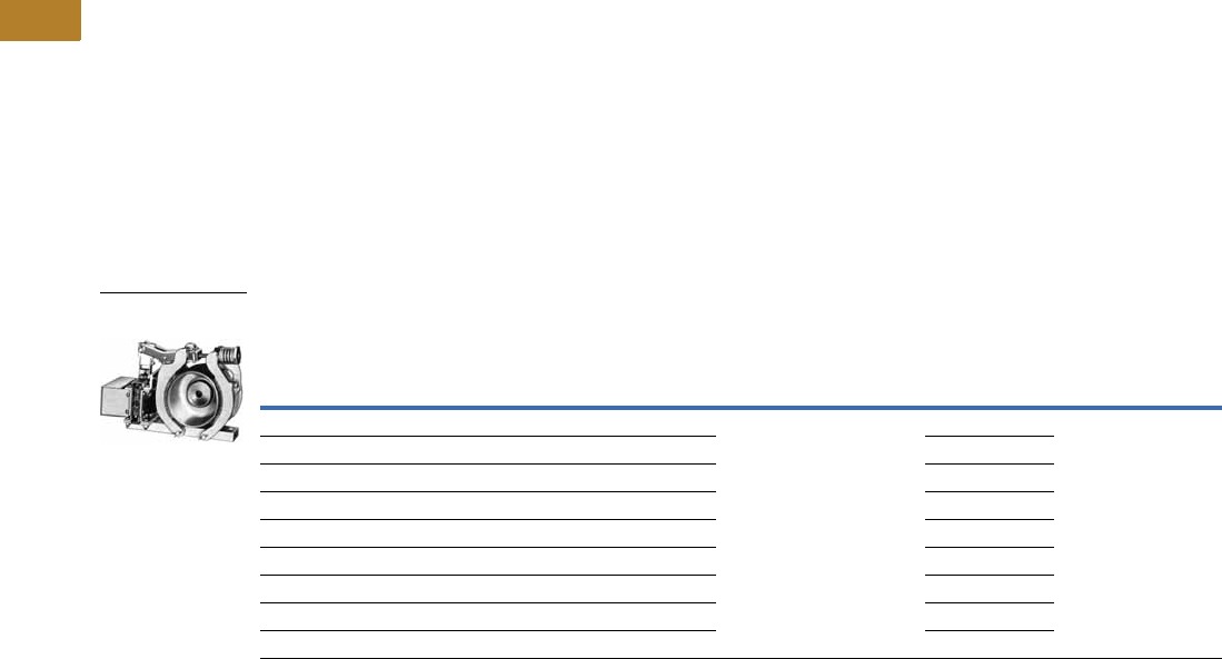
V5-T2-148 Volume 5—Motor Control and Protection CA08100006E—August 2014 www.eaton.com
2
2
2
2
2
2
2
2
2
2
2
2
2
2
2
2
2
2
2
2
2
2
2
2
2
2
2
2
2
2
2.5
NEMA Contactors and Starters
Shoe Brakes—AC and DC Magnetic
Product Selection
When Ordering Specify
●Brake
●Catalog number plus
suffix number for coil
●Example: 511H1193-41
●Wheel
●Catalog number plus
suffix number for
bore size
●Example: 511H1150-3
Type S Brakes—Floor Mounting
Notes
1 Intermittent duty indicates that the coil can be placed across the line continuously for one hour maximum without excessive heating. It is equivalent to 1/2 time ON
and 1/2 time OFF.
2 Add suffix number for coil voltage to base catalog number.
3 Does not include wheel.
Torque—lb-ft
Brake
Size
AC DC
Continuous Intermittent 1
Base
Catalog
Number 23
For Type S4, S5-1/2, S7, S10 Base
Catalog
Number 23
Coil
Voltage
Coil
Suffix 2
Coil Volts
and Hertz
Coil
Suffix 2
3 3 S-4 511H1194 120V 60 Hz
208V 60 Hz
240V 60 Hz
480V 60 Hz
600V 60 Hz
110V 50 Hz
220V 50 Hz
380V 50 Hz
440V 50 Hz
550V 50 Hz
-39
-45
-40
-41
-58
-5
-6
-7
-8
-9
511H955 120 Vdc
240 Vdc
-97
-98
10 10 S-4 511H1193 511H956
—15 S-4511H1192 511H957
25 25 S-5-1/2 511H992 511H994
— 35 S-5-1/2 511H993 511H995
50 50 S-7 511H970 511H975
—75 S-7511H971 511H976
85 85 S-7 511H1195 511H1197
— 110 S-7 511H1196 511H1198
Size S-4 Brake
and Wheel

Volume 5—Motor Control and Protection CA08100006E—August 2014 www.eaton.com V5-T2-149
2
2
2
2
2
2
2
2
2
2
2
2
2
2
2
2
2
2
2
2
2
2
2
2
2
2
2
2
2
2
2.5
NEMA Contactors and Starters
Shoe Brakes—AC and DC Magnetic
Brake Selection
The method most generally used to determine required
braking torque is to calculate the full load motor torque by
the following formula:
T = 5252 x hp
rpm
T = Full load motor torque in lb-ft
hp = Motor horsepower
rpm = Speed of shaft on which brake wheel is mounted
The torque rating of the brake selected should be at least equal
to the full load motor torque for the duty considered.
Brake Wheels
Brake Wheel Suffix Numbers
Notes
1Bore tolerance: +0.000–0.001 in.
2Taper is at rate of 1.25 in per ft on diameter. In bore size selection, use diameter of tapered shaft. Bore tolerance: +0.000–0.005 in.
3Add suffix number for bore size to base catalog number.
4Bore size selected must be between minimum and maximum dimensions listed in brake wheel selection table.
Wheel
Size in
Inches
Min.
Bore in
Inches (mm)
Max.
Bore in
Inches (mm)
Pilot
Bore in
Inches (mm) WK2
Straight
Bore 1
Tapered
Bore 2
Base 3
Catalog
Number
Base 3
Catalog
Number
4.0 0.50 (12.7) 1.38 (35.1) 0.50 (12.7) 0.06 511H1150 511H1151
5.5 0.75 (19.1) 2.00 (50.8) 0.75 (19.1) 0.26 511H1160 511H1161
7.0 1.00 (25.4) 2.25 (57.2) 0.75 (19.1) 0.77 511H1170 511H1171
Bore Size Suffix Number—Add to Base Catalog Number
Bore 4 in Inches (mm) Keyway in Inches Suffix Number Bore 4 in Inches (mm) Keyway in Inches (mm) Suffix Number
Standard Bore Sizes
Pilot bore None -1 1.625 (41.28) 3/38 x 3/16 -9
0.625 (15.88) 3/16 x 3/32 -2 1.875 (47.63) 1/2 x 1/4 -10
0.750 (19.05) 3/16 x 3/32 -3 2.125 (53.98) 1/2 x 1/4 -11
0.875 (22.23) 3/16 x 3/32 -4 2.375 (60.33) 5/8 x 5/16 -12
1.000 (25.40) 1/4 x 1/8 -5 2.500 (63.50) 5/8 x 5/16 -63
1.125 (28.58) 1/4 x 1/8 -6 2.625 (66.68) 5/8 x 5/16 -13
1.250 (31.75) 1/4 x 1/8 -7 2.750 (69.85) 5/8 x 5/16 -18
1.375 (34.93) 5/16 x 5/32 -8 2.875 (73.03) 3/4 x 3/8 -14
Non-Standard Bore Sizes
0.500 (12.70) 1/8 x 1/16 -50 1.687 (42.85) 3/8 x 3/16 -58
0.750 (19.05) 1/4 x 1/8 -51 1.750 (44.45) 3/8 x 3/16 -59
0.875 (22.23) 1/4 x 1/8 -52 1.937 (49.20) 1/2 x 1/4 -60
1.000 (25.40) 5/16 x 5/32 -53 2.000 (50.80) 1/2 x 1/4 -61
1.187 (30.15) 1/4 x 1/8 -54 2.250 (57.15) 1/2 x 1/4 -62
1.375 (34.93) 3/8 x 3/16 -55 —— —
1.437 (36.50) 3/8 x 3/16 -56 —— —
1.500 (38.10) 3/8 x 3/16 -57 —— —
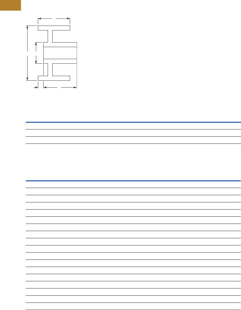
V5-T2-150 Volume 5—Motor Control and Protection CA08100006E—August 2014 www.eaton.com
2
2
2
2
2
2
2
2
2
2
2
2
2
2
2
2
2
2
2
2
2
2
2
2
2
2
2
2
2
2
2.5
NEMA Contactors and Starters
Shoe Brakes—AC and DC Magnetic
Dimensions
Approximate Dimensions in Inches (mm)
Standard Brake Wheels
Standard Brake Wheel Dimensions
Approximate Shipping Weights
Note
1Hub lengths other than standard are not available.
AZW
1XY
Bore
Max. Min.
4.00 (101.6) 2.75 (69.9) 1.63 (41.4) 1.38 (35.1) 2.50 (63.5) 1.38 (35.1) 0.50 (12.7)
5.50 (139.7) 3.25 (82.6) 2.00 (50.8) 1.63 (41.4) 3.25 (82.6) 2.00 (50.8) 0.75 (19.1)
7.00 (177.8) 4.25 (108.0) 3.00 (76.2) 1.25 (31.8) 4.00 (101.6) 2.25 (57.2) 1.00 (25.4)
Brake Size
Torque Rating
ft-lb
Weight in Lbs (kg)
Net —
Brake with Wheel
Net —
Wheel Only
Boxed —
Brake with Wheel
Type “S” AC Shoe Brakes
S-4 3 15.8 (7.2) 3.4 (1.5) 17.0 (7.7)
S-4 10 15.8 (7.2) 3.4 (1.5) 17.0 (7.7)
S-4 15 15.8 (7.2) 3.4 (1.5) 17.0 (7.7)
S-5-1/2 25 33.2 (15.1) 7.5 (3.4) 36.0 (16.3)
S-5-1/2 35 33.2 (15.1) 7.5 (3.4) 36.0 (16.3)
S-7 50 52.1 (23.7) 18.8 (8.5) 55.0 (25.0)
S-7 75 52.1 (23.7) 18.8 (8.5) 55.0 (25.0)
Type “S” DC Shoe Brakes
S-4 3 18.0 (8.2) 3.4 (1.5) 20.0 (9.1)
S-4 10 18.0 (8.2) 3.4 (1.5) 20.0 (9.1)
S-4 15 18.0 (8.2) 3.4 (1.5) 20.0 (9.1)
S-5-1/2 25 35.0 (15.9) 7.5 (3.4) 38.0 (17.3)
S-5-1/2 35 35.0 (15.9) 7.5 (3.4) 38.0 (17.3)
S-7 50 54.0 (24.5) 18.8 (8.5) 58.0 (26.3)
S-7 75 54.0 (24.5) 18.8 (8.5) 58.0 (26.3)
S-7 85 54.0 (24.5) 18.8 (8.5) 58.0 (26.3)
S-7 110 54.0 (24.5) 18.8 (8.5) 58.0 (26.3)
W
Z
X
AY
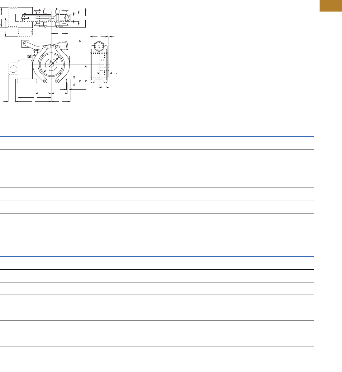
Volume 5—Motor Control and Protection CA08100006E—August 2014 www.eaton.com V5-T2-151
2
2
2
2
2
2
2
2
2
2
2
2
2
2
2
2
2
2
2
2
2
2
2
2
2
2
2
2
2
2
2.5
NEMA Contactors and Starters
Shoe Brakes—AC and DC Magnetic
Approximate Dimensions in Inches (mm)
Type S4, S5-1/2 and S7 Solenoid Operated
Type “S” AC Shoe Brakes
Type “S” DC Shoe Brakes
Note
1Open type brake only.
Brake
Size
Torque
Rating
ft-lb A B 1CDEFGHJKLMNOPQR
S-4 3 4.00
(101.6)
2.88
(73.2)
7.50
(190.5)
2.63
(66.8)
1.25
(31.8)
7.50
(190.5)
3.13
(79.5)
0.38
(9.7)
0.63
(16.0)
2.88
(73.2)
0.25
(6.4)
2.75
(69.9)
1.63
(41.4)
1.63
(41.4)
2.88
(73.2)
3.00
(76.2)
3.13
(79.5)
S-4 10 4.00
(101.6)
2.88
(73.2)
7.50
(190.5)
2.63
(66.8)
1.25
(31.8)
7.50
(190.5)
3.13
(79.5)
0.38
(9.7)
0.63
(16.0)
2.88
(73.2)
0.25
(6.4)
2.75
(69.9)
1.63
(41.4)
1.63
(41.4)
2.88
(73.2)
3.00
(76.2)
3.13
(79.5)
S-4 15 4.00
(101.6)
2.88
(73.2)
7.50
(190.5)
2.63
(66.8))
1.25
(31.8)
7.50
(190.5)
3.13
(79.5)
0.38
(9.7)
0.63
(16.0)
2.88
(73.2)
0.25
(6.4)
2.75
(69.9)
1.63
(41.4)
1.63
(41.4)
2.88
(73.2)
3.00
(76.2)
3.13
(79.5))
S-5-1/2 25 5.50
(139.7)
4.00
(101.6)
9.50
(241.3)
3.50
(88.9)
2.00
(50.8)
8.38
(212.9)
4.13
(104.9)
0.44
(11.2)
1.00
(25.4)
4.88
(124.0)
0.38
(9.7)
3.25
(82.6)
2.00
(50.8)
2.00
(50.8)
3.13
(79.5)
3.75
(95.3)
3.13
(79.5)
S-5-1/2 35 5.50
(139.7)
4.00
(101.6)
9.50
(241.3)
3.50
(88.9)
2.00
(50.8)
8.38
(212.9)
4.13
(104.9)
0.44
(11.2)
1.00
(25.4)
7.88
(200.2)
0.38
(9.7)
3.25
(82.6)
2.00
(50.8)
2.00
(50.8)
3.13
(79.5)
3.75
(95.3)
3.13
(79.5)
S-7 50 7.00
(177.8)
5.00
(127.0)
11.50
(292.1)
4.38
(111.3)
2.50
(63.5)
9.50
(241.3)
5.00
(127.0)
0.56
(14.2)
1.00
(25.4)
6.00
(152.4)
—4.25
(108.0)
2.13
(54.1)
3.00
(76.2)
3.13
(79.5)
4.75
(120.7)
3.13
(79.5)
S-7 75 7.00
(177.8)
5.00
(127.0)
11.50
(292.1)
4.38
(111.3)
2.50
(63.5)
9.50
(241.3)
5.00
(127.0)
0.56
(14.2)
1.00
(25.4)
6.00
(152.4)
—4.25
(108.0)
2.13
(54.1)
3.00
(76.2)
3.13
(79.5)
4.75
(120.7)
3.13
(79.5)
Brake
Size
Torque
Rating
ft-lb A B 1CDEFGHJKL MNOPQR
S-4 3 4.00
(101.6)
3.50
(88.9)
8.00
(203.2)
2.63
(66.8)
1.25
(31.8)
7.56
(192.0)
3.25
(82.6)
0.38
(9.7)
0.75
(19.1)
2.88
(73.2)
0.25
(6.4)
2.75
(69.9)
1.63
(41.4)
1.63
(41.4)
2.63
(66.8)
3.00
(76.2))
4.06
(103.1)
S-4 10 4.00
(101.6)
3.50
(88.9)
8.00
(203.2)
2.63
(66.8)
1.25
(31.8)
7.56
(192.0)
3.25
(82.6)
0.38
(9.7)
0.75
(19.1)
2.88
(73.2)
0.25
(6.4)
2.75
(69.9)
1.63
(41.4)
1.63
(41.4)
2.63
(66.8)
3.00
(76.2)
4.06
(103.1))
S-4 15 4.00
(101.6)
3.50
(88.9)
8.00
(203.2)
2.63
(66.8)
1.25
(31.8)
7.56
(192.0)
3.25
(82.6))
0.38
(9.7)
0.75
(19.1)
2.88
(73.2)
.25
(6.4)
2.75
(69.9)
1.63
(41.4)
1.63
(41.4)
2.63
(66.8)
3.00
(76.2)
4.06
(103.1)
S-5-1/2 25 5.50
(139.7)
4.00
(101.6)
9.50
(241.3)
3.50
(88.9)
2.00
(50.8)
8.38
(212.9)
4.13
(104.9)
0.44
(11.2)
0.75
(19.1)
4.88
(124.0)
0.38
(9.7)
3.25
(82.6)
2.00
(50.8)
2.00
(50.8)
2.88
(73.2)
3.75
(95.3)
4.06
(103.1)
S-5-1/2 35 5.50
(139.7)
4.00
(101.6)
9.50
(241.3)
3.50
(88.9)
2.00
(50.8)
8.38
(212.9)
4.13
(104.9)
0.44
(11.2)
0.75
(19.1)
4.88
(124.0)
0.38
(9.7)
3.25
(82.6)
2.00
(50.8)
2.00
(50.8)
2.88
(73.2)
3.75
(95.3)
4.06
(103.1)
S-7 50 7.00
(177.8)
5.00
(127.0)
11.50
(292.1)
4.38
(111.3)
2.50
(63.5)
9.50
(241.3)
5.00
(127.0)
0.56
(14.2)
0.75
(19.1)
6.00
(152.4)
—4.25
(108.0)
2.13
(54.1)
3.00
(76.2)
2.88
(73.2)
4.88
(124.0)
4.06
(103.1)
S-7 75 7.00
(177.8)
5.00
(127.0)
11.50
(292.1)
4.38
(111.3)
2.50
(63.5)
9.50
(241.3)
5.00
(127.0)
0.56
(14.2)
0.75
(19.1)
6.00
(152.4)
—4.25
(108.0)
2.13
(54.1)
3.00
(76.2)
2.88
(73.2)
4.88
(124.0)
4.06
(103.1)
S-7 85 7.00
(177.8)
5.00
(127.0)
11.50
(292.1)
4.38
(111.3)
2.50
(63.5)
9.50
(241.3)
5.00
(127.0)
0.56
(14.2)
0.75
(19.1)
6.00
(152.4)
—4.25
(108.0)
2.13
(54.1)
3.00
(76.2)
2.88
(73.2)
4.88
(124.0)
4.06
(103.1)
S-7 110 7.00
(177.8)
5.00
(127.0)
11.50
(292.1)
4.38
(111.3)
2.50
(63.5)
9.50
(241.3)
5.00
(127.0)
0.56
(14.2)
0.75
(19.1)
6.00
(152.4)
—4.25
(108.0)
2.13
(54.1)
3.00
(76.2)
2.88
(73.2)
4.88
(124.0)
4.06
(103.1)
F
T
D D
K
N
ML
(2) “H” Dia. Holes
for Mounting
Hub
Length
C
BO
Q
R
P
J
EU
GS
A

V5-T2-152 Volume 5—Motor Control and Protection CA08100006E—August 2014 www.eaton.com
2
2
2
2
2
2
2
2
2
2
2
2
2
2
2
2
2
2
2
2
2
2
2
2
2
2
2
2
2
2
2.6
NEMA Contactors and Starters
Reference Data
Reference Data
IEC Utilization Categories
(See also IEC/EN 60947-1;
2.1.18/IEV 441-17-19)
A combination of specified
requirements relating to the
condition in which the
switching device or fuse
fulfills its purpose and
selected to represent a
characteristic group of real-
life applications. The
specified requirements may,
for example, relate to the
values of making and
breaking capacity and other
characteristic values, data
concerning associated
circuits and the applicable
conditions of use and
operational behavior.
Used in Technical Data and Formulas
Code Descriptions Code Descriptions
DF Duty factory Irmv Response value of short-time delayed short-circuit release
IDn Response value of earth-fault release Isd Response value of short-time delayed short-circuit release
Icm Rated short-circuit making capacity ITResponse value of earth-fault release
Icn Rated short-circuit breaking capacity IgResponse value of earth-fault release
Ics Rated service short-circuit breaking capacity Ith Conventional free air thermal current
Icu Rated ultimate short-circuit breaking capacity Ithe Conventional thermal current of enclosed devices
Icw Rated short-time withstand current IuRated uninterrupted current
IeRated operational current SNT Transformer rating
IkTransformer initial short-circuit AC current trTime delay of overload release response
ILLoad monitoring response value tTTime delay of earth-fault release response
InRated current tgTime delay of earth-fault release response
INT Transformer rated current tvTime delay of short-circuit release response
IPK Rated peak withstand current UcRated actuating voltage
IqRated conditional short-circuit current UeRated operational voltage
IrOvercurrent release set value UiRated insulation voltage
Irm Response value of non-delayed short-circuit release Uimp Rated impulse withstand voltage
IiResponse value of non-delayed short-circuit release UkTransformer short-circuit voltage
Irmf Response value of fixed, non-delayed short-circuit release UsRated control voltage

Volume 5—Motor Control and Protection CA08100006E—August 2014 www.eaton.com V5-T2-153
2
2
2
2
2
2
2
2
2
2
2
2
2
2
2
2
2
2
2
2
2
2
2
2
2
2
2
2
2
2
2.6
NEMA Contactors and Starters
Reference Data
Annex A (informative)
Examples of Utilization Categories for Low-Voltage Switchgear and Controlgear 1
Notes
160947-1 © IEC: 2004.
2Plugging is understood to be stopping or reversing the motor rapidly by reversing motor primary connections while the motor is running.
3Inching is understood to be energizing a motor once or repeatedly for short periods to obtain small movements of the driven mechanism.
Category Typical Applications Relevant IEC Product Standard
Nature of Current—AC
AC-1 Non-inductive or slightly inductive loads, resistance furnaces 60947-4-1
AC-2 Slip-ring motors: starting, switching off 60947-4-1
AC-3 Squirrel-cage motors: starting, switching off motors during running 60947-4-1
AC-4 Squirrel-cage motors: starting, plugging 2, inching 360947-4-1
AC-5a Switching of electric discharge lamp controls 60947-4-1
AC-5b Switching of incandescent lamps 60947-4-1
AC-6a Switching of transformers 60947-4-1
AC-6b Switching of capacitor banks 60947-4-1
AC-7a Slightly inductive loads for household appliances and similar applications 61095
AC-7b Motor-loads for household applications 61095
AC-8a Hermetic refrigerant compressor motor control with manual resetting of overload releases 60947-4-1
AC-8b Hermetic refrigerant compressor motor control with automatic resetting of overload releases 60947-4-1
AC-12 Control of resistive loads and solid-state loads with isolation by optocouplers 60947-5-1
AC-12 Control of resistive loads and solid-state loads with optical isolation 60947-5-2
AC-13 Control of solid-state loads with transformer isolation 60947-5-1
AC-14 Control of small electromagnetic loads 60947-5-1
AC-15 Control of AC electromagnetic loads 60947-5-1
AC-20 Connecting and disconnecting under no-load conditions 60947-3
AC-21 Switching of resistive loads, including moderate overloads 60947-3
AC-22 Switching of mixed resistive and inductive loads, including moderate overloads 60947-3
AC-23 Switching of motor loads or other highly inductive loads 60947-3
AC-31 Non inductive or slightly inductive loads 60947-6-1
AC-33 Motor loads or mixed loads including motors, resistive loads and up to 30% incandescent lamp loads 60947-6-1
AC-35 Electric discharge lamp loads 60947-6-1
AC-36 Incandescent lamp loads 60947-6-1
AC-40 Distribution circuits comprising mixed resistive and reactive loads having a resultant inductive reactance 60947-6-2
AC-41 Non-inductive or slightly inductive loads, resistance furnaces 60947-6-2
AC-42 Slip-ring motors: starting, switching off 60947-6-2
AC-43 Squirrel cage motors: starting, switching off motors during running 60947-6-2
AC-44 Squirrel cage motors: starting, plugging 2, inching 360947-6-2
AC-45a Switching of electric discharge lamp controls 60947-6-2
AC-45b Switching of incandescent lamps 60947-6-2
AC-51 Non-inductive or slightly inductive loads, resistance furnaces 60947-4-3
AC-52a Control of slip ring motor stators: 8 h duty with on-load currents for start, acceleration, run 60947-4-2
AC-52b Control of slip ring motor stators: intermittent duty 60947-4-2
AC-53a Control of squirrel cage motors: 8 h duty with on-load currents for start, acceleration, run 60947-4-2
AC-53b Control of squirrel cage motors: intermittent duty 60947-4-2

V5-T2-154 Volume 5—Motor Control and Protection CA08100006E—August 2014 www.eaton.com
2
2
2
2
2
2
2
2
2
2
2
2
2
2
2
2
2
2
2
2
2
2
2
2
2
2
2
2
2
2
2.6
NEMA Contactors and Starters
Reference Data
Examples of Utilization Categories for Low-Voltage Switchgear and Controlgear, continued 1
Notes
160947-1 © IEC: 2004.
2Plugging is understood to be stopping or reversing the motor rapidly by reversing motor primary connections while the motor is running.
3Inching is understood to be energizing a motor once or repeatedly for short periods to obtain small movements of the driven mechanism.
Category Typical Applications Relevant IEC Product Standard
Nature of Current—AC, continued
AC-55a Switching of electric discharge lamp controls 60947-4-3
AC-55b Switching of incandescent lamps 60947-4-3
AC-56a Switching of transformers 60947-4-3
AC-56b Switching of capacitor banks 60947-4-3
AC-58a Control of hermetic refrigerant compressor motors with automatic resetting of overload releases: 8 h duty
with on-load currents for start, acceleration, run
60947-4-2
AC-58b Control of hermetic refrigerant compressor motors with automatic resetting of overload releases: intermittent duty 60947-4-2
AC-140 Control of small electromagnetic loads with holding (closed) current <0,2 A, for example contactor relays 60947-5-2
Nature of Current—AC and DC
A Protection of circuits, with no rated short-time withstand current 60947-2
B Protection of circuits, with a rated short-time withstand current 60947-2
Nature of Current—DC
DC-1 Non-inductive or slightly inductive loads, resistance furnaces 60947-4-1
DC-3 Shunt-motors: starting, plugging 2, inching 3, dynamic breaking of motors 60947-4-1
DC-5 Series-motors: starting, plugging 2, inching 3, dynamic breaking of motors 60947-4-1
DC-6 Switching of incandescent lamps 60947-4-1
DC-12 Control of resistive loads and solid-state loads with isolation by optocouplers 60947-5-1
DC-12 Control of resistive loads and solid-state loads with optical isolation 60947-5-2
DC-13 Control of electromagnets 60947-5-1
DC-13 Control of electromagnets 60947-5-2
DC-14 Control of electromagnetic loads having economy resistors in circuit 60947-5-1
DC-20 Connecting and disconnecting under no-load conditions 60947-3
DC-21 Switching of resistive loads, including moderate overloads 60947-3
DC-22 Switching of mixed resistive and inductive loads, including moderate overloads (for example shunt motors) 60947-3
DC-23 Switching of motor loads or other highly inductive loads (for example series motors) 60947-3
DC-31 Resistive loads 60947-6-1
DC-33 Motor loads or mixed loads including motors 60947-6-1
DC-36 Incandescent lamp loads 60947-6-1
DC-40 Distribution circuits comprising mixed resistive and reactive loads having a resultant inductive reactance 60947-6-2
DC-41 Non-inductive or slightly inductive loads, resistance furnaces 60947-6-2
DC-43 Shunt-motors: starting, plugging 2, inching 3, dynamic breaking of DC 60947-6-2
DC-45 Series-motors: starting, plugging 2, inching 3, dynamic breaking of DC 60947-6-2
DC-46 Switching of incandescent lamps 60947-6-2

Volume 5—Motor Control and Protection CA08100006E—August 2014 www.eaton.com V5-T2-155
2
2
2
2
2
2
2
2
2
2
2
2
2
2
2
2
2
2
2
2
2
2
2
2
2
2
2
2
2
2
2.6
NEMA Contactors and Starters
Reference Data
Motor Ratings Data
Ampere Rating of AC and DC Motors
Ampere ratings of motors
vary somewhat, depending
upon the type of motor. The
values given below are for
drip-proof, Class B insulated
(T Frame) where available,
1.15 service factor, NEMA
Design B motors. These
values represent an average
full load motor current which
was calculated from the
motor performance data
published by several motor
manufacturers. In the case
of high torque squirrel cage
motors, the ampere ratings
will be at least 10% greater
than the values given in the
following table.
Caution—These average
ratings could be high or low
for a specific motor
and therefore heater coil
selection on this basis
always involves risk.
For fully reliable motor
protection, select heater
coils on the basis of full
load current rating as
shown on the motor
nameplate.
Ampere Ratings of Three-Phase, 60 Hz, AC Induction Motor
Note
1380V 50 Hz.
hp
Syn. Speed
RPM
Current in Amperes
200V 230V 380V 1460V 575V 2200V
1/4 1800 1.09 .95 0.55 0.48 0.38 —
1200 1.61 1.40 0.81 0.70 0.56 —
900 1.841.600.930.800.64—
1/31800 1.371.190.690.600.48—
1200 1.83 1.59 0.92 0.80 0.64 —
900 2.071.801.040.900.72—
1/21800 1.981.720.990.860.69—
1200 2.47 2.15 1.24 1.08 0.86 —
900 2.742.381.381.190.95—
3/41800 2.832.461.421.230.98—
1200 3.36 2.92 1.69 1.46 1.17 —
900 3.753.261.881.631.30—
1 3600 3.222.801.701.401.12—
1800 4.09 3.56 2.06 1.78 1.42 —
1200 4.32 3.76 2.28 1.88 1.50 —
900 4.954.302.602.151.72—
1-1/23600 5.014.362.642.181.74—
1800 5.59 4.86 2.94 2.43 1.94 —
1200 6.07 5.28 3.20 2.64 2.11 —
900 6.445.603.392.802.24—
2 3600 6.445.603.392.802.24—
1800 7.36 6.40 3.87 3.20 2.56 —
1200 7.87 6.84 4.14 3.42 2.74 —
900 9.097.904.773.953.16—
3 3600 9.598.345.024.173.34—
1800 10.8 9.40 5.70 4.70 3.76 —
1200 11.7 10.2 6.20 5.12 4.10 —
900 13.111.46.905.704.55—
5 3600 15.513.58.206.765.41—
1800 16.6 14.4 8.74 7.21 5.78 —
1200 18.2 15.8 9.59 7.91 6.32 —
900 18.315.99.607.926.33—
7-1/2 3600 22.4 19.5 11.8 9.79 7.81 —
1800 24.7 21.5 13.0 10.7 8.55 —
1200 25.1 21.8 13.2 10.9 8.70 —
900 26.5 23.0 13.9 11.5 9.19 —
10 3600 29.2 25.4 15.4 12.7 10.1 —
1800 30.8 26.8 16.3 13.4 10.7 —
1200 32.2 28.0 16.9 14.0 11.2 —
900 35.1 30.5 18.5 15.2 12.2 —
15 3600 41.9 36.4 22.0 18.2 14.5 —
1800 45.1 39.2 23.7 19.6 15.7 —
1200 47.6 41.4 25.0 20.7 16.5 —
900 51.2 44.5 26.9 22.2 17.8 —
20 3600 58.0 50.4 30.5 25.2 20.1 —
1800 58.9 51.2 31.0 25.6 20.5 —
1200 60.7 52.8 31.9 26.4 21.1 —
900 63.1 54.9 33.2 27.4 21.9 —

V5-T2-156 Volume 5—Motor Control and Protection CA08100006E—August 2014 www.eaton.com
2
2
2
2
2
2
2
2
2
2
2
2
2
2
2
2
2
2
2
2
2
2
2
2
2
2
2
2
2
2
2.6
NEMA Contactors and Starters
Reference Data
Ampere Ratings of Three-Phase, 60 Hz, AC Induction Motor,
continued
hp
Syn. Speed
RPM
Current in Amperes
200V 230V 380V 1460V 575V 2200V
25 3600 69.9 60.8 36.8 30.4 24.3 —
1800 74.5 64.8 39.2 32.4 25.9 —
1200 75.4 65.6 39.6 32.8 26.2 —
900 77.4 67.3 40.7 33.7 27.0 —
30 3600 84.8 73.7 44.4 36.8 29.4 —
1800 86.9 75.6 45.7 37.8 30.2 —
1200 90.6 78.8 47.6 39.4 31.5 —
900 94.1 81.8 49.5 40.9 32.7 —
40 3600 111 96.4 58.2 48.2 38.5 —
1800 116 101 61.0 50.4 40.3 —
1200 117 102 61.2 50.6 40.4 —
900 121 105 63.2 52.2 41.7 —
50 3600 138 120 72.9 60.1 48.2 —
1800 143 124 75.2 62.2 49.7 —
1200 145 126 76.2 63.0 50.4 —
900 150 130 78.5 65.0 52.0 —
60 3600 164 143 86.8 71.7 57.3 —
1800 171 140 90.0 74.5 59.4 —
1200 173 150 91.0 75.0 60.0 —
900 177 154 93.1 77.0 61.5 —
75 3600 206 179 108 89.6 71.7 —
1800 210 183 111 91.6 73.2 —
1200 212 184 112 92.0 73.5 —
900 222 193 117 96.5 77.5 —
100 3600 266 231 140 115 92.2 —
1800 271 236 144 118 94.8 23.6
1200 275 239 145 120 95.6 24.2
900 290 252 153 126 101 24.8
125 3600 — 292 176 146 116 —
1800 — 293 177 147 117 29.2
1200 — 298 180 149 119 29.9
900 — 305 186 153 122 30.9
150 3600 — 343 208 171 137 —
1800 — 348 210 174 139 34.8
1200 — 350 210 174 139 35.5
900 — 365 211 183 146 37.0
200 3600 — 452 257 226 181 —
1800 — 458 265 229 184 46.7
1200 — 460 266 230 184 47.0
900 — 482 279 241 193 49.4
250 3600 — 559 338 279 223 —
1800 — 568 343 284 227 57.5
1200 — 573 345 287 229 58.5
900 — 600 347 300 240 60.5
300 1800 — 678 392 339 271 69.0
1200 — 684 395 342 274 70.0
400 1800 — 896 518 448 358 91.8
500 1800 — 1110 642 555 444 116
Single-Phase AC Motors
The following values of full-
load currents are for motors
running at usual speeds and
motors with normal torque
characteristics. Motors built
for especially low speeds or
high torques may have higher
full-load currents and
multispeed motors will have
full-load current varying with
speed, in which case the
nameplate current ratings
shall be used.
The voltages listed are rated
motor voltages. The currents
listed shall be permitted for
system voltage ranges of 110
to 120 and 220 to 240V.
Table 430.248. Full-Load
Currents in Amperes,
Single-Phase Alternating-
Current Motors
Note
1380V 50 Hz.
hp 115V 200V 208V 230V
1/6 4.4 2.5 2.4 2.2
1/4 5.8 3.3 3.2 2.9
1/3 7.2 4.1 4.0 3.6
1/2 9.8 5.6 5.4 4.9
3/4 13.8 7.9 7.6 6.9
1169.28.88
1-1/2 20 11.5 11 10
2 24 13.8 13.2 12
3 34 19.6 18.7 17
5 56 32.2 30.8 28
7-1/2 80 46 44 40
10 100 57.5 55 50

Volume 5—Motor Control and Protection CA08100006E—August 2014 www.eaton.com V5-T2-157
2
2
2
2
2
2
2
2
2
2
2
2
2
2
2
2
2
2
2
2
2
2
2
2
2
2
2
2
2
2
2.6
NEMA Contactors and Starters
Reference Data
DC Motors
The following values of full-
load currents are for motors
running at base speed.
These are average direct-
current quantities.
Table 430.247. Full-Load Current in Amperes,
Direct-Current Motors
hp
Armature Voltage Rating 1
Ampere Capacity of Fuses for Motors
Recommended Values
120V 240V 120V 240V
1/4 3.1 1.6 5 3
1/3 4.1 2.0 5 3
1/2 5.4 2.7 7 3
3/4 7.6 3.8 10 5
19.5 4.7 15 7
1-1/2 13.2 6.6 20 10
217 8.5 25 12
3 25 12.2 30 15
540 20 50 25
7-1/2 58 29 80 40
10 76 38 100 50
15 — 55 — 75
20 — 72 — 100
25 — 89 — 125
30 — 106 — 150
40 — 140 — 200
50 — 173 — 250
60 — 206 — 275
75 — 255 — 350
100 — 341 — 500
125 — 425 — 600
150 — 506 — —
200 — 675 — —
Three-Phase AC Motors
The following values of full-
load currents are typical for
motors running at speeds
usual for belted motors and
motors with normal torque
characteristics.
Motors built for low speeds
(1,200 RPM or less) or high
torques may require more
running current and
multispeed motors will have
full-load current varying with
speed. In these cases the
nameplate current rating shall
be used.
The voltages listed are rated
motor voltages. The currents
listed shall be permitted for
system voltage ranges of 110
to 120, 220 to 240, 440 to
480 and 550 to 600V.
Table 430.250. Full-Load Current Three-Phase
Alternating-Current Motors
Notes
1These are average direct-current quantities.
2For 90 and 80 percent power factor, the above figures shall be multiplied by 1.1 and
1.25 respectively.
hp
Induction Type Squirrel Cage and
Wound-Rotor Amperes
Synchronous Type Unity
Power Factor 2 Amperes
115V 200V 208V 230V 460V 575V 2300V 230V 460V 575V 2300V
1/24.42.52.42.21.10.9—————
3/46.43.73.53.21.61.3—————
1 8.44.84.64.22.11.7—————
1-1/212.06.96.66.03.02.4—————
2 13.67.87.56.83.42.7—————
3 —11.010.69.64.83.9—————
5 —17.516.715.27.66.1—————
7-1/2—25.324.222119 —————
10—32.230.8281411—————
15—48.346.2422117—————
20—62.159.4542722—————
25 — 78.2 74.8 68 34 27 — 53 26 21 —
30 —9288804032— 63 32 26 —
40 — 120 114 104 52 41 — 83 41 33 —
50 — 150 143 130 65 52 — 104 52 42 —
60 — 177 169 154 77 62 16 123 61 49 12
75 — 221 211 192 96 77 20 155 78 62 15
100 — 285 273 248 124 99 26 202 101 81 20
125 — 359 343 312 156 125 31 253 126 101 25
150 — 414 396 360 180 144 37 302 151 121 30
200 — 552 528 480 240 192 49 400 201 161 40
250————30224260————
300————36128972————
350————41433683————
400————47738295————
450————515412103————
500————590472118————
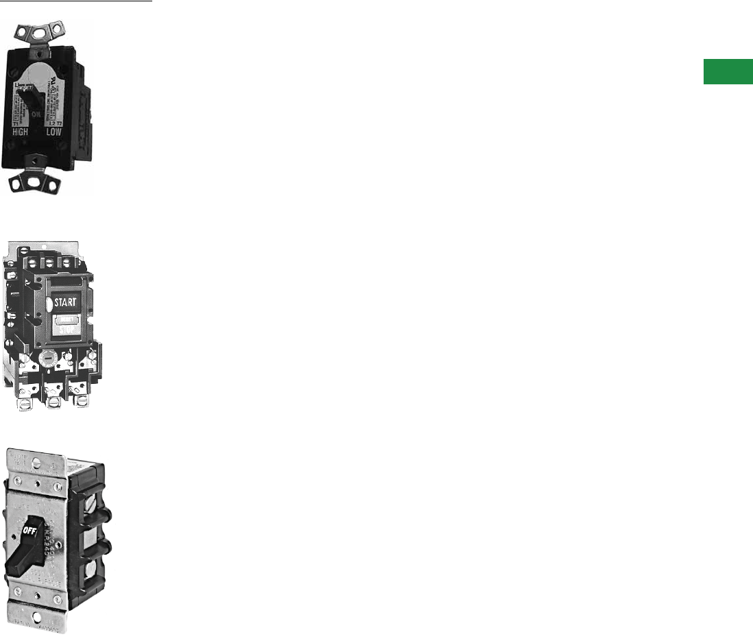
Volume 5—Motor Control and Protection CA08100006E—December 2013 www.eaton.com V5-T3-1
3
3
3
3
3
3
3
3
3
3
3
3
3
3
3
3
3
3
3
3
3
3
3
3
3
3
3
3
3
3
NEMA Manual Starters
MS Series, Single-Phase Starters
Type B100, Single- and
Three-Phase Starters
Types B230, B330 Switches
3.1 Starters and Switches
Product Overview . . . . . . . . . . . . . . . . . . . . . . . . . . . . . . . . . . . . . . . . V5-T3-2
Types B230, B330, Switches . . . . . . . . . . . . . . . . . . . . . . . . . . . . . . . . V5-T3-3
MS Series, Single-Phase Starters . . . . . . . . . . . . . . . . . . . . . . . . . . . . V5-T3-6
Type B100, Single- and Three-Phase Starters . . . . . . . . . . . . . . . . . . . V5-T3-10
Type 9441, Reversing Drum Switches . . . . . . . . . . . . . . . . . . . . . . . . . V5-T3-15
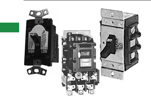
V5-T3-2 Volume 5—Motor Control and Protection CA08100006E—December 2013 www.eaton.com
3
3
3
3
3
3
3
3
3
3
3
3
3
3
3
3
3
3
3
3
3
3
3
3
3
3
3
3
3
3
3.1
NEMA Manual Starters
Starters and Switches
Starters and Switches
Contents
Description Page
Starters and Switches
Types B230, B330, Switches . . . . . . . . . . . . . . V5-T3-3
MS Series, Single-Phase Starters . . . . . . . . . . V5-T3-6
Type B100, Single- and Three-Phase
Starters . . . . . . . . . . . . . . . . . . . . . . . . . . . . . V5-T3-10
Type 9441, Reversing Drum Switches . . . . . . . V5-T3-15
Product Overview
Eaton offers the most
complete line of manual
motor starters in the industry.
Product offering includes
manual motor starters and
switches that cover single as
well as three-phase motor
applications.
Application Description
MS Motor Starter is a
compact, versatile unit
featuring heavy sliding
contacts as well as “quick-
make” and “quick-break”
mechanism.
B100 Manual Motor
Starters can be used in
single-phase applications
rated 3 hp at 240 Vac or 2 hp
at 230 Vdc. The starter can
also be rated for three-phase
applications up to 10 hp at
600 Vac.
B230 and B330 Manual
Motor Switches are available
in two- or three-pole
configurations rated at 30A.
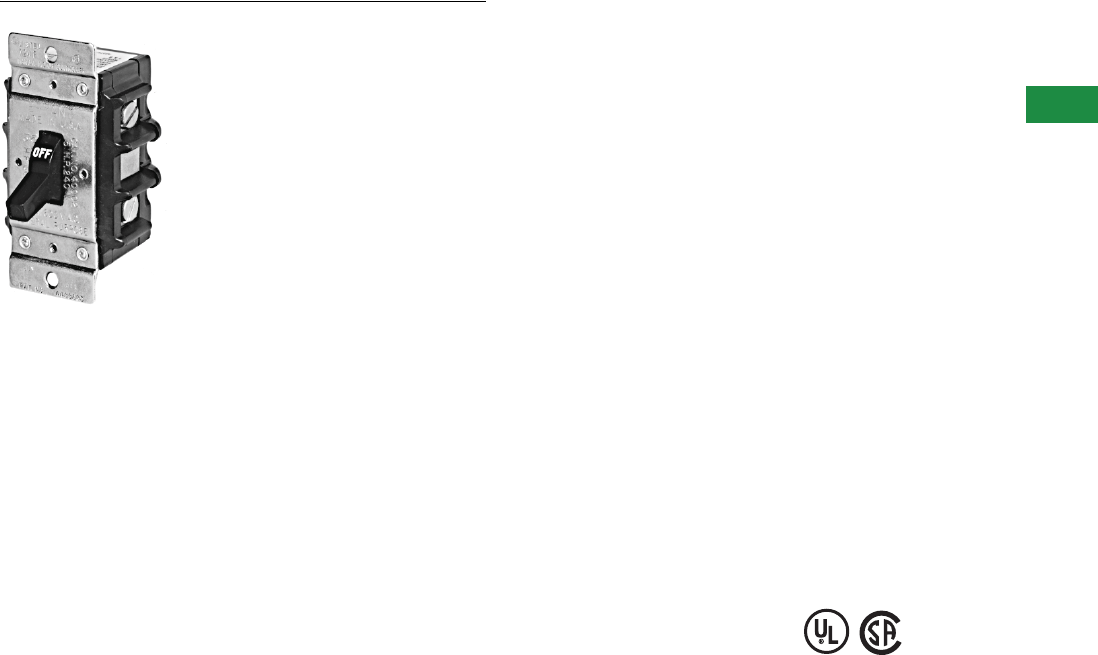
Volume 5—Motor Control and Protection CA08100006E—December 2013 www.eaton.com V5-T3-3
3
3
3
3
3
3
3
3
3
3
3
3
3
3
3
3
3
3
3
3
3
3
3
3
3
3
3
3
3
3
3.1
NEMA Manual Starters
Starters and Switches
Types B230, B330 Switches
Contents
Description Page
Types B230, B330, Switches
Product Selection . . . . . . . . . . . . . . . . . . . . . . . V5-T3-4
Wiring Diagrams . . . . . . . . . . . . . . . . . . . . . . . . V5-T3-4
Dimensions . . . . . . . . . . . . . . . . . . . . . . . . . . . V5-T3-5
MS Series, Single-Phase Starters . . . . . . . . . . . . . V5-T3-6
Type B100, Single- and Three-Phase Starters . . . . V5-T3-10
Type 9441, Reversing Drum Switches . . . . . . . . . . V5-T3-15
Types B230, B330, Switches
Product Description
Manual Motor Switches are
available in two- or three-pole
configurations rated at 30A.
Optional NEMA 1 aluminum
enclosure is supplied with a
padlock guard for locking in
the OFF or STOP position.
Application Description
Manual Motor Switches
provide manual control of
single- and three-phase
motors where overload
protection is not required or
provided separately.
Applications include:
●Fans
●Blowers
●Pumps
●Wood working equipment
●Machine tools
Features
●Compact size
●Easy installation
●Simple operation
●Padlockable NEMA 1
enclosure available
Standards and Certifications
●UL File No. E146654,
Category NLRV
●CSA File No. LR710828,
Class 3211-05
Instructional Leaflet
Pub25371
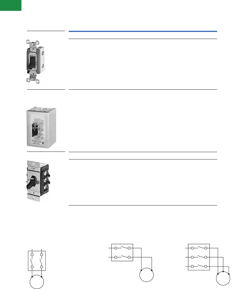
V5-T3-4 Volume 5—Motor Control and Protection CA08100006E—December 2013 www.eaton.com
3
3
3
3
3
3
3
3
3
3
3
3
3
3
3
3
3
3
3
3
3
3
3
3
3
3
3
3
3
3
3.1
NEMA Manual Starters
Starters and Switches
Product Selection
When Ordering Specify
●Catalog number of manual motor switch
Manual Motor Switches without Overload
Wiring Diagrams
B230AN B230BN B330AN
Maximum Horsepower Ratings
Open
NEMA 1
Enclosed120V 240V 480V 600V
Two-Pole—Manual Motor Switches
25 ——B230AN B230AG
2 5 10 15 B230BND B230BGD
Three-Pole—Manual Motor Switches
3 7-1/2 15 20 B330AND B330AGD
Two-Pole B230AN
Two-Pole
NEMA 1 Enclosure
B230BG
Three-Pole B330AN
L1 L2
T1 T2
1-Ph.
Motor
L1 T1
L2 T2
T1 T2
1-Ph.
Motor
L1 T1
L2 T2
L3 T3
T1 T3
T2
3-Ph.
Motor
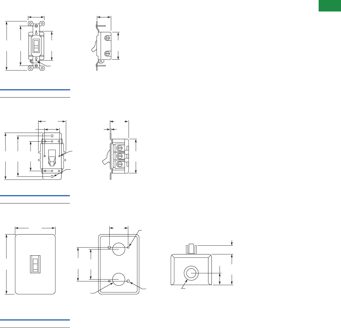
Volume 5—Motor Control and Protection CA08100006E—December 2013 www.eaton.com V5-T3-5
3
3
3
3
3
3
3
3
3
3
3
3
3
3
3
3
3
3
3
3
3
3
3
3
3
3
3
3
3
3
3.1
NEMA Manual Starters
Starters and Switches
Dimensions
Approximate Dimensions in Inches (mm)
B230AN
B230BN and B330AN
B230AG, B230BG, B330AG
2.38
(60.5)
4.06
(103.1) 3.28
(83.3)
1.30
(33.0)
2.27
(57.7)
1.11
(28.2)
2–#6-32 Tapped
Holes for Wall Plate
Approximate Shipping Weight
4 oz. (0.11 kg)
2–0.20 (5.1)
Dia. Mtg. Holes
1.44
(36.6)
0.06
(1.5)
1.12 (28.4)
3.78
(96.0) 3.28
(83.3) 2.38
(60.5)
2.75
(69.9)
4–#6-32
Tap
2.25
(57.2)
Approximate Shipping Weight
6 oz. (0.17 kg)
2.41
(61.2)
0.91
(23.1)
0.68
(17.3)
1.50
(38.1)
2.44
(62.0)
3.20
(81.3)
4.72
(119.9)
2.75
(69.9)
2 Holes
0.13 (3.3)
Dia.
2 Holes
0.27 (6.9)
Dia.2–0.5 (12.7)
Knockouts
Front View Back View End View
0.5 (12.7) x 0.75 (19.1)
Knockout Each End
Approximate Shipping Weight
14 oz. (0.40 kg)
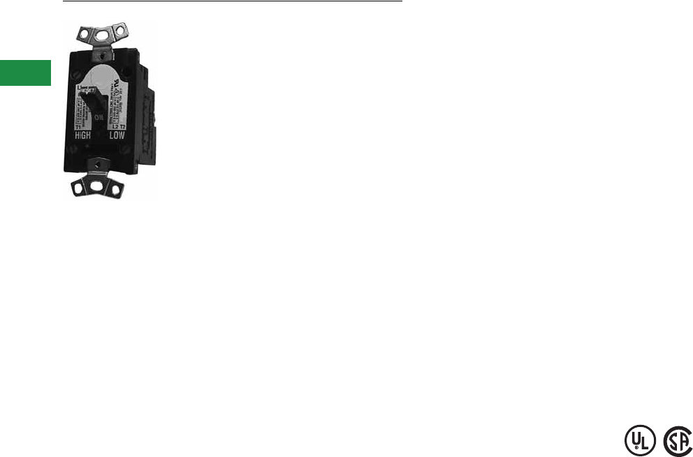
V5-T3-6 Volume 5—Motor Control and Protection CA08100006E—December 2013 www.eaton.com
3
3
3
3
3
3
3
3
3
3
3
3
3
3
3
3
3
3
3
3
3
3
3
3
3
3
3
3
3
3
3.1
NEMA Manual Starters
Starters and Switches
MS Series, Single-Phase Starters
Contents
Description Page
Types B230, B330, Switches . . . . . . . . . . . . . . . . V5-T3-3
MS Series, Single-Phase Starters
Product Selection . . . . . . . . . . . . . . . . . . . . . . . V5-T3-7
Accessories . . . . . . . . . . . . . . . . . . . . . . . . . . . V5-T3-9
Dimensions . . . . . . . . . . . . . . . . . . . . . . . . . . . V5-T3-9
Type B100, Single- and Three-Phase Starters . . . . V5-T3-10
Type 9441, Reversing Drum Switches . . . . . . . . . V5-T3-15
MS Series, Single-Phase Starters
Product Description
●The MS Motor Starter is a
compact, versatile unit
featuring heavy sliding
contacts as well as “quick-
make” and “quick-break”
mechanism
●Standard with large
pressure type terminals,
straight-through wiring and
a trip-free handle
mechanism
●The “plug-in” heater
element is keyed to ensure
proper positioning and an
adjustable knob allows a
setting of plus or minus ten
percent of the nominal
heater rating
Application Description
The MS Manual Motor Starter
provides manual control and
overload protection to single-
phase motors. By utilizing the
interchangeable heater
elements, the starter can
protect motors ranging from
0.40A up to 16.0A. Ideal for
HVAC applications.
Features
●Compact size
●Trip-free handle
mechanism
●Keyed heater elements to
ensure proper installation
●Starters available with red
pilot light
●The operating handle of the
enclosed units can be
locked in the OFF position
●Enclosures are offered in
NEMA 1, 3, 4 and 5
●Hazardous locations cast
aluminum enclosures are
available rated for Type 7,
Class I, Group D (vapors)
and Type 9, Class II,
Groups E, F an G (dust)
Standards and Certifications
●UL File No. E19222,
Category NLRV
●CSA File No. LR39402-6,
Class 3211-05
Instructional Leaflet
IL12987G
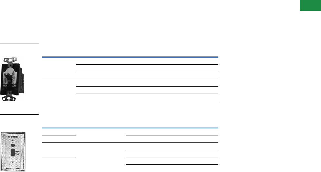
Volume 5—Motor Control and Protection CA08100006E—December 2013 www.eaton.com V5-T3-7
3
3
3
3
3
3
3
3
3
3
3
3
3
3
3
3
3
3
3
3
3
3
3
3
3
3
3
3
3
3
3.1
NEMA Manual Starters
Starters and Switches
Product Selection
When Ordering Specify
●Catalog number of manual motor starter
●Heater pack selection
●Any required accessories
●Heater coil selection according to the motor full load current requirements
MS Series Starters
Open Type
Flush Plate (No Enclosure Included)
Note
1 Does not include heater. Select heater from tables on Page V5-T3-8.
Number of Poles Horsepower Voltage Catalog Number 1
1 1 120/240V, 277 Vac MST01
1/4 120/240 Vdc MST01
1/4 32 Vdc MST01
2 1 120/240V, 277 Vac MST02
1 120/240 Vdc MST02
1/4 32 Vdc MST02
Number of Poles Flush Plate Type Voltage Catalog Number 1
1 General purpose Switch only MST01FN
2 Switch with pilot light MST02FN1P
1 Stainless steel Switch only MST01DN
Switch with pilot light MST01DN1P
2Switch onlyMST02DN
Switch with pilot light MST02DN1P
MS Series, Single-
Phase Starters
Switch and Pilot
Light Mounted
on Flush Plate
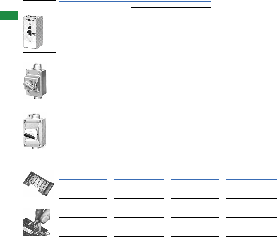
V5-T3-8 Volume 5—Motor Control and Protection CA08100006E—December 2013 www.eaton.com
3
3
3
3
3
3
3
3
3
3
3
3
3
3
3
3
3
3
3
3
3
3
3
3
3
3
3
3
3
3
3.1
NEMA Manual Starters
Starters and Switches
Enclosed Types
Heater Selection for MS Starters
Notes
1 Does not include heater. Select heater from table above.
2 Type 7D = Type 7, Class I, Group D; Type 9E, 9F and 9G = Type 9, Class II, Groups E, F and G.
Number of Poles Enclosure Type Voltage Catalog Number 1
1 General purpose
Type 1
Switch only MST01SN
Switch with pilot light MST01SN1P
2Switch onlyMST02SN
Switch with pilot light MST02SN1P
1 Waterproof
Type 3, 4 and 5
Through hub MST01AH
2 Through hub MST02AH
1 Hazardous location 2
Types 7D, 9E, 9F and 9G
Through hub MST01EH
2 Through hub MST02EH
Motor Full
Load Current
Catalog
Number
Motor Full
Load Current
Catalog
Number
Motor Full
Load Current
Catalog
Number
Motor Full
Load Current
Catalog
Number
0.4 – 0.43 MSH-5A 1.04–1.15 MSH1-3A 2.72–2.95 MSH3-4A 7.04– 7.74 MSH8-8A
0.44–0.48 MSH-55A 1.16–1.27 MSH1-45A 2.96–3.27 MSH3-7A 7.75– 8.46 MSH9-7A
0.49 –0.53 MSH-61A 1.28–1.35 MSH1-6A 3.28–3.59 MSH4-1A 8.47– 9.35 MSH10-6A
0.54–0.58 MSH-67A 1.36–1.51 MSH1-7A 3.60–3.99 MSH4-5A 9.36–10.30 MSH11-7A
0.59–0.64 MSH-74A 1.52–1.67 MSH1-9A 4.00–4.39 MSH5-0A 10.31–11.35 MSH12-9A
0.65–0.71 MSH-81A 1.68–1.83 MSH2-1A 4.40–4.79 MSH5-5A 11.36–12.47 MSH14-2A
0.72 –0.78 MSH-89A 1.84–1.99 MSH2-3A 4.80–5.26 MSH6-0A 12.48–13.67 MSH15-6A
0.79–0.87 MSH-98A 2.00–2.23 MSH2-5A 5.27–5.83 MSH6-6A 13.68–15.12 MSH17-1A
0.88–0.95 MSH1-1A 2.24–2.47 MSH2-8A 5.84–6.39 MSH7-3A 15.13–16.00 MSH18-6A
0.96–1.03 MSH1-2A 2.48–2.71 MSH3-1A 6.40–7.03 MSH8-0A ——
Switch and Pilot
Light Mounted in
Type 1 Enclosure
Waterproof
Type 3, 4 and 5
Hazardous Location
Type 7D, 9E, 9F and 9G
Typical Heater
Heater Element
Installation
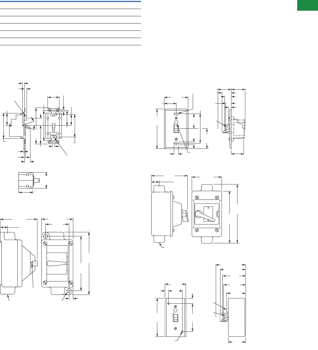
Volume 5—Motor Control and Protection CA08100006E—December 2013 www.eaton.com V5-T3-9
3
3
3
3
3
3
3
3
3
3
3
3
3
3
3
3
3
3
3
3
3
3
3
3
3
3
3
3
3
3
3.1
NEMA Manual Starters
Starters and Switches
Accessories
MS Accessories
Dimensions
Approximate Dimensions in Inches (mm)
MS Motor Starter Toggle Operated Open Units
Hazardous Location (Cast Aluminum)
Flush Plates
Watertight (Cast Aluminum)
Type 1 Enclosure (Boxes and Covers)
Description Catalog Number
Pilot light kit (NEMA 1 enclosure and flush plates) MSPT
Box, 1 unit (NEMA 1 enclosure) MS1BN
Cover, 1 unit (NEMA 1 enclosure) MS1CN
Flush plate, 1 unit (steel) MS1FN
Flush plate, 1 unit (stainless steel) MS1DN
Handle guard (padlockable for NEMA 1 enclosure and flush plates) MSLG
1.36
(34.5)
0.31
(7.9)
1.25
(31.8)
3.28
(83.3)
3.81
(96.8)
0.75
(19.1)
0.22
(5.6)
1.64
(41.7)
1.19
(30.2)
2.38
(60.5)
0.14-32
Tap
20
Typ.
0.31
(7.9)
0.06 (1.5)
0.11 (2.8)
Height
of Handle 0.73
(18.5)
1.91
(48.5)
0.19 (4.8)
0.36 (9.1)
Dia.
2.72
(69.1)
1.70
(43.2)
1.58
(40.1)
0.75 (19.1)
Pipe Tap
0.30 (7.6) Dia.
Lockout Hole
0.81
(20.6)
3.94
(100.1) 2.63
(66.8)
0.44
(11.2)
3.5 (88.9)
5.88
(149.4)
6.72
(170.7)
0.34 (8.6) Dia.
(2) Mounting Holes
0.31
(7.9) 1 Unit
0.22
(5.6) 2.25
(57.2)
1.64
(41.7)
Indicating Light
Handle
Guard
Mounting
Purposes
(2) Holes
1.38
(35.1) 0.34
(8.6)
0.66
(16.8)
0.78
(19.8)
1.06
(26.9)
1.64
(41.7)
1.52
(38.6)
2.75
(69.9)
3.28
(83.3)
4.5
(114.3)
1.53
(38.9)
0.75 (19.1) Pipe Tap
0.75
(19.1)
3.63
(92.2)
5.13
(130.3)
5.81
(147.6)
2.91
(73.9)
1 Unit
3.28 (83.3)
3.06
(77.7)
Indicating
Light
Handle
Guard
1.5 6
(39.6)
0.55
(14.0)
2.47
(62.7)
2.11
(53.6)
2.55
(64.8)
2.83 (71.9)
2.38
(60.5)
4.16
(105.7)
1.97
(50.0)
0.41
(10.4)
0.20 (5.1)
Diameter (2)
Mounting Hole
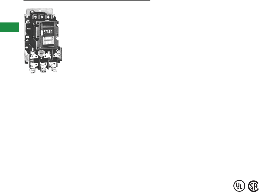
V5-T3-10 Volume 5—Motor Control and Protection CA08100006E—December 2013 www.eaton.com
3
3
3
3
3
3
3
3
3
3
3
3
3
3
3
3
3
3
3
3
3
3
3
3
3
3
3
3
3
3
3.1
NEMA Manual Starters
Starters and Switches
Type B100, Single- and Three-Phase Starters
Contents
Description Page
Types B230, B330, Switches . . . . . . . . . . . . . . . . V5-T3-3
MS Series, Single-Phase Starters . . . . . . . . . . . . . V5-T3-6
Type B100, Single- and Three-Phase Starters
Product Selection . . . . . . . . . . . . . . . . . . . . . . . V5-T3-11
Accessories . . . . . . . . . . . . . . . . . . . . . . . . . . . V5-T3-12
Options . . . . . . . . . . . . . . . . . . . . . . . . . . . . . . V5-T3-12
Technical Data and Specifications . . . . . . . . . . V5-T3-13
Dimensions . . . . . . . . . . . . . . . . . . . . . . . . . . . V5-T3-13
Type 9441, Reversing Drum Switches . . . . . . . . . V5-T3-15
Type B100, Single- and Three-Phase Starters
Product Description
The B100 Manual Motor
Starters can be used in
single-phase applications
rated 3 hp at 240 Vac or 2 hp
at 230 Vdc. The starter can
also be rated for three-phase
applications up to 10 hp at
600 Vac.
There are two methods of
operation for the B100
Manual Starter. It can be
ordered with a toggle switch
operator or a START/STOP
pushbutton operator.
Application Description
The B100 family of Manual
Motor Starters provides
manual control, as well as
overload protection, to both
single-phase and three-phase
motors. The starter protects
motors up to 38.9A single-
phase and 26.8A three-phase
with the appropriate heater
selection.
Features
●Includes three-pole
bimetallic overload relay
●Straight-through wiring
●Field mounted auxiliary
contacts
●Available in NEMA 1, 4, 7, 9
and 12 enclosures with
toggle operation (NEMA 1
enclosure for pushbutton
operator)
●Standard with a lockout
device to lock motor in the
OFF position
Standards and Certifications
●UL File No. E19222,
Category NLRV
●CSA File No. LR39402-6,
Class 3211-05 (Open
Starters)
●CSA File No. LR54517-1,
Class 3211-05 (Closed
Starters)
Instructional Leaflet
IL14890
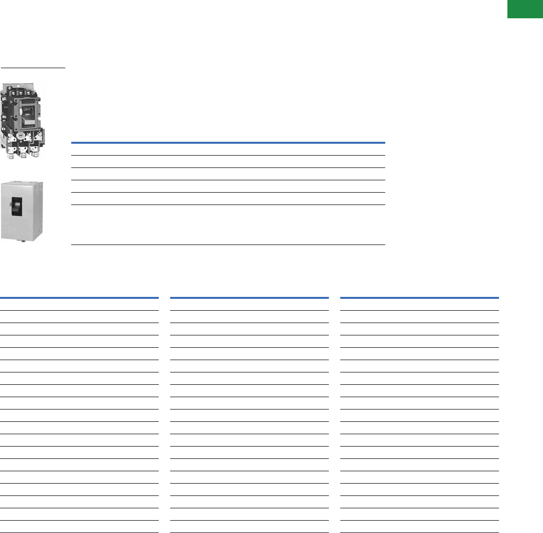
Volume 5—Motor Control and Protection CA08100006E—December 2013 www.eaton.com V5-T3-11
3
3
3
3
3
3
3
3
3
3
3
3
3
3
3
3
3
3
3
3
3
3
3
3
3
3
3
3
3
3
3.1
NEMA Manual Starters
Starters and Switches
Product Selection
When Ordering Specify
●Catalog number of
Starter with application
modifications
●Heater pack selection—
a three-phase starter
requires three heaters,
and a single-phase starter
requires two heaters
●Any required accessories
Toggle and Pushbutton Operated Starters
Heater Selection—Single-Phase Enclosed Starters 5
Notes
1 One 1 in chrome hub supplied on each end.
2 NEMA 7D = NEMA 7, Class I, Group D. NEMA 9E, 9F and 9G = NEMA 9, Class II, Groups E, F and G.
3 Tapped for 1 in conduit on each end.
4 Starter does not include heaters. Select catalog numbers of heaters from table on Page V5-T3-12.
5 Single-phase starters require two overload heaters.
NEMA
Size
Open Type
Toggle Handle
Enclosed
NEMA 1
General Purpose
NEMA 4
Watertight,
Stainless Steel 1
NEMA 7D,
9E, 9F and 9G for
Hazardous
Locations 23
NEMA 12
Dust-Tight
Catalog
Number 4
Catalog
Number 4
Catalog
Number 4
Catalog
Number 4
Catalog
Number 4
Type B100 Non-Reversing Two-Pole (For Single-Phase Motors and DC)
M-0 B100M0B B100S0B B100W0B B100U0B B100J0B
M-1 B100M1B B100S1B B100W1B B100U1B B100J1B
Type B100 Non-Reversing Three-Pole (For Polyphase Motors) 4
M-0 B100M0C B100S0C B100W0C B100U0C B100J0C
M-1 B100M1C B100S1C B100W1C B100U1C B100J1C
Motor Full
Load Current
Maximum
Fuse Amps
Catalog
Number
Motor Full
Load Current
Maximum
Fuse Amps
Catalog
Number
Motor Full
Load Current
Maximum
Fuse Amps
Catalog
Number
0.28–0.29 1 FH03 1.90–2.10 7 FH22 9.59–10.40 35 FH40
0.30–0.33 1 FH04 2.11–2.32 8 FH23 10.41–11.30 35 FH41
0.34–0.36 1 FH05 2.33–2.54 8 FH24 11.40–12.20 40 FH42
0.37–0.40 1 FH06 2.55–2.79 9 FH25 12.30–13.50 45 FH43
0.41–0.45 1 FH07 2.80–3.07 10 FH26 13.60–14.90 50 FH44
0.46–0.50 1 FH08 3.08–3.36 10 FH27 15.00–16.00 50 FH45
0.51–0.56 1 FH09 3.37–3.68 10 FH28 16.10–17.10 60 FH46
0.57–0.63 2 FH10 3.69–4.03 10 FH29 17.20–18.30 60 FH47
0.64–0.70 2 FH11 4.04–4.40 15 FH30 18.40–19.70 70 FH48
0.71–0.78 2 FH12 4.41–4.81 15 FH31 19.80–21.20 70 FH49
0.79–0.86 2 FH13 4.82–5.26 15 FH32 21.30–22.80 80 FH50
0.87–0.95 3 FH14 5.27–5.74 15 FH33 22.90–24.50 88 FH51
0.96–1.04 3 FH15 5.75–6.26 20 FH34 24.60–26.40 90 FH52
1.05–1.14 3 FH16 6.27–6.83 20 FH35 26.50–28.50 90 FH53
1.15–1.25 4 FH17 6.84–7.45 25 FH36 28.60–30.80 100 FH54
1.26–1.39 4 FH18 7.46–8.11 25 FH37 30.90–33.30 110 FH55
1.40–1.54 5 FH19 8.12–8.81 30 FH38 33.40–36.00 125 FH56
1.55–1.71 5 FH20 8.82–9.58 30 FH39 36.10–38.90 125 FH57
1.72–1.89 6 FH21 ——————
Toggle Operated
Type 1 Enclosure

V5-T3-12 Volume 5—Motor Control and Protection CA08100006E—December 2013 www.eaton.com
3
3
3
3
3
3
3
3
3
3
3
3
3
3
3
3
3
3
3
3
3
3
3
3
3
3
3
3
3
3
3.1
NEMA Manual Starters
Starters and Switches
Heater Selection—Three-Phase Enclosed Starters 2
Accessories
Ty p e B 10 0 S t a r t e r s
Options
Modifications
Notes
1Single-phase starters require two overload heaters.
2Three-phase starters require three overload heaters.
3Add suffix letter to starter catalog number Example: B100MOCA.
FH Series heaters are for Type B100 manual motor starters. Heater element selection is based
on motor nameplate’s listed full load amperes. Trip rating of this series of elements is 125% of
minimum motor full load amperes listed for the element. When motor and overload relay are in
the same ambient and the service factor of the motor is 1.15 to 1.25, select heaters from the
heater selection table. If the service factor is 1.0 or less (including zero), or a maximum of 115%
protection is desired, select a heater one size smaller than indicated for the amperage range required.
Motor Full
Load Current
Maximum
Fuse Amps
Catalog
Number
Motor Full
Load Current
Maximum
Fuse Amps
Catalog
Number
Motor Full
Load Current
Maximum
Fuse Amps
Catalog
Number
0.25–0.26 1 FH03 1.51–1.66 5 FH21 7.12–7.73 25 FH38
0.27–0.29 1 FH04 1.67–1.84 6 FH22 7.74–8.40 25 FH39
0.30–0.32 1 FH05 1.85–2.03 7 FH23 8.41–9.12 30 FH40
0.33–0.35 1 FH06 2.04–2.23 7 FH24 9.13–9.89 35 FH41
0.36–0.39 1 FH07 2.24–2.45 8 FH25 9.90–10.70 35 FH42
0.40–0.44 1 FH08 2.46–2.69 9 FH26 10.80–11.80 40 FH43
0.45–0.49 1 FH09 2.70–2.95 10 FH27 11.90–13.00 45 FH44
0.50–0.55 1 FH10 2.96–3.23 10 FH28 13.10–14.00 50 FH45
0.56–0.61 2 FH11 3.24–3.53 10 FH29 14.10–15.00 50 FH46
0.62–0.68 2 FH12 3.54–3.85 10 FH30 15.10–16.10 50 FH47
0.69–0.75 2 FH13 3.86–4.22 10 FH31 16.20–17.30 60 FH48
0.78–0.83 2 FH14 4.23–4.61 15 FH32 17.40–18.60 60 FH49
0.84–0.91 3 FH15 4.62–5.03 15 FH33 18.70–20.00 70 FH50
0.92–1.00 3 FH16 5.04–5.49 15 FH34 20.10–21.50 70 FH51
1.01–1.10 3 FH17 5.50–5.99 20 FH35 21.60–23.20 80 FH52
1.11–1.22 4 FH18 6.00–6.53 20 FH36 23.30–25.00 80 FH53
1.23–1.3 4 FH19 6.54–7.11 25 FH37 25.10–26.80 90 FH54
1.36–1.50 5 FH20 ——————
Description Catalog Number
Field Mounting Kits
1NO elect. auxiliary B1A
1NC elect. auxiliary B1B
Red pilot light 120/60 (NEMA 1 enclosure only) LK-21
Red pilot light 208-240/6 (NEMA 1 enclosure only) LK-22
Red pilot light 480-600/60 (NEMA 1 enclosure only) LK-26
Description Catalog Number Suffix 3
Pushbutton operator (open and NEMA 1 only) A
Without lockoff (open only) X
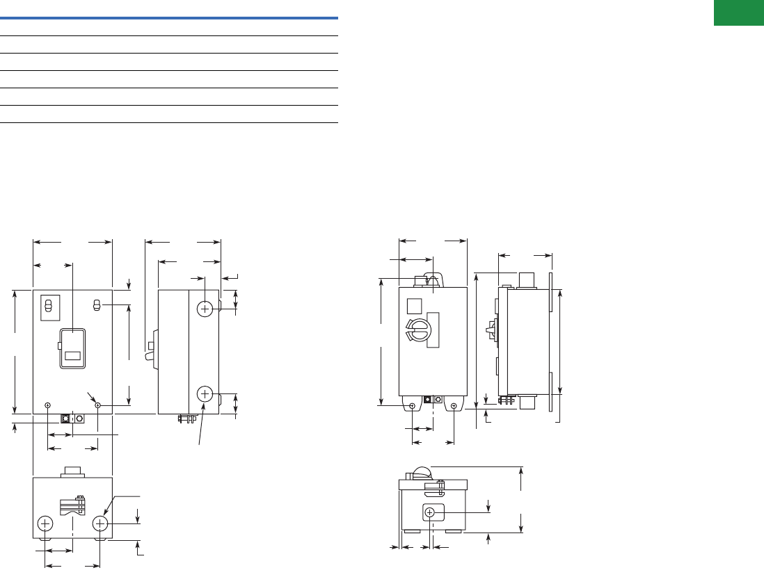
Volume 5—Motor Control and Protection CA08100006E—December 2013 www.eaton.com V5-T3-13
3
3
3
3
3
3
3
3
3
3
3
3
3
3
3
3
3
3
3
3
3
3
3
3
3
3
3
3
3
3
3.1
NEMA Manual Starters
Starters and Switches
Technical Data and Specifications
Ty p e B 10 0 S t a r t e r s
Dimensions
Approximate Dimensions in Inches (mm)
Type 1 Enclosed Type 4 Enclosed
Note
1Ratings up to 3 hp, three-phase are suitable for group fusing.
NEMA
Size
Maximum hp for AC Ratings 1Maximum hp for DC Ratings
120 Vac 208–240 Vac 480–600 Vac 115 Vdc 230 Vdc
Two-Pole, Single-Phase
M-0 1 2 — 1 1-1/2
M-1 2 3 — 1-1/2 2
Three-Pole, Three-Phase
M-0235——
M-1 3 7-1/2 10 — —
1.02
(25.9)
1/2 x 3/4 Conduit K.O.
2 in Bottom and 2 in
Top End
1/2 x 3/4 Conduit K.O.
2 in Each Side
0.92
(23.4)
0.92
(23.4)
6.00
(152.4)
1.05
(26.7)
7.59
(192.8)
0.63
(16.0)
4.72
(119.9) 4.98
(126.5)
3.98
(101.1)
1.02
(25.9)
2.36
(59.9)
3.25
(82.6)
1.63
(41.4)
2.50
(63.5)
1.25
(31.8)
OFF
0.22 (5.6) Dia.
4 Mtg. Holes
0.09
(2.3)
9.19
(233.4)
0.17
(4.3)
2.05
(52.1)
5.13
(130.3) 5.00
(127.0)
2.56
(65.0)
3.00
(76.2)
1.50
(38.1)
6.00
(152.4)
8.28
(210.3)
10.16
(258.1)
0.63
(16.0)
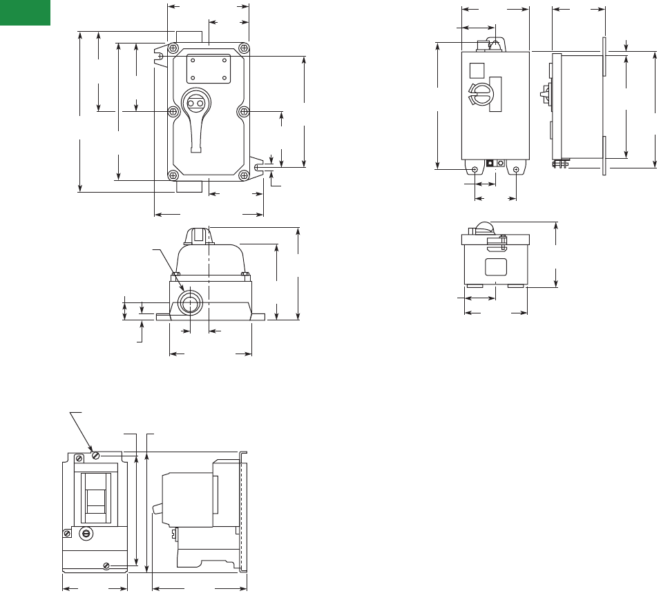
V5-T3-14 Volume 5—Motor Control and Protection CA08100006E—December 2013 www.eaton.com
3
3
3
3
3
3
3
3
3
3
3
3
3
3
3
3
3
3
3
3
3
3
3
3
3
3
3
3
3
3
3.1
NEMA Manual Starters
Starters and Switches
Approximate Dimensions in Inches (mm)
Type 7 and 9 Enclosed
Open, Non-Reversing Starter
Type 12 Enclosed
12.06
(306.3)
6.03
(153.2)
10.25
(260.4)
5.13
(130.3)
0.50
(12.7)
1.38
(35.1)
1 (25.4)-11.50 NPSK
2 Holes
7.13 (181.1)
3.56
(90.4)
6.0 (152.4)
8.25 (209.6)
7.77
(197.4)
6.31
(160.3)
8.38
(212.9)
0.41 (10.4) Slot
2 Req'd.
4.06
(130.1)
4.19
(106.4)
OFF ON
0.88
(22.4)
3.19
(81.0) 4.59
(116.6)
5.84
(148.3)
5.28
(134.1)
3/16-32 Mounting Screw
9.19
(233.4)
5.13
(130.3) 5.00
(127.0)
2.56
(65.0)
3.0
(76.2)
1.5
(38.1)
4.78
(121.4)
2.33
(59.2)
5.97
(151.6)
8.28
(210.3)
0.27
(6.9)
9.41
(239.0)
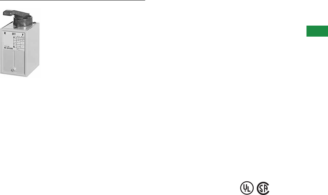
Volume 5—Motor Control and Protection CA08100006E—December 2013 www.eaton.com V5-T3-15
3
3
3
3
3
3
3
3
3
3
3
3
3
3
3
3
3
3
3
3
3
3
3
3
3
3
3
3
3
3
3.1
NEMA Manual Starters
Starters and Switches
Type 9441, Reversing Drum Switches
Contents
Description Page
Types B230, B330, Switches . . . . . . . . . . . . . . . . . V5-T3-3
MS Series, Single-Phase Starters . . . . . . . . . . . . . V5-T3-6
Type B100, Single- and Three-Phase Starters . . . . V5-T3-10
Type 9441, Reversing Drum Switches
Product Selection . . . . . . . . . . . . . . . . . . . . . . . V5-T3-16
Wiring Diagrams . . . . . . . . . . . . . . . . . . . . . . . . V5-T3-17
Dimensions . . . . . . . . . . . . . . . . . . . . . . . . . . . V5-T3-17
Type 9441, Reversing Drum Switches
Application Description
These drum switches are
designed primarily for
use with single-phase and
squirrel cage, single-speed
reversible motors which
may be connected directly
across-the-line. Typical
applications would be
hoists and machine tools.
Features
●Compact size
●Front mounting—
easily installed
●Terminals front
accessible—slanted 45°
for extra convenience
●Captive pressure clamps
on terminal screws back
off with screw—no prying
with screwdriver
necessary
●Choice of operators
●Large
●Lever
●Knob
●Orientation of operator
independent of legend—
360° positioning in 22-1/2°
increments—pointer
remains oriented to legend
●Field convertible from
maintained to momentary
operation
●Replaceable, large volume,
silver plated contacts
●Oiltight machine cavity or
surface mounting types
●Modern attractive
appearance
Operation
All of the operators may
be rotated 360° in 22-1/2°
increments without losing
the indication of the drum
position. A red-lined pointer
is permanently orientated to
the legend markings and
clearly indicates the selected
drum function regardless of
the selected setting for the
operator. This enables
the user to “offset” the
operator to afford the
most comfortable operating
position. This is accomplished
simply by loosening and
retightening one screw.
Standards and Certifications
●UL File No. E37316,
Category NLRV
●CSA Guide No.
184-N-13.13A, Class 3211
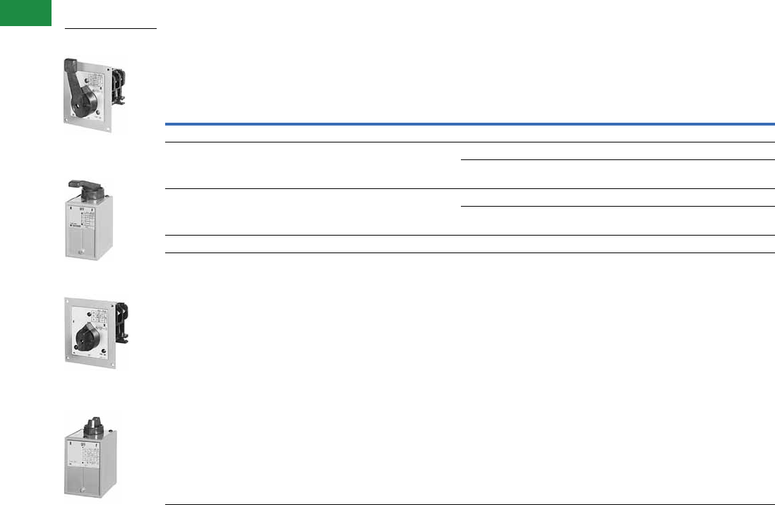
V5-T3-16 Volume 5—Motor Control and Protection CA08100006E—December 2013 www.eaton.com
3
3
3
3
3
3
3
3
3
3
3
3
3
3
3
3
3
3
3
3
3
3
3
3
3
3
3
3
3
3
3.1
NEMA Manual Starters
Starters and Switches
Product Selection
When Ordering Specify
●Catalog number
Reversing Drum Type without Overload Relay
Notes
1 These devices are field convertible from maintained both positions to momentary both positions.
2 These devices are field convertible from maintained FORWARD and momentary REVERSE to momentary FORWARD and maintained REVERSE.
Maximum Horsepower
Size
Type of
Operation
Surface Mounting
General Purpose—NEMA 1
Flush or Cavity Mounting
(Oiltight Mounting
on Sizes DB and DD)
Three-Phase Single-Phase DC
Lever
Operator Knob
Lever
Operator Knob
200–230V 380–575V 115V 230V 115V 230V Catalog Number Catalog Number
Three-Pole
2 2 1-1/2 2 1 1 DB 1 Maintained 19441H268 9441H269 9441H274 9441H275
Maintained and
Momentary 2
9441H271 9441H272 9441H276 —
3 5 1-1/2 2 1 1 DB 2 Maintained 19441H353 9441H354 9441H347 —
Maintained and
Momentary 2
9441H356 9441H357 9441H349 9441H350
5 7-1/2 1-1/2 3 2 3 DD 1 Maintained 19441H284 9441H285 9441H388 —
7-1/2 10 2 5 2 3 DD 2 Maintained 19441H361 9441H363 9441H362 —
Type DB1 Flush Mount
Standard Lever
Type DB and DD
Surface Mounting
Standard Lever
Type DB1 Flush Mount
Knob Operator
Type DB and DD
Surface Mounting
Knob Operator
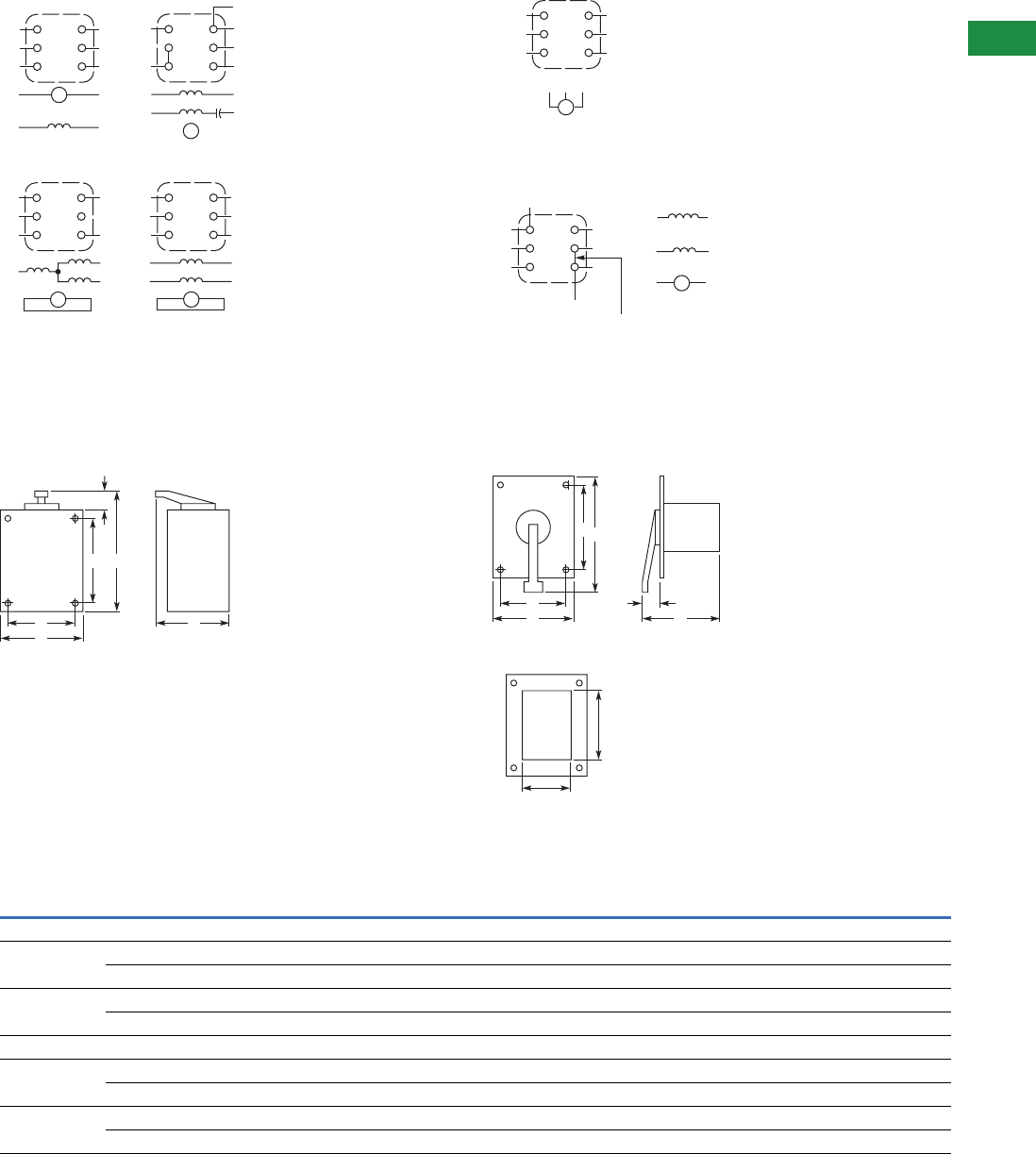
Volume 5—Motor Control and Protection CA08100006E—December 2013 www.eaton.com V5-T3-17
3
3
3
3
3
3
3
3
3
3
3
3
3
3
3
3
3
3
3
3
3
3
3
3
3
3
3
3
3
3
3.1
NEMA Manual Starters
Starters and Switches
Wiring Diagrams
Single-Phase Motors Polyphase Motors
DC Motors
Dimensions
Approximate Dimensions in Inches (mm)
Surface Mounting Cavity Mounting
Panel Cutout Cavity Mounting
Dimensions and Shipping Weights
L2
S1
L1
A1
S1
1
3
5
2
4
6
S2
A2
A1
A2
S2
Arm
T5
L1
T1
T8
Split-
Phase
1
3
5
2
4
6
T4
L2
T8
T1
T4
T5
Split-
Capacitor
Capacitor-Start
Universal
L2
T8
L1
1
3
5
2
4
6
T5
T1
T5
T8
Three-Wire
T1
L2
T8
L1
T1
T8
1
3
5
2
4
6
T5
T4
T1
T4
T5
Four-Wire
Repulsion-Start Induction,
Repulsion, Repulsion-Induction
Three-Phase Three-Wire
L1
T3
L2
T1 T3T2
1
3
5
2
4
6
T1
L3
T2
M
Series, Compound, Shunt
L1
F1
F2
A2
L2
1
3
5
2
4
6
A1
S1
S2
For Shunt Motor
Add Jumper
Shunt Field
Series Field
S1 S2
F1 F2
A1 A2
Arm
E
C
D
B
F
A
B
E
C
DF
A
3.50 (88.9)
Size DB1 and DB2
3.00 (76.2)
Size DB1 and DB2
3.88 (98.6)
Size DD1 and DD2
3.25 (82.6)
Size DD1 and DD2
Size
Type of
Operator
Wide
A
HIgh
B
Deep
C
Mounting
D
Mounting
E
Lever
F
Shipping Weight
Lbs (kg)
Surface Mounting
DB1 and DB2 Lever 2.50 (63.5) 5.88 (149.4) 4.38 (111.3) 2.00 (50.8) 2.25 (57.2) 1.88 (47.8) 3.0 (1.4)
Knob 2.50 (63.5) 5.38 (136.7) 3.00 (76.2) 2.00 (50.8) 2.25 (57.2) 1.38 (35.1) 3.0 (1.4)
DD1 and DD2 Lever 3.38 (85.9) 6.88 (174.8) 4.75 (120.7) 2.63 (66.8) 2.75 (69.9) 2.00 (50.8) 4.0 (1.8)
Knob 3.38 (85.9) 6.25 (158.8) 3.63 (92.2) 2.63 (66.8) 2.75 (69.9) 1.38 (35.1) 4.0 (1.8)
Cavity Mounting
DB1 and DB2 Lever 4.00 (101.6) 4.75 (120.7) 5.00 (127.0) 3.50 (88.9) 4.00 (101.6) 1.88 (47.8) 3.0 (1.4)
Knob 4.00 (101.6) 4.50 (114.3) 4.50 (114.3) 3.50 (88.9) 4.00 (101.6) 1.38 (35.1) 3.0 (1.4)
DD1 and DD2 Lever 4.50 (114.3) 5.75 (146.1) 5.25 (133.4) 4.00 (101.6) 4.50 (114.3) 2.00 (50.8) 4.0 (1.8)
Knob 4.50 (114.3) 5.13 (130.3) 4.63 (117.6) 4.00 (101.6) 4.50 (114.3) 1.38 (35.1) 4.0 (1.8)
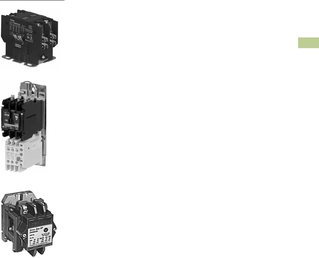
Volume 5—Motor Control and Protection CA08100006E—April 2014 www.eaton.com V5-T4-1
4
4
4
4
4
4
4
4
4
4
4
4
4
4
4
4
4
4
4
4
4
4
4
4
4
4
4
4
4
4
Definite Purpose Contactors and Starters
0–40A Compact Contactor
25–60A Starter
4.1 Product Overview—Contactors and Starters
Product Overview . . . . . . . . . . . . . . . . . . . . . . . . . . . . . . . . . . . . . . . . V5-T4-2
Application Description . . . . . . . . . . . . . . . . . . . . . . . . . . . . . . . . . . . . V5-T4-2
Catalog Number Selection . . . . . . . . . . . . . . . . . . . . . . . . . . . . . . . . . . V5-T4-3
4.2 Contactors
20–40A, Compact Single- and Two-Pole—C25 . . . . . . . . . . . . . . . . . . V5-T4-4
15–360A, Two-, Three- and Four-Pole—C25 . . . . . . . . . . . . . . . . . . . . . V5-T4-8
Accessories . . . . . . . . . . . . . . . . . . . . . . . . . . . . . . . . . . . . . . . . . . . . . V5-T4-11
15–40A, Three-Pole Fuse Block . . . . . . . . . . . . . . . . . . . . . . . . . . . . . . V5-T4-17
15–75A, Reversing and Two-Speed—C65 . . . . . . . . . . . . . . . . . . . . . . V5-T4-20
4.3 Starters
25–60A, Single- and Three-Phase—A25, B25 . . . . . . . . . . . . . . . . . . . V5-T4-23
15–45A, Single- and Three-Phase—A27, B27 . . . . . . . . . . . . . . . . . . . V5-T4-30
15–75A, Single- and Three-Phase—A30, B30 and
C440/XT Electronic Overload Relay . . . . . . . . . . . . . . . . . . . . . . . . . . V5-T4-38
4.4 NEMA Type 1 Enclosed Control
15–60A Contactors—C25 . . . . . . . . . . . . . . . . . . . . . . . . . . . . . . . . . . V5-T4-46
25–60A Starters—A25, B25 . . . . . . . . . . . . . . . . . . . . . . . . . . . . . . . . V5-T4-49
15–45A Starters—A27, B27 . . . . . . . . . . . . . . . . . . . . . . . . . . . . . . . . . V5-T4-52
Accessories . . . . . . . . . . . . . . . . . . . . . . . . . . . . . . . . . . . . . . . . . . . . . V5-T4-55
Options . . . . . . . . . . . . . . . . . . . . . . . . . . . . . . . . . . . . . . . . . . . . . . . . V5-T4-57
Technical Data and Specifications . . . . . . . . . . . . . . . . . . . . . . . . . . . . V5-T4-58
4.5 Renewal Parts
Product Selection
Contact Kits, Coils . . . . . . . . . . . . . . . . . . . . . . . . . . . . . . . . . . . . . . V5-T4-59
4.6 Heavy-Duty Special Purpose Contactors
Product Selection . . . . . . . . . . . . . . . . . . . . . . . . . . . . . . . . . . . . . . . . . V5-T4-64
Accessories . . . . . . . . . . . . . . . . . . . . . . . . . . . . . . . . . . . . . . . . . . . . . V5-T4-64
Renewal Parts . . . . . . . . . . . . . . . . . . . . . . . . . . . . . . . . . . . . . . . . . . . V5-T4-65
Technical Data and Specifications . . . . . . . . . . . . . . . . . . . . . . . . . . . . V5-T4-65
Dimensions . . . . . . . . . . . . . . . . . . . . . . . . . . . . . . . . . . . . . . . . . . . . . V5-T4-66
4.7 Direct Current Contactors
Mill Type Contactors . . . . . . . . . . . . . . . . . . . . . . . . . . . . . . . . . . . . . . V5-T4-67
600V Contactors . . . . . . . . . . . . . . . . . . . . . . . . . . . . . . . . . . . . . . . . . V5-T4-70
DPM 750V Contactor . . . . . . . . . . . . . . . . . . . . . . . . . . . . . . . . . . . . . . V5-T4-74
AVD–Contactor . . . . . . . . . . . . . . . . . . . . . . . . . . . . . . . . . . . . . . . . . . V5-T4-77
D–Contactor . . . . . . . . . . . . . . . . . . . . . . . . . . . . . . . . . . . . . . . . . . . . . V5-T4-80
Reversing/Assignment Contactor . . . . . . . . . . . . . . . . . . . . . . . . . . . . V5-T4-83
4.8 Ratings
Ampere Rating of AC Motors . . . . . . . . . . . . . . . . . . . . . . . . . . . . . . . V5-T4-86
Heavy-Duty Special Purpose
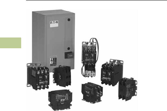
V5-T4-2 Volume 5—Motor Control and Protection CA08100006E—April 2014 www.eaton.com
4
4
4
4
4
4
4
4
4
4
4
4
4
4
4
4
4
4
4
4
4
4
4
4
4
4
4
4
4
4
4.1
Definite Purpose Contactors and Starters
Product Overview—Contactors and Starters
Definite Purpose Contactors and Starters
Contents
Description Page
Contactors
20–40A, Compact Single- and Two-Pole—
C25 . . . . . . . . . . . . . . . . . . . . . . . . . . . . . . . . V5-T4-4
15–360A, Two-, Three- and Four-Pole—C25 . . . V5-T4-8
15–40A, Three-Pole Fuse Block . . . . . . . . . . . . V5-T4-17
15–75A, Reversing and Two-Speed—C65 . . . . V5-T4-20
Starters
25–60A, Single- and Three-Phase—
A25, B25 . . . . . . . . . . . . . . . . . . . . . . . . . . . . V5-T4-23
15–45A, Single- and Three-Phase—
A27, B27 . . . . . . . . . . . . . . . . . . . . . . . . . . . . V5-T4-30
15–75A, Single- and Three-Phase—A30, B30
and C440/XT Electronic Overload Relay . . . . V5-T4-38
Product Overview
Eaton offers the most
complete line of Definite
Purpose (DP) contactors in
the industry. Designed for
heating, ventilation, air
conditioning and refrigeration
(HVACR) applications, Eaton’s
DP contactors are designed
to handle the most
challenging installations.
Application Description
These ampere and
horsepower rated devices
from Eaton’s Electrical Sector
are designed for
service in
applications such as
refrigeration, air conditioning
and resistance heating and
are manufactured to
traditional standards for
quality and reliability. They are
subjected to stringent quality
assurance inspections and
testing procedures. The life
expectancy, both electrical
and mechanical, will meet or
exceed industry performance
requirements for Definite
Purpose devices.
If more detailed technical
information is required—
specifications, ratings, and so
on—contact your local Eaton
distributor or sales office.
Features
●Completely encased
design impervious to dust
and other environmental
elements
●15–360A contactor ratings
●Single-, two-, three- and
four-pole configurations
●Contactors and starters
(up to 60A)
●Open components and
enclosed designs
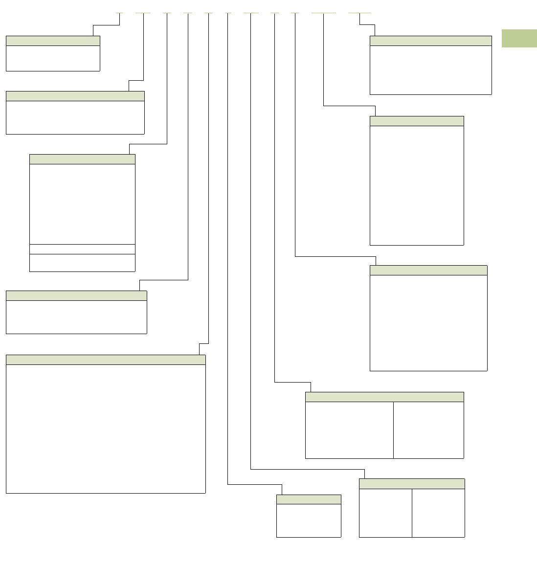
Volume 5—Motor Control and Protection CA08100006E—April 2014 www.eaton.com V5-T4-3
4
4
4
4
4
4
4
4
4
4
4
4
4
4
4
4
4
4
4
4
4
4
4
4
4
4
4
4
4
4
4.1
Definite Purpose Contactors and Starters
Product Overview—Contactors and Starters
Catalog Number Selection
Definite Purpose Control—Contactors and Starters
Note
1Not available on 50A devices.
Model
C = Contactor
A = Three-phase starter
B = Single-phase starter
Type
25 = Non-reversing contactors and starters (C306)
27 = Non-reversing starters (XTOB)
30 = Non-reversing starters (C440 EOL)
65 = Reversing contactors
C2 5 D N A 2 1 5 A A 1 6 1 - 8 4
Contactor Frame Size
A = Compact, single-pole
B = Compact, two-pole
C = Compact, single-pole w/shunt
D = 15–50A, two- and three-pole
E = 25–40A, four-pole
F = 60–75A, two- and three-pole
G = 90A, two- and three-pole
H = 120A, two- and three-pole
K = 200 and 300A, three-pole
L = 360A, three-pole
For Starters Only
C = Common control wiring
S = Separate control wiring
Enclosure Type
N = Open with metal mounting plate
R = Open with DIN rail mounting adapter
(two- and three-pole, 15–50A contactors only)
G = NEMA Type 1 Enclosed
Number of Poles
1 = Single-pole
2 = Two-pole
3 = Three-pole
4 = Four-pole
Options
Blank = Individual pkg.
GL = Global listed
-84 = 20 pc./pkg. (C25D_)
50 pc./pkg. (C25A_, C25B_, C25C_)
-86 = Rotate coil terminals 180° for
15A–50A contactors
Fuse Blocks
161 = Class M, 600V, 30A
237 = Class G, 300V, 15A
238 = Class G, 300V, 20A
231 = Class G, 300V, 30A
232 = Class G, 300V, 60A
361 = Class J, 600V, 30A
362 = Class J, 600V, 60A
431 = Class T, 300V, 30A
432 = Class T, 300V, 60A
461 = Class T, 600V, 30A
462 = Class T, 600V, 60A
521 = Class H, 250V, 30A
522 = Class H, 250V, 60A
621 = Class R, 250V, 30A
622 = Class R, 250V, 60A
Power Terminals
A = Binding head screw
B = Binding head screw and quick connect terminals (side-by-side)
C = Screw/pressure plate 1
D = Screw/pressure plate and quick connect terminals (side-by-side) 1
E = Box lugs (posidrive setscrew)
F = Box lugs (posidrive setscrew) and quick connect
terminals (side-by-side)
G = Binding head screw and quick connect terminals (vertical in-line)
H = Screw/pressure plate and quick connect terminals (vertical in-line) 1
J = Box lugs (posidrive setscrew) and quick connect terminals
(vertical in-line)
K = Box lugs (hex socket allen head setscrew)
L = Box lugs (hex socket allen head setscrew) and quick connect
terminals (side-by-side)
M = Box lugs (hex socket allen head setscrew) and quick connect
terminals (vertical in-line)
Auxiliary Contacts (Side Mount)
A = 1NO pressure plate
B = 1NC pressure plate
C = 1NO-1NC pressure plate
D = 2NO pressure plate
E = 2NC pressure plate
F = 1NO pressure plate and QC
G = 1NC pressure plate and QC
H = 1NO-1NC pressure plate and QC
J = 2NO pressure plate and QC
K = 2NC pressure plate and QC
L = 1NO-1NC snap switch QC only
M = 2NO-2NC snap switch QC only
Coil Selection
A = 110–120 Vac, 50/60 Hz
B = 208–240 Vac, 50/60 Hz
C = 440–480 Vac, 50/60 Hz
D = 550–600 Vac, 50/50 Hz
H = 277 Vac, 60 Hz
J = 220–240 Vac, 50/60 Hz
L = 380–415 Vac, 50 Hz
R = 12 Vac, 50/60 Hz
T = 24 Vac, 50/60 Hz
1R = 12 Vdc
1T = 24 Vdc
1W = 48 Vdc
1A = 120 Vdc
Current Rating
15 =15A
25 =25A
30 =30A
40 =40A
50 =50A
60 =60A
75 = 75A
90 = 90A
120 = 120A
200 = 200A
300 = 300A
360 = 360A
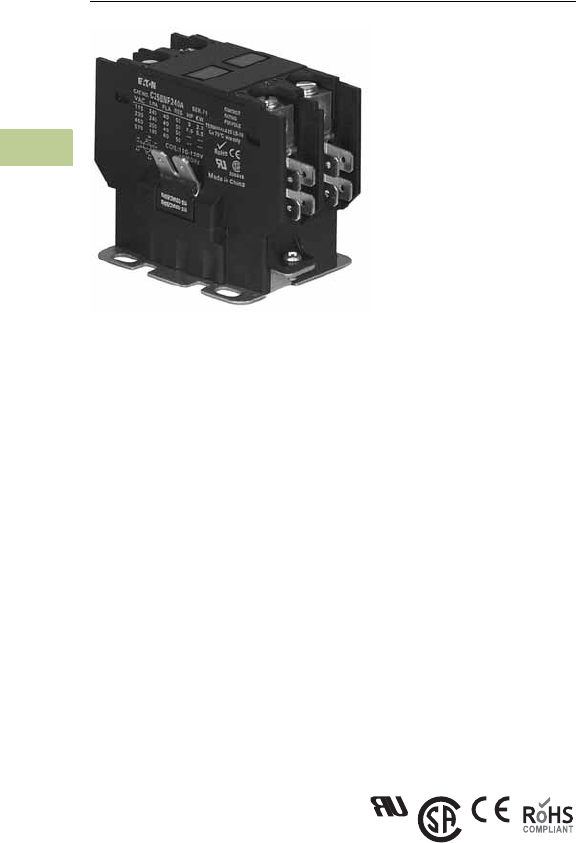
V5-T4-4 Volume 5—Motor Control and Protection CA08100006E—April 2014 www.eaton.com
4
4
4
4
4
4
4
4
4
4
4
4
4
4
4
4
4
4
4
4
4
4
4
4
4
4
4
4
4
4
4.2
Definite Purpose Contactors and Starters
Contactors
20–40A, Compact Single- and Two-Pole—C25
Contents
Description Page
20–40A, Compact Single- and Two-Pole—C25
Catalog Number Selection . . . . . . . . . . . . . . . . V5-T4-5
Product Selection . . . . . . . . . . . . . . . . . . . . . . . V5-T4-5
Options . . . . . . . . . . . . . . . . . . . . . . . . . . . . . . V5-T4-6
Technical Data and Specifications . . . . . . . . . . V5-T4-6
Dimensions . . . . . . . . . . . . . . . . . . . . . . . . . . . V5-T4-7
15–360A, Two-, Three- and Four-Pole—C25 . . . . . V5-T4-8
15–40A, Three-Pole Fuse Block . . . . . . . . . . . . . . . V5-T4-17
15–75A, Reversing and Two-Speed—C65 . . . . . . . V5-T4-20
20–40A, Compact Single- and Two-Pole—C25
Product Description
Eaton’s 20–40A, single- and
two-pole, Type C25
contactors from Eaton’s
Electrical Sector feature a
compact, efficient design
with a low VA coil and
straight-through wiring. New
contactor housing design
effectively limits dust and
other contaminants from
magnet structure—reduces
or eliminates noise. These
economically priced, UL
recognized/CSA certified,
ampere rated devices are
well suited for use in heating/
air conditioning, refrigeration,
data processing and food
service applications.
Standards and Certifications
●UL Recognized
Components: UL File
Number E1491, Guides
NLDX2 and NLDX8
●CSA Certified
Components: CSA C22.2
No. 14-05, File Number
238083 Class 3211 84
●IEC 60947-4-1
●EN 60947-4-1
●ARI 780/790 Standard
●CE
●RoHS Compliance
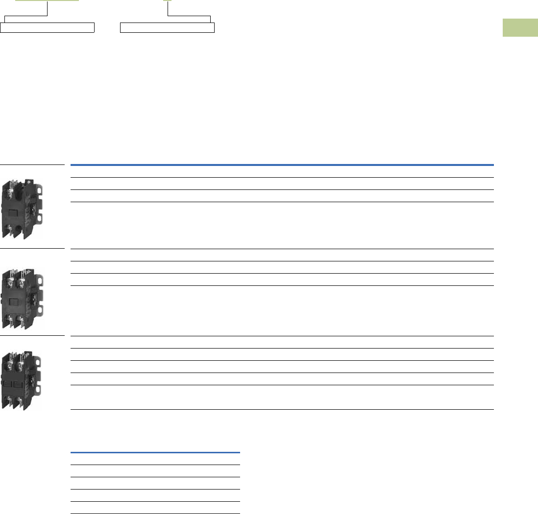
Volume 5—Motor Control and Protection CA08100006E—April 2014 www.eaton.com V5-T4-5
4
4
4
4
4
4
4
4
4
4
4
4
4
4
4
4
4
4
4
4
4
4
4
4
4
4
4
4
4
4
4.2
Definite Purpose Contactors and Starters
Contactors
Catalog Number Selection
20–40A, Compact Single- and Two-Pole—C25
When Ordering Specify
●Catalog number plus magnet coil suffix, see below
●Modify catalog number for any options required, see Options, Page V5-T4-6
Product Selection
Compact Contactors—Open Type
Magnet Coil Suffix
Notes
1 Rating per pole.
2 Incomplete catalog number. Replace underscore (_) in catalog number with coil suffix letter from the table above.
3 Bulk pack quantities are available in quantities of 50, contact local sales office.
Incomplete catalog number
C25BNB230 A
Magnet coil suffix
Ampere Rating 1Maximum Motor
(hp)
Maximum Motor
(kW)
Catalog Number 23
Inductive
Full Load Resistive
Locked Rotor
240–277V 480V 575V 115V 230V 115V 230V
Single-Pole
25 30 150 — — 2 3 1.5 2.2 C25ANB125_
30 40 150 75 50 2 5 1.5 3.7 C25ANB130_
40 50 240 — — 3 7-1/2 2.2 5.5 C25ANB140_
Single-Pole with Shunt
25 30 150 — — 2 3 1.5 2.2 C25CNB125_
30 40 150 75 50 2 5 1.5 3.7 C25CNB130_
40 50 240 — — 3 7-1/2 2.2 5.5 C25CNB140_
Tw o - Po l e
20 30 120 100 80 1-1/2 3 1.1 2.2 C25BNB220_
25 35 150 125 100 2 3 1.5 2.2 C25BNB225_
30 40 150 125 100 2 5 1.5 3.7 C25BNB230_
40 50 240 200 160 3 7-1/2 2.2 5.5 C25BNB240_
AC Coil Voltage
50/60 Hz Coil Suffix
24 T
110–120 A
208–240 B
277 H
380–415 (50 Hz), 440–480 (60 Hz) C
Single-Pole
Single-Pole
with Shunt
Two-Pole

V5-T4-6 Volume 5—Motor Control and Protection CA08100006E—April 2014 www.eaton.com
4
4
4
4
4
4
4
4
4
4
4
4
4
4
4
4
4
4
4
4
4
4
4
4
4
4
4
4
4
4
4.2
Definite Purpose Contactors and Starters
Contactors
Options
When Ordering Specify
To order replace letter in the 6th position of catalog number
with letter F. Example: C25BNF240A.
Compact Factory Installed Options
Technical Data and Specifications
20–40A, Compact Single- and Two-Pole—C25
Coil Characteristics
Description
Box lugs with quick connects for 20–40A contactors
Single-pole
Single-pole with shunt
Two-pole
Description Specification
Insulation voltage 690V
Current rated and hp/kw rated contacts Double break
Magnet coil Class F, 155°C
Contact arc covers Standard on all contactors
Standard power terminals 5/16 in hex washer head screws
Quad (4) quick connect terminals on all line and load terminals
Box lugs available as option
Line and load terminal designations Marked on contactors
Operating temperature range –13° to 158°F (–25° to 70°C)
Terminal wire range
Hex washer head screws 6–10 AWG, 30 lb-in torque rating
Box lugs 6–10 AWG, 35 lb-in torque rating
8 AWG, 40 lb-in torque rating
6–4 AWG, 45 lb-in torque rating
Mounting position Vertical, horizontal or tabletop
AC Coil
Voltage 50/60 Hz
Maximum
Inrush VA
Maximum
Sealed VA
Maximum
Sealed Watts
Single-Pole
24 33 6 2
120 33 6 2
208/240 33 6 2
277 33 6 2
Tw o - Po l e
24 41 6.5 3
120 41 6.5 3
208/240 41 6.5 3
277 41 6.5 3
480 41 6.5 3
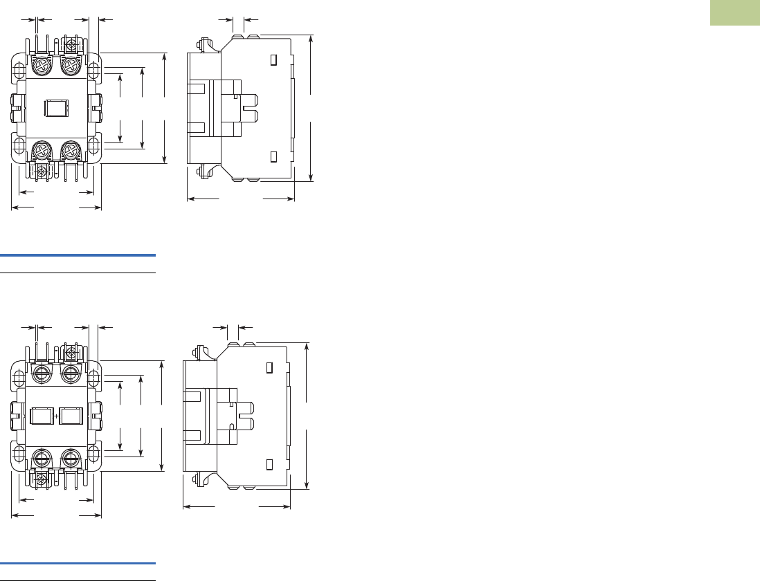
Volume 5—Motor Control and Protection CA08100006E—April 2014 www.eaton.com V5-T4-7
4
4
4
4
4
4
4
4
4
4
4
4
4
4
4
4
4
4
4
4
4
4
4
4
4
4
4
4
4
4
4.2
Definite Purpose Contactors and Starters
Contactors
Dimensions
Approximate Dimensions in Inches (mm)
20–40A, Compact Single- and Two-Pole—C25
Single-Pole and Single-Pole + Shunt
Tw o - Po l e
Approximate
Shipping Weight
0.5 lb (0.2 kg)
Approximate
Shipping Weight
0.7 lb (0.3 kg)
2.32 (59)
3.19
(81)
0.25 (6.3)
0.03
(0.8)
1.61 (41)
1.97 (50)
0.21
(5.2)
1.50
(38)
1.77
(45)
2.40
(61)
0.03
(0.8)
1.61 (41)
1.97 (50)
0.21
(5.2)
1.50
(38)
1.77
(45)
2.40
(61)
2.32 (59)
3.19
(81)
0.25 (6.3)
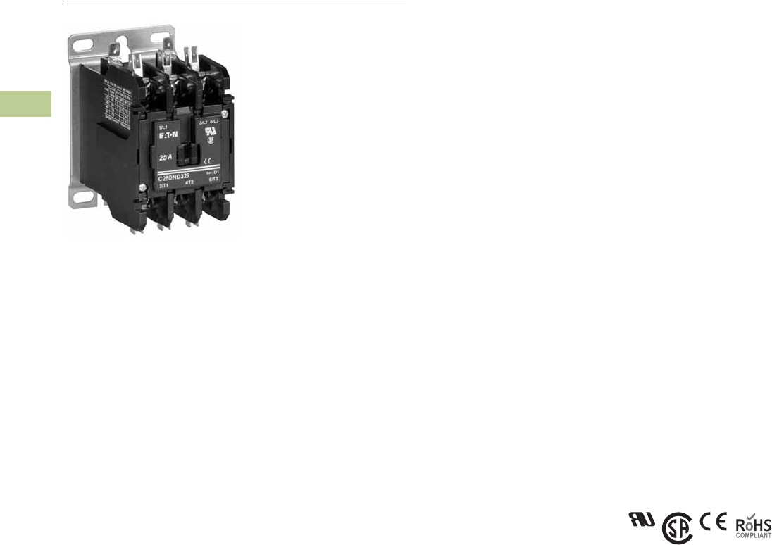
V5-T4-8 Volume 5—Motor Control and Protection CA08100006E—April 2014 www.eaton.com
4
4
4
4
4
4
4
4
4
4
4
4
4
4
4
4
4
4
4
4
4
4
4
4
4
4
4
4
4
4
4.2
Definite Purpose Contactors and Starters
Contactors
15–360A, Two-, Three- and Four-Pole—C25
Contents
Description Page
20–40A, Compact Single- and Two-Pole—C25 . . . V5-T4-4
15–360A, Two-, Three- and Four-Pole—C25
Product Selection . . . . . . . . . . . . . . . . . . . . . . . V5-T4-9
Accessories . . . . . . . . . . . . . . . . . . . . . . . . . . . V5-T4-11
Options . . . . . . . . . . . . . . . . . . . . . . . . . . . . . . V5-T4-13
Technical Data and Specifications . . . . . . . . . . V5-T4-14
Dimensions . . . . . . . . . . . . . . . . . . . . . . . . . . . V5-T4-16
15–40A, Three-Pole Fuse Block . . . . . . . . . . . . . . . V5-T4-17
15–75A, Reversing and Two-Speed—C65 . . . . . . . V5-T4-20
15–360A, Two-, Three- and Four-Pole—C25
Product Description
Eaton offers the most
comprehensive line of
definite purpose contactors in
the industry. Initially designed
as an HVAC and refrigeration
product, the C25 line is now
the market leader and the
product of choice for many
OEMs and contractors
serving diverse markets.
Featuring current ratings
between 15A and 360A, the
contactors are dual-rated for
inductive and resistive ratings
as well as for horsepower
and kilowatt ratings.
Other terminal configurations
are available, see Page
V5-T4-13. Contactors will
accept add-on auxiliary
contacts—order factory
assembled or as kits for field
installation.
The separately available snap-
on mechanical interlock
permits interlocking two
contactors for reversing or
two-speed applications.
Contactors between 15A
and 50A are offered as two
different lines—Standard
and Global Listed.
Standard DP Contactors
(15–50A, Two- and Three-Pole)
The standard line of C25 DP
contactor features:
●Pressure plates and quick
connects are standard on
15–30A contactors
●Lugs and quick connects
are standard on 40A and
50A contactors
●Highest electrical life in its
class—minimum 250,000
operations
●Universal baseplate
allows for easy retrofit of
competitive units (optional
DIN rail mounting)
●UL recognized design in
U.S. and Canada “cURus”
(CSA approval pending)
●Accessories including
auxiliary contacts,
mechanical interlocks
and fuse blocks
●RoHS (Reduction of
Hazardous Substances)
compliant
Global Listed Contactors
(15–50A, Two- and Three-Pole)
In addition to all the features
of the standard DP line,
the Global Listed line also
features:
●Exact footprint and
mounting dimensions as
the standard line—ideal
for retrofits
●CE (Conformité Européen),
CCC (China) and DEMKO
(Denmark) certifications
●Higher electrical life—
minimum 300,000
operations
Standards and Certifications
●UL Recognized
Components UL File
#E-1491, Guide NLDX2
●CSA Certified Components
File #LR353, Class 3211
04, 481301 and 122201
●CE mark (Global line only)
EN 60947-4-1
●RoHS Compliance
(15A to 50A and 90A)
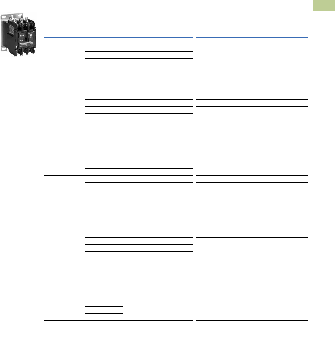
Volume 5—Motor Control and Protection CA08100006E—April 2014 www.eaton.com V5-T4-9
4
4
4
4
4
4
4
4
4
4
4
4
4
4
4
4
4
4
4
4
4
4
4
4
4
4
4
4
4
4
4.2
Definite Purpose Contactors and Starters
Contactors
Product Selection
When Ordering Specify
●Catalog number plus magnet coil suffix, see Page V5-T4-10
●Catalog numbers of accessory kits required, see Accessories, Page V5-T4-11
●Modify catalog number for any options required, see Options, Page V5-T4-13
C25 Contactors—Open Type
Note
1 Incomplete catalog number. Replace underscore (_) in catalog number with magnet coil suffix from table on Page V5-T4-10.
Maximum
Motor (hp)
Maximum
Motor (kW)
Number
of Poles
Standard DP Contactors Global Listed Line
Ampere Rating
With
Baseplate
With DIN Rail
Adapter
With
Baseplate
Inductive
Full Load
Resistive
per Pole
Line
Voltage
Locked
Rotor
Single-
Phase
Three-
Phase
Single-
Phase
Three-
Phase
Catalog
Number 1
Catalog
Number 1
Catalog
Number 1
15 20 115 90 3/4 — 0.40 — 2 C25DND215_ C25DRD215_ C25DND215_-GL
230 90 2 3 1.5 2.2 3 C25DND315_ C25DRD315_ C25DND315_-GL
460 75 — 5 — 3.7
575 60 — 5 — 3.7
25 35 115 150 2 — 1.5 — 2 C25DND225_ C25DRD225_ C25DND225_-GL
230 150 3 7-1/2 2.2 5.5 3 C25DND325_ C25DRD325_ C25DND325_-GL
460 125 — 10 — 7.5 4 C25END425_ — —
575 100 — 10 — 7.5
30 40 115 180 2 — 1.5 — 2 C25DND230_ C25DRD230_ C25DND230_-GL
230 180 5 10 3.7 7.5 3 C25DND330_ C25DRD330_ C25DND330_-GL
460 150 — 15 — 11 4 C25END430_ — —
575 120 — 15 — 11
40 50 115 240 3 — 2.2 — 2 C25DNF240_ C25DRF240_ C25DNF240_-GL
230 240 7-1/2 10 5.5 7.5 3 C25DNF340_ C25DRF340_ C25DNF340_-GL
460 200 — 20 — 15 4 C25ENF440_ — —
575 160 — 20 — 15
50 65 115 300 3 — 2.2 — 2 C25DNJ250_ C25DRJ250_ C25DNJ250_-GL
230 300 10 15 7.5 11 3 C25DNJ350_ C25DRJ350_ C25DNJ350_-GL
460 250 — 30 — 22
575 200 — 30 — 22
60 75 115 360 5 — 3.7 — 2 C25FNF260_ — —
230 360 10 20 7.5 15 3 C25FNF360_ — —
460 300 — 40 — 30
575 240 — 40 — 30
75 90 115 450 5 — 3.7 — 2 C25FNF275_ — —
230 450 15 20 11 18.5 3 C25FNF375_ — —
460 375 — 50 — 37
575 300 — 50 — 37
90 120 115 540 7-1/2 — 5.5 — 2 C25GNF290_ — —
230 540 15 30 11 22 3 C25GNF390_ — —
460 450 — 50 — 37
575 360 — 50 — 37
120 140 230720———— 3 C25HNE3120_ — —
460 720
575 570
200 200 2401200———— 3 C25KNE3200_ — —
480 1200
600 1000
300 300 2401800———— 3 C25KNE3300_ — —
480 1800
600 1500
360 360 2402320———— 3 C25LNE3360_ — —
480 2320
600 1900
DP Contactor

V5-T4-10 Volume 5—Motor Control and Protection CA08100006E—April 2014 www.eaton.com
4
4
4
4
4
4
4
4
4
4
4
4
4
4
4
4
4
4
4
4
4
4
4
4
4
4
4
4
4
4
4.2
Definite Purpose Contactors and Starters
Contactors
Magnet Coil Suffix
Notes
1 Class H AC coils available as option for 15A–50A contactor. Add 2 before AC coil suffix letter.
2 Available through 75A.
3 Available through 120A.
4 104–120V 50/60 Hz for 60A, 75A and all four-pole contactors (25A–40A).
5 Available 120–360A.
6 Available 15–90A, others 240V.
7 Available through 50A.
8 Not available for 90A.
9 Contactors with DC coils (only available up to 75A) include an early break NC auxiliary contact, C320KGD1.
See Page V5-T4-62 for more details.
jAvailable only for 15A through 75A contactors and four-pole contactors.
Voltage
60 Hertz 50 Hertz Coil Suffix
Voltage
60 Hertz Coil Suffix
AC 1DC 9
12 212 R12 1R
24 324 T24 1T
110–120 4110–120 4A48 1W
208 5—E120 1A j
208–240 6208–240 B
240 7220 J
277 — H
— 380–415 L
440–480 440–480 C
550–600 8550–600 D
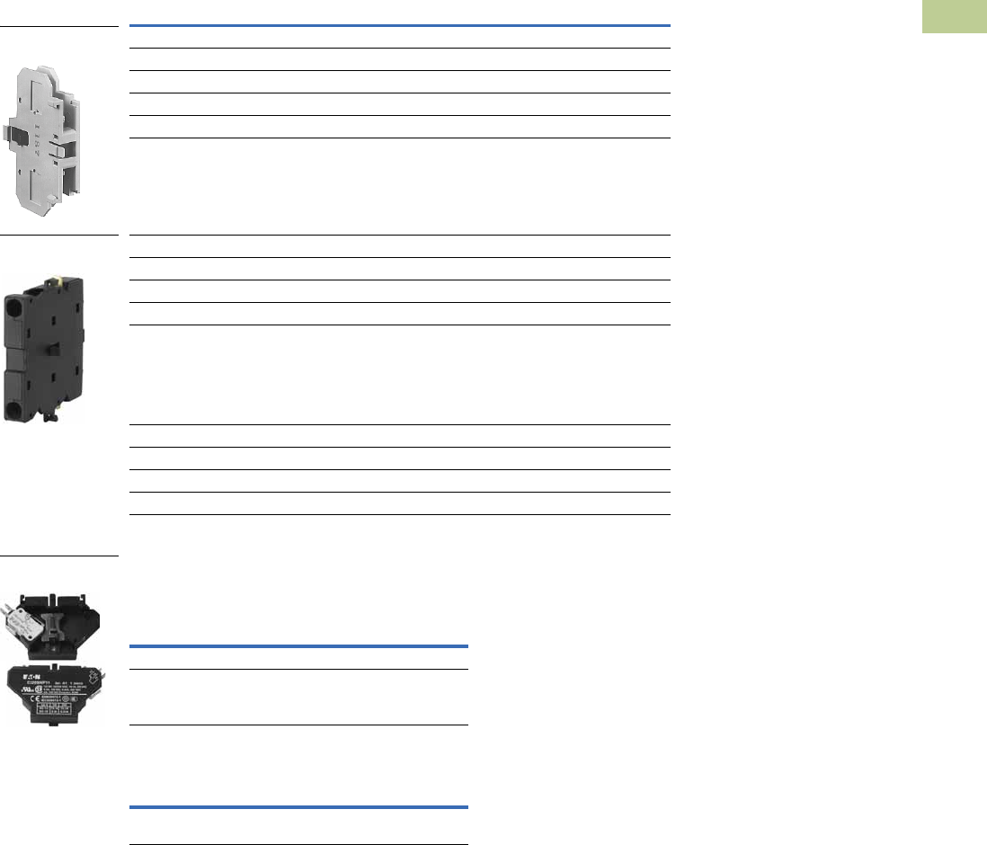
Volume 5—Motor Control and Protection CA08100006E—April 2014 www.eaton.com V5-T4-11
4
4
4
4
4
4
4
4
4
4
4
4
4
4
4
4
4
4
4
4
4
4
4
4
4
4
4
4
4
4
4.2
Definite Purpose Contactors and Starters
Contactors
Accessories
Auxiliary Contact Kits (Side Mounted)
Heavy-Duty Pilot Rated for 10A at 600 Vac
Snap Switch Design Side Mounted Auxiliary
Contacts (For 15–75A Contactors Only)
Magnet Coil Quick Connect Terminal
Notes
1 Valid on Series FI contactors only.
2 To order, add suffix number 9 to the complete catalog number.
Example: C25DND215A9.
With Standard Pressure
Plate Terminals
With Pressure Plate and
Quick Connect Terminals
Circuit Catalog Number Catalog Number
For 15 through 75A
1NO C320KG1 C320KG11
1NC C320KG2 C320KG12
1NO-1NC C320KG3 C320KG13
2NO C320KG4 C320KG14
2NC C320KG5 C320KG15
For 90A
1NO — FIC320DPG10 1
1NC — FIC320DPG01 1
1NO-1NC — FIC320DPG11 1
2NO — FIC320DPG20 1
For 120 through 360A
1NO C320KGS20 —
1NC C320KGS21 —
1NO-1NC C320KGS22 —
Snap Switch Design with
Quick Connect Terminals
Circuit Catalog Number
1NO-1NC C320SNP11
2NO-2NC C320SNP22
Description
Extra dual quick connect terminals (U-shaped)
for magnet coil terminals 2
Side Mounted
Auxiliary Contact
Auxiliary Contact for
FI Series Contactors
Side Mounted
Snap Switch
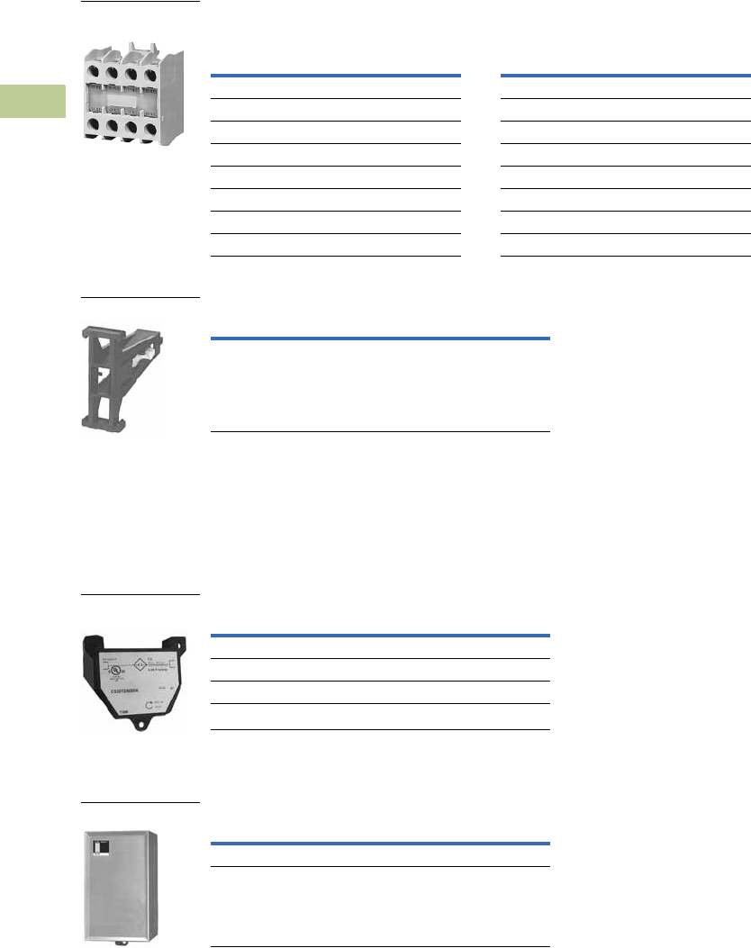
V5-T4-12 Volume 5—Motor Control and Protection CA08100006E—April 2014 www.eaton.com
4
4
4
4
4
4
4
4
4
4
4
4
4
4
4
4
4
4
4
4
4
4
4
4
4
4
4
4
4
4
4.2
Definite Purpose Contactors and Starters
Contactors
Auxiliary Contact Kits (Top Mounted)
Heavy-Duty Pilot Rated for 10A at 600 Vac
Mechanical Interlock Kit
Solid-State ON DELAY Timer
Side mounted on C25D, C25E and C25F frame.
This timer is designed to be wired in series with the load (typically a coil). When the START
button is pushed (power applied to timer), the ON DELAY timing function starts. At the completion
of the set timing period, timer and series wired load will both be energized.
Solid-State ON DELAY Timer
Separate Enclosures
Separate Enclosures—NEMA 1
Notes
1 Not available for four-pole contactors (15–40 Amp).
2 Add operating voltage suffix to catalog number.
A = 120V, B = 240V, E = 208V
3 Rated 0.5 ampere pilot duty—not to be used on larger contactors.
4 Terminal connections are quick connects only. Two per side.
With Standard Pressure
Plate Terminals
With Standard Pressure
Plate Terminals
Circuit Catalog Number Circuit Catalog Number
For 15 through 75A 1
1NO C320KGT1 1NO-2NC C320KGT11
1NC C320KGT2 3NC C320KGT12
1NO-1NC C320KGT3 4NO C320KGT13
2NO C320KGT4 3NO-1NC C320KGT14
2NC C320KGT5 2NO-2NC C320KGT15
3NO C320KGT9 1NO-3NC C320KGT16
2NO-1NC C320KGT10 4NC C320KGT17
Description Catalog Number
Mechanical interlock kit for 15 through 75A C321KM60B
Timing Range Catalog Number 234
0.1–1.0 seconds C320TDN1_
1–30 seconds C320TDN30_
30–300 seconds C320TDN300_
5–30 minutes C320TDN3000_
Application Catalog Number
15 through 50A, two- and three-pole C799B18
60A, two- and three-pole or
25 through 40A, four-pole
C799B19
Top Mounted
Auxiliary Contact
Mechanical Interlock
Solid-State ON DELAY
Timer
NEMA 1 Enclosure

Volume 5—Motor Control and Protection CA08100006E—April 2014 www.eaton.com V5-T4-13
4
4
4
4
4
4
4
4
4
4
4
4
4
4
4
4
4
4
4
4
4
4
4
4
4
4
4
4
4
4
4.2
Definite Purpose Contactors and Starters
Contactors
Options
To order C25, C65, A25 and B25 contactors and starters with the factory installed options listed
below, change the basic catalog number listed in the product selection table as noted.
Factory Installed Options Field Installed Options
Auxiliary Contacts (Side Mount)
Add code letter listed below to complete catalog number.
Example: Change C25DND215A to C25DND215AA.
Auxiliary Contacts—Factory Installed
Notes
1Screw/pressure plate terminals are not available on 50A contactors.
2Four-pole contactors have box lugs with slotted screws.
3Replace letter in the 6th position of catalog number with code letter listed. Example: Change C25FNF250 to C25FNE250.
490A available only with binding head screw and quick connect terminals.
5Kit contains quantity 1 shield.
6Not for use with Quick Connect terminals on the power poles.
Description Code Letter Number of Poles Description Catalog Number
Terminals—15A through 50A Finger-proof shield for 15–50A 49-7899KIT 56
Binding head screws
Without quick connect terminals A2-, 3-, 4-pole
With quick connect terminals (side-by-side) B2-, 3-, 4-pole
With quick connect terminals (vertical in-line) G2-, 3-pole
Screw/pressure plate 1
Without quick connect terminals C2-, 3-, 4-pole
With quick connect terminals (side-by-side) D2-, 3-, 4-pole
With quick connect terminals (vertical in-line) H2-, 3-pole
Box lugs (#2 posidrive/slotted screw
Without quick connect terminals E2-, 3-, 4-pole 2
With quick connect terminals (side-by-side) F2-, 3-, 4-pole 2
With quick connect terminals (vertical in-line) J2-, 3-pole
Box lugs (hex socket allen head screw)
Without quick connect terminals K2-, 3-pole
With quick connect terminals (side-by-side) L2-, 3-pole
With quick connect terminals (vertical in-line) M2-, 3-pole
Terminals—60A through 75A 3
Box lugs (slotted screw)
Without quick connect terminals E2-, 3-pole
With quick connect terminals F2-, 3-pole
Description
With Standard Pressure
Plate Terminals
With Quick
Connect Terminals
Snap Switch Design with
Quick Connect Terminals
Code Letter Code Letter Code Letter
For 15 through 90A 4
1NO AF —
1NC BG—
1NO-1NC CH—
2NO DJ—
2NC EK—
For 15 through 75A
1NO-1NC ——L
2NO-2NC ——M
For 120 through 360A
1NO A——
1NO-1NC C——
2NO D——
2NC E——
Special Marking (Special contactor marking, consult local sales office)

V5-T4-14 Volume 5—Motor Control and Protection CA08100006E—April 2014 www.eaton.com
4
4
4
4
4
4
4
4
4
4
4
4
4
4
4
4
4
4
4
4
4
4
4
4
4
4
4
4
4
4
4.2
Definite Purpose Contactors and Starters
Contactors
Technical Data and Specifications
Standard and Global Listed Line
15–360A, Two-, Three- and Four-Pole—C25
Contactor Torque Ratings
Notes
1The box lugs on the 15–75A device can accept two conductors per pole.
2The box lugs on the 15–50A device can accept two conductors per pole, the upper section will accept
4–14 AWG and the lower section will accept 6–14 AWG.
3The box lugs on the 60–75A device can accept two conductors per pole, the upper section will accept
3–14 AWG and the lower section will accept 6–14 AWG.
Specification
Description Standard Global Listed Line
Magnet coil Class B (C25E, F, G, H and K), 130°C
Class F (C25D and L), 155°C
Class H (C25D), 180°C
(available as factory installed option)
Class B (C25E, F, G, H and K), 130°C
Class F (C25D and L), 155°C
Class H (C25D), 180°C
(available as factory installed option)
Contacts Double break Double break
Coil terminals 18 AWG (90A) 18 AWG (90A)
Ambient temperature 150°F (65°C) maximum 150°F (65°C) maximum
Terminal wire range
#8–32 binding head screw 14–12 AWG (one conductor-solid) 14–12 AWG (one conductor-solid)
#8–32 screw/pressure plate 14–8 AWG (one conductor);
14–8 AWG (two conductors)
14–8 AWG (one conductor);
14–8 AWG (two conductors)
Box lugs—15–50A 1# 2 posidrive screw or 5/32 hex socket screw
Upper level: 14–4 AWG (one conductor)
Lower level: 14–6 AWG (one conductor)
# 2 posidrive screw or 5/32 hex socket screw
Upper level: 14–4 AWG (one conductor)
Lower level: 14–6 AWG (one conductor)
Box lugs—60–75A 1Upper level: 14–2 AWG
Lower level: 14–6 AWG
Upper level: 14–2 AWG
Lower level: 14–6 AWG
Box lugs—90A 1/0–8 AWG 1/0–8 AWG
Box lugs—120A 3/0–8 AWG 3/0–8 AWG
Box lugs—200–300A 350 kcmil–6 AWG 350 kcmil–6 AWG
Box lugs—360A 750 kcmil–2 AWG 750 kcmil–2 AWG
Contactor Size Terminal Wire Range Tightening Torque
15–50A 28–32 binding head screw 12–14 AWG 22 lb-in
Screw/pressure plate 8–14 AWG 15 lb-in
Box lug 12–14 AWG 15 lb-in
10 AWG 25 lb-in
8 AWG 40 lb-in
4–6 AWG 45 lb-in
60–75A 3Box lug 10–14 AWG 40 lb-in
8 AWG 45 lb-in
3–6 AWG 50 lb-in
90A Box lug 1/0–8 AWG 60 lb-in
120A Box lug 8 AWG 40 lb-in
4–6 AWG 45 lb-in
3–1/0 AWG 50 lb-in
200–300A Box lug 6–350 kcmil 200 lb-in
360A Box lug 2–750 kcmil 550 lb-in

Volume 5—Motor Control and Protection CA08100006E—April 2014 www.eaton.com V5-T4-15
4
4
4
4
4
4
4
4
4
4
4
4
4
4
4
4
4
4
4
4
4
4
4
4
4
4
4
4
4
4
4.2
Definite Purpose Contactors and Starters
Contactors
For Global Line Only
DC Ratings (Global Listed Line Only)
Lighting Duty Ratings (Global Listed Line Only)
IEC/CE Ratings (IEC 60947-4-1, EN 60947-4-1) for 15A through 50A
C25 D–Contactors (Global Listed Line Only)
Two-Pole, 15–30A Inductive Two-Pole, 40A Inductive Three-Pole, 15–30A Inductive Three-Pole, 40A Inductive
UL/CSA DC-3/DC-5 UL/CSA DC-3/DC-5 UL/CSA DC-3/DC-5 UL/CSA DC-3/DC-5
Voltage FLA hp IeFLA hp IeFLA hp IeFLA hp Ie
240 Vdc three poles in series — — — — — — 4 3/4 4 5 1 5
120 Vdc three poles in series — — — — — — 8 3/4 8 10 1 10
120 Vdc two poles in series 5.5 1/2 5.5 8 3/4 8 5.5 1/2 5.5 8 3/4 8
120 Vdc per pole 2 1/10 2 3.5 1/4 3.5 2 1/10 2 3.5 1/4 3.5
24 Vdc per pole 15 — 15 20 — 20 15 — 15 20 — 20
C25D_ Inductive Rating Tungsten and Ballast (480V)
25A 30A
30A 40A
40A 50A
50A 60A
C25D_ AC-1 (Ic)AC-3 (I
e)AC-4 (I
e)AC-8a
Inductive Rating 480V 600V 480V 600V 480V 600V 480V 600V
15A 20A 20A 15A 15A 15A — 15A 15A
25A 30A 30A 25A 25A 25A — 25A 25A
30A 40A 40A 30A 30A 30A — 30A 30A
40A 50A — 40A — 40A — 40A —
50A 65A 65A 50A 50A 50A — 50A 50A
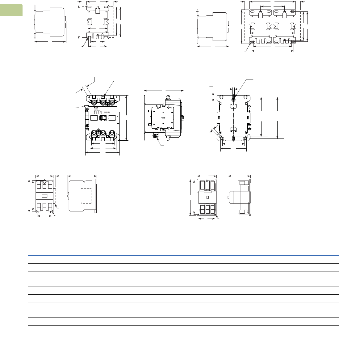
V5-T4-16 Volume 5—Motor Control and Protection CA08100006E—April 2014 www.eaton.com
4
4
4
4
4
4
4
4
4
4
4
4
4
4
4
4
4
4
4
4
4
4
4
4
4
4
4
4
4
4
4.2
Definite Purpose Contactors and Starters
Contactors
Dimensions
Approximate Dimensions in Inches (mm)
C25 Contactors, Open Type and Open Type—Reversing
15–75 Ampere (Non-Reversing) 15–75 Ampere (Reversing)
90 Ampere
120 Ampere 200–360 Ampere
Dimensions and Shipping Weights
Note
1Add 0.30 in (8 mm) to width for C25 contactors with DC coils.
C H
EMtg. Holes/Slots for 8 Screws
F
AJJ
BGD
Aux. Cont.
Aux. Cont.
C H
EMtg. Holes/Slots for 16 Screws
F
A
I
JJ
BGD
Aux. Cont.
Aux. Cont.
C
0.25 x 0.032 Male
with Quick Connect
Coil Terminal (2 places)
1NO Auxiliary Contact
with 0.25 x 0.032 Male
Quick Connects at Left
(2) 0.25 x 0.032 Male
with Quick Connects
(6 places)
B
A
H
E
0.20
(5.2)
0.20
(5.2)
0.20
(5.2)
0.393
(10.0) DIA
4.43
(112.5)
4.63
(117.5)
H
E
7/32 Hex Socket
(6 places)
Mtg. Holes for 3 Screws
ACJ
D
Aux.
BE
Side
Mtd.
Aux.
CA
BE
Mtg. Holes
for 3 Screws
D
Ampere
Size
Number
of Poles
Wide High Deep Mounting
Side Auxiliary
Contact Adder Shipping
Weight
Lbs (kg)ABCDE FGHJ
Open Type
15–50 2 and 3 2.40 (61.0) 13.75 (95.0) 3.35 (85.0) 3.25 (83.0) 2.00 (51.0) — 3.13 (79.0) 1.50 (38.0) 0.34 (8.6) 1.3 (.6)
25–40 4 2.68 (68.0) 13.75 (95.0) 3.38 (86.0) 3.25 (83.0) 2.00 (51.0) 1.50 (38.0) 3.13 (79.0) 1.50 (38.0) 0.50 (12.5) 2.3 (1.0)
60–75 2 and 3 2.63 (67.0) 13.75 (95.0) 3.97 (101.0) 3.25 (83.0) 2.00 (51.0) 1.50 (38.0) 3.13 (79.0) 1.50 (38.0) 0.37 (9.5) 2.8 (1.3)
90 2 and 3 3.86 (98.0) 5.00 (127.0) 4.41 (112.0) — 2.87 (73.0) — — 2.48 (63.0) — NN (NN)
120 2 and 3 3.54 (90.0) 7.17 (182.0) 5.94 (151.0) 3.00 (76.0) 6.63 (168.0) — — — 0.54 (13.7) 8.5 (3.9)
200 and 300 2 and 3 7.05 (179.0) 9.11 (232.0) 7.25 (184.0) 6.00 (152.0) 8.50 (216.0) — — — — 20.0 (9.1)
360 2 and 3 7.05 (179.0) 13.12 (333.0) 7.78 (198.0) 6.00 (152.0) 12.50 (318.0) — — — — 23.0 (10.4)
Open Type—Reversing
15–50 2 and 3 5.0 (127.0) 3.75 (95.0) 3.35 (85.0) 3.25 (83.0) 4.53 (118.0) — 3.13 (79.0) 4.13 (105.0) 0.34 (8.6) 2.6 (1.2)
60–75 2 and 3 5.77 (147.0) 3.75 (95.0) 3.97 (101.0) 3.25 (83.0 5.15 (131.0) 3.15 (80.0) 3.13 (79.0) 4.65 (118.0) 0.37 (9.5) 5.6 (2.5)
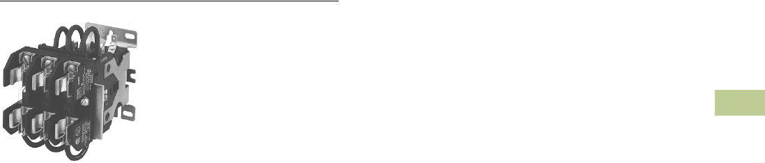
Volume 5—Motor Control and Protection CA08100006E—April 2014 www.eaton.com V5-T4-17
4
4
4
4
4
4
4
4
4
4
4
4
4
4
4
4
4
4
4
4
4
4
4
4
4
4
4
4
4
4
4.2
Definite Purpose Contactors and Starters
Contactors
15–40A, Three-Pole Fuse Block
Contents
Description Page
20–40A, Compact Single- and Two-Pole—C25 . . . V5-T4-4
15–360A, Two-, Three- and Four-Pole—C25 . . . . . V5-T4-8
15–40A, Three-Pole Fuse Block
Product Selection . . . . . . . . . . . . . . . . . . . . . . . V5-T4-18
Dimensions . . . . . . . . . . . . . . . . . . . . . . . . . . . V5-T4-19
15–75A, Reversing and Two-Speed—C65 . . . . . . . V5-T4-20
15–40A, Three-Pole Fuse Block
Product Description
Designed to save space and
reduce installation costs,
these three-pole fuse blocks
will accommodate a variety
of fuse classes and fuse
holders to satisfy a wide
range of electrical/electronic
applications such as
commercial space and water
heaters, dishwashers, food
coolers and sterilizing
equipment. They are supplied
either factory assembled,
mounted and wired to the
contactor or in kit form.
Note: Available only on three-
pole, 15–50A contactors
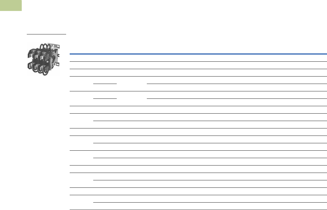
V5-T4-18 Volume 5—Motor Control and Protection CA08100006E—April 2014 www.eaton.com
4
4
4
4
4
4
4
4
4
4
4
4
4
4
4
4
4
4
4
4
4
4
4
4
4
4
4
4
4
4
4.2
Definite Purpose Contactors and Starters
Contactors
Product Selection
Optional Three-Pole Fuse Block
Available only on three-pole, 15–50A contactors
Designed to save space and reduce installation costs, these three-pole fuse blocks will accommodate
a variety of fuse classes and fuse holders to satisfy a wide range of electrical/electronic applications
such as commercial space and water heaters, dishwashers, food coolers and sterilizing equipment.
They are supplied either factory assembled, mounted and wired to the contactor or in kit form.
To order factory assembled, add suffix number from table below to catalog number of contactor listed
on Page V5-T4-9. Example: C25DND325A361.
Three-Pole Fuse Blocks
Fuse Holder Fuse Dimensions in Inches (mm) Maximum
Wire Size
Factory Installed
Ordering Suffix
Field Installation Kit
Catalog NumberVolts Amperes Diameter Length Terminal Type
Class M
600 30 0.41 (10.4) 1.50 (38.1) Pressure plate 10 AWG Cu 161 C350KM61
Class G
600 15 0.41 (10.4) 1.31 (33.3) Pressure plate 10 AWG Cu 237 C350KG37
20 1.41 (35.8) Pressure plate 10 AWG Cu 238 C350KG38
480 30 0.41 (10.4) 1.63 (41.4) Pressure plate 10 AWG Cu 231 C350KG31
60 2.25 (57.2) Box lug 2 AWG Cu/Al 232 C350KG32
Class J
600 30 0.81 (20.6) 2.25 (57.2) Pressure plate 10 AWG Cu 361 C350KJ61
60 1.06 (26.9) 2.38 (60.5) Box lug 2 AWG Cu/Al 362 C350KJ62
Class T
300 30 0.41 (10.4) 0.88 (22.4) Box lug 6 AWG Cu 431 C350KT31
60 0.56 (14.2) 0.88 (22.4) Box lug 2 AWG Cu/Al 432 C350KT32
600 30 0.56 (14.2) 1.50 (38.1) Box lug 6 AWG Cu 461 C350KT61
60 0.81 (20.6) 1.56 (39.6) Box lug 2 AWG Cu/Al 462 C350KT62
Class H
250 30 0.56 (14.2) 2.00 (50.8) Pressure plate 10 AWG Cu 521 C350KH21
60 0.81 (20.6) 3.00 (76.2) Box lug 2 AWG Cu/Al 522 C350KH22
Class R
250 30 0.56 (14.2) 2.00 (50.8) Pressure plate 10 AWG Cu 621 C350KR21
60 0.81 (20.6) 3.00 (76.2) Box lug 2 AWG Cu/Al 622 C350KR22
Three-Pole Fuse Block
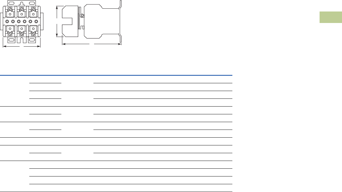
Volume 5—Motor Control and Protection CA08100006E—April 2014 www.eaton.com V5-T4-19
4
4
4
4
4
4
4
4
4
4
4
4
4
4
4
4
4
4
4
4
4
4
4
4
4
4
4
4
4
4
4.2
Definite Purpose Contactors and Starters
Contactors
Dimensions
Approximate Dimensions in Inches (mm)
Three-Pole Fuse Block and Contactor
Fuse Size
Class
Wide High Deep
Amps Volts A B C
G 15 600 2.41 (61) 2.81 (71) 5.14 (131)
20 2.41 (61) 2.81 (71) 5.14 (131)
30 480 2.41 (61) 2.81 (71) 5.14 (131)
60 2.62 (67) 4.25 (108) 5.18 (132)
H 30 250 3.00 (76) 3.03 (77) 5.33 (135)
60 4.22 (107) 4.75 (121) 5.86 (149)
J 30 600 4.81 (122) 4.12 (105) 5.92 (150)
60 4.81 (122) 4.12 (105) 5.92 (150)
M 30 600 2.41 (61) 2.81 (71) 5.14 (131)
R 30 250 3.00 (76) 3.03 (77) 5.33 (135)
60 4.22 (107) 4.75 (121) 5.86 (149)
T 30 300 3.44 (87) 2.75 (70) 5.43 (138)
60 300 3.44 (87) 2.75 (70) 5.43 (138)
30 600 3.75 (95) 3.19 (81) 5.36 (136)
60 600 4.87 (124) 2.94 (75) 5.68 (144)
B
A
Front View Side View
C
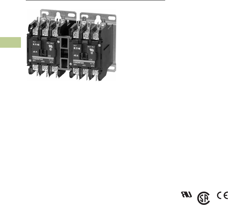
V5-T4-20 Volume 5—Motor Control and Protection CA08100006E—April 2014 www.eaton.com
4
4
4
4
4
4
4
4
4
4
4
4
4
4
4
4
4
4
4
4
4
4
4
4
4
4
4
4
4
4
4.2
Definite Purpose Contactors and Starters
Contactors
15–75A, Reversing and Two-Speed—C65
Contents
Description Page
20–40A, Compact Single- and Two-Pole—C25 . . . V5-T4-4
15–360A, Two-, Three- and Four-Pole—C25 . . . . . V5-T4-8
15–40A, Three-Pole Fuse Block . . . . . . . . . . . . . . . V5-T4-17
15–75A, Reversing and Two-Speed—C65
Catalog Number Selection . . . . . . . . . . . . . . . . V5-T4-21
Product Selection . . . . . . . . . . . . . . . . . . . . . . . V5-T4-21
15–75A, Reversing and Two-Speed—C65
Product Description
C65 Reversing Contactors
from Eaton’s Electrical
Sector are furnished with
pressure plates and quick
connect terminals as
standard on 15, 25 and 30A
devices and with box lugs
and quick connect terminals
on 40, 50, 60 and 75A.
Other terminal configurations
are available—see Factory
Installed Options on Page
V5-T4-13. Reversing
contactors will accept add-on
auxiliary contacts on either
side—order factory assembled
or as kits for field installation.
See Page V5-T4-13.
Standards and Certifications
●UL Recognized
Components UL File
#E-1491, Guide NLDX2
●CSA Certified Components
File #LR353, Guide
380w-1.14 Class 3211 04
●CE
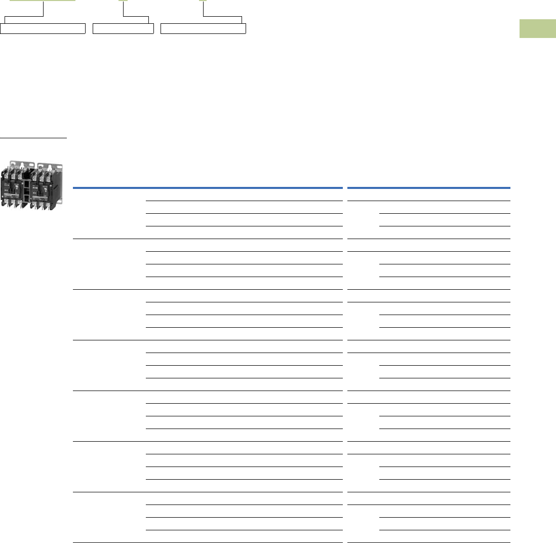
Volume 5—Motor Control and Protection CA08100006E—April 2014 www.eaton.com V5-T4-21
4
4
4
4
4
4
4
4
4
4
4
4
4
4
4
4
4
4
4
4
4
4
4
4
4
4
4
4
4
4
4.2
Definite Purpose Contactors and Starters
Contactors
Catalog Number Selection
15–75A, Reversing and Two-Speed—C65
When Ordering Specify
●Catalog number plus magnet coil suffix, see Page V5-T4-22
●Catalog numbers of accessory kits required, see Accessories, Page V5-T4-11
●Modify catalog number for any options required, see Options, Page V5-T4-13
Product Selection
Open Type Contactors—Unwired, Mechanically Interlocked Only
Note
1 Incomplete catalog number. Replace underscore (_) with magnet coil suffix from Page V5-T4-22.
Incomplete catalog number
C65DND315 A
Magnet coil suffix
X
Option code as necessary
Ampere Rating
Line
Voltage
Locked
Rotor
Maximum Motor
(hp)
Maximum Motor
(kW)
Number
of Poles
Open Type with Metal
Mounting Plate
Catalog Number 1
Open Type with DIN
Rail Adapter
Catalog Number 1
Inductive
Full Load
Resistive
per Pole
Single-
Phase
Three-
Phase
Single-
Phase
Three-
Phase
15 20 115 90 3/4 — 0.40 — 2 C65DND215_ C65DRD215_
230 90 2 3 1.5 2.2 3 C65DND315_ C65DRD315_
460 75 — 5 — 3.7 C65DND315_ C65DRD315_
575 60 — 5 — 3.7 C65DND315_ C65DRD315_
25 35 115 150 2 — 1.5 — 2 C65DND225_ C65DRD225_
230 150 3 7-1/2 2.2 5.5 3 C65DND325_ C65DRD325_
460 125 — 10 — 7.5 C65DND325_ C65DRD325_
575 100 — 10 — 7.5 C65DND325_ C65DRD325_
30 40 115 180 2 — 1.5 — 2 C65DND230_ C65DRD230_
230 180 5 10 3.7 7.5 3 C65DND330_ C65DRD330_
460 150 — 15 — 11 C65DND330_ C65DRD330_
575 120 — 15 — 11 C65DND330_ C65DRD330_
40 50 115 240 3 — 2.2 — 2 C65DNF240_ C65DRF240_
230 240 7-1/2 10 5.5 7.5 3 C65DNF340_ C65DRF340_
460 200 — 20 — 15 C65DNF340_ C65DRF340_
575 160 — 20 — 15 C65DNF340_ C65DRF340_
50 65 115 300 3 — 2.2 — 2 C65DNJ250_ C65DRJ250_
230 300 10 15 7.5 11 3 C65DNJ350_ C65DRJ350_
460 250 — 30 — 22 C65DNJ350_ C65DRJ350_
575 200 — 30 — 22 C65DNJ350_ C65DRJ350_
60 75 115 360 5 — 3.7 — 2 C65FNF260_ —
230 360 10 20 7.5 15 3 C65FNF360_ —
460 300 — 40 — 30 C65FNF360_ —
575 240 — 40 — 30 C65FNF360_ —
75 90 115 450 5 — 3.7 — 2 C65FNF275_ —
230 450 15 20 11 18.5 3 C65FNF375_ —
460 375 — 50 — 37 C65FNF375_ —
575 300 — 50 — 37 C65FNF375_ —
C65 Reversing
Contactor

V5-T4-22 Volume 5—Motor Control and Protection CA08100006E—April 2014 www.eaton.com
4
4
4
4
4
4
4
4
4
4
4
4
4
4
4
4
4
4
4
4
4
4
4
4
4
4
4
4
4
4
4.2
Definite Purpose Contactors and Starters
Contactors
Magnet Coil Suffix
Magnet Coil Options
Notes
1Class H AC coils available as option for 15A–50A contactor.
Add 2 before AC coil suffix letter.
2104–120V 50/60 Hz for 60A, 75A.
3Available through 50A.
Volts
60 Hz 50 Hz Coil Suffix 1
12 12 R
24 24 T
110–120 2110–120 2A
208–240 208–240 B
240 3220 J
277 — H
— 380–415 L
440–480 440–480 C
550–600 550–600 D
Description
Extra dual quick connect terminals (“U” shaped) for magnet coil terminals.
To order, add Suffix Number 9 to the complete catalog number.
Example: C65DND315A9.
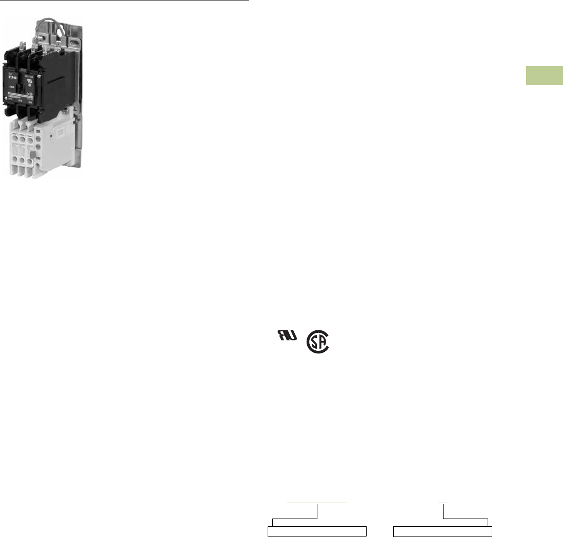
Volume 5—Motor Control and Protection CA08100006E—April 2014 www.eaton.com V5-T4-23
4
4
4
4
4
4
4
4
4
4
4
4
4
4
4
4
4
4
4
4
4
4
4
4
4
4
4
4
4
4
4.3
Definite Purpose Contactors and Starters
Starters
25–60A, Single- and Three-Phase—A25, B25
Contents
Description Page
25–60A, Single- and Three-Phase—A25, B25
Product Selection . . . . . . . . . . . . . . . . . . . . . . . V5-T4-24
Accessories . . . . . . . . . . . . . . . . . . . . . . . . . . . V5-T4-26
Technical Data and Specifications . . . . . . . . . . V5-T4-27
Trip Curves . . . . . . . . . . . . . . . . . . . . . . . . . . . . V5-T4-28
Wiring Diagrams . . . . . . . . . . . . . . . . . . . . . . . . V5-T4-28
Dimensions . . . . . . . . . . . . . . . . . . . . . . . . . . . V5-T4-29
15–45A, Single- and Three-Phase—A27, B27 . . . . V5-T4-30
15–75A, Single- and Three-Phase—A30, B30 and
C440/XT Electronic Overload Relay . . . . . . . . . . V5-T4-38
25–60A, Single- and Three-Phase—A25, B25
Product Description
A25 and B25 Definite
Purpose Starters from Eaton’s
Electrical Sector combine the
features and flexibility of the
C25 Definite Purpose
Contactors and Freedom
Series Bi-metallic Ambient
Compensated Overload
Relays mounted on a common
mounting plate.
Features and Benefits
Overload Relay
●Selectable manual or
automatic reset operation
●Interchangeable heater
packs adjustable ±24% to
match motor FLA and
calibrated for use with 1.0
and 1.15 service factor
motors
●Class 10 or 20 heater packs
●Bimetallic, ambient
compensated operated.
Trip free mechanism
●Electrically isolated NO-NC
contacts (pull RESET
button to test)
●Overload trip indication
●Shrouded or fingerproof
terminals to reduce
possibility of electrical
shock
●Single-phase sensitivity
Standards and Certifications
●UL Recognized
Components UL File
#E-1491, Guide NLDX2
●CSA Certified Components
File #LR353, Guide
380W-1.14 Class 3211 04
Catalog Number Selection
25–60A, Single- and Three-Phase—A25, B25
When Ordering Specify
●Catalog number plus magnet coil suffix, see Page V5-T4-24
Example, order catalog number A25CNC30A
●Heater packs for specific FLA of motor,
see Pages V5-T4-26 and V5-T4-27
Incomplete catalog number
A25CNC30 A
Magnet coil suffix
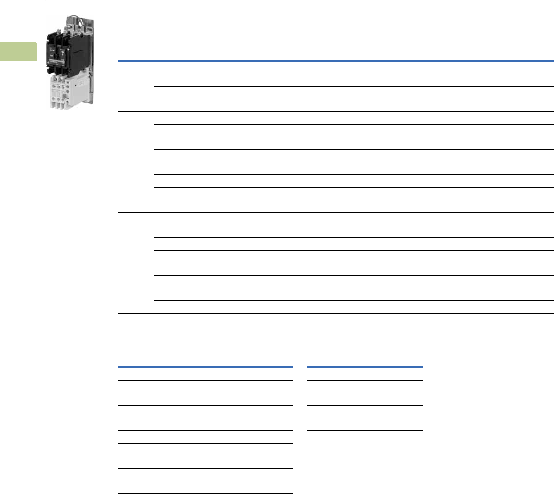
V5-T4-24 Volume 5—Motor Control and Protection CA08100006E—April 2014 www.eaton.com
4
4
4
4
4
4
4
4
4
4
4
4
4
4
4
4
4
4
4
4
4
4
4
4
4
4
4
4
4
4
4.3
Definite Purpose Contactors and Starters
Starters
Product Selection
Single- and Three-Phase Starters—Open Type
Magnet Coil Suffix
Notes
1 Starters do not include heater packs. Select heater pack from tables, see Pages V5-T4-26 and V5-T4-27.
2 Set of three heater packs required for single-phase applications.
3 Incomplete catalog number. Replace underscore (_) with magnet coil suffix from table above.
4 Class H AC coils available as option for 15A–50A contactor. Add 2 before AC coil suffix letter.
5 104–120V 50/60 Hz for 60A contactor.
6 Available through 50A.
7 Starters with DC coils include an early breaking auxiliary contact, C320KGD1. See Page V5-T4-62 for more detail.
Single-Phase 12 Three-Phase 1
Ampere Rating
Maximum Motor
(hp)
Maximum Motor
(kW)
Common
Control
Separate
Control
Common
Control
Separate
Control
Inductive
Full Load
Line
Voltage
Locked
Rotor
Single-
Phase
Three-
Phase
Single-
Phase
Three-
Phase
Catalog
Number 3
Catalog
Number 3
Catalog
Number 3
Catalog
Number 3
25 115 150 2 — 1.5 — B25CNC25_ B25SNC25_ A25CNC25_ A25SNC25_
230 150 3 7-1/2 2.2 5.5 B25CNC25_ B25SNC25_ A25CNC25_ A25SNC25_
460 125 — 10 — 7.5 B25CNC25_ B25SNC25_ A25CNC25_ A25SNC25_
575 100 — 10 — 7.5 B25CNC25_ B25SNC25_ A25CNC25_ A25SNC25_
30 115 180 2 — 1.5 — B25CNC30_ B25SNC30_ A25CNC30_ A25SNC30_
230 180 5 10 3.7 7.5 B25CNC30_ B25SNC30_ A25CNC30_ A25SNC30_
460 150 — 15 — 11 B25CNC30_ B25SNC30_ A25CNC30_ A25SNC30_
575 120 — 15 — 11 B25CNC30_ B25SNC30_ A25CNC30_ A25SNC30_
40 115 240 3 — 2.2 — B25CNE40_ B25SNE40_ A25CNE40_ A25SNE40_
230 240 7-1/2 10 5.5 7.5 B25CNE40_ B25SNE40_ A25CNE40_ A25SNE40_
460 200 — 20 — 15 B25CNE40_ B25SNE40_ A25CNE40_ A25SNE40_
575 160 — 20 — 15 B25CNE40_ B25SNE40_ A25CNE40_ A25SNE40_
50 115 300 — — — — N/A N/A A25CNE50_ A25SNE50_
230 300 — 15 — 11 N/A N/A A25CNE50_ A25SNE50_
460 250 — 30 — 22 N/A N/A A25CNE50_ A25SNE50_
575 200 — 30 — 22 N/A N/A A25CNE50_ A25SNE50_
60 115 360 — — — — N/A N/A A25CNE60_ A25SNE60_
230 360 — 20 — 15 N/A N/A A25CNE60_ A25SNE60_
460 300 — 40 — 30 N/A N/A A25CNE60_ A25SNE60_
575 240 — 40 — 30 N/A N/A A25CNE60_ A25SNE60_
Voltage
60 Hertz 50 Hertz Coil Suffix
Voltage
60 Hertz Coil Suffix
AC 4DC 7
12 12 R12 1R
24 24 T24 1T
110–120 5110–120 5A48 1W
208–240 208–240 B120 1A
240 6220 J
277 — H
— 380–415 L
440–480 440–480 C
550–600 550–600 D
A25 Starter

Volume 5—Motor Control and Protection CA08100006E—April 2014 www.eaton.com V5-T4-25
4
4
4
4
4
4
4
4
4
4
4
4
4
4
4
4
4
4
4
4
4
4
4
4
4
4
4
4
4
4
4.3
Definite Purpose Contactors and Starters
Starters
Overload Relay
General
Overload relays are provided
to protect motors, motor
control apparatus and motor-
branch circuit conductors
against excessive heating
due to motor overloads and
failure to start. This definition
does not include: 1) motor
circuits over 600 volts, 2)
short-circuits, 3) ground faults
and 4) fire pump control.
(NEC Art. 430-31)
Time Current
Characteristics
The time-current
characteristics of an overload
relay is an expression of
performance which defines
its operating time at various
multiples of its current
setting. Tests are run at
Underwriters Laboratory (UL)
in accordance with NEMA
Standards and the NEC.
UL requires—
●When tested at 100
percent of its current
rating, the overload relay
shall trip ultimately
●When tested at 200
percent of its current
rating, the overload relay
shall trip in not more than 8
minutes
●When tested at 600
percent of its current
rating, the overload relay
shall trip in not more than
10 or 20 seconds,
depending on the Class of
the relay or heater packs
“Current Rating” is defined
as the minimum current at
which the relay will trip. Per
NEC, an overload must
ultimately trip at 125% of FLA
(Full Load Amperes) current
(heater) setting for a 1.15
service factor motor and
115% FLA for a 1.0 service
factor motor.“Current
Setting” is defined as the
FLA of the motor and thus
the overload heater pack
setting.
Example: 600% of current
rating is defined as 750%
(600 x 1.25) of FLA current
(heater) setting for a 1.15
service factor motor. A 10
ampere heater setting must
trip in 20 seconds or less at
75 amperes motor current for
a Class 20 relay.
Overload Relay Setting
FLA Dial Adjustment—
For motors having a 1.15
service factor, rotate the FLA
adjustment dial to correspond
to the motor’s FLA rating.
Estimate the dial position
when the motor FLA falls
between two letter values as
shown in the example.
For motors having a 1.0
service factor, rotate the FLA
dial single-half position
counterclockwise (CCW).
Manual/Automatic Reset—
The overload relay is factory
set at M for manual reset
operation. For automatic
reset operation, turn the reset
adjustment dial to the A
position as shown in the
illustration.
Automatic reset is not
intended for two-wire control
devices.
Test for Trip Indication—
To test overload relay for trip
indication when in manual
reset, pull out the blue RESET
button. An orange flag will
appear indicating that the
device has tripped. Push
RESET button in to reset.
FLA Dial Adjustment Reset Adjustment Dial
Example of 12.0 FLA
setting for heater pack
number H2011B showing
position for 1.0 or 1.15
service factor motors.
Example of setting for manual
reset.
Replacement Overload with Connectors
AD
CB
1.0
Service
Factor
1.15
Service
Factor
A
M
Starter Size Overload Part Number
25 and 30A 10-7125
40 and 50A 10-7132
60A 10-7131

V5-T4-26 Volume 5—Motor Control and Protection CA08100006E—April 2014 www.eaton.com
4
4
4
4
4
4
4
4
4
4
4
4
4
4
4
4
4
4
4
4
4
4
4
4
4
4
4
4
4
4
4.3
Definite Purpose Contactors and Starters
Starters
Accessories
Contactor Accessories, see Pages V5-T4-11 and V5-T4-12.
Locking Cover for Overload Relay
Snap-on transparent or opaque plastic panel for covering access port to the overload relay trip
setting dial—helps prevent accidental or unauthorized changes to trip and reset setting.
Locking Cover for Overload Relay
Separate Enclosures
Separate Enclosures—NEMA 1
Heater Packs
Fast Trip—Class 10 Heater Packs
Manual or Automatic Reset
Heater packs are shipped three to a carton.
Catalog numbers listed below are for three heater packs.
Fast Trip Ratings
Notes
1For motor full load amperes between listed values, adjust dial clockwise for higher or counter-
clockwise for lower motor currents. The currents listed are for 1.5 service factor motors.
A position adjustment is provided for 1.0 service factor motors.
2Set of three heater packs are required for both single- and three-phase applications.
Description
Minimum Order
Quantity
(Std. Pkg.) Catalog Number
Clear cover, no accessibility 50 C320PC3
Gray cover, no accessibility, with auto only nib 50 C320PC4
Gray cover, no accessibility, with manual only nib 50 C320PC5
Gray cover with FLA dial accessibility, A, B, C, D positions
and auto only nib
50 C320PC6
Gray cover with FLA dial accessibility, A, B, C, D positions
and manual only nib
50 C320PC7
Application Catalog Number
25 and 30A C799B11
40, 50 and 60A C799B13
Motor Full Load Ampere Rating 1Catalog Number 2
(Includes Three Heater
Packs)
Dial Position
ABCD
0.26 0.313 0.367 0.42 H2101B-3
0.384 0.464 0.543 0.623 H2102B-3
0.57 0.688 0.806 0.924 H2103B-3
0.846 1.02 1.2 1.37 H2104B-3
1.28 1.55 1.83 2.1 H2105B-3
1.92 2.33 2.74 3.15 H2106B-3
2.3 2.79 3.28 3.77 H2107B-3
3.38 4.1 4.82 5.54 H2108B-3
4.96 6.03 7.09 8.16 H2109B-3
7.07 8.58 10.1 11.6 H2110B-3
9.6 11.2 12.8 14.4 H2111B-3
14.4 17.5 20.7 23.8 H2112B-3
18.7 21.8 25 28.1 H2113B-3
23.5 27.3 31 34.8 H2114B-3
28.3 32.6 37 41.3 H2115B-3
36.6 42.3 48.1 53.8 H2116B-3
53.8 60.8 67.9 74.9 H2117B-3
Trip Curves, see Page V5-T4-28.
Locking Cover

Volume 5—Motor Control and Protection CA08100006E—April 2014 www.eaton.com V5-T4-27
4
4
4
4
4
4
4
4
4
4
4
4
4
4
4
4
4
4
4
4
4
4
4
4
4
4
4
4
4
4
4.3
Definite Purpose Contactors and Starters
Starters
Standard Trip—Class 20 Heater Packs
Manual or Automatic Reset
Heater packs are shipped three to a carton.
Catalog numbers listed below are for three heater packs.
Standard Trip Ratings
Technical Data and Specifications
Terminal Wire Sizes
Power Terminals—Load—Cu Only (Stranded or Solid)
Notes
1For motor full load amperes between listed values, adjust dial clockwise for higher or counter-
clockwise for lower motor currents. The currents listed are for 1.5 service factor motors.
A position adjustment is provided for 1.0 service factor motors.
2Set of three heater packs are required for both single- and three-phase applications.
3Line side (contactor) torque ratings can be found on Page V5-T4-14.
Motor Full Load Ampere Rating 1
Catalog Number 2
(Includes Three Heater
Packs)
Dial Position
ABCD
0.254 0.306 0.359 0.411 H2001B-3
0.375 0.452 0.53 0.607 H2002B-3
0.56 0.676 0.791 0.907 H2003B-3
0.814 0.983 1.15 1.32 H2004B-3
1.2 1.45 1.71 1.96 H2005B-3
1.79 2.16 2.53 2.9 H2006B-3
2.15 2.6 3.04 3.49 H2007B-3
3.23 3.9 4.56 5.23 H2008B-3
4.55 5.5 6.45 7.4 H2009B-3
6.75 8.17 9.58 11 H2010B-3
9.14 10.8 12.4 14 H2011B-3
14 16.9 19.9 22.8 H2012B-3
18.7 22.7 26.7 30.7 H2013B-3
23.5 28.5 33.5 38.5 H2014B-3
29 34 39.1 44.1 H2015B-3
39.6 45.5 51.5 57.4 H2016B-3
53.9 60.9 67.9 74.9 H2017B-3
Trip Curves, see Page V5-T4-28.
Line Side (Contactor) 3
Wire Range—Solid or Stranded
Terminal Type Power Terminals Coil Terminals
Screw/pressure plate 8–14 AWG 12–16 AWG
Box lug: 25–50A 4–14 AWG 12–16 AWG
Box lug: 60A 3–14 AWG 12–16 AWG
Terminal Range Torque Rating
25 and 30A 14–6 AWG 20 lb-in (14–10 AWG)
40, 50 and 60A 14–2 AWG 35 lb-in (14–10 AWG)
40 lb-in (8 AWG)
45 lb-in (6–4 AWG)
50 lb-in (3–2 AWG)
Control Terminals—Cu Only
12–16 AWG stranded, 12–14 AWG solid
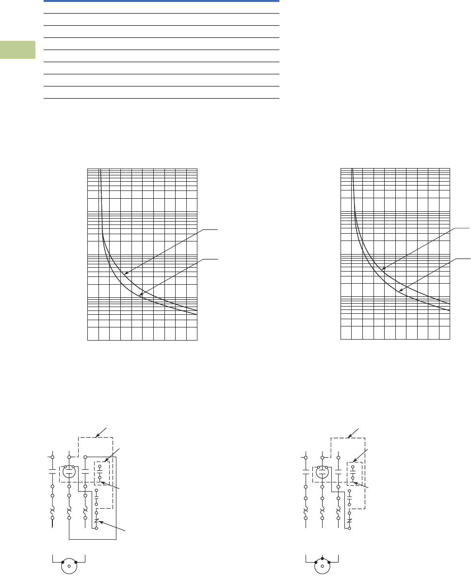
V5-T4-28 Volume 5—Motor Control and Protection CA08100006E—April 2014 www.eaton.com
4
4
4
4
4
4
4
4
4
4
4
4
4
4
4
4
4
4
4
4
4
4
4
4
4
4
4
4
4
4
4.3
Definite Purpose Contactors and Starters
Starters
Overload Relay UL/CSA Contact Ratings Control Circuit
Trip Curves
Bimetallic Ambient Compensated Overload Relay—25°C Open Rating
Class 10 Overload Relay Class 20 Overload Relay
Wiring Diagrams
Single-Phase Connections Three-Phase Connections
AC Volts 120V 240V 480V 600V
NC Contact B600
Make and break 30A 15A 7.5A 6A
Break 3A 1.5A 0.75A 0.6A
Continuous 5A 5A 5A 5A
NO Contact C600
Make and break 15A 7.5A 3.375A 3A
Break 1.5A 0.75A 0.375A 0.3A
Continuous 2.5A 2.5A 2.5A 2.5A
0
1
2
3
4
5
10
20
30
40
50
100
200
300
400
500
1000
2000
3000
4000
5000
10,000
246810
From
Hot Start
From
Cold Start
Multiples of Current Setting
Trip Time
(Seconds)
0
1
2
3
4
5
10
20
30
40
50
100
200
300
400
500
1000
2000
3000
4000
5000
10,000
246810
From
Hot Start
From
Cold Start
Multiples of Current Setting
Trip Time
(Seconds)
1NO Aux. Contact
(When Supplied)
Reset
Wire “D”
(Supplied with
1NO Aux. Contact)
Wire “C”
(Supplied with Common Control)
1
13
14
L1 L2
T1
4/T22/T1
T2
AC Motor
98
97
96
95
AC Motor
T2
L1 L2 L3
1
13
14
T1
6/T32/T1 4/T2
T3
98
97
96
95
Wire “D”
(Supplied with
1NO Aux. Contact)
Wire “C”
(Supplied with Common Control)
1NO Aux. Contact
(When Supplied)
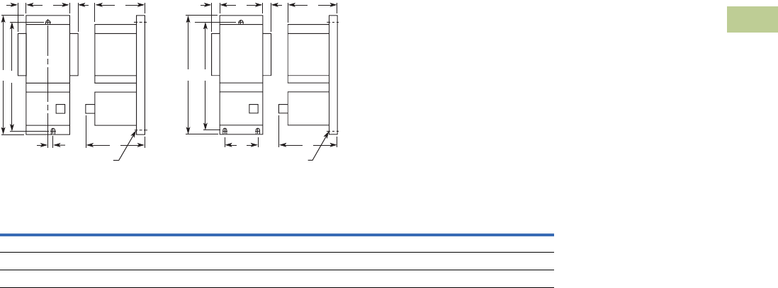
Volume 5—Motor Control and Protection CA08100006E—April 2014 www.eaton.com V5-T4-29
4
4
4
4
4
4
4
4
4
4
4
4
4
4
4
4
4
4
4
4
4
4
4
4
4
4
4
4
4
4
4.3
Definite Purpose Contactors and Starters
Starters
Dimensions
Approximate Dimensions in Inches (mm)
A25 and B25 Starers—Open Type
25 and 30 Ampere
40, 50 and 60 Ampere
Dimensions and Shipping Weights
G D
C
Mtg. for #10-32 Screw
AHH
BE
G D
Mtg. for #10-32 Screw
CAHH
BE
Ampere Size
Wide
A
High
B
Deep
C
Deep
D
Mounting
E
Mounting
G
Auxiliary
Contact Adder
H
Shipping
Weight
Lbs (kg)
25 and 30 2.50 (64.0) 7.14 (181.0) 3.56 (90.4) 3.69 (93.7) 6.55 (166.0) 0.20 (5.1) 0.54 (13.7) 1.8 (0.8)
40 2.56 (65.0) 8.08 (205.0) 3.50 (89.0) 3.66 (93.0) 7.50 (190.5) 2.00 (51.0) 0.54 (13.7) 1.8 (0.8)
50 and 60 2.56 (65.0) 8.08 (205.0) 4.15 (105.0) 3.66 (93.0) 7.50 (190.5) 2.00 (51.0) 0.54 (13.7) 3.6 (1.6)
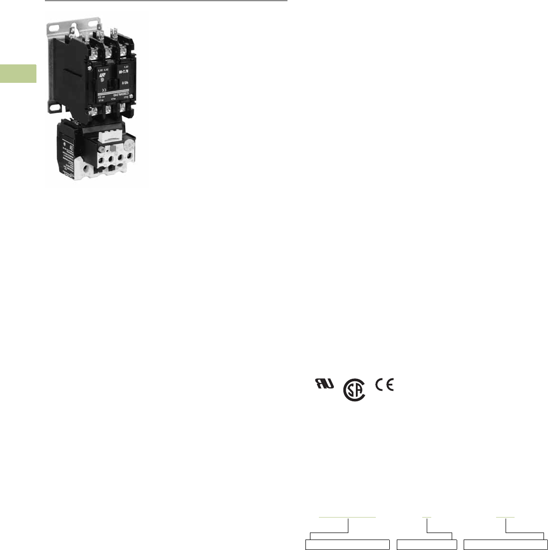
V5-T4-30 Volume 5—Motor Control and Protection CA08100006E—April 2014 www.eaton.com
4
4
4
4
4
4
4
4
4
4
4
4
4
4
4
4
4
4
4
4
4
4
4
4
4
4
4
4
4
4
4.3
Definite Purpose Contactors and Starters
Starters
15–45A, Single- and Three-Phase—A27, B27
Contents
Description Page
25–60A, Single- and Three-Phase—A25, B25 . . . . V5-T4-23
15–45A, Single- and Three-Phase—A27, B27
Product Selection . . . . . . . . . . . . . . . . . . . . . . . V5-T4-31
Renewal Parts . . . . . . . . . . . . . . . . . . . . . . . . . V5-T4-33
Technical Data and Specifications . . . . . . . . . . V5-T4-33
Trip Curve . . . . . . . . . . . . . . . . . . . . . . . . . . . . . V5-T4-36
Wiring Diagrams . . . . . . . . . . . . . . . . . . . . . . . V5-T4-36
Dimensions . . . . . . . . . . . . . . . . . . . . . . . . . . . V5-T4-37
15–75A, Single- and Three-Phase—A30, B30 and
C440/XT Electronic Overload Relay . . . . . . . . . . V5-T4-38
15–45A, Single- and Three-Phase—A27, B27
Product Description
A27 and B27 Definite
Purpose Starters from
Eaton’s Electrical Sector
combine the features and
flexibility of the C25 Definite
Purpose Contactors and XT
Series Bi-metallic Ambient
Compensated Overload
Relays.
Features and Benefits
●Selectable manual or
automatic reset operation
●Class 10 trip class
●Bimetallic, ambient
compensated operated.
Trip free mechanism
●Electrically isolated NO-NC
contacts (pull TEST button
to test)
●Shrouded or fingerproof
terminals to reduce
possibility of electrical
shock
●Single-phase sensitivity
Standards and Certifications
●UL Recognized
Components UL File
#E-1491, Guide NLDX2
●CSA Certified Components
File #LR353, Guide 3
80W-1.14 Class 3211 04
●IEC/EN 60947
●VDE 0660
●UL
●CSA
●CE
Catalog Number Selection
15–45A, Single- and Three-Phase—A27, B27
When Ordering Specify
●Catalog number plus magnet coil suffix plus overload relay
suffix, see Page V5-T4-32
Example, order catalog number A27CNE30A040
Incomplete catalog number
A27CNE30 A
Magnet coil suffix
040
Overload relay suffix
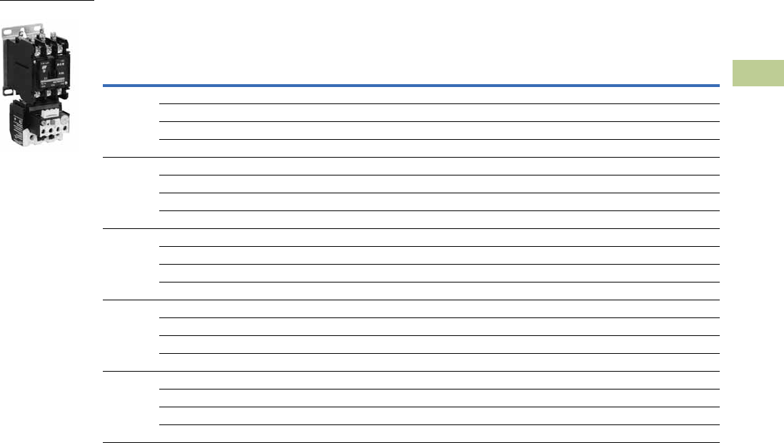
Volume 5—Motor Control and Protection CA08100006E—April 2014 www.eaton.com V5-T4-31
4
4
4
4
4
4
4
4
4
4
4
4
4
4
4
4
4
4
4
4
4
4
4
4
4
4
4
4
4
4
4.3
Definite Purpose Contactors and Starters
Starters
Product Selection
Three-Phase Starter—Open Type
Note
1 Incomplete catalog number. Replace underscore (_) with magnet coil suffix and overload relay suffix from Page V5-T4-32.
Maximum
Motor (hp)
Maximum
Motor (kW)
Common Control Separate Control
Ampere Rating
Metal
Mounting Plate
DIN Rail
Adapter
Metal
Mounting Plate
DIN Rail
Adapter
Inductive
Full Load
Line
Voltage
Locked
Rotor
Catalog
Number 1
Catalog
Number 1
Catalog
Number 1
Catalog
Number 1
15 115 90 — — A27CNC15_ A27CRC15_ A27SNC15_ A27SRC15_
230 90 3 2.2 A27CNC15_ A27CRC15_ A27SNC15_ A27SRC15_
460 75 5 3.7 A27CNC15_ A27CRC15_ A27SNC15_ A27SRC15_
575 60 5 3.7 A27CNC15_ A27CRC15_ A27SNC15_ A27SRC15_
25 115 150 — — A27CNC25_ A27CRC25_ A27SNC25_ A27SRC25_
230 150 7-1/2 5.5 A27CNC25_ A27CRC25_ A27SNC25_ A27SRC25_
460 125 10 7.5 A27CNC25_ A27CRC25_ A27SNC25_ A27SRC25_
575 100 10 7.5 A27CNC25_ A27CRC25_ A27SNC25_ A27SRC25_
30 115 180 — — A27CNE30_ A27CRE30_ A27SNE30_ A27SRE30_
230 180 10 7.5 A27CNE30_ A27CRE30_ A27SNE30_ A27SRE30_
460 150 15 11 A27CNE30_ A27CRE30_ A27SNE30_ A27SRE30_
575 120 15 11 A27CNE30_ A27CRE30_ A27SNE30_ A27SRE30_
40 115 240 — — A27CNE40_ A27CRE40_ A27SNE40_ A27SRE40_
230 240 10 7.5 A27CNE40_ A27CRE40_ A27SNE40_ A27SRE40_
460 200 20 15 A27CNE40_ A27CRE40_ A27SNE40_ A27SRE40_
575 160 20 15 A27CNE40_ A27CRE40_ A27SNE40_ A27SRE40_
45 115 270 — — A27CNE45_ A27CRE45_ A27SNE45_ A27SRE45_
230 270 15 11 A27CNE45_ A27CRE45_ A27SNE45_ A27SRE45_
460 225 30 22 A27CNE45_ A27CRE45_ A27SNE45_ A27SRE45_
575 180 30 22 A27CNE45_ A27CRE45_ A27SNE45_ A27SRE45_
A27 Starter

V5-T4-32 Volume 5—Motor Control and Protection CA08100006E—April 2014 www.eaton.com
4
4
4
4
4
4
4
4
4
4
4
4
4
4
4
4
4
4
4
4
4
4
4
4
4
4
4
4
4
4
4.3
Definite Purpose Contactors and Starters
Starters
Single-Phase Starter—Open Type, B27
Magnet Coil Suffix
Notes
1Incomplete catalog number. Replace underscore (_) with magnet coil suffix and overload
relay suffix from tables above.
2Class H AC coils available as option. Add 2 before AC coil suffix letter.
3Available through 45A.
4Starters with DC coils include an early breaking auxiliary contact, C320KGD1.
See Page V5-T4-62 for more detail.
Overload Relay Suffix
Maximum
Motor (hp)
Maximum
Motor (kW)
Common Control Separate Control
Ampere Rating
Metal
Mounting Plate
DIN Rail
Adapter
Metal
Mounting Plate
DIN Rail
Adapter
Inductive
Full Load
Line
Voltage
Locked
Rotor
Catalog
Number 1
Catalog
Number 1
Catalog
Number 1
Catalog
Number 1
15 115 90 3/4 0.4 B27CNC15_ B27CRC15_ B27SNC15_ B27SRC15_
230 90 2 1.5 B27CNC15_ B27CRC15_ B27SNC15_ B27SRC15_
460 75 — — B27CNC15_ B27CRC15_ B27SNC15_ B27SRC15_
575 60 — — B27CNC15_ B27CRC15_ B27SNC15_ B27SRC15_
25 115 150 2 1.5 B27CNC25_ B27CRC25_ B27SNC25_ B27SRC25_
230 150 3 2.2 B27CNC25_ B27CRC25_ B27SNC25_ B27SRC25_
460 125 — — B27CNC25_ B27CRC25_ B27SNC25_ B27SRC25_
575 100 — — B27CNC25_ B27CRC25_ B27SNC25_ B27SRC25_
30 115 180 2 1.5 B27CNE30_ B27CRE30_ B27SNE30_ B27SRE30_
230 180 5 3.7 B27CNE30_ B27CRE30_ B27SNE30_ B27SRE30_
460 150 — — B27CNE30_ B27CRE30_ B27SNE30_ B27SRE30_
575 120 — — B27CNE30_ B27CRE30_ B27SNE30_ B27SRE30_
40 115 240 3 2.2 B27CNE40_ B27CRE40_ B27SNE40_ B27SRE40_
230 240 7-1/2 5.5 B27CNE40_ B27CRE40_ B27SNE40_ B27SRE40_
460 200 — — B27CNE40_ B27CRE40_ B27SNE40_ B27SRE40_
575 160 — — B27CNE40_ B27CRE40_ B27SNE40_ B27SRE40_
45 115 270 3 2.2 B27CNE45_ B27CRE45_ B27SNE45_ B27SRE45_
230 270 7-1/2 7.5 B27CNE45_ B27CRE45_ B27SNE45_ B27SRE45_
460 225 — — B27CNE45_ B27CRE45_ B27SNE45_ B27SRE45_
575 180 — — B27CNE45_ B27CRE45_ B27SNE45_ B27SRE45_
Voltage
60 Hertz 50 Hertz Coil Suffix
Voltage
60 Hertz Coil Suffix
AC 2DC 4
12 12 R12 1R
24 24 T24 1T
110–120 110–120 A48 1W
208–240 208–240 B120 1A
240 3220 J
277 — H
— 380–415 L
440–480 440–480 C
550–600 550–600 D
Motor Full Load Amperes Suffix Code
For use with Contactor
Ampere Range
Frame C
0.1–0.16 P16 15–25A
0.16–0.24 P24 15–25A
0.24–0.4 P40 15–25A
0.4–0.6 P60 15–25A
0.6–1 001 15–25A
1–1.6 1P6 15–25A
1.6–2.4 2P4 15–25A
2.4–4 004 15–25A
4–6 006 15–25A
6–10 010 15–25A
10–16 016 15–25A
16–24 024 15–25A
24–32 032 15–25A
Frame D
6–10 010 30–45A
10–16 016 30–45A
16–24 024 30–45A
24–40 040 30–45A
40–57 057 30–45A

Volume 5—Motor Control and Protection CA08100006E—April 2014 www.eaton.com V5-T4-33
4
4
4
4
4
4
4
4
4
4
4
4
4
4
4
4
4
4
4
4
4
4
4
4
4
4
4
4
4
4
4.3
Definite Purpose Contactors and Starters
Starters
Renewal Parts
Overload Relays
Technical Data and Specifications
Terminal Wire Sizes
Note
1Line side (contactor) torque ratings can be found on Page V5-T4-14.
Power Terminals—Load—Cu Only (Stranded or Solid)
Motor Full
Load Amperes Suffix Code
For use with
Contactor
Ampere Range
Overload Relay
Catalog Number
Frame C
0.1–0.16 P16 15–25A XTOBP16CC1DP
0.16–0.24 P24 15–25A XTOBP24CC1DP
0.24–0.4 P40 15–25A XTOBP40CC1DP
0.4–0.6 P60 15–25A XTOBP60CC1DP
0.6–1 001 15–25A XTOB001CC1DP
1–1.6 1P6 15–25A XTOB1P6CC1DP
1.6–2.4 2P4 15–25A XTOB2P4CC1DP
2.4–4 004 15–25A XTOB004CC1DP
4–6 006 15–25A XTOB006CC1DP
6–10 010 15–25A XTOB010CC1DP
10–16 016 15–25A XTOB016CC1DP
16–24 024 15–25A XTOB024CC1DP
24–32 032 15–25A XTOB032CC1DP
Frame D
6–10 010 30–45A XTOB010DC1DP
10–16 016 30–45A XTOB016DC1DP
16–24 024 30–45A XTOB024DC1DP
24–40 040 30–45A XTOB040DC1DP
40–57 057 30–45A XTOB057DC1DP
Line Side (Contactor) 1Wire Range—Solid or Stranded
Terminal Type Power Terminals Coil Terminals
Screw/pressure plate 8–14 AWG 12–16 AWG
Box lug: 15–45A 4–14 AWG 12–16 AWG
Terminal Range Torque Rating
15 and 25A 14–8 AWG 16 lb-in (14–8 AWG)
30, 40 and 45A 14–2 AWG 31 lb-in (14–2 AWG)
Control Terminals—Cu Only
12–16 AWG stranded, 12–14 AWG solid

V5-T4-34 Volume 5—Motor Control and Protection CA08100006E—April 2014 www.eaton.com
4
4
4
4
4
4
4
4
4
4
4
4
4
4
4
4
4
4
4
4
4
4
4
4
4
4
4
4
4
4
4.3
Definite Purpose Contactors and Starters
Starters
Overload Relays
These tripping characteristics are the mean values of the spread at 20°C ambient temperature
in a cold state.
Tripping time depends on response current. With devices at operating temperature, the
tripping time of the overload relay reduces to approximately 25% of the read off value.
Specific characteristics for each individual setting range can be found in MN03402001E.
Overload Relays
Notes
1Ambient temperature operating range to IEC/EN 60947, PTB: –5° to 50°C [23° to 122°F].
26 mm2 flexible with ferrules to DIN 46228.
3Main contact terminal capacity, solid and stranded conductors with ferrules: When using two conductors use identical cross-section.
Description
XTOB … CC1
Specification
XTOB … DC1
Specification
General
Climatic proofing Damp heat, constant, to IEC 60068-2-78;
Damp heat, cyclic, to IEC 60 068-2-30
Damp heat, constant, to IEC 60068-2-78;
Damp heat, cyclic, to IEC 60 068-2-30
Ambient temperature range 1–25° to 50°C [–13° to 122°F] –25° to 50°C [–13° to 122°F]
Temperature compensation Continuous Continuous
Mechanical shock resistance (IEC/EN 60068-2-27)
Half-sinusoidal shock 10 ms 10g 10g
Degree of protection IP20 IP20
Protection against direct contact when actuated
from front (IEC 536)
Finger and back of hand proof Finger and back of hand proof
Insulation voltage (Ui) Vac 690 690
Overvoltage category/pollution degree III/3 III/3
Impulse withstand voltage (Uimp) Vac 6000 6000
Operational voltage (Ue) Vac 690 690
Safe isolation to VDE 0106 Part 101 and Part 101/A1
Between auxiliary contacts and main contacts (Vac) 440 440
Between main contacts (Vac) 440 440
Overload relay setting range 0.1–32A 6–75A
Temperature compensation residual error >20°C (%/K) <0.25 <0.25
Current heat loss (3 conductors)
Lower value of setting range, W 2.5 3
Upper value of setting range, W 6 7.5
Terminal capacity 2 x (1–6) 2 x (1–6)
Solid, mm22 x (1–4) 1 x 25
Flexible with ferrule, mm22 x (1–6) 22 x (1–10) 3
Solid or stranded, AWG 14-8 14-2
Terminal screw M4 M6
Tightening torque Nm (lb-in) 1.8 (16) 3.5 (31)
Tools
Pozidrive screwdriver Size 2 Size 2
Standard screwdriver 1 x 6 1 x 6

Volume 5—Motor Control and Protection CA08100006E—April 2014 www.eaton.com V5-T4-35
4
4
4
4
4
4
4
4
4
4
4
4
4
4
4
4
4
4
4
4
4
4
4
4
4
4
4
4
4
4
4.3
Definite Purpose Contactors and Starters
Starters
Overload Relays, continued
Note
1Rated operational current: Making and breaking conditions to DC-13, L/R constant as stated.
Description
XTOB … CC1
Specification
XTOB … DC1
Specification
Auxiliary and Control Circuit Connections
Impulse withstand voltage (Uimp) Vac 6000 6000
Overvoltage category/pollution degree III/3 III/3
Terminal capacity
Solid, mm2 2 x (0.75–4) 2 x (0.75–4)
Flexible with ferrule, mm2 2 x (0.75–2.5) 2 x (0.75–2.5)
Solid or stranded, AWG 2 x (18–12) 2 x (18–12)
Terminal screw M3.5 M3.5
Tightening torque Nm (lb-in) 0.8–1.3 (7–11.5) 0.8–1.3 (7–11.5)
Tools
Pozidrive screwdriver Size 2 Size 2
Standard screwdriver 1 x 6 1 x 6
Auxiliary circuit rated insulation voltage (Ui) Vac 500 500
Rated operational voltage (Ue) Vac 500 500
Safe isolation to VDE 0106 Part 101 and Part 101/A1
Between the auxiliary contacts (Vac) 240 240
Conventional thermal current, Ith 66
Rated operational current—AC-15
NO contact
120V 1.5 1.5
240V 1.5 1.5
415V 0.5 0.5
500V 0.5 0.5
NC contact
120V 1.5 1.5
240V 1.5 1.5
415V 0.9 0.9
500V 0.8 0.8
Rated operational current—DC-13 L/R <15 ms 1
NO contact
24V 0.9 0.9
60V 0.75 0.75
110V 0.4 0.4
220V 0.2 0.2
Short-circuit rating without welding maximum fuse, A gG/gL 6 6
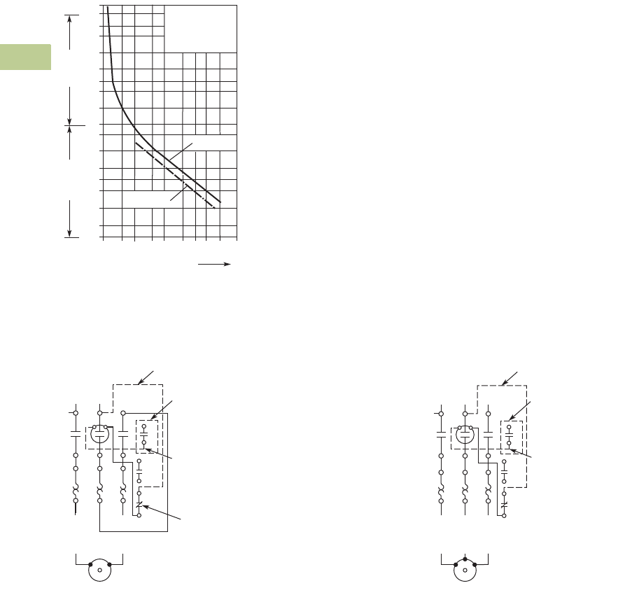
V5-T4-36 Volume 5—Motor Control and Protection CA08100006E—April 2014 www.eaton.com
4
4
4
4
4
4
4
4
4
4
4
4
4
4
4
4
4
4
4
4
4
4
4
4
4
4
4
4
4
4
4.3
Definite Purpose Contactors and Starters
Starters
Trip Curve
Overload Relay
Wiring Diagrams
Single-Phase Connections Three-Phase Connections
2h
100
60
40
20
10
6
4
2
1
40
20
10
6
4
2
1
0.6
XTOB...CC1,
XTOB...DC1
1 1.5 2 3 4 68 10 15 20
x Setting Current
2-Phase
Seconds Minutes
3-Phase
1NO Aux. Contact
(When Supplied)
Reset
Wire “D”
(Supplied with
1NO Aux. Contact)
Wire “C”
(Supplied with Common Control)
1
13
14
L1 L2
T1
4/T22/T1
T2
AC Motor
98
97
96
95
AC Motor
T2
L1 L2 L3
1
13
14
T1
6/T32/T1 4/T2
T3
98
97
96
95
Wire “D”
(Supplied with
1NO Aux. Contact)
Wire “C”
(Supplied with Common Control)
1NO Aux. Contact
(When Supplied)
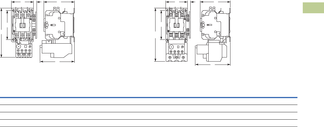
Volume 5—Motor Control and Protection CA08100006E—April 2014 www.eaton.com V5-T4-37
4
4
4
4
4
4
4
4
4
4
4
4
4
4
4
4
4
4
4
4
4
4
4
4
4
4
4
4
4
4
4.3
Definite Purpose Contactors and Starters
Starters
Dimensions
Approximate Dimensions in Inches (mm)
A27 and B27 Starters—Open Type
15 and 25 Ampere
30, 40 and 45 Ampere
Dimensions and Shipping Weights
D
CAH
B
E
D
C
AH
B
E
Ampere Size
Wide
A
High
B
Deep
C
Deep
D
Mounting
E
Mounting
G
Auxiliary
Contact Adder
H
Shipping Weight
Lbs (kg)
15 and 25 (metal plate) 2.40 (61.0) 5.50 (139.0) 3.35 (85.0) 3.70 (94.0) 3.13 (82.6) — 0.54 (13.7) 1.6 (0.7)
15 and 25 (DIN rail mount) 2.23 (56.5) 5.20 (133.0) 3.35 (85.0) 3.70 (94.0) — — 0.54 (13.7) 1.6 (0.7)
30, 40 and 45 (metal plate) 2.40 (61.0) 6.00 (152.0) 3.35 (85.0) 3.90 (98.0) 3.13 (82.6) — 0.54 (13.7) 1.11 (0.9)
30, 40 and 45 (DIN rail mount) 2.23 (56.5) 5.70 (145.0) 3.35 (85.0) 3.90 (98.0) — — 0.54 (13.7) 1.11 (0.9)
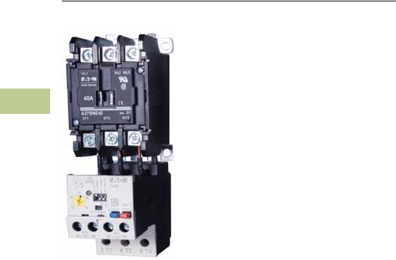
V5-T4-38 Volume 5—Motor Control and Protection CA08100006E—April 2014 www.eaton.com
4
4
4
4
4
4
4
4
4
4
4
4
4
4
4
4
4
4
4
4
4
4
4
4
4
4
4
4
4
4
4.3
Definite Purpose Contactors and Starters
Starters
15–75A, Single- and Three-Phase—A30, B30 and
C440/XT Electronic Overload Relay
Contents
Description Page
25–60A, Single- and Three-Phase—A25, B25 . . . . V5-T4-23
15–45A, Single- and Three-Phase—A27, B27 . . . . V5-T4-30
15–75A, Single- and Three-Phase—A30, B30 and
C440/XT Electronic Overload Relay
Standards and Certifications . . . . . . . . . . . . . . V5-T4-39
Catalog Number Selection . . . . . . . . . . . . . . . . V5-T4-39
Product Selection . . . . . . . . . . . . . . . . . . . . . . . V5-T4-40
Accessories . . . . . . . . . . . . . . . . . . . . . . . . . . . V5-T4-42
Technical Data and Specifications . . . . . . . . . . V5-T4-43
Wiring Diagrams . . . . . . . . . . . . . . . . . . . . . . . V5-T4-45
15–75A, Single- and Three-Phase—A30, B30 and
C440/XT Electronic Overload Relay
Product Description
A30 and B30 Starters
A30 and B30 Definite
Purpose Starters from Eaton’s
Electrical Sector combine the
features and flexibility of the
C25 Definite Purpose
Contactors and C440
Electronic Overload Relays.
C440 Overload
C440 is the most compact,
high-featured, economical
product in its class.
C440 is a self-powered
electronic overload relay
available up to 100A as a
self contained unit. With
external CTs, C440 can
protect motor up to
1500 FLA. Available add-on
accessories include remote
reset capability and
communication modules
with I/O for DeviceNet,
PROFIBUS, and Modbus.
Features
A30 and B30 Starters
●Standard version:
selectable trip class
(10A, 10, 20, 30) with
selectable manual or
auto reset
●Current adjustment
range: 5:1
●Self-powered design—will
accept AC voltages from
12 to 690V 50/60 Hz
●Ambient temperature
compensation
●Low heat generation
●Phase loss protection
●Phase unbalance
protection
●Electrically isolated
1NO-1NC contacts
(push-to-test)
●Trip status indicator
C440 Overload
●Reliable, accurate,
electronic motor protection
●Easy to select, install and
maintain
●Compact size
●Flexible, intelligent design
●Global product offering—
available with NEMA, IEC
and DP power control
Motor Control
●Two B600 alarm (NO) and
fault (NC) contacts
●Test/Trip button
Motor Protection
●Thermal overload
●Phase loss
●Selectable (ON/OFF)
phase unbalance
●Selectable (ON/OFF)
ground fault
User Interface
●Large FLA selection dial
●Trip status indicator
●Operating mode LED
●DIP switch selectable trip
class, phase unbalance and
ground fault
●Selectable Auto/Manual
reset
Feature Options
●Remote reset
●120 Vac
●24 Vac
●24 Vdc
●Tamper-proof cover
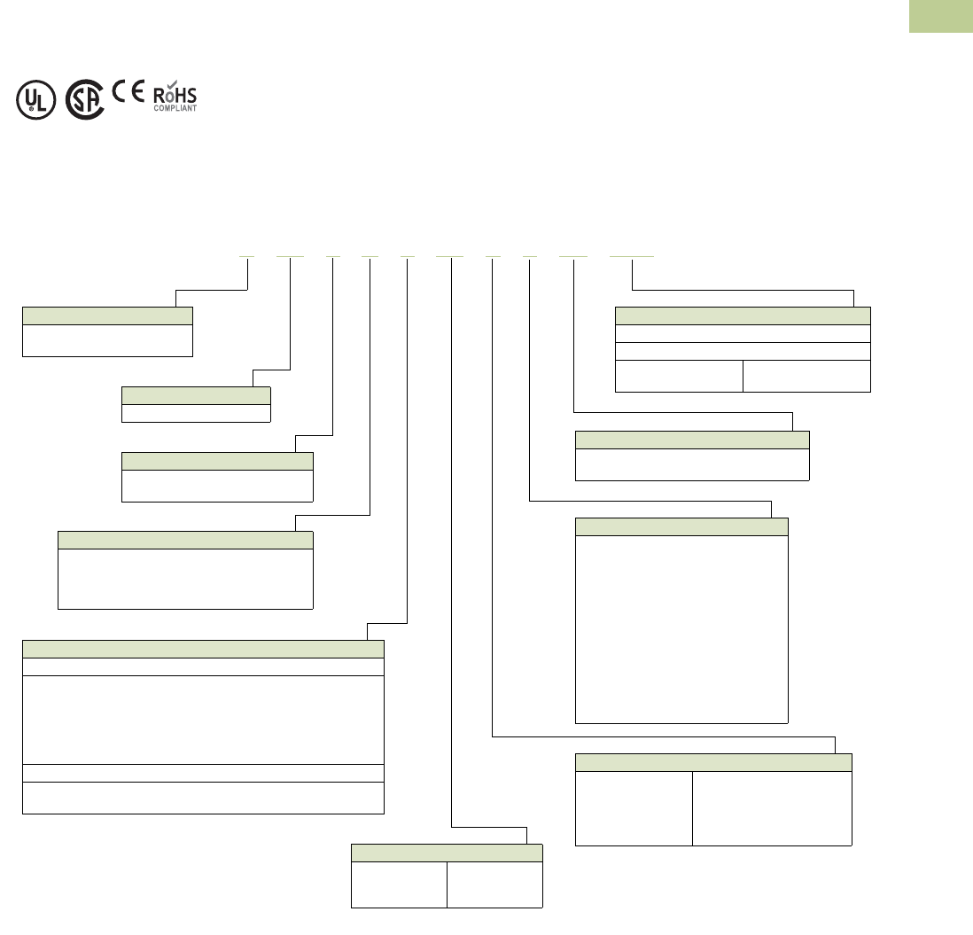
Volume 5—Motor Control and Protection CA08100006E—April 2014 www.eaton.com V5-T4-39
4
4
4
4
4
4
4
4
4
4
4
4
4
4
4
4
4
4
4
4
4
4
4
4
4
4
4
4
4
4
4.3
Definite Purpose Contactors and Starters
Starters
Standards and Certifications
A30 and B30 Starters
●UL Listed Components
●CSA Certified Components
●IEC EN 60947-4-1, EN
60947-5-1
●CE Certified Components
●CCC Certified Components
●
RoHS Certified Components
Catalog Number Selection
A30 and B30 Definite Purpose Starters
Designation
A = Three-phase starter
B = Single-phase starter
Type
30 = Non-reversing
Control
C = Common control
S = Separate control
Enclosure Type
N = Open with metal mounting plate
R = Open with DIN rail mounting adapter
(two- and three-pole, 15–50A contactors only)
G = NEMA Type 1 enclosed
Power Terminals
15–40A Contactor
A = Binding head screws without quick connect terminals
B = Binding head screws with quick connect terminals
C = Pressure plate without quick connect terminals
D = Pressure plate with quick connect terminals
E = Lugs without quick connect terminals
F = Lugs with quick connect terminals
50–75A Contactor
E = Lugs without quick connect terminals
F = Lugs with quick connect terminals
Auxiliary Contacts (Side Mount)
A = 1NO pressure plate
B = 1NC pressure plate
C = 1NO-1NC pressure plate
D = 2NO pressure plate
E = 2NC pressure plate
F = 1NO pressure plate and QC
G = 1NC pressure plate and QC
H = 1NO-1NC pressure plate and QC
J = 2NO pressure plate and QC
K = 2NC pressure plate and QC
L = 1NO-1NC snap switch QC only
M = 2NO-2NC snap switch QC only
X =None
AC Coil Codes
T = 24V
A = 110/120V
B = 208/240V
C = 440/480V
D = 550/600V
H = 277V
L = 380/415V
J = 240V/60 Hz; 220V/50 Hz
(Available through 50A)
Current Ratings
25 =25A
30 =30A
40 =40A
50 =50A
60 =60A
75 =75A
A3 0 CNC2 5 A X 5 E 0 0 5
OLR Model Designation
5C = C440 with ground fault
5E = Standard C440 OLR SEL Reset, SEL Class
Overload Range
DP Starters with C440 Electronic Overload
15A–75A Contactor
005 = 1–5A
020 = 4–20A
045 = 9–45A
100 = 20–100A
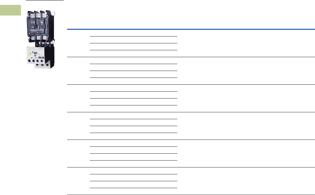
V5-T4-40 Volume 5—Motor Control and Protection CA08100006E—April 2014 www.eaton.com
4
4
4
4
4
4
4
4
4
4
4
4
4
4
4
4
4
4
4
4
4
4
4
4
4
4
4
4
4
4
4.3
Definite Purpose Contactors and Starters
Starters
Product Selection
When Ordering Specify
●Catalog number plus AC coil code, auxiliary contact code, OLR model designation and overload
range code, see below
Three-Phase Starters—Open Type A30 with C440 Electronic Overload
Note
1 Incomplete catalog number. Replace underscore (_) with suffix, see Page V5-T4-41.
Ampere Rating
Maximum
Motor (hp)
Maximum
Motor (kW)
Common Control Separate Control
Inductive
Full Load
Line
Voltage
Locked
Rotor
Metal
Mounting Plate DIN Rail Adapter
Metal
Mounting Plate DIN Rail Adapter
Catalog Number 1Catalog Number 1Catalog Number 1Catalog Number 1
25 115 150 — — A30CNC25_ A30CRC25_ A30SNC25_ A30SRC25_
230 150 7-1/2 5-1/2
460 125 10 7-1/2
575 100 10 7-1/2
30 115 180 — — A30CNE30_ A30CRE30_ A30SNE30_ A30SRE30_
230 180 10 7-1/2
460 150 15 11
575 120 15 11
40 115 240 — — A30CNE40_ A30CRE40_ A30SNE40_ A30SRE40_
230 240 10 7-1/2
460 200 20 15
575 160 20 15
45 115 300 — — A30CNE45_ A30CRE45_ A30SNE45_ A30SRE45_
230 300 15 11
460 250 30 22
575 200 30 22
60 115 360 — — A30CNE60_ —A30SNE60_ —
230 360 20 15
460 300 40 30
575 340 40 30
75 115 450 — — A30CNE75_ —A30SNE75_ —
230 450 20 18-1/2
460 375 50 37
575 300 50 37
A30 Starter
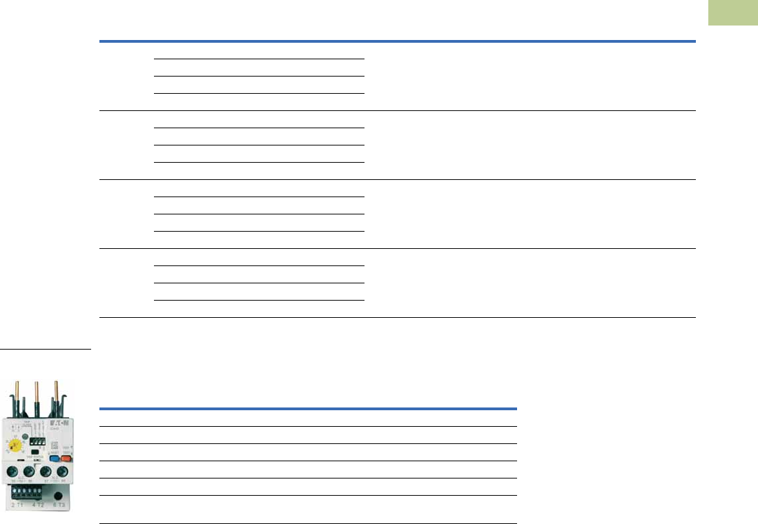
Volume 5—Motor Control and Protection CA08100006E—April 2014 www.eaton.com V5-T4-41
4
4
4
4
4
4
4
4
4
4
4
4
4
4
4
4
4
4
4
4
4
4
4
4
4
4
4
4
4
4
4.3
Definite Purpose Contactors and Starters
Starters
When Ordering Specify
●Catalog number plus AC coil code, auxiliary contact code, OLR model designation and overload
range code, see below
Single-Phase Starters—Open Type, B30 with C440 Electronic Overload
C440 Electronic Overload Relay for Integrated Use with DP Contactors
C440 Overload Relay for Integrated Use with DP Contactors by Feature Set
Note
1 Incomplete catalog number. Replace underscore (_) with suffix, see table above.
Ampere Rating
Maximum
Motor (hp)
Maximum
Motor (kW)
Common Control Separate Control
Inductive
Full Load
Line
Voltage
Locked
Rotor
Metal
Mounting Plate DIN Rail Adapter
Metal
Mounting Plate DIN Rail Adapter
Catalog Number 1Catalog Number 1Catalog Number 1Catalog Number 1
25 115 150 2 1.5 B30CNC25_ B30CRC25_ B30SNC25_ B30SRC25_
230 150 3 2.2
460 125 — —
575 100 — —
30 115 180 2 1.5 B30CNE30_ B30CRE30_ B30SNE30_ B30SRE30_
230 180 5 3.7
460 150 — —
575 120 — —
40 115 240 3 2.2 B30CNE40_ B30CRE40_ B30SNE40_ B30SRE40_
230 240 7-1/2 5.5
460 200 — —
575 160 — —
45 115 300 3 2.2 B30CNE45_ B30CRE45_ B30SNE45_ B30SRE45_
230 300 10 7.5
460 250 — —
575 200 — —
FLA Range
(Amps)
DP Contactor
Rating
Suffix
Code
Overload Relay Catalog
Number (Standard)
Overload Relay Catalog
Number (Ground Fault)
Frame D
1–5 25–50A 005 C440A1A005SDD C440A2A005SDD
4–20 25–50A 020 C440A1A020SDD C440A2A020SDD
9–45 25–50A 045 C440A1A045SDD C440A2A045SDD
Frame F
20–100 60–75A 100 C440B1A100SDF C440B2A100SDF
C440/XT Electronic
Overload Relay
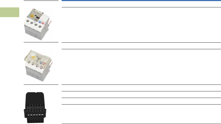
V5-T4-42 Volume 5—Motor Control and Protection CA08100006E—April 2014 www.eaton.com
4
4
4
4
4
4
4
4
4
4
4
4
4
4
4
4
4
4
4
4
4
4
4
4
4
4
4
4
4
4
4.3
Definite Purpose Contactors and Starters
Starters
Accessories
CT Kits
Accessories
Note
1 Customer can wire remote mounted button to reset module (that is, 22 mm pushbutton, catalog number M22-D-B-GB14-K10).
Description Catalog Number
Safety Cover
Clear Lexan cover that mounts on top of the FLA dial and DIP switches when closed. ZEB-XSC
Reset Bar
Assembles to the top of the overload to provide a larger target area for door
mounted reset operators.
ZEB-XRB
Remote Reset
Remote reset module (24 Vdc) 1C440-XCOM
Remote reset module (120 Vac) 1ZEB-XRR-120
Remote reset module (24 Vac) 1ZEB-XRR-24
Safety Cover
Reset Bar
Remote Reset

Volume 5—Motor Control and Protection CA08100006E—April 2014 www.eaton.com V5-T4-43
4
4
4
4
4
4
4
4
4
4
4
4
4
4
4
4
4
4
4
4
4
4
4
4
4
4
4
4
4
4
4.3
Definite Purpose Contactors and Starters
Starters
Technical Data and Specifications
Electronic Overload Relays up to 1500A
Specification
Description 45 mm 55 mm
Electrical Ratings Range Range
Operating voltage (three-phase) and frequency 690 Vac (60/50 Hz) 690 Vac (60/50 Hz)
FLA Range
0.33–1.65A
1–5A
4–20A
9–45A
20–100A
Use with Contactors
XT IEC frames B, C, D F, G
Freedom NEMA sizes 00, 0, 1, 2 3
DP contactors 25–50A 60, 75A
Tri p C l a s s
10A, 10, 20, 30
Selectable
10A, 10, 20, 30
Selectable
Motor Protection
Thermal overload setting 1.05 x FLA: does not trip
1.15 x FLA: overload trip
1.05 x FLA: does not trip
1.15 x FLA: overload trip
Feature Range Range
Phase loss Fixed threshold 50% Fixed threshold 50%
Phase unbalance (selectable: enable/disable) Fixed threshold 50% Fixed threshold 50%
Ground fault (selectable: enable/disable) 50% of FLA dial setting
>150% = 2 sec
>250% = 1 sec
50% of FLA dial setting
>150% = 2 sec
>250% = 1 sec
Reset Manual/automatic Manual/automatic
Indicators
Trip status Orange flag Orange flag
Mode LED One flash: Overload operating properly
Two flashes: Current is above FLA dial setting—pending trip
One flash: Overload operating properly
Two flashes: Current is above FLA dial setting—pending trip
Options
Remote reset Yes Yes
Reset bar Yes Yes
Communication expansion module Yes Yes
Communication adapter Yes Yes
Capacity
Load terminals
Terminal capacity 12–10 AWG (4–6 mm2)
8–6 AWG (6–16 mm2)
6–1 AWG (16–50 mm2)
Tightening torque 20–25 lb-in (2.3–2.8 Nm)
25–30 lb-in (2.8–3.4 Nm)
25–30 lb-in (2.8–3.4 Nm)
Input, auxiliary contact and remote reset terminals
Terminal capacity 2 x (18–12) AWG 2 x (18–12) AWG
Tightening torque 5.3 lb-in (0.8–1.2 Nm) 5.3 lb-in (0.8–1.2 Nm)
Voltages
Insulation voltage Ui (three-phase) 690 Vac 690 Vac
Insulation voltage Ui (control) 500 Vac 500 Vac
Rated impulse withstand voltage 6000 Vac 6000 Vac
Overvoltage category/pollution degree III/3 III/3

V5-T4-44 Volume 5—Motor Control and Protection CA08100006E—April 2014 www.eaton.com
4
4
4
4
4
4
4
4
4
4
4
4
4
4
4
4
4
4
4
4
4
4
4
4
4
4
4
4
4
4
4.3
Definite Purpose Contactors and Starters
Starters
Electronic Overload Relays up to 1500A, continued
Specification
Description 45 mm 55 mm
Auxiliary and Control Circuit Ratings
Conventional thermal continuous current 5A 5A
Rated operational current—IEC AC-15
Make contact (1800 VA)
120V 15A 15A
240V 15A 15A
415V 0.5A 0.5A
500V 0.5A 0.5A
Break contact (180 VA)
120V 1.5A 1.5A
240V 1.5A 1.5A
415V 0.9A 0.9A
500V 0.8A 0.8A
IEC DC-13 (L/R F 15 ms1)
0–250V 1.0A 1.0A
Rated operational current—UL B600
Make contact (3600 VA)
120V 30A 30A
240V 15A 15A
480V 7.5A 7.5A
600V 6A 6A
Break contact (360 VA)
120V 3A 3A
240V 1.5A 1.5A
480V 0.75A 0.75A
600V 0.6A 0.6A
R300—Vdc ratings (28 VA)
0–120V 0.22A 0.22A
250V 0.11A 0.11A
Short-Circuit Rating without Welding
Maximum fuse 6A gG/gL 6A gG/gL
Environmental Ratings
Ambient temperature (operating) –13° to 149°F (–25° to 65°C) –13° to 149°F (–25° to 65°C)
Ambient temperature (storage) –40° to 185°F (–40° to 85°C) –40° to 185°F (–40° to 85°C)
Operating humidity UL 991 (H3) 5% to 95% non-condensing 5% to 95% non-condensing
Altitude (no derating) NEMA ICS1 2000m 2000m
Shock (IEC 600068-2-27) 15g any direction 15g any direction
Vibration (IEC 60068-2-6) 3g any direction 3g any direction
Pollution degree per IEC 60947-4-1 3 for product (2 for pcb) 3 for product (2 for pcb)
Ingress protection IP20 IP20
Protection against direct contact when actuated from front (IEC 536) Finger- and back-of-hand proof Finger- and back-of-hand proof
Mounting position Any Any
Climatic proofing Damp heat, constant to IEC 60068-2-30 Damp heat, constant to IEC 60068-2-30
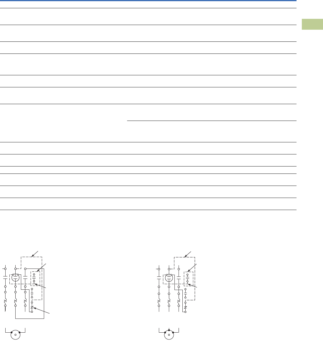
Volume 5—Motor Control and Protection CA08100006E—April 2014 www.eaton.com V5-T4-45
4
4
4
4
4
4
4
4
4
4
4
4
4
4
4
4
4
4
4
4
4
4
4
4
4
4
4
4
4
4
4.3
Definite Purpose Contactors and Starters
Starters
Electronic Overload Relays up to 1500A, continued
Wiring Diagrams
Single-Phase Connections Three-Phase Connections
Specification
Description 45 mm 55 mm
Electrical/EMC
Radiated emissions
IEC 60947-4-1-Table 15
EN 55011 (CISPIR 11) Group 1, Class A, ISM
30 MHz to 1000 MHz 30 MHz to 1000 MHz
Conducted emissions
IEC 60947-4-1-Table 14
EN 55011 (CISPIR 11) Group 1; Class ISM
0.15 MHz to 30 MHz 0.15 MHz to 30 MHz
ESD immunity
IEC 60947-4-1 (Table 13)
±8 kV air, ±6 kV contact ±8 kV air, ±6 kV contact
Radiated immunity
IEC 60947-4-1
IEC 61000-4-3
10V/m 80 MHz–1000 MHz
3V/m from 1.4 to 2.7 GHz
80% amplitude modulated
1 kHz sine wave
10V/m 80 MHz–1000 MHz
3V/m from 1.4 to 2.7 GHz
80% amplitude modulated
1 kHz sine wave
Conducted immunity
IEC 60947-4-1, IEC 61000-4-6
140 dub (10V rms)
150 kHz–100 MHz
140 dub (10V rms)
150 kHz–100 MHz
Fast transient immunity
IEC 60947-4-1 (Table 13)
IEC 61000-4-4
±4 kV using direct method
with accessory installed in expansion bay
±2 kV using direct method
±4 kV using direct method
with accessory installed in expansion bay
±2 kV using direct method
Surge immunity
IEC 60947-4-1 (Table 13)
IEC 61000-4-5 a Class 4
Three-phase power inputs:
±4 kV line-to-line (DM)
±4 kV line-to-ground (CM)
Three-phase power inputs:
±4 kV line-to-line (DM)
±4 kV line-to-ground (CM)
With accessory installed in expansion bay:
±2 kV line-to-line (DM) –>1.2/50 us;
2 kV line-to-earth, 1 kV line-to-line
±4 kV line-to-ground (CM)
With accessory installed in expansion bay:
±2 kV line-to-line (DM) –>1.2/50 us;
2 kV line-to-earth, 1 kV line-to-line
±4 kV line-to-ground (CM)
Power freq. magnetic field immunity
IEC 60947-4-1, IEC 61000-4-8
30A/m, 50 Hz 30A/m, 50 Hz
Electromagnetic field
IEC 60947-4-1 Table 13, IEC 61000-4-3
10 V/m 10 V/m
Distortion IEEE 519 5% THD max., 5th harmonic 3% max. 5% THD max., 5th harmonic 3% max.
Electrostatic discharge (ESD)
IEC 61000-4-2, EN 61131-2
4 kV contact
8 kV air discharge
4 kV contact
8 kV air discharge
Electrical fast transient (EFT)
IEC 61000-4-4, EN 61131-2
±2 kV using direct method ±2 kV using direct method
Surge immunity
IEC 61000-4-5, EN 61131-2
±2 kV line-to-ground (CM) ±2 kV line-to-ground (CM)
1NO Aux. Contact
(When Supplied)
Reset
Wire “D”
(Supplied with
1NO Aux. Contact)
Wire “C”
(Supplied with Common Control)
1
13
14
L1 L2
T1
4/T22/T1
T2
AC Motor
98
97
96
95
AC Motor
T2
L1 L2 L3
1
13
14
T1
6/T32/T1 4/T2
T3
98
97
96
95
Wire “D”
(Supplied with
1NO Aux. Contact)
Wire “C”
(Supplied with Common Control)
1NO Aux. Contact
(When Supplied)
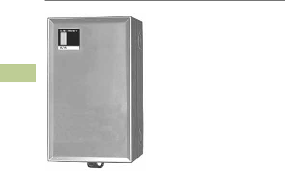
V5-T4-46 Volume 5—Motor Control and Protection CA08100006E—April 2014 www.eaton.com
4
4
4
4
4
4
4
4
4
4
4
4
4
4
4
4
4
4
4
4
4
4
4
4
4
4
4
4
4
4
4.4
Definite Purpose Contactors and Starters
NEMA Type 1 Enclosed Control
15–60A Contactors—C25
Contents
Description Page
15–60A Contactors—C25
Catalog Number Selection . . . . . . . . . . . . . . . . V5-T4-47
Product Selection . . . . . . . . . . . . . . . . . . . . . . . V5-T4-47
Dimensions . . . . . . . . . . . . . . . . . . . . . . . . . . . V5-T4-48
25–60A Starters—A25, B25 . . . . . . . . . . . . . . . . . V5-T4-49
15–45A Starters—A27, B27 . . . . . . . . . . . . . . . . . . V5-T4-52
Accessories . . . . . . . . . . . . . . . . . . . . . . . . . . . . . . V5-T4-55
Options . . . . . . . . . . . . . . . . . . . . . . . . . . . . . . . . . V5-T4-57
Technical Data and Specifications . . . . . . . . . . . . . V5-T4-58
15–60A Contactors—C25
Product Description
Eaton offers the Definite
Purpose Contactors and
Starters in NEMA 1
enclosures. The C25
contactors are available as
enclosed. The A25 and B25
Definite Purpose Starters
combine the features and
flexibility of the C25 Definite
Purpose Contactors and
Freedom Series Bimetallic
Ambient Compensated
Overload Relays mounted on
a common mounting plate.
Volume 5—Motor Control and Protection CA08100006E—April 2014 www.eaton.com V5-T4-47
4
4
4
4
4
4
4
4
4
4
4
4
4
4
4
4
4
4
4
4
4
4
4
4
4
4
4
4
4
4
4.4
Definite Purpose Contactors and Starters
NEMA Type 1 Enclosed Control
Catalog Number Selection
15–60A Contactors—C25
When Ordering Specify
●Catalog number plus magnet coil suffix, see Page V5-T4-48
●Modify catalog number for any options required, see Options, Page V5-T4-57
Product Selection
Two-, Three- and Four-Pole NEMA Type 1 Enclosed Contactors
Note
1 Incomplete catalog number. Replace underscore (_) in catalog number with magnet coil suffix from table on Page V5-T4-48.
Incomplete catalog number
C25DGD215 A
Magnet coil suffix
X
Option code as necessary
Ampere Rating Maximum Motor (hp) Maximum Motor (kW)
Number of
Poles
NEMA Type 1
Inductive
Full Load
Resistive
per Pole
Line
Voltage
Locked
Rotor
Single-
Phase
Three-
Phase
Single-
Phase
Three-
Phase
Catalog
Number 1
15 20 115 90 3/4 — 0.40 — 2 C25DGD215_
230 90 2 3 1.5 2.2 3 C25DGD315_
460 75 — 5 — 3.7 C25DGD315_
575 60 — 5 — 3.7 C25DGD315_
25 35 115 150 2 — 1.5 — 2 C25DGD225_
230 150 3 7-1/2 2.2 5.5 3 C25DGD325_
460 125 — 10 — 7.5 4 C25EGD425_
575 100 — 10 — 7.5 C25EGD425_
30 40 115 180 2 — 1.5 — 2 C25DGD230_
230 180 5 10 3.7 7.5 3 C25DGD330_
460 150 — 15 — 11 4 C25EGD430_
575 120 — 15 — 11 C25EGD430_
40 50 115 240 3 — 2.2 — 2 C25DGF240_
230 240 7-1/2 10 5.5 7.5 3 C25DGF340_
460 200 — 20 — 15 4 C25EGF440_
575 160 — 20 — 15 C25EGF440_
50 65 115 300 3 — 2.2 — 2 C25DGJ250_
230 300 10 15 7.5 11 3 C25DGJ350_
460 250 — 30 — 22 C25DGJ350_
575 200 — 30 — 22 C25DGJ350_
60 75 115 360 5 — 3.7 — 2 C25FGF260_
230 360 10 20 7.5 15 3 C25FGF360_
460 300 — 40 — 30 C25FGF360_
575 240 — 40 — 30 C25FGF360_
C25 Enclosed
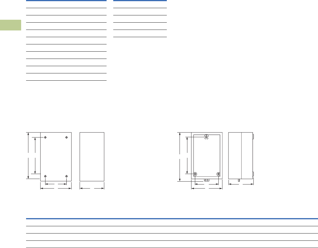
V5-T4-48 Volume 5—Motor Control and Protection CA08100006E—April 2014 www.eaton.com
4
4
4
4
4
4
4
4
4
4
4
4
4
4
4
4
4
4
4
4
4
4
4
4
4
4
4
4
4
4
4.4
Definite Purpose Contactors and Starters
NEMA Type 1 Enclosed Control
Magnet Coil Suffix
Dimensions
Approximate Dimensions in Inches (mm)
C25 Contactors, NEMA 1 Enclosed
15–50 Ampere, Two- and Three-Pole (C799B18)
25–40 Ampere, Four-Pole—
60 Ampere, Two- and Three-Pole (C799B19)
Dimensions and Shipping Weights
Notes
1Class H AC coils available as option. Add 2 before AC coil suffix letter.
2104–120A 50/60 Hz for 60A contactor.
3Available through 50A.
4Contactors with DC coils include an early break NC auxiliary contact, C320KGD1. See Page V5-T4-62 for more detail.
Voltage
60 Hertz 50 Hertz Coil Suffix
Voltage
60 Hertz Coil Suffix
AC 1DC 4
12 12 R12 1R
24 24 T24 1T
110–120 2110–120 2A48 1W
208–240 208–240 E120 1A
240 3220 B
277 — J
— 380–415 H
440–480 440–480 L
550–600 550–600 C
12 12 D
D
C
EB
A
D C
E
B
A
Ampere
Size
Number
of Poles
Wide
A
High
B
Deep
C
Mounting
DE
Shipping Weight
Lbs (kg)
NEMA 1 Enclosed
15–50 2 and 3 4.10 (104.0) 6.75 (171.0) 3.50 (89.0) 2.75 (70.0) 4.88 (124.0) 3.4 (1.5)
25–40 4 5.62 (142.0) 9.51 (241.0) 4.81 (122.0) 4.50 (114.0) 8.00 (203.0) 5.8 (2.6)
60 2 and 3 5.62 (142.0) 9.51 (241.0) 4.81 (122.0) 4.50 (114.0) 8.00 (203.0) 6.3 (2.9)
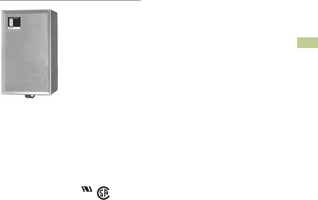
Volume 5—Motor Control and Protection CA08100006E—April 2014 www.eaton.com V5-T4-49
4
4
4
4
4
4
4
4
4
4
4
4
4
4
4
4
4
4
4
4
4
4
4
4
4
4
4
4
4
4
4.4
Definite Purpose Contactors and Starters
NEMA Type 1 Enclosed Control
25–60A Starters—A25, B25
Contents
Description Page
15–60A Contactors—C25 . . . . . . . . . . . . . . . . . . . V5-T4-46
25–60A Starters—A25, B25
Catalog Number Selection . . . . . . . . . . . . . . . . V5-T4-50
Product Selection . . . . . . . . . . . . . . . . . . . . . . . V5-T4-50
Dimensions . . . . . . . . . . . . . . . . . . . . . . . . . . . V5-T4-51
15–45A Starters—A27, B27 . . . . . . . . . . . . . . . . . . V5-T4-52
Accessories . . . . . . . . . . . . . . . . . . . . . . . . . . . . . . V5-T4-55
Options . . . . . . . . . . . . . . . . . . . . . . . . . . . . . . . . . V5-T4-57
Technical Data and Specifications . . . . . . . . . . . . . V5-T4-58
25–60A Starters—A25, B25
Product Description
A25 and B25 Definite
Purpose Starters from Eaton’s
Electrical Sector combine the
features and flexibility of the
C25 Definite Purpose
Contactors and Freedom
Series Bi-metallic Ambient
Compensated Overload
Relays mounted on a common
mounting plate.
Standards and Certifications
●UL Recognized
Components UL File
#E-1491, Guide NLDX2
●
CSA Certified Components
File #LR353, Guide
380W-1.14 Class 3211 04
V5-T4-50 Volume 5—Motor Control and Protection CA08100006E—April 2014 www.eaton.com
4
4
4
4
4
4
4
4
4
4
4
4
4
4
4
4
4
4
4
4
4
4
4
4
4
4
4
4
4
4
4.4
Definite Purpose Contactors and Starters
NEMA Type 1 Enclosed Control
Catalog Number Selection
25–60A Starters—A25, B25
When Ordering Specify
●Catalog number plus magnet coil suffix, see Page V5-T4-51
●Modify catalog number for any options required, see Options, Page V5-T4-57
●Heater packs for specific FLA of motor, see Page V5-T4-56
Product Selection
Single- and Three-Phase NEMA Type 1 Enclosed Starters
Notes
1 Starters do not include heater packs. Select heater pack from tables, see Page V5-T4-56.
2 Set of three heater packs required for single-phase applications.
3 Incomplete catalog number. Replace underscore (_) in catalog number with magnet coil suffix from table on Page V5-T4-51.
Incomplete catalog number
A25CGC30 A
Magnet coil suffix
X
Option code as necessary
Single-Phase 12 Three-Phase 2
Ampere Rating
Maximum Motor
(hp)
Maximum Motor
(kW)
Common
Control
Separate
Control
Common
Control
Separate
Control
Inductive
Full Load
Line
Voltage
Locked
Rotor
Single-
Phase
Three-
Phase
Single-
Phase
Three-
Phase
Catalog
Number 3
Catalog
Number 3
Catalog
Number 3
Catalog
Number 3
25 115 150 2 — 1.5 — B25CGC25_ B25SGC25_ A25CGC25_ A25SGC25_
230 150 3 7-1/2 2.2 5.5 B25CGC25_ B25SGC25_ A25CGC25_ A25SGC25_
460 125 — 10 — 7.5 B25CGC25_ B25SGC25_ A25CGC25_ A25SGC25_
575 100 — 10 — 7.5 B25CGC25_ B25SGC25_ A25CGC25_ A25SGC25_
30 115 180 2 — 1.5 — B25CGC30_ B25SGC30_ A25CGC30_ A25SGC30_
230 180 5 10 3.7 7.5 B25CGC30_ B25SGC30_ A25CGC30_ A25SGC30_
460 150 — 15 — 11 B25CGC30_ B25SGC30_ A25CGC30_ A25SGC30_
575 120 — 15 — 11 B25CGC30_ B25SGC30_ A25CGC30_ A25SGC30_
40 115 240 3 — 2.2 — B25CGE40_ B25SGE40_ A25CGE40_ A25SGE40_
230 240 7-1/2 10 5.5 7.5 B25CGE40_ B25SGE40_ A25CGE40_ A25SGE40_
460 200 — 20 — 15 B25CGE40_ B25SGE40_ A25CGE40_ A25SGE40_
575 160 — 20 — 15 B25CGE40_ B25SGE40_ A25CGE40_ A25SGE40_
50 115 300 — — — — — — A25CGE50_ A25SGE50_
230 300 — 15 — 11 — — A25CGE50_ A25SGE50_
460 250 — 30 — 22 — — A25CGE50_ A25SGE50_
575 200 — 30 — 22 — — A25CGE50_ A25SGE50_
60 115 360 — — — — — — A25CGE60_ A25SGE60_
230 360 — 20 — 15 — — A25CGE60_ A25SGE60_
460 300 — 40 — 30 — — A25CGE60_ A25SGE60_
575 240 — 40 — 30 — — A25CGE60_ A25SGE60_
A25, B25 Enclosed
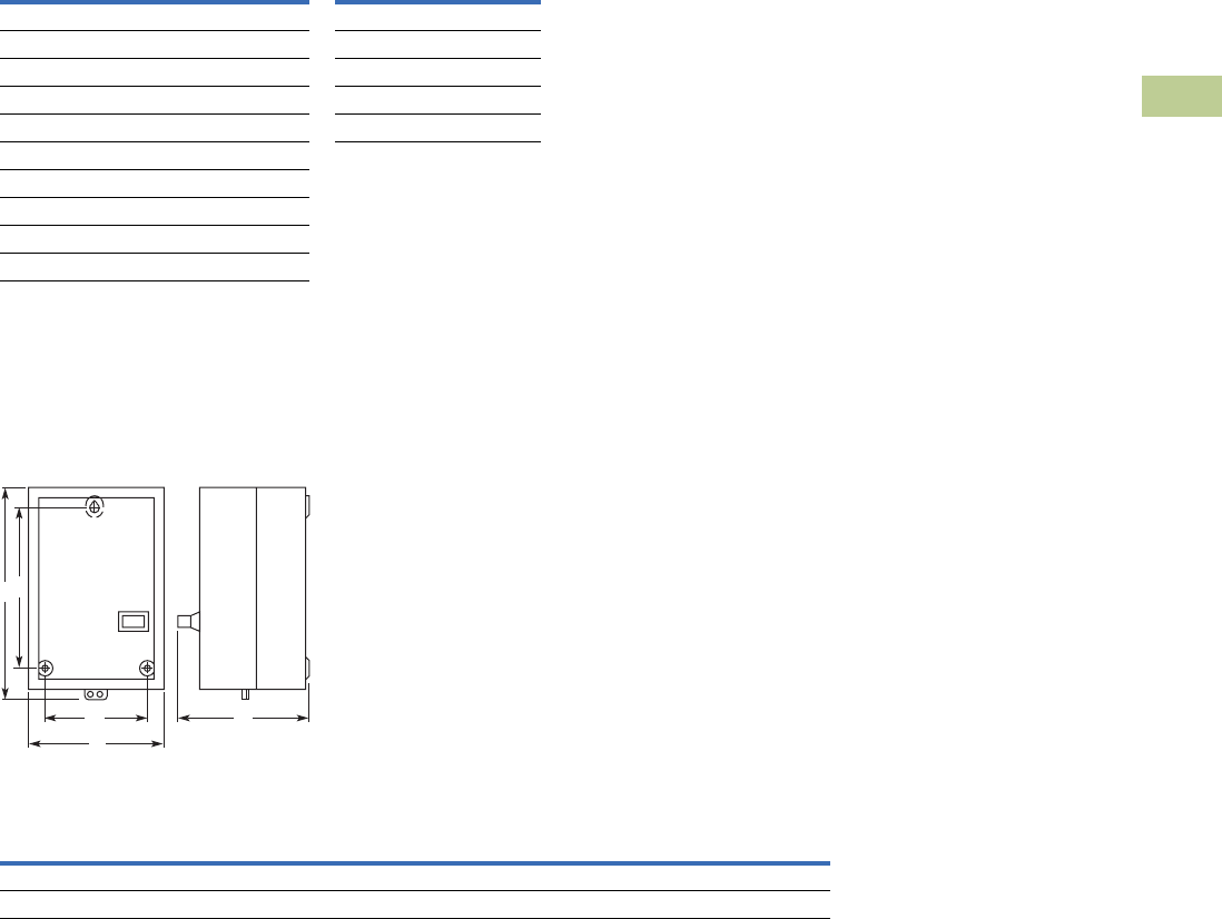
Volume 5—Motor Control and Protection CA08100006E—April 2014 www.eaton.com V5-T4-51
4
4
4
4
4
4
4
4
4
4
4
4
4
4
4
4
4
4
4
4
4
4
4
4
4
4
4
4
4
4
4.4
Definite Purpose Contactors and Starters
NEMA Type 1 Enclosed Control
Magnet Coil Suffix
Dimensions
Approximate Dimensions in Inches (mm)
A25 and B25 Starters
25, 30, 40, 50 and 60 Ampere
Dimensions and Shipping Weights
Notes
1Class H AC coils available as option. Add 2 before AC coil suffix letter.
2104–120A 50/60 Hz for 60A starter.
3Available through 50A.
4Starters with DC coils include an early breaking auxiliary contact, C320KGD1. See Page V5-T4-62 for more detail.
Voltage
60 Hertz 50 Hertz Coil Suffix
Voltage
60 Hertz Coil Suffix
AC 1DC 4
12 12 R12 1R
24 24 T24 1T
110–120 2110–120 2A48 1W
208–240 208–240 B120 1A
240 3220 J
277 — H
— 380–415 L
440–480 440–480 C
550–600 550–600 D
Ampere Size
Wide
A
High
B
Deep
C
Mounting
E
Mounting
G
Shipping
Weight
Lbs (kg)
25 and 30 5.63 (143.0) 10.17 (258.0) 5.81 (148.0) 8.00 (203.0) 4.50 (114.0) 4.8 (2.2)
40, 50 and 60 7.64 (194.0) 13.27 (337.0) 6.67 (169.0) 10.75 (273.0) 6.00 (152.0) 10.6 (4.8)
G C
E
B
A
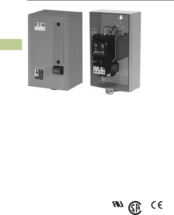
V5-T4-52 Volume 5—Motor Control and Protection CA08100006E—April 2014 www.eaton.com
4
4
4
4
4
4
4
4
4
4
4
4
4
4
4
4
4
4
4
4
4
4
4
4
4
4
4
4
4
4
4.4
Definite Purpose Contactors and Starters
NEMA Type 1 Enclosed Control
15–45A Starters—A27, B27
Contents
Description Page
15–60A Contactors—C25 . . . . . . . . . . . . . . . . . . . V5-T4-46
25–60A Starters—A25, B25 . . . . . . . . . . . . . . . . . V5-T4-49
15–45A Starters—A27, B27
Product Selection . . . . . . . . . . . . . . . . . . . . . . . V5-T4-53
Dimensions . . . . . . . . . . . . . . . . . . . . . . . . . . . V5-T4-54
Accessories . . . . . . . . . . . . . . . . . . . . . . . . . . . . . . V5-T4-55
Options . . . . . . . . . . . . . . . . . . . . . . . . . . . . . . . . . V5-T4-57
Technical Data and Specifications . . . . . . . . . . . . . V5-T4-58
15–45A Starters—A27, B27
Product Description
A27 and B27 Definite
Purpose Starters from
Eaton’s Electrical Sector
combine the features and
flexibility of the C25 Definite
Purpose Contactors and XT
Series Bi-metallic Ambient
Compensated Overload
Relays.
Standards and Certifications
●UL Recognized
Components UL File
#E-1491, Guide NLDX2
●
CSA Certified Components
File #LR353, Guide
380W-1.14 Class 3211 04
●
CE
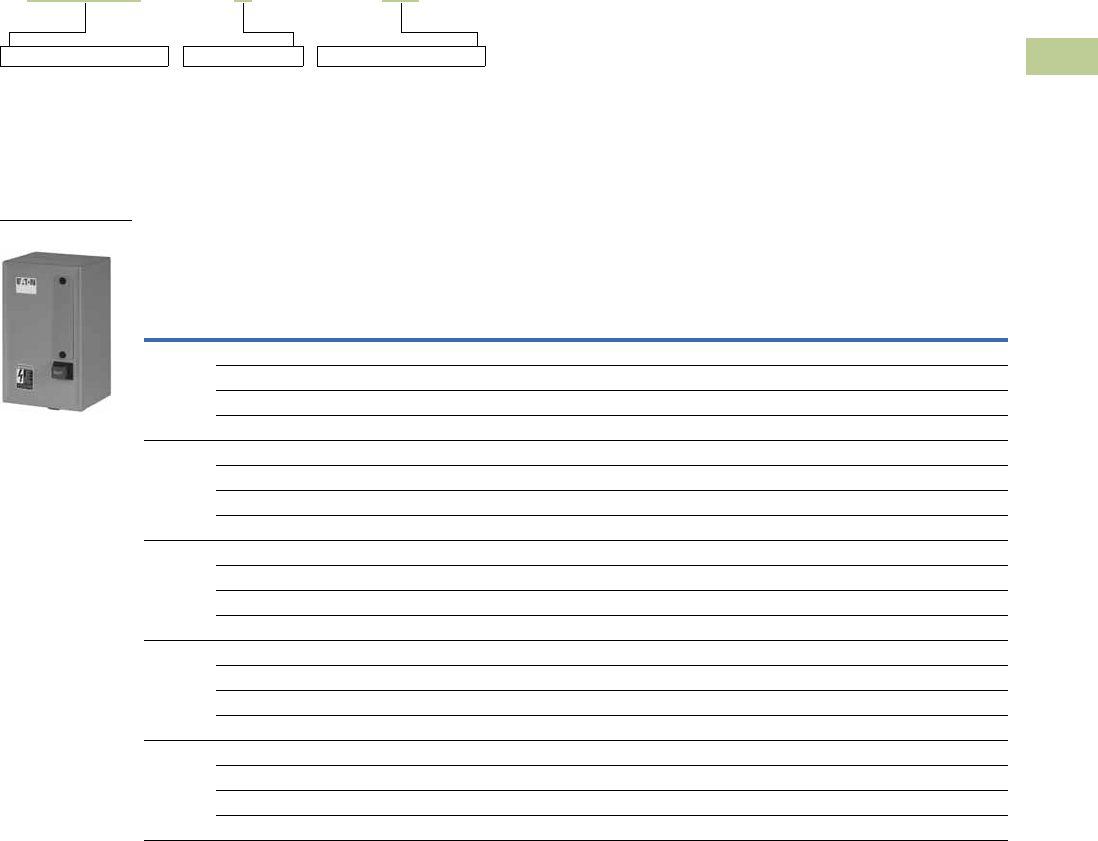
Volume 5—Motor Control and Protection CA08100006E—April 2014 www.eaton.com V5-T4-53
4
4
4
4
4
4
4
4
4
4
4
4
4
4
4
4
4
4
4
4
4
4
4
4
4
4
4
4
4
4
4.4
Definite Purpose Contactors and Starters
NEMA Type 1 Enclosed Control
Catalog Number Selection
15–45A Starters—A27, B27
When Ordering Specify
●Catalog number plus magnet coil suffix plus overload relay suffix, see Page V5-T4-54
Product Selection
Single- and Three-Phase NEMA Type 1 Enclosed Starters
Note
1 Incomplete catalog number. Replace underscore (_) in catalog number with magnet coil suffix plus overload relay suffix from tables on Page V5-T4-54.
Incomplete catalog number
A27CGE30 A
Magnet coil suffix
040
Overload relay suffix
Single-Phase Three-Phase
Ampere Rating
Maximum Motor
(hp)
Maximum Motor
(kW)
Common
Control
Separate
Control
Common
Control
Separate
Control
Inductive
Full Load
Line
Voltage
Locked
Rotor
Single-
Phase
Three-
Phase
Single-
Phase
Three-
Phase
Catalog
Number 1
Catalog
Number 1
Catalog
Number 1
Catalog
Number 1
15 115 90 3/4 — 0.4 — B27CGC15_ B27SGC15_ A27CGC15_ A27SGC15_
230 90 2 3 1.5 2.2 B27CGC15_ B27SGC15_ A27CGC15_ A27SGC15_
460 75 — 5 — 3.7 B27CGC15_ B27SGC15_ A27CGC15_ A27SGC15_
575 60 — 5 — 3.7 B27CGC15_ B27SGC15_ A27CGC15_ A27SGC15_
25 115 150 2 — 1.5 — B27CGC25_ B27SGC25_ A27CGC25_ A27SGC25_
230 150 3 7-1/2 2.2 5.5 B27CGC25_ B27SGC25_ A27CGC25_ A27SGC25_
460 125 — 10 — 7.5 B27CGC25_ B27SGC25_ A27CGC25_ A27SGC25_
575 100 — 10 — 7.5 B27CGC25_ B27SGC25_ A27CGC25_ A27SGC25_
30 115 180 2 — 1.5 — B27CGE30_ B27SGE30_ A27CGE30_ A27SGE30_
230 180 5 10 3.7 7.5 B27CGE30_ B27SGE30_ A27CGE30_ A27SGE30_
460 150 — 15 — 11 B27CGE30_ B27SGE30_ A27CGE30_ A27SGE30_
575 120 — 15 — 11 B27CGE30_ B27SGE30_ A27CGE30_ A27SGE30_
40 115 240 3 — 2.2 — B27CGE40_ B27SGE40_ A27CGE40_ A27SGE40_
230 240 7-1/2 10 5.5 7.5 B27CGE40_ B27SGE40_ A27CGE40_ A27SGE40_
460 200 — 20 — 15 B27CGE40_ B27SGE40_ A27CGE40_ A27SGE40_
575 160 — 20 — 15 B27CGE40_ B27SGE40_ A27CGE40_ A27SGE40_
45 115 270 3 — 2.2 — B27CGE45_ B27SGE45_ A27CGE45_ A27SGE45_
230 270 7-1/2 15 7.5 11 B27CGE45_ B27SGE45_ A27CGE45_ A27SGE45_
460 225 — 30 — 22 B27CGE45_ B27SGE45_ A27CGE45_ A27SGE45_
575 180 — 30 — 22 B27CGE45_ B27SGE45_ A27CGE45_ A27SGE45_
A27, B27 Enclosed
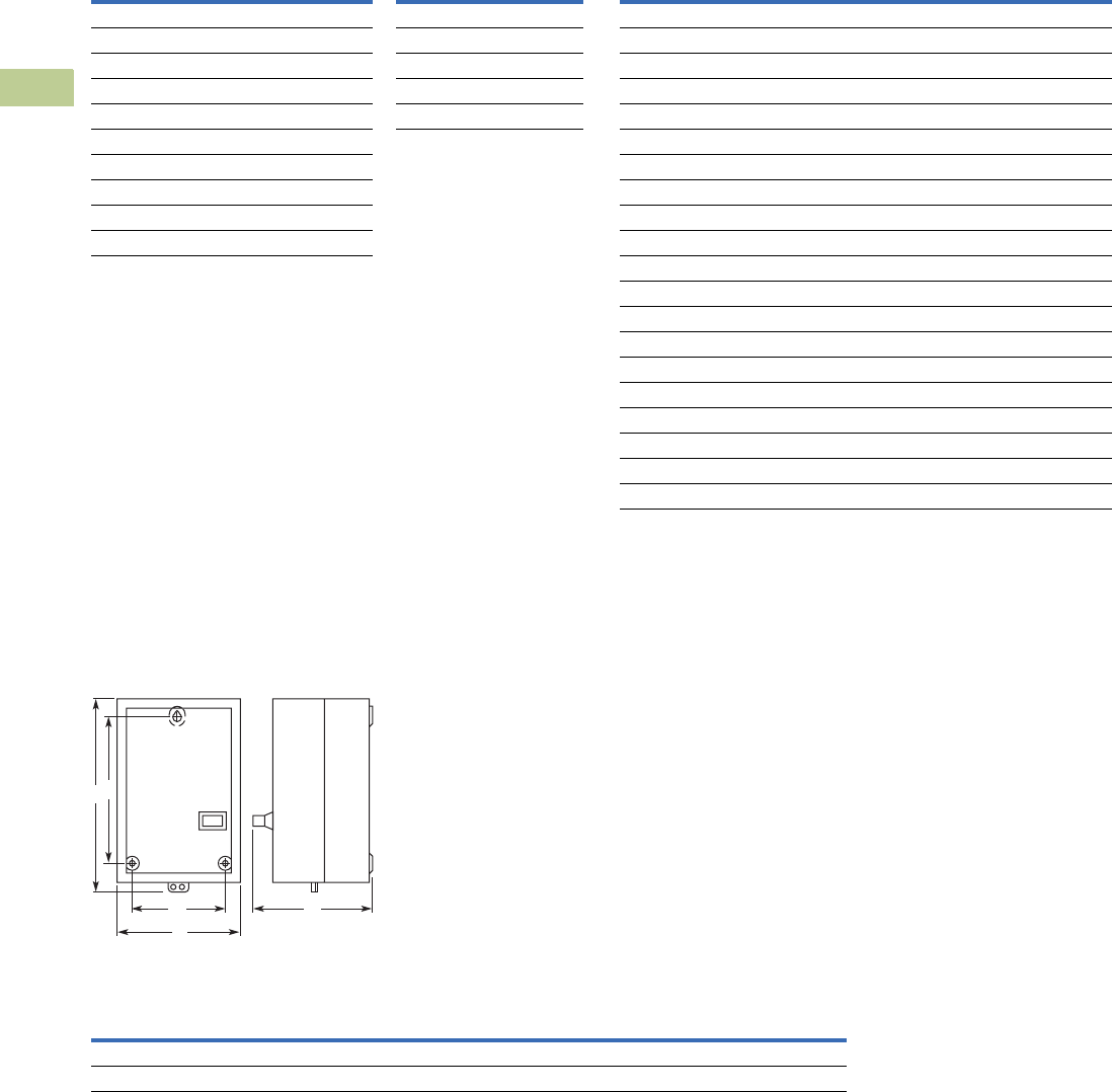
V5-T4-54 Volume 5—Motor Control and Protection CA08100006E—April 2014 www.eaton.com
4
4
4
4
4
4
4
4
4
4
4
4
4
4
4
4
4
4
4
4
4
4
4
4
4
4
4
4
4
4
4.4
Definite Purpose Contactors and Starters
NEMA Type 1 Enclosed Control
Magnet Coil Suffix Overload Relay Suffix
Dimensions
Approximate Dimensions in Inches (mm)
A27 and B27 Starters
15, 25, 30, 40 and 50 Ampere
Dimensions and Shipping Weights
Notes
1Class H AC coils available as option. Add 2 before AC coil suffix letter.
2Available through 45A.
3Starters with DC coils include an early breaking auxiliary contact, C320KGD1. See Page V5-T4-62 for more detail.
Voltage
60 Hertz 50 Hertz Coil Suffix
Voltage
60 Hertz Coil Suffix
AC 1DC 3
12 12 R12 1R
24 24 T24 1T
110–120 110–120 A48 1W
208–240 208–240 B120 1A
240 2220 J
277 — H
— 380–415 L
440–480 440–480 C
550–600 550–600 D
Motor Full Load Amperes Suffix Code
For use with Contactor
Ampere Range
Frame C
0.1–0.16 P16 15–25A
0.16–0.24 P24 15–25A
0.24–0.4 P40 15–25A
0.4–0.6 P60 15–25A
0.6–1 001 15–25A
1–1.6 1P6 15–25A
1.6–2.4 2P4 15–25A
2.4–4 004 15–25A
4–6 006 15–25A
6–10 010 15–25A
10–16 016 15–25A
16–24 024 15–25A
24–32 032 15–25A
Frame D
6–10 010 30–45A
10–16 016 30–45A
16–24 024 30–45A
24–40 040 30–45A
40–57 057 30–45A
Ampere Size
Wide
A
High
B
Deep
C
Mounting
E
Mounting
G
Shipping
Weight
Lbs (kg)
25 and 30 5.63 (143.0) 10.17 (258.0) 5.81 (148.0) 8.00 (203.0) 4.50 (114.0) 4.8 (2.2)
40, 50 and 60 7.64 (194.0) 13.27 (337.0) 6.67 (169.0) 10.75 (273.0) 6.00 (152.0) 10.6 (4.8)
G C
E
B
A
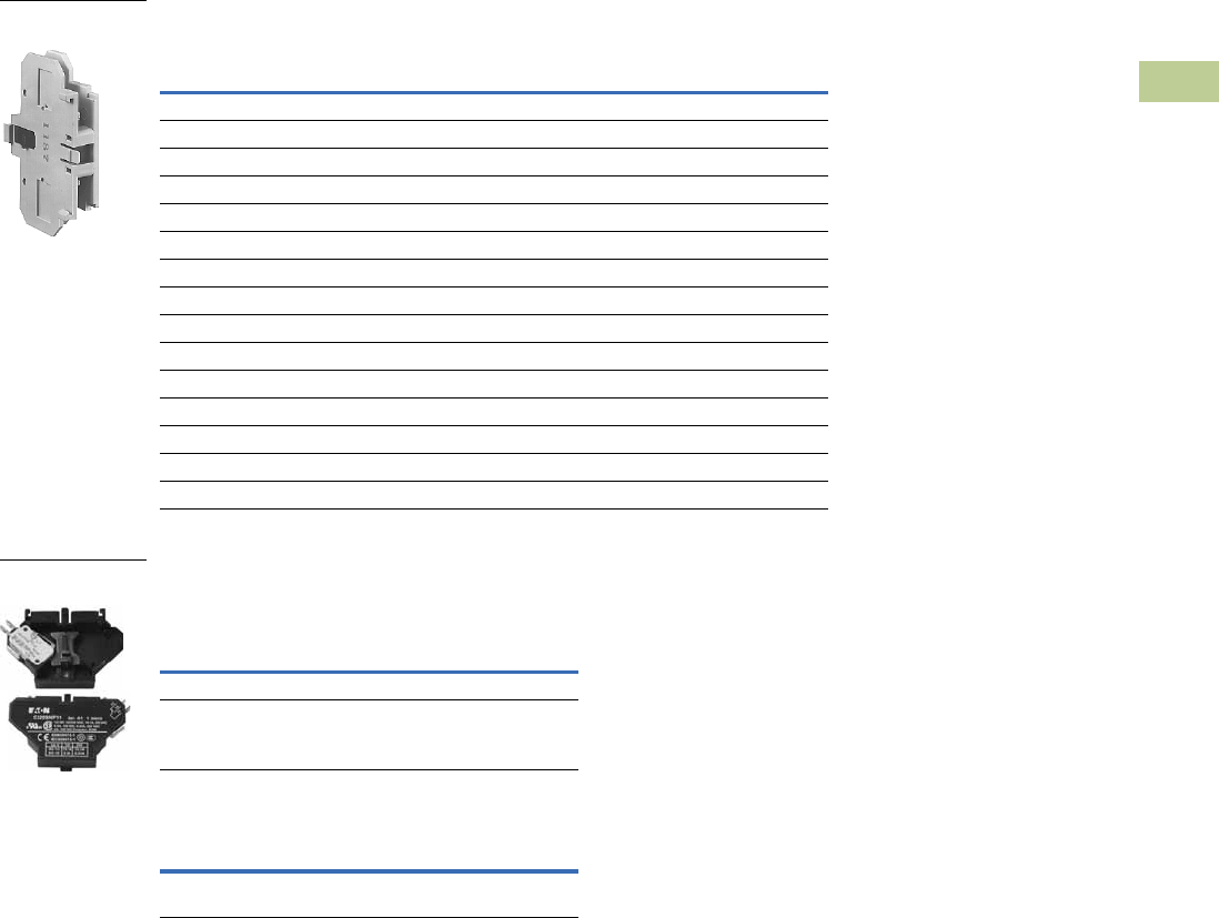
Volume 5—Motor Control and Protection CA08100006E—April 2014 www.eaton.com V5-T4-55
4
4
4
4
4
4
4
4
4
4
4
4
4
4
4
4
4
4
4
4
4
4
4
4
4
4
4
4
4
4
4.4
Definite Purpose Contactors and Starters
NEMA Type 1 Enclosed Control
Accessories
Auxiliary Contact Kits (Side Mounted)
Heavy-Duty Pilot Rated for 10A at 600 Vac
Snap Switch Design Side Mounted
Auxiliary Contacts
Magnet Coil Quick Connect Terminal
Note
1 To order, add suffix number 9 to the complete catalog number.
Example: C25DND215A9.
With Standard Pressure
Plate Terminals
With Pressure Plate and
Quick Connect Terminals
Circuit Catalog Number Catalog Number
For 15 through 75A
1NO C320KG1 C320KG11
1NC C320KG2 C320KG12
1NO-1NC C320KG3 C320KG13
2NO C320KG4 C320KG14
2NC C320KG5 C320KG15
For 90A
1NO — C320DPG10
1NC — C320DPG01
1NO-1NC — C320DPG11
2NO — C320DPG20
For 120 through 360A
1NO C320KGS20 —
1NC C320KGS21 —
1NO-1NC C320KGS22 —
Snap Switch Design with
Quick Connect Terminals
Circuit Catalog Number
1NO-1NC C320SNP11
2NO-2NC C320SNP22
Description
Extra dual quick connect terminals (U-shaped)
for magnet coil terminals 2
Side Mounted
Auxiliary Contact
Side Mounted
Snap Switch

V5-T4-56 Volume 5—Motor Control and Protection CA08100006E—April 2014 www.eaton.com
4
4
4
4
4
4
4
4
4
4
4
4
4
4
4
4
4
4
4
4
4
4
4
4
4
4
4
4
4
4
4.4
Definite Purpose Contactors and Starters
NEMA Type 1 Enclosed Control
Heater Packs
Fast Trip—Class 10 Heater Packs
Manual or Automatic Reset
Heater packs are shipped three to a carton.
Catalog numbers listed below are for three heater packs.
Fast Trip Ratings
Notes
1For motor full load amperes between listed values, adjust dial clockwise for higher or
counter-clockwise for lower motor currents. The currents listed are for 1.5 service factor
motors. A position adjustment is provided for 1.0 service factor motors.
2Set of three heater packs are required for both single- and three-phase applications.
Standard Trip—Class 20 Heater Packs
Manual or Automatic Reset
Heater packs are shipped three to a carton.
Catalog numbers listed below are for three heater packs.
Standard Trip Ratings
Motor Full Load Ampere Rating 1Catalog Number 2
(Includes Three Heater
Packs)
Dial Position
ABCD
0.26 0.313 0.367 0.42 H2101B-3
0.384 0.464 0.543 0.623 H2102B-3
0.57 0.688 0.806 0.924 H2103B-3
0.846 1.02 1.2 1.37 H2104B-3
1.28 1.55 1.83 2.1 H2105B-3
1.92 2.33 2.74 3.15 H2106B-3
2.3 2.79 3.28 3.77 H2107B-3
3.38 4.1 4.82 5.54 H2108B-3
4.96 6.03 7.09 8.16 H2109B-3
7.07 8.58 10.1 11.6 H2110B-3
9.6 11.2 12.8 14.4 H2111B-3
14.4 17.5 20.7 23.8 H2112B-3
18.7 21.8 25 28.1 H2113B-3
23.5 27.3 31 34.8 H2114B-3
28.3 32.6 37 41.3 H2115B-3
36.6 42.3 48.1 53.8 H2116B-3
53.8 60.8 67.9 74.9 H2117B-3
Trip Curves, see Page V5-T4-58.
Motor Full Load Ampere Rating 1
Catalog Number 2
(Includes Three Heater
Packs)
Dial Position
ABCD
0.254 0.306 0.359 0.411 H2001B-3
0.375 0.452 0.53 0.607 H2002B-3
0.56 0.676 0.791 0.907 H2003B-3
0.814 0.983 1.15 1.32 H2004B-3
1.2 1.45 1.71 1.96 H2005B-3
1.79 2.16 2.53 2.9 H2006B-3
2.15 2.6 3.04 3.49 H2007B-3
3.23 3.9 4.56 5.23 H2008B-3
4.55 5.5 6.45 7.4 H2009B-3
6.75 8.17 9.58 11 H2010B-3
9.1410.812.414 H2011B-3
14 16.9 19.9 22.8 H2012B-3
18.7 22.7 26.7 30.7 H2013B-3
23.5 28.5 33.5 38.5 H2014B-3
29 34 39.1 44.1 H2015B-3
39.6 45.5 51.5 57.4 H2016B-3
53.9 60.9 67.9 74.9 H2017B-3
Trip Curves, see Page V5-T4-58.

Volume 5—Motor Control and Protection CA08100006E—April 2014 www.eaton.com V5-T4-57
4
4
4
4
4
4
4
4
4
4
4
4
4
4
4
4
4
4
4
4
4
4
4
4
4
4
4
4
4
4
4.4
Definite Purpose Contactors and Starters
NEMA Type 1 Enclosed Control
Options
To order C25, C65, A25 and B25 contactors and starters with the factory installed options listed
below, change the basic catalog number listed in the product selection table as noted.
Factory Installed Options
Notes
1Screw/pressure plate terminals are not available on 50A contactors.
2Four-pole contactors have box lugs with slotted screws.
3Replace letter in the 6th position of catalog number with code letter listed. Example: Change C25FNF250 to C25FNE250.
Description Code Letter Number of Poles
Terminals—15A through 50A
Binding head screws
Without quick connect terminals A2-, 3-, 4-pole
With quick connect terminals (side-by-side) B2-, 3-, 4-pole
With quick connect terminals (vertical in-line) G2-, 3-pole
Screw/pressure plate 1
Without quick connect terminals C2-, 3-, 4-pole
With quick connect terminals (side-by-side) D2-, 3-, 4-pole
With quick connect terminals (vertical in-line) H2-, 3-pole
Box lugs (#2 posidrive/slotted screw)
Without quick connect terminals E2-, 3-, 4-pole 2
With quick connect terminals (side-by-side) F2-, 3-, 4-pole 2
With quick connect terminals (vertical in-line) J2-, 3-pole
Box lugs (hex socket allen head screw)
Without quick connect terminals K2-, 3-pole
With quick connect terminals (side-by-side) L2-, 3-pole
With quick connect terminals (vertical in-line) M2-, 3-pole
Terminals—60A through 75A 3
Box lugs (slotted screw)
Without quick connect terminals E2-, 3-pole
With quick connect terminals F2-, 3-pole
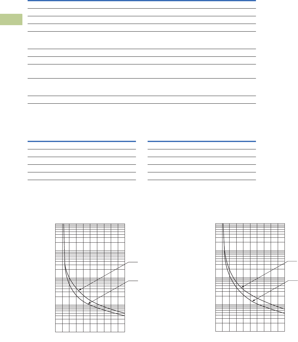
V5-T4-58 Volume 5—Motor Control and Protection CA08100006E—April 2014 www.eaton.com
4
4
4
4
4
4
4
4
4
4
4
4
4
4
4
4
4
4
4
4
4
4
4
4
4
4
4
4
4
4
4.4
Definite Purpose Contactors and Starters
NEMA Type 1 Enclosed Control
Technical Data and Specifications
20–40A, Compact Single- and Two-Pole—C25
Coil Characteristics
Trip Curves
Bimetallic Ambient Compensated Overload Relay—25°C Open Rating
Class 10 Overload Relay (25°C Open Rating) Class 20 Overload Relay (25°C Open Rating)
Description Specification
Insulation voltage 690V
Current rated and hp/kw rated contacts Double break
Magnet coil Class F, 155°C
Contact arc covers Standard on all contactors
Standard power terminals 5/16 in hex washer head screws
Quad (4) quick connect terminals on all line and load terminals
Box lugs available as option
Line and load terminal designations Marked on contactors
Operating temperature range –13° to 158°F (–25° to 70°C)
Terminal wire range
Hex washer head screws 6–10 AWG, 30 lb-in torque rating
Box lugs 6–10 AWG, 35 lb-in torque rating
8 AWG, 40 lb-in torque rating
6–4 AWG, 45 lb-in torque rating
Mounting position Vertical, horizontal or tabletop
AC Coil
Voltage
50/60 Hz
Maximum
Inrush
VA
Maximum Sealed AC Coil
Voltage
50/60 Hz
Maximum
Inrush
VA
Maximum Sealed
VA Watts VA Watts
Single-Pole Two-Pole
24 33 6 2 24 41 6.5 3
120 33 6 2 120 41 6.5 3
208/240 33 6 2 208/240 41 6.5 3
277 33 6 2 277 41 6.5 3
0
1
2
3
4
5
10
20
30
40
50
100
200
300
400
500
1000
2000
3000
4000
5000
10,000
246810
From
Hot Start
From
Cold Start
Multiples of Current Setting
Trip Time
(Seconds)
0
1
2
3
4
5
10
20
30
40
50
100
200
300
400
500
1000
2000
3000
4000
5000
10,000
246810
From
Hot Start
From
Cold Start
Multiples of Current Setting
Trip Time
(Seconds)

Volume 5—Motor Control and Protection CA08100006E—April 2014 www.eaton.com V5-T4-59
4
4
4
4
4
4
4
4
4
4
4
4
4
4
4
4
4
4
4
4
4
4
4
4
4
4
4
4
4
4
4.5
Definite Purpose Contactors and Starters
Renewal Parts
Renewal Parts
Renewal Contact Kits for C25 Definite Purpose Contactors
●Replace complete contactor for:
●C25A_
●C25B_
●C25C_
●C25D_
Renewal Contact Kits for C25 Definite Purpose Contactors
Product Selection
AC Coils
Single-Pole Kit Two-Pole Kit Three-Pole Kit
Catalog Number Part Number Part Number Part Number
C25FNF250 —6-65-5—
C25FNF350 ——6-65-6
C25FNF260 —6-65-7—
C25FNF360 ——6-65-8
C25FNF275 —6-65-20—
C25FNF375 ——6-65-19
C25GNF290 ———
C25GNF390 ———
C25HNE3120 ——6-43-6
C25KNE3200 ——6-288
C25KNE3300 ——6-286
C25LNE3360 ——6-45-2
AC Coil
Voltage
Inrush (Maximum) Sealed (Maximum) Coil
SuffixFrequency VA Watts VA Watts Class Part Number
15, 25, 30 and 40A—Two- and Three-Pole (Series D1 and E1)
12 60 74.85 46.1 5.53 1.68 RClass F, 155°C 9-3185-5
24 81.35 49.7 5.83 1.74 T 9-3185-6
110/120 74.69 51.6 5.79 1.81 A 9-3185-1
208/240 82.64 59.1 6.96 2.38 B 9-3185-2
220/240 60 74.03 51.8 5.85 1.99 JClass F, 155°C 9-3185-10
440/480 73.39 52.1 6.09 2.58 C 9-3185-3
550/600 79.47 51.7 6.56 3.05 D 9-3185-4
277 72.88 52.4 6.09 2.58 H 9-3185-7
380/415 50 64.5 50.6 6.08 2.43 LClass F, 155°C 9-3185-8
15, 25, 30 and 40A—Two- and Three-Pole (Series C1)
12 60 65 30 11 2.5 RClass F, 155°C 9-3125-5
24 65 30 11 2.5 T 9-3125-6
104/120 6530112.5A 9-3125-1
208/24050 7535173.5BClass F, 155°C 9-3125-2
440/480 7535173.5C 9-3125-3
550/600 7535173.5D 9-3125-4
27760 6530112.5HClass F, 155°C 9-3125-8
380/41550 7535173.5LClass F, 155°C 9-3125-8

V5-T4-60 Volume 5—Motor Control and Protection CA08100006E—April 2014 www.eaton.com
4
4
4
4
4
4
4
4
4
4
4
4
4
4
4
4
4
4
4
4
4
4
4
4
4
4
4
4
4
4
4.5
Definite Purpose Contactors and Starters
Renewal Parts
AC Coils, continued
AC Coil
Voltage
Inrush (Maximum) Sealed (Maximum) Coil
SuffixFrequency VA Watts VA Watts Class Part Number
15, 25, 30 and 40A—Two- and Three-Pole (Series D1 and E1)
12 60 74.85 46.1 5.53 1.68 RClass H, 180°C 9-3252-5
24 81.35 49.7 5.83 1.74 T 9-3252-6
110/120 74.69 51.6 5.79 1.81 A 9-3252-1
208/240 82.64 59.1 6.96 2.38 B 9-3252-2
220/240 60 74.03 51.8 5.85 1.99 JClass H, 180°C 9-3252-10
440/480 73.39 52.1 6.09 2.58 C 9-3252-3
550/600 79.47 51.7 6.56 3.05 D 9-3252-4
277 72.88 52.4 6.09 2.58 H 9-3252-7
380/415 50 64.5 50.6 6.08 2.43 LClass H, 180°C 9-3252-8
50A—Two- and Three-Pole (Series D1 and E1)
12 60 115.8 73.6 7.71 2.8 RClass F, 155°C 9-3186-5
24 118.1 70.7 7.58 2.79 T 9-3186-6
110/120 110.7 73.3 7.67 2.89 A 9-3186-1
208/240 124.9 90.3 10.04 3.74 B 9-3186-2
220/240 60 112.9 76.2 7.6 3.02 JClass F, 155°C 9-3186-10
440/480 114.7 75.6 8.01 3.68 C 9-3186-3
550/600 109 78.6 8.21 4.11 D 9-3186-4
277 115.4 73.1 7.73 3.12 H 9-3186-7
380/415 50 110.3 77 8.66 3.31 LClass F, 155°C 9-3186-8
50A—Two- and Three-Pole (Series D1 and E1)
12 60 115.8 73.6 7.71 2.8 RClass H, 180°C 9-3253-5
24 118.1 70.7 7.58 2.79 T 9-3253-6
110/120 110.7 73.3 7.67 2.89 A 9-3253-1
208/240 124.9 90.3 10.04 3.74 B 9-3253-2
220/240 60 112.9 76.2 7.6 3.02 JClass H, 180°C 9-3253-10
440/480 114.7 75.6 8.01 3.68 C 9-3253-3
550/600 109 78.6 8.21 4.11 D 9-3253-4
277 115.4 73.1 7.73 3.12 H 9-3253-7
380/415 50 110.3 77 8.66 3.31 LClass H, 180°C 9-3253-8
60 and 75A—Two- and Three-Pole; 25, 30 and 40A—Four-Pole
12 60 204 84 36.5 8 RClass B, 130°C 9-3256-5
24 T 9-3256-6
104/120 A 9-3256-1
208/240 50 240 100.8 50.4 10.8 BClass B, 130°C 9-3256-2
440/480 C 9-3256-3
550/600 D 9-3256-4
277 60 204 84 36.5 8 HClass B, 130°C 9-3256-7
380/415 50 199 88.8 37.8 8.8 LClass B, 130°C 9-3256-8

Volume 5—Motor Control and Protection CA08100006E—April 2014 www.eaton.com V5-T4-61
4
4
4
4
4
4
4
4
4
4
4
4
4
4
4
4
4
4
4
4
4
4
4
4
4
4
4
4
4
4
4.5
Definite Purpose Contactors and Starters
Renewal Parts
AC Coils, continued
AC Coil
Voltage
Inrush (Maximum) Sealed (Maximum) Coil
SuffixFrequency VA Watts VA Watts Class Part Number
90A—Two- and Three-Pole (Series F1)
24 50/60 325/300 — 48/35 12 TClass B, 130°C 9-3080-1
110/120 A 9-3080-2
208–220 B 9-3080-3
380–415 50/60 325/300 — 48/35 12 CClass B, 130°C 9-3080-5
277 60 325/300 — 48/35 12 HClass B, 130°C 9-3080-4
120A—Three-Pole
24 50/60 390 112 49.8 13 TClass B, 130°C 9-2756-16
110/120 A 9-2756-1
220/240 B 9-2756-2
440/480 C 9-2756-3
550/600 D 9-2756-4
208 60 390 112 49.8 13 EClass B, 130°C 9-2756-5
277 H 9-2756-9
200, 300 and 360A—Three-Pole
110/120 50/60 1040 216 116 17 AClass F, 155°C 9-1891-1
220/240 B 9-1891-2
440/480 C 9-1891-3
550/600 D 9-1891-4
208 60 1040 216 116 17 EClass F, 155°C 9-1891-13
277 H 9-1891-26
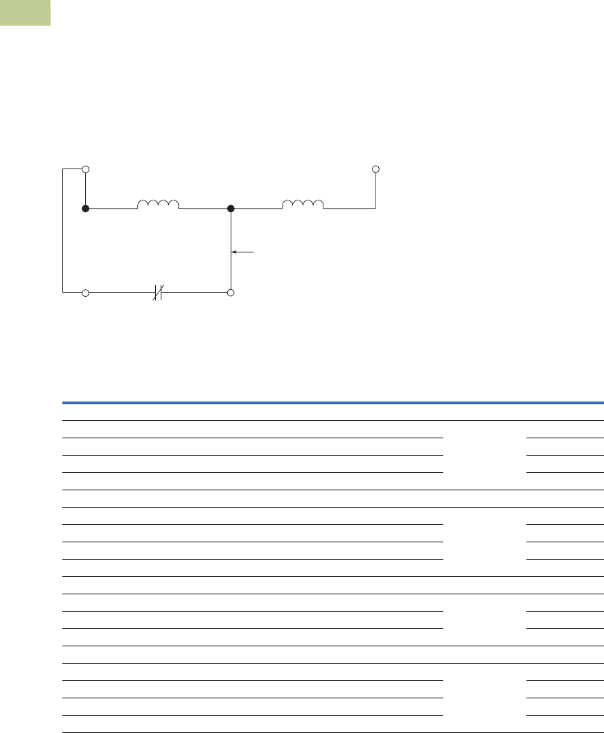
V5-T4-62 Volume 5—Motor Control and Protection CA08100006E—April 2014 www.eaton.com
4
4
4
4
4
4
4
4
4
4
4
4
4
4
4
4
4
4
4
4
4
4
4
4
4
4
4
4
4
4
4.5
Definite Purpose Contactors and Starters
Renewal Parts
DC Operation
These DC coils have separate
pick-up and seal windings.
The pick-up winding must be
connected to an early break
normally closed auxiliary
contact block and provide
the magnetic force required
to close the magnet. As the
magnet approaches the
closed position, the early
break normally closed contact
is opened and the holding coil
is inserted in series with the
pick-up winding.
The early break contact
block (C320KGD1) has to
be attached to the side of
the contactor, taking up one
of the positions available
for add-on auxiliary contact
blocks.
DC Coil Elementary Diagram—Contactors and Starters
DC Coils 1
Note
1DC coils require an early break NC auxiliary contact C320KGD1 (1NCI) or C320KGD2 (1NO-1NCI). Order separately, not included with replacement coil.
DC Coil
Voltage
Inrush (Maximum) Sealed (Maximum) Coil
SuffixAmperes Watts Amperes Watts Class Part Number
15, 25, 30 and 40A—Two- and Three-Pole (Series D1 and E1)
12 5.8 69 0.272 3.27 1R Class F, 155°C 9-3254-2
24 2.9 69 0.13 3.12 1T 9-3254-3
48 1.5 72 0.07 3.37 1W 9-3254-4
120 0.61 73 0.03 3.68 1A 9-3254-5
50A—Two- and Three-Pole (Series D1 and E1)
12 5.8 69 0.272 3.27 1R Class F, 155°C 9-3255-2
24 2.9 69 0.13 3.12 1T 9-3255-3
48 1.5 72 0.07 3.37 1W 9-3255-4
120 0.61 73 0.03 3.68 1A 9-3255-5
15, 25, 30 and 40A—Two- and Three-Pole (Series C1)
12 4.7 51 232 mA 1.8 1R Class F, 155°C 9-3126-1
24 2.7 64 110 mA 2.4 1T 9-3126-2
48 1.4 65 55 mA 2.5 1W 9-3126-3
60 and 75A—Two- and Three-Pole; 25, 30 and 40A—Four-Pole (Series C1)
12 15.4 126 0.434 5.26 1R Class F, 155°C 9-3257-1
24 6.2 88.4 0.211 5.12 1T 9-3257-2
48 2.9 76.2 0.102 4.92 1W 9-3257-3
120 1.1 67.3 0.044 5.32 1A 9-3257-4
A1 (Top)
NCI
Conductor Extending
from Bottom of Coil
Early Break Normally
Closed Auxiliary Contact
Hold (Seal) Pick-Up
A2 (Top)
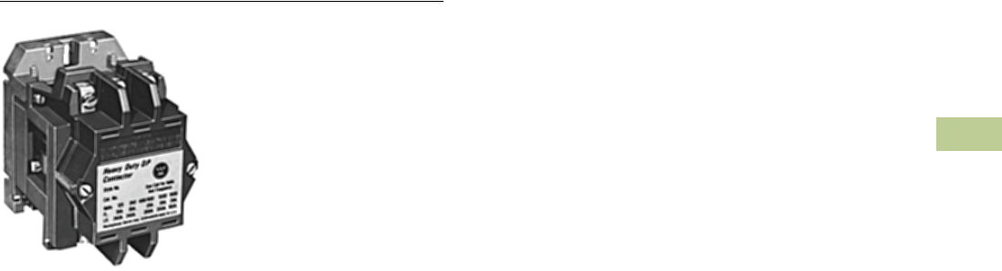
Volume 5—Motor Control and Protection CA08100006E—April 2014 www.eaton.com V5-T4-63
4
4
4
4
4
4
4
4
4
4
4
4
4
4
4
4
4
4
4
4
4
4
4
4
4
4
4
4
4
4
4.6
Definite Purpose Contactors and Starters
Heavy-Duty Special Purpose Contactors
Heavy-Duty Special Purpose Contactors
Contents
Description Page
Heavy-Duty Special Purpose Contactors
Product Selection . . . . . . . . . . . . . . . . . . . . . . . V5-T4-64
Accessories . . . . . . . . . . . . . . . . . . . . . . . . . . . V5-T4-64
Renewal Parts . . . . . . . . . . . . . . . . . . . . . . . . . V5-T4-65
Technical Data and Specifications . . . . . . . . . . V5-T4-65
Dimensions . . . . . . . . . . . . . . . . . . . . . . . . . . . V5-T4-66
Product Description
The DPCK Contactors are
designed to provide peak
performance and reliability on
special switching
applications. These heavy-
duty special purpose
contactors are rated for
applications up to 1500 Vac.
Application Description
●Typical applications include
mining equipment, welding
equipment, heating and air
conditioning applications
and other loads that
require a compact heavy-
duty contactor rated up to
1500 Vac
●The DPCK Contactors are
supplied with bolts and
washers on each terminal
for use with customer
supplied lugs
Features
●A double wound epoxy
coil allows for lower
temperature rise and
longer life
●The U-shaped magnet
provides fast, reliable
action, long life and lower
power requirements
●Stainless steel kick-out
springs
●Rugged single-piece
mounting plate
●Allows up to four double
circuit auxiliary contacts
per contactor
Benefits
●All contacts are silver alloy,
providing long life and
resistance to welding
●Straight-through wiring and
up front terminals allow for
fast, easy installation
●Loosening two captive
screws allows for easy
visual inspection of
contacts
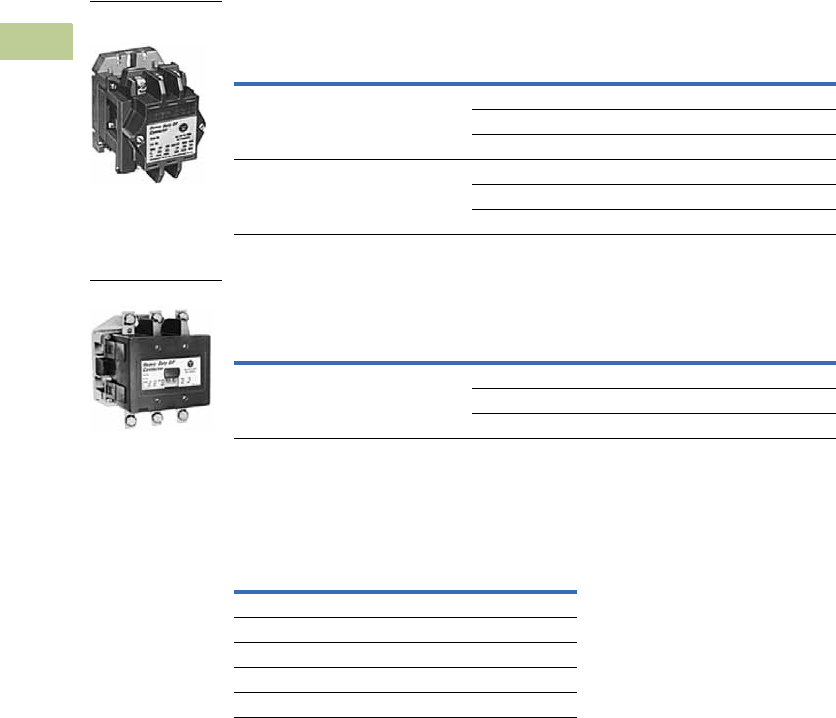
V5-T4-64 Volume 5—Motor Control and Protection CA08100006E—April 2014 www.eaton.com
4
4
4
4
4
4
4
4
4
4
4
4
4
4
4
4
4
4
4
4
4
4
4
4
4
4
4
4
4
4
4.6
Definite Purpose Contactors and Starters
Heavy-Duty Special Purpose Contactors
Product Selection
When Ordering Specify
●Catalog number with any required accessories from below
DPCK Air Break Contactors—Two- and Three-Pole 1
DPCK Air Break Contactors—Four- and Five-Pole 1
Accessories
Accessory Kits
Notes
1 Holding circuit auxiliary contact not included. If required, order from Accessories above.
2 For other coil voltages, refer to replacement coils on Page V5-T4-65 and insert proper letter in place of 9th character
of listed catalog number. Example: DPCK3035WW with 380/50 coil DPCK3035HW.
Open Ampere Rating Coil Voltage
Open Type—
Two-Pole Three-Pole
600V 1000V 1500V 60 Hz 2Catalog Number Catalog Number
35 35 20 240 DPCK2035WW DPCK3035WW
480 DPCK2035XW DPCK3035XW
600 DPCK2035EW DPCK3035EW
100 100 75 240 DPCK2100WW DPCK3100WW
480 DPCK2100XW DPCK3100XW
600 DPCK2100EW DPCK3100EW
Open Ampere Rating Coil Voltage
Open Type—
Four-Pole Five-Pole
600V 1000V 1500V 60 Hz 2Catalog Number Catalog Number
35 35 20 240 DPCK4035WW DPCK5035WW
480 DPCK4035XW DPCK5035XW
600 DPCK4035EW DPCK5035EW
Description Catalog Number
Auxiliary contacts, 1NO-1NC J11
Horizontal Mechanical Interlock
35A 180C113G09
100A 1264C37G01
Surge suppressor SS56
35A 600/1000V
Contactor
250A 600V Contactor

Volume 5—Motor Control and Protection CA08100006E—April 2014 www.eaton.com V5-T4-65
4
4
4
4
4
4
4
4
4
4
4
4
4
4
4
4
4
4
4
4
4
4
4
4
4
4
4
4
4
4
4.6
Definite Purpose Contactors and Starters
Heavy-Duty Special Purpose Contactors
Renewal Parts
DPCK Contactor Renewal Parts
Technical Data and Specifications
Magnet Coil VA—60 Hz
Notes
1For a four-pole device, use (2) of the 180C180G01 contact kits.
2For a five-pole device, use (1) of the 180C180G01 and (1) of the 180C180G02 contact kits.
Coil
Suffix
Code
35A 100A
Two-, Three-Pole Four-, Five-Pole Two-, Three-Pole
Description Hz Part Number Part Number Part Number
Contact Kit
Two-pole — — 180C180G01 1180C180G05
Three-pole — — 180C180G02 2180C180G06
ARC box — — 673B439G01 673B439G02 673B440G01
Upper base — — 673B439G03 673B439G04 673B440G02
Lower base — — 673B439G05 673B439G06 673B440G03
Crossbar — — 673B439G07 673B439G08 673B440G04
Magnet Coil
120/110 60/50 A 1266C28G01 1266C29G01 1254C70G01
110 60 V 1266C28G08 1266C29G06 1254C70G08
208/220 60 B 1266C28G02 1266C29G02 1254C70G02
220/240 60 — N/A N/A N/A
240/220 60/50 W 1266C28G09 1266C29G07 1254C70G03
480/440 60/50 X 1266C28G10 1266C29G08 1254C70G05
440/480 60 — N/A N/A N/A
600/550 60/50 E 1266C28G05 1266C29G04 1254C70G07
550 60 — N/A N/A N/A
380 50 H 1266C28G06 1266C29G09 N/A
380/110 60 — N/A N/A 1254C70G12
Catalog Number
Open
VA
Closed
VA
Closed
Watts
DPCK3035 625 50 18
DPCK3100 1200 130 40
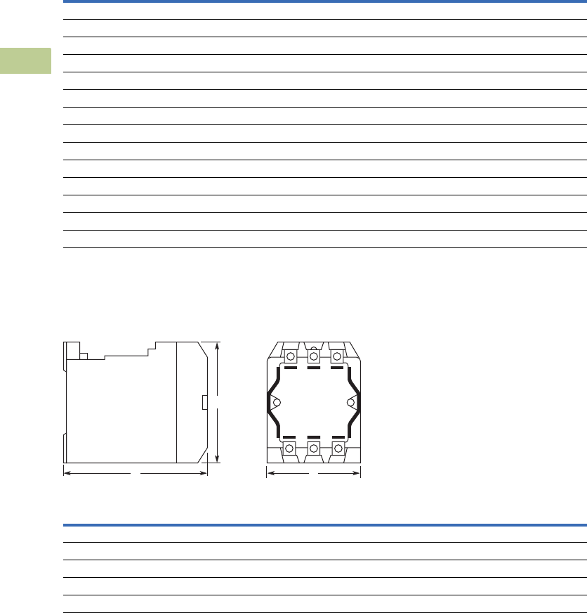
V5-T4-66 Volume 5—Motor Control and Protection CA08100006E—April 2014 www.eaton.com
4
4
4
4
4
4
4
4
4
4
4
4
4
4
4
4
4
4
4
4
4
4
4
4
4
4
4
4
4
4
4.6
Definite Purpose Contactors and Starters
Heavy-Duty Special Purpose Contactors
Contact Ratings
Dimensions
Approximate Dimensions in Inches (mm)
DPCK Air Break Contactors—35 and 100 Ampere
Volts
Full Load Current
(Amperes)
Locked Rotor Current
(Amperes)
Resistive Load
(Amperes)
Lighting Load
(Amperes)
Catalog Number DPCK3035
120 35 240 35 35
240 35 240 35 35
480 35 200 35 35
600 35 200 35 35
1000 35 200 — —
1500 20 160 — —
Catalog Number DPCK3100
120 100 600 100 100
240 100 600 100 100
480 100 600 100 100
600 100 600 100 100
1000 100 450 — —
1500 75 300 — —
Poles
Wide
A
High
B
Deep
C
Shipping Weight
Lbs (kg)
35A Contactors
2 and 3 4.06 (103.1) 5.44 (138.2) 5.63 (143.0) 16.0 (7.3)
4 and 5 6.06 (153.9) 5.44 (138.2) 5.63 (143.0) 19.0 (8.6)
100A Contactors
2 and 3 5.38 (136.7) 7.81 (198.4) 6.75 (171.5) 28.0 (12.7)
B
AC
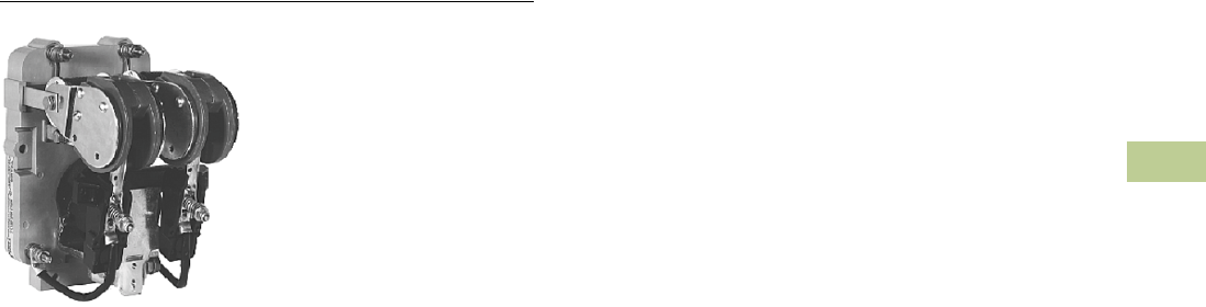
Volume 5—Motor Control and Protection CA08100006E—April 2014 www.eaton.com V5-T4-67
4
4
4
4
4
4
4
4
4
4
4
4
4
4
4
4
4
4
4
4
4
4
4
4
4
4
4
4
4
4
4.7
Definite Purpose Contactors and Starters
Direct Current Contactors
Mill Type Contactors
Contents
Description Page
Mill Type Contactors
Catalog Number Selection . . . . . . . . . . . . . . . . V5-T4-68
Product Selection . . . . . . . . . . . . . . . . . . . . . . . V5-T4-68
Accessories . . . . . . . . . . . . . . . . . . . . . . . . . . . V5-T4-69
Options . . . . . . . . . . . . . . . . . . . . . . . . . . . . . . . V5-T4-69
Technical Data and Specifications . . . . . . . . . . V5-T4-69
600V Contactors . . . . . . . . . . . . . . . . . . . . . . . . . . V5-T4-70
DPM 750V Contactor . . . . . . . . . . . . . . . . . . . . . . V5-T4-74
AVD–Contactor . . . . . . . . . . . . . . . . . . . . . . . . . . . V5-T4-77
D–Contactor . . . . . . . . . . . . . . . . . . . . . . . . . . . . . V5-T4-80
Reversing/Assignment Contactor . . . . . . . . . . . . . V5-T4-83
Mill Type Contactors
Product Description
These DC mill type
contactors are designed for
heavy industry service and
are suitable for use on
moving machinery. The
contactors listed here are for
surface mounting on steel
panels and front-of-panel
wiring. The power stud
assembly is mounted on the
side of the contactor, rather
than as part of a separate
mounting kit.
Application Description
●Applications include mining,
milling, cranes and
transportation
●These contactors utilize
DC coils
Note: Be sure to utilize a rectifier
module if the only control voltage
source available is 120 Vac.
Features
●Forged steel armature
levers and magnet frames
for superior physical
strength
●Self-lubricating bearings
●Long contact life
Standards and Certifications
●CMAA 5.6.6-2
●NEMA ICS3-441, 442, 443
●NEMA ICS2-331.23
●NEMA ICS2-110.05.02
●NEMA ICS2-125.21.02
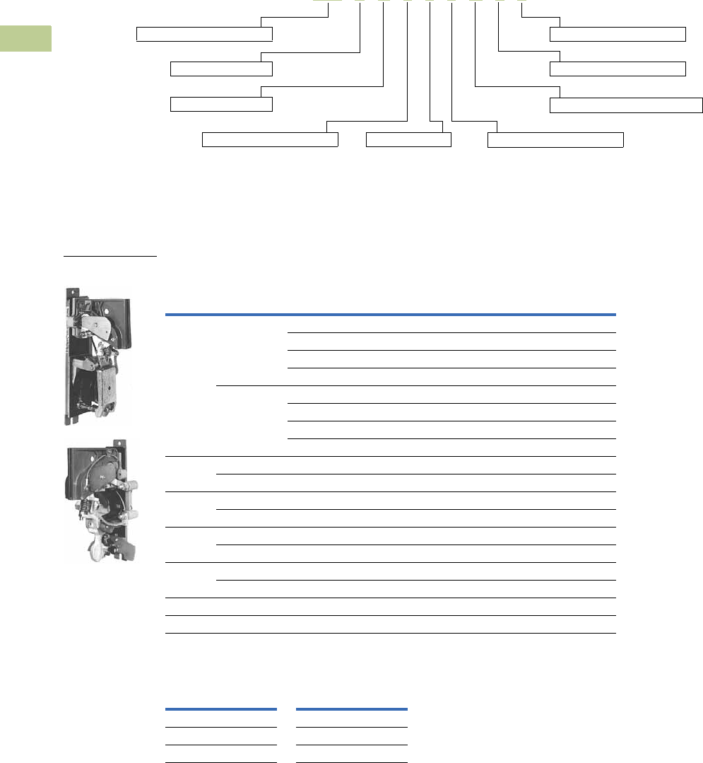
V5-T4-68 Volume 5—Motor Control and Protection CA08100006E—April 2014 www.eaton.com
4
4
4
4
4
4
4
4
4
4
4
4
4
4
4
4
4
4
4
4
4
4
4
4
4
4
4
4
4
4
4.7
Definite Purpose Contactors and Starters
Direct Current Contactors
Catalog Number Selection
DC Mill Type Contactor
Product Selection
When Ordering Specify
●The catalog number with any required accessories
DC Mill Type Contactors
Magnet Coil Suffix
Notes
1 See Page V5-T4-69 for options.
2 Not a NEMA size.
3 Consult factory.
Open Type Contactors Mechanical
Interlock
Catalog Number
NEMA
Size
Number of
Poles
Blowout Coil
Ampere Rating
230V Coil
Catalog Number
100V Coil
Catalog Number
2 1NO None C80DX12 C80DX14 C81DDA11
5C80DC12 C80DC14 C81DDA11
25 C80DF12 C80DF14 C81DDA11
50 C80DG12 C80DG14 C81DDA11
2NO None C80DX22 C80DX24 C81DDA12
5C80DC22 C80DC24 C81DDA12
25 C80DF22 C80DF24 C81DDA12
50 C80DG22 C80DG24 C81DDA12
31NO 100 C80EH121 C80EH141 C81DEA11
1NC 100 C80EH421 C80EH441 —
41NO 150 C80FJ121 C80FJ141 C81DEA11
1NC 150 C80FJ421 C80FJ441 —
51NO 300 C80GK121 C80GK141 C81DGA11
1NC 300 C80GK421 C80GK441 —
61NO 600 C80JL121 C80JL141 C81DJA11
1NC 600 C80JL421 C80JL441 —
6A 21NO 810 C80KM121 C80KM141 C81DJA11
8 1NO 1350 C80WN121 C80WN141 C81DLA11
DC Coil
Voltage
Coil
Suffix
DC Coil
Voltage
Coil
Suffix
115V 1 No Coil 5
230V 2 Special 39
100V 4
Basic contactor catalog number
Coil voltage
Type of auxiliary right position 1
C80 E H 4 2 1 N 2 0
Contactor NEMA size
Power pole configuration
Type of auxiliary left position 1
Auxiliary contact mounting options 1
Type of mounting options 1
Blowout coil rating
DC Mill Type
Contactors

Volume 5—Motor Control and Protection CA08100006E—April 2014 www.eaton.com V5-T4-69
4
4
4
4
4
4
4
4
4
4
4
4
4
4
4
4
4
4
4
4
4
4
4
4
4
4
4
4
4
4
4.7
Definite Purpose Contactors and Starters
Direct Current Contactors
Accessories
Auxiliary Contacts with Mounting Kit
Rectifier Module
Options
Auxiliary Contact Mounting Material Options
Auxiliary Contact Options per Side
Mounting Kit Options 1
Technical Data and Specifications
Mill Type Contactors
Notes
1Solderless lugs available, consult factory.
2Not available with Size 2.
Mounting Location Contact Arrangement Contactor Size Catalog Number
Side 1NO, 1NC 2 C81BAC1
Bottom 1NO, 1NC 2 C81BBC1
3, 4, 5, 6, 6A C81BBC2
Description Contactor Size Catalog Number
120 Vac Input, 100 Vdc Output All C81EB
Contactor
Size Location Suffix
2Side A
2 Bottom, with left hand and right hand option B
2 Bottom, with left hand or right hand option C
3–8 Bottom, with left hand and right hand option B
2–8 None N
Configuration Suffix
1NO 1
2NO 2
1NO-1NC 3
1NC 4
2NC 5
None 0
Description Suffix
Surface—Front of panel wiring 1
Elevated—Front of panel wiring 3 2
Description Specification
Current range 5–1800 amperes
Voltage 115, 230 and 550 Vdc
Mechanical life 20M operations
Electrical life 500K operations
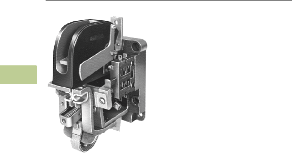
V5-T4-70 Volume 5—Motor Control and Protection CA08100006E—April 2014 www.eaton.com
4
4
4
4
4
4
4
4
4
4
4
4
4
4
4
4
4
4
4
4
4
4
4
4
4
4
4
4
4
4
4.7
Definite Purpose Contactors and Starters
Direct Current Contactors
600V Contactors
Contents
Description Page
Mill Type Contactors . . . . . . . . . . . . . . . . . . . . . . . V5-T4-67
600V Contactors
Product Selection . . . . . . . . . . . . . . . . . . . . . . . V5-T4-71
Accessories. . . . . . . . . . . . . . . . . . . . . . . . . . . . V5-T4-72
Renewal Parts . . . . . . . . . . . . . . . . . . . . . . . . . . V5-T4-73
Dimensions. . . . . . . . . . . . . . . . . . . . . . . . . . . . V5-T4-73
DPM 750V Contactor . . . . . . . . . . . . . . . . . . . . . . V5-T4-74
AVD–Contactor . . . . . . . . . . . . . . . . . . . . . . . . . . . V5-T4-77
D–Contactor . . . . . . . . . . . . . . . . . . . . . . . . . . . . . V5-T4-80
Reversing/Assignment Contactor . . . . . . . . . . . . . V5-T4-83
600V Contactors
Product Description
These DC Contactors are
designed to handle rugged
DC applications. They provide
durable service and easy
installation and maintenance.
Application Description
●Applications including
mining, milling, cranes and
transportation
●These contactors utilize
DC coils
Note: Be sure to utilize a rectifier
module if the only control voltage
source available is 120 Vac.
Features
●Sturdy glass polyester base
●Knife edge bearings that
guarantee precise
operation and minimal
wear
●High contact pressure
●Vacuum impregnated
magnetic coil
Benefits
●Able to mount on steel or
panels of any material for
maximum flexibility
●Front or rear mounting
available for convenient
installation and
maintenance
●Rapid arc quenching to
ensure long life
●Easily accessible contact
tips to remove and replace
Volume 5—Motor Control and Protection CA08100006E—April 2014 www.eaton.com V5-T4-71
4
4
4
4
4
4
4
4
4
4
4
4
4
4
4
4
4
4
4
4
4
4
4
4
4
4
4
4
4
4
4.7
Definite Purpose Contactors and Starters
Direct Current Contactors
Product Selection
When Ordering Specify
●Catalog number with appropriate coil suffix
●Any required accessories
600V Contactors
Notes
1 Other coil voltages available, see Page V5-T4-73. Substitute suffix code of desired voltage for last digit in listed catalog number. Example: ME010B.
2 For 10–150A rear connected contactors, order front connected ME contactor above and rear connection kit,
catalog number 2184A10G08, (field installed only). See Page V5-T4-73.
Size
Open 8 Hour
Ampere Rating
Contact
Arrangement
Provisions for Interlocks Magnet Coil
Voltage Catalog NumberMechanical Electrical
Front Connected
0 10 1NO Yes 4 125 Vdc 1ME010C
2NO 2 ME020C
1NO, 1NC 4 ME011C
1NC 2 ME001C
1 25 1NO Yes 4 125 Vdc 1ME110C
2NO 2 ME120C
1NO, 1NC 4 ME111C
1NC 2 ME101C
2 50 1NO Yes 4 125 Vdc 1ME210C
2NO 2 ME220C
1NO, 1NC 4 ME211C
1NC 2 ME201C
3 100 1NO Yes 4 125 Vdc 1ME310C
2NO 2 ME320C
1NO, 1NC 4 ME311C
1NC 2 ME301C
4 150 1NO Yes 4 125 Vdc 1ME410C
2NO 2 ME420C
1NO, 1NC 4 ME411C
1NC 2 ME401C
Rear Connected
0–4 10–150 — — — — ME 2
600V Contactor

V5-T4-72 Volume 5—Motor Control and Protection CA08100006E—April 2014 www.eaton.com
4
4
4
4
4
4
4
4
4
4
4
4
4
4
4
4
4
4
4
4
4
4
4
4
4
4
4
4
4
4
4.7
Definite Purpose Contactors and Starters
Direct Current Contactors
Accessories
Auxiliary Contacts (Electrical Interlocks)—For Field Installation Only 1
Standard Magnet Coil Suffix
Rear Connector Kit for
ME Contactors 3
Accessory Option
Mechanical Interlocks, Unmounted
Notes
1For factory installed electrical interlocks, consult factory.
2NO = Normally Open, NC = Normally Closed, DB = Delayed Break, FC = Front Connected, L = Left Hand, R = Right Hand, OB = Outboard (for single-pole, Size 2 frame).
3Field installation only.
Auxiliary
Contact Type Application
Contact
Arrangement 2
Number of
Auxiliary
Contacts
Auxiliary Contacts
Factory Installed 1
Auxiliary Contacts
Unmounted
Replacement Only
Mounting and Operating
Hardware for New
Applications
Catalog Number Catalog Number Catalog Number
L46 ME01 only NO–FC 1 11A8713G10 11A8713G10 None required
NC–FC 11A8713G09 11A8713G09 None required
ME10 only NC–FC–OB 1 487B878G01 487B878G01 None required
ME10, ME11, ME20, ME30,
ME31, ME40 and ME41
NO–FC 1 11A8713G09 11A8713G09 None required
NC–FC 11A8713G10 11A8713G10 None required
L66 ME10, ME11, ME20, ME30,
ME31, ME40 and ME41
DB–FC–L 1 659C301G04 659C301G04 None required
DB–FC–R 659C301G05 659C301G05 None required
ME10 Only DB–FC–L–OB 1 487B878G06 487B878G06 None required
DB–FC–R–OB 487B878G07 487B878G07 None required
Voltage Suffix Code
65 Vdc (ME Size 0–4 only) A
115 Vdc B
125 Vdc C
230 Vdc D
250 Vdc E
550 Vdc F
Other G
Catalog Number
2184A10G08
Description
Rectifier for AC Operation
Order by description
Type
Contactor
Type Size Contacts Catalog Number
M-25 ME All 1NO, 1NO + 1NC 878D400G01
M-25 ME All 2NO, 2NO + 1NC 878D401G01

Volume 5—Motor Control and Protection CA08100006E—April 2014 www.eaton.com V5-T4-73
4
4
4
4
4
4
4
4
4
4
4
4
4
4
4
4
4
4
4
4
4
4
4
4
4
4
4
4
4
4
4.7
Definite Purpose Contactors and Starters
Direct Current Contactors
Renewal Parts
ME Series
Kits
Coils
Dimensions
Approximate Dimensions in Inches (mm)
600V Contactors
Note
1If lower coils are required, order separately.
One NO Pole Two NO Poles One NC Pole One NO/NC Pole
Description Qty. Part Number Qty. Part Number Qty. Part Number Qty. Part Number
Contact kit 1 2184A10G14 22184A10G14 12184A10G14 22184A10G14
Arc box 10/25/50A 1 2184A10G09 22184A10G09 12184A10G09 22184A10G09
Arc box 100/150A 1 2184A10G10 22184A10G10 12184A10G10 22184A10G10
Shunt kit 1 2184A10G21 12184A20G16 12084A01G07 12184A11G07
Armature kit 1 2184A10G19 12184A20G15 12084A01G06 12184A11G06
Blowout Assembly
10A 1 2184A10G15 12184A20G11 12184A10G15 22184A10G15
25A 1 2184A10G16 12184A20G12 12184A10G16 22184A10G16
50A 1 2184A10G17 12184A20G13 12184A10G17 22184A10G17
110/150A 1 2184A10G18 12184A20G14 12184A10G18 22184A10G18
Rear conn. kit 1 2184A10G08 12184A10G08 12184A10G08 12184A10G08
Operating Coils Holding Coils (Lower)—1NO-1NC Contactors Only 1
10/25/50/100/150
Ampere Sizes
10/25/50
Ampere Sizes
100/150
Ampere Sizes
Voltage Part Number Part Number Part Number
65V 30B4376G06 44A6366G10 30B4376G27
90/92V 30B4376G25 44A6366G12 427C048G16
115V 30B4376G07 44A6366G13 30B4376G01
125V 30B4376G08 44A6366G19 30B4376G26
230/240V 30B4376G09 44A6366G15 30B4376G02
250V 30B4376G10 44A6366G23 30B4376G17
500V 30B4376G14 N/A N/A
550V 30B4376G11 44A6366G18 30B4376G03
Contactor Size
Contact
Arrangement Width Height Depth
Shipping Weight
Lbs (kg)
Front Connected
0–2 1NO 3.18 (80.8) 7.56 (192.0) 6.81 (173.0) 8.0 (3.6)
2NO 5.53 (140.5) 6.75 (171.5) 6.81 (173.0) 10.0 (4.5)
1NO, 1NC 3.67 (93.2) 12.44 (316.0) 6.81 (173.0) 12.0 (5.4)
1NC 3.67 (93.2) 9.57 (243.1) 6.81 (173.0) 10.0 (4.5)
3–4 1NO 3.18 (80.8) 7.78 (197.6) 6.81 (173.0) 8.0 (3.6)
2NO 5.53 (140.5) 7.44 (189.0) 6.81 (173.0) 10.0 (4.5)
1NO, 1NC 3.67 (93.2) 12.88 (327.2) 6.81 (173.0) 12.0 (5.4)
1NC 3.67 (93.2) 9.69 (246.1) 6.81 (173.0) 10.0 (4.5)
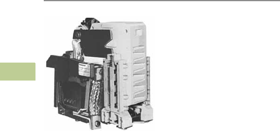
V5-T4-74 Volume 5—Motor Control and Protection CA08100006E—April 2014 www.eaton.com
4
4
4
4
4
4
4
4
4
4
4
4
4
4
4
4
4
4
4
4
4
4
4
4
4
4
4
4
4
4
4.7
Definite Purpose Contactors and Starters
Direct Current Contactors
DPM 750V Contactor
Contents
Description Page
Mill Type Contactors . . . . . . . . . . . . . . . . . . . . . . . V5-T4-67
600V Contactors . . . . . . . . . . . . . . . . . . . . . . . . . . V5-T4-70
DPM 750V Contactor
Product Selection . . . . . . . . . . . . . . . . . . . . . . . V5-T4-75
Accessories . . . . . . . . . . . . . . . . . . . . . . . . . . . V5-T4-75
Renewal Parts . . . . . . . . . . . . . . . . . . . . . . . . . V5-T4-75
Technical Data and Specifications . . . . . . . . . . V5-T4-76
Dimensions . . . . . . . . . . . . . . . . . . . . . . . . . . . V5-T4-76
AVD–Contactor . . . . . . . . . . . . . . . . . . . . . . . . . . . V5-T4-77
D–Contactor . . . . . . . . . . . . . . . . . . . . . . . . . . . . . V5-T4-80
Reversing/Assignment Contactor . . . . . . . . . . . . . V5-T4-83
DPM 750V Contactor
Product Description
The DPM 750 Vdc Definite
Purpose Contactor has been
designed to meet severe
environmental and vibration
conditions found in your
worst applications. The
contactor is of unit
construction, assembled
on a molded insulated
base, providing maximum
performance in minimum
space.
Application Description
This rugged device was
designed for applications
such as railway equipment,
offshore drilling, mining, off-
road vehicles, marine, and
so on.
Features
●Power circuit insulating
barriers are molded from
glass-polyester materials
having high arc and track
resisting qualities
●The DPM is designed to
mount directly on a
channel or angle frame, but
may be adapted for
mounting on a flat metal or
insulated panel
●Available with or without
an overcurrent latching
mechanism to prevent
opening under heavy
overload currents. When
the line current returns to
normal, the overcurrent
latch disengages
Benefits
●Saves panel space by
locating the arc chute vents
on the front of the unit.
This eliminates the need
for arcing clearance above
the contactor
●All vital parts are
removable from the front
without having to
disconnect line or load
connections, allowing for
easy maintenance
●Safety is a must. The
mechanical interlock
prevents the contactor
from closing when the arc
box has been removed or
when it is not installed
properly
Volume 5—Motor Control and Protection CA08100006E—April 2014 www.eaton.com V5-T4-75
4
4
4
4
4
4
4
4
4
4
4
4
4
4
4
4
4
4
4
4
4
4
4
4
4
4
4
4
4
4
4.7
Definite Purpose Contactors and Starters
Direct Current Contactors
Product Selection
When Ordering Specify
●Catalog number of contactor and any required accessories
750 Vdc Contactors
Accessories
Extra L-67 Auxiliary Contacts—Order Separately
Mechanical Interlock Kit
Renewal Parts
DPM Contactor
Notes
1For other coil operating voltages, contact Eaton Technical Resource Center.
2Includes factory installed 2NO/2NC auxiliary contacts.
3When interlock kit is installed, only one L-67 auxiliary contact can be mounted on each DPM contactor.
Coil Operating
Voltage 1Over-Current Latch Catalog Number
Coil Operating
Voltage 1Over-Current Latch Catalog Number
28 Vdc Without 2120A07G01 274 Vdc Without 2120A07G09
With 2120A07G02 2With 2120A07G10
36 Vdc Without 2120A07G03 2110 Vdc Without 2120A07G13
With 2120A07G04 2With 2120A07G14
55 Vdc Without 2120A07G05 2125 Vdc Without 2120A07G17
With 2120A07G06 2With 2120A07G18
Contact Combination Provided by
One Auxiliary Contact Assembly Field Installed Kit
Normally Open Normally Closed Catalog Number
042087A40G11
132087A40G12
222087A40G13
312087A40G14
402087A40G15
Description Catalog Number
Mechanical Horizontal Interlock Kit
Includes mounting instructions and
mounting hardware 3
1954D13G01
Description Catalog Number
Contact Kit 2131A94G10
Arc Box 2131A94G03
Shunt 3534C86G01
Coils
28 Vdc 2114A92G04
36 Vdc 2114A92G05
55 Vdc 2114A92G06
74 Vdc 2114A92G09
110/115 Vdc 2114A92G14
125 Vdc 2114A92G15
275 Vdc 2114A92G16
600 Vdc 2114A92G20
750 Vdc Contactor
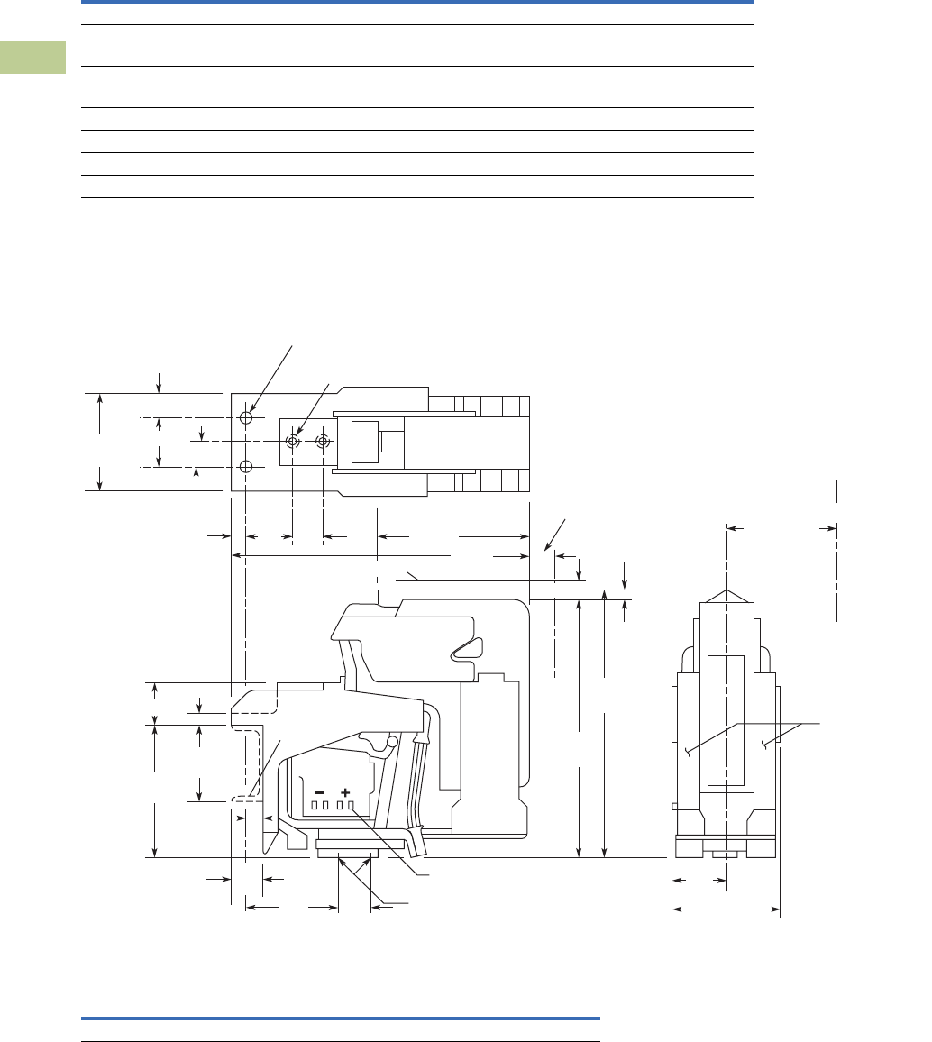
V5-T4-76 Volume 5—Motor Control and Protection CA08100006E—April 2014 www.eaton.com
4
4
4
4
4
4
4
4
4
4
4
4
4
4
4
4
4
4
4
4
4
4
4
4
4
4
4
4
4
4
4.7
Definite Purpose Contactors and Starters
Direct Current Contactors
Technical Data and Specifications
DPM Contactor
Dimensions
Approximate Dimensions in Inches (mm)
DPM Contactor
Description Specification
Line voltage 750 Vdc
Continuous current rating
Carrying and interrupting capacity 1250A
Operating coil
Duty rating Continuous
Operation Will operate at 80–110% of rated voltage
Insulation between power circuit and operating coil Rated 750 Vdc
Arcing and creepage distances Meet or exceed NEMA standards for 750V equipment
Blowout coil Rated for continuous duty
Width Height Depth
Shipping Weight
Lbs (kg)
4.13 (105) 11.06 (280.9) 12.12 (307.8) 30.5 (13.8)
C
L
.44 (11.1) Dia. - 2 Mounting Holes
.38-16 Tap 1.00 (25.4) Deep
2 Line Terminal Holes
.38-16 Tap 1.00 (25.4) Deep
2 Load Terminal Holes
Clearance to Ground
5.00 (127.0)
Duplicate
Adjacent
Contactor
Two L-67 Auxiliary
Contact Units
Coil Terminal Tabs for No. 250 Faston
To Remove Arc Chute
Customer
Mounting
Channel
1.88 (26.3)
.50 (12.7)
*This dimension must not be exceeded or ashover may occur.
1.25
(31.8)
4.00
(101.6)
1.50
(38.1)
3.00
(76.2)*
5.31
(134.9)
.63 (15.9) 1.88
(47.6)
1.25
(31.8)
6.25
(158.8)
12.13
(308.0)
1.00 (25.4)
1.00 (25.4)
2.00 (50.8)
4.00
(101.6)
1.3 8
(34.9)
1.00 (25.4)
.50
(12.7)
11.06
(281.0)
10.56
(268.3)
2.06
(52.4)
4.13
(105.0)
.88 (22.4)
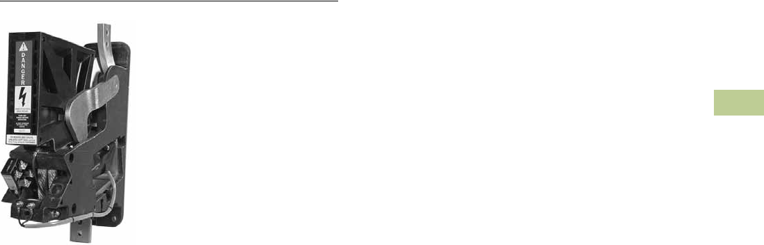
Volume 5—Motor Control and Protection CA08100006E—April 2014 www.eaton.com V5-T4-77
4
4
4
4
4
4
4
4
4
4
4
4
4
4
4
4
4
4
4
4
4
4
4
4
4
4
4
4
4
4
4.7
Definite Purpose Contactors and Starters
Direct Current Contactors
AVD–Contactor
Contents
Description Page
Mill Type Contactors . . . . . . . . . . . . . . . . . . . . . . . V5-T4-67
600V Contactors . . . . . . . . . . . . . . . . . . . . . . . . . . V5-T4-70
DPM 750V Contactor . . . . . . . . . . . . . . . . . . . . . . V5-T4-74
AVD–Contactor
Product Selection . . . . . . . . . . . . . . . . . . . . . . . V5-T4-78
Accessories . . . . . . . . . . . . . . . . . . . . . . . . . . . V5-T4-78
Renewal Parts . . . . . . . . . . . . . . . . . . . . . . . . . V5-T4-78
Technical Data and Specifications . . . . . . . . . . V5-T4-79
Dimensions . . . . . . . . . . . . . . . . . . . . . . . . . . . V5-T4-79
D–Contactor . . . . . . . . . . . . . . . . . . . . . . . . . . . . . V5-T4-80
Reversing/Assignment Contactor . . . . . . . . . . . . . V5-T4-83
AVD–Contactor
Product Description
The AVD–Contactor is a
single-pole normally open, load
break, bi-directional definite
purpose DC contactor. The
device is rated at 1400 amps
continuous and is capable of
switching up to 2000 Vdc
loads.
Application Description
The AVD–Contactor was
designed for the demanding
environmental requirements
of locomotive, rapid transit
and off highway vehicle
applications. This device is
also applied in high
horsepower DC drive
applications including
process lines and off shore
oil drilling rigs.
Features
●Bi-directional interrupting
capability
●2000 Vdc switching in a
compact design due to
arc chute
●Any combination of up to
four isolated NO or NC
auxiliary contacts
●Panel mount design
●Continuous duty
operating coil
●Continuous duty blow
out coil
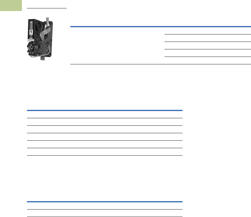
V5-T4-78 Volume 5—Motor Control and Protection CA08100006E—April 2014 www.eaton.com
4
4
4
4
4
4
4
4
4
4
4
4
4
4
4
4
4
4
4
4
4
4
4
4
4
4
4
4
4
4
4.7
Definite Purpose Contactors and Starters
Direct Current Contactors
Product Selection
When Ordering—Contact Technical Resource Center
●Product specification: The AVD-contactor is a definite purpose DC contactor
●Please consult our Technical Resource Center for catalog numbers of other device
configurations and application assistance
AVD–Contactor
Accessories
Auxiliary Contacts
Renewal Parts
Contacts
Device Type
Auxiliary Contact
Configuration Coil Voltage Catalog Number
1400A contactor 3NO/1NC 28 6702ED667-4
37 6702ED667-5
74 6702ED667-6
100 6702ED667-3
230 6702ED667-7
Contact
Configuration
Terminal
Configuration Catalog Number
1NO/1NC Fast-on 10-3519-5
2NO Fast-on 10-3519-6
2NC Fast-on 10-3519-7
1NO/1NC Screw type 10-6817
2NO Screw type 10-6817-2
2NC Screw type 10-6817-3
Description
Quantity Required
per Contactor Catalog Number
Stationary contact 1 23-7253
Movable contact 2 23-7255
1400A Contactor
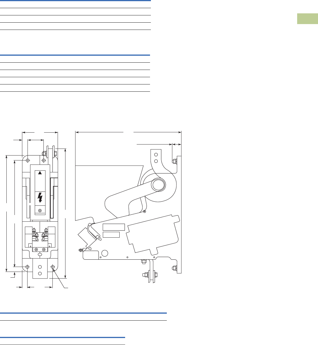
Volume 5—Motor Control and Protection CA08100006E—April 2014 www.eaton.com V5-T4-79
4
4
4
4
4
4
4
4
4
4
4
4
4
4
4
4
4
4
4
4
4
4
4
4
4
4
4
4
4
4
4.7
Definite Purpose Contactors and Starters
Direct Current Contactors
Technical Data and Specifications
AVD-Contactor
Operating Coil Characteristics
Dimensions
Approximate Dimensions in Inches (mm)
AVD-Contactor
Arc Clearances
Description Specification
Current carrying capability at 55°C 1400A continuous
Electrical creepage and clearance distances Up to 2000 Vdc applications
Mechanical life 2 million operations
Operating coil voltages (DC) 28, 37, 74, 100, 230 (others available)
Coil Voltage
Current Draw at Nominal
Voltage (±5% at 20°C) Catalog Number
28 1.87 9-3004-2
37 1.58 9-3004-3
74 0.79 9-3004-1
100 0.62 9-3004-5
230 0.25 9-3004-4
Width Height Depth
Shipping Weight
Lbs (kg)
15.0 (381.0) 19.5 (495.3) 5.0 (127.0) 70 (31.8)
Front Top Sides
2 (51) 2 (51) 1 (25)
19.50
(495.3)
16.00
(406.4)
17.50
(444.5)
2.25
(57.2)
.75
(19.1)
5.00
(127)
.75
(19.1)
.75
(19.1)
3.50
(88.9)
.43 (10.9) Dia.
Mounting Hole
(4 Places)
15.00
(381)
Maximum Stud Length
to Maintain 2000 Volt
Electrical Clearance Rating
(Top Right Stud Only)
1.25
Max
D
A
N
G
E
R
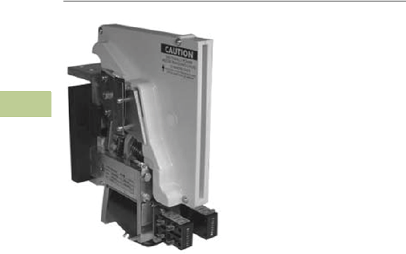
V5-T4-80 Volume 5—Motor Control and Protection CA08100006E—April 2014 www.eaton.com
4
4
4
4
4
4
4
4
4
4
4
4
4
4
4
4
4
4
4
4
4
4
4
4
4
4
4
4
4
4
4.7
Definite Purpose Contactors and Starters
Direct Current Contactors
D–Contactor
Contents
Description Page
Mill Type Contactors . . . . . . . . . . . . . . . . . . . . . . . V5-T4-67
600V Contactors . . . . . . . . . . . . . . . . . . . . . . . . . . V5-T4-70
DPM 750V Contactor . . . . . . . . . . . . . . . . . . . . . . V5-T4-74
AVD–Contactor . . . . . . . . . . . . . . . . . . . . . . . . . . . V5-T4-77
D–Contactor
Product Selection . . . . . . . . . . . . . . . . . . . . . . . V5-T4-81
Accessories . . . . . . . . . . . . . . . . . . . . . . . . . . . V5-T4-81
Renewal Parts . . . . . . . . . . . . . . . . . . . . . . . . . V5-T4-81
Technical Data and Specifications . . . . . . . . . . V5-T4-82
Dimensions . . . . . . . . . . . . . . . . . . . . . . . . . . . V5-T4-82
Reversing/Assignment Contactor . . . . . . . . . . . . . V5-T4-83
D–Contactor
Product Description
The D–Contactor is a single-
pole normally open, load
break, bi-directional definite
purpose DC contactor. Two
devices are available rated at
1800A and 3000A at 750 Vdc.
Application Description
The D–Contactor was
designed for the demanding
environmental requirements
of locomotive, rapid transit
and off highway vehicle
applications. This device is
also widely applied in high
horsepower DC drive
applications including
process lines and off shore
oil drilling rigs.
Features
●Bi-directional interrupting
capability
●Compact design due to
intermittent duty blowout
coil and arc interruption
circuit (not suitable for
extremely high duty cycle
or jogging applications)
●Any combination of up to
eight isolated NO or NC
auxiliary contacts
●Channel/angle frame
mounting standard,
optional panel mount kit
available
●Continuous duty
operating coil
●Screw type or fast-on
control terminals
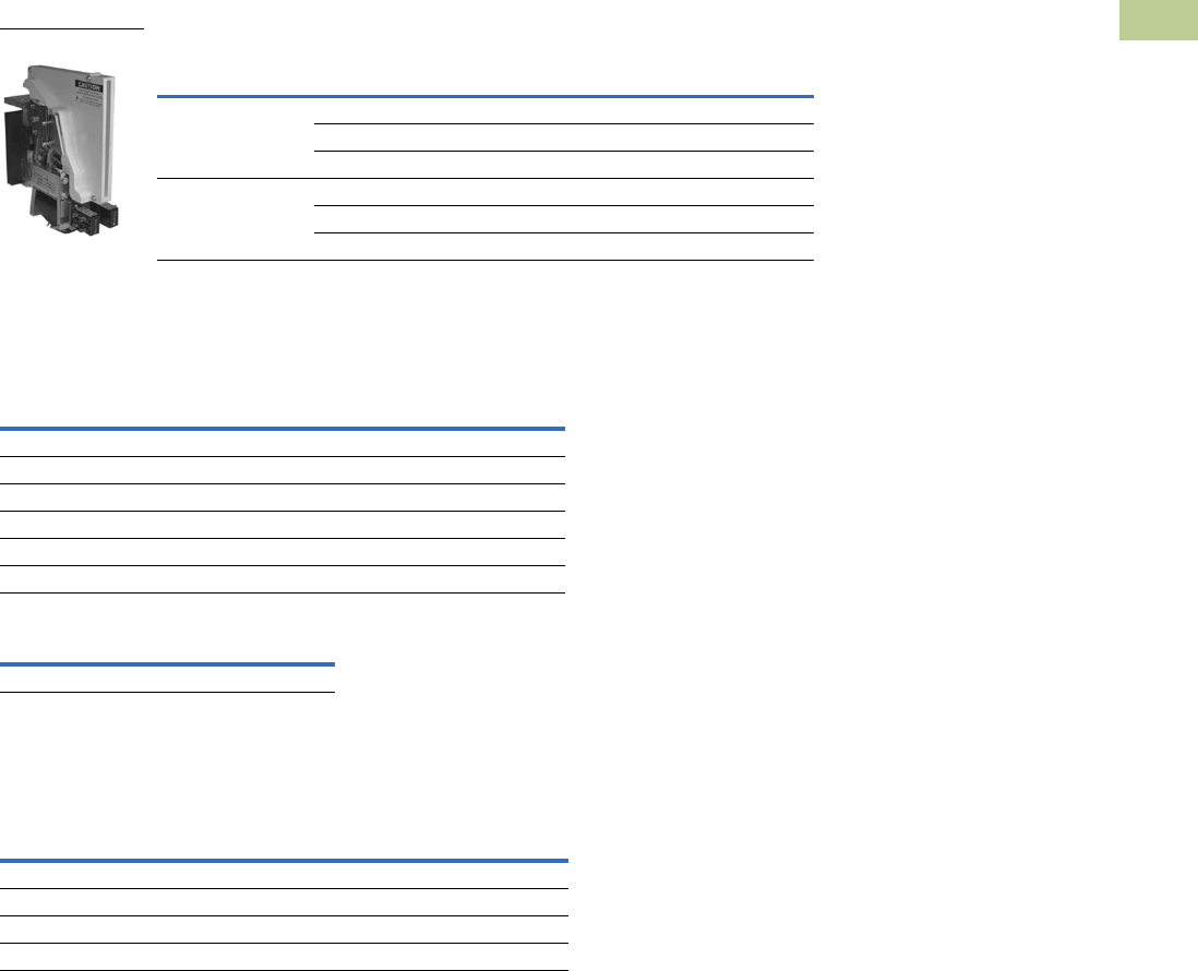
Volume 5—Motor Control and Protection CA08100006E—April 2014 www.eaton.com V5-T4-81
4
4
4
4
4
4
4
4
4
4
4
4
4
4
4
4
4
4
4
4
4
4
4
4
4
4
4
4
4
4
4.7
Definite Purpose Contactors and Starters
Direct Current Contactors
Product Selection
When Ordering—Contact Technical Resource Center
●Product specification: The D-contactor is a definite purpose DC contactor
●Please consult our Technical Resource Center for catalog numbers of other device
configurations and application assistance
D–Contactor
Accessories
Auxiliary Contacts
Panel Mounting Kit
Renewal Parts
Contact Kits
Device Type
Auxiliary Contact
Configuration Coil Voltage Catalog Number
1800A contactor 3NO/1NC 74 Vdc 6702ED584
3NO/1NC 100 Vdc 6702ED663
2NO/2NC 115 Vdc 6702ED584-2
3000A contactor 3NO/1NC 74 Vdc 6702ED587-2
2NO/2NC 100 Vdc 6702ED668
3NO/1NC 115 Vdc 6702ED587-4
Contact
Configuration
Terminal
Configuration Catalog Number
1NO/1NC Fast-on 10-3519-5
2NO Fast-on 10-3519-6
2NC Fast-on 10-3519-7
1NO/1NC Screw type 10-6817
2NO Screw type 10-6817-2
2NC Screw type 10-6817-3
Description Catalog Number
Panel mounting kit 99-3842
Device Rating
Main Contact
Configuration Contacts Catalog Number
1800A 2-Main Main contacts 6-497
1800A 2-Main Arcing contacts 23-5449
3000A 4-Main Main contacts 6-496
3000A 4-Main Arcing contacts 23-5448
1800A Contactor
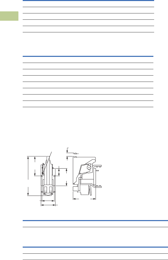
V5-T4-82 Volume 5—Motor Control and Protection CA08100006E—April 2014 www.eaton.com
4
4
4
4
4
4
4
4
4
4
4
4
4
4
4
4
4
4
4
4
4
4
4
4
4
4
4
4
4
4
4.7
Definite Purpose Contactors and Starters
Direct Current Contactors
Technical Data and Specifications
D–Contactor
Operating Coil Characteristics
Dimensions
Approximate Dimensions in Inches (mm)
D–Contactor
Arc Clearances
Description Specification
Current carrying capability at 55°C 1800A and 3000A continuous
Resistive interrupt rating 5000A 750 Vdc
Electrical creepage and clearance distances Up to 1500 Vdc applications
Mechanical life 2 million operations
Operating coil voltages (DC) 12, 24, 32, 48, 74, 100, 115, 230 (others available)
Coil Voltage
Current Draw at Nominal
Voltage (±7.5% at 20°C) Catalog Number
12 3.96 9-1688-15
24 2.00 9-1688-7
32 1.44 9-1688-9
48 1.00 9-1688-12
74 0.97 9-2064-3
100 0.45 9-1688-8
115 0.37 9-1688-2
230 0.20 9-1688-1
Width Height Depth
Shipping Weight
Lbs (kg)
9.6 (243.8) 13.68 (347.5) 6.04 (153.4) 43 (19.5)
750V
Type of Load Front Top Sides
Resistive 4 (102) 2 (51) 3 (76)
Inductive 7 (178) 4 (102) 3 (76)
13.68
(347.5)
6.04 (153.4)
6.33
(160.8)
6.52
(165.6)
2.52
(64)
1.75 (44.5) to
Remove Arc Shoot
5.0 (127) 9.6
(243.8)
.562 (14.3) Dia.
Mtg. Hole
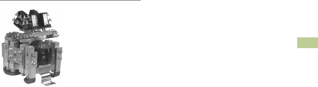
Volume 5—Motor Control and Protection CA08100006E—April 2014 www.eaton.com V5-T4-83
4
4
4
4
4
4
4
4
4
4
4
4
4
4
4
4
4
4
4
4
4
4
4
4
4
4
4
4
4
4
4.7
Definite Purpose Contactors and Starters
Direct Current Contactors
Reversing/Assignment Contactor
Contents
Description Page
Mill Type Contactors . . . . . . . . . . . . . . . . . . . . . . . V5-T4-67
600V Contactors . . . . . . . . . . . . . . . . . . . . . . . . . . V5-T4-70
DPM 750V Contactor . . . . . . . . . . . . . . . . . . . . . . V5-T4-74
AVD–Contactor . . . . . . . . . . . . . . . . . . . . . . . . . . . V5-T4-77
D–Contactor . . . . . . . . . . . . . . . . . . . . . . . . . . . . . V5-T4-80
Reversing/Assignment Contactor
Product Selection . . . . . . . . . . . . . . . . . . . . . . . V5-T4-84
Accessories . . . . . . . . . . . . . . . . . . . . . . . . . . . V5-T4-84
Renewal Parts . . . . . . . . . . . . . . . . . . . . . . . . . V5-T4-84
Technical Data and Specifications . . . . . . . . . . V5-T4-85
Dimensions . . . . . . . . . . . . . . . . . . . . . . . . . . . V5-T4-85
Reversing/Assignment Contactor
Product Description
The Reversing/Assignment
Contactor is a two-pole,
double-throw non-load break
definite purpose DC
contactor. A three-position
center-off and a two-position
magnetically-latched
configuration is available.
The device is rated for 1100A,
1000 Vdc. The Reversing
Contactor includes cross over
busbars for DC motor
reversing applications; the
Assignment Contactor omits
the cross over busbars for
motor assignment
applications. (See Page
V5-T4-85.)
Application Description
The Reversing/Assignment
Contactor was designed for
the demanding environmental
requirements of off highway
vehicle applications. This
device is also widely utilized
with high horsepower DC
drives for DC motor reversing
and drive assignment
applications.
Features
●Bi-directional current
carrying capability (non-
load break)
●Can replace four single-
pole contactors in DC
motor reversing
applications
●Can replace two or four
single-pole contactors in
DC motor assignment
applications
●Any combination of up to
eight isolated NO or NC
auxiliary contacts
●Panel mount design
●Continuous duty
operating coil
●Screw type or fast-on
control terminals
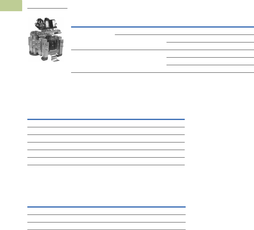
V5-T4-84 Volume 5—Motor Control and Protection CA08100006E—April 2014 www.eaton.com
4
4
4
4
4
4
4
4
4
4
4
4
4
4
4
4
4
4
4
4
4
4
4
4
4
4
4
4
4
4
4.7
Definite Purpose Contactors and Starters
Direct Current Contactors
Product Selection
When Ordering—Contact Technical Resource Center
●Product specification: The Reversing/assignment contactor is a definite purpose DC contactor
●Please consult our Technical Resource Center for catalog numbers of other device
configurations and application assistance
Reversing/Assignment Contactor (Three-Position, Center OFF)
Accessories
Auxiliary Contacts
Renewal Parts
Contact Kits
Note
1The 6-602-3 contact kit will upgrade the three-position, reversing/assignment device from the
original design that incorporated a leaf spring contact structure to the present design that
incorporates a coil spring contact structure. The 6-602 contact kit can then be used after the device
has been upgraded for subsequent contact replacement.
Device Type
Auxiliary Contact
Configuration Coil Voltage Catalog Number
Reverser 8NO 74 6702ED615
4NO/4NC 125 6702ED621-2
250 6702ED622
Assignment 4NO/4NC 74 6702ED664-2
125 6702ED621
250 6702ED664-6
Contact
Configuration
Terminal
Configuration Catalog Number
1NO/1NC Fast-on 10-3519-5
2NO Fast-on 10-3519-6
2NC Fast-on 10-3519-7
1NO/1NC Screw type 10-6817
2NO Screw type 10-6817-2
2NC Screw type 10-6817-3
Device Configuration Catalog Number
Reversing/assignment Three-position 6-602
Reversing/assignment upgrade kit 1Three-position 6-602-3
Magnetic latched reversing/assignment Two-position 6-602-5
1000V Contactor
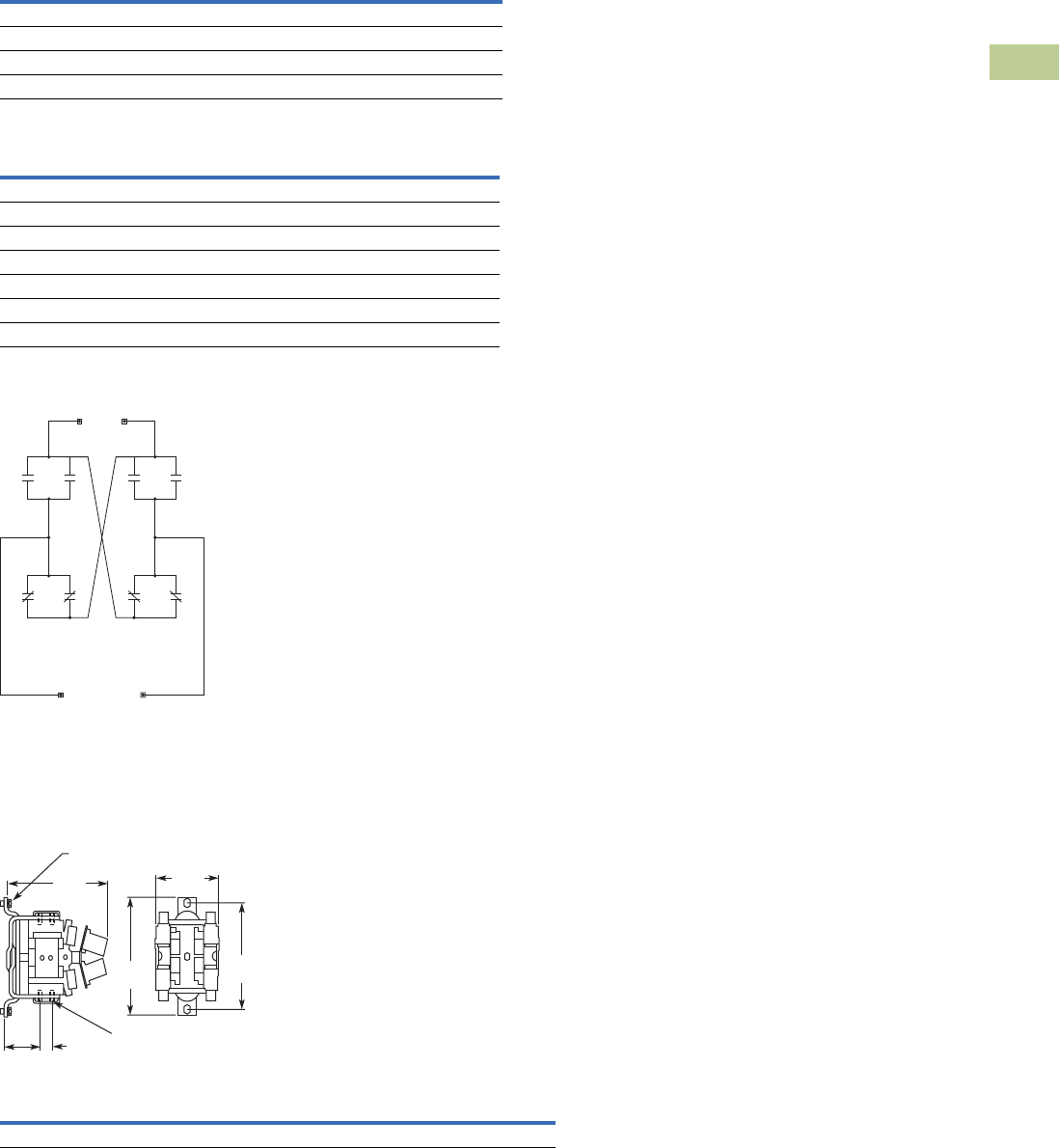
Volume 5—Motor Control and Protection CA08100006E—April 2014 www.eaton.com V5-T4-85
4
4
4
4
4
4
4
4
4
4
4
4
4
4
4
4
4
4
4
4
4
4
4
4
4
4
4
4
4
4
4.7
Definite Purpose Contactors and Starters
Direct Current Contactors
Technical Data and Specifications
Reversing/Assignment Contactor
Operating Coil Characteristics
Reversing Contactor
Schematic Diagram
The reversing contactor
includes the cross over
busbars for DC motor
reversing applications. The
assignment contactor omits
the cross over busbars for
motor assignment
applications.
Dimensions
Approximate Dimensions in Inches (mm)
Reversing Contactor
Description Specification
Current carrying capability at 55°C 1100A continuous
Electrical creepage and clearance distances For 1000 Vdc applications
Mechanical life 1 million operations
Operating coil voltages (DC) 24, 28, 36, 74, 110, 125, 250 (others available)
Coil Voltage
Current Draw at Nominal
Voltage (±7.5% at 20°C) Catalog Number
24 1.60 9-1903-9
28 1.30 9-1903-1
36 1.06 9-1903-3
74 0.49 9-1903-7
110 0.33 9-1903-6
125 0.33 9-1903-4
250 0.17 9-1903-8
Line
Load
Width Height Depth
Shipping Weight
Lbs (kg)
11.3 (287) 10.5 (266.7) 6.8 (172.7) 45 (20.4)
10.5
(266.7)
3.89
(98.8)
1.25
(31.8)
11. 3
(287)
6.8
(172.7)
2 1/2-13 x 1.0
Mtg. Screws
9.38
(238.3)
3/8-16 ASA 23
12 Holes

V5-T4-86 Volume 5—Motor Control and Protection CA08100006E—April 2014 www.eaton.com
4
4
4
4
4
4
4
4
4
4
4
4
4
4
4
4
4
4
4
4
4
4
4
4
4
4
4
4
4
4
4.8
Definite Purpose Contactors and Starters
Ratings
Ampere Rating of AC Motors
Ampere ratings of motors
vary somewhat, depending
upon the type of motor. The
values given below are for
drip-proof, Class B insulated
(T Frame) where available,
1.15 service factor, NEMA
Design B motors. These
values represent an average
full load motor current which
was calculated from the
motor performance data
published by several motor
manufacturers. In the case of
high torque squirrel cage
motors, the ampere ratings
will be at least 10% greater
than the values given below.
Caution—These average
ratings could be high or low
for a specific motor and
therefore heater coil
selection on this basis
always involves risk. For
fully reliable motor
protection, select heater
coils on the basis of full
load current rating as
shown on the motor
nameplate.
Ampere Ratings of Three-Phase, 60 Hz, AC Induction Motor
Notes
1To convert horsepower to kW, multiply horsepower by 0.7457.
2380V 50 Hz.
Syn. Speed
RPM
Current in Amperes
hp 1200V 230V 380V 2460V 575V 2200V
1/41800 1.090.950.550.480.38—
1200 1.61 1.4 0.81 0.7 0.56 —
900 1.84 1.6 0.93 0.8 0.64 —
1/3 1800 1.37 1.19 0.69 0.6 0.48 —
1200 1.83 1.59 0.92 0.8 0.64 —
900 2.07 1.8 1.04 0.9 0.72 —
1/21800 1.981.720.990.860.69—
1200 2.47 2.15 1.24 1.08 0.86 —
900 2.742.381.381.190.95—
3/41800 2.832.461.421.230.98—
1200 3.36 2.92 1.69 1.46 1.17 —
900 3.753.261.881.631.3 —
1 3600 3.22 2.8 1.7 1.4 1.12 —
1800 4.09 3.56 2.06 1.78 1.42 —
1200 4.32 3.76 2.28 1.88 1.5 —
900 4.954.3 2.6 2.151.72—
1-1/23600 5.014.362.642.181.74—
1800 5.59 4.86 2.94 2.43 1.94 —
1200 6.07 5.28 3.2 2.64 2.11 —
900 6.44 5.6 3.39 2.8 2.24 —
2 3600 6.44 5.6 3.39 2.8 2.24 —
1800 7.36 6.4 3.87 3.2 2.56 —
1200 7.87 6.84 4.14 3.42 2.74 —
900 9.09 7.9 4.77 3.95 3.16 —
3 3600 9.598.345.024.173.34—
1800 10.8 9.4 5.7 4.7 3.76 —
1200 11.7 10.2 6.2 5.12 4.1 —
900 13.111.46.9 5.7 4.55—
5 3600 15.5 13.5 8.2 6.76 5.41 —
1800 16.6 14.4 8.74 7.21 5.78 —
1200 18.2 15.8 9.59 7.91 6.32 —
900 18.3 15.9 9.6 7.92 6.33 —

Volume 5—Motor Control and Protection CA08100006E—April 2014 www.eaton.com V5-T4-87
4
4
4
4
4
4
4
4
4
4
4
4
4
4
4
4
4
4
4
4
4
4
4
4
4
4
4
4
4
4
4.8
Definite Purpose Contactors and Starters
Ratings
Ampere Ratings of Three-Phase, 60 Hz, AC Induction Motor, continued
Notes
1To convert horsepower to kW, multiply horsepower by 0.7457.
2380V 50 Hz.
Syn. Speed
RPM
Current in Amperes
hp 1200V 230V 380V 2460V 575V 2200V
7-1/23600 22.419.511.89.797.81—
1800 24.7 21.5 13 10.7 8.55 —
1200 25.1 21.8 13.2 10.9 8.7 —
900 26.523 13.911.59.19—
10 3600 29.2 25.4 15.4 12.7 10.1 —
1800 30.8 26.8 16.3 13.4 10.7 —
1200 32.2 28 16.9 14 11.2 —
900 35.1 30.5 18.5 15.2 12.2 —
15 3600 41.9 36.4 22 18.2 14.5 —
1800 45.1 39.2 23.7 19.6 15.7 —
1200 47.6 41.4 25 20.7 16.5 —
900 51.2 44.5 26.9 22.2 17.8 —
20 3600 58 50.4 30.5 25.2 20.1 —
1800 58.9 51.2 31 25.6 20.5 —
1200 60.7 52.8 31.9 26.4 21.1 —
900 63.1 54.9 33.2 27.4 21.9 —
25 3600 69.9 60.8 36.8 30.4 24.3 —
1800 74.5 64.8 39.2 32.4 25.9 —
1200 75.4 65.6 39.6 32.8 26.2 —
900 77.4 67.3 40.7 33.7 27 —
30 3600 84.8 73.7 44.4 36.8 29.4 —
1800 86.9 75.6 45.7 37.8 30.2 —
1200 90.6 78.8 47.6 39.4 31.5 —
900 94.1 81.8 49.5 40.9 32.7 —
40 3600 111 96.4 58.2 48.2 38.5 —
1800 116 101 61 50.4 40.3 —
1200 117 102 61.2 50.6 40.4 —
900 121 105 63.2 52.2 41.7 —
50 3600 138 120 72.9 60.1 48.2 —
1800 143 124 75.2 62.2 49.7 —
1200 145 126 76.2 63 50.4 —
900 150 130 78.5 65 52 —
60 3600 164 143 86.8 71.7 57.3 —
1800 171 140 90 74.5 59.4 —
1200 173 150 91 75 60 —
900 177 154 93.1 77 61.5 —
75 3600 206 179 108 89.6 71.7 —
1800 210 183 111 91.6 73.2 —
1200 212 184 112 92 73.5 —
900 222 193 117 96.5 77.5 —

V5-T4-88 Volume 5—Motor Control and Protection CA08100006E—April 2014 www.eaton.com
4
4
4
4
4
4
4
4
4
4
4
4
4
4
4
4
4
4
4
4
4
4
4
4
4
4
4
4
4
4
4.8
Definite Purpose Contactors and Starters
Ratings
Ampere Ratings of Three-Phase, 60 Hz, AC Induction Motor, continued
Notes
1To convert horsepower to kW, multiply horsepower by 0.7457.
2380V 50 Hz.
Syn. Speed
RPM
Current in Amperes
hp 1200V 230V 380V 2460V 575V 2200V
100 3600 266 231 140 115 92.2 —
1800 271 236 144 118 94.8 23.6
1200 275 239 145 120 95.6 24.2
900 290 252 153 126 101 24.8
125 3600 — 292 176 146 116 —
1800 — 293 177 147 117 29.2
1200 — 298 180 149 119 29.9
900 — 305 186 153 122 30.9
150 3600 — 343 208 171 137 —
1800 — 348 210 174 139 34.8
1200 — 350 210 174 139 35.5
900 — 365 211 183 146 37
200 3600 — 452 257 226 181 —
1800 — 458 265 229 184 46.7
1200 — 460 266 230 184 47
900 — 482 279 241 193 49.4
250 3600 — 559 338 279 223 —
1800 — 568 343 284 227 57.5
1200 — 573 345 287 229 58.5
900 — 600 347 300 240 60.5
300 1800 — 678 392 339 271 69
1200 — 684 395 342 274 70
400 1800 — 896 518 448 358 91.8
500 1800 — 1110 642 555 444 116
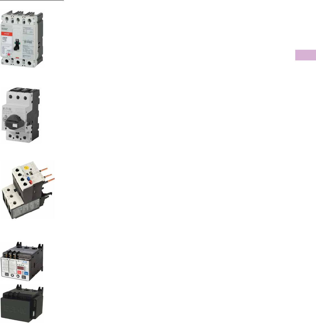
Volume 5—Motor Control and Protection CA08100006E—April 2014 www.eaton.com V5-T5-1
5
5
5
5
5
5
5
5
5
5
5
5
5
5
5
5
5
5
5
5
5
5
5
5
5
5
5
5
5
5
Motor Protection and Monitoring
Motor Protection Circuit Breaker
Overload Relay—C440
Overload Relays—C441,
Motor Insight
Manual Motor Protector
5.1 Monitoring Relays
Product Overview—Monitoring Relays . . . . . . . . . . . . . . . . . . . . . . . . V5-T5-2
Current Monitoring Relays . . . . . . . . . . . . . . . . . . . . . . . . . . . . . . . . . . V5-T5-5
Phase Monitoring Relays . . . . . . . . . . . . . . . . . . . . . . . . . . . . . . . . . . . V5-T5-16
Voltage Monitoring Relays . . . . . . . . . . . . . . . . . . . . . . . . . . . . . . . . . . V5-T5-28
Ground Fault Monitoring Relays . . . . . . . . . . . . . . . . . . . . . . . . . . . . . V5-T5-42
5.2 Motor Protection Circuit Breakers
Motor Protection Circuit Breakers (MPCB) . . . . . . . . . . . . . . . . . . . . . V5-T5-55
5.3 Manual Motor Protection
Manual Motor Protectors—XTPB, XTPR and XTPE . . . . . . . . . . . . . . . V5-T5-56
5.4 Overload Relays
Product Overview . . . . . . . . . . . . . . . . . . . . . . . . . . . . . . . . . . . . . . . . V5-T5-58
XT IEC Overload Relays . . . . . . . . . . . . . . . . . . . . . . . . . . . . . . . . . . . . V5-T5-60
Freedom Overload Relays . . . . . . . . . . . . . . . . . . . . . . . . . . . . . . . . . . V5-T5-64
C440/XT Electronic Overload Relay . . . . . . . . . . . . . . . . . . . . . . . . . . . V5-T5-65
IQ500 Overload Relays . . . . . . . . . . . . . . . . . . . . . . . . . . . . . . . . . . . . V5-T5-88
C441 Overload Relays . . . . . . . . . . . . . . . . . . . . . . . . . . . . . . . . . . . . . V5-T5-89
MP-3000 Overload Relays . . . . . . . . . . . . . . . . . . . . . . . . . . . . . . . . . . V5-T5-115
MP-4000 Overload Relays . . . . . . . . . . . . . . . . . . . . . . . . . . . . . . . . . . V5-T5-117
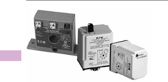
V5-T5-2 Volume 5—Motor Control and Protection CA08100006E—April 2014 www.eaton.com
5
5
5
5
5
5
5
5
5
5
5
5
5
5
5
5
5
5
5
5
5
5
5
5
5
5
5
5
5
5
5.1
Motor Protection and Monitoring
Monitoring Relays
Monitoring Relays
Contents
Description Page
Monitoring Relays
Current Monitoring Relays . . . . . . . . . . . . . . . . V5-T5-3
Phase Monitoring Relays . . . . . . . . . . . . . . . . . V5-T5-16
Voltage Monitoring Relays . . . . . . . . . . . . . . . . V5-T5-28
Ground Fault Monitoring Relays . . . . . . . . . . . . V5-T5-42
Product Overview—Monitoring Relays
Current Monitoring Relays
Eaton offers two different
series of current monitoring
relays:
CurrentWatch™ Series
●The CurrentWatch ECS and
ECSJ Series from Eaton’s
Electrical Sector is a family
of solid-state
adjustable
current switches,
ideal for
providing status
information on electrical
equipment
D65C Series
●
The D65C Series Current
Monitoring Relays monitor
AC single-phase currents for
over- or undercurrent
conditions
in three current
ranges: 0.1–1A, 0.5–5A
and 1–10A. An external
current transformer may
be used to extend the
range of the product. A
separate 24V or 120 Vac
input (supply) voltage
is required to power the
unit. All versions are
available in a compact
plug-in case using industry
standard 8- or 11-pin octal
sockets
Phase Monitoring Relays
The D65 Series Phase
Monitoring Relays provide
protection against premature
equipment failure caused by
voltage faults on three-phase
systems. All D65 phase
monitoring relays are
compatible with most wye
or delta systems. In wye
systems, a connection to
neutral is not required. Phase
Monitoring relays protect
against single-phasing
regardless of any
regenerative voltages.
Voltage Monitoring Relays
The D65 Series Voltage
Monitoring Relays monitor
either AC single-phase
(50/60 Hz) or DC voltages
to protect equipment against
voltage fault conditions.
No separate supply (input)
voltage is required. All
versions are available in a
compact plug-in case using
an 8-pin octal socket.
There are two styles of
voltage monitoring relays:
●Over/Undervoltage Relays
●Voltage Band Relays
Ground Fault Monitoring
Relays
Eaton offers two different
series of ground fault
monitoring relays:
D64R Series
●The new D64R digital
ground fault relays are
microprocessor-based
and replace the previous
generation of analog-based
devices
●Microprocessor-based
D64R GFRs combine more
selectable features into a
single model, which makes
easier model selection and
reduces spares inventory
requirements
D64L Series
●Type D64L ground fault
monitors are designed to
monitor ungrounded
supplies on three-phase AC
power systems up to 600V.
If an insulation fault
develops anywhere on the
system between the
source and the load, the
D64L will detect it and give
an alarm or trip, depending
on the adjustable field
settings selected
●The D64L is ideally suited
for systems supplied from
the secondary of either an
ungrounded delta or an
ungrounded wye
connected transformer
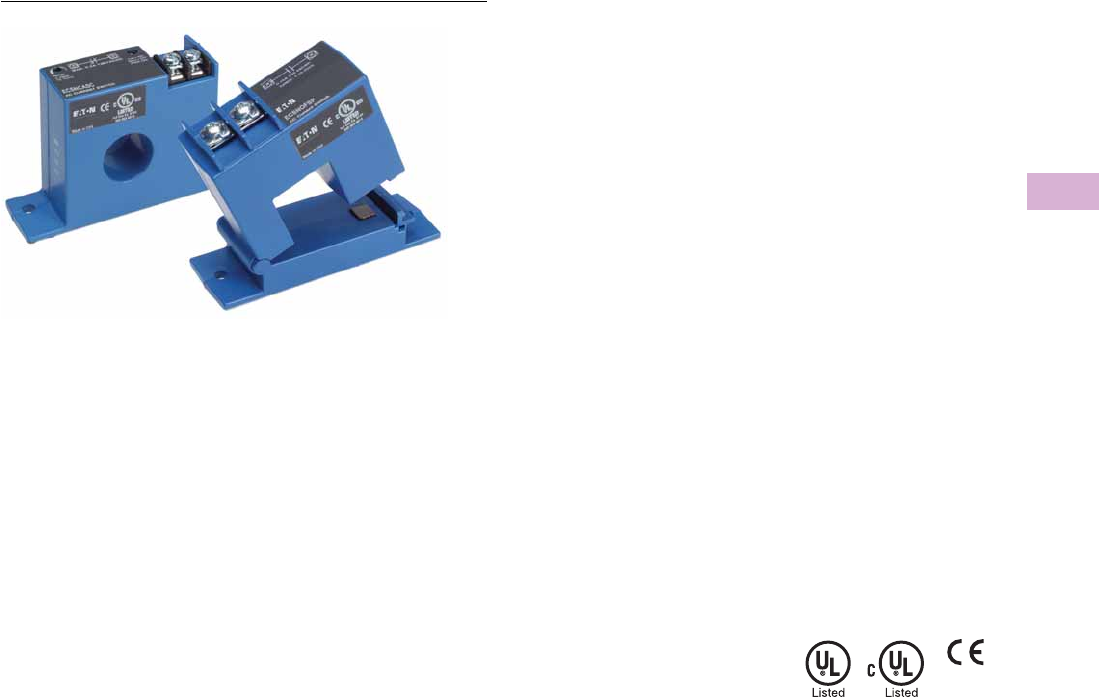
Volume 5—Motor Control and Protection CA08100006E—April 2014 www.eaton.com V5-T5-3
5
5
5
5
5
5
5
5
5
5
5
5
5
5
5
5
5
5
5
5
5
5
5
5
5
5
5
5
5
5
5.1
Motor Protection and Monitoring
Monitoring Relays
ECS Series CurrentWatch Current Switches
Contents
Description Page
Current Monitoring Relays
ECS Series CurrentWatch Current Switches
ECSJ Series CurrentWatch Current Switches . . V5-T5-4
D65 Current Monitoring Relays . . . . . . . . . . . . V5-T5-5
Phase Monitoring Relays . . . . . . . . . . . . . . . . . . . . V5-T5-16
Voltage Monitoring Relays . . . . . . . . . . . . . . . . . . . V5-T5-28
Ground Fault Monitoring Relays . . . . . . . . . . . . . . V5-T5-42
ECS Series CurrentWatch™ Current Switches
ECS Series
Product Description
The CurrentWatch™ ECS
Series from Eaton’s Electrical
Sector is a family of solid-
state adjustable current
switches, ideal for providing
status information on
electrical equipment. The
ECS is excellent for new
installations, where the
conductors run through the
housing, requiring no cutting.
These switches are also ideal
for retrofits, since split-core
models can be opened to fit
around existing conductors.
The current switch is
accurate, reliable and easy
to install.
The ECS can sense
continuous currents from
1 to 150A and does not
require any supply voltage,
as the power required is
induced from the monitored
conductor. The output is a
non-polarity-sensitive solid-
state contact for switching
AC and DC circuits up to
240 Vac/Vdc. This switch also
includes an LED indicating
two states: on and below trip
point, and above trip point
with contacts energized. All
ECS Series switches carry an
unconditional five-year
warranty.
Reference
Refer to Volume 8—Sensing Solutions, CA08100010E, Tab 7,
section 7.2 for additional product information.
ECS Series CurrentWatch Tab Section
Application Description . . . . . . . . . . . . . . . . . . . . . . . . . . . 7. 2
Product Selection . . . . . . . . . . . . . . . . . . . . . . . . . . . . . . . . 7. 2
Accessories . . . . . . . . . . . . . . . . . . . . . . . . . . . . . . . . . . . . 7. 2
Technical Data and Specifications . . . . . . . . . . . . . . . . . . . 7. 2
Wiring Diagrams . . . . . . . . . . . . . . . . . . . . . . . . . . . . . . . . 7. 2
Dimensions . . . . . . . . . . . . . . . . . . . . . . . . . . . . . . . . . . . . 7. 2
Any change in current can be
sensed with the ECS Series.
A change in current may
indicate motor failure, belt
loss/slippage or mechanical
failure. Any of these events
can cause the current to drop
significantly, tripping the
switch and notifying the
controller.
Standards and Certifications
●UL® Listed
●cUL® Listed
●CE Certified
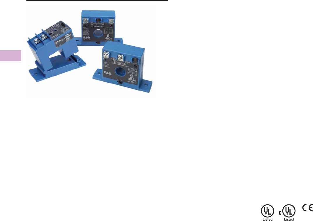
V5-T5-4 Volume 5—Motor Control and Protection CA08100006E—April 2014 www.eaton.com
5
5
5
5
5
5
5
5
5
5
5
5
5
5
5
5
5
5
5
5
5
5
5
5
5
5
5
5
5
5
5.1
Motor Protection and Monitoring
Monitoring Relays
ECSJ Series CurrentWatch Current Switches
Contents
Description Page
Current Monitoring Relays
ECS Series CurrentWatch Current Switches . . V5-T5-3
ECSJ Series CurrentWatch Current Switches
D65 Current Monitoring Relays . . . . . . . . . . . . V5-T5-5
Phase Monitoring Relays . . . . . . . . . . . . . . . . . . . V5-T5-16
Voltage Monitoring Relays . . . . . . . . . . . . . . . . . . V5-T5-28
Ground Fault Monitoring Relays . . . . . . . . . . . . . . V5-T5-42
ECSJ Series CurrentWatch Current Switches
ECSJ Series
Product Description
The CurrentWatch™ ECSJ
Series current operated
switches from Eaton’s
Electrical Sector provide the
same dependable indication
of status offered by the
CurrentWatch ECS Series,
but with the added benefit of
increased setpoint precision.
A choice of three, jumper-
selectable input ranges
allows the ECSJ Series to be
tailored to an application,
providing more precise
control through improved
setpoint resolution. Self-
powering, isolated solid-state
outputs, 1–6A, 6–40A and
40–200A input ranges, and a
choice of split- or solid-core
enclosures are standard.
For typical applications of the
CurrentWatch ECSJ Series,
see listing on this page.
Reference
Refer to Volume 8—Sensing Solutions, CA08100010E, Tab 7,
section 7.3 for additional product information.
ECSJ Series CurrentWatch Tab Section
Application Description . . . . . . . . . . . . . . . . . . . . . . . . . . . 7. 3
Product Selection . . . . . . . . . . . . . . . . . . . . . . . . . . . . . . . 7. 3
Accessories . . . . . . . . . . . . . . . . . . . . . . . . . . . . . . . . . . . . 7. 3
Technical Data and Specifications . . . . . . . . . . . . . . . . . . . 7. 3
Wiring Diagrams . . . . . . . . . . . . . . . . . . . . . . . . . . . . . . . . 7. 3
Dimensions . . . . . . . . . . . . . . . . . . . . . . . . . . . . . . . . . . . . 7. 3
Application Description
Typical Applications
●Electronic Proof of
Flow—Current operated
switches eliminate the
need for multiple pipe or
duct penetrations and are
more reliable than electro-
mechanical pressure or
flow switches
●Conveyors—Detect jams
and overloads
●Lighting Circuits—Easier
to install and more
accurate than photocells
●Fans, Pumps and Heating
Elements—Faster
response than temperature
sensors
●Critical Motors
●Ancillary Equipment
Standards and Certifications
●UL Listed
●cUL Listed
●CE Certified
●UL 508 Industrial
Equipment (USA and
Canada)
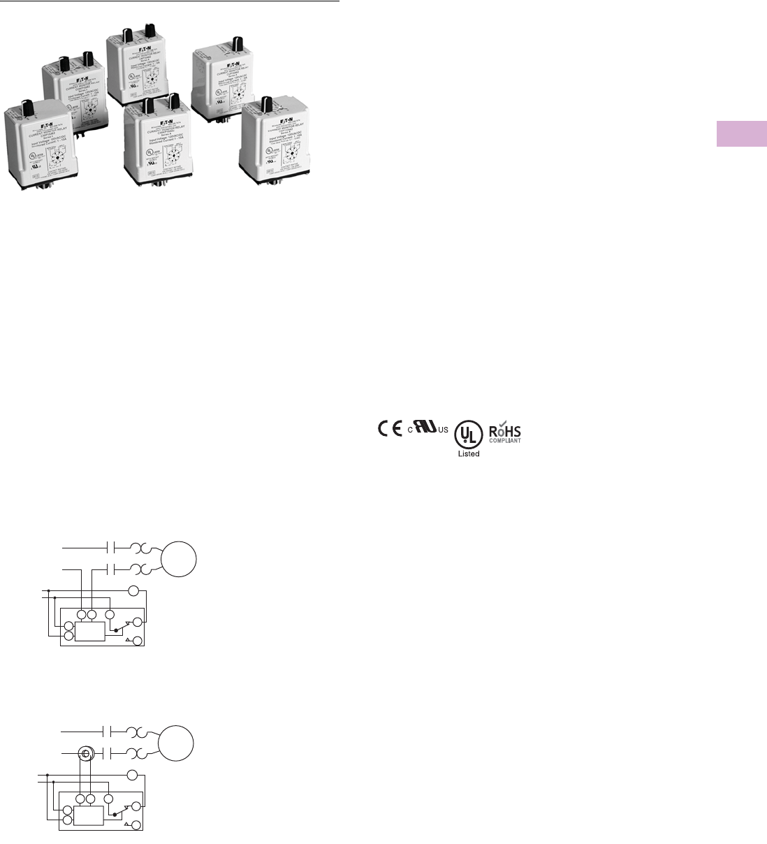
Volume 5—Motor Control and Protection CA08100006E—April 2014 www.eaton.com V5-T5-5
5
5
5
5
5
5
5
5
5
5
5
5
5
5
5
5
5
5
5
5
5
5
5
5
5
5
5
5
5
5
5.1
Motor Protection and Monitoring
Monitoring Relays
Current Monitoring Relays
Contents
Description Page
Current Monitoring Relays
ECS Series CurrentWatch Current Switches . . V5-T5-3
ECSJ Series CurrentWatch Current Switches . . V5-T5-4
D65 Current Monitoring Relays
Product Selection Guide . . . . . . . . . . . . . . . V5-T5-6
D65CE Series—Standard Current
Monitors . . . . . . . . . . . . . . . . . . . . . . . . . . V5-T5-7
D65CH Series—Overcurrent Monitors . . . . V5-T5-10
D65CL Series—Undercurrent Monitors . . . V5-T5-13
Phase Monitoring Relays . . . . . . . . . . . . . . . . . . . . V5-T5-16
Voltage Monitoring Relays . . . . . . . . . . . . . . . . . . . V5-T5-28
Ground Fault Monitoring Relays . . . . . . . . . . . . . . V5-T5-42
Product Overview
The D65C Series Current
Monitoring Relays monitor AC
single-phase currents for over-
or undercurrent conditions
in
three current ranges: 0.1–1A,
0.5–5A and 1–10A. An
external current transformer
may be used to extend the
range of the product. A
separate 24V or 120 Vac input
(supply) voltage is required to
power the unit. All versions
are available in a compact
plug-in case using industry
standard 8- or 11-pin octal
sockets.
Application Description
Typical Installation without External CT
Typical Installation with External CT
Current Monitor Relay
Control
Voltage
M
Motor
M
M
L1
L2
6
5
34 1 2
8
Current Monitor Relay
Control
Voltage
M
M
L1
L2
M
Motor
6
5
34 1 2
8
Standards and
Certifications
●CE
●cRUus listed
●UL listed 12
●RoHS compliant
Notes
1When used with accompanying Eaton
socket.
2In addition to the above approvals, all
plug-in products are also UL Listed when
used with the appropriate Eaton socket.

V5-T5-6 Volume 5—Motor Control and Protection CA08100006E—April 2014 www.eaton.com
5
5
5
5
5
5
5
5
5
5
5
5
5
5
5
5
5
5
5
5
5
5
5
5
5
5
5
5
5
5
5.1
Motor Protection and Monitoring
Monitoring Relays
Product Selection Guide
Standard
Fixed time delay on both
pickup and dropout current
settings.
D65C Standard Function
Overcurrent
Adjustable time delay on
pickup and fixed time delay
on dropout current settings.
D65C Overcurrent Function
Undercurrent
Fixed time delay on pickup
and adjustable time delay on
dropout current settings.
D65C Undercurrent Function
Note
1Fixed time delay eliminates nuisance tripping due to short current surges or drops.
Series
Pickup Dropout
PageSetting Time Delay Setting Time Delay
D65CE Adjustable (across
monitored range)
Fixed 100 ms 1Fixed (–5% pickup) Fixed 100 ms 1V5-T5-8
D65CEK Adjustable
(50–95% pickup)
Series
Pickup Dropout
PageSetting Time Delay Setting Time Delay
D65CH Adjustable (across
monitored range)
0.1–10 sec adjustable Fixed (–5% pickup) Fixed 100 ms 1V5-T5-11
D65CHK Adjustable
(50–95% pickup)
Series
Pickup Dropout
PageSetting Time Delay Setting Time Delay
D65CL Fixed
(+5% dropout)
Fixed 100 ms 1Adjustable (across
monitored range)
0.1–10 sec adjustable V5-T5-14
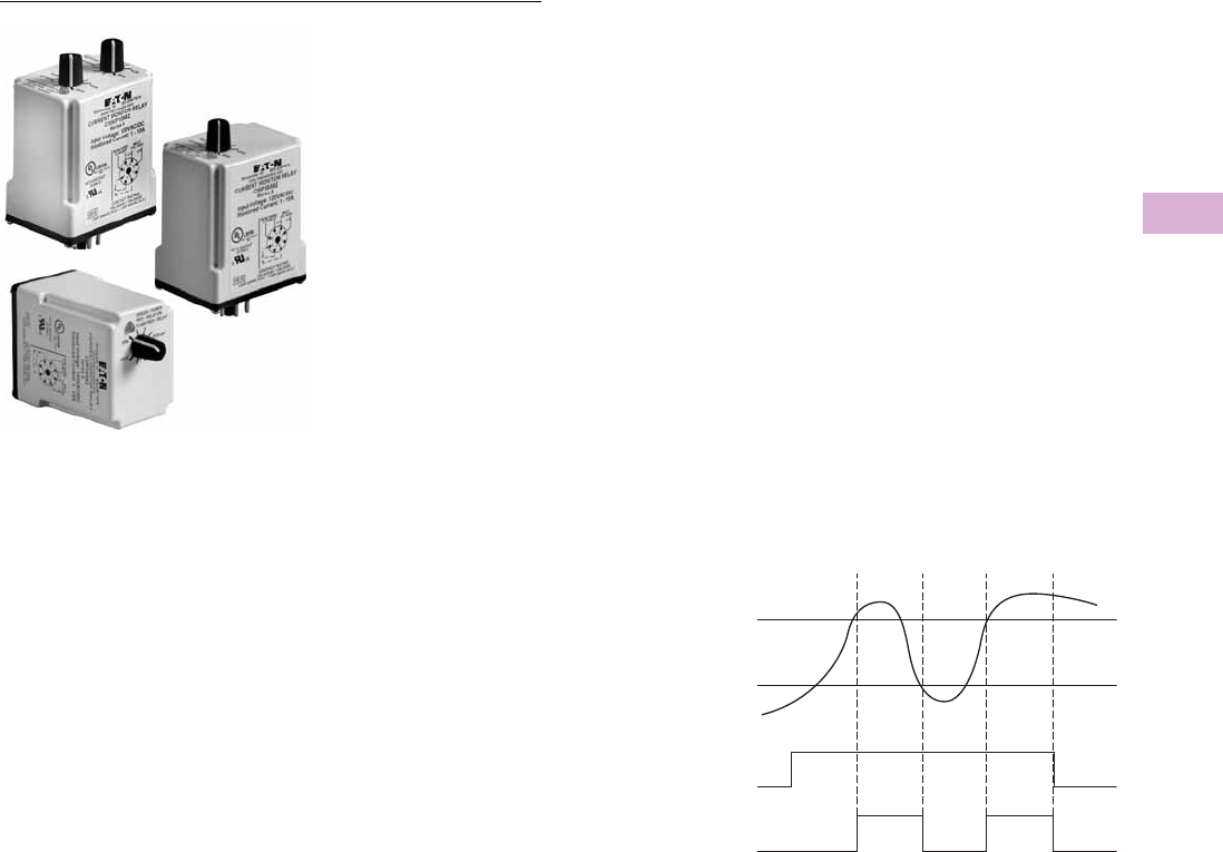
Volume 5—Motor Control and Protection CA08100006E—April 2014 www.eaton.com V5-T5-7
5
5
5
5
5
5
5
5
5
5
5
5
5
5
5
5
5
5
5
5
5
5
5
5
5
5
5
5
5
5
5.1
Motor Protection and Monitoring
Monitoring Relays
D65CE Series—Standard Current Monitors
Contents
Description Page
Current Monitoring Relays
ECS Series CurrentWatch Current Switches . . V5-T5-3
ECSJ Series CurrentWatch Current Switches . . V5-T5-4
D65 Current Monitoring Relays
Product Selection Guide . . . . . . . . . . . . . . . V5-T5-6
D65CE Series—Standard Current Monitors
Product Selection . . . . . . . . . . . . . . . . . . V5-T5-8
Technical Data and Specifications . . . . . V5-T5-9
Dimensions . . . . . . . . . . . . . . . . . . . . . . V5-T5-9
D65CH Series—Overcurrent Monitors . . . . V5-T5-10
D65CL Series—Undercurrent Monitors . . . V5-T5-13
Phase Monitoring Relays . . . . . . . . . . . . . . . . . . . . V5-T5-16
Voltage Monitoring Relays . . . . . . . . . . . . . . . . . . . V5-T5-28
Ground Fault Monitoring Relays . . . . . . . . . . . . . . V5-T5-42
D65CE Series—Standard Current Monitors
Product Description
The D65CE Series Standard
Current Monitors are used to
detect either an overcurrent
or undercurrent condition.
The pickup current setting is
user-adjustable within three
ranges (0.1–1A), (0.5–5A), or
(1–10A). The range can be
extended beyond 10A with
the use of an external current
transformer. Choose
between a fixed dropout
current setting at 95% of the
selected pickup setting or an
adjustable dropout setting of
50–95% of the selected
pickup setting. The relay will
energize when the monitored
AC current is above the
pickup setting, and will de-
energize when the monitored
AC current is below the
dropout setting. The time
delay on both pickup and
dropout is fixed at 100 ms.
Adjustable time delays are
available with the D65CH and
D65CL Series.
Features
●Monitors AC single-phase
currents
●Three separate current
monitoring ranges covering
0.1–10 amperes
●External CT can be used to
extend ranges
●Adjustable pickup setting
with either fixed or
adjustable dropout setting
●LED indicates output relay
status
●Choice of compact 8-pin
SPDT or 11-pin DPDT
plug-in case
●10A output contacts
Standard Current Monitoring
Monitored
Current
Pickup
Current
Dropout
Current
Input
Power
(Voltage)
Relay
Output
On
On
Off
Off
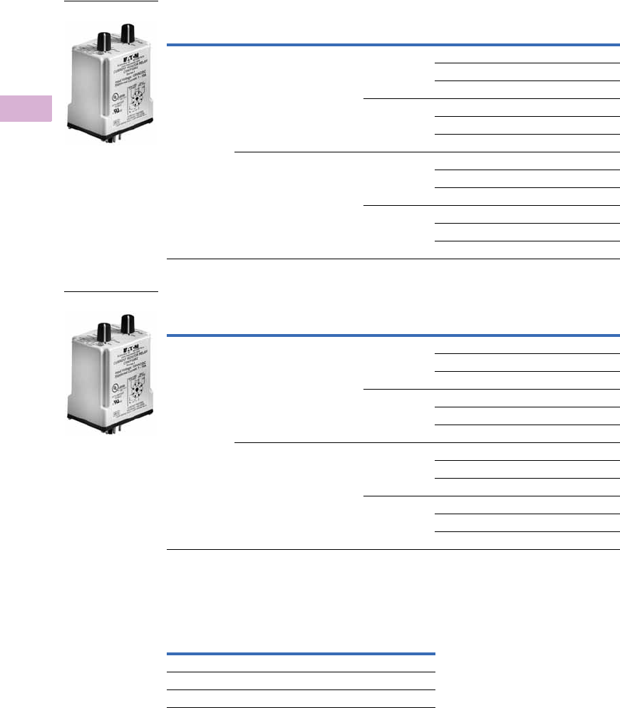
V5-T5-8 Volume 5—Motor Control and Protection CA08100006E—April 2014 www.eaton.com
5
5
5
5
5
5
5
5
5
5
5
5
5
5
5
5
5
5
5
5
5
5
5
5
5
5
5
5
5
5
5.1
Motor Protection and Monitoring
Monitoring Relays
Product Selection
D65CE Series—Standard Current Monitors, SPDT, 8-Pin Plug-In
D65CE Series—Standard Current Monitors, SPDT, 11-Pin Plug-In
Accessories
D65CE Current Monitors
Pickup
Setting
Dropout
Setting Input Voltage
Current Range
Monitored
Catalog
Number
Adjustable Fixed
(at 95% of pickup)
24 Vac 0.1–1A D65CE1C01T
0.5–5A D65CE1C5T
1–10A D65CE1C10T
120 Vac 0.1–1A D65CE1C01A
0.5–5A D65CE1C5A
1–10A D65CE1C10A
Adjustable
(from 50–95% of pickup)
24 Vac 0.1–1A D65CEK1C01T
0.5–5A D65CEK1C5T
1–10A D65CEK1C10T
120 Vac 0.1–1A D65CEK1C01A
0.5–5A D65CEK1C5A
1–10A D65CEK1C10A
Pickup
Setting
Dropout
Setting Input Voltage
Current Range
Monitored
Catalog
Number
Adjustable Fixed
(at 95% of pickup)
24 Vac 0.1–1A D65CE2C01T
0.5–5A D65CE2C5T
1–10A D65CE2C10T
120 Vac 0.1–1A D65CE2C01A
0.5–5A D65CE2C5A
1–10A D65CE2C10A
Adjustable
(from 50–95% of pickup)
24 Vac 0.1–1A D65CEK2C01T
0.5–5A D65CEK2C5T
1–10A D65CEK2C10T
120 Vac 0.1–1A D65CEK2C01A
0.5–5A D65CEK2C5A
1–10A D65CEK2C10A
Description
Standard
Pack
Catalog
Number
8-pin socket 10 D3PA2
11-pin socket 10 D3PA3-A2
Hold-down spring 10 D65CHDS
D65CE_
D65CE_
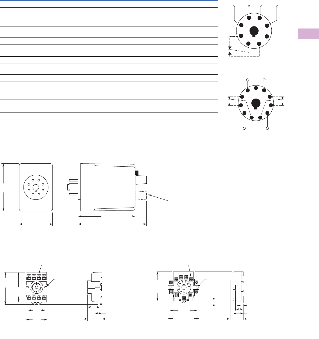
Volume 5—Motor Control and Protection CA08100006E—April 2014 www.eaton.com V5-T5-9
5
5
5
5
5
5
5
5
5
5
5
5
5
5
5
5
5
5
5
5
5
5
5
5
5
5
5
5
5
5
5.1
Motor Protection and Monitoring
Monitoring Relays
Technical Data and Specifications
D65CE Series, Standard Current Monitors
Dimensions
Approximate Dimensions in Inches (mm)
D65CE Series, Standard Current Monitors
D3PA2 Sockets D3PA3 Sockets
Description Specification
Input voltage tolerance AC operation: +10/–15% of nominal voltage at 50/60 Hz
Load (burden) Less than 5 VA
Current settings
Pickup Adjustable throughout current range monitored
Dropout Fixed at 95% of pickup setting for D65CE
Adjustable from 50–95% of pickup setting for D65CEK
Temperature –20° to 131°F (–28° to 55°C)
Response times
Pickup 100 ms
Dropout 100 ms
Output contacts 10A resistive at 240 Vac/30 Vdc
1/2 hp at 240 Vac (NO); 1/3 hp at 240 Vac (NC)
Mechanical life 10,000,000 operations
Electrical life 100,000 operations
Indicator LED Green when input voltage is applied;
red when relay is energized
Reset Automatic
Mounting Requires an 8- or 11-pin socket
Wiring Diagrams
Wiring for 8-Pin Socket
Wiring for 11-Pin Socket
1
4
(L1)
Monitored
Current
Input
Voltage
(L2)
36
27
8
5
1
(L1) (L2)
11
Monitored
Current
48
39
6
210
75
2.4
(60)
1.7
(43)
2.9
(74) 3.5
(89)
D65CEK
Only
0.97
(24.6)
Max.
0.82 (20.8)
0.58 (14.7)
2.03
(51.6)
Two 0.165
(4.2) Dia.
Slots
2.14
(54.3)
1.60
(40.6)
Max.
1.30
(33.0)
6–32 x 0.312 Combination
Head Screw and Pressure Clamping Plate
(8 places)
Tolerances: ± 0.010
± (0.25)
Unless Otherwise Shown
6–32 x 0.312 Combination
Head Screw and Pressure Clamp
(11 places)
2.05
(52.1)
Max.
2.33 (59.2)
Max.
2.06
(52.3)
0.97
(24.6)
0.77 (19.6)
0.58 (14.7)
0.15 (3.8)
0.13–0.16
(3.2–4.0)
Two 0.17
(4.3) Dia.
Holes
Tolerances: ± 0.010
± (0.25)
Unless Otherwise Shown
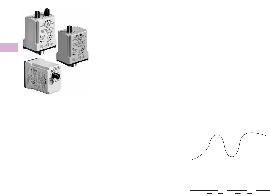
V5-T5-10 Volume 5—Motor Control and Protection CA08100006E—April 2014 www.eaton.com
5
5
5
5
5
5
5
5
5
5
5
5
5
5
5
5
5
5
5
5
5
5
5
5
5
5
5
5
5
5
5.1
Motor Protection and Monitoring
Monitoring Relays
D65CH Series—Overcurrent Monitors
Contents
Description Page
Current Monitoring Relays
ECS Series CurrentWatch Current Switches . . V5-T5-3
ECSJ Series CurrentWatch Current Switches . . V5-T5-4
D65 Current Monitoring Relays
Product Selection Guide . . . . . . . . . . . . . . . V5-T5-6
D65CE Series—Standard Current
Monitors . . . . . . . . . . . . . . . . . . . . . . . . . . V5-T5-7
D65CH Series—Overcurrent Monitors
Product Selection . . . . . . . . . . . . . . . . . . V5-T5-11
Technical Data and Specifications . . . . . V5-T5-12
Dimensions . . . . . . . . . . . . . . . . . . . . . . V5-T5-12
D65CL Series—Undercurrent Monitors . . . V5-T5-13
Phase Monitoring Relays . . . . . . . . . . . . . . . . . . . V5-T5-16
Voltage Monitoring Relays . . . . . . . . . . . . . . . . . . V5-T5-28
Ground Fault Monitoring Relays . . . . . . . . . . . . . . V5-T5-42
D65CH Series—Overcurrent Monitors
Product Description
The D65CH Series Overcurrent
Monitoring Relays are used to
detect an overcurrent
condition. The pickup current
setting is user-adjustable
within one of three ranges as
shown in product selection
table. An external current
transformer can be used to
extend the range beyond
10A. Users may select a
fixed dropout current setting
(95% of the selected pick-up
setting) or an adjustable drop-
out setting (50–95% of the
selected pickup setting). The
relay will energize when the
monitored AC current is
above the pickup setting for a
period longer than the
adjustable time delay of
0.1–10 seconds. This delay
prevents nuisance tripping
caused by inrush currents. It
will de-energize when the
monitored AC current is
below the dropout setting.
Features
●Monitors AC single-phase
currents for overcurrent
conditions
●Three separate current
monitoring ranges covering
0.1–10 amperes
●External CT can be used to
extend ranges
●Adjustable pickup setting
with either fixed or
adjustable dropout setting
●Adjustable time delay of
0.1–10 seconds on pickup
●LED indicates output relay
status
●Choice of compact SPDT
(8-pin) or DPDT (11-pin)
plug-in case
●10A output contacts
Overcurrent Monitoring
Monitored
Current
Pickup
Current
Dropout
Current
Input
Power
(Voltage)
Relay
Output
On
On
TT
Off
Off
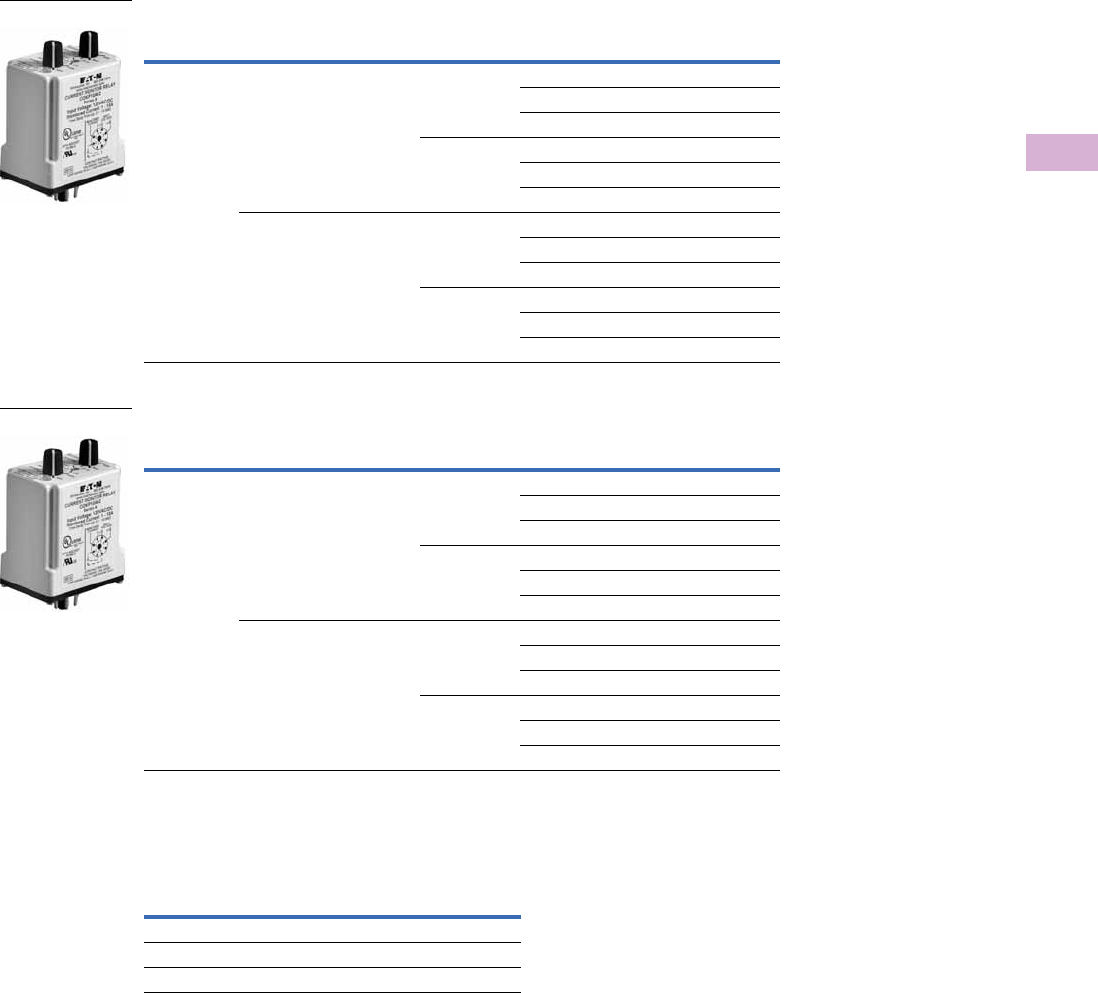
Volume 5—Motor Control and Protection CA08100006E—April 2014 www.eaton.com V5-T5-11
5
5
5
5
5
5
5
5
5
5
5
5
5
5
5
5
5
5
5
5
5
5
5
5
5
5
5
5
5
5
5.1
Motor Protection and Monitoring
Monitoring Relays
Product Selection
D65CH Series—Overcurrent Monitors, SPDT, 8-Pin Plug-In
D65CH Series—Overcurrent Monitors, SPDT, 11-Pin Plug-In
Accessories
D65CH Overcurrent Monitors
Pick-Up
Setting
Drop-Out
Setting Input Voltage
Current Range
Monitored
Catalog
Number
Adjustable Fixed
(at 95% of pickup)
24 Vac 0.1–1A D65CH1C1T
0.5–5A D65CH1C5T
1–10A D65CH1C10T
120 Vac 0.1–1A D65CH1C1A
0.5–5A D65CH1C5A
1–10A D65CH1C10A
Adjustable
(from 50–95% of pickup)
24 Vac 0.1–1A D65CHK1C1T
0.5–5A D65CHK1C5T
1–10A D65CHK1C10T
120 Vac 0.1–1A D65CHK1C1A
0.5–5A D65CHK1C5A
1–10A D65CHK1C10A
Pick-Up
Setting
Drop-Out
Setting Input Voltage
Current Range
Monitored
Catalog
Number
Adjustable Fixed
(at 95% of pickup)
24 Vac 0.1–1A D65CH2C1T
0.5–5A D65CH2C5T
1–10A D65CH2C10T
120 Vac 0.1–1A D65CH2C1A
0.5–5A D65CH2C5A
1–10A D65CH2C10A
Adjustable
(from 50–95% of pickup)
24 Vac 0.1–1A D65CHK2C1T
0.5–5A D65CHK2C5T
1–10A D65CHK2C10T
120 Vac 0.1–1A D65CHK2C1A
0.5–5A D65CHK2C5A
1–10A D65CHK2C10A
Description
Standard
Pack
Catalog
Number
8-pin socket 10 D3PA2
11-pin socket 10 D3PA3-A2
Hold-down spring 10 D65CHDS
D65CH_
D65CH_
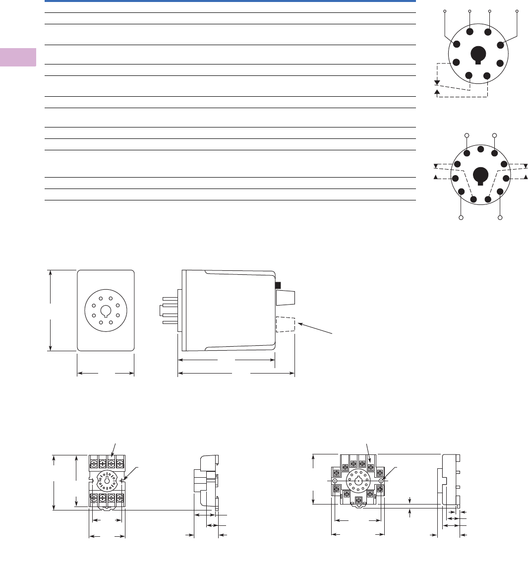
V5-T5-12 Volume 5—Motor Control and Protection CA08100006E—April 2014 www.eaton.com
5
5
5
5
5
5
5
5
5
5
5
5
5
5
5
5
5
5
5
5
5
5
5
5
5
5
5
5
5
5
5.1
Motor Protection and Monitoring
Monitoring Relays
Technical Data and Specifications
D65CH Series, Overcurrent Monitors
Dimensions
Approximate Dimensions in Inches (mm)
D65CH Series, Overcurrent Monitors
D3PA2 Sockets D3PA3 Sockets
Description Specification
Input voltage tolerance AC operation: +10/–15% of nominal voltage at 50/60 Hz
Load (burden) Less than 5 VA
Current settings
Pickup Adjustable throughout current range monitored
Dropout Fixed at 95% of pickup setting for D65CE
Adjustable from 50–95% of pickup setting for D65CEK
Temperature –20° to 131°F (–28° to 55°C)
Response times
Pickup Adjustable 0.1–10 seconds
Dropout Fixed at 100 ms
Output contacts 10A resistive at 240 Vac/30 Vdc
1/2 hp at 240 Vac (NO); 1/3 hp at 240 Vac (NC)
Mechanical life 10,000,000 operations
Electrical life 100,000 operations
Indicator LED Green when input voltage is applied;
red flashing when in time delay;
red steady when relay is energized
Reset Automatic
Mounting Requires an 8- or 11-pin socket
Wiring Diagrams
Wiring for 8-Pin Socket
Wiring for 11-Pin Socket
1
4
(L1)
Monitored
Current
Input
Voltage
(L2)
36
27
8
5
1
(L1) (L2)
11
Monitored
Current
48
39
6
210
75
2.4
(60)
1.7
(43)
2.9
(74) 3.5
(89)
D65CHK
Only
0.97
(24.6)
Max.
0.82 (20.8)
0.58 (14.7)
2.03
(51.6)
Two 0.165
(4.2) Dia.
Slots
2.14
(54.3)
1.60
(40.6)
Max.
1.30
(33.0)
6–32 x 0.312 Combination
Head Screw and Pressure Clamping Plate
(8 places)
Tolerances: ± 0.010
± (0.25)
Unless Otherwise Shown
6–32 x 0.312 Combination
Head Screw and Pressure Clamp
(11 places)
2.05
(52.1)
Max.
2.33 (59.2)
Max.
2.06
(52.3)
0.97
(24.6)
0.77 (19.6)
0.58 (14.7)
0.15 (3.8)
0.13–0.16
(3.2–4.0)
Two 0.17
(4.3) Dia.
Holes
Tolerances: ± 0.010
± (0.25)
Unless Otherwise Shown
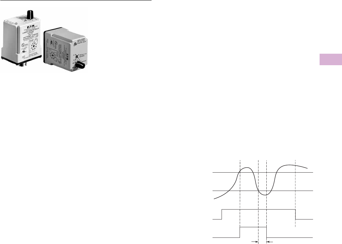
Volume 5—Motor Control and Protection CA08100006E—April 2014 www.eaton.com V5-T5-13
5
5
5
5
5
5
5
5
5
5
5
5
5
5
5
5
5
5
5
5
5
5
5
5
5
5
5
5
5
5
5.1
Motor Protection and Monitoring
Monitoring Relays
D65CL Series—Undercurrent Monitors
Contents
Description Page
Current Monitoring Relays
ECS Series CurrentWatch Current Switches . . V5-T5-3
ECSJ Series CurrentWatch Current Switches . . V5-T5-4
D65 Current Monitoring Relays
Product Selection Guide . . . . . . . . . . . . . . . V5-T5-6
D65CE Series—Standard Current
Monitors . . . . . . . . . . . . . . . . . . . . . . . . . . V5-T5-7
D65CH Series—Overcurrent Monitors . . . . V5-T5-10
D65CL Series—Undercurrent Monitors
Product Selection . . . . . . . . . . . . . . . . . . V5-T5-14
Technical Data and Specifications . . . . . V5-T5-15
Dimensions . . . . . . . . . . . . . . . . . . . . . . V5-T5-15
Phase Monitoring Relays . . . . . . . . . . . . . . . . . . . . V5-T5-16
Voltage Monitoring Relays . . . . . . . . . . . . . . . . . . . V5-T5-28
Ground Fault Monitoring Relays . . . . . . . . . . . . . . V5-T5-42
D65CL Series—Undercurrent Monitors
Product Description
The D65CL Series is
designed to detect an
undercurrent condition. The
dropout current setting is
user-adjustable within one of
three ranges as shown in the
product selection table. An
external current transformer
can be used to extend the
range beyond 10A. The
pickup current setting is fixed
at +5% of the selected drop-
out setting. The relay will
energize when the monitored
AC current is above the
pickup setting. It will de-
energize when the monitored
AC current is below the
dropout setting for a period
longer than the adjustable
time delay of 0.1–10 seconds.
This delay prevents nuisance
tripping caused by
momentary line dips. The
relay will energize when the
current rises 5% above the
dropout setting.
Features
●Monitors AC single-phase
currents for undercurrent
conditions
●Three separate current
monitoring ranges covering
0.1–10 amperes
●External CT can be used to
extend ranges
●Adjustable dropout setting
with fixed pickup setting
●Adjustable time delay of
0.1–10 seconds on dropout
●LED indicates output relay
status
●Choice of compact SPDT
(8-pin) or DPDT (11-pin)
plug-in case
●10A output contacts
Undercurrent Monitoring
Monitored
Current
Pickup
Current
Dropout
Current
Input
Power
(Voltage)
Relay
Output
On
On
T
Off
Off
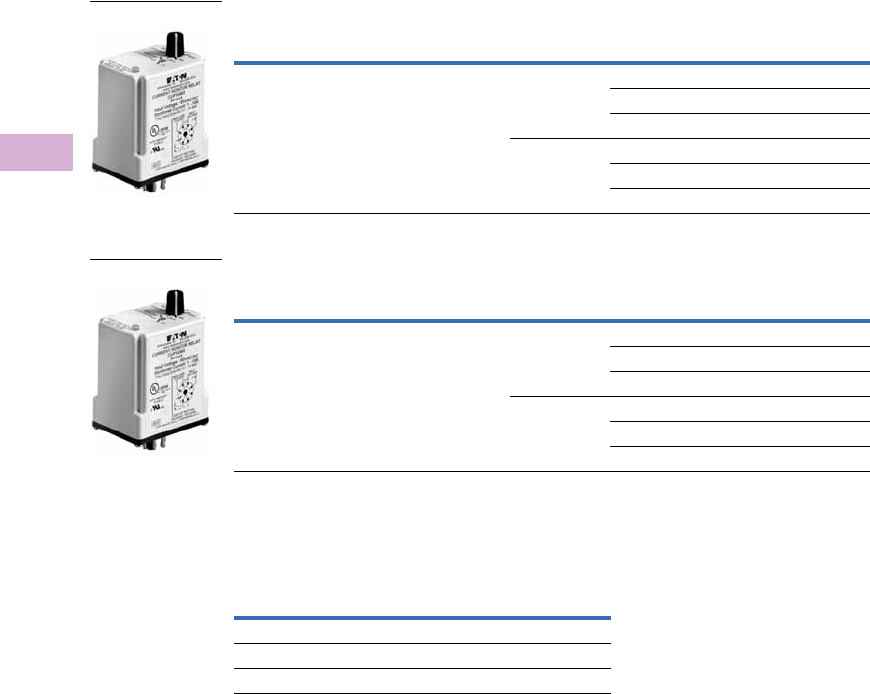
V5-T5-14 Volume 5—Motor Control and Protection CA08100006E—April 2014 www.eaton.com
5
5
5
5
5
5
5
5
5
5
5
5
5
5
5
5
5
5
5
5
5
5
5
5
5
5
5
5
5
5
5.1
Motor Protection and Monitoring
Monitoring Relays
Product Selection
D65CL Series—Undercurrent Monitors, SPDT, 8-Pin Plug-In
D65CL Series—Undercurrent Monitors, SPDT, 11-Pin Plug-In
Accessories
D65CL Undercurrent Monitors
Pickup
Setting
Dropout
Setting Input Voltage
Current Range
Monitored
Catalog
Number
Fixed (at 5% of Dropout) Adjustable 24 Vac 0.1–1A D65CL1C1T
0.5–5A D65CL1C5T
1–10A D65CL1C10T
120 Vac 0.1–1A D65CL1C1A
0.5–5A D65CL1C5A
1–10A D65CL1C10A
Pickup
Setting
Dropout
Setting Input Voltage
Current Range
Monitored
Catalog
Number
Adjustable Fixed
(at 95% of
pickup)
24 Vac 0.1–1A D65CL2C1T
0.5–5A D65CL2C5T
1–10A D65CL210T
120 Vac 0.1–1A D65CL2C1A
0.5–5A D65CL2C5A
1–10A D65CL2C10A
Description
Standard
Pack
Catalog
Number
8-pin socket 10 D3PA2
11-pin socket 10 D3PA3-A2
Hold-down spring 10 D65CHDS
D65CL_
D65CL_
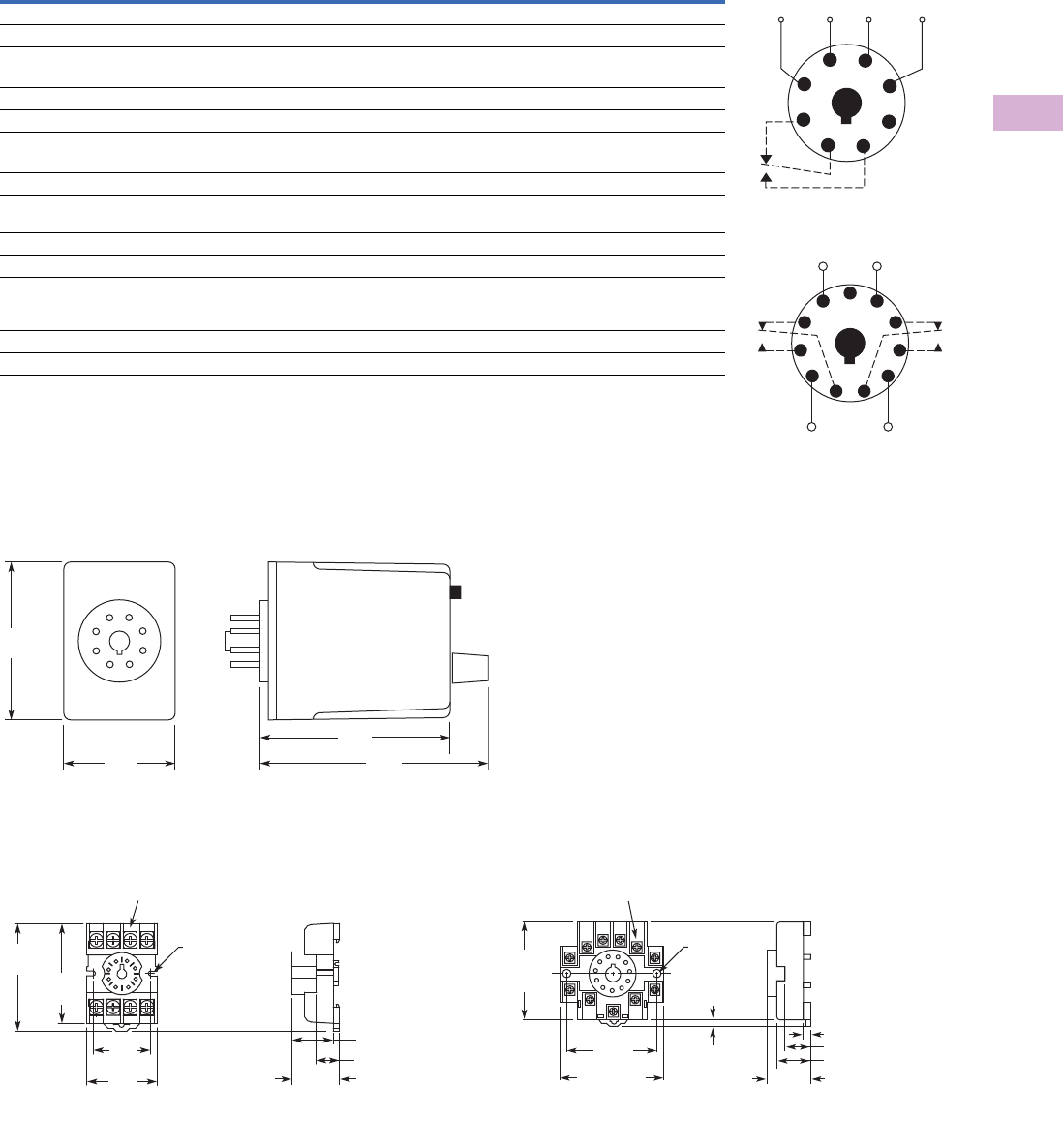
Volume 5—Motor Control and Protection CA08100006E—April 2014 www.eaton.com V5-T5-15
5
5
5
5
5
5
5
5
5
5
5
5
5
5
5
5
5
5
5
5
5
5
5
5
5
5
5
5
5
5
5.1
Motor Protection and Monitoring
Monitoring Relays
Technical Data and Specifications
D65CL Series, Undercurrent Monitors
Dimensions
Approximate Dimensions in Inches (mm)
D65CL Series, Undercurrent Monitors
D3PA2 Sockets D3PA3 Sockets
Description Specification
Input voltage tolerance AC operation: +10/–15% of nominal voltage at 50/60 Hz
Load (burden) Less than 5 VA
Current settings
Pickup Fixed at 5% above adjustable dropout setting
Dropout Adjustable throughout current range monitored
Temperature –20° to 131°F (–28° to 55°C)
Response times
Pickup Fixed at 100 ms
Dropout Adjustable 0.1–10 seconds
Output contacts 10A resistive at 240 Vac/30 Vdc
1/2 hp at 240 Vac (NO); 1/3 hp at 240 Vac (NC)
Mechanical life 10,000,000 operations
Electrical life 100,000 operations
Indicator LED Green when input voltage is applied;
red flashing when in time delay;
red steady when relay is energized
Reset Automatic
Mounting Requires an 8- or 11-pin socket
Wiring Diagrams
Wiring for 8-Pin Socket
Wiring for 11-Pin Socket
1
4
(L1)
Monitored
Current
Input
Voltage
(L2)
36
27
8
5
1
(L1) (L2)
11
Monitored
Current
48
39
6
210
75
2.4
(60)
1.7
(43)
2.9
(74) 3.5
(89)
0.97
(24.6)
Max.
0.82 (20.8)
0.58 (14.7)
2.03
(51.6)
Two 0.165
(4.2) Dia.
Slots
2.14
(54.3)
1.60
(40.6)
Max.
1.30
(33.0)
6–32 x 0.312 Combination
Head Screw and Pressure Clamping Plate
(8 places)
Tolerances: ± 0.010
± (0.25)
Unless Otherwise Shown
6–32 x 0.312 Combination
Head Screw and Pressure Clamp
(11 places)
2.05
(52.1)
Max.
2.33 (59.2)
Max.
2.06
(52.3)
0.97
(24.6)
0.77 (19.6)
0.58 (14.7)
0.15 (3.8)
0.13–0.16
(3.2–4.0)
Two 0.17
(4.3) Dia.
Holes
Tolerances: ± 0.010
± (0.25)
Unless Otherwise Shown
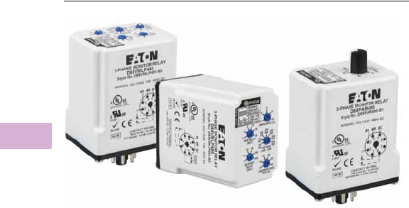
V5-T5-16 Volume 5—Motor Control and Protection CA08100006E—April 2014 www.eaton.com
5
5
5
5
5
5
5
5
5
5
5
5
5
5
5
5
5
5
5
5
5
5
5
5
5
5
5
5
5
5
5.1
Motor Protection and Monitoring
Monitoring Relays
Phase Monitoring Relays
Contents
Description Page
Current Monitoring Relays . . . . . . . . . . . . . . . . . . V5-T5-3
Phase Monitoring Relays
Standards and Certifications . . . . . . . . . . . . . . V5-T5-17
Product Selection Guide . . . . . . . . . . . . . . . . . V5-T5-17
D65VMC Series—Phase Reversal . . . . . . . . . . V5-T5-18
D65PLR Series—Phase Loss and Reversal . . . V5-T5-20
D65PAR Series—Phase Loss, Reversal
and Undervoltage . . . . . . . . . . . . . . . . . . . . . V5-T5-22
D65VM Series—Phase Loss, Reversal,
Imbalance and Under/Overvoltage . . . . . . . . V5-T5-24
Voltage Monitoring Relays . . . . . . . . . . . . . . . . . . V5-T5-28
Ground Fault Monitoring Relays . . . . . . . . . . . . . . V5-T5-42
Product Overview
The D65 Series Phase
Monitoring Relays provide
protection against premature
equipment failure caused by
voltage faults on three-phase
systems. All D65 phase
monitoring relays are
compatible with most wye
or delta systems. In wye
systems, a connection to
neutral is not required. Phase
Monitoring relays protect
against single-phasing
regardless of any
regenerative voltages.
Application Description
Protection
Depending on the unit
selected, it will protect three-
phase equipment against:
●Phase Loss
—total loss of
one or more of the three
phases. Also known as
“single phasing.” Typically
caused by a blown fuse,
broken wire or worn contact.
This condition would result in
a motor drawing locked rotor
current during startup. In
addition, a three-phase
motor will continue to run
after losing a phase, resulting
in possible motor burn-out.
●Phase Reversal
—reversing
any two of the three phases
will cause a three-phase
motor to run in the opposite
direction. This may cause
damage to driven machinery
or injury to personnel. The
condition usually occurs as a
result of mistakes made
during routine maintenance
or when modifications are
made to the circuit.
●Phase Imbalance—
imbalance of a three-phase
system occurs when
single-phase loads are
connected such that one or
two of the lines (phases)
carry more or less of the
load. This could cause
motors to run at
temperatures above
published ratings.
●Undervoltage—when
voltage in all three lines of
a three-phase system drop
simultaneously.
●Overvoltage—when
voltage in all three lines of
a three-phase system
increase simultaneously.
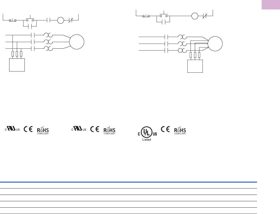
Volume 5—Motor Control and Protection CA08100006E—April 2014 www.eaton.com V5-T5-17
5
5
5
5
5
5
5
5
5
5
5
5
5
5
5
5
5
5
5
5
5
5
5
5
5
5
5
5
5
5
5.1
Motor Protection and Monitoring
Monitoring Relays
Typical Connections
Line Side Monitoring
With the relay connected before the motor starter, the
motor can be started in the reverse direction. However, the
motor is unprotected against phase failures between the relay
and the motor.
Line Side Monitoring
Standards and Certifications
D65VMC, D65PLR and
D65PAR Series
●cRUus listed
●RoHS recognized
●CE marked
D65VMLP Series
●cRUus listed
●RoHS recognized
●CE marked
Product Selection Guide
D65 Series—Product Family Selection
Note
1In addition to the above approvals, all plug-in products are
also UL Listed when used with the appropriate Eaton socket.
L1
Stop Start
Phase
Monitor
Relay
M
3
Phase
Motor
O/L
L2
L1 M
M
M
M
Input Fuses
2A Max.
Phase
Monitor
Relay
L2
L3
Series Mounting Style Phase Reversal
Phase Loss and
Reversal Undervoltage Overvoltage Phase Imbalance
Time Delay on
Undervoltage
D65VMC Plug-in 13 —————
D65PLR Plug-in 13 3 ————
D65PAR Plug-in 133✓ (adjustable) — — 50 ms fixed
D65VMLP Plug-in 133✓ (adjustable) ✓ (fixed) 3 0.1–20 sec
D65VMLS Surface 3 3 ✓ (adjustable) ✓ (fixed) 3 0.1–20 sec
Load Side Monitoring
With the relay connected directly to the motor, the total feed
lines are monitored. This connection should not be used with
reversing motors.
Load Side Monitoring
D65VMLS Series
●cULus listed
●RoHS recognized
●CE marked
L1
Stop
3
Phase
Motor
O/L
L2
M
M
M
M
Input Fuses
2A Max.
Phase
Monitor
Relay
Phase
Monitor Relay
Start
L1
L2
L3
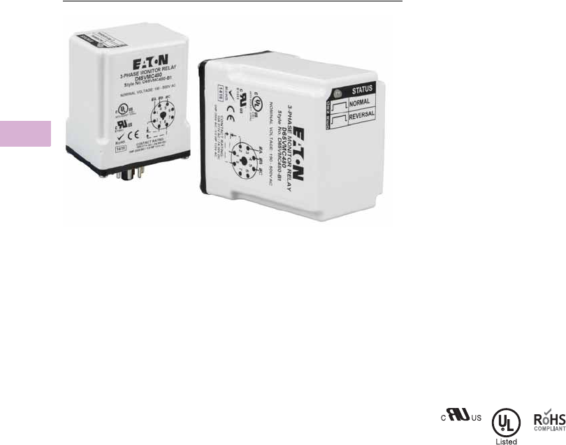
V5-T5-18 Volume 5—Motor Control and Protection CA08100006E—April 2014 www.eaton.com
5
5
5
5
5
5
5
5
5
5
5
5
5
5
5
5
5
5
5
5
5
5
5
5
5
5
5
5
5
5
5.1
Motor Protection and Monitoring
Monitoring Relays
D65VMC Series—Phase Reversal
Contents
Description Page
Current Monitoring Relays . . . . . . . . . . . . . . . . . . V5-T5-3
Phase Monitoring Relays
Product Selection Guide . . . . . . . . . . . . . . . . . V5-T5-17
D65VMC Series—Phase Reversal
Product Selection . . . . . . . . . . . . . . . . . . . . V5-T5-19
Technical Data and Specifications . . . . . . . . V5-T5-19
Dimensions . . . . . . . . . . . . . . . . . . . . . . . . . V5-T5-19
D65PLR Series—Phase Loss and Reversal . . . V5-T5-20
D65PAR Series—Phase Loss, Reversal
and Undervoltage . . . . . . . . . . . . . . . . . . . . . V5-T5-22
D65VM Series—Phase Loss, Reversal,
Imbalance and Under/Overvoltage . . . . . . . . V5-T5-24
Voltage Monitoring Relays . . . . . . . . . . . . . . . . . . V5-T5-28
Ground Fault Monitoring Relays . . . . . . . . . . . . . . V5-T5-42
D65VMC Series—Phase Reversal
Product Description
The D65VMC Series
Monitoring Relays provide
protection against phase
reversal in a compact plug-in
design. One version will work
on any three-phase system
from 190V to 500V. These
devices are designed to be
compatible with most wye or
delta systems. In wye
systems, a connection to a
neutral is not required.
A bi-color LED indicates
NORMAL conditions with a
green status and PHASE
REVERSAL conditions with a
red status. Re-energization is
automatic upon correction of
the fault condition.
Features
●Protects against phase
reversal
●One version works on
190–500V three-phase
systems
●Bi-color LED provides
indication for both normal
and fault conditions
●Compact plug-in case
utilizing industry-standard
8-pin octal socket
●10A SPDT output contacts
Standards and Certifications
●cRUus
●UL listed 1
●RoHS compliant
Note
1When used with appropriate Eaton
socket.
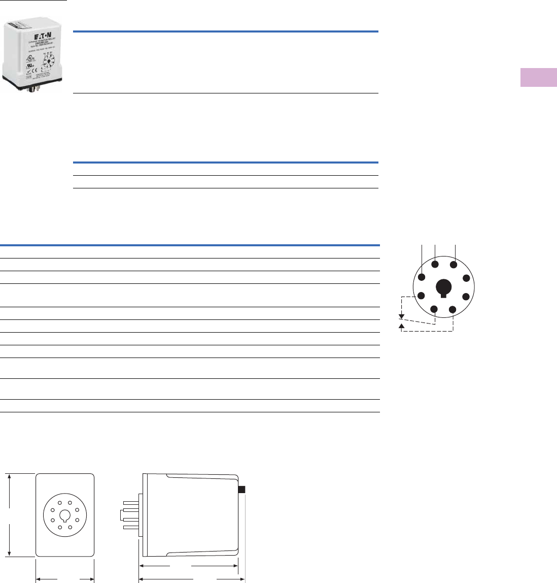
Volume 5—Motor Control and Protection CA08100006E—April 2014 www.eaton.com V5-T5-19
5
5
5
5
5
5
5
5
5
5
5
5
5
5
5
5
5
5
5
5
5
5
5
5
5
5
5
5
5
5
5.1
Motor Protection and Monitoring
Monitoring Relays
Product Selection
D65VMC Series, Phase Reversal
Accessories
D65VMC Series, Phase Reversal
Technical Data and Specifications
D65VMC Series, Phase Reversal
Dimensions
Approximate Dimensions in Inches (mm)
D65VMC Series, Phase Reversal
Note
1Requires a 600V rated socket when used on system voltages greater than 300V.
Mounting
Style
Nominal Voltage
50/60 Hz
Catalog
Number
Plug-in 190–500V D65VMC480 1
D65VMC480
Description Standard Pack
Catalog
Number
8-pin socket 10 D3PA2
Hold-down spring 10 D65CHDS
Description Specification
Phase reversal Unit trips if sequence of the three phases is anything other than A-B-C
Output contacts 10A SPDT at 277 Vac, 1 hp at 250 Vac, 1/2 hp at 120 Vac. C300 pilot duty
Life Full load—100,000 operations
Response times
Operate 50 ms
Release 50 ms
Load (burden) 3 VA
Temperature –20° to 150°F (–28° to 65°C)
Transient protection 10,000 volts for 20 microseconds
Mounting Uses an 8-pin octal socket. Requires a 600V rated socket when used on system voltages
greater than 300V
Indicator LED Bi-color LED will be Green when NORMAL condition is present and Red when PHASE REVERSAL
condition is present
Reset Automatic upon correction of fault
Wiring Diagram
Wiring for 8-Pin Socket
1
4
ØA ØB ØC
36
27
8
5
2.40
(60.0)
1.70
(43.0)
2.90
(74.0) 3.00
(76.0)
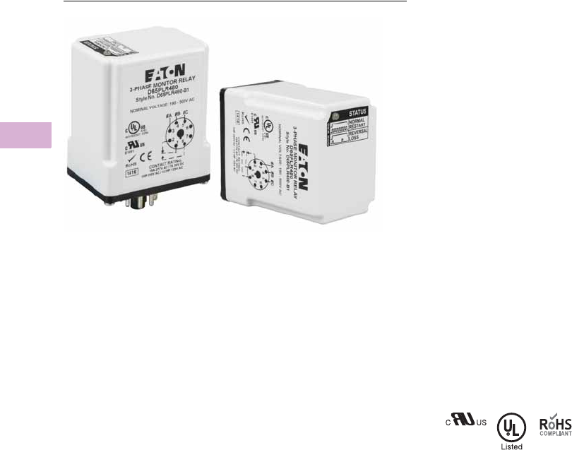
V5-T5-20 Volume 5—Motor Control and Protection CA08100006E—April 2014 www.eaton.com
5
5
5
5
5
5
5
5
5
5
5
5
5
5
5
5
5
5
5
5
5
5
5
5
5
5
5
5
5
5
5.1
Motor Protection and Monitoring
Monitoring Relays
D65PLR Series—Phase Loss and Reversal
Contents
Description Page
Current Monitoring Relays . . . . . . . . . . . . . . . . . . V5-T5-3
Phase Monitoring Relays
Product Selection Guide . . . . . . . . . . . . . . . . . V5-T5-17
D65VMC Series—Phase Reversal . . . . . . . . . . V5-T5-18
D65PLR Series—Phase Loss and Reversal
Product Selection . . . . . . . . . . . . . . . . . . . . V5-T5-21
Technical Data and Specifications . . . . . . . . V5-T5-21
Dimensions . . . . . . . . . . . . . . . . . . . . . . . . . V5-T5-21
D65PAR Series—Phase Loss, Reversal
and Undervoltage . . . . . . . . . . . . . . . . . . . . . V5-T5-22
D65VM Series—Phase Loss, Reversal,
Imbalance and Under/Overvoltage . . . . . . . . V5-T5-24
Voltage Monitoring Relays . . . . . . . . . . . . . . . . . . V5-T5-28
Ground Fault Monitoring Relays . . . . . . . . . . . . . . V5-T5-42
D65PLR Series—Phase Loss and Reversal
Product Description
The D65PLR Series
Monitoring Relays provide
protection against phase loss
and phase reversal in a
compact plug-in design.
These devices are designed
to be compatible with most
wye or delta systems. In wye
systems, a connection to a
neutral is not required. Phase
monitoring relays protect
against single-phasing
regardless of any
regenerative voltages.
A bi-color LED indicates
NORMAL conditions with
a green status, PHASE
REVERSAL conditions with
a steady red status, and
PHASE LOSS conditions
with a flashing red status.
Re-energization is automatic
upon correction of the
fault condition.
Features
●Protects against phase loss
and phase reversal
●True RMS voltage sensing
for improved accuracy
●Continued operation
through phase loss
conditions
●Bi-color LED provides
indication for both normal
and fault conditions
●Compact plug-in case
utilizing industry-standard
8-pin octal socket
●10A SPDT output contacts
Standards and Certifications
●cRUus
●UL listed 1
●RoHS compliant
Note
1When used with appropriate Eaton
socket.
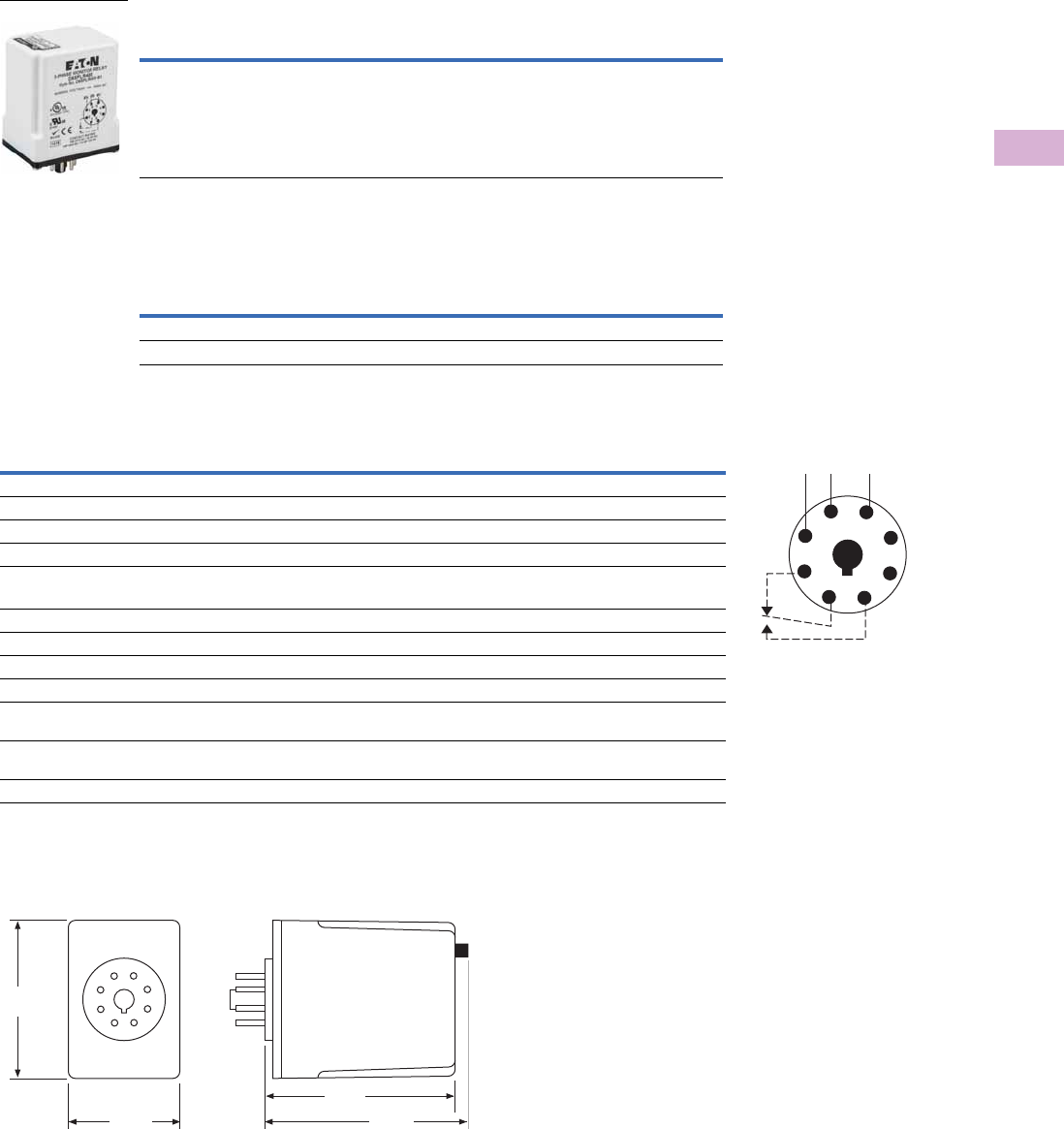
Volume 5—Motor Control and Protection CA08100006E—April 2014 www.eaton.com V5-T5-21
5
5
5
5
5
5
5
5
5
5
5
5
5
5
5
5
5
5
5
5
5
5
5
5
5
5
5
5
5
5
5.1
Motor Protection and Monitoring
Monitoring Relays
Product Selection
D65PLR Series, Phase Loss and Reversal
Accessories
D65PLR Series, Phase Loss and Reversal
Technical Data and Specifications
D65PLR Series, Phase Loss and Reversal
Dimensions
Approximate Dimensions in Inches (mm)
D65PLR Series, Phase Loss and Reversal
Note
1Requires a 600V rated socket when used on system voltages greater than 300V.
Mounting
Style
Nominal Voltage
50/60 Hz
Catalog
Number
Plug-in 190–500V D65PLR480 1
D65PLR480
Description Standard Pack
Catalog
Number
8-pin socket 10 D3PA2
Hold-down spring 10 D65CHDS
Description Specification
Phase loss Unit trips on loss of any Phase A, B or C
Phase reversal Unit trips if sequence of the three phases is anything other than A-B-C
Output contacts 10A SPDT at 277 Vac, 1 hp at 250 Vac, 1/2 hp at 120 Vac. C300 pilot duty
Life Full load—100,000 operations
Response times
Operate 50 ms
Release 50 ms
Load (burden) 3 VA
Temperature –20° to 150°F (–28° to 65°C)
Transient protection 10,000 volts for 20 microseconds
Mounting Uses an 8-pin octal socket. Requires a 600V rated socket when used on system voltages
greater than 300V
Indicator LED Bi-color LED will be Green when NORMAL condition is present, Steady Red when PHASE REVERSAL
condition is present, and Flashing Red when PHASE LOSS condition is present
Reset Automatic upon correction of fault
Wiring Diagram
Wiring for 8-Pin Socket
1
4
ØA ØB ØC
36
27
8
5
2.40
(60.0)
1.70
(43.0)
2.90
(74.0) 3.00
(76.0)
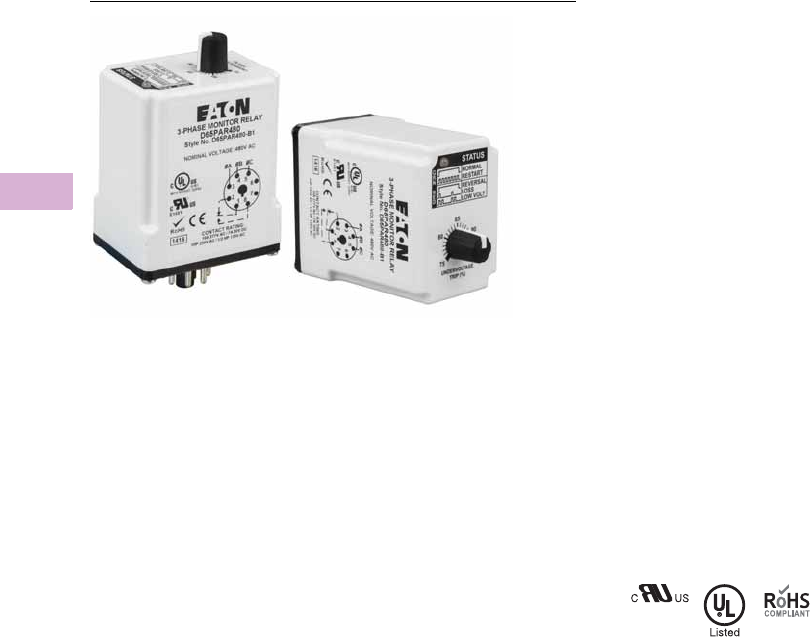
V5-T5-22 Volume 5—Motor Control and Protection CA08100006E—April 2014 www.eaton.com
5
5
5
5
5
5
5
5
5
5
5
5
5
5
5
5
5
5
5
5
5
5
5
5
5
5
5
5
5
5
5.1
Motor Protection and Monitoring
Monitoring Relays
D65PAR Series—Phase Loss, Reversal and Undervoltage
Contents
Description Page
Current Monitoring Relays . . . . . . . . . . . . . . . . . . V5-T5-3
Phase Monitoring Relays
Product Selection Guide . . . . . . . . . . . . . . . . . V5-T5-17
D65VMC Series—Phase Reversal . . . . . . . . . . V5-T5-18
D65PLR Series—Phase Loss and Reversal . . . V5-T5-20
D65PAR Series—Phase Loss, Reversal
and Undervoltage . . . . . . . . . . . . . . . . . . . . . V5-T5-22
Product Selection . . . . . . . . . . . . . . . . . . . . V5-T5-23
Technical Data and Specifications . . . . . . . . V5-T5-23
Dimensions . . . . . . . . . . . . . . . . . . . . . . . . . V5-T5-23
D65VM Series—Phase Loss, Reversal,
Imbalance and Under/Overvoltage . . . . . . . . V5-T5-24
Voltage Monitoring Relays . . . . . . . . . . . . . . . . . . V5-T5-28
Ground Fault Monitoring Relays . . . . . . . . . . . . . . V5-T5-42
D65PAR Series—Phase Loss, Reversal and Undervoltage
Product Description
The D65PAR Series
Monitoring Relays provide
protection against phase loss,
phase reversal and
undervoltage in a compact
plug-in design. These devices
are designed to be
compatible with most wye or
delta systems. In wye
systems, a connection to a
neutral is not required. Phase
monitoring relays protect
against single-phasing
regardless of any
regenerative voltages.
A bi-color LED indicates
NORMAL conditions with
a steady green status,
RESET with a flashing green
status, PHASE REVERSAL
with a steady red status,
PHASE LOSS with a single-
flash red status, and
UNDERVOLTAGE with a
double-flash red status. The
undervoltage drop-out can be
set at 75–95% of operating
voltage. Re-energization is
automatic upon correction
of the fault condition.
Features
●Protects against phase
loss, phase reversal and
undervoltage
●True RMS voltage sensing
for improved accuracy
●Continued operation
through phase loss
conditions
●Undervoltage setting is
adjustable from 75 to 95%
of nominal
●Bi-color LED provides
indication for both normal
and fault conditions
●Compact plug-in case
utilizing industry-standard
8-pin octal socket
●10A SPDT output contacts
Standards and Certifications
●cRUus
●UL listed 1
●RoHS compliant
Note
1When used with appropriate Eaton
socket.
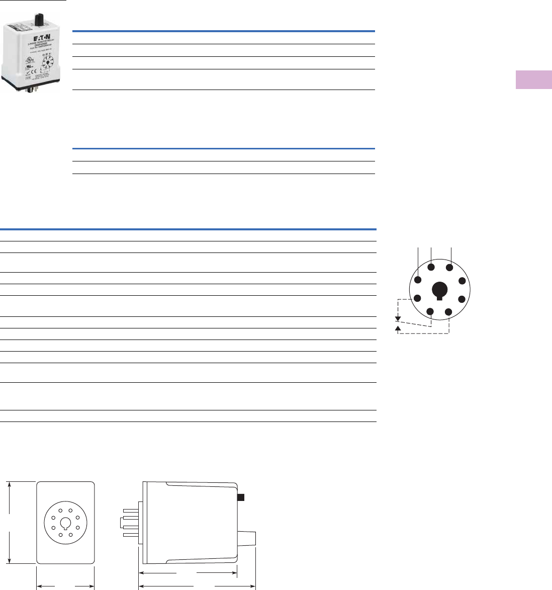
Volume 5—Motor Control and Protection CA08100006E—April 2014 www.eaton.com V5-T5-23
5
5
5
5
5
5
5
5
5
5
5
5
5
5
5
5
5
5
5
5
5
5
5
5
5
5
5
5
5
5
5.1
Motor Protection and Monitoring
Monitoring Relays
Product Selection
D65PAR Series, Phase Loss, Reversal and Undervoltage
Accessories
D65PAR Series, Phase Loss, Reversal and Undervoltage
Technical Data and Specifications
D65PAR Series, Phase Loss, Reversal and Undervoltage
Dimensions
Approximate Dimensions in Inches (mm)
D65PAR Series, Phase Loss, Reversal and Undervoltage
Notes
1Requires a 600V rated socket when used on system voltages greater than 300V.
2Single-flash is defined as on for 25 ms off for 175 ms. Double-flash is defined as on for 25 ms, off for 25 ms, on for 25 ms, off for 125 ms.
Mounting
Style
Nominal Voltage
60 Hz
Undervoltage
Range
Catalog
Number
Plug-in 208V 156–198V D65PAR208
Plug-in 240V 180–230V D65PAR240
Plug-in 400V 300–380V D65PAR400 1
Plug-in 480V 360–460V D65PAR480 1
Description Standard Pack
Catalog
Number
8-pin socket 10 D3PA2
Hold-down spring 10 D65CHDS
Description Specification
Phase loss Unit trips on loss of any Phase A, B or C
Phase reversal Unit trips if sequence of the three phases is anything other than A-B-C
Undervoltage Adjustable over a range per product selection table. Unit trips when the average of all three lines is
less than the adjusted set point.
Output contacts 10A SPDT at 277 Vac, 1 hp at 250 Vac, 1/2 hp at 120 Vac. C300 pilot duty
Life Full load—100,000 operations
Response times
Operate 50 ms
Release 50 ms
Load (burden) 3 VA
Temperature –20° to 150°F (–28° to 65°C)
Transient protection 10,000 volts for 20 microseconds
Mounting Uses an 8-pin octal socket. Requires a 600V rated socket when used on system voltages
greater than 300V
Indicator LED 2Bi-color LED will be Steady Green when NORMAL condition is present, Flashing Green during RESET,
Steady Red when PHASE REVERSAL condition is present, Single-Flash Red when PHASE LOSS
condition is present, and Double-Flash Red when UNDERVOLTAGE condition is present
Reset Automatic upon correction of fault
D65PAR_
Wiring Diagram
Wiring for 8-Pin Socket
1
4
ØA ØB ØC
36
27
8
5
2.40
(60.9)
1.70
(43.2)
2.90
(73.7) 3.50
(88.9)
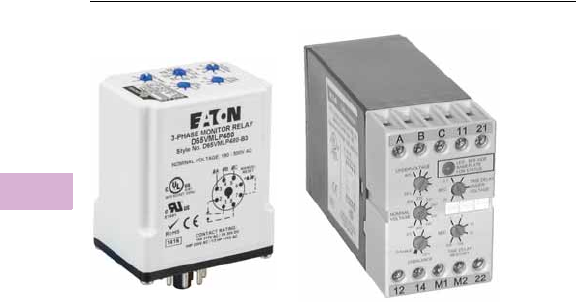
V5-T5-24 Volume 5—Motor Control and Protection CA08100006E—April 2014 www.eaton.com
5
5
5
5
5
5
5
5
5
5
5
5
5
5
5
5
5
5
5
5
5
5
5
5
5
5
5
5
5
5
5.1
Motor Protection and Monitoring
Monitoring Relays
D65VM Series—Phase Loss, Reversal, Imbalance and Under/Overvoltage
Contents
Description Page
Current Monitoring Relays . . . . . . . . . . . . . . . . . . V5-T5-3
Phase Monitoring Relays
Product Selection Guide . . . . . . . . . . . . . . . . . V5-T5-17
D65VMC Series—Phase Reversal . . . . . . . . . . V5-T5-18
D65PLR Series—Phase Loss and Reversal . . . V5-T5-20
D65PAR Series—Phase Loss, Reversal
and Undervoltage . . . . . . . . . . . . . . . . . . . . . V5-T5-22
D65VM Series—Phase Loss, Reversal,
Imbalance and Under/Overvoltage
Features . . . . . . . . . . . . . . . . . . . . . . . . . . . V5-T5-25
Product Selection . . . . . . . . . . . . . . . . . . . . V5-T5-26
Technical Data and Specifications . . . . . . . . V5-T5-26
Dimensions . . . . . . . . . . . . . . . . . . . . . . . . . V5-T5-27
Voltage Monitoring Relays . . . . . . . . . . . . . . . . . . V5-T5-28
Ground Fault Monitoring Relays . . . . . . . . . . . . . . V5-T5-42
D65VM Series—Phase Loss, Reversal, Imbalance and Under/Overvoltage
Product Description
Eaton’s D65 Phase
Monitoring Relay protects
distribution systems
supplying motor feeder or
branch circuits against
premature equipment failure
caused by voltage faults on
three-phase systems—wye
or delta connected. Phase
monitoring
relays protect
against voltage imbalance
and
single-phasing
regardless of
any regenerative
voltages.
The relay is energized when
the phase sequence and all
voltages are correct. Any of
five abnormal conditions
(phase loss, phase reversal,
overvoltage, undervoltage
or phase imbalance) will
de-energize the relay. As
standard, re-energization
is automatic upon correction
of the fault condition. The
D65 can also be wired for
manual reset.
Application Description
Protective Functions
The D65 Series Relay makes
separate trip decisions based
on the status of the three-
phase voltage inputs. Control
power is derived from the
three-phase voltage inputs.
Separate control power is not
required. The device will trip
in response to any
combination of the following
conditions:
●Undervoltage—When
voltage in all three lines of
a three-phase system
drops simultaneously.
Undervoltage drop-out can
be set at 80–95% of
operating voltage. Unit
trips when the average of
all three lines is less than
the adjusted set point for a
period longer than the
adjustable time delay drop-
out (0.1–20 seconds). This
time delay eliminates
nuisance tripping caused
by momentary voltage
fluctuation.
●Overvoltage—Fixed at
110% of nominal, unit trips
when the average of all
three lines is greater than
the fixed set point for a
period longer than the time
delay drop-out.
●Phase Imbalance—
Imbalance of a three-phase
system occurs when
single-phase loads are
connected such that one or
two of the lines (phases)
carry more or less of the
load. This could cause
motors to run at
temperatures above
published ratings. Unit trips
when any one of the three
lines is more than the
adjusted set point below
the average of all three
lines. The percent phase
imbalance is adjustable
from 2–10% and also has a
Disable setting for
applications where poor
voltage conditions could
cause nuisance tripping.
●Phase Loss (Single-
Phasing)—Total loss of
one or more of the three
phases. Typically caused by
a blown fuse, broken wire
or worn contact. This
condition would result in a
motor drawing locked rotor
current during start-up. In
addition, a three-phase
motor will continue to run
after losing a phase,
resulting in potential motor
burn-out. Unit trips on loss
of any phase.
●Phase Reversal—
Reversing any two of the
three phases will cause a
three-phase motor to run in
the opposite direction. This
may cause damage to
machinery or injury to
personnel. Unit trips if
rotation (sequence) of the
three phases is anything
other than A-B-C.
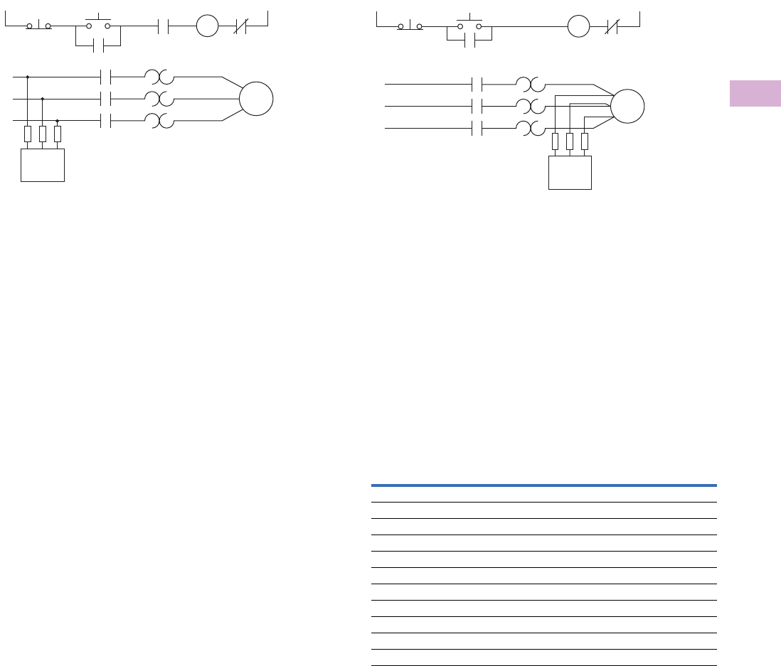
Volume 5—Motor Control and Protection CA08100006E—April 2014 www.eaton.com V5-T5-25
5
5
5
5
5
5
5
5
5
5
5
5
5
5
5
5
5
5
5
5
5
5
5
5
5
5
5
5
5
5
5.1
Motor Protection and Monitoring
Monitoring Relays
Typical Connections
Line Side Monitoring
With the relay connected before the motor starter, the motor
can be started in the reverse direction. However, the motor
is unprotected against phase failures between the relay and
the motor.
Features
●Universal voltage range of
190–500V provides the
flexibility to cover a variety
of applications (120V and
600V units also available)
●True RMS voltage sensing
for improved accuracy
●Continued operation
through phase loss
conditions
●Automatic or manual reset
after the fault condition is
corrected
●Bi-color LED indicates
normal condition and
defines fault type for
simpler troubleshooting
Operation
The D65 provides protection
against premature equipment
failure caused by voltage
faults on three-phase
systems. The D65 is
designed to be compatible
with most wye or delta
systems. In wye systems,
a connection to a neutral is
not required. D65 Phase
Monitoring Relays protect
against imbalanced voltages
or single-phasing regardless
of any regenerative voltages.
The relay is energized when
the phase sequence and all
voltages are correct. Any one
of five fault conditions will
de-energize the relay.
Re-energization is automatic
upon correction of the fault
condition.
Manual reset is available if
a NC switch is wired to the
appropriate terminals. A
bi-color LED indicates normal
condition and also provides
specific fault indication to
simplify troubleshooting. The
percent phase imbalance is
adjustable from
2–10%, and
the undervoltage drop-out can
be set at 80–95%
of operating
voltage. The adjustable time
delay drop-out on
undervoltage (0.1–20 sec.)
eliminates nuisance tripping
caused by momentary
voltage fluctuations.
START
L1
L1
L2
Voltage Monitor
Relay
Input Fuses
(Recommended)
2A Max.
Voltage
Monitor
Relay
3
Phase
M
otor
O/L
STOP
M
M
L2 M
L3 M
M
Load Side Monitoring
With the relay connected directly to the motor, the total feed
lines are monitored. This connection should not be used with
reversing motors.
●D65VMLS can be either
mounted directly on
35 mm DIN rail with no
additional parts or to a
back-panel with two
screws. No socket
required. D65VMLP will
plug into D3PA2 socket and
mount on 35 mm DIN rail
●Small, compact size
●User-adjustable settings
include nominal voltage,
percent phase imbalance,
undervoltage drop-out,
time delay on undervoltage
and time delay on restart
after fault
LED Operation
Notes
1Single flash = On 25 ms, Off 175 ms.
2Double flash = On 25 ms, Off 25 ms, On 25 ms, Off 125 ms.
3Triple flash = On 25 ms, Off 25 ms, On 25 ms, Off 25 ms, On 25 ms, Off 75 ms.
Input Fuses
(Recommended)
2A Max.
START
L1
L1
L2
Voltage Monitor
Relay
Voltage
Monitor
Relay
3
Phase
M
otor
O/L
STOP
M
L2 M
L3 M
M
LED Status Surface Mount Indication Plug-In Indication
Green steady Normal/relay ON Normal/relay ON
Green flashing Power-up/restart delay Power-up/restart delay
Red steady Imbalance Reversal
Red flashing Undervoltage/overvoltage N/A
Amber steady Reversal N/A
Amber flashing Loss N/A
Alternating green/red Undervoltage/overvoltage trip pending N/A
Alternating red/amber Nominal voltage set error N/A
Red single flash 1N/A Loss/imbalance
Red double flash 2N/A Undervoltage
Red triple flash 3N/A Overvoltage
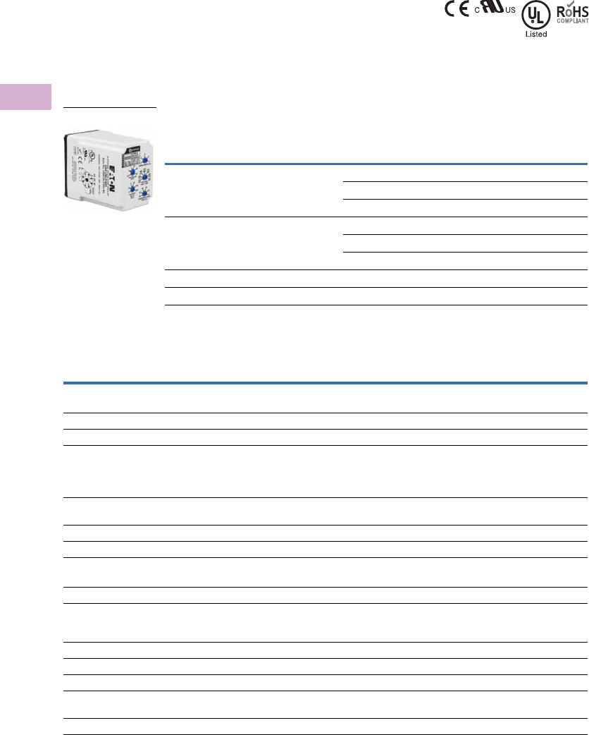
V5-T5-26 Volume 5—Motor Control and Protection CA08100006E—April 2014 www.eaton.com
5
5
5
5
5
5
5
5
5
5
5
5
5
5
5
5
5
5
5
5
5
5
5
5
5
5
5
5
5
5
5.1
Motor Protection and Monitoring
Monitoring Relays
Standards and Certifications
●CE (Low Voltage + EMC
Directive EN60947-5-1)
●cULus listed
(D65VMLS only)
●cRUus
(D65VMLP only)
●RoHS compliant
●UL Listed 1
Product Selection
D65VM Series—Phase Loss, Reversal, Imbalance and
Under/Overvoltage 2
Technical Data and Specifications
D65VM Series—Phase Loss, Reversal, Imbalance and Under/Overvoltage
Notes
1When used with accompanying Eaton Socket (D65VMLP only).
2Additional models available. Please visit our Web site for the latest offering.
3Requires a 600V-rated socket when used on system voltages greater than 300V. The D3PA2 socket is rated 10A, 600V.
Mounting Style
Operating Voltage
50/60 Hz
Catalog
Number
Surface-mount
(DIN rail or panel)
120V D65VMLS120
208–480V D65VMLS480
600V D65VMLS600
Plug-in
(DIN rail)
102–138V D65VMLP120
190–500V D65VMLP480 3
460–600V D65VMLP600
8-pin socket — D3PA2
8-pin IP20 rated socket — D3PA6
Description Specification
Nominal voltages (50–60 Hz)
For D65VMLS 120V, 208–480V, 575V
For D65VMLP 102–138V, 190–500V, 460–600V
Connections Three-wire wye or delta
Output contacts
For D65VMLS SPDT and SPNC (surface mount version only)
NO: 10A resistive at 240 Vac/30 Vdc, 1/2 hp at 240 Vac
NC: 10A resistive at 240 Vac/30 Vdc, 1/3 hp at 240 Vac
For D65VMLP SPDT:
10A SPDT at 277 Vac. 1 hp at 250 Vac. 1/2 hp at 120 Vac. C300 pilot duty
Dielectric 1000V + (2 * nominal voltage rating) between input terminals and case or active circuitry
Operating temp. –20° to 150°F (–28° to 65°C)
Response times
Power up 1–300 seconds adjustable
Restart after fault 1–300 seconds adjustable
Dropout due to fault 100 ms fixed on phase loss and phase reversal;
2 seconds fixed on phase imbalance;
0.1–20 sec. adjustable on undervoltage only; inverse time curve for overvoltage
Mechanical life 10,000,000 operations
Electrical life 100,000 operations
Power consumption 3 VA
Net weight 10.3 oz. (292g) D65VMLS
6.4 oz. (181g) D65VMLP
Hysteresis 2–3%
D65VM_
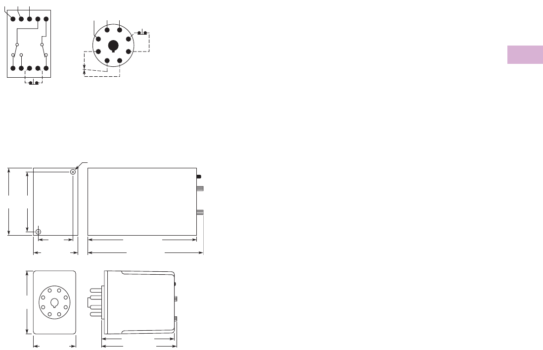
Volume 5—Motor Control and Protection CA08100006E—April 2014 www.eaton.com V5-T5-27
5
5
5
5
5
5
5
5
5
5
5
5
5
5
5
5
5
5
5
5
5
5
5
5
5
5
5
5
5
5
5.1
Motor Protection and Monitoring
Monitoring Relays
Wiring Diagrams
Surface-Mount and Plug-In
Dimensions
Approximate Dimensions in Inches (mm)
Surface-Mount and Plug-In
12 14
M
2
M
122
Manual Reset
AB C
ØA ØB ØC
11 21 ØA ØB ØC Manual
Reset
3
2
6
54
81 7
1.40
(35.6)
0.20 (50.8) Mounting Holes – 2 Places
2.70
(68.6)
1.80 (45.7)
4.40 (111.8)
4.50 (114.3)
2.40
(60.1)
1.70 (43.2)
2.90 (73.7)
3.00 (76.2)
2.40
(60.1)
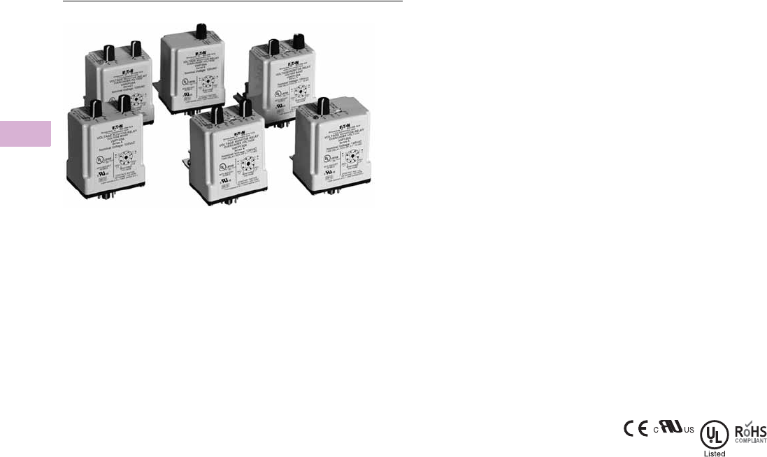
V5-T5-28 Volume 5—Motor Control and Protection CA08100006E—April 2014 www.eaton.com
5
5
5
5
5
5
5
5
5
5
5
5
5
5
5
5
5
5
5
5
5
5
5
5
5
5
5
5
5
5
5.1
Motor Protection and Monitoring
Monitoring Relays
Voltage Monitoring Relays
Contents
Description Page
Current Monitoring Relays . . . . . . . . . . . . . . . . . . V5-T5-3
Phase Monitoring Relays . . . . . . . . . . . . . . . . . . . V5-T5-16
Voltage Monitoring Relays
Product Selection Guide . . . . . . . . . . . . . . . . . V5-T5-29
D65VMRP and D65VMKP Over/Undervoltage
Relays (Fixed Time Delay) . . . . . . . . . . . . . . . V5-T5-30
D65VAP and D65VAKP Over/Undervoltage
Relays . . . . . . . . . . . . . . . . . . . . . . . . . . . . . . . V5-T5-33
D65VWP and D65VWKP Voltage Band
Relays . . . . . . . . . . . . . . . . . . . . . . . . . . . . . . V5-T5-36
VSR Series—Solid-State, Single-Phase
Voltage Sensing . . . . . . . . . . . . . . . . . . . . . . . V5-T5-39
Ground Fault Monitoring Relays . . . . . . . . . . . . . . V5-T5-42
Product Overview
Voltage Monitoring Relays
monitor either AC single-
phase (50/60 Hz) or DC
voltages to protect
equipment against voltage
fault conditions. No separate
supply (input) voltage is
required. All versions are
available in a compact plug-in
case using an 8-pin octal
socket.
There are two styles of
voltage monitoring relays:
●Over/Undervoltage Relays
●Voltage Band Relays
Over/Undervoltage Relays
Over/Undervoltage Relays
provide protection to
equipment where either an
over- or undervoltage
condition is potentially
damaging. Each relay can be
used as either an overvoltage
or an undervoltage relay,
depending on the output
contact used. When used as
an undervoltage relay, it
provides protection to
equipment that is required to
operate above a minimum
voltage. When used as an
overvoltage relay, it protects
equipment against excessive
voltage conditions. Over/
undervoltage relays are
designed to operate when
the operating voltage reaches
a preset value and drop out
when the operating voltage
drops to a level below the
preset value.
Voltage Band Relays
Voltage Band Relays provide
protection to equipment that
is required to operate within
an upper and lower voltage
limit. As long as the operating
voltage remains within an
over- and undervoltage range,
the internal relay stays
energized. If the operating
voltage falls outside this
range, the relay will drop out.
Standards and
Certifications
●CE
●cRUus listed
●UL listed 1
●RoHS recognized
Note
1When used with accompanying Eaton
socket.

Volume 5—Motor Control and Protection CA08100006E—April 2014 www.eaton.com V5-T5-29
5
5
5
5
5
5
5
5
5
5
5
5
5
5
5
5
5
5
5
5
5
5
5
5
5
5
5
5
5
5
5.1
Motor Protection and Monitoring
Monitoring Relays
Product Selection Guide
D65V Product Family Selection—Over/Undervoltage Relays
D65V Product Family Selection—Voltage Band Relays
Note
1Fixed time delay eliminates nuisance tripping due to short voltage surges or drops.
Series
Pickup
Voltage
Dropout
Voltage
Time Delay
Dropout
Fixed Time Delay for
Over/Undervoltage Relays
Adjustable Time Delay
Over/Undervoltage Relays
D65VMP Adjustable
85–115% nominal
Fixed at 95% of pickup Fixed 500 ms 1Page V5-T5-31 —
D65VMKP Adjustable 75–95% of pickup Page V5-T5-31 —
D65VAP Fixed at 95% of pickup Adjustable 0.5–10 seconds — Page V5-T5-34
D65VAKP Adjustable 75–95% of pickup — Page V5-T5-34
Series
Pickup
Voltage
Dropout
Voltage
Time Delay
Dropout Voltage Band Relays
D65VWP Adjustable
100–125% nominal
Adjustable 75–100% of nominal Fixed 500 ms 1Page V5-T5-37
D65VWKP Adjustable 0.5–10 seconds Page V5-T5-37
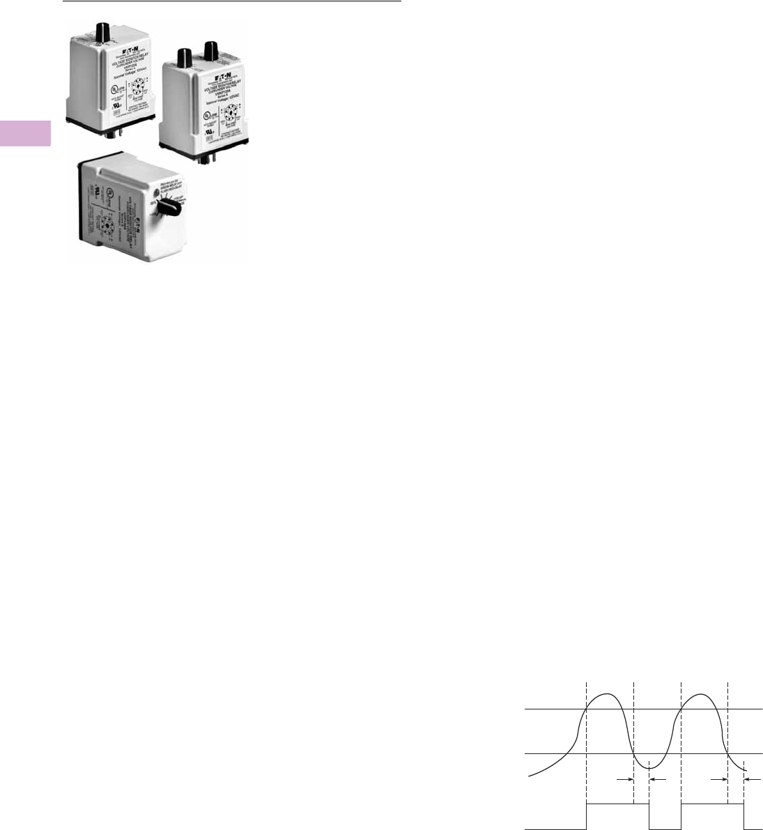
V5-T5-30 Volume 5—Motor Control and Protection CA08100006E—April 2014 www.eaton.com
5
5
5
5
5
5
5
5
5
5
5
5
5
5
5
5
5
5
5
5
5
5
5
5
5
5
5
5
5
5
5.1
Motor Protection and Monitoring
Monitoring Relays
D65VMRP and D65VMKP—Fixed Time Delay Over/Undervoltage Relays
Contents
Description Page
Current Monitoring Relays . . . . . . . . . . . . . . . . . . V5-T5-3
Phase Monitoring Relays . . . . . . . . . . . . . . . . . . . V5-T5-16
Voltage Monitoring Relays
Product Selection Guide . . . . . . . . . . . . . . . . . V5-T5-29
D65VMRP and D65VMKP Over/Undervoltage
Relays (Fixed Time Delay)
Product Selection . . . . . . . . . . . . . . . . . . . . V5-T5-31
Technical Data and Specifications . . . . . . . . V5-T5-32
Dimensions . . . . . . . . . . . . . . . . . . . . . . . . . V5-T5-32
D65VAP and D65VAKP Over/Undervoltage
Relays . . . . . . . . . . . . . . . . . . . . . . . . . . . . . . . V5-T5-33
D65VWP and D65VWKP Voltage Band
Relays . . . . . . . . . . . . . . . . . . . . . . . . . . . . . . V5-T5-36
VSR Series—Solid-State, Single-Phase
Voltage Sensing . . . . . . . . . . . . . . . . . . . . . . . V5-T5-39
Ground Fault Monitoring Relays . . . . . . . . . . . . . . V5-T5-42
D65VMRP and D65VMKP Over/Undervoltage Relays
(Fixed Time Delay)
Product Description
The D65VMRP and
D65VMKP Over/
Undervoltage Relays provide
protection to equipment
where either an over- or
undercurrent condition is
potentially damaging. They
are designed to operate when
the operating voltage reaches
a preset value and drop out
when the operating voltage
drops to a level below the
preset value.
The pickup voltage setting
is user-adjustable from
85–115% of the nominal
voltage rating. As standard,
the D65VMRP Series has a
dropout voltage setting fixed
at 95% of the pickup voltage
setting. An adjustable drop-
out setting of 75–95% of the
pickup setting is available on
the D65VMKP Series. The
relay energizes when the
monitored voltage is above
the pickup setting. The relay
de-energizes when the
monitored voltage is below
the dropout setting for a
period longer than the drop-
out time delay, which is fixed
at 500 ms. An adjustable time
delay on dropout of
0.5–10 seconds is available.
Application Description
Each relay can be used as
either an overvoltage or an
undervoltage relay,
depending on the output
contact used.
Overvoltage Relay
Provides protection to
equipment that cannot handle
excess voltages. Uses a
normally closed contact (NC).
As long as the monitored
voltage remains below the
maximum voltage the
equipment can withstand
(pickup setting), the relay
remains energized and the
NC contact remains closed,
keeping the load energized. If
the operating voltage
increases beyond the
maximum rating of the
equipment, the relay
energizes and the NC contact
opens, turning off the load.
When the voltage falls below
the dropout settings
(hysteresis), the relay de-
energizes and the NC contact
re-closes, turning on the load.
Undervoltage Relay
Provides protection to
equipment that is required to
operate above a certain
minimum voltage. Uses a
normally open contact (NO).
As long as the monitored
voltage is above the
minimum value required
(pickup setting), the relay will
energize and the NO contact
closes, turning on the load. If
the voltage drops below the
dropout setting (the minimum
voltage required minus
hysteresis), the relay will de-
energize and the NO contact
will re-open, turning off the
load.
Features
●Monitors AC single-phase
and DC voltages
●Wide range of user-
adjustable pickup and
dropout settings
●Fixed time delay on
dropout of 500 ms
●LED indicates output relay
status
●Compact plug-in case
using industry standard
8-pin socket
●10A DPDT output contacts
Fixed Time Delay Over/Undervoltage Current Monitoring
Monitored
Voltage
Relay
Output
Pickup
Voltage
Dropout
Voltage
On
TT
Off
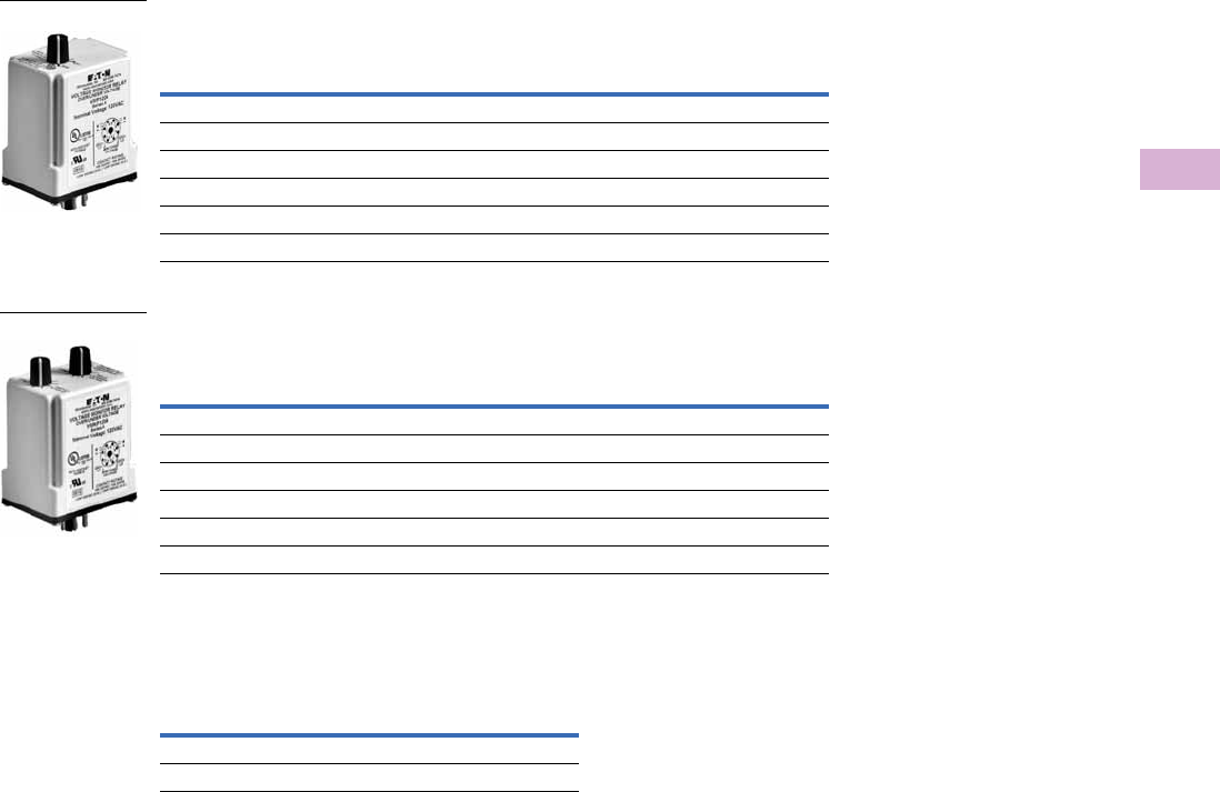
Volume 5—Motor Control and Protection CA08100006E—April 2014 www.eaton.com V5-T5-31
5
5
5
5
5
5
5
5
5
5
5
5
5
5
5
5
5
5
5
5
5
5
5
5
5
5
5
5
5
5
5.1
Motor Protection and Monitoring
Monitoring Relays
Product Selection
D65VMP and D65VMKP Series—Over/Undervoltage Relay 1,
Adjustable Pickup, Fixed Dropout Settings 2
D65VMP and D65VMKP Series—Over/Undervoltage Relay 1,
Adjustable Pickup and Dropout Settings 3
Accessories
D65VMP and D65VMKP Series—
Over/Undervoltage Relays
Notes
1 Time delay on dropout fixed at 500 ms.
2 Dropout voltage is fixed at 95% of the adjusted pickup setting.
3 Dropout voltage is adjustable from 75–95% of the adjusted pickup setting.
Nominal
Voltage
Voltage Range Catalog
NumberPickup Dropout
24 Vac 21–27 Vac 20–26 Vac D65VMRPT
120 Vac 102–138 Vac 97–131 Vac D65VMRPA
12 Vdc 10–14 Vdc 9–13 Vdc D65VMRPR1
24 Vdc 21–27 Vdc 20–26 Vdc D65VMRPT1
48 Vdc 41–55 Vdc 39–52 Vdc D65VMRPW1
110 Vdc 94–126 Vdc 89–121 Vdc D65VMRPA1
Nominal
Voltage
Voltage Range Catalog
NumberPickup Dropout
24 Vac 21–27 Vac 16–26 Vac D65VMKPT
120 Vac 102–138 Vac 77–131 Vac D65VMKPA
12 Vdc 10–14 Vdc 8–13 Vdc D65VMKPR1
24 Vdc 21–27 Vdc 16–26 Vdc D65VMKPT1
48 Vdc 41–55 Vdc 32–52 Vdc D65VMKPW1
110 Vdc 94–126 Vdc 71–121 Vdc D65VMKPA1
D65VM_
D65VM_
Description
Standard
Pack
Catalog
Number
8-pin socket 10 D3PA2
Hold-down spring 10 D65CHDS
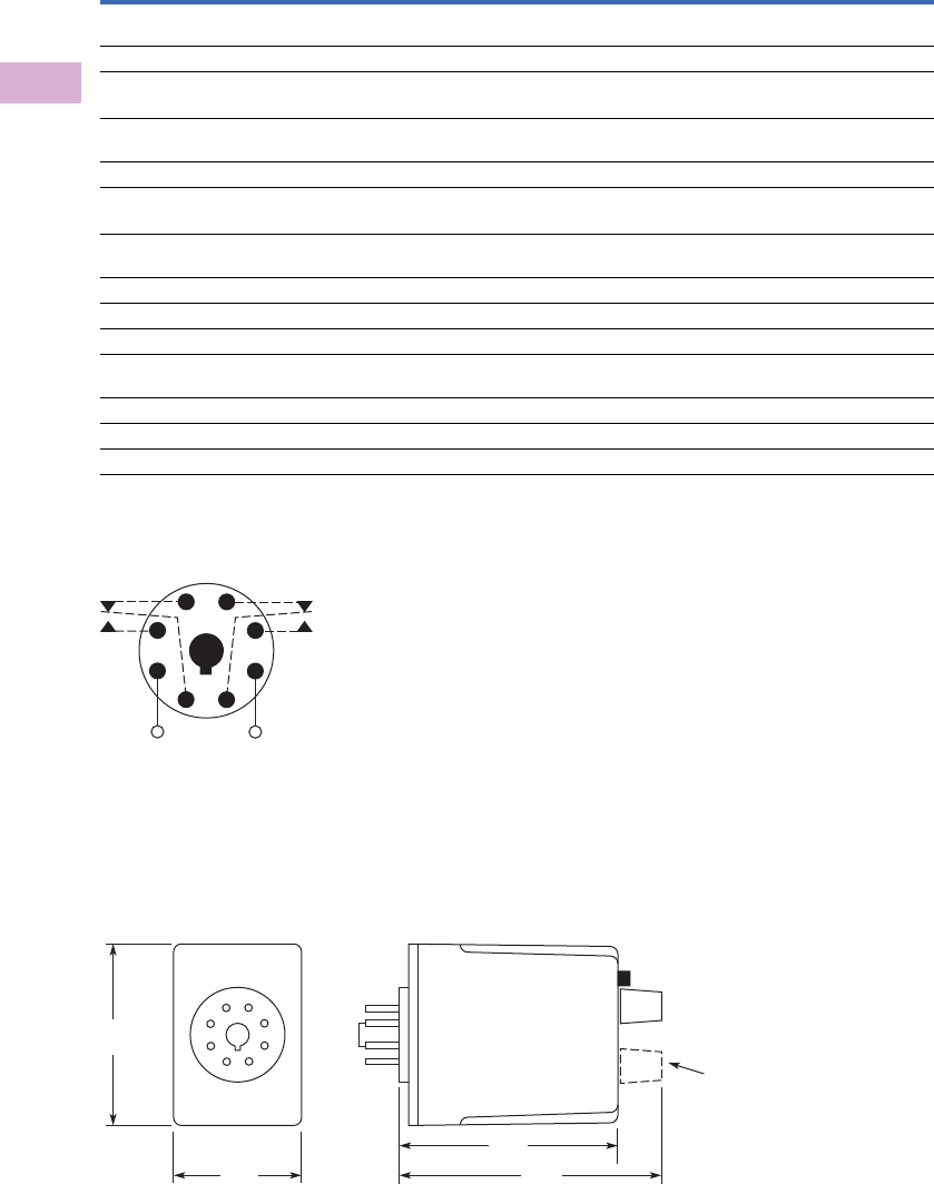
V5-T5-32 Volume 5—Motor Control and Protection CA08100006E—April 2014 www.eaton.com
5
5
5
5
5
5
5
5
5
5
5
5
5
5
5
5
5
5
5
5
5
5
5
5
5
5
5
5
5
5
5.1
Motor Protection and Monitoring
Monitoring Relays
Technical Data and Specifications
D65V Series—Fixed and Adjustable Time Delay Over/Undervoltage Relays
D65VMP, D65VMKP, D65VAP and D65VAKP Series, Over/Undervoltage Relays
Wiring Diagram
Wiring for 8-Pin Socket
Dimensions
Approximate Dimensions in Inches (mm)
D65V Series—Fixed and Adjustable Time Delay Over/Undervoltage Relays
Description Specification
Voltage tolerance +25%/–50% of nominal voltage; AC voltages are 50/60 Hz
No supply (input) voltage is required
Load (burden) Less than 3 VA
Current settings
Pickup Adjustable from 85–115% of nominal voltage
Dropout Fixed at 95% of the pickup setting for D65VMP and D65VAP
Adjustable from 75–95% of the pickup setting for D65VMKP and D65VAKP
Temperature –20° to 131°F (–28° to 55°C)
Response times
Pickup 500 ms
Dropout Fixed 500 ms for D65VMP and D65VMKP
Adjustable 0.5–10 seconds for D65VAP and D65VAKP
Output contacts 10A Resistive at 240 Vac/30 Vdc, 1/2 hp at 240 Vac (NO), 1/3 hp at 240 Vac (NC)
Mechanical life 10,000,000 operations
Electrical life 100,000 operations
Indicator LED Red steady when relay is energized;
green when relay is OFF
Transient protection 10,000 volts for 20 microseconds
Reset Automatic
Mounting Requires an 8-pin socket
Monitored
Voltage
1
(DC)+
L1
(DC)−
L2
8
4
36
27
5
2.4
(60)
1.7
(43)
2.9
(74) 3.5
(89)
D65VMKP and
D65VAKP Only
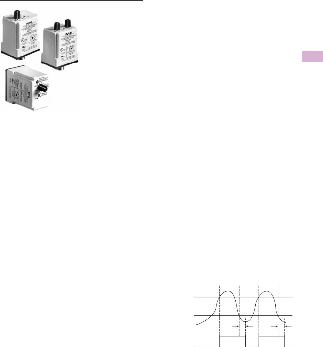
Volume 5—Motor Control and Protection CA08100006E—April 2014 www.eaton.com V5-T5-33
5
5
5
5
5
5
5
5
5
5
5
5
5
5
5
5
5
5
5
5
5
5
5
5
5
5
5
5
5
5
5.1
Motor Protection and Monitoring
Monitoring Relays
D65VAP & D65VAKP—Adjustable Time Delay Over/Undervoltage Relays
Contents
Description Page
Current Monitoring Relays . . . . . . . . . . . . . . . . . . . V5-T5-3
Phase Monitoring Relays . . . . . . . . . . . . . . . . . . . . V5-T5-16
Voltage Monitoring Relays
Product Selection Guide . . . . . . . . . . . . . . . . . . V5-T5-29
D65VMRP and D65VMKP Over/Undervoltage
Relays (Fixed Time Delay) . . . . . . . . . . . . . . . V5-T5-30
D65VAP and D65VAKP Over/Undervoltage
Relays (Adjustable Time Delay)
Product Selection . . . . . . . . . . . . . . . . . . . . V5-T5-34
Technical Data and Specifications . . . . . . . . V5-T5-35
Dimensions . . . . . . . . . . . . . . . . . . . . . . . . . V5-T5-35
D65VWP and D65VWKP Voltage Band
Relays . . . . . . . . . . . . . . . . . . . . . . . . . . . . . . V5-T5-36
VSR Series—Solid-State, Single-Phase
Voltage Sensing . . . . . . . . . . . . . . . . . . . . . . . V5-T5-39
Ground Fault Monitoring Relays . . . . . . . . . . . . . . V5-T5-42
D65VAP and D65VAKP Over/Undervoltage Relays
(Adjustable Time Delay)
Product Description
The D65VAP and D65VAKP
Over/Undervoltage Relays
provide protection to
equipment where either an
over- or undercurrent
condition is potentially
damaging. They are designed
to operate when the
operating voltage reaches a
preset value and drop out
when the operating voltage
drops to a level below the
preset value.
The pickup voltage setting is
user-adjustable from 85–
115% of the nominal voltage
rating. As standard, the
D65VAP Series has a dropout
voltage setting fixed at 95%
of the pickup voltage setting.
An adjustable dropout setting
of 75–95% of the pickup
setting is available on the
D65VAKP Series. The relay
energizes when the
monitored voltage is above
the pickup setting. The relay
de-energizes when the
monitored voltage is below
the dropout setting for a
period longer than the
dropout time delay, which is
adjustable from 0.5–10
seconds. A fixed time delay
of 500 ms is available with
the D65VMP Series.
Application Description
Each relay can be used as
either an overvoltage or an
undervoltage relay,
depending on the output
contact used.
Overvoltage Relay
Provides protection to
equipment that cannot handle
excess voltages. Uses a
normally closed contact (NC).
As long as the monitored
voltage remains below the
maximum voltage the
equipment can withstand
(pickup setting), the relay
remains energized and the
NC contact remains closed,
keeping the load energized.
If the operating voltage
increases beyond the
maximum rating of the
equipment, the relay
energizes and the NC contact
opens, turning off the load.
When the voltage falls below
the dropout settings
(hysteresis), the relay de-
energizes and the NC contact
re-closes, turning on the load.
Undervoltage Relay
Provides protection to
equipment that is required to
operate above a certain
minimum voltage. Uses a
normally open contact (NO).
As long as the monitored
voltage is above the minimum
value required (pickup setting),
the relay will energize and the
NO contact closes, turning on
the load. If the voltage drops
below the dropout setting
(the minimum voltage
required minus hysteresis),
the relay will de-energize and
the NO contact will re-open,
turning off the load.
Features
●Monitors AC single-phase
and DC voltages
●Wide range of user-
adjustable pickup and
dropout settings
●Adjustable time delay on
dropout of 0.5–10 seconds
●LED indicates output
relay status
●Compact plug-in case
using industry standard
8-pin socket
●10A DPDT output contacts
Adjustable Time Delay Over/Undervoltage Current Monitoring
Monitored
Voltage
Relay
Output
Pickup
Voltage
Dropout
Voltage
On
TT
Off
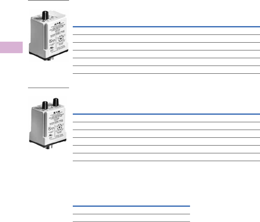
V5-T5-34 Volume 5—Motor Control and Protection CA08100006E—April 2014 www.eaton.com
5
5
5
5
5
5
5
5
5
5
5
5
5
5
5
5
5
5
5
5
5
5
5
5
5
5
5
5
5
5
5.1
Motor Protection and Monitoring
Monitoring Relays
Product Selection
D65VAP and D65VAKP Series—Over/Undervoltage Relay 1,
Adjustable Pickup, Fixed Dropout Settings 2
D65VAP and D65VAKP Series—Over/Undervoltage Relay 1,
Adjustable Pickup and Dropout Settings 3
Accessories
D65VMP and D65VMKP Series—
Over/Undervoltage Relays
Notes
1 Time delay on dropout fixed at 500 ms.
2 Dropout voltage is fixed at 95% of the adjusted pickup setting.
3 Dropout voltage is adjustable from 75–95% of the adjusted pickup setting.
Nominal
Voltage
Voltage Range Catalog
NumberPickup Dropout
24 Vac 21–27 Vac 20–26 Vac D65VAPT
120 Vac 102–138 Vac 97–131 Vac D65VAPA
12 Vdc 10–14 Vdc 9–13 Vdc D65VAPR1
24 Vdc 21–27 Vdc 20–26 Vdc D65VAPT1
48 Vdc 41–55 Vdc 39–53 Vdc D65VAPW1
110 Vdc 94–126 Vdc 89–121 Vdc D65VAPA1
Nominal
Voltage
Voltage Range Catalog
NumberPickup Dropout
24 Vac 21–27 Vac 16–26 Vac D65VAKPT
120 Vac 102–138 Vac 77–131 Vac D65VAKPA
12 Vdc 10–14 Vdc 8–13 Vdc D65VAKPR1
24 Vdc 21–27 Vdc 16–26 Vdc D65VAKPT1
48 Vdc 41–55 Vdc 32–52 Vdc D65VAKPW1
110 Vdc 94–126 Vdc 71–121 Vdc D65VAKPA1
D65VA_
D65VA_
Description
Standard
Pack
Catalog
Number
8-pin socket 10 D3PA2
Hold-down spring 10 D65CHDS
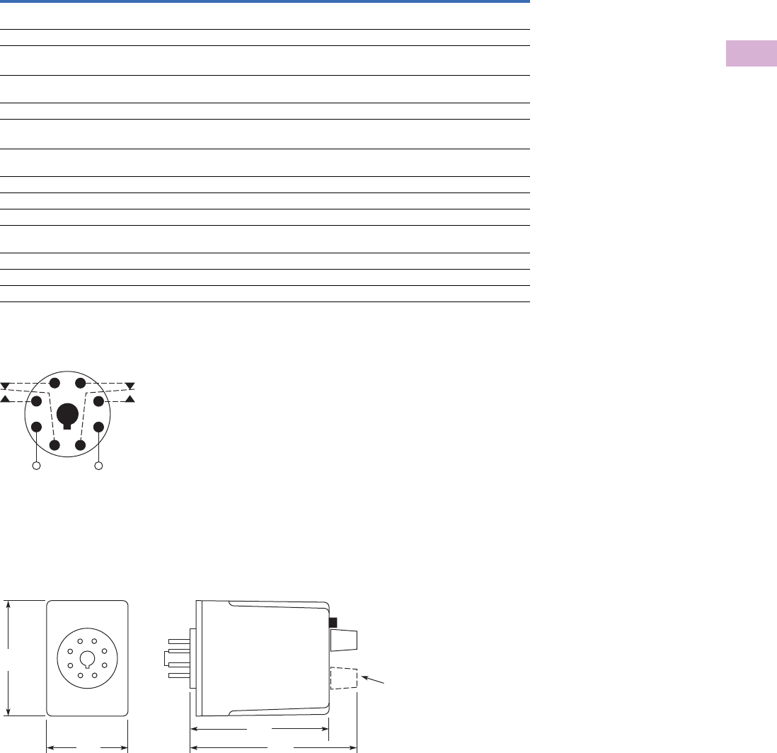
Volume 5—Motor Control and Protection CA08100006E—April 2014 www.eaton.com V5-T5-35
5
5
5
5
5
5
5
5
5
5
5
5
5
5
5
5
5
5
5
5
5
5
5
5
5
5
5
5
5
5
5.1
Motor Protection and Monitoring
Monitoring Relays
Technical Data and Specifications
D65V Series—Fixed and Adjustable Time Delay Over/Undervoltage Relays
D65VMP, D65VMKP, D65VAP and D65VAKP Series, Over/Undervoltage Relays
Wiring Diagram
Wiring for 8-Pin Socket
Dimensions
Approximate Dimensions in Inches (mm)
D65V Series—Fixed and Adjustable Time Delay Over/Undervoltage Relays
Description Specification
Voltage tolerance +25%/–50% of nominal voltage; AC voltages are 50/60 Hz
No supply (input) voltage is required
Load (burden) Less than 3 VA
Current settings
Pickup Adjustable from 85–115% of nominal voltage
Dropout Fixed at 95% of the pickup setting for D65VMP and D65VAP
Adjustable from 75–95% of the pickup setting for D65VMKP and D65VAKP
Temperature –20° to 131°F (–28° to 55°C)
Response times
Pickup 500 ms
Dropout Fixed 500 ms for D65VMP and D65VMKP
Adjustable 0.5–10 seconds for D65VAP and D65VAKP
Output contacts 10A resistive at 240 Vac/30 Vdc, 1/2 hp at 240 Vac (NO), 1/3 hp at 240 Vac (NC)
Mechanical life 10,000,000 operations
Electrical life 100,000 operations
Indicator LED Red steady when relay is energized;
green when relay is OFF
Transient protection 10,000 volts for 20 microseconds
Reset Automatic
Mounting Requires an 8-pin socket
Monitored
Voltage
1
(DC)+
L1
(DC)−
L2
8
4
36
27
5
2.4
(60)
1.7
(43)
2.9
(74) 3.5
(89)
D65VMKP and
D65VAKP Only
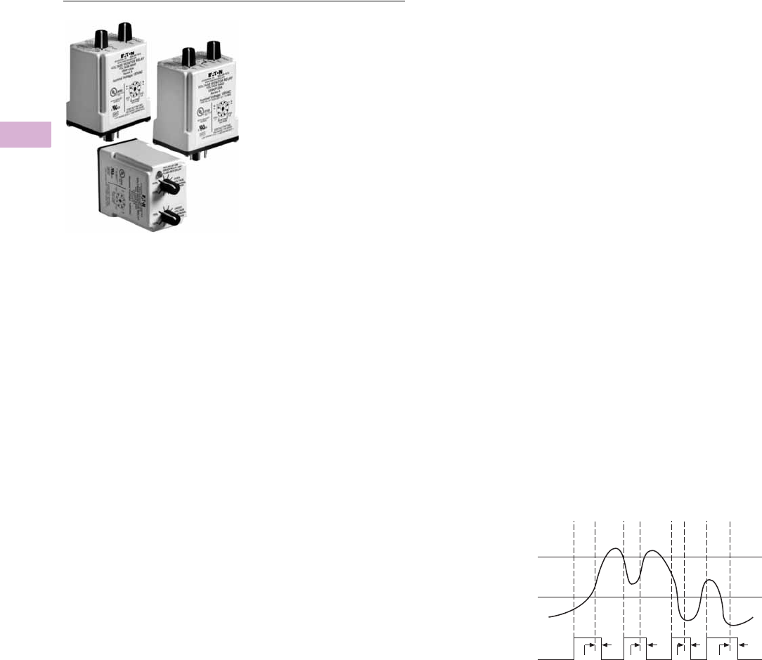
V5-T5-36 Volume 5—Motor Control and Protection CA08100006E—April 2014 www.eaton.com
5
5
5
5
5
5
5
5
5
5
5
5
5
5
5
5
5
5
5
5
5
5
5
5
5
5
5
5
5
5
5.1
Motor Protection and Monitoring
Monitoring Relays
D65VWP and D65VWKP Voltage Band Relays
Contents
Description Page
Current Monitoring Relays . . . . . . . . . . . . . . . . . . V5-T5-3
Phase Monitoring Relays . . . . . . . . . . . . . . . . . . . V5-T5-16
Voltage Monitoring Relays
Product Selection Guide . . . . . . . . . . . . . . . . . V5-T5-29
D65VMRP and D65VMKP Over/Undervoltage
Relays (Fixed Time Delay) . . . . . . . . . . . . . . . V5-T5-30
D65VAP and D65VAKP Over/Undervoltage
Relays (Adjustable Time Delay) . . . . . . . . . . . V5-T5-33
D65VWP and D65VWKP Voltage Band Relays
Product Selection . . . . . . . . . . . . . . . . . . . . V5-T5-37
Technical Data and Specifications . . . . . . . . V5-T5-38
Dimensions . . . . . . . . . . . . . . . . . . . . . . . . . V5-T5-38
VSR Series—Solid-State, Single-Phase
Voltage Sensing . . . . . . . . . . . . . . . . . . . . . . . V5-T5-39
Ground Fault Monitoring Relays . . . . . . . . . . . . . . V5-T5-42
D65VWP and D65VWKP Voltage Band Relays
Product Description
The D65VWP and D65VWKP
Series Voltage Band Relays
provide protection to
equipment that is required to
operate within an upper and
lower voltage limit. As long as
the operating voltage remains
within an over- and
undervoltage range, the
internal relay stays energized.
If the operating voltage falls
outside this range, the relay
will drop out.
When nominal operating
voltage is applied, the internal
relay will energize (pickup). If
the operating voltage falls
outside the preset over trip
point (adjustable 100–125%
of nominal), or under trip
point (adjustable 75–100% of
nominal), for a period longer
than the dropout time delay,
the relay will de-energize
(dropout). When the voltage
returns to normal (within the
preset over- and undervoltage
trip points), the unit
automatically resets and the
relay energizes. Choose
between a unit with fixed
dropout time of 500 ms or
one with an adjustable 0.5–10
seconds dropout time.
Features
●Monitors AC single-phase
and DC voltages
●Provides voltage band
(window) protection
●Wide range of user-
adjustable overvoltage and
undervoltage settings
●Fixed or adjustable time
delay on dropout
●LED indicates output relay
status
●Compact plug-in case
using industry standard 8-
pin octal socket
●10A DPDT output contacts
Voltage Band Relay Current Monitoring
T
Monitored
Current
Over
Voltage
Under
Voltage
Relay
Output
ON
OFF T T T
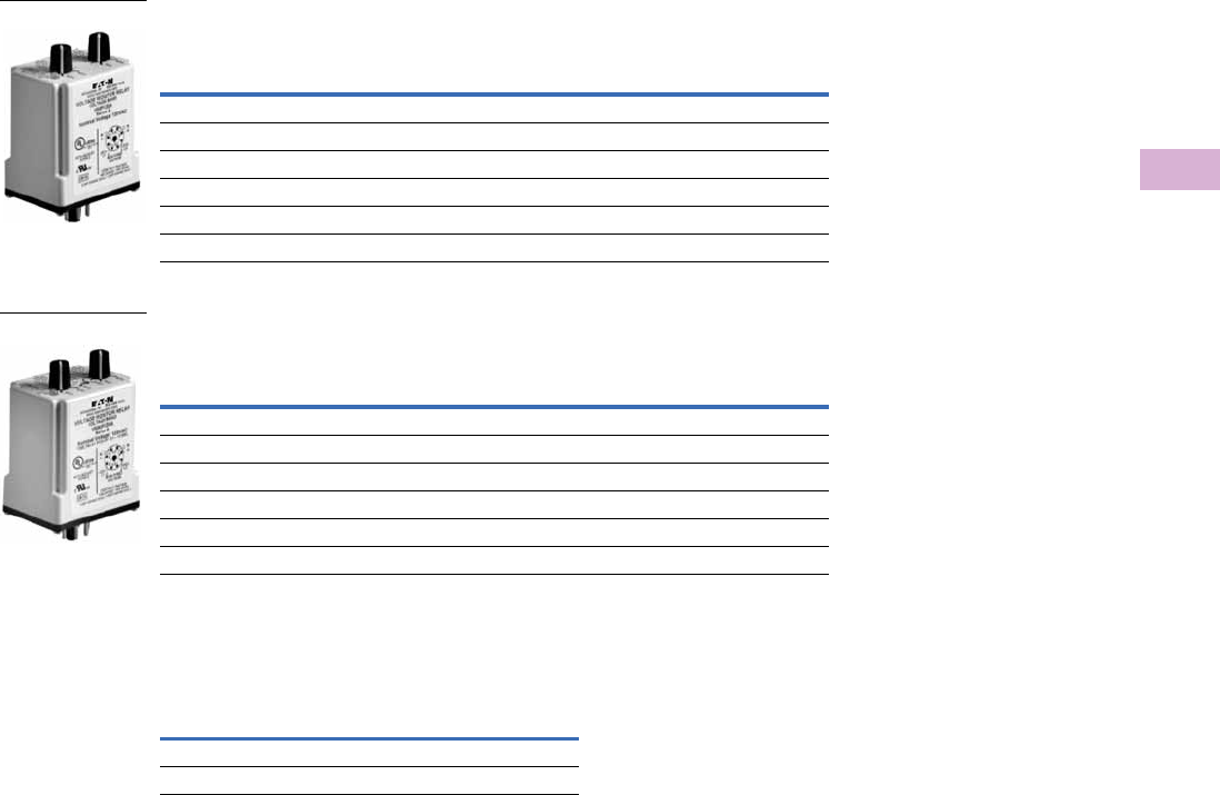
Volume 5—Motor Control and Protection CA08100006E—April 2014 www.eaton.com V5-T5-37
5
5
5
5
5
5
5
5
5
5
5
5
5
5
5
5
5
5
5
5
5
5
5
5
5
5
5
5
5
5
5.1
Motor Protection and Monitoring
Monitoring Relays
Product Selection
D65VWP and D65VWKP Voltage Band Relays
Fixed Dropout Time Delay, 500 ms
D65VWP and D65VWKP Voltage Band Relays
Adjustable Dropout Time Delay (0.5–10 Seconds)
Accessories
D65VWP and D65VWKP Voltage Band Relays
Nominal
Voltage
Voltage Range Catalog
NumberOver Under
24 Vac 24–30 Vac 18–24 Vac D65VWPT
120 Vac 120–150 Vac 90–120 Vac D65VWPA
12 Vdc 12–15 Vdc 9–12 Vdc D65VWPR1
24 Vdc 24–30 Vdc 18–24 Vdc D65VWPT1
48 Vdc 48–60 Vdc 36–48 Vdc D65VWPW1
110 Vdc 110–137 Vdc 83–110 Vdc D65VWPA1
Nominal
Voltage
Voltage Range Catalog
NumberOver Under
24 Vac 24–30 Vac 18–24 Vac D65VWKPT
120 Vac 120–150 Vac 90–120 Vac D65VWKPA
12 Vdc 12–15 Vdc 9–12 Vdc D65VWKPR1
24 Vdc 24–30 Vdc 18–24 Vdc D65VWKPT1
48 Vdc 48–60 Vdc 36–48 Vdc D65VWKPW1
110 Vdc 110–137 Vdc 83–110 Vdc D65VWKPA1
D65VW_
D65VW_
Description
Standard
Pack
Catalog
Number
8-pin socket 10 D3PA2
Hold-down spring 10 D65CHDS
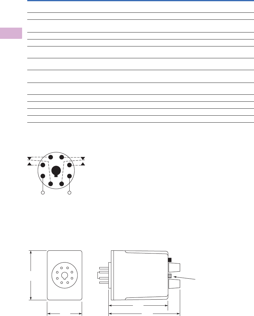
V5-T5-38 Volume 5—Motor Control and Protection CA08100006E—April 2014 www.eaton.com
5
5
5
5
5
5
5
5
5
5
5
5
5
5
5
5
5
5
5
5
5
5
5
5
5
5
5
5
5
5
5.1
Motor Protection and Monitoring
Monitoring Relays
Technical Data and Specifications
D65VWP and D65VWPK Series, Voltage Band Relays
Wiring Diagram
Wiring for 8-Pin Socket
Dimensions
Approximate Dimensions in Inches (mm)
D65VWP and D65VWPK Series, Voltage Band Relays
Description Specification
Voltage tolerance +25%/–50% of nominal voltage; AC voltages are 50/60 Hz
No separate supply (input) voltage is required
Load (burden) Less than 3 VA
Voltage settings
Overvoltage 100–125% of nominal voltage
Undervoltage 75–100% of nominal voltage
Temperature –20° to 131°F (–28° to 55°C)
Indicator LED Red steady when relay is energized;
green when relay is OFF
Reset Automatic
Contact Eaton for information on how to order a unit with manual reset
Response times
Operate 500 ms
Release Fixed 500 ms (D65VWP Series)
Adjustable 0.5–10 seconds (D65VWKP Series)
Output contacts 10A resistive at 240 Vac/30 Vdc, 1/2 hp at 240 Vac (NO), 1/3 hp at 240 Vac (NC)
Mechanical life 10,000,000 operations
Electrical life 100,000 operations
Transient protection 10,000 volts for 20 microseconds
Monitored
Voltage
1
(DC)+
L1
(DC)−
L2
8
4
36
27
5
2.4
(60)
1.7
(43)
2.9
(74) 3.5
(89)
D65VWKP
Only
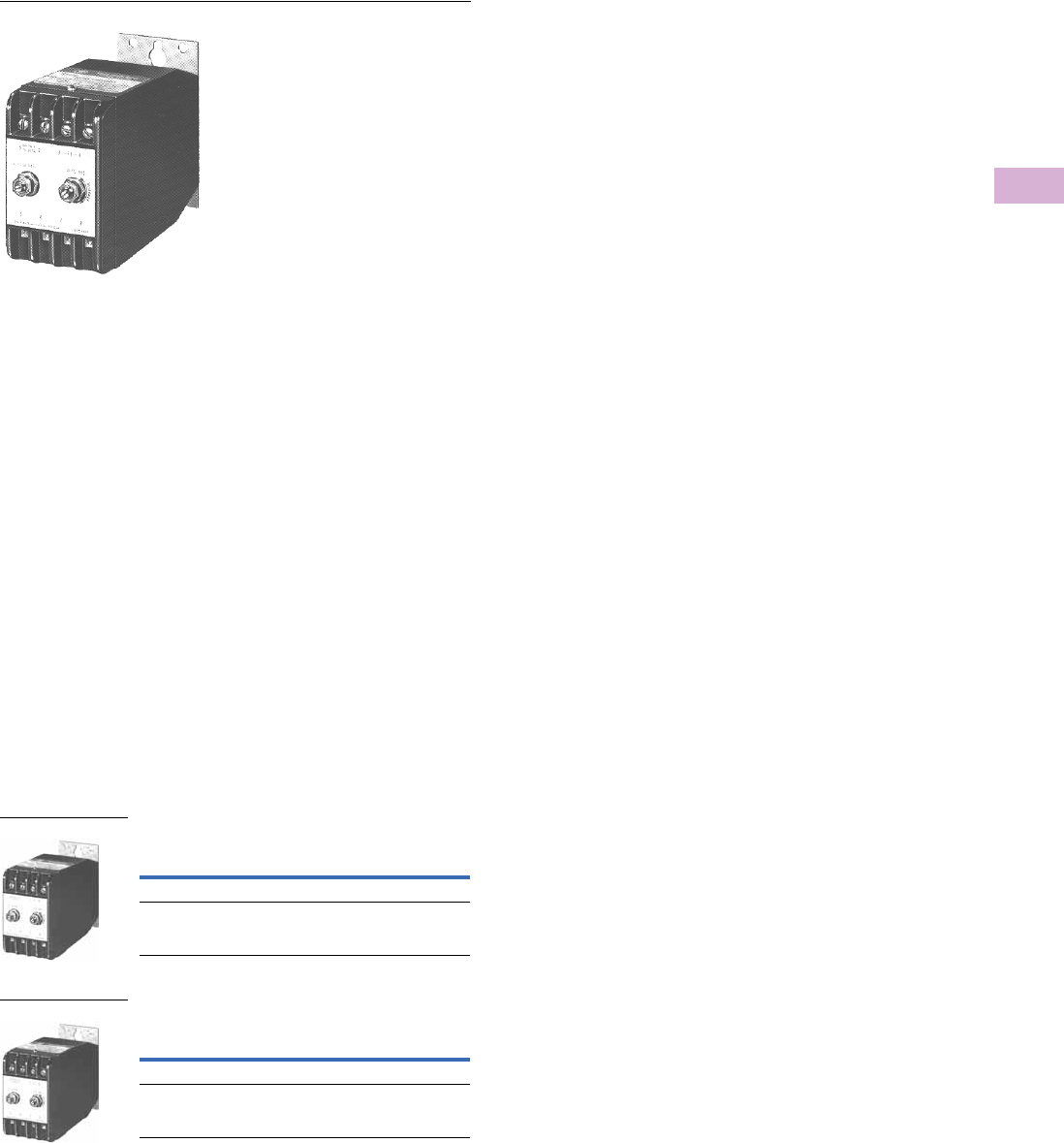
Volume 5—Motor Control and Protection CA08100006E—April 2014 www.eaton.com V5-T5-39
5
5
5
5
5
5
5
5
5
5
5
5
5
5
5
5
5
5
5
5
5
5
5
5
5
5
5
5
5
5
5.1
Motor Protection and Monitoring
Monitoring Relays
VSR Series—Solid-State, Single-Phase Voltage Sensing
Contents
Description Page
Current Monitoring Relays . . . . . . . . . . . . . . . . . . . V5-T5-3
Phase Monitoring Relays . . . . . . . . . . . . . . . . . . . . V5-T5-16
Voltage Monitoring Relays
Product Selection Guide . . . . . . . . . . . . . . . . . . V5-T5-29
D65VMRP and D65VMKP Over/Undervoltage
Relays (Fixed Time Delay) . . . . . . . . . . . . . . . V5-T5-30
D65VAP and D65VAKP Over/Undervoltage
Relays (Adjustable Time Delay) . . . . . . . . . . . V5-T5-33
D65VWP and D65VWKP Voltage Band
Relays . . . . . . . . . . . . . . . . . . . . . . . . . . . . . . V5-T5-36
VSR Series—Solid-State, Single-Phase
Voltage Sensing
Product Selection . . . . . . . . . . . . . . . . . . . . V5-T5-39
Technical Data and Specifications . . . . . . . . V5-T5-40
Dimensions . . . . . . . . . . . . . . . . . . . . . . . . . V5-T5-41
Ground Fault Monitoring Relays . . . . . . . . . . . . . . V5-T5-42
VSR Series—Solid-State, Single-Phase Voltage Sensing
Product Description
The Catalog Number VSR
voltage sensing relays are
highly accurate, solid-state,
AC voltage sensing devices
available in both overvoltage
and undervoltage types. They
include built-in locking shaft
potentiometers for voltage
and differential adjustment.
Relay circuit boards are
conformal contact for
environment-free operation.
Input is transformer isolated
from solid-state output
contact. Mounting
dimensions are the same as
Catalog Number BF relays.
Features
●Same base plate as
Catalog Number BF relay,
mounts in same area
●Captive, pressure clamp
terminals—accept 1 or 2
solid or stranded 14 AWG
or smaller wires
●Adjustment potentiometer
with locking shafts—
provides shock-proof
adjustment
●Conformal coated printed
circuit board—protects
relay against shock,
moisture, dirt and other
environmental hazards
●Built-in surge protection—
protects internal solid-state
contact from damage due
to load and line transients
Product Selection
When Ordering, Specify
●Catalog Number of Basic Relay
Voltage Sensing Relays—Undervoltage
Voltage Sensing Relays—Overvoltage
Voltage Range
Catalog
Number
70–120 Vac VSRUA
200–280 Vac VSRUB
Voltage Range
Catalog
Number
100–140 Vac VSROA
200–280 Vac VSROB
VSRU_
VSRO_
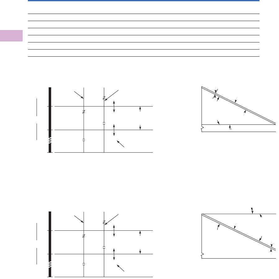
V5-T5-40 Volume 5—Motor Control and Protection CA08100006E—April 2014 www.eaton.com
5
5
5
5
5
5
5
5
5
5
5
5
5
5
5
5
5
5
5
5
5
5
5
5
5
5
5
5
5
5
5.1
Motor Protection and Monitoring
Monitoring Relays
Technical Data and Specifications
VSR Series—Solid-State, Single-Phase Voltage Sensing
Operating Curves—Undervoltage Relay
Solid-state NO contact closes when voltage exceeds upper limit
set by voltage adjustment potentiometer. Contact remains
closed until voltage drops below the value set with differential
adjustment. Contact will not reclose until voltage once again
exceeds upper limit.
Operating Curves—Overvoltage Relay
Providing a minimum of 60V input is present, solid-state contact
is NC. Differential adjustment sets upper limit where contact will
open. After opening, contact will remain open until voltage drops
below value set with voltage adjustment potentiometer.
Relay Pick-Up and Drop-Out Voltage
Ranges—Undervoltage
Relay Pick-Up and Drop-Out Voltage
Ranges—Overvoltage
Notes
1Can initiate a Size 4 motor starter.
212A rms maximum inrush for three cycles. If inrush current is greater than 12A and relay is
operated more than 30 times per minute, derating may be necessary. If surge current is 12A
or less, no derating is necessary. If currents exceeding these ratings could occur,
a series fuse having an I2t rating equal to 3A squared seconds is recommended.
3For operation in a higher ambient temperature, derating may be necessary.
Description Specification
Electrical ratings
Operating voltage range 70–140 Vac, 200–280 Vac 3 VA burden
Variable differential range See Operating Curves below
Repeatability ±0.5 Vac of setting
Solid-state contacts 2A continuous maximum inductive or resistive, 132 Vac maximum 12
Ambient temperature range 3–4° to 140°F (–20° to 60°C)
Open contact leakage current 3 mA maximum
Closed contact voltage drop 3 Vac maximum
200 Volts
Minimum
70 Volts 280 Volts
120 Volts
to
Line Volts
to
Relay Contact
Status Dropping
Voltage
Relay Contact Status
Rising Voltage
CW
CCW
CCW
CW
Voltage Adjustment
(Pickup)
Differential
Adjustment
(Dropout)
1 Volt Minimum
Recommended
Differential
Maximum
0 Volts Potentiometer Rotation
200 Volts
Minimum
70 Volts 280 Volts
120 Volts
to
Line Volts
to
Relay Contact
Status Dropping
Voltage
Relay Contact Status
Rising Voltage
CW
CCW
CCW
CW
Voltage Adjustment
(Pickup)
Differential
Adjustment
(Dropout)
1 Volt Minimum
Recommended
Differential
Maximum
0 Volts Potentiometer Rotation
Dropout Voltage
(Variable Between
70 Vac and
1 Vac Less Than
Pickup Voltage)
Diff. Adj. Max. CW
1 Vac
Diff. Adj.
Max. CCW
050
% Rotation Voltage Adj. Control
100
120
or 280
70
or 200
Line Voltage (VA-C)
on Terminals 1 & 2
Pickup Voltage (Variable
from 70 to 120 Vac
or 200 to 280 Vac)
Diff. Adj. Max. CW
Pickup Voltage
(Variable from
100 to 137 Vac
or 200 Vac)
Dropout Voltage
(Variable Between
3 Vac More Than
Pickup Voltage and
140 Vac)
050
% Rotation Voltage Adj. Control
100
140
or 280
100
or 200 3 Vac
Diff. Adj.
Max. CCW
Line Voltage (VA-C)
on Terminals 1 & 2
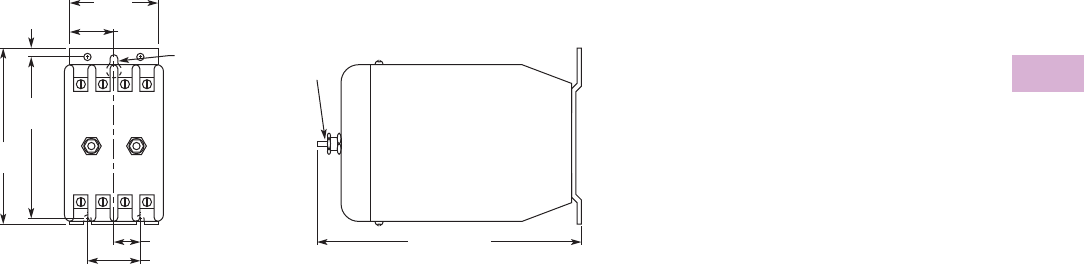
Volume 5—Motor Control and Protection CA08100006E—April 2014 www.eaton.com V5-T5-41
5
5
5
5
5
5
5
5
5
5
5
5
5
5
5
5
5
5
5
5
5
5
5
5
5
5
5
5
5
5
5.1
Motor Protection and Monitoring
Monitoring Relays
Dimensions
Approximate Dimensions in Inches (mm)
VSR Series—Solid-State, Single-Phase Voltage Sensing
4.69 (119.1)
0.5 (12.7)
Catalog Number VSR
3.13
(79.5)
1 (25.4)
2.81
(71.4)
0.16
(4.1)
1.63
(41.4)
0.81
(20.6)
Voltage Input:
Terminals 1 and 2
Solid-State Output:
Terminals 3 and 4
0.17 (4.3) Dia.
3 Mtg. Slots Lock
Nut
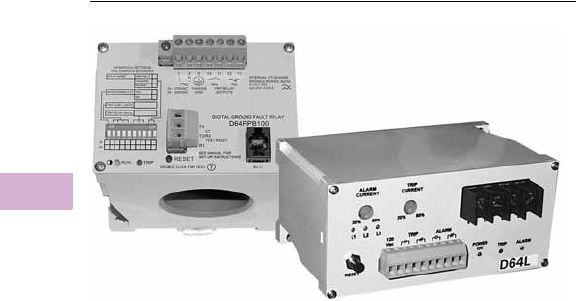
V5-T5-42 Volume 5—Motor Control and Protection CA08100006E—April 2014 www.eaton.com
5
5
5
5
5
5
5
5
5
5
5
5
5
5
5
5
5
5
5
5
5
5
5
5
5
5
5
5
5
5
5.1
Motor Protection and Monitoring
Monitoring Relays
Ground Fault Relays and Monitors
Contents
Description Page
Current Monitoring Relays . . . . . . . . . . . . . . . . . . V5-T5-3
Phase Monitoring Relays . . . . . . . . . . . . . . . . . . . V5-T5-16
Voltage Monitoring Relays . . . . . . . . . . . . . . . . . . V5-T5-28
Ground Fault Relays and Monitors
D64R Series—Digital Ground Fault Relays . . . . V5-T5-43
D64L Series—Ground Fault Monitors . . . . . . . V5-T5-53
Product Overview
D64R Series—
Digital Ground Fault Relays
The new D64R digital
ground fault relays are
microprocessor-based
and replace the previous
generation of analog-based
devices.
Microprocessor-based D64R
GFRs combine more
selectable features into a
single model, which makes
easier model selection and
reduces spares inventory
requirements.
These devices are designed to
provide reliable detection of
ground fault conditions on
three-phase AC resistance
grounded or solidly grounded
electrical distribution systems.
D64L Series—
Ground Fault Monitors
Type D64L ground fault
monitors are designed to
monitor ungrounded supplies
on three-phase AC power
systems up to 600V. If an
insulation fault develops
anywhere on the system
between the source and the
load, the D64L will detect it
and give an alarm or trip,
depending on the adjustable
field settings selected.
The D64L is ideally suited for
systems supplied from the
secondary of either an
ungrounded delta or an
ungrounded wye connected
transformer.
Because D64L has high
immunity from the effects of
voltage transients and cable
capacitance, it may be applied
in automotive, sub-sea,
mobile lighting, portable
generators, sensitive
equipment and other
installations where
ungrounded systems are
used extensively.
The user is able to individually
set the alarm level and the
trip level from 20%–80% of
the maximum leakage current
limit of the D64L selected.
Any leakage current above
the alarm level will activate
the alarm relay and light the
alarm LED. Should the
leakage current rise above
the trip level, the trip relay
and trip LED will activate.
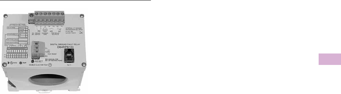
Volume 5—Motor Control and Protection CA08100006E—April 2014 www.eaton.com V5-T5-43
5
5
5
5
5
5
5
5
5
5
5
5
5
5
5
5
5
5
5
5
5
5
5
5
5
5
5
5
5
5
5.1
Motor Protection and Monitoring
Monitoring Relays
D64R Series—Digital Ground Fault Relays
Contents
Description Page
Current Monitoring Relays . . . . . . . . . . . . . . . . . . . V5-T5-3
Phase Monitoring Relays . . . . . . . . . . . . . . . . . . . . V5-T5-16
Voltage Monitoring Relays . . . . . . . . . . . . . . . . . . . V5-T5-28
Ground Fault Relays and Monitors
D64R Series—Digital Ground Fault Relays
Features . . . . . . . . . . . . . . . . . . . . . . . . . . . V5-T5-44
Options . . . . . . . . . . . . . . . . . . . . . . . . . . . . V5-T5-44
Standards and Certifications . . . . . . . . . . . . V5-T5-44
Product Selection . . . . . . . . . . . . . . . . . . . . V5-T5-45
Accessories . . . . . . . . . . . . . . . . . . . . . . . . . V5-T5-46
Technical Data and Specifications . . . . . . . . V5-T5-47
Wiring Diagrams . . . . . . . . . . . . . . . . . . . . . V5-T5-48
Dimensions . . . . . . . . . . . . . . . . . . . . . . . . . V5-T5-50
D64L Series—Ground Fault Monitors . . . . . . . V5-T5-53
D64R Series—Digital Ground Fault Relays
Product Description
The new D64R digital
ground fault relays are
microprocessor-based
and replace the previous
generation of analog-based
devices.
Microprocessor-based D64R
GFRs combine more
selectable features into a
single model, which makes
easier model selection and
reduces spares inventory
requirements.
These devices are designed to
provide reliable detection of
ground fault conditions on
three-phase AC resistance
grounded or solidly grounded
electrical distribution systems.
Application Description
D64R ground fault relays
feature adjustable trip
settings for both trip current
and trip time. This allows the
user to set the ground fault
trip current just above the
“charging” current of the
system. This prevents
nuisance tripping and
provides meaningful
protection of additional
ground fault leakage currents.
Every system has a
“charging” current that can
cause nuisance tripping if the
trip current is set too low. The
“charging” current is caused
by the capacitance-to-ground
effect of phase conductors in
a system and will vary
depending on:
●The overall length of the
cables
●The types of loads
●The quality of the
insulation on the phase
conductors
●Surrounding equipment
grounding, cable trays,
junction boxes, and so on
●Type and size of
transformer
A “rule-of-thumb” for systems
600V and lower: the “charging”
current is 0.5A per 1000 kVA of
transformer capacity.

V5-T5-44 Volume 5—Motor Control and Protection CA08100006E—April 2014 www.eaton.com
5
5
5
5
5
5
5
5
5
5
5
5
5
5
5
5
5
5
5
5
5
5
5
5
5
5
5
5
5
5
5.1
Motor Protection and Monitoring
Monitoring Relays
Features
Standard Models
●Built-in current sensor
(zero sequence CT)
●Run and trip indicating
LEDs
●Built-in harmonic filtering
for variable frequency
drives or standard 50/60 Hz
applications (see Page
V5-T5-47 for frequency
response range)
●DIN rail or panel mounting
●Rugged epoxy
encapsulated construction
●Pull-apart terminal block
connectors
●Form “Z” (4 terminal) NO
and NC output contacts,
5 amps at 250 Vac
●Pulsed (trip) auto reset
mode
The pulsed (trip) auto reset
mode is designed for
applications where the output
relay is operating a shunt trip
device. The D64R relay resets
automatically, three seconds
after the ground fault current
is interrupted by the tripping
action of the circuit breaker.
This opens the output contact
wired to the shunt trip coil
and prevents damage to the
internal mechanism of the
circuit breaker in the event
that the operator tries to
reset the circuit breaker.
●Suitable for use on 600V
systems—may be applied
on higher voltages by using
separate CTs with power
conductors insulated for
the system voltage
●Built-in test circuitry—no
external power or
additional wiring is
necessary—tests trip time
and current settings
●Communications port
(standard RJ-10 jack) for
connection to optional
remote display (D64D1)
and door mounted
units (on D64RPB100
models only)
●Fail-safe selectable
mode (on D64RPB100
models only)
In the fail-safe mode, the
relay is energized when
control voltage is applied and
will trip when either:
●a ground fault trip is
detected or,
●there is a loss of control
power.
Service Protection Models
●Service protection models
require C311CT
10,000:1 ratio CTs
●Trip current range of 50 to
1200A
●Green LED indicates
“Power On”
●Circuit breaker toggle
position indicates
“Normal” or “Tripped”
condition
●Form “C” (3 terminal)
NO-NC output contacts,
3 amps at 250 Vac
●Frequency response range
of 40 to 200 Hz
●Zone interlocking feature
with green LED to indicate
“Grading Input Active” and
DIP switch array for zone
grading backup delay and
block signal override (on
D64RPBH15 model only)
●Test button to invoke test
at 20A trip current—tests
external CT, electronics and
circuit breaker trip
●Fail-safe selectable mode
(see above for description)
●Inhibit selectable mode—
this allows the relay to
differentiate between
normal ground fault trip
levels and short circuit
conditions
The trip inhibit function is
useful when the relay is being
used to trip a contactor or
motor starter on a solidly
grounded system. Under a
bolted fault condition, the relay
would trip and could cause the
contactor or motor starter to
interrupt the high fault current
with harmful results. By
inhibiting the trip, the ground
fault relay will not trip on
bolted faults and will allow the
upstream protective device to
clear the fault instead.
●Through-the-door or rear
panel mounting
Options
●Other ranges of trip
currents and times
●Fixed trip current and times
●Other control voltages
●Custom packaging for
volume OEM requirements
●Separate outputs for
alarming vs trip
●Relays for neutral
grounding resistance
monitoring
●Relays for ground fault
detection on DC power
systems
●Other sizes of current
transformers
Standards and Certifications
●UL 1053
●Ground Fault Sensing
and Relaying Equipment,
Class 1
(UL File # E195341)
●CSA® C22.2 No. 144-M91
●Ground Fault Circuit
Interrupters
(CSA File # 700103)
●CE Mark—Declaration of
Conformity
●IEC 60755
●General Requirements
for residual current
operated protective
devices
●EN 50081-1
●Electromagnetic
compatibility (radiated
emission), “household”
directive
D64R ground fault relays
are UL listed as Class 1
devices designed to protect
electrical equipment against
extensive damage from
arcing ground faults.
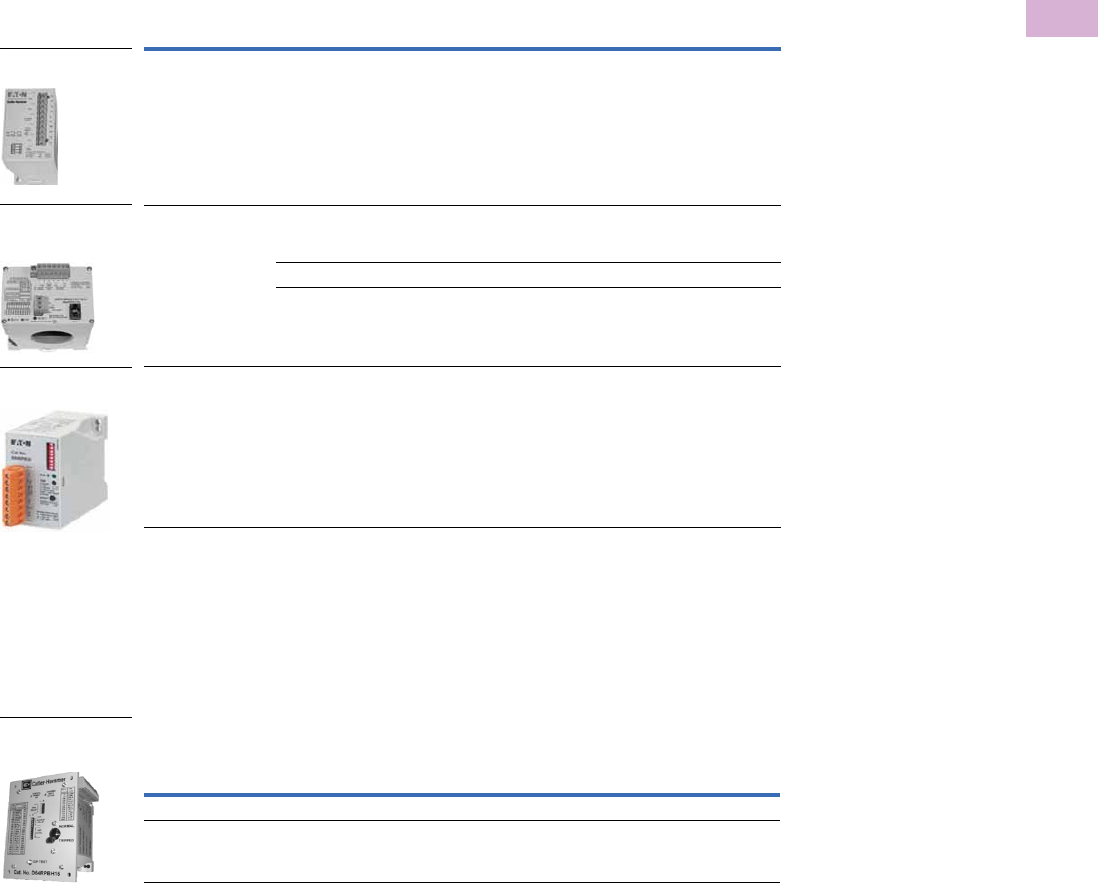
Volume 5—Motor Control and Protection CA08100006E—April 2014 www.eaton.com V5-T5-45
5
5
5
5
5
5
5
5
5
5
5
5
5
5
5
5
5
5
5
5
5
5
5
5
5
5
5
5
5
5
5.1
Motor Protection and Monitoring
Monitoring Relays
Product Selection
Standard Models
When Ordering, Specify
●Catalog number of relay from tables
●Catalog number of zero sequence current transformers, if or when required,
remote digital display or remote indicator units
Ground Fault Relay with Built-In Current Sensor
Service Protection Models
When Ordering, Specify
●Catalog number of relay from tables
●Catalog number of zero sequence current transformers, if or when required,
remote digital display or remote indicator units
Ground Fault Relay
Notes
1 Maximum allowable continuous current through built-in CT is 100 amps.
2 For 500:1 ratio CTs, select from Protective Relays in Volume 3—Power Distribution and Control Assemblies,
CA08100004E. Tab 9, section 9.3.
3 Maximum allowable continuous current through built-in CT is 200 amps.
4 For 500:5 or 5000:5 ratio CTs, select any commercially available 5 amp secondary CT with the same ratio.
5 For 10,000: 1 ratio CTs, select from Protective Relays in Volume 3—Power Distribution and Control Assemblies,
CA08100004E. Tab 9, section 9.3.
Control Power
Trip Current
Range
Current Transformer
Selection
Catalog
Number
24–240 Vac/Vdc 30 mA–6A Built-in 1.1 in CT 1
If external CT is required for specific application,
select 500:1 ratio CT 2
D64RP18
24–240 Vac/Vdc 30 mA–9A Built-in 2.0 in CT 3
If external CT is required for specific application,
select 500:1 ratio CT 2
D64RPB100_
3A–900A Select 500:5 ratio CT 4D64RPB100_
30A–9000A Select 5000:5 ratio CT 4D64RPB100_
24–240 Vac/Vdc 30 mA–9A Requires use of applicable C331CT,
see Page V5-T5-46.
D64RPB30
D64RP18
without Plug-In
D64RPB100
Full-Featured Ground
Fault Relay
D64RPB30
without Internal CT
Control
Power
Zone
Interlocking
Feature
Trip Current
Range
Current Transformer
Selection
Catalog
Number
120 Vac No 50A–1200A Select 10,000:1 ratio CT 5D64RPBH13
120 Vac Yes 50A–1200A Select 10,000:1 ratio CT 5D64RPBH15
D64RPBH15 Ground
Fault Relay with Zone
Interlocking
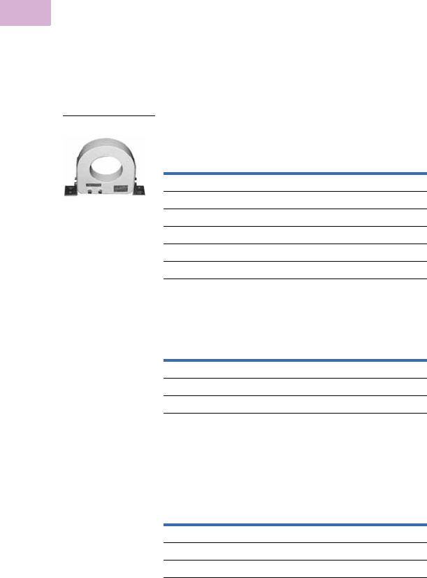
V5-T5-46 Volume 5—Motor Control and Protection CA08100006E—April 2014 www.eaton.com
5
5
5
5
5
5
5
5
5
5
5
5
5
5
5
5
5
5
5
5
5
5
5
5
5
5
5
5
5
5
5.1
Motor Protection and Monitoring
Monitoring Relays
Accessories
Zero Sequence Current
Transformers
●A complete size range of
zero sequence CTs
designed specifically for
use with D64R relays
provide excellent coupling
to the monitored circuit.
This means accurate
ground fault leakage
current detection over the
full setting range of the relay
with no saturation
●Built-in back-to-back zeners
across the output terminals
of all 500:1 and 10,000:1
CTs provide personnel
safety should the secondary
circuit be opened
●Rectangular split core CTs
make retro-fitting easy
●All CTs are epoxy potted,
panel mounted and come
with either secondary
screw terminals or
threaded studs
●The core is very high grade
silicon iron to give superior
coupling characteristics
and to withstand high
shock and vibration
●All CTs are 600 Volt class.
They may be used on
higher voltage circuits
provided that power
conductors are insulated
for the system voltage
Zero Sequence Current Transformers for D64RP18 and D64RPB100 Relay 123
To r o i d a l
Split Core (Rectangular/Square)
Zero Sequence Current Transformers for D64RPBH13 and D64RPBH15 Relays
To r o i d a l
Notes
1 D64RP18 relays use 500:1 ratio CTs if needed.
2 D64RPB100 relays can use 500:1 ratio CTs when needed for 30 mA–9A,
500:5 ratio for 3A–900A and 5000:5 ratio for 30A–9000A trip current ranges.
3 For 500:5 or 5000:5 ratio CTs, select any commercially available 5 Amp
secondary CT with the same ratio.
4 The maximum allowable continuous current through CTs is 1000A.
5 The maximum allowable continuous current through 10,000:1 ratio CTs is 10,000A.
Description/Window Size
Ratio 500:1 CTs 4
Catalog
Number
1.1 in (28 mm) C311CT8
1.8 in (46 mm) C311CT1
2.5 in (65 mm) C311CT9
3.5 in (90 mm) C311CT2
5.7 in (144 mm) C311CT5
9.5 in (240 mm) C311CT6
Description/Window Size
Ratio 500:1 CTs 4
Catalog
Number
5.9 x 6.7 in (150 x 170 mm) C311CT3
4.0 x 13.8 in (100 x 350 mm) C311CT4
11.8 x 11.8 in (300 x 300 mm) C311CT7
Description/Window Size
Ratio 10,000:1 CTs 5
Catalog
Number
2.5 in (65 mm) C311CT11
5.7 in (144 mm) C311CT12
9.5 in (240 mm) C311CT13
C311CT9
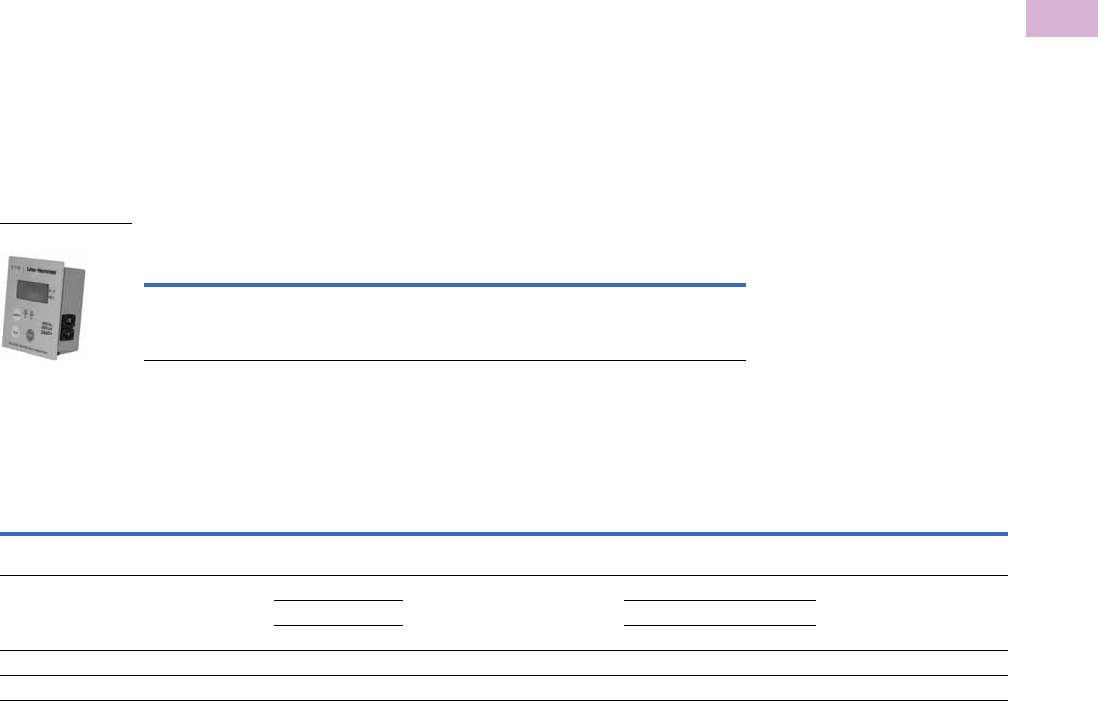
Volume 5—Motor Control and Protection CA08100006E—April 2014 www.eaton.com V5-T5-47
5
5
5
5
5
5
5
5
5
5
5
5
5
5
5
5
5
5
5
5
5
5
5
5
5
5
5
5
5
5
5.1
Motor Protection and Monitoring
Monitoring Relays
D64D1 Digital Display Unit
The D64D1 digital display unit
is connected to the
D64RPB100 by up to 30 ft
(10m) of standard four-wire
telephone type cable. It is
supplied with door-mounting
hardware. It provides the
following remote indications
and functions:
●Continuous reading of
actual ground fault current,
employing auto ranging
●Display of the pre-trip
ground fault current, after a
trip has occurred (flashing
display)
●Display of the trip current
setting, after a Test Trip has
been activated
●Green RUN LED, red
TRIP LED
●TEST and RESET
pushbuttons. The RESET
button must be held
pressed before the TEST is
pressed to invoke the test
procedure. The function of
this button can be enabled/
disabled by inserting the
interconnecting cable from
the D64RPB100 relay into
one of two sockets, TEST
ON or TEST OFF, on the
right side of the display
●Pushing VERIFY
pushbutton shows if
D64RPB100 tripped due to
a ground fault prior to loss
of its control voltage—red
TRIP LED lights, or if there
was no ground fault trip—
green RUN LED lights. This
indication will remain
available for at least ten
hours
●The Numerical LCD window
displays actual ground fault
current in amps. When a
5000:5 ratio interposing CT
is used, all displayed values
are to be interpreted as kA
rather than amps
Remote Display Unit for D64RPB100
Technical Data and Specifications
D64R Series—Digital Ground Fault Relays
Note
1With zone interlocking feature.
Description
Catalog
Number
Remote digital display with numerical LCD, RUN and TRIP LEDs,
TEST,
RESET and VERIFY
pushbuttons: C/W 3 ft (1m) of cable.
D64D1
Catalog
Number
Control
Power
(Volts)
Frequency
Response
(Hz)
Trip Current Range Trip Time Delay Range Built-In
Current
Sensor
External Current Transformer Test/Reset Provision
Min. Max. Min. Max. Required Ratio
Pushbutton
on Cover Remote
D64RP18 24–240 Vac/Vdc
non-isolated
45–450 Hz 30 mA 6A 20 ms 500 ms 1.1 in Optional 500:1 No Pushbutton
D64RPB100 24–240 Vac/Vdc
isolated
45–450 Hz 30 mA 9A 20 ms 5 sec 2.0 in Optional 500:1 Yes Pushbutton or
RJ-11
Communications
port
3A 900A Required 500:5
30A 9000A Required 5000:5
D64RPBH13 120 Vac 45–200 Hz 50A 1200A 35 ms 1 sec None Required 10000:1 Yes Pushbutton
D64RPBH15 1 120 Vac 40–200 Hz 50A 1200A 35 ms 1 sec None Required 10000:1 Yes Pushbutton
D64D1
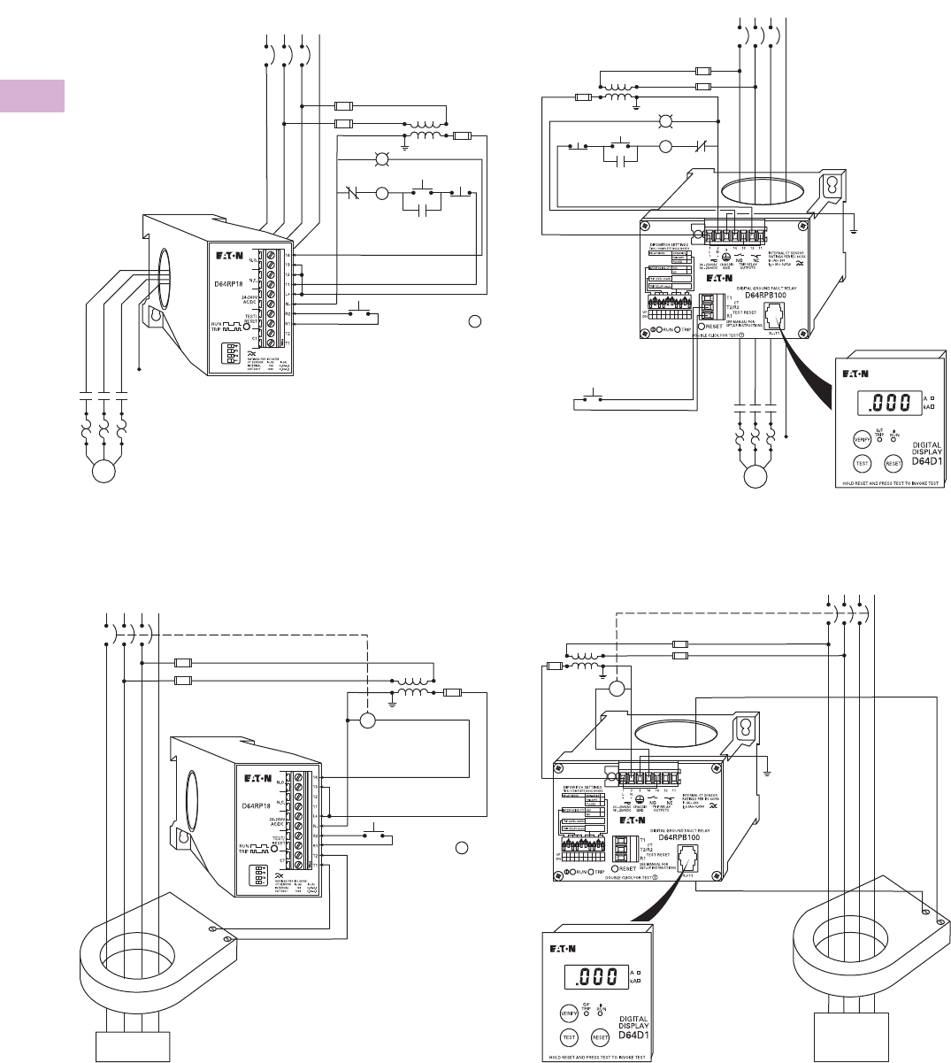
V5-T5-48 Volume 5—Motor Control and Protection CA08100006E—April 2014 www.eaton.com
5
5
5
5
5
5
5
5
5
5
5
5
5
5
5
5
5
5
5
5
5
5
5
5
5
5
5
5
5
5
5.1
Motor Protection and Monitoring
Monitoring Relays
Wiring Diagrams
Typical Field Connection of D64RP18 Using Built-In Current
Tr a n s fo r m e r
Typical Field Connection of D64RP18 with External 500:1
Current Transformer and Pulsed Trip-Auto Reset
Typical Field Connection of D64RPB100 Using Built-In
Current Transformer and Remote Test/Reset
Typical Field Connection of D64RPB100 with Interposing
500:5 Current Transformer, Pulsed Trip-Auto Reset for Shunt
Trip Breaker
1M
O/L
GROUNDED SYSTEMS
– 1-Phase 2-Wire
– 1-Phase 3-Wire
– 3-Phase 3-Wire
– 3-Phase 4-Wire
Power
Source
Current Carrying
Neutral, When Used
R
1M
1M
START STOP
O/L
Trip
Reset “Double
Click for Test” T
“Double Click
for Test”
(Pulsed
Trip-Auto Reset)
T
Power
Source
GROUNDED SYSTEMS
– 1-Phase 2-Wire
– 1-Phase 3-Wire
– 3-Phase 3-Wire
– 3-Phase 4-Wire
Current Carrying
Neutral, When Used
LOAD
500:1 C311CT
SERIES
ST
GF Trip Range:
30 mA to 9A.
Chassis
Close to
D64RPB100
Power Source
Current Carrying
Neutral, When Used
1M
START
STOP
Remote
Test/Reset
1M
O/L
R
Trip
1M
O/L
GROUNDED SYSTEMS
– 1-Phase 2-Wire
– 1-Phase 3-Wire
– 3-Phase 3-Wire
– 3-Phase 4-Wire
Current
Carrying
Neutral,
When Used
Power Source
GF Trip Range:
3A to 900A
Chassis
Close to
D64RPB100
LOAD
INTERPOSING 500:5
ST
GROUNDED
SYSTEMS
– 1-Phase 2-Wire
– 1-Phase 3-Wire
– 3-Phase 3-Wire
– 3-Phase 4-Wire
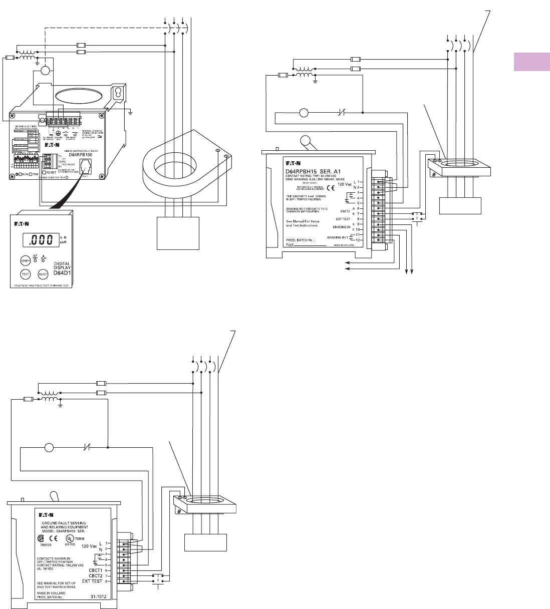
Volume 5—Motor Control and Protection CA08100006E—April 2014 www.eaton.com V5-T5-49
5
5
5
5
5
5
5
5
5
5
5
5
5
5
5
5
5
5
5
5
5
5
5
5
5
5
5
5
5
5
5.1
Motor Protection and Monitoring
Monitoring Relays
Typical Field Connection of D64RPB100 with External 500:1
Current Transformer (C311CT Series) Pulsed Trip-Auto Reset
for Shunt Trip Breaker
D64RPBH13 Typical Field Connections
D64RPBH15 Typical Field Connection
GROUNDED SYSTEMS
– 1-Phase 2-Wire
– 1-Phase 3-Wire
Current
Carrying
Neutral,
When Used
Power Source
GF Trip
Range:
30 mA to 9A
Chassis
Close to
D64RPB100
LOAD
500:1 C311CT SERIES
ST
– 3-Phase 3-Wire
– 3-Phase 4-Wire
C311CT
Current
Transformer
CB Coil
Clearing
Contact
Power
Source
ST
GROUNDED SYSTEMS
– 1-Phase 2-Wire
– 1-Phase 3-Wire
– 3-Phase 3-Wire
– 3-Phase 4-Wire
LOAD
Current Carrying
Neutral, When Used
C311CT
Current
Transformer
CB Coil
Clearing
Contact
Power
Source
ST
GROUNDED SYSTEMS
– 1-Phase 2-Wire
– 1-Phase 3-Wire
– 3-Phase 3-Wire
– 3-Phase 4-Wire
LOAD
Current Carrying
Neutral, When Used
To
Upstream
Zone From Downstream Zone
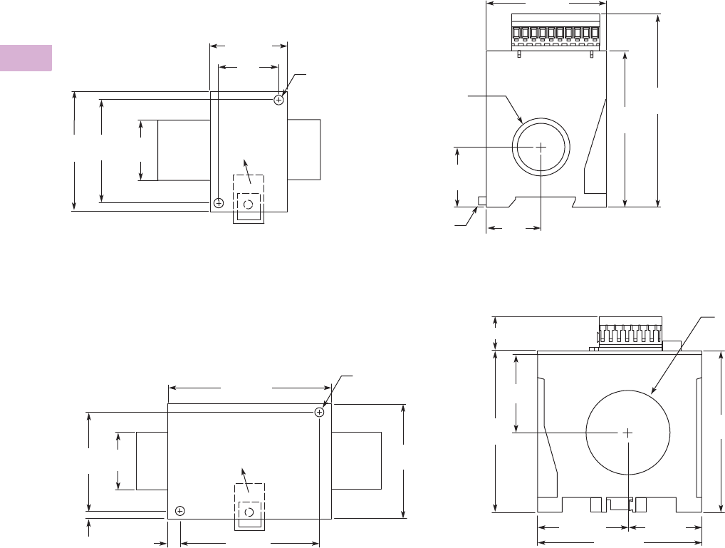
V5-T5-50 Volume 5—Motor Control and Protection CA08100006E—April 2014 www.eaton.com
5
5
5
5
5
5
5
5
5
5
5
5
5
5
5
5
5
5
5
5
5
5
5
5
5
5
5
5
5
5
5.1
Motor Protection and Monitoring
Monitoring Relays
Dimensions
Approximate Dimensions in Inches (mm)
D64RP18
D64RPB100
35 mm
DIN Rail
DIN Rail
Release
Clip
Rear Panel Mounting DIN Rail or Two Screw Right Hand Side View
2.76 (70)
1.26
(32)
1.77 (45)
1.38
(35)
2.36
(60)
2.76
(70) 1.38
(35)
Mounting Hole
0.22 (5.5) Dia.
1.10 (28)
Dia.
4.43
(112.5)
1.38
(35)
3.58
(91)
Rear Panel Mounting DIN Rail or Two Screw Bottom Side View
3.94
(100)
2.17 (55)
35 mm
DIN Rail
Mounting Hole
0.22 (5.5) Dia.
DIN Rail
Release
3.94 (100)
2.36
(60)
1.38
(35)
2.76
(70)
0.20 (5)
2.00
(50.8)
Dia.
3.35 (85)
0.30 (7.5)
1.97
(50)
4.02
(102)
0.82 (21)
1.77 (45)
3.94 (100)
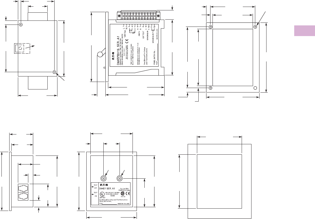
Volume 5—Motor Control and Protection CA08100006E—April 2014 www.eaton.com V5-T5-51
5
5
5
5
5
5
5
5
5
5
5
5
5
5
5
5
5
5
5
5
5
5
5
5
5
5
5
5
5
5
5.1
Motor Protection and Monitoring
Monitoring Relays
Approximate Dimensions in Inches (mm)
D64RPBH13 and D64RPBH15
D64D1 and D64D2
Through-the-Door Mounting
4.92
(125)
0.30 (7.5) Mounting Hole
0.158 (4) Dia.
4.01
(102)
Door
Cutout
4.33
(110)
3.74 (95)
0.16 (4)
0.30
(7.5)
0.16 (4)
3.15 (80)
2.83 (72)
Door Cutout
Right Side View
4.14 (105)
0.59
(15)
3.94 (100)
4.92
(125) 3.94
(100)
0.73
(18.4)
35 mm
DIN Rail
Rear Panel Mounting DIN Rail or Two Screw
Mounting Hole
0.22 (5.5) Dia.
DIN Rail
Release 3.94
(100)
2.36 (60)
1.38
(35)
2.76 (70)
0.20 (5)
3.35
(85)
0.30
(7.5)
3.27
(83)
Panel
Cutout
2.72 (69)
Panel Cutout
Rear View Through-the-Panel MountingRight Side View
1.02
(26)
0.83
(21)
2.68 (68)
3.19 (81)
0.41
(10.5)
1.46
(37)
3.27
(83)
0.31
(8) 3.74
(95)
1.82
(46.2)
M5
M5
3.27
(83)
3.74
(95)
1.50
(38)
1.38
(35)
0.94
(24)
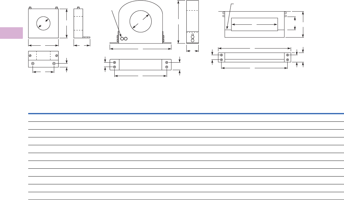
V5-T5-52 Volume 5—Motor Control and Protection CA08100006E—April 2014 www.eaton.com
5
5
5
5
5
5
5
5
5
5
5
5
5
5
5
5
5
5
5
5
5
5
5
5
5
5
5
5
5
5
5.1
Motor Protection and Monitoring
Monitoring Relays
Approximate Dimensions in Inches (mm)
C311CT Series
Catalog
Number Figure
Wide
A
High
B
Deep
C
Mounting
D
Mounting
EFGH
C311CT1 A 3.35 (85) 3.35 (85) 1.57 (40) 0.98 (25) 0.39 (10) 1.81 (46) — —
C311CT2 B 7.30 (185) 5.50 (140) 1.20 (30) 6.42 (163) 0.59 (15) 3.54 (90) — 0.89 (22.5)
C311CT3 C 13.58 (345) 8.75 (222) 1.57 (40) 12.80 (325) 0.59 (15) 6.70 (170) 5.90 (150) 0.89 (22.5)
C311CT4 C 20.87 (530) 7.87 (200) 1.57 (40) 20.08 (510) 0.59 (15) 13.78 (350) 3.94 (100) 0.89 (22.5)
C311CT5 B 10.12 (257) 8.27 (210) 1.46 (37) 9.33 (237) 0.59 (15) 5.70 (145) — 0.89 (22.5)
C311CT6 B 13.86 (352) 11.89 (302) 1.46 (37) 13.07 (332) 0.59 (15) 9.45 (240) — 0.89 (22.5)
C311CT8 A 2.17 (55) 2.56 (65) 2.20 (56) 0.98 (25) 0.59 (15) 1.10 (28) — —
C311CT9 B 6.68 (167) 4.84 (123) 1.18 (30) 5.78 (147) 0.59 (15) 2.56 (65) — 0.89 (22.5)
C311CT11 B 6.68 (167) 4.84 (123) 1.18 (30) 5.78 (147) 0.59 (15) 2.56 (65) — 0.89 (22.5)
C311CT12 B 10.12 (257) 8.27 (210) 1.85 (47) 9.33 (237) 0.59 (15) 5.70 (145) — 0.89 (22.5)
C311CT13 B 13.86 (352) 11.89 (302) 1.85 (47) 13.07 (332) 0.59 (15) 9.45 (240) — 0.89 (22.5)
BB
A C
C
Figure A Figure B Figure C
E
E
Split (If Split Core)
HC
D
F
D
A
H
E
D
A
F
FB
G
Threaded
Studs
M4 1 mm
Note: All Mounting Holes Are 0.25 (6.4) Dia.
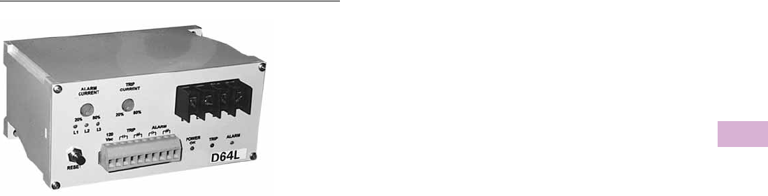
Volume 5—Motor Control and Protection CA08100006E—April 2014 www.eaton.com V5-T5-53
5
5
5
5
5
5
5
5
5
5
5
5
5
5
5
5
5
5
5
5
5
5
5
5
5
5
5
5
5
5
5.1
Motor Protection and Monitoring
Monitoring Relays
D64L Series—Ground Fault Monitors
Contents
Description Page
Current Monitoring Relays . . . . . . . . . . . . . . . . . . . V5-T5-3
Phase Monitoring Relays . . . . . . . . . . . . . . . . . . . . V5-T5-16
Voltage Monitoring Relays . . . . . . . . . . . . . . . . . . . V5-T5-28
Ground Fault Relays and Monitors
D64R Series—Digital Ground Fault Relays . . . . V5-T5-43
D64L Series—Ground Fault Monitors
Product Selection . . . . . . . . . . . . . . . . . . . . V5-T5-54
Wiring Diagram . . . . . . . . . . . . . . . . . . . . . . V5-T5-54
Dimensions . . . . . . . . . . . . . . . . . . . . . . . . . V5-T5-54
D64L Series—Ground Fault Monitors
Product Description
Type D64L ground fault
monitors are designed to
monitor ungrounded supplies
on three-phase AC power
systems up to 600V. If an
insulation fault develops
anywhere on the system
between the source and the
load, the D64L will detect it
and give an alarm or trip,
depending on the adjustable
field settings selected.
The D64L is ideally suited for
systems supplied from the
secondary of either an
ungrounded delta or an
ungrounded wye connected
transformer.
Because D64L has high
immunity from the effects of
voltage transients and cable
capacitance, it may be applied
in automotive, sub-sea,
mobile lighting, portable
generators, sensitive
equipment and other
installations where
ungrounded systems are
used extensively.
The user is able to individually
set the alarm level and the
trip level from 20%–80% of
the maximum leakage current
limit of the D64L selected.
Any leakage current above
the alarm level will activate
the alarm relay and light the
alarm LED. Should the
leakage current rise above
the trip level, the trip relay
and trip LED will activate.
Features
●Adjustable leakage current
limit setting (20 mA, 35 mA
or 50 mA). Factory set at
20 mA
●Built-in RESET button on all
models
●Selectable fail-safe/non-fail-
safe operation
●Auto reset after alarm
condition
●Selectable auto/manual
reset after trip
●Three LEDs for POWER
ON, ALARM and TRIP
●Three LEDs to indicate
which phase is faulted
●Adjustable alarm setting
20%–80% of leakage
current limit
●Adjustable trip setting
20%–80% of leakage
current limit
●70 ms response time for
alarm and trip level.
Resample time—
2 seconds
●Minimum alarm signal
duration—70 ms
●110/120V or 220/240V 50/
60 Hz control power, 4 VA
●Isolated voltage free Form
Z NO and NC contacts on
both alarm and trip relays,
5A at 250 Vac
●30A 600V screw terminals,
12 AWG capacity, for
phase and ground
connections
●10A 300V screw clamp
terminals, 12 AWG
capacity for relay outputs
and control supply
●CSA certified
●35 mm DIN rail or two
screw mounting
Suggested Fuse Block and Fuses
●DIN rail mounting
●1–C350BD3C61 600V
30A three-pole fuse
block
3–Class CC 600V 5A fuses
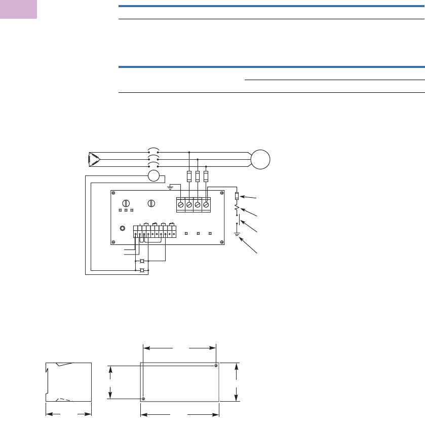
V5-T5-54 Volume 5—Motor Control and Protection CA08100006E—April 2014 www.eaton.com
5
5
5
5
5
5
5
5
5
5
5
5
5
5
5
5
5
5
5
5
5
5
5
5
5
5
5
5
5
5
5.1
Motor Protection and Monitoring
Monitoring Relays
Product Selection
When Ordering, Specify
●Catalog number of ground fault monitor
●Catalog number of fuse block and fuses as required
Fuse Block
Line Insulation Monitors
Wiring Diagram
D64L Series—Ground Fault Monitors
Dimensions
Approximate Dimensions in Inches (mm)
D64L Series—Ground Fault Monitors
Mounting Type Fuse Holder Rating Fuse Type
Catalog
Number
DIN rail 600V 30A three-pole Class CC 600V 5A WMR633G
Line Voltage Range 50/60 Hz Fuse Type
Catalog
Number
380–600V 110/120V 50/60 Hz D64L2A
220/240V 50/60 Hz D64L2B
480V
Transformer
Secondary
Load
3-Pole HRC Fusing
Alarm
Trip
120 Vac
ST
123456789
10
D64L2
Power
Ok
Trip
Current
Alarm
Current
Alarm
AlarmTrip
120 Vac
Trip
Suggested Test Circuit
1-Pole Deadfront Fuseholder
with 0.5A HRC Fuse
20% 80% 20% 80%
L1 L2
Reset
L3 GL1L2L3 Resistor – Refer to
Instruction Manual
NO Momentary Contact
Pushbutton Rated 600 Volts
Separate Connection
to Equipment Ground
3.94
(100.1)
2.36 (59.1)
5.31
(134.9)
3.00 (76.2)
6.14
(155.9)
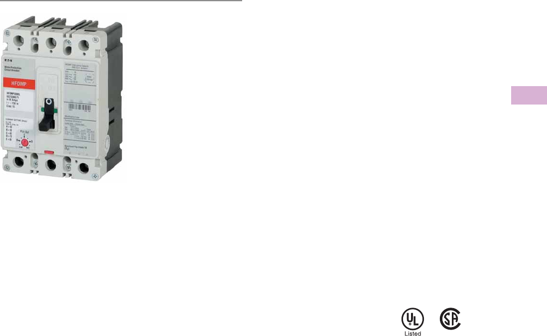
Volume 5—Motor Control and Protection CA08100006E—April 2014 www.eaton.com V5-T5-55
5
5
5
5
5
5
5
5
5
5
5
5
5
5
5
5
5
5
5
5
5
5
5
5
5
5
5
5
5
5
5.2
Motor Protection and Monitoring
Motor Protection Circuit Breakers
Motor Protection Circuit Breakers
Contents
Motor Protection Circuit Breakers (MPCB)
Motor Protection Circuit Breakers (MPCB)
Product Description
●Eliminates need for
separate overload relay
Application Description
●Can be used with
contactor to eliminate need
for overload relay and still
create manual motor
control
●Meets requirement for
motor branch protection,
including:
●Disconnecting means
●Branch circuit short
circuit protection
●Overload protection
Reference
Refer to Volume 4—Circuit Protection, CA08100005E, Tab 2,
section 2.2 for additional product information.
Motor Protection Circuit Breakers Tab Section
Product Selection . . . . . . . . . . . . . . . . . . . . . . . . . . . . . . . . 2.2
Technical Data and Specifications . . . . . . . . . . . . . . . . . . . 2.2
Features and Benefits
●Phase imbalance
protection
●Phase loss protection
●Hot trip/cold trip
●High load alarm
●Pre-detection trip relay
option
●Class 10, 15, 20, 30
protection
Standards and Certifications
●IEC 60947-2
●UL 489 100% rated
●UL 508
●CSA C22.2
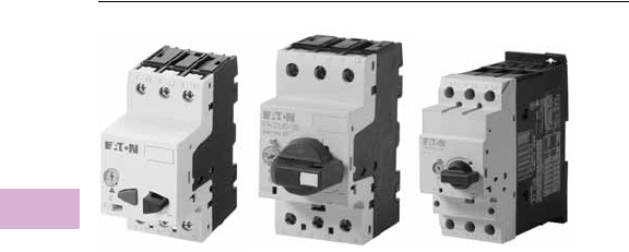
V5-T5-56 Volume 5—Motor Control and Protection CA08100006E—April 2014 www.eaton.com
5
5
5
5
5
5
5
5
5
5
5
5
5
5
5
5
5
5
5
5
5
5
5
5
5
5
5
5
5
5
5.3
Motor Protection and Monitoring
Manual Motor Protection
Manual Motor Protection
Contents
Description Page
Manual Motor Protection
Features and Benefits . . . . . . . . . . . . . . . . . . . V5-T5-57
Catalog Number Selection . . . . . . . . . . . . . . . . V5-T5-57
Reference . . . . . . . . . . . . . . . . . . . . . . . . . . . . . V5-T5-57
Manual Motor Protectors—XTPB, XTPR and XTPE
Product Description
Eaton’s new XT family of
manual motor protectors
(MMPs) features a
pushbutton or rotary ON/OFF
manual disconnect, Class 10
adjustable bimetallic overload
relay and fixed magnetic
short-circuit trip capability
in one compact unit. Two
frame sizes are available:
Frame B (45 mm) for motors
with FLA ratings up to 32A
and Frame D (55 mm) covers
motor FLA ratings up to 65A.
Application Description
The XTPB and XTPR MMPs
can be used in the following
applications.
Motor Protective Circuit Breaker
In many countries outside
of the United States and
Canada, especially Europe,
the MMPs are tested and
classified as thermal-
magnetic circuit breakers
for use in motor branch
circuits. This can be an
important consideration for all
companies who export their
equipment and machines
internationally. Both the XTPB
and XTPR conform to IEC/EN
60947 and have the CE Mark.
Manual Motor Protectors
The XTPB and XTPR MMPs
are UL listed under UL 508 as
manual motor protectors. They
provide an economical solution
for applications requiring
simple manual starting and
stopping of motors. When
used as a manual starter, they
are typically installed in an
enclosure. Many enclosures
are offered as accessories for
the MMPs. Separate short-
circuit protective devices, such
as circuit breakers or fuses, are
wired ahead of the MMPs. The
short-circuit protective device
should be sized per the NEC
and should not exceed 400%
of the maximum FLA dial
setting of the MMP.
Individual Branch Motor
Applications
A UL 508 Type E self-
protected manual
combination starter/motor
controller consists of a single
device possessing four
essential elements:
disconnect, short circuit
protection, motor controller,
and motor overload
protection. Some MMPs
require use of a lineside
adapter for this type of
approval. When tested as an
official combination by UL,
this device takes the place of
a fuse-starter or breaker-
starter, XT Type E MMPs are
self-protected, meaning they
do not need additional short
circuit protection of a fuse or
breaker. Type E devices can
also be used with a contactor
or other types of UL approved
controllers. If tested with a
contactor, the combination
motor controller becomes a
Type F device. See Tab 1 of
this volume, section 1.1 for
XTFC Type F devices.
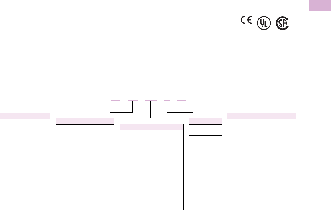
Volume 5—Motor Control and Protection CA08100006E—April 2014 www.eaton.com V5-T5-57
5
5
5
5
5
5
5
5
5
5
5
5
5
5
5
5
5
5
5
5
5
5
5
5
5
5
5
5
5
5
5.3
Motor Protection and Monitoring
Manual Motor Protection
Features and Benefits
●ON/OFF rotary handle with
lockout provision
●Visible trip indication
●Class 10 overload
protection
●Phase loss sensitivity
●Ambient temperature
compensation to IEC/EN
60947, VDE 0660
●Fixed short-circuit trip—
14 times maximum setting
of overload FLA dial
●Type 2 coordination per IEC
947
●Identification markers
standard on starter
faceplate
●Motor applications from
0.1A to 65A
●Built-in heater and
magnetic trip elements
to protect the motor
●Adjustment dial for setting
motor FLA
●DIN rail mount
●Terminal types available:
●Screw terminals
●Screw (line) and spring
cage (load) terminals
●Spring cage terminals
●Accessories include:
●Front and side auxiliary
contacts
●Trip indicating contacts
●Tamperproof cover for
OLR dial
●Undervoltage release
●Shunt trip
●Through-the-door
operators
●Enclosures
●
Three-phase line side
connecting links
Standards and Certifications
●CE approved
●UL listed File No. E245398
●UL 508 group motor and
Type E compliant
●IEC/EN 60947
●CSA File 229767, Class
3211-05
●DIN VDE 0660 Part 100,
Part 101 and Part 102
Catalog Number Selection
XT Manual Motor Protectors
Reference
Refer to Tab 1 of this volume, section 1.1 for additional
product information.
Manual Motor Protectors Tab Section
Product Identification . . . . . . . . . . . . . . . . . . . . . . . . . . . . . 1.1
Product Selection . . . . . . . . . . . . . . . . . . . . . . . . . . . . . . . . 1.1
Accessories . . . . . . . . . . . . . . . . . . . . . . . . . . . . . . . . . . . . 1.1
Technical Data and Specifications . . . . . . . . . . . . . . . . . . . 1.1
Dimensions . . . . . . . . . . . . . . . . . . . . . . . . . . . . . . . . . . . . 1.1
Type
PB = Manual motor protector—
pushbutton
PR = Manual motor protector—
rotary
PM = Manual motor protector—
magnetic only
PT = Manual transformer
protector (high mag.)
Designation
XT = XT IEC power control
Trip Class
C1 = Class 10
Blank = Magnetic only (no thermal trip)
Frame Size
B= 45 mm
D= 55 mm
Current Ratings
Frame B
P16 = 0.16A
P25 = 0.25A
P40 = 0.40A
P63 = 0.63A
001 = 1A
1P6 = 1.6A
2P5 = 2.5A
004 = 4A
6P3 = 6.3A
010 = 10A
012 = 12A
016 = 16A
020 = 20A
025 = 25A
032 = 32A
Frame D
016 = 16A
025 = 25A
032 = 32A
040 = 40A
050 = 50A
058 = 58A
063 = 63A
XT PR 012 BC1
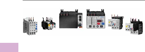
V5-T5-58 Volume 5—Motor Control and Protection CA08100006E—April 2014 www.eaton.com
5
5
5
5
5
5
5
5
5
5
5
5
5
5
5
5
5
5
5
5
5
5
5
5
5
5
5
5
5
5
5.4
Motor Protection and Monitoring
Overload Relays
Overload Relays
Contents
Description Page
Overload Relays
XT IEC Overload Relays . . . . . . . . . . . . . . . . . . V5-T5-60
Freedom Overload Relays . . . . . . . . . . . . . . . . V5-T5-64
C440/XT Electronic Overload Relay . . . . . . . . . V5-T5-65
IQ500 Overload Relays . . . . . . . . . . . . . . . . . . V5-T5-88
C441 Overload Relays . . . . . . . . . . . . . . . . . . . V5-T5-89
MP-3000 Overload Relays . . . . . . . . . . . . . . . . V5-T5-115
MP-4000 Overload Relays . . . . . . . . . . . . . . . . V5-T5-117
Product Overview
Overload Relays
XT IEC—Miniature
Product Description
Eaton’s new line of
XT
miniature controls includes
non-reversing and reversing
mini contactors, mini overload
relays and snap-on
accessories. A wide range of
applications is possible,
including small electrical
motors from fractional to 5 hp
(460 Vac) or up to 4 kW (400
Vac).
Features
●Phase failure sensitivity
●Direct mount to XTMC and
XTMF mini contactors
●Trip Class 10
●11 settings to cover
0.1 to 12A
●Ambient temperature
compensated –5° to 50°C
[23° to 122°F]
●Manual and automatic
reset by selector switch
●One make (NO) or one
break (NC) auxiliary contact
as standard
●Test/Off button
●Trip-free release
XT IEC—Thermal
Product Description
The XT line of IEC motor
thermal overload relays
provides an efficient motor
protection solution, available
up to 630A. XTOB units can
be directly mounted to the
contactor or mounted
separately.
Features
●Direct connect up to 250A
●Stand alone and CT type
up to 630A
●Large thermal overcurrent
range
●Test button
●Manual/automatic
selectable reset
●NO-NC auxiliary as
standard
●Class 10A (to 250A)
●Class 30 (CT type)
Freedom
Product Description
C306 Overload Relays are
designed for use with CE
or CN non-reversing and
reversing contactors. Four
sizes are available for
overload protection up
to 144A.
Features
●Selectable manual or
automatic reset operation
●Interchangeable heater
packs adjustable ±24%
to match motor FLA and
calibrated for use with
1.0 and 1.15 service factor
motors. Heater packs for
32A overload relay will
mount in 75A overload
relay—useful in derating
applications such as
jogging
●Class 10 or 20
heater packs
●Load lugs built into
relay base
●Bimetallic, ambient
compensated operated.
Tr ip fr e e m e ch an i s m
●Overload trip indication
C440/XTOE
Product Description
Eaton’s new electronic
overload relay (EOL) is
the most compact, high-
featured, economical product
in its class. Designed on a
global platform, the new
EOL covers the entire power
control spectrum including
NEMA®, IEC and
DP contactors. The NEMA
and DP versions are offered
with the C440 designation
while the IEC offering has the
XT designation. The
electronic design provides
reliable, accurate and value
driven protection and
communications capabilities
in a single compact device. It
is the flexible choice for any
application requiring easy-to-
use, reliable protection.
C440 is a self-powered
electronic overload relay
available up to 175A as a
self contained unit. With
external CTs, C440 can
protect motor up to
1500 FLA. Available add-on
accessories include remote
reset capability and
communication modules for
Modbus® RTU, DeviceNet™,
PROFIBUS®, Modbus TCP,
EtherNet/IP and HTTP web
services all with I/O options.

Volume 5—Motor Control and Protection CA08100006E—April 2014 www.eaton.com V5-T5-59
5
5
5
5
5
5
5
5
5
5
5
5
5
5
5
5
5
5
5
5
5
5
5
5
5
5
5
5
5
5
5.4
Motor Protection and Monitoring
Overload Relays
IQ500
The IQ500 is a heaterless,
current-sensing, solid-state
motor protective relay with
optional communications
capabilities. Several functions
are incorporated into the base
relay (IQ502/IQ504) as
standard:
●Overload (overcurrent)
protection
●Phase imbalance and
phase loss protection
●Ground current protection
(Class II)
The base relay can serve as
the initial building block for a
motor protection system by
adding the IQ500M Special
Function Module. The
module can address
application related motor load
functions with the additional
features:
●Underload protection
●Long acceleration
●Jam protection
●Load control
The IQ500 can provide a cost-
effective alternative to
conventional protective relays
such as current relays,
ground fault relays and phase
loss or phase imbalance
relays. Used with the
PowerNet system, a low-
cost, local area
communication network,
information such as current
values, status, setpoint
values and cause of trip can
be displayed remotely. The
IQ500 relay is ideal for a
variety of industrial
applications such as mining,
timber, material handling, air
conditioning compressors,
wastewater treatment plants
and petrochemical industries.
C441
Eaton’s Motor Insight, the
first product in the Intelligent
Power Control Solutions
family, is a highly configurable
motor, load and line
protection device with power
monitoring, diagnostics and
flexible communications
allowing the customer to
save energy, optimize their
maintenance schedules and
configure greater system
protection, thus reducing
overall costs and downtime.
Motor Insight is available
in either a line-powered or
120 Vac control powered
design, capable of monitoring
voltages up to 660 Vac. Each
of these units is available in
a 1–9 amp or a 5–90 amp FLA
model. With external CTs,
Motor Insight can protect
motors up to 540 amps FLA.
Available add-on accessories
include remote reset capability
and communication modules
for Modbus RTU, DeviceNet,
PROFIBUS, Modbus TCP,
EtherNet/IP and HTTP web
services all with I/O options.
For ease-of-use and operator
safety, Motor Insight offers a
remote display that mounts
easily with two 30 mm
knockouts.
The Motor Insight’s functions
consist of:
●Motor control
●Motor protection
●Load protection
●Line protection
●Monitoring capabilities
MP-3000
●Microprocessor-based,
multi-function motor
protection
●Current only device—
no need to add PTs
●Intel-I-Trip™ overload
protection based on
motor data
●Event recording and
operational logging
The protection functions are
listed below.
●I2t overload protection
(49/51)
●Locked rotor (49S/51)
●Ultimate trip current (51)
●Negative sequence phase
imbalance (46)
●Instantaneous
overcurrent (50)
●Ground fault
protection (50G)
●RTD trip and alarm with
URTD module (49/38)
●Underload trip (37)
●Starts per time (66)
●Jam or stall (51R)
●Auto or manual reset (86)
●Fail-safe or non-fail-safe
trip modes
The metering functions are:
●Motor currents:
●Average current (Iave)
●Individual phase and
ground current in
primary amperes
●Percent of full load
●Percent of phase
imbalance
●RTD temperatures:
●Individual winding
●Motor bearing
●Load
●Auxiliary temperatures
●Motor conditions:
●Percent of I2t thermal
bucket
●Time before start
●Remaining starts
allowed
●Oldest start time
MP-4000
●Microprocessor-based,
multi-function motor
protection
●Current and Voltage device
●Intel-I-Trip overload
protection based on
motor data
●Event recording and
operational logging
The protection functions are
listed below.
●All functions listed under
MP-3000 as well as:
●Undervoltage (27)
●Overvoltage (59)
●Under power (32)
●Negative sequence
voltage imbalance (47)
●Power factor (55)
The metering functions are:
●All functions listed under
MP-3000 as well as:
Metering—
●Average current
●Amperes: magnitude
and angle in primary
values
●Amperes: positive,
negative and zero
sequence
●Average voltage (V ave)
●Voltage: magnitude and
angle
●Voltage: positive,
negative and zero
sequence
●% of full load
●% current imbalance
●% voltage imbalance
●Power, vars and VA
●Power factor
●Frequency
●Energy metering with
time and date stamps
RTD temperatures—
●Individual winding
●Motor bearing
●Load
●Auxiliary temperatures
Motor conditions—
●Percent of I2t thermal
bucket
●Time before start
●Remaining starts
allowed
●Oldest start time
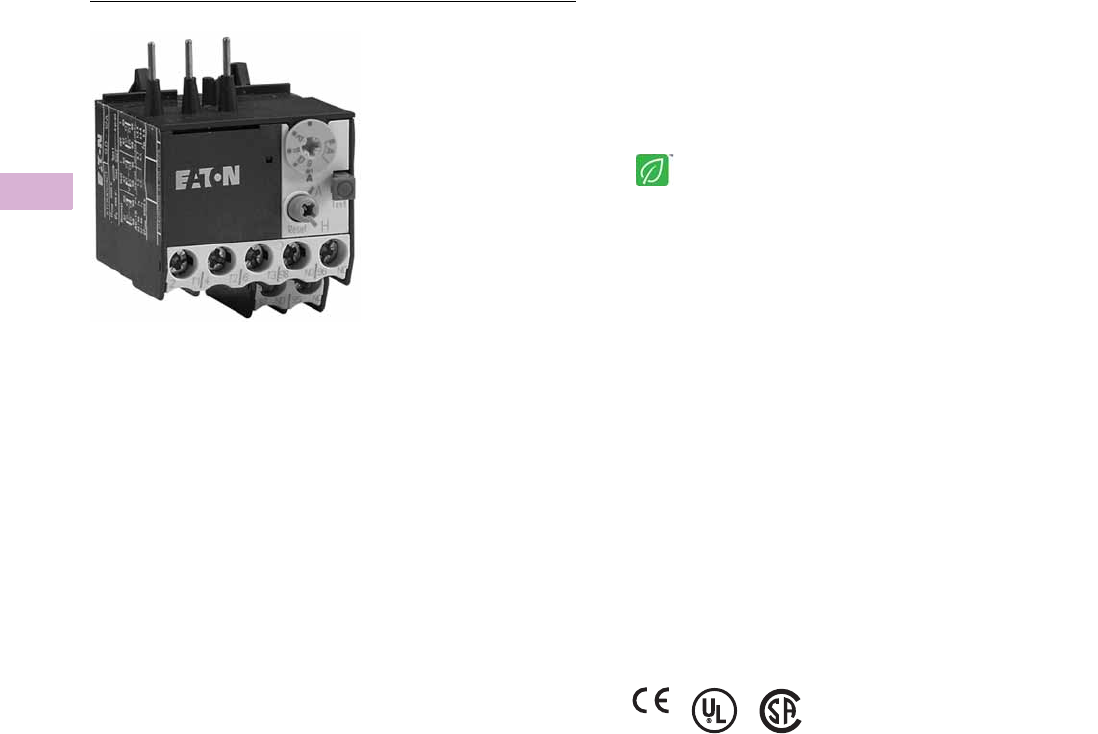
V5-T5-60 Volume 5—Motor Control and Protection CA08100006E—April 2014 www.eaton.com
5
5
5
5
5
5
5
5
5
5
5
5
5
5
5
5
5
5
5
5
5
5
5
5
5
5
5
5
5
5
5.4
Motor Protection and Monitoring
Overload Relays
Miniature Overload Relays
Contents
Description Page
XT IEC Overload Relays
Miniature Overload Relays
Catalog Number Selection . . . . . . . . . . . . . V5-T5-61
Reference . . . . . . . . . . . . . . . . . . . . . . . . . . V5-T5-61
An Eaton
Green Solution
Thermal Overload Relays . . . . . . . . . . . . . . . . . V5-T5-62
Freedom Overload Relays . . . . . . . . . . . . . . . . . . . V5-T5-64
C440/XT Electronic Overload Relay . . . . . . . . . . . V5-T5-65
IQ500 Overload Relays . . . . . . . . . . . . . . . . . . . . . V5-T5-88
C441 Overload Relays . . . . . . . . . . . . . . . . . . . . . . V5-T5-89
MP-3000 Overload Relays . . . . . . . . . . . . . . . . . . . V5-T5-115
MP-4000 Overload Relays . . . . . . . . . . . . . . . . . . . V5-T5-117
XT IEC Overload Relays
Miniature Overload Relays
Product Description
Eaton’s new line of
XT
miniature controls includes
non-reversing and reversing
mini contactors, mini overload
relays and snap-on
accessories. A wide range of
applications is possible,
including small electrical
motors from fractional to 5 hp
(460 Vac) or up to 4 kW (400
Vac).
Application Description
Due to its compact size, the
XT line of mini controls is
best suited to be applied in
light-duty loads, such as
hoisting, packaging, material
handling, heating, lighting and
automation systems. XT mini
contactors are a particularly
compact, economic and
environmentally friendly
solution wherever control
of small motors or loads
is required.
Features
Mini Overload Relays—
Bimetallic
Type XTOM
●Phase failure sensitivity
●Direct mount to XTMC and
XTMF mini contactors
●Trip Class 10
●11 settings to cover
0.1 to 12A
●Ambient temperature
compensated –5° to 50°C
[23° to 122°F]
●Manual and automatic
reset by selector switch
●One make (NO) or one
break (NC) auxiliary contact
as standard
●Test/Off button
●Trip-free release
Standards and Certifications
●IEC EN 60947
●CE approved
●UL
●CSA
●CCC
●ATEX
Instructional Leaflets
Pub51219 XTMC, XTMF Mini Contactors, XTRM Mini
Control Relay and Accessories
Pub51243 XTOM Mini Overload Relays
Pub51206 Mini Reversing Link Kits
MN03402002E XTOM Mini Overload Relays Installation
and User Manual
Volume 5—Motor Control and Protection CA08100006E—April 2014 www.eaton.com V5-T5-61
5
5
5
5
5
5
5
5
5
5
5
5
5
5
5
5
5
5
5
5
5
5
5
5
5
5
5
5
5
5
5.4
Motor Protection and Monitoring
Overload Relays
Catalog Number Selection
XT IEC Miniature Overload Relays
Mini Overload Relay Settings (A)
Note
Depending on the coordination type required (that is, Type 1 or Type 2) it must be established
whether the fuse protection and the input wiring for the main and delta contactors are to be
common or separate.
Reference
Refer to Tab 1 of this volume, section 1.1 for additional
product information.
Miniature Overload Relays Tab Section
Product Selection . . . . . . . . . . . . . . . . . . . . . . . . . . . . . . . . 1.1
Accessories . . . . . . . . . . . . . . . . . . . . . . . . . . . . . . . . . . . . 1.1
Technical Data and Specifications . . . . . . . . . . . . . . . . . . . 1.1
Wiring Diagrams . . . . . . . . . . . . . . . . . . . . . . . . . . . . . . . . 1.1
Dimensions . . . . . . . . . . . . . . . . . . . . . . . . . . . . . . . . . . . . 1.1
Setting Starting
A: IN x 0.58
Motor protection in the Y and delta configurations.
<15 sec
B: IN x 1
Only partial motor protection in star position
15–40 sec
C: IN x 0.58
Motor not protected in star position.
>40 sec
Timing relay set to approximately 10 sec.
Type
OM = Mini overload relay
Trip Class
C1 = Class 10A
Designation
XT = XT IEC power control Frame Size
A = 45 mm mini
XT OM P16 AC1
Overload Release
P16 = 0.1–0.16A
P24 = 0.16–0.24A
P40 = 0.24–0.4A
P60 = 0.4–0.6A
001 = 0.6–1A
1P6 = 1–1.6A
2P4 = 1.6–2.4A
004 =2.4–4A
006 = 4–6A
009 = 6–9A
012 = 9–12A
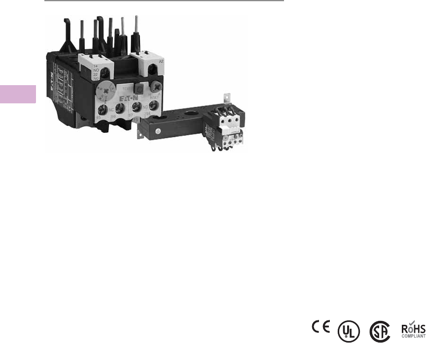
V5-T5-62 Volume 5—Motor Control and Protection CA08100006E—April 2014 www.eaton.com
5
5
5
5
5
5
5
5
5
5
5
5
5
5
5
5
5
5
5
5
5
5
5
5
5
5
5
5
5
5
5.4
Motor Protection and Monitoring
Overload Relays
Thermal Overload Relays
Contents
Description Page
XT IEC Overload Relays
Miniature Overload Relays . . . . . . . . . . . . . . . . V5-T5-60
Thermal Overload Relays
Catalog Number Selection . . . . . . . . . . . . . V5-T5-63
Reference . . . . . . . . . . . . . . . . . . . . . . . . . . V5-T5-63
Freedom Overload Relays . . . . . . . . . . . . . . . . . . . V5-T5-64
C440/XT Electronic Overload Relay . . . . . . . . . . . V5-T5-65
IQ500 Overload Relays . . . . . . . . . . . . . . . . . . . . . V5-T5-88
C441 Overload Relays . . . . . . . . . . . . . . . . . . . . . . V5-T5-89
MP-3000 Overload Relays . . . . . . . . . . . . . . . . . . . V5-T5-115
MP-4000 Overload Relays . . . . . . . . . . . . . . . . . . . V5-T5-117
Thermal Overload Relays
Product Description
The XT line of IEC motor
thermal overload relays
provides an efficient motor
protection solution, available
up to 630A. XTOB units can
be directly mounted to the
contactor or mounted
separately.
Features and Benefits
●Direct connect up to 250A
●Stand alone and CT type
up to 630A
●Large thermal overcurrent
range
●Test button
●Manual/automatic
selectable reset
●NO-NC auxiliary as
standard
●Class 10A (to 250A)
●Class 30 (CT type)
Standards and Certifications
●IEC EN 60947
●CE approved
●UL
●CSA
●ATEX
●RoHS
Instructional Leaflets
Pub51221 XTOB, D Frame overload relays
(inside of packaging)
Pub51222 XTOB, B–C Frame overload relays
(inside of packaging)
Notes
Short-circuit protection: Observe the maximum permissible fuse of the contactor with direct
device mounting. See MN03402001E for more information on overload relays for Frames B–G.
Trip Class: 10A
Suitable for protection of EEx e-motors. EC prototype test certificate available upon request.
See manuals MN03402001E and MN03407001E, Page 135.
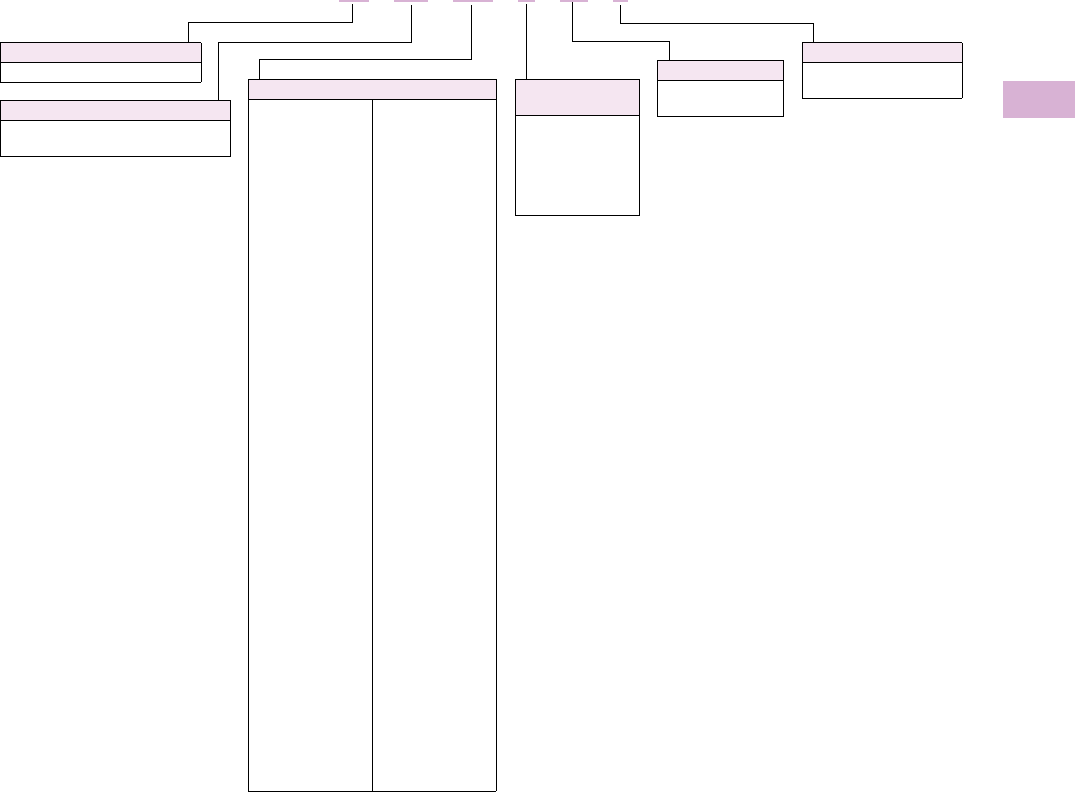
Volume 5—Motor Control and Protection CA08100006E—April 2014 www.eaton.com V5-T5-63
5
5
5
5
5
5
5
5
5
5
5
5
5
5
5
5
5
5
5
5
5
5
5
5
5
5
5
5
5
5
5.4
Motor Protection and Monitoring
Overload Relays
Catalog Number Selection
XT IEC Overload Relays
Reference
Refer to Tab 1 of this volume, section 1.1 for additional
product information.
Thermal Overload Relays Tab Section
Product Selection . . . . . . . . . . . . . . . . . . . . . . . . . . . . . . . . 1.1
Accessories . . . . . . . . . . . . . . . . . . . . . . . . . . . . . . . . . . . . 1.1
Technical Data and Specifications . . . . . . . . . . . . . . . . . . . 1.1
Dimensions . . . . . . . . . . . . . . . . . . . . . . . . . . . . . . . . . . . . 1.1
XT OB P16 BC1 S
Type
OB = Bimetallic overload relay
OT = Current transformer overload relay
Device Type
XT = XT line of IEC control Trip Class
C1 = Class 10A
C3 = Class 30
Mounting
Blank = Direct to contactor
S= Separate mount
Frame Size
Designation
B = 45 mm
C = 45 mm
D = 55 mm
G = 90 mm
L = 140 mm
Blank = XTOT only
Overload Release
Frame B
P16 = 0.1–0.16A
P24 = 0.16–0.24A
P40 = 0.24–0.4A
P60 = 0.4–0.6A
001 = 0.6–1A
1P6 = 1.0–1.6A
2P4 = 1.6–2.4A
004 = 2.4–4A
006 = 4–6A
010 = 6–10A
012 = 9–12A
016 = 12–16A
Frame C
P16 = 0.1–0.16A
P24 = 0.16–0.24A
P40 = 0.24–0.4A
P60 = 0.4–0.6A
001 = 0.6–1A
1P6 = 1.0–1.6A
2P4 = 1.6–2.4A
004 = 2.4–4A
006 = 4–6A
010 = 6–10A
016 = 12–16A
024 = 16–24A
032 = 24–32A
Frame D
010 = 6–10A
016 = 12–16A
024 = 16–24A
040 = 24–40A
057 = 40–57A
065 = 50–65A
075 = 65–75A
Frame F
035 = 25–35A
050 = 35–50A
070 = 50–70A
100 = 70–100A
Frame G
035 = 25–35A
050 = 35–50A
070 = 50–70A
100 = 70–100A
125 = 95–125A
150 = 120–150A
175 = 145–175A
Frame L
070 = 50–70A
100 = 70–100A
125 = 95–125A
160 = 120–160A
220 = 160–220A
250 = 200–250A
Frame M
063 = 42–63A
090 = 60–90A
125 = 85–125A
160 = 110–160A
240 = 160–240A
290 = 190–290A
400 = 170–400A
540 = 360–540A
Frame N
063 = 42–63A
090 = 60–90A
125 = 85–125A
160 = 110–160A
240 = 160–240A
290 = 190–290A
400 = 170–400A
540 = 360–540A
630 = 420–630A
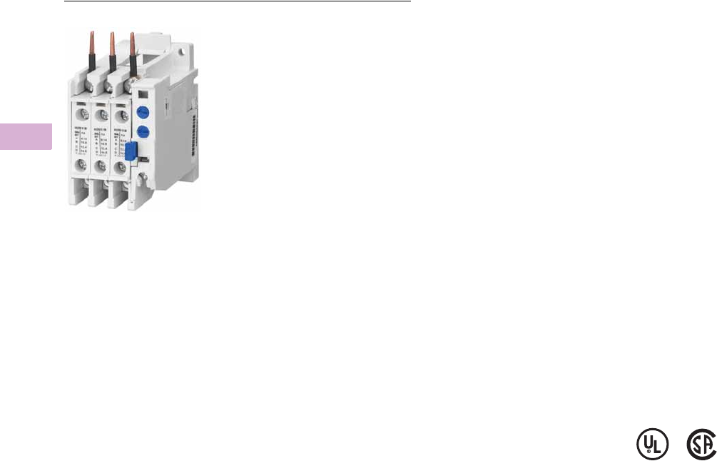
V5-T5-64 Volume 5—Motor Control and Protection CA08100006E—April 2014 www.eaton.com
5
5
5
5
5
5
5
5
5
5
5
5
5
5
5
5
5
5
5
5
5
5
5
5
5
5
5
5
5
5
5.4
Motor Protection and Monitoring
Overload Relays
32A Overload—C306DN3B
Contents
Description Page
XT IEC Overload Relays . . . . . . . . . . . . . . . . . . . . V5-T5-60
Freedom Overload Relays . . . . . . . . . . . . . . . . . . . V5-T5-64
C440/XT Electronic Overload Relay . . . . . . . . . . . V5-T5-65
IQ500 Overload Relays . . . . . . . . . . . . . . . . . . . . . V5-T5-88
C441 Overload Relays . . . . . . . . . . . . . . . . . . . . . . V5-T5-89
MP-3000 Overload Relays . . . . . . . . . . . . . . . . . . . V5-T5-115
MP-4000 Overload Relays . . . . . . . . . . . . . . . . . . . V5-T5-117
Freedom Overload Relays
Product Description
C306 Overload Relays are
designed for use with CE
or CN non-reversing and
reversing contactors. Four
sizes are available for
overload protection up
to 144A.
Features
●Selectable manual or
automatic reset operation
●Interchangeable heater
packs adjustable ±24%
to match motor FLA and
calibrated for use with
1.0 and 1.15 service factor
motors. Heater packs for
32A overload relay will
mount in 75A overload
relay—useful in derating
applications such as
jogging
●Class 10 or 20
heater packs
Reference
Refer to Tab 2 of this volume, section 2.1 for additional
product information.
Freedom Overload Relays Tab Section
Product Selection . . . . . . . . . . . . . . . . . . . . . . . . . . . . . . . 2.1
Accessories . . . . . . . . . . . . . . . . . . . . . . . . . . . . . . . . . . . . 2.1
Modifications . . . . . . . . . . . . . . . . . . . . . . . . . . . . . . . . . . . 2.1
Replacement Parts . . . . . . . . . . . . . . . . . . . . . . . . . . . . . . 2.1
Technical Data and Specifications . . . . . . . . . . . . . . . . . . . 2.1
Dimensions . . . . . . . . . . . . . . . . . . . . . . . . . . . . . . . . . . . . 2.1
●Load lugs built into
relay base
●Bimetallic, ambient
compensated operated.
Tr ip fr e e m e ch an i s m
●Electrically isolated NO-NC
contacts (pull RESET
button to test). (Electrical
ratings see tables in Tab 2
of this volume, section 2.1)
●Overload trip indication
●Shrouded or fingerproof
terminals to reduce
possibility of electrical
shock
Standards and Certifications
●Meets UL 508 single-
phasing requirements
●UL listed, CSA certified
and NEMA compliance
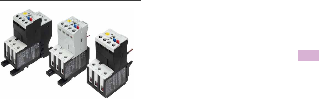
Volume 5—Motor Control and Protection CA08100006E—April 2014 www.eaton.com V5-T5-65
5
5
5
5
5
5
5
5
5
5
5
5
5
5
5
5
5
5
5
5
5
5
5
5
5
5
5
5
5
5
5.4
Motor Protection and Monitoring
Overload Relays
C440/XT Electronic Overload Relay
Contents
Description Page
XT IEC Overload Relays . . . . . . . . . . . . . . . . . . . . V5-T5-60
Freedom Overload Relays . . . . . . . . . . . . . . . . . . . V5-T5-64
C440/XT Electronic Overload Relay
Standards and Certifications . . . . . . . . . . . . . . V5-T5-66
Catalog Number Selection . . . . . . . . . . . . . . . . V5-T5-67
Product Selection . . . . . . . . . . . . . . . . . . . . . . . V5-T5-69
Accessories . . . . . . . . . . . . . . . . . . . . . . . . . . . V5-T5-74
Technical Data and Specifications . . . . . . . . . . V5-T5-78
Dimensions . . . . . . . . . . . . . . . . . . . . . . . . . . . V5-T5-84
IQ500 Overload Relays . . . . . . . . . . . . . . . . . . . . . V5-T5-88
C441 Overload Relays . . . . . . . . . . . . . . . . . . . . . . V5-T5-89
MP-3000 Overload Relays . . . . . . . . . . . . . . . . . . . V5-T5-115
MP-4000 Overload Relays . . . . . . . . . . . . . . . . . . . V5-T5-117
C440/XT Electronic Overload Relay
Product Description
Eaton’s new electronic
overload relay (EOL) is
the most compact, high-
featured, economical product
in its class. Designed on a
global platform, the new
EOL covers the entire power
control spectrum including
NEMA, IEC and
DP contactors. The NEMA
and DP versions are offered
with the C440 designation
while the IEC offering has the
XT designation. The
electronic design provides
reliable, accurate and value
driven protection and
communications capabilities
in a single compact device. It
is the flexible choice for any
application requiring easy-to-
use, reliable protection.
Eaton has a long history of
innovations and product
development in motor control
and protection, including both
traditional NEMA, as well as
IEC control. It was from this
experience that the C440 was
developed, delivering new
solutions to meet today’s
demands.
C440 is a self-powered
electronic overload relay
available up to 175A as a
self contained unit. With
external CTs, C440 can
protect motor up to
1500 FLA. Available add-on
accessories include remote
reset capability and
communication modules for
Modbus RTU, DeviceNet,
PROFIBUS, Modbus TCP,
EtherNet/IP and HTTP web
services all with I/O options.
Features and Benefits
Features
●Reliable, accurate, electronic motor protection
●Easy to select, install and maintain
●Compact size
●Flexible, intelligent design
●Global product offering—available with NEMA, IEC and DP
power control
Size/Range
●Broad FLA range
(0.33–1500A)
●Selectable trip class
(10A, 10, 20, 30)
●Direct mounting to NEMA,
IEC and DP contactors
●Most compact electronic
overload in its class
Motor Control
●Two B600 alarm (NO) and
fault (NC) contacts
●Test/Trip button
Motor Protection
●Thermal overload
●Phase loss
●Selectable (ON/OFF)
phase imbalance
●Selectable (ON/OFF)
ground fault
User Interface
●Large FLA selection dial
●Trip status indicator
●Operating mode LED
●DIP switch selectable trip
class, phase imbalance and
ground fault
●Selectable Auto/Manual
reset
Feature Options
●Remote reset
●120 Vac
●24 Vac
●24 Vdc
●Tamper-proof cover
●Communications modules
●Modbus RTU RS-485
●DeviceNet with I/O
●PROFIBUS with I/O
●Modbus RTU with I/O
●Ethernet IP with I/O
●Modbus TCP with I/O

V5-T5-66 Volume 5—Motor Control and Protection CA08100006E—April 2014 www.eaton.com
5
5
5
5
5
5
5
5
5
5
5
5
5
5
5
5
5
5
5
5
5
5
5
5
5
5
5
5
5
5
5.4
Motor Protection and Monitoring
Overload Relays
Benefits
Reliability and Improved
Uptime
●C440 provides the users
with peace of mind
knowing that their
assets are protected
with the highest level
of motor protection and
communication capability
in its class
●Extends the life of plant
assets with selectable
motor protection features
such as trip class, phase
imbalance and ground fault
●Protects against
unnecessary downtime
by discovering changes
in your system (line/load)
with remote monitoring
capabilities
●Status LED provides
added assurance that
valuable assets are
protected by indicating the
overload operational status
Flexibility
●Available with NEMA,
IEC and DP contactors
●Improves return on
investment by reducing
inventory carrying costs
with wide FLA adjustment
(5:1) and selectable
trip class
●Design incorporates built-in
ground fault protection
thus eliminating the need
for separate CTs and
modules
●Flexible communication
with optional I/O enables
easy integration into plant
management systems for
remote monitoring and
control
●Available as an open
component and in
enclosed control and motor
control center assemblies
Monitoring Capabilities
●Individual phase
currents RMS
●Average three-phase
current RMS
●Thermal memory
●Fault indication (overload,
phase loss, phase
imbalance, ground fault)
Safety
●IP 20 rated terminal blocks
●Available in Eaton’s
industry leading FlashGard
MCCs
●Tested to the highest
industry standards such
as UL, CSA, CE and IEC
●RoHS compliant
Standards and Certifications
●UL
●CSA
●CE
●NEMA
●IEC/EN 60947 VDE 0660
●ISO® 13849-1 (EN954-1)
●RoHS
●ATEX directive 94/9/EC
●Equipment Group 2,
Category 2
Electronic Overload Education
Description Definition Cause Effect if not Protected C440/XT Protection
Motor Protection
Thermal overload Overload is a condition in which
current draw exceeds 115% of
the full load amperage rating for
an inductive motor.
• An increase in the load or torque that is
being driven by the motor.
• A low voltage supply to the motor
causes the current to go high to
maintain the power needed.
• A poor power factor causing above
normal current draw.
• Increase in current draw leads to heat
and insulation breakdown, which can
cause system failure.
• Increase in current can increase
power consumption and waste
valuable energy.
• Thermal trip behavior is defined by
UL, CSA and IEC standards.
• Trip class is settable from 10A,
10, 20, 30
Ground fault A line to ground fault. A current leakage path to ground. An undetected ground fault can burn
through multiple insulation windings,
ultimately leading to motor failure, not to
mention risk to equipment or personnel
Fixed protective setting that takes the
starter offline if ground fault current
exceeds 50% of the FLA dial setting,
that is, if the FLA dial is set to 12A, the
overload relay will trip if the ground
current exceeds 6A.
Imbalanced phases
(voltage and current)
Uneven voltage or current between
phases in a three-phase system.
When a three-phase load is powered with
a poor quality line, the voltage per phase
may be imbalanced.
Imbalanced voltage causes large
imbalanced currents and as a result this
can lead to motor stator windings being
overloaded, causing excessive heating,
reduced motor efficiency and reduced
insulation life.
Fixed protective setting that takes the
starter offline if a phase drops below
50% of the other two phases.
Phase loss—current
(single-phasing)
One of the three-phase voltages is
not present.
Multiple causes, loose wire, improper
wiring, grounded phase, open fuse,
and so on.
Single-phasing can lead to unwanted
motor vibrations in addition to the results
of imbalanced phases as listed above.
Fixed protective setting that takes the
starter offline if a phase drops below
50% of the other two phases.
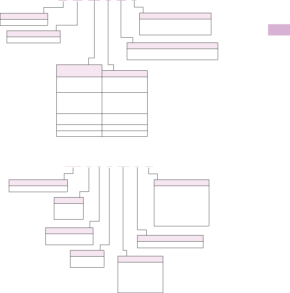
Volume 5—Motor Control and Protection CA08100006E—April 2014 www.eaton.com V5-T5-67
5
5
5
5
5
5
5
5
5
5
5
5
5
5
5
5
5
5
5
5
5
5
5
5
5
5
5
5
5
5
5.4
Motor Protection and Monitoring
Overload Relays
Catalog Number Selection
XT Electronic Overload Relay—IEC 1
C440 Electronic Overload Relay—NEMA 2
Notes
1See Page V5-T5-69 for Product Selection.
2See Page V5-T5-71 for Product Selection.
3On non-GF version only.
Designation
XT = XT line of IEC control
Type
OE = Electronic overload relay
Mounting
Blank = Direct to contactor
P = Pass-Through
S = Separate mount (Frames C and G only)
Trip Type
CS = Selectable Class 10A, 10, 20, 30
GS = Ground fault with selectable Class 10, 20
Overload Range
Contactor Frame
1P6 = 0.33–1.65A
005 = 1–5A
020 =4–20A
B = 45 mm
1P6 = 0.33–1.65A
005 = 1–5A
020 =4–20A
045 =9–45A
C = 45 mm
045 =9–45A
100 = 20–100A
D = 55 mm
100 = 20–100A F, G = 105 mm
175 = 35–175A G, H = 105 mm
XT OE 1P6 C CS S
Trip Class
S = Selectable—10A 3, 10, 20, 30 3
Overload Range
1P6 = 0.33–1.65A
005 = 1–5A
020 = 4–20A
045 = 9–45A
100 = 20–100A
140 = 28–140A
Frame Size
A =45 mm
B =55 mm
C = 110 mm
C440 A 1 A 005 S F1
Device Type
C440 = Electronic overload relay
Feature Set
1 = Standard
2 = Ground fault sensing
Reset Type
A = Selectable
Auto/Manual
Contactor Size
F00 = Freedom Size 00
F0 = Freedom Size 0
F1 = Freedom Size 1
F2 = Freedom Size 2
F3 = Freedom Size 3
F4 = Freedom Size 4
AX = Separate mount
PX = Pass-Through
V5-T5-68 Volume 5—Motor Control and Protection CA08100006E—April 2014 www.eaton.com
5
5
5
5
5
5
5
5
5
5
5
5
5
5
5
5
5
5
5
5
5
5
5
5
5
5
5
5
5
5
5.4
Motor Protection and Monitoring
Overload Relays
Freedom Series NEMA Starters with C440 Electronic Overload Relays 1
Notes
1See Page V5-T5-72 for Product Selection.
2NEMA Sizes 00 and 0 only.
3NEMA Sizes 00 and 0 only. Sizes 1–3 are 24/60 only.
4NEMA Size 5 starter available with 60-300A panel mounted CTs. Starter shipped as an assembled unit with
1–5A C440 overload relay (C440A1A005SELAX or C440A2A005SELAX).
A N 1 9 A N 0 A 5E 005
Device Type
A = Starter
Contactor Frame Size
NEMA
Size
Continuous
Amperes
A =
B =
C =
D =
G =
K =
M =
N =
S =
00
0
1C
1
2
3
4C
4
5
9
18
27
27
45
90
135
135
270
Device Assembly
Configuration
1 = Non-reversing
5 = Reversing
Standard
N = NEMA
OLR Type
9 = Starter w/C440 EOLR
NEMA Enclosure
N = Open
For Starters
Starter Mounting Option
0 = Horizontal
AC Coil Suffix
Suffix Volts and Hertz
A=
B=
C=
D=
E=
H=
J=
K=
L=
N=
T=
U=
V=
W=
Y=
120/60 or 110/50
240/60 or 220/50
480/60 or 440/50
600/60 or 550/50
208/60
277/60
208–240/60 2
240/50
380–415/50
550/50
24/60, 24/50 3
24/50
32/50
48/60
48/50
C440 OLR Designation
(FVNR and FVR only)
5E = Standard feature set
SEL Reset, SEL Class (10A, 10, 20, 30)
5G = Ground fault feature set
SEL Reset, SEL Class (10, 20)
C440 FLA Range
(FVNR and FVR only)
NEMA Size 00
1P6 = 0.33–1.65A
005 =1–5A
020 =4–20A
NEMA Size 0
1P6 = 0.33–1.65A
005 =1–5A
020 =4–20A
NEMA Size 1/1C
1P6 = 0.33–1.65A
005 =1–5A
020 =4–20A
045 =9–45A
NEMA Size 2
005 =1–5A
020 =4–20A
045 =9–45A
NEMA Size 3
100 = 20–100A
NEMA Size 4/4C
140 = 28–140A
NEMA Size 5 4
300 = 60–300A
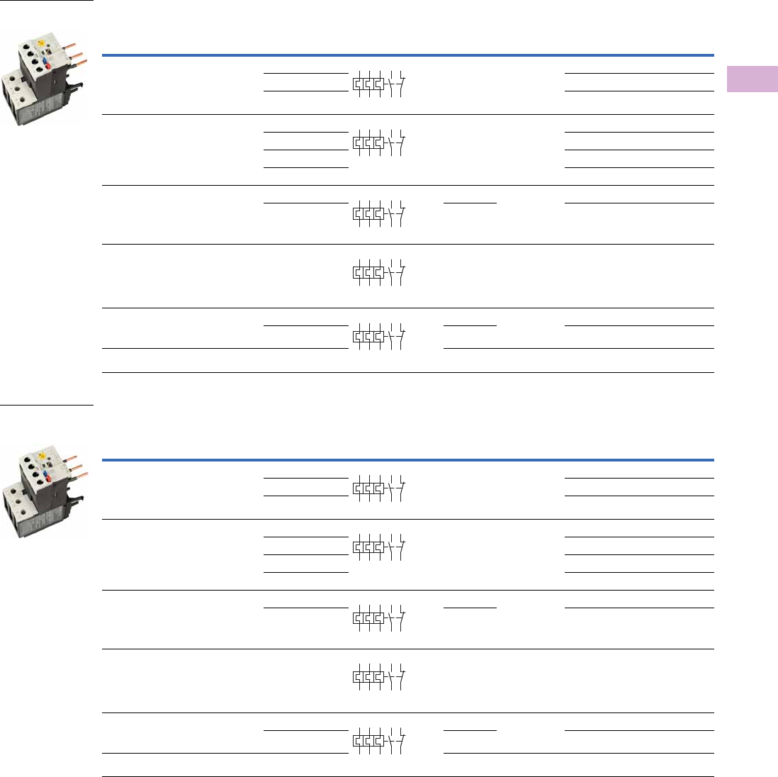
Volume 5—Motor Control and Protection CA08100006E—April 2014 www.eaton.com V5-T5-69
5
5
5
5
5
5
5
5
5
5
5
5
5
5
5
5
5
5
5
5
5
5
5
5
5
5
5
5
5
5
5.4
Motor Protection and Monitoring
Overload Relays
Product Selection
XT Electronic Overload Relays
XT Electronic Overload Relays for Direct Mount to XT Contactors
XT Electronic Overload Relays with Ground Fault for Direct Mount to XT Contactors
For Use with
XT Contactor
Frame
For Use with
Contactor
Overload
Range (Amps)
Contact
Sequence
Frame
Size
Auxiliary
Contact
Configuration Type Catalog Number
B XTCE007B…,
XTCE009B…,
XTCE012B…,
XTCE015B…
0.33–1.65 45 mm NO-NC ZEB12-1,65 XTOE1P6BCS
1–5 ZEB12-5 XTOE005BCS
4–20 ZEB12-20 XTOE020BCS
C XTCE018C…,
XTCE025C…,
XTCE032C
0.33–1.65 45 mm NO-NC ZEB32-1,65 XTOE1P6CCS
1–5 ZEB32-5 XTOE005CCS
4–20 ZEB32-20 XTOE020CCS
9–45 ZEB32-45 XTOE045CCS
D XTCE040D…,
XTCE050D…,
XTCE065D…,
XTCE072D…
9–45 45 mm NO-NC ZEB65-45 XTOE045DCS
20–100 55 mm ZEB65-100 XTOE100DCS
F XTCE080F…,
XTCE095F…,
XTCE115G…,
XTCE150G…,
XTCE170G…
20–100 55 mm NO-NC ZEB150-100 XTOE100GCS
G XTCE115G…,
XTCE150G…,
XTCE170G…
20–100 55 mm NO-NC ZEB150-100 XTOE100GGS
35–175 110 mm ZEB150-175 XTOE175GGS
H XTCE185H… 35–175 110 mm NO-NC ZEB225-175 XTOE175HCS
For Use with
XT Contactor
Frame
For Use with
Contactor
Overload
Range (Amps)
Contact
Sequence
Frame
Size
Auxiliary
Contact
Configuration Type Catalog Number
B XTCE007B…,
XTCE009B…,
XTCE012B…,
XTCE015B…
0.33–1.65 45 mm NO-NC ZEB12-1,65-GF XTOE1P6BGS
1–5 ZEB12-5-GF XTOE005BGS
4–20 ZEB12-20-GF XTOE020BGS
C XTCE018C…,
XTCE025C…,
XTCE032C
0.33–1.65 45 mm NO-NC ZEB32-1,65-GF XTOE1P6CGS
1–5 ZEB32-5-GF XTOE005CGS
4–20 ZEB32-20-GF XTOE020CGS
9–45 ZEB32-45-GF XTOE045CGS
D XTCE040D…,
XTCE050D…,
XTCE065D…,
XTCE072D…
9–45 45 mm NO-NC ZEB65-45-GF XTOE045DGS
20–100 55 mm ZEB65-100-GF XTOE100DGS
FXTCE080F…,
XTCE095F…,
XTCE115G…,
XTCE150G…,
XTCE170G…
20–100 55 mm NO-NC ZEB150-100-GF XTOE100GGS
G XTCE115G…,
XTCE150G…,
XTCE170G…
20–100 55 mm NO-NC ZEB150-100-GF XTOE100GGS
35–175 110 mm ZEB150-175-GF XTOE175GGS
H XTCE185H… 35–175 110 mm NO-NC ZEB225-175-GF XTOE175HGS
45 mm XT for
Direct Mount
2 4 6 98 96
97 95
2 4 6 98 96
97 95
2 4 6 98 96
97 95
2 4 6 98 96
97 95
2 4 6 98 96
97 95
45 mm XT for
Direct Mount
with Ground Fault
2 4 6 98 96
97 95
2 4 6 98 96
97 95
2 4 6 98 96
97 95
2 4 6 98 96
97 95
2 4 6 98 96
97 95
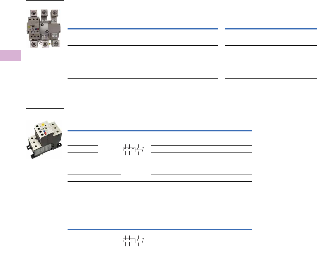
V5-T5-70 Volume 5—Motor Control and Protection CA08100006E—April 2014 www.eaton.com
5
5
5
5
5
5
5
5
5
5
5
5
5
5
5
5
5
5
5
5
5
5
5
5
5
5
5
5
5
5
5.4
Motor Protection and Monitoring
Overload Relays
XT Electronic Overload Relays for use with Large Frame XT Contactors (L–R)
Use CTs and 1-5A XT overload relay. CT kit does not include overload relay (order separately).
XT Electronic Overload Relays for Separate Mount
XT Electronic Overload Relay for Pass-Through Design
Pass-through design does not include any lugs to land wires.
Terminate motor leads directly on contactor.
XT
Contactor
Frame
For Use with IEC
Contactor Amp
Range (AC-3)
CT Range
(Amps) Description
CT Kit
Catalog Number
Terminal
Size
Overload Relay
Catalog Number
Overload Relay
with Ground Fault
Catalog Number
L, M 185–500A 60-300 300: 5 panel-mount CT kit
with integrated lugs
ZEB-XCT300 750 kcmil
(2) 250 kcmil
3/0 Cu/Al
XTOE005CCSS XTOE005CGSS
M, N 300–820A 120-600 600: 5 panel-mount CT kit
with integrated,
pass through holes
ZEB-XCT600 (2) 750 kcmil
3/0 Cu/Al
XTOE005CCSS XTOE005CGSS
N 580–1000A 200-1000 1000: 5 panel-mount CT kit
with integrated,
pass through holes
ZEB-XCT1000 (3) 750 kcmil
3/0 Cu/Al
XTOE005CCSS XTOE005CGSS
R 1600A 300-1500 1500: 5 panel-mount CT kit
with integrated,
pass through holes
ZEB-XCT1500 (4) 750 kcmil
1/0 Cu/Al
XTOE005CCSS XTOE005CGSS
Overload
Range (Amps)
Frame
Size
Contact
Sequence Type
Overload Relay
Catalog Number
Overload Relay
with Ground Fault
Catalog Number
Overload Relay
0.33–1.65 45 mm ZEB32-1.65/KK XTOE1P6CCSS XTOE1P6CGSS
1–5 ZEB32-5/KK XTOE005CCSS XTOE005CGSS
4–20 ZEB32-20/KK XTOE020CCSS XTOE020CGSS
9–45 ZEB32-45/KK XTOE045CCSS XTOE045CGSS
20–100 55 mm ZEB150-100/KK XTOE100GCSS XTOE100GGSS
35–175 110 mm ZEB150-175/KK XTOE175GCSS XTOE175GGSS
Overload
Range (Amps)
Frame
Size
Contact
Sequence Type
Overload Relay
Catalog Number
Overload Relay
with Ground Fault
Catalog Number
35–175 110 mm ZEB150-175/PT XTOE175GCSP XTOE175GGSP
1–5A OL with CTs
45 mm XT for
Separate Mount
1359795
2469896
1359795
2469896
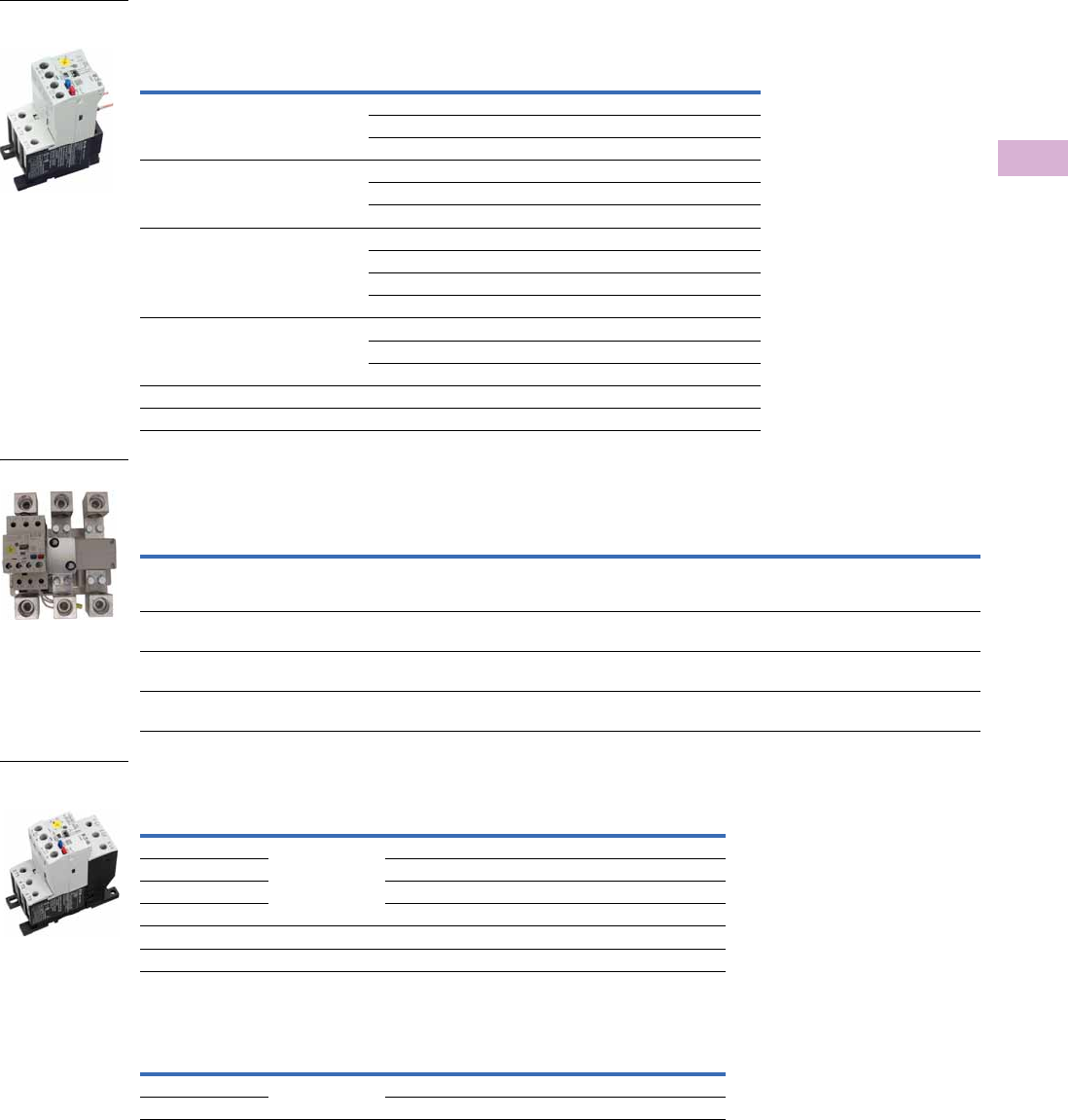
Volume 5—Motor Control and Protection CA08100006E—April 2014 www.eaton.com V5-T5-71
5
5
5
5
5
5
5
5
5
5
5
5
5
5
5
5
5
5
5
5
5
5
5
5
5
5
5
5
5
5
5.4
Motor Protection and Monitoring
Overload Relays
C440 Electronic Overload Relays
C440 Electronic Overload Relays for Direct Mount to
Freedom Series Contactors
C440 Electronic Overload Relays for use with NEMA Contactors Sizes 5–8
Use CTs and 1-5A C440 overload relay. CT kit does not include overload relay (order separately).
C440 Electronic Overload Relays for Separate Mount
C440 Electronic Overload Relays for Pass-Through Design
Note
1 CN15 contactor listed is non-reversing with a 120 Vac coil. For more options, see Tab 2 in this volume, section 2.1.
For Use with
Freedom NEMA
Contactor Size
For Use with
Contactor 1
Overload
Range (Amps)
Standard
Feature Set
Catalog Number
Standard Feature Set
with Ground Fault
Catalog Number
00 CN15AN3_B 0.33–1.65 C440A1A1P6SF00 C440A2A1P6SF00
1–5 C440A1A005SF00 C440A2A005SF00
4–20 C440A1A020SF00 C440A2A020SF00
0 CN15BN3_B 0.33–1.65 C440A1A1P6SF0 C440A2A1P6SF0
1–5 C440A1A005SF0 C440A2A005SF0
4–20 C440A1A020SF0 C440A2A020SF0
1 CN15DN3_B 0.33–1.65 C440A1A1P6SF1 C440A2A1P6SF1
1–5 C440A1A005SF1 C440A2A005SF1
4–20 C440A1A020SF1 C440A2A020SF1
9–45 C440A1A045SF1 C440A2A045SF1
2 CN15GN3_B 1–5 C440A1A005SF2 C440A2A005SF2
4–20 C440A1A020SF2 C440A2A020SF2
9–45 C440A1A045SF2 C440A2A045SF2
3 CN15KN3_ 20–100 C440B1A100SF3 C440B2A100SF3
4 CN15NN3_ 28–140 C440C1A140SF4 C440C2A140SF4
For Use with
NEMA
Contactor Size
CT Range
(Amps) Description
CT Kit
Catalog Number
Terminal
Size
Overload Relay
Catalog Number
Overload Relay
with Ground Fault
Catalog Number
5 60-300 300: 5 panel-mount CT kit with
integrated, pass through holes
ZEB-XCT300 750 kcmil
(2) 250 kcmil
3/0 Cu/Al
C440A1A005SAX C440A2A005SAX
6 120-600 600: 5 panel-mount CT kit with
integrated, pass through holes
ZEB-XCT600 (2) 750 kcmil
3/0 Cu/Al
C440A1A005SAX C440A2A005SAX
7 200-1000 1000: 5 panel-mount CT kit with
integrated, pass through holes
ZEB-XCT1000 (3) 750 kcmil
3/0 Cu/Al
C440A1A005SAX C440A2A005SAX
8 300-1500 1500: 5 panel-mount CT kit with
integrated, pass through holes
ZEB-XCT1500 (4) 750 kcmil
1/0 Cu/Al
C440A1A005SAX C440A2A005SAX
Overload Range Frame Size
Overload Relay
Catalog Number
Overload Relay
with Ground Fault
Catalog Number
0.33–1.65 45 mm C440A1A1P6SAX C440A2A1P6SAX
1–5 C440A1A005SAX C440A2A005SAX
4–20 C440A1A020SAX C440A2A020SAX
9–45 C440A1A045SAX C440A2A045SAX
20–100 55 mm C440B1A100SAX C440B2A100SAX
28–140 110 mm C440C1A140SAX C440C2A140SAX
Overload Range Frame Size
Overload Relay
Catalog Number
Overload Relay
with Ground Fault
Catalog Number
28–140 110 mm C440C1A140SPX C440C2A140SPX
35–175 XTOE175GCSP XTOE175GGSP
45 mm C440 for
Direct Mount
1–5A OL with CTs
45 mm C440 for
Separate Mount
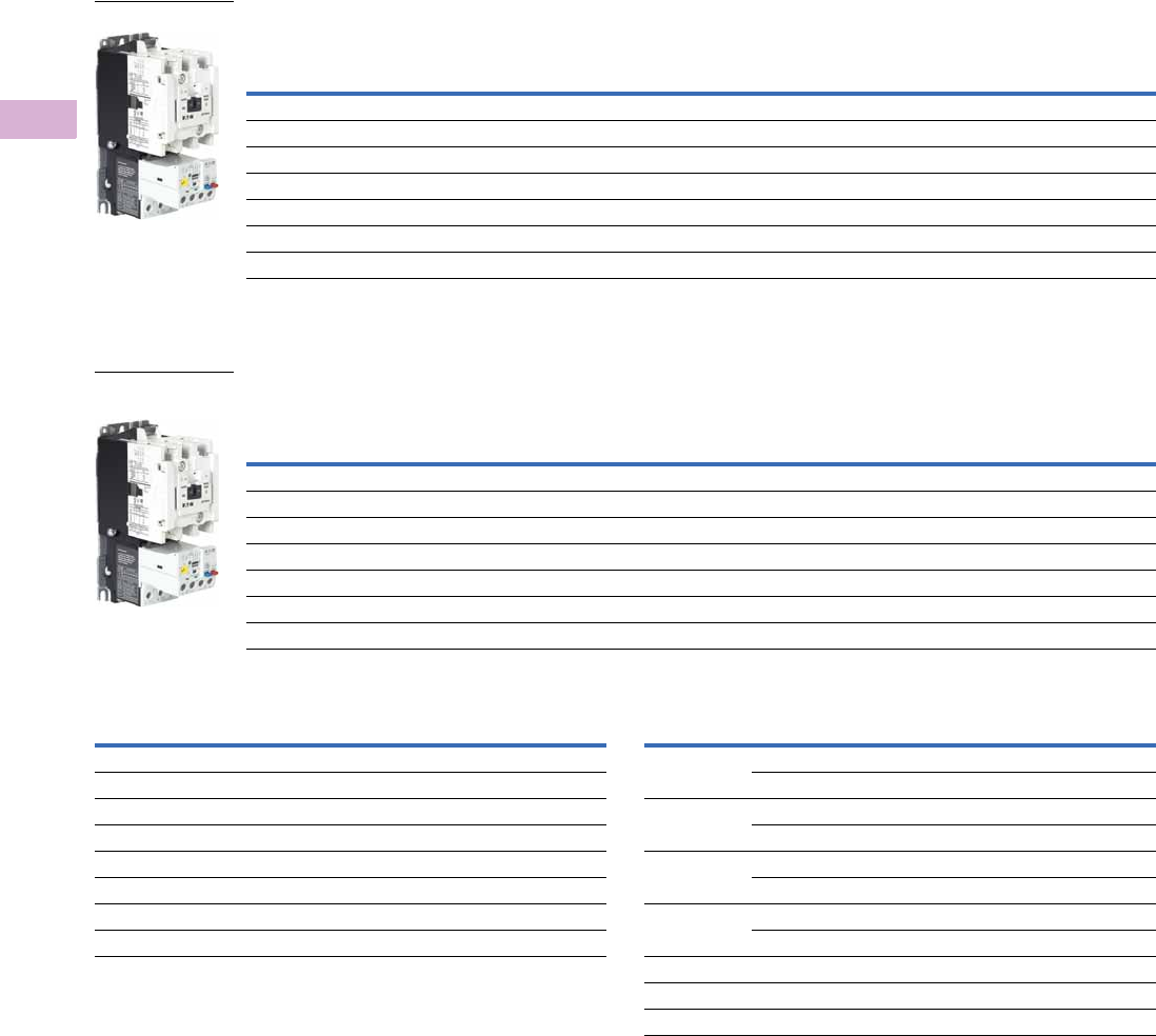
V5-T5-72 Volume 5—Motor Control and Protection CA08100006E—April 2014 www.eaton.com
5
5
5
5
5
5
5
5
5
5
5
5
5
5
5
5
5
5
5
5
5
5
5
5
5
5
5
5
5
5
5.4
Motor Protection and Monitoring
Overload Relays
Type AN19/59 Freedom Series Starters
Type AN19/59 Freedom Series Starters with C440 Electronic Overload Relays
Non-Reversing and Reversing
Type AN19/59 Freedom Series Starters with C440 with Ground Fault Electronic Overload Relays
Non-Reversing and Reversing
Coil Suffix Codes C440 FLA Range (FVNR and FVR Starters Only)
Notes
1Underscore (_) indicates coils suffix required, see Coil Suffix table above.
2Underscore (_) indicates OLR designation required, see C440 FLA Range table above.
3NEMA Size 5 starter available with 60-300A panel mounted CTs. Starter shipped as an assembled unit with
1–5A C440 overload relay (C440A1A005SELAX or C440A2A005SELAX).
NEMA
Size
Continuous
Ampere
Rating
Service Limit
Current Rating
(Amps)
Maximum UL Horsepower Three-Pole
Non-Reversing 12
Three-Pole
Reversing 12
Single-Phase Three-Phase
115V 230V 208V 240V 480V 600V Catalog Number Catalog Number
00 9 11 1/3 1 1-1/2 1-1/2 2 2 AN19AN0_ 5E _ AN59AN0_ 5E _
018 21 123355AN19BN0_ 5E _ AN59BN0_ 5E _
127 32 237-1/27-1/21010AN19DN0_ 5E _ AN59DN0_ 5E _
2 45 52 3 7-1/210152525AN19GN0_ 5E _ AN59GN0_ 5E _
3 90 104 ——25305050AN19KN0_ 5E _ AN59KN0_ 5E _
4 135 156 — — 40 50 100 100 AN19NN0_ 5E _ AN59NN0_ 5E _
5 3270 311 — — 75 100 200 200 AN19SN0_ 5E _ AN59SN0_ 5E _
NEMA
Size
Continuous
Ampere
Rating
Service Limit
Current Rating
(Amps)
Maximum UL Horsepower Three-Pole
Non-Reversing 12
Three-Pole
Reversing 12
Single-Phase Three-Phase
115V 230V 208V 240V 480V 600V Catalog Number Catalog Number
00 9 11 1/3 1 1-1/2 1-1/2 2 2 AN19AN0_ 5G _ AN59AN0_ 5G _
018 21 123355AN19BN0_ 5G _ AN59BN0_ 5G _
127 32 237-1/27-1/21010AN19DN0_ 5G _ AN59DN0_ 5G _
2 45 52 3 7-1/210152525AN19GN0_ 5G _ AN59GN0_ 5G _
3 90 104 ——25305050AN19KN0_ 5G _ AN59KN0_ 5G _
4 135 156 — — 40 50 100 100 AN19NN0_ 5G _ AN59NN0_ 5G _
5 3270 311 — — 75 100 200 200 AN19SN0_ 5G _ AN59SN0_ 5G _
NEMA Starter
NEMA Starter with
Ground Fault
Suffix Coil Volts and Hertz Suffix Coil Volts and Hertz
A120/60 or 110/50 L380–415/50
B240/60 or 220/50 N550/50
C480/60 or 440/50 T24/60, 24/50
D600/60 or 550/50 U24/50
E208/60 V32/50
H277/60 W48/60
J208–240/60 Y48/50
K240/50
NEMA Size OLR Code FLA Range OLR Code FLA Rating
00 1P6 0.33–1.65A 020 4.0–20A
005 1.0–5.0A ——
01P6 0.33–1.65A 020 4.0–20A
005 1.0–5.0A ——
11P6 0.33–1.65A 020 4.0–20A
005 1.0–5.0A 045 9.0–45A
2005 1.0–5.0A 045 9.0–45A
020 4.0–20A ——
3100 20–100A ——
4140 28–140A ——
5 3300 60–300A ——

Volume 5—Motor Control and Protection CA08100006E—April 2014 www.eaton.com V5-T5-73
5
5
5
5
5
5
5
5
5
5
5
5
5
5
5
5
5
5
5
5
5
5
5
5
5
5
5
5
5
5
5.4
Motor Protection and Monitoring
Overload Relays
Compact NEMA Size 1 and 4 Starters
New Compact NEMA Size 1 and 4 starters—available with electronic overload relay only.
Non-Reversing
Electrical Life at Rated Continuous Current
NEMA
Size
Continuous
Ampere
Rating
Service Limit
Current Rating
(Amps)
Maximum UL Horsepower Three-Pole
Non-Reversing Single-Phase Three-Phase
115V 230V 208V 240V 480V 600V Catalog Number
Standard Fault Overload
1C 27 32 2 3 7.5 7.5 10 10 AN19CN0_5E_
4C 135 156 — — 40 50 100 100 AN19MN0_5E_
Ground Fault Overload
1C 27 32 2 3 7.5 7.5 10 10 AN19CN0_5G_
4C 135 156 — — 40 50 100 100 AN19MN0_5G_
NEMA
Size
Rated Current
(Amperage)
AC3/AC4 Operations
1C 27/150 2,500,000/40,000
1 27/153 5,000,000/110,000
4C 135/516 500,000/40,000
4 135/822 800,000/70,000
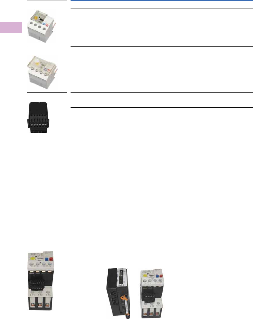
V5-T5-74 Volume 5—Motor Control and Protection CA08100006E—April 2014 www.eaton.com
5
5
5
5
5
5
5
5
5
5
5
5
5
5
5
5
5
5
5
5
5
5
5
5
5
5
5
5
5
5
5.4
Motor Protection and Monitoring
Overload Relays
Accessories
CT Kits
Accessories
Communication
The C440/XTOE is provided with two levels of communication capability.
Basic Communication via
Expansion Module—
Monitoring Only
Basic communication on
the C440 is accomplished
using an expansion module
(C440-XCOM). The expansion
module plugs into the
expansion bay on the C440
overload relay, enabling
communications with the
overload via their Modbus
RTU (RS-485) network. No
additional cards or modules are
required. See figure below.
Basic Communication—
Modbus
Advanced
Communication—
Monitoring and Control
C440 also has the ability to
communicate on industrial
protocols such as Modbus
RTU, DeviceNet, PROFIBUS,
Modbus TCP, and EtherNet/IP
while providing control
capability using I/O.
An expansion module (C440-
XCOM) combined with a
communication adapter
(C440-COM-ADP) and a
communication module
allows easy integration onto
the customer's network.
Seefigurebelow.
2
Advanced Communication—
Communication Adapter with
Communication Module
Advanced
Communication—
Communication Adapter 2
The communication adapter
(C440-COM-ADP) is required
for obtaining control capability
via communications within
the C440 family. Combined
with a communication
module, the customer is
provided with flexible
mounting options (DIN rail or
panel) along with four inputs
and two outputs (24 Vdc or
120 Vac) as standard.
Notes
1Customer can wire remote mounted button to reset module (that is, 22 mm pushbutton, catalog number M22-D-B-GB14-K10).
2Modbus TCP and EtherNet/IP communication modules do not require the C440-COM-ADP communication adapter.
Description Catalog Number
Safety Cover
Clear Lexan cover that mounts on top of the FLA dial and DIP switches when closed. ZEB-XSC
Reset Bar
Assembles to the top of the overload to provide a larger target area for door
mounted reset operators.
ZEB-XRB
Remote Reset
Remote reset module (24 Vdc) 1C440-XCOM
Remote reset module (120 Vac) 1ZEB-XRR-120
Remote reset module (24 Vac) 1ZEB-XRR-24
Safety Cover
Reset Bar
Remote Reset
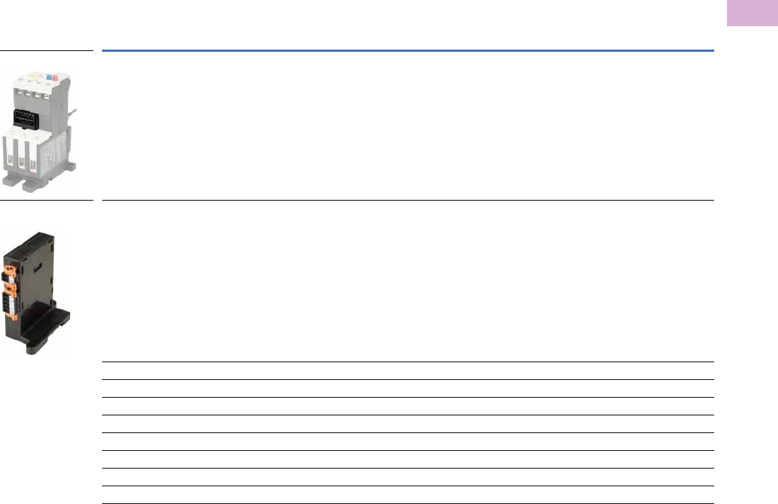
Volume 5—Motor Control and Protection CA08100006E—April 2014 www.eaton.com V5-T5-75
5
5
5
5
5
5
5
5
5
5
5
5
5
5
5
5
5
5
5
5
5
5
5
5
5
5
5
5
5
5
5.4
Motor Protection and Monitoring
Overload Relays
The following information can be viewed using the communication option:
●Motor status—running,
stopped, tripped or
resetting
●Individual rms phase
currents (A, B, C)
●Average of three-phase
rms current
●Percent thermal capacity
●Fault codes (only available
prior to reset)
●Percent phase unbalance
●Ground fault current and
percent
●Overload relay settings—
trip class, DIP switch
selections, reset selections
●Modbus address (can be
set over the network)
Communication Accessories
Description Catalog Number
Expansion module (Remote Reset/Modbus RTU, RS-485 Communication) C440-XCOM
Communication adapter kit (DIN C Panel mounted adapter, required for advance communication option) C440-COM-ADP
DeviceNet communication module kit—120V I/O (consists of C440-XCOM + C441K + C440-COM-ADP) C440-DN-120
DeviceNet communication module kit—24 Vdc I/O (consists of C440-XCOM + C441L + C440-COM-ADP) C440-DN-24
PROFIBUS communication module kit—120V I/O (consists of C440-XCOM + C441S + C440-COM-ADP) C440-DP-120
PROFIBUS communication module kit—24V I/O (consists of C440-XCOM + C441Q + C440-COM-ADP) C440-DP-24
Modbus communication module kit—120V I/O (consists of C440-XCOM + C441N + C440-COM-ADP) C440-MOD-120
Modbus communication module kit—24 Vdc I/O (consists of C440-XCOM + C441P + C440-COM-ADP) C440-MOD-24
Modbus TCP/Ethernet IP communication module kit—120V I/O (consists of C440-XCOM + C441U) C440-ET-120
Modbus TCP/Ethernet IP communication module kit—24V I/O (consists of C440-XCOM + C441V) C440-ET-24
Expansion Module
Communication
Adapter
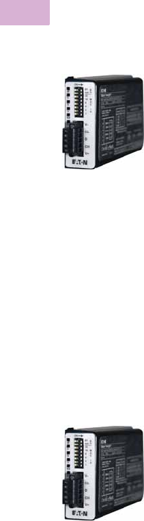
V5-T5-76 Volume 5—Motor Control and Protection CA08100006E—April 2014 www.eaton.com
5
5
5
5
5
5
5
5
5
5
5
5
5
5
5
5
5
5
5
5
5
5
5
5
5
5
5
5
5
5
5.4
Motor Protection and Monitoring
Overload Relays
Modbus Communication Module
The Modbus communication
module combined with an
expansion module and a
communication adapter
provides monitoring and
control capability to the
C440/XTOE electronic
overload relay via Modbus
RTU communications.
These modules also provide
convenient I/O with 24 Vdc or
120 Vac options.
Features and Benefits
●The Modbus
communication module is
capable of baud rates
up to 115K
●The Modbus address and
baud rate configuration can
be easily changed using
the HMi user interface
●Modbus address and baud
rate are set via convenient
DIP switches; LEDs are
provided to display
Modbus traffic
●Configuration with
common Modbus
configuration tools
●Terminals
●Unique locking
mechanism provides for
easy removal of the
terminal block with the
field wiring installed
●Each terminal is marked
for ease of wiring and
troubleshooting
●Selectable I/O assemblies
●4IN/2OUT
●Signal types include
24 Vdc I/O and
120 Vac I/O
●Each I/O module is
optically isolated
between the field I/O
and the network adapter
to protect the I/O and
communication circuits
from possible damage
due to transients and
ground loops
●Input Module features a
user-definable input
debounce, which limits
the effects of transients
and electrical noise
●Output Module supports
a user-definable safe
state for loss of
communication; hold
last state, ON or OFF
DeviceNet Communication Modules
The DeviceNet communication
module combined with an
expansion module and a
communication adapter
provides monitoring and
control capability to the
C440/XTOE electronic
overload relay via DeviceNet
communications. These
modules also provide
convenient I/O with 24 Vdc
or 120 Vac options.
Features and Benefits
●Communication to
DeviceNet uses only one
DeviceNet MAC ID
●Configuration
●DeviceNet MAC ID and
Baud rate are set via
convenient DIP switches
with an option to set
from the network
●Advanced configuration
available using common
DeviceNet tools
●Terminals
●Unique locking
mechanism provides for
easy removal of the
terminal block with the
field wiring installed
●Each terminal is marked
for ease of wiring and
troubleshooting
●Selectable I/O assemblies
●4IN/2OUT
●Signal types include
24 Vdc I/O and
120 Vac I/O
●Each I/O module is
optically isolated
between the field I/O
and the network adapter
to protect the I/O and
communication circuits
from possible damage
due to transients and
ground loops
●Input Module features a
user-definable input
debounce, which limits
the effects of transients
and electrical noise
●Output Module supports
a user-definable safe
state for loss of
communication; hold
last state, ON or OFF
●Combined status LED
Modbus
Communication Module
DeviceNet
Communication Module
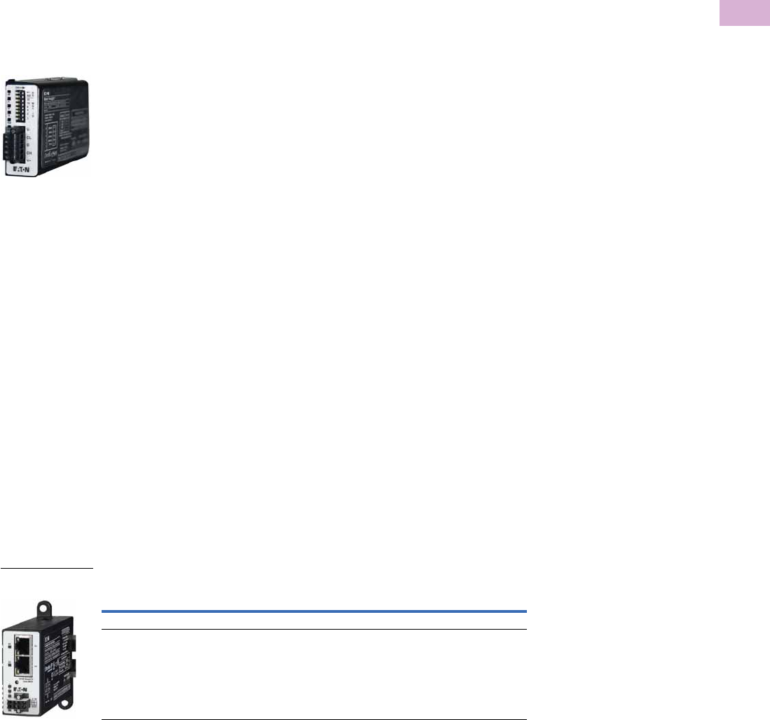
Volume 5—Motor Control and Protection CA08100006E—April 2014 www.eaton.com V5-T5-77
5
5
5
5
5
5
5
5
5
5
5
5
5
5
5
5
5
5
5
5
5
5
5
5
5
5
5
5
5
5
5.4
Motor Protection and Monitoring
Overload Relays
PROFIBUS Communication Modules
The PROFIBUS
communication module
combined with an expansion
module and a communication
adapter provides monitoring
and control capability to the
C440 / XTOE electronic
overload relay via PROFIBUS
communications. These
modules also provide
convenient I/O with 24 Vdc or
120 Vac options.
Features and Benefits
●The PROFIBUS
communication module is
capable of baud rates
up to 12 Mb
●PROFIBUS address is
set via convenient DIP
switches; LEDs are
provided to display
PROFIBUS status
●Intuitive configuration
with common PROFIBUS
configuration tools
●Terminals
●Unique locking
mechanism provides for
easy removal of the
terminal block with the
field wiring installed
●Each terminal is marked
for ease of wiring and
troubleshooting
●Selectable I/O assemblies
●4IN/2OUT
●Signal types include
24 Vdc I/O and
120 Vac I/O
●Each I/O module is
optically isolated
between the field I/O
and the network adapter
to protect the I/O and
communication circuits
from possible damage
due to transients and
ground loops
●Input Module features a
user-definable input
debounce, which limits
the effects of transients
and electrical noise
●Output Module supports
a user-definable safe
state for loss of
communication; hold
last state, ON or OFF
Ethernet Communication Modules
The Ethernet communication
module combined with an
expansion module provides
both Modbus TCP and
EtherNet/IP communication
capabilities with built-in HTTP
web services to the C440/
XTOE overload relay. Unlike
the other communications
modules, a communication
adapter (C440-COM-ADP) is
not required when using the
Ethernet communication
module in C440/XTOE
applications.
The Ethernet communication
module has built-in I/O
providing communication,
monitoring and control for the
C440/XTOE overload relay.
Features and Benefits
●Supports Modbus TCP or
EtherNet/IP in a single
device
●Contains an internal
embedded switch which
provides two Ethernet
ports allowing linear or ring
network configurations
●Embedded web services
allow for simple
configuration and
monitoring through
Internet Explorer
●IP Address is set via
convenient DIP Switches
located on the device
●Terminals
●Unique locking
mechanism provides for
easy removal of the
terminal block with the
field wiring installed
●Each terminal is marked
for ease of wiring and
troubleshooting
●Selectable I/O assemblies
●4IN/2OUT
●Signal types include
24 Vdc I/O and
120 Vac I/O
●Each I/O module is
optically isolated
between the field I/O
and the network adapter
to protect the I/O and
communication circuits
from possible damage
due to transients and
ground loops
●Input Module features a
user-definable input
debounce, which limits
the effects of transients
and electrical noise
●Output Module supports
a user-definable safe
state for loss of
communication; hold
last state, ON or OFF
Ethernet Communication Module
PROFIBUS
Communication Module
Description I/O
Catalog
Number
Modbus TCP / EtherNet/IP Communication Module, 4IN/2OUT (DIN/Panel) 120 Vac C441U
Modbus TCP / EtherNet/IP Communication Module, 4IN/2OUT (DIN/Panel) 24 Vdc C441V
Ethernet with
I/O Module

V5-T5-78 Volume 5—Motor Control and Protection CA08100006E—April 2014 www.eaton.com
5
5
5
5
5
5
5
5
5
5
5
5
5
5
5
5
5
5
5
5
5
5
5
5
5
5
5
5
5
5
5.4
Motor Protection and Monitoring
Overload Relays
Technical Data and Specifications
Electronic Overload Relays up to 1500A
Specification
Description 45 mm 55 mm 110 mm
Electrical Ratings Range Range Range
Operating voltage (three-phase) and frequency 690 Vac (60/50 Hz) 690 Vac (60/50 Hz) 690 Vac (60/50 Hz)
FLA Range
0.33–1.65A
1–5A
4–20A
9–45A
20–100A 28–140A (NEMA)
35–175A (IEC)
Use with Contactors
XT IEC frames B, C, D F, G G, H
Freedom NEMA sizes 00, 0, 1, 2 3 4
Tri p C l a s s
10A, 10, 20, 30
Selectable
10A, 10, 20, 30
Selectable
10A, 10, 20, 30
Selectable
Motor Protection
Thermal overload setting 1.05 x FLA: does not trip
1.15 x FLA: overload trip
1.05 x FLA: does not trip
1.15 x FLA: overload trip
1.05 x FLA: does not trip
1.15 x FLA: overload trip
Feature Range Range Range
Phase loss Fixed threshold 50% Fixed threshold 50% Fixed threshold 50%
Phase unbalance (selectable: enable/disable) Fixed threshold 50% Fixed threshold 50% Fixed threshold 50%
Ground fault (selectable: enable/disable) 50% of FLA dial setting
>150% = 2 sec
>250% = 1 sec
50% of FLA dial setting
>150% = 2 sec
>250% = 1 sec
50% of FLA dial setting
>150% = 2 sec
>250% = 1 sec
Reset Manual/automatic Manual/automatic Manual/automatic
Indicators
Trip status Orange flag Orange flag Orange flag
Mode LED One flash: Overload operating properly
Two flashes: Current is above FLA dial
setting—pending trip
One flash: Overload operating properly
Two flashes: Current is above FLA dial
setting—pending trip
One flash: Overload operating properly
Two flashes: Current is above FLA dial
setting—pending trip
Options
Remote reset Yes Yes Yes
Reset bar Yes Yes Yes
Communication expansion module Yes Yes Yes
Communication adapter Yes Yes Yes
Capacity
Load terminals
Terminal capacity 12–10 AWG (4–6 mm2)
8–6 AWG (6–16 mm2)
6–1 AWG (16–50 mm2) 8–4/0 AWG (10–95 mm2)
Tightening torque 20–25 lb-in (2.3–2.8 Nm)
25–30 lb-in (2.8–3.4 Nm)
25–30 lb-in (2.8–3.4 Nm) 124 lb-in (14 Nm)
Input, auxiliary contact and remote reset terminals
Terminal capacity 2 x (18–12) AWG 2 x (18–12) AWG 2 x (18–12) AWG
Tightening torque 7–11 lb-in (0.8–1.2 Nm) 7–11 lb-in (0.8–1.2 Nm) 7–11 lb-in (0.8–1.2 Nm)
Voltages
Insulation voltage Ui (three-phase) 690 Vac 690 Vac 690 Vac
Insulation voltage Ui (control) 500 Vac 500 Vac 500 Vac
Rated impulse withstand voltage 6000 Vac 6000 Vac 6000 Vac
Overvoltage category/pollution degree III/3 III/3 III/3

Volume 5—Motor Control and Protection CA08100006E—April 2014 www.eaton.com V5-T5-79
5
5
5
5
5
5
5
5
5
5
5
5
5
5
5
5
5
5
5
5
5
5
5
5
5
5
5
5
5
5
5.4
Motor Protection and Monitoring
Overload Relays
Electronic Overload Relays up to 1500A, continued
Specification
Description 45 mm 55 mm 110 mm
Auxiliary and Control Circuit Ratings
Conventional thermal continuous current 5A 5A 5A
Rated operational current—IEC AC-15
Make contact (1800 VA)
120V 15A 15A 15A
240V 15A 15A 15A
415V 0.5A 0.5A 0.5A
500V 0.5A 0.5A 0.5A
Break contact (180 VA)
120V 1.5A 1.5A 1.5A
240V 1.5A 1.5A 1.5A
415V 0.9A 0.9A 0.9A
500V 0.8A 0.8A 0.8A
IEC DC-13 (L/R F 15 ms1)
0–250V 1.0A 1.0A 1.0A
Rated operational current—UL B600
Make contact (3600 VA)
120V 30A 30A 30A
240V 15A 15A 15A
480V 7.5A 7.5A 7.5A
600V 6A 6A 6A
Break contact (360 VA)
120V 3A 3A 3A
240V 1.5A 1.5A 1.5A
480V 0.75A 0.75A 0.75A
600V 0.6A 0.6A 0.6A
R300—Vdc ratings (28 VA)
0–120V 0.22A 0.22A 0.22A
250V 0.11A 0.11A 0.11A
Short-Circuit Rating without Welding
Maximum fuse 6A gG/gL 6A gG/gL 6A gG/gL
Environmental Ratings
Ambient temperature (operating) –13° to 149°F (–25° to 65°C) –13° to 149°F (–25° to 65°C) –13° to 149°F (–25° to 65°C)
Ambient temperature (storage) –40° to 185°F (–40° to 85°C) –40° to 185°F (–40° to 85°C) –40° to 185°F (–40° to 85°C)
Operating humidity UL 991 (H3) 5% to 95% non-condensing 5% to 95% non-condensing 5% to 95% non-condensing
Altitude (no derating) NEMA ICS1 2000m 2000m 2000m
Shock (IEC 600068-2-27) 15g any direction 15g any direction 15g any direction
Vibration (IEC 60068-2-6) 3g any direction 3g any direction 3g any direction
Pollution degree per IEC 60947-4-1 3 for product (2 for pcb) 3 for product (2 for pcb) 3 for product (2 for pcb)
Ingress protection IP20 IP20 IP20
Protection against direct contact when actuated from
front (IEC 536)
Finger- and back-of-hand proof Finger- and back-of-hand proof Finger- and back-of-hand proof
Mounting position Any Any Any
Climatic proofing Damp heat, constant to IEC 60068-2-30 Damp heat, constant to IEC 60068-2-30 Damp heat, constant to IEC 60068-2-30

V5-T5-80 Volume 5—Motor Control and Protection CA08100006E—April 2014 www.eaton.com
5
5
5
5
5
5
5
5
5
5
5
5
5
5
5
5
5
5
5
5
5
5
5
5
5
5
5
5
5
5
5.4
Motor Protection and Monitoring
Overload Relays
Electronic Overload Relays up to 1500A, continued
Specification
Description 45 mm 55 mm 110 mm
Electrical/EMC
Radiated emissions
IEC 60947-4-1-Table 15
EN 55011 (CISPIR 11) Group 1, Class A, ISM
30 mHz to 1000 mHz 30 mHz to 1000 mHz 30 mHz to 1000 mHz
Conducted emissions
IEC 60947-4-1-Table 14
EN 55011 (CISPIR 11) Group 1; Class ISM
0.15 mHz to 30 mHz 0.15 mHz to 30 mHz 0.15 mHz to 30 mHz
ESD immunity
IEC 60947-4-1 (Table 13)
±8 kV air, ±6 kV contact ±8 kV air, ±6 kV contact ±8 kV air, ±6 kV contact
Radiated immunity
IEC 60947-4-1
IEC 61000-4-3
10 V/m 80 mHz–1000 mHz
3 V/m from 1.4 to 2.7 gHz
80% amplitude modulated
1 kHz sine wave
10 V/m 80 mHz–1000 mHz
3 V/m from 1.4 to 2.7 gHz
80% amplitude modulated
1 kHz sine wave
10 V/m 80 mHz–1000 mHz
3 V/m from 1.4 to 2.7 gHz
80% amplitude modulated
1 kHz sine wave
Conducted immunity
IEC 60947-4-1, IEC 61000-4-6
140 dub (10V rms)
150 kHz–100 mHz
140 dub (10V rms)
150 kHz–100 mHz
140 dub (10V rms)
150 kHz–100 mHz
Fast transient immunity
IEC 60947-4-1 (Table 13)
IEC 61000-4-4
±4 kV using direct method
with accessory installed in expansion bay
±2 kV using direct method
±4 kV using direct method
with accessory installed in expansion bay
±2 kV using direct method
±4 kV using direct method
with accessory installed in expansion bay
±2 kV using direct method
Surge immunity
IEC 60947-4-1 (Table 13)
IEC 61000-4-5 a Class 4
Three-phase power inputs:
±4 kV line-to-line (DM)
±4 kV line-to-ground (CM)
Three-phase power inputs:
±4 kV line-to-line (DM)
±4 kV line-to-ground (CM)
Three-phase power inputs:
±4 kV line-to-line (DM)
±4 kV line-to-ground (CM)
With accessory installed in expansion bay:
±2 kV line-to-line (DM) –>1.2/50 us;
2 kV line-to-earth, 1 kV line-to-line
±4 kV line-to-ground (CM)
With accessory installed in expansion bay:
±2 kV line-to-line (DM) –>1.2/50 us;
2 kV line-to-earth, 1 kV line-to-line
±4 kV line-to-ground (CM)
With accessory installed in expansion bay:
±2 kV line-to-line (DM) –>1.2/50 us;
2 kV line-to-earth, 1 kV line-to-line
±4 kV line-to-ground (CM)
Power freq. magnetic field immunity
IEC 60947-4-1, IEC 61000-4-8
30 A/m, 50 Hz 30 A/m, 50 Hz 30 A/m, 50 Hz
Electromagnetic field
IEC 60947-4-1 Table 13, IEC 61000-4-3
10 V/m 10 V/m 10 V/m
Distortion IEEE 519 5% THD max., 5th harmonic 3% max. 5% THD max., 5th harmonic 3% max. 5% THD max., 5th harmonic 3% max.
Electrostatic discharge (ESD)
IEC 61000-4-2, EN 61131-2
4 kV contact
8 kV air discharge
4 kV contact
8 kV air discharge
4 kV contact
8 kV air discharge
Electrical fast transient (EFT)
IEC 61000-4-4, EN 61131-2
±2 kV using direct method ±2 kV using direct method ±2 kV using direct method
Surge immunity
IEC 61000-4-5, EN 61131-2
±2 kV line-to-ground (CM) ±2 kV line-to-ground (CM) ±2 kV line-to-ground (CM)

Volume 5—Motor Control and Protection CA08100006E—April 2014 www.eaton.com V5-T5-81
5
5
5
5
5
5
5
5
5
5
5
5
5
5
5
5
5
5
5
5
5
5
5
5
5
5
5
5
5
5
5.4
Motor Protection and Monitoring
Overload Relays
Communication Modules
Note
1Relates to C441M only.
Description Modbus DeviceNet PROFIBUS Ethernet
Electrical/EMC
Radiated emissions
IEC 60947-4-1—Table 15, EN 55011
(CISPIR 11) Group 1, Class A
30–1000 mHz 30–1000 mHz 30–1000 mHz 30–1000 mHz
Conducted emissions
IEC 60947-4-1—Table 14, EN 55011
(CISPIR 11) Group 1, Class A
0.15–30 mHz 0.15–30 mHz 0.15–30 mHz 0.15–30 mHz
ESD immunity
IEC 60947-4-1 (Table 13)
±8 kV air, ±4 kV contact ±8 kV air, ±4 kV contact ±8 kV air, ±4 kV contact ±8 kV air, ±4 kV contact
Radiated immunity
IEC 60947-4-1
10 V/m 80–1000 mHz
80% amplitude modulated
1 kHz sine wave
10 V/m 80–1000 mHz
80% amplitude modulated
1 kHz sine wave
10 V/m 80–1000 mHz
80% amplitude modulated
1 kHz sine wave
10 V/m 80–1000 mHz
80% amplitude modulated
1 kHz sine wave
Conducted immunity
IEC 60947-4-1
140 dBuV (10V rms)
150 kHz–80 mHz
140 dBuV (10V rms)
150 kHz–80 mHz
140 dBuV (10V rms)
150 kHz–80 mHz
140 dBuV (10V rms)
150 kHz–80 mHz
Fast transient immunity
IEC 60947-4-1 (Table 13) IEC 6100-4-4
±2 kV using direct method ±2 kV supply and control,
±1 kV communication
±2 kV supply and control,
±1 kV communication
±2 kV supply and control,
±1 kV communication
Surge immunity
IEC 60947-4-1 (Table 13)
IEC 61000-4-5 Class 3
User IO and communication lines 1:
±1 kV line-to-line (DM)
±2 kV line-to-ground (CM)
User IO and communication lines:
±0.5 kV line-to-line (DM)
±1 kV line-to-ground (CM)
User IO and communication lines:
±0.5 kV line-to-line (DM)
±1 kV line-to-ground (CM)
User IO and communication lines:
±0.5 kV line-to-line (DM)
±1 kV line-to-ground (CM)
Electromagnetic field 1
IEC 60947-4-1 (Table 13) IEC 61000-4-3
10 V/m 10 V/m 10 V/m 10 V/m
Environmental Ratings
Ambient temperature (operating) –4° to 122°F (–20° to 50°C) –13° to 122°F (–25° to 50°C) –13° to 122°F (–25° to 50°C) –13° to 122°F (–25° to 50°C)
Ambient temperature (storage) –40° to 185°F (–40° to 85°C) –40° to 185°F (–40° to 85°C) –40° to 185°F (–40° to 85°C) –40° to 185°F (–40° to 85°C)
Operating humidity 5–95% noncondensing 5–95% noncondensing 5–95% noncondensing 5–95% noncondensing
Altitude (no derating) 2000m 2000m 2000m 2000m
Shock (IEC 600068-2-27) 15G any direction 15G any direction 15G any direction 15G any direction
Vibration (IEC 60068-2-6) 3G any direction 3G any direction 3G any direction 3G any direction
Pollution degree per IEC 60947-1 3 3 3 3
Degree of protection IP20 IP20 IP20 IP20
Overvoltage category per UL 508 III III III III
DeviceNet
DeviceNet connections — Group 2, polling, bit strobe,
explicit, no UCMM
——
DeviceNet baud rate — 125K, 250K, 500K — —
Ethernet
Ethernet connections — — — Integrated two-port switch with dual
RJ45 Ethernet connections
Ethernet type — — — Ethernet 10/100 Mbs, AutoMDX,
Auto Negotiation
PROFIBUS
PROFIBUS connections — — Group 2, polling, bit strobe,
explicit, no UCMM
—
PROFIBUS baud rate — — 9.6K, 19.2K, 45.45K, 93.75K, 187.5K,
500K, 1.5M, 3M, 6M, 12M
—

V5-T5-82 Volume 5—Motor Control and Protection CA08100006E—April 2014 www.eaton.com
5
5
5
5
5
5
5
5
5
5
5
5
5
5
5
5
5
5
5
5
5
5
5
5
5
5
5
5
5
5
5.4
Motor Protection and Monitoring
Overload Relays
Communication Modules, continued
Note
1Resistive current at 55°C ambient.
Description Modbus DeviceNet PROFIBUS Ethernet
C441_ 24 Vdc Input
Nominal input voltage 24 Vdc 24 Vdc 24 Vdc 24 Vdc
Operating voltage 18–30 Vdc 18–30 Vdc 18–30 Vdc 18–30 Vdc
Number of inputs 4 4 4 4
Signal delay 5 ms (programmable to 65 sec) 5 ms (programmable to 65 sec) 5 ms (programmable to 65 sec) 5 ms (programmable to 65 sec)
OFF-state voltage <6 Vdc <6 Vdc <6 Vdc <6 Vdc
ON-state voltage >18 Vdc >18 Vdc >10 Vdc >18 Vdc
Nominal input current 5 mA 5 mA 5 mA 5 mA
Isolation 1500V 1500V 1500V 1500V
Terminal screw torque 7–9 in-lb 7–9 in-lb 7–9 in-lb 7–9 in-lb
24V source current 50 mA 50 mA 50 mA 50 mA
Operating Voltage Range—DC Input Modules
OFF state 0–6 Vdc 0–6 Vdc 0–6 Vdc 0–6 Vdc
Transition region 6–18 Vdc 6–18 Vdc 6–18 Vdc 6–18 Vdc
ON state 18–30 Vdc 18–30 Vdc 18–30 Vdc 18–30 Vdc
C441_ 120 Vac Input
Nominal input voltage 120 Vac 120 Vac 120 Vac 120 Vac
Operating voltage 80–140 Vac 80–140 Vac 80–140 Vac 80–140 Vac
Number of inputs 4 4 4 4
OFF-state voltage <30 Vac <30 Vac <20 Vac <30 Vac
ON-state voltage >80 Vac >80 Vac >70 Vac >80 Vac
Nominal input current 15 mA 15 mA 15 mA 15 mA
Signal delay 1/2 cycle 1/2 cycle 1/2 cycle 1/2 cycle
Isolation 1500V 1500V 1500V 1500V
Terminal screw torque 7–9 in-lb 7–9 in-lb 7–9 in-lb 7–9 in-lb
Operating Voltage Range—AC Input Modules
OFF state 0–30 Vac 0–30 Vac 0–30 Vac 0–30 Vac
Transition region 30–80 Vac 30–80 Vac 30–80 Vac 30–80 Vac
ON state 80–140 Vac 80–140 Vac 80–140 Vac 80–140 Vac
Output Modules
Nominal voltage 120 Vac
24 Vdc
120 Vac
24 Vdc
120 Vac
24 Vdc
120 Vac
24 Vdc
Number of outputs (2) 1NO Form A
1NO/NC Form C
(2) 1NO Form A
1NO/NC Form C
(2) 1NO Form A
1NO/NC Form C
(2) 1NO Form A
1NO/NC Form C
Relay OFF time 3 ms 3 ms 3 ms 3 ms
Relay ON time 7 ms 7 ms 7 ms 7 ms
Max. current per point 15A (B300 rated) 5A (B300 rated) 5A (B300 rated) 5A (B300 rated)
Electrical life 100,000 cycles 100,000 cycles 100,000 cycles 100,000 cycles
Mechanical life 1,000,000 cycles 1,000,000 cycles 1,000,000 cycles 1,000,000 cycles

Volume 5—Motor Control and Protection CA08100006E—April 2014 www.eaton.com V5-T5-83
5
5
5
5
5
5
5
5
5
5
5
5
5
5
5
5
5
5
5
5
5
5
5
5
5
5
5
5
5
5
5.4
Motor Protection and Monitoring
Overload Relays
Short Circuit Ratings (North America CSA, cUL)
Changes to UL 508A and NEC in recent years have brought a focus to control panel safety with
regard to short-circuit current ratings (SCCR). Eaton’s C440 electronic overload relays combined
with XT series IEC and Freedom Series NEMA contactors provide a wide variety of SCCR
solutions needed for a variety of applications. The SCCR data in this document reflects the
latest information as of April 2010.
C440/XT Standalone Overload Relays (XT, C440)
NEMA Freedom Series Starters with C440 Electronic Overload Relays
IEC XT Starters with XT Electronic Overload Relays
Overload
FLA Range
Maximum
Operating
Voltage
Standard-Fault Short Circuit Data High-Fault Short Circuit Data
600V (kA)
Maximum
Fuse Size (A)
(RK5)
Maximum
Breaker
Size (A)
Fuses (RK5, J, CC) Thermal-Magnetic Circuit Breakers
480V (kA) 600V (kA)
Maximum
Fuse Size 480V (kA) 600V (kA)
Maximum
Breaker Size
0.33–1.65A600 Vac1 6 15 ——————
1–5A 600 Vac 5 20 20 100 100 30 100 35 20
4–20A 600 Vac 5 80 80 100 100 100 100 35 80
9–45A 600 Vac 5 175 175 100 100 100 100 35 100/175 (480/600)
20–100A 600 Vac 10 400 400 100 100 200 150 35 250/400 (480/600)
28–140A 600 Vac 10 450 500 100 100 400 100 65 400
35–175A 690 Vac 10 500 (gG) 350 (690 Vac)
320 (415 Vac)
100 100 500 (gG) 100 (415 Vac) — 350 (LGC3350)
320 (NZMH3)
NEMA
Size
Maximum
Operating
Voltage
High-Fault Short Circuit Data
Maximum
Fuse Size
Thermal-Magnetic Circuit Breakers
Fuses (RK5, J, CC)
480V 600V 480V 600V
Maximum
Breaker Size
00 0.33–1.65A 100 100 30 — — —
1–5A 100 100 30 100 35 35
4–20A 100 100 30 100 35 35
0 0.33–1.65A 100 100 60 — — —
1–5A 100 100 60 100 35 70
4–20A 100 100 60 100 35 70
1 0.33–1.65A 100 100 100 — — —
1–5A 100 100 100 100 35 100
4–20A 100 100 100 100 35 100
9–45A 100 100 100 100 35 100
2 1–5A 100 100 100 100 35 175
4–20A 100 100 100 100 35 175
9–45A 100 100 100 100 35 175
3 20–100A 100 100 200 50 50 250
4 28–140A 100 100 400 100 65 300
Contactor
Frame Size
Maximum
Operating
Voltage
High-Fault Short Circuit Data Thermal-Magnetic Circuit Breakers
Fuses (RK5, J, CC)
480V 600V
Maximum
Fuse Size 480V 600V
Maximum
Breaker Size
B 1–5A 100 100 30 ———
4–20A 100 100 30 — — —
C 1–5A 100 100 60 — — —
4–20A 100 100 60 — — —
9–45A 100 100 60 — — —
D 9–45A 100 100 200 65 35 175
20–100A 100 100 200 65 35 175
F 20–100A 100 100 200 65 65 350
G 20–100A 100 100 200 65 65 350
35–175A 100 100 400 65 30 250 (480 Vac)
350 (600 Vac)
H 35–175A 100 100 400 65 30 400
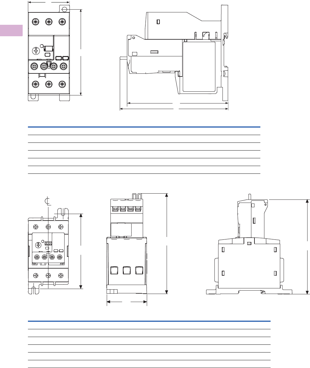
V5-T5-84 Volume 5—Motor Control and Protection CA08100006E—April 2014 www.eaton.com
5
5
5
5
5
5
5
5
5
5
5
5
5
5
5
5
5
5
5
5
5
5
5
5
5
5
5
5
5
5
5.4
Motor Protection and Monitoring
Overload Relays
Dimensions
Approximate Dimensions in Inches (mm)
45 mm C440/XT Electronic Overload Relays
55 mm C440/XT Electronic Overload Relays
Width
A
Depth
B1
Depth to Reset
B
Mounting Hole
(Height) C
NEMA Starter Size
00–2 1.80 (45.0) 4.32 (109.7) 4.63 (117.5) —
XT IEC Frame Size
B, C, D 1.80 (45.0) 4.32 (109.7) 4.30 (109.2) —
Standalone
0.35–45A 1.80 (45.0) 4.32 (109.7) 4.63 (117.5) 3.68 (93.5)
Width
A
Depth to Reset
B
Depth
B1
Mounting Hole
(Height) C
NEMA Starter Size
3 2.21 (55.0) 5.52 (140.2) 5.21 (132.4) 4.13 (104.8)
XT IEC Frame Size
D, F, G 2.21 (55.0) 5.52 (140.2) 5.21 (132.4) 4.13 (104.8)
Standalone
20–100A 2.21 (55.0) 5.52 (140.2) 5.21 (132.4) 4.13 (104.8)
A
C
Text Orientation
B1
B
C
B
A
B1
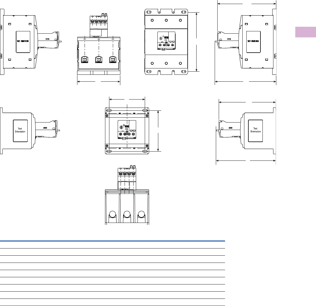
Volume 5—Motor Control and Protection CA08100006E—April 2014 www.eaton.com V5-T5-85
5
5
5
5
5
5
5
5
5
5
5
5
5
5
5
5
5
5
5
5
5
5
5
5
5
5
5
5
5
5
5.4
Motor Protection and Monitoring
Overload Relays
Approximate Dimensions in Inches (mm)
110 mm C4 40 / XT Electronic Overload Relays
Width
A
Height To Reset
BB1
Mounting Depth
C
NEMA Starter Size
4 4.33 (110.0) 6.20 (157.0) 5.90 (150.0) 6.00 (152.0)
XT IEC Frame Size
G 4.33 (110.0) 6.20 (157.0) 5.90 (150.0) 6.00 (152.0)
H 4.33 (110.0) 6.20 (157.0) 5.90 (150.0) 6.00 (152.0)
Standalone
4.33 (110.0) 6.20 (157.0) 5.90 (150.0) 6.00 (152.0)
Pass-Through
4.33 (110.0) 6.20 (157.0) 5.90 (150.0) 6.00 (152.0)
C
B
B1
A
C
B
B1
A
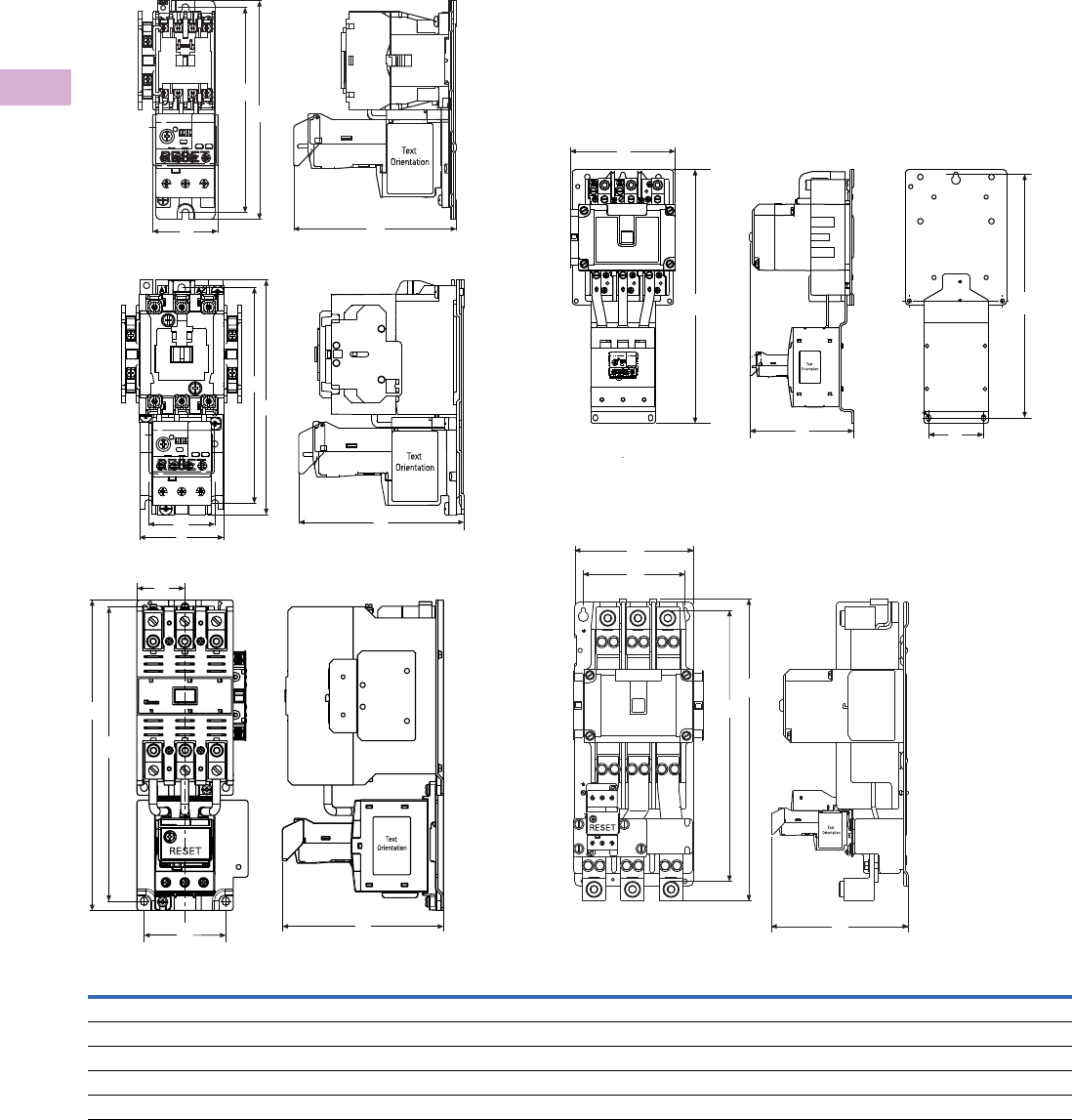
V5-T5-86 Volume 5—Motor Control and Protection CA08100006E—April 2014 www.eaton.com
5
5
5
5
5
5
5
5
5
5
5
5
5
5
5
5
5
5
5
5
5
5
5
5
5
5
5
5
5
5
5.4
Motor Protection and Monitoring
Overload Relays
Approximate Dimensions in Inches (mm)
NEMA Starters
Full Voltage Non-Reversing Starters
NEMA SizeABCDE
00, 0 1.97 (50.0) 6.60 (167.6) 4.90 (124.5) — 6.18 (157.0)
1, 2 2.60 (65.0) 7.10 (180.0) 4.98 (126.5) 2.00 (50.8) 6.50 (165.0)
3 4.09 (103.8) 11.40 (289.6) 5.92 (150.3) 1.77 (44.9) 10.81 (274.6)
4 7.10 (179.0) 17.00 (432.0) 7.00 (177.0) 3.70 (94.0) 16.30 (415.0)
5 7.00 (177.8) 17.81 (452.3) 8.08 (205.2) 6.00 (152.4) 16.01 (406.6)
A
B
C
E
Sizes 00, 0
A
B
CD
E
A
B
C
D
E
A
B
C
D
E
A
B
C
D
E
Sizes 1, 2
Size 4
Size 5Size 3
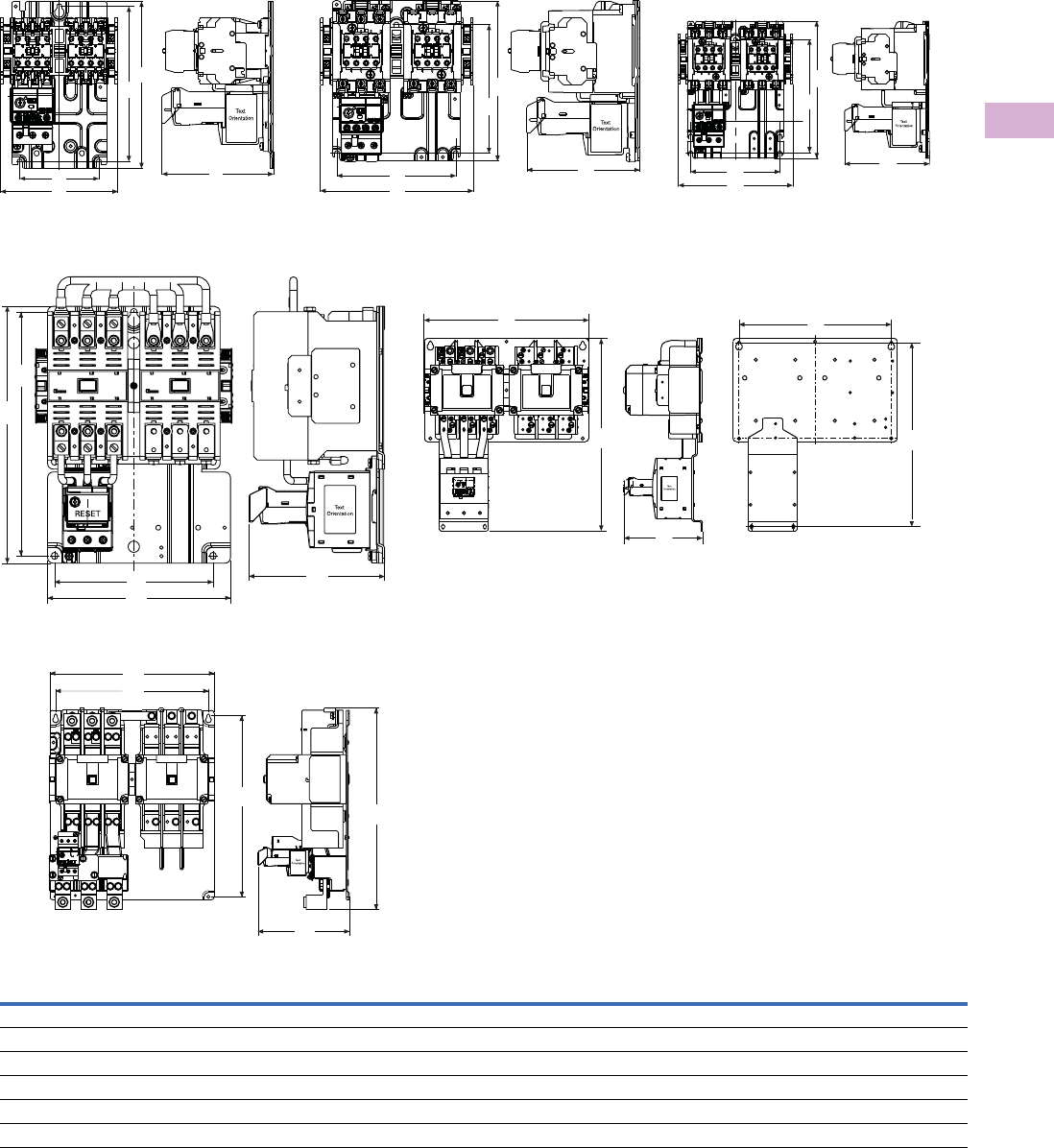
Volume 5—Motor Control and Protection CA08100006E—April 2014 www.eaton.com V5-T5-87
5
5
5
5
5
5
5
5
5
5
5
5
5
5
5
5
5
5
5
5
5
5
5
5
5
5
5
5
5
5
5.4
Motor Protection and Monitoring
Overload Relays
Approximate Dimensions in Inches (mm)
Full Voltage Reversing Starters
NEMA SizeABCDE
00, 0 5.20 (132.0) 7.40 (187.0) 4.90 (125.0) 3.50 (89.0) 6.90 (174.0)
1 6.70 (171.0) 7.10 (180.0) 4.98 (126.5) 5.25 (133.0) 5.70 (144.0)
2 6.70 (171.0) 8.10 (205.0) 4.98 (126.5) 5.25 (133.0) 6.70 (170.0)
3 8.08 (205.2) 11.35 (288.3) 6.00 (152.0) 7.00 (177.8) 10.77 (273.6)
4 14.60 (371.0) 17.10 (433.0) 7.00 (177.0) 13.50 (343.0) 16.30 (145.0)
5 14.50 (368.3) 17.81 (452.3) 8.06 (204.8) 13.50 (342.9) 16.00 (406.6)
Sizes 00, 0
A
B
C
D
E
A
B
C
D
E
Size 5
Size 1
A
B
C
D
E
A
B
C
D
E
Size 3
A
B
C
D
E
Size 2
A
B
C
D
E
Size 4
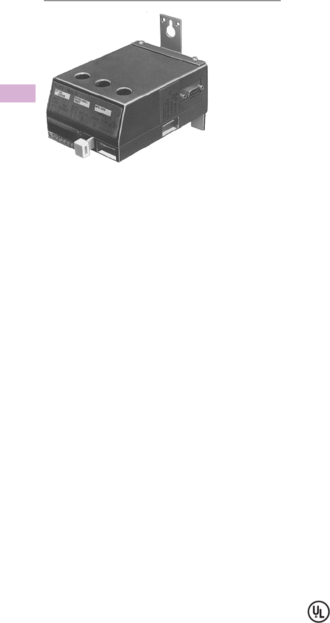
V5-T5-88 Volume 5—Motor Control and Protection CA08100006E—April 2014 www.eaton.com
5
5
5
5
5
5
5
5
5
5
5
5
5
5
5
5
5
5
5
5
5
5
5
5
5
5
5
5
5
5
5.4
Motor Protection and Monitoring
Overload Relays
IQ500 Overload Relays
Contents
Description Page
XT IEC Overload Relays . . . . . . . . . . . . . . . . . . . . V5-T5-60
Freedom Overload Relays . . . . . . . . . . . . . . . . . . . V5-T5-64
C440/XT Electronic Overload Relay . . . . . . . . . . . V5-T5-65
IQ500 Overload Relays
C441 Overload Relays . . . . . . . . . . . . . . . . . . . . . . V5-T5-89
MP-3000 Overload Relays . . . . . . . . . . . . . . . . . . . V5-T5-115
MP-4000 Overload Relays . . . . . . . . . . . . . . . . . . . V5-T5-117
IQ500 Overload Relays
Product Description
The IQ500 is a heaterless,
current-sensing, solid-state
motor protective relay with
optional communications
capabilities. Several functions
are incorporated into the base
relay (IQ502/IQ504) as
standard:
●Overload (overcurrent)
protection
●Phase imbalance and
phase loss protection
●Ground current protection
(Class II)
The base relay can serve as
the initial building block for a
motor protection system by
adding the IQ500M Special
Function Module. The module
can address application
related motor load functions
with the additional features:
●Underload protection
●Long acceleration
●Jam protection
●Load control
The IQ500 can provide a cost-
effective alternative to
conventional protective relays
such as current relays,
ground fault relays and phase
loss or phase imbalance
relays. Used with the
PowerNet system, a low-
cost, local area
communication network,
information such as current
values, status, setpoint
values and cause of trip can
be displayed remotely. The
IQ500 relay is ideal for a
variety of industrial
applications such as mining,
timber, material handling, air
conditioning compressors,
wastewater treatment plants
and petrochemical industries.
Reference
Refer to Tab 2 of this volume, section 2.2 for additional
product information.
IQ500 Overload Relays Tab Section
Benefits . . . . . . . . . . . . . . . . . . . . . . . . . . . . . . . . . . . . . . . 2.2
Product Selection . . . . . . . . . . . . . . . . . . . . . . . . . . . . . . . 2.2
Dimensions . . . . . . . . . . . . . . . . . . . . . . . . . . . . . . . . . . . . 2.2
Features
●Overload class is
adjustable using DIP
switches for 5, 10, 20 or 30
seconds, maximum trip
times at six times rated
current
●Designed for 1000V and
less distribution systems
●Form C (NO/NC) contact on
output relay
●Isolated alarm relay output
contact
●Communications capability
using IMPACC network
●Manual or automatic reset
(either a true manual or
remote electrical reset)—
selectable
●Overload, Class II ground
current, phase imbalance
and single-phase
protection are standard
●LED indication (bi-
colored—red/green) for
device status, including
overload, phase imbalance
or ground current trip
●Special Function Module
adds protection for
underload and jam
conditions, also provides
for long acceleration
●Optional load control
feature available with
special function module
●Feed-through current
transformer windows for
contactors, NEMA Sizes
1–4 (for Size 5 and larger,
external current
transformers can be used)
●Fits mounting footprint of
Eaton’s MORA relay
●Panel or starter mountable
●Cause of trip is held in
memory through a power
loss
●Bell alarm contact available
for remote status
indication
●DIP switch provided for
setting operating
frequency—50 or 60 Hz
●Plug-in terminal block for
control power, trip relay
and bell alarm relay
connections
●Operating temperature:
–20° to 60°C (–4° to 140°F)
Standards and Certifications
●UL File No. E19223
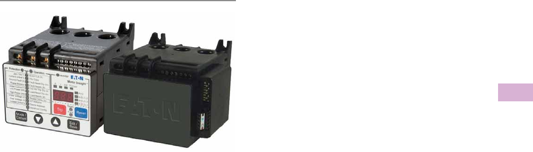
Volume 5—Motor Control and Protection CA08100006E—April 2014 www.eaton.com V5-T5-89
5
5
5
5
5
5
5
5
5
5
5
5
5
5
5
5
5
5
5
5
5
5
5
5
5
5
5
5
5
5
5.4
Motor Protection and Monitoring
Overload Relays
Motor Insight Overload and Monitoring Relay
Contents
Description Page
XT IEC Overload Relays . . . . . . . . . . . . . . . . . . . . V5-T5-60
Freedom Overload Relays . . . . . . . . . . . . . . . . . . . V5-T5-64
C440/XT Electronic Overload Relay . . . . . . . . . . . V5-T5-65
IQ500 Overload Relays . . . . . . . . . . . . . . . . . . . . . V5-T5-88
C441 Overload Relays
Features and Benefits . . . . . . . . . . . . . . . . . . . V5-T5-90
Catalog Number Selection . . . . . . . . . . . . . . . . V5-T5-93
Product Selection . . . . . . . . . . . . . . . . . . . . . . . V5-T5-94
Accessories . . . . . . . . . . . . . . . . . . . . . . . . . . . V5-T5-95
Technical Data and Specifications . . . . . . . . . . V5-T5-100
Dimensions . . . . . . . . . . . . . . . . . . . . . . . . . . . V5-T5-112
MP-3000 Overload Relays . . . . . . . . . . . . . . . . . . . V5-T5-115
MP-4000 Overload Relays . . . . . . . . . . . . . . . . . . . V5-T5-117
C441 Overload Relays
Product Description
Eaton’s Motor Insight, the
first product in the Intelligent
Power Control Solutions
family, is a highly configurable
motor, load and line
protection device with power
monitoring, diagnostics and
flexible communications
allowing the customer to
save energy, optimize their
maintenance schedules and
configure greater system
protection, thus reducing
overall costs and downtime.
Motor Insight is available
in either a line-powered or
120 Vac control powered
design, capable of monitoring
voltages up to 660 Vac. Each
of these units is available in
a 1–9 amp or a 5–90 amp FLA
model. With external CTs,
Motor Insight can protect
motors up to 540 amps FLA.
Available add-on accessories
include communication
modules for Modbus RTU,
DeviceNet, PROFIBUS,
Modbus TCP, EtherNet/IP and
HTTP web services all with I/O
options. For ease-of-use and
operator safety, Motor Insight
offers a remote display that
mounts easily with two
30 mm knockouts.

V5-T5-90 Volume 5—Motor Control and Protection CA08100006E—April 2014 www.eaton.com
5
5
5
5
5
5
5
5
5
5
5
5
5
5
5
5
5
5
5
5
5
5
5
5
5
5
5
5
5
5
5.4
Motor Protection and Monitoring
Overload Relays
Features and Benefits
Features
Size/Range
●Broad FLA range of 1–540A
●Selectable trip class (5–30)
●Four operating voltage
options
●Line-powered from
240 Vac, 480 Vac,
600 Vac
●Control-powered from
120 Vac
Motor Control
●Two output relays
●One B300 Form C fault
relay and one B300
ground fault shunt relay
●
Other relay configurations
are available, including
one Form A and one
Form B SPST (fault and
auxiliary relays) allowing
programmable isolated
relay behavior and
unique voltages
●One external remote
reset terminal
●Trip status indicator
Motor Protection
●Thermal overload
●Jam protection
●Current imbalance
●Current phase loss
●Ground fault
●Phase reversal
Load Protection
●Under current
●Low power (kW)
●High power (kW)
Line Protection
●Over voltage
●Under voltage
●Voltage imbalance
●Voltage phase loss
Monitoring Capabilities
●Current—average and
phase rms
●Voltage—average and
phase rms
●
Power—motor kW
●
Power factor
●Frequency
●Thermal capacity
●Run hours
●Ground fault current
●Current imbalance %
●Voltage imbalance %
●Motor starts
●Motor run hours
Options
●Type 1, 12 remote display
●Type 3R remote display kit
●Communication modules
●Modbus
●Modbus with I/O
●DeviceNet with I/O
●PROFIBUS with I/O
●Modbus TCP with I/O
●EtherNet/IP with I/O
Benefits
Reliability and Improved Uptime
●Advanced diagnostics
allows for quick and
accurate identification of
the root source of a motor,
pump or power quality
fault; reducing trouble-
shooting time and the loss
of productivity, reducing
repeat faults due to
misdiagnosis, and
increasing process output
and profitability
●Provides superior
protection of motors and
pumps before catastrophic
failure occurs
●Increases profitability with
greater process uptime
and throughput, reduced
costs per repair, reduced
energy consumption and
extended equipment life
●Adjustments to overload
configuration can be made
at any time
Safety
●IP20 rated terminal blocks
●Terminal blocks are set back
from the display to reduce
operator shock hazard
●Remote display (optional)
does not require that the
operator open the panel to
configure the device
Flexibility
●Communications modules
●Offered in a variety of
configurations
●
External snap-on modules
provide support for
multiple communications
protocols
●Advanced power, voltage
and current monitoring
capabilities
●Communications modules
and remote display can be
used simultaneously
●Highly configurable fault
and reset characteristics
for numerous applications
●Fully programmable
isolated fault and auxiliary
relays
Ease of Use
●Bright LED display with
easy-to-understand setting
and references
●Powered from line voltage
or 120 Vac control power
●Remote display powered
from base unit
●Full word descriptions and
units on user interface
Standards and Certifications
●cULus listed NKCR,
NKCR7, 508
●UL® 1053 applicable
sections for ground fault
detection
●CSA® certified
(Class 3211-02)
●CE
●NEMA®
●IEC EN 60947-4-1
●RoHS

Volume 5—Motor Control and Protection CA08100006E—April 2014 www.eaton.com V5-T5-91
5
5
5
5
5
5
5
5
5
5
5
5
5
5
5
5
5
5
5
5
5
5
5
5
5
5
5
5
5
5
5.4
Motor Protection and Monitoring
Overload Relays
Advanced Overload Education
Description Definition Source Result
Motor Insight
Protection
Motor Protection
Thermal overload Overload is a condition in which current
draw to a motor exceeds 115% of
the full load amperage rating over a
period of time for an inductive motor.
An increase in the load or torque that
is being driven by the motor.
A low voltage supply to the motor would
cause the current to go high to maintain
the power needed.
A poor power factor would cause
above normal current draw.
Increase in current draw. Current leads
to heat and insulation breakdown,
which can cause system failure.
Additionally, an increase in current can
increase power consumption and
waste valuable energy.
Thermal trip behavior is defined by UL,
CSA and IEC standards.
Trip class is settable from 5–30 by 1
Provides power factor monitoring and low
voltage protection features.
Jam Jam is similar to thermal overload in
that it is a current draw on the motor
above normal operating conditions.
Mechanical stall, interference, jam or
seizure of the motor or motor load.
The motor attempts to drive the load,
which has more resistive force due to
the mechanical interference. In order to
drive the load, the motor draws an
abnormal amount of current, which can
lead to insulation breakdown and
system failure.
Provides a configurable Jam setting that
is active during “motor run state” to avoid
nuisance trips.
Trip Threshold 150–400% of FLA.
Trip Delay 1–20 seconds.
Ground fault A line to ground fault. A current leakage path
to ground.
An undetected ground fault can burn
through multiple insulation windings,
ultimately leading to motor failure.
Motor Insight has ground fault protection
capability down to 0.15 amps estimated
from the existing three-phase CTs using
the residual current method. That is, the
three-phase current signals should sum to
zero unless a ground fault (GF) condition
is present. In the case of a GF, Motor
Insight can alarm, trip the starter, or trip
an alternative relay that can be used to
shunt trip a breaker or light up a warning
light. GF current can also be monitored in
real-time through the advanced
monitoring capabilities.
Note: GF settable thresholds vary with
motor FLA. 0.15 amps may not be
available in all cases.
Imbalanced phases
(voltage and current)
Uneven voltage or currents between
phases in a three-phase system.
When a three-phase load is powered with
a poor quality line, the voltage per phase
may be imbalanced.
Imbalanced voltage causes large
imbalanced currents and as a result this
can lead to motor stator windings being
overloaded, causing excessive heating,
reduced motor efficiency and reduced
insulation life.
Provides two protection settings that
address this problem. The user can
choose to set current imbalance
thresholds or voltage imbalance
thresholds, each of which can trip the
starter. Additionally, both of these may
be monitored through Motor Insight’s
advanced monitoring capabilities,
allowing the customer to notice in real-
time when and where a condition is
present.
Phase loss—current
(single-phasing)
One of the three-phase current is
not present.
Multiple causes, loose wire, improper
wiring, grounded phase, open fuse,
and so on.
Single-phasing can lead to unwanted
motor vibrations in addition to the results
of imbalanced phases as listed above.
Fixed protective setting that takes the
starter offline if a phase drops below
60% of the other two phases.
Phase rotation
(phase-reversal)
Improper wiring, leading to phases being
connected to the motor improperly.
A miswired motor. Inadvertent phase-
reversal by the utility.
Phase-reversal can cause unwanted
directional rotation of a motor. In the
event that the load attached to the motor
can only be driven in one direction, the
result could be significant mechanical
failure and/or injury to an operator.
Configurable phase protection, allowing
the user to define the phase sequencing
intended for that application. If no phase
sequence is required, the user has the
ability to disable this feature.
Frequency variance When line frequency
is inconsistent.
Malfunctioning alternator speed
regulator, or poor line quality caused by
an overload of a supply powered
by individual sources.
Variations in frequency can cause
increases in losses, decreasing the
efficiency of the motor. In addition,
this can result in interference with
synchronous devices.
Advanced monitoring capabilities
allow the user to monitor frequency
in real-time.

V5-T5-92 Volume 5—Motor Control and Protection CA08100006E—April 2014 www.eaton.com
5
5
5
5
5
5
5
5
5
5
5
5
5
5
5
5
5
5
5
5
5
5
5
5
5
5
5
5
5
5
5.4
Motor Protection and Monitoring
Overload Relays
Advanced Overload Education, continued
Description Definition Source Result
Motor Insight
Protection
Load Protection
Under current or
low power
Average rms current provided to the
motor falls below normal operating
conditions.
Under current is usually associated
with a portion of the user’s load
disappearing. Examples of this would
be a broken belt, a dry-pump (low
suction head) or a dead-headed
centrifugal pump.
If under current goes undetected, a
mechanical failure can and has
occurred. In the case of a pump,
running a pump dry or running a pump
in a dead-headed condition can cause
excessive heating, damaging
expensive seals and breaking down
desired fluid properties.
Motor Insight has two protection settings
to detect this: under current and low
power. Low power is a more consistent
way of ensuring detection as power is
linear with motor load, where as current
is not. An unloaded motor may draw 50%
of its rated current, but the power draw
will be less than 10% of rated power due
to a low power factor.
High power The motor load is drawing more power
than it should at normal operating
conditions.
This is typical of batch processing
applications where several ingredients
flow into a mixer. When a substance’s
consistency changes and viscosity
increases from what is expected, the
motor may use more power to blend
the mixture. Out-of-tolerance
conditions can be detected using the
High Power and Low Power settings.
If a high-power fault goes undetected,
the result may be a batch of material
that does not meet specification.
Monitors the three-phase real power. If
the real power value is estimated above
the set threshold for the set length of
time, a fault is detected and the overload
will trip the starter. Additionally, power
can be monitored in real-time.
Line Protection
Over voltage When the line voltage to the motor
exceeds the specified rating.
Poor line quality. An over voltage condition leads to a
lower than rated current draw and a
poor power factor. A trip limit of 110%
of rated voltage is recommended. Over
voltage can also lead to exceeding
insulation ratings.
Monitors the maximum rms value of
the three-phase voltages. If the rms
value rises above the set threshold for the
set length of time, a fault is detected and
the overload can trip the starter or send
and display an alarm of the condition. All
line-related faults have an “alarm-no-
trip” mode.
Under voltage When the line voltage to the motor is
below the specified rating.
Poor line quality. An under voltage condition leads to
excessive current draw. This increases
the heating of the motor windings and
can shorten insulation life. A trip limit
set to 90% of rated voltage is
recommended.
Monitors the minimum rms value of the
three-phase voltages. If the rms value
drops below the set threshold for the
set length of time, a fault is detected
and the overload can trip the starter or
send and display an alarm of the
condition. All line-related faults have
an “alarm-no-trip” mode.
Power-up delay Allows for starting motors and loads
in a deliberate fashion.
When there is a power failure, or
power cycle, multiple loads come
online simultaneously.
Multiple loads starting simultaneously
can cause sags affecting the operation
of devices that may prevent successful
startup.
If power is lost to a motor driving a
pump, it may be necessary to delay a
restart to allow the pump to come to a
complete stop to prevent starting a
motor during backspin.
Configurable to delay closing the fault
relay on power-up. For each Motor Insight
controlling a motor, a different setting can
be programmed, helping to maintain the
integrity of your line power.
Volume 5—Motor Control and Protection CA08100006E—April 2014 www.eaton.com V5-T5-93
5
5
5
5
5
5
5
5
5
5
5
5
5
5
5
5
5
5
5
5
5
5
5
5
5
5
5
5
5
5
5.4
Motor Protection and Monitoring
Overload Relays
Catalog Number Selection
Motor Insight Overload Relays
Motor Insight Overload Relays—Communications Modules and Accessory Types
Device Type
C441 = Motor Insight overload relay Overload Relay Current Rating
A = 1–9A (1–540A refer to
Page V5-T5-94)
B = 5–90A (5–90A refer to
Page V5-T5-94)
0109 = 120 Vac control power
(0–660 Vac, 1–9A)
0590 = 120 Vac control power
(0–660 Vac, 5–90A)
Overload Relay
Power Source Voltage
B= 240 Vac (170–264 Vac)
C= 480 Vac (323–528 Vac)
D= 600 Vac (487–660 Vac)
Blank = 120 Vac control power
(170–660 Vac)
C441 B A NOUI
Internal User Interface
Blank = With user interface
(line powered models)
NOUI = Without user interface
(120 Vac control models)
Device Type
C441 = Motor Insight overload relay Communication Module
K= DeviceNet module 4IN/2OUT 120 Vac
L= DeviceNet module 4IN/2OUT 24 Vdc
M= Modbus RTU module
N= Modbus RTU module 4IN/2OUT 120 Vac
P= Modbus RTU module 4IN/2OUT 24 Vdc
Q= PROFIBUS module 4IN/2OUT 120 Vac
R= Modbus TCP / EtherNet/IP module
4IN/2OUT 120 Vac
S= PROFIBUS module 4IN/2OUT 24 Vdc
T= Modbus TCP / EtherNet/IP module
4IN/2OUT 24 Vdc
Accessory Type
1= Type 1 and 12 remote mounted display
3= Type 3R kit for remote display
CMP1 = Conversion plate
C441 K
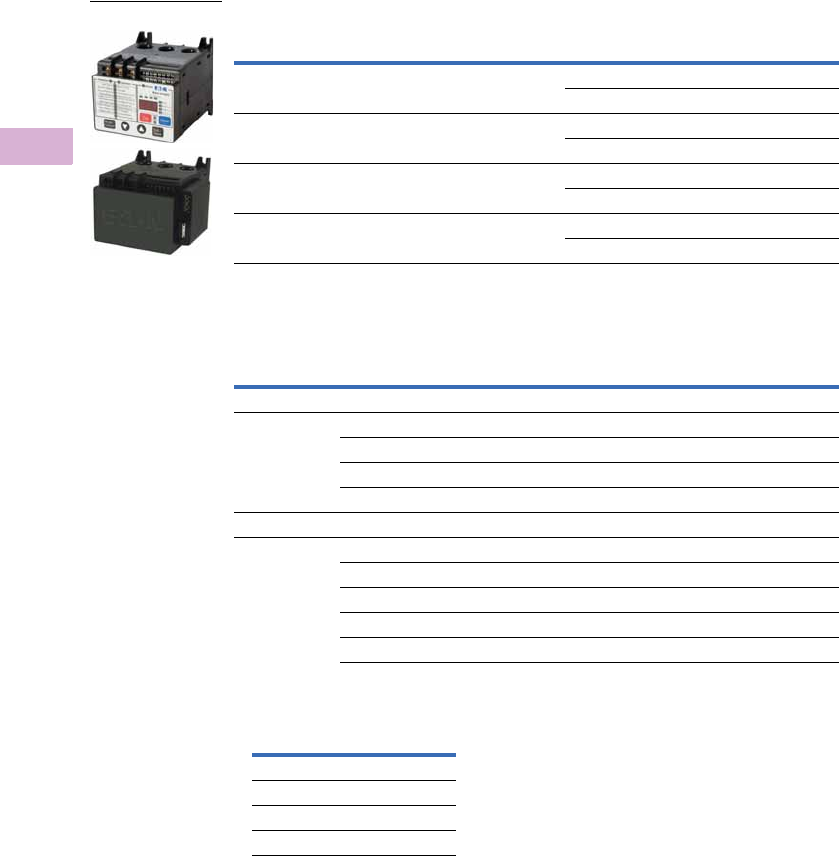
V5-T5-94 Volume 5—Motor Control and Protection CA08100006E—April 2014 www.eaton.com
5
5
5
5
5
5
5
5
5
5
5
5
5
5
5
5
5
5
5
5
5
5
5
5
5
5
5
5
5
5
5.4
Motor Protection and Monitoring
Overload Relays
Product Selection
Motor Insight
Motor Insight CT Multiplier and Wire Wrap Schedule
Notes
1 Underscore indicates Operating Voltage Code required.
Operating Voltage Codes:
2 Any manufacturer’s CTs may be used.
Power Source
Monitoring
Range
Current
Range
Catalog
Number
240 Vac (170–264) 170–264 Vac 1–9A C441BA
5–90A C441BB
480 Vac (323–528) 323–528 Vac 1–9A C441CA
5–90A C441CB
600 Vac (489–660) 489–660 Vac 1–9A C441DA
5–90A C441DB
120 Vac (93.5–132) 170–660 Vac 1–9A C4410109NOUI
5–90A C4410590NOUI
Catalog
Number 1
Motor
FLA
Number
of Loops
Number of
Conductors Through
CT Primary
CT
Multiplier
Setting
External CT Kit
Catalog Number 2
Current Range: 5–90A
C441_B and
C4410590NOUI
5–22.5A 3 4 4 —
6.67–30A 2 3 3 —
10–45A 1 2 2 —
20–90A 0 1 1 —
Current Range: 1–9A
C441_A and
C4410109NOUI
1–5A 1 2 2 —
2–9A 0 1 1 —
60–135A 0 1 150–(150:5) C441CTKIT150
120–270A 0 1 300–(300:5) C441CTKIT300
240–540A 0 1 600–(600:5) C441CTKIT600
Code Voltage
B240 Vac
C480 Vac
D600 Vac
<empty> 120 Vac Control Power
Motor Insight

Volume 5—Motor Control and Protection CA08100006E—April 2014 www.eaton.com V5-T5-95
5
5
5
5
5
5
5
5
5
5
5
5
5
5
5
5
5
5
5
5
5
5
5
5
5
5
5
5
5
5
5.4
Motor Protection and Monitoring
Overload Relays
Accessories
Modbus Communication Module
The Motor Insight Modbus
Communication Module
is a side-mounted device
providing Modbus
communication capability
to the Motor Insight
overload relay.
The Modbus Communication
Module with I/O provides
communication, monitoring
and control for the Motor
Insight overload relay.
Features and Benefits
●The Modbus
communication module is
capable of baud rates
up to 115K
●The Modbus address and
baud rate configuration can
be easily changed using
the Motor Insight user
interface (C441M only)
●Modbus address and baud
rate are set via convenient
DIP switches (C441N and
C441P); LEDs are provided
to display Modbus traffic
●Configuration with
common Modbus
configuration tools
●Terminals
●Unique locking
mechanism provides for
easy removal of the
terminal block with the
field wiring installed
●Each terminal is marked
for ease of wiring and
troubleshooting
●Selectable I/O assemblies
●4IN/2OUT
●Signal types include
24 Vdc I/O and
120 Vac I/O
●Each I/O module is
optically isolated
between the field I/O
and the network adapter
to protect the I/O and
communication circuits
from possible damage
due to transients and
ground loops
●Input Module features a
user-definable input
debounce, which limits
the effects of transients
and electrical noise
●Output Module supports
a user-definable safe
state for loss of
communication; hold
last state, ON or OFF
Modbus Communication Module
Description I/O
Catalog
Number
Modbus Communication Module None C441M
Modbus Communication Module 4IN/2OUT 120 Vac C441N
Modbus Communication Module 4IN/2OUT 24 Vdc C441P
Modbus Module
Modbus with
I/O Module

V5-T5-96 Volume 5—Motor Control and Protection CA08100006E—April 2014 www.eaton.com
5
5
5
5
5
5
5
5
5
5
5
5
5
5
5
5
5
5
5
5
5
5
5
5
5
5
5
5
5
5
5.4
Motor Protection and Monitoring
Overload Relays
DeviceNet Communication Modules
The DeviceNet
Communication Module
provides monitoring and
control for the Motor Insight
overload relay from a single
DeviceNet node. These
modules also offer convenient
I/O in two voltage options,
24 Vdc and 120 Vac.
Features and Benefits
●Communication to
DeviceNet uses only one
DeviceNet MAC ID
●Configuration
●DeviceNet MAC ID and
Baud rate are set via
convenient DIP switches
with an option to set
from the network
●Advanced configuration
available using common
DeviceNet tools
●Te r m i n a l s
●Unique locking
mechanism provides for
easy removal of the
terminal block with the
field wiring installed
●Each terminal is marked
for ease of wiring and
troubleshooting
●Selectable I/O assemblies
●4IN/2OUT
●Signal types include
24 Vdc I/O and
120 Vac I/O
●Each I/O module is
optically isolated
between the field I/O
and the network adapter
to protect the I/O and
communication circuits
from possible damage
due to transients and
ground loops
●Input Module features a
user-definable input
debounce, which limits
the effects of transients
and electrical noise
●Output Module supports
a user-definable safe
state for loss of
communication; hold
last state, ON or OFF
●Combined status LED
DeviceNet Modules
Description I/O
Catalog
Number
DeviceNet Communication Module 120 Vac C441K
DeviceNet Communication Module 24 Vdc C441L
DeviceNet Module

Volume 5—Motor Control and Protection CA08100006E—April 2014 www.eaton.com V5-T5-97
5
5
5
5
5
5
5
5
5
5
5
5
5
5
5
5
5
5
5
5
5
5
5
5
5
5
5
5
5
5
5.4
Motor Protection and Monitoring
Overload Relays
PROFIBUS Communication Module
The Motor Insight PROFIBUS
Communication Module
is a side-mounted device
providing PROFIBUS
communication capability
to the Motor Insight
overload relay.
The PROFIBUS
Communication Module
with I/O provides
communication, monitoring
and control for the Motor
Insight overload relay.
Features and Benefits
●The PROFIBUS
communication module is
capable of baud rates
up to 12 Mb
●PROFIBUS address is
set via convenient DIP
switches (C441Q and
C441S); LEDs are
provided to display
PROFIBUS status
●Intuitive configuration
with common PROFIBUS
configuration tools
●Terminals
●Unique locking
mechanism provides for
easy removal of the
terminal block with the
field wiring installed
●Each terminal is marked
for ease of wiring and
troubleshooting
●Selectable I/O assemblies
●4IN/2OUT
●Signal types include
24 Vdc I/O and
120 Vac I/O
●Each I/O module is
optically isolated
between the field I/O
and the network adapter
to protect the I/O and
communication circuits
from possible damage
due to transients and
ground loops
●Input Module features a
user-definable input
debounce, which limits
the effects of transients
and electrical noise
●Output Module supports
a user-definable safe
state for loss of
communication; hold
last state, ON or OFF
PROFIBUS Communication Module
Description I/O
Catalog
Number
PROFIBUS Communication Module 4IN/2OUT 120 Vac C441S
PROFIBUS Communication Module 4IN/2OUT 24 Vdc C441Q
PROFIBUS with
I/O Module

V5-T5-98 Volume 5—Motor Control and Protection CA08100006E—April 2014 www.eaton.com
5
5
5
5
5
5
5
5
5
5
5
5
5
5
5
5
5
5
5
5
5
5
5
5
5
5
5
5
5
5
5.4
Motor Protection and Monitoring
Overload Relays
Ethernet Communication Module
The Motor Insight Ethernet
Communication Module
is a side-mounted device
providing both Modbus
TCP and EtherNet/IP
communication capabilities
with built-in HTTP web
services to the Motor Insight
overload relay.
The Ethernet Communication
Module with I/O provides
communication, monitoring
and control for the Motor
Insight overload relay.
Features and Benefits
●Supports Modbus TCP or
EtherNet/IP in a single
device
●Contains internal
embedded switch which
provides two Ethernet
ports allowing linear or ring
network configurations
●Embedded web services
allow for simple
configuration and
monitoring through
Internet Explorer
●IP Address is set via
convenient DIP Switches
located on the device
●Terminals
●Unique locking
mechanism provides for
easy removal of the
terminal block with the
field wiring installed
●Each terminal is marked
for ease of wiring and
troubleshooting
●Selectable I/O assemblies
●4IN/2OUT
●Signal types include
24 Vdc I/O and
120 Vac I/O
●Each I/O module is
optically isolated
between the field I/O
and the network adapter
to protect the I/O and
communication circuits
from possible damage
due to transients and
ground loops
●Input Module features a
user-definable input
debounce, which limits
the effects of transients
and electrical noise
●Output Module supports
a user-definable safe
state for loss of
communication; hold
last state, ON or OFF
Ethernet Communication Module
Description I/O
Catalog
Number
Modbus TCP / EtherNet/IP Communication Module 4IN/2OUT 120 Vac C441R
Modbus TCP / EtherNet/IP Communication Module 4IN/2OUT 24 Vdc C441T
Ethernet with
I/O Module
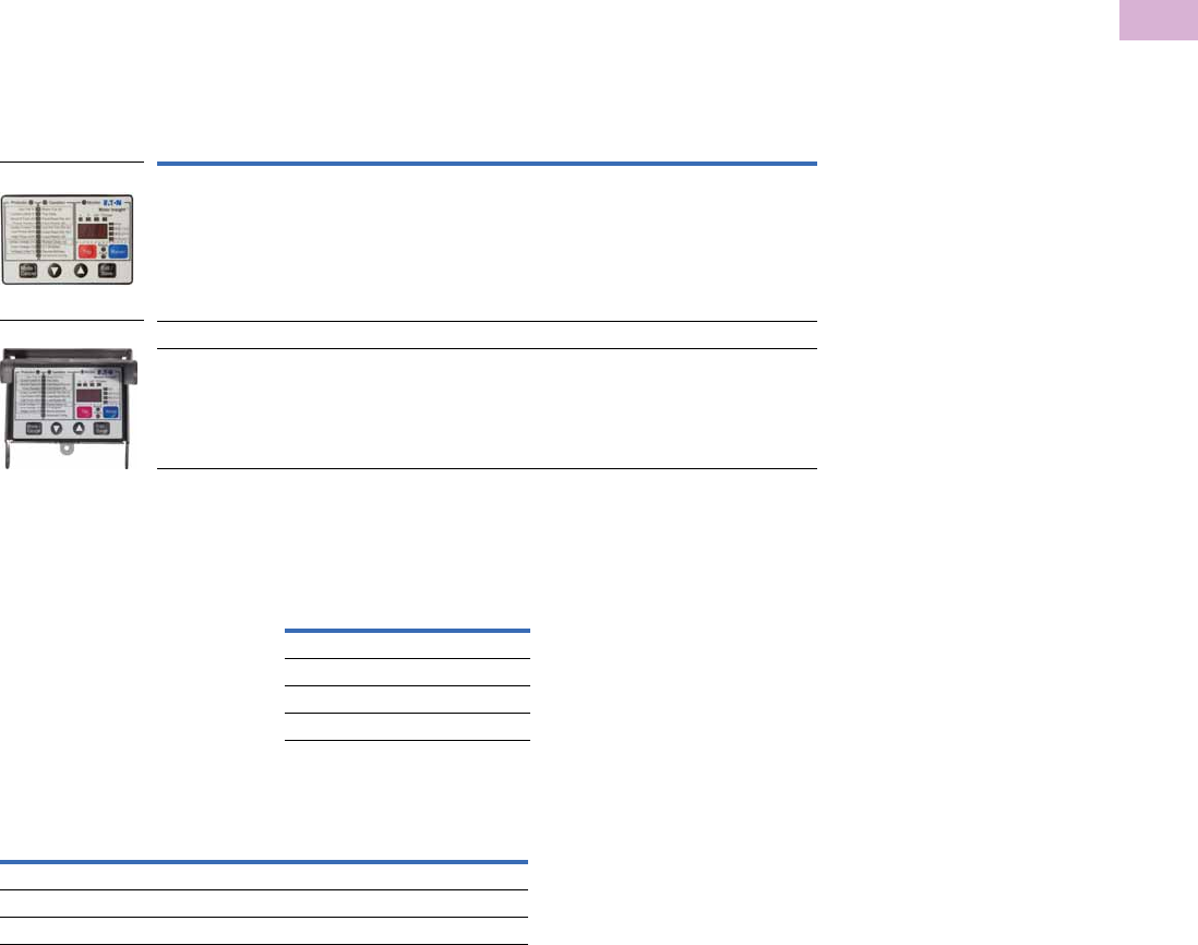
Volume 5—Motor Control and Protection CA08100006E—April 2014 www.eaton.com V5-T5-99
5
5
5
5
5
5
5
5
5
5
5
5
5
5
5
5
5
5
5
5
5
5
5
5
5
5
5
5
5
5
5.4
Motor Protection and Monitoring
Overload Relays
Type 3R Kit with Remote Display Mounted Inside
Motor Insight offers several
accessories for the
customer’s ease of use
and safety:
●Types 1 and 12 remote
display
●Type 3R remote display kit
●Mounting plate adapter
Features and Benefits
●Remote display unit:
●Same user interface as
the overload relay
●Enhanced operator
safety—operator can
configure the overload
without opening the
enclosure door
●Type 3R kit mounts with
standard 30 mm holes
●Mounting plate for retrofit
in existing installations
Type 3R Kit with Remote Display Mounted Inside
Communication Cables
The Remote Display requires
a communication cable to
connect to the Motor Insight
overload relay:
Communication Cable
Lengths
Current Transformer Kits
Description
Catalog
Number
Remote display Types 1 and 12 (UL 508) C4411
Type 3R kit for remote display (UL 508) C4413
Conversion plate (not shown) C441CMP1
C4411
C4413
Length in
Inches (meters)
Catalog
Number
9.8 (0.25) D77E-QPIP25
39.4 (1.0) D77E-QPIP100
78.7 (2.0) D77E-QPIP200
118.1 (3.0) D77E-QPIP300
Description
Catalog
Number
Three 150:5 CTs to be used with Motor Insight C441CTKIT150
Three 300:5 CTs to be used with Motor Insight C441CTKIT300
Three 600:5 CTs to be used with Motor Insight C441CTKIT600

V5-T5-100 Volume 5—Motor Control and Protection CA08100006E—April 2014 www.eaton.com
5
5
5
5
5
5
5
5
5
5
5
5
5
5
5
5
5
5
5
5
5
5
5
5
5
5
5
5
5
5
5.4
Motor Protection and Monitoring
Overload Relays
Technical Data and Specifications
Motor Insight
Notes
1Lower levels are achievable with multiple passes.
2Motor fault reset characteristics can be programmed as a group or for motor overloads only. Reference the user manual for more detailed information.
Description
Specification
C441B_ C441C_ C441D_ C441_ _ _ _NOUI
Electrical Ratings
Feature Range
Operating voltage (three-
phase) and frequency
170–264 Vac 50/60 Hz 323–528 Vac 50/60 Hz 489–660 Vac 50/60 Hz 170–660 Vac 50/60 Hz
Tri p C l a s s
5–30 Selectable Selectable Selectable Selectable
FLA Range
C441_A and
C4410109NOUI
1–9A Up to 540A with external CTs
Refer to Page V5-T5-94 for CT
multiplier and wire wrap
schedule.
Up to 540A with external CTs
Refer to Page V5-T5-94 for CT
multiplier and wire wrap
schedule.
Up to 540A with external CTs
Refer to Page V5-T5-94 for CT
multiplier and wire wrap
schedule.
C441_B and
C4410590NOUI
5–90A
Monitoring Capabilities
Feature Value
Current Per phase rms (1A, 1B, 1C),
2% accuracy
Average rms, 2% accuracy
Imbalance percent (0–100%)
Ground fault current,
10% accuracy
Per phase rms (1A, 1B, 1C),
2% accuracy
Average rms, 2% accuracy
Imbalance percent (0–100%)
Ground fault current,
10% accuracy
Per phase rms (1A, 1B, 1C),
2% accuracy
Average rms, 2% accuracy
Imbalance percent (0–100%)
Ground fault current,
10% accuracy
Per phase rms (1A, 1B, 1C),
2% accuracy
Average rms, 2% accuracy
Imbalance percent (0–100%)
Ground fault current,
10% accuracy
Voltage Per phase rms (1A, 1B, 1C),
2% accuracy
Average rms, 2% accuracy
Imbalance percent (0–100%)
Per phase rms (1A, 1B, 1C),
2% accuracy
Average rms, 2% accuracy
Imbalance percent (0–100%)
Per phase rms (1A, 1B, 1C),
2% accuracy
Average rms, 2% accuracy
Imbalance percent (0–100%)
Per phase rms (1A, 1B, 1C),
2% accuracy
Average rms, 2% accuracy
Imbalance percent (0–100%)
Power Motor kW, 5% accuracy
Motor power factor,
inductive 0–1.0, 1% accuracy
Motor kW, 5% accuracy
Motor power factor,
inductive 0–1.0, 1% accuracy
Motor kW, 5% accuracy
Motor power factor,
inductive 0–1.0, 1% accuracy
Motor kW, 5% accuracy
Motor power factor,
inductive 0–1.0, 1% accuracy
Thermal capacity 0% cold, 100% trip 0% cold, 100% trip 0% cold, 100% trip 0% cold, 100% trip
Motor run hours 0–65,535 hours 0–65,535 hours 0–65,535 hours 0–65,535 hours
Frequency 47–63 Hz, 1% accuracy 47–63 Hz, 1% accuracy 47–63 Hz, 1% accuracy 47–63 Hz, 1% accuracy
Motor Protection
Thermal overload setting 1.05 x FLA: Does not trip
1.15 x FLA: Overload trip
1.05 x FLA: Does not trip
1.15 x FLA: Overload trip
1.05 x FLA: Does not trip
1.15 x FLA: Overload trip
1.05 x FLA: Does not trip
1.15 x FLA: Overload trip
Feature Range Fault Delay Setting
Jam 150–400% of motor FLA, OFF 150–400% of motor FLA, OFF 150–400% of motor FLA, OFF 50–400% of motor FLA, OFF 1–20 seconds
Current imbalance 1–30%, OFF 1–30%, OFF 1–30%, OFF 1–30%, OFF 1–20 seconds
Current phase loss Fixed threshold 60% Fixed threshold 60% Fixed threshold 60% Fixed threshold 60% 1–20 seconds
Ground fault current
C441_A and
C4410109NOUI
1–9A
0.3–2.0A with one pass
through the CTs 1
0.3–2.0A with one pass
through the CTs 1
0.3–2.0A with one pass
through the CTs 1
0.3–2.0A with one pass
through the CTs 1
<150%, 1–60 seconds
>150%, 2 seconds
>250%, 1 second
C441_B and
C4410590NOUI
5–90A
3.0–20A with one pass
through the CTs 1
3.0–20A with one pass
through the CTs 1
3.0–20A with one pass
through the CTs 1
3.0–20A with one pass
through the CTs 1
<150%, 1–60 seconds
>150%, 2 seconds
>250%, 1 second
Phase reversal OFF = Ignore, 1 = ACB, 2 = ABC OFF = Ignore, 1 = ACB, 2 = ABC OFF = Ignore, 1 = ACB, 2 = ABC OFF = Ignore, 1 = ACB, 2 = ABC
Fault reset delay 2–500 minutes, auto 22–500 minutes, auto 22–500 minutes, auto 22–500 minutes, auto 2
Fault reset attempts 0–4 restarts allowed or
automatic reset 2
0–4 restarts allowed or
automatic reset 2
0–4 restarts allowed or
automatic reset 2
0–4 restarts allowed or
automatic reset 2

Volume 5—Motor Control and Protection CA08100006E—April 2014 www.eaton.com V5-T5-101
5
5
5
5
5
5
5
5
5
5
5
5
5
5
5
5
5
5
5
5
5
5
5
5
5
5
5
5
5
5
5.4
Motor Protection and Monitoring
Overload Relays
Motor Insight, continued
Description
Specification
C441B_ C441C_ C441D_ C441_ _ _ _NOUI
Load Protection
Feature Range Fault Delay Setting
Under current 50–90% of motor FLA 50–90% of motor FLA 50–90% of motor FLA 50–90% of motor FLA 1–60 seconds
Low power (kW) 20–80% of rated kW 20–80% of rated kW 20–80% of rated kW 20–80% of rated kW 1–60 seconds
High power (kW) 50–110% of rated kW 50–110% of rated kW 50–110% of rated kW 50–110% of rated kW 1–60 seconds
Load reset delay 2–500 minutes, auto 2–500 minutes, auto 2–500 minutes, auto 2–500 minutes, auto
Load reset attempts 0–4, auto 0–4, auto 0–4, auto 0–4, auto
Supply Protection
Feature Range Fault Delay Setting
Over voltage 170–264 Vac 323–528 Vac 489–660 Vac 0–660 Vac 1–20 seconds
Under voltage 170–264 Vac 323–528 Vac 489–660 Vac 0–660 Vac 1–20 seconds
Voltage imbalance 1–20% imbalance 1–20% imbalance 1–20% imbalance 1–20% imbalance 1–20% imbalance
Restart delay setting 1–500 seconds 1–500 seconds 1–500 seconds 1–500 seconds 1–500 seconds
Electrical/EMC
Radiated emissions
IEC 60947-4-1—Table 15,
EN 55011 (CISPIR 11)
Group 1, Class A
30–1000 mHz 30–1000 mHz 30–1000 mHz 30–1000 mHz 30–1000 mHz
Conducted emissions
IEC 60947-4-1—Table 14,
EN 55011 (CISPIR 11)
Group 1, Class A
0.15–30 mHz 0.15–30 mHz 0.15–30 mHz 0.15–30 mHz 0.15–30 mHz
ESD immunity
IEC 60947-4-1 (Table 13)
±8 kV air, ±4 kV contact ±8 kV air, ±4 kV contact ±8 kV air, ±4 kV contact ±8 kV air, ±4 kV contact ±8 kV air, ±4 kV contact
Radiated immunity
IEC 60947-4-1
10 V/m 80–1000 mHz
80% amplitude modulated
1 kHz sine wave
10 V/m 80–1000 mHz
80% amplitude modulated
1 kHz sine wave
10 V/m 80–1000 mHz
80% amplitude modulated
1 kHz sine wave
10 V/m 80–1000 mHz
80% amplitude modulated
1 kHz sine wave
10 V/m 80–1000 mHz
80% amplitude modulated
1 kHz sine wave
Conducted immunity
IEC 60947-4-1
140 dBuV (10V rms)
150 kHz–80 mHz
140 dBuV (10V rms)
150 kHz–80 mHz
140 dBuV (10V rms)
150 kHz–80 mHz
140 dBuV (10V rms)
150 kHz–80 mHz
140 dBuV (10V rms)
150 kHz–80 mHz
Fast transient immunity
IEC 60947-4-1 (Table 13)
IEC 61000-4-4
±2 kV using direct method ±2 kV using direct method ±2 kV using direct method ±2 kV using direct method ±2 kV using direct method
Surge immunity
IEC 60947-4-1 (Table 13)
IEC 61000-4-4
Three-phase power inputs:
±2 kV line-to-line (DM)
±4 kV line-to-ground (CM)
Three-phase power inputs:
±2 kV line-to-line (DM)
±4 kV line-to-ground (CM)
Three-phase power inputs:
±2 kV line-to-line (DM)
±4 kV line-to-ground (CM)
Three-phase power inputs:
±2 kV line-to-line (DM)
±4 kV line-to-ground (CM)
Three-phase power inputs:
±2 kV line-to-line (DM)
±4 kV line-to-ground (CM)
IEC 61000-4-5 Class 3 User IO
and communication lines:
±1 kV line-to-line (DM)
±2 kV line-to-ground (CM)
IEC 61000-4-5 Class 3 User IO
and communication lines:
±1 kV line-to-line (DM)
±2 kV line-to-ground (CM)
IEC 61000-4-5 Class 3 User IO
and communication lines:
±1 kV line-to-line (DM)
±2 kV line-to-ground (CM)
IEC 61000-4-5 Class 3 User IO
and communication lines:
±1 kV line-to-line (DM)
±2 kV line-to-ground (CM)
IEC 61000-4-5 Class 3 User IO
and communication lines:
±1 kV line-to-line (DM)
±2 kV line-to-ground (CM)
Voltage variations
immunity
IEC 60947-4-1
30% dip, at 100 ms
60% dip at 10 ms
>95% interrupt at 5 ms
30% dip, at 100 ms
60% dip at 10 ms
>95% interrupt at 5 ms
30% dip, at 100 ms
60% dip at 10 ms
>95% interrupt at 5 ms
30% dip, at 100 ms
60% dip at 10 ms
>95% interrupt at 5 ms
30% dip, at 100 ms
60% dip at 10 ms
>95% interrupt at 5 ms
Electromagnetic field
IEC 60947-4-1 (Table 13)
IEC 61000-4-3
10 V/m 10 V/m 10 V/m 10 V/m 10 V/m
Ground fault UL 508, UL 1053
Sections 21 and 27
UL 508, UL 1053
Sections 21 and 27
UL 508, UL 1053
Sections 21 and 27
UL 508, UL 1053
Sections 21 and 27
UL 508, UL 1053
Sections 21 and 27

V5-T5-102 Volume 5—Motor Control and Protection CA08100006E—April 2014 www.eaton.com
5
5
5
5
5
5
5
5
5
5
5
5
5
5
5
5
5
5
5
5
5
5
5
5
5
5
5
5
5
5
5.4
Motor Protection and Monitoring
Overload Relays
Motor Insight, continued
Note
1In this model, there are two isolated relays: one Form A and one Form B SPST. One is the fault relay, and one is a programmable auxiliary relay.
Description
Specification
C441B_ C441C_ C441D_ C441_ _ _ _NOUI
Environmental Ratings
Feature Range
Ambient temperature (operating) –4° to 122°F (–20° to 50°C) –4° to 122°F (–20° to 50°C) –4° to 122°F (–20° to 50°C) –4° to 122°F (–20° to 50°C)
Ambient temperature (storage) –40° to 85°C –40° to 85°C –40° to 85°C –40° to 85°C
Operating humidity 5% to 95% noncondensing 5% to 95% noncondensing 5% to 95% noncondensing 5% to 95% noncondensing
Altitude (no derating) 2000m 2000m 2000m 2000m
Shock (IEC 60068-2-27) 15G any direction 15G any direction 15G any direction 15G any direction
Vibration (IEC 60068-2-6) 3G any direction 3G any direction 3G any direction 3G any direction
Pollution degree per IEC 60947-13333
Ingress protection IP20 IP20 IP20 IP20
Capacity
Input, auxiliary contact and external reset terminals
Terminal capacity 18–12 AWG 18–12 AWG 18–12 AWG 18–12 AWG
Tightening torque 5.3 lb-in (0.6 Nm) 5.3 lb-in (0.6 Nm) 5.3 lb-in (0.6 Nm) 5.3 lb-in (0.6 Nm)
Voltages
Monitoring voltage 170–264 Vac 50/60Hz 323–528 Vac 50/60Hz 489–660 Vac 60Hz 0–660 Vac 50/60Hz
Insulation voltage Ui (three-phase voltage) 600 Vac 600 Vac 600 Vac 600 Vac
Insulation voltage Ui (control) 240 Vac 240 Vac 240 Vac 240 Vac
Impulse withstand Uimp
(main/control)
6 kV 6 kV 6 kV 6 kV
Expected Life
Mechanical/electrical 10 years 10 years 10 years 10 years
Output Contact Ratings
Two output relays
One Form C SPDT (fault relay)
One Form A SPST (ground fault relay)
C441_ _ _ _NOUI models:
One Form A SPST
One Form B SPST
B300 pilot duty
5A thermal continuous current
30A make 3.00A break
at 120 Vac and
15A make 1.50A break
at 240 Vac
B300 pilot duty
5A thermal continuous current
30A make 3.00A break
at 120 Vac and
15A make 1.50A break
at 240 Vac
B300 pilot duty
5A thermal continuous current
30A make 3.00A break
at 120 Vac and
15A make 1.50A break
at 240 Vac
B300 pilot duty
5A thermal continuous current
30A make 3.00A break
at 120 Vac and
30A make 1.50A break
at 240 Vac 1
External remote reset terminal Isolated 120 Vac digital input
IEC 61131-2 Section 5 Type 1
Isolated 120 Vac digital input
IEC 61131-2 Section 5 Type 1
Isolated 120 Vac digital input
IEC 61131-2 Section 5 Type 1
Isolated 120 Vac digital input
IEC 61131-2 Section 5 Type 1
Indications
Trip Fault Fault Fault Fault
Reset Ready Ready Ready Ready
Autoreset Trip faulted/Ready flashing Trip faulted/Ready flashing Trip faulted/Ready flashing Trip faulted/Ready flashing
Power Consumption
Maximum 5W5W5W5W
Options
Remote display Type 1, 12 and Type 3R kit Type 1, 12 and Type 3R kit Type 1, 12 and Type 3R kit Type 1, 12 and Type 3R kit
Communications modules Modbus, DeviceNet and
PROFIBUS with I/O
Modbus, DeviceNet and
PROFIBUS with I/O
Modbus, DeviceNet and
PROFIBUS with I/O
Modbus, DeviceNet and
PROFIBUS with I/O

Volume 5—Motor Control and Protection CA08100006E—April 2014 www.eaton.com V5-T5-103
5
5
5
5
5
5
5
5
5
5
5
5
5
5
5
5
5
5
5
5
5
5
5
5
5
5
5
5
5
5
5.4
Motor Protection and Monitoring
Overload Relays
Motor Insight Short Circuit Ratings (North America CSA and UL)
Overload
FLA Range
Maximum
Operating
Voltage
Standard-Fault Short Circuit Data
Maximum
Withstand
Rating
Maximum
Fuse (RK5)
Eaton
Thermal-Magnetic
Circuit Breaker
Catalog
Number
Withstand
Rating
Maximum
Fuse (RK5)
Maximum
Thermal-Magnetic
Circuit Breaker
1–9A 264 Vac 5000A at 240 Vac 35A 35A 100 kA at 240 Vac 35A — C441BA
100 kA at 240 Vac — FDC3035L
1–9A 528 Vac 5000A at 480 Vac 35A 35A 100 kA at 480 Vac 35A — C441CA
100 kA at 480 Vac — FDC3035L
1–9A 660 Vac 5000A at 600 Vac 35A 35A 100 kA at 600 Vac 35A — C441DA
35 kA at 600 Vac — FDC3035L
1–9A 660 Vac 5000A at 600 Vac 35A 35A 100 kA at 240 Vac
100 kA at 240 Vac
100 kA at 480 Vac
100 kA at 480 Vac
100 kA at 600 Vac
35 kA at 600 Vac
35A
—
35A
—
35A
—
—
FDC3035L
—
FDC3035L
—
FDC3035L
C4410109NOUI
5–90A 264 Vac 10,000A at 240 Vac 350A 350A 100 kA at 240 Vac 350A — C441BB
100 kA at 240 Vac — KDC3350
5–90A 528 Vac 10,000A at 480 Vac 350A 350A 100 kA at 480 Vac 350A — C441CB
100 kA at 480 Vac — KDC3350
5–90A 660 Vac 10,000A at 600 Vac 350A 350A 100 kA at 600 Vac 350A — C441DB
65 kA at 600 Vac — KDC3350
5–90A 660 Vac 10,000A at 600 Vac 350A 350A 100 kA at 240 Vac
100 kA at 240 Vac
100 kA at 480 Vac
100 kA at 480 Vac
100 kA at 600 Vac
35 kA at 600 Vac
350A
—
350A
—
350A
—
—
KDC3350
—
KDC3350
—
KDC3350
C4410590NOUI
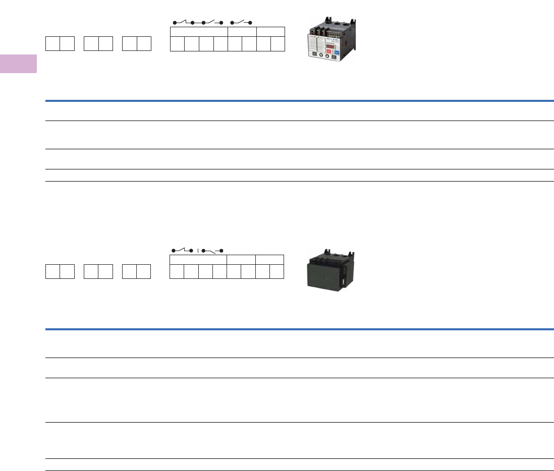
V5-T5-104 Volume 5—Motor Control and Protection CA08100006E—April 2014 www.eaton.com
5
5
5
5
5
5
5
5
5
5
5
5
5
5
5
5
5
5
5
5
5
5
5
5
5
5
5
5
5
5
5.4
Motor Protection and Monitoring
Overload Relays
Line Powered Models
Terminal Connection Diagram
Terminal Connection Specifications
Control Powered Models
Terminal Connection Diagram
Terminal Connection Specifications
Note
1No motor loads, 9A maximum.
Name Designation Input Description
Line voltage L1, L2, L3 Line voltage Three-phase line voltage input
L1, L2, L3 connections must correspond to the respective CT1, CT2, CT3 current leads
Fault relay 95/96
96/97 (common)
97/98
B300 UL 508 Form C contact:
95/96 Contact opens when the unit is faulted or unpowered
97/98 Contact closes when the unit is faulted or unpowered
GF shunt 15
16
B300 UL 508 Form A contact:
Contact closes when a ground fault is active
Reset input R1, R2 120 Vac Fault reset input IEC 61131-2 Type 1
Name Designation Input Description
Line voltage L1, L2, L3 Line voltage Three-phase line voltage input
L1, L2, L3 connections must correspond to the respective CT1, CT2, CT3 current leads
Terminal provided for wiring control power transformer (9A maximum capacity)
Control power X1, X2 110–120 Vac
50–60Hz (+10/–15%)
Control power option for C441_ _ _ _NOUI
Fault relay
For C441_ _ _ _NOUI, the fault relay and auxiliary relay are
isolated and do not share a common. By default they will
behave like a Form C, but they can be programmed to act
independently from one another.
95/96
96/97 (isolated)
97/98
B300 UL 508 Form C contact:
95/96 Contact opens when the unit is faulted or unpowered
97/98 Contact closes when the unit is faulted or unpowered
Can be programmed to act independently of the 95/96 only in the C441_ _ _ _NOUI models
GF shunt
This relay does not exist on the C441_ _ _ _NOUI models.
Instead, this functionality is available in the fully
programmable 97/98 auxiliary relay.
97/98 B300 UL 508 Form A contact:
Contact closes when a ground fault is active
Separate GF control can still be achieved by programming auxiliary relay 97/98 to act
independently of the 95/96 relay
Reset input R1, R2 120 Vac Fault reset input IEC 61131-2 Type 1
L1 L2 L3 95 96 97 98 15 16 R1 R2
NC NO GF Shunt Reset
120 Vac
18–12 AWG; Torque 5.3 lb-in/0.6 Nm
B300 Pilot Duty Only
Use 75C CU wire only
For C441BA, BB, CA, CB, DA and DB
aa a
L1 L2 L3 95 96 97 98 X1 X2 R1 R2
NC NO Cntrl. Pwr. Reset
120 Vac120 Vac
For C4410109NOUI and C441059NOUI
aaa

Volume 5—Motor Control and Protection CA08100006E—April 2014 www.eaton.com V5-T5-105
5
5
5
5
5
5
5
5
5
5
5
5
5
5
5
5
5
5
5
5
5
5
5
5
5
5
5
5
5
5
5.4
Motor Protection and Monitoring
Overload Relays
Modbus Communication Modules
Note
1Relates to C441M only.
Description Specification
Electrical/EMC
Radiated emissions
IEC 60947-4-1—Table 15, EN 55011 (CISPIR 11) Group 1, Class A
30–1000 mHz
Conducted emissions
IEC 60947-4-1—Table 14, EN 55011 (CISPIR 11) Group 1, Class A
0.15–30 mHz
ESD immunity
IEC 60947-4-1 (Table 13) IEC 61000-4-2
±8 kV air, ±4 kV contact
Radiated immunity
IEC 60947-4-1
10 V/m 80–1000 mHz
80% amplitude modulated 1 kHz sine wave
Conducted immunity
IEC 60947-4-1
140 dBuV (10V rms)
150 kHz–80 mHz
Fast transient immunity
IEC 60947-4-1 (Table 13) IEC 61000-4-4
±2 kV using direct method
Surge immunity
IEC 60947-4-1 (Table 13)
IEC 61000-4-5 Class 3
User IO and communication lines 1:
±1 kV line-to-line (DM)
±2 kV line-to-ground (CM)
Electromagnetic field 1
IEC 60947-4-1 (Table 13) IEC 61000-4-3
10 V/m
Environmental Ratings
Ambient temperature (operating) –20° to 50°C
Ambient temperature (storage) –40° to 85°C
Operating humidity 5 to 95% noncondensing
Altitude (no derating) 2000m
Shock (IEC 60068-2-27) 15G any direction
Vibration (IEC 60068-2-6) 3G any direction
Pollution degree per IEC 60947-1 3
Degree of protection IP20
Over voltage category per UL 508 III
C441P 24 Vdc Input
Nominal input voltage 24 Vdc
Operating voltage 18–30 Vdc
Number of inputs 4
Signal delay 5 ms (programmable to 65 sec)
OFF-state voltage <6 Vdc
ON-state voltage >18 Vdc
Nominal input current 5 mA
Isolation 1500V
Terminal screw torque 7–9 in-lb
24 Vdc source current 50 mA
Operating Voltage Range—DC Input Modules
OFF State Transition Region ON State
0–6 Vdc 6–18 Vdc 18–30 Vdc
C441N 120 Vac Input
Nominal input voltage 120 Vac
Operating voltage 80–140 Vac
Number of inputs 4
OFF-state voltage <30 Vac
ON-state voltage >80 Vac
Nominal input current 15 mA
Signal delay 1/2 cycle
Isolation 1500V
Terminal screw torque 7–9 in-lb

V5-T5-106 Volume 5—Motor Control and Protection CA08100006E—April 2014 www.eaton.com
5
5
5
5
5
5
5
5
5
5
5
5
5
5
5
5
5
5
5
5
5
5
5
5
5
5
5
5
5
5
5.4
Motor Protection and Monitoring
Overload Relays
Modbus Communication Modules, continued
DeviceNet Communication Modules
Note
1Resistive current at 55°C ambient.
Description Specification
Operating Voltage Range—AC Input Modules
OFF State Transition Region ON State
0–30 Vac 30–80 Vac 80–140 Vac
Output Modules
Nominal voltage 120 Vac
24 Vdc
Number of outputs (2) 1NO Form A
1NO/NC Form C
Relay OFF time 3 ms
Relay ON time 7 ms
Max. current per point 15A (B300 rated)
Electrical life 100,000 cycles
Mechanical life 1,000,000 cycles
Description Specification
Electrical/EMC
Radiated emissions
IEC 60947-4-1—Table 15, EN 55011
(CISPIR 11) Group 1, Class A
30–1000 mHz
Conducted emissions
IEC 60947-4-1—Table 14, EN 55011
(CISPIR 11) Group 1, Class A
0.15–30 mHz
ESD immunity
IEC 60947-4-1 (Table 13) IEC 61000-4-2
±8 kV air, ±4 kV contact
Radiated immunity
IEC 60947-4-1
10 V/m 80–1000 mHz
80% amplitude modulated 1 kHz sine wave
Conducted immunity
IEC 60947-4-1
140 dBuV (10V rms)
150 kHz–80 mHz
Fast transient immunity
IEC 60947-4-1 (Table 13) IEC 61000-4-4
±2 kV using direct method
Surge immunity
IEC 60947-4-1 (Table 13)
IEC 61000-4-5 Class 2
User IO and communication lines:
±1 kV line-to-line (DM)
±2 kV line-to-ground (CM)
Electromagnetic field
IEC 60947-4-1 Table 13, IEC 61000-4-3
10 V/m
Environmental Ratings
Ambient temperature (operating) –20° to 50°C
Ambient temperature (storage) –40° to 85°C
Operating humidity 5–95% noncondensing
Altitude (no derating) 2000m
Shock (IEC 60068-2-27) 15G any direction
Vibration (IEC 60068-2-6) 3G any direction
Pollution degree per IEC 60947-1 3
Degree of protection IP20
DeviceNet
DeviceNet connections Group 2, polling, bit strobe, explicit, no UCMM
DeviceNet baud rate 125K, 250K, 500K

Volume 5—Motor Control and Protection CA08100006E—April 2014 www.eaton.com V5-T5-107
5
5
5
5
5
5
5
5
5
5
5
5
5
5
5
5
5
5
5
5
5
5
5
5
5
5
5
5
5
5
5.4
Motor Protection and Monitoring
Overload Relays
DeviceNet Communication Modules, continued
Note
1Resistive current at 55°C ambient.
Description Specification
C441L 24 Vdc Input
Nominal input voltage 24 Vdc
Operating voltage 18–30 Vdc
Number of inputs 4
Signal delay 5 ms (programmable to 65 sec)
OFF-state voltage <6 Vdc
ON-state voltage >18 Vdc
Nominal input current 5 mA
Isolation 250V
Terminal screw torque 7–9 in-lb
24V source current 50 mA
Operating Voltage Range—DC Input Modules
OFF State Transition Region ON State
0–6 Vdc 6–18 Vdc 18–30 Vdc
C441K 120 Vac Input
Nominal input voltage 120 Vac
Operating voltage 80–140 Vac
Number of inputs 4
OFF-state voltage <30 Vac
ON-state voltage >80 Vac
Nominal input current 15 mA
Signal delay 1/2 cycle
Isolation 250V
Terminal screw torque 7–9 in-lb
Operating Voltage Range—AC Input Modules
OFF State Transition Region ON State
0–30 Vac 30–80 Vac 80–140 Vac
Output Modules
Nominal voltage 120 Vac
24 Vdc
Number of outputs (2) 1NO Form A
1NO/NC Form C
Relay OFF time 3 ms
Relay ON time 7 ms
Max. current per point 15A (B300 rated)
Electrical life 100,000 cycles
Mechanical life 1,000,000 cycles

V5-T5-108 Volume 5—Motor Control and Protection CA08100006E—April 2014 www.eaton.com
5
5
5
5
5
5
5
5
5
5
5
5
5
5
5
5
5
5
5
5
5
5
5
5
5
5
5
5
5
5
5.4
Motor Protection and Monitoring
Overload Relays
PROFIBUS Communication Modules
Description Specification
Electrical/EMC
Radiated emissions
IEC 60947-4-1—Table 15, EN 55011
(CISPIR 11) Group 1, Class A
30–1000 mHz
Conducted emissions
IEC 60947-4-1—Table 14, EN 55011
(CISPIR 11) Group 1, Class A
0.15–30 mHz
ESD immunity
IEC 60947-4-1 (Table 13) IEC 61000-4-2
±8 kV air, ±4 kV contact
Radiated immunity
IEC 60947-4-1 Table 13, IEC 61000-4-3
10 V/m 80–1000 mHz
80% amplitude modulated 1 kHz sine wave
Conducted immunity
IEC 60947-4-1
140 dBuV (10V rms)
150 kHz–80 mHz
Fast transient immunity
IEC 60947-4-1 (Table 13) IEC 61000-4-4
±2 kV using direct method
Surge immunity
IEC 60947-4-1 (Table 13)
IEC 61000-4-5 Class 2
User IO and communication lines:
±1 kV line-to-line (DM)
±2 kV line-to-ground (CM)
Environmental Ratings
Ambient temperature (operating) –20° to 50°C
Ambient temperature (storage) –40° to 85°C
Operating humidity 5–95% noncondensing
Altitude (no derating) 2000m
Shock (IEC 60068-2-27) 15G any direction
Vibration (IEC 60068-2-6) 3G any direction
Pollution degree per IEC 60947-1 3
Degree of protection IP20
PROFIBUS
PROFIBUS connections Group 2, polling, bit strobe, explicit, no UCMM
PROFIBUS baud rate 9.6K, 19.2K, 45.45K, 93.75K, 187.5K, 500K, 1.5M, 3M, 6M, 12M
C441Q 24 Vdc Input
Nominal input voltage 24 Vdc
Operating voltage 18–30 Vdc
Number of inputs 4
Signal delay 5 ms (programmable to 65 sec)
OFF-state voltage <6 Vdc
ON-state voltage >10 Vdc
Nominal input current 5 mA
Isolation 1500V
Terminal screw torque 7–9 in-lb
24V source current 50 mA

Volume 5—Motor Control and Protection CA08100006E—April 2014 www.eaton.com V5-T5-109
5
5
5
5
5
5
5
5
5
5
5
5
5
5
5
5
5
5
5
5
5
5
5
5
5
5
5
5
5
5
5.4
Motor Protection and Monitoring
Overload Relays
PROFIBUS Communication Modules, continued
Note
1Resistive current at 55°C ambient.
Description Specification
Operating Voltage Range—DC Input Modules
OFF State Transition Region ON State
0–6 Vdc 6–18 Vdc 18–30 Vdc
C441S 120 Vac Input
Nominal input voltage 120 Vac
Operating voltage 80–140 Vac
Number of inputs 4
OFF-state voltage <20 Vac
ON-state voltage >70 Vac
Nominal input current 15 mA
Signal delay 1/2 cycle
Isolation 1500V
Terminal screw torque 7–9 in-lb
Operating Voltage Range—AC Input Modules
OFF State Transition Region ON State
0–30 Vac 30–80 Vac 80–140 Vac
Output Modules
Nominal voltage 120 Vac
24 Vdc
Number of outputs (2) 1NO Form A
1NO/NC Form C
Relay OFF time 3 ms
Relay ON time 7 ms
Max. current per point 15A (B300 rated)
Electrical life 100,000 cycles
Mechanical life 1,000,000 cycles

V5-T5-110 Volume 5—Motor Control and Protection CA08100006E—April 2014 www.eaton.com
5
5
5
5
5
5
5
5
5
5
5
5
5
5
5
5
5
5
5
5
5
5
5
5
5
5
5
5
5
5
5.4
Motor Protection and Monitoring
Overload Relays
Ethernet (Modbus TCP / EtherNet/IP) Communication Modules
Description Specification
Electrical/EMC
Radiated emissions
IEC 60947-4-1, Table 15, EN 55011
(CISPIR 11) Group 1, Class A
30–1000 mHz
Conducted emissions
IEC 60947-4-1, Table 15, EN 55011
(CISPIR 11) Group 1, Class A
0.15–30 mHz
ESD immunity
IEC 60947-4-1 (Table 13) IEC 61000-4-2
±8 kV air, ±4 kV contact
Radiated immunity
IEC 60947-4-1 (Table 13) IEC 61000-4-3
10 V/m 80–1000 mHz
80% amplitude modulated 1 kHz sine wave
Conducted immunity
IEC 60947-4-1
140 dBuV (10V rms)
150 kHz to 80 mHz
Fast transient immunity
IEC 60947-4-1 (Table 13) IEC 61000-4-4
±2 kV using direct method
Surge immunity
IEC 60947-4-1 (Table 13)
IEC 61000-4-5 Class 2
User IO and communication lines:
±1 kV line-to-line (DM)
±2 kV line-to-ground (CM)
Environmental Ratings
Ambient temperature (operating) –20° to 50°C
Ambient temperature (storage) –40° to 85°C
Operating humidity 5–95% noncondensing
Altitude (no derating) 2000m
Shock (IEC 60068-2-27) 15G any direction
Vibration (IEC 60068-2-6) 3G any direction
Pollution degree per IEC 60947-1 3
Degree of protection IP20
Ethernet
Ethernet connections Integrated two-port switch with dual
RJ45 Ethernet connections
Ethernet type Ethernet 10/100 Mbs, AutoMDX,
Auto Negotiation
C441T 24 Vdc Input
Nominal input voltage 24 Vdc
Operating voltage 18–30 Vdc
Number of inputs 4
Signal delay 5 ms (programmable to 65 sec)
OFF-state voltage <6 Vdc
ON-state voltage >18 Vdc
Nominal input current 5 mA
Isolation 1500V
Terminal screw torque 7–9 in-lb
24V source current 50 mA

Volume 5—Motor Control and Protection CA08100006E—April 2014 www.eaton.com V5-T5-111
5
5
5
5
5
5
5
5
5
5
5
5
5
5
5
5
5
5
5
5
5
5
5
5
5
5
5
5
5
5
5.4
Motor Protection and Monitoring
Overload Relays
Ethernet (Modbus TCP / EtherNet/IP) Communication Modules, continued
Note
1Resistive current at 55°C ambient.
Description Specification
Operating Voltage Range—DC Input Modules
OFF State Transition Region ON State
0–6 Vdc 6–18 Vdc 18–30 Vdc
C441R 120 Vac Input
Nominal input voltage 120 Vac
Operating voltage 80–140 Vac
Number of inputs 4
OFF-state voltage <30 Vac
ON-state voltage >80 Vac
Nominal input current 15 mA
Signal delay 1/2 cycle
Isolation 1500V
Terminal screw torque 7–9 in-lb
Operating Voltage Range—AC Input Modules
OFF State Transition Region ON State
0–30 Vac 30–80 Vac 80–140 Vac
Nominal voltage 120 Vac
24 Vdc
Number of outputs (2) 1NO Form A
1NO/NC Form C
Relay OFF time 3 ms
Relay ON time 7 ms
Maximum current per point 15A (B300 rated)
Electrical life 100,000 cycles
Mechanical life 1,000,000 cycles
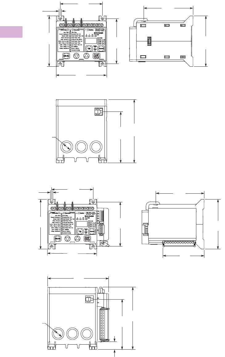
V5-T5-112 Volume 5—Motor Control and Protection CA08100006E—April 2014 www.eaton.com
5
5
5
5
5
5
5
5
5
5
5
5
5
5
5
5
5
5
5
5
5
5
5
5
5
5
5
5
5
5
5.4
Motor Protection and Monitoring
Overload Relays
Dimensions
Approximate Dimensions in Inches (mm)
Motor Insight Overload Relay
Motor Insight with Mounted DeviceNet, PROFIBUS or Modbus with I/O Communication Module
3.94
(100.1)
0.20
(5.1)
4 Places
3.31
(84.1)
3.50
(88.9)
3.94
(100.1)
Mounting Dimension
(4) 10-32
Terminal Ref.
3.82
(97.0)
3.94
(100.1)
Dia.
0.69
(17.5)
3 Places
3.98
(101.1)
4.92
(125.0)
3.94
(100.1)
0.20
(5.1)
3.31
(84.1)
3.50
(88.9)
3.94
(100.1)
Mounting Dimensions
(4) 10-32
4.84
(122.9)
4.92
(125.0)
3.98
(101.1)
0.63
(16.0)
Dia.
0.69
(17.5)
3 Places
Terminal Ref.
3.82
(97.0)
3.94
(100.1)
3.27
(83.1)
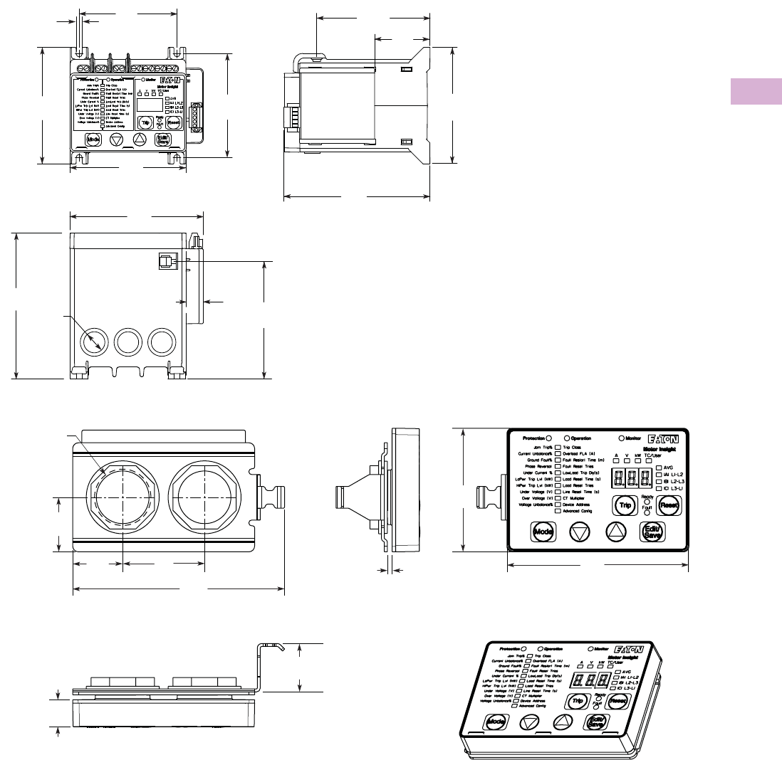
Volume 5—Motor Control and Protection CA08100006E—April 2014 www.eaton.com V5-T5-113
5
5
5
5
5
5
5
5
5
5
5
5
5
5
5
5
5
5
5
5
5
5
5
5
5
5
5
5
5
5
5.4
Motor Protection and Monitoring
Overload Relays
Approximate Dimensions in Inches (mm)
Motor Insight with Mounted Modbus Communication Module
Motor Insight Remote Display
0.20
(5.1)
4 Places
3.31
(84.1)
3.50
(88.9)
3.94
(100.1)
3.94
(100.1)
Mounting Dimensions
(4) 10-32
4.53
(115.1)
4.92
(125.0) Dia.
0.69
(17.5)
3 Places
3.98
(101.1)
0.59
(15.0)
Terminal Ref.
3.82
(97.0) 1.89
(48.0)
3.94
(100.1)
4.92
(125.0)
2.70
(68.6)
3.90
(99.1)
12 GA Max.
Panel Thickness
2X ø 1.22
(31.0)
Hole in Panel
4.60
(116.8)
1.75
(44.5)
1.10
(27.9)
1.20
(30.5)
1.0 0
(25.4)
0.60
(15.2)
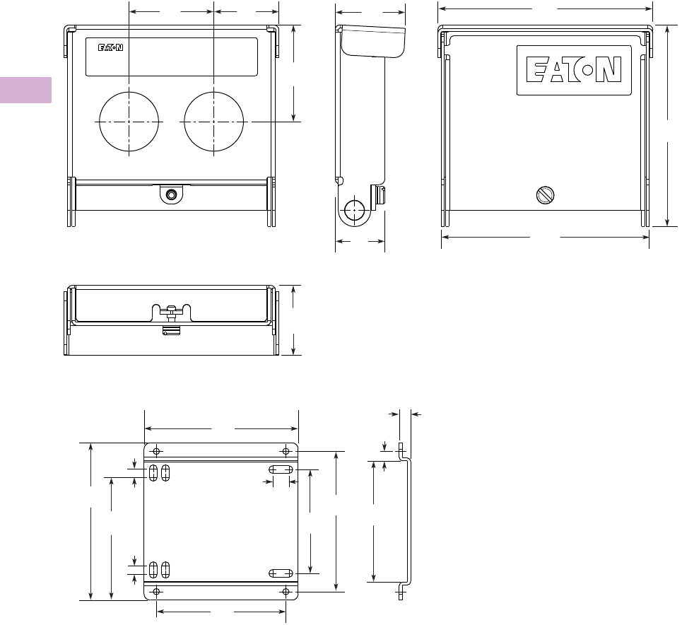
V5-T5-114 Volume 5—Motor Control and Protection CA08100006E—April 2014 www.eaton.com
5
5
5
5
5
5
5
5
5
5
5
5
5
5
5
5
5
5
5
5
5
5
5
5
5
5
5
5
5
5
5.4
Motor Protection and Monitoring
Overload Relays
Approximate Dimensions in Inches (mm)
Motor Insight Cover Assembly
Motor Insight Conversion Plate
4.20
(106.7)
4.40
(111.8)
4.30
(109.2)
1.40
(35.6)
2.00
(50.8)
1.40
(35.6)
1.0 0
(25.4)
1.30
(33.0)
1.75
(44.5)
Motor Insight
0.30
(7.6)
3.30
(83.8)
0.20
(5.1)
3.10
(78.7)
3.60
(91.4)
2.70
(68.6)
0.40
(10.2)
4.00
(101.6)
2.30
(58.4)0.20
(5.1)
0.20
(5.1)
3.90
(99.1)

Volume 5—Motor Control and Protection CA08100006E—April 2014 www.eaton.com V5-T5-115
5
5
5
5
5
5
5
5
5
5
5
5
5
5
5
5
5
5
5
5
5
5
5
5
5
5
5
5
5
5
5.4
Motor Protection and Monitoring
Overload Relays
MP-3000 Overload Relays
Contents
Description Page
XT IEC Overload Relays . . . . . . . . . . . . . . . . . . . . V5-T5-60
Freedom Overload Relays . . . . . . . . . . . . . . . . . . . V5-T5-64
C440/XT Electronic Overload Relay . . . . . . . . . . . V5-T5-65
IQ500 Overload Relays . . . . . . . . . . . . . . . . . . . . . V5-T5-88
C441 Overload Relays . . . . . . . . . . . . . . . . . . . . . . V5-T5-89
MP-3000 Overload Relays
Features, Benefits and Functions . . . . . . . . . . . V5-T5-116
Standards and Certifications . . . . . . . . . . . . . . V5-T5-116
Reference . . . . . . . . . . . . . . . . . . . . . . . . . . . . . V5-T5-116
MP-4000 Overload Relays . . . . . . . . . . . . . . . . . . . V5-T5-117
MP-3000 Overload Relays
Product Description
●Microprocessor-based,
multi-function motor
protection
●Current only device—
no need to add PTs
●Intel-I-Trip™ overload
protection based on
motor data
●Event recording and
operational logging
●Motor Start Profile™
●Optional Quick Release
Drawout Case
●Used on AMPGARD®
and medium voltage
assemblies
●“Help” menu provides
user operational assistance
Application Description
Eaton’s MP-3000 motor
protection relay is a
multifunctional
microprocessor-based
protective relay for the
protection of three-phase AC
motors. The MP-3000 motor
relay may be applied to any
size motor at any voltage
level. It is most commonly
used on large, medium
voltage three-phase induction
motors. It has also been
widely used on important
low voltage (480 volt)
motor applications and
synchronous motors.
The MP-3000 motor relay is
a current only device that
monitors three-phase and
ground currents. It provides
motor overload, stall, short
circuit, phase imbalance,
single phasing and ground
fault motor protection.
It can also be used to provide
protection for a load jam or
loss of load condition. Please
refer to Volume 3—Power
Distribution and Control
Assemblies, CA08100004E,
Tab 9, section 9.4 for additional
product info
rmation.
The MP-3000 motor relay
provides start control logic
to protect the motor against
excessive starts or starting
the motor before it has had
sufficient time to cool down.
The MP-3000 motor relay
may be applied to either
across the line starters or
reduced voltage starters. On
reduced voltage starters, the
MP-3000 relay can control the
switch from reduced voltage
to full voltage based on time
and/or motor transition. The
MP-3000 can protect the
starter against failure to
transition to full voltage
through contact feedback and
an incomplete sequence
function.
The MP-3000 motor relay is
generally used on a motor
starter or a breaker used for
a motor load. The MP-3000
motor relay provides the
intelligence to protect and
control the motor against
abnormal operating
conditions. It monitors the
currents from either a 5A
or 1A secondary of a CT
circuit. Ground current may
be obtained from either a
ground CT or from the
residual connection of the
phase CTs. It provides a
Form C contact output for
controlling the starter contacts
or breaker operation.

V5-T5-116 Volume 5—Motor Control and Protection CA08100006E—April 2014 www.eaton.com
5
5
5
5
5
5
5
5
5
5
5
5
5
5
5
5
5
5
5
5
5
5
5
5
5
5
5
5
5
5
5.4
Motor Protection and Monitoring
Overload Relays
Features, Benefits and Functions
●Complete motor protection
and control in a single
compact case reduces
panel space requirements
and wiring costs
●Microprocessor design
with self diagnostics
eliminates calibration
and reduces installation,
commissioning and
maintenance
●Programmable stop
2–20% of PCT
●Intel-I-Trip overload
protection develops
customized curve from
manufacturer’s supplied
motor data
●Intel-I-Trip overload
protection provides
adaptive trip characteristics
based on motor
temperature when motor
RTDs are connected
through an optional
URTD module
●Meets UL 1053 ground
fault protection standards
that eliminates the need
for a separate ground relay
saving cost, space, wiring
and time
●Voltage dip/loss ride
through capability reduces
unnecessary trips caused
by poor power quality
●Motor currents,
temperatures and
conditions are monitored
and displayed either locally
or remotely
●Event log provides motor
operating records for the
most recent 20 Trip or
Alarm events with date
and time stamping. This
information can improve
troubleshooting and
reduce downtime
●Log book records the most
recent 100 events such as
motor START/STOP and
set point changes to
provide a log of motor
operation with date and
time stamping
●RTD diagnostics reduces
unnecessary tripping
caused by faulty RTD, RTD
wiring or communications
●Arm/Disarm feature
improves security for
critical motor applications
●Motor Start profile verifies
protection and motor
starting coordination. This
feature can be used to
develop protection settings
on old motors where data
is not available
●Optional communication
module and Eaton’s
software simplifies setting,
configuration, monitoring,
commissioning and data
retrieval either locally or
remotely
●Optional Quick Release
Drawout Case construction
simplifies relay removal
and replacement
The protection functions are
listed below.
●I2t overload protection
(49/51)
●Locked rotor (49S/51)
●Ultimate trip current (51)
●Negative sequence phase
imbalance (46)
●Instantaneous
overcurrent (50)
●Ground fault
protection (50G)
●RTD trip and alarm with
URTD module (49/38)
●Underload trip (37)
●Starts per time (66)
●Jam or stall (51R)
●Auto or manual reset (86)
●Fail-safe or non-fail-safe
trip modes
The metering functions are:
●Motor currents:
●Average current (Iave)
●Individual phase and
ground current in
primary amperes
●Percent of full load
●Percent of phase
imbalance
●RTD temperatures:
●Individual winding
●Motor bearing
●Load
●Auxiliary temperatures
●Motor conditions:
●Percent of I2t thermal
bucket
●Time before start
●Remaining starts
allowed
●Oldest start time
Standards and Certifications
The MP-3000 motor
protection was designed to
meet the industry standards
for protective relays. It is
recognized under UL 1053
Ground Fault Protection
Standard.
●UL recognized
(File No. E154862)
●UL 1053 recognized
●UL 508 recognized
●ANSI C37.90, C37.90.1
●cUL
●CSA
Reference
Refer to Volume 3—Power Distribution and Control Assemblies,
CA08100004E, Tab 9, section 9.4 for additional product information.
Description Tab Section
Product Selection . . . . . . . . . . . . . . . . . . . . . . . . . . . . . . . 9.4
Options and Accessories . . . . . . . . . . . . . . . . . . . . . . . . . . 9.4
Technical Data and Specifications . . . . . . . . . . . . . . . . . . . 9.4
Dimensions . . . . . . . . . . . . . . . . . . . . . . . . . . . . . . . . . . . . 9.4
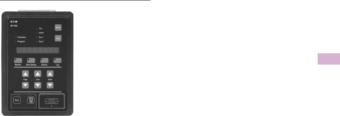
Volume 5—Motor Control and Protection CA08100006E—April 2014 www.eaton.com V5-T5-117
5
5
5
5
5
5
5
5
5
5
5
5
5
5
5
5
5
5
5
5
5
5
5
5
5
5
5
5
5
5
5.4
Motor Protection and Monitoring
Overload Relays
MP-4000 Overload Relays
Contents
Description Page
XT IEC Overload Relays . . . . . . . . . . . . . . . . . . . . V5-T5-60
Freedom Overload Relays . . . . . . . . . . . . . . . . . . . V5-T5-64
C440/XT Electronic Overload Relay . . . . . . . . . . . V5-T5-65
IQ500 Overload Relays . . . . . . . . . . . . . . . . . . . . . V5-T5-88
C441 Overload Relays . . . . . . . . . . . . . . . . . . . . . . V5-T5-89
MP-3000 Overload Relays . . . . . . . . . . . . . . . . . . . V5-T5-115
MP-4000 Overload Relays
Features, Benefits and Functions . . . . . . . . . . . V5-T5-118
Standards and Certifications . . . . . . . . . . . . . . V5-T5-118
Reference . . . . . . . . . . . . . . . . . . . . . . . . . . . . . V5-T5-118
MP-4000 Overload Relays
Product Description
●Microprocessor-based,
multi-function motor
protection
●Intel-I-Trip overload
protection based on
motor data
●Event recording and
operational logging
●Motor Start Profile
●Optional Quick Release
Drawout Case
●Used on AMPGARD
and medium voltage
assemblies
●“Help” menu provides
user operational assistance
Application Description
Eaton’s MP-4000 motor
protection relay is a multi-
functional microprocessor-
based protective relay for the
protection of three-phase AC
motors. The MP-4000 motor
relay may be applied to any
size motor at any voltage level.
It is most commonly used on
large, medium voltage three-
phase induction motors. It
has also been widely used
on important low voltage
(480 volt) motor applications
and synchronous motors.
The MP-4000 motor relay
monitors three-phase and
ground currents, and three-
phase voltages. It provides
motor overload, stall, short
circuit, phase imbalance, single
phasing over/undervoltage,
underpower, power factor and
ground fault motor protection.
It can also be used to provide
protection for a load jam or loss
of load condition.
The MP-4000 motor relay
provides start control logic
to protect the motor against
excessive starts or starting
the motor before it has had
sufficient time to cool down.
The MP-4000 motor relay may
be applied to either across the
line starters or reduced voltage
starters. On reduced voltage
starters, the MP-4000 relay can
control the switch from
reduced voltage to full voltage
based on time and/or motor
transition. The MP-4000 can
protect the starter against
failure to transition to full
voltage through contact
feedback and an incomplete
sequence function.
The MP-4000 motor relay is
generally used on a motor
starter or a breaker used for
a motor load. The MP-4000
motor relay provides the
intelligence to protect and
control the motor against
abnormal operating conditions.
It monitors the currents from
either a 5A or 1A secondary of
a CT circuit. Ground current
may be obtained from either a
ground CT or from the residual
connection of the phase CTs.
It provides a form C contact
output for controlling the
starter contacts or breaker
operation.

V5-T5-118 Volume 5—Motor Control and Protection CA08100006E—April 2014 www.eaton.com
5
5
5
5
5
5
5
5
5
5
5
5
5
5
5
5
5
5
5
5
5
5
5
5
5
5
5
5
5
5
5.4
Motor Protection and Monitoring
Overload Relays
Features, Benefits and Functions
●Complete motor protection
and control in a single
compact case reduces
panel space requirements
and wiring costs
●Microprocessor design
with self diagnostics
eliminates calibration
and reduces installation,
commissioning and
maintenance
●Programmable stop
2–20% of PCT
●Intel-I-Trip overload
protection develops
customized curve from
manufacturer’s supplied
motor data
●Intel-I-Trip overload
protection provides
adaptive trip characteristics
based on motor
temperature when motor
RTDs are connected
through an optional
URTD module
●Meets UL 1053 ground
fault protection standards
that eliminates the need
for a separate ground relay
saving cost, space, wiring
and time
●Voltage dip/loss ride
through capability reduces
unnecessary trips caused
by poor power quality
●Motor currents,
temperatures and
conditions are monitored
and displayed either locally
or remotely
●Event log provides motor
operating records for the
most recent 20 Trip or
Alarm events with date
and time stamping. This
information can improve
troubleshooting and
reduce downtime
●Log book records the most
recent 100 events such as
motor START/STOP and
set point changes to
provide a log of motor
operation with date and
time stamping
●RTD diagnostics reduces
unnecessary tripping
caused by faulty RTD, RTD
wiring or communications
●Arm/Disarm feature
improves security for
critical motor applications
●Motor Start profile verifies
protection and motor
starting coordination. This
feature can be used to
develop protection settings
on old motors where data
is not available
●Optional communication
module and Eaton’s
software simplifies setting,
configuration, monitoring,
commissioning and data
retrieval either locally or
remotely
●Optional Quick Release
Drawout Case construction
simplifies relay removal
and replacement
The metering functions are:
●Metering:
●Average current
●Amperes: magnitude
and angle in primary
values
●Amperes: positive,
negative and zero
sequence
●Average voltage (V ave)
●Voltage: magnitude and
angle
●Voltage: positive,
negative and zero
sequence
●% of full load
●% current imbalance
●% voltage imbalance
●Power, vars and VA
●Power factor
●Frequency
●Energy metering with
time and date stamps
●RTD temperatures:
●Individual winding
●Motor bearing
●Load
●Auxiliary temperatures
●Motor conditions:
●Percent of I2t thermal
bucket
●Time before start
●Remaining starts
allowed
●Oldest start time
The protection functions are
listed below:
●I2t overload
protection (49/51)
●Locked rotor (49S/51)
●Ultimate trip current (51)
●Negative sequence phase
imbalance (46)
●Instantaneous
overcurrent (50)
●Ground fault
protection (50G)
●Undervoltage (27)
●Overvoltage (59)
●Under power (32)
●Negative sequence voltage
imbalance (47)
●Power factor (55)
●RTD trip and alarm with
URTD module (49/38)
●Underload trip (37)
●Starts per time (66)
●Jam or stall (51R)
●Auto or manual reset (86)
●Fail-safe or non-fail-safe
trip modes
Standards and Certifications
The MP-4000 motor
protection was designed to
meet the industry standards
for protective relays. It is
recognized under UL 1053
Ground Fault Protection
Standard.
●UL recognized (File No.
E154862)
●UL 1053 recognized
●UL 508 recognized
●ANSI C37.90, C37.90.1
●cUL
●CSA
Reference
Refer to Volume 3—Power Distribution and Control Assemblies,
CA08100004E, Tab 9, section 9.4 for additional product information.
Description Tab Section
Product Selection . . . . . . . . . . . . . . . . . . . . . . . . . . . . . . . 9.4
Options and Accessories . . . . . . . . . . . . . . . . . . . . . . . . . . 9.4
Technical Data and Specifications . . . . . . . . . . . . . . . . . . . 9.4
Dimensions . . . . . . . . . . . . . . . . . . . . . . . . . . . . . . . . . . . . 9.4
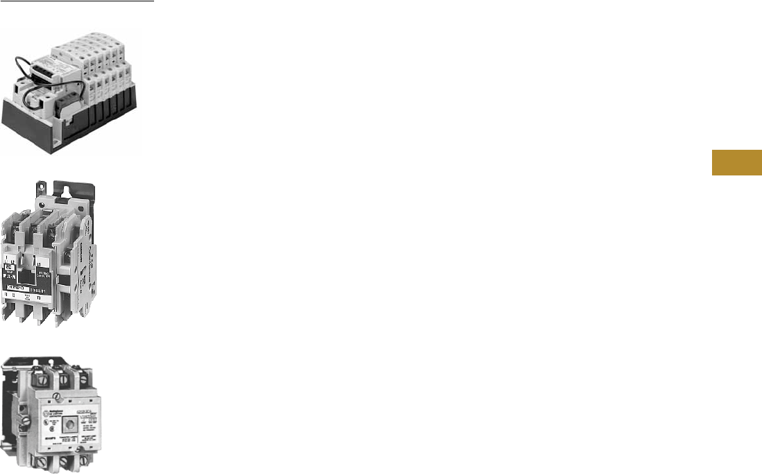
Volume 5—Motor Control and Protection CA08100006E—June 2014 www.eaton.com V5-T6-1
6
6
6
6
6
6
6
6
6
6
6
6
6
6
6
6
6
6
6
6
6
6
6
6
6
6
6
6
6
6
Lighting Contactors
C30CN Mechanically and
Electrically Held
CN35 Electrically Held
A202 Magnetically Latched
6.1 Open Control
Product Overview . . . . . . . . . . . . . . . . . . . . . . . . . . . . . . . . . . . . . . . . V5-T6-2
C30CN Mechanically and Electrically Held
Product Description . . . . . . . . . . . . . . . . . . . . . . . . . . . . . . . . . . . . V5-T6-3
Application Description . . . . . . . . . . . . . . . . . . . . . . . . . . . . . . . . . . V5-T6-3
Features . . . . . . . . . . . . . . . . . . . . . . . . . . . . . . . . . . . . . . . . . . . . . V5-T6-4
Standards and Certifications . . . . . . . . . . . . . . . . . . . . . . . . . . . . . . V5-T6-4
Instructional Leaflets . . . . . . . . . . . . . . . . . . . . . . . . . . . . . . . . . . . . V5-T6-4
Catalog Number Selection . . . . . . . . . . . . . . . . . . . . . . . . . . . . . . . V5-T6-5
Product Selection . . . . . . . . . . . . . . . . . . . . . . . . . . . . . . . . . . . . . . V5-T6-6
Components . . . . . . . . . . . . . . . . . . . . . . . . . . . . . . . . . . . . . . . . . . V5-T6-10
Replacement Parts . . . . . . . . . . . . . . . . . . . . . . . . . . . . . . . . . . . . . V5-T6-11
Technical Data and Specifications . . . . . . . . . . . . . . . . . . . . . . . . . . V5-T6-12
Wiring Diagrams . . . . . . . . . . . . . . . . . . . . . . . . . . . . . . . . . . . . . . . V5-T6-13
Dimensions . . . . . . . . . . . . . . . . . . . . . . . . . . . . . . . . . . . . . . . . . . . V5-T6-15
CN35 Electrically Held
Product Description . . . . . . . . . . . . . . . . . . . . . . . . . . . . . . . . . . . . V5-T6-16
Application Description . . . . . . . . . . . . . . . . . . . . . . . . . . . . . . . . . . V5-T6-16
Features . . . . . . . . . . . . . . . . . . . . . . . . . . . . . . . . . . . . . . . . . . . . . V5-T6-16
Standards and Certifications . . . . . . . . . . . . . . . . . . . . . . . . . . . . . . V5-T6-16
Instructional Leaflets . . . . . . . . . . . . . . . . . . . . . . . . . . . . . . . . . . . . V5-T6-16
Product Selection . . . . . . . . . . . . . . . . . . . . . . . . . . . . . . . . . . . . . . V5-T6-17
Accessories . . . . . . . . . . . . . . . . . . . . . . . . . . . . . . . . . . . . . . . . . . . V5-T6-18
Renewal Parts . . . . . . . . . . . . . . . . . . . . . . . . . . . . . . . . . . . . . . . . . V5-T6-20
Dimensions . . . . . . . . . . . . . . . . . . . . . . . . . . . . . . . . . . . . . . . . . . . V5-T6-21
A202 Magnetically Latched
Product Description . . . . . . . . . . . . . . . . . . . . . . . . . . . . . . . . . . . . V5-T6-23
Application Description . . . . . . . . . . . . . . . . . . . . . . . . . . . . . . . . . . V5-T6-23
Features . . . . . . . . . . . . . . . . . . . . . . . . . . . . . . . . . . . . . . . . . . . . . V5-T6-23
Standards and Certifications . . . . . . . . . . . . . . . . . . . . . . . . . . . . . . V5-T6-23
Instructional Leaflets . . . . . . . . . . . . . . . . . . . . . . . . . . . . . . . . . . . . V5-T6-23
Product Selection . . . . . . . . . . . . . . . . . . . . . . . . . . . . . . . . . . . . . . V5-T6-24
Accessories . . . . . . . . . . . . . . . . . . . . . . . . . . . . . . . . . . . . . . . . . . . V5-T6-24
Renewal Parts . . . . . . . . . . . . . . . . . . . . . . . . . . . . . . . . . . . . . . . . . V5-T6-25
Technical Data and Specifications . . . . . . . . . . . . . . . . . . . . . . . . . . V5-T6-26
Wiring Diagrams . . . . . . . . . . . . . . . . . . . . . . . . . . . . . . . . . . . . . . . V5-T6-26
Dimensions . . . . . . . . . . . . . . . . . . . . . . . . . . . . . . . . . . . . . . . . . . . V5-T6-27
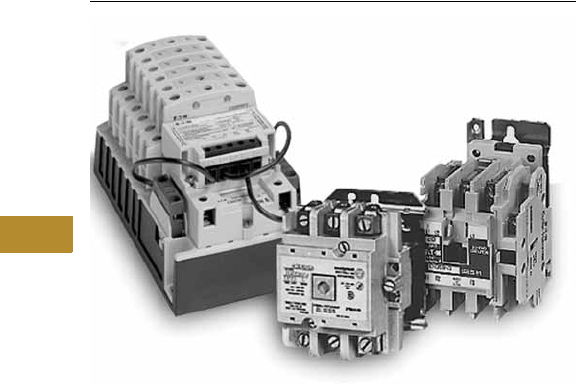
V5-T6-2 Volume 5—Motor Control and Protection CA08100006E—June 2014 www.eaton.com
6
6
6
6
6
6
6
6
6
6
6
6
6
6
6
6
6
6
6
6
6
6
6
6
6
6
6
6
6
6
6.1
Lighting Contactors
Open Control
Lighting Contactors-Open Control
Contents
Description Page
Open Control
C30CN Mechanically and Electrically Held . . . . V5-T6-3
CN35 Electrically Held. . . . . . . . . . . . . . . . . . . . V5-T6-16
A202 Magnetically Latched. . . . . . . . . . . . . . . . V5-T6-23
Product Overview
C30CN Mechanically and
Electrically Held
Electrically and Mechanically
Held C30CN Lighting
Contactor by Eaton Electrical
delivers unprecedented
versatility in application,
simplicity in configuration,
and performance in
operation. With a
revolutionary design, rugged
construction and expansive
feature set, the C30CN is the
right solution for effectively
controlling tungsten
(incandescent filament),
ballast (fluorescent and
mercury arc), High Intensity
Discharge (HID), and non-
motor AC resistive loads.
Application Description
Magnetically Latched—A202
Used in applications where it
is critical that the contactor
will not switch to an off
position during control power
failure.
30–200A contactors use an
electrically energized and de-
energized permanent
magnet, while the 300 and
400A contactors use a
mechanical latch to hold
contacts closed during the
operation (no continuous
control current).
Electrically Held CN35
Use in applications where it is
not critical that contacts stay
closed with loss of control
power.
●Control power is applied
continuously during
operation
●10–400A, 600 volt
maximum rating
●12 poles maximum for 20
and 30A devices
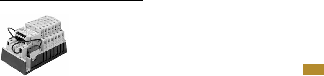
Volume 5—Motor Control and Protection CA08100006E—June 2014 www.eaton.com V5-T6-3
6
6
6
6
6
6
6
6
6
6
6
6
6
6
6
6
6
6
6
6
6
6
6
6
6
6
6
6
6
6
6.1
Lighting Contactors
Open Control
C30CNM Mechanically and Electrically Held
Contents
Description Page
C30CN Mechanically and Electrically Held
Standards and Certifications . . . . . . . . . . . . . . . V5-T6-4
Instructional Leaflets . . . . . . . . . . . . . . . . . . . . . V5-T6-4
Product Selection . . . . . . . . . . . . . . . . . . . . . . . V5-T6-6
Components . . . . . . . . . . . . . . . . . . . . . . . . . . . V5-T6-10
Replacement Parts . . . . . . . . . . . . . . . . . . . . . . V5-T6-11
Technical Data and Specifications . . . . . . . . . . . V5-T6-12
Wiring Diagrams . . . . . . . . . . . . . . . . . . . . . . . . V5-T6-13
Dimensions . . . . . . . . . . . . . . . . . . . . . . . . . . . . V5-T6-15
CN35 Electrically Held . . . . . . . . . . . . . . . . . . . . . . V5-T6-16
A202 Magnetically Latched . . . . . . . . . . . . . . . . . . V5-T6-23
C30CN Mechanically and Electrically Held
Product Description
The C30CNM 30A
Mechanically Held Lighting
Contactors from Eaton’s
Electrical Sector are designed
for industrial, commercial and
outdoor lighting applications
where efficient control is
required. The mechanically
held operation ensures that
the contactor will not switch
to OFF during control power
failure. It also ensures the
removal of coil from the circuit
for noise-free operation and
the elimination of all coil
losses after the contactor is
latched. The control module
microprocessor validates
the control signal before
operation, so it will not
respond to momentary
voltage spikes of noise.
The operation command
has a built-in 0.4 second delay
to avoid multiple short-term
commands that can cause
contact fatigue or failure. Also,
the feedback loop prevents
the contactor from getting out
of sequence with switches,
even after power failures.
Application Description
The mechanically held lighting
contactor provides effective
control in applications such as
office buildings, industrial
plants, hospitals, stadiums,
airports, and so on.
They are ideal for applications
that require quiet, energy-
efficient operation.
Designed to handle different
load types:
●Tungsten (incandescent
filament)
●Ballast (fluorescent and
mercury arc)
●High intensity discharge
(HID)
●Non-motor AC resistive
●Single- and three-phase
motor ratings
Operation
Three-wire control is
the choice for use with
momentary devices allowing
operation from multiple
locations. A momentary pulse
of energy operates the
contactor while a second
pulse on an alternate leg
returns the contactor to its
original state.
Two-wire control is the
choice for single output
automatic operation or for
operation from single-pole
devices. When voltage is
applied to the input terminals
the contactor is latched into
position (coil is removed
from the circuit while control
voltage is continuously
supplied). When control
voltage is removed, the
latch is disengaged and the
contactor is returned to its
original state.
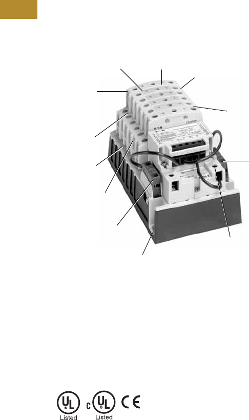
V5-T6-4 Volume 5—Motor Control and Protection CA08100006E—June 2014 www.eaton.com
6
6
6
6
6
6
6
6
6
6
6
6
6
6
6
6
6
6
6
6
6
6
6
6
6
6
6
6
6
6
6.1
Lighting Contactors
Open Control
Features
See figure below.
●30A power pole rating
●Up to 12 poles maximum
●Power poles latch easily
onto the base, and
designating them as NO
or NC is a simple matter
of left or right positioning.
Additional poles, either NO
or NC, may be easily added
at any time
●Low magnetic noise
results in quiet operation
●Low input VA permits long
wire runs
●Come in a wide range of
input voltages and with
coils from 24 Vac to
277 Vac and 12 Vac
to 24 Vdc
C30CNM Features
Standards and Certifications
●UL listed File E1491,
UL Category Code/
Guide NLDX/NLDX7
●cUL
●CE
●Designed and built to
NEMA ICS-2 Standards
Instructional Leaflets
50765 C30CN Lighting
Contactor Series
50766 Coil Kit for C30CN
Lighting Contactors
50767 Power Pole Kit for
C30CN Lighting
Contactors
50768 Control Module Kit
for C30CN Lighting
Contactors
Contact position indication—
when button protrudes,
contact is closed
Power poles are
available as single or
double poles, creating
74 different circuit
combinations
Convenient side
access for field
power wiring
Contact configuration
indicator
Robust pole terminals
accept up to two
8 AWG wires
Fast, sure three-point mounting
Common easily-installed power
poles change from NO to NC
(or vise versa) simply by
unlatching and rotating 180°
Power poles rated
for a range of tasks:
■30A rated contacts
■15A motor rated
■Pilot duty rated
Auxiliary
contacts, rated
A600, are
suitable for
use on low
level circuits
down to
12V, 5 mA
Finger and back-of-hand
safe power terminals
Plug-in auxiliary contacts are NC
when installed on the right side
of the base, NO on the left
Enclosed contacts resist
contaminants for greater reliability
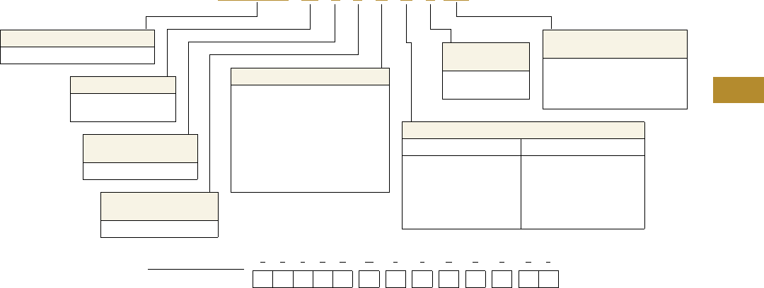
Volume 5—Motor Control and Protection CA08100006E—June 2014 www.eaton.com V5-T6-5
6
6
6
6
6
6
6
6
6
6
6
6
6
6
6
6
6
6
6
6
6
6
6
6
6
6
6
6
6
6
6.1
Lighting Contactors
Open Control
Catalog Number Selection
Type C30CN Lighting Contactors
C 3 0 C N M 2 2 A A 2A 0
Product
C30CN = Open 30A lighting contactor
Class
E = Electrically held
M = Mechanically held
Mechanically Held
Control Module Voltage
A0 = 110–120 Vac
H0 = 200–277 Vac
T0 = 24 Vac
T1 = 24 Vdc
Number of Normally
Closed Poles
0–8
Sample Catalog Number:
Digit Position:
C 3 0 C N M 2 2 A A 2 A 0
12345678910111213
Control Module
Operation
2 = Two-wire
3 = Three-wire
Number of Normally
Open Poles
0–12
Auxiliary Contact Installed
Two-Wire Control Module Three-Wire Control Module
0 = None
A = 1NO
B = 2NO
C = 1NC
D = 1NO-1NC
E = 2NO-1NC
0 = None
C = 1NC
F = 1NO
G = 1NO-1NC
Base Coil Voltage
A = 115–120V 60 Hz/110V 50 Hz
B = 230–240V 60 Hz/220V 50 Hz
C = 460–480V 60 Hz/440V 50 Hz
D = 575–600V 60 Hz/550V 50 Hz
E = 200–208V 60 Hz
H = 265–277V 60 Hz/240V 50 Hz
T = 24V 60 Hz/20V 50 Hz
V = 28V 60 Hz/24V 50 Hz
X = 347V 60 Hz
V5-T6-6 Volume 5—Motor Control and Protection CA08100006E—June 2014 www.eaton.com
6
6
6
6
6
6
6
6
6
6
6
6
6
6
6
6
6
6
6
6
6
6
6
6
6
6
6
6
6
6
6.1
Lighting Contactors
Open Control
Product Selection
Two-Wire Mechanically
Held Lighting Contactors—
Standard Assembled Forms
The Standard Assembled
Forms in tables on Pages
V5-T6-6 and V5-T6-7 are
two-wire open mechanically
held 30A lighting contactors
with 120V 60 Hz/110V 50 Hz
base coil voltage, 120V
control module voltage,
and no additional auxiliary
contacts. To change the
base coil voltage, auxiliary
contact options or control
module voltage, refer to
tables on Page V5-T6-7.
Two-Wire Mechanically Held Lighting Contactors—
Standard Assembled Forms
Notes
1 To change the base coil voltage, replace the content of Position 9 with the appropriate code suffix from the table
on Page V5-T6-7.
2 To change auxiliary contact options, replace the content of Position 10 with the appropriate code suffix from the
table on Page V5-T6-7.
3 To change the control module voltage, replace the content of Positions 12-13 with the appropriate code suffix from
the table on Page V5-T6-7.
Number of Poles NO NC Catalog Number 123
202C30CNM02A02A0
11C30CNM11A02A0
20C30CNM20A02A0
303C30CNM03A02A0
12C30CNM12A02A0
21C30CNM21A02A0
30C30CNM30A02A0
404C30CNM04A02A0
13C30CNM13A02A0
22C30CNM22A02A0
31C30CNM31A02A0
40C30CNM40A02A0
505C30CNM05A02A0
14C30CNM14A02A0
23C30CNM23A02A0
32C30CNM32A02A0
41C30CNM41A02A0
50C30CNM50A02A0
606C30CNM06A02A0
15C30CNM15A02A0
24C30CNM24A02A0
33C30CNM33A02A0
42C30CNM42A02A0
51C30CNM51A02A0
60C30CNM60A02A0
707C30CNM07A02A0
16C30CNM16A02A0
25C30CNM25A02A0
34C30CNM34A02A0
43C30CNM43A02A0
52C30CNM52A02A0
61C30CNM61A02A0
70C30CNM70A02A0
808C30CNM08A02A0
17C30CNM17A02A0
26C30CNM26A02A0
35C30CNM35A02A0
44C30CNM44A02A0
53C30CNM53A02A0
62C30CNM62A02A0
71C30CNM71A02A0
80C30CNM80A02A0
C30CN_

Volume 5—Motor Control and Protection CA08100006E—June 2014 www.eaton.com V5-T6-7
6
6
6
6
6
6
6
6
6
6
6
6
6
6
6
6
6
6
6
6
6
6
6
6
6
6
6
6
6
6
6.1
Lighting Contactors
Open Control
Two-Wire Mechanically Held Lighting Contactors—Standard
Assembled Forms, continued
Base Coil Voltage (Digit 9) 4
Auxiliary Contact Installed (Digit 10)
Control Module Voltage (Digit 12-13)
Notes
1To change the base coil voltage, replace the content of Position 9 with the appropriate code
suffix from the table above.
2To change auxiliary contact options, replace the content of Position 10 with the appropriate
code suffix from the table above.
3To change the control module voltage, replace the content of Positions 12-13 with the
appropriate code suffix from the table above.
4If coil supply is greater than 277V, use CPT.
Number
of Poles NO NC
Catalog
Number 123
918C30CNM18A02A0
27C30CNM27A02A0
36C30CNM36A02A0
45C30CNM45A02A0
54C30CNM54A02A0
63C30CNM63A02A0
72C30CNM72A02A0
81C30CNM81A02A0
90C30CNM90A02A0
10 2 8 C30CNM28A02A0
37C30CNM37A02A0
46C30CNM46A02A0
55C30CNM55A02A0
64C30CNM64A02A0
73C30CNM73A02A0
82C30CNM82A02A0
91C30CNM91A02A0
10 0 C30CNM100A02A0
11 3 8 C30CNM38A02A0
47C30CNM47A02A0
56C30CNM56A02A0
65C30CNM65A02A0
74C30CNM74A02A0
83C30CNM83A02A0
92C30CNM92A02A0
10 1 C30CNM101A02A0
11 0 C30CNM110A02A0
12 4 8 C30CNM48A02A0
66C30CNM66A02A0
84C30CNM84A02A0
10 2 C30CNM102A02A0
12 0 C30CNM120A02A0
Voltage Code Suffix
115–120V 60 Hz/110V 50 Hz A
230–240V 60 Hz/220V 50 Hz B
460–480V 60 Hz/440V 50 Hz C
575–600V 60 Hz/550V 50 Hz D
200–208V 60 Hz E
265–277V 60 Hz/240V 50 Hz H
24V 60 Hz/20V 50 Hz T
28V 60 Hz/24V 50 Hz V
347V 60 Hz X
Control Module Circuit Code Suffix
Two-wire None 0
1NO A
2NO B
1NC C
1NO-1NC D
2NO-1NC E
Coil Module Code Suffix
110–120 Vac A0
200–277 Vac H0
24 Vac T0
12–24 Vdc T1

V5-T6-8 Volume 5—Motor Control and Protection CA08100006E—June 2014 www.eaton.com
6
6
6
6
6
6
6
6
6
6
6
6
6
6
6
6
6
6
6
6
6
6
6
6
6
6
6
6
6
6
6.1
Lighting Contactors
Open Control
Three-Wire Mechanically
Held Lighting Contactors—
Standard Assembled Forms
The Standard Assembled
Forms in the table on
Page V5-T6-8 are three-wire
open mechanically held
30A lighting contactors with
120V 60 Hz/110V 50 Hz base
coil voltage, 120V control
module voltage, and no
additional auxiliary contacts.
To change the base coil
voltage, auxiliary contact
options or control module
voltage, refer to the tables
on Page V5-T6-9.
Three-Wire Mechanically Held Lighting Contactors—Standard Assembled Forms
Notes
1To change the base coil voltage, replace the content of Position 9 with the appropriate code suffix from the table on Page V5-T6-9.
2To change auxiliary contact options, replace the content of Position 10 with the appropriate code suffix from the table on Page V5-T6-9.
3To change the control module voltage, replace the content of Positions 12-13 with the appropriate code suffix from the table on Page V5-T6-9.
Number of Poles NO NC Catalog Number 123
202C30CNM02A03A0
11C30CNM11A03A0
20C30CNM20A03A0
303C30CNM03A03A0
12C30CNM12A03A0
21C30CNM21A03A0
30C30CNM30A03A0
404C30CNM04A03A0
13C30CNM13A03A0
22C30CNM22A03A0
31C30CNM31A03A0
40C30CNM40A03A0
505C30CNM05A03A0
14C30CNM14A03A0
23C30CNM23A03A0
32C30CNM32A03A0
41C30CNM41A03A0
50C30CNM50A03A0
606C30CNM06A03A0
15C30CNM15A03A0
24C30CNM24A03A0
33C30CNM33A03A0
42C30CNM42A03A0
51C30CNM51A03A0
60C30CNM60A03A0
707C30CNM07A03A0
16C30CNM16A03A0
25C30CNM25A03A0
34C30CNM34A03A0
43C30CNM43A03A0
52C30CNM52A03A0
61C30CNM61A03A0
70C30CNM70A03A0
808C30CNM08A03A0
17C30CNM17A03A0
26C30CNM26A03A0
35C30CNM35A03A0
44C30CNM44A03A0
53C30CNM53A03A0
62C30CNM62A03A0
71C30CNM71A03A0
80C30CNM80A03A0

Volume 5—Motor Control and Protection CA08100006E—June 2014 www.eaton.com V5-T6-9
6
6
6
6
6
6
6
6
6
6
6
6
6
6
6
6
6
6
6
6
6
6
6
6
6
6
6
6
6
6
6.1
Lighting Contactors
Open Control
Three-Wire Mechanically Held Lighting Contactors—
Standard Assembled Forms, continued
Base Coil Voltage (Digit 9) 4
Auxiliary Contact Installed (Digit 10)
Control Module Voltage (Digit 12-13)
Notes
1To change the base coil voltage, replace the content of Position 9 with the appropriate code
suffix from the table above.
2To change auxiliary contact options, replace the content of Position 10 with the appropriate
code suffix from the table above.
3To change the control module voltage, replace the content of Positions 12-13 with the
appropriate code suffix from the table above.
4If coil supply is greater than 277V, use CPT.
Number
of Poles NO NC
Catalog
Number 123
918C30CNM18A03A0
27C30CNM27A03A0
36C30CNM36A03A0
45C30CNM45A03A0
54C30CNM54A03A0
63C30CNM63A03A0
72C30CNM72A03A0
81C30CNM81A03A0
90C30CNM90A03A0
10 2 8 C30CNM28A03A0
37C30CNM37A03A0
46C30CNM46A03A0
55C30CNM55A03A0
64C30CNM64A03A0
73C30CNM73A03A0
82C30CNM82A03A0
91C30CNM91A03A0
10 0 C30CNM100A03A0
11 3 8 C30CNM38A03A0
47C30CNM47A03A0
56C30CNM56A03A0
65C30CNM65A03A0
74C30CNM74A03A0
83C30CNM83A03A0
92C30CNM92A03A0
10 1 C30CNM101A03A0
11 0 C30CNM110A03A0
12 4 8 C30CNM48A03A0
66C30CNM66A03A0
84C30CNM84A03A0
10 2 C30CNM102A03A0
12 0 C30CNM120A03A0
Voltage Code Suffix
115–120V 60 Hz/110V 50 Hz A
230–240V 60 Hz/220V 50 Hz B
460–480V 60 Hz/440V 50 Hz C
575–600V 60 Hz/550V 50 Hz D
200–208V 60 Hz E
265–277V 60 Hz/240V 50 Hz H
24V 60 Hz/20V 50 Hz T
28V 60 Hz/24V 50 Hz V
347V 60 Hz X
Control Module Circuit Code Suffix
Three-wire None 0
1NC C
1NO F
1NO-1NC G
Coil Module Code Suffix
110–120 Vac A0
200–277 Vac H0
24 Vac T0
12–24 Vdc T1
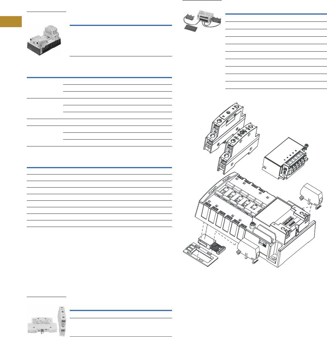
V5-T6-10 Volume 5—Motor Control and Protection CA08100006E—June 2014 www.eaton.com
6
6
6
6
6
6
6
6
6
6
6
6
6
6
6
6
6
6
6
6
6
6
6
6
6
6
6
6
6
6
6.1
Lighting Contactors
Open Control
Components
Electrically Held Base Contactor
The C30CNE20_0 Electrically Held Base Contactor contains
a 2NO power pole as standard and will allow the addition of
power poles to build an electrically held contactor up to 12 poles
maximum. A mechanically held module kit can also be added to
convert the electrically held contactor into a mechanically held
contactor in the field.
Electrically Held Base Contactor
Electrically Held Lighting Contactors 2
Coil Base Voltage (Digit 8)
Power Poles
The C30CNM contactor accepts up to a maximum six single- or
two-pole (or combinations) power poles. These can be used to
form up to:
●12 NO poles maximum when six two-poles are used in
NO positions (1–6) or
●8 NC poles maximum with four two-poles in the NC
position (1–4) and 4 NO poles with two two-poles in the
2 NO positions (5–6)
Power Poles
Mechanically Held Module Kits
These kits are for converting electrically held contactors to
mechanically held units. Kits include control module, latch,
latch cover and auxiliary contacts plus installation instructions.
Conversion kits are suitable for coil voltages of 277V and below.
Mechanically Held Module Kits
C30CNM Components—Exploded View
Notes
1When ordering, select required contactor by catalog number and replace the magnet coil
alpha designation in the catalog number (_) with the proper code suffix from the Coil Base
Voltage table on this page.
2A number of other power pole configurations are also available using the single-pole and
two-pole power poles. Electrically held units can be purchased with up to 12-pole
configurations with a maximum of 8NO and 4NC power poles.
Power Poles Catalog Number 1
2NO C30CNE20_0
Number of Poles NO NC Catalog Number
220C30CNE20_0
11C30CNE11_0
02C30CNE02_0
440C30CNE40_0
22C30CNE22_0
04C30CNE04_0
660C30CNE60_0
880C30CNE80_0
44C30CNE44_0
08C30CNE08_0
Voltage (Digit 8) Code Suffix
115–120V 60 Hz/110V 50 Hz A
230–240V 60 Hz/220V 50 Hz B
460–480V 60 Hz/440V 50 Hz C
575–600V 60 Hz/550V 50 Hz D
200–208V 60 Hz E
265–277V 60 Hz/240V 50 Hz H
24V 60 Hz/20V 50 Hz T
28V 60 Hz/24V 50 Hz V
347V 60 Hz X
Power Poles Catalog Number
Single-pole C320PRP1
Two-pole C320PRP2
Electrically Held
Base Contactor
Power Poles
Coil Volts Control Volts Catalog Number
Tw o - W i r e
24–277 Vac 110–120 Vac C320MH2WA0
200–277 Vac C320MH2WH0
24 Vac C320MH2WT0
12–24 Vdc C320MH2WT1
Three-Wire
24–277 Vac 110–120 Vac C320MH3WA0
200–277 Vac C320MH3WH0
24 Vac C320MH3WT0
12–24 Vdc C320MH3WT1
Conversion Kits
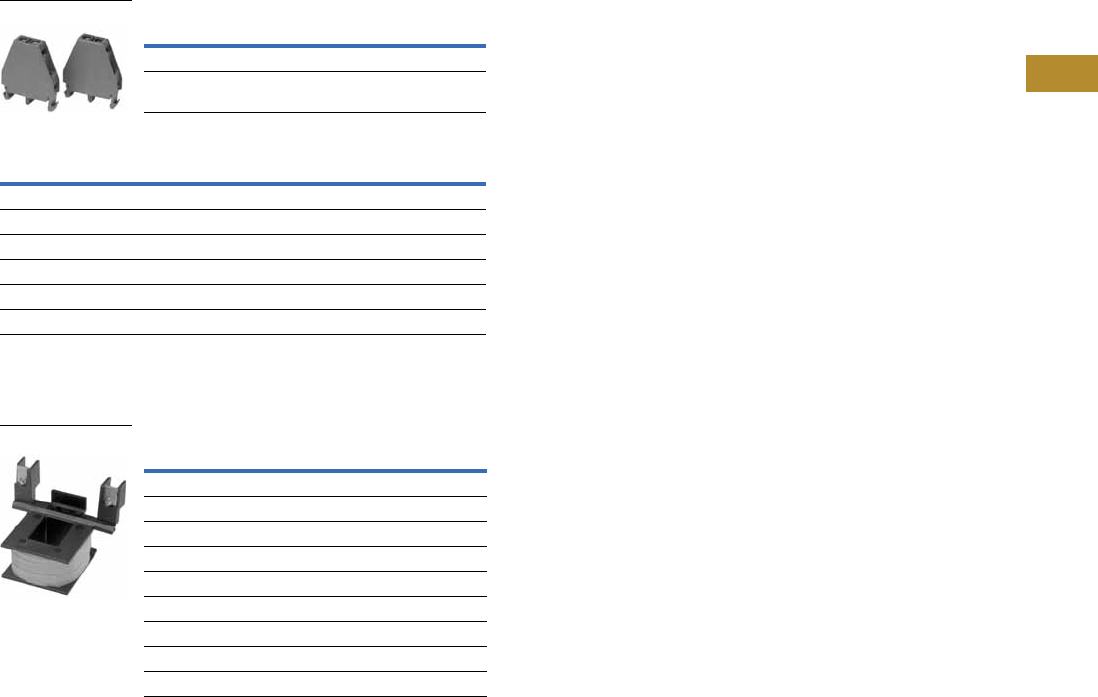
Volume 5—Motor Control and Protection CA08100006E—June 2014 www.eaton.com V5-T6-11
6
6
6
6
6
6
6
6
6
6
6
6
6
6
6
6
6
6
6
6
6
6
6
6
6
6
6
6
6
6
6.1
Lighting Contactors
Open Control
Auxiliary Contacts
A mechanically held contactor with a two-wire control module
uses 1NC auxiliary contact as standard for the control wiring
circuit. The mechanically held contactor with a three-wire control
module uses 1NO-1NC auxiliary contacts as standard for the
control wiring circuit. See table below for possible additional
auxiliary contact configurations.
Auxiliary Contacts
Auxiliary Contact Configurations
Replacement Parts
Magnet Coils for Base Contactors
Auxiliary Block Catalog Number
Single-pole C320AMH1
Two-pole C320AMH2
Two-Wire Three-Wire
None 1NC (two-pole)
1NO (single-pole) 1NO (two-pole)
2NO (two-pole) 1NO-1NC (two-pole)
1NC (two-pole) —
1NO-1NC (NO single-pole, NC two-pole) —
2NO-1NC (two-pole) —
Coil Voltage Catalog Number
115–120V 60 Hz/110V 50 Hz 9-3242-1
230–240V 60 Hz/220V 50 Hz 9-3242-2
460–480V 60 Hz/440V 50 Hz 9-3242-3
575–600V 60 Hz/550V 50 Hz 9-3242-4
200–208V 60 Hz 9-3242-5
265–277V 60 Hz/240V 50 Hz 9-3242-6
24V 60 Hz/20V 50 Hz 9-3242-7
28V 60 Hz/24V 50 Hz 9-3242-8
347V 60 Hz 9-3242-9
Auxiliary Contacts
Magnetic Coils

V5-T6-12 Volume 5—Motor Control and Protection CA08100006E—June 2014 www.eaton.com
6
6
6
6
6
6
6
6
6
6
6
6
6
6
6
6
6
6
6
6
6
6
6
6
6
6
6
6
6
6
6.1
Lighting Contactors
Open Control
Technical Data and Specifications
Main Power Poles
Maximum AC Voltage and Ampere Ratings
Maximum Horsepower Rating
Control Circuit Characteristics
Coil
Control Module
Other Control Module Characteristics
Auxiliary Contacts Rating
A600, 24 Vdc, 24 Vac
Ambient Temperature
–13 to 104°F (–25 to 40°C)
Mounting Position
Vertical 3-point mounting only
Wire Size
Wire Specifications
Note
18 AWG stranded only.
Load Type Amps Continuous
Poles
Single-Phase Three-Phase
Ballast 30 347 Vac 600 Vac
General use 30 600 Vac 600 Vac
Tungsten 20 277 Vac 480 Vac
AC resistive 30 600 Vac 600 Vac
Normal Starting Duty
Volts Horsepower
Single-Pole, Single-Phase
110–120V 1
220–240V 2
Three-Pole, Three-Phase
200–208V 3
220–240V 5
440–480V 10
550–600V 15
Description VA
Inrush 248 VA
Sealed 28 VA
Input Voltage
Steady State Current at
Rated Voltage (mA) Maximum VA
12–24 Vdc 42 2
24 Vac 80 5
115–120 Vac 83 12
200–277 Vac 91 30
Description Specification
Minimum pulse duration (three-wire control module) 250 ms
Maximum allowable leakage current 1.8 mA
EMI 35 V/m
Surge transient peak 6 kV
Frequency range 40–70 Hz
Component
Number
of Cables
Wire Range
(Solid or Stranded)
Wire
Temperature
Power poles 1 14–8 AWG 75°C Cu
2 14–8 AWG 175°C Cu
Coil 1 or 2 18–14 AWG 60°/75°C Cu
Control module 1 22–12 AWG 60°/75°C Cu
Auxiliary contacts 1 or 2 22–12 AWG 60°/75°C Cu
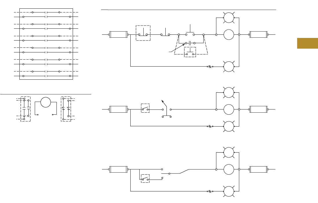
Volume 5—Motor Control and Protection CA08100006E—June 2014 www.eaton.com V5-T6-13
6
6
6
6
6
6
6
6
6
6
6
6
6
6
6
6
6
6
6
6
6
6
6
6
6
6
6
6
6
6
6.1
Lighting Contactors
Open Control
Wiring Diagrams
C30CNE
1
2
Line Load
3
4
5
6
C30CNE Electrically Held
View A
CONTROL
Refer to View “B” for Control Connections
Optional
Auxiliary
Contacts
Optional
Auxiliary
Contacts
A1 A2
Coil
Coil
Voltage
ON and OFF Pushbuttons
View B
Optional Pilot Devices for Electrically Held Contactor
O
FF AUTO
SS
* If Used
O
FF
O
N
AUTO
A1
L2L1
A2
*
Fuse
*Fuse
Remote
OFF
Remote
ON
ON
ON
Pushbutton
OFF
Pushbutton
OFF
Coil
Auxiliary
Contact Auxiliary
Contact
OFF/ON or OFF/AUTO Selector Switch
A1
L2L1
A2
*
Fuse
*Fuse
Remote
Device
ON
OFF
Coil
Auxiliary
Contact
OFF/ON/AUTO or HAND/OFF/AUTO Selector Switch
A1
L2L1
A2
*
Fuse
*Fuse
Remote
Device
ON
OFF
Coil
Auxiliary
Contact
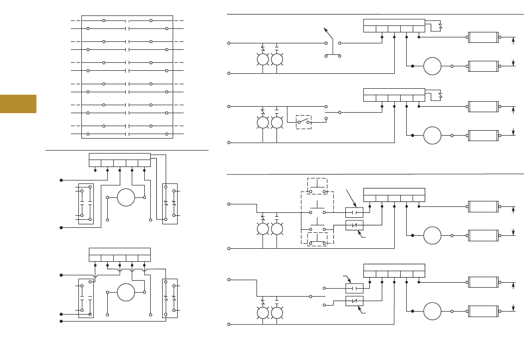
V5-T6-14 Volume 5—Motor Control and Protection CA08100006E—June 2014 www.eaton.com
6
6
6
6
6
6
6
6
6
6
6
6
6
6
6
6
6
6
6
6
6
6
6
6
6
6
6
6
6
6
6.1
Lighting Contactors
Open Control
C30CNM
1
2
Line Load
3
4
5
6
C30CNM Mechanically Held
Refer to View “A” for 2-/3-Wire Control Options
2-WIRE CONTROL
Refer to View “B” for Control Connections
View A
Optional
“N/O”
Aux.
Contacts
Optional
“NC”
Aux.
Contact
P1
A1
C
L
A2
P2 P3
Electronic-Module
Not Used
P4 P5
Coil
Coil
Voltage
3-WIRE CONTROL
Refer to View “C” for Control Connections
Optional
“N/O”
Aux.
Contacts
Optional
“NC”
Aux.
Contact
P1
A1
L
C
O
A2
P2 P3
Electronic-Module
P4 P5
Coil
Coil
Voltage
OFF/ON or OFF/AUTO Selector Switch
View B
Optional Pilot Devices for 2-Wire Control
P1
A1A2
P2 P3
Electronic-Module
P4 P5
Fuse
Fuse
Coil
Voltage
Control
Voltage
O
FF
O
N
(AUTO)
SS
Coil
HAND/OFF/AUTO or ON/OFF/AUTO Selector Switch
P1
A1A2
P2 P3
Electronic-Module
P4 P5
Fuse
Fuse
Coil
Voltage
*
*
*
*
*
*
*
*
* If Used
* If Used
Control
Voltage Remote
Device
O
FF
O
N
AUTO
Coil
ON & OFF Pushbuttons
View C
Optional Pilot Devices for 3-Wire Control
P1
A1A2
P2 P3
Electronic-Module
P4 P5
Fuse
Fuse
Coil
Voltage
Control
Voltage Coil
”NO“
Auxiliary
”NC“
Auxiliary
O
FF
O
N
Remote
O
FF
Remote
O
N
OFF/ON Selector Switch with Spring Return to Center
P1
A1A2
P2 P3
Electronic-Module
P4 P5
Fuse
Fuse
Coil
Voltage
Control
Voltage Coil
”NO“
Auxiliary
”NC“
Auxiliary
ON
OFF
O
FF
O
N
O
FF
O
N
O
FF
O
N
O
FF
O
N
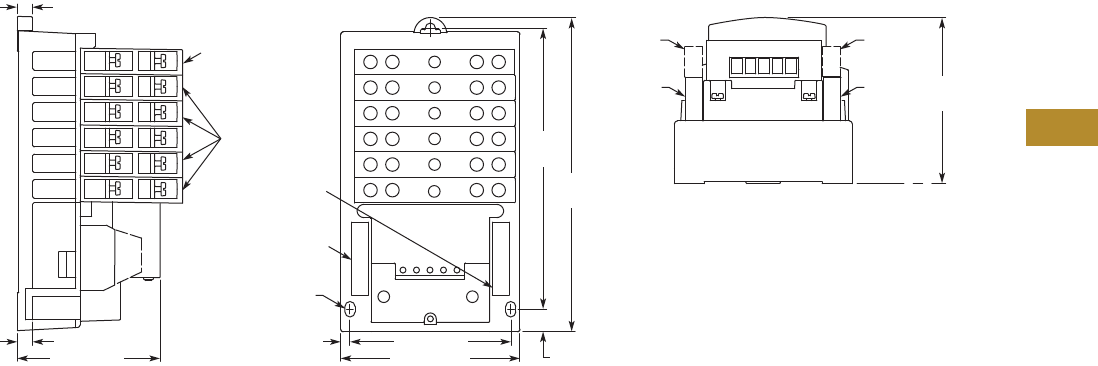
Volume 5—Motor Control and Protection CA08100006E—June 2014 www.eaton.com V5-T6-15
6
6
6
6
6
6
6
6
6
6
6
6
6
6
6
6
6
6
6
6
6
6
6
6
6
6
6
6
6
6
6.1
Lighting Contactors
Open Control
Dimensions
Approximate Dimensions in Inches (mm)
C30CN
ON ON ON ON ON ON
P1
A1 A2
P2 P3 P4 P5
P1 P2 P3 P4 P5
.35
(9.0)
NOTES:
1 Mounting dimensions remain the same
for 1 to 12 poles.
2 Line and Load terminals are interchangeable.
3 Up to 2NO and 2NC auxiliary contacts can be
added onto the base product.
4 Same power pole can be congured as
NO type or NC type in pole positions 1 – 4;
NO type only in positions 5 – 6.
SIDE VIEW TOP VIEW END VIEW
Power
Pole
Optional
Power
Pole
Optional “NC”
Aux Contacts
Optional “NO”
Aux Contacts
Mounting Holes
Accept
#10 Screws
2 “NO”
Aux
Contacts
1 “NO”
Aux
Contact
2 “NC”
Aux
Contacts
1 “NC”
Aux
Contact
3.86 (98.0)
.35 (9.0)
4.18 (106.2)
3.75 (95.3)
6.50
(165.1)
3.86
(98.0)
.59 (14.9)
7.39
(187.6)
.22 (5.5)
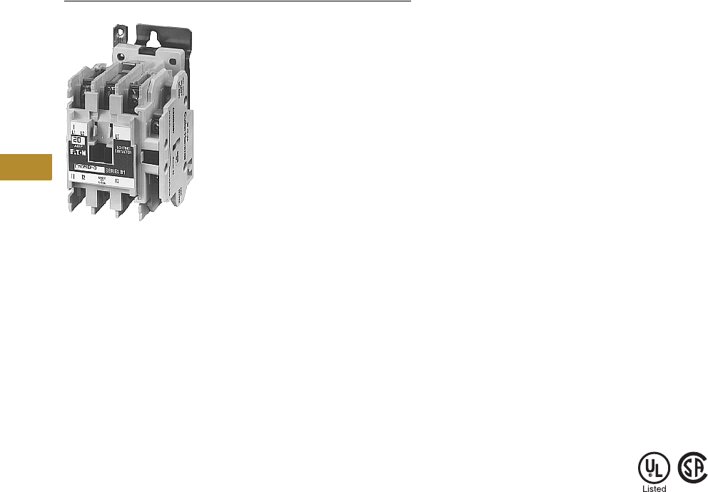
V5-T6-16 Volume 5—Motor Control and Protection CA08100006E—June 2014 www.eaton.com
6
6
6
6
6
6
6
6
6
6
6
6
6
6
6
6
6
6
6
6
6
6
6
6
6
6
6
6
6
6
6.1
Lighting Contactors
Open Control
CN35 Electrically Held
Contents
Description Page
C30CN Mechanically and Electrically Held. . . . . . . V5-T6-3
CN35 Electrically Held
Product Selection . . . . . . . . . . . . . . . . . . . . . . . V5-T6-17
Accessories. . . . . . . . . . . . . . . . . . . . . . . . . . . . V5-T6-18
Renewal Parts . . . . . . . . . . . . . . . . . . . . . . . . . . V5-T6-20
Dimensions. . . . . . . . . . . . . . . . . . . . . . . . . . . . V5-T6-21
A202 Magnetically Latched . . . . . . . . . . . . . . . . . . V5-T6-23
CN35 Electrically Held
Product Description
Type CN35 Electrically Held
Lighting Contactors from
Eaton’s Electrical Sector are
designed to handle the
switching of tungsten
(incandescent) or ballast
(fluorescent and mercury arc)
lamp loads as well as other
non-motor (resistive) loads.
Application Description
●Ideal applications include
industrial plants, stadiums,
parks and any new
construction requiring
lighting control
●Ballast lamps equate to
fluorescent, mercury vapor,
sodium vapor and quartz
loads and will operate at a
maximum of 600V
●Filament lamps equate to
incandescent, infrared,
sodium iodine and heating
loads and will operate at a
maximum of 480V
●Resistance heating
equates to radiant and
convection heating,
furnace and oven loads
Features
●Designed and tested
specifically for lighting and
resistive loads
●Easy to install and maintain
●Full line of Freedom snap-
on accessories
●Standard with 1NO
auxiliary contact (the 10A
two- and three-pole ship
standard with the auxiliary
in the fourth power pole
position with no increase in
width)
●Top and side mounted
auxiliary contacts available
for 10–60A devices; side
mounted auxiliaries only
available on 100A and
greater
●Straight-through wiring
Standards and Certifications
●UL File No. E37317,
Guide LR353
●CSA File No. LR353
●Designed and built to
NEMA ICS-2 Standards
Instructional Leaflets
19225 CN35AN (2-, 3-,
4-Pole)
19227 CN35BN (2-, 3-Pole)
24829 CN35BN (4-, 5-Pole)
24840 CN35BN (6-, 9-,
12-Pole)
19227 CN35DN (2-, 3-Pole)
19229 CN35GN (2-, 3-Pole)
19874 CN35GN (4-, 5-Pole)
20218 CN35KN (2-, 3-Pole)
20171 CN35NN (2-, 3-Pole)
20172 CN35SN (2-, 3-Pole)
20172 CN35TN (2-, 3-Pole)
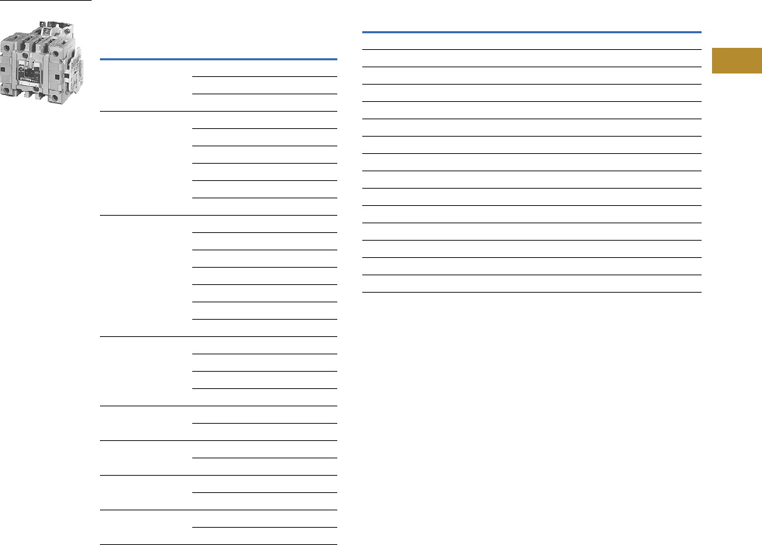
Volume 5—Motor Control and Protection CA08100006E—June 2014 www.eaton.com V5-T6-17
6
6
6
6
6
6
6
6
6
6
6
6
6
6
6
6
6
6
6
6
6
6
6
6
6
6
6
6
6
6
6.1
Lighting Contactors
Open Control
Product Selection
When Ordering Specify
●Catalog number including the coil suffix code from the
Magnet Coil Selection table
●Any required accessories
CN35 AC Lighting Contactors—
Electrically Held
Magnet Coil Selection
Notes
1 The listed ampere ratings are based on a maximum load voltage of 480V for tungsten lamp applications and 600V for ballast or mercury vapor type applications.
2 Additional power poles mounted on side(s) of contactor.
3 Underscore (_) indicates missing code letter for magnet coil—see Magnet Coil Selection table.
4 UL ballast and resistive ratings only.
5 For DC Magnet Coils, see NEMA Contactors and Starters, Tab 2 in this volume.
6 For 10, 20 and 30A sizes only. Sizes 60–400A are 24V/60 Hz only.
7 For 10, 20 and 30A sizes only.
Maximum
Ampere Rating 1
Number
of Poles
Open Type
Catalog Number 3
10 2 CN35AN2_B
3CN35AN3_B
4CN35AN4_B
20 2 CN35BN2_B
3CN35BN3_B
4CN35BN4_B
6CN35BN6_B
9CN35BN9_B
12 CN35BN12_B
30 2 CN35DN2_B
3CN35DN3_B
4CN35DN4_B
5CN35DN5_B
6CN35DN6_B
9CN35DN9_B
12 CN35DN12_B
60 2 CN35GN2_B
3CN35GN3_B
4 2CN35GN4_B
5 2CN35GN5_B
100 2 CN35KN2_
3CN35KN3_
200 2 CN35NN2_
3CN35NN3_
300 2 CN35SN2_
3CN35SN3_
400 42CN35TN2_
3CN35TN3_
CN35GN5A
Coil Voltage and Hertz 5Code Suffix
120/60 or 110/50 A
240/60 or 220/50 B
480/60 or 440/50 C
600/60 or 550/50 D
208/60 E
277/60 H
208–240/60 6J
240/50 K
380–415/60 L
550/50 N
24/60, 24/50 7T
24/50 U
32/50 V
48/60 W
48/50 Y
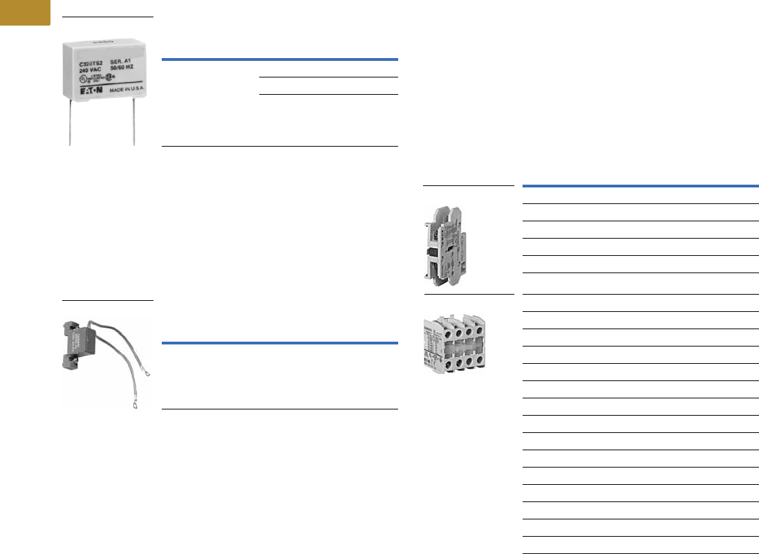
V5-T6-18 Volume 5—Motor Control and Protection CA08100006E—June 2014 www.eaton.com
6
6
6
6
6
6
6
6
6
6
6
6
6
6
6
6
6
6
6
6
6
6
6
6
6
6
6
6
6
6
6.1
Lighting Contactors
Open Control
Accessories
Transient Suppressor Kits
10–60A Contactors
These kits limit high voltage
transients produced in the
control circuit when power is
removed from the contactor or
starter coil. There are three
separate suppressors for use
on 24–120V, 240V or 480V
coils respectively.
These devices mount directly
to the coil terminals of
lighting contactors 10–60A.
Kits for 10–60A
100–300A Contactors
This device mounts on top of
any side mounted auxiliary
contact on lighting contactors
100–300A. It connects across
coil terminals on any 120V
contactor magnet coil.
Limits high voltage transients
produced in the circuit when
power is removed from
the coil.
Kits for 100–300A
Description
Coil
Voltage
Catalog
Number
Transient suppressor 24 –120V C320TS1
240V C320TS2
480V C320TS3
C320TS2
Description
Coil
Voltage
Catalog
Number
Transient suppressor 120V C320AS1
C320AS1
Auxiliary Contacts
CN35 Lighting Contactors
include a 1NO maintaining
auxiliary contact mounted
on right hand side (on 10A,
two- and three-pole devices,
auxiliary contact occupies
4th power pole position—
no increase in width). The
10–60A devices will accept
additional auxiliary contacts
on the top and/or sides.
Auxiliary contact blocks
are designed for snap-on
installation—fast, easy
installation (no tools required
up to 60A). All auxiliary
contacts are of the bifurcated
design with parallel circuit
paths. This redundant path
provides very high reliability.
Auxiliary contacts can be
snapped on the side (up to
two circuits—per auxiliary
contact) and on the top
(up to four circuits). Auxiliary
contacts for larger contactors,
100–400A sizes, will accept
side mounted auxiliaries only
and easily attach to the
side of the contactor with
two screws.
Auxiliary Contacts—10–60A Contactors
Notes
1For reference only—not part of catalog number. See Page V5-T6-19.
2Cannot be added to contactors or starters mounted in Box 1 (NEMA Type 1).
Description
Contact
Configuration Code 1
Catalog
Number
Side Mounted
1NO 10 C320KGS1
1NC 01 C320KGS2
1NO-1NC 11 C320KGS3
2NO 20 C320KGS4
2NC 02 C320KGS5
Top Mounted 2
1NO 10 C320KGT1
1NC 01 C320KGT2
1NO-1NC 11 C320KGT3
2NO 20 C320KGT4
2NC 02 C320KGT5
3NO 30 C320KGT9
2NO-1NC 21 C320KGT10
1NO-2NC 12 C320KGT11
3NC 03 C320KGT12
4NO 40 C320KGT13
3NO-1NC 31 C320KGT14
2NO-2NC 22 C320KGT15
1NO-3NC 13 C320KGT16
4NC 04 C320KGT17
Side Mounted
Top Mounted
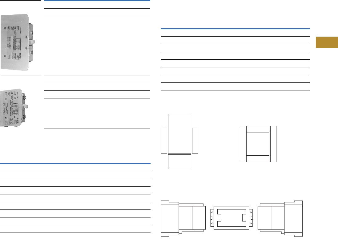
Volume 5—Motor Control and Protection CA08100006E—June 2014 www.eaton.com V5-T6-19
6
6
6
6
6
6
6
6
6
6
6
6
6
6
6
6
6
6
6
6
6
6
6
6
6
6
6
6
6
6
6.1
Lighting Contactors
Open Control
Auxiliary Contacts—100–400A Contactors
Auxiliary Contact Ratings (Amperes)
Contact Configuration Code
This 2-digit code is found on the auxiliary contact to assist in
identifying the specific contact configuration. The first digit
indicates the quantity of NO contacts and the second indicates
the quantity of NC contacts.
Auxiliary Contact Location
Auxiliary Contacts—Mounting Positions
The sketches below illustrate the maximum number of
auxiliary contacts that can be assembled to a contactor
and their locations in standard enclosures.
Auxiliary Contact Mounting Positions
10–60A Contactors
100–400A Contactors
Notes
1For reference only—not part of catalog number.
2NO-NC occupies two positions—L2 and L3 or R2 and R3.
3Available positions on contactors or starters other than what is factory installed.
4When a pneumatic timer is mounted on contactor, only side mounted auxiliary contact
positions are available. The solid-state timer, when added, takes up side mounted auxiliary
contact position.
5For 100–400A contactors, a base auxiliary contact must be added in position L1 before
additional contacts can be mounted.
Circuit
Contact
Configuration
Code 1
100A
Contactors
200 and 300A
Contactors
Catalog
Number
Catalog
Number
Base Auxiliary Contacts
NO 10 C320KGS31 C320KGS41
NO-NC 11 C320KGS32 C320KGS42
Auxiliary Contacts
NO 10 C320KGS20
NC 01 C320KGS21
NO-NC 211 C320KGS22
Current
AC Volts
120V 240V 480V 600V
NEMA A600
Make and interrupting 60.0 30.0 15.0 12.0
Break 6.0 3.0 1.5 1.0
Continuous 10.0 10.0 10.0 10.0
NEMA P300
Continuous thermal rating: 5A
DC Volts Make/Break Amperes
125 1.10
250 0.55
Base Auxiliary
Contact—C320KGS42
Auxiliary Contact—
C320KGS22
Size Poles
Available Mounting Positions 345
Open Type NEMA 1 NEMA 3R, 4X, 12
10A 2–4 T1, L1, R1 L1 L1, T1
20–60A 2–3 T1, L1 L1 L1, T1
60A 4 T1, L1 — L1, T1
60A 5 T1, L1 — L1, T1
100A 2–3 R2, R3, L1, L2, L3 R2, R3, L1, L2, L3 R2, R3, L1, L2, L3
200A 2–3 R2, R3, L1, L2, L3 R2, R3, L1, L2, L3 R2, R3, L1, L2, L3
300A 2–3 R2, R3, L1, L2, L3 R2, R3, L1, L2, L3 R2, R3, L1, L2, L3
400A 2–3 R2, R3, L1, L2, L3 R2, R3, L1, L2, L3 R2, R3, L1, L2, L3
L1
T1
L1 T1 R1
Front View
Top View
R1
Front
of Contactor
Left Side
of Contactor
L2
Aux.
Cont.
L3
Aux.
Cont.
R2
Aux.
Cont.
R3
Aux.
Cont.
L1
Base
Aux.
Cont.
R1
Base
Aux.
Cont.
Rear
Rear
Right Side
of Contactor
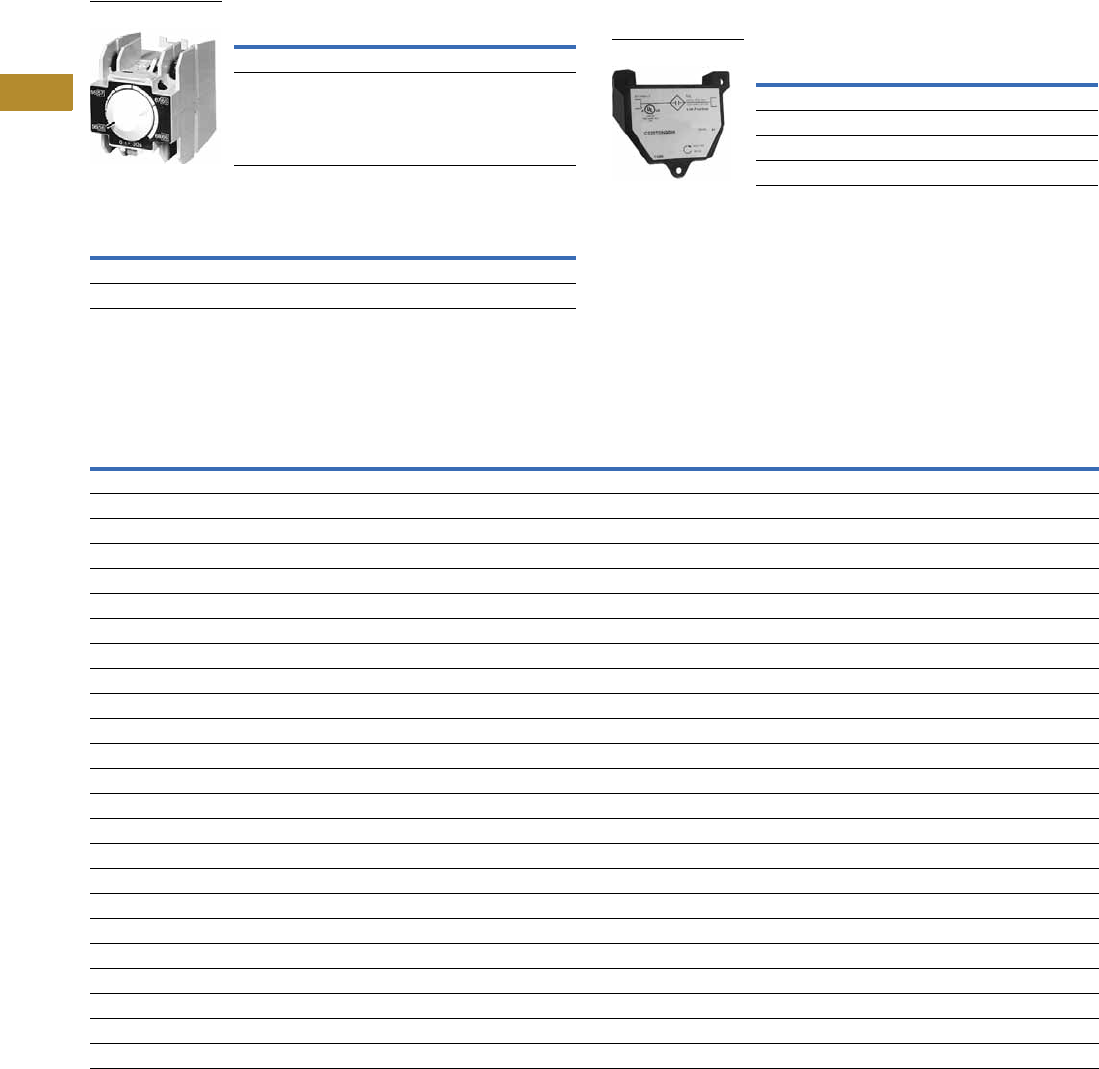
V5-T6-20 Volume 5—Motor Control and Protection CA08100006E—June 2014 www.eaton.com
6
6
6
6
6
6
6
6
6
6
6
6
6
6
6
6
6
6
6
6
6
6
6
6
6
6
6
6
6
6
6.1
Lighting Contactors
Open Control
Pneumatic Timers—Top Mounted
Attachment mounts on top of 10–60A lighting contactors (top
mounted auxiliary contacts can not be installed on device when
timer is used). Timer unit has DPST timed contacts—circuits in
each pole must be the same polarity. Units are convertible from
OFF to ON delay or vice-versa.
Pneumatic Timers
Maximum Ampere Ratings
Solid-State Timers
Solid-State ON DELAY Timer—Side Mounted on CN35
Freedom Series Lighting Contactors through 60A
This timer is designed to be wired in SERIES with the load
(typically a coil). When the START button is pushed (power
applied to timer), the ON DELAY timing function starts. At the
completion of the set timing period, timer and series wired load
will both be energized.
Mounted Timer
Renewal Parts
CN35 Lighting Contactors
Notes
1Add operating voltage suffix to catalog number. A = 120V, B = 240V, E = 208V
2Rated 0.5A pilot duty—not to be used on larger contactors.
3Terminal connections are quick connects only. Two per side.
4Replace with complete contactor.
Timing Range Catalog Number
0.1 to 30 seconds C320TP1
10 to 180 seconds C320TP2
Description
Volts AC
120 240 480 600
Make 30.0 15.0 7.5 6.0
Break 3.0 1.5 0.75 0.6
Pneumatic Timer
Timing Range Catalog Number 123
0.1–1.0 seconds C320TDN1_
1–30 seconds C320TDN30_
30–300 seconds C320TDN300_
5–30 minutes C320TDN3000_
Mounted Timer
Description
10A
Series C1
Part No.
20A, 30A
Series C1
Part No.
60A
Series B1
Part No.
100A
Part No.
200A
Part No.
300A
Series B1
Part No.
Contact Kits
Two-pole 446-65-7 6-43-5 6-44 6-45
Three-pole 446-65-8 6-43-6 6-44-2 6-45-2
Four-pole 446-65-15———
Five-pole 446-65-16———
Magnet Coils Coil Suffix
120V 60 Hz or 110V 50 Hz A 9-2875-1 9-2876-1 9-2703-1 9-2756-1 9-1891-1 9-1891-1
240V 60 Hz or 220V 50 Hz B 9-2875-2 9-2876-2 9-2703-2 9-2756-2 9-1891-2 9-1891-2
480V 60 Hz or 440V 50 Hz C 9-2875-3 9-2876-3 9-2703-3 9-2756-3 9-1891-3 9-1891-3
600V 60 Hz or 550V 50 Hz D 9-2875-4 9-2876-4 9-2703-4 9-2756-4 9-1891-4 9-1891-4
208V 60 Hz E 9-2875-5 9-2876-5 9-2703-9 9-2756-5 9-1891-13 9-1891-13
277V 60 Hz H 9-2875-12 9-2876-12 9-2703-7 9-2756-9 9-1891-26 9-1891-26
208/240V 60Hz J 9-2875-37 9-2876-37 ————
240V 50 Hz K 9-2875-11 9-2876-11 9-2703-14 9-2756-13 9-1891-20 9-1891-20
380–415V 50 Hz L 9-2875-6 9-2876-6 9-2703-8 — — —
380V 50 Hz L———9-2756-12 9-1891-14 9-1891-14
415V 50 Hz M———9-2756-8 9-1891-21 9-1891-21
550V 50 Hz N———9-2756-14 9-1891-8 9-1891-8
24V 60 Hz–24V 50 Hz T 9-2875-36 9-2876-36 ————
24V 60 Hz T — — 9-2703-6 9-2756-6 9-1891-15 9-1891-15
24V 50 Hz U 9-2875-36 9-2876-13 9-2703-12 9-2756-11 9-1891-16 9-1891-16
32V 50 Hz V 9-2875-16 9-2876-16 9-2703-10 9-2756-10 — —
48V 60 Hz W 9-2875-8 9-2876-8 9-2703-11 9-2756-15 — —
48V 50 Hz Y 9-2875-9 9-2876-9 9-2703-13 9-2756-7 9-1891-18 9-1891-18
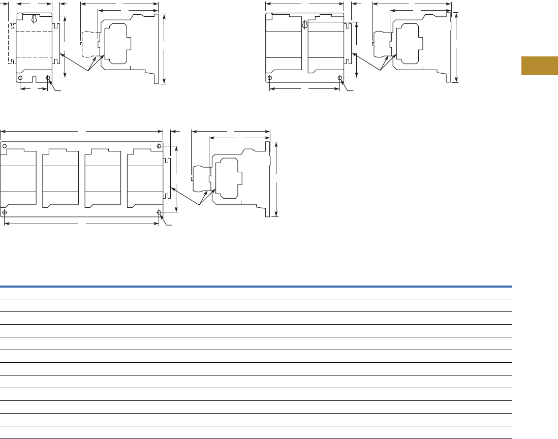
Volume 5—Motor Control and Protection CA08100006E—June 2014 www.eaton.com V5-T6-21
6
6
6
6
6
6
6
6
6
6
6
6
6
6
6
6
6
6
6
6
6
6
6
6
6
6
6
6
6
6
6.1
Lighting Contactors
Open Control
Dimensions
Approximate Dimensions in Inches (mm)
Open Type—10A, Two- to Four-Pole;
20–30A, Two- to Three-Pole Open Type—20–30A, Four- to Six-Pole
Open Type—20–30A, Nine- to 12-Pole
Dimensions and Shipping Weights
Note
1Center mounting slot at bottom on 10–30A sizes only.
A
U
X
A
U
X
AGGC
F
D
Top
Mtd.
Aux.
Auxiliary
Contacts
Mtg. Holes for #10-32 Screws
Top
Mtd.
Aux.
Side
Mtd.
Aux.
EB
A
U
X
AG C
F
D
Top
Mtd.
Aux.
Top
Mtd.
Aux.
Auxiliary
Contacts
Mtg. Holes for (3) #10-32 Screws
Top
Mtd.
Aux.
Side
Mtd.
Aux.
EB
Ampere
Rating
Number
of Poles
Wide
A
High
B
Deep
C
Mounting
FG
Shipping Weight
Lbs (kg)D 1E
Open Type
10 2–4 2.00 (50.8) 3.88 (98.6) 3.49 (88.6) 1.50 (38.1) 3.38 (85.9) 4.90 (124.5) 0.54 (13.7) 1.4 (0.6)
20–30 2–3 2.00 (50.8) 3.88 (98.6) 3.49 (88.6) 1.50 (38.1) 3.38 (85.9) 4.90 (124.5) 0.54 (13.7) 1.5 (0.7)
20–30 4–6 4.20 (106.7) 4.35 (110.5) 3.52 (89.4) 3.50 (88.9) 3.86 (98.0) 4.90 (124.5) 0.54 (13.7) 2.9 (1.3)
20–30 9 10.50 (266.7) 5.75 (146.1) 4.52 (114.8) 4.50 (114.3) 5.00 (127.0) — — 4.4 (2.0)
20–30 12 10.50 (266.7) 5.75 (146.1) 4.52 (114.8) 4.50 (114.3) 5.00 (127.0) — — 5.8 (2.6)
60 2–3 2.56 (65.0) 5.05 (128.3) 4.44 (112.8) 2.00 (50.8) 4.50 (114.3) 5.80 (147.3) 0.54 (13.7) 3.5 (1.6)
60 4 3.46 (87.9) 5.05 (128.3) 4.44 (112.8) 2.00 (50.8) 4.50 (114.3) 5.80 (147.3) 0.54 (13.7) 3.5 (1.6)
60 5 4.36 (110.7) 5.05 (128.3) 4.44 (112.8) 2.00 (50.8) 4.50 (114.3) 5.80 (147.3) 0.54 (13.7) 3.5 (1.6)
100 2–3 3.54 (89.9) 7.17 (182.1) 5.94 (150.9) 3.00 (76.2) 6.63 (168.4) — 0.54 (13.7) 9.0 (4.1)
200 2–3 7.05 (179.1) 9.11 (231.4) 7.25 (184.2) 6.00 (152.4) 8.50 (215.9) — — 20.0 (9.1)
300 2–3 7.05 (179.1) 13.12 (333.2) 7.78 (197.6) 6.00 (152.4) 12.50 (317.5) — — 23.0 (10.4)
AG
C
F
D
Top
Mtd.
Aux.
Top
Mtd.
Aux.
Top
Mtd.
Aux.
Auxiliary
Contacts
Mtg. Holes for (4) #10-32 Screws
Top
Mtd.
Aux.
Side
Mtd.
Aux.
A
U
X
EB
Top
Mtd.
Aux.
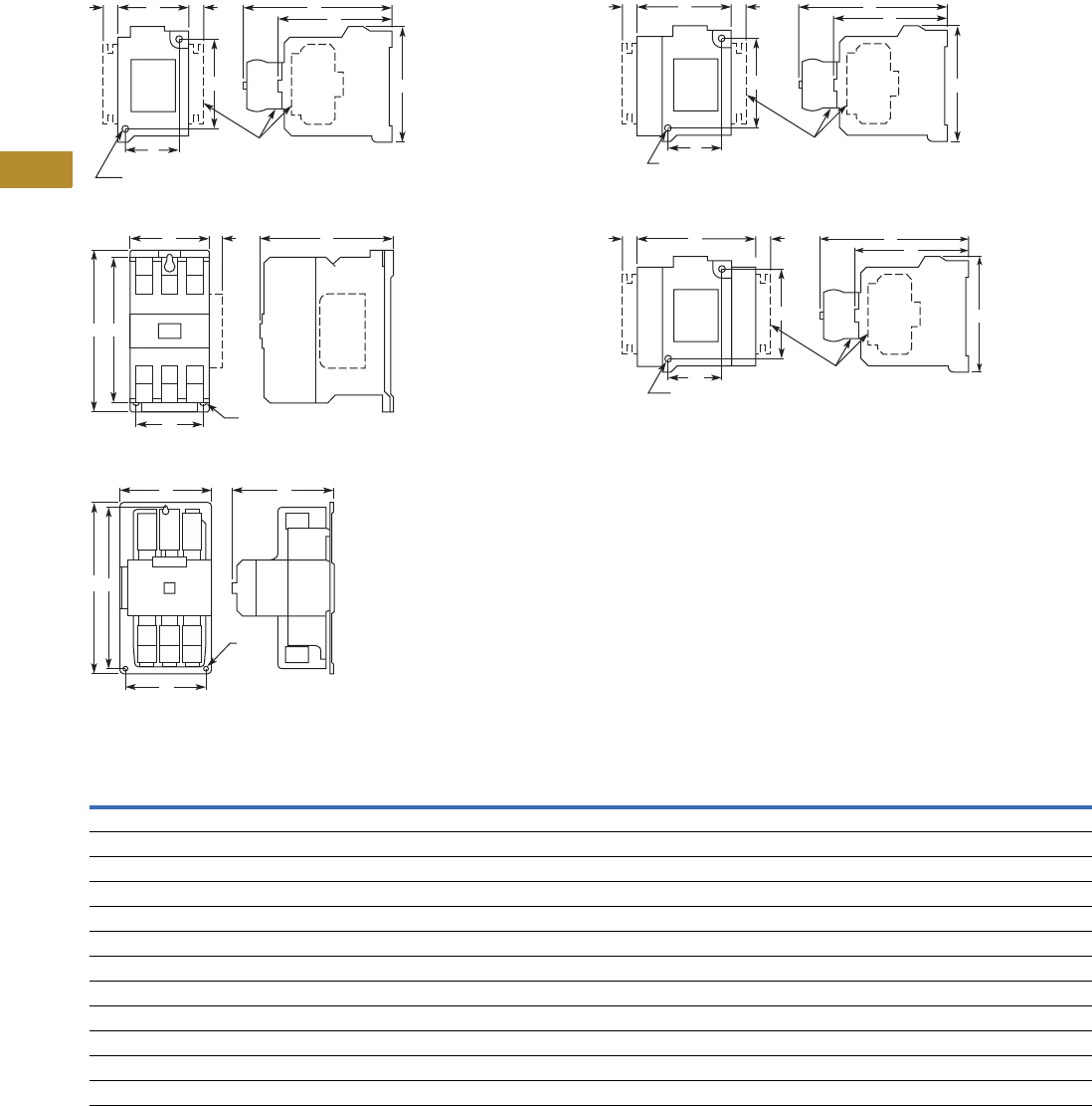
V5-T6-22 Volume 5—Motor Control and Protection CA08100006E—June 2014 www.eaton.com
6
6
6
6
6
6
6
6
6
6
6
6
6
6
6
6
6
6
6
6
6
6
6
6
6
6
6
6
6
6
6.1
Lighting Contactors
Open Control
Approximate Dimensions in Inches (mm)
60A, Two- to Three-Pole
100A, Two- to Three-Pole
200–300A, Two- to Three-Pole
60A, Four-Pole
60A, Five-Pole
Dimensions and Shipping Weights
Note
1Center mounting slot at bottom on 10–30A sizes only.
AFC
B
E
A
U
X
A
U
X
D
GG
Top
Mtd.
Aux.
Side
Mtd.
Aux.
Top
Mtd.
Aux.
Auxiliary
Contacts
Mtg. Holes for #10-32 Screws
E
B
AC
A
U
X
D
G
Side
Mtd.
Aux.
Mtg. Holes for
(3) Screws
E
B
AC
D
Mtg.
Holes
for (3)
Screws
AFC
B
E
A
U
X
A
U
X
D
GG
Top
Mtd.
Aux.
Side
Mtd.
Aux.
Top
Mtd.
Aux.
Auxiliary Contacts
Mtg. Holes for #10-32 Screws
AFC
B
E
A
U
X
A
U
X
D
GG
Top
Mtd.
Aux.
Side
Mtd.
Aux.
Top
Mtd.
Aux.
Mtg. Holes for #10-32 Screws
Auxiliary Contacts
Ampere
Rating
Number
of Poles
Wide
A
High
B
Deep
C
Mounting
FG
Shipping Weight
Lbs (kg)D 1E
Open Type
10 2–4 2.00 (50.8) 3.88 (98.6) 3.49 (88.6) 1.50 (38.1) 3.38 (85.9) 4.90 (124.5) 0.54 (13.7) 1.4 (0.6)
20–30 2–3 2.00 (50.8) 3.88 (98.6) 3.49 (88.6) 1.50 (38.1) 3.38 (85.9) 4.90 (124.5) 0.54 (13.7) 1.5 (0.7)
20–30 4–6 4.20 (106.7) 4.35 (110.5) 3.52 (89.4) 3.50 (88.9) 3.86 (98.0) 4.90 (124.5) 0.54 (13.7) 2.9 (1.3)
20–30 9 10.50 (266.7) 5.75 (146.1) 4.52 (114.8) 4.50 (114.3) 5.00 (127.0) — — 4.4 (2.0)
20–30 12 10.50 (266.7) 5.75 (146.1) 4.52 (114.8) 4.50 (114.3) 5.00 (127.0) — — 5.8 (2.6)
60 2–3 2.56 (65.0) 5.05 (128.3) 4.44 (112.8) 2.00 (50.8) 4.50 (114.3) 5.80 (147.3) 0.54 (13.7) 3.5 (1.6)
60 4 3.46 (87.9) 5.05 (128.3) 4.44 (112.8) 2.00 (50.8) 4.50 (114.3) 5.80 (147.3) 0.54 (13.7) 3.5 (1.6)
60 5 4.36 (110.7) 5.05 (128.3) 4.44 (112.8) 2.00 (50.8) 4.50 (114.3) 5.80 (147.3) 0.54 (13.7) 3.5 (1.6)
100 2–3 3.54 (89.9) 7.17 (182.1) 5.94 (150.9) 3.00 (76.2) 6.63 (168.4) — 0.54 (13.7) 9.0 (4.1)
200 2–3 7.05 (179.1) 9.11 (231.4) 7.25 (184.2) 6.00 (152.4) 8.50 (215.9) — — 20.0 (9.1)
300 2–3 7.05 (179.1) 13.12 (333.2) 7.78 (197.6) 6.00 (152.4) 12.50 (317.5) — — 23.0 (10.4)
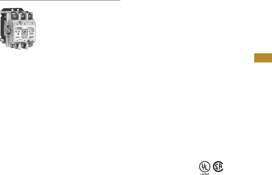
Volume 5—Motor Control and Protection CA08100006E—June 2014 www.eaton.com V5-T6-23
6
6
6
6
6
6
6
6
6
6
6
6
6
6
6
6
6
6
6
6
6
6
6
6
6
6
6
6
6
6
6.1
Lighting Contactors
Open Control
A202 Mechanically Latched
Contents
Description Page
C30CN Mechanically and Electrically Held . . . . . . . V5-T6-3
CN35 Electrically Held . . . . . . . . . . . . . . . . . . . . . . V5-T6-16
A202 Magnetically Latched
Product Selection . . . . . . . . . . . . . . . . . . . . . . . V5-T6-24
Accessories . . . . . . . . . . . . . . . . . . . . . . . . . . . . V5-T6-24
Renewal Parts . . . . . . . . . . . . . . . . . . . . . . . . . . V5-T6-25
Technical Data and Specifications . . . . . . . . . . . V5-T6-26
Wiring Diagrams . . . . . . . . . . . . . . . . . . . . . . . . V5-T6-26
Dimensions . . . . . . . . . . . . . . . . . . . . . . . . . . . . V5-T6-27
A202 Magnetically Latched
Product Description
The A202 Lighting Contactor
from Eaton’s Electrical
Sector provides a safe and
convenient means for local or
remote switching of relatively
large tungsten, fluorescent or
mercury arc lamp loads.
Application Description
●The magnetically latched
lighting contactors are
designed to withstand the
large initial inrush currents
of tungsten lamp loads
without contact welding
●The A202 contactors are
fully rated devices that do
not require de-rating similar
to standard motor control
contactors
●The magnetically latched
lighting contactor provides
effective control in
applications such as office
buildings, industrial plants,
hospitals, stadiums,
airports, and so on
Features
●Designed and tested
specifically for lighting
and resistive loads
●Easy to install and maintain
●No control power
necessary to maintain
contact closure
Operation
A permanent magnet is built
into the contactor structure
that will maintain the
contactor in its energized
state indefinitely without
using control power. When
energized, a DC current is
applied to the latch coil,
producing a magnetic field
that reinforces the polarity
of the permanent magnet,
pulling in the contactor.
The coil clearing interlock
disconnects the current to
the coil. In order to drop out
the contactor, it is necessary
to apply a field through the
STOP coil in the reverse
direction to the permanent
magnet. This momentarily
cancels the magnetic
attraction and the contactor
drops out.
Standards and Certifications
●UL Listed File No. E44424,
Guide NRNT
●CSA Certified File No.
LR39402, Class 3231-01
●Designed and built to
NEMA ICS-2 Standards
Instructional Leaflets
IL16965 30A (2-, 3-, 4-,
5-Poles)
IL16966 60–200A (2-, 3-, 4-,
5-Poles)
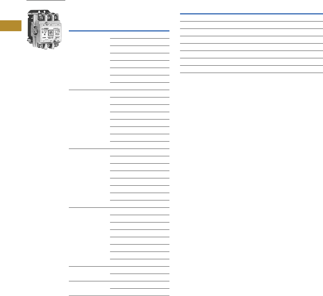
V5-T6-24 Volume 5—Motor Control and Protection CA08100006E—June 2014 www.eaton.com
6
6
6
6
6
6
6
6
6
6
6
6
6
6
6
6
6
6
6
6
6
6
6
6
6
6
6
6
6
6
6.1
Lighting Contactors
Open Control
Product Selection
When Ordering Specify
●Catalog number with coil suffix code from the Magnet Coil
Selection table
●Any required accessories
Latched AC Lighting Contactors 12 Magnet Coil Selection
Accessories
See A200 NEMA Contactor Accessories, Tab 2, section 2.2 in this
volume.
Notes
1Lighting contactors are not available with DC coils.
2Contactors rated 300A and 400A are mechanically latched.
3Underscore (_) indicates missing code letter for magnet coil selection—see Magnet Coil
Selection table.
4Available on two- to five-pole, 30 and 60A devices and on two- to three-pole 100 and
200A devices.
Holding Circuit Auxiliary Contact or
Pushbutton Station Not Included
Continuous
Amperes (Enclosed)
Number
of Poles
Open Type
Catalog Number 3
30 2 A202K1B_M
3A202K1C_M
4A202K1D_M
5A202K1E_M
6A202K1F_M
8A202K1G_M
10 A202K1H_M
12 A202K1K_M
60 2 A202K2B_M
3A202K2C_M
4A202K2D_M
5A202K2E_M
6A202K2F_M
8A202K2G_M
10 A202K2H_M
12 A202K2K_M
100 2 A202K3B_M
3A202K3C_M
4A202K3D_M
5A202K3E_M
6A202K3F_M
8A202K3G_M
10 A202K3H_M
12 A202K3K_M
200 2 A202K4B_M
3A202K4C_M
4A202K4D_M
5A202K4E_M
6A202K4F_M
8A202K4G_M
10 A202K4H_M
12 A202K4K_M
300 2 A202K5B_M
3A202K5C_M
400 2 A202K6B_M
3A202K6C_M
A202K_
Coil Voltage Catalog Number Suffix
120V, 60 Hz A
208V, 60 Hz B
277V, 60 Hz Z
440V/50, 480V/60 X
600V, 60 Hz E
120V/60, 110V/50 A
220V/50, 240V/60 W
24V, 60 Hz I 4

Volume 5—Motor Control and Protection CA08100006E—June 2014 www.eaton.com V5-T6-25
6
6
6
6
6
6
6
6
6
6
6
6
6
6
6
6
6
6
6
6
6
6
6
6
6
6
6
6
6
6
6.1
Lighting Contactors
Open Control
Renewal Parts
AC Coil, A202—Magnetically Latched
30A
60A
100 and 200A
Terminals (Line and Load)
Other Accessories
Arc boxes, upper base assemblies and cross bars are equivalent
to the A201 Series. See Tab 2, section 2.1 in this volume.
Contact kits are equivalent to the A201 Model J series, with the
exception of the magnetically latched 200A unit. It uses Catalog
Number 672B788G07 for the three-pole device. For other poles,
consult factory.
Notes
1Order quantity of two for four-pole design.
2Group members for the five-pole terminal represent the combination of the two- and three-
pole number.
3CC is coil clearing.
Voltage Hz
Two-, Three-, Four-Pole Five-Pole
Part Number Part Number
110/120 50/60 7874A93G01 7874A89G01
208/240 50/60 7874A93G02 7874A89G02
277 50/60 7874A93G03 7874A89G03
440/480 50/60 7874A93G04 7874A89G04
575 50/60 7874A93G05 7874A89G05
Voltage Hz
Two-, Three-Pole Four-, Five-Pole
Part Number Part Number
110/120 50/60 7874A93G01 7874A87G01
208/240 50/60 7874A93G02 7874A87G02
277 50/60 7874A93G03 7874A87G03
440/480 50/60 7874A93G04 7874A87G04
575 50/60 7874A93G05 7874A87G05
Voltage Hz
Two-, Three-Pole Four-, Five-Pole
Part Number Part Number
110/120 50/60 7874A85G01 7874A83G01
208/240 50/60 7874A85G02 7874A83G02
277 50/60 7874A85G03 7874A83G03
440/480 50/60 7874A85G04 7874A83G04
550/575 50/60 7874A85G05 7874A83G05
Two-Pole Three-Pole Four-Pole Five-Pole
Part Number Part Number Part Number Part Number
30A
N/A N/A N/A N/A
60A
179C755G17 179C755G16 179C755G17 1179C755G16
179C755G17 2
100A
179C755G19 179C755G18 179C755G19 1179C755G18
179C755G19 2
200A Model K Electrically Held
179C755G28 179C755G27 179C755G28 1179C755G27
179C755G28 2
200A Model J Magnetically Latched
179C755G31 179C755G30 179C755G31 1179C755G30
179C755G31 2
Description Size Part Number
Control module (rectifier) 30–200A 3915B98G01
1NO, 1NC CC auxiliary contact 330–200A J1C
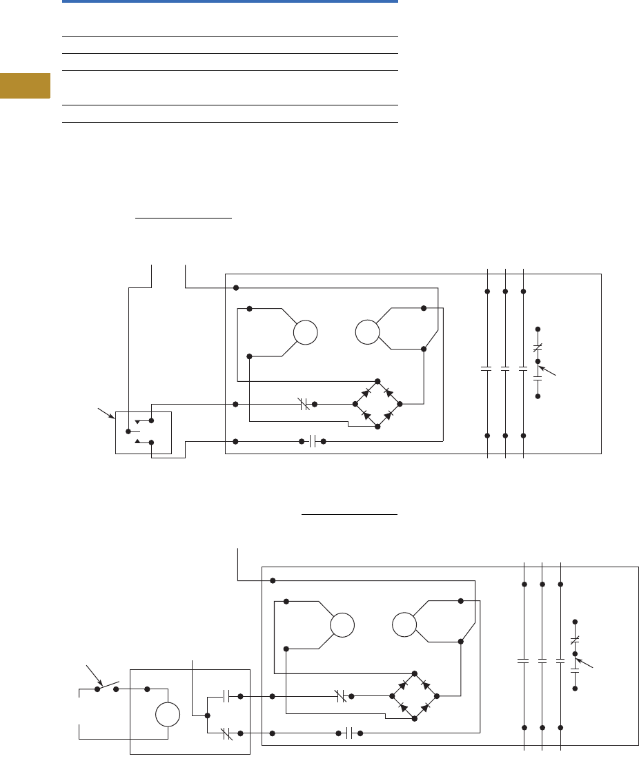
V5-T6-26 Volume 5—Motor Control and Protection CA08100006E—June 2014 www.eaton.com
6
6
6
6
6
6
6
6
6
6
6
6
6
6
6
6
6
6
6
6
6
6
6
6
6
6
6
6
6
6
6.1
Lighting Contactors
Open Control
Technical Data and Specifications
A202 Contactors
Wiring Diagrams
Standard Wiring
The standard wiring of an A202 contactor can be controlled
by a separate customer supplied single-pole double-throw
controlling station.
Two-Wire Control
Two-wire control can be accomplished with a customer supplied
relay with 1NO/1NC auxiliary contacts, wire as shown.
Description Specification
Terminals
All except 30A devices Cu/Al
30A devices Cu only
Ballast load 600 AC, breaking all lines
Tungsten lamp loads, maximum volts
Line-to-line 480 Vac
Line-to-neutral 277 Vac
Red3
2
Red
Red
AC
AC
OFF
(+)
Control Line
Auxiliary
Contact
(Option)
Typical
Control
Station
Line
Load
Close
Close Open
Open
ON
Black
White
(+)
L2
(+)
(–)
Red3
2
Red
Red
AC
AC
OFF
CM
CM
CM
(+)
Line
or
Neutral
Line
Switch
Auxiliary
Contact
(Option)
CM
Control
Line
Load
ON
Black
White
(+)
L2
(+)
(–)
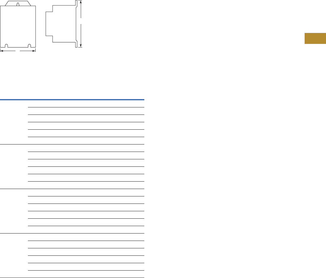
Volume 5—Motor Control and Protection CA08100006E—June 2014 www.eaton.com V5-T6-27
6
6
6
6
6
6
6
6
6
6
6
6
6
6
6
6
6
6
6
6
6
6
6
6
6
6
6
6
6
6
6.1
Lighting Contactors
Open Control
Dimensions
Approximate Dimensions in Inches (mm)
Open Type
Non-Combination Open Lighting Contactors—
Two- to 12-Pole
Continuous
Amperes
Number
of Poles
Pole
Configuration
Open Type
Wide
A
High
B
30 2–4 — 3.31 (84.1) 4.38 (111.3)
5 — 4.19 (106.4) 4.38 (111.3)
6 3 x 3 7.13 (181.1) 4.46 (113.3)
8 4 x 4 7.13 (181.1) 4.46 (113.3)
10 5 x 5 10.63 (270.0) 4.46 (113.3)
12 4 x 4 x 4 12.38 (314.5) 6.88 (174.8)
60 2, 3 — 3.31 (84.1) 4.38 (111.3)
4, 5 — 4.19 (106.4) 4.38 (111.3)
6 3 x 3 7.13 (181.1) 4.46 (113.3)
8 4 x 4 10.63 (270.0) 4.46 (113.3)
10 5 x 5 10.63 (270.0) 4.46 (113.3)
12 5 x 5 x 2 15.00 (381.0) 6.88 (174.8)
100 2, 3 — 4.63 (117.6) 6.63 (168.4)
4, 5 — 7.25 (184.2) 6.63 (168.4)
6 3 x 3 9.75 (247.7) 6.88 (174.8)
8 5 x 3 12.38 (314.5) 6.88 (174.8)
10 5 x 5 15.00 (381.0) 6.88 (174.8)
12 5 x 5 x 2 34.13 (866.9) 27.50 (698.5)
200 2, 3 — 4.63 (117.6) 6.63 (168.4)
4, 5 — 7.25 (184.2) 6.63 (168.4)
6 3 x 3 9.75 (247.7) 6.88 (174.8)
8 5 x 3 12.38 (314.5) 6.88 (174.8)
10 5 x 5 15.00 (381.0) 6.88 (174.8)
12 5 x 5 x 2 34.13 (866.9) 27.50 (698.5)
A
B
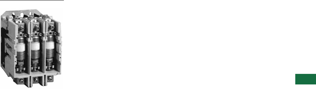
Volume 5—Motor Control and Protection CA08100006E—June 2014 www.eaton.com V5-T7-1
7
7
7
7
7
7
7
7
7
7
7
7
7
7
7
7
7
7
7
7
7
7
7
7
7
7
7
7
7
7
Vacuum Contactors and Starters
Size 4 Vacuum Contactor
7.1 NEMA, Special Purpose and Mining Rating
Product Description . . . . . . . . . . . . . . . . . . . . . . . . . . . . . . . . . . . . . . . V5-T7-2
Application Description . . . . . . . . . . . . . . . . . . . . . . . . . . . . . . . . . . . . V5-T7-2
Operation . . . . . . . . . . . . . . . . . . . . . . . . . . . . . . . . . . . . . . . . . . . . . . . V5-T7-2
Features . . . . . . . . . . . . . . . . . . . . . . . . . . . . . . . . . . . . . . . . . . . . . . . . V5-T7-2
Benefits . . . . . . . . . . . . . . . . . . . . . . . . . . . . . . . . . . . . . . . . . . . . . . . . V5-T7-2
Standards and Certifications . . . . . . . . . . . . . . . . . . . . . . . . . . . . . . . . V5-T7-2
Product Selection . . . . . . . . . . . . . . . . . . . . . . . . . . . . . . . . . . . . . . . . . V5-T7-3
Accessories . . . . . . . . . . . . . . . . . . . . . . . . . . . . . . . . . . . . . . . . . . . . . V5-T7-4
Replacement Parts . . . . . . . . . . . . . . . . . . . . . . . . . . . . . . . . . . . . . . . V5-T7-6
Technical Data and Specifications . . . . . . . . . . . . . . . . . . . . . . . . . . . . V5-T7-7
Wiring Diagrams . . . . . . . . . . . . . . . . . . . . . . . . . . . . . . . . . . . . . . . . . V5-T7-9
Dimensions . . . . . . . . . . . . . . . . . . . . . . . . . . . . . . . . . . . . . . . . . . . . . V5-T7-10
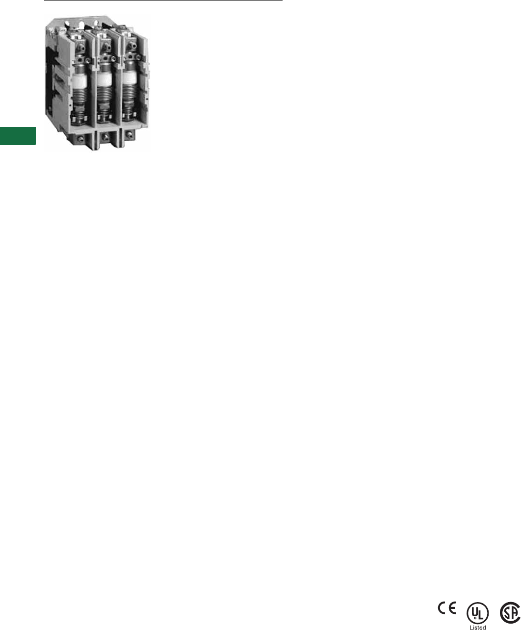
V5-T7-2 Volume 5—Motor Control and Protection CA08100006E—June 2014 www.eaton.com
7
7
7
7
7
7
7
7
7
7
7
7
7
7
7
7
7
7
7
7
7
7
7
7
7
7
7
7
7
7
7.1
Vacuum Contactors and Starters
NEMA, Special Purpose and Mining Rating
NEMA, Special Purpose and Mining Rating
Contents
Description Page
NEMA, Special Purpose and Mining Rating
Product Selection . . . . . . . . . . . . . . . . . . . . . . . V5-T7-3
Accessories . . . . . . . . . . . . . . . . . . . . . . . . . . . V5-T7-4
Replacement Parts . . . . . . . . . . . . . . . . . . . . . . V5-T7-6
Technical Data and Specifications . . . . . . . . . . V5-T7-7
Wiring Diagrams . . . . . . . . . . . . . . . . . . . . . . . V5-T7-9
Dimensions . . . . . . . . . . . . . . . . . . . . . . . . . . . V5-T7-10
Product Description
Vacuum contactors and
starters were designed for
starting and controlling three-
phase, 50/60 Hz, AC motors.
Each contact is enclosed in a
vacuum bottle to reduce and
contain contact arcing. This
design offers excellent
performance for plugging and
jogging applications.
Application Description
The vacuum contactors and
starters are offered in three
classifications. They are
NEMA rated devices up to
600 Vac, Special Purpose
rated devices up to 1500 Vac
and Mining rated devices
rated up to 1500 Vac. Each
device is tested to different
standards to serve its market.
Typical applications include
full voltage control of three-
phase squirrel cage motors,
primary control of low voltage
wound rotor motors and
circuit switching for low
voltage capacitors for power
factor improvement.
A vacuum contactor is
affected by atmospheric
pressure on the bellows of
the vacuum bottles. Up to an
altitude of 6600 feet, the
contactor is designed to
tolerate normal variations in
barometric pressure. If the
contactor is to be operated
above 6600 feet above sea
level, consult your Eaton
representative.
Operation
The contact structure of the
vacuum break contactor is
located inside sealed ceramic
tubes that have been
evacuated of air. Any arc
occurring across the contacts
upon opening is automatically
extinguished because ionized
air is not available to sustain
it—the arc breaks when the
current passes through zero.
The arc typically does not
service beyond the first half
cycle once the contacts begin
to separate. The large arc
chutes normally associated
with contactors of this size
are not required. The ceramic
tube with the moving and
stationary contacts is called a
vacuum interrupter or
bottle. There is one bottle for
each pole on the contactor.
A metal bellows (like a small,
circular accordion) within the
bottle allows the moving
contact to be closed and
pulled open from the outside
without leaking air into the
bottle. Both the bellow and
the metal-to-ceramic seals of
these state-of-the-art bottles
have been refined to the
point where the possibility of
loss of vacuum has been
virtually eliminated.
Features
●Rugged, compact and
lightweight
●Quiet operation
●Electrical and mechanical
interlocks available
●Long service life
Benefits
●Easy maintenance with
front removable coil and
auxiliaries
●Eliminate extra surge
suppressors with the
standard low chop
interrupters
●Plan your preventative
maintenance schedule by
utilizing the contact wear
indicator, standard on all
vacuum bottles
Standards and
Certifications
●NEMA Devices
●UL Listed File #E1491,
Guide Number NLDX
●CSA Approved
●Special Purpose Devices
●IEC 947-4-1
●CE Approved EN 60947-
4-1
●UL Listed File #E1491,
Guide Number NLDX
●CSA Approved
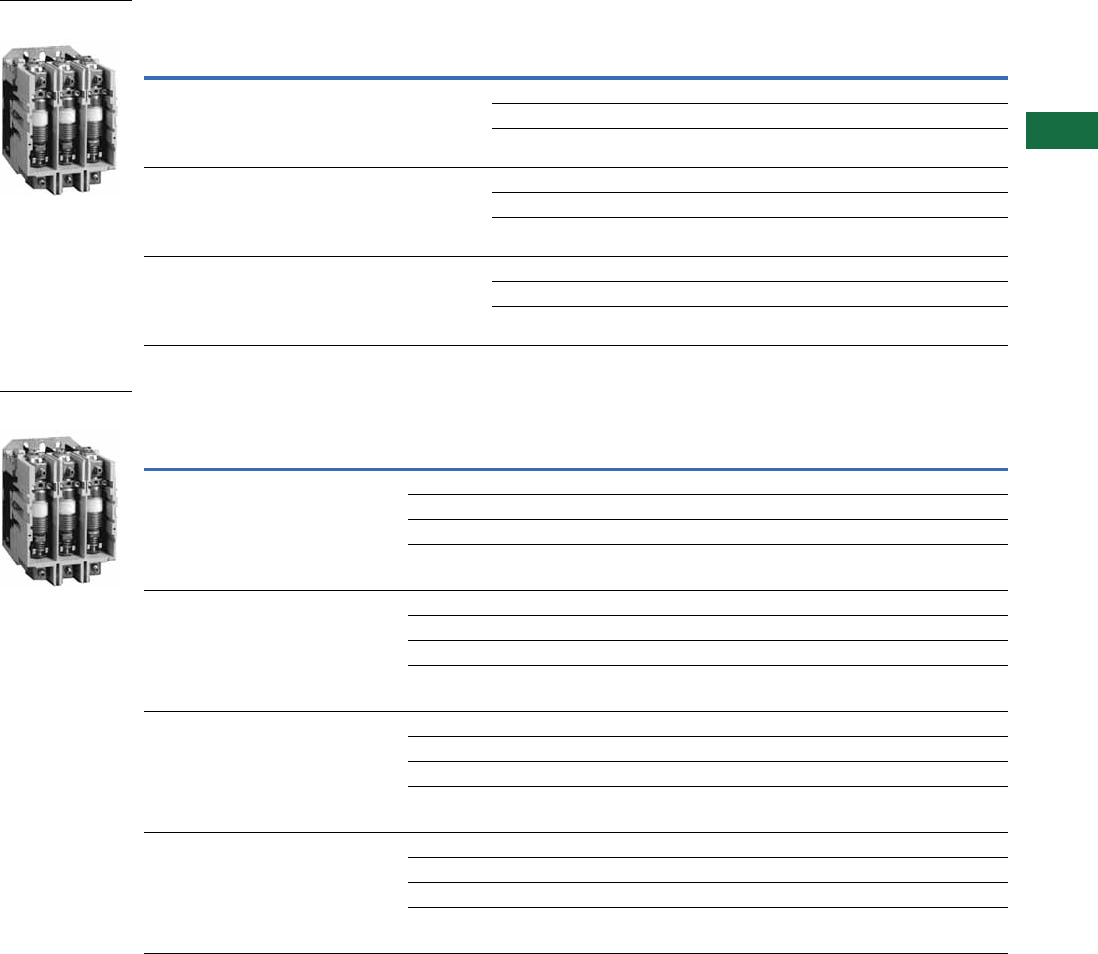
Volume 5—Motor Control and Protection CA08100006E—June 2014 www.eaton.com V5-T7-3
7
7
7
7
7
7
7
7
7
7
7
7
7
7
7
7
7
7
7
7
7
7
7
7
7
7
7
7
7
7
7.1
Vacuum Contactors and Starters
NEMA, Special Purpose and Mining Rating
Product Selection
When Ordering Specify
●Catalog number
●Heater pack if ordering a starter, order in quantities of three
●Any required accessories
NEMA Rated Vacuum Contactors and Starters
Special Purpose Vacuum Contactors and Starters
Notes
1 Coils are rated for 50/60 Hz applications.
2 Starters use Type B overload relay. Refer to Heater Coil Selection table on Page V5-T7-6. Starters do not include heater packs.
NEMA
Size
Ampere
Rating
Motor
Voltage
Maximum
Horsepower
Rating
Magnet
Coil Voltage 1
Contactor
Non-Reversing
Catalog Number
Contactor
Reversing
Catalog Number
Starter
Non-Reversing
Catalog Number 2
4135200
230
380
460
575
40
50
75
100
100
110/120 V201K4CJ V211K4CJ V200M4CJC
220/240 V201K4CK V211K4CK V200M4CK
440/480 V201K4CU V211K4CU V200M4CU
5270200
230
380
460
575
75
100
150
200
200
110/120 V201K5CJZ1 V211K5CJZ1 V200M5CJC
220/240 V201K5CKZ1 V211K5CKZ1 V200M5CK
440/480 V201K5CUZ1 V211K5CUZ1 V200M5CU
6540200
230
380
460
575
150
200
300
400
400
110/120 V201K6CJZ1 V211K6CJZ1 V200M6CJC
220/240 V201K6CKZ1 V211K6CKZ1 V200M6CK
440/480 V201K6CUZ1 — V200M6CU
Ampere
Rating
Motor
Voltage
Maximum
Horsepower
Rating
Magnet
Coil Voltage 1
Contactor
Non-Reversing
Catalog Number
Contactor
Reversing
Catalog Number
Starter
Non-Reversing
Catalog Number 2
Starter
Reversing
Catalog Number 2
160 200
230
380
460
575
800
1500
50
60
100
125
150
200
400
110/120 V201KRCJ V211KRCJ — —
220/240 V201KRCK V211KRCK — —
380/415 V201KRCH V211KRCH — —
440/480 V201KRCU V211KRCU — —
320 200
230
380
460
575
795
1500
100
125
200
250
300
400
800
110/120 V201KTCJZ1 V211KTCJZ1 V200MTCJC V210MTCJC
220/240 V201KTCKZ1 V211KTCKZ1 V200MTCK V210MTCK
380/415 V201KTCHZ1 V211KTCHZ1 V200MTCH V210MTCH
440/480 V201KTCUZ1 V211KTCUZ1 V200MTCU V210MTCU
540 200
230
380
460
575
795
1500
150
200
300
400
500
700
1300
110/120 V201KVCJZ1 V211KVCJZ1 V200MVCJ V210MVCJ
220/240 V201KVCKZ1 V211KVCKZ1 V200MVCK V210MVCK
380/415 V201KVCHZ1 — V200MVCH —
440/480 V201KVCUZ1 — V200MVCU —
610 200
230
380
460
575
795
1500
200
200
300
450
500
800
1600
110/120 V201KZCJZ1 V211KZCJZ1 — —
220/240 V201KZCKZ1 V211KZCKZ1 — —
380/415 V201KZCHZ1 — — —
440/480 V201KZCUZ1 — — —
Size 4 Vacuum
Contactor
160A Vacuum
Contactor
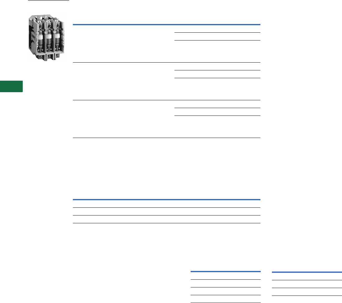
V5-T7-4 Volume 5—Motor Control and Protection CA08100006E—June 2014 www.eaton.com
7
7
7
7
7
7
7
7
7
7
7
7
7
7
7
7
7
7
7
7
7
7
7
7
7
7
7
7
7
7
7.1
Vacuum Contactors and Starters
NEMA, Special Purpose and Mining Rating
Mining Rated Vacuum Contactors and Starters
Accessories
Lug Sizes
●Size 4—12–4/0
●NEMA Size 5 and 6 and 320A, 540A and 610A—supplied without line or load lugs.
Lug Kits—Consist of Six Lugs
Field Modification Kits
Auxiliary Electrical Contacts
Size 4—Three Type J auxiliary
contacts may be mounted on
the top of Size 4 contactors to
provide six auxiliary, isolated
600V, 10A contacts for use in
control circuits.
Sizes 5–6—Two Type J
auxiliary contacts may be
mounted on each side of Size
5 and 6 contactors to provide
four auxiliary, isolated
600V,10A contacts for use in
control circuits.
Auxiliary Electrical Contacts Horizontal Mechanical
Interlock
Notes
1Coils are rated for 50/60 Hz applications.
2Used with Size 4 only. CC is coil clearing.
Ampere
Rating
Motor
Voltage
Maximum
Horsepower
Rating
Magnet
Coil Voltage 1
Contactor
Non-Reversing
Catalog Number
160 200
230
380
460
575
800
1500
50
60
100
125
150
200
400
110/120 VM160CJ
220/240 VM160CK
440/480 VM160CU
320 200
230
380
460
575
795
1500
100
125
200
250
300
400
800
110/120 VM320CJZ1
220/240 VM320CKZ1
440/480 VM320CUZ1
610 200
230
380
460
575
795
1500
150
200
300
400
500
700
1300
110/120 VM610CJZ1
220/240 VM610CKZ1
440/480 VM610CUZ1
Size Description Catalog Number
5 and 320A 1/0–500 kcmil C325KAL8
6, 540A and 610A 1/0–500 kcmil double barrel C325KAL9
610A 1/0–600 kcmil double barrel 80-19825-2
160A Mining Vacuum
Contactor
Contact
Arrangement Catalog Number
1NO, 1NC J11
1NO, 1NC CC 2J1CV
2NO J20
2NC J02
Size Catalog Number
4180C113G04
5180C113G16
5180C113G17
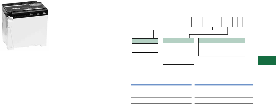
Volume 5—Motor Control and Protection CA08100006E—June 2014 www.eaton.com V5-T7-5
7
7
7
7
7
7
7
7
7
7
7
7
7
7
7
7
7
7
7
7
7
7
7
7
7
7
7
7
7
7
7.1
Vacuum Contactors and Starters
NEMA, Special Purpose and Mining Rating
AEGIS Powerline Filters
Ideal for applications that
utilize 120 Vac or 240 Vac
control voltage and have the
likelihood of harmonics or
noise being present on the
control signal. These are
stand-alone devices, not
mounted to the
contactor.
AEGIS Powerline Filters
Protect Against the Full
Spectrum of Transient
Disturbances
AEGIS filters the entire sine
wave and is effective against
both frequently occurring low
energy and occasional high
energy transients. High
energy transients can create
immediate damage, while
low energy transients cause
coil failure over time.
Catalog Numbering System
AEGIS-HW (Hard Wire Application)
230V applies to 220V and 240V applications.
AEGIS Powerline Filters
Notes
1Model tested at 15A UL/CSA = 16A CE.
2See AEGIS Powerline Filters in Volume 3—Power Distribution and Control Assemblies,
CA08100004E, Tab 2.
AGSHW CH X
Options
S = Standard
C = Form C contact for remote
monitor
Voltage Code
120N
230L
Current Capacity
03
05
10
15 1
20
Catalog Number 2Catalog Number 2
AGSHWCH120N03XC AGSHWCH230L03XC
AGSHWCH120N03XS AGSHWCH230L03XS
AGSHWCH120N05XC AGSHWCH230L05XC
AGSHWCH120N05XS AGSHWCH230L05XS

V5-T7-6 Volume 5—Motor Control and Protection CA08100006E—June 2014 www.eaton.com
7
7
7
7
7
7
7
7
7
7
7
7
7
7
7
7
7
7
7
7
7
7
7
7
7
7
7
7
7
7
7.1
Vacuum Contactors and Starters
NEMA, Special Purpose and Mining Rating
Heater Coils
Heater Coils for Type B Overload Relay 1
Replacement Parts
Vacuum Contactor—Replacement Coils
Notes
1 Motor full load current in amperes for use with three heaters only.
2 Three are required per overload relay.
3 125 Vdc can be directly applied to the Size 5 and 6 coil rated for 120 Vac/60 Hz (cannot be applied to Size 4).
4 250 Vdc can be directly applied to the Size 5 and 6 coil rated for 240 Vac/60 Hz (cannot be applied to Size 4).
Open Starter
Heater
Catalog Number 2
Open Starter
Heater
Catalog Number 2
Ambient Compensated
Overload Relay
Ambient Compensated
Overload Relay
Size 4 and 160A Size 5 and 320A with 300/5 Current Transformers
12.8–14.1 FH68 107–117 FH23
14.2–15.5 FH69 118–129 FH24
15.6–17.1 FH70 130–141 FH25
17.2–18.9 FH71 142–155 FH26
19.0–20.8 FH72 156–170 FH27
20.9–22.9 FH73 171–187 FH28
23.0–25.2 FH74 188–205 FH29
25.3–27.8 FH75 206–224 FH30
27.9–30.6 FH76 225–244 FH31
30.7–33.5 FH77 245–263 FH32
33.6–37.5 FH78 264–292 FH33
37.6–41.5 FH79 293–318 FH34
41.6–46.3 FH80 319–350 FH35
46.4–50 FH81 Size 6 and 540A with 600/5 Current Transformers
51–55 FH82 236–259 FH24
56–61 FH83 260–283 FH25
62–66 FH84 284–310 FH26
67–73 FH85 311–340 FH27
74–78 FH86 341–374 FH28
79–84 FH87 375–411 FH29
85–92 FH88 412–448 FH30
93–101 FH89 449–489 FH31
102–110 FH90 490–527 FH32
111–122 FH91 528–585 FH33
123–129 FH92 586–600 FH34
130–133 FH93
—FH94
Description Suffix Part Number
Size 4
110/120 Vac, 50/60 Hz J 9085A57G01
220/240 Vac, 50/60 Hz K 9085A57G02
380/415 Vac, 50/60 Hz H ID89221G07
440/480 Vac, 50/60 Hz U 9085A57G03
Size 5
110/120 Vac, 50/60 Hz J 7874A09G01 3
220/240 Vac, 50/60 Hz K 7874A09G04 4
380/415 Vac, 50/60 Hz H 7874A09G10
440/480 Vac, 50/60 Hz U 7874A09G05
Size 6
110/120 Vac, 50/60 Hz J 7874A24G01 3
220/240 Vac, 50/60 Hz K 7874A24G02 4
380/415 Vac, 50/60 Hz H 7874A24G07
440/480 Vac, 50/60 Hz U 7874A24G03

Volume 5—Motor Control and Protection CA08100006E—June 2014 www.eaton.com V5-T7-7
7
7
7
7
7
7
7
7
7
7
7
7
7
7
7
7
7
7
7
7
7
7
7
7
7
7
7
7
7
7
7.1
Vacuum Contactors and Starters
NEMA, Special Purpose and Mining Rating
Technical Data and Specifications
NEMA, Special Purpose and Mining Rating
Note
1For transformers having inrush currents of not more than 20 times the rated full load current.
Description
NEMA Special Purpose
Size 4
V201K4_
Size 5
V201K5_
Size 6
V201K6_
160A
V201KR_
320A
V201KT_
540A
V201KV_
610A
V201KZ_
Poles 3333333
Maximum voltage rating 600V 600V 600V 1500V 1500V 1500V 1500V
Ampere rating 135A 270A 540A 160A 320A 540A 610A
Frequency, Hz 50/60 50/60 50/60 50/60 50/60 50/60 50/60
Maximum closing current 1600A 3000A 6000A 1600A 3000A 6000A 6000A
Maximum interrupting current 1600A 3000A 6000A 1600A 3000A 6000A 6000A
Short time current
1 second 2400A RMS 4500A RMS 9000A RMS 2400A RMS 4500A RMS 9000A RMS 9000A RMS
2 second 1600A RMS 3000A RMS 6000A RMS 1600A RMS 3000A RMS 6000A RMS 6000A RMS
Dielectric strength 2200 Vac 5375 Vac 5375 Vac 2200 Vac 5375 Vac 5375 Vac 5375 Vac
Maximum allowable interrupting 1200/Hr. — — 1200/hr. — — —
Impulse voltage (1 x 40 ms) 15 kV 15 kV 15 kV 15 kV 15 kV 15 kV 15 kV
Maximum motor hp at:
200V 40 hp 75 hp 150 hp 50 hp 100 hp 150 hp 200 hp
230V 50 hp 100 hp 200 hp 60 hp 125 hp 200 hp 200 hp
380V 75 hp 150 hp 300 hp 100 hp 200 hp 300 hp 300 hp
460V 100 hp 200 hp 400 hp 125 hp 250 hp 400 hp 450 hp
575V 100 hp 200 hp 400 hp 150 hp 300 hp 400 hp 500 hp
800V — — — 200 hp 400 hp — 800 hp
1000V — — — 250 hp — — 1000 hp
1500V — — — 400 hp 800 hp 1300 hp 1600 hp
Three-phase capacitive switching (kVAR):
230V 0 kVAR 80 kVAR 160 kVAR 50 kVAR 80 kVAR 160 kVAR 176 kVAR
460V 80 kVAR 160 kVAR 320 kVAR 100 kVAR 160 kVAR 320 kVAR 356 kVAR
600V 100 kVAR 200 kVAR 400 kVAR 125 kVAR 200 kVAR 400 kVAR 400 kVAR
1500V — — — 205 kVAR 500 kVAR — 1000 kVAR
Transformer switching (kVA) 1
single-phase, two-pole:
120V 6.8 kVA 14 kVA 27 kVA 8 kVA 14 kVA 27 kVA 27 kVA
240V 14 kVA 27 kVA 54 kVA 16 kVA 27 kVA 54 kVA 54 kVA
480V 27 kVA 54 kVA 108 kVA 32 kVA 54 kVA 108 kVA 108 kVA
600V 34 kVA 68 kVA 135 kVA 40 kVA 68 kVA 135 kVA 135 kVA
Three-phase, three-pole:
240V 23 kVA 47 kVA 94 kVA 27 kVA 47 kVA 94 kVA 94 kVA
480V 47 kVA 94 kVA 188 kVA 55 kVA 94 kVA 188 kVA 188 kVA
600V 59 kVA 117 kVA 234 kVA 70 kVA 117 kVA 234 kVA 234 kVA

V5-T7-8 Volume 5—Motor Control and Protection CA08100006E—June 2014 www.eaton.com
7
7
7
7
7
7
7
7
7
7
7
7
7
7
7
7
7
7
7
7
7
7
7
7
7
7
7
7
7
7
7.1
Vacuum Contactors and Starters
NEMA, Special Purpose and Mining Rating
Electrical Characteristics—NEMA and Special Purpose Types
Electrical Characteristics Coil Data (AC Supply Rectified)
Description
Size
4 (160A) 5 (320A) 6 (540A and 610A)
DC coil data—burden:
(AC supply rectified)
Open VA 300 VA 500 VA 1450 VA
Closed VA 30 VA 25 VA 32 VA
Closed watts 6W 20W 30W
Pick-up volts 70% of rated coil volts 70% of rated coil volts 70% of rated coil volts
Drop-out volts 50% of rated coil volts 50% of rated coil volts 50% of rated coil volts
Pick-up time in Hz 1.5–2 Hz 1.5–2 Hz 1.5–2 Hz
Drop-out time in Hz 6–6.15 Hz 6–6.15 Hz 6–6.15 Hz
Maximum voltage rating 600V 600V 600V
Maximum closing current 1600A 3000A 6000A
Maximum interrupting current 1600A 3000A 6000A
Short time current:
1 second 2400A RMS 4500A RMS 9000A RMS
2 second 1600A RMS 3000A RMS 6000A RMS
Burden Size 4 (160A) Size 5 (320A) Size 6 (540A and 610A)
Inrush VA 300 600 1700
Sealed VA 30 20 28
Sealed watts 6 20 28
Pick-up volts 70% of rated coil volts 70% of rated coil volts 70% of rated coil volts
Drop-out volts 50% of rated coil volts 50% of rated coil volts 50% of rated coil volts
Pick-up time in Hz 1.5–2 1.5–2 1.5–2
Drop-out time in Hz 6–7.5 6–6.15 6–6.15
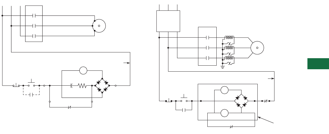
Volume 5—Motor Control and Protection CA08100006E—June 2014 www.eaton.com V5-T7-9
7
7
7
7
7
7
7
7
7
7
7
7
7
7
7
7
7
7
7
7
7
7
7
7
7
7
7
7
7
7
7.1
Vacuum Contactors and Starters
NEMA, Special Purpose and Mining Rating
Wiring Diagrams
Size 4 Contactor Sizes 5 and 6 Starter
L1 L2 L3
M
M
M
M
M
T1
T2
T3
Motor
Start
Stop
123
AB
+
-
C
Coil Aux. Contact
D
"C"
Vacuum
L1 L2 L3
M
M
M
S
R
T1
T2
T3
0T
1T
2T
OL
OL
OL
Motor
Start
Stop
1
23
AB
OL
95 96
+
-
C
L63 Coil Aux. Contact
D
"C"
Encapsulated
Coils and Diode
Disconnect
Means Vacuum
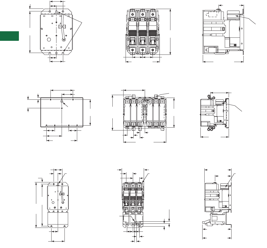
V5-T7-10 Volume 5—Motor Control and Protection CA08100006E—June 2014 www.eaton.com
7
7
7
7
7
7
7
7
7
7
7
7
7
7
7
7
7
7
7
7
7
7
7
7
7
7
7
7
7
7
7.1
Vacuum Contactors and Starters
NEMA, Special Purpose and Mining Rating
Dimensions
Approximate Dimensions in Inches (mm)
Open Type Contactors and Starters—Size 4 and 160A
Size and 160A Non-Reversing Contactor
Size 4 and 160A Reversing Contactor
Size 4 Non-Reversing Starter
Rear View — Drilling Plan Front View Side View
6.63
(168.4)
6
(152.4)
.38 (9.7)
5.96 (151.4)4.83 (122.7)
1.44 (36.6)
1.88 (47.8)
1.88 (47.8)
3.6 (91.4)
.94 (23.9)
.94 (23.9)
.28 (7.1) Dia.
3 Mtg. Slots
Front View Shown
without Cover Plate
and Overtravel
Gauge.
1.44 (36.6)
Recess for
Auxiliary
Interlock
1.88 (47.8) 1.88 (47.8)
6
(152.4)
.28 (7.1)
3 Mtg.
Slots
3.5 (88.9)
2
(50.8)
.44 (11.2) 5.13 (130.3)
2.56 (65)
4.88 (124)
7.0 (177.8)
Rear View — Drilling Plan Front View Side Vew
8.5
(215.9)
Max.
6.88
(174.8)
9.96 (253)
1.44 (36.6)
1.13 (28.7)
1.44 (36.6) 6.54
(166.1)
4.2 (106.7)
Mechanical
Interlock
Recess for
Auxiliary
Interlock
Reset
Front View Shown
without Cover Plate
and Overtravel Gauge.
Recess for
Auxiliary Interlock
1.44
(36.6)
.28 (7.1) Dia.
3 Mtg. Holes 1.44 (36.6)
1.44 (36.6) 3.60
(91.4)
4.83 (122.7) 5.94 (150.9)
6.11 (155.2)
Max. to Reset
6.34 (161.0)
Hand Reset
.46
(11.7)
.58
(14.7)
1.31 (33.3) 1.31 (33.3)
.65 (16.5)
.46 (11.7)
.38 (9.7)
.94 (23.9)
1.88 (47.8)
9.25
(235)
9.97
(253.2)
Rear View — Drilling Plan Front View Side Vew
2.88 (73.2)
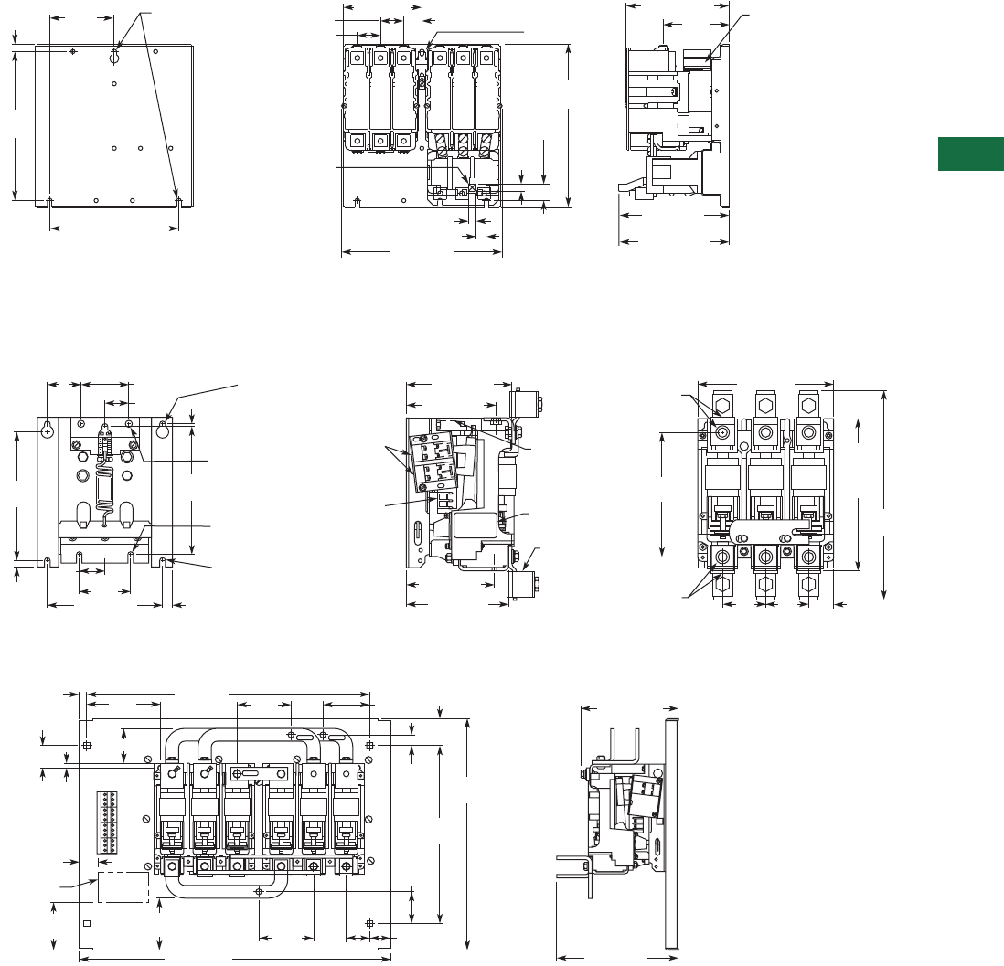
Volume 5—Motor Control and Protection CA08100006E—June 2014 www.eaton.com V5-T7-11
7
7
7
7
7
7
7
7
7
7
7
7
7
7
7
7
7
7
7
7
7
7
7
7
7
7
7
7
7
7
7.1
Vacuum Contactors and Starters
NEMA, Special Purpose and Mining Rating
Approximate Dimensions in Inches (mm)
Open Type Contactors and Starters—Size 4 and 160A, continued
Size 4 Reversing Starter
Open Type Contactors and Starters—Size 5 and 320A
Size 5 and 320A Non-Reversing Contactor
Size 5 and 320A Reversing Contactor
Mechanical
Interlock
Recess for
Auxiliary Interlock
10.12
(257)
.281 (7.14) Dia.
3 Mtg. Holes
Reset
8.00 (203.2)
9.25
(235)
.44
(11.2) 4.00
(101.6)
.47 (11.9) 6.61 (168)
Max. to Reset
6.86 (174.2)
Hand Reset
.66 (16.8)
.47
(11.9)
1.03
(26.2)
1.13 (28.7) 4.10
(104.1)
1.44 (36.6)
1.44 (36.6)
4.88 (124)
9.96 (253)
6.38 (162.1)
Rear View — Drilling Plan Front View Side Vew
8
(203.2)
.38
(9.7)
7. 5
(190.5)
6.75 (171.5)
Drilling Plan — Rear View
.58 (14.7)
3
(76.2)
1.5
(38.1)
7.28 (184.9)
Term. Holes
12.5
(317.5)
8.94
(227.1)
Term.
to
Term.
.13
(3.3)
A
B
1.38
(35.1)
2.75 (69.9) 6.13 (155.7)
5.22 (132.6)
Line Term.
5.93 (150.6)
7.9 (200.7)
2.5
(63.5)
2.5
(63.5) 1.45
(36.8)
5.09 (129.3)
Load Term.
2
(50.8)
Nameplate
Terminal
Clamps
Are
Optional
Coil Interlock
Location
3/8-16 Tap
Line Terminals
Six (6) Places
3/8-16 Tap
Line Terminals
Six (6) Places
.33 x .75
(8.4 x 19.1)
Key Holes
3 Places
.41 (10.4)
Dia.
2 Holes
.33 (8.4)
Slot
2 Places
.31 (7.9)
Slot
2 Places
A – Two Dual Circuit
Interlocks Located
on Both Sides of
Contactor.
(When Used)
B – Coil Terminals
Located on Both
Sides of Contactor.
3.75
(95.3)
1.75
(44.5)
.62
(15.7)
2.74 (69.6)
.38
(9.7)
4.1
(104.1)
Nameplate
22 (558.8)
5.73
(145.5)
1.5
(38.1)
4.25
(108) 2.5
(63.5)
1.9
(48.3)
1.62 (41.1)
4.21
(106.9) 3.65 (92.7)
2.5
(63.5)
24.24 (615.7) 9.48 (240.8)
6.61 (167.9)
18.24
(463.3)
14
(355.6)
2.12
(53.8)
2.48
(63)
.86
(21.8)
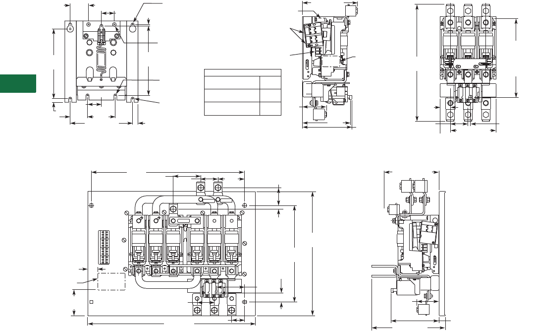
V5-T7-12 Volume 5—Motor Control and Protection CA08100006E—June 2014 www.eaton.com
7
7
7
7
7
7
7
7
7
7
7
7
7
7
7
7
7
7
7
7
7
7
7
7
7
7
7
7
7
7
7.1
Vacuum Contactors and Starters
NEMA, Special Purpose and Mining Rating
Approximate Dimensions in Inches (mm)
Open Type Contactors and Starters—Size 5 and 320A, continued
Size 5 and 320 Non-Reversing Starter
320 Reversing Starter
A
Coil
Interlock
Location
B
7.75 (196.9)
Line End
3.37
(85.6)
Load
End “A”
Dim.
“A” Dim.
Nameplate 16.43
(417.3)
1.45
(36.8)
2.5
(63.5) 7.89 (200.4)
10.88
(276.4)
to
Center
of
Reset Rod
.33 (8.4)
to Center of
Reset Rod
A – Two Dual Circuit
Interlocks Located
on Both Sides of
Starter.
(When Used)
B – Coil Terminals
Located on Both
Sides of Starter.
8
(203.2)
.38
(9.7)
7. 5
(190.5)
6.75 (171.5)
Drilling Plan — Rear View
.58 (14.7)
3
(76.2)
1.88
(47.8)
1.5
(38.1)
.14
(3.6)
1.38
(35.1)
2
(50.8) .33 x .75
(8.4 x 19.1)
Key Holes
3 Places
.41 (10.4)
Dia.
2 Holes
.31 (7.9)
Slot
2 Places
.33 (8.4)
Slot
2 Places 7 (177.8)
Normal
or Tripped
Type B Relay
Max. Dim to Reset
Type A Relay
Max. Dim to Reset
Type B Relay
Automatic Reset
6.75
(171.5)
6.73
(170.9)
6.61
(167.9)
3.75
(95.3)
2.5
(63.5)
3.87
(98.3)
Nameplate
1.5
(38.1) 1.32
(33.5)
.53
(13.5)
2.56
(65.0)
14
(355.6)
18
(457.2)
2.5
(63.5)
24 (609.6) 1.89 (48.0)
4
(101.6)
22.25
(565.2) 8 (203.2) Line
3.25
(82.6)
10.71(272.0)
7 (177.8)
Normal
or Tripped
4.08
(103.6)
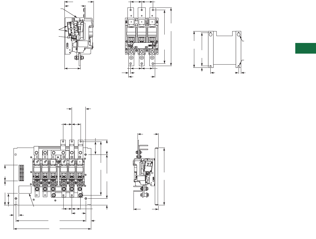
Volume 5—Motor Control and Protection CA08100006E—June 2014 www.eaton.com V5-T7-13
7
7
7
7
7
7
7
7
7
7
7
7
7
7
7
7
7
7
7
7
7
7
7
7
7
7
7
7
7
7
7.1
Vacuum Contactors and Starters
NEMA, Special Purpose and Mining Rating
Approximate Dimensions in Inches (mm)
Open Type Contactors and Starters—Size 6, 540A and 610A
Size 6, 540A and 610A Non-Reversing Contactor
Size 6, 540A and 610A Reversing Contactor
8
(203.2)
.38
(9.7)
8.75
(222.3)
12.9
(327.7)
Term.
Holes
13.99
(355.3)
6.75 (171.5) .58
(14.7)
.33 (8.4)
Slot
2 Places
.33 x .75
(8.4 x 19.1)
Key Holes
5 (127)
2.67 (67.8) 2.67 (67.8)
2.67 (67.8)
2.67 (67.8)
7 (177.8)
3.72 (94.5)
Load 1.28
(32.5) 7.9 (200.7)
A
B
Coil
Interlock
A—Two Dual Circuit Interlocks
Located on Both Sides of
Contactor. (When Used)
B—Coil Terminals Located on
Both Sides of Contactor.
Rear View—Drilling Plan
Front ViewSide Vew
2.73
(69.3) 2.73
(69.3)
4.39
(111.5)
3.75
(95.3)
7.87
(199.9)
4.88
(124)
1.5
(38.1)
14.01
(355.9)
2.09
(53.1)
18.24
(463.3)
4.62
(117.3)
6.5
(165.1)
4.12
(104.6)
17.02
(432.3)
24.24
(615.7)
22
(558.8)
2.67
(67.8) 2.67
(67.8)
4.4
(111.8)
1.64
(41.7)
7.84
(199.1)
Nameplate
Front View Side View
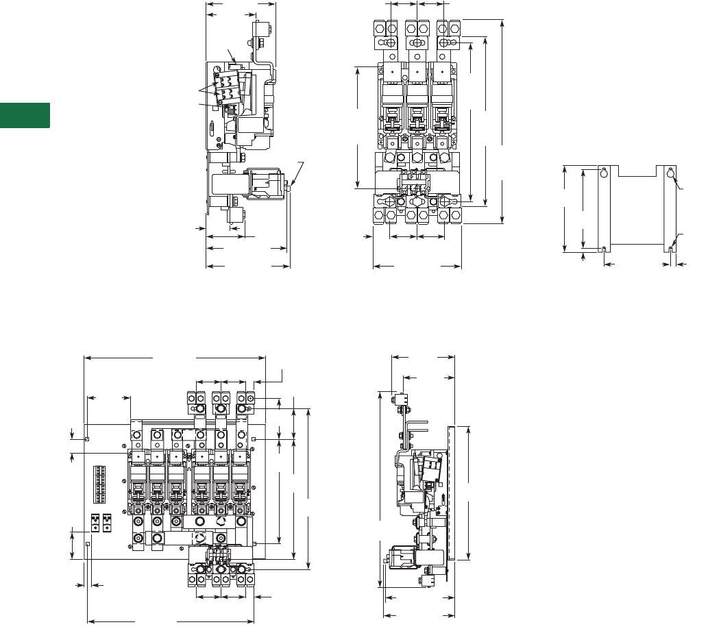
V5-T7-14 Volume 5—Motor Control and Protection CA08100006E—June 2014 www.eaton.com
7
7
7
7
7
7
7
7
7
7
7
7
7
7
7
7
7
7
7
7
7
7
7
7
7
7
7
7
7
7
7.1
Vacuum Contactors and Starters
NEMA, Special Purpose and Mining Rating
Approximate Dimensions in Inches (mm)
Open Type Contactors and Starters—Size 6, 540A and 610A, continued
Size 6 and 540A Non-Reversing Starter
540A Reversing Starter
8
(203.2)
.38
(9.7)
8.75
(222.3)
6.75 (171.5) .58
(14.7)
.33 (8.4)
Slot
2 Places
.33 x .75
(8.4 x 19.1)
Key Holes
Rear View—Drilling Plan
Overload Relay
Reset Rod
2.38
(60.5)
8.16 (207.3)
Normal or Tripped 8.90 (226.1)
3.86 (98.0)
Load
7.94 (201.7)
Reset
2.67
(67.8) 2.67
(67.8)
1.70
(43.2) 2.75
(69.9) 2.75
(69.9)
12.62
(320.5)
To Center
of Reset
15.94
(404.9)
Term.
Mtg.
20.50
(520.7)
Without
Term.
17.10
(434.3)
With
Term.
A
B
Coil
Interlock
A—Two Dual Circuit
Interlocks Located on
Both Sides of Starter.
(When Used)
B—Coil Terminals Located
on Both Sides of Starter.
Front ViewSide View
5 (127)
7 (177.8)
Front View Side View
24 (609.6)
22 (558.8)
18
(457.2)
21.5
(546.1)
26
(660.4)
16.06
(407.9)
14
(355.6)
4.13
(104.9)
5.43
(137.9)
3.23
(82)
5.81
(147.6)
1.75
(44.5)
3.23
(82)
3.23
(82) 3.23
(82)
1.17
(29.7)
1.17
(29.7)
8
(203.2)
3.64
(92.5)
6.5
(165.1)
9.16 (232.7)
Normal
8.94 (227.1)
Reset
1
(25.4)
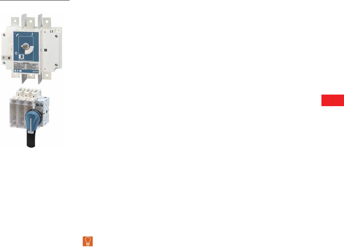
Volume 5—Motor Control and Protection CA08100006E—December 2013 www.eaton.com V5-T8-1
8
8
8
8
8
8
8
8
8
8
8
8
8
8
8
8
8
8
8
8
8
8
8
8
8
8
8
8
8
8
Rotary Disconnects
Rotary Disconnects
8.1 Introduction
UL/CSA Standards for Disconnect Switches . . . . . . . . . . . . . . . . . . . . V5-T8-2
UL Standards for Electrical Machinery . . . . . . . . . . . . . . . . . . . . . . . . . V5-T8-2
Eaton Solutions for UL 508A and NFPA 79 . . . . . . . . . . . . . . . . . . . . . V5-T8-3
8.2 R5 Series (UL 508) Non-Fusible 16–80A
Product Description . . . . . . . . . . . . . . . . . . . . . . . . . . . . . . . . . . . . . . . V5-T8-5
Features, Benefits and Functions . . . . . . . . . . . . . . . . . . . . . . . . . . . . V5-T8-5
Standards and Certifications . . . . . . . . . . . . . . . . . . . . . . . . . . . . . . . . V5-T8-5
Product Identification . . . . . . . . . . . . . . . . . . . . . . . . . . . . . . . . . . . . . . V5-T8-5
Product Selection . . . . . . . . . . . . . . . . . . . . . . . . . . . . . . . . . . . . . . . . . V5-T8-6
Accessories . . . . . . . . . . . . . . . . . . . . . . . . . . . . . . . . . . . . . . . . . . . . . V5-T8-6
Technical Data and Specifications . . . . . . . . . . . . . . . . . . . . . . . . . . . . V5-T8-9
Dimensions . . . . . . . . . . . . . . . . . . . . . . . . . . . . . . . . . . . . . . . . . . . . . V5-T8-10
8.3 R9 Series (UL 98)
Non-Fusible 30–100A Compact . . . . . . . . . . . . . . . . . . . . . . . . . . . . . . V5-T8-11
Non-Fusible 100–1200A . . . . . . . . . . . . . . . . . . . . . . . . . . . . . . . . . . . . V5-T8-18
Fusible 30–800A . . . . . . . . . . . . . . . . . . . . . . . . . . . . . . . . . . . . . . . . . V5-T8-26
DC Rated Disconnects . . . . . . . . . . . . . . . . . . . . . . . . . . . . . . . . . . . . V5-T8-45
8.4 MTS—Manual Transfer/Double Throw Switches
Product Description . . . . . . . . . . . . . . . . . . . . . . . . . . . . . . . . . . . . . . . V5-T8-52
Standards and Certifications . . . . . . . . . . . . . . . . . . . . . . . . . . . . . . . . V5-T8-52
Product Identification . . . . . . . . . . . . . . . . . . . . . . . . . . . . . . . . . . . . . . V5-T8-52
Product Selection . . . . . . . . . . . . . . . . . . . . . . . . . . . . . . . . . . . . . . . . . V5-T8-53
Accessories . . . . . . . . . . . . . . . . . . . . . . . . . . . . . . . . . . . . . . . . . . . . . V5-T8-54
Technical Data and Specifications . . . . . . . . . . . . . . . . . . . . . . . . . . . . V5-T8-56
Dimensions . . . . . . . . . . . . . . . . . . . . . . . . . . . . . . . . . . . . . . . . . . . . . V5-T8-57
Learn
Online
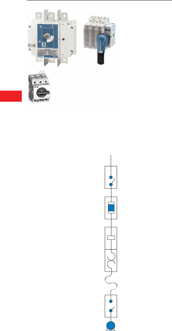
V5-T8-2 Volume 5—Motor Control and Protection CA08100006E—December 2013 www.eaton.com
8
8
8
8
8
8
8
8
8
8
8
8
8
8
8
8
8
8
8
8
8
8
8
8
8
8
8
8
8
8
8.1
Rotary Disconnects
Introduction
Rotary Disconnects
Contents
Description Page
Introduction
Eaton Solutions for UL 508 and NFPA 79 . . . . . V5-T8-3
UL/CSA Standards for Disconnect Switches
UL 98—Enclosed and
Deadfront Switches
(CSA C22.2 No. 4)
These requirements cover
enclosed or deadfront
switches, with or without
provision for fuses, at 600V
or less. These products are
used as disconnecting means
without restrictions; they are
heavy-duty products requiring
2.00 inches (50.0 mm)
minimum of creepage
distance between phases,
which gives maximum safety
for users and installation.
The short-circuit withstand
of those products goes up
to 200 kA.
UL 489—Molded Case
Switches
(CSA C22.22 No. 5)
These requirements cover
molded case circuit breakers,
molded case switches and
fused molded case switches,
rated at 600V or less and
6000A or less.
Typical Control Panel
UL 98 or UL 489
Non-Fusible
Disconnect Switches
or
Fusible Disconnect
Switches
UL 508
Non-Fusible Switches
UL Standards for Electrical Machinery
UL 508—Industrial
Control Equipment
(CSA C22.2 No. 14)
These requirements cover
manual, magnetic and solid-
state starters and controllers,
overload relays, pushbuttons,
selector switches and
control lights.
These products are smaller,
requiring only a creepage
distance between phases
of 0.50 inch (12.7 mm).
Their use as a disconnecting
means is limited to local
disconnection of motors.
These products can be used
as a disconnect means only
when they have been
additionally tested “suitable
as motor disconnect.” This
additional testing ensures
that the switch has a proper
closing capacity on a short
circuit. UL® 508 devices
cannot be used as main
disconnect of an electrical
panel, for example, at the
entrance of control panels.
A manual motor controller
marked “suitable as motor
disconnect” shall be installed
only on the load side of
the branch circuit protective
device [UL 508A 30.33
and NEC® 430.109 (6)].
NFPA 79 Electrical Standard
for Industrial Machinery
The following types of
machines are identified
as industrial machinery:
●Metalworking machine
tools, including machines
that cut or form metal
●Plastics machinery
●Wood machinery, including
woodworking, laminating
and sawmill machines
●Assembly machines
●Material handling
machines, including
industrial robots and
transfer machines
●Inspection and testing
machines, including
coordinate measuring
and in-process
gauging machines
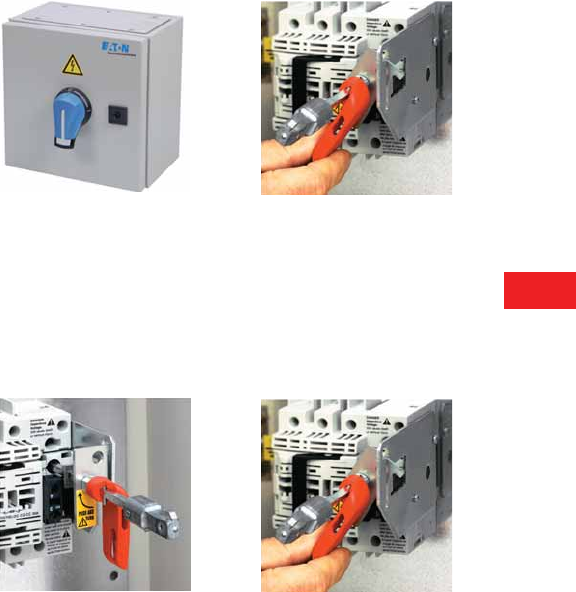
Volume 5—Motor Control and Protection CA08100006E—December 2013 www.eaton.com V5-T8-3
8
8
8
8
8
8
8
8
8
8
8
8
8
8
8
8
8
8
8
8
8
8
8
8
8
8
8
8
8
8
8.1
Rotary Disconnects
Introduction
Eaton Solutions for UL 508A and NFPA 79
The changes in UL 508A and NFPA® 79 impact the design and
construction of your equipment. Important modifications concern
major safety issues, the disconnect means and the interlocking
of the enclosure door.
The disconnect shall be operable independent of the door position.
The disconnect must be operable, by qualified persons,
independent of the door position without the use of accessory
tools or devices.
Note: NFPA 79; Paragraph 5.3.3.1 (5) T.
An operating mechanism for the disconnecting means shall be
operable independent of the door position without the use of
accessory tools or devices.
Note: UL 508A; Paragraph 66.6.3 c.
The disconnect means is not closable with the enclosure door open,
unless an interlock is operated by deliberate action.
The interlocking means shall fulfill the following requirement:
Prevent closing of the disconnect means while the enclosure
door is open, unless an interlock is operated by deliberate action.
Note: NFPA 79; Paragraph 6.2.3.1.2.
The disconnecting means is not closable with the enclosure
door open, unless an interlock is operated by deliberate action.
Note: UL 508A; Paragraph 66.1.5.
Operable independent of the position of the door
Door closed: operation with the
external handle through the door.
Door open: A robust optional kit with a
handle directly fitted on the shaft of the
switch allows the operation when the
door is open.
Operated by a deliberate action
1Push
Door open: It is necessary to push the
handle from OFF to ON. This deliberate
action permits the operator to turn and
switch ON. This action is necessary as
in most cases there is no padlock on the
switch when somebody opens the door
of an enclosure.
2Turn
ON to OFF action permits the operator
to turn and switch ON. That is a major
safety issue; switching ON directly
without any other action is extremely
dangerous. The use of a padlock does
not comply with the request of the
standard; when the panel door is
opened, there is generally no padlock,
and anybody can turn the switch ON.
1
2
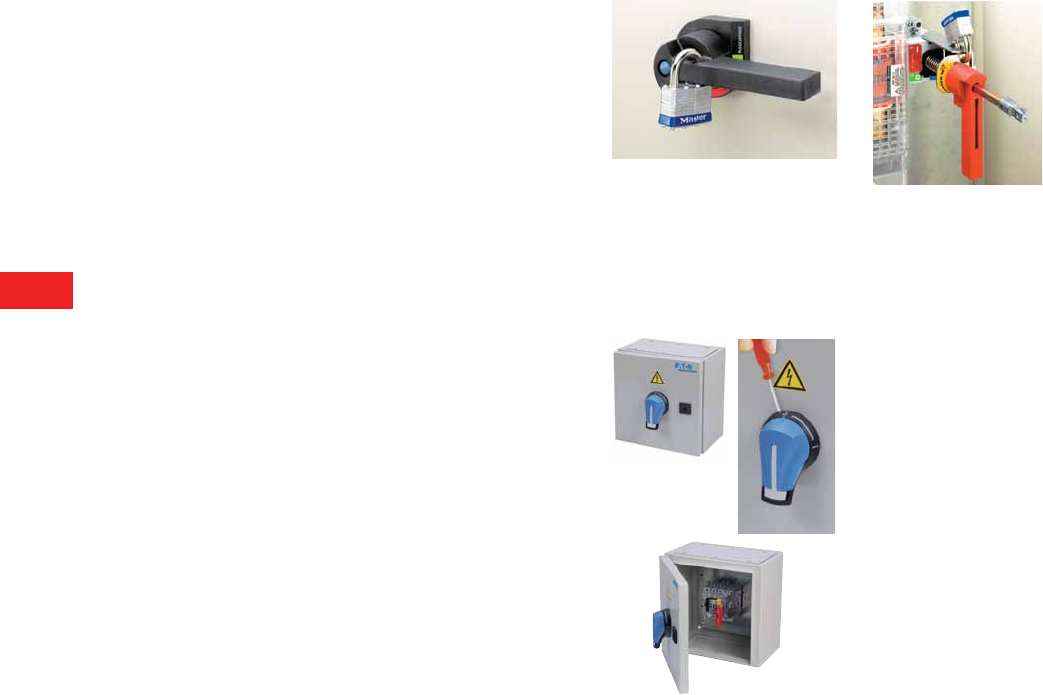
V5-T8-4 Volume 5—Motor Control and Protection CA08100006E—December 2013 www.eaton.com
8
8
8
8
8
8
8
8
8
8
8
8
8
8
8
8
8
8
8
8
8
8
8
8
8
8
8
8
8
8
8.1
Rotary Disconnects
Introduction
The disconnect means shall be able to be locked in the OPEN position
independent of the door position.
The circuit disconnecting device shall be provided with a
permanent means, permitting it to be locked in the OFF position
only independent of the door position. When locked, remote as
well as local closing shall be prevented.
Note: NFPA 79; Paragraph 5.3.3.1 (3).
An operating mechanism for the disconnecting means shall be
able to be locked in the OFF position independent of the door
position. When locked, closing of the disconnect is not possible.
Note: UL 508A; Paragraph 66.6.3 d.
The interlocking of the enclosure door shall be provided with means
to defeat the interlock without removing the power.
The interlocking means required by 66.1.5 shall be provided with
all of the following:
●Means to defeat the interlock without removing power,
and requires the use of a tool to operate
●Reactivated automatically when all the doors are closed
Note: Added 66.1.5.1 effective March 1, 2007. UL 508A;
Paragraph 66.1.5.1.
NFPA 79; Paragraph 6.2.3.1.2 states that the [enclosure]
interlocking means shall meet the following requirements:
●Use a device or tool to allow qualified persons to defeat
the interlock
●Be reactivated automatically when the door is closed
Locked in the open position independent of the door position
Door close: The external through-
the-door handle is padlocked when
locked closing of the disconnect is
not possible.
Door open: A strong metallic padlock
kit allows up to three padlocks. The
padlocking means is easily accessible,
when locked closing of the disconnect
is not possible.
Defeat the interlock without removing the power
A tool allows defeat of the interlock without
removing power. The interlocking is reactivated
automatically when the door is closed.
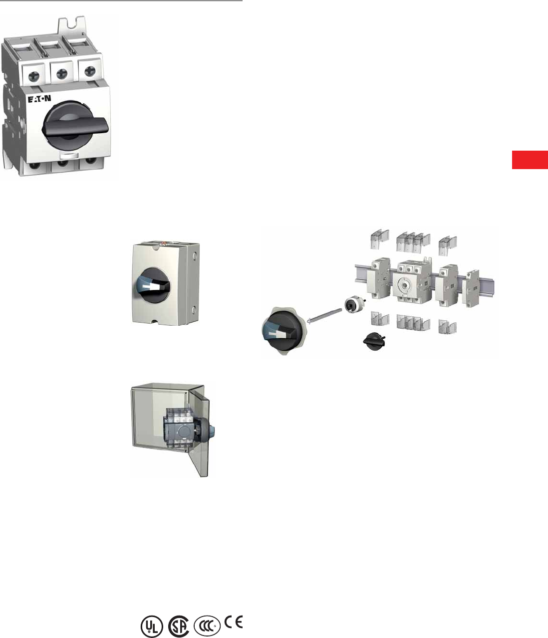
Volume 5—Motor Control and Protection CA08100006E—December 2013 www.eaton.com V5-T8-5
8
8
8
8
8
8
8
8
8
8
8
8
8
8
8
8
8
8
8
8
8
8
8
8
8
8
8
8
8
8
8.2
Rotary Disconnects
R5 Series (UL 508) Non-Fusible 16–80A
R5 Series Non-Fusible 16–80A
Contents
Description Page
R5 Series Non-Fusible 16–80A
Product Selection . . . . . . . . . . . . . . . . . . . . . . . V5-T8-6
Accessories . . . . . . . . . . . . . . . . . . . . . . . . . . . . V5-T8-6
Technical Data and Specifications . . . . . . . . . . . V5-T8-9
Dimensions . . . . . . . . . . . . . . . . . . . . . . . . . . . . V5-T8-10
Product Description
R5 Series (UL 508 listed)
products are manually
operated modular switches.
Load break switching and
isolation provide safety
solutions for any low voltage
circuit, particularly for
machine and control circuits.
The R5 Series products are
manual motor controllers
suitable as motor disconnect.
Features, Benefits
and Functions
●Up to 65 kAIC
short-circuit rating
●Direct or external operation
●Compact footprint
●DIN rail or base mount
●Wide range of accessories
●Up to eight-pole or
four-pole MTS
●Open and enclosed devices
●Modular design
●Integrated terminals
for additional safety
●Padlockable design (direct,
toggle and external handles)
●Product can be reverse fed
Standards and Certifications
Conformity to Standards
●UL 508 listed, Guide NLRV,
File E165150
●CSAT C22.2 No.14, File
217736
●IEC 60947-3, EN 60947-3
●CCC
●CE
Product Identification
1External front handle
2Shaft extension for external handle
3Direct handle
4Switched fourth-pole module
5Terminal shroud
6Auxiliary contacts
Note: For further details, please see the installation instructions
supplied with each device.
2
3
5
6
4
1

V5-T8-6 Volume 5—Motor Control and Protection CA08100006E—December 2013 www.eaton.com
8
8
8
8
8
8
8
8
8
8
8
8
8
8
8
8
8
8
8
8
8
8
8
8
8
8
8
8
8
8
8.2
Rotary Disconnects
R5 Series (UL 508) Non-Fusible 16–80A
Product Selection
R5 Series
Accessories
Notes
1Toggle version includes direct handle.
2Includes shaft and accessory cap.
Ampere
Rating
Three-Pole Toggle
Switch Only 1
Three-Pole Rotary
Switch Only
Direct
Handle
Front and Right
External Handle SH00
(Choose one)
Front and Right
External Handle SH0
(Choose one)
Shaft for SH0 and
SH00—5 x 5 mm—
In (mm)
16 — R5A3016U DHR5 SH00
Black
3R, 12
SHB00N12
SH00
Red
3R, 12
SHR00N12
SH00
Black
4, 4X
SHB00N4X
SH00
Red
4, 4X
SHR00N4X
SH0
Black
3R, 12
SHB0N12
SH0
Red
3R, 12
SHR0N12
SH0
Black
4, 4X
SHB0N4X
SH0
Red
4, 4X
SHR0N4X
2.20 (55.5)
SF55SH5X5
3.50 (90.0)
SF90SH5X5
5.90 (150.0)
SF150SH5X5
7.90 (200.0)
SF200SH5X5
12.60 (320.0)
SF320SH5X5
25 — R5A3025U
30 T5A3030U R5A3030U
40 T5A3040U R5A3040U
60 T5B3060U R5B3060U
80 T5B3080U R5B3080U
+++
Switch body Direct handle Switch body Shaft External handle
+++
Direct Operation External Operation
Ampere
Rating
Switched Fourth-Pole
Module
Auxiliary Contacts
(Choose one)
Terminal
Shrouds
Door
Mounting Kit 2
16 S4PR516 1NO + 1NC
AC1NONC
2NO
AC2N0
1P
TS1R5A
3P
TS3R5A
DMK
25 S4PR525
30 S4PR530
40 S4PR540
60 1P
TS1R5B
3P
TS3R5B
80
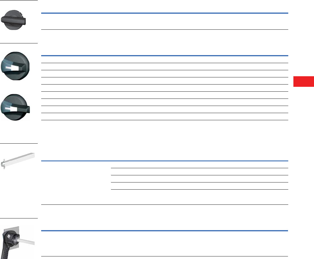
Volume 5—Motor Control and Protection CA08100006E—December 2013 www.eaton.com V5-T8-7
8
8
8
8
8
8
8
8
8
8
8
8
8
8
8
8
8
8
8
8
8
8
8
8
8
8
8
8
8
8
8.2
Rotary Disconnects
R5 Series (UL 508) Non-Fusible 16–80A
Handles
Direct Handle
Door Interlocked External Handle (Defeatable) 1
Shafts
Shaft Extensions for External Handle
Guide Cone
Note
1 Allows door to be opened when switch is in the ON position.
Ampere Rating Handle Color Catalog Number
16–80 Black DHR5
Ampere Rating Handle Color Handle Size NEMA Type Rating Catalog Number
Front and Right Side Operation I–0
16–80 Black SH00 3R, 12 SHB00N12
16–80 Black SH00 4, 4X SHB00N4X
16–80 Red/Yellow SH00 3R, 12 SHR00N12
16–80 Red/Yellow SH00 4, 4X SHR00N4X
16–80 Black SH0 3R, 12 SHB0N12
16–80 Black SH0 4, 4X SHB0N4X
16–80 Red/Yellow SH0 3R, 12 SHR0N12
16–80 Red/Yellow SH0 4, 4X SHR0N4X
Description Ampere Rating Use with Handle Type
Shaft Length
In (mm) Catalog Number
Standard lengths: 55 mm, 90 mm, 150 mm,
200 mm, 320 mm
For 3/4-pole switches: shafts are for external
front and side handle
For 6/8-pole switches and changeover
switches: shafts are for external
front and side handle
16–80 SH00/SH0 2.17 (55.0) SF055SH5X5
16–80 SH00/SH0 3.54 (90.0) SF090SH5X5
16–80 SH00/SH0 5.91 (150.0) SF150SH5X5
16–80 SH00/SH0 7.87 (200.0) SF2003H5X5
16–80 SH00/SH0 12.60 (320.0) SF320SH5X5
Description Ampere Rating Use with Handle Type Catalog Number
The guide cone facilitates an easier
connection between the shaft and a Size 00 or
Size 0 external selector handle. It allows the
shaft up to 10 mm of vertical play when making
the connection
16–80 SH00 and SH0 SFGAB
Direct Handle
Size 00 Handle
Size 0 Handle
Shaft 5 x 5
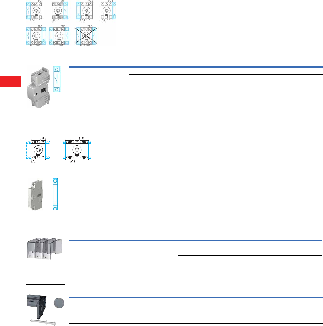
V5-T8-8 Volume 5—Motor Control and Protection CA08100006E—December 2013 www.eaton.com
8
8
8
8
8
8
8
8
8
8
8
8
8
8
8
8
8
8
8
8
8
8
8
8
8
8
8
8
8
8
8.2
Rotary Disconnects
R5 Series (UL 508) Non-Fusible 16–80A
Additional Pole Configurations
Switched Fourth-Pole Module
Auxiliary Contact Configurations
Auxiliary Contact Module
Te r m i n a l S h r o u d s
Door/Panel Mounting Kit
Note
1 Includes shaft and accessory cap.
Description Ampere Rating Number of Poles Type Catalog Number
Add one or two poles and transform:
• Three-pole R5 Series load break
switch into a four-pole
• Six-pole R5 Series switch into
an eight-pole
• Three-pole changeover switch into
a four-pole
16 1 Switched S4PR516
25 1 Switched S4PR525
30 1 Switched S4PR530
40 1 Switched S4PR540
Switched Fourth-Pole
Module
Description Ampere Rating Type Catalog Number
Early-break/same-make and
signalization of positions 0 and I by
NO + NC or 2NO auxiliary contacts.
They can be mounted on the left or
on the right side of the device. Two
modules maximum.
16–80 1NO + NC AC1N0NC
16–80 2NO AC2NO
Description Ampere Rating Number of Poles Position Catalog Number
Line and load protection against direct contact with the terminals
or connection parts: single- or three-pole.
Advantage: Perforations allowing thermographic inspection.
16–40 1 Line and load TS1R5A
16–40 3 Line and load TS3R5A
60–80 1 Line and load TS1R5B
60–80 3 Line and load TS3R5B
Description Ampere Rating Number of Poles Catalog Number
This kit enables direct mounting of the switch on the door panel.
Moreover, the connection clamps of the switch are always accessible.
The external handle is quick and easy to install due to an internal
locking nut mounted on the inside of the enclosure.
16–80 3 and 4 DMK 1

Volume 5—Motor Control and Protection CA08100006E—December 2013 www.eaton.com V5-T8-9
8
8
8
8
8
8
8
8
8
8
8
8
8
8
8
8
8
8
8
8
8
8
8
8
8
8
8
8
8
8
8.2
Rotary Disconnects
R5 Series (UL 508) Non-Fusible 16–80A
Technical Data and Specifications
UL 508 (CSA 22.2 No. 14) Manual Motor Controller “Suitable as Motor Disconnect” from 16–80A
IEC 60947-3 Characteristics
Notes
1Short-circuit rating achieved when used with respective fuse type and maximum fuse rating.
2A/B: Category with index A = frequent operation; category with index B = infrequent operation.
3The power value is given for information only; the current values vary from one manufacturer to another.
4De-rate 1% per °C above 40°C, max. 70°C.
5For a rated operating voltage, Ue = 400 Vac.
Technical Characteristics 16A 25A 30A 40A 60A 80A
Approvals
Short-circuit rating at 600 Vac (kA) 1
Branch circuit fuse type
Maximum fuse rating
UL 508/CSA 22.2 No. 14
10/65
J
60/30A
UL 508/CSA 22.2 No. 14
10/65
J
60/30A
UL 508/CSA 22.2 No. 14
10/65
J
60/30A
UL 508/CSA 22.2 No. 14
10/65
J
60/30A
UL 508/CSA 22.2 No. 14
50/65
J
100/60A
UL 508/CSA 22.2 No. 14
50/65
J
100/60A
Maximum UL Horsepower Ratings/Maximum Motor FLA Current, Three-Phase
208 Vac
220–240 Vac
440–480 Vac
600 Vac
3/10.6
5/15
10/14
10/11
7.5/24.2
7.5/22
15/21
20/22
7.5/24.2
7.5/22
15/21
20/22
7.5/24.2
7.5/22
20/27
25/27
15/46.2
15/42
30/40
30/32
15/46.2
20/54
40/52
40/41
Connection
Wire range (AWG), solid, single cable
Wire range (AWG), solid, two cables
Wire range (AWG), stranded, single cable
Wire range (AWG), stranded, two cables
#14–#10
2x #12
#14–#4
2x (#14–#12)
#14–#10
2x #12
#14–#4
2x (#14–#12)
#14–#10
2x #12
#14–#4
2x (#14–#12)
#14–#10
2x #12
#14–#4
2x (#14–#12)
#14–#10
2x #12
#14–#1
2x (#10–#6)
#14–#10
2x #12
#14–#1
2x (#10–#6)
Mechanical Characteristics
Endurance, number of mechanical cycles 10,000 10,000 10,000 10,000 10,000 10,000
Auxiliary Contacts
Electrical characteristics A300 A300 A300 A300 A300 A300
Technical Characteristics 16A 25A 32A 40A 63A 80A
Rated Operational Currents Ie (A)
Rated Voltage Load Duty Category A/B 2A/B 2A/B 2A/B 2A/B 2A/B 2
500 Vac AC-22 A/AC-22 B 16/16 25/25 32/32 40/40 63/63 80/80
500 Vac AC-23 A/AC-23 B 16/16 25/25 25/25 25/25 63/63 63/63
690 Vac AC-21 A/AC-21 B 16/16 25/25 32/32 40/40 63/63 80/80
690 Vac AC-22 A/AC-22 B 16/16 25/25 32/32 32/40 40/63 63/80
690 Vac AC-23 A/AC-23 B 16/16 25/25 25/25 25/25 40/40 40/40
Thermal Current Ith at 40°C (A)
Thermal current Ith (40°C) 416 25 32 40 63 80
Rated insulation voltage Ui (V) 800 800 800 800 800 800
Rated impulse withstand voltage Uimp (kV) 888888
Operational Power in AC-23 (kW)
At 400 Vac without prebreaking AC in AC-23 (kW) 23 7.5111518.53037
At 500 Vac without prebreaking AC in AC-23 (kW) 23 7.51115153037
At 690 Vac without prebreaking AC in AC-23 (kW) 23 7.5 15 18.5 18.5 30 37
Fuse Protected Short-Circuit Withstand (kA rms Prospective)
Prospective short-circuit current (kA rms) 550 50 50 50 50 50
Associated fuse rating (A) 516 25 32 40 63 80
Overload Capacity (Ue 415 Vac)
Rated short-time withstand current 0.3 s. ICW (kA rms) 52.5 2.5 2.5 2.5 3 3
Rated short-circuit making capacity Icm (kA peak) 5666699
Connection
Minimum Cu cable cross section (mm2) 1.5 1.5 1.5 1.5 2.5 2.5
Maximum Cu cable section (mm2) 161616163535
Tightening torque minimum/maximum (Nm) 2/2.2 2/2.2 2/2.2 2/2.2 3.5/3.85 3.5/3.85
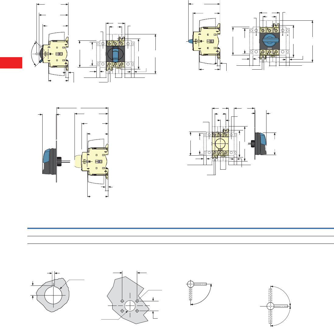
V5-T8-10 Volume 5—Motor Control and Protection CA08100006E—December 2013 www.eaton.com
8
8
8
8
8
8
8
8
8
8
8
8
8
8
8
8
8
8
8
8
8
8
8
8
8
8
8
8
8
8
8.2
Rotary Disconnects
R5 Series (UL 508) Non-Fusible 16–80A
Dimensions
Approximate Dimensions in Inches (mm)
R5 Series 16–80A
Toggle Operation
External Front Operation
Direct Operation with Handle
External Side Operation
R5 Series 2
Door Drilling—SH00/SH0
With Fixing Nut With Four Fixing Screws
Notes
1One switched fourth-pole module (one per device maximum) or one unswitched neutral pole
or one auxiliary contact.
2Maximum four additional blocks.
Operating Handle—SH00/SH0
Front Operation for R5
Front and Right Side Changeover Switches
Operation I–0–II or I–I+II–II
2.68
(68.0)
F
T
M5
M
N
G
AC
3.19
(81.0)
2.52
(64.0)
0.24
(6.0)
1.97
(50.0)
2.87
(73.0)
F1
F1
0.35
(8.8)
0.35
(8.8)
90
E
1.45
(37.0)
3.19
(81.0)
2.52
(64.0)
0.23
(6.0)
1.96
(50.0)
1.99
(50.6)
F
T
M5
M
N
G
AC
2.52
(64.0)
0.24
(6.0)
1.97
(50.0)
2.95
(75.0)
F1F1
2.67
(68.0)
0.35
(8.8)
0.35
(8.8)
J
2.68
(68.0)
F
T
M5
M
D
N
G
AC
F1
0.35
(8.8) F1
Ø2.79
(Ø71.0)
0.35
(8.8)
1.42
(36.0)
Overall Dimensions Terminal Shrouds Switch Body Switch Mounting Connection Terminal
Ampere
Rating D Min. D Max. E Min. E Max. AC F F1 G J M N T
16–40 1.18 (30.0) 9.25 (235.0) 3.94 (100.0) 14.65 (372.0) 4.33 (110.0) 1.77 (45.0) 0.59 (15.0) 2.68 (68.0) 0.59 (15.0) 1.18 (30.0) 2.95 (75.0) 0.59 (15.0)
63–80 1.18 (30.0) 9.25 (235.0) 3.94 (100.0) 14.65 (372.0) 4.33 (110.0) 2.06 (52.5) 0.69 (17.5) 2.99 (76.0) 0.69 (17.5) 1.38 (35.0) 3.35 (85.0) 0.69 (17.5)
0.53
(13.5)
0.12
(3.0) Ø0.89
(22.5)
1.57
(40.0)
Ø0.28
(7.0)
Ø1.22
(31.0)
1.10
(28.0)
0.16
(4.0)
90º
0º
I
I
II
90º
90º
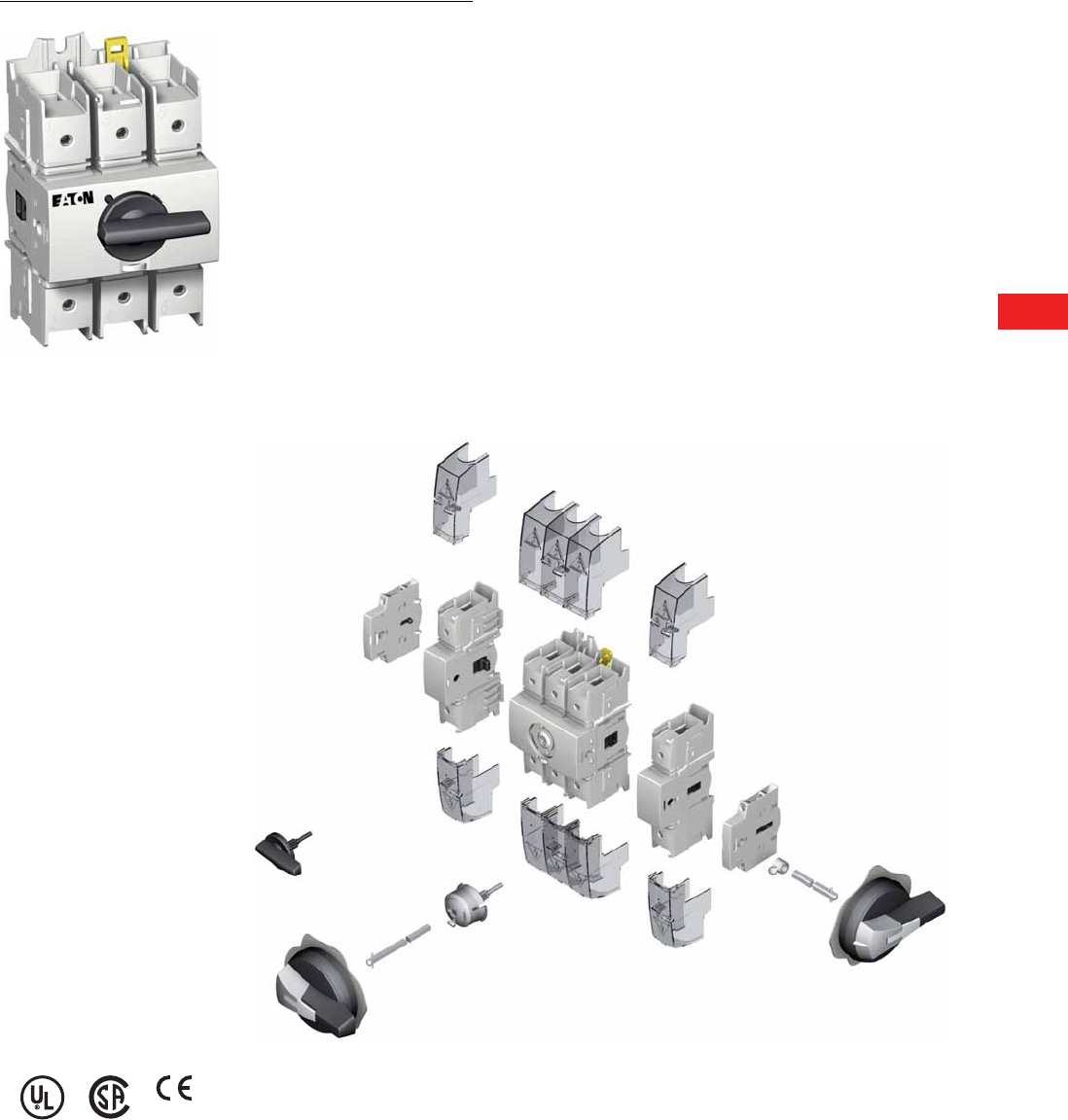
Volume 5—Motor Control and Protection CA08100006E—December 2013 www.eaton.com V5-T8-11
8
8
8
8
8
8
8
8
8
8
8
8
8
8
8
8
8
8
8
8
8
8
8
8
8
8
8
8
8
8
8.3
Rotary Disconnects
R9 Series (UL 98)
Non-Fusible 30–100A Compact
Contents
Description Page
Non-Fusible 30–100A Compact
Product Selection . . . . . . . . . . . . . . . . . . . . . . . V5-T8-12
Technical Data and Specifications . . . . . . . . . . . V5-T8-15
Dimensions . . . . . . . . . . . . . . . . . . . . . . . . . . . . V5-T8-16
Non-Fusible 100–1200A . . . . . . . . . . . . . . . . . . . . . V5-T8-18
Fusible 30–800A . . . . . . . . . . . . . . . . . . . . . . . . . . V5-T8-26
DC Rated Disconnects . . . . . . . . . . . . . . . . . . . . . V5-T8-45
Non-Fusible 30–100A
Compact
Product Description
The R9 Series (UL 98 listed)
non-fusible 30–100A compact
range ensures making or
breaking on load and safety
isolation for low voltage
electrical circuits, particularly
for machine control circuits
up to 600V.
Features, Benefits
and Functions
●Rating three-pole from
30A to 100A
●Direct or external operation
handle (padlockable in
ON position)
●Double breaking per phase
Standards and Certifications
●UL 98, File E222859
●CSAT 22.2 No. 4,
File 217736
●IEC 60947-3
●EN 60947-3
●CE
Product Identification
1Direct handle
2Door interlocked external handle
3Shaft extension
4Terminal shrouds
5Unswitched neutral pole
6Switch body
7Switched fourth-pole module
8Modular type auxiliary contacts
Note: For further details, please see the installation instructions supplied with each device.
1
2
3
4
56
7
8
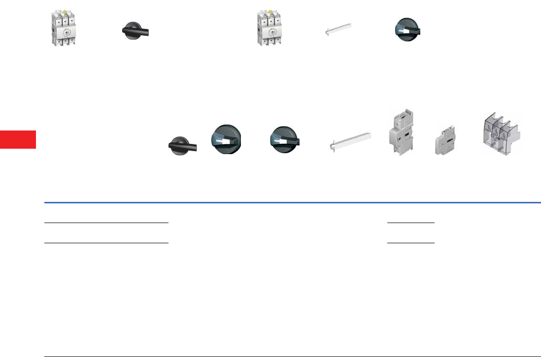
V5-T8-12 Volume 5—Motor Control and Protection CA08100006E—December 2013 www.eaton.com
8
8
8
8
8
8
8
8
8
8
8
8
8
8
8
8
8
8
8
8
8
8
8
8
8
8
8
8
8
8
8.3
Rotary Disconnects
R9 Series (UL 98)
Product Selection
R9 Series 30–100A
Ampere Rating
(Frame)
Number
of Poles
Switch Body
Only
Direct
Handle
Front and
Right External
Handle SH00
(Choose one)
Front and
Right External
Handle SH0
(Choose one)
Shaft for SH0
and SH00
Handles—
In (mm)
(Choose one)
Switched
Fourth-Pole
Module
Auxiliary
Contacts
(Choose one)
Terminal Shrouds
(Choose one)
30
(C-Frame)
3R9C3030U DHR9 SH00
Black
3R, 12
SHB00N12
SH00
Red
3R, 12
SHR00N12
SH00
Black
4, 4X
SHB00N4X
SH00
Red
4 4X
SHR00N4X
SH0
Black
3R, 12
SHB0N12
SH0
Red
3R, 12
SHR0N12
SH0
Black
4, 4X
SHB0N4X
SH0
Red
4 4X
SHR0N4X
2.20 (55.5)
SF55SH5X5
3.50 (90.0)
SF90SH5X5
5.91 (150.0)
SF150SH5X5
7.87 (200.0)
SF200SH5X5
12.60 (320.0)
SF320SH5X5
S4PR930 1NO + 1NC
AC1NONC
2NO
AC2N0
1P
TS1R9
3P
TS3R9CV
60
(C-Frame)
3R9C3060U S4PR960
100
(C-Frame)
3R9C3100U S4PR9100
+++
Switch body Direct handle Switch body Shaft External handle
+++
Direct Operation External Operation
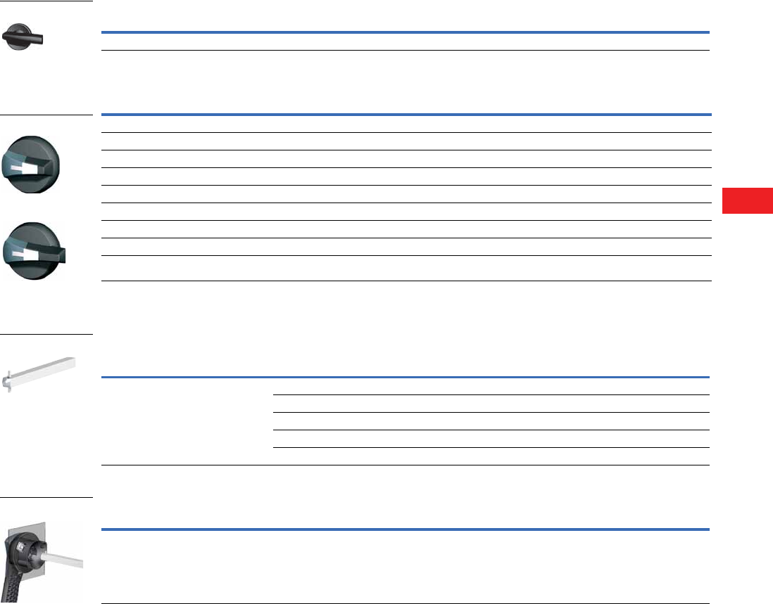
Volume 5—Motor Control and Protection CA08100006E—December 2013 www.eaton.com V5-T8-13
8
8
8
8
8
8
8
8
8
8
8
8
8
8
8
8
8
8
8
8
8
8
8
8
8
8
8
8
8
8
8.3
Rotary Disconnects
R9 Series (UL 98)
Handles
Direct Handle
Door Interlocked External Handle 1
Shafts
Shaft Extensions for External Handle
Guide Cone
Note
1 Allows door to be opened when switch is in the ON position.
Ampere Rating Handle Color Catalog Number
30–100 Black DHR9
Ampere Rating Handle Color Handle Size NEMA Type Rating Catalog Number
Front and Right External Handle
30–100 Black SH00 3R, 12 SHB00N12
30–100 Black SH00 4, 4X SHB00N4X
30–100 Red SH00 3R, 12 SHR00N12
30–100 Red SH00 4, 4X SHR00N4X
30–100 Black SH0 3R, 12 SHB0N12
30–100 Black SH0 4, 4X SHB0N4X
30–100 Red SH0 3R, 12 SHR0N12
30–100 Red SH0 4, 4X SHR0N4X
Description Ampere Rating Use with Handle Type
Shaft Length
In (mm) Catalog Number
Standard lengths: 55 mm, 90 mm, 150 mm,
200 mm, 320 mm
Shafts are for external front and right
side handles
30–100 SH00/SH0 2.20 (55.5) SF55SH5X5
30–100 SH00/SH0 3.50 (90.0) SF90SH5X5
30–100 SH00/SH0 5.91 (150.0) SF150SH5X5
30–100 SH00/SH0 7.87 (200.0) SF200SH5X5
30–100 SH00/SH0 12.60 (320.0) SF320SH5X5
Description Ampere Rating Use with Handle Type Catalog Number
The guide cone facilitates an easier
connection between the shaft and a Size 00
or Size 0 external selector handle. It allows
the shaft up to 10 mm of vertical play when
making the connection
16–80 SH00 and SH0 SFGAB
Direct Handle
Size 00 Handle
Size 0 Handle
Shaft 5 x 5
SFGAB
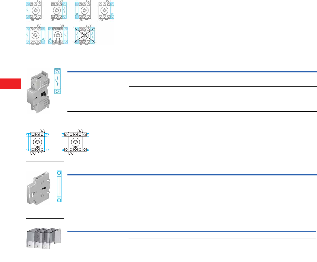
V5-T8-14 Volume 5—Motor Control and Protection CA08100006E—December 2013 www.eaton.com
8
8
8
8
8
8
8
8
8
8
8
8
8
8
8
8
8
8
8
8
8
8
8
8
8
8
8
8
8
8
8.3
Rotary Disconnects
R9 Series (UL 98)
Additional Pole Configurations
Switched Fourth-Pole Module
Auxiliary Contact Configurations
Auxiliary Contacts
Te r m i n a l S h r o u d s
Description Ampere Rating Number of Poles Type Catalog Number
Transforms a three-pole, R9 Series load
break switch into a four-pole
30 1 Switched S4PR930
60 1 Switched S4PR960
100 1 Switched S4PR9100
Description Ampere Rating Type Catalog Number
Early-break/same-make and signalization
of positions 0 and I by NO + NC or 2NO
auxiliary contacts. They can be mounted
on the left or on the right side of the
device. Maximum four auxiliary contacts
(two modules)
30–100 1NO + 1NC AC1N0NC
30–100 2NO AC2NO
Description Ampere Rating Number of Poles Position Catalog Number
Line and load protection against
direct contact with the terminals
or connection parts: single- or
three-pole
Advantage: Perforations allowing
thermographic inspection
30–100 1 Line and load TS1R9
30–100 3 Line and load TS3R9CV

Volume 5—Motor Control and Protection CA08100006E—December 2013 www.eaton.com V5-T8-15
8
8
8
8
8
8
8
8
8
8
8
8
8
8
8
8
8
8
8
8
8
8
8
8
8
8
8
8
8
8
8.3
Rotary Disconnects
R9 Series (UL 98)
Technical Data and Specifications
UL and CSA Characteristics
UL 98/CSA 22.2 No. 4
IEC 60647-3 Characteristics
Notes
1Short-circuit rating achieved when used with respective fuse type and maximum fuse rating.
2Category with index A = frequent operation.
3A/B: Category with index A = frequent operation; category with index B = infrequent operation.
4The power value is given for information only; the current values vary from one manufacturer to another.
5For a rated operating voltage, Ue = 400 Vac.
Technical Characteristics 30A 60A 100A
Short-circuit rating at 480 Vac (kA) 1100 kA 100 kA 100 kA
Short-circuit rating at 600 Vac (kA) 1100 kA 100 kA 25 kA
Fuse type J J J
Maximum fuse rating (A) 30 60 100
Maximum Horsepower Rating/Maximum Motor FLA Three-Phase
220–240 Vac 10/28 20/54 20/54
440–480 Vac 20/27 40/52 50/65
600 Vac 25/27 50/52 50/52
Maximum Horsepower Rating/Maximum Motor FLA Single-Phase
120 Vac 2/24 3/34 5/56
240 Vac 5/28 10/50 10/50
Connection
Solid, 1 wire #12–10 #12–10 #12–10
Stranded, 1 wire #12–2/0 #12–2/0 #12–2/0
Auxiliary Contacts
Electrical characteristic A300 A300 A300
Technical Characteristics 32A 63A 100A
Thermal Current Ith at 40°C (A)
Thermal current Ith (40°C) 30 60 100
Rated insulation voltage Ui (V) 800 800 800
Rated impulse withstand voltage Uimp (kV) 8 8 8
Rated Operation Currents Ie (A)
Load Duty Category Rated Voltage A 2A 2A 2
400 Vac AC-22A 32 63 100
400 Vac AC-23A 32 63 100
690 Vac AC-22A 32 63 80
690 Vac AC-23A 32 63 63
Operational Power in AC-23 (kW)
At 400 Vac without prebreak AC in AC-23 (kW) 34 15 30 45
At 500 Vac without prebreak AC in AC-23 (kW) 34 15 30 45
At 690 Vac without prebreak AC in AC-23 (kW) 34 18.5 30 45
Overload Capacity (Ue 415 Vac)
Rated short-time making capacity Icm (kA peak) 512 12 12
Connection
Minimum Cu cable cross section (mm2)2.5 2.510
Maximum Cu cable section (mm2)707070
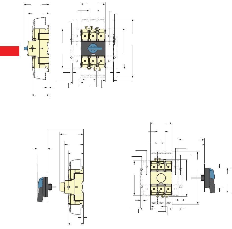
V5-T8-16 Volume 5—Motor Control and Protection CA08100006E—December 2013 www.eaton.com
8
8
8
8
8
8
8
8
8
8
8
8
8
8
8
8
8
8
8
8
8
8
8
8
8
8
8
8
8
8
8.3
Rotary Disconnects
R9 Series (UL 98)
Dimensions
Approximate Dimensions in Inches (mm)
R9 Series 30–100A Compact
Direct Operation
External Front Operation External Side Operation
Notes
1One switched fourth-pole module (one per device maximum) and/or one unswitched neutral pole.
2Auxiliary contact.
2.95
(75.0)
2.52
(64.0)
2.09
(53.0)
0.24
(6.0)
4.91
(124.6)
5.17
(131.4)
7.44
(189.0)
1.02
(26.0)
3.07
(78.0)
0.35
(8.8)
1.02
(26.0)
M5
26.00
(660.4)
1.02
(26.0) 1.02
(26.0)
0.35
(8.8)
1
2
1
2
0.51
(13.0)
4.91
(124.6)
5.17
(131.4)
7.44
(189.0)
1.02
(26.0)
3.07
(78.0)
0.35
(8.8)
1.02
(26.0)
M5
3.46
(88.0)
Ø2.80
(71.0)
1.18 min.
(30.0)
7.91 max.
(201.0)
0.35
(8.8)
1.02
(26.0) 1.02
(26.0)
1.46
(37.0)
3.94 min.
(100.0)
3.19
(81.0)
2.52
(64.0)
2.09
(53.0)
0.24
(6.0)
1.99
(50.6)
14.65 max.
(372.0)
1
2
1
2
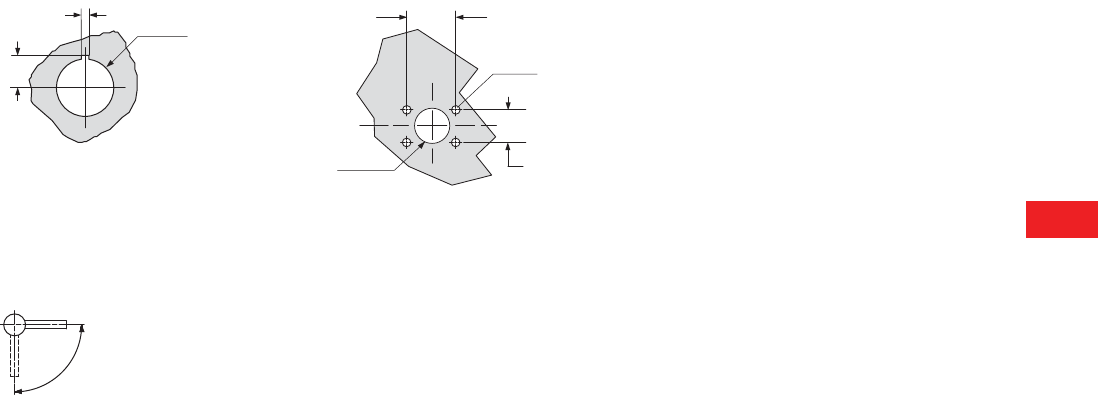
Volume 5—Motor Control and Protection CA08100006E—December 2013 www.eaton.com V5-T8-17
8
8
8
8
8
8
8
8
8
8
8
8
8
8
8
8
8
8
8
8
8
8
8
8
8
8
8
8
8
8
8.3
Rotary Disconnects
R9 Series (UL 98)
Approximate Dimensions in Inches (mm)
Door Drilling—SH00/SH0
With Fixing Nut With Four Fixing Screws
Operating Handle—SH00/SH0
Front and Right Side Operation
0.53
(13.5)
0.12
(3.0) Ø0.89
(22.5)
1.57
(40.0)
Ø0.28
(7.0)
Ø1.22
(31.0)
1.10
(28.0)
0.16
(4.0)
90º
0º
I
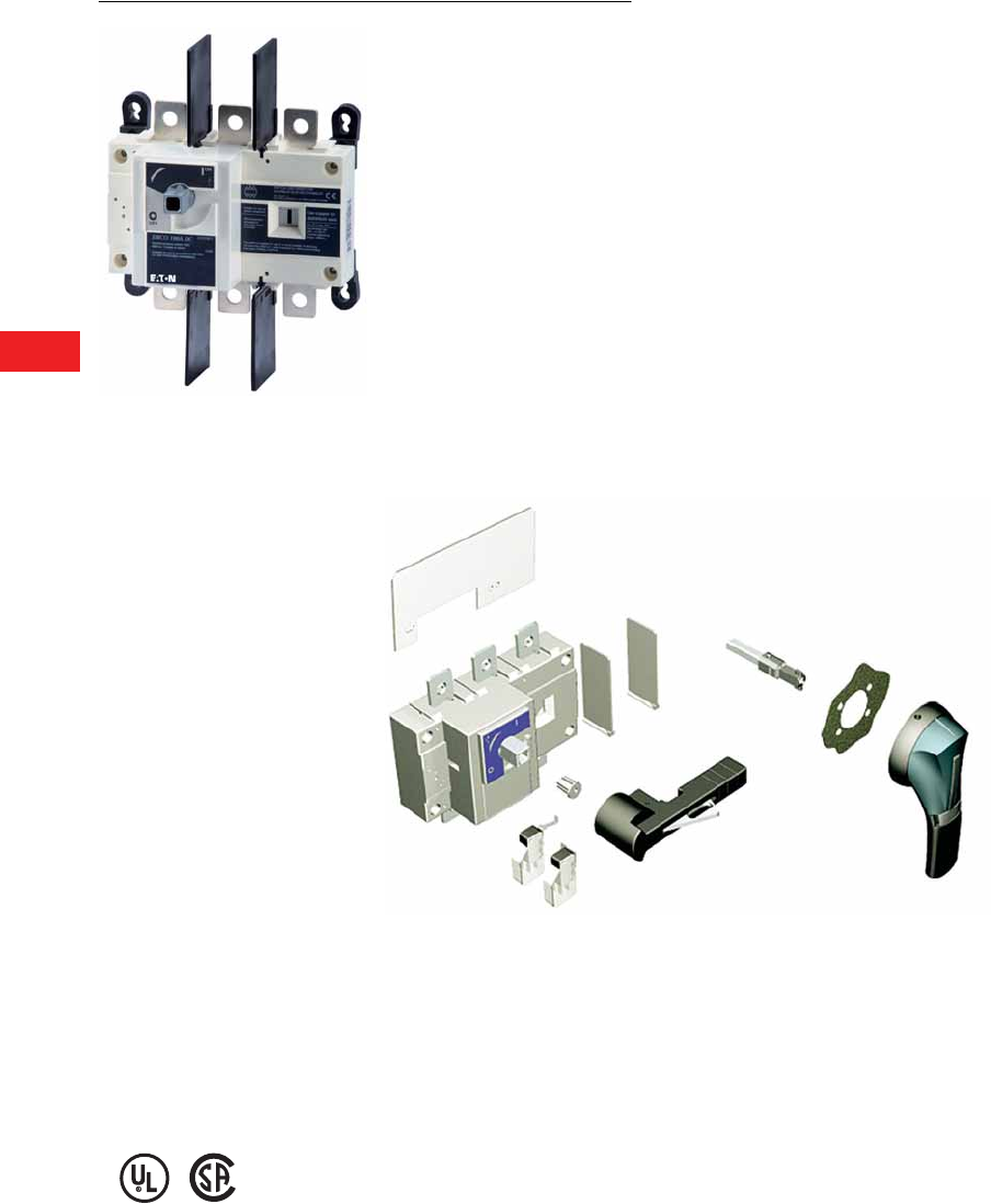
V5-T8-18 Volume 5—Motor Control and Protection CA08100006E—December 2013 www.eaton.com
8
8
8
8
8
8
8
8
8
8
8
8
8
8
8
8
8
8
8
8
8
8
8
8
8
8
8
8
8
8
8.3
Rotary Disconnects
R9 Series (UL 98)
Non-Fusible 100–1200A
Contents
Description Page
Non-Fusible 30–100A Compact . . . . . . . . . . . . . . . V5-T8-11
Non-Fusible 100–1200A
Product Selection . . . . . . . . . . . . . . . . . . . . . . . V5-T8-19
Accessories. . . . . . . . . . . . . . . . . . . . . . . . . . . . V5-T8-20
Technical Data and Specifications . . . . . . . . . . . V5-T8-22
Dimensions . . . . . . . . . . . . . . . . . . . . . . . . . . . V5-T8-23
Fusible 30–800A . . . . . . . . . . . . . . . . . . . . . . . . . . V5-T8-26
DC Rated Disconnects . . . . . . . . . . . . . . . . . . . . . V5-T8-45
Non-Fusible 100–1200A
Product Description
The R9 Series (UL 98 listed)
non-fusible 100–1200A are
manually operated multipole
load-break switches. Quick-
make, quick-break design
provides safety isolation for
any low voltage circuit.
Features, Benefits
and Functions
●High thermal and dynamic
withstand ratings
●Arduous categories of
applications
●High electrical and
mechanical endurances
Standards and Certifications
●UL 98, File E222859
●CSAT 22.2 No. 4,
File 217736
●IEC 60947-3
●EN 60947-3
Product Identification
1External front handle
2Shaft extensions for external handle
3Configurable U-type ACs, for pre-break and signalling or TEST
4Terminal Screens
Note: For further details, please see the installation instructions supplied with each device.
1
2
3
4
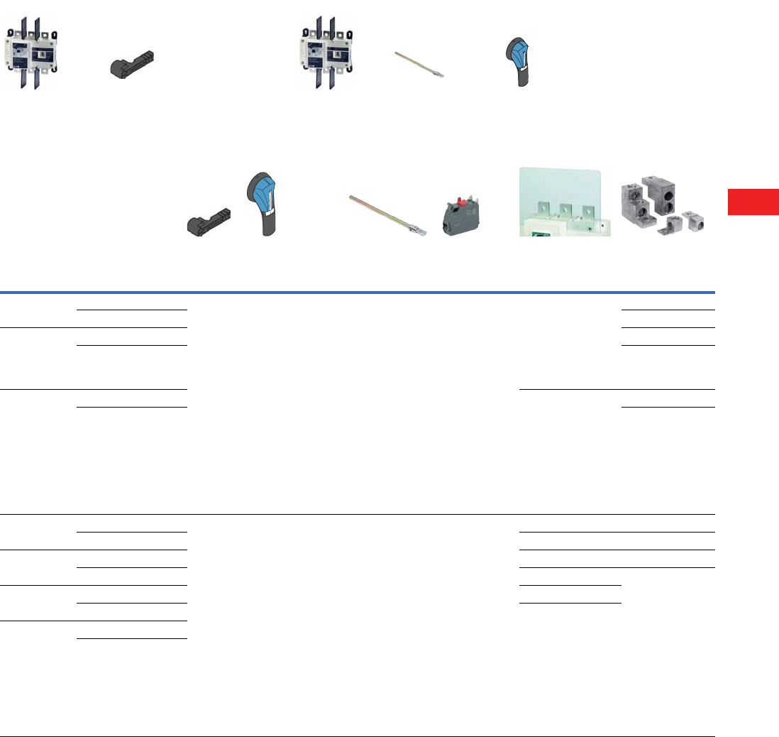
Volume 5—Motor Control and Protection CA08100006E—December 2013 www.eaton.com V5-T8-19
8
8
8
8
8
8
8
8
8
8
8
8
8
8
8
8
8
8
8
8
8
8
8
8
8
8
8
8
8
8
8.3
Rotary Disconnects
R9 Series (UL 98)
Product Selection
R9 Series Non-Fusible 100–1200A
Notes
1Top (line side) supplied as standard.
2Auxiliary contact requires holder (catalog number ACHFG) when used on F and G-Frame switches (non-fusible 600–1200A).
3Each catalog number is for line or load side. For both line and load, please order two sets.
4FS suffix = Finger Safe.
Ampere Rating
(Frame)
Number
of Poles
Switch
Body Only
Direct
Handle
Door Interlocked
External Pistol Handle
(Choose one)
Shaft Extensions for
External Handle—
In (mm)
(Choose one)
Auxiliary
Contacts
Terminal Screens
(Choose one)
Terminal
Lugs 3
100
(D-Frame)
3R9D3100U DHR9DE Size 2, Black
1, 3R, 12
Defeatable
PHB2N12F
Size 2, Red
1, 3R, 12
Defeatable
PHR2N12F
Size 2, Black
4, 4X
Defeatable
PHB2N4XF
Size 2, Red
4, 4X
Defeatable
PHR2N4XF
7.90 (200.0)
SF200PH10X10
12.60 (320.0)
SF320PH10X10
15.70 (400.0)
SF400PH10X10
19.70 (500.0)
SF500PH10X10
1NO + 1NC
AC1N0NCDE
AC1N0NCDELL
2NO + 2NC
AC2N0NCDE
AC2N0NCDELL
3-pole, Line side only
TS3R9DT
3-pole, Load side only
TS3R9DB
4-pole, Line or load side
TS4R9DTB
LK3R9DL
4R9D4100U LK4R9DL
200
(D-Frame)
3R9D3200U LK3R9DL
4R9D4200U LK4R9DL
400
(E-Frame)
3R9E3400U 3-pole, Line side only
TS3R9ET
3-pole, Load side only
TS3R9EB
4-pole, Line or load side
TS4R9ETB
LK3R9EM
4R9E4400U LK4R9EM
600
(F-Frame)
3R9F3600U DHR9FG Size 3, Black
4, 4X
Defeatable
PHB3N4XF
Size 3, Red
4, 4X
Defeatable
PHR3N4XF
Size 4, Black
4, 4X
Defeatable
PHB4N4XF
Size 4, Red
4, 4X
Defeatable
PHR4N4XF
7.90 (200.0)
SF200PH15X12
12.60 (320.0)
SF320PH15X12
1.70 (400.0)
SF400PH15X12
1NO AC U Type
AC1N0R9 2
1NC AC U Type
AC1NCR9 2
TS3R9F 1LK3R9FN
4R9F4600U TS4R9F 1LK4R9FN
800
(G-Frame)
3R9G3800U TS3R9FFS 4LK6R9G
4R9G4800U TS3R9G 1LK8R9G
1000
(G-Frame)
3R9G31000U TS4R9G 1
4R9G41000U TS3R9GFS 4
1200
(G-Frame)
3R9G31200U
4R9G41200U
+++
Switch body Direct handle Switch body Shaft External handle
+++
Direct Operation External Operation
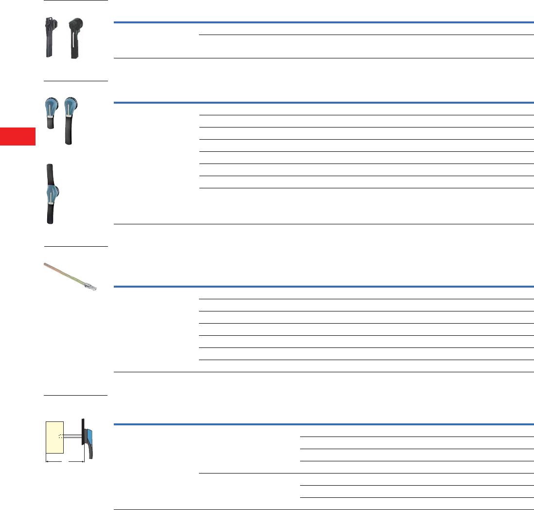
V5-T8-20 Volume 5—Motor Control and Protection CA08100006E—December 2013 www.eaton.com
8
8
8
8
8
8
8
8
8
8
8
8
8
8
8
8
8
8
8
8
8
8
8
8
8
8
8
8
8
8
8.3
Rotary Disconnects
R9 Series (UL 98)
Accessories
Direct Handle
Door Interlocked External Handle—Front Operation
Shaft Extensions for External Front Handle
Shaft Length Minimum Dimensions (X)—Inches (mm)
Note
1 Allow the door to be opened when the switch is in 1 (ON) position.
Description Ampere Rating Handle Color Catalog Number
Front operation 100–400 Black DHR9DE
600–1200 Black DHR9FG
Description Ampere Rating Switch Frame Handle Type Handle Color NEMA Type Defeatable 1Catalog Number
The door interlocked external
handle includes one lockable
handle and one escutcheon.
For Dimensions, see Page
V5-T8-23.
100–400 D/E PH2 Black 1,3R,12 Yes PHB2N12F
100–400 D/E PH2 Red 1,3R,12 Yes PHR2N12F
100–400 D/E PH2 Black 4,4X Yes PHB2N4XF
100–400 D/E PH2 Red 4,4X Yes PHR2N4XF
600–1200 F/G PH3 Black 4,4X Yes PHB3N4XF
600–1200 F/G PH3 Red 4,4X Yes PHR3N4XF
600–1200 F/G PH4 Black 4,4X Yes PHB4N4XF
600–1200 F/G PH4 Red 4,4X Yes PHR4N4XF
Front Operation
Use
Ampere Rating
(Frame) Handle Type
Shaft Length
In (mm) Catalog Number
Standard lengths:
200 mm, 320 mm,
400 mm, 500 mm
100–400 (D-, E-Frame) PH2 7.90 (200.0) SF200PH10X10
100–400 (D-, E-Frame) PH2 12.60 (320.0) SF320PH10X10
100–400 (D-, E-Frame) PH2 15.70 (400.0) SF400PH10X10
100–400 (D-, E-Frame) PH2 19.70 (500.4) SF500PH10X10
600–1200 (F-, G-Frame) PH3/PH4 7.90 (200.0) SF200PH15X12
600–1200 (F-, G-Frame) PH3/PH4 12.60 (320.0) SF320PH15X12
600–1200 (F-, G-Frame) PH3/PH4 15.70 (400.0) SF400PH15X12
Description
Ampere Rating
(Frame) X Length Catalog Number
Standard lengths:
• 7.90 (200.6)
• 12.60 (320.0)
• 5.70 (398.8)
100–400 (D-, E-Frame) 5.31–10.43 (135.0–265.0) 7.90 (200.6) SF200PH10X10
5.31–10.43 (135.0–385.0) 12.60 (320.0) SF320PH10X10
5.31–10.43 (135.0–465.0) 15.70 (398.8) SF400PH10X10
5.31–22.20 (135.0–565.0) 19.70 (500.4) SF500PH10X10
600–1200 (F-, G-Frame) 8.70–13.50 (221.0–343.0) 7.90 (200.6) SF200PH15X12
8.70–18.23 (221.0–463.0) 12.60 (320.0) SF320PH15X12
8.70–21.38 (221.0–543.0) 15.70 (398.8) SF400PH15X12
Direct Handle
PH2 and PH3 Types
PH4 Type
Shaft Extensions
X
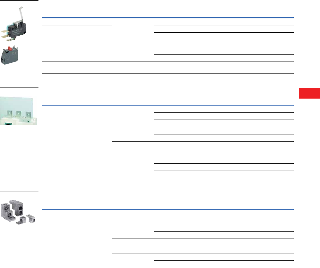
Volume 5—Motor Control and Protection CA08100006E—December 2013 www.eaton.com V5-T8-21
8
8
8
8
8
8
8
8
8
8
8
8
8
8
8
8
8
8
8
8
8
8
8
8
8
8
8
8
8
8
8.3
Rotary Disconnects
R9 Series (UL 98)
Auxiliary Contacts 1
Terminal Screens
Line and Load Terminal Lugs
Notes
1 Early-break/same-make.
2 Gold plated for minimal resistance—for PLC applications.
3 Requires use of ACHFG auxiliary contact holder for F- and G-Frame switches.
4 For two-hole lug, consult factory.
Description
Ampere Rating
(Frame) Number of AC AC Type
Catalog
Number
100–200A, up to two ACs max. 100–400
(D-, E-Frame)
1NO / 1NC Standard AC1NONCDE
400A, up to two ACs max. 1NO / 1NC Low Level 2 AC1NONCDELL
2NO / 2NC Standard AC2NONCDE
2NO / 2NC Low Level 2 AC2NONCDELL
600–1200A, up to four ACs max. 600–1200
(F-, G-Frame)
1NO Standard AC1NOR9 3
1NC Standard AC1NCR9 3
Auxiliary contact holder (for use with
AC1NOR9 and AC1NCR9)
600–1200
(F-, G-Frame)
—— ACHFG
Description
Maximum Ampere
Rating (Frame)
Number
of Poles
Line/Load
Side
Catalog
Number
Line and load protection against direct contact
with terminals or connection parts.
Line side terminal shrouds are included
standard on 600–1200A non-fusible switches.
Shrouds are not included on
the 100–400A.
100–200
(D-Frame)
3Line TS3R9DT
3 Load TS3R9DB
4 Line or load TS4R9DTB
400
(E-Frame)
3Line TS3R9ET
3 Load TS3R9EB
600
(F-Frame)
4 Line or load TS4R9ETB
3 Line or load TS3R9F
800–1200
(G-Frame)
4 Line or load TS4R9F
3 Line or load TS3R9G
4 Line or load TS4R9G
Description
Maximum Ampere
Rating (Frame)
Number
of Poles
Number of
Lugs/Pole Lug Capacity/Phase
Cable
Type
Catalog
Number
Connection of copper cables on to the
terminals (no spade lugs). Each kit includes
lugs for line or load side. For line and load
side, order two kits.
For Dimensions, see Page V5-T8-23.
100–200
(D-Frame)
3 1 #6–300 kcmil Cu/Al LK3R9DL
4 1 #6–300 kcmil Cu/Al LK4R9DL
400
(E-Frame)
3 1 #2–600 kcmil Cu/Al LK3R9EM 4
4 1 #2–600 kcmil Cu/Al LK4R9EM 4
600
(F-Frame)
3 1 (2) #2–600 kcmil Cu/Al LK3R9FN
4 1 (2) #2–600 kcmil Cu/Al LK4R9FN
800–1200
(G-Frame)
3 2 2x (2) #2–600 kcmil Cu/Al LK6R9G
4 2 2x (2) #2–600 kcmil Cu/Al LK8R9G

V5-T8-22 Volume 5—Motor Control and Protection CA08100006E—December 2013 www.eaton.com
8
8
8
8
8
8
8
8
8
8
8
8
8
8
8
8
8
8
8
8
8
8
8
8
8
8
8
8
8
8
8.3
Rotary Disconnects
R9 Series (UL 98)
Technical Data and Specifications
UL and CSA Characteristics
IEC 60947-3 Characteristics
Notes
1Short-circuit rating achieved when used with respective fuse type and maximum fuse rating.
2Category with index A = frequent operation.
3For a rated operating voltage, Ui = 400 Vac.
Technical Characteristics 100A 200A 400A 600A 800A 1000A 1200A
Short circuit rating at 600 Vac (kA) 1200 kA 200 kA 200 kA 200 kA 200 kA 100 kA 100 kA
Fuse type J J J J L L L
Maximum fuse rating (A) 100 200 400 600 800 1000 1200
Maximum Horsepower Rating/Maximum Motor FLA Three-Phase
220–240 Vac 30/80 75/192 125/312 200/480 200/480 200/480 200/480
440–480 Vac 75/96 150/180 250/302 400/477 500/590 500/590 500/590
600 Vac 100/99 200/192 350/336 350/336 500/472 500/472 500/472
Maximum Horsepower Rating/Maximum Motor FLA Direct Current
125 Vdc Two-pole in series 10/76 15/112 20/148 20/148 — — —
250 Vdc Three-pole in series 15/55 15/55 50/173 50/173 — — —
Connection
Minimum connection section/AWG #6 #6 #2 2 x #2 2 x #2 4 x #2 4 x #2
Maximum connection section/AWG 300 kcmil 300 kcmil 600 kcmil 2 x 600 kcmil 2 x 600 kcmil 4 x 600 kcmil 4 x 600 kcmil
Auxiliary Contacts
Electrical characteristics A300 A300 A300 A600 A600 A600 A600
Technical Characteristics 100A 200A 400A 600A 800A 1000A 1200A
Rated insulation voltage Ui (V) 1000 1000 1000 1000 1000 1000 1000
Rated impulse withstand voltage Uimp (kV) 88812121212
Rated Operational Currents Ie (A)
Rated Voltage
Load Duty
Category A 2A 2A 2A 2A 2A 2A 2
400 Vac AC-22A 100 200 400 630 800 1000 1200
400 Vac AC-23A 100 200 400 630 800 1000 1000
690 Vac AC-22A 100 200 400 500 630 630 630
690 Vac AC-23A 100 200 315 200 400 400 400
Connection
Minimum Cu cable cross section (mm2) 35 70 185 2 x 150 2 x 185 2 x 240 —
Minimum Cu busbar section (mm2) ———2 x 30 x 52 x 40 x 52 x 50 x 52 x 60 x 5
Operational Power in AC-23 (kW)
At 400 Vac without prebreaking AC in AC23 (kW) (2 x 3) 51 100 220 355 450 560 560
At 500 Vac without prebreaking AC in AC23 (kW) (2 x 3) 63 140 280 450 560 560 560
At 690 Vac without prebreaking AC in AC23 (kW) (2 x 3) 90 185 185 185 400 400 400
Overload Capacity (Ue 415 Vac)
Rated short-circuit making capacity Icm (kA peak) 317.6 32 48 48 75 48 75
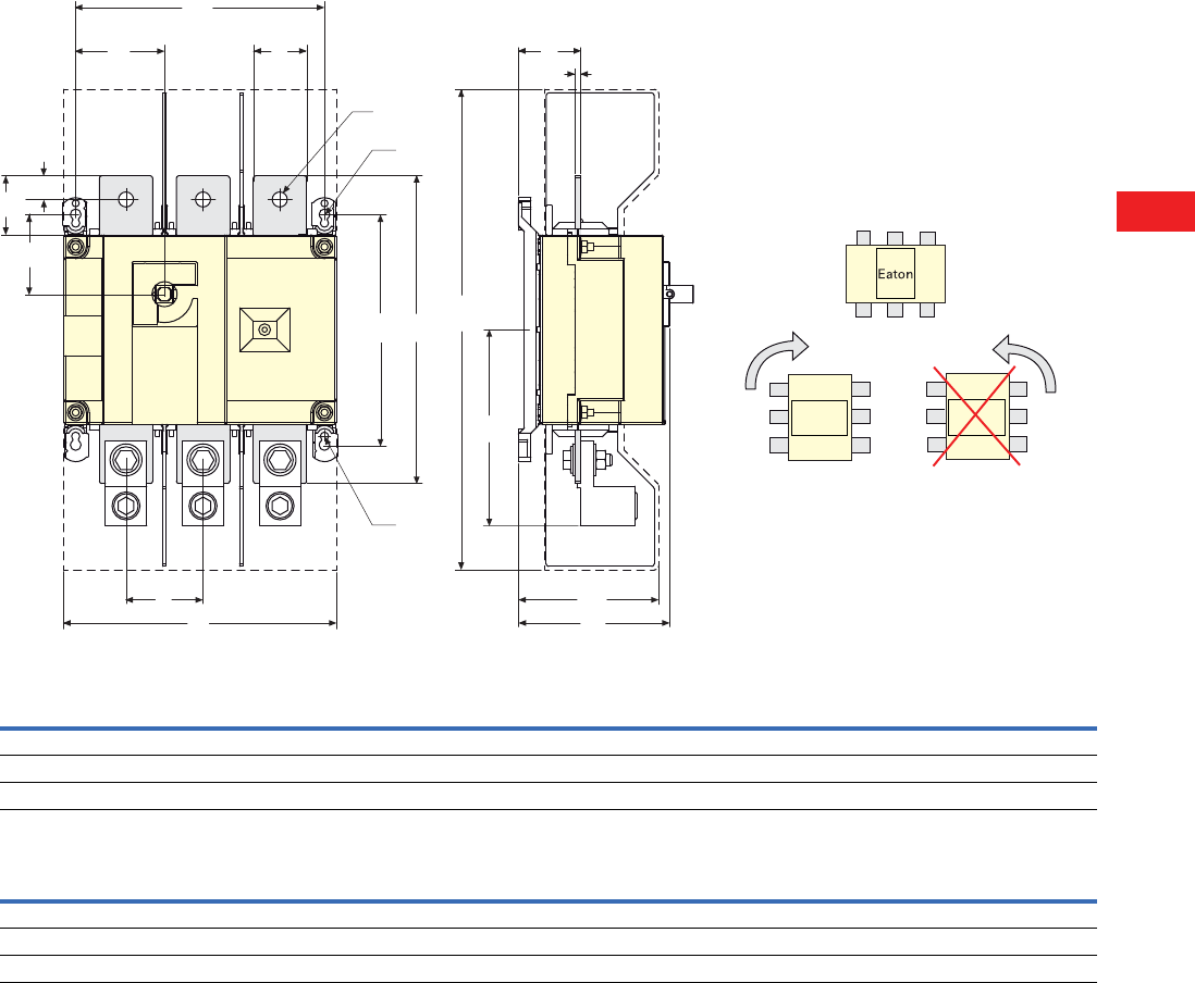
Volume 5—Motor Control and Protection CA08100006E—December 2013 www.eaton.com V5-T8-23
8
8
8
8
8
8
8
8
8
8
8
8
8
8
8
8
8
8
8
8
8
8
8
8
8
8
8
8
8
8
8.3
Rotary Disconnects
R9 Series (UL 98)
Dimensions
Approximate Dimensions in Inches (mm)
Front Operation—D- and E-Frames
R9 Series Non-Fusible 100–400A
Y
AC
K
CA
V
NAA
H
Z
J1 U
R1
M
AD
T
FC
R2
W
The switch will operate correctly when rotated
clockwise 90 degrees.
The switch will not operate correctly when
rotated counter
clockwise 90 degrees.
Ampere
Rating (A) Overall Dimensions
Terminal Shrouds Switch Body
AC AD F 3P F 4P H J1 3P J1 4P K
100 3.72 (94.6) 10.10 (256.0) 3.05 (77.5) 7.09 (180.0) 9.06 (230.0) 4.22 (107.0) 2.17 (55.0) 4.13 (105.0) 1.80 (45.6)
200 3.72 (94.6) 10.10 (256.0) 3.05 (77.5) 7.09 (180.0) 9.06 (230.0) 4.22 (107.0) 2.17 (55.0) 4.13 (105.0) 1.80 (45.6)
400 4.92 (128.0) 16.00 (406.0) 4.15 (115.0) 9.05 (230.0) 11.40 (290.0) 6.53 (166.0) 2.95 (75.0) 5.31 (135.0) 2.65 (67.5)
Ampere
Rating (A)
Switch Mounting Connection
M 3P M 4P N R1 R2 T U V W Y Z AA AC
100 6.30 (160.0) 8.27 (210.0) 5.31 (135.0) 0.35 (9.0) 0.27 (7.0) 1.97 (50.0) 0.98 (25.0) 1.18 (30.0) 0.43 (11.0) 0.14 (3.5) 1.35 (34.4) 6.30 (160.0) 0.60 (15.0)
200 6.30 (160.0) 8.27 (210.0) 5.31 (135.0) 0.35 (9.0) 0.27 (7.0) 1.97 (50.0) 0.98 (25.0) 1.18 (30.0) 0.43 (11.0) 0.14 (3.5) 1.35 (34.4) 6.30 (160.0) 0.60 (15.0)
400 8.26 (210.0) 10.60 (270.0) 7.67 (195.0) 0.35 (9.0) 0.27 (7.0) 2.56 (65.0) 1.77 (45.0) 1.97 (50.0) 0.43 (13.0) 0.20 (5.0) 2.08 (53.0) 10.20 (260.0) 0.80 (20.0)
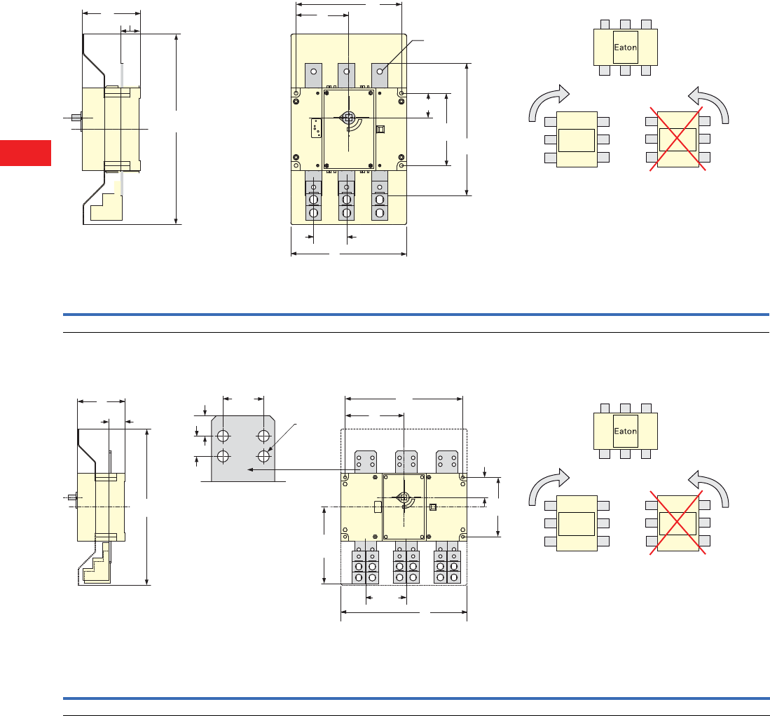
V5-T8-24 Volume 5—Motor Control and Protection CA08100006E—December 2013 www.eaton.com
8
8
8
8
8
8
8
8
8
8
8
8
8
8
8
8
8
8
8
8
8
8
8
8
8
8
8
8
8
8
8.3
Rotary Disconnects
R9 Series (UL 98)
Approximate Dimensions in Inches (mm)
Front Operation—F- and G-Frames
R9 Series Non-Fusible 600A
R9 Series Non-Fusible 800–1200A
HZ
M
Ø0.51
(Ø13.0)
J
N1
N
AA
F
X
Y
3.15
(80.0)
AC
The switch will operate correctly when rotated
clockwise 90 degrees.
The switch will not operate correctly when
rotated counter
clockwise 90 degrees.
Terminal Screens Switch Body Switch Mounting Connection Terminals
AC F 3P F 4P H J 2P J 4P M 4P M 4 P N N1 AA Z
18.11 (460.0) 11.02 (280.0) 14.17 (360.0) 5.51 (140.0) 5.00 (127.5) 6.59 (167.5) 10.03 (255.0) 13.19 (335.0) 6.89 (175.0) 2.34 (59.5) 12.6 (320.0) 1.85 (47.0)
M
J
F
X
Y
N
N2
H
Z
N1
AC
0.78
(19.8)
0.78
(19.8)
1.57
(40.0)
Ø0.43
(Ø10.9)
8.85
(224.8)
4.72
(119.9)
The switch will operate correctly when rotated
clockwise 90 degrees.
The switch will not operate correctly when
rotated counter
clockwise 90 degrees.
Terminal Screens Switch Body Switch Mounting Connection Terminals
AC F 3P F 4P H J 3P J 4P M 3P M 4P N N1 N2 Z
18.12 (460.0) 14.64 (372.0) 19.37 (492.0) 5.51 (140.0) 6.83 (173.5) 9.19 (233.5) 13.66 (347.0) 18.38 (467.0) 6.89 (175.0) 2.34 (59.5) 1.10 (28.0) 1.85 (47.0)
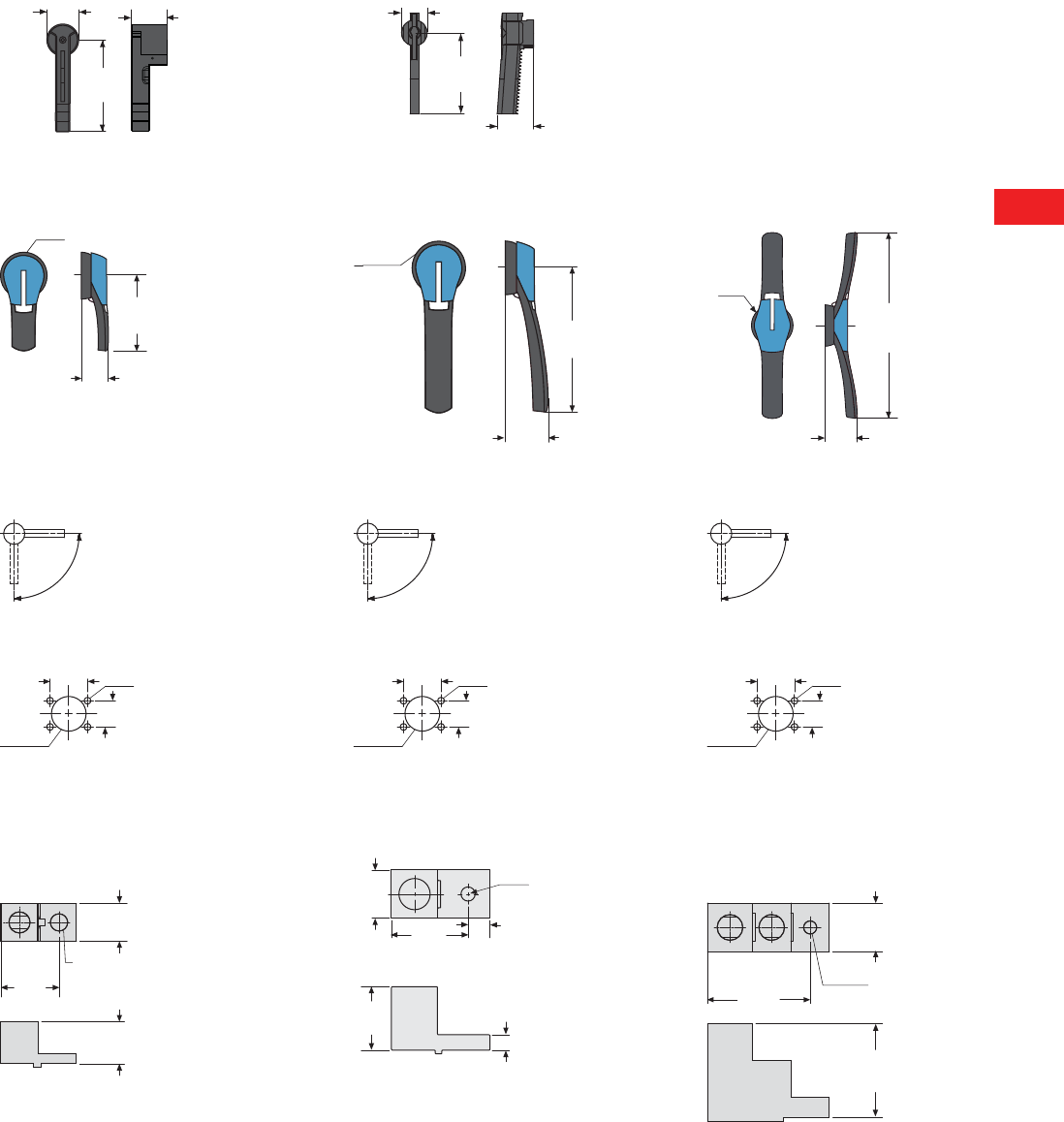
Volume 5—Motor Control and Protection CA08100006E—December 2013 www.eaton.com V5-T8-25
8
8
8
8
8
8
8
8
8
8
8
8
8
8
8
8
8
8
8
8
8
8
8
8
8
8
8
8
8
8
8.3
Rotary Disconnects
R9 Series (UL 98)
Approximate Dimensions in Inches (mm)
Direct Handle—Front Operation
R9 Series Non-Fusible 400A R9 Series Non-Fusible 600–1200A
Door Interlocked External Handle
PH2 Type Handle PH3 Type Handle PH4 Type Handle
Direction of Operation
Door Drilling Templates
Top and Bottom Terminal Lugs
R9 Series Non-Fusible 100–200A R9 Series Non-Fusible 400A R9 Series Non-Fusible 600–1200A
2.36
(60.0)
7.48
(190.0)
3.35
(85.0)
1.57
(40.0)
5.31
(135.0)
1.79
(45.5)
Ø3.07 (Ø78.0)
4.92
(125.0)
1.77
(45.0)
Ø3.07
(Ø78.0)
8.27
(210.0)
2.40
(61.0)
2.36
(60.0)
13.78
(350.0)
Ø78.00
(1981.2)
90º
0º
I
90º
0º
I
90º
0º
I
1.57
(40.0)
4Ø7
Ø1.46
(37.0) 1.10
(28.0)
1.57
(40.0)
4Ø7
Ø1.46
(37.0) 1.10
(28.0)
1.57
(40.0)
4Ø7
Ø1.46
(37.0) 1.10
(28.0)
2.87
(72.9)
3.15
(80.0)
1.49
(37.8)
0.40
(Ø10.2)
2.80
(71.5)
Ø 0.40 (Ø10.16)
Ø 4.70 (Ø119.38)
1.30
(35.0)
1.80
(46.0)
0.44
(11.13)
0.63
(15.9)
1.0 0
(25.4)
1.52
(38.6)
1.12
(28.4)
0.45
(Ø11.4)
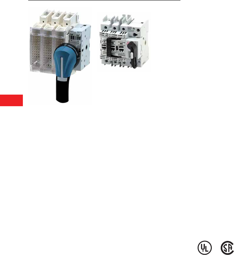
V5-T8-26 Volume 5—Motor Control and Protection CA08100006E—December 2013 www.eaton.com
8
8
8
8
8
8
8
8
8
8
8
8
8
8
8
8
8
8
8
8
8
8
8
8
8
8
8
8
8
8
8.3
Rotary Disconnects
R9 Series (UL 98)
Fusible 30–800A
Contents
Description Page
Non-Fusible 30–100A Compact . . . . . . . . . . . . . . . V5-T8-11
Non-Fusible 100–1200A . . . . . . . . . . . . . . . . . . . . V5-T8-18
Fusible 30–800A
Product Identification . . . . . . . . . . . . . . . . . . . . V5-T8-27
Product Selection . . . . . . . . . . . . . . . . . . . . . . . V5-T8-28
Accessories. . . . . . . . . . . . . . . . . . . . . . . . . . . . V5-T8-32
Technical Data and Specifications . . . . . . . . . . . V5-T8-37
Dimensions. . . . . . . . . . . . . . . . . . . . . . . . . . . . V5-T8-39
DC Rated Disconnects . . . . . . . . . . . . . . . . . . . . . V5-T8-45
Fusible 30–800A
Product Description
R9 Series (UL 98 listed)
Fusible 30–800A manual
operated multi-pole fusible
disconnect switches use
double break contacts per
pole that ensure complete
isolation of the fuse when the
switch is in the OFF position.
When installed with fuses,
they provide protection for
low voltage electrical
installations against short
circuit and overload.
Features, Benefits
and Functions
●Load break functionality
●Double break contacts
●Up to 200 kA short-circuit
rating with Class CC, J
or L fuses
●Compact footprints
●The optional TEST position
function (up to 400A)
enables testing of the
control circuit auxiliaries
without switching the main
contacts. This function
provides a simple
alternative to a separately
wired pushbutton
●Defeatable pistol handles
automatically re-latch when
the panel door is closed
●Front or side operation
●Flange operation
●NFPA 79 compliant kits
●Two-, three- and four-
pole devices
Standards and Certifications
●UL 98, File E222859 for
30 to 800A ratings
●UL 489, File E305341 for
H-Frame switches
●CSA® 22.2 No. 4,
File 217736
●CSA 22.2 No. 5,
File 217736, H-Frame only
●IEC 60947-1, EN 60947-1
●IEC 60947-3, EN 60947-3
●NFPA 79
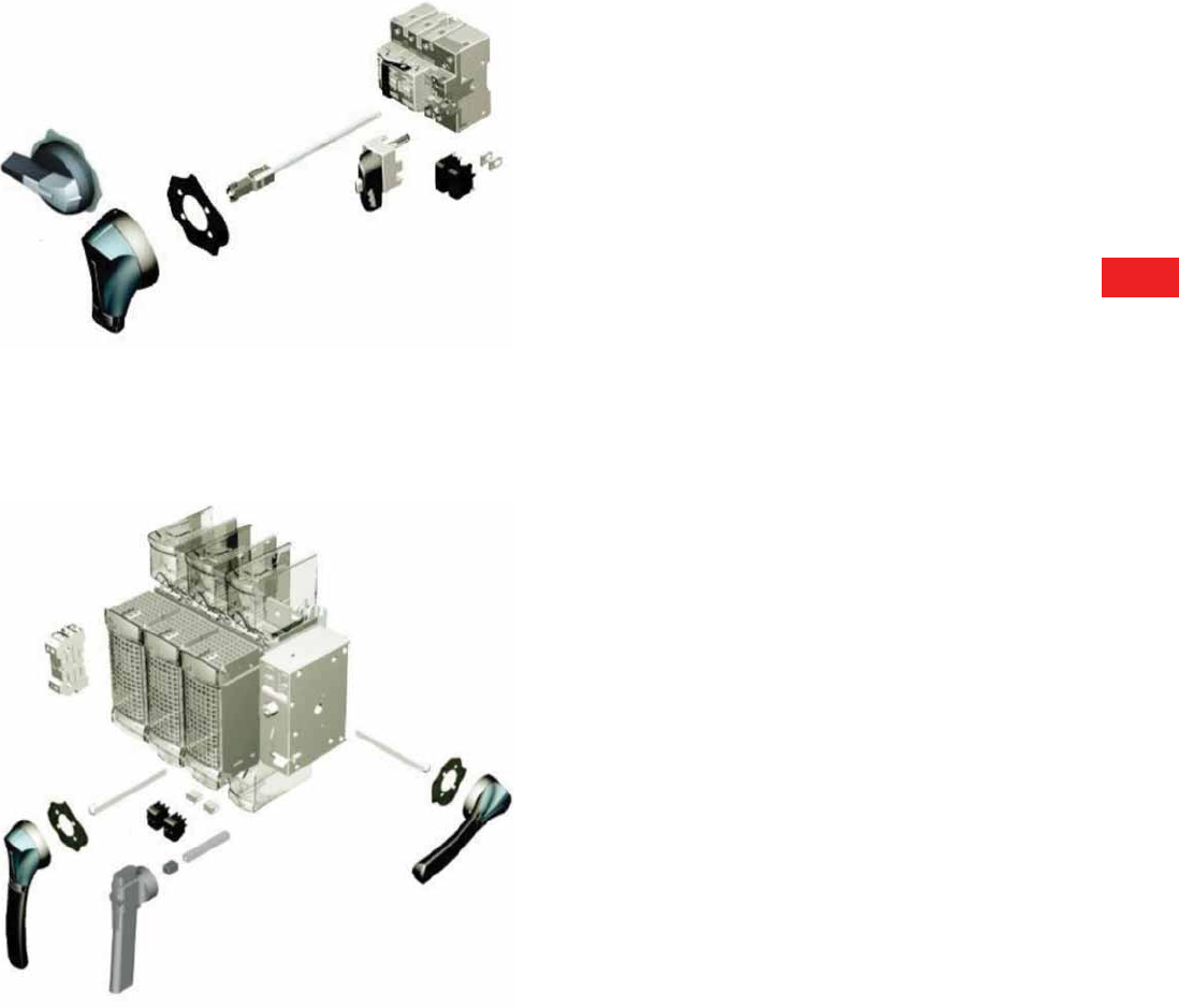
Volume 5—Motor Control and Protection CA08100006E—December 2013 www.eaton.com V5-T8-27
8
8
8
8
8
8
8
8
8
8
8
8
8
8
8
8
8
8
8
8
8
8
8
8
8
8
8
8
8
8
8.3
Rotary Disconnects
R9 Series (UL 98)
Product Identification
R9 Fusible 30A/CC and 30A/J H-Frame—Direct and External Operation
1External front handles
2Direct handle
3Shaft extensions for external handles
4Configurable U Type ACs, for pre-break and signaling or TEST
R9 Fusible 30A/J–800A/L (I–N-Frames)—Direct and External Operation
1External front handles
2External right side handle (not applicable for N-Frame 600/800A)
3Direct handle
4Shaft extensions for external handles
5Configurable U Type ACs, for pre-break and signaling or TEST
6Side auxiliary contacts
7Terminal shrouds
1
2
3
4
1
2
3
4
5
6
7
4
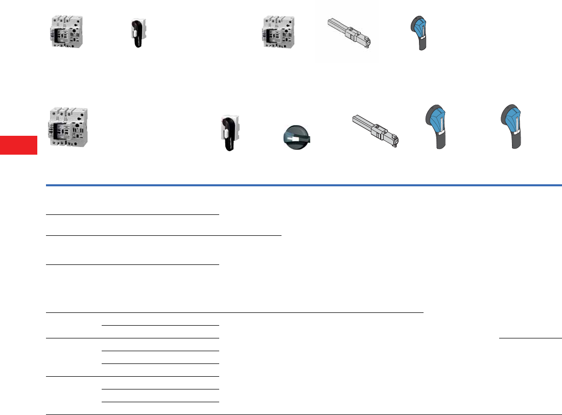
V5-T8-28 Volume 5—Motor Control and Protection CA08100006E—December 2013 www.eaton.com
8
8
8
8
8
8
8
8
8
8
8
8
8
8
8
8
8
8
8
8
8
8
8
8
8
8
8
8
8
8
8.3
Rotary Disconnects
R9 Series (UL 98)
Product Selection
Front and Right Side Operation
Note
1100 kA short-circuit rating.
Ampere Rating
(Frame)
(Fuse Class)
Number
of Poles
Switch
Body Only
Direct
Handle
External Selector
Handle
(Choose one)
Shaft Extension for
Selector Handle Only
(Choose one)
External Front
Pistol Handle
External Right
Side Pistol Handle
30 1
Compact
(H-Frame) (CC)
3R4H3030FCC DHR9HC Black
1,3R,12
SHB0N12HV
Red
1,3R,12
SHR0N12HV
Black
4,4X
SHB0N4XHV
Red
4,4X
SHR0N4XHV
7.90 (200.0)
SF200SH5X5H
Black
1,3R,12
PHB1N12F
Red
1,3R,12
PHR1N12F
Black
4,4X
PHB1N4XF
Red
4,4X
PHR1N4XF
Black
4,4X
(w/ TEST Position)
PHB1N4XFT
Red
4,4X
(w/ TEST Position)
PHR1N4XFT
—
30 1
(H-Frame) (CC)
3 + switched neutral R4H3030FCCSN 12.60 320.0)
SF320SH5X5H
30 1
Compact
(H-Frame) (J)
3R4H3030FJ DHR9HJ 15.70 (400.0)
SF400SH5X5H
30 1
(H-Frame) (J)
3 + switched neutral R4H3030FJSN
30
(I-Frame) (CC)
3R9I3030FCC DHR9J2M ——
4R9I4030FCC
30
(J-Frame) (J)
2R9J2030FJ Black
4, 4X
PHB1N4XS
Red
4, 4X
PHR1N4XS
3R9J3030FJ
4R9J4030FJ
60 1
(J-Frame) (J)
2R9J2060FJ
3R9J3060FJ
4R9J4060FJ
+++
Switch body Direct handle Switch body Shaft External handle
+++
Direct Operation External Operation
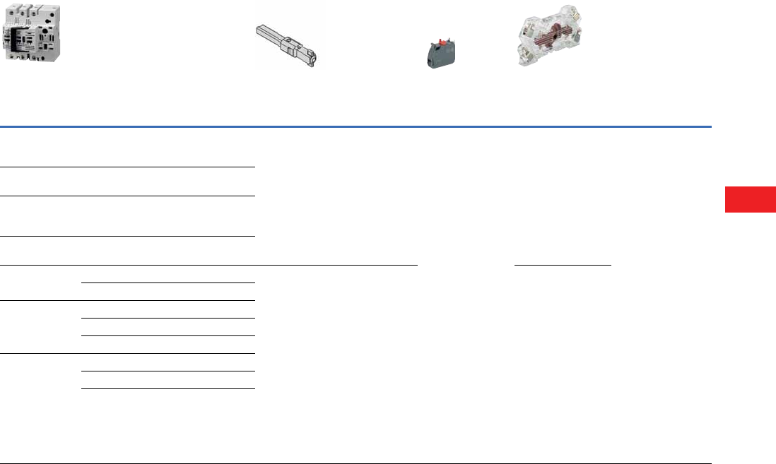
Volume 5—Motor Control and Protection CA08100006E—December 2013 www.eaton.com V5-T8-29
8
8
8
8
8
8
8
8
8
8
8
8
8
8
8
8
8
8
8
8
8
8
8
8
8
8
8
8
8
8
8.3
Rotary Disconnects
R9 Series (UL 98)
Front and Right Side Operation, continued
Note
1100 kA short-circuit rating.
Ampere Rating
(Frame)
(Fuse Class)
Number
of Poles
Switch
Body Only
Shaft Extensions for
Pistol Handle Only
In (mm)
(Choose one)
NFPA
79 Kit
Auxiliary
Contacts
(Choose one)
S Type Auxiliary
Contacts
(Choose one)
Terminal
Shrouds
30
Compact
(H-Frame) (CC)
3R4H3030FCC 7.90 (200.0)
SF200PH5X5
12.60 (320.0)
SF320PH5X5
15.70 (400.0)
SF400PH5X5
NFPA79H 1 AC
NO
AC1NOR9
1 AC
NC
AC1NCR
— Integral to switch
30
(H-Frame) (CC)
3 + switched neutral R4H3030FCCSN
30
Compact
(H-Frame) (J)
3R4H3030FJ
30
(H-Frame) (J)
3 + switched neutral R4H3030FJSN
30
(I-Frame) (CC)
3R9I3030FCC 7.90 (200.0)
SF200PH10X10
12.60 (320.0)
SF320PH10X10
15.70 (400.0)
SF400PH10X10
19.70 (500.0)
SF500PH10X10
NFPA79JKL 1 AC
NO + NC
AC1NO1NCJ2N
2 AC
NO + NC
AC2NO2NCJ2N
1 AC
NO + NC
w/ TEST
AC1NO1NCJ2NT
2 AC
NO + NC
w/ TEST
AC2NO2NCJ2NT
4R9I4030FCC
30
(J-Frame) (J)
2R9J2030FJ
3R9J3030FJ
4R9J4030FJ
60 1
(J-Frame) (J)
2R9J2060FJ
3R9J3060FJ
4R9J4060FJ
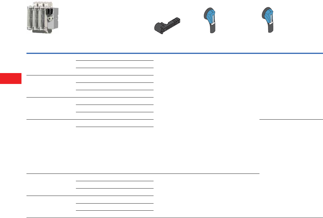
V5-T8-30 Volume 5—Motor Control and Protection CA08100006E—December 2013 www.eaton.com
8
8
8
8
8
8
8
8
8
8
8
8
8
8
8
8
8
8
8
8
8
8
8
8
8
8
8
8
8
8
8.3
Rotary Disconnects
R9 Series (UL 98)
Front and Right Side Operation, continued
Notes
1200 kA short-circuit rating.
2Requires test handle.
Ampere Rating
(Frame)
(Fuse Class)
Number
of Poles
Switch
Body Only
Direct Handle
(Black)
External Front
Pistol Handle
(Choose one)
External Right Side
Pistol Handle (Choose one)
60 1
(K-Frame) (J)
2R9K2060FJ DHR9J2M Black
1,3R,12
PHB2N12F
Red
1,3R,12
PHR2N12F
Black
4,4X
PHB2N4XF
Red
4,4X
PHR2N4XF
Black
4,4X
(w/ TEST Position)
PHB2N4XFT 2
Red
4,4X
(w/ TEST Position)
PHR2N4XFT 2
Black
4, 4X
PHB2N4XS
Red
4, 4X
PHR2N4XS
3R9K3060FJ
4R9K4060FJ
100
(K-Frame) (J)
2R9K2100FJ
3R9K3100FJ
4R9K4100FJ
200
(L-Frame) (J)
2R9L2200FJ
3R9L3200FJ
4R9L4200FJ
400
(M-Frame) (J)
3R9M3400FJ —
4R9M4400FJ
600
(N-Frame) (J)
2R9N2600FJ DHR9N Black
4, 4X
PHB3N4XF
Red
4,4X
PHR3N4XF
3R9N3600FJ
4R9N4600FJ
800
(N-Frame) (L)
2R9N2800FL
3R9N3800FL
4R9N4800FL
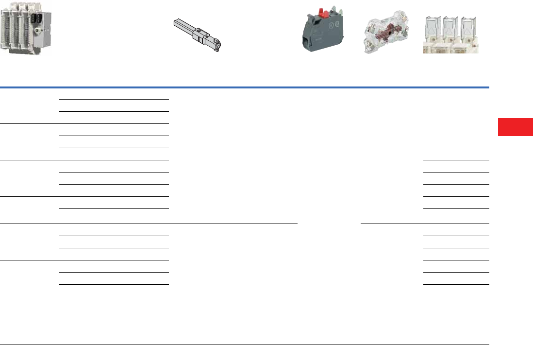
Volume 5—Motor Control and Protection CA08100006E—December 2013 www.eaton.com V5-T8-31
8
8
8
8
8
8
8
8
8
8
8
8
8
8
8
8
8
8
8
8
8
8
8
8
8
8
8
8
8
8
8.3
Rotary Disconnects
R9 Series (UL 98)
Front and Right Side Operation, continued
Notes
1200 kA short-circuit rating.
2Requires test handle.
Ampere Rating
(Frame)
(Fuse Class)
Number
of Poles
Switch
Body Only
Shaft Extensions
for External Handle
In (mm) (Choose one)
NFPA
79 Kit
Auxiliary
Contacts
(Choose one)
Auxiliary
Contacts
(Choose one)
Terminal
Shrouds
60 1
(K-Frame) (J)
2R9K2060FJ 7.90 (200.0)
Pistol
SF200PH10X10
12.60 (320.0)
Pistol
SF320PH10X10
15.70 (400.0)
Pistol
SF400PH10X10
19.70 (500.0)
Pistol
SF500PH10X10
NFPA79JKL 1 AC
NO
AC1NOR9
1 AC
NC
AC1NCR9
1 AC
NO + NC
AC1NO1NCJ2N
2 AC
NO + NC
AC2NO2NCJ2N
1 AC
NO + NC
w/ TEST
AC1NO1NCJ2NT 2
2 AC
NO + NC
w/ TEST
AC2NO2NCJ2NT 2
Integral to switch
3R9K3060FJ
4R9K4060FJ
100
(K-Frame) (J)
2R9K2100FJ
3R9K3100FJ
4R9K4100FJ
200
(L-Frame) (J)
2R9L2200FJ TSR9L2
3R9L3200FJ TSR9L3
4R9L4200FJ TSR9L4
400
(M-Frame) (J)
3R9M3400FJ TSR9M3
4R9M4400FJ TSR9M4
600
(N-Frame) (J)
2R9N2600FJ 7.90 (200.0)
Pistol
SF200PH12X12
12.60 (320.0)
Pistol
SF320PH12X12
15.70 (400.0)
Pistol
SF400PH12X12
19.70 (500.0)
Pistol
SF500PH12X12
NFPA79N 1 AC
NO + NC
AC1NO1NCJ2N
2 AC
NO + NC
AC2NO2NCJ2N
TSR9N2
3R9N3600FJ TSR9N3
4R9N4600FJ TSR9N4
800
(N-Frame) (L)
2R9N2800FL TSR9N2
3R9N3800FL TSR9N3
4R9N4800FL TSR9N4
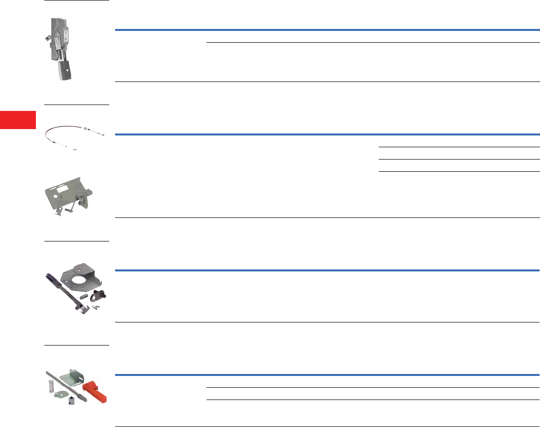
V5-T8-32 Volume 5—Motor Control and Protection CA08100006E—December 2013 www.eaton.com
8
8
8
8
8
8
8
8
8
8
8
8
8
8
8
8
8
8
8
8
8
8
8
8
8
8
8
8
8
8
8.3
Rotary Disconnects
R9 Series (UL 98)
Accessories
NFPA 79 Compliant
“Flange” Handle for Flange-Operated Switches
Cable Operator
Rod Operator
NFPA 79 “Through the Door” Kit
Note
1 Defeatable.
Description
Ampere Rating
(Frame) Handle Type NEMA Type Catalog Number
For side-operated switches only.
Provides heavy-duty flange style
operation. Meets both UL 508A and
NFPA 79 requirements. Please order
cable or rod link between handle
and switch.
30–400 (J-, K-, L-, M-Frame) Standard handle 1, 3, 3R, 4, 12 FHS 1
30–400 (J-, K-, L-, M-Frame) Chrome-plated handle 1, 3, 3R, 4, 4X, 12 FHCP 1
Description
Ampere Rating
(Frame) NEMA Type
Cable Length
In (mm) Catalog Number
Link between “Flange” handle
and side-operated switches.
Please order mechanism and
“Flange” handle.
30–400 (J-, K-, L-, M-Frame) Mechanism for
“Flange” handle
—CFM1
36.00 (914.4) CFC36
60.00 (1524.0) CFC60
120.00 (3048.0) CFC120
Description
Ampere Rating
(Frame)
For Enclosure Depth
In (mm) Catalog Number
Link between “Flange” handle
and side-operated switches.
Mechanism included.
Please order “Flange” handle.
30–400 (J-, K-, L-, M-Frame) 8.00–24.00 (203.2–609.6) RFM1
Description
Ampere Rating
(Frame) Catalog Number
For front-operated switches only.
Meets both UL 508A and NFPA 79
requirements. Kit includes
mechanism, shaft and internal
handle. Please also order a “PH”
type external pistol handle.
30 (H-Frame) NFPA79H
30–400 (J-, K-, L-, M-Frame) NFPA79JKL
600–800 (N-Frame) NFPA79N
Mechanism for
Flange Handle
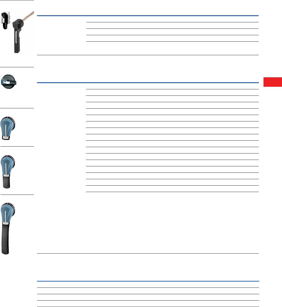
Volume 5—Motor Control and Protection CA08100006E—December 2013 www.eaton.com V5-T8-33
8
8
8
8
8
8
8
8
8
8
8
8
8
8
8
8
8
8
8
8
8
8
8
8
8
8
8
8
8
8
8.3
Rotary Disconnects
R9 Series (UL 98)
Direct Handle
Door Interlocked External Front Handles
Right Side External Handles
Note
1 Includes TEST position.
Description
Ampere Rating
(Frame) Fuse Catalog Number
Front operation. Black. 30 (H-Frame) CC DHR9HC
30 (H-Frame) J DHR9HJ
30 (I-Frame) CC DHR9J2M
30–400 (J-, K-, L-, M-Frame) J DHR9J2M
600–800 (N-Frame) J/L DHR9N
Description
Ampere Rating
(Frame) Handle Type NEMA Type Color
Standard
Catalog Number
The handle locking function of the
front external operation handle
prevents the user from opening
the door of the enclosure when the
switch is in the ON position, and
when the switch is padlocked in
the OFF position (PH1, PH2 and PH3
type handles only). Opening the
door when the switch is in the OFF
position is possible by defeating the
locking function with the use of a
tool (authorized persons only). The
locking function is restored when the
door is closed back.
30 (H-Frame) SO 1, 3R, 12 Black SHB0N12HV
30 (H-Frame) SO 1, 3R, 12 Red/yellow SHR0N12HV
30 (H-Frame) SO 4, 4X Black SHB0N4XHV
30 (H-Frame) SO 4, 4X Red/yellow SHR0N4XHV
30–60 (H-,I-, J-Frame) PH1 1, 3R, 12 Black PHB1N12F
30–60 (H-,I-, J-Frame) PH1 1, 3R, 12 Red/yellow PHR1N12F
30–60 (H-,I-, J-Frame) PH1 4, 4X Black PHB1N4XF
30–60 (H-,I-, J-Frame) PH1 4, 4X Red/yellow PHR1N4XF
30–60 (H-,I-, J-Frame) PH1 4, 4X Black PHB1N4XFT 1
30–60 (H-,I-, J-Frame) PH1 4, 4X Red/yellow PHR1N4XFT 1
60–400 (K-, L-, M-Frame) PH2 1, 3R, 12 Black PHB2N12F
60–400 (K-, L-, M-Frame) PH2 1, 3R, 12 Red/yellow PHR2N12F
60–400 (K-, L-, M-Frame) PH2 4, 4X Black PHB2N4XF
60–400 (K-, L-, M-Frame) PH2 4, 4X Red/yellow PHR2N4XF
60–400 (K-, L-, M-Frame) PH2 4, 4X Black PHB2N4XFT 1
60–400 (K-, L-, M-Frame) PH2 4, 4X Red/yellow PHR2N4XFT 1
600–800 (N-Frame) PH3 4, 4X Black PHB3N4XF
600–800 (N-Frame) PH3 4, 4X Red/yellow PHR3N4XF
Ampere Rating
(Frame) Handle Type NEMA Type Color
Standard
Catalog Number
30–60 (J-Frame) PH1 4, 4X Black PHB1N4XS
30–60 (J-Frame) PH1 4, 4X Red/yellow PHR1N4XS
60–400 (K-, L-, M-Frame) PH2 4, 4X Black PHB2N4XS
60–400 (K-, L-, M-Frame) PH2 4, 4X Red/yellow PHR2N4XS
SO Type Handle
PH1 Type Handle
PH2 Type Handle
PH3 Type Handle
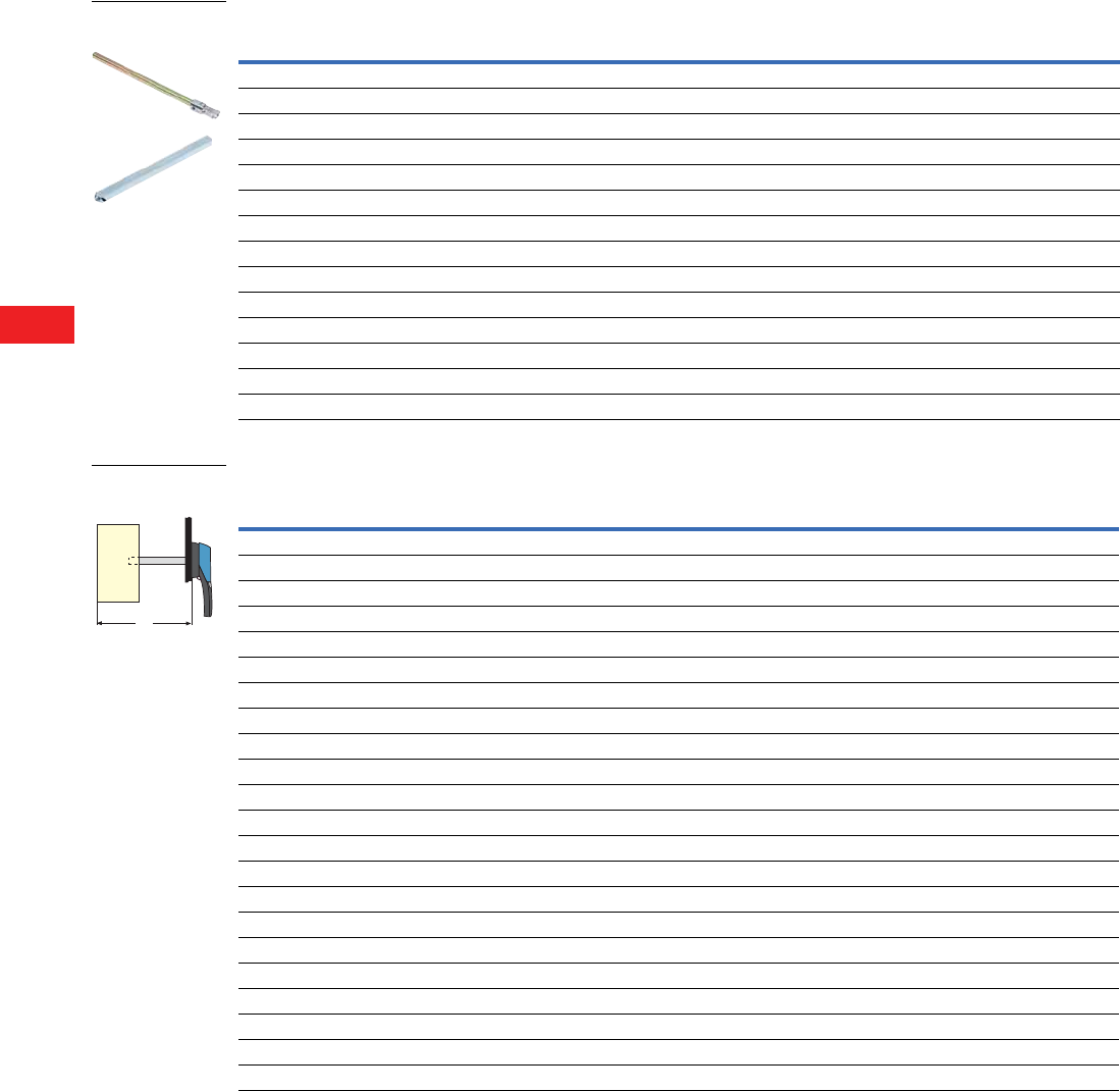
V5-T8-34 Volume 5—Motor Control and Protection CA08100006E—December 2013 www.eaton.com
8
8
8
8
8
8
8
8
8
8
8
8
8
8
8
8
8
8
8
8
8
8
8
8
8
8
8
8
8
8
8.3
Rotary Disconnects
R9 Series (UL 98)
Shaft Extensions for External Handles
Handle Types SH and PH, X Minimum Dimensions
Ampere Rating (Frame) Handle Type
Shaft Length
In (mm) Catalog Number
30 (H-Frame) SH0 7.90 (200.0) SF200SH5X5H
30 (H-Frame) SH0 12.60 (320.0) SF320SH5X5H
30 (H-Frame) SH0 15.70 (400.0) SF400SH5X5H
30 (H-Frame) PH1 7.90 (200.0) SF200PH5X5
30 (H-Frame) PH1 12.60 (320.0) SF320PH5X5
30 (H-Frame) PH1 15.70 (400.0) SF400PH5X5
30–400 (I-, J-, K-, L-, M-Frame) PH2 7.90 (200.0) SF200PH10X10
30–400 (I-, J-, K-, L-, M-Frame) PH2 12.60 (320.0) SF320PH10X10
30–400 (I-, J-, K-, L-, M-Frame) PH2 15.70 (400.0) SF400PH10X10
30–400 (I-, J-, K-, L-, M-Frame) PH3 19.70 (500.0) SF500PH10X10
600–800 (N-Frame) PH3 7.90 (200.0) SF200PH12X12
600–800 (N-Frame) PH3 12.60 (320.0) SF320PH12X12
600–800 (N-Frame) PH3 15.70 (400.0) SF400PH12X12
600–800 (N-Frame) PH3 19.70 (500.0) SF500PH12X12
Ampere Rating (Frame)
Dimensions X
In (mm) Handle Type
Shaft Length
In (mm) Catalog Number
30 (H-Frame) 4.02–9.65 (102.0–245.0) SH0 7.90 (200.0) SF200SH5X5H
30 (H-Frame) 4.02–14.37 (102.0–365.0) SH0 12.60 (320.0) SF320SH5X5H
30 (H-Frame) 4.02–17.52 (102.0–445.0) SH0 15.70 (400.0) SF400SH5X5H
30 (H-Frame) 4.02–9.65 (102.0–245.0) PH1 7.90 (200.0) SF200PH5X5
30 (H-Frame) 4.02–14.37 (102.0–365.0) PH1 12.60 (320.0) SF320PH5X5
30 (H-Frame) 4.02–17.52 (102.0–445.0) PH1 15.70 (400.0) SF400PH5X5
30–100 (I-, J-, K-Frame) 5.30–9.06 (135.0–230.0) PH2, PH3 7.90 (200.0) SF200PH10X10
200 (L-Frame) 5.70–9.06 (145.0–230.0) PH2, PH3 7.90 (200.0) SF200PH10X10
400 (M-Frame) 7.87–10.24 (200.0–260.0) PH2, PH3 7.90 (200.0) SF200PH10X10
30–100A (I-, J-, K-Frame) 5.30–13.78 (135.0–350.0) PH2, PH3 12.60 (320.0) SF320PH10X10
200 (L-Frame) 5.70–13.78 (145.0–350.0) PH2, PH3 12.60 (320.0) SF320PH10X10
400 (M-Frame) 7.87–14.96 (200.0–380.0) PH2, PH3 12.60 (320.0) SF320PH10X10
30–100 (I-, J-, K-Frame) 5.30–16.93 (135.0–430.0) PH2, PH3 15.70 (400.0) SF400PH10X10
200 (L-Frame) 5.70–16.93 (145.0–430.0) PH2, PH3 15.70 (400.0) SF400PH10X10
400 (M-Frame) 7.87–18.10 (200.0–460.0) PH2, PH3 15.70 (400.0) SF400PH10X10
30–100 (I-, J-, K-Frame) 5.30–20.87 (135.0–530.0) PH2, PH3 19.70 (500.0) SF500PH10X10
200 (L-Frame) 5.70–20.87 (145.0–530.0) PH2, PH3 19.70 (500.0) SF500PH10X10
400 (M-Frame) 7.87–22.05 (200.0–560.0) PH2, PH3 19.70 (500.0) SF500PH10X10
600–800 (N-Frame) 10.63–11.97 (270.0–304.0) PH3 12.60 (320.0) SF320PH12X12
600–800 (N-Frame) 10.63–16.69 (270.0–424.0) PH3 12.60 (320.0) SF320PH12X12
600–800 (N-Frame) 10.63–19.84 (270.0–504.0) PH3 15.70 (400.0) SF400PH12X12
600–800 (N-Frame) 10.63–23.78 (270.0–604.0) PH3 19.70 (50.00) SF500PH12X12
X
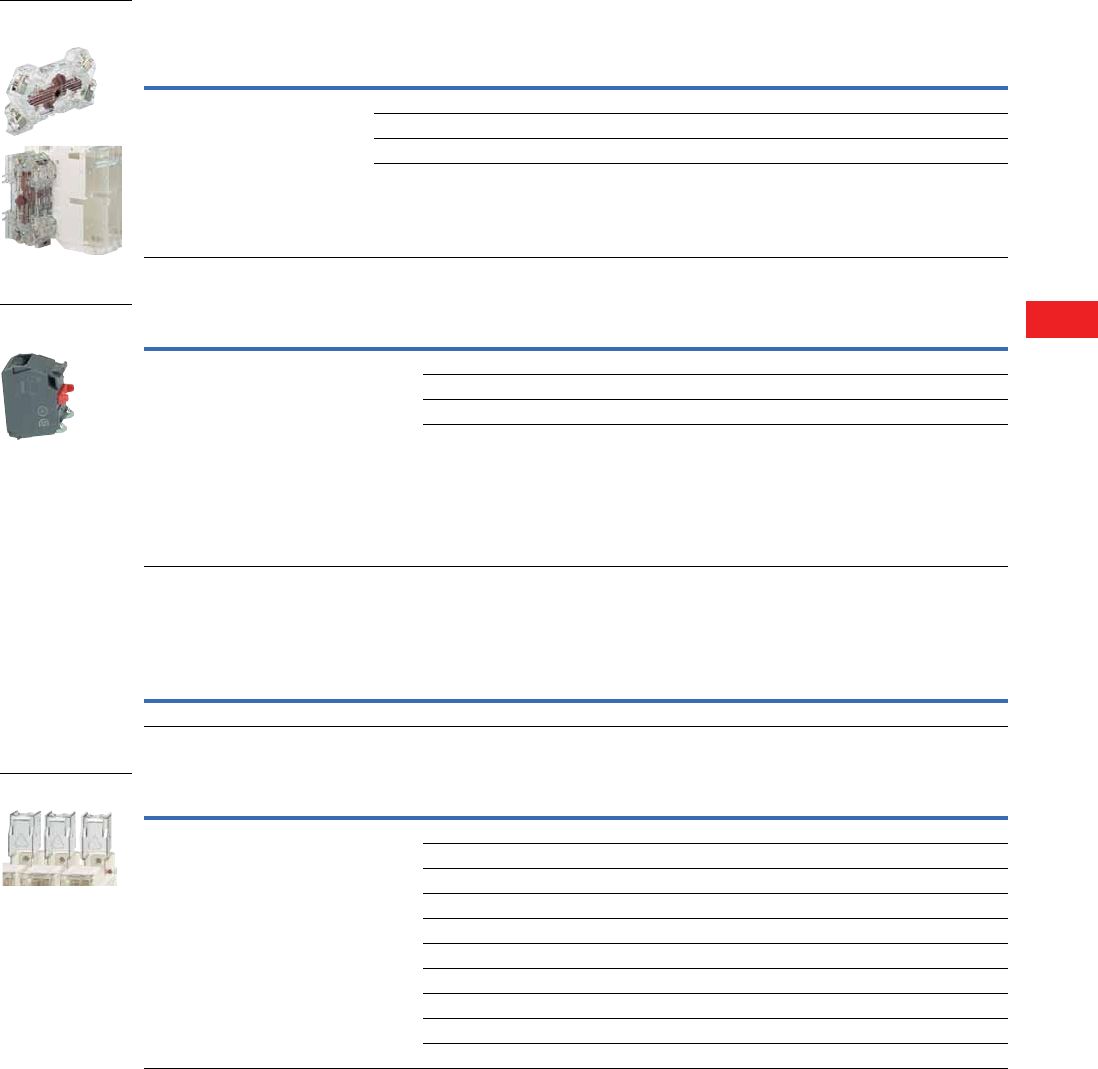
Volume 5—Motor Control and Protection CA08100006E—December 2013 www.eaton.com V5-T8-35
8
8
8
8
8
8
8
8
8
8
8
8
8
8
8
8
8
8
8
8
8
8
8
8
8
8
8
8
8
8
8.3
Rotary Disconnects
R9 Series (UL 98)
Auxiliary Contacts—NO + NC 1
Auxiliary Contacts—NO or NC 3
Characteristics for Pre-Break Auxiliary Contacts
Terminal Shrouds
Notes
1 Same-make/same-break auxiliary contacts.
2 Auxiliary contacts without “Test” cannot be used on I–M-Frame switches.
3 Early-break/same-make auxiliary contacts.
4 For replacement only. Both line and load side terminal shrouds are included with 400A switch.
Operating Current Ie (Amperes)
Description
Ampere Rating
(Frame)
Number
of ACs Nominal Current (Amperes)
Catalog
Number
For the R9 Series Fusible 30–800A,
indication of the O and I positions by
1 to 4 NO + NC auxiliary contacts.
Electrical principle:
Cabling by terminal cage with
#16 AWG maximum.
High electrical characteristics:
A600/D600
600–800 (N-Frame) 1NO + 1NC 10 AC1NO1NCJ2N 2
600–800 (N-Frame) 2NO + 2NC 10 AC2NO2NCJ2N 2
30–400 (I–M-Frame) 1NO + 1NC (w/ TEST) 10 AC1NO1NCJ2NT
30–400 (I–M-Frame) 2NO + 2NC (w/ TEST) 10 AC2NO2NCJ2NT
Description Ampere Rating (Frame) Number of ACs Catalog Number
The different functions (pre-break, 0 and 1 indication,
TEST feature) are easily configurable with pegs
(one or two pegs per position). Two superposed
auxiliary contacts maximum.
For 30A/CC (H-Frame), maximum of four ACs.
For 30A/J (H-Frame), maximum of two ACs.
For 30 to 100A/J (I, J and K-Frame), maximum
of four ACs.
For 200 to 600A/J (L and M-Frame),
maximum of eight ACs.
Cabling to the control circuit by terminals
with a maximum section of 2 x 2.5 mm2.
Electrical characteristics: A300
NO Auxiliary Contact
30–600 (H–M-Frame) 1 AC1NOR9
NC Auxiliary Contact
30–600 (H–M-Frame) 1 AC1NCR9
Operating Current Ie (Amperes)
Ampere Rating Contact Type
Nominal Current
Amperes 250 Vac AC-13 400 Vac AC-13 24 Vdc DC-13 48 Vdc DC-13
30–800 NO + NC 10 6 4 5 3
Description Ampere Rating (Frame) Number of Poles Catalog Number
Line or load side protection against direct contact
with terminals or the connection parts
30–100 (H-, I-, J-, K-Frame) 2/3/4 Integral to switch
200 (L-Frame) 2 TSR9L2
200 (L-Frame) 3 TSR9L3
200 (L-Frame) 4 TSR9L3
400 (M-Frame) 2 TSR9M2 4
400 (M-Frame) 3 TSR9M3 4
400 (M-Frame) 4 TSR9M4 4
600–800 (N-Frame) 2 TSR9N2
600–800 (N-Frame) 3 TSR9N3
600–800 (N-Frame) 4 TSR9N4
Terminal Shrouds
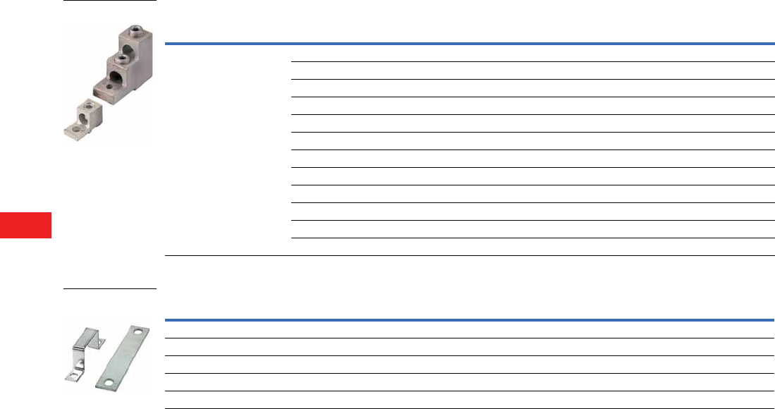
V5-T8-36 Volume 5—Motor Control and Protection CA08100006E—December 2013 www.eaton.com
8
8
8
8
8
8
8
8
8
8
8
8
8
8
8
8
8
8
8
8
8
8
8
8
8
8
8
8
8
8
8.3
Rotary Disconnects
R9 Series (UL 98)
Line and Load Terminal Lugs
Shorting Links
Description Ampere Rating (Frame) Fuse
Number
of Lugs
Lug Capacity/
Phase Cable Type Catalog Number
Connection of bare copper cables
on to the terminals
(no spade lugs).
30 (H-, I-Frame) CC/J — #14–#10 Cu Integral to switch
30 (H-, I-Frame) CC/J — #14–#10 Cu Integral to switch
30–60 (J-Frame) J — #10–#6 Cu Integral to switch
60–100 (K-Frame) J — #12–#1 Cu Integral to switch
200 (L-Frame) J 2 #6–300 kcmil Cu/Al LK2R9DL
200 (L-Frame) J 3 #6–300 kcmil Cu/Al LK3R9DL
200 (L-Frame) J 4 #6–300 kcmil Cu/Al LK4R9DL
400 (M-Frame) J 3 (2) #2–600 kcmil Cu/Al LK3R9FN
400 (M-Frame) J 4 (2) #2–600 kcmil Cu/Al LK4R9FN
600–800 (N-Frame) J/L 2 (2) #2–600 kcmil Cu/Al LK2R9FN
600–800 (N-Frame) J/L 3 (2) #2–600 kcmil Cu/Al LK3R9FN
600–800 (N-Frame) J/L 4 (2) #2–600 kcmil Cu/Al LK4R9FN
Ampere Rating (Frame) Fuse Pack Quantity Catalog Number
60 (J-,K-Frame) J 3 SLJK360
100 (K-Frame) J 3 SLK3100
200 (L-Frame) J 3 SLL3
400 (M-Frame) J 3 SLM3
600–800 (N-Frame) J/L 3 SLN3

Volume 5—Motor Control and Protection CA08100006E—December 2013 www.eaton.com V5-T8-37
8
8
8
8
8
8
8
8
8
8
8
8
8
8
8
8
8
8
8
8
8
8
8
8
8
8
8
8
8
8
8.3
Rotary Disconnects
R9 Series (UL 98)
Technical Data and Specifications
UL and CSA Characteristics
R9 Series Fusible 30–800A
Notes
1Two-pole in series.
2Three-pole in series.
Description 30A 30A 30A 30A 60A 60A 100A
General Use Ratings
Switch frame H H I J J K K
600 Vac (A) 30 30 30 30 60 60 100
600 Vdc (A) — — — — — — —
Short-Circuit Ratings
Short-circuit rating at
600 Vac (kA)
100 100 100 200 100 200 200
Fuse type CC J CC J J J J
Maximum fuse rating (A) 30 30 30 30 60 60 100
Maximum Horsepower Rating/Maximum Motor FLA Three-Phase
220–240 Vac 7.5/22 7.5/22 7.5/22 7.5/22 15/42 15/42 30/80
440–480 Vac 15/21 15/21 15/21 15/21 30/40 30/40 60/77
600 Vac 20/22 20/22 20/22 20/22 50/52 50/52 75/77
Maximum Horsepower Rating/Maximum Motor FLA Single-Phase
220–240 Vac — — 3/17 3/17 10/50 10/50 10/50
440–480 Vac — — 7.5/21 7.5/21 10/26 10/26 10/26
600 Vac — — 10/20 10/20 10/20 10/20 10/20
Maximum Horsepower Rating/Maximum Motor FLA DC
125 Vdc 13/25 3/25 3/25 3/25 5/40 5/40 7.5/58
250 Vdc 25/20 5/20 5/20 5/20 10/38 10/38 20/72
Mechanical Characteristics
Endurance
(number of operating cycles)
10,000 10,000 10,000 10,000 10,000 10,000 10,000
Terminal Lugs
Type Integrated Integrated Integrated Integrated Integrated Integrated Integrated
Minimum conn. section #14 #14 #14 #10 #10 #12 #12
Maximum conn. section #10 #10 #10 #6 #6 #1 #1

V5-T8-38 Volume 5—Motor Control and Protection CA08100006E—December 2013 www.eaton.com
8
8
8
8
8
8
8
8
8
8
8
8
8
8
8
8
8
8
8
8
8
8
8
8
8
8
8
8
8
8
8.3
Rotary Disconnects
R9 Series (UL 98)
R9 Series Fusible 30–800A, continued
Notes
1Two-pole in series.
2Three-pole in series.
Description 200A 400A 600A 800A
General Use Ratings
Switch Frame L M N N
600 Vac (A) 200 400 600 800
600 Vdc (A) — — 600 2800 2
Short-Circuit Ratings
Short-circuit rating at 600 Vac (kA) 200 200 200 200
Fuse type J J J L
Maximum fuse rating (A) 200 400 600 800
Maximum Horsepower Rating/Maximum Motor FLA Single-Phase
220–240 Vac — — — —
440–480 Vac — — — —
600 Vac — — — —
Maximum Horsepower Rating/Maximum Motor FLA Three-Phase
220–240 Vac 60/154 125/312 200/480 200/480
440–480 Vac 125/156 250/302 500/590 500/590
600 Vac 150/144 350/336 500/472 500/472
Maximum Horsepower Rating/Maximum Motor FLA DC
125 Vdc 1— 20/148 — —
250 Vdc 2— 50/173 2——
Mechanical Characteristics
Endurance
(number of operating cycles)
8000 6000 5000 5000
Terminal Lugs
Type Option Option Option Option
Minimum conn. section #6 #2 2x#2 2x#2
Maximum conn. section 3/0 300 kcmil 2 x 600 kcmil 2 x 600 kcmil
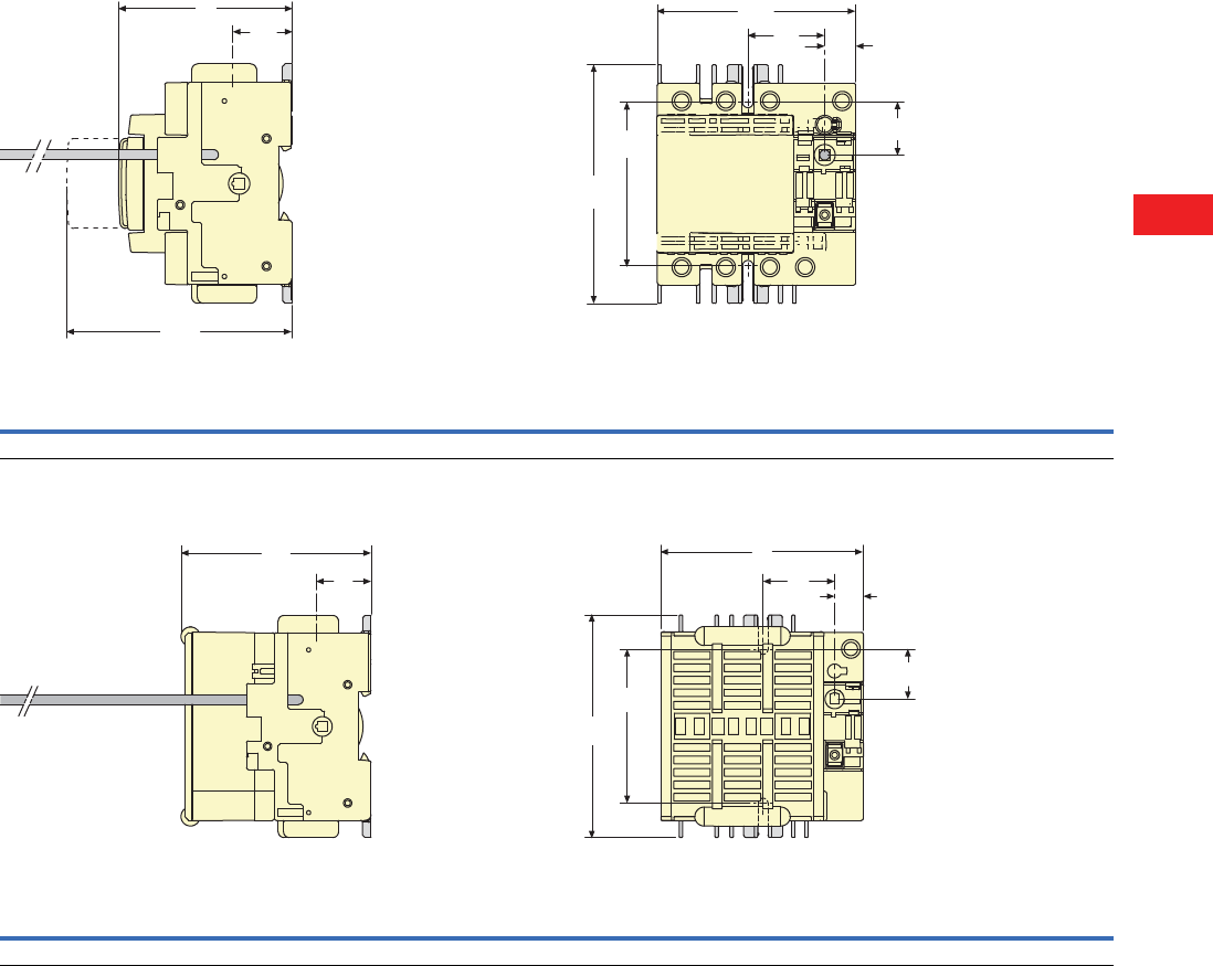
Volume 5—Motor Control and Protection CA08100006E—December 2013 www.eaton.com V5-T8-39
8
8
8
8
8
8
8
8
8
8
8
8
8
8
8
8
8
8
8
8
8
8
8
8
8
8
8
8
8
8
8.3
Rotary Disconnects
R9 Series (UL 98)
Dimensions
Approximate Dimensions in Inches (mm)
Front Operation
R9 Series Fusible 30A/CC—H-Frame
R9 Series Fusible 30A/J—H-Frame
H
Z
H1
AA
NN1
F
JJ1
Switch Body Switch Mounting Connection Terminals
FHH1JJ1NN1AAZ
3.78 (96.0) 3.28 (83.3) 5.19 (131.8) 1.47 (37.3) 0.59 (15.0) 3.13 (79.5) 1.00 (25.4) 4.56 (115.8) 1.12 (28.4)
H
Z
F
J
J1
AA
N
N1
Switch Body Switch Mounting Connection Terminals
FHJJ1NN1AAZ
4.13 (104.9) 3.89 (98.8) 1.47 (37.3) 0.59 (15.0) 3.30 (83.8) 1.00 (25.4) 4.56 (115.8) 1.12 (28.4)
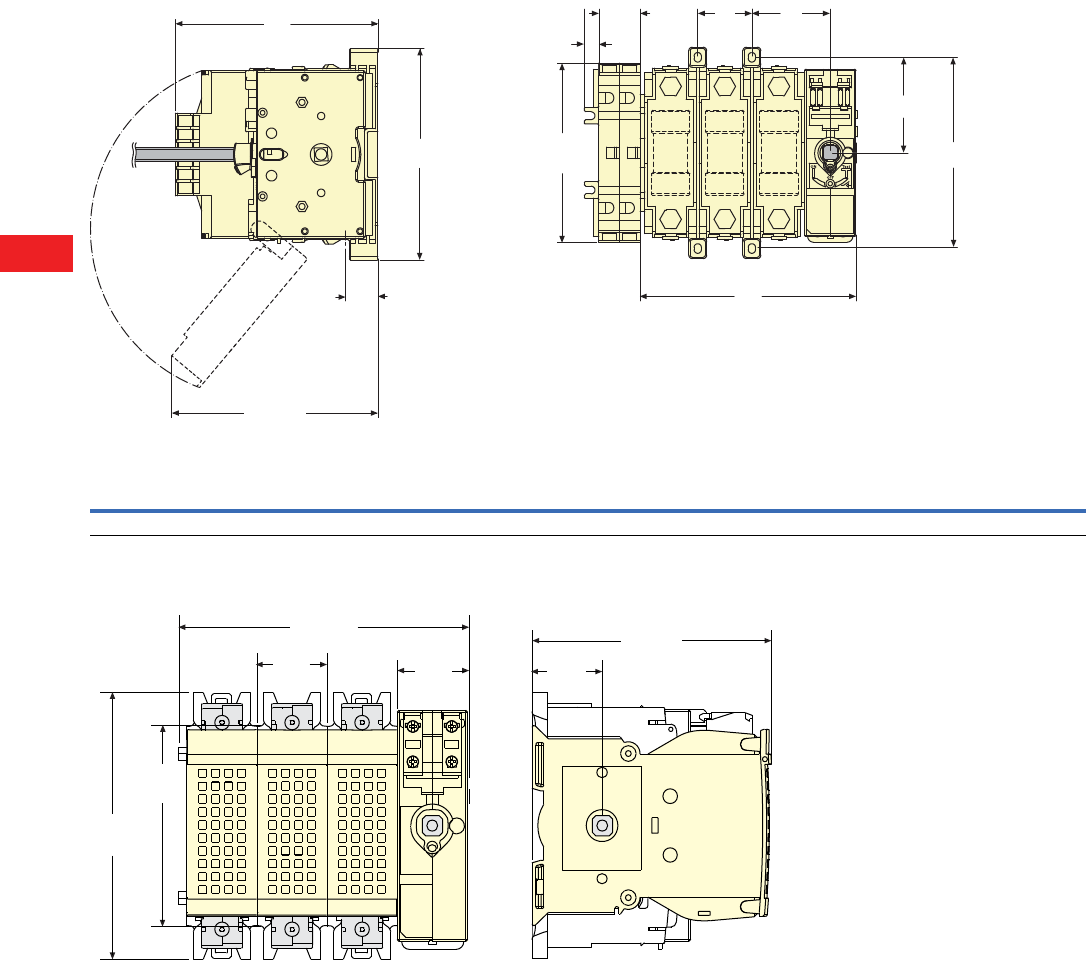
V5-T8-40 Volume 5—Motor Control and Protection CA08100006E—December 2013 www.eaton.com
8
8
8
8
8
8
8
8
8
8
8
8
8
8
8
8
8
8
8
8
8
8
8
8
8
8
8
8
8
8
8.3
Rotary Disconnects
R9 Series (UL 98)
Approximate Dimensions in Inches (mm)
R9 Series Fusible 30A/CC—I-Frame
R9 Series Fusible 30A/J and 60A/J (100 kA)—J-Frame
MJ
F
N1
N
H
AA
Z
1.14
(29.0)
0.41
(10.3)
4.98
(126.5)
6.02
(153.0)
Ampere Rating
(Fuse)
Switch Body Switch Mounting Connection Terminals
F 3P F 4P H J M N N1 AA Z
30 (CC) 4.92 (125.0) 6.06 (154.0) 3.89 (99.0) 1.77 (45.0) 1.14 (29.0) 5.31 (135.0) 2.63 (66.5) 5.87 (149.0) 1.21 (31.0)
5.35
(135.9)
5.87
(149.1)
1.41
(35.8) 1.46
(37.1)
4.84
(122.9)
1.41
(35.8)
4.02
(102.1)
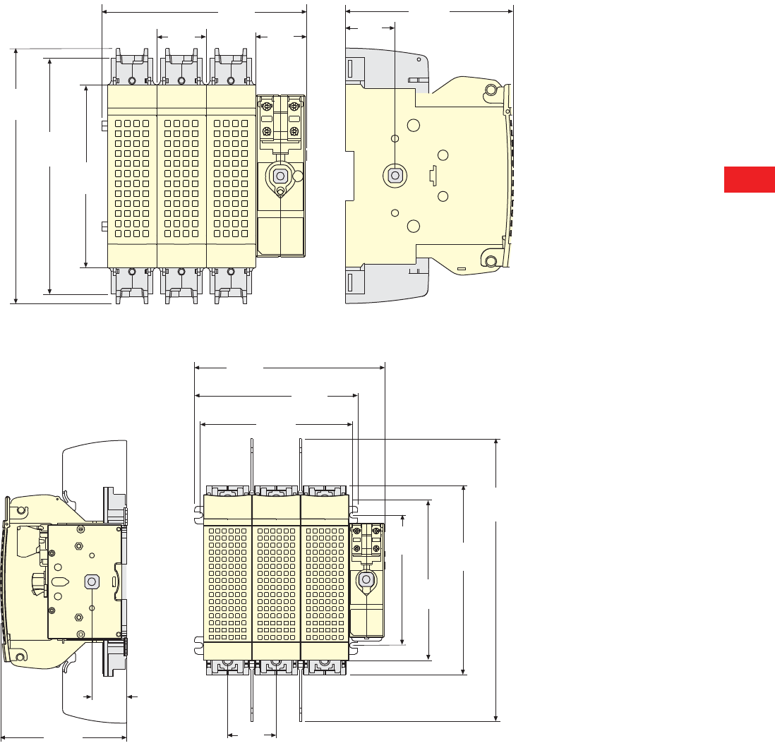
Volume 5—Motor Control and Protection CA08100006E—December 2013 www.eaton.com V5-T8-41
8
8
8
8
8
8
8
8
8
8
8
8
8
8
8
8
8
8
8
8
8
8
8
8
8
8
8
8
8
8
8.3
Rotary Disconnects
R9 Series (UL 98)
Approximate Dimensions in Inches (mm)
R9 Series Fusible 60A/J (200 kA) and 100A/J—K-Frame
R9 Series Fusible 200A/J—L-Frame
7.32
(185.9)
5.87
(149.1)
1.41
(35.8)
1.46
(37.1)
4.81
(122.2)
1.41
(35.8)
6.77
(172.0)
5.23
(132.8)
7.72
(196.1)
6.61
(167.9)
6.18
(157.0)
1.41
(35.8)
5.11
(129.8)
1.96
(49.8)
5.28
(134.1)
6.50
(165.1)
7.67
(194.8)
11.46
(291.1)
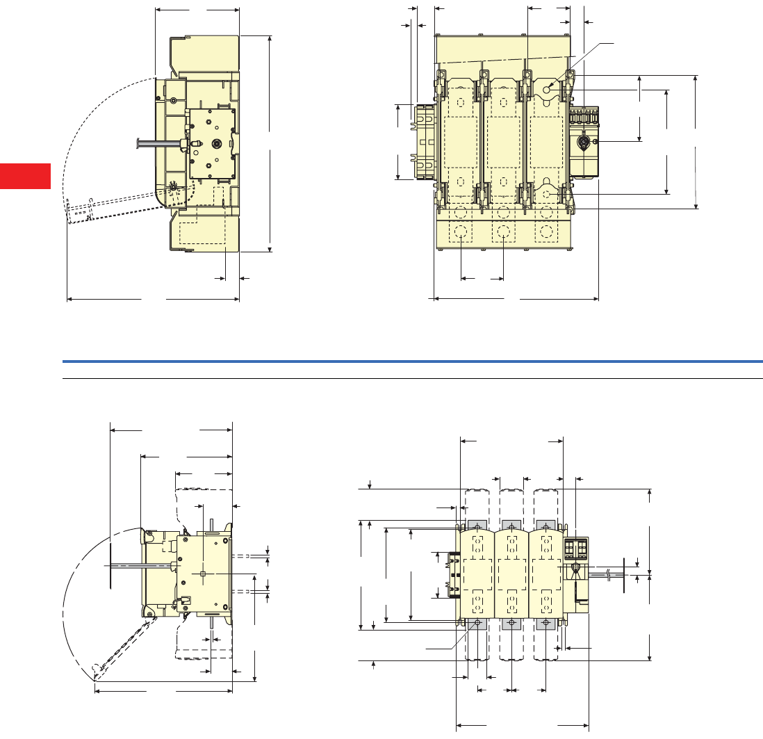
V5-T8-42 Volume 5—Motor Control and Protection CA08100006E—December 2013 www.eaton.com
8
8
8
8
8
8
8
8
8
8
8
8
8
8
8
8
8
8
8
8
8
8
8
8
8
8
8
8
8
8
8.3
Rotary Disconnects
R9 Series (UL 98)
Approximate Dimensions in Inches (mm)
R9 Series Fusible 400A/J—M-Frame
R9 Series Fusible 600–800A J/L—N-Frame
H
AA
H1
Z
0.40
(10.2)
5.00
(127.0)
1.14
(30.0) M
M10
J
F
M
N1
N
6.53
(166.0)
Switch Body Switch Mounting Connection Terminals
F 3P F 4P H H1 J M N N1 AA Z
10.80 (276.0) 13.70 (348.0) 5.56 (141.5) 11.41 (290.0) 0.88 (22.5) 2.84 (72.0) 8.83 (224.0) 4.41 (112.0) 14.31 (363.5) 1.06 (27.0)
9.84
(249.9) 6.10
(154.9)
3.12
(79.2)
0.27
(6.9)
2.32
(58.9)
14.96
(380.0)
Min. 10.43
(Min. 264.9)
0.43
(10.9)
2.56
(65.0) 1.34
(34.0)
0.35
(8.9)
3.70
(94.0)
3.70
(94.0)
Fix 9.84
(Fix 250.0)
5.00
(127.0)
11.81
(300.0)
0.86
(21.8)
9.27
(235.5)
9.27
(235.5)
10.23
(259.8)
3.36
(85.3)
2.00
(50.8)
ø0.51
(ø13.0)
3.36
(85.3)
11.81
(300.0)
3.54 (89.9)
0.27 (6.9)
0.27 (6.9)
3P
14.33
(364.0)
4P
18.03
(458.0)
3P
11. 1 8
(284.0)
4P
14.88
(378.0)
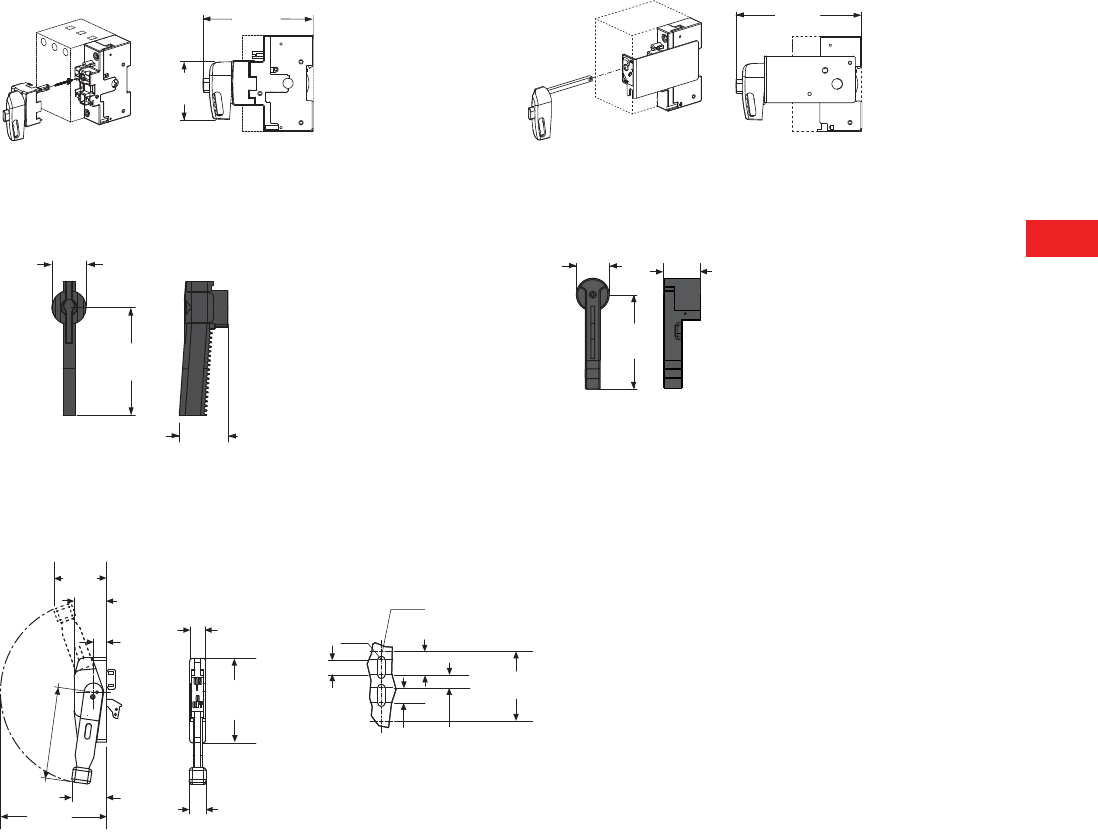
Volume 5—Motor Control and Protection CA08100006E—December 2013 www.eaton.com V5-T8-43
8
8
8
8
8
8
8
8
8
8
8
8
8
8
8
8
8
8
8
8
8
8
8
8
8
8
8
8
8
8
8.3
Rotary Disconnects
R9 Series (UL 98)
Approximate Dimensions in Inches (mm)
30CC (H-Frame) 30J (H-Frame)
30J to 400J 600J and 800L
Flange Handle
4.41
(112.0)
2.31
(58.7)
5.12
(130.0)
2.36
(60.0)
7.48
(190.0)
3.35
(85.0)
1.57
(40.0)
5.31
(135.0)
1.79
(45.5)
3.50
(88.9) 2.16
(54.9)
0.86
(21.8)
1.06
(26.9)
4.68
(118.9)
1.55
(39.4)
0.88
(22.3)
1.0 0
(25.4)
1.0 0
(25.4)
6.22
(158.0)
2.32
(58.9)
7. 1 0
(180.3)
Ø0.50
(Ø12.7)
Ø0.28
(Ø7.1)
2.70
(68.6)
5.66
(143.8)
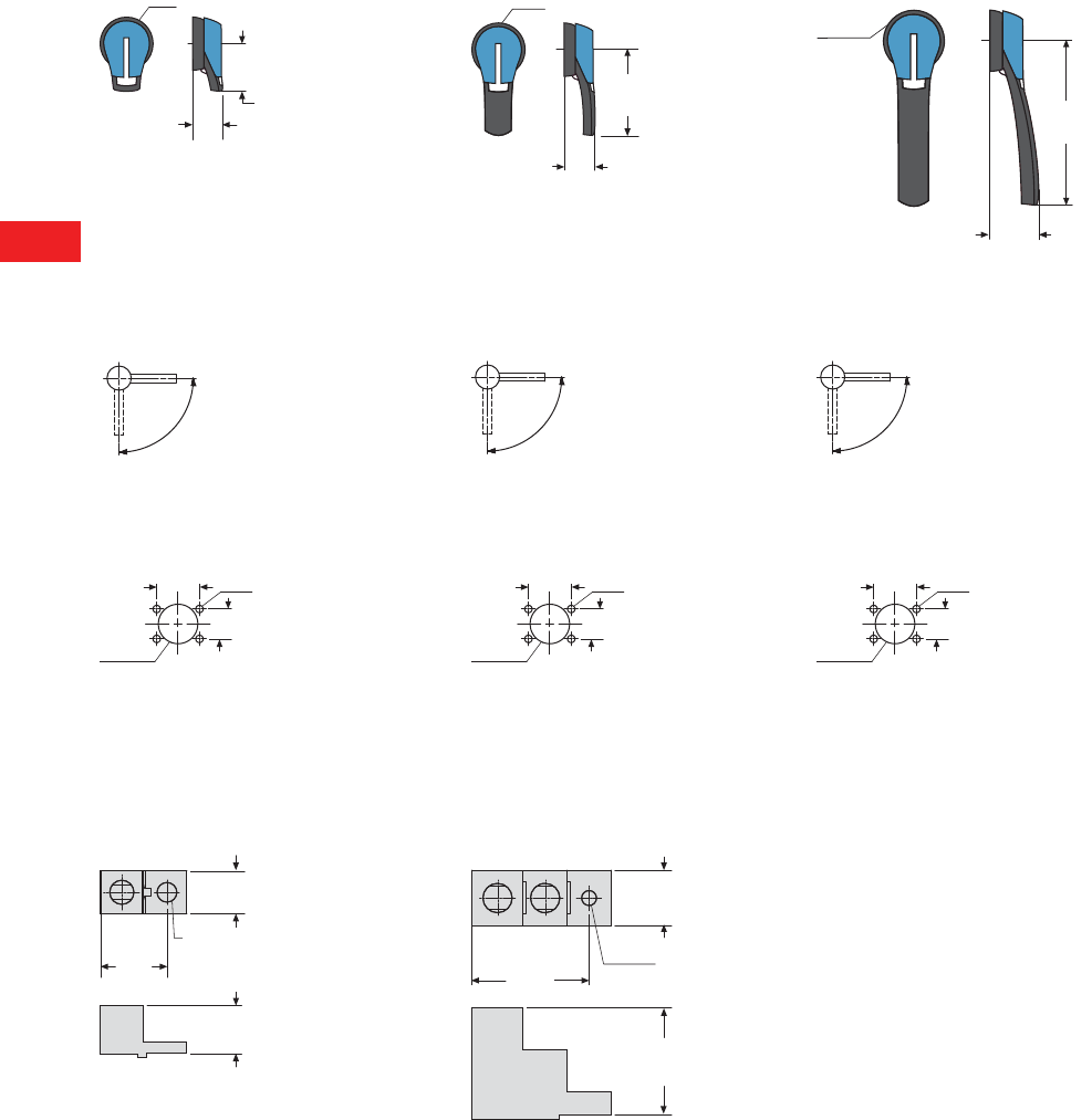
V5-T8-44 Volume 5—Motor Control and Protection CA08100006E—December 2013 www.eaton.com
8
8
8
8
8
8
8
8
8
8
8
8
8
8
8
8
8
8
8
8
8
8
8
8
8
8
8
8
8
8
8.3
Rotary Disconnects
R9 Series (UL 98)
Approximate Dimensions in Inches (mm)
Door Interlocked External Handle
PH1 Type Handle PH2 Type Handle PH3 Type Handle
Direction of Operation
Door Drilling Template
Line and Load Side Lugs
200A (L-Frame) 400–800A (M- and N-Frames)
2.75
(70.0)
1.73
(44.0)
Ø3.07 (Ø78.0)
Ø3.07 (Ø78.0)
4.92
(125.0)
1.77
(45.0)
Ø3.07
(Ø78.0)
8.27
(210.0)
2.40
(61.0)
90º
0º
I
90º
0º
I
90º
0º
I
1.57
(40.0)
4Ø7
Ø1.46
(37.0) 1.10
(28.0)
1.57
(40.0)
4Ø7
Ø1.46
(37.0) 1.10
(28.0)
1.57
(40.0)
4Ø7
Ø1.46
(37.0) 1.10
(28.0)
1.0 0
(25.4)
1.52
(38.6)
1.12
(28.4)
0.45
(Ø11.4)
2.87
(72.9)
3.15
(80.0)
1.49
(37.8)
0.40
(Ø10.2)
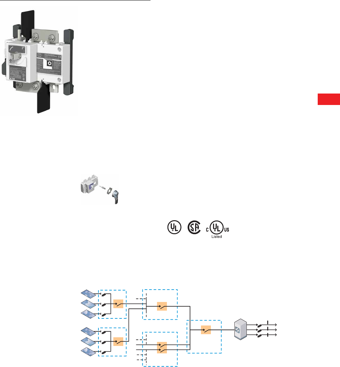
Volume 5—Motor Control and Protection CA08100006E—December 2013 www.eaton.com V5-T8-45
8
8
8
8
8
8
8
8
8
8
8
8
8
8
8
8
8
8
8
8
8
8
8
8
8
8
8
8
8
8
8.3
Rotary Disconnects
R9 Series (UL 98)
DC Rated Disconnects
Contents
Description Page
Non-Fusible 30–100A Compact . . . . . . . . . . . . . . . V5-T8-11
Non-Fusible 100–1200A . . . . . . . . . . . . . . . . . . . . . V5-T8-18
Fusible 30–800A . . . . . . . . . . . . . . . . . . . . . . . . . . V5-T8-26
DC Rated Disconnects
Product Selection . . . . . . . . . . . . . . . . . . . . . . . V5-T8-46
Accessories . . . . . . . . . . . . . . . . . . . . . . . . . . . . V5-T8-47
Technical Data and Specifications . . . . . . . . . . . V5-T8-49
Dimensions . . . . . . . . . . . . . . . . . . . . . . . . . . . . V5-T8-50
DC Rated Disconnects
Product Description
UL listed disconnect switches
600 Vdc for photovoltaic
applications 100 to 400A
R9 Series (UL 98 listed)
DC rated disconnects are
manually operated multi-pole
load break switches. They
provide safety isolation for
any low voltage circuit in a
photovoltaic application.
Features, Benefits
and Functions
●Switching technology
●Up to 600 Vdc according
to UL 98 / CSA
●Up to 1000 Vdc according
to IEC 947-3
Application Description
In three- and four-pole versions
from 100 to 400A
Standards and Certifications
●
UL 98, cULus
®
, File E222859
●CSA 22.2 No. 4,
File 217736 1
●IEC 60947-3
●EN 60947-3
●IEC 60-364-7-712
(Rules for the installations
and sites special—
photovoltaic applications)
Note
1Q4 2010
Simplified Large Photovoltaic System Layout
R9 DC
100 to 400A
to 1000V
R9 DC
R9 DC
R9 DC
100–600A
up to 1000V
Array Combiner
Source Combiner
R9 DC
100–400A
up to 1000V
Standard R9 Series
AC disconnect switch
non-fusible up to 1200A
or fusible up to 800A
Array Combiner
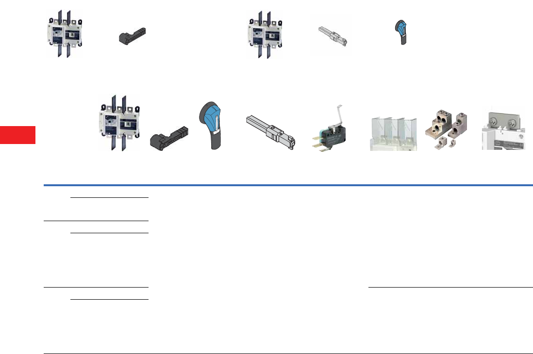
V5-T8-46 Volume 5—Motor Control and Protection CA08100006E—December 2013 www.eaton.com
8
8
8
8
8
8
8
8
8
8
8
8
8
8
8
8
8
8
8
8
8
8
8
8
8
8
8
8
8
8
8.3
Rotary Disconnects
R9 Series (UL 98)
Product Selection
Front Operation—Three- and Four-Pole
Notes
1Defeatable handle.
2Top (line side).
3Bottom (load side).
4Top or bottom (line or load side).
Ampere
Rating
Number
of Poles
Switch
Body Direct Handle
External Handle
(Choose one)
Shaft for External
Handle
In (mm) (Choose one)
Auxiliary Contacts
(Choose one)
Terminals
Shroud Terminal Lugs
Jumpers for
Connecting
Poles in Series
100 3 R9D3100UDC DHR9DE S2 Type
Black
1, 3R, 12 1
PHB2N12F
Red/Yellow
1, 3R, 12 1
PHR2N12F
Black
4, 4X 1
PHB2N4XF
Red/Yellow
4, 4X 1
PHR2N4XF
7.90 (200.0)
SF200PH10X10
12.60 (320.0)
SF320PH10X10
15.7 0 (400.0)
SF400PH10X10
C Type
1st Contact
NO+NC
AC1NONCDE
C Type
2nd Contact
NO+NC
AC2NONCDE
3P 2
TS3R9DT
3P 3
TS3R9DB
4P 4
TS4R9DTB
3P 4
LK3R9DL
4P 4
LK4R9DL
2 pieces
DCJUMPD2
3 pieces
DCJUMPD3
4R9D4100UDC
200 3 R9D3200UDC
4R9D4200UDC
400 3 R9E3400UDC 3P 2
TS3R9ET
3P 3
TS3R9EB
4P 4
TS4R9ETB
3P 4
LK3R9EM
4P 4
LK4R9EM
2 pieces
DCJUMPE2
3 pieces
DCJUMPE3
4R9E4400UDC
+++
Direct Operation External Operation
Volume 5—Motor Control and Protection CA08100006E—December 2013 www.eaton.com V5-T8-47
8
8
8
8
8
8
8
8
8
8
8
8
8
8
8
8
8
8
8
8
8
8
8
8
8
8
8
8
8
8
8.3
Rotary Disconnects
R9 Series (UL 98)
Accessories
Direct Handle
Door Interlocked External Handle Front Operation—l–0, Three- and Four-Pole
Auxiliary Contacts
Terminal Screens
Note
1 Order two sets for line and load sides.
Description Ampere Rating Handle Color Catalog Number
Front operation 100–400 Black DHR9DE
Ampere Rating Handle Handle Color NEMA Type Catalog Number
100–400 PH2 Type Black 1, 3R, 12 PHB2N12F 1
100–400 PH2 Type Red/yellow 1, 3R, 12 PHR2N12F 1
100–400 PH2 Type Black 4, 4X PHB2N4XF 1
100–400 PH2 Type Red/yellow 4, 4X PHR2N4XF 1
Description Ampere Rating Number of AC Type Catalog Number
Early-break/same-make and
signaling of positions 0 and 1:
1 to 2NO/NC auxiliary contacts
1 to 2 low level NO/NC auxiliary
contacts
Characteristics: NO/NC
AC: IP2 with front and side operation
Connection to the control circuit:
By 6.35 mm fast-on terminal
Electrical characteristics:
30,000 operations; A300
NO/NC Contact for Three and Four Poles
100–400 1 AC
NO + NC
C Type AC1NONCDE
100–400 2 AC
NO + NC
C Type AC2NONCDE
Low Level NO/NC Contact for Three and Four Poles
100–400 1 AC
NO + NC
C Type AC1NONCDELL
100–400 2 AC
NO + NC
C Type AC2NONCDELL
Description Ampere Rating Number of Poles Position Catalog Number
Line or load side protection against
direct contact with terminals or
connection parts
Three- and Four-Pole
100–200 3 Top (line) TS3R9DT
100–200 3 Bottom (load) TS3R9DB
100–200 4 Top or bottom (line or load) TS4R9DTB
400 3 Top (line) TS3R9ET
400 3 Bottom (load) TS3R9EB
400 4 Top or bottom (line or load) TS4R9ETB
Direct Handle
PH2 Type Handle
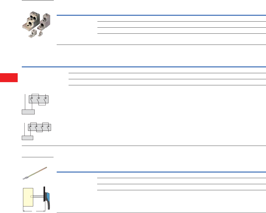
V5-T8-48 Volume 5—Motor Control and Protection CA08100006E—December 2013 www.eaton.com
8
8
8
8
8
8
8
8
8
8
8
8
8
8
8
8
8
8
8
8
8
8
8
8
8
8
8
8
8
8
8.3
Rotary Disconnects
R9 Series (UL 98)
Line and Load Terminal Lugs
Jumpers for Connecting Poles in Series
Shaft Extensions for External Front Dimensions (X)—Inches (mm)
Note
1 For other connections, refer to installation instructions.
Description Ampere Rating Connection Type
Number of Cables
per Terminal Lugs per Kit Cable Type Catalog Number
Connection of bare copper
cables onto the terminals
100–200 6–300 kcmil 1 2 Cu/Al LK2R9DL
100–200 6–300 kcmil 1 4 Cu/Al LK4R9DL
400 2–600 kcmil 1 2 Cu/Al LK2R9EM
400 2–600 kcmil 1 4 Cu/Al LK4R9EM
Description Ampere Rating Kit of Figure Number of Poles in Series Catalog Number
The jumpers will make easy
the connection of the poles in series,
allowing the following
configurations: 1
100–200 2 pieces 1 3 DCJUMPD2
100–200 3 pieces 2 4 DCJUMPD3
400 2 pieces 1 3 DCJUMPE2
400 3 pieces 2 4 DCJUMPE3
Description
Ampere
Rating Dimension X Handle Shaft Length Catalog Number
Standard lengths:
7.9 inches/200 mm
12.6 inches/320 mm
15.7 inches/400 mm
For Three- and Four-Pole
100–400 135–265 (3429.0–6731.0) PH2 Type 7.90 (200.0) SF200PH10X10
100–400 135–385 (3429.0–9779.0) PH2 Type 12.60 (320.0) SF320PH10X10
100–400 135–465 (3429.0–11811.0) PH2 Type 15.70 (400.0) SF400PH10X10
Line and Load Terminal
Lugs
-
+
Load
Load
-
+
X

Volume 5—Motor Control and Protection CA08100006E—December 2013 www.eaton.com V5-T8-49
8
8
8
8
8
8
8
8
8
8
8
8
8
8
8
8
8
8
8
8
8
8
8
8
8
8
8
8
8
8
8.3
Rotary Disconnects
R9 Series (UL 98)
Technical Data and Specifications
100–400A
Characteristics According to UL 98
Characteristics According to IEC 60947-3
Ampere Rating
Thermal Current Ith
at 40°C (A) 100 200 400
General Use Purpose Ampere Rating
Rated voltage In series A A A
600 Vdc 3P 100 200 400
Overload Capacity
Prospective short-circuit current (kA rms) 20 20 20
Type of fuse A70P100 A70P200 LDC
Fuse rating 100 200 400
Connection Terminals
Minimum connection section/AWG #6 #6 #2
Maximum connection section/AWG 300 kcmil 300 kcmil 600 kcmil
Auxiliary Contacts
Electrical characteristics A300 A300 A300
Ampere Rating
Thermal Current Ith
at 40°C (A) 160 250 630
Rated Operational Currents Ie (A), DC-22 B
Rated voltage In series A A A
750 Vdc 3P 160 250 400
750 Vdc 4P — — —
1000 Vdc 4P 160 250 400
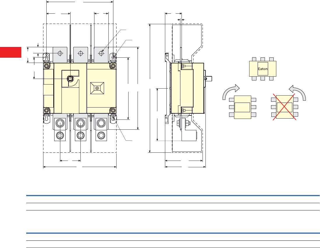
V5-T8-50 Volume 5—Motor Control and Protection CA08100006E—December 2013 www.eaton.com
8
8
8
8
8
8
8
8
8
8
8
8
8
8
8
8
8
8
8
8
8
8
8
8
8
8
8
8
8
8
8.3
Rotary Disconnects
R9 Series (UL 98)
Dimensions
Approximate Dimensions in Inches (mm)
R9 Series DC Rated Disconnects 100–400A
Front Operation
R9 Series DC Rated Disconnects
Ampere
Rating C AC AD F 3P F 4P H J1 3P J1 4P K M 3P M 4P
100–200 3.72 (94.5) 10.10 (256.5) 3.05 (77.5) 7.09 (180.1) 9.06 (230.0) 4.22 (107.2) 2.17 (55.1) 4.13 (104.9) 1.80 (45.7) 6.30 (160.0) 8.27 (210.1)
400 4.92 (125.0) 16.00 (406.4) 4.51 (114.5) 9.05 (230.0) 11.40 (290.0) 6.53 (166.0) 2.95 (75.7) 5.31 (134.9) 2.65 (67.3) 8.26 (209.8) 10.60 (269.2)
Y
AC
K
CA
V
NAA
H
Z
J1 U
R1
M
AD
T
FC
R2
W
The switch will operate correctly when rotated
clockwise 90 degrees.
The switch will not operate correctly when
rotated counter
clockwise 90 degrees.
Ampere
Rating N R1 R2 T U V W Y Z AA CA
100–200 5.31 (135.0) 0.35 (8.9) 0.27 (6.9) 1.97 (50.0) 0.98 (24.9) 1.18 (30.0) 0.43 (10.9) 0.14 (3.6) 1.35 (34.3) 6.30 (160.0) 0.60 (15.2)
400 7.60 (193.0) 0.35 (8.9) 0.27 (6.9) 2.56 (65.0) 1.77 (45.0) 1.97 (50.0) 0.43 (10.9) 0.20 (5.1) 2.08 (52.8) 10.20 (259.1) 0.80 (20.3)
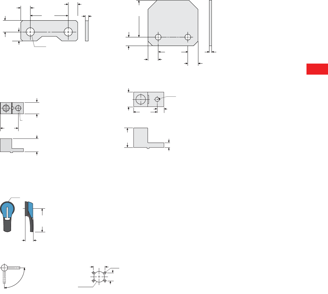
Volume 5—Motor Control and Protection CA08100006E—December 2013 www.eaton.com V5-T8-51
8
8
8
8
8
8
8
8
8
8
8
8
8
8
8
8
8
8
8
8
8
8
8
8
8
8
8
8
8
8
8.3
Rotary Disconnects
R9 Series (UL 98)
Approximate Dimensions in Inches (mm)
Jumpers
100–200A 400A
Terminal Lugs
100–200A 400A
Door Interlocked External Handle—100 to 400A, Three- and Four-Pole
PH2 Type Handle
Direction of Operation Door Drilling Template
22.50
(571.5)
19.00
(482.6)
81.00
(2057.4)
22.50
(571.5)
5.00
(127.0)
65.00
(1651.0)
0.49
(12.5)
Ø0.43
(Ø11.0)
0.47
(12.0)
0.59
(15.0)
1.97
(50.0)
0.49
(12.5)
0.16
(4.0)
1.0 0
(25.4)
1.52
(38.6)
1.12
(28.4)
0.45
(Ø11.4)
2.80
(71.5)
Ø 0.40 (Ø10.16)
Ø 4.70 (Ø119.38)
1.30
(35.0)
1.80
(46.0)
0.44
(11.13)
0.63
(15.9)
Ø3.07 (Ø78.0)
4.92
(125.0)
1.77
(45.0)
90º
0º
I
1.57
(40.0)
4Ø7
Ø1.46
(37.0) 1.10
(28.0)
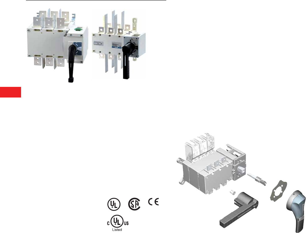
V5-T8-52 Volume 5—Motor Control and Protection CA08100006E—December 2013 www.eaton.com
8
8
8
8
8
8
8
8
8
8
8
8
8
8
8
8
8
8
8
8
8
8
8
8
8
8
8
8
8
8
8.4
Rotary Disconnects
Manual Transfer/Double Throw Switches
Manual Transfer Switches
Contents
Description Page
Manual Transfer/Double Throw Switches
Product Selection . . . . . . . . . . . . . . . . . . . . . . . V5-T8-53
Accessories. . . . . . . . . . . . . . . . . . . . . . . . . . . . V5-T8-54
Technical Data and Specifications . . . . . . . . . . . V5-T8-56
Dimensions. . . . . . . . . . . . . . . . . . . . . . . . . . . . V5-T8-57
Product Description
R9 Series (UL 98 listed)
non-fusible disconnects are
heavy-duty manual transfer
switches, they transfer load
manually between two low
voltage circuits and provide
safety disconnection.
These switches are
extremely durable and are
tested and approved for use
in the most demanding
applications as resistive load
or total system applications.
●Three load break
positions (I, 0, II)
●On load switching
●Direct or external handle
●480 Vac total system
●600 Vac resistive load
Standards and
Certifications
●UL 98, cULus,
File E222859
●UL1008 (600–1200A)
●CSA 22.2 No. 4,
File 217736
●IEC 60947-3
●EN 60947-3
●CE
Product Identification
1External front handle
2Direct handle
3Shaft extension for external handle
4Pre-break ACs (standard on 600–1200A)
5Terminal screen
5
4
1
3
2
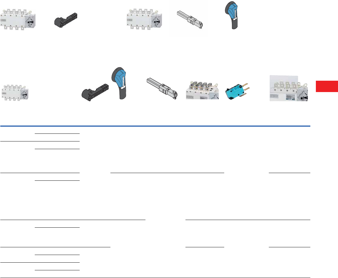
Volume 5—Motor Control and Protection CA08100006E—December 2013 www.eaton.com V5-T8-53
8
8
8
8
8
8
8
8
8
8
8
8
8
8
8
8
8
8
8
8
8
8
8
8
8
8
8
8
8
8
8.4
Rotary Disconnects
Manual Transfer/Double Throw Switches
Product Selection
Manual Transfer/Double Throw Switches—UL 98 Standard 1
Notes
1All ratings, 100–1200A, are UL 98 listed. Switches rated 600–1200A are UL 1008 listed as well.
2Line or load (top or bottom); for both line and load, order two kits.
3Low level auxiliary contact—gold plated for minimal resistance—for PLC applications.
Ampere
Rating
Number
of Poles
Switch
Body Only 1
Direct
Handle (Black)
External Three-
Position Handle
(Choose one)
Shaft Extensions for
External Handle
In (mm)
(Choose one)
Bridging
Bars
Auxiliary
Contacts
Terminal
Screens 2
100 3 RMTS3100U DHMTSSL Size 2, Black
I–0–II
Type 4/4X
PHB2N4X3P
Size 2, Red
I–0–II
Type 4/4X
PHR2N4X3P
7.90 (200.6)
SF200PH10X10
12.60 (320.0)
SF320PH10X10
15.70 (398.8)
SF400PH10X10
3P
BB3P200
4P
BB4P200
NO/NC
AC1NONCMTS400
Low level
AC1NONCMTS400LL 3
3P
TS3MTS200TB
4P
TS4MTS200TB
4RMTS4100U
200 3 RMTS3200U
4RMTS4200U
400 3 RMTS3400U Size 3, Black
I–0–II
Type 4/4X
PHB3N4X3P
Size 3, Red
I–0–II
Type 4/4X
PHR3N4X3P
7.90 (200.6)
SF200PH15X12
12.60 (320.0)
SF320PH15X12
15.70 (398.8)
SF400PH15X12
3P
BB3P400
4P
BB4P400
3P
TS3MTS400TB
4P
TS4MTS400TB
4RMTS4400U
600 3 RMTS3600U DHMTSDL Size 4, Black
I–0–II
Type 4/4X
PHB4N4X3P
Size 4, Red
I–0–II
Type 4/4X
PHR4N4X3P
3P
BB3P600
4P
BB4P600
NO/NC
contact
standard
3P
TS3MTS600
4P
TS4MTS600
4RMTS4600U
800 3 RMTS3800U DHMTSDLM 3P
BB3P1200
4P
BB4P1200
3P
TS3MTS1200
4P
TS4MTS1200
4RMTS4800U
1200 3 RMTS31200U
4RMTS41200U
+++
Switch body Direct handle Switch body Shaft External handle
+++
Direct Operation External Operation
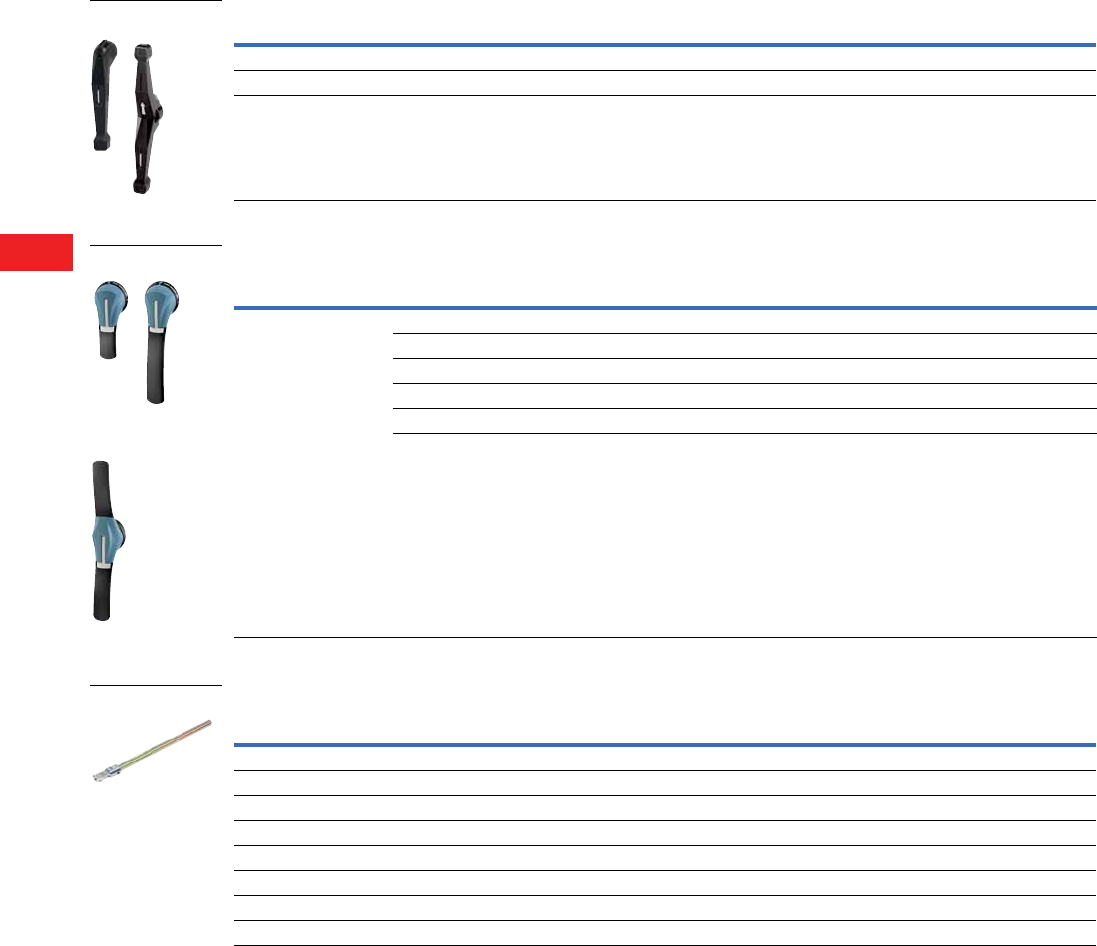
V5-T8-54 Volume 5—Motor Control and Protection CA08100006E—December 2013 www.eaton.com
8
8
8
8
8
8
8
8
8
8
8
8
8
8
8
8
8
8
8
8
8
8
8
8
8
8
8
8
8
8
8.4
Rotary Disconnects
Manual Transfer/Double Throw Switches
Accessories
Direct Handle
External Handle
Shaft Extension
Ampere Rating Handle Color Handle Type Catalog Number
100–400 Black Single lever DHMTSSL
600 Black Double lever DHMTSDL
800–1200 Black Double lever DHMTSDLM
Description Ampere Rating Handle Type Handle Color NEMA Type
Lockable in
the “3” Positions Catalog Number
The handle locking function
prevents the user from
opening the door of the
enclosure when the switch is
in the “ON” position.
Opening the door when the
switch is in the “ON” position
is possible by defeating the
locking function with the use
of a tool (authorized persons
only). The locking function is
restored when the door is
once again closed.
100–200 PH2 Black 4, 4X Yes PHB2N4X3P
100–200 PH2 Red/Yellow 4, 4X Yes PHR2N4X3P
400 PH3 Black 4, 4X Yes PHB3N4X3P
400 PH3 Red/Yellow 4, 4X Yes PHR3N4X3P
600–1200 PH4 Black 4, 4X Yes PHB4N4X3P
600–1200 PH4 Red/Yellow 4, 4X Yes PHR4N4X3P
Ampere Rating Handle Type
Length
In (mm) Catalog Number
100–800 PH1 7.90 (200.6) SF200PH10X10
125–800 PH1 12.60 (320.0) SF320PH10X10
100–200 PH2 15.70 (398.8) SF400PH10X10
630–1200 PH2, PH3 7.90 (200.6) SF200PH15X12
600–1200 PH2, PH3 12.60 (320.0) SF320PH15X12
400–1200 PH2, PH3 15.70 (398.8) SF400PH15X12
800–1200 V1 12.60 (320.0) SF320V1
800–1200 V1 15.70 (398.8) SF400V1
PH4 Type
PH2 and PH3 Type
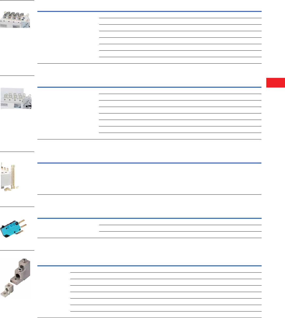
Volume 5—Motor Control and Protection CA08100006E—December 2013 www.eaton.com V5-T8-55
8
8
8
8
8
8
8
8
8
8
8
8
8
8
8
8
8
8
8
8
8
8
8
8
8
8
8
8
8
8
8.4
Rotary Disconnects
Manual Transfer/Double Throw Switches
Bridging Bars
Terminals Protection Screen
Mounting Spacers
Auxiliary Contacts
Line and Load Terminal Lugs
Note
1 Gold plated for minimal resistance—for PLC applications.
Description Ampere Rating Number of Bridging Bars Catalog Number
Creation of a common point, above or below
the switch, between positions I and II.
100 –200 3 BB3P200
100–200 4 BB4P200
400 3 BB3P400
400 4 BB4P400
600 3 BB3P600
600 4 BB4P600
800–1200 3 BB3P1200
800–1200 4 BB4P1200
Description Ampere Rating Number of Poles Catalog Number
Top or bottom (line or load) protection
against direct contacts with terminal
or connecting parts.
100–200 3 TS3MTS200TB
100–200 4 TS4MTS200TB
400 3 TS3MTS400TB
400 4 TS4MTS400TB
600 6 TS3MTS600
600 4 TS4MTS600
800–1200 3 TS3MTS1200
800–1200 4 TS4MTS1200
Description Ampere Rating Number of Poles Catalog Number
Raises the device’s terminals 10 mm away
from the bottom of the enclosure or frame
on which the device is mounted.
100–400 1 set of 2 spacers MSP400
Description Ampere Rating Contact(s) Catalog Number
Early-break/same-make and signalization per
position 1 and 2.
Electrical characteristics:
A300.
100–400 1NO/NC per position 1 and 2 AC1NONCMTS400
100–400 1NO/NC per position 1 and 2 low level AC1NONCMTS400LL 1
600–1200 1NO/NC per position 1 and 2 Standard
Description Ampere Rating
Connection
Type
Number of
Poles
Number of
Cables/Lug Lugs per Kit Cable Type Catalog Number
Connection of bare
copper cables onto the
terminals (without
spade lugs).
100–200 6–300 kcmil 3 1 3 Cu/Al LK3R9DL
100–200 6–300 kcmil 4 1 4 Cu/Al LK4R9DL
400 4–600 kcmil 3 1 3 Cu/Al LK3R9EM
400 4–600 kcmil 4 1 4 Cu/Al LK4R9EM
600 2x (#2–600 kcmil) 3 2 3 Cu/Al LK3R9FN
600 2x (#2–600 kcmil) 4 2 4 Cu/Al LK4R9FN
800–1200 2x (#2–600 kcmil) 3 2 6 Cu/Al LK6R9G
800–1200 2x (#2 –600 kcmil) 4 2 8 Cu/Al LK8R9G

V5-T8-56 Volume 5—Motor Control and Protection CA08100006E—December 2013 www.eaton.com
8
8
8
8
8
8
8
8
8
8
8
8
8
8
8
8
8
8
8
8
8
8
8
8
8
8
8
8
8
8
8.4
Rotary Disconnects
Manual Transfer/Double Throw Switches
Technical Data and Specifications
UL 1008 Characteristics
UL 98/CSA 22.2 No. 4 Characteristics
Notes
1Short-circuit rating achieved when used
with respective fuse type and maximum
fuse rating.
2Only UL 98 listed. For UL 1008
availability, contact Eaton.
3Two-pole in series.
4Three-pole in series.
Description 100A 200A 400A 600A 800A 1200A
Operation voltage 600 600 600 600 600 600
Short-circuit rating at 600 Vac (kA) 1100 100 65 100 100 100
Type of fuse J J J L L L
Maximum fuse rating (A) 200 400 600 800 1000 1600
Short-circuit rating with circuit breaker (kA/ms) 10/25 10/25 14/50 35/50 35/50 35/50
Operational Power/Current Maximum Operational Three-Phase
240 Vac total system (A) 100 100 250 400 700 700
240 Vac resistive load (A) 100 200 400 600 800 1200
480 Vac total system (A) 100 100 125 350 600 600
480 Vac resistive load (A) 100 200 400 600 800 1200
600 Vac resistive load (A) 100 200 400 400 800 1200
Mechanical Endurance
Endurance (number of operating cycles) 6050 6050 6050 6050 3550 3550
Connection Terminals
Minimum connection section/AWG #6 #6 #4/2 x #6 2x #2 4x #2 4x #2
Maximum connection section/AWG 300 kcmil 300 kcmil 600 kcmil/2x 350 kcmil 2x 600 kcmil 4x 600 kcmil 4x 600 kcmil
Description 100A 2200A 2400A 2600A 800A 1200A
Short-circuit rating at 600 Vac (kA) 200 200 200 200 100 100
Type of fuse J J J J L L
Maximum fuse rating (A) 100 200 400 600 800 1200
Maximum Motor, hp/FLA Three-Phase Motor Maximum
220–240 Vac 30/80 75/192 125/312 200/480 200/480 200/480
440–480 Vac 75/96 180/180 250/302 400/477 500/590 500/590
600 Vac 100/99 200/192 350/336 350/336 500/472 500/472
Maximum Motor Power, hp/DC FLA Motor Maximum
125 Vdc 37.5/58 15/112 20/148 20/148 — —
250 Vdc 420/72 40/140 50/173 50/173 — —
Mechanical Characteristics
Endurance (number of operating cycles) 10,000 8000 6000 6000 3500 3500
Operating torque (lbs.in/Nm) 88.5/10 88.5/10 128.3/14.5 327.5/37 442.5/50 442.5/50
Auxiliary Contacts
Electrical characteristics A300 A300 A300 A300 A300 A300
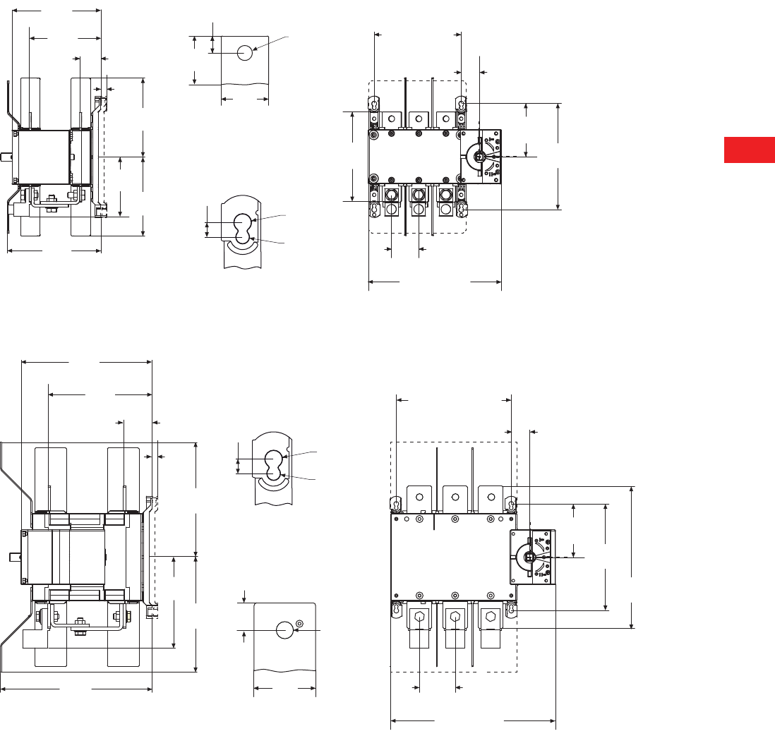
Volume 5—Motor Control and Protection CA08100006E—December 2013 www.eaton.com V5-T8-57
8
8
8
8
8
8
8
8
8
8
8
8
8
8
8
8
8
8
8
8
8
8
8
8
8
8
8
8
8
8
8.4
Rotary Disconnects
Manual Transfer/Double Throw Switches
Dimensions
Approximate Dimensions in Inches (mm)
100 to 200A
400A
6.41
(162.8)
5.19
(131.8) 1.53
(38.9)
5.51
(140.0)
4.29
(109.0)
6.77
(172.0)
5.51
(140.0)
0.41
(10.4)
1.18
(30.0)
0.98
(24.9)
1.37
(34.8)
0.53
(13.5)
Ø0.43
Ø(11.0)
View “A”
View “B”
“B”
“A”
Ø0.35
Ø(9.0)
Ø0.27
Ø(6.9)
0.29
(7.4)
1.97
(50.0)
6.30
(160)
5.31
(134.9)
2.67
(67.8)
3P
Fix 6.30
(160.0)
4P
Fix 8.26
(210.0)
3P
9.64
(245.0)
4P
11.41
(290.0)
9.41
(239.0)
7.48
(190.0)
2.04
(51.8)
0.41
(10.4)
View “A”
View “B”
Ø0.35
Ø(9.0)
Ø0.27
Ø(6.9)
0.29
(7.4)
8.26
(209.8)
8.26
(209.8)
6.53
(165.9)
10.90
(277.0)
“A”
1.38
(35.1)
Ø0.43
Ø(11.0)
0.49
(12.4)
“B”
1.37
(34.8)
7.67
(194.8)
3.85
(97.8)
10.23
(259.8)
2.56
(65.0)
3P
Fix 8.26
(210.0)
4P
Fix 10.63
(270.0)
3P
11.85
(301.0)
4P
14.21
(361.0)
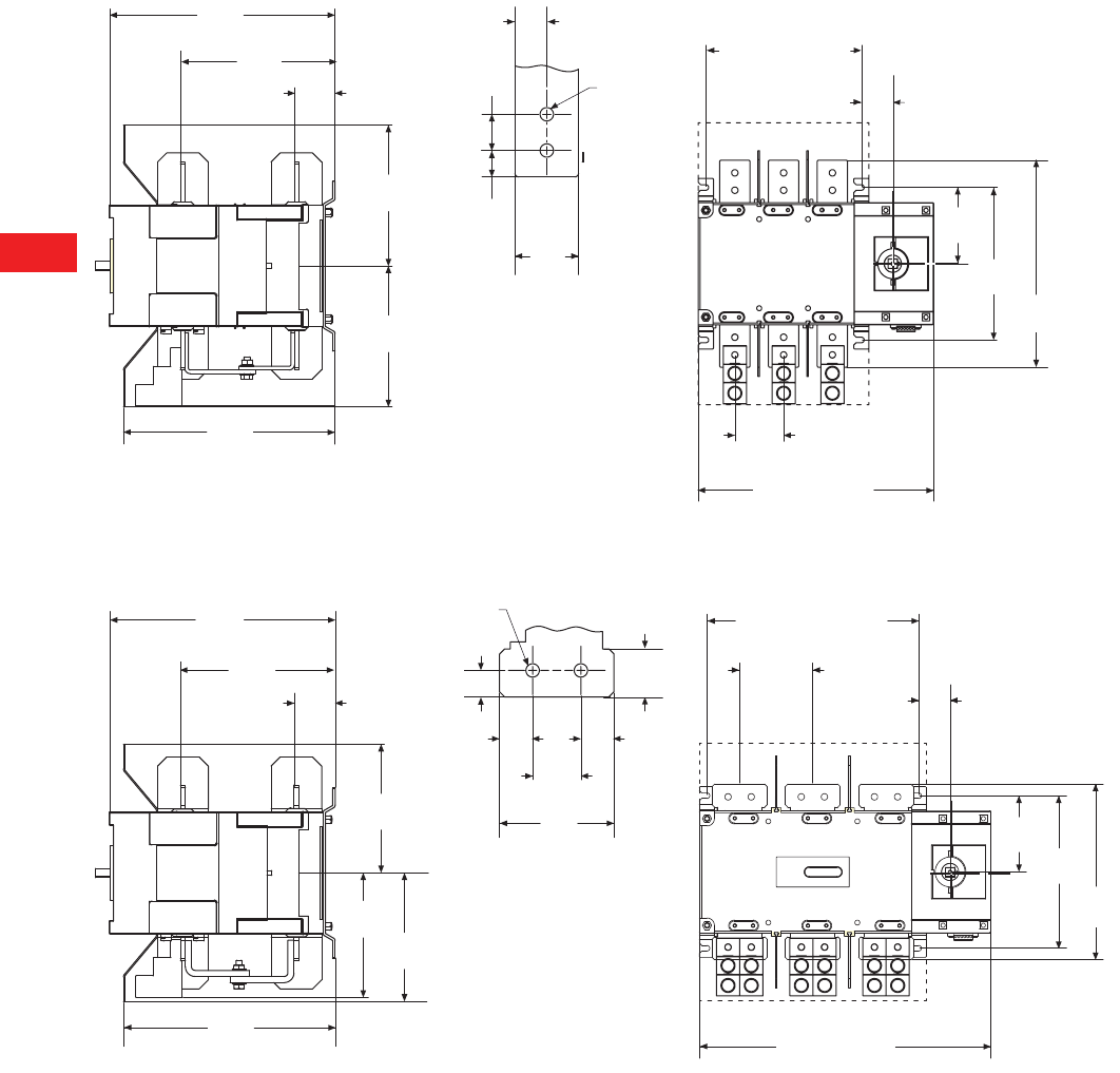
V5-T8-58 Volume 5—Motor Control and Protection CA08100006E—December 2013 www.eaton.com
8
8
8
8
8
8
8
8
8
8
8
8
8
8
8
8
8
8
8
8
8
8
8
8
8
8
8
8
8
8
8.4
Rotary Disconnects
Manual Transfer/Double Throw Switches
Approximate Dimensions in Inches (mm)
600A
800 to 1200A
14.56
(369.8)
9.98
(253.5) 2.61
(66.3)
9.09
(230.9)
9.09
(230.9)
13.66
(347.0)
View “A”
“A”
Ø0.41
Ø(10.5)
1.12
(28.4)
0.82
(20.8)
1.96
(49.8)
0.98
(24.9)
2.02
(51.3)
4.92
(125.0)
9.84
(249.9)
13.38
(339.9)
3.15
(80.0)
3P
Fix 10.04
(255.0)
4P
Fix 13.18
(335.0)
3P
15.19
(386.0)
4P
18.34
(466.0)
14.56
(369.8)
9.98
(253.5)
2.65
(67.3)
8.30
(210.8)
8.30
(210.8)
8.03
(204.0)
13.66
(347.0)
Ø0.41
Ø(10.5) View “A”
“A”
3.54
(89.9)
1.49
(37.8)
1.02
(25.9)
0.82
(20.8)
1.02
(25.9)
1.49
(37.8) 2.02
(51.3)
11.34
(288.0)
4.72
(119.9)
9.84
(249.9)
4.92
(125.0)
3P
Fix 13.66
(347.0)
4P
Fix 18.38
(467.0)
3P
15.19
(386.0)
4P
18.34
(466.0)
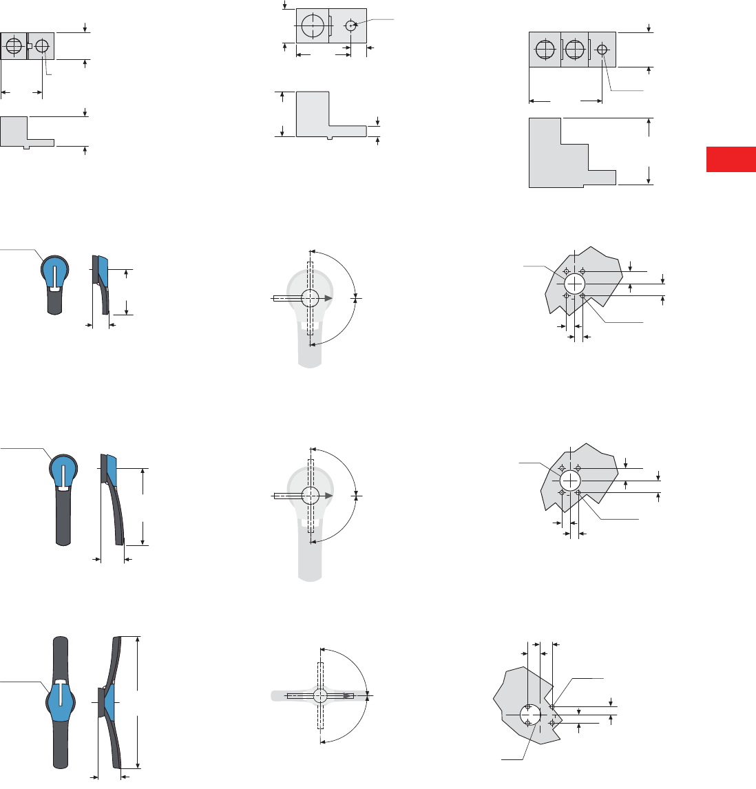
Volume 5—Motor Control and Protection CA08100006E—December 2013 www.eaton.com V5-T8-59
8
8
8
8
8
8
8
8
8
8
8
8
8
8
8
8
8
8
8
8
8
8
8
8
8
8
8
8
8
8
8.4
Rotary Disconnects
Manual Transfer/Double Throw Switches
Approximate Dimensions in Inches (mm)
Terminal Lugs
100–200A 400A 600–1200A
100–200A
PH2 Type Direction of Operation Door Drilling Template
400A
PH3 Type Direction of Operation Door Drilling Template
600–1200A
PH4 Type Direction of Operation Door Drilling Template
1.0 0
(25.4)
1.52
(38.6)
1.12
(28.4)
0.45
(Ø11.4)
2.80
(71.5)
Ø 0.40 (Ø10.16)
Ø 4.70 (Ø119.38)
1.30
(35.0)
1.80
(46.0)
0.44
(11.13)
0.63
(15.9)
2.87
(72.9)
3.15
(80.0)
1.49
(37.8)
0.40
(Ø10.2)
Ø3.07
(Ø78.0)
1.77
(45.0)
4.92
(125.0)
4 Ø 0.27
4 Ø 7.0
Ø D
90º
90º
I
II
0.79
(20.0)
0º
0.79
(20.0)
0.55
(14.0) 0.55
(14.0)
Ø78
(Ø1981.2)
61.00
(1549.4)
210
(5334.0)
90º
90º
I
II
0º
4 Ø 0.27
4 Ø 7.0
Ø D 0.79
(20.0)
0.79
(20.0)
0.55
(14.0) 0.55
(14.0)
0º
I
II
2.36
(60.0)
13.77
(350.0)
4 Ø 7
(4 Ø 7)
Ø D
90º
90º
0.79
(20.0)
Ø3.07
(Ø78.0)
0.79
(20.0)
0.55
(14.0)
0.55
(14.0)

Volume 5—Motor Control and Protection CA08100006E—December 2013 www.eaton.com V5-A1-1
Appendix 1—Eaton Terms & Conditions
Effective Date: November 1, 2008
Eaton Terms & Conditions
Contents
Description Page
Terms and Conditions of Sale. . . . . . . . . . . . . . . . . V5-A1-1
Terms of Payment . . . . . . . . . . . . . . . . . . . . . . . . . V5-A1-2
Freight . . . . . . . . . . . . . . . . . . . . . . . . . . . . . . . . . . V5-A1-3
Warranty. . . . . . . . . . . . . . . . . . . . . . . . . . . . . . . . . V5-A1-3
Selling Policy (Supersedes Selling Policy 25-000, dated February 20, 2006)
Terms and Conditions of Sale
The Terms and Conditions of
Sale set forth herein, and any
supplements which may be
attached hereto, constitute
the full and final expression
of the contract for the sale
of products or services
(hereinafter referred to as
Product(s) or Services by
Eaton Corporation
(hereinafter referred to as
Seller) to the Buyer, and
supersedes all prior
quotations, purchase orders,
correspondence or
communications whether
written or oral between the
Seller and the Buyer.
Notwithstanding any contrary
language in the Buyer’s
purchase order,
correspondence or other
form of acknowledgment,
Buyer shall be bound by
these Terms and Conditions
of Sale when it sends a
purchase order or otherwise
indicates acceptance of this
contract, or when it accepts
delivery from Seller of the
Products or Services.
THE CONTRACT FOR SALE
OF THE PRODUCTS OR
SERVICES IS EXPRESSLY
LIMITED TO THE TERMS
AND CONDITIONS OF SALE
STATED HEREIN. ANY
ADDITIONAL OR DIFFERENT
TERMS PROPOSED BY
BUYER ARE REJECTED
UNLESS EXPRESSLY
AGREED TO IN WRITING BY
SELLER. No contract shall
exist except as herein
provided.
Complete Agreement
No amendment or
modification hereto nor any
statement, representation or
warranty not contained herein
shall be binding on the Seller
unless made in writing by an
authorized representative of
the Seller. Prior dealings,
usage of the trade or a course
of performance shall not be
relevant to determine the
meaning of this contract even
though the accepting or
acquiescing party had
knowledge of the nature
of the performance and
opportunity for objection.
Quotations
Written quotations are valid
for 30 days from its date
unless otherwise stated in
the quotation or terminated
sooner by notice.
Verbal quotations, unless
accepted, expire the same
day they are made.
A complete signed order
must be received by Seller
within 20 calendar days of
notification of award,
otherwise the price and
shipment will be subject to
re-negotiation.
Termination and Cancellation
Any order may be terminated
by the Buyer only by written
notice and upon payment
of reasonable termination
charges, including all costs
plus profit.
Seller shall have the right to
cancel any order at any time
by written notice if Buyer
breaches any of the terms
hereof, becomes the subject
of any proceeding under state
or federal law for the relief
of debtors, or otherwise
becomes insolvent or
bankrupt, generally does not
pay its debts as they become
due or makes an assignment
for the benefit of creditors.
V5-A1-2 Volume 5—Motor Control and Protection CA08100006E—December 2013 www.eaton.com
Appendix 1—Eaton Terms & Conditions
Effective Date: November 1, 2008
Prices
All prices are subject to
change without notice. In the
event of a price change, the
effective date of the change
will be the date of the new
price or discount sheet, letter
or telegram. All quotations
made or orders accepted
after the effective date will be
on the new basis. For existing
orders, the price of the
unshipped portion of an order
will be the price in effect at
time of shipment.
Price Policy—Products and
Services
When prices are quoted as
firm for quoted shipment, they
are firm provided the following
conditions are met:
1. The order is released
with complete
engineering details.
2. Shipment of Products are
made, and Services
purchased are provided
within the quoted
lead time.
3. When drawings for
approval are required
for any Products, the
drawings applicable to
those Products must be
returned within 30*
calendar days from the
date of the original
mailing of the drawings
by Seller. The return
drawings must be
released for manufacture
and shipment and must
be marked “APPROVED”
or “APPROVED AS
NOTED.” Drawing
re-submittals which are
required for any other
reason than to correct
Seller errors will not
extend the 30-day period.
* 60 days for orders
through contractors
to allow time for their
review and approval
before and after
transmitting them
to their customers.
If the Buyer initiates or in
any way causes delays
in shipment, provision of
Services or return of approval
drawings beyond the periods
stated above, the price of the
Products or Services will be
increased 1% per month
or fraction thereof up to a
maximum of 18 months from
the date of the Buyer’s order.
For delays resulting in
shipment or provision of
Services beyond 18 months
from the date of the Buyer’s
order, the price must be
renegotiated.
Price Policy—BLS
Refer to Price Policy 25-050.
Minimum Billing
Orders less than $1,000 will
be assessed a shipping and
handling charge of 5% of the
price of the order, with a
minimum charge of $25.00
unless noted differently on
Product discount sheets.
Taxes
The price does not include
any taxes. Buyer shall be
responsible for the payment
of all taxes applicable to, or
arising from the transaction,
the Products, its sale, value,
or use, or any Services
performed in connection
therewith regardless of
the person or entity
actually taxed.
Terms of Payment
Products
Acceptance of all orders is
subject to the Buyer meeting
Seller’s credit requirements.
Terms of payment are subject
to change for failure to meet
such requirements. Seller
reserves the right at any time
to demand full or partial
payment before proceeding
with a contract of sale as a
result of changes in the
financial condition of the
Buyer. Terms of Payment are
either Net 30 days from the
date of invoice of each
shipment or carry a cash
discount based on Product
type. Specific payment terms
for Products are outlined in
the applicable Product
discount schedules.
Services
Terms of payment are net
within 30 days from date of
invoice for orders amounting
to less than $50,000.00.
Terms of payment for orders
exceeding $50,000.00 shall
be made according to the
following:
1. Twenty percent (20%) of
order value with the
purchase order payable
30 days from date of
invoice.
2. Eighty percent (80%) of
order value in equal
monthly payments over
the performance period
payable 30 days from
date of invoice.
Except for work performed (i)
under a firm fixed price basis
or (ii) pursuant to terms of a
previously priced existing
contract between Seller and
Buyer, invoices for work
performed by Seller shall
have added and noted on
each invoice a charge of 3%
(over and above the price of
the work) which is related
to Seller compliance with
present and proposed
environmental, health, and
safety regulations associated
with prescribed requirements
covering hazardous materials
management and employee
training, communications,
personal protective
equipment, documentation
and record keeping
associated therewith.
Adequate Assurances
If, in the judgment of Seller,
the financial condition of the
Buyer, at any time during the
period of the contract, does
not justify the terms of
payment specified, Seller
may require full or partial
payment in advance.
Delayed Payment
If payments are not made in
accordance with these terms,
a service charge will, without
prejudice to the right of Seller
to immediate payment, be
added in an amount equal to
the lower of 1.5% per month
or fraction thereof or the
highest legal rate on the
unpaid balance.
Volume 5—Motor Control and Protection CA08100006E—December 2013 www.eaton.com V5-A1-3
Appendix 1—Eaton Terms & Conditions
Effective Date: November 1, 2008
Freight
Freight policy will be listed on
the Product discount sheets,
or at option of Seller one of
the following freight terms
will be quoted.
F.O.B.—P/S—Frt./Ppd. and
Invoiced
Products are sold F.O.B. point
of shipment freight prepaid
and invoiced to the Buyer.
F.O.B.—P/S—Frt./Ppd.
and Allowed
Products sold are delivered
F.O.B. point of shipment,
freight prepaid and included
in the price.
F.O.B. Destination—Frt./Ppd.
and Allowed
At Buyer’s option, Seller will
deliver the Products F.O.B.
destination freight prepaid
and 2% will be added to the
net price.
The term “freight prepaid”
means that freight charges
will be prepaid to the
accessible common carrier
delivery point nearest the
destination for shipments
within the United States and
Puerto Rico unless noted
differently on the Product
discount sheets. For any
other destination contact
Seller’s representative.
Shipment and Routing
Seller shall select the point of
origin of shipment, the
method of transportation, the
type of carrier equipment and
the routing of the shipment.
If the Buyer specifies a
special method of
transportation, type of carrier
equipment, routing, or
delivery requirement, Buyer
shall pay all special freight
and handling charges.
When freight is included in
the price, no allowance will
be made in lieu of
transportation if the Buyer
accepts shipment at factory,
warehouse, or freight station
or otherwise supplies its own
transportation.
Risk of Loss
Risk of loss or damage to the
Products shall pass to Buyer
at the F.O.B. point.
Concealed Damage
Except in the event of F.O.B.
destination shipments, Seller
will not participate in any
settlement of claims for
concealed damage.
When shipment has been
made on an F.O.B. destination
basis, the Buyer must unpack
immediately and, if damage is
discovered must:
1. Not move the Products
from the point of
examination.
2. Retain shipping container
and packing material.
3. Notify the carrier in
writing of any apparent
damage.
4. Notify Seller
representative within
72 hours of delivery.
5. Send Seller a copy of
the carrier’s inspection
report.
Witness Tests/Customer
Inspection
Standard factory tests may be
witnessed by the Buyer
at Seller’s factory for an
additional charge calculated
at the rate of $2,500 per day
(not to exceed eight (8) hours)
per Product type. Buyer may
final inspect Products at the
Seller’s factory for $500 per
day per Product type.
Witness tests will add one (1)
week to the scheduled
shipping date. Seller will
notify Buyer fourteen (14)
calendar days prior to
scheduled witness testing
or inspection. In the event
Buyer is unable to attend, the
Parties shall mutually agree
on a rescheduled date.
However, Seller reserves
the right to deem the witness
tests waived with the right to
ship and invoice Products.
Held Orders
For any order held, delayed
or rescheduled at the request
of the Buyer, Seller may, at
its sole option (1) require
payment to be based on any
reasonable basis, including
but not limited to the contract
price, and any additional
expenses, or cost resulting
from such a delay; (2) store
Products at the sole cost and
risk of loss of the Buyer; and/
or (3) charge to the Buyer
those prices under the
applicable price policy.
Payment for such price,
expenses and costs, in any
such event, shall be due by
Buyer within thirty (30) days
from date of Seller’s invoice.
Any order so held delayed or
rescheduled beyond six (6)
months will be treated as a
Buyer termination.
Drawing Approval
Seller will design the
Products in line with, in
Seller’s judgment, good
commercial practice. If at
drawing approval Buyer
makes changes outside of
the design as covered in their
specifications, Seller will then
be paid reasonable charges
and allowed a commensurate
delay in shipping date based
on the changes made.
Drawing Re-Submittal
When Seller agrees to do so
in its quotation, Seller shall
provide Buyer with the first
set of factory customer
approval drawing(s) at Seller’s
expense. The customer
approval drawing(s) will be
delivered at the quoted
delivery date. If Buyer
requests drawing changes
or additions after the initial
factory customer approval
drawing(s) have been
submitted by Seller, the
Seller, at its option, may
assess Buyer drawing
charges. Factory customer
approval drawing changes
required due to
misinterpretation by Seller
will be at Seller’s expense.
Approval drawings generated
by Bid Manager are excluded
from this provision.
Warranty
Warranty for Products
Seller warrants that the
Products manufactured by
it will conform to Seller’s
applicable specifications and
be free from failure due to
defects in workmanship and
material for one (1) year from
the date of installation of
the Product or eighteen (18)
months from the date of
shipment of the Product,
whichever occurs first.
In the event any Product fails
to comply with the foregoing
warranty Seller will, at its
option, either (a) repair or
replace the defective
Product, or defective part or
component thereof, F.O.B.
Seller’s facility freight
prepaid, or (b) credit Buyer
for the purchase price of the
Product. All warranty claims
shall be made in writing.
Seller requires all non-
conforming Products be
returned at Seller’s expense
for evaluation unless
specifically stated otherwise
in writing by Seller.
This warranty does not
cover failure or damage
due to storage, installation,
operation or maintenance not
in conformance with Seller’s
recommendations and
industry standard practice
or due to accident, misuse,
abuse or negligence. This
warranty does not cover
reimbursement for labor,
gaining access, removal,
installation, temporary power
or any other expenses, which
may be incurred in connection
with repair or replacement.
This warranty does not
apply to equipment not
manufactured by Seller.
Seller limits itself to
extending the same warranty
it receives from the supplier.
V5-A1-4 Volume 5—Motor Control and Protection CA08100006E—December 2013 www.eaton.com
Appendix 1—Eaton Terms & Conditions
Effective Date: November 1, 2008
Extended Warranty for Products
If requested by the Buyer and
specifically accepted in
writing by Seller, the
foregoing standard warranty
for Products will be extended
from the date of shipment for
the period and price indicated
below:
●24 months—2% of
Contract Price
●30 months—3% of
Contract Price
●36 months—4% of
Contract Price
Special Warranty (In and Out)
for Products
If requested by the Buyer
and specifically accepted in
writing by Seller, Seller will,
during the warranty period
for Products, at an additional
cost of 2% of the contract
price, be responsible for the
direct cost of:
1. Removing the Product
from the installed
location.
2. Transportation to the
repair facility and return
to the site.
3. Reinstallation on site.
The total liability of Seller for
this Special Warranty for
Products is limited to 50%
of the contract price of the
particular Product being
repaired and excludes
expenses for removing
adjacent apparatus, walls,
piping, structures, temporary
service, etc.
Warranty for Services
Seller warrants that the
Services performed by it
hereunder will be performed
in accordance with generally
accepted professional
standards.
The Services, which do not
so conform, shall be
corrected by Seller upon
notification in writing by the
Buyer within one (1) year
after completion of the
Services.
Unless otherwise agreed to in
writing by Seller, Seller
assumes no responsibility
with respect to the suitability
of the Buyer’s, or its
customer’s, equipment or
with respect to any latent
defects in equipment not
supplied by Seller. This
warranty does not cover
damage to Buyer’s, or its
customer’s, equipment,
components or parts
resulting in whole or in part
from improper maintenance
or operation or from their
deteriorated condition. Buyer
will, at its cost, provide Seller
with unobstructed access
to the defective Services,
as well as adequate free
working space in the
immediate vicinity of the
defective Services and such
facilities and systems,
including, without limitation,
docks, cranes and utility
disconnects and connects,
as may be necessary in order
that Seller may perform its
warranty obligations. The
conducting of any tests shall
be mutually agreed upon and
Seller shall be notified of, and
may be present at, all tests
that may be made.
Warranty for Power Systems
Studies
Seller warrants that any
power systems studies
performed by it will conform
to generally accepted
professional standards. Any
portion of the study, which
does not so conform, shall
be corrected by Seller upon
notification in writing by the
Buyer within six (6) months
after completion of the study.
All warranty work shall be
performed in a single shift
straight time basis Monday
through Friday. In the event
that the study requires
correction of warranty items
on an overtime schedule,
the premium portion of such
overtime shall be for the
Buyer’s account.
Limitation on Warranties for
Products, Services and Power
Systems Studies
THE FOREGOING
WARRANTIES ARE
EXCLUSIVE EXCEPT FOR
WARRANTY OF TITLE.
SELLER DISCLAIMS ALL
OTHER WARRANTIES
INCLUDING ANY IMPLIED
WARRANTIES OF
MERCHANTABILITY
AND FITNESS FOR A
PARTICULAR PURPOSE.
CORRECTION OF NON-
CONFORMITIES IN THE
MANNER AND FOR THE
PERIOD OF TIME PROVIDED
ABOVE SHALL CONSTITUTE
SELLER’S SOLE LIABILITY
AND BUYER’S EXCLUSIVE
REMEDY FOR FAILURE OF
SELLER TO MEET ITS
WARRANTY OBLIGATIONS,
WHETHER CLAIMS OF
THE BUYER ARE BASED
IN CONTRACT, IN TORT
(INCLUDING NEGLIGENCE
OR STRICT LIABILITY), OR
OTHERWISE.
Asbestos
Federal Law requires that
building or facility owners
identify the presence,
location and quantity of
asbestos containing material
(hereinafter “ACM”) at work
sites. Seller is not licensed to
abate ACM. Accordingly, for
any contract which includes
the provision of Services,
prior to (i) commencement of
work at any site under a
specific Purchase Order, (ii) a
change in the work scope of
any Purchase Order, the
Buyer will certify that the
work area associated with the
Seller’s scope of work
includes the handling of Class
II ACM, including but not
limited to generator wedges
and high temperature gaskets
which include asbestos
materials. The Buyer shall, at
its expense, conduct
abatement should the
removal, handling,
modification or reinstallation,
or some or all of them, of said
Class II ACM be likely to
generate airborne asbestos
fibers; and should such
abatement affect the cost
of or time of performance
of the work then Seller shall
be entitled to an equitable
adjustment in the schedule,
price and other pertinent
affected provisions of
the contract.
Compliance with Nuclear
Regulation
Seller’s Products are sold as
commercial grade Products
not intended for application in
facilities or activities licensed
by the United States Nuclear
Regulatory Commission for
atomic purposes. Further
certification will be required
for use of the Products in any
safety-related application in
any nuclear facility licensed
by the U.S. Nuclear
Regulatory Commission.
Volume 5—Motor Control and Protection CA08100006E—December 2013 www.eaton.com V5-A1-5
Appendix 1—Eaton Terms & Conditions
Effective Date: November 1, 2008
Returning Products
Authorization and shipping
instructions for the return
of any Products must be
obtained from Seller before
returning the Products.
When return is occasioned
due to Seller error, full credit
including all transportation
charges will be allowed.
Product Notices
Buyer shall provide the user
(including its employees) of
the Products with all Seller
supplied Product notices,
warnings, instructions,
recommendations, and
similar materials.
Force Majeure
Seller shall not be liable for
failure to perform or delay
in performance due to fire,
flood, strike or other labor
difficulty, act of God, act of
any governmental authority or
of the Buyer, riot, embargo,
fuel or energy shortage, car
shortage, wrecks or delays in
transportation, or due to any
other cause beyond Seller’s
reasonable control. In the
event of delay in performance
due to any such cause, the
date of delivery or time for
completion will be extended
by a period of time reasonably
necessary
to overcome the
effect of such delay.
Liquidated Damages
Contracts which include
liquidated damage clauses for
failure to meet shipping or job
completion promises are not
acceptable or binding on
Seller, unless such clauses
are specifically accepted in
writing by an authorized
representative of the Seller at
its headquarters office.
Patent Infringement
Seller will defend or, at its
option, settle any suit or
proceeding brought against
Buyer, or Buyer’s customers,
to the extent it is based upon
a claim that any Product or
part thereof, manufactured by
Seller or its subsidiaries and
furnished hereunder,
infringes any United States
patent, other than a claim of
infringement based upon use
of a Product or part thereof in
a process, provided Seller is
notified in reasonable time
and given authority,
information and assistance
(at Seller’s expense) for the
defense of same. Seller shall
pay all legal and court costs
and expenses and court-
assessed damages awarded
therein against Buyer
resulting from or incident to
such suit or proceeding. In
addition to the foregoing, if at
any time Seller determines
there is a substantial question
of infringement of any United
States patent, and the use of
such Product is or may be
enjoined, Seller may, at its
option and expense: either (a)
procure for Buyer the right to
continue using and selling the
Product; (b) replace the
Product with non-infringing
apparatus; (c) modify the
Product so it becomes non-
infringing; or (d) as a last
resort, remove the Product
and refund the purchase
price, equitably adjusted for
use and obsolescence. In no
case does Seller agree to pay
any recovery based upon its
Buyer’s savings or profit
through use of Seller’s
Products whether the use be
special or ordinary. The
foregoing states the entire
liability of Seller for patent
infringement.
The preceding paragraph
does not apply to any claim of
infringement based upon: (a)
any modification made to a
Product other than by Seller;
(b) any design and/or
specifications of Buyer to
which a Product was
manufactured; or (c) the use
or combination of Product
with other products where
the Product does not itself
infringe. As to the above-
identified claim situations
where the preceding
paragraph does not apply,
Buyer shall defend and hold
Seller harmless in the same
manner and to the extent as
Seller’s obligations described
in the preceding paragraph.
Buyer shall be responsible for
obtaining (at Buyer’s
expense) all license rights
required for Seller to be able
to use software products in
the possession of Buyer
where such use is required in
order to perform any Service
for Buyer.
With respect to a Product or
part thereof not manufactured
by Seller or its subsidiaries,
Seller will attempt to obtain
for Buyer, from the supplier(s),
the patent indemnification
protection normally provided
by the supplier(s) to
customers.
Compliance with OSHA
Seller offers no warranty and
makes no representation that
its Products comply with the
provisions or standards of the
Occupational Safety and
Health Act of 1970, or any
regulation issued thereunder.
In no event shall Seller be
liable for any loss, damage,
fines, penalty or expenses
arising under said Act.
Limitation of Liability
THE REMEDIES OF THE
BUYER SET FORTH IN THIS
CONTRACT ARE EXCLUSIVE
AND ARE ITS SOLE
REMEDIES FOR ANY
FAILURE OF SELLER
TO COMPLY WITH ITS
OBLIGATIONS HEREUNDER.
NOTWITHSTANDING
ANY PROVISION IN THIS
CONTRACT TO THE
CONTRARY, IN NO EVENT
SHALL SELLER BE LIABLE
IN CONTRACT, IN TORT
(INCLUDING NEGLIGENCE
OR STRICT LIABILITY) OR
OTHERWISE FOR DAMAGE
TO PROPERTY OR
EQUIPMENT OTHER THAN
PRODUCTS SOLD
HEREUNDER, LOSS OF
PROFITS OR REVENUE,
LOSS OF USE OF
PRODUCTS, COST OF
CAPITAL, CLAIMS OF
CUSTOMERS OF THE
BUYER OR ANY SPECIAL,
INDIRECT, INCIDENTAL OR
CONSEQUENTIAL
DAMAGES WHATSOEVER,
REGARDLESS OF WHETHER
SUCH POTENTIAL
DAMAGES ARE
FORESEEABLE OR IF
SELLER HAS BEEN ADVISED
OF THE POSSIBILITY OF
SUCH DAMAGES.
THE TOTAL CUMULATIVE
LIABILITY OF SELLER
ARISING FROM OR
RELATED TO THIS
CONTRACT WHETHER
THE CLAIMS ARE BASED
IN CONTRACT, IN TORT
(INCLUDING NEGLIGENCE
OR STRICT LIABILITY) OR
OTHERWISE, SHALL NOT
EXCEED THE PRICE OF THE
PRODUCT OR SERVICES
ON WHICH SUCH LIABILITY
IS BASED.
Volume 5—Motor Control and Protection CA08100006E—April 2014 www.eaton.com V5-A2-1
Appendix 2—Catalog Parent Number Index
A
AA . . . . . . . . . . . . V5-T2-134
AE16 . . . . . . . . . . V5-T2-27
AE56 . . . . . . . . . . V5-T2-27
AGSH . . . . . . . . . V5-T7-5
AN . . . . . . . . . . . . V5-T2-134
AN13 . . . . . . . . . . V5-T2-67
AN16 . . . . . . . . . . V5-T2-11, V5-T2-27
AN19 . . . . . . . . . . V5-T2-51, V5-T2-52
AN53 . . . . . . . . . . V5-T2-67
AN56 . . . . . . . . . . V5-T2-11, V5-T2-27
AN59 . . . . . . . . . . V5-T2-51
AN700 . . . . . . . . . V5-T2-12
A20 . . . . . . . . . . . V5-T2-103, V5-T2-109
A202 . . . . . . . . . . V5-T6-24
A21 . . . . . . . . . . . V5-T2-104, V5-T2-110
A25 . . . . . . . . . . . V5-T2-104, V5-T2-110, V5-T4-24, V5-T4-50
A27 . . . . . . . . . . . V5-T4-31, V5-T4-53
A96 . . . . . . . . . . . V5-T2-111
A97 . . . . . . . . . . . V5-T2-111
A98 . . . . . . . . . . . V5-T2-111
B
BA . . . . . . . . . . . . V5-T2-131
BN16 . . . . . . . . . . V5-T2-16
B1A . . . . . . . . . . . V5-T3-12
B1B . . . . . . . . . . . V5-T3-12
B100 . . . . . . . . . . V5-T3-11
B230 . . . . . . . . . . V5-T3-4
B25 . . . . . . . . . . . V5-T4-24, V5-T4-50
B27 . . . . . . . . . . . V5-T4-32, V5-T4-53
B3NO . . . . . . . . . V5-T2-112, V5-T2-131
B330 . . . . . . . . . . V5-T3-4
C
CE15 . . . . . . . . . . V5-T2-27
CE55 . . . . . . . . . . V5-T2-27
CN13 . . . . . . . . . . V5-T2-66, V5-T2-68
CN15 . . . . . . . . . . V5-T2-5, V5-T2-6, V5-T2-27
CN35 . . . . . . . . . . V5-T2-27, V5-T6-17
CN53 . . . . . . . . . . V5-T2-66
CN55 . . . . . . . . . . V5-T2-5, V5-T2-27
C25 . . . . . . . . . . . V5-T4-5, V5-T4-9, V5-T4-47, V5-T4-59
C30CN. . . . . . . . . V5-T6-6–V5-T6-10
C306 . . . . . . . . . . V5-T2-32, V5-T2-33, V5-T2-39, V5-T2-43,
V5-T2-44, V5-T2-46
C311 . . . . . . . . . . V5-T5-46
C32 . . . . . . . . . . . V5-T4-11, V5-T4-12, V5-T4-26, V5-T4-55
C320 . . . . . . . . . . V5-T2-22–V5-T2-26, V5-T2-28, V5-T2-43,
V5-T6-10, V5-T6-11, V5-T6-18–V5-T6-20
C321 . . . . . . . . . . V5-T2-21, V5-T2-22, V5-T2-29
C325 . . . . . . . . . . V5-T7-4
C335 . . . . . . . . . V5-T2-28
C350 . . . . . . . . . V5-T2-21, V5-T4-18
C440 . . . . . . . . . V5-T1-146, V5-T1-147, V5-T2-85, V5-T2-86,
V5-T5-71, V5-T5-74, V5-T5-75
C441 . . . . . . . . . V5-T5-77, V5-T5-94–V5-T5-99
C65 . . . . . . . . . . V5-T4-21
C799 . . . . . . . . . V5-T4-12, V5-T4-26
C80 . . . . . . . . . . V5-T4-68
C81 . . . . . . . . . . V5-T4-68, V5-T4-69
D
DPCK . . . . . . . . . V5-T4-64, V5-T4-65
D3PA . . . . . . . . . V5-T5-8, V5-T5-11, V5-T5-14, V5-T5-19,
V5-T5-21, V5-T5-23, V5-T5-26, V5-T5-31,
V5-T5-34, V5-T5-37
D64D . . . . . . . . . V5-T5-47
D64L . . . . . . . . . V5-T5-54
D64R . . . . . . . . . V5-T5-45
D65C . . . . . . . . . V5-T5-8, V5-T5-11, V5-T5-14, V5-T5-19,
V5-T5-21, V5-T5-23, V5-T5-31, V5-T5-34,
V5-T5-37
D65P . . . . . . . . . V5-T5-21, V5-T5-23
D65V . . . . . . . . . V5-T5-19, V5-T5-26, V5-T5-31, V5-T5-34,
V5-T5-37
D77E . . . . . . . . . V5-T5-99
F
FH . . . . . . . . . . . V5-T2-139, V5-T2-140, V5-T3-11, V5-T3-12,
V5-T7-6
FT1. . . . . . . . . . . V5-T2-137
FT2. . . . . . . . . . . V5-T2-137
FT3. . . . . . . . . . . V5-T2-137
FT4. . . . . . . . . . . V5-T2-137
F56. . . . . . . . . . . V5-T2-112
H
H20 . . . . . . . . . . V5-T2-40, V5-T2-41, V5-T2-44, V5-T4-27,
V5-T4-56
H21 . . . . . . . . . . V5-T2-42, V5-T4-26, V5-T4-56
I
ID89 . . . . . . . . . . V5-T7-6
IQ50 . . . . . . . . . . V5-T2-142
L
LK. . . . . . . . . . . . V5-T3-12
M
MC382 . . . . . . . . V5-T2-23
ME . . . . . . . . . . . V5-T4-71
MS . . . . . . . . . . . V5-T3-7–V5-T3-9
M-3 . . . . . . . . . . V5-T2-112
V5-A2-2 Volume 5—Motor Control and Protection CA08100006E—April 2014 www.eaton.com
Appendix 2—Catalog Parent Number Index
P
PKE-SWD . . . . . . V5-T1-225
PNC . . . . . . . . . . . V5-T2-113
PNO. . . . . . . . . . . V5-T2-113
R
R56 . . . . . . . . . . . V5-T2-112
S
SS56 . . . . . . . . . . V5-T4-64
SS-56. . . . . . . . . . V5-T2-112
T
TK250A . . . . . . . . V5-T4-64
V
VM160. . . . . . . . . V5-T7-4
VM320. . . . . . . . . V5-T7-4
VM610. . . . . . . . . V5-T7-4
VSRO. . . . . . . . . . V5-T5-39
VSRU. . . . . . . . . . V5-T5-39
V200 . . . . . . . . . . V5-T7-3
V201 . . . . . . . . . . V5-T7-3
V210 . . . . . . . . . . V5-T7-3
V211 . . . . . . . . . . V5-T7-3
W
WMR. . . . . . . . . . V5-T5-54
X
XTAE . . . . . . . . . . V5-T1-50, V5-T1-51
XTAR . . . . . . . . . . V5-T1-52
XTCC . . . . . . . . . . V5-T1-63, V5-T1-64
XTCE . . . . . . . . . . V5-T1-7–V5-T1-10, V5-T1-39–V5-T1-44,
V5-T1-55–V5-T1-61, V5-T1-64, V5-T1-65,
V5-T1-67–V5-T1-77, V5-T2-69–V5-T2-72
XTCF . . . . . . . . . . V5-T1-45
XTCR . . . . . . . . . . V5-T1-47, V5-T1-48
XTCS . . . . . . . . . . V5-T1-42, V5-T1-43, V5-T1-60, V5-T1-77
XTFC . . . . . . . . . . V5-T1-199–V5-T1-202
XTFCE . . . . . . . . . V5-T1-219
XTFR . . . . . . . . . . V5-T1-199–V5-T1-202
XTMC . . . . . . . . . V5-T1-6, V5-T1-8, V5-T1-9, V5-T1-20, V5-T1-22,
V5-T1-24–V5-T1-26, V5-T1-65
XTMF. . . . . . . . . . V5-T1-20
XTMR . . . . . . . . . V5-T1-21
XTMT. . . . . . . . . . V5-T1-11
XTOB. . . . . . . . . . V5-T1-55–V5-T1-60, V5-T1-130–V5-T1-133,
V5-T4-33
XTOE . . . . . . . . . . V5-T1-144, V5-T1-145, V5-T2-83, V5-T2-84,
V5-T5-69–V5-T5-71
XTOM . . . . . . . . . V5-T1-23
XTOT . . . . . . . . . . V5-T1-60, V5-T1-61, V5-T1-132
XTPA . . . . . . . . . . V5-T1-163–V5-T1-170, V5-T1-173–V5-T1-175,
V5-T1-203, V5-T1-204
XTPAX . . . . . . . . . V5-T1-220–V5-T1-225
XTPB . . . . . . . . . . V5-T1-161, V5-T1-165, V5-T1-171, V5-T1-172
XTPE . . . . . . . . . V5-T1-218, V5-T1-219
XTPEX . . . . . . . . V5-T1-218, V5-T1-223
XTPR . . . . . . . . . V5-T1-162, V5-T1-163
XTRE . . . . . . . . . V5-T1-5
XTRM. . . . . . . . . V5-T1-5
XTSC . . . . . . . . . V5-T1-195–V5-T1-198
XTSR . . . . . . . . . V5-T1-195–V5-T1-198
XTTR . . . . . . . . . V5-T1-11, V5-T1-22, V5-T1-55–V5-T1-61
Z
ZEB-X . . . . . . . . . V5-T1-145, V5-T1-146, V5-T2-85, V5-T5-70,
V5-T5-71, V5-T5-74
Numerics
10-35 . . . . . . . . . V5-T4-78, V5-T4-81, V5-T4-84
10370. . . . . . . . . V5-T2-145
10-65 . . . . . . . . . V5-T2-32
10-68 . . . . . . . . . V5-T4-78, V5-T4-81, V5-T4-84
10-71 . . . . . . . . . V5-T4-25
11A8 . . . . . . . . . V5-T4-72
1250. . . . . . . . . . V5-T2-116, V5-T2-117
1254. . . . . . . . . . V5-T4-65
1255. . . . . . . . . . V5-T2-118
1264. . . . . . . . . . V5-T4-64
1266. . . . . . . . . . V5-T4-65
1268. . . . . . . . . . V5-T2-116
17-1 . . . . . . . . . . V5-T2-31
17-8 . . . . . . . . . . V5-T2-31
179C . . . . . . . . . V5-T4-64, V5-T4-65, V5-T6-25
180C . . . . . . . . . V5-T4-64, V5-T4-65, V5-T7-4
1954. . . . . . . . . . V5-T4-75
2050. . . . . . . . . . V5-T2-113, V5-T2-118, V5-T2-119
2057. . . . . . . . . . V5-T2-114
2066. . . . . . . . . . V5-T2-118
2084. . . . . . . . . . V5-T4-73
2114. . . . . . . . . . V5-T4-75
2119. . . . . . . . . . V5-T2-114
2120. . . . . . . . . . V5-T4-75
2131. . . . . . . . . . V5-T4-75
2184. . . . . . . . . . V5-T4-72, V5-T4-73
23-54 . . . . . . . . . V5-T4-81
23-72 . . . . . . . . . V5-T4-78
30B4 . . . . . . . . . V5-T4-73
3354. . . . . . . . . . V5-T2-115
3463. . . . . . . . . . V5-T2-113
3534. . . . . . . . . . V5-T4-75
371B . . . . . . . . . V5-T2-116
372B . . . . . . . . . V5-T2-117
373B . . . . . . . . . V5-T2-116
38A7 . . . . . . . . . V5-T2-115
3915. . . . . . . . . . V5-T6-25
42-35 . . . . . . . . . V5-T2-32, V5-T2-33
427C . . . . . . . . . V5-T4-73
438C . . . . . . . . . V5-T2-119
44A6 . . . . . . . . . V5-T4-73
461A . . . . . . . . . V5-T2-118
477B . . . . . . . . . V5-T2-118
48-1 . . . . . . . . . . V5-T2-31
Volume 5—Motor Control and Protection CA08100006E—April 2014 www.eaton.com V5-A2-3
Appendix 2—Catalog Parent Number Index
48-10 . . . . . . . . . . V5-T2-32
487B . . . . . . . . . . V5-T4-72
503C . . . . . . . . . . V5-T2-116, V5-T2-117
505C . . . . . . . . . . V5-T2-116, V5-T2-118
511H . . . . . . . . . . V5-T2-148, V5-T2-149
5249 . . . . . . . . . . V5-T4-65
5250 . . . . . . . . . . V5-T2-117, V5-T2-118
5264 . . . . . . . . . . V5-T2-115, V5-T2-118, V5-T2-119
550D . . . . . . . . . . V5-T2-115
567D . . . . . . . . . . V5-T2-113
578D . . . . . . . . . . V5-T2-113, V5-T2-117
6-26 . . . . . . . . . . . V5-T2-32
626B . . . . . . . . . . V5-T2-117
6379 . . . . . . . . . . V5-T2-114
640C . . . . . . . . . . V5-T2-118
6-43 . . . . . . . . . . . V5-T2-31, V5-T6-20
6-44 . . . . . . . . . . . V5-T2-32, V5-T6-20
6-45 . . . . . . . . . . . V5-T2-32, V5-T6-20
646C . . . . . . . . . . V5-T2-118
6-496 . . . . . . . . . . V5-T4-81
6-497 . . . . . . . . . . V5-T4-81
650C . . . . . . . . . . V5-T2-118
655C . . . . . . . . . . V5-T2-118
6-57 . . . . . . . . . . . V5-T2-33
659C . . . . . . . . . . V5-T4-72
6-60 . . . . . . . . . . . V5-T2-32
6-602 . . . . . . . . . . V5-T4-84
6-61 . . . . . . . . . . . V5-T2-33
6-64 . . . . . . . . . . . V5-T2-32
6-65 . . . . . . . . . . V5-T2-31, V5-T6-20
6702. . . . . . . . . . V5-T4-78, V5-T4-81, V5-T4-84
6714. . . . . . . . . . V5-T2-116, V5-T2-117
672B . . . . . . . . . V5-T2-116, V5-T2-117, V5-T4-65
673B . . . . . . . . . V5-T4-65
7856. . . . . . . . . . V5-T2-117
7858. . . . . . . . . . V5-T2-114
7864. . . . . . . . . . V5-T2-113, V5-T2-117
7874. . . . . . . . . . V5-T6-25, V5-T7-6
80-19 . . . . . . . . . V5-T7-4
818D . . . . . . . . . V5-T2-113
831D . . . . . . . . . V5-T2-118
843D . . . . . . . . . V5-T2-113, V5-T2-117
878D . . . . . . . . . V5-T4-72
9084. . . . . . . . . . V5-T2-113, V5-T2-117
9085. . . . . . . . . . V5-T7-6
9-18 . . . . . . . . . . V5-T2-32, V5-T4-61, V5-T6-20
9-20 . . . . . . . . . . V5-T2-28
9-26 . . . . . . . . . . V5-T2-32–V5-T2-34
9-27 . . . . . . . . . . V5-T2-31, V5-T2-32, V5-T2-34, V5-T4-61,
V5-T6-20
9-28 . . . . . . . . . . V5-T2-30, V5-T6-20
9-29 . . . . . . . . . . V5-T2-28
9-30 . . . . . . . . . . V5-T2-28, V5-T2-32, V5-T4-61
9-31 . . . . . . . . . . V5-T4-59, V5-T4-60, V5-T4-62
9-32 . . . . . . . . . . V5-T2-31, V5-T4-60, V5-T4-62, V5-T6-11
9441. . . . . . . . . . V5-T3-16
9917. . . . . . . . . . V5-T2-118
99-38 . . . . . . . . . V5-T4-81
9944. . . . . . . . . . V5-T2-113
Volume 5—Motor Control and Protection CA08100006E—April 2014 www.eaton.com V5-A3-1
Appendix 3—Alphabetical Product Index
A
A200 Series Contactors
Non-Reversing . . . . . . . . . . . . . . . . . . . . . . . . . . . . . V5-T2-103
Reversing . . . . . . . . . . . . . . . . . . . . . . . . . . . . . . . . . V5-T2-104
A200 Series Starters
Non-Reversing . . . . . . . . . . . . . . . . . . . . . . . . . . . . . V5-T2-109
Reversing . . . . . . . . . . . . . . . . . . . . . . . . V5-T2-110, V5-T2-111
Accessories
A202 Magnetically Latched Contactors . . . . . . . . . . . V5-T6-24
C440/XT Electronic Overload Relays . . . . . . . . . . . . . V5-T5-74
C441 Overload Relays. . . . . . . . . . . . . . . . . . . . . . . . . V5-T5-95
CN35 Electrically Held Contactors . . . . . . . . . . . . . . . V5-T6-18
Current Monitoring Relays
D65CE Series . . . . . . . . . . . . . . . . . . . . . . . . . . . . . . . V5-T5-8
D65CH Series. . . . . . . . . . . . . . . . . . . . . . . . . . . . . . V5-T5-11
D65CL Series . . . . . . . . . . . . . . . . . . . . . . . . . . . . . . V5-T5-14
D65 Phase Monitoring Relays
D65PAR Series. . . . . . . . . . . . . . . . . . . . . . . . . . . . . V5-T5-23
D65PLR Series . . . . . . . . . . . . . . . . . . . . . . . . . . . . . V5-T5-21
D65VMC Series . . . . . . . . . . . . . . . . . . . . . . . . . . . . V5-T5-19
D65 Voltage Monitoring Relays
D65VAP and D65VAKP. . . . . . . . . . . . . . . . . . . . . . . V5-T5-34
D65VMRP and D65VMKP . . . . . . . . . . . . . . . . . . . . V5-T5-31
D65VWP and D65VWKP . . . . . . . . . . . . . . . . . . . . . V5-T5-37
Definite Purpose Contactors
15–360A, Two-, Three- and Four-Pole . . . . . . . . . . . V5-T4-11
600V . . . . . . . . . . . . . . . . . . . . . . . . . . . . . . . . . . . . . V5-T4-72
AVD–Contactor. . . . . . . . . . . . . . . . . . . . . . . . . . . . . V5-T4-78
D–Contactor . . . . . . . . . . . . . . . . . . . . . . . . . . . . . . . V5-T4-81
DPM 1000V . . . . . . . . . . . . . . . . . . . . . . . . . . . . . . . V5-T4-75
Heavy-Duty Special Purpose . . . . . . . . . . . . . . . . . . V5-T4-64
Mill Type. . . . . . . . . . . . . . . . . . . . . . . . . . . . . . . . . . V5-T4-69
Reversing/Assignment . . . . . . . . . . . . . . . . . . . . . . . V5-T4-84
Definite Purpose Contactors and Starters
NEMA Type 1 Enclosed . . . . . . . . . . . . . . . . . . . . . . V5-T4-55
Definite Purpose Starters . . . . . . . . . . . . . . . . . . . . . . V5-T4-26
Digital Ground Fault Relays
D64R Series . . . . . . . . . . . . . . . . . . . . . . . . . . . . . . . V5-T5-46
IEC
C440/XT Electronic Overload . . . . . . . . . . . . . . . . . V5-T1-146
Combination Motor Controllers . . . . . . . . . . . . . . . V5-T1-203
Manual Motor Protectors . . . . . . . . . . . V5-T1-164–V5-T1-175
Miniature Controls . . . . . . . . . . . . . . . . . . V5-T1-24–V5-T1-26
Relays and Timers, XT . . . . . . . . . . . . . . . . V5-T1-6–V5-T1-11
Thermal Overload Relays . . . . . . . . . . . . . . . . . . . . V5-T1-133
XT Electronic Manual Motor Protection. . . . . . . . . V5-T1-220
XTCE Contactors and Starters . . . . . . . . . V5-T1-65–V5-T1-75
NEMA
A200, Non-Reversing and Reversing . . V5-T2-112–V5-T2-114
A200, Thermal Type B . . . . . . . . . . . . . . . . . . . . . . V5-T2-131
Freedom Contactors and Starters . . . . . . V5-T2-21–V5-T2-30
Freedom Three-Phase Starters . . . . . . . . . . . . . . . . V5-T2-13
Freedom, C440/XT Electronic
Overload Relays. . . . . . . . . . . . . . . . . . . V5-T2-53–V5-T2-56
Freedom, Contactors and Starters . . . . . . . . . . . . . . . V5-T2-6
Freedom, Thermal Overload Relays . . . . . . . . . . . . . V5-T2-43
Space-Savings Series . . . . . . . . . . . . . . . . . . . . . . . . V5-T2-68
Accessories, continued
Switching Devices, Manual Transfer Switches
Auxiliary Contacts . . . . . . . . . . . . . . . . . . . . . . . . . . . V5-T8-55
Bridging Bars. . . . . . . . . . . . . . . . . . . . . . . . . . . . . . . V5-T8-55
Direct Handle . . . . . . . . . . . . . . . . . . . . . . . . . . . . . . V5-T8-54
External Handle. . . . . . . . . . . . . . . . . . . . . . . . . . . . . V5-T8-54
Line and Load Terminal Lugs . . . . . . . . . . . . . . . . . . V5-T8-55
Mounting Spacers. . . . . . . . . . . . . . . . . . . . . . . . . . . V5-T8-55
Shaft Extension. . . . . . . . . . . . . . . . . . . . . . . . . . . . . V5-T8-54
Terminals Protection Screen. . . . . . . . . . . . . . . . . . . V5-T8-55
Switching Devices, R5 Series (UL 508)
Non-Fusible 16–80A
Auxiliary Contacts . . . . . . . . . . . . . . . . . . . . V5-T8-6, V5-T8-21
Direct Handle . . . . . . . . . . . . . . . . . . . . . . . . . . . . . . V5-T8-20
Door Interlocked External Handle—
Front Operation . . . . . . . . . . . . . . . . . . . . . . . . . . . V5-T8-20
Door Mounting Kit. . . . . . . . . . . . . . . . . . . . . . . . . . . . V5-T8-6
Line and Load Terminal Lugs . . . . . . . . . . . . . . . . . . V5-T8-21
Shaft Extensions for External Front Handle . . . . . . . V5-T8-20
Switched Fourth-Pole Module . . . . . . . . . . . . . . . . . . V5-T8-6
Terminal Screens . . . . . . . . . . . . . . . . . . . . . . . . . . . V5-T8-21
Terminal Shrouds . . . . . . . . . . . . . . . . . . . . . . . . . . . . V5-T8-6
Switching Devices, R9 Series (UL 98)
DC Rated Disconnects
Auxiliary Contacts . . . . . . . . . . . . . . . . . . . . . . . . . . . V5-T8-47
Direct Handle . . . . . . . . . . . . . . . . . . . . . . . . . . . . . . V5-T8-47
Door Interlocked External Handle
Front Operation . . . . . . . . . . . . . . . . . . . . . . . . . . . V5-T8-47
Jumpers for Connecting Poles in Series. . . . . . . . . . V5-T8-48
Line and Load Terminal Lugs . . . . . . . . . . . . . . . . . . V5-T8-48
Shaft Extensions for External Front . . . . . . . . . . . . . V5-T8-48
Terminal Screens . . . . . . . . . . . . . . . . . . . . . . . . . . . V5-T8-47
Switching Devices, R9 Series (UL 98)
Fusible 30–800A
Auxiliary Contacts—NO + NC . . . . . . . . . . . . . . . . . . V5-T8-35
Auxiliary Contacts—NO or NC . . . . . . . . . . . . . . . . . V5-T8-35
Cable Operator . . . . . . . . . . . . . . . . . . . . . . . . . . . . . V5-T8-32
Direct Handle . . . . . . . . . . . . . . . . . . . . . . . . . . . . . . V5-T8-33
Door Interlocked External Front Handles . . . . . . . . . V5-T8-33
Flange Handle for Flange-Operated Switches . . . . . V5-T8-32
Line and Load Terminal Lugs . . . . . . . . . . . . . . . . . . V5-T8-36
NFPA 79 “Through the Door” Kit . . . . . . . . . . . . . . . V5-T8-32
Right Side External Handles . . . . . . . . . . . . . . . . . . . V5-T8-33
Rod Operator . . . . . . . . . . . . . . . . . . . . . . . . . . . . . . V5-T8-32
Shaft Extensions for External Handles . . . . . . . . . . . V5-T8-34
Shorting Links . . . . . . . . . . . . . . . . . . . . . . . . . . . . . . V5-T8-36
Terminal Shrouds . . . . . . . . . . . . . . . . . . . . . . . . . . . V5-T8-35
Vacuum Contactors and Starters . . . . . . . . . . . . . . . . . . V5-T7-4
XTOE/XT Electronic Overload Relays . . . . . . . . . . . . . V5-T2-85
Adapter to DIN Rail Mount, Freedom NEMA . . . . . . . . . . . V5-T2-23
Add-On Power Pole Kit, Freedom NEMA . . . . . . . . . . . . . . V5-T2-24
Adhesive Dust Cover, Freedom NEMA . . . . . . . . . . . . . . . . V5-T2-24
Auxiliary Contacts
C30CN Mechanically and Electrically
Held Contactors . . . . . . . . . . . . . . . . . . . . . . . . . . . . V5-T6-11
CN35 Electrically Held . . . . . . . . . . . . . . . . . . . . . . . . . V5-T6-18
Definite Purpose Contactor
Side Mounted . . . . . . . . . . . . . . . . . . . . . . . . . . . . . . V5-T4-11
Top Mounted . . . . . . . . . . . . . . . . . . . . . . . . . . . . . . V5-T4-12
V5-A3-2 Volume 5—Motor Control and Protection CA08100006E—April 2014 www.eaton.com
Appendix 3—Alphabetical Product Index
Auxiliary Contacts, continued
Freedom, NEMA . . . . . . . . . . . . . . . . . . . . . V5-T2-25–V5-T2-27
Manual Motor Protectors, IEC . . . . . . . . V5-T1-164, V5-T1-220
Miniature Controls, IEC . . . . . . . . . . . . . . . . . . . . . . . . V5-T1-24
Relays and Timers, IEC . . . . . . . . . . . . . . . . . . . . . . . . . V5-T1-6
Switching Devices, Manual Transfer Switches
Accessories . . . . . . . . . . . . . . . . . . . . . . . . . . . . . . . V5-T8-54
Switching Devices, R5 Series (UL 508)
Non-Fusible 16–80A
Accessories . . . . . . . . . . . . . . . . . . . . . . . . V5-T8-6, V5-T8-20
Switching Devices, R9 Series (UL 98)
DC Rated Disconnects
Accessories . . . . . . . . . . . . . . . . . . . . . . . . . . . . . . . V5-T8-47
Vacuum Contactors and Starters . . . . . . . . . . . . . . . . . V5-T7-4
XT Electronic Manual Motor Protection . . . . . . . . . . V5-T1-220
XTCE Contactors and Starters, IEC . . . . . . . . . . . . . . . V5-T1-65
Auxiliary Contacts—NO + NC
Switching Devices, R9 Series (UL 98)
Fusible 30–800A
Accessories . . . . . . . . . . . . . . . . . . . . . . . . . . . . . . . V5-T8-35
Auxiliary Contacts—NO or NC
Switching Devices, R9 Series (UL 98)
Fusible 30–800A
Accessories . . . . . . . . . . . . . . . . . . . . . . . . . . . . . . . V5-T8-35
B
Bimetallic Overload Starters
Freedom . . . . . . . . . . . . . . . . . . . . . . . . . . . . . . . . . . . V5-T2-15
XTCE, Non-Reversing . . . . . . . . . . . . . . . . . . . . . . . . . V5-T1-50
XTCE, Reversing . . . . . . . . . . . . . . . . . . . . . . . . . . . . . V5-T1-52
Bridging Bars
Switching Devices, Manual Transfer Switches
Accessories . . . . . . . . . . . . . . . . . . . . . . . . . . . . . . . V5-T8-55
C
C306 Thermal Overload Relays. . . . . . . . . . . . . . . . . . . . . . V5-T2-39
Heater Selection . . . . . . . . . . . . . . . . . . . . . . . . . . . . . V5-T2-40
Cable Operator
Switching Devices, R9 Series (UL 98)
Fusible 30–800A
Accessories . . . . . . . . . . . . . . . . . . . . . . . . . . . . . . . V5-T8-32
Circuit Breakers
Motor Protection (MPCB) . . . . . . . . . . . . . . . . . . . . . . V5-T5-55
Combination Motor Controllers
XT, IEC . . . . . . . . . . . . . . . . . . . . . . . . . . . . . . . . . . . V5-T1-193
XTFC and XTFR, (CMC) . . . . . . . . . . . . . . . . . . . . . . . V5-T1-199
XTSC and XTSR, (MMC) . . . . . . . . . . . . . . . . . . . . . . V5-T1-195
Communication Modules
DeviceNet
C440/XT Electronic Overload Relays . . V5-T1-148, V5-T2-55,
V5-T2-87, V5-T5-76
C441 Overload Relays . . . . . . . . . . . . . . . . . . . . . . . V5-T5-96
Ethernet
C441 Overload Relays . . . . . . . . . . . . . . . . . . . . . . . V5-T5-98
Modbus
C440/XT Electronic Overload Relays . . . . . . . . . . . V5-T1-148,
V5-T2-55, V5-T2-87, V5-T5-76
C441 Overload Relays . . . . . . . . . . . . . . . . . . . . . . . V5-T5-95
Communication Modules, continued
PROFIBUS
C440/XT Electronic Overload Relays . . V5-T1-148, V5-T2-56,
V5-T2-88, V5-T5-77
C441 Overload Relays. . . . . . . . . . . . . . . . . . . . . . . . V5-T5-97
Competitive Mounting Plates, Freedom NEMA . . . . . . . . . V5-T2-29
Components
C30CN Mechanically and Electrically
Held Contactors . . . . . . . . . . . . . . . . . . . . . . . . . . . . V5-T6-10
Contactors
A200 Series, Non-Reversing and Reversing . . . . . . . V5-T2-101
Freedom Series, Magnet
Coils—AC and DC . . . . . . . . . . . . . . . . . . . . . V5-T2-5, V5-T2-6
Freedom Series, Non-Reversing and Reversing . . . . . . V5-T2-4
Freedom Series, Three-Pole . . . . . . . . . . . . . . . . . . . . . V5-T2-5
Freedom Series, Two-, Four- and Five-Pole. . . . . . . . . . V5-T2-6
Lighting
A202 Magnetically Latched. . . . . . . . . . . . . . . . . . . . V5-T6-23
C30CN Mechanically and Electrically Held . . . . . . . . . V5-T6-3
CN35 Electrically Held. . . . . . . . . . . . . . . . . . . . . . . . V5-T6-16
Contactors and Starters
A200 Series . . . . . . . . . . . . . . . . . . . . . . . . . . . . . . . . V5-T2-101
Definite Purpose . . . . . . . . . . . . . . . . . . . . . . . . . . . . . . V5-T4-2
Freedom Series . . . . . . . . . . . . . . . . . . . . . . . . . . . . . . . V5-T2-2
IEC, Reference Data . . . . . . . . . . . . . . . . V5-T1-229–V5-T1-249
NEMA Space-Savings Series . . . . . . . . . . . . . . . . . . . . V5-T2-65
NEMA, Reference Data . . . . . . . . . . . . . . V5-T2-152–V5-T2-157
Shoe Brakes—AC and DC Magnetic . . . . . . . . . . . . . V5-T2-147
Solenoids—Alternating Current . . . . . . . . . . . . . . . . . V5-T2-144
Vacuum . . . . . . . . . . . . . . . . . . . . . . . . . . . . . . . . . . . . . V5-T7-2
XT Electronic Manual Motor Protection . . . . . . . . . . V5-T1-216
XT IEC Power Control . . . . . . . . . . . . . . . . . . . . . . . . . . V5-T1-2
XTCE . . . . . . . . . . . . . . . . . . . . . . . . . . . . . . . . . . . . . . V5-T1-35
Control Circuit Fuse Block, Freedom NEMA . . . . . . . . . . . . V5-T2-23
Current Monitoring Relays
CurrentWatch
ECS Series . . . . . . . . . . . . . . . . . . . . . . . . . . . . . . . . . V5-T5-3
ECSJ Series . . . . . . . . . . . . . . . . . . . . . . . . . . . . . . . . V5-T5-4
D65 . . . . . . . . . . . . . . . . . . . . . . . . . . . . . . . . . . . . . . . . V5-T5-5
D65CE Series . . . . . . . . . . . . . . . . . . . . . . . . . . . . . . . V5-T5-7
D65CH Series . . . . . . . . . . . . . . . . . . . . . . . . . . . . . . V5-T5-10
D65CL Series . . . . . . . . . . . . . . . . . . . . . . . . . . . . . . V5-T5-13
D
DC Magnet Coils, Freedom NEMA . . . . . . . . . . . . . . . . . . . V5-T2-28
Definite Purpose Contactors . . . . . . . . . . . . . . . . . V5-T4-4–V5-T4-22
15–360A, Two-, Three- and Four-Pole—C25 . . . . . . . . . V5-T4-8
15–40A, Three-Pole Fuse Block. . . . . . . . . . . . . . . . . . V5-T4-17
15–75A, Reversing and Two-Speed—C65. . . . . . . . . . V5-T4-20
20–40A, Compact Single- and Two-Pole—C25 . . . . . . . V5-T4-4
Direct Current Contactors . . . . . . . . . . . . . . V5-T4-67–V5-T4-85
Heavy-Duty Special Purpose . . . . . . . . . . . . V5-T4-63–V5-T4-66
Ratings. . . . . . . . . . . . . . . . . . . . . . . . . . . . . . . . . . . . . V5-T4-86
Volume 5—Motor Control and Protection CA08100006E—April 2014 www.eaton.com V5-A3-3
Appendix 3—Alphabetical Product Index
Definite Purpose Contactors (Direct Current)
600V . . . . . . . . . . . . . . . . . . . . . . . . . . . . . . . . . . . . . . V5-T4-70
AVD–Contactor . . . . . . . . . . . . . . . . . . . . . . . . . . . . . . V5-T4-77
D–Contactor . . . . . . . . . . . . . . . . . . . . . . . . . . . . . . . . V5-T4-80
Mill Type . . . . . . . . . . . . . . . . . . . . . . . . . . . . . . . . . . . V5-T4-67
Reversing/Assignment . . . . . . . . . . . . . . . . . . . . . . . . V5-T4-83
Definite Purpose Contactors (Enclosed)
15–60A Contactors—C25 . . . . . . . . . . . . . . . . . . . . . . V5-T4-46
Definite Purpose Contactors and Starters
NEMA Type 1 Enclosed Control . . . . . . . . . V5-T4-46–V5-T4-62
Definite Purpose Starters . . . . . . . . . . . . . . . . . . V5-T4-23–V5-T4-45
15–45A, Single- and Three-Phase—A27, B27 . . . . . . . V5-T4-30
15–75A, Single- and Three-Phase—A29, B29 . . . . . . . V5-T4-38
25–60A, Single- and Three-Phase—A25, B25 . . . . . . . V5-T4-23
Overload Relay . . . . . . . . . . . . . . . . . . . . . . . . . . . . . . V5-T4-25
Definite Purpose Starters (Enclosed)
15–45A Starters—A27, B27 . . . . . . . . . . . . . . . . . . . . V5-T4-52
25–60A Starters—A25, B25 . . . . . . . . . . . . . . . . . . . . V5-T4-49
DIN Rail Mount Adapter, Freedom NEMA . . . . . . . . . . . . . V5-T2-23
DIN Rail Mounting Channel, Freedom NEMA. . . . . . . . . . . V5-T2-23
Direct Handle
Switching Devices, Manual Transfer Switches
Accessories . . . . . . . . . . . . . . . . . . . . . . . . . . . . . . . V5-T8-54
Switching Devices, R5 Series (UL 508)
Non-Fusible
Accessories . . . . . . . . . . . . . . . . . . . . . . . . . . . . . . . V5-T8-20
Switching Devices, R9 Series (UL 98)
DC Rated Disconnects
Accessories . . . . . . . . . . . . . . . . . . . . . . . . . . . . . . . V5-T8-47
Switching Devices, R9 Series (UL 98)
Fusible 30–800A
Accessories . . . . . . . . . . . . . . . . . . . . . . . . . . . . . . . V5-T8-33
Door Interlocked External Front Handles
Switching Devices, R9 Series (UL 98)
Fusible 30–800A
Accessories . . . . . . . . . . . . . . . . . . . . . . . . . . . . . . . V5-T8-33
Door Interlocked External Handle Front Operation
Switching Devices, R5 Series (UL 508) Non-Fusible
Accessories . . . . . . . . . . . . . . . . . . . . . . . . . . . . . . . V5-T8-20
Switching Devices, R9 Series (UL 98)
DC Rated Disconnects
Accessories . . . . . . . . . . . . . . . . . . . . . . . . . . . . . . . V5-T8-47
Door Mounting Kit
Switching Devices, R5 Series (UL 508)
Non-Fusible 16–80A
Accessories . . . . . . . . . . . . . . . . . . . . . . . . . . . . . . . . V5-T8-6
E
Electrical Life
Freedom NEMA . . . . . . . . . . . . . . . . . . . . . . . . . . . . . V5-T2-37
XTCE Contactors and Starters . . . . . . . . . . . . . . . . . V5-T1-111
External Handle
Switching Devices, Manual Transfer Switches
Accessories . . . . . . . . . . . . . . . . . . . . . . . . . . . . . . . V5-T8-54
F
Finger Protection Shields
Freedom NEMA. . . . . . . . . . . . . . . . . . . . . . . . . . . . . . V5-T2-23
Flange Handle for Flange-Operated Switches
Switching Devices, R9 Series (UL 98) Fusible 30–800A
Accessories. . . . . . . . . . . . . . . . . . . . . . . . . . . . . . . . V5-T8-32
Fuse Block Kits
Freedom, IEC and NEMA . . . . . . . . . . . . . . . . . . . . . . V5-T2-21
G
Ground Fault Monitoring Relays
D64L Series . . . . . . . . . . . . . . . . . . . . . . . . . . . . . . . . . V5-T5-53
Digital
D64R Series . . . . . . . . . . . . . . . . . . . . . . . . . . . . . . . V5-T5-43
H
Heater Selection
A200 Series . . . . . . . . . . . . . . . . . . . . . . . . . . . . . . . . V5-T2-139
C306 Thermal Overload Relays . . . . . . . . . . . . . . . . . . V5-T2-40
I
Identification Markers, Freedom NEMA . . . . . . . . . . . . . . . V5-T2-23
IEC
Accessories
Miniature Controls . . . . . . . . . . . . . . . . . . V5-T1-24–V5-T1-26
Relays and Timers, XT . . . . . . . . . . . . . . . . V5-T1-6–V5-T1-11
C440/XT Electronic Overload Relay . . . . . . . . . . . . . V5-T1-141
Combination Motor Controllers . . . . . . . . . . . . . . . . . V5-T1-193
Contactors and Starters
Reference Data . . . . . . . . . . . . . . . . . . . V5-T1-229–V5-T1-249
Manual Motor Protectors . . . . . . . . . . . . . . . . . . . . . V5-T1-157
XT Electronic Manual Motor Protection . . . . . . . . . . V5-T1-216
J
Jumpers for Connecting Poles in Series
Switching Devices, R9 Series (UL 98) DC Rated Disconnects
Accessories. . . . . . . . . . . . . . . . . . . . . . . . . . . . . . . . V5-T8-48
K
Kits
Auxiliary Contacts
Definite Purpose Contactors. . . . . . . . . . . V5-T4-11, V5-T4-12
C440/XT Electronic Overload Relays
CT . . . . . . . . . . . . . . . . . . . . . . . . . . . . . . . . . . . . . . . V5-T5-74
CT Kits. . . . . . . . . . . . . . . . . . V5-T1-146, V5-T2-53, V5-T2-85
C441 Overload Relays
Type 3R. . . . . . . . . . . . . . . . . . . . . . . . . . . . . . . . . . . V5-T5-99
CN35 Electrically Held Contactors . . . . . . . . . . . . . . . . V5-T6-18
IEC
Combination Connection. . . . . . . . . . . . . . . . . . . . . V5-T1-203
V5-A3-4 Volume 5—Motor Control and Protection CA08100006E—April 2014 www.eaton.com
Appendix 3—Alphabetical Product Index
Kits, continued
NEMA
Add-On Power Pole . . . . . . . . . . . . . . . . . . . . . . . . . V5-T2-24
Field Modification, A200. . . . . . . . . . . . . . . . . . . . . V5-T2-120
Freedom Contactors and Starters . . . . . . V5-T2-21–V5-T2-30
Freedom Three-Phase Starters . . . . . . . . . . . . . . . . V5-T2-13
Freedom, Contactors and Starters . . . . . . . . . . . . . . . V5-T2-6
Mechanical Interlock and Reversing. . . . . . . . . . . . . V5-T2-21
Shorting Bar . . . . . . . . . . . . . . . . . . . . . . . . . . . . . . . V5-T2-22
Three-Pole Top Mounted Fuse Block . . . . . . . . . . . . V5-T2-21
Transient Suppressor . . . . . . . . . . . . . . . . . . . . . . . . V5-T2-24
Vacuum Contactors and Starters . . . . . . . . . . . . . . . . . V5-T7-4
XT Electronic Manual Motor Protection . . . . . . . . . . V5-T1-224
L
Lighting Contactors
A202 Magnetically Latched. . . . . . . . . . . . . . . . . . . . . V5-T6-23
C30CN Components . . . . . . . . . . . . . . . . . . . . . . . . . . V5-T6-10
C30CN Mechanically and Electrically Held . . . . . . . . . . V5-T6-3
CN35 Electrically Held. . . . . . . . . . . . . . . . . . . . . . . . . V5-T6-16
Three-Wire Mechanically Held . . . . . . . . . . . . . . . . . . . V5-T6-8
Two-Wire Mechanically Held . . . . . . . . . . . . . . . . . . . . V5-T6-6
Line and Load Terminal Lugs
Switching Devices, Manual Transfer Switches
Accessories . . . . . . . . . . . . . . . . . . . . . . . . . . . . . . . V5-T8-55
Switching Devices, R5 Series (UL 508)
Non-Fusible
Accessories . . . . . . . . . . . . . . . . . . . . . . . . . . . . . . . V5-T8-21
Switching Devices, R9 Series (UL 98)
DC Rated Disconnects
Accessories . . . . . . . . . . . . . . . . . . . . . . . . . . . . . . . V5-T8-48
Switching Devices, R9 Series (UL 98)
Fusible 30–800A
Accessories . . . . . . . . . . . . . . . . . . . . . . . . . . . . . . . V5-T8-36
Line Side Adapters
IEC. . . . . . . . . . . . . . . . . . . . . . . . . . . . . . . . . . . . . . . V5-T1-203
Locking Cover, C306 Overload Relay . . . . . . . . . . . . . . . . . V5-T2-22
M
Magnet Coils—AC and DC
Contactors, Freedom Series . . . . . . . . . . . . . . V5-T2-5, V5-T2-6
Three-Phase Starters, Freedom Series . . . . . . . . . . . . V5-T2-11
Manual Motor Protectors
XT Electronic Manual Motor Protection . . . . . . . . . . V5-T1-216
XT, IEC . . . . . . . . . . . . . . . . . . . . . . . . . . . . . . . . . . . V5-T1-157
XTPB, XTPR and XTPE . . . . . . . . . . . . . . . . . . . . . . . . V5-T5-56
Manual Motor Starter . . . . . . . . . . . . . . . . . . . . . . . . . . . . V5-T1-161
Manual Transfer Switches
Switching Devices. . . . . . . . . . . . . . . . . . . . . . . . . . . . V5-T8-52
Mechanical Interlock Kits, Freedom NEMA . . . . . . . . . . . . V5-T2-21
Miniature Contactors
Full Voltage
Non-Reversing . . . . . . . . . . . . . . . . . . . . . . . . . . . . . V5-T1-20
Reversing . . . . . . . . . . . . . . . . . . . . . . . . . . . . . . . . . V5-T1-21
Mini Overload Relays . . . . . . . . . . . . . . . . . . . . . . . . . V5-T1-23
Star-Delta (Wye-Delta). . . . . . . . . . . . . . . . . . . . . . . . . V5-T1-22
Miniature Controls
XT IEC Power Control . . . . . . . . . . . . . . . . . . . . . . . . . V5-T1-18
Modifications
A200, Non-Reversing and Reversing . . . . . . . . . . . . . V5-T2-120
Freedom, Thermal Overload Relays . . . . . . . . . . . . . . V5-T2-43
Monitoring Relays . . . . . . . . . . . . . . . . . . . . . . . . . V5-T5-2–V5-T5-54
Current. . . . . . . . . . . . . . . . . . . . . . . . . . . . . . V5-T5-3–V5-T5-15
Ground Fault . . . . . . . . . . . . . . . . . . . . . . . . V5-T5-42–V5-T5-54
Phase . . . . . . . . . . . . . . . . . . . . . . . . . . . . . . V5-T5-16–V5-T5-27
Voltage. . . . . . . . . . . . . . . . . . . . . . . . . . . . . V5-T5-28–V5-T5-41
Motor Protection
Overload Relays
C440/XT Electronic . . . . . . . . . . . . . . . . . . . . . . . . . . V5-T5-65
C441 . . . . . . . . . . . . . . . . . . . . . . . . . . . . . . . . . . . . . V5-T5-89
Freedom . . . . . . . . . . . . . . . . . . . . . . . . . . . . . . . . . . V5-T5-64
IQ500 . . . . . . . . . . . . . . . . . . . . . . . . . . . . . . . . . . . . V5-T5-88
MP-3000 . . . . . . . . . . . . . . . . . . . . . . . . . . . . . . . . . V5-T5-115
MP-4000 . . . . . . . . . . . . . . . . . . . . . . . . . . . . . . . . . V5-T5-117
XT IEC, Miniature . . . . . . . . . . . . . . . . . . . . . . . . . . . V5-T5-60
XT IEC, Thermal . . . . . . . . . . . . . . . . . . . . . . . . . . . . V5-T5-62
Motor Protection and Monitoring
Overload Relays. . . . . . . . . . . . . . . . . . . . . V5-T5-58–V5-T5-118
Motor Protection Circuit Breakers (MPCB) . . . . . . . . . . . . . V5-T5-55
Mounting Spacers
Switching Devices, Manual Transfer Switches
Accessories. . . . . . . . . . . . . . . . . . . . . . . . . . . . . . . . V5-T8-55
N
NEMA
Accessories
A200, Non-Reversing and Reversing . . V5-T2-112–V5-T2-114
A200, Thermal Type B . . . . . . . . . . . . . . . . . . . . . . V5-T2-131
Freedom Contactors and Starters . . . . . . . V5-T2-21–V5-T2-30
Freedom Three-Phase Starters . . . . . . . . . . . . . . . . . V5-T2-13
Freedom, C440/XT Electronic
Overload Relays . . . . . . . . . . . . . . . . . . . V5-T2-53–V5-T2-56
Freedom, Thermal Overload Relays . . . . . . . . . . . . . V5-T2-43
Contactors and Starters
Reference Data . . . . . . . . . . . . . . . . . . . V5-T2-152–V5-T2-157
NEMA Space-Savings Series
Contactors and Starters . . . . . . . . . . . . . . . . . . . . . . . . V5-T2-65
NEMA, Special Purpose and Mining Rating
Vacuum Contactors and Starters . . . . . . . . . . . . . . . . . . V5-T7-2
NFPA 79 “Through the Door” Kit
Switching Devices, R9 Series (UL 98)
Fusible 30–800A
Accessories. . . . . . . . . . . . . . . . . . . . . . . . . . . . . . . . V5-T8-32
O
Options
Definite Purpose Contactors
15–360A, Two-, Three- and Four-Pole. . . . . . . . . . . . V5-T4-13
20–40A, Compact Single- and Two-Pole—C25 . . . . . . V5-T4-6
Mill Type . . . . . . . . . . . . . . . . . . . . . . . . . . . . . . . . . . V5-T4-69
Definite Purpose Contactors and Starters
NEMA Type 1 Enclosed . . . . . . . . . . . . . . . . . . . . . . V5-T4-57
Volume 5—Motor Control and Protection CA08100006E—April 2014 www.eaton.com V5-A3-5
Appendix 3—Alphabetical Product Index
Overload Relays
C440/XT Electronic . . . . . . . . . . . . . . . . . . . . . . . . . . . V5-T5-65
C441 . . . . . . . . . . . . . . . . . . . . . . . . . . . . . . . . . . . . . . V5-T5-89
Freedom . . . . . . . . . . . . . . . . . . . . . . . . . . . . . . . . . . . V5-T5-64
IQ500 . . . . . . . . . . . . . . . . . . . . . . . . . . . . . . . . . . . . . V5-T5-88
MP-3000 . . . . . . . . . . . . . . . . . . . . . . . . . . . . . . . . . . V5-T5-115
MP-4000 . . . . . . . . . . . . . . . . . . . . . . . . . . . . . . . . . . V5-T5-117
XT IEC, Miniature . . . . . . . . . . . . . . . . . . . . . . . . . . . . V5-T5-60
XT IEC, Thermal . . . . . . . . . . . . . . . . . . . . . . . . . . . . . V5-T5-62
XTOE/XT Electronic . . . . . . . . . . . . . . . . . . . . . . . . . . V5-T2-80
P
Phase Monitoring Relays
D65 . . . . . . . . . . . . . . . . . . . . . . . . . . . . . . . . . . . . . . . V5-T5-16
D65PAR Series. . . . . . . . . . . . . . . . . . . . . . . . . . . . . V5-T5-22
D65PLR Series . . . . . . . . . . . . . . . . . . . . . . . . . . . . . V5-T5-20
D65VM Series . . . . . . . . . . . . . . . . . . . . . . . . . . . . . V5-T5-24
D65VMC Series . . . . . . . . . . . . . . . . . . . . . . . . . . . . V5-T5-18
Pneumatic Timers, Freedom NEMA . . . . . . . . . . . . . . . . . . V5-T2-22
Pushbuttons
Manual Transfer/Double Throw Switches. . . . . . . . . . V5-T8-52
R5 Series Non-Fusible 16–80A . . . . . . . . . . . . . . . . . . . V5-T8-5
R9 Series (UL 98)
DC Rated Disconnects . . . . . . . . . . . . . . . . . . . . . . . V5-T8-45
Fusible 30–800A. . . . . . . . . . . . . . . . . . . . . . . . . . . . V5-T8-26
Non-Fusible 100–1200A . . . . . . . . . . . . . . . . . . . . . . V5-T8-18
Non-Fusible 30–100A Compact . . . . . . . . . . . . . . . . V5-T8-11
R
R5 Series (UL 508) Non-Fusible 16–80A
Switching Devices . . . . . . . . . . . . . . . . . . . . . . . . . . . . V5-T8-5
R9 Series (UL 98) DC Rated Disconnects
Switching Devices . . . . . . . . . . . . . . . . . . . . . . . . . . . V5-T8-45
R9 Series (UL 98) Fusible 30–800A
Switching Devices . . . . . . . . . . . . . . . . . . . . . . . . . . . V5-T8-26
R9 Series (UL 98) Non-Fusible 100–1200A
Switching Devices . . . . . . . . . . . . . . . . . . . . . . . . . . . V5-T8-18
R9 Series (UL 98) Non-Fusible 30–100A Compact
Switching Devices . . . . . . . . . . . . . . . . . . . . . . . . . . . V5-T8-11
Relays
A200 Series
Current Sensing Protective . . . . . . . . . . . . . . . . . . V5-T2-141
Heater Selection. . . . . . . . . . . . . . . . . . . . . . . . . . . V5-T2-139
Thermal and Fast Trip. . . . . . . . . . . . . . . . . . . . . . . V5-T2-128
Thermal Type A . . . . . . . . . . . . . . . . . . V5-T2-133, V5-T2-134
Thermal Type B . . . . . . . . . . . . . . . . . . V5-T2-130, V5-T2-131
Type FT Fast Trip . . . . . . . . . . . . . . . . . . . . . . . . . . V5-T2-136
Current Monitoring . . . . . . . . . . . . . . . . . . . . . . . . . . . . V5-T5-3
Freedom Series, NEMA
C306 Thermal Overload Relays . . . . . . . . . . . . . . . . V5-T2-39
C440/XT Electronic Overload Relays . . . . . . . . . . . . V5-T2-48
Thermal Overload Relays . . . . . . . . . . . . . . . . . . . . . V5-T2-38
Type AN19/59 Freedom Series Starters. . . . . . . . . . V5-T2-51
Ground Fault Monitoring . . . . . . . . . . . . . . . . . . . . . . . V5-T5-42
IEC
C440/XT Electronic Overload . . . . . . . . . . . . . . . . . V5-T1-141
Thermal Overload . . . . . . . . . . . . . . . . . . . . . . . . . . V5-T1-128
Relays, continued
Overload
C440/XT Electronic . . . . . . . . . . . . . . . . . . . . . . . . . . V5-T5-65
C441 . . . . . . . . . . . . . . . . . . . . . . . . . . . . . . . . . . . . . V5-T5-89
Freedom . . . . . . . . . . . . . . . . . . . . . . . . . . . . . . . . . . V5-T5-64
IQ500 . . . . . . . . . . . . . . . . . . . . . . . . . . . . . . . . . . . . V5-T5-88
MP-3000 . . . . . . . . . . . . . . . . . . . . . . . . . . . . . . . . . V5-T5-115
MP-4000 . . . . . . . . . . . . . . . . . . . . . . . . . . . . . . . . . V5-T5-117
XT IEC, Miniature . . . . . . . . . . . . . . . . . . . . . . . . . . . V5-T5-60
XT IEC, Thermal . . . . . . . . . . . . . . . . . . . . . . . . . . . . V5-T5-62
XTOE/XT Electronic . . . . . . . . . . . . . . . . . . . . . . . . . V5-T2-80
Phase Monitoring . . . . . . . . . . . . . . . . . . . . . . . . . . . . V5-T5-16
Voltage Monitoring . . . . . . . . . . . . . . . . . . . . . . . . . . . V5-T5-28
Relays and Timers
XT IEC Power Control . . . . . . . . . . . . . . . . . . . . . . . . . . V5-T1-3
Renewal Parts
A200, Non-Reversing and Reversing. . . . V5-T2-115–V5-T2-119
A202 Magnetically Latched Contactors. . . . . . . . . . . . V5-T6-25
CN35 Electrically Held Contactors . . . . . . . . . . . . . . . . V5-T6-20
Definite Purpose Contactors
600V . . . . . . . . . . . . . . . . . . . . . . . . . . . . . . . . . . . . . V5-T4-73
AVD–Contactor . . . . . . . . . . . . . . . . . . . . . . . . . . . . . V5-T4-78
D–Contactor . . . . . . . . . . . . . . . . . . . . . . . . . . . . . . . V5-T4-81
DPM 1000V. . . . . . . . . . . . . . . . . . . . . . . . . . . . . . . . V5-T4-75
Heavy-Duty Special Purpose. . . . . . . . . . . . . . . . . . . V5-T4-65
Reversing/Assignment . . . . . . . . . . . . . . . . . . . . . . . V5-T4-84
Definite Purpose Contactors and Starters
NEMA Type 1 Enclosed . . . . . . . . . . . . . . . . . . . . . . V5-T4-59
Definite Purpose Starters . . . . . . . . . . . . . . . . . . . . . . V5-T4-33
Freedom Contactors and Starters . . . . . . . . V5-T2-30–V5-T2-34
Freedom Three-Phase Starters . . . . . . . . . . . . . . . . . . V5-T2-13
XTCE Contactors and Starters . . . . . . . . . . . . . . . . . . . V5-T1-76
Replacement Parts
C30CN Mechanically and Electrically
Held Contactors . . . . . . . . . . . . . . . . . . . . . . . . . . . . V5-T6-11
Freedom, Thermal Overload Relays . . . . . . . . . . . . . . V5-T2-44
Vacuum Contactors and Starters . . . . . . . . . . . . . . . . . . V5-T7-6
Right Side External Handles
Switching Devices, R9 Series (UL 98)
Fusible 30–800A
Accessories. . . . . . . . . . . . . . . . . . . . . . . . . . . . . . . . V5-T8-33
Rod Operator
Switching Devices, R9 Series (UL 98)
Fusible 30–800A
Accessories. . . . . . . . . . . . . . . . . . . . . . . . . . . . . . . . V5-T8-32
Rotary Disconnects . . . . . . . . . . . . . . . . . . . . . . . . V5-T8-1–V5-T8-59
S
Shaft Extension
Switching Devices, Manual Transfer Switches
Accessories. . . . . . . . . . . . . . . . . . . . . . . . . . . . . . . . V5-T8-54
Shaft Extensions for External Front
Switching Devices, R9 Series (UL 98)
DC Rated Disconnects
Accessories. . . . . . . . . . . . . . . . . . . . . . . . . . . . . . . . V5-T8-48
Shaft Extensions for External Front Handle
Switching Devices, R5 Series (UL 508) Non-Fusible
Accessories. . . . . . . . . . . . . . . . . . . . . . . . . . . . . . . . V5-T8-20
V5-A3-6 Volume 5—Motor Control and Protection CA08100006E—April 2014 www.eaton.com
Appendix 3—Alphabetical Product Index
Shaft Extensions for External Handles
Switching Devices, R9 Series (UL 98)
Fusible 30–800A
Accessories . . . . . . . . . . . . . . . . . . . . . . . . . . . . . . . V5-T8-34
Shoe Brakes—AC and DC Magnetic . . . . . . . . . . . . . . . . . V5-T2-148
Brake Selection . . . . . . . . . . . . . . . . . . . . . . . . . . . . . V5-T2-149
Shorting Bar Kits, Freedom NEMA . . . . . . . . . . . . . . . . . . . V5-T2-22
Shorting Links
Switching Devices, R9 Series (UL 98)
Fusible 30–800A
Accessories . . . . . . . . . . . . . . . . . . . . . . . . . . . . . . . V5-T8-36
Solenoids—Alternating Current. . . . . . . . . . . . . . . . . . . . . V5-T2-145
Solid-State Timers
Freedom, IEC and NEMA . . . . . . . . . . . . . . . . . . . . . . V5-T2-22
Space-Savings Series
Contactors and Starters . . . . . . . . . . . . . . . . . . . . . . . V5-T2-65
XTOE/XT Electronic Overload Relays . . . . . . . . . . . . . V5-T2-80
Special Modifications, Freedom NEMA . . . . . . . . . . . . . . . V5-T2-30
Star-Delta (Wye-Delta)
Miniature Contactors. . . . . . . . . . . . . . . . . . . . . . . . . . V5-T1-22
XTCE Starters . . . . . . . . . . . . . . . . . . . . . . . . . . . . . . . V5-T1-55
Starters
A200 Series, Non-Reversing and Reversing . . . . . . . V5-T2-107
Freedom Series, NEMA
Single-Phase Non-Reversing, Bimetallic Overload . . V5-T2-15
Three-Phase Non-Reversing and Reversing . . . . . . . V5-T2-10
Manual
Fractional Horsepower . . . . . . . . . . . . . . . . . . . . . . . . V5-T3-7
Switched Fourth-Pole Module
Switching Devices, R5 Series (UL 508)
Non-Fusible 16–80A
Accessories . . . . . . . . . . . . . . . . . . . . . . . . . . . . . . . . V5-T8-6
Switching Devices
Manual Transfer Switches . . . . . . . . . . . . . V5-T8-52–V5-T8-59
R5 Series (UL 508) Non-Fusible 16–80A. . . . V5-T8-5–V5-T8-10
R9 Series (UL 98) DC Rated Disconnects . . V5-T8-45–V5-T8-51
R9 Series (UL 98) Fusible 30–800A. . . . . . . V5-T8-26–V5-T8-44
R9 Series (UL 98) Non-Fusible 100–1200A . V5-T8-18–V5-T8-25
R9 Series (UL 98) Non-Fusible 30–100A
Compact . . . . . . . . . . . . . . . . . . . . . . . . . . V5-T8-11–V5-T8-17
T
Terminal Screens
Switching Devices, R5 Series (UL 508) Non-Fusible
Accessories . . . . . . . . . . . . . . . . . . . . . . . . . . . . . . . V5-T8-21
Switching Devices, R9 Series (UL 98)
DC Rated Disconnects
Accessories . . . . . . . . . . . . . . . . . . . . . . . . . . . . . . . V5-T8-47
Terminal Shrouds
Switching Devices, R5 Series (UL 508)
Non-Fusible 16–80A
Accessories. . . . . . . . . . . . . . . . . . . . . . . . . . . . . . . . . V5-T8-6
Switching Devices, R9 Series (UL 98)
Fusible 30–800A
Accessories. . . . . . . . . . . . . . . . . . . . . . . . . . . . . . . . V5-T8-35
Terminals Protection Screen
Switching Devices, Manual Transfer Switches
Accessories. . . . . . . . . . . . . . . . . . . . . . . . . . . . . . . . V5-T8-55
Three-Phase Starters
Freedom Series, Magnet Coils—AC and DC . . . . . . . . V5-T2-11
Two-Speed Selective Control . . . . . . . . . . . . . . . . . . . V5-T2-12
Transient Suppressor Kits, Freedom NEMA . . . . . . . . . . . . V5-T2-24
Type AN19/59 Freedom Series Starters . . . . . . . . . . . . . . . V5-T2-51
V
Vacuum Contactors and Starters
NEMA, Special Purpose and Mining Rating. . . . . . . . . . V5-T7-2
Voltage Monitoring Relays
D65 . . . . . . . . . . . . . . . . . . . . . . . . . . . . . . . . . . . . . . . V5-T5-28
D65VAP and D65VAKP . . . . . . . . . . . . . . . . . . . . . . . V5-T5-33
D65VMRP and D65VMKP . . . . . . . . . . . . . . . . . . . . . V5-T5-30
D65VWP and D65VWKP . . . . . . . . . . . . . . . . . . . . . . V5-T5-36
VSR Series . . . . . . . . . . . . . . . . . . . . . . . . . . . . . . . . V5-T5-39
X
XT IEC Power Control . . . . . . . . . . . . . . . . . . . . . . . . . . . . . . V5-T1-2
Miniature Controls . . . . . . . . . . . . . . . . . . . . . . . . . . . . V5-T1-18
Relays and Timers . . . . . . . . . . . . . . . . . . . . . . . . . . . . . V5-T1-3
XTCE Contactors
Full Voltage
Non-Reversing . . . . . . . . . . . . . . . . . . . . . . . . . . . . . V5-T1-39
Reversing . . . . . . . . . . . . . . . . . . . . . . . . . . . . . . . . . V5-T1-47
XTCE Starters
Full Voltage
Non-Reversing, Bimetallic Overload . . . . . . . . . . . . . V5-T1-50
Reversing, Bimetallic Overload . . . . . . . . . . . . . . . . . V5-T1-52
Star-Delta (Wye-Delta) . . . . . . . . . . . . . . . . . . . . . . . . . V5-T1-55
XTOE/XT Electronic Overload Relays . . . . . . . . . . . . . . . . . V5-T2-80
