110246 Catalog
109933-Attachment 109933-Attachment 109933-Attachment 785901 Batch8 unilog cesco-content
2014-07-04
: Pdf 110246-Catalog 110246-Catalog 051712 Batch5 unilog
Open the PDF directly: View PDF ![]() .
.
Page Count: 128 [warning: Documents this large are best viewed by clicking the View PDF Link!]
19-1
© 2012 Schneider Electric
All Rights Reserved
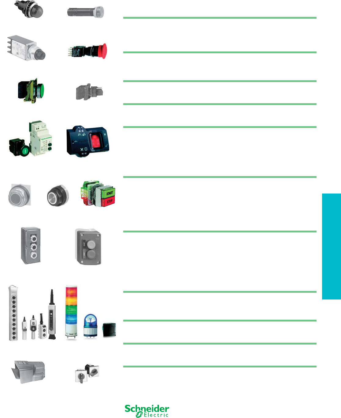
19 PUSH BUTTONS AND
OPERATOR INTERFACE
Table of Contents
Section 19
Push Buttons and Operator Interface
Product Panorama
Push Buttons
Control Stations
Pendant Stations
Tower Lights
19-2
19-4
19-5
19-6
22 and 30 mm Most Common Complete Operators
XB4, XB5 (22 mm) and Class 9001 Type K, SK (30 mm) most common complete
operators assembled with contact blocks and and light modules. Start-Stop,
Hand-Off-Auto, and other configurations are offered in this simplified quick selector.
19-8
Compact Pilot Lights
The Compact Pilot Light ranges include the XVL miniature LED type; the Type O low-
cost incandescent; and the Type J incandescent, push-to-test types.
19-10
16 mm Push Buttons
XB6 16 mm Push Buttons, selector switches, and pilot lights with a plastic bezel are
intended for high density panels such as laboratory and test fixtures.
19-12
22 mm Push Buttons
XB4 22 mm Push Buttons, selector switches, and pilot lights with a metal bezel are
designed for industrial applications, and combine ease of installation and robustness.
19-23
XB5 22 mm Push Buttons, the plastic version of the XB4 unit, is particularly suited to
applications requiring a resistance to chemical agents and/or double electrical insulation.
19-42
XB5R Plastic and XB4R Metal Wireless, Batteryless Push Buttons 19-63
XB5S Biometric Switches 19-65
30 mm Push Buttons
Class 9001 Type K Chrome-Plated Oiltight/Watertight Push Buttons are intended
primarily for machine tool and heavy-duty industrial applications.
19-67
Class 9001 Type SK Non-Metallic Watertight operators are designed for use in highly
corrosive areas.
19-77
Class 9001 Type KX operators are Square-Shaped Multifunction Control Units that
mount in a Type K mounting hole. This highly versatile line saves space by combining
push buttons and pilot lights into one common operator.
19-94
Control Stations and Enclosures
XAL control stations are available pre-assembled or custom assembled. These
control stations use push buttons and pilot lights from the XB5 22 mm range. XAP
enclosures are available in glass reinforced polyester, die cast metal and flush mount.
19-100
Type B Standard Duty Control Stations in 1, 2, and 3 button configurations are
available as predetermined complete stations.
19-103
Class 9001 Type KY/SKY Heavy Duty Control Stations are ideally suited for
commercial and industrial applications. Available in die cast metal, stainless steel,
painted sheet steel, and reinforced polyester.
19-105
Tower Lights
Tower Lights and Beacons. XVB, XVC, XVE, and XVP tower lights and beacons
provide long distance indication of the operation status or sequences of a machine
with with lights or buzzers.
19-107
Pendant Stations
Our full line of pendant stations for most crane and hoist applications range from the
light to medium duty BW and XAC pendants to the heavy duty SKYP pendants.
19-117
Foot Switches
The Type A foot switch is a heavy duty industrial foot switch which can be used in a
variety of industrial applications.
19-124
Rotary Cam Switches
K2 and K30–K150 Rotary Cam Switches. Miniature, Custom, and Power Switching
Cam Switches provide an inexpensive and versatile means of switching from 10 A
logic control through 150 A power switching.
19-126
XB5S Biometric Switch
(p. 19-65)
XVL Compact Light
(p. 19-11)
Type O Compact Light
(p. 19-11)
16 mm XB6
(p. 19-12)
Type J Compact Light
(p. 19-10)
22 mm XB4
(p. 19-23)
22 mm XB5
(p. 19-42)
30 mm Type KX
(p. 19-94)
30 mm Type K
(p. 19-67)
Type B Wall Station
(p. 19-103)
Type KY Enclosure
(p. 19-105)
Tower Lights
(p. 19-107)
Pendant Stations
(p. 19-117)
Type A Foot Switch
(p. 19-124)
Rotary Cam Switch
(p. 19-126)
30 mm Type SK
(p. 19-77)
XB5R Wireless, Batteryless
Push Button (p. 19-63)
19-2 © 2012 Schneider Electric
All Rights Reserved
www.schneider-electric.us
19 PUSH BUTTONS AND
OPERATOR INTERFACE
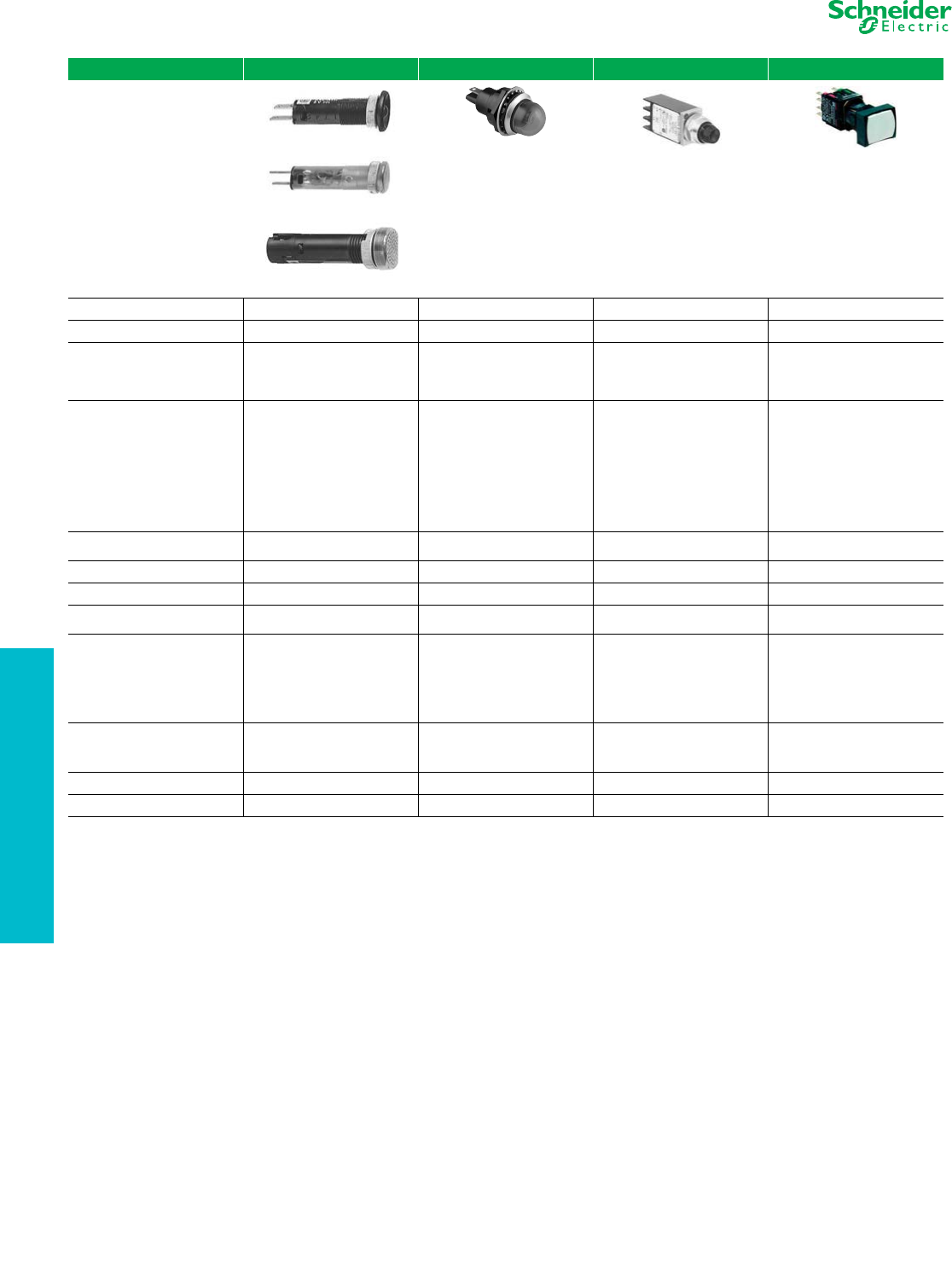
Push Buttons and Pilot
Lights
Selection Guide
Refer to Catalog 9001CT1102
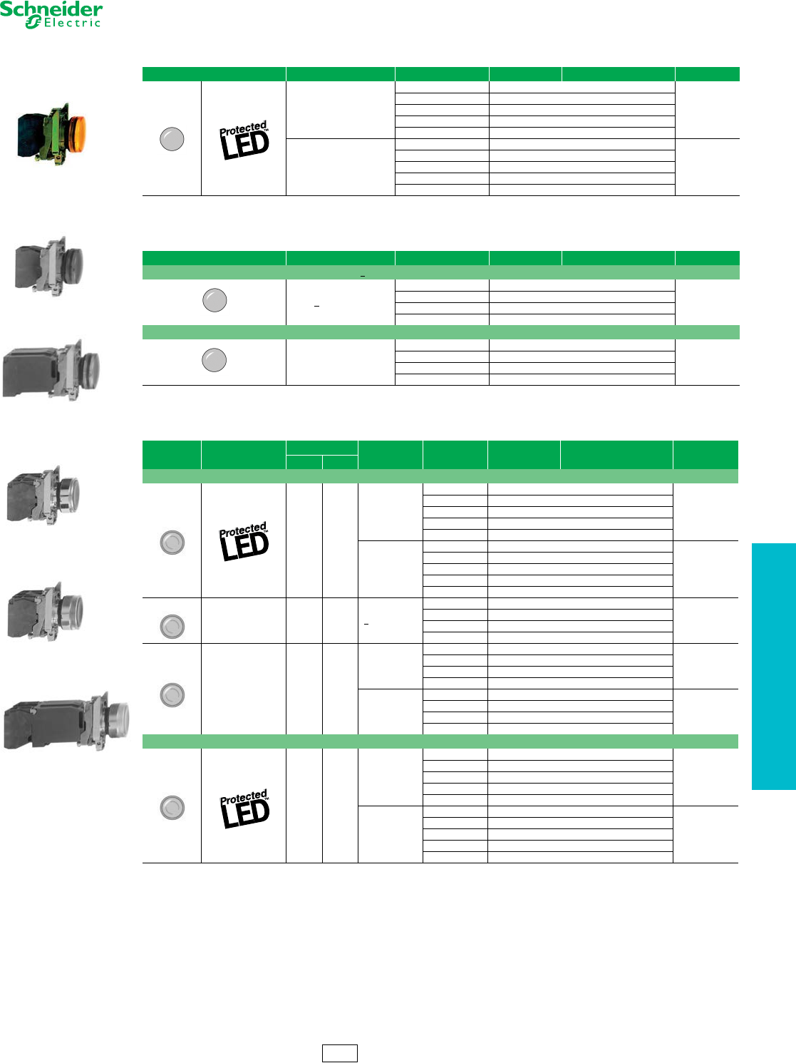
Family XVL Type O Type J XB6
Type of Product Mini Pilot Light Compact Pilot Light Compact Pilot Light 16 mm Push Button (plastic)
Mounting Hole Diameter 8 mm / 12 mm 17.5 mm (0.68 in) 17.5 mm (0.68 in) 16.2 mm
Approvals
UL Recognized File E164353,
CCN NKCR
UL Recognized File E179183,
CCN NKCR UL File E78403, CCN NKCR UL File E164353, CCN NKCR
CSA File LR44078,
Class 3211-03
CSA File LR25490,
Class 3211-03 CSA File LR25490, Class 3211-03 CSA File LR44087
Class 3211-03
Conforming to Standards
CE Marked
RoHS Compliant
IEC337-2
NF C 63-140
VDE 0660-200
CE Marked
RoHS Compliant
CE Marked
RoHS Compliant
CE Marked
RoHS Compliant
EN/IEC 60947-1, EN/IEC 60947-5-1,
EN/IEC 60947-5-5
EN/IEC 60204-1 and
EN/ISO 13850: 2006 (trigger action
and mechanical latching
Emergency Stop push buttons)
JIS C 4520 and 853
UL 508 and CSA C22-2 no. 14
Gost
CCC
Degree of Protection IP40
(IP65 with seal) NEMA 13 NEMA 4, 13 IP65
NEMA 1, 4, 4X, 12
Electric Shock Protection
Electrical Consumption
LED 25 mA 6-30 Vac/Vdc: 15 mA
48–120 Vac: 20 mA
Rated Operational
Characteristics
AC-15; B300
Ue = 240 Vac and le = 1.5A
Ue = 120 Vac and le = 3 A
Continuous 5 A
DC-13; R300
Ue = 250 Vdc and le = 0.1 A
Ue = 125 Vdc and le = 0.22 A
Connection Type
XVLA1** and XVLA2** =
2.8mm x 0.5mm Faston
XVLA3** = Screw Terminals
Faston Screw Terminal
—
Quick Connect/ Solder Tabs
0.11 x 0.02 in. (2.8 x 0.5 mm)
Cable Size 1 x 1.5 mm² max. 2 x 14 AWG (copper only)
Digest Page 19-10 19-10 19-11 19-13
XVLA3••
XVLA2••
XVLA1••
www.schneider-electric.us
19 PUSH BUTTONS AND
OPERATOR INTERFACE
© 2012 Schneider Electric
All Rights Reserved 19-3
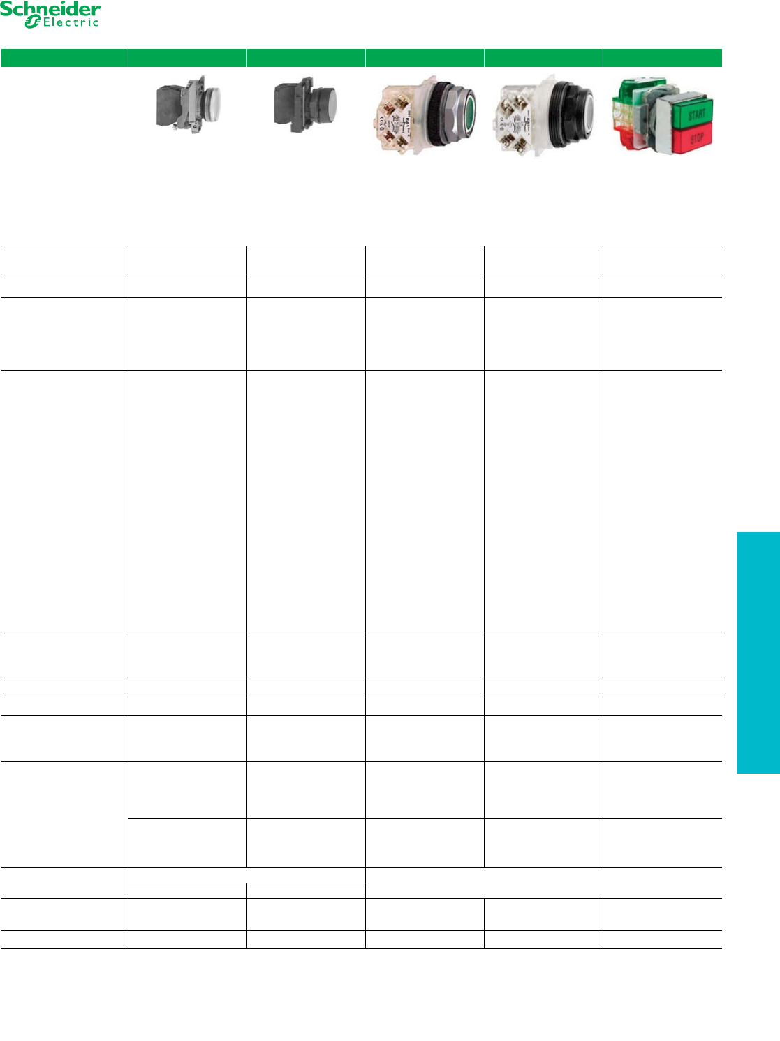
Push Buttons and Pilot
Lights
Selection Guide
Refer to Catalogs DIA4ED2060507BEN-US* and 9001CT1103**
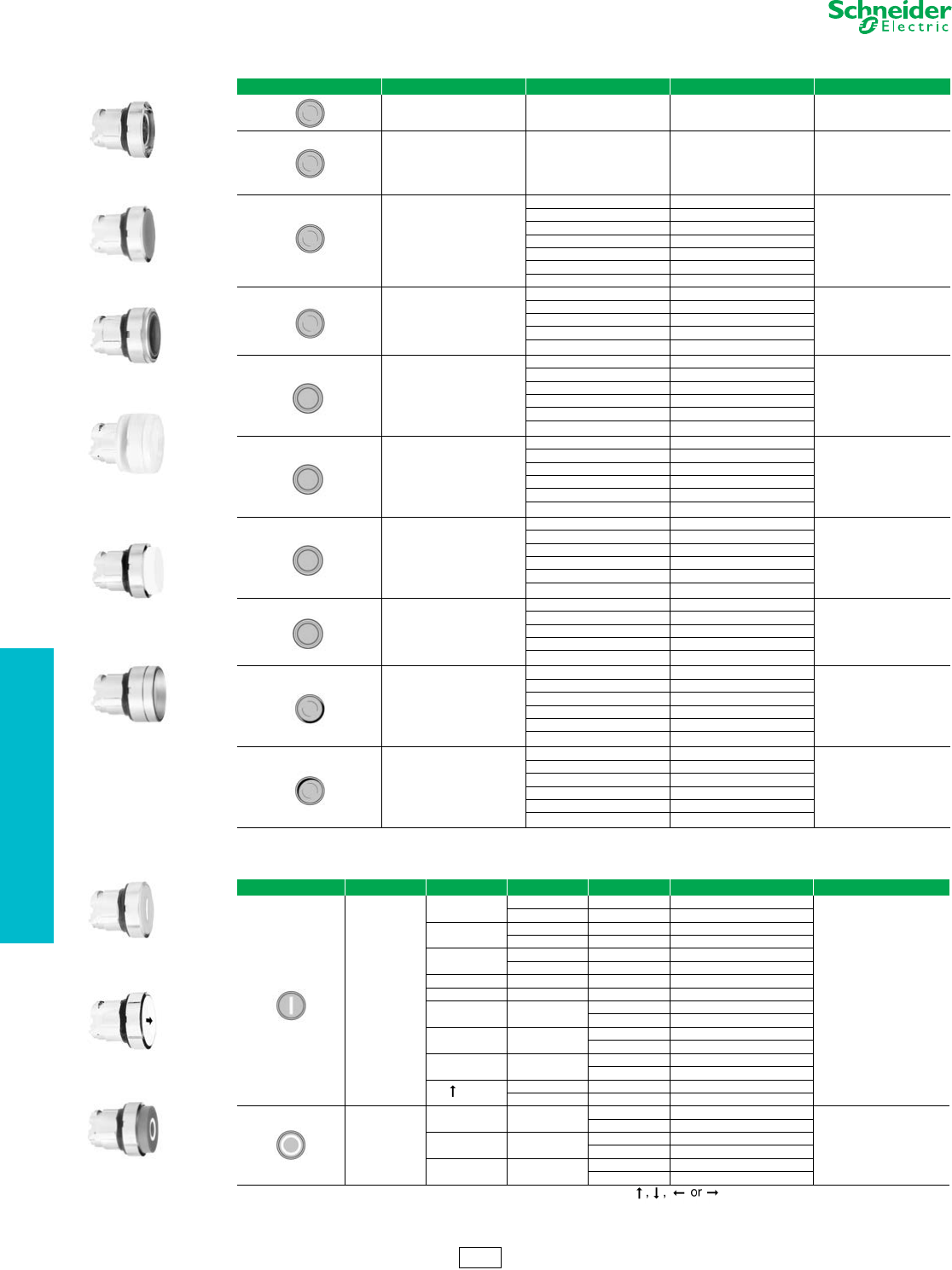
Family XB4 XB5 9001K 9001SK 9001KX
Type of Product *22 mm Push Button
(metal)
*22 mm Push Button
(plastic)
**30 mm Push Button
(metal)
**30 mm Push Button
(plastic)
**30 mm Push Button
(metal, square)
Mounting Hole Diameter 22.5 mm 22.5 mm 31 mm
(1.22 in)
31 mm
(1.22 in)
31 mm
(1.22 in)
Approvals
UL Listed File E164353,
CCN NKCR
UL Recognized File E164353.
CCN NKCR2
UL Listed File E164353,
CCN NKCR
UL Recognized File E164353.,
CCN NKCR2
UL File E78403. CCN NKCR UL File E78403. CCN NKCR UL File E78403. CCN NKCR
CSA File LR44087.
Class 3211-03
CSA File LR44087.
Class 3211-03
CSA File LR25490.
Class 3211-03
CSA File LR25490.
Class 3211-03
CSA File LR25490.
Class 3211-03
Conforming to Standards
CE Marked
RoHS Compliant
CE Marked
RoHS Compliant
CE Marked
RoHS Compliant
CE Marked
RoHS Compliant
CE Marked
RoHS Compliant
EN/IEC 60947-1,
EN/IEC 60947-5-1,
EN/IEC 60947-5-4,
EN/IEC 60947-5-5
EN/IEC 60947-1,
EN/IEC 60947-5-1,
EN/IEC 60947-5-4,
EN/IEC 60947-5-5
EN/IEC 60947-1 EN/IEC 60947-1
EN/IEC 60204-1 and
EN/ISO 13850: 2006 (trigger
action and mechanical latching
emergency stop push buttons)
EN/IEC 60204-1 and
EN/ISO 13850: 2006 (trigger
action and mechanical latching
emergency stop push button).
EN/IEC60947-5-1 EN/IEC60947-5-1
EN/IEC 60364-5-53
(emergency switching of
mechanical latching push
buttons)
EN/IEC 60364-5-53
(emergency switching of
mechanical latching push
buttons)
EN/IEC60947-5-4 EN/IEC60947-5-4
—
EN81-1 (emergency stop
trigger action and mechanical
latching push buttons with
mechanical state indicator)
JIS C 4520 JIS C 4520 JIS C 4520 and 852 JIS C 4520 and 852
UL 508 UL 508 UL 508 UL 508
CSA C22.2 No.14 CSA C22.-2 No.14 CSA C22.2 No.14 CSA C22.2 No.14
GOST GOST
CCC CCC
Degree of Protection
IP65 IP65 IP66 IP66 IP66
IP66 for booted IP66 for booted NEMA 1, 2, 3, 3R, 4, 12, 13 NEMA 1, 2, 3, 3R, 4, 4X, 12, 13 NEMA 1, 2, 3, 3R, 4, 12, 13
NEMA 1, 2, 3, 4, 12, 13 NEMA 1, 2, 3, 3R, 4, 4X, 12, 13
Electric Shock Protection Class I Class I Class II Class II Class II
Electrical Consumption
LED
24 Vac/Vdc: 18 mA 24 Vac/Vdc: 18 mA
Incandescent and LED bulbs
see ratings on page 19-86
Incandescent and LED bulbs
see ratings on page 19-86
120 Vac: 14 mA 120 Vac: 14 mA
240 Vac: 14 mA 240 Vac: 14 mA
Rated Operational
Characteristics
AC-15; B600
Ue = 600 Vac and le = 1.2 A
Ue = 240 Vac and
le = 3A
Ue = 120 Vac and le = 6A
Continuous 10 A
AC-15; B600
Ue = 600 Vac and le = 1.2 A
Ue = 240 Vac and le = 3 A
Ue = 120 Vac and le = 6 A
Continuous 10 A
AC-15; A600
Continuous 10 A
AC-15; A600
Continuous 10 A
AC-15; A600
Continuous 10 A
DC-13; Q600
Ue = 600 Vdc and le = 0.1 A
Ue = 250 Vdc and le = 0.27 A
Ue = 125 Vdc and le = 0.55 A
DC-13; Q600
Ue = 600 Vdc and le = 0.1 A
Ue = 250Vdc and
le = 0.27 A
Ue = 125 Vdc and le = 0.55 A
DC-13; Q600
Ue = 600 Vdc and le = 0.1 A
Ue = 250 Vdc and le = 0.27 A
Ue = 125 Vdc and le = 0.55 A
DC-13; Q600
Ue = 600 Vdc and le = 0.1 A
Ue = 250 Vdc and le = 0.27 A
Ue = 125 Vdc and le = 0.55 A
DC-13; Q600
Ue = 600 Vdc and le = 0.1 A
Ue = 250 Vdc and le = 0.27 A
Ue = 125 Vdc and le = 0.55 A
Connection Type IP20 Fingersafe Screw or Spring Terminal IP20 Fingersafe Screw Terminal
Screw Terminal: Spring Terminal:
Cable Size
1 x 24 AWG (0.22 mm²) min.
2 x 14 AWG (2.5 mm²) max.
2 x 16 AWG (1.5 mm²) max.
1 x 24 AWG (0.22 mm²) min.
2 x 14 AWG (2.5 mm²) max.
2 x 16 AWG (1.5 mm²) max.
1 x 24 AWG (0.22 mm²) min.
2 x 16 AWG (1.5 mm²) max
1 x 24 AWG (0.22 mm²) min.
2 x 16 AWG (1.5 mm²) max
1 x 24 AWG (0.2 2mm²) min.
2 x 16 AWG (1.5 mm²) max
Digest Page 19-23 19-42 19-67 19-77 19-94
19-4 © 2012 Schneider Electric
All Rights Reserved
www.schneider-electric.us
19 PUSH BUTTONS AND
OPERATOR INTERFACE
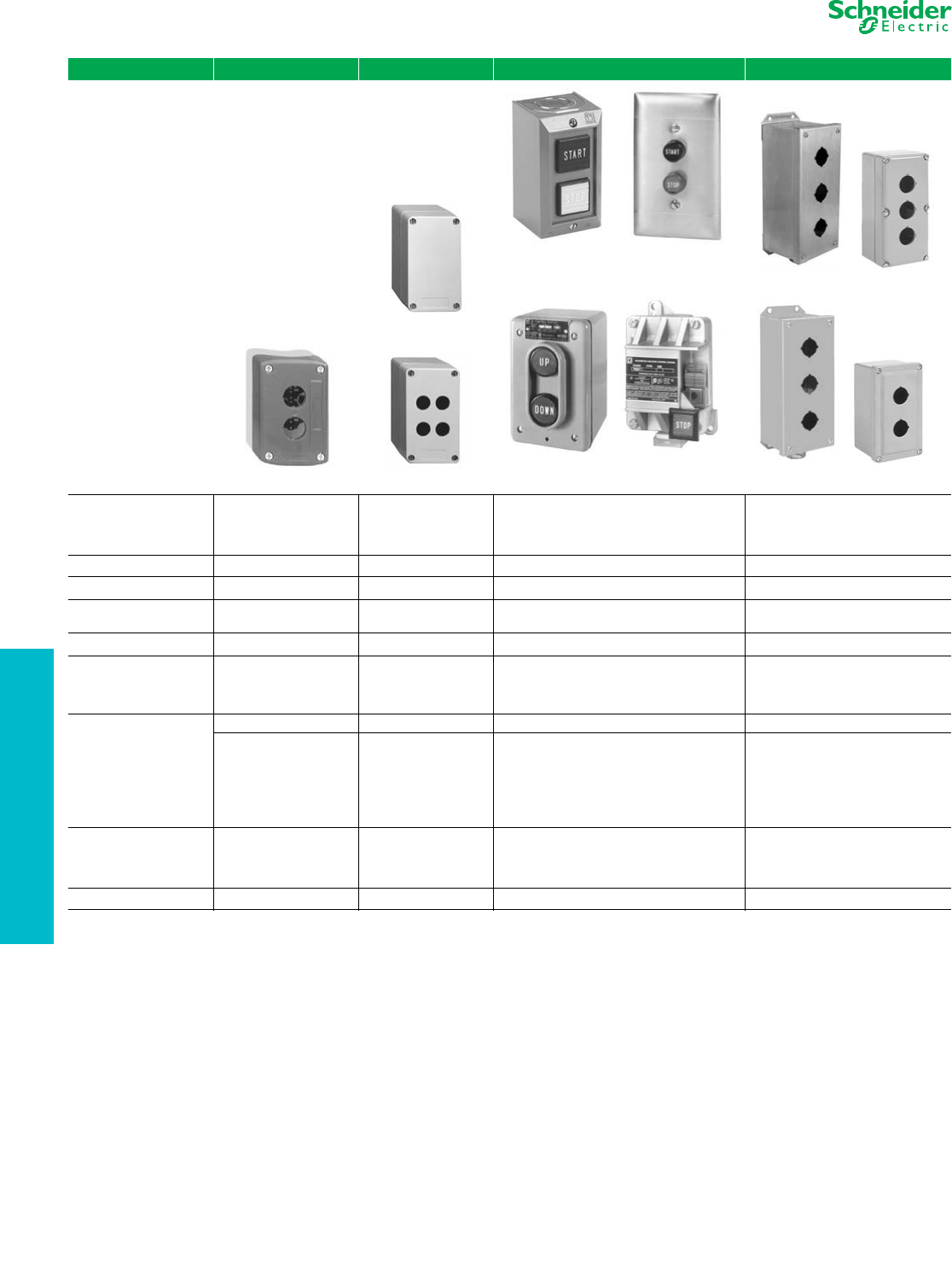
Control Stations Selection Guide
Refer to Catalog 9001CT1104
Family XAL XAP 9001B 9001KY/SKY
Type of Product/Material XALD—Polycarbonate
XALK—Polycarbonate
XAPA—glass filled polyester
XAPG—die cast zinc
XAPE—anodized aluminum
9001BG—plastic cover
9001BF—stainless steel
9001BW—die cast zinc
9001BR—cast aluminum
9001KYAF—sheet steel
9001KYSS—stainless steel
9001KY—die cast zinc
9001KZ—die cast zinc
9001SKY—Polyester
Number of holes 1 to 3 0 to 16 1 to 3 1 to 6
Type of Operators XB5 (22mm) XB5 (22mm) Built in 9001K/SK (30mm)
Available without
Operators Ye s Ye s N o Ye s
Available with Operators Ye s N o Ye s Ye s
Approvals
UL File E164353
CCN NKCR
UL File E164353
CCN NKCR
UL File E78403
CCN NKCR
UL File E78403
CCN NKCR
CSA File LR 44087
Class 3211-03
CSA File LR 44087
Class 3211-03
CSA File LR 25490
Class 3211-03
CSA File LR 25490
Class 3211-03
Conforming to Standards
CE Marked CE Marked CE Marked CE Marked
EN/IEC 60947-1,
EN/IEC 60947-5-1,
EN/IEC 60947-5-4,
EN/IEC 60947-1,
EN/IEC 60947-5-1,
EN/IEC 60947-5-4,
EN/IEC 60947-1,
EN/IEC 60947-5-1,
EN/IEC 60947-5-4,
EN/IEC 60947-1,
EN/IEC 60947-5-1,
EN/IEC 60947-5-4,
JIS C 4520 JIS C 4520 JIS C 4520 JIS C 4520
UL 508 UL 508 UL 508 UL 508
CSA C22.2 No.14 CSA C22.2 No.14 CSA C22.2 No.14 CSA C22.2 No.14
Cable Entry No. 13 knock out
XAPA—undrilled
XAPG—Tapped 3/4NPT
XAPE—flush mount (n/a)
9001BG—1/2 &3/4 knockout
9001BF—N/A
9001BW—1/2-14NPT
9001BR—1/2-14NPT
9001KYAF—customer provided
9001KYSS—G conduit hub
9001KY—customer provided
9001KZ—1/2 & 3/4 knockout
9001SKY—G conduit hub
Digest Page 19-100 19-100 19-103 19-105
XALD02
XAPA1100
XAPA1104
NEMA 1
Surface Mounting
9001BG••
NEMA 1
Flush Mounting
9001BF••
NEMA 4
9001BW••
NEMA 7 and 9
9001BR••
9001KYSS3 9001KY3
9001KYAF3 9001SKY2
www.schneider-electric.us
19 PUSH BUTTONS AND
OPERATOR INTERFACE
© 2012 Schneider Electric
All Rights Reserved 19-5
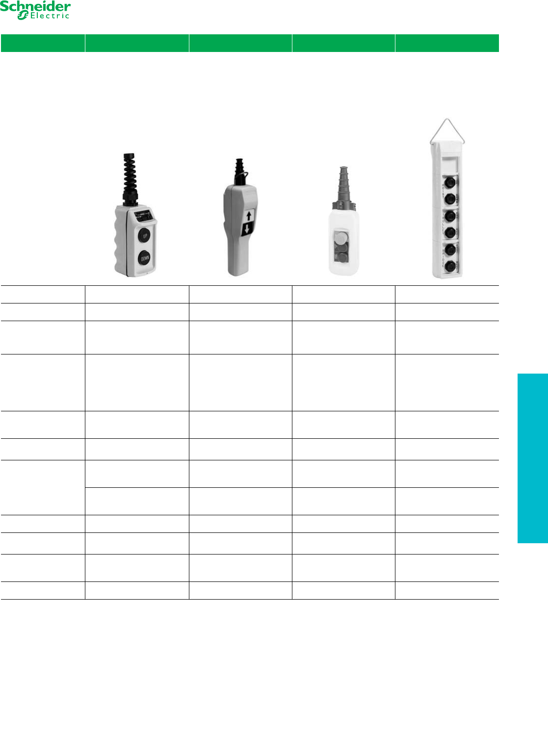
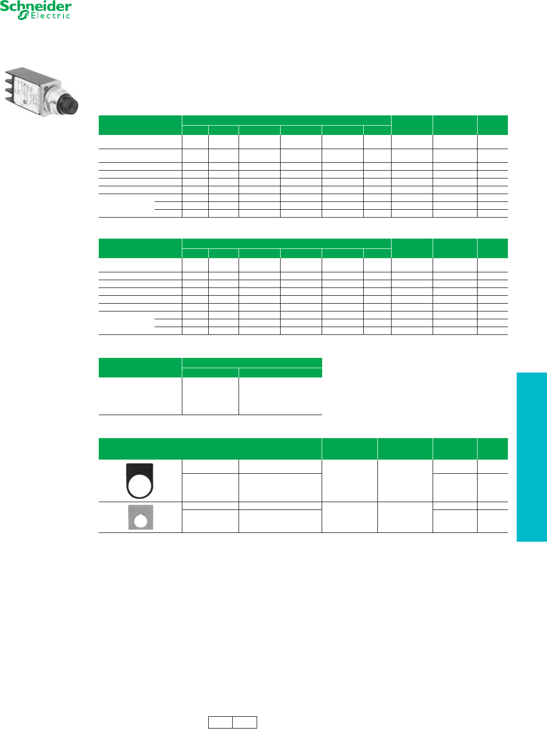
Pendant Stations Selection Guide
Refer to Catalog 9001CT1001
Family 9001BW XACA2 XACA0 9001SKYP
Type of Product 2-Button Pendant 2-Button Pistol Grip Pendant General Purpose Pendant Heavy Duty Pendant
Number of operators 2 2 2, 3, 4, 6, 8, 12 2, 4, 6, 8, 10
Approvals
UL File E78403
CNN NKCR
CSA File LR25490
Class 3211-03
UL File E164353
CNN NKCR
CS A Fi le L R 44087
Class 3211-03
UL Fil e E1 64353
CNN NKCR
CS A Fi le L R 44087
Class 3211-03
UL File E78403
CNN NKCR
CSA File LR25490
Class 3211-03
Conforming to
Standards CE Marked
EN/IEC 60947-5-1,
EN/IEC 60204-32,
EN/IEC 60947-5-5, and
EN/ISO 13850 (for versions with
trigger action emergency stop)
UL 508
CSA C22-2 No. 14
RoHS compliant
EN/IEC 60947-5-1,
EN/IEC 60204-32,
EN/IEC 60947-5-5, and
EN/ISO 13850 (for versions with
trigger action emergency stop)
UL 508
CSA C22-2 No. 14
RoHS compliant
CE Marked
Degree of Protection NEMA 1, 3, 3R, 4, 4X
NEMA 1, 4, 4X, 5
IP65
IK08
NEMA 1, 4, 4X, 5
IP65
IK08
NEMA 1,2, 3, 4, 4X, 12, 13
Housing Material Polycarbonate / PET Polyester
Blend Yellow Polypropylene Yellow Polypropylene Yellow Polycarbonate
Rated Operational
Characteristics a
AC - B600
AC-15: A600
or Ue = 600V, le = 1.2A
or Ue = 240V, le = 3A
AC-15: A600
or Ue = 600V, le = 1.2A
or Ue = 240V, le = 3A
SKRU2-SKRU5
AC - B300
DC - P600
DC - P600
DC-13: Q600
or Ue = 600V. le = 0.1A
or Ue = 250V, le = 0.27A
DC-13: Q600
or Ue = 600V. le = 0.1A
or Ue = 250V, le = 0.27A
SKRU1, 10, 11
AC - A600
DC - P600
Thermal Current Continuous 5A Continuous 10A Continuous 10A —
Connection Type 1/2 in. NPT
screw clamp terminals
8–26 mm cable entry
screw clamp terminals
8–26 mm cable entry
screw clamp terminals
NPT threaded conduit entry
screw clamp terminals
Cable Size —
1 x 0.5 mm² (20AWG) min.
2 x 1.5 mm² (16AWG) max.
1 x 2.5 mm² (14AWG) max.
1 x 14 AWG (copper only) —
Digest Page 19-117 19-118 19-118 19-121
aOSHA Section 1910.179, Overhead and Gantry Cranes, limits voltage at pendant push buttons to 150 Vac or 300 Vdc max.
19-6 © 2012 Schneider Electric
All Rights Reserved
www.schneider-electric.us
19 PUSH BUTTONS AND
OPERATOR INTERFACE
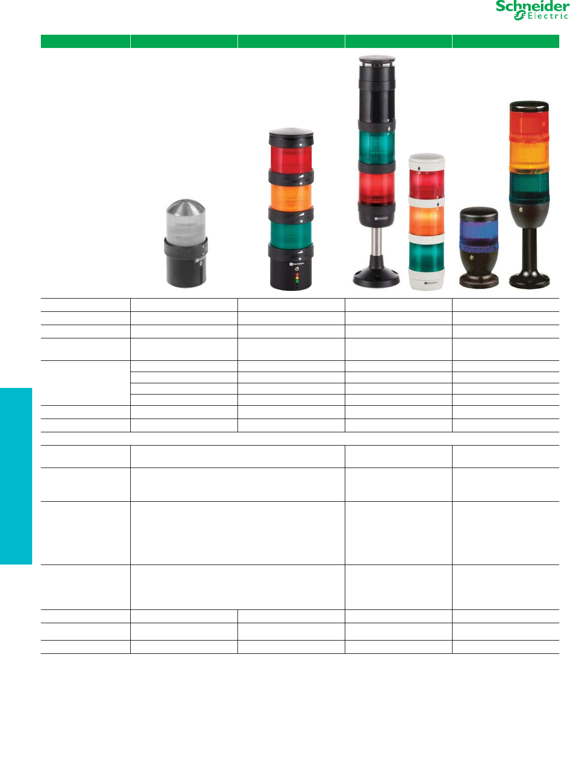
Tower Lights and
Beacons
Selection Guide
Refer to Catalog 9001CT1002
Family XVB L XVB C XVP XVE
Type of Product Beacon Tower Light Tower Light Tower Light and Beacon
Diameter 70mm 70 mm 50 mm 70 mm
Features Product for Customer Configuration Product for Customer Configuration Product for Customer Configuration Product for Customer Configuration
Approvals UL File E164353 CCN NKCR UL File E164353 CCN NKCR UL File E164353 CCN NKCR UL File E164353 CCN NKCR
CSA File LR 44087 Class 3211 03 CSA File LR 44087 Class 3211 03 CSA File LR 44087 Class 3211 03 CSA File LR 44087 Class 3211 03
Conforming to Standards
CE Marked CE Marked CE Marked CE Marked
IEC/EN 60947-5-1 IEC/EN 60947-5-1 IEC/EN 60947-5-1 IEC/EN 60947-5-1
UL 508 UL 508 UL 508 UL 508
CSA 22.2 No 14 CSA 22.2 No 14 CSA 22.2 No 14 CSA 22.2 No 14
Degree of Protection IP65 IP65 IP65 IP42
Light Source LED / Incandescent LED / Incandescent LED / Incandescent LED / Incandescent
Electrical Consumption
LED Steady 24 Vac/dc: < 30 mA 24 Vac/dc: < 80 mA 24V ac/dc: < 25mA
120–230 Vac: < 30 mA 120–230 Vac: < 30mA 120–230 Vac: |< 25 mA
LED Flashing
with Buzzer
24 Vac/dc: < 40 mA 24 V ac/dc: < 40mA 24 V ac/dc: < 30mA
120–230 Vac: < 15mA 120–230 Vac: < 15 mA 120–230Vac: < 25 mA
1 Hz (1 flash per second) 1 Hz (1 flash per second) 1 Hz (1 flash per second)
Strobe (Energized)
24 Vdc:
5 Joules unit < 430 mA; 10 J unit: < 850 mA 24 Vdc: ≤ 40mA 24 Vdc: ≤ 85 mA
120 Vac:
5 Joules unit: < 130 mA; 10 J unit: < 260 mA 120 Vac: ≤ 20mA 120 Vac: ≤ 35 mA
230 Vac:
5 Joules unit: < 105 mA; 10 J unit: < 210 mA 230 Vac: ≤ 11mA 230 Vac: ≤ 25 mA
1 Hz (1 flash per second) 1 Hz (1 flash per second) 1 Hz (1 flash per second)
Audible Sounders
12–48 Vac/dc: < 20 mA 24 Vdc: ≤ 15 mA 85 decibels at 1 meter
120–230 Vac: < 50 mA 120 Vac: ≤ 15 mA —
90 decibels at 1 meter 230 Vac: ≤ 12mA —
—55 to 85 decibels at 1 meter —
Connection Type Screw Clamp Screw Clamp Screw Clamp Screw Clamp
Cable Size 1 x 16 AWG (1.5 mm²)
With Cable End
1 x 16 AWG (1.5 mm²)
With Cable End
2 x 16 AWG (1.5 mm²)
With Cable End
2 x 16 AWG (1.5 mm²)
With Cable End
Digest Page 19-110 19-111 19-114 19-113
www.schneider-electric.us
19 PUSH BUTTONS AND
OPERATOR INTERFACE
© 2012 Schneider Electric
All Rights Reserved 19-7
For Tower Lights catalog numbers:
first dot denotes voltage selection
second dot denotes color selection
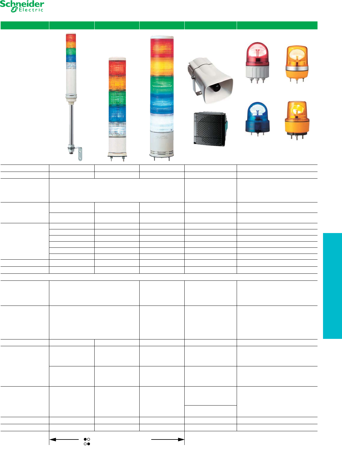
Tower Lights and
Beacons
Selection Guide
Refer to Catalog 9001CT1002
Family XVC 4 XVC 6 XVC 1 XVS XVR
Type of Product Tower Light Tower Light Tower Light Siren and Electronic Alarm Rotating Mirror Beacon
Diameter 40 mm 60 mm 100 mm — 84/106/120/130 mm
Features All devices are pre-assembled and pre-wired
Adjustable Tones
XVS14BMW, 0 to 105 decibels,
43 tones
XVS72BM••, 0 to 90
decibels, 16 tones
All devices are pre-assembled and pre-wired.
XVR12•••S includes buzzer: 70 to 90 decibels
Approvals
UL Recognized E164353
CNN NKCR
UL Recognized E164353
CNN NKCR
UL Recognized E164353
CNN NKCR
UL Recognized E164353
CNN UCST
UL Recognized E164353
CNN NKCR
CSA LR44087
Class 3211-03
CSA LR44087
Class 3211-03
CSA LR44087
Class 3211-03
CSA LR44087
Class 3211-03
CSA LR44087
Class 3211-03
Conforming to Standards
CE Marked CE Marked CE Marked CE Marked CE Marked
EN61000-6-2 EN61000-6-2 EN61000-6-2 — EN61000-6-2
EN61000-6-3 EN61000-6-3 EN61000-6-3 — EN61000-6-4
— EN61000-6-4 EN61000-6-4 — —
UL 508 UL 508 UL 508 UL 508 UL 508
CSA 22.2 No. 14 CSA 22.2 No. 14 CSA 22.2 No. 14 CSA 22.2 No. 14 CSA 22.2 No. 14
Degree of Protection IP54 IP54 IP54 IP53 / IP54 IP23 / IP65 / IP66
Light Source LED LED LED — LED
Electrical Consumption
LED Steady
24 V:
1 unit = 40mA;
2 unit = 80mA;
3 unit = 120mA
4 unit = 160mA;
5 unit = 200mA
24 V:
1 unit = 100mA;
2 unit = 200mA;
3 unit = 300mA
4 unit = 400mA;
5 unit = 500mA
—
XVR08, XVR10, XVR12, and XVR13 (without
buzzer)
12 Vac/dc: 360mA
24 Vac/dc: 180mA
LED Flashing
** with Buzzer
**24 V:
1 unit = 90 mA;
2 unit = 130 mA;
3 unit = 170 mA
4 unit = 210 mA;
5 unit = 250 mA
0.7 to 3 Hz (1 flash per 0.7 to 3 seconds)
24 V:
1 unit = 150mA;
2 unit = 250mA;
3 unit = 350mA
4 unit = 450mA;
5 unit = 550mA
3 to 3.5 Hz (1 flash per 3 to
3.5 seconds)
—
XVR12 with buzzer:
12 Vac/dc: 400 mA
24 Vac/dc: 230 mA
3 Hz (1 flash per 3 seconds)
Strobe (Energized) ———— —
Audible Sounders
70 to 85 decibels at 1
meter
70 to 85 decibels at 1
meter
60 to 85 decibels at 1
meter
XVS14BMW
12 Vdc: 350mA
24 Vdc: 400 mA
105 decibels at 1 meter
—
——
XVS72BM
12 Vdc: 280 mA
24 Vdc: 190 mA
90 decibels at 1 meter
—
Connection Type
Pre-Wired,
Color-Coded Wires
cable length:
600mm XVC4••
900mm XVC4••K
500mm XVC4••5S
Pre-Wired,
Color-Coded Wires
cable length:
600mm XVC6••
850mm XVC6••K
550mm XVC6••5S
850mm XVC6••5SK
Pre-Wired,
Color-Coded Wires
cable length:
500mm XVC1••K
500mm XVC1••SK
550mm XVC6••5S
850mm XVC6••5SK
XVS14BMW
Pre-Wired, Color-Coded Wires
cable length:
500mm XVS14
Pre-Wired
cable length:
500mm XVR08•••
400mm XVR10•••
400mm XVR12•••
400mm XVR13•••
XVS72BM••
Not Pre-Wired
Cable Size 22 AWG (0.33 mm²) 22 AWG (0.33 mm²) 22 AWG (0.33 mm²) — 18 AWG (0.75 mm²)
Digest Page 19-111 19-109 19-109 19-116 19-107
www.schneider-electric.us
19 PUSH BUTTONS AND
OPERATOR INTERFACE
19-8 © 2012 Schneider Electric
All Rights Reserved
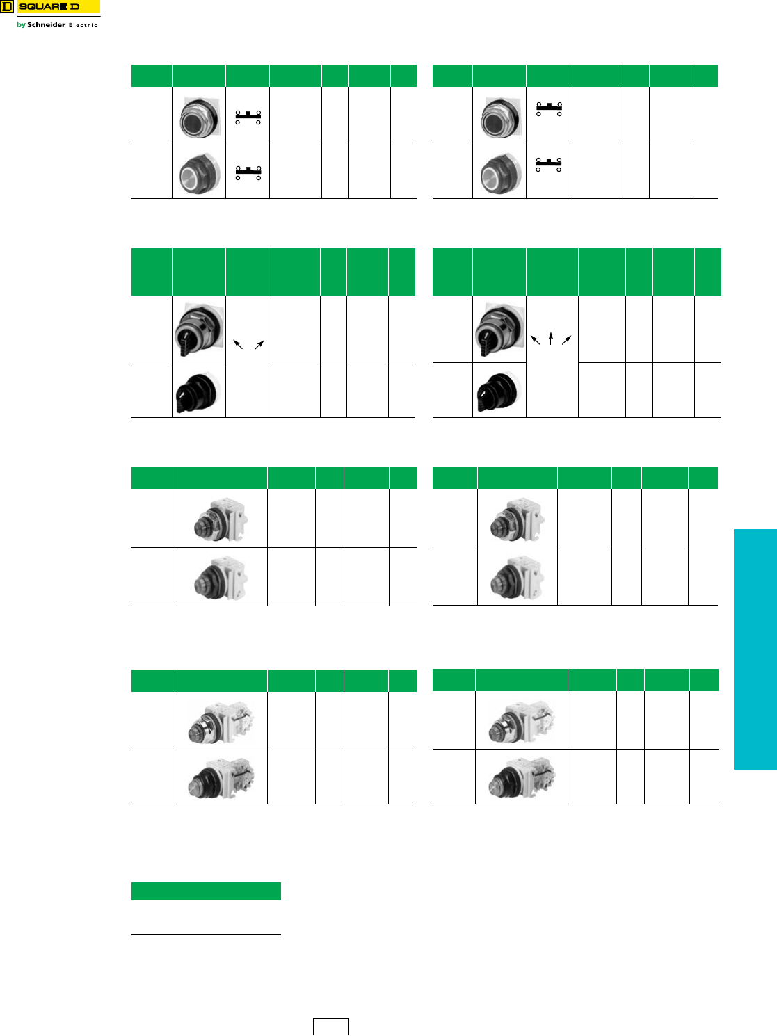
22 mm Push Buttons XB4–XB5 Common Operators, Complete with Contact Blocks
Refer to Catalog DIA4ED2060507BEN-US
Table 19.1: BLACK—Start Push Buttons
(flush head)
Operator
Style Description Contact
Block Type $ Price Legend
Plate $ Price
XB4 Die
Cast
Chrome
1 N.O.
XB4BA21 38.50 ZBY2303 3.40
XB5
Double
Insulated
1 N.O.
XB5AA21 38.50 ZBY2303 3.40
Table 19.2: BLACK—Off-On Selector Switch
Operator
Style Description Contact
Block Type $ Price Legend
Plate $ Price
XB4 Die
Cast
Chrome 1 N.O.
XB4BD21 51.00 ZBY2367 3.40
XB5
Double
Insulated
1 N.O.
XB5AD21 51.00 ZBY2367 3.40
Table 19.3: RED—120 Vac LED—On Pilot Light
Operator
Style Description Contact
Block Type $ Price Legend
Plate $ Price
XB4 Die
Cast
Chrome
120 Vac
Red LED XB4BVG4 72.00 ZBY2311 3.40
XB5
Double
Insulated
120 Vac
Red LED XB5AVG4 72.00 ZBY2311 3.40
Table 19.4: RED—40 mm Mushroom Stop
(Push-Pull)
Operator
Style Description Contact
Block Type $ Price Legend
Plate $ Price
XB4 Die
Cast
Chrome
1 N.C.
XB4BT42 68.00 ZBY9330 3.40
XB5
Double
Insulated
1 N.C.
XB5AT42 68.00 ZBY9330 3.40
When ordering, please specify:
•Quantity
•Type or Catalog Number
Table 19.5: RED—Stop Push Buttons
(extended head)
Operator
Style Description Contact
Block Type $ Price Legend
Plate $ Price
XB4 Die
Cast
Chrome
1 N.C.
XB4BL42 38.50 ZBY2304 3.40
XB5
Double
Insulated
1 N.C.
XB5AL42 38.50 ZBY2304 3.40
Table 19.6: Hand-Off-Auto Selector Switch
Operator
Style Description Contact
Block Type $ Price Legend
Plate $ Price
XB4 Die
Cast
Chrome 2 N.O.
XB4BD33 68.00 ZBY2387 3.40
XB5
Double
Insulated
2 N.O.
XB5AD33 68.00 ZBY2387 3.40
Table 19.7: GREEN—120 Vac LED—Off Pilot Light
Operator
Style Description Contact
Block Type $ Price Legend
Plate $ Price
XB4 Die
Cast
Chrome
120 Vac
Green
LED
XB4BVG3 72.00 ZBY2312 3.40
XB5
Double
Insulated
120 Vac
Green
LED
XB5AVG3 72.00 ZBY2312 3.40
Table 19.8: RED—40 mm Mushroom Emergency
Stop (Trigger Action, Turn-to-Release)
Operator
Style Description Contact
Block Type $ Price
Legend
Plate
60 mm
Round
$ Price
XB4 Die
Cast
Chrome 1 N.O. /
1N.C.
XB4BS8445 165.00 ZBY9330 3.40
XB5
Double
Insulated 1 N.O./
1N.C.
XB5AS8445 165.00 ZBY9330 3.40
IDiscount
Schedule
www.schneider-electric.us
19 PUSH BUTTONS AND
OPERATOR INTERFACE
© 2012 Schneider Electric
All Rights Reserved 19-9
30 mm Push Buttons Type K, SK Common Operators, Complete with Contact Blocks
Class 9001 / Refer to Catalog 9001CT1103
Table 19.9: BLACK—Start Push Buttons
Operator
Style Description Contact
Block Type $ Price Legend
Plate $ Price
30 mm
Industrial
(Metal)
KR1BH13 89.00 KN201 4.40
30 mm
Corrosion
Resistant
(Non-
Metallic)
SKR1BH13 89.00 KN101SP 4.40
Table 19.10: BLACK—Off-On Selector Switch
Operator
Style Description
Contact
Sequence
(Contact
Block
Included)
Type $ Price Legend
Plate $ Price
30 mm
Industrial
(Metal)
KS11BH13 106.00 KN244 2.90
30 mm
Corrosion
Resistant
(Non-
Metallic)
SKS11BH13 106.00 KN144SP 2.90
Table 19.11: RED—120 Vac—On Pilot Light
Operator
Style Description Type $ Price Legend
Plate $ Price
30 mm
Industrial
(Metal)
KP1R31 153.00 KN203 4.40
30 mm
Corrosion
Resistant
(Non-
Metallic)
SKP1R31 153.00 KN103SP 4.40
Table 19.12: RED—120 Vac—On Push-To-Test
Pilot Light
Operator
Style Description Type $ Price Legend
Plate $ Price
30 mm
Industrial
(Metal)
KT1R31 197.00 KN203 4.40
30 mm
Corrosion
Resistant
(Non-
Metallic)
SKT1R31 197.00 KN103SP 4.40
When ordering, please specify:
•Quantity
•Class Number (if appropriate)
•Type or Catalog Number
10
01
Table 19.13: RED—Stop Push Buttons
Operator
Style Description Contact
Block Type $ Price Legend
Plate $ Price
30 mm
Industrial
(Metal)
KR1RH13 89.00 KN202 4.40
30 mm
Corrosion
Resistant
(Non-
Metallic)
SKR1RH13 89.00 KN102RP 4.40
Table 19.14: BLACK—Hand-Off-Auto Selector Switch
Operator
Style Description
Contact
Sequence
(Contact
Block
Included)
Type $ Price Legend
Plate $ Price
30 mm
Industrial
(Metal)
KS43BH13 106.00 KN260 4.40
30 mm
Corrosion
Resistant
(Non-
Metallic)
SKS43BH13 106.00 KN160SP 4.40
Table 19.15: GREEN—120 Vac—Off Pilot Light
Operator
Style Description Type $ Price Legend
Plate $ Price
30 mm
Industrial
(Metal)
KP1G31 153.00 KN204 4.40
30 mm
Corrosion
Resistant
(Non-
Metallic)
SKP1G31 153.00 KN104SP 4.40
Table 19.16: GREEN—120 Vac—Off Push-To-Test
Pilot Light
Operator
Style Description Type $ Price Legend
Plate $ Price
30 mm
Industrial
(Metal)
KT1G31 197.00 KN204 4.40
30 mm
Corrosion
Resistant
(Non-
Metallic)
SKT1G31 197.00 KN104RP 4.40
100
001
CS1 Discount
Schedule
19-10 © 2012 Schneider Electric
All Rights Reserved
www.schneider-electric.us
19 PUSH BUTTONS AND
OPERATOR INTERFACE
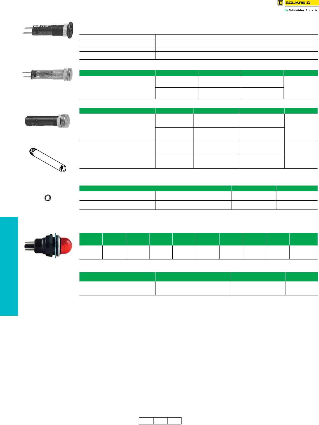
Compact Pilot Lights Type XVL and Type O
aQuick connects (2.8 x 0.5 mm).
bScrew termination.
Class 9001 Type O, NEMA 13 Pilot Lights
cTo order, add prefix 9001 to the beginning of the catalog number.
XVL Miniature LED
Table 19.17: Specifications
Conforming to standards IEC 337-2, NF C 63-140, VDE 0660-200
Degree of protection IP40 (IP65 with seal) conforming to IEC 529 and NF C 20-010
Current consumption 25 mA
Cabling XVLA1••, XVLA2••: tags for 2.8 x 0.5 mm Faston connectors, also for soldered connections.
XVLA3••: threaded connectors, clamping, capacity: min. 1 x 0.2 mm2, max. 1 x 1.5 mm2
Table 19.18: With Black Bezel, Raised LED
Description Supply Voltage DC Color Catalog Number $ Price Each
Ø 8 mm a
with integral ballast resistor
and reverse polarity protection diode
Degree of protection IP40
LED pilot lights Ø 8 mm, with black bezel,
visible LED XVLA1••
12 V
Green XVLA123
32.80
Red XVLA124
Amber XVLA125
24 V
Green XVLA133
Red XVLA134
Amber XVLA135
Table 19.19: With Integral Lens Cap, Covered LED
Description Supply Voltage DC Color Catalog Number $ Price Each
Ø 8 mma
with integral ballast resistor
and reverse polarity protection diode
Degree of protection IP40
Ø 8 mm, with lens incorporated,
LED XVLA2
12 V
Green XVLA223
32.80
Red XVLA224
Amber XVLA225
24 V
Green XVLA233
Red XVLA234
Amber XVLA235
Ø 12 mm b
with integral ballast resistor
and reverse polarity protection diode
Degree of protection IP40
Ø 12 mm, with lens incorporated,
LED XVLA3
12 V
Green XVLA323
52.00
Red XVLA324
Amber XVLA325
24 V
Green XVLA333
Red XVLA334
Amber XVLA335
Table 19.20: Accessories
Description Catalog Number $ Price Each
Tightening tools
(Sold singly)
For Ø 8 mm pilot lights XVLX08 18.60
For Ø 12 mm pilot lights XVLX12 24.00
Seals (IP65)
(Sold in lots of 10)
For Ø 8 mm pilot lights XVLZ911 0.65
For Ø 12 mm pilot lights XVLZ912
Table 19.21: Instrument Type Incandescent Pilot Lights—Type O NEMA 13
Vol tag e
Vac/Vdc
Avg. Current
(A)
Red
Lens
Typec
Green
Lens
Typec
Amber
Lens
Typec
Clear
Lens
Typec
Yellow
Lens
Typec
White
Lens
Typec
Fluted
Blue Lens
Typec
$ Price
12 .170 OR12 OG12 OA12 OC12 OY12 OW12 —
28.7024 .073 OR24 OG24 OA24 OC24 OY24 OW24 FB24
120 .025 OR120 OG120 OA120 OC120 OY120 OW120 FB120
Table 19.22: Replacement Lamps—Class 9001, Type O
Voltage Sylvania
Lamp Number
Square D
Part Number $ Price
12 V 12PSB 2550105003
16.5024 V 24PSB 2550105004
120 V 120PSB 2550105005
XVLA1••
XVLA2••
XVLA3••
XVLX••
XVLZ91•
Type O
CP1 CS1 CS2 Discount
Schedule
www.schneider-electric.us
19 PUSH BUTTONS AND
OPERATOR INTERFACE
© 2012 Schneider Electric
All Rights Reserved 19-11
Compact Pilot Lights Type J Compact Pilot Lights
Standard, Push-To-Test, and Remote Test Pilot Lights
Class 9001 Type J compact pilot lights are designed to be mounted in a 0.69 in. (11•16 in. or 17.5 mm) diameter
mounting hole. Each terminal accepts up to two 14 AWG wires (CU only). Type J compact pilot lights meet NEMA 4
(watertight) and NEMA 13 (oiltight). Type JT push-to-test pilot lights have contacts built into the encapsulated body.
Type JTR remote test pilot lights have dual inputs for one push remote testing—all you need is a push button with a
current rating equal to or greater than the total lamp draw. Type JTR remote test pilot lights can also be energized from
two separate input signals of the same voltage and polarity. This is done by wiring the Test terminal to the second input
signal.
aOther voltages are available. Refer to Catalog 9001CT0001.
bTo order, add prefix 9001 to the beginning of the catalog number.
Table 19.23: Standard Pilot Light a
Style/Voltage Color Capb
Lamp Replacement
Lamp $ Price
None $ Price Red Green Yellow $ Price
Transformer,
110–120 V, 50–60 Hz JP1 143.00 JP1R29 JP1G29 JP1Y29 153.00 6.3 V, 0.15 A 2550101020 12.50
Incandescent, 120 Vac/Vdc JP38 116.00 JP38R29 JP38G29 JP38Y29 126.00 120 V, 0.015
A2550101040 12.50
Incandescent, 24–28 Vac/Vdc JP35 116.00 JP35R29 JP35G29 JP35Y29 126.00 28 V, 0.040 A 2550101024 12.50
LED, 24–28 Vac — — JP35LRR29 JP35LGG29 JP35LYY29 153.00 28 V, 0.03 A — —
LED, 24–28 Vdc — — JP35DRR29 JP35DGG29 JP35DYY29 153.00 28 V, 0.03 A — —
LED, 120 Vac — — JP38LRR29 JP38LGG29 JP38LYY29 153.00 28 V, 0.03 A — —
Replacement LED,
120 Vac
Red — — — — — — — 6508805207 43.00
Yellow — — — — — — — 6508805208 43.00
Green — — — — — — — 6508805209 43.00
Table 19.24: Push-To-Test Pilot Light a
Style/Voltage Color Capb
Lamp Replacement
Lamp $ Price
None $ Price Red Green Yellow $ Price
Transformer,
110–120 V, 50–60 Hz JT1 185.00 JT1R29 JT1G29 JT1Y29 195.00 6.3 V, 0.15 A 2550101020 12.50
Incandescent, 120 Vac/Vdc JT38 158.00 JT38R29 JT38G29 JT38Y29 168.00 120 V, 0.015 A 2550101040 12.50
Incandescent, 24-28 Vac/Vdc JT35 158.00 JT35R29 JT35G29 JT35Y29 168.00 28 V, 0.040 A 2550101024 12.50
LED, 24–28 Vac — — JT35LRR29 JT35LGG29 JT35LYY29 195.00 28 V, 0.03 A ——
LED, 24–28 Vdc — — JT35DRR29 JT35DGG29 JT35DYY29 195.00 28 V, 0.03 A ——
LED, 120 Vac — — JT38LRR29 JT38LGG29 JT38LYY29 195.00 28 V, 0.03 A —
Replacement LED,
120 Vac
Red — — — — — — — 6508805207 43.00
Yellow — — — — — — — 6508805208 43.00
Green — — — — — — — 6508805209 43.00
Table 19.25: Color Caps, Class 9001 Type J
Color Replacement Color Caps
Plasticb$ Price
Red
Green
Amber
Blue
White
Yellow
R29
G29
A29
L29
W29
Y29
9.90
Table 19.26: Legend Plates
Description Maximum Number
of Lines
Maximum
Number of
Characters
Catalog
Numberb$ Price
Blank Black Field
Red Field
28
JN100
JN100R 4.40
Special Marking
(Specify Marking)
Black Field
Red Field
JN199
JN199R 18.50
Blank Aluminum Field
216
JN700 4.40
Special Marking
(Specify Marking) Aluminum Field JN799 18.50
Type JP1R29
CS1 I Discount
Schedule
19-12 © 2012 Schneider Electric
All Rights Reserved
www.schneider-electric.us
19 PUSH BUTTONS AND
OPERATOR INTERFACE
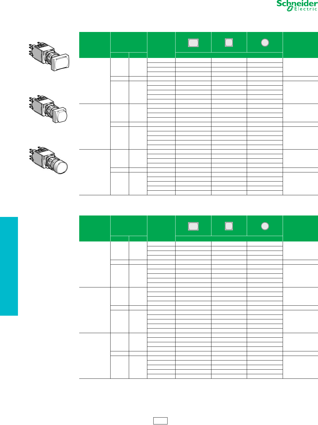
16 mm Push Buttons XB6 Complete Devices
Refer to Catalog 9001CT1102
Legends . . . . . . . . . . . . . . . . . . . . . . . . . . . . . . . . . . . pages 19-20 and 19-22
Table 19.27: Illuminated Push Buttons (12–24 Vac/Vdc LED included)
Complete Units with Quick Connectors/Solder Tabs
Type of Operator Type of Contact Color
Rectangular Square Round
$ Price
N.O. N.C. Catalog Number
Flush,
spring return
1—
White XB6DW1B1B XB6CW1B1B XB6AW1B1B
44.40
Green XB6DW3B1B XB6CW3B1B XB6AW3B1B
Yellow XB6DW5B1B XB6CW5B1B XB6AW5B1B
Blue XB6DW6B1B XB6CW6B1B XB6AW6B1B
—1 Red XB6DW4B2B XB6CW4B2B XB6AW4B2B 44.40
11
White XB6DW1B5B XB6CW1B5B XB6AW1B5B
52.00
Green XB6DW3B5B XB6CW3B5B XB6AW3B5B
Red XB6DW4B5B XB6CW4B5B XB6AW4B5B
Yellow XB6DW5B5B XB6CW5B5B XB6AW5B5B
Blue XB6DW6B5B XB6CW6B5B XB6AW6B5B
Flush, maintained
1—
White XB6DF1B1B XB6CF1B1B XB6AF1B1B
44.40
Green XB6DF3B1B XB6CF3B1B XB6AF3B1B
Yellow XB6DF5B1B XB6CF5B1B XB6AF5B1B
Blue XB6DF6B1B XB6CF6B1B XB6AF6B1B
—1 Red XB6DF4B2B XB6CF4B2B XB6AF4B2B 44.40
11
White XB6DF1B5B XB6CF1B5B XB6AF1B5B
52.00
Green XB6DF3B5B XB6CF3B5B XB6AF3B5B
Red XB6DF4B5B XB6CF4B5B XB6AF4B5B
Yellow XB6DF5B5B XB6CF5B5B XB6AF5B5B
Blue XB6DF6B5B XB6CF6B5B XB6AF6B5B
Extended,
spring return
1—
White XB6DE1B1B XB6CE1B1B XB6AE1B1B
44.40
Green XB6DE3B1B XB6CE3B1B XB6AE3B1B
Yellow XB6DE5B1B XB6CE5B1B XB6AE5B1B
Blue XB6DE6B1B XB6CE6B1B XB6AE6B1B
—1 Red XB6DE4B2B XB6CE4B2B XB6AE4B2B 44.40
11
White XB6DE1B5B XB6CE1B5B XB6AE1B5B
52.00
Green XB6DE3B5B XB6CE3B5B XB6AE3B5B
Red XB6DE4B5B XB6CE4B5B XB6AE4B5B
Yellow XB6DE5B5B XB6CE5B5B XB6AE5B5B
Blue XB6DE6B5B XB6CE6B5B XB6AE6B5B
Table 19.28: Illuminated Push Buttons (120 Vac LED included)
Complete Units with Quick Connectors/Solder Tabs
Type of Operator Type of Contact Color
Rectangular Square Round
$ Price
N.O. N.C. Catalog Number
Flush,
spring return
1—
White XB6DW1G1B XB6CW1G1B XB6AW1G1B
44.40
Green XB6DW3G1B XB6CW3G1B XB6AW3G1B
Yellow XB6DW5G1B XB6CW5G1B XB6AW5G1B
Blue XB6DW6G1B XB6CW6G1B XB6AW6G1B
—1 Red XB6DW4G2B XB6CW4G2B XB6AW4G2B 44.40
11
White XB6DW1G5B XB6CW1G5B XB6AW1G5B
52.00
Green XB6DW3G5B XB6CW3G5B XB6AW3G5B
Red XB6DW4G5B XB6CW4G5B XB6AW4G5B
Yellow XB6DW5G5B XB6CW5G5B XB6AW5G5B
Blue XB6DW6G5B XB6CW6G5B XB6AW6G5B
Flush, maintained
1—
White XB6DF1G1B XB6CF1G1B XB6AF1G1B
44.40
Green XB6DF3G1B XB6CF3G1B XB6AF3G1B
Yellow XB6DF5G1B XB6CF5G1B XB6AF5G1B
Blue XB6DF6G1B XB6CF6G1B XB6AF6G1B
—1 Red XB6DF4G2B XB6CF4G2B XB6AF4G2B 44.40
11
White XB6DF1G5B XB6CF1G5B XB6AF1G5B
52.00
Green XB6DF3G5B XB6CF3G5B XB6AF3G5B
Red XB6DF4G5B XB6CF4G5B XB6AF4G5B
Yellow XB6DF5G5B XB6CF5G5B XB6AF5G5B
Blue XB6DF6G5B XB6CF6G5B XB6AF6G5B
Extended,
spring return
1—
White XB6DE1G1B XB6CE1G1B XB6AE1G1B
44.40
Green XB6DE3G1B XB6CE3G1B XB6AE3G1B
Yellow XB6DE5G1B XB6CE5G1B XB6AE5G1B
Blue XB6DE6G1B XB6CE6G1B XB6AE6G1B
—1 Red XB6DE4G2B XB6CE4G2B XB6AE4G2B 44.40
11
White XB6DE1G5B XB6CE1G5B XB6AE1G5B
52.00
Green XB6DE3G5B XB6CE3G5B XB6AE3G5B
Red XB6DE4G5B XB6CE4G5B XB6AE4G5B
Yellow XB6DE5G5B XB6CE5G5B XB6AE5G5B
Blue XB6DE6G5B XB6CE6G5B XB6AE6G5B
XB6DW•••B
XB6CE•••B
XB6AF•••B
CS2 Discount
Schedule
www.schneider-electric.us
19 PUSH BUTTONS AND
OPERATOR INTERFACE
© 2012 Schneider Electric
All Rights Reserved 19-13
16 mm Push Buttons XB6 Complete Devices
Refer to Catalog 9001CT1102
aComplies with EN418/ISO13850 standards for Emergency Stop push buttons when used with circular Legend Plate ZB6Y7330 (see page 19-22)
bRonis 200 key
Legends. . . . . . . . . . . . . . . . . . . . . . . . . . . . . . . . . . . pages 19-20 and 19-22
Table 19.29: Pilot Lights (12–24 Vac/Vdc LED included)
Complete Units with Quick Connectors/Solder Tabs
Color
Rectangular Square Round
$ Price
Catalog Number
White XB6DV1BB XB6CV1BB XB6AV1BB
27.30
Green XB6DV3BB XB6CV3BB XB6AV3BB
Red XB6DV4BB XB6CV4BB XB6AV4BB
Yellow XB6DV5BB XB6CV5BB XB6AV5BB
Blue XB6DV6BB XB6CV6BB XB6AV6BB
Table 19.30: Pilot Lights (120 Vac LED)
Complete Units with Quick Connectors/Solder Tabs
Color
Rectangular Square Round
$ Price
Catalog Number
White XB6DV1GB XB6CV1GB XB6AV1GB
27.30
Green XB6DV3GB XB6CV3GB XB6AV3GB
Red XB6DV4GB XB6CV4GB XB6AV4GB
Yellow XB6DV5GB XB6CV5GB XB6AV5GB
Blue XB6DV6GB XB6CV6GB XB6AV6GB
Table 19.31: Push Buttons (Non-Illuminated)
Complete Units with Quick Connectors/Solder Tabs
Type of Push Type of Contact Color
Rectangular Square Round
$ Price
N.O. N.C. Catalog Number
Flush, spring return
1—
White XB6DA11B XB6CA11B XB6AA11B
26.20
Black XB6DA21B XB6CA21B XB6AA21B
Green XB6DA31B XB6CA31B XB6AA31B
Yellow XB6DA51B XB6CA51B XB6AA51B
Blue XB6DA61B XB6CA61B XB6AA61B
—1 Black XB6DA22B XB6CA22B XB6AA22B 26.20
Red XB6DA42B XB6CA42B XB6AA42B
11
White XB6DA15B XB6CA15B XB6AA15B
34.10
Black XB6DA25B XB6CA25B XB6AA25B
Green XB6DA35B XB6CA35B XB6AA35B
Red XB6DA45B XB6CA45B XB6AA45B
Yellow XB6DA55B XB6CA55B XB6AA55B
Blue XB6DA65B XB6CA65B XB6AA65B
Table 19.32: Trigger Action Emergency Stop Mushroom Head Push Buttons (Color Red)a
Shape of Head Type of Push Type of Contact Diameter
of Head (mm) Catalog Number $ Price
N.O. N.C.
Turn-to-release
—1 30XB6AS8342B 65.00
11 30XB6AS8345B 73.00
Key release
—1 30XB6AS9342Bb78.00
11 30XB6AS9345Bb87.00
Table 19.33: Circular Legends, 45 mm
Description Color Text Catalog Number $ Price
Circular legends, 45 mm Yellow Blank ZB6Y7001 3.40
Emergency stop ZB6Y7330
XB6DV••B
XB6CV••B
XB6AV••B
XB6DA••B
XB6CA••B
XB6AA••B
XB6AS8345B
XB6AS9345B
ZB6Y7330
CS2 Discount
Schedule
19-14 © 2012 Schneider Electric
All Rights Reserved
www.schneider-electric.us
19 PUSH BUTTONS AND
OPERATOR INTERFACE
16 mm Push Buttons XB6 Complete Devices
Refer to Catalog 9001CT1102
Note: Indicates key withdrawal position.
aAs viewed from the front of the panel.
Legends . . . . . . . . . . . . . . . . . . . . . . . . . . . . . . . . . . . pages 19-20 and 19-22
Table 19.34: Selector Switches (Switching Angle: Handle: 60o, Key: 70o)
Complete Units with Quick Connectors/Solder Tabs
Type of
Operator
Type of Contact Number and Type of
Positions Rectangular Square Round
$ Price
N.O. N.C. Catalog Number
Handle
1 — 2-maintained XB6DD221B XB6CD221B XB6AD221B 29.70
11
2-maintained XB6DD225B XB6CD225B XB6AD225B 37.60
3-maintained XB6DD235B XB6CD235B XB6AD235B 37.60
2 — 3-maintained XB6DD233B XB6CD233B XB6AD233B 37.60
Type of
Operator
Type of Contact Number and Type of
Positions Rectangular Square Round
$ Price
N.O. N.C. Catalog Number
Key
11
2-maintained XB6DGC5B XB6CGC5B XB6AGC5B 68.00
2-maintained XB6DGB5B XB6CGB5B XB6AGB5B 68.00
3-maintained XB6DGH5B XB6CGH5B XB6AGH5B 68.00
2 — 3-maintained XB6DGH3B XB6CGH3B XB6AGH3B 68.00
Table 19.35: Selector Switch Sequence
2 Position Selector Switch
Contact block guide a
O X 1 N.O. (left or right)
X O 1 N.C. (left or right)
OX1 N.O.
and
XO1 N.C.
3 Position Selector Switch
Contact block guide a
O O X 1 N.O. (left)
X O X 2 N.O. wired in parallel (side by side)
X O O 1 N.O. (right)
O X X 1 N.C. (right)
X X O 1 N.C. (left)
O X O 2 N.C. wired in series (side by side)
XB6DD•••B
XB6CD•••B
XB6AD•••B
XB6DG••B
XB6CG••B
XB6AG••B
CS2 Discount
Schedule
www.schneider-electric.us
19 PUSH BUTTONS AND
OPERATOR INTERFACE
© 2012 Schneider Electric
All Rights Reserved 19-15
16 mm Push Buttons XB6 Electrical Components
Refer to Catalog 9001CT1102
aIlluminated selector switches can be assembled by using a contact block/light module assembly in conjunction with a selector switch head, supplied
without handle, and a transparent handle. See page 19-16.
bThe LED must be the same color as the push button cap.
cThe LED must be the same color as the lens.
dOrder bulbs separately. See page 19-22.
eNeon bulb can only be used with a red, yellow, or white cap.
fElectrical components with connection by printed circuit board pins are available. See page 19-22.
Table 19.36: Contact Blocks and Light Modules for Illuminated Push Buttonsa
Description Supply Voltage Type of Contact Color of Light
Source Catalog Number $ Price
N.O. N.C.
Quick connectors/solder tabs
Integral LED b
12–24 Vac/Vdc
1—
White ZB6ZB11B
28.00
Green ZB6ZB31B
Ye l l o w ZB6ZB51B
Blue ZB6ZB61B
—1Red ZB6ZB42B 28.00
Ye l l o w ZB6ZB52B
11
White ZB6ZB15B
35.20
Green ZB6ZB35B
Red ZB6ZB45B
Ye l l o w ZB6ZB55B
Blue ZB6ZB65B
120 Vac
1—
White ZB6ZG11B
28.00
Green ZB6ZG31B
Ye l l o w ZB6ZG51B
Blue ZB6ZG61B
—1Red ZB6ZG42B 28.00
Ye l l o w ZB6ZG52B
11
White ZB6ZG15B
35.20
Green ZB6ZG35B
Red ZB6ZG45B
Ye l l o w ZB6ZG55B
Blue ZB6ZG65B
Direct for incandescent bulb
(not included)d< 24 Vac/Vdc
1— —ZB6ZH01B 23.80
—1 —ZB6ZH02B 23.80
11 —ZB6ZH05B 31.00
Table 19.37: Contact Blocks for Push Buttons and Selector Switches
Description Type of Contact Catalog Number $ Price
N.O. N.C.
Quick connectors/solder tabs
Contact blocks with mounting base
1—ZB6Z1B 9.40
—1ZB6Z2B 9.40
2—ZB6Z3B 16.60
—2ZB6Z4B 16.60
11ZB6Z5B 16.60
Table 19.38: Light Modules for Pilot Lights
Description Supply Voltage Color of Light Source Catalog Number $ Price
Quick connectors/solder tabsf
Integral LEDc
12–24 Vac/Vdc
White ZB6EB1B
16.60
Green ZB6EB3B
Red ZB6EB4B
Ye l l o w ZB6EB5B
Blue ZB6EB6B
120 Vac
White ZB6EG1B
16.60
Green ZB6EG3B
Red ZB6EG4B
Ye l l o w ZB6EG5B
Blue ZB6EG6B
With resistor for 95 V neon bulb (not included) de 110 Vac — ZB6EG0B 15.60
230 Vac — ZB6EM0B 15.60
Direct supply for 0.6 W max. incandescent bulb
(not included)d< 24 Vac/Vdc — ZB6EH0B 14.40
Table 19.39: Separate Contact Blocks (Maximum of 3 contacts per mounting base.)
Contact Material For use with mounting base Type of Contact Catalog Number $ Price
N.O. N.C.
Silver alloy Quick connectors/solder tabs 1—ZB6E1B 7.20
—1ZB6E2B 7.20
Gold flashed Quick connectors/solder tabs 1—ZB6E1E 12.40
—1ZB6E2E 12.40
Table 19.40: Accessories for Printed Circuit Board Installations
Description for use with Catalog Number
Plug-in Socket Adapter contact blocks and light modules ZB6Y010
Body Bracket plug-in socket adapter ZB6Y011
ZB6ZB••B
ZB6ZH••B
ZB6Z•B
ZB6E••B
ZB6E•0B
ZB6E•B
ZB6Y010
ZB6Y011
CS2 Discount
Schedule
19-16 © 2012 Schneider Electric
All Rights Reserved
www.schneider-electric.us
19 PUSH BUTTONS AND
OPERATOR INTERFACE
16 mm Push Buttons XB6 Illuminated Operators
Refer to Catalog 9001CT1102
aFive different color caps included with head (white, green, red, yellow, and blue).
bFive different color caps included with head (white, green, red, yellow, and blue).
Legends . . . . . . . . . . . . . . . . . . . . . . . . . . . . . . . . . . . pages 19-20 and 19-22
Table 19.41: Heads for Illuminated Push Buttons
(To combine with complete bodies and contact blocks, see page 19-15)
Type of Push Color
Rectangular Square Round
$ Price
Catalog Number
Flush, spring return
White ZB6DW1 ZB6CW1 ZB6AW1
14.40
Green ZB6DW3 ZB6CW3 ZB6AW3
Red ZB6DW4 ZB6CW4 ZB6AW4
Ye l l o w ZB6DW5 ZB6CW5 ZB6AW5
Blue ZB6DW6 ZB6CW6 ZB6AW6
5 colors aZB6DW9 ZB6CW9 ZB6AW9 16.40
Flush, maintained
White ZB6DF1 ZB6CF1 ZB6AF1
14.40
Green ZB6DF3 ZB6CF3 ZB6AF3
Red ZB6DF4 ZB6CF4 ZB6AF4
Ye l l o w ZB6DF5 ZB6CF5 ZB6AF5
Blue ZB6DF6 ZB6CF6 ZB6AF6
5 colors aZB6DF9 ZB6CF9 ZB6AF9 16.40
Extended, spring return
White ZB6DE1 ZB6CE1 ZB6AE1
14.40
Green ZB6DE3 ZB6CE3 ZB6AE3
Red ZB6DE4 ZB6CE4 ZB6AE4
Ye l l o w ZB6DE5 ZB6CE5 ZB6AE5
Blue ZB6DE6 ZB6CE6 ZB6AE6
5 colorsaZB6DE9 ZB6CE9 ZB6AE9 16.40
Table 19.42: Heads for Pilot Lights
(To combine with light modules, see page 19-15.)
Color
Rectangular Square Round
$ Price
Catalog Number
White ZB6DV1 ZB6CV1 ZB6AV1
8.20
Green ZB6DV3 ZB6CV3 ZB6AV3
Red ZB6DV4 ZB6CV4 ZB6AV4
Yellow ZB6DV5 ZB6CV5 ZB6AV5
Blue ZB6DV6 ZB6CV6 ZB6AV6
5 colors bZB6DV9 ZB6CV9 ZB6AV9 10.20
ZB6DW•
ZB6CE•
ZB6AF•
ZB6DV•
ZB6CV•
ZB6AV•
CS2 Discount
Schedule
www.schneider-electric.us
19 PUSH BUTTONS AND
OPERATOR INTERFACE
© 2012 Schneider Electric
All Rights Reserved 19-17
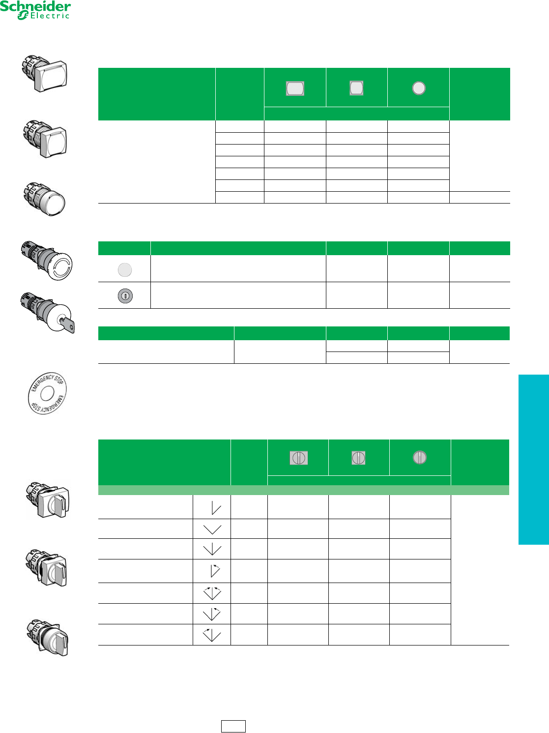
16 mm Push Buttons XB6 Non-Illuminated Operators and Selector Switches
Refer to Catalog 9001CT1102
Non-Illuminated Operators
aFive different color caps included with head (white, green, red, yellow, and blue).
bComplies with EN418/ISO13850 standards for Emergency Stop push buttons when used with circular Legend Plate ZB6Y7330 (see page 19-22)
cRonis 200 key
Non-Illuminated Selector Switches
aFor bodies with 2 contact blocks, maximum.
bSwitching angle: maintained positions 90o.
cSee selector switch sequence charts on page 19-19.
Legends. . . . . . . . . . . . . . . . . . . . . . . . . . . . . . . . . . . pages 19-20 and 19-22
Table 19.43: Heads for Push Buttons
(To combine with complete bodies and contact blocks, see page 19-15.)
Type of Push Color Rectangular Square Round $ Price
Catalog Number
Flush, spring return
White ZB6DA1 ZB6CA1 ZB6AA1
14.40
Black ZB6DA2 ZB6CA2 ZB6AA2
Green ZB6DA3 ZB6CA3 ZB6AA3
Red ZB6DA4 ZB6CA4 ZB6AA4
Yellow ZB6DA5 ZB6CA5 ZB6AA5
Blue ZB6DA6 ZB6CA6 ZB6AA6
6 colorsaZB6DA9 ZB6CA9 ZB6AA9 16.40
Table 19.44: Mushroom Heads for Trigger Action Push Buttons (30 mm)b
Shape of Head Type of Push Cap Color Catalog Number $ Price
Turn-to-release Red ZB6AS834 49.60
Key release Red ZB6AS934c62.60
Table 19.45: Circular Legends, 45 mm
Description Color Text Catalog Number $ Price
Circular legends, 45 mm Yellow
Blank ZB6Y7001
3.40
Emergency stop ZB6Y7330
Table 19.46: Heads for Non-Illuminated Selector Switchesac
(To combine with complete bodies and contact blocks, see page 19-15.)
Number and Type of Positions Color of
Handle Rectangular Square Round
$ Price
Catalog Number
Switching angle: maintained positions 60°, spring return positions 45°
2-maintained Black ZB6DD22 ZB6CD22 ZB6AD22
17.60
2-maintained Black ZB6DD28bZB6CD28bZB6AD28b
3-maintained Black ZB6DD23 ZB6CD23 ZB6AD23
2-spring return to center Black ZB6DD24 ZB6CD24 ZB6AD24
3-spring return to center Black ZB6DD25 ZB6CD25 ZB6AD25
3-spring return from right to center Black ZB6DD26 ZB6CD26 ZB6AD26
3-spring return from left to center Black ZB6DD27 ZB6CD27 ZB6AD27
ZB6DA•
ZB6CA•
ZB6AA•
ZB6AS834
ZB6AS934
ZB6Y7330
ZB6DD••
ZB6CD••
ZB6AD••
CS2 Discount
Schedule
19-18 © 2012 Schneider Electric
All Rights Reserved
www.schneider-electric.us
19 PUSH BUTTONS AND
OPERATOR INTERFACE
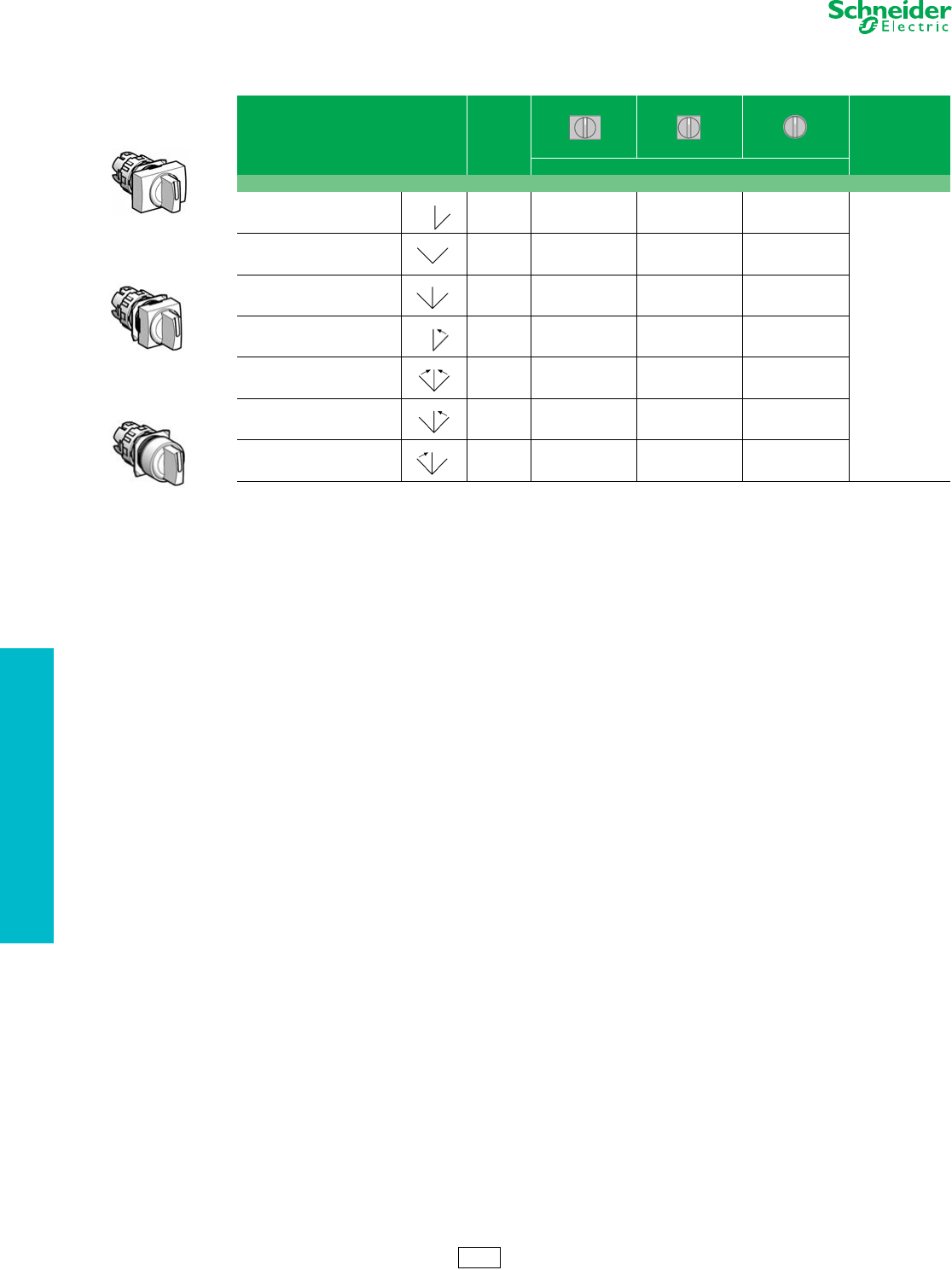
16 mm Push Buttons XB6 Selector Switches
Refer to Catalog 9001CT1102
aFor bodies with 2 contact blocks, maximum.
bSwitching angle: maintained positions 90o.
cSee selector switch sequence charts on page 19-14.
Legends . . . . . . . . . . . . . . . . . . . . . . . . . . . . . . . . . . . pages 19-20 and 19-22
Table 19.47: Heads for Non-Illuminated Selector Switchesac
(To combine with complete bodies and contact blocks, see page 19-15.)
Number and Type of Positions Color of
Handle Rectangular Square Round
$ Price
Catalog Number
Switching angle: maintained positions 60°, spring return positions 45°
2-maintained Black ZB6DD22 ZB6CD22 ZB6AD22
17.60
2-maintained Black ZB6DD28bZB6CD28bZB6AD28b
3-maintained Black ZB6DD23 ZB6CD23 ZB6AD23
2-spring return to center Black ZB6DD24 ZB6CD24 ZB6AD24
3-spring return to center Black ZB6DD25 ZB6CD25 ZB6AD25
3-spring return from right to center Black ZB6DD26 ZB6CD26 ZB6AD26
3-spring return from left to center Black ZB6DD27 ZB6CD27 ZB6AD27
ZB6DD••
ZB6CD••
ZB6AD••
CS2 Discount
Schedule
www.schneider-electric.us
19 PUSH BUTTONS AND
OPERATOR INTERFACE
© 2012 Schneider Electric
All Rights Reserved 19-19
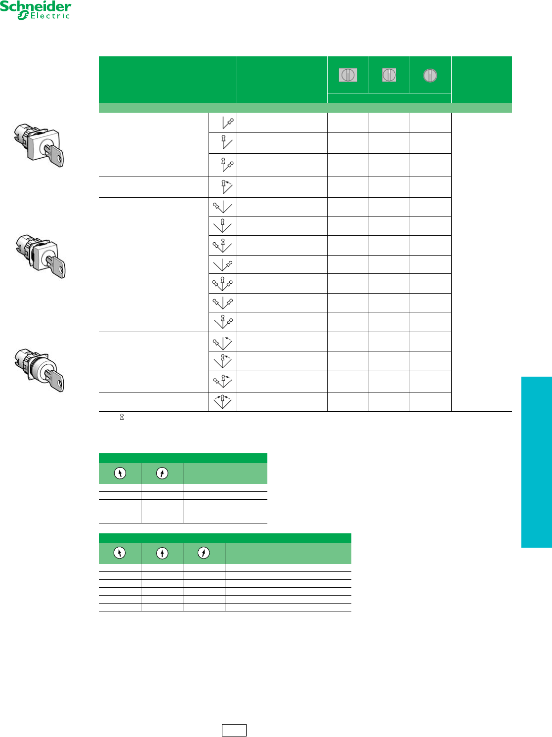
16 mm Push Buttons XB6 Keyed Selector Switches
Refer to Catalog 9001CT1102
Note: Indicates key withdrawal position.
aRonis 200 key standard.
bAs viewed from the front of the panel.
Legends. . . . . . . . . . . . . . . . . . . . . . . . . . . . . . . . . . . pages 19-20 and 19-22
Table 19.48: Heads for Ronis Key Operated Selector Switches a
(To combine with complete bodies and contact blocks, see page 19-15.)
Number and Type of Positions Key Withdrawal
Rectangular Square Round
$ Price
Catalog Number
Switching angle: maintained positions 70o, spring return positions 45o
2-maintained
Right-hand position ZB6DGA ZB6CGA ZB6AGA
45.60
Center position ZB6DGB ZB6CGB ZB6AGB
Both positions ZB6DGC ZB6CGC ZB6AGC
2-spring return from right to center Center position ZB6DGL ZB6CGL ZB6AGL
3-maintained
Left-hand position ZB6DGD ZB6CGD ZB6AGD
Center position ZB6DGE ZB6CGE ZB6AGE
Left-hand and center positions ZB6DGF ZB6CGF ZB6AGF
Right-hand position ZB6DGG ZB6CGG ZB6AGG
All 3 positions ZB6DGH ZB6CGH ZB6AGH
Left-hand and right-hand positions ZB6DGJ ZB6CGJ ZB6AGJ
Right-hand and center positions ZB6DGK ZB6CGK ZB6AGK
3-spring return from right to center
Left-hand position ZB6DGQ ZB6CGQ ZB6AGQ
Center position ZB6DGR ZB6CGR ZB6AGR
Left-hand and center positions ZB6DGS ZB6CGS ZB6AGS
3-spring return to center Center position ZB6DGT ZB6CGT ZB6AGT
Table 19.49: Selector Switch Sequence (using contact block assemblies, page 19-15)
2 Position Selector Switch
Contact block guide b
O X 1 N.O. (left or right)
X O 1 N.C. (left or right)
OX1 N.O.
and
XO1 N.C.
3 Position Selector Switch
Contact block guide b
O O X 1 N.O. (left)
X O X 2 N.O. wired in parallel (side by side)
X O O 1 N.O. (right)
O X X 1 N.C. (right)
XXO1 N.C. (left)
O X O 2 N.C. wired in series (side by side)
ZB6DG•
ZB6CG•
ZB6AG•
CS2 Discount
Schedule
www.schneider-electric.us
19 PUSH BUTTONS AND
OPERATOR INTERFACE
19-20 © 2012 Schneider Electric
All Rights Reserved
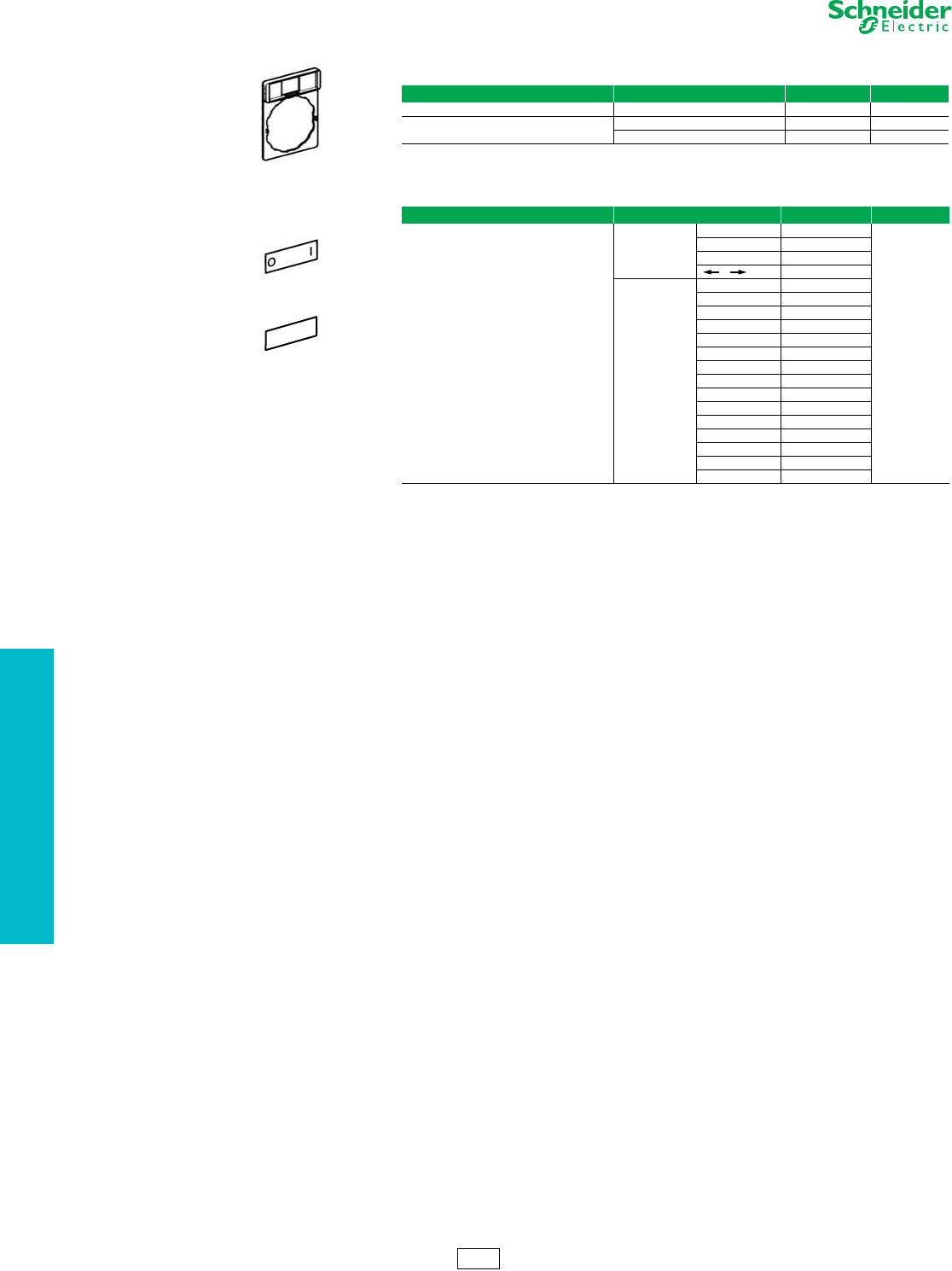
16 mm Push Buttons XB6 Accessories
Refer to Catalog 9001CT1102
aAdditional legend plate sizes and markings are available in Catalog 9001CT1102.
Table 19.50: Standard Legend Plate (24 X 28 mm) for 8 X 21 mm Legend a
Description Background Color of Legend Catalog Number $ Price
Without legend insert — ZB6YD20 2.00
With blank legend insert White or yellow ZB6YD21 3.40
Black or red ZB6YD22 3.40
Table 19.51: 8 x 21 mm Marked Legends (for 24 x 28 mm legend holder ZB6YD20) a
Color Marking Catalog Number $ Price
White Text
Red Background (Stop and Fault)
Black Background (all others)
International
O-I ZB6Y2178
1.60
I-II ZB6Y2179
I-O-II ZB6Y2186
OZB6Y2190
English
HAND-O-AUTO ZB6Y2387
CLOSE ZB6Y2314
DOWN ZB6Y2308
FORWARD ZB6Y2305
FAULT ZB6Y2334
LEFT ZB6Y2310
OFF ZB6Y2312
ON ZB6Y2303
OPEN ZB6Y2313
RESET ZB6Y2323
REVERSE ZB6Y2306
RIGHT ZB6Y2309
RUN ZB6Y2311
STOP ZB6Y2304
UP ZB6Y2307
ZB6YD20
ZB6Y2178
STOP
ZB6Y2304
CS2 Discount
Schedule
www.schneider-electric.us
19 PUSH BUTTONS AND
OPERATOR INTERFACE
© 2012 Schneider Electric
All Rights Reserved 19-21
16 mm Push Buttons XB6 Accessories
Refer to Catalog 9001CT1102
Table 19.52: Push Button Caps—Marked
Ink Marking Color:
White on colored cap
Black on white cap
Color
Rectangular Square Round
$ Price
Catalog Number
For non-illuminated push buttons
0White ZB6YD100 ZB6YC100 ZB6YA100
4.20
Black ZB6YD200 ZB6YC200 ZB6YA200
1White ZB6YD101 ZB6YC101 ZB6YA101
Black ZB6YD201 ZB6YC201 ZB6YA201
2White ZB6YD102 ZB6YC102 ZB6YA102
Black ZB6YD202 ZB6YC202 ZB6YA202
3White ZB6YD103 ZB6YC103 ZB6YA103
Black ZB6YD203 ZB6YC203 ZB6YA203
4White ZB6YD104 ZB6YC104 ZB6YA104
Black ZB6YD204 ZB6YC204 ZB6YA204
5White ZB6YD105 ZB6YC105 ZB6YA105
Black ZB6YD205 ZB6YC205 ZB6YA205
6White ZB6YD106 ZB6YC106 ZB6YA106
Black ZB6YD206 ZB6YC206 ZB6YA206
7White ZB6YD107 ZB6YC107 ZB6YA107
Black ZB6YD207 ZB6YC207 ZB6YA207
8White ZB6YD108 ZB6YC108 ZB6YA108
Black ZB6YD208 ZB6YC208 ZB6YA208
9White ZB6YD109 ZB6YC109 ZB6YA109
Black ZB6YD209 ZB6YC209 ZB6YA209
ON White ZB6YD117 ZB6YC117 ZB6YA117
Green ZB6YD317 ZB6YC317 ZB6YA317
OFF Black ZB6YD224 ZB6YC224 ZB6YA224
Red ZB6YD424 ZB6YC424 ZB6YA424
IWhite ZB6YD111 ZB6YC111 ZB6YA111
Green ZB6YD311 ZB6YC311 ZB6YA311
OBlack ZB6YD210 ZB6YC210 ZB6YA210
Red ZB6YD410 ZB6YC410 ZB6YA410
RBlack ZB6YD226 ZB6YC226 ZB6YA226
Blue ZB6YD626 ZB6YC626 ZB6YA626
START White ZB6YD140 ZB6YC140 ZB6YA140
Green ZB6YD340 ZB6YC340 ZB6YA340
STOP Black ZB6YD241 ZB6YC241 ZB6YA241
Red ZB6YD441 ZB6YC441 ZB6YA441
II White ZB6YD112 ZB6YC112 ZB6YA112
Black ZB6YD212 ZB6YC212 ZB6YA212
III White ZB6YD113 ZB6YC113 ZB6YA113
Black ZB6YD213 ZB6YC213 ZB6YA213
+White ZB6YD114 ZB6YC114 ZB6YA114
Black ZB6YD214 ZB6YC214 ZB6YA214
-White ZB6YD115 ZB6YC115 ZB6YA115
Black ZB6YD215 ZB6YC215 ZB6YA215
UP White ZB6YD127 ZB6YC127 ZB6YA127
Black ZB6YD227 ZB6YC227 ZB6YA227
DOWN White ZB6YD128 ZB6YC128 ZB6YA128
Black ZB6YD228 ZB6YC228 ZB6YA228
CLOSE White ZB6YD132 ZB6YC132 ZB6YA132
Black ZB6YD232 ZB6YC232 ZB6YA232
White ZB6YD119 ZB6YC119 ZB6YA119
Black ZB6YD219 ZB6YC219 ZB6YA219
White ZB6YD120 ZB6YC120 ZB6YA120
Black ZB6YD220 ZB6YC220 ZB6YA220
White ZB6YD121 ZB6YC121 ZB6YA121
Black ZB6YD221 ZB6YC221 ZB6YA221
White ZB6YD122 ZB6YC122 ZB6YA122
Black ZB6YD222 ZB6YC222 ZB6YA222
ZB6YD•10
ZB6YC•10
ZB6YA•10
ZB6YD•17
ZB6YD•19
ZB6YC•19
ZB6YA•19
CS2 Discount
Schedule
www.schneider-electric.us
19 PUSH BUTTONS AND
OPERATOR INTERFACE
19-22 © 2012 Schneider Electric
All Rights Reserved
16 mm Push Buttons XB6 Accessories
Refer to Catalog 9001CT1102
a28 V bulb supplied, for use on 24 V.
b95 V bulb supplied, for use on 110/230 V.
aAdditional legend plate sizes and markings are available in Catalog 9001CT0001.
Table 19.53: Accessories
Description Application Catalog Number $ Price
Body Fitting contact blocks ZB6Y009 2.00
Bezel tightening tool + bulb extractor Fixing the switch and changing bulbs ZB6Y905 4.20
Three piece tool kit — ZB6Y019 12.40
Nut Fixing head to panel ZB6Y002 2.00
Adaptor Flush mounting a circular head push button or
pilot light in Ø 22 mm cut-out ZB6YA002 6.20
Shroud Protecting contacts against touching ZB6Y001 3.40
Protective cover
Circular and square head push buttons and
switches ZB6YA001 16.60
Rectangular head push buttons and switches ZB6YD001 16.60
Female Quick connector/Solder tab Sold in lots of 100 pieces ZB6Y004 0.42
Blanking plug Plugging an unused knockout ZB6Y005 4.20
Ronis key, 2 pieces Key operated selector switches and
emergency stop mushroom ZB6Y007 6.20
Incandescent bulbs, bayonet T1 1/4
6 V ZB6YA006 2.00
12 V ZB6YJ012 2.00
28 VaZB6YB028 2.00
Neon bulbs 110/230 V bZB6YG095 4.20
Table 19.54: Standard Legend Plate (24 X 28 mm) for 8 X 21 mm Legend a
Description Background Color of Legend Catalog Number $ Price
Without legend insert — ZB6YD20 2.00
With blank legend insert White or yellow ZB6YD21 3.40
Black or red ZB6YD22 3.40
Table 19.55: 8 x 21 mm Marked Legends (for 24 x 28 mm legend holder ZB6YD20) a
Color Marking Catalog Number $ Price
White Text
Red Background (Stop and Fault)
Black Background (all others)
International
O-I ZB6Y2178
1.60
I-II ZB6Y2179
I-O-II ZB6Y2186
OZB6Y2190
English
HAND-O-AUTO ZB6Y2387
CLOSE ZB6Y2314
DOWN ZB6Y2308
FORWARD ZB6Y2305
FAULT ZB6Y2334
LEFT ZB6Y2310
OFF ZB6Y2312
ON ZB6Y2303
OPEN ZB6Y2313
RESET ZB6Y2323
REVERSE ZB6Y2306
RIGHT ZB6Y2309
RUN ZB6Y2311
STOP ZB6Y2304
UP ZB6Y2307
Table 19.56: Circular Legends, 45 mm
Description Color Text Catalog Number $ Price
Circular legends, 45 mm Yellow Blank ZB6Y7001 3.40
Emergency stop ZB6Y7330
Table 19.57: Accessories for Printed Circuit Board Installations
Description for use with Catalog Number
Plug-in Socket Adapter contact blocks and light modules ZB6Y010
Body Bracket plug-in socket adapter ZB6Y011
ZB6Y905
ZB6Y009
ZB6Y002
ZB6Y001
ZB6YA001
ZB6YD001
ZB6Y005
ZB6Y007
ZB6YD20
ZB6Y2178
STOP
ZB6Y2304
ZB6Y7330
ZB6Y010
ZB6Y011
CS2 Discount
Schedule
www.schneider-electric.us
19 PUSH BUTTONS AND
OPERATOR INTERFACE
© 2012 Schneider Electric
All Rights Reserved 19-23
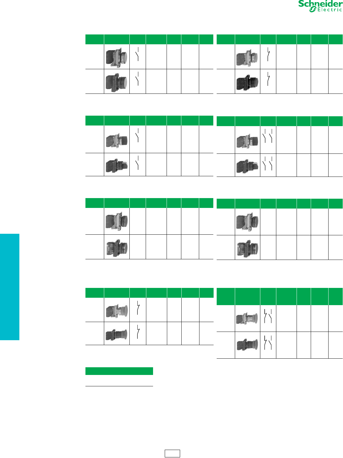
22 mm Push Buttons XB4 Complete Devices
Refer to Catalog DIA4ED2060507BEN-US
Legends. . . . . . . . . . . . . . . . . . . . . . . . . . . . . . . . . . . . . pages 19-37 to 19-39
Caps. . . . . . . . . . . . . . . . . . . . . . . . . . . . . . . . . . . . . . . . . . . . . . . . .page 19-39
Table 19.58: Non-Illuminated Push Buttons, Momentary (screw clamp terminal connections)
Shape of
Head Type of Push Type of Contact Marking Cap Color Catalog Number Components $ Price
N.O. N.C.
Flush
1— —
Black XB4BA21 (ZB4BZ101 + ZB4BA2)
38.50
Green XB4BA31 (ZB4BZ101 + ZB4BA3)
Yellow XB4BA51 (ZB4BZ101 + ZB4BA5)
Blue XB4BA61 (ZB4BZ101 + ZB4BA6)
—1 — RedXB4BA42 (ZB4BZ102 + ZB4BA4) 38.50
11 —
Black XB4BA25 (ZB4BZ105 + ZB4BA2)
56.00
Green XB4BA35 (ZB4BZ105 + ZB4BA3)
Red XB4BA45 (ZB4BZ105 + ZB4BA4)
Yellow XB4BA55 (ZB4BZ105 + ZB4BA5)
Blue XB4BA65 (ZB4BZ105 + ZB4BA6)
Flush 1 — “I”
(white) Green XB4BA3311 (ZB4BZ101 + ZB4BA331) 44.70
Flush — 1 “O”
(white) Red XB4BA4322 (ZB4BZ102 + ZB4BA432) 44.70
Flush with clear
silicone boot
(color of pusher
unobscured)
1— —
Black XB4BP21 (ZB4BZ101 + ZB4BP2)
53.00
Green XB4BP31 (ZB4BZ101 + ZB4BP3)
Yellow XB4BP51 (ZB4BZ101 + ZB4BP5)
Blue XB4BP61 (ZB4BZ101 + ZB4BP6)
—1 — RedXB4BP42 (ZB4BZ102 + ZB4BP4) 53.00
Extended
—1 — RedXB4BL42 (ZB4BZ102 + ZB4BL4) 38.50
11 — RedXB4BL45 (ZB4BZ105 + ZB4BL4) 56.00
Mushroom head
Ø 40 mm 1— — BlackXB4BC21 (ZB4BZ101 + ZB4BC2) 56.00
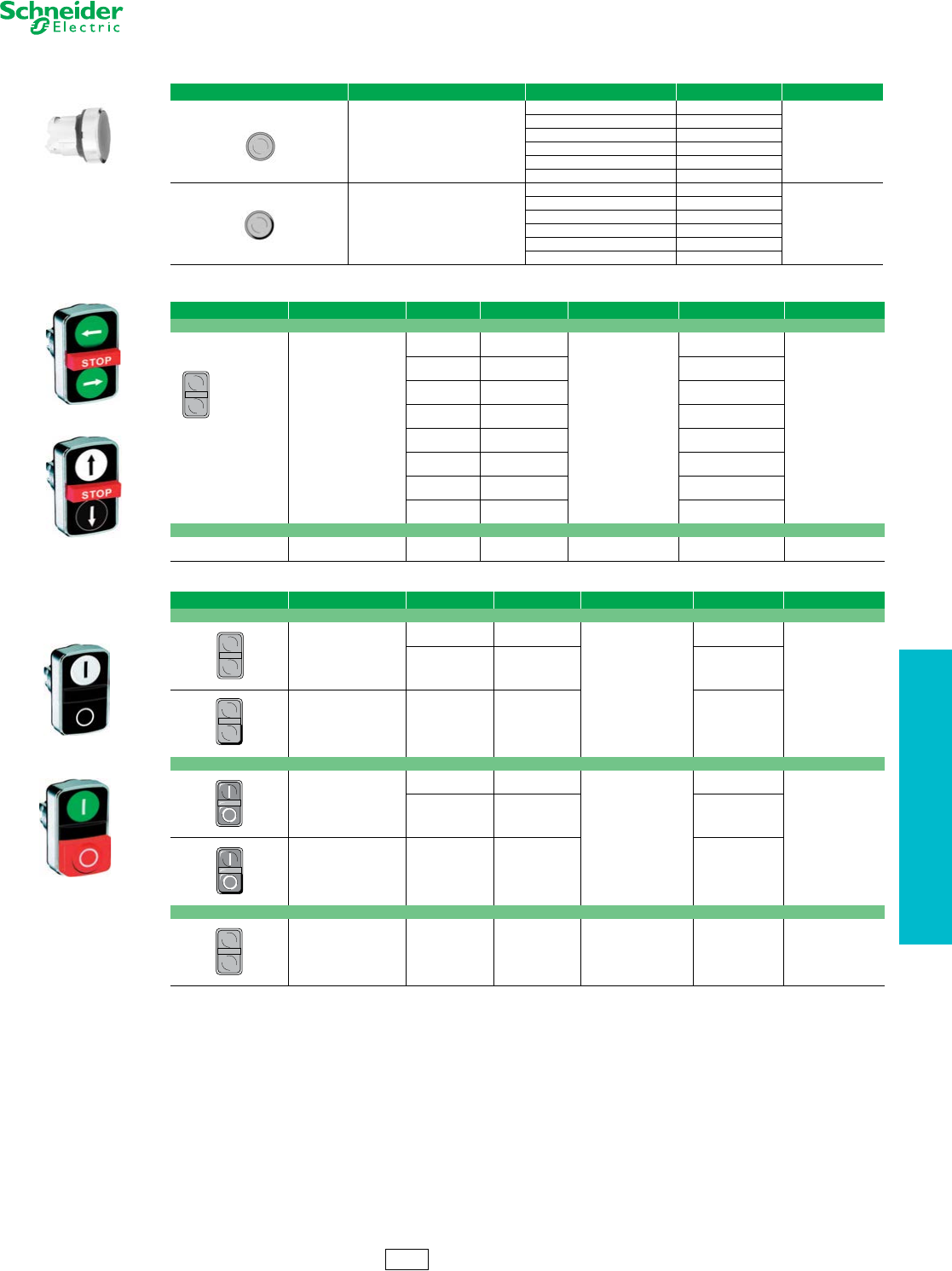
Table 19.59: Two Button Push Buttons, Momentary (screw clamp terminal connections)
Shape of
Head Type of Push Type of Contact Marking Degree of Protection Catalog Number Components $ Price
N.O. N.C.
One flush
green push*
One extended
red push**
11
*“I” (white)
**“O” (white)
IP66
IP69K XB4BL73415 (ZB4BZ105 + ZB4BL7341) 69.00
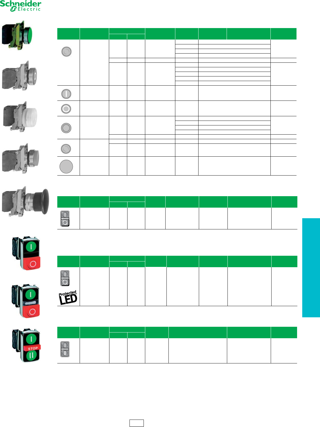
Table 19.60: Two Button Push Buttons, Momentary + one white central pilot light
(screw clamp terminal connections)
Shape of
Head Type of Push Type of Contact Marking Degree of ProtectionPilot Light Voltage Catalog Number $ Price
N.O. N.C.
One flush
green push*
One extended
red push**
One white central
pilot light block
11
*“I” (white)
**“O” (white)
IP66
IP69K
24
120
240
XB4BW73731B5
XB4BW73731G5
XB4BW73731M5
130.00
Table 19.61: Three Button Push Buttons, Momentary (screw clamp terminal connections)
Shape of
Head Type of Push Type of Contact Degree of
Protection Marking and Cap Color Catalog Number $ Price
N.O. N.C.
Two flush
pushes
+ one central
projecting
red push*
21IP66
IP69K
White “I” on green background
White “II” on green background
*White “Stop” on red background
Black “V” on white background
White “B” on black background
*White “Stop” on red background
XB4BA731327
XB4BA711237
120.00
XB4BA31
XB4BA4322
XB4BP51
XB4BL42
XB4BC21
CS2 Discount
Schedule
XB4BL73415
XB4BL73731p5
XB4BA731327
19-24 © 2012 Schneider Electric
All Rights Reserved
www.schneider-electric.us
19 PUSH BUTTONS AND
OPERATOR INTERFACE
22 mm Push Buttons XB4 Complete Devices
Refer to Catalog DIA4ED2060507BEN-US
aTrigger action mushroom heads are tamper proof in that a change of contact state is not possible by teasing or floating the operator. For emergency stop
applications, always use a trigger action push button (per EN/IEC 13850).
Note: The symbol indicates key withdrawal position(s).
bSee page 19-29 for contact configurations.
Legends . . . . . . . . . . . . . . . . . . . . . . . . . . . . . . . . . . . . pages 19-37 to 19-39
Table 19.62: Non-Illuminated Emergency Stop and Emergency Off Mushroom Head Push Buttons, Ø 40 mm,
Red (screw clamp terminal connections)
Shape of
Head Type of Push Type of Contact Catalog Number Components $ Price
N.O. N.C.
Trigger action
push-pulla11 XB4BT845 (ZB4BZ105 + ZB4BT84) 101.00
Trigger action
turn-to-releasea
11 XB4BS8445 (ZB4BZ105 + ZB4BS844)
165.00
12 XB4BS84441 (ZB4BZ141 + ZB4BS844)
Trigger action
Key release a
(No. 455)
11 XB4BS9445 (ZB4BZ105 + ZB4BS944) 165.00
Push-pull — 1 XB4BT42 (ZB4BZ102 + ZB4BT4) 68.00
Turn-to-release — 1 XB4BS542 (ZB4BZ102 + ZB4BS54) 110.00
Key release
(No. 455) —1 XB4BS142 (ZB4BZ102 + ZB4BS14) 147.00
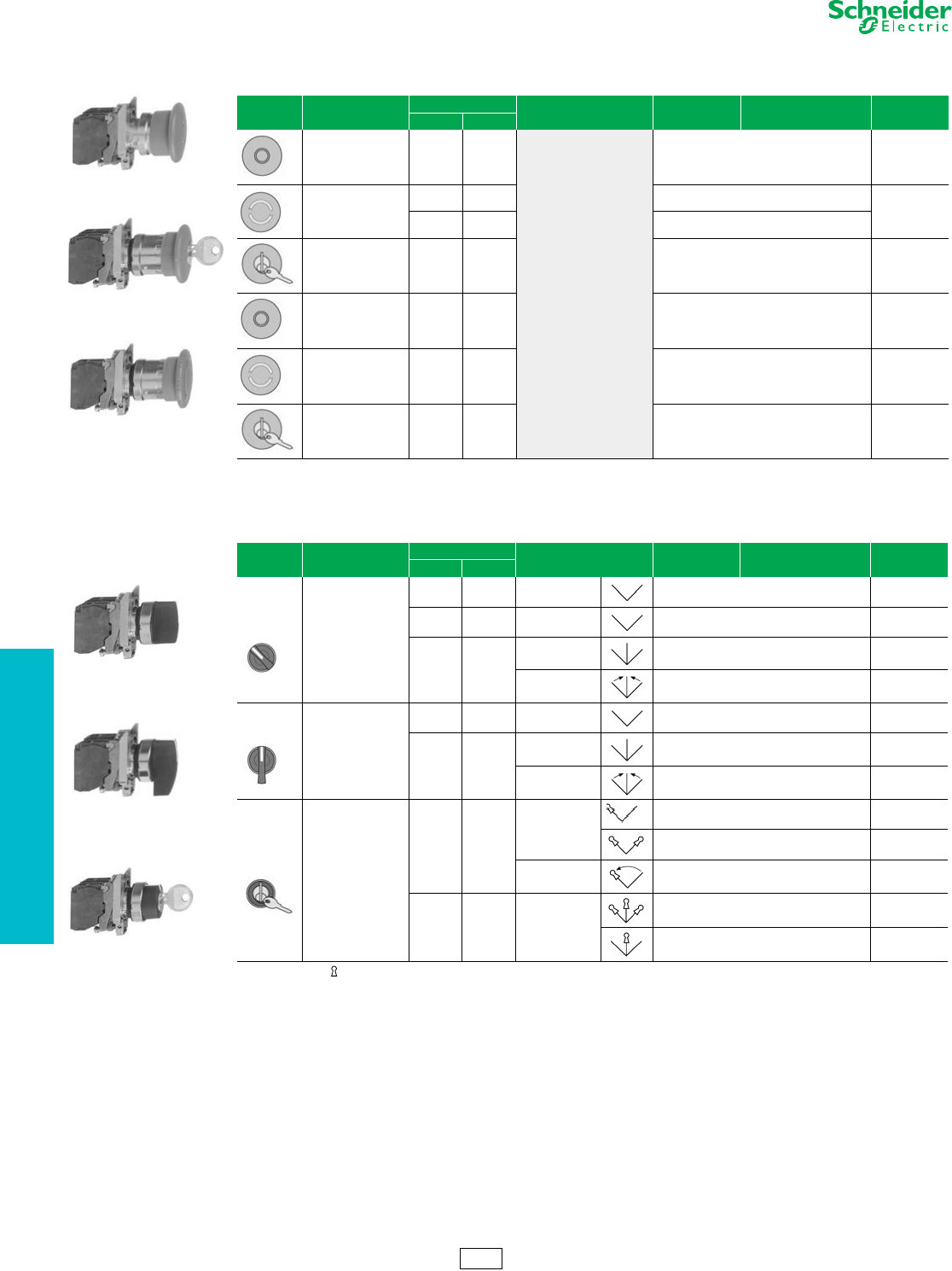
Table 19.63: Non-Illuminated Selector Switches and Key Switches (screw clamp terminal connections)b
Shape of
Head Type of Operator Type of Contact Number and Type of
Positions Catalog Number Components $ Price
N.O. N.C.
Standard lever, black
1 — 2-maintained XB4BD21 (ZB4BZ101 + ZB4BD2) 51.00
1 1 2-maintained XB4BD25 (ZB4BZ105 + ZB4BD2) 68.00
2—
3-maintained XB4BD33 (ZB4BZ103 + ZB4BD3) 68.00
3-momentary to
center XB4BD53 (ZB4BZ103 + ZB4BD5) 75.00
Extended lever, black
1 — 2-maintained XB4BJ21 (ZB4BZ101 + ZB4BJ2) 51.00
2—
3-maintained XB4BJ33 (ZB4BZ103 + ZB4BJ3) 68.00
3-momentary to
center XB4BJ53 (ZB4BZ103 + ZB4BJ5) 75.00
Key (No. 455)
1—
2-maintained
XB4BG21 (ZB4BZ101 + ZB4BG2) 123.00
XB4BG41 (ZB4BZ101 + ZB4BG4) 123.00
2-momentary to
left XB4BG61 (ZB4BZ101 + ZB4BG6) 123.00
2 — 3-maintained
XB4BG03 (ZB4BZ103 + ZB4BG0) 141.00
XB4BG33 (ZB4BZ103 + ZB4BG3) 141.00
XB4BT845
XB4BS9445
XB4BS542
XB4BG33
XB4BD33
XB4BJ33
CS2 Discount
Schedule
www.schneider-electric.us
19 PUSH BUTTONS AND
OPERATOR INTERFACE
© 2012 Schneider Electric
All Rights Reserved 19-25
22 mm Push Buttons XB4 Complete Devices
Refer to Catalog DIA4ED2060507BEN-US
aFor 240 V LED, replace the last “B” or “G” in the catalog number with an “M”. For example, XB4BVB1 (24 V) becomes XB4BVM1 (240 V—AC only).
Legends. . . . . . . . . . . . . . . . . . . . . . . . . . . . . . . . . . . . . pages 19-37 to 19-39
Table 19.64: Pilot Lights with Protected LED™ (screw clamp terminal connections) a
Shape of Head Supply Voltage Color Catalog Number Components $ Price
24 Vac/Vdc
White XB4BVB1 (ZB4BVB1 + ZB4BV013)
72.00
Green XB4BVB3 (ZB4BVB3 + ZB4BV033)
Red XB4BVB4 (ZB4BVB4 + ZB4BV043)
Ye l l o w XB4BVB5 (ZB4BVB5 + ZB4BV053)
Blue XB4BVB6 (ZB4BVB6 + ZB4BV063)
110–120 Vac
White XB4BVG1 (ZB4BVG1 + ZB4BV013)
72.00
Green XB4BVG3 (ZB4BVG3 + ZB4BV033)
Red XB4BVG4 (ZB4BVG4 + ZB4BV043)
Ye l l o w XB4BVG5 (ZB4BVG5 + ZB4BV053)
Blue XB4BVG6 (ZB4BVG6 + ZB4BV063)
Table 19.65: Pilot Lights for BA9s Bulb (screw clamp terminal connections)
Shape of Head Supply Voltage Color Catalog Number Components $ Price
Direct supply, for BA9s (incandescent, LED, neon) V < 250 V, 2.4 W bulb (bulb not included)
< 250 Vac/Vdc
White XB4BV61 (ZB4BV6 + ZB4BV01)
51.00
Green XB4BV63 (ZB4BV6 + ZB4BV03)
Red XB4BV64 (ZB4BV6 + ZB4BV04)
Ye l l o w XB4BV65 (ZB4BV6 + ZB4BV05)
Transformer type with 1.2 VA, 6 V secondary. BA9s incandescent bulb included
110–120 Vac
50/60 Hz
White XB4BV31 (ZB4BV3 + ZB4BV01)
117.00
Green XB4BV33 (ZB4BV3 + ZB4BV03)
Red XB4BV34 (ZB4BV3 + ZB4BV04)
Ye l l o w XB4BV35 (ZB4BV3 + ZB4BV05)
Table 19.66: Illuminated Push Buttons, Momentary (screw clamp terminal connections) a
Shape of Head Description Type of Contact Supply Voltage Color of Push Catalog Number Components $ Price
N.O. N.C.
Flush
11
24 Vac/Vdc
White XB4BW31B5 (ZB4BW0B15 + ZB4BW313)
119.00
Green XB4BW33B5 (ZB4BW0B35 + ZB4BW333)
Red XB4BW34B5 (ZB4BW0B45 + ZB4BW343)
Ye l l o w XB4BW35B5 (ZB4BW0B55 + ZB4BW353)
Blue XB4BW36B5 (ZB4BW0B65 + ZB4BW363)
110–120 Vac
White XB4BW31G5 (ZB4BW0G15 + ZB4BW313)
119.00
Green XB4BW33G5 (ZB4BW0G35 + ZB4BW333)
Red XB4BW34G5 (ZB4BW0G45 + ZB4BW343)
Ye l l o w XB4BW35G5 (ZB4BW0G55 + ZB4BW353)
Blue XB4BW36G5 (ZB4BW0G65 + ZB4BW363)
Direct supply
for BA9s
2.4 W max.
bulb not
included
11< 250 Vac/Vdc
White XB4BW3165 (ZB4BW065 + ZB4BW31)
99.00
Green XB4BW3365 (ZB4BW065 + ZB4BW33)
Red XB4BW3465 (ZB4BW065 + ZB4BW34)
Ye l l o w XB4BW3565 (ZB4BW065 + ZB4BW35)
Transformer
type
1.2 VA, 6 V secondary.
BA9s incandescent
bulb
included
11
110–120 Vac
50/60 Hz
White XB4BW3135 (ZB4BW035 + ZB4BW31)
163.00
Green XB4BW3335 (ZB4BW035 + ZB4BW33)
Red XB4BW3435 (ZB4BW035 + ZB4BW34)
Ye l l o w XB4BW3535 (ZB4BW035 + ZB4BW35)
230–240 Vac
50/60 Hz
White XB4BW3145 (ZB4BW045 + ZB4BW31)
163.00
Green XB4BW3345 (ZB4BW045 + ZB4BW33)
Red XB4BW3445 (ZB4BW045 + ZB4BW34)
Ye l l o w XB4BW3545 (ZB4BW045 + ZB4BW35)
Extended
11
24 Vac/Vdc
White XB4BW11B5 (ZB4BW0B15 + ZB4BW113)
113.00
Green XB4BW13B5 (ZB4BW0B35 + ZB4BW133)
Red XB4BW14B5 (ZB4BW0B45 + ZB4BW143)
Ye l l o w XB4BW15B5 (ZB4BW0B55 + ZB4BW153)
Blue XB4BW16B5 (ZB4BW0B65 + ZB4BW163)
110–120 Vac
White XB4BW11G5 (ZB4BW0G15 + ZB4BW113)
113.00
Green XB4BW13G5 (ZB4BW0G35 + ZB4BW133)
Red XB4BW14G5 (ZB4BW0G45 + ZB4BW143)
Ye l l o w XB4BW15G5 (ZB4BW0G55 + ZB4BW153)
Blue XB4BW16G5 (ZB4BW0G65 + ZB4BW163)
XB4BVB5
XB4BV64
XB4BV33
XB4BW33B5
XB4BW3465
XB4BW3545
CS2 Discount
Schedule
19-26 © 2012 Schneider Electric
All Rights Reserved
www.schneider-electric.us
19 PUSH BUTTONS AND
OPERATOR INTERFACE
22 mm Push Buttons XB4 Operators
Refer to Catalog DIA4ED2060507BEN-US
aColor cap to be ordered separately, see page 19-39.
bFor legend ordering information, see page 19-39.
cCap supplied not clipped-in, allowing orientation of arrow in any one of 4 directions:
Legends . . . . . . . . . . . . . . . . . . . . . . . . . . . . . . . . . . . . pages 19-37 to 19-39
Table 19.67: Non-Illuminated Operators, Momentary—Unmarked
Shape of Head Type of Push Cap Color Catalog Number $ Price
Flush, without color cap a—ZB4BA0 11.00
Flush, with set of 6 color caps
White
Black
Green
Red
Ye l l o w
Blue
ZB4BA9 13.00
Flush
White ZB4BA1
13.00
Black ZB4BA2
Green ZB4BA3
Red ZB4BA4
Ye l l o w ZB4BA5
Blue ZB4BA6
Gray ZB4BA8
Flush with transparent cap,
for insertion of legend b
White ZB4BA18
16.00
Green ZB4BA38
Red ZB4BA48
Ye l l o w ZB4BA58
Blue ZB4BA68
Booted Flush (clear silicone)
Cap color unobscured
White ZB4BPA1
25.80
Black ZB4BPA2
Green ZB4BPA3
Red ZB4BPA4
Ye l l o w ZB4BPA5
Blue ZB4BPA6
Booted Extended (clear silicone)
Cap color unobscured
White ZB4BP1
25.80
Black ZB4BP2
Green ZB4BP3
Red ZB4BP4
Ye l l o w ZB4BP5
Blue ZB4BP6
Booted (colored silicone)
Cap color unobscured
White ZB4BP1S
25.80
Black ZB4BP2S
Green ZB4BP3S
Red ZB4BP4S
Ye l l o w ZB4BP5S
Blue ZB4BP6S
Booted (clear silicone)
for insertion of legend b
Cap color unobscured
White ZB4BP18
29.00
Green ZB4BP38
Red ZB4BP48
Ye l l o w ZB4BP58
Blue ZB4BP68
Extended
White ZB4BL1
13.00
Black ZB4BL2
Green ZB4BL3
Red ZB4BL4
Ye l l o w ZB4BL5
Blue ZB4BL6
Guarded Head
White ZB4BA16
35.00
Black ZB4BA26
Green ZB4BA36
Red ZB4BA46
Ye l l o w ZB4BA56
Blue ZB4BA66
Table 19.68: Non-Illuminated Operators, Momentary—Premarked
Shape of Head Type of Push Marking Text Marking Color Cap Color Catalog Number $ Price
Flush
IWhite Green ZB4BA331
18.60
Black White ZB4BA131
START White Green ZB4BA333
Black White ZB4BA133
ON White Green ZB4BA341
Black White ZB4BA141
RESET White Black ZB4BA222
JOG White Black ZB4BA245
OWhite
Red ZB4BA432
Black ZB4BA232
STOP White Red ZB4BA434
Black ZB4BA234
OFF White Red ZB4BA435
Black ZB4BA235
cBlack White ZB4BA334
White Black ZB4BA335
Extended
OWhite
Red ZB4BL432
18.60
Black ZB4BL232
STOP White Red ZB4BL434
Black ZB4BL234
OFF White Red ZB4BL435
Black ZB4BL235
ZB4BA0
ZB4BP18
ZB4BL1
ZB4BA4
ZB4BA38
ZB4BA36
ZB4BA331
ZB4BA334
ZB4BL432
CS2 Discount
Schedule
www.schneider-electric.us
19 PUSH BUTTONS AND
OPERATOR INTERFACE
© 2012 Schneider Electric
All Rights Reserved 19-27
22 mm Push Buttons XB4 Operators
Refer to Catalog DIA4ED2060507BEN-US
Legends. . . . . . . . . . . . . . . . . . . . . . . . . . . . . . . . . . . . . pages 19-37 to 19-39
Caps. . . . . . . . . . . . . . . . . . . . . . . . . . . . . . . . . . . . . . . . . . . . . . . . .page 19-39
Table 19.69: Non-Illuminated Push-on/Push-off Operators
Shape of Head Type of Push Color of Push Catalog Number $ Price
Flush
White ZB4BH01
17.60
Black ZB4BH02
Green ZB4BH03
Red ZB4BH04
Yellow ZB4BH05
Blue ZB4BH06
Extended
White ZB4BH1
17.60
Black ZB4BH2
Green ZB4BH3
Red ZB4BH4
Yellow ZB4BH5
Blue ZB4BH6
Table 19.70: Three Head Operators, Momentary
Shape of Head Description Marking Cap Color Degree of Protection Catalog Number $ Price
Premarked
Two flush
+ one central
projecting red push
marked “Stop”
Two flush
“I”
“II”
Green
Green
IP66
IP69K
ZB4BA73132
60.00
“X”
“V”
Green
Green
ZB4BA73133
“A”
“E”
Green
Green
ZB4BA73134
“+”
“-”
Green
Green
ZB4BA73135
“+”
“-”
White
White
ZB4BA71115
“X”
“V”
White
Black
ZB4BA71123
“A”
“E”
White
Black
ZB4BA71124
“A”
“E”
Black
Black
ZB4BA72124
Without caps
Two flush
without caps —— IP66
IP69K ZB4BA791 51.00
Table 19.71: Two Head Operators, Momentary
Shape of Head Description Marking Cap Color Degree of Protection Catalog Number $ Price
No Marking
Two flush
—Green
Red
IP66
IP69K
ZB4BA7340
37.20
—White
Black ZB4BA7120
One flush
One extended —Green
Red ZB4BL7340
Premarked
Two flush
“I”
“O”
Green
Red
IP66
IP69K
ZB4BA7341
41.40
“I”
“O”
White
Black ZB4BA7121
One flush
One extended
“I”
“O”
Green
Red ZB4BL7341
Without caps
Two flush
without caps —— IP66
IP69K ZB4BA79 35.00
ZB4BH02
ZB4BA7121
ZB4BL7341
CS2 Discount
Schedule
ZB4BA73133
ZB4BA71124
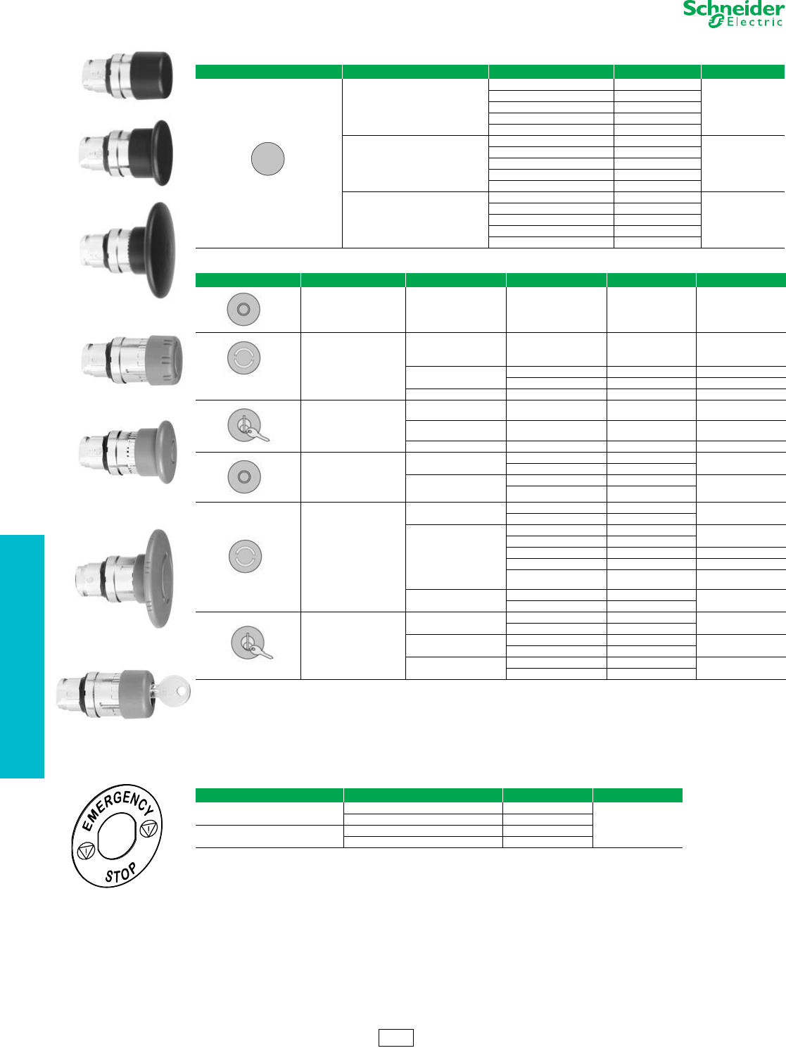
19-28 © 2012 Schneider Electric
All Rights Reserved
www.schneider-electric.us
19 PUSH BUTTONS AND
OPERATOR INTERFACE
22 mm Push Buttons XB4 Operators and Emergency Stop Operators
Refer to Catalog DIA4ED2060507BEN-US
aTrigger action mushroom heads are tamper proof in that a change of contact state is not possible by teasing or floating the operator. For emergency stop
applications, always use a trigger action push button (per EN/IEC 13850).
bOther key numbers:
—key no. 421E: add the suffix 12 to the catalog number.
—key no. 458A: add the suffix 10 to the catalog number.
—key no. 520E: add the suffix 14 to the catalog number.
—key no. 3131A: add the suffix 20 to the catalog number.
Example: The catalog number for a head with key No. 421E for a 2 position maintained, lockable selector switch, with key withdrawal from the left-hand
position, becomes: ZB4BG212.
Legends . . . . . . . . . . . . . . . . . . . . . . . . . . . . . . . . . . . . pages 19-37 to 19-39
Caps . . . . . . . . . . . . . . . . . . . . . . . . . . . . . . . . . . . . . . . . . . . . . . . . page 19-39
Table 19.72: Mushroom Heads, Momentary
Shape of Head Diameter of Head Color of Head Catalog Number $ Price
30 mm
Black ZB4BC24
29.40
Green ZB4BC34
Red ZB4BC44
Ye l l o w ZB4BC54
Blue ZB4BC64
40 mm
Black ZB4BC2
29.40
Green ZB4BC3
Red ZB4BC4
Ye l l o w ZB4BC5
Blue ZB4BC6
60 mm
Black ZB4BR2
35.00
Green ZB4BR3
Red ZB4BR4
Ye l l o w ZB4BR5
Blue ZB4BR6
Table 19.73: Mushroom Heads for Maintained Push Buttons
Shape of Head Type of Push Diameter of Head Color Catalog Number $ Price
Trigger action
Push-pull a40 mm Red ZB4BT84 54.00
Trigger action
Turn-to-release a
30 mm Red ZB4BS834 112.00
40 mm Red ZB4BS844 112.00
Red marked “EMO” ZB4BS84430 118.00
60 mm Red ZB4BS864 112.00
Trigger action
Key release
(No. 455) a
30 mm Red ZB4BS934 112.00
40 mm Red ZB4BS944 b112.00
60 mm Red ZB4BS964 112.00
Push-pull
40 mm Black ZB4BT2 40.40
Red ZB4BT4
60 mm Black ZB4BX2 46.00
Red ZB4BX4
Turn-to-release
30 mm Black ZB4BS42 78.00
Red ZB4BS44
40 mm
Black ZB4BS52 78.00
Red ZB4BS54
Red marked “EMO” ZB4BS5430 85.00
Ye l l o w ZB4BS55 78.00
Ye l l o w m a r k e d
“Robot Stop” ZB4BS5550 85.00
60 mm Black ZB4BS62 90.00
Red ZB4BS64
Key release
(No. 455)
30 mm Black ZB4BS72 112.00
Red ZB4BS74
40 mm Black ZB4BS12 112.00
Red ZB4BS14 b
60 mm Black ZB4BS22 112.00
Red ZB4BS24
Table 19.74: Circular Legends for Emergency Stop Mushroom Heads (yellow background)
Diameter Text Catalog Number $ Price
60 mm Blank ZBY9101
3.40
EMERGENCY STOP ZBY9330
90 mm Blank ZBY8101
EMERGENCY STOP ZBY8330
ZBY9330
CS2 Discount
Schedule
ZB4BS834
ZB4BT4
ZB4BS64
ZB4BS74
ZB4BC24
ZB4BC2
ZB4BR2
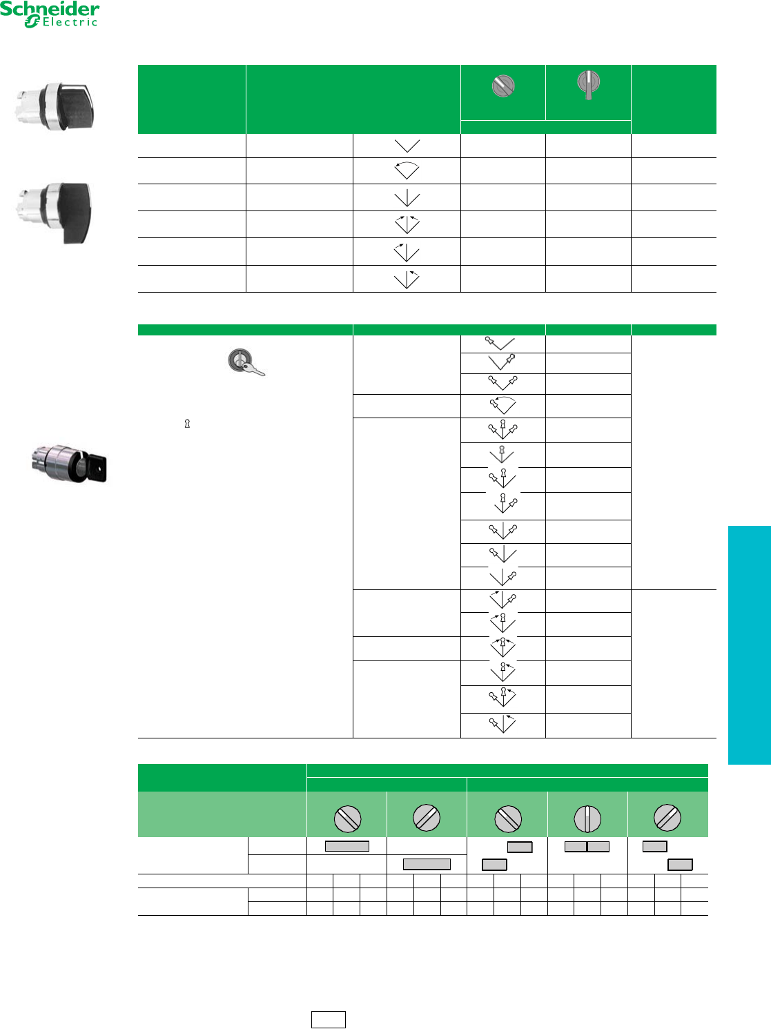
www.schneider-electric.us
19 PUSH BUTTONS AND
OPERATOR INTERFACE
© 2012 Schneider Electric
All Rights Reserved 19-29
22 mm Push Buttons XB4 Selector Switches
Refer to Catalog DIA4ED2060507BEN-US
aFor colored lever, add the following code to the end of part number: 01–white, 03–green, 04–red, 05–yellow, 06–blue (Example: ZB4BD204).
Legends. . . . . . . . . . . . . . . . . . . . . . . . . . . . . . . . . . . . . pages 19-37 to 19-39
Selector Switch Sequence (Table 19.91) . . . . . . . . . . . . . . . . . . . .page 19-33
Table 19.75: Non-Illuminated Selector Switches b
Color Number and Type of Positions
Standard Lever aExtended Lever
$ Price
Catalog Number
Black 2-maintained ZB4BD2 ZB4BJ2 24.00
Black 2-momentary from
right to left ZB4BD4 ZB4BJ4 29.40
Black 3-maintained ZB4BD3 ZB4BJ3 24.00
Black 3-momentary to center ZB4BD5 ZB4BJ5 29.40
Black 3-momentary from
left to center ZB4BD7 ZB4BJ7 29.40
Black 3-momentary from
right to center ZB4BD8 ZB4BJ8 29.40
Table 19.76: Non-Illuminated Key Switches b
Type of Operator Number and Type of Positions Catalog Number $ Price
Key (No. 455) c
Note:
The symbol indicates the key withdrawal position(s).
2-maintained
ZB4BG2
90.00
ZB4BG02
ZB4BG4
2-momentary from
right to left ZB4BG6
3-maintained
ZB4BG0
ZB4BG3
ZB4BG03
ZB4BG04
ZB4BG5
ZB4BG9
ZB4BG09
bSee Table 19.77 for contact configurations.
cOther key numbers: 3-momentary from
left to center
ZB4BG1
116.00
—key no. 421E: add the suffix 12 to the catalog
number.
—key no. 458A: add the suffix 10 to the catalog
number.
—key no. 520E: add the suffix 14 to the catalog
number.
—key no. 3131A: add the suffix 20 to the catalog
number.
ZB4BG01
3-momentary to center ZB4BG7
3-momentary from right to
center
ZB4BG8
ZB4BG05
Example: For a head with key no. 421E for a 2 position
maintained, lockable selector switch, with key withdrawal
from the left-hand position, order ZB4BG212.
ZB4BG08
Table 19.77: Sequence of Contacts on Selector Switch Bodies
Unit Type Selector Switches
2-position 3-position
Note:
L=Left, C=Center, R=Right,
O=Open, X=Closed
Operator Plunger Position
Up
Down
Contact Block Location L C R L C R L C R L C R L C R
Contacts N/O OOOXXXXXOOOOOX X
N/C XXXOOOOOXXXXXOO
ZB4BD4
Standard Lever
ZB4BJ3
Extended Lever
ZB4BG8
315° 45°
315°
0°
45°
CS2 Discount
Schedule
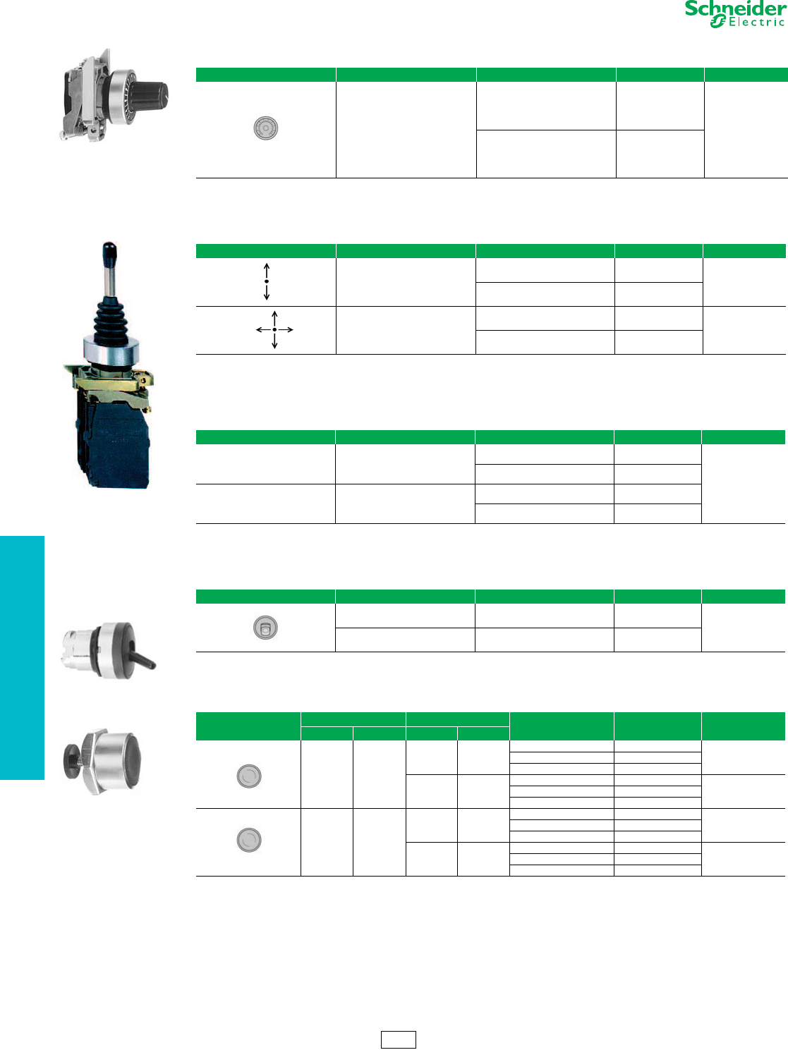
19-30 © 2012 Schneider Electric
All Rights Reserved
www.schneider-electric.us
19 PUSH BUTTONS AND
OPERATOR INTERFACE
22 mm Push Buttons XB4 Specialty Operators
Refer to Catalog DIA4ED2060507BEN-US
aDo not use standard contact blocks ZBE10• (single) or ZBE20• (double).
Legends . . . . . . . . . . . . . . . . . . . . . . . . . . . . . . . . . . . . pages 19-37 to 19-39
Table 19.78: Potentiometer Operator (with Mounting Collar)
Shape of Head Description Application Catalog Number $ Price
For potentiometer with
shaft length 1.73 to 1.97 in.
(45 to 50 mm)
(potentiometer not included)
For shaft Ø 1/4 in. (6.35 mm) ZB4BD922
142.00
For shaft Ø 0.24 in. (6 mm) ZB4BD912
Table 19.79: Joysticks (54 mm, Extended Operating Shaft) a
Description Contact Operation Action Catalog Number $ Price
2 direction 1 step 1 N.O. contact per direction
Maintained XD4PA12
250.00
Momentary XD4PA22
4 direction 1 step 1 N.O. contact per direction
Maintained XD4PA14
316.00
Momentary XD4PA24
Table 19.80: Legends for Joysticks
Description For use with Color Catalog Number $ Price
Legends
30 x 48 mm for customer engraving 2 direction
Black one side
Red reverse ZBG2201
3.40
White one side
Yellow reverse ZBG2401
Legends
48 x 48 mm for customer engraving 4 direction
Black one side
Red reverse ZBG4201
White one side
Yellow reverse ZBG4401
Table 19.81: Two Position Toggle Switch
Shape of Head Color Type of Positions Catalog Number $ Price
Black Maintained ZB4BD28
46.60
Black Momentary ZB4BD48
ZB4BD922
XD4PA12
ZB4BD28
XB4BA8•1
Table 19.82: Reset Operators, Flush, Adjustable Shaft
Shape of Head Travel Actuation Distance Color Catalog Number $ Price
in. mm in. mm
0.39 10
0.24–0.63 6–16
Black XB4BA821
30.10Red XB4BA841
Blue XB4BA861
0.63–1.02 16–26
Black XB4BA822
30.10Red XB4BA842
Blue XB4BA862
0.55 14
1.18–5.12 30–130
Black XB4BA921
36.10Red XB4BA941
Blue XB4BA961
5.12–10.12 130–257
Black XB4BA922
45.10Red XB4BA942
Blue XB4BA962
CS2 Discount
Schedule
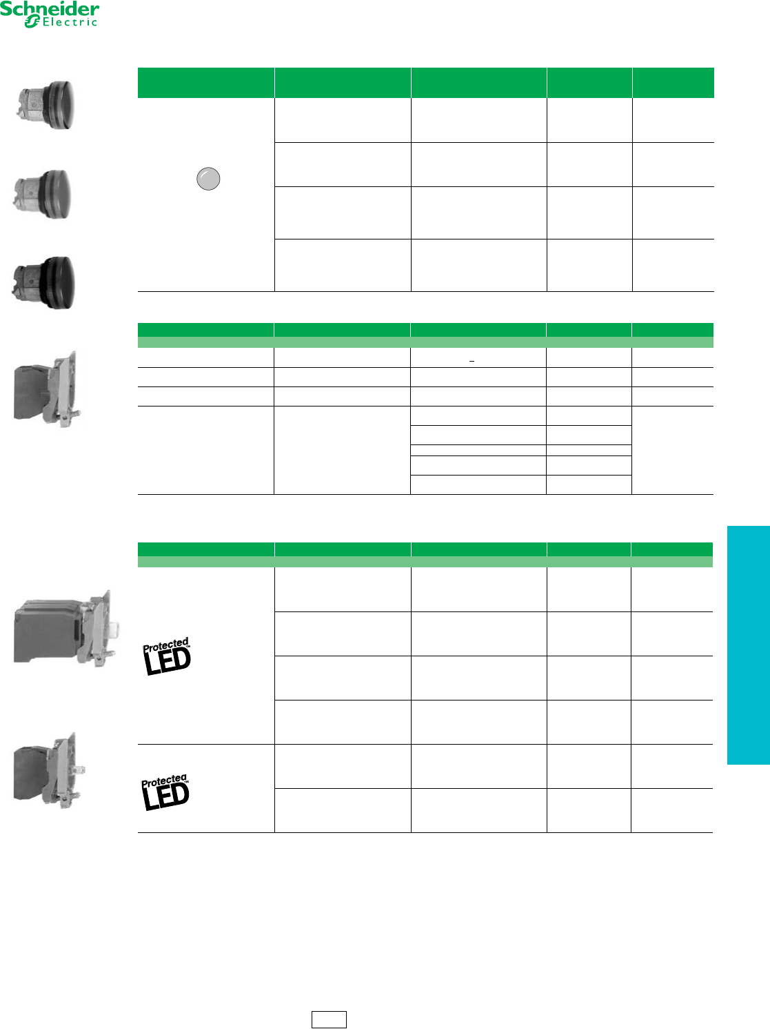
www.schneider-electric.us
19 PUSH BUTTONS AND
OPERATOR INTERFACE
© 2012 Schneider Electric
All Rights Reserved 19-31
22 mm Push Buttons XB4 Pilot Lights
Refer to Catalog DIA4ED2060507BEN-US
aFor use in bright ambient conditions, for example, in sunlight.
bOrder bulb separately; see page 19-40. For BA9 LED, see page 19-120.
cFor 240 V LED, replace the last “B” or “G” in the catalog number with an “M”. For example, ZB4BVB1 (24 V) becomes ZB4BVM1 (240 V).
dFor Quick-Connect version, add “3” to the end of the catalog number Example: ZB4BVJ13 (Quick-Connect size 1 x 1/40" or 2 x 0.110").
Legends. . . . . . . . . . . . . . . . . . . . . . . . . . . . . . . . . . . . . pages 19-37 to 19-39
Table 19.83: Pilot Light Heads
Shape of Head
For Use with Body
Comprising Light
Module Type
Color of Lens Catalog Number $ Price
Protected LED™ only
White ZB4BV013
7.60
Green ZB4BV033
Red ZB4BV043
Yellow ZB4BV053
Blue ZB4BV063
Protected LED only
Fresnel (jeweled) lens a
White ZB4BV013S
7.60
Green ZB4BV033S
Red ZB4BV043S
Amber ZB4BV053S
Blue ZB4BV063S
For BA9s incandescent
bulb, neon or LED only b
White ZB4BV01
7.60
Green ZB4BV03
Red ZB4BV04
Yellow ZB4BV05
Blue ZB4BV06
Clear ZB4BV07
For BA9s incandescent
bulb, neon or LED
Fresnel (jeweled) lens b
White ZB4BV01S
7.60
Green ZB4BV03S
Red ZB4BV04S
Amber ZB4BV05S
Blue ZB4BV06S
Clear ZB4BV07S
Table 19.84: Complete Bodies (Mounting Collar + Light Module for BA9s Incandescent Bulb, Neon or LED)
Description Light Source Supply Voltage (V) Catalog Number $ Price
Screw clamp terminal connections
Direct supply BA9s bulb 2.4 W max.
Not included b<250 ZB4BV6 38.60
Direct supply BA9s incandescent
bulb included 24 v 2 Watt ZB4BV624 49.20
Direct supply BA9s incandescent
bulb included 120 v 2.4 Watt ZB4BV6120 49.20
Transformer type
1.2 VA, 6 V secondary
BA9s incandescent
bulb included
110–120 Vac
50/60 Hz ZB4BV3
98.00
230–240 Vac
50/60 Hz ZB4BV4
400–50 Hz ZB4BV5
440–480 Vac
60 Hz ZB4BV8
550–600 Vac
60 Hz ZB4BV9
Table 19.85: Complete Bodies (Mounting Collar + Light Module with Protected LED™) c
Light Source Supply Voltage Color of Light Source Catalog Number $ Price
Screw clamp terminal connections d
12 Vac/Vdc
White ZB4BVJ1
57.00
Green ZB4BVJ3
Red ZB4BVJ4
Yellow ZB4BVJ5
Blue ZB4BVJ6
24 Vac/Vdc
White ZB4BVB1
57.00
Green ZB4BVB3
Red ZB4BVB4
Yellow ZB4BVB5
Blue ZB4BVB6
24–120 Vac/Vdc
White ZB4BVBG1
57.00
Green ZB4BVBG3
Red ZB4BVBG4
Yellow ZB4BVBG5
Blue ZB4BVBG6
110–120 Vac
White ZB4BVG1
57.00
Green ZB4BVG3
Red ZB4BVG4
Yellow ZB4BVG5
Blue ZB4BVG6
Flashing 24 Vac/Vdc
White ZB4BV18B1
66.00
Green ZB4BV18B3
Red ZB4BV18B4
Yellow ZB4BV18B5
Blue ZB4BV18B6
110–120 Vac
White ZB4BV18G1
66.00
Green ZB4BV18G3
Red ZB4BV18G4
Yellow ZB4BV18G5
Blue ZB4BV18G6
ZB4BV063
ZB4BV04
ZB4BV043S
ZB4BV6
ZB4BV•
ZB4BV••
CS2 Discount
Schedule
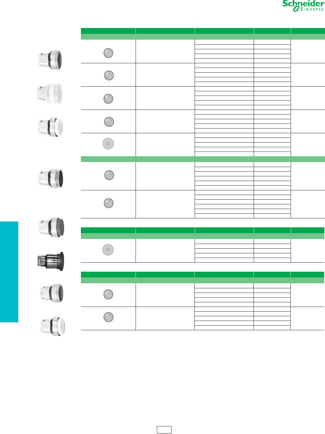
19-32 © 2012 Schneider Electric
All Rights Reserved
www.schneider-electric.us
19 PUSH BUTTONS AND
OPERATOR INTERFACE
22 mm Push Buttons XB4 Illuminated Operators
Refer to Catalog DIA4ED2060507BEN-US
Legends . . . . . . . . . . . . . . . . . . . . . . . . . . . . . . . . . . . . pages 19-37 to 19-39
ZB4BW333
ZB4BW563
ZB4BW113
ZB4BW33
ZB4BW14
Table 19.86: Heads for Momentary Illuminated Push Buttons
Shape of Head Type of Push Color Catalog Number $ Price
Only use with Protected LED™ light modules
Flush
White ZB4BW313
18.60
Green ZB4BW333
Red ZB4BW343
Ye l l o w ZB4BW353
Blue ZB4BW363
Flush with clear silicone boot
White ZB4BW513
31.00
Green ZB4BW533
Red ZB4BW543
Ye l l o w ZB4BW553
Blue ZB4BW563
Flush for insertion of legend
White ZB4BA18
16.00
Green ZB4BA38
Red ZB4BA48
Ye l l o w ZB4BA58
Blue ZB4BA68
Extended
White ZB4BW113
13.00
Green ZB4BW133
Red ZB4BW143
Ye l l o w ZB4BW153
Blue ZB4BW163
Mushroom (40 mm)
Clear ZB4BW413
29.40
Green ZB4BW433
Red ZB4BW443
Ye l l o w ZB4BW453
Blue ZB4BW463
Only use with light modules for a BA9s incandescent bulb, neon or LED
Flush
White ZB4BW31
18.60
Green ZB4BW33
Red ZB4BW34
Ye l l o w ZB4BW35
Blue ZB4BW36
Clear ZB4BW37
Extended
White ZB4BW11
13.00
Green ZB4BW13
Red ZB4BW14
Ye l l o w ZB4BW15
Blue ZB4BW16
Clear ZB4BW17
ZB4BW643
Table 19.87: Heads for Maintained Illuminated Push Buttons
Shape of Head Type of Push Color of Lens Catalog Number $ Price
Only use with Protected LED light modules
Push/Pull Mushroom (40 mm)
Clear ZB4BW613
46.00
Green ZB4BW633
Red ZB4BW643
Ye l l o w ZB4BW653
Blue ZB4BW663
ZB4BH033
ZB4BH63
Table 19.88: Illuminated Push-On/Push-Off Operators
Shape of Head Type of Push Color of Lens Catalog Number $ Price
Only use with Protected LED light modules
Flush
White ZB4BH013
24.80
Green ZB4BH033
Red ZB4BH043
Yellow ZB4BH053
Blue ZB4BH063
Extended
White ZB4BH13
19.60
Green ZB4BH33
Red ZB4BH43
Yellow ZB4BH53
Blue ZB4BH63
CS2 Discount
Schedule
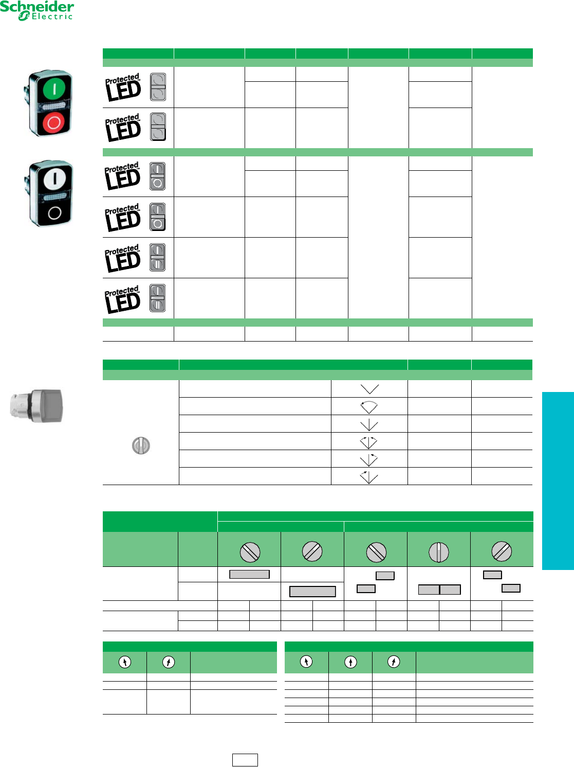
www.schneider-electric.us
19 PUSH BUTTONS AND
OPERATOR INTERFACE
© 2012 Schneider Electric
All Rights Reserved 19-33
22 mm Push Buttons XB4 Illuminated Operators
Refer to Catalog DIA4ED2060507BEN-US
eDesignate color as follows: 1—white, 3—green, 4—red, 5—yellow, 6—blue.
Legends. . . . . . . . . . . . . . . . . . . . . . . . . . . . . . . . . . . . . pages 19-37 to 19-39
Caps. . . . . . . . . . . . . . . . . . . . . . . . . . . . . . . . . . . . . . . . . . . . . . . . . page19-39
Table 19.89: Two Button with Clear Pilot Light, Momentary
Shape of Head Description Marking Cap Color Degree of Protection Catalog Number $ Price
No Marking
Two flush
—Green
Red
IP66
IP69K
ZB4BW7A3740
48.00
—White
Black ZB4BW7A1720
One flush
One extended —Green
Red ZB4BW7L3740
Premarked
Two flush
“I”
“O”
Green
Red
IP66
IP69K
ZB4BW7A3741
52.00
“I”
“O”
White
Black ZB4BW7A1721
One flush
One extended
“I”
“O”
Green
Red ZB4BW7l3741
Two flush “A”
“E”
White
Black ZB4BW7A1724
Two flush “+”
“-”
White
Black ZB4BW7A1715
Without caps
Two flush
without caps —— IP66
IP69K ZB4BW7A9 35.00
ZB4BK1343
Table 19.90: Illuminated Selector Switches, Standard Lever
Shape of Head Number and Type of Positions Catalog Number e$ Price
Only use with Protected LED light modules
2-maintained ZB4BK12•3 35.00
2-momentary from right to left ZB4BK14•3 51.00
3-maintained ZB4BK13•3 35.00
3-momentary to center ZB4BK15•3 51.00
3-momentary from right to center ZB4BK18•3 51.00
3-momentary from left to center ZB4BK17•3 51.00
Table 19.91: Sequence of Contacts on Illuminated Selector Switch Bodies
Unit Type Selector Switches
2-position 3-position
Operator Plunger Position
Up
Down
Contact Block Location LRLRLRLRLR
Contacts N/O OOXXXOOOOX
N/C XXOOOXXXXO
Note: L=Left, R=Right, O=Open, X=Closed
2 Position Selector Switch 3 Position Selector Switch
Contact block guide Contact block guide
O X 1 N.O. (left or right) O O X 1 N.O. (left)
X O 1 N.C. (left or right) X O X 2 N.O. wired in parallel (side by side)
O X 1 N.O. X O O 1 N.O. (right)
and O X X 1 N.C. (right)
X O 1 N.C. X X O 1 N.C. (left)
O X O 2 N.C. wired in series (side by side)
315°
45°
315°
0°
45°
CS2 Discount
Schedule
ZB4BW7A1721
ZB4BW7A3741
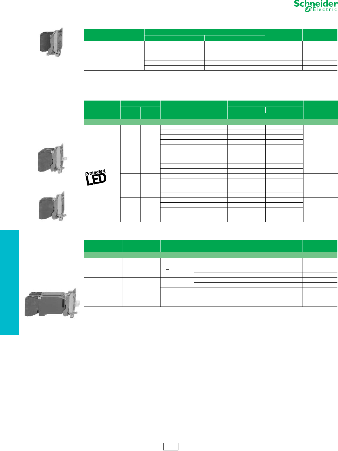
19-34 © 2012 Schneider Electric
All Rights Reserved
www.schneider-electric.us
19 PUSH BUTTONS AND
OPERATOR INTERFACE
22 mm Push Buttons XB4 Electrical Components
Refer to Catalog DIA4ED2060507BEN-US
For Quick-Connect version add “3” to the end of the catalog number Example: ZB4BZ1013 (Quick-Connect size 1 x 0.250" or 2 x 0.110").
For Ring Tongue compatible blocks add “9” to the end of the catalog number (Example: ZB4BZ1029).
Electrical components with connection by printed circuit board pins are available. Refer to Catalog 9001CT0001.
Electrical components with connection by plug-in connector are available. Refer to Catalog 9001CT0001.
fCan be fitted with additional contact blocks, see page 19-35.
gFor 240V LED, replace the “B” or “G” with “M”. (Example: change “ZB4BW0B11 (24V) to ZB4BW0M11 (240V))
hOrder bulb separately, see page 19-40.
iCan be fitted with additional contact blocks, see page 19-35.
ZB4BZ101
Table 19.92: Contact Blocks (Mounting Collar with Contact Blocks)
Description Type of Contact Catalog Number $ Price
N.O. N.C.
Screw clamp terminal connections
1—ZB4BZ101 22.00
—1ZB4BZ102 22.00
2—ZB4BZ103 38.20
—2ZB4BZ104 38.20
11ZB4BZ105 38.20
12ZB4BZ141 55.00
ZB4BW0••3
Table 19.93: Complete Bodies
(Mounting Collar + Single Contact Block + Light Module with Protected LED™)
Light Source
Type of Contact f
Color
Supply Voltage g
$ Price
N.O. N.C. 24 Vac/Vdc 110–120 Vac
Catalog Number
Screw clamp terminal connections
1—
White ZB4BW0B11 ZB4BW0G11
73.00
Green ZB4BW0B31 ZB4BW0G31
Red ZB4BW0B41 ZB4BW0G41
Ye l l o w ZB4BW0B51 ZB4BW0G51
Blue ZB4BW0B61 ZB4BW0G61
—1
White ZB4BW0B12 ZB4BW0G12
73.00
Green ZB4BW0B32 ZB4BW0G32
Red ZB4BW0B42 ZB4BW0G42
Ye l l o w ZB4BW0B52 ZB4BW0G52
Blue ZB4BW0B62 ZB4BW0G62
2—
White ZB4BW0B13 ZB4BW0G13
90.00
Green ZB4BW0B33 ZB4BW0G33
Red ZB4BW0B43 ZB4BW0G43
Ye l l o w ZB4BW0B53 ZB4BW0G53
Blue ZB4BW0B63 ZB4BW0G63
11
White ZB4BW0B15 ZB4BW0G15
90.00
Green ZB4BW0B35 ZB4BW0G35
Red ZB4BW0B45 ZB4BW0G45
Ye l l o w ZB4BW0B55 ZB4BW0G55
Blue ZB4BW0B65 ZB4BW0G65
ZB4BW06•
ZB4BW0•5
Table 19.94: Mounting Collar, Contact Block and Light Module (with screw clamp terminal connections) h
Supply Light Source Supply Voltage Type of Contact hColor of Light
Source Catalog Number $ Price
N.O. N.C.
Screw clamp terminal connections
Direct supply
BA9s
2.4 W max. bulb
Not included h
< 250 Vac/Vdc
1— — ZB4BW061 55.00
—1 — ZB4BW062 55.00
2— — ZB4BW063 71.00
11 — ZB4BW065 71.00
Transformer type
1.2 VA, 6 V
secondary
BA9s
incandescent
bulb included
110–120 Vac
50/60 Hz
1— — ZB4BW031 114.00
11 — ZB4BW035 130.00
230–240 Vac
50/60 Hz
1— — ZB4BW041 114.00
11 — ZB4BW045 130.00
440–480 Vac
60 Hz
1— — ZB4BW081 114.00
11 — ZB4BW085 130.00
CS2 Discount
Schedule
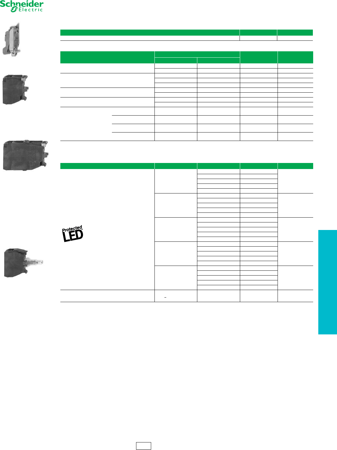
www.schneider-electric.us
19 PUSH BUTTONS AND
OPERATOR INTERFACE
© 2012 Schneider Electric
All Rights Reserved 19-35
22 mm Push Buttons XB4 Electrical Components
Refer to Catalog DIA4ED2060507BEN-US
aFor Quick-Connect version add “3” to the end of the catalog number Example: ZBE1013 (Quick-Connect size 1 x 0.250" or 2 x 0.110").
bFor Ring Tongue compatible blocks add “9” to the end of the catalog number (Example: ZBE1029).
cCannot stack additional contact blocks onto these blocks.
dElectrical components with connection by printed circuit board pins are available. Refer to Catalog 9001CT0001 for more details.
eElectrical components with connection by plug-in connector are available. Refer to Catalog 9001CT0001 for more details.
fSee page 19-40 for bulb information.
ZB4BZ009
Table 19.95: Body/Mounting Collar
For use with Catalog Number $ Price
Electrical block (contact or light module) ZB4BZ009 5.40
ZBE101
ZBE203
Table 19.96: Add-On Contact Block (with screw clamp terminal connections) de
Description Type of Contact Catalog Number $ Price
N.O. N.C.
Standard single contact blocksab 1—ZBE101 16.40
—1ZBE102 16.40
Standard double contact blocksab
2—ZBE203 33.20
—2ZBE204 33.20
11ZBE205 33.20
Special contact blocks for low power switching c1—ZBE1016 32.80
—1ZBE1026 32.80
Low-power switching Dusty environment c
(IP5X, 50 µm dust)
1 — ZBE1016P 32.80
—1 ZBE1026P 32.80
Staggered contacts
Early make
N/O 1 – ZBE201 16.40
Late break
N/C —1 ZBE202 16.40
Overlapping
N/O+N/C 1 1 ZB4BZ106 32.80
Staggered
N/O+N/O —2 ZB4BZ107 32.80
ZBVB•
Table 19.97: Light Modules (with screw clamp terminal connections) de
Description Supply Voltage Color of Light Source Catalog Number $ Price
12 Vac/Vdc
White ZBVJ1
52.00
Green ZBVJ3
Red ZBVJ4
Ye l l o w ZBVJ5
Blue ZBVJ6
24 Vac/Vdc
White ZBVB1
52.00
Green ZBVB3
Red ZBVB4
Ye l l o w ZBVB5
Blue ZBVB6
110–120 Vac
White ZBVG1
52.00
Green ZBVG3
Red ZBVG4
Ye l l o w ZBVG5
Blue ZBVG6
24–120 Vac/Vdc
White ZBVBG1
52.00
Green ZBVBG3
Red ZBVBG4
Ye l l o w ZBVBG5
Blue ZBVBG6
230–240 Vac
White ZBVM1
52.00
Green ZBVM3
Red ZBVM4
Ye l l o w ZBVM5
Blue ZBVM6
Direct supply for BA9s
2.4 W max. bulb
Not included f
<250 Vac/Vdc — ZBV6 33.20
CS2 Discount
Schedule
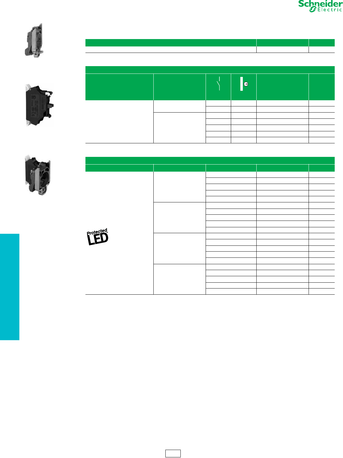
19-36 © 2012 Schneider Electric
All Rights Reserved
www.schneider-electric.us
19 PUSH BUTTONS AND
OPERATOR INTERFACE
22 mm Push Buttons XB4 Spring Terminal Products
Refer to Catalog DIA4ED2060507BEN-US
Table 19.98: Spring Terminal Products for XB4 22 mm Push Buttons
Body/Mounting Collar
For use with Catalog Number $ Price
Contact block or light module ZB4BZ009 5.40
Contact Blocks a
Spring Terminal Connections, Contacts for Standard Applications
Description Type of contact
N/O N/C
Catalog Number $ Price
Contact blocks
Single 1– ZBE1015 18.00
–1 ZBE1025 18.00
Single with
body/mounting collar
1– ZB4BZ1015 24.00
–1 ZB4BZ1025 24.00
2– ZB4BZ1035 42.00
–2 ZB4BZ1045 42.00
11 ZB4BZ1055 42.00
Light Modules a
Spring Terminal Connections
Description Supply voltage Color of light source Catalog Number $ Price
Integral LED
(to combine with
heads for integral LED)
12 Vac/Vdc
White ZBVJ15 57.00
Green ZBVJ35 57.00
Red ZBVJ45 57.00
Orange ZBVJ55 57.00
Blue ZBVJ65 57.00
24 Vac/Vdc
White ZBVB15 57.00
Green ZBVB35 57.00
Red ZBVB45 57.00
Orange ZBVB55 57.00
Blue ZBVB65 57.00
110–120 Vac
White ZBVG15 57.00
Green ZBVG35 57.00
Red ZBVG45 57.00
Orange ZBVG55 57.00
Blue ZBVG65 57.00
230–240 Vac
White ZBVM15 57.00
Green ZBVM35 57.00
Red ZBVM45 57.00
Orange ZBVM55 57.00
Blue ZBVM65 57.00
aAdditional blocks cannot be attached to the back of these contact blocks or light modules. However, spring terminal contact blocks can be mounted
behind screw terminal contact blocks.
ZB4BZ009
ZBE1015
ZB4BZ1015
CS2 Discount
Schedule
www.schneider-electric.us
19 PUSH BUTTONS AND
OPERATOR INTERFACE
© 2012 Schneider Electric
All Rights Reserved 19-37
22 mm Push Buttons XB4 Legend Holders
Refer to Catalog DIA4ED2060507BEN-US
aFor marked legends, see page 19-38.
bStart functions: white letters on black background. Stop functions: white letters on red background (unless otherwise specified above).
cFor custom Legends, see page 19-38.
ZBZ32
ZBY•101
ZBY2303
Table 19.99: Standard (30 x 40 mm) Legend Holders for 8 x 27 mm Legends
Description Legend Catalog Number $ Price
Color Text
Without legend a—— ZBZ32 2.00
With blank legend
(for engraving)
Black or red background —ZBY2101 3.40
White or yellow background —ZBY4101
Custom Legend
(Specify Engraving)
2 lines of 11 characters
(including spaces)
maximum per line
Black background White ZBY2002
14.20
Red background White ZBY2004
White background Black ZBY4001
Yellow background Black ZBY4005
With legend marked with
international language Black or red background b
O (black background) ZBY2146
3.40
O (red background) ZBY2931
IZBY2147
II ZBY2148
O-I ZBY2178
I-II ZBY2179
I-O-II ZBY2186
With legend marked with
English language
Black or red backgroundb
AUTO ZBY2115
3.40
AUTO-HAND ZBY2364
AUTO-O-HAND ZBY2385
CLOSE ZBY2314
DOWN ZBY2308
EMERGENCY STOP ZBY2330
FAST ZBY2328
FORWARD ZBY2305
FOR-REV ZBY2371
HAND ZBY2316
HAND-OFF-AUTO ZBY2387
INCH ZBY2321
JOG ZBY2382
LEFT ZBY2310
OFF ZBY2312
OFF-ON ZBY2367
ON ZBY2311
OPEN ZBY2313
POWER ON ZBY2326
RESET (red background) ZBY2323
RESET (black background) ZBY2322
REVERSE ZBY2306
RIGHT ZBY2309
RUN ZBY2334
SLOW ZBY2327
START ZBY2303
STOP ZBY2304
STOP-START ZBY2366
UP ZBY2307
ZBZ34
ZBZ35 ZBY6H10•
ZBY•H101
ZBZ33 ZBY610•
Table 19.100: Large (30 x 50 mm) Legend Holders for 18 x 27 mm Legends
Description cColor Catalog Number $ Price
Without legend insert —ZBZ33 2.00
With blank legend insert Black or red background ZBY6101 3.40
White or yellow background ZBY6102
Table 19.101: 30 x 40 mm legend holder (flush mounting with bezel) for 8 x 27 mm legends
Description cColor Catalog Number $ Price
Without legend —ZBZ34 2.00
With blank legend Black or red background ZBY2H101 3.40
White or yellow background ZBY4H101 3.40
Table 19.102: 30 x 50 mm legend holder (flush mounting with bezel) for 18 x 27 mm legends
Description cColor Catalog Number $ Price
Without legend —ZBZ35 4.20
With blank legend Black or red background ZBY6H101 5.40
White or yellow background ZBY6H102 5.40
CS2 Discount
Schedule
19-38 © 2012 Schneider Electric
All Rights Reserved
www.schneider-electric.us
19 PUSH BUTTONS AND
OPERATOR INTERFACE
22 mm Push Buttons XB4 Legend Inserts Only
Refer to Catalog DIA4ED2060507BEN-US
aStart functions: white letters on black background. Stop functions: white letters on red background (unless otherwise specified above).
ZBY02178
ZBY02303
Table 19.103: Marked Legends for 8 x 27 mm (for 30 x 40 mm legend holders ZBZ32)
Color Marking Text Catalog Number $ Price
Black or red background a
International
O (black background) ZBY02146
1.70
O (red background) ZBY02931
IZBY02147
II ZBY02148
O-I ZBY02178
I-II ZBY02179
I-O-II ZBY02186
English
AUTO ZBY02115
1.70
AUTO-HAND ZBY02364
AUTO-O-HAND ZBY02385
CLOSE ZBY02314
DOWN ZBY02308
EMERGENCY STOP ZBY02330
FAST ZBY02328
FORWARD ZBY02305
FOR-REV ZBY02371
HAND ZBY02316
HAND-OFF-AUTO ZBY02387
INCH ZBY02321
JOG ZBY02382
LEFT ZBY02310
OFF ZBY02312
OFF-ON ZBY02367
ON ZBY02311
OPEN ZBY02313
POWER ON ZBY02326
RESET (red background) ZBY02323
RESET (black background) ZBY02322
REVERSE ZBY02306
RIGHT ZBY02309
RUN ZBY02334
SLOW ZBY02327
START ZBY02303
STOP ZBY02304
STOP-START ZBY02366
UP ZBY02307
Table 19.104: Legends for Customer Engraving (inserts only)
Description For use with Color Text Color Catalog Number $ Price
8 x 27 mm 30 x 40 mm legend holders Black or red background White ZBY0101
1.70
White or yellow background Black ZBY0102
18 x 27 mm 30 x 50 mm legend holders Black or red background White ZBY5101
White or yellow background Black ZBY5102
Table 19.105: Legends for Factory Engraving (inserts only)
Description For use with Color Text Color Catalog Number $ Price
8 x 27 mm Custom Legend/Insert Only (Specify
Engraving) 2 lines of 11 characters (including
spaces) maximum per line
(Example: ZBY01002 marked “Robot”)
30 x 40 mm
legend holders
Black background White ZBY01002
12.20
Red background White ZBY01004
White background Black ZBY01001
Yellow background Black ZBY01005
18 x 27 mm Custom Legend/Insert Only (Specify
Engraving) 3 lines of 11 characters (including
spaces) maximum per line
(Example: ZBY05002 marked “Robot”)
30 x 50 mm
legend holders
Black background White ZBY05002
12.20
Red background White ZBY05004
White background Black ZBY05001
Yellow background Black ZBY05005
CS2 Discount
Schedule
www.schneider-electric.us
19 PUSH BUTTONS AND
OPERATOR INTERFACE
© 2012 Schneider Electric
All Rights Reserved 19-39
22 mm Push Buttons XB4 Accessories
Refer to Catalog DIA4ED2060507BEN-US
aSet of 6 different colored caps: white, black, green, red, yellow, blue.
bStart functions: white letters on black background. Stop functions: white letters on red background (unless otherwise specified).
cDouble injection molded marking.
dCap supplied not clipped-in, allowing orientation of arrow in any one of 4 directions:
ZBY1101
Table 19.106: Sheets of Legends for Push Buttons, Switches, and Pilot Lights
Description Marking Text Catalog Number $ Price
Sheets of 66 circular peel-off
transparent self-adhesive legends
Blank ZBY1101 6.20
International
OZBY1146
10.40
IZBY1147
II ZBY1148
III ZBY1149
STOP ZBY1304
ZBY1912
English
HAND ZBY1316
10.40
OFF ZBY1312
ON ZBY1311
START ZBY1303
SiS Label Software Legend Design Software: English, French, German, Spanish, Italian XBY2U 104.00
ZBA•
ZBL•
Table 19.107: Push Button Caps—Unmarked
For use with Type of Push Color Catalog Number $ Price
ZB4BA0
push button heads
Flush
White ZBA1
2.00
Black ZBA2
Green ZBA3
Red ZBA4
Yellow ZBA5
Blue ZBA6
6 colors aZBA9 4.20
Extended
White ZBL1
2.00
Black ZBL2
Green ZBL3
Red ZBL4
Yellow ZBL5
Blue ZBL6
6 colors aZBL9 4.20
ZBA•33
Table 19.108: Push Button Caps—Marked
For use with Type of Push Marking Cap Color Catalog Number $ Price
Text bColor
ZB4BA0
push button heads Flush
I cWhite Green ZBA331
4.20
Black White ZBA131
START cWhite Green ZBA333
Black White ZBA133
ON White Green ZBA341
Black White ZBA141
UP cBlack White ZBA343
DOWN cWhite Black ZBA344
c
White Green ZBA345
c
White Black ZBA245
White Green ZBA346
Black White ZBA334 d
White Black ZBA335 d
O cWhite Red ZBA432
Black ZBA232
STOP cWhite Red ZBA434
Black ZBA234
OFF White Red ZBA435
Black ZBA235
R cWhite Blue ZBA639
CS2 Discount
Schedule
19-40 © 2012 Schneider Electric
All Rights Reserved
www.schneider-electric.us
19 PUSH BUTTONS AND
OPERATOR INTERFACE
22 mm Push Buttons XB4 Accessories
Refer to Catalog DIA4ED2060507BEN-US
aSold in lots of 10.
bSet of 10 different caps: white, black, green, red, yellow, blue, white “I” on green background, black “I” on white background, white “O” on red background,
white “O” on black background.
cRequires a ZB4BZ009 body/mounting collar for mounting, see page 19-35.
dFor additional information, refer to publication 9001DB0601R6/06.
eStandard circular legends are not compatible with this product. Use special legends ZBY• •T listed above.
fMaximum panel thickness is 2.5 mm.
Table 19.109: Multiple-head and XB5R Push Button Capsa
For use with Type of Push Marking Cap Color Catalog Number $ Price
Double push button heads
Tripe push button heads
ZB4RZA0
ZB5RZA0
Flush
Unmarked
White
ZBA71 4.00
“I” black ZBA7131 5.30
“V” black ZBA7134 5.30
“+” black ZBA7138 5.30
Unmarked
Black
ZBA72 4.00
“O” white ZBA7232 5.30
“+” white ZBA7233 5.30
“V” white ZBA7235 5.30
“I” white ZBA7237 5.30
Unmarked
Green
ZBA73 4.00
“I” white ZBA7331 5.30
“+” white ZBA7333 5.30
“A” white ZBA7335 5.30
“II” white ZBA7336 5.30
Unmarked Red ZBA74 4.00
“O” white ZBA7432 5.30
Unmarked Yellow ZBA75 4.00
Unmarked Blue ZBA76 4.00
Assorted 10 colorsbZBA79 3.00
Table 19.110: Accessories
Description Application Color Catalog Number $ Price
Padlocking kit
Conforming to EN/ISO 13850 e
(See legends below)
For Emergency Stop function only, with the following
Ø 40 trigger-action push buttons:
XB4BT8•
XB4BS8•
XB4BS9•
ZB4BT8•
ZB4BS8•
ZB4BS9•
Yellow ZBZ3605 108.00
Metal guards
Padlockable
For Emergency Stop function only with the
following Ø 40 mm trigger-action push buttons:
XB4BT8•
XB4BS8•
XB4BS9•
ZB4BT8• (except ZB5AT8643M)
ZB4BS8•
ZB4BS9•
Chromium Plated ZBZ1600
108.00
Black ZBZ1602
Red ZBZ1604
Yellow ZBZ1605
Blue ZBZ1606
Metal guard For XB4 illuminated push buttons Chromium-plated ZBZ1800 108.00
Plastic guardsd
Round Guard for ZB4BS5430, 2.5” dia
EMO Mushroom Operators Yellow ZB4BZ1905
25.80
Narrow Flange Guard for ZB4BS5430 or
ZB4BS84430 EMO Mushroom OperatorsfYellow ZB4BZ2005
Trigger Action Guard for ZB4BS84430, 3” dia
EMO Mushroom Operators Yellow ZB4BZ2105
Padlockable flaps For push buttons Black ZB4BZ62 32.80
Red ZB4BZ64
Mounting kit For push buttons ZB4B• with flush mounting bezel head
For 30 mm mounting hole. Minimum quantity 10 ZB4BZ011 16.60
Metal blanking plug, round chromium
plated cFor Ø 22 mm control and signalling units ZB4SZ3 11.00
Plastic blanking plug, round black with
mounting nut For Ø 22 mm control and signalling units ZB5SZ3 11.00
Description Marking Color Catalog Number $ Price
Ø 60 mm Legend
for padlocking device ZBZ3605
Without Yellow ZBY9101T 3.40
EMERGENCY STOP Yellow ZBY9330T
ZB4BZ011
DL1CE•••
XBFX13
DL1CF•••
ZBZ8
Table 19.111: BA9s Bulbs and Associated Accessories
Description Characteristics Catalog Number $ Price
Replacement bulbs
(Type BA9s)
Incandescent
6 V, 1.2 W DL1CB006
11.00
12 V, 2 W DL1CE012
24 V, 2 W DL1CE024
120–130 V, 2.4 W DL1CE130
Neon bulbs 120–130 V, 1.8 mA DL1CF110 15.20
230–240 V, 1,8 mA DL1CF220
Bulb extractor — XBFX13 11.00
Lens cap tightening tool Illuminated push buttons with flush push ZBZ8 6.20
Power driver bits for mounting and wiring
(package of 5) Cross headed screw (POZIDRIV type 1) ZB4BZ905 52.00
Mounting Adapter For mounting 22 mm push button in 30 mm KO ZBZ41 10.40
CS2 Discount
Schedule
ZBA7235 ZBA7331
ZBA7432
ZBA79
Ø 8 mm maximum
Ø 6 mm minimum
ZBZ3605
ZB4BZ6•
Ø 6
ZBZ160•
ZBZ1800
www.schneider-electric.us
19 PUSH BUTTONS AND
OPERATOR INTERFACE
© 2012 Schneider Electric
All Rights Reserved 19-41
22 mm Push Buttons XB4 Accessories
Refer to Catalog DIA4ED2060507BEN-US
aOnly when mounted on control stations. Use special legends ZBY• •T.
Table 19.112: Bellows Seals for Harsh Environments (IP 69K) a
Description For use with Color &
Material
Sold in
Lots of Catalog Number $ Price
Bellows seals for harsh environments
(Humidity, dust, high-pressure cleaning)
Any Harmony XB4 metal,
mushroom head push button d,
Ø 40 mm or Ø 60 mm (except ZB4BR•16)
Red
Silicone 2ZBZ48
12.40
Black
EPDM 2ZBZ28
Yellow
EPDM 2ZBZ58
Table 19.113: Boot for Standard Selector Switch Handle
Description For use with Catalog Number $ Price
Boot for standard handle ZB4BD•• ZBD D2 12.40
Table 19.114: Replacement Keys
Description Key Number Catalog Number $ Price
Set of 2 keys
455 ZBG455
11.00
421E ZBG421E
458A ZBG458A
520E ZBG520E
3131A ZBG3131A
Set of 2 keys,
One of which is supplied booted (rubber boot)
455 ZBG455P
23.40
421E ZBG421EP
458A ZBG458AP
520E ZBG520EP
3131A ZBG3131AP
Table 19.115: Clear Boots
Description For use with Material Catalog Number $ Price
Single boots Booted push buttons with circular head
Silicone
ZBP0 12.40
Booted push buttons with circular head used in food industry applications ZBP0A 12.40
Double boots Double-headed push buttons, two flush ZBA708 10.80
Double-headed push buttons, one flush + one projecting ZBA709 10.80
Triple boot Triple-headed push buttons, two flush + one projecting ZBA710 10.80
Table 19.116: Colored boots
Description Color Catalog Number $ Price
Single boot
(can be replaced without dismantling the head)
Black ZB2 BP012
13.00
Green ZB2 BP013
Red ZB2 BP014
Ye l l o w ZB2 BP015
Blue ZB2 BP016
Table 19.117: Lens Caps
For use with Color Catalog Number $ Price
Lens caps for Protected LED™ light modules
Pilot lights
White ZBV0113
5.40
Green ZBV0133
Red ZBV0143
Ye l l o w ZBV0153
Blue ZBV0163
Illuminated push buttons with flush push
White ZBW9113
5.40
Green ZBW9133
Red ZBW9143
Ye l l o w ZBW9153
Blue ZBW9163
Illuminated push buttons with extended push
White ZBW9313
5.40
Green ZBW9333
Red ZBW9343
Ye l l o w ZBW9353
Blue ZBW9363
Lens caps for BA9 light modules
Pilot lights
White ZBV011
5.40
Green ZBV013
Red ZBV014
Ye l l o w ZBV015
Blue ZBV016
Clear ZBV017
Illuminated push buttons with flush push
White ZBW911
5.40
Green ZBW913
Red ZBW914
Ye l l o w ZBW915
Blue ZBW916
Clear ZBW917
Illuminated push buttons with extended push
White ZBW931
5.40
Green ZBW933
Red ZBW934
Ye l l o w ZBW935
Blue ZBW936
Clear ZBW937
ZBV01•3
ZBV01•
CS2 Discount
Schedule
ZBG455
ZBDD2
ZBG455P
ZBP0
ZBA709
ZBZ•8
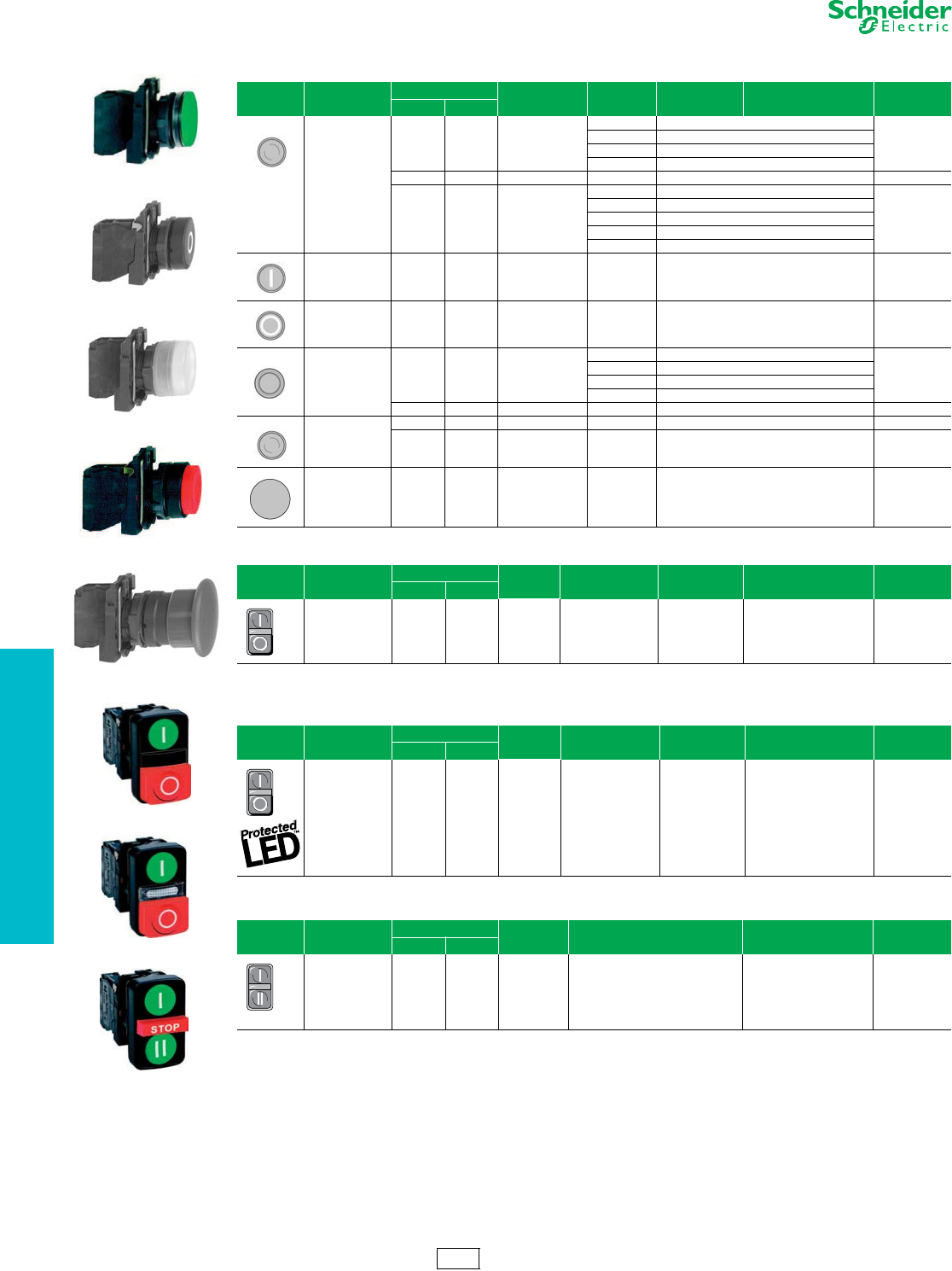
19-42 © 2012 Schneider Electric
All Rights Reserved
www.schneider-electric.us
19 PUSH BUTTONS AND
OPERATOR INTERFACE
22 mm Push Buttons XB5 Complete Devices
Refer to Catalog DIA4ED2060507BEN-US
Legends . . . . . . . . . . . . . . . . . . . . . . . . . . . . . . . . . . . . pages 19-58 to 19-60
Caps . . . . . . . . . . . . . . . . . . . . . . . . . . . . . . . . . . . . . . . . . . . . . . . . page 19-39
XB5AA31
XB5AA4322
XB5AP51
XB5AL42
XB5AC21
Table 19.118: Non-Illuminated Push Buttons, Momentary (screw clamp terminal connections)
Shape of Head Type of Push Type of Contact Marking Cap Color Catalog Number Components $ Price
N.O. N.C.
Flush
1— —
Black XB5AA21 (ZB5AZ101 + ZB5AA2)
38.50
Green XB5AA31 (ZB5AZ101 + ZB5AA3)
Yellow XB5AA51 (ZB5AZ101 + ZB5AA5)
Blue XB5AA61 (ZB5AZ101 + ZB5AA6)
—1 — Red XB5AA42 (ZB5AZ102 + ZB5AA4) 38.50
11 —
Black XB5AA25 (ZB5AZ105 + ZB5AA2)
56.00
Green XB5AA35 (ZB5AZ105 + ZB5AA3)
Red XB5AA45 (ZB5AZ105 + ZB5AA4)
Yellow XB5AA55 (ZB5AZ105 + ZB5AA5)
Blue XB5AA65 (ZB5AZ105 + ZB5AA6)
Flush 1 — “I”
(white) Green XB5AA3311 (ZB5AZ101 + ZB5AA331) 44.70
Flush — 1 “O”
(white) Red XB5AA4322 (ZB5AZ102 + ZB5AA432) 44.70
Flush with clear
silicone boot
(color of pusher
unobscured)
1— —
Black XB5AP21 (ZB5AZ101 + ZB5AP2)
53.00
Green XB5AP31 (ZB5AZ101 + ZB5AP3)
Yellow XB5AP51 (ZB5AZ101 + ZB5AP5)
Blue XB5AP61 (ZB5AZ101 + ZB5AP6)
—1 — Red XB5AP42 (ZB5AZ102 + ZB5AP4) 53.00
Extended
—1 — Red XB5AL42 (ZB5AZ102 + ZB5AL4) 38.50
11 — RedXB5AL45 (ZB5AZ105 + ZB5AL4) 38.50
Mushroom head
Ø 40 mm 1— — BlackXB5AC21 (ZB5AZ101 + ZB5AC2) 56.00
Table 19.119: Two Button Push Buttons, Momentary (screw clamp terminal connections)
Shape of Head Type of Push Type of Contact Marking Degree of Protection Catalog Number Components $ Price
N.O. N.C.
One flush
green push*
One extended
red push**
11
*“I” (white)
**“O” (white)
IP66
IP69K XB5AL73415 (ZB5AZ105 + ZB5AL7341) 80.75
Table 19.120: Two Button Push Buttons, Momentary + one white central pilot light
(screw clamp terminal connections)
Shape of Head Type of Push Type of Contact Marking Degree of Protection Pilot Light Voltage Catalog Number $ Price
N.O. N.C.
One flush
green push*
One extended
red push**
One white central
pilot light block
11
*“I” (white)
**“O” (white)
IP66
IP69K
24
120
240
XB5AW73731B5
XB5AW73731G5
XB5AW73731M5
123.50
Table 19.121: Three Button Push Buttons, Momentary (screw clamp terminal connections)
Shape of Head Type of Push Type of Contact Degree of
Protection Marking and Cap Color Catalog Number $ Price
N.O. N.C.
Two flush
pushes
+ one central
projecting
red push*
21IP66
IP69K
White “I” on green background
White “II” on green background
*White “Stop” on red background
Black “V” on white background
White “B” on black background
*White “Stop” on red background
XB5AA731327
XB5AA711237
114.00
CS2 Discount
Schedule
XB5AL73415
XB5AW73731p5
XB5AA731327
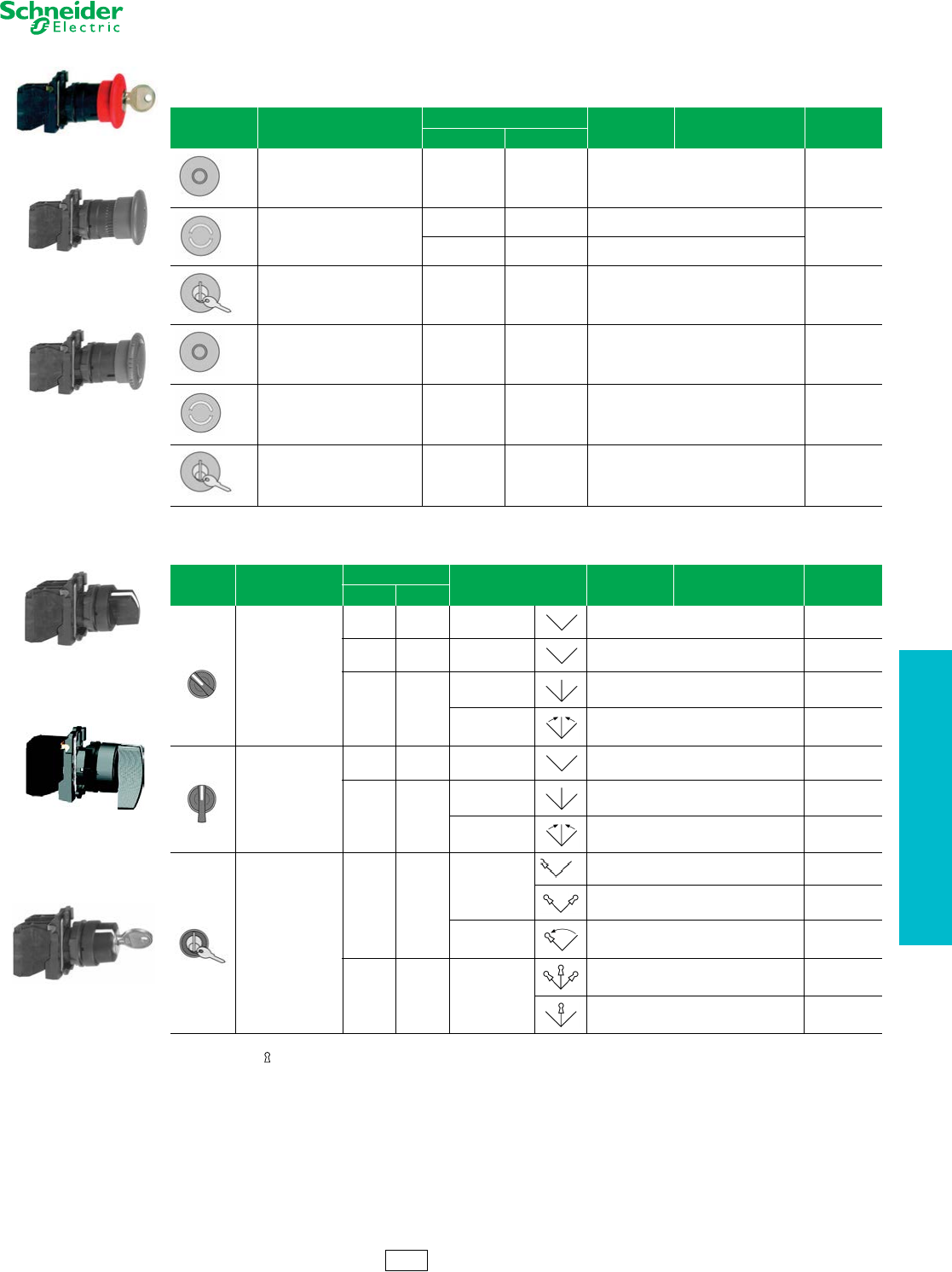
www.schneider-electric.us
19 PUSH BUTTONS AND
OPERATOR INTERFACE
© 2012 Schneider Electric
All Rights Reserved 19-43
22 mm Push Buttons XB5 Complete Devices
Refer to Catalog DIA4ED2060507BEN-US
aTrigger action mushroom heads are tamper proof in that a change of contact state is not possible by teasing or floating the operator. For emergency stop
applications, always use a trigger action push button (per EN/IEC 13850).
bSee 19-49 for contact configurations.
Note: The symbol indicates key withdrawal position(s)
Legends. . . . . . . . . . . . . . . . . . . . . . . . . . . . . . . . . . . . . pages 19-58 to 19-60
XB5AS9445
XB5AT42
XB5AS542
Table 19.122: Non-Illuminated Emergency Stop and Emergency Off Mushroom Head Push Buttons, Ø 40 mm (Red)
(screw clamp terminal connections)
Shape of Head Typ e o f P us h
Type of Contact
Catalog Number Components $ Price
N.O. N.C.
Trigger action push-pulla11XB5AT845 (ZB5AZ105 + ZB5AT84) 101.00
Trigger action turn-to-releasea
11XB5AS8445 (ZB5AZ105 + ZB5AS844)
165.00
—2XB5AS8444 (ZB5AZ104 + ZB5AS844)
Trigger action Key release
(No. 455)a11XB5AS9445 (ZB5AZ105+ ZB5AS944) 165.00
Push-pull — 1 XB5AT42 (ZB5AZ102 + ZB5AT4) 68.00
Tu r n - t o - r e l e a s e — 1 XB5AS542 (ZB5AZ102 + ZB5AS54) 110.00
Key release (No. 455) — 1 XB5AS142 (ZB5AZ102 + ZB5AS14) 147.00
XB5AD33
XB5AJ33
XB5AG33
Table 19.123: Non-Illuminated Selector Switches and Key Switches (screw clamp terminal connections) b
Shape of
Head Type of Operator
Type of Contact
Number and Type of Positions Catalog Number Components $ Price
N.O. N.C.
Standard lever, black
1 — 2-maintained XB5AD21 (ZB5AZ101 + ZB5AD2) 51.00
1 1 2-maintained XB5AD25 (ZB5AZ105 + ZB5AD2) 68.00
2—
3-maintained XB5AD33 (ZB5AZ103 + ZB5AD3) 68.00
3-momentary to
center XB5AD53 (ZB5AZ103 + ZB5AD5) 75.00
Extended lever, black
1 — 2-maintained XB5AJ21 (ZB5AZ101 + ZB5AJ2) 51.00
2—
3-maintained XB5AJ33 (ZB5AZ103 + ZB5AJ3) 68.00
3-momentary to
center XB5AJ53 (ZB5AZ103 + ZB5AJ5) 75.00
Key (No. 455)
1—
2-maintained
XB5AG21 (ZB5AZ101 + ZB5AG2) 123.00
XB5AG41 (ZB5AZ101 + ZB5AG4) 123.00
2-momentary to
left XB5AG61 (ZB5AZ101 + ZB5AG6) 123.00
2 — 3-maintained
XB5AG03 (ZB5AZ103 + ZB5AG0) 141.00
XB5AG33 (ZB5AZ103 + ZB5AG3) 141.00
CS2 Discount
Schedule
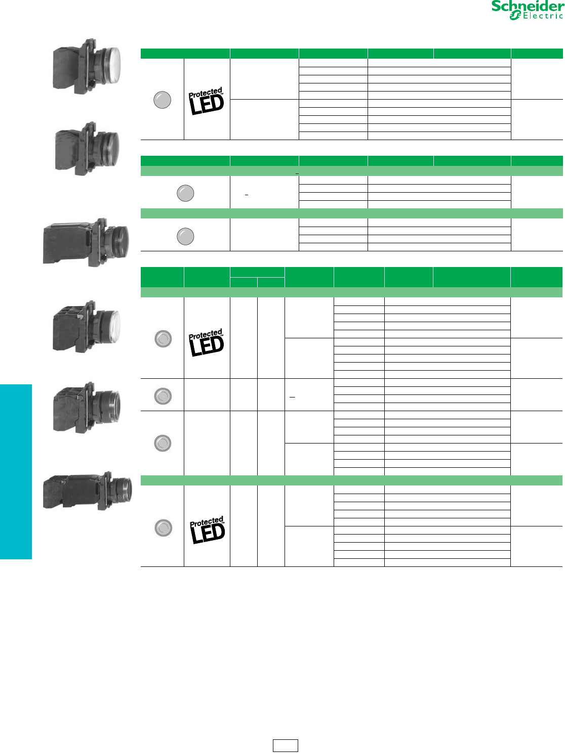
19-44 © 2012 Schneider Electric
All Rights Reserved
www.schneider-electric.us
19 PUSH BUTTONS AND
OPERATOR INTERFACE
22 mm Push Buttons XB5 Complete Devices
Refer to Catalog DIA4ED2060507BEN-US
aFor 240V LED, replace the “B” or “G” with “M”. (Example: XB5APVB1 (24 V) to XB5APVM1 (240 Vac only))
bFor bulb information, refer to page 19-61
Legends . . . . . . . . . . . . . . . . . . . . . . . . . . . . . . . . . . . . pages 19-58 to 19-60
XB5AVB1
XB5AV63
XB5AV34
Table 19.124: Pilot Lights with Protected LED™ (screw clamp terminal connections) a
Shape of Head Supply Voltage Color Catalog Number Components $ Price
24 Vac/Vdc
White XB5AVB1 (ZB5AVB1 + ZB5AV013)
72.00
Green XB5AVB3 (ZB5AVB3 + ZB5AV033)
Red XB5AVB4 (ZB5AVB4 + ZB5AV043)
Yellow XB5AVB5 (ZB5AVB5 + ZB5AV053)
Blue XB5AVB6 (ZB5AVB6 + ZB5AV063)
110–120 Vac
White XB5AVG1 (ZB5AVG1 + ZB5AV013)
72.00
Green XB5AVG3 (ZB5AVG3 + ZB5AV033)
Red XB5AVG4 (ZB5AVG4 + ZB5AV043)
Yellow XB5AVG5 (ZB5AVG5 + ZB5AV053)
Blue XB5AVG6 (ZB5AVG6 + ZB5AV063)
Table 19.125: Pilot Lights for BA9s Bulb (screw clamp terminal connections)
Shape of Head Supply Voltage Color Catalog Number Components $ Price
Direct supply, for BA9s (incandescent, LED, neon) V < 250 V, 2.4 W bulb (bulb not included) b
<250 Vac/Vdc
White XB5AV61 (ZB5AV6 + ZB5AV01)
51.00
Green XB5AV63 (ZB5AV6 + ZB5AV03)
Red XB5AV64 (ZB5AV6 + ZB5AV04)
Yellow XB5AV65 (ZB5AV6 + ZB5AV05)
Transformer type with 1.2 VA, 6 V secondary. BA9s incandescent bulb included
110–120 Vac
50/60 Hz
White XB5AV31 (ZB5AV3 + ZB5AV01)
117.00
Green XB5AV33 (ZB5AV3 + ZB5AV03)
Red XB5AV34 (ZB5AV3 + ZB5AV04)
Yellow XB5AV35 (ZB5AV3 + ZB5AV05)
XB5AW3465
XB5AW31B5
XB5AW3335
Table 19.126: Illuminated Push Buttons, Momentary (screw clamp terminal connections) a
Shape of Head Description Type of Contact Supply Voltage Color of Push Catalog Number Components $ Price
N.O. N.C.
Flush
11
24 Vac/Vdc
White XB5AW31B5 (ZB5AW0B15 + ZB5AW313)
119.00
Green XB5AW33B5 (ZB5AW0B35 + ZB5AW333)
Red XB5AW34B5 (ZB5AW0B45 + ZB5AW343)
Yellow XB5AW35B5 (ZB5AW0B55 + ZB5AW353)
Blue XB5AW36B5 (ZB5AW0B65 + ZB5AW363)
110–120 Vac
White XB5AW31G5 (ZB5AW0G15 + ZB5AW313)
119.00
Green XB5AW33G5 (ZB5AW0G35 + ZB5AW333)
Red XB5AW34G5 (ZB5AW0G45 + ZB5AW343)
Yellow XB5AW35G5 (ZB5AW0G55 + ZB5AW353)
Blue XB5AW36G5 (ZB5AW0G65 + ZB5AW363)
Direct supply for
BA9s
2.4 W max. bulb
not included
11< 250 Vac/Vdc
White XB5AW3165 (ZB5AW065 + ZB5AW31)
99.00
Green XB5AW3365 (ZB5AW065 + ZB5AW33)
Red XB5AW3465 (ZB5AW065 + ZB5AW34)
Yellow XB5AW3565 (ZB5AW065 + ZB5AW35)
Transformer type
1.2 VA, 6 V
secondary.
BA9s
incandescent
bulb included
11
110–120 Vac
50/60 Hz
White XB5AW3135 (ZB5AW035 + ZB5AW31)
163.00
Green XB5AW3335 (ZB5AW035 + ZB5AW33)
Red XB5AW3435 (ZB5AW035 + ZB5AW34)
Yellow XB5AW3535 (ZB5AW035 + ZB5AW35)
230–240 Vac
50/60 Hz
White XB5AW3145 (ZB5AW045 + ZB5AW31)
163.00
Green XB5AW3345 (ZB5AW045 + ZB5AW33)
Red XB5AW3445 (ZB5AW045 + ZB5AW34)
Yellow XB5AW3545 (ZB5AW045 + ZB5AW35)
Extended
11
24 Vac/Vdc
White XB5AW11B5 (ZB5AW0B15 + ZB5AW113)
113.00
Green XB5AW13B5 (ZB5AW0B35 + ZB5AW133)
Red XB5AW14B5 (ZB5AW0B45 + ZB5AW143)
Yellow XB5AW15B5 (ZB5AW0B55 + ZB5AW153)
Blue XB5AW16B5 (ZB5AW0B65 + ZB5AW163)
110–120 Vac
White XB5AW11G5 (ZB5AW0G15 + ZB5AW113)
113.00
Green XB5AW13G5 (ZB5AW0G35 + ZB5AW133)
Red XB5AW14G5 (ZB5AW0G45 + ZB5AW143)
Yellow XB5AW15G5 (ZB5AW0G55 + ZB5AW153)
Blue XB5AW16G5 (ZB5AW0G65 + ZB5AW163)
CS2 Discount
Schedule
www.schneider-electric.us
19 PUSH BUTTONS AND
OPERATOR INTERFACE
© 2012 Schneider Electric
All Rights Reserved 19-45
22 mm Push Buttons XB5 Non-Illuminated Operators
Refer to Catalog DIA4ED2060507BEN-US
aOrder color cap separately, see page 19-60.
bSix colored caps included with head (white, black, green, red, yellow, blue).
cFor legend ordering information see page 19-60.
Legends. . . . . . . . . . . . . . . . . . . . . . . . . . . . . . . . . . . . . pages 19-58 to 19-60
ZB5AA0
ZB5AA5
ZB5AL3
ZB5AP1
ZB5CA2
Table 19.127: Non-Illuminated Operators, Momentary—Unmarked
Shape of Head Type of Push Cap Color Catalog Number $ Price
Flush, without color cap a—ZB5AA0 11.00
Flush, with set of 6 color caps 6 colors bZB5AA9 13.00
Flush
White ZB5AA1
13.00
Black ZB5AA2
Green ZB5AA3
Red ZB5AA4
Yellow ZB5AA5
Blue ZB5AA6
Gray ZB5AA8
Flush with transparent cap,
for insertion of legend c
White ZB5AA18
16.00
Green ZB5AA38
Red ZB5AA48
Yellow ZB5AA58
Blue ZB5AA68
Extended
White ZB5AL1
13.00
Black ZB5AL2
Green ZB5AL3
Red ZB5AL4
Yellow ZB5AL5
Blue ZB5AL6
Booted Flush (clear)
Cap color unobscured
White ZB5APA1
25.80
Black ZB5APA2
Green ZB5APA3
Red ZB5APA4
Yellow ZB5APA5
Blue ZB5APA6
Booted Extended (clear)
Cap color unobscured
White ZB5AP1
25.80
Black ZB5AP2
Green ZB5AP3
Red ZB5AP4
Yellow ZB5AP5
Blue ZB5AP6
Booted (colored)
Cap color unobscured
White ZB5AP1S
25.80
Black ZB5AP2S
Green ZB5AP3S
Red ZB5AP4S
Yellow ZB5AP5S
Blue ZB5AP6S
Booted (clear)
for insertion of legend c
Cap color unobscured
White ZB5AP18
29.00
Green ZB5AP38
Red ZB5AP48
Yellow ZB5AP58
Blue ZB5AP68
Flush Plunger
(with high guard)
White ZB5AA14
32.20
Black ZB5AA24
Green ZB5AA34
Red ZB5AA44
Yellow ZB5AA54
Blue ZB5AA64
Flush
White ZB5CA1
27.00
Black ZB5CA2
Green ZB5CA3
Red ZB5CA4
Yellow ZB5CA5
Blue ZB5CA6
Extended
White ZB5CL1
27.00
Black ZB5CL2
Green ZB5CL3
Red ZB5CL4
Yellow ZB5CL5
Blue ZB5CL6
Heads only
Recessed (high guard)
White ZB5 AA16
32.20
Black ZB5 AA26
Green ZB5 AA36
Red ZB5 AA46
Yellow ZB5 AA56
Blue ZB5 AA66
Heads only
Recessed (high guard)
White ZB5 CA16
Black ZB5 CA26
Green ZB5 CA36
Red ZB5 CA46
Yellow ZB5 CA56
Blue ZB5 CA66
CS2 Discount
Schedule
19-46 © 2012 Schneider Electric
All Rights Reserved
www.schneider-electric.us
19 PUSH BUTTONS AND
OPERATOR INTERFACE
22 mm Push Buttons XB5 Non-Illuminated Operators
Refer to Catalog DIA4ED2060507BEN-US
aCap supplied not clipped-in, allowing orientation of arrow in any one of 4 directions:
Legends . . . . . . . . . . . . . . . . . . . . . . . . . . . . . . . . . . . . pages 19-58 to 19-60
ZB5AA331
ZB5AA432
ZB5AL232
Table 19.128: Non-Illuminated Operators, Momentary—Premarked
Shape of Head Type of Push Marking Cap Color Catalog Number $ Price
Text Color
Flush
IWhite Green ZB5AA331
18.60
Black White ZB5AA131
START White Green ZB5AA333
Black White ZB5AA133
ON White Green ZB5AA341
Black White ZB5AA141
TWhite Green ZB5AA345
OWhite Red ZB5AA432
Black ZB5AA232
STOP White Red ZB5AA434
Black ZB5AA234
OFF White Red ZB5AA435
Black ZB5AA235
UP Black White ZB5AA343
DOWN White Black ZB5AA344
aBlack White ZB5AA334
White Black ZB5AA335
Extended
OWhite Red ZB5AL432
18.60
Black ZB5AL232
STOP White Red ZB5AL434
Black ZB5AL234
OFF White Red ZB5AL435
Black ZB5AL235
Flush
IWhite Green ZB5CA331 32.00
OWhite Red ZB5CA432 32.00
ZB5AC24
ZB5AC2
ZB5AR4
Table 19.129: Mushroom Heads, Momentary
Shape of Head Diameter of Head Color of Head Catalog Number $ Price
30 mm
Black ZB5AC24
29.40
Green ZB5AC34
Red ZB5AC44
Ye l l o w ZB5AC54
Blue ZB5AC64
40 mm
Black ZB5AC2
29.40
Green ZB5AC3
Red ZB5AC4
Ye l l o w ZB5AC5
Blue ZB5AC6
60 mm
Black ZB5AR2
35.00
Green ZB5AR3
Red ZB5AR4
Ye l l o w ZB5AR5
Blue ZB5AR6
CS2 Discount
Schedule
www.schneider-electric.us
19 PUSH BUTTONS AND
OPERATOR INTERFACE
© 2012 Schneider Electric
All Rights Reserved 19-47
22 mm Push Buttons XB5 Non-Illuminated Operators
Refer to Catalog DIA4ED2060507BEN-US
Caps. . . . . . . . . . . . . . . . . . . . . . . . . . . . . . . . . . . . . . . . . . . . . . . . .page 19-60
ZB5AH04
Table 19.130: Non-Illuminated Push-on/Push-off Operators
Shape of Head Type of Push Color of Push Catalog Number $ Price
Flush
White ZB5AH01
17.60
Black ZB5AH02
Green ZB5AH03
Red ZB5AH04
Ye l l o w ZB5AH05
Blue ZB5AH06
Extended
White ZB5AH1
17.60
Black ZB5AH2
Green ZB5AH3
Red ZB5AH4
Ye l l o w ZB5AH5
Blue ZB5AH6
Flush
White ZB5CH01
35.20
Black ZB5CH02
Green ZB5CH03
Red ZB5CH04
Ye l l o w ZB5CH05
Blue ZB5CH06
Table 19.131: Two Head Operators, Momentary
Shape of Head Description Marking Cap Color Degree of Protection Catalog Number $ Price
No Marking
Two flush
—Green
Red
IP66
IP69K
ZB5AA7340
35.50
—White
Black ZB5AA7120
One flush
One extended —Green
Red ZB5AL7340
Premarked
Two flush
“I”
“O”
Green
Red
IP66
IP69K
ZB5AA7341
39.50
“I”
“O”
White
Black ZB5AA7121
One flush
One extended
“I”
“O”
Green
Red ZB5AL7341
Without caps
Two flush
without caps —— IP66
IP69K ZB5AA79 33.25
Table 19.132: Three Head Operators, Momentary
Shape of Head Description Marking Cap Color Degree of Protection Catalog Number $ Price
Premarked
Two flush
+ one central
projecting red push
marked “Stop”
Two flush
“I”
“II”
Green
Green
IP66
IP69K
ZB5AA73132
57.00
“X”
“V”
Green
Green
ZB5AA73133
“A”
“E”
Green
Green
ZB5AA73134
“+”
“-”
Green
Green
ZB5AA73135
“+”
“-”
White
White
ZB5AA71115
“X”
“V”
White
Black
ZB5AA71123
“A”
“E”
White
Black
ZB5AA71124
“A”
“E”
Black
Black
ZB5AA72124
Without caps
Two flush
without caps —— IP66
IP69K ZB5AA791 48.50
ZB5AA7121
ZB5AL7341
CS2 Discount
Schedule
ZB5AA73133
ZB5AA71124
19-48 © 2012 Schneider Electric
All Rights Reserved
www.schneider-electric.us
19 PUSH BUTTONS AND
OPERATOR INTERFACE
22 mm Push Buttons XB5 Emergency Stop Operators
Refer to Catalog DIA4ED2060507BEN-US
aOther key numbers:
—key no. 421E: add the suffix 12 to the catalog number.
—key no. 458A: add the suffix 10 to the catalog number.
—key no. 520E: add the suffix 14 to the catalog number.
—key no. 3131A: add the suffix 20 to the catalog number.
Example: The catalog number for a Ø 40 mm red mushroom head for a trigger action, maintained push button, with release by
key no. 421E becomes: ZB5AS94412.
bTrigger action mushroom heads are tamper proof in that a change of contact state is not possible by teasing or floating the operator. For emergency stop
applications, always use a trigger action push button (per EN/IEC 13850).
Legends . . . . . . . . . . . . . . . . . . . . . . . . . . . . . . . . . . . . pages 19-58 to 19-60
ZB5AS844
ZB5AS934
ZB5AT4
ZB5AS54
ZB5AS64
Table 19.133: Mushroom Heads for Maintained Push Buttons
Shape of Head Type of Push Diameter of Head Color Catalog Number $ Price
Trigger action
Push-pull b40 mm Red ZB5AT84 54.00
Trigger action
Turn-to-release b
30 mm Red ZB5AS834 112.00
40 mm Red ZB5AS844 112.00
Trigger action
Key release
(No. 455) b
30 mm Red ZB5AS934 112.00
40 mm Red ZB5AS944 a112.00
60 mm Red ZB5AS964 112.00
Push-pull
30 mm Black ZB5AT24 40.40
Red ZB5AT44
40 mm Black ZB5AT2 40.40
Red ZB5AT4
60 mm Black ZB5AX2 46.00
Red ZB5AX4
Turn-to-release
30 mm Black ZB5AS42 78.00
Red ZB5AS44
40 mm
Black ZB5AS52
78.00Red ZB5AS54
Yellow ZB5AS55
60 mm Black ZB5AS62 90.00
Red ZB5AS64
Key release
(No. 455)
30 mm Black ZB5AS72 112.00
Red ZB5AS74
40 mm Black ZB5AS12 112.00
Red ZB5AS14 a
60 mm Black ZB5AS22 112.00
Red ZB5AS24
ZBY9330
Table 19.134: Circular Legends for Emergency Stop Mushroom Heads (yellow background)
Diameter Text Catalog Number $ Price
60 mm Blank ZBY9101
3.40
EMERGENCY STOP ZBY9330
90 mm Blank ZBY8101
EMERGENCY STOP ZBY8330
CS2 Discount
Schedule
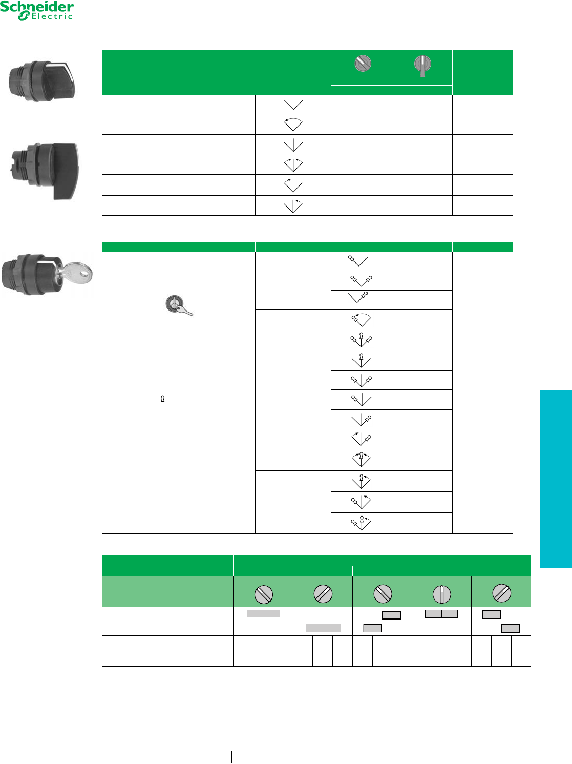
www.schneider-electric.us
19 PUSH BUTTONS AND
OPERATOR INTERFACE
© 2012 Schneider Electric
All Rights Reserved 19-49
22 mm Push Buttons XB5 Selector Switches
Refer to Catalog DIA4ED2060507BEN-US
aFor colored lever, add the following code to the end of catalog number: 01—white, 03—green, 04—red, 05—yellow, 06—blue (Example: ZB5AD204).
Selector Switch Sequence (Table 19.91) . . . . . . . . . . . . . . . . . . . .page 19-33
ZB5AD•
Standard Lever
ZB5AJX•
Extended Lever
Table 19.135: Non-Illuminated Selector Switches
Color Number and Type of Positions
Standard Lever aExtended Lever
$ Price
Catalog Number
Black 2-maintained ZB5AD2 ZB5AJ2 24.00
Black 2-momentary from
right to left ZB5AD4 ZB5AJ4 29.40
Black 3-maintained ZB5AD3 ZB5AJ3 24.00
Black 3-momentary to center ZB5AD5 ZB5AJ5 29.40
Black 3-momentary from
left to center ZB5AD7 ZB5AJ7 29.40
Black 3-momentary from
right to center ZB5AD8 ZB5AJ8 29.40
Table 19.136: Non-Illuminated Key Switches
Type of Operator Number and Type of Positions Catalog Number b$ Price
Key (No. 455)
Note: The symbol indicates key withdrawal
position(s).
bOther key numbers:
—key no. 421E: add the suffix 12 to the catalog
number.
—key no. 458A: add the suffix 10 to the catalog
number.
—key no. 520E: add the suffix 14 to the catalog
number.
—key no. 3131A: add the suffix 20 to the
catalog number.
—key no. 8D1: add the suffix D to the catalog
number.
Example: The catalog number for a head with
key no. 421E for a 2 position maintained,
lockable selector switch, with key withdrawal
from the left-hand position, becomes:
ZB5AG212
2-maintained
ZB5AG2
90.00
ZB5AG4
ZB5AG02
2-momentary from
right to left ZB5AG6
3-maintained
ZB5AG0
ZB5AG3
ZB5AG5
ZB5AG9
ZB5AG09
3-momentary from
left to center ZB5AG1
116.00
3-momentary to center ZB5AG7
3-momentary from right to
center
ZB5AG8
ZB5AG08
ZB5AG05
Table 19.137: Sequence of Contacts on Selector Switch Bodies
Unit Type Selector Switches
2-position 3-position
Operator Plunger Position
Up
Down
Contact Block Location L C R L C R L C R L C R L C R
Contacts N/O OOOXXXXXOOOOOX X
N/C XXXOOOOOXXXXXOO
Note: L=Left, C=Center, R=Right, O=Open, X=Closed
ZB5AG•
315°
45°
315°
0°
45°
CS2 Discount
Schedule
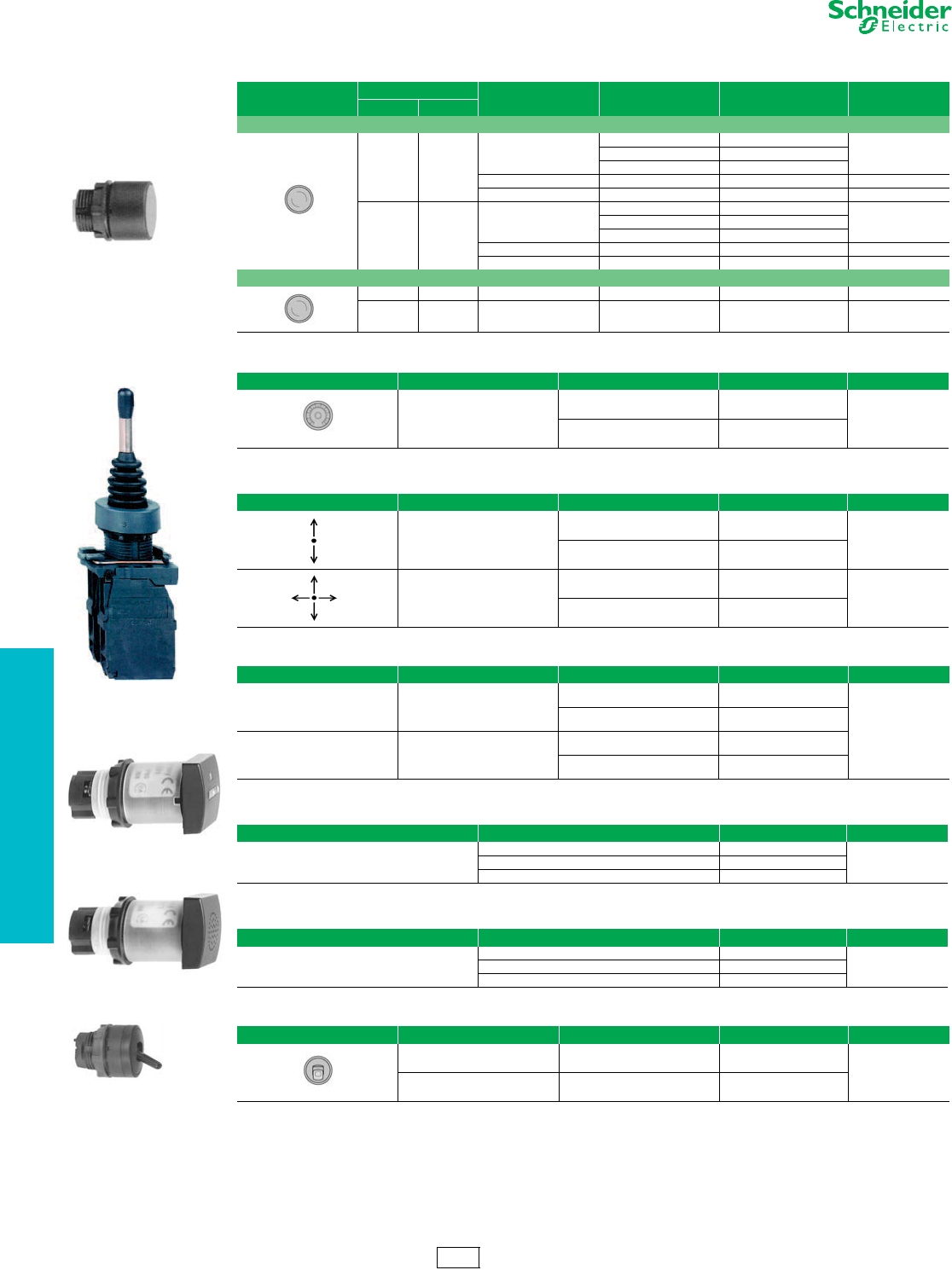
19-50 © 2012 Schneider Electric
All Rights Reserved
www.schneider-electric.us
19 PUSH BUTTONS AND
OPERATOR INTERFACE
22 mm Push Buttons XB5 Specialty Operators
Refer to Catalog DIA4ED2060507BEN-US
bDo not use standard contact blocks ZBE10• (single) or ZBE20• (double)
cUR E191025, XHNR2 and XHNR8.
Legends . . . . . . . . . . . . . . . . . . . . . . . . . . . . . . . . . . . . pages 19-58 to 19-60
Table 19.138: Reset Operators
Shape of Head Actuation Distance Text Color Catalog Number $ Price
in mm
Flush Adjustable Shafta
0.67–4.72 17–120
Without
Green XB5AA831
37.60Red XB5AA841
Blue XB5AA861
ORedXB5AA84101 45.40
RBlueXB5AA86102 45.40
4.72–10.12 120–257
Without
Green XB5AA832
43.40Red XB5AA842
Blue XB5AA862
ORedXB5AA84201 50.00
RBlueXB5AA86202 50.00
Extended
0.67–4.72 17–120 O Red XB5AL84101 45.40
4.72–10.12 120–257 O Red XB5AL84201 50.00
aShaft only (short) is W40437632 (Price = $20.00)
Table 19.139: Potentiometer Operator (with Mounting Collar)
Shape of Head Description Application Catalog Number $ Price
For potentiometer with
shaft length 1.73 to 1.97 in.
(44 to 50 mm)
(potentiometer not included)
For shaft Ø 0.25 in. (6.35 mm) ZB5AD922
142.00
For shaft Ø 0.24 in. (6 mm) ZB5AD912
Table 19.140: Joystick (54 mm, Extended Operating Shaft) b
Description Contact Operation Action Catalog Number $ Price
2 direction 1 step 1 N.O. contact
per direction
Maintained XD5PA12
250.00
Momentary XD5PA22
4 direction 1 step 1 N.O. contact
per direction
Maintained XD5PA14
316.00
Momentary XD5PA24
Table 19.141: Legends for Joystick
Description For use with Catalog Number $ Price
Legends
30 x 48 mm for engraving 2 direction
Black one side
Red reverse ZBG2201
3.40
White one side
Yellow reverse ZBG2401
Legends
48 x 48 mm for engraving 4 direction
Black one side
Red reverse ZBG4201
White one side
Yellow reverse ZBG4401
Table 19.142: Hour Counters c
Characteristics Supply Voltage Catalog Number $ Price
Indication 0–9999.9
(IP40 NEMA 1)
12–24 Vdc or Vac, 50/60 Hz XB5DSB
383.00120 Vac, 60 Hz XB5DSG
230–240 Vac, 50 Hz XB5DSM
Table 19.143: Buzzer c
Characteristics Supply Voltage Catalog Number $ Price
85 db buzzer:4kHz, continuous or intermittent
(IP40 NEMA 1)
24 Vdc or Vac, 50/60 Hz XB5KSB
183.00120 Vac, 60 Hz XB5KSG
230–240 Vac, 50 Hz XB5KSM
Table 19.144: Two Position Toggle Switch
Shape of Head Color Type of Positions Catalog Number $ Price
Black Maintained ZB5AD28
46.60
Black Momentary ZB5AD48
XB5AA
XD5PA12
XB5DS•
XB5KS•
ZB5AD28
CS2 Discount
Schedule
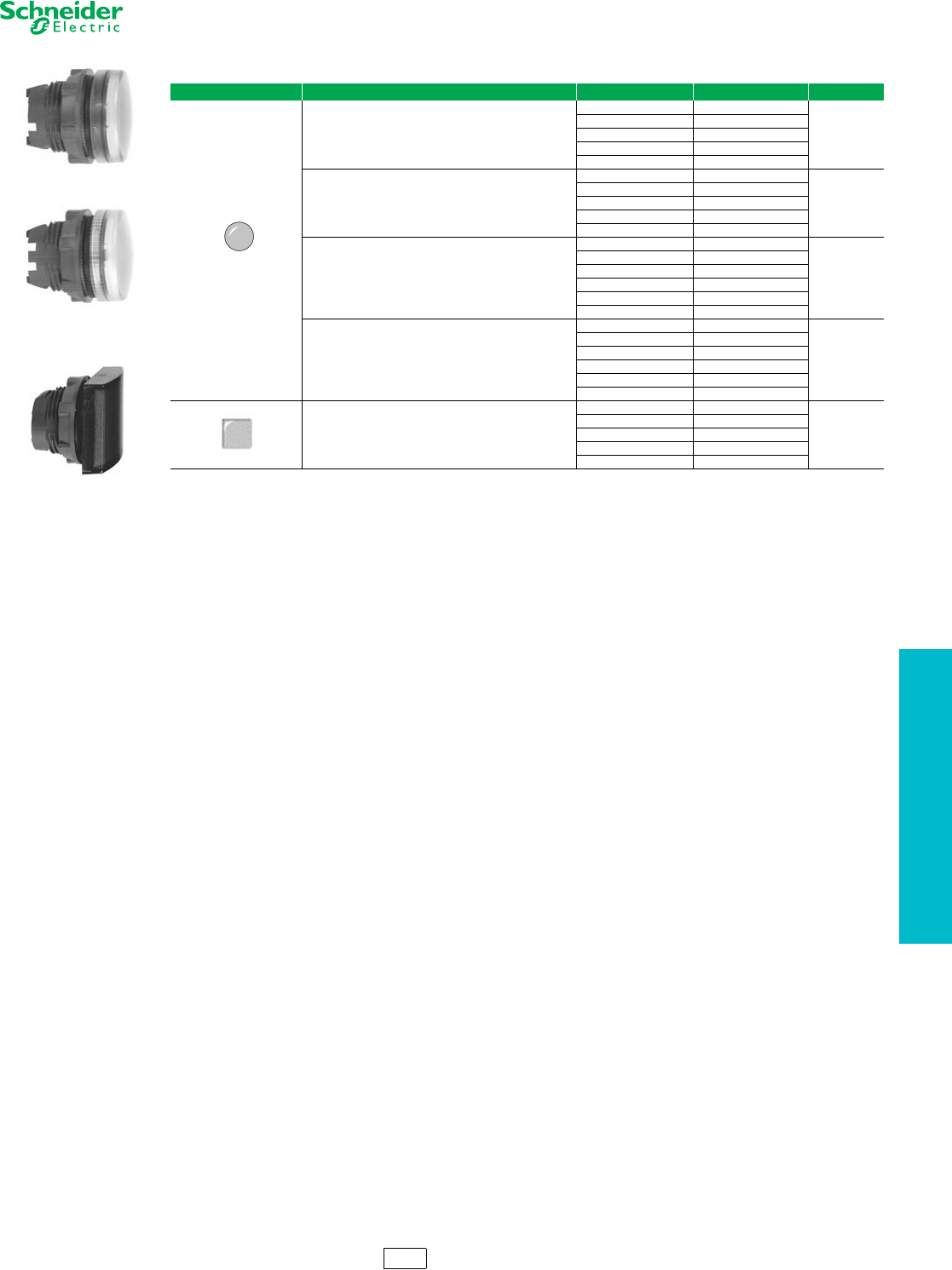
www.schneider-electric.us
19 PUSH BUTTONS AND
OPERATOR INTERFACE
© 2012 Schneider Electric
All Rights Reserved 19-51
22 mm Push Buttons XB5 Pilot Lights
Refer to Catalog DIA4ED2060507BEN-US
aFor use in bright ambient conditions (i.e., sunlight).
bOrder bulb separately; see page 19-40. For BA9 LED, see page 19-120.
Legends. . . . . . . . . . . . . . . . . . . . . . . . . . . . . . . . . . . . . pages 19-58 to 19-60
ZB5AV053
ZB5AV01
ZB5CV063
Table 19.145: Pilot Light Heads
Shape of Head For use with Body Comprising Light Module Type Color of Lens Catalog Number $ Price
Protected LED™ only
White ZB5AV013
7.60
Green ZB5AV033
Red ZB5AV043
Yellow ZB5AV053
Blue ZB5AV063
Protected LED only Fresnel (jeweled) lens a
White ZB5AV013S
7.60
Green ZB5AV033S
Red ZB5AV043S
Amber ZB5AV053S
Blue ZB5AV063S
For BA9s incandescent bulb, neon or LED only b
White ZB5AV01
7.60
Green ZB5AV03
Red ZB5AV04
Yellow ZB5AV05
Blue ZB5AV06
Clear ZB5AV07
For BA9s incandescent bulb, neon or LED Fresnel (jeweled)
lens b
White ZB5AV01S
7.60
Green ZB5AV03S
Red ZB5AV04S
Amber ZB5AV05S
Blue ZB5AV06S
Clear ZB5AV07S
Protected LED only
White ZB5CV013
27.00
Green ZB5CV033
Red ZB5CV043
Yellow ZB5CV053
Blue ZB5CV063
CS2 Discount
Schedule
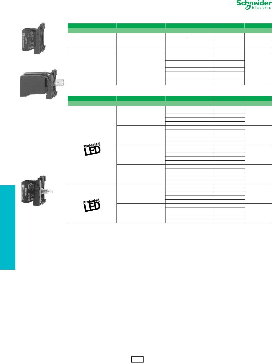
19-52 © 2012 Schneider Electric
All Rights Reserved
www.schneider-electric.us
19 PUSH BUTTONS AND
OPERATOR INTERFACE
22 mm Push Buttons XB5 Pilot Lights
Refer to Catalog DIA4ED2060507BEN-US
aOrder bulb separately, see page 19-61.
bFor Quick-Connect version, add “3” to the end of the catalog number Example: ZB5AVJ13 (Quick-Connect size 1 x 0.250" or 2 x 0.110").
cFor 240 V LED, replace the “B” or “G” with “M”. (Example: ZB5AVB1 (24V) to ZB5AVM1 (240V))
ZB5AV6
ZB5AV3
Table 19.146: Complete Bodies (Mounting Collar + Light Module for BA9s Incandescent Bulb, Neon or LED)
Description Light Source Supply Voltage (V) Catalog Number $ Price
Screw clamp terminal connections
Direct supply BA9s bulb 2.4 W max.
Not included a<250 ZB5AV6 38.60
Direct supply BA9s incandescent
bulb included 24 V 2 W ZB5AV624 49.20
Direct supply BA9s incandescent
bulb included 120 V 2.4 W ZB5AV6120 49.20
Transformer type
1.2 VA, 6 V secondary
BA9s incandescent
bulb included
110–120 Vac
50/60 Hz ZB5AV3
98.00
230–240 Vac
50/60 Hz ZB5AV4
400–50 Hz ZB5AV5
440–480 Vac
60 Hz ZB5AV8
550–600 Vac
60 Hz ZB5AV9
ZB5AV••
Table 19.147: Complete Bodies (Mounting Collar + Light Module with Protected LED™) bc
Light Source Supply Voltage Color of Light Source Catalog Number $ Price
Screw clamp terminal connections
12 Vac/Vdc
White ZB5AVJ1
57.00
Green ZB5AVJ3
Red ZB5AVJ4
Yellow ZB5AVJ5
Blue ZB5AVJ6
24 Vac/Vdc
White ZB5AVB1
57.00
Green ZB5AVB3
Red ZB5AVB4
Yellow ZB5AVB5
Blue ZB5AVB6
24–120 Vac/Vdc
White ZB5AVBG1
57.00
Green ZB5AVBG3
Red ZB5AVBG4
Yellow ZB5AVBG5
Blue ZB5AVBG6
110–120 Vac
White ZB5AVG1
57.00
Green ZB5AVG3
Red ZB5AVG4
Yellow ZB5AVG5
Blue ZB5AVG6
Flashing 24 Vac/Vdc
White ZB5AV18B1
66.00
Green ZB5AV18B3
Red ZB5AV18B4
Yellow ZB5AV18B5
Blue ZB5AV18B6
110–120 Vac
White ZB5AV18G1
66.00
Green ZB5AV18G3
Red ZB5AV18G4
Yellow ZB5AV18G5
Blue ZB5AV18G6
CS2 Discount
Schedule
www.schneider-electric.us
19 PUSH BUTTONS AND
OPERATOR INTERFACE
© 2012 Schneider Electric
All Rights Reserved 19-53
22 mm Push Buttons XB5 Illuminated Operators
Refer to Catalog DIA4ED2060507BEN-US
Legends. . . . . . . . . . . . . . . . . . . . . . . . . . . . . . . . . . . . . pages 19-58 to 19-60
ZB5AW313
ZB5AW363
ZB5AW143
ZB5CW313
ZB5AW33
Table 19.148: Heads for Momentary Illuminated Push Buttons
Shape of Head Type of Push Color Catalog Number $ Price
Only use with Protected LED™ light modules
Flush
White ZB5AW313
18.60
Green ZB5AW333
Red ZB5AW343
Yellow ZB5AW353
Blue ZB5AW363
Flush with clear boot
White ZB5AW513
31.00
Green ZB5AW533
Red ZB5AW543
Yellow ZB5AW553
Blue ZB5AW563
Flush for insertion of legend
White ZB5AA18
16.00
Green ZB5AA38
Red ZB5AA48
Yellow ZB5AA58
Blue ZB5AA68
Extended
White ZB5AW113
13.00
Green ZB5AW133
Red ZB5AW143
Yellow ZB5AW153
Blue ZB5AW163
Flush for insertion of legend
White ZB5CW313
27.00
Green ZB5CW333
Red ZB5CW343
Yellow ZB5CW353
Blue ZB5CW363
Extended
White ZB5CW113
27.00
Green ZB5CW133
Red ZB5CW143
Yellow ZB5CW153
Blue ZB5CW163
Only use with light modules for a BA9s incandescent bulb, neon or LED
Flush
White ZB5AW31
18.60
Green ZB5AW33
Red ZB5AW34
Yellow ZB5AW35
Blue ZB5AW36
Clear ZB5AW37
Extended
White ZB5AW11
13.00
Green ZB5AW13
Red ZB5AW14
Yellow ZB5AW15
Blue ZB5AW16
Clear ZB5AW17
Table 19.149: Illuminated Push-on/Push-off Operators
Shape of Head Type of Push Color of Lens Catalog Number $ Price
Only use with Protected LED light modules
Flush
White ZB5AH013
24.80
Green ZB5AH033
Red ZB5AH043
Yellow ZB5AH053
Blue ZB5AH063
Extended
White ZB5AH13
19.60
Green ZB5AH33
Red ZB5AH43
Yellow ZB5AH53
Blue ZB5AH63
CS2 Discount
Schedule
19-54 © 2012 Schneider Electric
All Rights Reserved
www.schneider-electric.us
19 PUSH BUTTONS AND
OPERATOR INTERFACE
22 mm Push Buttons XB5 Illuminated Operators
Refer to Catalog DIA4ED2060507BEN-US
NOTE: ZB5AT8643M not to be used with ZBZ16* guard.
dDesignate color as follows: 1—white, 3—green, 4—red, 5—yellow, 6—blue
Legends . . . . . . . . . . . . . . . . . . . . . . . . . . . . . . . . . . . . pages 19-58 to 19-60
Caps . . . . . . . . . . . . . . . . . . . . . . . . . . . . . . . . . . . . . . . . . . . . . . . . page 19-60
Table 19.150: Two Button with Clear Pilot Light, Momentary
Shape of Head Description Marking Cap Color Degree of Protection Catalog Number $ Price
No Marking
Two flush
—Green
Red
IP66
IP69K
ZB5AW7A3740
45.60
—White
Black ZB5AW7A1720
One flush
One extended —Green
Red ZB5AW7L3740
Premarked
Two flush
“I”
“O”
Green
Red
IP66
IP69K
ZB5AW7A3741
49.50
“I”
“O”
White
Black ZB5AW7A1721
One flush
One extended
“I”
“O”
Green
Red ZB5AW7l3741
Two flush “A”
“E”
White
Black ZB5AW7A1724
Two flush “+”
“-”
White
Black ZB5AW7A1715
Without caps
Two flush
without caps ——
IP66
IP69K ZB5AW7A9 42.75
ZB5AW7•
Table 19.151: Heads for Maintained Illuminated Push Buttons
Shape of Head Type of Push Color Catalog Number $ Price
Only use with Protected LED light modules
Turn-to-Release Mushroom (40 mm)
White ZB5AW713
63.00
Green ZB5AW733
Red ZB5AW743
Yellow ZB5AW753
Blue ZB5AW763
ZB5AK1213
ZB5AT8643M
ZB5AK1463
Table 19.152: Emergency Stop, Trigger Action and Mechanical Latching Push Button with Mechanical State
Indicator for Elevator Inspection Box Applications—Heads Only
Shape of Head Type of Reset Color Catalog Number $ Price
Push-pull (40 mm) Red ZB5AT8643M 124.00
Table 19.153: Illuminated Selector Switches, Standard Lever
Shape of Head Number and Type of Positions Catalog Number d$ Price
Only use with Protected LED light modules
2-maintained ZB5AK12d335.00
2-momentary from right to left ZB5AK14d351.00
3-maintained ZB5AK13d335.00
3-momentary to center ZB5AK15d351.00
3-momentary from right to center ZB5AK18d351.00
3-momentary from left to center ZB5AK17d351.00
Table 19.154: Sequence of Contacts on Selector Switch Bodies
Unit Type Selector Switches
2-position 3-position
Operator Plunger Position
Up
Down
Contact Block Location LCRLCRLCRLCRLCR
Contacts N/O OOOXXXXXOOOOOXX
N/C XXXOOOOOXXXXXOO
Note: L=Left, C=Center, R=Right, O=Open, X=Closed
315°
45
315° 0°
45°
CS2 Discount
Schedule
ZB5AW7A1721
ZB5AW7A3741
www.schneider-electric.us
19 PUSH BUTTONS AND
OPERATOR INTERFACE
© 2012 Schneider Electric
All Rights Reserved 19-55
22 mm Push Buttons XB5 Electrical Components
Refer to Catalog DIA4ED2060507BEN-US
NOTE: For the Quick-Connect version, add the numeral 3 to the end of the catalog number.
Example: ZB5AZ1013 (Quick-Connect size 1 x 0.250" or 2 x 0.110").
aFor Ring Tongue compatible blocks add “9” to the end of the catalog number (Example: ZB5AZ1029).
bElectrical components with connection by printed circuit board pins are available. Refer to Catalog 9001CT0001 for more information.
cElectrical components with connection by plug-in connector are available. Refer to Catalog 9001CT0001 for more information.
dFor 240V LED, replace the “B” or “G” with “M”. (Example: change “ZB5AW0B11 (24 V) to ZB5AW0M11 (240 V))
eCan be fitted with additional contact blocks, see page 19-56.
fOrder bulb separately, see page 19-61.
Table 19.155: Contact Blocks (Mounting Collar with Contact Blocks) abc
Description Type of Contact Catalog Number $ Price
N.O. N.C.
Screw clamp terminal connections
1—ZB5AZ101 22.00
—1ZB5AZ102 22.00
2—ZB5AZ103 38.20
—2ZB5AZ104 38.20
11ZB5AZ105 38.20
12ZB5AZ141 55.00
ZB5AZ101
ZB5AW0••1
Table 19.156: Complete Bodies (Mounting Collar + Single Contact Block + Light Module with Protected LED™)
Light Source
Type of Contact
e
Color
Supply Voltage d
$ Price
N.O. N.C. 24 Vac/Vdc 110–120 Vac
Catalog Number
Screw clamp terminal connections
1—
White ZB5AW0B11 ZB5AW0G11
73.00
Green ZB5AW0B31 ZB5AW0G31
Red ZB5AW0B41 ZB5AW0G41
Yellow ZB5AW0B51 ZB5AW0G51
Blue ZB5AW0B61 ZB5AW0G61
—1
White ZB5AW0B12 ZB5AW0G12
73.00
Green ZB5AW0B32 ZB5AW0G32
Red ZB5AW0B42 ZB5AW0G42
Yellow ZB5AW0B52 ZB5AW0G52
Blue ZB5AW0B62 ZB5AW0G62
2—
White ZB5AW0B13 ZB5AW0G13
90.00
Green ZB5AW0B33 ZB5AW0G33
Red ZB5AW0B43 ZB5AW0G43
Yellow ZB5AW0B53 ZB5AW0G53
Blue ZB5AW0B63 ZB5AW0G63
11
White ZB5AW0B15 ZB5AW0G15
90.00
Green ZB5AW0B35 ZB5AW0G35
Red ZB5AW0B45 ZB5AW0G45
Yellow ZB5AW0B55 ZB5AW0G55
Blue ZB5AW0B65 ZB5AW0G65
Table 19.157: Mounting Collar, Contact Block and Light Module (with screw clamp terminal connections) e
Supply Light Source Supply Voltage Type of Contact eColor of Light
Source Catalog Number $ Price
N.O. N.C.
Screw clamp terminal connections
Direct supply
BA9s
2.4 W max. bulb
Not included f
< 250 Vac/Vdc
1— — ZB5AW061 55.00
—1 — ZB5AW062 55.00
2— — ZB5AW063 71.00
11 — ZB5AW065 71.00
Transformer type
1.2 VA, 6 V
secondary
BA9s
incandescent
bulb included
110–120 Vac
50/60 Hz
1— — ZB5AW031 114.00
11 — ZB5AW035 130.00
230–240 Vac
50/60 Hz
1— — ZB5AW041 114.00
11 — ZB5AW045 130.00
440–480 Vac
60 Hz
1— — ZB5AW081 114.00
11 — ZB5AW085 130.00
ZB5AW065
ZB5AW035
CS2 Discount
Schedule
www.schneider-electric.us
19 PUSH BUTTONS AND
OPERATOR INTERFACE
19-56 © 2012 Schneider Electric
All Rights Reserved
22 mm Push Buttons XB5 Electrical Components
Refer to Catalog DIA4ED2060507BEN-US
aFor Quick-Connect version add “3” to the end of the catalog number (Example: ZBE1013) (Quick-Connect size 1 x 0.250" or 2 x 0.110").
bFor Ring Tongue compatible blocks add “9” to the end of the catalog number (Example: ZBE1029).
cCannot stack additional contact blocks onto these blocks.
dElectrical components with connection by printed circuit board pins are available. Refer to Catalog 9001CT0001 for more details.
eElectrical components with connection by plug-in connector are available. Refer to Catalog 9001CT0001 for more details.
ZB5AZ009
Table 19.158: Body/Mounting Collar
For use with Catalog Number $ Price
Electrical block (contact or light module) ZB5AZ009 5.40
ZBE101
ZBE203
Table 19.159: Add-On Contact Block (with screw clamp terminal connections) de
Description Type of Contact Catalog Number $ Price
N.O. N.C.
Standard single contact blocksab 1—ZBE101 16.40
—1ZBE102 16.40
Standard double contact blocksab
2—ZBE203 33.20
—2ZBE204 33.20
11ZBE205 33.20
Special contact blocks for low-power switching c1—ZBE1016 32.80
—1ZBE1026 32.80
Low-power switching Dusty environment c
(IP5X, 50 µm dust)
1 — ZBE1016P 32.80
—1 ZBE1026P 32.80
Staggered contacts
Early make
N/O 1 – ZBE201 16.40
Late break
N/C —1 ZBE202 16.40
Overlapping
N/O+N/C 1 1 ZB4BZ106 32.80
Staggered
N/O+N/O —2 ZB4BZ107 32.80
ZBVB•
Table 19.160: Light Modules (with screw clamp terminal connections)de
Description Supply Voltage Color of Light Source Catalog Number $ Price
12 Vac/Vdc
White ZBVJ1
52.00
Green ZBVJ3
Red ZBVJ4
Yellow ZBVJ5
Blue ZBVJ6
24 Vac/Vdc
White ZBVB1
52.00
Green ZBVB3
Red ZBVB4
Yellow ZBVB5
Blue ZBVB6
110–120 Vac
White ZBVG1
52.00
Green ZBVG3
Red ZBVG4
Yellow ZBVG5
Blue ZBVG6
24–120 Vac/Vdc
White ZBVBG1
52.00
Green ZBVBG3
Red ZBVBG4
Yellow ZBVBG5
Blue ZBVBG6
230–240 Vac
White ZBVM1
52.00
Green ZBVM3
Red ZBVM4
Yellow ZBVM5
Blue ZBVM6
Direct supply for BA9s
(2.4 W max. bulb not included—see page 19-61) < 250 Vac/Vdc — ZBV6 33.20
CS2 Discount
Schedule
www.schneider-electric.us
19 PUSH BUTTONS AND
OPERATOR INTERFACE
© 2012 Schneider Electric
All Rights Reserved 19-57
22 mm Push Buttons XB5 Spring Terminal Products
Refer to Catalog DIA4ED2060507BEN-US
Table 19.161: Spring Terminal Products for XB5 22 mm Push Buttons
Body/Mounting Collar
For Use With Catalog Number $ Price
Contact block or light module ZB5AZ009 5.40
Contact Blocks a
Spring Terminal Connections, Contacts for Standard Applications
Description Type of Contact
N/O N/C
Catalog Number $ Price
Contact blocks
Single 1– ZBE1015 18.00
–1 ZBE1025 18.00
Single with
body/mounting collar
1– ZB5AZ1015 24.00
–1 ZB5AZ1025 24.00
2– ZB5AZ1035 42.00
–2 ZB5AZ1045 42.00
11 ZB5AZ1055 42.00
Light Modules a
Spring Terminal Connections
Description Supply Voltage Color of Light Source Catalog Number $ Price
Integral LED
(to combine with
heads for integral LED)
12 Vac/Vdc
White ZBVJ15 57.00
Green ZBVJ35 57.00
Red ZBVJ45 57.00
Orange ZBVJ55 57.00
Blue ZBVJ65 57.00
24 Vac/Vdc
White ZBVB15 57.00
Green ZBVB35 57.00
Red ZBVB45 57.00
Orange ZBVB55 57.00
Blue ZBVB65 57.00
110–120 Vac
White ZBVG15 57.00
Green ZBVG35 57.00
Red ZBVG45 57.00
Orange ZBVG55 57.00
Blue ZBVG65 57.00
230–240 Vac
White ZBVM15 57.00
Green ZBVM35 57.00
Red ZBVM45 57.00
Orange ZBVM55 57.00
Blue ZBVM65 57.00
aAdditional blocks cannot be attached to the back of these contact blocks or light modules.
ZB5AZ009
ZBE1015
ZB5AZ1015
CS2 Discount
Schedule
19-58 © 2012 Schneider Electric
All Rights Reserved
www.schneider-electric.us
19 PUSH BUTTONS AND
OPERATOR INTERFACE
22 mm Push Buttons XB5 Legend Holders
Refer to Catalog DIA4ED2060507BEN-US
aFor legends, see page 19-59.
bStart functions: white letters on black background. Stop functions: white letters on red background (unless otherwise specified above).
cFor custom legends, please see page 19-59
ZBZ32
ZBY•101
ZBY2303
Table 19.162: Standard (30 x 40 mm) Legend Holders for 8 x 27 mm Legends
Description Legend Catalog Number $ Price
Color Text
Without legend insert a—— ZBZ32 2.00
With blank legend insert
(for engraving)
Black or red background — ZBY2101 3.40
White or yellow background — ZBY4101
Custom legend plate and insert
(specify engraving)
2 lines of 11 characters
(including spaces)
maximum per line
Black background White ZBY2002
14.20
Red background White ZBY2004
White background Black ZBY4001
Yellow background Black ZBY4005
With international language marked
legend Black or red backgroundb
O (black background) ZBY2146
3.40
O (red background) ZBY2931
IZBY2147
II ZBY2148
O-I ZBY2178
I-II ZBY2179
I-O-II ZBY2186
With English language
marked legend
Black or red backgroundb
AUTO ZBY2115
3.40
AUTO-HAND ZBY2364
AUTO-O-HAND ZBY2385
CLOSE ZBY2314
DOWN ZBY2308
EMERGENCY STOP ZBY2330
FAST ZBY2328
FORWARD ZBY2305
FOR-REV ZBY2371
HAND ZBY2316
HAND-OFF-AUTO ZBY2387
INCH ZBY2321
JOG ZBY2382
LEFT ZBY2310
OFF ZBY2312
OFF-ON ZBY2367
ON ZBY2311
OPEN ZBY2313
POWER ON ZBY2326
RESET (red background) ZBY2323
RESET (black background) ZBY2322
REVERSE ZBY2306
RIGHT ZBY2309
RUN ZBY2334
SLOW ZBY2327
S TA R T ZBY2303
STOP ZBY2304
STOP-START ZBY2366
UP ZBY2307
ZBZ34
ZBZ35 ZBY6H10•
ZBY•H101
ZBZ33 ZBY610•
Table 19.163: Large (30 x 50 mm) Legend Holders for 18 x 27 mm Legends
Description cFor use with Color Catalog Number $ Price
Without legend insert Circular and square heads —ZBZ33 2.00
With blank legend insert Circular and square heads Black or red background ZBY6101 3.40
White or yellow background ZBY6102
Table 19.164: 30 x 40 mm legend holder (flush mounting with bezel) for 8 x 27 mm legends
Description cColor Catalog Number $ Price
Without legend —ZBZ34 2.00
With blank legend Black or red background ZBY2H101 3.40
White or yellow background ZBY4H101
Table 19.165: 30 x 50 mm legend holder (flush mounting with bezel) for 18 x 27 mm legends
Description cColor Catalog Number $ Price
Without legend —ZBZ35 4.20
With blank legend Black or red background ZBY6H101 5.40
White or yellow background ZBY6H102
CS2 Discount
Schedule
www.schneider-electric.us
19 PUSH BUTTONS AND
OPERATOR INTERFACE
© 2012 Schneider Electric
All Rights Reserved 19-59
22 mm Push Buttons XB5 Legends, Inserts Only
Refer to Catalog DIA4ED2060507BEN-US
aStart functions: white letters on black background. Stop functions: white letters on red background (unless otherwise specified above).
ZBY02178
ZBY02303
Table 19.166: Marked Legends for 8 x 27 mm (for 30 x 40 mm legend holders ZBZ32)
Color Marking Text Catalog Number $ Price
Black or red backgrounda
International
O (black background) ZBY02146
1.70
O (red background) ZBY02931
IZBY02147
II ZBY02148
O-I ZBY02178
I-II ZBY02179
I-O-II ZBY02186
English
AUTO ZBY02115
1.70
AUTO-HAND ZBY02364
AUTO-O-HAND ZBY02385
CLOSE ZBY02314
DOWN ZBY02308
EMERGENCY STOP ZBY02330
FAST ZBY02328
FORWARD ZBY02305
FOR-REV ZBY02371
HAND ZBY02316
HAND-OFF-AUTO ZBY02387
INCH ZBY02321
JOG ZBY02382
LEFT ZBY02310
OFF ZBY02312
OFF-ON ZBY02367
ON ZBY02311
OPEN ZBY02313
POWER ON ZBY02326
RESET (red background) ZBY02323
RESET (black background) ZBY02322
REVERSE ZBY02306
RIGHT ZBY02309
RUN ZBY02334
SLOW ZBY02327
START ZBY02303
STOP ZBY02304
STOP-START ZBY02366
UP ZBY02307
Table 19.167: Legends for Customer Engraving (inserts only)
Description For use with Color Text Color Catalog Number $ Price
8 x 27 mm 30 x 40 mm legend holders Black or red background White ZBY0101
1.70
White or yellow background Black ZBY0102
18 x 27 mm 30 x 50 mm legend holders Black or red background White ZBY5101
White or yellow background Black ZBY5102
Table 19.168: Legends for Factory Engraving (inserts only)
Description For use with Color Text Color Catalog Number $ Price
8 x 27 mm
Custom legend/insert only
(specify engraving)
2 lines of 11 characters
(including spaces)
maximum per line
Example: ZBY01002 marked
“Robot”
30 x 40 mm legend holders
Black background White ZBY01002
12.20
Red background White ZBY01004
White background Black ZBY01001
Yellow background Black ZBY01005
18 x 27 mm
Custom legend/insert only
(specify engraving)
3 lines of 11 characters
(including spaces)
maximum per line
Example: ZBY05002 marked
“Robot”
30 x 50 mm legend holders
Black background White ZBY05002
12.20
Red background White ZBY05004
White background Black ZBY05001
Yellow background Black ZBY05005
CS2 Discount
Schedule
19-60 © 2012 Schneider Electric
All Rights Reserved
www.schneider-electric.us
19 PUSH BUTTONS AND
OPERATOR INTERFACE
22 mm Push Buttons XB5 Accessories
Refer to Catalog DIA4ED2060507BEN-US
aSet of 6 different colored caps: white, black, green, red, yellow, blue.
bDouble injection molded marking.
cCap supplied not clipped-in, allowing orientation of arrow in any one of 4 directions:
Table 19.169: Sheets of Legends for Push Buttons, Switches, and Pilot Lights
Description Marking Text Catalog Number $ Price
Sheets of 66 circular
peel-off transparent self-
adhesive legends
Blank–Round ZBY1101 6.20
Blank–Square legends ZBCY1101 6.20
International
OZBY1146
10.40
IZBY1147
II ZBY1148
III ZBY1149
STOP ZBY1304
ZBY1912
English
HAND ZBY1316
10.40
OFF ZBY1312
ON ZBY1311
START ZBY1303
SiS Label Software Legend Design Software: English, French, German, Spanish, Italian XBY2U 104.00
Table 19.170: Push Button Caps—Unmarked
For use with Type of Push Color Catalog Number $ Price
ZB5AA0 push button heads
Flush
White ZBA1
2.00
Black ZBA2
Green ZBA3
Red ZBA4
Ye l l o w ZBA5
Blue ZBA6
6 colors aZBA9 4.20
Extended
White ZBL1
2.00
Black ZBL2
Green ZBL3
Red ZBL4
Ye l l o w ZBL5
Blue ZBL6
6 colors aZBL9 4.20
Table 19.171: Push Button Caps—Marked
For use with Type of Push Marking Cap Color Catalog Number $ Price
Text Color
ZB5AA0
push button heads Flush
I bWhite Green ZBA331
4.20
Black White ZBA131
START bWhite Green ZBA333
Black White ZBA133
ON White Green ZBA341
Black White ZBA141
UP bBlack White ZBA343
DOWNbWhite Black ZBA344
b
White Green ZBA345
White Black ZBA245
White Green ZBA346
Black White ZBA334c
White Black ZBA335c
ObWhite Red ZBA432
Black ZBA232
STOPbWhite Red ZBA434
Black ZBA234
OFF White Red ZBA435
Black ZBA235
RbWhite Blue ZBA639
ZBY1101
ZBA•
ZBL•
ZBA•33
CS2 Discount
Schedule
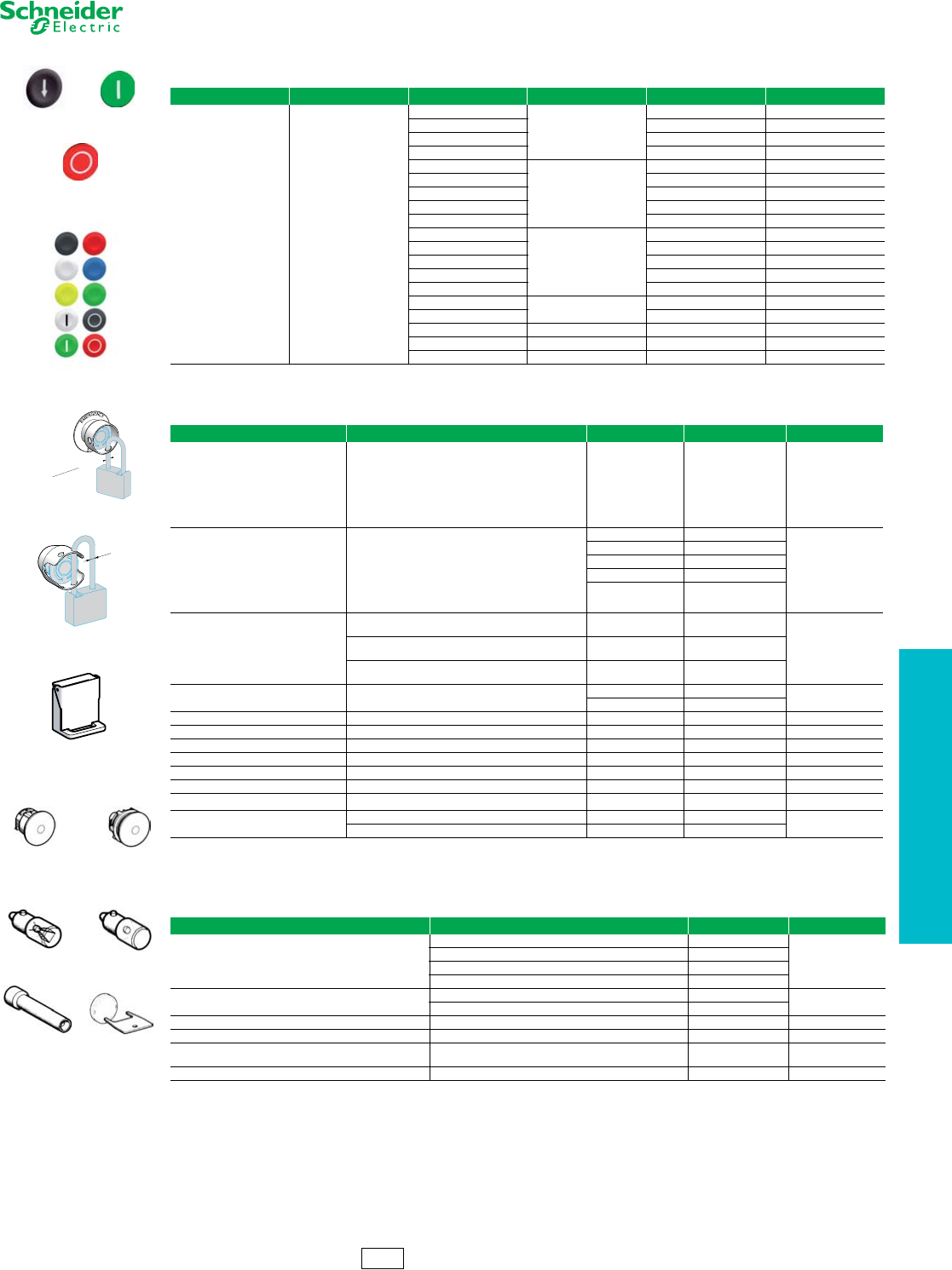
www.schneider-electric.us
19 PUSH BUTTONS AND
OPERATOR INTERFACE
© 2012 Schneider Electric
All Rights Reserved 19-61
22 mm Push Buttons XB5 Accessories
Refer to Catalog DIA4ED2060507BEN-US
aSold in lots of 10.
bSet of 10 different caps: white, black, green, red, yellow, blue, white “I” on green background, black “I” on white background, white “O” on red background,
white “O” on black background.
cMounting nut included with blanking plug.
dFor additional information, refer to publication 9001DB0601R6/06.
eStandard circular legends are not compatible with this product. Use special legends ZBY• •T listed above.
fMaximum panel thickness is 2.5 mm.
ZB4SZ3 ZB5SZ3
Table 19.172: Multiple-head and XB5R Push Button Capsb
For use with Type of Push Marking Cap Color Catalog Number $ Price
Double push button heads
Tripe push button heads
ZB4RZA0
ZB5RZA0
Flush
Unmarked
White
ZBA71 4.00
“I” black ZBA7131 5.30
“V” black ZBA7134 5.30
“+” black ZBA7138 5.30
Unmarked
Black
ZBA72 4.00
“O” white ZBA7232 5.30
“+” white ZBA7233 5.30
“V” white ZBA7235 5.30
“I” white ZBA7237 5.30
Unmarked
Green
ZBA73 4.00
“I” white ZBA7331 5.30
“+” white ZBA7333 5.30
“A” white ZBA7335 5.30
“II” white ZBA7336 5.30
Unmarked Red ZBA74 4.00
“O” white ZBA7432 5.30
Unmarked Yellow ZBA75 4.00
Unmarked Blue ZBA76 4.00
Assorted 10 colorscZBA79 3.00
Table 19.173: Accessories
Description Application Color Catalog Number $ Price
Padlocking kit
Conforming to EN / ISO 13850 e
(See legends below)
For Emergency Stop function only, with the following
Ø40 mm trigger-action push buttons:
XB5AT8•
XB5AS8•
XB5AS9•
ZB5AT8•
ZB5AS8•
ZB5AS9•
Yellow ZBZ3605 108.00
Metal guards
Padlockable
For Emergency stop function only with the following
Ø40 mm trigger-action push buttons:
XB5AT8•
XB5AS8•
XB5AS9•
ZB5AT8• (except ZB5AT8643M)
ZB5AS8•
ZB5AS9•
Chromium Plated ZBZ1600
108.00
Black ZBZ1602
Red ZBZ1604
Yellow ZBZ1605
Blue ZBZ1606
Plastic guardsd
Round Guard for ZB5AS5430
EMO Mushroom Operators Yellow ZB4BZ1905
25.80
Narrow Flange Guard for ZB5AS5430 or ZB5AS84430
EMO Mushroom OperatorsfYellow ZB4BZ2005
Trigger Action Guard for ZB5AS84430
EMO Mushroom Operators Yellow ZB4BZ2105
Padlockable flaps For push buttons Black ZB4BZ62 32.80
Red ZB4BZ64
Plastic blanking plug, roundcFor Ø22 mm units with round heads Black ZB5SZ3 11.00
Plastic blanking plug, squarecFor Ø22 mm units with square heads Black ZB5SZ5 11.00
Square insert To give square appearance to ZB5A round heads Black ZB5AZ31 2.00
Mounting nut Operator — ZB5AZ901 4.40
Tool For tightening mounting nut ZB5AZ901 — ZB5AZ905 12.40
Plate Anti-rotation of head — ZB5AZ902 2.00
Description Marking Color Catalog Number $ Price
Ø60 mm Legend
for padlocking device ZBZ3605
Without Yellow ZBY9101T 3.40
EMERGENCY STOP Yellow ZBY9330T
DLCE••• DL1CF•••
XBFX13 ZBZ8
Table 19.174: BA9s Bulbs and Associated Accessories
Description Characteristics Catalog Number $ Price
Replacement bulbs
(Type BA9s)
Incandescent
6 V, 1.2 W DL1CB006
11.00
12 V, 2 W DL1CE012
24 V, 2 W DL1CE024
120–130 V, 2.4 W DL1CE130
Neon bulbs 120–130 V DL1CF110 15.20
230–240 V DL1CF220
Bulb extractor — XBFX13 11.00
Lens cap tightening tool Illuminated push buttons with flush push ZBZ8 6.20
Power driver bits for mounting and wiring
(package of 5) Cross headed screw (POZIDRIV type 1) ZB4BZ905 52.00
Mounting Adapter For mounting 22 mm push button in 30 mm knockout ZBZ41 10.40
CS2 Discount
Schedule
Ø 6
ZBZ160•
ZBA7235 ZBA7331
ZBA7432
ZBA79
Ø 8 mm maximum
Ø 6 mm minimum
ZBZ3605
ZB4BZ6•
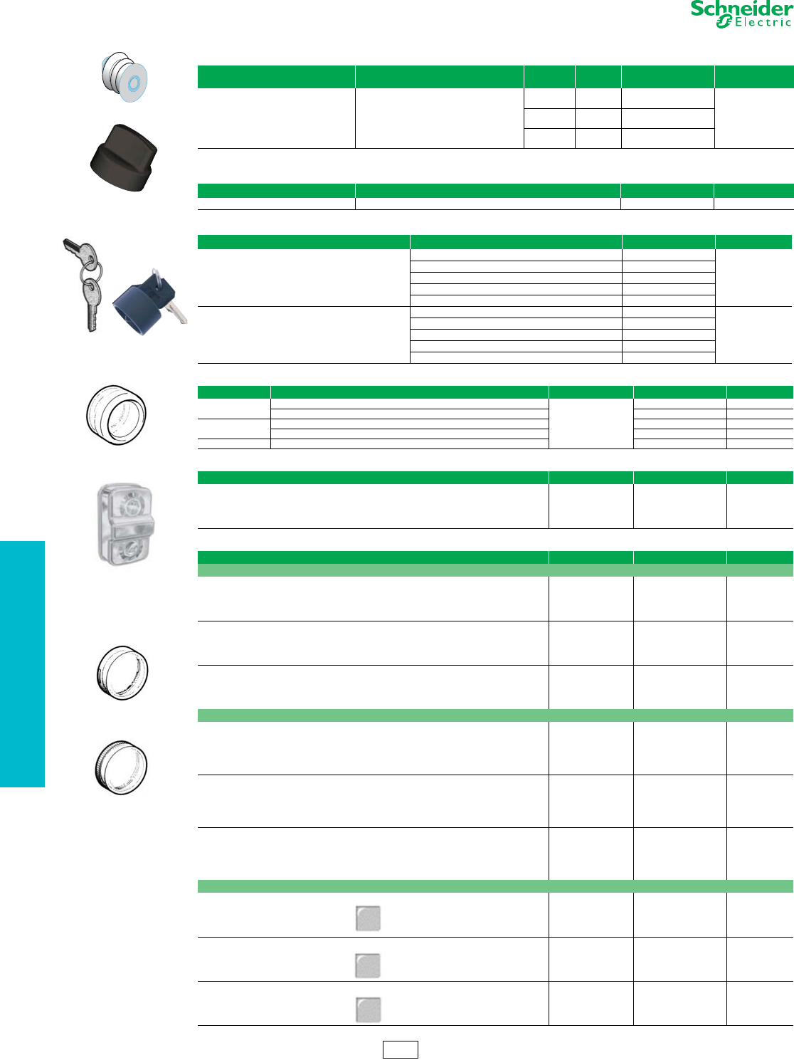
19-62 © 2012 Schneider Electric
All Rights Reserved
www.schneider-electric.us
19 PUSH BUTTONS AND
OPERATOR INTERFACE
22 mm Push Buttons XB5 Accessories
Refer to Catalog DIA4ED2060507BEN-US
aOnly when mounted on control stations. Use special legends ZBY• •T.
Table 19.175: Bellows Seals for Harsh Environments (IP 69K) a
Description For use with Color &
Material
Sold in
Lots of Catalog Number $ Price
Bellows Seals for harsh environments
(Humidity, dust, high-pressure cleaning)
XB5 plastic mushroom head push button a,
Ø40 mm or Ø60 mm
Red
Silicone 2ZBZ48
12.40
Black
EPDM 2ZBZ28
Yellow
EPDM 2ZBZ58
Table 19.176: Boot for standard selector switch handle
Description For use with Catalog Number $ Price
Boot for standard handle ZB5A•• ZBDD2 12.40
Table 19.177: Replacement Keys
Description Key Number Catalog Number $ Price
Set of 2 keys
455 ZBG455
11.00
421E ZBG421E
458A ZBG458A
520E ZBG520E
3131A ZBG3131A
Set of 2 keys,
One of which is supplied booted (rubber boot)
455 ZBG455P
23.40
421E ZBG421EP
458A ZBG458AP
520E ZBG520EP
3131A ZBG3131AP
Table 19.178: Clear Boots
Description For use with Material Catalog Number $ Price
Single boots Booted push buttons with circular head
Silicone
ZBP0 12.40
Booted push buttons with circular head used in food industry applications ZBP0A 12.40
Double boots Double-headed push buttons, two flush ZBA708 10.80
Double-headed push buttons, one flush + one projecting ZBA709 10.80
Triple boot Triple-headed push buttons, two flush + one projecting ZBA710 10.80
Table 19.179: Colored boots
Description Color Catalog Number $ Price
Single boot
(can be replaced without dismantling the head)
Black
Green
Red
Ye l l o w
Blue
ZB2 BP012
ZB2 BP013
ZB2 BP014
ZB2 BP015
ZB2 BP016
13.00
Table 19.180: Lens Caps
For use with Color Catalog Number $ Price
Lens caps for Protected LED™ light modules
Pilot lights
White
Green
Red
Yellow
Blue
ZBV0113
ZBV0133
ZBV0143
ZBV0153
ZBV0163
5.40
Illuminated push buttons with flush push
White
Green
Red
Yellow
Blue
ZBW9113
ZBW9133
ZBW9143
ZBW9153
ZBW9163
5.40
Illuminated push buttons with extended push
White
Green
Red
Yellow
Blue
ZBW9313
ZBW9333
ZBW9343
ZBW9353
ZBW9363
5.40
Circular lens caps for BA9s light modules
Pilot lights
White
Green
Red
Yellow
Blue
Clear
ZBV011
ZBV013
ZBV014
ZBV015
ZBV016
ZBV017
5.40
Illuminated push buttons with flush push
White
Green
Red
Yellow
Blue
Clear
ZBW911
ZBW913
ZBW914
ZBW915
ZBW916
ZBW917
5.40
Illuminated push buttons with extended push
White
Green
Red
Yellow
Blue
Clear
ZBW931
ZBW933
ZBW934
ZBW935
ZBW936
ZBW937
5.40
Square lens caps for Protected LED light modules (ZB5C operators only)
Pilot lights White
Green
Red
Yellow
Blue
ZBCV0113
ZBCV0133
ZBCV0143
ZBCV0153
ZBCV0163
9.40
Illuminated push buttons with flush push White
Green
Red
Yellow
Blue
ZBCW9113
ZBCW9133
ZBCW9143
ZBCW9153
ZBCW9163
9.40
Illuminated push buttons with extended push White
Green
Red
Yellow
Blue
ZBCW9313
ZBCW9333
ZBCW9343
ZBCW9353
ZBCW9363
9.40
CS2 Discount
Schedule
ZBV01•3
ZBV01•
ZBG455
ZBDD2
ZBG455P
ZBP0
ZBA709
ZBZ•8
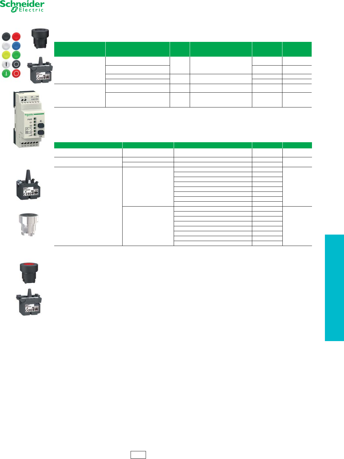
www.schneider-electric.us
19 PUSH BUTTONS AND
OPERATOR INTERFACE
© 2012 Schneider Electric
All Rights Reserved 19-63
22 mm Push Buttons Harmony™ XB5R Plastic and XB4R Metal
Wireless, Batteryless Push Buttons
Refer to Catalog DIA4ED2060507BEN-US
CS2 Discount
Schedule
ZBRT1
ZB4RZA0
ZB5RTA4
XB5RFA02
aWireless and batteryless push button and receiver, factory-paired.
bFor additional components, these devices can be field-paired.
cSupplied with output function set to momentary. Outputs programmable to maintained and Start-Stop.
dNon-programmable momentary output function.
eSupplied with a magnet.
fMounting collar ZB5AZ009 (plastic) or ZB4BZ009 (metal) to be ordered separately.
gOnly heads ZB4RZA0 and ZB5RZA0 are mechanically compatible.
hCap to be ordered separately: see Table 19.184 on page 19-64.
iThis cap is fitted by Schneider Electric and cannot be removed (risk of damage).
Table 19.181: Ready-to-use Packsa
Description Transmitter Type
Voltage
Receiver
V
Receiver Type Catalog Number $ Price
Packs include:
- 1 push button/transmitter
- 1 receiver
The push button and receiver
are factory-pairedb
Ø 22 mm plastic head
+ 1 set of 10 different colored caps a/c
24 to 240
Programmable receiver with:
- 2 relay outputs type RT 3Ac
XB5RFA02 510.00
Ø 22 mm metallic head
+ 1 set of 10 different colored caps XB4RFA02 510.00
Ø 22 mm plastic head c 24 Non-programmable receiver with:
- 1 relay output type RT 3Ad
XB5RFB01 210.00
Ø 22 mm metallic head XB4RFB01 210.00
Packs include:
- 1 push button/transmitter in
handy boxe
- 1 receiver
The push button and receiver
are factory-pairedb
Ø 22 mm plastic head
+ 1 set of 10 different colored caps
a/c
24 to 240
Programmable receiver with:
- 2 relay outputs type RT 3AcXB5RMA04 590.00
Ø 22 mm metallic head
+ 1 operator head c 24 Non-programmable receiver with:
- 1 relay output type RT 3AdXB5RMB03 290.00
Table 19.182: Transmitter Components for Wireless, Batteryless Push Buttons
Description Type of Push Cap Color Catalog Number $ Price
Transmitter for wireless, batteryless
push buttonsf g–– ZBRT1 110.00
Spring return push button heads for
transmitter ZBRT1
Plastic Without caphZB5RZA0 18.60
Metal Without caphZB4RZA0
Wireless, batteryless push buttons
including:
- a transmitter fitted with mounting collar
- a spring return push button head with
clipped-in capi
Plastic
White ZB5RTA1
130.00
Black ZB5RTA2
Green ZB5RTA3
Green with white “I” ZB5RTA331
Red ZB5RTA4
Red with white “O” ZB5RTA432
Ye l l o w ZB5RTA5
Blue ZB5RTA6
Metal
White ZB4RTA1
130.00
Black ZB4RTA2
Green ZB4RTA3
Green with white “I” ZB4RTA331
Red ZB4RTA4
Red with white “O” ZB4RTA432
Ye l l o w ZB4RTA5
Blue ZB4RTA6
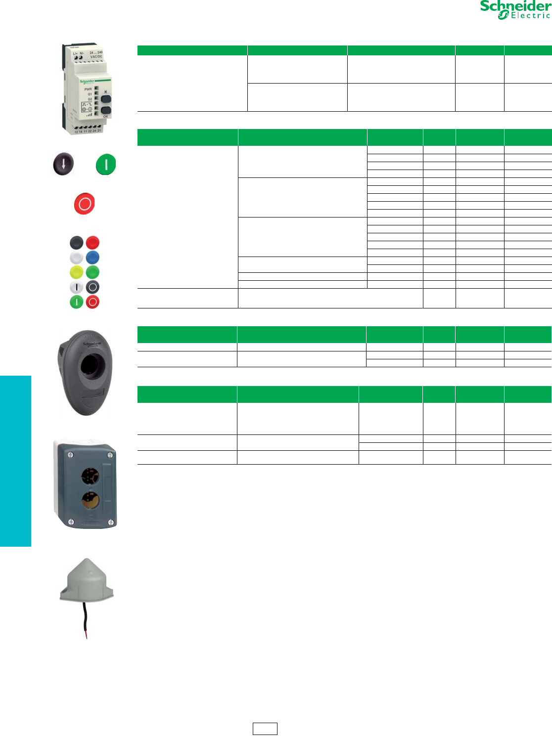
19-64 © 2012 Schneider Electric
All Rights Reserved
www.schneider-electric.us
19 PUSH BUTTONS AND
OPERATOR INTERFACE
22 mm Push Buttons Harmony™ XB5R Plastic and XB4R Metal
Wireless, Batteryless Push Buttons
Refer to Catalog DIA4ED2060507BEN-US
aSupplied with output function set to momentary Outputs programmable to maintained and Start-Stop.
bCap can be clipped-in at 90° steps, through 360°.
cCannot be used for wired contacts (no cable gland outlet).
dSupplied with a magnet.
eBox equipped with cable gland outlets, compatible with Harmony ZB5 push button heads.
fNot wired to the receiver.
Table 19.183: Programmable Receivers
Description Output Type Voltage Receiver V Catalog Number $ Price
Programmable receivers equipped with:
- 2 buttons (“Scroll-through”, “Ok”)
- 6 indicating LEDs (power ON, outputs,
signal strength)
4 PNP outputs, 200 mA / 24 V c 24 ZBRRC 430.00
2 relay outputs type
RT 3Aaa/c 24 to 240 ZBRRA 430.00
Table 19.184: Caps for Harmony Push Button Heads ZB5RZA0 and ZB4RZA0
Description Background Color Marking Sold in
lots of Catalog Number $ Price
Sets of 10 different colored caps with
identical markingb
White
Without 10 ZBA71 4.00
“I” (black) 10 ZBA7131 5.30
“A” (black) 10 ZBA7134 5.30
“+” (black) 10 ZBA7138 5.30
Black
Without 10 ZBA72 4.00
“O” (white) 10 ZBA7232 5.30
“+” (white) 10 ZBA7233 5.30
“R” (white) 10 ZBA7235 5.30
“I” (white) 10 ZBA7237 5.30
Green
Without 10 ZBA73 4.00
“I” (white) 10 ZBA7331 5.30
“+” (white) 10 ZBA7333 5.30
“Z” white 10 ZBA7335 5.30
“II” (white) 10 ZBA7336 5.30
Red Without 10 ZBA74 4.00
“O” (white) 10 ZBA7432 5.30
Yellow Without 10 ZBA75 4.00
Blue Without 10 ZBA76 4.00
Set of 10 different colored caps with
different markingsb
White, black, green, red, yellow, blue, white “I” on green background,
black “I” on white background, white “O” on red background, white “O” on
black background
10 ZBA79 3.00
Table 19.185: Boxes for Wireless, Batteryless Push Buttons
Description For use with: Marking Sold in
lots of Catalog Number $ Price
Handy box, plastic, empty c dMobile wireless,batteryless push buttons 1 cut-out 1 ZBRM01 80.00
Empty enclosures eMounted or on-board wireless,batteryless push
buttons
1 cut-out 1 XALD01H7 32.80
2 cut-outs 1 XALD02H7 38.20
Table 19.186: Accessories
Description For use with: Marking Sold in
lots of Catalog Number $ Price
External antenna fBetween transmitter and receiver, used to
increase the range and/or get around obstacles
a/c 24 to 240 V
- 5m cable
- 1 power-ON LED
- 2 LEDs
reception/transmission
1ZBRA1 170.00
Mounting collar – Plastic 10 ZB5AZ009 5.40
Metal 10 ZB4BZ009 5.40
Legend plate, 27 x 8 mm,
for engraving For adhering to handy box ZBRM01 Self-adhesive, blank,
black background 10 ZBY0101T 1.70
CS2 Discount
Schedule
ZBRM01
XALD02H7
ZBRRA
ZBA7235 ZBA7331
ZBA7432
ZBA79
ZBRA1
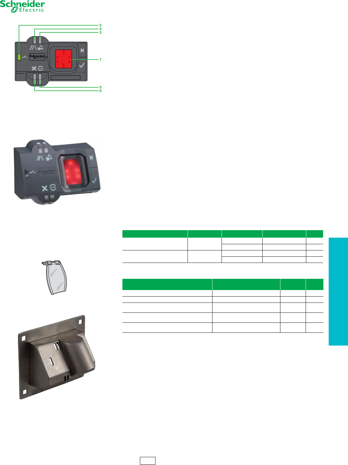
www.schneider-electric.us
19 PUSH BUTTONS AND
OPERATOR INTERFACE
© 2012 Schneider Electric
All Rights Reserved 19-65
22 mm Push Buttons XB5S Biometric Switches
Refer to Catalog DIA4ED2060507BEN-US
Biometric Switches
The fingerprint-reading biometric switch is designed for use in industry to restrict access to
systems or machines. No interface is required to program or operate the switch: it is an
independent unit.
Two types of products are available:
•Maintained biometric switches, Type XB5S1B, with two fixed states
•Momentary biometric switches, Type XB5S2B, with pulse output
The biometric switch is aimed at two types of users:
•The administrator who manages the registration and deletion of fingerprints
•The operator who, once registered, uses the product as a control unit
The product is of monolithic design (a single plastic housing) and is mounted by a nut
(hand-tightened without the need for tools) in a standard 22 mm diameter hole. It operates
on a 24 Vdc supply.
The product connects to the power supply and to the control output (relay or PLC) with a
2 meter cable or with an M12 connector.
It can be installed on a flat, horizontal, or vertical surface.
Two protective covers are available (see table below)
•One to protect the active face of the sensing screen. This cover is attached with a self-adhesive
hinge
•One made of 12 gauge stainless steel — designed to cover the entire switch — which protects the
entire switch from the outdoor environment (rain, sleet, snow, sunlight, UV protection). It also gives
some protection from someone trying to break into the switch
Description
The product consists of a dark gray housing, with the following on its front face:
•A sensing screen (1) that allows the registration of fingerprints and subsequent recognition of the
registered fingerprints
•A green LED output state indicator (2), which illuminates when the output is activated (N.O. solid
state contact)
•An orange LED (3), indicating an administrator’s Registration mode
•An orange LED (4), indicating an operator’s Registration mode
•A red Reset LED (5), which indicates in Delete mode that the administrator is deleting all or part of
the memory
•A red LED (6) which flashes to indicate an unrecognized fingerprint or incorrect operation
Table 19.187: Complete Units
Description Output Connection Catalog Number $ Price
Maintained biometric switch, 24 Vdc PNP 2 m cable XB5S1B2L2 580.00
M12 connector XB5S1B2M12 595.00
Momentary biometric switch, 24 Vdc
with 0.5 s output pulse PNP 2 m cable XB5S2B2L2 580.00
M12 connector XB5S2B2M12 595.00
Table 19.188: Accessories
Description Function Catalog
Number $ Price
Protective cover, translucent and self-adhesive Protection of the sensing screen ZB5SZ70 10.00
Mounting nut, Ø 22 mm Replacement part ZB5SZ71 6.00
Legend plate, 28 x 7 mm, self-adhesive, blank, with
black background, for engraving ZBY0101T 1.70
Mounting adapter Allows this product to mount in a 30 mm
mounting hole ZBZ41 10.40
Stainless-steel protective cover Protects switch from outside elements
and vandalism ZB5SZ72 220.00
XB5 S•B••••
ZB5 SZ70
ZB5SZ72
CS2 Discount
Schedule
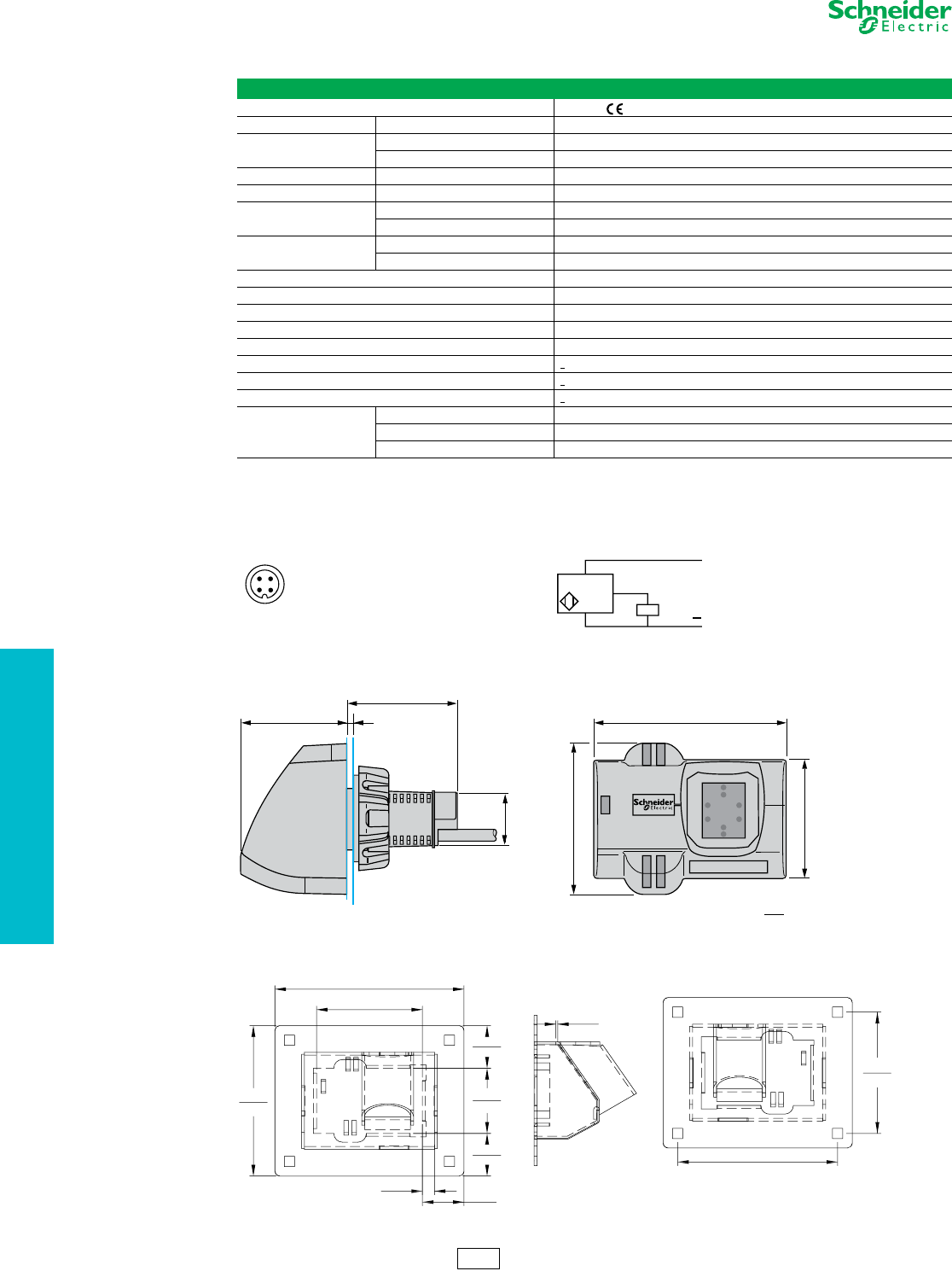
19-66 © 2012 Schneider Electric
All Rights Reserved
www.schneider-electric.us
19 PUSH BUTTONS AND
OPERATOR INTERFACE
22 mm Push Buttons XB5S Biometric Switches
Refer to Catalog DIA4ED2060507BEN-US
NOTE: Momentary switch has 0.5 s output pulse.
Figure 19.1: Connections
Figure 19.2: Dimensions
Table 19.189: Biometric Switch Specifications
Biometric Switch, Types XB5S1B•••• and XB5S2B••••
Product certifications UL, CSA, IEC 61000-6-2 / IEC 61000-6-4
Degree of protection Conforming to EN/IEC 60529 IP 65, NEMA 1, 2, 3, 3R, 12
Ambient air temperature Storage -25 to +70°C
Operation -5 to +50°C
Vibration resistance Conforming to IEC 60068-2-6 1 gn, 9 to 500 Hz. Amplitude 3 mm, 5 to 9 Hz
Electric shock resistance Conforming to IEC60068-2-27 50 gn, duration 11 ms
Connection method Cable Length: 2 m, 3-wire, pre-wired
Connector M12
Materials Housing Polyamide PA66
Cable PvR 3 x 0.34 mm2
Memory capacity 200 records (100 users, operators, or administrators, each registering 2 fingerprints)
Output state indicator Green LED
Short-circuit protection By gG fuse, 250 mA
Rated supply voltage 24 Vdc with protection against reverse polarity
Voltage limits (including ripple) 20–30 Vdc
Switching capacity < 200 mA with protection against overloads and short-circuits
Residual voltage, closed state < 1 V
No-load current consumption < 50 mA
Delays
First-up < 2 s
Response time < 1 s
Recovery time < 1 s
Connector Cable PNP
M12 1 (+) BU: Blue
3 (-) BN: Brown
4 Output BK: Black
12
43 BN / 1
BU / 3
+
P N P BK / 4
69 . 3
2 . 7 3
D im. = mm
in.
39 . 7
38. 8 1. 56
1. 53
54
2 . 13
42 . 3
1. 67
e
Ø 2 2
4. 87 5
12 3. 82
3. 87 5
9 8. 42
0. 312
7 . 9 2 1. 07 2
27.23
2 . 7 30
69 . 34
1. 680
42 . 67
1. 09 8
2 7 . 89 4. 12 4
104. 7 5
Back view
(for mounting)
3. 12 4
7 9 . 35
0. 057
1. 45
1. 09 8
2 7 . 89
e = 1 to 6 mm
(0.04 to 0.24 in.)
Stainless-Steel Cover
XB5 Biometric Switch
CS2 Discount
Schedule
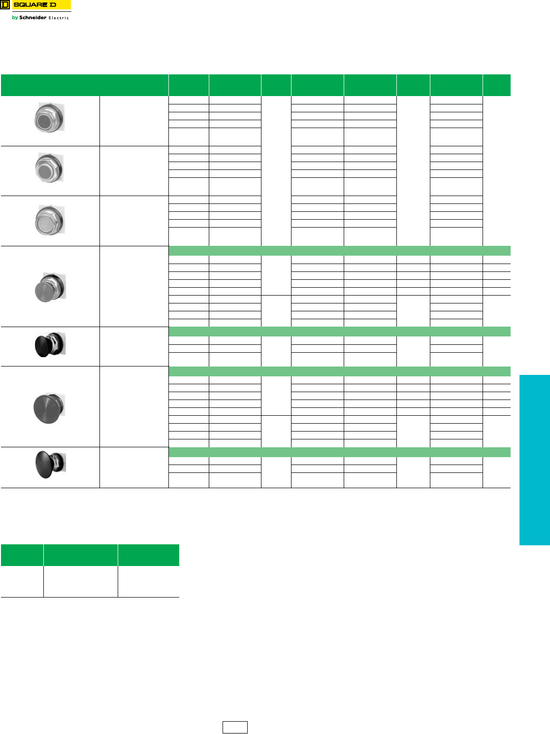
www.schneider-electric.us
19 PUSH BUTTONS AND
OPERATOR INTERFACE
© 2012 Schneider Electric
All Rights Reserved 19-67
30 mm Push Buttons Type K Heavy Duty Operators
Class 9001 / Refer to Catalog 9001CT1103
Table 19.190: Non-Illuminated Momentary Push Button Operators
UL Types 4, 13/NEMA 4, 13
For use in hazardous locations—See page 19-87.
Contact blocks and legend plate not included unless otherwise noted.
Description Color
Operator with
1 N.O. and 1 N.C.
Contact (KA1)
$ Price
Operator with
1 N.O. Contact
(KA2)
Operator with
1 N.C. Contact
(KA3)
$ Price
Operator Only
with No
Contacts
$ Price
9001KR1B
Full Guard
Black KR1BH13
89.00
KR1BH5 KR1BH6
66.00
KR1B
38.60
Red KR1RH13 KR1RH5 KR1RH6 KR1R
Green KR1GH13 KR1GH5 KR1GH6 KR1G
Universal aKR1UH13 KR1UH5 KR1UH6 KR1U
Other bKR1bH13 KR1bH5 KR1bH6 KR1b
9001KR3B
No Guard
Black KR3BH13 KR3BH5 KR3BH6 KR3B
Red KR3RH13 KR3RH5 KR3RH6 KR3R
Green KR3GH13 KR3GH5 KR3GH6 KR3G
Universal aKR3UH13 KR3UH5 KR3UH6 KR3U
Other bKR3bH13 KR3bH5 KR3bH6 KR3b
9001KR2B
Extended Guard
Black KR2BH13 KR2BH5 KR2BH6 KR2B
Red KR2RH13 KR2RH5 KR2RH6 KR2R
Green KR2GH13 KR2GH5 KR2GH6 KR2G
Universal aKR2UH13 KR2UH5 KR2UH6 KR2U
OtherbKR2bH13 KR2bH5 KR2bH6 KR2b
9001KR4B
1-3/8 in. (35 mm)
Diameter
Mushroom Button
Snap-In Plastic Mushroom Button
Black KR4BH13
138.00
KR4BH5 KR4BH6 112.00 KR4B 81.00
Red KR4RH13 KR4RH5 KR4RH6 112.00 KR4R 81.00
Red cKR4R05H13 KR4R05H5 KR4R05H6 119.00 KR4R05 86.00
Green KR4GH13 KR4GH5 KR4GH6 112.00 KR4G 81.00
Other dKR4dH13 KR4dH5 KR4dH6 112.00 KR4d81.00
Black KR24BH13
138.00
KR24BH5 KR24BH6
112.00
KR24B
81.00
Red KR24RH13 KR24RH5 KR24RH6 KR24R
Green KR24GH13 KR24GH5 KR24GH6 KR24G
OtherdKR24dH13 KR24dH5 KR24dH6 KR24d
9001KR24BM
1-1/2 in. (40 mm)
Diameter
Mushroom Button
Screw-in Metal Mushroom Button with Set Screw Security
Black —
—
——
—
9001KR24BM
90.00
Red — — — 9001KR24RM
Green — — — 9001KR24GM
9001KR5B
2-1/4 in. (57 mm)
Diameter
Mushroom Button
Snap-In Plastic Mushroom Button
Black KR5BH13
138.00
KR5BH5 KR5BH6 112.00 KR5B 81.00
Red KR5RH13 KR5RH5 KR5RH6 119.00 KR5R 81.00
Red cKR5R05H13 cKR5R05H5 cKR5R05H6 c112.00 KR5R05 c86.00
Green KR5GH13 KR5GH5 KR5GH6 112.00 KR5G 81.00
OtherdKR5dH13 KR5dH5 KR5dH6 112.00 KR5d81.00
Black KR25BH13
138.00
KR25BH5 KR25BH6
112.00
KR25B
81.00
Red KR25RH13 KR25RH5 KR25RH6 KR25R
Green KR25GH13 KR25GH5 KR25GH6 KR25G
OtherdKR25dH13 KR25dH5 KR25dH6 KR25d
9001KR25BM
2-3/8 in. (60 mm)
Diameter
Mushroom Button
Screw-in Metal Mushroom Button with Set Screw Security
Black —
—
——
—
9001KR25BM
101.00
Red — — — 9001KR25RM
Green — — — 9001KR25GM
aThe universal push button operators contain one each of the following color inserts: black, red, green, yellow, orange, blue and white.
bSee Table 19.191 for color code.
cKnob has the words “Emergency Stop” in raised letters highlighted in white for readability.
dSee Table 19.191 for color code.
Table 19.191: Color Codes
Color
KR1, 2, 3
Place Color Code
in Type Number b
KR4, 5, 24, 25
Place Color Code
in Type Number d
Blue
Yellow
White
Orange
Gray
L
Y
W
S
E
L
Y
—
S
—
CS1 Discount
Schedule
NOTE: When ordering, add prefix 9001 to the catalog number.
NOTE: To select and order contact blocks, light modules, and accessories, see pages 19-85 through 19-92.
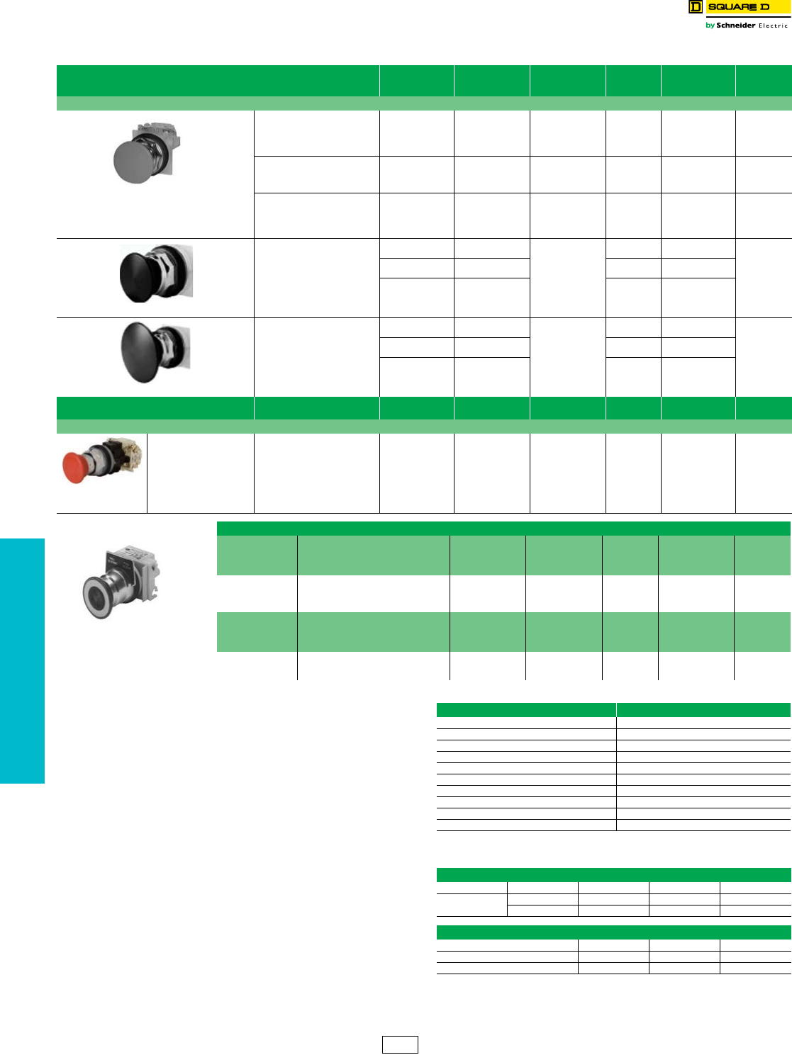
www.schneider-electric.us
19 PUSH BUTTONS AND
OPERATOR INTERFACE
19-68 © 2012 Schneider Electric
All Rights Reserved
30 mm Push Buttons............................................................................Type K Heavy Duty Operators
Class 9001 / Refer to Catalog 9001CT1103
eChoose one color from the Color Codes table here, and insert the color code in Type
number. Example: KR9 with a yellow knob = KR9Y
fAdd the voltage assembly code as chosen from page 19-86. Example: KR8P with a 277
V 50–60 Hz voltage = KR8P8
gThe knob must be the same color as the LED light module chosen, for example, for a
green LED, use a green knob.
hOn neon light modules, use clear knobs only.
iThese operators can be ordered complete with contact blocks. For maximum block
usage, see page 19-88. Add the “H” number chosen from page 19-88 to the end of the
operator Type number and add the cost of the “H” number to the operator cost.
jKR11UH1 has 1 KA1 (1 N.O., 1 N.C.) and KR12UH1H1 has 2 KA1 (2 N.O., 2 N.C.).
kTo obtain a red knob with “Push Emergency Stop” printed on the red knob—substitute
“R05” in place of “R” and add $2.10 to the price.
lFor 1-3/8 in. or 2-1/4 in. Dia. Knob:
a) Order Type -20 or -21 knob from page 19-92.
b) Order 9001K54 adapter (no charge)—allows Type -20 or -21 knob to fit on push pull
operators. Voids UL and NEMA 6 rating.
c) Can order assembled operator by adding color code to Type -20 or -21. Example:
9001KR9R would be 9001KR9R20 or 9001KR9R21. No price adder.
mSee page 19-67 for contact sequences.
nSee Table 19.193.
NOTE: To select and order contact blocks, light modules, and
accessories, see pages 19-85 through 19-92.
Table 19.192: 30 mm Multifunction Operators
Description lColor
With 2 N.C.
Contacts
(1 KA3, 1 KA5)
With 1 N.O. &
1 N.C. Contact
(1 KA1)
$ Price Without
Contacts i$ Price
Non-Illuminated Push-Pull Mushroom Operators
KR9R94H13
Set Screw Style
Position, Plastic Head
1-5/8 in. (40 mm), Screw-0n
Momentary Pull
Maintained Neutral
Momentary Push m
Red
Green
Other e
KR8RH25
KR8GH25
KR8eH25
—
—
—
142.00
KR8R
KR8G
KR8e
86.00
2 Position, Plastic Head
1-5/8 in. (40 mm), Screw-0n
Maintained Pull
Maintained Push n
Red k
Green
Other e
—
—
—
KR9RH13
KR9GH13
KR9eH13
188.00
KR9R
KR9G
KR9e
129.00
2 Position , Plastic Head
1-5/8 in. (40 mm),
Screw-0n Head with Set Screw
Maintained Pull
Maintained Push n
Red — KR9R94H13 194.00 KR9R94 134.00
9001KR9RM94
2 Position,
Metal Head
1-1/2 in. (40 mm) Diameter
Black —
—
—9001KR9BM94
138.00
Red ——9001KR9RM94
Green — — 9001KR9GM94
9001KR9RM95
2 Position,
Metal Head
2-3/8 in. (60 mm) Diameter
Black —
—
—9001KR9BM95
149.00
Red ——9001KR9RM95
Green — — 9001KR9GM95
Description Color With 1 N.O. & 1 N.C.
Contact (KA1) $ Price With 2 N.O. & 2 N.C.
Contacts (KA2) $ Price Without Contacts $ Price
Non-Illuminated Turn-to-Release Mushroom Operators
9001KR16H2
Tr i gge r Act i o n
2 Position,
Plastic Head
Turn-to-Release
Trigger Action
Red KR16H13 172.00 KR16H2 218.00 KR16 113.00
9001KR9P1
1.625 in. Diameter Knob
For 1-3/8 in. or 2-1/4 in. Diameter Knob l
Includes Type KN379
Legend Plate Marked
Pull To Start Push To Stop
Screw-On Plastic Illuminated Push-Pull Mushroom Operators
Description lVoltage
With Red Knob
and 2 N.C.
Contacts
(1 KA3, 1 KA5)
With Other
Color Knob and
2 N.C. Contacts
(1 KA3, 1 KA5)
$ Price
With Other Color
Knob Without
Contacts i
$ Price
3 Position Illuminated
Momentary Pull
Maintained Neutral
Momentary Pushm
110-120 V, 50-60 Hz
Other—Transformer, LED, Flashing g
Other—Full Voltage, Resistor, Neon h
KR8P1RH25
KR8PfRH25
KR8PfRH25
KR8P1eH25
KR8PfeH25
KR8PfeH25
267.00
267.00
215.00
KR8P1e
KR8Pfe
KR8Pfe
201.00
201.00
171.00
Description lVoltage
With Redk Knob
and 1 N.O. &
1 N.C. Contact
(KA1)
With Other Color
Knob and 1 N.O.
& 1 N.C. Contact
(KA1)
$ Price
With Other Color
Knob Without
Contacts
$ Price
2 Position Illuminated
Maintained Pull
Maintained Push
110–120 V, 50–60 Hz
Other—Transformer, LED, Flashing g
Other—Full Voltage, Resistor, Neon h
KR9P1RH13
KR9PfRH13
KR9PfRH13
KR9P1eH13
KR9PfeH13
KR9PfeH13
316.00
316.00
257.00
KR9P1e
KR9Pfe
KR9Pfe
243.00
243.00
215.00
Table 19.193: Color Codes
Color KR8, KR9
Black oB
Red R
Green G
Blue L
Yellow Y
White W
Orange oS
Clear C
Amber A
Gray —
oThese colors are not available on illuminated push-pull operators.
Table 19.194: Contact Sequences
9001 KR8RH1 or H13
Pull Ctr Push
(KA1) KA3 X O O
KA2 O O X
9001 KR8RH25
KA3 X O O
KA5 X X O
KA2 O O X
CS1 Discount
Schedule
NOTE: When ordering, add prefix 9001 to the catalog number.
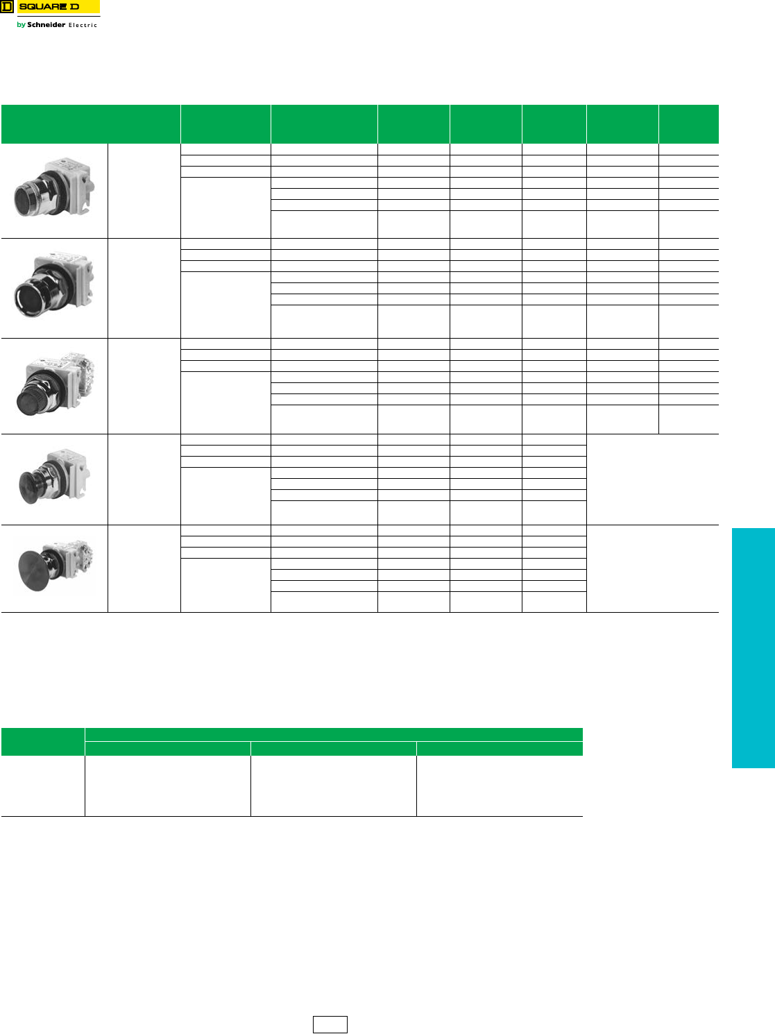
www.schneider-electric.us
19 PUSH BUTTONS AND
OPERATOR INTERFACE
© 2012 Schneider Electric
All Rights Reserved 19-69
30 mm Push Buttons Type K Heavy Duty Operators
Class 9001 / Refer to Catalog 9001CT1103
Table 19.195: Illuminated Momentary Push Button Operators
UL Types 4, 13/NEMA 4, 13
For use in hazardous locations—See page 19-87.
Legend plate and contact block not included unless otherwise noted.
Description
Volt age
and
Frequency
Style
With Red Color
Cap and 1 N.O.
and 1 N.C.
Contact (KA1)
With Green Color
Cap and 1 N.O.
and 1 N.C.
Contact (KA1)
$ Price g
With Other Color
Cap Without
Contact Block a
$ Price h
9001K1L1
Full Guard
Illuminated
Push Button
Clear Plastic Top
110–120 V, 50–60 Hz Transformer K1L1RH13 K1L1GH13 231.00 K1L1e184.00
220–240 V, 50–60 Hz Transformer K1L7RH13 K1L7GH13 231.00 K1L7e184.00
24–28 Vac/Vdc Full Voltage K1L35RH13 K1L35GH13 198.00 K1L35e138.00
For other voltages
see Table b
Transformer or Flashing K1LbRH13 K1LbGH13 231.00 K1Lbe 184.00
Full Voltage K1LbRH13 K1LbGH13 198.00 K1Lbe 138.00
Resistor or NeoncK1LbRH13 K1LbGH13 198.00 K1Lbe 138.00
LED dK1LbRH13 K1LbGH13 231.00 K1Lbe 184.00
9001K3L1
Full Guard
Illuminated
Push Button
Metal Top
110–120 V, 50–60 Hz Transformer K3L1RH13 K3L1GH13 231.00 K3L1e184.00
220–240 V, 50–60 Hz Transformer K3L7RH13 K3L7GH13 231.00 K3L7e184.00
24–28 Vac/Vdc Full Voltage K3L35RH13 K3L35GH13 198.00 K3L35e138.00
For other voltages
see Table b
Transformer or Flashing K3LbRH13 K3LbGH13 231.00 K3Lbe 184.00
Full Voltage K3LbRH13 K3LbGH13 198.00 K3Lbe 138.00
Resistor or Neon cK3LbRH13 K3LbGH13 231.00 K3Lbe 138.00
LED dK3LbRH13 K3LbGH13 231.00 K3Lbe 184.00
9001K2L1
No Guard
Illuminated
Push Button
110–120 V, 50–60 Hz Transformer K2L1RH13 K2L1GH13 217.00 K2L1e153.00
220–240 V, 50–60 Hz Transformer K2L7RH13 K2L7GH13 217.00 K2L7e153.00
24–28 Vac/Vdc Full Voltage K2L35RH13 K2L35GH13 184.00 K2L35e125.00
For other voltages
see Table b
Transformer or Flashing K2LbRH13 K2LbGH13 217.00 K2Lbe 153.00
Full Voltage K2LbRH13 K2LbGH13 184.00 K2Lbe 125.00
Resistor or Neon cK2LbRH13 K2LbGH13 184.00 K2Lbe 125.00
LED dK2LbRH13 K2LbGH13 217.00 K2Lbe 153.00
9001K2LR20
1-3/8 in. (35 mm)
Illuminated
Mushroom,
Screw-On
Plastic Head
110–120 V, 50–60 Hz Transformer K2L1R20H13 K2L1G20H13 217.00
Order K2L be
Above f
220–240 V, 50–60 Hz Transformer K2L7R20H13 K2L7G20H13 217.00
24–28 Vac/Vdc Full Voltage K2L35R20H13 K2L35G20H13 184.00
For other voltages
see Table b
Transformer or Flashing K2LbR20H13 K2LbG20H13 217.00
Full Voltage K2LbR20H13 K2LbG20H13 184.00
Resistor or Neon cK2LbR20H13 K2LbG20H13 184.00
LED dK2LbR20H13 K2LbG20H13 217.00
9001K2LR21
2-1/4 in. (57 mm)
Illuminated
Mushroom,
Screw-On
Plastic Head
110–120 V, 50–60 Hz Transformer K2L1R21H13 K2L1G21H13 217.00
Order K2L be
Above f
220–240 V, 50–60 Hz Transformer K2L7R21H13 K2L7G21H13 217.00
24–28 Vac/Vdc Full Voltage K2L35R21H13 K2L35G21H13 184.00
For other voltages
see Table b
Transformer or Flashing K2LbR21H13 K2LbG21H13 217.00
Full Voltage K2LbR21H13 K2LbG21H13 184.00
Resistor or Neon cK2LbR21H13 K2LbG21H13 184.00
LED dK2LbR21H13 K2LbG21H13 217.00
aThese operators can be ordered complete with contact blocks. For maximum block usage, see page 19-88. Add the “H”
number chosen from page page 19-88 to the end of the operator type number and add the cost of the “H” number to the operator cost.
bAdd the voltage assembly code as chosen from Table 19.248 or Table 19.249 on page 19-86. Example: K2La with 240 Vac/Vdc = K2L25
cOn neon light modules, use clear color caps only.
dThe cap must be the same color as the LED light module chosen, e.g., for red LED, use red color cap.
eAdd the color code as chosen from the color cap table. Example: K2L25c with a blue 13•8 mushroom button = K2L25L20
fThe only difference between a no guard (K2Lq) operator and mushroom button operator is the color cap.
gPrice includes operator, light module, contact block, and color cap.
hPrice includes operator, light module, and color cap.
Table 19.196: Color Caps
Color Color Codes
eK1L, K2L, K3L e 1-3/8 in. Mushroom e 2-1/4 in. Mushroom
Red
Green
Blue
Yellow
White
Clear
Amber
R
G
L
Y
W
C
A
R20
G20
L20
Y20
W20
C20
A20
R21
G21
L21
Y21
W21
C21
A21
CS1 Discount
Schedule
NOTE: When ordering, add prefix 9001 to the catalog number.
NOTE: To select and order contact blocks, light modules, and accessories, see pages 19-85 through 19-92.
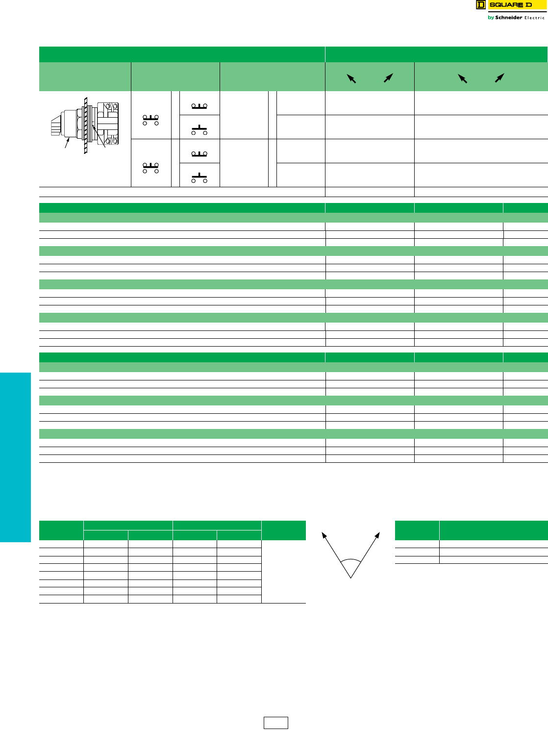
www.schneider-electric.us
19 PUSH BUTTONS AND
OPERATOR INTERFACE
19-70 © 2012 Schneider Electric
All Rights Reserved
30 mm Push Buttons 9001K and SK Selector Switches
Class 9001 / Refer to Catalog 9001CT1103
NOTE: To select and order Contact Blocks, Light Modules, Knobs, and Accessories, see pages 19-85 through 19-92.
Table 19.197: 2-Position Selector Switches
Contact Block Required 1 — Contact Closed 0 — Contact Open
Contact Block
Position
Quantity and Type
KA1 or KA2 or KA3
Mount on Side
KA1 or KA2 or KA3
Left Right Left Right
KA1
or
KA3
KA1
#2 or
KA3
#2 10 01
KA2 KA2
#2 01 10
KA1
or
KA3
KA1
#1 or
KA3
#1 10 01
KA2 KA2
#1 01 10
Cam (see page 19-73)ED
Non-Illuminated Operators Cat. No. Cat. No. $ Price
Manual Return a, Operator Only (without contact blocks)
Without Knob KS11 KS12 42.80
With Knob (select style and color from Table 19.198 below) KS11* KS12* 42.80
Key Operated with E10 Key (Code1,2,3) KS11K** KS12K** 138.00
Operator with Contact Blocks and Standard black knob
With 1 KA1 on Side #2 KS11BH13 —106.00
With 1 KA1 on Side #1 KS11BH1 —106.00
With 1 KA1 on Side #1 and 1 KA1 on side #2 KS11BH2 —152.00
Spring Return from Left a, Operator Only (without contact blocks)
Without Knob KS25 —71.00
With Knob (select style and color from Table 19.198) KS25* — 71.00
Key Operated with E10 Key (Code 2 only)dKS25K2 —167.00
Spring Return from Right a, Operator Only (without contact blocks)
Without Knob —KS34 71.00
With Knob (select style and color from Table 19.198 below) — KS34* 71.00
Key Operated with E10 Key (Code 1 only) — KS34K1 167.00
Illuminated Operators Cat. No. Cat. No. $ Price
Manual Return a, Operator Only (without contact blocks)
Without Knob, 110-120V 50-60 Hz Transformer K11J1 K12J1 158.00
With Standard Red Knob, 110-120V 50-60 Hz Transformer K11J1R K12J1R 167.00
With Other Color Knob and other voltage Light Module b cK11Jbc K12Jbc 167.00
Spring Return from Left a, Operator Only (without contact blocks)
Without Knob, 110-120V 50-60 Hz Transformer K25J1 —185.00
With Standard Red Knob, 110-120V 50-60 Hz Transformer K25J1R —197.00
With Other Color Knob and other voltage Light Module b cK25Jbc —197.00
Spring Return from Right a, Operator Only (without contact blocks)
Without Knob, 110-120V 50-60 Hz Transformer — K34J1 185.00
With Standard Red Knob, 110-120V 50-60 Hz Transformer — K34J1R 197.00
With Other Color Knob and other voltage Light Module b c—K34Jbc 197.00
aThese operators can be ordered complete with contact blocks. Add the "H code" from page 19-88 as needed for your application.
bAdd the voltage assembly code as chosen from page 19-86. Example: K25Jb with 208 Vac = K25J3.
cAdd the knob color code from Table 19.198. For LED, knob color must match LED.
dAdd the key withdrawal code from Table 19.199.
Top View
Side 2
Side 1
Operator Locating
Notch
Table 19.198: Selector Switch Assembly Code and Knob Cat. No. Table 19.199: d Key Withdrawal Codes
Color Standard Knob Gloved Hand Knob $ Price Code Position
c Knob Code Cat. No. c Knob Code Cat. No.
Black B B11 FB B25
9.90
1 Left Only
Red R R8 FR R24 2Right Only
Green G G8 FG G24 3 Left and Right
Yellow Y Y8 FY Y24
Blue L L8 FL L24
White W W8 FW W24
Amber A A8 FA A24
Clear C C8 FC C24
70
2 Position
CS1 Discount
Schedule
NOTE: When ordering, add prefix 9001 to the catalog number.
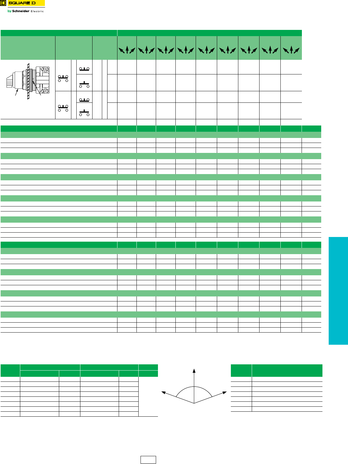
www.schneider-electric.us
19 PUSH BUTTONS AND
OPERATOR INTERFACE
© 2012 Schneider Electric
All Rights Reserved 19-71
30 mm Push Buttons 9001 K and SK Selector Switches
Class 9001 / Refer to Catalog 9001CT1103
NOTE: To select and order Contact Blocks, Light Modules, Knobs, and Accessories, see pages 19-85 through 19-92.
Table 19.200: 3-Position Selector Switches
Contact Block Required 1 - Contact Closed 0- Contact Open
Contact
Block
Position
Quantity
and
Type
Mount
on
Side
Center
Left Right
Center
Left Right
Center
Left Right
Center
Left Right
Center
Left Right
Center
Left Right
Center
Left Right
Center
Left Right
Center
Left Right
KA1 or
KA3
KA1
#2 or
KA3
#2 100 100 001 100 100 100 100 010 110
KA2
KA2
#2 011 001 010 010 001 011 011 100 001
KA1 or
KA3
KA1
#1 or
KA3
#1 001 100 001 100 010 001 101 001 011
KA2
KA2
#1 110 001 010 010 001 100 010 010 100
Cam (see page 19-73)BCD E F G J L M
Non-Illuminated Operators Cat. No. Cat. No. Cat. No. Cat. No. Cat. No. Cat. No. Cat. No. Cat. No. Cat. No. $ Price
Manual Return, Operator Only (without contact blocks) a
Without Knob KS42 KS43 KS44 KS45 KS46 KS47 KS49 KS401 KS402 43.00
With Knob (select style and color from table 19.168 below) KS42cKS43cKS44cKS45cKS46cKS47cKS49cKS401cKS402c53.00
Key Operated with E10 Key (Code 4 through 10) eKS42KeKS43KeKS44KeKS45KeKS46KeKS47KeKS49KeKS401KeKS402Ke 138.00
Operator with Contact Blocks and Standard black knob d
With 1 KA1 on Side #2 (H13) KS42BH13 KS43BH13 KS44BH13 KS45BH13 KS46BH13 KS47BH13 KS49BH13 KS401BH13 KS402BH13 106.00
With 1 KA1 on Side #1 (H1) KS42BH1 KS43BH1 KS44BH1 KS45BH1 KS46BH1 KS47BH1 KS49BH1 KS401BH1 KS402BH1 106.00
With 1 KA1 on Side #1 and 1 KA1 on side #2 (H2) KS42BH2 KS43BH2 KS44BH2 KS45BH2 KS46BH2 KS47BH2 KS49BH2 KS401BH2 KS402BH2 152.00
Spring Return from Left to Center, Operator Only (without contact blocks) a
Without Knob KS62 KS63 KS64 KS65 KS66 KS67 KS69 KS601 KS602 71.00
With Knob (select style and color from table 19.168 below) KS62cKS63cKS64cKS65cKS66cKS67cKS69cKS601cKS602c81.00
Key Operated with E10 Key (Code 5, 6 or 9 only)eKS62KeKS63KeKS64KeKS65KeKS66KeKS67KeKS69KeKS601KeKS602Ke167.00
Spring Return from Right to Center, Operator Only (without contact blocks) a
Without Knob KS72 KS73 KS74 KS75 KS76 KS77 KS79 KS701 KS702 71.00
With Knob (select style and color from table 19.168 below) KS72cKS73cKS74cKS75cKS76cKS77cKS79cKS701cKS702c81.00
Key Operated with E10 Key (Code 4, 5 or 7 only) KS72KeKS73KeKS74KeKS75KeKS76KeKS77KeKS79KeKS701KeKS702Ke167.00
Spring Return from Both Sides to Center, Operator Only (without contact blocks) a
Without Knob KS52 KS53 KS54 KS55 KS56 KS57 KS59 KS501 KS502 71.00
With Knob (select style and color from table 19.168 below) KS52cKS53cKS54cKS55cKS56cKS57cKS59cKS501cKS502c81.00
Key Operated with E10 Key (Code 4, 5 or 7 only) KS52KeKS53KeKS54KeKS55KeKS56KeKS57KeKS59KeKS501KeKS502Ke167.00
Illuminated Operators Cat. No. Cat. No. Cat. No. Cat. No. Cat. No. Cat. No. Cat. No. Cat. No. Cat. No. $ Price
Manual Return, Operator Only (without contact blocks) a
Without Knob, 110-120V 50-60 Hz Transformer K42J1 K43J1 K44J1 K45J1 K46J1 K47J1 K49J1 K401J1 K402J1 158.00
With Standard Red Knob, 110-120V 50-60 Hz Transformer K42J1R K43J1R K44J1R K45J1R K46J1R K47J1R K49J1R K401J1R K402J1R 167.00
With Other Color Knob and other voltage Light Module b cK42Jbc K42Jbc K44Jbc K45Jbc K46Jbc K47Jbc K49Jbc K401Jbc K402Jbc 158.00
Spring Return from Left to Center, Operator Only (without contact blocks) a
Without Knob, 110-120V 50-60 Hz Transformer K62J1 K63J1 K64J1 K65J1 K66J1 K67J1 K69J1 K601J1 K602J1 185.00
With Standard Red Knob, 110-120V 50-60 Hz Transformer K62J1R K63J1R K64J1R K65J1R K66J1R K67J1R K69J1R K601J1R K602J1R 197.00
With Other Color Knob and other voltage Light Module b cK62Jbc K62Jbc K64Jbc K65Jbc K66Jbc K67Jbc K69Jbc K601Jbc K602Jbc 167.00
Spring Return from Right to Center, Operator Only (without contact blocks) a
Without Knob, 110-120V 50-60 Hz Transformer K72J1 K73J1 K74J1 K75J1 K76J1 K77J1 K79J1 K701J1 K702J1 185.00
With Standard Red Knob, 110-120V 50-60 Hz Transformer K72J1R K73J1R K74J1R K75J1R K76J1R K77J1R K79J1R K701J1R K702J1R 197.00
With Other Color Knob and other voltage Light Module b cK72Jbc K72Jbc K74Jbc K75Jbc K76Jbc K77Jbc K79Jbc K701Jbc K702Jbc 167.00
Spring Return from Both Sides to Center, Operator Only (without contact blocks) a
Without Knob, 110-120V 50-60 Hz Transformer K52J1 K53J1 K54J1 K55J1 K56J1 K57J1 K59J1 K501J1 K502J1 185.00
With Standard Red Knob, 110-120V 50-60 Hz Transformer K52J1R K53J1R K54J1R K55J1R K56J1R K57J1R K59J1R K501J1R K502J1R 197.00
With Other Color Knob and other voltage Light Module b cK52Jbc K53Jbc K54Jbc K55Jbc K56Jbc K57Jbc K59Jbc K501Jbc K502Jbc 167.00
aThese operators can be ordered complete with contact blocks.00 Add the "H code" from page 19-88 as needed for your application.
bAdd the voltage assembly code as chosen from page 19-86. Example: K25Jb with 208Vac = K25J3.
cAdd the knob color code from Table 19.201. For LED, knob color must match LED.
dFor other color knobs replace the B with knob color code from Table 19.201.
eAdd the key withdrawal code from table Table 19.202. Example: KS43Ke with key withdrawal in the right position only = KS43K6.
Top View
Side 2
Side 1
Operator Locating
Notch
Table 19.201: Selector Switch Assembly Code and Knob Cat. No. Table 19.202: e Key Withdrawal Codes
Color Standard Knob Gloved Hand Knob Code Position
c Knob Code Cat. No. c Knob Code Cat. No. $ Price
Black B B11 FB B25
9.90
4Left Only
Red R R8 FR R24 5 Center Only
Green G G8 FG G24 6 Right Only
Yellow Y Y8 FY Y24 7 Left and Center
Blue L L8 FL L24 8 Left and Right
White W W8 FW W24 9 Center and Right
Amber A A8 FA A24 10 Left, Center, and Right
Clear C C8 FC C24
70 70
3 Position
CS1 Discount
Schedule
NOTE: When ordering, add prefix 9001 to the catalog number.
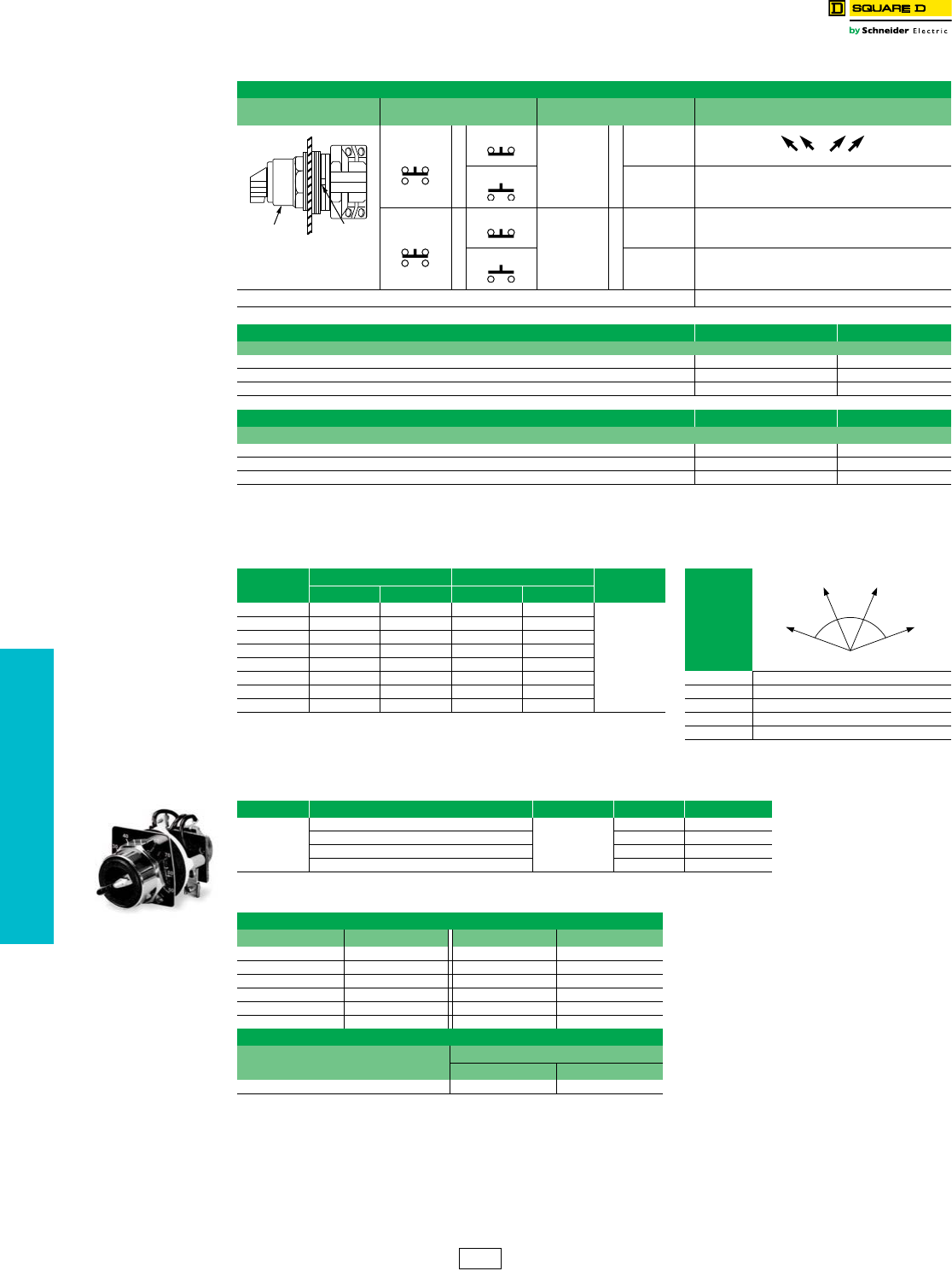
www.schneider-electric.us
19 PUSH BUTTONS AND
OPERATOR INTERFACE
19-72 © 2012 Schneider Electric
All Rights Reserved
30 mm Push Buttons 9001 K and SK Selector Switches
Class 9001 / Refer to Catalog 9001CT1103
Potentiometers with Dial Plate
Any potentiometer with a shaft 7/8" long and 1/4" diameter may be used with these operators
NOTE: To select and order Contact Blocks, Light Modules, Knobs, and Accessories. See pages 19-85 through 19-92.
Table 19.203: 4-Position Selector Switches
Contact Block Required
Contact Block Position Quantity and Type
KA1 or KA2 or KA3
Mount on Side
KA1 or KA2 or KA3
1—Contact Closed
0—Contact Open
KA1
or
KA3
KA1
#2 or
KA3
#2 1000
KA2 KA2
#2 0010
KA1
or
KA3
KA1
#1 or
KA3
#1 0001
KA2 KA2
#1 0100
Cam (see page 19-73) H
Non-Illuminated Operators Cat. No. $ Price
Manual Return a, Operator Only (without contact blocks)
Without Knob KS88 42.80
With Knob (select style and color from table 19.168 below) KS88c53.00
Key Operated with E10 Key (Codes 11, 12, 13, 14, 15) KS88Kd138.00
Illuminated Operators Cat. No. $ Price
Manual Return a, Operator Only (without contact blocks)
Without Knob, 110-120V 50-60 Hz Transformer KS88J1 158.00
With Standard Red Knob, 110-120V 50-60 Hz Transformer KS88J1R 167.00
With Other Color Knob and other voltage Light Module b cKS88Jbc 158.00
aThese operators can be ordered complete with contact blocks. Add the "H code" from page 19-88 as needed for your application.
bAdd the voltage assembly code as chosen from page 19-86. Example: K25Jb with 208Vac = K25J3.
cAdd the knob color code from table 19.204. For LED, knob color must match LED.
dAdd the key withdrawal code from Table 19.205.
Table 19.204: Selector Switch Assembly Code and Knob Cat. No. Table 19.205: d Key Withdrawal Codes
Color Standard Knob Gloved Hand Knob $ Price Code Position
c Knob Code Cat. No. c Knob Code Cat. No.
Black B B11 FB B25
9.90
Red R R8 FR R24
Green G G8 FG G24
Yellow Y Y8 FY Y24
Blue L L8 FL L24
White W W8 FW W24 11 1 and 4
Amber A A8 FA A24 12 4 only
Clear C C8 FC C24 13 1 only
14 1, 2, 3 and 4
15 2, 3, and 4
Table 19.206: Potentiometers with Dial Plate (not UL listed)—Maximum Voltage 300 Vac
Power Description Ratings Type $ Price
2 W
Operator Only, for Single Potentiometer
NEMA 4, 13
K20 201.00
Operator with Single Potentiometer K21 287.00
Operator Only, for Tandem Potentiometer K22 314.00
Operator with Tandem Potentiometer K23 399.00
Table 19.207: Potentiometer Suffixes
Single Potentiometer
Suffix eResistance Suffix eResistance
01 50 Ω 07 5 kΩ
02 100 Ω 08 10 kΩ
04 500 Ω 09 25 kΩ
05 1 kΩ 13 500 kΩ
39 2 kΩ 37 750 kΩ
06 2.5 kΩ 14 1 MΩ
Tandem Potentiometer
Suffix eResistance
Front Rear
82 1 kΩ 1 kΩ
eFor the complete part number, add the suffix from Table 19.207 to the catalog number
from Table 19.206. Example: 9001K2105.
Top View
Side 2
Side 1
Operator Locating
Notch
47 47
46
4 Position
CS1 Discount
Schedule
NOTE: When ordering, add prefix 9001 to the catalog number.
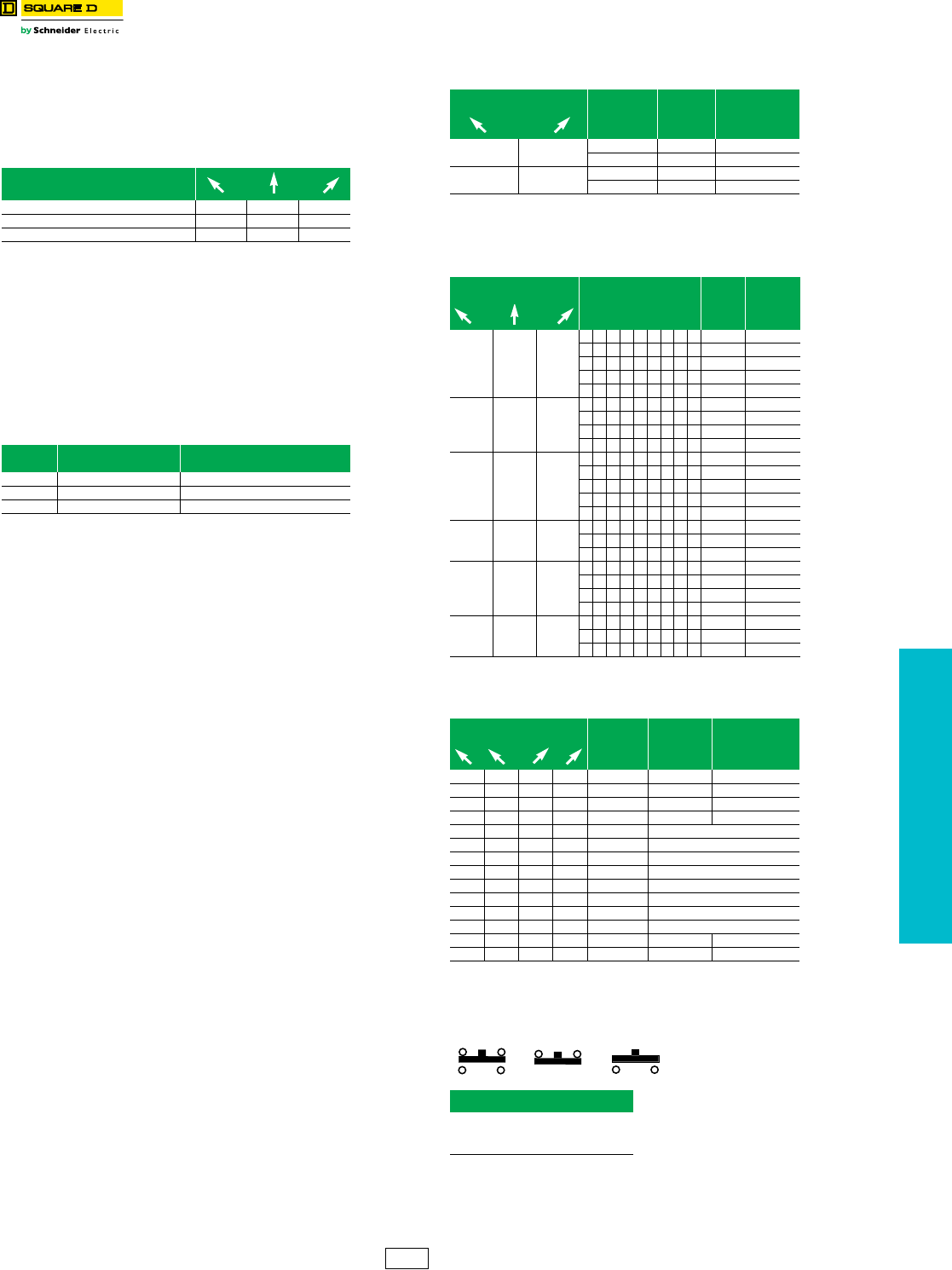
www.schneider-electric.us
19 PUSH BUTTONS AND
OPERATOR INTERFACE
© 2012 Schneider Electric
All Rights Reserved 19-73
30 mm Push Buttons Type K, KX, and SK Selector Switch Guide
Class 9001 / Refer to Catalog 9001CT1103
Shown below is a simplified method of selecting a selector switch to
meet almost any combination of contact sequences.
Step No. 1
Determine the contact sequence(s) required. Set up a target table like
the one shown for the example below.
Step No. 2
Look for a cam type common to all sequences in Table 19.208,
Table 19.209, or Table 19.210. For the example above, Table 19.209
would be used. For the contact sequences A (1 0 0), B (0 1 0) and
C (0 0 1) of the example above, cam types F and L are common to all
three sequences.
Step No. 3
Next, use the cam type common to all the sequences (if several cam
types are common, choose one) to find the operator type number. Go to
the proper page number as indicated in the table below:
If for the example above a manual return operator with a standard black
knob is required and:
The F cam type is chosen, the operator type number is:
•Type K—Class 9001 Type KS46B (from page19-71)
•Type SK—Class 9001 Type SKS46B (from page 19-81)
•Type KX—Class 9001 Type KXSDFB (from page 19-97)
The L cam type is chosen, the operator type number is:
•Type K—Class 9001 Type KS401B (from page 19-71)
•Type SK—Class 9001 Type SKS401B (from page 19-81)
•Type KX—Class 9001 Type KXSDLB (from page 19-97)
Step No. 4:
Determine the contact blocks required by using the same table in Step
No. 2.
If, for the example above, the F cam type is chosen:
•Use a 9001KA3 mounted on side no. 2 for sequence A (1 0 0).
•Use a 9001KA3 mounted on side no. 1 for sequence B (0 1 0).
•Use a 9001KA2 mounted on side no. 1 or 2 for sequence C (0 0 1).
If, for the example above, the L cam type is chosen:
•Use a 9001KA2 mounted on side no. 2 for sequence A (1 0 0).
•Use a 9001KA2 mounted on side no. 1 or a 9001KA3 mounted on side no. 2
for sequence B (0 1 0).
•Use a 9001KA3 mounted on side no. 1 for sequence C (0 0 1).
One Type KA1 double circuit block can be used in place of one Type
KA2 single circuit block plus one Type KA3 single circuit block mounted
on the same side.
aType KA5 must be the last block on either side. If more than one KA5 is required on either
side—contact your local Square D sales office.
Note: For Outline Dimensions see Catalog 9001CT1103
For “H” Numbers . . . . . . . . . . . . . . . . . . . . . . . . . . . . . . . . . . . . . . .page 19-88
Contact Sequence
0—contact open 1—contact closed
A100
B010
C001
Number of
Positions Push Button Line Page Number
2 Type K, Type SK, Type KX 19-70, 19-80, 19-88, 19-95, 19-97
3 Type K, Type SK, Type KX 19-71, 19-81, 19-88, 19-95, 19-97
4 Type K, Type SK, Type KX 19-72, 19-82, 19-93
Table 19.208: 2 Position Selector Switch
If you require
contact sequence— Use Cam
Type
Use
Contact
Block Type
Mount on
side no.
(See page 19-88)
10EKA31 or 2
DKA21 or 2
01EKA21 or 2
DKA31 or 2
Table 19.209: 3 Position Selector Switch
If you require
contact sequence— Use Cam Type
Use
Contact
Block
Type
Mount on
side no.
(See page
19-88)
100
GMKA2 1
LKA2 2
CE KA3 1
BC EFGJ KA3 2
BGJKA5a2
010
DE J L KA2 1
DE KA2 2
FKA31
LKA3 2
001
CF KA21 or 2
BD GL KA3 1
DKA32
BKA5a1
MKA2 2
110
BKA21
CF KA5a1 or 2
MKA3 2
011
BGJKA22
GKA5a1
LKA5a2
MKA3 1
101
JKA31
DE J L KA5a1
DE KA5a2
Table 19.210: 4 Position Selector Switch
If you require
contact sequence— Use Cam
Type
Use Contact
Block Type
Mount on
side no.
(See page 19-88)
1 0 0 0 H (A) KA3 2
0 1 0 0 H (B) KA2 1
0010 H (C) KA2 2
0001 H (D) KA3 1
1 0 0 1 H A & D Wired in Parallel
1 1 0 0 H A & B Wired in Parallel
0 1 1 0 H B & C Wired in Parallel
0 0 1 1 H C & D Wired in Parallel
1 1 1 0 H A, B & C Wired in Parallel
0 1 1 1 H B, C & D Wired in Parallel
1 0 1 0 H A & C Wired in Parallel
0 1 0 1 H B & D Wired in Parallel
1101 H KA5a2
1011 H KA5a1
When ordering, please specify:
•Quantity
•Class Number
•Type or Catalog Number
KA1 KA3 KA2
=+
=+
CS1 Discount
Schedule
NOTE: When ordering, add prefix 9001 to the catalog number.
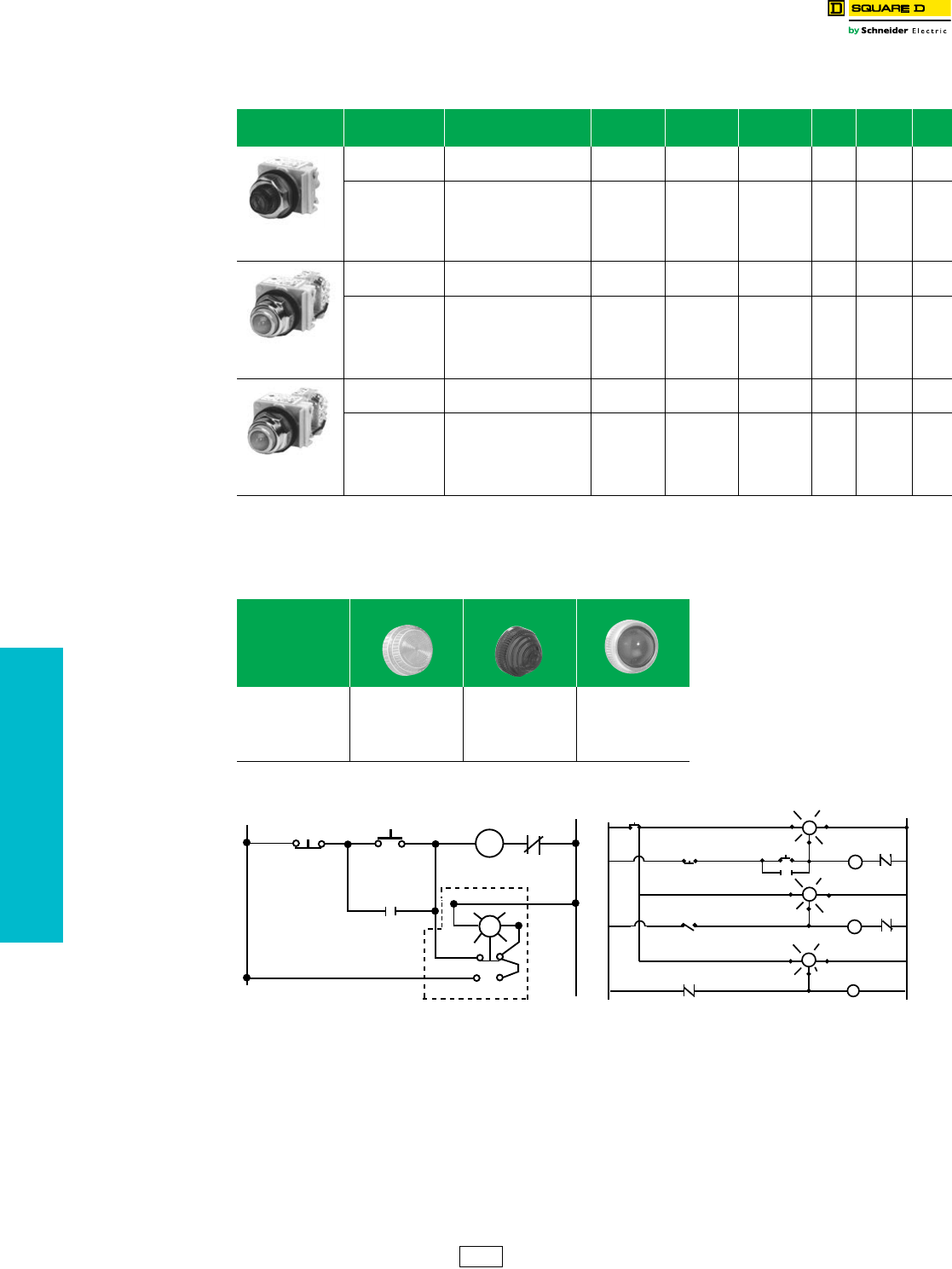
19-74 © 2012 Schneider Electric
All Rights Reserved
www.schneider-electric.us
19 PUSH BUTTONS AND
OPERATOR INTERFACE
30 mm Push Buttons Type K Heavy Duty Pilot Lights
Class 9001 / Refer to Catalog 9001CT1103
aAdd the voltage assembly code as chosen from Table 19.248 or Table 19.249 on 19-86. EXAMPLE: KTaR31 with 208 Vac red LED = KT37LRR31
bAdd the color code as chosen from Table 19.212. EXAMPLE: KP1b with a blue fresnel cap = KP1L31
cThe cap must be the same color as the LED light module chosen, e.g., for green LED, use green color cap.
dOn neon light modules, use clear color caps only.
eOn remote test pilot lights use only full voltage or resistor voltage assembly codes. Do not choose LED, neon or transformer codes. For AC use only.
NOTE: To select and order contact blocks, light modules, and accessories, see pages 19-85 through 19-92.
Table 19.211: Pilot Lights—UL Types 4, 13/NEMA 4 & 13
For use in hazardous locations—See page 19-87.
Legend plates not included.
Description Voltage Style
With Red
Fresnel Color
Cap
With Green
Fresnel Color
Cap
With Other
Color Cap $ Price Without
Color Cap $ Price
Standard Pilot Light
(Plastic Fresnel Color
Cap Shown)
110–120 V, 50–60 Hz
220–240 V, 50–60 Hz
24–28 Vac/Vdc
Tr a n s fo r m e r
Tr a n s fo r m e r
Full Voltage
KP1R31
KP7R31
KP35R31
KP1G31
KP7G31
KP35G31
KP1b
KP7b
KP35b
153.00
153.00
125.00
KP1
KP7
KP35
143.00
143.00
116.00
For other voltages
see page 19-86.
Transformer, Flashing or LED c
Full Voltage, Neon or Resistor d
KPaR31
KPaR31
KPaG31
KPaG31
KPab
KPab
153.00
125.00
KPa
KPa
143.00
116.00
Push-To-Test Pilot Light
(Glass Color Cap
Shown)
110–120 V, 50–60 Hz
220–240 V, 50–60 Hz
24–28 Vac/Vdc
Tr a n s fo r m e r
Tr a n s fo r m e r
Full Voltage
KT1R31
KT7R31
KT35R31
KT1G31
KT7G31
KT35G31
KT1b
KT7b
KT35b
197.00
197.00
167.00
KT1
KT7
KT35
185.00
185.00
158.00
For other voltages
see page 19-86.
Transformer, Flashing or LED c
Full Voltage, Neon or Resistor d
KTaR31
KTaR31
KTaG31
KTaG31
KTab
KTab
197.00
167.00
KTa
KTa
185.00
158.00
Remote Test Pilot Light
(Glass Color Cap
Shown)
120 Vac Only
24–28 Vac Only
for other voltages
Resistor e
Full Voltage e
KTR38R31
KTR35R31
KTR38G31
KTR35G31
KTR38b
KTR35b
197.00
197.00
KTR38
KTR35
185.00
185.00
See page 19-86.eFull Voltage or Resistor eKTRaR31 KTRaG31 KTR ab 197.00 KTRa185.00
Table 19.212: Color Caps
Color
Plastic Fresnel Plastic Domed Glass
Amber
Blue
Clear
Green
Red
White
Ye l l o w
A31
L31
C31
G31
R31
W31
Y31
A9
L9
C9
G9
R9
W9
Y9
A6
L6
C6
G6
R6
W6
Y6
R
M
MO.L.
L2
3
2
1
L1
STOP
START
L2
C
Test
L1
M
Push-To-Test Pilot Light
Typical Wiring Diagram
STOP
LSI
M3
(TEST) C
(TEST) C L2
L2
L1
(SIG) CR
M2
M1
L2
(TEST) C
START
TEST
BUTTON
L1 L2
L1
(SIG)
L1
(SIG)
Remote Test Pilot Light
CS1 Discount
Schedule
NOTE: When ordering, add prefix 9001 to the catalog number.
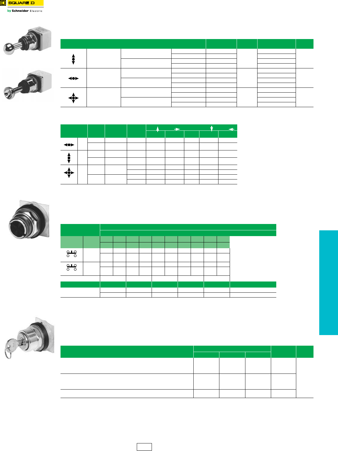
www.schneider-electric.us
19 PUSH BUTTONS AND
OPERATOR INTERFACE
© 2012 Schneider Electric
All Rights Reserved 19-75
30 mm Push Buttons Type K Heavy Duty Specialty Operators
Class 9001 / Refer to Catalog 9001CT1103
aThese operators can be ordered complete with contact blocks—a total of four (4) contact blocks can be used. Add the “H” number chosen from
page 19-88 to the operator type number and add the cost of the “H” number to the operator cost.
For use in hazardous locations—See page 19-87. Legend plate and contact block not included.
Inserts are field convertible. For colors not listed, order operator without insert, plus separate color insert from
page 19-92. Up to two Type KA contact blocks can be mounted in tandem (total of four blocks). Selector push buttons
cannot be illuminated.
bOrder color inserts from page 19-92.
cCams are not interchangeable.
For use in hazardous locations. See page 19-87. Key operated push buttons are used wherever unauthorized use of a
push button is discouraged. Examples are locking a Start push button in the extended position or locking a Stop push
button in the depressed position. The operator can also be locked in the flush position—holding all contacts open. Up to
two Type KA contact blocks can be mounted in tandem (total of four blocks).
Legend Plate and Contact Block Not Included (“X” = locked position) d
dAll key operated push buttons are furnished as standard with Square D no. E10 key change. See catalog 9001CT0001 for other key changes.
Without Latch
With Latch
Table 19.213: Joy Stick Operators—UL Types 4, 13/NEMA 4, 13
for use in hazardous locations. See page 19-87.
Contact blocks and legend plate not included unless noted.
Description Operator
With Contacts $ Price Operator
Without Contacts a$ Price
3 Position—
Center Off
Momentary Contact—
Spring Return to Center
Without Latch K71H7
326.00
K71
252.00
With Latch K70H7 K70
Maintained Contact Without Latch K73H7 K73
With Latch K72H7 K72
3 Position—
Center Off
Momentary Contact—
Spring Return to Center
Without Latch K31H8
326.00
K31
252.00
With Latch K30H8 K30
Maintained Contact Without Latch K33H8 K33
With Latch K32H8 K32
5 Position—
Center Off
Momentary Contact—
Spring Return to Center
Without Latch K35H2
435.00
K35
309.00
With Latch K34H2 K34
Maintained Contact Without Latch K37H2 K37
With Latch K36H2 K36
Table 19.214: Contact Arrangements
Operator
Positions
Contact
Block
Type
Contact
Block
Location
Contact
Handle position (with reference to Nib)
The joy stick operator is ideal for applications
where only one circuit is to be energized at one
time. The three position joy stick closes one
circuit in each Up-Down or Right-Left position
with all circuits open in center position. The five
position operator closes one circuit in each Up,
Down, Left and Right position with all circuits
open in center position.
Momentary contact operators are spring return to
the center position. Maintained operators remain
in position and must be returned manually.
Operators with latch cannot be operated until the
latch button in center of handle is pressed.
1 2 OFF 3 4
3
KA3 POS 1 (3) A — 1 0 — 0
KA3 POS 2 (4) A — 0 0 — 1
3
KA2 POS 1 (3) B 1 — 0 0 —
KA2 POS 2 (4) B 0 — 0 1 —
5
KA1 POS 1 (3) A 0 100 0
B 1 000 0
KA1 POS 2 (4) A 0 000 1
B 0 001 0
(1) Contact Closed (0) Contact Open
Table 19.215: Selector Push Button Operators—UL Types 4, 13/NEMA 4, 13
Contact Block
Required
Two Position Operators
0—Contact Open 1—Contact Closed F—Free D—Depressed
Quantity and
Type
Mount on
Side
Left Right Left Right Left Right Left Right Left Right
Order Contact Blocks
From Pages 19-85 and 19-87.
FD FD FD FD FD FD FD FD FD FD
1 KA1
#2
00 10 00 10 00 11 11 10 10 00
01 01 01 00 01 00 00 01 01 01
1 KA1
#1
00 11 00 10 11 00 10 11 11 00
01 00 01 00 00 01 01 00 00 01
Cam cPRSTY
Color Insert Type Type Type Type Type $ Price
Without Insert b Black KQ11 KQ12 KQ13 KQ14 KQ15 80.
KQ11B KQ12B KQ13B KQ14B KQ15B 81.
Table 19.216: Key Operated Push Button – UL Types 4, 13/NEMA 4, 13
Description Lockable Positions Type $ Price
Extended Flush Depressed
Push button operable only with key in lock. Key is removable in locked position only.
X
—
—
X
—
X
—
X
—
—
X
X
KR131
KR132
KR133
KR137
125.00
Push button operable with or without key in lock. Push button can be locked with key
only. Key removable in both locked or unlocked position.
X
—
—
X
—
X
—
X
—
—
X
X
KR141
KR142
KR143
KR147
To lock the unit, rotate the key with the button in the extended position. Then, push the
button to lock it in the position indicated at right. Key is removable only in this position.
—
—
X
—
—
X
KR152
KR153
Selector Push Button
9001KQ
Key Operated Push Button
9001KR
CS1 Discount
Schedule
NOTE: When ordering, add prefix 9001 to
the catalog number.
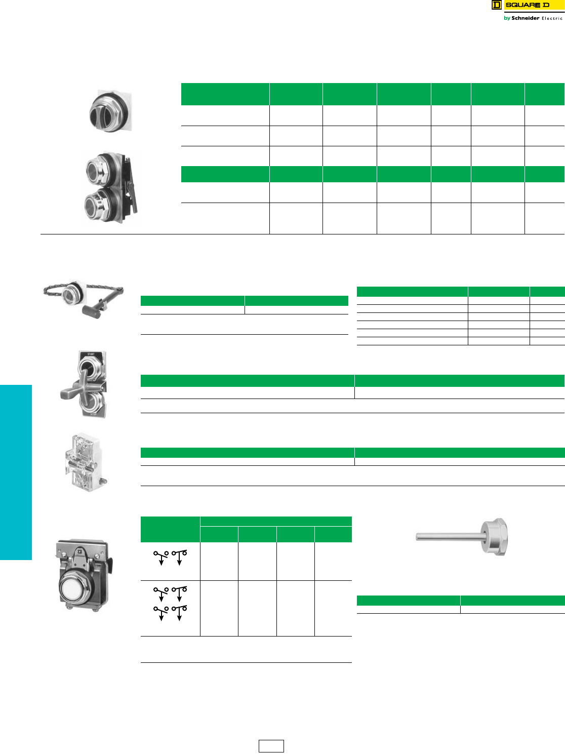
www.schneider-electric.us
19 PUSH BUTTONS AND
OPERATOR INTERFACE
19-76 © 2012 Schneider Electric
All Rights Reserved
30 mm Push Buttons Type K Heavy Duty Specialty Operators
Class 9001 / Refer to Catalog 9001CT1103
.
eFor enclosed versions see page 19-106.
Note: When mounted in top or bottom hole of a Type K enclosure, device
requires one additional space below or above operator. When mounted
other than in top or bottom hole, device may require two additional
spaces, one above and one below operator. Closing plates must be
installed on unused holes.
Table 19.217: Illuminated and Non-Illuminated Dual Operators
Meets UL Type 13/NEMA 13 and UL Type 6/NEMA 6, which
UL and NEMA consider an equivalent to UL Type 4/NEMA 4.
For use in hazardous locations—See page 19-87. Legend plate
and contact blocks not included unless otherwise noted.
9001KR7U
9001KR11U
Description Color
With 2 N.O.
Contacts
(2 KA2)
With 1 N.O. &
1 N.C. Contact
(KA2, KA3)
$ Price Without
Contacts d$ Price
Momentary
Dual
Function
Universal a
Green-Red
Other b
KR6UH7
KR6GRH7
KR6bH7
KR6UH37
KR6GRH37
KR6bH37
138.00
KR6U
KR6GR
KR6b
81.00
Momentary
Interlocked
Dual Function
Universala
Green-Red
Other b
KR67UH7
KR67GRH7
KR67bH7
KR67UH37
KR67GRH37
KR67bH37
184.00
KR67U
KR67GR
KR67b
125.00
Maintained
Interlocked
Dual Function
Universal a
Green-Red
Other b
KR7UH7
KR7GRH7
KR7bH7
KR7UH37
KR7GRH37
KR7bH37
184.00
KR7U
KR7GR
KR7b
125.00
Description Color Contacts (KA1) $ Price Without
Contacts d$ Price
Both Buttons
Maintained Interlocked
Assembly
Universal c
Other d—KR11UH1
KR11dH1 178.00 KR11U
KR11d120.00
One Button Momentary
One Button Maintained
Interlocked Assembly
Universal c
Otherd—KR12UH1H1
KR12dH1H1 273.00 KR12U
KR12d162.00
aUniversal for KR6, KR67, KR7 includes 2 inserts each of black, red and green.
bChoose one color for each button. R = red, G = green, B = Black. Example: 9001KR6 with left red and right black = 9001KR6RB. See Table 19.193.
cUniversal for KR11, KR12 includes 2 each of black, red, green, yellow, orange, blue, white.
dChoose one color for each button from Table 19.193 and insert color code in type number. Example: 9001KR11 with top button gray and bottom button orange = 9001KR11ES
Emergency Break-Glass
Operator 9001K15
Table 19.218: Emergency Break-Glass Operator—
UL 4, 13/NEMA 4, 13e
Type $ Price
K15 125.00
Operator is held in a depressed position by a glass disc. When the glass disc
is broken with the hammer, button returns to a normal extended position.
Package of 5 discs included with operator.
Table 19.219: 9001K15 Replacement Parts
Description Part Number $ Price
Yellow bumper 3105211101 14.30
Hammer and chain 3105206750 57.30
Lower ring nut 6512232801 16.70
Top ring nut 9001K40 4.40
Package of 5 replacement discs 9001K57 16.70
Clip to hold hammer 2540902240 2.60
Rocker Arm Operating
Lever 9001K50
Table 19.220: Rocker Arm Operating Lever
Type $ Price
K50 77.00
Allows two standard push buttons to be operated independently of each other. Price does not include push buttons or legend plates. Order push buttons and legend
plates from pages 19-67, 19-89, and 19-90—specify which marking is to be inverted.
Push-on Push-off Module
9001K85
Table 19.221: Alternate Action—Push-on, Push-off Module
Type $ Price
K85 42.80
This module can be added to standard 9001 Type K, KX, SK or T momentary push button operators. Contact blocks mounted behind this module (maximum of 2) are
held in the depressed position when the operator is pressed once, and released to their normal position when the operator is pressed again. For a N.C. circuit, use a
9001KA3 or the N.C. contact of either a 9001KA1 or 9001KA4. For a N.O. circuit, use the N.O. contact of either a 9001KA4 or 9001KA6.
Time Delay Push Button
9001KRD
Table 19.222: Off Delay Push Button—
UL Types 4, 13/NEMA 4, 13
Description
Type (All Colors)
Full
Guard
Extended
Guard
No
Guard $ Price
Timed Contact
1 N.O. and 1 N.C.
KRD1UH1 KRD2UH1 KRD3UH1 277.00
Timed Contact
2 N.O. and 2 N.C.
KRD1UH2 KRD2UH2 KRD3UH2 514.00
Timing period is adjustable from 0.1 second to 60 seconds and begins after button
has been released. Devices include a pack of seven color inserts for color coding
the push button. See 19-92 for Universal color insert. Contacts are quick make-
quick break.
Table 19.223: Wobble Stick
For easy operation of any standard
push button.
Type $ Price
K8 42.80
CS1 Discount
Schedule
NOTE: When ordering, add prefix 9001 to the catalog number.
www.schneider-electric.us
19 PUSH BUTTONS AND
OPERATOR INTERFACE
© 2012 Schneider Electric
All Rights Reserved 19-77
30 mm Push Buttons Type SK Corrosion Resistant Non-Illuminated Operators
Class 9001 / Refer to Catalog 9001CT1103
aThe universal push button operators include one each of the following color inserts: black, red, green, yellow, orange, blue and white.
bSee Table 19.225.
cKnob has the words “Emergency Stop” in raised letters highlighted in white for readability.
dSee Table 19.225.
eThese operators can be ordered complete with contact blocks. For maximum block usage, see page 19-88. Add the “H” number chosen from
page 19-88 to the end of the operator type number and add the cost of the “H” number to the operator cost.
NOTE: To select and order contact blocks, light modules, and accessories, see pages 19-85 through 19-92.
Table 19.224: Non-Illuminated Momentary Push Button Operators
UL Types 4, 4X, 13/NEMA 4, 4X, 13. For use in hazardous
locations—See page 19-87. Contact blocks and legend plate
not included unless otherwise noted.
Description Color
Operator with
1 N.O. and
1 N.C. Contact
(KA1)
$ Price
Operator with
1 N.O. Contact
(KA2)
Operator with
1 N.C. Contact
(KA3)
$ Price Operator Only
No Contacts e$ Price
9001SKR1B
Full Guard
Black SKR1BH13 89.00 SKR1BH5 SKR1BH6 66.00 SKR1B 38.60
Red SKR1RH13 89.00 SKR1RH5 SKR1RH6 66.00 SKR1R 38.60
Green SKR1GH13 89.00 SKR1GH5 SKR1GH6 66.00 SKR1G 38.60
Universal aSKR1UH13 89.00 SKR1UH5 SKR1UH6 66.00 SKR1U 38.60
Other bSKR1bH13 89.00 SKR1bH5 SKR1bH6 66.00 SKR1b38.60
9001SKR3B
No Guard
Black SKR3BH13 89.00 SKR3BH5 SKR3BH6 66.00 SKR3B 38.60
Red SKR3RH13 89.00 SKR3RH5 SKR3RH6 66.00 SKR3R 38.60
Green SKR3GH13 89.00 SKR3GH5 SKR3GH6 66.00 SKR3G 38.60
Universal aSKR3UH13 89.00 SKR3UH5 SKR3UH6 66.00 SKR3U 38.60
Other bSKR3bH13 89.00 SKR3bH5 SKR3bH6 66.00 SKR3b38.60
9001SKR2B
Extended Guard
Black SKR2BH13 89.00 SKR2BH5 SKR2BH6 66.00 SKR2B 38.60
Red SKR2RH13 89.00 SKR2RH5 SKR2RH6 66.00 SKR2R 38.60
Green SKR2GH13 89.00 SKR2GH5 SKR2GH6 66.00 SKR2G 38.60
Universal aSKR2UH13 89.00 SKR2UH5 SKR2UH6 66.00 SKR2U 38.60
Other bSKR2b89.00 SKR2bH5 SKR2bH6 66.00 SKR2b38.60
9001SKR4B
1-3/8 in. (35 mm)
Mushroom Button
Snap-In Mushroom Button
Black SKR4BH13 138.00 SKR4BH5 SKR4BH6 112.00 SKR4B 81.00
Red SKR4RH13 138.00 SKR4RH5 SKR4RH6 112.00 SKR4R 81.00
Red cSKR4R05H13 142.00 SKR4R05H5 SKR4R05H6 119.00 SKR4R05 86.00
Green SKR4GH13 138.00 SKR4GH5 SKR4GH6 112.00 SKR4G 81.00
Other dSKR4dH13 138.00 SKR4dH5 SKR4dH6 112.00 SKR4d81.00
Screw-On Mushroom Button with Set Screw Security
Black SKR24BH13 138.00 SKR24BH5 SKR24BH6 112.00 SKR24B 81.00
Red SKR24RH13 138.00 SKR24RH5 SKR24RH6 112.00 SKR24R 81.00
Green SKR24GH13 138.00 SKR24GH5 SKR24GH6 112.00 SKR24G 81.00
Other dSKR24dH13 138.00 SKR24dH5 SKR24dH6 112.00 SKR24d81.00
9001SKR5
2-1/4 in. (57 mm)
Mushroom Button
Snap-In Mushroom Button, Plastic Head
Black SKR5BH13 138.00 SKR5BH5 SKR5BH6 112.00 SKR5B 81.00
Red SKR5RH13 138.00 SKR5RH5 SKR5RH6 112.00 SKR5R 81.00
Red cSKR5R05H13 142.00 SKR5R05H5 SKR5R05H6 119.00 SKR5R05 86.00
Green SKR5GH13 138.00 SKR5GH5 SKR5GH6 112.00 SKR5G 81.00
Other dSKR5dH13 138.00 SKR5dH5 SKR5dH6 112.00 SKR5d81.00
Screw-On Mushroom Button with Set Screw Security, Plastic Head
Black SKR25BH13 138.00 SKR25BH5 SKR25BH6 112.00 SKR25B 81.00
Red SKR25RH13 138.00 SKR25RH5 SKR25RH6 112.00 SKR25R 81.00
Green SKR25GH13 138.00 SKR25GH5 SKR25GH6 112.00 SKR25G 81.00
Other dSKR25dH13 138.00 SKR25dH5 SKR25dH6 112.00 SKR25d81.00
Table 19.225: Color Codes
Color b SKR1, 2, 3 Place Color Code in Type Number d SKR4, 5, 24, 25 Place Color Code in Type Number
Blue L L
Ye l l o w Y Y
White W —
Orange S S
Gray E —
CS1 Discount
Schedule
NOTE: When ordering, add prefix 9001 to the catalog number.
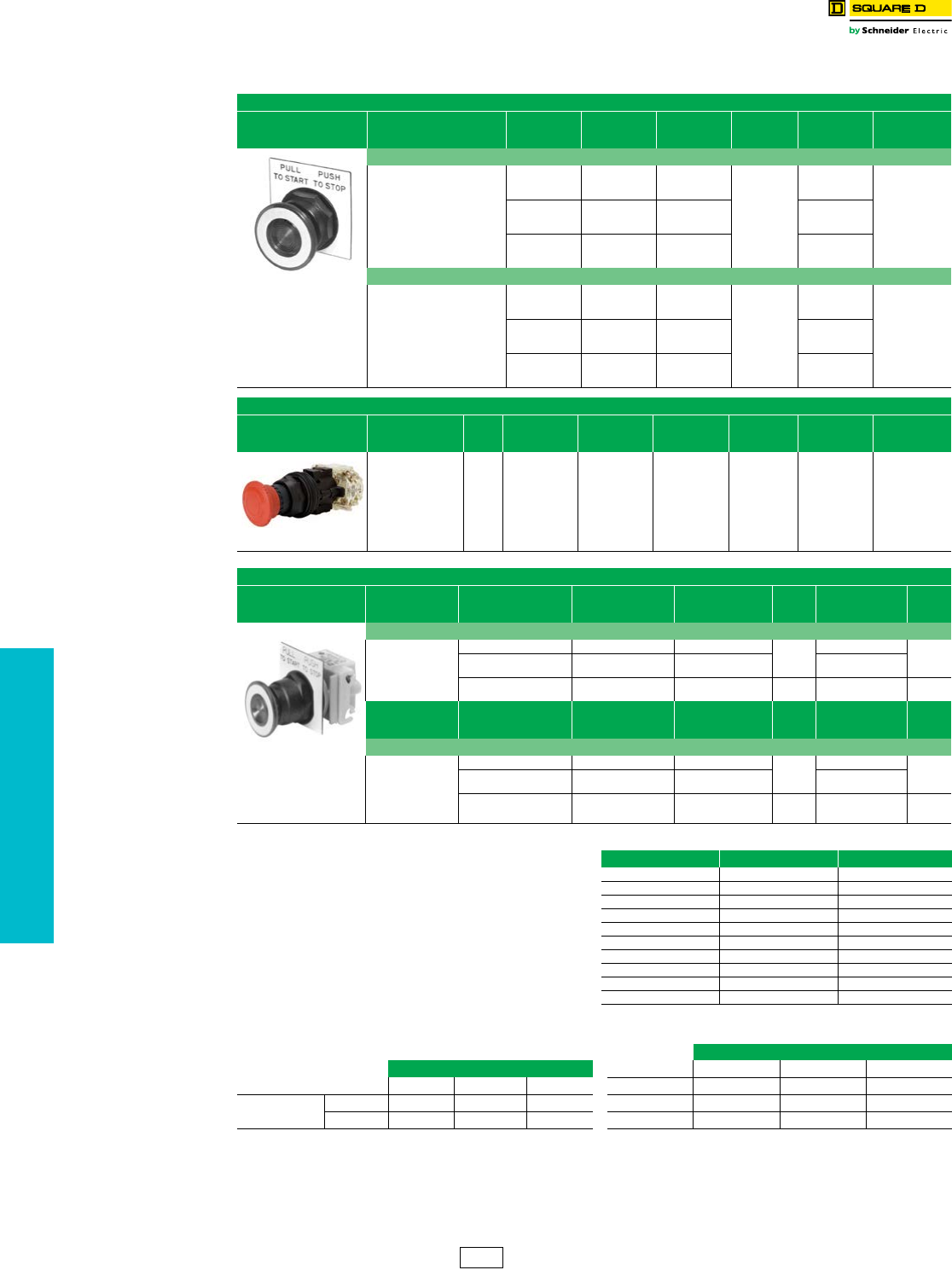
www.schneider-electric.us
19 PUSH BUTTONS AND
OPERATOR INTERFACE
19-78 © 2012 Schneider Electric
All Rights Reserved
30 mm Push Buttons Type SK Corrosion Resistant Multifunction Operators
Class 9001 / Refer to Catalog 9001CT1103
fTo obtain a red knob with “Push Emergency Stop” printed on the red
knob—substitute R05 in place of “R” and add $2.10 to the price.
gChoose one color from Table 19.227 and insert the color code in the
Type number. Example: SKR9g with a yellow knob = SKR9Y
hAdd the voltage assembly code as chosen from page 19-86.
Example: SKR8Ph with 277 V 50–60 Hz = SKR8P8
iThe knob must be the same color as the LED light module chosen; e.g.,
for green LED, use green knob.
jOn neon light modules, use clear knobs only.
kThese operators can be ordered complete with contact blocks. For
maximum block usage, see page 19-88. Add the “H”
number chosen from page 19-88 to the end of the operator type
number and add the cost of the “H” number to the operator cost.
lSKR11UH1 has 1 KA1(1 N.O., 1 N.C.) and SKR12UH1H1 has 2 KA1
(2 N.O., 2 N.C.).
mFor positions, refer to Tables 19.228 and 19.229. nThese colors are not available on illuminated push-pull operators.
NOTE: To select and order contact blocks, light modules, and accessories, see pages 19-85 through 19-92.
Table 19.226: 30 mm Multifunction Operators
UL Types 4, 4X, 13/NEMA 4, 4X, 13
Non-Illuminated Push-Pull Screw-on Mushroom Operators, Plastic Head
Description Color
With 2 N.C.
Contacts
(1 KA3, 1 KA5)
With 1 N.O./1
N.C.
Contact (1 KA1)
$ Price Without
Contacts k$Price
9001SKR9R
Non-Illuminated
1-5/8 in. Diameter Knob
Includes Type KN179WP
Legend Plate Marked
Pull To Start Push To Stop
3 Position
Momentary Pull-
Maintained Neutral-
Momentary Push j
Red SKR8RH25 —
142.00
SKR8R
86.00Green SKR8GH25 —SKR8G
Other gSKR8gH25 — SKR8g
2 Positionf
Maintained Pull-
Maintained Push
Red — SKR9RH13
188.00
SKR9R
129.00Green — SKR9GH13 SKR9G
Other g—SKR9gH13 SKR9g
Non-Illuminated Turn-to-Release Mushroom Operators
Description Color
With 1 N.O.
Contact
(KA1)
$ Price
With 2 N.O./2
N.C. Contacts
(2 KA1)
$ Price Without
Contacts $Price
9001SKR16H2
2 Position,
Plastic Head
Turn-to-Release
Tr i gge r Act i o n
Red SKR16H13 172.00 SKR16H2 218.00 SKR16 113.00
Screw-On Plastic Illuminated Push-Pull Mushroom Operators
Illuminated Description Voltage
With Red Knob and 2
N.C. Contacts
(1 KA3, 1 KA5)
With Other Color
Knob and 2 N.C.
Contacts
$ Price
With Other Color
Knob Without
Contacts k
$ Price
9001SKR9P1
Illuminated
1-5/8 in. Diameter Knob
Includes Type KN179WP
Legend Plate Marked
Pull to Start Push To Stop
3 Position
Momentary Pull-
Maintained Neutral-
Momentary Push m
110–120 V, 50–60 Hz SKR8P1RH25 SKR8P1gH25
267.00
SKR8P1g
201.00
Other—Transformer,
LED, Flashing iSKR8PhRH25 SKR8PhgH25 SKR8Phg
Other—Full Voltage,
Resistor, Neon jSKR8PhRH25 SKR8PhgH25 215.00 SKR8Phg 171.00
Description Voltag e
With Red f Knob and
1 N.O. & 1 N.C.
Contact (KA1)
With Other Color
Knob and 1 N.O. & 1
N.C. Contact (KA1)
$ Price
With Other Color
Knob Without
Contacts
$ Price
2 Position
Maintained Pull-
Maintained Push
110–120 V, 50–60 Hz SKR9P1RH13 SKR9P1gH13
316.00
SKR9P1g
243.00
Other—Transformer,
L.E.D., Flashing iSKR9PhRH13 SKR9PhgH13 SKR9Phg
Other—Full Voltage,
Resistor, Neon jSKR9PhRH13 SKR9PhgH13 257.00 SKR9Phg 215.00
Table 19.227: Color Codes
Color SKR11, SKR12 SKR8, SKR9
Black nBB
Red R R
Green G G
Blue L L
Yellow Y Y
White W W
Orange nSS
Clear — C
Amber — A
Gray E —
Table 19.228: Positions for 9001SKR8RH1 or H13 Table 19.229: Positions for 9001SKR8H25
9001SKR8H25
9001SKR8RH1 or H13 PULL CTR PUSH
PULL CTR PUSH KA3 XOO
(KA1) KA3 XOO KA5 XXO
KA2 OOX KA2 OOX
CS1 Discount
Schedule
NOTE: When ordering, add prefix 9001 to the catalog number.
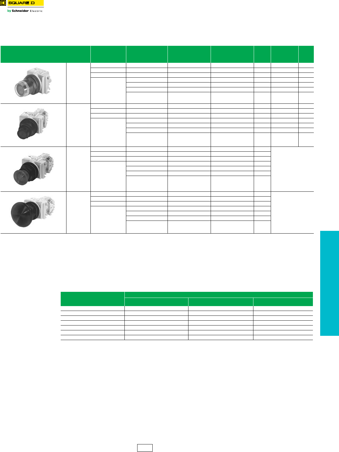
www.schneider-electric.us
19 PUSH BUTTONS AND
OPERATOR INTERFACE
© 2012 Schneider Electric
All Rights Reserved 19-79
30 mm Push Buttons Type SK Corrosion Resistant Illuminated Operators
Class 9001 / Refer to Catalog 9001CT1103
NOTE: To select and order contact blocks, light modules, and accessories, see pages 19-85 through 19-92.
Table 19.230: Illuminated Push Button Operators
UL Types 4, 4X, 13/NEMA 4, 4X, 13
For use in hazardous locations—See page 19-87.
Legend plate not included unless otherwise noted.
Description Voltage and
Frequency Style
With Red Color Cap and
1 N.O. and 1 N.C. Contact
(KA1)
With Green Color Cap and
1 N.O.and 1 N.C. Contact
(KA1)
$ Price g
With Other Color
Cap Without
Contact Blocks
a
$ Price h
9001SK1L1
Full Guard
Illuminated
Push Button
110–120 V, 50–60 Hz Transformer SK1L1RH13 SK1L1GH13 231.00 SK1L1 158.00
220–240 V, 50–60 Hz Transformer SK1L7RH13 SK1L7GH13 231.00 SK1L7 158.00
24–28 Vac/Vdc Full Voltage SK1L35RH13 SK1L35GH13 198.00 SK1L35 129.00
For other voltages
See Table b
Transformer, Flashing SK1LbRH13 SK1LbGH13 231.00 SK1L b158.00
Full Voltage SK1LbRH13 SK1LbGH13 198.00 SK1L b129.00
Resistor, Neon cSK1LbRH13 SK1LbGH13 198.00 SK1L b129.00
LED eSK1LbRH13 SK1LbGH13 231.00 SK1L bd 158.00
9001SK2L1
No Guard
Illuminated
Push Button
110–120 V, 50–60 Hz Transformer SK2L1RH13 SK2L1GH13 217.00 SK2L1 143.00
220–240 V, 50–60 Hz Transformer SK2L7RH13 SK2L7GH13 217.00 SK2L7 143.00
24–28 Vac/Vdc Full Voltage SK2L35RH13 SK2L35GH13 184.00 SK2L35 116.00
For other voltages
See Table b
Transformer, Flashing SK2LbRH13 SK2LbGH13 217.00 SK2L b143.00
Full Voltage SK2LbRH13 SK2LbGH13 184.00 SK2L b116.00
Resistor, Neon cSK2LbRH13 SK2LbGH13 184.00 SK2L b116.00
LEDeSK2LbRH13 SK2LbGH13 217.00 SK2L bd 143.00
9001SK2L1R20
1-3/8 in.
(35 mm)
Illuminated
Mushroom,
Screw-On
Plastic Head
110–120 V, 50–60 Hz Transformer SK2L1R20H13 SK2L1G20H13 217.00
Order SK2Lbdf
220–240 V, 50–60 Hz Transformer SK2L7R20H13 SK2L7G20H13 217.00
24–28 Vac/Vdc Full Voltage SK2L35R20H13 SK2L35G20H13 184.00
For other voltages
See Table b
Transformer, Flashing SK2LbR20H13 SK2LbG20H13 217.00
Full Voltage SK2LbR20H13 SK2LbG20H13 184.00
Resistor, Neon cSK2LbR20H13 SK2LbG20H13 184.00
LED eSK2LbR20H13 SK2LbG20H13 217.00
9001SK2L1R21
2-1/4 in.
(57 mm)
Illuminated
Mushroom,
Screw-On
Plastic Head
110–120 V, 50–60 Hz Transformer SK2L1R21H13 SK2L1G21H13 217.00
Order SK2Lbdf
220–240 V, 50–60 Hz Transformer SK2L7R21H13 SK2L7G21H13 217.00
24–28 Vac/Vdc Full Voltage SK2L35R21H13 SK2L35G21H13 184.00
For other voltages
See Table b
Transformer, Flashing SK2LbR21H13 SK2LbG21H13 217.00
Full Voltage SK2LbR21H13 SK2LbG21H13 184.00
Resistor, Neon cSK2LbR21H13 SK2LbG21H13 184.00
LED eSK2LbR21H13 SK2LbG21H13 217.00
aThese operators can be ordered complete with contact blocks. For maximum block usage, see page 19-88. Add the “H” number chosen from page 19-88 to the end of the operator type
number and add the cost of the “H” number to the operator cost.
bAdd the voltage assembly code as chosen from page 19-86. EXAMPLE: SK2Lb with 240 Vac/Vdc = SK2L25.
cOn neon light modules, use clear color caps only.
dThe cap must be the same color as the LED light module chosen e.g., for red LED, use red color cap.
eAdd the color code as chosen from the color cap table below. EXAMPLE: SK2L25e with a blue 1-3/8 in. mushroom button = SK2L25L20.
fThe only difference between a no guard (SK2L) operator and mushroom button operator is the color cap.
gPrice includes operator, light module, contact blocks and color cap.
hPrice includes operator, light module and color cap.
Table 19.231: Color Caps
Color
Color Codes
SK1L/SK2L 1-3/8 in. (35 mm) Mushroom 2-1/4 in. (57 mm) Mushroom
Red R R20 R21
Green G G20 G21
Blue L L20 L21
Yellow Y Y20 Y21
White W W20 W21
Clear C C20 C21
Amber A A20 A21
CS1 Discount
Schedule
NOTE: When ordering, add prefix 9001 to the catalog number.
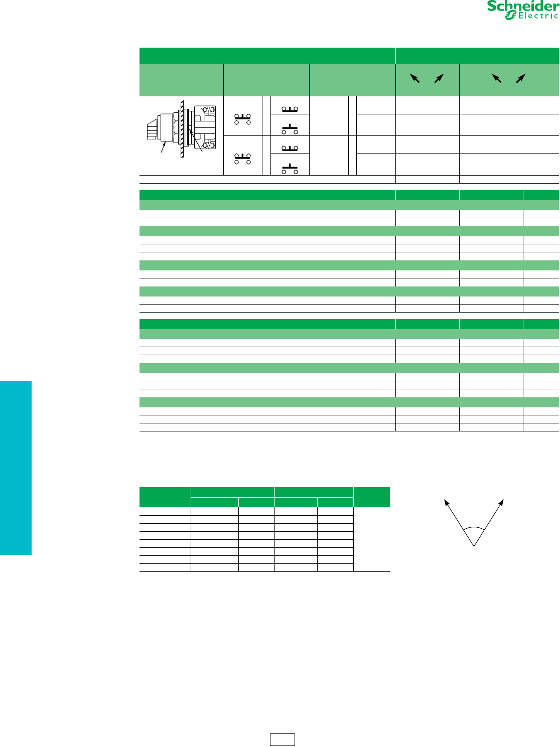
www.schneider-electric.us
19 PUSH BUTTONS AND
OPERATOR INTERFACE
19-80 © 2012 Schneider Electric
All Rights Reserved
30 mm Push Buttons 9001SK Selector Switches
Class 9001 / Refer to Catalog 9001CT1103
NOTE: To select and order Contact Blocks, Light Modules, Knobs, and Accessories. See pages 19-85 through 19-92.
Table 19.232: 2-Position Selector Switches
Contact Block Required 1—Contact Closed
0—Contact Open
Contact Block Position Quantity and Type
KA1 or KA2 or KA3
Mount on Side
KA1 or KA2 or KA3
Left Right Left Right
KA1
or
KA3
KA1
#2 or
KA3
#2 100 1
KA2 KA2
#2 011 0
KA1
or
KA3
KA1
#1 or
KA3
#1 100 1
KA2 KA2
#1 011 0
Cam (see page 19-73) ED
Non-Illuminated Operators Type Type $ Price
Manual Return a, Operator Only (without contact blocks)
Without Knob SKS11 SKS12 42.80
With Knob (select style and color from Table 19.233 below) SKS11cSKS12c53.00
Operator with Contact Blocks and Standard black knob
With 1 KA1 on Side #2 SKS11BH13 —106.00
With 1 KA1 on Side #1 SKS11BH1 —106.00
With 1 KA1 on Side #1 and 1 KA1 on side #2 SKS11BH2 —152.00
Spring Return from Left a, Operator Only (without contact blocks)
Without Knob SKS25 —71.00
With Knob (select style and color from Table 19.233 below) SKS25c—81.00
Spring Return from Right a, Operator Only (without contact blocks)
Without Knob —SKS34 71.00
With Knob (select style and color from Table 19.233 below) — SKS34c81.00
Illuminated Operators Type Type $ Price
Manual Return a, Operator Only (without contact blocks)
Without Knob, 110-120V 50-60 Hz Transformer SK11J1 SK12J1 158.00
With Standard Red Knob, 110-120V 50-60 Hz Transformer SK11J1R SK12J1R 167.00
With Other Color Knob and other voltage Light Module b cSK11Jbc SK12Jbc 167.00
Spring Return from Left a, Operator Only (without contact blocks)
Without Knob, 110-120V 50-60 Hz Transformer SK25J1 —185.00
With Standard Red Knob, 110-120V 50-60 Hz Transformer SK25J1R —197.00
With Other Color Knob and other voltage Light Module b cSK25Jbc —197.00
Spring Return from Right a, Operator Only (without contact blocks)
Without Knob, 110-120V 50-60 Hz Transformer — SK34J1 185.00
With Standard Red Knob, 110-120V 50-60 Hz Transformer — SK34J1R 197.00
With Other Color Knob and other voltage Light Module b c— SK34Jbc 197.00
aThese operators can be ordered complete with contact blocks. Add the "H code" from page 19-88 as needed for your application.
bAdd the voltage assembly code as chosen from page 19-86. Example: K25Jb with 208Vac = K25J3
cAdd the knob color code from Table 19.233. For LED, knob color must match LED.
Table 19.233: Selector Switch Assembly Code and Knob Cat. No.
Color Standard Knob Gloved Hand Knob $ Price
c Knob Code Cat. No. c Knob Code Cat. No.
Black B B11 FB B25
9.90
Red R R8 FR R24
Green G G8 FG G24
Yellow Y Y8 FY Y24
Blue L L8 FL L24
White W W8 FW W24
Amber A A8 FA A24
Clear C C8 FC C24
Side 2
Side 1
Operator Locating
70
2 Position
CS1 Discount
Schedule
Top View
NOTE: When ordering, add prefix 9001 to the catalog number.
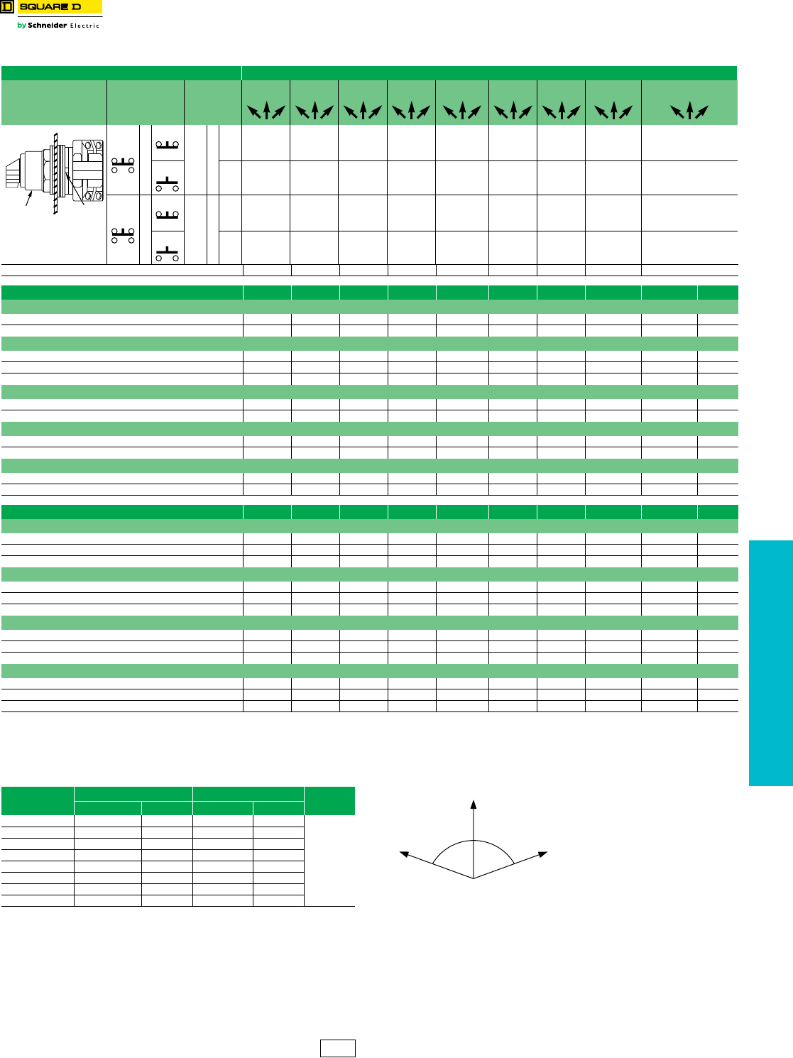
www.schneider-electric.us
19 PUSH BUTTONS AND
OPERATOR INTERFACE
© 2012 Schneider Electric
All Rights Reserved 19-81
30 mm Push Buttons 9001SK Selector Switches
Class 9001 / Refer to Catalog 9001CT1103
NOTE: To select and order Contact Blocks, Light Modules, Knobs, and Accessories. See pages 19-85 through 19-92.
Table 19.234: 3-Position Selector Switches
Contact Block Required 1 — Contact Closed 0 — Contact Open
Contact
Block
Position
Quantity
and
Type
Mount
on
Side
Center Center Center Center Center Center Center Center Center
KA1
or
KA3
KA1
#2 or
KA3
#2 1001000011001 0 0100100 0 1 0 1 10
KA2 KA2
#2 0110010100100 0 1011011 1 0 0 0 01
KA1
or
KA3
KA1
#1 or
KA3
#1 0011000011000 1 0001101 0 0 1 0 11
KA2 KA2
#1 1100010100100 0 1100010 0 1 0 1 00
Cam (see page 19-73) B C D E F G J L M
Non-Illuminated Operators Type Type Type Type Type Type Type Type Type $ Price
Manual Return, Operator Only (without contact blocks) a
Without Knob SKS42 SKS43 SKS44 SKS45 SKS46 SKS47 SKS49 SKS401 SKS402 42.80
With Knob (select style and color from Table 19.235 below) SKS42cSKS43cSKS44cSKS45cSKS46cSKS47cSKS49cSKS401cSKS402c53.00
Operator with Contact Blocks and Standard black knob d
With 1 KA1 on Side #2 (H13) SKS42BH13 SKS43BH13 SKS44BH13 SKS45BH13 SKS46BH13 SKS47BH13 SKS49BH13 SKS401BH13 SKS402BH13 106.00
With 1 KA1 on Side #1 (H1) SKS42BH1 SKS43BH1 SKS44BH1 SKS45BH1 SKS46BH1 SKS47BH1 SKS49BH1 SKS401BH1 SKS402BH1 106.00
With 1 KA1 on Side #1 and 1 KA1 on side #2 (H2) SKS42BH2 SKS43BH2 SKS44BH2 SKS45BH2 SSKS46BH2 SKS47BH2 SKS49BH2 SKS401BH2 SKS402BH2 152.00
Spring Return from Left to Center, Operator Only (without contact blocks) a
Without Knob SKS62 SKS63 SKS64 SKS65 SKS66 SKS67 SKS69 SKS601 SKS602 71.00
With Knob (select style and color from Table 19.235 below) SKS62cSKS63cSKS64cSKS65cSKS66cSKS67cSKS69cSKS601cSKS602c81.00
Spring Return from Right to Center, Operator Only (without contact blocks) a
Without Knob SKS72 SKS73 SKS74 SKS75 SKS76 SKS77 SKS79 SKS701 SKS702 71.00
With Knob (select style and color from Table 19.235 below) SKS72cSKS73cSKS74cSKS75cSKS76cSKS77cSKS79cSKS701cSKS702c81.00
Spring Return from Both Sides to Center, Operator Only (without contact blocks) a
Without Knob SKS52 SKS53 SKS54 SKS55 SKS56 SKS57 SKS59 SKS501 SKS502 71.00
With Knob (select style and color from Table 19.235 below) SKS52cSKS53cSKS54cSKS55cSKS56cSKS57cSKS59cSKS501cSKS502c81.00
Illuminated Operators Type Type Type Type Type Type Type Type Type $ Price
Manual Return, Operator Only (without contact blocks) a
Without Knob, 110-120V 50-60 Hz Transformer SK42J1 SK43J1 SK44J1 SK45J1 SK46J1 SK47J1 SK49J1 SK401J1 SK402J1 158.00
With Standard Red Knob, 110-120V 50-60 Hz Transformer SK42J1R SK43J1R SK44J1R SK45J1R SK46J1R SK47J1R SK49J1R SK401J1R SK402J1R 167.00
With Other Color Knob and other voltage Light Module b cSK42Jbc SK43Jbc SK44Jbc SK45Jbc SK46Jbc SK47Jbc SK49Jbc SK401Jbc SK402Jbc 167.00
Spring Return from Left to Center, Operator Only (without contact blocks) a
Without Knob, 110-120V 50-60 Hz Transformer SK62J1 SK63J1 SK64J1 SK65J1 SK66J1 SK67J1 SK69J1 SK601J1 SK602J1 185.00
With Standard Red Knob, 110-120V 50-60 Hz Transformer SK62J1R SK63J1R SK64J1R SK65J1R SK66J1R SK67J1R SK69J1R SK601J1R SK602J1R 197.00
With Other Color Knob and other voltage Light Module b cSK62Jbc SK63Jbc SK64Jbc SK65Jbc SK66Jbc SK67Jbc SK69Jbc SK601Jbc SK602Jbc 197.00
Spring Return from Right to Center, Operator Only (without contact blocks) a
Without Knob, 110-120V 50-60 Hz Transformer SK72J1 SK73J1 SK74J1 SK75J1 SK76J1 SK77J1 SK79J1 SK701J1 SK702J1 185.00
With Standard Red Knob, 110-120V 50-60 Hz Transformer SK72J1R SK73J1R SK74J1R SK75J1R SK76J1R SK77J1R SK79J1R SK701J1R SK702J1R 197.00
With Other Color Knob and other voltage Light Module b cSK72Jbc SK73Jbc SK74Jbc SK75Jbc SK76Jbc SK77Jbc SK79Jbc SK701Jbc SK702Jbc 197.00
Spring Return from Both Sides to Center, Operator Only (without contact blocks) a
Without Knob, 110-120V 50-60 Hz Transformer SK52J1 SK53J1 SK54J1 SK55J1 SK56J1 SK57J1 SK59J1 SK501J1 SK502J1 185.00
With Standard Red Knob, 110-120V 50-60 Hz Transformer SK52J1R SK53J1R SK54J1R SK55J1R SK56J1R SK57J1R SK59J1R SK501J1R SK502J1R 197.00
With Other Color Knob and other voltage Light Module b cSK52Jbc SK53Jbc SK54Jbc SK55Jbc SK56Jbc SK57Jbc SK59Jbc SK501Jbc SK502Jbc 197.00
aThese operators can be ordered complete with contact blocks. Add the "H code" from page 19-88 as needed for your application.
bAdd the voltage assembly code as chosen from page 19-86. Example: K25Jb with 208Vac = K25J3.
cAdd the knob color code from Table 19.235 below. For LED, knob color must match LED.
dFor other color knobs replace the B with knob color code from Table 19.235 below.
Top View
Side 2
Side 1
Operator Locating
Notch
Table 19.235: Selector Switch Assembly Code and Knob Cat. No.
Color Standard Knob Gloved Hand Knob $ Price
c Knob Code Cat. No. c Knob Code Cat. No.
Black B B11 FB B25
9.90
Red R R8 FR R24
Green G G8 FG G24
Yellow Y Y8 FY Y24
Blue L L8 FL L24
White W W8 FW W24
Amber A A8 FA A24
Clear C C8 FC C24
70 70
3 Position
CS1 Discount
Schedule
NOTE: When ordering, add prefix 9001 to the catalog number.
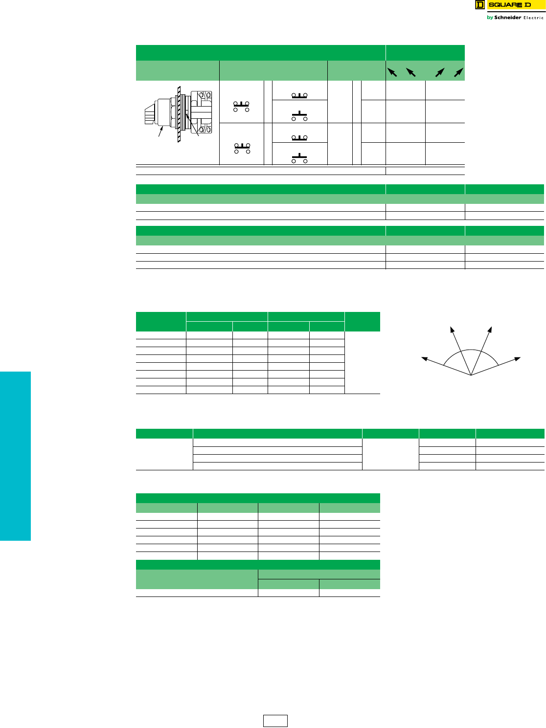
www.schneider-electric.us
19 PUSH BUTTONS AND
OPERATOR INTERFACE
19-82 © 2012 Schneider Electric
All Rights Reserved
30 mm Push Buttons 9001SK Selector Switches
Class 9001 / Refer to Catalog 9001CT1103
Potentiometers with Dial Plate
Any potentiometer with a shaft 7/8 in. long and 1/4 in. diameter may be used with these operators.
NOTE: To select and order Contact Blocks, Light Modules, Knobs, and Accessories. See pages 19-85 through 19-92.
Table 19.236: 4-Position Selector Switches
Contact Block Required 1 — Contact Closed
0 — Contact Open
Contact Block Position Quantity and Type Mount on Side
KA1
or
KA3
KA1
#2
or
KA3
#2 1000
KA2 KA2
#2 0010
KA1
or
KA3
KA1
#1 or
KA3
#1 0001
KA2 KA2
#1 0100
Cam (see page 19-73) H
Non-Illuminated Operators Type $ Price
Manual Return a, Operator Only (without contact blocks)
Without Knob SKS88 42.80
With Knob (select style and color from Table 19.237 below) SKS88c52.65
Illuminated Operators Type $ Price
Manual Return a, Operator Only (without contact blocks)
Without Knob, 110-120V 50-60 Hz Transformer SK88J1 158.00
With Standard Red Knob, 110-120V 50-60 Hz Transformer SK88J1R 167.00
With Other Color Knob and other voltage Light Module b cSK88Jbc 167.00
aThese operators can be ordered complete with contact blocks. Add the "H code" from page 19-88 as needed for your application.
bAdd the voltage assembly code as chosen from page 19-86. Example: K25Jb with 208Vac = K25J3
cAdd the knob color code from Table 19.237. For LED, knob color must match LED
Table 19.237: Selector Switch Assembly Code and Knob Cat. No.
Color Standard Knob Gloved Hand Knob $ Price
c Knob Code Cat. No. c Knob Code Cat. No.
Black B B11 FB B25
9.90
Red R R8 FR R24
Green G G8 FG G24
Yellow Y Y8 FY Y24
Blue L L8 FL L24
White W W8 FW W24
Amber A A8 FA A24
Clear C C8 FC C24
Table 19.238: Potentiometers with Dial Plate (not UL listed)—Maximum Voltage 300 Vac
Power Description Ratings Type $ Price
2 W
Operator Only, for Single Potentiometer
NEMA 4, 13
SK20 201.00
Operator with Single Potentiometer SK21 287.00
Operator Only, for Tandem Potentiometer SK22 314.00
Operator with Tandem Potentiometer SK23 399.00
Table 19.239: Potentiometer Suffixes
Single Potentiometer
Suffix dResistance Suffix dResistance
01 50 Ω 07 5 kΩ
02 100 Ω 08 10 kΩ
04 500 Ω 09 25 kΩ
05 1 kΩ 13 500 kΩ
39 2 kΩ 37 750 kΩ
06 2.5 kΩ 14 1 MΩ
Tandem Potentiometer
Suffix dResistance
Front Rear
82 1 kΩ 1 kΩ
dFor the complete part number, add the suffix from Table 19.239 to the catalog number
from Table 19.238. Example: 9001K2105.
Top View
Side 2
Side 1
Operator Locating
Notch
47 47
46
4 Position
CS1 Discount
Schedule
NOTE: When ordering, add prefix 9001 to the catalog number.
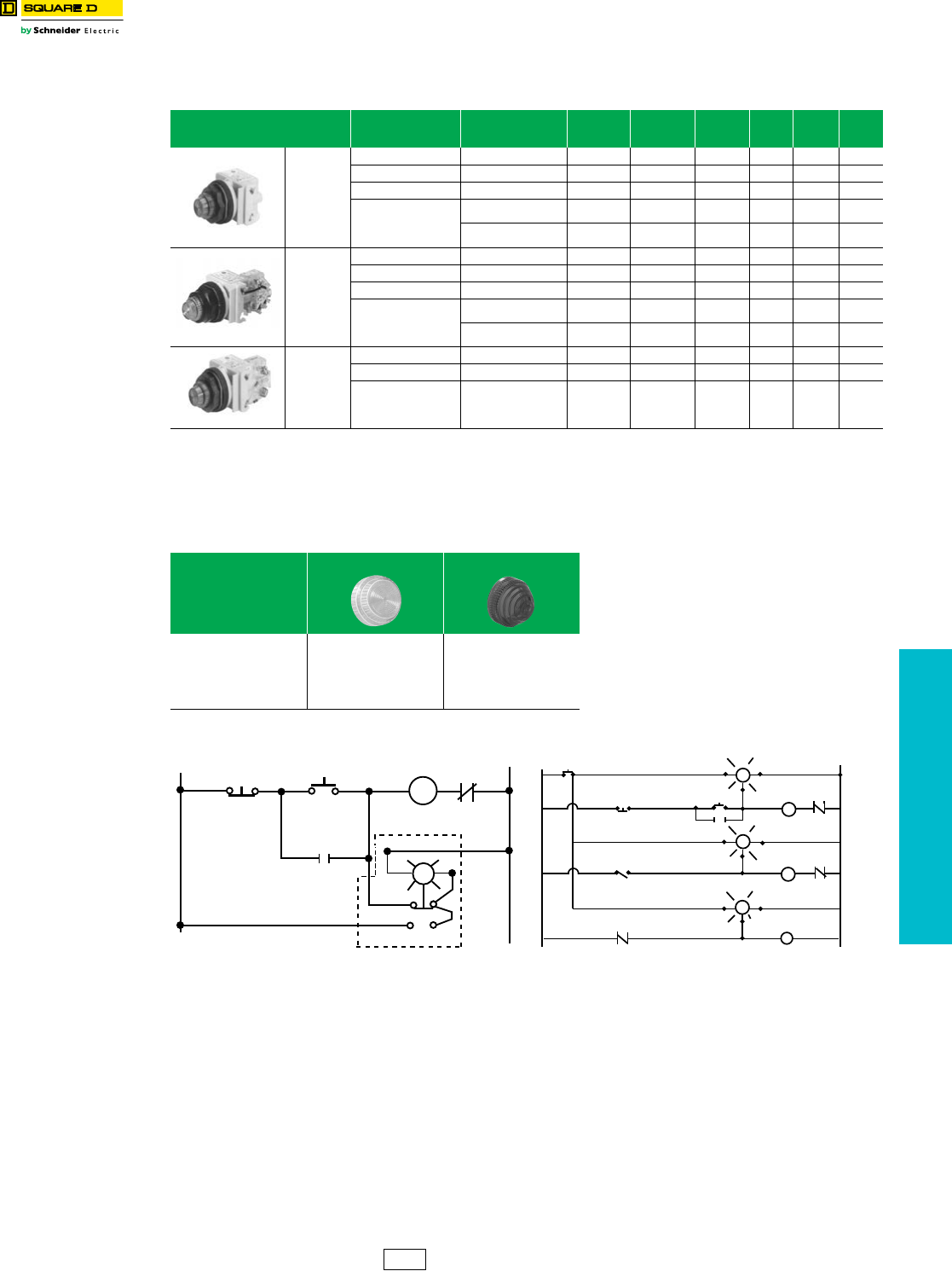
www.schneider-electric.us
19 PUSH BUTTONS AND
OPERATOR INTERFACE
© 2012 Schneider Electric
All Rights Reserved 19-83
30 mm Push Buttons Type SK Corrosion Resistant Pilot Lights
Class 9001 / Refer to Catalog 9001CT1103
aAdd the voltage assembly code as chosen from Table 19.248 or Table 19.249 on page 19-86.
EXAMPLE: SKTqR31 with 208 Vac red LED voltage = SKT37LRR31.
bAdd the color code as chosen from the color cap table below.
EXAMPLE: SKP1c with a blue fresnel cap = SKP1L31.
cThe cap must be the same color as the LED light module chosen, e.g., for a green LED, use a green color cap.
dOn neon light modules, use clear color caps only.
eUse only full voltage or resistor voltage assembly codes on remote test pilot lights. Do not choose LED, neon or transformer codes. For AC use only.
NOTE: To select and order contact blocks, light modules, and accessories, see pages 19-85 through 19-92.
Table 19.240: Pilot Lights—UL Types 4, 4X,
13/NEMA 4, 4X, 13. For use in hazardous locations,
see page 19-87. Legend plate not included.
Description Voltag e Style
With Red
Fresnel Color
Cap
With Green
Fresnel Color
Cap
With Other
Color Cap $ Price Without
Color Cap $ Price
9001SKP1
Standard
Pilot Light
(Fresnel color
cap shown)
110–120 V, 50–60 Hz Transformer SKP1R31 SKP1G31 SKP1b153.00 SKP1 143.00
220–240 V, 50–60 Hz Transformer SKP7R31 SKP7G31 SKP7b153.00 SKP7 143.00
24–28 Vac/Vdc Full Voltage SKP35R31 SKP35G31 SKP35b125.00 SKP35 116.00
For other voltages
see Table a
Transformer, Flashing
or LEDcSKPaR31 SKPaG31 SKPab 125.00 SKPa116.00
Full Voltage, Neon or
ResistordSKPaR31 SKPaG31 SKPab 125.00 SKPa116.00
9001SKT1
Push-To-Test
Pilot Light
(Fresnel color
cap shown)
110–120 V, 50–60 Hz Transformer SKT1R31 SKT1G31 SKT1b197.00 SKT1 185.00
220–240 V, 50–60 Hz Transformer SKT7R31 SKT7G31 SKT7b197.00 SKT7 185.00
24–28 Vac/Vdc Full Voltage SKT35R31 SKT35G31 SKT35b167.00 SKT35 158.00
For other voltages
see Table a
Transformer, Flashing
or LEDcSKTaR31 SKTaG31 SKTab 197.00 SKTa158.00
Full Voltage, Neon or
ResistordSKTaR31 SKTaG31 SKTab 197.00 SKTa158.00
9001SKTR38
Remote Test
Pilot Light
(Fresnel color
cap shown)
120 Vac Only Resistor SKTR38R31 SKTR38G31 SKTR38b197.00 SKTR38 185.00
24–28 Vac Only Full Voltage SKTR35R31 SKTR35G31 SKTR35b197.00 SKTR35 185.00
For other voltages
see Tables abe
Full Voltage or Resistor
eSKTRaR31 SKTRaG31 SKTRab 197.00 SKTRa185.00
Table 19.241: Color Caps
Color
b Plastic Fresnel b Plastic Domed
Amber
Blue
Clear
Green
Red
White
Yellow
A31
L31
C31
G31
R31
W31
Y31
A9
L9
C9
G9
R9
W9
Y9
R
M
MO.L.
L2
3
2
1
L1
STOP
START
L2
C
Test
L1
M
Push-To-Test Pilot Light
Typical Wiring Diagram
STOP
LSI
M3
(TEST) C
(TEST) C L2
L2
L1
(SIG) CR
M2
M1
L2
(TEST) C
START
TEST
BUTTON
L1 L2
L1
(SIG)
L1
(SIG)
Remote Test Pilot Light
CS1 Discount
Schedule
NOTE: When ordering, add prefix 9001 to the catalog number.
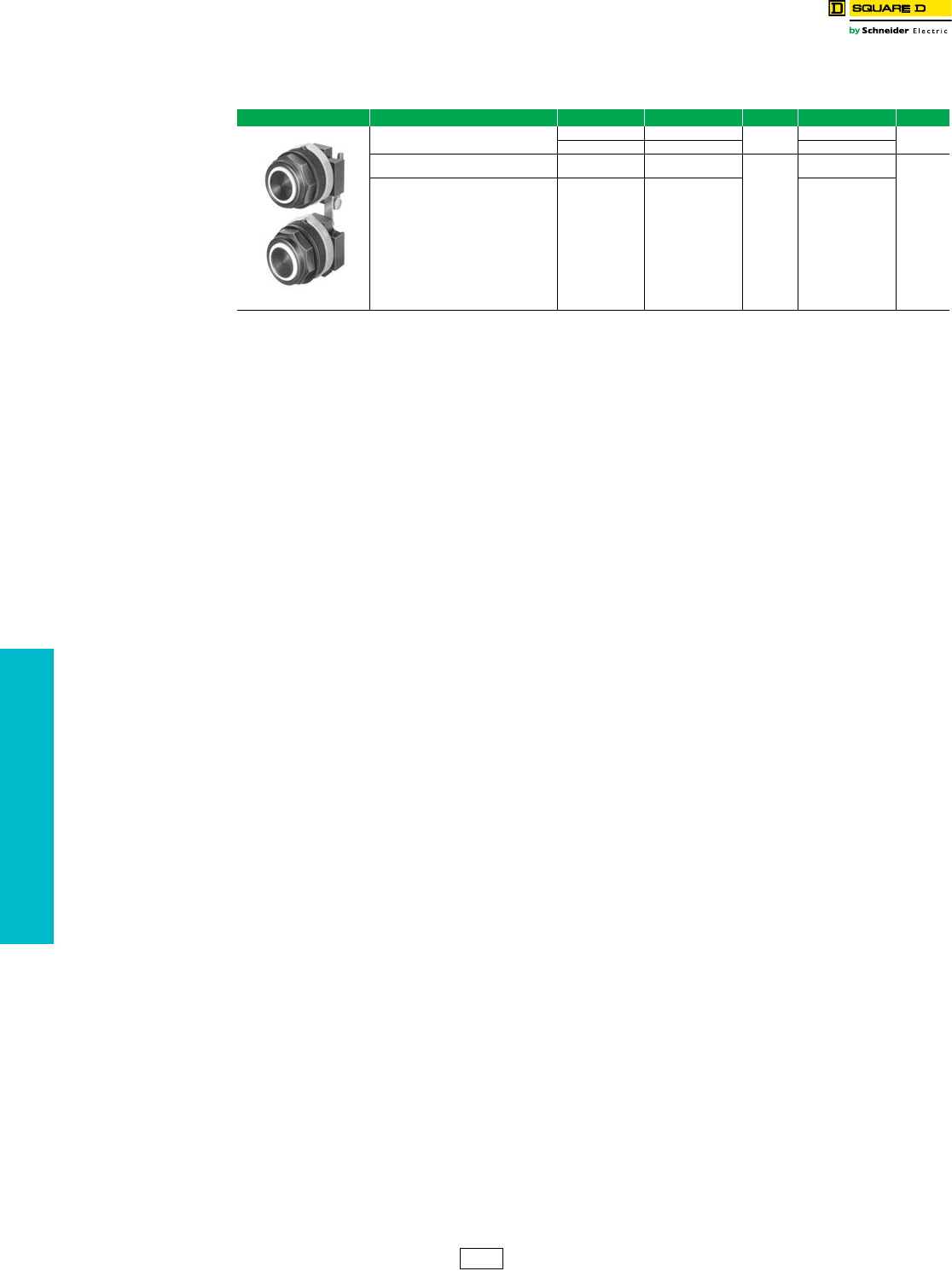
www.schneider-electric.us
19 PUSH BUTTONS AND
OPERATOR INTERFACE
19-84 © 2012 Schneider Electric
All Rights Reserved
30 mm Push Buttons Type SK Corrosion Resistant Multifunction Operators
Class 9001 / Refer to Catalog 9001CT1103
Table 19.242: Multifunction Operators—UL Types 4, 4X, 13/NEMA 4, 4X, 13
For use in hazardous locations—See page 19-87.
Legend plate and contact blocks not included unless otherwise noted.
Interlocked Assembly Description Color Contacts $ Price Without Contacts $ Price
9001SKR11U
Interlocked Assembly
Both Buttons Maintained
Universal aSKR11UH1 178.00 SKR11U 120.00
Other bSKR11bH1 SKR11b
Interlocked Assembly
One Button Momentary Universal aSKR12UH1H1
273.00
SKR12U
162.00
Interlocked Assembly
One Button Maintained Other bSKR12bH1H1 SKR12b
aUniversal for SKR11,12 includes 2 each of black, red, green, yellow, orange, blue, white.
bChoose one color for each button. R = red, G = green, B = Black.
Example: 9001SKR11 with top button gray and bottom button orange = 9001SKR11ES. See Table 19.227
CS1 Discount
Schedule
NOTE: When ordering, add prefix 9001
to the catalog number.
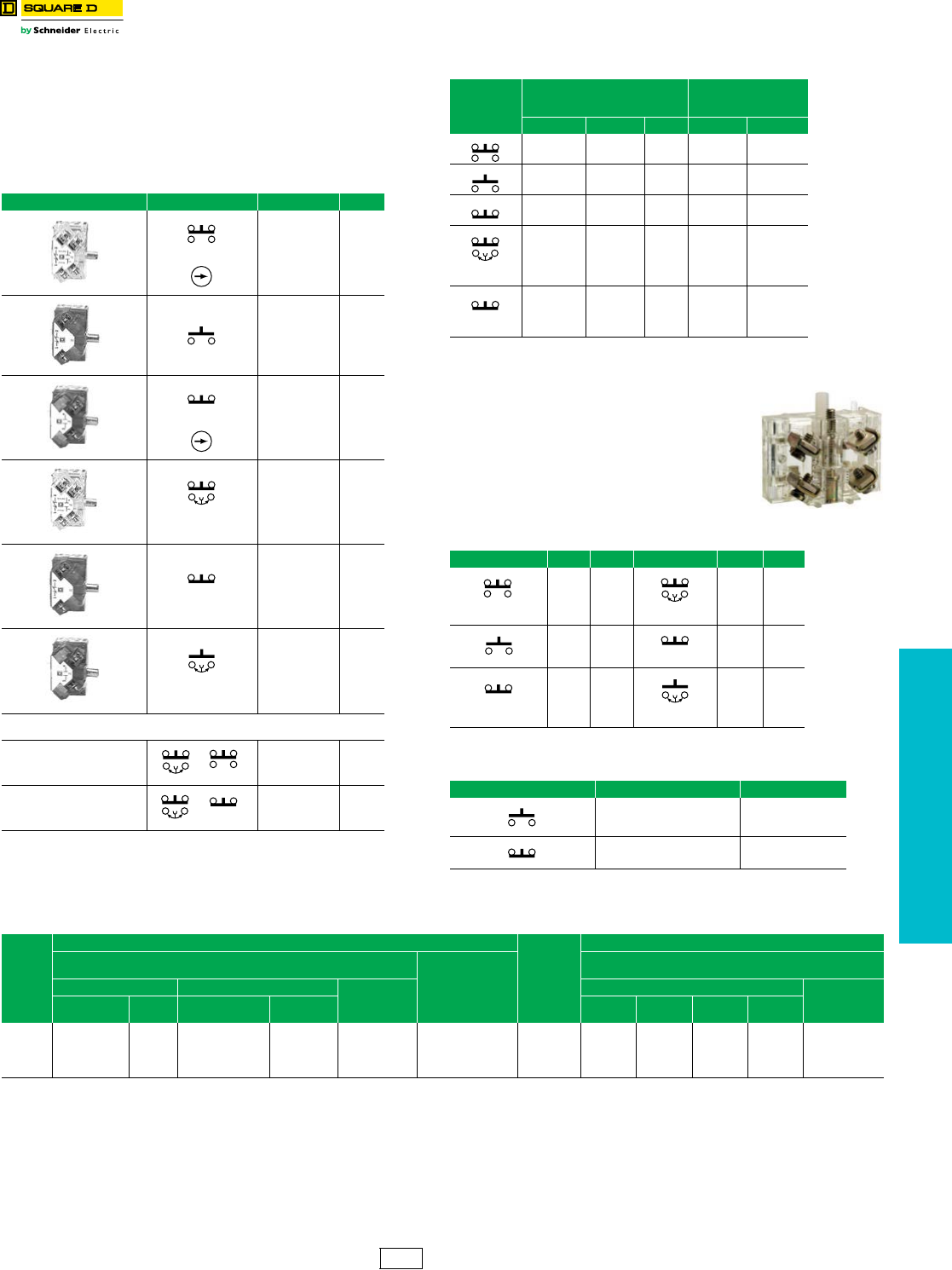
www.schneider-electric.us
19 PUSH BUTTONS AND
OPERATOR INTERFACE
© 2012 Schneider Electric
All Rights Reserved 19-85
The Class 9001 Type KA contact blocks are Fingersafe® contact blocks
(meeting VDE 0106 Part 100). They have one screw mounting and
captive (backed out) plus/minus terminal screws. These contact blocks
are double-break, direct-acting contacts. Because of the wiping action of
these contacts, they are suitable for use with programmable controllers.
All contact blocks listed below accept up to 2 #12–#24 AWG solid or
stranded wires. Recommended tightening torque for screw terminals is
7lb-in.
aFor push buttons or two-position selector switches only. For sequencing or overlapping
contacts on other operators, refer to catalog 9001CT0001.
bMinimum order quantity is 25. The price represents one individual contact block.
Contact blocks listed below are not Fingersafe, but provide:
•Terminals that accept ring tongue/fork tongue
connectors
•Short single circuit contact blocks (0.75" deep vs.
0.97" deep on the Fingersafe)
•Same as old style Series G product available prior to
March, 1989.
•For assembled operators, use form Y238 (add to
catalog number as suffix, for example:
9001KRU1H13Y238)
Dimensions . . . . . . . . . . . . . . . . . . . . . . . . . . . . . . . . . . Catalog 9001CT0001
Table 19.243: Standard Contact Blocks
Description Symbol Type $ Price
(Clear Cover)
Direct-Acting KA1 42.80
(Green Cover)
KA2 21.50
(Red Cover)
Direct-Acting KA3 21.50
(Clear Cover)
N.O. Contact
Early Closing
KA4 42.80
(Red Cover)
N.C. Contact
Late Opening
KA5 21.50
(Green Cover)
N.O. Contact
Early Closing
KA6 21.50
Table 19.244: Additional Circuit Arrangements
Sequencing a
N.O. Contact of KA4 closes
before N.O. Contact on KA1
KA4 KA1
Order One
Type KA4 and One
Typ e K A1
85.60
Overlapping a
N.O. Contact of KA4 closes
before N.C. Contact of KA5
Opens
KA4 KA5
Order One
Type KA4 and One
Typ e K A5
64.30
Symbol
Contact Blocks with
Binder Head Screws
(not Fingersafe)
Gold Flashed Contacts
with Standard
Pressure Wire Terminals
Type Quantityb$ Price Type $ Price
KA21 25–Up 42.80 KA31 71.00
KA22 25–Up 21.50 KA32 35.60
KA23 25–Up 21.50 KA33 35.60
N.O. Early
Closing
KA24 25–Up 42.80 KA34 71.00
N.C. Contact
Late Opening
KA25 25–Up 21.50 KA35 35.60
Table 19.245: Contact blocks (not Fingersafe)
Symbol Type $ Price Symbol Type $ Price
KA1G 42.80
N.O. Contact
Early Closing
KA4G 42.80
KA2G 21.50 N.C. Contact
Late Opening
KA5G 21.50
KA3G 21.50
N.O. Contact
Early Closing
KA6G 21.50
Table 19.246: Contact blocks with Quick-Connect terminals
(not Fingersafe)
Symbol Type $ Price
KA12 35.60
KA13 35.60
Table 19.247: Maximum Current Ratings for Control Circuit Contacts—Types KA1–KA6, KA21–KA25, KA31–KA35, KA1G–KA6G
V
AC
Volts
DC
Inductive (NEMA / UL Type A600)
35% Power Factor Resistive 75% Power
Factor Make, Break
and Continuous
Amperes
Inductive and Resistive
(NEMA Q600)
Make Break Continuous
Carrying
Amperes
Make and Break Continuous
Carrying
Amperes
Amperes VA Amperes VA KA1 KA2
KA3 KA4 KA5
KA6
120 60
7200
6.0
720 10 10
125
250
600
0.55
0.27
0.10
0.55
0.27
0.10
—
—
—
—
—
—
2.5
240 30 3.0
480 15 1.5
600 12 1.2
CS1 Discount
Schedule
NOTE: When ordering, add prefix 9001 to the catalog number.
30 mm Push Buttons Type K, SK and KX Electrical Components
Class 9001 / Refer to Catalog 9001CT1103
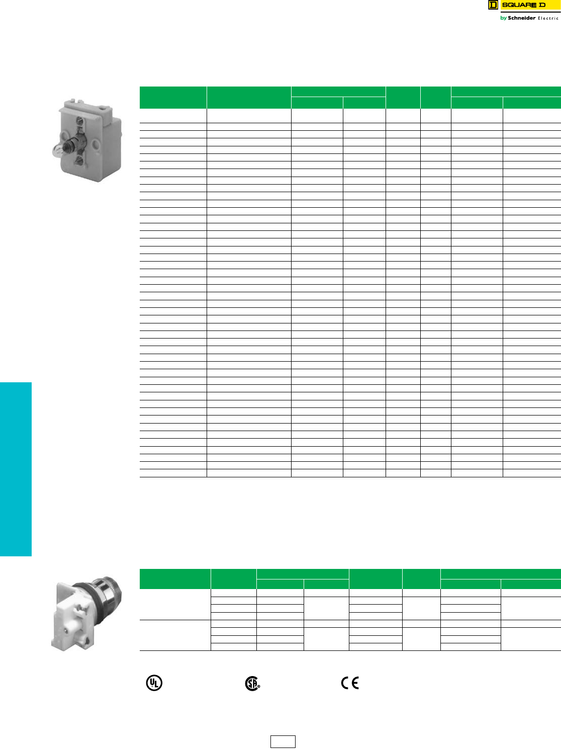
www.schneider-electric.us
19-86 © 2012 Schneider Electric
All Rights Reserved
19 PUSH BUTTONS AND
OPERATOR INTERFACE
30 mm Push Buttons Type K, SK and KX Electrical Components
Class 9001 / Refer to Catalog 9001CT1103
For use in hazardous locations—See page 19-87.
•With neon type light modules, use a clear color cap only.
•With LED light modules, use either a clear color cap or a cap the same color as the LED.
aNot for use on KX operators.
bFor use with all operators except KX and remote test pilot.
NOTE: Light modules are available in other voltages. For additional information, refer to Catalog 9001CT0001.
For use in hazardous locations—See page 19-87.
•Reduces the depth of illuminated push buttons with contact blocks by over 33%.
•With LED light modules, use a cap that is the same color as the LED.
cFor use with all operators except KX and remote test pilot.
Table 19.248: Standard Light Modules for
Types K, SK, and KX Control Units b
Vol tag e Description
Light Module Voltage
Assembly
Code
Rating
Replacement Lamp
Type $ Price Part Number b$ Price
All Full Voltage
(without Bayonet Base Lamp) KM40 78.00 40 — None —
6 Vac/Vdc Full Voltage KM31 86.00 31 .9 VA 2550101020 12.45
6 Vac/Vdc LED Red KM31LR 116.00 31LR 6508805201 42.75
6 Vac/Vdc LED Green KM31LG 116.00 31LG 6508805203 42.75
6 Vac/Vdc LED Yellow KM31LY 116.00 31LY 6508805202 28.50
12–14 Vac/Vdc Full Voltage KM32 86.00 32 1.2 VA 2550101037 12.45
12–14 Vac/Vdc LED Red KM32LR 116.00 32LR 6508805201 42.75
12–14 Vac/Vdc LED Green KM32LG 116.00 32LG 6508805203 42.75
12–14 Vac/Vdc LED Yellow KM32LY 116.00 32LY 6508805202 28.50
18 Vac/Vdc Resistor KM33 86.00 33 1.4 VA 2550101037 12.45
24–28 Vac/Vdc Full Voltage KM35 86.00 35 1.2 VA 2550101002 12.45
24–28 Vac/Vdc LED Red KM35LR 116.00 35LR .28 VA 6508805210 42.75
24–28 Vac/Vdc LED Green KM35LG 116.00 35LG .28 VA 6508805212 42.75
24–28 Vac/Vdc LED Yellow KM35LY 116.00 35LY .28 VA 6508805211 42.75
24–28 Vac/Vdc LED White KM35LW 116.00 35LW .28 VA 6508805214 42.75
24–28 Vac/Vdc LED Blue KM35LL 116.00 35LL .28 VA 6508805213 42.75
48 Vac/Vdc Full Voltage KM36 86.00 36 2.6 VA 2550101025 12.45
110–120 V, 50–60 Hz LED Red KM1LR 143.00 1LR 6508805201 42.75
110–120 V, 50–60 Hz LED Green KM1LG 143.00 1LG 6508805203 42.75
110–120 V, 50–60 Hz LED Yellow KM1LY 143.00 1LY 6508805202 42.75
110–120 V, 50–60 Hz Transformer KM1 116.00 12.4 VA2550101020 12.45
110–120 V, 50–60 Hz Flashing KMF1 116.00 F1 .85 VA 2550101036 16.50
120 Vac/Vdc Full Voltage/Resistor KM38 86.00 38 3.0 VA 2550101027 12.45
120 Vac/Vdc Neon aKM11 86.00 11 0.2 VA 2550101013 32.85
120 Vac/Vdc LED Red KM38LR 116.00 38LR 1.4 VA 6508805210 42.75
120 Vac/Vdc LED Green KM38LG 116.00 38LG 1.4 VA 6508805212 42.75
120 Vac/Vdc LED Yellow KM38LY 116.00 38LY 1.4 VA 6508805211 42.75
120 Vac/Vdc LED White KM38LW 116.00 38LW 1.4 VA 6508805214 42.75
120 Vac/Vdc LED Blue KM38LL 116.00 38LL 1.4 VA 6508805213 42.75
208–220 V, 50–60 Hz Transformer KM3 116.00 32.5 VA2550101020 12.45
208–220 V, 50–60 Hz LED Red KM3LR 143.00 3LR 6508805201 42.75
208–220 V, 50–60 Hz LED Green KM3LG 143.00 3LG 6508805203 42.75
208–220 V, 50–60 Hz LED Yellow KM3LY 143.00 3LY 6508805202 42.75
208–220 V, 50–60 Hz LED White KM3LW 143.00 3LW 6508805215 42.75
208–220 V, 50–60 Hz LED Blue KM3LL 143.00 3LL 6508805216 42.75
220–240 V, 50–60 Hz Transformer KM7 116.00 72.0 VA2550101020 12.45
220–240 V, 50–60 Hz LED Red KM7LR 143.00 7LR 6508805201 42.75
220–240 V, 50–60 Hz LED Green KM7LG 143.00 7LG 6508805203 42.75
220–240 V, 50–60 Hz LED Yellow KM7LY 143.00 7LY 6508805202 42.75
220–240 V, 50–60 Hz LED White KM7LW 143.00 7LW 6508805215 42.75
220–240 V, 50–60 Hz LED Blue KM7LL 143.00 7LL 6508805216 42.75
240 Vac/Vdc Resistor KM25 86.00 25 6.0 VA 2550101027 12.45
240 Vac/Vdc Neon aKM12 86.00 12 0.3 VA 2550101013 32.85
277 V, 50–60 Hz Transformer KM8 116.00 82.4 VA2550101020 12.45
380–480 V, 50–60 Hz Transformer KM5 116.00 52.8 VA2550101020 12.45
480 Vac/Vdc Neon aKM14 86.00 14 0.5 VA 2550101013 32.85
550–600 V, 50–60 Hz Transformer KM6 116.00 62.5 VA2550101020 12.45
Table 19.249: Shallow Depth Light Modules For Types K and SK Control Units c
Voltage Description Light Module Voltage Assembly
Code Rating Replacement Lamp
Type $ Price Part Number $ Price
24–28 Vac/Vdc
Full Voltage KM55 86.00 55 1.2 VA 2550101002 12.45
LED Red KM55LR
116.00
55LR
0.5 VA
6508805204 42.75
LED Green KM55LG 55LG 6508805206
LED Yellow KM55LY 55LY 6508805205
110–120 Vac/Vdc
Full Voltage KM58 86.00 58 3.0 VA 2550101027 12.45
LED Red KM58LR
116.00
58LR
0.5 VA
6508805204 42.75
LED Green KM58LG 58LG 6508805206
LED Yellow KM58LY 58LY 6508805205
File
CCN
E78403
NKCR
File
Class
LR25490
3211 03 marked
CS1 Discount
Schedule
NOTE: When ordering, add prefix 9001 to the catalog number.
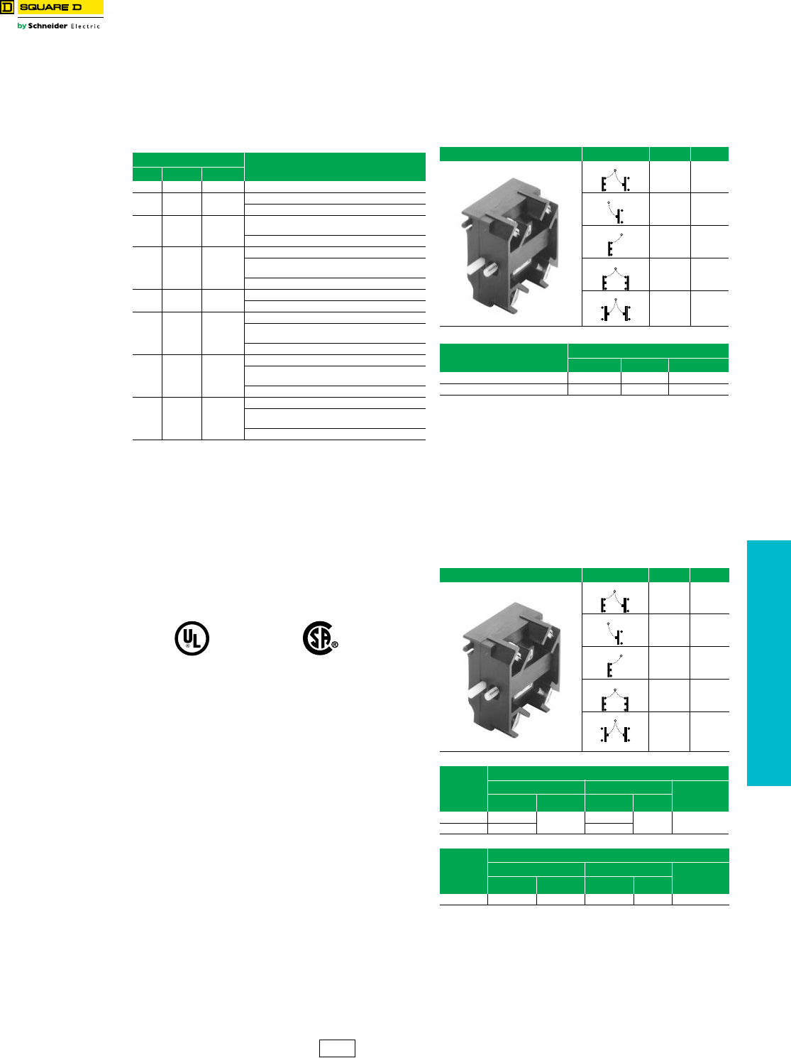
www.schneider-electric.us
19 PUSH BUTTONS AND
OPERATOR INTERFACE
© 2012 Schneider Electric
All Rights Reserved 19-87
30 mm Push Buttons Type K, SK and KX Electrical Components
Class 9001 / Refer to Catalog 9001CT1103
Hazardous locations do not always require the use of
explosion-proof equipment like the Class 9001 Type BR
control stations. Selecting the most appropriate device for
the location can save you money. For more information on
the types of hazardous locations, contact your local
electrical inspector.
aAny Class 9001 Type K, SK or KX operator can be used in an area
classified as Class I, Division 2 hazardous locations, if:
1. Only logic (KA40 series) or power (KA50 series) reed contact blocks
are used.
2. All Type K and SK illuminated operators are UL approved for use in
Class I Division 2 areas. c
3. Type KX illuminated operators do not use 4 lamp light modules, or 2
lamp light modules other than the transformer type. c
4. The operators are mounted in any NEMA 4 & 13 enclosures.
bAny Class 9001 Type K, SK, or KX operator mounted in a Class 9001
Type KY, KYSS, KYAF, SKY enclosure may be used, except
potentiometer operators.
cAdd Form Y243 to single lamp Push-To-Test pilot lights.
Note: For a and b: UL Listed: File E10054(N), CCN NOIV.
NOTE: When ordering, add prefix 9001 to the catalog
number. All contact blocks listed below accept
#12–18 solid or stranded wire.
The maximum number of logic and/or power reed contact
blocks per operator is as indicated on individual selection
tables for standard contact blocks, except:
•On 3 position selector switches with cams C, D, E, F, G, L, or
M, mount reed blocks on one side only (either side), maximum
2 in tandem.
•On 4 position selector switches, mount reed blocks on one
side only (either side), maximum 2 in tandem.
•On joysticks or on Type KR8 or SKR8 push-pull operators,
mount reed blocks on one side only (either side), maximum
2 in tandem.
Note: The power reed contact blocks can be used with standard industrial
relays and starters through NEMA Size 4. Minimum voltage is 5 V and
the minimum current is 1 mA.
dInductive Rating—35% Power Factor.
eInductive and Resistive Ratings
fNot for use in pendant stations.
Table 19.250: Square D Offering According to
Class, Division, and Group
For Use
Class Division Group(s)
I 1 A 1. Intrinsically Safe System
I1B, C, D
1. 9001 BR station
2. Intrinsically Safe System
I2 A
1. 9001 K, SK, KX control stations
with restrictions a
2. Intrinsically Safe System
I2B, C, D
1. 9001 BR station
2. 9001 K, SK, KX control stations
with restrictions a
3. Intrinsically Safe System
II 1 E, F, G 1. 9001 BR station
2. Intrinsically Safe System
II 2 E, F
1. 9001 BR station
2. 9001 K, SK, KX control stations
with restrictions a
3. Intrinsically Safe System
II 2 G
1. 9001 BR station
2. 9001 K, SK, KX control stations
with restrictions b
3. Intrinsically Safe System
III 1, 2 —
1. 9001 BR Station
2. 9001 K, SK, KX control stations
with restrictions b
3. Intrinsically Safe System
Table 19.251: Hazardous Locations (see page 19-87)
Ty p es
K, SK
File
CCN
E10054(N)
NOIV
File
Class
LR26817
3218 02
Table 19.252: Hermetically Sealed Logic Reed
Contact Blocks f
Suitable for use on low energy level
circuits
Description Symbol Type $ Price
KA41 86.00
KA42 42.80
KA43 42.80
KA44 86.00
KA45 86.00
Max. Vac/Vdc Maximum Load
Resistive Inductive Continuous
32/30 .25 A .10 A .5 A
120/100 8 VA 3 VA .5 A
Table 19.253: Hermetically Sealed Power Reed
Contact Blocks f
Description Symbol Type $ Price
KA51 143.00
KA52 101.00
KA53 101.00
KA54 143.00
KA55 143.00
Volt s
AC NEMA C300 d
Make Break Continuous
Carrying
Amperes
AVA AVA
120 10.00 1200 1.000 120 3.0
240 5.00 .500
Vol ts
DC NEMA Q150 e
Make Break Continuous
Carrying
Amperes
AVA AVA
115 .50 58 .50 58 3.0
CS1 Discount
Schedule
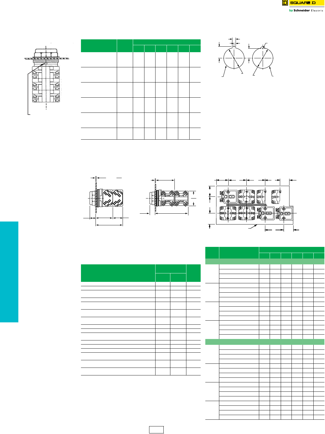
www.schneider-electric.us
19 PUSH BUTTONS AND
OPERATOR INTERFACE
19-88 © 2012 Schneider Electric
All Rights Reserved
30 mm Push Buttons Type K, SK and KX Contact Block “H” Numbers
Class 9001 / Refer to Catalog 9001CT1103
The design of the Class 9001 Type KA contact blocks allows them to be mounted
side by side and/or in tandem. This enables you to specify an operator and a
particular arrangement of contact blocks (shipped completely assembled) with a
single Type number.
NOTE: For “H” Codes not shown in this table, contact
your local Schneider Electric Customer Care
Center.
aOperator can be converted to an illuminated operator by removing the
liner (6512240601) and adding a light module.
bOperator can be converted to a non-illuminated operator by adding
liner (6512240601).
cOperator includes jumper wires for push-to-test conversion.
dThese operators can be supplied with 1-3/8 in or 2-1/4 in dia.
mushroom buttons. For 1-3/8 in.: add ( ) 20 to type number. The ( )
refers to the color chosen—see page 19-92. For 2-1/4 in.: Add ( ) 21
to type number. The ( ) refers to the color chosen—see page 19-92.
Voids UL and NEMA 6 Rating.
Hole Punch: Use Greenlee Tool #60242 to punch mounting hole
and notch.
Maximum Contact Block Usage
(Includes Types K, SK and KX)
•2 blocks mounted side by side only: Any 2, 3 or 4 position
spring return selector switch (non-illuminated, illuminated or
keyed).
•2 blocks mounted in tandem on one side only: Any 2
operator interlocked push button.
•2 blocks mounted in tandem (total of four blocks): Any
selector push button, keyed push button, 2, 3, or 4 position
maintained selector switch (non-illuminated, illuminated or
keyed), push-pull operators (non-illuminated or illuminated),
joy stick, dual push button.
•3 blocks mounted in tandem (total of six blocks): Single
momentary push buttons (non-illuminated or illuminated).
Example: A Type KR1B push
button with 2 Type KA1 contact
blocks would be Class 9001
Type KR1BH2.
Locating Nib
Side 2Side 1
POS 1
POS 2
POS 3
POS 4
POS 5
POS 6
Table 19.254: “H” Codes
Suffix No.
(Add to Operator
Type)
$ Price
Positions
123456
H1 28.50 KA1
H2 57.00 KA1 KA1
H3 86.00 KA1 KA1 KA1
H4 114.00 KA1 KA1 KA1 KA1
H5 14.30 KA2
H6 14.30 KA3
H7 28.50 KA2 KA2
H8 28.50 KA3 KA3
H9 57.00 KA4 KA1
H10 42.80 KA4 KA5
H11 86.00 KA1 KA1 KA1
H12 57.00 KA2 KA3 KA2 KA3
H13 28.50 KA1
H14 14.30 KA3
H15 42.80 KA2 KA3 KA2
H16 42.80 KA2 KA3 KA3
H17 71.00 KA1 KA1 KA2
H18 71.00 KA3 KA1 KA3 KA3
H19 143.00 KA1 KA1 KA1 KA1 KA1
H21 28.50 KA2 KA3
H23 171.00 KA1 KA1 KA1 KA1 KA1 KA1
H24 42.80 KA1 KA2
H25 28.50 KA5 KA3
Table 19.255: Dimensions When Using Contact Blocks
Standard Blocks Reed Blocks
Table 19.256: Basic Operators (Without Color Caps,
Mushroom Buttons, Knobs, Selector
Switch Cams, Contact Blocks, Light
Modules, or Legend Plates)
Description
For UL
Types/NEMA $ Price
1, 3R, 4,
12, 13 4, 4X, 13
Non-Illuminated Push Button (Extended Guard) KR2 SKR2 38.55
Non-Illuminated Push Button (No Guard) KR3 SKR3 38.55
Non-Illuminated Push Button (Mushroom
Button/Screw-On) KR20 SKR20 38.55
Non-Illuminated Dual Push Button (Momentary) KR6 —78.00
Non-Illuminated Dual Push Button (Momentary
Interlocked) KR67 —121.50
Non-Illuminated Dual Push Button (Maintained
Interlocked) KR7 —121.50
Momentary Pull—Maintained Neutral—
Momentary Push KR8 ad SKR8 a75.00
Maintained Pull—Maintained Push KR9 ad SKR9 a120.00
Illuminated Push Button (Full Guard—Plastic Top) K1L bSK1L b42.75
Illuminated Push Button and Push-To-Test
(No Guard) K2L bc SK2Lbc 28.65
Illuminated Push Button (Full Guard—Metal Top) K3L b—42.75
Standard Pilot Light KP SKP 28.65
3 Position Maintained Selector Switch KS4 aSKS4 a36.30
3 Position Spring Return Both Sides To Center—
Selector Switch KS5 aSKS5 a64.80
3 Position Spring Return Left To Center—
Selector Switch KS6 aSKS6 a64.80
3 Position Spring Return Right To Center—
Selector Switch KS7 aSKS7 a64.80
.06
2
.25
6
min. max.
Panel Thickness
0.56
14
1.66
42
.97
25
2.63
67
2.10
53
0.56
14
1.60
41
3.66
93
Panel Thickness
1/16 min.-1/4 max.
Min. Centerline Spacing, Type K & SK Control Units
Legend
Plate Operator Centerline Spacing (in.)
A B C D E F
Legend Plate Orientation Position #1
KN2
KN5
Standard Push Button 1.75 1.31 1.44 2.25 1.69 0.88
1.375 in. Dia. Mushroom 1.75 1.31 1.44 2.25 1.69 0.88
2.25 in. Dia. Mushroom 2.25 1.31 1.44 2.25 2.25 1.12
Selector Switch Knobs 1.751.311.442.251.690.88
KN3
Standard Push Button 2.00 1.31 1.44 2.25 1.75 0.88
1.375 in. Dia. Mushroom 2.00 1.31 1.44 2.25 1.75 0.88
2.25 in. Dia. Mushroom 2.25 1.31 1.44 2.25 2.25 1.12
Selector Switch Knobs 2.001.311.442.251.750.88
KN4
Standard Push Button 1.94 1.31 1.44 2.25 1.62 0.88
1.375 in. Dia. Mushroom 1.94 1.31 1.44 2.25 1.62 0.88
2.25 in. Dia. Mushroom 2.25 1.31 1.44 2.25 2.25 1.12
Selector Switch Knobs 1.741.311.442.251.620.88
KN6
Standard Push Button 2.38 1.62 1.44 2.25 2.25 1.12
1.375 in. Dia. Mushroom 2.38 1.62 1.44 2.25 2.25 1.12
2.25 in. Dia. Mushroom 2.38 1.62 1.44 2.25 2.25 1.12
Selector Switch Knobs 2.381.621.442.252.251.12
Legend Plate Orientation Position #2
KN2
KN5
Standard Push Button 1.62 1.31 1.44 2.25 1.75 0.88
1.375 in. Dia. Mushroom 1.62 1.31 1.44 2.25 1.75 0.88
2.25 in. Dia. Mushroom 2.25 1.31 1.44 2.25 2.25 1.12
Selector Switch Knobs 1.621.311.442.251.750.88
KN3
Standard Push Button 1.75 1.31 1.44 2.25 2.00 0.88
1.375 in. Dia. Mushroom 1.75 1.31 1.44 2.25 2.00 0.88
2.25 in. Dia. Mushroom 2.25 1.31 1.44 2.25 2.25 1.12
Selector Switch Knobs 1.751.311.442.252.000.88
KN4
Standard Push Button 1.62 1.31 1.44 2.25 1.94 1.00
1.375 in. Dia. Mushroom 1.62 1.31 1.44 2.25 1.94 1.00
2.25 in. Dia. Mushroom 2.25 1.31 1.44 2.25 2.25 1.12
Selector Switch Knobs 1.621.311.442.251.941.00
KN6
Standard Push Button 2.25 1.31 1.62 2.38 2.38 0.88
1.375 in. Dia. Mushroom 2.25 1.31 1.62 2.38 2.38 0.88
2.25 in. Dia. Mushroom 2.25 1.31 1.62 2.38 2.38 1.12
Selector Switch Knobs 2.251.311.622.382.380.88
.19
5.09
2.25 Dia.
6
*
1.22 Dia.
31
*
1.22 Dia.
31
.69
18 .56
14
Alternate
Cover Drilling
Preferred
Cover Drilling
*
Units also mount in 1.20 dia.
30
A30464-162
Dual Dimensions: INCHES
Millimeters
Mounting Hole for All Types K, SK, and KX Control Units
D30052-287
Enclosure or
Grounded Metal Part
E
D
D
D
A
F
B
C
1.13
1.31
Light
Module
Light
Module
Light
Module
KA KA KAKA
KAKA KA KA
UnitUnit
UnitUnit
Unit Unit Unit Unit
CS1 Discount
Schedule
NOTE: When ordering, add prefix 9001 to the catalog number.
www.schneider-electric.us
19 PUSH BUTTONS AND
OPERATOR INTERFACE
© 2012 Schneider Electric
All Rights Reserved 19-89
30 mm Push Buttons Type K and SK Accessories
Class 9001 / Refer to Catalog 9001CT1103
Table 19.257: Legend Plates
Standard
Markings
Plastic Legend Plates
for use with Types K and SK Operators
Aluminum Legend Plates
for use with Type K Operators
1-3/4" Square 2-1/4" Square 2-1/2" Square
Black
Legend
Black
Legend
Blue
Legend
Silver
Legend with
Black Letters
White
Legend with
Black Letters
Black
Legend with
White Letters
Silver
Legend with
Black Letters
White
Legend with
Black Letters
Black
Legend with
White Letters
Silver
Legend with
Black Letters
White
Legend with
Black Letters
Black
Legend with
White Letters
For Push Button or Pilot Light KN200 KN300 KN800
Blank KN200SP KN200WP KN200BP KN100SP KN100WP KN100BP KN700SP KN700WP KN700BP KN200 KN300 KN800
Blank (red) KN200RP bKN200RP bKN200RP bKN100RP bKN100RP bKN100RP bKN700RP bKN700RP bKN700RP bKN200R aKN300R aKN800R a
Start KN201SP KN201WP KN201BP KN101SP KN101WP KN101BP KN701SP KN701WP KN701BP KN201 KN301 KN801
Stop KN202RP bKN202RP bKN202RP bKN102RP bKN102RP bKN102RP bKN702RP bKN702RP bKN702RP bKN202 aKN302 aKN802 a
On KN203SP KN203WP KN203BP KN103SP KN103WP KN103BP KN703SP KN703WP KN703BP KN203 KN303 KN803
Off KN204RP bKN204RP bKN204RP bKN104RP bKN104RP bKN104RP bKN704RP bKN704RP bKN704RP bKN204 aKN304 aKN804 a
Emerg. Stop KN205RP bKN205RP bKN205RP bKN105RP bKN105RP bKN105RP bKN705RP bKN705RP bKN705RP bKN205 aKN305 aKN805 a
Forward KN206SP KN206WP KN206BP KN106SP KN106WP KN106BP KN706SP KN706WP KN706BP KN206 KN306 KN806
Reverse KN207SP KN207WP KN207BP KN107SP KN107WP KN107BP KN707SP KN707WP KN707BP KN207 KN307 KN807
Close KN208SP KN208WP KN208BP KN108SP KN108WP KN108BP KN708SP KN708WP KN708BP KN208 KN308 KN808
Open KN209SP KN209WP KN209BP KN109SP KN109WP KN109BP KN709SP KN709WP KN709BP KN209 KN309 KN809
Down KN210SP KN210WP KN210BP KN110SP KN110WP KN110BP KN710SP KN710WP KN710BP KN210 KN310 KN810
Up KN211SP KN211WP KN211BP KN111SP KN111WP KN111BP KN711SP KN711WP KN711BP KN211 KN311 KN811
Fast KN212SP KN212WP KN212BP KN112SP KN112WP KN112BP KN712SP KN712WP KN712BP KN212 KN312 KN812
Slow KN213SP KN213WP KN213BP KN113SP KN113WP KN113BP KN713SP KN713WP KN713BP KN213 KN313 KN813
High KN214SP KN214WP KN214BP KN114SP KN114WP KN114BP KN714SP KN714WP KN714BP KN214 KN314 KN814
Low KN215SP KN215WP KN215BP KN115SP KN115WP KN115BP KN715SP KN715WP KN715BP KN215 KN315 KN815
Inch KN216SP KN216WP KN216BP KN116SP KN116WP KN116BP KN716SP KN716WP KN716BP KN216 KN316 KN816
In KN217SP KN217WP KN217BP KN117SP KN117WP KN117BP KN717SP KN717WP KN717BP KN217 KN317 KN817
Jog KN218SP KN218WP KN218BP KN118SP KN118WP KN118BP KN718SP KN718WP KN718BP KN218 KN318 KN818
Jog For. KN219SP KN219WP KN219BP KN119SP KN119WP KN119BP KN719SP KN719WP KN719BP KN219 KN319 KN819
Jog Rev. KN220SP KN220WP KN220BP KN120SP KN120WP KN120BP KN720SP KN720WP KN720BP KN220 KN320 KN820
Lower KN221SP KN221WP KN221BP KN121SP KN121WP KN121BP KN721SP KN721WP KN721BP KN221 KN321 KN821
Out KN222SP KN222WP KN222BP KN122SP KN122WP KN122BP KN722SP KN722WP KN722BP KN222 KN322 KN822
Reset KN223SP KN223WP KN223BP KN123SP KN123WP KN123BP KN723SP KN723WP KN723BP KN223 KN323 KN823
Run KN224SP KN224WP KN224BP KN124SP KN124WP KN124BP KN724SP KN724WP KN724BP KN224 KN324 KN824
Start Jog KN225SP KN225WP KN225BP KN125SP KN125WP KN125BP KN725SP KN725WP KN725BP KN225 KN325 KN825
Test KN226SP KN226WP KN226BP KN126SP KN126WP KN126BP KN726SP KN726WP KN726BP KN226 KN326 KN826
Raise KN227SP KN227WP KN227BP KN127SP KN127WP KN127BP KN727SP KN727WP KN727BP KN227 KN327 KN827
Decrease KN228SP KN228WP KN228BP KN128SP KN128WP KN128BP KN728SP KN728WP KN728BP KN228 KN328 KN828
Increase KN229SP KN229WP KN229BP KN129SP KN129WP KN129BP KN729SP KN729WP KN729BP KN229 KN329 KN829
Left KN230SP KN230WP KN230BP KN130SP KN130WP KN130BP KN730SP KN730WP KN730BP KN230 KN330 KN830
Right KN231SP KN231WP KN231BP KN131SP KN131WP KN131BP KN731SP KN731WP KN731BP KN231 KN331 KN831
Cycle Start KN232SP KN232WP KN232BP KN132SP KN132WP KN132BP KN732SP KN732WP KN732BP KN232 KN332 KN832
Feed Start KN233SP KN233WP KN233BP KN133SP KN133WP KN133BP KN733SP KN733WP KN733BP KN233 KN333 KN833
Cycle Stop KN234SP KN234WP KN234BP KN134SP KN134WP KN134BP KN734SP KN734WP KN734BP KN234 KN334 KN834
Motor Run KN236SP KN236WP KN236BP KN136SP KN136WP KN136BP KN736SP KN736WP KN736BP KN236 KN336 KN836
Motor Stop KN237SP KN237WP KN237BP KN137SP KN137WP KN137BP KN737SP KN737WP KN737BP KN237 KN337 KN837
Power On KN238SP KN238WP KN238BP KN138SP KN138WP KN138BP KN738SP KN738WP KN738BP KN238 KN338 KN838
Pull To Start
Push To Stop N/A N/A N/A KN179SP KN179WP KN179BP KN779SP KN779WP KN779BP N/A KN379 N/A
For Selector Switch or Selector Push Button
For.-Rev. KN239SP KN239WP KN239BP KN139SP KN139WP KN139BP KN739SP KN739WP KN739BP KN239 KN339 KN839
Hand-Auto. KN240SP KN240WP KN240BP KN140SP KN140WP KN140BP KN740SP KN740WP KN740BP KN240 KN340 KN840
High-Low KN241SP KN241WP KN241BP KN141SP KN141WP KN141BP KN741SP KN741WP KN741BP KN241 KN341 KN841
Jog-Run KN242SP KN242WP KN242BP KN142SP KN142WP KN142BP KN742SP KN742WP KN742BP KN242 KN342 KN842
Man.-Auto. KN243SP KN243WP KN243BP KN143SP KN143WP KN143BP KN743SP KN743WP KN743BP KN243 KN343 KN843
Off-On KN244SP KN244WP KN244BP KN144SP KN144WP KN144BP KN744SP KN744WP KN744BP KN244 KN344 KN844
On-Off KN245SP KN245WP KN245BP KN145SP KN145WP KN145BP KN745SP KN745WP KN745BP KN245 KN345 KN845
Open-Close KN246SP KN246WP KN246BP KN146SP KN146WP KN146BP KN746SP KN746WP KN746BP KN246 KN346 KN846
Raise-Lower KN247SP KN247WP KN247BP KN147SP KN147WP KN147BP KN747SP KN747WP KN747BP KN247 KN347 KN847
Run-Jog KN248SP KN248WP KN248BP KN148SP KN148WP KN148BP KN748SP KN748WP KN748BP KN248 KN348 KN848
Slow-Fast KN250SP KN250WP KN250BP KN150SP KN150WP KN150BP KN750SP KN750WP KN750BP KN250 KN350 KN850
Start-Stop KN251SP KN251WP KN251BP KN151SP KN151WP KN151BP KN751SP KN751WP KN751BP KN251 KN351 KN851
Up-Down KN253SP KN253WP KN253BP KN153SP KN153WP KN153BP KN753SP KN753WP KN753BP KN253 KN353 KN853
Low-High KN254SP KN254WP KN254BP KN154SP KN154WP KN154BP KN754SP KN754WP KN754BP KN254 KN354 KN854
Stop-Start KN255SP KN255WP KN255BP KN155SP KN155WP KN155BP KN755SP KN755WP KN755BP KN255 KN355 KN855
Left-Right KN256SP KN256WP KN256BP KN156SP KN156WP KN156BP KN756SP KN756WP KN756BP KN256 KN356 KN856
On-Auto KN276SP KN276WP KN276BP KN176SP KN176WP KN176BP KN776SP KN776WP KN776BP KN276 KN376 KN876
Auto-Off-Hand KN258SP KN258WP KN258BP KN158SP KN158WP KN158BP KN758SP KN758WP KN758BP KN258 KN358 KN858
For.-Off-Rev. KN259SP KN259WP KN259BP KN159SP KN159WP KN159BP KN759SP KN759WP KN759BP KN259 KN359 KN859
Hand-Off-Auto. KN260SP KN260WP KN260BP KN160SP KN160WP KN160BP KN760SP KN760WP KN760BP KN260 KN360 KN860
Man.-Off-Auto. KN262SP KN262WP KN262BP KN162SP KN162WP KN162BP KN762SP KN762WP KN762BP KN262 KN362 KN862
Open-Off-Close KN263SP KN263WP KN263BP KN163SP KN163WP KN163BP KN763SP KN763WP KN763BP KN263 KN363 KN863
Up-Off-Down KN264SP KN264WP KN264BP KN164SP KN164WP KN164BP KN764SP KN764WP KN764BP KN264 KN364 KN864
Low-Off-High KN265SP KN265WP KN265BP KN165SP KN165WP KN165BP KN765SP KN765WP KN765BP KN265 KN365 KN865
Jog-Stop-Run KN267SP KN267WP KN267BP KN167SP KN167WP KN167BP KN767SP KN767WP KN767BP KN267 KN367 KN867
High-Low-Off KN270SP KN270WP KN270BP KN170SP KN170WP KN170BP KN770SP KN770WP KN770BP KN270 KN370 KN870
High-Off-Low KN277SP KN277WP KN277BP KN177SP KN177WP KN177BP KN777SP KN777WP KN777BP KN277 KN377 KN877
Auto-Man.-Off KN278SP KN278WP KN278BP KN178SP KN178WP KN178BP KN778SP KN778WP KN778BP KN278 KN378 KN878
aLegend plate has red background with silver letters.
bLegend plate has red background with black letters.
For Pricing Information . . . . . . . . . . . . . . . . . . . . . . . . . . . . . . . . . .page 19-90
CS1 Discount
Schedule
NOTE: When ordering, add prefix 9001 to the catalog number.
www.schneider-electric.us
19 PUSH BUTTONS AND
OPERATOR INTERFACE
19-90 © 2012 Schneider Electric
All Rights Reserved
aOther colors available (see Table 19.259).
bSpecify marking required.
Note: The maximum number of characters and lines is a practical maximum, based on a
minimum size of characters to facilitate easy reading.
aLegend plate has red background with silver letters.
bLegend plate has red background with black letters.
For Pricing Information. . . . . . . . . . . . . . . . . . . . . . . . . . . . . . . . . . page 19-90
Table 19.258: Legend Plates–Special Marking
Legend
Plate Description Type $ Price
KN100( )P
(Plastic) a
2.25 in
Square
Standard Markings See page 19-89 4.40
Special Marking
b
Silver Field, Black Letters KN199SP
18.50
White Field, Black Letters KN199WP
Red Field, Black Letters KN199RP
Black Field, White Letters KN199BP
KN200
Aluminum
Standard Markings See page 19-89 4.40
Special Marking
b
Black Field KN299 18.50
Red Field KN299R
KN200( )P
(Plastic) a
1.7 in.
Square
Standard Markings See page 19-89 4.40
Special Marking
b
Silver Field, Black Letters KN299SP
18.50
White Field, Black Letters KN299WP
Red Field, Black Letters KN299RP
Black Field, White Letters KN299BP
KN300
Aluminum
Standard Markings See page 19-89 4.40
Special Marking
b
Black Field KN399 18.50
Red Field KN399R
KN400
Aluminum
Blank KN400 8.60
Any Marking b KN499 22.80
KN500
Aluminum
Standard Markings Select from
Table 19.263 4.40
Special Marking
b
Black Field KN599
18.50
Green Red
Field KN519
KN600
Aluminum
Blank Black Field KN600 9.90
Red Field KN600R
Any Marking
b
Black Field KN699 22.80
Red Field KN699R
KN700( )P
(Plastic) a
2.5 in.
Square
Standard Markings Select from page 19-89 4.40
Special Marking
b
Silver Field, Black Letters KN799SP
18.50
White Field, Black Letters KN799WP
Red Field, Black Letters KN799RP
Black Field, White Letters KN799BP
KN800
Aluminum
Standard Markings Select from page 19-89 4.40
Special Marking
b
Blue Field KN899 18.50
Red Field KN899R
KN900
Aluminum
Blank KN900 4.40
Any Marking b KN999 18.50
Table 19.259: Plastic Legend Plates—Other Colors
Plate Color Letter
Color 1.7 in. Square 2.25 in. Square 2.5 in. Square $ Price
Blank
Legend
Plates
Yellow Black KN200YP KN100YP KN700YP
4.40
Green
White
KN200GP KN100GP KN700GP
Blue KN200LP KN100LP KN700LP
Red KN200CP KN100CP KN700CP
Special
Engraved
Legend
Plates
Yellow Black KN299YP KN199YP KN799YP
18.50
Green
White
KN299GP KN199GP KN799GP
Blue KN299LP KN199LP KN799LP
Red KN299CP KN199CP KN799CP
Table 19.260: Maximum Number of Lines and Characters for
Type KN Legend Plates
Type KN100 KN200 KN300 KN400 KN500 KN600 KN700 KN800 KN900
Max. No. of
Characters
per Line
16 14 18 18 8
per field 22 17 18 18
per pos.
Max. No. of
Lines 2132 2
per field 422 1
per pos.
Table 19.261: Circular Legends for Emergency Stop Mushroom
Heads (yellow background)
Diameter Text Catalog Number $ Price
60 mm —9001KN9100
4.40
EMERGENCY STOP 9001KN9330
90 mm —9001KN8100
EMERGENCY STOP 9001KN8330
Table 19.262: Min. Centerline Spacing, Type K & SK Control Units
Legend Plate Operator Centerline Spacing (in.)
A B C D E F
Legend Plate Orientation Position #1
KN2
KN5
Standard Push Button 1.75 1.31 1.44 2.25 1.69 0.88
1.375 in. Dia. Mushroom 1.75 1.31 1.44 2.25 1.69 0.88
2.25 in. Dia. Mushroom 2.25 1.31 1.44 2.25 2.25 1.12
Selector Switch Knobs 1.75 1.31 1.44 2.25 1.69 0.88
KN3
Standard Push Button 2.00 1.31 1.44 2.25 1.75 0.88
1.375 in. Dia. Mushroom 2.00 1.31 1.44 2.25 1.75 0.88
2.25 in. Dia. Mushroom 2.25 1.31 1.44 2.25 2.25 1.12
Selector Switch Knobs 2.00 1.31 1.44 2.25 1.75 0.88
KN4
Standard Push Button 1.94 1.31 1.44 2.25 1.62 0.88
1.375 in. Dia. Mushroom 1.94 1.31 1.44 2.25 1.62 0.88
2.25 in. Dia. Mushroom 2.25 1.31 1.44 2.25 2.25 1.12
Selector Switch Knobs 1.74 1.31 1.44 2.25 1.62 0.88
KN6
Standard Push Button 2.38 1.62 1.44 2.25 2.25 1.12
1.375 in. Dia. Mushroom 2.38 1.62 1.44 2.25 2.25 1.12
2.25 in. Dia. Mushroom 2.38 1.62 1.44 2.25 2.25 1.12
Selector Switch Knobs 2.38 1.62 1.44 2.25 2.25 1.12
Legend Plate Orientation Position #2
KN2
KN5
Standard Push Button 1.62 1.31 1.44 2.25 1.75 0.88
1.375 in. Dia. Mushroom 1.62 1.31 1.44 2.25 1.75 0.88
2.25 in. Dia. Mushroom 2.25 1.31 1.44 2.25 2.25 1.12
Selector Switch Knobs 1.62 1.31 1.44 2.25 1.75 0.88
KN3
Standard Push Button 1.75 1.31 1.44 2.25 2.00 0.88
1.375 in. Dia. Mushroom 1.75 1.31 1.44 2.25 2.00 0.88
2.25 in. Dia. Mushroom 2.25 1.31 1.44 2.25 2.25 1.12
Selector Switch Knobs 1.75 1.31 1.44 2.25 2.00 0.88
KN4
Standard Push Button 1.62 1.31 1.44 2.25 1.94 1.00
1.375 in. Dia. Mushroom 1.62 1.31 1.44 2.25 1.94 1.00
2.25 in. Dia. Mushroom 2.25 1.31 1.44 2.25 2.25 1.12
Selector Switch Knobs 1.62 1.31 1.44 2.25 1.94 1.00
KN6
Standard Push Button 2.25 1.31 1.62 2.38 2.38 0.88
1.375 in. Dia. Mushroom 2.25 1.31 1.62 2.38 2.38 0.88
2.25 in. Dia. Mushroom 2.25 1.31 1.62 2.38 2.38 1.12
Selector Switch Knobs 2.25 1.31 1.62 2.38 2.38 0.88
Table 19.263: Special Legend Plates
Type KN500
(For Use with Dual Function Operators: KR6, KR7 and KR67)
Standard Markings
Type Green Red
KN500 Blank Blank
KN501 Start Stop
KN502 On Off
Type Black Black
KN520 Blank Blank
KN521 Start Stop
KN522 On Off
KN523 Forward Reverse
KN524 Up Down
KN525 High Low
KN526 Open Close
Legend Plate
Position #1
Legend Plate
Position #2
CS1 Discount
Schedule
NOTE: When ordering, add prefix 9001 to the catalog number.
30 mm Push Buttons Type K and SK Accessories
Class 9001 / Refer to Catalog 9001CT1103
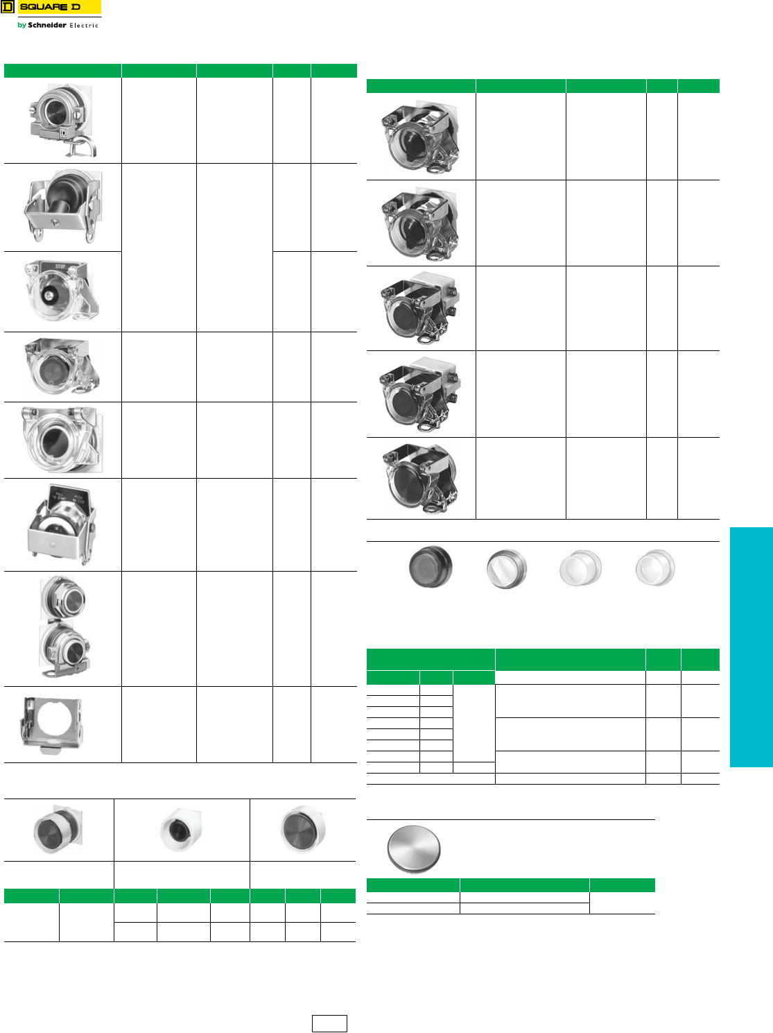
www.schneider-electric.us
19 PUSH BUTTONS AND
OPERATOR INTERFACE
© 2012 Schneider Electric
All Rights Reserved 19-91
30 mm Push Buttons Type K and SK Accessories
Class 9001 / Refer to Catalog 9001CT1103
aThe mushroom guard has finger holes for push-pull operators.
bB=Black G=Green R=Red Y=Yellow
cR=Red Y=Yellow
dUse KU27 for maintained contact push buttons.
eMeets UL and NEMA 1, 2, 3, 4, 4X, 6, 12 and 13.
Dimensions see catalog 9001CT0001
Table 19.264: Padlock Attachments
Used On Description Type $ Price
Type K
non-illuminated
push button —
Standard or
mushroom (KR4,
KR5 mushroom
buttons only).
Holds button in
depressed position
and can be
padlocked.
K4 42.80
Types K and SK
non-illuminated
push buttons with or
without protective
boots.
Holds button in
depressed position
when padlocked.
K5 71.00
K97 42.80
Types K and SK
non-illuminated
push buttons, cover
type attachment.
KR, SKR
Attachment can be
padlocked. Does not
hold button in
depressed position.
K6 42.80
Types K and SK
push buttons, cover
type attachment.
Spring loaded cover
cannot be
padlocked. Does not
hold button in
depressed position.
K60 57.00
Types K and SK
push-pull operator
and illuminated push
buttons. KR8, KR9
Holds button in
depressed position
and can be
padlocked.
K62 71.00
KR11U and KR12U
Interlocked
Assembly
Holds maintained
button in depressed
position and can be
padlocked.
K96 42.80
Type KR9 & SKR9
Push-Pull
operators—
Non-Illuminated
and Illuminated
Holds button in
depressed position.
Can be padlocked.
K162 59.00
Table 19.265: Mushroom Button Guards
Aluminum Mushroom Guard
for 1.375 in. Mushroom Button
Operator (KR4, KR24)
Yellow Plastic Extended Mushroom
Guard for 1.375 in. and 1.625 in.
Mushroom Button Operators
Aluminum Mushroom Guard
for 2.25 in. Mushroom Button
Operator
Type $ Price Type Used On $ Price Type Used On $ Price
K48 57.00
K56bKR4,
SKR4 57.00 K68 KR5 57.00
K56cMaKR8, KR9,
SKR8, SKR9 68.00 K685 KR25 68.00
Table 19.266: Padlock Attachments
Used On Description Type $ Price
Types K and SK
selector switches and
potentiometers (will not
work with gloved-hand
knob).
Cover type
attachment that can
be padlocked to keep
unauthorized
personnel from
tampering with the
operator.
K7 42.80
Types K and SK
selector switches and
potentiometers (will not
work with gloved-hand
knob).
Same as 9001K7 but
with spring loaded
lockout cover.
K107 56.00
Types K and SK
illuminated push buttons
(with or without guard)
and key operated push
buttons.
Cover type
attachment that can
be padlocked to keep
unauthorized
personnel from
tampering with the
operator.
K108 42.80
Types K and SK
illuminated push buttons
(with or without guard)
and key operated push
buttons.
Same as 9001K108
but with spring loaded
lockout cover.
K109 57.00
Types K and SK
maintained push-pull
operators using 1.375 in.
dia. mushroom buttons
(-20 series as shown on
page 19-92).
Cover type
attachment that holds
mushroom button in
depressed position
and can be
padlocked.
K110 54.00
Table 19.267: Protective Boots
Note: These Type KU protective boots are recommended for very dirty environments or severe
hose down, but they are not required for UL Type 4 rating on the Type K operators or UL
Type 4 or 4X rating on the Type SK operators. The K1 wrench (see page 19-93) is required
for installation of these boots.
For Non-Illuminated
Push ButtonsdClear Color for Type $ Price
Color Type $ Price Standard knob selector switch KU17 42.80
Black KU1
28.70
Gloved-hand cap for use on standard
knob selector switch
KU18
42.80Red KU2
Blue KU3
Brown KU4 Standard pilot light and maintained contact
push buttons
KU27
42.80Green KU5
Yellow KU6
Clear KU7 Push-to-test and illuminated push button
without guard
KU37 42.80
Clear KU8 42.80
(Provides Full Guard) Illuminated push button with guard KU47 57.00
Table 19.268: Closing Plates
Round (1-1/2 in. Dia.)
Description Type $ Price
Gray K51e14.30
Black K52e
KU1 KU17 KU37 KU27
CS1 Discount
Schedule
NOTE: When ordering, add prefix 9001 to the catalog number.
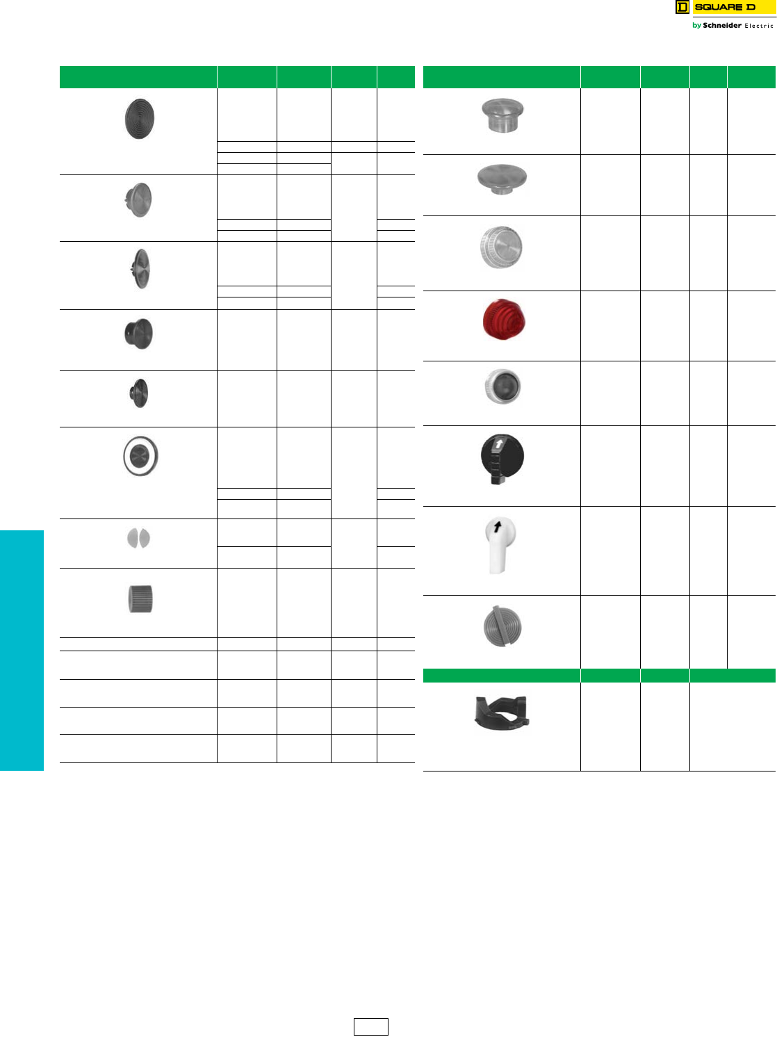
www.schneider-electric.us
19 PUSH BUTTONS AND
OPERATOR INTERFACE
19-92 © 2012 Schneider Electric
All Rights Reserved
30 mm Push Buttons Type K and SK Accessories
Class 9001 / Refer to Catalog 9001CT1103
Table 19.269: Accessories
aIncludes one each of the following color inserts: Black, Red, Green, Yellow, Orange, Blue,
and White.
b“EMERGENCY STOP” is in raised letters and hot stamped white across the front of the
mushroom button.
cThe mushroom button cap listed here may be assembled to a 9001KR1U or SKR1U to
form a 9001KR4 or SKR4.
dThe mushroom button cap listed here may be assembled to a 9001KR1U or SKR1U to
form a 9001KR5 or SKR5.
eThe mushroom button cap listed here may be assembled to a 9001KR20 to form a
9001KR24 or SKR20 to form a 9001SKR24.
fThe mushroom button cap listed here may be assembled to a 9001KR20 to form a
9001KR25 or a SKR20 to form a 9001SKR25.
gThese color caps are opaque and are for use on non-illuminated operators only.
hIncludes two of each of the following color inserts: Black, Red, and Green.
iMay be used on KR8 and KR9 operators. Order mushroom button and K54 adapter (no
charge) from page 19-88. Using the K54 adapter voids Type 6 rating.
jRed knob with “Push Emergency Stop” marked on top of knob.
Description Color Type Package
Qty.
$ Price
Each
Color inserts for
KR1, KR2, KR3, SKR1, SKR2, SKR3, KR11,
KR12, SKR11, SKR12, KRD, T, TRD
Black
Blue
Gray
Green
Orange
Red
T8BK
T8BE
T8GY
T8GN
T8OE
T8RD
10 .72
Universal aT8U 75.70
White T8WH 10 .70
Yellow T8YW
1.375 in. Snap-in Mushroom knob for
KR4 and SKR4 c
Black
Blue
Green
Orange
Red
K16B
K16L
K16G
K16S
K16R 1
42.80
Red b K16R05 47.60
Yellow K16Y 42.80
2-1/4 in. Snap-in Mushroom knob for
KR5 and SKR5 d
Black
Blue
Green
Orange
Red
K17B
K17L
K17G
K17S
K17R 1
42.80
Red bK17R05 42.80
Yellow K17Y 42.80
1-3/8 in. Screw-on Mushroom knob for
KR24 and SKR24e
Black
Blue
Green
Orange
Red
Yellow
K92B
K92L
K92G
K92S
K92R
K92Y
142.80
2-1/4 in. Screw-on Mushroom knob for
KR25 and SKR25 f
Black
Blue
Green
Orange
Red
Yellow
K93B
K93L
K93G
K93S
K93R
K93Y
142.80
Push-Pull Knobs for
KR8, KR9, SKR8, SKR9 Operators
Amber
Black g
Blue
Clear
Green
Orange g
Red
A22
B23
L22
C22
G22
S23
R22
1
9.90
Red jR2205 15.80
White
Yellow
W22
Y22 9.90
Color Inserts for Dual Function
Operators KR6, KR7, KR67
Black
Green
Red
B19
G19
R19 10
1.40
Universal hU19 8.60
Standard Color
Caps for Illuminated Push Buttons
K1L, K2L, K3L, SK1L, SK2L
Amber
Blue
Clear
Green
Red
White
Yellow
A7
L7
C7
G7
R7
W7
Y7
19.90
Knob for KR9R94 Red R94 19.90
Metal Knob for KR24
Red
Green
Black
K92RM
K92GM
K92BM
151.00
Metal Knob for KR25
Red
Green
Black
K93RM
K93GM
K93BM
163.00
Metal Knob for KR9 (40 mm)
Red
Green
Black
K94RM
K94GM
K94BM
151.00
Metal Knob for KR9 (60 mm) Red
Green
Black
K95RM
K95GM
K95BM
163.00
Description Color Type Package
Qty.
$ Price
Each
1-3/8 in. Mushroom Knob for
Illuminated Push Buttons K2L, SK2L i
Amber
Blue
Clear
Green
Red
White
Yellow
A20
L20
C20
G20
R20
W20
Y2
19.90
2-1/4 in. Mushroom Knob for
Illuminated Push Buttons K2L, SK2L i
Amber
Blue
Clear
Green
Red
White
Yellow
A21
L21
C21
G21
R21
W21
Y21
19.90
Plastic Fresnel Pilot Light Lens for
KP, KT, SKP, SKT
Amber
Blue
Clear
Green
Red
White
Yellow
A31
L31
C31
G31
R31
W31
Y31
19.90
Domed Plastic Pilot Light Lens for
KP, KT, SKP, SKT
Amber
Blue
Clear
Green
Red
White
Yellow
A9
L9
C9
G9
R9
W9
Y9
19.90
Glass Pilot Light Lens for
KP, KT
Amber
Blue
Clear
Green
Red
White
Yellow
A6
L6
C6
G6
R6
W6
Y6
19.90
Standard Selector Switch Knob for
K and SK Selector Switches
Amber
Black g
Blue
Clear
Green
Orange g
Red
White
Yellow
A8
B11
L8
C8
G8
S11
R8
W8
Y8
19.90
Gloved-Hand Selector Switch Knob for
K and SK Selector Switches
Amber
Black g
Blue
Clear
Green
Orange g
Red
White
Yellow
A24
B25
L24
C24
G24
S25
R24
W24
Y24
19.90
Color Inserts for
KQ and TQ Selector Push Buttons
Black
Blue
Green
Orange
Red
White
Yellow
T5BK
T5BE
T5GN
T5OE
T5RD
T5WH
T5YW
10 1.40
Cam Type $ Price Each
Selector Switch Cams
B
C
D
E
F
G
H
J
L
M
K13B
K13C
K13D
K13E
K13F
K13G
K13H
K13J
K13L
K13M
6.30
CS1 Discount
Schedule
NOTE: When ordering, add prefix 9001 to the catalog number.
www.schneider-electric.us
19 PUSH BUTTONS AND
OPERATOR INTERFACE
© 2012 Schneider Electric
All Rights Reserved 19-93
aMaintained button of two button operator.
bMomentary button of two button operator.
cSecondary ring nut (holds knob on selector switch or potentiometer).
dGE44 and GE755 are interchangeable (GE755 gives longer life). If a GE44 lamp is
ordered, a GE755 (2550101020) will be substituted. For a replacement lamp in a current
series light module see the light module listing on page 19-86.
eAllows Type -20 and -21 mushroom color caps to be used on push-pull operators. Use of
9001K54 voids Type 6 rating.
Table 19.270: Ring Nuts
Used On Type Used On Type $ Price
K1L K44 SK1L SK44 18.50
K30-K37 K45 ——4.40
K70-K73 K45 ——4.40
K20, K21, K22, K23 K45 SK20, SK21, SK22, SK23 SK45 4.40
K20, K21, K22, K23 cSK46 SK20, SK21, SK22, SK23 cSK46 4.40
K2L K49 SK2L SK49 4.40
K3L (complete) K111 ——18.50
K3L (metal top only) 6515802701 ——12.00
KP, KTR K41 SKP, SKTR SK41 4.40
KR1 K41 SKR1 SK41 4.40
KR11 K42 SKR11 SK42 4.40
KR12 aK42 SKR12 aSK42 4.40
KR12 bK41 SKR12 bSK41 4.40
KR13, 14, 15 K55 ——4.40
KR2 K42 SKR2 SK42 4.40
KR20 K49 ——4.40
KR24 K49 ——4.40
KR25 K49 SKR25 SK49 4.40
KR3 K40 SKR3 SK40 4.40
KR4 K41 SKR4 SK41 4.40
KR5 K41 SKR5 SK41 4.40
KR6 K47 ——4.40
KR67 K47 ——4.40
KR7 K47 ——4.40
KR8 K58 SKR8 6509704401 4.40
KR9 K41 SKR9 SK41 4.40
KS K45 SKS SK45 4.40
KS cSK46
SKS c
SKRU11
SKRU1,2,3,4,5,10
SK46
SK41
SK40
4.40
KT K49 SKT SK49 4.40
Table 19.271: Replacement Lamps For Series A–F (black)
Light Modules
Light
Module Type
Lamp Number
(ANSI)
Square D Replacement Lamps
Part Number $ Price
KM1 GE44d——
KM2 GE1490 2550101003 12.45
KM3 GE44d——
KM4 GE1490 2550101003 12.45
KM5 GE44d——
KM6 GE44d——
KM7 GE44d——
KM8 GE44d——
KM9 GE755 2550101020 12.45
KM11 CMDK1A5 2550105014 33.00
KM12 CMDK1A5 2550105014 33.00
KM13 CMDK1A5 2550105014 33.00
KM14 CMDK1A5 2550105014 33.00
KM15 CMDK1A5 2550105014 33.00
KM21 SYL12PSB 2550105003 16.50
KM22 SYL12PSB 2550105003 16.50
KM23 SYL28PSB 2550105008 16.50
KM25 SYL120PSB 2550105005 16.50
KM31 SYL6PSB 2550105007 16.50
KM32 SYL12PSB 2550105003 16.50
KM34 SYL24PSB 2550105004 16.50
KM35 SYL28PSB 2550105008 16.50
KM36 SYL48PSB 2550105009 16.50
KM37 SYL60PSB 2550105010 16.50
KM38 SYL120PSB 2550105005 16.50
Table 19.272: Repair Parts
Description Part Number $ Price
E10 Key
Gray cap for KR11, KR12, SKR11, or SKR12
Clear plastic top (only) for 9001K44 & SK44
Ring Nut
Gasket for Type K and SK Push-Pull Knob
Gasket for Plastic Illuminated Lens
Gasket for Type K and SK selector switch knob
Black Compensating Gasket (Type K and SK
Operators
Liner for Non-Illuminated Operators
Locking Thrust Washer
Nylon Spacer
Locking Thrust Washer (Std. Type SK Operator)
Push-Pull Mushroom Adaptere
Rubber Boot for Joystick
Knob on Joysticks without latch
Knob for SK Potentiometer
Fingersafe™ Cover for 9001KM
2941101100
3105217001
4487D63XI
6509701801
6509701901
3105406401
6509702001
6509704901
6512231201
6509705001
6512240601
K54
6512243201
4458D20X3
3105404408
6508804101
9.90
13.80
7.95
1.95
3.90
1.95
3.90
N/C
3.90
5.10
3.90
N/C
7.20
12.90
10.65
3.00
Table 19.273: KU Replacement Ring Nuts
(Threaded Inside and Out)
Used On Part Number $ Price
KU1 through KU8, KU27, KU37, KU47 3105204101 4.35
KU17, KU18 3105205901 10.65
Table 19.274: Interlock
For mechanically interlocking two push buttons so that
only one button can be depressed at a time. A Type K3
attachment is furnished with the 9001 KR11, KR12,
SKR11, SKR12, SKRU1 and SKRU11 operators.
However, these are maintained operators and the K3
interlock serves to release one of the buttons when the
other is depressed. When used with momentary contact
buttons, the K3 interlock does not hold the buttons in
the depressed position. It simply prevents pushing both
buttons at the same time.
The Type K3 interlock is mounted behind the operators.
Operators not included.
Type $ Price
K3 28.65
Table 19.275: Screwdriver
Used to tighten mounting screws on
contact blocks and light modules.
Type $ Price
K69 35.50
Table 19.276: Wrenches
K95 K1
Where Used Type $ Price
For tightening ring nuts on 22 and 30 mm control units K95 42.75
For tightening threaded protective caps K1 71.40
CS1 Discount
Schedule
NOTE: When ordering, add prefix 9001 to the catalog number.
30 mm Push Buttons Type K and SK Accessories
Class 9001 / Refer to Catalog 9001CT1103
NOTE: For more information, see Instruction Bulletin No. 30072-100-10.
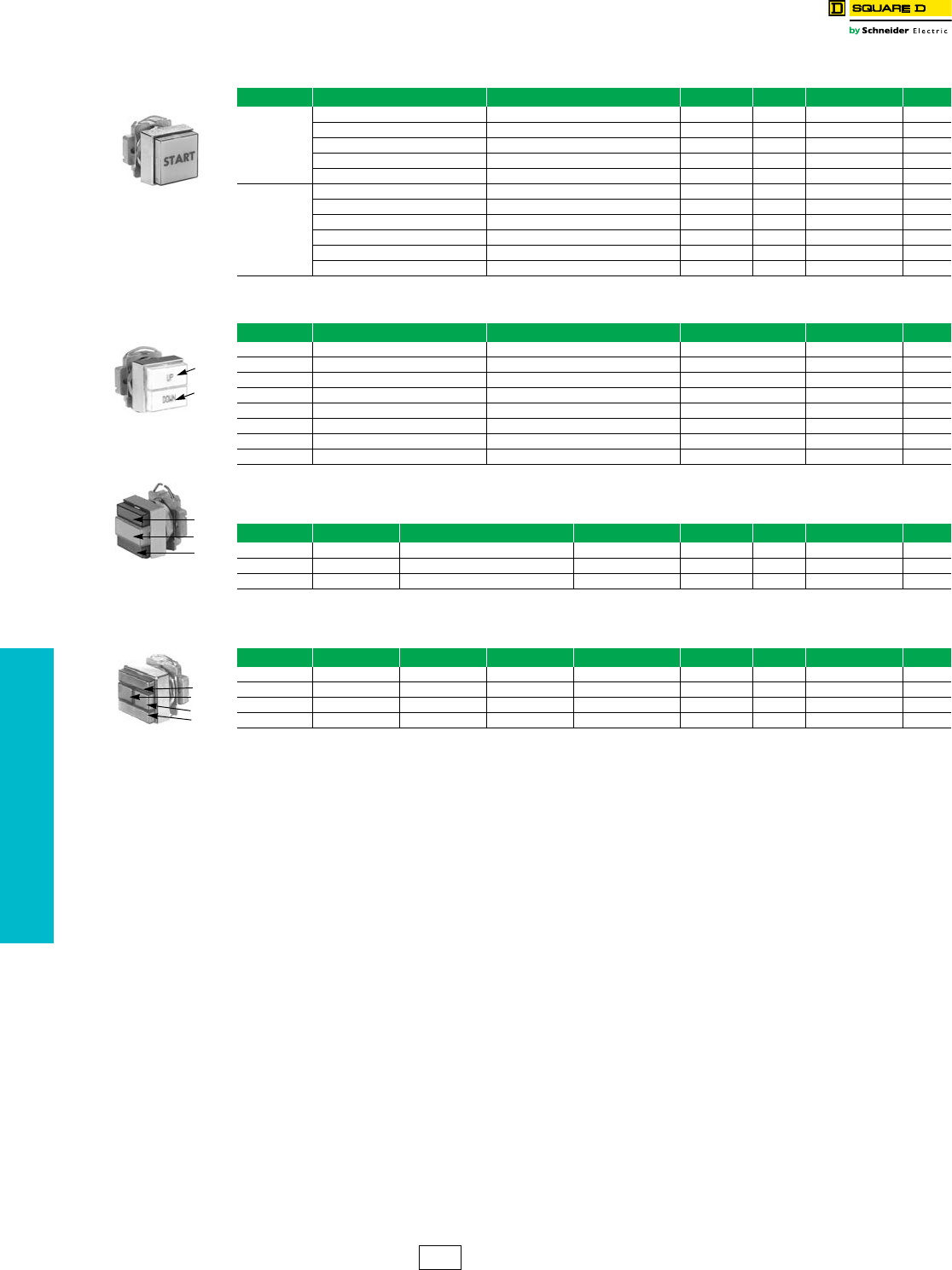
www.schneider-electric.us
19 PUSH BUTTONS AND
OPERATOR INTERFACE
19-94 © 2012 Schneider Electric
All Rights Reserved
Push Buttons, 30 mm
Square
KX Square Multifunction Operators
Class 9001 / Refer to Catalog 9001CT1103
aMaintained operators are mechanically interlocked
bText is vertical
Table 19.277: Push Buttons—Single, with Contacts
Description Button Color Legend Marking Contacts Voltage Type $ Price
Non-
Illuminated
Green Start 1 N/O — KXRA133 64.00
Red Stop 1 N/C — KXRA134 64.00
Amber blank 2 C/O — KXRAAH2 138.00
Green blank 2 C/O — KXRAGH2 138.00
Blue blank 2 C/O — KXRALH2 138.00
Illuminated
Amber blank 1 C/O 24 KXRB34AH1 184.00
Green blank 1 C/O 24 KXRB34GH1 184.00
Red blank 1 C/O 24 KXRB34RH1 184.00
Amber blank 1 C/O 110/120 KXRB1AH1 217.00
Green blank 1 C/O 110/120 KXRB1GH1 217.00
Red blank 1 C/O 110/120 KXRB1RH1 217.00
Table 19.278: Push Buttons—Dual, with Contacts
Description Top Button (#1) Lower Button (#2) Contacts Type $ Price
Momentary Start (Green) Stop (Red) 2 C/O KXRC111 171.00
Momentary Start (Green) Stop (Red) 1 N/O, 1 N/C KXRC136 129.00
Momentary Up (Green) Down (Green) 2 N/O KXRD140 135.00
Momentary blank (Blue) blank (Blue) 2 N/O KXRDLLH7 139.00
MaintainedaStart (Green) Stop (Red) 1 C/O KXRE115 171.00
Maintained aOn (Blue)bOff (Blue)b3 C/O KXRELLH3 273.00
Maintained aOn (Blue)bOff (Blue)b3 C/O KXRELLH3 273.00
Maintained aOn (Blue)bOff (Blue)b2 C/O KXRELLH2 277.00
Table 19.279: Push Buttons—Dual with One Pilot Light and Contacts
Description Top Button (#1) Middle Lens (#2) Lower Button (#3) Contacts Voltage Type $ Price
Momentary Start (Green) On (Red) Stop (Red) 2 C/O 110/120 KXRG117 314.00
Momentary Start (Green) On (Red) Stop (Red) 1 N/O, 1 N/C 110/120 KXRG137 270.00
Maintained aStart (Green) On (Red) Stop (Red) 1 C/O 110/120 KXRJ119 329.00
Table 19.280: Push Buttons—Dual with Two Pilot Lights and Contacts
Description Top Button (#1) Left Lens (#2) Right Lens (#3) Lower Button (#4) Contacts Voltage Type $ Price
Momentary Start (Green) On (Red) Off (Green) Stop (Red) 2 C/O 110/120 KXRL121 485.00
Momentary Start (Green) On (Red) Off (Green) Stop (Red) 1 N/O, 1 N/C 110/120 KXRL138 441.00
Momentary Start (Green) On (Red) Off (Green) Stop (Red) 2 C/O 24 KXRL34GRGRH2 451.00
Momentary Start (Green) On (Red) Off (Green) Stop (Red) 1 N/O, 1 N/C 24 KXRL34GRGRH37 494.00
1
2
1
2
3
Pilot Light at
110–120 V, 50–60 Hz
Transformer
1
2
3
4
Pilot Lights at
110–120 V, 50–60 Hz
Transformer
CS1 Discount
Schedule
NOTE: When ordering, add prefix 9001 to the catalog number.
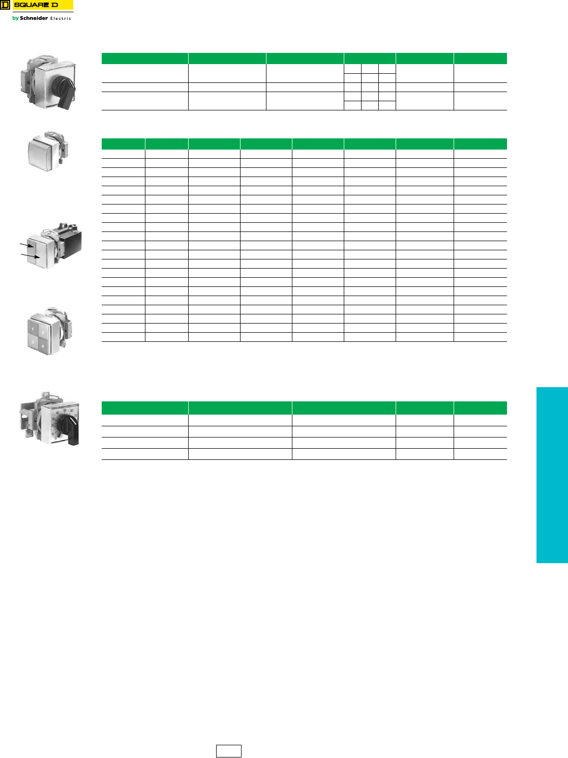
www.schneider-electric.us
19 PUSH BUTTONS AND
OPERATOR INTERFACE
© 2012 Schneider Electric
All Rights Reserved 19-95
Push Buttons, 30 mm
Square
KX Square Multifunction Operators
Class 9001 / Refer to Catalog 9001CT1103
\
Table 19.281: Selector Switches—with Contacts
Description Legend Knob Contacts Type $ Price
2-position, maintained Off-On Black 10 KXSA125 99.00
01
2-position, maintained Off-On Black 1 0 KXSA139 78.00
3-position, maintained Hand-Off-Auto Black 100 KXSD126 99.00
001
Table 19.282: Pilot Lights
Description Voltage Lens 1* Lens 2* Lens 3* Lens 4* Type $ Price
Single 24 Amber KXPA35A 125.00
Single 24 Red KXPA35R 125.00
Single 24 Green KXPA35G 125.00
Single 24 White KXPA35W 125.00
Single 110/120 Amber KXPA1A 153.00
Single 110/120 Red KXPA1R 153.00
Single 110/120 Green KXPA1G 153.00
Single 110/120 White KXPA1W 153.00
Dual 24 Amber Amber KXPB34AA 219.00
Dual 24 Red Red KXPB34RR 219.00
Dual 24 Green Green KXPB34GG 219.00
Dual 24 White White KXPB34WW 219.00
Dual 24 Red Green KXPB34RG 219.00
Dual 110/120 Amber Amber KXPB1AA 278.00
Dual 110/120 Red Red KXPB1RR 278.00
Dual 110/120 Green Green KXPB1GG 278.00
Dual 110/120 White White KXPB1WW 278.00
Dual 110/120 Red Green KXPB1RG 278.00
Quad 24 White Amber Green Red KXPC34WAGR 552.00
Quad 110/120 White Amber Green Red KXPC1WAGR 552.00
Quad 110/120 White Blue Green Red KXPC1WLGR 552.00
* Lenses are blank (no markings)
Table 19.283: Potentiometers
Description Power Resistance Type Price
Single 2 W 3.2 kΩKXBB06 287.00
Single 2 W 5 kΩKXBB07 287.00
Single 2 W 10 kΩKXBB08 287.00
Tandem 2 W 5 kΩ / 5 kΩKXBD83 399.00
110–120 V,
50–60 Hz
Transformer
110–120 V, 50–60 Hz.
Transformer
1
2
110–120 V, 50–60 Hz
Transformer
CS1 Discount
Schedule
NOTE: When ordering, add prefix 9001 to the catalog number.
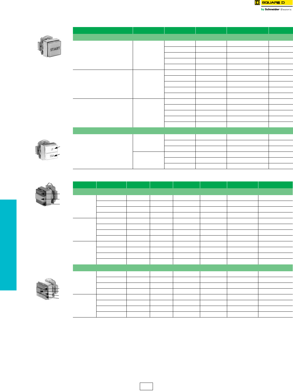
www.schneider-electric.us
19 PUSH BUTTONS AND
OPERATOR INTERFACE
19-96 © 2012 Schneider Electric
All Rights Reserved
Push Buttons, 30 mm
Square
KX Square Multifunction Operators
Class 9001 / Refer to Catalog 9001CT1103
aOrder contact blocks separately (See Table 19.287 on Page 19-97)
Accessories . . . . . . . . . . . . . . . . . . . . . . . . . . . . . . . . . . . . . . . . . . Page 19-99
Table 19.284: Push Buttons—without Contacts a
Push Button Action Lens Color (1) Lens Color (2) Type Price
Single Push Button
Non-Illuminated Momentary
Amber — KXRAA 38.60
Green — KXRAG 38.60
Blue — KXRAL 38.60
Red — KXRAR 38.60
White — KXRAW 38.60
Illuminated 24 V Momentary
Amber — KXRB35A 125.00
Green — KXRB35G 125.00
Blue — KXRB35L 125.00
Red — KXRB35R 125.00
White — KXRB35W 125.00
Illuminated 110/120 V Momentary
Amber — KXRB38A 125.00
Green — KXRB38G 125.00
Blue — KXRB38L 125.00
Red — KXRB38R 125.00
White — KXRB38W 125.00
Dual Push Button
Non-Illuminated
Momentary +
Interlock
Green Red KXRCGR 77.00
White White KXRCWW 77.00
Green Green KXRCGG 77.00
Maintained +
Interlock
Green Red KXREGR 120.00
White White KXREWW 120.00
Green Green KXREGG 120.00
Table 19.285: Dual Push Button with Pilot Light—without Contacts a
Action Voltag e Lens Color (1) Lens Color (2) Lens Color (3) Lens Color (4) Type Price
With One Pilot Light
Momentary
24 Vac/dc Red White Green — KXRG35RWG 188.00
24 Vac/dc Green White Green — KXRG35GWG 188.00
110/120 Vac/dc Red White Green — KXRG38RWG 188.00
110/120 Vac/dc Green White Green — KXRG38GWG 188.00
Momentary +
Interlock
24 Vac/dc Red White Green — KXRH35RWG 221.00
24 Vac/dc Green White Green — KXRH354GWG 221.00
110/120 Vac/dc Red White Green — KXRH38RWG 221.00
110/120 Vac/dc Green White Green — KXRH38GWG 221.00
Maintained +
Interlock
24 Vac/dc Red White Green — KXRJ35RWG 243.00
24 Vac/dc Green White Green — KXRJ35GWG 243.00
110/120 Vac/dc Red White Green — KXRJ38RWG 243.00
110/120 Vac/dc Green White Green — KXRJ38GWG 243.00
With Two Pilot Lights
Momentary
24 Vac/dc Red White White Green KXRL35RWWG 324.00
24 Vac/dc Red Red Green Green KXRL35GGRR 324.00
110/120 Vac/dc Red White White Green KXRL38RWWG 324.00
110/120 Vac/dc Red Red Green Green KXRL38GGRR 324.00
Momentary +
Interlock
24 Vac/dc Red White White Green KXRM35RWWG 368.00
24 Vac/dc Red Red Green Green KXRM35RRGG 368.00
110/120 Vac/dc Red White White Green KXRM38RWWG 368.00
110/120 Vac/dc Red Red Green Green KXRM38RRGG 368.00
1
2
1
2
3
1
2
3
4
CS1 Discount
Schedule
NOTE: When ordering, add prefix 9001 to the catalog number.
www.schneider-electric.us
19 PUSH BUTTONS AND
OPERATOR INTERFACE
© 2012 Schneider Electric
All Rights Reserved 19-97
Selectors, 30 mm
Square
KX Square Multifunction Operators
Class 9001 / Refer to Catalog 9001CT1103
aOrder contacts separately (See Table 19.287)
Table 19.286: Selectors—without Contacts a
Description Voltage Knob Color Type $ Price
2-Position, Maintained
Non-Illuminated — Black KXSAEB 53.00
Illuminated 24 Vac/dc Red KXSJE35R 138.00
Illuminated 24 Vac/dc Green KXSJE35G 138.00
Illuminated 24 Vac/dc White KXSJE35W 138.00
Illuminated 120 Vac/dc Red KXSJE38R 138.00
Illuminated 120 Vac/dc Green KXSJE38G 138.00
Illuminated 120 Vac/dc White KXSJE38W 138.00
Key (Withdraw L) — N/A KXSRE1 140.00
Key (Withdraw R) — N/A KXSRE2 138.00
Key (Withdraw Both) — N/A KXSRE3 138.00
3-Position, Maintained
Non-Illuminated — Black KXSDCB 53.00
Key (Withdraw C) — N/A KXSVC5 138.00
Key (Withdraw All) — N/A KXSVC10 138.00
4-Position, Maintained Non-Illuminated — Black KXSHHB 58.00
Table 19.287: Contact Blocks—Purchase Separately
Description Type $ Price
(Clear Cover)
1 N/O, 1 N/C KA1 42.80
(Green Cover)
1 N/O KA2 21.50
(Red Cover)
1 N/C KA3 21.50
(Clear Cover)
1 N/C, 1 N/O (Early Make) KA4 42.80
(Red Cover)
1 N/C (Late Break) KA5 21.50
(Green Cover)
1 N/O (Early Make) KA6 21.50
CS1 Discount
Schedule
NOTE: When ordering, add prefix 9001 to the catalog number.
www.schneider-electric.us
19 PUSH BUTTONS AND
OPERATOR INTERFACE
19-98 © 2012 Schneider Electric
All Rights Reserved
aThese legend inserts are for the pilot lights in the center of the operator.
bThese legend inserts are for the push button portion of the operator.
cThese legend inserts have vertical printing.
All Type KX push buttons and pilot lights have a blank insert as
standard. These blank inserts can be custom marked using a marking
pen, a mechanical lettering set, press letters, or a tape lettering machine
that marks a tape which can then be transferred to the blank insert.
To have legend inserts installed into the operators, order the operator as
normal and then indicate where to install the legend inserts using the
numbered positions shown on the operator ordered.
Table 19.288: Legend Plates for Push Buttons or Pilot Lights
Marking
Used On
$ Price
A B C D E F
KXRA,
KXRB
KXRN,
KXRP
KXPA,
KXPC
KXTA,
KXTB
KXTE
KXRC,
KXRD
KXRE,
KXRF
KXPB
KXTD c
KXRG,
KXRH
KXRJ,
KXRKa
KXRG,
KXRH
KXRJ,
KXRK
KXRL,
KXRM
KXTC b
KXRL,
KXRM
KXTC a
Blank
Start
Stop
On
Off
Emerg. Stop
Forward
Reverse
Close
Open
Down
Up
Jog
Reset
Run
Cycle Start
Motor Run
Power On
KXN100
KXN101
KXN102
KXN103
KXN104
KXN105
KXN106
KXN107
KXN108
KXN109
KXN110
KXN111
KXN118
KXN123
KXN124
KXN132
KXN136
KXN138
KXN200
KXN201
KXN202
KXN203
KXN204
KXN205
KXN206
KXN207
KXN208
KXN209
KXN210
KXN211
KXN218
KXN223
KXN224
KXN232
KXN236
KXN238
KXN200
KXN201V
KXN202V
KXN203V
KXN204V
KXN205V
KXN206V
KXN207V
KXN208V
KXN209V
KXN210V
KXN211V
KXN218V
KXN223V
KXN224V
KXN232V
KXN236V
KXN238V
KXN300
KXN301
KXN302
KXN303
KXN304
KXN305
KXN306
KXN307
KXN308
KXN309
KXN310
KXN311
KXN318
KXN323
KXN324
KXN332
KXN336
KXN338
KXN400
KXN401
KXN402
KXN403
KXN404
KXN405
KXN406
KXN407
KXN408
KXN409
KXN410
KXN411
KXN418
KXN423
KXN424
KXN432
KXN436
KXN438
KXN500
KXN501
KXN502
KXN503
KXN504
KXN505
KXN506
KXN507
KXN508
KXN509
KXN510
KXN511
KXN518
KXN523
KXN524
KXN532
KXN536
KXN538
4.40
Special-
Marking KXN199 KXN299 KXN299V KXN399 KXN499 KXN599 18.50
Table 19.289: Legend Plates for Selector Switches
Used On
Marking $ Price
KXSA, KXSB, KXSC, KXSD,
KXSE, KXSF, KXSG, KXSH,
KXSJ, KXSK, KXSL, KXSM,
KXSN, KXSO, KXSP, KXSQ
KXSR, KXSS, KXST,
KXSV, KXSW, KXSX,
KXSY, KXSZ
Blank
For.-Rev.
Hand-Auto
Man-Auto
Off-On
On-Off
Open-Close
Start-Stop
Auto-Off-Hand
Hand-Off-Auto
Man-Off-Auto
KXN600
KXN639
KXN640
KXN643
KXN644
KXN645
KXN646
KXN651
KXN658
KXN660
KXN662
KXN700
KXN739
KXN740
KXN743
KXN744
KXN745
KXN746
KXN751
KXN758
KXN760
KXN762
4.40
Special Marking KXN699 KXN799 18.50
1.23
31
1.23
31 1.23
31
0.56
14
0.56
14
1.23
31
0.48
12
0.43
11
0.26
7
Square
AB
C (vertical)
DE F
1.33
34
0.76
19
Square
KXN-600
1.33
34
0.76
19
Square
KXN-700
KXN100
KXN200
(Pos. 1)
KXN400
(Pos. 1)
KXN300
(Pos. 2)
KXN400
(Pos. 3)
KXN400
(Pos. 1)
KXN400
(Pos. 4)
KXN-
500
(Pos. 2)
KXN-
500
(Pos. 3)
KXN200
(Pos. 2)
(Pos. 1)
(Pos. 1)
(Pos. 2)
K
X
N
2
0
0
K
X
N
2
0
0
KXRA, KXRB
KXRN, KXRP
KXPA, KXPC
KXTA, KXTB
KXRC, KXRD
KXRE, KXRF
KXRG, KXRH
KXRJ, KXRK
KXRL, KXRM
KXTC
KXPB, KXTD
Table 19.290: Letter Height For Standard Legends
in. mm
KXN100
KXN200
KXN300
KXN400
KXN500
KXN600
KXN700
1•4
3•16
3•16
3•16
3•16
1•8
1•8
6
4.75
4.75
4.75
4.75
3
3
Table 19.291: Maximum Number of Lines and Characters
For Type KXN Legend Inserts
Letter
Height Number
of … KXN199 KXN299
Horizontal
KXN299
Vertical KXN399 KXN499 KXN599
in. mm
1•4 6
Characters
per Line 7 7 3773
Lines per
Legend
Insert
4 2 4111
3•16 4.75
Characters
per Line 9 9 4994
Lines per
Legend
Insert
5 2 6212
1•8 3
Characters
per Line 14 14 5 14 14 6
Lines per
Legend
Insert
8 4 9323
Table 19.292: Maximum Number of Lines and Characters
for Type KXN699 and KXN799 Legend Plates
Position
Letter
Height
Characters Per
Marking Area
in. mm A and C B
3•16 4.75 6 6
1•8 3 8 9
3•16 4.75 10 5
1•8 3 13 7
Example:
9001KXRL1GRGRH2 with a
9001KXN 401 in position 1
9001KXN 503 in position 2
9001KXN 504 in position 3
9001KXN 402 in position 4
B
AC
B
AC
CS1 Discount
Schedule
NOTE: When ordering, add prefix 9001 to the catalog number.
30 mm Push Buttons Type KX Accessories
Class 9001 / Refer to Catalog 9001CT1103
www.schneider-electric.us
19 PUSH BUTTONS AND
OPERATOR INTERFACE
© 2012 Schneider Electric
All Rights Reserved 19-99
aEach KXAC28 includes a clear cover and 1 each of all colors. If the same color is
required for position #1and #2 of the KXPB operator, order 2 of Type KXAC28.
bWhen specifying color codes—the first will be installed in #1 and the second in #2.
The price for BOTH color codes is $6.60.
cEach KXAC48 includes a clear cover and 1 each of all colors. If the same color is
required for position #1and #2 of the KXPC operator, order 2 of Type KXAC48.
dWhen specifying color codes—the first will be installed in #1, the second in #2, the third
in #3 and the fourth in #4. The price for ALL FOUR color codes is $6.60.
eTwo required per operator. When ordering an assembled operator—specify two code
numbers.The first code will be assembled into #1 and the second code will be
assembled into #2.
Table 19.293: Closing Plate
UL Types 4, 13/NEMA 4, 13
Square Closing Plate (Chrome Plated)
Same size as KX bezel
Type $ Price
KXAK52 14.30
Table 19.294: Boots
For Use On Type $ Price
All KX**
push buttons and pilot lights KXAKU7 28.70
All KX**
selector switches and potentiometers KXAKU17B 42.80
Table 19.295: Shrouds
Description For Use On Color Type $ Price
Full Shroud All push buttons and
pilot lights
Red KXAK41R 7.20
Black KXAK41B 7.20
Short Shroud Any KX operator
Red KXAK40R 7.20
Black KXAK40B 7.20
Table 19.296: Lamp and Lens Removal Kit
Used to remove lamp and lens on all
illuminated operators and pilot lights.
Type $ Price
KXALLRT 21.50
Table 19.297: Button Covers
Description For Use On Color Type Code $ Price
Includes
2-KXN200
KXPB
KXTD
Red
Green
Amber
Blue
White
KXAC28a
KXAC28a
KXAC28a
KXAC28a
KXAC28a
Rb
Gb
Ab
Lb
Wb
9.90
Includes
KXN400
KXTC (Position 1 & 4)
Red
Green
Amber
Blue
White
KXAR4
KXAG4
KXAA4
KXAL4
KXAW4
R
G
A
L
W
9.90
Includes
KXN500
KXTC (Position 2 & 3) ó
Red
Green
Amber
Blue
White
KXAR5
KXAG5
KXAA5
KXAL5
KXAW5
R
G
A
L
W
9.90
Includes
1–KXN100
KXPC
Red
Green
Amber
Blue
White
KXAC48c
KXAC48c
KXAC48c
KXAC48c
KXAC48c
Rd
Gd
Ad
Ld
Wd
9.90
Includes
KXN100
KXRA
KXRB
Red
Green
Amber
Blue
White
KXAR1
KXAG1
KXAA1
KXAL1
KXAW1
R
G
A
L
W
6.60
Includes
KXN100
KXRN
KXRP
Red
Green
Amber
Blue
White
KXARM1
KXAGM1
KXAAM1
KXALM1
KXAWM1
R
G
A
L
W
17.10
Includes
KXN200
KXRC
KXRD
KXRE
KXRF
Red
Green
Amber
Blue
White
KXAR2
KXAG2
KXAA2
KXAL2
KXAW2
R
G
A
L
W
9.90
Includes
KXN300
KXRG (Position 2)
KXRH (Position 2)
KXRJ (Position 2)
KXRK (Position 2)
Red
Green
Amber
Blue
White
KXAR3
KXAG3
KXAA3
KXAL3
KXAW3
R
G
A
L
W
9.90
Includes
KXN400
KXRG (Position 1 & 3)
KXRH (Position 1 & 3)
KXRJ (Position 1 & 3)
KXRK (Position 1 & 3)
KXRL (Position 1 & 4)
KXRM (Position 1 & 4)
Red
Green
Amber
Blue
White
KXAR4
KXAG4
KXAA4
KXAL4
KXAW4
R
G
A
L
W
9.90
Includes
KXN500
KXRL (Position 2 & 3)
KXRM (Position 2 & 3)
Red
Green
Amber
Blue
White
KXAR5
KXAG5
KXAA5
KXAL5
KXAW5
R
G
A
L
W
9.90
Includes
KXN100
KXPA
Red
Green
Amber
Blue
White
KXAR8
KXAG8
KXAA8
KXAL8
KXAW8
R
G
A
L
W
9.90
Includes
KXN100
KXTA
KXTB
Red
Green
Amber
Blue
White
KXAR1
KXAG1
KXAA1
KXAL1
KXAW1
R
G
A
L
W
9.90
e
CS1 Discount
Schedule
NOTE: When ordering, add prefix 9001 to the catalog number.
30 mm Push Buttons Type KX Accessories
Class 9001 / Refer to Catalog 9001CT1103
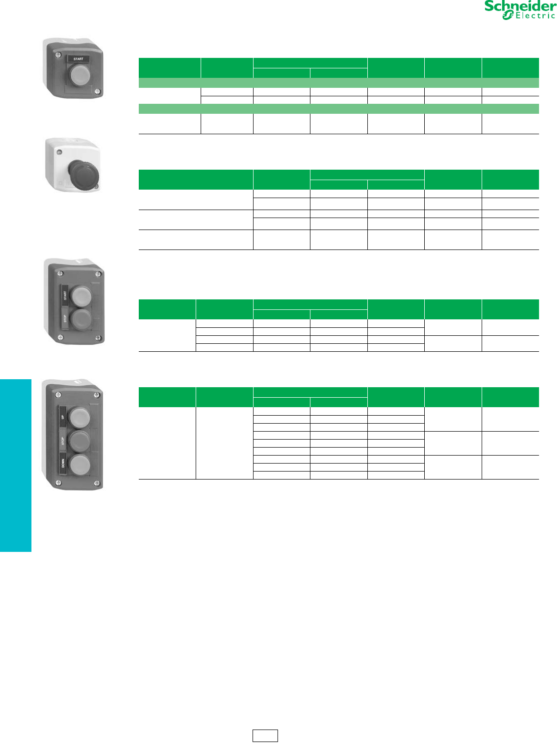
19-100 © 2012 Schneider Electric
All Rights Reserved
www.schneider-electric.us
19 PUSH BUTTONS AND
OPERATOR INTERFACE
Control Stations and
Enclosures
XAL 22 mm Control Stations
Refer to Catalog 9001CT1104
aEmergency Off (IEC 60364-5-53)
bEmergency Stop (EN / IEC 13850)
Table 19.298: Start or Stop Function
Polycarbonate; Light gray base, RAL7035; Dark gray lid, RAL7016
Description Type of Push Type of Contact Marking Catalog Number $ Price
N.O. N.C.
Marking on Legend Holder
1 momentary
push button
Flush black 1 — Start XALD101H29H7 73.00
Flush red — 1 Stop XALD111H29H7 73.00
Marking on Legend Holder
1 mushroom head
push button Ø 40 mm,
momentary
Red — 1 Stop on red legend XALD164H29H7 84.00
Table 19.299: Emergency Stop or Emergency Off Function
Polycarbonate; Light gray base, RAL7035; Yellow lid, RAL1012
Description Type Type of Contact Catalog Number $ Price
N.O. N.C.
1 mushroom head
push button Ø 40 mm, red
Turn-to-release
Standard a—1XALK174H7 117.00
Trigger action b—1XALK178H7 147.00
1 mushroom head
push button Ø 40 mm, red
Key release (Key No. 455)
Standard a—1XALK184H7 147.00
Trigger action b—1XALK188H7 147.00
1 mushroom head
push button Ø 40 mm, red
Push-pull
Standard a—1XALK194H7 99.00
Table 19.300: Start-Stop Function
Polycarbonate; Light gray base, RAL7035; Dark gray lid, RAL7016
Description Type of Push Type of Contact Text Catalog Number $ Price
N.O. N.C.
2 momentary
push buttons
1 flush black 1 — Start XALD211H29H7 73.00
1 flush red — 1 Stop
1 flush black 1 — Forward XALD251H29H7 73.00
1 flush black 1 — Reverse
Table 19.301: Three Function
Polycarbonate; Light gray base, RAL7035; Dark gray lid, RAL7016
Description Type of Push Type of Contact Text Catalog Number $ Price
N.O. N.C.
3 momentary
push buttons
(no markings)
1 flush black
1 flush red
1 flush black
1—Open
XALD351H29H7 143.00—1Stop
1 — Close
1—Forward
XALD311H29H7 143.00—1Stop
1—Reverse
1—Up
XALD321H29H7 143.00—1Stop
1 — Down
XALD101H29H7
XALK174H7
XALD211H29H7
XALD321H29H7
CS2 Discount
Schedule
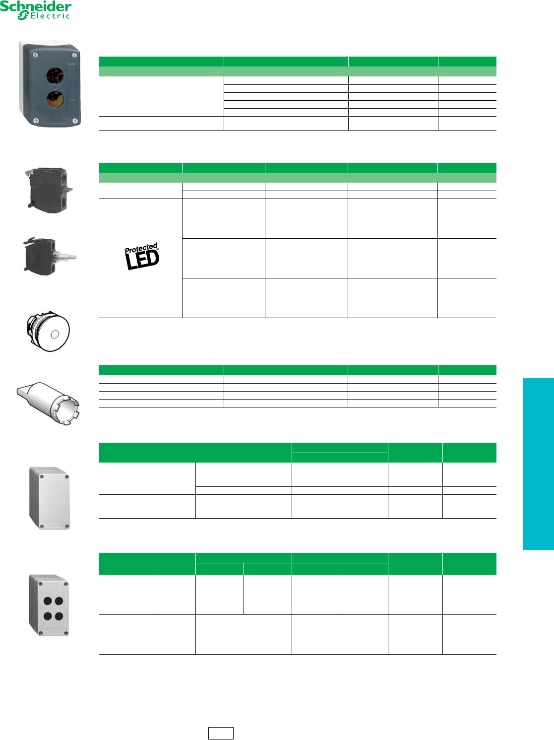
www.schneider-electric.us
19 PUSH BUTTONS AND
OPERATOR INTERFACE
© 2012 Schneider Electric
All Rights Reserved 19-101
Control Stations and
Enclosures
XAL 22 mm Control Stations
Refer to Catalog 9001CT1104
aFor customer assembly using XB5 operators and standard screw-terminal contact blocks, see Push Buttons—ZB5 22 mm starting on page 19-45.
Either mounting method can be used: contact block ZENL mounting on metal plate, or contact block ZBE mounting on operator with mounting collar.
bUses standard XB5 products from pages 19-42 through 19-62. Do not use ZENL style contact blocks.
Table 19.302: Empty Enclosures a
Polycarbonate
Description Number of Holes Catalog Number $ Price
For normal environments, CSA approved and UL Listed (with stainless steel lid mounting screws)
Light gray base RAL7035
Dark gray lid RAL7016
1XALD01H7 32.80
2XALD02H7 38.20
3XALD03H7 49.00
4XALD04H7 71.00
5XALD05H7 87.00
Light gray base RAL7035
Yellow lid RAL1012 1XALK01H7 35.40
Table 19.303: Electrical Block and Accessories (for mounting on metal plate at back of enclosure) a
Description Type Color Catalog Number $ Price
Electrical blocks with screw clamp terminal connections
Metal-plate-mounting
contact blocks
N.O. contact — ZENL1111 16.60
N.C. contact — ZENL1121 16.40
Light blocks with
24 Vac/Vdc
White ZALVB1
52.00
Green ZALVB3
Red ZALVB4
Ye l l o w ZALVB5
Blue ZALVB6
120 Vac
White ZALVG1
52.00
Green ZALVG3
Red ZALVG4
Ye l l o w ZALVG5
Blue ZALVG6
230 Vac
White ZALVM1
52.00
Green ZALVM3
Red ZALVM4
Ye l l o w ZALVM5
Blue ZALVM6
Table 19.304: Accessories for electrical blocks
Description Application Catalog Number $ Price
Blanking plug Ø 22 mm units ZB5SZ3 11.00
Nut Head mounting ZB5AZ901 4.40
Grounding terminal Grounding XALZ09 5.40
Key For tightening nut ZB5AZ905 12.40
Table 19.305: Undrilled Enclosures, Glass-Reinforced Polyester
Type H x W Dimensions Catalog Number $ Price
IN mm
NEMA 4, 4X, 13
Usable depth 3.27 in. (83 mm)
Without hinges
3.34 x 5.75 85 x 146 XAPA1100 110.00
3.34 x 8.90 85 x 226 XAPA2100 180.00
5.95 x 9.49 151 x 241 XAPA3100 284.00
With hinges 5.95 x 9.49 151 x 241 XAPA4100 378.00
Undrilled Grounding Plate Sheet steel with ground screw
For XAPA1100 XAPZ100 22.00
For XAPA2100 XAPZ200 24.60
For XAPA3100 and 4100 XAPZ300 32.00
Table 19.306: Drilled Insulated Enclosures, Glass-Reinforced Polyester b
Type
Number of
Knockouts
22 mm
Number of Rows H x W Dimensions
Catalog Number $ Price
Vertical Horizontal IN mm
NEMA 4, 4X, 13
Usable depth
3.27 in. (83 mm)
1.58 in. (40 mm)
centerline
spacing of holes
1 1 1 3.35 X 5.75 85 X 146 XAPA1110 114.00
2 1 2 3.35 X 5.75 85 X 146 XAPA1120 114.00
4 2 2 3.35 X 5.75 85 X 146 XAPA1104 114.00
8 2 4 3.35 X 8.90 85 X 226 XAPA2108 182.00
16 4 4 5.94 X 9.49 151 X 241 XAPA3116 390.00
Drilled Grounding Plate Sheet steel with ground screw
For XAPA1110 XAPZ110 22.00
For XAPA1120 XAPZ120 22.00
For XAPA1104 XAPZ104 22.00
For XAPA2108 XAPZ208 24.60
For XAPA3116 XAPZ316 32.00
XALD02H7
ZENL1111
ZALV••
ZB5SZ3
ZB5AZ905
XAPA1100
XAPA1104
CS2 Discount
Schedule
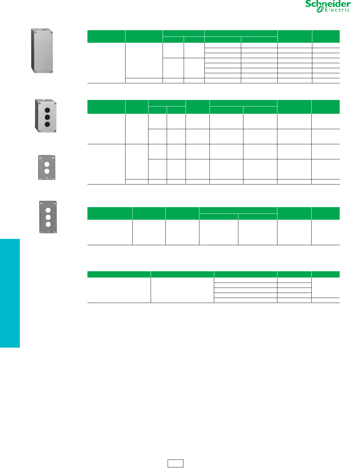
19-102 © 2012 Schneider Electric
All Rights Reserved
www.schneider-electric.us
19 PUSH BUTTONS AND
OPERATOR INTERFACE
Control Stations and
Enclosures
XAP 22 mm Enclosures and Accessories
Refer to Catalog 9001CT1104
aCan use either XB4 or XB5 products.
bCan use either XB4 or XB5 products.
Table 19.307: Undrilled Die Cast Enclosures (Painted Gray RAL7032)
Type Material Usable Depth H x W x D Dimensions Catalog Number $ Price
IN mm IN mm
NEMA 4, 13 Zinc
1.93 49
3.15 x 3.15 x 2.03 80 x 80 x 51.5 XAPG19100 110.00
5.12 x 3.15 x 2.03 130 x 80 x 51.5 XAPG29100 120.00
6.89 x 3.15 x 2.03 175 x 80 x 51.5 XAPG39100 142.00
2.93 74.5
3.15 x 3.15 x 3.03 80 x 80 x 77 XAPG19400 110.00
5.12 x 3.15 x 3.03 130 x 80 x 77 XAPG29400 120.00
6.89 x 3.15 x 3.03 175 x 80 x 77 XAPG39400 142.00
8.66 x 3.15 x 3.03 220 x 80 x 77 XAPG49400 174.00
Aluminum 2.93 2.93 12.20 x 3.35 x 3.03 310 x 85 x 77 XAPG59400 262.00
Table 19.308: Drilled Die Cast Enclosures (Painted Gray RAL7032) a
Type Material
Usable Depth Number of
22 mm
holes
H x W x D Dimensions Catalog Number $ Price
IN mm IN mm
NEMA 4, 13
1.18 in. (30 mm)
centerline
spacing of holes
for horizontal mount
Zinc
1.93 49
2 3.15 x 3.15 x 2.03 80 x 80 x 51.5 XAPG19702 120.00
3 5.12 x 3.15 x 2.03 130 x 80 x 51.5 XAPG29703 142.00
4 6.90 x 3.15 x 2.03 175 x 80 x 51.5 XAPG39704 174.00
2.93 74.5
2 3.15 x 3.15 x 3.03 80 x 80 x 77 XAPG19802 120.00
3 5.12 x 3.15 x 3.03 130 x 80 x 77 XAPG29803 142.00
4 6.90 x 3.15 x 3.03 175 x 80 x 77 XAPG39804 174.00
NEMA 4, 13
1.58 in. (40 mm)
centerline
spacing of holes
for vertical mount
Zinc
1.93 1.93
1 3.15 x 3.15 x 2.03 80 x 80 x 51.5 XAPG19201 110.00
2 5.12 x 3.15 x 2.03 130 x 80 x 51.5 XAPG29202 120.00
3 6.90 x 3.15 x 2.03 175 x 80 x 51.5 XAPG39203 142.00
2.93 74.5
1 3.15 x 3.15 x 3.03 80 x 80 x 77 XAPG19501 110.00
2 5.12 x 3.15 x 3.03 130 x 80 x 77 XAPG29502 120.00
3 6.90 x 3.15 x 3.03 175 x 80 x 77 XAPG39503 142.00
4 8.66 x 3.15 x 3.03 220 x 80 x 77 XAPG49504 174.00
Aluminum 2.93 74.5 5 12.20 x 3.35 x 3.03 310 x 85 x 77 XAPG59505 268.00
Table 19.309: Drilled Flush Plates b
Type Material Number of
22 mm holes
H x W x D Dimensions Catalog Number $ Price
IN mm
NEMA 4, 13
1.18 in. (30 mm)
centerline spacing
of holes
Anodized
Aluminum
1 2.83 x 2.83 72 x 72 XAPE301 52.00
2 4.13 x 2.83 105 x 72 XAPE302 60.00
3 5.43 x 2.83 138 x 72 XAPE303 68.00
4 6.73 x 2.83 171 x 72 XAPE304 82.00
5 8.03 x 2.83 204 x 72 XAPE305 98.00
Table 19.310: Optional Back Box (for finger protection, if required)
Type Material For Use With Catalog Number $ Price
Protective rear covers Insulating Fiberglass
Flush plate XAPE301 XAPE901
32.80
Flush plate XAPE302 XAPE902
Flush plate XAPE303 XAPE903
Flush plate XAPE304 XAPE904
Flush plate XAPE305 XAPE905 60.00
XAPG39400
XAPG29703
XAPE302
XAPE303
CS2 Discount
Schedule
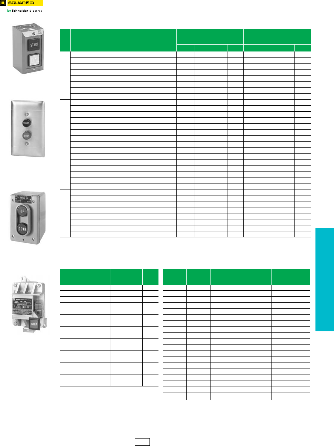
www.schneider-electric.us
19 PUSH BUTTONS AND
OPERATOR INTERFACE
© 2012 Schneider Electric
All Rights Reserved 19-103
30 mm Control Stations
and Enclosures
9001B Standard Duty Control Stations
Refer to Catalog 9001CT1104
aSee Table 19.314 on page 19-104.
bUses standard 2.0 or 2.13 in. deep wall boxes, single gang for Types BF1 and BF2, two gang for Type BF3
cAlso rated for Class l, Division l and ll, Groups B, C, or D; Class ll, Division l and ll, Groups E, F, or G
Replacement Interiors. . . . . . . . . . . . . . . . . . . . . . . . . . . . . . . . . page 19-104
Electrical Contact Ratings . . . . . . . . . . . . . . . . . . . . . . . . . . . . . page 19-104
Table 19.311: Control Stations
No.
of
But-
tons
Nameplate Markings and Features
Contact
Symbol
a
Surface Mounting
NEMA1
Stainless Steel
Flush Plate b
Watertight and
Dusttight
NEMA4
For Hazardous
Locations
NEMA 7 & 9 c
Type $ Price Type $ Price Type $ Price Type $ Price
1
Start 1 BG101 86.00 BF101 116.00 BW146 270.00 BR101 363.00
Stop 3 BG102 86.00 BF102 116.00 BW147 270.00 ——
Stop (Mushroom Button) 3 BG103 99.00 ——BW151 287.00 BR103 378.00
Stop (Lockout) 3 BG104 129.00 ——BW148 270.00 BR104 363.00
Universal (w/o legend insert) 16 BG107 83.00 BF107 111.00 BW159 269.00 BR107 360.00
Off-On (Selector Switch) 19 BG111 86.00 ——————
Hand-Off-Auto (Selector Switch) 17 BG112 86.00 ——————
Universal Selector Switch (w/o legend insert) 19 or 17 BG114 83.00 ——————
2
Start-Stop 145 BG201 86.00 BF201 116.00 BW240 270.00 BR204 363.00
Start-Stop (for latching Applications) 146 BG202 107.00 ——BW252 270.00 BR202 363.00
Start-Stop (Mushroom on Stop) 145 BG203 99.00 ——BW250 287.00 BR203 378.00
Start-Stop (Lockout on Stop) 145 BG204 129.00 ——BW241 270.00 BR204 363.00
Start-Stop (Mushroom on both) 145 BG205 116.00 ——BW246 300.00 BR205 392.00
Forward-Reverse 146 BG206 107.00 ——BW242 270.00 ——
Open-Close 146 BG207 107.00 ——BW244 270.00 ——
Up-Down 146 BG208 107.00 BF208 135.00 BW243 270.00 BR208 363.00
Raise-Lower 146 BG209 107.00 ——BW253 270.00 ——
On-Off 145 BG210 86.00 BF210 116.00 BW245 270.00 ——
On-Off 146 BG211 107.00 BF211 135.00 BW254 270.00 ——
Universal (w/o legend inserts) 25 BG214 78.00 ——BW260 264.00 BR214 356.00
Start-Stop (Maintained Contact) 10 BG215 129.00 BF215 158.00 BW255 314.00 BR215 405.00
On -Off (Maintained Contact) 10 BG216 129.00 BF216 158.00 BW256 314.00 BR216 405.00
Universal (Maintained contact w/o legend inserts) 10 BG218 122.00 ————BR218 399.00
3
Fast-Slow-Stop 109 BG301 171.00 ——————
Forward-Reverse-Stop 109 BG302 171.00 ——————
Opn-Close-Stop 109 BG303 171.00 BF303 207.00 ————
Raise-Lower-Stop 109 BG304 171.00 ——————
Up-Down-Stop 109 BG305 171.00 BF305 207.00 ————
Start-Jog-Stop 109 BG316 171.00 ——————
Universal (w/o legend inserts) 8 BG307 162.00 ——————
Start-Stop, Red Pilot Light: 120Vac/dc 145 & 121 BG308 314.00 BF308 342.00 ————
Table 19.312: Accessories Table 19.313: Interchangeable Push Button Legend Inserts
Description Color Type $ Price Marking
For NEMA 1
Surface
Mount
For NEMA 4 or 7/9
Lever Type
For NEMA 4
Round Button
For NEMA4
Mushroom
Button
$ Price
Mushroom Caps for NEMA 1 Red B301 14.30 Start B101 B161 B259 B282 3.60
Mushroom Caps for NEMA 4 Red B303 14.30 Stop B102 B162 B260 B283 3.60
Lockout Kit for NEMA 1 — B321 42.80 Fast B103 ———3.60
Pilot Light Lenses, NEMA 1
Surface Mount Red B331 10.70 Slow B104 ———3.60
Forward B105 —B255 —3.60
Pilot Light Lenses, NEMA 1
Surface Mount Green B332 10.70 Reverse B106 —B256 —3.60
Open B107 —B263 —3.60
Pilot Light Lenses, NEMA 1
Flush Mount Red B341 10.70 Close B108 —B264 —3.60
Raise B109 —B261 —3.60
Pilot Light Lenses, NEMA 1
Flush Mount Green B342 10.70 Lower B110 —B262 3.60
Up B111 —B253 B276 3.60
Replacement Covers for
BW240 e—BWD219 17.90 Down B112 —B254 B277 3.60
On B115 B175 B257 —3.60
Replacement Covers for
BW241 de —BWD220 35.60 Off B116 B176 B258 —3.60
Hand B117 —B265 —3.60
Replacement Covers for
BW242-BW260 e—BWD219 17.90 Auto B118 —B266 —3.60
Jog B119 ———3.60
dIncludes factory installed lockout on the cover.
eReplacement case/covers are not avaiulable for
Type BR devices.
Blank (Black) B129 B189 B251 B251 3.60
Blank (Red) B129R B189R B252 B252 3.60
NEMA 1
Surface Mounting
Type BG201
NEMA 1
Flush Mounting
(w/o pullbox)
Type BF201
NEMA 4
Type BW243
NEMA 7 and 9
Type BR103
CS1 Discount
Schedule
NOTE: When ordering, add prefix 9001 to the catalog number.
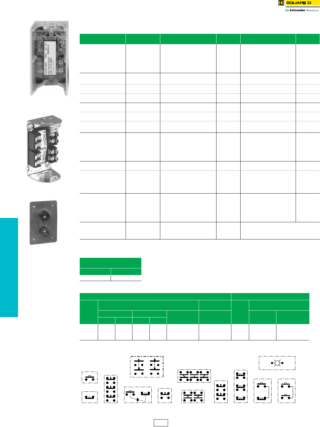
www.schneider-electric.us
19 PUSH BUTTONS AND
OPERATOR INTERFACE
19-104 © 2012 Schneider Electric
All Rights Reserved
30 mm Control Stations
and Enclosures
Type B Standard Duty Control Stations—Replacement Parts
Class 9001 / Refer to Catalog 9001CT1104
Note: Contact block assemblies for all Type BG stations include cover and contact block. Replacement contact block assemblies and terminal block wiring
receptacles for push buttons have provision for 1 N.O. & 1 N.C. circuit on each button. Unneeded circuits need not be wired.
aOrder separate legend plates, if required, from listing on page 19-103.
bOSHA Regulation, Section 1910.70, Overhead and Gantry Cranes, limits the voltage of pendant push buttons to 150 Vac or 300 Vdc.
Contact Symbols
Table 19.314: Replacement Interiors For Type B
Standard Duty Push Button Stations
For Control Station
Types
Contact
Symbol
Contact Block Assembly q
Type $ Price Terminal Block Wiring Receptacle
Type $ Price
BF101–BF107 16 BOC107 39.20 BFB107 42.80
BF111–BF114 19 or 17 BOC114 39.20 BFB114 42.80
BF121–BF123 121 BOC123 147.00 BFB123 42.80
BF201–BF214 25 BOC214 35.60 BFB214 42.80
BF215–BF218 10 BOC218 78.00 BFB214 42.80
BF221–BF224 7 or 19 & 121 BOC224 234.00 BFB224 64.00
BF225–BF226 17 or 19 & 16 BOC226 57.00 BFB226 64.00
BF301–BF307 8 &
BOC214
BOC107
35.60
39.20 &
BFB214
BFB107
42.80
42.80
BF308–BF309 25
& 121 &
BOC214
BOC123
35.60
147.00 &
BFB214
BFB123
42.80
42.80
BF310–BF313 10 & 121 &
BOC218
BOC123
78.00
147.00 &
BFB214
BFB123
42.80
42.80
BF314–BF315 17 or 19 & 25 &
BOC214
BOC114
35.60
39.20 &
BFB214
BFB114
42.80
42.80
BG101–BG107 16 BGC107 39.20 BGB107 42.80
BG111–BG114 17 or 19 BGC114 39.20 BGB114 42.80
BG121–BG123 121 BGC123 147.00 BGB123 42.80
BG201–BG214 25 BGC214 35.60 BGB214 42.80
BG215–BG218 10 BGC218 78.00 BGB214 42.80
BG221–BG224 17 or 19 & 121 BGC224 234.00 BGB224 64.00
BG225–BG226 17 or 19 & 16 BGC226 57.00 BGB226 64.00
BG301–BG307
BG316–BG326 8BGC307 39.20 BGB307 57.00
BG308–BG309 25 & 121 BGC309 212.00 BGB309 86.00
BG310–BG313 10 & 121 BGC313 242.00 BGB309 86.00
BG314–BG315 17 or 19 & 25 BGC315 75.00 BGB315 86.00
BR101–BR107 16 BOC107 39.20 BFB107 42.80
BR202–BR214 25 BOC214 35.60 BFB214 42.80
BR215–BR219 10 BOC218 78.00 BFB214 42.80
BW101–BW107 16 BOC107 39.20 BFB107 42.80
BW202–BW214 25 BOC214 35.60 BFB214 42.80
BW215–BW218 10 BOC218 78.00 BFB214 42.80
BW146–BW159 16 BOC360 126.00
BW240–BW260 25 BOC361 126.00
BW255–BW258 10 BOC362 126.00
C-Shaped Mounting Bracket
for 9001BR Interior
Catalog Number $ Price
3110112001 8.70
Table 19.315: Electrical Contact Ratings b
AC—NEMA B600 DC—NEMA P600
Vol ts
Inductive
35% Power Factor
Resistive
75% Power Factor
Volt s
Inductive and Resistive
Make Break Continuous
Carrying
Amperes
Make, Break and
Continuous
Carrying Amperes
Make and Break
Amperes
Continuous
Carrying Amperes
AVA AVA
120
240
480
600
30.5
15
7.5
6
3600
3600
3600
3600
3.75
1.5
.75
.6
360
360
360
360
5
5
5
5
5
5
5
5
120
240
600
1.1
0.55
0.2
5
5
5
Type BGC214
(Type BGC contact block
assemblies include cover.)
Type BGB214
BOC361
10
17
1916
1
38 25 109 145 146
121
120 V Com
100
CS1 Discount
Schedule
NOTE: When ordering, add prefix 9001 to the catalog number.
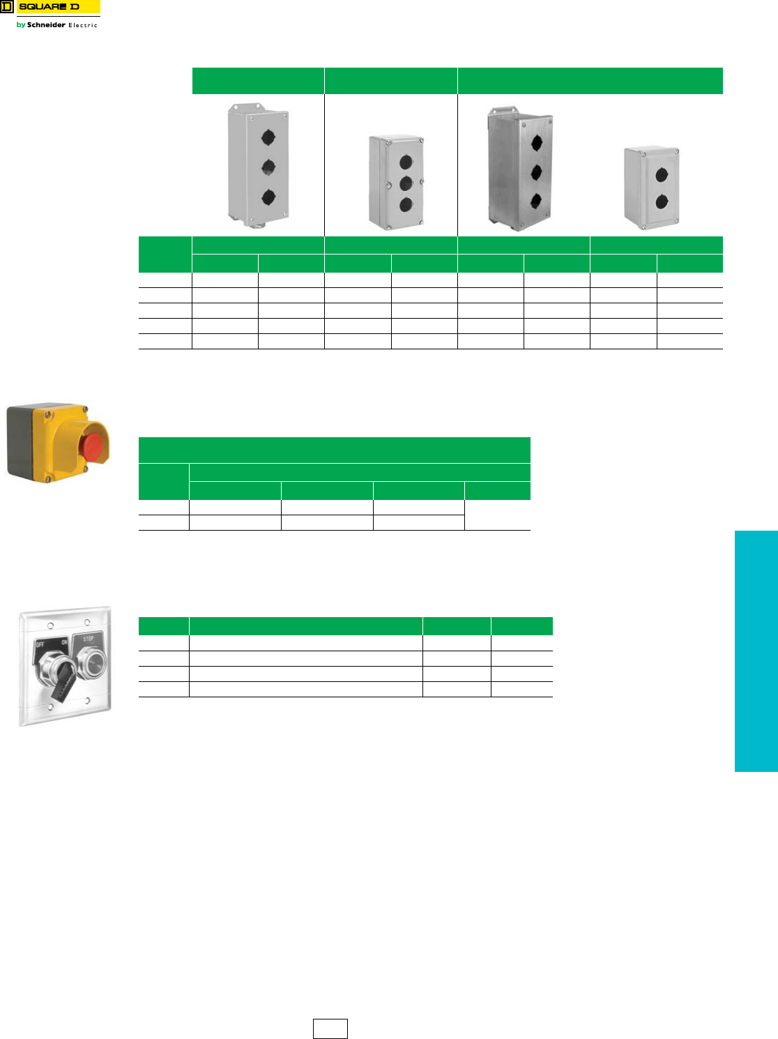
www.schneider-electric.us
19 PUSH BUTTONS AND
OPERATOR INTERFACE
© 2012 Schneider Electric
All Rights Reserved 19-105
30 mm Enclosures 9001KY/SKY Control Stations
Class 9001 / Refer to Catalog 9001CT1104
aOnly KN200 series legend plates will fit upright on these enclosures with their long axis vertical.
NOTE: See Table 19.319 on Page 19-106 for Assembled Control Stations
bIncludes 1” NPT threaded conduit opening.
NOTE: See Table 19.319 on Page 19-106 for Assembled Control Stations
cTo be used with a standard 2 x 3 in. general purpose switch box. A 2.5 in. deep switch box should be
used if two Type KA contact blocks are mounted side by side. If two Type KA contact blocks are
mounted in tandem, a 3.5 in. deep box should be used.
Table 19.316: Empty Enclosures (for Customer Assembly)
UL Types 1, 3 and 13/
NEMA 1, 3, and 13
UL Types 1, 3, 4 and 13/
NEMA 1, 3, 4 and 13
UL Types 1, 3, 4, 4X and 13/
NEMA 1, 3, 4, 4X and 13
No of
Holes
Sheet Steel Die Cast Zinc Stainless Steel (304) Polymeric (Plastic)
Type $ Price Type $ Price Type $ Price Type $ Price
1KYAF1 143.00 KY1 143.00 KYSS1 257.00 SKY1 171.00
2KYAF2 158.00 KY2 a158.00 KYSS2 270.00 SKY2 201.00
3KYAF3 185.00 KY3 a185.00 KYSS3 372.00 SKY3 228.00
4KYAF4 228.00 KY4 a228.00 KYSS4 485.00 SKY4 269.00
6KYAF6 287.00 KY6 287.00 KYSS6 714.00 SKY6 287.00
KYG1Y
(mushroom head
not included)
Table 19.317: Guarded Enclosures
UL Types 1, 3, 4 and 13/
NEMA 1, 3, 4 and 13
No of Holes
Die Cast Zinc
Cover Color Box Color Type $ Price
1 Gray Gray KYG1 b
150.00
1Yellow Gray KYG1Y b
Table 19.318: Stainless Steel (302) NEMA 1 Flush Plates c
No of Holes Description Type $ Price
1 1 Hole flush plate, cover screws, insulating liners K25 28.70
2 2 Hole flush plate, cover screws, insulating liners K26 42.80
3 3 Hole flush plate, cover screws, insulating liners K27 57.00
4 4 Hole flush plate, cover screws, insulating liners K28 86.00
K26
CS1 Discount
Schedule
NOTE: When ordering, add prefix 9001 to the catalog number.
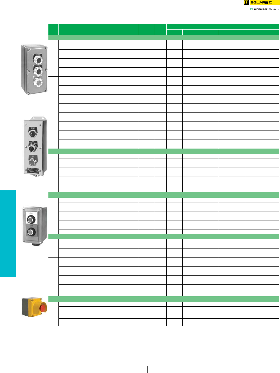
www.schneider-electric.us
19 PUSH BUTTONS AND
OPERATOR INTERFACE
19-106 © 2012 Schneider Electric
All Rights Reserved
30 mm Control Stations 9001KY/SKY Control Stations
Class 9001 / Refer to Catalog 9001CT1104
aUses 9001K metal operators and metal legend plates.
bUses 9001K metal operators and plastic legend plates.
cUses 9001SK plastic operators and plastic legend plates.
dControl Station consists of components that are UL listed for use in Class 1, Division 2, Groups A, B, C, or D.
eIncludes 1” NPT threaded conduit opening.
Table 19.319: Assembled Control Stations
No of
Holes Operator Style and Features Type $ Price Consists of
Enclosure Operators Contact Blocks Legend Plates
UL Types 1, 3, 4 and 13/NEMA 1, 3, 4 and 13 Die Cast Zinc Enclosurea
1
Selector Switch (3 Pos Maintained) KYK111 243. KY1 KS43B KA1 Hand-Off-Auto
Selector Switch (2 Pos Maintained) KYK110 243. KY1 KS11B KA1 Off-On
Push Button (Momentary) KYK11 228. KY1 KR1B KA1 Start
Push Button (Momentary) KYK13 228. KY1 KR1R KA1 Stop
Mushroom Button (Momentary) KYK14 270. KY1 KR4R KA1 Stop
Push Button (with Lockout) KYK15 270. KY1 KR3R, K4 KA1 Stop
Break Glass Operator KYK116 329. KY1 K15 KA1 To Stop—Break Glass
Break Glass Operator (Red Enclosure) KYK117 329. KY1S1 K15 KA1 To Stop—Break Glass
2
2 Push Buttons (Lockout on Stop) KYK224 372. KY2 KR1B, KR3R, K4 KA1, KA1 Jog-Stop
2 Push Buttons KYK218 329. KY2 KR1B, KR3R KA1, KA1 On-Off
2 Push Buttons KYK26 329. KY2 KR1B, KR1B KA1, KA1 Open-Close
2 Push Buttons KYK25 329. KY2 KR1B, KR1B KA1, KA1 Up-Down
2 Push Buttons KYK21 329. KY2 KR1B, KR3R KA1, KA1 Start-Stop
2 Push Buttons (with Sealed Contacts) dKYK223 527. KY2 KR1B, KR3R KA51, KA51 Start-Stop
2 Push Buttons (Lockout on Stop) KYK23 372. KY2 KR1B, KR3R, K4 KA1, KA1 Start-Stop
2 Push Buttons (Maintained/Interlocked) KYK27 329. KY2 KR11GR KA1 Start-Stop
1 Push Button, 1 Mushroom Button KYK22 372. KY2 KR1B, KR4R KA1, KA1 Start-Stop
3
3 Push Buttons KYK31 441. KY3 KR1B, KR1B, KR3R KA1, KA1, KA1 Forward; Reverse; Stop
3 Push Buttons (Lockout on Stop) KYK326 485. KY3 KR1B, KR1B, KR3R, K4 KA1, KA1, KA1 Forward; Reverse; Stop
3 Push Buttons (With Sealed Contacts & Lockout on Stop) dKYK322 783. KY3 KR1B, KR1B, KR3R, K4 KA51, KA51, KA51 Forward; Reverse; Stop
3 Push Buttons KYK33 441. KY3 KR1B, KR1B, KR3R KA1, KA1, KA1 Open; Close; Stop
Red 120v Pilot Light, 2 Push Buttons KYK317 471. KY3 KP1R31, KR1B, KR3R KA2, KA3 Start; Stop
3 Push Buttons KYK32 441. KY3 KR1B, KR1B, KR3R KA1, KA1, KA1 Up; Down; Stop
3 Push Buttons (Lockout on Stop) KYK325 485. KY3 KR1B, KR1B, KR3R, K4 KA1, KA1, KA1 Up ; Down; Stop
UL Types 1, 3, 4 and 13/NEMA 1, 3, 4 and 13—Stainless Steel (304) b
1
Push Button (Momentary) KYSS101 342. KYSS1 KR1B KA1 Start
Push Button (Momentary) KYSS103 320. KYSS1 KR1B KA3 Stop
Selector Switch (2 Pos Maintained) KYSS110 356. KYSS1 KS11B KA1 Off-On
Selector Switch (3 Pos Maintained) KYSS111 356. KYSS1 KS43B KA1 Hand-Off-Auto
2
2 Push Buttons KYSS201 422. KYSS2 KR1B, KR3R KA1, KA3 Start; Stop
2 Push Buttons (Lockout on Stop) KYSS203 491. KYSS2 KR1B, KR3R, K5 KA1, KA3 Start; Stop
2 Push Buttons (Maintained with Interlock) KYSS210 441. KYSS2 KR11U KA1, KA1 Start; Stop
2 Push Buttons KYSS205 441. KYSS2 KR1B, KR1B KA1, KA1 Up; Down
UL Types 1, 3, 4. 4X and 13/NEMA 1, 3, 4, 4X and 13—Stainless Steel (304) c
1
Push Button (Momentary) KYSK101 342. KYSS1 SKR1B KA1 Start
Push Button (Momentary) KYSK103 320. KYSS1 SKR3R KA3 Stop
Selector Switch (2 Pos Maintained) KYSK110 356. KYSS1 SKS11B KA1 Off-On
Selector Switch (3 Pos Maintained) KYSK111 356. KYSS1 SKS43B KA1 Hand-Off-Auto
2
2 Push Buttons KYSK201 422. KYSS2 SKR1B, SKR3R KA1, KA3 Start; Stop
2 Push Buttons (Lockout on Stop) KYSK203 491. KYSS2 SKR1B, SKR3R, K5 KA1, KA3 Start; Stop
2 Push Buttons (Maintained with Interlock) KYSK210 441. KYSS2 SKR11U KA1, KA1 Start; Stop
2 Push Buttons KYSK205 441. KYSS2 SKR1B, SKR1B KA1, KA1 Up; Down
UL Types 1, 3, 4. 4X and 13/NEMA 1, 3, 4, 4X and 13—Polymeric (Plastic) c
Selector Switch (3 Pos Maintained) SKY111 270. SKY1 SKS43B KA1 Hand-Off-Auto
1
Selector Switch (2 Pos Maintained) SKY110 270. SKY1 SKS11B KA1 Off-On
Selector Switch (2 Pos Maintained with Sealed Contacts) dSKY122 372. SKY1 SKS11B KA51 Off-On
Push Button (with Lockout) SKY105 306. SKY1 SKR3R, K5 KA3 Stop
2
2 Push Buttons SKY201 350. SKY2 SKR1B, SKR3R KA1, KA3 Start-Stop
2 Push Buttons (Lockout on Stop) SKY203 422. SKY2 SKR1B, SKR1R, K5 KA1, KA3 Start-Stop
2 Push Buttons (With Sealed Contacts) dSKY223 570. SKY2 SKR1B, SKR3R KA51, KA51 Start-Stop
2 Push Buttons (With Sealed Contacts) dSKY222 570. SKY2 SKR1B, SKR3R KA51, KA51 On-Off
2 Push Buttons SKY205 372. SKY2 SKR1B, SKR1B KA1, KA1 Up-Down
3
3 Push Buttons SKY302 464. SKY3 SKR1B, SKR1B, SKR3R KA1, KA1, KA3 Up-Down-Stop
3 Push Buttons SKY303 464. SKY3 SKR1B, SKR1B, SKR3R KA1, KA1, KA3 Open-Close-Stop
Red 120v Pilot Light, 2 Push Buttons SKY315A 531. SKY3 SKP1R31, SKR1B,
SKR3R KA1, KA3 Start-Stop
UL Types 1, 3, 4 and 13/NEMA 1, 3, 4 and 13 Die Cast Zinc Enclosures with Integral Guard
1
Guarded Enclosure (grey) with 120V Red LED Pilot Light KYG11 e250. KYG1 KP38LRR9 — order separately
Guarded Enclosure (grey) with 120V Green LED Pilot Light KYG12 e250. KYG1 KP38LGG9 — order separately
Guarded Enclosure (Yellow Cover) with Red Push-Pull
Mushroom KYG1Y1 e275. KYG1Y KR9R KA3 Push to Stop/
Pull to Start
Guarded Enclosure (Yellow Cover) with Red Turn-To
Release Mushroom KYG1Y2 e275. KYG1Y KR16 KA3 Emergency Stop
Type KYK31
Type KYSS300
Type SKY201
Type KYG1Y2
CS1 Discount
Schedule
NOTE: When ordering, add prefix 9001 to the catalog number.
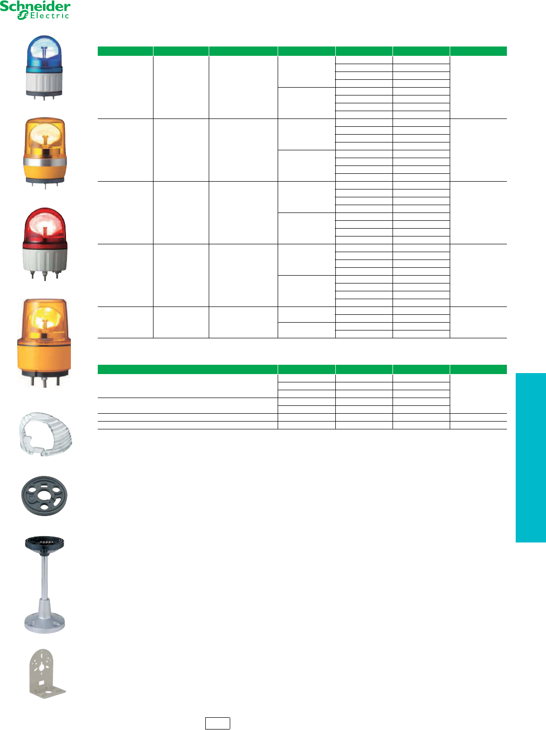
www.schneider-electric.us
19 PUSH BUTTONS AND
OPERATOR INTERFACE
© 2012 Schneider Electric
All Rights Reserved 19-107
Tower Lights and
Beacons
XVR Pre-Wired Rotating Mirror Beacons
Refer to Catalog 9001CT1002
Table 19.320: XVR Pre-Wired Rotating Mirror Beacons
Diameter (mm) Sound Option Enclosure Rating Voltage Color Catalog Number $ Price
Ø 84 Without buzzer IP 23
(IP 65 with accessories)
12 Vac/Vdc
Red XVR 08J04
180.00
Orange XVR 08J05
Green XVR 08J03
Blue XVR 08J06
24 Vac/Vdc
Red XVR 08B04
Orange XVR 08B05
Green XVR 08B03
Blue XVR 08B06
Ø 106 Without buzzer IP 23
(IP 55 with accessories)
12 Vac/Vdc
Red XVR 10J04
207.00
Orange XVR 10J05
Green XVR 10J03
Blue XVR 10J06
24 Vac/Vdc
Red XVR 10B04
Orange XVR 10B05
Green XVR 10B03
Blue XVR 10B06
Ø 120 Without buzzer IP 23
12 Vac/Vdc
Red XVR 12J04
198.00
Orange XVR 12J05
Green XVR 12J03
Blue XVR 12J06
24 Vac/Vdc
Red XVR 12B04
Orange XVR 12B05
Green XVR 12B03
Blue XVR 12B06
Ø 120 With buzzer IP 23
12 Vac/Vdc
Red XVR 12J04S
216.00
Orange XVR 12J05S
Green XVR 12J03S
Blue XVR 12J06S
24 Vac/Vdc
Red XVR 12B04S
Orange XVR 12B05S
Green XVR 12B03S
Blue XVR 12B06S
Ø 130 Without buzzer IP 23
Resistant to vibration
12 Vdc Red XVR 13J04
270.00
Orange XVR 13J05
24 Vdc Red XVR 13B04
Orange XVR 13B05
Table 19.321: XVR Accessories
Description Diameter (mm) Height (mm) Catalog Number $ Price
Reflecting prism
84 — XVR ZR1
36.00
106 —XVR ZR2
120/130 —XVR ZR3
Rubber base
to increase the IP degree of protection
84 — XVR Z081
106 — XVR Z082
Mount tube and base 106, 120 and 130 300 XVC Z13 270.00
L-shape mounting bracket 84, 106 and 120 — XVC Z23 27.00
XVR 13ppp
XVR 08 ppp
XVR 10 ppp
XVR 12 ppp
XVR ZR1
XVR Z081
XVC Z13
XVC Z23
XV Discount
Schedule
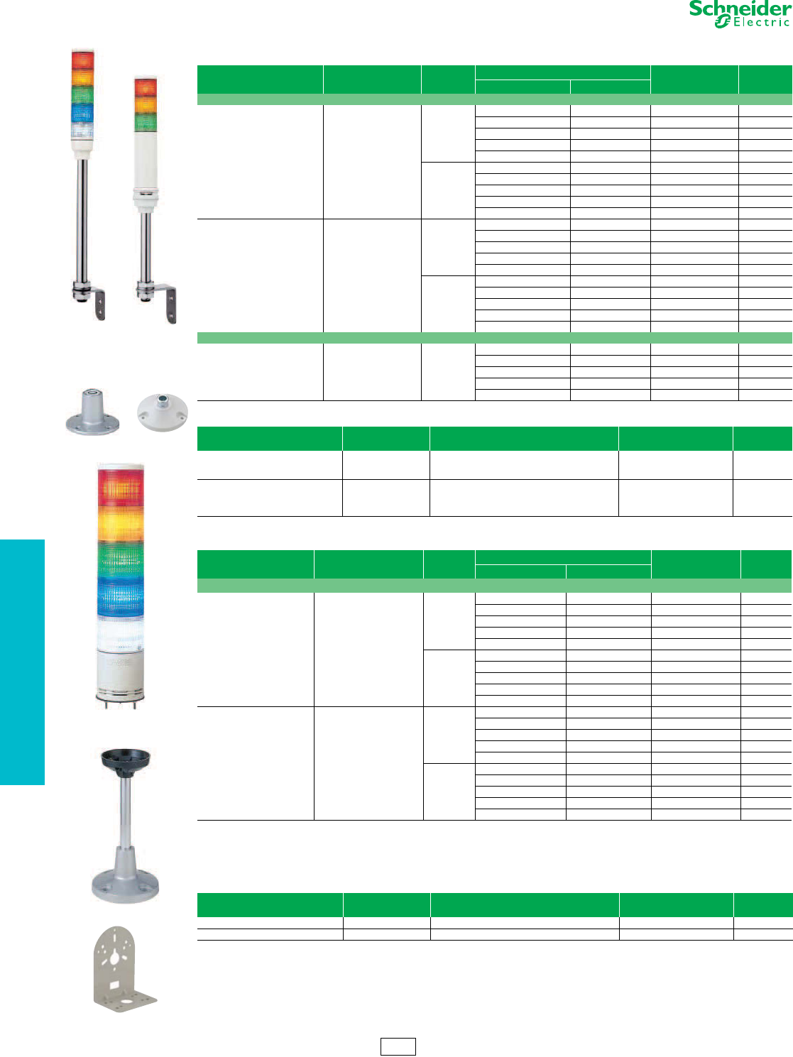
www.schneider-electric.us
19 PUSH BUTTONS AND
OPERATOR INTERFACE
19-108 © 2012 Schneider Electric
All Rights Reserved
Tower Lights and
Beacons
XVC, 40 mm, 60 mm, and 100 mm Diameter
Refer to Catalog 9001CT1002
aSignaling colors: R = Red, G = Green, O = Orange, B = Blue, C = Clear. The colors are listed in the mounting order of the illuminated units from
top to bottom.
bFlashing light function selected by wiring or programming.
Table 19.322: XVC4 Tower Lights — 40 mm diameter (1.5 inches)
Description Light source (included) Voltage Signaling colors a
Catalog Number $ Price
Steady Flashing
With support tube mounting
Without buzzer LED for steady
light only
24 Vdc
R – XVC 4B1 157.50
R, O – XVC 4B2 198.00
R, O, G – XVC 4B3 229.50
R, O, G, B – XVC 4B4 283.50
R, O, G, B, C – XVC 4B5 352.50
100-240 Vac
R – XVC 4M1 181.50
R, O – XVC 4M2 228.00
R, O, G – XVC 4M3 264.00
R, O, G, B – XVC 4M4 379.50
R, O, G, B, C – XVC 4M5 379.50
With buzzer
+ flashing light
LED for steady or
flashing light b
24 Vdc
R R XVC 4B15S 240.00
R, O R, O XVC 4B25S 271.50
R, O, G R, O, G XVC 4B35S 309.00
R, O, G, B R, O, G, B XVC 4B45S 378.00
R, O, G, B, C R, O, G, B, C XVC 4B55S 441.00
100-240 Vac
R R XVC 4M15S 276.00
R, O R, O XVC 4M25S 312.00
R, O, G R, O, G XVC 4M35S 355.50
R, O, G, B R, O, G, B XVC 4M45S 435.00
R, O, G, B, C R, O, G, B, C XVC 4M55S 507.00
For base mounting
Without buzzer LED for steady
light only 24 Vdc
R – XVC 4B1K 117.00
R, O – XVC 4B2K 154.50
R, O, G – XVC 4B3K 189.00
R, O, G, B – XVC 4B4K 255.00
R, O, G, B, C – XVC 4B5K 331.50
Table 19.323: Accessories for XVC4
Description Diameter
mm
Minimum height to be added
mm Catalog Number $ Price
Die-cast metal mounting base (for use
with XVC4•• and XVC4••5S with
support tube)
90 32 XVC Z11 39.00
Plastic mounting base (for use with
XVC4, XVC4•• and XVC4••5S —
customer must discard the support
tube)
84 24.5 XVC Z01 64.50
Table 19.324: XVC Tower Lights — 100 mm diameter (4 inches)
Description Light source (included) Voltage
Vdc
Signaling colors a
Catalog Number $ Price
Steady Flashing
For base mounting
Without buzzer
With flashing light
LED for steady or
flashing light b
24
R R XVC 1B1K 631.50
R, O R, O XVC 1B2K 685.50
R, O, G R, O, G XVC 1B3K 739.50
R, O, G, B R, O, G, B XVC 1B4K 793.50
R, O, G, B, C R, O, G, B, C XVC 1B5K 847.50
100-240 Vac
R R XVC 1M1K 726.00
R, O R, O XVC 1M2K 787.50
R, O, G R, O, G XVC 1M3K 850.50
R, O, G, B R, O, G, B XVC 1M4K 912.00
R, O, G, B, C R, O, G, B, C XVC 1M5K 975.00
With buzzer
+ flashing light
LED for steady or
flashing light b
24
R R XVC 1B1SK 703.50
R, O R, O XVC 1B2SK 757.50
R, O, G R, O, G XVC 1B3SK 811.50
R, O, G, B R, O, G, B XVC 1B4SK 865.50
R, O, G, B, C R, O, G, B, C XVC 1B5SK 919.50
100-240 Vac
R R XVC 1M1SK 808.50
R, O R, O XVC 1M2SK 871.50
R, O, G R, O, G XVC 1M3SK 933.00
R, O, G, B R, O, G, B XVC 1M4SK 996.00
R, O, G, B, C R, O, G, B, C XVC 1M5SK 1057.50
Table 19.325: Accessories for XVC1
Description Diameter
mm
Height
mm Catalog Number $ Price
Mount tube and base 140 300 XVC Z13 270.00
L-shape mount bracket — — XVC Z23 27.00
XVC Z11 XVC Z01
XVC 4B5 XVC 4B35S
XV Discount
Schedule
XVC 1B5K
XVC 1B5SK
XVC Z13
XVC Z23
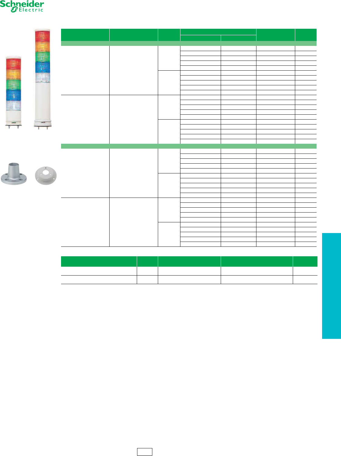
www.schneider-electric.us
19 PUSH BUTTONS AND
OPERATOR INTERFACE
© 2012 Schneider Electric
All Rights Reserved 19-109
Tower Lights and
Beacons
XVC, 40 mm, 60 mm, and 100 mm Diameter
Refer to Catalog 9001CT1002
aSignaling colors: R = Red, G = Green, O = Orange, B = Blue, C = Clear. The colors are listed in the mounting order of the illuminated units from
top to bottom.
bFlashing light function selected by wiring or programming.
Table 19.326: XVC6 Tower Lights, 60 mm diameter (2.375 inches)
Description Light source (included) Voltage Signaling colors a
Catalog Number $ Price
Steady Flashing
With support tube mounting
Without buzzer LED for steady
light only
24 Vdc
R – XVC 6B1 169.50
R, O – XVC 6B2 211.50
R, O, G – XVC 6B3 252.00
R, O, G, B – XVC 6B4 303.00
R, O, G, B, C – XVC 6B5 426.00
100-240 Vac
R – XVC 6M1 195.00
R, O – XVC 6M2 243.00
R, O, G – XVC 6M3 289.50
R, O, G, B – XVC 6M4 348.00
R, O, G, B, C – XVC 6M5 489.00
With buzzer
+ flashing light
LED for steady or
flashing light b
24 Vdc
R R XVC 6B15S 252.00
R, O R, O XVC 6B25S 292.50
R, O, G R, O, G XVC 6B35S 315.00
R, O, G, B R, O, G, B XVC 6B45S 378.00
R, O, G, B, C R, O, G, B, C XVC 6B55S 472.50
100-240 Vac
R R XVC 6M15S 289.50
R, O R, O XVC 6M25S 336.00
R, O, G R, O, G XVC 6M35S 363.00
R, O, G, B R, O, G, B XVC 6M45S 435.00
R, O, G, B, C R, O, G, B, C XVC 6M55S 543.00
For base mounting
Without buzzer LED for steady
light only
24 Vdc
R – XVC 6B1K 132.00
R, O – XVC 6B2K 163.50
R, O, G – XVC 6B3K 214.50
R, O, G, B – XVC 6B4K 283.50
R, O, G, B, C – XVC 6B5K 378.00
100-240 Vac
R – XVC 6M1K 151.50
R, O – XVC 6M2K 187.50
R, O, G – XVC 6M3K 246.00
R, O, G, B – XVC 6M4K 325.50
R, O, G, B, C – XVC 6M5K 435.00
With buzzer
+ flashing light
LED for steady or
flashing light b
24 Vdc
R R XVC 6B15SK 205.50
R, O R, O XVC 6B25SK 252.00
R, O, G R, O, G XVC 6B35SK 283.50
R, O, G, B R, O, G, B XVC 6B45SK 346.50
R, O, G, B, C R, O, G, B, C XVC 6B55SK 426.00
100-240 Vac
R R XVC 6M15SK 237.00
R, O R, O XVC 6M25SK 289.50
R, O, G R, O, G XVC 6M35SK 327.00
R, O, G, B R, O, G, B XVC 6M45SK 399.00
R, O, G, B, C R, O, G, B, C XVC 6M55SK 490.50
Table 19.327: Accessories for XVC6
Description Diameter
mm
Minimum height to be added
mm Catalog Number $ Price
Die-cast metal mounting base
for XVC6B• and XVC6B•5S with support tube. 100 30 XVC Z02 27.00
Stamped metal mounting base for
XVC6B• K and XVC6B•5SK 84 21.6 XVC Z12 45.00
XVC Z02 XVC Z12
XVC 6B5K XVC 6B55SK
XV Discount
Schedule
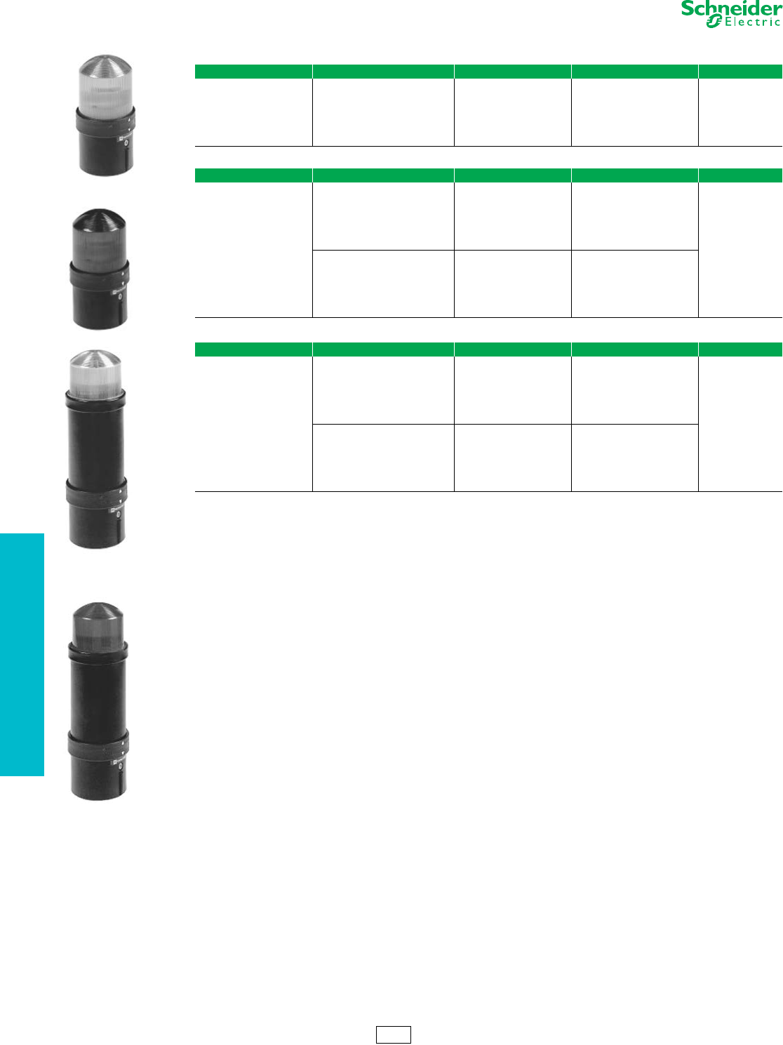
www.schneider-electric.us
19 PUSH BUTTONS AND
OPERATOR INTERFACE
19-110 © 2012 Schneider Electric
All Rights Reserved
Tower Lights and
Beacons
XVB—70 mm Diameter (2.75 inches)
Refer to Catalog 9001CT1002
aImportant: Discharge tube elements are not suitable for continuous-operation signaling due to temperature rise caused by the discharge tube.
bFor 5 Joule units, specify XVBL6••, instead of XVBL8•• ($190.00).
cFor bulbs, see Table 19.336 on page 19-112.
NOTE: There are no replacement lenses for strobes.
Table 19.328: XVB Beacons with Steady Light
Description Light Source and Voltage Color Catalog Number $ Price
Complete unit, includes:
1 lens unit
1 base unit (direct or tube
mounting)
Bulb (10 W max)
not included
250 V max
(must order bulb separately c)
Green XVBL33
114.00
Red XVBL34
Amber XVBL35
Blue XVBL36
Clear XVBL37
Ye l l o w XVBL38
Table 19.329: XVB Beacons with Flashing Light (one flash per second)
Description Light Source and Voltage Color Catalog Number $ Price
Complete unit, includes:
1 lens unit
1 base unit (direct or tube
mounting)
Bulb (10 W max)
not included
24 Vac
24–48 Vdc
(must order bulb separately c)
Green XVBL4B3
193.50
Red XVBL4B4
Amber XVBL4B5
Blue XVBL4B6
Clear XVBL4B7
Yellow XVBL4B8
Bulb (10 W max)
not included
48–230 Vac
(must order bulb separately c)
Green XVBL4M3
Red XVBL4M4
Amber XVBL4M5
Blue XVBL4M6
Clear XVBL4M7
Yellow XVBL4M8
Table 19.330: XVB Beacons with 10 Joule Strobe (2.75 in./70 mm diameter) a
Description Light Source and Voltage Color Catalog Number b$ Price
Complete unit, includes:
1 lens unit
1 base unit (direct or tube
mounting)
Strobe
24 Vac/Vdc
(includes bulb)
Green XVBL8B3
366.00
Red XVBL8B4
Amber XVBL8B5
Blue XVBL8B6
Clear XVBL8B7
Yellow XVBL8B8
Strobe
120 Vac
(includes bulb)
Green XVBL8G3
Red XVBL8G4
Amber XVBL8G5
Blue XVBL8G6
Clear XVBL8G7
Yellow XVBL8G8
XVBL3•
XVBL4B•
XVBL6B•
5 Joule
XVBL8B•
10 Joule
XV Discount
Schedule
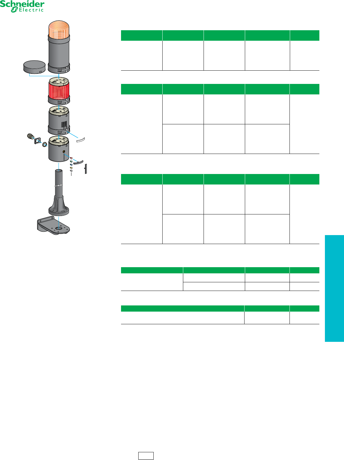
www.schneider-electric.us
19 PUSH BUTTONS AND
OPERATOR INTERFACE
© 2012 Schneider Electric
All Rights Reserved 19-111
Tower Lights and Beacons XVB Components—70 mm diameter (2.75 inches)
Refer to Catalog 9001CT1002
Note: There are no replacement lenses units for the XVBC8•• strobes.
aFor 5 Joule units, specify XVBC6••, instead of XVBC8•• ($155.00).
bFor bulbs, see Table 19.336 on page 19-112.
Table 19.331: XVB Lens Units for Steady Light
Description Light Source and
Voltage Color Catalog Number $ Price
Illuminated lens unit
Bulb (10 W max)
not included
250 Vac/Vdc max
(must order bulb
separately b)
Green XVBC33
60.60
Red XVBC34
Orange XVBC35
Blue XVBC36
Clear XVBC37
Yellow XVBC38
Table 19.332: XVB Lens Unit for Flashing Light
Description Light Source and
Voltage Color Catalog Number $ Price
Illuminated lens unit
Bulb (10 W max)
not included
24 Vac
24–48 Vdc
(must order bulb
separately b)
Green XVBC4B3
141.00
Red XVBC4B4
Orange XVBC4B5
Blue XVBC4B6
Clear XVBC4B7
Ye l l o w XVBC4B8
Bulb (10 W max)
not included
48–230 Vac
(must order bulb
separately b)
Green XVBC4M3
Red XVBC4M4
Orange XVBC4M5
Blue XVBC4M6
Clear XVBC4M7
Ye l l o w XVBC4M8
Table 19.333: XVB Lens Units with 10 Joule Strobe
Description Light Source and
Voltage Color Catalog Number a$ Price
Lens unti with integral
10 Joule strobe
Strobe
24 Vac/Vdc
(includes bulb)
Green XVBC8B3
313.50
Red XVBC8B4
Orange XVBC8B5
Blue XVBC8B6
Clear XVBC8B7
Ye l l o w XVBC8B8
Strobe
120 Vac
(includes bulb)
Green XVBC8G3
Red XVBC8G4
Orange XVBC8G5
Blue XVBC8G6
Clear XVBC8G7
Ye l l o w XVBC8G8
Table 19.334: Audible Sounder Units
Description Supply Voltage Catalog Number $ Price
Sounder unit
90 dB at 1 m 12–48 Vac/Vdc XVBC9B 217.50
Adjustable from 75–90 dB
Continuous or intermittent modes 120–230 Vac XVBC9M 342.00
Table 19.335: Base Units + Cover
Description Catalog Number $ Price
Base unit + cover
for direct or tube mounting, bottom or side cable entry
(includes gasket)
XVBC21 60.60
XVBC8
XVBC081
XVBC
XVBC9
XVBC1 XVBC07
XVBCY2
XVBC22
XVBC23
XVBZ0
XVBC12
XVBC081 +
XVBC07 =
XVBC21
XV Discount
Schedule
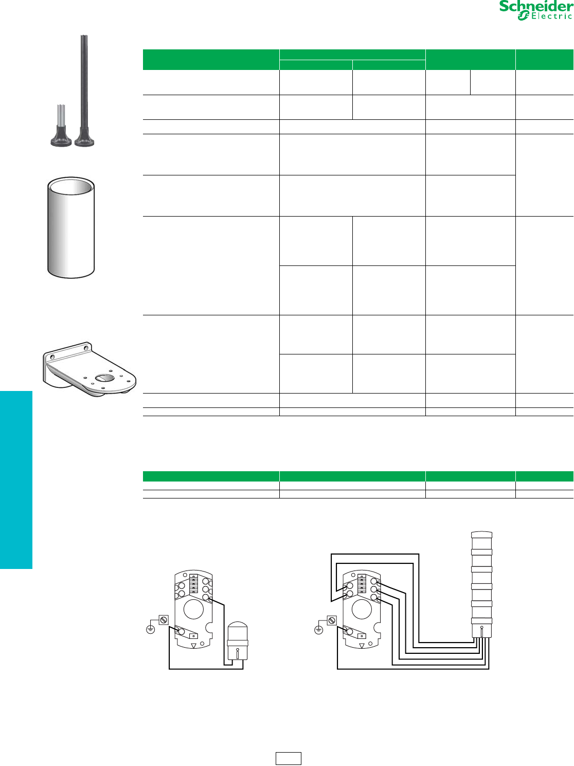
www.schneider-electric.us
19 PUSH BUTTONS AND
OPERATOR INTERFACE
19-112 © 2012 Schneider Electric
All Rights Reserved
Tower Lights and
Beacons
XVB Accessories—70 mm Diameter (2.75 inches)
Refer to Catalog 9001CT1002
Wiring Diagrams, Base Units
Table 19.336: XVB Accessories
Description Characteristics Catalog Number $ Price
in. mm
Black tube with integral black plastic mounting base
(includes gasket)
4.72 120 XVBZ02 XVBZ02A a 18.75
15.75 400 XVBZ03 XVBZ03A a 37.50
31.50 800 XVBZ04 XVBZ04A a 75.00
Support tube concealment cover
3.94 100 XVBC020 11.70
15.75 400 XVBC030 34.50
31.50 800 XVBC040 62.10
Wall mount bracket (metal) For direct mounting on base unit or with tulip
XVBC11 + tube XVBC0• XVBC12 48.45
Incandescent bulbs
bayonet type BA 15d, 10 Watts
12 Vac/Vdc DL1BLJ
8.10
24 Vac/Vdc DL1BLB
48 Vac/Vdc DL1BLE
120 Vac/Vdc DL1BLG
230 Vac/Vdc DL1BLM
Incandescent bulbs
bayonet type BA 15d, 7 Watts
12 Vac/Vdc DL1BEJ
24 Vac/Vdc DL1BEB
48 Vac/Vdc DL1BEE
120 Vac/Vdc DL1BEG
230 Vac/Vdc DL1BEM
Steady-On LED bulbs
bayonet type BA 15d
(sold as single) b
24 Vac/Vdc
White DL1BDB1
108.00
Green DL1BDB3
Red DL1BDB4
Blue DL1BDB6
Ye l l o w DL1BDB8
Amber DL1BDB5
120 Vac
White DL1BDG1
Green DL1BDG3
Red DL1BDG4
Blue DL1BDG6
Ye l l o w DL1BDG8
Amber DL1BDG5
Flashing LED bulbs
24 Vac/Vdc
White
Green
Red
Amber
Blue
Ye l l o w
DL1BKB1
DL1BKB3
DL1BKB4
DL1BKB5
DL1BKB6
DL1BKB8 139.50
120 Vac
White
Green
Red
Amber
Blue
Ye l l o w
DL1BKG1
DL1BKG3
DL1BKG4
DL1BKG5
DL1BKG6
DL1BKG8
Adapter
for side entry through base unit
With CM12 (p. 13.5) cable gland, for cable size
of 0.4 to 0.55 in. (10 to 14 mm) diameter XVBC14 7.80
Conduit adapter 1/2 in. NPT (for customer supplied tubing) XVBC00 3.15
aAluminum tube.
bFor 240 Vac, replace the B or G in the catalog number with M—for example, DL1BDM1. For flashing LEDs, refer to catalog 9001CT0001.
Table 19.337: XVB Accessories
Description Characteristics Catalog Number $ Price
Set of colored markers 6 colors XVBC22 3.15
Set of 5 legend holders Identification of stacked units on base XVBC23 12.45
XVBC020
XVBC12
XVBZ0•
1
C
1
4
2
5
3
1
C
1
2
3
4
5
Screw terminals
Torque to 4.4 in-lb (0.5 N•m)
2 x 16 AWG (1.5 mm
2
)
1 x 14 AWG (2.5 mm2)
XV Discount
Schedule
XVBL XVBC
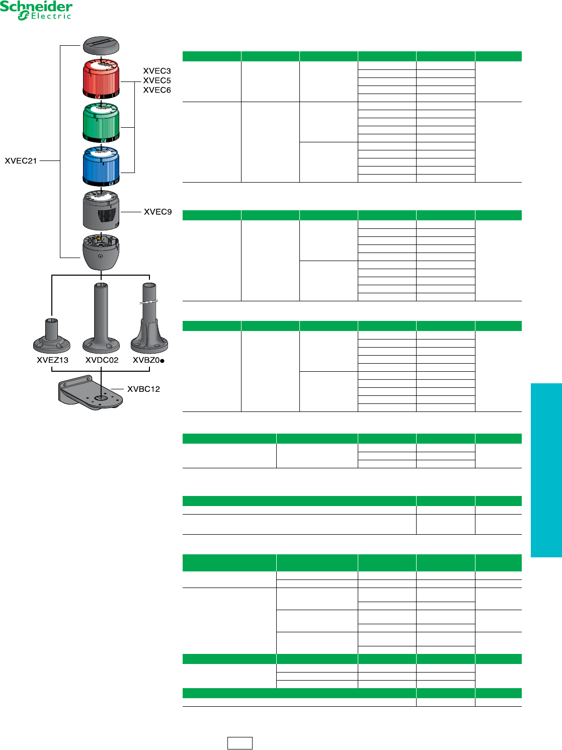
www.schneider-electric.us
19 PUSH BUTTONS AND
OPERATOR INTERFACE
© 2012 Schneider Electric
All Rights Reserved 19-113
Table 19.338: XVE Lens Units with Steady Light
Description Light source Supply voltage Color of lens Catalog Number $ Price
Lens units only for
BA 15d base
fitting bulb
5W max.
(must order bulb
separately a)
24 Vac/Vdc to
240 Vac/Vdc
(Maximum)
Green XVEC33
24.00
Red XVEC34
Orange XVEC35
Blue XVEC36
Clear XVEC37
Illuminated units
Integral LED on
printed board circuit
(separate bulb
not required)
24 Vac/Vdc
Green XVEC2B3
60.00
Red XVEC2B4
Orange XVEC2B5
Blue XVEC2B6
Clear XVEC2B7
120 Vac
Green XVEC2G3
Red XVEC2G4
Orange XVEC2G5
Blue XVEC2G6
Clear XVEC2G7
aOrder clear incandescent bulb separately. See Table 19.336 on Page 19-112.
Table 19.339: XVE Lens Units with Flashing LED
Description Light source Supply voltage Color of lens Catalog Number $ Price
Illuminated units
Integral LED on
printed board circuit
(separate bulb
not required)
24 Vac/Vdc
Green XVEC5B3
90.00
Red XVEC5B4
Orange XVEC5B5
Blue XVEC5B6
Clear XVEC5B7
120 Vac
Green XVEC5G3
Red XVEC5G4
Orange XVEC5G5
Blue XVEC5G6
Clear XVEC5G7
Table 19.340: XVE Lens Units with Strobe Light
Description Light source Supply voltage Color of lens Catalog Number $ Price
Lens units with
integral 1 Joule strobe
light
Discharge tube,
1Joule
(separate bulb
not required)
24 Vac/Vdc
Green XVEC6B3
105.00
Red XVEC6B4
Orange XVEC6B5
Blue XVEC6B6
Clear XVEC6B7
120 Vac
Green XVEC6G3
Red XVEC6G4
Orange XVEC6G5
Blue XVEC6G6
Clear XVEC6G7
Table 19.341: XVE Audible Sounder Units
Description Supply Voltage Catalog Number $ Price
Audible Sounder Units 85dB
24 Vac/Vdc XVEC9B
90.00120 Vac XVEC9G
230/240 Vac XVEC9M
Table 19.342: XVE Base Units and Covers
Discription Catalog Number $ Price
Base unit + snap on cover for NEMA and UL Type 12, IP42 rating XVEC21 24.00
Base unit + screw mounting cover
for IP54 rating
(includes 5 O-ring seals for lens units and 1 gasket for base unit)
XVEC21P 30.00
Table 19.343: XVE Accessories
Description Height under base unit
in. (mm) Color Catalog Number $ Price
Plastic mounting bases 0.78 (20) Black XVEZ13 12.00
3.93 (100) Black XVDC02 15.00
Mounting bases
comprising:
Ø 25 mm aluminium
support tube +
black plastic
mounting support
3.15 (80)
Black
aluminium XVBZ02 18.75
Aluminium XVBZ02A
15.7 (400)
Black
aluminium XVBZ03 37.50
Aluminium XVBZ03A
31.5 (800)
Black
aluminium XVBZ04 75.00
Aluminium XVBZ04A
Description Electrical characteristics Catalog Number $ Price
Clear incandescent bulbs with
BA 15d base fitting
for lens units type XVE C3p
4 W, z 24 Vac/Vdc DL1BEBS
6.155 W, z 120 Vac/Vdc DL1EDGS
5 W, z 230 Vac/Vdc DL1BEMS
Description Catalog Number $ Price
Wall mount bracket (metal) XVBC12 48.45
XV Discount
Schedule
Tower Lights and
Beacons
XVE Components—70 mm Diameter (2.75 inches)
Refer to Catalog 9001CT1002
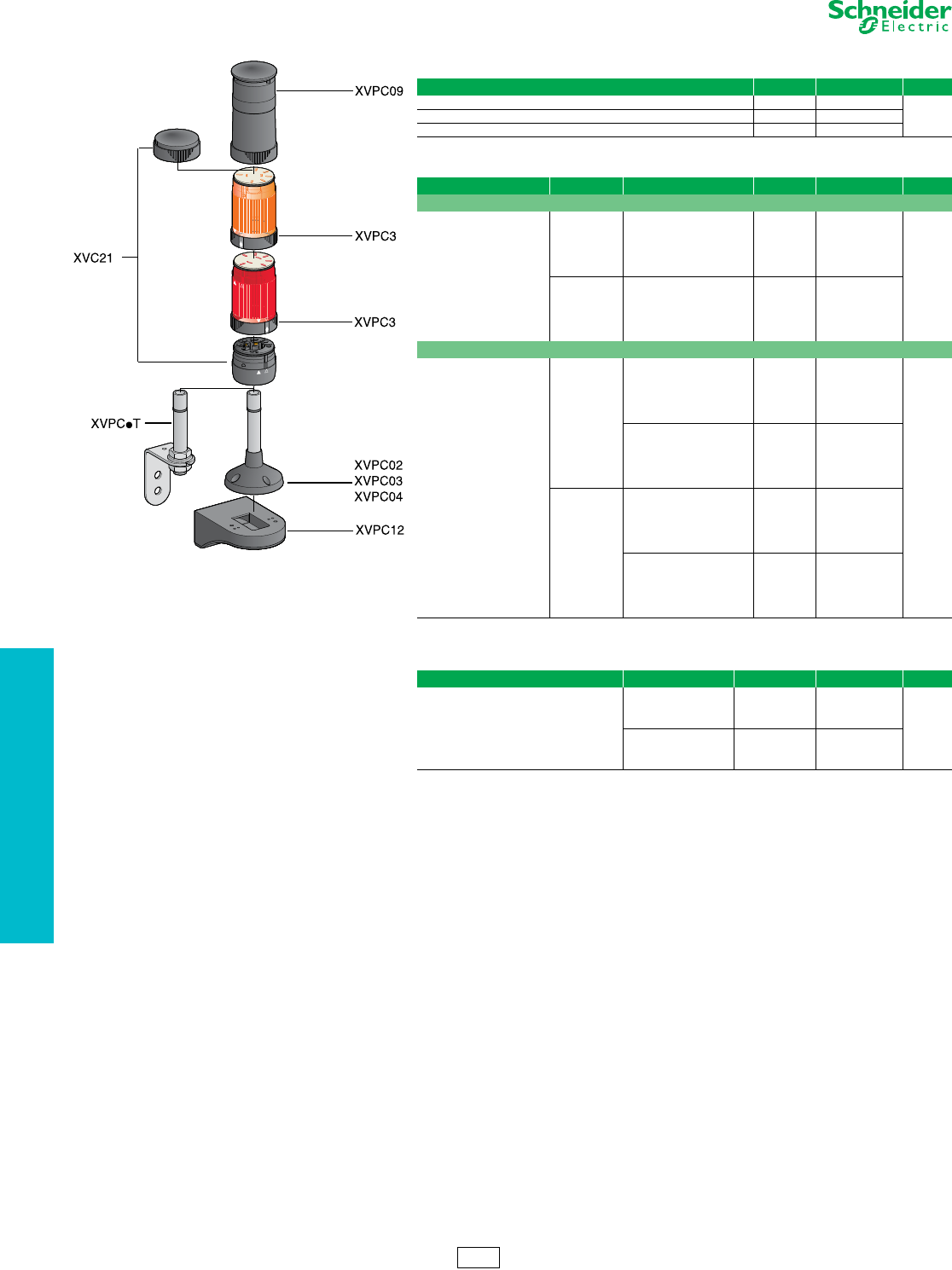
www.schneider-electric.us
19 PUSH BUTTONS AND
OPERATOR INTERFACE
19-114 © 2012 Schneider Electric
All Rights Reserved
aFor bulbs see Table 19.336 on page 19-112.
Table 19.344: Base Units + Covers
Description Color Catalog Number $ Price
Base unit and cover Black XVPC21
48.00Base unit and cover Off-white XVPC21W
Base unit and cover (with ring-tongue compatible terminal) Off-white XVPC21WR
Table 19.345: XVP Lens Units
Description Ring Color Light Source and Voltage Lens Color Catalog Number $ Price
Steady or Flashing
50 mm steady lens unit
(See Table 19.347 on
page 19-115 and
Table 19.348 on page 19-115
for LEDs and incandescent
bulbs)
Black
Bulb (7 W max)
not included
250 V
(must order bulb
separately a)
Green
Red
Amber
Blue
Clear
Yellow
XVPC33
XVPC34
XVPC35
XVPC36
XVPC37
XVPC38 43.50
Off-white
Bulb (7 W max)
not included
250 V max
(must order bulb
separately a)
Green
Red
Amber
Blue
Clear
Yellow
XVPC33W
XVPC34W
XVPC35W
XVPC36W
XVPC37W
XVPC38W
Strobe
Lens unit with integral strobe
Black
Strobe 24 Vdc
0.3 Joule
(separate bulb not required)
Green
Red
Amber
Blue
Clear
Yellow
XVPC6B3
XVPC6B4
XVPC6B5
XVPC6B6
XVPC6B7
XVPC6B8
186.00
Strobe 120 Vac
0.6 Joule
(separate bulb not required)
Green
Red
Amber
Blue
Clear
Yellow
XVPC6G3
XVPC6G4
XVPC6G5
XVPC6G6
XVPC6G7
XVPC6G8
Off-white
Strobe 24 Vdc
0.3 Joule
(separate bulb not required)
Green
Red
Amber
Blue
Clear
Yellow
XVPC6B3W
XVPC6B4W
XVPC6B5W
XVPC6B6W
XVPC6B7W
XVPC6B8W
Strobe 120 Vac
0.6 Joule
(separate bulb not required)
Green
Red
Amber
Blue
Clear
Yellow
XVPC6G3W
XVPC6G4W
XVPC6G5W
XVPC6G6W
XVPC6G7W
XVPC6G8W
Table 19.346: XVP Audible Sounder Units
Description Ring Color Supply Voltage Catalog Number $ Price
50 mm sounder unit
(IP40 NEMA 1)
Ten tone selections,
75–85 dB at 1 m
Black
24 Vdc XVPC09B
156.00
120 Vac XVPC09G
230 Vac XVPC09M
Off-white
24 Vdc XVPC09BW
120 Vac XVPC09GW
230 Vac XVPC09MW
XV Discount
Schedule
Tower Lights and
Beacons
XVP Components—50 mm Diameter (2 inches)
Refer to Catalog 9001CT1002
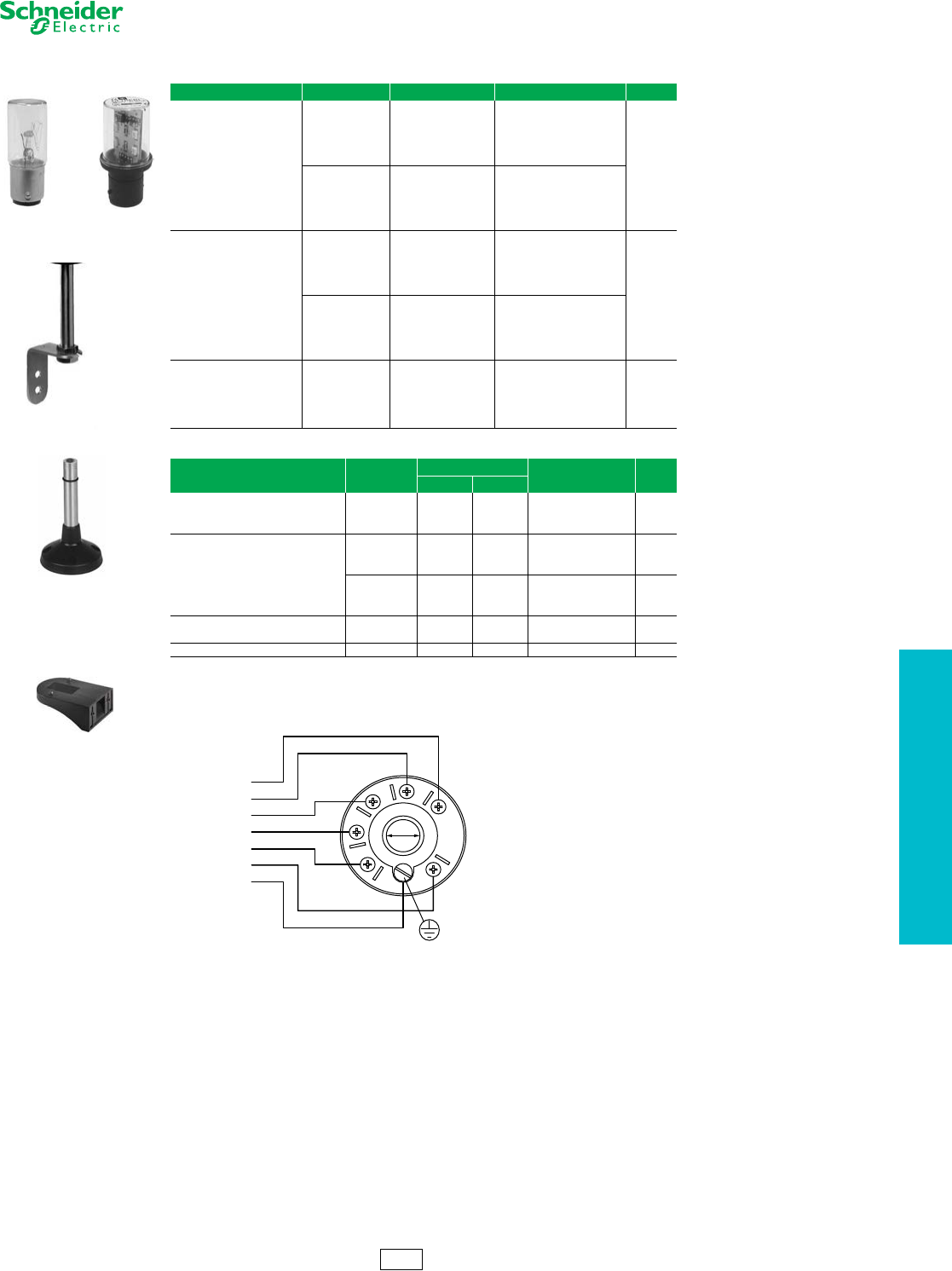
www.schneider-electric.us
19 PUSH BUTTONS AND
OPERATOR INTERFACE
© 2012 Schneider Electric
All Rights Reserved 19-115
Tower Lights and
Beacons
XVP Accessories — 50 mm Diameter (2 inches)
Refer to Catalog 9001CT1002
Wiring Diagram
Cable Connections, Supply line maximum: 1.5 mm2 (16 AWG)
Table 19.347: XVP LED Bulbs
Description Voltage Color Catalog Number $ Price
Steady-On LED bulb
24 Vac/Vdc
White
Green
Red
Amber
Blue
Yellow
DL1BDB1
DL1BDB3
DL1BDB4
DL1BDB5
DL1BDB6
DL1BDB8 108.00
120 Vac
White
Green
Red
Amber
Blue
Yellow
DL1BDG1
DL1BDG3
DL1BDG4
DL1BDG5
DL1BDG6
DL1BDG8
Flashing LED bulb
24 Vac/Vdc
White
Green
Red
Amber
Blue
Yellow
DL1BKB1
DL1BKB3
DL1BKB4
DL1BKB5
DL1BKB6
DL1BKB8 139.50
120 Vac
White
Green
Red
Amber
Blue
Yellow
DL1BKG1
DL1BKG3
DL1BKG4
DL1BKG5
DL1BKG6
DL1BKG8
Incandescent bulbs
Bayonet type BA 15d, 7 W
12 Vac/Vdc Clear DL1BEJ
8.10
24 Vac/Vdc Clear DL1BEB
48 Vac/Vdc Clear DL1BEE
120 Vac/Vdc Clear DL1BEG
230 Vac/Vdc Clear DL1BEM
Table 19.348: XVP Accessories
Description Color Characteristics Catalog Number $ Price
IN mm
Mounting tube with bracket Silver
4 100 XVPC02T 32.55
10 250 XVPC03T 40.35
16 400 XVPC04T 48.00
Mounting tube with tulip base
Black
4100 XVPC02 32.55
10 250 XVPC03 48.00
16 400 XVPC04 48.00
Off-white
4100 XVPC02W 40.35
10 250 XVPC03W 40.35
16 400 XVPC04W 48.00
Wall mounting bracket (plastic) Black — XVPC12 15.60
Off-white — XVPC12W
Bulb mounting and removal tool — — XVPCX13 7.80
DL1BDB1
DL1BEJ
XVPC02
XVPC12
XVPC03T
Ø 12
0.47
+/5+/4
+/3
+/2
+/1
–/C
wire 5
wire 4
wire 3
wire 2
wire 1
wire 6
green-yellow
XV Discount
Schedule
XVPC21
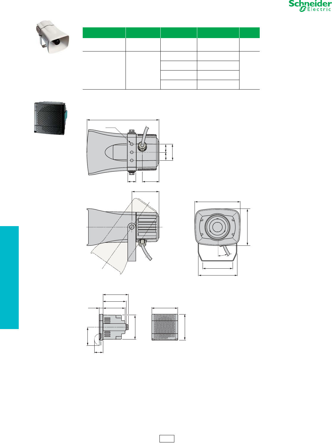
www.schneider-electric.us
19 PUSH BUTTONS AND
OPERATOR INTERFACE
19-116 © 2012 Schneider Electric
All Rights Reserved
Tower Lights and
Beacons
XVS Sirens and Electronic Alarms
Refer to Catalog 9001CT1002
Table 19.349: XVS Sirens and Electronic Alarms
Description Voltage Color Catalog Number $ Price
Multisound siren
105 dB, 43 tones 12/24 Vdc White XVS 14BMW 360.00
Electronic alarms
90 dB, 16 tones
Panel Mount DIN72
12/24 Vac/Vdc
PNP, Black XVS 72BMBP
180.00
PNP, White XVS 72BMWP
NPN, Black XVS 72BMBN
NPN, White XVS 72BMWN
Table 19.350: Dimensions (mm)
XVS72BM
XVS14BMW
XVS 14BMW
140
84
223
114
50
2 5
3xØ9
52
2 0°
12 0
9 7
= =
XVS 72BMpp
7 2
10, 9 60, 7
63, 3
69 , 3
2 4
7 2
U 67 , 5
51
XV Discount
Schedule
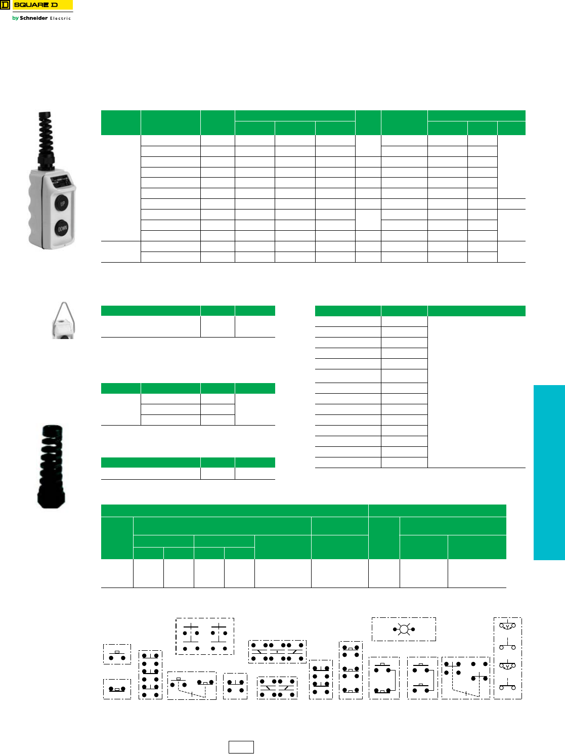
www.schneider-electric.us
19 PUSH BUTTONS AND
OPERATOR INTERFACE
© 2012 Schneider Electric
All Rights Reserved 19-117
Pendant Stations Type BW Pendant Stations
Refer to Catalog 9001CT1001
This pre-assembled, two-button station now comes complete with internal and external strain relief. Oversized finger
grips on the rear of the enclosure make it easy to grip and operate.
•Well suited for standard hoist applications
•Push button legend inserts
•Field-installable mushroom button
•Full cover gasket, to exclude harmful contaminants
dOSHA Regulation, Section 1910.70, Overhead and Gantry Cranes, limits the voltage of pendant push buttons to 150 Vac or 300 Vdc.
Contact Symbols
NOTE: When ordering, add prefix 9001 to the catalog number.
Table 19.351: BW90 and BW100 Pendant Stations – with cord connector and strain relief
Description Legend Insert
Markings
Mechanical
Interlock
Enclosure Color
$ Price Contact
Symbol
Replacement Interior b
Yellow Black Red 9001 Type Contact
Symbol $ Price
Single Speed
Up-Down Yes BW92Y BW92B BW92R 136.00 146 BOC368 146
90.00
Forward-Reverse Yes BW93Y BW93B BW93R 146 BOC368 146
On-Off aYe s BW94Y BW94B BW94R 180.00 10 BOC358 147
Start-Stop No BW95Y BW95B BW95R 136.00 145 BOC359 25
Start-Stop aYe s BW96Y BW96B BW96R 180.00 10 BOC358 147
On-Off aNo BW97Y BW97B BW97R 136.00 146 BOC359 25
Up-Down Yes BW98Y BW98B —147.00 100 — — —
without Inserts Yes BW90YU BW90BU BW90RU 130.00 147 BOC366 25
90.00without Inserts No BW91YU BW91BU BW91RU 25 BOC359 25
without Inserts aYe s BW94YU BW94BU BW94RU 172.00 147 BOC358 147
Two S p ee d without Inserts Yes BW100YU BW100BU BW100RU 195.00 150 BOC367 150 158.00
Up-Down Yes BW102Y BW102B BW102R 202.00 150 BOC367 150
aMaintained Contact
bIncludes gasket
Table 19.352: Hanger Bracket Table 19.353: Interchangeable Legend Inserts c
Description Form $ Price Marking Type $ Price
External Bracket
(cannot be field installed) Y236 10.50 Start B259
3.60
Stop B260
Forward B255
Reverse B256
Open B263
Table 19.354: Replacement Enclosures Close B264
Description Color Type $ Price Raise B261
Box & Cover
with 4 screws
Yellow BWRY
54.00
Lower B262
Red BWRR Up B253
Black BWRB Down B254
On B257
Off B258
Table 19.355: Strain Relief Replacement Blank - black B251
Description Type $ Price Blank - red B252
Strain Relief Replacement BWSR 10.00 cOrder must specify a quantity of 10 or multiples of 10.
Table 19.356: Electrical Contact Ratings d
AC—NEMA B600 DC—NEMA P600
Vol ts
Inductive
35% Power Factor
Resistive
75% Power Factor
Volt s
Inductive and Resistive
Make Break Continuous
Carrying
Amperes
Make, Break and
Continuous
Carrying Amperes
Make and Break
Amperes
Continuous
Carrying Amperes
AVA AVA
120
240
480
600
30.5
15
7.5
6
3600
3600
3600
3600
3.75
1.5
.75
.6
360
360
360
360
5
5
5
5
5
5
5
5
120
240
600
1.1
0.55
0.2
5
5
5
10
17
1916
1
3 8 25 109 150
145 146
121
120 V Com
147
Speed 2
Speed 2
Speed 1
Speed 1
100
CS1 Discount
Schedule
BW90 / BW100
BWSR
Y236
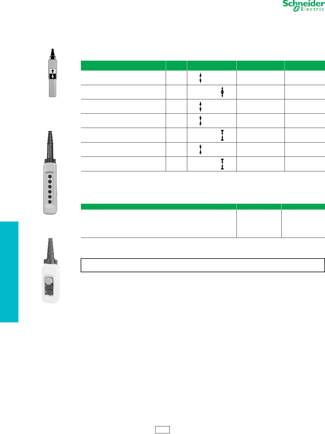
www.schneider-electric.us
19 PUSH BUTTONS AND
OPERATOR INTERFACE
19-118 © 2012 Schneider Electric
All Rights Reserved
Pendant Stations XAC Standard Duty Pistol Grips, Enclosures, Contact Blocks
Refer to Catalog 9001CT1001
XAC pendant stations are designed for standard- or medium-duty control circuit applications.
•Single- or two-speed versions
•Double insulated
•Shock and corrosion resistant
•2, 4, 6, 8, 12 element versions
•Ease of operation
aThese units are available with factory installed E-stops. Add a “3” to the end of the catalog number for standard E-stop or add a “4” for a trigger
action E-stop.
bThese units are available with a factory installed E-stop. Use XACD22 ••• for a standard E-stop or XACD24••• for a trigger action E-stop.
Note: Legends are required to achieve NEMA4 rating.
cStandard enclosures include internal mounting plate, cable sleeve for 8 to 26 mm, internal cable clamp, suspension ring and cable tie.
dFor ordering information on custom built XACA pendants, visit our website at www.Schneider-Electric.us.
Table 19.357: Pistol Grip Stations
Description Speeds Function
1 speed/2 speed Catalog Number $ Price
1 N.O. contact per operator
2 Mechanically interlocked operators 1XACA201a150.00
2 N.O. (staggered) contacts per operator
2 Mechanically interlocked operators 2XACA207a222.00
1 N.O. + 1 N.C.
2 Mechanically interlocked operators 1XACA205a187.00
1 N.O. contact per direction
1 Mechanically interlocked 2 way toggle 1XACD21A0101b167.00
1 N.O. + 1 N.O. staggered
1 Mechanically interlocked 2 way toggle 2XACD21A1231b451.00
1 N.O. & 1 N.C. contact per direction
1 Mechanically interlocked 2 way toggle 1XACD21A0105b202.00
1 N.C. + 1 N.O. + 1 N.O. staggered
1 Mechanically interlocked 2 way toggle 2XACD21A1241b480.00
Table 19.358: General Purpose Pendantscd
Enclosures Catalog Number $ Price
2 hole enclosure XACA02H7 192.00
3 hole enclosure XACA03H7 220.00
4 hole enclosure XACA04H7 250.00
6 hole enclosure XACA06H7 306.00
8 hole enclosure XACA08H7 382.00
12 hole enclosure XACA12H7 478.00
To place a custom pendant order, use the worksheet on page 19-121 as a guide. Orders must be
placed through the Product Selector in Quote to Cash. There is a 10% charge for assembly.
XACA06
XACA03
with
operators
CS2 Discount
Schedule
XACA201
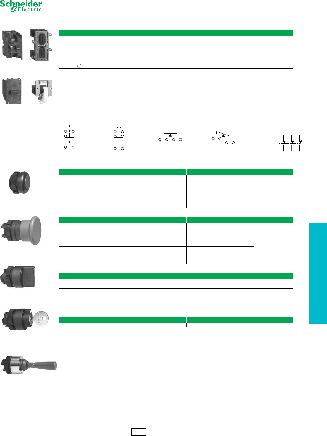
www.schneider-electric.us
19 PUSH BUTTONS AND
OPERATOR INTERFACE
© 2012 Schneider Electric
All Rights Reserved 19-119
Pendant Stations XAC Standard Duty Pistol Grips, Enclosures, Contact Blocks
Refer to Catalog 9001CT1001
aCannot be used with XACA03 pendant.
Wiring Diagrams
bBooted push buttons are for cover mounting only. All other operators can be mounted on cover or bottom.
cTrigger action mushroom heads are tamper proof in that a change of contact state is not possible by teasing or floating the operator.
dNot for use with XEN G contact blocks.
eFor lamps, see page 19-120.
Table 19.359: Contact Blocks for Operators in Cover
Description Wiring Diagram Catalog Number $ Price
1 N.O./spring return/1 speed — ZB2BE101 16.40
1 N.C./spring return/1 speed — ZB2BE102
1 N.O. early close & 1 N.C. & 1 N.O./spring return/2 speed Figure 1 XENG1191
49.00
1 N.C. & 2 N.O./spring return/1 speed Figure 2 XENG1491
1 N.O. & 1 N.O. latching/1 speed/interlocked Figure 3 XENG3781
1 N.O. & 1 N.C. latching/1 speed/interlocked Figure 4 XENG3791
3 N.C.—all direct acting Figure 5 XENT1192
Table 19.360: Contact Blocks for Operators in Base of Enclosure a
1 N.O./1 speed XACS101 28.60
1 N.C./1 speed XACS102
2 N.O./1 speed XACS103
38.202 N.C./1 speed XACS104
1 N.O. & 1 N.C./1 speed XACS105
Table 19.361: Operators b
Description Color Catalog Number $ Price
Booted push button
White XACA9411
8.20
Black XACA9412
Green XACA9413
Red XACA9414
Yellow XACA9415
Blue XACA9416
Brown XACA9419
Table 19.362: Mushroom Operators
Description Mushroom Size Color Catalog Number $ Price
Mushroom head, momentary 30 mm Red ZA2BC44 36.80
Mushroom head, push to maintain/turn-to-release 30 mm Red ZA2BS44 79.00
40 mm Red ZA2BS54
Mushroom head, push to maintain/turn-to-release
(trigger action)c
30 mm Red ZA2BS834
112.00
40 mm Red ZA2BS844
Mushroom head, push to maintain/key turn-to-release 30 mm Red ZA2BS74
40 mm Red ZA2BS14
Mushroom head, push to maintain/key turn-to-release
(trigger action)c40 mm Red ZA2BS944
Table 19.363: Selector Switches and Wobble Stick
Description Color Catalog Number $ Price
Selector switch/2 position—maintaineddBlack ZA2BD2 30.00
Selector switch/3 position—maintaineddBlack ZA2BD3
Selector switch/2 position—maintained key operated—key removal from LT or RT positiondNA ZA2BG4 112.00
Selector switch/3 position—maintained key operated—key removal from LT or RT positiondNA ZA2BG5
Wobble stick (bottom mounting recommended) Black ZA2BB2 102.00
Red ZA2BB4
Table 19.364: Pilot Light Components
Description Color Catalog Number $ Price
Direct supply base/without lamp (for 6 to 120 V applications) (AC/DC) e—ZB2BV006 24.60
ZB2BE10 XENG37
XENG1191 XACS10
13 14
21 22
33 34
13 14
21 22
33 34
13 14 13 14 13 14
11 12
N/C + N/C + N/C
with positive
opening operation
1112
2122
3132
Figure 1 Figure 3 Figure 4 Figure 2 Figure 5
Booted Push Button
Mushroom Head
Selector Switch
Selector Switch
(key operated)
Wobble Stick
CS2 Discount
Schedule
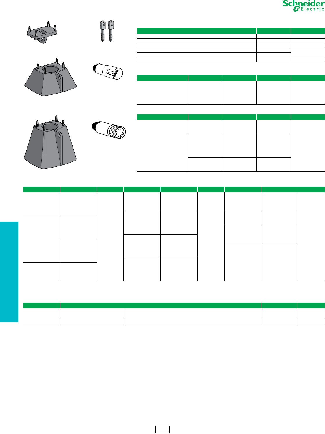
www.schneider-electric.us
19 PUSH BUTTONS AND
OPERATOR INTERFACE
19-120 © 2012 Schneider Electric
All Rights Reserved
Pendant Stations XAC Standard Duty Operators—Accessories
Refer to Catalog 9001CT1001
Table 19.365: Enclosure Accessories
Description Catalog Number $ Price
Blank hole plug ZB2SZ3 13.60
Mechanical interlock (momentary). For use with XAC booted operators only XACA009 8.20
Screw adapter for self-supporting cable XACB961 6.80
Low suspension ring for single row station XACA971 19.20
Protective guard for bottom mounted mushroom head XACA982
Protective guard for bottom mounted selector switch or key switch XACA983 27.40
Table 19.366: Lamps
Type Voltage Watts Catalog Number $ Price
Replacement bulbs
(Type BA9s)
Incandescent
6 Vac/Vdc 1.2 DL1CB006
11.00
12 Vac/Vdc 2.0 DL1CE012
24 Vac/Vdc 2.0 DL1CE024
48 Vac/Vdc 2.4 DL1CE048
130 Vac/Vdc 2.6 DL1CE130
Table 19.367: LED, BA9s Base
Type Color Voltage Catalog Number $ Price
LED, BA9s base for
Direct Supply blocks
Green 6 Vac/Vdc DL1CJUS0063
25.00
Red 6 Vac/Vdc DL1CJUS0064
Amber 6 Vac/Vdc DL1CJUS0065
Green 24 Vac/Vdc DL1CJUS0243
Red 24 Vac/Vdc DL1CJUS0244
Amber 24 Vac/Vdc DL1CJUS0245
White 24 Vac/Vdc DL1CJ0241
Blue 24 Vac/Vdc DL1CJ0246
Green 120 Vac/Vdc DL1CJUS1203
Red 120 Vac/Vdc DL1CJUS1204
Amber 120 Vac/Vdc DL1CJUS1205
XACA982
XACA971
XACA983
DL1CE0••
(Incandescent)
DL1CJUS••••
(LED)
XACB961
Table 19.368: PVC Standard Legend Plates 30 x 40 mm
TextaCatalog Number $ Price TextaCatalog Number $ Price TextaCatalog Number $ Price
Bridge Forward ZB2BY2343
4.20
Left ZB2BY2310
4.20
Stop ZB2BY2304
4.20
Bridge Reverse ZB2BY2344 Low ZB2BY2336 Stop Start ZB2BY2366
Close ZB2BY2314 Lower ZB2BY2337 Trolley Right ZB2BY2345
Down ZB2BY2308 Man Auto ZB2BY2372 Tr o l l ey L e ft ZB2BY2346
Emergency Stop ZB2BY2330 Off ZB2BY2312 Up ZB2BY2307
Fast ZB2BY2328 On ZB2BY2311 Up Down ZB2BY2370
Forward ZB2BY2305 Off On ZB2BY2367 Up-O-Down ZB2BY2389
For Rev ZB2BY2371 Open ZB2BY2313 North 6516002379
For-O-Rev ZB2BY2384 Open Close ZB2BY2376 South 6516002380
Hand Off Auto ZB2BY2387 Open-O-Close ZB2BY2388 East 6516002381
High ZB2BY2338 Out ZB2BY2339 West 6516002382
High Low ZB2BY2369 Power On ZB2BY2326
Hoist Down ZB2BY2342 Raise ZB2BY2335
Hoist Up ZB2BY2341 ResetaZB2BY2323
In ZB2BY2503 Reverse ZB2BY2306
Inch ZB2BY2321 Right ZB2BY2309
Jog For ZB2BY2381 Run ZB2BY2334
Jog Rev ZB2BY2380 Slow ZB2BY2327
Jog Run ZB2BY2365 Start ZB2BY2303
aAll nameplates are black with white lettering except “Stop”, “Emergency Stop” and “Reset” which are red with white lettering.
For black “Reset” change final digit of catalog number to 2.
Type Description Catalog Number $ Price
PVC blank legend Blank Black or red background—30 mm x 40 mm ZB2BY2101 4.20
Blank Yellow or white background—30 mm x 40 mm ZB2BY4101
PVC custom
engraved
Special engravingb
Special engravingb
Black background, white letters—30 mm x 40 mm
White background, black letters—30 mm x 40 mm
ZB2BY2002
ZB2BY4001 17.80
bPlease specify lettering when ordering. Two lines with 11 characters (including spaces) maximum on each plate.
CS2 Discount
Schedule
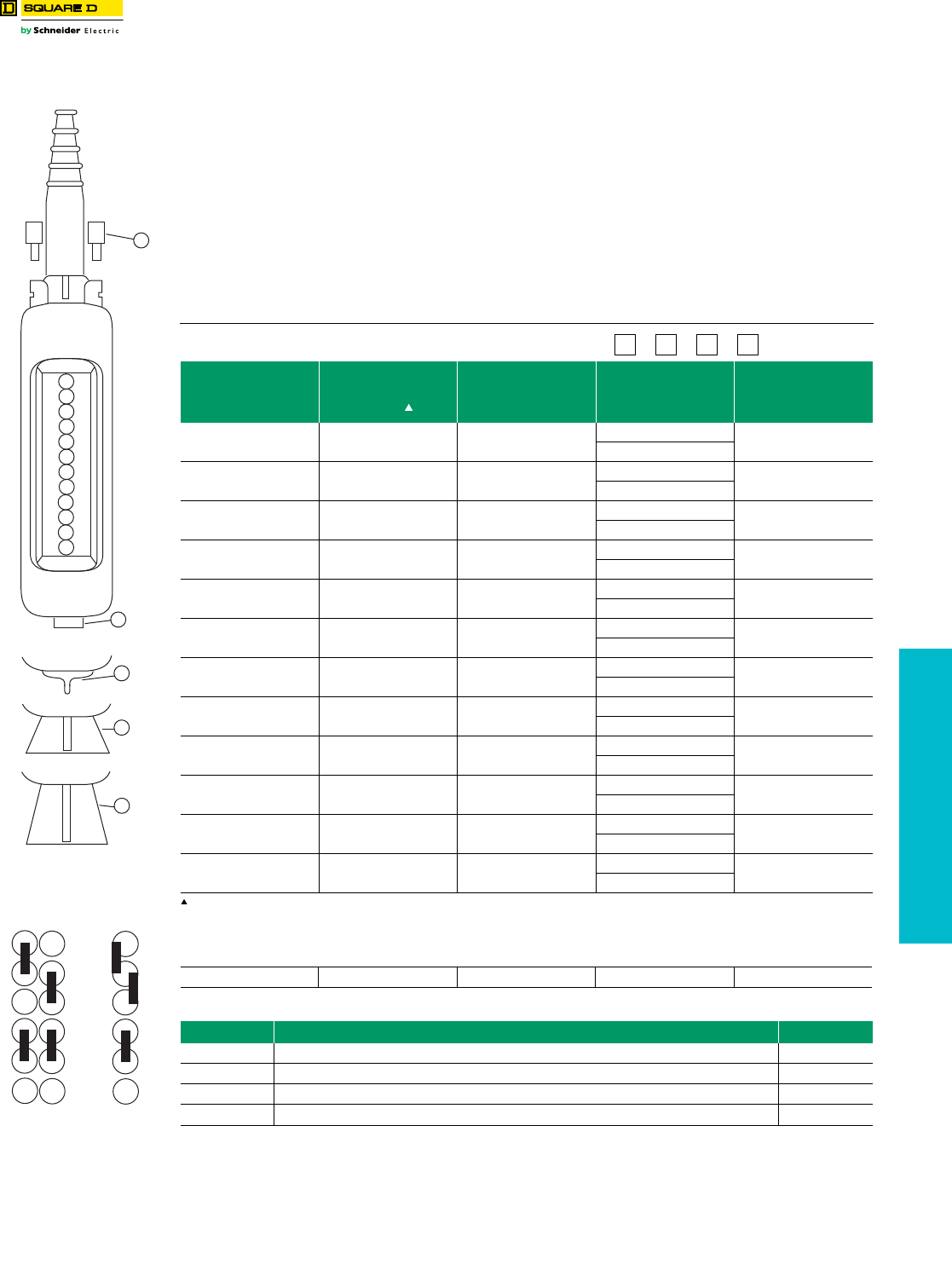
www.schneider-electric.us
19 PUSH BUTTONS AND
OPERATOR INTERFACE
© 2012 Schneider Electric
All Rights Reserved 19-121
Pendant Stations Type XACA Worksheet
Class 9001 / Refer to Catalog 9001CT1001
Type XACA Worksheet
Use this worksheet to assist in component selection. Custom orders for XACA pendant stations must
be placed through the Product Selector in Quote to Cash. There is a 10% charge for assembly.
XACA Order Guide Instructions
Custom built pendant stations
1. Determine the number of operators needed, then choose an enclosure with a corresponding number of holes.
2. Select the type of operator, contact block, and appropriate nameplate for each function required.
3. Check for special functions that may be required. These items could include mechanical interlocks, adapters for self-supporting
cable, lower support rings, protective guards, etc.
Catalog number
of enclosure XACA
Functions
(optional)
Mechanical interlock
(draw a vertical line
between the 2 units to
be interlocked )
deriuqer 900ACAX fo rebmuN900ACAX kcolretni lacinahceM
Legends Contact blocks and
pilot light bodies
Push button
Pilot light or
Blanking plug
1
2
3
4
5
6
7
8
9
10
11
12
Unit mounted in base of station (facing downwards)
13
Attachments
Position Type Catalog No.
14 Adapters for self-supporting cable type BBAP (available only with cable sleeve Ø8–26 mm) XACB961
15 Lower support ring XACA971
16 Protective guard for base mounted selector switch or 40 mm emergency-stop push button XACA982
17 Protective guard for key switch XACA983
1
2
3
4
5
6
7
8
9
10
11
12
13
14
15
16
17
11
2
2
33
44
55
66
1
2
3
4
5
6
Mechanical Interlock
(XACA009)
Possible
Combinations
Impossible
Combinations
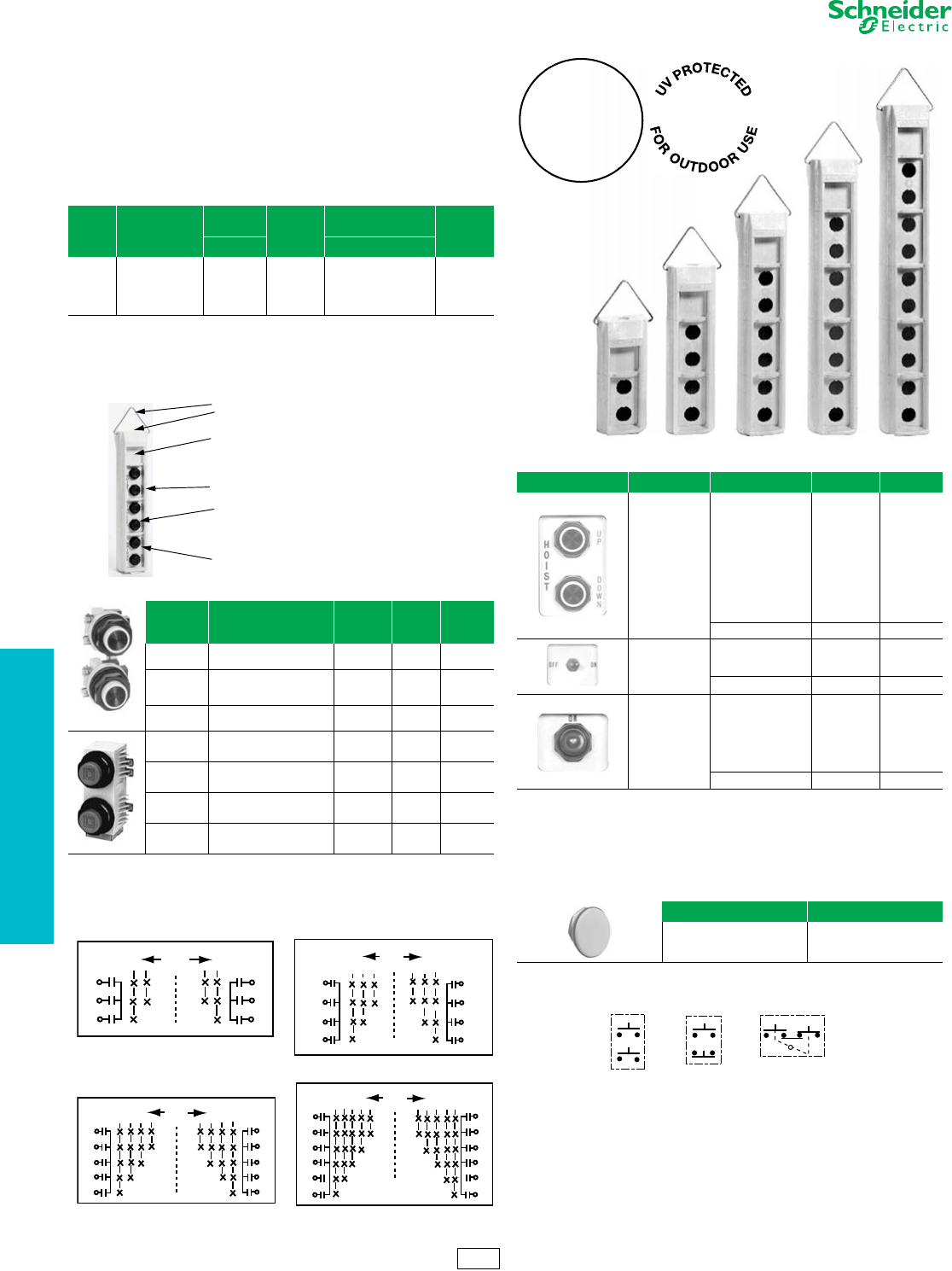
www.schneider-electric.us
19 PUSH BUTTONS AND
OPERATOR INTERFACE
19-122 © 2012 Schneider Electric
All Rights Reserved
This line of pendant stations consists of polymeric enclosures (2 through
10 units), push button units (1 through 5 speed) and laminated legend
plates. All enclosures have an extra single unit space near the top which
permits the installation of a toggle switch, a Type SK operator or pilot
light, or a warning label. All enclosures come with a stainless steel
hanger bracket and internal strain relief post. Enclosures are yellow and
have a threaded opening in the top.
NOTE: When ordering, add prefix 9001 to the catalog number.
aClass 9001 SK push-to-test pilot lights and remote test pilot lights will not fit in these
enclosures.
bAssembled pendant stations consist of an enclosure, operators and legend plates. All
custom orders must include the pendant key sheet available as shown on page 19-123.
cThe price of an assembled pendant SKYP station includes the enclosure and components
plus a 10% assembly charge. (Example: 9001 SKYP2 ($189),
+ SKRU1 ($129), + SKN201 ($8.60) = $326.60 + 10% = $360.
dTypes SKRU 1, 10 and 11 use Type KA contact blocks. Types SKRU 2 thru 5 are factory
enclosed contact blocks.
eBoot part number is 9001KU1.
fBoot part number is 9001KU37.
Figure 19.3: Multispeed Contact Symbols (X = Contact Closed)
gCan be supplied by Square D as Class 9001 Type SKSTS1- includes boot for NEMA Type
4X.
hSee 9001SK on pages 19-77 thru 19-84.
iIncludes legend plate, gasket and ground plate to be used with toggle switch.
jTri-laminated legend plate having a yellow or red background on a black core.
k19 characters each side max.
Figure 19.4: Single Speed Contact Symbols
Worksheet for Custom Assembled Pendant . . . . . . . . . . . . . . . Page 19-123
Table 19.369: Enclosure Catalog Numbers
Number
of
Buttons
Conduit
Entrance
Size
Enclosure
Onlya$ Price
Enclosure For
Assembled Stationb$ Price
Cat. No. Cat. No.
2
4
6
8
10
3/4"-14 NPT
3/4"-14 NPT
1"-111/2 NPT
11/4"-111/2 NPT
11/4"-111/2 NPT
SKYP2
SKYP4
SKYP6
SKYP8
SKYP10
189.00
239.00
287.00
356.00
428.00
SKYP20
SKYP40
SKYP60
SKYP80
SKYP100
c
Table 19.370: Push Button Units
Number of
Buttons
per Unit
Description
Contact
Symbol –
See Below
Cat.
No.d$ Price
2Single Speed –
Momentary Interlocked 7SKRU1 129.00e
2
Single Speed –
Momentary Non-
Interlocked
5SKRU10 107.00e
2Single Speed –
Maintained Interlock 10 SKRU11 149.00e
2Two Speed –
Momentary Interlocked 87 SKRU2 270.00f
2Three Speed –
Momentary Interlocked 88 SKRU3 320.00f
2Four Speed –
Momentary Interlocked 89 SKRU4 341.00f
2Five Speed –
Momentary Interlocked 90 SKRU5 356.00f
Hanger bracket (Part no. 65091-061-01)
Threaded conduit hole
Space for toggle switch, a type SK operator or pilot light. Use
appropriate legend plates.
Type SKYP enclosure
Type SKRU1 through SKRU11 operators. Any Type SK pilot
light▲ or operator can be mounted in this enclosure. The
enclosure depth will accommodate 1 Type KA1 thru KA6 (total
of 2) contact blocks.
Type SKN2 legend plate
Te r m in als
87
2868-D30
C
1
2
21
SPEED POSITION
OFF 12
C
1
2
Te r m in als
C
1
2
3
321
SPEED POSITION
OFF
2868-D29
88
123Te r m in als
C
1
2
3
Te r m in als
Te r m in als
C
1
2
3
4
4321
SPEED POSITION
OFF
2868-D31
89
12 34Te r m in als
C
1
2
3
4
Te r m in als
C
1
2
3
4
4321
SPEED POSITION
OFF
2868-D32
90
1234Te r m in als
C
1
2
3
4
55
5
5
Table 19.371: Legend Plate Catalog Numbers
Where Used Marking Cat. No. $ Price
For SKRU1
through
SKRU11
Blank-Blank
Hoist: Up-Down
Trolley: East-West
Trolley: Fwd.-Rev.
Trolley: North-South
Bridge: Fwd.-Rev.
Bridge: East-West
Bridge: North-South
Start-Stop
Reset-Stop
Aux Hoist: Up-Down
Power: On-Off
SKN200k
SKN201
SKN202
SKN203
SKN204
SKN205
SKN206
SKN207
SKN208
SKN209
SKN210
SKN211
8.60
Specify Marking SKN299k37.20
With toggle
switchg in
top space of
enclosure
Blank
Off-On
On-Off
SKN500i
SKN544i
SKN545i12.90
Specify Marking SKN599 i27.00
With
9001SKh
operator or
pilot light
in top space
of enclosure
Blank
On
Off
Emerg. Stop
Run
Power On
Off-On
SKN100j
SKN103
SKN104
SKN105
SKN124
SKN138
SKN144
4.40
Specify Marking SKN199j18.50
Table 19.372: Closing Plate Catalog Number
Cat. No. $ Price
SK52 14.30
LIFETIME
ENCLOSURE
WARRANTY
10
5
7
CS1 Discount
Schedule
Pendant Stations Application and Ordering Information
Class 9001 / Refer to Catalog 9001CT1001

www.schneider-electric.us
© 2012 Schneider Electric
All Rights Reserved 19-123
19 PUSH BUTTONS AND
OPERATOR INTERFACE
Pendant Stations Application and Ordering Information
Class 9001 / Refer to Catalog 9001CT1001
1. Operator or Closing Plate.
Example - SKRU1
2. Legend Plate Type Number
Example - SKN201
3. Legend Plate Marking
– Used Only if Special Marking is Required
Example:
Line 2 - SKN299
Line 3 - A.) Hoist
B.) FWD
C.) REV
ENCLOSURES – NEMA 4X, 13
PUSH BUTTON UNITS – NEMA / UL 4X, 13
CLOSING PLATE
Control
Products
Type SKYP Worksheet
Use this worksheet to assist in component selection. SKYP Custom Pendant orders must be placed
through the Product Selector in Quote to Cash. There is a 10% charge for assembly.
Class 9001 epyT SKYP -________
Size
Conduit
Entrance
Size
Enclosure
for Assembled
Station
Type
2 Button 3/4" -14 NPT SKYP20
4 Button 3/4" -14 NPT SKYP40
06PYKSTPN 41- "1nottuB 6
1nottuB 8 1/4" -11 1/2SKYP80
1nottuB 01 1/4" -11 1/2SKYP100
Assembled pendant stations consist of an enclosure, operators, and
legend plates.
Number of
Buttons per
Unit
Description Contact
Symbol Type
2Single Speed - Momentary
Interlocked 7SKRU1
2Single Speed - Momentary
Non-Interlocked 5SKRU10
2Single Speed - Maintained
Interlocked 10 SKRU11
2Two Speed - Momentary
Interlocked 87 SKRU2
2Three Speed - Momentary
Interlocked 88 SKRU3
2Four Speed - Momentary
Interlocked 89 SKRU4
2Five Speed - Momentary
Interlocked 90 SKRU5
Type
SK52
When operator and legend plate
use 2 adjacent holes - specify
same in both locations. Example:
1
2
3
1
2
3A)
B)
C)
1
2
3A)
B)
C)
1
2
3A)
B)
C)
1
2
3A)
B)
C)
1
2
3A)
B)
C)
1
2
3A)
B)
C)
1
2
3A)
B)
C)
1
2
3A)
B)
C)
1
2
3A)
B)
C)
1
2
3A)
B)
C)
Space for tog-
gle switch , a
Type SK opera-
tor or pilot light,
or a warning la-
bel. Use SKN-5
or SKN-1 leg-
end plates.
Ty p e S KRU1
through
SKRU11
operators or
Ty p e SK
operators and
Type SKN-2
legend plate.
TYPE NUMBER KEY
A
1
C
B2
3
SKRU1
SKN201
1
2
3
SKRU1
SKN201
Hanger bracket
Threaded conduit
hole
Space for toggle
switch , a Type SK
operator or pilot light
or a warning label.
Use SKN5 or SKN1
legend plates.
Type SKYP enclosure
Typ e SK RU 1 t h ro u gh
SKRU11 operators.
Type SKN2 legend
plate
LEGEND PLATES – NEMA / UL 4X, 13
Available as 9001SKSTS1
Includes legend plate, gasket and ground plate to be
used with toggle switch.
Tri-laminated legend plate having a yellow or red
background on a black core.
19 characters each side.
Class 9001 Type SK Push-To-Test Pilot lights and Re-
mote Test Pilot lights will not fit in these enclosures.
Where Used Marking Type
For SKRU1
through
SKRU11
Blank-Blank
Hoist: Up-Down
Trolley: East-West
Trolley: Fwd.-Rev.
Trolley: North-South
Bridge: Fwd.-Rev.
Bridge: East-West
Bridge: North-South
Start-Stop
Reset-Stop
Specify Marking
SKN200
SKN201
SKN202
SKN203
SKN204
SKN205
SKN206
SKN207
SKN208
SKN209
SKN299
With Toggle
Switch in
Top Space of
Enclosure
Blank
Off-On
On-Off
Specify Marking
SKN500
SKN544
SKN545
SKN599
With Type SK
Operator
or Pilot Light
in Top Space
of Enclosure
Blank
On
Off
Emerg. Stop
Run
Power On
Off-On
Specify Marking
Specify Marking
(Red Background)
SKN100
SKN103
SKN104
SKN105
SKN124
SKN138
SKN144
SKN199
SKN199R
The price of the total station
consists of the price of each
individual component plus a
10% charge for assembly.
CS1 Discount
Schedule
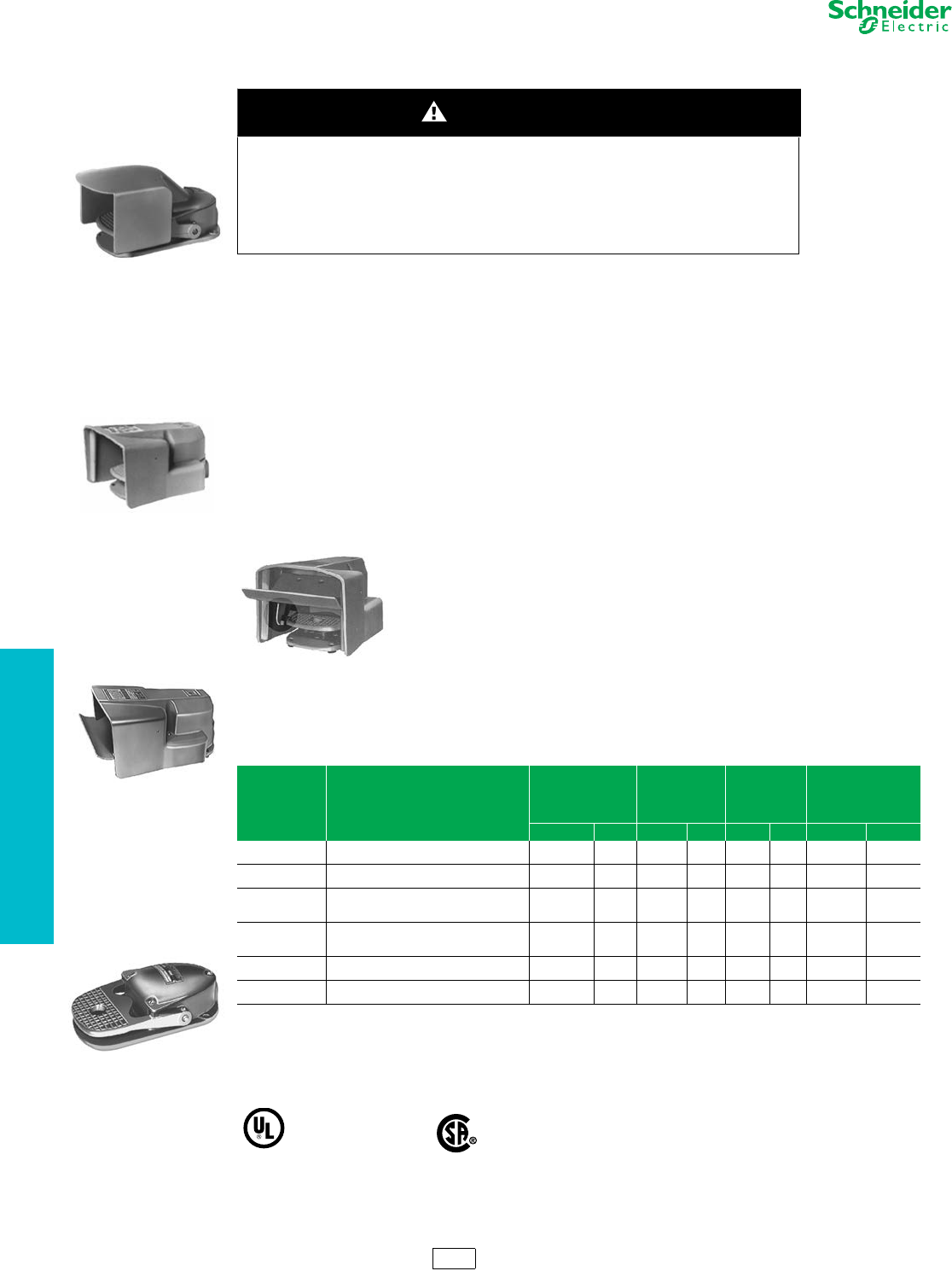
19-124 © 2012 Schneider Electric
All Rights Reserved
www.schneider-electric.us
19 PUSH BUTTONS AND
OPERATOR INTERFACE
Foot Switches 9002A Heavy Duty Industrial
Class 9002
Heavy Duty Industrial Foot Switches—Oiltight, Watertight, Dusttight and Driptight Enclosure,
NEMA 2, 4 and 13
Foot Switch Selection
Foot switches are used to control many industrial processes, while leaving the operator's hands free to perform other
functions. The type or model of foot switch suitable for each application will vary depending on factors such as the
control function required, degree of protection required, production methods, unusual conditions, government
regulations, etc. In some applications more than one foot switch may be required, as when two or more persons are
operating a machine. In these cases, safe practice and regulations require that the foot switches be wired in series
making it necessary that each operator's foot switch be actuated before the machine will cycle.
Only the user can be aware of all the conditions and factors present during setup, operation and maintenance of the
machine; therefore, only the user can determine which foot switch(es) can be properly used. When selecting a foot
switch for a particular application, the user should refer to the applicable ANSI standards and OSHA regulations. The
National Safety Council's Accident Prevention Manual also provides much useful information.
In some applications, such as power presses, additional operator protection such as point-of-operation guarding must
be provided when a foot switch is used as an actuator. This is necessary since the operator's hands and other parts of
the body are free to enter the pinch point area and serious injury can occur. The shielding provided on foot switches
cannot protect an operator from injury. For this reason the foot switch cannot be substituted for or take the place of
point-of-operation protection.
A Trilingual Danger Sign regarding the need for point-of-operation protection is supplied with each foot switch. The sign
incorporates three languages: English, Spanish and French. Additional copies of the sign are available by contacting
your Square D sales office.
Type AW Fully Shielded Foot Switch with Oversized Pedal Shield, Side Shields and
Safety Door. The Safety Door is interlocked with the pedal to prevent operation due to
shock or vibration. It prevents accidental pedal operation by requiring a simple but
intentional motion to lift the door before inserting the foot.
Operating Temperature: –30 to +60 °C (–22 to +140 °F)
NOTE: When ordering, add prefix “9002” to the catalog number.
a2 N.O. and 2 N.C. isolated, direct acting contacts.
bA single pole snap switch that contains two double break contact elements (1 N.O. and 1 N.C.) must be used on circuits of same polarity.
A double pole snap switch contains two electrically separated sets of contact elements allowing use on circuits of opposite polarity. Each set that contains
two double break contact elements (1 N.O. and 1 N.C.) must be used on circuits of same polarity.
cFor replacement cover drilled to accept latch. For Series C foot switches order AC9. Price is $182.00 No replacement cover available for Series A or
B devices drilled to accept latch. AC8 is spring return only.
dWARNING: These foot switches must not be used to operate machines or equipment where the possibility of operator injury exists. Typical uses
include Emergency Stop functions, “Dead Man” controls, signal functions (lights, bells, etc.).
For replacement parts for Class 9002 Type AW: See instruction bulletin 65013-010-31.
For contact symbol tables, see page 19-125
HAZARDOUS APPLICATIONS
Do not use foot switches on machines without point-of-operation protection.
Failure to follow these instructions will result in death, serious injury, or
equipment damage.
Table 19.373: Foot Switch Catalog Numbers
Description Features
Fully Shielded with
Oversized Pedal
Shield,
Side Shields and
Safety Door
With Oversized
Pedal Shield
and
Side Shields
With Pedal
Shield and
Side Shields
UNSHIELDED
(See Warning noted)
Cat. No. $ Price Cat. No. $ Price Cat. No. $ Price Cat. No. $ Price
Single Poleb
Double Throw
Spring Return
With Mechanical Latch
AW117
—
750.00
—
AW132
—
750.00
—
AW2
AW7
363.00
527.00
AW1
—
396.00
—
Two Pole b
Double Throw
Spring Return
With Mechanical Latch
AW124 a
—
903.00
—
AW133
—
903.00
—
AW14
AW15
527.00
692.00
AW13
—
575.00
—
Two Stage b
(One Pole Each
Stage) Table 1
Spring Return
With Mechanical Latch in 1st Stage
With Mechanical Latch in 2nd Stage
AW119
—
—
930.00
—
—
AW134
—
—
930.00
—
—
AW6
AW9
AW10
543.00
705.00
705.00
AW5
—
—
590.00
—
—
Four Stage b
(One Pole Each
Stage) Table 2
Spring Return AW123 1295.00 ——AW22 912.00 AW21 995.00
Single Pole
Single Throw Maintained Contact—Push On/Push Off — — — — AW12 527.00 AW11 575.00
Replacement
Cover Assembly —AC5 363.00 AC7 363.00 AC8c140.00 AC1 153.00
File
CCN
E42259
NKCR
File
Class
LR25490
184 N 13.1U
DANGER
AW2
Type AW Foot Switch with
Top Pedal Shield and Side
Shields
AW132
Type AW with Oversized
Pedal Shield and Side
Shields
AW117
Type AW with Oversized
Pedal Shield, Side
Shields and Safety Door
AW1
Type AW Foot Switch
without Pedal Shield
CP1 Discount
Schedule
AW124
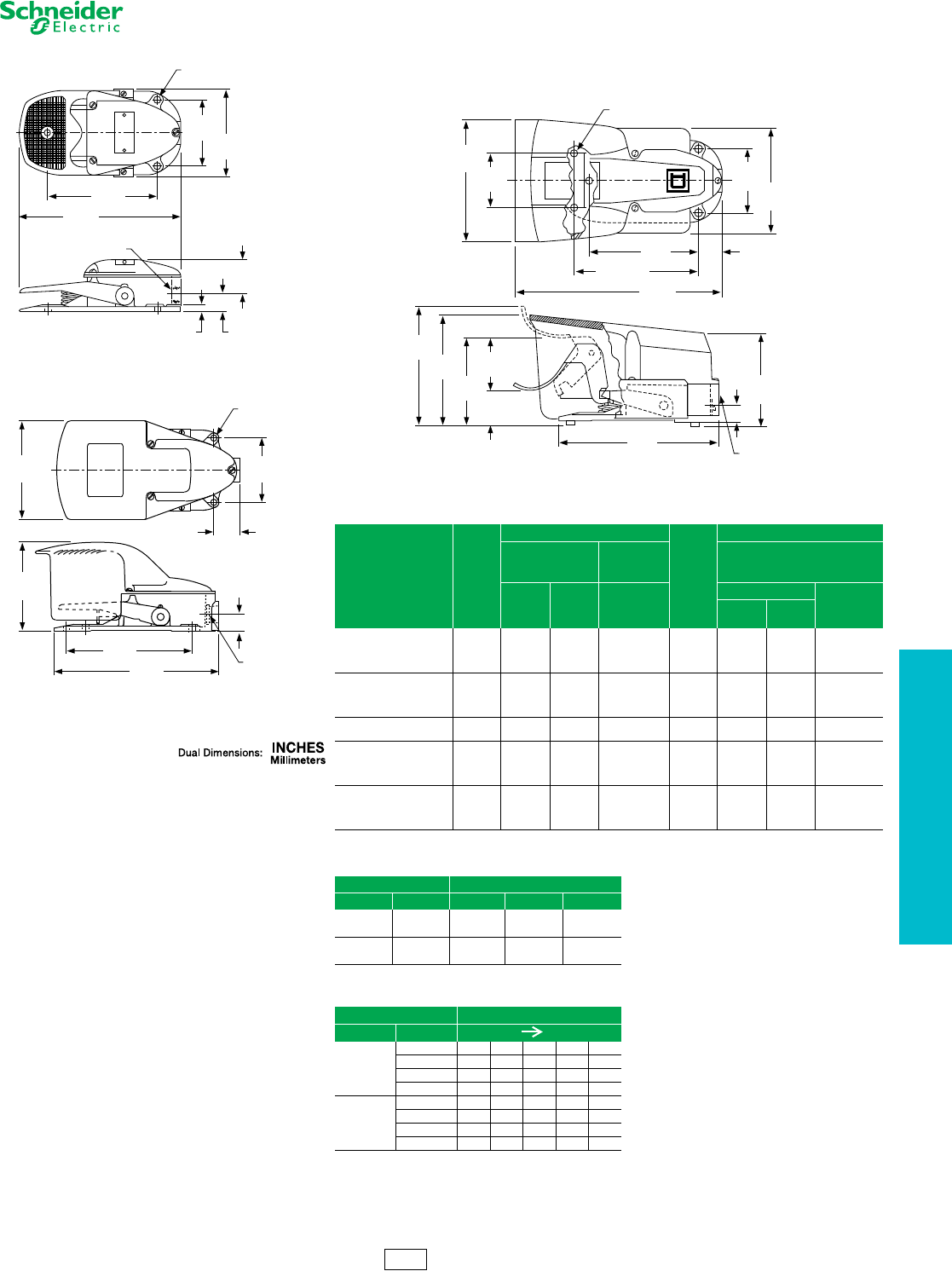
www.schneider-electric.us
19 PUSH BUTTONS AND
OPERATOR INTERFACE
© 2012 Schneider Electric
All Rights Reserved 19-125
Foot Switches 9002A Heavy Duty Industrial
Class 9002
Approximate Dimensions
Note: Double throw switches are rated 250 Vdc maximum.
Note: 0 = Open 1 = Closed
Table 19.374: Maximum Current Ratings For Control Circuit Contacts
Type Volts
AC Amperes
Volts
DC Amperes
Inductive
35% Power Factor
Resistive
75% Power
Factor
Inductive
and Resistive
Make Break
Make, Break
and
Continuous
Make and Break
Continuous
Single
Throw
Double
Throw
AW1 through AW10,
AW117, AW119,
AW132
120
240
480
600
40
20
10
8
15
10
6
5
15
10
6
5
125
250
600
2.0
0.5
0.1
0.5
0.2
0.02
15
15
15
AW13, AW14, AW15,
AW133
120
240
480
600
30
15
7.5
6
3
1.5
0.75
0.6
3
1.5
0.75
0.6
125
250
600
—
1.0
0.3
0.1
—
0.2
0.1
—
—
10
10
10
—
AW11, AW12 115
230
36
18
6
3
—
—
125
250
2.2
1.1
—
—
—
—
AW21, AW22,
AW123
120
240
480
600
15.0
7.5
3.75
3.0
1.5
0.75
0.375
0.3
10
10
10
10
—
—
—
—
—
—
—
—
—
—
—
—
—
—
—
—
AW124
120
240
480
600
60
30
15
12
6
3
1.5
1.2
10
10
10
10
120
240
600
1.1
0.55
0.2
—
—
—
10
10
10
Table 19.375: Contact Symbol—Two Stage
Snap Switch Pedal
Unit Circuit Up Half Down Full Down
1A1 0 1 1
B1 1 0 0
2A2 1 1 0
B2 0 0 1
Table 19.376: Contact Symbol—Four Stage
Snap Switch Pedal Position
Unit Circuit Up Down
1
1A1 00111
1B1 11000
2A1 01111
2B1 10000
2
1A2 11100
1B2 00011
2A2 11110
2B2 00001
3.50
89
5.81
148
8.56
216
4.50
114
.38
10
.94
24
2.94
75
(3) .34 Dia. Mtg. Holes
9
3/4 14 Pipe Tap
Types AW1, AW5, AW11, AW13 and AW21
3/4-14 NPT
3.50
89
1.44
37
6.87
174
.94
24
9.00
229
5.38
137
4.84
123
(5) .34 Dia. Mtg. Hole
9
Types AW2, AW6, AW12, AW14 and AW22
3.50
89
5.63
143
5.81
147
5.02
128
.94
24
2.87
73
1.25
32
6.40
163
2.90
74
1.84
47
8.56
217
6.62
Typ.
168
11.13
283
(5) .34 Dia. Mtg. Holes
9
3/4 14 Pipe Tap
4.60
117
5.73
146
6.26
159
Types AW117, AW119, AW123, AW124
Types AW132, AW133 and AW134 (without safety door)
CP1 Discount
Schedule
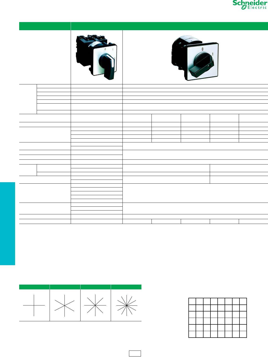
19-126 © 2012 Schneider Electric
All Rights Reserved
www.schneider-electric.us
19 PUSH BUTTONS AND
OPERATOR INTERFACE
aIncomplete part numbers. Contact your local supplier for assistance.
Table 19.377: Rotary Cam Switches
Applications Used in building control panels and consoles, Type K cam switches allow control of processes and utilities in industry and buildings, and direct
control for simple machines.
Functions
Off-On/On-Off switches 1 to 6-pole 1 to 6-pole
Stepping switches 2 to 12-position, 1 to 4-pole –
Changeover switches 1 to 5-pole 1 to 4-pole
Measurement switches Voltmeter and ammeter –
Reversing switches 2 and 3-pole 2 and 3-pole
Reversing star-delta
switches Star-delta Star-delta
Pole change switches 2 and 3-speed 2-speed
Conventional rated thermal current
(Ith) 20 A 32 A 50 A 63 A 115 A 150 A
Rated insulation voltage (Ui) 690 V 690 V 690 V 690 V 690 V 690 V
Electrical operating characteristics
AC-3 - 3-phase AC-3 - 3-phase AC-3 - 3-phase AC-3 - 3-phase AC-3 - 3-phase AC-3 - 3-phase
230 V - 2.2 kW - 8.3 A 230 V - 5.5 kW 230 V - 7.5 kW 230 V - kW 230 V - 5 kW 230 V - 22 kW
AC - 15 AC - 15 AC - 15 – – –
230 V - 4 A 230 V - 14 A 230 V - 6 A
Front plate degree of protection IP 40 IP 40
IP 65 (with seal)
Product composition Complete switches and custom Complete switches
Adaptable sub-assemblies
Compatibility Ø 22 control and signalling units –
Mounting Front mounting Multi-fixing By 4 holes on 48 mm centers By 4 holes on 68 mm centers
Single Ø 22 hole
Rear mounting Screw fixing, 4 holes on 36 mm centers Screw fixing, 4 holes on 48 mm centers Screw fixing, 4 holes on 68 mm centers
Front plate dimensions (mm) 45 x 45 64 x 64 88 x 88
60 x 60 (adaptable sub-assemblies)
Operating heads
Black and red standard and long handles
Black standard handle
Metallic legend, black marking
Key operator
Metallic head
Metallic legend with black marking or
black legend with white marking
Approvals
UL-CSA cULus
EN/IEC 60947-3
EN/IEC 60947-3
EN/IEC 60947-5-1
Type Type K2 Type K30–K150
Cam switch model aClass 9003, K2 K30 K50 K63 K115 K150
Instructions for the Key Sheet on page 19-127 Explanation of the Contact Sequence Example Below
1. From the chart below, choose the switching angle as determined on the key
sheet (see page 19-127). This identifies the angular location and the position
numbers for the various positions of the rotary cam switch. Zero degrees or
straight up is always position 1. Use these position numbers when
completing the target table.
2. Terminals on the cam switch have the same numbers as the terminal
numbers on the target table. Contact 1-2 is a single contact.
NOTE: When indicating a contact closure, place “X” within the
square as shown in the contact sequence example.
1. Contact 1-2 is open in all positions except position 2.
2. Contact 3-4 is closed from the 2nd through the 4th position. The contact
does not open while switching from one position to another.
3. Contacts 5-6 and 7-8 overlap between positions 2 and 3.
4. Contact 9-10 is closed in positions 2 and 3. It is open momentarily while
switching between positions 2 and 3.
5. Contact 11-12 closes mementarily when switching from position 2 to
positiion 3. This contact is not closed in position 2 or position 3.
NOTE: Position 1 is an off position
Table 19.378: Switching Angle Chart Figure 19.5: Contact Sequence Example
90 ° 60 ° 45 ° 30 °
1—2—3—4—
1-2
X
3-4
XXXXX
5-6
XX
7-8
XX
9-10
XX
11-12
X
Positions
C
o
n
t
a
c
t
s
1
3
24
1
4
2
3
5
6
1
5
2
3
46
7
8
1
7
2
3
4
5
6
8
9
10
11
12
CS1 Discount
Schedule
Rotary Cam Switches K2 Custom and K30–K150 Power Switching
Class 9003
www.schneider-electric.us
19 PUSH BUTTONS AND
OPERATOR INTERFACE
© 2012 Schneider Electric
All Rights Reserved 19-127
Rotary Cam Switches Application and Ordering Information
Class 9003
See Instructions on page 19-126.
To order custom cam switches:
NOTE: See page 19-126 for target table explanation
Customer F,O . N O.
Date P.O. Number Qty
1. Indicate the contact size at right (9003 K2)
2. Indicate the desired switching angle at right. If the switching angle is not
indicated, the factory will determine the angle from the table to the
right.
3. From the example shown on page 19-126, fill in the target table on page
19-128.
4. Indicate the operator/handle type.
5. If the operator/handle bezel has a legend and legend marking is desired,
indicate the legend marking on the back of this form.
6. If a separate legend is required, indicate the legend type on the right and
the marking on the back of this form.
xXSwitching AnglexX Maximum
xNumber of Positionsx
See Ordering
xInstructions at LeftxX
3-2 4 ° 09
5-4 6 ° 06
7-6 8 ° 54
21-8 21 ° 03
Contact size Class 9003 Type
K
2
epyT elgna gnihctiwS
Operator/Handle type Class 9003 Type
Separate legend Class 9003 Type
CS1 Discount
Schedule
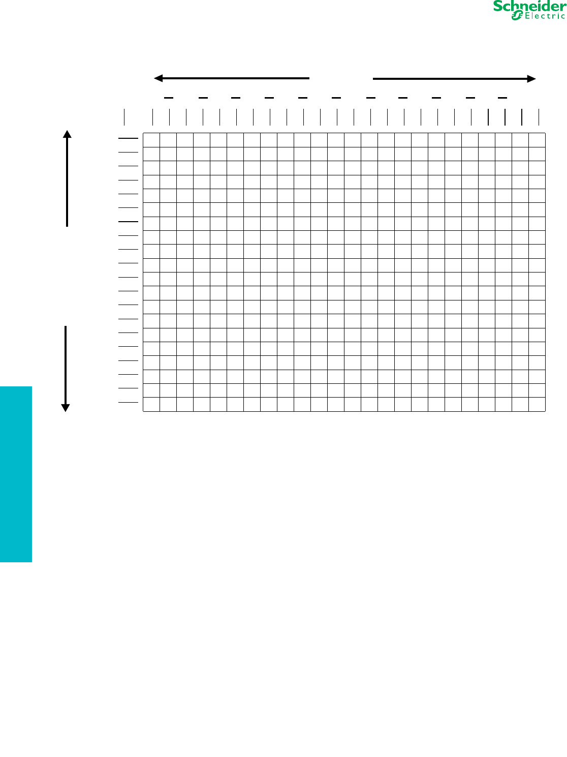
www.schneider-electric.us
19 PUSH BUTTONS AND
OPERATOR INTERFACE
19-128 © 2012 Schneider Electric
All Rights Reserved
Figure 19.6: Target Table
39-40
11-12
13-14
15-16
17-18
19-20
21-22
23-24
25-26
27-28
29-30
31-32
33-34
35-36
37-38
9-10
1-2
123456789101112
3-4
5-6
7-8
T
E
R
M
I
N
A
L
S
Target Table
Positions
Rotary Cam Switches Application and Ordering Information
Class 9003
