Brochure
86669-Catalog 86669-Catalog 86669-Catalog 662019 Batch8 unilog cesco-content
128940-Catalog 128940-Catalog 128940-Catalog Batch9 unilog cesco-content
2014-07-05
: Pdf 110465-Brochure 110465-Brochure 662019 Batch5 unilog
Open the PDF directly: View PDF ![]() .
.
Page Count: 40
ABB DC Drives
DCS800, 10 to 4000 hp
Catalog
Low voltage DC drives

2 ABB DCS800 Technical Catalog
Product series
Type
A0 = Enclosed converter
EP = Panel mounted converter
R0 = Rebuild kit
S0 = 3-phase converter module
Bridge type
1 = non-regenerative(2-Q)
2 = regenerative (4-Q)
Rated Current
Current rating of drive unit (Amps)
Rated Input Voltage
05 = 230...525 V AC
06 = 270...600 V AC
07 = 315...690 V AC
08 = 360...800 V AC
10 = 450...990 V AC
12 = 540...1200 V AC
Revision
Blank = No option (D1 - D4)
B = High Efficiency Fans (D5-D7)*
Power Terminal Connection
Blank = No option (D1 - D6)
L = Left side power terminals
R = Right side power terminals
Additional Factory
Installed Options
* Standard after July 15, 2013
Selecting and ordering your drive
Type designation: DCS800 -S01 -0680 -05 +XXXX
Type designation is a unique reference number that clearly
identifies the drive by construction, power and voltage
rating and selected options. Using the type designation
you can specify your drives from the wide range of options
available. Options are added to the type designation using the
corresponding “plus” (+) code.
Build up your own ordering code using the type designation
key below or contact your local ABB drives sales office and let
them know what you want.

ABB DCS800 Technical Catalog 3
Contents
ABB low voltage DC drive, DCS800
ABB DCS800 drive 4
Overview 4
Power Converter Modules 5
Panel Drive 6
Enclosed Converter 7
Rebuild and Upgrade Kits 9
Adaptive Programming and Start-up Assistants 10
DriveWindow Light 11
Commissioning Macros 13
DCS800 Firmware 14
Ratings and Specications 15
Technical Specifications 15
Ratings 16
Dimensions and Weights 19
Hardware 20
Technical Diagram 20
Plug in Options 21
Feedback Options 22
Communication Options 23
External Field Supply 24
Fuse Connections 26
Line Reactors 27
Input and Output Contactors 28
Software Options / PC Tools 29
Control Builder 29
DriveWindow 30
DriveSize 31
DriveOPC and DriveBrowser 32
Remote Monitoring Tool 33
Drawings 34
Services and parts 36
Trademarks
DriveWindow is a registered trademark of ABB
Modbus is a trademark of Schneider Electric
Profibus is a trademark of Siemens
ControlNet is a trademark of ControlNet International, Ltd.
DeviceNet is a trademark of the Open DeviceNet Vendor Association.
Windows in a registered trademark of Microsoft Corp
Reliance Electric® and FlexPak® 3000 are registered trademarks of Rockwell Automation, Inc.
4 ABB DCS800 Technical Catalog
DC Industrial Drives Overview
ABB DC Industrial Drives
The DCS800 DC industrial drive from ABB combines a powerful
controller with a thyristor power platform that has been proven
in factories all over the world. The DCS800 boasts a wider
power range than any other DC drive on the market. The
hardware and software are designed with you, the user in mind.
Special features make installation and configuration simple and
allow you to customize the application to your needs.
Industrial Applications
The DCS800 can be used in a wide range of industrial
applications including:
−Metals
−Electrolysis
−Pulp & Paper
−Ski lifts
−Printing
−Magnets
−Material handling
−Food & Beverage
−Battery Chargers
−Test rigs
−Plastic & Rubber
−Mining
DCS800 DC Drive Promises
The drive meets the requirements of the most demanding drive
applications. Embedded software functions offer upgrades to all
classic installations like 12-pulse, double motor operation, and
field reversal.
Highlights
−Reduced installation and commissioning work
−Internal three phase field power supply without additional
external hardware (D1-D5)
−Excellent control performance up to highest dynamic
application in field weakening operation
−All ACS800 PC tools (via DDCS) can be connected
−Able to be customized to your needs with Adaptive
Programming and with option Control Builder
−Flexible fieldbus system with numerous internally mountable
fieldbus adapters
−Virtually all DCS800 component parts are suitable for
recycling.
−Coated circuit boards as standard
PC Tool for ABB Drives
DriveWindow Light is an easy-to-use tool for your PC for start
up and maintenance of your ABB drive. It is included with every
DCS800 drive and has the following features:
−User interface tool to view and set parameters
−Startup Assistant tool
−Adaptive Programming (AP) tool
It supports a wide range of ABB industrial drives, including
ACS350, ACS550, ACS800, as well as the DCS800.
Main Features
−Basic control
−Transducer and transducerless operation
−Macros to simplify setup
−High-speed serial via Ethernet, ControlNet, etc.
−On/Off control with pulsed or maintained inputs
−Field heating
−Adaptive Programming
−Remembers two sets of motor parameters
−Drive position display
−Save parameter set to PC or keypad
−Motor Control
−Easily switches between local control via keypad and
remote control via digital I/O or high-speed serial
−Window speed control
−Flying start
−Field reversal, boost and opti-torque
−Motor pot up and down control
−Drive Configurations
−Stand-alone
−Master-follower (up to 10 followers)
−12-pulse operation
−Hard-parallel operation (D7 only)
−Inputs and outputs
−All user-designated inputs and outputs
−Relay output for AC or DC contactor control
−Motor brake control, including torque proving input
−Motor temperature sensor monitoring
−High speed DC breaker monitoring
−Faults and Diagnostics
−Fault logging with time and date stamp
−Diagnostic assistant activates when fault occurs

ABB DCS800 Technical Catalog 5
Power Converter Modules
Enclosure Rating
The DCS800-S0x power converter module carries a NEMA
TYPE OPEN (IP00) rating and must be mounted in a protective
enclosure. There are seven different frame sizes, D1 through D7,
graduated in terms of current and voltage.
Regenerative and Non-Regenerative Drives
Non-regenerative (2-Q) power converter modules are used when
motor torque and speed are always in the same direction and
when significant stopping power is not required.
This is ideal for applications such as:
−Fan or blower
−Mixer
−Pump
−Extruder
It is not possible for a 2-Q drive to slow down an inertial load.
The load will stop only due to friction, windage, or another form
of load resistance. It is also not possible for a non-regenerative
drive to reverse direction unless field reversal is used.
Speed
Torque
2-Q
4-Q
Motor
voltage
Current
max. regenerative
motor voltage
2-Q
4-Q
Regenerative (4-Q) power converter modules are used
when motor torque can occur in either direction. This is for
applications such as:
−Stop-start conveyor
−Draw Roll
−Rolling mill
−Unwinder
−Overhead crane hoist
A 4-Q drive is able to start and stop an inertial load in both
forward and reverse directions.
Field Power Supplies and Fusing
Converter modules sizes D1 through D5 are equipped with fused
internal field power supplies. Sizes D6 – D7 require an external
field power supply. See page 21 for details.
AC line fuses and DC armature fuses must be separately
mounted. See page 24 for fuse information as well as
information on other optional system components.
AC line fuses to be separately mounted on sizes D1 - D4.
They are included internally on D5 - D7. DC armature fuses are
needed for all 4-Q drives and are to be separately mounted.
See page 26 for fuse recommendations as well as specifications
for other external system components.
Voltage Selection
The output voltage of the drive depends on the incoming AC
line voltage and whether a 2-Q or 4-Q drive is selected. The
table below shows the maximum output voltage that will result
for various input voltages for both the 2-Q and 4-Q drives.
The maximum output voltage of a 4-Q drive can be increased
up to the level of Udmax 2-Q if the torque reversal time from
motor to regenerative mode is set above 300 ms.
Low Mains Voltage - (30 to 120 V) SDCS-SUB-4 (+S186)
External DC Voltage Measurement - Measures Vdc at the
motor; (D1-D4) SDCS-UCM-1; (not needed D5-D7)
Analog, Digital and Encoder Interface
The drive is equipped with high-speed, high-resolution analog
inputs and outputs to interface with user signals. Analog inputs
are 16-bit resolution (15 plus one sign bit) which is the highest
resolution in the industry.
The following interfaces are standard features:
−Analog DC tachometer
−Pulse encoder
−Motorized pot, speed pot and up to two analog meters
Optional modules are available to increase the number of
analog, digital, tachometer, and encoder interfaces and to add
isolated interfaces for temperature sensors and other devices.
System
input AC
line voltage
DC voltage
(recommended)
Ideal DC
voltage
without
load
Recommended DCS800
voltage class type code
2Q 4Q
UVN Udmax 2-Q Udmax 4-Q Udi0
[V] [V] [V] [V]
230 265 240 310 05
380 440 395 510 05
400 465 415 540 05
415 480 430 560 05
440 510 455 590 05
460 530 480 620 05
480 555 500 640 05
500 580 520 670 05
525 610 545 700 05 (D1-D4), 06
575 670 600 770 06
600 700 625 810 06
660 765 685 890 07
690 800 720 930 07
800 915 820 1060 08
990 1160 1040 1350 10
1200 1380 1235 1590 12
6 ABB DCS800 Technical Catalog
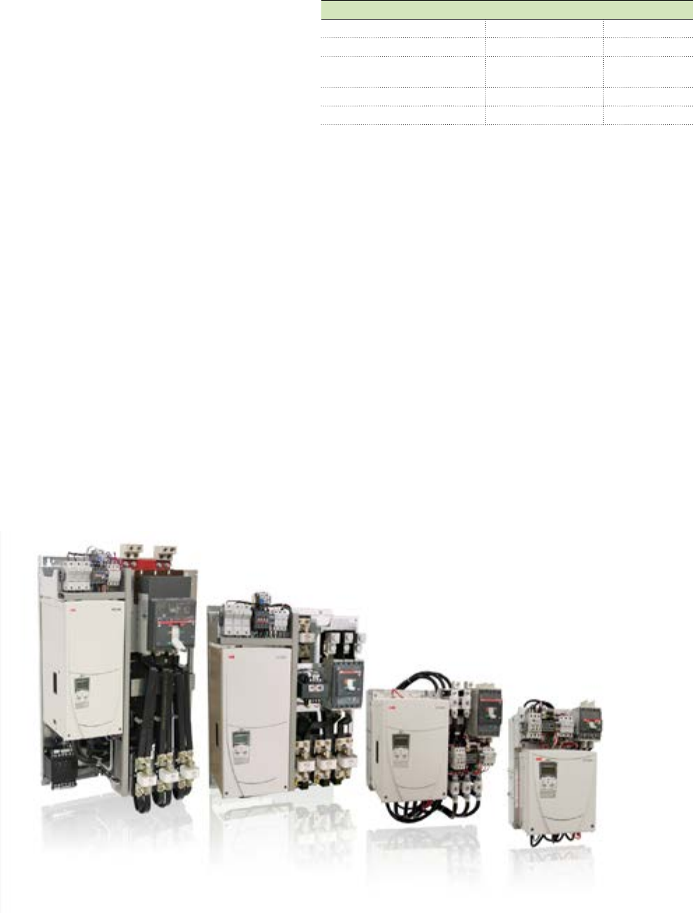
DCS800 Panel Drive
The DCS800-EPx Panel Drive is a DCS800 power module
and associated system components mounted and wired on a
sub-panel and ready to be installed into an industrial enclosure.
System components include AC input fuses, DC output fuses
(regen only), control transformer, AC contactor, plus optional
components. The drive is designed to easily replace a Reliance
Electric® FlexPak® 3000 drive.
Product Offering
−460 Vac, factory or field convertible to 230 Vac
−10 to 500 HP with heavy duty overload ratings (150 pct for
60 sec.)
−600 HP with normal duty ratings (110 pct for 60 sec.)
− Integral ABB AC contactor
−UL Listed with 65 kA SCCR
Panel Drive Benefits
−Space efficient multilevel panel
−Easy to maintain
−Pre-wired, pre-tested solution for smooth start ups
−Greatly simplifies the procurement process
−Module can be replaced without replacing the entire panel
Optional Features
Option Size Option Code
Integral line reactor * Up to 150 hp +E213
ABB Tmax MCP circuit breaker +F278
ABB A-line blower motor
contactor & overload
Blower from 1/2 to
15 hp
+M611 -
+M641
Without AC contactor +0F250
230 Vac supply +S235
*Reactor or isolation transformer required!
DCS800 Power Module Benefits
−Highly reliable DCS800 module drive
−Integral field supply, including field weakening
−Control Panel with 5-line display and 2 soft keys
−DriveWindows Light PC tool included
Excellent Reliance® FlexPak® 3000 Retrofit Drive
−Same bolt pattern
−Similar features
−Fits within FlexPak® 3000 clearance area
−ABB’s Replacement Guide (DCS800-PHTG01U-EN) makes
conversions go smoothly
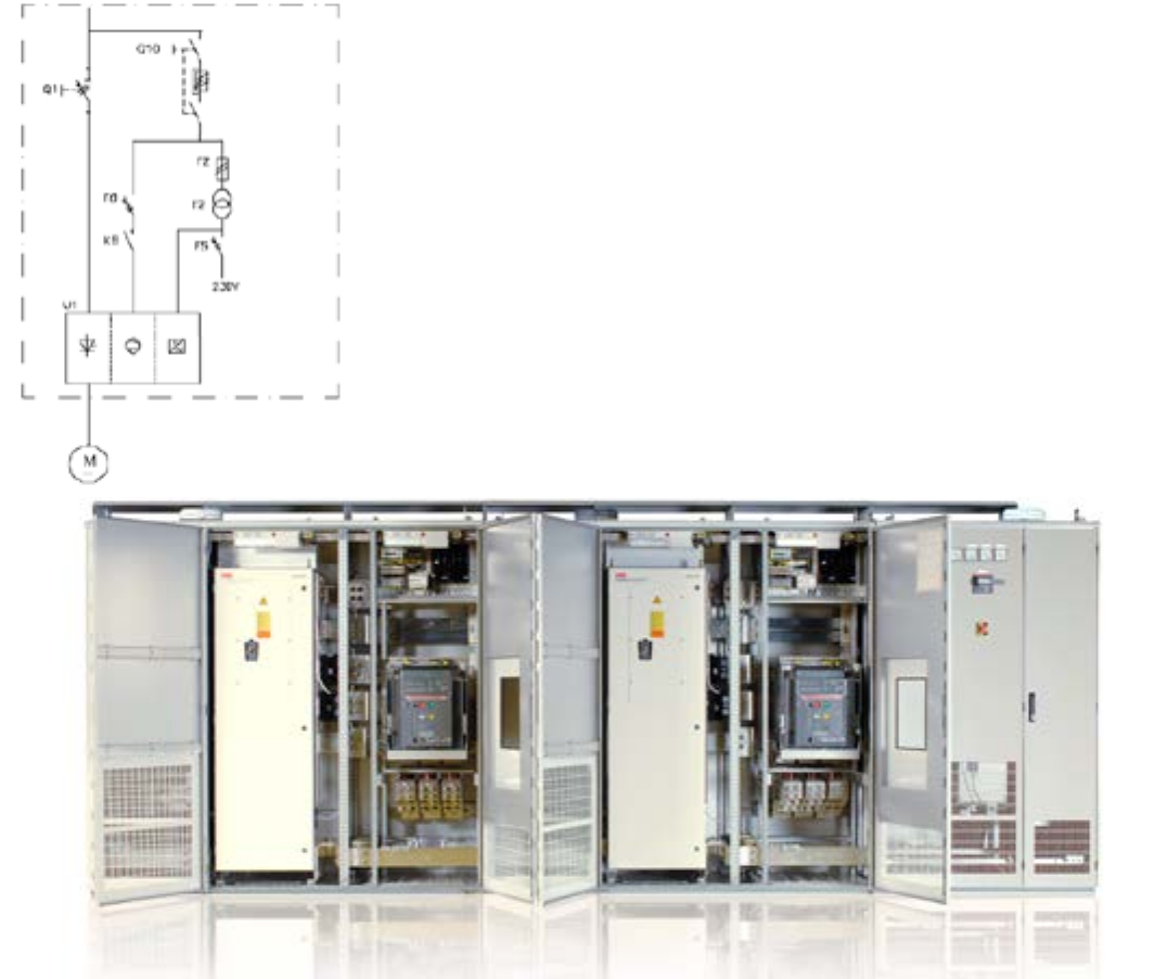
ABB DCS800 Technical Catalog 7
DCS800 Enclosed Converters
The DCS800-A enclosed converters are drive modules and
supporting hardware that is mounted in an enclosure, intended
to power and control DC industrial machines. In addition to the
drive module, the basic package typically includes the following
(varies by size):
−Single-door / multi-door cabinet (IP 21, similar to NEMA 1)
−Fused disconnect / circuit breaker
−Line contactor
−Line reactor
−Control transformer and fuses
−Converter fan relay and fuses
−E-stop relay
−I/O converter board - SDCS-IOB-2x
−I/O converter board - SDCS-IOB-3
−Terminals
Comprehensive Product Range
DCS800-A enclosed converters are available with regenerative
(4-quadrant) and non-regenerative (2-quadrant) drives in
standard 6-pulse or 12-pulse configurations. The cabinets have
a continuous current rating which ranges from 18 Amps up to
9800 Amps. (19,600 Amps possible with parallel units.) Supply
voltage ranges from 230 to 1200 Vac.
Custom configurations are possible with a wide range of
optional components, including motor blower starter, 24
Vdc supply, external field supply, multiple drives, Advant (AC
800M) controller and S800 I/O system. Contact your local ABB
factory sales team for additional information and for a custom
quotation.
These cabinets are not UL listed. For large projects, UL listed
cabinets may be available. Contact ABB for more information.
Cabinets are built to meet CE LVD regulations and, with options,
can be built to receive the CE mark.
Single line diagram DCS800-A-2050...3000
400 V...690V with breaker
8 ABB DCS800 Technical Catalog
DCS800 Enclosed Converters
Mechanics
The robust frame body is made from 12 gauge steel. All
enclosure panels are 16 gauge steel. To prevent corrosion, all
metal parts have hot zinc galvanization. The standard height is
83-1/2 inches (2120 mm) which includes a detachable 4-1/2
inch high hood. Cabinet widths depend on the power and size
of the drive but include 200, 400, 600, 800 and 1000 mm wide
bays.
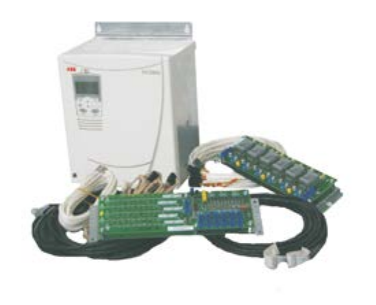
ABB DCS800 Technical Catalog 9
DCS800 Rebuild and Upgrade Kits
The DCS800-R Rebuild or Upgrade Kit from ABB allows you to
update the controls on your existing DC drive and continue to
utilize the existing power section.
ABB, with the help of our channel partners, can make your
existing drive look and act like a new DCS800 drive. Gain the
benefits of having the latest motor control technology and
high speed serial connectivity without having to replace the
power section. This is an engineered solution which can have
significant cost advantages over complete drive replacement,
especially on large systems.
General Purpose Rebuild Kit
The DC800-R Rebuild Kit is recommended for thyristor-based
power sections that are:
−500 horsepower (800 Amps) and above
−Originally manufactured by ABB or another drive company
−Regenerative (4-quadrant) or non-regenerative (2-quadrant)
−From 1, up to 4 parallel bridges
In order to determine if your existing drive can be rebuilt,
consider the following:
−Is the power section healthy?
Replacing the controls usually does not reduce the
occurrence of blown fuses or over-current faults. These
conditions commonly indicate that there is a malfunction
in the power section. Carefully consider the benefits of
upgrading compared to replacing with a full drive with a
brand new warranty.
−What data is available on the existing power section?
An accurate, up-to-date schematic is essential. The
schematic needs to include any changes that occurred over
the years.
−Is there space to mount the retrofit components?
A panel layout diagram, along with visual inspection of the
panel is needed.
−Are there any special features in the existing controller?
The DCS800 has functions to run most any application but
it is important to be sure that the new controller has the
functionality of the existing controller, or if other modifications
will be required.
DCS500 to DCS800 Upgrade Kit
The DCS800-R Upgrade Kit is specifically designed to upgrade
the controls of existing DCS500 drives.
−For frame sizes A5, A6, A7, C2b, C3, & C4
−For drives approx. 350 HP and above
−Replaces existing door, control tray and keypad
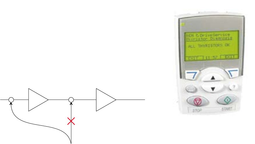
How it Works
A modern drive can be subdivided into two major sections, the
power section and the controller. The power section transfers
a measured amount of voltage and current from the incoming
lines to the motor. The computer-based controller controls the
power section, along with several other functions. The rebuild/
upgrade kit replaces the existing controller with a DCS800
controller.
In addition to controlling the power section, the DCS800-R will
also provide user interface (via keypad or DriveWindow Light)
and encoder and/or tachometer interface, if present. After the
drive is rebuilt, the complete drive system will operate like a
DCS800, which may include communicating with your PLC
via Ethernet, ControlNet, etc, receiving signals from switches,
push-buttons and pots, and sending signals to lamps and
meters.
DCS800-R Rebuild Kit
10 ABB DCS800 Technical Catalog
Adaptive Programming and Start-up Assistants
Adaptive Programming
Optimal Adaptability
Adaptive Programming gives you the ability to customize the
drive to your needs without adding more hardware. Change how
a digital output works, modify speed or torque reference, or
filter an analog input - all these things are possible. You program
the drive with the control panel or your PC using DriveWindow
Light. Adaptive programming gives you the flexibility you need to
make the drive work to your specifications.
Features
−16 programmable function blocks
−31 Available functions:
−Logical: AND, OR and XOR
−Mathematical: add, mul, div, abs, max and min
−Other: timer, switch, comparator, filter, SR, PI and user-
defined warnings or faults
−Freely definable execution order
−Easy documentation
−Similar to the ACS800 AC Drives
The DCS800 DC drive offers you all this as standard features.
If more function blocks are required, ControlBuilder, which
uses compact flash memory, is available with expanded
capacity. See page 29 for details.
Start-Up Assistants
Faster and Easier Commissioning
The Startup Assistant is part of the standard DCS800 DC
Drives software package. It guides you actively through the
commissioning procedure either through the control panel
or with your PC using DriveWindow Light. It is multilingual,
requests data with clear and plain text messages, and sets the
required parameters to your needs.
On-line Info System
To make it easier and more informative, “info system” is
available at each step, helping to set the correct values for each
parameter and troubleshoot the problems. It also provides you
with a step-by-step reference to the printed manuals.
Features
−Easy and fast commissioning procedure
−Intelligent guide to assist you through the commissioning
−Available in 8 languages, including Spanish and French
−Info system always available
−Auto detection of connected hardware
The DCS800 DC drive offers you all this as standard features.
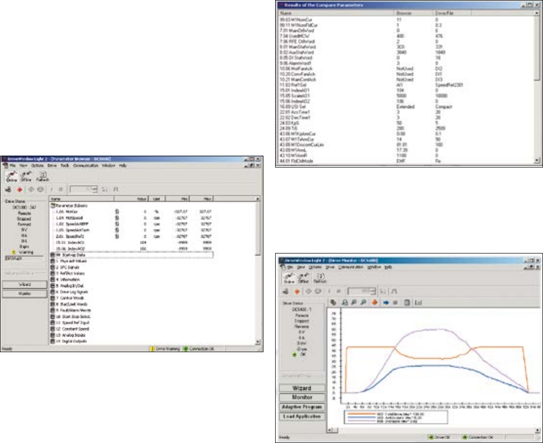
ABB DCS800 Technical Catalog 11
DriveWindow Light
Startup and Maintenance Tool
PC tool for ABB drives
DriveWindow Light is an easy-to-use tool for PC-based start
up and maintenance of your ABB drive. It is included with every
DCS800 drive and has the following features:
−User interface tool to view and set parameters
−Startup Assistant tool
−Adaptive Programming (AP) tool
−Fault Logging/Troubleshooting
It supports a wide range of ABB industrial drives, including
ACS350, ACS550, ACS800, as well as the DCS800.
Highlights
−Viewing and setting parameters in offline and online modes
−Editing, saving and downloading parameters
−Comparing parameters
−Graphical and numerical signal monitoring
−Drive control
−Start-up assistants
−DWL AP tool for DCS800 (for Adaptive Programming)
−All DCS800 DC drives are equipped with DriveWindow Light
Light Software with Heavy Features
DriveWindow Light offers many functions in an easy-to-use
package. It can be used in an offline mode, which enables
parameter setting at the office even before going to the actual
site. The parameter browser enables viewing, editing and saving
of parameters. The parameter comparison feature makes it
possible to compare parameter values between the drive and
the file. With the parameter subset you can create your own
parameter sets. Controlling of the drive is naturally one of the
features in DriveWindow Light. Drive status and fault information
keeps commissioning time low.
With DriveWindow Light, you can monitor up to four signals
simultaneously. This can be done in both graphical and numerical
format. Any signal can be set to start the monitoring from a pre-
defined level.
12 ABB DCS800 Technical Catalog
DriveWindow Light
Startup and Maintenance Tool
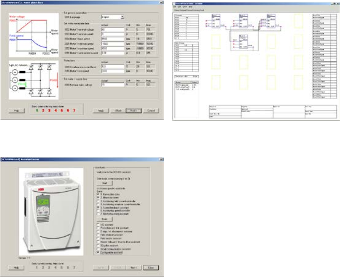
DWL Start-Up Assistant
DWL Start-Up Assistant for DCS800 gives important assistance
for commissioning by interactive dialog. The commissioning
steps are presented in correct sequence and necessary
parameters are preselected.
−The basic assistant collects motor and connection data and
executes controller auto tunings
−Advanced assistants provide guidance for 12-pulse
operation, field reversal, network communication (fieldbus)
and master-follower configuration.
−A context-sensitive help function is present during the whole
sequence
One page is freely configurable by the user. An individual
commissioning sequence or parameter selection can be setup
to application, machine or motor demands.
Adaptive Programming (AP) Tool
DWL AP is a graphical PC tool to create, document, edit and
download Adaptive Programs. Adaptive Program tools contain 16
function blocks and are available in standard firmware. DWL AP
offers a clear and easy way to develop, test and document these
programs with a PC.
It is a user-friendly tool to modify function blocks and their
connections. No special programming skills are required; basic
knowledge about block programming is sufficient.
Adaptive Programs are easy to document as hard copies are store
as PC files. All related information is saved directly to the drive by
parameter.

ABB DCS800 Technical Catalog 13
Commissioning Macros
DCS800 Macros
The DCS800 includes macros that cover the most frequent
parameter settings. Macros are pre-programmed parameter
sub-sets. During start-up, the drive can be configured easily
without the need to change many individual parameters by using
a macro. The functions of inputs, outputs, and many allocations
in the control structure are set up with the selection of a macro.
Twelve (12) macros are available, plus the factory default
macro. The program also allows you to switch between macros
with ease. Except for a few special cases, motor and tuning
parameters will be maintained when switching from one macro
to another.
The selections include the following macros:
The macro will define:
−whether the drive is speed-controlled or torque-controlled
−if two-wire (maintained) or three-wire (pulsed) motor-on inputs
are being used
−if a DC contactor is being used
−the type of control that is needed (standard, constant speed,
hand/motor-pot, etc.)
−the source of the command (digital and analog inputs and
outputs or via high-speed-serial link)
−which actual values are available at the analog outputs
Macro Description
Factory Resets all parameters to default values.
Standard The Drive turns on with a maintained input. Motion is commanded with digital inputs (DI) RUN, JOG1, or
JOG2. Run speed is set with an analog input. Jog speeds are set to preset levels.
Manual / Constant
Speed
Run speed is set with an analog input, but if one of two digital inputs is set, speed is changed to preset
levels. Control is by way of 3-wire control (pulsed inputs).
Hand / Auto A digital input switches between Hand (Local I/O) and Auto mode, and also switches speed reference. In
Hand mode, speed is set with an analog input; in Auto mode, speed and motor control are set over a high-
speed network, usually by a PLC. Manual control is 2-wire.
Hand / Motor Pot A digital input switches speed reference from an analog input to Motor Pot. In Motor Pot mode, one digital
input (MOTOR POT UP) increases speed and another (MOTOR POT DOWN) decreases speed. Control is
3-wire.
Motor Pot Speed is always controlled through the MOTOR POT -UP and -DOWN digital inputs. Motor pot minimum
speed can be released by setting a digital input to allow MOTOR POT DOWN to reduce speed to zero.
Control is 2-wire.
Torque Control A digital input switches between Speed and Torque control mode. While in Torque mode, an analog input
is used as reference; while in Speed mode, speed is set to a preset level. A digital output can control a DC
circuit breaker. Control is 2-wire.
Torque Limit This macro is the same as “Standard,” except a second analog input determines torque limit.
3-Wire Standard Run speed is set with analog input, but if DI-1 is set, speed is changed to preset level. The drive turns on
and runs with pulsed RUN digital input. It turns off with clearing of the STOP input. (3-wire control).
2-Wire DC
Contactor US
This macro is the same as “Standard” except it also sets up the drive to control a DC contactor with a
digital output. A DC contactor acknowledge input is required.
3-Wire DC Contac-
tor US
This macro is the same as “3-Wire Standard” except it also sets up the drive to control a DC contactor
with a digital output. A DC contactor acknowledge input is required.
User 1 and 2 The user is allowed to record the current set of parameters as one of two “User Macros” and restore the
drive to one of these sets. Restoration is done by setting or clearing a digital input or by sending a signal
over a high-speed serial link. This is handy if, for example, the machine setup changes (i.e., making snow
throwers half the season, and lawn mowers the other half) or if changing a drive from being a master to
being a follower, etc.
3-Wire Jog For Flexpak3000 replacements. DI5 switches between Manual (AI1) and Auto (AI2) speed reference. Jog
input (DI3) initiates motion and reverses with DI4. Control is 3-wire.
14 ABB DCS800 Technical Catalog
DCS800 Firmware
DCS800 Basic Firmware
DCS800 firmware includes the basic function of speed control,
armature current, field current and voltage. The flexible design
for command location enables fieldbus control, master-follower
control, control from hardware signals as well as a mixed
structure. The design of drive logic enables a drive reaction
defined by Profibus standard but can also be configured to
adapt classic command structures.
All parameters can be accessed through network
communication or by IEC 61131 or adaptive programming.
Twelve macros are pre-defined and two user-macros can be
configured by the user.
Functions of Basic Firmware
−Different speed ramp functions
−Speed control
−Torque control
−Armature current control
−Field current control
−Automatic field weakening
−E-stop function according to Profibus standard
−Dual field control
−Mechanical brake control
−DC breaker control
−Programmable digital and analogue outputs
−Master-Follower
−16 blocks Adaptive Program
−Interface for IEC 61131 programming
−12-pulse function - parallel, serial, sequential
−3-phase field power supply operation
−Converter protection (temperature, voltage,...)
Motor protections
−Stall protections
−Thermal motor model
−2 channel motor temperature measurement PTC or PT100
−Klixon supervision (RDIO-01 Recommended)
−Speed feedback error
−Over speed
−Armature current ripple
−Armature over current
−Minimum field current
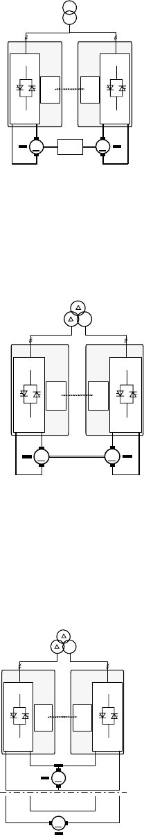
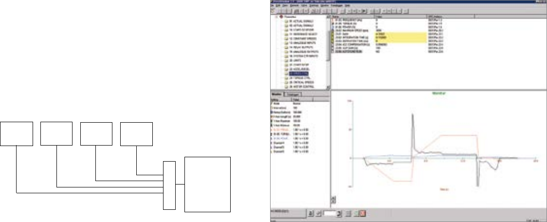
Master-Follower Applications
Drives connected in Master-Follower application
When motors run on a common shaft or other belted or
mechanical connection, and run with the same speed or torque,
use the master/follower configuration.
DSL
M
DSL
M
DSL
link
D1 C1 C1 D1
Master-Follower
connected
via load
Master
DCS800
Follower
DCS800
Partial 12-pulse Master-Follower configuration
Under this configuration, converters are fed by a 12-pulse
transformer with separated secondary windings whose phase
positions differ by 30°. This configuration delivers the same
advantages concerning harmonics to the network as a standard
12-pulse application (see next item), but no T-reactor is needed.
DSL
M
DSL
M
Y
D1 C1 C1 D1
partial 12-pulse
Tandem motors
Master
DCS800
Follower
DCS800
DSL
link
Typical configuration for high power drives connected in
12-pulse parallel, serial or sequential application
12-pulse systems are used to reduce line harmonics or motor
noise level, or to increase output current or voltage of the
converter system. Only the 11th and 13th, the 23rd and 25th, the
35th etc. are present. The harmonics on the DC side are reduced
also, which increases efficiency.
DSL
M
DSL
Y
M
D1 C1 C1 D1
DSL
link
D1 C1 C1 D1
12-pulse parallel
12-pulse serial
Master
DCS800
Follower
DCS800

ABB DCS800 Technical Catalog 15
Technical Specifications
System connection
Voltage, 3-phase 240 to 990 V acc. to IEC 60038
Voltage deviation ±10% continuous; ±15% up to 0.5 sec.
Rated frequency 50 Hz or 60 Hz
Static frequency
deviation
50 Hz ±2 %; 60 Hz ±2 %
Dynamic: frequency
range
50 Hz: ±5 Hz; 60 Hz: ± 5 Hz
NOTE: Special consideration must be taken for voltage deviation in regen-
erative mode.
Short Circuit Current
Rating
(SCCR)
D1 - D4 = 65 kA
D5 - D7 = 100 kA
Protection Class
Converter module and
options (line chokes,
fuse holder, field supply
unit, etc.)
UL Type Open
Speed Feedback / Accuracy
Speed resolution with encoder 0.005% of nominal speed,
with analog tach, 0.1% (16 bits)
Cycle time, speed and
current controller
2.77 ms at 60 Hz, 3.33 ms at 50 Hz
Step response, current
controller
5 ms
Speed feedback EMF (transducerless), analog tach, encoder, 2nd
encoder with RTAC
Analog tach voltage ±8-30 Vdc, ±30-90 Vdc, ±90-270 Vdc
Pulse encoder voltage 5, 12, 15, 24 Vdc
Environmental limit values
Permissible cooling air temperature.
- at converter module
air inlet 0 to +55°C
with rated DC current 0 to +40°C
with different DC
current +40 to +55°C derating (1%/1oC)
- Options 0 to +40°C
Relative humidity
(at 5...+40°C) 5 to 95%, no condensation
Relative humidity
(at 0...+5°C) 5 to 50%, no condensation
Change of the ambient
temperature < 0.5°C / minute
Storage temperature -40 to +55°C
Transport temperature -40 to +70°C
Pollution degree (IEC
60664-1, IEC 60439-1) 2
Site elevation
<1000 m above M.S.L. 100%, without derating
1000 to 4000 M.S.L. with derating (1%/100m)
4000 to 5000 M.S.L. with derating and factory approval
Sound pressure level
Size Sound pressure level LP (1 m distance) Vibration
as module enclosed conv. as module
D1 55 dBA 54 dBA
1.5 mm, 2...9 Hz
0.5 g, 9...200 Hz
D2 55 dBA 55 dBA
D3 60 dBA 73 dBA
D4 66 - 70 dBA 77 dBA
D5 73 dBA 78 dBA
1 mm, 2...9 Hz
0.1 g, 9...200 Hz
D6 75 dBA 73 dBA
D7 82 dBA 80 dBA
North American Standards
In North America the system components fulfil the requirements of the
table below.
Rated supply
voltage
Standards
Converter module Enclosed converter
to 600 V UL 508 C
Power Conversion Equipment
cULus C 22.2 No. 14-95
Industrial Control Equipment, Indus-
trial Products
Available for converter modules
including field power supply units.
Types with UL mark:
• see UL Listing www.ul.com /
certificate no. E196914
• or on request
Enclosed converter cabi-
nets are not UL listed
>600 V to
1000 V
EN / IEC: see table below.
Available for converter modules
including field power supply units.
EN / IEC types: on re-
quest (for details see table
below)
Regulatory compliance
The converter module and enclosed converter components are designed for use in
industrial environments. In EEA countries, the components fulfill the requirements of
the EU directives, see table below.
European
union
directive
Manufacturer‘s
assurance
Harmonized standards
Converter
module
Enclosed
converter
Machinery Directive
98/37/EEC
93/68/EEC
Declaration of Incorpora-
tion
EN 60204-1
[IEC 60204-1]
EN 60204-1
[IEC 60204-1]
Low Voltage Directive
73/23/EEC
93/68/EEC
Declaration of Conformity EN 60146-1-1
[IEC 60146-1-1]
EN 61800-5-1
(EN 50178 [IEC--])
see additional
IEC 60664
EN 60204-1
[IEC 60204-1]
EN 61800-5-1
EN 60439-1
[IEC 60439-1]
EMC Directive
89/336/EEC
93/68/EEC
Declaration of Conformity
(Provided that all instal-
lation instructions con-
cerning cable selection,
cabling and EMC filters
or dedicated transformer
are followed.)
EN 61800-3 j
[IEC 61800-3]
EN 61800-3 j
[IEC 61800-3]
j in accordance
with 3ADW 000 032
j in accordance
with 3ADW 000
032/3ADW 000
091

16 ABB DCS800 Technical Catalog
Type code
Non-regenerative
Frame
Size
Input
RMS
Current
Arms
Normal Duty Standard Duty Heavy Duty Internal
eld
current
A
Air Flow
60 Hz
ft3/min
Heat
Dissipation
BTU/hr
I2Nd
Adc
P2Nd
HP
I2Sd
Adc
P2Sd
HP
I2Hd
Adc
P2Hd
HP
500 Vdc
DCS800-S01-0020-05
D1
16 19 10 18 10 18 10
6A
nonvent. 375
DCS800-S01-0045-05 37 42 25 38 20 38 20 210 580
DCS800-S01-0065-05 53 61 30 54 30 54 30 210 751
DCS800-S01-0090-05 73 88 50 78 40 78 40 210 955
DCS800-S01-0125-05 102 124 75 111 60 104 60 210 1297
DCS800-S01-0180-05 D2 147 171 100 164 100 148 75 15A 210 1911
DCS800-S01-0230-05 188 219 125 205 125 205 125 210 2491
DCS800-S01-0315-05
D3
257 300 150 264 150 264 150
20A
210 3105
DCS800-S01-0405-05 330 385 200 325 200 325 200 420 3822
DCS800-S01-0470-05 384 447 250 405 250 405 250 420 4504
DCS800-S01-0610-05+S171
D4
498 580 300 490 300 484 300
25A
610 6005
DCS800-S01-0740-05+S171 604 704 400 670 400 664 400 610 7302
DCS800-S01-0900-05+S171 734 865 500 795 500 795 500 1160 9145
DCS800-S01-1200-05B+S164
D5
979 1105 700 950 600 851 550
25A
500 17402
DCS800-S01-1500-05B+S164 1224 1450 900 1320 800 1280 800 500 18084
DCS800-S01-2000-05B+S164 1632 1904 1100 1480 900 1479 900 500 22520
DCS800-S01-2050-05
D6
1673 1985 1250 1585 1000 1585 1000
External
940 27297
DCS800-S01-2500-05 2040 2395 1500 1986 1250 1990 1250 940 30709
DCS800-S01-3000-05 2448 2820 1750 2416 1500 2416 1500 940 37875
DCS800-S01-3300-05B
D7
2693 3178 2000 2416 1500 2416 1500
External
2500 39922
DCS800-S01-4000-05B 3264 3690 2250 2890 1750 2897 1750 2500 44358
DCS800-S01-5200-05B 4243 4820 3000 3972 2500 3800 2250 2500 64831
600 Vdc
DCS800-S01-0290-06 D3 237 280 200 268 200 268 200 External 210 3105
DCS800-S01-0590-06+S171 D4 481 561 400 480 300 470 300 External 610 6347
DCS800-S01-0900-06
D5
734 828 600 665 500 665 500
External
500 17402
DCS800-S01-1500-06 1224 1428 1000 1325 1000 1325 1000 500 21496
DCS800-S01-2000-06 1632 1850 1250 1490 1100 1479 1100 500 27638
DCS800-S01-2050-06
D6
1673 1850 1250 1490 1100 1479 1100
External
940 31392
DCS800-S01-2500-06 2040 2380 1750 1990 1500 1990 1500 940 34804
DCS800-S01-3000-06 2448 2790 2000 2380 1750 2380 1750 940 41628
DCS800-S01-3300-06B
D7
2693 3035 2250 2380 1750 2380 1750
External
2500 44699
DCS800-S01-4000-06B 3264 3720 2500 2970 2250 2970 2250 2500 51523
DCS800-S01-4800-06B 3917 4410 3250 3507 2500 3507 2500 2500 66537
700 Vdc
DCS800-S01-0900-07
D5
734 820 700 620 500 620 500
External
500 17402
DCS800-S01-1500-07 1224 1428 1250 1160 1000 1160 1000 500 21496
DCS800-S01-2000-07 1632 1850 1500 1490 1250 1479 1250 500 27638
DCS800-S01-2050-07
D6
1673 1850 1500 1490 1250 1479 1250
External
940 31392
DCS800-S01-2500-07 2040 2380 2000 1990 1750 1990 1750 940 34804
DCS800-S01-3000-07 2448 2790 2500 2380 2000 2380 2000 940 41628
DCS800-S01-3300-07B
D7
2693 3035 2500 2380 2000 2380 2000
External
2500 44669
DCS800-S01-4000-07B 3264 3720 3250 2970 2500 2970 2500 2500 51523
DCS800-S01-4800-07B 3917 4480 4000 3507 3000 3507 3000 2500 66537
360 - 800 Vdc line voltage DATA AVAILABLE UPON REQUEST
450 - 990 Vdc line voltage DATA AVAILABLE UPON REQUEST
540 - 1200 Vdc line voltage DATA AVAILABLE UPON REQUEST
Current Ratings - Modules
Non-Regenerative

ABB DCS800 Technical Catalog 17
Type code
Regenerative
Frame
Size
Input
RMS
Current
Arms
Normal Duty Standard Duty Heavy Duty Internal
eld
current
A
Air Flow
60 Hz
ft3/min
Heat
Dissipation
BTU/hr
I2Nd
Adc
P2Nd
HP
I2Sd
Adc
P2Sd
HP
I2Hd
Adc
P2Hd
HP
500 Vdc
DCS800-S02-0025-05
D1
20 23 10 20 10 20 10
6A
nonvent. 375
DCS800-S02-0050-05 41 47 25 38 20 38 20 210 580
DCS800-S02-0075-05 61 71 40 54 30 54 30 210 751
DCS800-S02-0100-05 82 95 50 84 50 79 40 210 955
DCS800-S02-0140-05 114 133 75 125 75 110 60 210 1297
DCS800-S02-0200-05 D2 163 190 100 166 100 166 100 15A 210 1911
DCS800-S02-0260-05 212 247 150 208 125 208 125 210 2491
DCS800-S02-0350-05
D3
286 333 200 287 150 264 150
20A
210 3105
DCS800-S02-0450-05 367 428 250 360 200 357 200 420 3822
DCS800-S02-0520-05 424 489 300 405 250 405 250 420 4504
DCS800-S02-0680-05+S171
D4
506 647 400 605 300 544 300
25A
610 6005
DCS800-S02-0820-05+S171 669 806 500 740 400 664 400 610 7302
DCS800-S02-1000-05+S171 816 965 600 815 500 810 500 1160 9145
DCS800-S02-1200-05B+S164
D5
979 1105 700 950 600 851 500
25A
500 17402
DCS800-S02-1500-05B+S164 1224 1450 900 1320 800 1280 800 500 18084
DCS800-S02-2000-05B+S164 1632 1885 1100 1490 900 1479 900 500 22520
DCS800-S02-2050-05
D6
1673 1985 1250 1585 1000 1585 1000
External
940 27297
DCS800-S02-2500-05 2040 2395 1500 1995 1250 1990 1250 940 30709
DCS800-S02-3000-05 2448 2820 1750 2382 1500 2382 1500 940 37875
DCS800-S02-3300-05B
D7
2693 3178 2000 2416 1500 2416 1500
External
2500 39922
DCS800-S02-4000-05B 3264 3690 2250 2890 1750 2890 1750 2500 44358
DCS800-S02-5200-05B 4243 4820 3000 3972 2500 3800 2250 2500 64831
600 Vdc
DCS800-S02-0320-06 D3 261 295 200 268 200 268 200 External 210 3105
DCS800-S02-0650-06+S171 D4 530 619 400 540 400 540 400 External 610 6347
DCS800-S02-0900-06 D5 734 828 600 665 500 665 500 External 500 17402
DCS800-S02-1500-06 1224 1428 1000 1325 1000 1325 1000 500 21496
DCS800-S02-2050-06
D6
1673 1850 1250 1490 1100 1490 1100
External
940 31392
DCS800-S02-2500-06 2040 2380 1750 1980 1500 1980 1500 940 34804
DCS800-S02-3000-06 2448 2790 2000 2293 1750 2293 1750 940 41628
DCS800-S02-3300-06B
D7
2693 3035 2250 2370 1750 2370 1750
External
2500 44699
DCS800-S02-4000-06B 3264 3720 2500 2970 2250 2970 2250 2500 51523
DCS800-S02-4800-06B 3917 4410 3250 3507 2500 3507 2500 2500 66537
700 Vdc
DCS800-S02-0900-07 D5 734 820 700 620 500 620 500 External 500 17402
DCS800-S02-1500-07 1224 1428 1250 1160 1000 1160 1000 500 21496
DCS800-S02-2050-07
D6
1673 1850 1500 1490 1250 1490 1250
External
940 31392
DCS800-S02-2500-07 2040 2380 2000 1990 1750 1983 1750 940 34804
DCS800-S02-3000-07 2448 2790 2500 2280 2000 2275 2000 940 41628
DCS800-S02-3300-07B
D7
2693 3035 2500 2380 2000 2380 2000
External
2500 44669
DCS800-S02-4000-07B 3264 3720 3250 2970 2500 2965 2500 2500 51523
DCS800-S02-4800-07B 3917 4480 4000 3507 3000 3507 3000 2500 66537
360 - 800 Vdc line voltage DATA AVAILABLE UPON REQUEST
450 - 990 Vdc line voltage DATA AVAILABLE UPON REQUEST
540 - 1200 Vdc line voltage DATA AVAILABLE UPON REQUEST
Note: Normal Duty: 110% overload for 60 seconds; then <= 100% for 10 minutes
Standard Duty: 150% overload for 30 seconds; then <= 100% for 15 minutes
Heavy Duty: 150% overload for 60 seconds; then <= 100% for 15 minutes
Current Ratings - Modules
Regenerative

18 ABB DCS800 Technical Catalog
Current Ratings - Modules
DCS800-EP Panel Drive
Type code Panel
Size
Frame
Size
Heavy Duty
460Vac / 500Vdc
Heavy Duty
230Vac / 240Vdc
Internal
field
current
A
Air
Flow
60 Hz
ft3/min
Heat
Loss
without
Inductor
Watts
Heat
Loss
with
Inductor
Watts
Input
Arms
I2HD
Adc
P2HD
HP
Input
Arms
I2HD
Adc
P2HD
HP
Non-regenerative
DCS800-EP1-0020-05 AD1 14 17 10 16 20 56nonvent. 162 182
DCS800-EP1-0045-05 AD1 29 35 20 30 37 10 6210 228 283
DCS800-EP1-0065-05 AD1 43 53 30 44 54 15 6210 291 350
DCS800-EP1-0090-05 AD1 55 68 40 58 71 20 6210 356 426
DCS800-EP1-0125-05 AD1 85 104 60 85 104 30 6210 483 578
DCS800-EP1-0180-05 BD2 102 125 75 102 125 30 15 210 656 751
DCS800-EP1-0230-05 BD2 167 205 125 168 206 60 15 210 882 1017
DCS800-EP1-0315-05 BD3 200 245 150 208 255 75 20 210 1074 1209
DCS800-EP1-0405-05 CD3 265 325 200 278 341 100 20 420 1326 -
DCS800-EP1-0470-05 CD3 330 405 250 347 425 125 20 420 1551 -
DCS800-EP1-0610-05 CD4 392 480 300 413 506 150 25 610 1996 -
DCS800-EP1-0740-05 DD4 522 640 400 - - - 25 610 2334 -
DCS800-EP1-0900-05 DD4 649 795 500 - - - 25 1160 2982 -
Regenerative
DCS800-EP2-0025-05 AD1 14 17 10 16 20 56nonvent. 170 190
DCS800-EP2-0050-05 AD1 29 35 20 30 37 10 6210 246 301
DCS800-EP2-0075-05 AD1 43 53 30 44 54 15 6210 319 378
DCS800-EP2-0100-05 AD1 55 68 40 58 71 20 6210 387 457
DCS800-EP2-0140-05 AD1 85 104 60 85 104 30 6210 530 625
DCS800-EP2-0200-05 BD2 134 164 100 143 175 50 15 210 776 903
DCS800-EP2-0260-05 BD2 167 205 125 168 206 60 15 210 960 1095
DCS800-EP2-0350-05 BD3 200 245 150 208 255 75 20 210 1168 1303
DCS800-EP2-0450-05 CD3 265 325 200 278 341 100 20 420 1465 -
DCS800-EP2-0520-05 CD3 330 405 250 347 425 125 20 420 1695 -
DCS800-EP2-0680-05 CD4 392 480 300 413 506 150 25 610 2167 -
DCS800-EP2-0820-05 DD4 522 640 400 - - - 25 610 2552 -
DCS800-EP2-1000-05 DD4 649 795 500 - - -25 1160 3252 -
DCS800-EP2-1010-05* DD4 775 950 600 - - - 25 1160 3305 -
*All DCS800-EP panel drives have a heavy duty rating except DCS800-EP2-1010-05 which has a normal duty rating
Environmental Conditions and Specifications
DCS800-EP Panel Drive
Environmental limit values
Input Voltage 3-Phase 460 Vac (230 Vac as option)
Environmental limit values
Cabinet internal ambient tempera-
ture 0 to 40°C
Protection Class UL Type Open / IP00
Environmental limit values
cULus Listed UL 508A with 65 kA SCCR
See module conditions and specifications for additional data
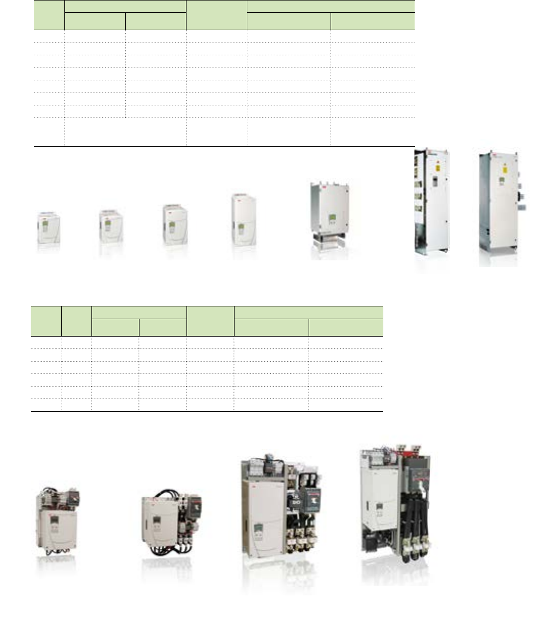
ABB DCS800 Technical Catalog 19
Dimensions and Weights - Module Drive
Unit
Size
Power Connection Weight
(lbs)
Dimensions
In Out h x w x d
(in)
h x w x d
In Out (mm)
D1 Bottom Bottom 24 14.6 x 10.6 x 7.9 370 x 270 x 200
D2 Bottom Bottom 35 14.6 x 10.6 x 10.6 370 x 270 x 270
D3 Bottom Bottom 55 18.1 x 10.6 x 12.2 459 x 270 x 310
D4 Bottom Bottom 84 25.4 x 10.6 x 13.6 644 x 270 x 345
D5 Top Bottom 242 39.6 x 20.1 x 16.1 1005 x 510 x 410
D5(B)* Bottom Bottom 240 37.4 x 20.1 x 16.1 950 x 510 x 410
D6 Left Left 396 69.0 x 18.1 x 16.1 1750 x 460 x 410
D7** Left or Right
(as selected in the type code) 693 69.0 x 30.0 x 22.4 1750 x 760 x 570
Dimensions and Weights - Panel Drive
Panel
Size
Drive
Size
Power Connection Weight
(lbs)
Dimensions
In Out h x w x d
(in)
h x w x d
In Out (mm)
AD1 Top Top 62 18.8 x 12.2 x 14.4 478 x 309 x 366
BD2 Top Top 103 19.3 x 20.0 x 13.8* 490 x 508 x 351
BD3 Top Top 130 19.3 x 20.0 x 13.8* 490 x 508 x 351
CD3 Top Top 231 35.3 x 23.6 x 16.2 897 x 599 x 411
CD4 Top Top 260 35.3 x 23.6 x 16.2 897 x 599 x 411
DD4 Top Top 355 45.7 x 26.7 x 16.0** 1160 x 678 x 406
*19.3 inch (490 mm) depth when internal reactor option is included.
**19.7 in (499 mm) depth when circuit breaker option is included.
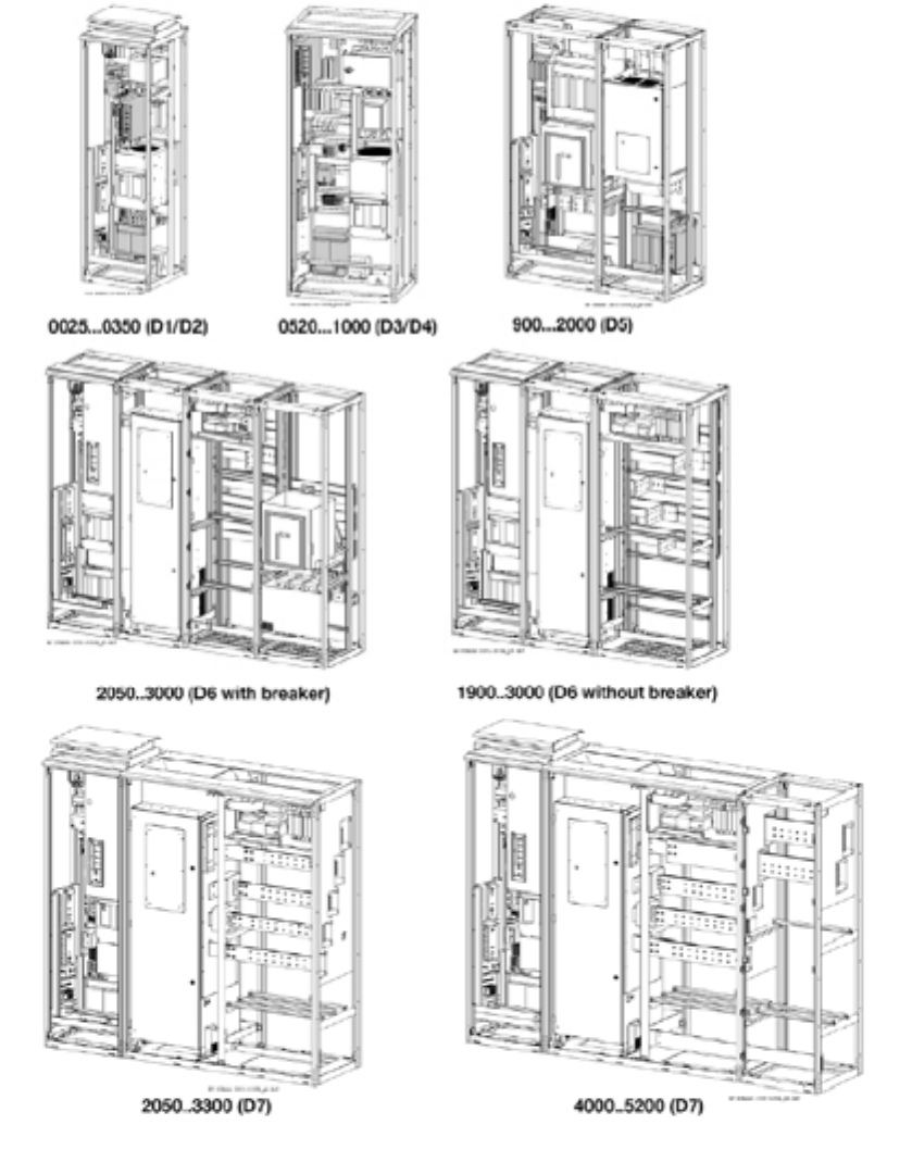
Dimensions and Weights
* D5(B) - for drives with “B„ after voltage code. e.g. DCS800-S01-2050-05B
**Largest D7 rating in each voltage class has separately mounted control section with deimensions same as a D1 unit.
A B C D
D1 D2 D3 D4 D5 D6 D7
20 ABB DCS800 Technical Catalog
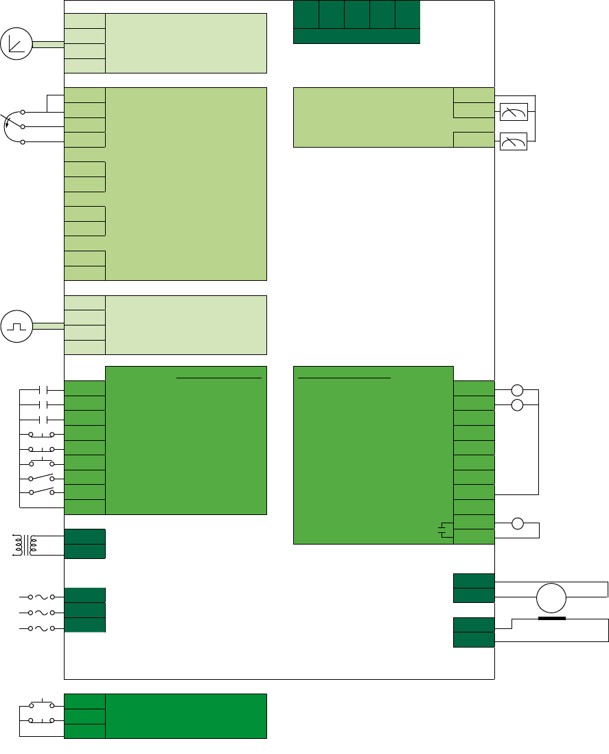
Technical Diagram
X2:1
2
3
4
5
X3:1 90-270 VDC
230-90 VDC DC Tach Input Converter Fan
38-30 VDC
4GND
X4:3 GND GND X4:6
X3:5 AI-1- analog in 1 analog out 1 AO-1 7
X3:6 AI-1+
X4:4 +10VDC analog out 2 AO-2 8
X3:7 AI-2- analog in 2
8AI-2+
9AI-3- analog in 3
10 AI-3+
X4:1 AI-4- analog in 4
2AI-4+
X5:1 Pulse Encoder Input
…
9
7GND
digital inputs 1 - 8 digital outputs 1 - 8
X6:1 DI-1 drive fan ack fans on DO-1 X7:1
2DI-2 motor fan ack field on DO-2 2
3DI-3 main cont ack DO-3 3
4DI-4 coast stop DO-4 4
5DI-5 e-stop DO-5 5
6DI-6 reset DO-6 6
7DI-7 on-off DO-7 7
8DI-8 start-stop GND 8
9+24VDC
main cont on RO-8 X96:1
X99:1 110-230 VAC 2
2 50/60 Hz 1-Phase
ARM - C
U1 LINE 1 ARM + D
V1 LINE 2
W1 LINE 3 FIELD - X10:1
FIELD + 2
Frames
D1 to D4
only
X6:7 DI-7 run
8DI-8 stop
9+24VDC
3-wire control
−Digital Inputs and Outputs can be freely configured by the user. This diagram shows the default settings with 2-wire control
(maintained inputs). The drive can optionally be configured to accept 3-wire control (pulsed inputs).
−RDIO-01 Digital Extension Module adds three (3) isolated digital inputs and two (2) relay outputs. Up to two can be added
providing a maximum of 14 digital inputs and 12 digital outputs.
−RAIO-01 Analog Extension Module adds two (2) isolated current/voltage analog inputs and two (2) isolated current analog
outputs. One can be added providing a maximum of six (6) analog inputs and four (4) analog outputs.
M
115 VAC 1Ø (D1-D4)
230 VAC 1Ø (D5)
460 VAC 3Ø (D6-D7)
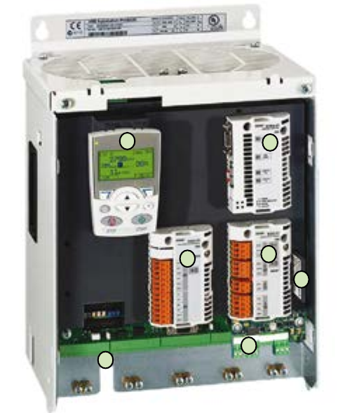
ABB DCS800 Technical Catalog 21
Plug-in Options
1. Basic Control Panel
The DCS800 control panel is standard with every drive. It
features a 5-line display and two soft keys. The panel is used to
commission and control the drive. Parameters can be saved to
it for backup or to download to another drive.
Plus code
+0J400 If no control panel is required
+J409 NEMA 4X (IP66) panel mount with 3m cable
NEMA 12 panel mount with 3m cable (OPMP-01)
2. Plug-in Fieldbus Module
See “Fieldbus Control” section
Fast Optical DDCS Communication Module
This optional communications module gives the DCS800 the
ability to communicate over fiber optics using ABB’s DDCS
communication protocol.
−Master channel ModuleBus to AC800M
−I/O channel to AIMA-01 board
−Master-Follower DDCS channel
−Tools channel e.g DriveWindow, remote diagnostic NETA, as
well as the CDP 312 from ACS800 range can be connected
on this board
−The board must be located in slot3
Plus code
+L508 Module bus 10 Mbd (SDCS-COM-81)
+L509 NxxA fieldbus adapter 5 Mbd (SDCS-COM-82)
3. Drive-Specific Serial Communication Board
The SDCS-DSL-4 board provides the serial communication for:
−Drive to drive (e.g. master-follower)
−Drive to external field power supply
−12-pulse applications
Plus code
+S199 SDCS-DSL-4 communication board
4. Field Power Supply
Sizes D1 through D4 drives have an internal field power supply.
On Size D5, the field power supply is included as a US standard
but can be omitted by dropping the plus code. Sizes D6 – D7
require an external field power supply.
Plus code
+S164 Internal field supply (D5)
5. Control Builder
Control Builder is an optional, user-friendly tool for programming
the DCS800 based on the IEC61131-3 standard. To include
Control Builder with the drive, a compact flash memory card
must be ordered with a plus code. CoDeSys software for the PC
is included with every drive. See page 29 for more information.
Plus code
+S200 Compact flash memory card (SDCS-MEM-8)
6. I/O Extension Option Module
The RAIO and RDIO plug-in options offer additional analog or
digital I/O. They can be used, for example, in a Master-Follower
application for interlocking functions. All the relays can be
configured by parameter. Alternatively, a fieldbus module can
be used to control any external components in the system. I/O
extension modules can be located in any of the three available
option slots.
Plus code
+L501 RDIO-01 Digital extension module 3xDI, 2xDO (isolated)
+L500 RAIO-01 Analog extension module 2xAI, 2xAO (isolated)
External isolated digital I/O modules are also available which
replace the drive’s non-isolated digital I/O.
Plus code
24-48 Vdc Isolated I/O (8 DI, 8 DO) (SDCS-IOB-21)
115 Vac Isolated I/O (8 DI, 8 DO) (SDCS-IOB-22)
230 Vac Isolated I/O (8 DI, 8 DO) (SDCS-IOB023)
12
3
4
5
66
22 ABB DCS800 Technical Catalog
Feedback Options
The DCS800 can be configured to work with a variety of
feedback options to monitor motor and line speed. Together
with the standard interface, the drive can read up to one
tachometer and two encoders simultaneously. Resolvers can be
used in place of encoders. “Encoderless” operation, using motor
EMF as feedback, is also possible and an excellent choice in
many applications.
Tachometer
The drive has a tachometer interface as standard for
tachometers with maximum voltages of 8 to 270 Vdc. For AC
tachometers with rectifiers, the drive has a filter to smooth out
the signal going to the drive.
Pulse Encoders
The drive also has one encoder interface as standard, to
operate with single-ended and differential pulse encoders. The
non-isolated interface works with 5Vdc and 24Vdc devices, and
also 12Vdc devices for drives over 1000 Amps (D5 and over).
A second pulse encoder interface (non-isolated) can be used
with the addition of one of the RTAC pulse encoder interface
adapters. The RTAC-03 is used for TTL encoders; the RTAC-
01 is used for other types. To add an isolated pulse encoder
interface, the IOB-03 can be used. The IOB-03 is separately
mounted on DIN rail.
+L517 5 & 24 Vdc TTL encoder interface (RTAC-03)
+L502 15 & 24 Vdc encoder interface (RTAC-01)
Analog and encoder I/O module (SDCS-IOB-3)
Feedback Options
Resolvers
Two options are available for resolver interface. The first option
is for applications where the resolver is primarily used as a
positioning device, a lifting table, for example. In this case, the
RRIA-01 resolver interface adapter can be used. The RSCM-01
can also be used to double the resolver voltage to adapt it to the
working range of RRIA-01.
+L516 Resolver interface adapter (RRIA-01)
Resolver signal conditioning mod. (RSCM-01)
When speed control is required, or whenever a premium interface
is desired, the FEN-21 resolver interface adapter should be used.
The FEN-21 provides an ultra-smooth speed feedback signal
for optimal speed control. The FEN-21 is mounted to a DIN-rail
extension adapter (FEA-01) which converts the feedback to a
fiber optic signal and transmits it to the drive’s COM-81 or COM-
82 module. (Fiber optic cable and external 24Vdc supply also
required.)
+L508 Fiber optic - standard (COM-81)
+L509 Fiber optic - NETA (COM-82)
external F-type resolver (FEN-21)
external F-type extension adapter (FEA-01)
FEN-21 resolver interface module mounted on a FEA-01 F-type extension adapter.

ABB DCS800 Technical Catalog 23
Resolvers
Two options are available for resolver interface. The first option
is for applications where the resolver is primarily used as a
positioning device, a lifting table, for example. In this case, the
RRIA-01 resolver interface adapter can be used. The RSCM-01
can also be used to double the resolver voltage to adapt it to the
working range of RRIA-01.
+L516 Resolver interface adapter (RRIA-01)
Resolver signal conditioning mod. (RSCM-01)
When speed control is required, or whenever a premium interface
is desired, the FEN-21 resolver interface adapter should be used.
The FEN-21 provides an ultra-smooth speed feedback signal
for optimal speed control. The FEN-21 is mounted to a DIN-rail
extension adapter (FEA-01) which converts the feedback to a
fiber optic signal and transmits it to the drive’s COM-81 or COM-
82 module. (Fiber optic cable and external 24Vdc supply also
required.)
+L508 Fiber optic - standard (COM-81)
+L509 Fiber optic - NETA (COM-82)
external F-type resolver (FEN-21)
external F-type extension adapter (FEA-01)
Communication Options
Fieldbus Control
DCS800 DC Drives have connectivity to major automation
systems. This is achieved with a dedicated gateway concept
between the fieldbus systems and ABB drives.
The fieldbus gateway module can easily be mounted inside the
drive. As a result of the wide range of fieldbus gateways, your
choice of automation system is independent from your decision
to use first-class ABB drives.
Manufacturing flexibility
Drive control
The drive control word (16 bit) provides a wide variety of
functions from start, stop and reset to ramp generator control.
Typical setpoint values like speed, torque and position can be
transmitted to the drive with 15 bit accuracy.
Drive monitoring
A set of drive parameters and/or actual signals, like torque,
speed, position, current etc., can be selected for cyclic data
transfer providing fast data for operators and the manufacturing
process.
Drive diagnostics
Accurate and reliable diagnostic information can be obtained via
the drive alarm, limit and fault words, reducing the drive down
time and, therefore, the downtime of the manufacturing process.
Drive parameter handling
Total integration of the drives in the production process is
achieved by single parameter read/write up to complete
parameter set-up or download.
Easy to expand
Serial communication simplifies the latest trend of modular
machine design enabling the installation to be expanded at a
later stage with low effort.
Reduced installation and engineering effort
Cabling
Substituting the large amount of conventional drive control cabling
with a single twisted pair reduces costs and increases system
reliability.
Design
The use of fieldbus control reduces engineering time at installation
because of the modular structure of the hardware
and software.
Commissioning and assembly
The modular machine configuration allows pre-commissioning of
single machine sections and provides easy and fast assembly of
the complete installation.
Currently available protocols
Fieldbus Plus Code Kit
Profibus-DP +K454 RPBA-01
DeviceNet +K451 RDNA-01
CANopen +K457 RCAN-01
ControlNet +K462 RCNA-01
Modbus RTU +K458 RMBA-01
Ethernet/IP, Modbus TCP +K466 RETA-01
EtherCAT +K469 RECA-01 (beta)
ProfiNet +K467 RETA-02 (beta)

24 ABB DCS800 Technical Catalog
Field Supply Types
DCF803-0016, DCF803-0035 and FEX425
−Three-phase or single-phase operation
−Full-wave half-controlled thyristor/diode bridge
−Microprocessor control, with the electronic system being
supplied by the armature-circuit converter (24 V)
−Construction and components have been designed for an
insulation voltage of 600 Vac
−Fast-response excitation is possible with an appropriate
voltage reserve; de-excitation takes place by field time
constant
−Field Output voltage UA (single-phase operation):
U
A
≤
U
v
* 100% + TOL * 0.9
100%
TOL = tolerance of line voltage in %
U
V
= Line voltage
U
A
= Field voltage
−Recommendation (single-phase operation):
UA= 0.6 to 0.8 * UV or UV = 1.25 to 1.7 * UA
−Field Output voltage UA (three-phase operation):
U
A
≤
U
v
* 100% + TOL * 1.35
100%
TOL = tolerance of line voltage in %
U
V
= Line voltage
U
A
= Field voltage
−All except FEX-425 must be externally fused. See table below
for selection.
−DCS800-DSL communications cable required.
External Field Supply
General Data
−Currents from 0.3 to 520 A
−Minimum field current monitor
−Integrated external field power converter or completely
separate switchgear cubicle
−Single-phase or 3-phase model
−Controlled by serial communication via DSL board
The three-phase field power converter causes less voltage
stress on the motor over the single-phase field converter. This is
because rectifying three-phase power provides a smoother DC
voltage.
For single-phase operation, we recommend integrating an auto
transformer in the field power converter’s supply circuit to adjust
the AC input voltage to the field voltage and to reduce the
voltage ripple in the field circuit.
All field converters are controlled by the armature converter via
a serial interface (SDCS-DSL-4 board). This interface serves
to set-up, control and diagnose the field converter and thus
provides an option for exact control.
Reactor for Field supply on the D5 Drive:
The D5 drive with plus code +S164 has internal field supply
FEX425-INT. This field supply should be seperately powered and
requires its own line reactor as identified below.
(
(
(
(
Table of field converter units
Unit type Output
current IDC
AC field supply
voltage
Auxiliary
supply
voltage
Comments
DCF803-0016
DCF803-0035
0.3 to 16A
0.3 to 35A 110V -15% to 500V*/1-ph +10%
single-phase or three-phase
24 V DC
200 mA
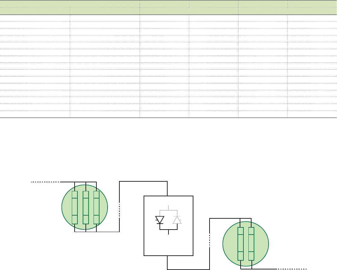
Line reactor required:
- for 3 phase operation use KLR16BTB, KLR45CTB
- for 1 phase, use ND-30
DCF803-0016, DCF803-0035 needs external fusing
FEX425-INT 0.3 to 25A
DCF503B-0050
DCF503B-0060
0.3 to 50A
0.3 to 60A 110V -15% to 500V**/1-ph +10%
115 or
230 V
Line reactor NOT required. (Internal line reactor included)
External fusing required
DCF504B-0050
DCF504B-0060
0.3 to 50A
0.3 to 60A 110V -15% to 500V**/1-ph +10%
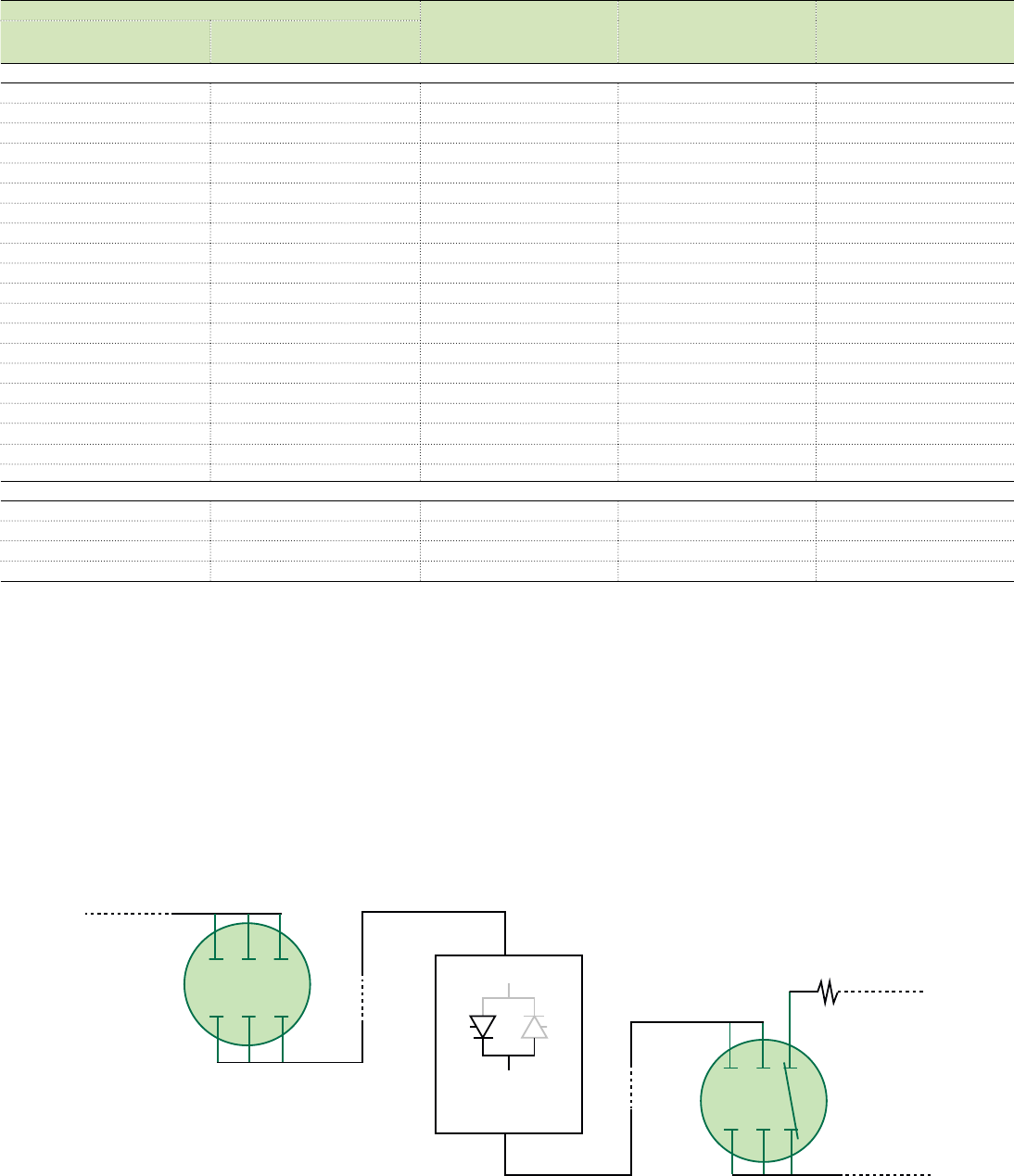
DCS800-S0x-xxxx-05 25 to 520 A 200V. to 500V**/3-ph Additional hardware components required for overvoltage
protection (DCF506)
Notes:
* Up to 600 Vac with auto transformer
** Up to 690 Vac with auto transformer

ABB DCS800 Technical Catalog 25
External Field Supply
DCF503B-0050, DCF503B-00601
−Single-phase operation
−Full-wave half-controlled thyristor/diode bridge (1-Q)
−Internal line reactor included
−Microprocessor control with the control electronics being
supplied separately (115...230 V/1-ph)
−Construction and components have been designed for an
insulation voltage of 690 VAC.
−Field Output voltage UA :
U
A
≤
U
v
* 100% + TOL * 0.9
100%
TOL = tolerance of line voltage in %
U
V
= Line voltage
U
A
= Field voltage
−Recommendation:
UA= 0.6 to 0.8 * UV or UV = 1.25 to 1.7 * UA
DCF504B-0050, DCF504B-00602
−Single-phase operation
−Full-wave fully-controlled regenerative thyristor bridge (4-Q)
−Internal line reactor included
−This unit offers field reversal as well as fast-response
excitation / de-excitation In the steady-state condition. The
full-wave bridge runs in half-wave mode so as to keep the
voltage ripple at a minimum. With a quickly alternating field
current, the bridge switches to fully-controlled mode.
−Same design as DCF503B
−Requires DCS800-DSL communications cable
−All external field supplies must be externally fused. See table
below for selection
−DCS800-DSL communications cable required
External Field Supply AC Line Fuses
Field Supply Ifield
Fuse
Single Phase
Fuse
Three Phase
DCF803-0035,
DCF503B-0050 or
DCF504B-0050
6 Amps FWP-10B FWP-5B
6 - 12 Amps FWP-15B FWP-10B
12 - 25 Amps FWP-25B FWP-25B
25 - 35 Amps FWP-50B FWP-30B
DCF503B-0050 or
DCF504B-0050 35 - 50 Amps FWP-60B -
DCF503B-00601
DCF504B-0060250 - 60 Amps FWP-70B -
DCS800 as Field Supply
The DCS800-S0X Drive Module can also be used for field exciter
operation. An additional overvoltage protection unit is required. It
provides field currents from 25 A up to 520 A unipolar and bipolar
for field reversal function.
−Output voltage
UA respectively Udmax 2-Q : see table on page 5
−Recommendation:
Field voltage = 0.5 to 1.1 * UV
−Overvoltage Protection Unit REQUIRED: The three-phase
field supply converters DCS800- S01/S02 need a separate
active Overvoltage Protection Unit DCF 506 for protecting the
power part against inadmissibly high voltages.
Overvoltage Protection Unit Selection Chart
Field supply converter for
motor fields
Overvoltage protection
DCS800-S0x-0020-05
DCF506-0140-51 ...
DCS800-S0x-0140-05
DCS800-S0x-0200-05
DCF506-0520-51 ...
DCS800-S0x-0520-05
(
(
1Transitioning to DCF803 -0050 and -0060 in 2013. Specifications remain the same.
2Transitioning to DCF804 -0050 and -0060 in 2013. Specifications remain the same.
26 ABB DCS800 Technical Catalog
Fuse Connections
Semiconductor type F1 fuses and fuse holders for AC and
DC power lines
AC Line Fuses
The converter units are subdivided into two groups. Frame sizes
D1, D2, D3, and D4, with rated currents up to 1000 Amps,
require external AC line fuses. Recommendations are shown
below. Frame sizes D5, D6, and D7, with rated currents of 900
to 5200 Amps, have semiconductor fuses installed internally. No
additional external semiconductor line fuses are needed.
Table of field converter units
Type of Converter Fuse Fuse Holder Fuse Fuse Holder
2-Q Converter 4-Q Converter North America Worldwide
DCS800-SO1-0020-05 DCS800-SO2-0025-05 FWP-50B 1BS101 170M 1564 OFAX 00 S3L
DCS800-SO1-0045-05 DCS800-SO2-0050-05 FWP-80B 1BS101 170M 1565 OFAX 00 S3L
DCS800-SO1-0065-05 DCS800-SO2-0075-05 FWP-125A 1BS103 170M 1568 OFAX 00 S3L
DCS800-SO1-0090-05 DCS800-SO2-0100-05 FWP-125A 1BS103 170M 1568 OFAX 00 S3L
DCS800-SO1-0125-05 DCS800-SO2-0140-05 FWP-200A 1BS103 170M 3815 OFAX 1 S3
DCS800-SO1-0180-05 DCS800-SO2-0200-05 FWP-250A 1BS103 170M 3816 OFAX 1 S3
DCS800-SO1-0230-05 DCS800-SO2-0260-05 FWP-300A 1BS103 170M 3817 OFAX 1 S3
DCS800-SO1-0315-05 DCS800-SO2-0350-05 FWP-500A 1BS104 170M 5810 OFAX 2 S3
DCS800-SO1-0405-05 DCS800-SO2-0450-05 FWP-700A See Note 1 170M 6811 OFAX 3 S3
DCS800-SO1-0470-05 DCS800-SO2-0520-05 FWP-700A See Note 1 170M 6811 OFAX 3 S3
DCS800-SO1-0610-05 DCS800-SO2-0680-05 FWP-900A See Note 1 170M 6163 3X 170H 3006
DCS800-SO1-0740-05 DCS800-SO2-0820-05 FWP-900A See Note 1 170M 6163 3X 170H 3006
DCS800-SO1-0900-05 DCS800-SO2-1000-05 FWP-1200A See Note 1 170M 6166 3X 170H 3006
DCS800-SO1-0290-06 DCS800-SO2-0320-06 FWP-500A 1BS104 170M 5810 OFAX 2 S3
DCS800-SO1-0590-06 DCS800-SO2-0650-06 FWP-900A See Note 1 170M 6813 OFAX 3 S3
Three (3) fuses and fuse holders are required for the AC side. DC fuses are required for 4-Q converters D1-D4. When needed, use 2 for the DC side.
Note 1: No fuse holder is available. Attach fuses directly to busbar.
DC Fuses
DC fuses between the drive and the motor are required for
regenerative (4-quadrant) converters. This is to protect the
drive in the possible event of an inversion fault. When needed,
DC fuses should be the same size and type as AC line fuses.
DCS800 drives frames D5 – D7 include thyristor branch fuses
which can protect the motor during a commutation (inversion)
fault but thyristor or motor damage could still result. Use DC
fuses or a high speed DC breaker for complete protection,
especially for motors that regenerate routinely and on large
motor drive systems.
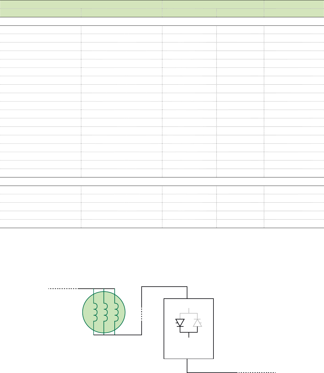
ABB DCS800 Technical Catalog 27
Line reactors
Unit Type Line Choke for Config. A Line Choke for Config. B
2Q Converters 4Q Converters 1.5% impedance 3% impedance 5% impedance
500 Vdc
DCS800-S01-0020-05 DCS800-S02-0025-05 KLR21BTB LRAC02502 KLR21CTB
DCS800-S01-0045-05 DCS800-S02-0050-05 KLR45BTB LRAC04502 KLR45CTB
DCS800-S01-0065-05 DCS800-S02-0075-05 KLR80BTB LRAC08002 KLR80CTB
DCS800-S01-0090-05 DCS800-S02-0100-05 KLR110BCB LRAC13002 KLR110CCB
DCS800-S01-0125-05 DCS800-S02-0140-05 KLR130BCB LRAC13002 KLR130CCB
DCS800-S01-0180-05 DCS800-S02-0200-05 KLR200BCB LRAC20002 KLR200CCB
DCS800-S01-0230-05 -- KLR200BCB LRAC20002 KLR200CCB
-- DCS800-S02-0260-05 KLR250BCB LRAC25002 KLR250CCB
DCS800-S01-0315-05 DCS800-S02-0350-05 KLR300BCB LRAC40002 KLR300CCB
DCS800-S01-0405-05 -- KLR360BCB LRAC40002 KLR360CCB
DCS800-S01-0470-05 DCS800-S02-0450-05 KLR420BCB LRAC40002 KLR420CCB
-- DCS800-S02-0520-05 KLR480BCB LRAC50002 KLR480CCB
DCS800-S01-0610-05 DCS800-S02-0680-05 KLR600BCB LRAC60002 KLR600CCB
DCS800-S01-0740-05 DCS800-S02-0820-05 KLR750BCB KLR750CCB
DCS800-S01-0900-05 -- KLR750BCB KLR750CCB
-- DCS800-S02-1000-05 KLR850BCB KLR850CCB
DCS800-S01-1200-05 DCS800-S02-1200-05 KDRX3L KDRX3H
DCS800-S01-1500-05 DCS800-S02-1500-05 KDRY1L KDRY2H
600 Vdc
DCS800-S01-0290-06 -- KLR250BCB KLR250ECB
-- DCS800-S02-0320-06 KLR300BCB KLR300ECB
DCS800-S01-0590-06 DCS800-S02-0650-06 KLR600BCB KLR600ECB
DCS800-S01-0900-06 DCS800-S02-0900-06 KLR750BCB KLR750ECB
DCS800-S01-1500-06 DCS800-S02-1500-06 KDRY41L KDRY42H
Note:
- 3% reactors beginning with “LRAC„ are available from Baldor Electric.
- Conguration A: For most installations
- Conguration B: For installations that require compliance with EN 61-800-3 or when AC and DC drives are on the same line
- See DCS800 hardware manual for additional information
28 ABB DCS800 Technical Catalog
Input and Output Contactors
Unit Type AC Input
Contactors
3-Pole (NO)
DC Output
Contactors
2-Pole (NO)
Dynamic Brake
Contactors
2-NO & 1-NC
2Q Converters 4Q Converters
500 Vdc
DCS800-S01-0020-05 DCS800-S02-0025-05 A12-30-11-84 DA75-20-11-84 DA75-21-21-84
DCS800-S01-0045-05 DCS800-S02-0050-05 A30-30-11-84 DA75-20-11-84 DA75-21-21-84
DCS800-S01-0065-05 DCS800-S02-0075-05 A50-30-11-84 EHDB220C2P-1L EHDB220C-1L
DCS800-S01-0090-05 DCS800-S02-0100-05 A75-30-11-84 EHDB220C2P-1L EHDB220C-1L
DCS800-S01-0125-05 DCS800-S02-0140-05 A110-30-11-84 EHDB220C2P-1L EHDB220C-1L
DCS800-S01-0180-05 DCS800-S02-0200-05 A145-30-11-84 EHDB220C2P-1L EHDB220C-1L
DCS800-S01-0230-05 - - A210-30-11-84 EHDB280C2P-1L EHDB280C-1L
- - DCS800-S02-0260-05 A210-30-11-84 EHDB280C2P-1L EHDB280C-1L
DCS800-S01-0315-05 DCS800-S02-0350-05 A260-30-11-84 EHDB360C2P-1L EHDB360C-1L
DCS800-S01-0405-05 - - AF400-30-11-70 EHDB520C2P-1L EHDB520C-1L
DCS800-S01-0470-05 DCS800-S02-0450-05 AF400-30-11-70 EHDB520C2P-1L EHDB520C-1L
- - DCS800-S02-0520-05 AF400-30-11-70 EHDB520C2P-1L EHDB520C-1L
DCS800-S01-0610-05 - - AF580-30-11-70 EHDB650C2P-1L EHDB650C-1L
- - DCS800-S02-0680-05 AF580-30-11-70 EHDB800C2P-1L EHDB800C-1L
DCS800-S01-0740-05 - - AF750-30-11-70 EHDB800C2P-1L EHDB800C-1L
DCS800-S02-0820-05 AF750-30-11-70 EHDB960C2P-1L EHDB960C-1L
DCS800-S01-0900-05 - - AF1350-30-11-70 EHDB960C2P-1L EHDB960C-1L
- - DCS800-S02-1000-05 AF1350-30-11-70 Bar Contactor Bar Contactor
DCS800-S01-1200-05 DCS800-S02-1200-05 AF1350-30-11-70 Bar Contactor Bar Contactor
DCS800-S01-1500-05 DCS800-S02-1500-05 AF1650-30-11-70 Bar Contactor Bar Contactor
600 Vdc
DCS800-S01-0290-06 DCS800-S02-0320-06 A260-30-11-84 EHDB360C2P-1L EHDB360C-1L
DCS800-S01-0590-06 DCS800-S02-0650-06 AF460-30-11-70 EHDB680C2P-1L EHDB680C-1L
DCS800-S01-0900-06 DCS800-S02-0900-06 AF750-30-11-70 EHDB960C2P-1L EHDB960C-1L
DCS800-S01-1500-06 DCS800-S02-1500-06 AF1650-30-11-70 Bar Contactor Bar Contactor
AC Input Contactors: Contactors have 120Vac / 50-60Hz coil with 1-NO and 1-NC aux. contact.
DC Output and Dynamic Brake Contactors: Contactors have 120Vac / 60Hz coil with1-NO and 1-NC aux. contact.
Either an AC or DC contactor is required, but not both.
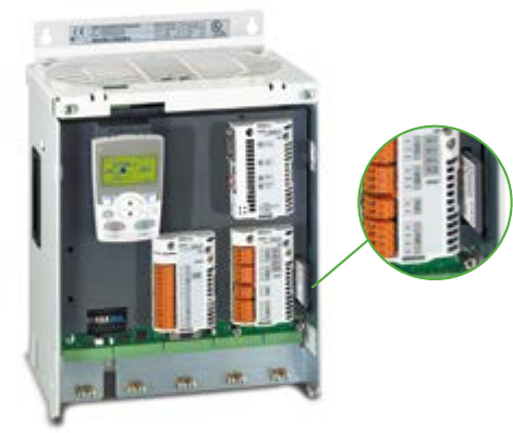
ABB DCS800 Technical Catalog 29
Control Builder
Programming Tool
Control Builder is an optional, user-friendly tool for programming
the DCS800 based on the IEC61131-3 standard. With Control
Builder, it is possible to develop application programs directly
in the drive quickly and easily, programs that customize the
application, decentralize control, add additional interlocks,
and much more. Control Builder offers a clear and easy way to
develop, test and document your application programs.
Control Builder consists of the following:
−CoDeSys programming software for the PC
−Compact flash memory card
−Expanded library of functions
CoDeSys: a PC software tool for creating, documenting,
editing and downloading your custom application program. No
special programming skills are required. CoDeSys supports
all five programming languages of IEC61131-3 Additionally, a
Continuous Function Chart option is included. This makes it
possible for you to program the drive in whatever language you
are most comfortable with. CoDeSys is included as standard
with every DCS800 on the DCS800 Tools CD.
Compact flash memory card: The application program is
stored on a compact flash memory card (MC) which is plugged
into the drive. MC memory is sufficient to store a program
made up of hundreds of functions. The MC is optional. One is
required for each drive using Control Builder.
Expanded library of functions: More than 100 types of
functions are available including strings, timers, counters,
and triggers, in addition to math and conversion functions.
Various pre-configured functions are also included such as a
PID-controller and a winder. User defined functions can also
be created and saved. The library is included as standard with
every DCS800 on the DCS800 Tools CD.
Upload and Download
Application programs can be uploaded from connected drives
and displayed graphically on a PC screen for service and
documentation purposes. Online debugging functions include
single-step, single-cycle, and breakpoint modes. An event
triggered recording tool for variables and signals is also available.
Programs made off-line can be downloaded to any of the
connected drives that support them.
Three Operating Modes
Control Builder can be used to program the drive in three
different ways:
−Standalone mode – CoDeSys is not connected to the drive.
The application program can be written in the office and later
downloaded to the drive.
−Off-line mode – CoDeSys is connected to the drive. Changes
can be made to the application program without any affect on
the drive until the program is downloaded.
−On-line mode – CoDeSys is connected to the drive. Changes to
the application program are written immediately to the drive and
actual values are shown on the screen in real-time.
Advantages and Features
−Easy-to-use tool, no special skills required
−Create and download custom programs
−Automatic documentation
−Can eliminate the need for an external PLC
−The application, including source code, is always part of the
drive and thus, can be maintained during the whole life cycle of
the machine
−The source code can be password protected against
unauthorized access
If 16 or fewer function blocks are required, you may be able to use
Adaptive Programming instead, which is standard on all DCS800
drives. See page 10.
30 ABB DCS800 Technical Catalog
Start-up and Maintenance Tool
ABB’s DriveWindow is an advanced, easy-to-use PC software
tool for the start-up and maintenance of the DCS800 and
other ABB drives. Its host of features and clear, graphical
presentation of the operation make it a valuable addition to your
system providing information necessary for troubleshooting,
maintenance and service, as well as training.
With DriveWindow the user is able to follow the operation of
several drives simultaneously by collecting the actual values
from the drives onto a single screen or printout.
Additionally, the client part of DriveWindow may reside on one
Local Area Network PC, and the server side on another PC
closer to the drives. This enables plant-wide monitoring to be
easily accomplished with two PCs.
High Speed Communication
DriveWindow uses a high-speed fiber optic cable network
with DDCS communication protocol.
This makes communication between PC and drives very fast.
The fiber optic network is safe and immune to external
disturbance. A fiber optic communication card is needed inside
the computer.
Monitoring Drives
Using DriveWindow you can monitor several drives
simultaneously. The history buffer makes it possible to record a
large
amount of data in the PC‘s memory. The drive‘s data logger can
be accessed with DriveWindow and viewed in graphical form.
The fault logger inside the drive automatically documents every
faults, warnings and events that occur. The fault history stored
in the drive can be uploaded to your computer.
Start-up, maintenance and integration
DriveWindow
Versatile Back-Up Functions
Drive parameters can be saved to the PC with DriveWindow, and
can easily be downloaded back to the drive whenever needed.
DriveWindow Features
−Easy-to-use tool for commissioning and maintenance
−Several drives connected and monitored at the same time
−Monitor, edit or save signals and parameters, clear graphical
presentation
−High-speed communication between PC and drive
−Versatile back-up functions
−View data collected and stored in the drive
−Fault diagnosis; DriveWindow indicates the status of drives, and
also reads fault history data from the drive
−Compare function for comparing parameter sets
DCS800 DCS800 DCS800 DCS800
PC
DriveWindow
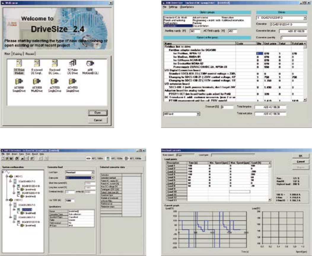
ABB DCS800 Technical Catalog 31
Quality Dimensioning
DriveSize is a PC program to help the user select the optimal
converter and options, especially in those cases where a
straightforward selection from a catalog is not possible.
Additionally, it can be used to create printed documents about
the dimensioning based on actual load.
The default values make DriveSize simple to use, but the user
is provided with many options for drive selection. The shortcut
keys make drive selection easy while still honoring the relatively
complicated rules. A manual selection mode is also supported.
DriveSize is currently used by more than 1000 engineers
globally.
Start-up, maintenance and integration
DriveSize
DriveSize is for Drive System Components
−Motors
−DCS converter modules
−DCS enclosed converters
−Group drives (line-ups)
−Drive options
DriveSize Features
−Selects the optimal drive unit and motor
−Calculates duty load cycles for converters
−Supplies dimensioning results in graphical and numerical format
−Same tool used for AC and DC
−Excellent tool for supporting small systems
−Prints and saves the results

32 ABB DCS800 Technical Catalog
DriveOPC
Integration Tool
DriveOPC is a software package which allows OLE for Process
Control (OPC) communication between Windows applications
and DCS800 DC drives. It allows Object Linking and Embedding
(OLE) for Process Control (OPC) communication. This OPC
server is an ideal tool for integrating DCS800 DC drives with
commercial PC software and creating PC-based controlling and
monitoring systems.
Remote Monitoring
DriveOPC enables remote connection via LAN (local area
networks). The remote PC can be connected by its IP address
(e.g. “164.12.43.33”) or by the DNS name (e.g. “Gitas213”).
OPC Based Software
OPC is an industry standard created in cooperation with
Microsoft. It is an open architecture interface design, managed
by the international OPC foundation. OPC is meant for different
kinds of factory automation.
DriveOPC is based on OPC foundation data access standard
1.0A and Microsoft COM/DCOM technology. DriveOPC has full
access to all drives, even when remote connection via LAN is
used.
High Speed Communication
DriveOPC uses a high-speed fiber optic cable network with
DDCS communication protocol. This makes communication
between PC and drives very fast. The fiber optic network
is safe and immune to external disturbance. A fiber optic
communication card is needed inside the computer.
Features
DriveOPC supports OPC’s data access 1.0A.
Read access to:
−Drive status: local, running, direction, fault, warning, reference
−Signals and parameters
−Fault logger contents
−Event logger contents
−General drive information
−Data logger settings, status and contents
Write access to:
−Drive control: local, start, stop, forward, reverse, coast stop,
reset fault, home, teach-in, contactor on/off, reference
−Parameters
−Fault logger clear
−Data logger init, start, trig, clear
Start-up, maintenance and integration
DriveBrowser
DriveBrowser allows parameter upload/download, editing and
saving, monitoring up to four (4) signals from a single drive. Unique
connections to networks of drives can be configured and saved.
The user can assign user friendly names to each drive and save
the network set-up for future connectivity.
This ABB drive PC software tool uses the PC’s standard Ethernet
port and existing fieldbus network as the communication media.
DriveBrowser supports connection to the DCS800 drive using
these fieldbus adapters:
−Ethernet IP / Modbus TCP (RETA-01)
−ProfiNET (RETA-02)
−ControlNet (SECG-01)
−DeviceNet (SEDG-01)
DriveBrowser supports ABB’s standard drives ACS350, ACS355,
ACS550, ACH550, industrial drives ACS800 Standard Application
firmware in addition to DCS800.
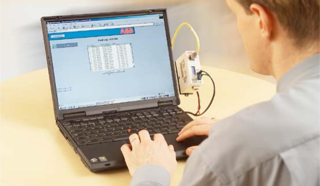
ABB DCS800 Technical Catalog 33
Browser-Based, User-Friendly
The intelligent Ethernet NETA-01 module gives simple access
to the drive by means of the Internet communicating via a
standard web browser. The user can set up a virtual monitoring
room wherever there is a PC with an Internet connection or
via a simple dial-up modem connection. This enables remote
monitoring, configuration, diagnostics and, when needed,
control. The drive can also provide process related information,
such as load level, run time, energy consumption and I/O data,
the bearing temperature of the driven machine, for instance.
This opens new possibilities for the monitoring and maintenance
of unmanned applications across a range of industries, for
instance water, wind power, building services and oil & gas,
as well as any application where the user needs access to
the drives from more than one location. It also provides an
opportunity for OEMs and system integrators to support their
installed base globally.
No PC Needed at Local End
The intelligent Ethernet module has an embedded server with
the necessary software for the user interface, communication
and data storage. This gives ease of access, realtime
information and the possibility for two-way communication with
the drive, enabling immediate response and actions, saving time
and money. This is possible without using a PC at the local end,
as required by other remote solutions.
Remote monitoring tool
Ethernet module
Powerful and Versatile
Up to nine drives can be connected to the intelligent Ethernet
module via fiber optic links. It is available as an option for new
drives, as well as an upgrade for existing systems. Access to the
module is secured by user ID and passwords.
The web page of the module is opened like any other web
address. The home page shows a general overview of the system
with traffic lights and action buttons to guide the user through the
different sections.
Features
−Virtual monitoring room for
−Monitoring
−Configuration of parameters
−Diagnostics
−Control, if needed
−Browser based access via
−Intra-/extra-/Internet or
−Email Client
−Event Notification
−Drives status update
−No PC needed at the local end
−Can be used as a Modbus/TCP bridge for control purpose
Coming Soon: NETA-21 Remote Monitoring Tool
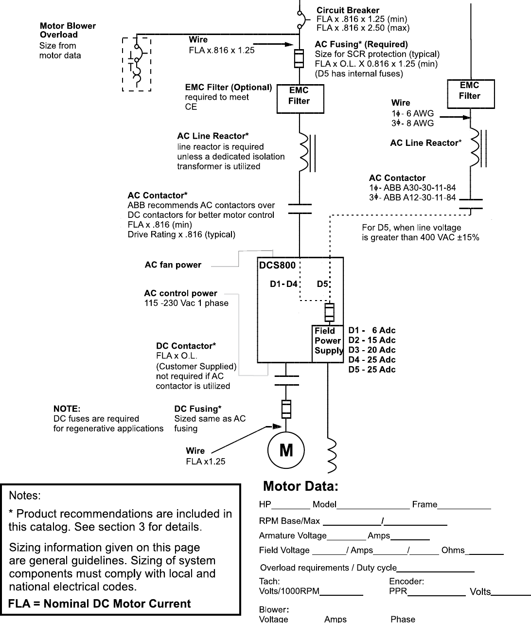
34 ABB DCS800 Technical Catalog
Drawings
DCS800-S01, S02 Power Modules D1-D5 Frames (500 Vdc)
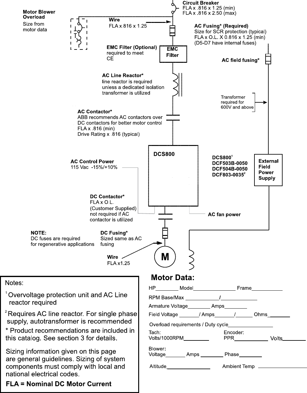
ABB DCS800 Technical Catalog 35
Drawings
DCS800-S01, S02 Power Modules D1-D5 Frames (600 Vdc and above)
DCS800 D6-D7 Frames (all voltages)
36 ABB DCS800 Technical Catalog
Spare Part Kits
A stock of spare parts for your DCS800 drive will save you
time and minimize expense. Spare parts kits are available to
provide ready replacements for the most common parts.
Our standard spare part kits include the following:
−AC input fuses when internally mounted (D5 – D7)
−Field supply fuses when internally mounted (D1 – D5)
−Cooling fan
−Thyristors for one bridge
We also offer optional kits for critical applications which
include the following:
−Control board
−Power interface board
−Pulse transformer board
−Power supply board
−Field supply board
Spare parts kits are ordered by drive type code. Not every kit
will include all of these parts; it depends on the drive. Spare
plug-in options (fieldbus, I/O extensions, etc.) must be ordered
separately.
Spare Part Services
ABB offers a fast and effortless information and ordering system
to facilitate spare part management. Parts OnLine is at your
service 24 hours.
http://www.abb.com/partsonline
Spare Parts and Service Products
Service Products
To reduce the total cost of owning ABB drives and to maximize
their availability ABB offers the following services:
Training Services
ABB offers dedicated training on ABB drives for your service
and operating personnel. Upon successful completion of the
training course your personnel will have acquired the skills to
use ABB drives correctly and safely, and also to get the best
results from their application.
Service product
code
Service type Service type
US190 DCS800 - 3 days Maintenance & Commissioning
US191 DCS800 - 1 day Serial Communications
ABB has a service organization that spans the globe. Contact
your local ABB sales office for more information about our
services.
http://www.abb.us/drives
Start-Up Services
Using ABB’s start-up services you can trust that your drives are
correctly commissioned and well-tuned to their application. ABB
employs authorized professionals who have been thoroughly
trained for their job.
ABB Maintenance Services
ABB maintenance services ensure optimal operation of your
drives and extend their useful life.
ABB DCS800 Technical Catalog 37
38 ABB DCS800 Technical Catalog
ABB DCS800 Technical Catalog 39

Contact us
DCS800-PHTC01U-EN REVK Effective 04/04/2014. Subject to change without notice. All rights reserved.
ABB Inc.
Low Voltage Drives
16250 W. Glendale Drive
New Berlin, WI 53151
Tel: (800) 752-0696
Fax: (262) 785-0397
www.abb.us/drives
