Interface Technology And Switching Devices 2015 / 2016 Brochure
1000510245-Catalog 1 1000510245-Catalog_1 1000510245-Catalog_1 B5 unilog cesco-content
2016-10-06
: Pdf 111619-Brochure 111619-Brochure B5 unilog
Open the PDF directly: View PDF ![]() .
.
Page Count: 638 [warning: Documents this large are best viewed by clicking the View PDF Link!]
7
Interface Technology
and Switching Devices
2015 / 2016
Also discover the Phoenix Contact catalog app
interactively on your tablet.
Interface technology and switching devices
Terminal blocks
• Terminal blocks
Sensor/actuator cabling and
industrial connectors
• Sensor/actuator cabling
• Cables and lines
• Connectors
Marking systems, tools, and
mounting material
• Marking and labeling
• Tools
• Installation and mounting material
Surge protection and
power supplies
• Surge protection and interference suppression
filters
• Power supplies and UPS
• Protective devices
Control technology, I/O systems, and
automation infrastructure
• Lighting and signaling
• Fieldbus components and systems
• Functional Safety
• HMIs and industrial PCs
• I/O systems
• Industrial Ethernet
• Industrial communication technology
• Software
• Controllers
• Wireless data communication
PCB connection technology and
electronics housing 2013/14
• PCB terminal blocks and PCB connectors
• Electronics housing
Connection technology for fi eld devices
2013/14
• Connectors
• Cables and lines
Information on these products can be found in the electronic
product catalogs for 2013/14.
Or get the latest on all the new products and additional
information directly in the product area of our website:
phoenixcontact.net/products
Find out more
with the web code
On some of the catalog pages, you can find our web
codes: a number sign followed by a four-digit number
combination.
Web code: #1234 (example)
This allows you to reach information on our website
quickly.
It couldn't be simpler:
1. Go to the Phoenix Contact website
2. Enter # and the number combination
in the search field
3. Receive more information and product versions
Search
Or use the direct link:
phoenixcontact.net/webcode/#1234


Electronic switching devices and motor control
Motor management
Page 14
Hybrid motor starters
Page 20
Solid-state contactors
Page 36
IP67 motor starters
Page 46
(Ex i) signal conditioners with
SIL functional safety Page 152
(Ex i) signal conditioners with
PL functional safety Page 184
Multiplexers for HART signals
Page 222
Ex i 2-wire field devices
Page 223
Current transformers
Page 252
Current transformers for retrofitting
Page 266
Test disconnect terminal blocks
See Catalog 3
Current transducers, current protectors
Page 272
Multifunctional monitoring relays
Page 300
Ultra-narrow timer relays
Page 308
Multifunctional timer relays
Page 310
Function modules
Page 312
4
PHOENIX CONTACT
Complete overview
Product range overview
For further information and full technical data, visit phoenixcontact.net/products
MCR technology
Frequency inverters
Page 48
Highly compact signal conditioners with
plug-in connection technology Page 64
Highly compact signal conditioners
Page 90
Signal conditioners, head transducers, and
process indicators Page 128
Monitoring
Controllers
See Catalog 8
Energy meters, function and
communication modules Page 238
Complete packages for data logging
Page 245
Compressed air meters
Page 246
PV system monitoring
Page 282
Residual current monitoring
Page 288
Components for E-Mobility
Page 292
Compact monitoring relays
Page 298
Lightning monitoring system
See Catalog 6
HMIs
See Catalog 8
Signal towers
See Catalog 8
5
PHOENIX CONTACT
Complete overview
Product range overview
Relay modules
RIFLINE complete
Page 328
PR series
Page 378
PLC-INTERFACE
Page 400
Programmable logic relay system - PLC logic
Page 452
System cabling for controllers
Controller-specific system cabling
Page 490
V8 adapters
Page 451
Universal modules
Page 576
Universal cables
Page 600
6
PHOENIX CONTACT
Complete overview
Product range overview
8
PHOENIX CONTACT

Product range overview
Product overview 10
Electronic motor management 12
Network-capable hybrid motor starters with reversing function 20
Hybrid motor starters with reversing function 22
Network-capable hybrid motor starters with direct start function
24
Hybrid motor starters with direct start function 26
Hybrid motor starters with short-circuit protection 29
3-phase solid-state reversing contactors 36
3-phase solid-state contactors 38
Solid-state reversing contactor for DC motors 42
Single-phase solid-state contactors 44
IP67 motor starters 46
IP20 frequency inverters 48
9
PHOENIX CONTACT
Switching devices for starting, reversing,
and protecting electric motors are some of
the most frequently used components in
automation technology. These are often
designed redundantly for safety-sensitive
applications. When it comes to reducing
installation time and space requirements,
CONTACTRON hybrid motor starters are
the state-of-the-art alternative.
This is because CONTACTRON hybrid
motor starters combine up to four
functions in a single device. Integration into
popular fieldbus systems is realized via the
INTERFACE system connection or via the
SmartWire-DT™ wiring system.
For protection of the entire system, the
product range now includes the electronic
motor manager (EMM). In addition to
typical measured values such as voltage and
current, the behavior of the system is
monitored and protected by means of real
power measurement. The process data in all
popular fieldbus systems can be supplied via
gateways and evaluated by a controller.
Electronic switching devices and motor control
Motor management
Electronic motor management
Page 14
Gateways
Page 16
Software
Page 17
Hybrid motor starters
Network-capable hybrid motor starters with
reversing function Page 20
Hybrid motor starters with reversing function
Page 22
Network-capable hybrid motor starters with
direct start function Page 24
Hybrid motor starters with
direct start function Page 26
Solid-state contactors
3-phase solid-state reversing contactors
Page 36
3-phase solid-state contactors
Page 38
Solid-state reversing contactor with
soft starter Page 40
Solid-state reversing contactor for
DC motors Page 42
IP67 motor starters Frequency inverters
PROFINET motor starters for distributed use
Page 46
Stainless steel base, IP67 protection
Page 47
Inline frequency inverters for
the control cabinet Page 48
10
PHOENIX CONTACT
Electronic switching devices and motor control
Product overview
For further information and full technical data, visit phoenixcontact.net/products
Hybrid motor starters with
short-circuit protection Page 29
Loop bridge for hybrid motor starters
Page 30
SmartWire-DT™ accessories
Page 32
Single-phase solid-state contactors
Page 44
11
PHOENIX CONTACT
Electronic switching devices and motor control
Product overview
12
PHOENIX CONTACT
Electronic switching devices and motor control
Motor management
Electronic motor management
(EMM)
The electronic motor management
modules offer all the advantages of modern
real power monitoring.
The measuring and evaluation electronics
for all performance classes. EMM offers the
same functionality for all performance
classes, only without a power section.
Power within limits
Monitoring is based on freely
parameterizable switching and signaling
thresholds for overload and underload
detection. Identical or separate settings can
be made for the thresholds relating to the
two directions of rotation.
Parameterization relies on the real power
consumed (calculated from three currents,
voltages, and the phase angle), thereby
offering a much more precise basis than if
only the current is taken into consideration,
as it is independent of voltage fluctuations
and drive load. If a switching threshold is
violated, the EMM initiates an emergency
shutdown of the motor immediately (or
with an adjustable “delay time”). In addition,
a message can be sent via an output.
This state can only be deactivated via a
defined reset. If the real power consumed is
determined as being above or below the
message thresholds, all that occurs is that a
check-back is returned for the duration for
which the module was addressed.
In addition, signals are generated by the
module for the recognition of the direction
of rotation. Asymmetry and phase failures
are detected and signaled.
Permanent status monitoring with high
scanning rates and the fast semiconductor
switch enable complete system protection,
including motor protection.
Without any extra wiring - and with just a
single device - pumps, actuating drives, fans,
and tools are monitored for proper
functioning, contamination (filter or
similar), and wear. The adjustable “inrush
suppression” time can be used to mask out
the switching operation from the
monitoring process.
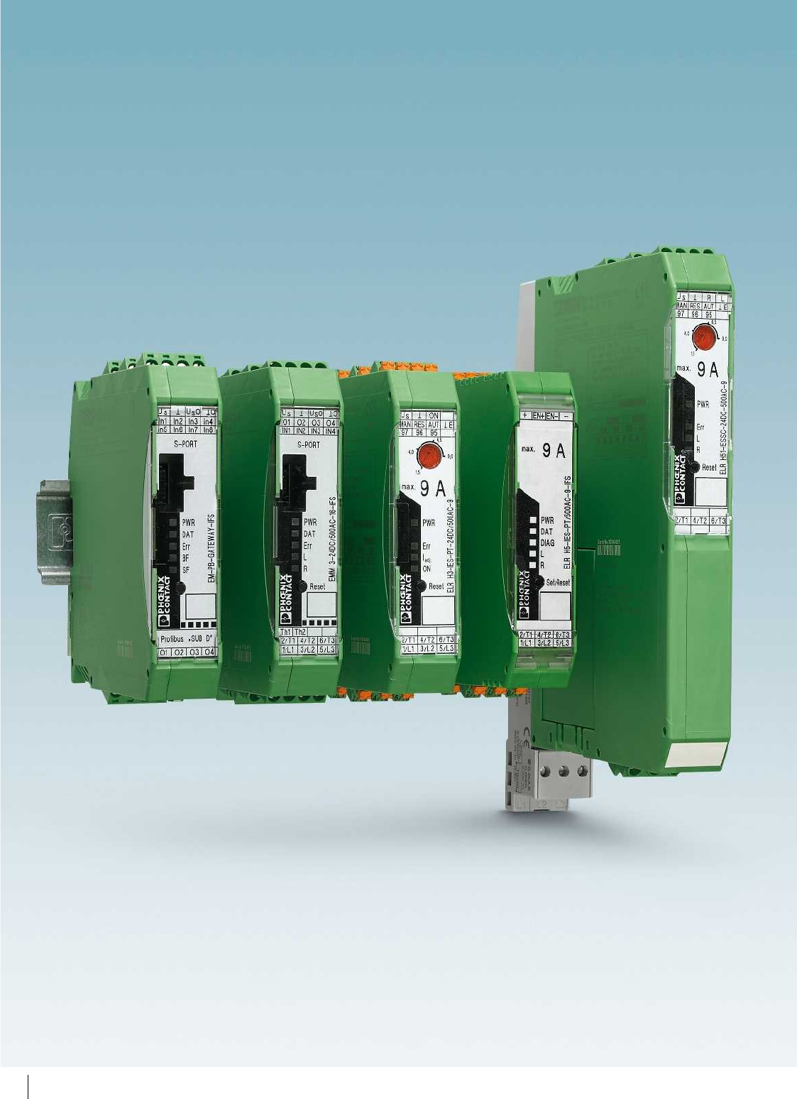
INTERFACE system
The INTERFACE system (IFS) consists of
devices which can be connected to each
other via the DIN rail connector (TBUS). A
GATEWAY with up to 32 IFS devices forms
the head of the INTERFACE system and
manages the station.
INTERFACE system properties:
– Use of the INTERFACE system via the
DIN rail connector for the purpose of
parameterization, diagnostics, and
exchange of data with one another
– Compatible with defined IFS accessories
– 24 V supply of the devices (e.g., EMM...IFS,
ELR...IFS, EM-GATEWAY-IFS) via the
DIN rail connector
For further information and full technical data, visit phoenixcontact.net/products
13PHOENIX CONTACT
Electronic switching devices and motor control
Motor management
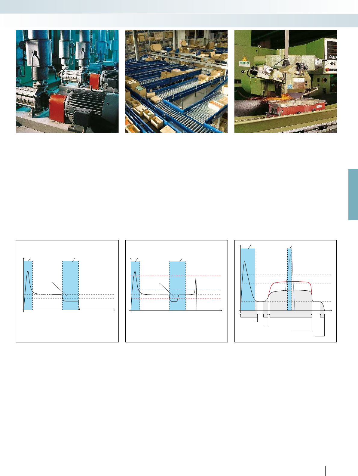
Protection against dry running, blocking,
and cavitation, warning thresholds to
indicate filter contamination.
Protection against blocking, warning
thresholds for bearing wear and other cases
that trigger overload.
Protection against blocking and broken
tools, warning thresholds for tool and
bearing wear.
In the case of motor-driven pumps, the
lower performance threshold provides
reliable protection against hazardous dry
running.
Forced shutdown of the drive can be
delayed by the “delay time”.
This prevents forced shutdown in the
event of air bubbles.
Machine tools are monitored and
protected in a similar way when drilling,
milling or grinding. If the feed value on a
milling machine is set too high, a tool may
break in the “worst-case” scenario. The
power threshold - parameterized
accordingly - can be used to resolve this
issue.
Additionally, a message threshold signals
tool wear in advance.
Performance
Real power (P)
Time (t)
Lower
performance threshold
Continuous dry running
with forced shutdown
Delay timeSwitch-on delay
Signaling threshold,
contamination of screen
or filter
Performance
Real power (P)
Time (t)
Lower
performance threshold
Upper
performance threshold
Temporary
dry running
Delay timeSwitch-on delay
Real power (P)
Time (t)
Performance
when idling
Signaling threshold
Tool wear
Performance threshold
Broken tool
Increased performance
Tool wear
Excess performance
due to possible
broken tool
Delay timeSwitch-on delay
Motor startup
Tool positioning
Milling process
Drive shutdown
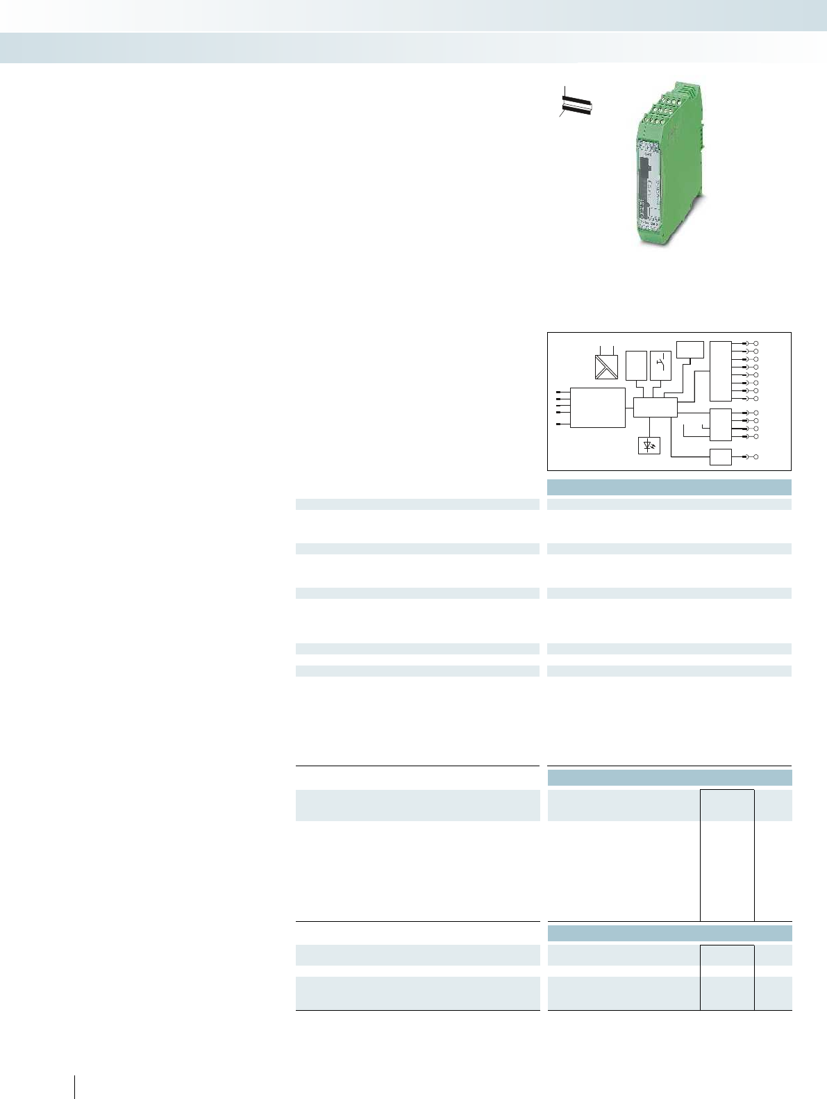
Thermistor
Logic
μP
U
S
U
SO
O
IN1
O1
IN2
O2
IN3
O3
IN4
O4
Digital
IN
Digital
OUT
T-BUS
V1
I11
I12
V2
I21
I22
V3
I31
I32
Th1
Th2
DAT
ERR
L
R
IFS-
Port
Reset
P
Thermistor
Logic
μP
P
1/L1
U
S
U
SO
O
IN1
O1
IN2
O2
IN3
O3
IN4
O4
24 VDC
24 VDC
Digital
IN
Digital
OUT
DAT
ERR
L
R
2/T1
T-BUS
3/L2
4/T2
5/L3
6/T3
Th1
Th2
IFS-
Port
Reset
Ex:
Ex:
Technical data Technical data
Input data
Rated control supply voltage U
S
24 V DC 230 V AC 24 V DC 230 V AC
Rated control supply voltage range with reference to U
S
0.8 ... 1.25 0.4 ... 1.1 0.8 ... 1.25 0.4 ... 1.1
Rated control supply current I
S
at U
S
25 mA 10 mA 25 mA 10 mA
Input data of digital inputs EMM 3- 24DC/500AC-IFS EMM 3-230AC/500AC-IFS EMM 3- 24DC/500AC-16-IFS EMM 3-230AC/500AC-16-IFS
Number of inputs 4 (IN1 - IN4) 4 (IN1 - IN4) 4 (IN1 - IN4) 4 (IN1 - IN4)
Rated actuating voltage U
C
24 V DC 230 V AC 24 V DC 230 V AC
Rated actuating current I
C
3.3 mA 3.5 mA 3.3 mA 3.5 mA
Power measurement
Voltage measuring input 42 V AC ... 575 V AC 42 V AC ... 575 V AC - -
Nominal current, voltage measuring input < 0.5 mA < 0.5 mA - -
Current measuring input
5 A (secondary external converter) 5 A (secondary external converter)
max. 16 A max. 16 A
Output power of the converter > 1.25 VA > 1.25 VA - -
Internal resistance EMM 0.02 0.02 --
Output data for confirmation contacts
O1 - O4 in the case of 1 signal 24 V DC
(semiconductor output) / 500 mA
230 V AC
(relay output/500 mA) / 500 mA
24 V DC
(semiconductor output) / 500 mA
230 V AC
(relay output/500 mA) / 500 mA
General data
Rated insulation voltage 500 V 500 V
Rated surge voltage 6 kV 6 kV 6 kV 6 kV
Ambient temperature (operation) -25 °C ... 70 °C -25 °C ... 70 °C
Standards/regulations EN 60947 / EN 60947-4-2 EN 60947 / EN 60947-4-2
DIN EN 50178 DIN EN 50178
Degree of protection in acc. with IEC 60529/EN 60529 IP20 IP20
Mounting position Vertical (horizontal DIN rail) Vertical (horizontal DIN rail)
Screw connection solid / stranded / AWG 0.14 - 2.5 mm² / 0.14 - 2.5 mm² / 26 - 12 0.14 - 2.5 mm² / 0.14 - 2.5 mm² / 26 - 12
Dimensions W / H / D 22.5 mm / 99 mm / 114.5 mm 22.5 mm / 99 mm / 114.5 mm
EMC note Class A product, see page 625 Class A product, see page 625
Ordering data Ordering data
Description Type Order No. Pcs. /
Pkt. Type Order No. Pcs. /
Pkt.
Electronic motor management
EMM 3- 24DC/500AC-IFS 2297497 1EMM 3- 24DC/500AC-16-IFS 2297523 1
EMM 3-230AC/500AC-IFS 2297507 1EMM 3-230AC/500AC-16-IFS 2297536 1
Accessories Accessories
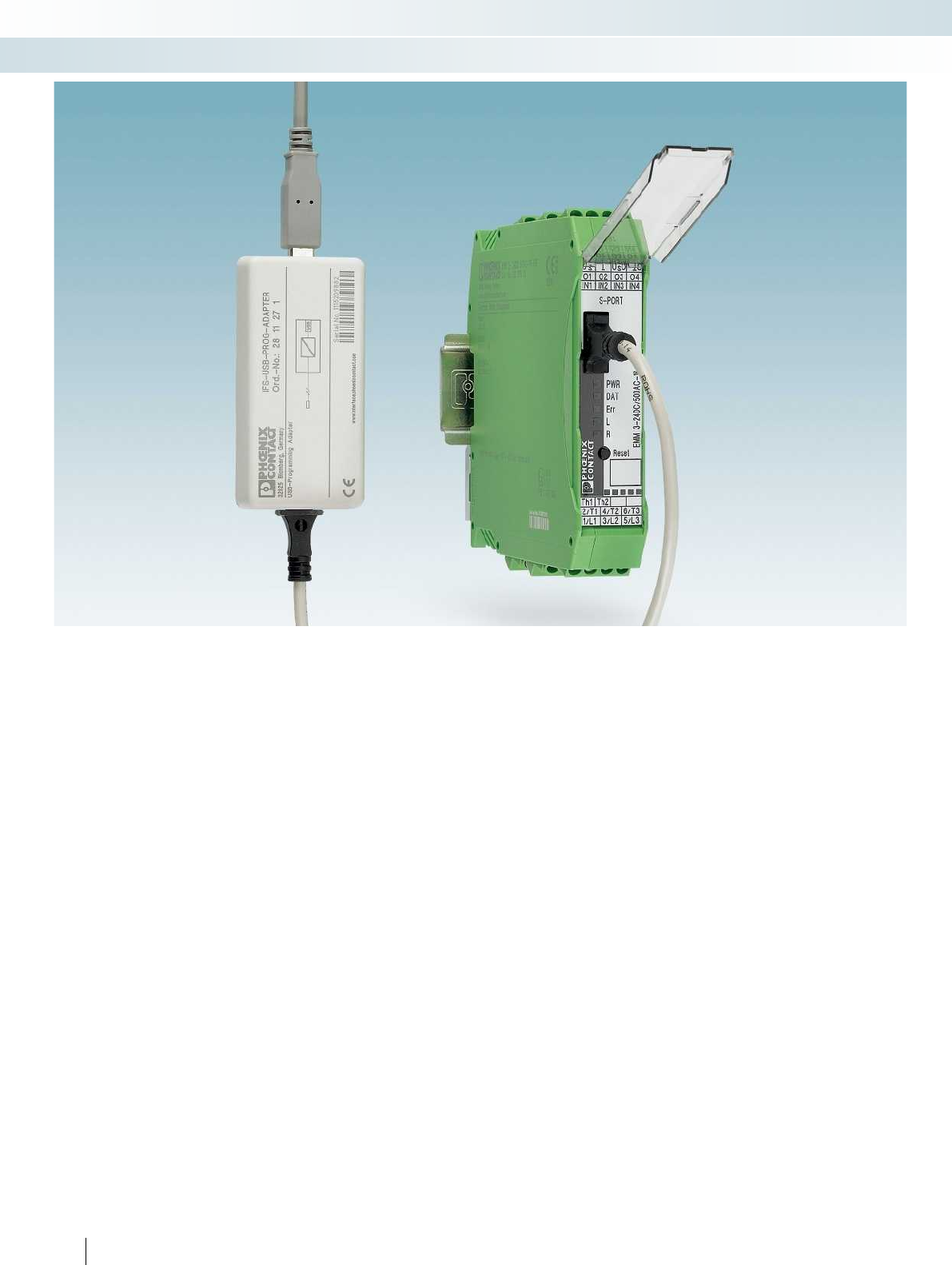
Programming adapter for configuring modules with
S-PORT interface
IFS-USB-PROG-ADAPTER 2811271 1IFS-USB-PROG-ADAPTER 2811271 1
DIN rail connector ME 22,5 TBUS 1,5/ 5-ST-3,81 GN 2707437 50 ME 22,5 TBUS 1,5/ 5-ST-3,81 GN 2707437 50
Voltage transducer for 690 V, for EMM 3-.../500AC-IFS,
comprising 3 modular terminal blocks and cover
UT 4-MTD-R/CVC 690/SET 2901667 1
Multifunctional memory module for the INTERFACE system
- Flat design IFS-CONFSTICK 2986122 1IFS-CONFSTICK 2986122 1
- Tall design IFS-CONFSTICK-L 2901103 1IFS-CONFSTICK-L 2901103 1
Mini COMBICON connector
- Socket contact MC 1,5/ 5-ST-3,81 1803604 50 MC 1,5/ 5-ST-3,81 1803604 50
- Pin contact IMC 1,5/ 5-ST-3,81 1857919 50 IMC 1,5/ 5-ST-3,81 1857919 50
14
PHOENIX CONTACT
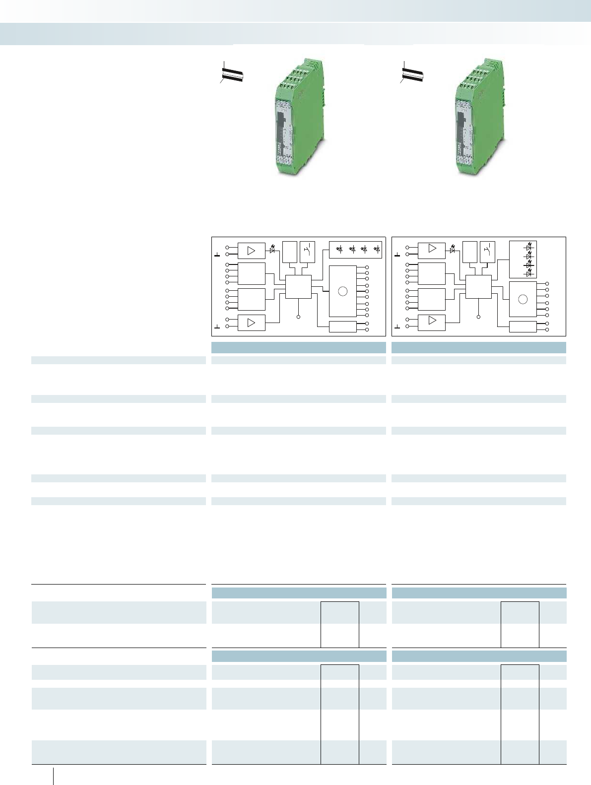
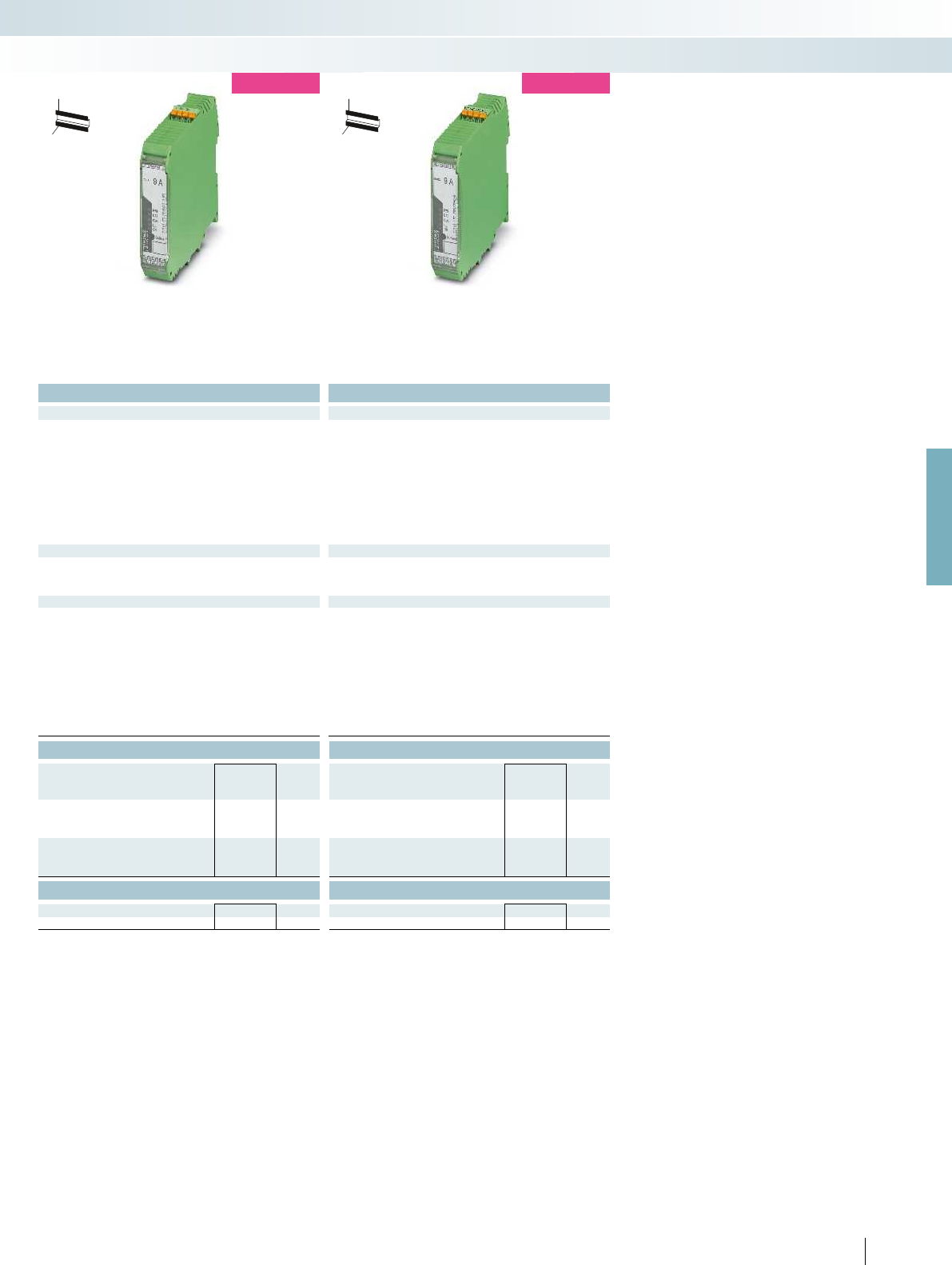
The EMM motor management module
(with/without current transformer) for all
performance classes monitors and protects
3-phase loads, such as electrical drives.
– Freely parameterizable signaling or
switching thresholds
– Digital outputs control external switching
elements
– Optional connection to INTERFACE
system and EM-GATEWAY-IFS via TBUS
H
W
D
H
W
D
Electronic motor management
Electronic switching devices and motor control
Motor management
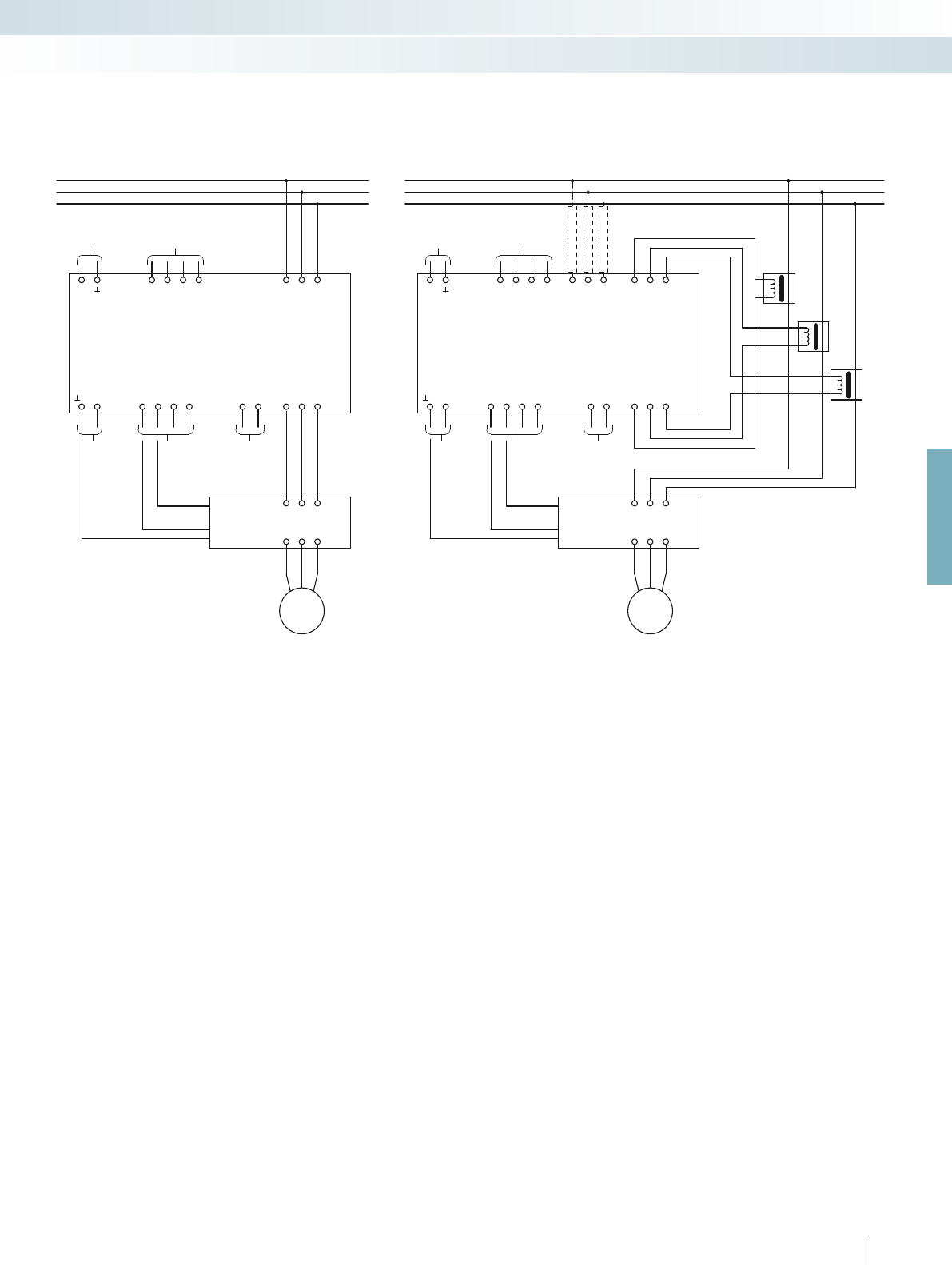
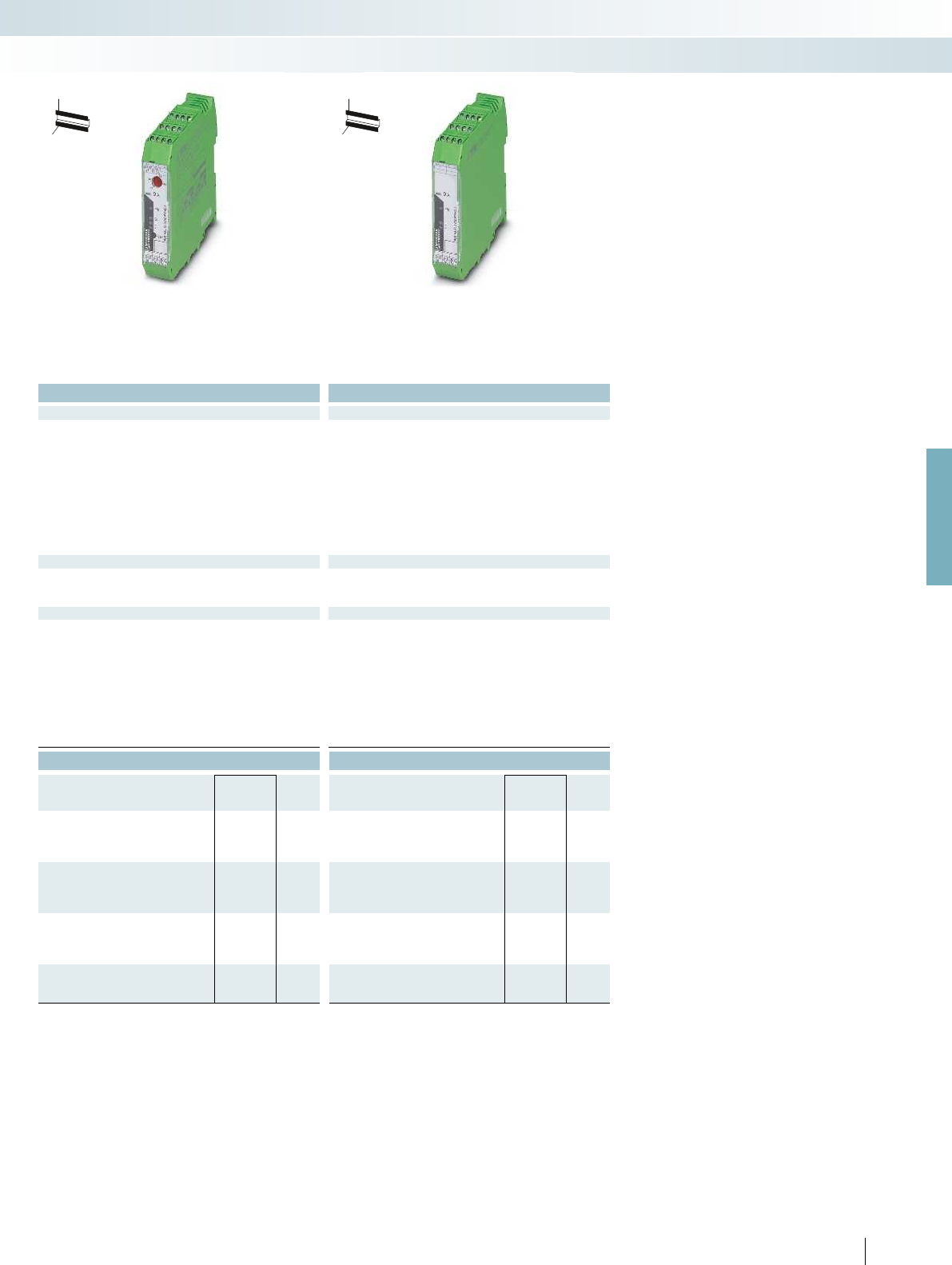
Allows the use of external current
transformers
With integrated current transformers
L1
L2
L3
1/L1 3/L2 5/L3
2/T1 4/T2 6/T3
GND
EMM 3-.../500AC-16-IFS
O
UO
S
O1 O2 O3 O4
Th1
Th2
2/T1
4/T2
6/T3
U
S
IN1 IN2 IN3 IN4
3/L2
5/L3
1/L1
M
1/L1 3/L2 5/L3
2/T1 4/T2 6/T3
GND
EMM 3-.../500AC-IFS
OO
UO
S
O1 O2 O3 O4
Th1
Th2
I12
I22
I32
U
S
IN1 IN2 IN3 IN4
I21
V2
I31
V3
I11
V1
P1
P2
S2/l
S1/k
P1
P2
S2/l
S1/k
P1
P2
S2/l
S1/k
M
UT4-MTD-R/CVC 690
UT4-MTD-R/CVC 690
UT4-MTD-R/CVC 690
For further information and full technical data, visit phoenixcontact.net/products
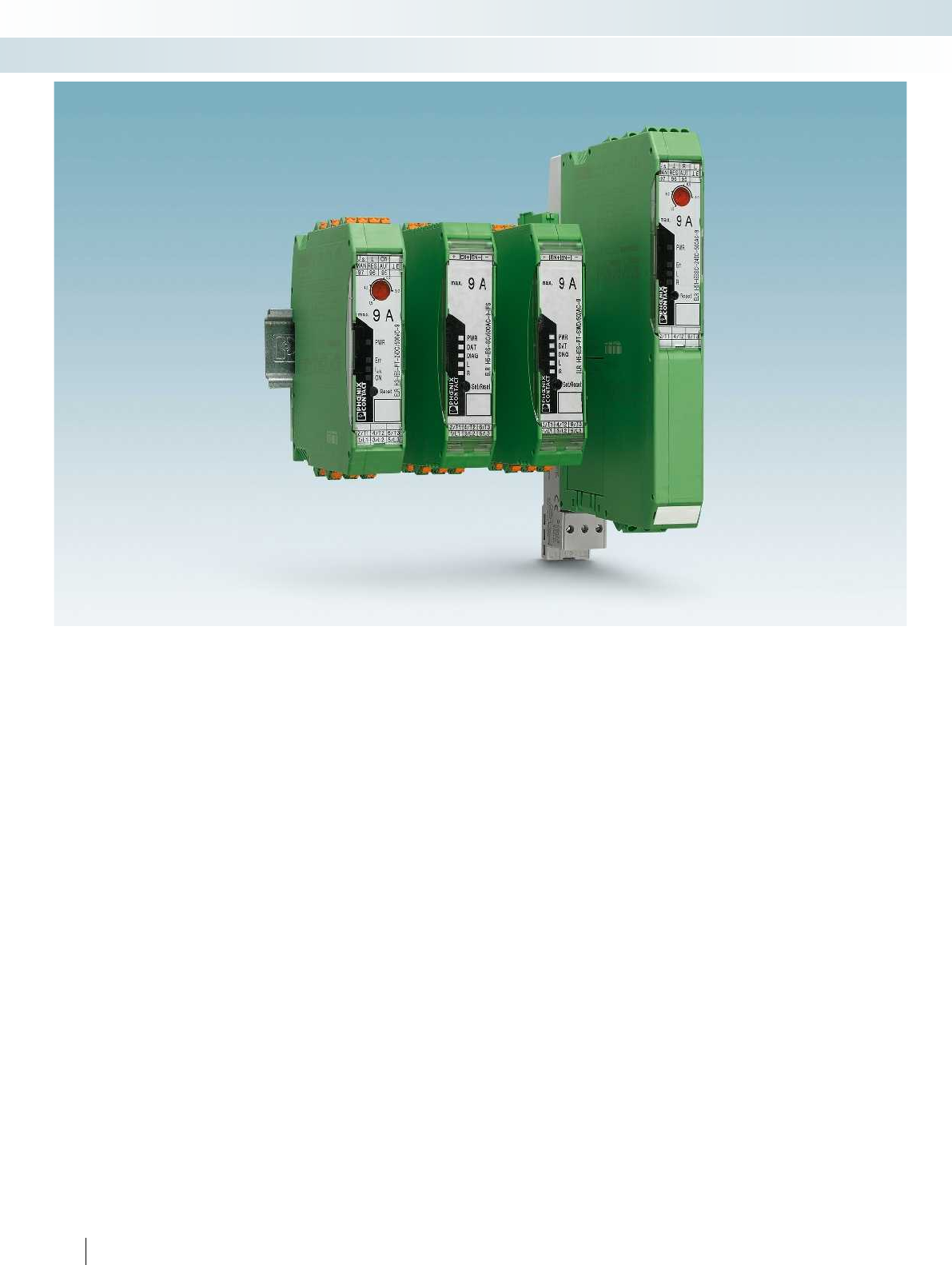
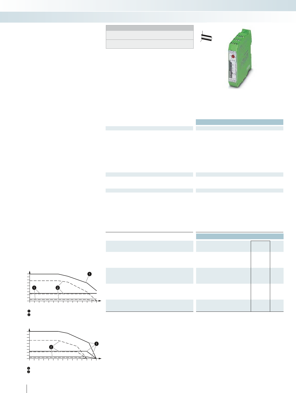
The electronic motor management
modules offer all the advantages of modern
real power monitoring. Every 6.6 ms, the
real power of a drive system or of any other
3-phase load is calculated from three
currents, voltages, and the phase angle.
Currents of up to 16 A can be directly
acquired and currents >16 A are supplied via
external converters. Digital outputs can be
used to control separate mechanical or
electronic switching elements that adopt
the actual switching of the load. In this
configuration, the EMM reliably protects
connected loads – irrespective of their
power consumption – against overload and
underload, and provides permanent status
monitoring.
Up to 8 freely parameterizable switching,
message thresholds and up to four freely
configurable inputs and outputs enable the
protection of electrical drives and the
system.
The EMM modules can record the
following data:
– Apparent real and reactive power
– Currents and voltages
– Phase angle
– Cycle and operating hours counter
– Power meter
Additional functions:
– Adjustable bimetal function class 5-30
– Thermistor monitor
– Recording measured values
– GATEWAY connection via TBUS
– Pre-configured motor exits such as
reversing starters, star-delta starters, etc.
The EMM modules can be used to record
complete curves that can be used for
system documentation.
Actuating and regulating drives, pumps,
tools, conveyer belts or similar are switched
and monitored for function, contamination
or wear in the following operating modes:
right rotation, left rotation, reverse, and
limit switch operation (with integrated
restart inhibit).
Current transformer
The external converters should be
selected with a secondary nominal current
of 5 A. The primary current is determined
by the current consumption of the load
(refer to connection diagram). For suitable
current transformers, see INTERFACE
catalog.
TBUS DIN rail connector
The TBUS (Order No. 2707437) can be
used to supply several EMMs with 24 V DC
or to couple up to 32 EMMs (for example)
to the PROFIBUS-GATEWAY-IFS.
Switching element
Depending on the particular requirements
of the application, either an electro-
mechanical contactor or reversing contactor
combination, or a solid-state contactor or a
solid-state reversing contactor is to be used
for the actual task of switching the load.
These switching elements are controlled via
the digital outputs of the EMM modules.
15
PHOENIX CONTACT
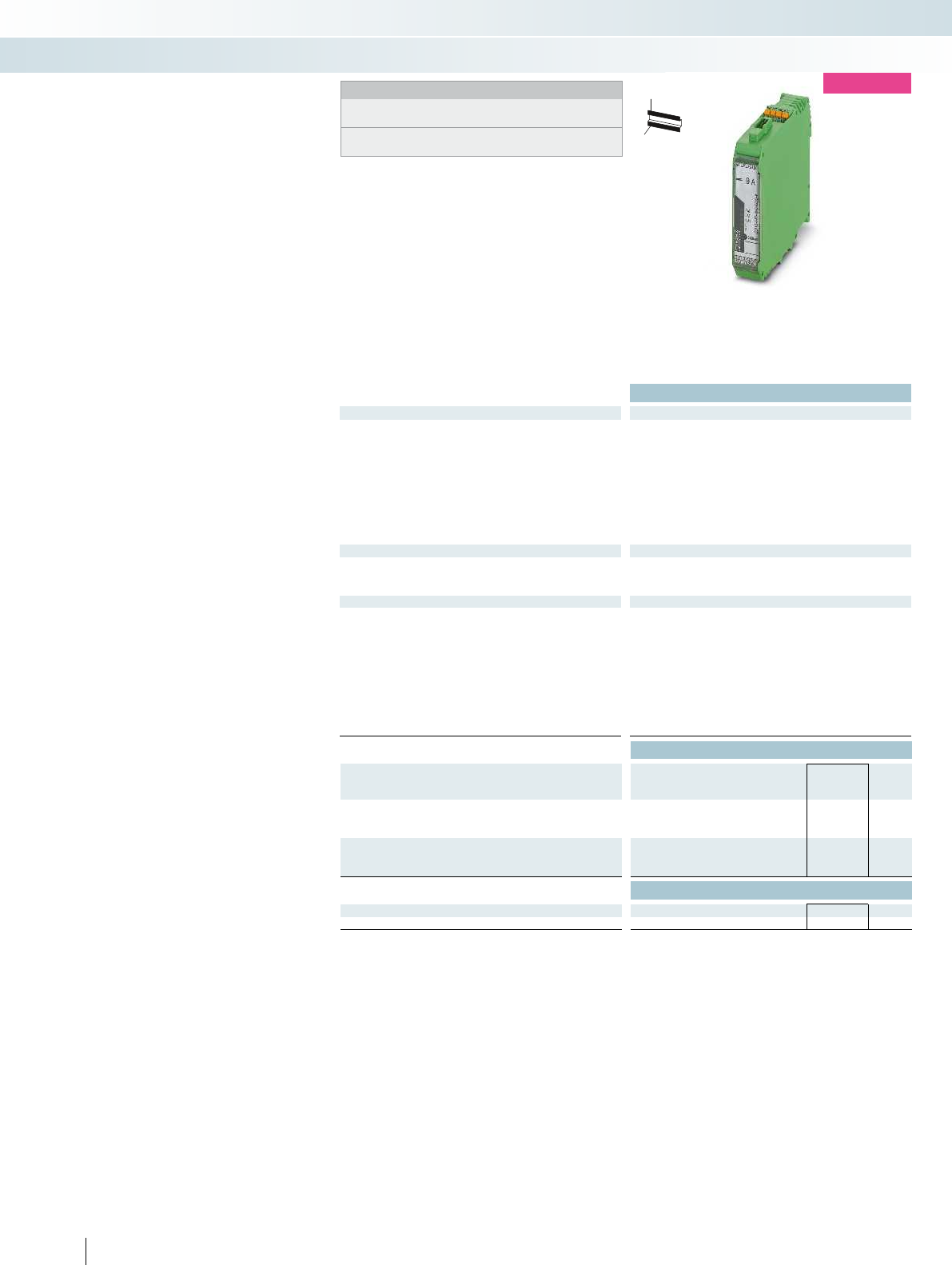
Module
supply
Digital
inputs
Digital
outputs
Supply
digital
outputs
Current measurement
Current measurement
Reverse running
Separate switching module
Forward running
Thermistor
input
Module
supply
Digital
inputs
Current
measurement
Voltage
measurement
Digital
outputs
Supply
digital
outputs
Current measurement
Thermistor
input
Reverse running
Separate switching module
Forward running
Electronic motor management
Electronic switching devices and motor control
Motor management
U
SO
U
S
GND
24V
DC
EPROM
µController
O4
O3
O2
O1
OUT
TBUS
IFS
IN
IN1
IN2
IN3
IN4
IN5
IN6
IN7
IN8
TO
IFS-
Port
Reset
Technical data
Input data
Rated control supply voltage U
S
24 V DC -20% ... +25%
Rated control supply current I
S
85 mA (plus load current of the outputs)
Input circuit Protection against polarity reversal
Digital inputs
Rated actuating voltage U
C
24 V DC ±20 %
Rated actuating current I
C
3 mA
Input circuit Protection against polarity reversal
Digital outputs
Maximum switching voltage 23 V DC (U
B
- U
resid.
of the output)
Max. switching current 500 mA
Residual voltage 1 V
Output protection Parallel protection against polarity reversal, pay attention to the fuse
IFS interface
Connection method DIN rail connector
General data
Ambient temperature (operation) -35 °C ... 50 °C
Nominal operating mode 100% operating factor
Standards/regulations EN 50178
Degree of protection IP20
Mounting position / mounting any / can be aligned without spacing
Connection data solid / stranded / AWG 0.2 ... 2 mm² / 0.2 ... 2.5 mm² / 12 - 24
Dimensions W / H / D 22.5 mm / 99 mm / 114.5 mm
EMC note Class A product, see page 625
Ordering data
Description Type Order No. Pcs. /
Pkt.
IFS gateway for
PROFIBUS DP EM-PB-GATEWAY-IFS 2297620 1
RS-232 EM-RS232-GATEWAY-IFS 2901526 1
RS-485 EM-RS485-GATEWAY-IFS 2901527 1
Modbus/TCP EM-MODBUS-GATEWAY-IFS 2901528 1
DeviceNet™ EM-DNET-GATEWAY-IFS 2901529 1
CANopen® EM-CAN-GATEWAY-IFS 2901504 1
PROFINET EM-PNET-GATEWAY-IFS 2904472 1
Ethernet/IP™ EM-ETH-GATEWAY-IFS 2901988 1
Accessories
Programming adapter for configuring modules with
S-PORT interface
IFS-USB-PROG-ADAPTER 2811271 1
DIN rail connector ME 22,5 TBUS 1,5/ 5-ST-3,81 GN 2707437 50
Mini COMBICON connector
- Socket contact MC 1,5/ 5-ST-3,81 1803604 50
- Pin contact IMC 1,5/ 5-ST-3,81 1857919 50
16
PHOENIX CONTACT
H
W
D
EM...GATEWAY-IFS for connecting
INTERFACE system devices (IFS) to
popular bus systems: PROFIBUS DP,
Modbus, Modbus/TCP, DeviceNet™,
CANopen®, and PROFINET,
EtherNet/IP™.
– Communication via TBUS with up to
32 INTERFACE system devices such as
EMM...IFS and ELR...IFS modules
– Equipped with freely parameterizable
digital inputs and outputs
– Digital switching outputs for direct
control
IFS gateways for
INTERFACE system devices
Electronic switching devices and motor control
Motor management
Status
Fieldbus
connection

For further information and full technical data, visit phoenixcontact.net/products
Ordering data
Description Type Order No. Pcs. /
Pkt.
Configuration package for the EMM...IFS, comprising
CONTACTRON-DTM-IFS, USB programming adapter, and user
manual on CD
MM-CONF-SET 2297992 1
Accessories
Programming adapter for configuring modules with
S-PORT interface
IFS-USB-PROG-ADAPTER 2811271 1
17PHOENIX CONTACT
– CONTACTRON-DTM-IFS, programming
adapter, and user manual on CD available
as configuration package
– USB programming adapter also available
separately as an option
– CONTACTRON-DTM-IFS also available
free of charge as a separate download
from phoenixcontact.com
Device Type Manager (DTM) for
motor management modules
EMM...IFS
Electronic switching devices and motor control
Motor management
18
PHOENIX CONTACT
Electronic switching devices and motor control
Hybrid motor starters
Hybrid motor starters for controlling
3-phase asynchronous motors combine up
to four functions in one device as required.
These include forward running, reverse
running with optional reversing function
including load wiring. The locking circuit for
the reversing function is also integrated and
certified as a single electronic reversing
starter according to UL 508a and the new
UL 60947-1. Furthermore, the devices
protect the motor by means of an
integrated motor protection relay with
automatic and remote reset function. The
implemented safety function according to
Performance Level e (PL e) of EN ISO
13849-1 provides the emergency stop
requirement. A PDT confirmation contact
provides information regarding the
availability of the device, and the motor
state. This means that in the event of motor
control without an error message the
integrated current measurement and
symmetry scanning ensures that the motor
is turning. Even with these numerous
functions, the hybrid motor starter is just
22.5 mm wide.
Short-circuit-proof hybrid motor starters
with integrated protective devices, for
mounting on 35 mm DIN rails and 60 mm
busbar systems and connection to popular
bus systems via SmartWire-DT™ complete
the product portfolio.

For further information and full technical data, visit phoenixcontact.net/products
19PHOENIX CONTACT
Electronic switching devices and motor control
Hybrid motor starters
Hybrid motor starters with up to four
functions in one device: forward running,
reverse running, motor protection, and
emergency stop.
Short-circuit-proof hybrid motor starters
with integrated fuses for mounting on
35 mm DIN rails and 60 mm busbar systems.
Connection of hybrid motor starters in a
bus system via SmartWire-DT™. Gateways
are provided for the main bus systems:
PROFIBUS, Modbus/TCP, EtherNet/IP™,
and CANopen
®
.
Connection of the hybrid motor starter
to a bus system via the IFS INTERFACE
system.
Gateways are provided for the main bus
systems: PROFIBUS DP, Modbus/TCP,
EtherNet/IP™, CANopen
®
, DeviceNet™,
PROFINET, etc.
20
PHOENIX CONTACT
H
W
D
new
Network-capable hybrid motor
starters with reversing function
Notes:
Type of housing:
Polyamide PA non-reinforced, color: green.
Marking systems and mounting material
See Catalog 5
Technical data
Input data
Rated control supply voltage U
S
24 V DC
Rated control supply voltage range with reference to U
S
0.8 ... 1.25
Rated control supply current I
S
at U
S
40 mA
Rated actuating voltage UC EN+ -
Rated actuating voltage range with reference to U
C
-
Rated actuating current I
C
at U
C
-
Input circuit Protection against polarity reversal, surge protection Protection against polarity reversal, surge protection Protec
Operating voltage / status / error indicator Green LED / Yellow LED / Red LED Green LED / Yellow LED / Red LED Green LED / Yellow
Output data load side
Output voltage range 42 V AC ... 550 V AC
Surge current 100 A (t = 10 ms)
Output protection Surge protection
General data
Rated insulation voltage 550 V
Rated surge voltage 6 kV (safe isolation)
Ambient temperature (operation) -5 °C ... 55 °C
Electrical service life 3 x 10
7
cycles
Standards/regulations IEC 60947-1 / EN 60947-4-2 IEC 60947-1 / EN 60947-4-2 / IEC 61508 / ISO 13849 IEC 60947-1 / EN 60947-4-2
IEC 60947-1
Mounting position Vertical (horizontal DIN rail) Vertical (horizontal DIN rail) Vertical (horizontal DIN rail)
Mounting can be aligned with spacing: see derating can be aligned with spacing: see derating can be aligned with spacing: see dera
Screw connection solid / stranded / AWG 0.14 - 2.5 mm² / 0.14 - 2.5 mm² / 26 - 14 0.14 - 2.5 mm² / 0.14 - 2.5 mm² / 26 - 14 0.14 -
Dimensions W / H / D 22.5 mm / 99 mm / 114.5 mm 22.5 mm / 99 mm / 114.5 mm 22.5 mm / 99 mm / 114.5 mm
Ordering data
Description Type Order No. Pcs. /
Pkt.
Load current 0.075 - 0.6 A
Screw connection
Push-in connection ELR H5-I-PT-SWD/500AC-06 2905073 1
Load current 0.18 A ... 3 A
Screw connection
Push-in connection ELR H5-I-PT-SWD/500AC-3 2905074 1
Accessories
Device plug, 8-pos. SWD4-8SF2-5 PXC 2903107 10
DIN rail connector
Electronic switching devices and motor control
Hybrid motor starters
Motor protection and
SmartWire-DT™ support
These 3-phase hybrid motor starters
provide up to four functions: right
contactor, left contactor, motor protection
relay, and emergency stop up to category 3.
They offer the following advantages:
– Connection to INTERFACE system (IFS)
via TBUS
– Connection to SmartWire-DT™ (SWD)
– 22.5 mm wide
– Reduction in wiring
– Bi-metal function, adjustable up to 3 A
– Long service life
– Space-saving
– 3-phase loop bridging
Safety level according to:
– IEC 61508-1: SIL3
– ISO 13849: PL e

For further information and full technical data, visit phoenixcontact.net/products
21PHOENIX CONTACT
H
W
D
new
H
W
D
new
Technical data Technical data
24 V DC 24 V DC
0.8 ... 1.25 0.8 ... 1.25
40 mA 40 mA
24 V DC -
0.8 ... 1.25 -
5 mA -
Input circuit Protection against polarity reversal, surge protection Protection against polarity reversal, surge protection Protection against polarity reversal, surge protection
Operating voltage / status / error indicator Green LED / Yellow LED / Red LED Green LED / Yellow LED / Red LED Green LED / Yellow LED / Red LED
42 V AC ... 550 V AC 42 V AC ... 550 V AC
100 A (t = 10 ms) 100 A (t = 10 ms)
Surge protection Surge protection
550 V 550 V
6 kV (safe isolation) 6 kV (safe isolation)
-5 °C ... 60 °C -5 °C ... 60 °C
3 x 10
7
cycles 3 x 10
7
cycles
Standards/regulations IEC 60947-1 / EN 60947-4-2 IEC 60947-1 / EN 60947-4-2 / IEC 61508 / ISO 13849 IEC 60947-1 / EN 60947-4-2
IEC 60947-1 IEC 60947-1
Mounting position Vertical (horizontal DIN rail) Vertical (horizontal DIN rail) Vertical (horizontal DIN rail)
Mounting can be aligned with spacing: see derating can be aligned with spacing: see derating can be aligned with spacing: see derating
Screw connection solid / stranded / AWG 0.14 - 2.5 mm² / 0.14 - 2.5 mm² / 26 - 14 0.14 - 2.5 mm² / 0.14 - 2.5 mm² / 26 - 14 0.14 - 2.5 mm² / 0.14 - 2.5 mm² / 26 - 14
Dimensions W / H / D 22.5 mm / 99 mm / 114.5 mm 22.5 mm / 99 mm / 114.5 mm 22.5 mm / 99 mm / 114.5 mm
Ordering data Ordering data
Type Order No. Pcs. /
Pkt. Type Order No. Pcs. /
Pkt.
ELR H5-IES-SC/500AC-06-IFS 2905151 1ELR H5-I-SC/500AC-06-IFS 2905157 1
ELR H5-IES-PT/500AC-06-IFS 2905138 1ELR H5-I-PT/500AC-06-IFS 2905144 1
ELR H5-IES-SC/500AC-3-IFS 2905152 1ELR H5-I-SC/500AC-3-IFS 2905159 1
ELR H5-IES-PT/500AC-3-IFS 2905139 1ELR H5-I-PT/500AC-3-IFS 2905146 1
Accessories Accessories
ME 22,5 TBUS 1,5/ 5-ST-3,81 GN 2707437 50 ME 22,5 TBUS 1,5/ 5-ST-3,81 GN 2707437 50
Electronic switching devices and motor control
Hybrid motor starters
Motor protection, emergency stop, and
INTERFACE system support
Motor protection and
INTERFACE system support

0,18
1
2
3
4
5
6
7
8
9
0
10
203040
50
60 70
0,18
1
2
3
4
5
6
7
8
9
0102030405060 70
Ex:
22
PHOENIX CONTACT
H
W
D
Hybrid motor starters with
reversing function
Notes:
Type of housing:
Polyamide PA non-reinforced, color: green.
Marking systems and mounting material
See Catalog 5
Technical data
Input data
Rated control supply voltage U
S
24 V DC 230 V AC (50/60 Hz) 24 V DC 230 V AC (50/60 Hz) 24 V DC 230 V AC (50/60 Hz)
Rated control supply voltage range with reference to U
S
0.8 ... 1.25 0.4 ... 1.1 0.8 ... 1.25 0.4 ... 1.1 0.8 ... 1.25 0.4 ... 1.1
Rated control supply current I
S
at U
S
40 mA 4 mA 40 mA 4 mA 40 mA 4 mA
Rated actuating voltage U
C
R/L 24 V DC 230 V AC 24 V DC 230 V AC 24 V DC 230 V AC
Rated actuating voltage range with reference to U
C
0.8 ... 1.25 0.4 ... 1.1 0.8 ... 1.25 0.4 ... 1.1 0.8 ... 1.25 0.4 ... 1.1
Rated actuating current I
C
at U
C
5 mA 7 mA 5 mA 7 mA 5 mA 7 mA
Input circuit Protection against polarity
reversal, surge protection
Surge protection Protection against polarity
Operating voltage / status / error indicator Green LED / Yellow LED / Red LED Green LED / Yellow LED / Red LED Green LED / Yellow
Output data load side
Output voltage range 42 V AC ... 550 V AC 42 V AC ... 550 V AC 42 V AC ... 550 V AC 42 V AC ... 550 V AC 42 V AC ... 550 V AC 42 V AC
Surge current 100 A (t = 10 ms) 100 A (t = 10 ms) 100 A (t = 10 ms) 100 A (t = 10 ms) 100 A (t = 10 ms) 100 A (t = 10 ms)
Output protection Surge protection
General data
Rated insulation voltage 500 V
Rated surge voltage 6 kV (safe isolation) 6 kV (safe isolation) 6 kV (safe isolation) 6 kV (safe isolation) 6 kV (safe isolation) 6 k
Ambient temperature (operation) -25 °C ... 70 °C
Electrical service life 3 x 10
7
cycles
Standards/regulations EN 60947 / IEC 61508 / ISO 13849 EN 60947 EN 60947
DIN EN 50178
Mounting position Vertical (horizontal DIN rail) Vertical (horizontal DIN rail) Vertical (horizontal DIN rail)
Mounting can be aligned with spacing: see derating can be aligned with spacing: see derating can be aligned with spacing: see dera
Screw connection solid / stranded / AWG 0.14 - 2.5 mm² / 0.14 - 2.5 mm² / 26 - 14 0.14 - 2.5 mm² / 0.14 - 2.5 mm² / 26 - 14 0.14 - 2
Dimensions W / H / D 22.5 mm / 99 mm / 114.5 mm 22.5 mm / 99 mm / 114.5 mm 22.5 mm / 99 mm / 114.5 mm
Ordering data
Description Type Order No. Pcs. /
Pkt.
Load current 0.075 - 0.6 A
Screw connection ELR H5-IES-SC- 24DC/500AC-0,6 2900582 1
Push-in connection ELR H5-IES-PT- 24DC/500AC-0,6 2903902 1
Screw connection ELR H5-IES-SC-230AC/500AC-0,6 2900692 1
Load current 0.18 A ... 2.4A
Screw connection ELR H5-IES-SC- 24DC/500AC-2 2900414 1
Push-in connection ELR H5-IES-PT- 24DC/500AC-2 2903904 1
Screw connection ELR H5-IES-SC-230AC/500AC-2 2900420 1
Load current 1.5 - 9 A
Screw connection ELR H5-IES-SC- 24DC/500AC-9 2900421 1
Push-in connection ELR H5-IES-PT- 24DC/500AC-9 2903906 1
Screw connection ELR H5-IES-SC-230AC/500AC-9 2900422 1
Load current 0 - 9 A
Screw connection
Screw connection
Electronic switching devices and motor control
Hybrid motor starters
Motor protection
and emergency stop
These 3-phase hybrid motor starters
provide up to four functions: right
contactor, left contactor, motor protection
relay, and emergency stop up to category 3.
They offer the following advantages:
– 22.5 mm wide
– Reduction in wiring
– Bi-metal function, adjustable up to 9 A
– Long service life
– Space-saving
– 3-phase loop bridging
Safety level according to:
– IEC 61508-1: SIL3
– ISO 13849: PL e
Ambient temperature [°C]
Load current[A]
= aligned with 20 mm spacing
= aligned without spacing
Derating curve for ELR H5...230AC...
Ambient temperature [°C]
Load current[A]
= aligned with > 20 mm spacing
= aligned without spacing
Derating curve for ELR H5...24DC...
For further information and full technical data, visit phoenixcontact.net/products
23
PHOENIX CONTACT
H
W
D
H
W
D
Technical data Technical data
24 V DC 230 V AC (50/60 Hz) 24 V DC 230 V AC (50/60 Hz) 24 V DC 230 V AC (50/60 Hz)
0.8 ... 1.25 0.4 ... 1.1 0.8 ... 1.25 0.4 ... 1.1 0.8 ... 1.25 0.4 ... 1.1
40 mA 4 mA 40 mA 4 mA 40 mA 4 mA
R/L 24 V DC 230 V AC 24 V DC 230 V AC 24 V DC 230 V AC
0.8 ... 1.25 0.4 ... 1.1 0.8 ... 1.25 0.4 ... 1.1 0.8 ... 1.25 0.4 ... 1.1
5 mA 7 mA 5 mA 7 mA 5 mA 7 mA
Surge protection Protection against polarity
reversal, surge protection
Surge protection Protection against polarity
reversal, surge protection
Surge protection
Operating voltage / status / error indicator Green LED / Yellow LED / Red LED Green LED / Yellow LED / Red LED Green LED / Yellow LED / Red LED
Output voltage range 42 V AC ... 550 V AC 42 V AC ... 550 V AC 42 V AC ... 550 V AC 42 V AC ... 550 V AC 42 V AC ... 550 V AC 42 V AC ... 550 V AC
Surge current 100 A (t = 10 ms) 100 A (t = 10 ms) 100 A (t = 10 ms) 100 A (t = 10 ms) 100 A (t = 10 ms) 100 A (t = 10 ms)
Surge protection Surge protection
500 V 500 V
Rated surge voltage 6 kV (safe isolation) 6 kV (safe isolation) 6 kV (safe isolation) 6 kV (safe isolation) 6 kV (safe isolation) 6 kV (safe isolation)
-25 °C ... 70 °C -25 °C ... 70 °C
3 x 10
7
cycles 3 x 10
7
cycles
Standards/regulations EN 60947 / IEC 61508 / ISO 13849 EN 60947 EN 60947
DIN EN 50178 DIN EN 50178
Mounting position Vertical (horizontal DIN rail) Vertical (horizontal DIN rail) Vertical (horizontal DIN rail)
Mounting can be aligned with spacing: see derating can be aligned with spacing: see derating can be aligned with spacing: see derating
Screw connection solid / stranded / AWG 0.14 - 2.5 mm² / 0.14 - 2.5 mm² / 26 - 14 0.14 - 2.5 mm² / 0.14 - 2.5 mm² / 26 - 14 0.14 - 2.5 mm² / 0.14 - 2.5 mm² / 26 - 14
Dimensions W / H / D 22.5 mm / 99 mm / 114.5 mm 22.5 mm / 99 mm / 114.5 mm 22.5 mm / 99 mm / 114.5 mm
Ordering data Ordering data
Type Order No. Pcs. /
Pkt. Type Order No. Pcs. /
Pkt.
ELR H5-I-SC- 24DC/500AC-0,6 2900573 1
ELR H5-I-PT- 24DC/500AC-0,6 2903908 1
ELR H5-I-SC-230AC/500AC-0,6 2900691 1
ELR H5-I-SC- 24DC/500AC-2 2900574 1
ELR H5-I-PT- 24DC/500AC-2 2903910 1
ELR H5-I-SC-230AC/500AC-2 2900575 1
ELR H5-I-SC- 24DC/500AC-9 2900576 1
ELR H5-I-PT- 24DC/500AC-9 2903912 1
ELR H5-I-SC-230AC/500AC-9 2900578 1
ELR H5-SC- 24DC/500AC-9 2900538 1
1ELR H5-SC-230AC/500AC-9 2900539 1
Electronic switching devices and motor control
Hybrid motor starters
Motor protection Reversing function only

24
PHOENIX CONTACT
H
W
D
new
Network-capable hybrid motor
starters with direct start function
Notes:
Type of housing:
Polyamide PA non-reinforced, color: green.
Marking systems and mounting material
See Catalog 5
Technical data
Input data
Rated control supply voltage U
S
24 V DC (according to IEC 60947-1) 24 V DC 24 V DC
Rated control supply voltage range with reference to U
S
0.8 ... 1.25
Rated control supply current I
S
at U
S
40 mA
Rated actuating voltage UC EN+ -
Rated actuating voltage range with reference to U
C
-
Rated actuating current I
C
at U
C
-
Input circuit Protection against polarity reversal, surge protection Protection against polarity reversal, surge protection Protec
Operating voltage / status / error indicator Green LED / Yellow LED / Red LED Green LED / Yellow LED / Red LED Green LED / Yellow
Output data load side
Output voltage range 42 V AC ... 550 V AC
Surge current 100 A (t = 10 ms)
Output protection Surge protection
General data
Rated insulation voltage 550 V
Rated surge voltage 6 kV (safe isolation)
Ambient temperature (operation) -5 °C ... 55 °C
Electrical service life 3 x 10
7
cycles
Standards/regulations IEC 60947-1 / EN 60947-4-2 IEC 60947-1 / EN 60947-4-2 / IEC 61508 / ISO 13849 IEC 60947-1 / EN 60947-4-2
IEC 60947-1
Mounting position Vertical (horizontal DIN rail) Vertical (horizontal DIN rail) Vertical (horizontal DIN rail)
Mounting can be aligned with spacing: see derating can be aligned with spacing: see derating can be aligned with spacing: see dera
Screw connection solid / stranded / AWG 0.14 - 2.5 mm² / 0.14 - 2.5 mm² / 26 - 14 0.14 - 2.5 mm² / 0.14 - 2.5 mm² / 26 - 14 0.14 - 2
Dimensions W / H / D 22.5 mm / 99 mm / 114.5 mm 22.5 mm / 99 mm / 114.5 mm 22.5 mm / 99 mm / 114.5 mm
Ordering data
Description Type Order No. Pcs. /
Pkt.
Load current 0.075 - 0.6 A
Screw connection
Push-in connection ELR H3-I-PT-SWD/500AC-06 2905076 1
Load current 0.18 A ... 3 A
Screw connection
Push-in connection ELR H3-I-PT-SWD/500AC-3 2905078 1
Accessories
Device plug, 8-pos. SWD4-8SF2-5 PXC 2903107 10
DIN rail connector
Electronic switching devices and motor control
Hybrid motor starters
Motor protection and
SmartWire-DT™ support
These 3-phase hybrid motor starters
provide up to three functions: right
contactor, motor protection relay, and
emergency stop up to category 3.
They offer the following advantages:
– Connection to INTERFACE system (IFS)
via TBUS
– Connection to SmartWire-DT™ (SWD)
– 22.5 mm wide
– Reduction in wiring
– Bi-metal function, adjustable up to 3 A
– Long service life
– Space-saving
– 3-phase loop bridging
Safety level according to:
– IEC 61508-1: SIL3
– ISO 13849: PL e
For further information and full technical data, visit phoenixcontact.net/products
25PHOENIX CONTACT
H
W
D
new
H
W
D
new
Technical data Technical data
24 V DC (according to IEC 60947-1) 24 V DC 24 V DC
0.8 ... 1.25 0.8 ... 1.25
40 mA 40 mA
24 V DC -
0.8 ... 1.25 -
5 mA -
Input circuit Protection against polarity reversal, surge protection Protection against polarity reversal, surge protection Protection against polarity reversal, surge protection
Operating voltage / status / error indicator Green LED / Yellow LED / Red LED Green LED / Yellow LED / Red LED Green LED / Yellow LED / Red LED
42 V AC ... 550 V AC 42 V AC ... 550 V AC
100 A (t = 10 ms) 100 A (t = 10 ms)
Surge protection Surge protection
550 V 550 V
6 kV (safe isolation) 6 kV (safe isolation)
-5 °C ... 60 °C -5 °C ... 60 °C
3 x 10
7
cycles 3 x 10
7
cycles
Standards/regulations IEC 60947-1 / EN 60947-4-2 IEC 60947-1 / EN 60947-4-2 / IEC 61508 / ISO 13849 IEC 60947-1 / EN 60947-4-2
IEC 60947-1 IEC 60947-1
Mounting position Vertical (horizontal DIN rail) Vertical (horizontal DIN rail) Vertical (horizontal DIN rail)
Mounting can be aligned with spacing: see derating can be aligned with spacing: see derating can be aligned with spacing: see derating
Screw connection solid / stranded / AWG 0.14 - 2.5 mm² / 0.14 - 2.5 mm² / 26 - 14 0.14 - 2.5 mm² / 0.14 - 2.5 mm² / 26 - 14 0.14 - 2.5 mm² / 0.14 - 2.5 mm² / 26 - 14
Dimensions W / H / D 22.5 mm / 99 mm / 114.5 mm 22.5 mm / 99 mm / 114.5 mm 22.5 mm / 99 mm / 114.5 mm
Ordering data Ordering data
Type Order No. Pcs. /
Pkt. Type Order No. Pcs. /
Pkt.
ELR H3-IES-SC/500AC-06-IFS 2905154 1ELR H3-I-SC/500AC-06-IFS 2905162 1
ELR H3-IES-PT/500AC-06-IFS 2905141 1ELR H3-I-PT/500AC-06-IFS 2905148 1
ELR H3-IES-SC/500AC-3-IFS 2905155 1ELR H3-I-SC/500AC-3-IFS 2905163 1
ELR H3-IES-PT/500AC-3-IFS 2905142 1ELR H3-I-PT/500AC-3-IFS 2905149 1
Accessories Accessories
ME 22,5 TBUS 1,5/ 5-ST-3,81 GN 2707437 50 ME 22,5 TBUS 1,5/ 5-ST-3,81 GN 2707437 50
Electronic switching devices and motor control
Hybrid motor starters
Motor protection, emergency stop, and
INTERFACE system support
Motor protection and
INTERFACE system support
0,18
1
2
3
4
5
6
7
8
9
0
10
203040
50
60 70
0,18
1
2
3
4
5
6
7
8
9
0102030405060 70
Ex:
26
PHOENIX CONTACT
H
W
D
Hybrid motor starters with
direct start function
Notes:
Type of housing:
Polyamide PA non-reinforced, color: green.
Marking systems and mounting material
See Catalog 5
Technical data
Input data
Rated control supply voltage U
S
24 V DC 230 V AC (50/60 Hz) 24 V DC 230 V AC (50/60 Hz) 24 V DC 230 V AC (50/60 Hz)
Rated control supply voltage range with reference to U
S
0.8 ... 1.25 0.4 ... 1.1 0.8 ... 1.25 0.4 ... 1.1 0.8 ... 1.25 0.4 ... 1.1
Rated control supply current I
S
at U
S
40 mA 4 mA 40 mA 4 mA 40 mA 4 mA
Rated actuation voltage U
C
ON 24 V DC 230 V AC 24 V DC 230 V AC 24 V DC 230 V AC
Rated actuating voltage range with reference to U
C
0.8 ... 1.25 0.4 ... 1.1 0.8 ... 1.25 0.4 ... 1.1 0.8 ... 1.25 0.4 ... 1.1
Rated actuating current I
C
at U
C
5 mA 7 mA 5 mA 7 mA 5 mA 7 mA
Input circuit Protection against polarity
reversal, surge protection
Surge protection Protection against polarity
Operating voltage / status / error indicator Green LED / Yellow LED / Red LED Green LED / Yellow LED / Red LED Green LED / Yellow
Output data load side
Output voltage range 42 V AC ... 550 V AC 42 V AC ... 550 V AC 42 V AC ... 550 V AC 42 V AC ... 550 V AC 42 V AC ... 550 V AC 42 V AC
Surge current 100 A (t = 10 ms) 100 A (t = 10 ms) 100 A (t = 10 ms) 100 A (t = 10 ms) 100 A (t = 10 ms) 100 A (t = 10 ms)
Output protection Surge protection
General data
Rated insulation voltage 500 V
Rated surge voltage 6 kV (safe isolation) 6 kV (safe isolation) 6 kV (safe isolation) 6 kV (safe isolation) 6 kV (safe isolation) 6 k
Ambient temperature (operation) -25 °C ... 70 °C
Electrical service life 3 x 10
7
cycles
Standards/regulations IEC 60947-1 / EN 60947-4-2 / IEC 61508 / ISO 13849 EN 60947 EN 60947
DIN EN 50178
Mounting position Vertical (horizontal DIN rail) Vertical (horizontal DIN rail) Vertical (horizontal DIN rail)
Mounting can be aligned with spacing: see derating can be aligned with spacing: see derating can be aligned with spacing: see dera
Screw connection solid / stranded / AWG 0.14 - 2.5 mm² / 0.14 - 2.5 mm² / 26 - 14 0.14 - 2.5 mm² / 0.14 - 2.5 mm² / 26 - 14 0.14 - 2
Dimensions W / H / D 22.5 mm / 99 mm / 114.5 mm 22.5 mm / 99 mm / 114.5 mm 22.5 mm / 99 mm / 114.5 mm
Ordering data
Description Type Order No. Pcs. /
Pkt.
Load current 0.075 - 0.6 A
Screw connection ELR H3-IES-SC- 24DC/500AC-0,6 2900566 1
Push-in connection ELR H3-IES-PT- 24DC/500AC-0,6 2903914 1
Screw connection ELR H3-IES-SC-230AC/500AC-0,6 2900689 1
Load current 0.18 A ... 2.4A
Screw connection ELR H3-IES-SC- 24DC/500AC-2 2900567 1
Push-in connection ELR H3-IES-PT- 24DC/500AC-2 2903916 1
Screw connection ELR H3-IES-SC-230AC/500AC-2 2900568 1
Load current 1.5 - 9 A
Screw connection ELR H3-IES-SC- 24DC/500AC-9 2900569 1
Push-in connection ELR H3-IES-PT- 24DC/500AC-9 2903918 1
Screw connection ELR H3-IES-SC-230AC/500AC-9 2900570 1
Load current 0 - 9 A
Screw connection
Screw connection
Electronic switching devices and motor control
Hybrid motor starters
Motor protection
and emergency stop
These 3-phase hybrid motor starters
provide up to three functions: right
contactor, motor protection relay, and
emergency stop up to category 3.
They offer the following advantages:
– 22.5 mm wide
– Reduction in wiring
– Bi-metal function, adjustable up to 9 A
– Long service life
– Space-saving
– 3-phase loop bridging
Safety level according to:
– IEC 61508-1: SIL3
– ISO 13849: PL e
Ambient temperature [°C]
Load current[A]
= aligned with 20 mm spacing
= aligned without spacing
Derating curve for ELR H3...230AC...
Ambient temperature [°C]
Load current[A]
= aligned with > 20 mm spacing
= aligned without spacing
Derating curve for ELR H3...24DC...

For further information and full technical data, visit phoenixcontact.net/products
27
PHOENIX CONTACT
H
W
D
H
W
D
Technical data Technical data
24 V DC 230 V AC (50/60 Hz) 24 V DC 230 V AC (50/60 Hz) 24 V DC 230 V AC (50/60 Hz)
0.8 ... 1.25 0.4 ... 1.1 0.8 ... 1.25 0.4 ... 1.1 0.8 ... 1.25 0.4 ... 1.1
40 mA 4 mA 40 mA 4 mA 40 mA 4 mA
ON 24 V DC 230 V AC 24 V DC 230 V AC 24 V DC 230 V AC
0.8 ... 1.25 0.4 ... 1.1 0.8 ... 1.25 0.4 ... 1.1 0.8 ... 1.25 0.4 ... 1.1
5 mA 7 mA 5 mA 7 mA 5 mA 7 mA
Surge protection Protection against polarity
reversal, surge protection
Surge protection Protection against polarity
reversal, surge protection
Surge protection
Operating voltage / status / error indicator Green LED / Yellow LED / Red LED Green LED / Yellow LED / Red LED Green LED / Yellow LED / Red LED
Output voltage range 42 V AC ... 550 V AC 42 V AC ... 550 V AC 42 V AC ... 550 V AC 42 V AC ... 550 V AC 42 V AC ... 550 V AC 42 V AC ... 550 V AC
Surge current 100 A (t = 10 ms) 100 A (t = 10 ms) 100 A (t = 10 ms) 100 A (t = 10 ms) 100 A (t = 10 ms) 100 A (t = 10 ms)
Surge protection Surge protection
500 V 500 V
Rated surge voltage 6 kV (safe isolation) 6 kV (safe isolation) 6 kV (safe isolation) 6 kV (safe isolation) 6 kV (safe isolation) 6 kV (safe isolation)
-25 °C ... 70 °C -25 °C ... 70 °C
3 x 10
7
cycles 3 x 10
7
cycles
Standards/regulations IEC 60947-1 / EN 60947-4-2 / IEC 61508 / ISO 13849 EN 60947 EN 60947
DIN EN 50178 DIN EN 50178
Mounting position Vertical (horizontal DIN rail) Vertical (horizontal DIN rail) Vertical (horizontal DIN rail)
Mounting can be aligned with spacing: see derating can be aligned with spacing: see derating can be aligned with spacing: see derating
Screw connection solid / stranded / AWG 0.14 - 2.5 mm² / 0.14 - 2.5 mm² / 26 - 14 0.14 - 2.5 mm² / 0.14 - 2.5 mm² / 26 - 14 0.14 - 2.5 mm² / 0.14 - 2.5 mm² / 26 - 14
Dimensions W / H / D 22.5 mm / 99 mm / 114.5 mm 22.5 mm / 99 mm / 114.5 mm 22.5 mm / 99 mm / 114.5 mm
Ordering data Ordering data
Type Order No. Pcs. /
Pkt. Type Order No. Pcs. /
Pkt.
ELR H3-I-SC- 24DC/500AC-0,6 2900542 1
ELR H3-I-PT- 24DC/500AC-0,6 2903920 1
ELR H3-I-SC-230AC/500AC-0,6 2900685 1
ELR H3-I-SC- 24DC/500AC-2 2900543 1
ELR H3-I-PT- 24DC/500AC-2 2903922 1
ELR H3-I-SC-230AC/500AC-2 2900544 1
ELR H3-I-SC- 24DC/500AC-9 2900545 1
ELR H3-I-PT- 24DC/500AC-9 2903924 1
ELR H3-I-SC-230AC/500AC-9 2900546 1
ELR H3-SC- 24DC/500AC-9 2900530 1
1ELR H3-SC-230AC/500AC-9 2900531 1
Electronic switching devices and motor control
Hybrid motor starters
Motor protection Direct start function only

Input data
Rated control supply voltage U
S
Rated control supply voltage range with reference to U
S
Rated control supply current I
S
at U
S
Rated actuating voltage U
C
R/L 24 V DC 24 V DC 24 V DC
Rated actuating voltage range with reference to U
C
Rated actuating current I
C
at U
C
Input circuit
Operating voltage / status / error indicator Green LED / Yellow LED / Red LED Green LED / Yellow LED / Red LED Green LED / Yellow
Output data load side
Output voltage range
Load current
Min. load current
Residual voltage
Output protection
General data
Rated insulation voltage 500 V 500 V 500 V
Rated surge voltage
Ambient temperature (operation) -25 °C ... 70 °C -25 °C ... 70 °C -25 °C ... 70 °C
Electrical service life
Standards/regulations EN 60947 EN 60947 EN 60947
Mounting position
Mounting
Screw connection solid / stranded / AWG 0.14 - 2.5 mm² / 0.14 - 2.5 mm² / 26 - 14 0.14 - 2.5 mm² / 0.14 - 2.5 mm² / 26 - 14 0.14 - 2
Dimensions W / H / D 22.5 mm / 160 mm / 114.5 mm 22.5 mm / 160 mm / 114.5 mm 22.5 mm / 160 mm / 114.5 mm
Description
Short-circuit-proof hybrid motor starter
Hybrid motor starter
DIN rail adapter
Power rail adapter, 160 mm
Power rail adapter, 200 mm
Set consisting of short-circuit-proof hybrid motor starter and
adapter
- with DIN rail adapter
- with power rail adapter, 160 mm
- with power rail adapter, 200 mm
Fuse
Coordination type 2 to 10 kA/500 V
Coordination type 2 to 5 kA/400 V
Coordination type 1 to 30 kA/500 V
28
PHOENIX CONTACT
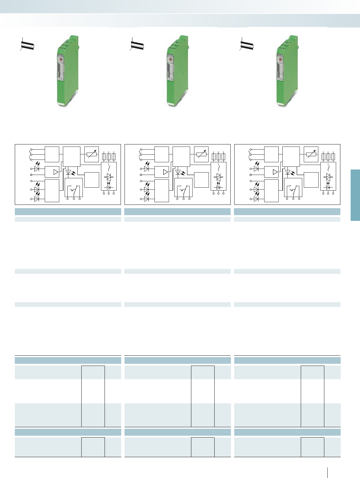
These short-circuit-proof 3-phase hybrid
motor starters for mounting on 30 mm
DIN rails or 60 mm power busbars combine
four functions in one device: right
contactor, left contactor, motor protection
relay, and emergency stop up to category 3.
They offer the following advantages:
– 22.5 mm wide
– Bi-metal function can be set up to 9 A
– Long service life
– Space-saving
– Reduction in wiring
– 3-phase loop bridging
– Plug-in motor output terminal block
– Coordination type 2 according to
IEC/EN 60947-4-2
Hybrid motor starters with
short-circuit protection
Electronic switching devices and motor control
Hybrid motor starters
MAN
RES
AUT
T
T
E
U
s
L
R
Reset2
Reset
Auto-
Reset
24
VDC
24VDC
97
2/T1
964/T2
95
6/T3
Logic
μP
L1 L2 L3
& Error
reset
MAN
RES
AUT
T
T
E
U
s
L
R
Reset2
Reset
Auto-
Reset
24
VDC
24VDC
97
2/T1
964/T2
95
6/T3
Logic
μP
L1 L2 L3
& Error
reset
MAN
RES
AUT
T
T
E
U
s
L
R
Reset2
Reset
Auto-
Reset
24
VDC
24VDC
97
2/T1
964/T2
95
6/T3
Logic
μP
L1 L2 L3
& Error
reset
For further information and full technical data, visit phoenixcontact.net/products
Ex:
Ex:
Ex:
Technical data Technical data Technical data
24 V DC 24 V DC 24 V DC
0.8 ... 1.25 0.8 ... 1.25 0.8 ... 1.25
40 mA 40 mA 40 mA
R/L 24 V DC 24 V DC 24 V DC
0.8 ... 1.25 0.8 ... 1.25 0.8 ... 1.25
5 mA 5 mA 5 mA
Protection against polarity reversal, surge protection Protection against polarity reversal, surge protection Protection against polarity reversal, surge protection
Operating voltage / status / error indicator Green LED / Yellow LED / Red LED Green LED / Yellow LED / Red LED Green LED / Yellow LED / Red LED
42 V AC ... 550 V AC 42 V AC ... 550 V AC 42 V AC ... 550 V AC
max. 600 mA max. 2.4 A max. 9 A
75 mA 180 mA 1.5 A
< 0.3 V < 0.4 V < 0.6 V
Surge protection, short-circuit protection Surge protection, short-circuit protection Surge protection, short-circuit protection
Rated insulation voltage 500 V 500 V 500 V
6 kV (safe isolation) 6 kV (safe isolation) 6 kV (safe isolation)
Ambient temperature (operation) -25 °C ... 70 °C -25 °C ... 70 °C -25 °C ... 70 °C
3 x 10
7
cycles 3 x 10
7
cycles 3 x 10
7
cycles
Standards/regulations EN 60947 EN 60947 EN 60947
DIN EN 50178 DIN EN 50178 DIN EN 50178
Vertical (horizontal DIN rail) Vertical (horizontal DIN rail) Vertical (horizontal DIN rail)
Can be aligned with spacing = 20 mm Can be aligned with spacing = 20 mm Can be aligned with spacing = 20 mm
Screw connection solid / stranded / AWG 0.14 - 2.5 mm² / 0.14 - 2.5 mm² / 26 - 14 0.14 - 2.5 mm² / 0.14 - 2.5 mm² / 26 - 14 0.14 - 2.5 mm² / 0.14 - 2.5 mm² / 26 - 14
Dimensions W / H / D 22.5 mm / 160 mm / 114.5 mm 22.5 mm / 160 mm / 114.5 mm 22.5 mm / 160 mm / 114.5 mm
Ordering data Ordering data Ordering data
Type Order No. Pcs. /
Pkt. Type Order No. Pcs. /
Pkt. Type Order No. Pcs. /
Pkt.
ELR H51-IESSC-24DC500AC-06 2902746 1ELR H51-IESSC-24DC500AC-2 2902744 1ELR H51-IESSC-24DC500AC-9 2902745 1
EM RD-ADAPTER 2902747 1EM RD-ADAPTER 2902747 1EM RD-ADAPTER 2902747 1
EM RI-ADAPTER COMPACT 2902748 1EM RI-ADAPTER COMPACT 2902748 1EM RI-ADAPTER COMPACT 2902748 1
EM RI-ADAPTER CLASSIC 2902831 1EM RI-ADAPTER CLASSIC 2902831 1EM RI-ADAPTER CLASSIC 2902831 1
ELR H51-0.6-DIN-RAIL-SET 2902952 1ELR H51-2.4-DIN-RAIL-SET 2902953 1ELR H51-9-DIN-RAIL-SET 2902954 1
ELR-H51-0,6-BUSBAR-COMPACT-SET
2904333 1
ELR-H51-2,4-BUSBAR-COMPACT-SET
2904335 1ELR-H51-9-BUSBAR-COMPACT-SET 2904337 1
ELR-H51-0,6-BUSBAR-CLASSIC-SET 2904334 1ELR-H51-2,4-BUSBAR-CLASSIC-SET 2904336 1ELR-H51-9-BUSBAR-CLASSIC-SET 2904338 1
Accessories Accessories Accessories
FUSE-10X38-16A-GR 2903126 10 FUSE-10X38-16A-GR 2903126 10 FUSE-10X38-16A-GR 2903126 10
FUSE-10X38-20A-GR 2903384 10 FUSE-10X38-20A-GR 2903384 10 FUSE-10X38-20A-GR 2903384 10
FUSE-10X38-30A-MR 2903119 10 FUSE-10X38-30A-MR 2903119 10 FUSE-10X38-30A-MR 2903119 10
29
PHOENIX CONTACT
Electronic switching devices and motor control
Hybrid motor starters
For reversing 3~ AC motors
up to550VAC/3 x 0.6A
For reversing 3~ AC motors
up to550VAC/3 x 2.4A
For reversing 3~ AC motors
up to550VAC/3 x 9A
H
W
D
H
W
D
H
W
D

123
22,5 mm≤
≤55 mm
4 10
...
Technical data
General data
Nominal voltage U
N
42 V AC ... 575 V AC
Nominal current at U
N
25 A
Cross section 2.5 mm²
Ordering data
Description Type Order No. Pcs. /
Pkt.
3-phase loop bridge
2-way BRIDGE- 2 2900746 1
3-way BRIDGE- 3 2900747 1
4-way BRIDGE- 4 2900748 1
5-way BRIDGE- 5 2900749 1
6-way BRIDGE- 6 2900750 1
7-way BRIDGE- 7 2900751 1
8-way BRIDGE- 8 2900752 1
9-way BRIDGE- 9 2900753 1
10-way BRIDGE-10 2900754 1
30
PHOENIX CONTACT
Loop bridge for
hybrid motor starters
The flexible CONTACTRON loop bridge
(BRIDGE-...) simplifies the supply and
looping through of phases L1, L2, and L3.
It is available in 2 to 10-way versions for
modules in the CONTACTRON family with
22.5 mm housing width.
Features of the 3-phase loop bridge:
– Saves considerable wiring
– Suitable for CONTACTRON series
- ELR H3...
- ELR H5...
- ELR (W)3...
- EMM...IFS
– Bridging of 2 to 10 devices with maximum
module spacing of 22.5 mm
– Up to 575 V AC/3 x 25 A
– Additional bridge versions available on
request
Electronic switching devices and motor control
Hybrid motor starters
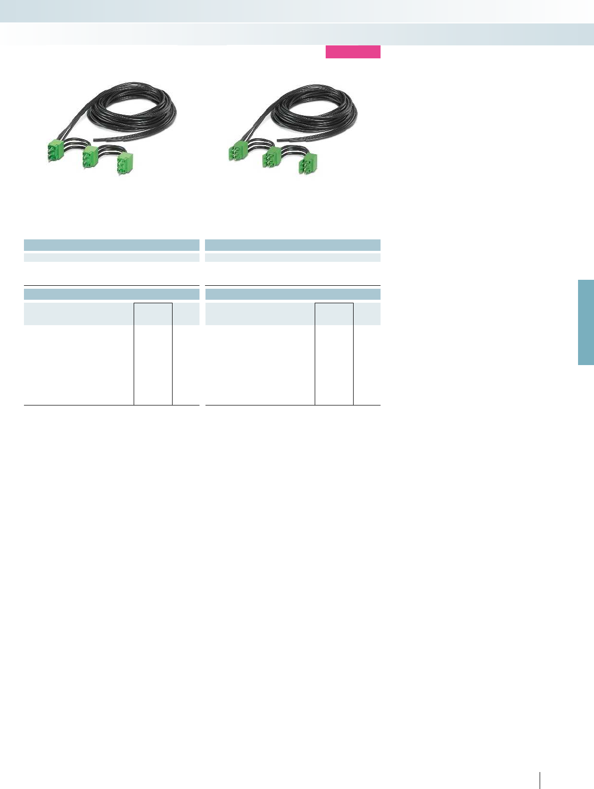
0.3 m connecting cable for hybrid motor starter
with screw connection
For further information and full technical data, visit phoenixcontact.net/products
Technical data Technical data
42 V AC ... 575 V AC 42 V AC ... 575 V AC
25 A 25 A
2.5 mm² 2.5 mm²
Ordering data Ordering data
Type Order No. Pcs. /
Pkt. Type Order No. Pcs. /
Pkt.
BRIDGE- 2-3M 2901543 1BRIDGE-PT 2 2904490 1
BRIDGE- 3-3M 2901656 1BRIDGE-PT 3 2904491 1
BRIDGE- 4-3M 2901659 1BRIDGE-PT 4 2904492 1
BRIDGE- 5-3M 2901545 1BRIDGE-PT 5 2904493 1
BRIDGE- 6-3M 2901697 1BRIDGE-PT 6 2904494 1
BRIDGE- 7-3M 2901698 1BRIDGE-PT 7 2904495 1
BRIDGE- 8-3M 2901700 1BRIDGE-PT 8 2904496 1
BRIDGE- 9-3M 2901701 1BRIDGE-PT 9 2904497 1
BRIDGE-10-3M 2901702 1BRIDGE-PT 10 2904498 1
31PHOENIX CONTACT
Electronic switching devices and motor control
Hybrid motor starters
new
3 m connecting cable for hybrid motor starter
with screw connection
3 m connecting cable for hybrid motor starter
with push-in connection

32
PHOENIX CONTACT
SmartWire-DT™ accessories
Devices can be integrated seamlessly into
the fieldbus world via SmartWire-DT™ with
the SmartWire-DT™ “EM SWD-ADAPTER”
adapter for CONTACTRON 24 V DC
devices. Corresponding gateways are available
for the following bus systems:
– PROFIBUS DP
– CANopen
®
– Modbus/TCP / EtherNet/IP™
Technical data
Input data
Supply voltage U
AUX
-
Rated current I
AUX
-
Supply voltage U
POW
-
Rated current I
POW
-
Input data
Description Enable input
Input voltage 24 V DC
Input current 5 mA
Output data
Description -
Output supply -
Output current -
SmartWire-DT™ interface
Connection method Pin strip, 8-pos.
Data rate 125 kBd / 250 kBd
Current consumption I
AUX
120 mA
Current consumption I
POW
25 mA
General data
Ambient temperature (operation) -25 °C ... 55 °C
Standards/regulations IEC 60947-1 / EN 60947-1 EN 50178 EN 50178 EN 50178
Degree of protection in acc. with IEC 60529/EN 60529 IP20
Mounting position any
Mounting On CONTACTRON hybrid motor starter - - -
Connection data solid / stranded / AWG 0.14 - 1 mm² / 0.14 - 1 mm² / 26 - 18 0.2 - 1.5 mm² / 0.2 - 1.5 mm² / 24 - 16 0.2 - 1.5 mm² / 0
Dimensions W / H / D 22.5 mm / 165 mm / 114.5 mm 35 mm / 90 mm / 127 mm 35 mm / 90 mm / 101 mm 35 mm / 90 mm / 124 mm
Ordering data
Description Type Order No. Pcs. /
Pkt.
SmartWire-DT™ adapter
EM SWD-ADAPTER 2902776 1
Gateways
CANopen®
PROFIBUS
Ethernet
I/O modules
Digital, 4 inputs, 4 outputs
Digital, 4 inputs
Digital, 8 outputs
Analog, 2 inputs, 2 outputs
Power feed module for supplying further SmartWire-DT™
devices
Electronic switching devices and motor control
Hybrid motor starters
SmartWire-DT™ adapter Gateways Input/output modules Power feed
For further information and full technical data, visit phoenixcontact.net/products
33
PHOENIX CONTACT
H
W
D
H
W
D
H
W
D
Technical data Technical data Technical data
- -
24 V DC -15 % ... +20 % - - 24 V DC -15 % ... +20 %
3 A - - 3 A
24 V DC -15 % ... +20 % - - 24 V DC -15 % ... +20 %
700 mA - - 700 mA
- -
- Digital inputs Analog inputs -
- 24 V DC - -
- typ. 4 mA - -
- -
- Digital outputs Analog outputs -
- 24 V DC -15 % ... +20 % - -
- typ. 500 mA - -
- -
Pin strip, 8-pos. Pin strip, 8-pos. Pin strip, 8-pos. Pin strip, 8-pos.
125 kBd / 250 kBd 125 kBd / 250 kBd 125 kBd / 250 kBd 125 kBd / 250 kBd
- -- -
- -- -
-25 °C ... 55 °C - -
Standards/regulations IEC 60947-1 / EN 60947-1 EN 50178 EN 50178 EN 50178
IP20 IP20 IP20
any any any
Mounting On CONTACTRON hybrid motor starter - - -
Connection data solid / stranded / AWG 0.14 - 1 mm² / 0.14 - 1 mm² / 26 - 18 0.2 - 1.5 mm² / 0.2 - 1.5 mm² / 24 - 16 0.2 - 1.5 mm² / 0.2 - 1.5 mm² / 24 - 16 0.2 - 1.5 mm² / 0.2 - 1.5 mm² / 24 - 16
Dimensions W / H / D 22.5 mm / 165 mm / 114.5 mm 35 mm / 90 mm / 127 mm 35 mm / 90 mm / 101 mm 35 mm / 90 mm / 124 mm
Ordering data Ordering data Ordering data
Type Order No. Pcs. /
Pkt. Type Order No. Pcs. /
Pkt. Type Order No. Pcs. /
Pkt.
EU5C-SWD-CAN PXC 2903098 1
EU5C-SWD-DP PXC 2903100 1
EU5C-SWD-EIP-MODTCP PXC 2903244 1
EU5E-SWD-4D4D PXC 2903101 1
EU5E-SWD-4DX PXC 2903102 1
EU5E-SWD-X8D PXC 2903103 1
EU5E-SWD-2A2A PXC 2903104 1
EU5C-SWD-PF2-1 PXC 2903113 1
Electronic switching devices and motor control
Hybrid motor starters
SmartWire-DT™ adapter Gateways Input/output modules Power feed
Ordering data Ordering data
Description Color Type Order No. Pcs. /
Pkt. Type Order No. Pcs. /
Pkt.
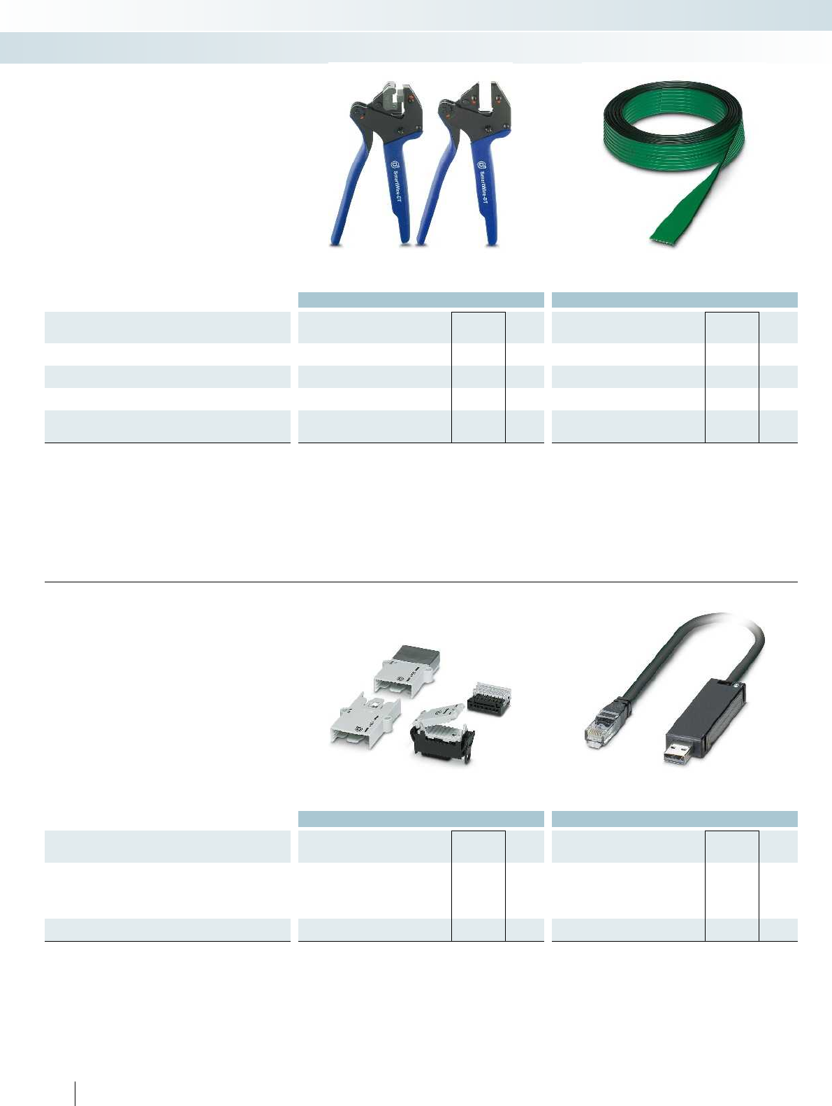
Pliers for device plugs
SWD4-CRP-1 PXC 2903110 1
Pliers for flat plugs
SWD4-CRP-2 PXC 2903114 1
Flat-ribbon cable, 8-pos., 100 m
SWD4-100LF-8-24 PXC 2903111 1
Flat-ribbon cable, assembled with 2 flat plugs, 8-pos., 3 m
SWD4-3LF8-24-2S PXC 2903112 1
SmartWire-DT™ accessories
Electronic switching devices and motor control
Hybrid motor starters
Plug tools Flat-ribbon cable, 8-pos.
Ordering data Ordering data
Description Color Type Order No. Pcs. /
Pkt. Type Order No. Pcs. /
Pkt.
Plug and coupling
Network dummy plug SWD4-RC8-10 PXC 2903106 1
Device plug, 8-pos. SWD4-8SF2-5 PXC 2903107 10
Flat plug, 8-pos. SWD4-8MF2 PXC 2903108 10
Coupling for 8-pos. flat plug SWD4-8SFF2-5 PXC 2903109 1
Programming adapter
EU4A-RJ45-USB-CAB1 PXC 2903465 1
34
PHOENIX CONTACT
Accessories for SmartWire-DT™ and
SmartWire-DT™ devices for connecting
digital and analog input and output signals.
SmartWire-DT™ accessories
Plug and coupling Programming adapter

L1
L2
L3
+24V DC
GND
F1
F2
F3
S11
S21
S12
S22
13
14
23
24
A1 S33A2 S34
M
3~
PE
EM SWD-ADAPTER
CONTACTRON N in1
EU5C SWD-DP PXC
PSR-SCP-24UC/ESA4/2x1/1x2
2/T1 1/L1
3/L2
5/L3
4/T2
6/T3
969597
U
S
GND R
+–
L
EN+ EN–
GND_E
MAN RESAUT
SWD
SWD EN
SWD
S1
AUX
Config.
PROFIBUS-DP
POW
SWD
L1
L2
L3
F1
F2
F3
M
3~
PE
EM SWD-ADAPTER
CONTACTRON N in1
EU5C SWD-DP PXC
2/T1 1/L1
3/L2
5/L3
4/T2
6/T3
969597
U
S
GND R
+–
L
EN+ EN–
GND_E
MAN RESAUT
SWD
SWD EN
SWD
AUX
Config.
PROFIBUS-DP
POW
SWD
0,18
1
2
3
4
5
6
7
8
9
010203040506070
1
2
2
10203040506070
0,3
0,2
0,1
0,4
0,5
0,6
0,7
0,8
0,9
0
1
2
For further information and full technical data, visit phoenixcontact.net/products
35PHOENIX CONTACT
Emergency stop wiring example (two-channel)
Wiring example without emergency stop
Intended use
The SmartWire-DT™ adapter is approved exclusively for use in
conjunction with the following CONTACTRON hybrid motor
starters. If other switching devices are used, correct operation, in
particular of the safety function, cannot be ensured.
Motor protection and safe shutdown
2900582 ELR H5-IES-SC-24DC/500AC-0,6
2900414 ELR H5-IES-SC-24DC/500AC-2
2900421 ELR H5-IES-SC-24DC/500AC-9
2900566 ELR H3-IES-SC-24DC/500AC-0,6
2900567 ELR H3-IES-SC-24DC/500AC-2
2900569 ELR H3-IES-SC-24DC/500AC-9
2297031 ELR W3- 24DC/500AC-2I
2297057 ELR W3- 24DC/500AC-9I
2902952 ELR H51-0,6-DINRAIL-SET
2902953 ELR H51-2,4-DINRAIL-SET
2902954 ELR H51-9-DINRAIL-SET
2902746 ELR H51-IESSC-24DC500AC-06
2902744 ELR H51-IESSC-24DC500AC-2
2902745 ELR H51-IESSC-24DC500AC-9
Motor protection only
2900573 ELR H5-I-SC-24DC/500AC-0,6
2900574 ELR H5-I-SC-24DC/500AC-2
2900576 ELR H5-I-SC-24DC/500AC-9
2900542 ELR H3-I-SC-24DC/500AC-0,6
2900543 ELR H3-I-SC-24DC/500AC-2
2900545 ELR H3-I-SC-24DC/500AC-9
Ambient temperature [°C]
Output current [A]
Derating curve for ELR H5-IES-SC-SWD/500AC-2 and
ELR H5-IES-SC-SWD/500AC-9
100% operating time
Ambient temperature [°C]
Output current [A]
Derating curve for ELR H5-IES-SC-SWD/500AC-0,6
100% operating time
1 Aligned with > 20 mm spacing
2 Aligned without spacing
Electronic switching devices and motor control
Hybrid motor starters

604020
5
10
15
20
25
30
35
40
45
10
ELR ...-16
ELR ...-37
604020
1
2
3
4
5
6
7
8
9
10
10
ELR ...-2
ELR ...-9
L
T
1/L1 3/L2 5/L3
2/T1 4/T2 6/T3
R
Technical data
Input data
Rated actuating voltage U
C
R/L 24 V DC 230 V AC 24 V DC 230 V AC 24 V DC 230 V AC 24 V DC 230 V AC
Rated actuating voltage range with reference to U
C
0.8 ... 1.25 0.4 ... 1.1 0.8 ... 1.25 0.4 ... 1.1 0.8 ... 1.25 0.4 ... 1.1 0.8 ... 1.25 0.4 ... 1.1
Rated actuating current I
C
at U
C
12.7 mA 11.2 mA 12.7 mA 11.2 mA 12.7 mA 11.2 mA 12.7 mA 11.2 mA
Input circuit Protection against polarity
reversal, surge protection
Surge protection Protection against polarity
Operating voltage / status / error indicator - / Yellow LED / Red LED - / Yellow LED / Red LED - / Yellow LED / Red LED - / Yellow
Output data load side
Output voltage range 48 V AC ... 575 V AC 48 V AC ... 575 V AC 48 V AC ... 575 V AC 48 V AC ... 575 V AC 48 V AC ... 575 V AC 48 V AC
Periodic peak reverse voltage 1200 V 1200 V 1200 V 1200 V 1200 V 1200 V 1200 V 1200 V
Load current max. 2 A (see derating curve) max. 2 A (see derating curve) max. 9 A (see derating curve) max. 9 A (see derating curve
Surge current 200 A (t = 10 ms) 200 A (t = 10 ms) 300 A (t = 10 ms) 300 A (t = 10 ms) 300 A (t = 10 ms) 300 A (t = 10 ms) 1300 A (t =
Min. load current 100 mA 100 mA 100 mA 100 mA 100 mA 100 mA 200 mA 200 mA
Residual voltage < 1.5 V < 1.5 V < 1.5 V < 1.5 V < 1.5 V < 1.5 V < 1.5 V < 1.5 V
Leakage current 6 mA 6 mA 6 mA 6 mA 6 mA 6 mA 6 mA 6 mA
Max. load value I
2
x t (t = 10 ms) 250 A
2
s 250 A
2
s 580 A
Output protection RCV circuit
General data
Rated insulation voltage 500 V
Rated surge voltage 6 kV 6 kV 6 kV 6 kV 6 kV 6 kV 6 kV 6 kV
Insulation Basic insulation
Reversing frequency max. 10 Hz max. 2 Hz max. 10 Hz max. 2 Hz max. 10 Hz max. 2 Hz max. 10 Hz max. 2 Hz
Switching frequency max. 5 Hz max. 1 Hz max. 5 Hz max. 1 Hz max. 5 Hz max. 1 Hz max. 5 Hz max. 1 Hz
Ambient temperature (operation) -25 °C ... 70 °C
Standards/regulations EN 60947
DIN EN 50178
Degree of protection in acc. with IEC 60529/EN 60529 IP20
Mounting position Vertical (horizontal DIN rail) Vertical (horizontal DIN rail) Vertical (horizontal DIN rail) Vertical (horizontal
Mounting Can be aligned with spacing = 20 mm Can be aligned with spacing = 20 mm Can be aligned with spacing = 40 mm Can be aligned
Screw connection solid / stranded / AWG
- Control side 0.14 - 2.5 mm² / 0.14 - 2.5 mm² / 26 - 12 0.14 - 2.5 mm² / 0.14 - 2.5 mm² / 26 - 12 0.2 - 4 mm² / 0.2 - 2.5 mm² / 2
- Load side 0.14 - 2.5 mm² / 0.14 - 2.5 mm² / 26 - 12 0.14 - 2.5 mm² / 0.14 - 2.5 mm² / 26 - 12 0.5 - 16 mm² / 0.5 - 16 mm² / 20 -
Dimensions W / H / D 40 mm / 99 mm / 114.5 mm 67.5 mm / 99 mm / 114.5 mm 147.5 mm / 99 mm / 114.5 mm 147.5 mm / 99 mm / 114.5 mm
Ordering data
Description Type Order No. Pcs. /
Pkt.
3-phase solid-state reversing contactor
ELR W3- 24DC/500AC- 2 2297293 1
ELR W3-230AC/500AC- 2 2297303 1
Accessories
Thermal fuse THERMAL FUSE TF104 2900796 1
36
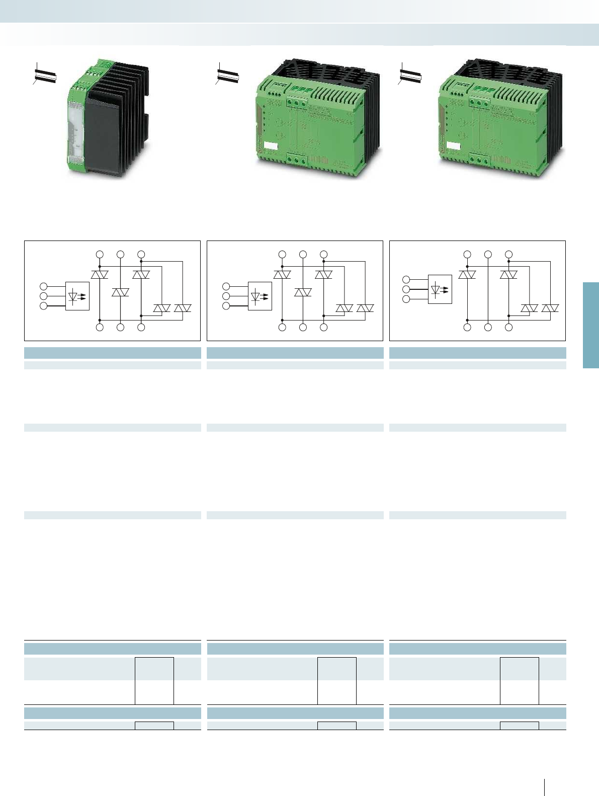
PHOENIX CONTACT
Three-phase solid-state reversing
contactors
The three-phase solid-state reversing
contactors with an integrated locking circuit
and load wiring are intended for applications
such as control valves, slides, separating
filters, ship steering gears, etc. The scope of
performance ranges from 575 V AC/3 x 2 A
to 575 V AC/3 x 37 A.
Advantages of three-phase solid-state
reversing contactors:
– Noise-free and wear-free switching
– Integrated protective circuit
– Stable and short switching times
– Long service life
– High switching frequency
– Integrated locking and load wiring
– Thermal fuse optional
Ambient temperature [°C]
Output current [A]
Load current as a function of the ambient temperature
Operating time: 100% operating factor
Ambient temperature [°C]
Output current [A]
Load current as a function of the ambient temperature
Operating time: 100% operating factor
Electronic switching devices and motor control
Solid-state contactors
H
W
D
Notes:
Type of insulation housing:
ELR W 3...2, ELR W 3...9
Polyamide PA non-reinforced, color: green
ELR W 3...16, ELR W 3...37
Polyester PBT non-reinforced, color: green
Marking systems and mounting material
See Catalog 5
For reversing 3~ AC motors
up to575VAC/3 x 2A
L
T
1/L1 3/L2 5/L3
2/T1 4/T2 6/T3
R
L
T
1/L1 3/L2 5/L3
2/T1 4/T2 6/T3
R
1/L1 3/L2 5/L3
2/T1 4/T2 6/T3
L
T
R
For further information and full technical data, visit phoenixcontact.net/products
Technical data Technical data Technical data
R/L 24 V DC 230 V AC 24 V DC 230 V AC 24 V DC 230 V AC 24 V DC 230 V AC
0.8 ... 1.25 0.4 ... 1.1 0.8 ... 1.25 0.4 ... 1.1 0.8 ... 1.25 0.4 ... 1.1 0.8 ... 1.25 0.4 ... 1.1
12.7 mA 11.2 mA 12.7 mA 11.2 mA 12.7 mA 11.2 mA 12.7 mA 11.2 mA
Surge protection Protection against polarity
reversal, surge protection
Surge protection Protection against polarity
reversal, surge protection
Surge protection Protection against polarity
reversal, surge protection
Surge protection
Operating voltage / status / error indicator - / Yellow LED / Red LED - / Yellow LED / Red LED - / Yellow LED / Red LED - / Yellow LED / Red LED
Output voltage range 48 V AC ... 575 V AC 48 V AC ... 575 V AC 48 V AC ... 575 V AC 48 V AC ... 575 V AC 48 V AC ... 575 V AC 48 V AC ... 575 V AC 48 V AC ... 575 V AC 48 V AC ... 575 V AC
Periodic peak reverse voltage 1200 V 1200 V 1200 V 1200 V 1200 V 1200 V 1200 V 1200 V
Load current max. 2 A (see derating curve) max. 2 A (see derating curve) max. 9 A (see derating curve) max. 9 A (see derating curve) max. 16 A (see derating curve) max. 16 A (see derating curve) max. 37 A (see derating curve) max. 37 A (see derating curve)
Surge current 200 A (t = 10 ms) 200 A (t = 10 ms) 300 A (t = 10 ms) 300 A (t = 10 ms) 300 A (t = 10 ms) 300 A (t = 10 ms) 1300 A (t = 10 ms) 1300 A (t = 10 ms)
Min. load current 100 mA 100 mA 100 mA 100 mA 100 mA 100 mA 200 mA 200 mA
Residual voltage < 1.5 V < 1.5 V < 1.5 V < 1.5 V < 1.5 V < 1.5 V < 1.5 V < 1.5 V
Leakage current 6 mA 6 mA 6 mA 6 mA 6 mA 6 mA 6 mA 6 mA
s 580 A
2
s 580 A
2
s 580 A
2
s 580 A
2
s 9000 A
2
s 9000 A
2
s
RCV circuit RCV circuit RCV circuit
500 V 500 V 500 V
Rated surge voltage 6 kV 6 kV 6 kV 6 kV 6 kV 6 kV 6 kV 6 kV
Basic insulation Basic insulation Basic insulation
Reversing frequency max. 10 Hz max. 2 Hz max. 10 Hz max. 2 Hz max. 10 Hz max. 2 Hz max. 10 Hz max. 2 Hz
Switching frequency max. 5 Hz max. 1 Hz max. 5 Hz max. 1 Hz max. 5 Hz max. 1 Hz max. 5 Hz max. 1 Hz
-25 °C ... 70 °C -25 °C ... 70 °C -25 °C ... 70 °C
EN 60947 EN 60947 EN 60947
DIN EN 50178 DIN EN 50178 DIN EN 50178
IP20 IP20 IP20
Mounting position Vertical (horizontal DIN rail) Vertical (horizontal DIN rail) Vertical (horizontal DIN rail) Vertical (horizontal DIN rail)
Mounting Can be aligned with spacing = 20 mm Can be aligned with spacing = 20 mm Can be aligned with spacing = 40 mm Can be aligned with spacing = 40 mm
- Control side 0.14 - 2.5 mm² / 0.14 - 2.5 mm² / 26 - 12 0.14 - 2.5 mm² / 0.14 - 2.5 mm² / 26 - 12 0.2 - 4 mm² / 0.2 - 2.5 mm² / 24 - 12 0.2 - 4 mm² / 0.2 - 2.5 mm² / 24 - 12
- Load side 0.14 - 2.5 mm² / 0.14 - 2.5 mm² / 26 - 12 0.14 - 2.5 mm² / 0.14 - 2.5 mm² / 26 - 12 0.5 - 16 mm² / 0.5 - 16 mm² / 20 - 6 0.5 - 16 mm² / 0.5 - 16 mm² / 20 - 6
Dimensions W / H / D 40 mm / 99 mm / 114.5 mm 67.5 mm / 99 mm / 114.5 mm 147.5 mm / 99 mm / 114.5 mm 147.5 mm / 99 mm / 114.5 mm
Ordering data Ordering data Ordering data
Type Order No. Pcs. /
Pkt. Type Order No. Pcs. /
Pkt. Type Order No. Pcs. /
Pkt.
ELR W3- 24DC/500AC- 9 2297316 1ELR W3- 24DC/500AC-16 2297332 1ELR W2+1- 24DC/500AC-37 2297374 1
ELR W3-230AC/500AC- 9 2297329 1ELR W3-230AC/500AC-16 2297345 1ELR W2+1-230AC/500AC-37 2297387 1
Accessories Accessories Accessories
THERMAL FUSE TF104 2900796 1THERMAL FUSE TF104 2900796 1THERMAL FUSE TF104 2900796 1
37
PHOENIX CONTACT
Electronic switching devices and motor control
Solid-state contactors
H
W
D
H
W
D
H
W
D
For reversing 3~ AC motors
up to575VAC/3 x 9A
For reversing 3~ AC motors
up to575VAC/3 x 16A
For reversing 3~ AC motors
up to575VAC/3 x 37A

604020
5
10
15
20
25
30
35
40
45
10
ELR ...-16
ELR ...-37
604020
1
2
3
4
5
6
7
8
9
10
10
ELR ...-2
ELR ...-9
ON
T
1/L1 3/L2 5/L3
2/T1 4/T2 6/T3
Technical data
Input data
Rated actuation voltage U
C
ON 24 V DC 230 V AC 24 V DC 230 V AC 24 V DC 230 V AC 24 V DC 230 V AC
Rated actuating voltage range with reference to U
C
0.8 ... 1.25 0.4 ... 1.1 0.8 ... 1.25 0.4 ... 1.1 0.8 ... 1.25 0.4 ... 1.1 0.8 ... 1.25 0.4 ... 1.1
Rated actuating current I
C
at U
C
8.3 mA 12.5 mA 8.3 mA 12.5 mA 8.3 mA 12.5 mA 8.3 mA 12.5 mA
Input circuit Protection against polarity
reversal, surge protection
Surge protection Protection against polarity
Operating voltage / status / error indicator - / Yellow LED / Red LED - / Yellow LED / Red LED - / Yellow LED / Red LED - / Yellow
Output data load side
Output voltage range 48 V AC ... 575 V AC 48 V AC ... 575 V AC 48 V AC ... 575 V AC 48 V AC ... 575 V AC 48 V AC ... 575 V AC 48 V AC
Periodic peak reverse voltage 1200 V 1200 V 1200 V 1200 V 1200 V 1200 V 1200 V 1200 V
Load current 2 A (see derating curve) 2 A (see derating curve)
Surge current 200 A (t = 10 ms) 200 A (t = 10 ms) 300 A (t = 10 ms) 300 A (t = 10 ms) 300 A (t = 10 ms) 300 A (t = 10 ms) 1300 A (t =
Min. load current 100 mA 100 mA 100 mA 100 mA 100 mA 100 mA 200 mA 200 mA
Residual voltage < 1.5 V < 1.5 V < 1.5 V < 1.5 V < 1.5 V < 1.5 V < 1.5 V < 1.5 V
Leakage current 6 mA 6 mA 6 mA 6 mA 6 mA 6 mA 6 mA 6 mA
Max. load value I
2
x t (t = 10 ms) 250 A
2
s 250 A
2
s 580 A
Output protection RCV circuit
General data
Rated insulation voltage 500 V
Rated surge voltage 6 kV 6 kV 6 kV 6 kV 6 kV 6 kV 6 kV 6 kV
Insulation Basic insulation
Switching frequency 10 Hz 1 Hz
Ambient temperature (operation) -25 °C ... 70 °C
Standards/regulations EN 60947
DIN EN 50178
Degree of protection in acc. with IEC 60529/EN 60529 IP20
Mounting position Vertical (horizontal DIN rail) Vertical (horizontal DIN rail) Vertical (horizontal DIN rail) Vertical (horizontal
Mounting Can be aligned with spacing = 20 mm Can be aligned with spacing = 20 mm Can be aligned with spacing = 40 mm Can be aligned
Screw connection solid / stranded / AWG
- Control side 0.14 - 2.5 mm² / 0.14 - 2.5 mm² / 26 - 12 0.14 - 2.5 mm² / 0.14 - 2.5 mm² / 26 - 12 0.2 - 4 mm² / 0.2 - 2.5 mm² / 2
- Load side 0.14 - 2.5 mm² / 0.14 - 2.5 mm² / 26 - 12 0.14 - 2.5 mm² / 0.14 - 2.5 mm² / 26 - 12 0.5 - 16 mm² / 0.5 - 16 mm² / 20 -
Dimensions W / H / D 40 mm / 99 mm / 114.5 mm 67.5 mm / 99 mm / 114.5 mm 147.5 mm / 99 mm / 114.5 mm 147.5 mm / 99 mm / 114.5 mm
Ordering data
Description Type Order No. Pcs. /
Pkt.
Three-phase solid-state contactor
ELR 3- 24DC/500AC- 2 2297196 1
ELR 3-230AC/500AC- 2 2297206 1
Accessories
Thermal fuse THERMAL FUSE TF104 2900796 1
38
PHOENIX CONTACT
Three-phase solid-state contactors
Motors of mixers, machine tools,
conveying systems, pumps and fans up to
575 V AC/3x37 A (equivalent to 1 kW to
18.5 kW) can be controlled using the
CONTACTRON three-phase solid-state
contactors.
Advantages of three-phase solid-state
contactor:
– Noise-free and wear-free switching
– Integrated protective circuit
– Stable and short switching times
– Long service life
– High switching frequency
– Thermal fuse optional
Ambient temperature [°C]
Output current [A]
Load current as a function of the ambient temperature
Operating time: 100% operating factor
Ambient temperature [°C]
Output current [A]
Load current as a function of the ambient temperature
Operating time: 100% operating factor
Electronic switching devices and motor control
Solid-state contactors
H
W
D
Notes:
Type of insulation housing:
ELR 3...2, ELR 3...9
Polyamide PA non-reinforced, color: green
ELR 3...16, ELR 3...37
Polyester PBT non-reinforced, color: green
Marking systems and mounting material
See Catalog 5
For switching 3~ AC motors
up to575VAC/3 x 2A
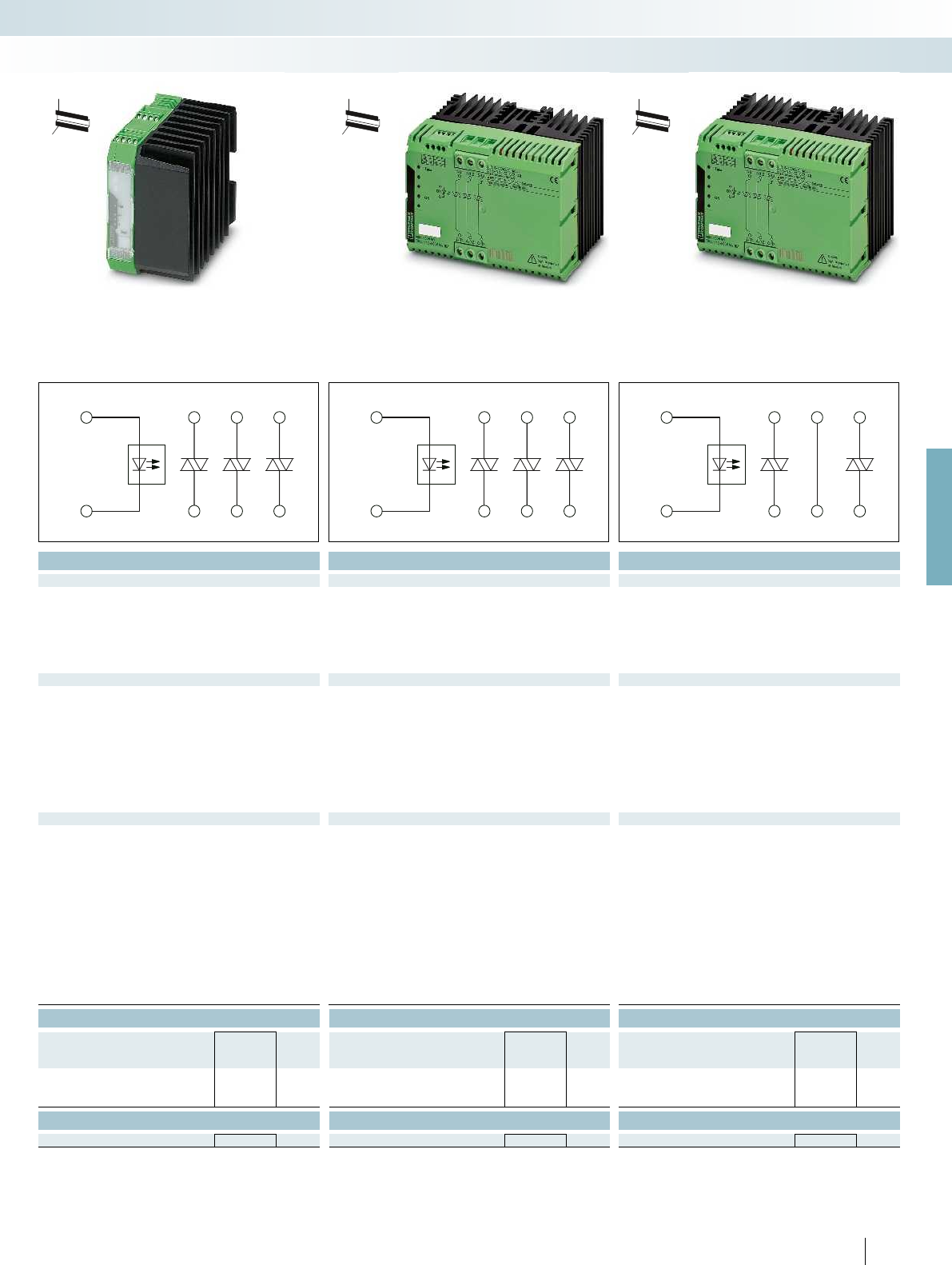
ON
T
1/L1 3/L2 5/L3
2/T1 4/T2 6/T3
ON
T
1/L1 3/L2 5/L3
2/T1 4/T2 6/T3
ON
T
1/L1 3/L2 5/L3
2/T1 4/T2 6/T3
For further information and full technical data, visit phoenixcontact.net/products
Technical data Technical data Technical data
ON 24 V DC 230 V AC 24 V DC 230 V AC 24 V DC 230 V AC 24 V DC 230 V AC
0.8 ... 1.25 0.4 ... 1.1 0.8 ... 1.25 0.4 ... 1.1 0.8 ... 1.25 0.4 ... 1.1 0.8 ... 1.25 0.4 ... 1.1
8.3 mA 12.5 mA 8.3 mA 12.5 mA 8.3 mA 12.5 mA 8.3 mA 12.5 mA
Surge protection Protection against polarity
reversal, surge protection
Surge protection Protection against polarity
reversal, surge protection
Surge protection Protection against polarity
reversal, surge protection
Surge protection
Operating voltage / status / error indicator - / Yellow LED / Red LED - / Yellow LED / Red LED - / Yellow LED / Red LED - / Yellow LED / Red LED
Output voltage range 48 V AC ... 575 V AC 48 V AC ... 575 V AC 48 V AC ... 575 V AC 48 V AC ... 575 V AC 48 V AC ... 575 V AC 48 V AC ... 575 V AC 48 V AC ... 575 V AC 48 V AC ... 575 V AC
Periodic peak reverse voltage 1200 V 1200 V 1200 V 1200 V 1200 V 1200 V 1200 V 1200 V
9 A (see derating curve) 9 A (see derating curve) 16 A (see derating curve) 16 A (see derating curve) 37 A (see derating curve) 37 A (see derating curve)
Surge current 200 A (t = 10 ms) 200 A (t = 10 ms) 300 A (t = 10 ms) 300 A (t = 10 ms) 300 A (t = 10 ms) 300 A (t = 10 ms) 1300 A (t = 10 ms) 1300 A (t = 10 ms)
Min. load current 100 mA 100 mA 100 mA 100 mA 100 mA 100 mA 200 mA 200 mA
Residual voltage < 1.5 V < 1.5 V < 1.5 V < 1.5 V < 1.5 V < 1.5 V < 1.5 V < 1.5 V
Leakage current 6 mA 6 mA 6 mA 6 mA 6 mA 6 mA 6 mA 6 mA
s 580 A
2
s 580 A
2
s 580 A
2
s 580 A
2
s 9000 A
2
s 9000 A
2
s
RCV circuit RCV circuit RCV circuit
500 V 500 V 500 V
Rated surge voltage 6 kV 6 kV 6 kV 6 kV 6 kV 6 kV 6 kV 6 kV
Basic insulation Basic insulation Basic insulation
10 Hz 1 Hz 10 Hz 1 Hz 10 Hz 1 Hz
-25 °C ... 70 °C -25 °C ... 70 °C -25 °C ... 70 °C
EN 60947 EN 60947 EN 60947
DIN EN 50178 DIN EN 50178 DIN EN 50178
IP20 IP20 IP20
Mounting position Vertical (horizontal DIN rail) Vertical (horizontal DIN rail) Vertical (horizontal DIN rail) Vertical (horizontal DIN rail)
Mounting Can be aligned with spacing = 20 mm Can be aligned with spacing = 20 mm Can be aligned with spacing = 40 mm Can be aligned with spacing = 40 mm
- Control side 0.14 - 2.5 mm² / 0.14 - 2.5 mm² / 26 - 12 0.14 - 2.5 mm² / 0.14 - 2.5 mm² / 26 - 12 0.2 - 4 mm² / 0.2 - 2.5 mm² / 24 - 12 0.2 - 4 mm² / 0.2 - 2.5 mm² / 24 - 12
- Load side 0.14 - 2.5 mm² / 0.14 - 2.5 mm² / 26 - 12 0.14 - 2.5 mm² / 0.14 - 2.5 mm² / 26 - 12 0.5 - 16 mm² / 0.5 - 16 mm² / 20 - 6 0.5 - 16 mm² / 0.5 - 16 mm² / 20 - 6
Dimensions W / H / D 40 mm / 99 mm / 114.5 mm 67.5 mm / 99 mm / 114.5 mm 147.5 mm / 99 mm / 114.5 mm 147.5 mm / 99 mm / 114.5 mm
Ordering data Ordering data Ordering data
Type Order No. Pcs. /
Pkt. Type Order No. Pcs. /
Pkt. Type Order No. Pcs. /
Pkt.
ELR 3- 24DC/500AC- 9 2297219 1ELR 3- 24DC/500AC-16 2297235 1ELR 2+1- 24DC/500AC-37 2297277 1
ELR 3-230AC/500AC- 9 2297222 1ELR 3-230AC/500AC-16 2297248 1ELR 2+1-230AC/500AC-37 2297280 1
Accessories Accessories Accessories
THERMAL FUSE TF104 2900796 1THERMAL FUSE TF104 2900796 1THERMAL FUSE TF104 2900796 1
39
PHOENIX CONTACT
Electronic switching devices and motor control
Solid-state contactors
H
W
D
H
W
D
H
W
D
For switching 3~ AC motors
up to575VAC/3 x 9A
For switching 3~ AC motors
up to575VAC/3 x 16A
For switching 3~ AC motors
up to575VAC/3 x 37A
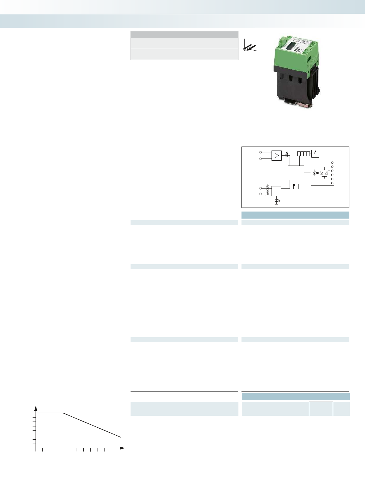
605040302010
8
3
2
1
0
4
5
6
7
24V DC
24V DC
24V DC U
IN
&
1/L1
3/L2
5/L3
2/T1
4/T2
6/T3
Technical data
Input data
Supply nominal voltage U
VN
24 V DC
Supply voltage range with reference to U
VN
0.8 ... 1.2
Quiescent current 85 mA
Control voltage U
ST
right/left 24 V DC
Control voltage range in reference to U
ST
0.8 ... 1.2
Typ. input current at U
N
5 mA
Input circuit Protection against polarity reversal, surge protection
Operating voltage / status / error indicator Green LED / Yellow LED / Red LED
Output data load side
Max. switching voltage 440 V AC (L1/T1)
440 V AC (L2/T2)
440 V AC (L3/T3)
Output voltage range 110 V AC ... 433 V AC
Periodic peak reverse voltage 1000 V
Load current < 8 A (IL1, at 20 °C Ta, see derating)
< 8 A (IL2, at 20 °C Ta, see derating)
< 8 A (IL3, at 20 °C Ta, see derating)
Surge current 230 A (tp = 10 ms, at 25 °C)
Min. load current 150 mA
Residual voltage typ. 1.5 V (For IL)
Leakage current 5 mA (IL1, in switched-off state)
Output protection RC element, surge protection
General data
Test voltage input/output 2.5 kV
Ambient temperature (operation) -20 °C ... 60 °C
Standards/regulations EN 61000-6-2 / EN 61000-6-4
DIN EN 50178
Degree of protection in acc. with IEC 60529/EN 60529 IP20
Mounting position Vertical (horizontal DIN rail)
Mounting Can be aligned with > 20 mm spacing
Screw connection solid / stranded / AWG 0.2 - 6 mm² / 0.2 - 4 mm² / 24 - 10
Dimensions W / H / D 62 mm / 94 mm / 122 mm
EMC note Class A product, see page 625
Ordering data
Description Type Order No. Pcs. /
Pkt.
Electronic reversing load relay, with an integrated soft switch
ELR W3/ 9-400 S 2963569 1
40
PHOENIX CONTACT
Notes:
Type of housing:
Polycarbonate PC, color: green.
Marking systems and mounting material
See Catalog 5
DW
H
Solid-state reversing contactor with
soft starter
The ELR W 3/9-400 S soft switch can be
used to increase the service life of a 3-phase
induction motor.
– Parameterization is performed directly on
the device via display and keyboard
– Friction time
– Torque, start
– Start time
– Stop time
– Torque, stop
– Braking time and
– Braking torque
– Drive can be controlled locally via
keyboard
Ambient temperature [°C]
Load current [A]
Load current as a function of the ambient temperature
Operating time: 100% operating factor
Electronic switching devices and motor control
Solid-state contactors
Alarm
Parameterization
L
R
Memory
Logic
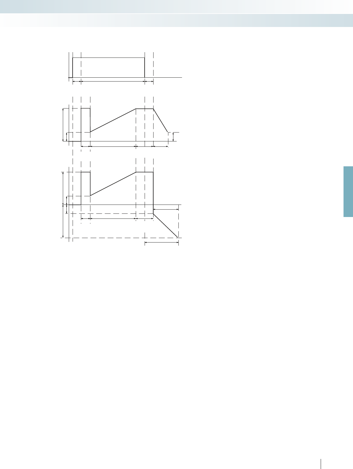
For further information and full technical data, visit phoenixcontact.net/products
The figure shows the control of the
reversing load relay with a soft starter and
the operation of a three-phase current load.
41
PHOENIX CONTACT
Friction time
Friction time
Start time
Start time
Switch
operation
Switch
operation
Stop time
Torque,stop
Braking time
100%operation positive
100%operation positive
100%operation negative
ON
delay
OFF
delay
Switch-off procedure
Operation
Torque,start
Torque,start
Torque,stop
Electronic switching devices and motor control
Solid-state contactors
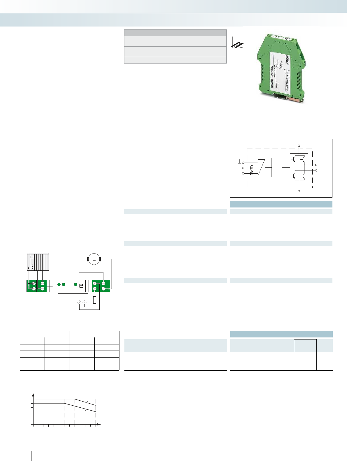
+U
M+
M-
GND
R
L
605040302010
3
2
1
0
4
5
6
2
1
L
L
M+
24V
R
R
U
M-
GND
M
+-
24 V DC
Technical data
Input data
Control voltage U
ST
right/left 24 V DC 24 V DC
Control voltage range in reference to U
ST
0.8 ... 1.2 0.8 ... 1.2
Typ. input current at U
N
3 mA 3 mA
Input circuit Protection against polarity reversal, surge protection
Operating voltage / status / error indicator Green LED / yellow LED, forward running (R), yellow LED,
reverse running (L) / -
Output data load side
Output voltage range 10 V DC ... 30 V DC 10 V DC ... 30 V DC
Load current 2 A (aligned without spacing) 6 A (see derating curve)
Quiescent current
approx. 7 mA (when switched off) approx. 7 mA (when switched off)
Current limitation at short-circuits 15 A 20 A
Output protection Protection against polarity reversal, surge protection
Operating voltage / status / error indicator Green LED / - / -
General data
Test voltage input/output 2.5 kV AC
Ambient temperature (operation) -20 °C ... 60 °C
Nominal operating mode 100% operating factor
Standards/regulations EN 50178 / Basic insulation
Degree of protection in acc. with IEC 60529/EN 60529 IP20
Mounting position Vertical (horizontal DIN rail)
Screw connection solid / stranded / AWG 0.2 - 6 mm² / 0.2 - 4 mm² / 24 - 10
Dimensions W / H / D 12.5 mm / 99 mm / 114.5 mm
EMC note Class A product, see page 625
Ordering data
Description Type Order No. Pcs. /
Pkt.
3-phase solid-state reversing contactor, for
controlling DC motors
ELR W1/ 2-24DC 2963598 1
ELR W1/ 6-24DC 2982090 1
42
PHOENIX CONTACT
Notes:
Type of housing:
Polycarbonate PC, color: green.
Marking systems and mounting material
See Catalog 5
PWM = Pulse Width Modulation
DW
H
Electronic reversing load relays for
DC motors
Electronic switching devices and motor control
Solid-state contactors
Logic
Application example
Status table
Input Output
Right Left M + M –
00
High resistance High resistance
1 0 +24 V GND
0 1 GND +24 V
1 1 GND GND
Load current depending on ambient temperature
Operating time: 100% OT
1 Single device
2 Aligned without spacing
Ambient temperature [°C]
Load current [A]
The ELR-DC electronic reversing load
relays allow mechanically commutated DC
motors to be switched. They reverse and
reduce the speed of DC motors up to 24
V/6 A in a wear-free manner. A short-circuit,
surge-voltage and overload-proof output
guarantees reliable use in the plant.
If a 24 V DC signal is applied to the “left”
input, the ELR-DC is interconnected so that
the output supplies the motor with voltage.
If the “right” input is triggered, the polarity of
the voltage is inverted on the output.
By triggering both inputs, i.e. “right” and
“left”, the motor is short-circuited internally
via the ELR-DC and reduces the speed.
Thanks to the internal interlocking circuit
and load wiring, wiring effort is reduced to
a minimum.

For further information and full technical data, visit phoenixcontact.net/products
43PHOENIX CONTACT
Electronic switching devices and motor control
Solid-state contactors
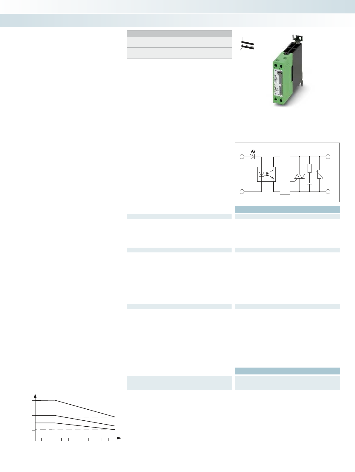
604020
30
20
10
11
16
28,5
10
40
50
A1
+
A2
-
1/L1
2/T1
Technical data
Input data
Input voltage range 4 V DC ... 32 V DC 24 V AC ... 275 V AC 4 V DC ... 32 V DC 24 V AC ... 275 V AC 4 V DC ... 32 V DC 24 V AC ... 27
Typ. input current at U
N
approx. 12 mA approx. 17 mA approx. 12 mA approx. 17 mA approx. 12 mA approx. 17 mA
Switching level 1 signal ("H") ≥ 4 V DC ≥ 22 V AC
0 signal ("L") ≤ 1 V DC ≤ 6 V AC
Transmission frequency f
limit
25 Hz 6 Hz 25 Hz 6 Hz 25 Hz 6 Hz
Operating voltage / status / error indicator Green LED / - / -
Output data load side
Output voltage range 42 V AC ... 660 V AC (45/65 Hz) 42 V AC ... 660 V AC (45/65 Hz) 42 V AC ... 660 V AC (45/65 Hz) 42 V AC ... 66
Periodic peak reverse voltage 1200 V 1200 V 1200 V 1200 V 1200 V 1200 V
Load current 20 A (see derating curve) 20 A (see derating curve) 30 A (see derating curve) 30 A (see derating curve) 50 A (see derat
Surge current 250 A (t = 10 ms) 250 A (t = 10 ms) 400 A (t = 10 ms) 400 A (t = 10 ms) 1900 A (t = 10 ms) 1900 A (t = 10 ms)
Min. load current 350 mA 350 mA 150 mA 150 mA 150 mA 150 mA
Residual voltage < 1.6 V < 1.6 V < 1.6 V < 1.6 V < 1.6 V < 1.6 V
Leakage current < 3 mA (in off state) < 3 mA (in off state) < 3 mA (in off state) < 3 mA (in off state) < 3 mA (in off state) < 3 mA
Phase angle (cos φ) 0.5 0.5 0.5 0.5 0.5 0.5
Max. load value I
2
x t (t = 10 ms) 525 A
2
s 525 A
2
s 1800 A
Output protection RCV circuit
General data
Test voltage input/output 4 kV
rms
Insulation Basic insulation
Ambient temperature (operation) -30 °C ... 70 °C
Standards/regulations
EN 61000-4-2 / EN 61000-4-3 / EN 61000-4-4 / EN 61000-4-5 /
EN 61000-4-6 / EN 55011
Mounting position Vertical (horizontal DIN rail) Vertical (horizontal DIN rail) Vertical (horizontal DIN rail)
Mounting Can be aligned with ≥ 22.5 mm spacing Can be aligned with
Screw connection solid / stranded / AWG
- Control side 0.5 - 2.5 mm² / 0.5 - 2.5 mm² / 20 - 14 0.5 - 2.5 mm² / 0.5 - 2.5 mm² / 20 - 14 0.5 - 4 mm² / 0.5 - 4 mm² / 20 - 12
- Load side 0.5 - 4 mm² / 0.5 - 4 mm² / 20 - 12 0.5 - 4 mm² / 0.5 - 4 mm² / 20 - 12 4 - 25 mm² / 4 - 25 mm² / 12 - 3
Dimensions W / H / D 22.5 mm / 103 mm / 103 mm 22.5 mm / 103 mm / 103 mm 45 mm / 103 mm / 103 mm
Ordering data
Description Type Order No. Pcs. /
Pkt.
Single-phase electronic load relay
ELR 1- 24DC/600AC-20 2297138 1
ELR 1-230AC/600AC-20 2297141 1
44
PHOENIX CONTACT
Single-phase solid-state contactors
Single-phase solid-state contactors are
used in AC voltage networks wherever
silent switching, high switching frequencies
and a practically unlimited service life are
required.
The robust power semiconductors switch
in zero voltage crossing and thus produce
no additional high frequency interference.
The modules are resistant to shock loads
and vibrations – they can even be used in
aggressive, polluted environments without
any problems.
They offer the following advantages:
– High switching frequency
– Wear-free and output-free
– 24 V DC and 230 V AC input voltage
versions
Common areas of application are:
– Conveyor equipment
– Light and lighting systems
– Conveyor equipment
– Light and lighting systems
Ambient temperature [°C]
Output current [A]
Load current as a function of the ambient temperature
Operating time: 100% operating factor
Electronic switching devices and motor control
Solid-state contactors
Zero voltage
switch
H
W
D
Notes:
Type of housing:
Polycarbonate PC, color: green.
Marking systems and mounting material
See Catalog 5
For switching 1~ AC motors
up to660VAC/20A
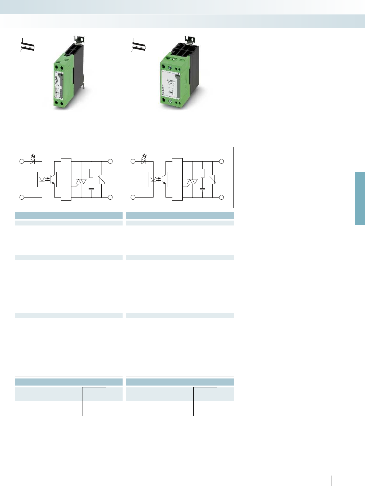
A1
+
A2
-
1/L1
2/T1
A1
+
A2
-
1/L1
2/T1
For further information and full technical data, visit phoenixcontact.net/products
Technical data Technical data
Input voltage range 4 V DC ... 32 V DC 24 V AC ... 275 V AC 4 V DC ... 32 V DC 24 V AC ... 275 V AC 4 V DC ... 32 V DC 24 V AC ... 275 V AC
approx. 12 mA approx. 17 mA approx. 12 mA approx. 17 mA approx. 12 mA approx. 17 mA
4 V DC 22 V AC 4 V DC 22 V AC
1 V DC 6 V AC 1 V DC 6 V AC
25 Hz 6 Hz 25 Hz 6 Hz 25 Hz 6 Hz
Green LED / - / - Green LED / - / -
Output voltage range 42 V AC ... 660 V AC (45/65 Hz) 42 V AC ... 660 V AC (45/65 Hz) 42 V AC ... 660 V AC (45/65 Hz) 42 V AC ... 660 V AC (45/65 Hz) 42 V AC ... 660 V AC (45/65 Hz) 42 V AC ... 660 V AC (45/65 Hz)
Periodic peak reverse voltage 1200 V 1200 V 1200 V 1200 V 1200 V 1200 V
Load current 20 A (see derating curve) 20 A (see derating curve) 30 A (see derating curve) 30 A (see derating curve) 50 A (see derating curve) 50 A (see derating curve)
Surge current 250 A (t = 10 ms) 250 A (t = 10 ms) 400 A (t = 10 ms) 400 A (t = 10 ms) 1900 A (t = 10 ms) 1900 A (t = 10 ms)
Min. load current 350 mA 350 mA 150 mA 150 mA 150 mA 150 mA
Residual voltage < 1.6 V < 1.6 V < 1.6 V < 1.6 V < 1.6 V < 1.6 V
Leakage current < 3 mA (in off state) < 3 mA (in off state) < 3 mA (in off state) < 3 mA (in off state) < 3 mA (in off state) < 3 mA (in off state)
) 0.5 0.5 0.5 0.5 0.5 0.5
s 1800 A
2
s 1800 A
2
s 18000 A
2
s 18000 A
2
s
RCV circuit RCV circuit
4 kV
rms
4 kV
rms
Basic insulation Basic insulation
-30 °C ... 70 °C -30 °C ... 70 °C
EN 61000-4-2 / EN 61000-4-3 / EN 61000-4-4 / EN 61000-4-5 /
EN 61000-4-6 / EN 55011
EN 61000-4-2 / EN 61000-4-3 / EN 61000-4-4 / EN 61000-4-5 /
EN 61000-4-6 / EN 55011
Mounting position Vertical (horizontal DIN rail) Vertical (horizontal DIN rail) Vertical (horizontal DIN rail)
22.5 mm spacing Can be aligned with 22.5 mm spacing Can be aligned with 22.5 mm spacing
- Control side 0.5 - 2.5 mm² / 0.5 - 2.5 mm² / 20 - 14 0.5 - 2.5 mm² / 0.5 - 2.5 mm² / 20 - 14 0.5 - 4 mm² / 0.5 - 4 mm² / 20 - 12
- Load side 0.5 - 4 mm² / 0.5 - 4 mm² / 20 - 12 0.5 - 4 mm² / 0.5 - 4 mm² / 20 - 12 4 - 25 mm² / 4 - 25 mm² / 12 - 3
Dimensions W / H / D 22.5 mm / 103 mm / 103 mm 22.5 mm / 103 mm / 103 mm 45 mm / 103 mm / 103 mm
Ordering data Ordering data
Type Order No. Pcs. /
Pkt. Type Order No. Pcs. /
Pkt.
ELR 1- 24DC/600AC-30 2297154 1ELR 1- 24DC/600AC-50 2297170 1
ELR 1-230AC/600AC-30 2297167 1ELR 1-230AC/600AC-50 2297183 1
45
PHOENIX CONTACT
Electronic switching devices and motor control
Solid-state contactors
Zero voltage
switch
Zero voltage
switch
H
W
D
H
W
D
For switching 1~ AC motors
up to660VAC/30A
For switching 1~ AC motors
up to660VAC/50A

PROFIBUS
46
PHOENIX CONTACT
PROFINET motor starters
Motor starters in robust stainless steel
housing (IP67) can be used directly in the
system as a compact function unit. This
eliminates the complex wiring of individual
functions in the control cabinet.
The motor starter can be used to control
three-phase asynchronous motors in two
directions of rotation, completely via
PROFINET. Distributed sensors and
actuators can be directly connected to
PROFINET without the need for further
intermediate stations or additional cabling.
A complete PROFINET motor starter
consists of three products. For example:
– ELR 5011 IP PN
– IBS IP 400 MBH-F
– IBS PG SET
Additional features:
– Performance classes: 1.1 kW to 3.0 kW
– One and two-motor reversing starters
(CONTACTRON hybrid motor starter)
– Easy assembly
– Plug-in connection system
– Exchangeable module electronics
– Status and diagnostics indicators on the
module
– 10 digital inputs for connecting sensors
– 4 digital outputs for connecting actuators
Technical data
ELR 5011 IP PN ELR 5011-2 IP PN ELR 5030 IP PN ELR 5030-2 IP PN IBS IP 400 MBH -F
Interface
Fieldbus system PROFINET
Connection method 8-pos. RJ45 socket on motor starter 8-pos. RJ45 socket on motor starter -
Power supply for module electronics
Supply voltage 24 V DC (U
S1
/ U
S2
)
Supply voltage range 20 V DC ... 30 V DC (including ripple) 20 V DC ... 30 V DC (including ripple) -
Power supply for sensors
Minimum voltage U
INI
= U
S1
minus 1 V
Nominal current per sensor 500 mA
Type of protection Short-circuit/overload protection Short-circuit/overload protection -
Digital inputs
Number of inputs 10
Connection method M12 connector
Connection method 2, 3, 4-wire
Digital outputs
Number of outputs 4
Connection method M12 connector
Connection method 2-wire
Output current max. 500 mA (per channel) max. 500 mA (per channel) -
Motor starter, output
Connection method POWER-COMBICON POWER-COMBICON -
Operating voltage 360 V AC ... 550 V AC (line voltage 50/60 Hz) 360 V AC ... 550 V AC (line voltage 50/60 Hz) -
Nominal current range 0.18 A ... 2.4 A
Frequency range 50 Hz ... 60 Hz (mains frequency) 50 Hz ... 60 Hz (mains frequency) -
Nominal motor power 1.1 kW (at U
mains
= 400 V AC) 3 kW (at U
Motor monitoring
Parameterization range 0.2 A ... 2.4 A
Tripping class Based on class 10 A of IEC 60947 Based on class 10 A of IEC 60947 -
General data
Weight 2115 g 2425 g 2115 g 2425 g 1130 g -
Degree of protection IP67 in acc. with IEC 60529 IP67 in acc. with IEC 60529 IP67 in acc. with IEC 60529 -
Ambient temperature (operation) -25 °C ... 50 °C (non-condensing) -25 °C ... 50 °C (non-condensing) -
EMC note
Ordering data
Description Type Order No. Pcs. /
Pkt.
PROFINET motor starter
- 1-channel reversing starter, 1.1kW ELR 5011 IP PN 2700745 1
- 2-channel reversing starter, 1.1kW ELR 5011-2 IP PN 2701007 1
PROFINET motor starter
- 1-channel reversing starter, 3.0kW
- 2-channel reversing starter, 3.0kW
Lower housing part, stainless steel
- Standard version IBS IP 400 MBH -F 2732868 1
Pg screw connection, plastic (IP67), for INTERBUS and
PROFINET motor starters and variable frequency drives.
IBS PG SET 2836599 1
Accessories
RJ45 connector, shielded, with bend protection sleeve, x 2
- gray for straight cables FL PLUG RJ45 GR/2 2744856 1
- green for crossed cables FL PLUG RJ45 GN/2 2744571 1
Bus system cable VS-937/... 1402611 1
Crimping pliers, for assembling the RJ45 connectors FL CRIMPTOOL 2744869 1
Electronic switching devices and motor control
IP67 motor starters
Electronic motor starters,
1 x 1.1 kW and 2 x 1.1 kW

For further information and full technical data, visit phoenixcontact.net/products
47
PHOENIX CONTACT
Technical data Technical data
ELR 5011 IP PN ELR 5011-2 IP PN ELR 5030 IP PN ELR 5030-2 IP PN IBS IP 400 MBH -F
PROFINET -
Connection method 8-pos. RJ45 socket on motor starter 8-pos. RJ45 socket on motor starter -
24 V DC (U
S1
/ U
S2
)-
Supply voltage range 20 V DC ... 30 V DC (including ripple) 20 V DC ... 30 V DC (including ripple) -
U
INI
= U
S1
minus 1 V -
500 mA -
Type of protection Short-circuit/overload protection Short-circuit/overload protection -
10 -
M12 connector -
2, 3, 4-wire -
4-
M12 connector -
2-wire -
max. 500 mA (per channel) max. 500 mA (per channel) -
POWER-COMBICON POWER-COMBICON -
Operating voltage 360 V AC ... 550 V AC (line voltage 50/60 Hz) 360 V AC ... 550 V AC (line voltage 50/60 Hz) -
2.4 A ... 6 A -
Frequency range 50 Hz ... 60 Hz (mains frequency) 50 Hz ... 60 Hz (mains frequency) -
= 400 V AC) 3 kW (at U
mains
= 400 V AC) -
2.4 A ... 6 A -
Based on class 10 A of IEC 60947 Based on class 10 A of IEC 60947 -
2115 g 2425 g 2115 g 2425 g 1130 g -
Degree of protection IP67 in acc. with IEC 60529 IP67 in acc. with IEC 60529 IP67 in acc. with IEC 60529 -
Ambient temperature (operation) -25 °C ... 50 °C (non-condensing) -25 °C ... 50 °C (non-condensing) -
Class A product, see page 625
Ordering data Ordering data
Type Order No. Pcs. /
Pkt. Type Order No. Pcs. /
Pkt.
ELR 5030 IP PN 2701006 1
ELR 5030-2 IP PN 2701008 1
IBS IP 400 MBH -F 2732868 1IBS IP 400 MBH -F 2732868 1
IBS PG SET 2836599 1IBS PG SET 2836599 1
Accessories Accessories
FL PLUG RJ45 GR/2 2744856 1FL PLUG RJ45 GR/2 2744856 1
FL PLUG RJ45 GN/2 2744571 1FL PLUG RJ45 GN/2 2744571 1
VS-937/... 1402611 1VS-937/... 1402611 1
FL CRIMPTOOL 2744869 1FL CRIMPTOOL 2744869 1
Electronic switching devices and motor control
IP67 motor starters
Electronic motor starters,
1 x 3.0 kW and 2 x 3.0 kW
Stainless steel lower housing part,
IP67 protection

48
PHOENIX CONTACT
Inline frequency inverters
Inline frequency inverters for the control
cabinet are the compact solution for
extending your Easy Automation solution
to include electronic speed regulation for
asynchronous motors. The devices
seamlessly integrate into the Inline system
and have IP20 protection. Depending on the
drive task, you can select frequency
inverters from various performance classes,
up to a maximum of 4 kW. In order to
connect to the Inline system via the
Fieldline local bus, you just need the
IB IL 24 FLM-PAC Inline module. The Inline
frequency inverter can be connected to a
Phoenix Contact controller via the Inline
module.
Additional features:
– Max. motor power of
0.75 kW, 1.5 kW, 2.2 kW, and 4.0 kW
– 3 x 400V mains input (±15%) 50/60Hz
– DTM for parameterization and
diagnostics
– 8 freely programmable parameter records
– PTC evaluation for
2.2 kW and 4.0 kW versions
– Integrated line filter
– U/f linear and U/f square operating modes
– S-ramp function
– Motor protection function (It)
– Connection of a braking resistor
– DC braking
– Evaluation of the temperature switch in
the motor
– Voltage boost
– 1 x analog input, 1 x analog output,
1 x relay output
Technical data
Interface
Designation Fieldline local bus
Connection method 9-pos. D-SUB connector/socket 9-pos. D-SUB connector/socket 9-pos. D-SUB connector/socket 9-pos. D-SUB connector/
Power supply for module electronics
Supply voltage 24 V DC ±15 %
Supply voltage range 20.4 V DC ... 27.6 V DC ±15 % 20.4 V DC ... 27.6 V DC ±15 % 20.4 V DC ... 27.6 V DC ±15 % 20.4 V DC ... 27.6 V
Digital inputs
Number of inputs 5
Connection method COMBICON
Connection method Spring-cage connection Spring-cage co
Analog inputs
Number of inputs 1
Connection method COMBICON
Connection method Spring-cage connection Spring-cage co
Analog outputs
Number of inputs 1
Connection method COMBICON
Connection method Spring-cage connection Spring-cage co
Frequency inverter output
Rated current 2.6 A +20 %
Frequency range 0 Hz ... 400 Hz
Parameterization Via INTERBUS
Tripping class 5.6 A OC tripping current 8.8 A OC tripping current 12.5 A OC tripping current 21 A OC tripping current
General data
Weight 1400 g
Degree of protection IP20 in acc. with IEC 60529/ EN 60529 IP20 in
Width 90 mm
Height 173 mm
Depth 153.5 mm
Ordering data
Description Type Order No. Pcs. /
Pkt.
Inline frequency inverter for the control cabinet
VFD 5007 IL IB 2701054 1
Accessories
Inline Modular branch terminal for coupling one
Fieldline Modular M8 local bus at the end of an Inline station
IB IL 24 FLM-PAC 2736903 1
Remote bus cable, highly flexible, 3 x 2 x 0.25 mm² IBS RBC/F-T/ 2740151 1
Electronic switching devices and motor control
IP20 frequency inverters
Frequency inverter for max.
motor power of up to 0.75 kW
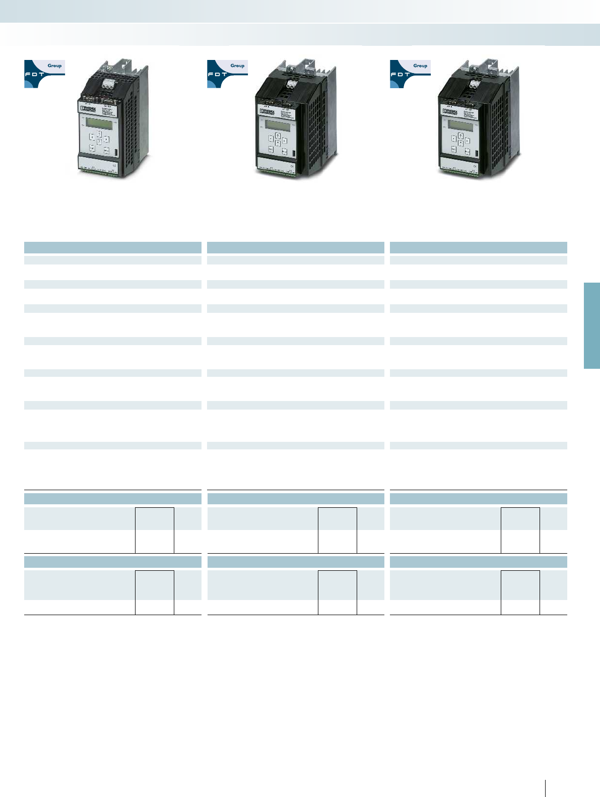
For further information and full technical data, visit phoenixcontact.net/products
49PHOENIX CONTACT
Technical data Technical data Technical data
Fieldline local bus Fieldline local bus Fieldline local bus
Connection method 9-pos. D-SUB connector/socket 9-pos. D-SUB connector/socket 9-pos. D-SUB connector/socket 9-pos. D-SUB connector/socket
24 V DC ±15 % 24 V DC ±15 % 24 V DC ±15 %
Supply voltage range 20.4 V DC ... 27.6 V DC ±15 % 20.4 V DC ... 27.6 V DC ±15 % 20.4 V DC ... 27.6 V DC ±15 % 20.4 V DC ... 27.6 V DC ±15 %
555
COMBICON COMBICON COMBICON
Connection method Spring-cage connection Spring-cage connection Spring-cage connection Spring-cage connection
111
COMBICON COMBICON COMBICON
Connection method Spring-cage connection Spring-cage connection Spring-cage connection Spring-cage connection
111
COMBICON COMBICON COMBICON
Connection method Spring-cage connection Spring-cage connection Spring-cage connection Spring-cage connection
4.1 A +20 % 5.8 A +20 % 9.5 A +20 %
0 Hz ... 400 Hz 0 Hz ... 400 Hz 0 Hz ... 400 Hz
Via INTERBUS Via INTERBUS Via INTERBUS
Tripping class 5.6 A OC tripping current 8.8 A OC tripping current 12.5 A OC tripping current 21 A OC tripping current
1400 g 2200 g 2200 g
Degree of protection IP20 in acc. with IEC 60529/ EN 60529 IP20 in acc. with IEC 60529/ EN 60529 IP20 in acc. with IEC 60529/ EN 60529 IP20 in acc. with IEC 60529/ EN 60529
90 mm 117 mm 117 mm
173 mm 173 mm 173 mm
153.5 mm 174.5 mm 174.5 mm
Ordering data Ordering data Ordering data
Type Order No. Pcs. /
Pkt. Type Order No. Pcs. /
Pkt. Type Order No. Pcs. /
Pkt.
VFD 5015 IL IB 2701055 1VFD 5022 IL IB 2701057 1VFD 5040 IL IB 2701058 1
Accessories Accessories Accessories
IB IL 24 FLM-PAC 2736903 1IB IL 24 FLM-PAC 2736903 1IB IL 24 FLM-PAC 2736903 1
IBS RBC/F-T/ 2740151 1IBS RBC/F-T/ 2740151 1IBS RBC/F-T/ 2740151 1
Electronic switching devices and motor control
IP20 frequency inverters
Frequency inverter for max.
motor power of up to 1.5 kW
Frequency inverter for max.
motor power of up to 2.2 kW
Frequency inverter for max.
motor power of up to 4.0 kW
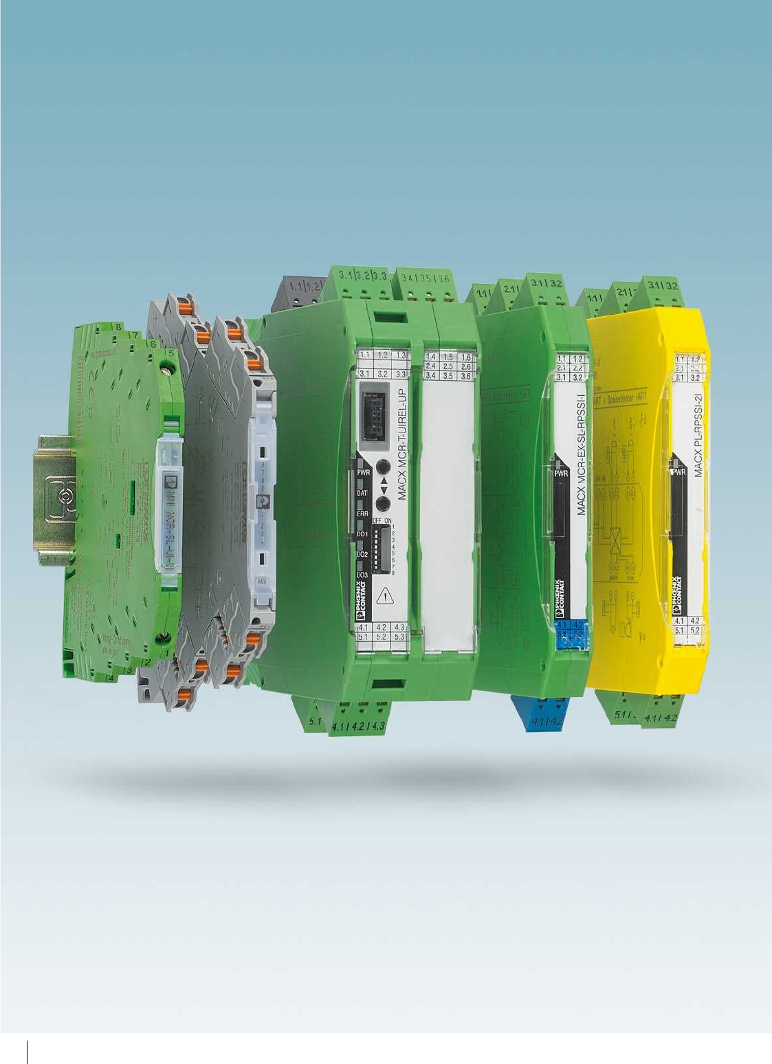
50
PHOENIX CONTACT

Product range overview
Product overview 52
Selection guide for signal conditioners 56
Basics 58
Highly compact signal conditioners with
plug-in connection technology – MINI Analog Pro
64
Highly compactsignal conditioners–
MINIAnalog
90
Signal conditioners, head transducers, and
process indicators – MCR Analog
128
Signal conditioners with functional safety and
explosion protection - the MACX ranges
142
Signal conditioners with
SIL functional safety – MACXAnalog
152
Signal conditioners with
PL functional safety – MACX Safety
184
Exi signal conditioners with
SILfunctional safety – MACXAnalog Ex
188
Ex i signal conditioners with
PL functional safety – MACX Safety Ex
218
Multiplexers for HART signals 222
Ex i 2-wire field devices 223
51
PHOENIX CONTACT
From highly compact 6 mm signal
conditioners to functionally safe signal
conditioners through to signal isolators for
intrinsically safe circuits in the Ex area: our
signal conditioner range offers a solution for
all applications in analog signal conditioning.
We offer the following product ranges:
Highly compact signal conditioners
with plug-in connection technology –
MINI Analog Pro
For maximum convenience during
installation and service
– Overall width of just 6.2 mm
– Current measurement without isolation
– Safe electrical isolation
Highly compact signal conditioners –
MINI Analog
For significant space savings and efficiency
– Overall width of just 6.2 mm
– System cabling and multiplexer solutions
– Electrical isolation
Signal conditioners, head transducers,
and digital displays – MCR Analog
– Electrical isolation
– Record and convert temperatures
directly in the field
– Display process values
Signal conditioners with
SIL functional safety – MACX Analog
Formaximumsignal safety
– Consistent SIL certification
– Safe electrical isolation
Signal conditioners with
PL functional safety – MACX Safety
The proven MACX range for safety
applications according to the Machinery
Directive
Ex i signal conditioners with
SIL functional safety – MACX Analog Ex
For intrinsically safe circuits in the Ex area
– Maximum explosion protection for all
Ex zones and gas groups
– Safe electrical isolation
Ex i signal conditioners with
PL functional safety – MACX Safety Ex
The proven MACX EX range for safety
applications according to the Machinery
Directive
MCR technology
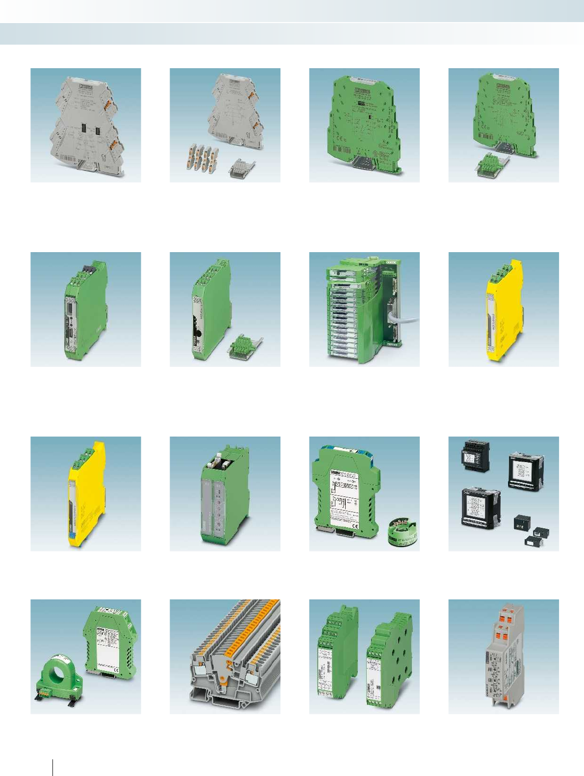
Highly compact signal conditioners with
plug-in connection technology
Highly compact signal conditioners
MINI Analog Pro
Page 64
Accessories for MINI Analog Pro
Page 84
MINI Analog
Page 90
Supply components, feed-through terminal
blocks, marking material Page 116
Signal conditioners with
SIL functional safety
Signal conditioners with
PL functional safety
MACX Analog
Page 152
Supply components, marking material
Page 178
System cabling, Termination Carriers
Page 182
MACX Safety
Page 184
Ex i signal conditioners with
PL functional safety
Multiplexers Ex i 2-wire field devices Energy and
power measurement
MACX Safety Ex
Page 218
Multiplexers for HART signals
Page 222
Ex i 2-wire field devices
Page 223
EMpro energy meters, function and
communication modules Page 238
Monitoring and diagnostics Controllers Surge protection
AC current transducers, AC/DC, AC current
protectors Page 272
Test disconnect terminal blocks
See Catalog 3
SOLARCHECK PV string monitoring
Page 282
EMD-BL
Compact monitoring relays Page 298
52
PHOENIX CONTACT
MCR technology
Product overview
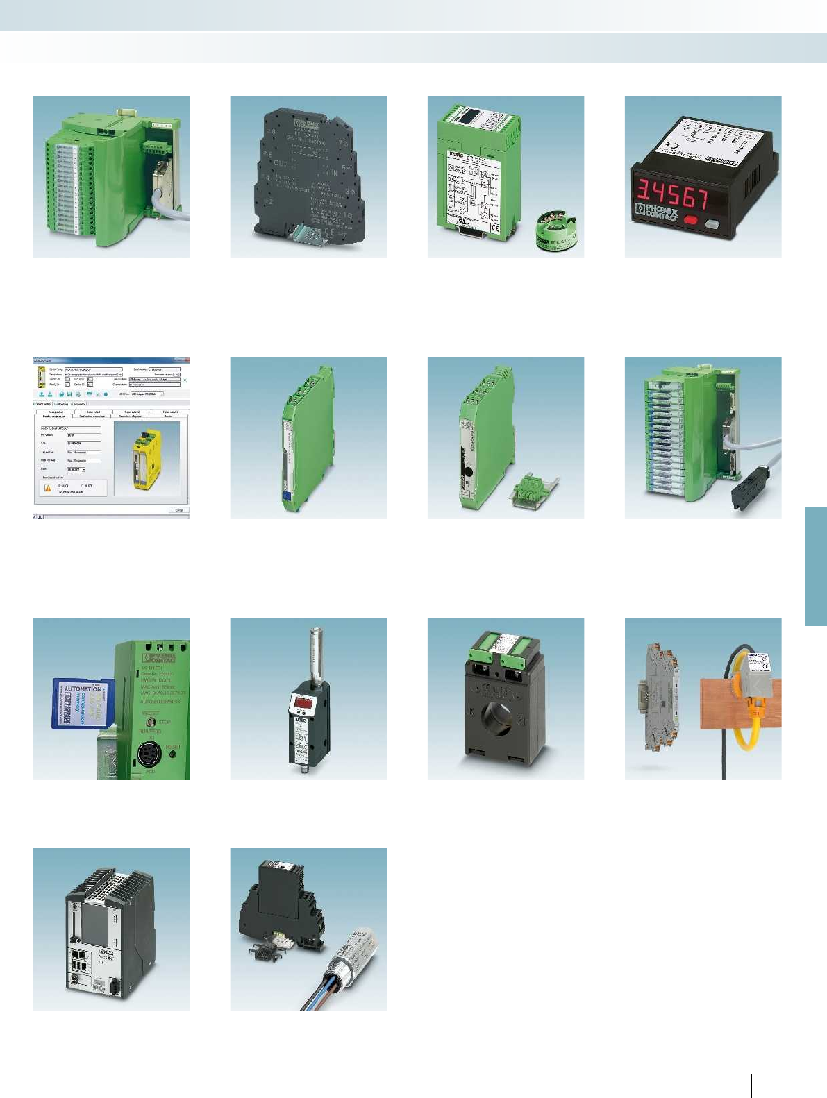
For further information and full technical data, visit phoenixcontact.net/products
Signal conditioners, head transducers, and
process indicators
System cabling, Termination Carriers
Page 120
Surge protection
Page 126
MCR Analog
Page 128
Process indicators
Page 140
Ex i signal conditioners with
SIL functional safety
Configuration software
Page 187
MACX Analog Ex
Page 188
Supply components, marking material
Page 213
System cabling, Termination Carriers
Page 216
Current measurement
Software for usage data acquisition
Page 244
PSK compressed air meters
Page 246
PACT current transformers
Page 252
PACT RCP current transformers for
retrofitting Page 298
Monitoring and diagnostics Controllers Surge protection
Controllers
See Catalog 8
Surge protection for MCR technology
See Catalog 6
53
PHOENIX CONTACT
MCR technology
Product overview
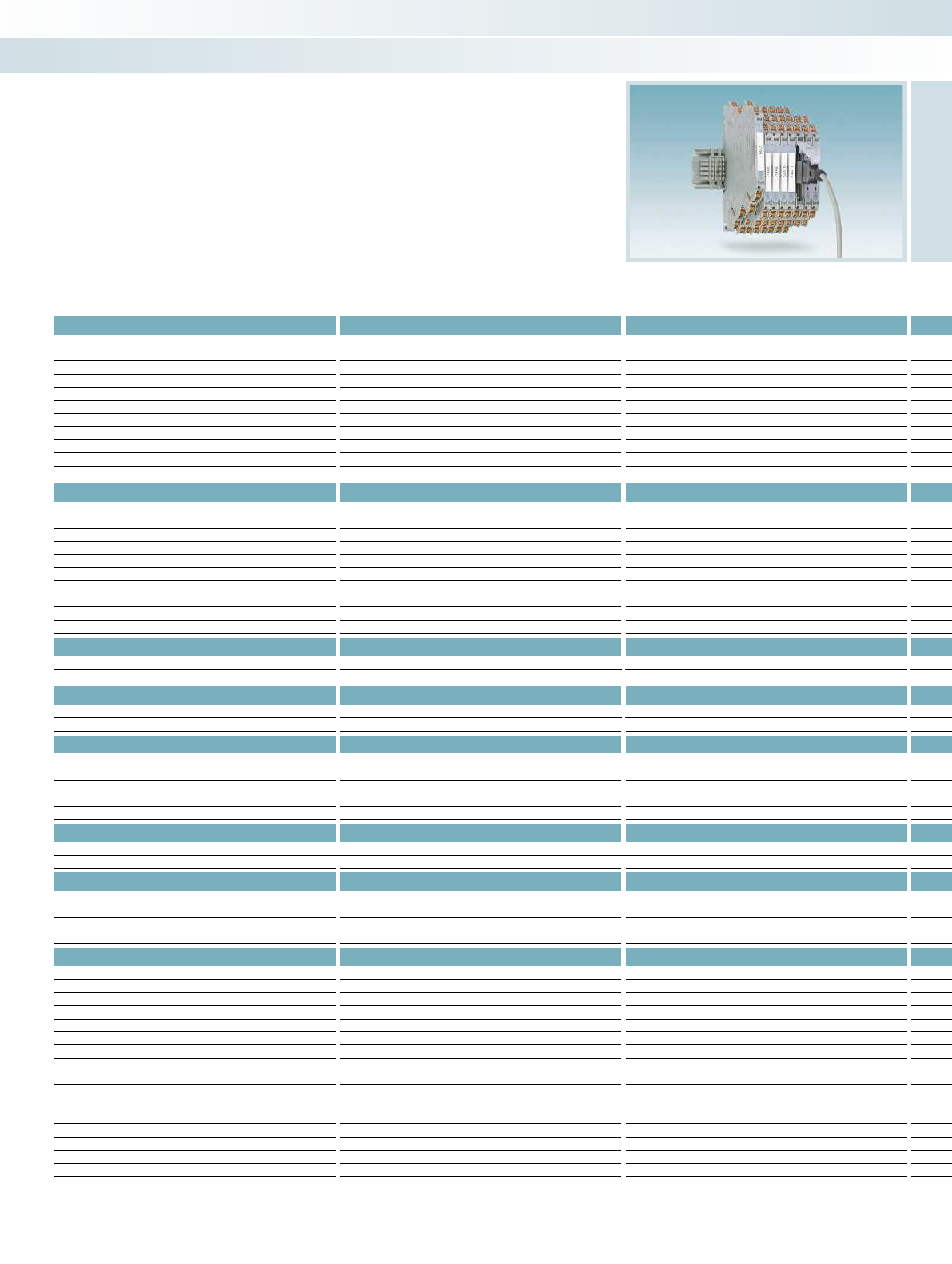
Highly compact signal conditioners -
MINI Analog Pro
Analog IN/Analog OUT Page
3-way signal conditioners Configurable From 68
Fixed signal combinations 70
4-way signal duplicators Configurable
3-way repeater power supplies Single-channel 71
Signal duplicators
Two-channel
2-way passive isolators Input loop-powered
Output loop-powered 72
3-way output isolator Fixed signal combinations
Process indicators Standard signals
Setpoint adjusters
Temperature
Temperature transducers Universal
Universal, output loop-powered
For resistance thermometers (RTD) 74
For resistance thermometers (RTD), passive
For Pt 100
For Pt 100, output loop-powered
For thermocouples 76
For thermocouples, type J and K
Temperature head transmitters Universal, output loop-powered
Pt 100, output loop-powered
Frequency
Frequency transducers Universal
Analog frequency transducers 78
Potentiometer/resistor
Potiposition transducers 80
Setpoint potentiometers
Digital IN
Signal conditioners NAMUR sensors, floating contacts 82
NAMUR sensors, floating contacts, 2-channel
NAMUR sensors on NAM
Digital OUT
Solenoid drivers Loop-powered
With line fault detection
Threshold values
Threshold value switches Standard analog signals, universal 83
Standard analog signals
Temperature
Accessories
Configuration
Programming adapters 89
Constant voltage source/constant current source 84
Setpoint potentiometers
System cabling System adapters
1:1 feed-through terminal block 88
Termination Carriers
Multiplexers Analog multiplexers
Multiplexers for HART signals
Supply components Power terminal/fault signaling modules/
DIN rail connector/system power supply From 86
Marking material 89
Surge protection
Shield fast connection
Resistance circuit For line fault detection
Connector set Screw connection or push-in connection 85
54
PHOENIX CONTACT
MCR technology
Selection guide for signal conditioners
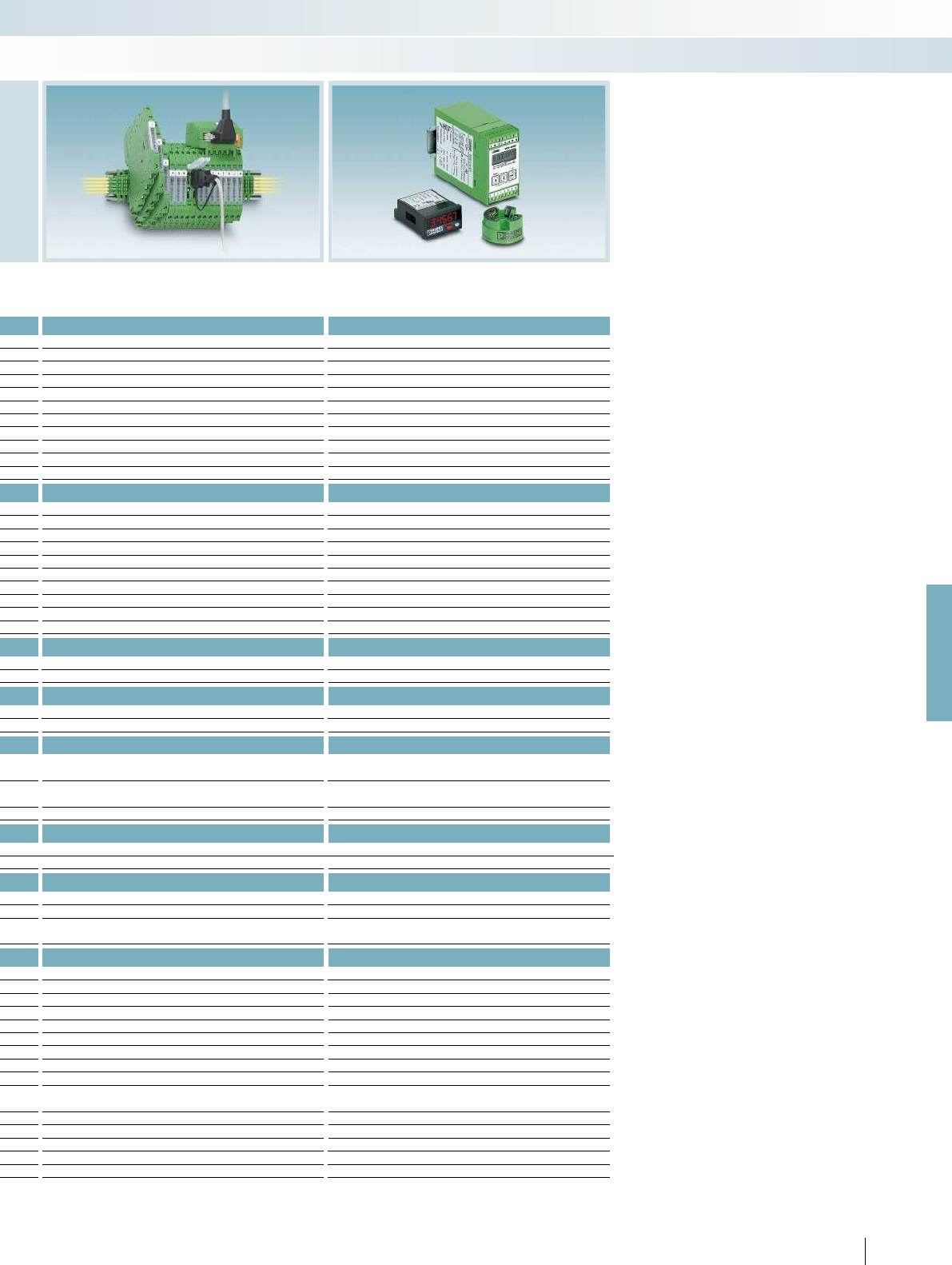
For further information and full technical data, visit phoenixcontact.net/products
Highly compact signal conditioners -
MINI Analog
Signal conditioners, head transducers,
and process indicators - MCR Analog
Page Page
From 92
97
98 130
99
101
102
100
140
141
133
103
From 104
106
107
108
134
135
109 136
110
111
139
112
138
113
132
138
89
114
139
122
116
125
123
222
From 116
117
126
227
180
55PHOENIX CONTACT
MCR technology
Selection guide for signal conditioners
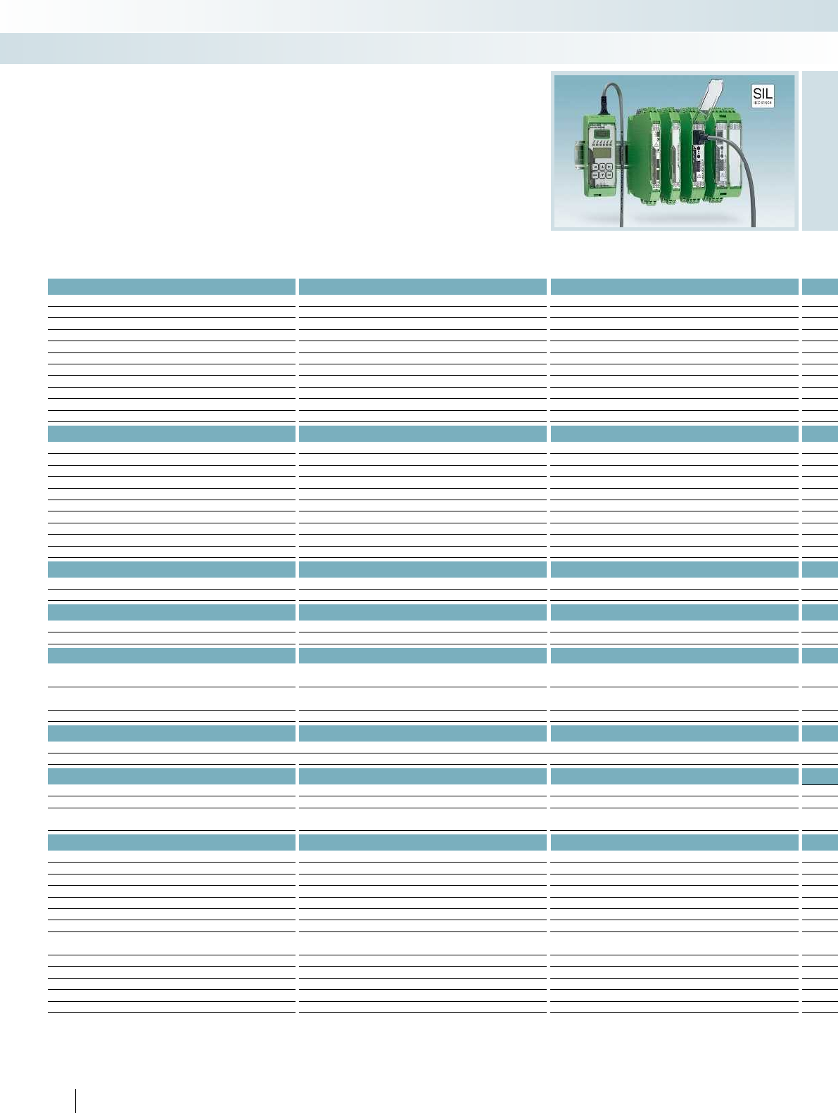
Signal conditioners with SIL
functional safety - MACX Analog
Analog IN/Analog OUT Page
3-way signal conditioners Configurable From 154
Fixed signal combinations
4-way signal duplicators Configurable
3-way repeater power supplies Single-channel 158
Signal duplicators 159
Two-channel 161
2-way passive isolators Input loop-powered
Output loop-powered
3-way output isolators Fixed signal combinations 162
Process indicators Standard signals
Setpoint adjusters
Temperature
Temperature transducers Universal From 163
Universal, output loop-powered
For resistance thermometers (RTD) 166
For resistance thermometers (RTD), passive
For Pt 100
For Pt 100, output loop-powered
For thermocouples 168
For thermocouples, type J and K
Temperature head transmitters Universal, output loop-powered
Pt 100, output loop-powered
Frequency
Frequency transducers Universal
Analog frequency transducers
Potentiometer/resistor
Potiposition transducers From 164
Setpoint potentiometers
Digital IN
Signal conditioners NAMUR sensors, floating contacts 172
176
NAMUR sensors, floating contacts, 2-channel 174
177
NAMUR sensors on NAM
Digital OUT
Solenoid drivers Loop-powered
With line fault detection
Threshold values
Threshold value switches Standard analog signals, universal
Standard analog signals
Temperature 163
Accessories
Configuration Configuration software
Programming adapter 89
Display unit and operator interface, removable 170
Holder module for display unit and operator interface 170
Termination Carriers 183
Multiplexers Analog multiplexer
Multiplexer for HART signals 222
Supply components Power terminal/fault signaling modules/
DIN rail connector/system power supply From 178
Marking material 179
Surge protection
Shield fast connection 227
Test plugs 180
Resistance circuit For line fault detection 180
56
PHOENIX CONTACT
MCR technology
Selection guide for signal conditioners
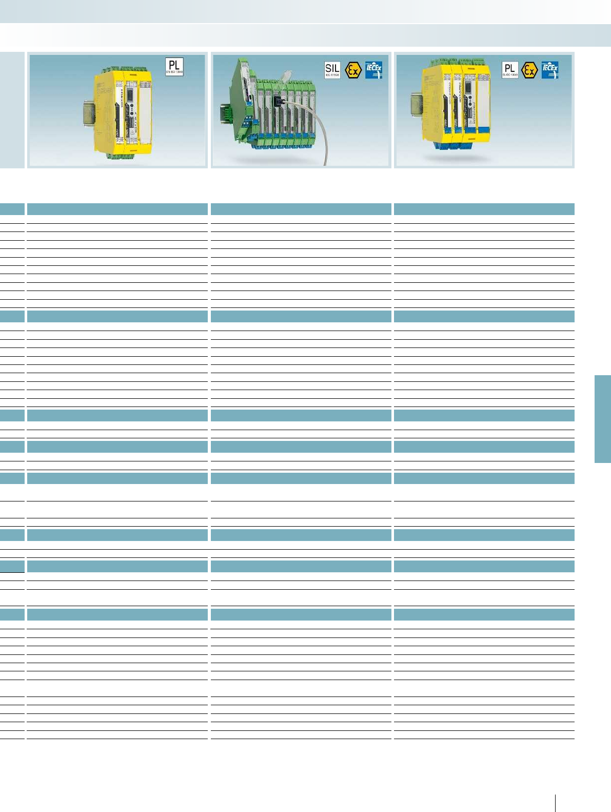
For further information and full technical data, visit phoenixcontact.net/products
Signal conditioners with PL
functional safety - MACX Safety
Ex i signal conditioners with SIL
functional safety - MACX Analog Ex
Ex i signal conditioners with PL
functional safety - MACX Safety Ex
Page Page Page
190
190
185 191 219
192 220
194
186 From 198 221
223
195
196
224
225
186 From 198
201
205
203
206
207
From 209
209
186 200 221
89
89 226
216
222
178
179
227
180
180
57PHOENIX CONTACT
MCR technology
Selection guide for signal conditioners

Input
Maximum input signal
The maximum input signal describes the
value achieved before any damage occurs to
the module and the signal generator. If these
values are exceeded, suppressor diodes can
be triggered to short circuit this input when
a surge voltage is detected. The
transmission range of the analog signals is
located exclusively within the specified
input ranges.
Input resistance
The input resistance of a signal
conditioner or measuring transducer is
determined in such a way as to ensure that
the input signal is loaded only slightly. This
results in a low-resistance input for current
inputs and a high-resistance input for
voltage inputs.
Voltage drop
In the case of passive isolators, the input
voltage drop occurs as a result of the
voltage drop of the operational load and the
auxiliary power consumption of the
module. The greater the auxiliary power
consumption of the passive isolator, the
smaller the operational output load is
allowed to be. Low auxiliary power
consumption is regarded as an indicator of
device quality.
Common mode rejection
In the case of signal conditioners,
operational amplifiers are used internally for
transmission. In theory, operational
amplifiers should display ideal transmission
and amplification behavior. However, it is a
different matter in practice. When both
input voltages are changed in the same
direction, i.e., exactly the same voltage to
ground is applied to both input terminal
blocks, this leads to an unintended output
signal. Theoretically, if the operational
amplifier is ideal, no output signal should
appear since the differential input signal is “0
V”. Common mode rejection indicates the
factor (in dB) by which the common input
voltage at both inputs is amplified to a lesser
extent than the difference in voltage
between the two inputs.
Analog output
Maximum output signal
During uninterrupted operation of the
devices, an overload at the input cannot
cause greater values than at the output.
Zero/span adjustment
When the zero point is set, the zero point
of an analog output is adjusted and set in
relation to the input signal.
When the “amplification” span is set, the
analog output is adjusted in relation to the
input signal. In this case, the output
characteristic curve is increased or
decreased by an amplification factor.
Load
The load on the output side indicates the
load-carrying capacity of a measuring
transducer or a signal conditioner. Current
outputs can usually drive a maximum of
500 , voltage outputs can be loaded with a
minimum of up to 10 k.
Residual ripple/ripple
A superimposed ripple can appear on the
output signal due to signal conditioning
required by the circuit. The residual ripple is
indicated in mV
PP
or mV
rms
.
Open-circuit behavior
With some measuring transducers, the
input signal is permanently monitored for
possible open circuits in the signal line. If the
signal exceeds or falls below a tolerance
limit, an open circuit is detected and a
defined output signal is sent. With
programmable devices, the output signals
can be freely selected.
Digital output
Relays
Many of the products with a relay output
that are shown in the catalog feature hard
gold-plated relay contact material. The
voltage range has an important role to play
in terms of how this contact material can be
used. Up to 50 mA can be transmitted with
voltage ranges of up to 30 V AC/36 V DC.
Even very small currents are transmitted
perfectly. If the afore-mentioned voltage
range is exceeded and values of 250 V
AC/DC are processed, currents of up to 2
A can flow. However, in this case the
subsequent transmission of small currents
can no longer be guaranteed.
Transistor
A PNP transistor switching output can be
used to transmit 24 V DC switching signals
up to approximately 100 mA.
General data
Supply voltage
The product range includes DC and AC
power supplies for specific products. There
is a standard power supply available in the
form of a 24 V DC version that operates
within a voltage range of 20 ... 30 V DC. For
other supply voltages, please refer to the
technical data.
Current consumption
The value specified here describes the
self-consumption of the devices. It also
includes the output current and, where
applicable, the switching output load.
Transmission errors
The transmission precision is a gauge of
the quality of a measuring transducer. It is
the deviation from the ideal transmission
characteristic curve and includes linearity,
span, and offset errors.
Non-linearity
Non-linearity is the deviation from the
ideal transmission precision without
including span and offset errors.
The non-linearity of a signal makes it
possible to evaluate the course from zero
to end point. Normally, the linearity errors
are expressed as a percentage that indicates
the extent of deviation from the ideal
transmission characteristic curve.
58
PHOENIX CONTACT
MCR technology
Basics

For further information and full technical data, visit phoenixcontact.net/products
Temperature coefficient
The temperature coefficient provides an
assessment of the extent to which precision
deviates when the ambient temperature
around a signal conditioner or measuring
transducer changes. In most cases this is
specified as a percentage. An alternative
definition is ppm/K (parts per
million/Kelvin). Example:
250 ppm/K = 0.025%/K.
Cut-off frequency
Signal conditioners are generally designed
for transmitting DC signals. However, signal
changes call for a dynamic form of behavior
so that small AC quantities (normally:
30 Hz) can also be transmitted. This is
achieved by defining a cut-off frequency.
At the same time, a low cut-off frequency
can be used to suppress higher-frequency
AC components.
Step response
The step response indicates the response
time of the output signal when an input
signal step occurs (10 ... 90%). The step
response is inversely proportional to the
cut-off frequency. This means that the
response time decreases as the cut-off
frequency increases.
Te s t vo l t a g e
The test voltage indicates the electric
strength of an isolated distance and is
determined by type tests. In this test, a
50 Hz voltage is applied for one minute;
it describes the value achieved before a
disruptive discharge is able to move to
another potential level in the device.
Safe isolation
“Safe isolation” is defined as protection
against hazardous shock currents. When
module specifications are provided
according to EN 61010, a distinction is
made between error-free operation and
operation under fault conditions. With
error-free operation, nominal supply
voltages of 30 V AC/60 V DC are valid.
Ambient temperature range
The temperature limits specified here
relate exclusively to operation. These limits
do not apply to storage and transport. It is
here where the temperature limits of the
materials used are the decisive factor. If the
devices are outside of the specified
temperature range during assembly, they
must be brought back within the specified
temperature range prior to system startup.
It is important to make sure that no
condensation occurs.
Protective circuit
In order to protect the measurement and
control modules against surge voltages,
suppressor diodes are connected upstream
of the signal and supply paths. These diodes
behave in a similar manner to conventional
Zener diodes. Except for the fact that
suppressor diodes have faster response
times and a higher maximum current.
Directives EU International
Electromagnetic Compatibility Directive (EMC) 2004/108/EC -
Low-Voltage Directive (LVD) 2006/95/EC -
Ex Directive (ATEX) 94/9/EC -
Product standards
Electronic equipment for use in power installations EN 50178:1997 -
Safety requirements for electrical equipment for measurement, control, and laboratory use -
Part 1: General requirements EN 61010-1:2001 IEC 61010-1:2004
Programmable logic controllers -
Part 2: Equipment requirements and tests EN 61131-2:2007 IEC 61131-2:2007
EMC
EMC - Part 6-2: Generic standards - Immunity for industrial environments EN 61000-6-2:2005 IEC 61000-6-2:2005
EMC - Part 6-4: Generic standards - Emission standard for industrial environments EN 61000-6-4:2007 IEC 61000-6-4:2006
Electrical equipment for measurement, control, and laboratory use
EMC requirements EN 61326-1:2006 IEC 61326-1:2005
ATEX
Electrical equipment for explosive gas atmospheres -
Part 0: General requirements EN 60079-0:2006 IEC 60079-0:2007
Explosive atmospheres -
Part 11: Equipment protection by intrinsic safety “i” EN 60079-11:2007 IEC 60079-11:2006
Electrical equipment for explosive gas atmospheres -
Part 15: Construction, test, and marking of protection type “n” electrical equipment EN 60079-15:2005 IEC 60079-15:2005
Environmental tests
Environmental testing -
Part 2-1: Tests - Test A: Cold EN 60068-2-1:2007 IEC 60068-2-1:2007
Environmental testing -
Part 2-2: Tests - Test B: Dry heat EN 60068-2-2:2007 IEC 60068-2-2:2007
Environmental testing -
Part 2-6: Tests - Test Fc: Vibration (sinusoidal) EN 60068-2-6:2008 IEC 60068-2-6:2008
Information on directives and standards
When carrying out further processing of non-independent items of
equipment (components), the applicable regulations pertaining to
installation must be observed.
The relevant device-specific regulations also apply with regard to
installation in devices.
(Standards applicable at the time of going to print)
59
PHOENIX CONTACT
MCR technology
Basics
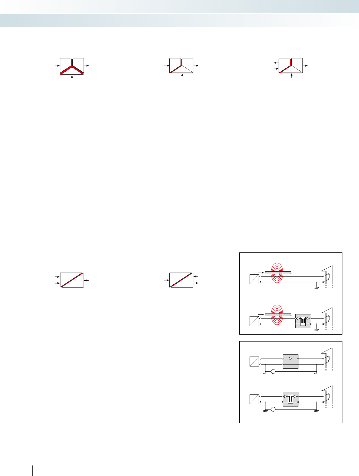
IN
OUT
IN OUT
IN OUT
IN OUT
IN
OUT
I
RE
I
RE
RE
~
RE
~
Passive isolation, supplied on the
input side
The modules draw the power needed for
signal transmission and electrical isolation
from the active input circuit. On the output
side, a conditioned current signal is
provided to the controller or to actuating
elements.
This passive isolation allows signal
conditioning (interruption of ground loops)
and filtering without an additional power
supply.
Input signal
Output signal
Power via signal
3-way isolation
In the case of modules with this isolation
method, all components that are connected
to the input, output or power supply are
protected against interference from each
other. All three directions (input, output,
and power supply) are electrically isolated
from one another accordingly.
The 3-way isolation provides electrical
isolation between the measurement sensor
and the controller as well as between the
controller and the actuating element.
On the input side, the modules need
active signals. On the output side, they
provide a filtered and amplified signal.
Input signal Output signal
POWER
Input isolation
In the case of modules with this isolation
method, the electronics connected on the
output side (e.g., the controller) are to be
protected from interference from the field.
For this reason, only the input is electrically
isolated from the output and the power
supply which are at the same potential.
On the input side, the modules need
active signals (e.g., from measurement
sensors). On the output side, they provide
a filtered and amplified signal (e.g., from the
controller).
Input signal Output signal
POWER
Repeater power supply
Repeater power supplies use the signal
input side not only for measured value
acquisition, but also to provide the
necessary power to the passive
measurement sensors connected on the
input side.
On the output side, they provide a
filtered and amplified signal (e.g., from the
controller).
The isolation method used by these
modules is input isolation.
Input signal
Output signal
POWER
Power for the
measuring transducer
Passive isolation, supplied on the
output side (loop-powered)
The modules obtain the power needed
for signal transmission and electrical
isolation from the active output circuit,
ideally from the PLC input board that
supplies power.
On the output side, the loop-powered
modules operate with a 4 ... 20 mA
standard signal. On the input side, the
passive isolator processes active signals.
When this isolation method is used, it is
important to make sure that the active
signal source connected on the output side
(e.g., an active PLC input board) is able to
supply the passive isolator with power, as
well as operate its load.
Input signal
Output signal
Power
via signal
Active isolation
Applications
Problem: disruptive radiation
Solution:
Problem: voltage difference in the ground potential
Solution:
No ground current
loop
Ground current loop
P
Ground 1
P
Ground 2
P
Ground 1
P
Ground 2
Passive isolation
60
PHOENIX CONTACT
MCR technology
Basics

10000
1000
100
-200
-100
0
100
200
300
400
500
600
700
800
Pt 1000
Pt 100
Pt 10
i
RL1
RL2
i
RL1
RL2
RL3
1
Fe
CuNi
Cu
Cu
0
200
400
600
800
1000
1200
1400
1600
1800
-200
80
60
40
20
0
Typ T
Typ N
Typ K
Typ J
Typ E
Typ B
Typ S
Typ R
For further information and full technical data, visit phoenixcontact.net/products
Three-conductor connection technology
Three-conductor
technology is normally used
to minimize the effect of
cable resistances. An
additional cable is connected
to the resistance thermometer, so that the
latter can be measured using two measuring
circuits, one of which acts as a reference. In
this way, it is possible to compensate for the
cable resistance.
measuring junction (
1
) and
the cold junction (
2
), no
current will flow because the
generated partial voltages
cancel each other out.
However, if the temperatures at the
measuring junction and the cold junction
are different, different voltages are
produced that do not completely cancel
each other out, and thus current flows.
A thermocouple thus always measures
only a temperature difference. This is
derived from the difference between the
thermal voltages at the measuring junction
and at the cold junction.
The voltage produced by the
thermoelectric effect is very low; only a few
microvolts per Kelvin.
Example: If a thermocouple type J (FE-CuNi) is connected to a copper
terminal, thermal voltages with opposite signs will be generated (at the
iron-copper and copper constantan transitions) and cancel each other out.
Therefore, only the difference in the
thermal voltages between constantan
(Cu-Ni) and iron is of relevance.
A role is also played by the temperature
at the terminal point. If it is known, the
temperature at the measuring junction can
be derived by adding the thermal voltage
measured at the same junction.
The MCR temperature transducers for
thermocouples therefore detect the
temperature at the terminal points and
compensate this value, which is also
referred to as the reference junction or the
cold junction.
This process is sometimes called cold
junction compensation.
Four-conductor connection
technology
Four-conductor connection technology is
an ideal connection technology for
resistance thermometers.
The measurement result is affected
neither by cable resistances nor by their
temperature-dependent fluctuations. The
voltage drop on the supply and return lines
can therefore be measured and
compensated for separately. Line
compensation is not necessary.
Two-conductor connection technology
The resistance
thermometer is connected
to the MCR measuring
transducer using a two-core
cable. Please note that the supply cable
resistances are added to the measured
resistance and consequently distort the
result.
A distance of 10 m should not be
exceeded.
Example: a 50 meter long copper cable with a cross section of 0.5 mm
2
has a specific resistance of 3.4 .. A Pt 100 sensor has a resistance change
per 1 K temperature change of 0.384 . This corresponds to an error of
8.8°C.
Resistance thermometers (e.g., Pt 100,
Ni 1000) change their resistance value
depending on the temperature. The MCR
temperature transducers detect this change
and convert it into a proportional analog
signal.
To avoid unwanted self-heating of the
sensor, the constant measured current
used is kept as low as possible
(MCR-T-UI... 250 A).
Resistance thermometers
Thermocouples
In contrast to resistance thermometers,
thermocouples are active sources that
generate a voltage in the microvolt range.
The temperature difference measured
between the measurement junction and the
cold junction is converted into an absolute
temperature with the help of cold junction
compensation.
Operating principle:
If different metals are joined together, a
thermal voltage is produced in the metal
atoms as a result of the different binding
energies of the electrons. This voltage is
dependent firstly on the metals themselves
and secondly on the temperature.
If the same temperature prevails at the
Identical cable lengths and an identical
ambient temperature are essential here.
Since this is more or less the case in the
majority of applications, three-wire
technology is the most commonly
encountered today. Line compensation is
not necessary.
Temperature [°C]
Resistance thermometers:
Resistance change as a function of the temperature
Resistance []
Temperature [°C]
Thermocouple voltage [mV]
Thermocouples:
Thermocouple voltage change as a function of the temperature
61
PHOENIX CONTACT
MCR technology
Basics
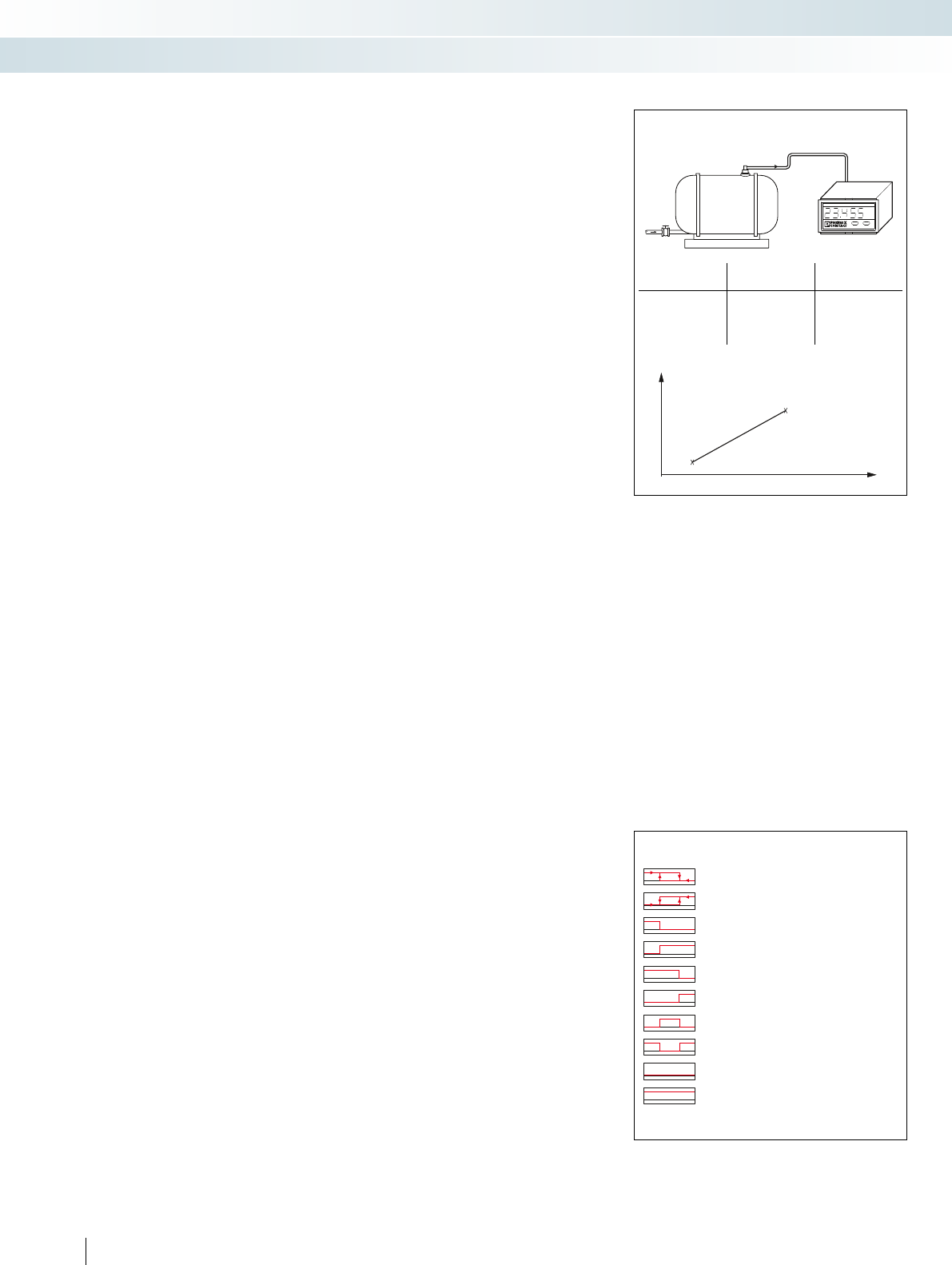
bar
4...20 mA
Switching behavior of relay or
transistor outputs:
A different kind of switching behavior can
be defined for each relay or each transistor
when it reaches a preset switching point.
All the possible settings for the switching
behavior are shown and explained in the list:
– The first two options include hysteresis,
i.e., the behavior of the relay depends on
the direction from which a switching point
is reached.
– For the remaining options, with the
exception of the last two (“on” and “off”),
a switching tolerance is taken into account
to prevent the relay contact from
“chattering”. The relay is not switched
until the switching point plus switching
tolerance has been reached.
– In the “on” state, the relay is permanently
picked up. It only responds if there is an
open circuit and in this case, if the relay is
set to drop out when this happens.
– In the “off” state, the relay only responds
if there is an open circuit and it has been
set to pick up when this happens.
Digital displays
Use of the freely programmable
characteristic curve
The freely programmable characteristic
curve, i.e., the assignment of the displayed
value to the input value, is important in
process applications for indicating flow
rates or liquid levels.
The purpose of level measurements is
very often not to determine how much
liquid is still inside the tank, but rather to
establish how much has been drawn out of
it. In this case, the characteristic curve can
simply be inverted in order to display the
required value.
Parameterization of the
characteristic curve using
interpolation points
With non-linear input signals, the
received analog values can be assigned to
the value to be displayed by means of a
programmable characteristic curve. This
characteristic curve can consist of up to 24
interpolation points. This allows flow
sensors with a non-linear characteristic
curve to be adapted, for instance. The
analog signal digital displays in the Function
Line additionally feature a summing function
which - to take a typical example of use
from bottling technology - allows you to
switch over at the touch of a button from
the instantaneous value (= flow rate in
l/min) to the total flow integrated in the
background, which can be displayed in any
unit. This saves space and money, because
there is no need for a second digital display.
Limit values can also be called at the
touch of a button. Limit values 1 and 2 can
be assigned to either the actual value or the
cumulative value. If the latter value is
exceeded, one of the two output relays is
activated.
Other applications include indicating
liquid levels, pressures, and temperatures.
With servo motors, the analog output
signals (0 ... 10 V) generated by the
tachometer can be supplied to the input of
the digital display in order to indicate the
motor speed.
Application:
Pressure measurement and display on MCR-SL-D-U-I
Table: Analog signal Display value
Interpolation
point 1
4 mA 15 bar
Interpolation
point 2
20 mA 30 bar
Pressure [bar]
Measured value [mA]
Interpolation point 1
Interpolation point 2
Characteristic curve:
Relay picks up when the value is below SPL,
Hysteresis active
Relay picks up when SPH is exceeded,
Hysteresis active
Relay picks up when the value is below SPL
Relay picks up when SPL is exceeded
Relay picks up when the value is below SPH
Relay picks up when SPH is exceeded
Relay picks up when value is between SPL and SPH
Relay picks up when value is outside SPL and SPH
Relay is permanently dropped
Relay is permanently picked up
Possible settings for the switching behavior
SPL = Set Point Low (lower switching point)
SPH = Set Point High (upper switching point)
62
PHOENIX CONTACT
MCR technology
Basics
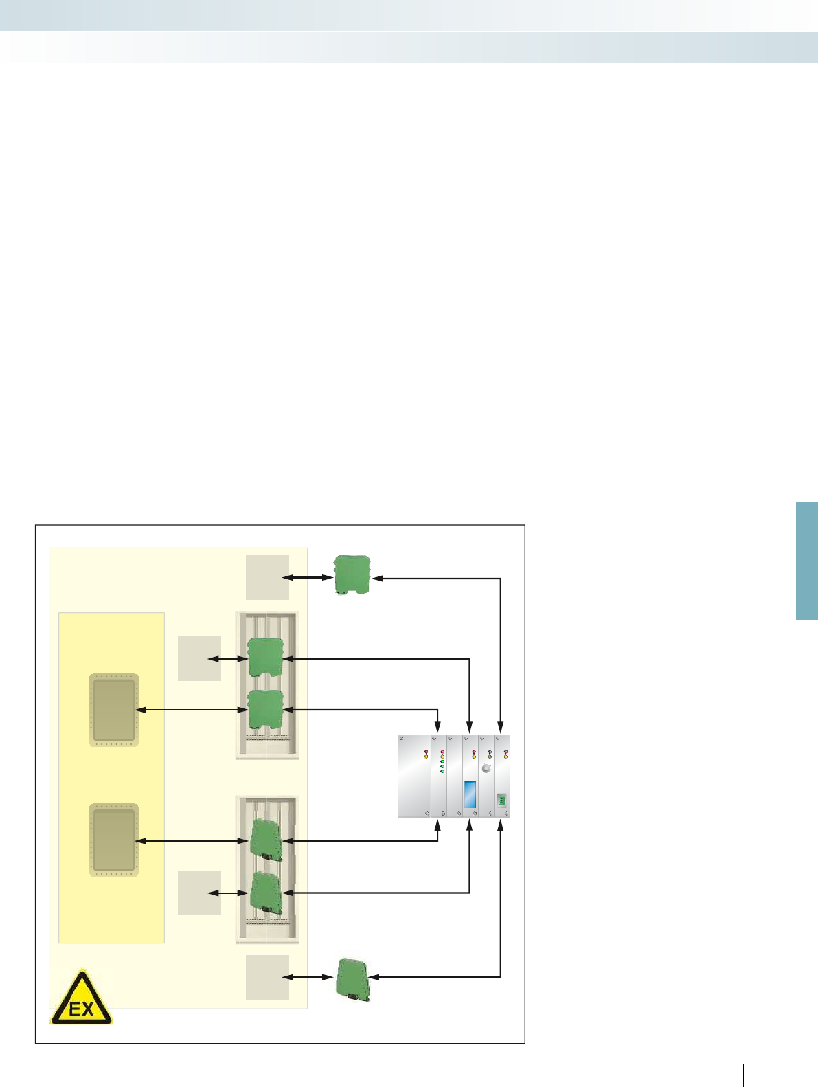
For further information and full technical data, visit phoenixcontact.net/products
Non-intrinsically safe signal transmission in potentially explosive
areas
Electrical equipment operated in systems
with potentially explosive areas is subject to
different usage requirements, depending on
the application.
For example, electrical equipment could
be used in the following locations when
analog signals are being transmitted:
– Sensors and actuators can be located in
zone 0, zone 1 or zone 2.
– Signal transmitters can be located in
zone 1, zone 2 or the safe area.
– The controller, e.g., PLC, is in the safe area.
For examples of the kinds of electrical
devices that can be installed for the purpose
of transmitting signals, please see the figure.
Devices must be designed to offer a
suitable protection type if they are to be
used in zone 2. The MINI Analog Pro, MINI
Analog, and MACX Analog ranges are
designed to provide protection type “n” for
this purpose and must be installed in zone 2
in suitable and approved housing
(EN 60079-15 and EN 60079-0) with at
least IP54 protection class.
Example:
A sensor/actuator with protection type
“n” can be connected to an isolator from
the MINI Analog Pro, MINI Analog or
MACX Analog ranges in zone 2.
When selecting suitable devices for zone
2, it must be ensured that the electrical data
of the sensors/actuators is not exceeded.
If the sensors/actuators are mounted in
explosion-proof housing or if they have
their own explosion-proof housing, they
can also be installed in zone 1.
Installation requirements
The figure shows a range of options for
installing electrical devices in areas with a
danger of gas explosions. Special
requirements regarding the configuration,
selection, and installation of electrical
systems in areas with a danger of gas
explosions can be found in EN 60079-14.
In the 2008 edition, the relevant contents
of EN 61241-14 were incorporated in
EN 60079-14.
EN 61241-14 must still be observed when
installing electrical equipment in areas
containing combustible dust. Other
important factors when it comes to running
systems in potentially explosive areas are
inspection, maintenance, and repairs.
Stipulations regarding these matters can be
found in EN 60079-17 and EN 60079-19.
Zone 2
Zone 1
Sensor/
actuator
Ex n
Housing
IP54*
MACX
Ex n
MACX
Ex n
Housing
IP54*
MINI
Ex n
MINI
Ex n
Housing
e.g., Ex d
Sensor/
actuator
Safe area
Housing
e.g., Ex d
Sensor/
actuator
Sensor/
actuator
Ex n
Sensor/
actuator
Ex n
MINI
Ex n
Sensor/
actuator
Ex n
MACX
Ex n
Installation of electrical devices for signal transmission
*Use of suitable housing approved for use in zone 2
63
PHOENIX CONTACT
MCR technology
Basics

64
PHOENIX CONTACT
Easier than ever but as slim as before
MINI Analog Pro offers you the easiest
installation and startup in confined spaces.
– Space savings of up to 65%
Select from the following categories
– Analog IN/OUT
– Temperature
– Frequency
– Potentiometer
– Digital IN
– Threshold values
– Accessories
Easy installation
– Easily visible and accessible terminal
points and FASTCON Pro plug-in
connection terminal blocks
Power bridging and fault monitoring
– The DIN rail connector simplifies supply
and enables group error monitoring via
remote diagnostics
DIN rail connector-compatible
The DIN rail connector enables the modular bridging of
the 24 V supply voltage.
MCR technology
Highly compact signal conditioners with plug-in connection technology - MINI Analog Pro
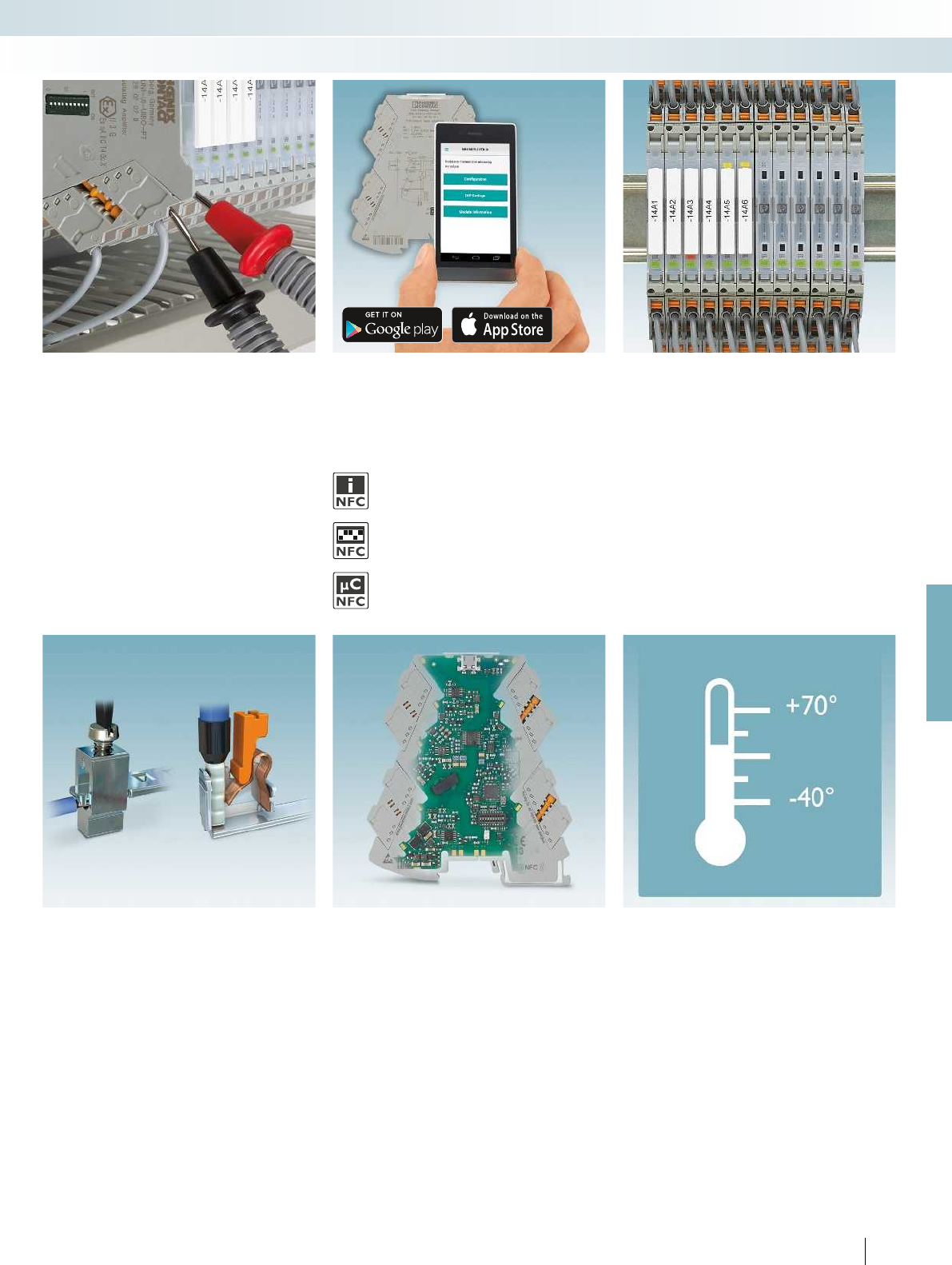
For further information and full technical data, visit phoenixcontact.net/products
65PHOENIX CONTACT
Numerous parameterization options
– Via DIP, PC or smartphone app
Measure current signals during
operation
Measure signals conveniently for startup
and servicing during operation, thanks to
integrated knife disconnect terminal blocks.
– The circuit does not have to be separated
in order to integrate the measuring device
in the signal circuit
– By setting the connector to the
disconnect position, signal circuits can be
easily interrupted during servicing and
startup
Service-friendly
– Large-surface marking areas for complete
loop identification using standard marking
material as well as constantly visible
status LEDs in every module
Optimum signal quality
– The latest transmission technology and
safe electrical isolation between input,
output, and supply with 3 kV test voltage
Choice of connection technology
– Wiring with screw connection or fast and
tool-free with push-in connection
technology
Suitable for any application
– Extended supply voltage and temperature
range as well as multifunctional device
types.
App functions via NFC communication
Configuration via NFC
– Access module information
– Display DIP switch setting help
– Wireless configuration via smartphone
DIP switch setting help
– Access module information
– Display DIP switch setting help on the smartphone
Access to information
– Access module information
MCR technology
Highly compact signal conditioners with plug-in connection technology - MINI Analog Pro

OUT
IN
POWER
U,I
U,I
FM
passive
IN
OUT
5
6
Zone 2
4-wire
US
1
2
Sensor / Field PLC / DCS
OUT
U, I+
OUT
U, I–
PWR+
PWR–
+
+
+
–
–
–
–
+
FM
1 5
2
3 7
48
OUT U, I–
PWR–
IN U, I+
IN U, I–
RO–
OUT U, I+
TI+TI–
PWR+RO+
6
S-Port
active
Ex:
Housing width 6.2 mm
Technical data
Input data U input I input
Input signal (configurable via DIP switch or freely via software) 0 V ... 10 V
2 V ... 10 V
0 V ... 5 V
1 V ... 5 V
10 V ... 0 V
10 V ... 2 V
5 V ... 0 V
5 V ... 1 V
0 V ... 12 V
0 mA ... 20 mA
4 mA ... 20 mA
0 mA ... 10 mA
2 mA ... 10 mA
20 mA ... 0 mA
20 mA ... 4 mA
10 mA ... 0 mA
10 mA ... 2 mA
0 mA ... 24 mA
Input resistance > 120 kapprox. 50
Output data U output I output
Output signal (configurable via DIP switch or freely via software) 0 V ... 10 V
2 V ... 10 V
0 V ... 5 V
1 V ... 5 V
0 V ... 10.5 V
0 mA ... 20 mA
4 mA ... 20 mA
0 mA ... 10 mA
2 mA ... 10 mA
0 mA ... 21 mA
Maximum output signal approx. 12.3 V 24.6 mA
Load R
B
10 k 600 (at 20 mA)
Ripple < 20 mV
PP
(at 600 ) < 20 mV
PP
(at 600 )
General data U output I output
Supply voltage U
B
9.6 V DC ... 30 V DC
Nominal supply voltage 24 V DC
Current consumption 32 mA (at 24 V DC) 63 mA (at 12 V DC)
Power consumption 1 W (at I
OUT
= 20 mA, 9.6 V DC,
600 load)
Maximum transmission error 0.1 % (of final value)
Temperature coefficient 0.01 %/K
Step response (10-90%) approx. 140 ms (15 Hz sample rate)
approx. 45 ms (60 Hz sample rate)
approx. 25 ms (240 Hz sample rate)
Electrical isolation Reinforced insulation in accordance with IEC 61010-1
Test voltage, input/output/supply 3 kV (50 Hz, 1 min.)
Degree of protection IP20
Ambient temperature (operation) -40 °C ... 70 °C
Mounting any
Housing material PBT
Dimensions W / H / D 6.2 / 110.5 / 120.5 mm
Push-in connection solid / stranded / AWG 0.14 ... 2.5 mm² / 0.14 ... 2.5 mm² / 24 - 12
Screw connection solid / stranded / AWG 0.2 ... 1.5 mm² / 0.2 ... 1.5 mm² / 24 - 12
EMC note Class A product, see page 625
Conformance / approvals
Conformance CE-compliant
ATEX
II 3 G Ex nA IIC T4 Gc X
UL, USA / Canada UL 508 Listed
Class I, Div. 2, Groups A, B, C, D T6
Class I, Zone 2, Group IIC T6
GL GL applied for
Ordering data
Description Type Order No. Pcs. /
Pkt.
4-way signal conditioner with switching output, for
electrical isolation of analog signals
Standard configuration Push-in connection MINI MCR-2-UNI-UI-UIRO-PT 2902028 1
Standard configuration Screw connection MINI MCR-2-UNI-UI-UIRO 2902026 1
Order configuration Push-in connection MINI MCR-2-UNI-UI-UIRO-PT-C 2902027 1
Order configuration Screw connection MINI MCR-2-UNI-UI-UIRO-C 2902024 1
Accessories
Programming adapter for configuring modules with
S-PORT interface
IFS-USB-PROG-ADAPTER 2811271 1
Programming adapter for configuring modules with
NFC interface
NFC-USB-PROG-ADAPTER 2900013 1
66
PHOENIX CONTACT
– Universally configurable, highly compact
signal conditioner with switching output
for electrical isolation, conversion,
amplification, and filtering of standard
analog signals
– Plug-in connection system
– Safe 4-way isolation
– Standard signal combinations configurable
via DIP switches
– Freely configurable via software or
smartphone app
– Power supply and fault monitoring
possible via DIN rail connector
– Limiting behavior at the output
configurable
– Status and error indicator LEDs
Notes:
The configuration software can be downloaded from the Internet:
phoenixcontact.net/products.
Information on the programming adapters can be found on
page 89
Information on MINI Analog Pro accessories can be found from
page 85
To order a product with an order configuration, please enter the
desired configuration by referring to the order key.
Analog IN/Analog OUT
4-way signal conditioner
MCR technology
Highly compact signal conditioners with plug-in connection technology - MINI Analog Pro
Universal 4-way signal conditioner with
switching output, configurable
For further information and full technical data, visit phoenixcontact.net/products
67PHOENIX CONTACT
Order key for MINI MCR-2-UNI-UI-UIRO(-PT)(-C) 4-way signal conditioner (standard configuration entered as an example)
Order No. Input Sample rate Output Output
limitation
Input signal Start End Output signal Start End
2902024 / I / 0.0 / 20.0 / 15 / I / 0.0 / 20.0 / 0 / ...
2902024
MINI MCR-2-
UNI-UI-UIRO-C
I I 0.0 0 mA 20.0 20 mA 15 15 Hz I I 0.0 0 mA 20.0 20 mA 0 OFF
U U I: freely
selectable
between 0.0 ...
24 mA
I: freely
selectable
between 0.0 ...
24 mA
60 60 Hz U U I: freely
selectable
between 0.0 ...
21 mA
I: freely
selectable
between 0.0 ...
21 mA
1 ON
240 240 Hz
2902027
MINI MCR-2-
UNI-UI-UIRO-PT-C U: freely
selectable
between 0.0 ...
12 V
U: freely
selectable
between 0.0 ...
12 V
U: freely
selectable
between 0.0 ...
10.5 V
U: freely
selectable
between 0.0 ...
10.5 V
Measuring range span at least 0.5 V/1 mA
Increment 0.1 V/0.1 mA
Output signal span at least 0.5 V/1 mA
Increment 0.1 V/0.1 mA
Failure information
Behavior in the event of an error Open circuit/short circuit Overrange Underrange
... / NE43DO / 0.0 / 0.0 / 0.0
FD freely definable 0.0 0 mA
I: freely selectable
between 0.0 ... 21.5 mA
U: freely selectable between
0.0 ... 11 V
(free definition only for
unlimited output)
(signal type corresponds to
selected output signal)
0.0 0 mA
I: freely selectable
between 0.0 ... 21.5 mA
U: freely selectable between
0.0 ... 11 V
(free definition only for
unlimited output)
(signal type corresponds to
selected output signal)
0.0 0 mA
I: freely selectable
between 0.0 ... 21.5 mA
U: freely selectable between
0.0 ... 11 V
(free definition only for
unlimited output)
(signal type corresponds to
selected output signal)
Note: failure information according to NE 43 can only be selected for 4 ... 20 mA output
NE43UP NE 43 upscale 21.5 mA 21.5 mA 21.5 mA
NE43DO NE 43 downscale 3.5 mA 3.5 mA 3.5 mA
NE430 NE 43 0 mA 0 mA 0 mA 0 mA
NE43UD NE 43 upscale/downscale 3.5 mA 21.5 mA 21.5 mA
MCR technology
Highly compact signal conditioners with plug-in connection technology - MINI Analog Pro
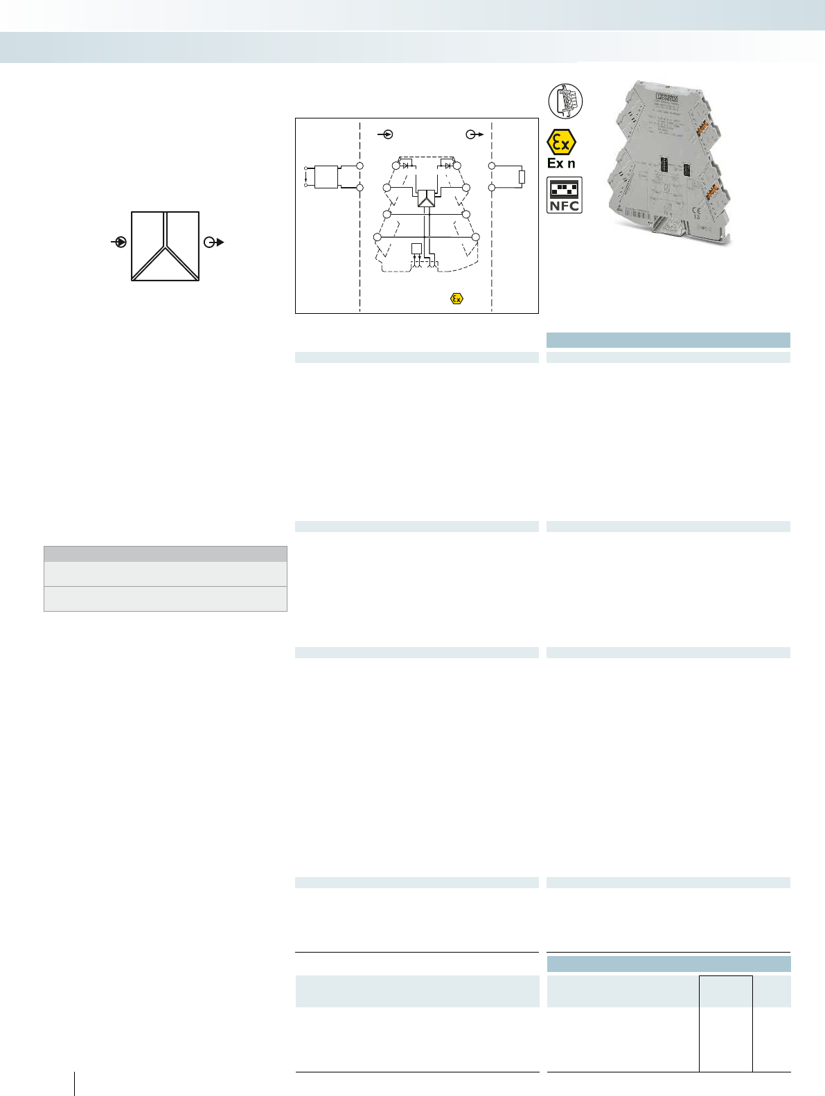
POWER
U,I U,I OUT
IN
FM
Zone 2
passive
IN
Sensor / Field
OUT
PLC / DCS
4-wire
OUT
U,I
GND
US
5
6
1
2
PWR+
PWR–
+
+
+
–
–
–
–
+PWR+
FM
1 5
2 6
3 7
48
active
OUT U, I–
PWR–
IN U, I+
IN U, I–
PWR+
PWR–
OUT U, I+
TI+TI–
Ex:
Housing width 6.2 mm
Technical data
Input data U input I input
Input signal (configurable using the DIP switch) 0 V ... 5 V
1 V ... 5 V
-5 V ... 5 V
0 V ... 10 V
2 V ... 10 V
-10 V ... 10 V
0 V ... 20 V
4 V ... 20 V
-20 V ... 20 V
0 V ... 24 V
4.8 V ... 24 V
-24 V ... 24 V
0 V ... 30 V
6 V ... 30 V
-30 V ... 30 V
0 mA ... 20 mA
4 mA ... 20 mA
-20 mA ... 20 mA
Input resistance > 1000 kapprox. 63
Output data U output I output
Output signal (configurable using the DIP switch) 0 V ... 5 V
1 V ... 5 V
-5 V ... 5 V
0 V ... 10 V
2 V ... 10 V
-10 V ... 10 V
0 mA ... 20 mA
4 mA ... 20 mA
Maximum output signal 22 mA
No-load voltage < 17 V
Short-circuit current < 32 mA
Load R
B
10 k 600 (at 20 mA)
Ripple < 20 mV
PP
(at 600 ) < 20 mV
PP
(at 600 )
General data U output I output
Supply voltage U
B
9.6 V DC ... 30 V DC
Nominal supply voltage 24 V DC
Current consumption 25 mA (current output,
at 24 V DC incl. load)
54 mA (current output,
at 12 V DC incl. load)
Power consumption 800 mW (at I
OUT
= 20 mA,
9.6 V DC, 600 load)
Maximum transmission error 0.1 % (of final value)
Temperature coefficient 0.01 %/K
Cut-off frequency (3 dB) 30 Hz (via DIP switch)
Step response (10-90%) < 8.5 ms (with 30 Hz filter)
Electrical isolation Reinforced insulation in accordance with IEC 61010-1
Test voltage, input/output/supply 3 kV (50 Hz, 1 min.)
Degree of protection IP20
Ambient temperature (operation) -40 °C ... 70 °C
Mounting any
Housing material PBT
Dimensions W / H / D 6.2 / 110.5 / 120.5 mm
Push-in connection solid / stranded / AWG 0.14 ... 2.5 mm² / 0.14 ... 2.5 mm² / 24 - 12
Screw connection solid / stranded / AWG 0.2 ... 1.5 mm² / 0.2 ... 1.5 mm² / 24 - 12
EMC note Class A product, see page 625
Conformance / approvals
Conformance CE-compliant
ATEX
II 3 G Ex nA IIC T4 Gc X
UL, USA / Canada UL 508 Listed
Class I, Div. 2, Groups A, B, C, D T6
Class I, Zone 2, Group IIC T6
GL GL applied for
Ordering data
Description Type Order No. Pcs. /
Pkt.
3-way signal conditioner, for electrical isolation of analog signals
Standard configuration Push-in connection MINI MCR-2-UI-UI-PT 2902040 1
Standard configuration Screw connection MINI MCR-2-UI-UI 2902037 1
Order configuration Push-in connection MINI MCR-2-UI-UI-PT-C 2902039 1
Order configuration Screw connection MINI MCR-2-UI-UI-C 2902036 1
68
PHOENIX CONTACT
– Configurable, highly compact signal
conditioner for electrical isolation,
conversion, amplification, and filtering of
standard analog signals
– Plug-in connection system
– Safe 3-way isolation
– Standard signal combinations configurable
via DIP switches
– Power supply and fault monitoring
possible via DIN rail connector
– Status LED
Notes:
Information on MINI Analog Pro accessories can be found from
page 85
To order a product with an order configuration, please enter the
desired configuration by referring to the order key.
Analog IN/Analog OUT
3-way signal conditioner
MCR technology
Highly compact signal conditioners with plug-in connection technology - MINI Analog Pro
3-way signal conditioner for standard signals,
configurable

For further information and full technical data, visit phoenixcontact.net/products
69PHOENIX CONTACT
Order key for MINI MCR-2-UI-UI(-PT)(-C) 3-way signal conditioner (standard configuration entered as an example)
Order No. Input Output Cut-off frequency
2902036 / IN03 / OUT01 / 5K
2902036
MINI MCR-2-
UI-UI-C
IN 01 0 ... 20 mA OUT 01 0...20 mA 30 Hz
IN 02 4 ... 20 mA OUT 02 4 ... 20 mA 5 kHz
IN 03 0 ... 10 V OUT 03 0 ... 10 V
IN 04 2 ... 10 V OUT 04 2 ... 10 V
2902039
MINI MCR-2-
UI-UI-PT-C
IN 05 0 ... 5 V OUT 05 0 ... 5 V
IN 06 1 ... 5 V OUT 06 1 ... 5 V
IN 21 -5 ... 5 V OUT 13 -5 ... 5 V
IN 22 -10 ... 10 V OUT 14 -10 ... 10 V
IN 23 -20 ... 20 V
IN 32 0 ... 20 V
IN 35 -20 ... 20 mA
IN 38 0 ... 24 V
IN 39 0 ... 30 V
IN 80 -30 ... 30 V
IN 93 -24 ... 24 V
IN 94 4.8 ... 24 V
IN 95 6 ... 30 V
IN 96 4 ... 20 V
Signal combination for MINI MCR-2-UI-UI(-PT)(-C) signal conditioner
Output
Input 0 ... 20 mA 4 ... 20 mA 0 ... 5 V 1 ... 5 V -5 ... 5 V 0 ... 10 V 2 ... 10 V -10 ... 10 V
0 ... 20 mA X X X X X X X X
4 ... 20 mA XXXXXXXX
-20 ... 20 mA X X X X X X X X
0 ... 5 V XXXXXXXX
1 ... 5 V X X X X X X X X
-5 ... 5 V XXXXXXXX
0 ... 10 V X X X X X X X X
2 ... 10 V XXXXXXXX
-10 ... 10 V X X X X X X X X
0 ... 20 V XXXXXXXX
4 ... 20 V X X X X X X X X
-20 ... 20 V XXXXXXXX
0 ... 24 V X X X X X X X X
4.8 ... 24 V XXXXXXXX
-24 ... 24 V X X X X X X X X
0 ... 30 V XXXXXXXX
6 ... 30 V X X X X X X X X
-30 ... 30 V XXXXXXXX
MCR technology
Highly compact signal conditioners with plug-in connection technology - MINI Analog Pro
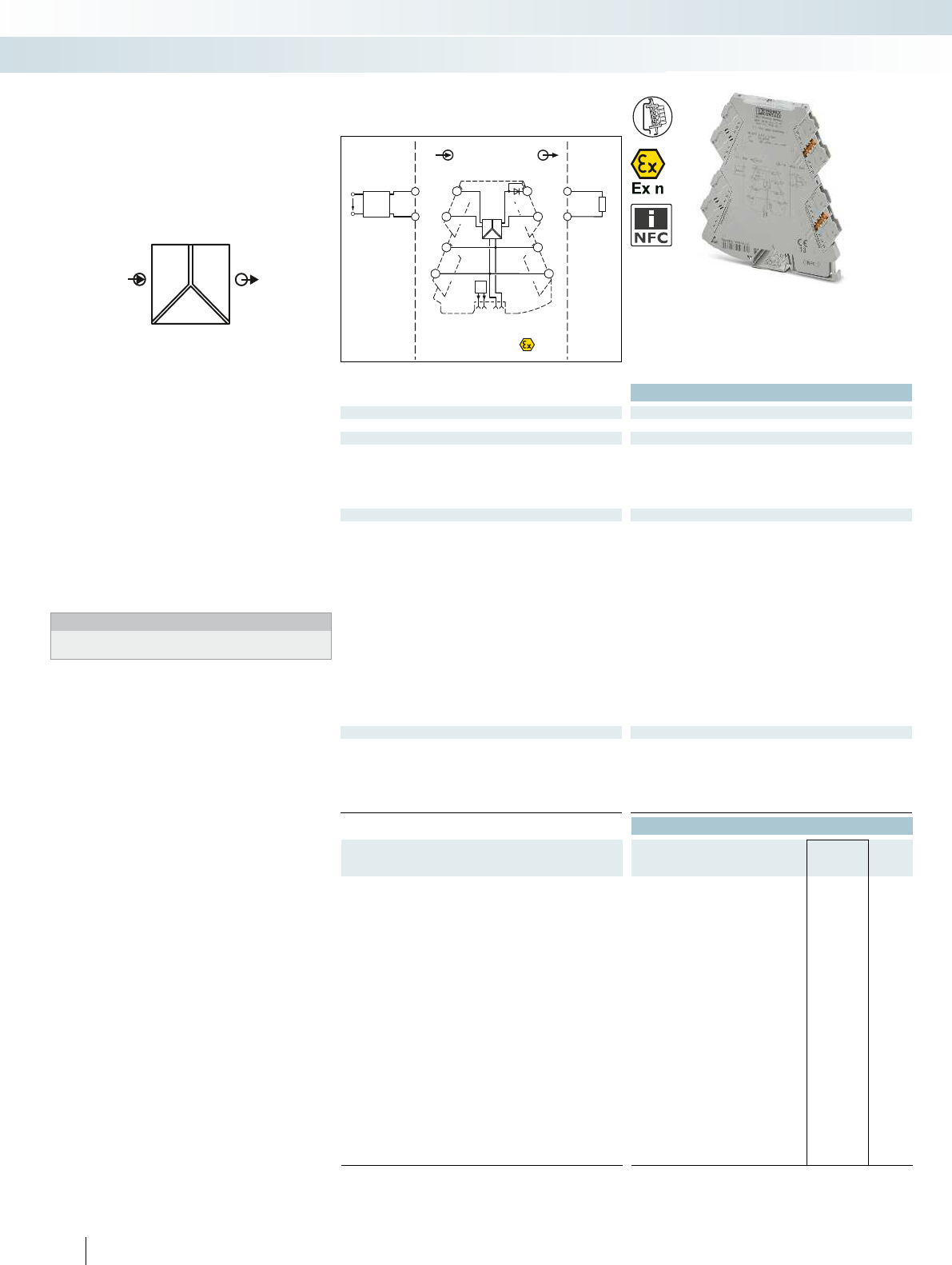
POWER
U,I U,I OUT
IN
FM
Zone 2
IN
Sensor / Field
OUT
PLC / DCS
4-wire
OUT
U+
US
5
6
1
2
OUT
U-
PWR+
PWR–
+
+
+
–
–
–
–
+
FM
1 5
2 6
3 7
48
IN U+ OUT I+
TI+
PWR+
OUT I–
PWR–
IN U–
PWR+
PWR–
activepassive
Ex:
Technical data
Input data U input I input
Input resistance approx. 100 kapprox. 63
Output data U output I output
Maximum output signal 11 V 22 mA
No-load voltage < 17 V
Short-circuit current < 15 mA
Load R
B
10 k 600 (at 20 mA)
Ripple < 20 mV
PP
(at 10 k) < 20 mV
PP
(at 600 )
General data
Supply voltage U
B
9.6 V DC ... 30 V DC
Nominal supply voltage 24 V DC
Typ. current consumption 25 mA (at 24 V DC)
Maximum transmission error 0.1 % (of final value)
Temperature coefficient 0.01 %/K
Cut-off frequency (3 dB) approx. 30 Hz
Step response (10-90%) approx. 10 ms
Degree of protection IP20
Electrical isolation Reinforced insulation in accordance with IEC 61010-1
Test voltage, input/output/supply 3 kV (50 Hz, 1 min.)
Ambient temperature (operation) -40 °C ... 70 °C
Housing material PBT
Dimensions W / H / D 6.2 / 110.5 / 120.5 mm
Push-in connection solid / stranded / AWG 0.14 ... 2.5 mm² / 0.14 ... 2.5 mm² / 24 - 12
Screw connection solid / stranded / AWG 0.2 ... 1.5 mm² / 0.2 ... 1.5 mm² / 24 - 12
EMC note Class A product, see page 625
Conformance / approvals
Conformance CE-compliant
ATEX
II 3 G Ex nA IIC T4 Gc X
UL, USA / Canada UL 508 Listed
Class I, Div. 2, Groups A, B, C, D T6
Class I, Zone 2, Group IIC T6
GL GL applied for
Ordering data
Description Input signal Output signal Type Order No. Pcs. /
Pkt.
3-way signal conditioner, for electrical isolation of analog signals
Push-in connection 0 ... 10 V 0 ... 20 mA MINI MCR-2-U-I0-PT 2902023 1
Screw connection 0 ... 10 V 0 ... 20 mA MINI MCR-2-U-I0 2902022 1
Push-in connection 0 ... 10 V 4 ... 20 mA MINI MCR-2-U-I4-PT 2902030 1
Screw connection 0 ... 10 V 4 ... 20 mA MINI MCR-2-U-I4 2902029 1
Push-in connection 0 ... 20 mA 0 ... 10 V MINI MCR-2-I0-U-PT 2902001 1
Screw connection 0 ... 20 mA 0 ... 10 V MINI MCR-2-I0-U 2902000 1
Push-in connection 4 ... 20 mA 0 ... 10 V MINI MCR-2-I4-U-PT 2902003 1
Screw connection 4 ... 20 mA 0 ... 10 V MINI MCR-2-I4-U 2902002 1
Push-in connection 0 ... 20 mA,
4 ... 20 mA
0 ... 20 mA,
4 ... 20 mA
MINI MCR-2-I-I-PT 2901999 1
Screw connection 0 ... 20 mA,
4 ... 20 mA
0 ... 20 mA,
4 ... 20 mA
MINI MCR-2-I-I 2901998 1
Push-in connection 0 ... 10 V,
2 ... 10 V
0 ... 10 V,
-10 ... 10 V
MINI MCR-2-U-U-PT 2902043 1
Screw connection 0 ... 10 V,
2 ... 10 V
0 ... 10 V,
-10 ... 10 V
MINI MCR-2-U-U 2902042 1
70
PHOENIX CONTACT
– Highly compact signal conditioner for
electrical isolation, conversion,
amplification, and filtering of standard
analog signals
– Fixed signal combinations
– Plug-in connection system
– Safe 3-way isolation
– Power supply and fault monitoring
possible via DIN rail connector
– Status LED
Notes:
Information on MINI Analog Pro accessories can be found from
page 85
Analog IN/Analog OUT
3-way signal conditioner
MCR technology
Highly compact signal conditioners with plug-in connection technology - MINI Analog Pro
3-way signal conditioner with
fixed signal combinations
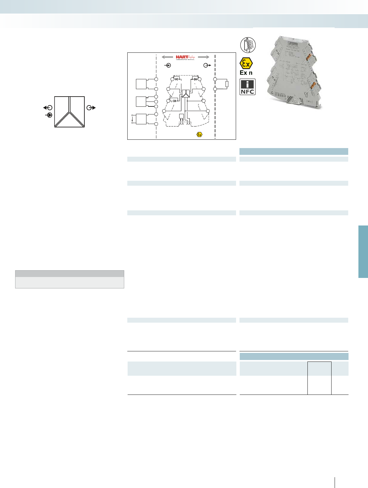
POWER
II OUT
IN
POWER
FM
PWR+
PWR–
++
–
–
–
+
passive
IN OUT
FM
1 5
2 6
3 7
48
5
6
Zone 2
2-wire
1
2OUT I–
PWR–
PWR OUT +
IN I–
Sensor / Field PLC / DCS
OUT I+
PWR
IN+
OUT I–
TI+
PWR+
IN I+
4-wire
US
3
4
3-wire
1
4
3
PWR
IN+
OUT I–
OUT I+
OUT I–
OUT I+
IN I–
TI–
TI+
active
+
–
For further information and full technical data, visit phoenixcontact.net/products
Ex:
Housing width 6.2 mm
Technical data
Input data
Input signal 0 ... 20 mA, isolator operation /
4 ... 20 mA, repeater power supply and isolator operation
Input resistance approx. 68
Transmitter supply voltage > 19.5 V
Output data
Output signal 0 ... 20 mA / 4 ... 20 mA
Maximum output signal 24 mA
No-load voltage < 20 V
Load R
B
600 (at 20 mA)
Ripple < 20 mV
PP
(at 600 )
General data
Supply voltage U
B
9.6 V DC ... 30 V DC
Nominal supply voltage 24 V DC
Current consumption 25 mA (at 24 V DC and in isolator operation)
Power consumption 1400 mW (at I
OUT
= 20 mA, 9.6 V DC, 600 load)
Maximum transmission error 0.1 % (of final value)
Temperature coefficient 0.01 %/K
Cut-off frequency (3 dB) > 1.75 kHz (typ.)
Communication HART specification in both operating modes
(RPSS isolator / RPSS repeater power supply)
Step response (10-90%) < 200 µs (typ.)
Electrical isolation Reinforced insulation in accordance with IEC 61010-1
Test voltage, input/output/supply 3 kV (50 Hz, 1 min.)
Degree of protection IP20
Ambient temperature (operation) -40 °C ... 70 °C
Mounting any
Housing material PBT
Dimensions W / H / D 6.2 / 110.5 / 120.5 mm
Push-in connection solid / stranded / AWG 0.14 ... 2.5 mm² / 0.14 ... 2.5 mm² / 24 - 12
Screw connection solid / stranded / AWG 0.2 ... 1.5 mm² / 0.2 ... 1.5 mm² / 24 - 12
EMC note Class A product, see page 625
Conformance / approvals
Conformance CE-compliant
ATEX
II 3 G Ex nA IIC T4 Gc X
UL, USA / Canada UL 508 Listed
Class I, Div. 2, Groups A, B, C, D T5
Class I, Zone 2, Group IIC T5
GL GL applied for
Ordering data
Description Type Order No. Pcs. /
Pkt.
3-way repeater power supply with HART transmission
Push-in connection MINI MCR-2-RPSS-I-I-PT 2902015 1
Screw connection MINI MCR-2-RPSS-I-I 2902014 1
71
PHOENIX CONTACT
– Highly compact repeater power supply
for electrical isolation, conversion,
amplification, and filtering of standard
analog signals
– Supply of 2-wire and passive 3-wire
sensors
– Can also be used as an isolator without
supply
– Plug-in connection system
– Safe 3-way isolation
– Bidirectional HART transmission as an
option
– Power supply and fault monitoring
possible via DIN rail connector
– Status LED
Notes:
Information about power bridging, system cabling, and marking
components can be found from page 116
Analog IN/Analog OUT
3-way repeater power supply
MCR technology
Highly compact signal conditioners with plug-in connection technology - MINI Analog Pro
3-way repeater power supply with
HART transmission
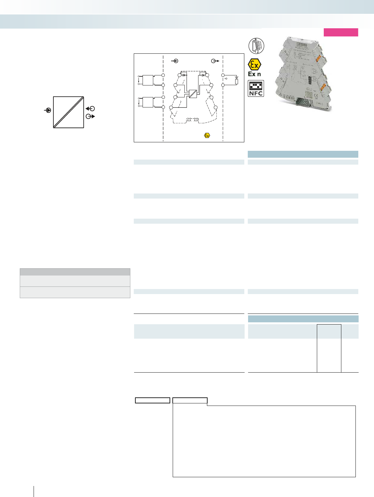
U,I I POWER
IN
OUT
Zone 2
INOUT
Sensor / Field
4-wire
OUT I+
OUT I-
US
1
2
4-wire
OUT U+
OUT U-
US
3
4
++
+
–
–
–
1
2 6
4
passive
OUT I
IN I+
IN I–
IN U+
IN U–
PWR In
TI+
7
8
TI–
5
3
PLC / DCS
PWR
active
5
6
Housing width 6.2 mm
Technical data
Input data U input I input
Input signal (configurable using the DIP switch) 2 ... 10 V, additional ranges can be configured, see table
Maximum input signal < 30 V < 40 mA
(electric strength up to 30 V)
Input resistance approx. 100 k (at 1 V,
otherwise approximately 1 M)
50
Output data
Output signal 4 ... 20 mA
Maximum output signal 29 mA
Load R
B
(U
B
- 8 V) / 22 mA
Ripple < 20 mV
PP
(at 600 )
General data
Current consumption 3 mA
Maximum transmission error < 0.1 % (of final value)
Temperature coefficient 0.01 %/K, typ. 0.005 %/K
Cut-off frequency (3 dB) approx. 30 Hz
Step response (10-90%) 15 ms
Electrical isolation Reinforced insulation in accordance with IEC 61010-1
Test voltage, input/output/supply 3 kV (50 Hz, 1 min.)
Degree of protection IP20
Ambient temperature (operation) -40 °C ... 70 °C
Housing material PBT
Dimensions W / H / D 6.2 / 110.5 / 120.5 mm
Push-in connection solid / stranded / AWG 0.14 ... 2.5 mm² / 0.14 ... 2.5 mm² / 24 - 12
Screw connection solid / stranded / AWG 0.2 ... 1.5 mm² / 0.2 ... 1.5 mm² / 24 - 12
Conformance / approvals
Conformance CE-compliant
ATEX
II 3 G Ex nA IIC T4 Gc X
UL, USA / Canada UL applied for
Class I, Div. 2, Groups A, B, C, D T5 applied for
Ordering data
Description Type Order No. Pcs. /
Pkt.
Output loop-powered 2-way isolator, for isolating current signals
without auxiliary power
Standard configuration Push-in connection MINI MCR-2-UI-I-OLP-PT 2902063 1
Standard configuration Screw connection MINI MCR-2-UI-I-OLP 2902061 1
Order configuration Push-in connection MINI MCR-2-UI-I-OLP-PT-C 2902062 1
Order configuration Screw connection MINI MCR-2-UI-I-OLP-C 2902060 1
72
PHOENIX CONTACT
– Highly compact passive isolator for
electrical isolation and filtering of
standard analog signals
– Safe 2-way isolation
– Supplied by an output loop
– Does not require any additional auxiliary
voltage
– Up to 74 signal combinations can be
configured using DIP switches
– Plug-in connection technology
– Voltage input from mV voltages up to 30 V
– Current input from 2mA right up to
40mA
– Status LED
Notes:
To order a product with an order configuration, please enter the
desired configuration by referring to the order key.
Information on MINI Analog Pro accessories can be found from
page 85
Analog IN/Analog OUT
2-way passive isolator,
output loop-powered
Order key for MINI MCR-2-UI-I-OLP(-PT)(-C)
Order No. Input
2602060 / 0 mV ... 1000 mV
2902060
MINI MCR-2-
UI-I-OLP-C
2902062
MINI MCR-2-
UI-I-OLP-PT-C
0 mV ... 1000 mV
0 mV ... 750 mV
0 mV ... 500 mV
0 mV ... 300 mV
0 mV ... 250 mV
0 mV ... 200 mV
0 mV ... 150 mV
0 mV ... 125 mV
0 mV ... 120 mV
0 mV ... 100 mV
0 mV ... 75 mV
0 mV ... 60 mV
0 mV ... 50 mV
0 V ... 10 V
0 V ... 7.5 V
0 V ... 5 V
0 V ... 3 V
0 V ... 2.5 V
0 V ... 2 V
0 V ... 1.5 V
0 V ... 1.25 V
0 V ... 1.2 V
0 V ... 30 V
0 V ... 25 V
0 V ... 20 V
0 V ... 12.5 V
0 V ... 12 V
0 V ... 15 V
-1000 mV ... 1000 mV
-750 mV ... 750 mV
-500 mV ... 500 mV
-300 mV ... 300 mV
-250 mV ... 250 mV
-200 mV ... 200 mV
-125 mV ... 125 mV
-120 mV ... 120 mV
-150 mV ... 150 mV
-100 mV ... 100 mV
-75 mV ... 75 mV
-60 mV ... 60 mV
-50 mV ... 50 mV
-10 V ... 10 V
-7.5 V ... 7.5 V
-5 V ... 5 V
-3 V ... 3 V
-2.5 V ... 2.5 V
-2 V ... 2 V
-1.25 V ... 1.25 V
-1.2 V ... 1.2 V
-1.5 V ... 1.5 V
-30 V ... 30 V
-25 V ... 25 V
-20 V ... 20 V
-12.5 V ... 12.5 V
-12 V ... 12 V
-15 V ... 15 V
1 V ... 5 V
0 mA ... 40 mA
0 mA ... 30 mA
0 mA ... 20 mA
0 mA ... 12 mA
0 mA ... 10 mA
0 mA ... 8 mA
0 mA ... 7.5 mA
0 mA ... 5 mA
0 mA ... 6 mA
0 mA ... 4 mA
0 mA ... 3 mA
0 mA ... 2.5 mA
0 mA ... 2 mA
4 mA ... 20 mA
2 mA ... 10 mA
1 mA ... 5 mA
MCR technology
Highly compact signal conditioners with plug-in connection technology - MINI Analog Pro
new
Configurable,
up to 74 signal combinations

For further information and full technical data, visit phoenixcontact.net/products
73PHOENIX CONTACT
MCR technology
Highly compact signal conditioners with plug-in connection technology - MINI Analog Pro

OUT
IN
POWER
U,I
FM
PWR+
PWR–
+
+
–
–
passive
IN
OUT
FM
1 5
2 6
8
5
6
Zone 2
Sensor / Field PLC / DCS
3
4
7
S-Port
OUT U, I–
OUT U, I+
PWR+
PWR–
ϑ
ϑϑ
TI+
1
2
3
4
active
Ex:
Housing width 6.2 mm
Technical data
Input data
Input signal (can be configured using DIP switches) Pt, Ni, Cu sensors : 2, 3, 4-wire
Temperature range -200 °C ... 850 °C (range depends on sensor type, range can be set
freely via software or in increments via DIP switches)
Measuring range span 20 K
Linear resistance measuring range 0 ... 4000 (minimum measuring span: 10% of the selected
measuring range)
Output data U output I output
Output signal (configurable via DIP switch or freely via software) 0 ... 5 V / 1 ... 5 V 0 ... 20 mA / 4 ... 20 mA
0 ... 10 V / 10 ... 0 V 20 ... 0 mA / 20 ... 4 mA
Maximum output signal approx. 12.3 V 24.6 mA
No-load voltage < 17.5 V
Short-circuit current < 31.5 mA
Load R
B
10 k 600 (at 20 mA)
Ripple < 20 mV
PP
< 20 mV
PP
(at 600 )
General data
Supply voltage U
B
9.6 V DC ... 30 V DC
Current consumption 32 mA (at 24 V DC)
Power consumption 850 mW (at I
OUT
= 20 mA, 9.6 V DC, 600 load)
Transmission error 0.1 % * 350 K / set measuring range; 0.1 % > 350 K (Pt/Ni)
0.3 % * 200 K / set measuring range; 0.3 % > 200 K (Cu)
Temperature coefficient 0.01 %/K
Step response (0–99%) typ. 200 ms (2-wire)
typ. 500 ms (3-wire)
typ. 500 ms (4-wire)
Electrical isolation Reinforced insulation in accordance with IEC 61010-1
Test voltage, input/output/supply 3 kV (50 Hz, 1 min.)
Ambient temperature (operation) -40 °C ... 70 °C
Housing material PBT
Dimensions W / H / D 6.2 / 110.5 / 120.5 mm
Push-in connection solid / stranded / AWG 0.14 ... 2.5 mm² / 0.14 ... 2.5 mm² / 24 - 12
Screw connection solid / stranded / AWG 0.2 ... 1.5 mm² / 0.2 ... 1.5 mm² / 24 - 12
EMC note Class A product, see page 625
Conformance / approvals
Conformance CE-compliant
ATEX
II 3 G Ex nA IIC T4 Gc X
UL, USA / Canada UL 508 Listed
Class I, Div. 2, Groups A, B, C, D T6
Class I, Zone 2, Group IIC T6
GL GL applied for
Ordering data
Description Type Order No. Pcs. /
Pkt.
Temperature transducer for resistance thermometers
Standard configuration Push-in connection MINI MCR-2-RTD-UI-PT 2902052 1
Standard configuration Screw connection MINI MCR-2-RTD-UI 2902049 1
Order configuration Push-in connection MINI MCR-2-RTD-UI-PT-C 2902051 1
Order configuration Screw connection MINI MCR-2-RTD-UI-C 2902048 1
Accessories
Programming adapter for configuring modules with
S-PORT interface
IFS-USB-PROG-ADAPTER 2811271 1
Programming adapter for configuring modules with
NFC interface
NFC-USB-PROG-ADAPTER 2900013 1
74
PHOENIX CONTACT
– Universally configurable, highly compact
temperature transducer for electrical
isolation, conversion, amplification, and
filtering of resistance thermometer and
remote resistance-type sensor signals
– For 2, 3 or 4-wire sensors according to
IEC 751, JIS, GOST
– Plug-in connection system
– Safe 3-way isolation
– Standard signal combinations configurable
via DIP switches
– Freely configurable via software or
smartphone app
– Power supply and fault monitoring
possible via DIN rail connector
– Status and error indicator LEDs
Notes:
The configuration software can be downloaded from the Internet:
phoenixcontact.net/products.
Information on the programming adapters can be found on
page 89
Information on MINI Analog Pro accessories can be found from
page 85
To order a product with an order configuration, please enter the
desired configuration by referring to the order key.
Temperature
Temperature transducer for
resistance thermometers
MCR technology
Highly compact signal conditioners with plug-in connection technology - MINI Analog Pro
Universal temperature transducer
for resistance thermometers

For further information and full technical data, visit phoenixcontact.net/products
75PHOENIX CONTACT
Order key for MINI MCR-2-RTD-UI(-PT)(-C) temperature transducer (standard configuration entered as example)
Order No. Sensor type Connection
technology
Measuring range
Measuring unit
Output
Start End Output signal Start End
2902048 / PT100 / 3 / -50 / 150 / C / I / 4.0 / 20.0 / ...
2902048
MINI MCR-2-
RTD-UI-C
PT100 Pt 100 IEC 751 2 2-wire freely selectable
between
-200°C ... 850°C
(measuring
range limits
depend on
sensor type)
freely selectable
between
-200°C ... 850°C
(measuring
range limits
depend on
sensor type)
C °C I I 0.0 0 mA 20.0 20 mA
PT200 Pt 200 IEC 751 3 3-wire F °F U U I: freely
selectable
between 0.0
... 21 mA
I: freely
selectable
between 0.0
... 21 mA
PT500 Pt 500 IEC 751 4 4-wire
PT1000 Pt 1000 IEC 751
2902051
MINI MCR-2-
RTD-UI-PT-C
PT100G Pt 100 GOST 6651-2009 ( = 0.00394)
PT1000G Pt 1000 GOST 6651-2009 ( = 0.00394)
PT100J Pt 100 JIS C1604/1997 U: freely
selectable
between 0.0
... 10.5 V
U: freely
selectable
between 0.0
... 10.5 V
PT1000J Pt 1000 JIS C1604/1997
NI100 Ni 100 DIN 43760
NI1000 Ni 1000 DIN 43760
CU50 Cu 50 GOST 6651-2009 ( = 0.00428)
CU100 Cu 100 GOST 6651-2009 ( = 0.00428)
CU53 Cu 53 GOST 6651-2009 ( = 0.00426)
Minimum measuring span 20 K Output signal span at least 0.5 V/1 mA
Increment 0.1 V/0.1 mA
Failure information
Behavior in the event of an error Open circuit Short circuit Overrange Underrange
... / NE43DO / 0.0 / 0.0 / 0.0 / 0.0
FD freely definable 0.0 0 mA
I: freely selectable
between 0.0 ... 21.5 mA
U: freely selectable between
0.0 ... 11 V
(signal type corresponds to
selected output signal)
0.0 0 mA
I: freely selectable
between 0.0 ... 21.5 mA
U: freely selectable between
0.0 ... 11 V
(signal type corresponds to
selected output signal)
0.0 0 mA
I: freely selectable
between 0.0 ... 21.5 mA
U: freely selectable between
0.0 ... 11 V
(signal type corresponds to
selected output signal)
0.0 0 mA
I: freely selectable
between 0.0 ... 21.5 mA
U: freely selectable between
0.0 ... 11 V
(signal type corresponds to
selected output signal)
Note: failure information according to NE 43 can only be selected for 4 ... 20 mA output
NE43UP NE 43 upscale 21.5 mA 21.5 mA 21.5 mA 21.5 mA
NE43DO NE 43 downscale 3.5 mA 3.5 mA 3.5 mA 3.5 mA
NE430 NE 43 0 mA 0 mA 0 mA 0 mA 0 mA
NE43UD NE 43 upscale/downscale 3.5 mA 3.5 mA 21.5 mA 21.5 mA
Sensor types and measuring ranges for MINI MCR-2-RTD-UI(-PT)(-C) temperature transducer
Sensor type Standard Measuring range Smallest measuring
span
Adjustable using:
Pt100 IEC 751 = GOST 6651-2009 ( = 0.00385) -200°C ... +850°C 20 K DIP switch
Pt200 IEC 751 = GOST 6651-2009 ( = 0.00385) -200°C ... +850°C 20 K DIP switch
Pt500 IEC 751 = GOST 6651-2009 ( = 0.00385) -200°C ... +850°C 20 K Software or smartphone app
Pt1000 IEC 751 = GOST 6651-2009 ( = 0.00385) -200°C ... +850°C 20 K Software or smartphone app
Pt100 GOST 6651-2009 ( = 0.00391) -200°C ... +850°C 20 K Software or smartphone app
Pt1000 GOST 6651-2009 ( = 0.00391) -200°C ... +850°C 20 K Software or smartphone app
Pt100 JIS C1604-1997 -200°C ... +850°C 20 K Software or smartphone app
Pt1000 JIS C1604-1997 -200°C ... +850°C 20 K Software or smartphone app
Ni100 DIN 43760 -60°C ... +250°C 20 K Software or smartphone app
Ni1000 DIN 43760 -60°C ... +250°C 20 K Software or smartphone app
Cu50 GOST 6651-2009 ( = 0.0428) -180°C ... +200°C 20 K Software or smartphone app
Cu100 GOST 6651-2009 ( = 0.0428) -180°C ... +200°C 20 K Software or smartphone app
Cu53 GOST 6651-2009 ( = 0.0426) -50°C ... +180°C 20 K Software or smartphone app
Customer-specific characteristic curves -200°C ... +850°C 20 K Software or smartphone app
MCR technology
Highly compact signal conditioners with plug-in connection technology - MINI Analog Pro
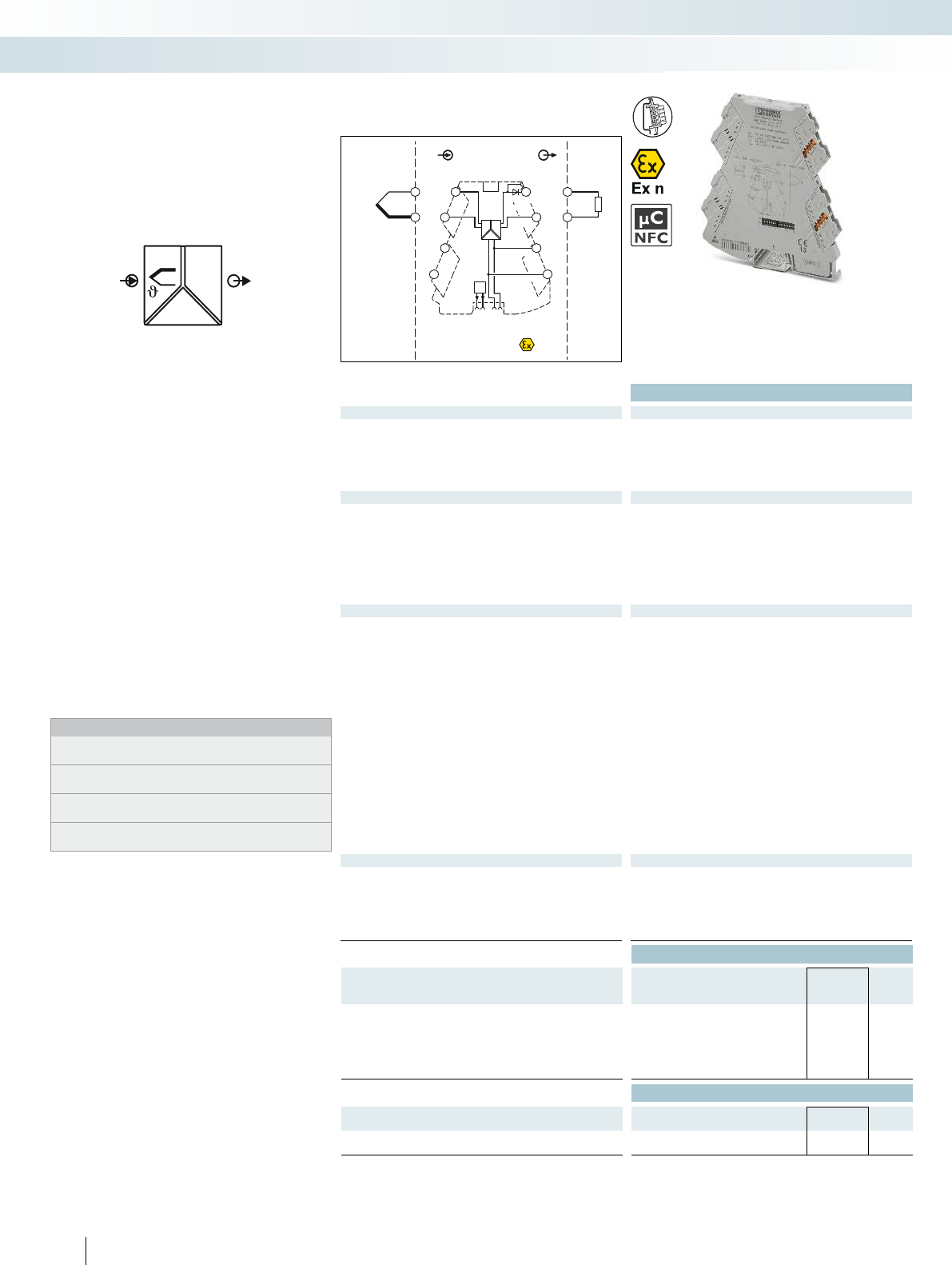
OUT
IN
POWER
U,I
FM
PWR+
PWR–
+
+
–
–
passive
IN OUT
FM
1 5
2 6
8
5
6
Zone 2
Sensor / Field PLC / DCS
3
4
7
S-Port
OUT U, I–
OUT U, I+
PWR+
PWR–
1
2
TI+
TC
+
–
active
Ex:
Housing width 6.2 mm
Technical data
Input data
Input signal (can be configured using DIP switches) B, E, J, K, N, R, S, T, L, U, A-1, A-2, A-3, M, L
Temperature range -250 °C ... 2500 °C (range depends on sensor type, range can be set
freely via software or in increments via DIP switches)
Measuring range span min. 50 K
Output data U output I output
Output signal (configurable via DIP switch or freely via software) 0 ... 5 V / 1 ... 5 V 0 ... 20 mA / 4 ... 20 mA
0 ... 10 V / 10 ... 0 V 20 ... 0 mA / 20 ... 4 mA
Maximum output signal approx. 12.3 V 24.6 mA
No-load voltage < 17.5 V
Short-circuit current < 31.5 mA
Load R
B
10 k 600 (at 20 mA)
Ripple < 20 mV
PP
< 20 mV
PP
(at 600 )
General data
Supply voltage U
B
9.6 V DC ... 30 V DC
Current consumption 32.7 mA (at 24 V DC)
Power consumption 850 mW (at I
OUT
= 20 mA, 9.6 V DC, 600 load)
Transmission error 0.1 % * 600 K / set measuring range; 0.1 % > 600 K (E, J, K, N, T, L,
U, M Gost, L Gost) 0.2 % * 600 K / set measuring range; 0.2 % > 600
K (B, R, S, A1, A2, A3)
Cold junction errors - ( typ. 2 K (2 K + (0.2 K * T)) )
Temperature coefficient 0.01 %/K
Step response (0–99%) typ. 400 ms
Electrical isolation Reinforced insulation in accordance with IEC 61010-1
Test voltage, input/output/supply 3 kV (50 Hz, 1 min.)
Ambient temperature (operation) -40 °C ... 70 °C
Housing material PBT
Dimensions W / H / D 6.2 / 110.5 / 120.5 mm
Push-in connection solid / stranded / AWG 0.14 ... 2.5 mm² / 0.14 ... 2.5 mm² / 24 - 12
Screw connection solid / stranded / AWG 0.2 ... 1.5 mm² / 0.2 ... 1.5 mm² / 24 - 12
EMC note Class A product, see page 625
Conformance / approvals
Conformance CE-compliant
ATEX
II 3 G Ex nA IIC T4 Gc X
UL, USA / Canada UL 508 Listed
Class I, Div. 2, Groups A, B, C, D T6
Class I, Zone 2, Group IIC T6
GL GL applied for
Ordering data
Description Type Order No. Pcs. /
Pkt.
Temperature transducer for resistance thermometers
Standard configuration Push-in connection MINI MCR-2-TC-UI-PT 2905249 1
Standard configuration Screw connection MINI MCR-2-TC-UI 2902055 1
Order configuration Push-in connection MINI MCR-2-TC-UI-PT-C 2905248 1
Order configuration Screw connection MINI MCR-2-TC-UI-C 2902053 1
Accessories
Programming adapter for configuring modules with
S-PORT interface
IFS-USB-PROG-ADAPTER 2811271 1
Programming adapter for configuring modules with
NFC interface
NFC-USB-PROG-ADAPTER 2900013 1
76
PHOENIX CONTACT
– Universally configurable, highly compact
temperature transducer for electrical
isolation, conversion, amplification, and
filtering of thermocouple signals
– For thermocouples according to IEC 584
and GOST
– Internal cold junction compensation
– Plug-in connection system
– Safe 3-way isolation
– Standard signal combinations configurable
via DIP switches
– Freely configurable via software or
smartphone app
– Power supply and fault monitoring
possible via DIN rail connector
– Status and error indicator LEDs
Notes:
The configuration software can be downloaded from the Internet:
phoenixcontact.net/products.
Information on the programming adapters can be found on
page 89
Information on MINI Analog Pro accessories can be found from
page 85
To order a product with an order configuration, please enter the
desired configuration by referring to the order key.
Temperature
Temperature transducer
for thermocouples
MCR technology
Highly compact signal conditioners with plug-in connection technology - MINI Analog Pro
Universal temperature transducer
for thermocouples
For further information and full technical data, visit phoenixcontact.net/products
77PHOENIX CONTACT
Order key for MINI MCR-2-TC-UI(-PT)(-C) temperature transducer (standard configuration entered as an example)
Order No. Sensor type Cold junction
error
compensation
Measuring range Measuring
unit
Output
Start End Output signal Start End
2902048 / J / 1 / -200 / 1200 / C / I / 4.0 / 20.0 / ...
2902053
MINI MCR-2-
TC-UI-C
B B IEC 584-1 (Pt30Rh-Pt6Rh) 0 OFF freely selectable
between
-250°C ... 2500°C
(measuring range limits
depend on
sensor type)
freely selectable
between
-250°C ... 2500°C
(measuring range limits
depend on
sensor type)
C °C I I 0.0 0 mA 20.0 20 mA
E E IEC 584-1 (NiCr-CuNi) 1 ON F °F U U I: freely
selectable
between 0.0 ...
21 mA
I: freely
selectable
between 0.0 ...
21 mA
J J IEC 584-1 (Fe-CuNi)
K K IEC 584-1 (NiCr-Ni)
2905248
MINI MCR-2-
TC-UI-PT-C
N N IEC 584-1 (NiCrSi-NiSi)
R R IEC 584-1 (Pt13Rh-Pt)
S S IEC 584-1 (Pt10Rh-Pt) U: freely
selectable
between 0.0 ...
10.5 V
U: freely
selectable
between 0.0 ...
10.5 V
T T IEC 584-1 (Cu-CuNi)
L L DIN 43760 (Fe-CuNi)
U U DIN 43760 (Cu-CuNi)
A1G A-1 GOST 8.585-2001
A2G A-2 GOST 8.585-2001
A3G A-3 GOST 8.585-2001
MG M GOST 8.585-2001
LG L GOST 8.585-2001
Minimum measuring span 50 K Output signal span at least 0.5 V/1 mA
Increment 0.1 V/0.1 mA
Sensor types and measuring ranges for MINI MCR-2-TC-UI(-PT)(-C) temperature transducer
Sensor type Standard Measuring range Smallest measuring
span
Adjustable using:
BIEC 584-1 +500°C ... +1820 °C 50 K Software or smartphone app
E IEC 584-1 -230°C ... +1000°C 50 K Software or smartphone app
JIEC 584-1 -210°C ... +1200°C 50 K DIP switch
K IEC 584-1 -250°C ... +1372°C 50 K DIP switch
NIEC 584-1 -200°C ... +1300°C 50 K Software or smartphone app
R IEC 584-1 -50°C ... +1768°C 50 K Software or smartphone app
SIEC 584-1 -50°C ... +1768°C 50 K Software or smartphone app
T IEC 584-1 -200°C ... +400°C 50 K Software or smartphone app
LDIN 43710 -200°C ... +900°C 50 K Software or smartphone app
U DIN 43710 -200°C ... +600°C 50 K Software or smartphone app
A-1 GOST 8.585 0°C ... +2500°C 50 K Software or smartphone app
A-2 GOST 8.585 0°C ... +1800°C 50 K Software or smartphone app
A-3 GOST 8.585 0°C ... +1800°C 50 K Software or smartphone app
M GOST 8.585 -200°C ... +100°C 50 K Software or smartphone app
LGOST 8.585 -200°C ... +800°C 50 K Software or smartphone app
Customer-specific characteristic curves -250°C ... +2500°C 50 K Software or smartphone app
Failure information
Behavior in the event of an error Open circuit Overrange Underrange
... / NE43DO / 0.0 / 0.0 / 0.0
FD freely definable 0.0 0 mA
I: freely selectable
between 0.0 ... 21.5 mA
U: freely selectable between
0.0 ... 11 V
(signal type corresponds to
selected output signal)
0.0 0 mA
I: freely selectable
between 0.0 ... 21.5 mA
U: freely selectable between
0.0 ... 11 V
(signal type corresponds to
selected output signal)
0.0 0 mA
I: freely selectable
between 0.0 ... 21.5 mA
U: freely selectable between
0.0 ... 11 V
(signal type corresponds to
selected output signal)
Note: failure information according to NE 43 can only be selected for 4 ... 20 mA output
NE43UP NE 43 upscale 21.5 mA 21.5 mA 21.5 mA
NE43DO NE 43 downscale 3.5 mA 3.5 mA 3.5 mA
NE430 NE 43 0 mA 0 mA 0 mA 0 mA
NE43UD NE 43 upscale/downscale 3.5 mA 21.5 mA 21.5 mA
MCR technology
Highly compact signal conditioners with plug-in connection technology - MINI Analog Pro
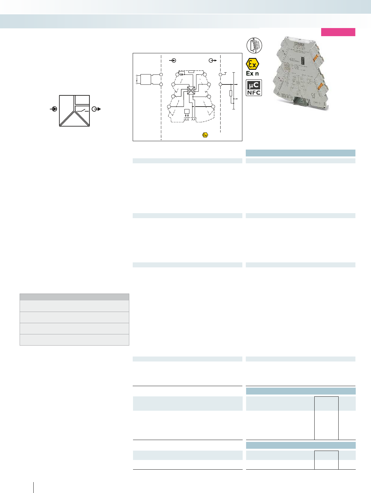
POWER
U, I
f
OUT
IN
FM
IN OUT
Sensor / Field
4-wire
OUT I+
OUT I-
US
1
2
+
–
–
6
4
OUT f
PWM–
PWM+
OUT f
+
–
7
8
5
+3
FM
RO +
RO -
PWR+
PWR+
PWR–
PWR–
S-Port
passive
+
–
1
2
IN U, I+
IN U, I–
TI–
PLC / DCS
max.
100mA
5
6
+-
R
L
OUT +
OUT -
supply
max. 30VDC
II 3 G
Ex nA IIC T4 Gc X
Housing width 6.2 mm
Technical data
Input data U input I input
Input signal (configurable via DIP switch or freely via software) 0 V ... 10 V
2 V ... 10 V
0 V ... 5 V
1 V ... 5 V
10 V ... 0 V
10 V ... 2 V
5 V ... 0 V
5 V ... 1 V
0 V ... 12 V
0 mA ... 20 mA
4 mA ... 20 mA
0 mA ... 10 mA
2 mA ... 10 mA
20 mA ... 0 mA
20 mA ... 4 mA
10 mA ... 0 mA
10 mA ... 2 mA
0 mA ... 24 mA
Maximum input signal 12 V 24 mA
Input resistance > 120 kapprox. 50
Output data Frequency output PWM output
Output signal (configurable via DIP switch or freely via software) 0 Hz ... 10 kHz / 0 Hz ... 5 kHz
15.6 kHz (10 bit) / 1.9 kHz (10 bit)
0 Hz ... 2.5 kHz / 0 Hz ... 1 kHz 3.9 Hz (12 bit) / 488 Hz (12 bit)
0 Hz ... 500 Hz / 0 Hz ... 250 Hz 977 Hz (14 bit) / 122 Hz (14 bit)
0 Hz ... 100 Hz / 0 Hz ... 50 Hz 244 Hz (16 bit) / 31 Hz (16 bit)
Minimum load 4 mA (U
L
/ R
L
) 100 mA 12 mA (U
L
/ R
L
) 100 mA
Load current maximum 100 mA
Maximum switching voltage 30 V
Overrange/underrange Can be set (via software)
General data
Supply voltage U
B
9.6 V DC ... 30 V DC
Nominal supply voltage 24 V DC
Current consumption 25 mA (12 V DC)
12.5 mA (24 V DC)
Power consumption 350 mW (9.6 V DC)
Maximum transmission error 0.1 % (> 7 kHz 0.2%)
Temperature coefficient < 0.01 %/K
Step response (0–99%) 120 ms (15 Hz sample rate)
Further values can be set via software
Electrical isolation Reinforced insulation in accordance with IEC 61010-1
Test voltage, input/output/supply 3 kV (50 Hz, 1 min.)
Degree of protection IP20
Ambient temperature (operation) -40 °C ... 70 °C
Mounting any
Housing material PBT
Dimensions W / H / D 6.2 / 110.5 / 120.5 mm
Push-in connection solid /stranded / AWG 0.14 ... 2.5 mm² / 0.14 ... 2.5 mm² / 24 - 12
Screw connection solid / stranded / AWG 0.2 ... 1.5 mm² / 0.2 ... 1.5 mm² / 24 - 12
Conformance / approvals
Conformance CE-compliant
ATEX
II 3 G Ex nA IIC T4 Gc X
UL, USA / Canada UL applied for
Class I, Div. 2, Groups A, B, C, D T5 applied for
GL GL applied for
Ordering data
Description Type Order No. Pcs. /
Pkt.
Analog frequency converter with limit value function
Standard configuration Push-in connection MINI MCR-2-UI-FRO-PT 2902032 1
Standard configuration Screw connection MINI MCR-2-UI-FRO 2902031 1
Order configuration Push-in connection MINI MCR-2-UI-FRO-PT-C 2906202 1
Order configuration Screw connection MINI MCR-2-UI-FRO-C 2906201 1
Accessories
Programming adapter for configuring modules with
S-PORT interface
IFS-USB-PROG-ADAPTER 2811271 1
Programming adapter for configuring modules with
NFC interface
NFC-USB-PROG-ADAPTER 2900013 1
78
PHOENIX CONTACT
– Universally configurable highly compact
analog-to-frequency transducer for
electrical isolation, amplification,
conversion and filtering of standard
analog signals to frequencies or
PWM signals
– Plug-in connection technology
– Safe 3-way isolation
– Additional switching output
– Frequency output can be used as second
switching output
– Standard signal combinations configurable
via DIP switches
– Freely configurable via software or
smartphone app
– Power supply and fault monitoring
possible via DIN rail connector
– Status and error indicator LEDs
Notes:
The configuration software can be downloaded from the Internet:
phoenixcontact.net/products.
Information on the programming adapters can be found on
page 89
Information on MINI Analog Pro accessories can be found from
page 85
To order a product with an order configuration, enter the required
configuration by referring to the adjacent order key.
Frequency
Analog frequency transducer
MCR technology
Highly compact signal conditioners with plug-in connection technology - MINI Analog Pro
new
Configurable,
frequency, PWM or switching output
For further information and full technical data, visit phoenixcontact.net/products
79PHOENIX CONTACT
Order key for MINI MCR-2-UI-FRO(-PT)(-C) measuring transducer (standard configuration entered as example)
Order No. Input Sample rate Output Output
limitation
Input signal Start End Output signal Carrier frequency Start End
2906201 / I / 0.0 / 20.0 / 15 / I / 0 / 0 / 1000 / 15 / .
2906201
MINI MCR-2-
UI-FRO-C
I I 0.0 0 mA 20.0 20 mA 15 Hz 15 Hz
60 Hz 60 Hz
240 Hz 240 Hz
f f 0 at frequency
output
0 0 Hz
f: freely
selectable
between
0...10 kHz
10000 10 kHz
f: freely
selectable
between
0...10 kHz
0 off
1 on
U U I: freely
selectable
between
0.0 ... 24 mA
I: freely
selectable
between
0.0 ... 24 mA
2906202
MINI MCR-2-
UI-FRO-PT-C U: freely
selectable
between
0.0 ... 12 V
U: freely
selectable
between
0.0 ... 12 V
PWM PWM 15.6 k 15.6 kHz
15.6 kHz (10 bits)
1.9 kHz (10 bits)
7.8 kHz (11 bits)
977 Hz (11 bits)
3.9 kHz (12 bits)
488 Hz (12 bits)
1.9 kHz (13 bits)
244 Hz (13 bits)
977 Hz (14 bits)
122 Hz (14 bits)
488 Hz (15 bits)
61 Hz (15 bits)
244 Hz (16 bits)
31 Hz (16 bits)
D: freely
selectable
between
0.0 ... 100%
D: freely
selectable
between
0.0 ... 100%
Measuring range span at least 0.5 V/1 mA
Increment 0.1 V/0.1 mA
Output signal span at least 10 Hz/1%
Increment 1 Hz/0.1%
Failure information
Behavior in the event of an error Open circuit/short circuit Overrange Underrange
.../ FD /0/0/0
FD freely definable 0 0 Hz
f: freely selectable between
0 ... 11 kHz
D: freely selectable between
0.0 and 100%
0 0 Hz
f: freely selectable between
0 ... 11 kHz
D: freely selectable between
0.0 and 100%
0 0 Hz
f: freely selectable between
0 ... 11 kHz
D: freely selectable between
0.0 and 100%
Failure information only adjustable for
unlimited output
(free definition only for
unlimited output)
(signal type corresponds to
selected output signal)
(free definition only for
unlimited output)
(signal type corresponds to
selected output signal)
(free definition only for
unlimited output)
(signal type corresponds to
selected output signal)
MCR technology
Highly compact signal conditioners with plug-in connection technology - MINI Analog Pro

POWER
RU,I OUT
IN
FM
PWR+
PWR–
+
+
–
–
passive
IN
OUT
FM
1 5
2 6
8
5
6
Zone 2
Sensor / Field PLC / DCS
3
4
7
S-Port
OUT U, I–
OUT U, I+
PWR+
PWR–
TI+
1
3
IN
IN
IN
2
active
Ex:
Housing width 6.2 mm
Technical data
Input data
Potentiometer 100 ... 100 k
Output data U output I output
Output signal (configurable via DIP switch or freely via software) 1 ... 5 V / 10 ... 0 V 0 ... 20 mA / 4 ... 20 mA
0 ... 5 V / 0 ... 10 V 20 ... 0 mA / 20 ... 4 mA
Maximum output signal approx. 12.3 V 24.6 mA
No-load voltage < 17.5 V
Short-circuit current < 31.5 mA
Load R
B
10 k 600 (at 20 mA)
Ripple < 20 mV
PP
(at 10 k) < 20 mV
PP
Behavior in the event of a sensor error configurable
General data
Supply voltage U
B
9.6 V DC ... 30 V DC
Nominal supply voltage 24 V DC
Current consumption 33 mA (at 24 V DC)
Power consumption 850 mW (at I
OUT
= 20 mA, 9.6 V DC, 600 load)
Maximum transmission error < 0.1 % (R < 240 = < 0.2 %)
Temperature coefficient 0.01 %/K
Step response (0–99%) < 60 ms
Electrical isolation Reinforced insulation in accordance with IEC 61010-1
Test voltage, input/output/supply 3 kV (50 Hz, 1 min.)
Degree of protection IP20
Ambient temperature (operation) -40 °C ... 70 °C
Mounting any
Housing material PBT
Dimensions W / H / D 6.2 / 110.5 / 120.5 mm
Push-in connection solid / stranded / AWG 0.14 ... 2.5 mm² / 0.14 ... 2.5 mm² / 24 - 12
Screw connection solid / stranded / AWG 0.2 ... 1.5 mm² / 0.2 ... 1.5 mm² / 24 - 12
EMC note Class A product, see page 625
Conformance / approvals
Conformance CE-compliant
ATEX
II 3 G Ex nA IIC T4 Gc X
UL, USA / Canada UL 508 Listed
Class I, Div. 2, Groups A, B, C, D T5
Class I, Zone 2, Group IIC T5
GL GL applied for
Ordering data
Description Type Order No. Pcs. /
Pkt.
Potiposition transducer
Standard configuration Push-in connection MINI MCR-2-POT-UI-PT 2902017 1
Standard configuration Screw connection MINI MCR-2-POT-UI 2902016 1
Order configuration Push-in connection MINI MCR-2-POT-UI-PT-C 2905006 1
Order configuration Screw connection MINI MCR-2-POT-UI-C 2905005 1
Accessories
Programming adapter for configuring modules with
S-PORT interface
IFS-USB-PROG-ADAPTER 2811271 1
Programming adapter for configuring modules with
NFC interface
NFC-USB-PROG-ADAPTER 2900013 1
80
PHOENIX CONTACT
– Universally configurable, highly compact
potiposition transducer for electrical
isolation, conversion, amplification, and
filtering of potentiometer signals
– For potentiometers from 100 to 100 k
– Automatic potentiometer detection
without manual adjustment
– Plug-in connection system
– Safe 3-way isolation
– Standard signal combinations configurable
via DIP switches
– Freely configurable via software or
smartphone app
– Power supply and fault monitoring
possible via DIN rail connector
– Status and error indicator LEDs
Notes:
The configuration software can be downloaded from the Internet:
phoenixcontact.net/products.
Information on the programming adapters can be found on
page 89
Information on MINI Analog Pro accessories can be found from
page 85
To order a product with an order configuration, please enter the
desired configuration by referring to the order key.
Potentiometer
Potiposition transducer
MCR technology
Highly compact signal conditioners with plug-in connection technology - MINI Analog Pro
Potiposition transducer,
configurable
For further information and full technical data, visit phoenixcontact.net/products
81PHOENIX CONTACT
Order key for MINI MCR-2-POT-UI(-PT)(-C) potiposition transducer (standard configuration entered as an example)
Order No. Automatic potentiometer
detection
Output Filter Open circuit
detect
Output signal Start End
2905005 / AUTO / I 4.0 20.0 / 1 / ON / ...
2905005
MINI MCR-2-
POT-UI-C
AUTO ON I I 0.0 0 mA 20.0 20 mA 1 ON ON
OFF OFF U U I: freely
selectable
between 0.0 ...
21 mA
I: freely
selectable
between 0.0 ...
21 mA
2 OFF OFF
3
4
2905006
MINI MCR-2-
POT-UI-PT-C
5
6
U: freely
selectable
between
0.0 ... 10.5 V
U: freely
selectable
between
0.0 ... 10.5 V
7
8
9
10
Output signal span at least 0.5 V/1 mA
Increment 0.1 V/0.1 mA
Failure information
Behavior in the event of an error Open circuit slider Input open (no potentiometer
connected)
Overrange Underrange
... / NE43DO / 0.0 / 0.0 / 0.0 / 0.0
FD freely definable 0.0 0 mA
I: freely selectable
between 0.0 ... 21.5 mA
U: freely selectable between
0.0 ... 11 V
(only if open circuit detection
is on)
(signal type corresponds to
selected output signal)
0.0 0 mA
I: freely selectable
between 0.0 ... 21.5 mA
U: freely selectable between
0.0 ... 11 V
(signal type corresponds to
selected output signal)
0.0 0 mA
I: freely selectable
between 0.0 ... 21.5 mA
U: freely selectable between
0.0 ... 11 V
(signal type corresponds to
selected output signal)
0.0 0 mA
I: freely selectable
between 0.0 ... 21.5 mA
U: freely selectable between
0.0 ... 11 V
(signal type corresponds to
selected output signal)
Note: failure information according to NE 43 can only be selected for 4 ... 20 mA output
NE43UP NE 43 upscale 21.5 mA 21.5 mA 21.5 mA 21.5 mA
NE43DO NE 43 downscale 3.5 mA 3.5 mA 3.5 mA 3.5 mA
NE430 NE 43 0 mA 0 mA 0 mA 0 mA 0 mA
NE43UD NE 43 upscale/downscale 3.5 mA 3.5 mA 21.5 mA 21.5 mA
MCR technology
Highly compact signal conditioners with plug-in connection technology - MINI Analog Pro
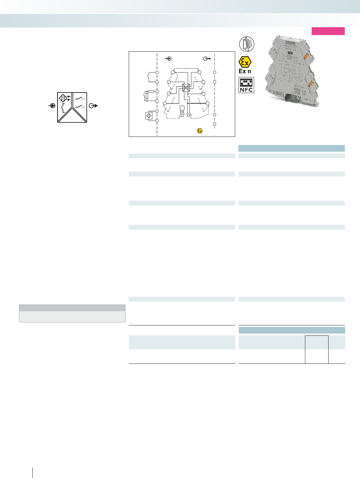
POWER
OUT
IN
FM
DI1
DI2
IN
Sensor / Field
OUT
PLC / DCS
5
3
6
4
1
1
1
2
2
2
++
–
–
–
1
2 6
4
OUT 1–
IN +
IN–
OUT 1+
+
–
7
8
5
+3
FM
OUT 2+
OUT 2-
PWR+
PWR+
PWR–
PWR–
II 3 G
Ex nA IIC T4 Gc X
Housing width 6.2 mm
Technical data
Input data
Input signal NAMUR proximity sensors (EN 60947-5-6)
open circuit switch contacts
Switch contacts with resistance circuit
Control circuit
No-load voltage 8.2 V DC 10 %
Switching points (in acc. with IEC 60947-5-6) < 1.2 mA (blocking)
> 2.1 mA (conductive)
Line fault detection > 6 mA (in the event of a short-circuit)
< 0.35 mA (in the event of an open circuit)
Switching output
Transistor output 2 N/O contacts
Max. switching voltage 30 V DC
Max. switching current 50 mA
Switching frequency 5 kHz
General data
Supply voltage U
B
9.6 V DC ... 30 V DC
Nominal supply voltage 24 V DC
Current consumption 35 mA (12 V DC)
18 mA (24 V DC)
Power consumption 450 mW (9.6 V DC)
Electrical isolation Reinforced insulation in accordance with IEC 61010-1
Test voltage, input/output/supply 3 kV (50 Hz, 1 min.)
Degree of protection IP20
Ambient temperature (operation) -40 °C ... 70 °C
Mounting any
Housing material PBT
Dimensions W / H / D 6.2 / 110.5 / 120.5 mm
Push-in connection solid / stranded / AWG 0.14 ... 2.5 mm² / 0.14 ... 2.5 mm² / 24 - 12
Screw connection solid / stranded / AWG 0.2 ... 1.5 mm² / 0.2 ... 1.5 mm² / 24 - 12
Conformance / approvals
Conformance CE-compliant
ATEX
II 3 G Ex nA IIC T4 Gc X
UL, USA / Canada UL applied for
Class I, Div. 2, Groups A, B, C, D T5 applied for
GL GL applied for
Ordering data
Description Type Order No. Pcs. /
Pkt.
NAMUR signal conditioner
Push-in connection MINI MCR-2-NAM-2RO-PT 2902005 1
Screw connection MINI MCR-2-NAM-2RO 2902004 1
82
PHOENIX CONTACT
– Highly compact signal conditioner for
electrical isolation, amplification, and
duplication of proximity sensor signals
– For proximity sensors in accordance with
IEC 60947-5-6 and EN 50227
– Floating contacts and contacts with
resistance circuit can be connected
– Plug-in connection technology
– Input and output signals can be configured
via DIP switches
– Transistor switching contacts on the
output
– Second output can be used as a doubler
or error signaling output
– Safe 3-way isolation
– Switchover between operating current
and quiescent current (inverted switching
behavior)
– Power supply and fault monitoring
possible via DIN rail connector
– Status LEDs
Notes:
Information on MINI Analog Pro accessories can be found from
page 85
Digital IN
Signal conditioner
MCR technology
Highly compact signal conditioners with plug-in connection technology - MINI Analog Pro
new
Configurable,
for NAMUR sensors and floating contacts
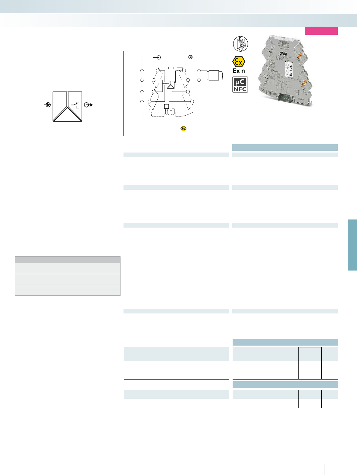
POWER
OUT
IN U,I
FM
IN
OUT
Sensor / Field
4-wire
OUT
U,I +
OUT
U,I -
US
5
6
14
11
11
12
PLC / DCS
1
2
3
4
PWR+
PWR–
+
+
–
–
PWR+
FM
1 5
2 6
3 7
48
IN U, I–
PWR–
IN U, I+
TI-
S-Port
II 3 G
Ex nA IIC T4 Gc X
For further information and full technical data, visit phoenixcontact.net/products
Housing width 6.2 mm
Technical data
Input data U input I input
Input signal (configurable using the DIP switch) 0 ... 10 V / 0 ... 12 V 0 ... 20 mA / 0 ... 24 mA
Maximum input signal 12 V 24 mA
Input resistance > 120 kapprox. 50
Specification of the switching point Can be set via software or in increments via DIP switches
Switching output
Relay output 1 PDT
Contact material AgSnO
2
, hard gold-plated
Max. switching voltage 250 V AC
Limiting continuous current 6 A
Hysteresis (configurable using the DIP switch) can be set freely via software
Setting range of the response delay (configurable using the DIP
switch)
0 s ... 10 s (can be set freely via software)
General data
Supply voltage U
B
9.6 V DC ... 30 V DC
Nominal supply voltage 24 V DC
Current consumption 20 mA (at 24 V DC)
40 mA (at 12 V DC)
Power consumption 0.5 W
Maximum transmission error 0.1 % (of final value)
Temperature coefficient 0.01 %/K
Step response (0–99%) typ. 140 ms (can be set via software)
Electrical isolation Reinforced insulation in accordance with IEC 61010-1
Test voltage, input/output/supply 3 kV (50 Hz, 1 min.)
Degree of protection IP20
Ambient temperature (operation) -40 °C ... 70 °C
Mounting any
Housing material PBT
Dimensions W / H / D 6.2 / 110.5 / 120.5 mm
Push-in connection solid / stranded / AWG 0.14 ... 2.5 mm² / 0.14 ... 2.5 mm² / 24 - 12
Screw connection solid / stranded / AWG 0.2 ... 1.5 mm² / 0.2 ... 1.5 mm² / 24 - 12
Conformance / approvals
Conformance CE-compliant
ATEX
II 3 G Ex nA nC IIC T4 Gc X
UL, USA / Canada UL applied for
Class I, Div. 2, Groups A, B, C, D T5 applied for
GL GL applied for
Ordering data
Description Type Order No. Pcs. /
Pkt.
Threshold value switch with relay PDT output
Push-in connection MINI MCR-2-UI-REL-PT 2902035 1
Screw connection MINI MCR-2-UI-REL 2902033 1
Accessories
Programming adapter for configuring modules with
S-PORT interface
IFS-USB-PROG-ADAPTER 2811271 1
Programming adapter for configuring modules with
NFC interface
NFC-USB-PROG-ADAPTER 2900013 1
83
PHOENIX CONTACT
– Universally configurable highly compact
threshold value switch for switching
analog limit values
– Plug-in connection technology
– Safe 3-way isolation
– Standard switching behavior can be
configured via DIP switches
– Freely configurable via software or
smartphone app
– PDT relay at output
– Limiting continuous current up to 6 A
– Power supply and fault monitoring
possible via DIN rail connector
– Status and error indicator LEDs
Notes:
The configuration software can be downloaded from the Internet:
phoenixcontact.net/products.
Information on the programming adapters can be found on
page 89
Information on MINI Analog Pro accessories can be found from
page 85
Limit values,
threshold value switch
MCR technology
Highly compact signal conditioners with plug-in connection technology - MINI Analog Pro
new
Configurable,
with relay PDT output
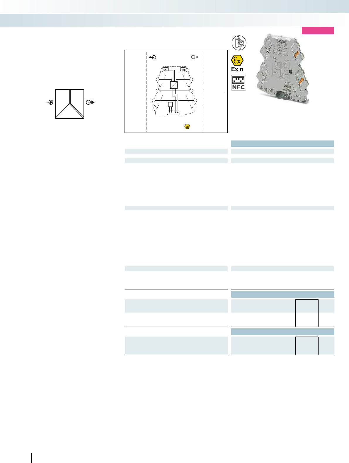
IN
U
I
CV
CC
POWER
OUT
FM
Zone 2
Sensor / Field
OUT
OUT
PLC / DCS
+
+
+
+
–
–
–
–
1
2 6
4
OUT U,I–
OUT U,I+ OUT U,I+
OUT U,I–
TI+
7
8
TI+
5
FM
PWR+
PWR–
3PWR+
PWR+
PWR- PWR-
Housing width 6.2 mm
Technical data
Input data
Input signal 9.6 ... 30 V
Output data U output I output
Output signal (can be configured using DIP switches) 10 V DC
8.75 V DC
7.5 V DC
6.25 V DC
5 V DC
3.75 V DC
2.5 V DC
1.25 V DC
20 mA
17.5 mA
15 mA
12.5 mA
10 mA
7.5 mA
5 mA
2.5 mA
Short-circuit current > 32 mA
Ripple < 20 mV
PP
(at 600 )
General data
Supply voltage U
B
9.6 V DC ... 30 V DC
Power consumption < 1.1 W (9.6 V DC)
Maximum transmission error 0.1 % (of final value)
Temperature coefficient < 0.01 %/K
Electrical isolation Reinforced insulation in accordance with IEC 61010-1
Test voltage, input/output/supply 3 kV (50 Hz, 1 min.)
Degree of protection IP20
Ambient temperature (operation) -40 °C ... 70 °C
Housing material PBT
Dimensions W / H / D 6.2 / 110.5 / 120.5 mm
Push-in connection solid / stranded / AWG 0.14 ... 2.5 mm² / 0.14 ... 2.5 mm² / 24 - 12
Screw connection solid / stranded / AWG 0.2 ... 1.5 mm² / 0.2 ... 1.5 mm² / 24 - 12
Conformance / approvals
Conformance CE-compliant
ATEX
II 3 G Ex nA IIC T4 Gc X
UL, USA / Canada UL applied for
Class I, Div. 2, Groups A, B, C, D T5 applied for
Ordering data
Description Type Order No. Pcs. /
Pkt.
Constant voltage/constant current source
Push-in connection MINI MCR-2-CVCS-PT 2902065 1
Screw connection MINI MCR-2-CVCS 2902064 1
Accessories
Setpoint potentiometer, for individual setpoint definition
Resistance value 4.7 kEMG 30-SP- 4K7LIN 2940252 10
Resistance value 10 kEMG 30-SP-10K LIN 2942124 10
84
PHOENIX CONTACT
– Constant voltage/constant current
source for potentiometers, measuring
bridges, encoders, etc.
– Plug-in connection technology
– Highly precise
– Output signals can be configured via
DIP switches
– Input signal corresponds to power supply
– Input signal and therefore energy supply
and fault monitoring via the DIN rail
connector
– For voltages up to 10 V and currents up
to 20 mA
– Status LED
Accessories
Constant voltage/constant current
source
MCR technology
Highly compact signal conditioners with plug-in connection technology - MINI Analog Pro
new
Output signals, configurable
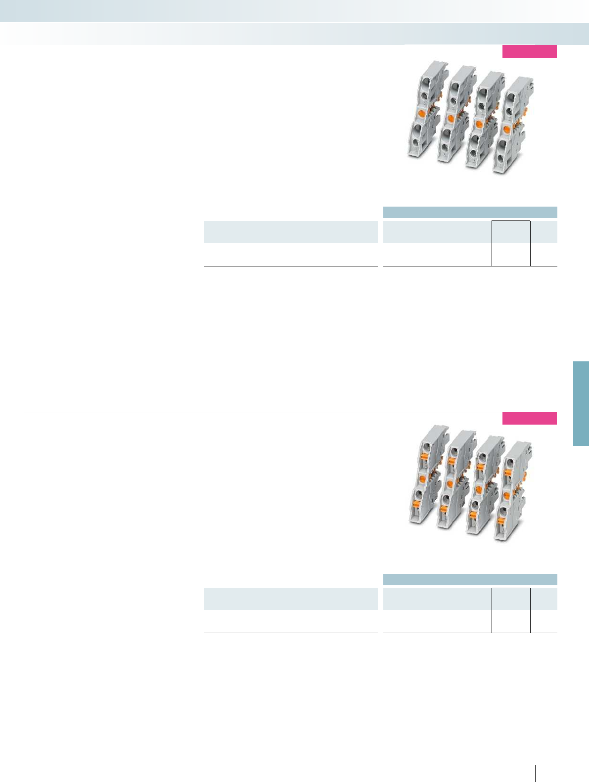
For further information and full technical data, visit phoenixcontact.net/products
Ordering data
Description Type Order No. Pcs. /
Pkt.
FASTCON Pro connector set with screw connection technology
FASTCON PRO-SET 2906227 1
new
– FASTCON Pro connector set
– Consisting of four connectors, one each
for every position on the module
– Suitable for all MINI Analog Pro modules
– Four-way coding prevents incorrect
insertion into the device
– Screw connection technology
Accessories
Screw connection connector set
MCR technology
Highly compact signal conditioners with plug-in connection technology - MINI Analog Pro
Ordering data
Description Type Order No. Pcs. /
Pkt.
FASTCON Pro connector set with push-in connection technology
FASTCON PRO-SET-PT 2906228 1
85
PHOENIX CONTACT
new
– FASTCON Pro connector set
– Consisting of four connectors, one each
for every position on the module
– Suitable for all MINI Analog Pro modules
– Four-way coding prevents incorrect
insertion into the device
– Push-in connection technology
Accessories
Push-in connection connector set
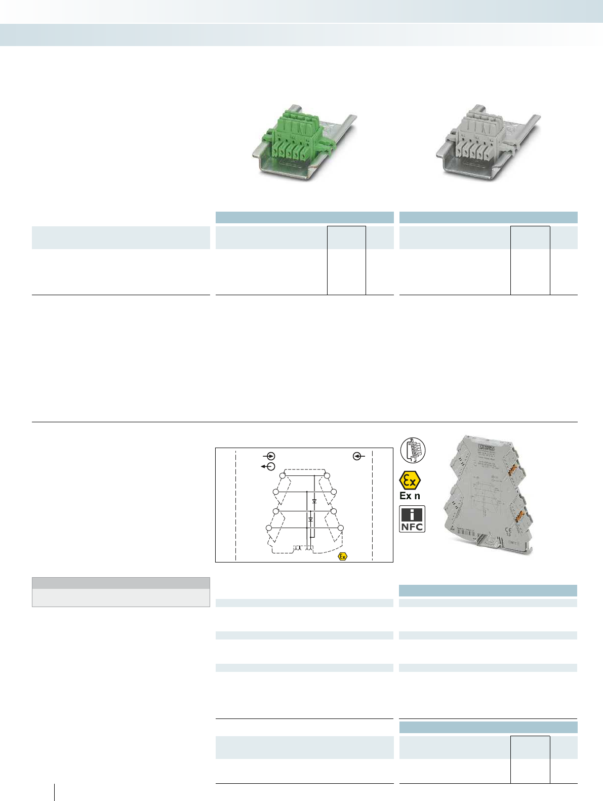
PWR OUT
+
+
+
–
–
–
–
+
PWR 1 IN
OUT-FM
PWR 2 IN
OUT-FMPWR 2 IN
PWR 1 IN
IN
OUT FM
1 5
2 6
3 7
48
+9,6 V
…+30 V
+9,6 V
…+30 V
Zone 2
IN
+9,6 V
…+30 V
+9,6 V
…+30 V
–
+
Ordering data Ordering data
Description Type Order No. Pcs. /
Pkt. Type Order No. Pcs. /
Pkt.
DIN rail connector (TBUS), for bridging the supply voltage, can
be snapped onto 35 mm DIN rails as per EN 60715, with UL
approval
Color: green ME 6,2 TBUS-2 1,5/5-ST-3,81 GN 2869728 10
Color: gray ME 6,2 TBUS-2 1,5/5-ST-3,81 GY 2695439 10
– For bridging the supply voltage
– Reduces wiring costs
– Module replacement without interrupting
the supply to the remaining modules
(hot swappable)
– One DIN rail connector for two
MINI Analog Pro modules
– Only distinguished by color coding
Accessories
ME 6,2 TBUS... DIN rail connector
MCR technology
Highly compact signal conditioners with plug-in connection technology - MINI Analog Pro
For bridging the supply voltage For bridging the supply voltage
Technical data
Input data/output data
Input voltage range 9.9 V DC ... 30 V DC
Output voltage Input voltage - 0.3 V
Output current 3.2 A
General data
Ambient temperature (operation) -40 °C ... 70 °C
Housing material PBT
EMC note Class A product, see page 625
Conformance / approvals
Conformance CE-compliant
ATEX
II 3 G Ex nA IIC T4 Gc X
UL, USA / Canada UL 508 Listed
Class I, Div. 2, Groups A, B, C, D T6
Class I, Zone 2, Group IIC T6
GL GL applied for
Ordering data
Description Type Order No. Pcs. /
Pkt.
MINI Analog Pro power terminal
Push-in connection MINI MCR-2-PTB-PT 2902067 1
Screw connection MINI MCR-2-PTB 2902066 1
86
PHOENIX CONTACT
– Power terminal for supplying the supply
voltage to the DIN rail connector
– Plug-in connection system
– Increased output current of 3.2 A
– For up to 115 MINI Analog Pro modules
– Monitoring of supplies in combination
with the fault monitoring module
– Flexible redundant supply from one or
both module sides
– Status and error indicator LEDs
Notes:
Observe the supply instructions for the MINI and MACX modules.
Accessories
Power terminal
Redundant supply for existing 24 V
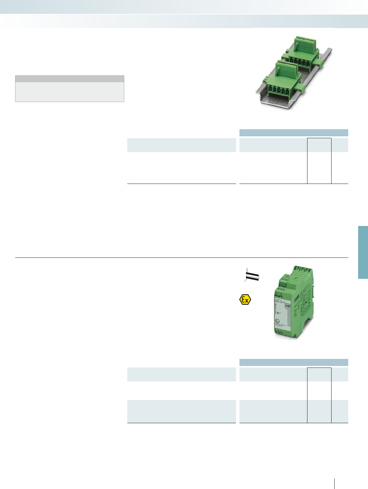
For further information and full technical data, visit phoenixcontact.net/products
Ordering data
Description Type Order No. Pcs. /
Pkt.
DIN rail connector, for bridging the supply voltage, can be
snapped onto 35 mm DIN rails as per EN 60715, with UL approval,
two pieces are required per system power supply
ME 17,5 TBUS 1,5/ 5-ST-3,81 GN 2709561 10
– For bridging the supply voltage when
using a MINI POWER system power
supply
Notes:
If the system power supply is used, two ME 17,5 TBUS DIN rail
connectors are required. This allows you to establish the
connection to the ME 6,2 TBUS DIN rail connector of the
MINI Analog system and provide an effective power supply.
Accessories
ME 17,5 TBUS-... DIN rail connector
MCR technology
Highly compact signal conditioners with plug-in connection technology - MINI Analog Pro
For system power supply
Ordering data
Description Type Order No. Pcs. /
Pkt.
System power supply, primary-switched, with zone 2 approval.
Further information can be found in Catalog 6, Surge protection and
power supplies.
MINI-PS-100-240AC/24DC/1.5/EX 2866653 1
System power supply, primary-switched (not for zone 2)
Further information can be found in Catalog 6, Surge protection and
power supplies.
MINI-SYS-PS-100-240AC/24DC/1.5 2866983 1
87
PHOENIX CONTACT
H
W
D
– For supplying the supply voltage via the
DIN rail connector where AC voltages
are available
– Nominal input voltage range
100 ... 240 V AC
– 24 V DC output voltage
– For up to 60 MINI Analog modules
– For up to 1.5 A, secondary
– Status and error signaling via diagnostics
LEDs
Accessories
System power supply
For applications with local voltages of
over 100 V
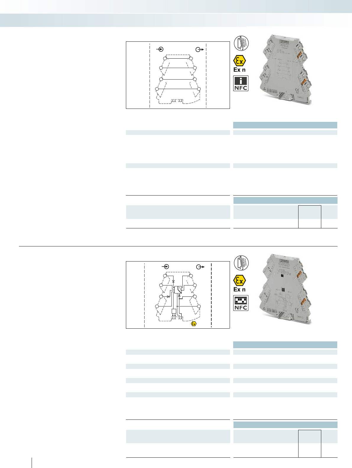
OUTIN
OUTIN
OUT
IN OUT
1 5
2 6
3 7
48
Sensor / Field PLC / DCS
IN
OUTIN
PWR+
PWR–
+
+
+
–
–
–
–
+
OUT RC
OUT RC
PWR 1
IN
PWR 2
IN
PWR
OUT
FAULT
CONTACT
IN OUT
FM
1 5
2 6
3 7
48
+9,6 V…+30 V+9,6 V…+30 V
+9,6 V…+30 V
Zone 2
Technical data
General data
Degree of protection IP20
Ambient temperature (operation) -40 °C ... 70 °C
Mounting any
Housing material PBT
Dimensions W / H / D 6.2 / 110.5 / 120.5 mm
Screw connection solid / stranded / AWG 0.2 ... 1.5 mm² / 0.2 ... 1.5 mm² / 24 - 12
Conformance / approvals
Conformance CE-compliant
ATEX
II 3 G Ex nA IIC T4 Gc X
UL, USA / Canada UL 508 Listed
Class I, Div. 2, Groups A, B, C, D T6
Class I, Zone 2, Group IIC T6
GL GL applied for
Ordering data
Description Type Order No. Pcs. /
Pkt.
MINI Analog Pro feed-through terminal block
Screw connection MINI MCR-2-TB 2902068 1
– Feed-through terminal block for
1:1 forwarding of signals that are already
electrically isolated in the MINI Analog
Pro group
– Plug-in connection system
Accessories
Feed-through terminal block
MCR technology
Highly compact signal conditioners with plug-in connection technology - MINI Analog Pro
For signals already electrically isolated
Technical data
Input data/output data
Input signal 9.9 V DC ... 30 V DC
Output signal 9.6 V DC ... 29.7 V DC
Switching output
Max. switching voltage 30 V DC
Max. switching current 50 mA
General data
Test voltage input/output 1.5 kV AC (50 Hz, 1 min.)
EMC note Class A product, see page 625
Conformance / approvals
ATEX
II 3 G Ex nA IIC T4 Gc X
UL, USA / Canada UL 508 Listed
Class I, Div. 2, Groups A, B, C, D T6
Class I, Zone 2, Group IIC T6
GL GL applied for
Ordering data
Description Type Order No. Pcs. /
Pkt.
MINI Analog Pro fault signaling module
Push-in connection MINI MCR-2-FM-RC-PT 2904508 1
Screw connection MINI MCR-2-FM-RC 2904504 1
88
PHOENIX CONTACT
– Fault monitoring module for evaluating
and reporting group errors from the fault
monitoring system
– Monitoring of up to 115 connected
MINI Analog Pro modules
– Plug-in connection system
– Monitoring of supply voltages of
MINI MCR-2-PTB(-PT) power terminals
– Drawing off the supply is possible
– Fault signaling via an N/C contact
– Status and error indicator LEDs
– CE-compliant
Accessories
Fault signaling module
For group error indication and
supply monitoring

For further information and full technical data, visit phoenixcontact.net/products
Technical data
General data
EMC note Class A product, see page 625
Ordering data
Description Type Order No. Pcs. /
Pkt.
Programming adapter for configuring modules with
S-PORT interface
IFS-USB-PROG-ADAPTER 2811271 1
Programming adapter for configuring modules with
NFC interface
NFC-USB-PROG-ADAPTER 2900013 1
IFS-USB-PROG-ADAPTER and
NFC-USB-PROG-ADAPTER programmable
adapters for configuring Phoenix Contact
interface modules with S-PORT or NFC
interface.
The adapters are used with the FDT/DTM
or the ANALOG-CONF software.
For programming MACX Analog,
MINI Analog Pro, and MINI Analog.
Accessories
Programming adapters
MCR technology
Highly compact signal conditioners with plug-in connection technology - MINI Analog Pro
Ordering data Ordering data
Description Color Type Order No. Pcs. /
Pkt. Type Order No. Pcs. /
Pkt.
UniCard, can be marked with THERMOMARKCARD and
BLUEMARK, 24-section, 8individual labels per strip, lettering field
size: 30 x 5mm
white UCT-EM (30X5) 0801505 10
Lettering field size: 30x5mm white UCT-EM (30X5) CUS 0801589 1
10-section, lettering field size: 15 x 5 mm white UC-EMLP (15X5) 0819301 10
10-section, lettering field size: 15 x 5 mm white UC-EMLP (15X5) CUS 0824550 1
Self-adhesive marker strips, unprinted, continuous, material
off the roll, for marking with thermal transfer printer, can be
separated using cutter, pitch as desired, strip length of up to
1000mm, 10strips, strip height of5.0mm, 1roll = 90m
white SK 5,0 WH:REEL 0805221 1
89
PHOENIX CONTACT
– Snap-in labels and adhesive labels with
large area for marking
– For snapping-into or sticking onto
MINI Analog Pro covers, without
overlapping the status and error LEDs
– The sheets can be marked quickly and
easily using the BLUEMARK CLED and
the THERMOMARK CARD...
– They can also be custom printed
according to customer requirements
Accessories
Marking labels for transparent cover
Unmarked and marked according to
customer specifications
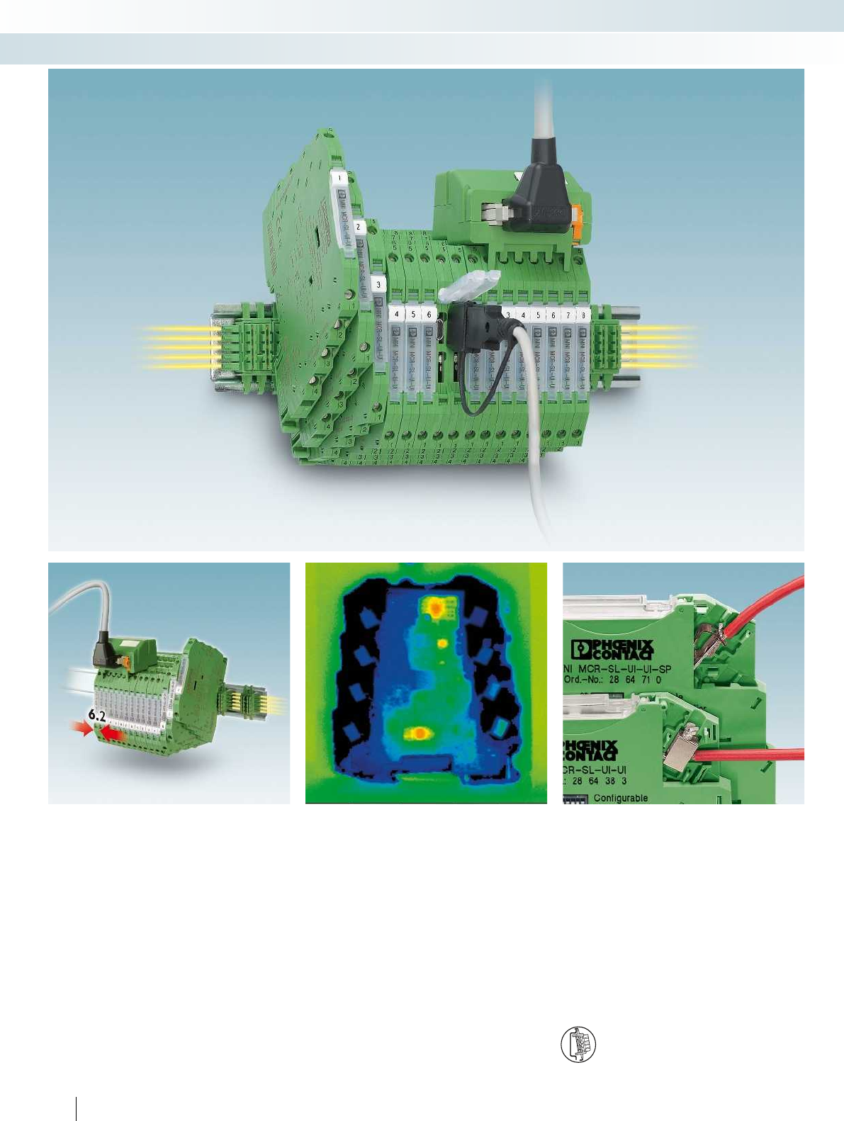
90
PHOENIX CONTACT
Extremely compact and efficient
The signal conditioners from the
MINI Analog range offer the full spectrum
of analog signal conditioning. They are
therefore extremely efficient with regard to
saving costs, space, and energy.
Choose the right MINI Analog signal
conditioner for your application:
– Analog IN/OUT
– Temperature
– Frequency
– Potentiometer/resistor
– Digital IN
– Threshold values
– Accessories
Low power consumption
– The resulting minimal self-heating ensures
long service life and a high degree of
operational reliability
Clearly arranged wiring
– Eight connections with a choice of screw
or spring-cage terminal blocks
DIN rail connector-compatible
The DIN rail connector enables modular
bridging of the 24 V supply voltage.
MCR technology
Highly compact signal conditioners - MINI Analog

For further information and full technical data, visit phoenixcontact.net/products
91PHOENIX CONTACT
MCR technology
Highly compact signal conditioners - MINI Analog
Fault monitoring and power bridging
– The DIN rail connector simplifies supply
and enables group error monitoring
High operational reliability
– 3-way electrical isolation increases the
operational reliability against system
disturbances
Easy configuration
– Can be configured easily via DIP switches
or software, for extended functionality
and monitoring
Reduction in analog inputs on
controllers
– The MINI Analog multiplexer reduces up
to eight analog signals to a 4 ... 20 mA
signal
Time-saving system cabling
– Plug and Play – for eight channels on the
signal conditioner and controller side
Fast and error-free signal connection
– Compact Termination Carriers connect
MINI Analog devices to the automation
systems – Plug and Play and hot-swap-
capable
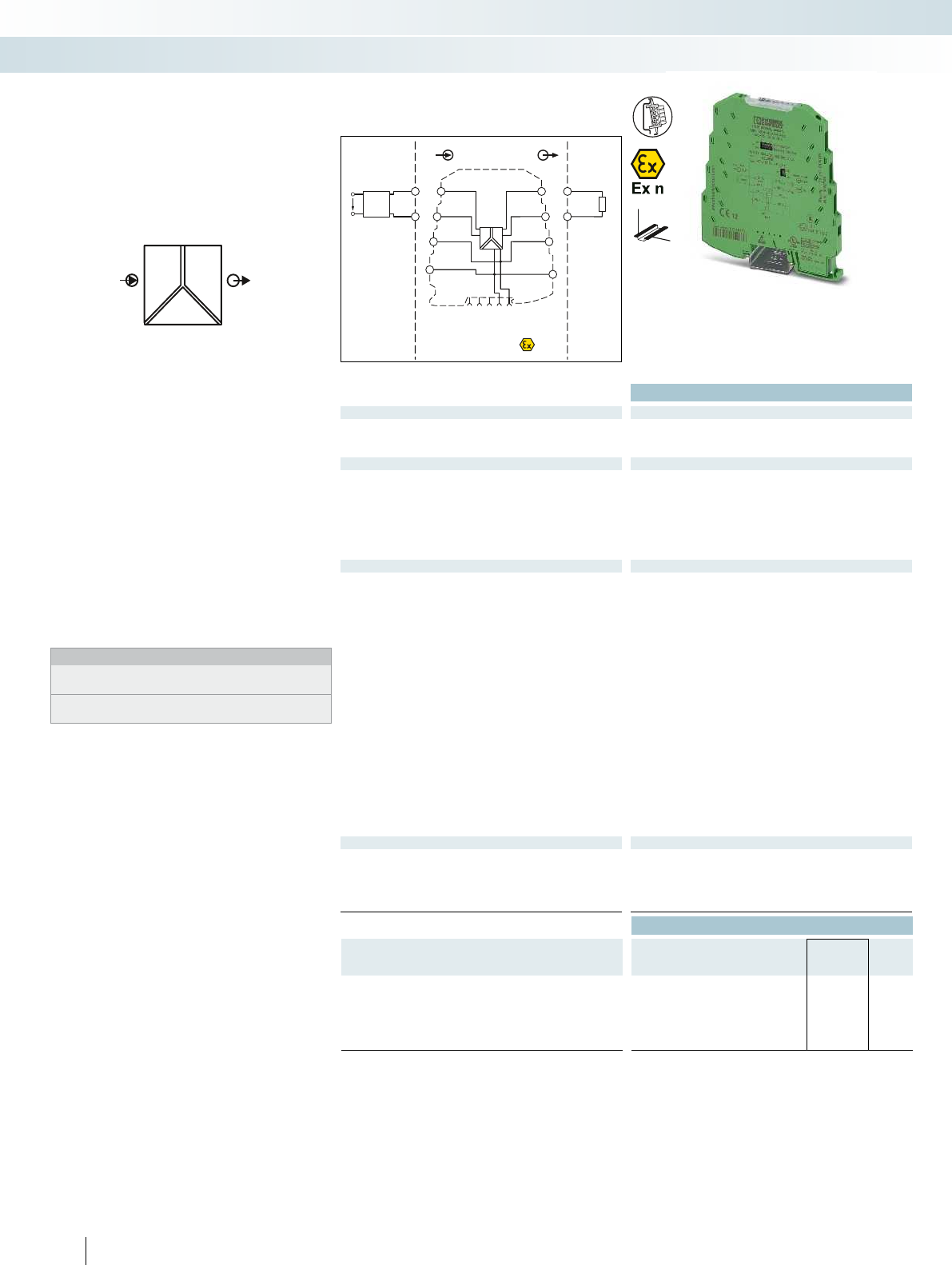
POWER
U,I U,I OUT
IN
Zone 2
Div. 2
passive
IN
Sensor / Field
OUT
PLC / DCS
4-wire
–
+
–
–
+
+
+
–
+24V
+24V
+24V
GND 3
GND 3
GND 2
active
GND 3
GND 1
OUT U,IIN U,I
1 5
2
6
7
8
3
4
OUT
U,I
GND
US
5
6
1
2
Ex:
Housing width 6.2 mm
Technical data
Input data U input I input
Input signal 0 ... 5 V / 1 ... 5 V 0 ... 20 mA / 4 ... 20 mA
0 ... 10 V / 2 ... 10 V
Input resistance approx. 100 kapprox. 50
Output data U output I output
Output signal 0 ... 5 V / 1 ... 5 V 0 ... 20 mA / 4 ... 20 mA
0 ... 10 V / 2 ... 10 V
Maximum output signal approx. 12.5 V 28 mA
No-load voltage approx. 12.5 V
Short-circuit current approx. 22 mA
Load R
B
10 k< 500 (at 20 mA)
Ripple < 20 mV
PP
(at 10 k) < 20 mV
PP
(at 500 )
General data U output I output
Supply voltage U
B
19.2 V DC ... 30 V DC
Nominal supply voltage 24 V DC
Current consumption < 9 mA (voltage output,
at 24 V DC incl. load)
< 19 mA (current output,
at 24 V DC incl. load)
Power consumption < 200 mW (voltage output) < 450 mW (current output)
Maximum transmission error 0.1 % (of final value)
Temperature coefficient < 0.01 %/K, typ. < 0.002 %/K
Cut-off frequency (3 dB) approx. 100 Hz
Step response (10-90%) approx. 3.2 ms
Electrical isolation Basic insulation according to EN 61010
Test voltage, input/output/supply 1.5 kV (50 Hz, 1 min.)
Degree of protection IP20
Ambient temperature (operation) -20 °C ... 65 °C
Mounting any
Housing material PBT
Dimensions W / H / D 6.2 / 93.1 / 102.5 mm
Screw connection solid / stranded / AWG 0.2 ... 2.5 mm² / 0.2 ... 2.5 mm² / 26 - 12
Spring-cage connection solid / stranded / AWG 0.2 ... 2.5 mm² / 0.2 ... 2.5 mm² / 24 - 12
EMC note Class A product, see page 625
Conformance / approvals
Conformance CE-compliant
ATEX
II 3 G Ex nA IIC T4 Gc X
UL, USA / Canada UL 508 Recognized
Class I, Div. 2, Groups A, B, C, D T5
GL GL EMC 2 D
Ordering data
Description Type Order No. Pcs. /
Pkt.
MCR 3-way signal conditioner, for electrical isolation of
analog signals
Order configuration Screw connection MINI MCR-SL-UI-UI 2864383 1
Order configuration Spring-cage connection MINI MCR-SL-UI-UI-SP 2864710 1
Standard configuration Screw connection MINI MCR-SL-UI-UI-NC 2864150 1
Standard configuration Spring-cage connection MINI MCR-SL-UI-UI-SP-NC 2864163 1
92
PHOENIX CONTACT
– Highly compact signal conditioner for
electrical isolation, conversion,
amplification, and filtering of standard
analog signals
– Up to 36 signal combinations can be
configured using DIP switches
– 3-way isolation
– Low power consumption
– Power supply possible through the foot
element (DIN rail connector)
– Standard configuration:
0 ... 10 V input, 0 ... 20 mA output
Notes:
To order a product with an order configuration, enter the required
configuration by referring to the adjacent order key.
Information about power bridging, system cabling, and marking
components can be found from page 116
Analog IN/Analog OUT
3-way signal conditioner
MCR technology
Highly compact signal conditioners - MINI Analog
DW
H
Configurable,
up to 36 signal combinations
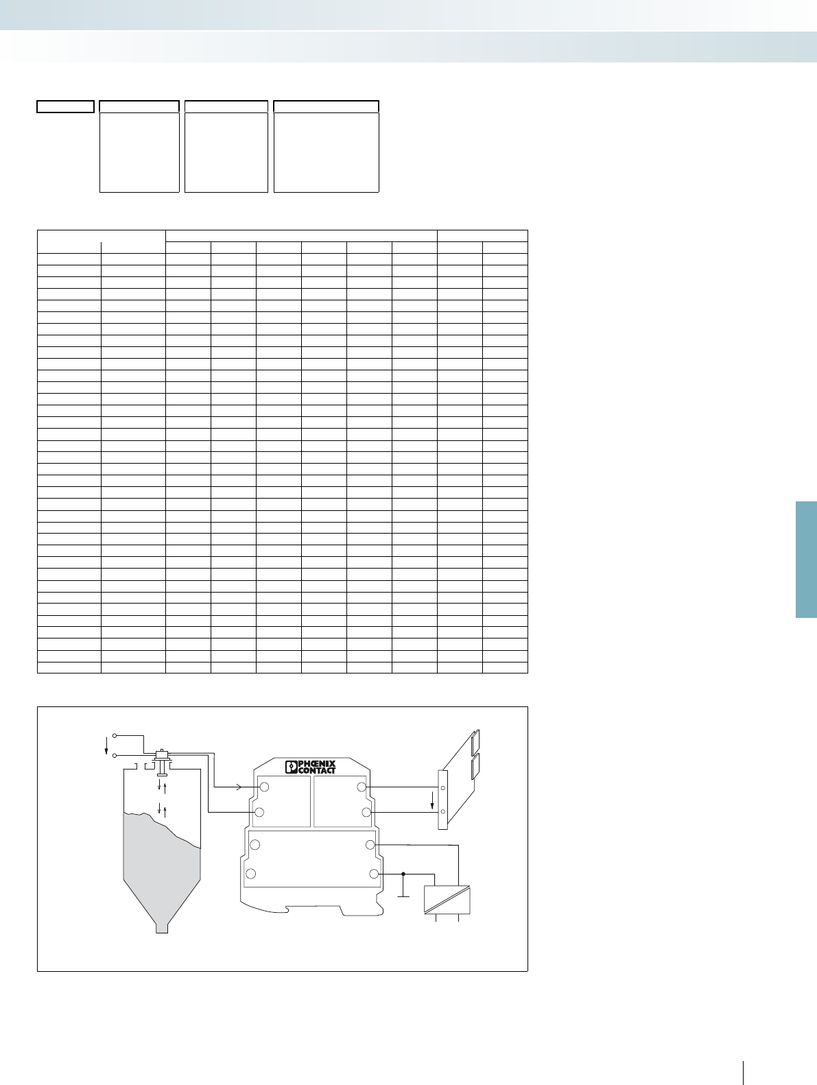
0...20mA
24V
0...10V
24V
MINIMCR-SL-UI-UI
51
2
3
4
6
7
8
GND3
GND1
IN
GND2
OUT
UB+ UB+
GND3
For further information and full technical data, visit phoenixcontact.net/products
93
PHOENIX CONTACT
Order key MINI MCR-SL-UI-UI(-SP) (standard configuration entered as an example)
Configuration table for input and output signals
Application example: level measurement
DIP switch SW 2 DIP switch SW 1
Input Output DIP 1 DIP 2 DIP 3 DIP 4 DIP 5 DIP 6 DIP 1 DIP 2
0 - 10 V 0 - 20 mA OFF OFF OFF OFF OFF OFF OFF OFF
4 - 20 mA OFF OFF OFF OFF OFF ON OFF OFF
0 - 10 V ON OFF ON OFF OFF OFF OFF OFF
2 - 10 V ON OFF ON OFF OFF ON OFF OFF
0 - 5 V ON ON OFF OFF OFF OFF OFF OFF
1 - 5 V ON ON OFF OFF OFF ON OFF OFF
2 - 10 V 0 - 20 mA OFF OFF OFF ON ON OFF OFF OFF
4 - 20 mA OFF OFF OFF OFF OFF OFF OFF OFF
0 - 10 V ON OFF ON ON ON OFF OFF OFF
2 - 10 V ON OFF ON OFF OFF OFF OFF OFF
0 - 5 V ON ON OFF ON ON OFF OFF OFF
1 - 5 V ON ON OFF OFF OFF OFF OFF OFF
0 - 5 V 0 - 20 mA OFF OFF OFF OFF OFF OFF ON OFF
4 - 20 mA OFF OFF OFF OFF OFF ON ON OFF
0 - 10 V ON OFF ON OFF OFF OFF ON OFF
2 - 10 V ON OFF ON OFF OFF ON ON OFF
0 - 5 V ON ON OFF OFF OFF OFF ON OFF
1 - 5 V ON ON OFF OFF OFF ON ON OFF
1 - 5 V 0 - 20 mA OFF OFF OFF ON ON OFF ON OFF
4 - 20 mA OFF OFF OFF OFF OFF OFF ON OFF
0 - 10 V ON OFF ON ON ON OFF ON OFF
2 - 10 V ON OFF ON OFF OFF OFF ON OFF
0 - 5 V ON ON OFF ON ON OFF ON OFF
1 - 5 V ON ON OFF OFF OFF OFF ON OFF
0 - 20 mA 0 - 20 mA OFF OFF OFF OFF OFF OFF OFF ON
4 - 20 mA OFF OFF OFF OFF OFF ON OFF ON
0 - 10 V ON OFF ON OFF OFF OFF OFF ON
2 - 10 V ON OFF ON OFF OFF ON OFF ON
0 - 5 V ON ON OFF OFF OFF OFF OFF ON
1 - 5 V ON ON OFF OFF OFF ON OFF ON
4 - 20 mA 0 - 20 mA OFF OFF OFF ON ON OFF OFF ON
4 - 20 mA OFF OFF OFF OFF OFF OFF OFF ON
0 - 10 V ON OFF ON ON ON OFF OFF ON
2 - 10 V ON OFF ON OFF OFF OFF OFF ON
0 - 5 V ON ON OFF ON ON OFF OFF ON
1 - 5 V ON ON OFF OFF OFF OFF OFF ON
NONE =without FCC
2864383 =IN01 =0 ... 20 mA OUT01 =0 ... 20 mA Yes =with FCC (a fee
is charged)
MINI MCR-SL-
UI-UI
IN02 =4 ... 20 mA OUT02 =4 ... 20 mA
IN03 =0 ... 10 V OUT03 =0 ... 10 V
IN04 =2 ... 10 V OUT04 =2 ... 10 V YESPLUS =FCC with
5 measuring
points (a fee is
charged)
2864710 IN05 =0 ... 5 V OUT05 =0 ... 5 V
MINI MCR-SL-
UI-UI-SP
IN06 =1 ... 5 V OUT06 =1 ... 5 V
Order No.
Input Output Factory calibration
certificate (FCC)
2864383 / IN03 / OUT01 / NONE
Level sensor
Controller
Mains voltage
MCR technology
Highly compact signal conditioners - MINI Analog

POWER
UU,I OUT
IN
Zone 2
passive
IN
Sensor /Field
OUT
PLC / DCS
4-wire
–
+
–
–
+
+
+
–
+24V
+24V
+24V
GND 3
GND 3
GND 2
active
GND 3
GND 1
OUTU,IIN U
1 5
2
6
7
8
3
4
OUTU
GND
US
5
6
1
2
Ex:
Housing width 6.2 mm
Technical data
Input data
Input signal (can be configured using DIP switches) 0 ... 50 mV
Maximum input signal approx. 30 V DC
Input resistance approx. 10 k
Output data U output I output
Output signal (configurable using the DIP switch) 0 ... 5 V / 1 ... 5 V 0 ... 20 mA / 4 ... 20 mA
0 ... 10 V / 2 ... 10 V
-5 ... 5 V / -10 ... 10 V
(the bipolar output can only be
used for bipolar input signals)
Maximum output signal 12.5 V 28 mA
Load R
B
10 k< 500 (at 20 mA)
Ripple < 20 mV
PP
(at 10 k) < 20 mV
PP
(at 500 )
General data
Supply voltage U
B
19.2 V DC ... 30 V DC
Nominal supply voltage 24 V DC
Power consumption < 450 mW (current output)
Maximum transmission error 0.2 %
Temperature coefficient < 0.01 %/K, typ. < 0.002 %/K
Cut-off frequency (3 dB) 100 Hz / 30 Hz switchable
Step response (10-90%) 3.5 ms (at 100 Hz)
Electrical isolation Basic insulation according to EN 61010
Test voltage, input/output/supply 1.5 kV (50 Hz, 1 min.)
Degree of protection IP20
Ambient temperature (operation) -20 °C ... 65 °C
Mounting any
Housing material PBT
Dimensions W / H / D 6.2 / 93.1 / 102.5 mm
Screw connection solid / stranded / AWG 0.2 ... 2.5 mm² / 0.2 ... 2.5 mm² / 26 - 12
Spring-cage connection solid / stranded / AWG 0.2 ... 2.5 mm² / 0.2 ... 2.5 mm² / 24 - 12
EMC note Class A product, see page 625
Conformance / approvals
Conformance CE-compliant
ATEX
II 3 G Ex nA IIC T4 Gc X
UL, USA / Canada UL 508 Recognized
Class I, Div. 2, Groups A, B, C, D T5 applied for
GL GL EMC 2 D
Ordering data
Description Type Order No. Pcs. /
Pkt.
MCR 3-way signal conditioner, for converting mV voltages to
standard signals
Order configuration Screw connection MINI MCR-SL-SHUNT-UI 2810858 1
Order configuration Spring-cage connection MINI MCR-SL-SHUNT-UI-SP 2810874 1
Standard configuration Screw connection MINI MCR-SL-SHUNT-UI-NC 2810780 1
Standard configuration Spring-cage connection MINI MCR-SL-SHUNT-UI-SP-NC 2810793 1
94
PHOENIX CONTACT
– Highly compact signal conditioner for
electrical isolation, conversion,
amplification, and filtering of mV signals to
create standard analog signals
– Ideal for converting signals in the case of
shunt measurements
– Up to 280 signal combinations can be
configured using DIP switches
– 3-way isolation
– Low power consumption
– Power supply possible through the foot
element (DIN rail connector)
– Standard configuration:
0 ... 50 mV input, 0 ... 20 mA output
Notes:
To order a product with an order configuration, enter the required
configuration by referring to the adjacent order key.
Information about power bridging, system cabling, and marking
components can be found from page 116
Analog IN/Analog OUT
3-way signal conditioner
MCR technology
Highly compact signal conditioners - MINI Analog
DW
H
Configurable, for shunt measurements
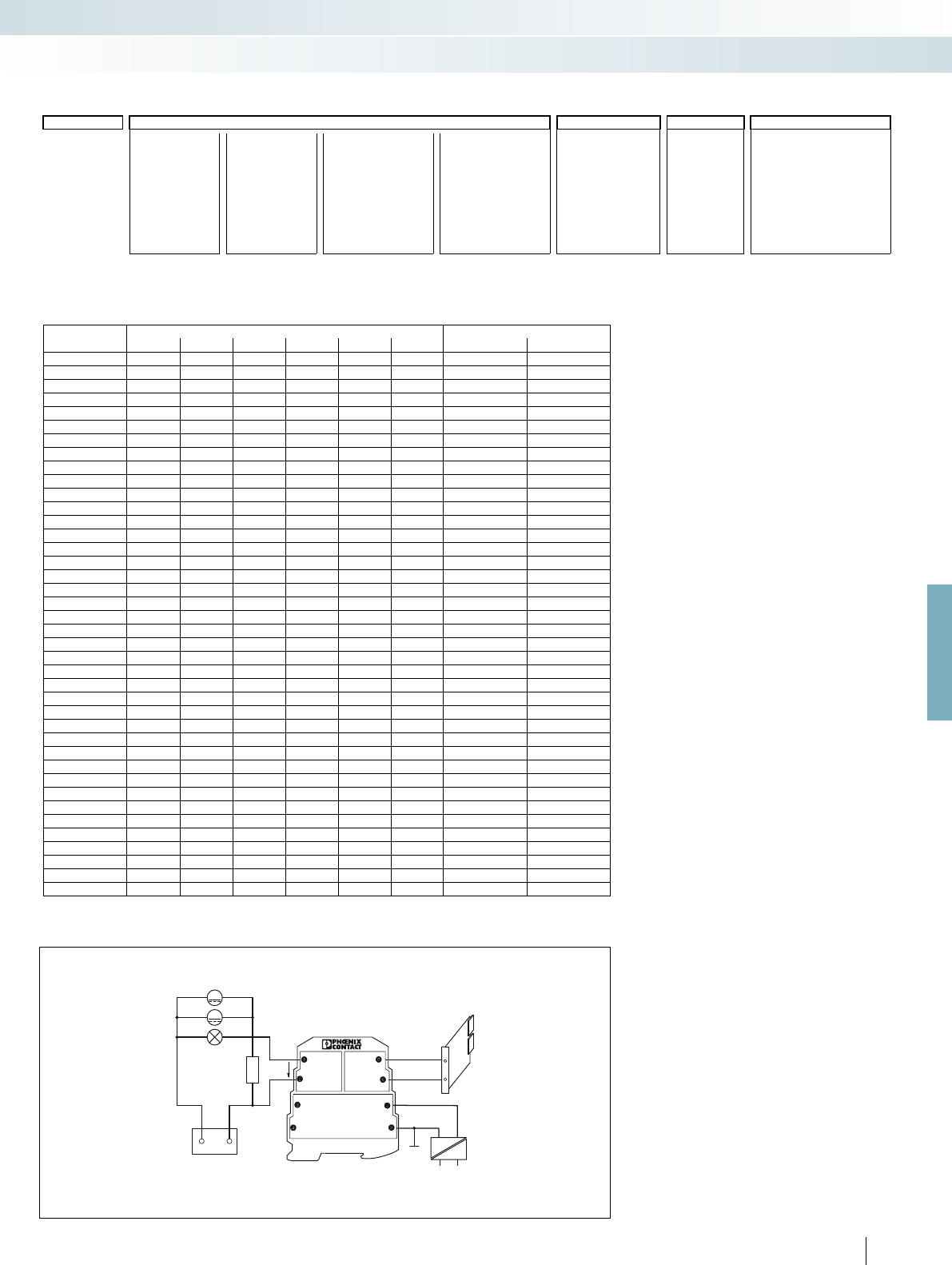
G
M
IN OUT
GND2
UB+
GND3
GND1
UB+
GND3
MINI MCR-SL-SHUNT-UI
±...mVU/I
24V
+–
For further information and full technical data, visit phoenixcontact.net/products
95PHOENIX CONTACT
Order key for MINI MCR-SL-SHUNT-UI(-SP) (standard configuration entered as an example)
Combination table for input and output signals
Application example: monitoring of loading and unloading currents
Voltage output Current output
Input -10 ... +10 V 0 ... 10 V 2 ... 10 V -5 ... +5 V 0 ... 5 V 1 ... 5 V 0 ... 20 mA 4 ... 20 mA
0 ... 50 mV x x x x x x
0..60 mV x x x x x x
0..75 mV x x x x x x
0..80 mV x x x x x x
0..100 mV x x x x x x
0..120 mV x x x x x x
0 ... 150 mV x x x x x x
0..200 mV x x x x x x
0..240 mV x x x x x x
0..300 mV x x x x x x
0..500 mV x x x x x x
0..600 mV x x x x x x
0..750 mV x x x x x x
0..800 mV x x x x x x
0 ... 1 V x x x x x x
0 ... 1.2 V x x x x x x
0 ... 1.5 V x x x x x x
0...2 V x x x x x x
0 ... 2.4 V x x x x x x
0...3 V x x x x x x
-50 ... 50 mV x x x x x x x x
-60..60 mV x x x x x x x x
-75..75 mV x x x x x x x x
-80 ... 80 mV x x x x x x x x
-100 ... 100 mV x x x x x x x x
-120 ... 120 mV x x x x x x x x
-150 ... 150 mV x x x x x x x x
-200 ... 200 mV x x x x x x x x
-240 ... 240 mV x x x x x x x x
-300 ... 300 mV x x x x x x x x
-500 ... 500 mV x x x x x x x x
-600 ... 600 mV x x x x x x x x
-750 ... 750 mV x x x x x x x x
-800 ... 800 mV x x x x x x x x
-1 ... 1 V x x x x x x x x
-1.2 ... 1.2 V x x x x x x x x
-1.5 ... 1.5 V x x x x x x x x
-2 ... 2 V x x x x x x x x
-2.4 ... 2.4 V x x x x x x x x
-3 ... 3 V x x x x x x x x
IN40 =0 ... 50 mV IN28 =0..500 mV IN53 =-50..+50 mV IN17 =-500..+500 mV OUT01 =0 ... 20 mA 30 =30 Hz NONE =without FCC
2810858 = IN24 =0..60 mV IN46 =0..600 mV IN13 =-60..+60 mV IN59 =-600..+600 mV OUT02 =4 ... 20 mA 100 =100 Hz YES =with FCC (a fee is
charged)
MINI MCR-SL-
SHUNT-UI
IN41 =0..75 mV IN47 =0..750 mV IN54 =-75..+75 mV IN60 =-750..+750 mV OUT03 =0 ... 10 V
IN42 =0..80 mV IN48 =0..800 mV IN55 =-80..+80 mV IN61 =-800..+800 mV OUT04 =2 ... 10 V
IN25 =0..100 mV IN29 =0 ... 1.0 V IN14 =-100..+100 mV IN18 =-1.0 ... +1.0 V OUT05 =0 ... 5 V YESPLUS =FCC with
5 measuring points
(a fee is charged)
IN43 =0..120 mV IN49 =0 ... 1.2 V IN56 =-120..+120 mV IN62 =-1.2 ... +1.2 V OUT06 =1 ... 5 V
2810874 =
MINI MCR-SL-
SHUNT-UI-SP
IN44 =0..150 mV IN50 =0 ... 1.5 V IN57 =-150..+150 mV IN63 =-1.5 ... +1.5 V
IN26 =0..200 mV IN30 =0 ... 2.0 V IN15 =-200..+200 mV IN19 =-2.0 ... +2.0 V OUT13 =-5 ... +5 V
IN45 =0..240 mV IN51 =0 ... 2.4 V IN58 =-240..+240 mV IN64 =-2.4 ... +2.4 V OUT14 =-10 ... +10 V
IN27 =0..300 mV IN52 =0 ... 3.0 V IN16 =-300..+300 mV IN65 =-3.0 ... +3.0 V
Note:
A bipolar output (-5 ... +5 V, -10 ... +10 V) can only be used for a bipolar input signal.
Order No.
Input Output Cut-off
frequency
Factory calibration certificate
(FCC)
2810858 / IN40 / OUT01 / 100 / NONE
Supply
Battery
Shunt
resistor
Controller
MCR technology
Highly compact signal conditioners - MINI Analog

0...10V0...24V
24V
IN U
GND1
UB+
GND3
OUT
GND2
UB +
GND3
MINI MCR-SL-U-UI
51
2
3
4
6
7
8
Zone 2
Div. 2
passive
IN
Sensor /Field
OUT
PLC / DCS
4-wire
–
+
–
–
+
+
+
–
+24V
+24V
+24V
GND 3
GND 3
GND 2
active
GND 3
GND 1
OUTU,IIN U
1 5
2
6
7
8
3
4
OUTU
GND
US
5
6
1
2
POWER
UU,I OUT
IN
Ex:
Housing width 6.2 mm
Technical data
Input data
Input signal 0 ... 24 V / 0 ... 30 V
Input resistance approx. 125 k (0 ... 24 V)
Output data U output I output
Output signal (configurable using the DIP switch) 0 ... 5 V / 1 ... 5 V 0 ... 20 mA / 4 ... 20 mA
0 ... 10 V / 2 ... 10 V
Maximum output signal 12.5 V 28 mA
No-load voltage 12.5 V
Short-circuit current 22 mA
Load R
B
> 10 k< 500 (at 20 mA)
Ripple < 20 mV
PP
(at 10 k) < 20 mV
PP
(at 500 )
General data
Supply voltage U
B
19.2 V DC ... 30 V DC
Power consumption < 450 mW
Maximum transmission error < 0.1 % (of final value)
Temperature coefficient < 0.01 %/K, typ. < 0.002 %/K
Cut-off frequency (3 dB) approx. 100 Hz
Step response (10-90%) approx. 3.5 ms
Electrical isolation Basic insulation according to EN 61010
Test voltage, input/output/supply 1.5 kV (50 Hz, 1 min.)
Ambient temperature (operation) -20 °C ... 65 °C
Housing material PBT
Dimensions W / H / D 6.2 / 93.1 / 102.5 mm
Screw connection solid / stranded / AWG 0.2 ... 2.5 mm² / 0.2 ... 2.5 mm² / 26 - 12
Spring-cage connection solid / stranded / AWG 0.2 ... 2.5 mm² / 0.2 ... 2.5 mm² / 24 - 12
EMC note Class A product, see page 625
Conformance / approvals
Conformance CE-compliant
ATEX
II 3 G Ex nA IIC T4 Gc X
UL, USA / Canada UL 508 Recognized
Class I, Div. 2, Groups A, B, C, D T5
GL GL EMC 2 D
Ordering data
Description Type Order No. Pcs. /
Pkt.
MCR 3-way signal conditioner, for electrical isolation of analog
signals
Order configuration Screw connection MINI MCR-SL-U-UI 2864053 1
Order configuration Spring-cage connection MINI MCR-SL-U-UI-SP 2811213 1
Standard configuration Screw connection MINI MCR-SL-U-UI-NC 2865007 1
Standard configuration Spring-cage connection MINI MCR-SL-U-UI-SP-NC 2810078 1
96
PHOENIX CONTACT
2864053 = MINI MCR-
SL-UI-UI
IN38 =0...24 V OUT01 =0 ... 20
IN39 =0...30 V OUT02 =4 ... 20
OUT03 =0...10 V
OUT04 =2...10 V
2811213 = MINI MCR-
SL-UI-UI-SP
OUT05 =0...5 V
OUT06 =1...5 V
Order key MINI MCR-SL-U-UI(-SP) (standard configuration entered as an example)
Order No. Input Output
2864053 / IN39 / OUT01
Signal conversion according to
uninterruptible power supply (UPS)
Mains voltage
DW
H
– Highly compact signal conditioner for
electrical isolation, conversion,
amplification, and filtering of 24 V or
30 V DC signals to create standard analog
signals
– Up to 12 signal combinations can be
configured using DIP switches
– 3-way isolation
– Low power consumption
– Power supply possible through the foot
element (DIN rail connector)
– Standard configuration:
0 ... 30 V input, 0 ... 20 mA output
Notes:
To order a product with an order configuration, please enter the
desired configuration by referring to the order key; see below.
Information about power bridging, system cabling, and marking
components can be found from page 116
Analog IN/Analog OUT
3-way signal conditioner
MCR technology
Highly compact signal conditioners - MINI Analog
Configurable,
for 0 ... 24 V / 0 ... 30 V input signals

POWER
U,I U,I OUT
IN
Zone 2
passive
IN
Sensor /Field
OUT
PLC / DCS
4-wire
–
+
–
–
+
+
+
–
+24V
+24V
+24V
GND 3
GND 3
GND 2
active
GND 3
GND 1
OUTIIN U
1 5
2
6
7
8
3
4
OUTU
GND
US
5
6
1
2
For further information and full technical data, visit phoenixcontact.net/products
Ex:
Technical data
Input data U input I input
Input resistance approx. 100 kapprox. 50
Output data U output I output
Maximum output signal 12.5 V 28 mA
No-load voltage approx. 12.5 V
Short-circuit current approx. 2 mA
Load R
B
10 k 500
Ripple < 20 mV
PP
(at 10 k) < 20 mV
PP
(at 500 )
General data
Supply voltage U
B
19.2 V DC ... 30 V DC
Nominal supply voltage 24 V DC
Current consumption < 20 mA
Maximum transmission error 0.1 % (of final value)
Temperature coefficient < 0.01 %/K, typ. < 0.002 %/K
Cut-off frequency (3 dB) approx. 100 Hz
Step response (10-90%) approx. 3.5 ms
Degree of protection IP20
Electrical isolation Basic insulation according to EN 61010
Test voltage, input/output/supply 1.5 kV (50 Hz, 1 min.)
Ambient temperature (operation) -20 °C ... 65 °C
Housing material PBT
Dimensions W / H / D 6.2 / 93.1 / 102.5 mm
Screw connection solid / stranded / AWG 0.2 ... 2.5 mm² / 0.2 ... 2.5 mm² / 26 - 12
Spring-cage connection solid / stranded / AWG 0.2 ... 2.5 mm² / 0.2 ... 2.5 mm² / 24 - 12
EMC note Class A product, see page 625
Conformance / approvals
Conformance CE-compliant
ATEX
II 3 G Ex nA IIC T4 Gc X
UL, USA / Canada UL 508 Recognized
Class I, Div. 2, Groups A, B, C, D T5 applied for
GL GL EMC 2 D
Ordering data
Description Input signal Output signal Type Order No. Pcs. /
Pkt.
MCR 3-way signal conditioner, for electrical isolation of
analog signals
Screw connection 0 ... 10 V 0 ... 20 mA MINI MCR-SL-U-I-0 2813512 1
Spring-cage connection 0 ... 10 V 0 ... 20 mA MINI MCR-SL-U-I-0-SP 2813570 1
Screw connection 0 ... 10 V 4 ... 20 mA MINI MCR-SL-U-I-4 2813525 1
Spring-cage connection 0 ... 10 V 4 ... 20 mA MINI MCR-SL-U-I-4-SP 2813583 1
Screw connection 0 ... 20 mA 0 ... 10 V MINI MCR-SL-I-U-0 2813541 1
Spring-cage connection 0 ... 20 mA 0 ... 10 V MINI MCR-SL-I-U-0-SP 2813554 1
Screw connection 4 ... 20 mA 0 ... 10 V MINI MCR-SL-I-U-4 2813538 1
Spring-cage connection 4 ... 20 mA 0 ... 10 V MINI MCR-SL-I-U-4-SP 2813567 1
Screw connection 0 ... 20 mA,
4 ... 20 mA
0 ... 20 mA,
4 ... 20 mA
MINI MCR-SL-I-I 2864406 1
Spring-cage connection 0 ... 20 mA,
4 ... 20 mA
0 ... 20 mA,
4 ... 20 mA
MINI MCR-SL-I-I-SP 2864723 1
Screw connection 0 ... 10 V,
-10 ... 10 V
0 ... 10 V,
-10 ... 10 V
MINI MCR-SL-U-U 2864684 1
Spring-cage connection 0 ... 10 V,
-10 ... 10 V
0 ... 10 V,
-10 ... 10 V
MINI MCR-SL-U-U-SP 2864697 1
97
PHOENIX CONTACT
– Highly compact signal conditioner for
electrical isolation, conversion,
amplification, and filtering of standard
analog signals
– Fixed signal combinations
– Entry-level alternative to configurable
signal conditioners
– 3-way isolation
– Low power consumption
– Power supply possible through the
foot element (DIN rail connector)
Notes:
Information about power bridging, system cabling, and
marking components can be found from page 116
Analog IN/Analog OUT
3-way signal conditioner
MCR technology
Highly compact signal conditioners - MINI Analog
DW
H
With fixed signal combinations

Zone 2
Div. 2
passive
passive
IN
Sensor /Field
OUT
PLC / DCS
4-wire
–
+
–
–
+
+
+
–
+24V
OUT2I
+24V
GND 4
GND 4
GND 1
active
active
GND 2
GND 3
OUT1IIN U,I
1 5
2
6
7
8
3
4
OUT
U,I
GND
US
5
3
6
4
1
2
POWER
U,I I OUT2
IN
I
OUT1
Ex:
Housing width 6.2 mm
Technical data
Input data U input I input
Input signal 0 ... 10 V / 1 ... 5 V 0 ... 20 mA / 4 ... 20 mA
Maximum input signal 30 V 50 mA
Input resistance approx. 100 kapprox. 50
Output data
Output signal (configurable using the DIP switch) 2x; 0 ... 20 mA / 4 ... 20 mA
Maximum output signal 22 mA
No-load voltage 9 V
Load R
B
250 (at 20 mA)
Ripple < 20 mV
PP
(at 250 )
General data
Supply voltage U
B
19.2 V DC ... 30 V DC
Current consumption < 30 mA (at 24 V DC incl. load)
Power consumption < 600 mW
Maximum transmission error 0.2 % (of final value), typ. < 0.1 %
Temperature coefficient < 0.01 %/K, typ. < 0.004 %/K
Cut-off frequency (3 dB) approx. 35 Hz
Step response (0–99%) approx. 10 ms
Electrical isolation Basic insulation according to EN 61010
Test voltage, input/output/supply 1.5 kV (50 Hz, 1 min.)
Ambient temperature (operation) -20 °C ... 60 °C
Housing material PBT
Dimensions W / H / D 6.2 / 93.1 / 102.5 mm
Screw connection solid / stranded / AWG 0.2 ... 2.5 mm² / 0.2 ... 2.5 mm² / 26 - 12
Spring-cage connection solid / stranded / AWG 0.2 ... 2.5 mm² / 0.2 ... 2.5 mm² / 24 - 12
EMC note Class A product, see page 625
Conformance / approvals
Conformance CE-compliant
ATEX
II 3 G Ex nA IIC T4 Gc X
UL, USA / Canada UL 508 Recognized
Class I, Div. 2, Groups A, B, C, D T5
GL GL EMC 2 D
Ordering data
Description Type Order No. Pcs. /
Pkt.
MCR signal duplicator, for duplication and electrical isolation of
analog signals
Order configuration Screw connection MINI MCR-SL-UI-2I 2864794 1
Order configuration Spring-cage connection MINI MCR-SL-UI-2I-SP 2864804 1
Standard configuration Screw connection MINI MCR-SL-UI-2I-NC 2864176 1
Standard configuration Spring-cage connection MINI MCR-SL-UI-2I-SP-NC 2864189 1
98
PHOENIX CONTACT
Order key MINI MCR-SL-UI-2I(-SP) (standard configuration entered as an example)
Explanation for output combination:
Output 1 Output 2
A 0 ... 20 mA 0 ... 20 mA
B 0 ... 20 mA 4 ... 20 mA
C 4 ... 20 mA 4 ... 20 mA
NONE =without FCC
2864794 =
MINI MCR-
SL-UI-2I
IN01 =0 ... 20 mA A 0 =Analog behavior Yes =with FCC (a fee
is charged)
IN02 =4 ... 20 mA B
IN03 =0 ... 10 V C 1 =Limitation
IN06 =1...5 V YESPLUS =FCC with
5 measuring
points (a fee is
charged)
2864804 =
MINI MCR-
SL-UI-2I-SP
1
) For explanations, see adjacent text on the right; for further details, see data sheet: www.phoenixcontact.net/products
Order No.
Input Output
combination
1
)
Behavior of the analog
outputs
Factory calibration
certificate (FCC)
2864794 / IN03 / A / 0 / NONE
DW
H
– Highly compact signal conditioner for
electrical isolation, conversion,
amplification, filtering, and duplication of
standard analog signals
– Duplication of a standard analog signal on
two current outputs
– Up to 8 signal combinations can be
configured using DIP switches
– 4-way isolation
– Power supply possible through the foot
element (DIN rail connector)
– Standard configuration:
Input: 0 ... 10 V, output 1: 0 ... 20 mA,
output 2: 0 ... 20 mA
Notes:
To order a product with an order configuration, please enter the
desired configuration by referring to the order key; see below.
Information about power bridging, system cabling, and marking
components can be found from page 116
Analog IN/Analog OUT
signal duplicator
MCR technology
Highly compact signal conditioners - MINI Analog
Configurable,
with two current output signals
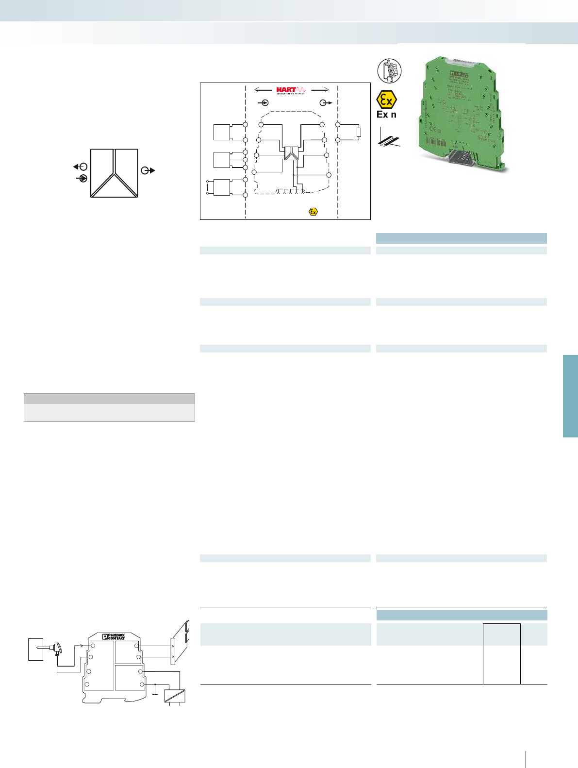
4...20mA
24V
INI
GND1
GND1
OUTI
GND2
UB+
GND3
MINIMCR-SL-RPSS-I-I
51
2
3
4
6
7
8
PWR OUT
POWER
II OUT
IN
POWER
Zone 2
passive
IN
Sensor /Field
OUT
PLC / DCS
2-wire
3-wire
4-wire
–
+–
–
+
+
–
–
+24V
+24V
GND 3
GND 3
GND 2
active
GND 1
GND 1
OUTIIN I
PWR OUT
1 5
2
6
7
8
3
4
PWR
IN
PWR
IN
OUTI
OUTI
OUTI
GND
GND
US
5
6
1
1
1
2
2
3
3
For further information and full technical data, visit phoenixcontact.net/products
Ex:
Housing width 6.2 mm
Technical data
Input data MINI MCR-SL-RPSS-I-I MINI MCR-SL-RPS-I-I
Input signal 0 ... 20 mA,
isolator operation / 4 ... 20 mA
0 ... 20 mA,
isolator operation / 4 ... 20 mA
Input resistance approx. 50 approx. 50
Transmitter supply voltage 16.5 V 14.7 V DC ... 25.5 V DC
U
B
- max. 4.5 V for load
0 mA ... 20 mA
Output data
Output signal 0 ... 20 mA / 4 ... 20 mA 0 ... 20 mA / 4 ... 20 mA
Maximum output signal 21 mA 28 mA
No-load voltage approx. 12.5 V approx. 12.5 V
Load R
B
500 (at I = 20 mA) 500 (at I = 20 mA)
Ripple < 20 mV
rms
(at 500 ) < 20 mV
rms
(at 500 )
General data
Supply voltage U
B
20.4 V DC ... 30 V DC 19.2 V DC ... 30 V DC
Nominal supply voltage 24 V DC 24 V DC
Current consumption
Power consumption < 900 mW (at 24 V DC and in
repeater power supply
operation)
< 900 mW (at 24 V DC and in
repeater power supply
operation)
Maximum transmission error 0.2 % (of final value),
typ. 0.1 % (of final value)
0.2 % (of final value),
typ. 0.1 % (of final value)
Temperature coefficient < 0.005 %/K, typ. < 0.002 %/K < 0.01 %/K, typ. < 0.002 %/K
Cut-off frequency (3 dB) 175 Hz (typ.) approx. 100 Hz
Communication HART specification in both
operating modes
(RPSS isolator / RPSS repeater
power supply)
-
Step response (10-90%) < 2 ms (typ.) approx. 3.5 ms
Electrical isolation Basic insulation according to EN 61010
Test voltage, input/output/supply 1.5 kV (50 Hz, 1 min.) 1.5 kV (50 Hz, 1 min.)
Degree of protection IP20 IP20
Ambient temperature (operation) -20 °C ... 60 °C -20 °C ... 60 °C
Mounting any any
Housing material PBT PBT
Dimensions W / H / D 6.2 / 93.1 / 102.5 mm 6.2 / 93.1 / 102.5 mm
Screw connection solid / stranded / AWG 0.2 ... 2.5 mm² / 0.2 ... 2.5 mm² / 26 - 12
Spring-cage connection solid / stranded / AWG 0.2 ... 2.5 mm² / 0.2 ... 2.5 mm² / 24 - 12
EMC note Class A product, see page 625
Conformance / approvals
Conformance CE-compliant CE-compliant
ATEX
II 3 G Ex nA IIC T4 Gc X
II 3 G Ex nA IIC T4 Gc X
UL, USA / Canada UL 508 Recognized applied for
Class I, Div. 2, Groups A, B, C, D
T5 applied for
UL 508 Recognized
Class I, Div. 2, Groups A, B, C, D
T5
GL GL EMC 2 D GL EMC 2 D
Ordering data
Description Type Order No. Pcs. /
Pkt.
MCR repeater power supply
with HART
®
protocol Screw connection MINI MCR-SL-RPSS-I-I 2864079 1
with HART
®
protocol Spring-cage connection MINI MCR-SL-RPSS-I-I-SP 2810230 1
Screw connection MINI MCR-SL-RPS-I-I 2864422 1
Spring-cage connection MINI MCR-SL-RPS-I-I-SP 2864752 1
Control system
Mains voltage
99
PHOENIX CONTACT
– Highly compact repeater power supply
for electrical isolation, amplification, and
filtering of standard analog signals
– Supply of 2-wire and passive 3-wire
sensors
– Can also be used as an isolator without
supply
– 3-way isolation
– Bidirectional HART transmission as an
option
– Power supply possible through the foot
element (DIN rail connector)
Notes:
Information about power bridging, system cabling, and marking
components can be found from page 99
Analog IN/Analog OUT
repeater power supply
Repeater power supply operation with a passive sensor
MCR technology
Highly compact signal conditioners - MINI Analog
DW
H
Available with HART transmission
as an option

POWER
II
OUT IN
Zone 2
IN
PLC / DCS
2-wire
GND
IN I
1
2
PWR
active
5
6
GND
OUT I
Sensor / Field
OUT
-
-
+
+
+24V
+24V
GND 3
GND 3
GND 1
passive
+24V
GND 3
IN IOUT I
GND 2
1 5
2
6
7
8
3
4
-
-
+
+
C O M M U N I C A T I O N P R O T O C O L
Housing width 6.2 mm
Technical data
Input data
Input signal 0 ... 20 mA / 4 ... 20 mA
Maximum input signal 20 mA
Input voltage limitation < 2 V (20 mA)
Output data
Output signal 0 ... 20 mA / 4 ... 20 mA
Load R
B
800 (at 20 mA)
Ripple < 20 mV
rms
General data
Supply voltage U
B
19.2 V DC ... 30 V DC
Nominal supply voltage 24 V DC
Power consumption < 600 mW (at 24 V DC)
Maximum transmission error 0.1 % (of final value)
Temperature coefficient typ. < 0.01 %/K
Cut-off frequency (3 dB) > 175 Hz
Communication HART specification
Step response (10-90%) < 2 ms
Electrical isolation Basic insulation according to EN 61010
Test voltage, input/output/supply 1.5 kV (50 Hz, 1 min.)
Degree of protection IP20
Ambient temperature (operation) -20 °C ... 60 °C
Mounting any
Housing material PBT
Dimensions W / H / D 6.2 / 93.1 / 102.5 mm
Screw connection solid / stranded / AWG 0.2 ... 2.5 mm² / 0.2 ... 2.5 mm² / 26 - 12
Spring-cage connection solid / stranded / AWG 0.2 ... 2.5 mm² / 0.2 ... 2.5 mm² / 24 - 12
Conformance / approvals
Conformance CE-compliant
ATEX
II 3 G Ex nA IIC T4 Gc X
UL, USA / Canada UL 508 Recognized applied for
Class I, Div. 2, Groups A, B, C, D T5 applied for
GL GL applied for
Ordering data
Description Type Order No. Pcs. /
Pkt.
3-way output isolator
Screw connection MINI MCR-SL-IDS-I-I 2905577 1
Spring-cage connection MINI MCR-SL-IDS-I-I-SP 2905578 1
100
PHOENIX CONTACT
– Highly compact output signal conditioner
for electrical isolation, conversion,
amplification, and filtering of standard
analog signals
– For controlling I/P converters, control
valves, and displays
– 3-way isolation
– Bidirectional HART transmission
– Power supply possible through the foot
element (DIN rail connector)
Notes:
Information about power bridging, system cabling, and
marking components can be found from page 116
Analog IN/Analog OUT
3-way output isolator
MCR technology
Highly compact signal conditioners - MINI Analog
DW
H
new
HART transmission
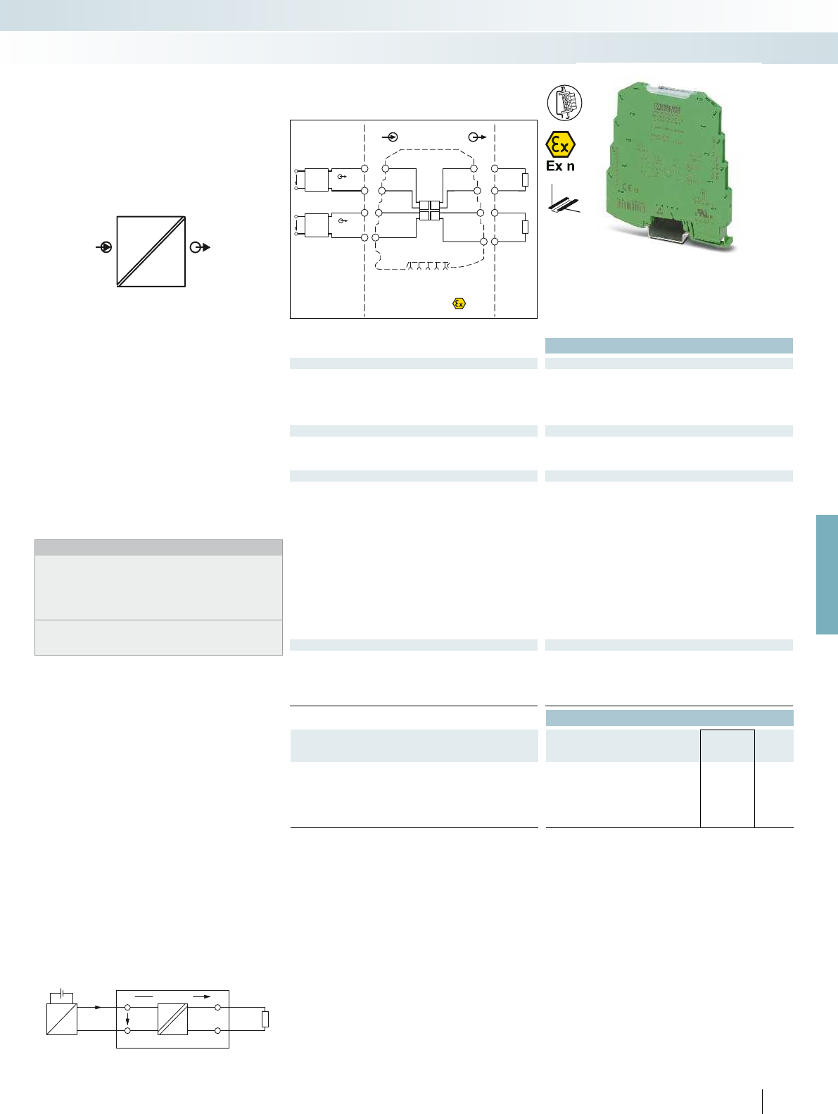
I
MINI MCR-SL-1CP-I-I
U
E
U = 1,7 V
V
I
I
I
R
B
U
B
IIOUT
IN
Zone 2
passive
passive
IN
Sensor /Field
OUT
PLC / DCS
4-wire
4-wire
–
–
+
+
+
+
–
–
GND 2
GND 4
active
active
GND 1
GND 3
OUTI1
OUTI2
INI1
INI2
1 5
2
6
7
8
3
4
OUTI
OUTI
GND
GND
US
US
5
7
6
8
1
3
2
4
PWR
max.18 VDC
PWR
max.18 VDC
For further information and full technical data, visit phoenixcontact.net/products
Ex:
Housing width 6.2 mm
Technical data
Input data
Input signal 0 ... 20 mA / 4 ... 20 mA
Voltage drop 1.7 V (at I = 20 mA)
Response current approx. 190 µA
Maximum input current / overload 40 mA
Maximum input voltage 18 V
Output data
Output signal 0 ... 20 mA / 4 ... 20 mA
Load R
B
< 600 (at I = 20 mA output signal)
Ripple < 10 mV
rms
(at 600 )
General data
Maximum transmission error 0.1 % (of final value)
Additional error per 100 load 0.03 % (of measured value / 100 load)
Temperature coefficient 0.002 %/K (of measured value / 100 load)
Cut-off frequency (3 dB) 75 Hz
Step response (10-90%) 5 ms (at 600 load)
Electrical isolation Basic insulation according to EN 61010
Test voltage input/output 1.5 kV (50 Hz, 1 min.)
Degree of protection IP20
Ambient temperature (operation) -20 °C ... 65 °C
Mounting any
Housing material PBT
Dimensions W / H / D 6.2 / 93.1 / 102.5 mm
Screw connection solid / stranded / AWG 0.2 ... 2.5 mm² / 0.2 ... 2.5 mm² / 26 - 12
Spring-cage connection solid / stranded / AWG 0.2 ... 2.5 mm² / 0.2 ... 2.5 mm² / 24 - 12
Conformance / approvals
Conformance CE-compliant
ATEX
II 3 G Ex nA II T6 X
UL, USA / Canada UL 508 Recognized
Class I, Div. 2, Groups A, B, C, D
GL GL EMC 2 D
Ordering data
Description Type Order No. Pcs. /
Pkt.
MCR passive isolator, for electrical isolation of current signals
without auxiliary power
two-channel Screw connection MINI MCR-SL-2CP-I-I 2864655 1
two-channel Spring-cage connection MINI MCR-SL-2CP-I-I-SP 2864781 1
single-channel Screw connection MINI MCR-SL-1CP-I-I 2864419 1
single-channel Spring-cage connection MINI MCR-SL-1CP-I-I-SP 2864749 1
101
PHOENIX CONTACT
– Highly compact 2-wire passive isolator
for electrical isolation and filtering of
standard analog signals
– Input loop-supplied
– Does not require any additional auxiliary
voltage
– 2 channels in conj. with an overall width
of just 6.2 mm
– Voltage drop on signal conditioner of
just 1.7 V
Notes:
When using passive isolators, make sure that the current sourcing
voltage of the measuring transducer U
B
is sufficient to drive the
maximum current of 20 mA via the passive isolator with a voltage
drop U
V
= 1.7 V and load R
B
.
This means:
U
B
≥ U
E
= 1.7 V + 20 mA x R
B
Information on components for power bridging, system cabling,
and marking can be found in Catalog 7, Interface technology and
switching devices or at phoenixcontact.net/products
Analog IN/Analog OUT
2-way passive isolator,
input loop-powered
MCR technology
Highly compact signal conditioners - MINI Analog
DW
H
Either 1 or 2-channel
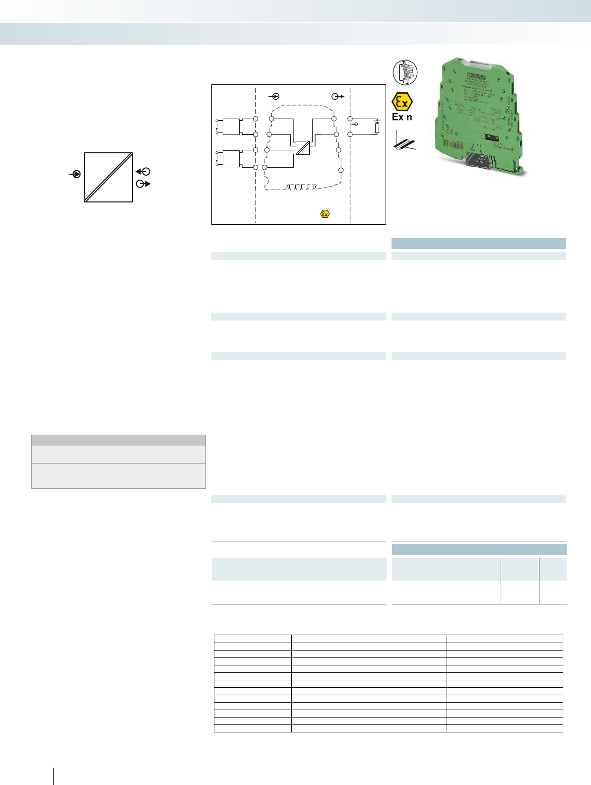
IN
I
U, I
POWER
OUT
IN
Sensor / Field
OUT
PLC / DCS
–
++
+
–
–
passive
OUT IGND
IN I
IN U
GND
PWR IN
1 5
2
6
7
8
3
4
3
4
Zone 2
4-wire
4-wire
OUT
I
OUT
U
GND
GND
US
US
1
2
PWR
active
5
6
Ex:
Housing width 6.2 mm
Technical data
Input data U input I input
Input signal (configurable using the DIP switch) 2 ... 10 V, additional ranges can be configured, see table
Maximum input signal < 40 V < 50 mA
(electric strength up to 30 V)
Input resistance approx. 100 k (at 1 V,
otherwise approximately 1 M)
50
Output data
Output signal 4 ... 20 mA
Maximum output signal 35 mA
Load R
B
(U
B
- 8 V) / 22 mA
Ripple < 20 mV
PP
(at 500 )
General data
Current consumption < 3.5 mA (without signal current)
Power consumption 28 mW (without signal)
Maximum transmission error < 0.1 % (of final value)
Temperature coefficient 0.01 %/K, typ. 0.005 %/K
ZERO / SPAN adjustment ± 2 % / ± 2 %
Cut-off frequency (3 dB) approx. 30 Hz
Step response (10-90%) approx. 16 ms
Electrical isolation Basic insulation according to EN 61010
Test voltage input/output 1.5 kV (50 Hz, 1 min.)
Degree of protection IP20
Ambient temperature (operation) -25 °C ... 70 °C
Mounting any
Housing material PBT
Dimensions W / H / D 6.2 / 93.1 / 102.5 mm
Screw connection solid / stranded / AWG 0.2 ... 2.5 mm² / 0.2 ... 2.5 mm² / 26 - 12
Spring-cage connection solid / stranded / AWG 0.2 ... 2.5 mm² / 0.2 ... 2.5 mm² / 24 - 12
EMC note Class A product, see page 625
Conformance / approvals
Conformance CE-compliant
ATEX
II 3 G Ex nA IIC T4 Gc X
UL, USA / Canada UL 508 Listed
Class I, Div. 2, Groups A, B, C, D T5
Class I, Zone 2, Group IIC
Ordering data
Description Type Order No. Pcs. /
Pkt.
MCR isolator, output loop-powered
Screw connection MINI MCR-SL-UI-I-LP-NC 2902829 1
Spring-cage connection MINI MCR-SL-UI-I-LP-SP-NC 2902830 1
102
PHOENIX CONTACT
– Highly compact signal conditioner for
electrical isolation, conversion, and
filtering of standard analog signals
– Supplied by an output loop
– Does not require any additional auxiliary
voltage
– Up to 74 signal combinations can be
configured using DIP switches
– Voltage input from mV voltages right up
to 30volts
– Current input from 2mA right up
to 40mA
– 2-way isolation
– Standard configuration:
Input 2...10 V, output 4...20 mA
Notes:
Other input signals that have not been listed can be provided on
request.
Information on components for power bridging, system cabling,
and marking can be found in Catalog 7, Interface technology and
switching devices or at phoenixcontact.net/products
Analog IN/Analog OUT
2-way isolator, output loop-powered
Possible input signal ranges (configurable via DIP switch)
0...40 mA 0...30 V 0...10 V 2...10 V 0...1000 mV ±30 V ±10 V ±1000 mV
0...30 mA 0...25 V 0...7.5 V 0...750 mV ±25 V ±7.5 V ±750 mV
0...20 mA 4...20 mA 0...20 V 0...5 V 1...5 V 0...500 mV ±20 V ±5 V ±500 mV
0...12 mA 0...15 V 0...3 V 0...300 mV ±15 V ±3 V ±300 mV
0...10 mA 2...10 mA 0...12.5 V 0...2.5 V 0...250 mV ±12.5 V ±2.5 V ±250 mV
0...8 mA 0...12 V 0...2 V 0...200 mV ±12 V ±2 V ±200 mV
0...7.5 mA 0...1.5 V 0...150 mV ±1.5 V ±150 mV
0...6 mA 0...1.25 V 0...125 mV ±1.25 V ±125 mV
0...5 mA 1...5 mA 0...1.2 V 0...120 mV ±1.2 V ±120 mV
0...4 mA 0...100 mV ±100 mV
0...3 mA 0...75 mV ±75 mV
0...2.5 mA 0...60 mV ±60 mV
0...2 mA 0...50 mV ±50 mV
MCR technology
Highly compact signal conditioners - MINI Analog
DW
H
Configurable,
up to 74 signal combinations,
output loop-powered
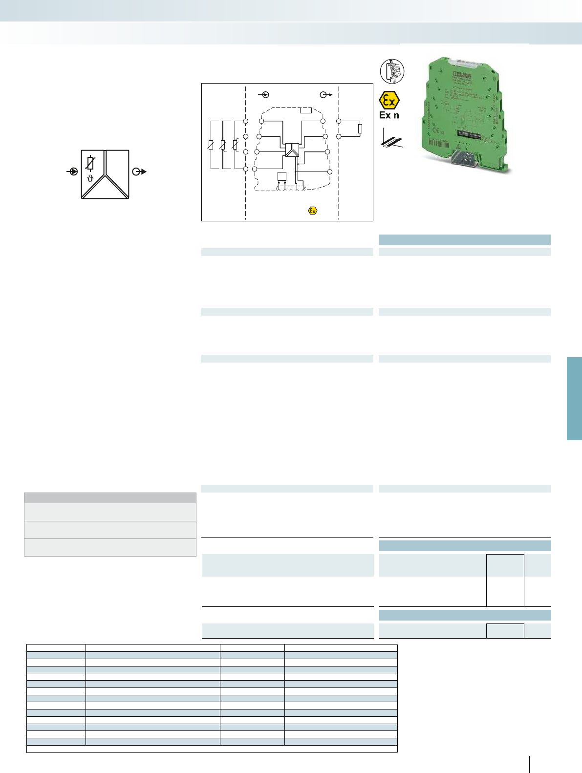
IN
Sensor / Field
OUT
PLC / DCS
–
–
+
+
+24V
+24V
GND 2
GND 2
active
GND 1
OUT U,I
1 5
2
6
7
8
3
4
5
6
1
2
3
4
ϑϑϑ
Zone 2
passive
FM
S-Port
OUT
IN
POWER
U,I
FM
For further information and full technical data, visit phoenixcontact.net/products
Ex:
Housing width 6.2 mm
Technical data
Input data
Input signal (can be configured using DIP switches) Pt, Ni, Cu sensors : 2, 3, 4-wire
Temperature range -200 °C ... 850 °C (range depends on sensor type, range can be set
freely via software or in increments via DIP switches)
Measuring range span min. 50 K
Linear resistance measuring range 0 ... 4000 (minimum measuring span: 10% of the selected
measuring range)
Output data U output I output
Output signal 0 ... 5 V / 1 ... 5 V 0 ... 20 mA / 4 ... 20 mA
0 ... 10 V / 10 ... 0 V 20 ... 0 mA / 20 ... 4 mA
Maximum output signal approx. 12.3 V 24.6 mA
Load R
B
10 k500 (at 20 mA)
Ripple < 20 mV
PP
< 20 mV
PP
(at 500 )
General data
Supply voltage U
B
9.6 V DC ... 30 V DC
Current consumption < 27 mA (at 24 V DC)
Power consumption 700 mW (at I
OUT
= 20 mA, 9.6 V DC, load 500 )
Transmission error 0.1 % * 350 K / set measuring range; 0.1 % > 350 K (Pt/Ni)
0.3 % * 200 K / set measuring range; 0.3 % > 200 K (Cu)
Temperature coefficient 0.01 %/K
Step response (0–99%) typ. 200 ms (2-wire)
typ. 500 ms (3-wire)
typ. 500 ms (4-wire)
Electrical isolation Basic insulation according to EN 61010
Test voltage, input/output/supply 1.5 kV (50 Hz, 1 min.)
Ambient temperature (operation) -20 °C ... 65 °C
Dimensions W / H / D 6.2 / 93.1 / 102.5 mm
Screw connection solid / stranded / AWG 0.2 ... 2.5 mm² / 0.2 ... 2.5 mm² / 26 - 12
Spring-cage connection solid / stranded / AWG 0.2 ... 2.5 mm² / 0.2 ... 2.5 mm² / 24 - 12
EMC note Class A product, see page 625
Conformance / approvals
Conformance CE-compliant
ATEX
II 3 G Ex nA IIC T4 Gc X
UL, USA / Canada UL 508 Listed
Class I, Div. 2, Groups A, B, C, D T4
Class I, Zone 2, Group IIC
GL GL applied for
Ordering data
Description Type Order No. Pcs. /
Pkt.
Temperature transducer for resistance thermometers
Standard configuration Screw connection MINI MCR-RTD-UI-NC 2902849 1
Standard configuration Spring-cage connection MINI MCR-RTD-UI-SP-NC 2902850 1
Accessories
Programming adapter for configuring modules with
S-PORT interface
IFS-USB-PROG-ADAPTER 2811271 1
103
PHOENIX CONTACT
Sensor type Standard Measuring range Smallest measuring range span
Pt100 IEC 751 = GOST 6651-2009 ( = 0.00385) -200°C ... +850°C 50 K
Pt200 IEC 751 = GOST 6651-2009 ( = 0.00385) -200°C ... +850°C 50 K
Pt500 IEC 751 = GOST 6651-2009 ( = 0.00385) -200°C ... +850°C 50 K
Pt1000 IEC 751 = GOST 6651-2009 ( = 0.00385) -200°C ... +850°C 50 K
Pt100 GOST 6651-2009 ( = 0.00391) -200°C ... +850°C 50 K
Pt1000 GOST 6651-2009 ( = 0.00391) -200°C ... +850°C 50 K
Pt100 JIS C1604-1997 -200°C ... +850°C 50 K
Pt1000 JIS C1604-1997 -200°C ... +850°C 50 K
Ni100 DIN 43760 -60°C ... +250°C 50 K
Ni1000 DIN 43760 -60°C ... +250°C 50 K
Cu50 GOST 6651-2009 ( = 1.428) -180°C ... +200°C 50 K
Cu100 GOST 6651-2009 ( = 1.428) -180°C ... +200°C 50 K
Cu53 GOST 6651-2009 ( = 1.426) -50°C ... +180°C 50 K
Customer-specific characteristic curves
DW
H
Universal temperature transducer for
electrical isolation, conversion,
amplification, and filtering of resistance
thermometers and remote resistance-type
sensors
– High level of accuracy over the entire
measuring range
– For 2, 3 or 4-wire sensors according to
IEC 751, JIS, GOST
– Configurable via DIP switches and
software
– Software available free of charge on the
Internet
– Power supply possible through the foot
element (DIN rail connector)
– Supports fault monitoring
– Standard configuration: Pt 100 IEC 751
sensor; 3-wire; -50 ... 150°C; output
4 ... 20 mA; error evaluation according to
NE43 (downscale); fault monitoring
contact responds to any errors
Notes:
The configuration software can be downloaded from the Internet:
phoenixcontact.net/products.
Information on the programming adapters can be found on
page 89
Information about power bridging, system cabling, and marking
components can be found from page 116
Temperature
Temperature transducer
for resistance thermometers
MCR technology
Highly compact signal conditioners - MINI Analog
Universal measuring transducer for
resistance thermometers
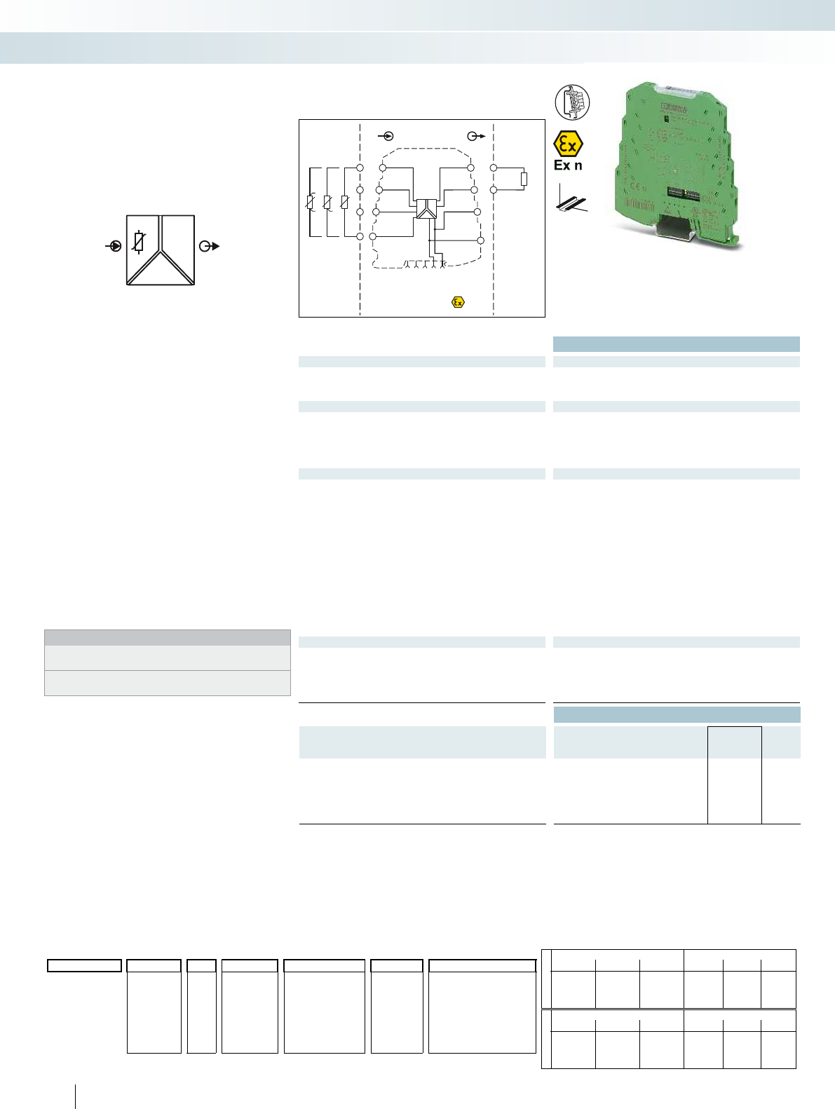
IN
Sensor /Field
OUT
PLC / DCS
–
–
+
+
+24V
+24V
GND 2
GND 2
active
GND 1
OUTU,I
1 5
2
6
7
8
3
4
5
6
1
2
3
4
ϑϑϑ
PT100
Zone 2
Div. 2
passive
OUT
IN
POWER
U,I
PT100
Ex:
Housing width 6.2 mm
Technical data
Input data
Input signal (can be configured using DIP switches) Pt 100 (IEC 60751/EN 60751): 2, 3, 4-wire
Temperature range -50 °C ... 200 °C (configurable)
Measuring range span min. 50 K
Output data U output I output
Output signal 0 ... 5 V / 1 ... 5 V 0 ... 20 mA / 4 ... 20 mA
0 ... 10 V / 10 ... 0 V 20 ... 0 mA / 20 ... 4 mA
Maximum output signal approx. 12.5 V 23 mA
Load R
B
> 10 k< 500 (at 20 mA)
Ripple < 20 mV
PP
(at 10 k) < 20 mV
PP
(at 500 )
General data
Supply voltage U
B
19.2 V DC ... 30 V DC
Current consumption < 21 mA (at 24 V DC)
Power consumption < 500 mW
Transmission error for the full/set measuring range 0.25%; ((50 K / Temp)+ 0.05)%
Temperature coefficient < 0.02 %/K
Step response (0–99%) < 200 ms
Electrical isolation Basic insulation according to EN 61010
Test voltage, input/output/supply 1.5 kV (50 Hz, 1 min.)
Ambient temperature (operation) -20 °C ... 65 °C
Housing material PBT
Dimensions W / H / D 6.2 / 93.1 / 102.5 mm
Screw connection solid / stranded / AWG 0.2 ... 2.5 mm² / 0.2 ... 2.5 mm² / 26 - 12
Spring-cage connection solid / stranded / AWG 0.2 ... 2.5 mm² / 0.2 ... 2.5 mm² / 24 - 12
EMC note Class A product, see page 625
Conformance / approvals
Conformance CE-compliant
ATEX
II 3 G Ex nA IIC T4 Gc X
UL, USA / Canada UL 508 Recognized
Class I, Div. 2, Groups A, B, C, D T5
GL GL EMC 2 D
Ordering data
Description Type Order No. Pcs. /
Pkt.
MCR temperature transducer, for Pt 100 temperature sensors
Order configuration Screw connection MINI MCR-SL-PT100-UI-200 2864309 1
Order configuration Spring-cage connection MINI MCR-SL-PT100-UI-200-SP 2864192 1
Unconfigured Screw connection MINI MCR-SL-PT100-UI-200-NC 2864370 1
Unconfigured Spring-cage connection MINI MCR-SL-PT100-UI-200-SP-NC 2864202 1
104
PHOENIX CONTACT
Order key MINI MCR-SL-PT100-UI-200(-SP) (standard configuration entered as an example)
Failure information (depends on the output signal range):
Overrange Open circuit
0 ... 20 mA 4 ... 20 mA 0 ... 10 V
0 ... 20 mA 4 ... 20 mA
0 ... 10 V
A 20.5 mA 20.5 mA 10.25 V 21 mA 21 mA 10.5 V
B 20.5 mA 20.5 mA 10.25 V 21 mA 21 mA 10.5 V
C 20 mA 20 mA 10 V 21 mA 21 mA 10.5 V
D 20 mA 20 mA 10 V 0 mA 4 mA 0 V
Underrange Short circuit
0 ... 20 mA 4 ... 20 mA 0 ... 10 V
0 ... 20 mA 4 ... 20 mA
0 ... 10 V
A 0 mA 4 mA 0 V 0 mA 4 mA 0 V
B 0 mA 3.5 mA 0 V 0 mA 3 mA 0 V
C 0 mA 4 mA 0 V 21 mA 21 mA 10.5 V
D 0 mA 4 mA 0 V 0 mA 4 mA 0 V
2=2-wire 0 Range
(increment)
OUT01 =0 ... 20 mA A NONE =without FCC
2864309 =
MINI MCR-SL-
PT100-UI-200
-5 OUT02 =4 ... 20 mA B Yes =with FCC (a fee
is charged)
3=3-wire -10 OUT03 =0...10 V C
-15 0...200 (5 K) OUT05 =0...5 V D
4=4-wire -20 OUT06 =1...5 V YESPLUS =FCC with
5 measuring
points (a fee is
charged)
2864192 =
MINI MCR-SL-
PT100-UI-200-SP
-30 OUT07 =20 ... 0 mA
-40 OUT08 =20 ... 4 mA
-50 OUT09 =10...0 V
1
) For explanations, see adjacent text on the right; for further details, see data sheet: www.phoenixcontact.net/products
Order No.
Connection
technology
Measuring range [°C] Output Failure in-
formation
1
)
Factory calibration
certificate (FCC)
Start End
2864309 / 3 / 0 / 100 / OUT01 / A / NONE
DW
H
– Highly compact temperature transducer
for electrical isolation, conversion,
amplification, and filtering of Pt 100
signals to create standard signals
– Optimized temperature measuring range
of -50°C to +200°C for increased
accuracy
– For 2, 3 or 4-wire Pt 100 sensors
according to IEC 60751
– Input and output signals can be configured
via DIP switches
– 3-way isolation
– Error signaling via diagnostics LED and
analog signal
– Power supply possible through the foot
element (DIN rail connector)
Notes:
To order a product with an order configuration, please enter the
desired configuration by referring to the order key; see below.
Information about power bridging, system cabling, and marking
components can be found from page 116
Temperature
Temperature transducer for Pt 100
MCR technology
Highly compact signal conditioners - MINI Analog
Configurable, for a temperature measuring
range of -50°C ... +200°C

IN
Sensor /Field
OUT
PLC / DCS
–
–
+
+
+24V
+24V
GND 2
GND 2
active
GND 1
OUTU,I
1 5
2
6
7
8
3
4
5
6
1
2
3
4
ϑϑϑ
PT100
Zone 2
Div. 2
passive
OUT
IN
POWER
U,I
PT100
For further information and full technical data, visit phoenixcontact.net/products
Ex:
Housing width 6.2 mm
Technical data
Input data
Input signal (can be configured using DIP switches) Pt 100 (IEC 60751/EN 60751): 2, 3, 4-wire
Temperature range -150 °C ... 850 °C (configurable)
Measuring range span min. 50 K
Output data U output I output
Output signal (configurable using the DIP switch) 0 ... 5 V / 1 ... 5 V 0 ... 20 mA / 4 ... 20 mA
0 ... 10 V / 10 ... 0 V 20 ... 0 mA / 20 ... 4 mA
Maximum output signal approx. 12.5 V 23 mA
Load R
B
10 k< 500 (at 20 mA)
Ripple < 20 mV
PP
(at 10 k) < 20 mV
PP
(at 500 )
General data
Supply voltage U
B
19.2 V DC ... 30 V DC
Current consumption < 21 mA (at 24 V DC)
Power consumption < 500 mW
Transmission error for the full/set measuring range 0.2%; ((100 K / set measuring range [K]) + 0.1)%
Temperature coefficient < 0.02 %/K
Step response (0–99%) < 160 ms
Electrical isolation Basic insulation according to EN 61010
Test voltage, input/output/supply 1.5 kV (50 Hz, 1 min.)
Ambient temperature (operation) -20 °C ... 65 °C
Housing material PBT
Dimensions W / H / D 6.2 / 93.1 / 102.5 mm
Screw connection solid / stranded / AWG 0.2 ... 2.5 mm² / 0.2 ... 2.5 mm² / 26 - 12
Spring-cage connection solid / stranded / AWG 0.2 ... 2.5 mm² / 0.2 ... 2.5 mm² / 24 - 12
EMC note Class A product, see page 625
Conformance / approvals
Conformance CE-compliant
ATEX
II 3 G Ex nA IIC T4 Gc X
UL, USA / Canada UL 508 Recognized
Class I, Div. 2, Groups A, B, C, D T5
GL GL EMC 2 D
Ordering data
Description Type Order No. Pcs. /
Pkt.
MCR temperature transducer, for Pt 100 temperature sensors
Order configuration Screw connection MINI MCR-SL-PT100-UI 2864435 1
Order configuration Spring-cage connection MINI MCR-SL-PT100-UI-SP 2864736 1
Unconfigured Screw connection MINI MCR-SL-PT100-UI-NC 2864273 1
Unconfigured Spring-cage connection MINI MCR-SL-PT100-UI-SP-NC 2864286 1
105
PHOENIX CONTACT
Order key MINI MCR-SL-PT100-UI(-SP) (standard configuration entered as an example)
Failure information (depends on the output signal range):
Overrange Open circuit
0 ... 20 mA 4 ... 20 mA 0 ... 10 V
0 ... 20 mA 4 ... 20 mA
0 ... 10 V
A 20.5 mA 20.5 mA 10.25 V 21 mA 21 mA 10.5 V
B 20.5 mA 20.5 mA 10.25 V 21 mA 21 mA 10.5 V
C 20 mA 20 mA 10 V 21 mA 21 mA 10.5 V
D 20 mA 20 mA 10 V 0 mA 4 mA 0 V
Underrange Short circuit
0 ... 20 mA 4 ... 20 mA 0 ... 10 V
0 ... 20 mA 4 ... 20 mA
0 ... 10 V
A 0 mA 4 mA 0 V 0 mA 4 mA 0 V
B 0 mA 3.5 mA 0 V 0 mA 3 mA 0 V
C 0 mA 4 mA 0 V 21 mA 21 mA 10.5 V
D 0 mA 4 mA 0 V 0 mA 4 mA 0 V
2=2-wire 0 Range
(increment)
OUT01 =0 ... 20 mA A NONE =without FCC
2864435 =
MINI MCR-SL-
PT100-UI
-10 OUT02 =4 ... 20 mA B Yes =with FCC (a fee
is charged)
3=3-wire -20 OUT03 =0 ... 10 V C
-30 0...100 (5 K) OUT05 =0...5 V D
4=4-wire -40 110...300 (10 K) OUT06 =1...5 V YESPLUS =FCC with
5 measuring
points (a fee is
charged)
2864736 =
MINI MCR-SL-
PT100-UI-SP
-50 320...700 (20 K) OUT07 =20 ... 0 mA
-100 750...850 (50 K) OUT08 =20 ... 4 mA
-150 OUT09 =10...0 V
1
) For explanations, see adjacent text on the right; for further details, see data sheet:
www.phoenixcontact.net/products
Order No.
Connection
technology
Measuring range [°C] Output Failure in-
formation
1
)
Factory calibration
certificate (FCC)
Start End
2864435 / 3 / 0 / 100 / OUT01 / A / NONE
DW
H
– Highly compact temperature transducer
for electrical isolation, conversion,
amplification, and filtering of Pt 100
signals to create standard signals
– Temperature measuring range of
-150°C to +850°C
– For 2, 3 or 4-wire Pt 100 sensors
according to IEC 60751
– Input and output signals can be configured
via DIP switches
– 3-way isolation
– Error signaling via diagnostics LED and
analog signal
– Power supply possible through the foot
element (DIN rail connector)
Notes:
To order a product with an order configuration, please enter the
desired configuration by referring to the order key; see below.
Information about power bridging, system cabling, and marking
components can be found from page 116
Temperature
Temperature transducer for Pt 100
MCR technology
Highly compact signal conditioners - MINI Analog
Configurable, for a temperature measuring
range of -150°C ... +850°C

PWR
active
IN
Sensor /Field
OUT
PLC / DCS
7
8
–
+
passive
OUTI
PWR IN
1 5
2
6
3
4
5
6
1
2
3
4
ϑϑϑ
PT100
Zone 2
IN I
PT100
POWER
OUT
Ex:
Housing width 6.2 mm
Technical data
Input data
Input signal (can be configured using DIP switches) Pt 100 (IEC 60751/EN 60751): 2, 3, 4-wire
Temperature range -150 °C ... 300 °C (configurable)
Measuring range span min. 50 K
Output data
Output signal 4 ... 20 mA / 20 ... 4 mA
Maximum output signal 23 mA
Load R
B
(U
supply
- 12 V) / 22 mA
Ripple < 20 mV
PP
(at 500 )
General data
Supply voltage U
B
12 V DC ... 30 V DC
Current consumption < 3.5 mA (without signal current)
Power consumption < 42 mW (without signal current)
Transmission error for the full/set measuring range 0.25%; ((90 K / set measuring range [K]) + 0.05)%
Temperature coefficient < 0.02 %/K
Step response (0–99%) < 200 ms
Electrical isolation Basic insulation according to EN 61010
Test voltage, input/output/supply 1.5 kV (50 Hz, 1 min.)
Degree of protection IP20
Ambient temperature (operation) -20 °C ... 65 °C
Mounting any
Housing material PBT
Dimensions W / H / D 6.2 / 93.1 / 102.5 mm
Screw connection solid / stranded / AWG 0.2 ... 2.5 mm² / 0.2 ... 2.5 mm² / 26 - 12
Spring-cage connection solid / stranded / AWG 0.2 ... 2.5 mm² / 0.2 ... 2.5 mm² / 24 - 12
EMC note Class A product, see page 625
Conformance / approvals
Conformance CE-compliant
ATEX
II 3 G Ex nA IIC T4 Gc X
UL, USA / Canada UL 508 Recognized
Class I, Div. 2, Groups A, B, C, D T5 applied for
Ordering data
Description Type Order No. Pcs. /
Pkt.
MCR temperature transducer, for Pt 100 temperature sensors,
output loop-powered
Order configuration Screw connection MINI MCR-SL-PT100-LP 2810298 1
Order configuration Spring-cage connection MINI MCR-SL-PT100-LP-SP 2810382 1
Unconfigured Screw connection MINI MCR-SL-PT100-LP-NC 2810308 1
Unconfigured Spring-cage connection MINI MCR-SL-PT100-LP-NC-SP 2810395 1
106
PHOENIX CONTACT
Order key for MINI MCR-SL-PT100-LP(-SP) (standard configuration entered as an example)
Failure information:
Overrange Open circuit
1 - Start of range
2 21.5 mA 21.5 mA
3 3.5 mA 3.5 mA
4 21.5 mA 21.5 mA
Underrange Short circuit
1 - Start of range
2 21.5 mA 21.5 mA
3 3.5 mA 3.5 mA
4 3.5 mA 3.5 mA
2=2-wire 0 Range
(increment)
NONE =without FCC
2810298 =
MINI MCR_SL-
PT100-LP
-10 OUT02 =4 ... 20 mA 1 YES =with FCC (a fee
is charged)
3=3-wire -20 OUT08 =20 ... 4 mA 2
-30 0 ... 300 (5 K) 3
4=4-wire -40 4 YESPLUS =FCC with
5 measuring
points (a fee is
charged)
2810382 =
MINI MCR_SL-
PT100-LP-SP
-50
-100
-150
1
) For explanations, see adjacent text on the right; for further details, see data sheet: www.phoenixcontact.net/products
Order No.
Connection
technology
Measuring range [°C] Output Failure in-
formation
1
)
Factory calibration
certificate (FCC)
Start End
2810298 / 3 / 0 / 100 / OUT02 / 1 / NONE
DW
H
– Highly compact output loop-powered
temperature transducer for electrical
isolation, conversion, amplification, and
filtering of Pt 100 signals to create
standard signals
– Supplied by an output loop
– Does not require any additional auxiliary
voltage
– Temperature measuring range of
-150°C to +300°C
– 2, 3 or 4-wire Pt 100 sensors
– Input signals can be configured via
DIP switches
– 2-way isolation
– Error signaling via diagnostics LED and
analog signal
Notes:
To order a product with an order configuration, please enter the
desired configuration by referring to the order key; see below.
Information about power bridging, system cabling, and marking
components can be found from page 116
Temperature
Temperature transducer for Pt 100
MCR technology
Highly compact signal conditioners - MINI Analog
Configurable,
for temperature measuring range -150 ... 300°C,
output loop-powered

Zone 2
passive
+
–
–
+
+
–
+24V
+24V
GND 2
GND 2
GND 1
active
OUT U,I
1 5
2
6
7
8
3
4
5
6
1
2
TC
FM
S-Port
IN
Sensor / Field
OUT
PLC / DCS
OUT
IN
POWER
U,I
FM
For further information and full technical data, visit phoenixcontact.net/products
Ex:
Housing width 6.2 mm
Technical data
Input data
Input signal (can be configured using DIP switches) B, E, J, K, N, R, S, T, L, U, A-1, A-2, A-3, M, L
Temperature range -250 °C ... 2500 °C (range depends on sensor type, range can be set
freely via software or in increments via DIP switches)
Measuring range span min. 50 K
Output data U output I output
Output signal (configurable using the DIP switch) 0 ... 5 V / 1 ... 5 V 0 ... 20 mA / 4 ... 20 mA
0 ... 10 V / 10 ... 0 V 20 ... 0 mA / 20 ... 4 mA
Maximum output signal approx. 12.3 V 24.6 mA
No-load voltage < 17.5 V
Short-circuit current < 31.5 mA
Load R
B
10 k< 500 (at 20 mA)
Ripple < 20 mV
PP
< 20 mV
PP
(at 500 )
General data
Supply voltage U
B
9.6 V DC ... 30 V DC
Current consumption < 27 mA (at 24 V DC)
Power consumption 700 mW (at I
OUT
= 20 mA, 9.6 V DC, load 500 )
Transmission error 0.1 % * 600 K / set measuring range; 0.1 % > 600 K (E, J, K, N, T, L,
U, M Gost, L Gost) 0.2 % * 600 K / set measuring range;
0.2 % > 600 K (B, R, S, A1, A2, A3)
Cold junction errors < 3 K ( typ. < 2 K )
Temperature coefficient 0.01 %/K
Step response (0–99%) typ. 400 ms
Electrical isolation Basic insulation according to EN 61010
Test voltage, input/output/supply 1.5 kV (50 Hz, 1 min.)
Ambient temperature (operation) -20 °C ... 65 °C
Housing material PBT
Dimensions W / H / D 6.2 / 93.1 / 102.5 mm
Screw connection solid / stranded / AWG 0.2 ... 2.5 mm² / 0.2 ... 2.5 mm² / 26 - 12
EMC note Class A product, see page 625
Conformance / approvals
Conformance CE-compliant
ATEX
II 3 G Ex nA IIC T4 Gc X
UL, USA / Canada UL 508 Listed
Class I, Div. 2, Groups A, B, C, D T4
Class I, Zone 2, Group IIC
GL GL applied for
Ordering data
Description Type Order No. Pcs. /
Pkt.
Universal temperature transducer for thermocouples
Standard configuration Screw connection MINI MCR-TC-UI-NC 2902851 1
Accessories
Programming adapter for configuring modules with
S-PORT interface
IFS-USB-PROG-ADAPTER 2811271 1
107
PHOENIX CONTACT
Sensor type Standard Measuring range Sensor type Standard Measuring range
BIEC 584-1 +500°C ... +1820°C LDIN 43710 -200°C ... +900°C
E IEC 584-1 -230°C ... +1000°C U DIN 43710 -200°C ... +600°C
JIEC 584-1 -210°C ... +1200°C A-1 GOST 8.585 0°C ... +2500°C
K IEC 584-1 -250°C ... +1372°C A-2 GOST 8.585 0°C ... +1800°C
NIEC 584-1 -200°C ... +1300°C A-3 GOST 8.585 0°C ... +1800°C
R IEC 584-1 -50°C ... +1768°C M GOST 8.585 -200°C ... +100°C
SIEC 584-1 -50°C ... +1768°C LGOST 8.585 -200°C ... +800°C
T IEC 584-1 -200°C ... +400°C Customer-specific characteristic curves
DW
H
Highly compact temperature transducer
for electrical isolation, conversion,
amplification, and filtering of thermocouple
signals.
– For thermocouples according to IEC 584
and GOST
– Internal cold junction compensation
– Configurable via DIP switches and
software
– Software available free of charge on the
Internet
– Power supply possible through the foot
element (DIN rail connector)
– Supports fault monitoring
– Standard configuration: TC sensor type J
IEC584 TC; cold junction compensation
“ON”; -200 ... 1200°C; 4 ... 20 mA
output; error evaluation according to
NE43 (downscale); fault monitoring
contact responds on any error.
Notes:
Information on the programming adapters can be found on
page 89
The configuration software can be downloaded from the Internet:
phoenixcontact.net/products.
Information about power bridging, system cabling, and marking
components can be found from page 116
Temperature
Temperature transducer
for thermocouples
MCR technology
Highly compact signal conditioners - MINI Analog
Universal measuring transducer for
thermocouples
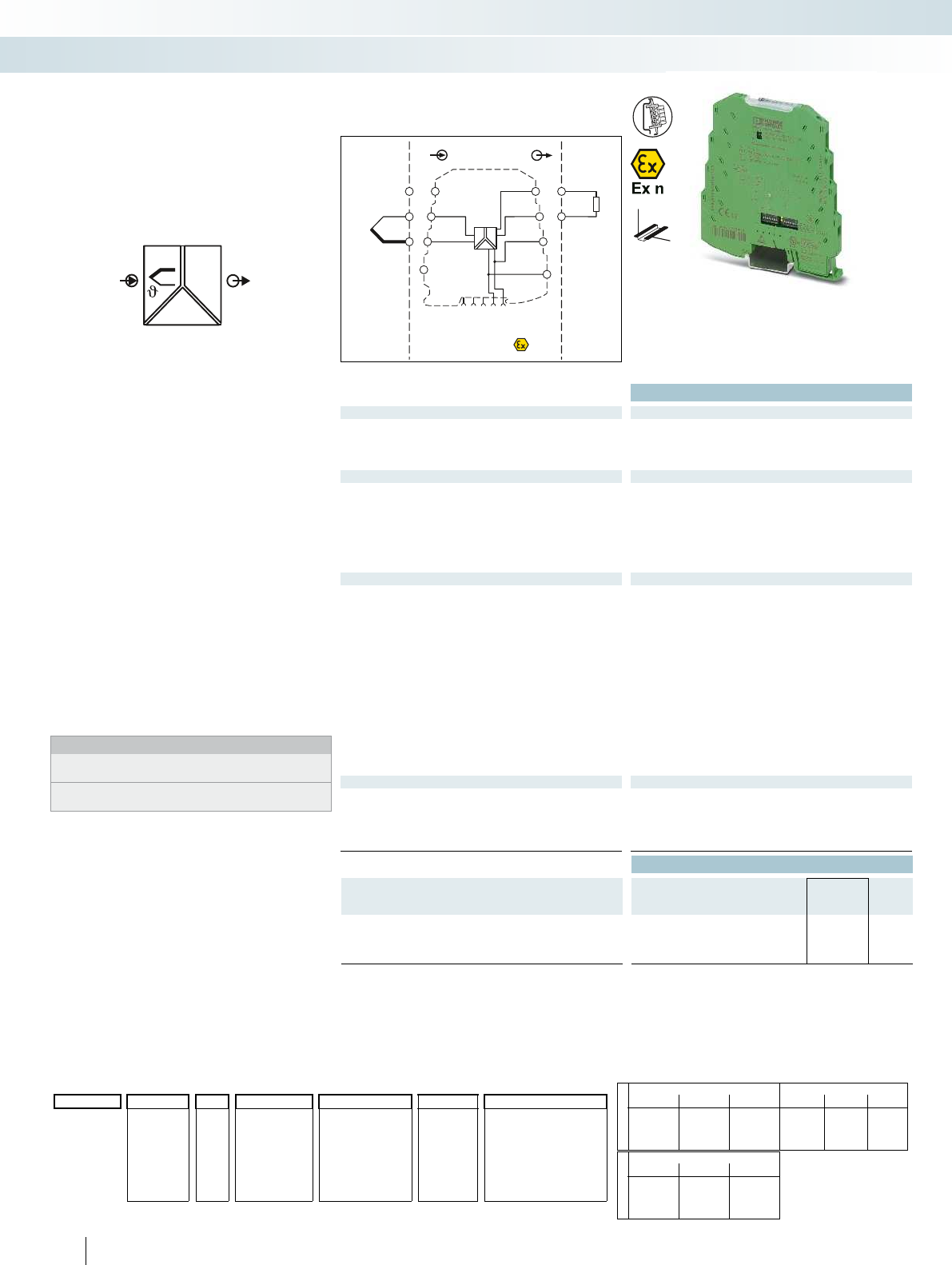
Zone 2
Div. 2
passive
IN
Sensor /Field
OUT
PLC / DCS
+–
–
+
+
–
+24V
+24V
GND 2
GND 2
GND 1
active
OUTU,I
1 5
2
6
7
8
3
4
5
6
1
2
3
TC
OUT
IN
POWER
U,I
Ex:
Housing width 6.2 mm
Technical data
Input data
Input signal (can be configured using DIP switches) Thermocouples, type J, K (IEC 584-1)
Temperature range Type J: -150 °C ... 1200 °C (configurable)
Type K: -150 °C ... 1350 °C
Measuring range span min. 50 K
Output data U output I output
Output signal (configurable using the DIP switch) 0 ... 5 V / 1 ... 5 V 0 ... 20 mA / 4 ... 20 mA
0 ... 10 V / 10 ... 0 V 20 ... 0 mA / 20 ... 4 mA
Maximum output signal approx. 12.5 V 23 mA
No-load voltage approx. 12.5 V
Short-circuit current approx. 10 mA
Load R
B
10 k< 500 (at 20 mA)
Ripple < 20 mV
PP
(at 10 k) < 20 mV
PP
(at 500 )
General data
Supply voltage U
B
19.2 V DC ... 30 V DC
Current consumption < 25 mA (at 24 V DC)
Power consumption < 500 mW
Transmission error for the full/set measuring range 0.2%; ((150 K / set measuring range [K]) + 0.1)%
Cold junction errors < 3 K ( typ. < 2 K )
Temperature coefficient < 0.02 %/K
Step response (0–99%) < 30 ms
Electrical isolation Basic insulation according to EN 61010
Test voltage, input/output/supply 1.5 kV (50 Hz, 1 min.)
Ambient temperature (operation) -20 °C ... 65 °C
Housing material PBT
Dimensions W / H / D 6.2 / 93.1 / 102.5 mm
Screw connection solid / stranded / AWG 0.2 ... 2.5 mm² / 0.2 ... 2.5 mm² / 26 - 12
EMC note Class A product, see page 625
Conformance / approvals
Conformance CE-compliant
ATEX
II 3 G Ex nA IIC T4 Gc X
UL, USA / Canada UL 508 Recognized
Class I, Div. 2, Groups A, B, C, D T5
GL GL EMC 2 D
Ordering data
Description Type Order No. Pcs. /
Pkt.
MCR temperature transducer, for thermocouples
Order configuration Screw connection MINI MCR-SL-TC-UI 2864448 1
Unconfigured Screw connection MINI MCR-SL-TC-UI-NC 2864299 1
108
PHOENIX CONTACT
Order key MINI MCR-SL-TC-UI (standard configuration entered as an example)
Failure information (depends on the output signal range):
Overrange Open circuit
0 ... 20 mA 4 ... 20 mA 0 ... 10 V
0 ... 20 mA 4 ... 20 mA
0 ... 10 V
A 20.5 mA 20.5 mA 10.25 V 21 mA 21 mA 10.5 V
B 20.5 mA 20.5 mA 10.25 V 21 mA 21 mA 10.5 V
C 20 mA 20 mA 10 V 21 mA 21 mA 10.5 V
D 20 mA 20 mA 10 V 0 mA 4 mA 0 V
Underrange
0 ... 20 mA 4 ... 20 mA 0 ... 10 V
A 0 mA 4 mA 0 V
B 0 mA 3.5 mA 0 V
C 0 mA 4 mA 0 V
D 0 mA 4 mA 0 V
J=Type J 0 Range
(increment)
OUT01 =0 ... 20 mA A NONE =without FCC
MINI MCR-SL-
TC-UI
-10 OUT02 =4 ... 20 mA B Yes =with FCC (a fee
is charged)
K=Type K -20 OUT03 =0 ... 10 V C
-30 OUT05 =0 ... 5 V D
-40 0 ... 300 (10 K) OUT06 =1...5 V YESPLUS =FCC with
5 measuring
points (a fee is
charged)
-50 320 ... 700 (20 K) OUT07 =20 ... 0 mA
-100
750 ... 1350
(50 K) OUT08 =20 ... 4 mA
-150 OUT09 =10 ... 0 V
1
) For explanations, see adjacent text on the right; for further details, see data sheet: www.phoenixcontact.net/products
Order No.
Sensor type Measuring range [°C] Output Failure in-
formation
1
)
Factory calibration
certificate (FCC)
Start End
2864448 / J / 0 / 1000 / OUT01 / A / NONE
DW
H
– Highly compact temperature transducer
for electrical isolation, conversion,
amplification, and filtering of
thermocouple signals to create standard
signals
– Temperature measuring range of
-150°C to +1350°C
– For J and K thermocouples according to
IEC 584-1
– Internal cold junction compensation
– Input and output signals can be configured
via DIP switches
– 3-way isolation
– Error signaling via diagnostics LED and
analog signal
– Power supply possible through the foot
element (DIN rail connector)
Notes:
To order a product with an order configuration, please enter the
desired configuration by referring to the order key; see below.
Information about power bridging, system cabling, and marking
components can be found from page 116
Temperature,
temperature transducer for
type J and K thermocouples
MCR technology
Highly compact signal conditioners - MINI Analog
Configurable, for a temperature measuring
range of -150°C ... +1350°C
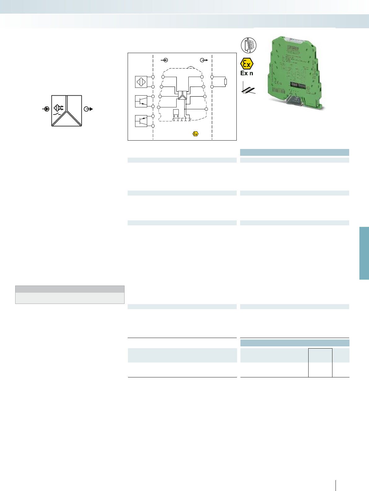
OUT
IN U,I
NPN
PNP
POWER
FM
Zone 2
–
–
+
+
+24V
+24V
GND 2
GND 3
GND 2
active
OUT U,INAMUR
NPN
PNP
GND 1
1 5
2
6
7
8
3
4
passive
5
6
1
4
2
4
4
3
FM
Teach In
IN
Sensor / Field
OUT
PLC / DCS
For further information and full technical data, visit phoenixcontact.net/products
Ex:
Housing width 6.2 mm
Technical data
Input data
Input sources NPN/PNP transistor outputs
NAMUR initiators
Floating relay contact (dry contact)
Frequency measuring range 0.002 Hz ... 20 kHz (DIP switch)
0.002 Hz ... 80 kHz (teach-in wheel)
Maximum input signal 30 V (incl. DC voltage)
Output data U output I output
Output signal 0 ... 5 V / 1 ... 5 V 0 ... 20 mA / 4 ... 20 mA
0 ... 10 V / 10 ... 0 V 20 ... 0 mA / 20 ... 4 mA
Maximum output signal approx. 12.3 V 24.6 mA
Load R
B
10 k500 (at 20 mA)
Ripple < 20 mV
PP
< 20 mV
PP
(at 500 )
General data
Supply voltage U
B
9.6 V DC ... 30 V DC
Power consumption < 800 mW (at I
OUT
= 20 mA, 9.6 V DC, load 500 )
Transmission error of the set measuring span 0.1 %
Temperature coefficient 0.01 %/K
Step response (0–99%) < 35 ms (at f > 500 Hz)
Electrical isolation Basic insulation according to EN 61010
Test voltage, input/output/supply 1.5 kV (50 Hz, 1 min.)
Degree of protection IP20
Ambient temperature (operation) -20 °C ... 65 °C
Mounting any
Housing material PBT
Dimensions W / H / D 6.2 / 93.1 / 102.5 mm
Screw connection solid / stranded / AWG 0.2 ... 2.5 mm² / 0.2 ... 2.5 mm² / 26 - 12
Spring-cage connection solid / stranded / AWG 0.2 ... 2.5 mm² / 0.2 ... 2.5 mm² / 24 - 12
EMC note Class A product, see page 625
Conformance / approvals
Conformance CE-compliant
ATEX
II 3 G Ex nA IIC T4 Gc X
UL, USA / Canada UL 508 Listed
Class I, Div. 2, Groups A, B, C, D T4
Class I, Zone 2, Group IIC
GL GL applied for
Ordering data
Description Type Order No. Pcs. /
Pkt.
MCR frequency transducer
Standard configuration Screw connection MINI MCR-SL-F-UI-NC 2902832 1
Standard configuration Spring-cage connection MINI MCR-SL-F-UI-SP-NC 2902833 1
109
PHOENIX CONTACT
Configurable 3-way isolated frequency
transducer.
– Suitable for the connection of NAMUR
proximity sensors (IEC 60947-5-6 and
EN 50227) as well as for sensors with
NPN and PNP outputs that generate a
frequency signal
– The device is configured via DIP switches
– Frequency range is freely adjustable via a
press/slide button (“teach-in wheel”)
– Supports fault monitoring
– Standard configuration:
NAMUR sensor; mean-value generation
“OFF”; 0.002 Hz ... 20 kHz frequency
range; 4 ... 20 mA output; error evaluation
NE43 (downscale); fault monitoring
contact responds on any error
Notes:
Information about power bridging, system cabling, and marking
components can be found from page 116
Frequency
Frequency transducer
for up to 80 kHz
MCR technology
Highly compact signal conditioners - MINI Analog
DW
H
Frequency transducer for up to 80 kHz

TTTTTT
T T TT T T
OUT
IN
POWER
U,I f
Zone 2
max. 20mA
IN
Sensor / Field
OUT
PLC / DCS
4-wire
OUT
U,I
GND
GND – OUT +
US
5
6
1
2
supply
max. 30VDC
+–
RL
–
+
–
–
+
+
+
–
+24V
+24V
+24V
GND 3
GND 3
GND 2
passive
GND 3
GND 1
OUTIN U,I
1 5
2
6
7
8
3
4
Ex:
Housing width 6.2 mm
Technical data
Input data U input I input
Input signal (configurable using the DIP switch) 0 ... 5 V / 1 ... 5 V 0 ... 20 mA / 4 ... 20 mA
0 ... 10 V / 2 ... 10 V 0 ... 10 mA / 2 ... 10 mA -
Maximum input signal 30 V DC 100 mA
Input resistance approx. 110 kapprox. 50
Output data Frequency output PWM output
Output signal (can be configured using DIP switches) 0 Hz ... 10 kHz / 0 Hz ... 5 kHz 7.8 kHz (10 bit) / 3.9 kHz (10 bit)
0 Hz ... 2.5 kHz / 0 Hz ... 1 kHz 1.9 kHz (12 bit) / 977 Hz (12 bit)
0 Hz ... 500 Hz / 0 Hz ... 250 Hz 488 Hz (14 bit) / 244 Hz (14 bit)
0 Hz ... 100 Hz / 0 Hz ... 50 Hz 122 Hz (16 bit) / 61 Hz (16 bit)
Minimum load 4 mA (U
L
/ R
L
) 20 mA 12 mA (U
L
/ R
L
) 20 mA
Load current maximum 20 mA
Maximum switching voltage 30 V
Overrange/underrange Can be set (via DIP switch)
Protective circuit Short-circuit protection, polarity reversal protection
General data
Supply voltage U
B
19.2 V DC ... 30 V DC
Nominal supply voltage 24 V DC
Current consumption < 10 mA (at 24 V DC)
Power consumption < 200 mW
Maximum transmission error 0.1 % (> 7 kHz 0.2%)
Temperature coefficient < 0.02 %/K
Step response (0–99%) < 15 ms (+ (1/f) smallest filter)
< 1 s (+ (1/f) largest filter)
Electrical isolation Basic insulation according to EN 61010
Test voltage, input/output/supply 1.5 kV (50 Hz, 1 min.)
Degree of protection IP20
Ambient temperature (operation) -20 °C ... 65 °C
Mounting any
Housing material PBT
Dimensions W / H / D 6.2 / 93.1 / 102.5 mm
Screw connection solid / stranded / AWG 0.2 ... 2.5 mm² / 0.2 ... 2.5 mm² / 26 - 12
Spring-cage connection solid / stranded / AWG 0.2 ... 2.5 mm² / 0.2 ... 2.5 mm² / 24 - 12
EMC note Class A product, see page 625
Conformance / approvals
Conformance CE-compliant
ATEX
II 3 G Ex nA IIC T4 Gc X
UL, USA / Canada UL 508 Recognized
Class I, Div. 2, Groups A, B, C, D T5 applied for
GL GL EMC 2 D
Ordering data
Description Type Order No. Pcs. /
Pkt.
MCR Analog frequency transducer
Screw connection MINI MCR-SL-UI-F 2864082 1
Spring-cage connection MINI MCR-SL-UI-F-SP 2810243 1
PWM output (pulse width modulation)
Variable pulse-pause ratio / Fixed period duration T
Frequency output
Variable frequency / Period duration T
110
PHOENIX CONTACT
– Highly compact analog-to-frequency
transducer for electrical isolation,
amplification, conversion, and filtering of
standard signals to create frequencies or
PWM signals
– Configurable interference suppression
filter
– Input and output signals can be configured
via DIP switches
– 3-way isolation
– Error signaling via diagnostics LED and
analog signal
– Power supply possible through the foot
element (DIN rail connector)
– PWM output of 5 ... 95%
Notes:
Information about power bridging, system cabling, and marking
components can be found from page 116
Frequency
Analog frequency transducer
MCR technology
Highly compact signal conditioners - MINI Analog
DW
H
Configurable,
frequency and PWM output
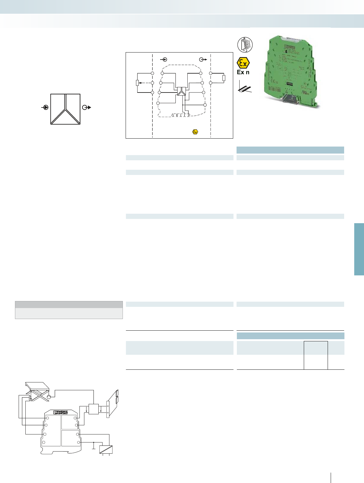
24V
OUT
GND1
UB +
GND2
MINI MCR-SL-R-UI
51
2
3
4
6
7
8
M
POWER
RU,I OUT
IN
IN
Zone 2
Sensor /Field
OUT
PLC / DCS
–
–
+
+
+24V
+24V
GND 2
GND 2
GND 1
active
OUTU,IIN
IN
IN
1 5
2
6
7
8
3
4
passive
5
6
1
2
3
For further information and full technical data, visit phoenixcontact.net/products
Ex:
Housing width 6.2 mm
Technical data
Input data
Potentiometer 100 ... 100 k
Reference voltage source < 3.6 V
Output data U output I output
Output signal 0 ... 5 V / 1 ... 5 V 0 ... 20 mA / 4 ... 20 mA
0 ... 10 V / 10 ... 0 V 20 ... 0 mA / 20 ... 4 mA
Maximum output signal 12.5 V 23 mA
No-load voltage approx. 12.5 V
Short-circuit current approx. 10 mA
Load R
B
> 10 k< 500 (20 mA)
Ripple < 20 mV
PP
(at 10 k) < 20 mV
PP
(at 500 )
Behavior in the event of a sensor error 0 % ... 105 % (configurable)
General data
Supply voltage U
B
19.2 V DC ... 30 V DC
Nominal supply voltage 24 V DC
Current consumption < 25 mA (at 24 V DC)
Power consumption < 500 mW
Maximum transmission error < 0.2 %
Temperature coefficient < 0.02 %/K
Step response (0–99%) < 30 ms
Electrical isolation Basic insulation according to EN 61010
Test voltage, input/output/supply 1.5 kV (50 Hz, 1 min.)
Degree of protection IP20
Ambient temperature (operation) -20 °C ... 65 °C
Mounting any
Housing material PBT
Dimensions W / H / D 6.2 / 93.1 / 102.5 mm
Screw connection solid / stranded / AWG 0.2 ... 2.5 mm² / 0.2 ... 2.5 mm² / 26 - 12
Spring-cage connection solid / stranded / AWG 0.2 ... 2.5 mm² / 0.2 ... 2.5 mm² / 24 - 12
EMC note Class A product, see page 625
Conformance / approvals
Conformance CE-compliant
ATEX
II 3 G Ex nA IIC T4 Gc X
UL, USA / Canada UL 508 Recognized
Class I, Div. 2, Groups A, B, C, D T5 applied for
GL GL EMC 2 D
Ordering data
Description Type Order No. Pcs. /
Pkt.
MCR potiposition transducer
Screw connection MINI MCR-SL-R-UI 2864095 1
Spring-cage connection MINI MCR-SL-R-UI-SP 2810256 1
Control system
Lifting platform
Potentiometer
Actuator motor
Mains voltage
Controller
TARGET
0...10 V
ACTUAL
0...10 V
111
PHOENIX CONTACT
– Highly compact potiposition transducer
for electrical isolation, conversion,
amplification, and filtering of
potentiometer positions to create
standard signals
– Automatic potentiometer detection
without manual adjustment
– For potentiometers from 100 to 100 k
– Configurable measuring range and output
signals
– A potentiometer sub-range can be
linearized via the “teach-in” switch on the
device
– Input and output signals can be configured
via DIP switches
– 3-way isolation
– Error signaling via diagnostics LED and
analog signal
– Power supply possible through the foot
element (DIN rail connector)
Notes:
Information about power bridging, system cabling, and marking
components can be found from page 116
Potentiometers
Potiposition transducer
Height adjustment of a lifting platform with
setpoint and actual value control
MCR technology
Highly compact signal conditioners - MINI Analog
DW
H
Configurable,
automatic potentiometer detection

POWER
OUT
IN
Zone 2
IN
Sensor /Field
OUT
PLC / DCS
5
3
6
4
1
1
1
2
2
2
–
+
+
–
+24V
OUT2
OUT2
+24V
GND
GND
OUT1
OUT1IN
IN
1 5
2
6
7
8
3
4
13
13
14
14
DI 1
DI 2
Ex:
Housing width 6.2 mm
Technical data
Input data
Input signal NAMUR proximity sensors (EN 60947-5-6)
open circuit switch contacts
Switch contacts with resistance circuit
Control circuit
No-load voltage 8.2 V DC 10 %
Switching points (in acc. with IEC 60947-5-6) < 1.2 mA (blocking)
> 2.1 mA (conductive)
Line fault detection > 6 mA (in the event of a short-circuit)
< 0.35 mA (in the event of an open circuit)
Switching output
Relay output 2 N/O contacts
Contact material Hard gold-plated AgNi
Max. switching voltage 250 V AC
Max. switching current 2 A
Min. contact current 1 mA (at 5 V DC)
Switching frequency 0.5 Hz (240 V AC / 30 V DC / 2 A)
10 Hz (without load)
General data
Supply voltage U
B
19.2 V DC ... 30 V DC
Nominal supply voltage 24 V DC
Current consumption < 25 mA
Power consumption < 600 mW
Electrical isolation Basic insulation according to EN 61010
Test voltage, input/output/supply 1.5 kV (50 Hz, 1 min.)
Degree of protection IP20
Ambient temperature (operation) -20 °C ... 65 °C
Mounting any
Housing material PBT
Dimensions W / H / D 6.2 / 93.1 / 102.5 mm
Screw connection solid / stranded / AWG 0.2 ... 2.5 mm² / 0.2 ... 2.5 mm² / 26 - 12
Spring-cage connection solid / stranded / AWG 0.2 ... 2.5 mm² / 0.2 ... 2.5 mm² / 24 - 12
EMC note Class A product, see page 625
Conformance / approvals
Conformance CE-compliant
ATEX
II 3 G Ex nA nC IIC T4 Gc X
UL, USA / Canada UL 508 Recognized
Class I, Div. 2, Groups A, B, C, D T5 applied for
GL GL EMC 2 D
Ordering data
Description Type Order No. Pcs. /
Pkt.
MCR NAMUR signal conditioner
Screw connection MINI MCR-SL-NAM-2RNO 2864105 1
Spring-cage connection MINI MCR-SL-NAM-2RNO-SP 2810269 1
112
PHOENIX CONTACT
– Highly compact signal conditioner for
electrical isolation, amplification, and
duplication of proximity sensor signals
– For proximity sensors in accordance with
IEC 60947-5-6 and EN 50227
– Floating contacts and contacts with
resistance circuit can be connected
– Input and output signals can be configured
via DIP switches
– N/O contacts at output
– Second output can be used as a doubler
or error signaling output
– 3-way isolation
– Switchover between operating current
and quiescent current (inverted switching
behavior)
– Error signaling via diagnostics LED and
analog signal
– Power supply possible through the foot
element (DIN rail connector)
Notes:
Information about power bridging, system cabling, and marking
components can be found from page 116
Digital IN
NAMUR signal conditioner
MCR technology
Highly compact signal conditioners - MINI Analog
DW
H
Configurable,
for NAMUR sensors and
floating contacts

POWER
OUT
IN U,I
4-wire
OUT
U,I
GND 14
11
12
US
2
3
4
5
6
–
+
+
–
+24V
+24V
GND 2
GND 2
GND 1
IN U,I
5 1
6
2
3
4
7
8
IN
Sensor /Field
OUT
PLC / DCS
Zone 2
For further information and full technical data, visit phoenixcontact.net/products
Ex:
Housing width 6.2 mm
Technical data
Input data U input I input
Input signal (configurable using the DIP switch) 0 ... 10 V 0 ... 20 mA
Maximum input signal 30 V 100 mA
Input resistance > 100 k50
Specification of the switching point With 25-speed potentiometer
Switching output
Relay output 1 PDT
Contact material AgSnO
2
, hard gold-plated
Max. switching voltage 250 V AC
Limiting continuous current 2 A
Hysteresis (configurable using the DIP switch) 0.1 %; 1 %; 2.5 %; 5 %
Operating and closed-circuit current behavior Can be selected via DIP switch
Setting range of the response delay (configurable using the DIP
switch)
0 s ... 10 s (0 s; 1 s; 2 s; 3 s; 4 s; 6 s; 8 s; 10 s)
General data
Supply voltage U
B
19.2 V DC ... 30 V DC
Nominal supply voltage 24 V DC ±15 %
Current consumption < 14 mA (at 24 V DC)
Power consumption < 330 mW (at 24 V DC)
Linearity error -
Temperature coefficient < 0.02 %/K
Step response (0–99%) < 35 ms
Electrical isolation Basic insulation according to EN 61010
Test voltage input/power supply 1.5 kV AC (50 Hz, 1 min.)
Degree of protection IP20
Ambient temperature (operation) -20 °C ... 65 °C
Mounting any
Housing material PBT
Dimensions W / H / D 6.2 / 93.1 / 102.5 mm
Screw connection solid / stranded / AWG 0.2 ... 2.5 mm² / 0.2 ... 2.5 mm² / 26 - 12
Spring-cage connection solid / stranded / AWG 0.2 ... 2.5 mm² / 0.2 ... 2.5 mm² / 24 - 12
EMC note Class A product, see page 625
Conformance / approvals
Conformance CE-compliant
ATEX
II 3 G Ex nA nC IIC T4 Gc X
UL, USA / Canada UL 508 Recognized
UL, USA Class I, Zone 2, AEx nA nC IIC T5
UL, Canada Class I, Zone 2, Ex nA nC IIC T5 Gc
GL GL EMC 2 D
Ordering data
Description Type Order No. Pcs. /
Pkt.
MCR threshold value switch
Screw connection MINI MCR-SL-UI-REL 2864480 1
Spring-cage connection MINI MCR-SL-UI-REL-SP 2864493 1
113
PHOENIX CONTACT
– Highly compact threshold value switch for
switching analog limit values
– Input signal, hysteresis, and delay time can
be configured via DIP switches
– Limit value can be freely adjusted via
potentiometer on front
– 3-way isolation
– PDT relay at output
– Operating current/quiescent current
switchover
– Status and error signaling via two
diagnostics LEDs
– Power supply possible through the foot
element (DIN rail connector)
Notes:
Information about power bridging, system cabling, and marking
components can be found from page 116
Limit values,
threshold value switch
MCR technology
Highly compact signal conditioners - MINI Analog
DW
H
Configurable,
with relay PDT output

IN
U
CV
POWER
OUT
Zone 2
OUT
–
+
–
–
+
+
+
–
+24V
+24V
+24V
GND 2
GND 2
GND 1
GND 2
GND 1
OUT UOUT U
1 5
2
6
7
8
3
4
OUT
Ex:
Housing width 6.2 mm
Technical data
Input data
Input signal 9.6 ... 30 V
Output data
Output signal (can be configured using DIP switches) 10 V DC
7.5 V DC
5 V DC
2.5 V DC
Short-circuit current approx. 32 mA
Ripple < 20 mV
PP
General data
Supply voltage U
B
9.6 V DC ... 30 V DC
Power consumption < 600 mW (at 24 V IN)
Maximum transmission error 0.1 % (of final value)
Temperature coefficient < 0.01 %/K, typ. < 0.002 %/K
Electrical isolation Basic insulation according to EN 61010
Test voltage input/output 1.5 kV (50 Hz, 1 min.)
Degree of protection IP20
Ambient temperature (operation) -20 °C ... 65 °C
Housing material PBT
Dimensions W / H / D 6.2 / 93.1 / 102.5 mm
Screw connection solid / stranded / AWG 0.2 ... 2.5 mm² / 0.2 ... 2.5 mm² / 26 - 12
Spring-cage connection solid / stranded / AWG 0.2 ... 2.5 mm² / 0.2 ... 2.5 mm² / 24 - 12
EMC note Class A product, see page 625
Conformance / approvals
Conformance CE-compliant
ATEX
II 3 G Ex nA IIC T4 Gc X
UL, USA / Canada UL 508 Listed
Class I, Div. 2, Groups A, B, C, D T6
Class I, Zone 2, Group IIC
Ordering data
Description Type Order No. Pcs. /
Pkt.
MCR constant voltage source
Screw connection MINI MCR-SL-CVS-24-5-10-NC 2902822 1
Spring-cage connection MINI MCR-SL-CVS-24-5-10-SP-NC 2902823 1
Accessories
Setpoint potentiometer, for individual setpoint definition
Resistance value 4.7 kEMG 30-SP- 4K7LIN 2940252 10
Resistance value 10 kEMG 30-SP-10K LIN 2942124 10
114
PHOENIX CONTACT
– Constant voltage source for
potentiometers, measuring bridges,
encoders
– Highly precise
– Input signal corresponds to power supply
– Input signal and, in turn, the power supply
can be provided via the foot element
(DIN rail connector)
– Standard configuration:
Output 10 V DC
Accessories,
constant voltage source
MCR technology
Highly compact signal conditioners - MINI Analog
DW
H
Configurable,
output signals: 2.5 V / 5 V / 7.5 V / 10 V

For further information and full technical data, visit phoenixcontact.net/products
Ex:
Technical data
General data
EMC note Class A product, see page 625
Ordering data
Description Type Order No. Pcs. /
Pkt.
Programming adapter for configuring modules with
S-PORT interface
IFS-USB-PROG-ADAPTER 2811271 1
115PHOENIX CONTACT
The IFS-USB-PROG-ADAPTER
programming adapter is used for configuring
Phoenix Contact INTERFACE modules
with S-Port interface.
The adapter is used with FDT/DTM
software or ANALOG-CONF software.
For programming MACX Analog,
MINI Analog Pro, and MINI Analog.
Accessories
Programming adapter
MCR technology
Highly compact signal conditioners - MINI Analog
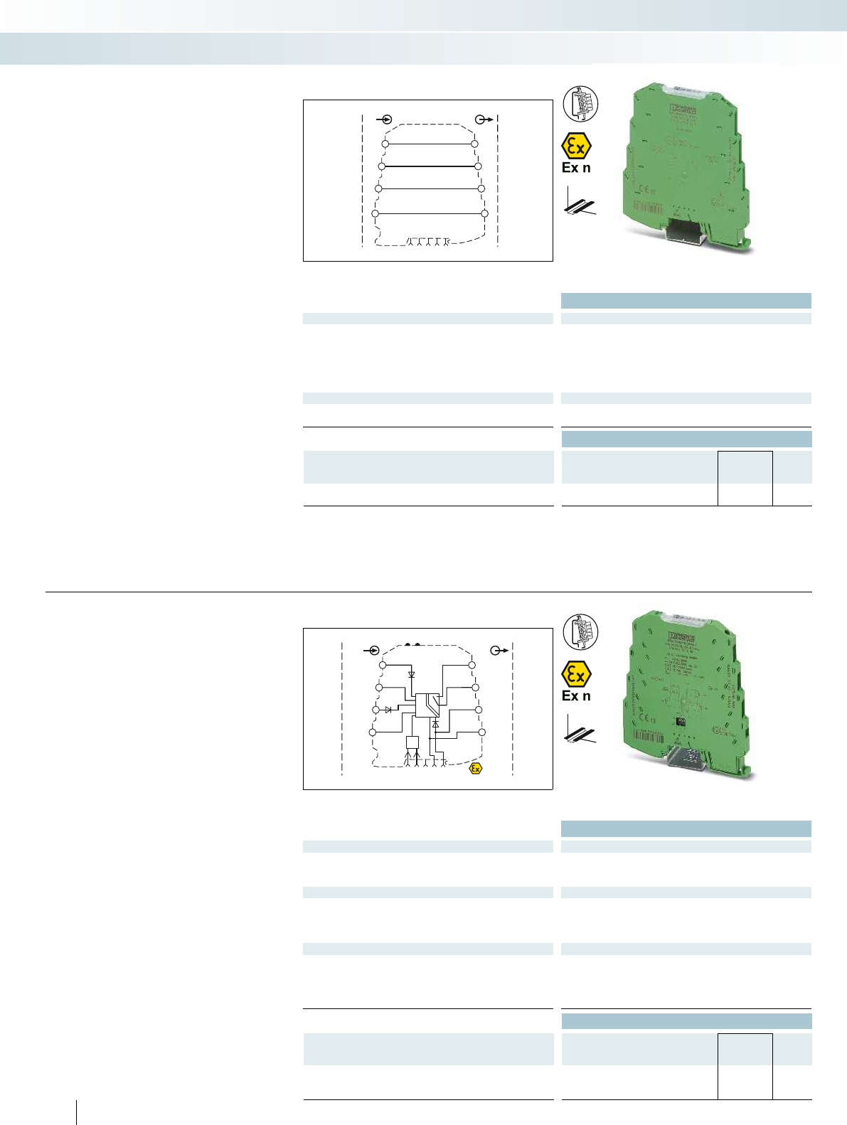
IN
Sensor / Field
OUT
PLC / DCS
OUT
OUTIN
IN
1 5
2
6
7
8
3
4
1:1
OUT
IN
OUT
IN
IN
PWR 1
IN
FAULT
CONTACT
+24V
+24V
Zone 2
–
–
+
+
+24V
OUT RC
OUT RC
1 5
2
6
7
8
3
4
OUT
21
PWR
OUT
+24V
PWR 1
IN
–
–
+
+
FM
–
+
Technical data
General data
Degree of protection IP20
Ambient temperature (operation) -20 °C ... 65 °C
Mounting any
Housing material PBT
Dimensions W / H / D 6.2 / 93.1 / 102.5 mm
Screw connection solid / stranded / AWG 0.2 ... 2.5 mm² / 0.2 ... 2.5 mm² / 24 - 12
Conformance / approvals
ATEX
II 3 G Ex nA IIC T4 Gc X
GL GL EMC 2 D
Ordering data
Description Type Order No. Pcs. /
Pkt.
MINI Analog feed-through terminal block
Screw connection MINI MCR-SL-TB 2811420 1
DW
H
– Feed-through terminal block for 1:1
forwarding of signals in the MINI Analog
group
– For plugging gaps in system cabling with
the V8 system adapter, e.g., when there
are fewer than eight signals
– Used in conjunction with the
MINI Analog multiplexer
– For direct mounting in the case of
applications without signal conversion
and without electrical isolation
Accessories
Feed-through terminal block
MCR technology
Highly compact signal conditioners - MINI Analog
1:1 connection
Technical data
Input data/output data
Input signal 9.6 V DC ... 30 V DC
Output signal 8.8 V DC ... 29.2 V DC
Output signal maximum current 2 A
Switching output
Max. switching voltage 30 V AC/DC
Max. switching current 50 mA
Test voltage input/output 1.5 kV AC (50 Hz, 1 min.)
EMC note Class A product, see page 625
Conformance / approvals
ATEX
II 3 G Ex nA nC IIC T4 Gc X
UL, USA / Canada UL 508 Listed
Class I, Div. 2, Groups A, B, C, D T4
Class I, Zone 2, Group IIC
GL GL applied for
Ordering data
Description Type Order No. Pcs. /
Pkt.
MINI Analog fault signaling module
Standard configuration Screw connection MINI MCR-SL-FM-RC-NC 2902961 1
Standard configuration Spring-cage connection MINI MCR-SL-FM-RC-SP-NC 2902962 1
116
PHOENIX CONTACT
DW
H
Fault monitoring module for evaluating
and reporting group errors from the fault
monitoring system.
– Monitoring of supply voltages of
MINI MCR-SL-PTB-FM(-SP) power
terminals
– Drawing off the supply is possible
– The error is reported via an N/C contact
– Standard configuration: group error
detection “ON”; redundancy monitoring
“ON“; relay “active”
Accessories
Fault signaling module
Group error indication and
supply monitoring
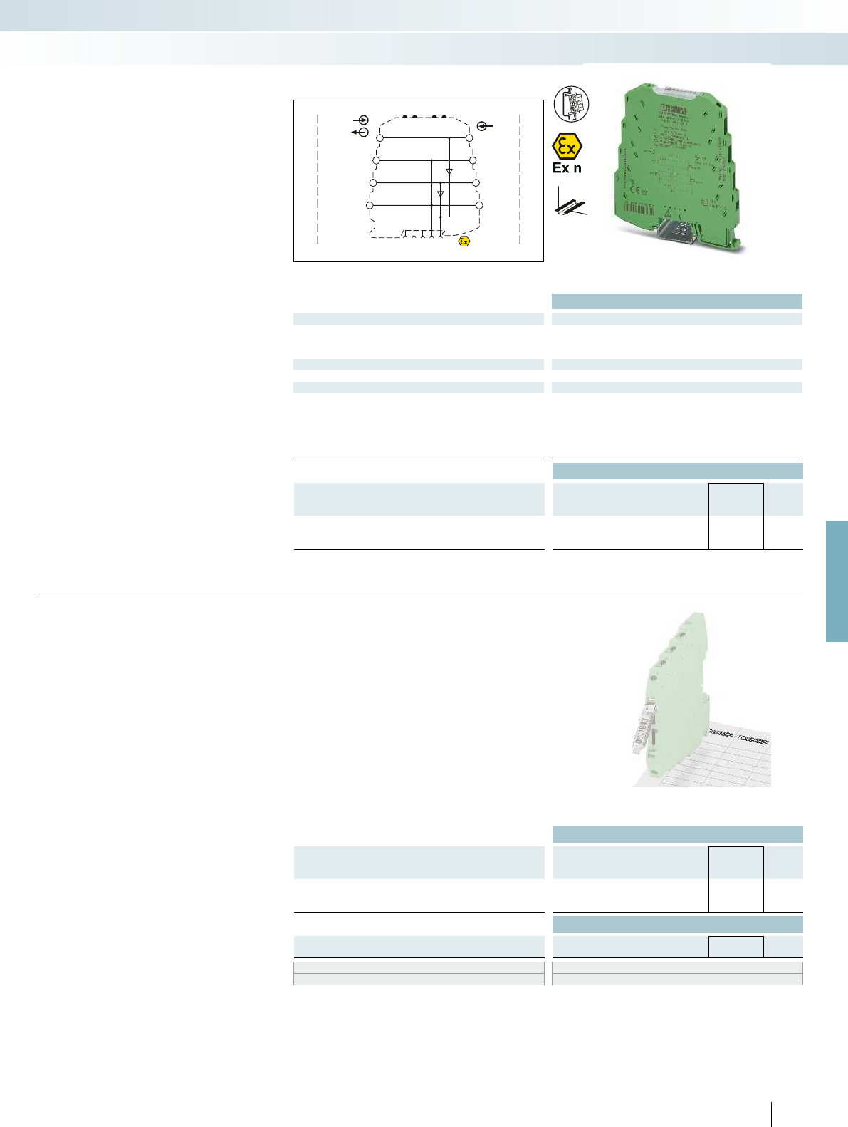
Zone 2
IN
PWR 1
IN +24V
PWR 2
IN +24V
+24V
PWR 2
IN / OUT-FM
+24V
PWR 1
IN / OUT-FM
IN
OUT FM
PWR OUT
1 5
2
6
7
8
3
4
–
–
–
+
+
+
–
+
–
+
4321
+24V
For further information and full technical data, visit phoenixcontact.net/products
Technical data
Input data/output data
Input voltage range 0 V DC ... 30 V DC
Output voltage Input voltage - 0.8 V
Output current 2 A
General data
EMC note Class A product, see page 625
Conformance / approvals
Conformance CE-compliant
ATEX II 3 G Ex nA IIC T4 Gc X
UL, USA / Canada UL 508 Listed
Class I, Div. 2, Groups A, B, C, D T4
Class I, Zone 2, Group IIC
GL GL applied for
Ordering data
Description Type Order No. Pcs. /
Pkt.
MINI Analog power terminal
Screw connection MINI MCR-SL-PTB-FM 2902958 1
Spring-cage connection MINI MCR-SL-PTB-FM-SP 2902959 1
DW
H
– For up to 80 MINI Analog modules
– The MINI MCR-SL-PTB-FM(-SP) power
terminal is used to supply the supply
voltage to the DIN rail connector
– Monitoring of supplies in combination
with the fault monitoring module
– Flexible redundant supply from one or
both module sides
– Extended supply voltage range from
0 ... 30 V DC
Accessories
Power terminal
MCR technology
Highly compact signal conditioners - MINI Analog
Power terminal, can be monitored
Ordering data
Description Type Order No. Pcs. /
Pkt.
Hinged transparent cover, for marking MINI Analog modules with
insert strips
MINI MCR DKL 2308111 10
Accessories
Insert strips, stamped, for transparent cover MINI MCR-DKL-LABEL 2810272 10
Zack marker strip, flat ZBF 6 (see Catalog 5)
UniCard sheets, for marker groove UC-TMF 6 (see Catalog 5)
117
PHOENIX CONTACT
– Flexible marking system with hinged
transparent cover and matching insert
strips
– Transparent cover that can be snapped
onto the module instead of the standard
cover
– Insert strips on pre-punched paper sheets
– Marking option for standard cover in the
form of ZBF 6 zack marker strip marking
labels
Accessories
Marking material
Transparent cover with insert strips

IN IN
PWR1IN PWR2IN
PWR OUT
+24V+24V
+24V
1 5
2
6
7
8
3
4
–
–
–
+
+
+
Zone 2
Ordering data
Description Type Order No. Pcs. /
Pkt.
DIN rail connector (TBUS), for bridging the supply voltage,
can be snapped onto 35 mm DIN rails as per EN 60715, with
UL approval
Color: green ME 6,2 TBUS-2 1,5/5-ST-3,81 GN 2869728 10
– For bridging the supply voltage
– Reduces wiring costs
– Module replacement without interrupting
the supply to the remaining modules
(hot swappable)
– One DIN rail connector for two
MINI Analog modules
Accessories
ME 6,2 TBUS... DIN rail connector
MCR technology
Highly compact signal conditioners - MINI Analog
For bridging the supply voltage
Technical data
Input data
Input voltage range 20 V DC ... 30 V DC
Output data
Output voltage Input voltage - 0.8 V
Output current 2 A
General data
Ambient temperature (operation) -20 °C ... 65 °C
Housing material PBT
EMC note Class A product, see page 625
Conformance / approvals
Conformance CE-compliant
ATEX
II 3 G Ex nA IIC T4 Gc X
UL, USA / Canada UL 508 Recognized
Class I, Div. 2, Groups A, B, C, D T5
GL GL EMC 2 D
Ordering data
Description Type Order No. Pcs. /
Pkt.
MCR power terminal
Screw connection MINI MCR-SL-PTB 2864134 1
Spring-cage connection MINI MCR-SL-PTB-SP 2864147 1
118
PHOENIX CONTACT
DW
H
– For supplying the supply voltage via the
foot element (DIN rail connector) where
DC voltages of up to 30 V are already
available
– Option of redundant supply decoupled
from diode
– For up to 80 MINI Analog modules
– For up to 2 A
– Status and error signaling via diagnostics
LEDs
Notes:
Recommended fuse for power terminal:
Fuse in acc. with IEC 60127-2/V
Nominal current: 2.5 A
Characteristics: slow-blow
(e.g., Wickmann 5 x 20 mm/No. 195 - glass fuse)
Accessories
Power terminal
Redundant supply for existing 24 V

For further information and full technical data, visit phoenixcontact.net/products
Ordering data
Description Type Order No. Pcs. /
Pkt.
DIN rail connector, for bridging the supply voltage, can be
snapped onto 35 mm DIN rails as per EN 60715, with UL approval,
two pieces are required per system power supply
ME 17,5 TBUS 1,5/ 5-ST-3,81 GN 2709561 10
– For bridging the supply voltage when
using a MINI POWER system power
supply
Notes:
If the system power supply is used, two ME 17,5 TBUS DIN rail
connectors are required. This allows you to establish the
connection to the ME 6,2 TBUS DIN rail connector of the
MINI Analog system and provide an effective power supply.
Accessories
ME 17,5 TBUS-... DIN rail connector
MCR technology
Highly compact signal conditioners - MINI Analog
For system power supply
Ordering data
Description Type Order No. Pcs. /
Pkt.
System power supply, primary-switched, with zone 2 approval.
Further information can be found in Catalog 6, Surge protection and
power supplies.
MINI-PS-100-240AC/24DC/1.5/EX 2866653 1
System power supply, primary-switched (not for zone 2)
Further information can be found in Catalog 6, Surge protection and
power supplies.
MINI-SYS-PS-100-240AC/24DC/1.5 2866983 1
119
PHOENIX CONTACT
H
W
D
– For supplying the supply voltage via the
DIN rail connector where AC voltages
are available
– Nominal input voltage range
100 ... 240 V AC
– 24 V DC output voltage
– For up to 60 MINI Analog modules
– For up to 1.5 A, secondary
– Status and error signaling via diagnostics
LEDs
Accessories
System power supply
For applications with local voltages of
over 100 V
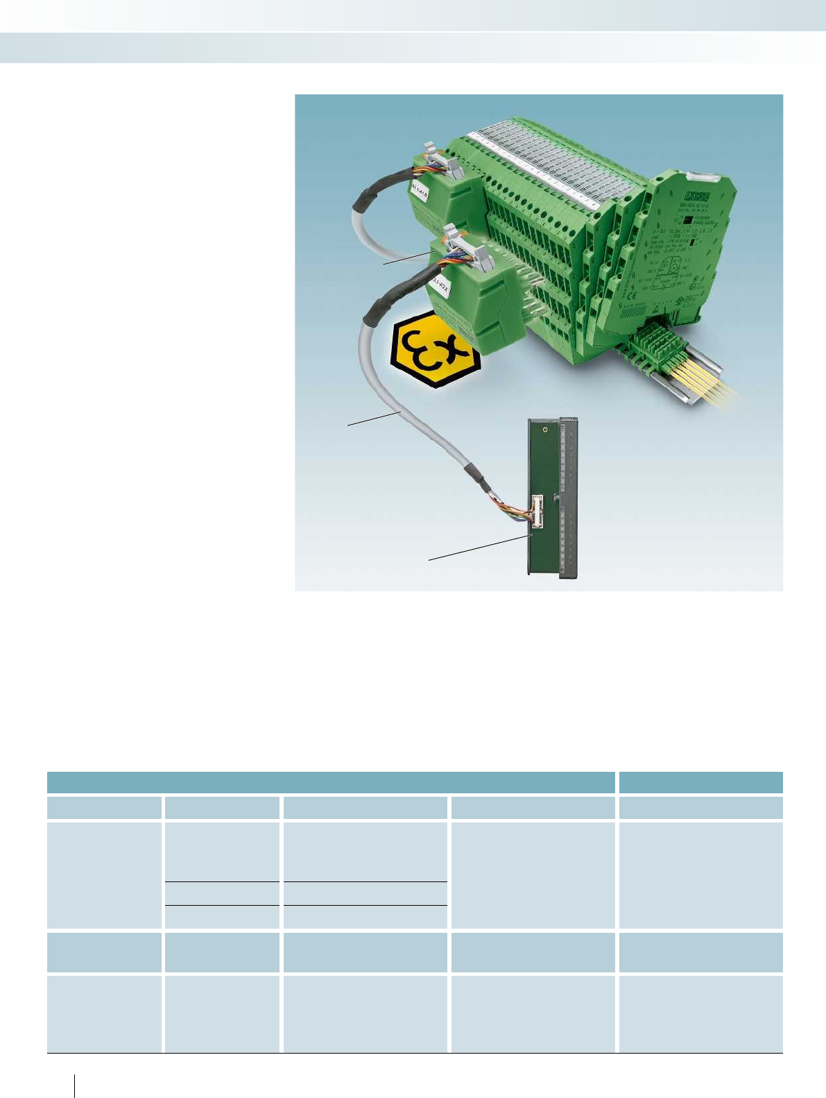
Accessories
System cabling
A high number of channels enables analog
signal transmission across 6 mm in a
confined space for many applications. In this
kind of context, in particular, it is really
important to have access to wiring
solutions that avoid errors and are time-
efficient, thereby cutting costs.
The MINI Analog system cabling solution
allows you to wire up to eight channels
quickly, easily, and without errors.
System cabling can take various forms.
System cabling with a front adapter
This includes:
– A 16-pos. FLK cable
– The V8 system adapter for MINI Analog
modules
– A front adapter that needs to be
specifically selected based on the analog
card of the controller
With this solution, all you need to do is
connect the components together. There is
virtually no wiring effort involved. What's
more, it completely rules out wiring errors,
as the pre-assembled components ensure
correct assignment by virtue of their design.
System cabling without a front
adapter
The version that does not require the use
of a front adapter is the ideal addition.
This solution involves using a 16-pos.
FLK cable with open ends on one side. The
open ends are fitted with ferrules and are
numbered. This allows you to create a
system cabling connection to virtually any
module without having to fit a front
adapter. The other advantage is that you
can implement system cabling on the
module side quickly, easily, and without
errors.
The tables below are designed to serve as
a configuration aid. Details of other
solutions are available on the Internet or on
request.
Configuration aid for MINI Analog system cabling
Controller Analog card Front adapter FLK cable V8 system adapter for MINI Analog
Siemens
SIMATIC S7-300 /
ET 200 M
6ES7-331-7KF02-0AB0
FLKM 16-PA-S300/MINI-MCR
(in the catalog on page 522)
FLK 16/EZ-DR/.../KONFEK
(non-molded plugs,
in the catalog on page 606)
MINI MCR-SL-V8-FLK 16-A
(in the catalog on page 122)
6ES7-331-7KB02-0AB0
6ES7-331-7KB81-0AB0
6ES7-331-7TF00-0AB0
6ES7-332-8TF01-0AB0
6ES7-331-1KF01-0AB0
(for current signals)
FLKM 16-PA-331-1KF/I/MINI-MCR
(in the catalog on page 523)
6ES7-331-5HF00-0AB0
(for current signals)
FLKM 16-PA-332-5HF/I/MINI-MCR
(in the catalog on page 523)
Yokogawa
Centum CS 3000 R3
AAI 141
Not required
CABLE-40/2/FLK16/.../YUC
(non-molded plugs,
in the catalog on page 535)
2 x MINI MCR-SL-V8-FLK 16-A
(in the catalog on page 122)
AAI 143
Miscellaneous controllers /
actuators / sensors All cards Not required
CABLE-FLK16/OE/0,14/...M
(non-molded plugs,
in the catalog on page 602)
MINI MCR-SL-V8-FLK 16-A
(in the catalog on page 122)
or alternatively
VIP-CAB-FLK16/FR/OE/0,14/...M
(molded plugs,
in the catalog on page 602)
System cabling with a front adapter
V8 system adapter
for MINI Analog
16-pos. FLK cable
Front adapter for analog card
120
PHOENIX CONTACT
MCR technology
Highly compact signal conditioners - MINI Analog
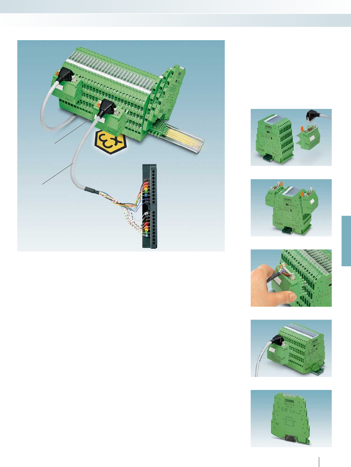
For further information and full technical data, visit phoenixcontact.net/products
V8 system adapter
for MINI Analog
16-pos. VIP or FLK cable with
open ends
Innovative concept
Thanks to its innovative design concept,
the MINI MCR-SL-V8-FLK 16 A MINI
Analog system adapter can be used on both
the input and output side. Consequently,
there is nothing at all to prevent you from
using the same components for system
cabling on both output and input modules.
Complete flexibility
The proven FLK cable series offers
complete flexibility in terms of selection
and is the ideal solution for system cabling
with a front adapter. The flat and flexible
plug connections mean that the products
can be easily installed in any analog module.
Increased protection
Complete flexibility
Innovative concept
Plug-in connection
Addition
Increased protection
The new VIP cables with molded FLK
plugs offer enhanced protection in harsh
industrial environments. If you opt for
system cabling without a front adapter,
you can enjoy all the advantages of the new
VIP cables on the system adapter side.
Addition
If the application demands a form of
system cabling with fewer than eight
channels, the MINI MCR-SL-TB feed-
through terminal block (page 116)
represents the perfect addition.
System cabling without a front adapter
121
PHOENIX CONTACT
MCR technology
Highly compact signal conditioners - MINI Analog
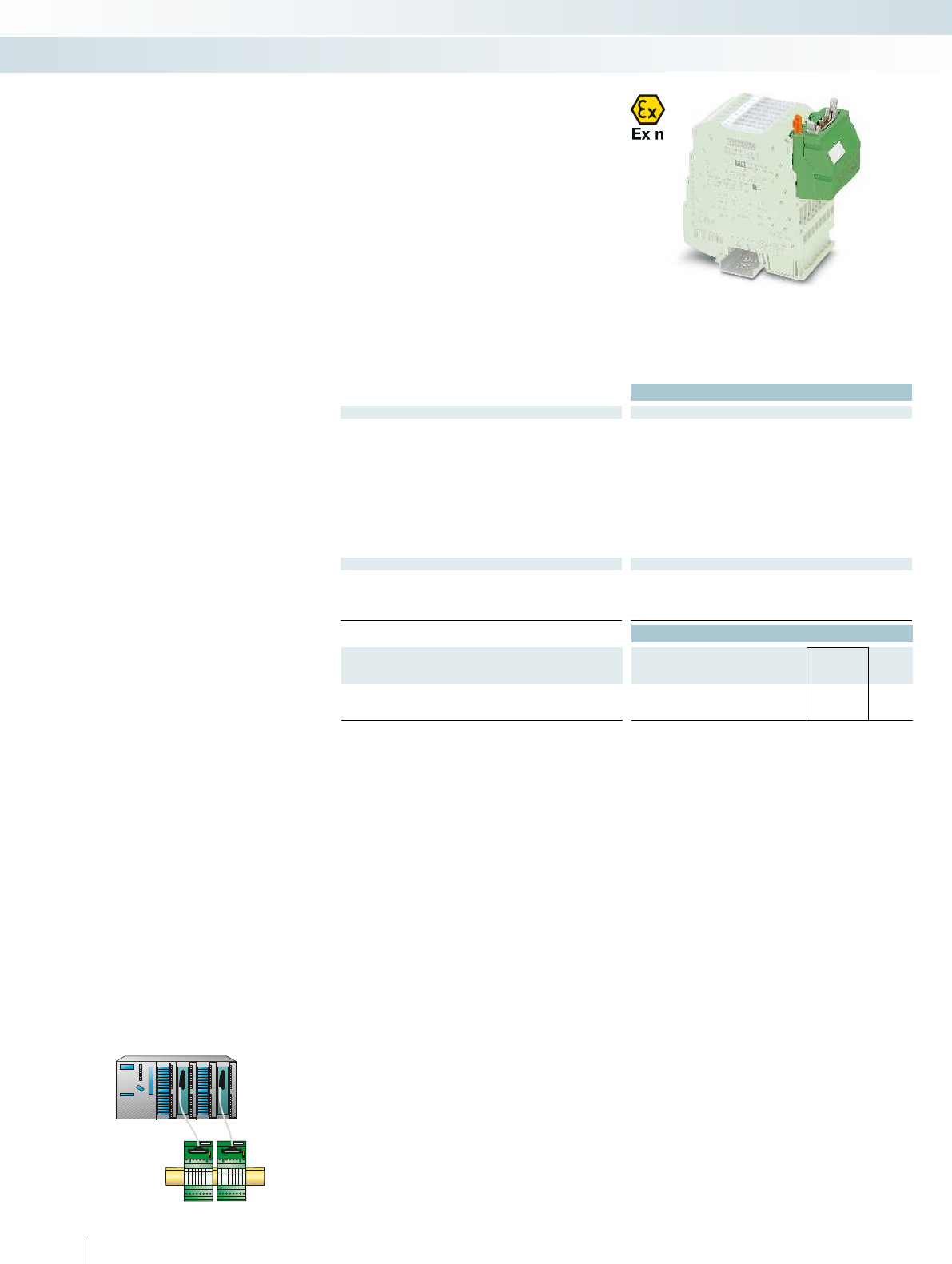
Ex:
Housing width 50.4 mm
Technical data
General data
Contact resistance < 10 m
Current carrying capacity 1 A
Test voltage -
Vibration resistance 0.7 g
Surge voltage category / Pollution degree III / 2
Ambient temperature (operation) -20 °C ... 60 °C
Housing material PBT
Dimensions W / H / D 50.4 / 46.2 / 45.5 mm
Connection to the signal level Flat-ribbon cable connector in acc. with IEC 60603-13
Insertion/withdrawal cycles (system adapter / FLK 16) 10 / 200
Conformance / approvals
ATEX
II 3 G Ex nA IIC T4 Gc X
UL, USA / Canada UL 508 Recognized
Class I, Div. 2, Groups A, B, C, D T5 applied for
GL GL EMC 2 D
Ordering data
Description Type Order No. Pcs. /
Pkt.
System adapter, for MINI Analog modules with screw connection
MINI MCR-SL-V8-FLK 16-A 2811268 1
122
PHOENIX CONTACT
– Time-saving wiring solution thanks to
unique plug-in concept
– System cabling on PLC side
– Plug and Play
– For up to eight channels
– Reduces wiring costs and errors
Accessories
MINI Analog system adapter
MINI Analog system cabling
MCR technology
Highly compact signal conditioners - MINI Analog
System adapter
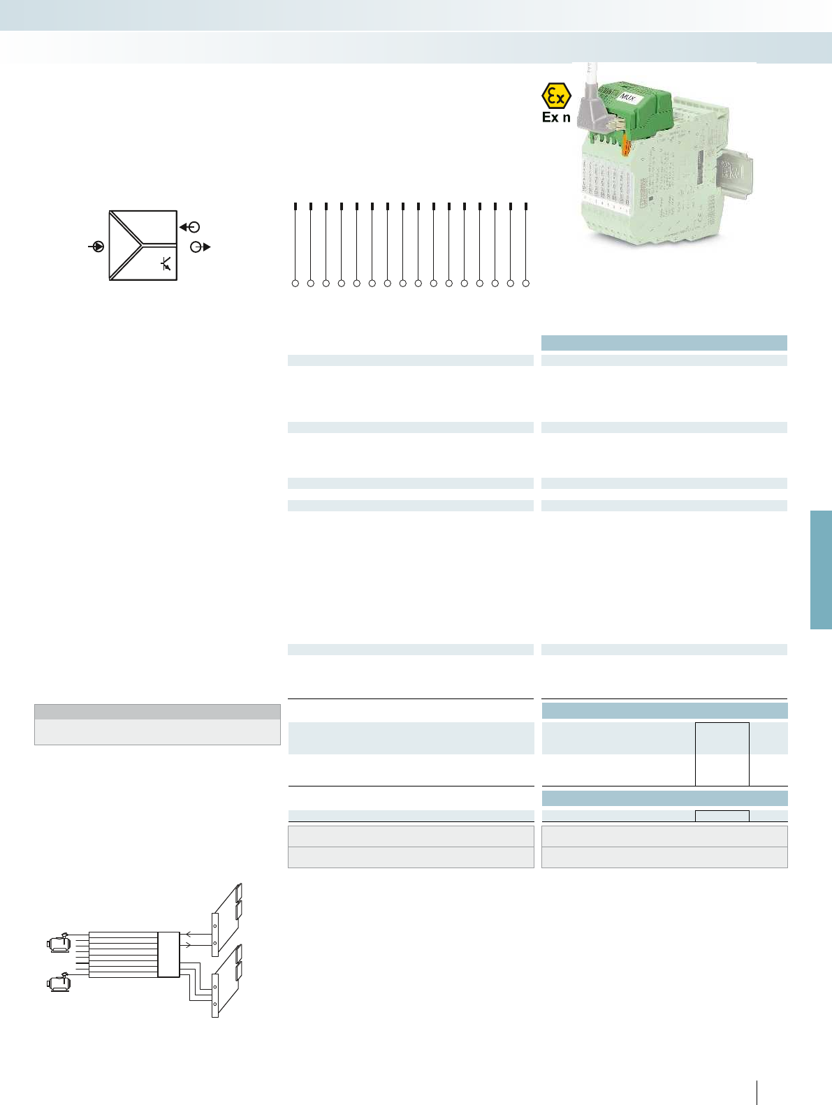
4...20 mA
Power
MINIMCR-SL-PT100-UI
MINI MCR-SL-MUX..
MINIMCR-SL-PT100-UI
MINIMCR-SL-PT100-UI
MINIMCR-SL-PT100-UI
MINIMCR-SL-PT100-UI
MINIMCR-SL-PT100-UI
DO
DO
DO
AO
MINIMCR-SL-PT100-UI
MINIMCR-SL-PT100-UI
....
8xIIN
1xIOUT
3xDO
POWER
OUT
IN
1
1
2
2
3
3
4
4
5
5
6
6
7
7
8
8
9
9
10
10
11
11
12
12
13
13
14
14
15
15
16
16
BIT3BIT2BIT1
AO
I
Out
D1+D2+D3+D1-D2-D3-
PWR
In
For further information and full technical data, visit phoenixcontact.net/products
Ex:
Housing width 50.4 mm
Technical data
Input data
Description 2, 4, 6 or 8-channel (can be selected)
Can be configured/parameterized Via DIP switches
Input signal 4 ... 20 mA
Maximum input signal < 30 mA
Switching cycles 2 or 1 sec. (can be selected)
Output data
Output signal 4 ... 20 mA
Maximum output signal < 30 mA
Load R
B
(U
supply
- 7 V) / I
max
Status indication active input 1, 2, 3-bit digital output (can be selected)
Switching output 3 x PNP optocouplers
Maximum switching voltage 30 V DC
General data
Supply voltage U
B
7 V DC ... 30 V DC (loop-powered)
Current consumption < 3.5 mA (without signal current)
Power consumption < 24 mW (without signal current)
Maximum transmission error 0.3 % (0.1%, typical)
Temperature coefficient < 0.01 %/K
Ambient temperature (operation) -20 °C ... 65 °C
Housing material PBT
Dimensions W / H / D 50.4 / 45.5 / 46.2 mm
Connection to control level Flat-ribbon cable connector in acc. with IEC 60603-13
Insertion/withdrawal cycles (system adapter / FLK 16) 10 / 200
EMC note Class A product, see page 625
Conformance / approvals
Conformance CE-compliant
ATEX
II 3 G Ex nA IIC T4 Gc X
UL, USA / Canada UL 508 Recognized applied for
Class I, Div. 2, Groups A, B, C, D T5 applied for
Ordering data
Description Type Order No. Pcs. /
Pkt.
Multiplexer for MINI Analog modules with screw connection
MINI MCR-SL-MUX-V8-FLK 16 2811815 1
Accessories
MINI Analog feed-through terminal block MINI MCR-SL-TB 2811420 1
For round cable with one open end, see “System cabling for
controllers” section
VIP-CAB-FLK16/FR/OE/0,14/...
For round cable with one open end, see “System cabling for
controllers” section
CABLE-FLK16/OE/0,14/...
Controller
1 x Analog IN
8 x Analog IN
3 x Digital IN
Controller
Bit 000
Channel 1
Active
123
PHOENIX CONTACT
– Generates an analog output from up to
eight analog input signals – parallel analog
signals are transmitted serially via a cable
– The desired number of channels is
selected via DIP switches (8, 6, 4 or
2 channels).
– The channel currently switched is
indicated as a bit pattern via three digital
outputs
– Two clock cycles for execution can be
selected via DIP switches (one or two-
second clock)
– Supplied by an output loop
– For 4 ... 20 mA current signals
– Can be easily snapped onto MINI Analog
modules with screw connection technology
– Huge reduction in analog inputs at
controllers
– System cabling on the output side using
pre-assembled FLK cables with open
ends.
Notes:
For six, four or two channels you will also need the corresponding
number of feed-through terminal blocks (i.e., two, four or six).
Accessories,
MINI Analog multiplexer
Monitoring of eight motor temperatures with just one
analog control input
MCR technology
Highly compact signal conditioners - MINI Analog
FLK pin strip assignment
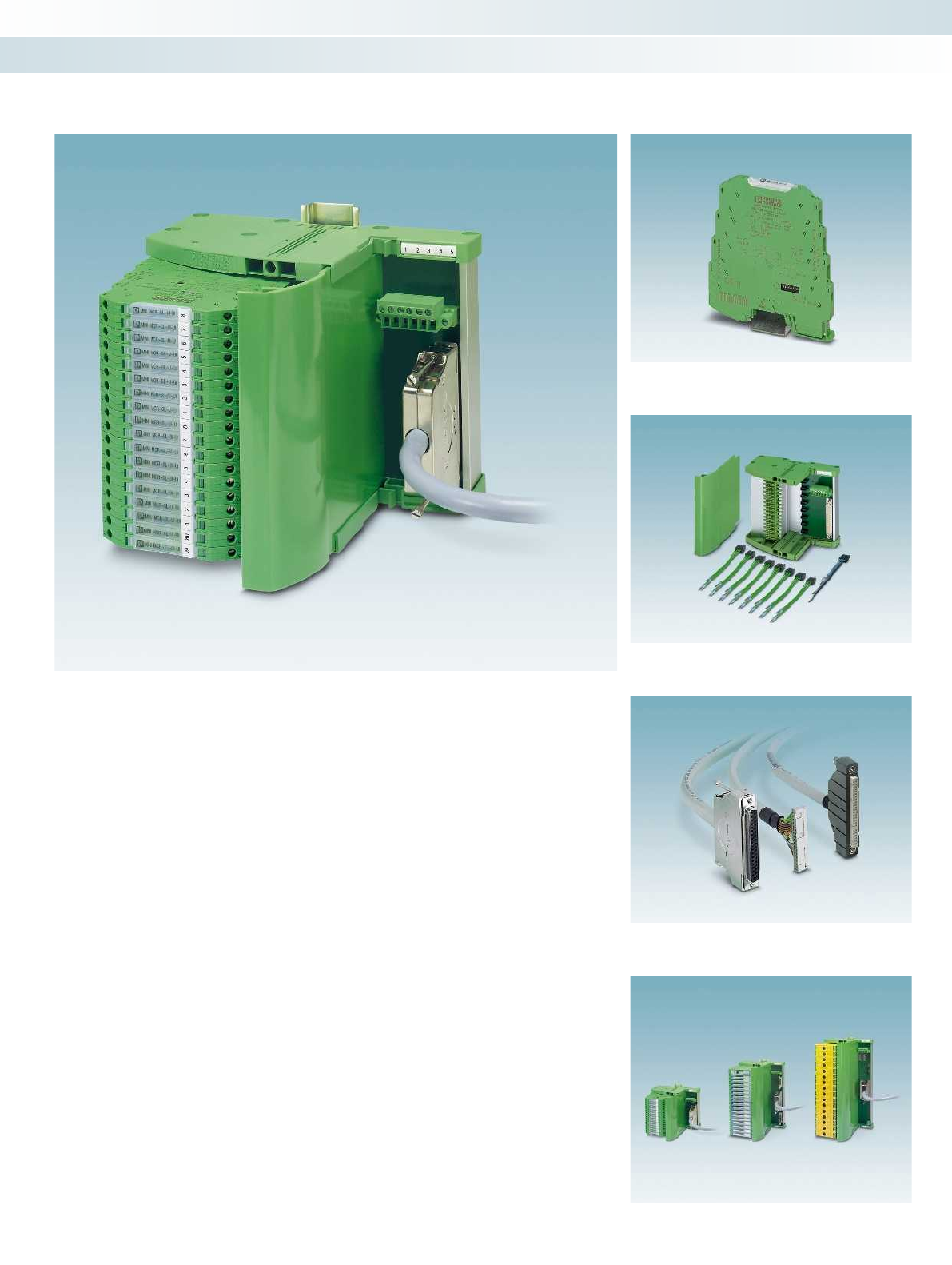
TC... Termination Carriers are
compact solutions for conveniently and
smoothly connecting standard DIN rail
signal conditioners from the MINI Analog
series to input/output cards of automation
systems using system cables.
The most compact signal conditioners
combined with the most compact and
flexible module carriers on the market
enable you to achieve a hitherto
unparalleled packing density in your control
cabinet together with professional system
cabling.
Compact
– The compact design associated with
MINI Analog saves up to 65% of space in
the control cabinet
Robust and reliable
– Stable, vibration-resistant aluminum
carrier device profile
– PCB is completely decoupled from signal
conditioners
– PCB without active electronics
– Redundant supply via separate DIN rail
module
– Horizontal or vertical DIN rail mounting
Flexible
– Profile sections without pitch markings
– Quick and safe module connection with
plug-in cable sets
– Horizontal or vertical DIN rail mounting
– Can be flexibly adapted to suit any
controller or higher-level control system
– Solutions tailored to your requirements
on request
– Available pre-assembled with modules
and wired, or for self-assembly
124
PHOENIX CONTACT
Termination Carriers for
MINI Analog signal conditioners
Solutions are also available for MACX Analog,
MACX Analog Ex, and Safety
Select controller-specific front adapter and system cable
Select module carrier
Select standard DIN rail device
MCR technology
Highly compact signal conditioners - MINI Analog
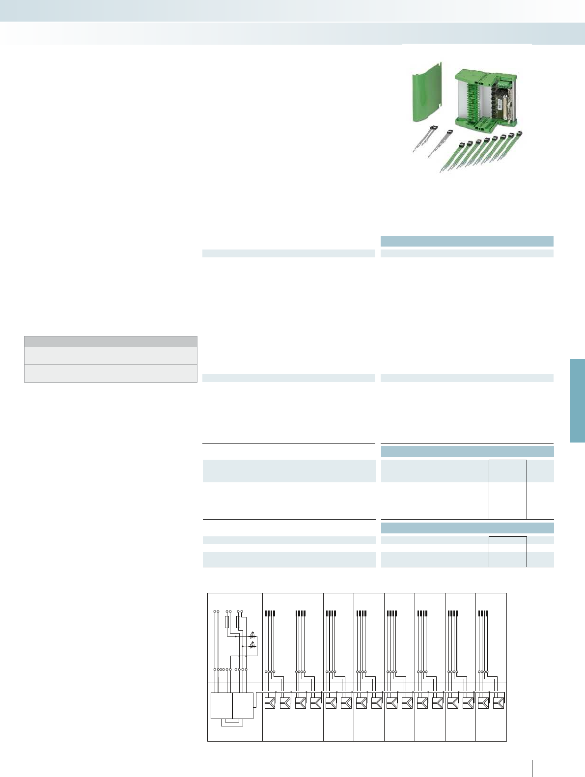
CH1
CH3
CH5
CH7
CH9
CH11
CH13
CH15
1
20
CH2
CH4
CH6
CH8
CH10
CH12
CH14
CH16
2
21
3
22
4
23
5
24
6
25
7
26
8
27
9
28
10
29
11
30
12
31
13
32
14
33
15
34
16
35
1
1
1
1
1
1
1
1
+
+
+
+
+
+
+
+
+
+
+
+
+
+
+
+
-
-
-
-
-
-
-
-
-
-
-
-
-
-
-
-
X20 COMBICON
X1 DSUB 37PTSM
PTB
FM
5
6
7
8
6
T-BUS
F1
1
1
7
8
F2
1
3 (+)
5 (+)
Alarm
PW1
PW2
2
4 (-)
6 (-)
1
3 (+)
2
5
FBS 2-6
-
+
MINI MCR-
SL-FM-RC-
NC
2902961
MINI MCR-
SL-PTB-FM
2902958PW1PW2
For further information and full technical data, visit phoenixcontact.net/products
Ex:
Housing width 136 mm
Technical data
General data
Connection to the control system level D-SUB pin strip
Number of positions 37
Max. operating voltage < 50 V DC (per signal/channel)
Max. permissible current 23 mA (signal/channel)
Rated insulation voltage 50 V
Pollution degree 2
Surge voltage category II
Rated surge voltage 0.5 kV
Clearance and creepage distances DIN EN 50178 (basic insulation)
Ambient temperature range -20 °C ... 60 °C (please observe module specifications)
Shock 15g, according to IEC 60068-2-27
Vibration (operation) 2g, according to IEC 60068-2-6
Dimensions W / H / D 136 / 170 / 160 mm
EMC note Class A product, see page 625
Power supply via power module
Input voltage range 19.2 V DC ... 30 V DC
Redundant supply yes, decoupled from diodes
Polarization and surge protection Yes
Fuse 2x 2.5 A on PCB, slow-blow (replaceable)
Status indication 2 x red LED (error)
2x green LEDs (PWR1 and PWR2)
Switching output 1 N/C contact (alarm = open)
Ordering data
Description Type Order No. Pcs. /
Pkt.
Module carrier for 16 MINI Analog channels, power and
feed-through module
TC-D37SUB-ADIO16-M-P-UNI 2902933 1
- With connection for MACX MCR-S-MUX HART multiplexer TC-D37SUB-AIO16-M-PS-UNI 2902934 1
Accessories
MINI Analog power terminal MINI MCR-SL-PTB-FM 2902958 1
MINI Analog fault signaling module MINI MCR-SL-FM-RC-NC 2902961 1
HART multiplexer,
32-chanel, including two 14-wire flat-ribbon
cables
MACX MCR-S-MUX 2865599 1
125
PHOENIX CONTACT
The TC-D37SUB-ADIO16-M-P-UNI
universal Termination Carrier is a compact
solution which connects signal conditioners
from the MINI Analog series to analog or
binary input/output cards of automation
systems.
In conjunction with the
MACX MCR-S-MUX HART multiplexer,
the TC-D37SUB-AIO16-M-PS-UNI
Termination Carrier version also allows
communication between HART-capable
field devices and a management system.
– Connection of up to 16 single-channel
signal conditioners
– Universal 1:1 signal routing to a
37-pos. D-SUB connector
– For system cables with D-SUB socket and
open ends for universal connection
– Redundant supply and monitoring via
separate MINI MCR-SL-PTB-FM
power terminal and
MINI MCR-SL-FM-RC-NC fault signaling
module
Notes:
Contact us: together, we can develop optimum solutions for your
automation system with the Termination Carrier for MINI Analog.
TC-D37SUB-ADIO16-M-P-UNI (Order No. 2902933) is not a class
A product.
Termination Carriers for
MINI Analog signal conditioners
TC-D37SUB-ADIO16-M-P-UNI and TC-D37SUB-AIO16-M-PS-UNI connection scheme
MCR technology
Highly compact signal conditioners - MINI Analog
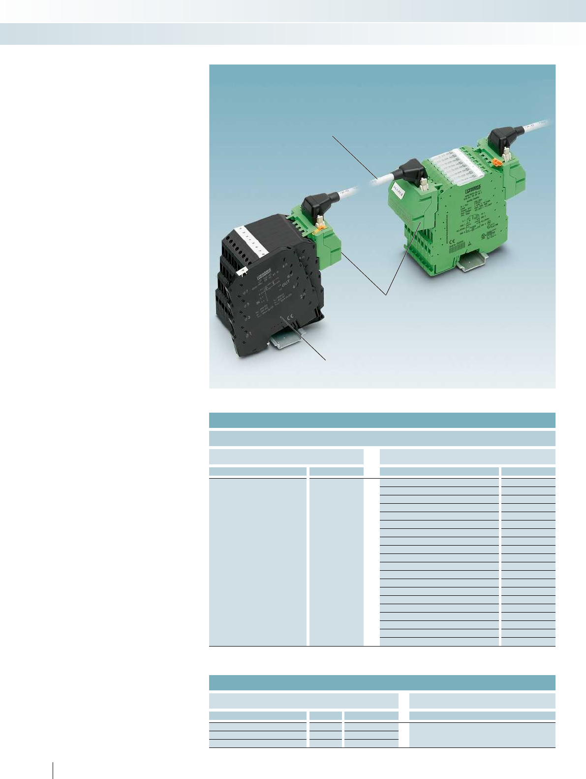
V8 system adapters
for MINI Analog
LINETRAB LIT
LINETRAB LIT surge protection
modules
Assembled 16-pos. round cable
VIP-CAB-FLK16/FR...
Accessories
Surge protection
LINETRAB LIT
The ideal addition to MINI Analog - the
innovative surge protection solution in
6.2 mm housing.
Since the LINETRAB LIT and MINI Analog
housing is the same shape, you can benefit
from the numerous advantages of system
cabling. The advantage of combining
MINI Analog and LINETRAB LIT products is
that it enables you to set up a space-saving,
protected, and optimally coordinated signal
chain from the sensor right up to the
controller.
The tables below are designed to serve as
configuration aids for combining MINI Analog
and LINETRAB products.
On the left, you will find a list of the
components and combination options
for setting up system cabling between
MINI Analog and LINETRAB.
For details of system cabling solutions
that can be used between MINI Analog
and the controller side, please refer to
page 120.
For more detailed information on
LINETRAB LIT surge protection modules,
please see the TRABTECH catalog.
Reliable and systematic measurements - LINETRAB LIT and MINI Analog
Configuration aid for LINETRAB LIT - MINI Analog
Cabling via MINI Analog system adapter (8 modules)
LINETRAB LIT (surge protection) MINI Analog
Type Order No. Type Order No.
LIT 1X2-24 2804610
MINI MCR-SL-UI-UI 2864383
MINI MCR-SL-UI-UI-NC 2864150
MINI MCR-SL-U-UI-NC 2865007
MINI MCR-SL-U-I-0 2813512
MINI MCR-SL-U-I-4 2813525
MINI MCR-SL-I-U-0 2813541
MINI MCR-SL-I-U-4 2813538
MINI MCR-SL-I-I 2864406
MINI MCR-SL-IDS-I-I 2905577
MINI MCR-SL-U-U 2864684
MINI MCR-SL-UI-2I 2864794
MINI MCR-SL-UI-2I-NC 2864176
MINI MCR-SL-RPS-I-I 2864422
MINI MCR-SL-RPSS-I-I 2864079
MINI MCR-SL-1CP-I-I 2864419
MINI MCR-SL-UI-F 2864082
MINI MCR-SL-NAM-2RNO 2864105
MINI MCR-SL-UI-REL 2864480
MINI MCR-SL-SHUNT-UI 2810858
MINI MCR-SL-SHUNT-UI-NC 2810780
VIP... round cables are available in special lengths on request.
Components required for system cabling
Available 16-pos. VIP... round cables V8 system adapter for MINI Analog
Type Length Order No. Type
VIP-CAB-FLK16/FR/FR/0,14/0,5M 0.5 m 2900154 2 x MINI MCR-SL-V8-FLK 16-A
(in the catalog on page 122)
VIP-CAB-FLK16/FR/FR/0,14/1,0M 1.0 m 2900155
VIP-CAB-FLK16/FR/FR/0,14/2,0M 2.0 m 2900156
126
PHOENIX CONTACT
MCR technology
Highly compact signal conditioners - MINI Analog

For further information and full technical data, visit phoenixcontact.net/products
Surge protection
Increased protection
Innovative concept
VIP system cable
Configuration aid for LINETRAB LIT - MINI Analog
Manual cabling
LINETRAB LIT (surge protection) MINI Analog
Type Order No. Type Order No.
LIT 1X2-24 2804610
MINI MCR-SL-UI-UI 2864383
MINI MCR-SL-UI-UI-NC 2864150
MINI MCR-SL-UI-UI-SP 2864710
MINI MCR-SL-UI-UI-SP-NC 2864163
MINI MCR-SL-SHUNT-UI-SP 2810874
MINI MCR-SL-SHUNT-UI-SP-NC 2810793
MINI MCR-SL-U-UI-SP 2811213
MINI MCR-SL-U-UI-SP-NC 2810078
MINI MCR-SL-U-I-0-SP 2813570
MINI MCR-SL-U-I-4-SP 2813583
MINI MCR-SL-I-U-0-SP 2813554
MINI MCR-SL-I-U-4-SP 2813567
MINI MCR-SL-I-I-SP 2864723
MINI MCR-SL-IDS-I-I-SP 2905578
MINI MCR-SL-U-U-SP 2864697
MINI MCR-SL-UI-2I-SP 2864804
MINI MCR-SL-UI-2I-SP-NC 2864189
MINI MCR-SL-RPS-I-I-SP 2864752
MINI MCR-SL-RPSS-I-I-SP 2810230
MINI MCR-SL-1CP-I-I-SP 2864749
LIT 2X2-24 2804623 MINI MCR-SL-2CP-I-I 2864655
MINI MCR-SL-2CP-I-I-SP 2864781
MINI MCR-SL-PT100-UI-200 2864309
MINI MCR-SL-PT100-UI-200-NC 2864370
MINI MCR-SL-PT100-UI-200-SP 2864192
LIT 2-12
(for 2-conductor connection
technology)
2804665 MINI MCR-SL-PT100-UI-200-SP-NC 2864202
MINI MCR-SL-PT100-UI 2864435
MINI MCR-SL-PT100-UI-NC 2864273
LIT 4-12
(for 3 and 4-conductor connection
technology)
2804678 MINI MCR-SL-PT100-UI-SP 2864736
MINI MCR-SL-PT100-UI-SP-NC 2864286
MINI MCR-SL-PT100-UI-LP 2810298
MINI MCR-SL-PT100-UI-LP-NC 2810308
MINI MCR-SL-PT100-UI-LP-SP 2810382
MINI MCR-SL-PT100-UI-LP-SP-NC 2810395
LIT 1X2-24 2804610
MINI MCR-SL-UI-F-SP 2810243
MINI MCR-SL-NAM-2RNO-SP 2810269
MINI MCR-SL-UI-REL-SP 2864493
LIT 4-24 2804678 MINI MCR-SL-R-UI 2864095
MINI MCR-SL-R-UI-SP 2810256
VIP system cable
The new VIP cables provide a way of
setting up secure and robust connections,
even in harsh industrial environments.
Innovative concept
The MINI Analog system adapter does
not just support system cabling on the input
and output sides. It also allows cabling to be
installed with LINETRAB surge protection
modules quickly, easily, and without errors.
Increased protection
In addition to all the advantages
associated with electrical isolation, filtering,
amplification, and the conversion of
standard analog signals using MINI Analog,
there is now also the option of effective
surge protection.
Surge protection
Surge protection is a reliable means of
actively preventing and protecting against
system damage and downtimes. LINETRAB
is able to limit transient surge voltages
safely and without affecting the signal - all in
a compact device with an overall width of
just 6.2 mm.
127
PHOENIX CONTACT
MCR technology
Highly compact signal conditioners - MINI Analog
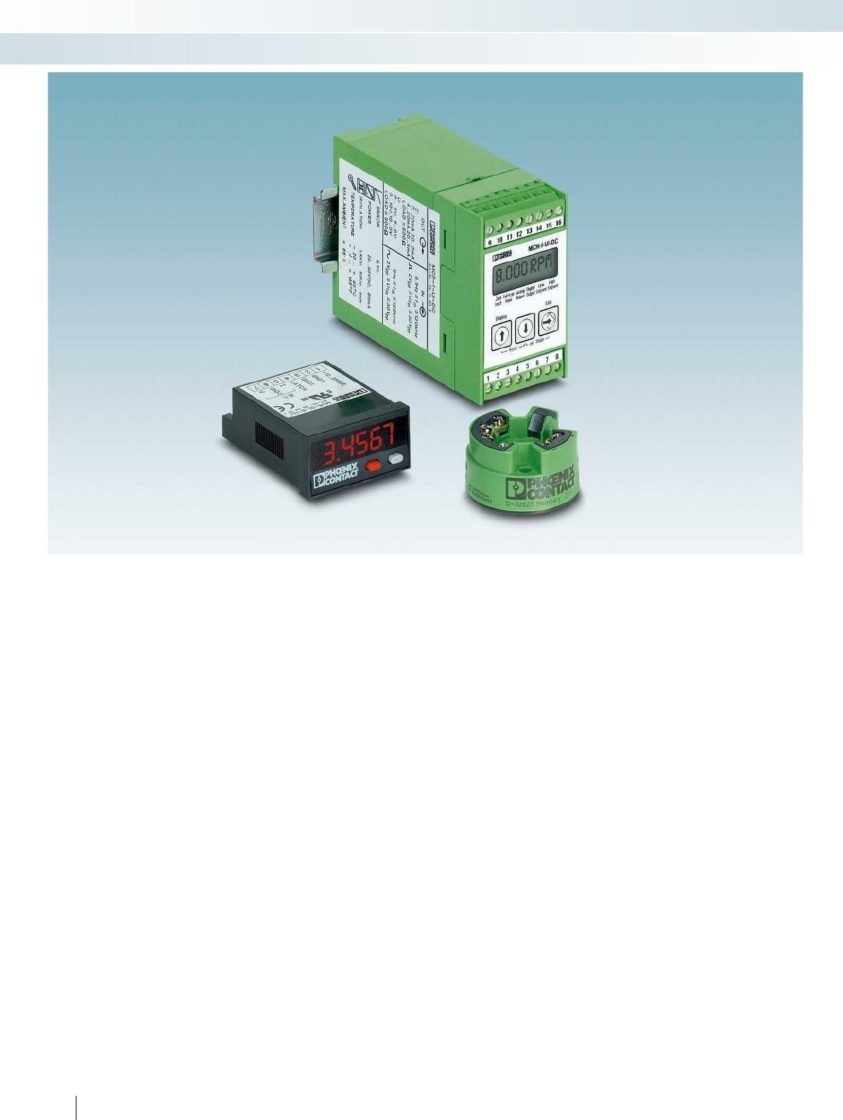
128
PHOENIX CONTACT
MCR technology
Signal conditioners, head transducers, and process indicators - MCR Analog
MCR signal conditioners, head
transducers, and process indicators
The MCR signal conditioners in
conjunction with proven DIN rail housings
and plug-in connection technology offer you
a large number of input signal types which
can be converted to standard signals.
When using off the DIN rail, you can
display or specify your process values with
the process indicators and the head
transducers convert your temperature
values directly into a standard signal.
Choose the right MCR Analog signal
conditioner for your application:
Analog IN/Analog OUT
– Configurable signal multipliers to double
standard analog signals
Temperature
– Temperature relay for 2-wire Pt100
– Output loop-powered temperature
transducer for thermocouples and
resistance thermometers
– Head transducers for thermocouples and
resistance thermometers
Frequency
– Programmable frequency transducer for
frequencies up to 120 kHz
Limit values
– Universal threshold value switch for
temperature sensors and standard signals
Process indicators
– Programmable process indicators for
standard signals
– Setpoint adjuster
Accessories
– Setpoint potentiometers
Your advantages:
– High operational reliability in the event of
disturbances, thanks to electrical isolation
– Configuration via software, DIP switches
or display keypad
– Process indicators including mounting
accessories and IP65 protection
– Clearly legible LED 7-segment display
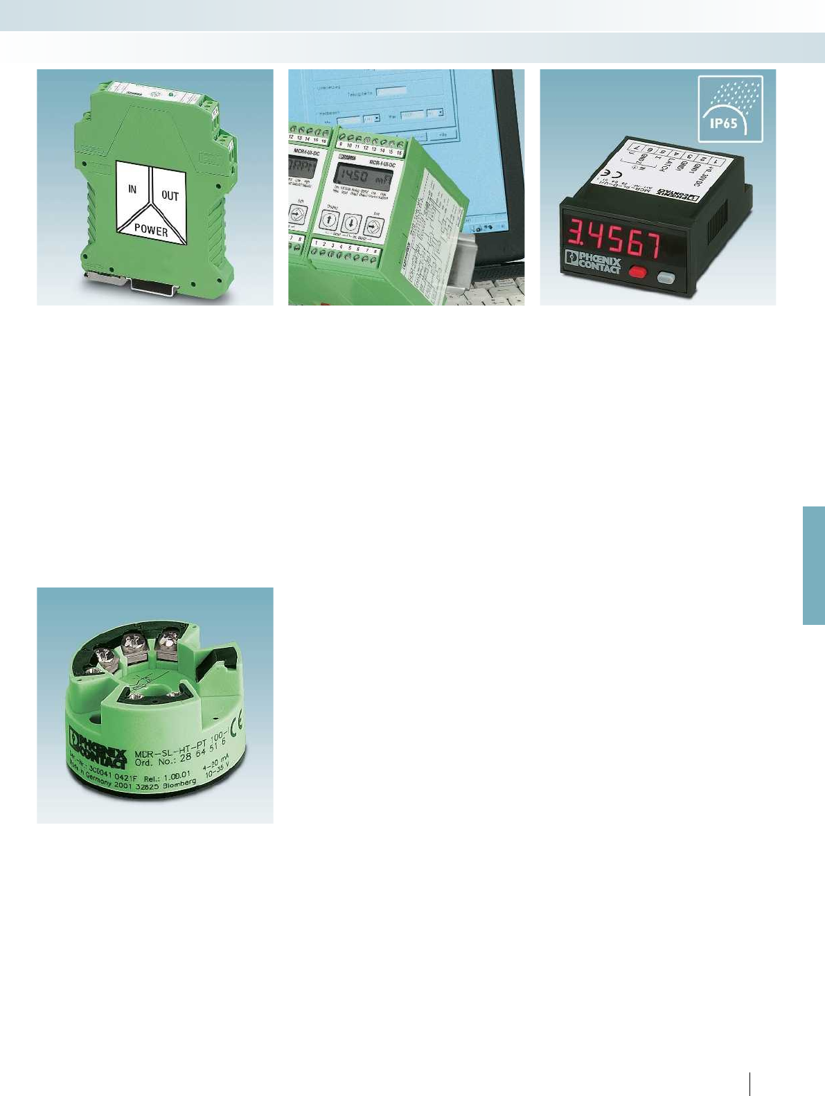
For further information and full technical data, visit phoenixcontact.net/products
129PHOENIX CONTACT
MCR technology
Signal conditioners, head transducers, and process indicators - MCR Analog
– High operational reliability in the event of
disturbances, thanks to electrical isolation
– Configuration via software, DIP switches
or display keypad
– Process indicators including mounting
accessories and IP65 protection
– Convenient reading of process indicators
thanks to LED 7-segment display
– Process indicator programming without
software
– Convert temperature signals directly into
standard analog signals with temperature
head transmitters
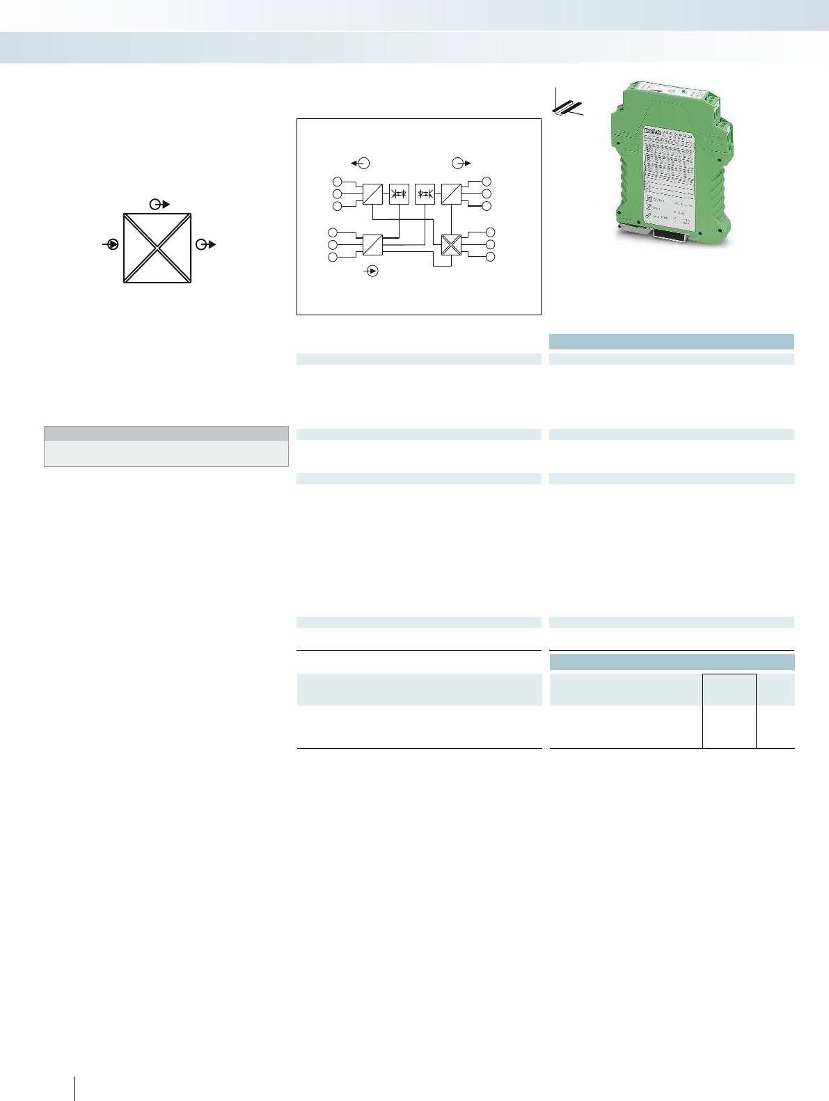
POWER
U,I U,I OUT2
IN
U,I
OUT1
5
D
1
3
OUTI2
GND 2
IN
OUT
7
8
9
OUTI1
OUTU1
GND 1
10
11
12
+24V DC
GND 4
GND 4
2OUTU2
A
A
D
D
4
6
IN I
GND 3
IN U
A
OUT
Ex:
Housing width 17.5 mm
Technical data
Input data U input I input
Input signal 0 V ... 12 V (freely selectable in
0.1 V increments)
0 mA ... 24 mA (freely selectable
in 0.1 mA increments)
Measuring range span min. 4 V min. 8 mA
Maximum input signal 30 V 50 mA
Input resistance 200 k50
Output data U output I output
Output signal (configurable using the DIP switch) refer to the order key refer to the order key
Maximum output signal 15 V 35 mA
Load R
B
10 k 600
General data
Supply voltage U
B
20 V DC ... 30 V DC
Current consumption < 25 mA
Maximum transmission error 0.15 % (of final value), typ. 0.05 % (of final value)
Temperature coefficient < 0.015 %/K, typ. 0.0075 %/K
Test voltage, input/output/supply 1.5 kV (50 Hz, 1 min.)
Degree of protection IP20
Ambient temperature (operation) -25 °C ... 55 °C
Housing material Polyamide PA non-reinforced
Dimensions W / H / D 17.5 / 99 / 114.5 mm
Screw connection solid / stranded / AWG 0.2 ... 2.5 mm² / 0.2 ... 2.5 mm² / 24 - 14
EMC note Class A product, see page 625
Conformance / approvals
Conformance CE-compliant
UL, USA / Canada Class I, Div. 2, Groups A, B, C, D or Non-Hazardous Locations
Ordering data
Description Type Order No. Pcs. /
Pkt.
MCR signal multiplier, for multiplication and electrical isolation of
analog signals
Order configuration MCR-FL-C-UI-2UI-DCI 2814854 1
Standard configuration MCR-FL-C-UI-2UI-DCI-NC 2814867 1
130
PHOENIX CONTACT
– 4-way isolation
– Calibrated reversible input and output
signals
Notes:
To order a product with an order configuration, enter the required
configuration by referring to the adjacent order key.
Analog IN/Analog OUT,
signal multiplier
MCR technology
Signal conditioners, head transducers, and process indicators - MCR Analog
DW
H
With freely configurable input and two outputs
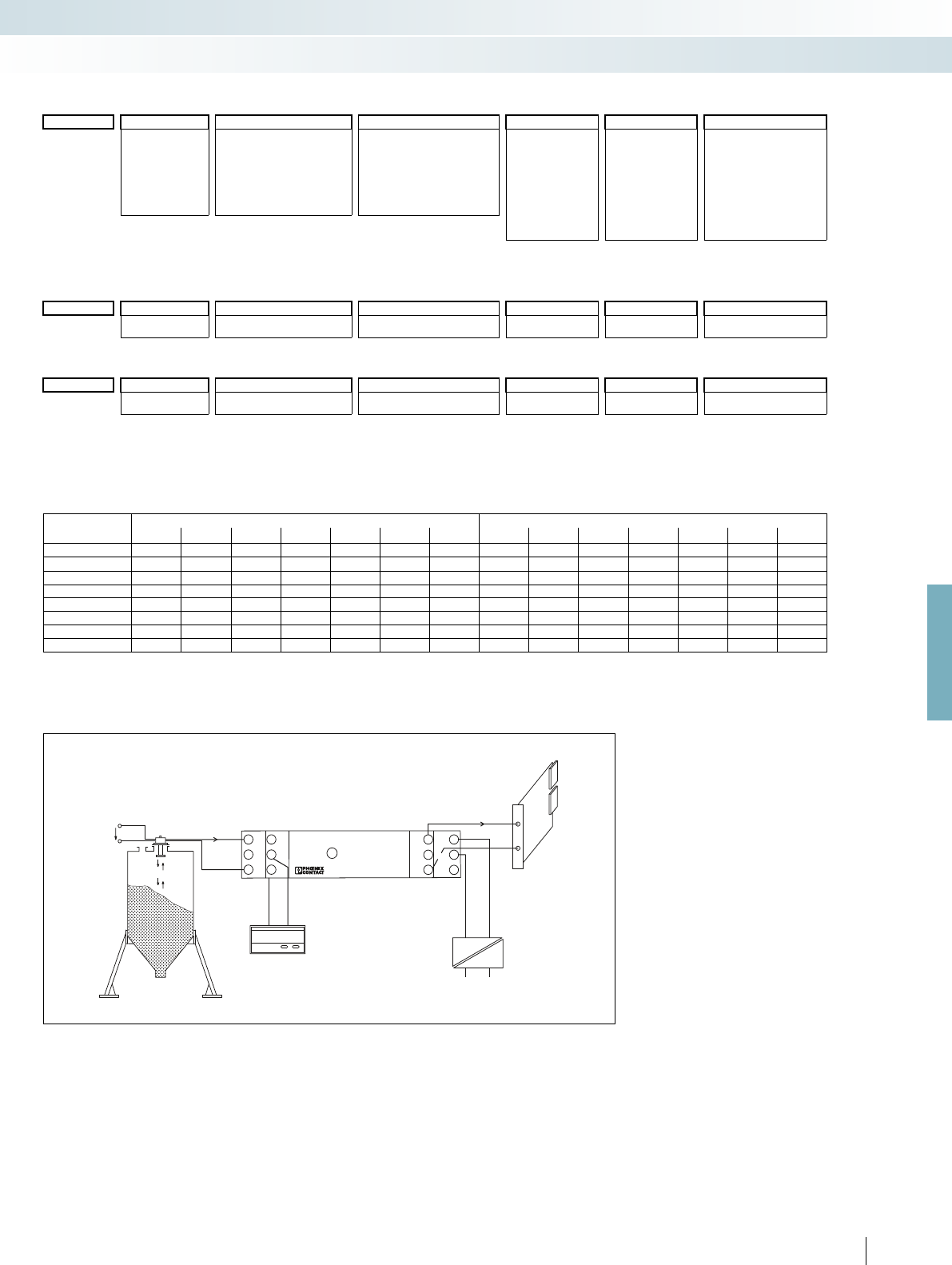
24V 0...20mA1
2
3
I2
U2
MCR-FL-C-UI-2UI-DCI
POWER
OUT1
I
U1
GND 1
7
8
9
10
11
12
POWER
+24V
GND 4
GND 4
24V
0...20mA
3
15m
0...10V
OUT2
4
5
6
I
U
GND 3
IN
GND 2
For further information and full technical data, visit phoenixcontact.net/products
131PHOENIX CONTACT
Order key for MCR-FL-C-UI-2UI-DCI (standard configuration entered as an example)
Combination table for input and output signals that can be set via DIP switches
Application example: level measurement with subsequent signal multiplication
Order No.
Input signal (standard and special signals) Output signal (standard signals) Factory calibration
certificate (FCC)Input signal Initial value Final value Output 1 Output 2
2814854 / I / 0.0 / 20.0 / OUT01 / OUT01 / NONE
I=Current 0.0 =0.0 mA 20.0 =20.0 mA OUT01 =0...20 mA OUT01 =0...20 mA NONE =without FCC
U=Voltage I : freely selectable between
0.0 ... 24.0 mA
I : freely selectable between
0.0 ... 24.0 mA
OUT02 =4...20 mA OUT02 =4...20 mA YES =with FCC (a fee
is charged)
OUT03 =0...10 V OUT03 =0...10 V
OUT04 =2...10 V OUT04 =2...10 V
U : freely selectable between
0.0 ... 12.0 V
U : freely selectable between
0.0 ... 12.0 V
OUT05 =0...5 V OUT05 =0...5 V YESPLUS =FCC with
5 measuring
points (a fee is
charged)
OUT06 =1...5 V OUT06 =1...5 V
OUT16 =0...10 mA OUT16 =0...10 mA
8.0 mA/4.0 V min. measuring range span
0.1 mA/0.1 V increment
Ordering examples: Input signal (standard and special signals) Output signal (standard signals) Factory calibration
certificate (FCC)
Initial value Final value Output 1 Output 2
2814854 / I / 5.3 / 13.3 / OUT01 / OUT01 / NONE
I=Current I =5.3 mA I =13.3 mA OUT01 =0...20 mA OUT01 =0...20 mA NONE =without FCC
8.0 mA measuring range span, i.e., can be ordered.
2814854 / U / 7.8 / 11.8 / OUT01 / OUT03 / NONE
U=Voltage U =7.8 V U =11.8 V OUT01 =0...20 mA OUT03 =0...10 V NONE =without FCC
4.0 V measuring range span, i.e., can be ordered.
Output 1 Output 2
Input 0...20 mA 4...20 mA 0...10 mA 0...10 V 0...5 V 1...5 V 2...10 V 0...20 mA 4...20 mA 0...10 mA 0...10 V 0...5 V 1...5 V 2...10 V
0...20 mA xxxxxxxxxxxxxx
4...20 mA xxxxxxxxxxxxxx
0...10 mA xxxxxxxxxxxxxx
2...10 mA xxxxxxxxxxxxxx
0...10 V xxxxxxxxxxxxxx
2...10 V xxxxxxxxxxxxxx
0...5 V xxxxxxxxxxxxxx
1...5 V xxxxxxxxxxxxxx
Level sensor
Controller
Mains voltage
MCR technology
Signal conditioners, head transducers, and process indicators - MCR Analog
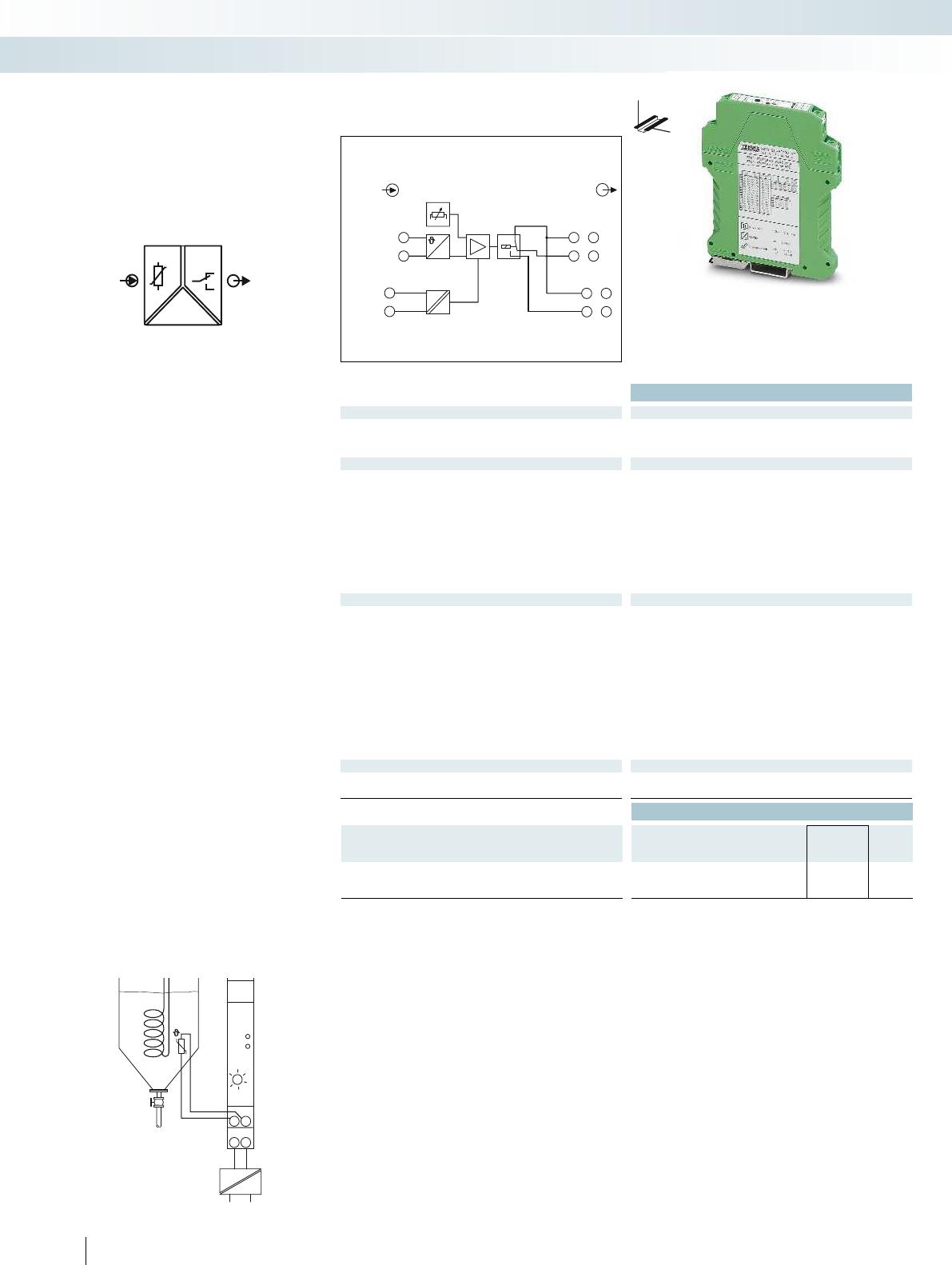
Pt 100
MCR-SL-PT100-SP
SP
ERROR
SETPOINT
010
5040
30
K
20
12
IN
+24V
GND
34
24V
OUT
IN
POWER
PT100
15
6
7
8
2
3
4
IN OUT
U
DC
DC
SETPOINT
Pt 100
+24 VDC
GND
11
12
11
14
Housing width 12.5 mm
Technical data
Input data
Resistance thermometers Pt 100 (IEC 60751/EN 60751): 2-wire
Temperature range -100 °C ... 700 °C
Sensor input current approx. 1 mA
Switching output Relay output
Contact type 1 PDT
Contact material AgSnO, hard gold-plated
Max. switching current 50 mA (for gold layer, 30 V AC/ 36 V DC)
2 A (in case of a destroyed gold layer, 250 V AC)
Operate delay time approx. 6 ms
Off delay time approx. 200 ms
Switching hysteresis Adjustable using DIP switches (0.5 K, 2 K, 3 K, 5 K)
Error/status indicator Red LED (short-circuit/open circuit) / Yellow LED (relay active)
General data
Supply voltage U
B
20 V DC ... 30 V DC
Current consumption < 30 mA
Linearity error < 0.1 %
Setting accuracy < 1 %, typ. < 0.5 %
Temperature coefficient < 0.01 %/K, typ. 0.005 %/K
Test voltage, input/output/supply 1.5 kV (50 Hz, 1 min.)
Ambient temperature (operation) -20 °C ... 65 °C
Mounting any
Housing material Polyamide PA non-reinforced
Dimensions W / H / D 12.5 / 99 / 114.5 mm
Screw connection solid / stranded / AWG 0.2 ... 2.5 mm² / 0.2 ... 2.5 mm² / 24 - 14
EMC note Class A product, see page 625
Conformance / approvals
Conformance CE-compliant
UL, USA / Canada UL 508 Recognized
Ordering data
Description Type Order No. Pcs. /
Pkt.
MCR temperature relay, for Pt 100 in 2-wire system
MCR-SL-PT100-SP 2814948 1
132
PHOENIX CONTACT
– Switching point in the temperature range
from -100°C ... +700°C freely selectable
– Changeover relay output
– Electrically isolated
– Adjustable switch hysteresis
Temperature,
temperature relay
Application example - Temperature control of a heated medium
1 = mains voltage
MCR technology
Signal conditioners, head transducers, and process indicators - MCR Analog
DW
H
For Pt 100

IPOWER
IN
OUT
DC
DA
D
DC
OUTI
IN
POWER
6
5
IN OUT
-
+
1
2
3
4
C
For further information and full technical data, visit phoenixcontact.net/products
Ex:
Housing width 12.5 mm
Technical data
Input data
Resistance thermometers
Pt, Ni (100, 500, 1000); minimum measuring range 10 K : 2, 3, 4-wire
Thermocouple sensors
B, C, D, E, J, K, L, N, R, S, T, U; minimum measuring range 50 K/500 K
Resistor
Resistance-type sensor from 10 to 400 and from 10 to 2000 ;
minimum measuring range 10 /100
Voltage -10 mV ... 100 mV (min. measuring range 5 mV)
Output data
Output signal 4 ... 20 mA / 20 ... 4 mA
Load R
B
Max (V
supply
-12 V) / 0.023 A (current output)
Output signal with short-circuit 3.6 mA or 21 mA (adjustable, not for thermocouples)
Output signal with open circuit 3.6 mA or 21 mA (adjustable)
Measuring range overrange / underrange 20.5 mA / 3.8 mA (linear increase/decrease)
General data
Supply voltage U
B
12 V DC ... 35 V DC
Current consumption < 3.5 mA
Transmission error Resistance thermometers
0.2 K (Pt 100, Ni 100), 0.5 K (Pt 500, Ni 500), 0.3 K (Pt 1000, Ni 1000)
Thermocouple sensors Type 0.5 K (K, J, T, E, L, U), 1.0 K (N, C, D), 2.0 K (S, B, R)
Resistance-type sensors ± 0.1 (10...400 ), ± 1.5 (10...2000 )
Voltage sensor ± 20 µV (-10...100 mV)
Step response (10-90%) < 2 s
Pickup delay 4 s
Test voltage input/output 2 kV (50 Hz, 1 min.)
Degree of protection IP20
Ambient temperature (operation) -40 °C ... 85 °C
Mounting any
Housing material Polyamide PA non-reinforced
Dimensions W / H / D 12.5 / 99 / 114.5 mm
Screw connection solid / stranded / AWG 0.2 ... 2.5 mm² / 0.2 ... 2.5 mm² / 24 - 14
Conformance / approvals
Conformance CE-compliant
UL, USA / Canada Class I, Div. 2, Groups A, B, C, D
Ordering data
Description Type Order No. Pcs. /
Pkt.
MCR temperature transducer, loop-powered
for resistance thermometers, thermocouples, resistance-type and
voltage sensors
MCR-FL-T-LP-I 2864561 1
Accessories
Software adapter cable, 2.4 m in length, with USB connection,
for programming MCR-...-LP-... and MCR-...-HT-... modules
MCR-PAC-T-USB 2309000 1
133
PHOENIX CONTACT
– Output loop-powered temperature
transducer
– Freely configurable
– Software available free of charge on the
Internet
Notes:
The devices are supplied with the standard configuration:
Pt 100 sensor, measuring range 0 ... 100°C, 3-wire connection.
The configuration software can be downloaded from the Internet:
phoenixcontact.net/products.
Temperature,
temperature transducer
MCR technology
Signal conditioners, head transducers, and process indicators - MCR Analog
DW
H
Loop-powered,
programmable
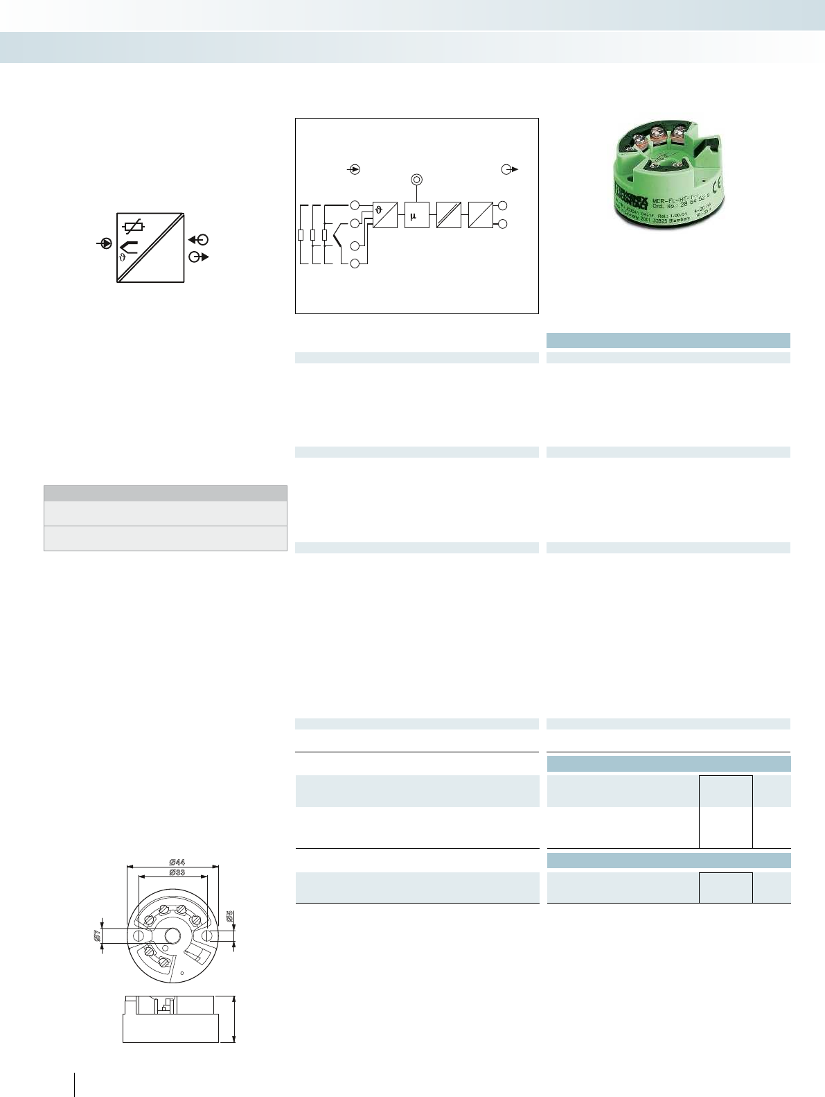
21
3
4
5
6
2
1
∅33
∅44
∅5
∅7
IPOWER
IN
OUT
3
4
6
DC
DA
D
DC 2
1
5
IN OUT
C
OUTI
IN
POWER
Ex:
Technical data
Input data
Resistance thermometers
Pt, Ni (100, 500, 1000); minimum measuring range 10 K : 2, 3, 4-wire
Thermocouple sensors
B, C, D, E, J, K, L, N, R, S, T, U; minimum measuring range 50 K/500 K
Resistor
Resistance-type sensor from 10 to 400 and from 10 to 2000 ;
minimum measuring range 10 /100
Voltage -10 mV ... 75 mV (min. measuring range 5 mV)
Output data
Output signal 4 ... 20 mA / 20 ... 4 mA
Load R
B
Max (V
supply
- 8 V) / 0.025 A (current output)
Output signal with short-circuit 3.6 mA or 21 mA (adjustable, not for thermocouples)
Output signal with open circuit 3.6 mA or 21 mA (adjustable)
Measuring range overrange / underrange 20.5 mA / 3.8 mA (linear increase/decrease)
General data
Supply voltage U
B
8 V DC ... 35 V DC
Current consumption < 3.5 mA
Transmission error Resistance thermometers
0.2 K (Pt 100, Ni 100), 0.5 K (Pt 500, Ni 500), 0.3 K (Pt 1000, Ni 1000)
Thermocouple sensors Type 0.5 K (K, J, T, E, L, U), 1.0 K (N, C, D), 2.0 K (S, B, R)
Resistance-type sensors ± 0.1 (10...400 ), ± 1.5 (10...2000 )
Voltage sensor ± 20 µV (-10...100 mV)
Step response (10-90%) < 2 s
Pickup delay 6 s
Test voltage input/output 2 kV (50 Hz, 1 min.)
Degree of protection IP00, IP66 (integrated in the connecting head)
Ambient temperature (operation) -40 °C ... 85 °C
Mounting any
Housing material Polycarbonate, PC
Screw connection solid / stranded / AWG 0.2 ... 1.75 mm² / 0.2 ... 1.75 mm² / 24 - 15
Conformance / approvals
Conformance CE-compliant
UL, USA / Canada Class I, Div. 2, Groups A, B, C, D
Ordering data
Description Type Order No. Pcs. /
Pkt.
MCR temperature head transmitter, loop-powered
for resistance thermometers, thermocouples, resistance-type and
voltage sensors
MCR-FL-HT-T-I 2864529 1
Accessories
Software adapter cable, 2.4 m in length, with USB connection,
for programming MCR-...-LP-... and MCR-...-HT-... modules
MCR-PAC-T-USB 2309000 1
134
PHOENIX CONTACT
– Output loop-powered temperature head
transmitter
– Freely configurable
– Software available free of charge on the
Internet
– For mounting in the connecting head,
form B
Notes:
The devices are supplied with the standard configuration:
Pt 100 sensor, measuring range 0 ... 100°C, 3-wire connection.
The configuration software can be downloaded from the Internet:
phoenixcontact.net/products.
Temperature,
temperature head transmitter
MCR technology
Signal conditioners, head transducers, and process indicators - MCR Analog
Loop-powered,
programmable
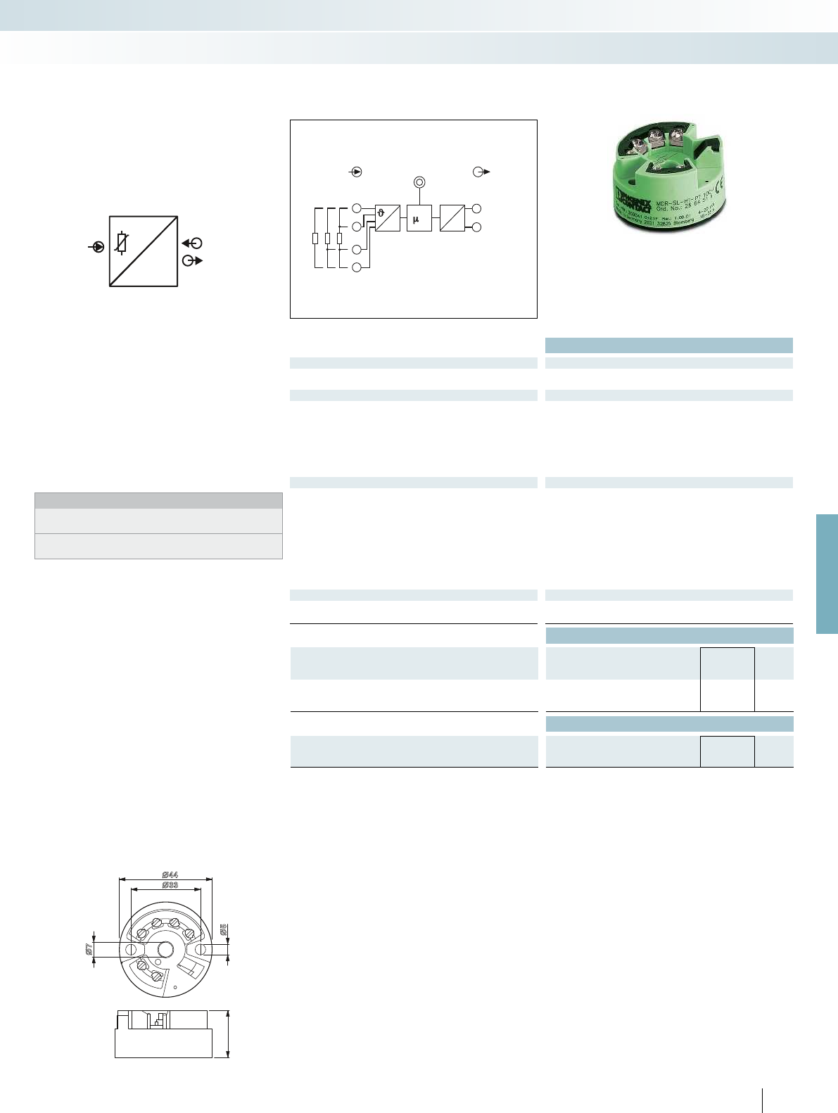
21
3
4
5
6
2
1
∅33
∅44
∅5
∅7
IN I
PT100
POWER
OUT
3
4
6
DA
D
2
1
5
IN OUT
C
OUTI
IN
POWER
For further information and full technical data, visit phoenixcontact.net/products
Ex:
Technical data
Input data
Resistance thermometers Pt 100; minimum measuring range 10 K : 2, 3, 4-wire
Output data
Output signal 4 ... 20 mA / 20 ... 4 mA
Load R
B
Max (V
supply
- 10 V) / 0.023 A (current output)
Output signal with short-circuit 3.6 mA or 21 mA (adjustable)
Output signal with open circuit 3.6 mA or 21 mA (adjustable)
Measuring range overrange / underrange 20.5 mA / 3.8 mA (linear increase/decrease)
General data
Supply voltage U
B
10 V DC ... 35 V DC
Current consumption < 3.5 mA
Transmission error Resistance thermometers 0.2 K
Step response (10-90%) < 2 s
Pickup delay 4 s
Degree of protection IP00, IP54 (integrated in the connecting head)
Ambient temperature (operation) -40 °C ... 85 °C
Mounting any
Housing material Polycarbonate, PC
Conformance / approvals
Conformance CE-compliant
UL, USA / Canada Class I, Div. 2, Groups A, B, C, D
Ordering data
Description Type Order No. Pcs. /
Pkt.
MCR temperature head transmitter, loop-powered
for Pt 100 resistance thermometer MCR-SL-HT-PT 100-I 2864516 1
Accessories
Software adapter cable, 2.4 m in length, with USB connection,
for programming MCR-...-LP-... and MCR-...-HT-... modules
MCR-PAC-T-USB 2309000 1
135
PHOENIX CONTACT
– Output loop-powered temperature head
transmitter for Pt 100 sensors
– Freely configurable
– Software available free of charge on the
Internet
– For mounting in the connecting head,
form B
Notes:
The devices are supplied with the standard configuration:
Pt 100 sensor, measuring range 0 ... 100°C, 3-wire connection.
The configuration software can be downloaded from the Internet:
phoenixcontact.net/products.
Temperature,
temperature head transmitter
MCR technology
Signal conditioners, head transducers, and process indicators - MCR Analog
Loop-powered,
programmable
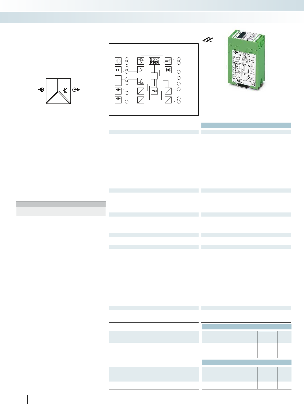
POWER
f,U,I
U,I
OUT
IN
m
NPN
PNP
Dry
Contact
0-10V
0-20mA
A
D
A
D
C
A
D
A
D
DC
DC
DC
9
1
2
3
4
5
6
7
8
+8,2 V
Namur
IN
fin
GND 1
NPN
PNP
+15 V
Uin
10
11
12
13
14
15
16
+24 V
GND
SW
GND
NC
I OUT
U OUT
GND 2
Iin
Ex:
Housing width 45 mm
Technical data
Input data Frequency input
Frequency range 0.1 Hz ... 120 kHz
Input sources NPN/PNP transistor outputs
NAMUR initiators
Floating relay contact (dry contact)
Frequency generator
Transducer supply approx. 15 V DC / max. 25 mA (constant)
Signal level 2 V
PP
(in case of square 0.1 Hz ... 120 kHz)
2 V
PP
(in case of sine 8 Hz ... 120 kHz)
13 V
PP
(in case of sine 1 Hz ... 120 kHz)
Maximum input signal 30 V (incl. DC voltage)
Signal form any
Pulse length 1 µs
Resolution > 12 bit
Signal conversion time 32 ms
Input data Signal conditioner function
Input signal 0 V ... 10 V (freely adjustable) 0 mA ... 20 mA (freely
adjustable)
Maximum input signal 12 V 24 mA
Input resistance 95 k200
Resolution 14 bit (full-scale) 14 bit (full-scale)
Output data U output I output
Output signal 0 ... 5 V / 0 ... 10 V 0 ... 20 mA
Maximum output signal 12.5 V 25 mA
Load R
B
500 500
Ripple < 20 mV
PP
Switching output Transistor output, pnp
Switches supply voltage to terminal block SW,
can carry a load of 100 mA, not protected against short-circuit
General data
Supply voltage U
B
20 V DC ... 30 V DC
Current consumption < 60 mA (without load, without switching output)
Maximum transmission error 0.15 % (of measured value), typ. 0.1 %
Temperature coefficient 0.015 %/K, typ. 0.01 %/K
ZERO / SPAN adjustment ± 25 % / ± 25 %
Step response (10-90%) < 25 ms
Test voltage, input/output/supply 1.5 kV (50 Hz, 1 min.)
Ambient temperature (operation) -20 °C ... 65 °C (for specified data)
Status indication LC display
Operating elements Membrane keypad with 3 keys and LCD display
Housing material ASA-PC (V0)
Dimensions W / H / D 45 / 75 / 110 mm
Screw connection solid / stranded / AWG 0.2 ... 2.5 mm² / 0.2 ... 2.5 mm² / 24 - 14
EMC note Class A product, see page 625
Conformance / approvals
Conformance CE-compliant
UL, USA / Canada Class I, Div. 2, Groups A, B, C, D or Non-Hazardous Locations
GL Germanischer Lloyd
Ordering data
Description Type Order No. Pcs. /
Pkt.
MCR frequency transducer, for conversion of frequencies into
analog signals 0(4)...20 mA, 0...(5)10 V and their inverse signals
MCR-F-UI-DC 2814605 1
Accessories
Software adapter cable (stereo jack plug/25-pos. D-SUB),
1.2 m long, for programming MCR-T-..., MCR-S-..., and
MCR-F-... modules
MCR-TTL-RS232-E 2814388 1
Connecting cable,
D-9-SUB to USB, with adapter D-9-SUB to D-25-SUB
CM-KBL-RS232/USB 2881078 1
136
PHOENIX CONTACT
– Frequencies up to 120 kHz
– For NAMUR sensors, floating contacts,
frequency generators, and NPN/PNP
transistor outputs
– Analog and switching output
– 3-way isolation
– Configurable via membrane keypad or
software
– Software available free of charge on the
Internet
– Display of input or output signal
Notes:
The configuration software can be downloaded from the Internet:
phoenixcontact.net/products.
Frequency,
frequency transducer
MCR technology
Signal conditioners, head transducers, and process indicators - MCR Analog
DW
H
Frequencies up to 120 kHz,
configurable

MCR-f-UI-DC
1
3
4
6
7
8
2
5
+8,2 V
f IN
GND 1
+15 V
U IN
I IN
NAMUR
IN
NPN
PNP
bn
bu
bn
bu
MCR-f-UI-DC
1
3
4
6
7
8
2
5
+8,2 V
f IN
GND 1
+15 V
U IN
I IN
NAMUR
IN
NPN
PNP
MCR-f-UI-DC
1
3
4
6
7
8
2
5
+8,2 V
f IN
GND 1
+15 V
U IN
I IN
NAMUR
IN
NPN
PNP
bn
bu
bk
pnp
MCR-f-UI-DC
1
3
4
6
7
8
2
5
+8,2 V
f IN
GND 1
+15 V
U IN
I IN
NAMUR
IN
NPN
PNP
bu
bn
bk
npn
MCR-f-UI-DC
1
3
4
6
7
8
2
5
+8,2 V
f IN
GND 1
+15 V
U IN
I IN
NAMUR
IN
NPN
PNP
bk
bu
bn
MCR-f-UI-DC
1
3
4
6
7
8
2
5
+8,2 V
f IN
GND 1
+15 V
U IN
I IN
NAMUR
IN
NPN
PNP
bk
bn
bu
MCR-f-UI-DC
1
3
4
6
7
8
2
5
+8,2 V
f IN
GND 1
+15 V
U IN
I IN
NAMUR
IN
NPN
PNP
bn
bu
bk
wh
pnp
MCR-f-UI-DC
1
3
4
6
7
8
2
5
+8,2 V
f IN
GND 1
+15 V
U IN
I IN
NAMUR
IN
NPN
PNP
bu
bn
bk
wh
npn
MCR-f-UI-DC
1
3
4
6
7
8
2
5
+8,2 V
f IN
GND 1
+15 V
U IN
I IN
NAMUR
IN
NPN
PNP
U= 5-30 V DC
B
U= 0 V DC
B
MCR-f-UI-DC
1
3
4
6
7
8
2
5
+8,2 V
f IN
GND 1
+15 V
U IN
I IN
NAMUR
IN
NPN
PNP
15 V/25 mA
MCR-f-UI-DC
1
3
4
6
7
8
2
5
+8,2 V
f IN
GND 1
+15 V
U IN
I IN
NAMUR
IN
NPN
PNP
U= 24 V DC
B
U= 0 V
B
K1, K2 K0
K1 K2 K0,
MCR-f-UI-DC
1
3
4
6
7
8
2
5
+8,2 V
f IN
GND 1
+15 V
U IN
I IN
NAMUR
IN
NPN
PNP
15 V/25 mA
K1, K2 K0
K1 K2 K0,
24 V
NPN
PNP
Dry
Contact
0-10V
0-20 mA
A
D
A
D
μC
DC
DC
DC
D
A
D
A
2
1
3
4
5
6
7
8
+8,2V
Namur
IN
F in
GND1
NPN
PNP
+15 V
Uin
I in
9
10
11
12
13
14
15
16
+24 V
GND
SW
GND
NC
IOUT
U OUT
GND2
24 V
NPN
PNP
Dry
Contact
0-10V
0-20 mA
A
D
A
D
μC
DC
DC
DC
D
A
D
A
2
1
3
4
5
6
7
8
+8,2V
Namur
IN
F in
GND1
NPN
PNP
+15 V
Uin
I in
9
10
11
12
13
14
15
16
+24 V
GND
SW
GND
NC
IOUT
U OUT
GND2
For further information and full technical data, visit phoenixcontact.net/products
137PHOENIX CONTACT
Example connections for common frequency transmitters
2-wire DC (mechanical contact)
Alternatively instead
of terminal block ⑥
terminal block ①
possible.
2-wire DC NAMUR sensor
3-wire DC
• With PNP transistor output
• With NPN transistor output
3-wire DC
• PNP transistor with pull-down resistor
• NPN transistor with pull-up resistor
4-wire DC
• With PNP transistor output
• With NPN transistor output
Incremental rotary transducer with push-pull:
• External supply of signal generator
• Supply of signal generator from the module
The external supply can
also be tapped from
terminal blocks ⑨
+24VDC and ⑩ GND.
3-way isolation is then
no longer provided.
Incremental rotary transducer with HTL logic:
• External supply of signal generator
• Supply of signal generator from the module
NAMUR
actuated: 1.2 mA
not actuated: 2.1 mA
Controller
Mains voltage
Application example:
Speed detection of a drive
Application examples:
The MCR-F-UI-DC frequency
transducer converts the pulse signal into a
standard analog signal, which, for example,
corresponds to the number of bottles filling
systems recorded during a specified time
unit.
For speed detection, it is possible to
enter the measuring range in revolutions
per minute (RPM) and display the current
measured value on the unit.
The frequency transducer has an
automatic measuring range selection
function (autorange) to ensure the best
possible resolution. This permits response
times to be reduced to a minimum and the
measured value is optimally adapted to the
input value.
NAMUR sensor
Controller
Mains voltage
Application example:
Flow measurement
MCR technology
Signal conditioners, head transducers, and process indicators - MCR Analog
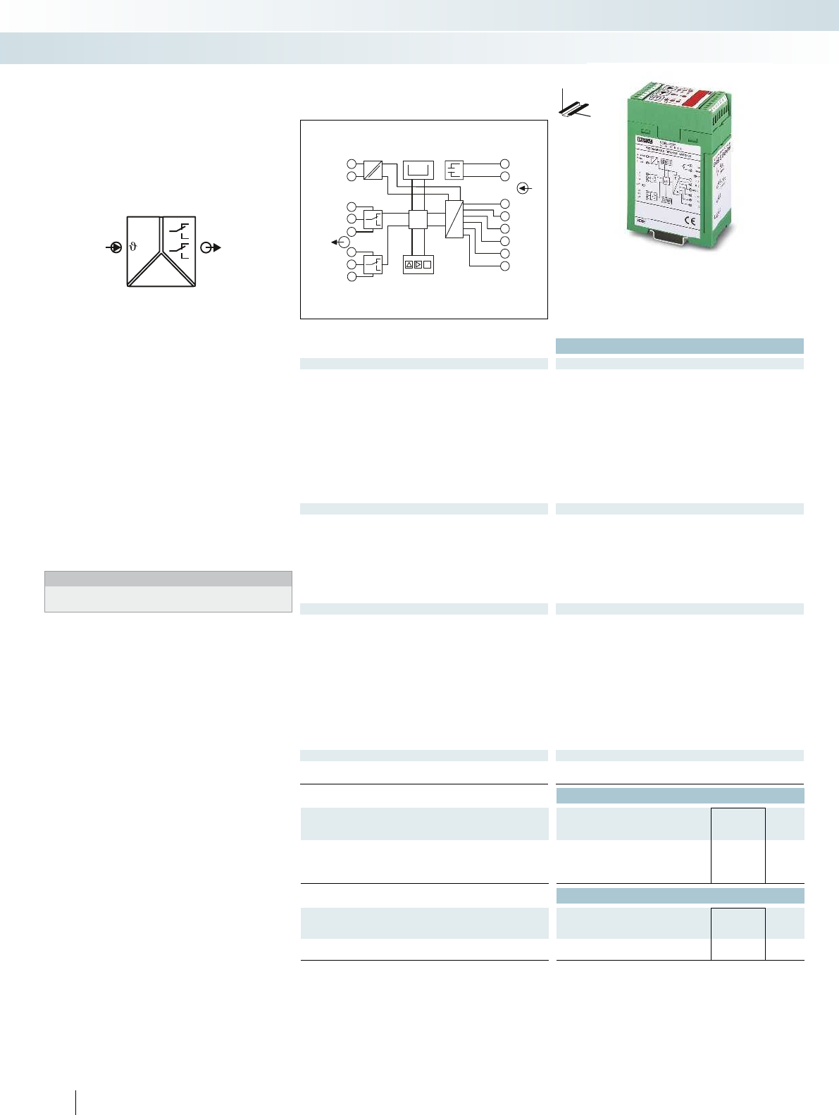
OUT
IN
POWER
,U,I,R
μC
-
-
E
0000
D
A
1
2
3
4
5
6
7
8
(+)
(-)
12
11
14
22
21
24
24 VDC
GND
POWER
IN
OUT
9
10
11
12
13
14
15
16
MM
shield
I(±)
U(±)
GND (±)
U(-)
U(+)
I
Housing width 45 mm
Technical data
Input data
Input sources Resistance thermometer 2, 3 or 4-wire system
(in acc. with DIN 43760/DIN IEC 751 or SAMA RC 21-4-1966),
e.g. PT sensors, Ni sensors etc.
Thermocouple sensors (in acc. with DIN IEC 584-1/DIN 43710):
B, E, J, K, L, N, R, S, T, U
Resistance: 0 k ... 8 k (only 2-wire connection)
Current: - 30 mA...+ 30 mA
Voltage: - 30 V...+ 30 V
Measuring rate 2 Hz
Input resistance Current / voltage 50 / 200 k
Discontinuous control resolution 0.1 °C / 0.01 V / 0.01 mA / 0.1
Switching output
Contact type 2 x PDT contact, / 2 switching points each, pick-up/drop-out
(can be switched)
Contact material AgNi 0.15 + HTV (hard gold-plated)
Max. switching voltage 250 V AC
Max. switching current 2 A AC
Response delay 0 s ... 2 s (adjustable)
Mechanical service life 2 x 10
7
cycles
Error/status indicator LED display
General data
Supply voltage U
B
20 V DC ... 30 V DC
Current consumption < 60 mA
Maximum transmission error 0.1 % (of final value)
Temperature coefficient 0.01 %/K
Test voltage input/power supply 1 kV AC (50 Hz, 1 min.)
Ambient temperature (operation) -20 °C ... 65 °C
Status indication 5-position 7-segment display and LEDs
Mounting any
Housing material ABS
Dimensions W / H / D 45 / 75 / 110 mm
Screw connection solid / stranded / AWG 0.2 ... 2.5 mm² / 0.2 ... 2.5 mm² / 24 - 14
EMC note Class A product, see page 625
Conformance / approvals
Conformance CE-compliant
UL, USA / Canada cULus
Ordering data
Description Type Order No. Pcs. /
Pkt.
MCR threshold value switch, with two relay contacts
With electrically isolated input MCR-PSP-DC 2811925 1
MCR-PSP 2811912 1
Accessories
Software adapter cable (6-pos./D-SUB 25-pos.), 1.5 m in length,
for programming MCR-PSP modules
MCR-TTL-RS232 2814391 1
Connecting cable,
D-9-SUB to USB, with adapter D-9-SUB to D-25-SUB
CM-KBL-RS232/USB 2881078 1
138
PHOENIX CONTACT
– For thermocouple sensors, resistance
thermometers, and linear resistors
– For current or voltage signals
– Four independently adjustable switching
thresholds
– With or without electrical isolation of
input signals
– Configuration via membrane keypad or
software
– Software available free of charge on the
Internet
– Continuous measured value display
Notes:
The configuration software can be downloaded from the Internet:
phoenixcontact.net/products.
Threshold values
Programmable threshold value switch
MCR technology
Signal conditioners, head transducers, and process indicators - MCR Analog
DW
H
Configurable threshold value switch for
standard and temperature signals
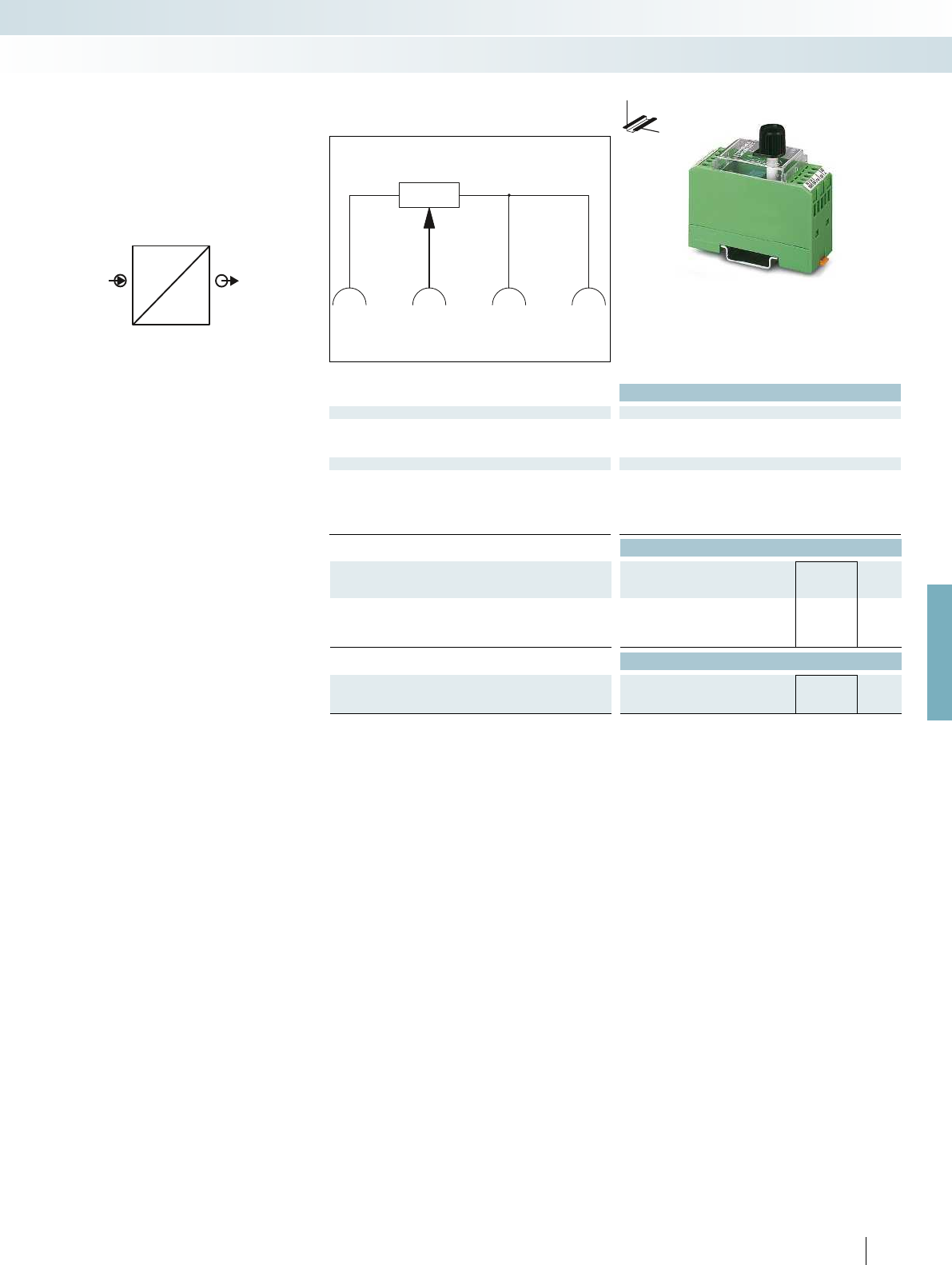
OUT
IN
U
ref
U
10VSw0V0V
For further information and full technical data, visit phoenixcontact.net/products
Housing width 30 mm
Technical data
Input data EMG 30-SP- 4K7LIN EMG 30-SP-10K LIN
Resistance value 4.7 k ±20 % 10 k ±20 %
Linearity 5 % (of final value) 5 % (of final value)
Load capacity 1 W 0.5 W
General data
Ambient temperature (operation) 0 °C ... 40 °C
Mounting any
Housing material Polycarbonate fiber reinforced PC-F
Dimensions W / H / D 30 / 75 / 68 mm
Screw connection solid / stranded / AWG 0.2 ... 4 mm² / 0.2 ... 2.5 mm² / 24 - 14
Ordering data
Description Type Order No. Pcs. /
Pkt.
Setpoint potentiometer, for individual setpoint definition
Resistance value 4.7 kEMG 30-SP- 4K7LIN 2940252 10
Resistance value 10 kEMG 30-SP-10K LIN 2942124 10
Accessories
MCR constant voltage source
MINI MCR-SL-CVS-24-5-10-NC 2902822 1
MINI MCR-SL-CVS-24-5-10-SP-NC 2902823 1
139
PHOENIX CONTACT
– For direct setpoint definition in
combination with a constant voltage
source
Accessories
Setpoint potentiometer
MCR technology
Signal conditioners, head transducers, and process indicators - MCR Analog
DW
H
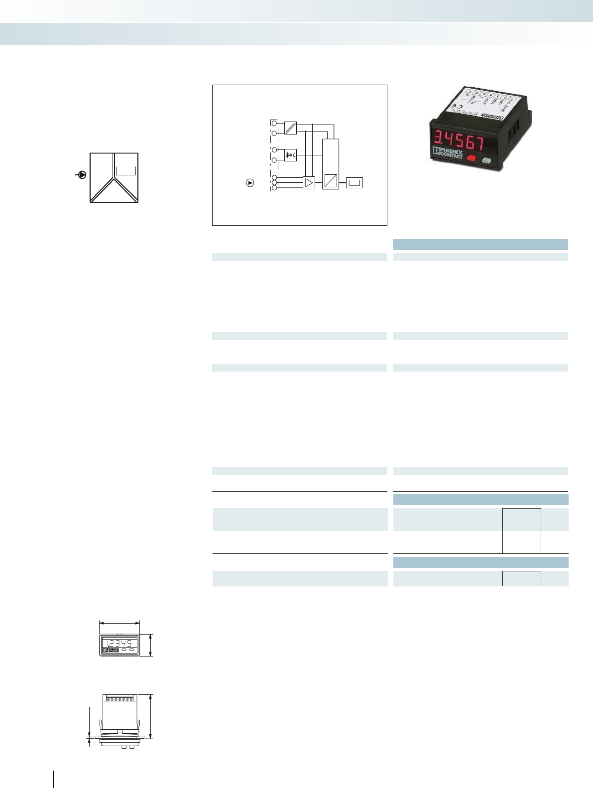
max. 19,3
59
48
24
IN
POWER
00000
U,I
μC
A
D
LATCH
GND 1
10VDC/30mA
GND 1
U
GND 2
I
0000
IN
1
2
3
4
6
5
-
-
7
Housing width 48 mm
Technical data
Input data U input I input
Input signal 0 ... 10 V 0 ... 20 mA / 4 ... 20 mA
Maximum input signal 30 V DC 50 mA
Input resistance > 1 Mapprox. 100 with 5 mA /
approx. 70 with 20 mA
Resolution 1 mV 2 µA
Measuring rate 0.5 to 2 measurements/second
Input latch signal Display stop
Switching level 1 signal ("H") 4 V DC ... 30 V DC
0 signal ("L") 0 V DC ... 2 V DC
Output data
Display 7-segment LED; 8 mm; red
Number of positions displayed 5
Accuracy < 0.1 % ±1 digit (at an ambient temperature of 20°C)
General data
Supply voltage U
B
10 V DC ... 30 V DC
Current consumption 50 mA
Mass storage EEPROM 1 mil. memory cycles or 10 years
Resolution A/D 14 bit
System hum suppression Digital filtering 50/60 Hz
Test voltage input/power supply 500 V
rms
(50/60 Hz, 1 min.)
Degree of protection IP65 from the front
Ambient temperature (operation) -10 °C ... 50 °C
Housing material Macrolon 2405
Dimensions W / H / D 48 / 24 / 68 mm
Control panel cutout 22(+0.6)x45(+0.8) mm
Screw connection solid / stranded / AWG 0.14 ... 1.5 mm² / 0.14 ... 1.5 mm² / 26 - 16
Conformance / approvals
Conformance CE-compliant
UL, USA / Canada UL 508 Recognized
Ordering data
Description Type Order No. Pcs. /
Pkt.
MCR process display, for measuring and
displaying standard signals
MCR-SL-D-U-I 2864011 1
Accessories
MCR DIN rail adapter for digital displays in a 24 x 48 mm housing MCR-SL-D-RA 2810081 1
140
PHOENIX CONTACT
– For 0 ... 10 V and 0(4) ... 20 mA standard
analog signals
– Configurable
– 5 positions displayed
– 8 mm LED, 7-segment
– Electrically isolated
– Min./max. value saved
– Latch/hold function for storing the display
value
– Display 48 x 24 mm
Analog IN,
standard signals
MCR technology
Signal conditioners, head transducers, and process indicators - MCR Analog
For standard analog signals, configurable
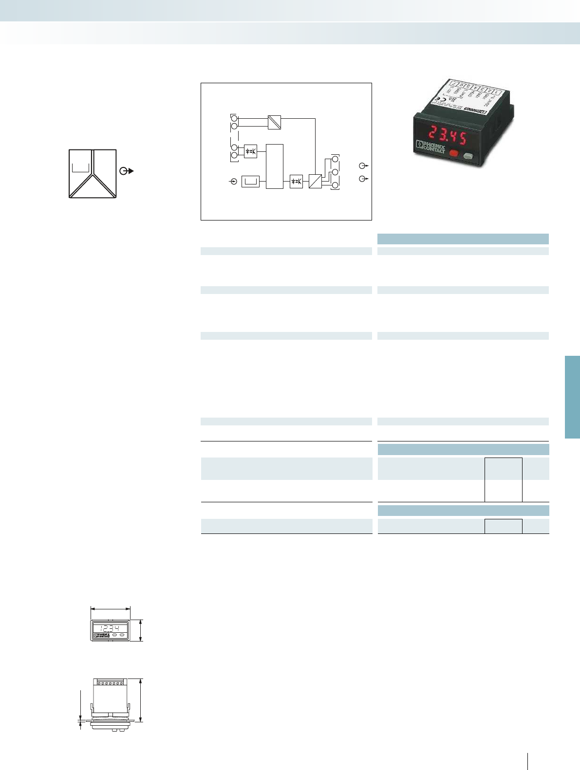
max.19,3
5924
48
OUT
POWER
Uref
Iref
0000
GND 2
0...24 mA
HOLD
0...12 V
GND 3
+10...30 V
GND 1
DC
DC
0000
µ
C
D
A
1
2
4
3
U OUT
I OUT
IN
7
6
5
For further information and full technical data, visit phoenixcontact.net/products
Housing width 48 mm
Technical data
Input data
Display 7-segment, 8 mm, red
Number of positions displayed 4
Switching level 1 signal ("H") 4 V DC ... 30 V DC
0 signal ("L") 0 V DC ... 2 V DC
Output data U output I output
Output signal 0 ... 12 V 0 ... 24 mA
Length of step 10 mV 10 µA
Load R
B
2 k 500 (up to 20 mA)
400 (> 20 mA)
Ripple 10 mV
PP
General data
Supply voltage U
B
10 V DC ... 30 V DC
Power consumption 1 W (with 24 mA/12 V)
Maximum transmission error < 0.2 % ((full-scale) at rated voltage)
Test voltage output/power supply 500 V AC (50 Hz, 1 min.)
Degree of protection IP65 from the front
Ambient temperature (operation) -20 °C ... 65 °C
Housing material Macrolon 2405
Dimensions W / H / D 48 / 24 / 68 mm
Control panel cutout 45(+0.6)x22.2(+0.3) mm
Screw connection solid / stranded / AWG 0.14 ... 1.5 mm² / 0.14 ... 1.5 mm² / 26 - 16
Conformance / approvals
Conformance CE-compliant
UL, USA / Canada UL 508 Recognized
Ordering data
Description Type Order No. Pcs. /
Pkt.
MCR digital setpoint adjuster, for presetting current and
voltage signals
MCR-SL-D-SPA-UI 2710314 1
Accessories
MCR DIN rail adapter for digital displays in a 24 x 48 mm housing MCR-SL-D-RA 2810081 1
141
PHOENIX CONTACT
– Manual setpoint definition with increment
setting
– Manual setpoint definition via direct input
– Automatic setpoint definition with hold
function and 20 support points
– Flexibly adjustable 0 ... 12 V or 0 ... 24 mA
signal ranges
– Data backup in case of a power failure
– Display value parameterization
– Electrical isolation between output and
supply
Analog OUT,
setpoint adjuster
MCR technology
Signal conditioners, head transducers, and process indicators - MCR Analog
With manual and automatic ramp function
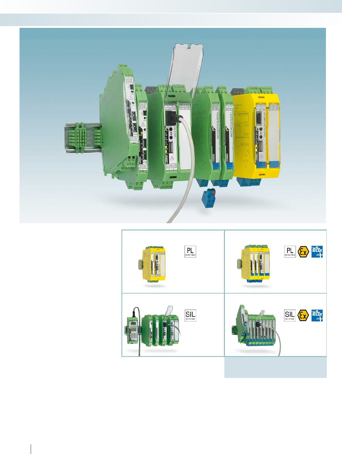
142
PHOENIX CONTACT
Signal conditioner
with PL functional
safety
MACX Safety
Signal conditioner
with SIL functional
safety
MACX Analog
Ex i signal conditioner
with PL functional
safety
MACX Safety Ex
Ex i signal conditioner
with SIL functional
safety
MACX Analog Ex
Machine building/process industry
EN ISO 13849-1
EN 62061
IEC 61508
EN 60511
Process industry
IEC 61508
EN 60511
Intrinsic safety
ATEX/IECEx
EN 60079-11
No intrinsic safety
MCR technology
Signal conditioners with functional safety and explosion protection - the MACX ranges

For further information and full technical data, visit phoenixcontact.net/products
143PHOENIX CONTACT
MCR technology
Signal conditioners with functional safety and explosion protection - the MACX ranges
Reliable and safe
Maximum safety for your machines and
systems.
Phoenix Contact meets the requirements
of functional safety according to IEC 61508
in a standardized development process. We
take measures for fault avoidance and fault
control into consideration, from the
development and production of a device up
to device operation.
Tested quality and safety
Independent test centers are involved
throughout the entire development cycle
and audit the measures as part of a full
assessment. The certificates, technical
information, and the safety manual are
available for you to download.
A solution for every type of signal
Safely isolate, condition, filter, and amplify:
MACX Analog offers comprehensive
solutions for analog signal processing.
Analog signals with performance level
MACX Safety is also equipped with
performance level PL d. This means that you
can integrate analog signals easily into your
safety application according to the
Machinery Directive.
Maximum explosion protection
Highly compact and leading technology:
with an overall width of just 12.5 mm,
MACX Analog Ex offers single and two-
channel signal isolators for intrinsically safe
circuits in the hazardous area.
Analog Ex i signals with performance
level
Also for intrinsically safe circuits in the
hazardous area: in addition to PL d. MACX
Safety Ex also has ATEX and IECEx
approvals.
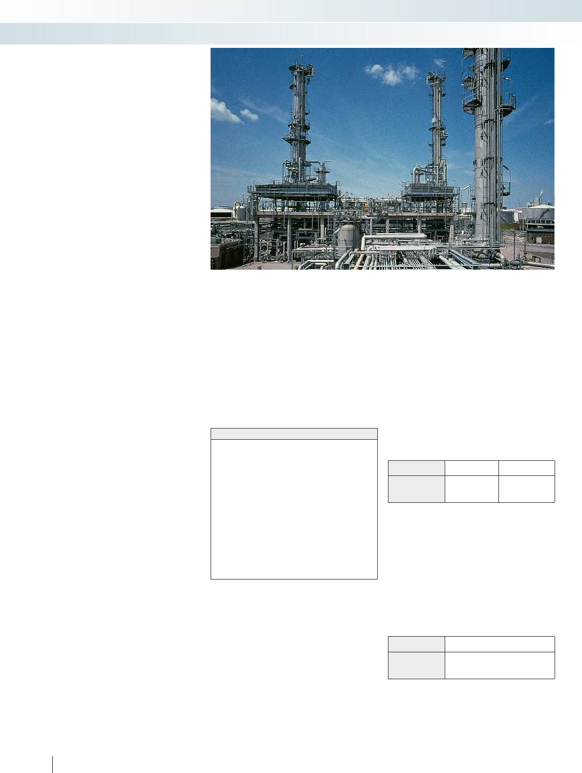
Facts about explosion protection
The chemical and petrochemical
industries involve industrial processes
which produce explosive atmospheres.
They are caused, for example, by gases,
fumes or vapors. Explosive atmospheres are
also likely to occur in mills, silos, and sugar
and fodder factories due to the dust present
there.
Therefore, electrical devices in potentially
explosive areas are subject to special
directives.
Devices and protective systems in
potentially explosive areas
European Parliament directive 94/9/EC of
March 23, 1994 (ATEX manufacturer
directive) is of particular importance within
CENELEC (European Community and
Western European EFTA states). It is
designed to facilitate the harmonization of
legal provisions in the member states of the
European Union for devices and protective
systems in terms of ensuring correct use in
potentially explosive areas. Directive
94/9/EC must be applied to all explosion-
protected devices and protective systems
placed on the market in the European
Union.
The scope of this directive also includes
safety, monitoring, and control devices
which are used outside of potentially
explosive areas, but which are necessary for,
or contribute towards, the safe operation of
devices and protective systems with respect
to explosion hazards.
The term device includes machines,
equipment, stationary or mobile devices,
control components, and system
accessories. The directive also covers alarm
and protection systems which are meant to
be used, either individually or in
combination, for the generation,
transmission, storage, measurement,
control, and conversion of energy as well as
for processing materials and which have the
potential to ignite and cause an explosion.
Protective systems are devices
designed to stop an incipient explosion
immediately and/or restrict the area
affected by the explosion, and which are
placed on the market separately as
autonomous systems.
Components are defined as those parts
that are necessary for ensuring the safe
operation of devices and protective
systems, but do not perform an
autonomous function in themselves.
European directives are implemented in
ordinances or laws at a national level.
Systems in potentially explosive areas
Directive 1999/92/EC (ATEX Operator
Directive) was passed in Europe to regulate
the operation of systems in potentially
explosive areas.
Classification into groups
The general stipulations of EN 60079-0
divide electrical devices for potentially
explosive areas into three groups.
Group I:
Electrical devices for firedamp areas
(mines) which are susceptible to pit gases
(methane) and/or combustible dusts (coal
dust).
Group II:
Electrical devices for operation in areas
where explosive gas atmospheres are likely
to occur, excluding mines susceptible to
firedamp.
This also includes devices for the
chemical, petrochemical, and
pharmaceutical industries as well as for
wastewater treatment.
Electrical devices are further divided into
subcategories according to the properties
of the explosive atmosphere.
In the case of the intrinsic safety
protection type, classification is based on
the minimum ignition energy of the gas or
vapor.
Group III:
Electrical devices for operation in areas
where explosive dust atmospheres are likely
to occur, excluding mines susceptible to
firedamp.
This includes devices for areas associated
with the food industry (mills, silos), for
example.
Electrical devices are further divided into
subcategories according to the properties
of the explosive atmosphere.
Terminology associated with the Ex area
Explosive atmosphere
A mixture of combustible gases, steam, vapors or dust and air in
atmospheric conditions that allow the entire mixture to combust once
ignited.
Potentially explosive area
An area where the atmosphere has the potential to explode due to
local or operational conditions (“Ex area”).
Electrical equipment
The entire set of components, electric circuits or parts of electric
circuits that are usually located within a single housing.
Intrinsically safe electrical equipment
An electrical device in which all circuits are intrinsically safe.
Note: these devices may be used directly in the Ex area.
Associated equipment
Electrical devices that contain both intrinsically safe and non-
intrinsically safe circuits and that are designed in such a way that the
non-intrinsically safe circuits cannot influence the intrinsically safe ones.
Note: associated electrical equipment must not be used directly in
potentially explosive areas without additional protection defined by a
further protection type.
Designation Typical gas Ignition energy/J
Intrinsic safety
II A Propane > 180
II B Ethylene 60 ... 180
II C Hydrogen < 60
Designation Dusts
III A Combustible flyings
III B Non-conductive dust
III C Conductive dust
144
PHOENIX CONTACT
MCR technology
Signal conditioners with functional safety and explosion protection - the MACX ranges

For further information and full technical data, visit phoenixcontact.net/products
Classification into temperature classes
Simply dividing the various gases into
explosion or gas groups according to their
minimum ignition energy is not sufficient to
describe the gases adequately with regard
to their explosive properties.
A gas may explode either when the
ignition energy is exceeded or where there
is an excessively high temperature caused by
a hot surface. This ignition temperature is,
however, not usually linked to the ignition
energy, i.e., a gas with a low ignition energy
does not necessarily explode at a low
temperature. Consequently, devices that
are used directly in potentially explosive
atmospheres are divided into temperature
classes. Temperature classes define the
maximum surface temperature even in the
event of errors. Parallel to this, the gases
are classified according to their different
ignition temperatures.
The following table provides an overview
of the ignition energies and ignition
temperatures for certain gases:
Zone classification
Potentially explosive areas are divided
into zones according to the probability of
their occurrence. The EN 60079-10-1
standard defines the zones containing
explosive atmospheres as follows:
Zone 0:
Area in which an explosive atmosphere is
present for continuous or long periods.
These conditions are usually present
inside containers, pipelines, apparatus, and
tanks.
Zone 1:
Area in which an explosive atmosphere is
to be expected only occasionally during
normal operation.
This includes the immediate area
surrounding zone 0, as well as areas close to
filling and emptying equipment.
Zone 2:
Area in which an explosive atmosphere is
not expected during normal operation;
however, if it does occur, then it does so
only rarely and for a short period.
Zone 2 includes areas that are used
exclusively for storage, areas around pipe
connections that can be disconnected, and
generally the immediate area surrounding
zone 1.
Areas that are potentially explosive as a
result of combustible dusts are divided
into the following zones according to EN
60079-10-2 (formerly: EN 61241-10):
Zone 20:
Area in which an explosive atmosphere is
present for continuous, frequent or long
periods in the form of an airborne cloud of
combustible dust.
Zone 21:
Area in which an explosive atmosphere in
the form of an airborne cloud of
combustible dust is to be expected only
occasionally during normal operation.
Zone 22:
Area in which an explosive atmosphere in
the form of an airborne cloud of
combustible dust is not expected during
normal operation. However, if it does occur,
then it does so only for a short period.
Categories
The ATEX Directive assigns devices for
use in potentially explosive areas to
categories. In IEC 60079-0, “Equipment
Protection Level (EPL)” is the term used
instead of “category”.
In the same way that there are different
zones, there are also different device
categories. These consist of categories M1
and M2 for Group I and categories 1, 2, and
3 for Group II. The categories for
equipment group II are described in
more detail below:
Category 1:
Devices constructed to guarantee a very
high degree of safety.
Devices in this category must guarantee
the required degree of safety even in the
unlikely event of a device failure and
therefore be provided with measures to
protect against explosion, so that:
– In the event of one integrated protection
measure failing, a second, independent
protection measure is able to guarantee
the necessary safety.
– In the event of two independent errors,
the necessary safety is guaranteed.
Category 2:
Devices constructed to guarantee a very
high degree of safety.
The explosion protection measures
associated with this category guarantee the
required degree of safety, even in the case of
frequent device failures or common error
states.
Category 3:
Devices constructed to guarantee a
standard degree of safety.
Devices in this category guarantee an
adequate degree of safety in normal
operation.
The table below shows which categories
are assigned to which zones:
Temperature class Maximum
permissible surface
temperature of
equipment
Ignition
temperatures of
combustible
substances
°C °C
T 1 450 > 450
T 2 300 > 300 450
T 3 200 > 200 300
T 4 135 > 135 200
T 5 100 > 100 135
T 6 85 > 85 100
Substance T
ign
Tempera-
ture
class
E
min
Group
Ethoxyethane 170 T 4 190 II B
Ethylene 425 T 2 82 II B
Ammonia 630 T 1 14000 II A
Butane 365 T 2 250 II A
Methane 595 T 1 280 I
Propane 470 T 1 250 II A
Carbon disulfide 95 T 6 9 II C
Hydrogen 560 T 1 16 II C
Category For zone Also possible
10
20
1 and 2
21 and 22
21
21
2
22
32
22
145
PHOENIX CONTACT
MCR technology
Signal conditioners with functional safety and explosion protection - the MACX ranges
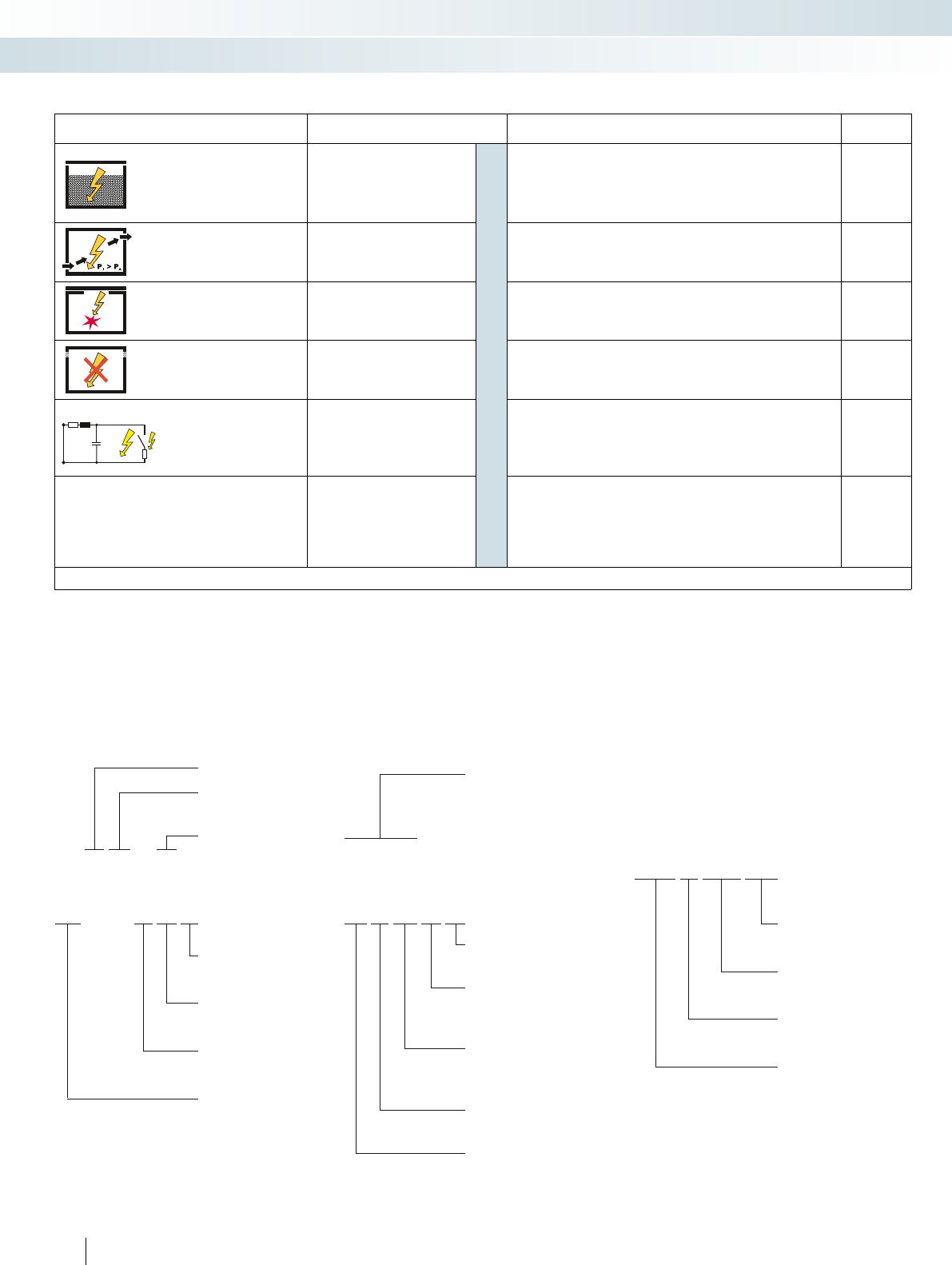
[Ex ia Ga] IIC
Ex e IIC T6 Gb
RL
CU
10 II (1) G
10 II 2 G
IBExU 08 ATEX 1069
Designation according to
EN 60079-0
Associated electrical
equipment
Intrinsic safety
Increased safety
Equipment protection level (EPL)
(Ga, Gb, Gc, Da, Db, Dc)
Temperature class,
for items of equipment
used directly in the Ex area
(T1 ... T6)
Gas group
(IIA, IIB, IIC) or
Dust group
(IIIA, IIIB, IIIC)
Protection type
(ia, ib, ic, e, d, ...)
Explosion-protected
Protection types
Protection principle Protection type Usage range (selection) Standard
Isolation
Oil immersion o Transformers, relays, startup controls, switching devices EN 60079-6
Sand filling q Transformers, relays, capacitors EN 60079-5
Molded encapsulation m* Coils of relays and motors, electronics, solenoid valves, connection systems EN 60079-18
Exclusion Pressurized enclosure p Control cabinets, motors, measuring and analysis devices, computers EN 60079-2
Special mechanical design Flameproof enclosure d Motors, switching devices, power electronics EN 60079-1
Clearance from electrically
conductive parts Increased safety e Terminal blocks, housing, lights, motors EN 60079-7
Energy limitation
Intrinsic safety
i*
Electronics, measurement and control EN 60079-11
Intrinsically safe systems Electronic systems EN 60079-25
Intrinsically safe fieldbus systems Fieldbus systems EN 60079-27
Improved industrial quality
nA: non-sparking
nC: sparking equipment
nR: restricted breathing housing
nL: energy-limited
nP: simplified pressurized enclosures
Protection type “n” n** Motors, housing, lights, electronics EN 60079-15
* ia, ma: application in zone 0, 1, 2 / ib, mb: application in zone 1, 2 / ic, mc: application in zone 2 only ** Application in zone 2 only
Marking according to
ATEX Directive
EC-type examination certificate
Current year of manufacture
Conformity assessment
according to ATEX Directive
94/9/EC
Associated electrical
equipment
0344
0344
Atmosphere
(G = Gas, D = Dust)
Equipment category
(1, 2, 3)
Equipment group
(I, II)
Notified body, production
monitoring (e.g., KEMA)
mark does not apply to components.
Certificate number
Type-tested according to
94/9/EC
Year of EC-type examination
certificate
Notified body
146
PHOENIX CONTACT
MCR technology
Signal conditioners with functional safety and explosion protection - the MACX ranges

For further information and full technical data, visit phoenixcontact.net/products
147PHOENIX CONTACT
MCR technology
Signal conditioners with functional safety and explosion protection - the MACX ranges
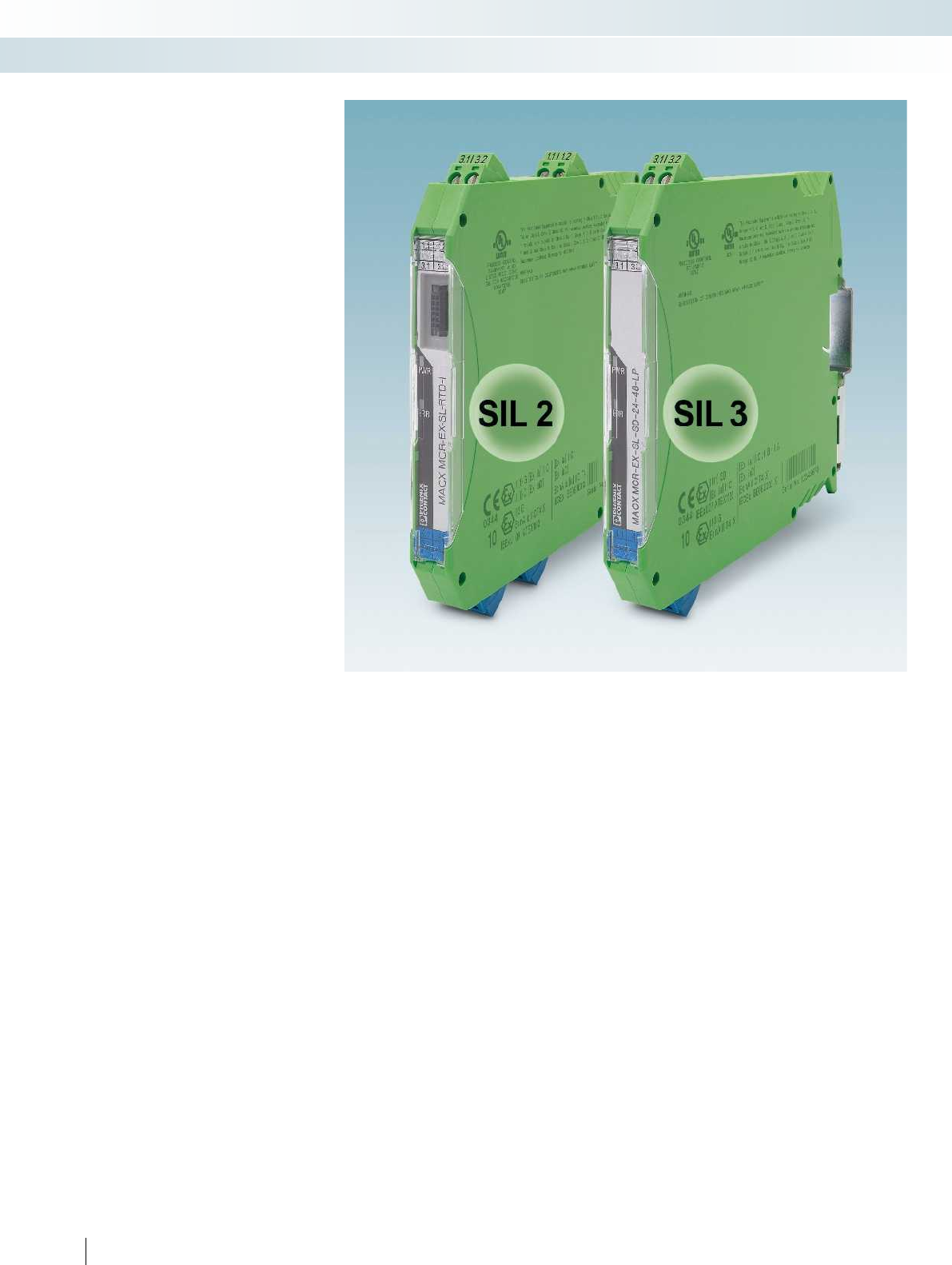
SIL marking on devices
Safety-related function for the
hazardous area
The term SIL (safety integrity level) is
becoming more and more significant in the
field of process technology. It defines the
requirements that a device or a system is
expected to fulfill so that the probability of
failure can be established. The aim is to
achieve the maximum possible operational
reliability. If a device or system fails, a
defined state is attained. Standard-based
inspections are carried out to determine
statistical probability.
Application of SIL on the basis of
IEC 61508 and IEC 61511
The SIL standard is used for a wide range
of industries within the process industry,
including the chemical industry, refineries,
oil and gas production, paper
manufacturing, and conventional power
generation. In addition to functional safety
requirements, systems in potentially
explosive areas are also subject to Ex
standards EN 60079-0 ff.
IEC 61508: “Functional safety of
electrical/electronic/programmable
electronic safety-related systems”
This standard describes the requirements
that the manufacturer has to bear in mind
when producing devices or systems.
IEC 61511: “Functional safety - Safety
instrumented systems for the process
industry sector”
The IEC 61511 standard describes the
requirements for achieving systems with
functional safety
Compliance with the standard is
determined by operators, owners, and
planners on the basis of safety plans and
national regulations. In addition, the
standard also describes the requirements
for using a device in an application on the
basis of its proven effectiveness (proven in
use).
The products in the MACX range from
Phoenix Contact, which have been
developed according to IEC 61508, are
marked with the designation SIL 2 or SIL 3.
This indicates clearly that the devices may
be suitable for safety instrumented
functions (SIF).
To determine whether they can actually
be used, you need to calculate the sum of
the probability of failure values for all the
devices in the signal circuit. The values
required for this can be found in the safety
user manual accompanying any SIL product.
Overview of terms from SIL standards IEC 61508 and IEC 61511
SIL
Safety Integrity Level
One of four discrete levels for the specification of
requirements for the safety integrity of safety
instrumented functions, which are assigned to the E/E/PE
safety instrumented systems, where SIL 4 is the highest
and SIL 1 the lowest level.
EUC
Equipment under control
Equipment, machines, devices or systems used in
production, materials processing or transport.
MTBF
Mean Time Between Failures
The expected mean time between failures.
PFD
Probability of failure on demand
The probability of a failure on demand.
Describes the probability of a safety instrumented
system failing to perform its function when required.
PFDavg
Average Probability of Failure on Demand
The average probability of the function failing on
demand.
E/E/PES
Electrical/electronic/programmable electronic
systems
This term is used for all electrical devices or systems
which can be used to execute a safety instrumented
function. It includes simple electrical devices and all types
of programmable logic controllers (PLCs).
PFH
Probability of dangerous Failure per Hour
Describes the probability of dangerous failure occurring
per hour.
SFF
Safe failure fraction
Describes the proportion of harmless failures. This is the
ratio of the rate of safe failures plus the rate of diagnosed
or detected faults in relation to the total failure rate of
the system.
SIF
Safety Instrumented Function
Describes the safety instrumented functions of a system.
SIS
Safety Instrumented System
An SIS (safety instrumented system) consists of one or
more safety instrumented functions. An SIL requirement
is applicable for each of these safety instrumented
functions.
148
PHOENIX CONTACT
MCR technology
Signal conditioners with functional safety and explosion protection - the MACX ranges
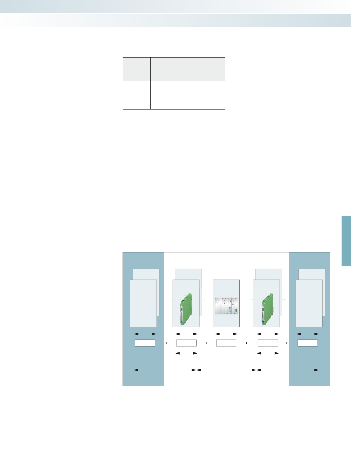
For further information and full technical data, visit phoenixcontact.net/products
SIL inspection
The complete signal path must be taken
into account during the SIL inspection. The
example shows how in a typical safety
application the calculation is based on
average failure probabilities of individual
devices.
Table 2 of the IEC 61508-1 standard
describes the relationship between the
average failure probability and the attainable
SIL. Here, the level required determines the
overall budget for the sum of all PFD values.
A system with a single-channel structure
with a low demand rate is used as an
example; the average PFD value is between
10
-3
and < 10
-2
.
Safety integrity level: failure limit values for a safety function which is
operated in an operating mode with a low demand rate.
The INTERFACE Analog and INTERFACE
Ex product ranges include products that
meet the requirements for explosion
protection as well as functional safety.
Safety integrity
level
SIL
Operating mode with a low demand rate
(average probability of the specified function failing
on demand)
4 10
-5
to < 10
-4
3 10
-4
to < 10
-3
2 10
-3
to < 10
-2
1 10
-2
to < 10
-1
Example:
A sensor and actuator are assembled in
the field and are exposed to chemical and
physical loads (process medium, pressure,
temperature, vibration, etc.). Accordingly,
these components have a high risk of failure:
– The sensor accounts for 25% of the overall
PFD
– The actuator accounts for 40% of the
overall PFD
Neither the failsafe controller nor the
interface modules come into contact with
the process medium and both are usually
located in a protected control cabinet:
– The failsafe controller accounts for 15% of
the overall PFD
– Each of the interface modules accounts for
10% of the overall PFD
Typically, the values form the basis for a
calculation.
Error distribution in the closed-loop control circuit
PFD
1
35%
Sensors and signal path
15%
SPLC
50%
Actuator and signal path
10%
Signal path
10%
Signal path
PFD
2
PFD
4
PFD
5
PFD
3
Digital
input
Sensor Digital
output Actuator
Sensor Analog
input
Analog
output
ActuatorController
149
PHOENIX CONTACT
MCR technology
Signal conditioners with functional safety and explosion protection - the MACX ranges
Functional Safety
In order to achieve the necessary
“functional safety” of a system, it is essential
for the safety-related parts of the safety
equipment and control devices to operate
correctly and, in the event of failure, for the
system to remain in the safe state or enter
a safe state. The requirements for achieving
functional safety are based on the following
objectives:
– Avoidance of systematic errors
– Control of systematic errors
– Control of random faults or failures
The EN ISO 13849 (and EN 62061)
standard specifies the various safety levels in
the form of the Performance Level “PL”
(and the Safety Integrity Level “SIL”)
depending on the extent of the risk and
describes the characteristics of the safety
functions.
Practical procedure according to
EN ISO 13849
In practice, the following steps have
proved to be effective:
1. Definition of the safety function
The information is derived from the risk
assessment.
2. Determination of the required
Performance Level (PL)
For each safety function, the required
performance level is estimated using the
adjacent risk graph (Fig. 3).
3. Technical implementation
This step involves the technical pre-
planning of the safety function, taking
possible technologies and components into
account.
4. Dividing the safety function into
subsystems
Implementation takes place in block
diagrams. As a rule, a safety function
consists of a sensor-logic actuator.
5. Determination of the achieved PL for
each subsystem
A characteristic value when determining
the performance level is the so-called PFHd
value, the statistical “probability of
dangerous failure per hour”. The safety
technology characteristics are in the
product data sheet, the FUNCTIONAL
SAFETY CHARACTERISTICS data sheet or
the SISTEMA library (Fig. 4).
Further safety technology characteristic
data is in the category, the DC value, and
the MTTFD value (Fig. 5).
6. Determination of the achieved PL
The manufacturer of subsystems states
the category and makes the specifications
on the achieved PFHd value and the PL
available.
7. Verification of the achieved PL
Each individual subsystem and the entire
safety chain must both meet the
requirements of the necessary PL. This
includes both the quantitative evaluation
and the consideration of systematic aspects,
such as proven components and safety
principles.
8. Validation
Finally, it is necessary to check whether
the selected measures achieve the required
risk reduction and therefore, the protection
objectives of the risk assessment. The result
is included in the final risk assessment.
Definitions:
PFH
D
: probability of dangerous failure per
hour
DC: diagnostic coverage
MTTF
d
: mean time to dangerous failure
Category:
B10
d
: number of operating cycles, after
which 10% of the devices have failed
CCF: common cause failure
Figure 2:
Safety technology
block diagram (according to EN 13849-1)
LOI
I
m
I
m
General
In modern industrial systems, the amount
of complex technical equipment used is
constantly increasing. The purpose of safety
technology is to reduce the risk as far as
possible but at least to a reasonable degree.
At the same time, the availability of
production equipment should not be
restricted any more than is absolutely
necessary.
The Machinery Directive defines the
requirements machinery must meet before
it can be placed on the market and operated
in the European Economic Area. It also
contains essential health and safety
requirements for the planning and
construction of machinery and safety
components.
However, the number of systems subject
to the directive that do not belong to
classical machine building is increasing
continually. For example, this includes wind
power plants. However, biogas systems,
distributed energy generation in general and
other process engineering systems also
focus on the statutory requirements.
For this reason, analog signals are
increasingly being handled according to the
specifications of the Machinery Directive.
Every “machine” or system poses a risk.
According to the requirements of the
Machinery Directive, a risk assessment
must be carried out for every machine. If
the risk is greater than the level of risk that
can be tolerated, risk reduction must be
implemented.
Functional Safety Performance Level
(PL) according to EN ISO 13849-1 and
EN 62061
Figure 1:
Risk reduction according to EN ISO 12100
How to proceed
Design-related
measures
Has everything been done?
Has everything been done?
Protective
measures
Organization
Risk
150
PHOENIX CONTACT
MCR technology
Signal conditioners with functional safety and explosion protection - the MACX ranges
P1
P2
P1
P2
P1
P2
P1
P2
F1
F2
F1
F2
S1
S2
a
b
c
d
e
a
b
c
d
e
Kat. B Kat. 1Kat. 2Kat. 2Kat. 3Kat. 3Kat. 4
MTTF
d
MTTF
d
MTTF
d
10
-5
10
-6
10
-7
10
-8
PFH
D
Dcavg Dcavg Dcavg Dcavg Dcavg Dcavg Dcavg
3.1 3 .2
4.1 4 .2 4. 2
3.2 3. 4 3.5 3.6
MACX PL -E X-T-UIRE L-UP
C
MAC
P
X P
L-E X- T
UI
-U
RE L
RE
-U
P
4.
14
.2
4
4 … 20 mA
DO, SIL
mV,
1.2 2.2
1.3 2.3
1.4 2.4
1.1 2.1
1.2
1.3
1.4
1.1 2.1
1.2 2.2
1.3 2.3
1.4 2.4
1.1 2.1
1.2 2.2
1.3 2.3
1.4 2.4
1.1 2.1 1.1
1.2 2.2
1.3 2.3
1.4 2.4
1.2 2.2
1.3 2.3
1.4 2.4
1.2 2.2
1.3 2.3
1.4 2.4
1.2 2.2
1.3 2.3
1.4 2.4
1.1
2
.
1
1.1
1
.
1
1.1
1.
2
2
.
2
1.
3
2
.
3
1
.
4
2
.
4
1
.
1
2
.
1
1.
2
2
.2
1.
3
2
.3
1
.
4
2
.
4
1
.
1
2
.
1
1
.2 2.2
1
.3 2.3
1
.
4
2
.
4
1
.
1
2
.
1
1
.2 2.2
1
.3 2.3
1
.
4
2
.
4
1.2 2.2
1.3 2.3
1.4 2.4
1.1 2.1
1.2
1.3
1.4
1.1 2.1
1.2 2.2
1.3 2.3
1.4 2.4
1.1 2.1
1.2 2.2
1.3 2.3
1.4 2.4
1.1 2.1
1.2 2.2
1.3 2.3
1.4 2.4
1.2 2.2
1.3 2.3
1.4 2.4
1.2 2.2
1.3 2.3
1.4 2.4
1.2 2.2
1.3 2.3
1.4 2.4
1
.
1
2
.
1
1.2
2.2
1.3
2.3
1.4
2.4
1
.
1
2
.
1
1.2
2.2
1.3
2.3
1.4
2.4
1
.
1
2
.
1
1.2
2.2
1.3
2.3
1.4
2.4
1
.
1
2
.
1
1.2
2.2
1.3
2.3
1.4
2.4
For further information and full technical data, visit phoenixcontact.net/products
Meaning of individual parameters:
S: severity of injury
– S1: slight (reversible) injuries
– S2: severe (irreversible) injuries
F: frequency and duration of exposure to
the hazard
– F1: seldom to not very frequent
– F2: frequent to continuous or long
P: possibility of avoiding or limiting damage
– P1: possible under certain conditions
– P2: hardly possible
SISTEMA is a product library with which
safety functions can be easily calculated. The
products from MACX Safety and MACX
Safety Ex are included in a SISTEMA library.
It is available from the product download
area on the Phoenix Contact homepage.
Phoenix Contact offers a series of
services surrounding the topic of functional
safety.
It covers everything from initial planning
and startup to the modernization of the
safety lifecycle. There is also a training
concept. Dates are published on the
homepage.
In addition, all questions are answered via
the free safety hotline.
Low
risk
High
risk
Start
Required
performance level
None None Low Medium Low Medium High
Low
High
Medium
Figure 5:
Relationship between PL, category, DC, and MTTFd (according to EN 13849-1)
Figure 3: Risk graph
Figure 4: SISTEMA library
Application example:
safety-related temperature monitoring in a wind power plant
151
PHOENIX CONTACT
MCR technology
Signal conditioners with functional safety and explosion protection - the MACX ranges
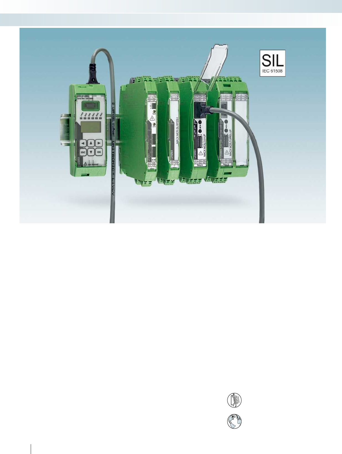
152
PHOENIX CONTACT
Reliable and safe
MACX Analog - safe and high-
performance signal conditioners. This
product range enables you to safely isolate,
condition, filter, and amplify all the signals of
your system.
In all phases of the product life cycle, the
MACX Analog range has been consistently
developed and produced according to
standards for functional safety. Save planning
and operating costs – by combining high
signal flexibility with safe isolation and SIL
evaluation.
Even for the hazardous area
The devices of the MACX Analog range
are approved according to the Ex n
protection type for use in Ex zone 2.
Choose the right MACX Analog signal
conditioner for your application:
The universal nature of the product range
provides you with a solution for all
applications using analog signal
transmission. You are free to choose
between either multifunctional high-end
devices or reasonably-priced standard
modules with exactly the right functions.
Analog IN/OUT
– Universal configurable 3-way signal
conditioners
– Repeater power supply and signal
duplicator with HART signal transmission
– Output signal conditioners with HART
signal transmission
Temperature
– Universal temperature transducers for
resistance thermometers, resistance-type
sensors, potentiometers, thermocouples,
and mV sources – also with safe limit
value relays as an option
– Configurable temperature transducer for
resistance thermometers and resistance-
type sensors
– Configurable temperature transducer for
thermocouples and mV sources
Digital IN
– NAMUR signal conditioner with input for
NAMUR proximity sensors or switches.
– Different versions in single or
two-channel design, with relay or
transistor output or for signal duplication.
Wide range supply
The modules featuring a wide range supply (...-UP)
can be used in all power supply networks the world over
without the need for additional power supply units.
DIN rail connector-compatible
The DIN rail connector enables modular
bridging of the 24 V supply voltage.
Flexible energy supply
MCR technology
Signal conditioners with SIL functional safety - MACX Analog
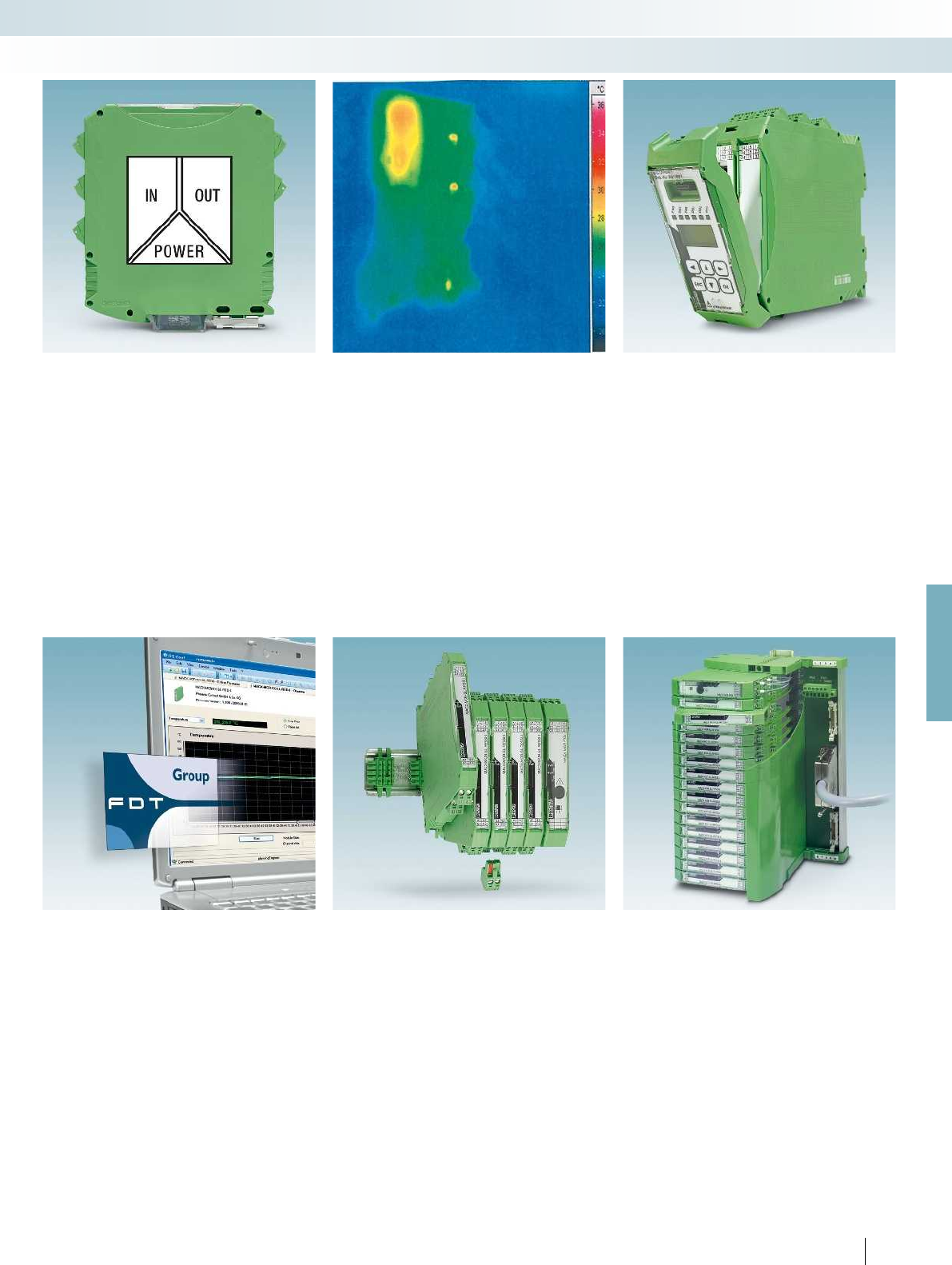
For further information and full technical data, visit phoenixcontact.net/products
153PHOENIX CONTACT
MCR technology
Signal conditioners with SIL functional safety - MACX Analog
Precise, interference-free signal
transmission
– Precise and interference-free signal
transmission due to a patented
transmission concept with safe electrical
isolation.
Long service life and high operational
reliability
– Long service life and high operational
reliability over the entire operating
temperature range, thanks to low power
consumption and self-heating
Easy configuration
– Without software via DIP switches on the
device front or with the operator
interface and display unit.
Easy configuration and monitoring
– Either via FDT/DTM or user-friendly
stand-alone software – with integrated
monitoring function
Easy installation, power bridging, and
diagnostics
– Flexible supply voltage bridging and the
option of redundant, diode-decoupled
supply and error indication.
– Plug-in, coded connection terminal blocks
with test sockets; with screw connection
or with fast push-in connection
technology as an option
Fast and error-free signal connection
– Compact Termination Carriers connect
MACX Analog devices to the automation
system – Plug and Play
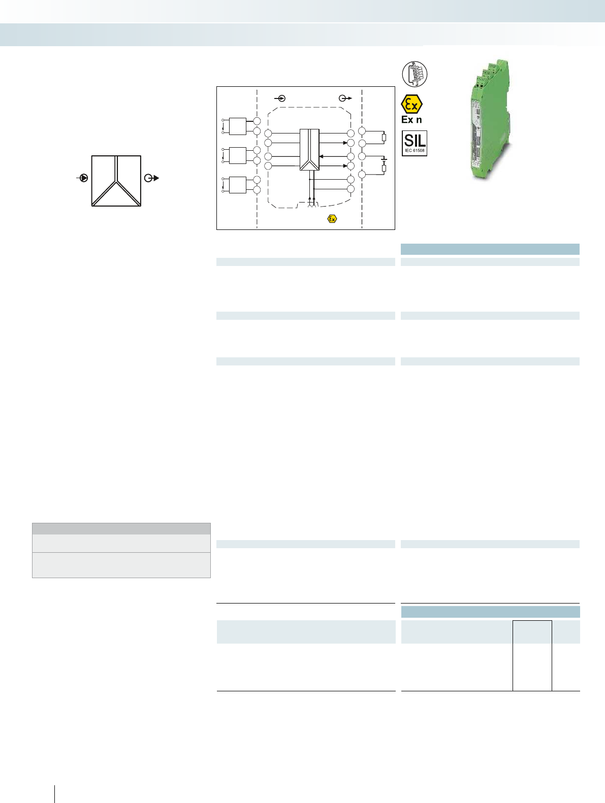
POWER
U,I U,I OUT
IN
Zone 2
Div. 2
IN
Sensor /Field
OUT
PLC / DCS
±±
±1 ±
50mV... 1000 mV
mA... 5 mA
±10mA... ±100 mA+
-
±1 V... ±100 V
GND
active
passive
+24 V
GND
4.2 3.2
5.2 2.2
1.2
4.1 3.1
5.1 2.1
1.1
+24 V
GND
4-wire
[mA]
US
4.1
5.2
4-wire
[mV]
US
4.2
5.2
4-wire
[V]
US
5.1
5.2
passive
-
+
3.2
3.1
active
-
+
2.2
2.1
Functional Safety
Ex:
Housing width 12.5 mm
Technical data
Input data U input I input
Input signal (configurable using the DIP switch)
0 ... 10 V, please indicate if different setting when ordering 0 ... 1 mA,
configurable via DIP switches
Maximum input signal ± 100 V ± 100 mA
Input resistance approx. 1 M
(± 1 V DC ... ± 100 V DC)
approx. 10
(± 10 mA DC ... ± 100 mA DC)
Output data U output I output
Output signal (configurable using the DIP switch) 0 ... 10 V, configurable via DIP switches
0 ... 20 mA, please indicate if different setting when ordering
Load R
B
1 k (10 V) 600 (20 mA; active)
passive: (UB-2 V) / I
outmax
General data
Supply voltage U
B
12 V DC ... 24 V DC (-20% / +25%)
Power dissipation < 0.7 W (at 24 V DC / 20 mA)
Maximum transmission error 0.1 % (compared to the final value)
Temperature coefficient 0.0075 %/K
ZERO / SPAN adjustment ± 4 % / ± 4 %
Cut-off frequency (3 dB) 10 kHz (can be switched to 30 Hz)
Step response (10-90%) 35 µs (at 10 kHz)
11 ms (at 30 Hz)
Electrical isolation
Input/output/power supply 2.5 kV (50 Hz, 1 min., test voltage)
300 V
rms
(rated insulation voltage (surge voltage category II;
pollution degree 2, safe isolation as per EN 61010-1))
Test voltage, input/output/supply 2.5 kV (50 Hz, 1 min.)
Degree of protection IP20
Ambient temperature (operation) -20 °C ... 70 °C
Mounting any
Housing material PA 66-FR
Dimensions W / H / D 12.5 / 99 / 114.5 mm
Screw connection solid / stranded / AWG 0.2 ... 2.5 mm² / 0.2 ... 2.5 mm² / 24 - 14
Push-in connection solid / stranded / AWG 0.2 ... 1.5 mm² / 0.2 ... 1.5 mm² / 24 - 16
EMC note Class A product, see page 625
Conformance / approvals
Conformance CE-compliant
ATEX
II 3 G Ex nA IIC T4 Gc
IECEx Ex nA IIC T4 Gc
UL, USA / Canada UL 61010 Listed
Class I, Div. 2, Groups A, B, C, D T6
Class I, Zone 2, Group IIC
SIL in accordance with IEC 61508 2
Ordering data
Description Type Order No. Pcs. /
Pkt.
3-way signal conditioner, for electrical isolation of analog signals
Order configuration Screw connection MACX MCR-UI-UI 2811284 1
Order configuration Push-in connection MACX MCR-UI-UI-SP 2811572 1
Standard configuration Screw connection MACX MCR-UI-UI-NC 2811446 1
Standard configuration Push-in connection MACX MCR-UI-UI-SP-NC 2811556 1
154
PHOENIX CONTACT
Universal signal conditioner for operating
4-wire measuring transducers
– Analog signal conditioner for isolating,
filtering, amplifying, and converting
standard analog signals
– Configurable input and output signals,
including bipolar current and voltage
signals
– 3-way electrical isolation
– Over 1600 signal conversions can be set
via DIP switches on the front
– 10 kHz cut-off frequency for time-critical
applications
– Output active or passive
– Plug-in screw or push-in connection
technology
– Power supply via DIN rail connector
possible
– Status indicator for supply voltage
– Up to SIL 2 according to IEC 61508
– Installation in zone 2 permitted
Notes:
To order a product with an order configuration, enter the required
configuration by referring to the adjacent order key.
Information about the power and fault signaling module as well as
about the DIN rail connectors and marking material can be found
from page 178
Analog IN/Analog OUT
3-way signal conditioner
MCR technology
Signal conditioners with SIL functional safety - MACX Analog
Universal,
more than 1600 signal combinations
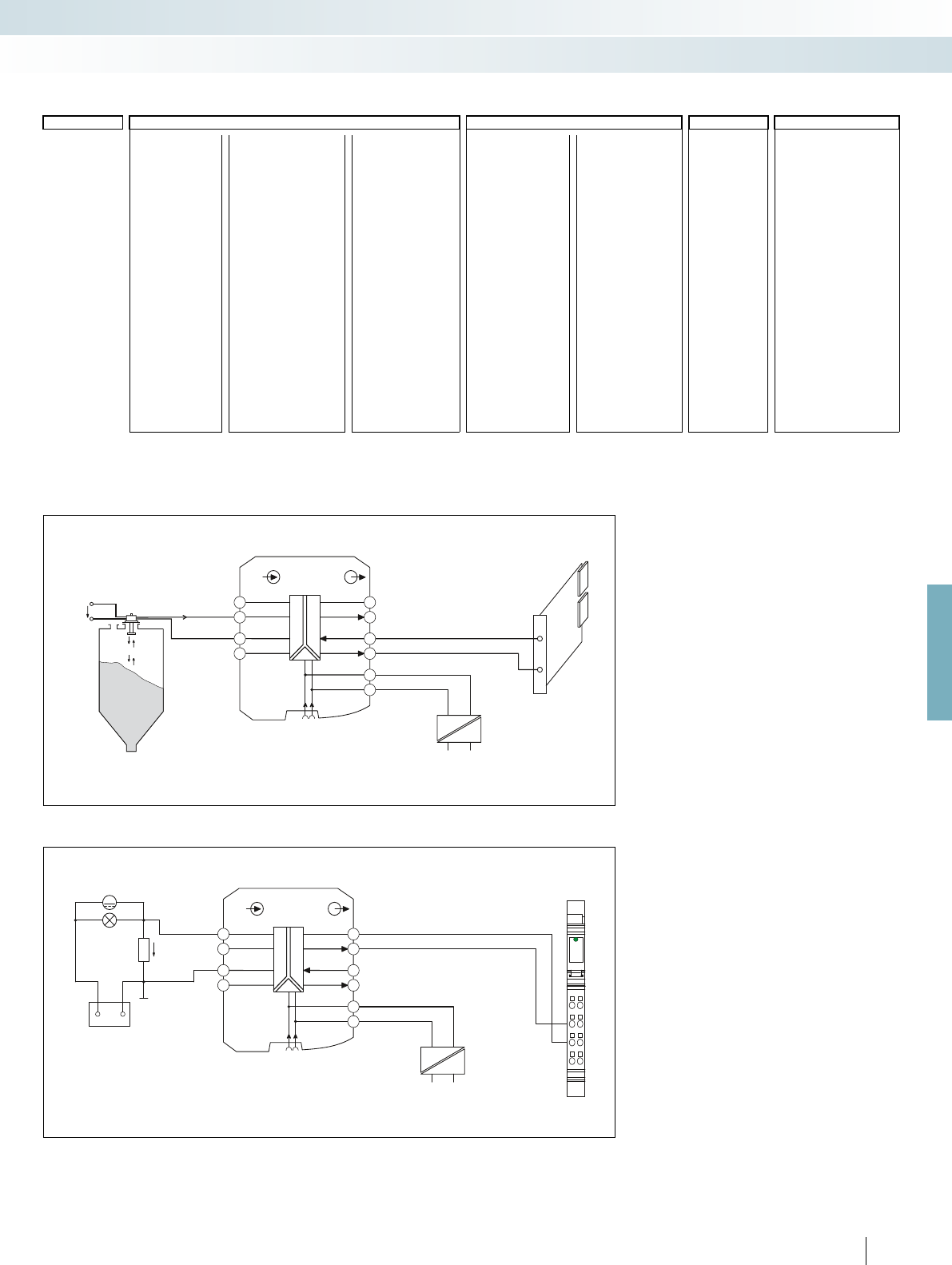
24 V0...20 mA
IN OUT
MACXMCR-UI-UI
±±
±1±
50 mV... 1000 mV
mA... 5mA
±10±100mA... mA +
–
±1V... ±100 V
GND
active
passive
4.2 3.2
5.2 2.2
1.2
4.13.1
5.1 2.1
1.1
24 V
+24 V
GND
+24 V
GND
M
mV
+–
12
1
2
3
4
1
2
3
4
D
AI2
IN OUT
MACXMCR-UI-UI
±±
±1±
50 mV... 1000 mV
mA... 5mA
±10±100mA... mA +
–
±1V... ±100 V
GND
active
passive
+24 V
GND
4.2 3.2
5.2 2.2
1.2
4.13.1
5.1 2.1
1.1
24 V
+24 V
GND
For further information and full technical data, visit phoenixcontact.net/products
155PHOENIX CONTACT
Order key for MACX MCR-UI-UI(-SP) (standard configuration entered as an example)
Application example: level measurement and active analog input card
Application example: shunt measurement and Inline terminal with passive analog input channels within an Inline station
(Information on automation solutions from Phoenix Contact can be found in Catalog 8 or at www.phoenixcontact.net/products)
Order No.
Input Output Cut-off
frequency
Factory calibration
certificate (FCC)
2811284 / IN03 / OUT01 / 10K / NONE
IN40 =0..50 mV IN53 =-50..+50 mV IN70 =0 ... 1.0 mA OUT19 =0 ... 2.5 V OUT15 =0 ... 5 mA 30 =30 Hz NONE =without FCC
2811284 = IN24 =0..60 mV IN13 =-60..+60 mV IN71 =0 ... 1.5 mA OUT05 =0 ... 5 V OUT16 =0 ... 10 mA 10K =10 kHz YES =with FCC (a fee
is charged)
MACX MCR-UI-UI IN41 =0..75 mV IN54 =-75..+75 mV IN72 =0 ... 2.0 mA OUT03 =0 ... 10 V OUT01 =0 ... 20 mA
IN25 =0..100 mV IN14 =-100..+100 mV IN73 =0 ... 3.0 mA
IN43 =0..120 mV IN56 =-120..+120 mV IN36 =0 ... 5 mA OUT20 =-2.5 ... +2.5 V OUT21 =-5 ... +5 mA YESPLUS =FCC with
5 measuring
points (a fee is
charged)
2811572 = IN44 =0..150 mV IN57 =-150..+150 mV IN37 =0 ... 10 mA OUT13 =-5 ... +5 V OUT22 =-10 ... +10 mA
MACX MCR-
UI-UI-SP
IN26 =0..200 mV IN15 =-200..+200 mV IN74 =0 ... 15 mA OUT14 =-10 ... +10 V OUT23 =-20 ... +20 mA
IN27 =0..300 mV IN16 =-300..+300 mV IN01 =0 ... 20 mA
IN28 =0..500 mV IN17 =-500..+500 mV IN75 =0 ... 30 mA OUT24 =0.5 ... +2.5 V OUT25 =1 ... 5 mA
IN66 =0..1000 mV IN78 =-1000..+1000 mV IN76 =0 ... 50 mA OUT06 =1 ... 5 V OUT26 =2 ... 10 mA
IN29 =0 ... 1.0 V IN18 =-1.0 ... +1.0 V IN77 =0 ... 100 mA OUT04 =2 ... 10 V OUT02 =4 ... 20 mA
IN50 =0 ... 1.5 V IN63 =-1.5 ... +1.5 V
IN30 =0 ... 2.0 V IN19 =-2.0 ... +2.0 V IN83 =-1.0 ... +1.0 mA OUT27 =2.5 ... 0 V OUT28 =5 ... 0 mA
IN52 =0 ... 3.0 V IN65 =-3.0 ... +3.0 V IN84 =-1.5 ... +1.5 mA OUT11 =5 ... 0 V OUT29 =10 ... 0 mA
IN05 =0 ... 5 V IN21 =-5 ... +5 V IN85 =-2.0 ... +2.0 mA OUT09 =10 ... 0 V OUT07 =20 ... 0 mA
IN03 =0 ... 10 V IN22 =-10 ... +10 V IN86 =-3.0 ... +3.0 mA
IN67 =0 ... 15 V IN79 =-15 ... +15 V IN33 =-5 ... +5 mA
IN32 =0 ... 20 V IN23 =-20 ... +20 V IN34 =-10 ... +10 mA
IN39 =0 ... 30 V IN80 =-30 ... +30 V IN87 =-15 ... +15 mA
IN68 =0 ... 50 V IN81 =-50 ... +50 V IN35 =-20 ... +20 mA
IN69 =0 ... 100 V IN82 =-100 ... +100 V IN88 =-30 ... +30 mA
IN89 =-50 ... +50 mA
IN90 =-100 ... +100 mA
IN06 =1 ... 5 V IN91 =1 ... 5 mA
IN04 =2 ... 10 V IN92 =2 ... 10 mA
IN02 =4 ... 20 mA
Level sensor
Controller
Mains voltage
IB IL AI 2/SF
Battery
Shunt resistor
Mains voltage
MCR technology
Signal conditioners with SIL functional safety - MACX Analog
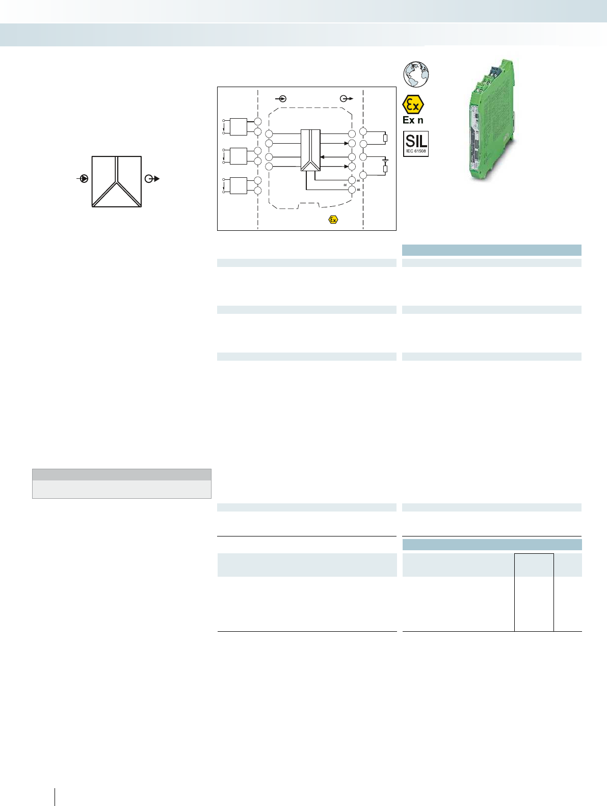
POWER
U,I U,I OUT
IN
Zone 2
Div. 2
IN
Sensor /Field
OUT
PLC / DCS
4-wire
[mA]
US
4.1
5.2
4-wire
[mV]
US
4.2
5.2
4-wire
[V]
US
5.1
5.2
passive
-
+
3.2
3.1
active
-
+
2.2
2.1
±±
±1 ±
50mV... 1000 mV
mA... 5 mA
±10mA... ±100 mA+
-
±1 V... ±100 V
GND
active
passive
Power
24V ...230V AC/DC
4.2 3.2
5.2 2.2
1.2
4.1 3.1
5.1 2.1
1.1
Functional Safety
Ex:
Housing width 12.5 mm
Technical data
Input data U input I input
Input signal (configurable using the DIP switch) 0 ... 10 V, please indicate if different setting when ordering
Maximum input signal ± 100 V ± 100 mA
Input resistance approx. 1 M
(± 1 V DC ... ± 100 V DC)
approx. 10
(± 10 mA DC ... ± 100 mA DC)
Output data U output I output
Output signal (configurable using the DIP switch) 0 ... 20 mA, configurable via DIP switches
Maximum output signal 15 V 35 mA
Load R
B
1 k (10 V) 600 (20 mA; active)
passive: (UB-2 V) / I
outmax
General data
Supply voltage U
B
24 V ... 230 V AC/DC (-20%/+10%, 50/60 Hz)
Power dissipation < 0.8 W (at 24 V DC / 20 mA)
< 0.9 W (at 230 V AC / 20 mA)
Maximum transmission error 0.1 % (compared to the final value)
Temperature coefficient 0.0075 %/K
ZERO / SPAN adjustment ± 4 % / ± 4 %
Electrical isolation
Input/output/power supply 2.5 kV (50 Hz, 1 min., test voltage)
300 V
rms
(rated insulation voltage (surge voltage category II;
pollution degree 2, safe isolation as per EN 61010-1))
Degree of protection IP20
Ambient temperature (operation) -20 °C ... 70 °C
Housing material PA 66-FR
Dimensions W / H / D 12.5 / 99 / 114.5 mm
Screw connection solid / stranded / AWG 0.2 ... 2.5 mm² / 0.2 ... 2.5 mm² / 24 - 14
Push-in connection solid / stranded / AWG 0.2 ... 1.5 mm² / 0.2 ... 1.5 mm² / 24 - 16
EMC note Class A product, see page 625
Conformance / approvals
Conformance CE-compliant
ATEX
II 3 G Ex nA IIC T4 Gc
SIL in accordance with IEC 61508 2
Ordering data
Description Type Order No. Pcs. /
Pkt.
3-way signal conditioner, for electrical isolation of analog signals
with long-range power supply
Order configuration Screw connection MACX MCR-UI-UI-UP 2811459 1
Order configuration Push-in connection MACX MCR-UI-UI-UP-SP 2811585 1
Standard configuration Screw connection MACX MCR-UI-UI-UP-NC 2811297 1
Standard configuration Push-in connection MACX MCR-UI-UI-UP-SP-NC 2811569 1
156
PHOENIX CONTACT
– Analog signal conditioner for isolating,
filtering, amplifying, and converting
standard analog signals
– Configurable input and output signals,
including bipolar current and voltage
signals
– 3-way electrical isolation
– Over 1600 signal conversions can be set
via DIP switches on the front
– Output active or passive
– Plug-in screw or push-in connection
technology
– Wide range power supply:
19.2 ... 253 V AC/DC
– Status indicator for supply voltage
– Up to SIL 2 according to IEC 61508
– Installation in zone 2 permitted
Notes:
To order a product with an order configuration, enter the required
configuration by referring to the adjacent order key.
Analog IN/Analog OUT
3-way signal conditioner
MCR technology
Signal conditioners with SIL functional safety - MACX Analog
Universal,
more than 1600 signal combinations,
wide range power supply

Power
24V ...230V AC/DC
24V0...20mA
IN OUT
MACXMCR-UI-UI-UP
±±
±1±
50mV... 1000mV
mA... 5mA
±10±100mA... mA +
–
±1V... ±100V
GND
active
passive
Power
24V ...230V AC/DC
4.2 3.2
5.2 2.2
1.2
4.13.1
5.1 2.1
1.1
≃
M
mV
+–
12
1
2
3
4
1
2
3
4
D
AI2
Power
24V ...230V AC/DC
IN OUT
MACXMCR-UI-UI-UP
±±
±1±
50mV... 1000mV
mA... 5mA
±10±100mA... mA +
–
±1V... ±100V
GND
active
passive
Power
24V ...230V AC/DC
4.2 3.2
5.2 2.2
1.2
4.13.1
5.1 2.1
1.1
≃
For further information and full technical data, visit phoenixcontact.net/products
157PHOENIX CONTACT
Order key for MACX MCR-UI-UI(-SP) (standard configuration entered as an example)
Application example: level measurement and active analog input card
Application example: shunt measurement and Inline terminal with analog input channels within an Inline station
(Information on automation solutions from Phoenix Contact can be found in Catalog 8 or at www.phoenixcontact.net/products)
Order No.
Input Output Cut-off
frequency
Factory calibration
certificate (FCC)
2811459 / IN03 / OUT01 / 10K / NONE
IN40 =0..50 mV IN53 =-50..+50 mV IN70 =0 ... 1.0 mA OUT19 =0 ... 2.5 V OUT15 =0 ... 5 mA 30 =30 Hz NONE =without FCC
2811459 = IN24 =0..60 mV IN13 =-60..+60 mV IN71 =0 ... 1.5 mA OUT05 =0 ... 5 V OUT16 =0 ... 10 mA 10K =10 kHz YES =with FCC (a fee
is charged)
MACX MCR-
UI-UI-UP
IN41 =0..75 mV IN54 =-75..+75 mV IN72 =0 ... 2.0 mA OUT03 =0 ... 10 V OUT01 =0 ... 20 mA
IN25 =0..100 mV IN14 =-100..+100 mV IN73 =0 ... 3.0 mA
IN43 =0..120 mV IN56 =-120..+120 mV IN36 =0 ... 5 mA OUT20 =-2.5...+2.5 V OUT21 =-5 ... +5 mA YESPLUS =FCC with
5 measuring
points (a fee is
charged)
2811585 = IN44 =0..150 mV IN57 =-150..+150 mV IN37 =0 ... 10 mA OUT13 =-5...+5 V OUT22 =-10 ... +10 mA
MACX MCR-
UI-UI-UP-SP
IN26 =0..200 mV IN15 =-200..+200 mV IN74 =0 ... 15 mA OUT14 =-10 ... +10 V OUT23 =-20 ... +20 mA
IN27 =0..300 mV IN16 =-300..+300 mV IN01 =0 ... 20 mA
IN28 =0..500 mV IN17 =-500..+500 mV IN75 =0 ... 30 mA OUT24 =0.5...+2.5 V OUT25 =1 ... 5 mA
IN66 =0..1000 mV IN78 =-1000..+1000 mV IN76 =0 ... 50 mA OUT06 =1...5 V OUT26 =2 ... 10 mA
IN29 =0 ... 1.0 V IN18 =-1.0 ... +1.0 V IN77 =0 ... 100 mA OUT04 =2...10 V OUT02 =4 ... 20 mA
IN50 =0 ... 1.5 V IN63 =-1.5...+1.5 V
IN30 =0 ... 2.0 V IN19 =-2.0 ... +2.0 V IN83 =-1.0 ... +1.0 mA OUT27 =2.5...0 V OUT28 =5 ... 0 mA
IN52 =0 ... 3.0 V IN65 =-3.0 ... +3.0 V IN84 =-1.5...+1.5 mA OUT11 =5...0 V OUT29 =10 ... 0 mA
IN05 =0 ... 5 V IN21 =-5...+5 V IN85 =-2.0 ... +2.0 mA OUT09 =10 ... 0 V OUT07 =20 ... 0 mA
IN03 =0 ... 10 V IN22 =-10 ... +10 V IN86 =-3.0 ... +3.0 mA
IN67 =0 ... 15 V IN79 =-15...+15 V IN33 =-5 ... +5 mA
IN32 =0 ... 20 V IN23 =-20 ... +20 V IN34 =-10 ... +10 mA
IN39 =0 ... 30 V IN80 =-30 ... +30 V IN87 =-15 ... +15 mA
IN68 =0 ... 50 V IN81 =-50 ... +50 V IN35 =-20 ... +20 mA
IN69 =0 ... 100 V IN82 =-100 ... +100 V IN88 =-30 ... +30 mA
IN89 =-50 ... +50 mA
IN90 =-100 ... +100 mA
IN06 =1...5 V IN91 =1 ... 5 mA
IN04 =2...10 V IN92 =2 ... 10 mA
IN02 =4 ... 20 mA
Level sensor
Controller
IB IL AI 2/SF
Battery
Shunt resistor
MCR technology
Signal conditioners with SIL functional safety - MACX Analog
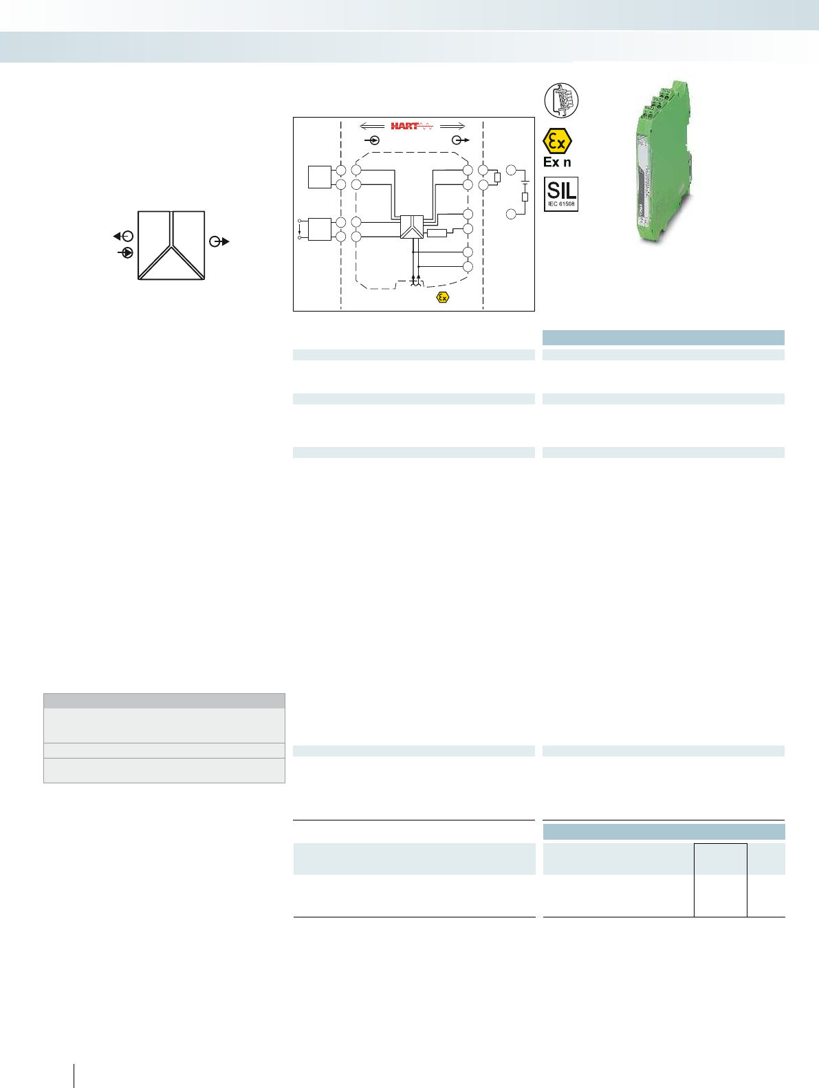
POWER
II OUT
IN
POWER
Sensor / Field
or
4.2
4.1
2-wire
5.2
5.1
4-wire
US
Zone 2
Div.2
INOUT
4.2
4.1
3.2
3.1
+
-
GND
+24V
Power
250 Ω
GND +24V
5.2
5.1
+
-
2.2
2.1
1.2
1.1
PLC / DCS
3.2
3.1
passive
-
+
active
-
+
3.2
2.2
C O M M U N I C A T I O N P R OT O C O L
Functional Safety
Ex:
Housing width 12.5 mm
Technical data
Input data
Input signal 4 mA ... 20 mA
Transmitter supply voltage > 21.5 V (20 mA)
Voltage drop < 3.5 V
Output data
Output signal 4 mA ... 20 mA (active)
4 mA ... 20 mA (14 ... 26 V ext. source voltage)
Load < 1000 (20 mA)
Output ripple < 20 mV
rms
General data
Supply voltage range 19.2 V DC ... 30 V DC (24 V DC (-20% ... +25%))
Current consumption < 76 mA (24VDC / 20mA / 1000);
< 55 mA (24VDC / 20mA / 250)
Power dissipation < 1.1 W (24 V DC/ 20 mA)
< 0.95 W (24VDC / 20mA / 250)
< 1.2 W (24VDC / 20mA / 0)
Temperature coefficient < 0.01 %/K
Step response (10-90%) < 200 µs (for 4 mA ... 20 mA step, load 600)
Transmission error, typical < 0.05 % (of final value)
Maximum transmission error < 0.1 % (of final value)
Underload/overload range according to NE 43
Electrical isolation
Input/output/power supply 300 V
rms
(rated insulation voltage (surge voltage category II;
pollution degree 2, safe isolation as per EN 61010-1))
2.5 kV (50 Hz, 1 min., test voltage)
Ambient temperature range -20 °C ... 60 °C (any mounting position)
Status indication Green LED (supply voltage)
SMART communication Yes
Signal bandwidth as per HART specifications
Protocols supported HART
Housing material PA 66-FR
Dimensions W / H / D 12.5 / 112.5 / 114.5 mm
Screw connection solid / stranded / AWG 0.2 ... 2.5 mm² / 0.2 ... 2.5 mm² / 24 - 14
Push-in connection solid / stranded / AWG 0.2 ... 1.5 mm² / 0.2 ... 1.5 mm² / 24 - 16
EMC note Class A product, see page 625
Conformance / approvals
Conformance CE-compliant, additionally EN 61326
ATEX
II 3 G Ex nA IIC T4 Gc
UL, USA / Canada UL 61010 Listed
Class I, Div. 2, Groups A, B, C, D T4
Class I, Zone 2, Group IIC T4
SIL in accordance with IEC 61508 2
Ordering data
Description Type Order No. Pcs. /
Pkt.
Repeater power supply, with HARTR protocol
Screw connection MACX MCR-SL-RPSSI-I 2865955 1
Push-in connection MACX MCR-SL-RPSSI-I-SP 2924207 1
158
PHOENIX CONTACT
Repeater power supply and input signal
conditioner for the operation of 2-wire
measuring transducers, 4-wire measuring
transducers, and mA current sources
– Input 0/4...20 mA (powered or not
powered)
– 0/4...20 mA output (active or passive)
– Bidirectional transmission of digital HART
communication signals
– Plug-in screw or push-in connection
technology, with integrated sockets for
HART communicators
– Terminal point with 250 resistor to
increase the HART impedance in the case
of low-impedance systems
– 3-way electrical isolation
– Power supply via DIN rail connector
possible
– Up to SIL 2 according to IEC 61508
– Installation in zone 2 permitted
Notes:
Information about the power and fault signaling module as well as
about the DIN rail connectors and marking material can be found
from page 178
Test plugs for test sockets can be found on page 180
Information on Plug and Play connection using system cabling can
be found from page 182
Analog IN/Analog OUT
repeater power supply
MCR technology
Signal conditioners with SIL functional safety - MACX Analog
Repeater power supply and
input signal conditioner
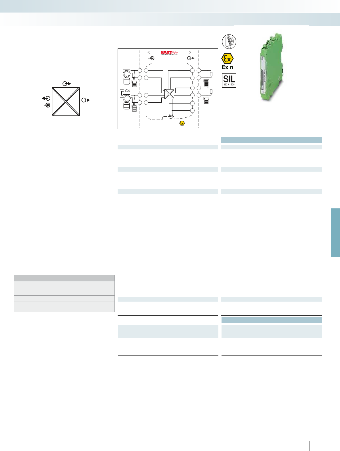
POWER
IIOUT2
I
OUT1
IN
POWER
Zone 2
Div. 2
IN OUT
4.2
5.2
4.1
5.1
3.2
3.1
2.2
2.1
1.2
1.1
GND
OUT 1
OUT 2
+24V
GND +24V
Power
+
+
-
-
+
-
Sensor / Field
or
4.2
4.1
5.2
5.1
PLC / DCS
passive
-
+
3.2
3.1
passive
-
+
2.2
2.1
For further information and full technical data, visit phoenixcontact.net/products
Functional Safety
Ex:
Housing width 12.5 mm
Technical data
Input data
Input signal 4 mA ... 20 mA / 0 mA ... 20 mA
Transmitter supply voltage > 21.5 V (at 20 mA)
Voltage drop < 3.9 V (in input signal conditioner operation)
Output data
Output signal (per output) 0 mA ... 20 mA (active)
4 mA ... 20 mA (active)
Load < 450 (at 20 mA)
Output ripple < 20 mV
rms
General data
Supply voltage range 19.2 V DC ... 30 V DC (24 V DC (-20% ... +25%))
Current consumption < 75 mA (at 24 V DC)
Power dissipation < 1.45 W (at 24 V DC / 20 mA)
Temperature coefficient < 0.01 %/K
Step response (10-90%) < 1.3 ms (for 4 mA ... 20 mA step)
Transmission error, typical < 0.05 % (of final value)
Maximum transmission error < 0.1 % (of final value)
Underload/overload range according to NE 43
Electrical isolation
Input/output/power supply 300 V
rms
(rated insulation voltage (surge voltage category II;
pollution degree 2, safe isolation as per EN 61010-1))
2.5 kV (50 Hz, 1 min., test voltage)
Output 1/output 2 1.5 kV AC (50 Hz, 1 min., test voltage)
Ambient temperature range -20 °C ... 60 °C (any mounting position)
Status indication Green LED (PWR supply voltage)
SMART communication (per output) Yes
Protocols supported HART
Housing material PA 66-FR
Dimensions W / H / D 12.5 / 99 / 114.5 mm
Screw connection solid / stranded / AWG 0.2 ... 2.5 mm² / 0.2 ... 2.5 mm² / 24 - 14
Push-in connection solid / stranded / AWG 0.2 ... 1.5 mm² / 0.2 ... 1.5 mm² / 24 - 16
EMC note Class A product, see page 625
Conformance / approvals
Conformance CE-compliant, additionally EN 61326
ATEX
II 3 G Ex nA IIC T4 Gc X
SIL in accordance with IEC 61508 2
Ordering data
Description Type Order No. Pcs. /
Pkt.
Repeater power supply, with HARTR protocol
Screw connection MACX MCR-SL-RPSSI-2I 2924825 1
Push-in connection MACX MCR-SL-RPSSI-2I-SP 2924838 1
159
PHOENIX CONTACT
Repeater power supply and input signal
conditioner for the operation of 2-wire
measuring transducers, 4-wire measuring
transducers, and mA current sources
– Input 0/4...20 mA (powered or not
powered)
– Two electrically isolated 0/4 ... 20 mA
(active) outputs
– Bidirectional transmission of digital HART
communication signals (both outputs)
– Plug-in screw or push-in connection
technology, with integrated sockets for
HART communicators
– 4-way electrical isolation
– Power supply via DIN rail connector
possible
– Up to SIL 2 according to IEC 61508
– Installation in zone 2 permitted
Notes:
Information about the power and fault signaling module as well as
about the DIN rail connectors and marking material can be found
from page 178
Test plugs for test sockets can be found on page 180
Information on Plug and Play connection using system cabling can
be found from page 182
Analog IN/Analog OUT
repeater power supply
MCR technology
Signal conditioners with SIL functional safety - MACX Analog
Repeater power supply and
input signal conditioner,
with two electrically isolated outputs
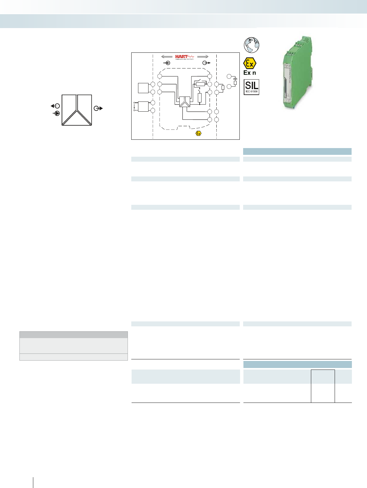
POWER
II OUT
IN
POWER
Zone 2
Div. 2
INOUT
4.3
4.2
3.3
3.2
Power
24V ...230V AC/DC
250
Ω
4.1 3.1
1.2
1.1
250 Ω
S2
S1
–
~
–
~
–
~
PLC / DCS
passive
3.2
3.1
-
+
active
-
+
3.3
3.2
1.2
1.1
Sensor / Field
4.2
4.1
2-wire
4.3
4.2
4-wire
US
+
-
+
-
or
Functional Safety
Ex:
Housing width 17.5 mm
Technical data
Input data
Input signal 4 mA ... 20 mA
Transmitter supply voltage > 16 V (20 mA)
Voltage drop < 3.5 V (in input signal conditioner operation)
Output data
Output signal 4 mA ... 20 mA (active)
4 mA ... 20 mA (14 ... 26 V ext. source voltage)
1 V ... 5 V (internal resistance, 250 , 0.1%)
Load < 600 (20 mA)
Output ripple < 20 mV
rms
General data
Supply voltage range 24 V ... 230 V AC/DC (-20%/+10%, 50/60 Hz)
Current consumption < 80 mA (24 V DC/ 20 mA)
Power dissipation < 1.6 W (24 V DC/ 20 mA)
Temperature coefficient < 0.01 %/K
Step response (10-90%) < 600 µs (for 4 mA ... 20 mA step)
Transmission error, typical < 0.05 % (of final value)
Maximum transmission error < 0.1 % (of final value)
Underload/overload range according to NE 43
Electrical isolation
Input/output/power supply 300 V
rms
(rated insulation voltage (surge voltage category II;
pollution degree 2, safe isolation as per EN 61010-1))
2.5 kV (50 Hz, 1 min., test voltage)
Ambient temperature range -20 °C ... 60 °C (any mounting position)
Status indication Green LED (supply voltage)
SMART communication Yes
Signal bandwidth as per HART specifications
Protocols supported HART
Housing material PA 66-FR
Dimensions W / H / D 17.5 / 99 / 114.5 mm
Screw connection solid / stranded / AWG 0.2 ... 2.5 mm² / 0.2 ... 2.5 mm² / 24 - 14
Push-in connection solid / stranded / AWG 0.2 ... 1.5 mm² / 0.2 ... 1.5 mm² / 24 - 16
EMC note Class A product, see page 625
Conformance / approvals
Conformance CE-compliant, additionally EN 61326
ATEX
II 3 G Ex nA IIC T4 Gc X
UL, USA / Canada UL 508 Listed
UL 61010 Listed
Class I, Div. 2, Groups A, B, C, D T4
Class I, Zone 2, Group IIC T4
SIL in accordance with IEC 61508 2
Ordering data
Description Type Order No. Pcs. /
Pkt.
Repeater power supply, with HARTR protocol
Screw connection MACX MCR-SL-RPSSI-I-UP 2865968 1
Push-in connection MACX MCR-SL-RPSSI-I-UP-SP 2924210 1
160
PHOENIX CONTACT
Repeater power supply and input signal
conditioner for the operation of 2-wire
measuring transducers, 4-wire measuring
transducers, and mA current sources
– Input 0/4...20 mA (powered or not
powered)
– Output 0/4...20 mA (active or passive),
0/1...5 V, can be switched via the DIP
switch
– Bidirectional transmission of digital HART
communication signals
– Plug-in screw or push-in connection
technology, with integrated sockets for
HART communicators
– 250 resistor that can be activated via
DIP switches to increase the HART
impedance in the case of low-impedance
systems
– 3-way electrical isolation
– Wide range power supply:
19.2 ... 253 V AC/DC
– Up to SIL 2 according to IEC 61508
– Installation in zone 2 permitted
Notes:
Information about the power and fault signaling module as well as
about the DIN rail connectors and marking material can be found
from page 178
Test plugs for test sockets can be found on page 180
Analog IN/Analog OUT
repeater power supply
MCR technology
Signal conditioners with SIL functional safety - MACX Analog
Repeater power supply and
input signal conditioner,
wide range power supply

POWER
OUT
OUT
IN
POWER
IN
POWER
II
II
Zone 2
GND +24V
PLC / DCS
Sensor / Field
INOUT
CH1
CH2
AI
passive
3.2
3.1
+
-
HHT
passive
2.1
2.2
-
+
HHT
+
-
CH2
3.2
3.1
2.2
2.1
GND
1.2
1.1
+24V
Power
active
active
5.2
5.1
4.2
4.1
+
-
CH1
5.2
5.1
HHT
4.2
4.1
HHT
For further information and full technical data, visit phoenixcontact.net/products
Housing width 12.5 mm
Technical data
Input data per channel
Input signal 4 mA ... 20 mA
Transmitter supply voltage > 16 V (at 20 mA)
Underload/overload signal range 0 mA ... 24 mA
Output data per channel
Output signal 4 mA ... 20 mA (active)
Load 450 (20 mA)
Underload/overload signal range 0 mA ... 24 mA
General data
Supply voltage range 19.2 V DC ... 30 V DC (24 V DC (-20% ... +25%))
Current consumption < 100 mA (24 V / 20 mA)
Power dissipation < 1.4 W (at 24 V DC / 20 mA)
Temperature coefficient < 0.01 %/K
Step response (10-90%) < 1.3 ms (for 4 mA ... 20 mA step)
Transmission error, typical < 0.05 % (of final value)
Maximum transmission error < 0.1 % (of final value)
Electrical isolation
Input/output, power supply 300 V
rms
(rated insulation voltage (surge voltage category II;
pollution degree 2, safe isolation as per EN 61010-1))
2.5 kV (50 Hz, 1 min., test voltage)
Input/output 375 V (peak value in accordance with EN 60079-11)
Input/power supply 375 V (peak value in accordance with EN 60079-11)
Output 1/output 2/ power supply 1.5 kV (50 Hz, 1 min., test voltage)
Ambient temperature range -20 °C ... 60 °C (any mounting position)
Status indication Green LED (supply voltage)
SMART communication Yes
Signal bandwidth as per HART specifications
Protocols supported HART
Housing material PA 66-FR
Dimensions W / H / D 12.5 / 99 / 114.5 mm
Screw connection solid / stranded / AWG 0.2 ... 1.5 mm² / 0.2 ... 1.5 mm² / 24 - 16
Push-in connection solid / stranded / AWG 0.2 ... 1.5 mm² / 0.2 ... 1.5 mm² / 24 - 16
Conformance / approvals
Conformance CE-compliant, additionally EN 61326
ATEX
II 3 G Ex nA IIC T4 Gc
IECEx -
UL, USA / Canada UL 61010 Listed
Class I, Div. 2, Groups A, B, C, D T4
Class I, Zone 2, Group IIC T4
SIL in accordance with IEC 61508 3
Ordering data
Description Type Order No. Pcs. /
Pkt.
Repeater power supply, 2-channel
Screw connection MACX MCR-SL-RPSS-2I-2I 2904089 1
Push-in connection MACX MCR-SL-RPSS-2I-2I-SP 2904090 1
161
PHOENIX CONTACT
Repeater power supply for the operation
of 2-wire measuring transducers.
– 2-channel
– Input: 4 ... 20 mA (powered)
– Output: 4 ... 20 mA (active)
– Bidirectional transmission of digital HART
communication signals
– Plug-in screw or push-in connection
technology, with integrated sockets for
HART communicators
– Safe 3-way electrical isolation
– Power supply via DIN rail connector
possible
– Up to SIL 3 according to IEC 61508
– Installation in zone 2 permitted
Notes:
Information about the power and fault signaling module as well as
about the DIN rail connectors and marking material can be found
from page 178
Test plugs for test sockets can be found on page 180
Information on Plug and Play connection using system cabling can
be found from page 182
Analog IN/Analog OUT
repeater power supply
MCR technology
Signal conditioners with SIL functional safety - MACX Analog
new
2-channel repeater power supply
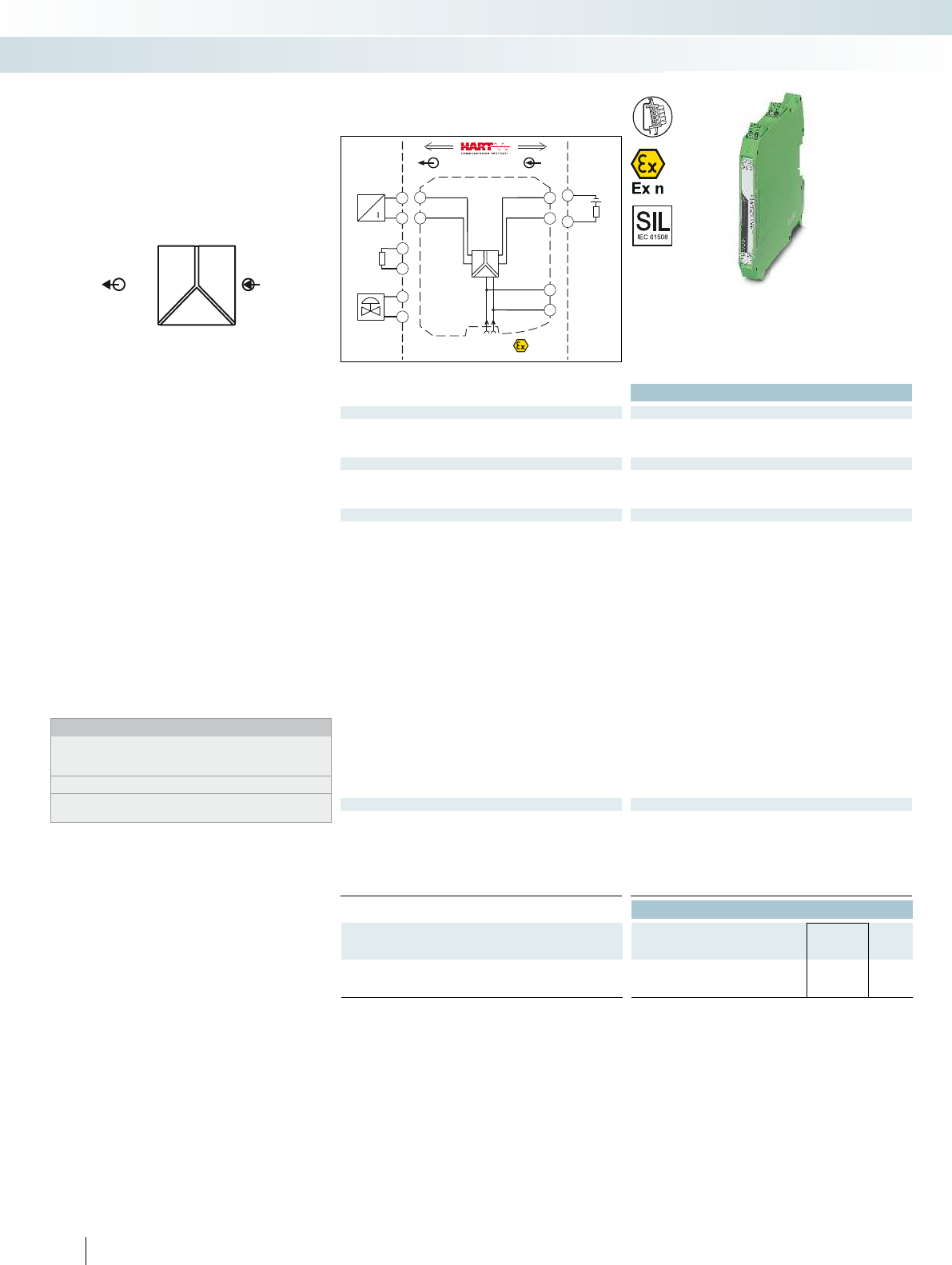
POWER
II
OUTIN
PLC / DCS
active
-
+
3.2
3.1
Sensor /Field
4.2
4.1
4.2
4.1
+
-
+
-
P
4.2
4.1
+
-
Zone 2
Div. 2
INOUT
4.2
4.1
3.2
3.1
1.2
1.1
GND
+24V
GND +24V
Power
+
-
+
-
Functional Safety
Ex:
Housing width 12.5 mm
Technical data
Input data
Input signal 0 mA ... 20 mA / 4 mA ... 20 mA
Input voltage 5.4 V (at 20 mA)
Input impedance in the event of a cable break at the output > 100 k (If there is a line fault)
Output data
Output signal 0 mA ... 20 mA / 4 mA ... 20 mA
Load < 800 (20 mA)
Output ripple < 20 mV
rms
General data
Supply voltage range 19.2 V DC ... 30 V DC (24 V DC (-20% ... +25%))
Current consumption < 46 mA (24 V DC / 20 mA)
Power dissipation < 1.1 W (24 V DC / 20 mA)
Temperature coefficient < 0.01 %/K
Step response (10-90%) < 140 µs (for 4 mA ... 20 mA step)
Maximum transmission error < 0.1 % (of final value)
Electrical isolation
Input/output/power supply 1.5 kV (50 Hz, 1 min., test voltage)
300 V
rms
(rated insulation voltage (surge voltage category II,
pollution degree 2))
Ambient temperature range -20 °C ... 60 °C (any mounting position)
Humidity 10 % ... 95 % (non-condensing)
SMART communication Yes
Signal bandwidth as per HART specifications
Protocols supported HART
Housing material PA 66-FR
Inflammability class in acc. with UL 94 V0
Dimensions W / H / D 12.5 / 99 / 114.5 mm
Screw connection solid / stranded / AWG 0.2 ... 2.5 mm² / 0.2 ... 2.5 mm² / 24 - 14
Push-in connection solid / stranded / AWG 0.2 ... 1.5 mm² / 0.2 ... 1.5 mm² / 24 - 16
EMC note Class A product, see page 625
Conformance / approvals
Conformance CE-compliant, additionally EN 61326
ATEX
II 3 G Ex nA IIC T4 Gc X
UL, USA / Canada UL 508 Listed
UL 61010 Listed
Class I, Div. 2, Groups A, B, C, D T4
Class I, Zone 2, Group IIC T4
SIL in accordance with IEC 61508 2
Ordering data
Description Type Order No. Pcs. /
Pkt.
Output signal conditioner
Screw connection MACX MCR-SL-IDSI-I 2865971 1
Push-in connection MACX MCR-SL-IDSI-I-SP 2924223 1
162
PHOENIX CONTACT
Output signal conditioner for controlling
I/P transducers, control valves, and displays
– 0/4...20 mA input
– 0/4 ... 20 mA output
– Bidirectional transmission of digital HART
communication signals
– Plug-in screw or push-in connection
technology, with integrated sockets for
HART communicators
– Line fault detection (LF)
– 3-way electrical isolation
– Power supply via DIN rail connector
possible
– Up to SIL 2 according to IEC 61508
– Installation in zone 2 permitted
Notes:
Information about the power and fault signaling module as well as
about the DIN rail connectors and marking material can be found
from page 178
Test plugs for test sockets can be found on page 180
Information on Plug and Play connection using system cabling can
be found from page 182
Analog OUT
Output signal conditioner
MCR technology
Signal conditioners with SIL functional safety - MACX Analog
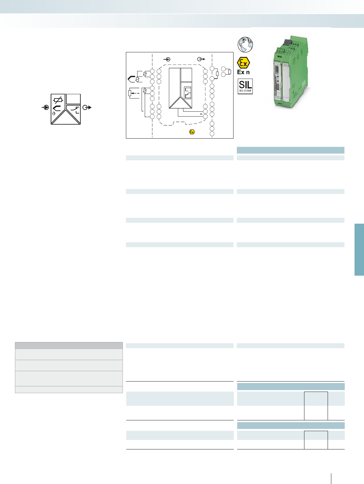
OUT
IN
POWER
U,I
3x
3x
Zone 2
Div. 2
IN OUT
Power
24V ...230V AC/DC
3.3
3.1
1.2
3.2
1.1
1.3
4.3
4.1
4.2
5.3
5.1
5.2
GND
I
U
OUT
OUT
NC
PLC / DCS
passive
-
+
3.3
3.2
-
+
3.3
3.1
11
21
31
12
22
32
14
24
34
3.6
3.4
3.5
2.6
2.4
2.5
1.6
1.4
1.5
DI
DI
DI
Sensor /Field
4.3
4.1
4.2
ϑ
RTD
4.3
4.1
4.2
5.3
5.1
5.2
ϑ
Poti
TC
-
+
ϑ
For further information and full technical data, visit phoenixcontact.net/products
Functional Safety
Ex:
Housing width 35 mm
Technical data
Input data
Resistance thermometers Pt, Ni, Cu sensors: 2, 3, 4-wire
Thermocouple sensors B, E, J, K, N, R, S, T, L, U, CA, DA, A1G, A2G, A3G, MG, LG
Resistor 0 ... 50 k
Potentiometer 0 ... 50 k
Voltage -1000 mV ... 1000 mV
Output data U output I output
Output signal 0 mA ... 20 mA ±10 V
(in the case of SIL; further free configuration without SIL)
Maximum output signal ± 11 V 22 mA
Load R
B
10 k 600 (at 20 mA)
Behavior in the event of a sensor error according to NE 43 or freely configurable
Switching output Relay output
Contact type 3 PDTs
Contact material AgSnO
2
, hard gold-plated
Max. switching voltage 250 V AC (250 V DC)
Max. switching current 2 A (250 V AC) / 2 A (28 V DC)
General data
Supply voltage range 24 V ... 230 V AC/DC (-20%/+10%, 50/60 Hz)
Power consumption < 2.4 W
Temperature coefficient 0.01 %/K
Transmission error, total -
Electrical isolation
Input/output/power supply 300 V
rms
(rated insulation voltage (surge voltage category II;
pollution degree 2, safe isolation as per EN 61010-1))
2.5 kV (50 Hz, 1 min., test voltage)
Input/output 375 V (peak value in accordance with EN 60079-11)
Input/power supply 375 V (peak value in accordance with EN 60079-11)
Input/switching output 375 V (peak value in accordance with EN 60079-11)
Ambient temperature range -20 °C ... 65 °C
Humidity typ. 5 % ... 95 % (non-condensing)
Housing material PA 66-FR
Inflammability class in acc. with UL 94 V0
Dimensions W / H / D 35 / 99 / 114.5 mm
Screw connection solid / stranded / AWG 0.2 ... 2.5 mm² / 0.2 ... 2.5 mm² / 24 - 14
Push-in connection solid / stranded / AWG 0.2 ... 1.5 mm² / 0.2 ... 1.5 mm² / 24 - 16
EMC note Class A product, see page 625
Conformance / approvals
Conformance CE-compliant
ATEX
II 3 G Ex nA nC ic IIC T4 Gc X
IECEx Ex nA nC ic IIC T4 Gc X
UL, USA / Canada UL 508 Listed
Class I, Div. 2, Groups A, B, C, D T6
Class I, Zone 2, Group IIC T6
SIL in accordance with IEC 61508 2
Ordering data
Description Type Order No. Pcs. /
Pkt.
Temperature transducer
Standard configuration Screw connection MACX MCR-T-UIREL-UP 2811378 1
Standard configuration Push-in connection MACX MCR-T-UIREL-UP-SP 2811828 1
Accessories
Programming adapter for configuring modules with
S-PORT interface
IFS-USB-PROG-ADAPTER 2811271 1
Cold junction compensation connector for thermocouples MACX MCR-CJC 2924993 1
163
PHOENIX CONTACT
Universal temperature transducer with
freely configurable properties
– Input for resistance thermometers,
thermocouples, resistance-type sensors,
potentiometers, and mV sources
– Measure differential temperatures
– Freely programmable input and output
– Option of inverse output signal ranges
– Three limit value relays, can be used in
combination as a safe limit value relay
– Configuration via software (FDT-DTM) or
IFS-OP-UNIT operating and display unit
– Programming during operation and also
voltage-free using IFS-USB-PROG-
ADAPTER programming adapter
– Plug-in screw or push-in connection
technology
– Cold junction compensation with
separate connector
– Wide range power supply:
19.2 ... 253 V AC/DC
– Status indicator for supply voltage, cable,
sensor, and module errors
– Up to SIL 2 according to IEC 61508
– Installation in zone 2 permitted
Notes:
To order a product with an order configuration, enter the required
configuration by referring to the adjacent order key.
The configuration software can be downloaded from the Internet
(phoenixcontact.net/products).
Information on the IFS-OP-UNIT operating and display unit and the
associated IFS-OP-CRADLE DIN rail cradle can be found on page
170
For information on the programming adapter, refer to page 89
Temperature,
temperature transducer
MCR technology
Signal conditioners with SIL functional safety - MACX Analog
Universal, with three limit value relays, wide
range power supply
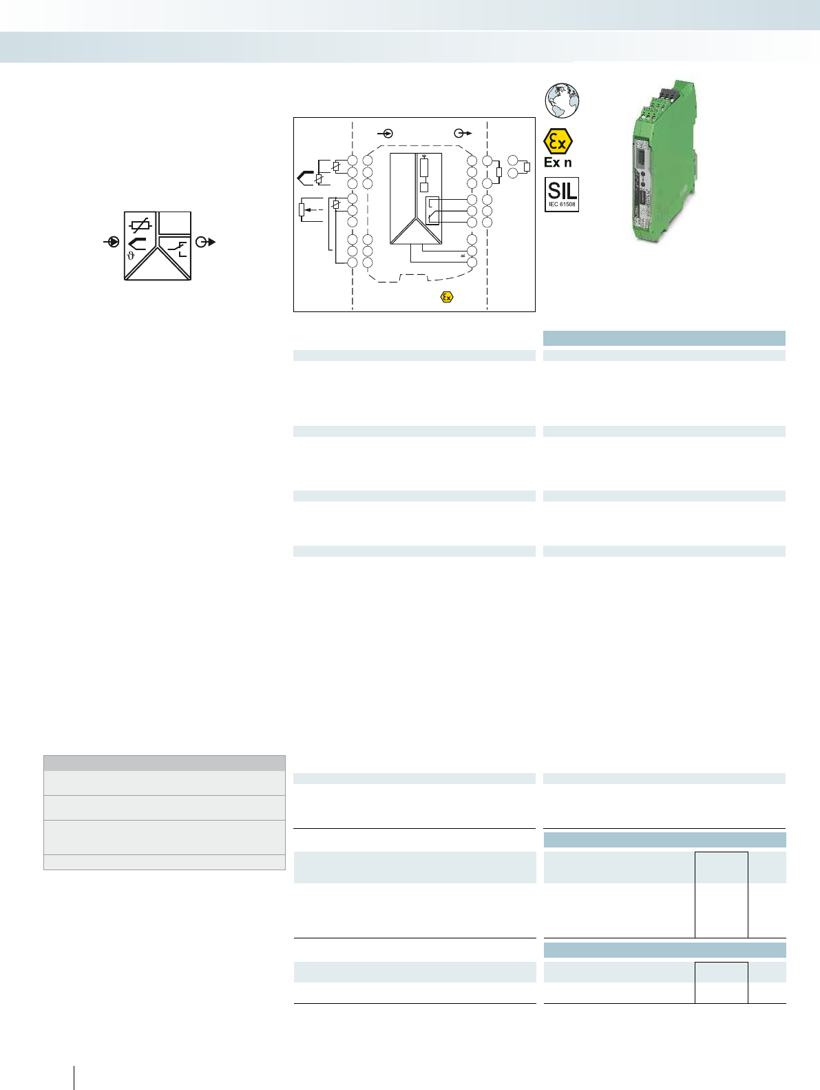
OUT
IN
POWER
U,I
PLC / DCS
passive
-
+
3.3
3.2
-
+
3.3
3.1
DI
11
12
14
2.3
2.1
2.2
Zone 2
Div. 2
IN OUT
Power
24V ...230V AC/DC
3.3
3.1
1.2
3.2
1.1
2.3
2.1
2.2
1.3
4.3
4.1
4.2
5.3
5.1
5.2
μC
S-PORT
GND
I
U
OUT
OUT
NC
Sensor /Field
4.3
4.1
4.2
TC
-
+
ϑ
RTD
ϑ
4.3
4.1
4.2
5.3
5.1
5.2
ϑ
Poti
Functional Safety
Ex:
Housing width 17.5 mm
Technical data
Input data
Resistance thermometers Pt, Ni, Cu sensors: 2, 3, 4-wire
Thermocouple sensors B, E, J, K, N, R, S, T, L, U, CA, DA, A1G, A2G, A3G, MG, LG
Resistor 0 ... 50 k
Potentiometer 0 ... 50 k
Voltage -1000 mV ... 1000 mV
Output data U output I output
Output signal 0 mA ... 20 mA ±10 V
(in the case of SIL; further free configuration without SIL)
Maximum output signal ± 11 V 22 mA
Load R
B
10 k 600 (20 mA)
Behavior in the event of a sensor error according to NE 43 or freely configurable
Switching output Relay output
Contact type 1 PDT
Contact material AgSnO
2
, hard gold-plated
Max. switching voltage 30 V AC (30 V DC)
Max. switching current 0.5 A (30 V AC) / 1 A (30 V DC)
General data
Supply voltage range 24 V ... 230 V AC/DC (-20%/+10%, 50/60 Hz)
Power consumption < 1.5 W
Temperature coefficient 0.01 %/K
Transmission error, total < 0.1 % (e.g., for Pt 100, 300 K span, 4 ... 20 mA)
Electrical isolation
Input/output/power supply 300 V
rms
(rated insulation voltage (surge voltage category II;
pollution degree 2, safe isolation as per EN 61010-1))
2.5 kV (50 Hz, 1 min., test voltage)
Input/output 375 V (peak value in accordance with EN 60079-11)
Input/power supply 375 V (peak value in accordance with EN 60079-11)
Input/switching output 375 V (peak value in accordance with EN 60079-11)
Ambient temperature range -20 °C ... 65 °C
Humidity typ. 5 % ... 95 % (non-condensing)
Housing material PA 66-FR
Inflammability class in acc. with UL 94 V0
Dimensions W / H / D 17.5 / 99 / 114.5 mm
Screw connection solid / stranded / AWG 0.2 ... 2.5 mm² / 0.2 ... 2.5 mm² / 24 - 14
Push-in connection solid / stranded / AWG 0.2 ... 1.5 mm² / 0.2 ... 1.5 mm² / 24 - 16
EMC note Class A product, see page 625
Conformance / approvals
Conformance CE-compliant
ATEX
II 3 G Ex nA nC ic IIC T4 Gc X
IECEx Ex nA nC ic IIC T4 Gc X
SIL in accordance with IEC 61508 2
Ordering data
Description Type Order No. Pcs. /
Pkt.
Temperature transducer
Standard configuration Screw connection MACX MCR-T-UI-UP 2811394 1
Standard configuration Push-in connection MACX MCR-T-UI-UP-SP 2811860 1
Order configuration Screw connection MACX MCR-T-UI-UP-C 2811873 1
Order configuration Push-in connection MACX MCR-T-UI-UP-SP-C 2811970 1
Accessories
Programming adapter for configuring modules with
S-PORT interface
IFS-USB-PROG-ADAPTER 2811271 1
Cold junction compensation connector for thermocouples MACX MCR-CJC 2924993 1
164
PHOENIX CONTACT
Universal temperature transducer with
freely configurable properties
– Input for resistance thermometers,
thermocouples, resistance-type sensors,
potentiometers, and mV sources
– Measure differential temperatures
– Freely programmable input and output
– Option of inverse output signal ranges
– Relay switching output
– Configuration via software (FDT-DTM) or
IFS-OP-UNIT operating and display unit
– Programming during operation and also
voltage-free using IFS-USB-PROG-
ADAPTER programming adapter
– Plug-in screw or push-in connection
technology
– Cold junction compensation with
separate connector
– Wide range power supply:
19.2 ... 253 V AC/DC
– Status indicator for supply voltage, cable,
sensor, and module errors
– Up to SIL 2 according to IEC 61508
– Installation in zone 2 permitted
Notes:
To order a product with an order configuration, enter the required
configuration by referring to the adjacent order key.
The configuration software can be downloaded from the Internet
(phoenixcontact.net/products).
Information on the IFS-OP-UNIT operating and display unit and the
associated IFS-OP-CRADLE DIN rail cradle can be found on
page 170
For information on the programming adapter, refer to page 89
Temperature,
temperature transducer
MCR technology
Signal conditioners with SIL functional safety - MACX Analog
Universal, with switching output,
wide range power supply

For further information and full technical data, visit phoenixcontact.net/products
165PHOENIX CONTACT
Order key for MACX MCR-T-UI-UP(-SP)-C temperature transducer (standard configuration entered as an example)
Order No. Safety integrity level
(SIL)
Sensor type Connection
technology
Cold junction
compensation
Measuring range: Measuring
unit
Output range Factory calibration
certificate = FCC
Start End
2811873 / ON / PT100 / 4 / 0 / -50 / 150 / C / OUT02 / NONE
2811873 =
MACX MCR-
T-UI-UP-C
ON =active See below 2 =2-wire 0 =off, e.g., with
RTD, R,
potentiometer,
mV
see
below
see
below
C=°C OUT15 =0 ... 5 mA NONE =without FCC
F=°F OUT16 =0 ... 10 mA
NONE =not active O=OUT01 =0 ... 20 mA
3=3-wire P =% OUT15 =0 ... 5 mA YES =with FCC (a fee is
charged)
2811970 =
MACX MCR-
T-UI-UP-SP-C
V=mV OUT25 =1 ... 5 mA
ON only with output
range = OUT02
1=on, e.g., with TC OUT26 =2 ... 10 mA
4=4-wire OUT02 =4 ... 20 mA
OUT05 =0 ... 5 V YESPLUS =FCC with
5 measuring points
(a fee is charged)
OUT03 =0 ... 10 V
OUT06 =1 ... 5 V
OUT04 =2 ... 10 V
OUT13 =-5 ... +5 V
OUT14 =-10...+10 V
Others can be freely
configured in the
software
Smallest measuring
range span
Other setting options can be configured
with the IFS-CONF software:
- Freely configurable user characteristic curve
with 30 interpolation points
- Output behavior in the event of a short circuit,
sensor break or overrange/underrange can be
freely configured or set acc. to NE43
(standard configuration: NE43 upscale)
- Filter setting (standard configuration: 1)
- Restart after failsafe (standard configuration:
ON)
- Switching behavior: switching output
(limit values, times, etc.)
(standard configuration: OFF)
Resistance thermometers (RTD)
Others can be selected or freely
configured in the software.
PT100 =Pt 100 acc. to IEC 751 -200 850 °C 20 K
PT200 =Pt 200 acc. to IEC 751 -200 850 °C 20 K
PT500 =Pt 500 acc. to IEC 751 -200 850 °C 20 K
PT1000 =Pt 1000 acc. to IEC 751 -200 850 °C 20 K
PT100S =
Pt 100 acc. to Sama RC21-4-1966
-200 850 °C 20 K
PT1000S =
Pt 1000 acc. to Sama RC21-4-1966
-200 850 °C 20 K
PT100G =Pt 100 acc. to
GOST 6651-2009 (
= 0.00385)
-200 850 °C 20 K
PT1000G =Pt 1000 acc. to
GOST 6651-2009 (
= 0.00385)
-200 850 °C 20 K
PT100J =Pt 100 acc. to JIS C1604/1997 -200 850 °C 20 K
PT1000J =Pt 1000 acc. to JIS C1604/1997 -200 850 °C 20 K
NI100 =Ni 100 acc. to DIN 43760/DIN IEC 60751 -60 250 °C 20 K
NI1000 =Ni 1000 acc. to DIN 43760/DIN IEC 60751 -60 250 °C 20 K
NI100S =Ni 100 acc. to Sama RC21-4-1966 -60 180 °C 20 K
NI1000S =Ni 1000 acc. to Sama RC21-4-1966 -60 180 °C 20 K
NI1000L =Ni 1000 (Landis & Gyr) -50 160 °C 20 K
CU10 =Cu 10 acc. to Sama RC21-4-1966 -70 500 °C 100 K
CU50 =
Cu50 acc. to GOST 6651-2009 (
= 0.00428)
-50 200 °C 100 K
CU100 =
Cu100 acc. to GOST 6651-2009 (
= 0.00428)
-50 200 °C 100 K
CU53 =
Cu53 acc. to GOST 6651-2009 (
= 0.00426)
-50 180 °C 100 K
KTY81 =KTY81-110 (Philips) -55 150 °C 20 K
KTY84 =KTY84-130 (Philips) -40 300 °C 20 K
Thermocouples (TC)
Others can be selected in the software.
B =acc. to IEC 584-1 (Pt30Rh-Pt6Rh) 500 1820 °C 50 K
E=acc. to IEC 584-1 (NiCr-CuNi) -230 1000 °C 50 K
J =acc. to IEC 584-1 (Fe-CuNi) -210 1200 °C 50 K
K=acc. to IEC 584-1 (NiCr-Ni) -250 1372 °C 50 K
N=acc. to IEC 584-1 (NiCrSi-NiSi) -250 1300 °C 50 K
R=acc. to IEC 584-1 (Pt13Rh-Pt) -50 1768 °C 50 K
S=acc. to IEC 584-1 (Pt10Rh-Pt) -50 1768 °C 50 K
T=acc. to IEC 584-1 (Cu-CuNi) -200 400 °C 50 K
L=acc. to DIN 43760 (Fe-CuNi) -200 900 °C 50 K
U=acc. to DIN 43760 (Cu-CuNi) -200 600 °C 50 K
CA =C ASTM JE988 (2002) 02315 °C 50 K
DA =D ASTM JE988 (2002) 0 2315 °C 50 K
A1G =A-1 GOST 8.585-2001 02500 °C 50 K
A2G =A-2 GOST 8.585-2001 0 1800 °C 50 K
A3G =A-3 GOST 8.585-2001 01800 °C 50 K
MG =M GOST 8.585-2001 -200 100 °C 50 K
LG =L GOST 8.585-2001 -200 800 °C 50 K
Remote resistance-type sensors (R)
(2, 3, 4-wire)
Others can be selected in the software.
RES03 =0 ... 150 resistor 0150
10% of the selected
measuring range
RES05 =0 ... 600 resistor 0 600
RES06 =0 ... 1200 resistor 01200
RES09 =0 ... 6250 resistor 0 6250
RES10 =0 ... 12500 resistor 012500
RES12 =0 ... 50000 resistor 0 50000
Potentiometers
(3-wire)
Others can be selected in the software.
POT03 =0 ... 150 potentiometer 0100 %
10% of the selected
measuring range
POT05 =0 ... 600 potentiometer 0 100 %
POT06 =0 ... 1200 potentiometer 0100 %
POT09 =0 ... 6250 potentiometer 0 100 %
POT10 =0 ... 12500 potentiometer 0100 %
POT12 =0 ... 50000 potentiometer 0 100 %
Voltage signals (mV)
Others can be selected in the software.
V04 =Voltage (mV) -1000 +1000 mV 10% of nominal
span
9
T [°F] = – T [°C] + 32
5
Temperature conversion guide for °C to °F:
MCR technology
Signal conditioners with SIL functional safety - MACX Analog
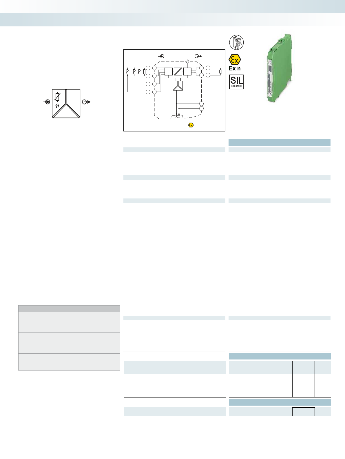
OUT
IN
POWER
I
Zone 2
Div. 2
IN OUT
PLC / DCS
passive
-
+
3.2
3.1
GND
+24V
GND +24V
+
-
μC μC
Power
4.2
5.2
4.1
5.1
3.2
3.1
1.2
1.1
Sensor /Field
4.2
4.1
5.2
5.1
ϑϑϑ
Ex:
Housing width 12.5 mm
Technical data
Input data
Resistance thermometers Pt, Ni, Cu sensors: 2, 3, 4-wire
Resistor 0 ... 2000
Cable resistance 50 per line
Sensor input current 200 A ... 1 mA
Measuring range span > 50 K
Output data
Output signal 0 mA ... 20 mA / 4 mA ... 20 mA
Load 500
Behavior in the event of a sensor error As per NE 43 or can be freely defined
Output ripple < 50 µA
PP
General data
Supply voltage range 19.2 V DC ... 30 V DC (24 V DC (-20% ... +25%))
Current consumption < 40 mA (24 V DC)
Power dissipation < 1 W
Temperature coefficient 0.01 %/K
Step response (0–99%) typ. 800 ms (with SIL)
max. 1200 ms (with SIL)
typ. 700 ms (without SIL)
max. 1100 ms (without SIL)
Transmission error, total 0.05 % x 100 [K] / measuring range span [K] + 0.05 %
ZERO / SPAN adjustment ± 5 % / ± 5 %
Electrical isolation
Input/output/power supply 2.5 kV (50 Hz, 1 min., test voltage)
300 V
rms
(rated insulation voltage (surge voltage category II;
pollution degree 2, safe isolation as per EN 61010-1))
Input/output 375 V (peak value in accordance with EN 60079-11)
Input/power supply 375 V (peak value in accordance with EN 60079-11)
Ambient temperature range -20 °C ... 60 °C (any mounting position)
Humidity 5 % ... 95 % (non-condensing)
Housing material PA 66-FR
Inflammability class in acc. with UL 94 V0
Dimensions W / H / D 12.5 / 99 / 114.5 mm
Screw connection solid / stranded / AWG 0.2 ... 2.5 mm² / 0.2 ... 2.5 mm² / 24 - 14
Push-in connection solid / stranded / AWG 0.2 ... 1.5 mm² / 0.2 ... 1.5 mm² / 24 - 16
EMC note Class A product, see page 625
Conformance / approvals
Conformance CE-compliant, additionally EN 61326
ATEX
II 3G Ex nA ic IIC T4 Gc X
UL, USA / Canada UL 508 Listed
UL 61010 Listed
Class I, Div. 2, Groups A, B, C, D T4
Class I, Zone 2, Group IIC T4
SIL in accordance with IEC 61508 2
Ordering data
Description Type Order No. Pcs. /
Pkt.
Temperature transducer
Order configuration Screw connection MACX MCR-SL-RTD-I 2865065 1
Order configuration Push-in connection MACX MCR-SL-RTD-I-SP 2924317 1
Standard configuration Screw connection MACX MCR-SL-RTD-I-NC 2865078 1
Standard configuration Push-in connection MACX MCR-SL-RTD-I-SP-NC 2924320 1
Accessories
Programming adapter for configuring modules with
S-PORT interface
IFS-USB-PROG-ADAPTER 2811271 1
166
PHOENIX CONTACT
Programmable temperature transducer
for operating resistance thermometers and
resistance-type sensors. The measured
values are converted into a linear 0 ... 20 mA
or 4 ... 20 mA signal.
– Input for resistance thermometers and
resistance-type sensors
– 0 ... 20 mA or 4 ... 20 mA output
– Configuration via software (FDT/DTM):
Sensor type, connection method,
measuring range, measuring unit, filter,
alarm signal, and output range
– Programming during operation and also
voltage-free using IFS-USB-PROG-
ADAPTER programming adapter
– Status indicator for supply voltage, cable,
sensor, and module errors
– 3-way electrical isolation
– Power supply via DIN rail connector
possible
– Up to SIL 2 according to IEC 61508
– Installation in zone 2 permitted
Notes:
To order a product with an order configuration, enter the required
configuration by referring to the adjacent order key.
The configuration software can be downloaded from the Internet
(phoenixcontact.net/products).
Information about the power and fault signaling module as well as
about the DIN rail connectors and marking material can be found
from page 178
For information on the programming adapter, refer to page 89
Test plugs for test sockets can be found on page 180
Information on Plug and Play connection using system cabling can
be found from page 182
Temperature,
temperature transducer
MCR technology
Signal conditioners with SIL functional safety - MACX Analog
For resistance thermometers and resistance-
type sensors
For further information and full technical data, visit phoenixcontact.net/products
167PHOENIX CONTACT
Order key for MACX MCR-SL-RTD-I(-SP) temperature transducer (standard configuration entered as an example)
Order key and temperature ranges
for the MACX MCR-SL-RTD-I(-SP)
temperature transducer
Alarm signal Alarm signal
Factory calibration certificate = FCC
Short circuit/
Overrange
Sensor break/
Underrange
... / I035 / I215 / NONE Temperature conversion guide for °C to °F:
9
T [°F] = – T [°C] + 32
5
I000 =0 mA I000 =0 mA NONE =without FCC
I035 =3.5 mA I035 =3.5 mA YES =with FCC (a fee is charged)
I215 =21.5 mA I215 =21.5 mA YESPLUS =FCC with 5 measuring points
(a fee is charged)
I035 only with output range = OUT02
Alarm signals can also be configured individually using
software.
Order No. Sensor type Safety integrity level
(SIL)
Connection
technology
Measuring range: Measuring
unit
Output range Filter Filter
Start End Oversampling Moving mean value
2865065 / Pt100 / ON / 3 / 0 / 100 / C / OUT02 / 10 / 1 / ...
2865065 =
MACX MCR-
SL-RTD-I
See below ON =Active 2 =2-wire see
below
see
below
C=°C OUT01 = 0 ... 20 mA 1 =1 value 1 =1 value
NONE =not active F =°F 3 =3 values 2 =2 values
3=3-wire O =OUT02 = 4...20 mA 5 =5 values 3 =3 values
ON only with output range
= OUT02
7=7 values 4 =4 values
2924317 =
MACX MCR-
SL-RTD-I-SP
4=4-wire 10 =10 values
20 =20 values
Smallest measuring
range span
RES01 =Resistor 0 2000 25
PT50 =Pt 50 acc. to IEC 751 -200 850 °C 50 K
Pt100 =Pt 100 acc. to IEC 751 -200 850 °C 50 K
Pt200 =Pt 200 acc. to IEC 751 -200 850 °C 50 K
Pt500 =Pt 500 acc. to IEC 751 -200 850 °C 50 K
PT100S =Pt 100 acc. to Sama RC21-4-1966 -200 600 °C 50 K
PT500S =Pt 500 acc. to Sama RC21-4-1966 -200 600 °C 50 K
NI100DIN =Ni 100 acc. to DIN 43760 -60 250 °C 50 K
NI500DIN =Ni 500 acc. to DIN 43760 -60 250 °C 50 K
CU50 =
Cu 50 acc. to GOST 6651-2009 (
= 0.00428)
-50 200 °C 50 K
CU53 =
Cu 53 acc. to GOST 6651-2009 (
= 0.00426)
-50 180 °C 50 K
MCR technology
Signal conditioners with SIL functional safety - MACX Analog
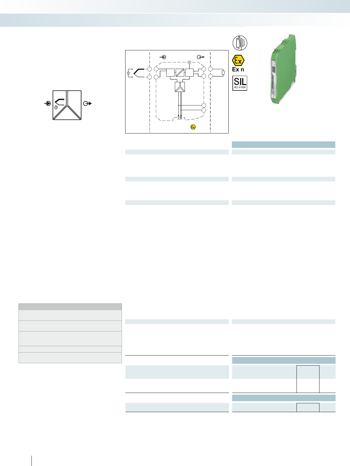
OUT
IN
POWER
I
PLC/DCS
passive
-
+
3.2
3.1
Zone 2
Div. 2
INOUT
GND
+24V
GND+24V
+
-
μCμC
Power
4.2
4.1
3.2
3.1
1.2
1.1
+
-
Sensor /Field
4.2
4.1
Ex:
Housing width 12.5 mm
Technical data
Input data
Thermocouple sensors E, J, K, N as per IEC / EN 60584, L as per DIN 43760
Voltage -20 mV ... 70 mV
Measuring range span Min. 50 K for thermocouples, 3 mV for mV sources
Output data
Output signal 0 mA ... 20 mA / 4 mA ... 20 mA
Load max. 500
Behavior in the event of a sensor error As per NE 43 or can be freely defined
Output ripple < 50 µA
PP
General data
Supply voltage range 19.2 V DC ... 30 V DC (24 V DC (-20% ... +25%))
Current consumption < 40 mA (24 V DC)
Power dissipation < 1 W
Temperature coefficient 0.01 %/K
Step response (0–99%) typ. 800 ms (with SIL)
max. 1200 ms (with SIL)
typ. 700 ms (without SIL)
max. 1100 ms (without SIL)
Transmission error, total 0.05% x 200 [K]/Measuring range span [K] + 0.05%
Cold junction errors ± 1 K
ZERO / SPAN adjustment ± 5 % / ± 5 %
Electrical isolation
Input/output/power supply 300 V
rms
(rated insulation voltage (surge voltage category II;
pollution degree 2, safe isolation as per EN 61010-1))
2.5 kV (50 Hz, 1 min., test voltage)
Input/output 375 V (peak value in accordance with EN 60079-11)
Input/power supply 375 V (peak value in accordance with EN 60079-11)
Ambient temperature range -20 °C ... 60 °C (any mounting position)
Humidity 5 % ... 95 % (non-condensing)
Housing material PA 66-FR
Inflammability class in acc. with UL 94 V0
Dimensions W / H / D 12.5 / 99 / 114.5 mm
Screw connection solid / stranded / AWG 0.2 ... 2.5 mm² / 0.2 ... 2.5 mm² / 24 - 14
EMC note Class A product, see page 625
Conformance / approvals
Conformance CE-compliant, additionally EN 61326
ATEX
II 3G Ex nA ic IIC T4 Gc X
UL, USA / Canada UL 508 Listed
UL 61010 Listed
Class I, Div. 2, Groups A, B, C, D T4
Class I, Zone 2, Group IIC T4
SIL in accordance with IEC 61508 2
Ordering data
Description Type Order No. Pcs. /
Pkt.
Temperature transducer
Order configuration Screw connection MACX MCR-SL-TC-I 2924333 1
Standard configuration Screw connection MACX MCR-SL-TC-I-NC 2924346 1
Accessories
Programming adapter for configuring modules with
S-PORT interface
IFS-USB-PROG-ADAPTER 2811271 1
168
PHOENIX CONTACT
Programmable temperature transducer
for operating thermocouples and mV
sources. The measured values are
converted into a linear 0 ... 20 or 4 ... 20 mA
signal.
– Input for thermocouples and mV sources
– 0 ... 20 mA or 4 ... 20 mA output
– Configuration via software (FDT/DTM):
Sensor type, connection method,
measuring range, measuring unit, filter,
alarm signal, and output range
– Programming during operation and also
voltage-free using IFS-USB-PROG-
ADAPTER programming adapter
– Status indicator for supply voltage, cable,
sensor, and module errors
– 3-way electrical isolation
– Power supply via DIN rail connector
possible
– Up to SIL 2 according to IEC 61508
– Installation in zone 2 permitted
Notes:
To order a product with an order configuration, enter the required
configuration by referring to the adjacent order key.
The configuration software can be downloaded from the Internet
(phoenixcontact.net/products).
Information about the power and fault signaling module as well as
about the DIN rail connectors and marking material can be found
from page 178
For information on the programming adapter, refer to page 89
Information on Plug and Play connection using system cabling can
be found from page 182
Temperature,
temperature transducer
MCR technology
Signal conditioners with SIL functional safety - MACX Analog
For thermocouples and mV sources
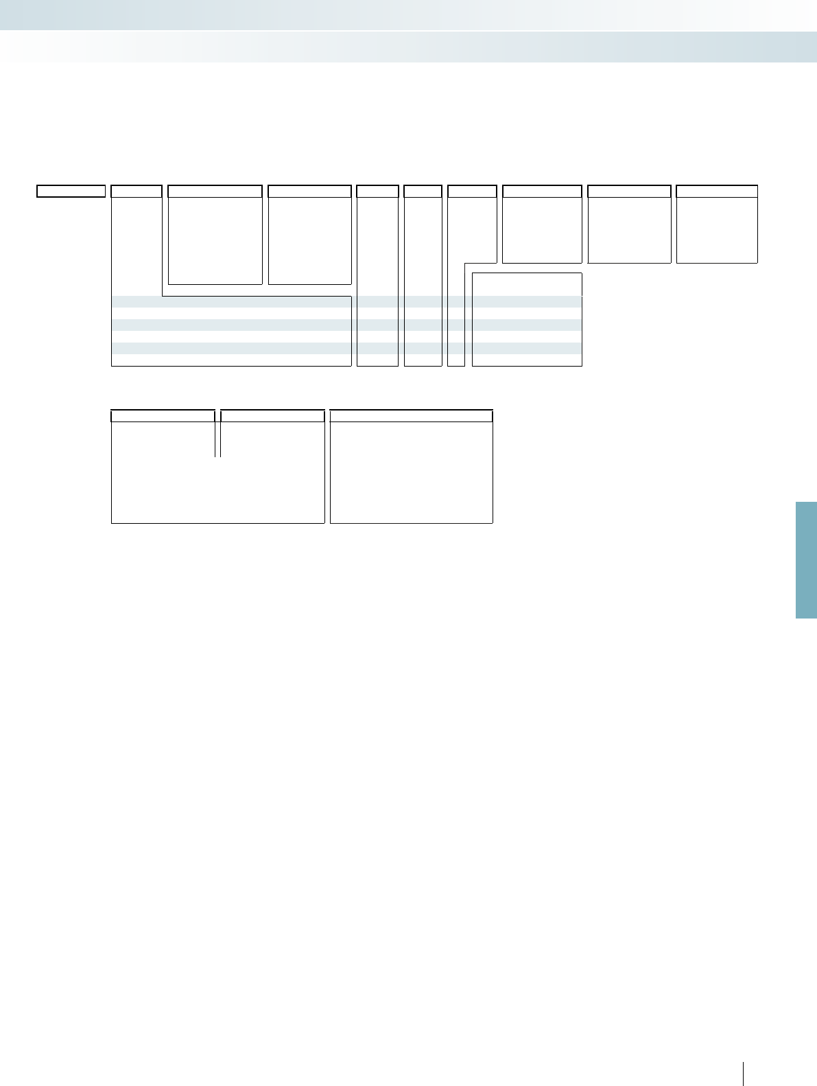
For further information and full technical data, visit phoenixcontact.net/products
169PHOENIX CONTACT
Order key for MACX MCR-SL-TC-I temperature transducer (standard configuration entered as an example)
Order key and temperature ranges
for the MACX MCR-SL-TC-I
temperature transducer
Order No. Sensor type Safety integrity level
(SIL)
Cold junction
compensation
Measuring range: Measuring
unit
Output range Filter Filter
Start End Oversampling Moving mean value
2924333 / J / ON / 1 / 0 / 1000 / C / OUT02 / 10 / 1 / ...
MACX MCR-
SL-TC-I
see below ON =active 1 =switched on see
below
see
below
C=°C OUT01 = 0 ... 20 mA 1 =1 value 1 =1 value
NONE =not active F =°F 3 =3 values 2 =2 values
0=switched off
(e.g., for mV
voltage
measurement)
V=mV OUT02 = 4 ... 20 mA 5 =5 values 3 =3 values
7=7 values 4 =4 values
10 =10 values
ON only with output range
= OUT02
20 =20 values
Smallest measuring
range span
V03 =Voltage (mV) -20 +70 mV 3 mV
E=acc. to IEC 584-1 (NiCr-CuNi) -250 1000 °C 50 K
J =acc. to IEC 584-1 (Fe-CuNi) -210 1200 °C 50 K
K=acc. to IEC 584-1 (NiCr-Ni) -250 1372 °C 50 K
N=acc. to IEC 584-1 (NiCrSi-NiSi) -250 1300 °C 50 K
L=acc. to DIN 43760 (Fe-CuNi) -200 900 °C 50 K
Alarm signal Alarm signal
Factory calibration certificate = FCC
Overrange Sensor break/
Underrange
... / I035 / I215 / NONE Temperature conversion guide for °C to °F:
9
T [°F] = – T [°C] + 32
5
I000 =0 mA I000 =0 mA NONE =without FCC
I035 =3.5 mA I035 =3.5 mA YES =with FCC (a fee is charged)
I215 =21.5 mA I215 =21.5 mA YESPLUS =FCC with 5 measuring points
(a fee is charged)
I035 only with output range = OUT02
Alarm signals can also be configured individually using
software.
MCR technology
Signal conditioners with SIL functional safety - MACX Analog

Technical data
General data
Ambient temperature range -20 °C ... 65 °C (-4°F ... 149°F)
Humidity 90 % (at 25 °C, non-condensing)
Housing material PA 6.6
Dimensions W / H / D 35 / 99 / 20 mm
Connection method PC side S port (socket)
Measuring transducer side S port (connector)
EMC note Class A product, see page 625
Conformance / approvals
Conformance CE-compliant
ATEX
II 3G Ex nA ic IIC T4 Gc X
IECEx Ex nA ic IIC T4 X
Ordering data
Description Type Order No. Pcs. /
Pkt.
Operating and display unit
IFS-OP-UNIT 2811899 1
– Local display of actual values
– Copy function
– Easy guided operation
– Easy configuration without PC software
– Operating and display unit can be snapped
directly onto compatible devices with a
housing width of 35 mm
– DIN rail mounting possible for thinner
devices in conjunction with cradle unit
– Backlighting
– Installation in zone 2 permitted
Accessories,
operating and display unit
MCR technology
Signal conditioners with SIL functional safety - MACX Analog
Can be snapped directly onto
compatible 35 mm devices
Technical data
General data
Ambient temperature range -20 °C ... 65 °C (-4°F ... 149°F)
Humidity 90 % (at 25 °C, non-condensing)
Housing material PA 6.6
Dimensions W / H / D 35.2 / 29 / 99 mm
Connection method
IFS-OP-UNIT operator interface
S port (socket)
Measuring transducer side S port (connector)
EMC note Class A product, see page 625
Conformance / approvals
Conformance CE-compliant
ATEX
II 3G Ex nA ic IIC T4 Gc X
IECEx Ex nA ic IIC T4 X
Ordering data
Description Type Order No. Pcs. /
Pkt.
Cradle unit, for snapping the operating and display unit onto the
DIN rail
IFS-OP-CRADLE 2811886 1
170
PHOENIX CONTACT
H
W
D
– For snapping onto the DIN rail
– For control cabinet mounting of the
operating and display unit
Accessories,
cradle unit
Cradle for operating and display unit

For further information and full technical data, visit phoenixcontact.net/products
Ex:
Ordering data
Description Type Order No. Pcs. /
Pkt.
Programming adapter for configuring modules with
S-PORT interface
IFS-USB-PROG-ADAPTER 2811271 1
171PHOENIX CONTACT
The IFS-USB-PROG-ADAPTER
programming adapter is used for configuring
Phoenix Contact INTERFACE modules
with S-Port interface.
The adapter is used with FDT/DTM
software or ANALOG-CONF software.
For programming MACX Analog,
MINI Analog Pro, and MINI Analog.
Accessories
Programming adapter
MCR technology
Signal conditioners with SIL functional safety - MACX Analog
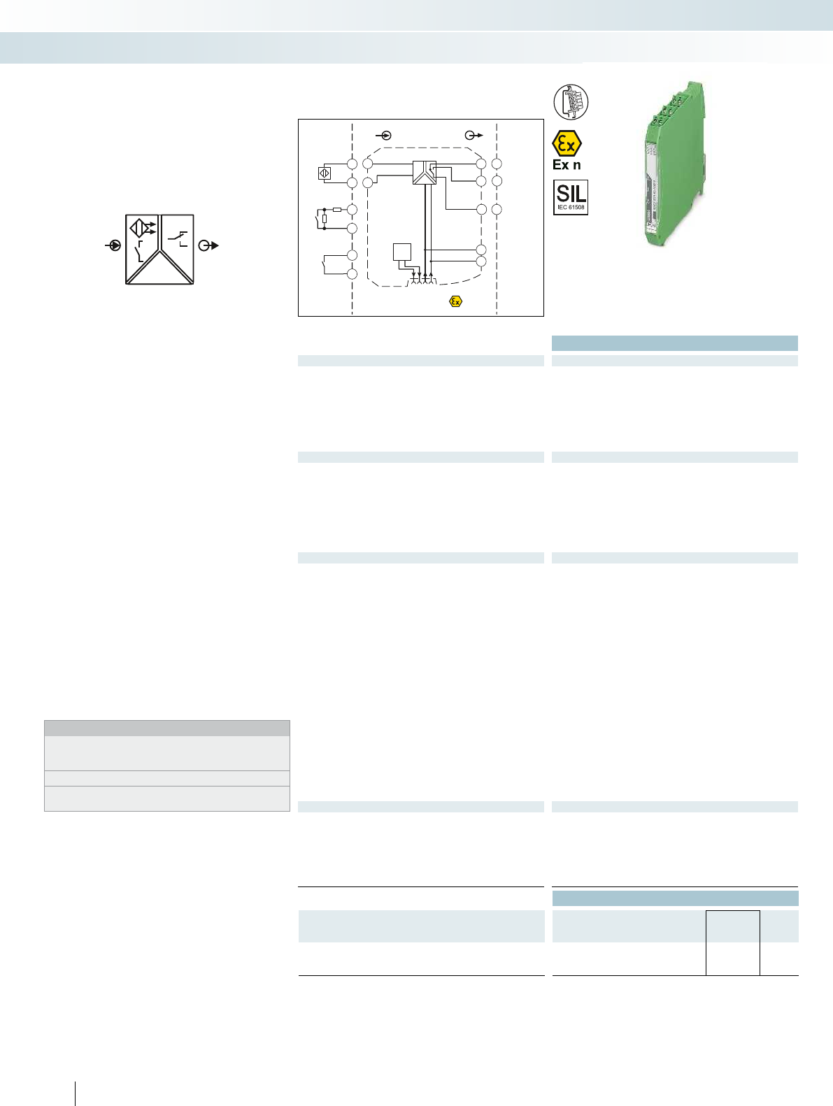
POWER
OUT
IN
Sensor /Field
4.2
4.1
4.2
4.1
+
-
4.2
4.1
Zone 2
Div. 2
IN OUT
GND
+24V
+
-
4.2
4.1
3.2
3.1
1.2
1.1
+
-
Power
Faultsignal
GND
+24VLFD
2.2
PLC / DCS
3.2
3.1
2.2
DI
11
12
14
Functional Safety
Ex:
Housing width 12.5 mm
Technical data
Input data
Input signal NAMUR proximity sensors (EN 60947-5-6)
Floating switch contacts
Switch contacts with resistance circuit
No-load voltage ~ 8 V DC
Switching points > 2.1 mA (conductive) / < 1.2 mA (blocking)
Switching hysteresis < 0.2 mA
Line fault detection Break 0.05 mA < IIN < 0.35 mA
Short circuit 100 < RSensor < 360
Switching output Relay output
Contact type 1 PDT
Contact material AgSnO
2
, hard gold-plated
Max. switching voltage 250 V AC (2 A) / 120 V DC (0.2 A) / 30 V DC (2 A)
Max. switching capacity 500 VA
Recommended minimum load 5 V / 10 mA
Mechanical service life 10
7
cycles
Switching behavior Can be inverted via slide switch
Max. switching frequency 20 Hz (without load)
General data
Supply voltage range 19.2 V DC ... 30 V DC
Current consumption 21 mA (24 V DC)
Power dissipation < 650 mW
Electrical isolation
Input/output 375 V (peak value in accordance with EN 60079-11)
Input/output/supply, DIN rail connector 300 V
rms
(rated insulation voltage (surge voltage category II;
pollution degree 2, safe isolation as per EN 61010-1))
2.5 kV (50 Hz, 1 min., test voltage)
Output/input, supply, TBUS 300 V
rms
(rated insulation voltage (surge voltage category III;
pollution degree 2, safe isolation as per EN 61010-1))
2.5 kV (50 Hz, 1 min., test voltage)
Input/supply, DIN rail connector 375 V (peak value in accordance with EN 60079-11)
Ambient temperature range -20 °C ... 60 °C (any mounting position)
Humidity 10 % ... 95 % (non-condensing)
Housing material PA 66-FR
Inflammability class in acc. with UL 94 V0
Dimensions W / H / D 12.5 / 99 / 114.5 mm
Screw connection solid / stranded / AWG 0.2 ... 2.5 mm² / 0.2 ... 2.5 mm² / 24 - 14
Push-in connection solid / stranded / AWG 0.2 ... 1.5 mm² / 0.2 ... 1.5 mm² / 24 - 16
EMC note Class A product, see page 625
Conformance / approvals
Conformance CE-compliant, additionally EN 61326
ATEX
II 3 G Ex nA nC IIC T4 Gc X
UL, USA / Canada UL 508 Listed
UL 61010 Listed
Class I, Div. 2, Groups A, B, C, D T4
Class I, Zone 2, Group IIC T4
SIL in accordance with IEC 61508 2
Ordering data
Description Type Order No. Pcs. /
Pkt.
NAMUR signal conditioner
Screw connection MACX MCR-SL-NAM-R 2865997 1
Push-in connection MACX MCR-SL-NAM-R-SP 2924252 1
172
PHOENIX CONTACT
NAMUR signal conditioner for operating
proximity sensors and mechanical contacts
– Input for NAMUR proximity sensors
(EN 60947-5-6), floating contacts or
contacts with resistance circuit
– Relay signal output (PDT)
– Reversible direction of action (operating
current or closed-circuit current
behavior)
– Line fault detection (LFD), can be
activated/deactivated, error message
signaled by red flashing LED with de-
excitation of output relay
– Power supply and error indication
possible via the DIN rail connector
– LED displays for indicating supply voltage,
circuit state, and malfunctions to
NAMUR NE 44
– 3-way electrical isolation
– Up to SIL 2 according to IEC 61508
– Installation in zone 2 permitted
Notes:
Information about the power and fault signaling module as well as
about the DIN rail connectors and marking material can be found
from page 178
Information about resistance circuits is given on page 180
Information on Plug and Play connection using system cabling can
be found from page 182
Digital IN
NAMUR signal conditioner
MCR technology
Signal conditioners with SIL functional safety - MACX Analog
Signal output: PDT relay
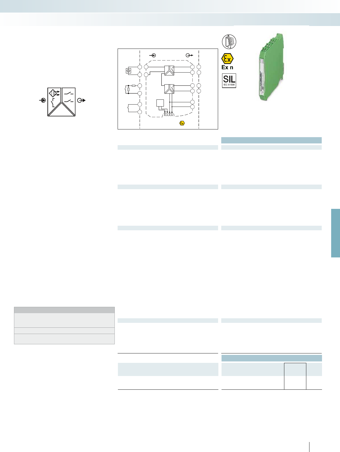
POWER
OUT
IN
Sensor /Field
4.2
4.1
4.2
4.1
+
-
4.2
4.1
OUT2
Zone 2
Div. 2
IN OUT
GND
+24V
4.2
4.1
3.2
3.1
1.2
1.1
+
-
Power
Faultsignal
GND
+24VLFD
2.2
2.1
OUT1
PLC / DCS
3.2
3.1
DI
2.2
2.1
DI
13
14
13
14
For further information and full technical data, visit phoenixcontact.net/products
Functional Safety
Ex:
Housing width 12.5 mm
Technical data
Input data
Input signal NAMUR proximity sensors (EN 60947-5-6)
Floating switch contacts
Switch contacts with resistance circuit
No-load voltage ~ 8 V DC
Switching points > 2.1 mA (conductive) / < 1.2 mA (blocking)
Switching hysteresis < 0.2 mA
Line fault detection Break 0.05 mA < IIN < 0.35 mA
Short circuit 100 < RSensor < 360
Switching output Relay output
Contact type 2 N/O contacts
Contact material AgSnO
2
, hard gold-plated
Max. switching voltage 250 V AC (2 A) / 120 V DC (0.2 A) / 30 V DC (2 A)
Max. switching capacity 500 VA
Recommended minimum load 5 V / 10 mA
Mechanical service life 10
7
cycles
Switching behavior Can be inverted via slide switch
Max. switching frequency 20 Hz (without load)
General data
Supply voltage range 19.2 V DC ... 30 V DC
Current consumption 30 mA (24 V DC)
Power dissipation < 950 mW
Electrical isolation
Input/output/supply, DIN rail connector 300 V
rms
(rated insulation voltage (surge voltage category II;
pollution degree 2, safe isolation as per EN 61010-1))
2.5 kV (50 Hz, 1 min., test voltage)
Output 1/output 2/input, power supply, DIN rail connector 300 V
rms
(rated insulation voltage (surge voltage category III;
pollution degree 2, safe isolation as per EN 61010-1))
2.5 kV (50 Hz, 1 min., test voltage)
Ambient temperature range -20 °C ... 60 °C (any mounting position)
Humidity 10 % ... 95 % (non-condensing)
Housing material PA 66-FR
Inflammability class in acc. with UL 94 V0
Dimensions W / H / D 12.5 / 99 / 114.5 mm
Screw connection solid / stranded / AWG 0.2 ... 2.5 mm² / 0.2 ... 2.5 mm² / 24 - 14
Push-in connection solid / stranded / AWG 0.2 ... 1.5 mm² / 0.2 ... 1.5 mm² / 24 - 16
EMC note Class A product, see page 625
Conformance / approvals
Conformance CE-compliant, additionally EN 61326
ATEX
II 3 G Ex nA nC IIC T4 Gc X
UL, USA / Canada UL 508 Listed
UL 61010 Listed
Class I, Div. 2, Groups A, B, C, D T4
Class I, Zone 2, Group IIC T4
SIL in accordance with IEC 61508 2
Ordering data
Description Type Order No. Pcs. /
Pkt.
NAMUR signal conditioner
Screw connection MACX MCR-SL-NAM-2RO 2865010 1
Push-in connection MACX MCR-SL-NAM-2RO-SP 2924265 1
173
PHOENIX CONTACT
NAMUR signal conditioner for operating
proximity sensors and mechanical contacts
– Input for NAMUR proximity sensors
(EN 60947-5-6), floating contacts or
contacts with resistance circuit
– Two relay signal outputs (N/O contact);
output 2 can be used as an error message
output
– Reversible direction of action (operating
current or closed-circuit current
behavior)
– Line fault detection (LFD), can be
activated/deactivated, error message
signaled by red flashing LED with de-
excitation of output relay
– Power supply and error indication
possible via the DIN rail connector
– LED displays for indicating supply voltage,
circuit state, and malfunctions to
NAMUR NE 44
– 4-way electrical isolation
– Up to SIL 2 according to IEC 61508
– Installation in zone 2 permitted
Notes:
Information about the power and fault signaling module as well as
about the DIN rail connectors and marking material can be found
from page 178
Information about resistance circuits is given on page 180
Information on Plug and Play connection using system cabling can
be found from page 182
Digital IN
NAMUR signal conditioner
MCR technology
Signal conditioners with SIL functional safety - MACX Analog
2 signal outputs: N/O contact relay
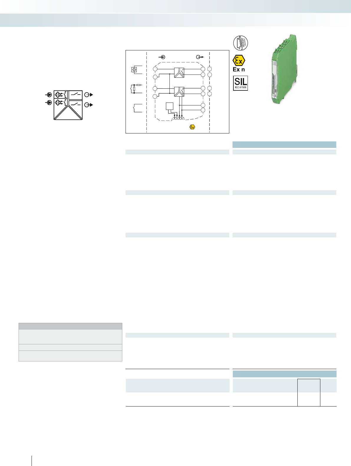
POWER
OUT1
IN1
IN2 OUT2
Zone 2
Div. 2
IN OUT
GND
+24V
4.2
4.1
3.2
3.1
1.2
1.1
+
-
Power
Faultsignal
GND
+24VLFD
2.2
2.1
5.2
5.1
+
-
PLC / DCS
3.2
3.1
2.2
2.1
13
13
14
14
DI
DI
Sensor / Field
CH1
CH2
+
+
+
-
-
-
Functional Safety
Ex:
Housing width 12.5 mm
Technical data
Input data
Input signal NAMUR proximity sensors (EN 60947-5-6)
Floating switch contacts
Switch contacts with resistance circuit
No-load voltage ~ 8 V DC
Switching points > 2.1 mA (conductive) / < 1.2 mA (blocking)
Switching hysteresis < 0.2 mA
Line fault detection Break 0.05 mA < IIN < 0.35 mA
Short circuit 100 < RSensor < 360
Switching output Relay output
Contact type 1 N/O contact per channel
Contact material AgSnO
2
, hard gold-plated
Max. switching voltage 250 V AC (2 A) / 120 V DC (0.2 A) / 30 V DC (2 A)
Max. switching capacity 500 VA
Recommended minimum load 5 V / 10 mA
Mechanical service life 10
7
cycles
Switching behavior Can be inverted via slide switch
Max. switching frequency 20 Hz (without load)
General data
Supply voltage range 19.2 V DC ... 30 V DC
Current consumption 35 mA (24 V DC)
Power dissipation < 1 W
Electrical isolation
Input/supply, DIN rail connector 300 V
rms
(rated insulation voltage (surge voltage category II;
pollution degree 2, safe isolation as per EN 61010-1))
2.5 kV (50 Hz, 1 min., test voltage)
Output 1/output 2/input, power supply, DIN rail connector 300 V
rms
(rated insulation voltage (surge voltage category III;
pollution degree 2, safe isolation as per EN 61010-1))
2.5 kV (50 Hz, 1 min., test voltage)
Ambient temperature range -20 °C ... 60 °C (any mounting position)
Humidity 5 % ... 95 % (non-condensing)
Housing material PA 66-FR
Inflammability class in acc. with UL 94 V0
Dimensions W / H / D 12.5 / 99 / 114.5 mm
Screw connection solid / stranded / AWG 0.2 ... 2.5 mm² / 0.2 ... 2.5 mm² / 24 - 14
Push-in connection solid / stranded / AWG 0.2 ... 1.5 mm² / 0.2 ... 1.5 mm² / 24 - 16
EMC note Class A product, see page 625
Conformance / approvals
Conformance CE-compliant, additionally EN 61326
ATEX
II 3 G Ex nA nC IIC T4 Gc X
UL, USA / Canada UL 508 Listed
UL 61010 Listed
Class I, Div. 2, Groups A, B, C, D T4
Class I, Zone 2, Group IIC T4
SIL in accordance with IEC 61508 2
Ordering data
Description Type Order No. Pcs. /
Pkt.
NAMUR signal conditioner
Screw connection MACX MCR-SL-2NAM-RO 2865049 1
Push-in connection MACX MCR-SL-2NAM-RO-SP 2924294 1
174
PHOENIX CONTACT
NAMUR signal conditioner for
intrinsically safe operation of proximity
sensors and mechanical contacts installed in
Ex areas.
– 2-channel
– Input for NAMUR proximity sensors
(EN 60947-5-6), floating contacts or
contacts with resistance circuit
– Relay signal output (N/O contact)
– Reversible direction of action (operating
current or closed-circuit current
behavior)
– Line fault detection (LFD), can be
activated/deactivated, error message
signaled by red flashing LED with de-
excitation of output relay
– Power supply and error indication
possible via the DIN rail connector
– LED displays for indicating supply voltage,
circuit state, and malfunctions to
NAMUR NE 44
– 3-way electrical isolation
– Up to SIL 2 according to IEC 61508
– Installation in zone 2 permitted
Notes:
Information about the power and fault signaling module as well as
about the DIN rail connectors and marking material can be found
from page 178
Information about resistance circuits is given on page 180
Information on Plug and Play connection using system cabling can
be found from page 182
Digital IN
NAMUR signal conditioner
MCR technology
Signal conditioners with SIL functional safety - MACX Analog
2-channel, signal output: N/O contact relay

POWER
OUT1
IN1
IN2 OUT2
PLC / DCS
3.3
2.3
3.2
2.2
3.1
2.1
IN
Zone 2
Div. 2
OUT
4.3
4.1
3.3
2.3
3.2
2.2
3.1
2.1
1.2
1.1
+
-
5.3
5.1
+
-
CH1
CH2
24...230 V
AC/DC –
~
12
12
11
11
14
14
Sensor / Field
DI
DI
+
+
+
-
-
-
For further information and full technical data, visit phoenixcontact.net/products
Functional Safety
Ex:
Housing width 17.5 mm
Technical data
Input data
Input signal NAMUR proximity sensors (EN 60947-5-6)
open circuit switch contacts
Switch contacts with resistance circuit
No-load voltage ~ 8 V DC
Switching points > 2.1 mA (conductive) / < 1.2 mA (blocking)
Switching hysteresis approx. 0.2 mA
Line fault detection Break 0.05 mA < IIN < 0.35 mA
Short circuit 100 < RSensor < 360
Switching output Relay output
Contact type 1 PDT per channel
Contact material AgSnO
2
, hard gold-plated
Max. switching voltage 250 V AC (2 A, 60 Hz) / 120 V DC (0.2 A) / 30 V DC (2 A)
Max. switching capacity 500 VA
Recommended minimum load 5 V / 10 mA
Mechanical service life 10
7
cycles
Switching behavior can be inverted using DIP switch
Max. switching frequency 20 Hz (load-dependent)
General data
Supply voltage range 24 V ... 230 V AC/DC (-20 % ... +10 %, 50 Hz ... 60 Hz)
Current consumption < 80 mA ; < 42 mA (24 V DC)
Power dissipation 1.3 W
Electrical isolation
Input/power supply 300 V
rms
(rated insulation voltage (surge voltage category II;
pollution degree 2, safe isolation as per EN 61010-1))
2.5 kV (50 Hz, 1 min., test voltage)
Output 1/output 2/input, power supply 300 V
rms
(rated insulation voltage (surge voltage category III;
pollution degree 2, safe isolation as per EN 61010-1))
2.5 kV (50 Hz, 1 min., test voltage)
Ambient temperature range -20 °C ... 60 °C
Humidity 10 % ... 95 % (non-condensing)
Housing material PA 66-FR
Inflammability class in acc. with UL 94 V0
Dimensions W / H / D 17.5 / 99 / 114.5 mm
Screw connection solid / stranded / AWG 0.2 ... 2.5 mm² / 0.2 ... 2.5 mm² / 24 - 14
Push-in connection solid / stranded / AWG 0.2 ... 1.5 mm² / 0.2 ... 1.5 mm² / 24 - 16
EMC note Class A product, see page 625
Conformance / approvals
Conformance CE-compliant, additionally EN 61326
ATEX
II 3 G Ex nA nC IIC T4 Gc X
UL, USA / Canada UL 508 Listed
UL 61010 Listed
Class I, Div. 2, Groups A, B, C, D T4
Class I, Zone 2, Group IIC T4
SIL in accordance with IEC 61508 2
Ordering data
Description Type Order No. Pcs. /
Pkt.
NAMUR signal conditioner
Screw connection MACX MCR-SL-2NAM-R-UP 2865052 1
Push-in connection MACX MCR-SL-2NAM-R-UP-SP 2924304 1
175
PHOENIX CONTACT
NAMUR signal conditioner for operating
proximity sensors and mechanical contacts
– 2-channel
– Input for NAMUR proximity sensors
(EN 60947-5-6), floating contacts or
contacts with resistance circuit
– Relay signal output (PDT)
– Reversible direction of action (operating
current or closed-circuit current
behavior)
– Line fault detection (LFD), can be
activated/deactivated, error message
signaled by red flashing LED with de-
excitation of output relay
– Wide range power supply:
19.2 ... 253 V AC/DC
– LED displays for indicating supply voltage,
circuit state, and malfunctions to
NAMUR NE 44
– 3-way electrical isolation
– Up to SIL 2 according to IEC 61508
– Installation in zone 2 permitted
Notes:
Information on resistance circuits and marking material can be
found on page 180
Digital IN
NAMUR signal conditioner
MCR technology
Signal conditioners with SIL functional safety - MACX Analog
2-channel, signal output: PDT relay,
wide range power supply
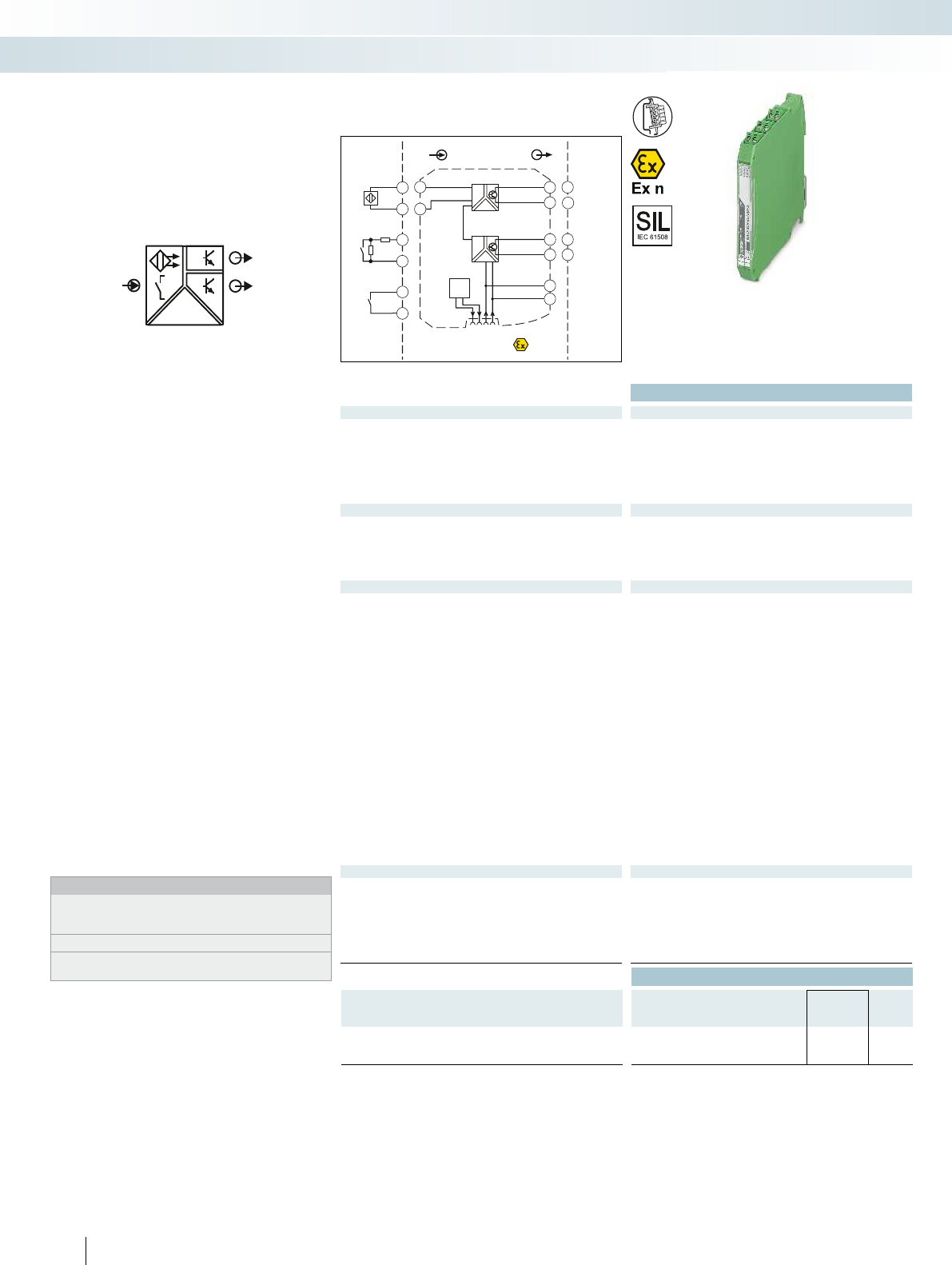
POWER
IN
OUT1
OUT2
Sensor / Field
4.2
4.1
4.2
4.1
+
-
4.2
4.1
PLC / DCS
3.2
3.1
DI
2.2
2.1
DI
-
+
-
+
OUT2
Zone 2
Div. 2
IN OUT
GND
+24V
4.2
4.1
3.2
3.1
1.2
1.1
+
-
Power
Faultsignal
GND
+24VLFD
2.2
2.1
OUT1
Functional Safety
Ex:
Housing width 12.5 mm
Technical data
Input data
Input signal NAMUR proximity sensors (EN 60947-5-6)
Floating switch contacts
Switch contacts with resistance circuit
No-load voltage ~ 8 V DC
Switching points > 2.1 mA (conductive) / < 1.2 mA (blocking)
Line fault detection Break 0.05 mA < IIN < 0.35 mA
Short circuit 100 < RSensor < 360
Switching output 2 transistor outputs, passive
Max. switching voltage 30 V DC (per output)
Max. switching current 50 mA (short-circuit resistant)
Drop (U) < 1.4 V
Switching behavior can be inverted using DIP switch
Max. switching frequency 5 kHz
General data
Supply voltage range 19.2 V DC ... 30 V DC (24 V DC (-20% ... +25%))
Current consumption < 28 mA (24 V DC)
Power dissipation 800 mW
Electrical isolation
Input/output 375 V (peak value in accordance with EN 60079-11)
Input/output/supply, DIN rail connector 300 V
rms
(rated insulation voltage (surge voltage category II;
pollution degree 2, safe isolation as per EN 61010-1))
2.5 kV (50 Hz, 1 min., test voltage)
Input/supply, DIN rail connector 375 V (peak value in accordance with EN 60079-11)
Output 1/output 2 50 V
rms
(rated insulation voltage (surge voltage category II; pollution
degree 2, safe isolation as per EN 61010-1))
1 kV (50 Hz, 1 min., test voltage)
Ambient temperature range -20 °C ... 60 °C (any mounting position)
Humidity 10 % ... 95 % (non-condensing)
Housing material PA 66-FR
Inflammability class in acc. with UL 94 V0
Dimensions W / H / D 12.5 / 99 / 114.5 mm
Screw connection solid / stranded / AWG 0.2 ... 2.5 mm² / 0.2 ... 2.5 mm² / 24 - 14
Push-in connection solid / stranded / AWG 0.2 ... 1.5 mm² / 0.2 ... 1.5 mm² / 24 - 16
EMC note Class A product, see page 625
Conformance / approvals
Conformance CE-compliant, additionally EN 61326
ATEX
II 3 G Ex nA IIC T4 Gc X
UL, USA / Canada UL 508 Listed
UL 61010 Listed
Class I, Div. 2, Groups A, B, C, D T4
Class I, Zone 2, Group IIC T4
SIL in accordance with IEC 61508 2
Ordering data
Description Type Order No. Pcs. /
Pkt.
NAMUR signal conditioner
Screw connection MACX MCR-SL-NAM-2T 2865023 1
Push-in connection MACX MCR-SL-NAM-2T-SP 2924278 1
176
PHOENIX CONTACT
NAMUR signal conditioner for operating
proximity sensors and mechanical contacts
– Input for NAMUR proximity sensors
(EN 60947-5-6), floating contacts or
contacts with resistance circuit
– 2 signal outputs: transistor (passive); up
to 5 kHz
– Signal output 2 can also be used as a fault
signaling output
– Reversible direction of action (operating
current or closed-circuit current
behavior)
– Line fault detection (LFD), can be
activated/deactivated, error message
signaled by red flashing LED with
inhibiting of transistor output
– Power supply and error indication
possible via the DIN rail connector
– LED displays for indicating supply voltage,
circuit state, and malfunctions to
NAMUR NE 44
– 4-way electrical isolation
– Up to SIL 2 according to IEC 61508
– Installation in zone 2 permitted
Notes:
Information about the power and fault signaling module as well as
about the DIN rail connectors and marking material can be found
from page 178
Information about resistance circuits is given on page 180
Information on Plug and Play connection using system cabling can
be found from page 182
Digital IN
NAMUR signal conditioner
MCR technology
Signal conditioners with SIL functional safety - MACX Analog
2 signal outputs: transistor (passive)
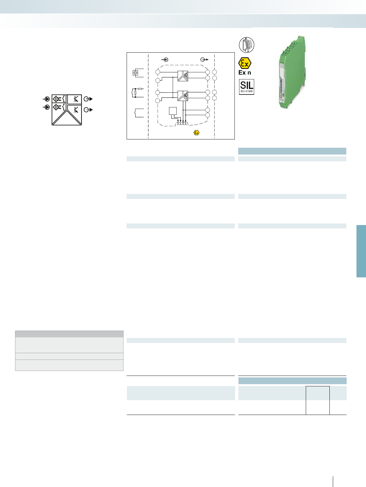
POWER
IN1
IN2
OUT1
OUT2
Sensor / FieldPLC / DCS
3.2
3.1
2.2
2.1
Zone 2
Div. 2
IN OUT
GND
+24V
4.2
4.1
3.2
3.1
1.2
1.1
+
-
Power
Faultsignal
GND
+24VLFD
2.2
2.1
5.2
5.1
+
-
DI
DI
CH1
CH2
+
+
+
-
-
-
+
+
-
-
For further information and full technical data, visit phoenixcontact.net/products
Functional Safety
Ex:
Housing width 12.5 mm
Technical data
Input data
Input signal NAMUR proximity sensors (EN 60947-5-6)
Floating switch contacts
Switch contacts with resistance circuit
No-load voltage ~ 8 V DC
Switching points > 2.1 mA (conductive) / < 1.2 mA (blocking)
Line fault detection Break 0.05 mA < IIN < 0.35 mA
Short circuit 100 < RSensor < 360
Switching output Transistor output, passive
Max. switching voltage 30 V DC (per output)
Max. switching current 50 mA (short-circuit resistant)
Drop (U) < 1.4 V
Switching behavior can be inverted using DIP switch
Max. switching frequency 5 kHz
General data
Supply voltage range 19.2 V DC ... 30 V DC
Current consumption < 34 mA (24 V DC)
Power dissipation 1000 mW
Electrical isolation
Input/output 375 V (peak value in accordance with EN 60079-11)
Input/output/supply, DIN rail connector 300 V
rms
(rated insulation voltage (surge voltage category II;
pollution degree 2, safe isolation as per EN 61010-1))
2.5 kV (50 Hz, 1 min., test voltage)
Input/supply, DIN rail connector 375 V (peak value in accordance with EN 60079-11)
Output 1/output 2 50 V
rms
(rated insulation voltage (surge voltage category II; pollution
degree 2, safe isolation as per EN 61010-1))
1 kV (50 Hz, 1 min., test voltage)
Ambient temperature range -20 °C ... 60 °C (any mounting position)
Humidity 10 % ... 95 % (non-condensing)
Housing material PA 66-FR
Inflammability class in acc. with UL 94 V0
Dimensions W / H / D 12.5 / 99 / 114.5 mm
Screw connection solid / stranded / AWG 0.2 ... 2.5 mm² / 0.2 ... 2.5 mm² / 24 - 14
Push-in connection solid / stranded / AWG 0.2 ... 1.5 mm² / 0.2 ... 1.5 mm² / 24 - 16
EMC note Class A product, see page 625
Conformance / approvals
Conformance CE-compliant, additionally EN 61326
ATEX
II 3 G Ex nA IIC T4 Gc X
UL, USA / Canada UL 508 Listed
UL 61010 Listed
Class I, Div. 2, Groups A, B, C, D T4
Class I, Zone 2, Group IIC T4
SIL in accordance with IEC 61508 2
Ordering data
Description Type Order No. Pcs. /
Pkt.
NAMUR signal conditioner
Screw connection MACX MCR-SL-2NAM-T 2865036 1
Push-in connection MACX MCR-SL-2NAM-T-SP 2924281 1
177
PHOENIX CONTACT
NAMUR signal conditioner for operating
proximity sensors and mechanical contacts
– 2-channel
– Input for NAMUR proximity sensors
(EN 60947-5-6), floating contacts or
contacts with resistance circuit
– Signal output transistor (passive); up to
5 kHz
– Reversible direction of action (operating
current or closed-circuit current
behavior)
– Line fault detection (LFD), can be
activated/deactivated, error message
signaled by red flashing LED with
inhibiting of transistor output
– Power supply and error indication
possible via the DIN rail connector
– LED displays for indicating supply voltage,
circuit state, and malfunctions to
NAMUR NE 44
– 3-way electrical isolation
– Up to SIL 2 according to IEC 61508
– Installation in zone 2 permitted
Notes:
Information about the power and fault signaling module as well as
about the DIN rail connectors and marking material can be found
from page 178
Information about resistance circuits is given on page 180
Information on Plug and Play connection using system cabling can
be found from page 182
Digital IN
NAMUR signal conditioner
MCR technology
Signal conditioners with SIL functional safety - MACX Analog
2-channel, signal output transistor (passive)

1.2
2.2
3.2
12
3.3
14
1.1
2.1
3.1
11
Fault out
PWR2
PWR1
–
–
+
+
Faultsignal
GND
+24VLFD
Ex:
Housing width 17.5 mm
Technical data
Input data
Input signal 19.2 V DC ... 30 V DC (24 V DC (-20% ... +25%))
Redundant supply yes, decoupled from diodes
Polarization and surge protection Yes
Output data
Maximum output signal 3.75 A
Output voltage Input voltage - max 0.8 V at 3.75 A
Switching output Relay
Contact type 1 PDT
Contact material Gold (Au)
Max. switching voltage 50 V AC (50VDC (0.3A) / 50VDC (2 A) / 33VAC (2 A))
General data
Ambient temperature range -20 °C ... 60 °C (any mounting position)
Humidity 5 % ... 95 % (non-condensing)
Fuse 5 A (replaceable), slow-blow 250 V AC
Status indication 1 x red LED (error)
2 x green LEDs (PWR1 and PWR2)
Housing material Polyamide (PA 6.6)
Inflammability class in acc. with UL 94 V0
Dimensions W / H / D 17.5 / 99 / 114.5 mm
Screw connection solid / stranded / AWG 0.2 ... 2.5 mm² / 0.2 ... 2.5 mm² / 24 - 14
Push-in connection solid / stranded / AWG 0.2 ... 1.5 mm² / 0.2 ... 1.5 mm² / 24 - 16
Conformance / approvals
Conformance CE-compliant
ATEX
II 3 G Ex nA nC IIC T4 Gc X
IECEx Ex nA nC IIC T4 Gc X
UL, USA / Canada UL 61010 Listed
Class I, Div. 2, Groups A, B, C, D T5
Class I, Zone 2, Group IIC
Ordering data
Description Type Order No. Pcs. /
Pkt.
Power and fault signaling module, including the relevant DIN rail
connector ME 17,5 TBUS 1,5/5-ST-3,81 GN
Screw connection MACX MCR-PTB 2865625 1
Push-in connection MACX MCR-PTB-SP 2924184 1
178
PHOENIX CONTACT
Power and fault signaling module
Power and fault signaling module for
feeding the 24 V supply voltage to the DIN
rail connectors and signaling line faults and
power supply failures.
– One-time or redundant supply, decoupled
from diode, protected against
polarization
– Supply current up to 3.75 A
– Relay output (PDT) and flashing LED for
error messages
– Error message in the event of a power
supply failure or fuse fault
– Bus cable fault message for
MACX MCR-...(2)NAM... devices
connected via DIN rail connectors
– Replaceable fuse
– Installation in zone 2 permitted
Accessories
MCR technology
Signal conditioners with SIL functional safety - MACX Analog
H
W
D
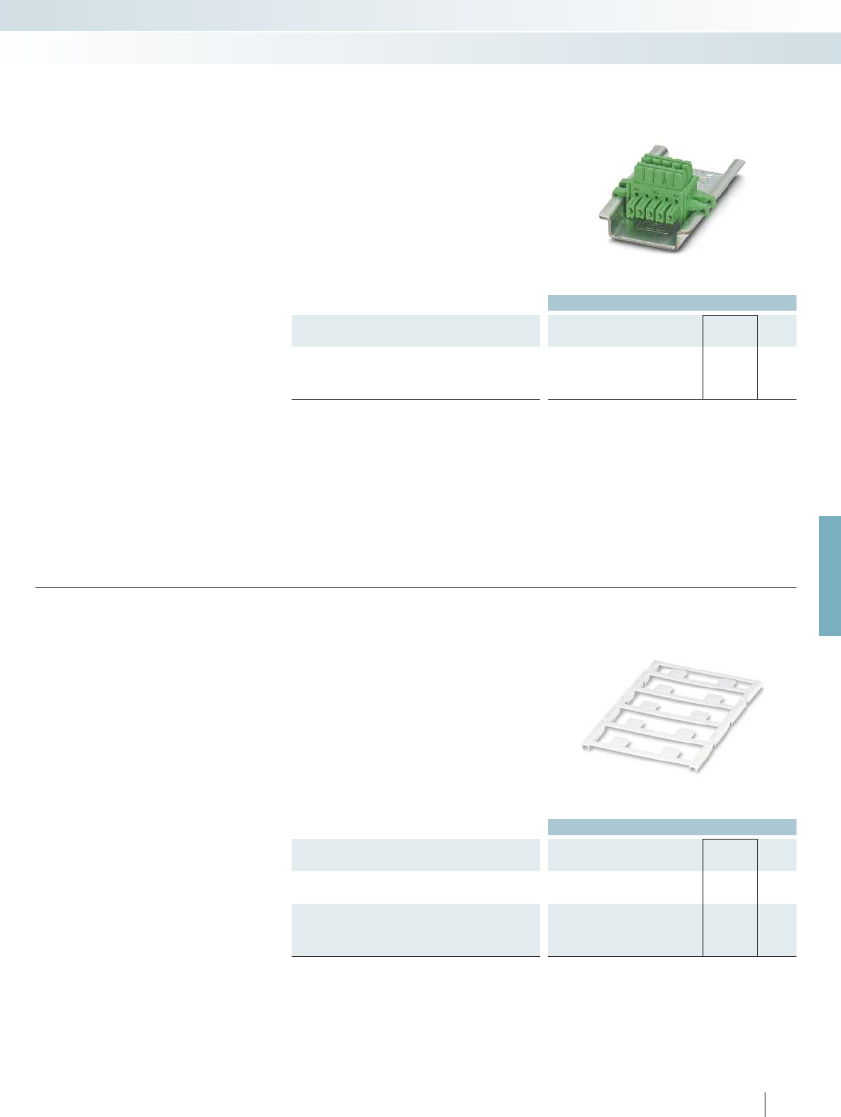
For further information and full technical data, visit phoenixcontact.net/products
Ordering data
Description Type Order No. Pcs. /
Pkt.
DIN rail connector (TBUS), for bridging the supply voltage, can
be snapped onto 35 mm DIN rails as per EN 60715, with
UL approval
Color: green ME 6,2 TBUS-2 1,5/5-ST-3,81 GN 2869728 10
ME 6,2 TBUS... DIN rail connector
DIN rail connector (5-pos.) for bridging
the supply voltage of 12.5 mm wide
MACX Analog modules
– Reduces wiring costs
– System can be extended or module
replaced even while process is active
– Inter-extendable
Accessories
MCR technology
Signal conditioners with SIL functional safety - MACX Analog
Ordering data
Description Color Type Order No. Pcs. /
Pkt.
UniCard, with self-adhesive plastic labels
10-part, lettering field size: 11x9mm white UC-EMLP (11X9) 0819291 10
UniCard, with self-adhesive plastic labels, marked according to
customer specifications
For ordering details, see Catalog 5 or phoenixcontact.net/product.
10-part, lettering field size: 11x9mm white UC-EMLP (11X9) CUS 0824547 1
179
PHOENIX CONTACT
Marking material for device marking
– For device marking inside the control
cabinet and in the field
– Self-adhesive with high adhesive strengths
– Large temperature range
Accessories
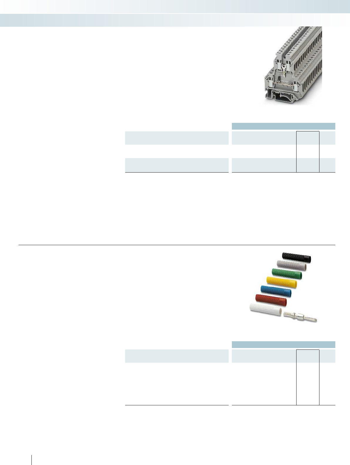
Ordering data
Description Color Type Order No. Pcs. /
Pkt.
Double-level terminal block, with pre-assembled resistors
With screw connection UKK 5-2R/NAMUR 2941662 50
Cover, width 2.5 mm
gray D-UKK 3/5 2770024 50
blue D-UKK 3/5 BU 2770105 50
Resistance circuit
Double-level terminal block with
resistance circuit according to NAMUR for
line fault detection in the case of mechanical
contacts
Important:
– For intrinsically safe circuits, only in
combination with D-UKK 3/5 cover
Accessories
MCR technology
Signal conditioners with SIL functional safety - MACX Analog
Ordering data
Description Color Type Order No. Pcs. /
Pkt.
Test plug, consisting of:
Metal part for 2.3 mm Ø socket hole and silver MPS-MT 0201744 10
Insulating sleeve, for MPS metal part red MPS-IH RD 0201676 10
black MPS-IH BK 0201731 10
gray MPS-IH GY 0201728 10
green MPS-IH GN 0201702 10
yellow MPS-IH YE 0201692 10
blue MPS-IH BU 0201689 10
white MPS-IH WH 0201663 10
180
PHOENIX CONTACT
Test plug
Accessories

For further information and full technical data, visit phoenixcontact.net/products
181PHOENIX CONTACT
MCR technology
Signal conditioners with SIL functional safety - MACX Analog
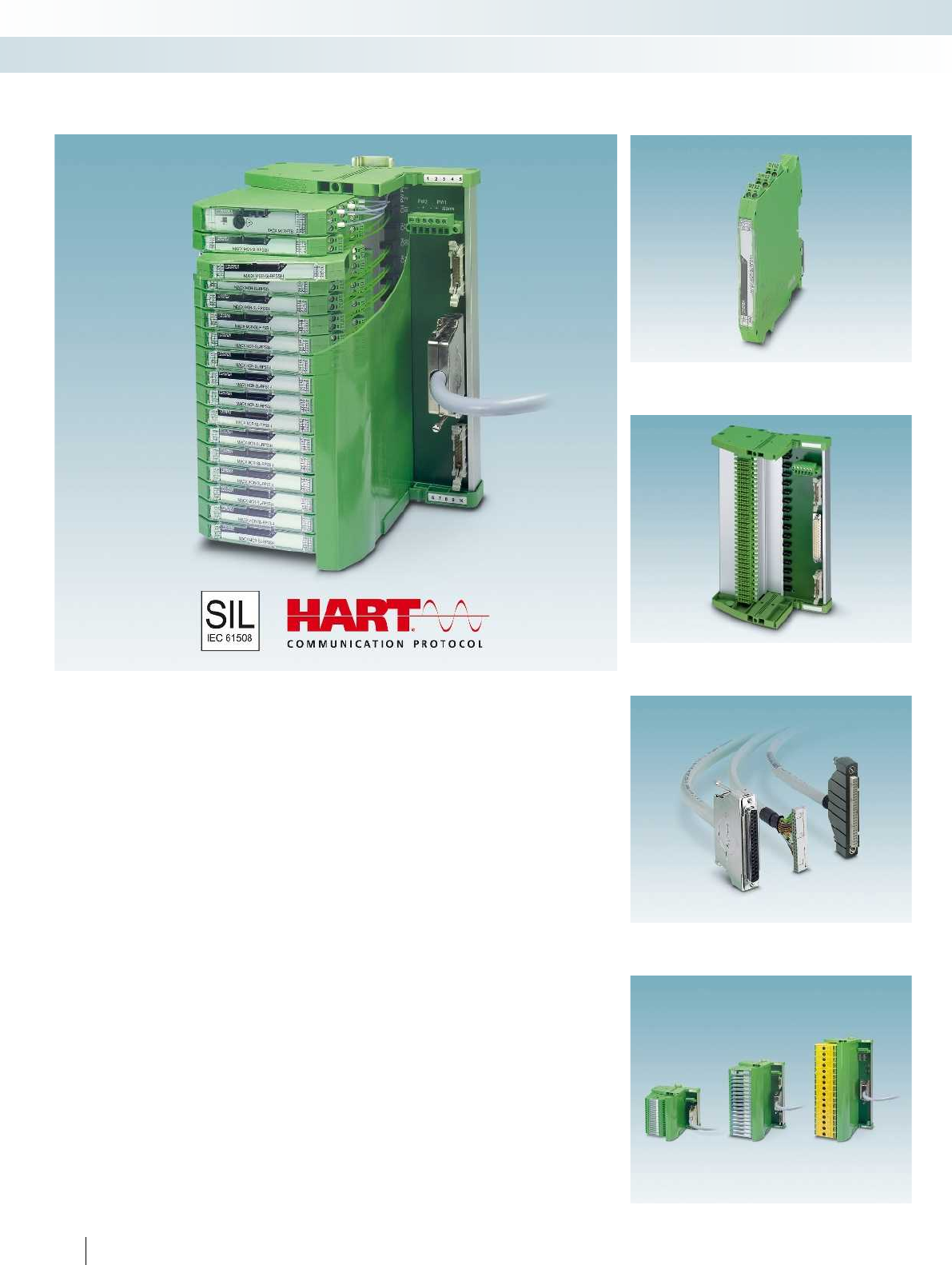
TC... Termination Carriers are
compact solutions for quickly and smoothly
connecting DIN rail devices from the
MACX Analog Ex series to input/output
cards of automation systems using system
cabling.
The Termination Carriers combine the
advantages of modular DIN rail devices with
those offered by Plug and Play rapid cabling
solutions to provide a consistent solution
for system technology.
Compact
– Saves up to 30% of space due to compact
design
Robust and reliable
– Stable, vibration-resistant aluminum
carrier device profile
– PCB is completely decoupled from
modules
– PCB without active components
– Redundant supply and monitoring in
separate DIN rail module
Easy maintenance
– Use of standard DIN rail devices
– Easy access to connection points
– Quick and safe module connection with
plug-in and coded cable sets
Flexible
– Horizontal or vertical DIN rail mounting
– Profile section without pitch markings for
I/O cards with specific number of
channels
– Can be specifically adapted for I/O cards
of various automation systems with
different system plug types
182
PHOENIX CONTACT
Termination Carriers for
MACX Analog Ex signal conditioners
Solutions are also available for MINI Analog,
MACX Analog Ex, and Safety
Select controller-specific front adapter and system cable
Select module carrier
Select standard DIN rail device
MCR technology
Signal conditioners with SIL functional safety - MACX Analog

X20 COMBICON
X1 DSUB 37PTSM
+
+
CH1
PW2
PW1
1
20
+
-
CH2
2
21
+
-
CH3
3
22
+
-
CH4
4
23
+
-
CH5
5
24
-
CH6
6
25
+
-
CH7
7
26
-
CH8
8
27
+
-
CH9
9
28
+
-
CH10
10
29
+
-
CH11
11
30
+
-
CH12
12
31
+
-
CH13
13
32
+
-
CH14
14
33
+
-
CH15
15
34
+
-
CH16
16
35
-
+
3.1
3.1
3.1
3.1
3.1
3.1
3.1
3.1
3.1
3.1
3.1
3.1
3.1
3.1
3.1
3.1
3.1
3.2
3.2
3.2
3.2
3.2
3.2
3.2
3.2
3.2
3.2
3.2
3.2
3.2
3.2
3.2
3.2
3.3
1.3
1.1
1.2
2.3
T-BUS
F1
1
1
2.1
2.2
TC-MACX-
MCR-PTB
2904673
F2
1
3 (+)
5 (+)
Alarm
PW1
PW2
2
4 (-)
6 (-)
1
3 (+)
2
1
1
1
1
1
1
1
1
1
1
1
1
1
1
1
1
PW1PW2
For further information and full technical data, visit phoenixcontact.net/products
Ex:
Housing width 242 mm
Technical data
General data
Connection to the control system level D-SUB pin strip
Number of positions 37
Max. operating voltage < 50 V DC (per signal/channel)
Max. permissible current 23 mA (signal/channel)
Rated insulation voltage 50 V
Pollution degree 2
Surge voltage category II
Rated surge voltage 0.5 kV (basic insulation)
Clearance and creepage distances DIN EN 50178
Ambient temperature range -20 °C ... 60 °C (please observe module specifications)
Shock 15g, according to IEC 60068-2-27
Vibration (operation) 2g, according to IEC 60068-2-6
Dimensions W / H / D 242 / 170 / 160 mm
EMC note Class A product, see page 625
Power supply via power module
Input voltage range 19.2 V DC ... 30 V DC
Redundant supply yes, decoupled from diodes
Polarization and surge protection Yes
Fuse 2x 2.5 A on PCB, slow-blow (replaceable)
Status indication 1 x red LED (error)
2x green LEDs (PWR1 and PWR2)
Switching output 1 N/C contact (alarm = open)
Maximum switching voltage 50 V DC (0.3 A) / 30 V DC (2 A) / 33 V AC (2 A)
Ordering data
Description Type Order No. Pcs. /
Pkt.
Universal Termination Carrier for 16 MACX MCR-EX isolators
TC-D37SUB-ADIO16-EX-P-UNI 2924854 1
- With connection for MACX MCR-S-MUX HART multiplexer TC-D37SUB-AIO16-EX-PS-UNI 2902932 1
Accessories
Power and fault signaling module TC-MACX-MCR-PTB 2904673 1
HART multiplexer, 32-chanel, including two 14-wire flat-ribbon
cables
MACX MCR-S-MUX 2865599 1
183PHOENIX CONTACT
The TC-D37SUB-ADIO16-EX-P-
UNI universal Termination Carrier is a
compact solution which connects signal
conditioners from the MACX Analog series
to analog or binary input/output cards of
automation systems.
The TC-D37SUB-AIO16-EX-PS-UNI
Termination Carrier design, when
combined with the MACX MCR-S-MUX
HART multiplexer, also enables
communication between HART-capable
field devices and a management system.
– Connection of up to 16 single-channel
(Ex i) signal conditioners
– Universal 1:1 signal routing to a 37-pos.
D-SUB connector
– For system cables with D-SUB socket and
open ends for universal connection
– Redundant supply and monitoring in
separate DIN rail module
Notes:
Contact us: specific Termination Carrier designs for I/O modules of
various automation systems are available, planned or can be
implemented according to your specifications.
Termination Carriers for
MACX Analog Ex signal conditioners
TC-D37SUB-ADIO16-EX-P-UNI and TC-D37SUB-AIO16-EX-PS-UNI connection scheme
MCR technology
Signal conditioners with SIL functional safety - MACX Analog
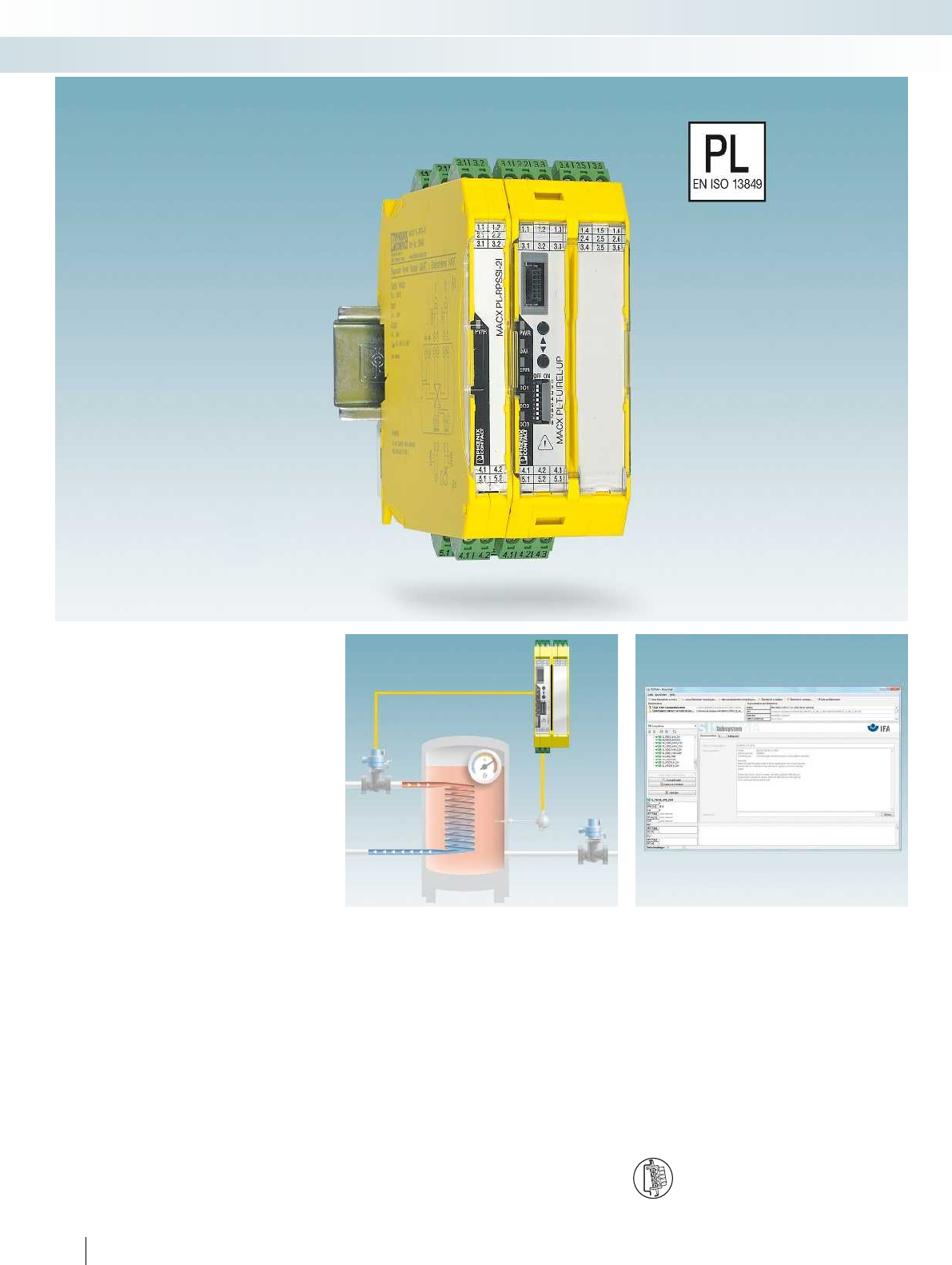
184
PHOENIX CONTACT
Integrate analog signals safely
Integrate analog signals easily into your
safety application according to the
Machinery Directive. The MACX Safety
analog signal conditioners are certified
according to EN ISO 13849-1 with
performance level PL d.
Choose the right MACX Safety signal
conditioner for your application:
Analog IN
– 4...20 mA repeater power supplies and
input signal conditioners with
2 electrically isolated outputs
Temperature
– Universal temperature transducers Direct switching of limit values
possible without an additional safety
controller
– Cost savings: direct, safe switching of limit
values possible without an additional
safety controller
– Easy to combine active or passive analog
signals with other safety modules
Easy planning of the safety application
with SISTEMA
– Easy planning of the safety application
with SISTEMA: the required data is
already stored there
DIN rail connector-compatible
The DIN rail connector enables the modular bridging of
the 24 V supply voltage.
MCR technology
Signal conditioners with PL and SIL functional safety - MACX Safety
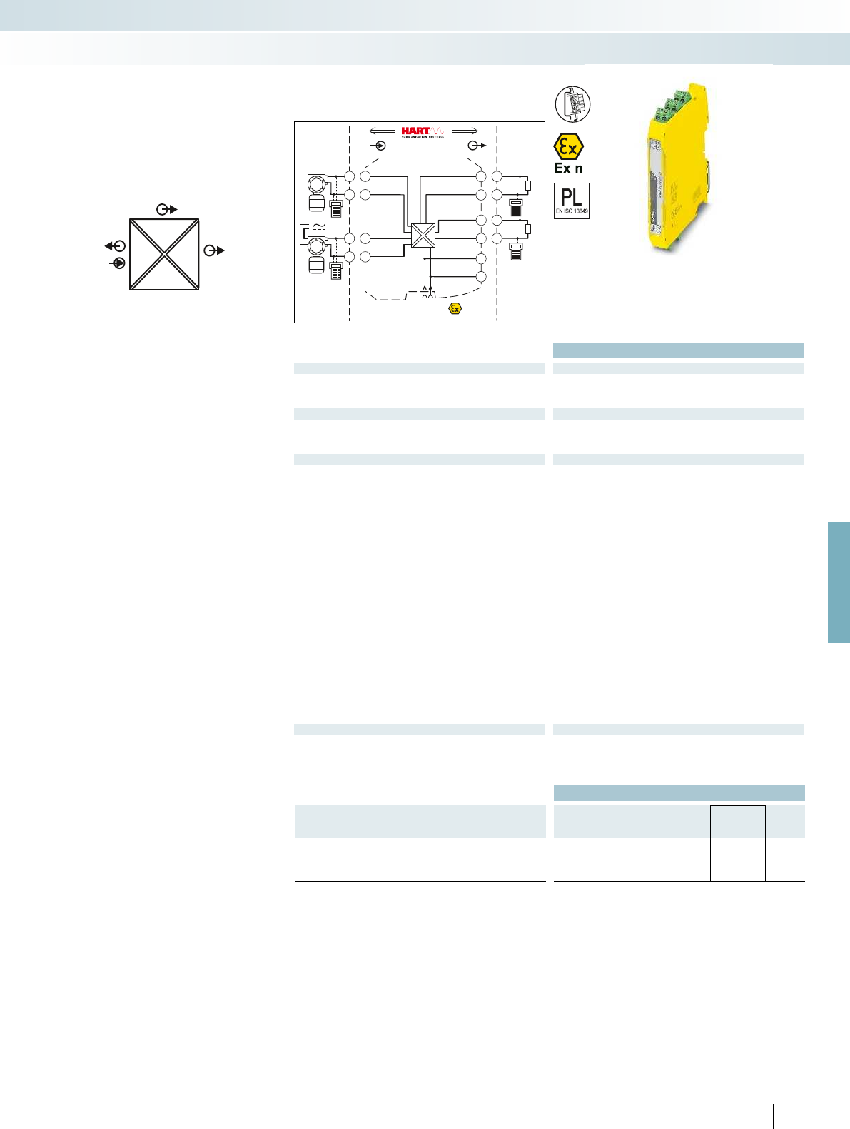
POWER
IIOUT2
I
OUT1
IN
POWER
Zone 2
Div. 2
IN OUT
4.2
5.2
4.1
5.1
3.2
3.1
2.2
2.1
1.2
1.1
GND
OUT 1
OUT 2
+24V
GND +24V
Power
+
+
-
-
+
-
Sensor / Field
or
4.2
4.1
5.2
5.1
PLC / DCS
passive
-
+
3.2
3.1
passive
-
+
2.2
2.1
For further information and full technical data, visit phoenixcontact.net/products
Housing width 12.5 mm
Technical data
Input data
Input signal 4 mA ... 20 mA / 4 mA ... 20 mA
Transmitter supply voltage > 21.5 V (20 mA)
Voltage drop -
Output data
Output signal (per output) 4 mA ... 20 mA (active)
Load < 450 (20 mA)
Output ripple < 20 mV
rms
General data
Supply voltage range 19.2 V DC ... 30 V DC (24 V DC (-20% ... +25%))
Current consumption < 75 mA (24 V DC)
Power dissipation < 1.45 W (24 V DC/ 20 mA)
Temperature coefficient < 0.01 %/K
Step response (10-90%) < 1.3 ms (for 4 mA ... 20 mA step)
Transmission error, typical < 0.05 % (of final value)
Maximum transmission error < 0.1 % (of final value)
Underload/overload range according to NE 43
Electrical isolation
Input/output/power supply 300 V
rms
(rated insulation voltage (surge voltage category II;
pollution degree 2, safe isolation as per EN 61010-1))
2.5 kV (50 Hz, 1 min., test voltage)
Output 1/output 2 1.5 kV AC (50 Hz, 1 min., test voltage)
Ambient temperature range -20 °C ... 60 °C (any mounting position)
Status indication Green LED (PWR supply voltage)
SMART communication (per output) Yes
Protocols supported HART
Housing material PA 66-FR
Dimensions W / H / D 12.5 / 99 / 114.5 mm
Screw connection solid / stranded / AWG 0.2 ... 2.5 mm² / 0.2 ... 2.5 mm² / 24 - 14
Push-in connection solid / stranded / AWG 0.2 ... 1.5 mm² / 0.2 ... 1.5 mm² / 24 - 16
EMC note Class A product, see page 625
Conformance / approvals
Conformance CE-compliant, additionally EN 61326
ATEX
II 3 G Ex nA IIC T4 Gc X
SIL in accordance with IEC 61508 2
Performance level according to ISO 13849 PLd
Ordering data
Description Type Order No. Pcs. /
Pkt.
Repeater power supply and input signal conditioner,
signal duplicator, with performance level
Screw connection MACX PL-RPSSI-2I 2904961 1
Push-in connection MACX PL-RPSSI-2I-SP 2904962 1
185
PHOENIX CONTACT
– 4...20 mA input, powered and not
powered
– Two electrically isolated 4...20 mA
(active) outputs
– PL d according to EN ISO 13849-1
– Up to SIL 2 according to IEC 61508
– Installation in zone 2 possible
– Plug-in screw and push-in connection
technology
– 4-way electrical isolation
– Bidirectional HART communication
possible
– Power supply via DIN rail connector
possible
Analog IN
Repeater power supply
MCR technology
Signal conditioners with PL and SIL functional safety - MACX Safety
Repeater power supply and
input signal conditioner,
with two electrically isolated outputs
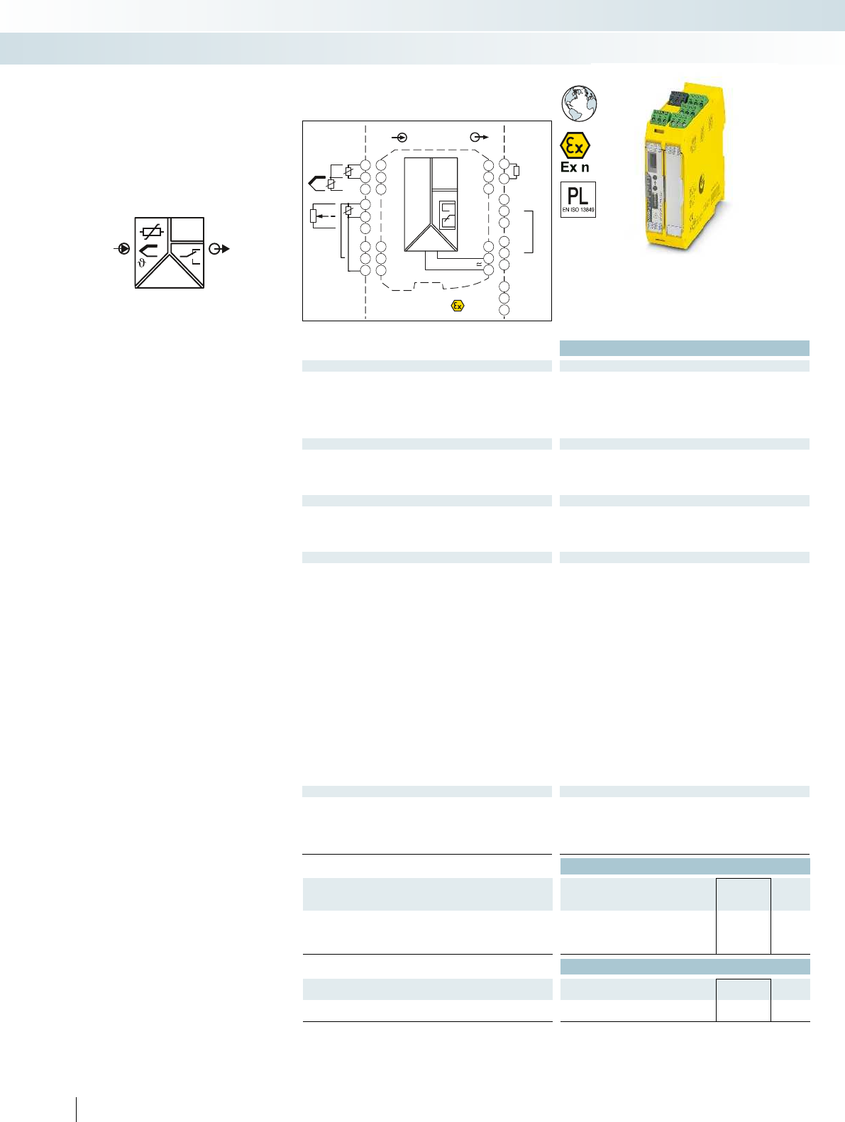
OUT
IN
POWER
I
Zone 2
Div. 2
IN OUT
Power
24V ...230V AC/DC
3.3
3.1
1.2
3.2
1.1
1.3
4.3
4.1
4.2
5.3
5.1
5.2
GND
I
OUT
NC
PLC / DCS
passive
-
+
3.3
3.2
11
21
31
12
22
32
14
24
34
3.6
3.4
3.5
2.6
2.4
2.5
1.6
1.4
1.5
DI
DI
Sensor /Field
4.3
4.1
4.2
ϑ
RTD
4.3
4.1
4.2
5.3
5.1
5.2
ϑ
Poti
TC
-
+
ϑ
Functional Safety
Ex:
Housing width 35 mm
Technical data
Input data
Resistance thermometers Pt, Ni, Cu sensors: 2, 3, 4-wire
Thermocouple sensors B, E, J, K, N, R, S, T, L, U, CA, DA, A1G, A2G, A3G, MG, LG
Resistor 0 ... 50 k
Potentiometer 0 ... 50 k
Voltage -1000 mV ... 1000 mV
Output data
Output signal 4 mA ... 20 mA
Maximum output signal 22 mA
Load R
B
600 (at 20 mA)
Behavior in the event of a sensor error according to NE 43 or freely configurable
Switching output Relay output
Contact type 2 PDT
Contact material AgSnO
2
, hard gold-plated
Max. switching voltage 250 V AC (250 V DC)
Max. switching current 2 A (250 V AC) / 2 A (28 V DC)
General data
Supply voltage range 24 V ... 230 V AC/DC (-20%/+10%, 50/60 Hz)
Power consumption < 2.4 W
Temperature coefficient 0.01 %/K
Maximum transmission error 0.1 % (e.g. for Pt 100, 300 K span, 4 ... 20 mA)
Electrical isolation
Input/output/power supply 300 V
rms
(rated insulation voltage (surge voltage category II;
pollution degree 2, safe isolation as per EN 61010-1))
2.5 kV (50 Hz, 1 min., test voltage)
Input/output 375 V (peak value in accordance with EN 60079-11)
Input/power supply 375 V (peak value in accordance with EN 60079-11)
Input/switching output 375 V (peak value in accordance with EN 60079-11)
Ambient temperature range -20 °C ... 65 °C
Humidity typ. 5 % ... 95 % (non-condensing)
Housing material PA 66-FR
Inflammability class in acc. with UL 94 V0
Dimensions W / H / D 35 / 99 / 114.5 mm
Screw connection solid / stranded / AWG 0.2 ... 2.5 mm² / 0.2 ... 2.5 mm² / 24 - 14
Push-in connection solid / stranded / AWG 0.2 ... 1.5 mm² / 0.2 ... 1.5 mm² / 24 - 16
EMC note Class A product, see page 625
Conformance / approvals
Conformance CE-compliant
ATEX
II 3 G Ex nA nC ic IIC T4 Gc X
IECEx Ex nA nC ic IIC T4 Gc X
SIL in accordance with IEC 61508 2
Performance level according to ISO 13849 PLd
Ordering data
Description Type Order No. Pcs. /
Pkt.
Temperature transducer and threshold value switch with
performance level
Screw connection MACX PL-T-UIREL-UP 2904901 1
Push-in connection MACX PL-T-UIREL-UP-SP 2904903 1
Accessories
Programming adapter for configuring modules with
S-PORT interface
IFS-USB-PROG-ADAPTER 2811271 1
Connector, for current signals between +20 mA and -20 mA MACX MCR-I20 2905680 1
186
PHOENIX CONTACT
– Input for resistance thermometers,
thermocouples, resistance-type sensors,
potentiometers, mV sources
– A safety-related limit value relay, by
bridging two relays
– Differential measurement possible with
Pt 100
– An additional limit value relay for non-
safety-related function
– PL d according to EN ISO 13849-1
– Up to SIL 2 according to IEC 61508
– Configuration via software
(ANALOG-CONF or FDT/DTM)
– Cold junction compensation with
separate connector
– Wide range power supply
19.2...253 V AC/DC
– Status indicators for supply voltage, cable,
sensor, and module errors
– Installation in zone 2 possible
– Plug-in screw and push-in connection
technology
Temperature,
temperature transducer
MCR technology
Signal conditioners with PL and SIL functional safety - MACX Safety
Universal, with limit value relay,
wide range power supply
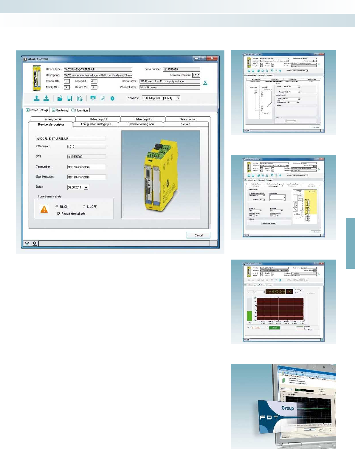
For further information and full technical data, visit phoenixcontact.net/products
ANALOG-CONF
The user-friendly ANALOG-CONF
software allows you to quickly and clearly
configure the temperature modules. The
pin assignment for the input and output is
directly displayed. You have access to the
complete range of configurable parameters.
You have the option to pre-configure
parameters and then import them into any
number of temperature transducers or read
the data from the device and directly display
the settings and measured values.
FDT/DTM
Configuration is also possible via the
FDT/DTM universal configuration tool. The
DTM files can simply be downloaded in the
download area for the item.
The following parameters can be
configured:
– Restart following failsafe
Input:
– Resistance thermometer
– Thermocouples
– Potentiometer
– Remote resistance-type sensor
– Voltage signals ±1 V
– User characteristic curve
– Additional analog signals
– Filter
– Cold junction
Analog output:
– Type of fault signaling
Switching outputs:
– Acknowledgment, switching behavior
– Switch-on/off delay
Monitoring:
– Representation in diagram or value list,
recording possible
Service:
– Reset, password protection, display
DIP switch position
– And much more
187
PHOENIX CONTACT
Configuration software
ANALOG-CONF and FDT/DTM
Configuration with FDT/DTM
Monitoring function
Relay configuration
Input configuration with indication of the pin assignment
MCR technology
Signal conditioners with PL and SIL functional safety - MACX Safety

188
PHOENIX CONTACT
Highly compact – leading technology
MACX Analog Ex – single and two-
channel signal conditioners for intrinsically
safe circuits in the Ex area. The MACX
Analog Ex signal conditioners ensure
maximum system safety and explosion
protection within a minimum amount of
space. With an overall width of just 12.5
mm, this comprehensive range for analog
signal conditioning is approved according to
ATEX and IECEx and consistently SIL-
certified.
Safe and reliable functions
Consistent SIL certification. The MACX
Analog Ex signal conditioners are developed
and produced according to functional safety
and IEC 61508 standards. This ensures the
highest level of reliability and safety for your
systems.
Maximum explosion protection for all
Ex zones and gas groups
As associated equipment according to the
intrinsic safety (Ex i) protection type, the
MACX Analog Ex signal conditioners isolate
intrinsically safe circuits from non-
intrinsically safe circuits and ensure safe
limitation of the energy supplied to the Ex
area. Furthermore, they handle extensive
signal conditioning tasks.
All MACX Analog Ex signal conditioners
are approved in accordance with the
applicable ATEX/IECEx standards:
– [Ex ia] – for intrinsically safe circuits up to
Ex zone 0 and Ex zone 20
– Ex n – for installing devices in Ex zone 2
– In addition, relevant national approvals
such as UL and GOST are available
Choose the right MACX Analog Ex
signal conditioner for your
application:
Analog IN
Measuring transducer repeater power
supply and input signal conditioner for the
intrinsically safe operation of 2-wire
transmitters, 4-wire measuring transducers,
and current sources.
Analog OUT
Output signal conditioners for the
intrinsically safe operation of control valves,
I/P converters, and displays.
Temperature
Configurable temperature transducers
for the intrinsically safe operation of
resistance thermometers, remote
resistance-type sensors, thermocouples,
and mV sources – with safe limit value relays
as an option.
Digital IN
NAMUR signal conditioners for the
intrinsically safe operation of proximity
sensors and switches.
Digital OUT
Solenoid drivers for the intrinsically safe
operation of solenoid valves and alarm
transmitters.
Wide range supply
The modules featuring a wide range supply (...-UP) can
be used in all power supply networks the world over
without the need for additional power supply units.
DIN rail connector-compatible
The DIN rail connector enables the modular bridging of
the 24 V supply voltage.
Flexible energy supply
MCR technology
Ex i signal conditioners with SIL functional safety - MACX Analog Ex
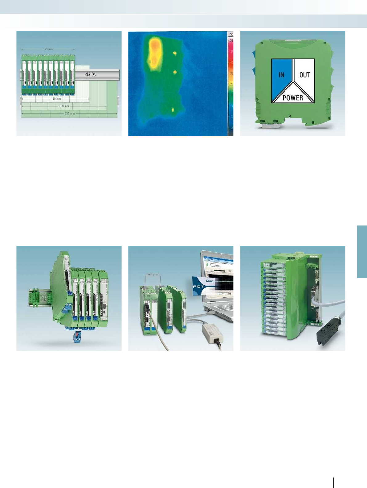
For further information and full technical data, visit phoenixcontact.net/products
189PHOENIX CONTACT
MCR technology
Ex i signal conditioners with SIL functional safety - MACX Analog Ex
Significant space savings
– Housing width of just 12.5 mm for all
single and two-channel devices with DIN
rail connector connection
– Space saving of up to 45% compared to
other Ex i signal conditioners on the
market
Long service life and high operational
reliability
– Long service life and high operational
reliability over the entire operating
temperature range, thanks to low power
consumption and self-heating
Precise, interference-free signal
transmission
– Precise and interference-free signal
transmission due to a patented
transmission concept with safe electrical
isolation.
Easy installation, power bridging, and
diagnostics
– Flexible supply voltage bridging and the
option of redundant, diode-decoupled
supply and error indication.
– Plug-in, coded connection terminal blocks
with test sockets; with screw connection
or with fast push-in connection
technology as an option
Easy configuration and monitoring
– Either via FDT/DTM or alternatively via
user-friendly stand-alone software – with
integrated monitoring function
– Or without software via DIP switches on
the housing front or with the operator
interface and display unit
Fast and error-free signal connection
– Compact Termination Carriers connect
MACX Analog Ex devices to the
automation system – Plug and Play

POWER
II OUT
IN
POWER
PLC / DCS
AI
passive
3.2
3.1
2.1
+
-
-
active
3.2
2.2
2.1
-
+
+
HHT
HHT
Sensor / Field
or
4.2
5.2
4.1
5.1
Zone 0,1,2
Zone 20,21,22
Div. 1,2
HHT
HHT
Zone 2
Div.2
4.2
5.2
4.1
5.1
3.2
3.1
2.2
2.1
1.2
1.1
GND
+24V
GND +24V
Power
+
+
-
-250 Ω
INOUT
Functional Safety
Ex:
EAC Ex
Housing width 12.5 mm
Technical data
Input data
Input signal 4 mA ... 20 mA
Transmitter supply voltage > 16 V (20 mA)
Voltage drop -
Output data
Output signal 4 mA ... 20 mA (active)
4 mA ... 20 mA (14 ... 26 V ext. source voltage)
Load < 1000 (20 mA)
Output ripple < 20 mV
rms
General data
Supply voltage range 19.2 V DC ... 30 V DC (24 V DC (-20% ... +25%))
Current consumption < 76 mA (24VDC / 20mA / 1000);
< 55 mA (24VDC / 20mA / 250)
Power dissipation < 1.1 W (24VDC / 20mA / 1000)
< 0.95 W (24VDC / 20mA / 250)
< 1.2 W (24VDC / 20mA / 0)
Temperature coefficient < 0.01 %/K
Step response (10-90%) < 200 µs (for 4 mA ... 20 mA step, load 600)
Transmission error, typical < 0.05 % (of final value)
Maximum transmission error < 0.1 % (of final value)
Underload/overload range according to NE 43
Electrical isolation
Input/output/power supply 300 V
rms
(rated insulation voltage (surge voltage category II;
pollution degree 2, safe isolation as per EN 61010-1))
2.5 kV (50 Hz, 1 min., test voltage)
Input/output 375 V (peak value in accordance with EN 60079-11)
Input/power supply 375 V (peak value in accordance with EN 60079-11)
Ambient temperature range -20 °C ... 60 °C (any mounting position)
Humidity 10 % ... 95 % (non-condensing)
Status indication Green LED (supply voltage)
SMART communication Yes
Signal bandwidth as per HART specifications
Protocols supported HART
Housing material PA 66-FR
Inflammability class in acc. with UL 94 V0
Dimensions W / H / D 12.5 / 112.5 / 114.5 mm
Screw connection solid / stranded / AWG 0.2 ... 2.5 mm² / 0.2 ... 2.5 mm² / 24 - 14
Push-in connection solid / stranded / AWG 0.2 ... 1.5 mm² / 0.2 ... 1.5 mm² / 24 - 16
EMC note Class A product, see page 625
Safety data as per ATEX
Max. output voltage U
o
25.2 V
Max. output current I
o
93 mA
Max. output power P
o
587 mW
Maximum voltage U
m
253 V AC (125 V DC)
Conformance / approvals
Conformance CE-compliant, additionally EN 61326
ATEX
II (1) G [Ex ia Ga] IIC/IIB
II (1) D [Ex ia Da] IIIC
II 3 (1) G Ex nA [ia Ga] IIC/IIB T4 Gc
I (M1) [Ex ia Ma] I
IECEx [Ex ia Ga] IIC/IIB, [Ex ia Da] IIIC, Ex nA [ia Ga] IIC/IIB T4 Gc
UL, USA / Canada UL 61010 Listed
Class I Div 2; IS for Class I, II, III Div 1
SIL in accordance with IEC 61508 2
Ordering data
Description Type Order No. Pcs. /
Pkt.
Repeater power supply, smart, intrinsically safe input
Screw connection MACX MCR-EX-SL-RPSSI-I 2865340 1
Push-in connection MACX MCR-EX-SL-RPSSI-I-SP 2924016 1
190
PHOENIX CONTACT
Repeater power supply and input signal
conditioner for the operation of intrinsically
safe (Ex i) 2-wire measuring transducers,
4-wire measuring transducers, and mA
current sources installed in Ex areas.
– 0/4 ... 20 mA input, [Ex ia]
(powered or not powered)
– 0/4...20 mA output (active or passive)
– Bidirectional transmission of digital HART
communication signals
– Plug-in screw or push-in connection
technology, with integrated sockets for
HART communicators
– Terminal point with 250 resistor to
increase the HART impedance in the case
of low-impedance systems
– 3-way electrical isolation
– Power supply via DIN rail connector
possible
– Up to SIL 2 according to IEC 61508
– Installation in zone 2 permitted
Notes:
Information about the power and fault signaling module as well as
about the DIN rail connectors and marking material can be found
from page 213
Test plugs for test sockets can be found on page 180
Information on Plug and Play connection using system cabling can
be found from page 216
Analog IN
Repeater power supply, Ex i
MCR technology
Ex i signal conditioners with SIL functional safety - MACX Analog Ex
Repeater power supply and
input signal conditioner
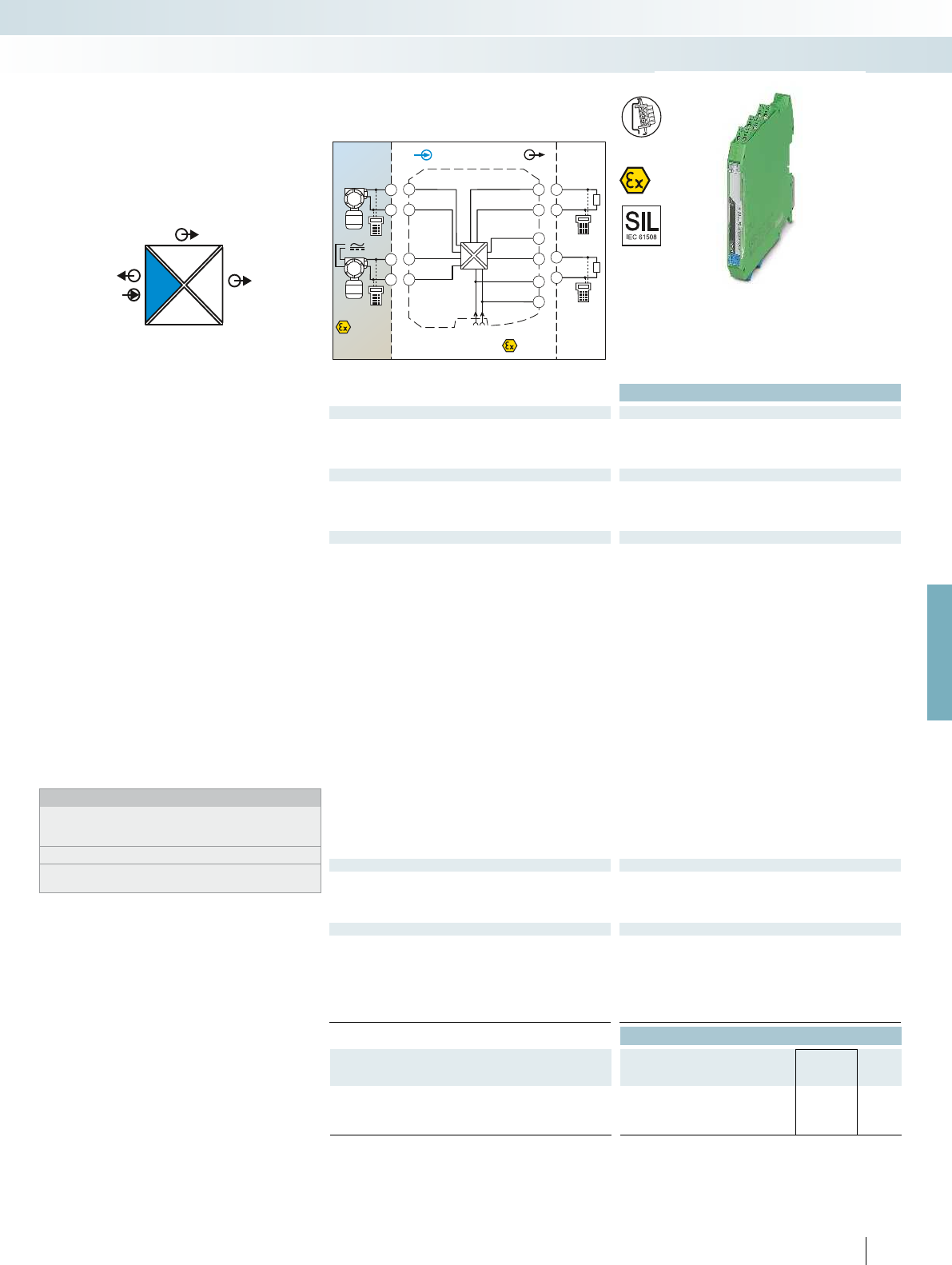
POWER
IIOUT2
I
OUT1
IN
POWER
Zone 2
Div. 2
Sensor / Field
or
4.2
5.2
4.1
5.1
Zone 0,1,2
Zone 20,21,22
Div. 1,2
4.2
5.2
4.1
5.1
3.2
3.1
2.2
2.1
1.2
1.1
GND
OUT 1
OUT 2
+24V
GND +24V
Power
+
+
-
-
IN OUT
PLC / DCS
3.2
3.1
+
-
2.2
2.1
+
-
passive
passive
AI
For further information and full technical data, visit phoenixcontact.net/products
Functional Safety
Ex: EAC Ex
Housing width 12.5 mm
Technical data
Input data
Input signal 4 mA ... 20 mA / 0 mA ... 20 mA
Transmitter supply voltage > 16 V (at 20 mA)
Voltage drop < 3.9 V (in input signal conditioner)
Output data
Output signal (per output) 4 mA ... 20 mA (active)
Load < 450 (at 20 mA)
Output ripple < 20 mV
rms
General data
Supply voltage range 19.2 V DC ... 30 V DC (24 V DC (-20% ... +25%))
Current consumption < 75 mA (24 V DC/ 20 mA)
Power dissipation < 1.45 W (24 V DC/ 20 mA)
Temperature coefficient < 0.01 %/K
Step response (10-90%) < 1.3 ms (for 4 mA ... 20 mA step)
Transmission error, typical < 0.05 % (of final value)
Maximum transmission error < 0.1 % (of final value)
Underload/overload range according to NE 43
Electrical isolation
Input/output/power supply 300 V
rms
(rated insulation voltage (surge voltage category II;
pollution degree 2, safe isolation as per EN 61010-1))
2.5 kV (50 Hz, 1 min., test voltage)
Input/output 375 V (peak value in accordance with EN 60079-11)
Input/power supply 375 V (peak value in accordance with EN 60079-11)
Output 1/output 2 1.5 kV AC (50 Hz, 1 min., test voltage)
Ambient temperature range -20 °C ... 60 °C (any mounting position)
Status indication Green LED (PWR supply voltage)
SMART communication (per output) Yes
Protocols supported HART
Housing material PA 66-FR
Dimensions W / H / D 12.5 / 99 / 114.5 mm
Screw connection solid / stranded / AWG 0.2 ... 2.5 mm² / 0.2 ... 2.5 mm² / 24 - 14
Push-in connection solid / stranded / AWG 0.2 ... 1.5 mm² / 0.2 ... 1.5 mm² / 24 - 16
EMC note Class A product, see page 625
Safety data as per ATEX
Max. output voltage U
o
25.2 V
Max. output current I
o
93 mA
Max. output power P
o
587 mW
Maximum voltage U
m
253 V AC (125 V DC)
Conformance / approvals
Conformance CE-compliant, additionally EN 61326
ATEX
II (1) G [Ex ia Ga] IIC/IIB
II (1) D [Ex ia Da] IIIC
II 3 (1) G Ex nA [ia Ga] IIC/IIB T4 Gc
IECEx [Ex ia Ga] IIC/IIB, [Ex ia Da] IIIC, Ex nA [ia Ga] IIC/IIB T4 Gc
UL, USA / Canada Class I Div 2; IS for Class I, II, III Div 1
SIL in accordance with IEC 61508 2
Ordering data
Description Type Order No. Pcs. /
Pkt.
Repeater power supply, smart, intrinsically safe input
Screw connection MACX MCR-EX-SL-RPSSI-2I 2865366 1
Push-in connection MACX MCR-EX-SL-RPSSI-2I-SP 2924236 1
191
PHOENIX CONTACT
Repeater power supply and input signal
conditioner for the operation of intrinsically
safe (Ex i) 2-wire measuring transducers,
4-wire measuring transducers, and mA
current sources installed in Ex areas.
– 0/4 ... 20 mA input, [Ex ia]
(powered or not powered)
– Two electrically isolated 0/4 ... 20 mA
(active) outputs
– Bidirectional transmission of digital HART
communication signals (both outputs)
– Plug-in screw or push-in connection
technology, with integrated sockets for
HART communicators
– 4-way electrical isolation
– Power supply via DIN rail connector
possible
– Up to SIL 2 according to IEC 61508
– Installation in zone 2 permitted
Notes:
Information about the power and fault signaling module as well as
about the DIN rail connectors and marking material can be found
from page 213
Test plugs for test sockets can be found on page 180
Information on Plug and Play connection using system cabling can
be found from page 216
Analog IN
Repeater power supply, Ex i
MCR technology
Ex i signal conditioners with SIL functional safety - MACX Analog Ex
Repeater power supply and
input signal conditioner,
with two electrically isolated outputs
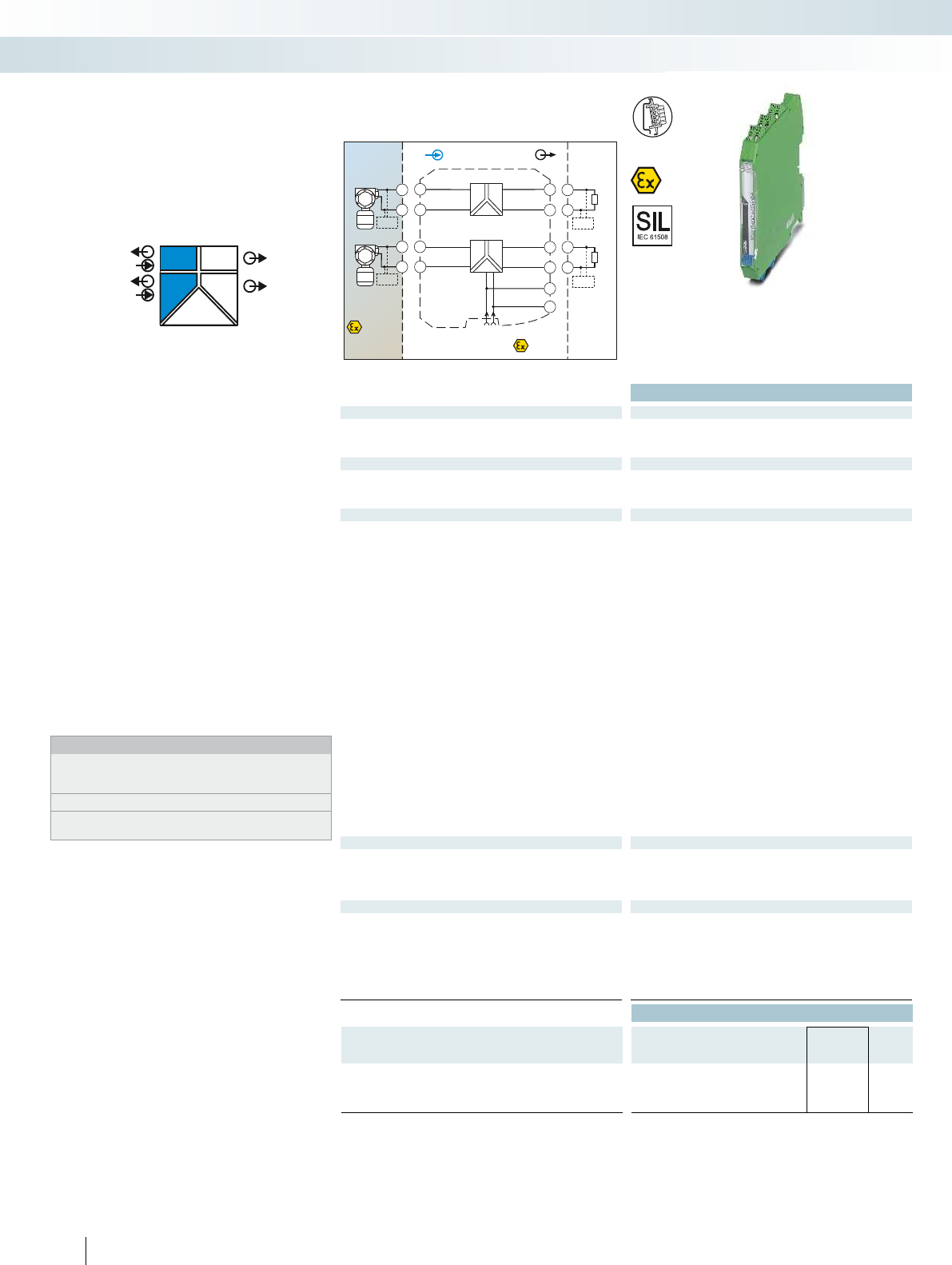
POWER
OUT
OUT
IN
POWER
IN
POWER
II
II
PLC / DCS
AI
Sensor / Field
Zone 2
3.2
3.1
2.2
2.1
GND
1.2
1.1
+24V
GND +24V
Power
Zone 0,1,2
Zone 20,21,22
passive
3.2
3.1
+
-
HHT
INOUT
CH1
CH2
active
active
passive
2.1
2.2
-
+
HHT
5.2
5.1
5.2
5.1
+
-
CH2
HHT
4.2
4.1
4.2
4.1
+
-
CH1
HHT
Div. 1,2Div. 1
Functional Safety
Ex:
Housing width 12.5 mm
Technical data
Input data per channel
Input signal 4 mA ... 20 mA
Transmitter supply voltage > 16 V (at 20 mA)
Underload/overload signal range 0 mA ... 24 mA
Output data per channel
Output signal 4 mA ... 20 mA (active)
Load 450 (20 mA)
Underload/overload signal range 0 mA ... 24 mA
General data
Supply voltage range 19.2 V DC ... 30 V DC (24 V DC (-20% ... +25%))
Current consumption < 100 mA (24 V / 20 mA)
Power dissipation < 1.4 W (at 24 V DC / 20 mA)
Temperature coefficient < 0.01 %/K
Step response (10-90%) < 1.3 ms (for 4 mA ... 20 mA step)
Transmission error, typical < 0.05 % (of final value)
Maximum transmission error < 0.1 % (of final value)
Electrical isolation
Input/output, power supply 300 V
rms
(rated insulation voltage (surge voltage category II;
pollution degree 2, safe isolation as per EN 61010-1))
2.5 kV (50 Hz, 1 min., test voltage)
Input/output 375 V (peak value in accordance with EN 60079-11)
Input/power supply 375 V (peak value in accordance with EN 60079-11)
Output 1/output 2/ power supply 1.5 kV (50 Hz, 1 min., test voltage)
Ambient temperature range -20 °C ... 60 °C (any mounting position)
Status indication Green LED (supply voltage)
SMART communication Yes
Signal bandwidth as per HART specifications
Protocols supported HART
Housing material PA 66-FR
Dimensions W / H / D 12.5 / 99 / 114.5 mm
Screw connection solid / stranded / AWG 0.2 ... 2.5 mm² / 0.2 ... 2.5 mm² / 24 - 14
Push-in connection solid / stranded / AWG 0.2 ... 1.5 mm² / 0.2 ... 1.5 mm² / 24 - 16
EMC note Class A product, see page 625
Safety data as per ATEX
Max. output voltage U
o
25.2 V
Max. output current I
o
93 mA
Max. output power P
o
587 mW
Maximum voltage U
m
253 V AC (125 V DC)
Conformance / approvals
Conformance CE-compliant, additionally EN 61326
ATEX
II (1) G [Ex ia Ga] IIC/IIB
II (1) D [Ex ia Da] IIIC
II 3(1) G Ex nA [ia Ga] IIC T4 Gc
IECEx [Ex ia Ga] IIC/IIB, [Ex ia Da] IIIC, Ex nA [ia Ga] IIC T4 Gc
UL, USA / Canada Class I Div 2; IS for Class I, II, III Div 1
SIL in accordance with IEC 61508 3
Ordering data
Description Type Order No. Pcs. /
Pkt.
Repeater power supply, 2-channel, smart, intrinsically safe input
Screw connection MACX MCR-EX-SL-RPSS-2I-2I 2865382 1
Push-in connection MACX MCR-EX-SL-RPSS-2I-2I-SP 2924676 1
192
PHOENIX CONTACT
Repeater power supply for the operation
of intrinsically safe (Ex i) 2-wire measuring
transducers installed in the Ex area.
– 2-channel
– 4 ... 20 mA input, [Ex ia] (powered)
– 4 ... 20 mA output (active)
– Bidirectional transmission of digital HART
communication signals
– Plug-in screw or push-in connection
technology, with integrated sockets for
HART communicators
– Safe 3-way electrical isolation
– Power supply via DIN rail connector
possible
– Up to SIL 3 according to IEC 61508
– Installation in zone 2 permitted
Notes:
Information on the power and fault signaling module, DIN rail
connectors, system cabling, and marking material can be found
from page 213
Test plugs for test sockets can be found on page 180
Information on Plug and Play connection using system cabling can
be found from page 216
Analog IN
Repeater power supply, Ex i
MCR technology
Ex i signal conditioners with SIL functional safety - MACX Analog Ex
2-channel repeater power supply
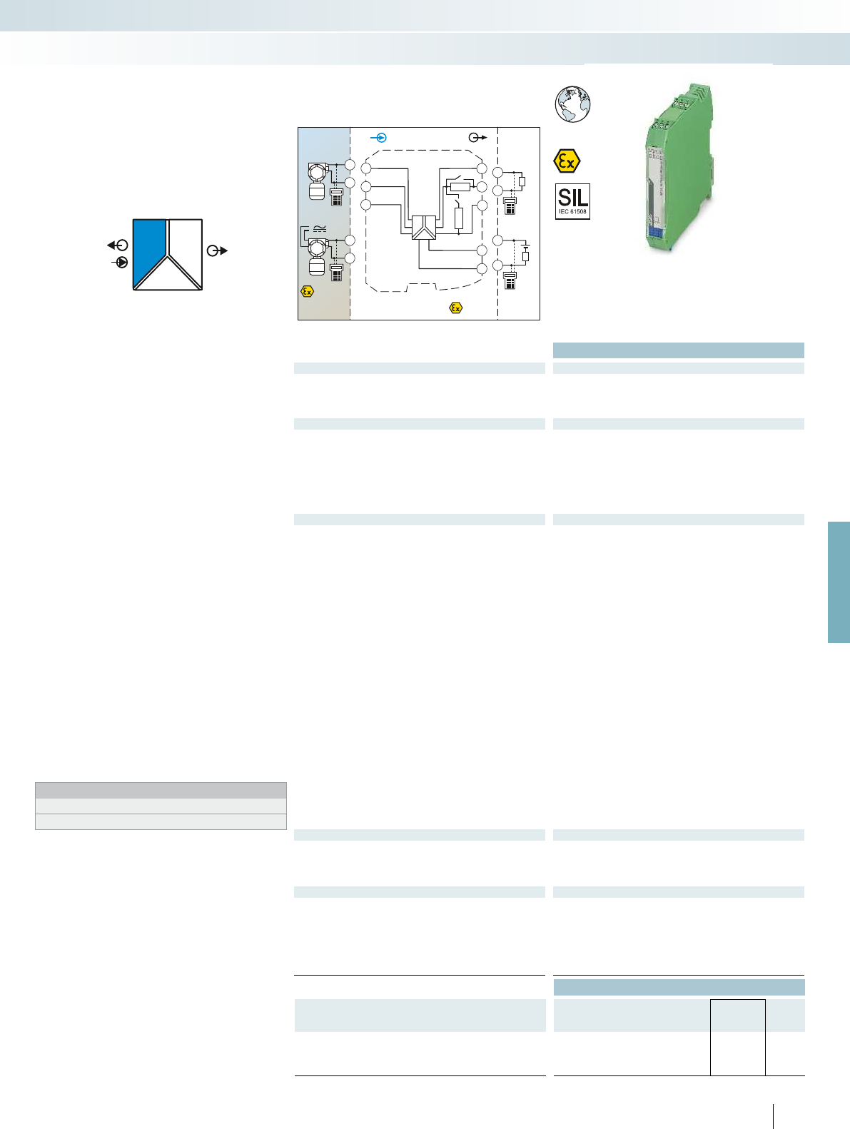
POWER
II OUT
IN
POWER
Zone 2
Div. 2
IN OUT
24...230 V
AC/DC
4.3
4.2
3.3
3.2
250
Ω
4.1 3.1
1.2
1.1
250Ω
S2
S1
–
~
PLC / DCS
passive
3.2
3.1
+
-
active
3.3
3.2
+
-
AI
Sensor / Field
or
+
-4.2
4.1
Zone 0,1,2
Zone 20,21,22
Div. 1,2
4.3
4.2
+
-
For further information and full technical data, visit phoenixcontact.net/products
Functional Safety
Ex: EAC Ex // Applied for: GL
Housing width 17.5 mm
Technical data
Input data
Input signal 0 mA ... 20 mA / 4 mA ... 20 mA
Transmitter supply voltage > 16 V (at 20 mA)
Voltage drop < 3.5 V (in input signal conditioner operation)
Output data
Output signal (configurable using the DIP switch) 0 mA ... 20 mA (active)
4 mA ... 20 mA (active)
0 mA ... 20 mA (14 ... 26 V ext. source voltage)
4 mA ... 20 mA (14 ... 26 V ext. source voltage)
0 V ... 5 V (internal resistance, 250 , 0.1%)
1 V ... 5 V (internal resistance, 250 , 0.1%)
Load < 600 (I output)
Output ripple < 20 mV
rms
General data
Supply voltage range 24 V ... 230 V AC/DC (-20%/+10%, 50/60 Hz)
Current consumption < 80 mA (at 24 V DC)
Power dissipation < 1.6 W
Temperature coefficient < 0.01 %/K
Step response (10-90%) < 600 µs (for 4 mA ... 20 mA step)
Transmission error, typical < 0.05 % (of final value)
Maximum transmission error < 0.1 % (of final value)
Underload/overload range according to NE 43
Electrical isolation
Input/output/power supply 300 V
rms
(rated insulation voltage (surge voltage category II;
pollution degree 2, safe isolation as per EN 61010-1))
2.5 kV (50 Hz, 1 min., test voltage)
Input/output 375 V (peak value in accordance with EN 60079-11)
Input/power supply 375 V (peak value in accordance with EN 60079-11)
Ambient temperature range -20 °C ... 60 °C (any mounting position)
Humidity 10 % ... 95 % (non-condensing)
Status indication Green LED (supply voltage)
SMART communication Yes
Signal bandwidth as per HART specifications
Protocols supported HART
Housing material PA 66-FR
Inflammability class in acc. with UL 94 V0
Dimensions W / H / D 17.5 / 99 / 114.5 mm
Screw connection solid / stranded / AWG 0.2 ... 2.5 mm² / 0.2 ... 2.5 mm² / 24 - 14
Push-in connection solid / stranded / AWG 0.2 ... 1.5 mm² / 0.2 ... 1.5 mm² / 24 - 16
EMC note Class A product, see page 625
Safety data as per ATEX
Max. output voltage U
o
25.2 V
Max. output current I
o
93 mA
Max. output power P
o
587 mW
Maximum voltage U
m
253 V AC (125 V DC)
Conformance / approvals
Conformance CE-compliant, additionally EN 61326
ATEX
II (1) G [Ex ia Ga] IIC/IIB
II (1) D [Ex ia Da] IIIC
II 3(1) G Ex nA [ia Ga] IIC/IIB T4 Gc
IECEx [Ex ia Ga] IIC/IIB, [Ex ia Da] IIIC, Ex nA [ia Ga] IIC/IIB T4 Gc
UL, USA / Canada Class I Div 2; IS for Class I, II, III Div 1
SIL in accordance with IEC 61508 2
Ordering data
Description Type Order No. Pcs. /
Pkt.
Repeater power supply, smart, intrinsically safe input
Screw connection MACX MCR-EX-SL-RPSSI-I-UP 2865793 1
Push-in connection MACX MCR-EX-SL-RPSSI-I-UP-SP 2924029 1
193
PHOENIX CONTACT
Repeater power supply and input signal
conditioner for the operation of intrinsically
safe (Ex i) 2-wire measuring transducers,
4-wire measuring transducers, and mA
current sources installed in Ex areas.
– 0/4 ... 20 mA input, [Ex ia]
(powered or not powered)
– Output 0/4...20 mA (active or passive),
0/1...5 V, can be switched via the DIP
switch
– Bidirectional transmission of digital HART
communication signals
– Plug-in screw or push-in connection
technology, with integrated sockets for
HART communicators
– 250 resistor that can be activated via
DIP switches to increase the HART
impedance in the case of low-impedance
systems
– 3-way electrical isolation
– Wide range power supply:
19.2 ... 253 V AC/DC
– Up to SIL 2 according to IEC 61508
– Installation in zone 2 permitted
Notes:
Information on marking material can be found on page 179
Test plugs for test sockets can be found on page 180
Analog IN
Repeater power supply with wide
range power supply, Ex i
MCR technology
Ex i signal conditioners with SIL functional safety - MACX Analog Ex
Repeater power supply and
input signal conditioner,
wide range power supply
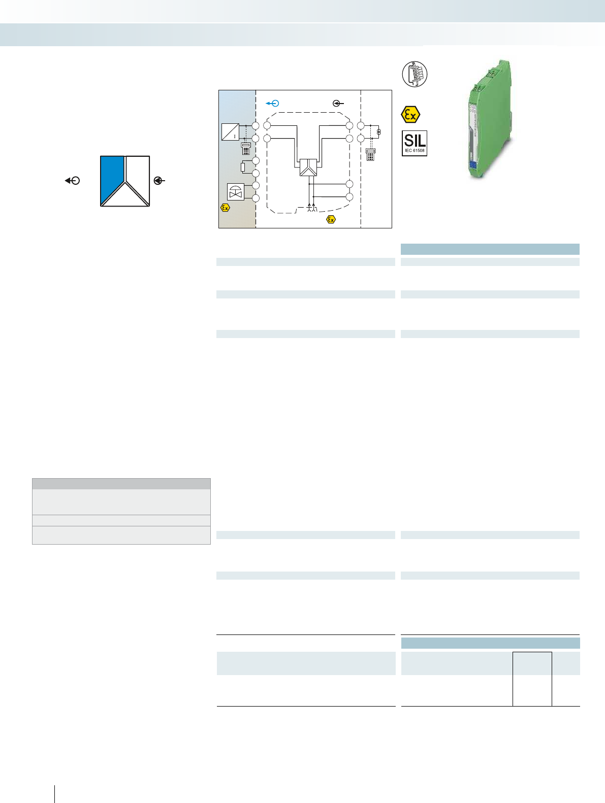
POWER
II
OUTIN
PLC/DCS
Sensor /Field
4.2
4.1
4.2
4.1
+
-
+
-
P
4.2
4.1
+
-
Zone 2
Div. 2
INOUT
4.2
4.1
3.2
3.1
1.2
1.1
GND
+24V
GND+24V
Power
+
-
-
+
3.2
3.1
Zone 0,1,2
Zone 20,21,22
Div. 1,2
AO
Functional Safety
Ex:
Housing width 12.5 mm
Technical data
Input data
Input signal 0 mA ... 20 mA / 4 mA ... 20 mA
Input voltage 5.4 V (at 20 mA)
Input impedance in the event of a cable break at the output > 100 k (If there is a line fault)
Output data
Output signal 0 mA ... 20 mA (intrinsically safe) /
4 mA ... 20 mA (intrinsically safe)
Load < 800 (at 20 mA)
Output ripple < 20 mV
rms
General data
Supply voltage range 19.2 V DC ... 30 V DC (24 V DC (-20% ... +25%))
Current consumption < 46 mA (at 24 V DC / 20 mA)
Power dissipation < 1.1 W (at 24 V DC / 20 mA)
Temperature coefficient < 0.01 %/K
Step response (10-90%) < 140 µs (for 4 mA ... 20 mA step)
Maximum transmission error < 0.1 % (of final value)
Electrical isolation
Input/output/power supply 1.5 kV (50 Hz, 1 min., test voltage)
300 V
rms
(rated insulation voltage (surge voltage category II,
pollution degree 2))
Output/input 375 V (peak value in accordance with EN 60079-11)
Output/supply 375 V (peak value in accordance with EN 60079-11)
Ambient temperature range -20 °C ... 60 °C (any mounting position)
Humidity 10 % ... 95 % (non-condensing)
Status indication Green LED (supply voltage)
SMART communication Yes
Signal bandwidth as per HART specifications
Protocols supported HART
Housing material PA 66-FR
Inflammability class in acc. with UL 94 V0
Dimensions W / H / D 12.5 / 99 / 114.5 mm
Screw connection solid / stranded / AWG 0.2 ... 2.5 mm² / 0.2 ... 2.5 mm² / 24 - 14
Push-in connection solid / stranded / AWG 0.2 ... 1.5 mm² / 0.2 ... 1.5 mm² / 24 - 16
EMC note Class A product, see page 625
Safety data as per ATEX
Max. output voltage U
o
27.7 V
Max. output current I
o
92 mA
Max. output power P
o
633 mW
Maximum voltage U
m
253 V AC (125 V DC)
Conformance / approvals
Conformance CE-compliant, additionally EN 61326
ATEX
II (1) G [Ex ia Ga] IIC/IIB
II (1) D [Ex ia Da] IIIC
II 3(1) G Ex nA [ia Ga] IIC/IIB T4 Gc
IECEx [Ex ia Ga] IIC/IIB, [Ex ia Da] IIIC, Ex nA [ia Ga] IIC/IIB T4 Gc
UL, USA / Canada Class I Div 2; IS for Class I, II, III Div 1
SIL in accordance with IEC 61508 2
Ordering data
Description Type Order No. Pcs. /
Pkt.
Output signal conditioner, smart, intrinsically safe output
Screw connection MACX MCR-EX-SL-IDSI-I 2865405 1
Push-in connection MACX MCR-EX-SL-IDSI-I-SP 2924032 1
194
PHOENIX CONTACT
Output signal conditioner for controlling
intrinsically safe (Ex i) I/P converters,
control valves, and indicators installed in
Ex areas.
– 0/4...20 mA input
– 0/4...20 mA output, [Ex ia] IIC
– Bidirectional transmission of digital HART
communication signals
– Plug-in screw or push-in connection
technology, with integrated sockets for
HART communicators
– Line fault detection (LFD)
– 3-way electrical isolation
– Power supply via DIN rail connector
possible
– Up to SIL 2 according to IEC 61508
– Installation in zone 2 permitted
Notes:
Information about the power and fault signaling module as well as
about the DIN rail connectors and marking material can be found
from page 213
Test plugs for test sockets can be found on page 180
Information on Plug and Play connection using system cabling can
be found from page 216
Analog OUT
Output signal conditioner, Ex i
MCR technology
Ex i signal conditioners with SIL functional safety - MACX Analog Ex

OUT
IN
POWER
I
Zone 0,1,2
Zone 20,21,22
Div. 1,2
IN
Zone 2
Div. 2
OUT
PLC / DCS
passive
-
+
3.2
3.1
GND
+24V
GND +24V
μC μC
Power
4.2
5.2
4.1
5.1
3.2
3.1
1.2
1.1
Sensor /Field
4.2
4.1
5.2
5.1
ϑϑϑ
AI
For further information and full technical data, visit phoenixcontact.net/products
Ex:
Housing width 12.5 mm
Technical data
Input data
Resistance thermometers Sensors (2, 3, 4-wire)
Resistor 0 ... 2000
Cable resistance 50 per cable
Sensor input current 200 A ... 1 mA
Measuring range span min. 50 K
Output data
Output signal 0 mA ... 20 mA / 4 mA ... 20 mA
Load 500
Behavior in the event of a sensor error As per NE 43 or can be freely defined
Output ripple < 50 µA
PP
General data
Supply voltage range 19.2 V DC ... 30 V DC (24 V DC (-20% ... +25%))
Current draw 40 mA (at 24 V DC)
Power dissipation < 1 W
Temperature coefficient 0.01 %/K
Step response (0–99%) typ. 800 ms (with SIL)
max. 1200 ms (with SIL)
typ. 700 ms (without SIL)
max. 1100 ms (without SIL)
Transmission error, total 0.05 % x 100 [K] / measuring range span [K] + 0.05 %
ZERO / SPAN adjustment ± 5 % / ± 5 %
Electrical isolation
Input/output/power supply 300 V
rms
(rated insulation voltage (surge voltage category II;
pollution degree 2, safe isolation as per EN 61010-1))
2.5 kV (50 Hz, 1 min., test voltage)
Input/output 375 V (peak value in accordance with EN 60079-11)
Input/power supply 375 V (peak value in accordance with EN 60079-11)
Ambient temperature range -20 °C ... 60 °C (any mounting position)
Humidity 5 % ... 95 % (non-condensing)
Status indication Green LED (supply voltage, PWR)
Red LED, flashing (line, sensor error, ERR)
Red LED (module error, ERR)
Inflammability class in acc. with UL 94 V0
Dimensions W / H / D 12.5 / 99 / 114.5 mm
Screw connection solid / stranded / AWG 0.2 ... 2.5 mm² / 0.2 ... 2.5 mm² / 24 - 14
Push-in connection solid / stranded / AWG 0.2 ... 1.5 mm² / 0.2 ... 1.5 mm² / 24 - 16
EMC note Class A product, see page 625
Safety data as per ATEX
Max. output voltage U
o
6 V
Max. output current I
o
6.3 mA
Max. output power P
o
9.4 mW
Conformance / approvals
Conformance CE-compliant, additionally EN 61326
ATEX
II (1) G [Ex ia Ga] IIC
II (1) D [Ex ia Da] IIIC
II 3(1) G Ex nA ic [ia Ga] IIC T4 Gc X
IECEx [Ex ia Ga] IIC, [Ex ia Da] IIIC, Ex nA ic [ia Ga] IIC T4 Gc
UL, USA / Canada Class I Div 2; IS for Class I, II, III Div 1
SIL in accordance with IEC 61508 2
Ordering data
Description Type Order No. Pcs. /
Pkt.
Temperature transducer for resistance thermometers,
intrinsically safe input
Order configuration Screw connection MACX MCR-EX-SL-RTD-I 2865939 1
Order configuration Push-in connection MACX MCR-EX-SL-RTD-I-SP 2924142 1
Standard configuration Screw connection MACX MCR-EX-SL-RTD-I-NC 2865573 1
Standard configuration Push-in connection MACX MCR-EX-SL-RTD-I-SP-NC 2924168 1
Accessories
Programming adapter for configuring modules with
S-PORT interface
IFS-USB-PROG-ADAPTER 2811271 1
195
PHOENIX CONTACT
Programmable temperature transducer
for intrinsically safe operation of resistance
thermometers and resistance-type sensors
installed in Ex areas. The measured values
are converted into a linear 0 ... 20 mA or
4 ... 20 mA signal.
– Input for resistance thermometers and
resistance-type sensors, [Ex ia]
– 0 ... 20 mA or 4 ... 20 mA output
– Configuration via software (FDT/DTM):
Sensor type, connection method,
measuring range, measuring unit, filter,
alarm signal, and output range
– Programming during operation with Ex
measuring circuit connected and also
voltage-free using IFS-USB-PROG-
ADAPTER programming adapter
– Status indicator for supply voltage, cable,
sensor, and module errors
– 3-way electrical isolation
– Power supply via DIN rail connector
possible
– Up to SIL 2 according to IEC 61508
– Installation in zone 2 permitted
Notes:
To order a product with an order configuration, please enter the
desired configuration by referring to the order key, see page 197
The configuration software can be downloaded from the Internet
(phoenixcontact.net/products).
Information about the power and fault signaling module as well as
about the DIN rail connectors and marking material can be found
from page 213
For information on the programming adapter, refer to page 89
Information on Plug and Play connection using system cabling can
be found from page 216
Temperature
Temperature transducer, Ex i
MCR technology
Ex i signal conditioners with SIL functional safety - MACX Analog Ex
For resistance thermometers and
resistance-type sensors
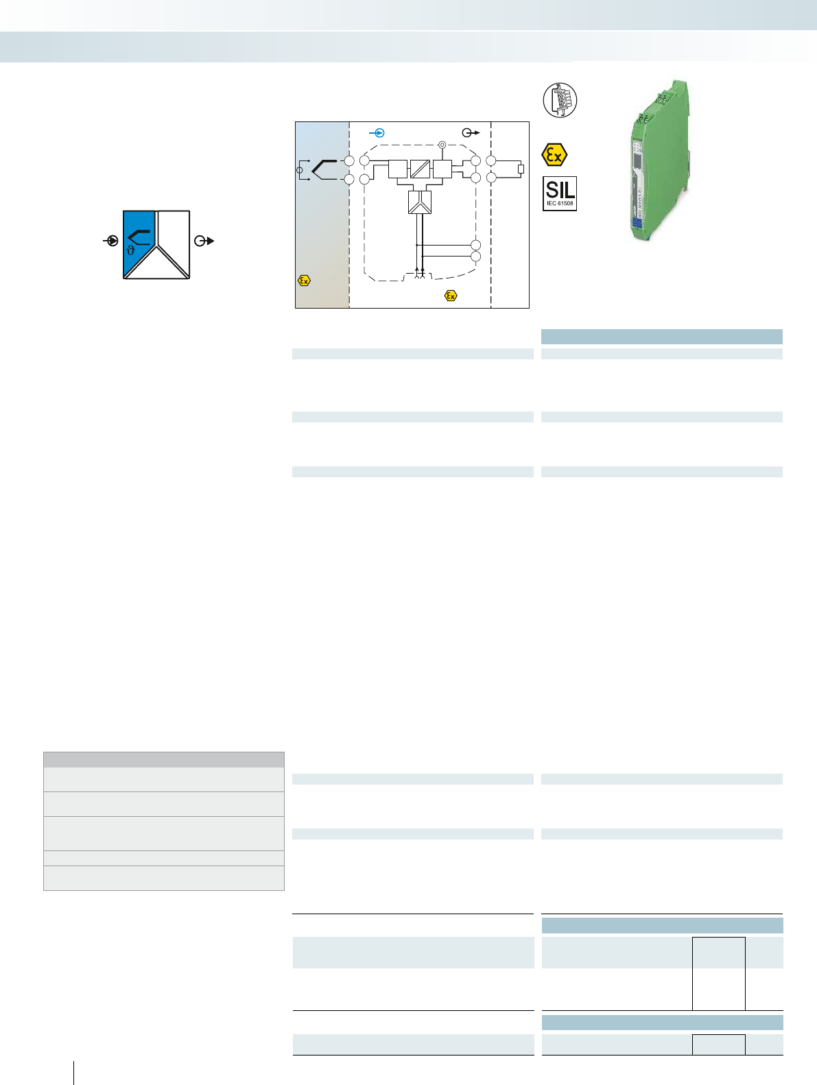
OUT
IN
POWER
I
Zone 0,1,2
Zone 20,21,22
Div. 1,2
IN
PLC/DCS
passive
-
+
3.2
3.1
Zone 2
Div. 2
OUT
GND
+24V
GND+24V
μCμC
Power
4.2
4.1
3.2
3.1
1.2
1.1
+
-
Sensor /Field
4.2
4.1
AI
Ex:
Housing width 12.5 mm
Technical data
Input data
Thermocouple sensors E, J, K, N as per IEC / EN 60584, L as per DIN 43760
Voltage -20 mV ... 70 mV
Measuring range span Min. 50 K for thermocouples, 3 mV for mV sources
Output data
Output signal 0 mA ... 20 mA / 4 mA ... 20 mA
Load 500
Behavior in the event of a sensor error As per NE 43 or can be freely defined
Output ripple < 50 µA
PP
General data
Supply voltage range 19.2 V DC ... 30 V DC (24 V DC (-20% ... +25%))
Current consumption < 40 mA (24 V DC)
Power dissipation < 1 W
Temperature coefficient 0.01 %/K
Step response (0–99%) typ. 800 ms (with SIL)
max. 1200 ms (with SIL)
typ. 700 ms (without SIL)
max. 1100 ms (without SIL)
Transmission error, total 0.05% x 200 [K]/Measuring range span [K] + 0.05%
Cold junction errors ± 1 K
ZERO / SPAN adjustment ± 5 % / ± 5 %
Electrical isolation
Input/output/power supply 300 V
rms
(rated insulation voltage (surge voltage category II;
pollution degree 2, safe isolation as per EN 61010-1))
2.5 kV (50 Hz, 1 min., test voltage)
Input/output 375 V (peak value in accordance with EN 60079-11)
Input/power supply 375 V (peak value in accordance with EN 60079-11)
Ambient temperature range -20 °C ... 60 °C (any mounting position)
Humidity 5 % ... 95 % (non-condensing)
Status indication Green LED (supply voltage, PWR)
Red LED, flashing (line, sensor error, ERR)
Red LED (module error, ERR)
Housing material PA 66-FR
Inflammability class in acc. with UL 94 V0
Dimensions W / H / D 12.5 / 99 / 114.5 mm
Screw connection solid / stranded / AWG 0.2 ... 2.5 mm² / 0.2 ... 2.5 mm² / 24 - 14
EMC note Class A product, see page 625
Safety data as per ATEX
Max. output voltage U
o
6 V
Max. output current I
o
4.7 mA
Max. output power P
o
7 mW
Maximum voltage U
m
253 V AC (125 V DC)
Conformance / approvals
Conformance CE-compliant, additionally EN 61326
ATEX
II (1) G [Ex ia Ga] IIC
II (1) D [Ex ia Da] IIIC
II 3(1) G Ex nA ic [ia Ga] IIC T4 Gc X
IECEx [Ex ia Ga] IIC, [Ex ia Da] IIIC, Ex nA ic [ia Ga] IIC T4 Gc
UL, USA / Canada Class I Div 2; IS for Class I, II, III Div 1
SIL in accordance with IEC 61508 2
Ordering data
Description Type Order No. Pcs. /
Pkt.
Temperature transducer for thermocouples, intrinsically safe
input
Order configuration Screw connection MACX MCR-EX-SL-TC-I 2865942 1
Standard configuration Screw connection MACX MCR-EX-SL-TC-I-NC 2865586 1
Accessories
Programming adapter for configuring modules with
S-PORT interface
IFS-USB-PROG-ADAPTER 2811271 1
196
PHOENIX CONTACT
Programmable temperature transducer
for intrinsically safe operation of
thermocouples and mV sources installed in
Ex areas. The measured values are
converted into a linear 0 ... 20 mA or
4 ... 20 mA signal.
– Input for thermocouples and mV sources,
[Ex ia]
– 0 ... 20 mA or 4 ... 20 mA output
– Configuration via software (FDT/DTM):
Sensor type, connection method,
measuring range, measuring unit, filter,
alarm signal, and output range
– Programming during operation with
Ex measuring circuit connected and also
voltage-free using IFS-USB-PROG-
ADAPTER programming adapter
– Status indicator for supply voltage, cable,
sensor, and module errors
– 3-way electrical isolation
– Power supply via DIN rail connector
possible
– Up to SIL 2 according to IEC 61508
– Installation in zone 2 permitted
Notes:
To order a product with an order configuration, please enter the
desired configuration by referring to the order key, see page 197
The configuration software can be downloaded from the Internet
(phoenixcontact.net/products).
Information about the power and fault signaling module as well as
about the DIN rail connectors and marking material can be found
from page 213
For information on the programming adapter, refer to page 89
Information on Plug and Play connection using system cabling can
be found from page 216
Temperature
Temperature transducer, Ex i
MCR technology
Ex i signal conditioners with SIL functional safety - MACX Analog Ex
For thermocouples and mV sources
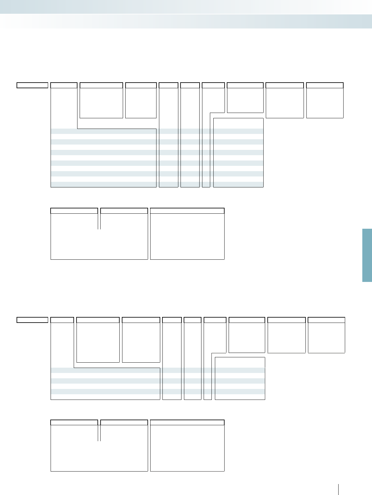
For further information and full technical data, visit phoenixcontact.net/products
197PHOENIX CONTACT
Order key for MACX MCR-EX-SL-RTD-I(-SP) temperature transducer (standard configuration entered as an example)
Order key for MACX MCR-EX-SL-TC-I temperature transducer (standard configuration entered as an example)
Order key and temperature ranges for
the MACX MCR-EX-SL-RTD-I(-SP)
temperature transducer
Order key and temperature ranges
for the MACX MCR-EX-SL-TC-I
temperature transducer
Alarm signal Alarm signal
Factory calibration certificate = FCC
Short circuit/
overrange
Sensor break/
underrange
... / I035 / I215 / NONE Temperature conversion guide for °C to °F:
9
T [°F] = – T [°C] + 32
5
I000 = 0 mA I000 = 0 mA NONE =without FCC
I035 =3.5 mA I035 =3.5 mA Yes =with FCC (a fee is charged)
I215 =21.5 mA I215 =21.5 mA YESPLUS =FCC with 5 measuring points
(a fee is charged)
I035 only with output range = OUT02
Alarm signals can also be configured individually using
software.
Order No. Sensor type Safety integrity level
(SIL)
Connection
technology
Measuring range: Measuring
unit
Output range Filter Filter
Start End Oversampling Moving average value
2865939 / PT100 / ON / 3 / 0 / 100 / C / OUT02 / 10 / 1 / ...
2865939 =
MACX MCR-EX-
SL-RTD-I
See below ON =active 2 =2-wire see
below
see
below
C=°C OUT01 = 0 ... 20 mA 1 =1 value 1 =1 value
NONE =not active F =°F 3 =3 values 2 =2 values
3=3-wire O =OUT02 = 4 ... 20 mA 5 =5 values 3 =3 values
ON only with output range
= OUT02
7=7 values 4 =4 values
2924142 =
MACX MCR-EX-
SL-RTD-I-SP
4=4-wire 10 =10 values
20 =20 values
Smallest measuring
range span
RES01 =Resistor 0 2000 25
PT50 =Pt 50 acc. to IEC 751 -200 850 °C 50 K
PT100 =Pt 100 acc. to IEC 751 -200 850 °C 50 K
PT200 =Pt 200 acc. to IEC 751 -200 850 °C 50 K
PT500 =Pt 500 acc. to IEC 751 -200 850 °C 50 K
PT100S =Pt 100 acc. to Sama RC21-4-1966 -200 600 °C 50 K
PT500S =Pt 500 acc. to Sama RC21-4-1966 -200 600 °C 50 K
NI100DIN =Ni 100 acc. to DIN 43760 -60 250 °C 50 K
NI500DIN =Ni 500 acc. to DIN 43760 -60 250 °C 50 K
CU50 =
CU50 acc. to GOST 6651 (
= 1.428)
-50 200 °C 50 K
CU53 =CU53 acc. to GOST 6651 ( = 1.426) -50 180 °C 50 K
Order No. Sensor type Safety integrity level
(SIL)
Cold junction
compensation
Measuring range: Measuring
unit
Output range Filter Filter
Start End Oversampling Moving average value
2924942 / J / ON / 1 / 0 / 1000 / C / OUT02 / 10 / 1 / ...
MACX MCR-EX-
SL-TC-I
see below ON =active 1 =Enabled see
below
see
below
C=°C OUT01 = 0 ... 20 mA 1 =1 value 1 =1 value
NONE =Not active F =°F 3 =3 values 2 =2 values
0=switched off
(e.g., for mV
voltage
measurement)
V=mV OUT02 = 4 ... 20 mA 5 =5 values 3 =3 values
7=7 values 4 =4 values
10 =10 values
ON only with output range
= OUT02
20 =20 values
Smallest measuring
range span
V03 =Voltage (mV) -20 +70 mV 3 mV
E=acc. to IEC 584-1 (NiCr-CuNi) -250 1000 °C 50 K
J =acc. to IEC 584-1 (Fe-CuNi) -210 1200 °C 50 K
K=acc. to IEC 584-1 (NiCr-Ni) -250 1372 °C 50 K
N=acc. to IEC 584-1 (NiCrSi-NiSi) -250 1300 °C 50 K
L=acc. to DIN 43760 (Fe-CuNi) -200 900 °C 50 K
Alarm signal Alarm signal
Factory calibration certificate = FCC
Overrange Sensor break/
underrange
... / I035 / I215 / NONE Temperature conversion guide for °C to °F:
9
T [°F] = – T [°C] + 32
5
I000 = 0 mA I000 = 0 mA NONE =without FCC
I035 =3.5 mA I035 =3.5 mA Yes =with FCC (a fee is charged)
I215 =21.5 mA I215 =21.5 mA YESPLUS =FCC with 5 measuring points
(a fee is charged)
I035 only with output range = OUT02
Alarm signals can also be configured individually using
software.
MCR technology
Ex i signal conditioners with SIL functional safety - MACX Analog Ex

OUT
IN
POWER
U,I
Zone 0,1,2
Zone 20,21,22
PLC/DCS
passive
-
+
3.3
3.2
-
+
3.3
3.1
DI
11
12
14
2.3
2.1
2.2
Zone 2
INOUT
Power
24V ...230V AC/DC
3.3
3.1
1.2
3.2
1.1
2.3
2.1
2.2
1.3
4.3
4.1
4.2
5.3
5.1
5.2
μC
S-PORT
GND
I
U
OUT
OUT
NC
Sensor /Field
4.3
4.1
4.2
TC
-
+
ϑ
RTD
ϑ
4.3
4.1
4.2
5.3
5.1
5.2
ϑ
Poti
Functional Safety
Ex:
Housing width 17.5 mm
Technical data
Input data
Resistance thermometers Pt, Ni, Cu sensors: 2, 3, 4-wire
Thermocouple sensors B, E, J, K, N, R, S, T, L, U, CA, DA, A1G, A2G, A3G, MG, LG
Resistor 0 ... 50 k
Potentiometer 0 ... 50 k
Voltage -1000 mV ... 1000 mV
Output data U output I output
Output signal 4 mA ... 20 mA
(in the case of SIL; further free configuration without SIL)
Maximum output signal ± 11 V 22 mA
Load R
B
10 k 600 (20 mA)
Behavior in the event of a sensor error according to NE 43 or freely configurable
Switching output Switching output
Contact type 1 PDT
Contact material AgSnO
2
, hard gold-plated
Max. switching voltage 30 V AC (30 V DC)
Max. switching current 0.5 A (30 V AC) / 1 A (30 V DC)
General data
Supply voltage range 24 V ... 230 V AC/DC (-20%/+10%, 50/60 Hz)
Power consumption < 1.5 W
Temperature coefficient 0.01 %/K
Transmission error, total < 0.1 % (e.g., for Pt 100, 300 K span, 4 ... 20 mA)
Electrical isolation
Input/output/power supply 2.5 kV (50 Hz, 1 min., test voltage)
Input/output 375 V (peak value in accordance with EN 60079-11)
Input/power supply 375 V (peak value in accordance with EN 60079-11)
Input/switching output 375 V (peak value in accordance with EN 60079-11)
Output/supply 300 V
rms
(rated insulation voltage (surge voltage category II;
pollution degree 2, safe isolation as per EN 61010-1))
Ambient temperature range -20 °C ... 65 °C
Humidity typ. 5 % ... 95 % (non-condensing)
Housing material PA 66-FR
Inflammability class in acc. with UL 94 V0
Dimensions W / H / D 17.5 / 99 / 114.5 mm
Screw connection solid / stranded / AWG 0.2 ... 2.5 mm² / 0.2 ... 2.5 mm² / 24 - 14
Push-in connection solid / stranded / AWG 0.2 ... 1.5 mm² / 0.2 ... 1.5 mm² / 24 - 16
EMC note Class A product, see page 625
Safety data as per ATEX
Max. output voltage U
o
6 V
Max. output current I
o
7.4 mA
Max. output power P
o
11 mW
Conformance / approvals
Conformance CE-compliant
ATEX
II (1) G [Ex ia Ga] IIC
II (1) D [Ex ia Da] IIIC
II 3 G Ex nA nC ic IIC T4 Gc X
IECEx [Ex ia Ga] IIC, [Ex ia Da] IIIC, Ex nA nC ic IIC T4 Gc X
SIL in accordance with IEC 61508 2
Ordering data
Description Type Order No. Pcs. /
Pkt.
Temperature transducer, intrinsically safe input
Standard configuration Screw connection MACX MCR-EX-T-UI-UP 2865654 1
Standard configuration Push-in connection MACX MCR-EX-T-UI-UP-SP 2924689 1
Order configuration Screw connection MACX MCR-EX-T-UI-UP-C 2811763 1
Order configuration Push-in connection MACX MCR-EX-T-UI-UP-SP-C 2924692 1
Accessories
Programming adapter for configuring modules with
S-PORT interface
IFS-USB-PROG-ADAPTER 2811271 1
198
PHOENIX CONTACT
Universal temperature transducer with
freely configurable properties for
intrinsically safe operation of resistance
thermometers, thermocouples, resistance-
type sensors, and potentiometers installed
in Ex areas
– Input for resistance thermometers,
thermocouples, resistance-type sensors,
potentiometers, and mV sources, [Ex ia]
– Measure differential temperatures
– Freely programmable input and output
– Option of inverse output signal ranges
– Relay switching output
– Configuration via software (FDT-DTM) or
IFS-OP-UNIT operating and display unit
– Programming during operation with
Ex measuring circuit connected and also
voltage-free using IFS-USB-PROG-
ADAPTER programming adapter
– Plug-in screw or push-in connection
technology
– Cold junction compensation with
separate connector
– Wide range power supply:
19.2 ... 253 V AC/DC
– Status indicator for supply voltage, cable,
sensor, and module errors
– Up to SIL 2 according to IEC 61508
– Installation in zone 2 permitted
Notes:
To order a product with an order configuration, enter the required
configuration by referring to the adjacent order key.
The configuration software can be downloaded from the Internet
(phoenixcontact.net/products).
Information on the IFS-OP-UNIT operating and display unit and the
associated IFS-OP-CRADLE DIN rail cradle can be found on
page 170
For information on the programming adapter, refer to page 89
Temperature
Temperature transducer, Ex i
MCR technology
Ex i signal conditioners with SIL functional safety - MACX Analog Ex
Universal, with switching output,
wide range power supply
For further information and full technical data, visit phoenixcontact.net/products
199PHOENIX CONTACT
Order key for MACX MCR-EX-T-UI-UP(-SP)-C temperature transducer (standard configuration entered as an example)
Order No. Safety integrity level
(SIL)
Sensor type Connection
technology
Cold junction
compensation
Measuring range: Measuring
unit
Output range Factory calibration
certificate = FCC
Start End
2811763 / ON / PT100 / 4 / 0 / -50 / 150 / C / OUT02 / NONE
2811763 =
MACX MCR-EX-
T-UI-UP-C
ON =Active See below 2 =2-wire 0 =off, e.g., with
RTD, R,
potentiometer,
mV
see
below
see
below
C=°C OUT15 =0 ... 5 mA NONE =without FCC
F=°F OUT16 =0 ... 10 mA
NONE =not active O=OUT01 =0 ... 20 mA
3=3-wire P =% OUT15 =0 ... 5 mA YES =with FCC (a fee is
charged)
2924692 =
MACX MCR-EX-
T-UI-UP-SP-C
V=mV OUT25 =1 ... 5 mA
ON only with output
range = OUT02
1=on, e.g., with TC OUT26 =2 ... 10 mA
4=4-wire OUT02 =4 ... 20 mA
OUT05 =0 - 5 V DC YESPLUS =FCC with
5 measuring points
(a fee is charged)
OUT03 =0...10 V
OUT06 =1...5 V
OUT04 =2...10 V
OUT13 =-5...+5 V
OUT14 =-10...+10 V
Others can be freely
configured in the
software
Smallest measuring
range span
Other setting options can be configured
with the IFS-CONF software:
- Freely configurable user characteristic curve
with 30 interpolation points
- Output behavior in the event of a short circuit,
sensor break or overrange/underrange can be
freely configured or set acc. to NE43
(standard configuration: NE43 upscale)
- Filter setting (standard configuration: 1)
- Restart after failsafe (standard configuration:
ON)
- Switching behavior: switching output
(limit values, times, etc.)
(standard configuration: OFF)
Resistance thermometers (RTD)
Others can be selected or freely
configured in the software.
PT100 =Pt 100 acc. to IEC 751 -200 850 °C 20 K
PT200 =Pt 200 acc. to IEC 751 -200 850 °C 20 K
PT500 =Pt 500 acc. to IEC 751 -200 850 °C 20 K
PT1000 =Pt 1000 acc. to IEC 751 -200 850 °C 20 K
PT100S =Pt 100 acc. to Sama RC21-4-1966 -200 850 °C 20 K
PT1000S =Pt 1000 acc. to Sama RC21-4-1966 -200 850 °C 20 K
PT100G =
Pt 100 acc. to GOST 6651-2009 (
= 0.00385)
-200 850 °C 20 K
PT1000G =
Pt 1000 acc. to GOST 6651-2009 (
= 0.00385)
-200 850 °C 20 K
PT100J =Pt 100 acc. to JIS C1604/1997 -200 850 °C 20 K
PT1000J =Pt 1000 acc. to JIS C1604/1997 -200 850 °C 20 K
NI100 =Ni 100 acc. to DIN 43760/DIN IEC 60751 -60 250 °C 20 K
NI1000 =Ni 1000 acc. to DIN 43760/DIN IEC 60751 -60 250 °C 20 K
NI100S =Ni 100 acc. to Sama RC21-4-1966 -60 180 °C 20 K
NI1000S =Ni 1000 acc. to Sama RC21-4-1966 -60 180 °C 20 K
NI1000L =Ni 1000 (Landis & Gyr) -50 160 °C 20 K
CU10 =Cu 10 acc. to Sama RC21-4-1966 -70 500 °C 100 K
CU50 =
Cu 50 acc. to GOST 6651-2009 (
= 0.00428)
-50 200 °C 100 K
CU100 =
Cu 100 acc. to GOST 6651-20091 (
= 0.00428)
-50 200 °C 100 K
CU53 =
Cu 53 acc. to GOST 6651-2009 (
= 0.00426)
-50 180 °C 100 K
KTY81 =KTY81-110 (Philips) -55 150 °C 20 K
KTY84 =KTY84-130 (Philips) -40 300 °C 20 K
Thermocouples (TC)
Others can be selected in the software.
B =acc. to IEC 584-1 (Pt30Rh-Pt6Rh) 500 1820 °C 50 K
E=acc. to IEC 584-1 (NiCr-CuNi) -230 1000 °C 50 K
J =acc. to IEC 584-1 (Fe-CuNi) -210 1200 °C 50 K
K=acc. to IEC 584-1 (NiCr-Ni) -250 1372 °C 50 K
N=acc. to IEC 584-1 (NiCrSi-NiSi) -250 1300 °C 50 K
R=acc. to IEC 584-1 (Pt13Rh-Pt) -50 1768 °C 50 K
S=acc. to IEC 584-1 (Pt10Rh-Pt) -50 1768 °C 50 K
T=acc. to IEC 584-1 (Cu-CuNi) -200 400 °C 50 K
L=acc. to DIN 43760 (Fe-CuNi) -200 900 °C 50 K
U=acc. to DIN 43760 (Cu-CuNi) -200 600 °C 50 K
CA =C ASTM JE988 (2002) 02315 °C 50 K
DA =D ASTM JE988 (2002) 0 2315 °C 50 K
A1G =A-1 GOST 8.585-2001 02500 °C 50 K
A2G =A-2 GOST 8.585-2001 0 1800 °C 50 K
A3G =A-3 GOST 8.585-2001 01800 °C 50 K
MG =M GOST 8.585-2001 -200 100 °C 50 K
LG =L GOST 8.585-2001 -200 800 °C 50 K
Remote resistance-type sensors (R)
(2, 3, 4-wire)
Others can be selected in the software.
RES03 =0...150 resistor 0150
10% of the selected
measuring range
RES05 =0...600 resistor 0 600
RES06 =0...1200 resistor 01200
RES09 =0...6250 resistor 0 6250
RES10 =0...12500 resistor 012500
RES12 =0...50000 resistor 0 50000
Potentiometers
(3-wire)
Others can be selected in the software.
POT03 =0...150 potentiometer 0100 %
10% of the selected
measuring range
POT05 =0...600 potentiometer 0 100 %
POT06 =0...1200 potentiometer 0100 %
POT09 =0...6250 potentiometer 0 100 %
POT10 =0...12500 potentiometer 0100 %
POT12 =0...50000 potentiometer 0 100 %
Voltage signals (mV)
Others can be selected in the software.
V04 =Voltage (mV) -1000 +1000 mV 10% of nominal
span
9
T [°F] = – T [°C] + 32
5
Temperature conversion guide for °C to °F:
MCR technology
Ex i signal conditioners with SIL functional safety - MACX Analog Ex
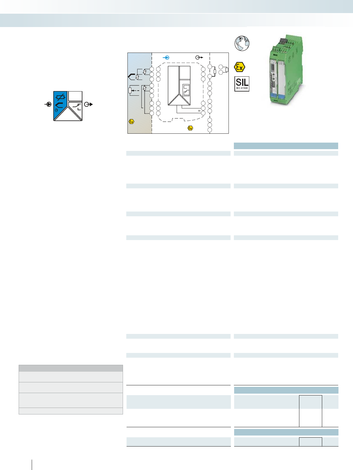
OUT
IN
POWER
U,I
3x
Zone 0,1,2
Zone 20,21,22
3x
Zone 2
IN OUT
Power
24V ...230V AC/DC
3.3
3.1
1.2
3.2
1.1
1.3
4.3
4.1
4.2
5.3
5.1
5.2
GND
I
U
OUT
OUT
NC
PLC / DCS
passive
-
+
3.3
3.2
-
+
3.3
3.1
11
21
31
12
22
32
14
24
34
3.6
3.4
3.5
2.6
2.4
2.5
1.6
1.4
1.5
DI
DI
DI
Sensor /Field
4.3
4.1
4.2
ϑ
RTD
4.3
4.1
4.2
5.3
5.1
5.2
ϑ
Poti
TC
-
+
ϑ
Functional Safety
Ex:
Housing width 35 mm
Technical data
Input data
Resistance thermometers Pt, Ni, Cu sensors: 2, 3, 4-wire
Thermocouple sensors B, E, J, K, N, R, S, T, L, U, CA, DA, A1G, A2G, A3G, MG, LG
Resistor 0 ... 50 k
Potentiometer 0 ... 50 k
Voltage -1000 mV ... 1000 mV
Output data U output I output
Output signal 0 mA ... 20 mA ±10 V
(in the case of SIL; further free configuration without SIL)
Maximum output signal ± 11 V 22 mA
Load R
B
10 k 600 (20 mA)
Behavior in the event of a sensor error according to NE 43 or freely configurable
Switching output Relay output
Contact type 3 PDTs
Contact material AgSnO
2
, hard gold-plated
Max. switching voltage 250 V AC (250 V DC)
Max. switching current 2 A (250 V AC) / 2 A (28 V DC)
General data
Supply voltage range 24 V ... 230 V AC/DC (-20%/+10%, 50/60 Hz)
Power consumption < 2.4 W
Temperature coefficient 0.01 %/K
Maximum transmission error 0.1 % (e.g. for Pt 100, 300 K span, 4 ... 20 mA)
Electrical isolation
Input/output/power supply 2.5 kV (50 Hz, 1 min., test voltage)
Input/output 375 V (peak value in accordance with EN 60079-11)
Input/power supply 375 V (peak value in accordance with EN 60079-11)
Input/switching output 375 V (peak value in accordance with EN 60079-11)
Output/supply 300 V
rms
(rated insulation voltage (surge voltage category II;
pollution degree 2, safe isolation as per EN 61010-1))
Ambient temperature range -20 °C ... 65 °C
Humidity typ. 5 % ... 95 % (non-condensing)
Housing material PA 66-FR
Inflammability class in acc. with UL 94 V0
Dimensions W / H / D 35 / 99 / 114.5 mm
Screw connection solid / stranded / AWG 0.2 ... 2.5 mm² / 0.2 ... 2.5 mm² / 24 - 14
Push-in connection solid / stranded / AWG 0.2 ... 1.5 mm² / 0.2 ... 1.5 mm² / 24 - 16
EMC note Class A product, see page 625
Safety data as per ATEX
Max. output voltage U
o
6 V
Max. output current I
o
7.4 mA
Max. output power P
o
11 mW
Conformance / approvals
Conformance CE-compliant
ATEX
II (1) G [Ex ia Ga] IIC
II (1) D [Ex ia Da] IIIC
II 3 G Ex nA nC ic IIC T4 Gc X
IECEx [Ex ia Ga] IIC, [Ex ia Da] IIIC, Ex nA nC ic IIC T4 Gc X
SIL in accordance with IEC 61508 2
Ordering data
Description Type Order No. Pcs. /
Pkt.
Temperature transducer, intrinsically safe input
Standard configuration Screw connection MACX MCR-EX-T-UIREL-UP 2865751 1
Standard configuration Push-in connection MACX MCR-EX-T-UIREL-UP-SP 2924799 1
Accessories
Programming adapter for configuring modules with
S-PORT interface
IFS-USB-PROG-ADAPTER 2811271 1
200
PHOENIX CONTACT
Universal temperature transducer with
freely configurable properties for
intrinsically safe operation of resistance
thermometers, thermocouples, resistance-
type sensors, and potentiometers installed
in Ex areas
– Input for resistance thermometers,
thermocouples, resistance-type sensors,
potentiometers, and mV sources, [Ex ia]
– Measure differential temperatures
– Freely programmable input and output
– Option of inverse output signal ranges
– Three limit value relays, can be used in
combination as a safe limit value relay
– Configuration via software (FDT-DTM) or
IFS-OP-UNIT operating and display unit
– Programming during operation with Ex
measuring circuit connected and also
voltage-free using IFS-USB-PROG-
ADAPTER programming adapter
– Plug-in screw or push-in connection
technology
– Cold junction compensation with
separate connector
– Wide range power supply:
19.2 ... 253 V AC/DC
– Status indicator for supply voltage, cable,
sensor, and module errors
– Up to SIL 2 according to IEC 61508
– Installation in zone 2 permitted
Notes:
To order a product with an order configuration, enter the required
configuration by referring to the adjacent order key.
The configuration software can be downloaded from the Internet
(phoenixcontact.net/products).
Information on the IFS-OP-UNIT operating and display unit and the
associated IFS-OP-CRADLE DIN rail cradle can be found on
page 170
For information on the programming adapter, refer to page 89
Temperature
Temperature transducer, Ex i
MCR technology
Ex i signal conditioners with SIL functional safety - MACX Analog Ex
Universal, with three limit value relays,
wide range power supply
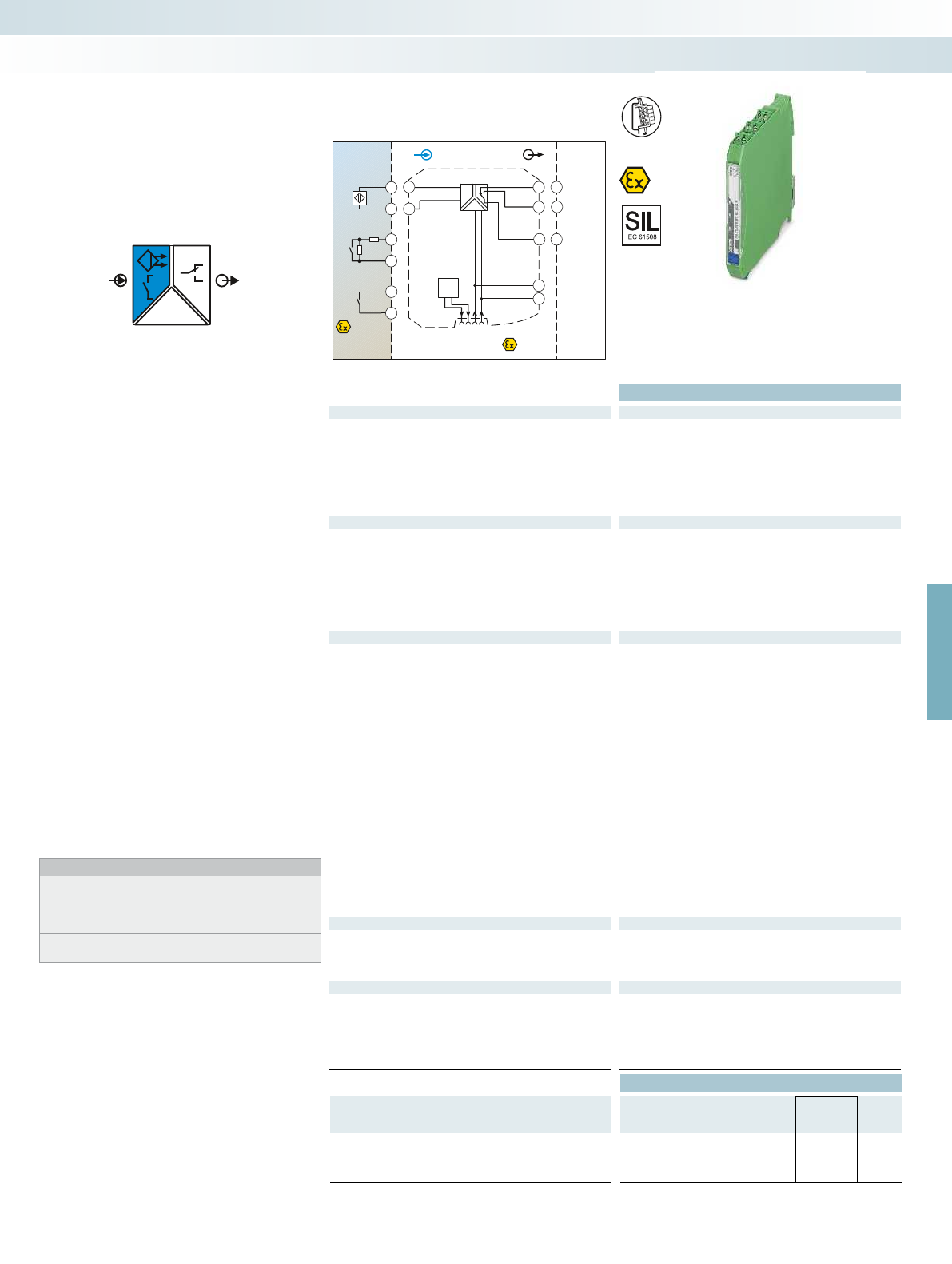
POWER
OUT
IN
Zone 0,1,2
Zone 20,21,22
Div. 1,2
IN
Sensor /Field
4.2
4.1
4.2
4.1
+
-
4.2
4.1
Zone 2
Div. 2
OUT
GND
+24V
4.2
4.1
3.2
3.1
1.2
1.1
+
-
Power
Faultsignal
GND
+24VLFD
2.2
PLC / DCS
3.2
3.1
2.2
11
12
14
DI
For further information and full technical data, visit phoenixcontact.net/products
Functional Safety
Ex:
Housing width 12.5 mm
Technical data
Input data
Input signal NAMUR proximity sensors (EN 60947-5-6)
Floating switch contacts
Switch contacts with resistance circuit
No-load voltage ~ 8 V DC
Switching points > 2.1 mA (conductive) / < 1.2 mA (blocking)
Switching hysteresis < 0.2 mA
Line fault detection Break 0.05 mA < IIN < 0.35 mA
Short circuit 100 < RSensor < 360
Switching output Relay output
Contact type 1 PDT
Contact material AgSnO
2
, hard gold-plated
Max. switching voltage 250 V AC (2 A) / 120 V DC (0.2 A) / 30 V DC (2 A)
Max. switching capacity 500 VA
Recommended minimum load 5 V / 10 mA
Mechanical service life 10
7
cycles
Switching behavior Can be inverted via slide switch
Max. switching frequency 20 Hz (without load)
General data
Supply voltage range 19.2 V DC ... 30 V DC (24 V DC (-20% ... +25%))
Current consumption 21 mA (24 V DC)
Power dissipation < 650 mW
Number of channels 1
Electrical isolation
Input/output 375 V (peak value in accordance with EN 60079-11)
Input/output/supply, DIN rail connector 300 V
rms
(rated insulation voltage (surge voltage category II;
pollution degree 2, safe isolation as per EN 61010-1))
2.5 kV (50 Hz, 1 min., test voltage)
Input/supply, DIN rail connector 375 V (peak value in accordance with EN 60079-11)
Ambient temperature range -20 °C ... 60 °C (any mounting position)
Humidity 10 % ... 95 % (non-condensing)
Status indication Green LED (supply voltage)
Yellow LED (switching state)
Red LED (line fault)
Housing material PA 66-FR
Inflammability class in acc. with UL 94 V0
Dimensions W / H / D 12.5 / 99 / 114.5 mm
Screw connection solid / stranded / AWG 0.2 ... 2.5 mm² / 0.2 ... 2.5 mm² / 24 - 14
Push-in connection solid / stranded / AWG 0.2 ... 1.5 mm² / 0.2 ... 1.5 mm² / 24 - 16
EMC note Class A product, see page 625
Safety data as per ATEX
Max. output voltage U
o
9.6 V
Max. output current I
o
10 mA
Max. output power P
o
25 mW
Maximum voltage U
m
253 V AC (125 V DC)
Conformance / approvals
Conformance CE-compliant, additionally EN 61326
ATEX
II (1) G [Ex ia Ga] IIC
II (1) D [Ex ia Da] IIIC
IECEx [Ex ia Ga] IIC, [Ex ia Da] IIIC, Ex nA nC IIC T4 Gc
UL, USA / Canada Class I Div 2; IS for Class I, II, III Div 1
SIL in accordance with IEC 61508 2
Ordering data
Description Type Order No. Pcs. /
Pkt.
NAMUR signal conditioner, 1-channel, intrinsically safe input,
output: PDT contact
Screw connection MACX MCR-EX-SL-NAM-R 2865434 1
Push-in connection MACX MCR-EX-SL-NAM-R-SP 2924045 1
201
PHOENIX CONTACT
NAMUR signal conditioner for
intrinsically safe operation of proximity
sensors and mechanical contacts installed in
Ex areas.
– Input for NAMUR proximity sensors
(EN 60947-5-6), floating contacts or
contacts with resistance circuit, [Ex ia]
– Relay signal output (PDT)
– Reversible direction of action (operating
current or closed-circuit current
behavior)
– Line fault detection (LFD), can be
activated/deactivated, error message
signaled by red flashing LED with de-
excitation of output relay
– Power supply and error indication
possible via the DIN rail connector
– LED displays for indicating supply voltage,
circuit state, and malfunctions to
NAMUR NE 44
– 3-way electrical isolation
– Up to SIL 2 according to IEC 61508
– Installation in zone 2 permitted
Notes:
Information about the power and fault signaling module as well as
about the DIN rail connectors and marking material can be found
from page 213
Information about resistance circuits is given on page 180
Information on Plug and Play connection using system cabling can
be found from page 216
Digital IN
NAMUR signal conditioner, Ex i
MCR technology
Ex i signal conditioners with SIL functional safety - MACX Analog Ex
Signal output: PDT relay
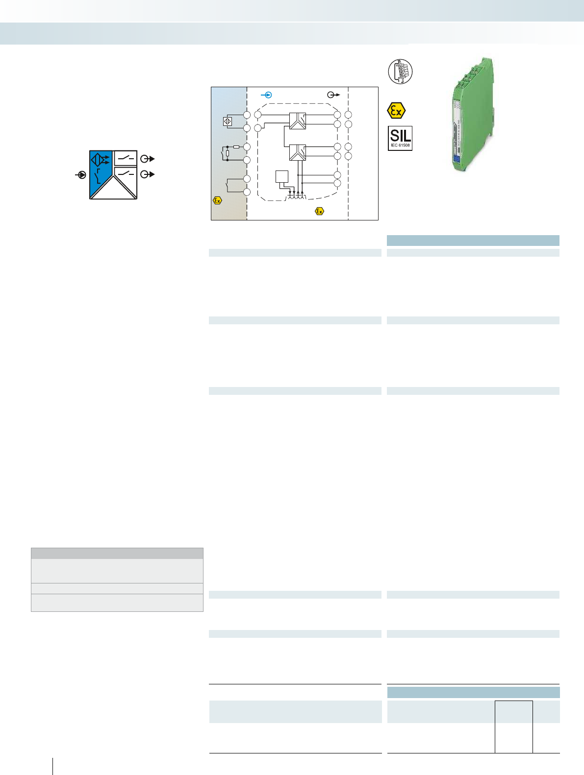
POWER
IN
OUT1
OUT2
Zone 0,1,2
Zone 20,21,22
Div. 1,2
IN
Sensor /Field
4.2
4.1
4.2
4.1
+
-
4.2
4.1
OUT2
Zone 2
Div. 2
OUT
GND
+24V
4.2
4.1
3.2
3.1
1.2
1.1
+
-
Power
Faultsignal
GND
+24VLFD
2.2
2.1
OUT1
PLC / DCS
3.2
3.1
2.2
2.1
13
14
13
14
DI
Functional Safety
Ex:
Housing width 12.5 mm
Technical data
Input data
Input signal NAMUR proximity sensors (EN 60947-5-6)
Floating switch contacts
Switch contacts with resistance circuit
No-load voltage ~ 8 V DC
Switching points > 2.1 mA (conductive) / < 1.2 mA (blocking)
Switching hysteresis < 0.2 mA
Line fault detection Break 0.05 mA < IIN < 0.35 mA
Short circuit 100 < RSensor < 360
Switching output Relay output
Contact type 2 N/O contacts
Contact material AgSnO
2
, hard gold-plated
Max. switching voltage 250 V AC (2 A) / 120 V DC (0.2 A) / 30 V DC (2 A)
Max. switching capacity 500 VA
Recommended minimum load 5 V / 10 mA
Mechanical service life 10
7
cycles
Switching behavior Can be inverted via slide switch
Max. switching frequency 20 Hz (without load)
General data
Supply voltage range 19.2 V DC ... 30 V DC (24 V DC (-20% ... +25%))
Current consumption 30 mA (24 V DC)
Power dissipation < 950 mW
Number of channels 1
Electrical isolation
Input/output 375 V (peak value in accordance with EN 60079-11)
Input/supply, DIN rail connector 375 V (peak value in accordance with EN 60079-11)
300 V
rms
(rated insulation voltage (surge voltage category II;
pollution degree 2, safe isolation as per EN 61010-1))
Output 1/output 2/input, power supply, DIN rail connector 300 V
rms
(rated insulation voltage (surge voltage category III;
pollution degree 2, safe isolation as per EN 61010-1))
Output 1/output 2/input/power supply, DIN rail connector 2.5 kV (50 Hz, 1 min., test voltage)
Ambient temperature range -20 °C ... 60 °C (any mounting position)
Humidity 10 % ... 95 % (non-condensing)
Status indication Green LED (supply voltage)
Yellow LED (switching state)
Red LED (line fault)
Housing material PA 66-FR
Inflammability class in acc. with UL 94 V0
Dimensions W / H / D 12.5 / 99 / 114.5 mm
Screw connection solid / stranded / AWG 0.2 ... 2.5 mm² / 0.2 ... 2.5 mm² / 24 - 14
Push-in connection solid / stranded / AWG 0.2 ... 1.5 mm² / 0.2 ... 1.5 mm² / 24 - 16
EMC note Class A product, see page 625
Safety data as per ATEX
Max. output voltage U
o
9.6 V
Max. output current I
o
10 mA
Max. output power P
o
25 mW
Maximum voltage U
m
253 V AC (125 V DC)
Conformance / approvals
Conformance CE-compliant, additionally EN 61326
ATEX
II (1) G [Ex ia Ga] IIC
II (1) D [Ex ia Da] IIIC
IECEx [Ex ia Ga] IIC, [Ex ia Da] IIIC, Ex nA nC IIC T4 Gc
UL, USA / Canada Class I Div 2; IS for Class I, II, III Div 1
SIL in accordance with IEC 61508 2
Ordering data
Description Type Order No. Pcs. /
Pkt.
NAMUR signal conditioner, 1-channel, intrinsically safe input,
output: 2 N/O contacts
Screw connection MACX MCR-EX-SL-NAM-2RO 2865450 1
Push-in connection MACX MCR-EX-SL-NAM-2RO-SP 2924061 1
202
PHOENIX CONTACT
NAMUR signal conditioner for
intrinsically safe operation of proximity
sensors and mechanical contacts installed in
Ex areas.
– Input for NAMUR proximity sensors
(EN 60947-5-6), floating contacts or
contacts with resistance circuit, [Ex ia]
– Two relay signal outputs (N/O contact);
output 2 can be used as an error message
output
– Reversible direction of action (operating
current or closed-circuit current
behavior)
– Line fault detection (LFD), can be
activated/deactivated, error message
signaled by red flashing LED with de-
excitation of output relay
– Power supply and error indication
possible via the DIN rail connector
– LED displays for indicating supply voltage,
circuit state, and malfunctions to
NAMUR NE 44
– 4-way electrical isolation
– Up to SIL 2 according to IEC 61508
– Installation in zone 2 permitted
Notes:
Information about the power and fault signaling module as well as
about the DIN rail connectors and marking material can be found
from page 213
Information about resistance circuits is given on page 180
Information on Plug and Play connection using system cabling can
be found from page 216
Digital IN
NAMUR signal conditioner, Ex i
MCR technology
Ex i signal conditioners with SIL functional safety - MACX Analog Ex
2 signal outputs: N/O contact relay
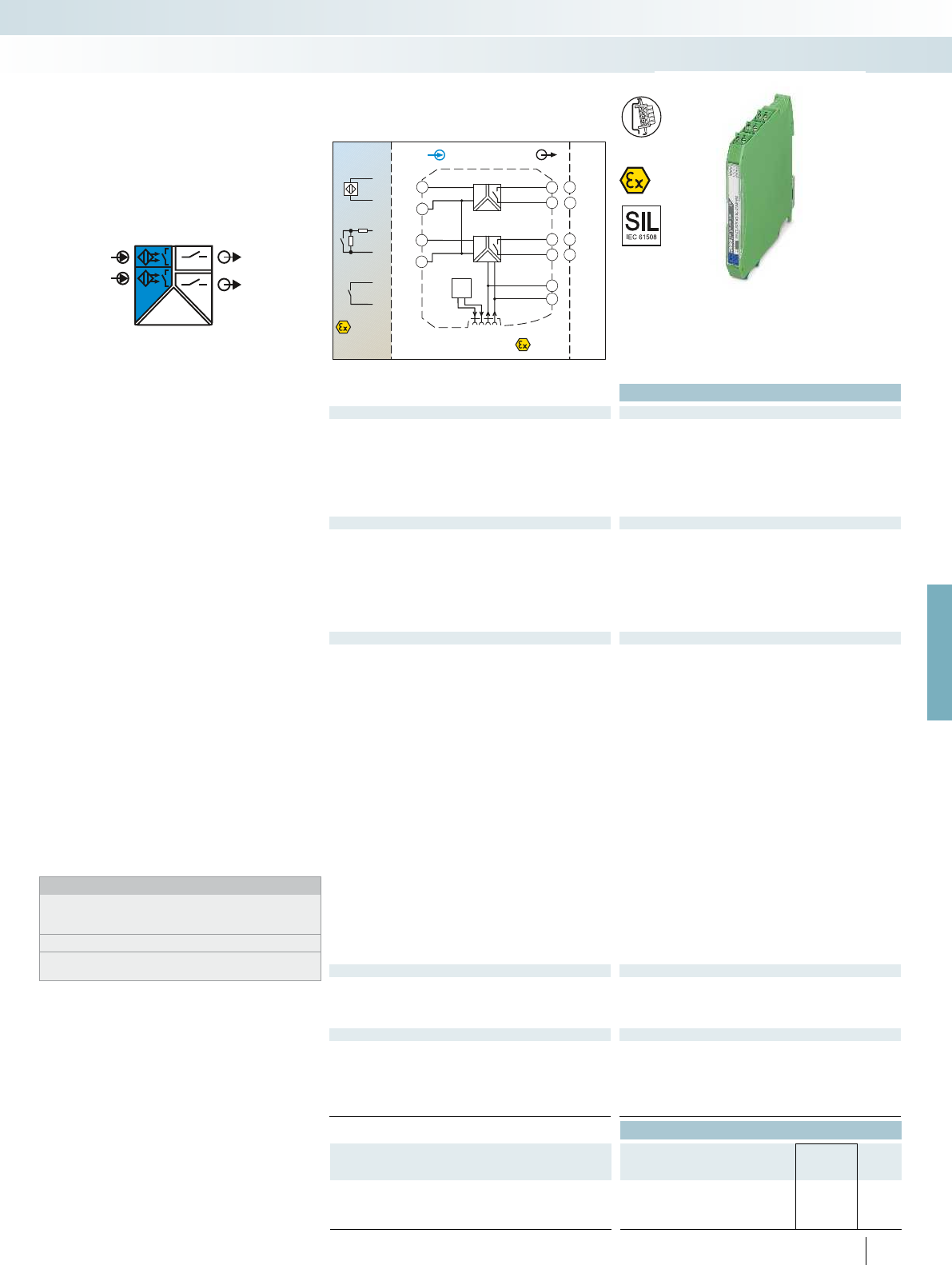
POWER
OUT1
IN1
IN2 OUT2
Zone 0,1,2
Zone 20,21,22
Div. 1,2
Sensor /FieldPLC / DCS
3.2
3.1
CH1
2.2
2.1
CH2
IN
Zone 2
Div. 2
OUT
GND
+24V
4.2
4.1
3.2
3.1
1.2
1.1
+
-
-
-
-
+
+
+
Power
Faultsignal
GND
+24VLFD
2.2
2.1
5.2
5.1
+
-
CH1
CH2
13
13
14
14
DI
For further information and full technical data, visit phoenixcontact.net/products
Functional Safety
Ex:
Housing width 12.5 mm
Technical data
Input data
Input signal NAMUR proximity sensors (EN 60947-5-6)
Floating switch contacts
Switch contacts with resistance circuit
No-load voltage ~ 8 V DC
Switching points > 2.1 mA (conductive) / < 1.2 mA (blocking)
Switching hysteresis < 0.2 mA
Line fault detection Break 0.05 mA < IIN < 0.35 mA
Short circuit 100 < RSensor < 360
Switching output Relay output
Contact type 1 N/O contact per channel
Contact material AgSnO
2
, hard gold-plated
Max. switching voltage 250 V AC (2 A) / 120 V DC (0.2 A) / 30 V DC (2 A)
Max. switching capacity 500 VA
Recommended minimum load 5 V / 10 mA
Mechanical service life 10
7
cycles
Switching behavior Can be inverted via slide switch
Max. switching frequency 20 Hz (without load)
General data
Supply voltage range 19.2 V DC ... 30 V DC (24 V DC (-20% ... +25%))
Current consumption 35 mA (24 V DC)
Power dissipation < 1 W
Number of channels 2
Electrical isolation
Input/output 375 V (peak value in accordance with EN 60079-11)
Input/supply, DIN rail connector 375 V (peak value in accordance with EN 60079-11)
300 V
rms
(rated insulation voltage (surge voltage category II;
pollution degree 2, safe isolation as per EN 61010-1))
Output 1/output 2/input, power supply, DIN rail connector 300 V
rms
(rated insulation voltage (surge voltage category III;
pollution degree 2, safe isolation as per EN 61010-1))
Output 1/output 2/input/power supply, DIN rail connector 2.5 kV (50 Hz, 1 min., test voltage)
Ambient temperature range -20 °C ... 60 °C (any mounting position)
Humidity 5 % ... 95 % (non-condensing)
Status indication Green LED (supply voltage)
Yellow LED (switching state)
Red LED (line fault)
Housing material PA 66-FR
Inflammability class in acc. with UL 94 V0
Dimensions W / H / D 12.5 / 99 / 114.5 mm
Screw connection solid / stranded / AWG 0.2 ... 2.5 mm² / 0.2 ... 2.5 mm² / 24 - 14
Push-in connection solid / stranded / AWG 0.2 ... 1.5 mm² / 0.2 ... 1.5 mm² / 24 - 16
EMC note Class A product, see page 625
Safety data as per ATEX
Max. output voltage U
o
9.6 V
Max. output current I
o
10.3 mA
Max. output power P
o
25 mW
Maximum voltage U
m
253 V AC (125 V DC)
Conformance / approvals
Conformance CE-compliant, additionally EN 61326
ATEX
II (1) G [Ex ia Ga] IIC
II (1) D [Ex ia Da] IIIC
IECEx [Ex ia Ga] IIC, [Ex ia Da] IIIC, Ex nA nC IIC T4 Gc
UL, USA / Canada Class I Div 2; IS for Class I, II, III Div 1
SIL in accordance with IEC 61508 2
Ordering data
Description Type Order No. Pcs. /
Pkt.
NAMUR signal conditioner, 2-channel, intrinsically safe input,
output: N/O contact
Screw connection MACX MCR-EX-SL-2NAM-RO 2865476 1
Push-in connection MACX MCR-EX-SL-2NAM-RO-SP 2924087 1
203
PHOENIX CONTACT
NAMUR signal conditioner for
intrinsically safe operation of proximity
sensors and mechanical contacts installed in
Ex areas.
– 2-channel
– Input for NAMUR proximity sensors
(EN 60947-5-6), floating contacts or
contacts with resistance circuit, [Ex ia]
– Relay signal output (N/O contact)
– Reversible direction of action (operating
current or closed-circuit current
behavior)
– Line fault detection (LFD), can be
activated/deactivated, error message
signaled by red flashing LED with de-
excitation of output relay
– Power supply and error indication
possible via the DIN rail connector
– LED displays for indicating supply voltage,
circuit state, and malfunctions to
NAMUR NE 44
– 3-way electrical isolation
– Up to SIL 2 according to IEC 61508
– Installation in zone 2 permitted
Notes:
Information about the power and fault signaling module as well as
about the DIN rail connectors and marking material can be found
from page 213
Information about resistance circuits is given on page 180
Information on Plug and Play connection using system cabling can
be found from page 216
Digital IN
NAMUR signal conditioner, Ex i
MCR technology
Ex i signal conditioners with SIL functional safety - MACX Analog Ex
2-channel, signal output: N/O contact relay
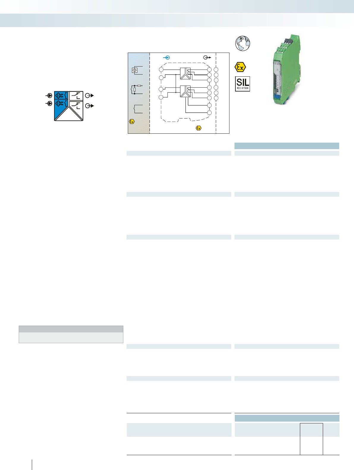
POWER
OUT1
IN1
IN2 OUT2
Zone 0,1,2
Zone 20,21,22
Div. 1,2
Sensor /FieldPLC / DCS
3.3
2.3
3.2
2.2
3.1
2.1
CH1
CH2
IN
Zone 2
Div. 2
OUT
4.3
4.1
3.3
2.3
3.2
2.2
3.1
2.1
1.2
1.1
+
-
-
-
-
+
+
+
5.3
5.1
+
-
CH1
CH2
24...230V
AC/DC –
~
12
12
11
11
14
14
DI
Functional Safety
Ex:
EAC Ex
Housing width 17.5 mm
Technical data
Input data
Input signal NAMUR proximity sensors (EN 60947-5-6)
open circuit switch contacts
Switch contacts with resistance circuit
No-load voltage ~ 8 V DC
Switching points > 2.1 mA (conductive) / < 1.2 mA (blocking)
Switching hysteresis approx. 0.2 mA
Line fault detection Break 0.05 mA < IIN < 0.35 mA
Short circuit 100 < RSensor < 360
Switching output Relay output
Contact type 1 PDT per channel
Contact material AgSnO
2
, hard gold-plated
Max. switching voltage 250 V AC (2 A, 60 Hz) / 120 V DC (0.2 A) / 30 V DC (2 A)
Max. switching capacity 500 VA
Recommended minimum load 5 V / 10 mA
Mechanical service life 10
7
cycles
Switching behavior can be inverted using DIP switch
Max. switching frequency 20 Hz (load-dependent)
General data
Supply voltage range 24 V ... 230 V AC/DC (-20 % ... +10 %, 50 Hz ... 60 Hz)
Current consumption < 80 mA ; < 42 mA (24 V DC)
Power dissipation 1.3 W
Electrical isolation
Input/output 375 V (peak value in accordance with EN 60079-11)
Input/power supply 375 V (peak value in accordance with EN 60079-11)
300 V
rms
(rated insulation voltage (surge voltage category II;
pollution degree 2, safe isolation as per EN 61010-1))
2.5 kV AC (50 Hz, 1 min., test voltage)
Output 1/output 2/input, power supply 300 V
rms
(rated insulation voltage (surge voltage category III;
pollution degree 2, safe isolation as per EN 61010-1))
2.5 kV (50 Hz, 1 min., test voltage)
Ambient temperature range -20 °C ... 60 °C
Humidity 10 % ... 95 % (non-condensing)
Housing material PA 66-FR
Inflammability class in acc. with UL 94 V0
Dimensions W / H / D 17.5 / 99 / 114.5 mm
Screw connection solid / stranded / AWG 0.2 ... 2.5 mm² / 0.2 ... 2.5 mm² / 24 - 14
Push-in connection solid / stranded / AWG 0.2 ... 1.5 mm² / 0.2 ... 1.5 mm² / 24 - 16
EMC note Class A product, see page 625
Safety data as per ATEX
Max. output voltage U
o
9.6 V
Max. output current I
o
10.3 mA
Max. output power P
o
25 mW
Maximum voltage U
m
253 V AC/DC (supply terminals)
250 V AC (output terminals)
120 V DC (output terminals)
Conformance / approvals
Conformance CE-compliant, additionally EN 61326
ATEX
II (1) G [Ex ia Ga] IIC
II (1) D [Ex ia Da] IIIC
II 3(1) G Ex nA nC [ia Ga] IIC T4 Gc X
IECEx [Ex ia Ga] IIC, [Ex ia Da] IIIC, Ex nA nC [ia Ga] IIC T4 Gc
UL, USA / Canada Class I Div 2; IS for Class I, II, III Div 1
SIL in accordance with IEC 61508 2
Ordering data
Description Type Order No. Pcs. /
Pkt.
NAMUR signal conditioner, 2-channel, intrinsically safe input,
output: PDT
Screw connection MACX MCR-EX-SL-2NAM-R-UP 2865984 1
Push-in connection MACX MCR-EX-SL-2NAM-R-UP-SP 2924249 1
204
PHOENIX CONTACT
NAMUR signal conditioner for
intrinsically safe operation of proximity
sensors and mechanical contacts installed in
Ex areas.
– 2-channel
– Input for NAMUR proximity sensors
(EN 60947-5-6), floating contacts or
contacts with resistance circuit, [Ex ia]
– Relay signal output (PDT)
– Reversible direction of action (operating
current or closed-circuit current
behavior)
– Line fault detection (LFD), can be
activated/deactivated, error message
signaled by red flashing LED with de-
excitation of output relay
– Wide range power supply:
19.2 ... 253 V AC/DC
– LED displays for indicating supply voltage,
circuit state, and malfunctions to
NAMUR NE 44
– 3-way electrical isolation
– Up to SIL 2 according to IEC 61508
– Installation in zone 2 permitted
Notes:
Information on resistance circuits and marking material can be
found on page 180
Digital IN
NAMUR signal conditioner, Ex i
MCR technology
Ex i signal conditioners with SIL functional safety - MACX Analog Ex
2-channel, signal output: PDT relay,
wide range power supply
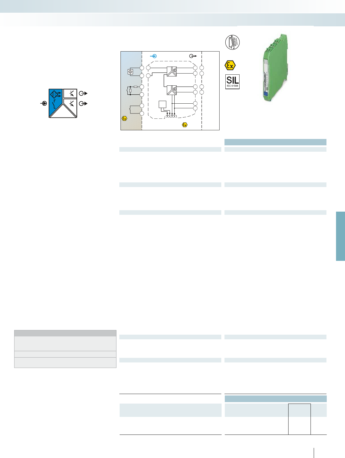
POWER
IN
OUT1
OUT2
Zone 0,1,2
Zone 20,21,22
Div. 1,2
IN
Sensor /Field
4.2
4.1
4.2
4.1
+
-
4.2
4.1
OUT2
Zone 2
Div. 2
OUT
GND
+24V
4.2
4.1
3.2
3.1
1.2
1.1
+
-
Power
Faultsignal
GND
+24VLFD
2.2
2.1
OUT1
PLC / DCS
3.2
3.1
2.2
2.1
-
-
+
+
DI
For further information and full technical data, visit phoenixcontact.net/products
Functional Safety
Ex:
Housing width 12.5 mm
Technical data
Input data
Input signal NAMUR proximity sensors (EN 60947-5-6)
Floating switch contacts
Switch contacts with resistance circuit
No-load voltage ~ 8 V DC
Switching points > 2.1 mA (conductive) / < 1.2 mA (blocking)
Line fault detection Break 0.05 mA < IIN < 0.35 mA
Short circuit 100 < RSensor < 360
Switching output 2 transistor outputs, passive
Max. switching voltage 30 V DC
Max. switching current 50 mA (short-circuit resistant)
Drop (U) < 1.4 V
Switching behavior can be inverted using DIP switch
Max. switching frequency 5 kHz
General data
Supply voltage range 19.2 V DC ... 30 V DC (24 V DC (-20% ... +25%))
Current consumption < 28 mA (24 V DC)
Power dissipation 800 mW
Number of channels 1
Electrical isolation
Input/output 375 V (peak value in accordance with EN 60079-11)
Input/output/supply, DIN rail connector 300 V
rms
(rated nsulation voltage (surge voltage category II; pollution
degree 2, safe isolation as per EN 61010-1))
2.5 kV (50 Hz, 1 min., test voltage)
Input/supply, DIN rail connector 375 V (peak value in accordance with EN 60079-11)
Output 1/output 2 50 V
rms
(rated insulation voltage (surge voltage category II; pollution
degree 2, basic insulation as per EN 61010-1))
1 kV (50 Hz, 1 min., test voltage)
Ambient temperature range -20 °C ... 60 °C (any mounting position)
Humidity 10 % ... 95 % (non-condensing)
Status indication Green LED (supply voltage)
Yellow LED (switching state)
Red LED (line fault)
Housing material PA 66-FR
Inflammability class in acc. with UL 94 V0
Dimensions W / H / D 12.5 / 99 / 114.5 mm
Screw connection solid / stranded / AWG 0.2 ... 2.5 mm² / 0.2 ... 2.5 mm² / 24 - 14
Push-in connection solid / stranded / AWG 0.2 ... 1.5 mm² / 0.2 ... 1.5 mm² / 24 - 16
EMC note Class A product, see page 625
Safety data as per ATEX
Max. output voltage U
o
9.6 V
Max. output current I
o
10.3 mA
Max. output power P
o
25 mW
Maximum voltage U
m
253 V AC (125 V DC)
Conformance / approvals
Conformance CE-compliant, additionally EN 61326
ATEX
II (1) G [Ex ia Ga] IIC
II (1) D [Ex ia Da] IIIC
II 3 G Ex nA IIC T4 Gc X
IECEx [Ex ia Ga] IIC, [Ex ia Da] IIIC, Ex nA IIC T4 Gc
UL, USA / Canada Class I Div 2; IS for Class I, II, III Div 1
SIL in accordance with IEC 61508 2
Ordering data
Description Type Order No. Pcs. /
Pkt.
NAMUR signal conditioner, intrinsically safe input, output:
transistor, passive
Screw connection MACX MCR-EX-SL-NAM-2T 2865463 1
Push-in connection MACX MCR-EX-SL-NAM-2T-SP 2924074 1
205
PHOENIX CONTACT
NAMUR signal conditioner for
intrinsically safe operation of proximity
sensors and mechanical contacts installed in
Ex areas.
– Input for NAMUR proximity sensors
(EN 60947-5-6), floating contacts or
contacts with resistance circuit, [Ex ia]
– 2 signal outputs: transistor (passive); up
to 5 kHz
– Signal output 2 can also be used as a fault
signaling output
– Reversible direction of action (operating
current or closed-circuit current
behavior)
– Line fault detection (LFD), can be
activated/deactivated, error message
signaled by red flashing LED with
inhibiting of transistor output
– Power supply and error indication
possible via the DIN rail connector
– LED displays for indicating supply voltage,
circuit state, and malfunctions to
NAMUR NE 44
– 4-way electrical isolation
– Up to SIL 2 according to IEC 61508
– Installation in zone 2 permitted
Notes:
Information about the power and fault signaling module as well as
about the DIN rail connectors and marking material can be found
from page 213
Information about resistance circuits is given on page 180
Information on Plug and Play connection using system cabling can
be found from page 216
Digital IN
NAMUR signal conditioner, Ex i
MCR technology
Ex i signal conditioners with SIL functional safety - MACX Analog Ex
2 signal outputs: transistor (passive)
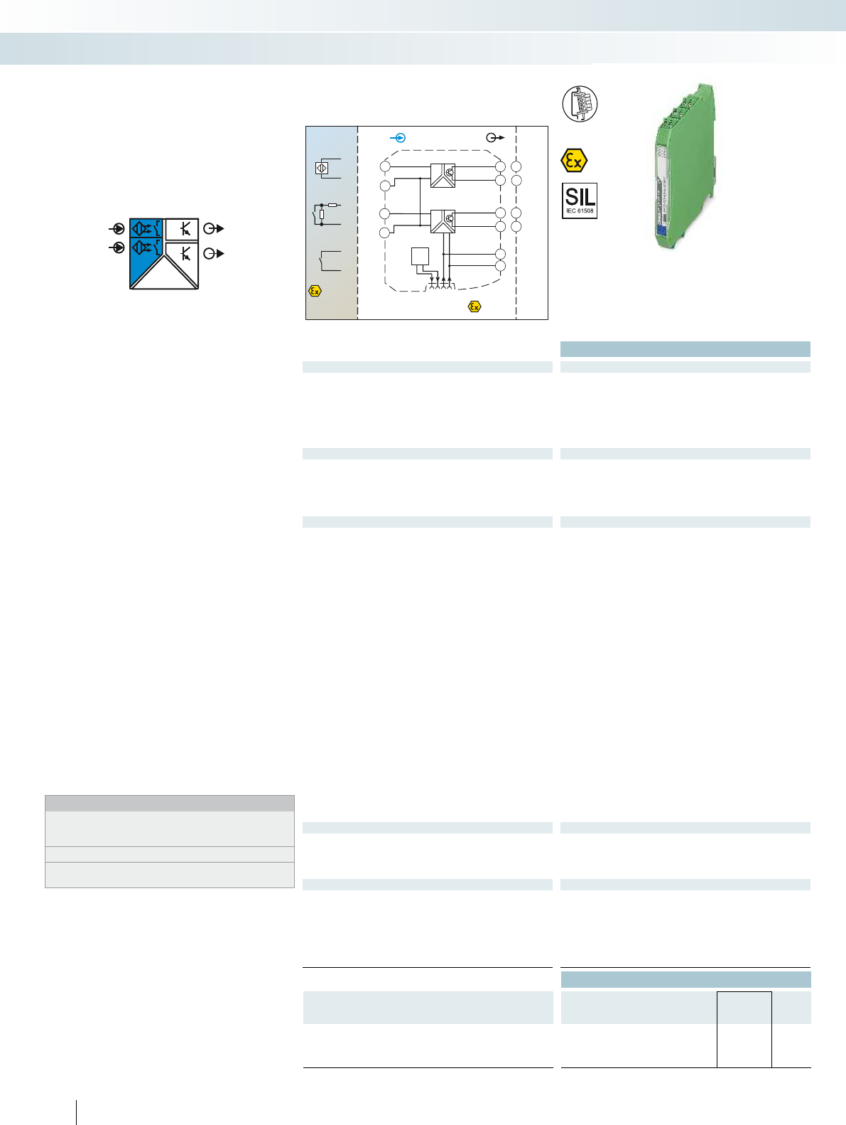
POWER
IN1
IN2
OUT1
OUT2
Zone 0,1,2
Zone 20,21,22
Div. 1,2
Sensor /FieldPLC / DCS
3.2
3.1
CH1
2.2
2.1
CH2
IN
Zone 2
Div. 2
OUT
GND
+24V
4.2
4.1
3.2
3.1
1.2
1.1
+
--
-
+
+
-
-
-
+
+
+
Power
Faultsignal
GND
+24VLFD
2.2
2.1
5.2
5.1
+
-
CH1
CH2
DI
Functional Safety
Ex:
Housing width 12.5 mm
Technical data
Input data
Input signal NAMUR proximity sensors (EN 60947-5-6)
Floating switch contacts
Switch contacts with resistance circuit
No-load voltage ~ 8 V DC
Switching points > 2.1 mA (conductive) / < 1.2 mA (blocking)
Line fault detection Break 0.05 mA < IIN < 0.35 mA
Short circuit 100 < RSensor < 360
Switching output 1 transistor output, passive (per channel)
Max. switching voltage 30 V DC
Max. switching current 50 mA (short-circuit resistant)
Drop (U) < 1.4 V
Switching behavior can be inverted using DIP switch
Max. switching frequency 5 kHz
General data
Supply voltage range 19.2 V DC ... 30 V DC (24 V DC (-20% ... +25%))
Current consumption < 34 mA (24 V DC)
Power dissipation 1000 mW
Number of channels 2
Electrical isolation
Input/output 375 V (peak value in accordance with EN 60079-11)
Input/output/supply, DIN rail connector 300 V
rms
(rated insulation voltage (surge voltage category II;
pollution degree 2, safe isolation as per EN 61010-1))
2.5 kV (50 Hz, 1 min., test voltage)
Input/supply, DIN rail connector 375 V (peak value in accordance with EN 60079-11)
Output 1/output 2 50 V
rms
(rated insulation voltage (surge voltage category II; pollution
degree 2, basic insulation as per EN 61010-1))
1 kV (50 Hz, 1 min., test voltage)
Ambient temperature range -20 °C ... 60 °C (any mounting position)
Humidity 10 % ... 95 % (non-condensing)
Status indication Green LED (supply voltage)
Yellow LED (switching state)
Red LED (line fault)
Housing material PA 66-FR
Inflammability class in acc. with UL 94 V0
Dimensions W / H / D 12.5 / 99 / 114.5 mm
Screw connection solid / stranded / AWG 0.2 ... 2.5 mm² / 0.2 ... 2.5 mm² / 24 - 14
Push-in connection solid / stranded / AWG 0.2 ... 1.5 mm² / 0.2 ... 1.5 mm² / 24 - 16
EMC note Class A product, see page 625
Safety data as per ATEX
Max. output voltage U
o
9.6 V
Max. output current I
o
10.3 mA
Max. output power P
o
25 mW
Maximum voltage U
m
253 V AC (125 V DC)
Conformance / approvals
Conformance CE-compliant, additionally EN 61326
ATEX
II (1) G [Ex ia Ga] IIC
II (1) D [Ex ia Da] IIIC
II 3 G Ex nA IIC T4 Gc X
IECEx [Ex ia Ga] IIC, [Ex ia Da] IIIC, Ex nA IIC T4 Gc
UL, USA / Canada Class I Div 2; IS for Class I, II, III Div 1
SIL in accordance with IEC 61508 2
Ordering data
Description Type Order No. Pcs. /
Pkt.
NAMUR signal conditioner, 2-channel, intrinsically safe input,
output: transistor, passive
Screw connection MACX MCR-EX-SL-2NAM-T 2865489 1
Push-in connection MACX MCR-EX-SL-2NAM-T-SP 2924090 1
206
PHOENIX CONTACT
NAMUR signal conditioner for
intrinsically safe operation of proximity
sensors and mechanical contacts installed in
Ex areas.
– 2-channel
– Input for NAMUR proximity sensors
(EN 60947-5-6), floating contacts or
contacts with resistance circuit, [Ex ia]
– Signal output transistor (passive); up to
5 kHz
– Reversible direction of action (operating
current or closed-circuit current
behavior)
– Line fault detection (LFD), can be
activated/deactivated, error message
signaled by red flashing LED with
inhibiting of transistor output
– Power supply and error indication
possible via the DIN rail connector
– LED displays for indicating supply voltage,
circuit state, and malfunctions to
NAMUR NE 44
– 3-way electrical isolation
– Up to SIL 2 according to IEC 61508
– Installation in zone 2 permitted
Notes:
Information about the power and fault signaling module as well as
about the DIN rail connectors and marking material can be found
from page 213
Information about resistance circuits is given on page 180
Information on Plug and Play connection using system cabling can
be found from page 216
Digital IN
NAMUR signal conditioner, Ex i
MCR technology
Ex i signal conditioners with SIL functional safety - MACX Analog Ex
2-channel, signal output transistor (passive)

POWER
IN
OUT
Zone 0,1,2
Zone 20,21,22
IN
Sensor / Field
4.2
4.1
4.2
4.1
+
-
4.2
4.1
Zone 2
OUT
3.2
3.1
4.2
4.1
+
-
Power
GND
+24VLFD
GND
+24V
1.2
1.1
Faultsignal
PLC / DCS
3.2
3.1
-
+
DI-NAM
Div. 1,2Div. 1
For further information and full technical data, visit phoenixcontact.net/products
Ex:
Housing width 12.5 mm
Technical data
Input data
Input signal NAMUR proximity sensors (EN 60947-5-6)
Floating switch contacts
Switch contacts with resistance circuit
No-load voltage ~ 8 V DC
Switching points > 2.1 mA (conductive) / < 1.2 mA (blocking)
Line fault detection Break 0.05 mA < IIN < 0.35 mA
Short circuit 100 < RSensor < 360
Switching output Resistive (transistor, passive)
Switching voltage typ. 8.2 V DC ±10 % (according to EN60947-5-6)
Switching frequency 5 kHz (ohmic load)
Impedance 0-signal 11 k ±5 %
Impedance 1-signal 1.4 k ±5 %
Impedance fault > 100 k
Switching behavior can be inverted using DIP switch
General data
Supply voltage range 12 V DC ... 24 V DC -20% ... +25%
Current draw 25 mA (24 V DC)
Power dissipation < 0.6 W
Electrical isolation
Input/output 375 V (peak value in accordance with EN 60079-11)
Input/output/supply, DIN rail connector 300 V
rms
(rated insulation voltage (surge voltage category II;
pollution degree 2, safe isolation as per EN 61010-1))
2.5 kV (50 Hz, 1 min., test voltage)
Input/supply, DIN rail connector 375 V (peak value in accordance with EN 60079-11)
Ambient temperature range -20 °C ... 60 °C (any mounting position)
Humidity 10 % ... 95 % (non-condensing)
Status indication Green LED (supply voltage)
Yellow LED (switching state)
Red LED (line fault)
Housing material PA 66-FR
Inflammability class in acc. with UL 94 V0
Dimensions W / H / D 12.5 / 99 / 114.5 mm
Screw connection solid / stranded / AWG 0.2 ... 2.5 mm² / 0.2 ... 2.5 mm² / 24 - 14
Push-in connection solid / stranded / AWG 0.2 ... 1.5 mm² / 0.2 ... 1.5 mm² / 24 - 16
EMC note Class A product, see page 625
Safety data as per ATEX
Max. output voltage U
o
9.6 V
Max. output current I
o
10 mA
Max. output power P
o
25 mW
Maximum voltage U
m
253 V
Conformance / approvals
Conformance CE-compliant, additionally EN 61326
ATEX
II (1) G [Ex ia Ga] IIC
II (1) D [Ex ia Da] IIIC
II 3G Ex nA IIC T4 Gc X
IECEx [Ex ia Ga] IIC, [Ex ia Da] IIIC, Ex nA IIC T4 Gc
SIL in accordance with IEC 61508 2
Ordering data
Description Type Order No. Pcs. /
Pkt.
NAMUR signal conditioner, intrinsically safe input, output with
line fault transparency
Screw connection MACX MCR-EX-SL-NAM-NAM 2866006 1
Push-in connection MACX MCR-EX-SL-NAM-NAM-SP 2924883 1
207
PHOENIX CONTACT
NAMUR signal conditioner for the
intrinsically safe operation of proximity
sensors or mechanical contacts installed in
the Ex area.
– Input for NAMUR proximity sensors
(EN 60947-5-6), floating contacts or
contacts with resistance circuit, [Ex ia]
– Signal output with resistive behavior
(transistor)
– Signal output with line fault transparency:
line fault indicated directly via output to
PLC or PCS. The output responds in
accordance with EN 60947-5-6.
– Up to 5 kHz
– Direction of operation can be selected
– Line fault detection can be
activated/deactivated
– Power supply and error indication
possible via the DIN rail connector
– LED indicators for supply voltage, status,
and fault according to NAMUR NE 44
– Plug-in screw or push-in connection
technology
– Safe 3-way electrical isolation
– Up to SIL 2 according to IEC 61508
– Installation in zone 2 permitted
Notes:
Information on the power and fault signaling module, DIN rail
connectors, system cabling, and marking material can be found
from page 213
Information about resistance circuits is given on page 180
Digital IN
NAMUR signal conditioner, Ex i
MCR technology
Ex i signal conditioners with SIL functional safety - MACX Analog Ex
With line fault transparency
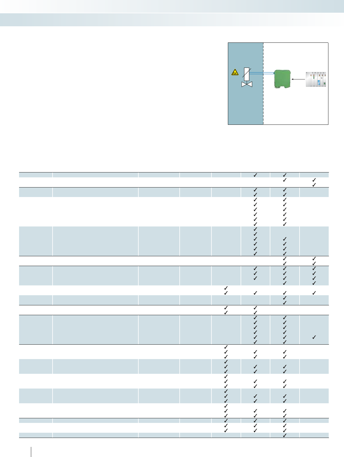
208
PHOENIX CONTACT
Solenoid drivers for
controlling solenoid valves
In order to control intrinsically safe Ex i
solenoid valves, you have to have an
intrinsically safe control circuit. This is
provided by the solenoid drivers that are
available from Phoenix Contact.
The following must be taken into account
when dimensioning your intrinsically safe
control circuit:
– Valve
– Cable with corresponding resistance
– Solenoid driver
As a result, it may be the case that not all
valves are compatible with the solenoid
drivers.
Below is an extract from a table showing
possible combinations of valves and
solenoid drivers.
A complete and updated list (along with
details of the technical data of suitable
valves, the maximum cable lengths, and the
maximum cable resistances of the individual
combinations) can be found on the Internet
at:
www.phoenixcontact.net/products
Overview of valves
INTERFACE Ex solenoid driver
Manufacturer Type designation Ex certificate Condition MACX MCR-EX-
SL-SD-21-25-LP
MACX MCR-EX-
SL-SD-21-40-LP
MACX MCR-EX-
SL-SD-24-48-LP
MACX MCR-EX-
SL-SD-21-60-LP
ASCO Coil 195 LCIE 08 ATEX 6083
Coil 302 (12 V) INERIS 03 ATEX 0249X
Coil 302 (24 V) INERIS 03 ATEX 0249X
Bürkert Coil AC 10, standard PTB 01 ATEX 2101
Coil AC 10, high-resistance PTB 01 ATEX 2101
Coil AC 21, standard PTB 01 ATEX 2175 700 mW/65°C
Coil AC 21, high-resistance PTB 01 ATEX 2175 700 mW/65°C
Coil AC 21, standard PTB 01 ATEX 2175 900 mW/45°C
Coil AC 21, high-resistance PTB 01 ATEX 2175 900 mW/45°C
Coil AC 21, standard PTB 01 ATEX 2175 900 mW/60°C
Coil AC 21, high-resistance PTB 01 ATEX 2175 900 mW/60°C
Coil G1 642735, standard 600 mW/50°C
Coil G1 642735, high-resistance 600 mW/50°C
Coil G1 642735, standard PTB 01 ATEX 2173 800 mW/40°C
Coil G1 642735, high-resistance PTB 01 ATEX 2173 800 mW/40°C
Coil G1 642735, standard PTB 01 ATEX 2173 1000 mW/40°C
Coil G1 642735, high-resistance PTB 01 ATEX 2173 1000 mW/40°C
FESTO Coil MFH-...IA-SA-EX GBXE022AIAD03 PTB 03 ATEX 2097
Coil ( J)MFH-...BIA-SA-EX GBXE022AIAD03 PTB 03 ATEX 2097
Norgren Herion Coil 2050 PTB 07 ATEX 2019
Coil 2051 PTB 07 ATEX 2019
Coil 2052 PTB 07 ATEX 2019
Coil 2053 PTB 07 ATEX 2019
Coil 2085 PTB 06 ATEX 2001 U
Coil 2086 PTB 06 ATEX 2001 U
Coil 3039 PTB 03 ATEX 2134
Coil 2003 PTB 04 ATEX 2010
Hörbiger Piezo P8 38x RF-Nx-SPN65 DMT 01 ATEX E026X 30 V type
Piezo P20 381RF-NG-CPN61 DMT 01 ATEX E025X 30 V type
Parker Coil VZ07 488650.01 LCIE 02 ATEX 6024X
Coil VZ33 494035.10 LCIE 02 ATEX 6024X
Coil VZ08 488660.01 LCIE 02 ATEX 6024X
Coil VZ09 488670.01 LCIE 02 ATEX 6024X
Coil VZ95 482160.01 LCIE 02 ATEX 6024X EEx ia IIB T6
Coil VZ23 482870.01 LCIE 02 ATEX 6024X
Samson Coil 3701-11 (6 V) PTB 02 ATEX 2178
Coil 3701-12 (12 V) PTB 02 ATEX 2178
Coil 3701-13 (24 V) PTB 02 ATEX 2178
Coil 3963-11 (6 V) PTB 01 ATEX 2085
Coil 3963-12 (12 V) PTB 01 ATEX 2085
Coil 3963-13 (24 V) PTB 01 ATEX 2085
Coil 3964-11 (6 V) PTB 02 ATEX 2047
Coil 3964-12 (12 V) PTB 02 ATEX 2047
Coil 3964-13 (24 V) PTB 02 ATEX 2047
Coil 3965-11 (6 V) PTB 05 ATEX 2044X
Coil 3965-12 (12 V) PTB 05 ATEX 2044X
Coil 3965-13 (24 V) PTB 05 ATEX 2044X
Coil 3967-11 (6 V) PTB 06 ATEX 2027
Coil 3967-12 (12 V) PTB 06 ATEX 2027
Coil 3967-13 (24 V) PTB 06 ATEX 2027
Seitz Pilot valve PV 12F73 Ci oH PTB 99 ATEX 2146
Pilot valve PV 12F73 Xi oH PTB 00 ATEX 2030
Pilot valve PV 12F73 Xi oH-2 PTB 00 ATEX 2030
Solenoid 11 G 52 PTB 01 ATEX 2020
Example circuit
Associated equipment, e.g.,
MAC MCR-EX-SL-SD-...
II (1) GD [Ex ia] IIC
PLC
Hazardous area Safe area
Intrinsically safe
equipment
II 1 G
Ex ia IIB T6
MCR technology
Ex i signal conditioners with SIL functional safety - MACX Analog Ex
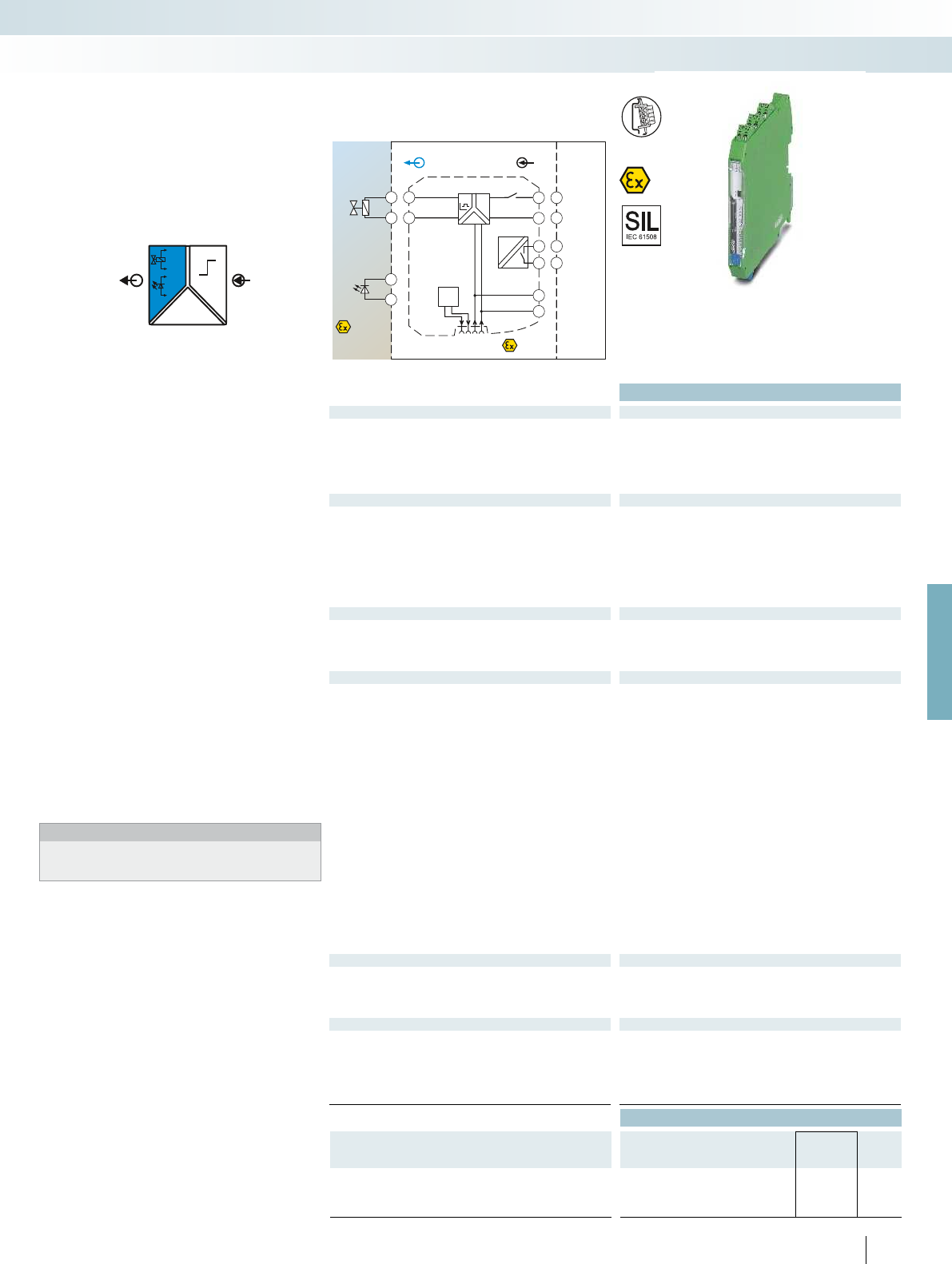
POWER
OUTIN
+
-
+
-
Sensor / Field
Zone 0,1,2
Zone 20,21,22
4.2
4.1
+
-4.2
4.1
PLC / DCS
+
-
3.2
3.1
DO
2.1
2.2
DI
Zone 2
INOUT
3.2
3.1
4.2
4.1
LFD
Faultsignal
GND
+24V
GND
+24V
1.2
1.1
2.2
2.1
Faultsignal
Div. 1,2Div. 1
For further information and full technical data, visit phoenixcontact.net/products
Functional Safety
Ex:
Housing width 12.5 mm
Technical data
Input data
Switching level 0 signal ("L") 0 V DC ... 5 V DC (Open)
Switching level 1 signal ("H") 15 V DC ... 30 V DC
Input current < 12 mA
Input impedance in the event of a line fault at the output 3 M (high resistance (Mega ))
Transparent for test pulses Yes
Output data
Output voltage 9.5 V DC (at 48 mA)
Current limitation > 48 mA (with line fault detection)
No-load voltage > 23.3 V DC
Internal resistance 269 (internal resistance R
i
)
Immunity to short-circuiting Yes
Response time t
A
< 30 ms
Line fault detection < 50 (short circuit on the line)
> 10 k (line break)
Error message output
Switch contact N/C contact
Max. switching voltage 30 V DC
Max. switching current 50 mA
Short-circuit-proof Yes
General data
Supply voltage range 19.2 V DC ... 30 V DC (24 V DC (-20% ... +25%))
Current draw < 90 mA
Power dissipation < 1.5 W
Electrical isolation
Input/output, supply, error message output 375 V (peak value in accordance with EN 60079-11)
300 V
rms
(rated insulation voltage (surge voltage category II;
pollution degree 2, safe isolation as per EN 61010-1))
2.5 kV (50 Hz, 1 min., test voltage)
Ambient temperature range -20 °C ... 60 °C (any mounting position)
Humidity 10 % ... 95 % (non-condensing)
Status indication Green LED (supply voltage)
Yellow LED (switching state)
Red LED (line fault)
Degree of protection IP20
Housing material PA 66-FR
Inflammability class in acc. with UL 94 V0
Dimensions W / H / D 12.5 / 99 / 114.5 mm
Screw connection solid / stranded / AWG 0.2 ... 2.5 mm² / 0.2 ... 2.5 mm² / 24 - 14
Push-in connection solid / stranded / AWG 0.2 ... 1.5 mm² / 0.2 ... 1.5 mm² / 24 - 16
EMC note Class A product, see page 625
Safety data as per ATEX
Max. output voltage U
o
25.3 V
Max. output current I
o
94 mA
Max. output power P
o
595 mW
Maximum voltage U
m
253 V
Conformance / approvals
Conformance CE-compliant, additionally EN 61326
ATEX
II (1) G [Ex ia Ga] IIC
II (1) D [Ex ia Da] IIIC
II 3(1) G Ex nA [ia Ga] IIC T4 Gc X
IECEx [Ex ia Ga] IIC, [Ex ia Da] IIIC, Ex nA IIC T4 Gc
SIL in accordance with IEC 61508 2
Ordering data
Description Type Order No. Pcs. /
Pkt.
Solenoid driver, logic input, intrinsically safe output, line fault
detection
Screw connection MACX MCR-EX-SL-SD-23-48-LFD 2924867 1
Push-in connection MACX MCR-EX-SL-SD-23-48-LFD-SP 2924870 1
209
PHOENIX CONTACT
Solenoid driver for the intrinsically safe
control of Ex i solenoid valves, alarm
transmitters or indicators installed in the
Ex area.
– Input: logic (low/high signal)
– Output: 48 mA current limitation at 9.5 V,
[Ex ia]
– Line fault detection (can be
activated/deactivated)
- Directly via signal channel
- Or via switching output
– Transparent for test pulses
– Power supply and error indication
possible via the DIN rail connector
– LED indicators for supply voltage, status,
and fault according to NAMUR NE 44
– Plug-in screw or push-in connection
technology
– Safe 3-way electrical isolation
– Up to SIL 2 according to IEC 61508
– Installation in zone 2 permitted
Notes:
Information on the power and fault signaling module, DIN rail
connectors, system cabling, and marking material can be found
from page 213
Digital OUT
Solenoid driver, Ex i
MCR technology
Ex i signal conditioners with SIL functional safety - MACX Analog Ex
Current limitation 48 mA,
with line fault detection
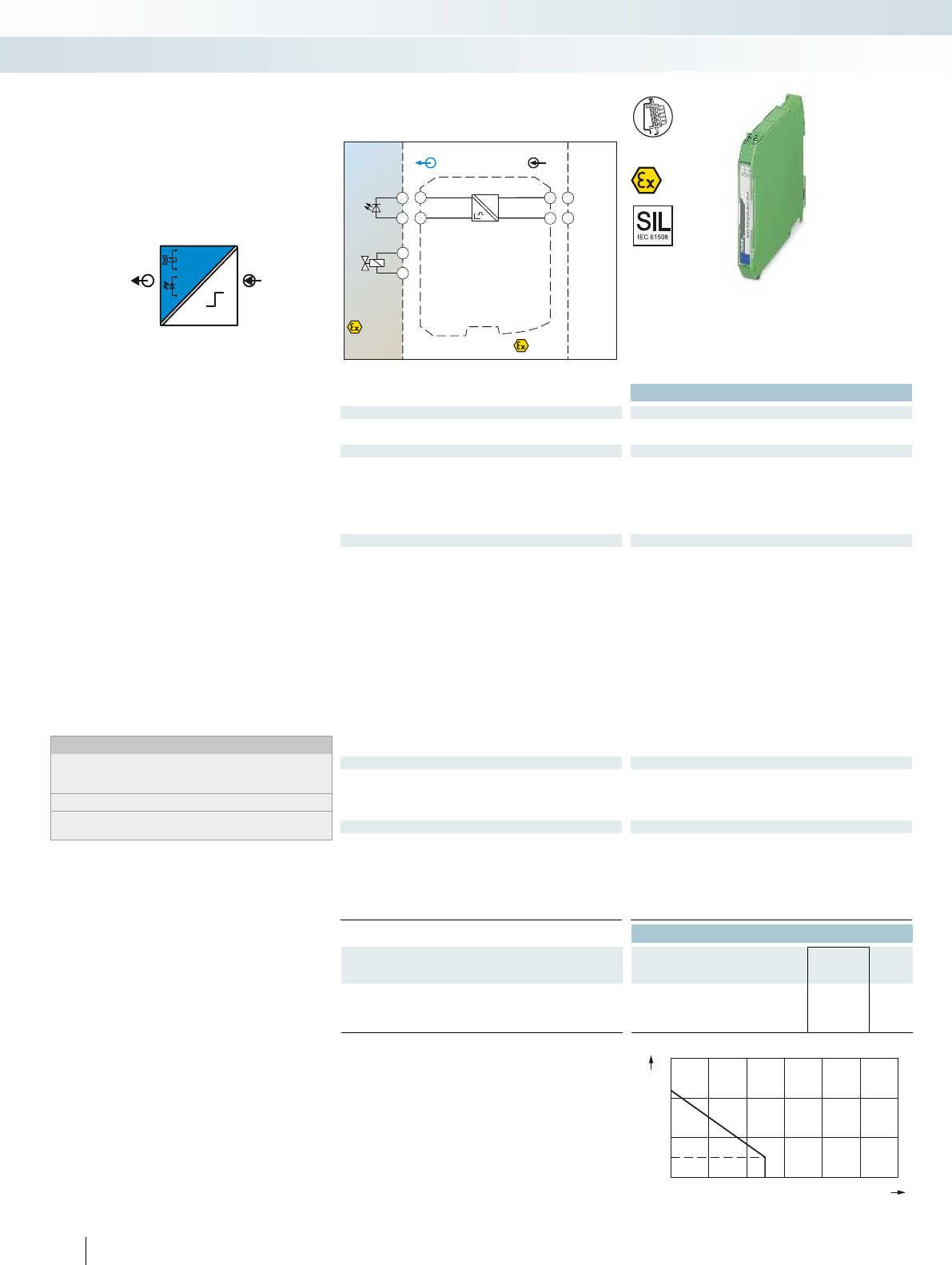
OUTIN
+
-
+
-
0
10
20
30
0302010405060
21,9 V
5,5V
PLC / DCS
Sensor /Field
4.2
4.1
+
+
-
-4.2
4.1
Zone 2
Div. 2
INOUT
4.2
4.1
3.2
3.1
+
-
+
-
3.2
3.1
Zone 0,1,2
Zone 20,21,22
Div. 1,2
DO
Functional Safety
Ex:
Housing width 12.5 mm Housing width 12.5 mm Housing width 12.5 mm Housing width 12.5 mm
Technical data
Input data
Input signal 20 V DC ... 30 V DC
Input current 10 mA DC ... 70 mA DC (45 mA for U
e
= 24 V DC) 10 mA ... 95 mA (65 mA for U
Output data
Output voltage 5.5 V DC (at 25 mA)
Current limitation 25 mA
No-load voltage 21.9 V DC
Internal resistance 641 (internal resistance R
i
) 287
Immunity to short-circuiting Yes
Response time t
A
20 ms
General data
Power dissipation < 1 W
Temperature coefficient 0.01 %/K
Electrical isolation
Output/input 375 V (peak value in accordance with EN 60079-11)
300 V
rms
(rated insulation voltage (surge voltage category II;
pollution degree 2, safe isolation as per EN 61010-1))
2.5 kV (50 Hz, 1 min., test voltage)
Ambient temperature range -20 °C ... 60 °C (any mounting position) -20 °C ... 60 °C (any mounting position) -20 °C ... 60 °C (any
Status indication Yellow LED (switching state / status, lights up when output circuit is
active)
Degree of protection IP20
Inflammability class in acc. with UL 94 V0
Dimensions W / H / D 12.5 / 99 / 114.5 mm
Screw connection solid / stranded / AWG 0.2 ... 2.5 mm² / 0.2 ... 2.5 mm² / 24 - 14 0.2 ... 2.5 mm² / 0.2 ... 2.5 mm² / 24 - 14 0.2
Push-in connection solid / stranded / AWG 0.2 ... 1.5 mm² / 0.2 ... 1.5 mm² / 24 - 16 0.2 ... 1.5 mm² / 0.2 ... 1.5 mm² / 24 - 16 0.
EMC note Class A product, see page 625 Class A product, see page 625 Class A product, see page 625 Class A product, see page 625
Safety data as per ATEX
Max. output voltage U
o
25.1 V
Max. output current I
o
39 mA
Max. output power P
o
245 mW
Maximum voltage U
m
253 V AC (125 V DC)
Conformance / approvals
Conformance CE-compliant, additionally EN 61326 CE-compliant, additi
ATEX
II 3 G Ex nA IIC T4 Gc X
II (1) G [Ex ia Ga] IIC/IIB/IIA
II (1) D [Ex ia Da] IIIC
IECEx [Ex ia Ga] IIC/IIB/IIA, [Ex ia Da] IIIC, Ex nA IIC T4 Gc X [Ex ia Ga] IIC/IIB/IIA [Ex ia Ga] IIC/IIB/IIA [Ex ia Ga] IIB/IIA
UL, USA / Canada Class I Div 2; IS for Class I, II, III Div 1 Class I Div 2; IS for Class I, II, III Div 1 Class I Div 2; IS for C
SIL in accordance with IEC 61508 3
Ordering data
Description Type Order No. Pcs. /
Pkt.
Solenoid driver, loop-powered, intrinsically safe output
Screw connection MACX MCR-EX-SL-SD-21-25-LP 2865492 1
Push-in connection MACX MCR-EX-SL-SD-21-25-LP-SP 2924113 1
210
PHOENIX CONTACT
Digital OUT
Solenoid driver, Ex i
Solenoid drivers for controlling
intrinsically safe solenoid valves, alarm
transmitters, and indicators installed in
Ex areas.
– 20 ... 30 V DC input
– Output [Ex ia]
– Various output characteristic curves
compatible with standard solenoid valves
– Loop-powered: the required power is
supplied via the control signal on the
input side.
– Mechanically compatible with DIN rail
connector
– 2-way electrical isolation
– Up to SIL3 as per EN61508
– Installation in zone 2 permitted
Notes:
A list of suitable valves and notes for calculating a valve circuit are
available from the download center at
phoenixcontact.net/products.
Information on marking material can be found on page 179
Information on Plug and Play connection using system cabling can
be found from page 216
output current I [mA]
V
output voltage U [V]
V
MCR technology
Ex i signal conditioners with SIL functional safety - MACX Analog Ex
Current limitation 25 mA Current limitation 40 mA Current limitation 48 mA Current limitation 58 mA,
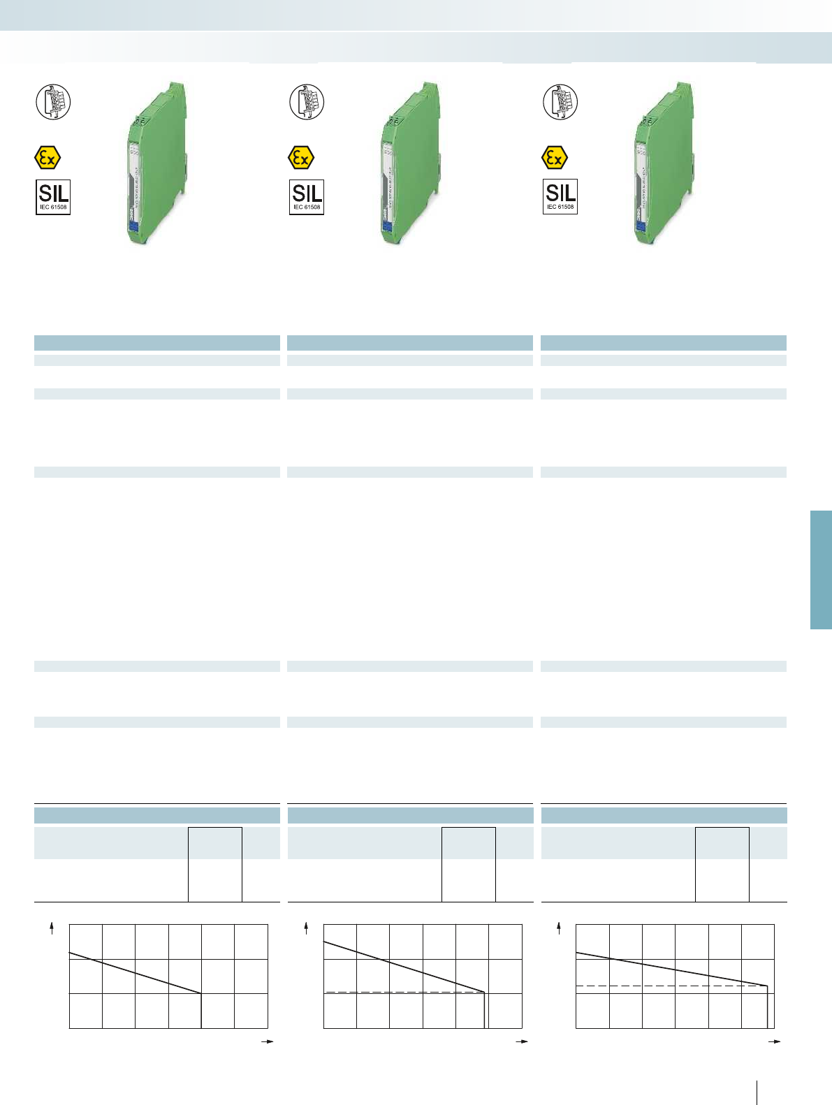
0
10
20
30
0302010405060
21,9 V
10,0 V
0
10
20
30
0302010405060
24 V
10,5 V
0
10
20
30
0302010405060
21,9 V
12,9 V
For further information and full technical data, visit phoenixcontact.net/products
Functional Safety
Ex:
Functional Safety
Ex:
Functional Safety
Ex:
Housing width 12.5 mm Housing width 12.5 mm Housing width 12.5 mm Housing width 12.5 mm
Technical data Technical data Technical data
20 V DC ... 30 V DC 20 V DC ... 30 V DC 20 V DC ... 30 V DC
= 24 V DC) 10 mA ... 95 mA (65 mA for U
e
= 24 V DC) 10 mA ... 95 mA (75 mA for U
e
= 24 V DC) 10 mA ... 105 mA (95 mA for U
e
= 24 V DC)
10 V DC (at 40 mA) 10.5 V DC (at 48 mA) 12.9 V DC (at 58 mA)
40 mA 48 mA 58 mA
21.9 V DC 24 V DC 21.9 V DC
) 287 (internal resistance R
i
) 276 (internal resistance R
i
) 133 (internal resistance R
i
)
Yes Yes Yes
20 ms 30 ms 30 ms
< 1.2 W < 1.4 W < 1.4 W
0.01 %/K 0.01 %/K 0.01 %/K
375 V (peak value in accordance with EN 60079-11)
300 V
rms
(rated insulation voltage (surge voltage category II;
pollution degree 2, safe isolation as per EN 61010-1))
2.5 kV (50 Hz, 1 min., test voltage)
375 V (peak value in accordance with EN 60079-11)
300 V
rms
(rated insulation voltage (surge voltage category II;
pollution degree 2, safe isolation as per EN 61010-1))
2.5 kV (50 Hz, 1 min., test voltage)
375 V (peak value in accordance with EN 60079-11)
300 V
rms
(rated insulation voltage (surge voltage category II;
pollution degree 2, safe isolation as per EN 61010-1))
2.5 kV (50 Hz, 1 min., test voltage)
Ambient temperature range -20 °C ... 60 °C (any mounting position) -20 °C ... 60 °C (any mounting position) -20 °C ... 60 °C (any mounting position) -20 °C ... 60 °C (any mounting position)
Yellow LED (switching state / status, lights up when output circuit is
active)
Yellow LED (switching state / status, lights up when output circuit is
active)
Yellow LED (switching state / status, lights up when output circuit is
active)
IP20 IP20 IP20
V0 V0 V0
12.5 / 99 / 114.5 mm 12.5 / 99 / 114.5 mm 12.5 / 99 / 114.5 mm
Screw connection solid / stranded / AWG 0.2 ... 2.5 mm² / 0.2 ... 2.5 mm² / 24 - 14 0.2 ... 2.5 mm² / 0.2 ... 2.5 mm² / 24 - 14 0.2 ... 2.5 mm² / 0.2 ... 2.5 mm² / 24 - 14 0.2 ... 2.5 mm² / 0.2 ... 2.5 mm² / 24 - 14
Push-in connection solid / stranded / AWG 0.2 ... 1.5 mm² / 0.2 ... 1.5 mm² / 24 - 16 0.2 ... 1.5 mm² / 0.2 ... 1.5 mm² / 24 - 16 0.2 ... 1.5 mm² / 0.2 ... 1.5 mm² / 24 - 16 0.2 ... 1.5 mm² / 0.2 ... 1.5 mm² / 24 - 16
EMC note Class A product, see page 625 Class A product, see page 625 Class A product, see page 625 Class A product, see page 625
25.1 V 27.7 V 25.1 V
87 mA 101 mA 188 mA
550 mW 697 mW 1.18 W
253 V AC (125 V DC) 253 V AC (125 V DC) 253 V AC (125 V DC)
Conformance CE-compliant, additionally EN 61326 CE-compliant, additionally EN 61326 CE-compliant, additionally EN 61326 CE-compliant, additionally EN 61326
II 3 G Ex nA IIC T4 Gc X
II (1) G [Ex ia Ga] IIC/IIB/IIA
II (1) D [Ex ia Da] IIIC
II 3 G Ex nA IIC T4 Gc X
II (1) G [Ex ia Ga] IIC/IIB/IIA
II (1) D [Ex ia Da] IIIC
II 3 G Ex nA IIC T4 Gc X
II (1) G [Ex ia Ga] IIB/IIA
II (1) D [Ex ia Da] IIIC
IECEx [Ex ia Ga] IIC/IIB/IIA, [Ex ia Da] IIIC, Ex nA IIC T4 Gc X [Ex ia Ga] IIC/IIB/IIA [Ex ia Ga] IIC/IIB/IIA [Ex ia Ga] IIB/IIA
UL, USA / Canada Class I Div 2; IS for Class I, II, III Div 1 Class I Div 2; IS for Class I, II, III Div 1 Class I Div 2; IS for Class I, II, III Div 1 Class I Div 2; IS for Class I, II, III Div 1
333
Ordering data Ordering data Ordering data
Type Order No. Pcs. /
Pkt. Type Order No. Pcs. /
Pkt. Type Order No. Pcs. /
Pkt.
MACX MCR-EX-SL-SD-21-40-LP 2865764 1MACX MCR-EX-SL-SD-24-48-LP 2865609 1MACX MCR-EX-SL-SD-21-60-LP 2865515 1
MACX MCR-EX-SL-SD-21-40-LP-SP 2924139 1MACX MCR-EX-SL-SD-24-48-LP-SP 2924126 1MACX MCR-EX-SL-SD-21-60-LP-SP 2924100 1
211
PHOENIX CONTACT
output current I [mA]
V
output voltage U [V]
V
output current I[mA]
V
output voltage U [V]
V
output current I [mA]
V
output voltage U [V]
V
MCR technology
Ex i signal conditioners with SIL functional safety - MACX Analog Ex
Current limitation 25 mA Current limitation 40 mA Current limitation 48 mA Current limitation 58 mA,
[Ex ia] IIB

Ex:
Technical data
General data
EMC note Class A product, see page 625
Ordering data
Description Type Order No. Pcs. /
Pkt.
Programming adapter for configuring modules with
S-PORT interface
IFS-USB-PROG-ADAPTER 2811271 1
212
PHOENIX CONTACT
The IFS-USB-PROG-ADAPTER
programming adapter is used for configuring
Phoenix Contact INTERFACE modules
with S-Port interface.
The adapter is used with FDT/DTM
software or ANALOG-CONF software.
For programming MACX Analog,
MINI Analog Pro, and MINI Analog.
Accessories
Programming adapter
MCR technology
Ex i signal conditioners with SIL functional safety - MACX Analog Ex
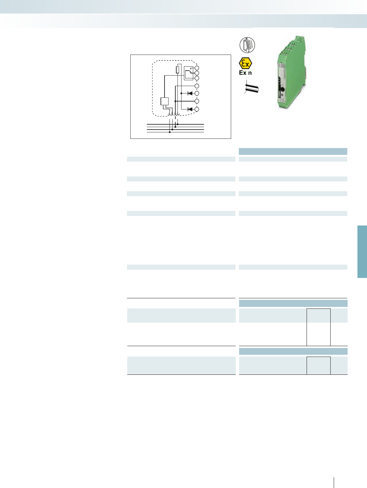
1.2
2.2
3.2
12
3.3
14
1.1
2.1
3.1
11
Fault out
PWR2
PWR1
–
–
+
+
Faultsignal
GND
+24VLFD
For further information and full technical data, visit phoenixcontact.net/products
Ex:
Housing width 17.5 mm
Technical data
Input data
Input signal 19.2 V DC ... 30 V DC (24 V DC (-20% ... +25%))
Redundant supply yes, decoupled from diodes
Polarization and surge protection Yes
Output data
Maximum output signal 3.75 A
Output voltage Input voltage - max 0.8 V at 3.75 A
Switching output Relay
Contact type 1 PDT
Contact material Gold (Au)
Max. switching voltage 50 V AC (50VDC (0.3A) / 50VDC (2 A) / 33VAC (2 A))
General data
Ambient temperature range -20 °C ... 60 °C (any mounting position)
Humidity 5 % ... 95 % (non-condensing)
Fuse 5 A (replaceable), slow-blow 250 V AC
Status indication 1 x red LED (error)
2 x green LEDs (PWR1 and PWR2)
Housing material Polyamide (PA 6.6)
Inflammability class in acc. with UL 94 V0
Dimensions W / H / D 17.5 / 99 / 114.5 mm
Screw connection solid / stranded / AWG 0.2 ... 2.5 mm² / 0.2 ... 2.5 mm² / 24 - 14
Push-in connection solid / stranded / AWG 0.2 ... 1.5 mm² / 0.2 ... 1.5 mm² / 24 - 16
Conformance / approvals
Conformance CE-compliant
ATEX II 3 G Ex nA nC IIC T4 Gc X
IECEx Ex nA nC IIC T4 Gc X
UL, USA / Canada UL 61010 Listed
Class I, Div. 2, Groups A, B, C, D T5
Class I, Zone 2, Group IIC
Ordering data
Description Type Order No. Pcs. /
Pkt.
Power and fault signaling module, including the relevant DIN rail
connector ME 17,5 TBUS 1,5/5-ST-3,81 GN
Screw connection MACX MCR-PTB 2865625 1
Push-in connection MACX MCR-PTB-SP 2924184 1
Accessories
DIN rail connector (TBUS), for bridging the supply voltage, can
be snapped onto 35 mm DIN rails as per EN 60715, with
UL approval
ME 6,2 TBUS-2 1,5/5-ST-3,81 GN 2869728 10
213PHOENIX CONTACT
Power and fault signaling module
Power and fault signaling module for
feeding the 24 V supply voltage to the
DIN rail connectors and signaling line faults
and power supply failures.
– One-time or redundant supply, decoupled
from diode, protected against
polarization
– Supply current up to 3.75 A
– Relay output (PDT) and flashing LED for
error messages
– Error message in the event of a power
supply failure or fuse fault
– Bus cable fault message for
MACX MCR-...(2)NAM... devices
connected via DIN rail connectors
– Replaceable fuse
– Installation in zone 2 permitted
ME 6,2 TBUS... DIN rail connector
DIN rail connector (5-pos.) for bridging
the supply voltage of 12.5 mm wide
MACX Analog Ex modules.
– Reduces wiring costs
– System can be extended or module
replaced even while process is active
– Inter-extendable
Accessories
MCR technology
Ex i signal conditioners with SIL functional safety - MACX Analog Ex
H
W
D
Power and fault signaling module

Ordering data
Description Color Type Order No. Pcs. /
Pkt.
UniCard, with self-adhesive plastic labels
10-part, lettering field size: 11x9mm white UC-EMLP (11X9) 0819291 10
UniCard, with self-adhesive plastic labels,
marked according to customer specifications
For ordering details, see Catalog 5 or phoenixcontact.net/product.
10-part, lettering field size: 11x9mm white UC-EMLP (11X9) CUS 0824547 1
Marking material for device marking
– For device marking inside the control
cabinet and in the field
– Self-adhesive with high adhesive strengths
– Large temperature range
Accessories
MCR technology
Ex i signal conditioners with SIL functional safety - MACX Analog Ex
Ordering data
Description Color Type Order No. Pcs. /
Pkt.
Double-level terminal block, with pre-assembled resistors
With screw connection UKK 5-2R/NAMUR 2941662 50
Cover, width 2.5 mm
gray D-UKK 3/5 2770024 50
blue D-UKK 3/5 BU 2770105 50
214
PHOENIX CONTACT
Resistance circuit
Double-level terminal block with
resistance circuit according to NAMUR for
line fault detection in the case of mechanical
contacts
Important:
– For intrinsically safe circuits, only in
combination with D-UKK 3/5 cover
Accessories

For further information and full technical data, visit phoenixcontact.net/products
215PHOENIX CONTACT
MCR technology
Ex i signal conditioners with SIL functional safety - MACX Analog Ex

TC... Termination Carriers are
compact solutions for quickly and smoothly
connecting DIN rail devices from the
MACX Analog Ex series to input/output
cards of automation systems using system
cables.
The Termination Carriers combine the
advantages of modular DIN rail devices with
those offered by Plug and Play rapid cabling
solutions to provide a consistent solution
for system technology.
Compact
– Saves up to 30% of space due to compact
design
Robust and reliable
– Stable, vibration-resistant aluminum
carrier device profile
– PCB is completely decoupled from
modules
– PCB without active components
– Redundant supply and monitoring in
separate DIN rail module
Easy maintenance
– Use of standard DIN rail devices
– Easy access to connection points
– Quick and safe module connection with
plug-in and coded cable sets
Flexible
– Horizontal or vertical DIN rail mounting
– Profile section without pitch markings for
I/O cards with specific number of
channels
– Can be specifically adapted for I/O cards
of various automation systems with
different system plug types
216
PHOENIX CONTACT
Termination Carriers for MACX
Analog Ex signal conditioners
Solutions are also available for MINI Analog,
MACX Analog Ex, and Safety
Select controller-specific front adapter and system cable
Select module carrier
Select standard DIN rail device
MCR technology
Ex i signal conditioners with SIL functional safety - MACX Analog Ex
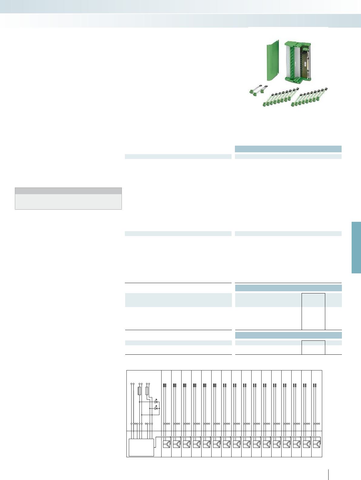
X20 COMBICON
X1 DSUB 37PTSM
+
+
CH1
PW2
PW1
1
20
+
-
CH2
2
21
+
-
CH3
3
22
+
-
CH4
4
23
+
-
CH5
5
24
-
CH6
6
25
+
-
CH7
7
26
-
CH8
8
27
+
-
CH9
9
28
+
-
CH10
10
29
+
-
CH11
11
30
+
-
CH12
12
31
+
-
CH13
13
32
+
-
CH14
14
33
+
-
CH15
15
34
+
-
CH16
16
35
-
+
3.1
3.1
3.1
3.1
3.1
3.1
3.1
3.1
3.1
3.1
3.1
3.1
3.1
3.1
3.1
3.1
3.1
3.2
3.2
3.2
3.2
3.2
3.2
3.2
3.2
3.2
3.2
3.2
3.2
3.2
3.2
3.2
3.2
3.3
1.3
1.1
1.2
2.3
T-BUS
F1
1
1
2.1
2.2
TC-MACX-
MCR-PTB
2904673
F2
1
3 (+)
5 (+)
Alarm
PW1
PW2
2
4 (-)
6 (-)
1
3 (+)
2
1
1
1
1
1
1
1
1
1
1
1
1
1
1
1
1
PW1PW2
For further information and full technical data, visit phoenixcontact.net/products
Ex:
Housing width 242 mm
Technical data
General data
Connection to the control system level D-SUB pin strip
Number of positions 37
Max. operating voltage < 50 V DC (per signal/channel)
Max. permissible current 23 mA (signal/channel)
Rated insulation voltage 50 V
Pollution degree 2
Surge voltage category II
Rated surge voltage 0.5 kV (basic insulation)
Clearance and creepage distances DIN EN 50178
Ambient temperature range -20 °C ... 60 °C (please observe module specifications)
Shock 15g, according to IEC 60068-2-27
Vibration (operation) 2g, according to IEC 60068-2-6
Dimensions W / H / D 242 / 170 / 160 mm
EMC note Class A product, see page 625
Power supply via power module
Input voltage range 19.2 V DC ... 30 V DC
Redundant supply yes, decoupled from diodes
Polarization and surge protection Yes
Fuse 2x 2.5 A on PCB, slow-blow (replaceable)
Status indication 1 x red LED (error)
2x green LEDs (PWR1 and PWR2)
Switching output 1 N/C contact (alarm = open)
Maximum switching voltage 50 V DC (0.3 A) / 30 V DC (2 A) / 33 V AC (2 A)
Ordering data
Description Type Order No. Pcs. /
Pkt.
Universal Termination Carrier for 16 MACX MCR-EX isolators
TC-D37SUB-ADIO16-EX-P-UNI 2924854 1
- With connection for MACX MCR-S-MUX HART multiplexer TC-D37SUB-AIO16-EX-PS-UNI 2902932 1
Accessories
Power and fault signaling module TC-MACX-MCR-PTB 2904673 1
HART multiplexer, 32-chanel, including two 14-wire flat-ribbon
cables
MACX MCR-S-MUX 2865599 1
217PHOENIX CONTACT
The TC-D37SUB-ADIO16-EX-P-
UNI universal Termination Carrier is a
compact solution which connects signal
conditioners from the MACX Analog Ex
series to analog or binary input/output
cards of automation systems.
The TC-D37SUB-AIO16-EX-PS-UNI
Termination Carrier design, when
combined with the MACX MCR-S-MUX
HART multiplexer, also enables
communication between HART-capable
field devices and a management system.
– Connection of up to 16 single-channel
(Ex i) signal conditioners
– Universal 1:1 signal routing to a 37-pos.
D-SUB connector
– For system cables with D-SUB socket and
open ends for universal connection
– Redundant supply and monitoring in
separate DIN rail module
Notes:
Contact us: specific Termination Carrier designs for I/O modules of
various automation systems are available, planned or can be
implemented according to your specifications.
Termination Carriers for MACX
Analog Ex signal conditioners
TC-D37SUB-ADIO16-EX-P-UNI and TC-D37SUB-AIO16-EX-PS-UNI connection scheme
MCR technology
Ex i signal conditioners with SIL functional safety - MACX Analog Ex

218
PHOENIX CONTACT
Integrate analog signals safely
Integrate analog signals easily into your
safety application according to the
Machinery Directive. The MACX Safety
Ex analog signal conditioners are certified
according to EN ISO 13849-1 with
performance level PL d.
Universal use for intrinsically safe circuits
in all Ex zones and for all gas and dust
groups, thanks to international approval
package.
Choose the right
MACX Safety Ex signal conditioner
for your application:
Analog IN
– 4...20 mA repeater power supplies and
input signal conditioners with
2 electrically isolated outputs
Temperature
– Universal temperature transducers
Direct switching of limit values
possible without an additional safety
controller
– Cost savings: direct, safe switching of limit
values possible without an additional
safety controller
– Easy to combine active or passive analog
signals with other safety modules
Easy planning of the safety application
with SISTEMA
– Easy planning of the safety application
with SISTEMA: the required data is
already stored there
DIN rail connector-compatible
The DIN rail connector enables the modular bridging of
the 24 V supply voltage.
MCR technology
Ex i signal conditioners with PL and SIL functional safety - MACX Safety Ex
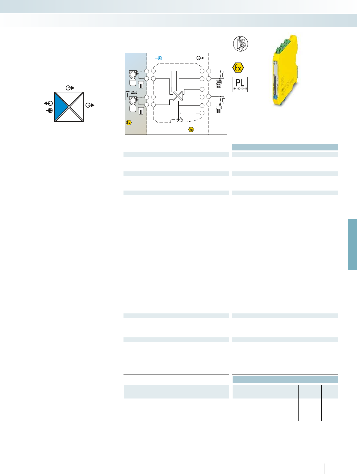
POWER
IIOUT2
I
OUT1
IN
POWER
Zone 2
Div. 2
Sensor / Field
or
4.2
5.2
4.1
5.1
Zone 0,1,2
Zone 20,21,22
Div. 1,2
4.2
5.2
4.1
5.1
3.2
3.1
2.2
2.1
1.2
1.1
GND
OUT 1
OUT 2
+24V
GND +24V
Power
+
+
-
-
IN OUT
PLC / DCS
3.2
3.1
+
-
2.2
2.1
+
-
passive
passive
AI
For further information and full technical data, visit phoenixcontact.net/products
Ex:
Housing width 12.5 mm
Technical data
Input data
Input signal 4 mA ... 20 mA / 4 mA ... 20 mA
Transmitter supply voltage > 16 V (at 20 mA)
Voltage drop approx. 3.9 V
Output data
Output signal (per output) 4 mA ... 20 mA (active)
Load < 450 (at 20 mA)
Output ripple < 20 mV
rms
General data
Supply voltage range 19.2 V DC ... 30 V DC (24 V DC (-20% ... +25%))
Current consumption < 75 mA (24 V DC/ 20 mA)
Power dissipation < 1.45 W (24 V DC/ 20 mA)
Temperature coefficient < 0.01 %/K
Step response (10-90%) < 1.3 ms (for 4 mA ... 20 mA step)
Transmission error, typical < 0.05 % (of final value)
Maximum transmission error < 0.1 % (of final value)
Underload/overload range according to NE 43
Electrical isolation
Input/output/power supply 300 V
rms
(rated insulation voltage (surge voltage category II;
pollution degree 2, safe isolation as per EN 61010-1))
2.5 kV (50 Hz, 1 min., test voltage)
Input/output 375 V (peak value in accordance with EN 60079-11)
Input/power supply 375 V (peak value in accordance with EN 60079-11)
Output 1/output 2 1.5 kV AC (50 Hz, 1 min., test voltage)
Ambient temperature range -20 °C ... 60 °C (any mounting position)
Status indication Green LED (PWR supply voltage)
SMART communication (per output) Yes
Protocols supported HART
Housing material PA 66-FR
Dimensions W / H / D 12.5 / 99 / 114.5 mm
Screw connection solid / stranded / AWG 0.2 ... 2.5 mm² / 0.2 ... 2.5 mm² / 24 - 14
Push-in connection solid / stranded / AWG 0.2 ... 1.5 mm² / 0.2 ... 1.5 mm² / 24 - 16
EMC note Class A product, see page 625
Safety data as per ATEX
Max. output voltage U
o
25.2 V
Max. output current I
o
93 mA
Max. output power P
o
587 mW
Maximum voltage U
m
253 V AC (125 V DC)
Conformance / approvals
Conformance CE-compliant, additionally EN 61326
ATEX
II (1) G [Ex ia Ga] IIC/IIB
II (1) D [Ex ia Da] IIIC
II 3 (1)G Ex nA [ia Ga] IIC/IIB T4 Gc
IECEx [Ex ia Ga] IIC/IIB, [Ex ia Da], Ex nA [ia Ga] IIC/IIB T4 Gc
SIL in accordance with IEC 61508 2
Performance level according to ISO 13849 PLd
Ordering data
Description Type Order No. Pcs. /
Pkt.
Repeater power supply and input signal conditioner, signal
duplicator, with performance level, intrinsically safe input
Screw connection MACX PL-EX-RPSSI-2I 2904959 1
Push-in connection MACX PL-EX-RPSSI-2I-SP 2904960 1
219
PHOENIX CONTACT
– 4...20 mA input, [Ex ia], powered and not
powered
– Two electrically isolated 4...20 mA
(active) outputs
– PL d according to EN ISO 13849-1
– Up to SIL 2 according to IEC 61508
– Installation in zone 2 possible
– Plug-in screw and push-in connection
technology
– 4-way electrical isolation
– Bidirectional HART communication
possible
– Power supply via DIN rail connector
possible
Analog IN
Repeater power supply, Ex i
MCR technology
Ex i signal conditioners with PL and SIL functional safety - MACX Safety Ex
Repeater power supply and
input signal conditioner,
with two electrically isolated outputs
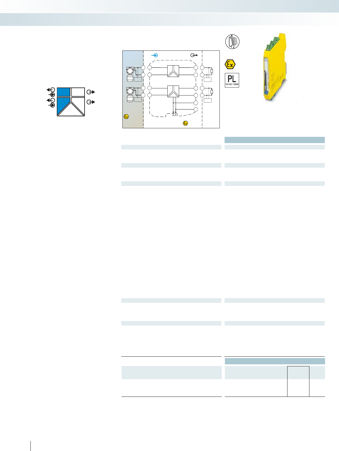
POWER
OUT
OUT
IN
POWER
IN
POWER
II
II
PLC / DCS
AI
Sensor / Field
Zone 2
3.2
3.1
2.2
2.1
GND
1.2
1.1
+24V
GND +24V
Power
Zone 0,1,2
Zone 20,21,22
passive
3.2
3.1
+
-
HHT
INOUT
CH1
CH2
active
active
passive
2.1
2.2
-
+
HHT
5.2
5.1
5.2
5.1
+
-
CH2
HHT
4.2
4.1
4.2
4.1
+
-
CH1
HHT
Div. 1,2Div. 1
Functional Safety
Ex:
Housing width 12.5 mm
Technical data
Input data per channel
Input signal 4 mA ... 20 mA
Transmitter supply voltage > 16 V (at 20 mA)
Underload/overload signal range 0 mA ... 24 mA
Output data per channel
Output signal 4 mA ... 20 mA (active)
Load 450 (20 mA)
Underload/overload signal range 0 mA ... 24 mA
General data
Supply voltage range 19.2 V DC ... 30 V DC (24 V DC (-20% ... +25%))
Current consumption < 100 mA (24 V / 20 mA)
Power dissipation < 1.4 W (at 24 V DC / 20 mA)
Temperature coefficient < 0.01 %/K
Step response (10-90%) < 1.3 ms (for 4 mA ... 20 mA step)
Transmission error, typical < 0.05 % (of final value)
Maximum transmission error < 0.1 % (of final value)
Electrical isolation
Input/output, power supply 300 V
rms
(rated insulation voltage (surge voltage category II;
pollution degree 2, safe isolation as per EN 61010-1))
2.5 kV (50 Hz, 1 min., test voltage)
Input/output 375 V (peak value in accordance with EN 60079-11)
Input/power supply 375 V (peak value in accordance with EN 60079-11)
Output 1/output 2/ power supply 1.5 kV (50 Hz, 1 min., test voltage)
Ambient temperature range -20 °C ... 60 °C (any mounting position)
Status indication Green LED (supply voltage)
SMART communication Yes
Signal bandwidth as per HART specifications
Protocols supported HART
Housing material PA 66-FR
Dimensions W / H / D 12.5 / 99 / 114.5 mm
Screw connection solid / stranded / AWG 0.2 ... 2.5 mm² / 0.2 ... 2.5 mm² / 24 - 14
Push-in connection solid / stranded / AWG 0.2 ... 1.5 mm² / 0.2 ... 1.5 mm² / 24 - 16
EMC note Class A product, see page 625
Safety data as per ATEX
Max. output voltage U
o
25.2 V
Max. output current I
o
93 mA
Max. output power P
o
587 mW
Maximum voltage U
m
253 V AC (125 V DC)
Conformance / approvals
Conformance CE-compliant, additionally EN 61326
ATEX
II (1) G [Ex ia Ga] IIC/IIB
II (1) D [Ex ia Da] IIIC
II 3(1) G Ex nA [ia Ga] IIC T4 Gc
IECEx [Ex ia Ga] IIC/IIB, [Ex ia Da] IIIC, Ex nA [ia Ga] IIC T4 Gc
SIL in accordance with IEC 61508 3
Performance level according to ISO 13849 PLd
Ordering data
Description Type Order No. Pcs. /
Pkt.
Repeater power supply, two-channel, with performance level,
intrinsically safe input
Screw connection MACX PL-EX-RPSS-2I-2I 2904963 1
Push-in connection MACX PL-EX-RPSS-2I-2I-SP 2904964 1
220
PHOENIX CONTACT
– 2-channel
– 4...20 mA input, [Ex ia], powered
– 4 ... 20 mA output (active)
– PL d according to EN ISO 13849-1
– Up to SIL 3 according to IEC 61508
– Installation in zone 2 possible
– Plug-in screw and push-in connection
technology
– 3-way electrical isolation, per channel
– Bidirectional HART communication
possible
– Power supply via DIN rail connector
possible
Analog IN
Repeater power supply, Ex i
MCR technology
Ex i signal conditioners with PL and SIL functional safety - MACX Safety Ex
2-channel repeater power supply
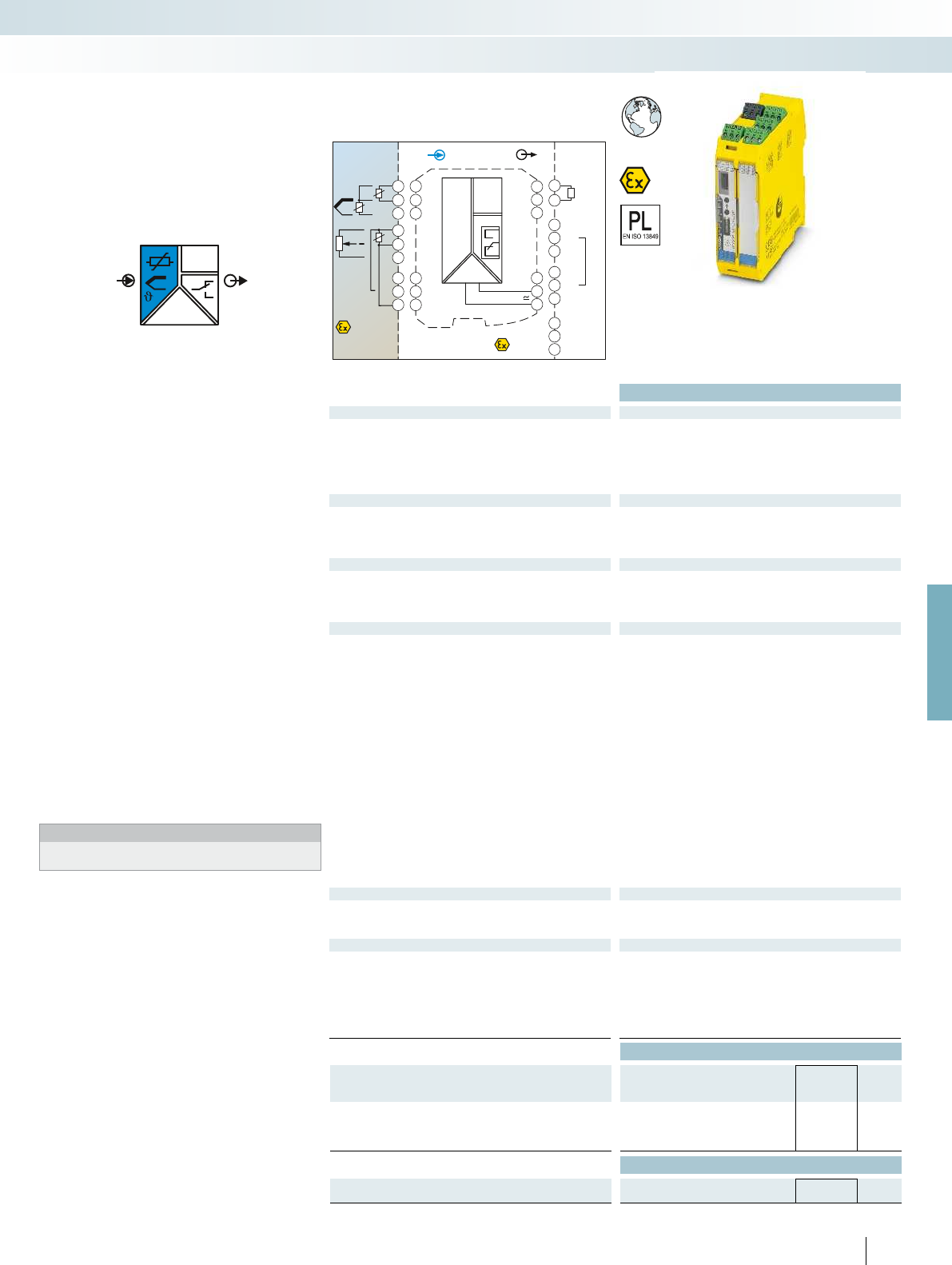
OUT
IN
POWER
I
Zone 0,1,2
Zone 20,21,22 Zone 2
IN OUT
Power
24V ...230V AC/DC
3.3
3.1
1.2
3.2
1.1
1.3
4.3
4.1
4.2
5.3
5.1
5.2
GND
I
OUT
NC
PLC / DCS
passive
-
+
3.3
3.2
11
21
31
12
22
32
14
24
34
3.6
3.4
3.5
2.6
2.4
2.5
1.6
1.4
1.5
DI
DI
Sensor /Field
4.3
4.1
4.2
ϑ
RTD
4.3
4.1
4.2
5.3
5.1
5.2
ϑ
Poti
TC
-
+
ϑ
For further information and full technical data, visit phoenixcontact.net/products
Functional Safety
Ex:
Housing width 35 mm
Technical data
Input data
Resistance thermometers Pt, Ni, Cu sensors: 2, 3, 4-wire
Thermocouple sensors B, E, J, K, N, R, S, T, L, U, CA, DA, A1G, A2G, A3G, MG, LG
Resistor 0 ... 50 k
Potentiometer 0 ... 50 k
Voltage -1000 mV ... 1000 mV
Output data
Output signal 4 mA ... 20 mA
Maximum output signal 22 mA
Load R
B
600 (20 mA)
Behavior in the event of a sensor error according to NE 43 or freely configurable
Switching output Relay output
Contact type 2 PDT
Contact material AgSnO
2
, hard gold-plated
Max. switching voltage 250 V AC (250 V DC)
Max. switching current 2 A (250 V AC) / 2 A (28 V DC)
General data
Supply voltage range 24 V ... 230 V AC/DC (-20%/+10%, 50/60 Hz)
Power consumption < 2.4 W
Temperature coefficient 0.01 %/K
Maximum transmission error 0.1 % (e.g. for Pt 100, 300 K span, 4 ... 20 mA)
Electrical isolation
Input/output/power supply 2.5 kV (50 Hz, 1 min., test voltage)
Input/output 375 V (peak value in accordance with EN 60079-11)
Input/power supply 375 V (peak value in accordance with EN 60079-11)
Input/switching output 375 V (peak value in accordance with EN 60079-11)
Output/supply 300 V
rms
(rated insulation voltage (surge voltage category II;
pollution degree 2, safe isolation as per EN 61010-1))
Ambient temperature range -20 °C ... 65 °C
Humidity typ. 5 % ... 95 % (non-condensing)
Housing material PA 66-FR
Inflammability class in acc. with UL 94 V0
Dimensions W / H / D 35 / 99 / 114.5 mm
Screw connection solid / stranded / AWG 0.2 ... 2.5 mm² / 0.2 ... 2.5 mm² / 24 - 14
Push-in connection solid / stranded / AWG 0.2 ... 1.5 mm² / 0.2 ... 1.5 mm² / 24 - 16
EMC note Class A product, see page 625
Safety data as per ATEX
Max. output voltage U
o
6 V
Max. output current I
o
7.4 mA
Max. output power P
o
11 mW
Conformance / approvals
Conformance CE-compliant
ATEX
II (1) G [Ex ia Ga] IIC
II (1) D [Ex ia Da] IIIC
II 3 G Ex nA nC ic IIC T4 Gc X
IECEx [Ex ia Ga] IIC, [Ex ia Da] IIIC, Ex nA nC ic IIC T4 Gc X
SIL in accordance with IEC 61508 2
Performance level according to ISO 13849 PLd
Ordering data
Description Type Order No. Pcs. /
Pkt.
Temperature transducer with threshold value switch, with
performance level, intrinsically safe input
Screw connection MACX PL-EX-T-UIREL-UP 2904910 1
Push-in connection MACX PL-EX-T-UIREL-UP-SP 2904912 1
Accessories
Programming adapter for configuring modules with
S-PORT interface
IFS-USB-PROG-ADAPTER 2811271 1
221
PHOENIX CONTACT
– Input for resistance thermometers,
thermocouples, resistance-type sensors,
potentiometers, mV sources, [Ex ia]
– Differential measurement possible with
Pt 100
– A safety-related limit value relay, by
bridging two relays
– An additional limit value relay for
non-safety-related function
– PL d according to EN ISO 13849-1
– Up to SIL 2 according to IEC 61508
– Configuration via software
(ANALOG-CONF or FDT/DTM)
– Cold junction compensation with
separate connector
– Wide range power supply
19.2...253 V AC/DC
– Status indicators for supply voltage, cable,
sensor, and module errors
– Installation in zone 2 possible
– Plug-in screw and push-in connection
technology
Notes:
You can find the ANALOG-CONF and FDT/DTM configuration
software on page 187
Temperature
Temperature transducer, Ex i
MCR technology
Ex i signal conditioners with PL and SIL functional safety - MACX Safety Ex
Universal, with limit value relay,
wide range power supply
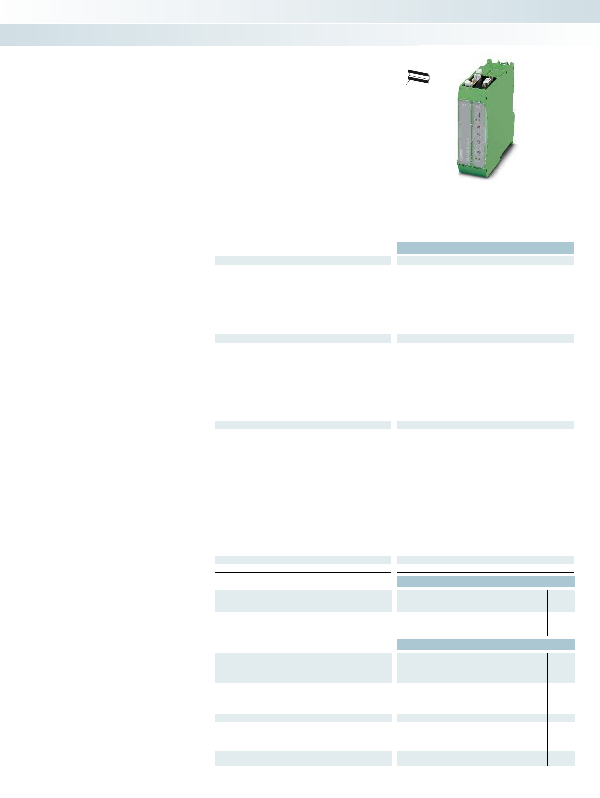
Housing width 35.2 mm
Technical data
Field devices interface (HART)
Channels 16 or 32; adjustable using a switch
Connection method Flat-ribbon cable, 14-pos. (inclusive)
Signal HART FSK
HART specification
HART Field Communication Protocol Rev. 6.0 (downward compatible
up to Rev 4.0); FSK Physical Layer Specification (Rev. 8.1)
Data transmission display Two yellow "Tx" and "Rx" "HART" LEDs
Display error Red "ERR" LED (flashes in case of an error in the HART bus)
RS-485 interface
Connection method D-SUB-9 socket
Signal RS-485
Data flow control/protocols Compatible with OPC HART server, PDM, PRM, and FDT/DTM
Number of HART multiplexers per bus segment Max 31
Address setting 0...127; using a rotary switch at the front
Data rate 9600 / 19200 / 38400 / 57600 [bps]; via rotary switch at the front
Transmission length 1200 m
Display Two yellow "Tx" and "Rx" "RS-485" LEDs
General data
Supply voltage range 18 V ... 31.2 V
Nominal supply voltage 24 V DC
Current consumption 55 mA
Power consumption 1.35 W
Operating voltage display Green "PWR" LED
Undervoltage monitoring Yes (no faulty devices / output states)
Electrical isolation between HART signal/RS-485 350 V AC
Electrical isolation between HART signals 100 V DC (capacitive)
Electrical isolation between HART signal/supply 350 V AC
Electrical isolation between RS-485/supply 350 V AC
Error monitoring Processor error: “PWR” LED flashes;
HART communication error: “ERR” LED flashes
Ambient temperature range -20 °C ... 60 °C
Humidity 95 % (non-condensing)
Dimensions W / H / D 35.2 / 99 / 114.5 mm
Conformance / approvals
Conformance CE-compliant
Ordering data
Description Type Order No. Pcs. /
Pkt.
HART multiplexer, 32-chanel, including two 14-wire flat-ribbon
cables
MACX MCR-S-MUX 2865599 1
Accessories
Universal Termination Carrier for 16 MACX MCR-EX isolators
- With connection for MACX MCR-S-MUX HART multiplexer TC-D37SUB-AIO16-EX-PS-UNI 2902932 1
Module carrier for 16 MINI Analog channels, power and
feed-through module
- With connection for MACX MCR-S-MUX HART multiplexer TC-D37SUB-AIO16-M-PS-UNI 2902934 1
HART connection board MACX MCR-S-MUX-TB 2308124 1
Interface converter, for conversion from RS-232 (V.24) to
RS-485, with electrical isolation, DIN-rail-mountable, changeover of
data direction self-controlling or through RTS/CTS
PSM-ME-RS232/RS485-P 2744416 1
Repeater, for electrical isolation and increased range PSM-ME-RS485/RS485-P 2744429 1
222
PHOENIX CONTACT
Multiplexer for digital connection of
HART-capable field devices (such as
measuring transducers or control valves) to
a PC or management system.
– Supports online configuration and
diagnostics for the connected
HART-capable field devices
– Constant documentation of process
variables and states
– 32 HART channels per multiplexer
– Up to 128 HART multiplexers at one
PC interface
– Communication via software tool
(e.g. HART OPC Server) using RS-485
interface
– Electrical isolation between auxiliary
energy, RS-485 bus, and the HART
channels
– HART field devices are accessed at the
same time that the measurement signal is
transmitted without affecting measured
value processing
– HART field devices connected via
universal HART connection boards; direct
connection if processing non-Ex signals,
with separate Ex i signal isolator
connected upstream if processing
Ex signals
– Power supplied via HART connection
board
Multiplexers for HART signals
MCR technology
Multiplexers for HART signals
H
W
D

1
2
3
4
6
5
DC
DA
D
DC
OUT 1
GND 1
-
+
1
2
3
4
6
5
DC
DA
D
DC
OUT 1
GND 1
-
+
For further information and full technical data, visit phoenixcontact.net/products
Ex:
Housing width 12.5 mm
Technical data
Measuring input
Resistance thermometers Pt, Ni (100, 500, 1000); min. measuring range 10 K
Thermocouple sensors B, C, D, E, J, K, L, N, R, S, T, U; min. measuring range 50 K/500 K
Resistor 10 ... 400 (min. measuring range 10 )
10 ... 2000 (min. measuring range 100 )
Voltage -10 mV ... 100 mV (min. measuring range 5 mV)
Configuration Yes, programmable
Measuring output
Output signal range 4 mA ... 20 mA / 20 mA ... 4 mA
Maximum output signal 23 mA
Load 520 (at U
V
= 24 V; U
supply
- 12 V / 0.023 A)
Line monitoring NE 43
Short-circuit current 3.6 mA or 21 mA (adjustable, not for thermocouples)
Output current with open circuit 3.6 mA or 21 mA (adjustable)
Output current, measuring range overrange/underrange 3.8 mA ... 20.5 mA
General data
Supply voltage range 12 V DC ... 30 V DC
Current consumption < 3.5 mA
Step response (10-90%) < 2 s
Transmission error Resistance thermometers
0.2 K (Pt 100, Ni 100), 0.5 K (Pt 500, Ni 500), 0.3 K (Pt 1000, Ni 1000)
Thermocouple sensors Type 0.5 K (K, J, T, E, L, U), 1.0 K (N, C, D), 2.0 K (S, B, R)
Resistance-type sensors ± 0.1 (10...400 ), ± 1.5 (10...2000 )
Voltage sensor ± 20 µV (-10...100 mV)
Test voltage input/output 2 kV AC (50 Hz, 1 min.)
Switch on delay time 4 s
Standards/regulations NAMUR recommendation NE 21
Housing material Polyamide PA non-reinforced
Inflammability class in acc. with UL 94 V0
Dimensions W / H / D 12.5 / 99 / 114.5 mm
Connection method Screw connection
Screw connection solid / stranded / AWG 0.2 ... 2.5 mm² / 0.2 ... 2.5 mm² / 24 - 14
Safety data as per ATEX MCR-FL-TS-LP-I-EX MCR-FL-T-LP-I-EX
Max. voltage U
i
30 V 30 V
Max. current I
i
100 mA 100 mA
Max. power P
i
750 mW 750 mW
Max. voltage U
o
5 V DC 4.4 V DC
Max. current I
o
5.9 mA 9.6 mA
Max. power P
o
7.2 mW 10.6 mW
Gas group IIA IIB IIC IIA IIB IIC
- Max. external inductance Lo [mH] 100 100 100 100 100 100
- Max. external capacitance Co [µF] 10 10 2 12 12 2.4
Max. ambient temperature T4 = 85 °C, T5 = 70 °C,
T6 = 55 °C
T4 = 85 °C, T5 = 65 °C,
T6 = 50 °C
Conformance / approvals
Conformance CE-compliant CE-compliant
ATEX
II 2(1) G Ex ia IIC T6
II 2(1) G Ex ia IIC T4...T6
UL, USA / Canada cULus cULus
Functional Safety (SIL) SIL 2 -
Ordering data
Description Type Order No. Pcs. /
Pkt.
MCR temperature transducer, for resistance thermometers,
thermocouples, resistance-type sensors, and voltage sensors
HART-compatible MCR-FL-TS-LP-I-EX 2864587 1
MCR-FL-T-LP-I-EX 2864574 1
223
PHOENIX CONTACT
– 1-channel
– Loop-powered
– Input for resistance thermometers,
thermocouples, and linear mV signals,
Ex ia IIC
– Output 4...20 mA/20...4 mA
– Can be installed in zone 1
– 2-way electrical isolation
– HART-capable (MCR-FL-TS-LP-I-EX)
– Configuration using software
Notes:
The devices are supplied with the standard configuration: Pt 100
sensor, measuring range 0 ... 100°C, 3-wire connection.
To configure the MCR-FL-TS-LPI-EX HART-capable device
(2864587), you need a HART modem.
To configure the MCR-FL-T-LP-EX device (2864574), you need
the MCR-PAC-T-USB programming adapter and the
MCR/PI-CONF-WIN software, see page 226
Programmable loop-powered
temperature transducer, Ex i
Block diagram MCR-FL-T-LP-I-EX
MCR technology
Ex i 2-wire field devices
DW
H
Loop-powered,
programmable
Block diagram MCR-FL-TS-LP-I-EX

21
3
4
5
6
2
1
∅33
∅44
∅5
∅7
3
4
5
6
2
1
DC
DA
D
DC
OUT 1
GND 1
Ex:
Technical data
Measuring input
Resistance thermometers Pt, Ni (100, 500, 1000); min. measuring range 10 K
Thermocouple sensors B, C, D, E, J, K, L, N, R, S, T, U; min. measuring range 50 K/500 K
Resistor 10 ... 400 (min. measuring range 10 )
10 ... 2000 (min. measuring range 100 )
Voltage -10 mV ... 75 mV (min. measuring range 5 mV)
Configuration Yes, programmable
Measuring output
Output signal range 4 mA ... 20 mA / 20 mA ... 4 mA
Maximum output signal 23 mA
Load 630 (at UV = 24 V; U
supply
- 10 V / 0.023 A)
Line monitoring NE 43
Short-circuit current 3.6 mA or 21 mA (adjustable, not for thermocouples)
Output current with open circuit 3.6 mA or 21 mA (adjustable)
Output current, measuring range overrange/underrange 3.8 mA ... 20.5 mA (linear increase/decrease)
General data
Supply voltage range 12 V DC ... 30 V DC
Current consumption < 3.5 mA
Step response (10-90%) < 2 s
Transmission error Resistance thermometers
0.2 K (Pt 100, Ni 100), 0.5 K (Pt 500, Ni 500), 0.3 K (Pt 1000, Ni 1000)
Thermocouple sensors Type 0.5 K (K, J, T, E, L, U), 1.0 K (N, C, D), 2.0 K (S, B, R)
Resistance-type sensors ± 0.1 (10...400 ), ± 1.5 (10...2000 )
Voltage sensor ± 20 µV (-10...75 mV)
Test voltage input/output 2 kV AC (50 Hz, 1 min.)
Switch on delay time 6 s
Degree of protection IP00, IP66 (integrated in the connecting head)
Mounting position Connecting head in acc. with DIN 43729 form B
Connection Installation in connection head according to DIN 43729 form B
Standards/regulations NAMUR recommendation NE 21
Housing material Polycarbonate, PC
Inflammability class in acc. with UL 94 V0
Screw connection solid / stranded / AWG 0.2 ... 1.75 mm² / 0.2 ... 1.75 mm² / 24 - 15
Safety data as per ATEX
Max. voltage U
i
30 V
Max. current I
i
100 mA
Max. power P
i
750 mW
Max. voltage U
o
5 V DC
Max. current I
o
5.4 mA
Max. power P
o
6.6 mW
Gas group IIA IIB IIC
- Max. external inductance Lo [mH] 100 100 100
- Max. external capacitance Co [µF] 9.9 9.9 2
Max. ambient temperature Category 1: T4 = 60°C, T5 = 50°C, T6 = 40°C
Category 2: T4 = 85°C, T5 = 70°C, T6 = 55°C
Conformance / approvals
Conformance CE-compliant
ATEX
II 1 G and II 2 G Ex ia IIC T6/T5/T4
UL, USA / Canada cULus
Functional Safety (SIL) SIL 2
Ordering data
Description Type Order No. Pcs. /
Pkt.
MCR temperature transducer, smart, for resistance
thermometers, thermocouples, resistance-type sensors and
voltage sensors
MCR-FL-HT-TS-I-EX 2864545 1
224
PHOENIX CONTACT
– 1-channel
– Loop-powered
– Input for resistance thermometers,
thermocouples, and linear mV signals,
Ex ia IIC
– Output 4...20 mA/20...4 mA
– Can be installed in zone 0
– 2-way electrical isolation
– HART-compatible
Notes:
The devices are supplied with the standard configuration: Pt 100
sensor, measuring range 0 ... 100°C, 3-wire connection.
To configure the MCR-FL-TS-LPI-EX HART-capable device, you
need a HART modem.
Programmable loop-powered
temperature transducer with
connection heads, Ex i
MCR technology
Ex i 2-wire field devices
Loop-powered,
programmable
Block diagram MCR-FL-HT-TS-I-EX

21
3
4
5
6
2
1
∅33
∅44
∅5
∅7
3
4
5
6
2
1
DC
DA
D
DC
OUT 1
GND 1
For further information and full technical data, visit phoenixcontact.net/products
Ex:
Technical data
Measuring input
Resistance thermometers Pt, Ni (100, 500, 1000); min. measuring range 10 K
Thermocouple sensors B, C, D, E, J, K, L, N, R, S, T, U; min. measuring range 50 K/500 K
Resistor 10 ... 400 (min. measuring range 10 )
10 ... 2000 (min. measuring range 100 )
Voltage -10 mV ... 100 mV (min. measuring range 5 mV)
Configuration Yes, programmable
Measuring output
Output signal range 4 mA ... 20 mA / 20 mA ... 4 mA
Maximum output signal 25 mA
Load 720 (For U
V
= 24 V; U
supply
- 8 V / 0.025 A)
Line monitoring NE 43
Short-circuit current 3.6 mA or 21 mA (adjustable, not for thermocouples)
Output current with open circuit 3.6 mA or 21 mA (adjustable)
Output current, measuring range overrange/underrange 3.8 mA ... 20.5 mA (linear increase/decrease)
General data
Supply voltage range 8 V DC ... 30 V DC
Current consumption < 3.5 mA
Step response (10-90%) < 2 s
Transmission error Resistance thermometers
0.2 K (Pt 100, Ni 100), 0.5 K (Pt 500, Ni 500), 0.3 K (Pt 1000, Ni 1000)
Thermocouple sensors Type 0.5 K (K, J, T, E, L, U), 1.0 K (N, C, D), 2.0 K (S, B, R)
Resistance-type sensors ± 0.1 (10...400 ), ± 1.5 (10...2000 )
Voltage sensor ± 20 µV (-10...100 mV)
Test voltage input/output 2 kV AC (50 Hz, 1 min.)
Switch on delay time 6 s
Degree of protection IP00, IP66 (integrated in the connecting head)
Mounting position Connecting head in acc. with DIN 43729 form B
Connection Installation in connection head according to DIN 43729 form B
Standards/regulations NAMUR recommendation NE 21
Housing material Polycarbonate, PC
Inflammability class in acc. with UL 94 V0
Screw connection solid / stranded / AWG 0.2 ... 1.75 mm² / 0.2 ... 1.75 mm² / 24 - 15
Safety data as per ATEX
Max. voltage U
i
30 V
Max. current I
i
100 mA
Max. power P
i
750 mW
Max. voltage U
o
8.2 V DC
Max. current I
o
4.6 mA
Max. power P
o
9.35 mW
Gas group IIB IIC
- Max. external inductance Lo [mH] 8.5 4.5
- Max. external capacitance Co [µF] 1.9 0.974
Max. ambient temperature Category 1: T4 = 60°C, T5 = 50°C, T6 = 40°C
Category 2: T4 = 85°C, T5 = 70°C, T6 = 55°C
Conformance / approvals
Conformance CE-compliant
ATEX
II 1 G Ex ia IIC T6/T5/T4
UL, USA / Canada cULus
Ordering data
Description Type Order No. Pcs. /
Pkt.
MCR temperature transducer, for resistance thermometers,
thermocouples, resistance-type sensors and voltage sensors
MCR-FL-HT-T-I-EX 2864532 1
225
PHOENIX CONTACT
– 1-channel
– Loop-powered
– Input for resistance thermometers,
thermocouples, and linear mV signals,
Ex ia IIC
– Output 4...20 mA/20...4 mA
– Can be installed in zone 0
– 2-way electrical isolation
– Configuration using software
Notes:
The devices are supplied with the standard configuration: Pt 100
sensor, measuring range 0 ... 100°C, 3-wire connection.
You can implement your own measuring range settings,
linearization, and characteristic curve adjustments. For this
purpose, you need the MCR-PAC-T-USB programming adapter
and the MCR/PI-CONF-WIN configuration software, see page 226
Programmable loop-powered
temperature transducer with
connection heads, Ex i
MCR technology
Ex i 2-wire field devices
Loop-powered,
programmable
Block diagram MCR-FL-HT-T-I-EX
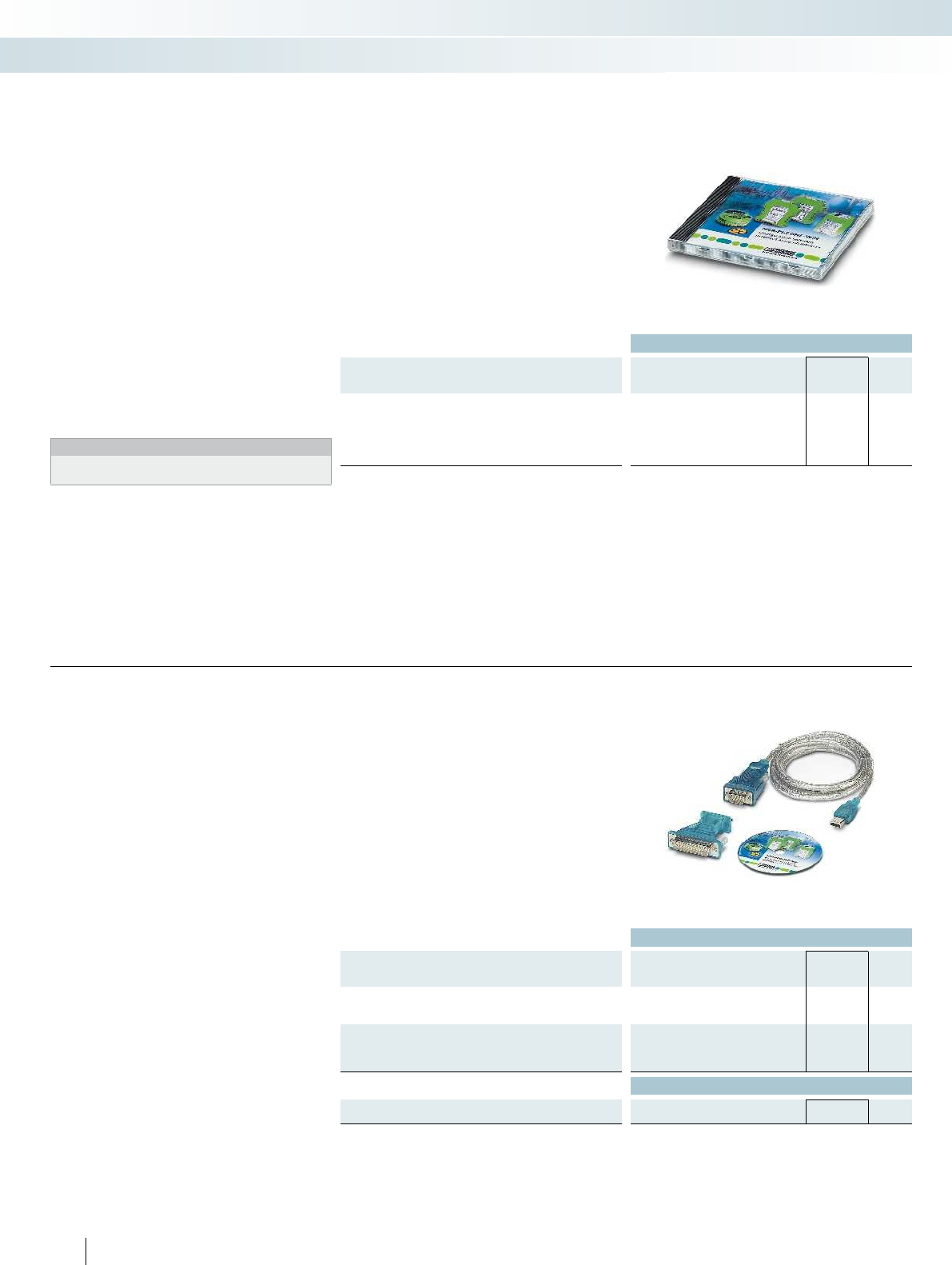
Ordering data
Description Type Order No. Pcs. /
Pkt.
MCR configuration software, for programming MCR-T-...-,
MCR-...-LP-...-, MCR-...-HT-...-, MCR-S-...-, MCR-F-..., and
MCR-PSP-... modules, CD-ROM
MCR/PI-CONF-WIN 2814799 1
Configuration software package
The MCR/PI-CONF-WIN
configuration software package is used
to configure and visualize all parameters for
the programmable loop-powered
temperature transducers.
– For temperature transducers:
MCR-FL-T(S)-LP-I-EX and
MCR-FL-HT-T(S)-I-EX
– Electrically isolated
– Configuration possible during operation
– Straightforward menu interface
– Rapid programming
The computer and the measuring
transducer communicate with one another
via a software adapter cable and a serial
interface.
Notes:
The software runs under the following operating systems:
Windows NT™, 2000™, and XP™.
Accessories
MCR technology
Ex i 2-wire field devices
Ordering data
Description Type Order No. Pcs. /
Pkt.
USB adapter cable,
D-9-SUB to USB, with adapter D-9-SUB to D-25-SUB
CM-KBL-RS232/USB 2881078 1
Software adapter cable, 2.4 m in length, with USB connection, for
programming MCR-...-LP-... and MCR-...-HT-... modules
MCR-PAC-T-USB 2309000 1
Accessories
Adapter cable, flexible, 9-pos. D-SUB socket to
25-pos. D-SUB pin
PSM-KAD 9 SUB 25/BS 2761295 1
226
PHOENIX CONTACT
USB adapter cable
Software adapter cable
For connecting the programmable
MCR-/PI modules to the USB interface of a
computer, the USB adapter cable
CM-KBL-RS232/USB can be used
together with the relevant adapter cables.
Programming with the MCR/PI-CONF-
WIN software is supported under
Windows 98™, Windows 2000™ and
Windows XP™.
The following modules are supported:
– MCR-FL-T-LP-I-EX
– MCR-FL-HT-T-I-EX
Accessories
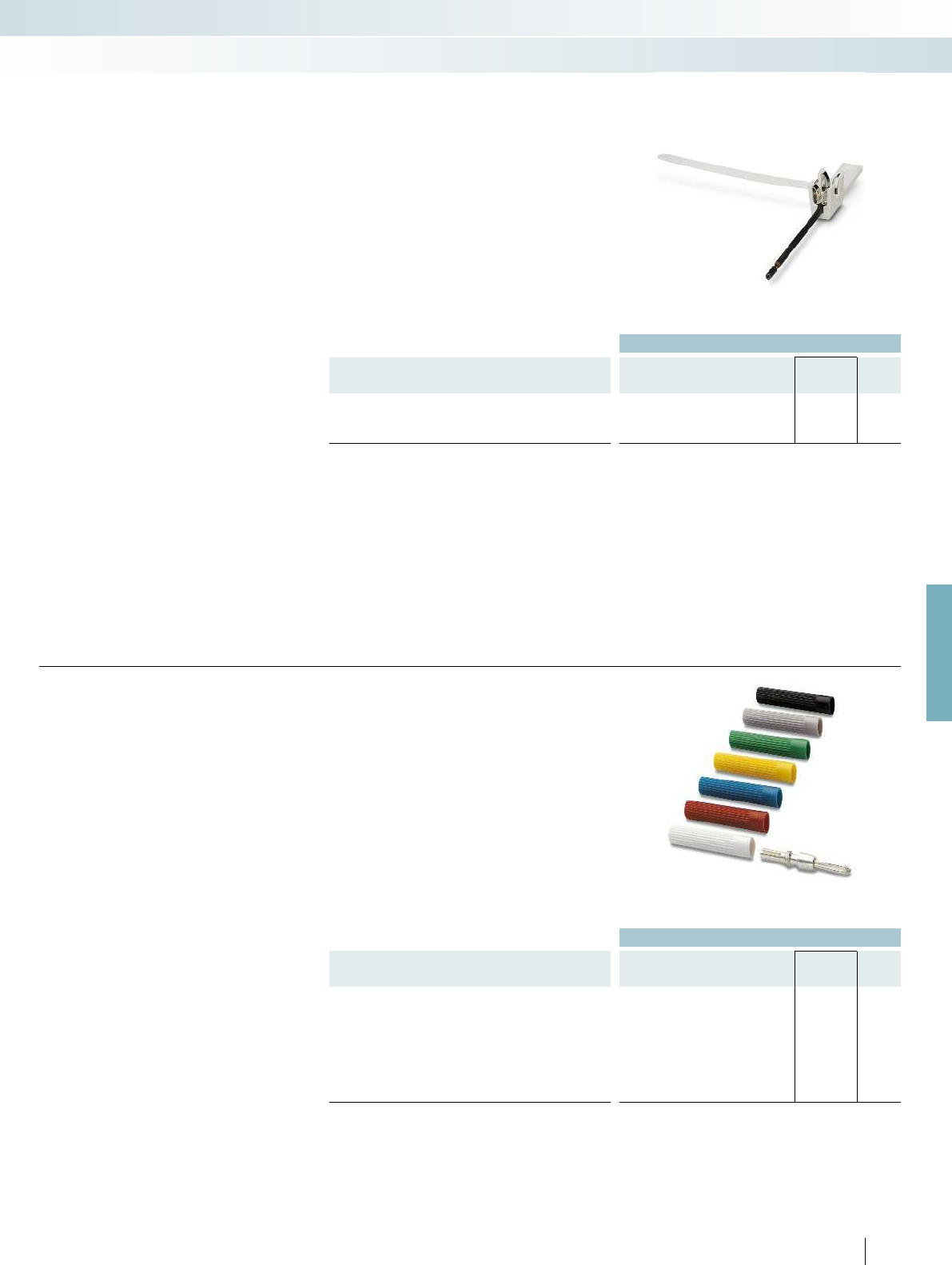
For further information and full technical data, visit phoenixcontact.net/products
Ordering data
Description Type Order No. Pcs. /
Pkt.
Shield fast connection, for connection to PLUGTRAB PT
For Ø 3-6 mm SSA 3-6 2839295 10
For Ø 5-10 mm SSA 5-10 2839512 10
Shield fast connection
– For connecting cable shielding to cable
terminal points
– Can be connected to PLUGTRAB PT
– Easy assembly
Accessories
MCR technology
Accessories
Ordering data
Description Color Type Order No. Pcs. /
Pkt.
Test plug, consisting of:
Metal part for 2.3 mm Ø socket hole and silver MPS-MT 0201744 10
Insulating sleeve, for MPS metal part red MPS-IH RD 0201676 10
white MPS-IH WH 0201663 10
blue MPS-IH BU 0201689 10
yellow MPS-IH YE 0201692 10
green MPS-IH GN 0201702 10
gray MPS-IH GY 0201728 10
black MPS-IH BK 0201731 10
227
PHOENIX CONTACT
Test plug
Accessories
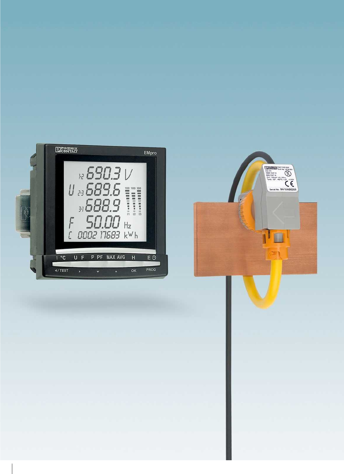
228
PHOENIX CONTACT

Product range overview
Product overview 230
Measuring power and energy 232
EMpro energy meters 238
EMpro function and communication modules 240
Accessories 243
Software for usage data acquisition 244
Complete packages for data logging 245
Pressure sensors and compressed air meters 246
Current measurement
Current transformers 250
Current transformer selection guide 252
PACT current transformers 253
Accessories for PACT current transformers 263
PACT RCP current transformers for retrofitting 266
Current transducers 272
Accessories for current transducers 280
Monitoring and diagnostics
Solar system monitoring 282
Residual current monitoring 286
Components for E-Mobility 290
EMD electronic monitoring relays 296
ETD electronic timer relays 308
Diode modules, lamp testing modules, EMG display modules 312
229
PHOENIX CONTACT
Measuring power and energy
EMpro energy meters measure, analyze,
and communicate electrical system
parameters.
Monitoring software ensures efficient
energy and power measurement.
Stand-alone data loggers are the
complete package for decentralized data
acquisition.
PSK sensors acquire the operating
pressure of gaseous media.
PSK meters record compressed air
consumption.
Current measurement
PACT current transformers convert
currents up to 4000 A into secondary
currents of 1 and 5 A.
MCR current transducers convert
currents into standard analog signals.
Monitoring and diagnostics
The SOLARCHECK modular monitoring
system is used for string monitoring in
photovoltaic systems.
RCM devices provide residual current
monitoring in grounded power supply
systems. They detect residual currents at an
early stage before they result in forced
shutdown.
EV Charge Control is the charging
controller used to charge electric vehicles
on the AC mains according to IEC 61851-1.
EMD monitoring relays detect and
indicate deviations in important system
parameters at an early stage.
ETD timer relays are used for
straightforward time control functions.
Diode modules, lamp testing modules,
and EMG display modules allow industrial
use of simple components such as diodes -
with professional housing and connection
technology.
Monitoring
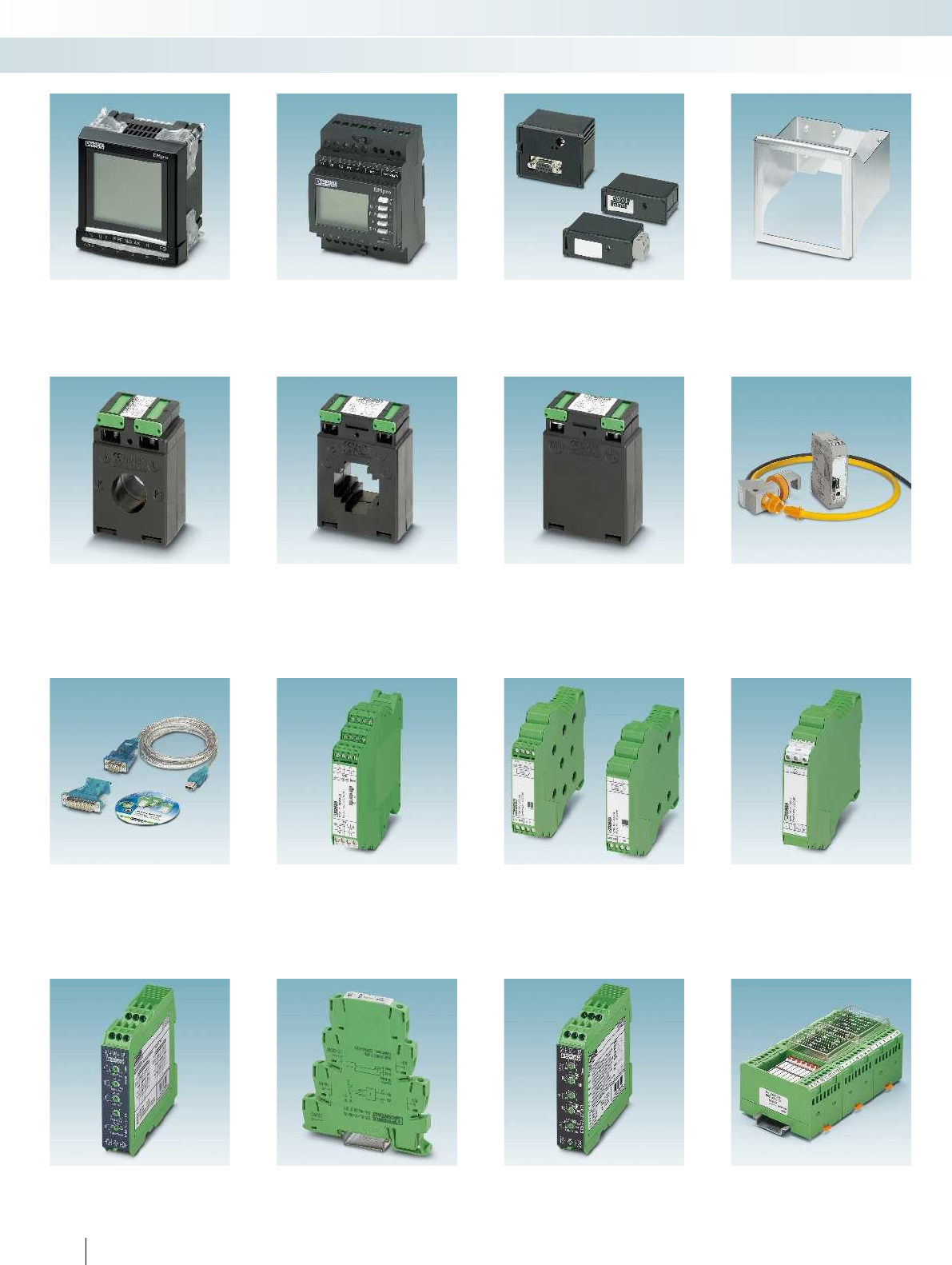
Measuring power and energy
EMpro energy meters for front-panel
installation Page 238
EMpro energy meters for DIN rail mounting
Page 239
Function and communication modules for
EMpro Page 240
DIN rail adapter for EMpro
Page 243
Current transformers
PACT bus-bar current transformers
Page 252
Can be calibrated Page 264
PACT window-type current transformers
Page 254
Can be calibrated Page 264
PACT winding current transformer
Page 262
PACT RCP... current transformers for
retrofitting Page 268
Solar system monitoring
Accessories
Configuration software and USB adapter
cable Page 226
SOLARCHECK PV string monitoring
Communication module Page 282
SOLARCHECK PV string monitoring
Current measuring module Page 285
SOLARCHECK PV string monitoring
Voltage measuring module Page 285
Timer relays
Function modules
EMD
Multifunctional monitoring relays Page 300
ETD-BL
Ultra-narrow timer relays Page 308
ETD
Multifunctional timer relays Page 310
EMG
Diode modules, lamp testing modules,
display modules Page 312
230
PHOENIX CONTACT
Monitoring
Product overview

For further information and full technical data, visit phoenixcontact.net/products
Software for usage data acquisition
Page 244
Complete packages for data logging
Page 245
Pressure sensor with IO-Link
Page 248
Compressed air meters
Page 246
Current measurement
Mounting accessories, shock protection
Page 263
MCR current transducers for AC/DC and
distorted currents Page 272
MCR current transducers for sinusoidal and
distorted AC currents Page 276
Passive, up to 5 A Page 278
MCR current protector for AC currents,
sinusoidal up to 16 A Page 279
Residual current
monitoring
Components for E-Mobility Monitoring relays
RCM residual current monitoring for
DC residual currents and pulsating DC and
AC residual currents Page 288
EV Charge Control
Charging controller Page 292
EV Charge Lock Release
Mains failure plug release Page 292
EMD-BL
Compact monitoring relays Page 298
Lightning monitoring
system
HMIs Signal towers
Lightning monitoring system
See Catalog 6
HMIs
See Catalog 8
Signal towers
See Catalog 8
231
PHOENIX CONTACT
Monitoring
Product overview
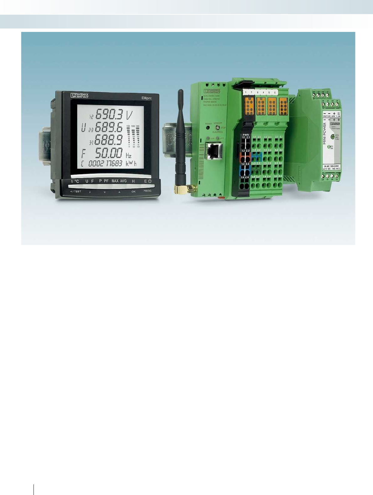
232
PHOENIX CONTACT
Monitoring
Measuring power and energy
Energy costs at a glance
Within industry, energy is viewed as a
variable cost factor. As a result, lower
energy costs are becoming increasingly
important in terms of providing companies
with a major competitive advantage in the
areas of production, process, and industrial
engineering.
Alongside energy consumption, the
quality of the energy supplied, the reliability
of supply, and effective system utilization
also play an important role in ensuring
profitability. This calls for continuous
measurement and analysis of all sources of
energy.
Advantages of energy data acquisition
Continuously recorded energy flow
provides the basis for a target-oriented
energy management system.
Access comprehensive information
regarding the characteristic electrical data
of your machinery and benefit from the
advantages of this:
– Reduce your energy costs by identifying
potential energy savings.
– Optimize your system capacity: through
intelligent switching of system parts,
uniform network load, and reduced
harmonics.
– Reduce peak loads using forward-looking
trend calculation and load management.
– Safeguard your production processes and
minimize downtimes by continuously
monitoring important system
parameters.
Measurement – monitoring –
communication
Efficient energy management – network-
capable EMpro energy meters can be used
to acquire and monitor the characteristic
electrical data of your machines and
systems.
They can be freely extended with
communication modules and function
modules, enabling your energy meters to
keep pace with your growing requirements.
Future-proof planning and investment is
therefore ensured.
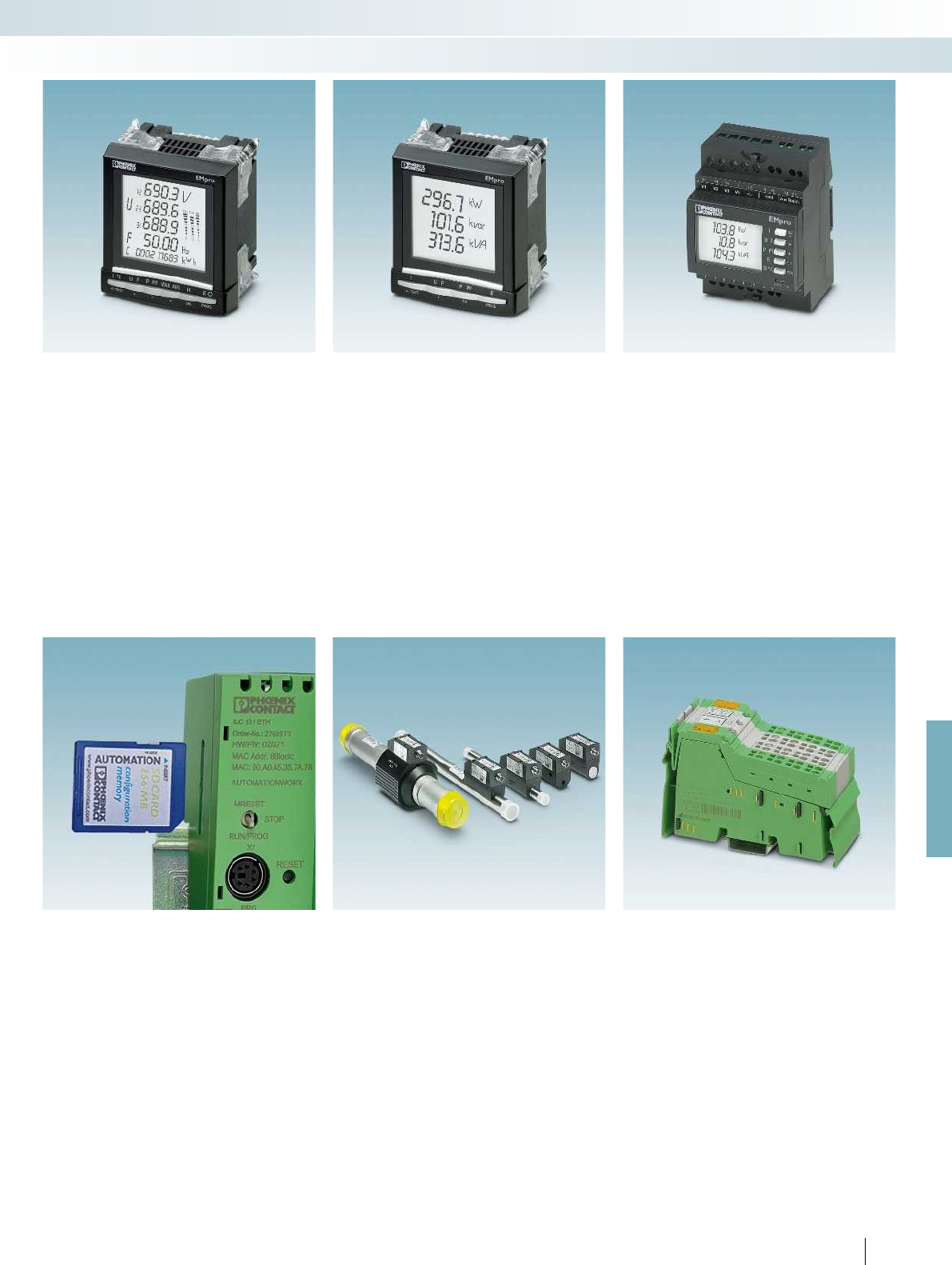
For further information and full technical data, visit phoenixcontact.net/products
233PHOENIX CONTACT
Monitoring
Measuring power and energy
The communication expert
The EMpro MA600 is capable of
performing all measurement tasks
associated with power supply applications
up to 700 V AC.
– From simple current and power
measurement to the detection of
harmonics including spectral analysis
– Flexible integration into Ethernet,
PROFIBUS or RS-485 networks
– Remote access via web server
– Optional DIN rail adapter for DIN rail
mounting
– Can be extended with communication
modules and function modules
The universal solution on the front
panel
The EMpro MA400 performs standard
measuring tasks up to 519 V AC.
– Optional DIN rail adapter for DIN rail
mounting
– Communication module for integration
into RS-485 networks (Modbus/RTU)
– Function module for pulse or alarm
output
The measuring device with RS-485
communication
The EMpro MA250 performs standard
measuring tasks up to 519 V AC.
– DIN rail device
– With pulse or alarm output
– Integrated RS-485 communication
(Modbus/RTU)
The measuring device with pulse
output
The EMpro MA200 is ideal for simple
measuring tasks up to 519 V AC.
– DIN rail device
– With pulse or alarm output
Software for usage data acquisition
In conjunction with a 100-series modular
controller, the EMwise software from
Phoenix Contact is the efficient solution for
recording energy data related to heat, cold,
air, or electricity. You can therefore keep an
eye on your resources at all times and
efficiently manage their use in your
machines and systems.
Sensors and meters
Use of resources at a glance - determine
all relevant states using sensors and meters.
– Detailed procurement measurement,
thanks to precise sensor and meter
technology
– Intelligent sensor communication, thanks
to IO-Link technology
Inline power measurement terminal
The Inline power measurement terminal
enables analysis of AC networks.
– For measuring current, voltage, and
power, as well as identifying distortion
and harmonics
The power measurement terminal can be
found in Catalog 8, Control technology,
I/O systems, and network structure.
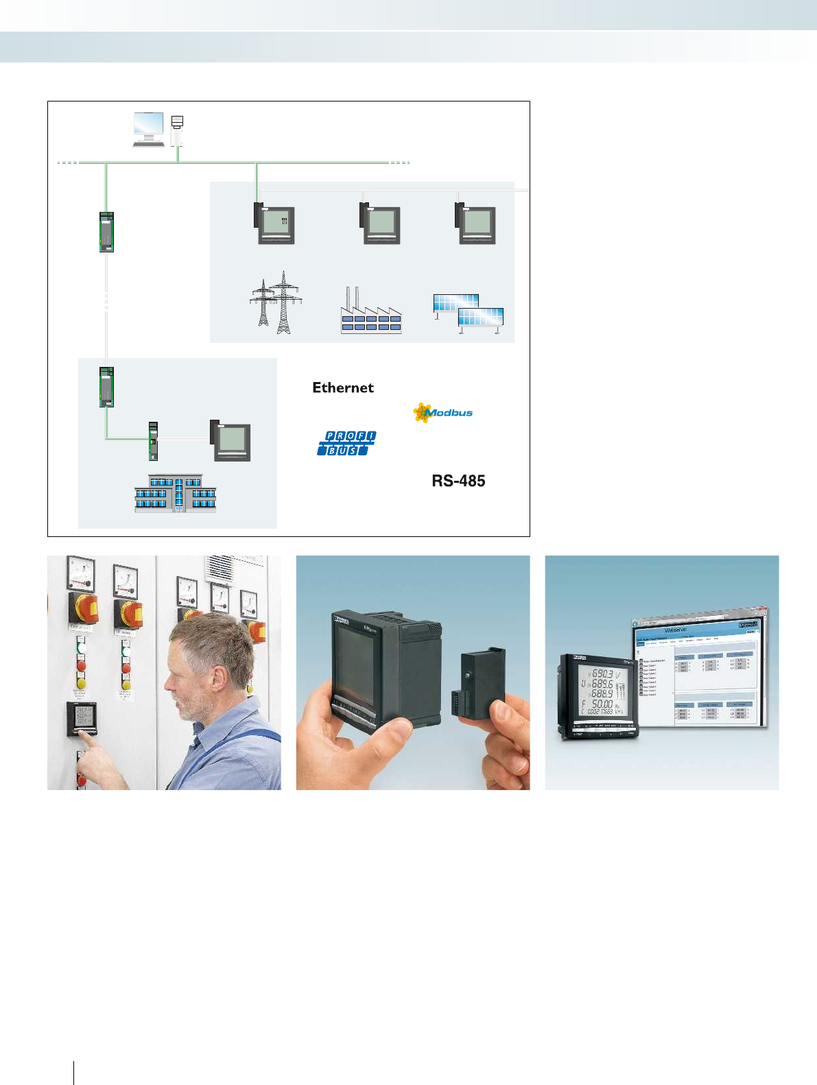
720,2 kW
350,6 kvar
801,0 kVA
EMpro
470,8 kW
101,2 kvar
481,6 kVA
EMpro
87,2 kW
1,5 kvar
87,2 kVA
EMpro
692,1 V
U 689,9
2-3
F 50,00 Hz
C 000217683 kWh
3-1690,3
50
100
50
100
50
100
EMpro
UL
FD
100
TD
RD
VCC
DIAG
PSI-MODEM-SHDSL/ETH
Ord.-No.2313 643
DSLADSL B
LINK
ETH
USB
ACT
STAT
LINKLINK
ERR
STAT
ETH
VCC
DIAG
PSI-MODEM-SHDSL/ETH
Ord.-No.2313 643
DSLADSLB
LINK
ETH
USB
ACT
STAT
LINKLINK
ERR
STAT
ETH
Ethernet
Ethernet
RS-485
RS-485
Ethernet-
Gateway
RS-485
COM-Server
SHDSL modem
Energy meter
EMpro MA400
Energy meter
EMpro MA400
Energy meter
EMpro MA600
Energy meter
EMpro MA400
SHDSL modem
DSL (up to 20 km)
Measurement – monitoring –
communication
In order to achieve efficient energy
management, all energy data that has been
determined is acquired and analyzed
centrally in the control center.
For data transmission, integrate the
EMpro measuring devices flexibly into your
network structures.
The network components from Phoenix
Contact offer interference-free and high-
performance communication of energy
data, even in harsh industrial environments:
– Copper-based and fiber optic data
transmission
– Ethernet and modem communication
– Industrial wireless transmission
Direct access to measured values
Analyze your system parameters quickly
on site. At the touch of a button, you can
access precisely those measured values that
are of relevance.
You can also use the user-friendly web
server function to request measured values
directly from the control center.
Planning reliability and investment
security
EMpro extension modules, function
modules, and communication modules
enable you to remain flexible and extend
your EMpro measuring devices at any time:
– Digital inputs and outputs
– Pulse outputs
– Analog outputs
– Communication interfaces
– Measured mass storage
– Temperature measurement
Remote access to multiple meters -
with just one IP address
The web server that has been integrated
into the Ethernet communication modules
allows you to conveniently configure key
parameters online. It also allows remote
access to key electrical characteristics such
as current, voltage, power, energy, and
harmonics.
Energy meters
234
PHOENIX CONTACT
Monitoring
Measuring power and energy
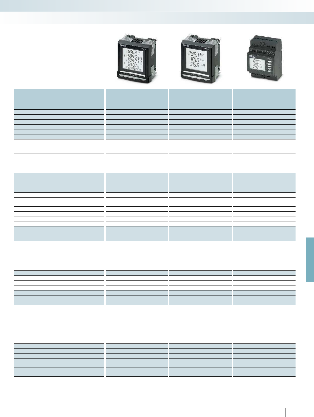
For further information and full technical data, visit phoenixcontact.net/products
Selection guide
You can easily select the right device for
your application by referring to the table
below:
Product type EMpro MA600 EMpro MA400 EMpro MA200/250
2901366 EEM-MA600 2901364 EEM-MA400 2901362 EEM-MA200
2902352 EEM-MA600-24DC 2901363 EEM-MA250
Voltages
Voltage measurement direct up to 700 V up to 519 V up to 519 V
Voltage converter up to 500 kV
Voltages U12, U23, U31, V1, V2, V3
∙∙∙
Maximum mean value
∙
Mean value
∙
Currents
Current measurement direct up to 6 A or current transformer Current transformer Current transformer
Currents I1, I2, I3
∙∙∙
Neutral conductor current IN (calculation)
∙∙∙
Maximum mean value
∙∙∙
Mean value
∙
Frequency
F
∙∙∙
Maximum mean value
∙ ∙
Mean value
∙
Power
Real power, reactive power, apparent power:
P (+/-), Q (+/-), S (+/-)
∙∙∙
P, Q, S per phase
∙∙∙
Maximum mean value
∙∙∙
Mean value
∙
Trend performances
∙
Power factor
PF
∙∙∙
PF per phase
∙∙∙
Metering
Real energy (kWh) kWh+/kWh- kWh+ kWh+
Reactive power (kvarh) kvarh+/kvarh- kvarh+ kvarh+
Apparent energy (kVAh) kVAh
Multi-tariff meter 2
Operating hours
∙∙∙
Accuracy class (EN62053-22) 0.5 S 0.5 S 0.5 S
Harmonics analysis
Distortion factor THD I/U/V up to 63rd up to 51st up to 51st
Spectral analysis up to 63rd
Functions
Temperature recording
∙
Digital input
∙
Function modules (optional)
1 pulse or alarm output 2904314 EEM-IMP-MA400 Integrated
2 pulse outputs 2904313 EEM-IMP-MA600
2 digital inputs, 2 digital outputs 2901371 EEM-2DIO-MA600
2 analog outputs 2901475 EEM-2AO-MA600
3 Pt100 inputs and 1 internal temperature measurement 2901949 EEM-TEMP-MA600
Memory 2901370 EEM-MEMO-MA600
Communication modules (optional)
RS-485 (Modbus/RTU) 2901367 EEM-RS485-MA600 2901365 EEM-RS485-MA400 integrated (MA250 only)
D-SUB (PROFIBUS) 2901418 EEM-PB12-MA600
Ethernet gateway (Modbus/TCP/RTU) with integrated web server 2901374 EEM-ETH-RS485-MA600
Ethernet (Modbus/TCP) with integrated web server 2901373 EEM-ETH-MA600
Key
I1, I2, I3 Conductor currents PReal power THD Total harmonic distortion
IN Neutral conductor current QReactive power Total values
U12, U23, U31 Phase conductor voltages SApparent power
V1, V2, V3 Phase/N conductor voltages PF Power factor
235
PHOENIX CONTACT
Monitoring
Measuring power and energy

RS485
+
°–
13 15 17
RS485
RS485
RS485
+
+
+
°
°
–
–
13
15
17
Transmit electrical characteristics
wirelessly and easily
Class 100 ILC small-
scale controller
Radioline
wireless
module
Radioline
wireless
module
EMpro MA250
energy meter
Radioline
wireless
module
EMpro RS-485
communication
modules
EMpro MA600
energy meter
EMpro MA400
energy meter
EMpro MA250
energy meter
RS-485
RS-485
EMpro MA600
energy meter
EMpro MA400
energy meter
RS-485
PC
Ethernet
EMpro MA600
energy meter
EMpro function
module (DIO)
EMpro Ethernet
communication
module
Water meter
PSK compressed
air meter
Direct connection from the
PC to the EMpro MA600
236
PHOENIX CONTACT
Monitoring
Measuring power and energy
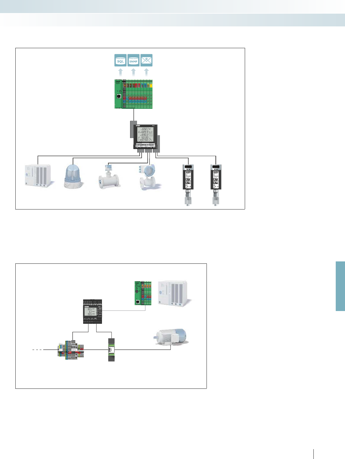
RS485
+
°–
13 15 17
RS485
RS485
RS485
RS485
+
+
+
+
°
°
–
13
15
17
COM
For further information and full technical data, visit phoenixcontact.net/products
Connect up to six external meters to
one EMpro MA600
Easy machine monitoring -
communicate electrical characteristics via Modbus/RTU
Class 100 ILC
small-scale controller
PC Worx
PLC programming
RS-485
EMpro MA600
energy meter
EMpro function
module (DIO)
EMpro RS-485
communication
module
PSK
compressed
air meter
Controller
status messages
Alarm light Gas meter Water meter
RS-485
EMpro MA250
energy meter
Controllers
Motor
PACT
current
transformer
Power
supply
237
PHOENIX CONTACT
Monitoring
Measuring power and energy
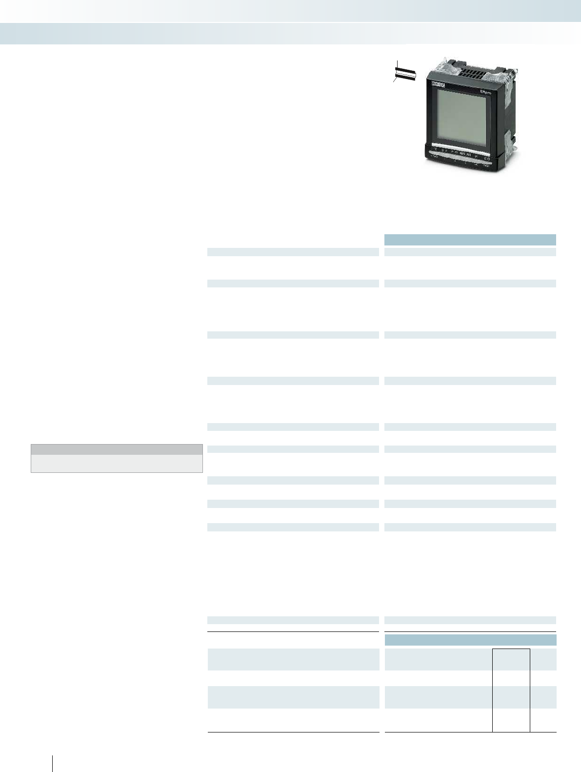
238
PHOENIX CONTACT
H
W
D
Energy meters
EMpro energy meters are capable of
acquiring, monitoring, and displaying all
electrical system and machine parameters
locally.
EEM-MA600
– Can be extended with function and
communication modules
– Remote access via web server, integrated
into Ethernet communication module
– Acquisition of individual harmonic
components up to 63rd order
– Trend calculation for real and reactive
power
EEM-MA400
– Can be extended with output module
– Can be extended with RS-485
communication module
(JBUS/MODBUS)
– Acquisition of total harmonic content up
to 51st order
EEM-MA250
– Two-tariff measurement via digital input
– Pulse or alarm output
– RS-485 interface ( JBUS/MODBUS)
EEM-MA200
– Two-tariff measurement via digital input
– Pulse or alarm output
EEM-MKT-DRA
– DIN rail adapter for the EEM-MA600 and
EEM-MA400 front panel devices see
page 243.
Notes:
The EEM-MA600-24DC energy meter (Order No. 2902352) is not
CE-compliant.
Technical data
Input data
Measuring principle True r.m.s. value measurement True r.m.s. value measurement True r.m.s. value measurement
Acquisition of harmonics up to 63rd harmonic
Measured value ACsine (50/60 Hz)
Voltage measuring input V1, V2, V3
Input voltage range 18 V AC ... 700 V AC (phase/phase)
11 V AC ... 404 V AC (phase/neutral conductor)
500 kV AC (Primary, via external voltage transducers)
Secondary: 60, 100, 110, 115, 120, 173, 190 V AC
Accuracy 0.2 %
Current measuring input I1, I2, I3
Input current range (via external transformers) 9999 A (primary)
1 A and 5 A, secondary
Overload capacity 6 A (permanent)
Operate threshold 10 mA
Accuracy 0.2 %
Power measurement
Measuring range 0 MW ... 8000 MW / 0 Mvar ... 8000 Mvar / 0 MVA ... 8000 MVA 0 MW ... 11 MW / 0 Mvar ... 11 Mvar / 0 MVA ... 11 M
Accuracy 0.5 %
Real power (IEC 62053-22) Class 0.5S
Reactive power (IEC 62053-23) Class 2
Digital input
Voltage input signal Via function module
Switching output
Output description Via function module
Maximum switching voltage -
Current carrying capacity -
Serial port
Output description Via communication module Via communication module Modbus RTU/JBUS RS-485 None
Serial transmission speed -
Display
Type LCD display, backlighting LCD display, backlighting LCD display, backlighting
Measuring rate 1 s
General data
Supply voltage
Nominal power consumption 10 VA
20 VA (with maximum number of extension modules)
Degree of protection IP52 (front), IP30 (back) IP52 (front), IP30 (back) IP51 (front), IP20 (back)
Ambient temperature range -10 °C ... 55 °C (14 °F to 131 °F) -10 °C ... 55 °C (14 °F to 131 °F) -10 °C ... 55 °C (14 °F to 131 °F)
Dimensions W / H / D 96 / 96 / 82 mm
Installation depth with extension module 80 mm
Connection cross section (solid / stranded / AWG)
Voltage and other connections 0.5 ... 2.5 mm² / 0.5 ... 2.5 mm² / 20 - 14 0.5 ... 2.5 mm² / 0.5 ... 2.5 mm² / 20 - 14 0.5 ... 2.5
Current connection 0.5 ... 6 mm² / 0.5 ... 6 mm² / 20 - 8 0.5 ... 6 mm² / 0.5 ... 6 mm² / 20 - 8 0.5 ... 4 mm² / 0.5 ... 4 mm² / 2
EMC note Class A product, see page 625 Class A product, see page 625 Class A product, see page 625
Conformance / approvals
Conformance CE-compliant
Ordering data
Description Type Order No. Pcs. /
Pkt.
Energy meter, for front-panel installation
EEM-MA600 2901366 1
Energy meter, for front-panel installation, 24 V DC
EEM-MA600-24DC 2902352 1
Energy meter, for mounting on a DIN rail
Monitoring
Measuring power and energy
Measuring voltage up to 700 V AC,
can be extended with function and
communication modules
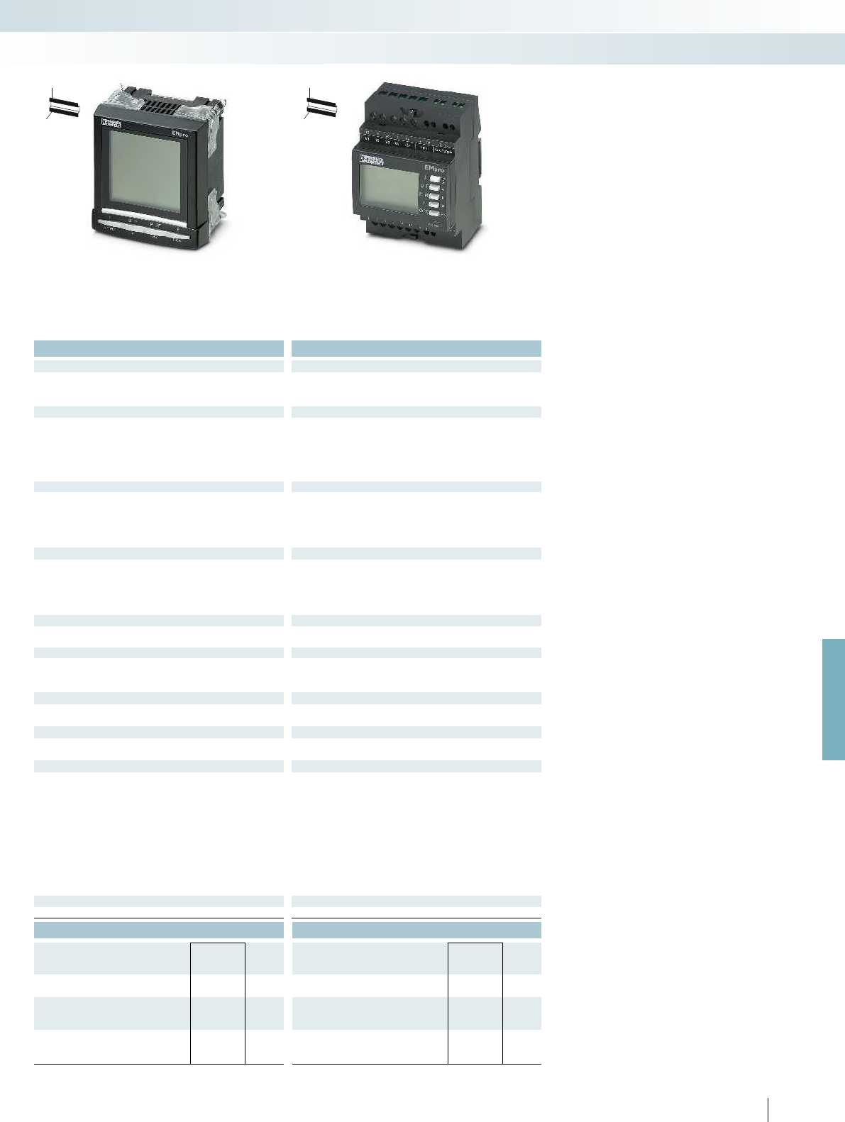
For further information and full technical data, visit phoenixcontact.net/products
239
PHOENIX CONTACT
H
W
D
H
W
D
Technical data Technical data
Measuring principle True r.m.s. value measurement True r.m.s. value measurement True r.m.s. value measurement
up to 51st harmonic up to 51st harmonic
ACsine (50/60 Hz) ACsine (50/60 Hz)
50 V AC ... 500 V AC (phase/phase)
28 V AC ... 289 V AC (phase/neutral conductor)
50 V AC ... 519 V AC (phase/phase)
28 V AC ... 300 V AC (phase/neutral conductor)
--
0.2 % 0.2 %
9999 A (primary)
5 A (secondary)
9999 A (primary)
5 A (secondary)
6 A (permanent) 6 A (permanent)
5 mA 5 mA
0.2 % 0.2 %
Measuring range 0 MW ... 8000 MW / 0 Mvar ... 8000 Mvar / 0 MVA ... 8000 MVA 0 MW ... 11 MW / 0 Mvar ... 11 Mvar / 0 MVA ... 11 MVA 0 kW ... 9999 kW / 0 kvar ... 9999 kvar / 0 kVA ... 9999 kVA
0.5 % 0.5 %
Class 0.5S Class 0.5S
Class 2 Class 2
- 230 V AC 10 % (tariff switchover: e.g., day/nighttime tariff)
Via function module Transistor output, active
- 30 V DC
- 27 mA
EEM-MA250 EEM-MA200
Output description Via communication module Via communication module Modbus RTU/JBUS RS-485 None
- 2.4 ... 38.4 kbps
Type LCD display, backlighting LCD display, backlighting LCD display, backlighting
1 s 1 s
5 VA
10 VA (with maximum number of extension modules)
5 VA
Degree of protection IP52 (front), IP30 (back) IP52 (front), IP30 (back) IP51 (front), IP20 (back)
Ambient temperature range -10 °C ... 55 °C (14 °F to 131 °F) -10 °C ... 55 °C (14 °F to 131 °F) -10 °C ... 55 °C (14 °F to 131 °F)
96 / 96 / 82 mm 72 / 90 / 64 mm
80 mm
Voltage and other connections 0.5 ... 2.5 mm² / 0.5 ... 2.5 mm² / 20 - 14 0.5 ... 2.5 mm² / 0.5 ... 2.5 mm² / 20 - 14 0.5 ... 2.5 mm² / 0.5 ... 2.5 mm² / 20 - 14
Current connection 0.5 ... 6 mm² / 0.5 ... 6 mm² / 20 - 8 0.5 ... 6 mm² / 0.5 ... 6 mm² / 20 - 8 0.5 ... 4 mm² / 0.5 ... 4 mm² / 20 - 10
EMC note Class A product, see page 625 Class A product, see page 625 Class A product, see page 625
CE-compliant CE-compliant
Ordering data Ordering data
Type Order No. Pcs. /
Pkt. Type Order No. Pcs. /
Pkt.
EEM-MA400 2901364 1
EEM-MA250 2901363 1
EEM-MA200 2901362 1
Monitoring
Measuring power and energy
Measuring voltage up to 519 V AC,
can be extended with RS-485 interface
and output module
Measuring voltage up to 519 V AC,
DIN rail installation,
also with RS-485 interface

Technical data Technical data
Digital input
Voltage input signal 10 V DC ... 30 V DC -
Input pulse length 10 ms -
Output
Output description Relay output Current output
Maximum switching voltage 250 V AC/DC -
General data
Supply voltage 9 V (via EEM-MA600) 9 V (via EEM-MA600)
Degree of protection IP20 IP20
Ambient temperature range -10 °C ... 55 °C (14 °F to 131 °F) -10 °C ... 55 °C (14 °F to 131 °F)
EMC note Class A product, see page 625 Class A product, see page 625
Conformance / approvals
Conformance CE-compliant CE-compliant
UL, USA / Canada UL 61010-1 UL 61010-1
Ordering data Ordering data
Description Type Order No. Pcs. /
Pkt. Type Order No. Pcs. /
Pkt.
Function module (for EEM-MA600)
EEM-2DIO-MA600 2901371 1EEM-2AO-MA600 2901475 1
Plug-in function modules for the
EEM-MA600 energy meter.
EEM-2DIO-MA600
– Two digital inputs and outputs
– Configurable threshold values
EEM-2AO-MA600
– Two 0 ... 20 mA/4 ... 20 mA analog
outputs, configurable
Function modules
Monitoring
Measuring power and energy
Two digital inputs, two digital outputs Two analog outputs
Technical data
Digital input
Voltage input signal 10 V DC ... 30 V DC
General data
Supply voltage 9 V (via EEM-MA600)
Memory size 512 kByte
Degree of protection IP20
Ambient temperature range -10 °C ... 55 °C (14 °F to 131 °F)
EMC note Class A product, see page 625
Conformance / approvals
Conformance CE-compliant
UL, USA / Canada UL 61010-1
Ordering data
Description Type Order No. Pcs. /
Pkt.
Function module (for EEM-MA600)
Memory module EEM-MEMO-MA600 2901370 1
240
PHOENIX CONTACT
Plug-in function module for the
EEM-MA600 energy meter.
EEM-MEMO-MA600
– Stores P (+/-) and Q (+/-) with an internal
or external synchronization pulse of
5, 8, 10, 20, 30 or 60 minutes, e.g.,
synchronization pulse of 15 minutes over
45 days
– Stores the last ten alarms with time stamp
(2DIO function module necessary)
– Stores the last smallest and largest
instantaneous values for voltages,
currents, frequency, actual power, reactive
power, entire harmonic distortion
– Stores the mean values of the cable
voltage, line to line voltage and frequency
(maximum 60 days)
– Stores undervoltage, surge voltage, and
phase failure
– Cannot be combined with PROFIBUS
communication module
Function module
Memory module
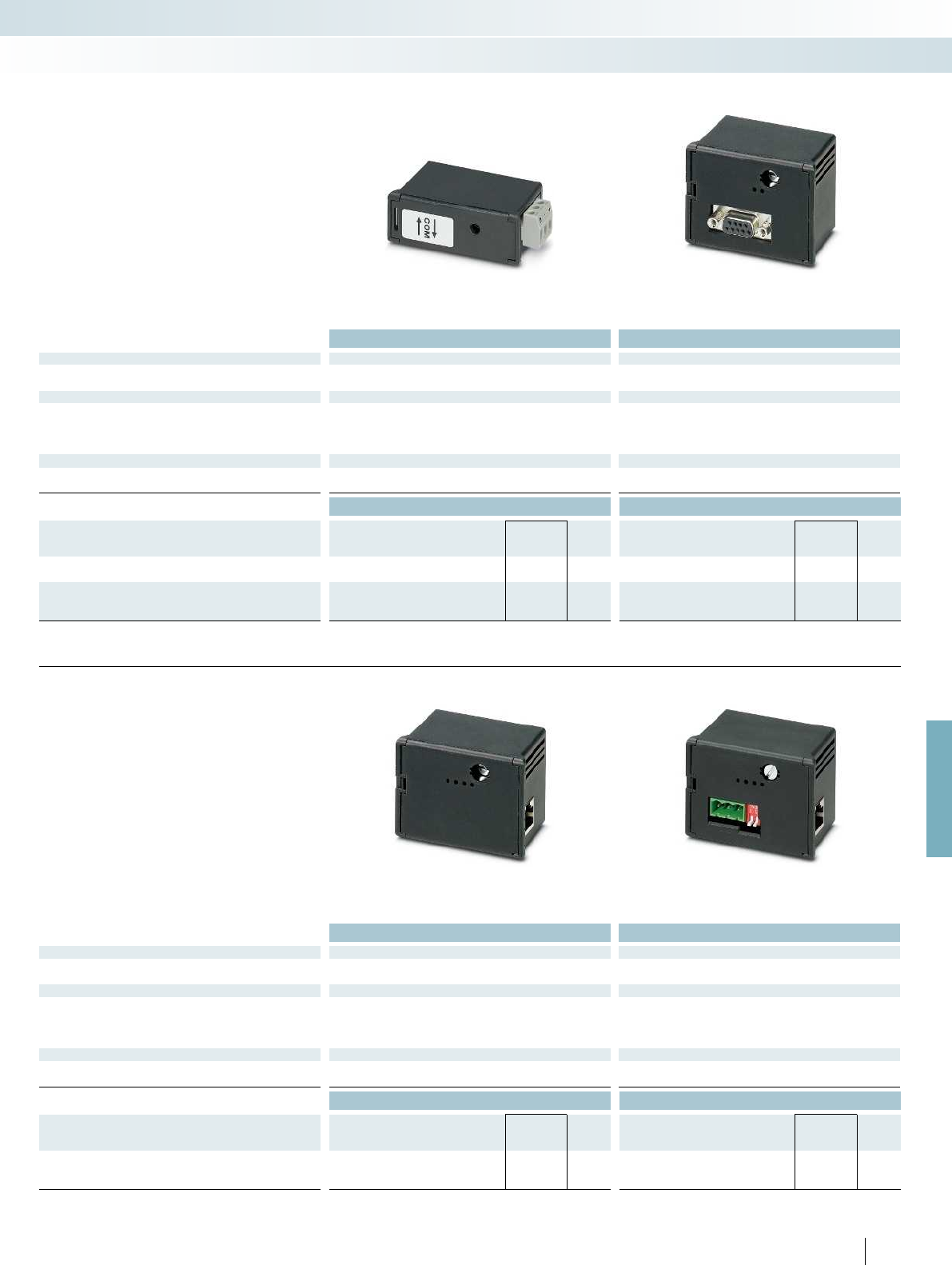
For further information and full technical data, visit phoenixcontact.net/products
Technical data Technical data
Serial port
Output description Modbus RTU/JBUS RS-485 PROFIBUS DP
Serial transmission speed 2.4 ... 38.4 kbps 12Mbps
General data
Supply voltage 9 V (Via EEM-MA600/EEM-MA400) 9 V (via EEM-MA600)
Degree of protection IP20 IP20
Ambient temperature range -10 °C ... 55 °C (14 °F to 131 °F) -10 °C ... 55 °C (14 °F to 131 °F)
EMC note Class A product, see page 625 Class A product, see page 625
Conformance / approvals
Conformance CE-compliant CE-compliant
UL, USA / Canada UL 61010-1 UL 61010-1
Ordering data Ordering data
Description Type Order No. Pcs. /
Pkt. Type Order No. Pcs. /
Pkt.
Communication module (for EEM-MA400)
RS-485 (JBUS/Modbus/RTU) EEM-RS485-MA400 2901365 1
Communication module (for EEM-MA600)
RS-485 (JBUS/Modbus/RTU) EEM-RS485-MA600 2901367 1
D-SUB (PROFIBUS DP) EEM-PB 12-MA600 2901418 1
EEM-PB 12-MA600
– PROFIBUS DP, with transmission speeds
of 12 Mbps
EEM-RS485-MA...
– JBUS/Modbus/RTU
Communication modules
Monitoring
Measuring power and energy
Modbus/RTU (RS-485) PROFIBUS
Technical data Technical data
Serial port
Output description Modbus/TCP Ethernet (RJ45) Modbus/TCP Ethernet (RJ45)
Serial transmission speed 10/100 Mbps 10/100 Mbps
General data
Supply voltage 9 V (via EEM-MA600) 9 V (via EEM-MA600)
Degree of protection IP20 IP20
Ambient temperature range -10 °C ... 55 °C (14 °F to 131 °F) -10 °C ... 55 °C (14 °F to 131 °F)
EMC note Class A product, see page 625 Class A product, see page 625
Conformance / approvals
Conformance CE-compliant CE-compliant
UL, USA / Canada UL 61010-1 UL 61010-1
Ordering data Ordering data
Description Type Order No. Pcs. /
Pkt. Type Order No. Pcs. /
Pkt.
Communication module (for EEM-MA600)
Ethernet EEM-ETH-MA600 2901373 1
Ethernet gateway EEM-ETH-RS485-MA600 2901374 1
241
PHOENIX CONTACT
EEM-ETH-MA600
– Ethernet
– Modbus/TCP
– Integrated web server
EEM-ETH-RS485-MA600
– Ethernet gateway to RS-485
– Modbus/TCP / Modbus/RTU
– Integrated web server
Communication modules
Ethernet with integrated web server Ethernet gateway with integrated web server
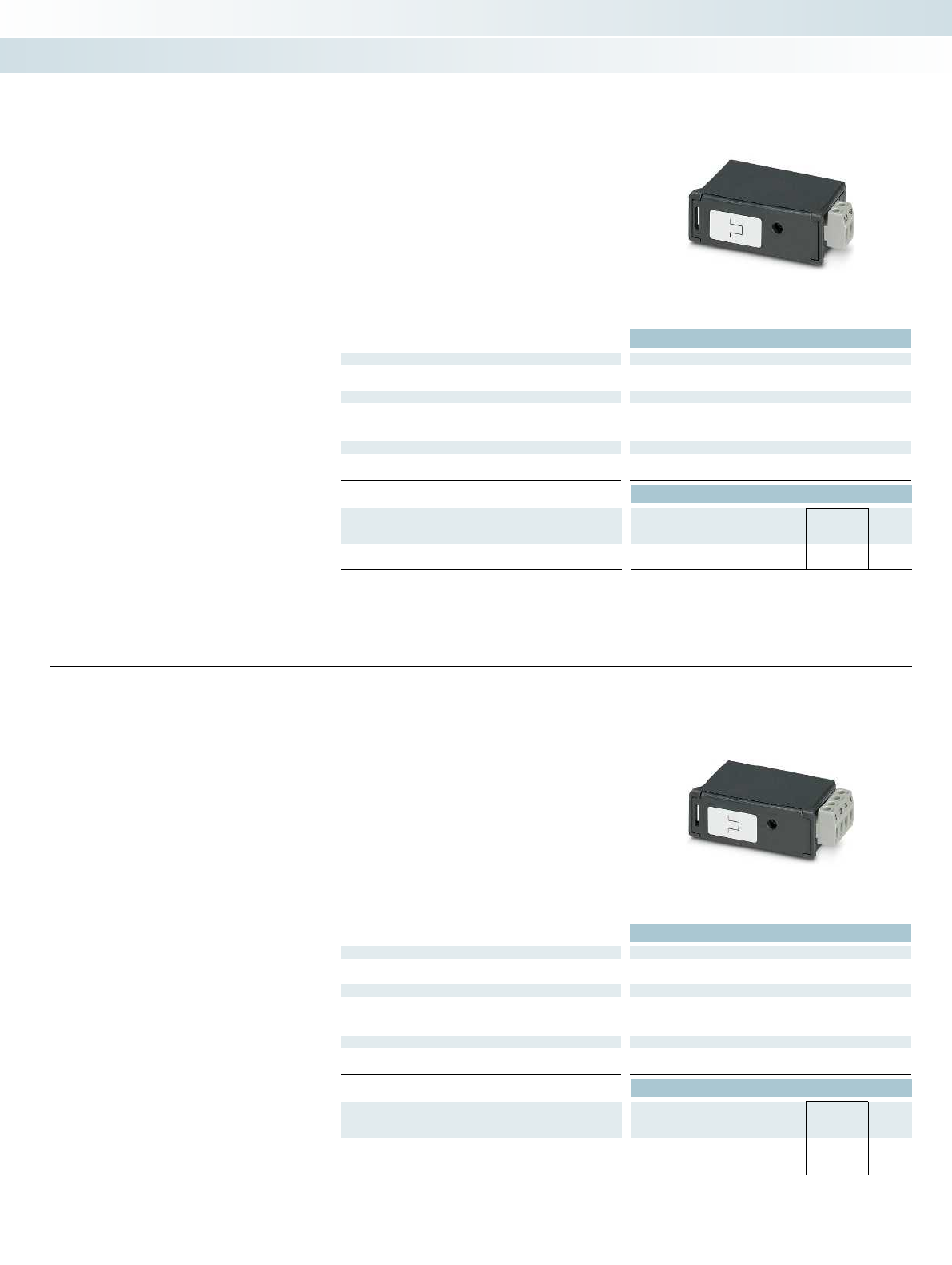
Technical data
Output
Output description Relay output
Maximum switching voltage 100 V DC
General data
Supply voltage 9 V (via EEM-MA400)
Degree of protection IP20
Ambient temperature range -10 °C ... 55 °C (14 °F to 131 °F)
Conformance / approvals
Conformance CE-compliant
UL, USA / Canada UL 61010-1
Ordering data
Description Type Order No. Pcs. /
Pkt.
Function module (for EEM-MA400)
with one pulse or alarm output EEM-IMP-MA400 2904314 1
Plug-in function module for the
EEM-MA400 energy meter.
EEM-IMP-MA400
– One configurable pulse output or one
configurable threshold value
Function modules
Monitoring
Measuring power and energy
Pulse module
Technical data
Output
Output description Relay output
Maximum switching voltage 100 V DC
General data
Supply voltage 9 V (via EEM-MA600)
Degree of protection IP20
Ambient temperature range -10 °C ... 55 °C (14 °F to 131 °F)
Conformance / approvals
Conformance CE-compliant
UL, USA / Canada UL 61010-1
Ordering data
Description Type Order No. Pcs. /
Pkt.
Function module (for EEM-MA600)
with two configurable pulse outputs EEM-IMP-MA600 2904313 1
242
PHOENIX CONTACT
Plug-in function module for the
EEM-MA600 energy meter.
EEM-IMP-MA600
– Two configurable pulse outputs
Function module
Pulse module
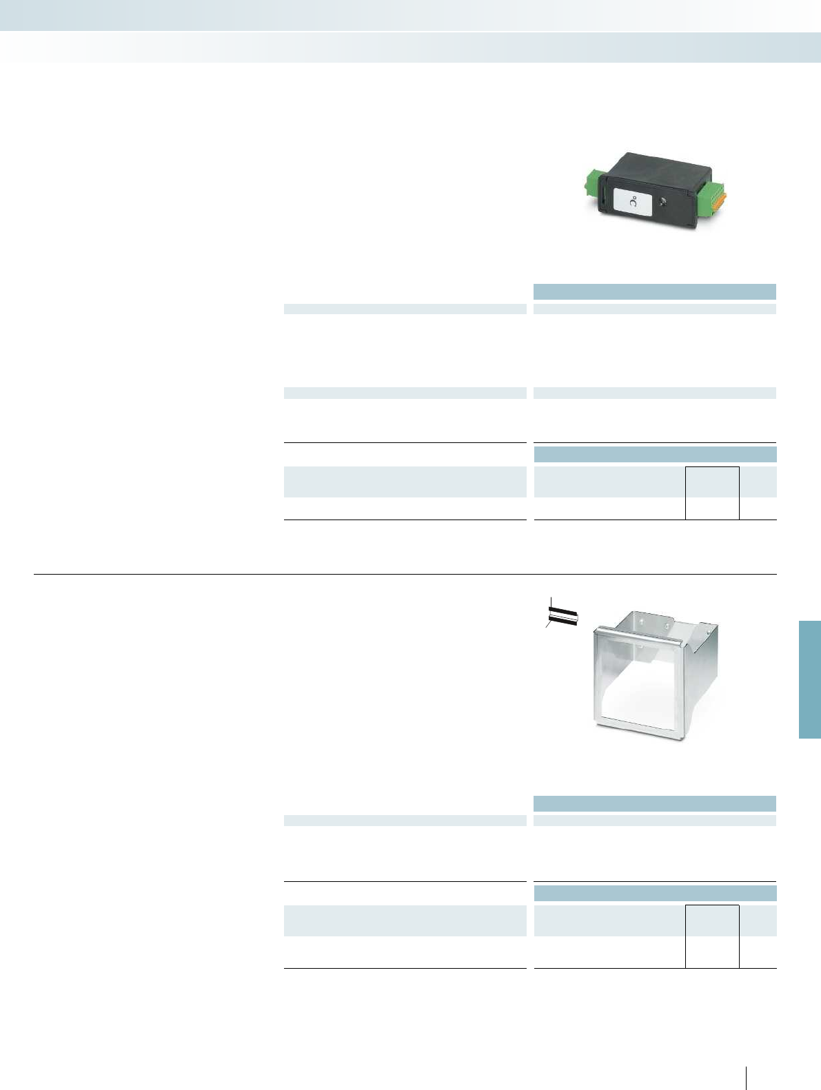
For further information and full technical data, visit phoenixcontact.net/products
Technical data
Input data
Description of the input Pt 100 input: 2, 3, 4-wire
Temperature range -20 °C ... 150 °C (connected sensors)
-10 °C ... 55 °C (in the immediate vicinity)
Transmission error 0.5 K/m (2-wire)
0.25 K/m (3-wire)
0 K/m (4-wire)
Basic accuracy ± 1 K
General data
Supply voltage 9 V (via EEM-MA600)
Degree of protection IP20
Ambient temperature range -10 °C ... 55 °C (14 °F to 131 °F)
EMC note Class A product, see page 625
Ordering data
Description Type Order No. Pcs. /
Pkt.
Function module (for EEM-MA600)
for temperature recording EEM-TEMP-MA600 2901949 1
Plug-in function module for the
EEM-MA600 energy meter.
EEM-TEMP-MA600
– Temperature recording for up to three
Pt100 temperature sensors
– Temperature measuringrange
–20°C...+150°C
– Internal temperature recording of the
ambienttemperature–10°C...+55°C
– CE-compliant
Function module
Monitoring
Measuring power and energy
Temperature module
Technical data
General data
Vibration resistance 57 Hz ... 150 Hz (2 g)
Weight 265 g
DIN rail clip material Aluminum, natural anodized
Fixing sheet material Stainless steel VA
Dimensions W / H / D 116 / 112 / 115 mm
Ordering data
Description Type Order No. Pcs. /
Pkt.
DIN rail adapter for EEM-MA600 and EEM-MA400
EEM-MKT-DRA 2902078 1
243
PHOENIX CONTACT
H
W
D
DIN rail adapter
– For mounting the EEM-MA600 or
EEM-MA400 energy meters on a 35-mm
DIN rail according to EN60715
Accessories
For mounting on DIN rails

Technical data
See phoenixcontact.net/products
Ordering data
Description Type Order No. Pcs. /
Pkt.
Program and configuration memory, plug-in, 2 GB with license
key and application program for reading from measuring devices
via pulses
SD FLASH 2GB EMWISE IMPULS 2701745 1
Program and configuration memory, plug-in, 2 GB with license
key and application program for reading from measuring devices
via pulses and analog values
SD FLASH 2GB EMWISE IMP ANALOG 2701746 1
Program and configuration memory, plug-in, 2 GB with license
key and application program for reading from measuring devices
via pulses, analog values, M-bus, Modbus RTU, and IO-Link
SD FLASH 2GB EMWISE EXTENDED 2701747 1
244
PHOENIX CONTACT
The EMwise software from
PhoenixContact is the efficient solution for
acquiring energy data regarding heat, cold,
air or electricity in conjunction with a
compact controller.
Integrate up to 24 digital inputs, 8 analog
channels, 50 EMpro energy meters,
30 M-bus counters, and 4 IO-Link
measuring sensors.
A web-based interface is available for
system parameterization. Each
device/channel can be configured
individually, without any programming
knowledge. The configuration is saved to a
file and can be reused for identical systems.
Your advantages:
– Startup without programming knowledge
– Direct parameterization of predefined
sensors
Three software versions, suitable for
every application:
– EMWISE IMPULS: for up to 16 digital
signals
– EMWISE IMP ANALOG: for up to
16 digital and 6 analog signals
– EMWISE EXTENDED: for up to 24 digital
and 8 analog signals, EMpro energy
meters, M-bus counters, M-bus level
converters, IO-Link sensors
Software for
usage data acquisition
Monitoring
Measuring power and energy
Monitoring software

For further information and full technical data, visit phoenixcontact.net/products
Technical data
Interfaces
Interfaces RS-232
RS-232/-485
Serial
Ethernet
Digital inputs/outputs
Number of inputs 4
Number of outputs 2 (relay output)
Analog inputs
Number of inputs 2
IEC-61131 runtime system
Program memory 832 kByte
Retentive mass storage 1 Mbyte
Realtime clock Yes (battery-backed)
Power supply
Supply voltage 24 V DC
Typical current consumption 5 mA
General data
Weight 475 g
Width 210 mm
Height 110 mm
Depth 45 mm
Degree of protection IP20
Ambient temperature (operation) -20 °C ... 65 °C
Ordering data
Description Type Order No. Pcs. /
Pkt.
Multifunctional data logger
PSK RTU 50 2400018 1
245PHOENIX CONTACT
The PSK RTU 50 is a multifunctional RTU
(Remote Telemetry Unit), which combines
the functions of a data logger, gateway, and
alarm manager. The PSK RTU 50 offers
various communication options, was
developed with low power technology and
allows independent operation, e.g., with
batteries or solar cells.
Your advantages:
– GSM/GPRS modem
– Ethernet interface
– IEC 60870-5-101
– IEC 60870-5-104
– Modbus/RTU
Complete packages for data logging
Monitoring
Measuring power and energy
new
Multifunctional data logger
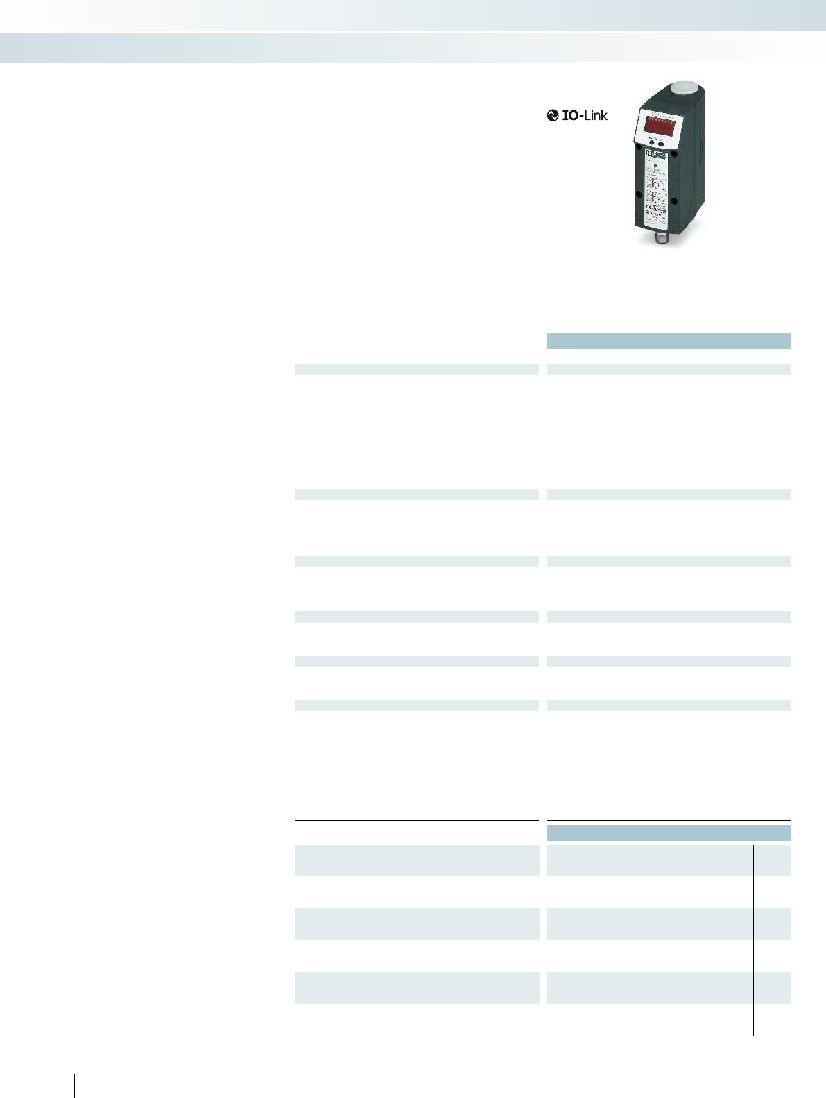
246
PHOENIX CONTACT
Compressed air meters
Compressed air meters
Use meters from Phoenix Contact to
monitor the use of compressed air, an
expensive production resource. By using
compressed air efficiently, you can decrease
compressor usage and therefore reduce
energy costs. The calorimetric measuring
procedure records even the smallest
consumption rates. You can therefore
detect wear or leaks based on the amount
of air consumed.
Use compressed air meters to acquire
the following values:
– The current volumetric flow according to
ISO2533 and DIN1343
– The total volume used
– The temperature of the compressed air in
the monitored operating processes
The compressed air meters impress
thanks to their:
– Detailed reference measurement with
flow rate, total volume, and temperature
display
– Intelligent sensor communication, thanks
to IO-Link technology
– A measuring range from 0.06Nm/h to
700.0Nm/h
– Flexible use, thanks to IP65 protection:
resistant to dust and splash water
Technical data
PSK AFS6050IOL PSK AFS6000IOL
Flow monitoring
Measuring range 0.20 Nm³/h ... 75 Nm³/h 0.04 Nm³/h ... 15 Nm³/h 0.70 Nm³/h ... 225 Nm³/h 2.30 Nm³/h ... 700 Nm³/h
Display range 0.00 Nm³/h ... 90 Nm³/h 0.00 Nm³/h ... 18 Nm³/h 0.00 Nm³/h ... 270 Nm³/h 0.00 Nm³/h ... 840 Nm³/h
Repeatability ±1.5% of the measured value ±1.5% of the measured value ±1.5% of the measured value ±1.5% of the measured value
Response time < 0.1 s ((dAP = 0)) < 0.1 s ((dAP = 0)) < 0.1 s ((dAP = 0)) < 0.1 s ((dAP = 0))
Measured value error ±15 % of the measured value
+1.5 % of the measuring range
final value
Depending on the air quality:
±3% of the measured value +
0.3% of the measuring range
final value; ±6% of the measured
value + 0.6% of the measuring
range final value
Temperature monitoring
Measuring range 0 °C ... 60 °C 0 °C ... 60 °C 0 °C ... 60 °C 0 °C ... 60 °C
Display range -12 °C ... 72 °C -12 °C ... 72 °C -12 °C ... 72 °C -12 °C ... 72 °C
Response time 30 s (Q > 0.1 Nm
3
/h) 30 s (Q > 0.1 Nm
Resolution 0.5 °C 0.5 °C 0.5 °C 0.5 °C
Accuracy ± 2.5 °C (Q > 0.1 Nm
3
/h) ± 2.5 °C (Q > 0.1 Nm
Supply for module electronics
Connection method M12 connector M12 connector M12 connector M12 connector
No. of pos. 4444
Supply voltage range 19 V DC ... 30 V DC 19 V DC ... 30 V DC 19 V DC ... 30 V DC 19 V DC ... 30 V DC
Current draw < 100 mA < 100 mA < 100 mA < 100 mA
Digital outputs
Pulse value 0.0010 m³ ... 1000000 m³ 0.0010 m³ ... 1000000 m³ 0.0030 m³ ... 3000000 m³ 0.0100 m³ ... 4000000 m³
Pulse length min. 0.04 s min. 0.2 s min. 0.02 s min. 0.043 s
Delay time 0.5 s (operational readiness) 0.5 s (operational readiness) 1 s (operational readiness) 0.5 s (operational readiness)
Analog outputs
Type of protection Short-circuit protection, polarity reversal protection Short-circuit protection, polarity reversal protection S
Current output signal 4 mA ... 20 mA 4 mA ... 20 mA 4 mA ... 20 mA 4 mA ... 20 mA
Load/output load current output 500
General data
Weight 581 g 961 g 887 g 2.053 kg 4.332 kg
Width 45 mm 45 mm 45 mm 133 mm
Height 111 mm 300 mm 193.3 mm 475 mm 475 mm
Depth 79.5 mm 76.8 mm 74.5 mm 88.5 mm -
Degree of protection IP65 IP65 IP65 IP65
Protection class III III III III
Ambient temperature (operation) 0 °C ... 60 °C 0 °C ... 60 °C 0 °C ... 60 °C 0 °C ... 60 °C
Ambient temperature (storage/transport) -20 °C ... 85 °C -20 °C ... 85 °C -20 °C ... 85 °C -20 °C ... 85 °C
Vibration resistance in acc. with EN60068-2-6/IEC60068-2-6 5g (55 ... 2000 Hz) 5g (55 ... 2000 Hz) 5g (55 ... 2000 Hz) 5g (55 ... 2000 Hz)
Ordering data
Description Type Order No. Pcs. /
Pkt.
Compressed air meter: G1/2 process connection, measuring
range up to 75 Nm
3
/h
PSK AFS6050IOL 2700704 1
Compressed air meter: G1/2 process connection, measuring
range up to 75 Nm
3
/h
PSK AFS6000IOL 2700707 1
Compressed air meter: R1/4 process connection, measuring
range up to 15 Nm
3
/h
Compressed air meter: R1 process connection, measuring range
up to 225 Nm
3
/h
Compressed air meter: R2 process connection, measuring range
up to 700 Nm
3
/h
Monitoring
Measuring power and energy
Compressed air meter up to 75 Nm
3
/h Compressed air meter up to 15 Nm
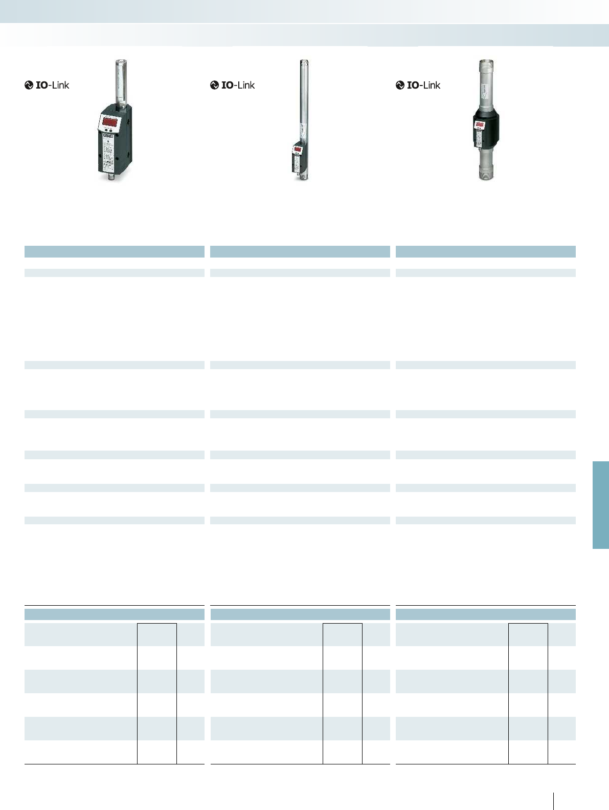
For further information and full technical data, visit phoenixcontact.net/products
247
PHOENIX CONTACT
Technical data Technical data Technical data
0.20 Nm³/h ... 75 Nm³/h 0.04 Nm³/h ... 15 Nm³/h 0.70 Nm³/h ... 225 Nm³/h 2.30 Nm³/h ... 700 Nm³/h
0.00 Nm³/h ... 90 Nm³/h 0.00 Nm³/h ... 18 Nm³/h 0.00 Nm³/h ... 270 Nm³/h 0.00 Nm³/h ... 840 Nm³/h
±1.5% of the measured value ±1.5% of the measured value ±1.5% of the measured value ±1.5% of the measured value
< 0.1 s ((dAP = 0)) < 0.1 s ((dAP = 0)) < 0.1 s ((dAP = 0)) < 0.1 s ((dAP = 0))
Depending on the air quality: ±3% of the measured value + 0.3% of
the measuring range final value; ±6% of the measured value + 0.6%
of the measuring range final value
Depending on the air quality: ±3% of the measured value + 0.3% of
the measuring range final value; ±6% of the measured value + 0.6%
of the measuring range final value
Depending on the air quality: ±3% of the measured value + 0.3% of
the measuring range final value; ±6% of the measured value + 0.6%
of the measuring range final value
0 °C ... 60 °C 0 °C ... 60 °C 0 °C ... 60 °C 0 °C ... 60 °C
-12 °C ... 72 °C -12 °C ... 72 °C -12 °C ... 72 °C -12 °C ... 72 °C
/h) 30 s (Q > 0.1 Nm
3
/h) 30 s (Q > 0.1 Nm
3
/h) 30 s (Q > 0.1 Nm
3
/h)
0.5 °C 0.5 °C 0.5 °C 0.5 °C
/h) ± 2.5 °C (Q > 0.1 Nm
3
/h) ± 2.5 °C (Q > 0.1 Nm
3
/h) ± 2.5 °C (Q > 0.1 Nm
3
/h)
M12 connector M12 connector M12 connector M12 connector
4444
19 V DC ... 30 V DC 19 V DC ... 30 V DC 19 V DC ... 30 V DC 19 V DC ... 30 V DC
< 100 mA < 100 mA < 100 mA < 100 mA
0.0010 m³ ... 1000000 m³ 0.0010 m³ ... 1000000 m³ 0.0030 m³ ... 3000000 m³ 0.0100 m³ ... 4000000 m³
min. 0.04 s min. 0.2 s min. 0.02 s min. 0.043 s
0.5 s (operational readiness) 0.5 s (operational readiness) 1 s (operational readiness) 0.5 s (operational readiness)
Type of protection Short-circuit protection, polarity reversal protection Short-circuit protection, polarity reversal protection Short-circuit protection, polarity reversal protection Short-circuit protection, polarity reversal protection
4 mA ... 20 mA 4 mA ... 20 mA 4 mA ... 20 mA 4 mA ... 20 mA
500 500 500
581 g 961 g 887 g 2.053 kg 4.332 kg
45 mm 45 mm 45 mm 133 mm
111 mm 300 mm 193.3 mm 475 mm 475 mm
79.5 mm 76.8 mm 74.5 mm 88.5 mm -
IP65 IP65 IP65 IP65
III III III III
Ambient temperature (operation) 0 °C ... 60 °C 0 °C ... 60 °C 0 °C ... 60 °C 0 °C ... 60 °C
Ambient temperature (storage/transport) -20 °C ... 85 °C -20 °C ... 85 °C -20 °C ... 85 °C -20 °C ... 85 °C
60068-2-6 5g (55 ... 2000 Hz) 5g (55 ... 2000 Hz) 5g (55 ... 2000 Hz) 5g (55 ... 2000 Hz)
Ordering data Ordering data Ordering data
Type Order No. Pcs. /
Pkt. Type Order No. Pcs. /
Pkt. Type Order No. Pcs. /
Pkt.
PSK AFS5000IOL 2700705 1
PSK AFS8000IOL 2700708 1
PSK AFS2000IOL 2700709 1
Monitoring
Measuring power and energy
/h Compressed air meter up to 15 Nm
3
/h Compressed air meter up to 225 Nm
3
/h Compressed air meter up to 700 Nm
3
/h
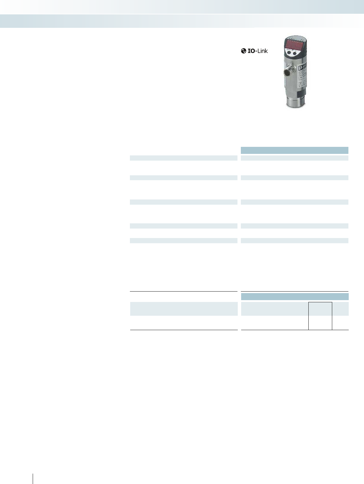
248
PHOENIX CONTACT
Pressure sensor
Pressure sensor with IO-Link
Pressure sensors from Phoenix Contact
detect the operating pressure of gas media
in a range from -1 to 10 bar. The overload-
proof ceramic measuring cell is designed for
in excess of 100 million cycles and enables a
high switching point accuracy. The pressure
switch offers the option of using the set
switching points via two switching outputs
or reading all process data via the IO-Link
interface.
Your advantages:
– IO-Link communication
– Parameterization, diagnostics, and
process value monitoring via IO-Link
– Programmable function
– 4-character alphanumeric display
Technical data
Pressure monitoring
Measuring range -1 bar ... 10 bar (minimum burst pressure 150 bar)
Pressure resistance 75 bar
Process connection G1/4 I
Supply for module electronics
Connection method M12 connector
No. of pos. 4
Supply voltage range 18 V DC ... 36 V DC
Current draw < 35 mA
Digital outputs
Number of outputs 2 (OUT1 = switching output, OUT2 = switching output or diagnostic
output)
Connection method M12 connectors, assigned four times
Delay time 0.3 s (operational readiness)
IO-Link
Specification V1.1
Transmission speed 38.4 kbaud
General data
Weight 263 g
Width 34 mm
Height 91.5 mm
Depth 48 mm
Degree of protection IP65
Protection class III
Ambient temperature (operation) -25 °C ... 80 °C
Ambient temperature (storage/transport) -40 °C ... 100 °C
Vibration resistance in acc. with EN60068-2-6/IEC60068-2-6 20g(10Hz...2000Hz)
Ordering data
Description Type Order No. Pcs. /
Pkt.
Pressure sensor with indicator,
G1/4I process connection, IO-Link communication
PSK APS7004IOL 2700710 1
Monitoring
Measuring power and energy
Pressure sensor up to 10 bar

For further information and full technical data, visit phoenixcontact.net/products
249PHOENIX CONTACT
Monitoring
Measuring power and energy
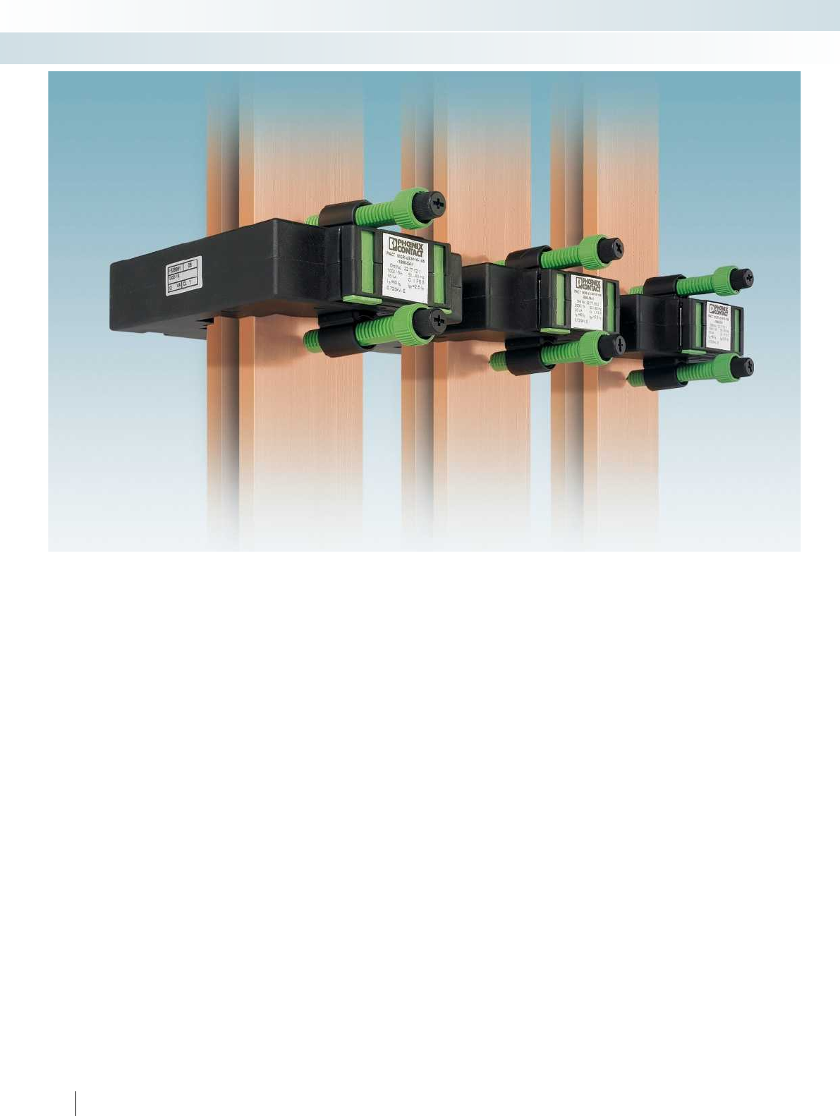
250
PHOENIX CONTACT
Monitoring
Current measurement
Extremely versatile
PACT current transformers offer a
complete product range for converting
alternating currents up to 4000 A into
secondary currents of 1 A and 5 A.
Depending on requirements, bus-bar, plug-
in, and winding current transformers are
available. PACT current transformers are
available in different transformation ratios,
accuracy classes, and rated powers - in
3000 versions, for your current
measurement requirements.
Also available for higher accuracy
classes
For standard applications, such as in
machine building or systems manufacturing,
PhoenixContact offers current
transformers with accuracy classes 0.5 and 1
in a version that cannot be calibrated.
For higher accuracy or for billing purposes
in energy supply, type-tested transformers
that can be calibrated as well as calibrated
transformers are available - with classes
0.2/0.2S/0.5 and 0.5S.
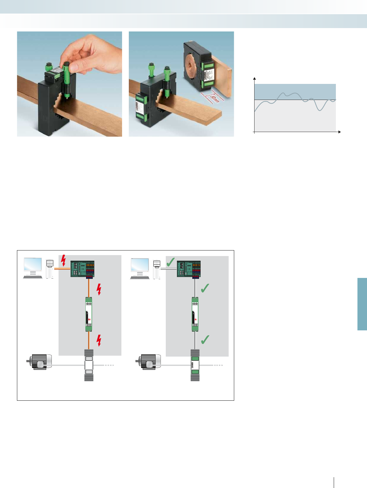
MACXMCR-SL-CAC-S-I
PWR
ERR
1
2
ON OFF
1.11.11.11.11.1
OUTGNDGNDGND
0,5nc D0,5
MACXMCR-SL-CAC-S-I
PWR
ERR
1
2
ON OFF
1.11.11.11.11.1
OUTGNDGNDGND
0,5nc D0,5
PACTMCR V2
12020-159
RUN
FAIL
RUN/PROG
MRESET
STP
RDY/ RUN
BSA
FAIL
PF
PRG
LNK
ACT
100
10/100
RESET
INLINECONTROL
ILC370 ETH 2TX-IB
Ord.No.: 2876999
PLC
IL
ETH
LNK
ACT
100
RC
BA
RD
TR
RBIN RB OUT
IB
RUN
FAIL
RUN/PROG
MRESET
STP
RDY/ RUN
BSA
FAIL
PF
PRG
LNK
ACT
100
10/100
RESET
INLINECONTROL
ILC370 ETH 2TX-IB
Ord.No.: 2876999
PLC
IL
ETH
LNK
ACT
100
RC
BA
RD
TR
RBIN RB OUT
IB
120 %
100 %
t
IPN
For further information and full technical data, visit phoenixcontact.net/products
251PHOENIX CONTACT
Fast and secure installation
The current transformer quick-action
mechanism offers the following advantages:
– Tool-free mounting
– Considerable reduction in installation
time
– Easy handling and secure fastening by
pressing with finger
– Current transformers align themselves –
no need for subsequent alignment
Variable and space-saving mounting
In addition to the vertical and horizontal
mounting position, the optional accessories
offer further installation options such as
mounting on the DIN rail or on the control
cabinet panel.
All PACT current transformers are just
30 mm wide. This saves space – for example
flat mounting when measuring branch
outlets.
Safe detection of current peaks
PACT current transformers can be used
to safely detect current peaks greater than
the rated nominal current strength –
without resulting in any damage: the
transformers are designed for a continuous
thermal nominal current that is 120% of the
primary rated current strength.
Example: a PACT transformer with a
specified rated power of 10 VA does indeed
deliver 14.4 VA on a continual basis.
PLC PLC
Current
transducer
Current
transducer
Current transformer
According to EN 60044-1
PACT current transformer
Safe isolation
PACT current transformers are
manufactured in accordance with
EN 50178. This is relevant for electronic
equipment for use in power installations.
EN 50178 differs considerably from
EN 60044, the usual standard for
transformers, with regard to safety.
Your advantages:
– PACT current transformers offer safe
isolation, thanks to greater clearance
and creepage distances.
– PACT current transformers ensure that
there is no sparkover on the secondary
side of the transformer and human life is
protected inside and outside the control
cabinet.
– Up to 1000 V (L-N) operating voltage
possible
– Routine testing with 12 kV (1.2/50 s)
– Surge voltage category 3 is met
Monitoring
Current measurement
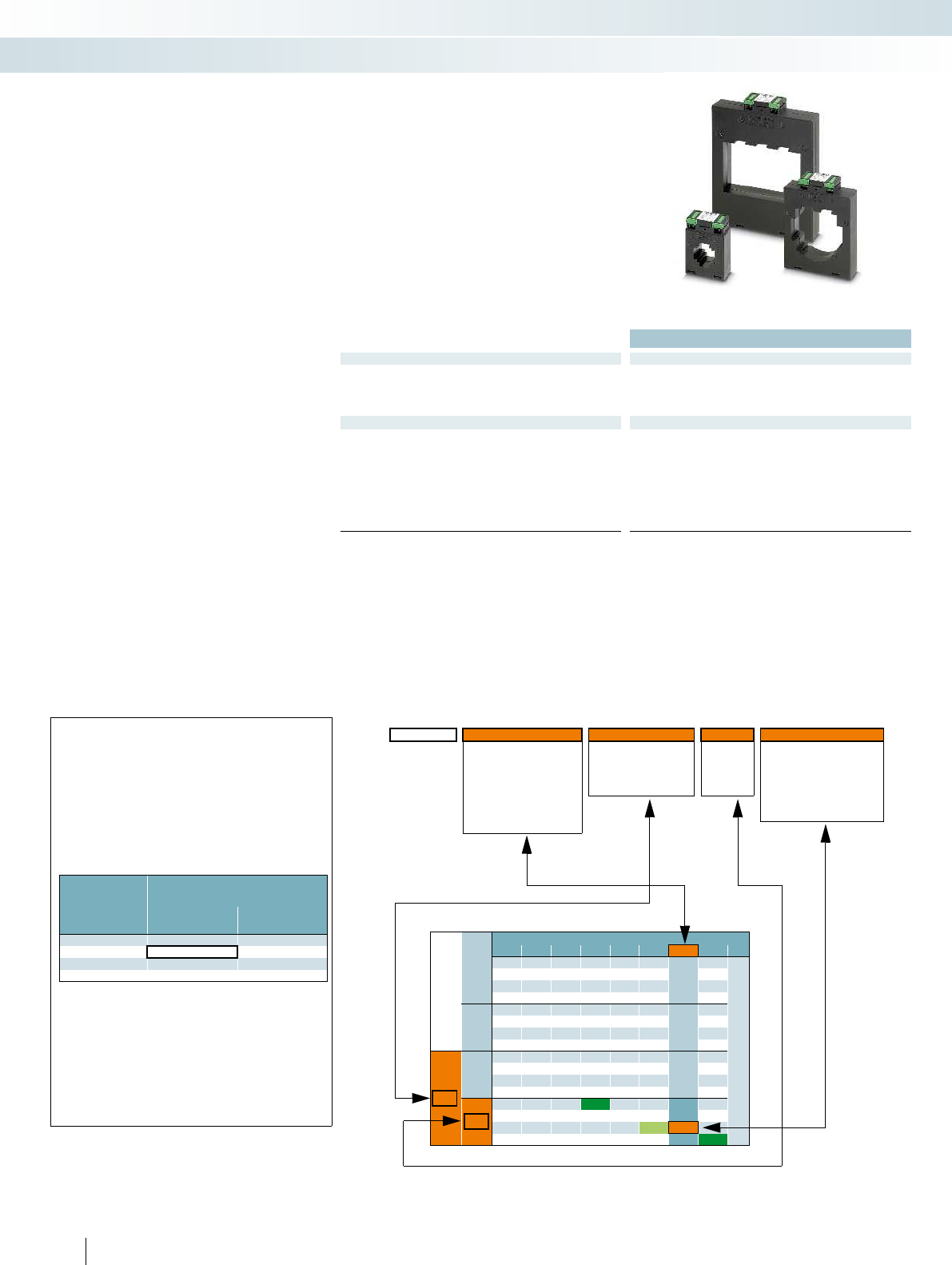
Technical data
Input data
Thermal rated short-time current I
th
= 60 * I
n
Rated surge current I
dyn
= 2.5 * I
th
Rated frequency 50 Hz ... 60 Hz
Surge current limitation factor FS 5
General data
Rated insulation voltage 1 kV
Test voltage 3 kV (50 Hz, 1 min.)
Impulse withstand voltage 12 kV (1.2 /50 s)
Insulating material class E
Connection capacity of secondary terminals 2 x (2.5 x 4) mm
Ambient temperature (operation) -25 °C ... 40 °C
Standards/regulations IEC 60044-1, EN 50178
Housing material Polyamide PA fiberglass reinforced
– Complete range consisting of winding,
bus-bar, and window-type current
transformers
– Popular types available from stock;
alternatively, order key can be used for
custom dimensioning
– Versions available to support official
calibration
Selection
– Select your transformer in accordance
with the dimensions of the copper rail
– Specify the four electrical characteristics
of the transformer:
1.The primary rated current
strength I
pn
- the maximum amperage
occurring in the path to be measured
2.The secondary rated current I
sn
-
supplied to the downstream measuring
devices
3. Class - accuracy for adherence to the
specified tolerances
4. Rated power S
n
[VA] - takes
account of all the loads occurring in the
measuring circuit
Current transformer selection guide
Monitoring
Current measurement
Calculation guide
Order key - example for PACT MCR-V2-3015-60
Preferred types that can be ordered directly are marked in green in the selection table.
Order No. Primary current I
pn
Secondary current I
sn
Class Rated power S
n
2277271 /IP02000 / IS05 / C10 / P750
IP00600 =60 A P125 =1.25 VA
IP00750 =75 A IS01 =1 A C02 =0.2 P250 =2.5 VA
IP00800 =80 A IS05 =5 A C05 =0.5 P375 =3.75 VA
IP01000 =100 A C10 =1P500 =5.0 VA
IP01250 =125 A P750 =7.5 VA
IP02000 =200 A P1000 =10 VA
IP02500 =250 A
Selection table (extract)
I
sn
Cl. Primary rated current strength I
pn
[A]
60 75 80 100 125 150 200 250
1A
0.5
1.25 2.5 2.5 2.5 2.5
Rated power S
n
[VA]
3.75 5
1
1.25 2.5 2.5 2.5 2.5 2.5 2.5 2.5
3.75 5 55
7.5
5A
0.5
2.5 2.5
3.75 5
1
1.25 1.25 1.25 2.5 2.5 2.5 2.5 2.5
1.5 2 3.75 3.75 55
57.5 7.5
10
1. 2. 3. 4.
Determination of the secondary side rated power S
n
All the occurring loads must be added:
– Calculate the power requirement of the copper cable (forward and
return line)
– Take into account the power requirement of the connected devices
(measuring devices)
– Add a reserve requirement
S
n
total = S
n
copper cable + S
n
measuring device + S
n
reserve
Power requirement of copper cables with a different
diameter
Conductor cross
section in mm
2
Rated power in VA/m
(consider the forward and return line)
Secondary current I
sn
5 A
Secondary current I
sn
1 A
1.5 0.2917 0.0117
2.5 0.1750 0.0070
4 0.1094 0.0044
6 0.0729 0.0029
Example:
S
n
copper cable = cable length x 2 x rated power
S
n
copper cable = 10 m x 2 x 0.1750 VA/m = 3.50 VA
S
n
measuring device = 2 VA
S
n
reserve < 0.5 x (S
n
copper cable + S
n
measuring device)
S
n
reserve = 2 VA
S
n
total = S
n
copper cable + S
n
measuring device + S
n
reserve
S
n
total = 3.5 VA + 2 VA + 2 VA = 7.5 VA
Determination of the secondary side rated power S
n
All the occurring loads must be added:
– Calculate the power requirement of the copper cable (forward and
return line)
– Take into account the power requirement of the connected devices
(measuring devices)
– Add a reserve requirement
S
n
total = S
n
copper cable + S
n
measuring device + S
n
reserve
252
PHOENIX CONTACT
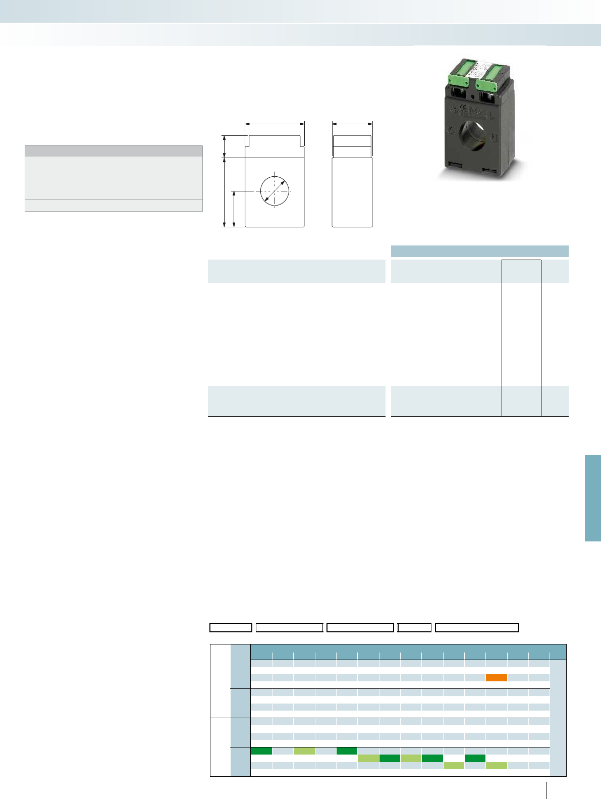
21
16
26
50
44 30
For further information and full technical data, visit phoenixcontact.net/products
Ordering data
Description
Rated power S
n
Type Order No. Pcs. /
Pkt.
Preferred versions available from stock
(marked in green in the selection table)
Primary rated current I
pn
:
- 50 A 1.25 VA PACT MCR-V1-21-44- 50-5A-1 2277019 1
- 75 A 2.5 VA PACT MCR-V1-21-44- 75-5A-1 2277611 1
- 100 A 2.5 VA PACT MCR-V1-21-44-100-5A-1 2277022 1
- 125 A 3.75 VA PACT MCR-V1-21-44-125-5A-1 2277763 1
- 150 A 5 VA PACT MCR-V1-21-44-150-5A-1 2277035 1
- 200 A 5 VA PACT MCR-V1-21-44-200-5A-1 2277776 1
- 250 A 5 VA PACT MCR-V1-21-44-250-5A-1 2277048 1
- 300 A 10 VA PACT MCR-V1-21-44-300-5A-1 2277789 1
- 400 A 5 VA PACT MCR-V1-21-44-400-5A-1 2277051 1
- 500 A 10 VA PACT MCR-V1-21-44-500-5A-1 2277792 1
Current transformer, observe the order key below to determine
the desired current transformer type
PACT MCR-V1-21-44 2277268 1
253
PHOENIX CONTACT
PACT MCR-V1-21-44
– Primary rated current I
pn
:
0...(50...500) A
– Circular conductor dimensions: Ø 21 mm
Notes:
Our configurator, which is available at
phoenixcontact.net/products, makes ordering easy.
Current transformers that support official calibration: to specify the
type of current transformer you require, please use the order key
on page 264
The relevant installation accessories can be found on page 263
Current transformers
Add order key from the selection table (ordering example marked in orange)
Order No. Primary current I
pn
Secondary current I
sn
Class Rated power S
n
2277268 / IP05000 / IS01 / C05 / P1000
Selection table PACT MCR-V1-21-44 (Order No.: 2277268)
I
sn
Cl. Primary rated current amperage I
pn
[A]
50 60 75 80 100 125 150 200 250 300 400 500
IS01
=1 A
C05
= 0.5
1.25 2.5 2.5 2.5 2.5 2.5 2.5 2.5
Rated power S
n
[VA]
3.7555555
7.5 7.5 10
C10
= 1
1.25 1.25 2.5 2.5 2.5 2.5 2.5 2.5 2.5 2.5 2.5 2.5
3.75555555
7.5 7.5 10
IS05
= 5 A
C05
= 0.5
1.25 1.25 1.25 2.5 2.5 2.5 2.5 2.5
1.5 2.0 2.5 3.75 5 5 5 5
7.5 10 7.5 7.5
C10
= 1
1.25 1.25 2.5 2.5 2.5 2.5 2.5 2.5 2.5 2.5 2.5 2.5
1.5 3.75 555555
7.5 7.5 10 7.5 10
Monitoring
Current measurement
Bus-bar curr. transf.,
official calibration as an option
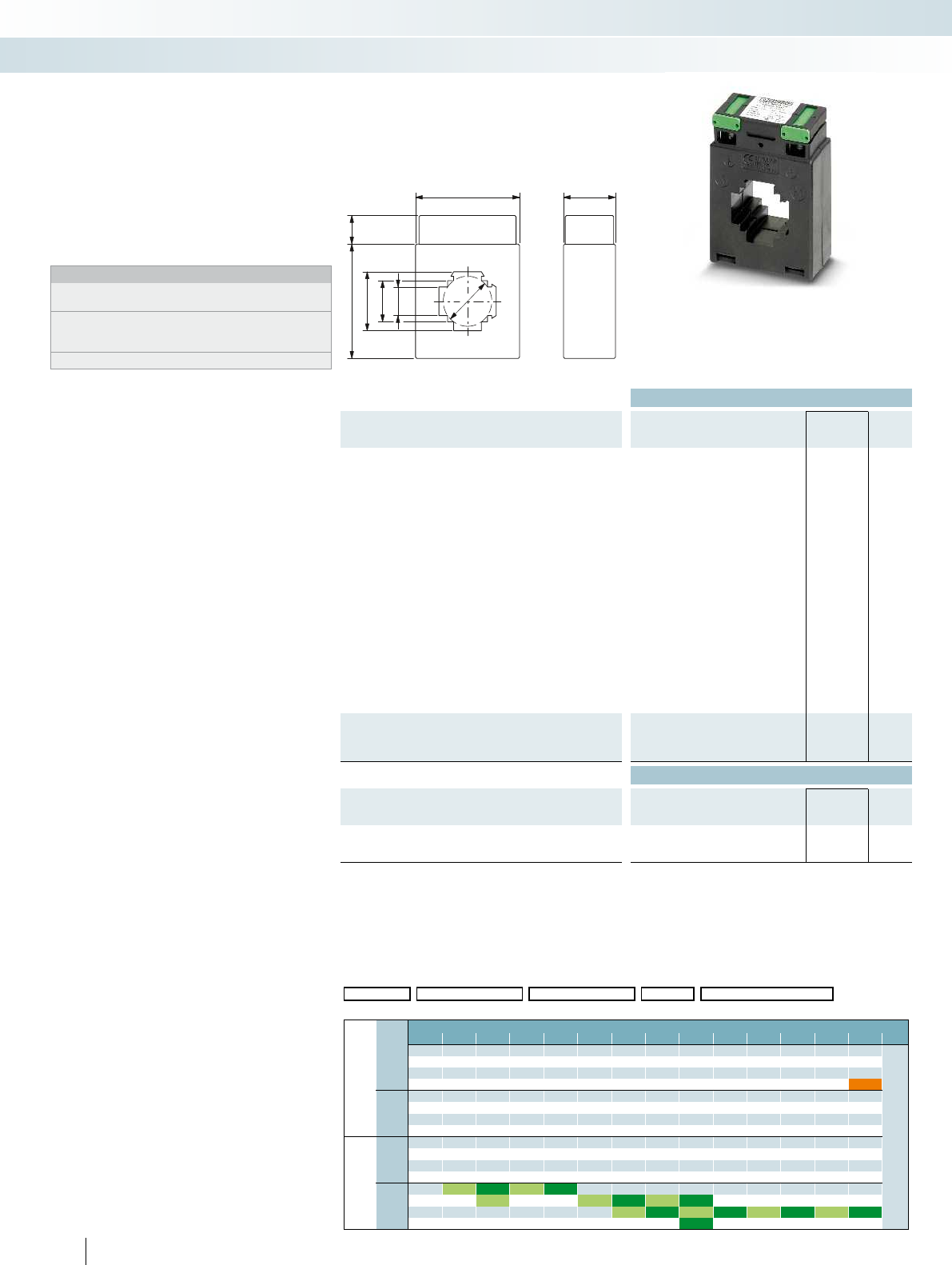
30
28
60
1664
33x16
23x23
16x33
Ordering data
Description
Rated power S
n
Type Order No. Pcs. /
Pkt.
Preferred versions available from stock
(marked in green in the selection table)
Primary rated current I
pn
:
- 60 A 1.25 VA PACT MCR-V2-3015- 60- 60-5A-1 2277815 1
- 75 A 1.25 VA PACT MCR-V2-3015- 60- 75-5A-1 2277828 1
- 75 A 1.5 VA PACT MCR-V2- 3015- 60- 75-5A-1 2276502 1
- 80 A 1.25 VA PACT MCR-V2-3015- 60- 80-5A-1 2277831 1
- 100 A 2.5 VA PACT MCR-V2-3015- 60- 100-5A-1 2277064 1
- 125 A 3.75 VA PACT MCR-V2-3015- 60- 125-5A-1 2277624 1
- 150 A 3.75 VA PACT MCR-V2-3015- 60- 150-5A-1 2277844 1
- 150 A 5 VA PACT MCR-V2- 3015- 60-150-5A-1 2277077 1
- 200 A 5 VA PACT MCR-V2-3015- 60- 200-5A-1 2277637 1
- 200 A 7.5 VA PACT MCR-V2-3015- 60- 200-5A-1 2277857 1
- 250 A 5 VA PACT MCR-V2- 3015- 60-250-5A-1 2276544 1
- 250 A 7.5 VA PACT MCR-V2-3015- 60- 250-5A-1 2277860 1
- 250 A 10 VA PACT MCR-V2- 3015- 60-250-5A-1 2277080 1
- 300 A 7.5 VA PACT MCR-V2-3015- 60- 300-5A-1 2277640 1
- 400 A 10 VA PACT MCR-V2- 3015- 60-400-5A-1 2277093 1
- 500 A 10 VA PACT MCR-V2-3015- 60- 500-5A-1 2277653 1
- 600 A 10 VA PACT MCR-V2-3015- 60- 600-5A-1 2277103 1
- 750 A 10 VA PACT MCR-V2-3015- 60- 750-5A-1 2277666 1
Current transformer, observe the order key below to determine
the desired current transformer type
PACT MCR-V2- 3015- 60 2277271 1
Accessories
Quick-action mechanism; width of the holding latch 16 mm
Fixing pin length 40 mm PACT-FAST-MNT-W16-L40 2276638 1
Quick-action mechanism; width of the holding latch 16 mm
Fixing pin length 65 mm PACT-FAST-MNT-W16-L65 2276641 1
254
PHOENIX CONTACT
PACT MCR-V2-3015-60
– Primary rated current I
pn
:
0...(50...750) A
– Circular conductor dimensions: Ø 28 mm
– Rail dimensions:
30x15 mm; 20x20 mm
Notes:
Our configurator, which is available at
phoenixcontact.net/products, makes ordering easy.
Current transformers that support official calibration: to specify the
type of current transformer you require, please use the order key
on page 264
The relevant installation accessories can be found on page 263
Current transformers
Add order key from the selection table (ordering example marked in orange)
Order No. Primary current I
pn
Secondary current I
sn
Class Rated power S
n
2277271 / IP07500 / IS01 / C05 / P1500
Selection table PACT MCR-V2-3015-60 (Order No.: 2277271)
I
sn
Cl. Primary rated current amperage I
pn
[A]
50 60 75 80 100 125 150 200 250 300 400 500 600 750
IS01
= 1 A
C05
= 0.5
1.25 2.5 2.5 2.5 2.5 2.5 2.5 2.5 2.5 2.5
Rated power S
n
[VA]
3.75555555
7.5 10 10 10 10
15 15
C10
= 1
1.25 1.25 2.5 2.5 2.5 2.5 2.5 2.5 2.5 2.5 2.5 2.5 2.5 5
3.75555555510
7.5 10 10 10 10 15
15 20
IS05
= 5 A
C05
= 0.5
2.5 2.5 2.5 2.5 2.5 2.5 2.5
3.75555555
7.5 10 10 10 10
C10
= 1
1.25 1.25 1.25 2.5 2.5 2.5 2.5 2.5 2.5 2.5 2.5 2.5 2.5
1.5 2 3.75 3.75 5555555
57.5 7.5 7.5 10 10 10 10
10 10 15 15
Monitoring
Current measurement
Window-type curr. transformer,
official calibration as an option
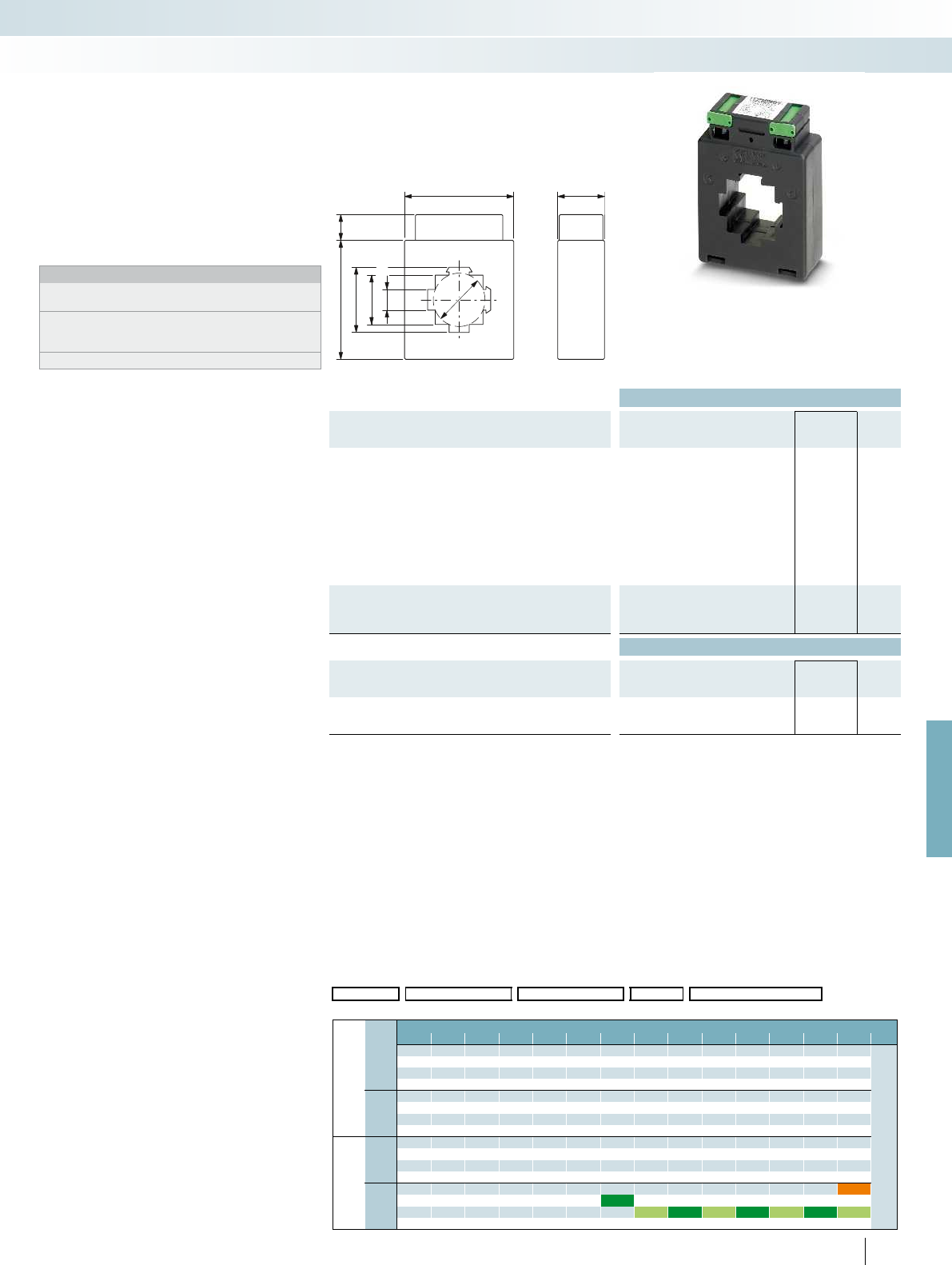
30
40,5x13
74 16
31x31
13x40,5
70
33
For further information and full technical data, visit phoenixcontact.net/products
Ordering data
Description
Rated power S
n
Type Order No. Pcs. /
Pkt.
Preferred versions available from stock
(marked in green in the selection table)
Primary rated current I
pn
:
- 250 A 5 VA PACT MCR-V2-4012- 70- 250-5A-1 2277116 1
- 300 A 7.5 VA PACT MCR-V2-4012- 70- 300-5A-1 2277679 1
- 400 A 7.5 VA PACT MCR-V2-4012- 70- 400-5A-1 2277129 1
- 500 A 10 VA PACT MCR-V2-4012- 70- 500-5A-1 2277682 1
- 600 A 10 VA PACT MCR-V2-4012- 70- 600-5A-1 2277132 1
- 750 A 10 VA PACT MCR-V2-4012- 70- 750-5A-1 2277695 1
- 800 A 10 VA PACT MCR-V2-4012- 70- 800-5A-1 2277145 1
- 1000 A 10 VA PACT MCR-V2-4012- 70-1000-5A-1 2277158 1
Current transformer, observe the order key below to determine
the desired current transformer type
PACT MCR-V2- 4012- 70 2277284 1
Accessories
Quick-action mechanism; width of the holding latch 13 mm
Fixing pin length 40 mm PACT-FAST-MNT-W13-L40 2276612 1
Quick-action mechanism; width of the holding latch 13 mm
Fixing pin length 65 mm PACT-FAST-MNT-W13-L65 2276625 1
255
PHOENIX CONTACT
PACT MCR-V2-4012-70
– Primary rated current I
pn
:
0...(75...1000) A
– Circular conductor dimensions: Ø 33 mm
– Rail dimensions:
40x12 mm; 2x 30x10 mm
Notes:
Our configurator, which is available at
phoenixcontact.net/products, makes ordering easy.
Current transformers that support official calibration: to specify the
type of current transformer you require, please use the order key
on page 264
The relevant installation accessories can be found on page 263
Current transformers
Add to order key from the selection table (ordering example marked in orange)
Order No. Primary current I
pn
Secondary current I
sn
Class Rated power S
n
2277284 / IP010000 / IS05 / C10 / P250
Selection table PACT MCR-V2-4012-70 (Order No.: 2277284)
I
sn
Cl. Primary rated current strength I
pn
[A]
75 80 100 125 150 200 250 300 400 500 600 750 800 1000
IS01
=1 A
C05
= 0.5
1.25 2.5 2.5 2.5 2.5 2.5 2.5 2.5 2.5 2.5 2.5
Rated power S
n
[VA]
3.7555555555
7.5 10 10 10 10 10
15
C10
= 1
1.25 1.25 2.5 2.5 2.5 2.5 2.5 2.5 2.5 2.5 2.5 2.5 2.5 2.5
3.755555555555
7.5 10 10 10 10 10 10 10
15 15
IS05
= 5 A
C05
= 0.5
1.25 2.5 2.5 2.5 2.5 2.5 2.5 2.5 2.5 2.5 2.5
3.7555555555
7.5 10 10 10 10 10
15
C10
= 1
1.25 1.25 2.5 2.5 2.5 2.5 2.5 2.5 2.5 2.5 2.5 2.5 2.5 2.5
3.75 5 5 55555555
7.5 7.5 7.5 10 10 10 10 10
15 15
Monitoring
Current measurement
Window-type curr. transformer,
official calibration as an option
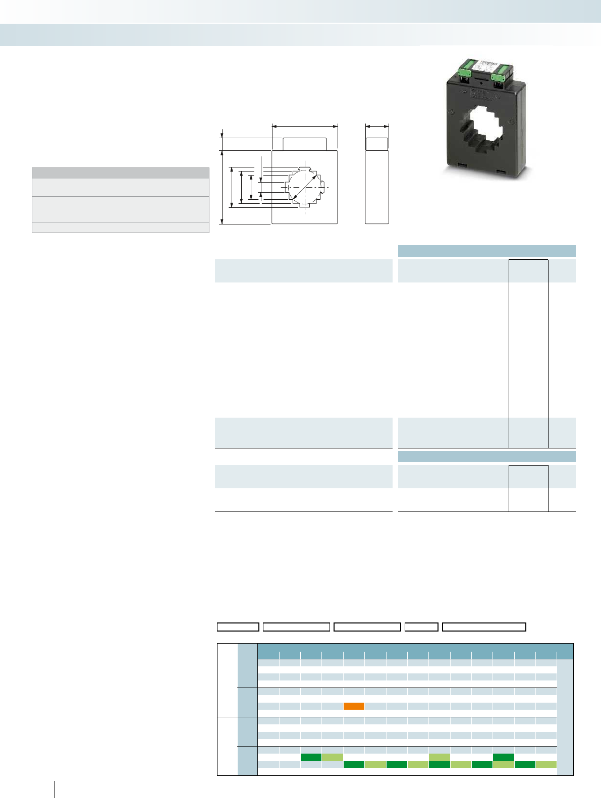
30
42
92
50,5x13
41x31
31x41
13x50,5
16
85
Ordering data
Description
Rated power S
n
Type Order No. Pcs. /
Pkt.
Preferred versions available from stock
(marked in green in the selection table)
Primary rated current I
pn
:
- 150 A 3.75 VA PACT MCR-V2-5012- 85- 150-5A-1 2276117 1
- 200 A 5 VA PACT MCR-V2-5012- 85- 200-5A-1 2276120 1
- 250 A 7.5 VA PACT MCR-V2-5012- 85- 250-5A-1 2276133 1
- 300 A 10 VA PACT MCR-V2-5012- 85- 300-5A-1 2276146 1
- 400 A 10 VA PACT MCR-V2-5012- 85- 400-5A-1 2277161 1
- 500 A 15 VA PACT MCR-V2-5012- 85- 500-5A-1 2276159 1
- 600 A 10 VA PACT MCR-V2-5012- 85- 600-5A-1 2277174 1
- 600 A 15 VA PACT MCR-V2-5012- 85- 600-5A-1 2276162 1
- 750 A 10 VA PACT MCR-V2-5012- 85- 750-5A-1 2276175 1
- 800 A 10 VA PACT MCR-V2-5012- 85- 800-5A-1 2277187 1
- 1000 A 10 VA PACT MCR-V2-5012- 85-1000-5A-1 2276463 1
- 1000 A 15 VA PACT MCR-V2-5012- 85-1000-5A-1 2277190 1
- 1250 A 15 VA PACT MCR-V2-5012- 85-1250-5A-1 2277200 1
- 1500 A 15 VA PACT MCR-V2-5012- 85-1500-5A-1 2276188 1
Current transformer, observe the order key below to determine
the desired current transformer type
PACT MCR-V2- 5012- 85 2277297 1
Accessories
Quick-action mechanism; width of the holding latch 13 mm
Fixing pin length 40 mm PACT-FAST-MNT-W13-L40 2276612 1
Quick-action mechanism; width of the holding latch 13 mm
Fixing pin length 65 mm PACT-FAST-MNT-W13-L65 2276625 1
256
PHOENIX CONTACT
PACT MCR-V2-5012-85
– Primary rated current I
pn
:
0...(100...1500) A
– Circular conductor dimensions: Ø 42 mm
– Rail dimensions:
50x12 mm; 2x 40x10 mm
Notes:
Our configurator, which is available at
phoenixcontact.net/products, makes ordering easy.
Current transformers that support official calibration: to specify the
type of current transformer you require, please use the order key
on page 264
The relevant installation accessories can be found on page 263
Current transformers
Add order key from the selection table (ordering example marked in orange)
Order No. Primary current I
pn
Secondary current I
sn
Class Rated power S
n
2277297 / IP02500 / IS01 / C10 / P750
Selection table PACT MCR-V2-5012-85 (Order No.: 2277297)
I
sn
Cl. Primary rated current amperage I
pn
[A]
100 125 150 200 250 300 400 500 600 750 800 1000 1250 1500
IS01
= 1 A
C05
= 0.5
1.25 2.5 2.5 2.5 2.5 2.5 2.5 2.5 2.5 2.5 2.5 2.5
Rated power S
n
[VA]
55555555555
7.5 10 10 10 10 10 10 10 10
15 15 15 15 15 15
C10
= 1
1.25 2.5 2.5 2.5 2.5 2.5 2.5 2.5 2.5 2.5 2.5 5 5 5
3.7555555555101010
7.5 7.5 10 10 10 10 10 10 15 15 15
10 15 20 20 15 20 20 30
IS05
= 5 A
C05
= 0.5
1.25 2.5 2.5 2.5 2.5 2.5 2.5 2.5 2.5 2.5 2.5 2.5
55555555555
7.5 10 10 20 10 10 10 10 10
15 15 15 15 15 15
C10
= 1
1.25 2.5 2.5 2.5 2.5 2.5 2.5 5 5 2.5 2.5 5 5 5
3.75 55551010 5 5 10 10 10
7.5 7.5 10 10 15 15 10 10 15 15 15
10 15 20 20 15 20 20 20
Monitoring
Current measurement
Window-type curr. transformer,
official calibration as an option
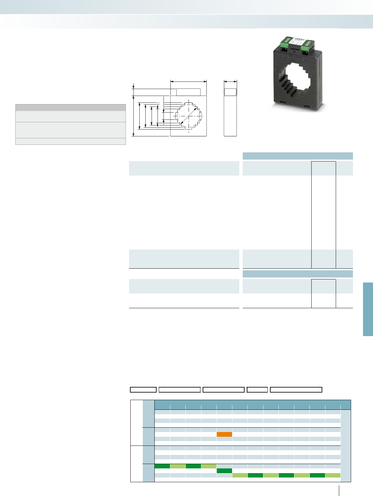
52
30
92
60,5x16
52x32
42x42
32x52
16x60,5
16
85
For further information and full technical data, visit phoenixcontact.net/products
Ordering data
Description
Rated power S
n
Type Order No. Pcs. /
Pkt.
Preferred versions available from stock
(marked in green in the selection table)
Primary rated current I
pn
:
- 200 A 2.5 VA PACT MCR-V2-6015- 85- 200-5A-1 2277873 1
- 250 A 2.5 VA PACT MCR-V2-6015- 85- 250-5A-1 2277886 1
- 300 A 2.5 VA PACT MCR-V2-6015- 85- 300-5A-1 2277899 1
- 400 A 2.5 VA PACT MCR-V2-6015- 85- 400-5A-1 2277909 1
- 500 A 5 VA PACT MCR-V2-6015- 85- 500-5A-1 2277912 1
- 600 A 10 VA PACT MCR-V2-6015- 85- 600-5A-1 2277925 1
- 750 A 10 VA PACT MCR-V2-6015- 85- 750-5A-1 2277938 1
- 800 A 10 VA PACT MCR-V2-6015- 85- 800-5A-1 2277941 1
- 1000 A 15 VA PACT MCR-V2-6015- 85-1000-5A-1 2277954 1
- 1250 A 15 VA PACT MCR-V2-6015- 85-1250-5A-1 2277967 1
- 1500 A 15 VA PACT MCR-V2-6015- 85-1500-5A-1 2277970 1
- 1600 A 15 VA PACT MCR-V2-6015- 85-1600-5A-1 2277983 1
Current transformer, observe the order key below to determine
the desired current transformer type
PACT MCR-V2- 6015- 85 2277336 1
Accessories
Quick-action mechanism; width of the holding latch 16 mm
Fixing pin length 40 mm PACT-FAST-MNT-W16-L40 2276638 1
Quick-action mechanism; width of the holding latch 16 mm
Fixing pin length 65 mm PACT-FAST-MNT-W16-L65 2276641 1
257
PHOENIX CONTACT
PACT MCR-V2-6015-85
– Primary rated current I
pn
:
0...(200...1600) A
– Circular conductor dimensions: Ø 52 mm
– Rail dimensions:
60x15 mm; 2x 50x10 mm; 40x40 mm
Notes:
Our configurator, which is available at
phoenixcontact.net/products, makes ordering easy.
Current transformers that support official calibration: to specify the
type of current transformer you require, please use the order key
on page 264
The relevant installation accessories can be found on page 263
Current transformers
Add order key from the selection table (ordering example marked in orange)
Order No. Primary current I
pn
Secondary current I
sn
Class Rated power S
n
2277336 / IP05000 / IS01 / C10 / P375
Selection table PACT MCR-V2-6015-85 (Order No.: 2277336)
I
sn
Cl. Primary rated current amperage I
pn
[A]
200 250 300 400 500 600 750 800 1000 1250 1500 1600
IS01
= 1 A
C05
= 0.5
1.25 1.25 1.25 2.5 2.5 2.5 2.5 2.5 2.5
Rated power S
n [VA]
55
C10
= 1
2.5 2.5 2.5 2.5 2.5 2.5 2.5 2.5 2.5 2.5
3.75 5 3.75 3.75 5
IS05
= 5 A
C05
= 0.5
1.25 1.25 1.25 2.5 2.5 2.5 2.5 2.5 5 5 5
2.5 5 5 5 5 5 10 10 10
10 10 10 10 15 15 15
15 15 20 20
C10
= 1
2.5 2.5 2.5 2.5 2.5 2.5 2.5 2.5 5 5 5 5
5 5 5 5 10 10 10 10
10 10 10 15 15 15 15
15 20 30
Monitoring
Current measurement
Window-type curr. transformer,
official calibration as an option
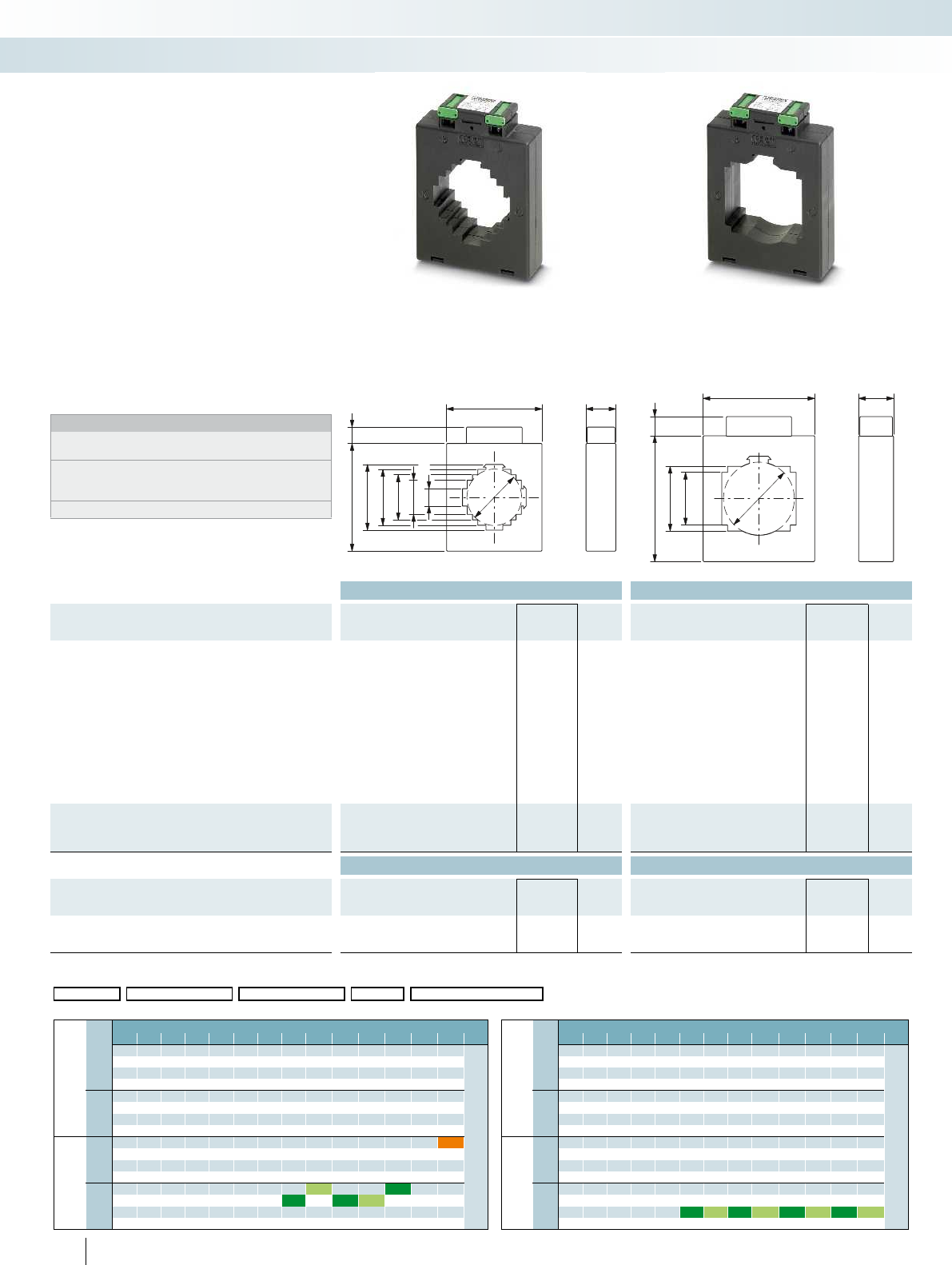
53
9530
16x64
32x54
42x42
54x32
64x16
10516
30
61
96
44x64
54x54
105 16
Ordering data Ordering data
Description
Rated power S
n
Type Order No. Pcs. /
Pkt. Type Order No. Pcs. /
Pkt.
Preferred versions available from stock
(marked in green in the selection table)
Primary rated current I
pn
:
- 600 A 10 VA PACT MCR-V2-6040- 96- 600-5A-1 2276191 1
- 750 A 10 VA PACT MCR-V2-6040- 96- 750-5A-1 2276201 1
- 800 A 10 VA PACT MCR-V2-6315- 95- 800-5A-1 2277213 1PACT MCR-V2-6040- 96- 800-5A-1 2276214 1
- 1000 A 10 VA PACT MCR-V2-6315- 95-1000-5A-1 2277226 1PACT MCR-V2-6040- 96-1000-5A-1 2277705 1
- 1250 A 10 VA PACT MCR-V2-6315- 95-1250-5A-1 2277239 1
- 1250 A 15 VA PACT MCR-V2-6040- 96-1250-5A-1 2276227 1
- 1500 A 10 VA PACT MCR-V2-6315- 95-1500-5A-1 2277242 1PACT MCR-V2-6040- 96-1500-5A-1 2277718 1
- 1600 A 10 VA PACT MCR-V2-6315- 95-1600-5A-1 2277255 1
- 1600 A 15 VA PACT MCR-V2-6040- 96-1600-5A-1 2276230 1
- 2000 A 15 VA PACT MCR-V2-6040- 96-2000-5A-1 2276243 1
Current transformer, observe the order key below to determine
the desired current transformer type
PACT MCR-V2- 6315- 95 2277307 1PACT MCR-V2- 6040- 96 2277349 1
Accessories Accessories
Quick-action mechanism; width of the holding latch 16 mm
Fixing pin length 40 mm PACT-FAST-MNT-W16-L40 2276638 1PACT-FAST-MNT-W16-L40 2276638 1
Quick-action mechanism; width of the holding latch 16 mm
Fixing pin length 65 mm PACT-FAST-MNT-W16-L65 2276641 1PACT-FAST-MNT-W16-L65 2276641 1
258
PHOENIX CONTACT
PACT MCR-V2-6315-95
– Primary rated current I
pn
:
0...(200...2500) A
– Circular conductor dimensions: Ø 53 mm
– Rail dimensions:
63x15 mm
2x 50x10 mm
40x40 mm
PACT MCR-V2-6040-96
– Primary rated current I
pn
:
0...(200...2000) A
– Circular conductor dimensions: Ø 61 mm
– Rail dimensions:
60x40 mm; 50x50 mm
Notes:
Our configurator, which is available at
phoenixcontact.net/products, makes ordering easy.
Current transformers that support official calibration: to specify the
type of current transformer you require, please use the order key
on page 265
The relevant installation accessories can be found on page 263
Current transformers
Add order key from the selection table (ordering example marked in orange)
Order No. Primary current I
pn
Secondary current I
sn
Class Rated power S
n
2277307 / IP25000 / IS05 / C05 / P500
Selection table PACT MCR-V2-6315-95 (Order No.: 2277307) Selection table PACT MCR-V2-6040-96 (Order No.: 2277349)
I
sn
Cl. Primary rated current amperage I
pn
[A] I
sn
Cl. Primary rated current amperage I
pn
[A]
200 250 300 400 500 600 750 800 1000 1250 1500 1600 2000 2500 200 250 300 400 500 600 750 800 1000 1250 1500 1600 2000
IS01
= 1 A
C05
= 0.5
2.5 2.5 2.5 2.5 2.5 2.5 5 5 5 5 5 5 5
Rated power S
n [VA]
IS01
= 1 A
C05
= 0.5
2.5 2.5 2.5 2.5 2.5 2.5 2.5 2.5 2.5 2.5
Rated power S
n [VA]
5 5 5 5 10 10 10 10 10 10 10 55555 5 5
7.5 10 10 15 15 15 15 15 7.5 7.5 7.5 10 10
20
C10
= 1
2.5 2.5 2.5 2.5 2.5 2.5 5 5 5 5 5 5 10
C10
= 1
2.5 2.5 2.5 2.5 2.5 2.5 2.5 2.5 2.5 2.5 2.5
3.75 5 5 5 5 5 10 10 10 10 10 10 15 3.7555555555 5 5
7.5 10 10 10 15 15 15 15 20 7.5 7.5 7.5 7.5 10 10
15 20
IS05
= 5 A
C05
= 0.5
2.5 2.5 2.5 2.5 2.5 2.5 5 5 5 5 5 5 5 5
IS05
= 5 A
C05
= 0.5
2.5 2.5 2.5 2.5 2.5 2.5 2.5 2.5 2.5 2.5 2.5 5
3.75 5 5 5 5 10 10 10 10 10 10 10 10 55555 5 5 5 510
7.5 10 10 10 15 15 15 15 15 15 15 15 7.5 7.5 10 10 7.5 10 10 10 15
15 15 20 20 30 20 30 30 30 30 15
C10
= 1
2.5 2.5 2.5 2.5 5 5 5 5 10 5 5 10 10 10
C10
= 1
2.5 2.5 2.5 2.5 2.5 2.5 2.5 2.5 2.5 52.5 5 5
3.75 5 5 5 10 10 10 10 15 10 10 15 15 15 3.75 3.75 5 5 5 5 5 5 5 10 5 10 10
10 10 15 15 15 15 30 15 15 30 30 30 7.5 7.5 10 10 10 10 15 10 15 15
15 20 20 30 30 30 30 15
Monitoring
Current measurement
Window-type curr. transformer,
official calibration as an option
Window-type curr. transformer,
official calibration as an option
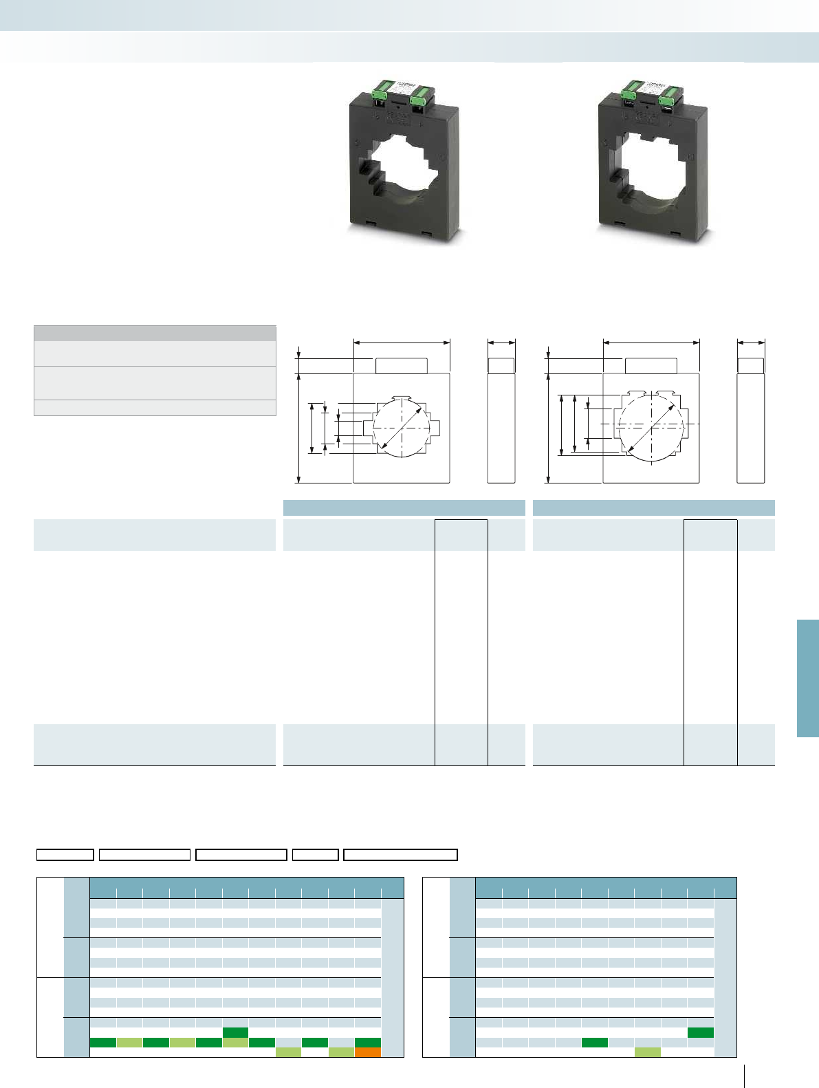
30
61
105
16116
53x53
33x63
16x83
30
70
105
16116
64x53
60x64
31x81
For further information and full technical data, visit phoenixcontact.net/products
Ordering data Ordering data
Description
Rated power S
n
Type Order No. Pcs. /
Pkt. Type Order No. Pcs. /
Pkt.
Preferred versions available from stock
(marked in green in the selection table)
Primary rated current I
pn
:
- 400 A 7.5 VA PACT MCR-V2-8015-105- 400-5A-1 2276256 1
- 500 A 10 VA PACT MCR-V2-8015-105- 500-5A-1 2276269 1
- 600 A 10 VA PACT MCR-V2-8015-105- 600-5A-1 2276272 1
- 750 A 10 VA PACT MCR-V2-8015-105- 750-5A-1 2276285 1
- 800 A 15 VA PACT MCR-V2-8015-105- 800-5A-1 2276298 1
- 1000 A 10 VA PACT MCR-V2-8015-105-1000-5A-1 2277721 1PACT MCR-V2-8020-105-1000-5A-1 2277747 1
- 1000 A 15 VA PACT MCR-V2-8015-105-1000-5A-1 2276308 1
- 1250 A 10 VA PACT MCR-V2-8015-105-1250-5A-1 2276311 1
- 1500 A 15 VA PACT MCR-V2-8015-105-1500-5A-1 2277734 1PACT MCR-V2-8020-105-1500-5A-1 2277750 1
- 1600 A 15 VA PACT MCR-V2-8015-105-1600-5A-1 2276324 1
- 2000 A 10 VA PACT MCR-V2-8020-105-2000-5A-1 2276382 1
- 2000 A 20 VA PACT MCR-V2-8015-105-2000-5A-1 2276337 1
- 2500 A 20 VA PACT MCR-V2-8015-105-2500-5A-1 2276340 1
Current transformer, observe the order key below to determine
the desired current transformer type
PACT MCR-V2- 8015-105 2277352 1PACT MCR-V2- 8020-105 2277365 1
259
PHOENIX CONTACT
PACT MCR-V2-8015-105
– Primary rated current I
pn
:
0...(400...2500) A
– Circular conductor dimensions: Ø 61 mm
– Rail dimensions:
80x15 mm; 2x 60x10 mm; 3x 50x10 mm
PACT MCR-V2-8020-105
– Primary rated current I
pn
:
0...(500...2000) A
– Circular conductor dimensions: Ø 70 mm
– Rail dimensions:
2x 80x10 mm; 60x60 mm
Notes:
Our configurator, which is available at
phoenixcontact.net/products, makes ordering easy.
Current transformers that support official calibration: to specify the
type of current transformer you require, please use the order key
on page 265
The relevant installation accessories can be found on page 263
Current transformers
Add order key from the selection table (ordering example marked in orange)
Order No. Primary current I
pn
Secondary current I
sn
Class Rated power S
n
2277352 / IP25000 / IS05 / C10 / P3000
Selection table PACT MCR-V2-8015-105 (Order No.: 2277352) Selection table PACT MCR-V2-8020-105 (Order No.: 2277365)
I
sn
Cl. Primary rated current amperage I
pn
[A] I
sn
Cl. Primary rated current amperage I
pn
[A]
400 500 600 750 800 1000 1250 1500 1600 2000 2500 500 600 750 800 1000 1250 1500 1600 2000
IS01
= 1 A
C05
= 0.5
2.5 2.5 2.5 2.5 2.5 2.5 2.5 2.5 2.5 5
Rated power S
n
[VA]
IS01
= 1 A
C05
= 0.5
2.5 2.5 2.5 2.5 2.5 2.5 2.5 2.5
Rated power S
n [VA]
5555555510 5555 55
10 10 7.5 10 10 10 15 10
15 15 20
C10
= 1
2.5 2.5 2.5 2.5 2.5 2.5 2.5 5 5 10
C10
= 1
2.5 2.5 2.5 2.5 2.5 2.5 2.5 2.5
5555555101015 55555555
7.5 10 10 10 10 10 10 15 15 20 7.5 7.5 7.5 10
15 15 20 20 25 15
IS05
= 5 A
C05
= 0.5
2.5 2.5 2.5 2.5 2.5 52.5 2.5 2.5 2.5 5
IS05
= 5 A
C05
= 0.5
2.5 2.5 2.5 2.5 2.5 2.5 2.5 2.5 2.5
5555510555510 555555555
10 10 10 15 10 10 10 10 15 7.5 7.5 7.5 10 10 10 10 10
15 15 20 15 15 20 15
C10
= 1
2.5 2.5 2.5 2.5 5 5 2.5 2.5 5 5 10
C10
= 1
2.5 2.5 2.5 2.5 2.5 2.5 2.5 5 5
55551010 5 5 10 10 15 55555551010
7.5 10 10 10 15 15 10 10 15 15 20 7.5 7.5 10 10 10 10 15
15 20 15 20 30 15
Monitoring
Current measurement
Window-type curr. transformer,
official calibration as an option
Window-type curr. transformer,
official calibration as an option

30
85
129
16140
81x54
64x84
31x101
30
129
16140
56x101
Ordering data Ordering data
Description
Rated power S
n
Type Order No. Pcs. /
Pkt. Type Order No. Pcs. /
Pkt.
Preferred versions available from stock
(marked in green in the selection table)
Primary rated current I
pn
:
- 2500 A 15 VA PACT MCR-V2-10020-129-2500-5A 2276395 1
- 3000 A 15 VA PACT MCR-V2-10036-129-3000-5A 2276405 1
Current transformer, observe the order key below to determine
the desired current transformer type
PACT MCR-V2-10020-129 2277378 1PACT MCR-V2-10036-129 2277381 1
260
PHOENIX CONTACT
PACT MCR-V2-10020-129
– Primary rated current I
pn
:
0...(400...4000) A
– Circular conductor dimensions: Ø 85 mm
– Rail dimensions:
2x 100x10 mm; 80x64 mm
PACT MCR-V2-10036-129
– Primary rated current I
pn
:
0...(400...4000) A
– Rail dimensions:
3x 100x12 mm
Notes:
Our configurator, which is available at
phoenixcontact.net/products, makes ordering easy.
Current transformers that support official calibration: to specify the
type of current transformer you require, please use the order key
on page 265
The relevant installation accessories can be found on page 263
Current transformers
Add order key from the selection table (ordering example marked in orange)
Order No. Primary current I
pn
Secondary current I
sn
Class Rated power S
n
2277378 / IP40000 / IS05 / C05 / P2500
Selection table PACT MCR-V2-10020-129 (Order No.: 2277378) Selection table PACT MCR-V2-10036-129 (Order No.: 2277381)
I
sn
Cl. Primary rated current amperage I
pn
[A] I
sn
Cl. Primary rated current amperage I
pn
[A]
400 500 600 750 800 1000 1250 1500 1600 2000 2500 3000 4000 400 500 600 750 800 1000 1250 1500 1600 2000 2500 3000 4000
IS01
= 1 A
C05
= 0.5
2.5 5555555555
Rated power S
n
[VA]
IS01
= 1 A
C05
= 0.5
2.5 5555555555
Rated power S
n
[VA]
5 10 10 10 10 10 10 10 10 10 10 5 10 10 10 10 10 10 10 10 10 10
15 15 15 15 15 15 15 15 15 15 15 15
20 20 20 20
C10
= 1
2.5 2.5 5555555555
C10
= 1
2.5 2.5 5555555555
5 5 10 10 10 10 10 10 10 10 10 10 5 5 10 10 10 10 10 10 10 10 10 10
15 15 15 15 15 15 15 15 15 15 15 15
25 30 25 30
IS05
= 5 A
C05
= 0.5
2.5 2.5 5555555555
IS05
= 5 A
C05
= 0.5
2.5 2.5 5555555555
5 5 10 10 10 10 10 10 10 10 10 10 5 5 10 10 10 10 10 10 10 10 10 10
15 15 15 15 15 15 15 15 15 15 15 15 15 15
20 20 25 25 20 20 25 25
C10
= 1
2.5 2.5 55555555555
C10
= 1
2.5 2.5 55555555555
5 5 10 10 10 10 10 10 10 10 10 10 10 5 5 10 10 10 10 10 10 10 10 10 10 10
15 15 15 15 15 15 15 15 15 15 15 15 15 15 15 15
20 25 30 30 30 20 25 30 30 30
Monitoring
Current measurement
Window-type curr. transformer,
official calibration as an option
Window-type curr. transformer,
official calibration as an option
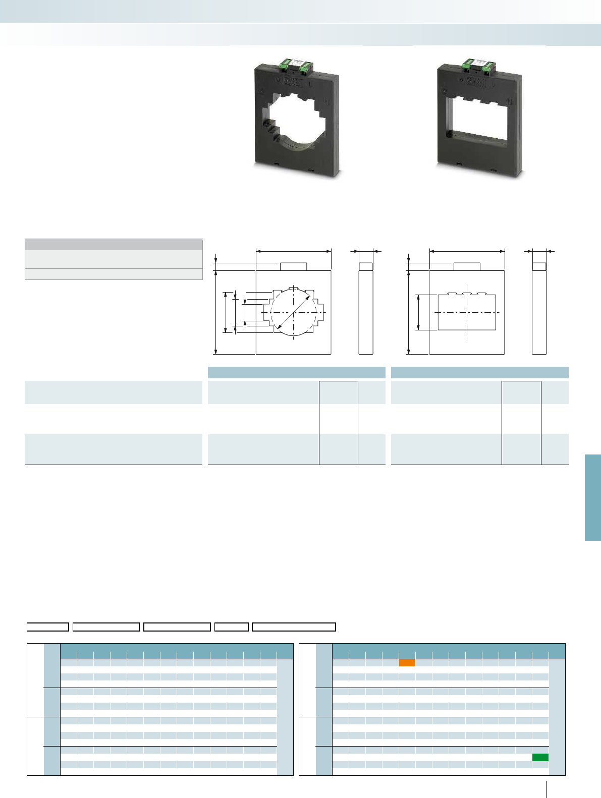
15930
16172
83x83
55x103
34x126
96
15930
16172
72x122
For further information and full technical data, visit phoenixcontact.net/products
Ordering data Ordering data
Description
Rated power S
n
Type Order No. Pcs. /
Pkt. Type Order No. Pcs. /
Pkt.
Preferred versions available from stock
(marked in green in the selection table)
Primary rated current I
pn
:
- 4000 A 15 VA PACT MCR-V2-12040-159-4000-5A 2276418 1
Current transformer, observe the order key below to determine
the desired current transformer type
PACT MCR-V2-12020-159 2277394 1PACT MCR-V2-12040-159 2277404 1
261
PHOENIX CONTACT
PACT MCR-V2-12020-159
– Primary rated current I
pn
:
0...(400...4000) A
– Circular conductor dimensions: Ø 96 mm
– Rail dimensions:
2x 120x10 mm; 3x 100x10 mm;
80x80 mm
PACT MCR-V2-12040-159
– Primary rated current I
pn
:
0...(400...4000) A
– Rail dimensions:
4x 120x10 mm
Notes:
Our configurator, which is available at
phoenixcontact.net/products, makes ordering easy.
The relevant installation accessories can be found on page 263
Current transformers
Add order key from the selection table (ordering example marked in orange)
Order No. Primary current I
pn
Secondary current I
sn
Class Rated power
2277404 / IP08000 / IS01 / C05 / P250
Selection table PACT MCR-V2-12020-159 (Order No.: 2277394) Selection table PACT MCR-V2-12040-159 (Order No.: 2277404)
I
sn
Cl. Primary rated current amperage I
pn
[A] I
sn
Cl. Primary rated current amperage I
pn
[A]
400 500 600 750 800 1000 1250 1500 1600 2000 2500 3000 4000 400 500 600 750 800 1000 1250 1500 1600 2000 2500 3000 4000
IS01
= 1A
C05
= 0.5
2.5 2.5 2.5 2.5 2.5 2.5 55555510
Rated power S
n
[VA]
IS01
= 1A
C05
= 0.5
2.5 2.5 2.5 2.5 2.5 2.5 55555510
Rated power S
n
[VA]
5 5 5 5 5 5 10 10 10 10 10 10 15 5 5 5 5 5 5 10 10 10 10 10 10 15
10 10 10 10 10 10 15 15 15 15 15 15 30 10 15 15 15 15 15 15 30
1520303030303045
C10
= 1
2.5 5 5 2.5 2.5 55555510 10
C10
= 1
2.5 5 5 2.5 2.5 5 5 5 5 5 5 10 10
5 1010 5 5 1010101010101515 5 10 10 5 5 10 10 10 10 10 10 15 15
10 15 15 10 10 15 15 15 15 15 15 30 30 10 15 15 10 15 15 15 15 15 15 30 30
152020 152030303030304545
IS05
= 5 A
C05
= 0.5
2.5 2.5 2.5 2.5 2.5 5 5 10 5 5 5 10 10
IS05
= 5 A
C05
= 0.5
2.5 2.5 2.5 2.5 2.5 5 5 10 5 5 5 10 10
5 5 5 5 5 1010151010101515 5 5 5 5 5 1010151010101515
10 10 10 10 10 15 15 30 15 15 15 30 30 10 10 15 15 30 15 15 15 30 30
15153030453030304545
C10
= 1
2.5 5 5 5 5 5 5 10 5 5 10 10 10
C10
= 1
2.5 5 5 5 5 5 5 10 5 5 10 10 10
5 101010101010151010151515 5 10 10 10 10 10 10 15 10 10 15 15 15
10 15 15 15 15 15 15 30 15 15 30 30 30 10 15 15 15 15 15 15 30 15 15 30 30 30
15202020303030453030454545
Monitoring
Current measurement
Window-type current transformer Window-type current transformer
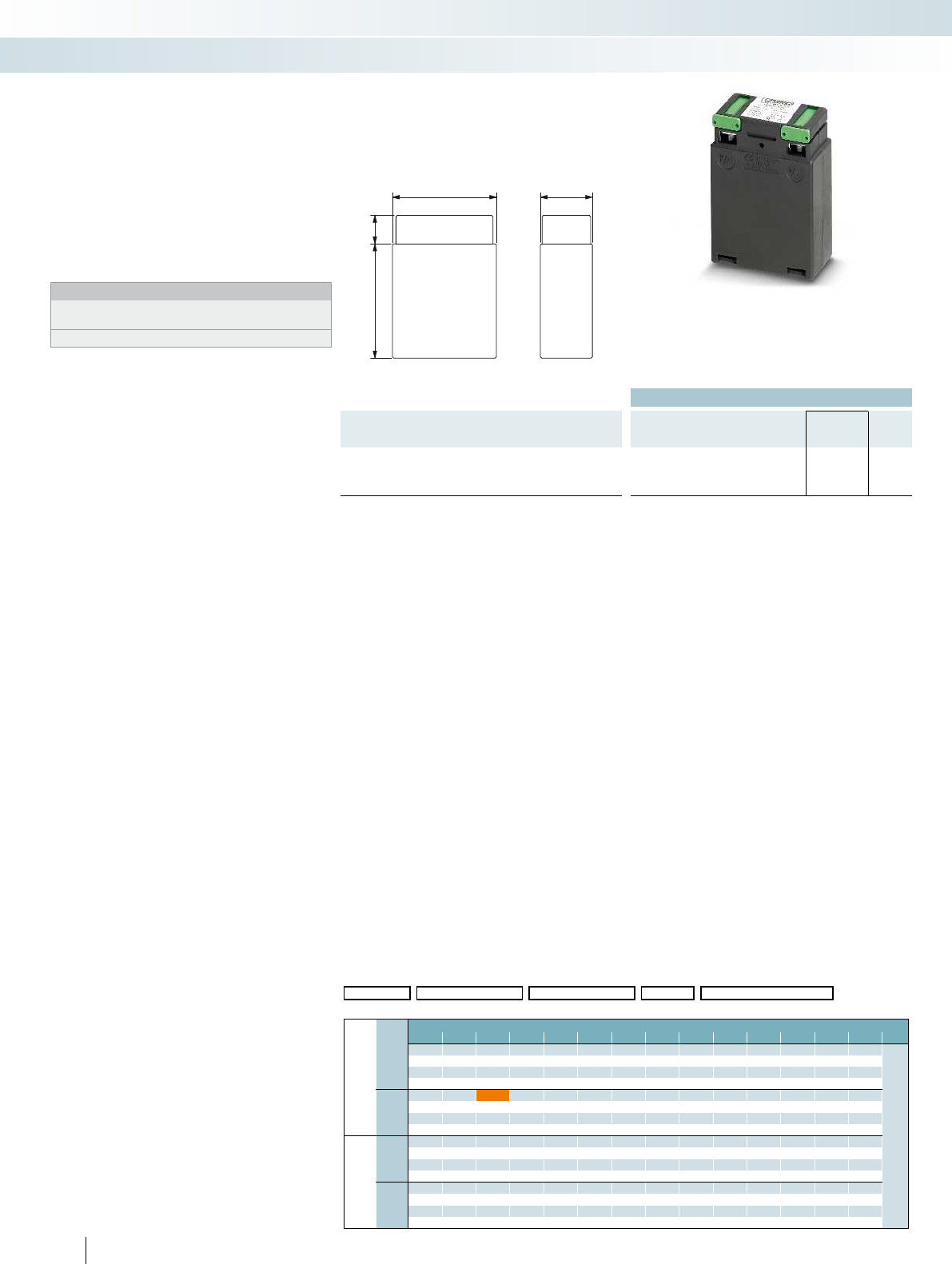
30
60
1664
Ordering data
Description Type Order No. Pcs. /
Pkt.
Current transformer, observe the order key below to determine
the desired current transformer type
PACT MCR-V3-60 2277417 1
262
PHOENIX CONTACT
PACT MCR-V3-60
– Primary rated current I
pn
:
0...(1...40) A
– Current-carrying copper lines connected
directly to the screw terminal blocks on
the primary side
Notes:
Our configurator, which is available at
phoenixcontact.net/products, makes ordering easy.
The relevant installation accessories can be found on page 263
Current transformers
Add to order key from the selection table (ordering example marked in orange)
Order No. Primary current I
pn
Secondary current I
sn
Class Rated power S
n
2277417 / IP00025 / IS01 / C10 / P250
Selection table PACT MCR-V3-60 (Order No.: 2277417)
I
sn
Cl. Primary rated current strength I
pn
[A]
1 2 2.5 4567.5 10 12.5 15 20 25 30 40
IS01
=1 A
C05
= 0.5
2.5 2.5 2.5 2.5 2.5 2.5 2.5 2.5 2.5 2.5 2.5 2.5 2.5 2.5
Rated power S
n
[VA]
55555555555555
C10
= 1
2.5 2.5 2.5 2.5 2.5 2.5 2.5 2.5 2.5 2.5 2.5 2.5 2.5 2.5
55555555555555
IS05
= 5 A
C05
= 0.5
2.5 2.5 2.5 2.5 2.5 2.5 2.5 2.5 2.5 2.5 2.5 2.5 2.5 2.5
55555555555555
C10
= 1
2.5 2.5 2.5 2.5 2.5 2.5 2.5 2.5 2.5 2.5 2.5 2.5 2.5 2.5
55555555555555
Monitoring
Current measurement
Winding current transformer

For further information and full technical data, visit phoenixcontact.net/products
Technical data Technical data
General data
Material PA 6 PA 6
Ambient temperature (operation) -25 °C ... 120 °C -25 °C ... 120 °C
Ordering data Ordering data
Description Type Order No. Pcs. /
Pkt. Type Order No. Pcs. /
Pkt.
Quick-action mechanism; width of the holding latch 13 mm
Fixing pin length 65 mm PACT-FAST-MNT-W13-L65 2276625 1
Fixing pin length 40 mm PACT-FAST-MNT-W13-L40 2276612 1
Quick-action mechanism; width of the holding latch 16 mm
Fixing pin length 65 mm PACT-FAST-MNT-W16-L65 2276641 1
Fixing pin length 40 mm PACT-FAST-MNT-W16-L40 2276638 1
Quick-action mechanism for PACT
current transformers
– No tools necessary for mounting
– Extremely easy handling, thanks to secure
fastening by pressing with finger
– Set consisting of two fixing pins and a
holding latch
Notes:
The 16 mm wide quick-action mechanism can also be used for
larger current transformers if the length of the fixing pins is
sufficient.
Accessories
Monitoring
Current measurement
for: ...-V2-4012-70..., ...-V2-5012-85...
for: ...-V2-3015-60..., ...-V2-6015-85..., ...-V2-6315-95...
Ordering data Ordering data
Description Type Order No. Pcs. /
Pkt. Type Order No. Pcs. /
Pkt.
Copper sleeves, for establishing a conductive connection during
the horizontal assembly of PACT analog current transformers. The
size of the copper sleeve depends on the diameter of the inner hole
of the current transformer.
- for PACT MCR-V1-21-44-... Ø 21/8 mm PACT MCR-CB-21- 8 2277569 1
- for PACT MCR-V1-21-44-... Ø 21/12 mm PACT MCR-CB-21-12 2277556 1
- for PACT MCR-V2-3015-60-... Ø 28/12 mm PACT MCR-CB-28-12 2277543 1
- for PACT MCR-V2-5012-85-... Ø 42/12 mm PACT MCR-CB-42-12 2277530 1
DIN rail adapter
PACT MCR-RA 2277598 12
Secondary terminal cover, for increasing the clearance and
creepage distances
Length: 60 mm PACT MCR-ETC-60 2277572 9
Length: 75 mm PACT MCR-ETC-75 2277585 9
Insulating caps, for protection against unintended contact with
mounting screws of the primary rail
PACT MCR-ICAP 2277608 18
263
PHOENIX CONTACT
– Copper sleeves
– DIN rail adapter
– Secondary terminal cover
– Insulating caps
Accessories
Copper sleeves
DIN rail adapter
Secondary terminal cover
Insulating caps

264
PHOENIX CONTACT
Current transformers that can be calibrated - order key
Add order key from the relevant selection table (ordering examples are marked in orange)
Order No. Primary current I
pn
Secondary current I
sn
Class Rated power S
n
Calibration Calibration certificate
/ / // / /
IP01500 =150 A
IP02000 =200 A IS05 = 5 A C02S = 0.2S P250 =2.5 VA NONE =not calibrated NONE =no calibration certificate
IP02500 =250 A C02 = 0.2 P500 =5.0 VA YES =calibrated YES =calibration certificate (a fee is
charged)
IP03000 =300 A C05S = 0.5S P1000 =10 VA
IP04000 =400 A C05 = 0.5 P1500 =15 VA
IP05000 =500 A P2000 =20 VA
IP06000 =600 A P3000 =30 VA YESPLUS =Calibration certificate with catalog
of errors (5 measuring points)
(a fee is charged)
IP07500 =750 A
IP08000 =800 A
IP10000 =1000 A
IP12000 =1200 A
IP12500 =1250 A
IP15000 =1500 A
IP16000 =1600 A
IP20000 =2000 A
IP25000 =2500 A
PACT MCR-V2C-3015-60 (Order No.: 2277433)
You will find information about the product on page 254.
Add order key from the selection table
2277433 /IP02000 /IS05 /C05 /P250 /NONE /NONE
Selection table
I
sn
Cl. Primary rated current amperage I
pn
[A]
200 250 300 400 500 600 750
IS05
= 5 A
C02S
=
0.2S
2.5 2.5
Rated power S
n
[VA]
55
10 10
C02
= 0.2
2.5 2.5 2.5 2.5
555
10 10
C05S
=
0.5S
2.5 2.5 2.5 2.5 2.5 2.5
55555
10 10 10 10
15
C05
= 0.5
2.5 2.5 2.5 2.5 2.5 2.5 2.5
555555
10 10 10 10
15
PACT MCR-V1C-21-44 (Order No.: 2277420)
You will find information about the product on page 253.
Add order key from the selection table
2277420 / IP03000 /IS05 /C02 /P250 /NONE /NONE
Selection table
I
sn
Cl. Primary rated current amperage I
pn
[A]
150 200 250 300 400 500
IS05
= 5 A
C02S
=
0.2S
2.5 2.5
Rated power S
n
[VA]
5
C02
= 0.2
2.5 2.5 2.5
555
C05S
=
0.5S
2.5 2.5 2.5 2.5 2.5
5555
10 10
C05
= 0.5
2.5 2.5 2.5 2.5 2.5 2.5
55555
10 10
PACT MCR-V2C-4012-70 (Order No.: 2277446)
You will find information about the product on page 255.
Add order key from the selection table
2277446 / IP06000 /IS05 /C02 /P1000 /NONE /NONE
Selection table
I
sn
Cl. Primary rated current amperage I
pn
[A]
200 250 300 400 500 600 750 800 1000
IS05
= 5 A
C02S
=
0.2S
2.5 2.5 2.5 5
Rated power S
n
[VA]
55510
10 10
C02
= 0.2
2.5 2.5 2.5 52.5 5
5 5 510510
10 10 10
C05S
=
0.5S
2.5 2.5 2.5 2.5 5 5 2.5 5
5 5 5 10 10 5 10
10 10 10
C05
= 0.5
2.5 2.5 2.5 2.5 2.5 5 5 2.5 5
5 5 5 5 10 10 5 10
10 10 10
PACT MCR-V2C-5012-85 (Order No.: 2277459)
You will find information about the product on page 256.
Add order key from the selection table
2277459 / IP10000 /IS05 /C05 /P1500 /NONE /NONE
Selection table
I
sn
Cl. Primary rated current amperage I
pn
[A]
200 250 300 400 500 600 750 800 1000 1200
IS05
= 5 A
C02S
=
0.2S
2.5 2.5 2.5 5 5
Rated power S
n
[VA]
5551010
10 10 15 15
20 30
C02
= 0.2
2.5 2.5 2.5 2.5 2.5 5 5
555551010
10 10 10 15 15
30 30
C05S
=
0.5S
2.5 2.5 2.5 2.5 2.5 55555
5 5 5 10 10 10 10 10
10 10 15 15
30 30
C05
= 0.5
2.5 2.5 2.5 2.5 2.5 55555
5 5 5 5 10 10 10 10 10
10 10 15 15
30 30
PACT MCR-V2C-6015-85 (Order No.: 2277462)
You will find information about the product on page 257.
Add order key from the selection table
2277462 / IP02500 /IS05 /C05 /P250 /NONE /NONE
Selection table
I
sn
Cl. Primary rated current amperage I
pn
[A]
250 300 400 500 600 750 800 1000 1200
IS05
= 5 A
C02S
=
0.2S
2.5 2.5 2.5 2.5
Rated power S
n
[VA]
5555
10 10
C02
= 0.2
2.5 2.5 2.5 2.5 2.5
5555
10 10
15
C05S
=
0.5S
2.5 2.5 2.5 2.5 2.5 2.5 2.5
555555
10 10 10 10
15 15
C05
= 0.5
2.5 2.5 2.5 2.5 2.5 2.5 2.5 2.5 2.5
555555
10 10 10 10
15 15
Monitoring
Current measurement
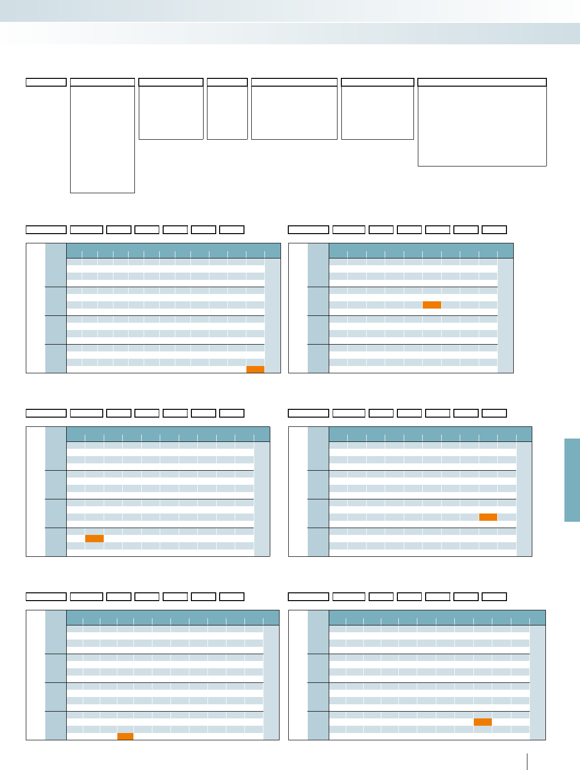
For further information and full technical data, visit phoenixcontact.net/products
265PHOENIX CONTACT
Current transformers that can be calibrated - order key
Add order key from the relevant selection table (ordering examples are marked in orange)
Order No. Primary current I
pn
Secondary current I
sn
Class Rated power S
n
Calibration Calibration certificate
/ / // / /
IP01500 =150 A
IP02000 =200 A IS05 = 5 A C02S = 0.2S P250 =2.5 VA NONE =not calibrated NONE =no calibration certificate
IP02500 =250 A C02 = 0.2 P500 =5.0 VA YES =calibrated YES =calibration certificate (a fee is
charged)
IP03000 =300 A C05S = 0.5S P1000 =10 VA
IP04000 =400 A C05 = 0.5 P1500 =15 VA
IP05000 =500 A P2000 =20 VA
IP06000 =600 A P3000 =30 VA YESPLUS =Calibration certificate with catalog
of errors (5 measuring points)
(a fee is charged)
IP07500 =750 A
IP08000 =800 A
IP10000 =1000 A
IP12000 =1200 A
IP12500 =1250 A
IP15000 =1500 A
IP16000 =1600 A
IP20000 =2000 A
IP25000 =2500 A
PACT MCR-V2C-8015-105 (Order No.: 2277491)
You will find information about the product on page 259.
Add order key from the selection table
2277491 /IP05000 /IS05 /C05 /P500 /NONE /NONE
Selection table
I
sn
Cl. Primary rated current amperage I
pn
[A]
400 500 600 750 800 1000 1200 1250 1500
IS05
= 5 A
C02S
=
0.2S
2.5
Rated power S
n
[VA]
5
C02
= 0.2
2.5 2.5 2.5 2.5 2.5 2.5 2.5
5555555
10 10 10 10 10 10
15 15
C05S
=
0.5S
2.5 2.5 2.5 2.5 2.5 2.5 2.5 2.5 2.5
55510555
10 10 15 10 10 10
15 20 15
C05
= 0.5
2.5 2.5 2.5 2.5 2.5 52.5 2.5 2.5
5555510555
10 10 10 15 10 10 10
15 15 20 15
PACT MCR-V2C-6040-96 (Order No.: 2277488)
You will find information about the product on page 258.
Add order key from the selection table
2277488 / IP12000 /IS05 /C02 /P1000 /NONE /NONE
Selection table
I
sn
Cl. Primary rated current amperage I
pn
[A]
500 600 750 800 1000 1200 1250 1500
IS05
= 5 A
C02S
=
0.2S
2.5 2.5 2.5
Rated power S
n
[VA]
555
10
15
C02
= 0.2
2.5 2.5 2.5 2.5 2.5 2.5
555555
10 10
15
C05S
=
0.5S
2.5 2.5 2.5 2.5 2.5 2.5 2.5 2.5
5555555
10 10 10 10 10
15 15
C05
= 0.5
2.5 2.5 2.5 2.5 2.5 2.5 2.5 2.5
55555555
10 10 10 10 10 10
15 15
PACT MCR-V2C-8020-105 (Order No.: 2277501)
You will find information about the product on page 259.
Add order key from the selection table
2277501 / IP15000 /IS05 /C05S /P1000 /NONE /NONE
Selection table
I
sn
Cl. Primary rated current amperage I
pn
[A]
400 500 600 750 800 1000 1200 1250 1500
IS05
= 5 A
C02S
=
0.2S
2.5 2.5
Rated power S
n
[VA]
55
C02
= 0.2
2.5 2.5 2.5 2.5 2.5 2.5 2.5
5555
10 10 10
C05S
=
0.5S
2.5 2.5 2.5 2.5 2.5 2.5 2.5 2.5
5555555
10 10 10 10 10
C05
= 0.5
2.5 2.5 2.5 2.5 2.5 2.5 2.5 2.5 2.5
555555555
10 10 10 10 10
PACT MCR-V2C-10036-129 (Order No.: 2277527)
You will find information about the product on page 260.
Add order key from the selection table
2277527 / IP16000 /IS05 /C05 /P500 /NONE /NONE
Selection table
I
sn
Cl. Primary rated current amperage I
pn
[A]
500 600 750 800 1000 1200 1250 1500 1600 2000 2500
IS05
= 5 A
C02S
=
0.2S
Rated power S
n
[VA]
C02
= 0.2
2.5 2.5 2.5 2.5 2.5 2.5 2.5
5555555
10 10 10 10 10 10 10
15 15 15 15
C05S
=
0.5S
C05
= 0.5
2.5 2.5 2.5 2.5 2.5 2.5 2.5 2.5 2.5 2.5 2.5
5555 5 5 5 5 555
10 10 10 10 10 10 10 10 10
15 15 15 15 15
PACT MCR-V2C-10020-129 (Order No.: 2277514)
You will find information about the product on page 260.
Add order key from the selection table
2277514 / IP08000 /IS05 /C05 /P1500 /NONE /NONE
Selection table
I
sn
Cl. Primary rated current amperage I
pn
[A]
500 600 750 800 1000 1200 1250 1500 1600 2000 2500
IS05
= 5 A
C02S
=
0.2S
2.5 2.5 2.5 2.5
Rated power S
n
[VA]
5555
10
C02
= 0.2
2.5 2.5 2.5 2.5 2.5 2.5 2.5
5555555
10 10 10 10 10 10 10
15 15 15 15 15
C05S
=
0.5S
2.5 2.5 2.5 2.5 2.5 2.5 2.5 2.5 2.5 2.5 2.5
55555555555
10 10 10 10 10 10 10 10
15 15 15 15 15 15
C05
= 0.5
2.5 2.5 2.5 2.5 2.5 2.5 2.5 2.5 2.5 2.5 2.5
55555555555
10 10 10 10 10 10 10 10 10
15 15 15 15 15 15 15 15
PACT MCR-V2C-6315-95 (Order No.: 2277475)
You will find information about the product on page 258.
Add order key from the selection table
2277475 / IP15000 /IS05 /C05 /P3000 /NONE /NONE
Selection table
I
sn
Cl. Primary rated current amperage I
pn
[A]
200 250 300 400 500 600 750 800 1000 1200 1250 1500
IS05
= 5 A
C02S
=
0.2S
2.5 555
Rated power S
n
[VA]
5 10 10 10
10 15 15 15
20 20 20
C02
= 0.2
2.5 2.5 2.5 2.5 2.5 5555
5 5 5 5 5 10 10 10 10
10 10 10 15 15 15 15
15 15 20 20 20 30
C05S
=
0.5S
2.5 2.5 2.5 2.5 2.5 55555
5 5 5 5 10 10 10 10 10
10 10 10 15 15 15 15 15
15 20 20 20 30 30
C05
= 0.5
2.5 2.5 2.5 2.5 2.5 2.5 5 5 5 5 5 5
5 5 5 5 5 10 10 10 10 10 10
10 10 10 15 15 15 15 15 15
15 15 15 20 30 30 20 30 30
Monitoring
Current measurement
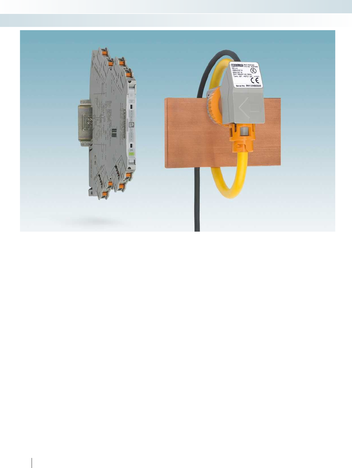
266
PHOENIX CONTACT
Monitoring
Current measurement
Fast installation in a confined space
PACT RCP current transformers for
retrofitting can be conveniently mounted
where there is not enough space for split
core current transformers. System
downtimes are reduced as system parts do
not have to be removed for installation.
Your advantages:
– High system availability due to reduced
downtimes: fast installation without
removing system parts
– Safe installation and operation: no
dangerous open circuit voltages
– No magnetic saturation
– High linearity, even at high currents
– Responds to fast current changes
– The coil is protected against
electromagnetic interference
– The current can rise up to the short-
circuit current without necessarily
destroying the coil
– High nominal insulation voltage
Professional holding device for
busbars
The PACT RCP-CLAMP holding device
offers the following advantages:
– Suitable for industrial applications
– Steel bracket ensures permanent fixed
seating at high busbar temperatures
– Designed for rails with a thickness of
10 ... 15 mm
– Rogowski coil is snapped onto the fixing
element
– Rogowski coil has a safe and defined place
on the busbar
– Rogowski coil can be rotated in
15° increments for optimum alignment.
– PACT RCP avoids direct contact of the
measuring coil with its own or adjacent
busbar
– This allows installations on warm busbars
to remain under control
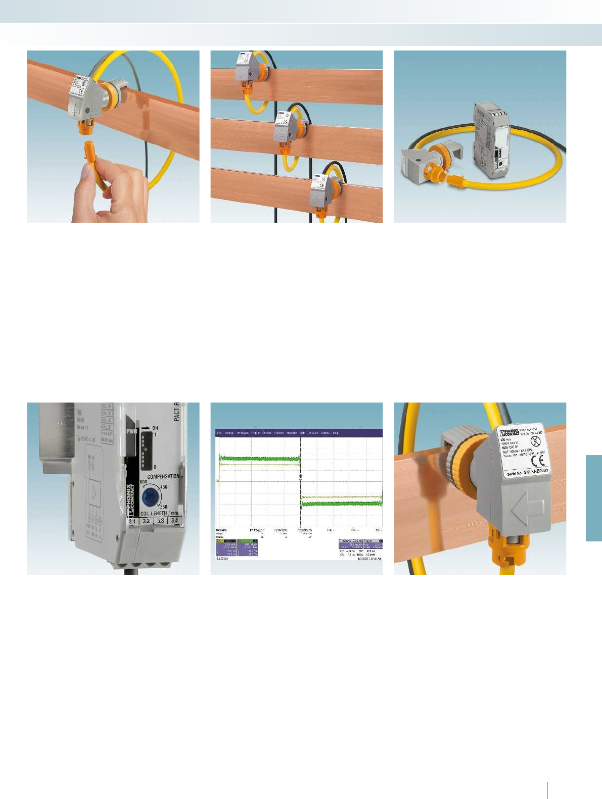
For further information and full technical data, visit phoenixcontact.net/products
267PHOENIX CONTACT
Monitoring
Current measurement
Easy and safe installation
Simply place the handy Rogowski coil
quickly around power rails and circular
conductors. The measuring transducer
connected downstream supplies the same
typical secondary currents as a standard
current transformer.
Fast installation in a confined space
PACT RCP current transformers save
space and are handy as the size and weight
of the Rogowski coil are not dependent on
the amperage and unlike split core current
transformers, remain the same.
One measuring system for all
amperages
Acquire alternating currents up to 4000 A
using a single coil type. Rogowski coils are
available in three different lengths for
optimum adjustment to the busbar and
circular conductor dimensions.
Eight current measuring ranges
The measuring transducer connected
downstream supplies the same typical
secondary currents as a standard current
transformer. Choose between eight
different current measuring ranges via DIP
switches. For optimum measuring accuracy,
compensate for the different coil lengths by
simply using a potentiometer.
Detect harmonics and transients
PACT RCP current transformers for
retrofitting cover a large frequency range
from 10 to 5000 Hz. You can therefore
measure harmonics and transients with
phase accuracy.
Safe seating
The optional holding device ensures safe
seating and optimal alignment of the coil
even on very hot busbars. If the gap
between the busbars is very small, simply
turn the coil diagonally to avoid touching
other rails.
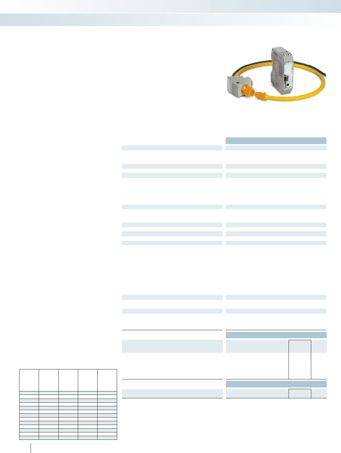
Technical data
Measuring coil input data
Frequency range 10 Hz ... 5000 Hz
Input signal Sine
Position error < 1 %
Measuring coil signal output
Output signal (at 50 Hz) 100 mV (no load, at 1000 A)
General data, measuring coil
Length of signal cable 3000 mm
Rated insulation voltage 1000 V AC (rms CAT III)
600 V AC (rms CAT IV)
Test voltage 10.45 kV (DC / 1 min.)
Ambient temperature (operation) -30 °C ... 80 °C (measuring coil)
Ambient temperature (storage/transport) -40 °C ... 90 °C (measuring coil)
Measuring transducer input data
Measuring ranges (current) via DIP switch 100 A, 250 A, 400 A, 630 A, 1000 A, 1500 A, 2000 A, 4000 A
Phase angle < 1 °
Measuring transducer signal input
Input signal (at 50 Hz) 100 mV (1000 A)
Measuring transducer signal output
Current output signal 0 A AC ... 1 A AC (effective at sine)
Miscellaneous data for measuring transducer
Nominal supply voltage 24 V DC -20% ... +25%
Nominal supply voltage range 19.2 V DC ... 30 V DC
Transmission error, maximum 0.5 % (of range final value)
Linearity error < 0.5 % (of range final value)
Frequency range 45 Hz ... 65 Hz
Degree of protection IP20
Test voltage 1.5 kV AC (supply/input and output: 50 Hz, 1 min)
Dimensions W / H / D 22.5 / 70.4 / 85 mm
Ambient temperature (operation) -20 °C ... 70 °C (measuring transducer)
Ambient temperature (storage/transport) -25 °C ... 85 °C (measuring transducer)
General data for the set
Altitude < 2000 m
Permissible humidity (operation) 5 % ... 95 % (non-condensing)
Approvals / conformities
Standards/specifications IEC61010-1
IEC61010-031
IEC61010-2-031
IEC61010-2-032
Ordering data
Description Type Order No. Pcs. /
Pkt.
Current transformer for retrofitting, set consisting of
Rogowski coil and measuring transducer, output signal: 1 A AC
(effective for sine)
Length of measuring coil 300 mm PACT RCP-4000A-1A-D95 2904921 1
Length of measuring coil 450 mm PACT RCP-4000A-1A-D140 2904922 1
Length of measuring coil 600 mm PACT RCP-4000A-1A-D190 2904923 1
Accessories
Holding device for power rail
PACT RCP-CLAMP 2904895 1
268
PHOENIX CONTACT
PACT RCP
– Practical handling due to the flexible
measuring coil for opening
– Universal application possibilities through
8 different current measuring ranges in
one device: (0 ... 100/ ... / ... /4000 A)
– The large bandwidth (10...5000 Hz)
enables harmonics and transients to be
detected
– It is not possible for dangerous open
circuit voltages to occur
– The bracket ensures optimum alignment
of the measuring coil to the power rail
– Low space requirement in the control
cabinet
Current transformers for retrofitting
Recommendations for the use of coil lengths and power rail
dimensions
Busbar Dia-
meter/
coil
length
1 busbar per
phase 2 busbars
per phase 3 busbars
per phase
[mm x mm] [mm]
30 x 10 95/300 X X
40 x 10 95/300 X X
40 x 10 140/450 X
50 x 10 95/300 X
50 x 10 140/450 X X
60 x 10 95/300 X
60 x 10 140/450 X X
60 x 10 140/450 X X X
100 x 10 140/450 X X
100 x 10 190/600 X
120 x 10 140/450 X
120 x 10 190/600 X X
160 x 10 190/600 X X X
Monitoring
Current measurement
Current transformer for subsequent
installation in the field

For further information and full technical data, visit phoenixcontact.net/products
Technical data
Measuring coil input data
Frequency range 10 Hz ... 5000 Hz
Input signal Sine
Position error < 1 %
Measuring coil signal output
Output signal (at 50 Hz) 100 mV (no load, at 1000 A)
General data, measuring coil
Length of signal cable 3000 mm
Rated insulation voltage 1000 V AC (rms CAT III)
600 V AC (rms CAT IV)
Test voltage 10.45 kV (DC / 1 min.)
Ambient temperature (operation) -30 °C ... 80 °C (measuring coil)
Measuring transducer input data
Measuring ranges (current) via DIP switch 100 A, 250 A, 400 A, 630 A, 1000 A, 1500 A, 2000 A, 4000 A
Measuring transducer signal input
Input signal (at 50 Hz) 100 mV (1000 A)
Measuring transducer signal output
Current output signal 0 mA ... 20 mA (via DIP switch)
4 mA ... 20 mA (via DIP switch)
0 mA ... 10 mA (via DIP switch)
2 mA ... 10 mA (via DIP switch)
0 mA ... 21 mA (can be set via software)
Output signal
Voltage
0 V ... 10 V (via DIP switch)
2 V ... 10 V (via DIP switch)
0 V ... 5 V (via DIP switch)
1 V ... 5 V (via DIP switch)
0 V ... 10.5 V (can be set via software)
Miscellaneous data for measuring transducer
Nominal supply voltage 24 V DC
Nominal supply voltage range 9.6 V DC ... 30 V DC
Transmission error, maximum 0.5 % (of range final value)
Frequency range 16 Hz ... 1000 Hz
Degree of protection IP20
Test voltage 3 kV (50 Hz, 1 min.)
Dimensions W / H / D 6.2 / 110.5 / 120.5 mm
Ambient temperature (operation) -40 °C ... 70 °C (measuring transducer)
General data for the set
Altitude > 4000 m
Permissible humidity (operation) 5 % ... 95 % (non-condensing)
Approvals / conformities
Standards/specifications IEC61010-1
IEC61010-031
IEC61010-2-031
IEC61010-2-032
Ordering data
Description Type Order No. Pcs. /
Pkt.
Current transformer with screw connection for retrofitting, set
consisting of Rogowski coil and 4-way signal conditioner with
switching output
Length of measuring coil 300 mm PACT RCP-4000A-UIRO-D95 2906231 1
Length of measuring coil 450 mm PACT RCP-4000A-UIRO-D140 2906232 1
Length of measuring coil 600 mm PACT RCP-4000A-UIRO-D190 2906233 1
Current transformer with push-in connection for retrofitting,
set consisting of Rogowski coil and 4-way signal conditioner with
switching output
Length of measuring coil 300 mm PACT RCP-4000A-UIRO-PT-D95 2906234 1
Length of measuring coil 450 mm PACT RCP-4000A-UIRO-PT-D140 2906235 1
Length of measuring coil 600 mm PACT RCP-4000A-UIRO-PT-D190 2906236 1
Accessories
Holding device for power rail
PACT RCP-CLAMP 2904895 1
269PHOENIX CONTACT
PACT RCP
– Universal application possibilities through
8 different current measuring ranges in
one device: (0 ... 100/ ... / ... /4000 A)
– Detection of harmonics and transients in
the frequency range from (16 ... 1000) Hz
– Large number of different standard signals
on output side
– Freely configurable 4-way signal
conditioner with switching output
– FASTCON Pro plug-in connection system
– Overall width of just 6.2 mm
– Easy configuration, e.g., via DIP switches,
programmable software, via smartphone
app or FDT/DTM
Current transformers for retrofitting
Monitoring
Current measurement
new
Current transformer for subsequent
installation in the field
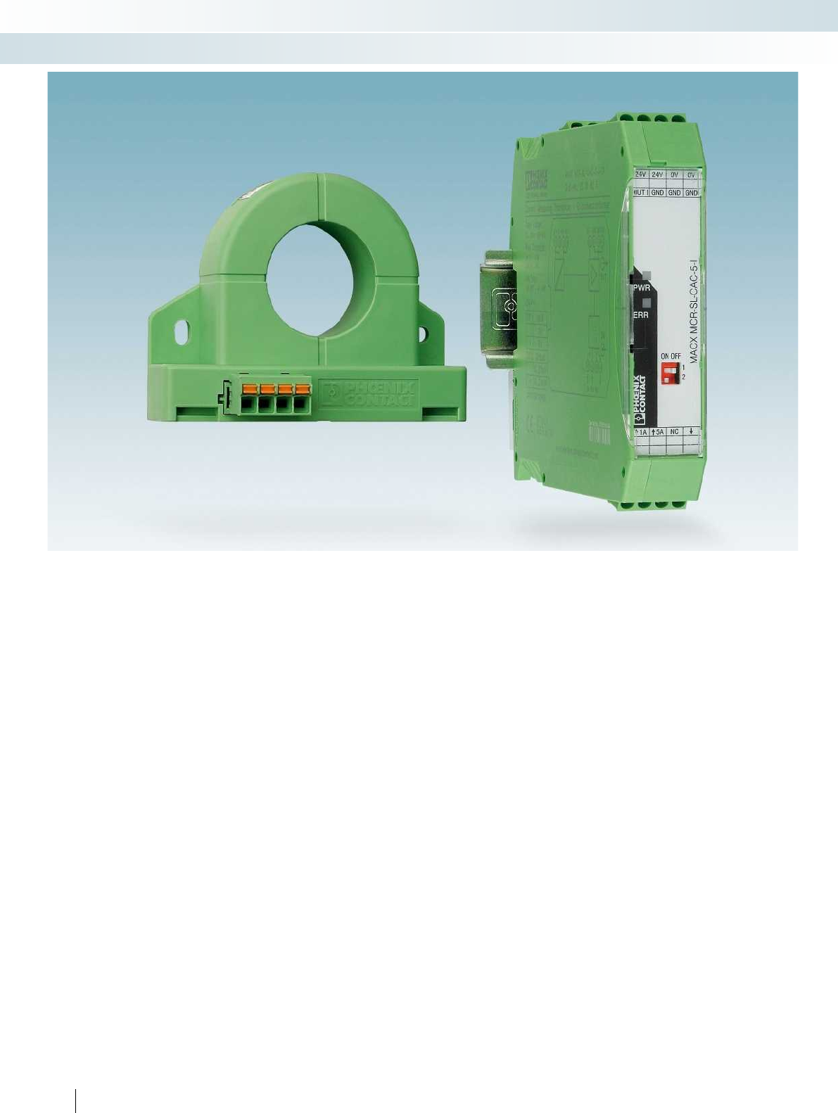
270
PHOENIX CONTACT
Monitoring
Current measurement
With flexible power supply – current
transducers up to 12 A AC
Active current transducers convert
sinusoidal alternating currents up to 12A.
The integrated wide range power supply
unit enables use in various different
countries.
With hinged Rogowski sensor –
current transducers up to 200 A AC
The AC current transducers measure
sinusoidal and non-sinusoidal alternating
currents up to 200 A. The hinged Rogowski
sensor ensures very easy installation, as
cables that are to be measured do not have
to be isolated. This enables mounting to be
carried out without interruptions.
Limit value monitoring with the
current protector
At the current protector, a desired
amperage is specified at which a PDT
contact switches a load on or off.
Flexible signal conditioning – current
transducers up to 55AAC/DC
Current transducers up to 55 A offer an
infinitely adjustable measuring range. This
range is mapped over the entire output
signal range. This ensures extremely
accurate resolution of measured values.
Basic configuration can be performed
quickly via the DIP switches. Additional
useful device functions can be set via the
software.
For high currents – current
transducers up to 600AAC/DC
The universal current transducers are the
ideal solution for measuring high currents
with any waveform up to 600 A AC/DC.
The product range offers various different
devices in graded measuring ranges with
current or voltage output.
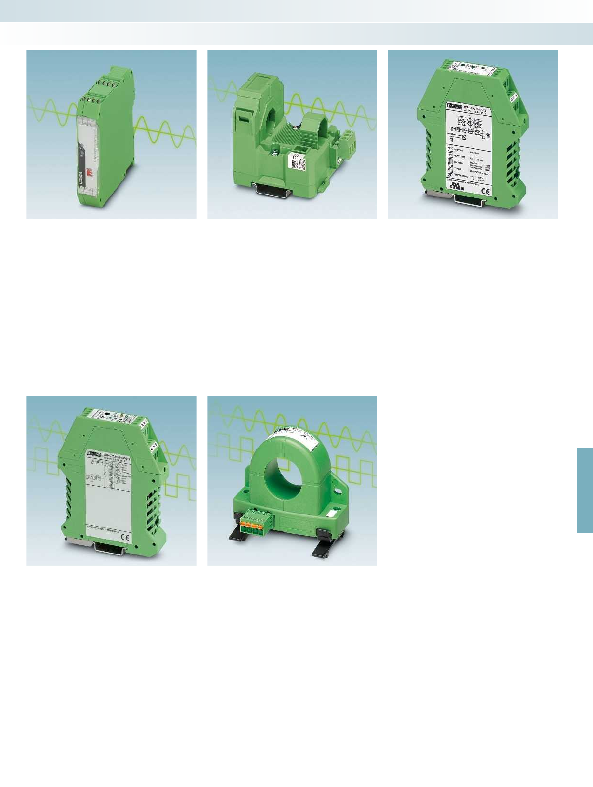
For further information and full technical data, visit phoenixcontact.net/products
271PHOENIX CONTACT
Monitoring
Current measurement
For sinusoidal alternating currents up
to 12 A
– 3-way electrical isolation
– Wide range version from
19.2 ... 253 V AC/DC
– Voltage bridging with DIN rail connector
– Input/output can be configured via DIP
switches
– Suitable for potentially explosive areas,
thanks to ATEX approval for Ex zone 2
For sinusoidal and non-sinusoidal
alternating currents up to 200 A
– Distorted alternating currents up to
6000 Hz can be also acquired, thanks to
true r.m.s. value measurement (RMS)
– Uninterrupted installation and lossless
current measurement thanks to hinged
Rogowski sensor
– Measuring range selection with slide
switch
Limit value monitoring
The current protector converts
sinusoidal alternating currents to binary
switching signals.
– Switching point can be freely selected in
the measuring range of 0 ... 16 A AC
– Changeover relay output
– Adjustable switch hysteresis
– 3-way isolation
– Operating current/quiescent current
behavior can be set
With flexible measuring ranges for all
waveforms up to 55 A
– Lossless true r.m.s. value measurement
without shunt via Hall sensor (TRMS)
– Optimum mapping of the measuring
range up to 55 A, thanks to software-
programmable upper and lower limits
– Limit value alarm in the event of threshold
value overrange or underrange up to 55 A
– via relay or transistor output
For high currents – current
transducers up to 600AAC/DC
– Lossless true r.m.s. value measurement
without shunt via Hall sensor (TRMS)
– Compact dimensions also enable
distributed use
– Variable mounting on DIN rail and
mounting plate
– COMBICON plug-in connection terminal
blocks
– 3-way isolation
– For a conductor diameter of up to 32 mm
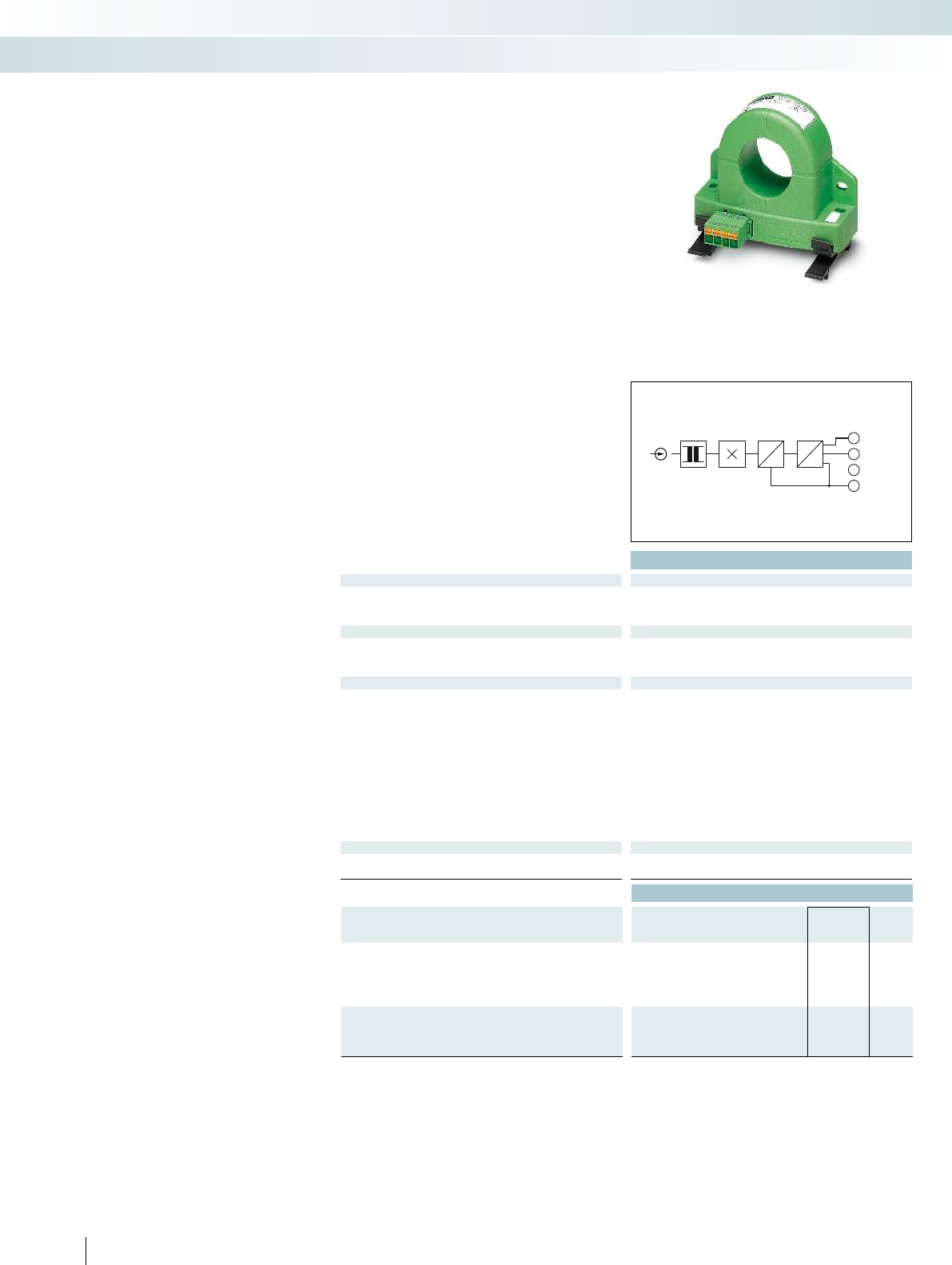
IN
1.3
1.4
1.2
1.1
GND
OUTU
NC
+24 V DC
ADC
μC
DAC
U
Housing width 90 mm
Technical data
Input data
Frequency range 20 Hz ... 6000 Hz (0 Hz) 20 Hz ... 6000 Hz (0 Hz)
Curve type AC, DC or distorted currents AC, DC or distorted currents
Connection method Cable design: 32 mm diameter Cable design: 32 mm diameter
Output data
Output signal 0 ... 10 V
Maximum output signal
Load R
B
10 k
General data
Supply voltage U
B
20 V DC ... 30 V DC
Maximum transmission error <± 1 % (of final value)
Temperature coefficient typ. 0.02 %/K (0 ... 60°C) 0.04 %/K (-40 ... 65°C) typ. 0.02 %/K (0 ... 60°C) 0.04 %/K (-40 ... 65°C)
Step response (10-90%) 150 ms
Safe isolation acc. to EN 61010
Rated insulation voltage 300 V AC
Surge voltage category / pollution degree III / 2
Degree of protection IP20
Ambient temperature range -40 °C ... 65 °C
Dimensions W / H / D 90 / 33.8 / 85 mm
Spring-cage connection solid / stranded / AWG 0.25 ... 2.5 mm² / 0.2 ... 2.5 mm² / 24 - 12 0.25 ... 2.5 mm² / 0.2 ... 2.5 mm² / 24 -
Conformance / approvals
Conformance CE-compliant
UL, USA / Canada UL/C-UL listed UL 508 UL/C-UL listed UL 508
Ordering data
Description Overload
capacity Type Order No. Pcs. /
Pkt.
Universal current transducer
Input current range: 0 ... 100 A 6 x I
IN
MCR-SL-CUC-100-U 2308108 1
Input current range: 0 ... 200 A 3 x I
IN
MCR-SL-CUC-200-U 2308205 1
Input current range: 0 ... 300 A 3.33 x I
IN
MCR-SL-CUC-300-U 2308302 1
Input current range: 0 ... 400 A 2.5 x I
IN
Universal current transducer without UL approval
Input current range: 0 ... 500 A 3.6 x I
IN
Input current range: 0 ... 600 A 3 x I
IN
272
PHOENIX CONTACT
Current transducers for AC/DC and
distorted currents
The MCR-SL-CUC-... current
transducers measure DC, AC, and
distorted currents of 0 ... 600 A.
– Universal current measurement, no shunt
required
– Compact dimensions also enable
distributed use
– Variable mounting on DIN rail and
mounting plate
– Simple connection method thanks to
COMBICON plug-in connection terminal
blocks
– 3-way isolation
Monitoring
Current measurement
For DC, AC, and distorted currents of
0 ... 300 A,
voltage output
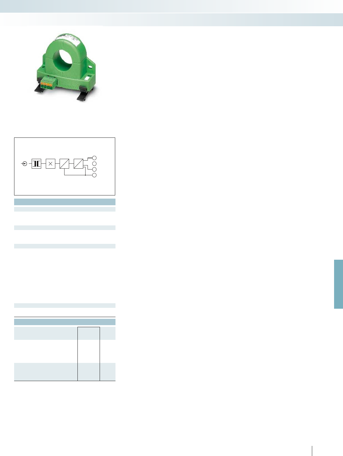
IN
1.3
1.4
1.2
1.1
GND
NC
OUT I
+24 V DC
ADC
μC
DAC
I
For further information and full technical data, visit phoenixcontact.net/products
Housing width 90 mm
Technical data
Frequency range 20 Hz ... 6000 Hz (0 Hz) 20 Hz ... 6000 Hz (0 Hz)
Curve type AC, DC or distorted currents AC, DC or distorted currents
Connection method Cable design: 32 mm diameter Cable design: 32 mm diameter
4 ... 20 mA
< 25 mA
< 300
20 V DC ... 30 V DC
<± 1 % (of final value)
Temperature coefficient typ. 0.02 %/K (0 ... 60°C) 0.04 %/K (-40 ... 65°C) typ. 0.02 %/K (0 ... 60°C) 0.04 %/K (-40 ... 65°C)
150 ms
acc. to EN 61010
300 V AC
III / 2
IP20
-40 °C ... 65 °C
90 / 33.8 / 85 mm
Spring-cage connection solid / stranded / AWG 0.25 ... 2.5 mm² / 0.2 ... 2.5 mm² / 24 - 12 0.25 ... 2.5 mm² / 0.2 ... 2.5 mm² / 24 - 12
CE-compliant
UL, USA / Canada UL/C-UL listed UL 508 UL/C-UL listed UL 508
Ordering data
Type Order No. Pcs. /
Pkt.
MCR-SL-CUC-100-I 2308027 1
MCR-SL-CUC-200-I 2308030 1
MCR-SL-CUC-300-I 2308043 1
MCR-SL-CUC-400-I 2308072 1
MCR-SL-CUC-500-I 2308085 1
MCR-SL-CUC-600-I 2308098 1
273PHOENIX CONTACT
Monitoring
Current measurement
For DC, AC, and distorted currents of
0 ... 600 A,
current output
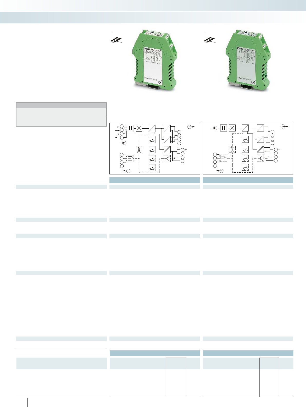
OUT
µC
ADC DAC
DAC
OUT
U
SPAN
9
OUTU
GND2
GND2
10
11
12
OUTI
Po
wer
=
12
10A
11
5A
14
1A
1
5
2
6
3
7
4
8
NC
ZEROTIME
24VDC
GND1
SW
13
14
15
GND1
16
IN
I
SET
POINT
OUT
µC
ADC DAC
DAC
OUT
U
SPAN
9
OUTU
GND2
GND2
10
11
12
OUTI
Po
wer
=
12
11
14
1
2
3
4
NC
ZEROTIME
24VDC
GND1
SW
13
14
15
GND1
16
IN
I
SET
POINT
Ex:
Ex:
Housing width 22.5 mm Housing width 22.5 mm
Technical data Technical data
Input data
Input current 0 A ... 11 A (AC/DC) 0 A ... 55 A (AC/DC)
Operate threshold 2 % (of measuring range nominal value 1/5/10 A) 0.8 % (of measuring range nominal value 50 A)
Frequency range 15 Hz ... 400 Hz 15 Hz ... 400 Hz
Curve type AC, DC or distorted currents AC, DC or distorted currents
Overload capacity 2 x I
N
(continuous) Depending on through connected conductor
Surge strength 20 x I
N
(1 s) Depending on through connected conductor
Connection method Screw connection Through connection, diameter 10.5 mm
Output data U output I output U output I output
Output signal (normal and inverse) 0 ... 5 V / 1 ... 5 V / 0 ... 10 V 0 ... 20 mA / 4 ... 20 mA 0 ... 5 V / 1 ... 5 V / 0 ... 10 V 0 ... 20 mA / 4 ... 20 mA
2 ... 10 V / -5 ... 5 V / -10 ... 10 V 2 ... 10 V / -5 ... 5 V / -10 ... 10 V
Load R
B
> 10 k< 500 > 10 k< 500
Switching output
Relay output Contact material 1 PDT / AgSnO, hard gold-plated 1 PDT / AgSnO, hard gold-plated
Max. switching current 50 mA (for gold layer, 30 V AC/ 36 V DC)
2 A (in case of a destroyed gold layer, 250 V AC)
50 mA (for gold layer, 30 V AC/ 36 V DC)
2 A (in case of a destroyed gold layer, 250 V AC)
Transistor output pnp Output voltage 19 V ... 29 V (supply voltage - 1 V) 19 V ... 29 V (supply voltage - 1 V)
Continuous load current 80 mA (not short-circuit-proof) 80 mA (not short-circuit-proof)
Setting range of the threshold value 1 % ... 110 % 1 % ... 110 %
Response delay 0.1 s ... 20 s 0.1 s ... 20 s
Status indication Yellow LED Yellow LED
General data
Supply voltage U
B
20 V DC ... 30 V DC 20 V DC ... 30 V DC
Current consumption < 50 mA (without load) < 50 mA (without load)
Maximum transmission error < 0.5 % (of nominal range value under nominal conditions) < 0.5 % (of nominal range value under nominal conditions)
Temperature coefficient typ. < 0.025 %/K typ. < 0.025 %/K
Step response (10-90%) 330 ms (with AC) 40 ms (with DC) 330 ms (with AC) 40 ms (with DC)
Safe isolation acc. to EN 50178, EN 61010 acc. to EN 50178, EN 61010
Rated insulation voltage 300 V AC (to ground) 300 V AC (to ground)
Surge voltage category / pollution degree III / 2 III / 2
Test voltage input/output 4 kV (50 Hz, 1 min.) 4 kV (50 Hz, 1 min.)
Test voltage input/power supply 4 kV (50 Hz, 1 min.) 4 kV (50 Hz, 1 min.)
Test voltage output/power supply 500 V (50 Hz, 1 min.) 500 V (50 Hz, 1 min.)
Degree of protection IP20 IP20
Dimensions W / H / D 22.5 / 99 / 114.5 mm 22.5 / 99 / 114.5 mm
Screw connection solid / stranded / AWG 0.2 ... 2.5 mm² / 0.2 ... 2.5 mm² / 24 - 14 0.2 ... 2.5 mm² / 0.2 ... 2.5 mm² / 24 - 14
EMC note Class A product, see page 625 Class A product, see page 625
Conformance / approvals
Conformance CE-compliant CE-compliant
UL, USA / Canada Class I, Zone 2, AEx nC IIC T6, Ex nC IIC T6 Class I, Zone 2, AEx nC IIC T6, Ex nC IIC T6
Ordering data Ordering data
Description Type Order No. Pcs. /
Pkt. Type Order No. Pcs. /
Pkt.
MCR current transducer for measuring AC, DC, and distorted
currents with relay and transistor switching output
Configurable product MCR-S-1-5-UI-SW-DCI 2814650 1MCR-S-10-50-UI-SW-DCI 2814663 1
Standard product MCR-S-1-5-UI-SW-DCI-NC 2814731 1MCR-S10-50-UI-SW-DCI-NC 2814744 1
Configurable product, without switching output MCR-S-1-5-UI-DCI 2814634 1MCR-S-10-50-UI-DCI 2814647 1
Standard product, without switching output MCR-S-1-5-UI-DCI-NC 2814715 1MCR-S10-50-UI-DCI-NC 2814728 1
274
PHOENIX CONTACT
The MCR-S-...-UI(-SW)-DCI current
transducers measure direct, alternating, and
distorted currents.
– Device can be set via DIP switches or
MCR/PI-CONF-WIN configuration
software
– True r.m.s. value measurement
– 3-way isolation
– With optional relay and transistor output
Notes:
To order a configurable product, enter the required configuration
by referring to the adjacent order key.
Further information about the configuration software can be found
on page 280
DW
H
DW
H
Current transducers for AC/DC and
distorted currents
Monitoring
Current measurement
For DC, AC, and distorted currents
0 ... 11 A
For DC, AC, and distorted currents
0 ... 55 A
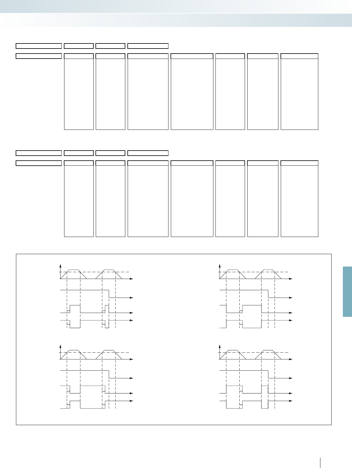
t
t
t
t
t1
t1
I
IN
(H)
(L)
t
t
t
t
t1t1
t1t1
I
IN
(H)
(L)
t
t
t
t
t1
t1
I
IN
(H)
(L)
t
t
t
t
t1t1
t1t1
I
IN
(H)
(L)
For further information and full technical data, visit phoenixcontact.net/products
275
PHOENIX CONTACT
Order key for the current transducers (standard configuration entered as example)
Functional diagram: switching behavior of relay and transistor output:
Order No.
Measuring range: Output Threshold value Suppression
time
Switching behavior of relay and transistor
Start End
2814634 / 0.00 / 5.00 / OUT01
2814650 / 0.00 / 5.00 / OUT01 / 50 / 3.0 / A / O
2814634 Measuring range
start value
between 0.00 ...
7.50 A
0.00 0.00 A
Measuring range
end value
between
0.2 ... 11 A
5.00 5.00 A
OUT01 0 ... 20 mA Switching threshold
between 1 ... 110%
between 0.1 ...
20 s
AOperating
current
controlled
OOverrun
MCR-S-1-5-UI-DCI OUT02 4 ... 20 mA
OUT03 0 ... 10 V
2814650 OUT04 2 ... 10 V 50 50% of set
measuring range
final value (here:
2.5 A)
3.0 3 s
MCR-S-1-5-UI-SW-DCI OUT05 0 ... 5 V
OUT06 1 ... 5 V R Closed-circuit
current
controlled
UUnderrun
OUT07 20 ... 0 mA
OUT08 20 ... 4 mA
OUT09 10 ... 0 V
OUT10 10 ... 2 V
OUT11 5 ... 0 V
OUT12 5 ... 1 V
OUT13 -5 ... +5 V
OUT14 -10 ... +10 V
OUT17 +10 ... -10 V
OUT18 +5 ... -5 V
Order No.
Measuring range: Output Threshold value Suppression
time
Switching behavior of relay and transistor
Start End
2814647 / 0.0 / 50.0 / OUT01
2814663 / 0.0 / 50.0 / OUT01 / 50 / 3.0 / A / O
2814647 Measuring range
start value
between 0.0 ...
37.5 A
0.0 0.0 A
Measuring range
end value
between
9.5 ... 55 A
50.0 50.0 A
OUT01 0 ... 20 mA Switching threshold
between 1 ... 110%
between 0.1 ...
20 s
AOperating
current
controlled
OOverrun
MCR-S-10-50-UI-DCI OUT02 4 ... 20 mA
OUT03 0 ... 10 V
2814663 OUT04 2 ... 10 V 50 50% of set
measuring range
final value (here: 25
A)
3.0 3 s
MCR-S-10-50-UI-SW-DCI OUT05 0 ... 5 V
OUT06 1 ... 5 V R Closed-circuit
current
controlled
UUnderrun
OUT07 20 ... 0 mA
OUT08 20 ... 4 mA
OUT09 10 ... 0 V
OUT10 10 ... 2 V
OUT11 5 ... 0 V
OUT12 5 ... 1 V
OUT13 -5 ... +5 V
OUT14 -10 ... +10 V
OUT17 +10 ... -10 V
OUT18 +5 ... -5 V
(1)
(0)
(0)
(1)
(1)
(0)
(0)
(1)
(0) N/O contact and transistor open / N/C contact closed
(1) N/O contact and transistor closed / N/C contact open
1) Operating current controlled when threshold value is exceeded
Operating voltage UB
SW condition
Relay N/O contact and
transistor output
Relay N/C contact
3) Closed-circuit current controlled when above threshold value 4) Closed-circuit current controlled when below the threshold value
Operating voltage UB
SW condition
Relay N/O contact and
transistor output
Relay N/C contact
(1)
(0)
(0)
(1)
Operating voltage UB
SW condition
Relay N/O contact and
transistor output
Relay N/C contact
2) Operating current controlled when threshold value is underrun
(1)
(0)
(0)
(1)
Operating voltage UB
SW condition
Relay N/O contact and
transistor output
Relay N/C contact
Monitoring
Current measurement
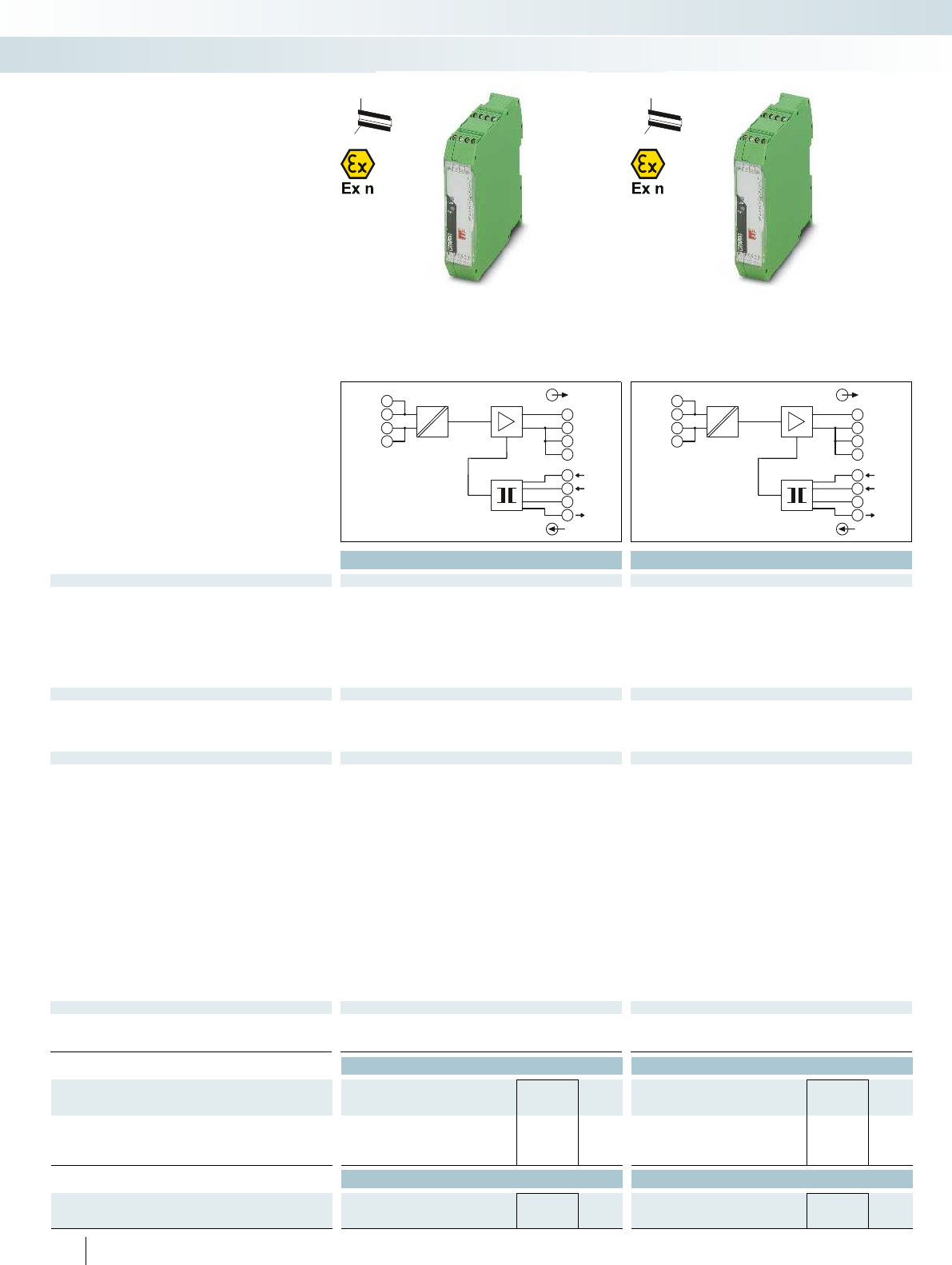
OUT
IN
4.1
3.1
1.1
4.2
3.2
1.2
4.3
3.3
1.3
4.4
3.4
1.4
5A
1A
GND
L(+) OUT1
L(+)
NC
GND
N(-)
GND
N(-)
OUT
IN
4.1
3.1
1.1
4.2
3.2
1.2
4.3
3.3
1.3
4.4
3.4
1.4
5A
12A
GND
L(+) OUT1
L(+)
NC
GND
N(-)
GND
N(-)
Ex:
Ex:
Housing width 22.5 mm Housing width 22.5 mm
Technical data Technical data
Input data
Input current (configurable) 0 A AC ... 1 A AC (configurable) / 0 A AC ... 5 A AC (configurable) 0 A AC ... 5 A AC (configurable) / 0 A AC ... 12 A AC (configurable)
Nominal frequency 50 Hz 50 Hz
Frequency range 45 Hz ... 65 Hz 45 Hz ... 65 Hz
Curve type Sine Sine
Overload capacity 2 x I
N
(continuous) 1 x I
N
(continuous)
Surge strength 20 x I
N
(1 s) 8 x I
N
(1 s)
Connection method Screw terminal block Screw terminal block
Output data
Output signal (configurable) 0 ... 20 mA / 4 ... 20 mA 0 ... 20 mA / 4 ... 20 mA
Maximum output signal 25 mA 25 mA
Load R
B
< 500 (at 20 mA) < 500 (at 20 mA)
Ripple < 10 mV
PP
(for 500 at 20 mA) < 10 mV
PP
(for 500 at 20 mA)
General data MACX MCR-SL-CAC- 5-I MACX MCR-SL-CAC- 5-I-UP MACX MCR-SL-CAC-12-I-UP
Supply voltage U
B
19.2 V DC ... 30 V DC 19.2 V AC/DC ... 253 V AC/DC 19.2 V AC/DC ... 253 V AC/DC -
Current consumption < 32 mA (at U
B
=24 V DC,
I
OUT
=20 mA)
< 30 mA (at U
B
=24 V DC,
I
OUT
=20 mA)
< 33 mA (at 24 V DC)
Maximum transmission error 0.5 % (of nominal range value
under nominal conditions)
0.5 % (of nominal range value
under nominal conditions)
0.5 % (of nominal range value
under nominal conditions)
-
Temperature coefficient < 0.02 %/K < 0.02 %/K < 0.02 %/K -
Step response (10-90%) max. 300 ms typ. 200 ms max. 300 ms typ. 200 ms < 300 ms -
Safe isolation acc. to EN 61010 acc. to EN 61010 acc. to EN 61010 -
Rated insulation voltage - - 300 V AC (to ground) -
Surge voltage category Input/output - - III -
Pollution degree 2 2 2 -
Test voltage input/output 4 kV (50 Hz, 1 min.) 4 kV (50 Hz, 1 min.) 4 kV (50 Hz, 1 min.) -
Test voltage output/power supply 1.5 kV (50 Hz, 1 min.) 2 kV (50 Hz, 1 min.) 2 kV (50 Hz, 1 min.) -
Degree of protection IP20 IP20 IP20 -
Ambient temperature range -20 °C ... 65 °C (-4°F ... 149°F) -20 °C ... 65 °C (-4°F ... 149°F) -20 °C ... 65 °C (-4°F ... 149°F) -
Dimensions W / H / D 22.5 / 104 / 114.5 mm 22.5 / 104 / 114.5 mm 22.5 / 104 / 114.5 mm - / - / -
Screw connection solid / stranded / AWG 0.2 ... 2.5 mm² / 0.2 ... 2.5 mm² /
24 - 14
0.2 ... 2.5 mm² / 0.2 ... 2.5 mm² /
24 - 14
0.2 ... 2.5 mm² / 0.2 ... 2.5 mm² /
24 - 14
- ... - / - ... - / -
Conformance / approvals
Conformance CE-compliant CE-compliant
ATEX
II 3 G Ex nA IIC T4 Gc X
II 3 G Ex nA IIC T4 Gc X
UL, USA / Canada UL 508 Recognized -
Ordering data Ordering data
Description Type Order No. Pcs. /
Pkt. Type Order No. Pcs. /
Pkt.
MCR current transducer for sinusoidal alternating currents
Supply voltage 19.2 ... 30 V DC MACX MCR-SL-CAC- 5-I 2810612 1
Supply voltage 19.2 ... 253 V AC/DC MACX MCR-SL-CAC- 5-I-UP 2810625 1MACX MCR-SL-CAC-12-I-UP 2810638 1
Accessories Accessories
DIN rail connector,
for bridging the supply voltage (19.2...30 V DC),
can be snapped onto 35 mm DIN rails as per EN 60715
ME 22,5 TBUS 1,5/ 5-ST-3,81 GN 2707437 50
276
PHOENIX CONTACT
The MCR-SL-CAC-... current
transducers measure sinusoidal alternating
currents within the range 0 ... 1/5/12 A.
– Wide range version from
19.2 ... 253 V AC/DC
– 3-way isolation
– Input/output can be configured using the
DIP switch
H
W
D
H
W
D
AC current transducers,
sinusoidal
Monitoring
Current measurement
For sinusoidal alternating currents
0 ... 1 A/0 ... 5 A
For sinusoidal alternating currents
0 ... 5 A/0 ... 12 A
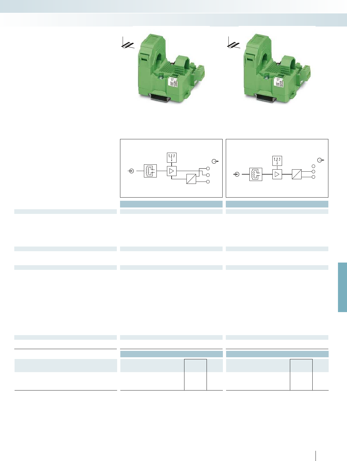
OUT
+24V
GND
=
=
IN
OUT
OUT
+24V
U
I
IN
OUT
For further information and full technical data, visit phoenixcontact.net/products
Ex:
Ex:
Housing width 55 mm Housing width 55 mm
Technical data Technical data
Input data ...-S-100-U ...-S-200-U ...-S-100-I-LP ...-S-200-I-LP
Input current (configurable) 0 A ... 100 A (0...50/75/100 A) 0 A ... 200 A (0..100/150/200 A) 0 A ... 100 A (0...50/75/100 A) 0 A ... 200 A (0...100/150/200 A)
Operate threshold 1 % (of final value) 1 % (of final value)
Frequency range 30 Hz ... 6000 Hz 30 Hz ... 6000 Hz
Curve type Sinusoidal and non-sinusoidal Sinusoidal and non-sinusoidal
Overload capacity Depending on laid conductor Depending on laid conductor
Surge strength Depending on through connected conductor Depending on through connected conductor
Connection method Clamp-on cable design, diameter 18.5 mm Clamp-on cable design, diameter 18.5 mm
Output data
Output signal 0 ... 5 V / 0 ... 10 V 4 ... 20 mA
Maximum output signal (0 V ... 10 V) 14 V, (0 V ... 5 V) 7 V < 25 mA
Load R
B
10 k(U
B
- 12 V) x 350 / 12 A
General data
Supply voltage U
B
20 V DC ... 30 V DC 20 V DC ... 30 V DC
Current consumption < 30 mA
Maximum transmission error < 1 % (of final value) < 1 % (of final value)
Cable position error < 0.63 % < 0.63 %
Temperature coefficient < 0.035 %/K < 0.025 %/K
Step response (10-90%) < 340 ms < 340 ms
Safe isolation As per IEC 61010-1 and IEC 61326 As per IEC 61010-1 and IEC 61326
Rated insulation voltage 300 V AC (to ground) 300 V AC (to ground)
Surge voltage category / pollution degree III / 2 III / 2
Test voltage input/output 5 kV (50 Hz, 1 min.) 5 kV (50 Hz, 1 min.)
Degree of protection IP20 IP20
Ambient temperature range -20 °C ... 60 °C -20 °C ... 60 °C
Dimensions W / H / D 55 / 85 / 70.5 mm 55 / 85 / 70.5 mm
Screw connection solid / stranded / AWG 0.2 ... 2.5 mm² / 0.2 ... 2.5 mm² / 24 - 14 0.2 ... 2.5 mm² / 0.2 ... 2.5 mm² / 24 - 14
Conformance / approvals
Conformance CE-compliant CE-compliant
UL, USA / Canada cULus cULus
Ordering data Ordering data
Description Type Order No. Pcs. /
Pkt. Type Order No. Pcs. /
Pkt.
MCR current transducer for sinusoidal and non-sinusoidal
alternating currents
Input current range: 0...50/75/100 A MCR-SL-S-100-U 2813457 1MCR-SL-S-100-I-LP 2813486 1
Input current range: 0..0.100/150/200 A MCR-SL-S-200-U 2813460 1MCR-SL-S-200-I-LP 2813499 1
277
PHOENIX CONTACT
The MCR-SL-S-...00-... current
transducers measure sinusoidal and non-
sinusoidal alternating currents within the
range 0 ... 200 A.
– True r.m.s. value measurement from
30...6000 Hz
– Measuring range selection with slide
switch
– Loop-powered
– Can be retrofitted with the hinged
Rogowski coil
DW
H
DW
H
AC current transducers,
sinusoidal and distorted
Monitoring
Current measurement
For sinusoidal and non-sinusoidal
alternating currents, 0 ... 200 A,
voltage output
For sinusoidal and non-sinusoidal
alternating currents, 0 ... 200 A,
current output (loop-powered)

OUT
IN
4
2
19
12
11
10
3
5A
1A
OUTU
OUTI
I
OUT
NC
GND
500
GND
J
Housing width 22.5 mm
Technical data
Input data 1 A input 5 A input
Input current 0 A AC ... 1 A AC 0 A AC ... 5 A AC
Frequency range 45 Hz ... 60 Hz 45 Hz ... 60 Hz
Curve type Sine Sine
Overload capacity 2 x I
N
(5 min. at 60°C ambient
temperature)
-
Surge strength 50 A (1 s) 100 A (1 s)
Permissible output range 1.2 x I
N
1.2 x I
N
Connection method Screw connection Screw connection
Output data U output I output
Output signal 0 ... 10 V 0 ... 20 mA
Maximum output signal 20 V 30 mA
Load R
B
> 100 k< 750
< 250 (when current and
voltage outputs are used
simultaneously)
Ripple < 50 mV
PP
< 50 mV
PP
General data
Maximum transmission error < 0.5 % (of final value)
Temperature coefficient < 0.015 %/K
Step response (10-90%) < 200 ms
Safe isolation acc. to EN 50178, EN 61010
Rated insulation voltage 300 V AC (to ground)
Surge voltage category / pollution degree III / 2
Test voltage input/output 4 kV (50 Hz, 1 min.)
Degree of protection IP20
Ambient temperature range -25 °C ... 60 °C
Dimensions W / H / D 22.5 / 99 / 114.5 mm
Screw connection solid / stranded / AWG 0.2 ... 2.5 mm² / 0.2 ... 2.5 mm² / 24 - 14
EMC note Class A product, see page 625
Conformance / approvals
Conformance CE-compliant
Ordering data
Description Type Order No. Pcs. /
Pkt.
MCR passive current transducer for sinusoidal alternating
currents
MCR-SLP-1-5-UI-0 2814359 1
278
PHOENIX CONTACT
DW
H
The MCR-SLP-1-5-UI-0 passive current
transducer measures sinusoidal alternating
currents within the range 0 ... 1 A/0 ... 5 A.
– Loop-powered
– Measuring ranges 1 A and 5 A AC,
reconnectable
Passive AC current transducer,
sinusoidal
Monitoring
Current measurement
For sinusoidal alternating currents
0 ... 1 A/0 ... 5 A
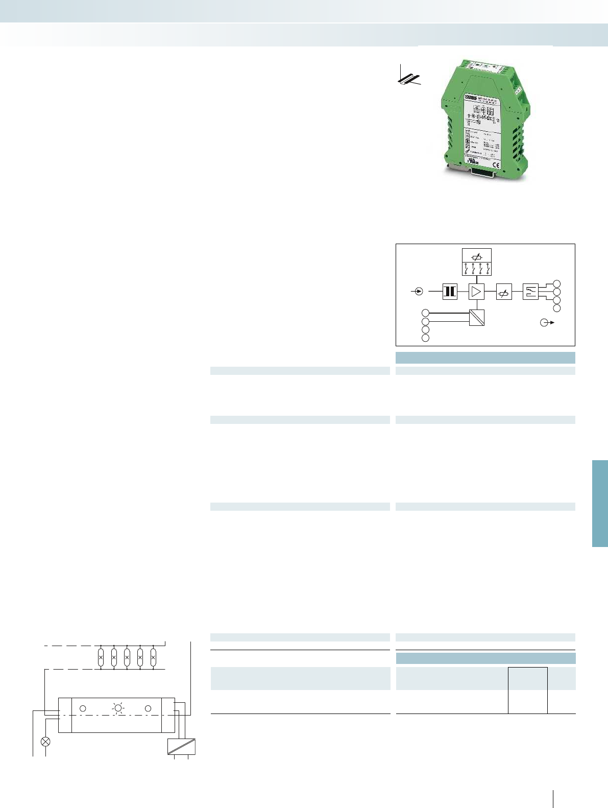
MCR - SL - S - 16 - SP - 24
+ 24V
NC
RELAY ACTIV
DELAY TIME
NC
SETPOINT
GND
24V
L1
N
N
14
11
12
NC
50
0
10
20
K
30
40
L2
OUT
IN
5
7
6
8
12
15
14
14
13
11
16
NC
NC
GND
NCNC
24V DC
=
=
SETPOINT
Delay
For further information and full technical data, visit phoenixcontact.net/products
Housing width 22.5 mm
Technical data
Input data
Input current 0 A AC ... 16 A AC
Frequency range 45 Hz ... 65 Hz
Curve type Sine
Overload capacity 2 x I
N
(continuous)
Connection method Through connection, diameter 4.2 mm
Switching output Relay output
Contact type 1 PDT
Contact material AgSnO, hard gold-plated
Max. switching current 50 mA (for gold layer, 30 V AC/ 36 V DC)
2 A (in case of a destroyed gold layer, 250 V AC)
Switching hysteresis Adjustable using a DIP switch (0.5 %, 5 %, 10 %, 15 %)
Response delay typ. 0.1 s ... 10 s (adjustable using a potentiometer)
Operating and closed-circuit current behavior Adjustable using a DIP switch
Relay status display Yellow LED (relay active)
General data
Supply voltage U
B
20 V DC ... 30 V DC
Current consumption < 30 mA
Setting accuracy < 0.5 %
Temperature coefficient < 0.02 %/K
Step response (10-90%) 40 ms
Safe isolation acc. to EN 50178, EN 61010-1
Rated insulation voltage 300 V AC (to ground)
Surge voltage category / pollution degree III / 2
Test voltage input/output 4 kV (50 Hz, 1 min.)
Test voltage input/power supply 4 kV (50 Hz, 1 min.)
Degree of protection IP20
Ambient temperature range -20 °C ... 65 °C
Dimensions W / H / D 22.5 / 99 / 114.5 mm
Screw connection solid / stranded / AWG 0.2 ... 2.5 mm² / 0.2 ... 2.5 mm² / 24 - 14
EMC note Class A product, see page 625
Conformance / approvals
Conformance CE-compliant
Ordering data
Description Type Order No. Pcs. /
Pkt.
MCR current protector for sinusoidal alternating currents
MCR-SL-S- 16-SP- 24 2864464 1
279
PHOENIX CONTACT
Emergency lighting
Lighting system
Mains voltage
Lighting system with emergency lighting
DW
H
The MCR-SL-S-16-SP-24 current
protector converts sinusoidal 50 Hz/60 Hz
alternating currents into binary switching
signals.
– Switching point can be freely selected in
the measuring range of 0...16 A AC
– Changeover relay output
– Adjustable switch hysteresis
– 3-way isolation
– Operating current/quiescent current
behavior can be set
AC current protector, sinusoidal
Monitoring
Current measurement
For sinusoidal alternating currents,
0 ... 16 A AC
Ordering data
Description Type Order No. Pcs. /
Pkt.
MCR configuration software, for programming MCR-T-...-,
MCR-...-LP-...-, MCR-...-HT-...-, MCR-S-...-, MCR-F-..., and
MCR-PSP-... modules, CD-ROM
MCR/PI-CONF-WIN 2814799 1
Accessories
Labels, for marking MCR-T and MCR-S modules, four sheets
DIN A4 marking labels (112 pieces.)
MCR-ET 38X35 WH 2814317 1
The MCR/PI-CONF-WIN
configuration software package is used
to configure and visualize all parameters for
the programmable MCR measuring
transducers.
– Straightforward menu interface
– Rapid programming
Notes:
The software runs under the following operating systems:
Windows NT™, 2000™, and XP™.
Accessories
Configuration software package
Monitoring
Current measurement
For MCR-S-... current transducer
Ordering data
Description Type Order No. Pcs. /
Pkt.
USB adapter cable,
D-9-SUB to USB, with adapter D-9-SUB to D-25-SUB
CM-KBL-RS232/USB 2881078 1
Software adapter cable (stereo jack plug/25-pos. D-SUB),
1.2 m long, for programming MCR-T-..., MCR-S-..., and
MCR-F-... modules
MCR-TTL-RS232-E 2814388 1
Accessories
Adapter cable, flexible, 9-pos. D-SUB socket to
25-pos. D-SUB pin
PSM-KAD 9 SUB 25/BS 2761295 1
280
PHOENIX CONTACT
The following adapter cables are available
for programming the MCR-S... current
transducers:
– USB adapter cable
– Software adapter cable
USB adapter cable
Software adapter cable
For MCR-S-... current transducer

For further information and full technical data, visit phoenixcontact.net/products
281PHOENIX CONTACT
Monitoring
Current measurement

282
PHOENIX CONTACT
Monitoring
Monitoring and diagnostics
Utilize solar electricity efficiently
Detect errors – increase efficiency:
photovoltaic systems should achieve
maximum energy yield within the shortest
possible time.
SOLARCHECK provides reliable
information regarding the performance of
your photovoltaic system. It can be used to
detect faults, which may be caused by
damaged panels, defective contacts or
damage in the cabling. This allows you to
implement countermeasures quickly,
thereby increasing the efficiency of your
system.
Current topic: reliable monitoring
Whether a small roof-top system on a
family home or a megawatt outdoor system:
for reliable operation, the photovoltaic
market requires monitoring systems where
status information is continuously available
and visualization is easy. PhoenixContact
offers a comprehensive portfolio of
hardware and software products specifically
designed for this purpose.
Energy of the future
From installation to monitoring - in the
“Components and systems for
photovoltaics” brochure you will find
further innovative solutions for your
photovoltaic system, such as:
– Connection technology
– Surge protection
– Hardware and software solutions
– Generator connection boxes
– Tools and marking
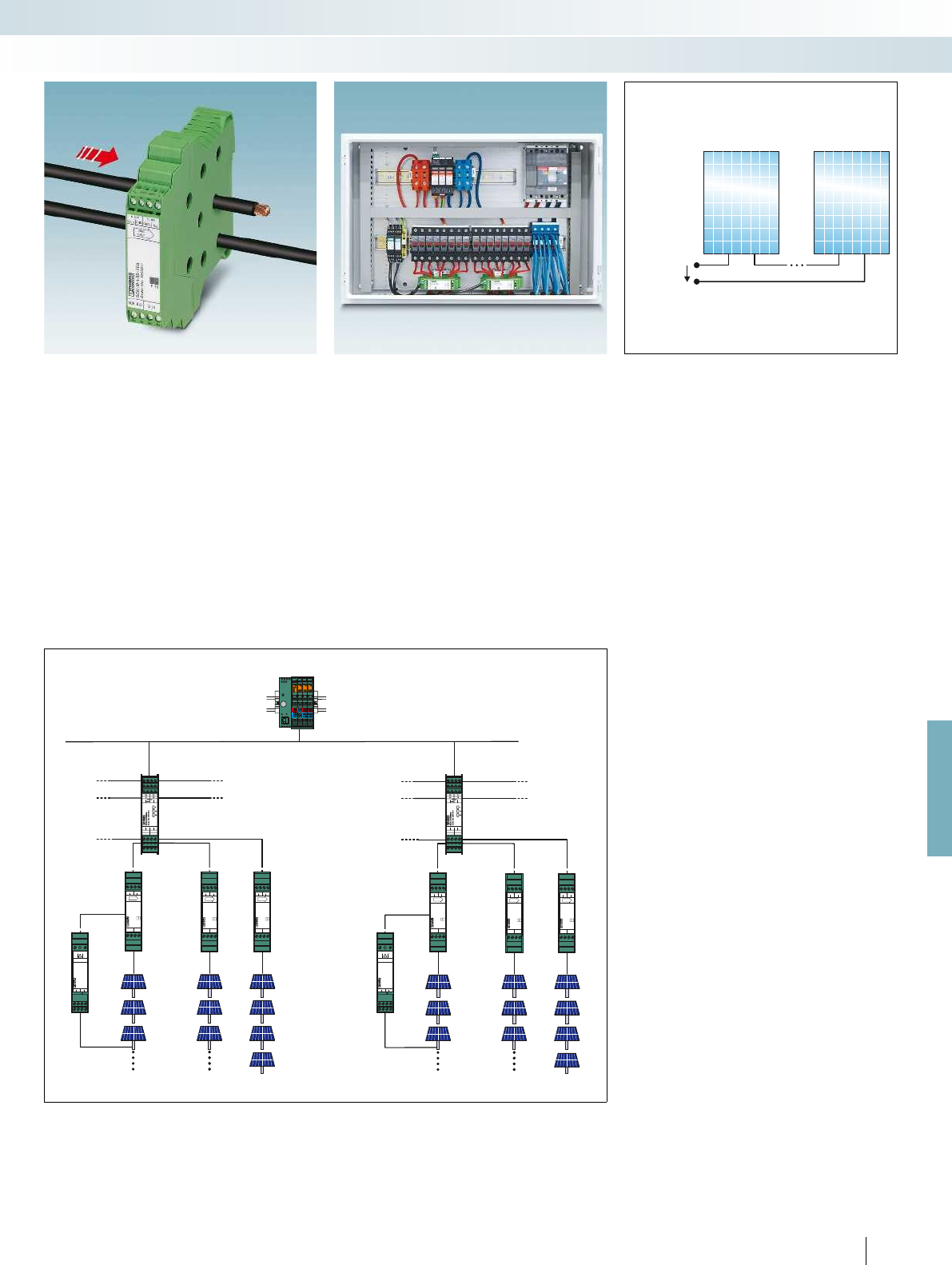
1....8 x SCK-M-...
SCK-C-MODBUS
Modbus RTU slave
1....8 x SCK-M-...
SCK-C-MODBUS
Modbus RTU slave
MRESET
STOP
RUN/PROG
LNK ACT
GSM
AV TR
US
UL
UM
E
RDY
FAIL
BSA
PF
I5
I7
I2
I6
I8
I13
I15
I10
I14
I16
1 x 1500 V
≤8 x 0...20 A DC
≤8 x 0...20 A DC
≤8 x 0...20 A DC
≤8 x 0...20 A DC
≤4 x 0...20 A DC
≤4 x 0...20 A DC
SCK-M-U-1500V
SCK-M-I-8S-... SCK-M-I-8S-... SCK-M-I-4S-...
1 x 1500 V
SCK-M-U-1500V
SCK-M-I-8S-... SCK-M-I-8S-... SCK-M-I-4S-...
P_OUT
SCK-M-I-4S-20A
Order No. 2903242
P
SCK BUSD_IN
TX
0...10V
U
OUT
U
IN
0...10V
GND2GND1
STRING
CURRENT
P_OUT
SCK-M-I-8S-20A
Order No. 2903241
P
SCK BUSD_IN
TX
0...10V
U
OUT
U
IN
0...10V
GND2GND1
STRING
CURRENT
P_OUT
SCK-M-I-8S-20A
Order No. 2903241
P
SCK BUSD_IN
TX
0...10V
U
OUT
U
IN
0...10V
GND2GND1
STRING
CURRENT
P_OUT
SCK-M-I-8S-4A
Order No. 2903239
P
SCK BUSD_IN
TX
0...10V
U
OUT
U
IN
0...10V
GND2GND1
STRING
CURRENT
P_OUT
SCK-M-I-8S-4A
Order No. 2903239
P
SCK BUSD_IN
TX
0...10V
U
OUT
U
IN
0...10V
GND2GND1
STRING
CURRENT
P_OUT
SCK-M-I-8S-4A
Order No. 2903239
P
SCK BUSD_IN
TX
0...10V
U
OUT
U
IN
0...10V
GND2GND1
STRING
CURRENT
P_OUT
SCK-M-I-4S-20A
Order No. 2903242
P
SCK BUSD_IN
TX
0...10V
U
OUT
U
IN
0...10V
GND2GND1
STRING
CURRENT
P_OUT
SCK-M-I-8S-20A
Order No. 2903241
P
SCK BUSD_IN
TX
0...10V
U
OUT
U
IN
0...10V
GND2GND1
STRING
CURRENT
P_OUT
SCK-M-I-8S-20A
Order No. 2903241
P
SCK BUSD_IN
TX
0...10V
U
OUT
U
IN
0...10V
GND2GND1
STRING
CURRENT
SCK-M-U-1500V
Order No. 2903591
!
-+
+-24V 0V
VOLTAGE INPUT MAX 1500V DC
2...10 V OUTP - In
PE
SCK-M-U-1500V
Order No. 2903591
!
-+
+-24V 0V
VOLTAGE INPUT MAX 1500V DC
2...10 V OUTP - In
PE
T7
T8
T5T6
COM
GND2 GND2 BA
+24V GND1GND1
T7
T8
T5T6
COM
GND2 GND2 BA
+24V GND1GND1
1500 V DC
For further information and full technical data, visit phoenixcontact.net/products
283PHOENIX CONTACT
Contact-free current measurement
Contact-free measurement using Hall
sensors offers many advantages:
– Safe isolation is already ensured by the
cable insulation.
– No contact resistance due to additional
contact points.
– The current is forwarded safely as the line
circuit is not directly accessed.
Space-saving installation without an
additional power supply
With a width of just 22.5 mm, the
narrow measuring module bundles the
cables in a confined space.
– The 2-wire communication cable is also
used to supply the measuring modules.
– This means that one communication
module supplies up to eight measuring
modules – without an additional power
supply.
Flexible expansion
Optional extension of voltage
measurement up to 1500 V DC.
– Also suitable for grounded systems.
– Suitable for PV systems with extra high
system voltages
– Flexible use, even outside the
SOLARCHECK system
Easy integration in monitoring
systems
The modular SOLARCHECK
monitoring system consists of various
measuring modules for current and voltage
measurement and an associated
communication module.
The communication module collects the
measured values from the current measuring
modules and forwards them to a higher-level
controller. You can acquire up to eight or
four string currents with one current
measuring module each. A maximum of eight
current measuring modules of any type can
be connected to one communication
module. The 2-wire communication cable is
also used to supply the measuring modules
with power. This means that no additional
power supply is required in the field.
The voltage measuring module is usually
connected to and also supplied via the
analog input provided on the 8-channel
current measuring modules.
Monitoring
Monitoring and diagnostics

A
+24 V
B
GND1
GND2
GND2
GND1
+24 V
DC
DC
RS-485
C
INPUT
SCK-MODBUS
T1
T2
T3
T4
T5
T6
T7
T8
Housing width 22.5 mm Housing width 22.5 mm Housing width 22.5 mm Housing width 22.5 mm
Technical data
Supply
Supply voltage 24 V DC -10 % ... +25 % Via SCK-C-MODBUS Via SC
Own current consumption 22 mA (typical)
Measuring input
Current measuring range -
Transmission error, maximum -
Temperature coefficient -
Reverse current detection -
Number of measuring channels -
Voltage measuring range -
Connection method -
Digital input
Controlled by external floating contact -
Analog input
Input voltage range -
Analog output
Output voltage range -
SCK-C-MODBUS data interface
Cable length (for 0.15 mm²) -
Communication protocol Proprietary
Serial port RS-485
Serial transmission speed 9.6/14.4/19.2/38.4 kbps - - -
Cable length 1200 m
Communication protocol Modbus/RTU
General data
Degree of protection IP20
Ambient temperature range -20 °C ... 70 °C
Dimensions W / H / D 22.5 / 102 / 106 mm
Screw connection solid / stranded / AWG 0.2 ... 2.5 mm² / 0.2 ... 2.5 mm² / 24 - 12 0.2 ... 2.5 mm² / 0.2 ... 2.5 mm² / 24 - 12 0.2
EMC note Class A product, see page 625 Class A product, see page 625 Class A product, see page 625 Class A product, see page 625
Conformance / approvals
Conformance CE-compliant
UL, USA 1741 Recognized
UL, USA / Canada 508 Listed
Ordering data
Description Type Order No. Pcs. /
Pkt.
Communication module
SCK-C-MODBUS 2901674 1
Current measuring module, 8-channel
Current measuring module, 4-channel for extension
Voltage measuring module
284
PHOENIX CONTACT
Solar system monitoring
PV string monitoring
SOLARCHECK
The modular SOLARCHECK monitoring
system consists of various devices for
current and voltage measurement and an
associated communication module.
Communication module:
– For connecting and collecting measured
values from up to eight measuring
modules
– Provision of data for transfer to higher-
level controllers
Current measuring modules:
– 8-channel current measurement up
to20ADC
– Detection of reverse currents
up to-1A
– 4-channel extension modules
for20ADC
– Internal temperature monitoring
– Digital input for monitoring, e.g., the
remote indication contacts of surge
protection modules
– Supply via the communication module
Voltage measuring module
– Voltage measurement up to 1500 V DC in
any grounded PV system
– Connection and supply is usually via the
analog input provided (0 ... 10 V) on the
8-channel SOLARCHECK current
measuring module
– Output of the voltage measured value as
a 2 ... 10 V analog signal
– As an option, can also be removed from
the SOLARCHECK group and used
separately
Monitoring
Monitoring and diagnostics
H
W
D
Communication module
RS-485 (Modbus RTU)
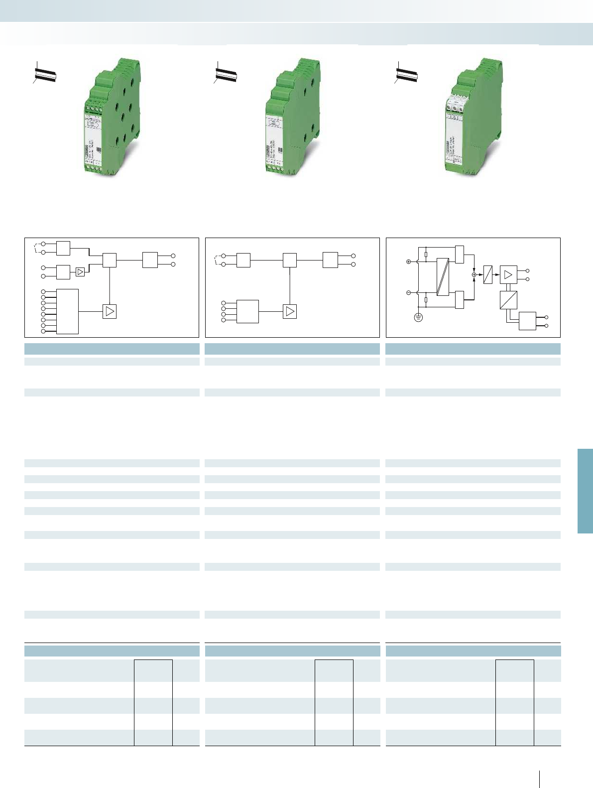
SCK-
BUS
OUT
U-IN
Digital
IN
1
+
–
2
3
4
5
6
7
8
I-IN
μ
C
COM
8x
0...10V
1
2
3
4
I-IN
m
C
SCK-
BUS
OUT COM
4x
Digital
IN
U1
U2
U_OUT
P_IN 0 V
24 V
0...1500 V DC
RX
RX
For further information and full technical data, visit phoenixcontact.net/products
Housing width 22.5 mm Housing width 22.5 mm Housing width 22.5 mm Housing width 22.5 mm
Technical data Technical data Technical data
Supply voltage 24 V DC -10 % ... +25 % Via SCK-C-MODBUS Via SCK-C-MODBUS 24 V DC -10 % ... +25 % (or via SSCK-M-I-8S-20A)
43 mA (typical) 43 mA (typical) 8 mA (typical)
0 A DC ... 20 A DC (UL: 0 A DC...25 A DC) 0 A DC ... 20 A DC (UL: 0 A DC...25 A DC) -
± 1 % (of measuring range final value) ± 1 % (of measuring range final value) ± 1 % (after additional tuning (valid for 100 - 1500 V DC))
0.02 %/K (T
K20
) 0.02 %/K (T
K20
) < 0.01 %/K
-1 A DC ... 0 A DC -1 A DC ... 0 A DC -
841
- - 0 V DC ... 1500 V DC
Through connection, 9.5 mm diameter Through connection, 9.5 mm diameter Screw connection
Floating switch contacts Floating switch contacts -
0 V ... 10 V - -
- - 2 V DC ... 10 V DC
300 m (0.14 mm²) 300 m (0.14 mm²) -
Proprietary Proprietary -
Serial transmission speed 9.6/14.4/19.2/38.4 kbps - - -
---
---
IP20 IP20 IP20
-20 °C ... 70 °C -20 °C ... 70 °C -20 °C ... 70 °C
22.5 / 102 / 128.5 mm 22.5 / 102 / 128.5 mm 22.5 / 102 / 128.5 mm
Screw connection solid / stranded / AWG 0.2 ... 2.5 mm² / 0.2 ... 2.5 mm² / 24 - 12 0.2 ... 2.5 mm² / 0.2 ... 2.5 mm² / 24 - 12 0.2 ... 2.5 mm² / 0.2 ... 2.5 mm² / 24 - 12 0.2 ... 2.5 mm² / 0.2 ... 2.5 mm² / 24 - 12
EMC note Class A product, see page 625 Class A product, see page 625 Class A product, see page 625 Class A product, see page 625
CE-compliant CE-compliant CE-compliant
1741 Recognized 1741 Recognized 1741 Recognized
508 Listed 508 Listed 508 Listed
Ordering data Ordering data Ordering data
Type Order No. Pcs. /
Pkt. Type Order No. Pcs. /
Pkt. Type Order No. Pcs. /
Pkt.
SCK-M-I-8S-20A 2903241 1
SCK-M-I-4S-20A 2903242 1
SCK-M-U-1500V 2903591 1
285
PHOENIX CONTACT
Monitoring
Monitoring and diagnostics
H
W
D
H
W
D
H
W
D
Current measuring module, 20 A DC,
8-channel
Extension module, 4-channel
Current measurement 20 A DC
Voltage measuring module,
0...1500 VDC

L
N
PE
I
L
I
F
L
N
PE
I
L
I
F
L
1
L2
L
3
N
PE
I
L
I
F
I
L
t
t
I
L
t
I
L
I
F
t
I
F
t
I
F
t
RCM devices provide residual current
monitoring in grounded power supply
systems. They detect residual currents at an
early stage such as those that occur as a
result of insulation errors. They can
therefore be used to prevent forced system
shutdown. Plans can be made to remove
errors outside of operating hours. RCM
devices also act as a form of fire prevention.
Detect errors before they actually
occur
Increasing use is being made of equipment
such as frequency inverters. In the event of
an error, residual currents with a frequency
of up to 50 kHz can be generated. Type B+
RCM devices from Phoenix Contact are
already able to detect residual currents with
frequencies up to 100 kHz. This far exceeds
present-day requirements of 20 kHz for
type B+ devices.
Single-phase Single-phase
with smoothing
Three-phase
star circuit
Circuit
Correct load current
Residual current
to ground potential
Solution
Type A – –
Type B Type B Type B
286
PHOENIX CONTACT
Monitoring
Monitoring and diagnostics
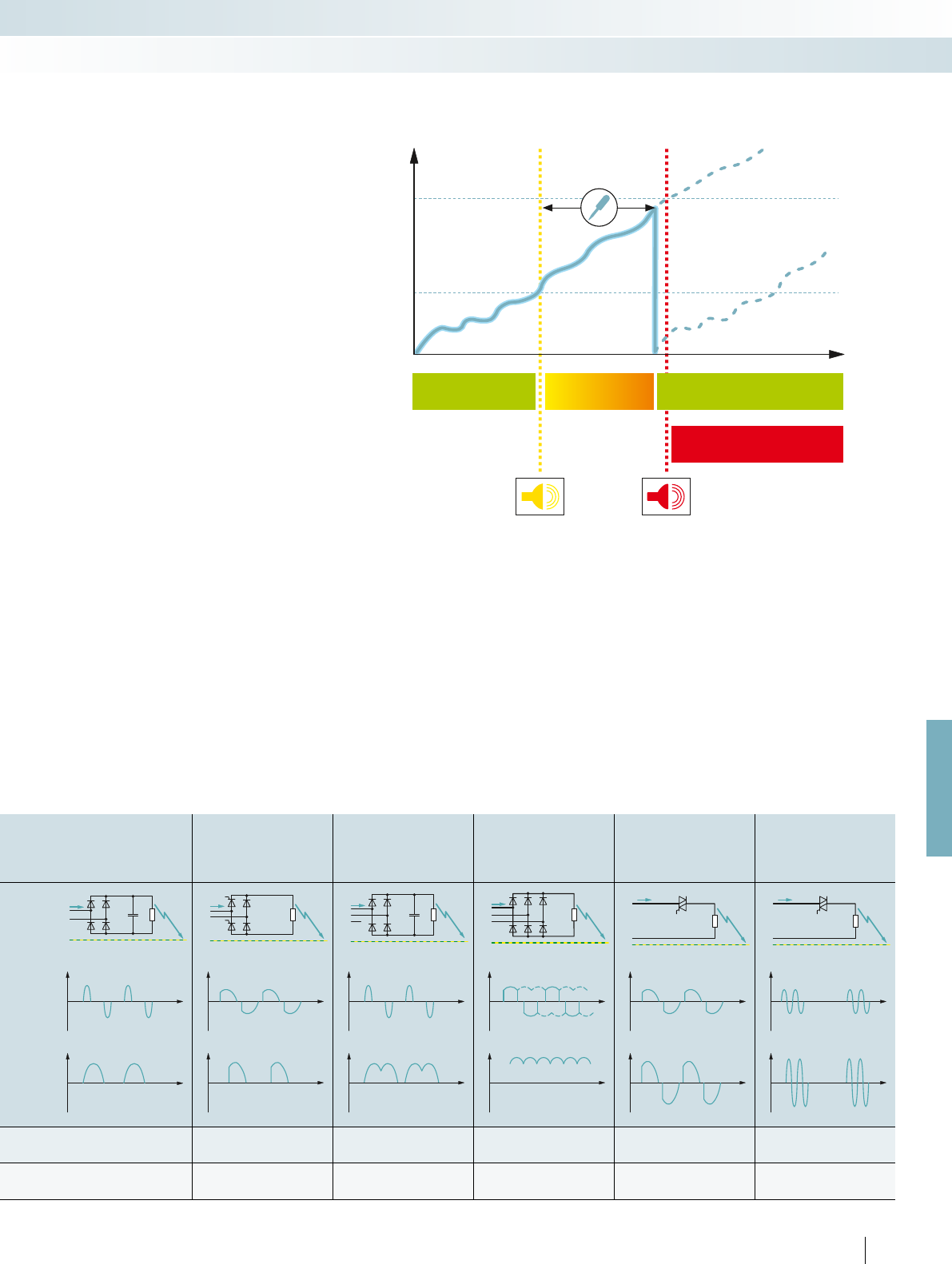
L
N
PE
I
L
I
F
L
N
PE
I
L
I
F
L
1
L
2
N
PE
I
L
I
F
L
1
L
2
L
3
PE
I
L
I
F
L
N
PE
I
L
I
F
L
N
PE
I
L
I
F
t
I
L
t
I
L
t
I
L
t
I
L
t
I
L
t
I
L
I
F
t
I
F
t
I
F
t
I
F
t
I
F
t
I
F
t
For further information and full technical data, visit phoenixcontact.net/products
Residual currents can increase continually
due to gradual processes. This can be
attributed, for example, to humidity or
conductive dirt on live parts. Residual
current devices trip at different rated
residual currents I
n
, depending on their
type. Additionally installed residual current
monitoring devices prevent sudden system
downtimes thanks to early warnings. The
continuous supply of information about
gradually increasing residual currents allows
timely intervention. Unplanned system
failures can be avoided.
Full bridge circuit Semi-controlled
full bridge circuit
Full bridge circuit
between
outer conductors
Three-phase
full bridge circuit
Phase-controlled
modulator Burst control
Type A Type A – – Type A Type A
Type B Type B Type B Type B Type B Type B
Normal operation Warning range Normal operation
following intervention
System failure
I
n
I
alarm
287
PHOENIX CONTACT
Monitoring
Monitoring and diagnostics
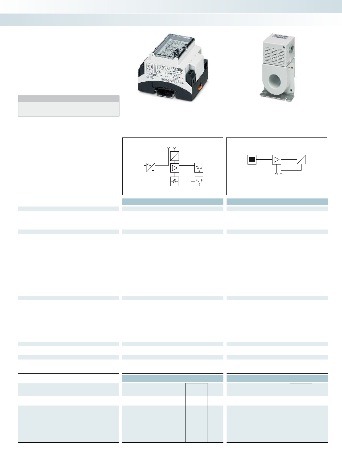
A1
12 14
11
A2
Alarm
Pre-alarm
12 14
11
U
RJ 45
I
U
RJ 45
I
Total width 71.6 mm Total width 65.5 mm
Technical data Technical data
Electrical data ...SCT-35 ...SCT-70 ...SCT-105
Nominal voltage range 85 V AC ... 264 V AC - - - 85 V AC ... 264 V AC
Nominal frequency f
N
50 Hz (60 Hz) --- 50 Hz (60 Hz) ---- ---
Rated current I
n
- 125 A 200 A 300 A - 50 A 100 A 125 A 200 A 250 A 350 A 400 A
Max. required back-up fuse 16 A (B) --- 16 A (B) ---- ---
RCM data
Rated response differential current I
dyn
3 A 3 A 3 A 3 A 3 A 3 A 3 A 3 A 3 A 3 A 3 A 3 A
Differential current acquisition characteristic Type B+ (DC up to 100 kHz) Type B+ (DC
up to 100 kHz)
Type B+ (DC
up to 100 kHz)
Type B+ (DC up to 100 kHz) Type A (50 / 60 Hz) Type A
Response differential current I
n
30, 100, 300, 1000, 3000 mA (adjustable) 0.03 A ... 3 A 0.03 A ... 3 A 0.1 A ... 3 A 30, 100, 300, 1000, 3000 mA (adjustable) 0.03 A
Discrimination threshold main alarm 80 % ... 100 % (of the set response differential current I
n
) - - - 80 % ... 100 % (of the set response differential current I
Discrimination threshold pre-alarm 10 % ... 90 % (of the main alarm threshold, adjustable) - - - 10 % ... 90 % (of the main alarm th
Response time for 2 x I
n
0.1 s ... 1 s (adjustable) - - - 0.1 s ... 1 s (adjustable) - - - - - - -
Thermal permanent differential current I
cth
- 150 A (50 Hz /
20 kHz)
150 A (50 Hz /
20 kHz)
150 A (50 Hz / 20 kHz) - 1.5 x I
Thermal rated short-time differential current I
th
- 3 kA for 1 s (50
Hz/20 kHz)
3 kA for 1 s (50
Hz/20 kHz)
3 kA for 1 s (50 Hz/20 kHz) - 10 x I
Rated surge voltage resistance U
imp
4 kV 8 kV 8 kV 8 kV 4 kV 8 kV 8 kV 8 kV 8 kV 8 kV 8 kV 8 kV
General data
Connection data solid / stranded / AWG 0.2 ... 4 mm² / 0.2 ... 2.5 mm² / 24 - 12 - 0.2 ... 4 mm² / 0.2 ... 2.5 mm² / 24 - 12 0.2 .
Maximum permissible outside diameter of cables - 23.00 mm 46.00 mm 70.00 mm - 13.00 mm 20.00 mm 23.00 mm 46.00 mm 70.00 mm 93.00 mm 140.00
Housing material Polycarbonate Polycarbonate Polycarbonate
Ambient temperature (operation) -25 °C ... 65 °C -20 °C ... 65 °C -25 °C ... 65 °C
Degree of protection IP20 IP20 IP20
Test standards DIN EN 62020 / DIN EN 60664 / DIN VDE 0664-400 DIN EN 62020 / VDE 0663 / DIN EN 60044-1 / DIN EN 62020 / DIN EN 606
Test standards - VDE 0414 / DIN VDE 0664-400 -
Pollution degree 2 222 2 2222 222
Surge voltage category III IV IV IV III IV IV IV IV IV IV IV
Mounting
Mounting type DIN rail: 35 mm Screw
mounting
Screw
mounting
Screw mounting DIN rail: 35 mm DIN rail: 35
Remote indication contact PDT contact -
Connection data solid / stranded / AWG 0.2 ... 4 mm² / 0.2 ... 2.5 mm² / - - 0.2 ... 4 mm² / 0.2 ... 2.5 mm² / - - -
Max. operating voltage 230 V AC - 230 V AC
Max. operating current 5 A (cos phi > 0.9) - 5 A (cos phi > 0.9)
Ordering data Ordering data
Description Type Order No. Pcs. /
Pkt. Type Order No. Pcs. /
Pkt.
Evaluation unit
RCM-B/50/85-264V 2806210 1
Current transformer
20 mm Ø
30 mm Ø
35 mm Ø RCM-B-SCT- 35 2806223 1
70 mm Ø RCM-B-SCT- 70 2806236 1
105 mm Ø RCM-B-SCT-105 2806249 1
140 mm Ø
210 mm Ø
288
PHOENIX CONTACT
– Adjustable residual response current of
30 mA to 3 A
– Adjustable pre-alarm threshold and delay
time
– Actual differential current can be read via
LED display
– Remote signaling for main and pre-alarm
Notes:
Cables for type B+ converter connection (RJ45, 4-pair, 1:1 line)
can be found in the accessories section by entering the order
number (RCM/converter) at: phoenixcontact.net/products
Residual current monitoring - RCM
Monitoring
Monitoring and diagnostics
RCM type B+ for smooth and
pulsating DC and AC residual currents up
to 100 kHz
Converter for RCM type B+ RCM type A for pulsating DC and AC
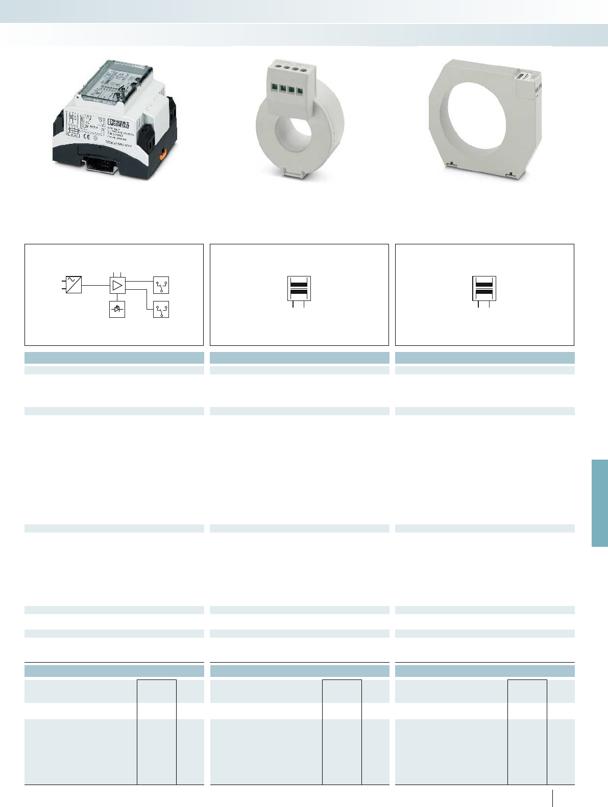
A1
=
l
k
A2
12 14
11
Alarm
Pre-alarm
12 14
11
l
k
l
k
For further information and full technical data, visit phoenixcontact.net/products
Total width 71.6 mm Total width 32 mm Total width 33 mm
Technical data Technical data Technical data
...SCT-20 ...SCT-30 ...SCT-35 ...SCT-70 ...SCT-105 ...SCT-140 ...SCT-210
Nominal voltage range 85 V AC ... 264 V AC - - - 85 V AC ... 264 V AC ---- ---
50 Hz (60 Hz) --- 50 Hz (60 Hz) ---- ---
- 125 A 200 A 300 A - 50 A 100 A 125 A 200 A 250 A 350 A 400 A
Max. required back-up fuse 16 A (B) --- 16 A (B) ---- ---
3 A 3 A 3 A 3 A 3 A 3 A 3 A 3 A 3 A 3 A 3 A 3 A
Type B+ (DC up to 100 kHz) Type A (50 / 60 Hz) Type A
(50 / 60 Hz)
Type A
(50 / 60 Hz)
Type A
(50 / 60 Hz)
Type A
(50 / 60 Hz)
Type A
(50 / 60 Hz)
Type A
(50 / 60 Hz)
Type A
(50 / 60 Hz)
30, 100, 300, 1000, 3000 mA (adjustable) 0.03 A ... 3 A 0.03 A ... 3 A 0.1 A ... 3 A 30, 100, 300, 1000, 3000 mA (adjustable) 0.03 A ... 3 A 0.03 A ... 3 A 0.03 A ... 3 A 0.03 A ... 3 A 0.03 A ... 3 A 0.03 A ... 3 A 0.03 A ... 3 A
) - - - 80 % ... 100 % (of the set response differential current I
n
)---- ---
Discrimination threshold pre-alarm 10 % ... 90 % (of the main alarm threshold, adjustable) - - - 10 % ... 90 % (of the main alarm threshold, adjustable) - - - - - - -
0.1 s ... 1 s (adjustable) - - - 0.1 s ... 1 s (adjustable) - - - - - - -
150 A (50 Hz / 20 kHz) - 1.5 x I
n
1.5 x I
n
1.5 x I
n
1.5 x I
n
1.5 x I
n
1.5 x I
n
1.5 x I
n
3 kA for 1 s (50 Hz/20 kHz) - 10 x I
n
(for 1 s) 10 x I
n
(for 1 s) 10 x I
n
(for 1 s) 10 x I
n
(for 1 s) 10 x I
n
(for 1 s) 10 x I
n
(for 1 s) 10 x I
n
(for 1 s)
4 kV 8 kV 8 kV 8 kV 4 kV 8 kV 8 kV 8 kV 8 kV 8 kV 8 kV 8 kV
Connection data solid / stranded / AWG 0.2 ... 4 mm² / 0.2 ... 2.5 mm² / 24 - 12 - 0.2 ... 4 mm² / 0.2 ... 2.5 mm² / 24 - 12 0.2 ... 4 mm² / 0.2 ... 2.5 mm² / 24 - 12 0.2 ... 4 mm² / 0.2 ... 2.5 mm² / 24 - 12
Maximum permissible outside diameter of cables - 23.00 mm 46.00 mm 70.00 mm - 13.00 mm 20.00 mm 23.00 mm 46.00 mm 70.00 mm 93.00 mm 140.00 mm
Polycarbonate Polycarbonate Polycarbonate Polycarbonate
-20 °C ... 65 °C -25 °C ... 65 °C -20 °C ... 65 °C -20 °C ... 65 °C
IP20 IP20 IP20 (terminal blocks) IP20 (terminal blocks)
Test standards DIN EN 62020 / DIN EN 60664 / DIN VDE 0664-400 DIN EN 62020 / VDE 0663 / DIN EN 60044-1 / DIN EN 62020 / DIN EN 60664 DIN EN 62020 / VDE 0663 / DIN EN 60044-1 / DIN EN 62020 / VDE 0663 / DIN EN 60044-1 /
VDE 0414 / DIN VDE 0664-400 - VDE 0414 VDE 0414
Pollution degree 2 222 2 2222 222
Surge voltage category III IV IV IV III IV IV IV IV IV IV IV
Screw mounting DIN rail: 35 mm DIN rail: 35
mm
DIN rail: 35
mm
Screw
mounting
Screw
mounting
Screw
mounting
Screw
mounting
Screw mounting
PDT contact - -
Connection data solid / stranded / AWG 0.2 ... 4 mm² / 0.2 ... 2.5 mm² / - - 0.2 ... 4 mm² / 0.2 ... 2.5 mm² / - - -
- 230 V AC --
- 5 A (cos phi > 0.9) --
Ordering data Ordering data Ordering data
Type Order No. Pcs. /
Pkt. Type Order No. Pcs. /
Pkt. Type Order No. Pcs. /
Pkt.
RCM-A/50/85-264V 2806016 1
RCM-A-SCT- 20 2806045 1
RCM-A-SCT- 30 2806058 1
RCM-A-SCT- 35 2806061 1
RCM-A-SCT- 70 2806074 1
RCM-A-SCT-105 2806087 1
RCM-A-SCT-140 2806090 1
RCM-A-SCT-210 2806100 1
289
PHOENIX CONTACT
Monitoring
Monitoring and diagnostics
Converter for RCM type B+ RCM type A for pulsating DC and AC
residual currents with 50/60 Hz
Converter for RCM type A Converter for RCM type A
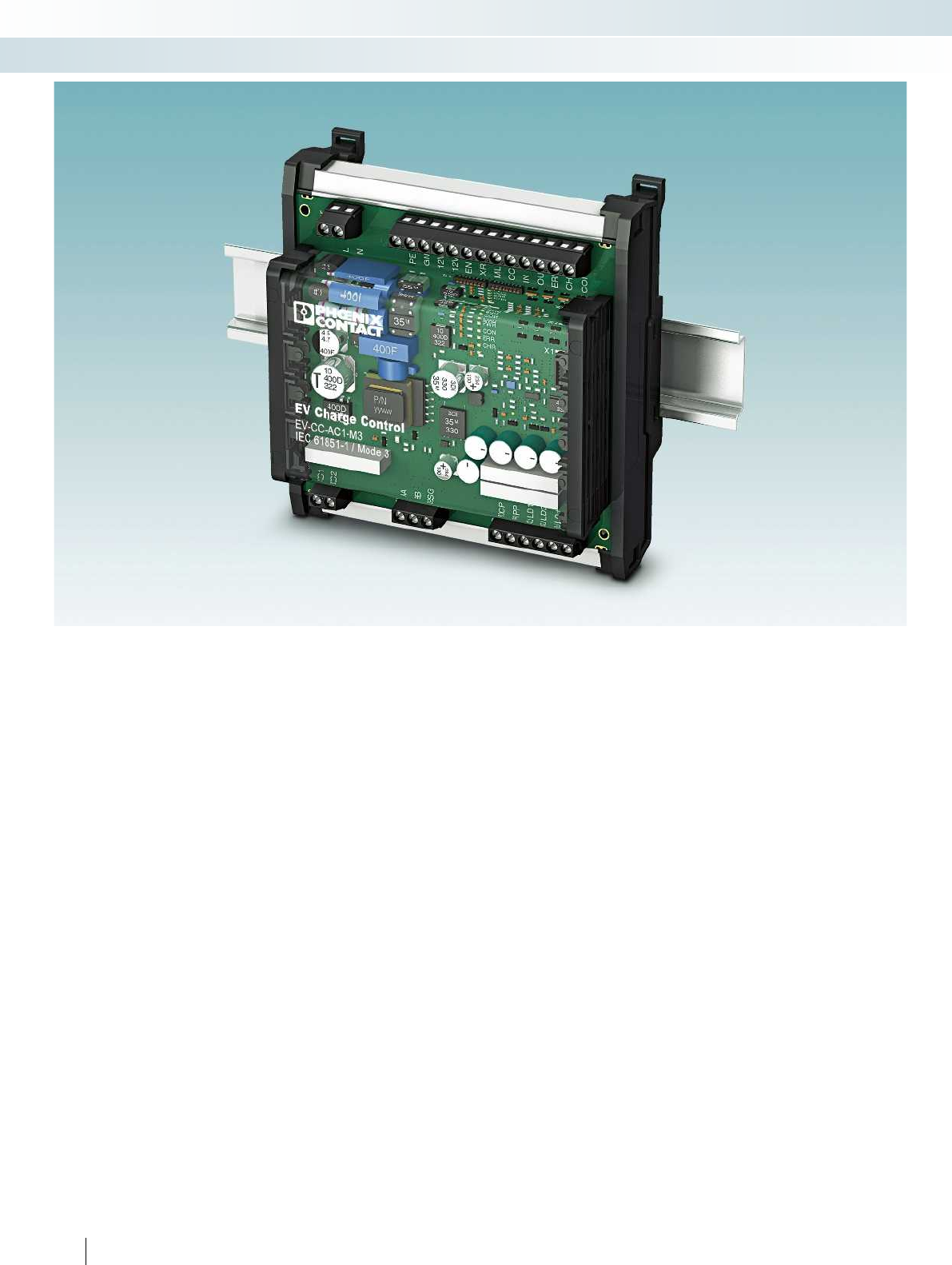
290
PHOENIX CONTACT
Monitoring
Components for E-Mobility
Control and monitor the charging
process of electric vehicles
Sustainable E-Mobility requires safe and
reliable charging infrastructure functions
that can be intelligently integrated into
energy systems if required. The controller
and monitoring components from Phoenix
Contact allow the setup of charging stations
according to current standards and
therefore ensure a high degree of safety and
interoperability with electric vehicles.
Charging controllers for AC charging
Charge electric vehicles according to the
IEC 61851-1 standard with the
E-Mobility
EV-CC-...
and
EM-CP-PP-ETH
charging controllers. The portfolio addresses
the entire spectrum of charging stations,
from simple autonomous charging points up
to networked stations. Comprehensive
configuration options in the devices are
provided for the specific requirements of our
customers.
From the charging point to the
networked charging infrastructure
Phoenix Contact charging controllers can
be operated both autonomously and in
networks. Status data can be acquired via
the integrated communication interfaces
and controlled intervention into the
charging process. Here we rely on
standardized communication interfaces and
protocols and therefore offer easy
connection options to various automation
systems.
Smart charging
Operating a charging infrastructure
requires more than just the charging
technology in the charging station.
Intelligent charging infrastructures are
integrated in management systems and
communicate with billing and operator
systems. Based on Phoenix Contact
products, software function blocks for
implementing charging and energy
management, authorization routines, and
interfaces to back-end systems are available,
for example, via the Open Charge Point
Protocol (OCPP).
Residual current detection in the
charging station
The E-Mobility residual current modules
from the E V- R C M series detect AC and
DC residual currents. In conjunction with
existing residual current protection devices,
the modules increase the voltage protection
level during charging of electric vehicles
according to DIN VDE 0100-722. Based on
IEC 62752, residual current devices
(e.g., RCD type A) are protected against
DC components and can continue to be
operated.

For further information and full technical data, visit phoenixcontact.net/products
291PHOENIX CONTACT
Monitoring
Components for E-Mobility
All the necessary functions in one
controller
The EV-CC-... charging controllers are
specially designed for simple charging
points. All functions required for this
application are integrated. From the
interface to the vehicle, the control of the
connector locking and its release in case of
mains failure or control of the charging
contactor, all in one device.
The optimum marking solution for
every version
The versions of the EV-CC-... are
conceived respectively for the possible
charging station types. Corresponding
versions are available, whether for charging
stations with permanently connected
Vehicle Connector or with an Infrastructure
Socket Outlet, classical design with DIN rail
or PCB for integration into the housing.
Interface to power meters
Detection of the actual charging current
and the charging power for each individual
vehicle is necessary for efficient charging
and energy management.
The EM-CP-PP-ETH charging
controller is equipped with a configurable
RS-485/Modbus/RTU interface, to which
various meters can be connected.
Compatible with Phoenix Contact
charging controllers
The universal RCM modules from
Phoenix Contact detect DC and AC
residual current and therefore offer
additional protection during vehicle
charging. Optional status monitoring and
resetting of the RCM module is possible in
conjunction with the charging controllers
from Phoenix Contact.
Vehicle Connectors and
Infrastructure Socket Outlets
Phoenix Contact has a unique and wide
range of Vehicle Connectors, charging
cables, Infrastructure Socket Outlets, and
vehicle inlets. Different standards for the
European, American, and Chinese markets
are covered. Solutions for both
conventional AC and fast DC charging are
available for all standards - in particular
components of so-called “Combined
Charging Systems” (CCS).
Note:
Information on charging systems can be
found in Catalog 4, Sensor/actuator cabling
and industrial connectors.
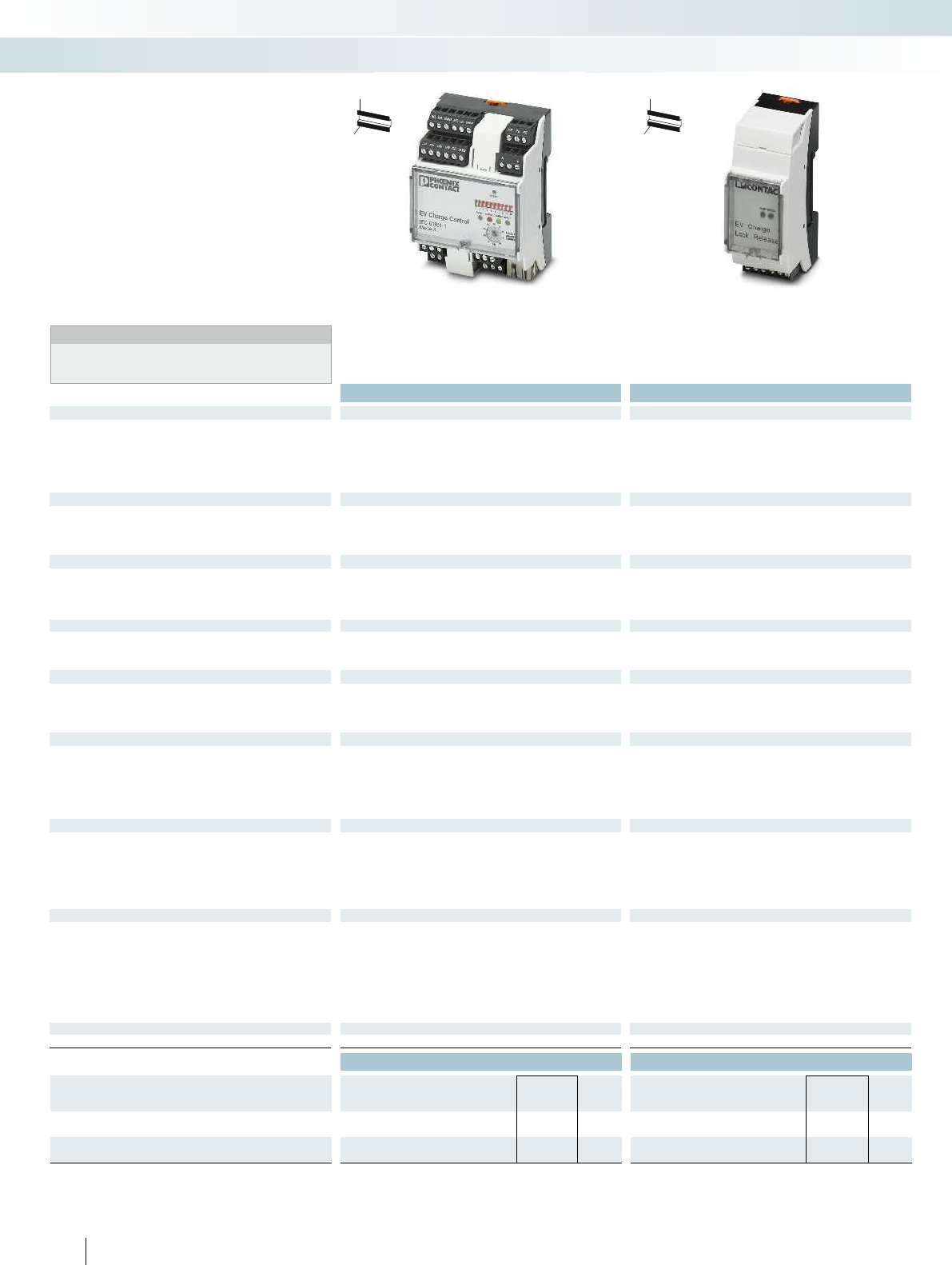
Housing width 71.6 mm Housing width 35.6 mm
Technical data Technical data
Input
Description of the input Digital input Signal input
Nominal input voltage U
N
24 V 12 V
Input current 8 mA (24 V) approx. 5 mA (at 12 V)
Input voltage level digital I/O -3 V ... 5 V (Off)
15 V ... 30 V (On)
-3 V ... 3 V (Off)
-30 V ... -10 V (lock ON)
10 V ... 30 V (release ON)
Switching output
Socket locking Relay output R
1.3
and R
2.4
Relay output
Maximum switching voltage 30 V AC/DC approx. 11.5 V (operating/capacitor voltage minus the diode voltage
of ~ 0.5 V)
Max. switching current 6 A 4 A
Switching output
Charging contactor output Relay output C
1.2
and V
1.2
-
Maximum switching voltage 250 V AC -
Max. switching current 6 A -
Maximum switching capacity 1500 VA -
Switching output
Ventilation control Digital output -
Maximum output voltage 30 V -
Maximum output current 0.6 A -
Digital outputs
Number of outputs 4 -
Output voltage 12 V ... 30 V -
Output current 0.1 A (total current for all outputs; internally supplied)
0.6 A (per output; externally supplied)
-
Ethernet interface
Designation Ethernet interface, 100Base-TX according to IEEE 802.3u /
10Base-T according to IEEE 802.3
-
Connection method RJ45 socket -
Transmission speed 10/100 Mbps -
Transmission length 100 m (with shielded, twisted-pair data cable) -
RS-485 interface
Designation RS-485 interface, 2-wire + GND -
Connection method Screw connection -
Transmission mode 8, N, 1 -
Transmission speed 9.6 kbps (standard) -
2.4 kbps ... 19.2 kbps (adjustable) -
Protocols Modbus/RTU (master) -
General data
Supply voltage 12 V DC ±5 %
Supply voltage range 110 V AC ... 240 V AC (nominal voltage range)
95 V AC ... 264 V AC
-
Max. current consumption 40 mA -
Frequency range 45 Hz ... 65 Hz -
Degree of protection IP20 IP20
Ambient temperature range -25 °C ... 60 °C -25 °C ... 60 °C
Dimensions W / H / D 71.6 / 61 / 90 mm 35.6 / 61 / 90 mm
Conformance / approvals
Conformance CE-compliant CE-compliant
Ordering data Ordering data
Description Type Order No. Pcs. /
Pkt. Type Order No. Pcs. /
Pkt.
EV Charge Control charging controller
EM-CP-PP-ETH 2902802 1
Mains failure plug release EV Charge Lock Release
EM-EV-CLR-12V 2903246 1
292
PHOENIX CONTACT
Monitoring
Components for E-Mobility
Charging controller Mains power failure plug release
EM-CP-PP-ETH
– AC charging according to IEC 61851-1,
Mode 3
– Comprehensive configuration options
– Ethernet/Modbus/TCP interface
– Charging and energy management
– Connection of power meters
EM-EV-CLR-12V
– Plug release in case of mains failure
– For 12 V actuators
Notes:
For information on plug-in charging systems, see Catalog 2,
Connection technology for field devices.
H
W
D
H
W
D
EV Charge Control charging
controller
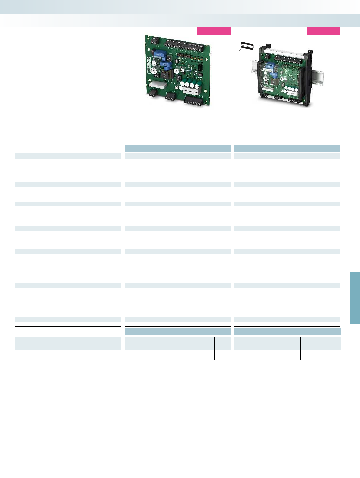
For further information and full technical data, visit phoenixcontact.net/products
Housing width 120 mm Housing width 124 mm
Technical data Technical data
Input
Description of the input Digital input Digital input
Nominal input voltage U
N
12 V 12 V
Input current 1 mA (12 V) 1 mA (12 V)
Input voltage level digital I/O 0 V ... 3 V (Off)
9 V ... 15 V (On)
0 V ... 3 V (Off)
9 V ... 15 V (On)
Switching output
Socket locking Relay output Relay output
Maximum switching voltage 12 V (internal supply) 12 V (internal supply)
Max. switching current 2 A (internal supply) 2 A (internal supply)
Switching output
Charging contactor output Relay output Relay output
Maximum switching voltage 250 V AC (external supply) 250 V AC (external supply)
Max. switching current 6 A (external supply) 6 A (external supply)
Maximum switching capacity 1500 VA 1500 VA
Digital outputs
Number of outputs 4 4
Output voltage 5 V ... 30 V 5 V ... 30 V
Output current 0.5 A (total current for all outputs; internally supplied)
0.6 A (per output; externally supplied)
0.5 A (total current for all outputs; internally supplied)
0.6 A (per output; externally supplied)
RS-485 interface
Designation RS-485 interface, 2-wire + GND RS-485 interface, 2-wire + GND
Connection method Screw connection Screw connection
Transmission mode 8, N, 1 8, N, 1
Transmission speed 9.6 kbps (standard) 9.6 kbps (standard)
9.6 kbps ... 19.2 kbps (adjustable) 9.6 kbps ... 19.2 kbps (adjustable)
Protocols Modbus/RTU (slave) Modbus/RTU (slave)
General data
Supply voltage range 100 V AC ... 240 V AC (nominal voltage range) 100 V AC ... 240 V AC (nominal voltage range)
Power consumption < 1 W (no-load) < 1 W (no-load)
Frequency range 50 Hz ... 60 Hz 50 Hz ... 60 Hz
Degree of protection IP00 IP20
Ambient temperature range -35 °C ... 70 °C (operation) -35 °C ... 70 °C (operation)
Dimensions W / H / D 120 / 108 / 20 mm 124 / 128 / 64 mm
Conformance / approvals
Conformance CE-compliant CE-compliant
Ordering data Ordering data
Description Type Order No. Pcs. /
Pkt. Type Order No. Pcs. /
Pkt.
Charging controller for case B and C
EV-CC-AC1-M3-CBC-SER-PCB 1622453 1EV-CC-AC1-M3-CBC-SER-HS 1622452 1
293
PHOENIX CONTACT
Monitoring
Components for E-Mobility
Charging controller on PCB DIN rail housing charging controller
EV-CC-AC1-M3-CBC-SER-...
– AC charging according to IEC 61851-1,
Mode 3
– Comprehensive configuration options
– Adjustable amperage
– Integrated locking controller (12V)and
mains failure plug release
– RS-485 interface (Modbus/RTU slave)
– PCB version and DIN rail device
new
H
W
D
new
EV CC Electrical Vehicle Charge
Control
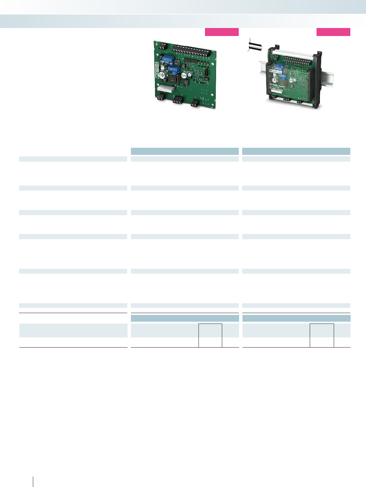
Housing width 120 mm Housing width 124 mm
Technical data Technical data
Input
Description of the input Digital input Digital input
Nominal input voltage U
N
12 V 12 V
Input current 1 mA (12 V) 1 mA (12 V)
Input voltage level digital I/O 0 V ... 3 V (Off)
9 V ... 15 V (On)
0 V ... 3 V (Off)
9 V ... 15 V (On)
Switching output
Charging contactor output Relay output Relay output
Maximum switching voltage 250 V AC (external supply) 250 V AC (external supply)
Max. switching current 6 A (external supply) 6 A (external supply)
Maximum switching capacity 1500 VA 1500 VA
Digital outputs
Number of outputs 4 4
Output voltage 5 V ... 30 V 5 V ... 30 V
Output current 0.5 A (total current for all outputs; internally supplied)
0.6 A (per output; externally supplied)
0.5 A (total current for all outputs; internally supplied)
0.6 A (per output; externally supplied)
RS-485 interface
Designation RS-485 interface, 2-wire + GND RS-485 interface, 2-wire + GND
Connection method Screw connection Screw connection
Transmission mode 8, N, 1 8, N, 1
Transmission speed 9.6 kbps (standard) 9.6 kbps (standard)
9.6 kbps ... 19.2 kbps (adjustable) 9.6 kbps ... 19.2 kbps (adjustable)
Protocols Modbus/RTU (slave) Modbus/RTU (slave)
General data
Supply voltage range 100 V AC ... 240 V AC (nominal voltage range) 100 V AC ... 240 V AC (nominal voltage range)
Power consumption < 1 W (no-load) < 1 W (no-load)
Frequency range 50 Hz ... 60 Hz 50 Hz ... 60 Hz
Degree of protection IP00 IP20
Ambient temperature range -35 °C ... 70 °C (operation) -35 °C ... 70 °C (operation)
Dimensions W / H / D 120 / 108 / 20 mm 124 / 128 / 64 mm
Conformance / approvals
Conformance CE-compliant CE-compliant
Ordering data Ordering data
Description Type Order No. Pcs. /
Pkt. Type Order No. Pcs. /
Pkt.
Charging controller for case C
EV-CC-AC1-M3-CC-SER-PCB 1622460 1EV-CC-AC1-M3-CC-SER-HS 1622459 1
294
PHOENIX CONTACT
Monitoring
Components for E-Mobility
Charging controller on PCB DIN rail housing charging controller
EV-CC-AC1-M3-CC-SER-...
– AC charging according to IEC 61851-1,
Mode 3
– Comprehensive configuration options
– Adjustable amperage
– Optimized for charging stations with
vehicle connector (case C)
– RS-485 interface (Modbus/RTU slave)
– PCB version and DIN rail device
new
H
W
D
new
EV CC Electrical Vehicle Charge
Control
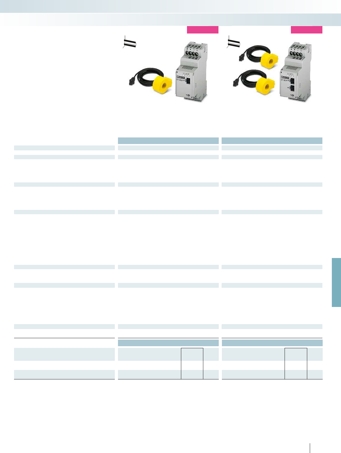
For further information and full technical data, visit phoenixcontact.net/products
Housing width 36 mm Housing width 36 mm
Technical data Technical data
Input
Measuring transducer input plug-in; front plug-in; front
Switching output
Alarm relay K1 I
n
DC1 I
n
AC1 and I
n
DC1
Maximum switching voltage 250 V 250 V
Max. switching current 5 A 5 A
Method of operation Quiescent current Quiescent current
Contact type 1 N/O contact 1 N/O contact
Switching output
Alarm relay K2 I
n
AC2 I
n
AC2 and I
n
DC2
Maximum switching voltage 250 V 250 V
Max. switching current 5 A 5 A
Method of operation Quiescent current Quiescent current
Contact type 1 N/O contact 1 N/O contact
Residual current measuring range
Rated frequency 2000 Hz 2000 Hz
Number of channels 1 2
Measuring range ± 300 mA (peak) ± 300 mA (peak)
Current measuring range 50 A (45 Hz ... 50 Hz) 50 A (45 Hz ... 50 Hz)
Residual current In1 30 mA 30 mA
Residual current In2 6 mA 6 mA
Load current 32 A 32 A
Response time at 1 x In < 180 ms < 180 ms
Response time at 2 x I
n
< 70 ms < 70 ms
Response time at 5 x In < 20 ms < 20 ms
Response time at I
N
< 500 ms < 500 ms
Measuring current transducer
Cable feed-through diameter 15 mm 15 mm
Supply via RCM module via RCM module
Connection method Connector Connector
General data
Supply voltage range 100 V AC ... 240 V AC (nominal voltage range) 100 V AC ... 240 V AC (nominal voltage range)
Max. current consumption 22 mA 22 mA
Frequency range 45 Hz ... 60 Hz 45 Hz ... 60 Hz
Degree of protection IP20 IP20
Ambient temperature range -25 °C ... 80 °C (operation) -25 °C ... 80 °C (operation)
Reload function 3 switch-on attempts at intervals of 15 min. 3 switch-on attempts at intervals of 15 min.
Operating elements Test/reset button; 2 status LEDs Test/reset button; 2 status LEDs
Dimensions W / H / D 36 / 90 / 70.5 mm 36 / 90 / 70.5 mm
Conformance / approvals
Conformance CE-compliant CE-compliant
Climatic class According to IEC 60271/-1/-2/-3 According to IEC 60271/-1/-2/-3
Ordering data Ordering data
Description Type Order No. Pcs. /
Pkt. Type Order No. Pcs. /
Pkt.
EV RCM 1-channel
EV-RCM-C1-AC30-DC6 1622450 1
EV RCM 2-channel
EV-RCM-C2-AC30-DC6 1622451 1
295
PHOENIX CONTACT
Monitoring
Components for E-Mobility
RCM module for one charging point RCM module for two separate charging points
EV RCM...
– Universal residual current monitoring for
AC and DC residual current detection
– Operate values DC 6 mA and AC 30 mA
– Protection of higher-level safety
equipment, such as type A residual
current circuit breakers, against DC
residual currents
– Single or two-channel version
H
W
D
new
H
W
D
new
EV RCM residual current monitoring
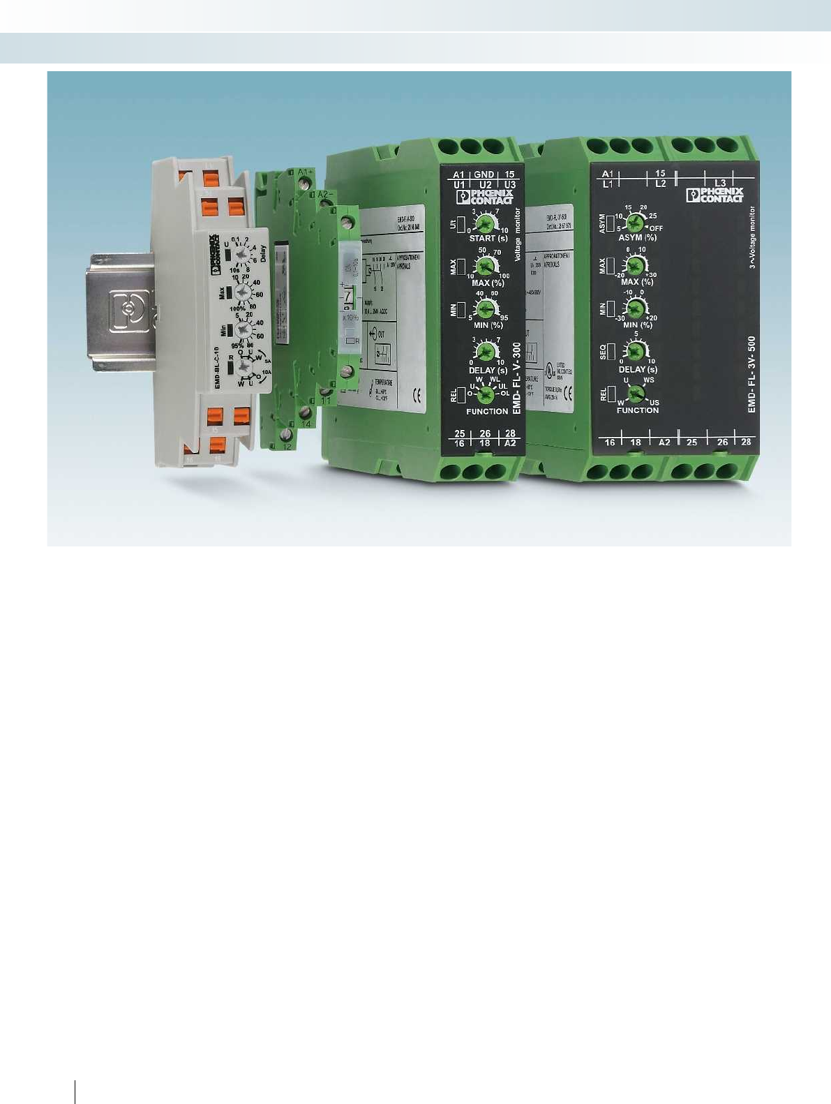
296
PHOENIX CONTACT
Monitoring
Monitoring and diagnostics
For high system availability
EMD monitoring relays can be used to
detect deviations in important system
parameters at an early stage. These can be
indicated or system parts can be shut down
selectively. EMD monitoring relays ensure
error-free and cost-effective operation of
your system. They are an inexpensive
solution for numerous monitoring
functions.
– Surge voltage and undervoltage
– Overcurrent and undercurrent
– Phase failure, phase sequence, and phase
asymmetry
– Power factor and real power
– Motor winding temperature
– Levels
For system monitoring, choose from two
product ranges: compact or multifunctional
monitoring relays.
Perfect timing
ETD timer relays ensure optimum time
sequences.
The modules are the cost-effective
alternative to a PLC: with easy configuration
and fast wiring.
Choose from two product ranges for
your ideal time control application:
– Ultra-narrow timer relays each with one
time range and one function
– Multifunctional timer relays with
selectable time ranges and functions
Professionally packaged components
Function modules with professional
housing and connection technology can be
used to integrate electronic components in
your system. They can be used to perform a
variety of tasks:
– Diode modules provide protection
against polarity reversal. In addition, they
decouple messages in fault reporting
systems.
– Lamp testing modules decouple signals in
isolation in the field of fault reporting
technology.
– Display modules simplify troubleshooting
and provide help for monitoring
processes.
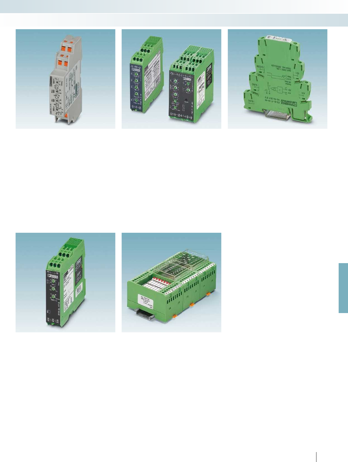
For further information and full technical data, visit phoenixcontact.net/products
297PHOENIX CONTACT
Monitoring
Monitoring and diagnostics
Compact monitoring relays
Ideal for simple monitoring tasks – from
series production to building installation.
– Compact installation housing
– Quick and tool-free wiring with push-in
technology
– Parameters can be adjusted easily using
rotary switches
– Clear diagnostics, thanks to color status
LED
Multifunctional monitoring relays
– Parameters can be adjusted easily using
rotary switches
– Fast error detection, thanks to fine tuning
and short response times
– Worldwide use, thanks to wide range
power supply unit or plug-in transformer
– Space saving – with two PDT outputs in
22.5mm wide housing
– Electrically isolated measuring and supply
circuits
– Clear diagnostics, thanks to color status
LEDs
Ultra-narrow timer relays
The space-saving and inexpensive solution
for simple time control applications.
– Each with one time range and one
function
– Overall width of just 6.2mm - saves up
to70% space compared to conventional
timer relays
– Precise time setting using the illuminated
thumbwheel
– Fast wiring through the use of jumpers
Multifunctional timer relays
For universal use thanks to wide range of
functions.
– Just three versions for all conventional
time control applications.
– Two floating PDT outputs on an overall
width of just 22.5 mm
– Supply voltage via wide range power
supply unit
– Optimum setting of times ranging from
milliseconds to several days
Function modules
Function modules transform components
such as diodes into a shock-proof and dust-
proof electronics module.
– Easy installation, thanks to electronics
housing with IP20 protection that can be
installed in a control cabinet
– Fast mounting on DIN rails, thanks to the
foot catch
– User-friendly wiring, thanks to practical
connection technology
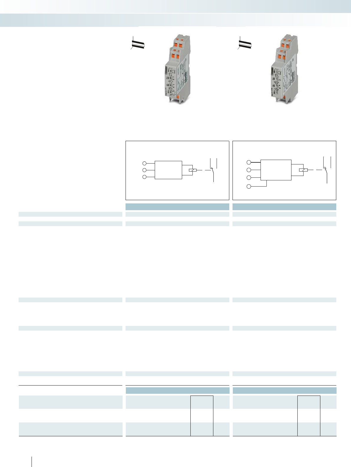
Li
Lk
N
16
15
18
U =230 V AC
GND
U1 24 V DC
U2 24 V AC
U3 230 V AC
16
15
18
Housing width 17.5 mm Housing width 17.5 mm
Technical data Technical data
Functions
Overcurrent, undercurrent, window Undervoltage, window
Input
Input ranges 0 V DC ... 24 V DC (connection terminal blocks: U1 and GND)
0 V AC ... 24 V AC (connection terminal blocks: U2 and GND)
0 V AC ... 230 V AC (connection terminal blocks: U3 and GND)
Input ranges 0 A ... 5 A AC
0 A ... 10 A AC
Configurable via rotary switch
-
Input resistance 3 m-
Min. setting range 5 % ... 95 % (of I
N
) 75 % ... 115 % (of U
N
)
Max. setting range 10 % ... 100 % (of I
N
) 80 % ... 120 % (of U
N
)
Setting range for response delay 0.1 s ... 10 s 0.1 s ... 10 s
Basic accuracy 5 % (of the nominal value) 5 % (of scale end value)
Setting accuracy ± 5 % (of the nominal value) ± 5 % (of scale end value)
Repeat accuracy 2 % 2 %
Relay output
Contact type 1 floating PDT 1 floating PDT
Switching capacity 1250 VA (5 A/250 V AC) 1250 VA (5 A/250 V AC)
Electrical service life 1 x 10
5
cycles 1 x 10
5
cycles
Mechanical service life 15 x 10
6
cycles 15 x 10
6
cycles
Output fuse 5 A (fast-blow) 5 A (fast-blow)
General data
Supply voltage 230 V AC ±15 % -25 % ... +20 % (= measuring voltage)
Nominal power consumption 5 VA (0.8 W) 10 VA (at 230 V AC (0.6 W))
1.3 VA (at 24 V AC (0.8 W))
0.6 W (at 24 V DC)
Degree of protection IP40 (housing) / IP20 (connection terminal blocks) IP40 (housing) / IP20 (connection terminal blocks)
Ambient temperature range -25 °C ... 55 °C -25 °C ... 55 °C
Dimensions W / H / D 17.5 / 88 / 65.5 mm 17.5 / 88 / 65.5 mm
Connection data solid / stranded / AWG 0.14 ... 2.5 mm² / 0.14 ... 2.5 mm² / 26 - 14 0.14 ... 2.5 mm² / 0.14 ... 2.5 mm² / 26 - 14
Conformance / approvals
Conformance CE-compliant CE-compliant
UL, USA / Canada UL/C-UL listed UL 508 UL/C-UL listed UL 508
Ordering data Ordering data
Description Type Order No. Pcs. /
Pkt. Type Order No. Pcs. /
Pkt.
Compact monitoring relay with push-in connection
EMD-BL-C-10-PT 2903522 1EMD-BL-V-230-PT 2903524 1
Compact monitoring relay with screw connection
EMD-BL-C-10 2903521 1EMD-BL-V-230 2903523 1
298
PHOENIX CONTACT
Single-phase current monitoring
The EMD-BL-C-10 monitors
AC currents from 0 ... 10 A.
– Adjustable response delay
– 0 ... 5 A or 0 ... 10 A measuring range
– Adjustable via rotary switch on the front
Single-phase voltage monitoring
The EMD-BL-V-230 monitors DC and
AC voltages.
– 24 V AC/DC or 230 V AC
– Separately adjustable response delay
– Adjustable monitoring range
– Adjustable via potentiometer on the
front
H
W
D
H
W
D
Monitoring relays
Monitoring
Monitoring and diagnostics
Current monitoring, 1-phase
Overcurrent, undercurrent, window
Voltage monitoring, 1-phase
Undervoltage, window
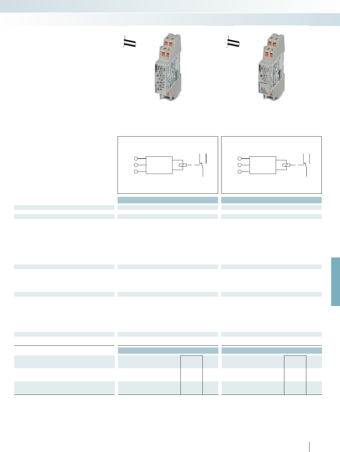
L1
L2
L3
16
15
18
L1
L2
L3
16
15
18
For further information and full technical data, visit phoenixcontact.net/products
Housing width 17.5 mm Housing width 17.5 mm
Technical data Technical data
Functions
Window, phase sequence Phase sequence, phase failure, asymmetry
Input
Monitoring range 280 V AC ... 519 V AC 187 V AC ... 519 V AC
Input ranges 3~ 400/230 V 3~ 208 ... 480 V/120 ... 277 V
Input resistance - -
Min. setting range 70 % ... 120 % (of U
N
)-
Max. setting range 80 % ... 130 % (of U
N
)-
Setting range for response delay 0.1 s ... 10 s 0.1 s ... 10 s
Asymmetry - 5% ... 25% / OFF
Basic accuracy 5 % (of the nominal value) 5 % (of scale end value)
Setting accuracy ± 5 % (of scale end value) ± 5 % (of scale end value)
Repeat accuracy 2 % 2 %
Relay output
Contact type 1 floating PDT 1 floating PDT
Switching capacity 1250 VA (5 A/250 V AC) 1250 VA (5 A/250 V AC)
Electrical service life 1 x 10
5
cycles 1 x 10
5
cycles
Mechanical service life 15 x 10
6
cycles 15 x 10
6
cycles
Output fuse 5 A (fast-blow) 5 A (fast-blow)
General data
Supply voltage ±30 % (= measuring voltage) ±10 % (= measuring voltage)
Nominal power consumption 10 VA (1 W) 10 VA ((1 W) at 400 V/50 Hz)
16 VA ((1.5 W) at 480 V/60 Hz)
Degree of protection IP40 (housing) / IP20 (connection terminal blocks) IP40 (housing) / IP20 (connection terminal blocks)
Ambient temperature range -25 °C ... 55 °C -25 °C ... 55 °C
Dimensions W / H / D 17.5 / 88 / 65.5 mm 17.5 / 88 / 65.5 mm
Connection data solid / stranded / AWG 0.14 ... 2.5 mm² / 0.14 ... 2.5 mm² / 26 - 14 0.14 ... 2.5 mm² / 0.14 ... 2.5 mm² / 26 - 14
Conformance / approvals
Conformance CE-compliant CE-compliant
UL, USA / Canada UL/C-UL listed UL 508 UL/C-UL listed UL 508
Ordering data Ordering data
Description Type Order No. Pcs. /
Pkt. Type Order No. Pcs. /
Pkt.
Compact monitoring relay with push-in connection
EMD-BL-3V-400-PT 2903526 1EMD-BL-PH-480-PT 2903528 1
Compact monitoring relay with screw connection
EMD-BL-3V-400 2903525 1EMD-BL-PH-480 2903527 1
299
PHOENIX CONTACT
Three-phase voltage monitoring
The EMD-BL-3V-400 monitors three-
phase AC voltages.
– 3~ 400 V AC/230 V AC ±30%
– Separately adjustable response delay
– Adjustable monitoring range
– Adjustable via potentiometer on the
front
– Supply from the measuring circuit
Phase monitoring
The EMD-BL-PH-400 monitors three-
phase AC voltages.
– 3~ 208 ... 480 V AC/120 ... 277 V AC
– Adjustable response delay
– Adjustable asymmetry: 5 ... 25%/OFF
– Adjustable via potentiometer on the
front
– Supply from the measuring circuit
H
W
D
H
W
D
Monitoring relays
Monitoring
Monitoring and diagnostics
Voltage monitoring, 3-phase
Window, phase sequence
Phase monitoring
Phase sequence, phase failure, asymmetry

I1
I2
I3
GND
100 mA
1A
10A
A1 A2
16 26
15 25
1828
U = 24...240V AC/DC
I1
I2
I3
GND
100 mA
1A
10A
A1
A2
16
15
18
POWER
MODULE
U=24VDC
24...230V AC
Housing width 22.5 mm Housing width 22.5 mm
Technical data Technical data
Functions EMD-SL-C-OC-10 EMD-SL-C-UC-10
Overcurrent, undercurrent, window, error memory Overcurrent Undercurrent
Input
Input ranges 0 mA ... 100 mA AC/DC (connection terminal blocks: I1 and GND)
0 A ... 1 A AC/DC (connection terminal blocks: I2 and GND)
0 A ... 10 A AC/DC (connection terminal blocks: I3 and GND)
0 mA ... 100 mA AC/DC (connection terminal blocks: I1 and GND)
0 A ... 1 A AC/DC (connection terminal blocks: I2 and GND)
0 A ... 10 A AC/DC (connection terminal blocks: I3 and GND)
Input resistance 470 m (at I
N
= 100 mA); 47 m (at I
N
= 1 A); 5 m (at I
N
= 10 A) 470 m (at I
N
= 100 mA); 47 m (at I
N
= 1 A); 5 m (at I
N
= 10 A)
Min. setting range 5 % ... 95 % (of I
N
) 5 % ... 95 % (of I
N
)
Max. setting range 10 % ... 100 % (of I
N
) 10 % ... 100 % (of I
N
)
Setting range for response delay 0.1 s ... 10 s 0.2 s ... 10 s
Setting range for starting delay 0 s ... 10 s -
Basic accuracy ± 5 % (of scale end value) ± 5 % (of scale end value)
Setting accuracy 5 % (of scale end value) 5 % (of scale end value)
Repeat accuracy 2 % 2 %
Relay output
Contact type 2 floating PDT contacts 1 floating PDT
Switching capacity 750 VA (3 A/250 V AC, module aligned, 5 mm spacing)
1250 VA (5 A/250 V AC, module not aligned, 5 mm spacing)
750 VA (3 A/250 V AC, module aligned, 5 mm spacing)
1250 VA (5 A/250 V AC, module not aligned, 5 mm spacing)
Electrical service life 2 x 10
5
cycles at ohmic load, 1000 VA 2 x 10
5
cycles at ohmic load, 1000 VA
Mechanical service life Approx. 2 x 10
7
cycles Approx. 2 x 10
7
cycles
Output fuse 5 A (fast-blow) 5 A (fast-blow)
General data
Supply voltage
Nominal power consumption 4.5 VA (1.5 W) 2 VA (1.5 W)
Degree of protection IP40 (housing) / IP20 (connection terminal blocks) IP40 (housing) / IP20 (connection terminal blocks)
Ambient temperature range -25 °C ... 55 °C -25 °C ... 55 °C
Dimensions W / H / D 22.5 / 90 / 113 mm 22.5 / 90 / 113 mm
Screw connection solid / stranded / AWG 0.5 ... 2.5 mm² / 0.25 ... 2.5 mm² / 20 - 14 0.5 ... 2.5 mm² / 0.25 ... 2.5 mm² / 20 - 14
EMC note Class A product, see page 625
Conformance / approvals
Conformance CE-compliant CE-compliant
UL, USA / Canada UL/C-UL listed UL 508 UL/C-UL listed UL 508
Ordering data Ordering data
Description Type Order No. Pcs. /
Pkt. Type Order No. Pcs. /
Pkt.
Electronic monitoring relay
EMD-FL-C-10 2866022 1EMD-SL-C-OC-10 2866019 1
EMD-SL-C-UC-10 2867937 1
Power module, plug-in, please order at the same time!
Supply voltage 20 ... 30 V DC EMD-SL-PS- 24DC 2885359 1
Supply voltage 20.2 ... 26.4 V AC EMD-SL-PS- 24AC 2866103 1
Supply voltage 88 ... 121 V AC EMD-SL-PS-110AC 2866116 1
Supply voltage 108 ... 132 V AC EMD-SL-PS-120AC 2885731 1
Supply voltage 195 ... 264 V AC EMD-SL-PS-230AC 2866129 1
300
PHOENIX CONTACT
Single-phase current monitoring
EMD-...C... monitoring relays monitor
DC and AC currents within the range
0 ... 10 A.
– Separately adjustable startup and release
delays
– Variable supply voltage range
– Adjustable via potentiometer on front
H
W
D
H
W
D
Monitoring relays
Monitoring
Monitoring and diagnostics
Overcurrent and undercurrent monitoring Overcurrent or undercurrent monitoring
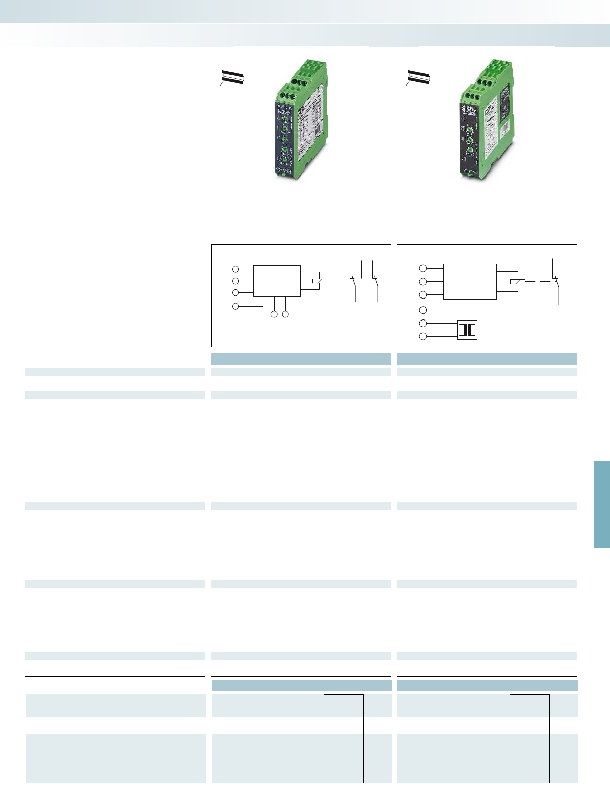
U1
U2
U3
GND
30V
60V
300 V
A1 A2
16 26
15 25
1828
U = 24...240V AC/DC
U1
U2
U3
GND
30V
60V
300 V
A1
A2
16
15
18
POWER
MODULE
U=24VDC
24...230V AC
For further information and full technical data, visit phoenixcontact.net/products
Housing width 22.5 mm Housing width 22.5 mm
Technical data Technical data
Functions
Undervoltage, overvoltage, window, error memory Undervoltage
Input
Input ranges 0 V ... 30 V AC/DC (connection terminal blocks: U1 and GND)
0 V ... 60 V AC/DC (connection terminal blocks: U2 and GND)
0 V ... 300 V AC/DC (connection terminal blocks: U3 and GND)
0 V ... 30 V AC/DC (connection terminal blocks: U1 and GND)
0 V ... 60 V AC/DC (connection terminal blocks: U2 and GND)
0 V ... 300 V AC/DC (connection terminal blocks: U3 and GND)
Input resistance 47 k (connection terminal blocks: U1 and GND)
100 k (connection terminal blocks: U2 and GND)
470 k (connection terminal blocks: U3 and GND)
47 k (connection terminal blocks: U1 and GND)
100 k (connection terminal blocks: U2 and GND)
470 k (connection terminal blocks: U3 and GND)
Min. setting range 5 % ... 95 % (of U
N
) 5 % ... 95 % (of U
N
)
Max. setting range 10 % ... 100 % (of U
N
) 10 % ... 100 % (of U
N
)
Setting range for response delay 0.1 s ... 10 s 0.2 s ... 10 s
Setting range for starting delay 0 s ... 10 s -
Basic accuracy ± 5 % (of scale end value) ± 5 % (of scale end value)
Setting accuracy 5 % (of scale end value) 5 % (of scale end value)
Repeat accuracy 2 % 2 %
Relay output
Contact type 2 floating PDT contacts 1 floating PDT
Switching capacity 750 VA (3 A/250 V AC, module aligned, 5 mm spacing)
1250 VA (5 A/250 V AC, module not aligned, 5 mm spacing)
750 VA (3 A/250 V AC, module aligned, 5 mm spacing)
1250 VA (5 A/250 V AC, module not aligned, 5 mm spacing)
Electrical service life 2 x 10
5
cycles at ohmic load, 1000 VA 2 x 10
5
cycles at ohmic load, 1000 VA
Mechanical service life Approx. 2 x 10
7
cycles Approx. 2 x 10
7
cycles
Output fuse 5 A (fast-blow) 5 A (fast-blow)
General data
Supply voltage
Nominal power consumption 4.5 VA (1.5 W) 2 VA (1.5 W)
Degree of protection IP40 (housing) / IP20 (connection terminal blocks) IP40 (housing) / IP20 (connection terminal blocks)
Ambient temperature range -25 °C ... 55 °C -25 °C ... 55 °C
Dimensions W / H / D 22.5 / 90 / 113 mm 22.5 / 90 / 113 mm
Screw connection solid / stranded / AWG 0.5 ... 2.5 mm² / 0.25 ... 2.5 mm² / 20 - 14 0.5 ... 2.5 mm² / 0.25 ... 2.5 mm² / 20 - 14
EMC note Class A product, see page 625
Conformance / approvals
Conformance CE-compliant CE-compliant
UL, USA / Canada UL/C-UL listed UL 508 UL/C-UL listed UL 508
Ordering data Ordering data
Description Type Order No. Pcs. /
Pkt. Type Order No. Pcs. /
Pkt.
Electronic monitoring relay
EMD-FL-V-300 2866048 1EMD-SL-V-UV-300 2866035 1
Power module, plug-in, please order at the same time!
Supply voltage 20 ... 30 V DC EMD-SL-PS- 24DC 2885359 1
Supply voltage 20.2 ... 26.4 V AC EMD-SL-PS- 24AC 2866103 1
Supply voltage 88 ... 121 V AC EMD-SL-PS-110AC 2866116 1
Supply voltage 108 ... 132 V AC EMD-SL-PS-120AC 2885731 1
Supply voltage 195 ... 264 V AC EMD-SL-PS-230AC 2866129 1
301
PHOENIX CONTACT
Single-phase voltage monitoring
EMD-...V... monitoring relays monitor
DC and AC voltages within the range
0 ... 300 V.
– Separately adjustable startup and release
delays
– Variable supply voltage range
– Adjustable via potentiometer on front
H
W
D
H
W
D
Monitoring relays
Monitoring
Monitoring and diagnostics
Undervoltage and overvoltage monitoring Undervoltage monitoring
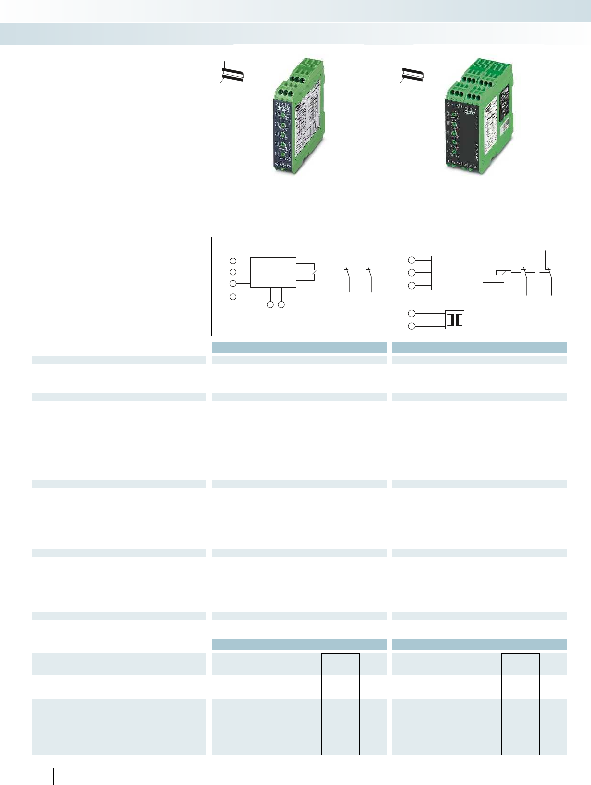
L1
L2
L3
(N)
A1 A2
16 26
15 25
1828
U = 24...240V AC/DC
L1
L2
L3
A1
A2
26
16
2515
2818
POWER
MODULE U=110...500 V AC
Housing width 22.5 mm Housing width 45 mm
Technical data Technical data
Functions EMD-FL-3V-400 EMD-FL-3V-230 EMD-FL-3V-690 EMD-FL-3V-500
Undervoltage, window,
asymmetry, phase sequence,
phase failure
Undervoltage, window,
asymmetry, phase sequence,
phase failure
Undervoltage, window,
asymmetry, phase sequence,
phase failure
Undervoltage, window,
asymmetry, phase sequence,
phase failure
Input
Monitoring range 280 V AC ... 520 V AC 161 V AC ... 299 V AC 483 V AC ... 897 V AC 350 V AC ... 650 V AC 280 V AC ... 520 V AC 280 V
Input ranges 3 N ~ 400/230 V 3 N ~ 230/132 V 3 ~ 690 V 3 ~ 500 V 3 ~ 400 V 3 N ~ 400/230 V 3 N ~ 400/230 V 3~ 208 V ... 690 V
Input resistance 1 M470 k1 M1 M
Min. setting range -30 % ... 20 % (of U
N
) -30 % ... 20 % (of U
N
)
Max. setting range -20 % ... 30 % (of U
N
) -20 % ... 30 % (of U
N
)
Setting range for response delay 0.1 s ... 10 s 0.1 s ... 10 s
Asymmetry 5% ... 25% / OFF 5% ... 25% / OFF 5% ... 25% / OFF 5% ... 25% / OFF
Basic accuracy ± 5 % (of scale end value) ± 5 % (of scale end value) ± 5 % (of scale end value) -
Setting accuracy 5 % (of scale end value) 5 % (of scale end value)
Repeat accuracy 2 % 2 %
Relay output
Contact type 2 floating PDT contacts 2 floating PDT contacts 1
Switching capacity 750 VA (3 A/250 V AC, module aligned, 5 mm spacing)
1250 VA (5 A/250 V AC, module not aligned, 5 mm spacing)
750 VA (3 A/250 V AC, module aligned, 5 mm spacing)
1250 VA (5 A/250 V AC, module not aligned, 5 mm spacing)
Electrical service life 2 x 10
5
cycles at ohmic load, 1000 VA 2 x 10
5
cycles at ohmic load, 1000 VA 2 x 10
Mechanical service life Approx. 2 x 10
7
cycles Approx. 2 x 10
7
cycles Approx. 2 x 10
Output fuse 5 A (fast-blow) 5 A (fast-blow)
General data
Supply voltage
Nominal power consumption 4.5 VA (1.5 W) 4.5 VA (1.5 W)
Degree of protection IP40 (housing) / IP20 (connection terminal blocks) IP40 (housing) / IP20 (connection terminal blocks) IP40 (h
Ambient temperature range -25 °C ... 55 °C -25 °C ... 55 °C
Dimensions W / H / D 22.5 / 90 / 113 mm 45 / 90 / 113 mm
Screw connection solid / stranded / AWG 0.5 ... 2.5 mm² / 0.25 ... 2.5 mm² / 20 - 14 0.5 ... 2.5 mm² / 0.25 ... 2.5 mm² / 20 - 14 0.
EMC note Class A product, see page 625
Conformance / approvals
Conformance CE-compliant CE-compliant
UL, USA / Canada UL/C-UL listed UL 508 UL/C-UL listed UL 508 UL/C-UL listed UL 508 UL/C-UL listed UL 508 UL/C-UL listed UL 508
Ordering data Ordering data
Description Type Order No. Pcs. /
Pkt. Type Order No. Pcs. /
Pkt.
Electronic monitoring relay
EMD-FL-3V-400 2866064 1EMD-FL-3V-690 2885249 1
EMD-FL-3V-230 2885773 1EMD-FL-3V-500 2867979 1
Power module, plug-in, please order at the same time!
Supply voltage 20 ... 30 V DC
Supply voltage 20.2 ... 26.4 V AC
Supply voltage 88 ... 121 V AC EMD-SL-PS45-110AC 2885281 1
Supply voltage 108 ... 132 V AC EMD-SL-PS45-120AC 2885744 1
Supply voltage 195 ... 264 V AC EMD-SL-PS45-230AC 2885294 1
Supply voltage 323 ... 456 V AC EMD-SL-PS45-400AC 2885304 1
302
PHOENIX CONTACT
Three-phase voltage monitoring
EMD-...-3V... monitoring relays monitor
three-phase AC voltages of 160 ... 897 V AC
(depending on the device concerned).
– Adjustable response delay
– Variable supply voltage range
– Adjustable via potentiometer on front
– Adjustable asymmetry
Monitoring relays
Monitoring
Monitoring and diagnostics
Undervoltage and phase monitoring,
400 V or 230 V
Undervoltage and phase monitoring,
500 V or 690 V
H
W
D
H
W
D
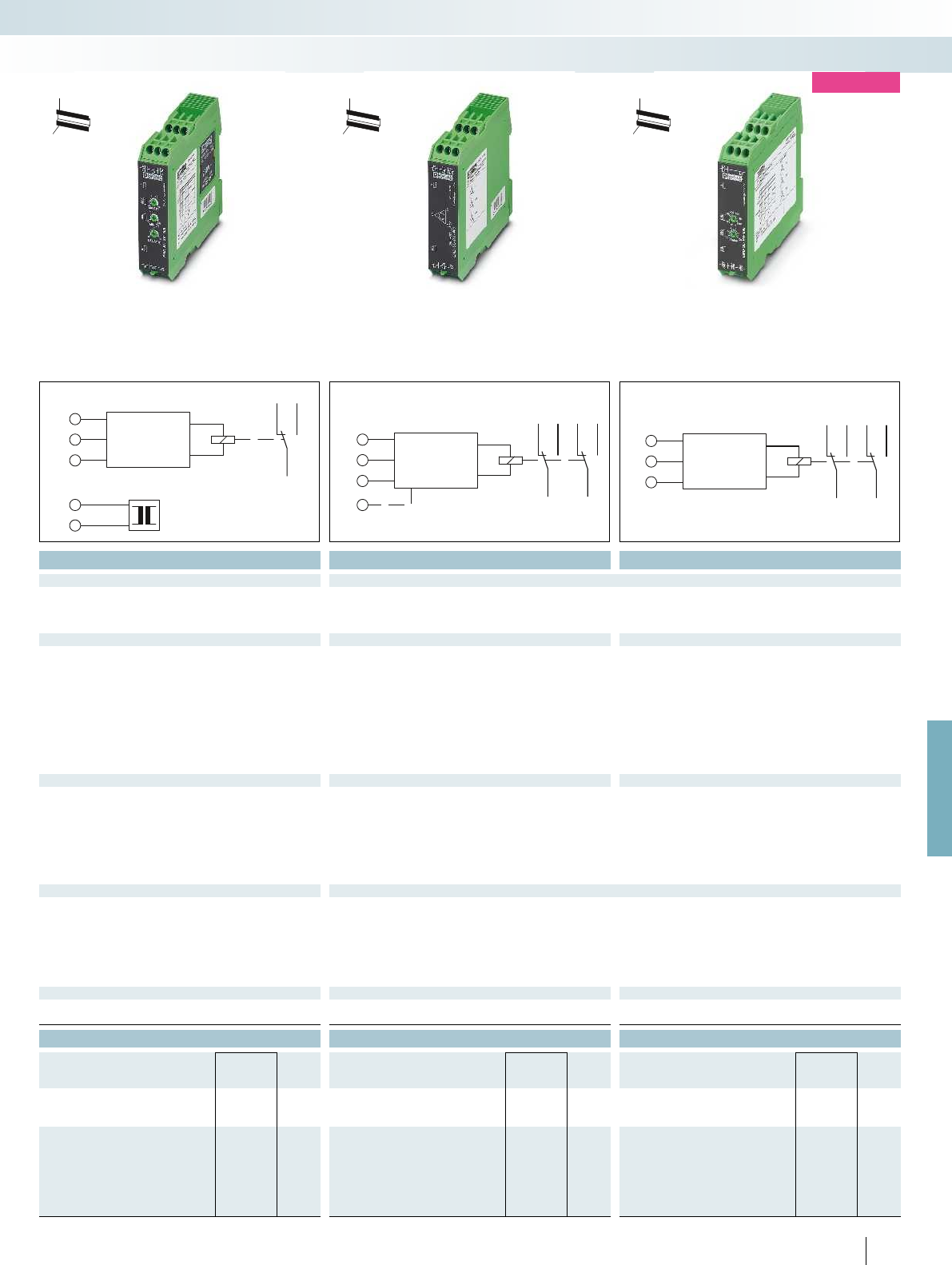
L1
L2
L3
A1
A2
16
15
18
POWER
MODULE
U=24VDC
24...230V AC
L1
L2
L3
22
12
2111
2414
(N)
L1
L2
L3
26
16
2515
2818
For further information and full technical data, visit phoenixcontact.net/products
Housing width 22.5 mm Housing width 22.5 mm Housing width 22.5 mm
Technical data Technical data Technical data
EMD-SL-3V-400 EMD-SL-3V-400-N
Window, without neutral
conductor connection
Window, with neutral conductor
connection
Phase sequence, phase failure, asymmetry Undervoltage, phase sequence, phase failure
Monitoring range 280 V AC ... 520 V AC 161 V AC ... 299 V AC 483 V AC ... 897 V AC 350 V AC ... 650 V AC 280 V AC ... 520 V AC 280 V AC ... 520 V AC 342 V AC ... 457 V AC 177 V AC ... 794 V AC
Input ranges 3 N ~ 400/230 V 3 N ~ 230/132 V 3 ~ 690 V 3 ~ 500 V 3 ~ 400 V 3 N ~ 400/230 V 3 N ~ 400/230 V 3~ 208 V ... 690 V
1 M1 M15 k-
-30 % ... 20 % (of U
N
)- -
-20 % ... 30 % (of U
N
)- -
0.2 s ... 10 s 350 ms (fixed setting) 0.1 s ... 10 s
Fixed, approx. 30 % 25 %
Basic accuracy ± 5 % (of scale end value) ± 5 % (of scale end value) ± 5 % (of scale end value) - 3 % (of scale end value)
5 % (of scale end value) - 5 % (of scale end value)
2 % - 2 %
Contact type 2 floating PDT contacts 2 floating PDT contacts 1 floating PDT 2 floating PDT contacts 2 floating PDT contacts
750 VA (3 A/250 V AC, module aligned, 5 mm spacing)
1250 VA (5 A/250 V AC, module not aligned, 5 mm spacing)
750 VA (3 A/250 V AC, module aligned, 5 mm spacing)
1250 VA (5 A/250 V AC, module not aligned, 5 mm spacing)
1250 VA (5 A/250 V AC at +55 °C)
150 VA (5 A/30 V DC at +55°C)
cycles at ohmic load, 1000 VA 2 x 10
5
cycles at ohmic load, 1000 VA 2 x 10
5
cycles at ohmic load, 1000 VA 2 x 10
5
cycles
cycles Approx. 2 x 10
7
cycles Approx. 2 x 10
7
cycles 20 x 10
6
cycles
5 A (fast-blow) 5 A (fast-blow) 5 A (fast-blow)
From the measured voltage ±15 % (= measuring voltage)
2 VA (1.5 W) 9 VA 2 VA (1.2 W)
Degree of protection IP40 (housing) / IP20 (connection terminal blocks) IP40 (housing) / IP20 (connection terminal blocks) IP40 (housing) / IP20 (connection terminal blocks) IP40 (housing) / IP20 (connection terminal blocks) IP40 (housing) / IP20 (connection terminal blocks)
-25 °C ... 55 °C -25 °C ... 55 °C -25 °C ... 70 °C (C300)
22.5 / 90 / 113 mm 22.5 / 90 / 113 mm 22.5 / 90 / 113 mm
Screw connection solid / stranded / AWG 0.5 ... 2.5 mm² / 0.25 ... 2.5 mm² / 20 - 14 0.5 ... 2.5 mm² / 0.25 ... 2.5 mm² / 20 - 14 0.5 ... 2.5 mm² / 0.25 ... 2.5 mm² / 20 - 14 0.5 ... 2.5 mm² / 0.25 ... 2.5 mm² / 20 - 14 0.5 ... 2.5 mm² / 0.5 ... 2.5 mm² / 20 - 14
CE-compliant CE-compliant CE-compliant
UL, USA / Canada UL/C-UL listed UL 508 UL/C-UL listed UL 508 UL/C-UL listed UL 508 UL/C-UL listed UL 508 UL/C-UL listed UL 508
Ordering data Ordering data Ordering data
Type Order No. Pcs. /
Pkt. Type Order No. Pcs. /
Pkt. Type Order No. Pcs. /
Pkt.
EMD-SL-3V-400 2866051 1EMD-SL-PH-400 2866077 1EMD-SL-PH-690 2905597 1
EMD-SL-3V-400-N 2885278 1
EMD-SL-PS- 24DC 2885359 1
EMD-SL-PS- 24AC 2866103 1
EMD-SL-PS-110AC 2866116 1
EMD-SL-PS-120AC 2885731 1
EMD-SL-PS-230AC 2866129 1
303
PHOENIX CONTACT
Monitoring
Monitoring and diagnostics
H
W
D
new
Undervoltage/overvoltage monitoring,
400 V with/without neutral conductor
Phase monitoring, 400 V Phase monitoring, 690 V
H
W
D
H
W
D
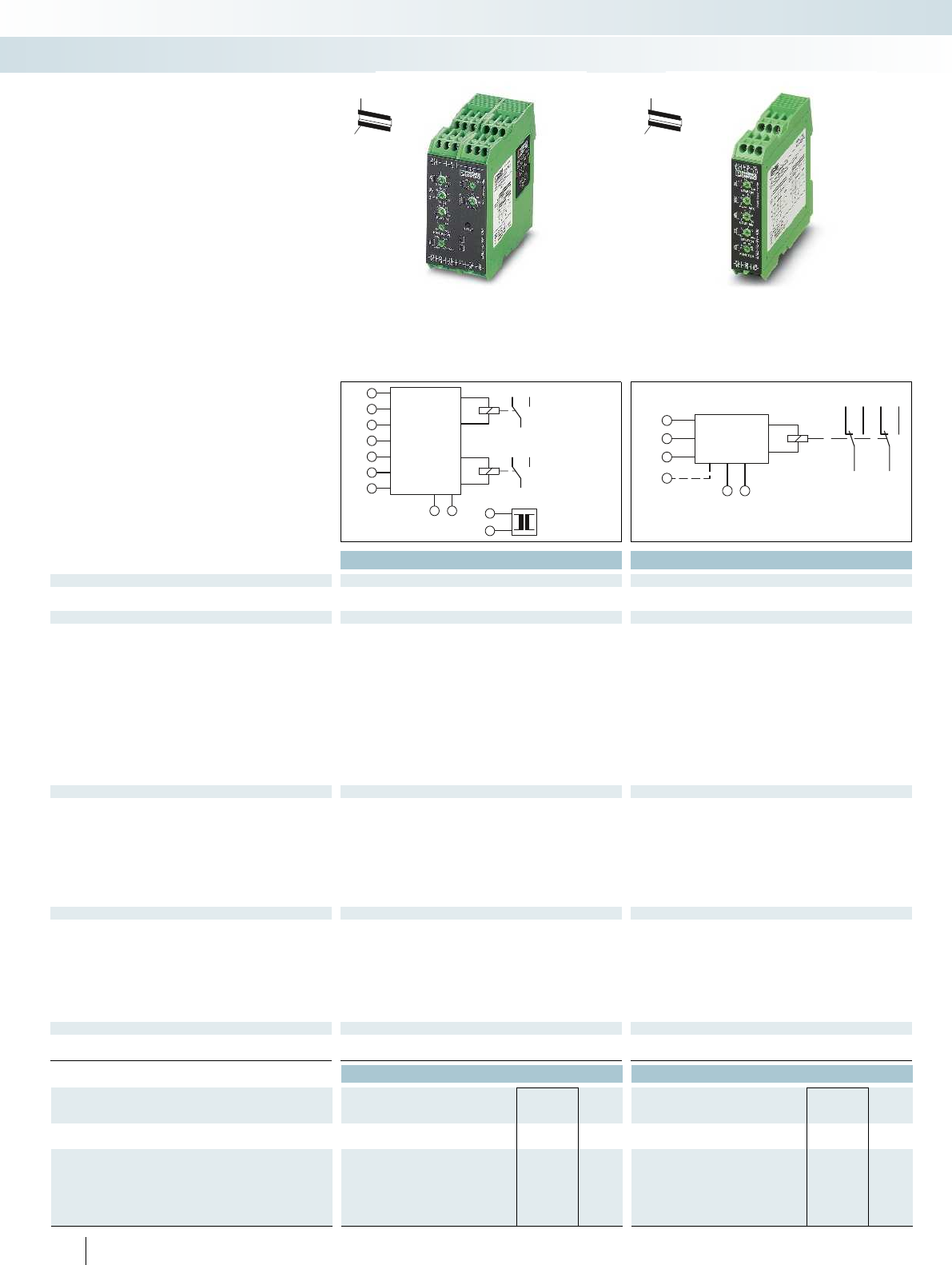
L3
T1
T2
A1
A2
16
26
15
25
18
28
POWER
MODULE
supply≤500 V AC
L2
L1
k
i
Y2
Y1
L1I
L2
L3
L1K
A1 A2
16 26
15 25
1828
U = 24...240V AC/DC
Housing width 45 mm Housing width 22.5 mm
Technical data Technical data
Functions
Underload, overload, window, winding temperature monitoring Underload, overload, Window
Input
Description of the input Voltage input -
Measured value AC sine (10 Hz ... 400 Hz) AC sine (10 ... 100 Hz)
Measuring ranges P
N
Can be switched between 0.75 kW, 1.5 kW, 3 kW and 6 kW -
Nominal input voltage U
N
480 V (3 N ~ 480/277 V) 3 N ~ 415/240 V
Input ranges 0 V AC ... 480 V AC (1(N) ~, single-phase load)
0 V AC ... 480 V AC (3(N) ~, 3-phase load)
40 V AC ... 415 V AC (1(N) ~, single-phase load)
40 V AC ... 415 V AC (3(N) ~, 3-phase load)
Input ranges 0.15 A ... 6 A (range: 0.75 kW and 1.5 kW)
0.3 A ... 12 A (range: 3 kW and 6 kW)
0.5 A ... 10 A (connection terminal blocks: L1i and L1k)
Min. setting range 5 % ... 110 % (of P
N
)-
Max. setting range 10 % ... 120 % (of P
N
)-
Switching threshold cos Min. - 0.1 ... 0.99
Max. - 0.2 ... 1
Relay output
Contact type 2 floating PDT contacts 2 floating PDT contacts
Switching capacity 750 VA (3 A/250 V AC, module aligned, 5 mm spacing)
1250 VA (5 A/250 V AC, module not aligned, 5 mm spacing)
750 VA (3 A/250 V AC, module aligned, 5 mm spacing)
1250 VA (5 A/250 V AC, module not aligned, 5 mm spacing)
Electrical service life 2 x 10
5
cycles at ohmic load, 1000 VA 2 x 10
5
cycles at ohmic load, 1000 VA
Mechanical service life Approx. 2 x 10
7
cycles Approx. 2 x 10
7
cycles
Output fuse 5 A (fast-blow) 5 A (fast-blow)
General data
Supply voltage
Nominal power consumption 3.5 VA (3 W) 4.5 VA (1.5 W)
Rated insulation voltage 300 V (according to EN 50178) 300 V (according to EN 50178)
Degree of protection IP40 (housing) / IP20 (connection terminal blocks) IP40 (housing) / IP20 (connection terminal blocks)
Ambient temperature range -25 °C ... 55 °C -25 °C ... 55 °C
Dimensions W / H / D 45 / 90 / 113 mm 22.5 / 90 / 113 mm
Screw connection solid / stranded / AWG 0.5 ... 2.5 mm² / 0.25 ... 2.5 mm² / 20 - 14 0.5 ... 2.5 mm² / 0.25 ... 2.5 mm² / 20 - 14
EMC note Class A product, see page 625
Conformance / approvals
Conformance CE-compliant CE-compliant
UL, USA / Canada UL applied for UL/C-UL listed UL 508
Ordering data Ordering data
Description Type Order No. Pcs. /
Pkt. Type Order No. Pcs. /
Pkt.
Electronic monitoring relay
EMD-FL-RP-480 2900177 1EMD-FL-PF-400 2885809 1
Power module, plug-in, please order at the same time!
Supply voltage 88 ... 121 V AC EMD-SL-PS45-110AC 2885281 1
Supply voltage 108 ... 132 V AC EMD-SL-PS45-120AC 2885744 1
Supply voltage 195 ... 264 V AC EMD-SL-PS45-230AC 2885294 1
Supply voltage 323 ... 456 V AC EMD-SL-PS45-400AC 2885304 1
Supply voltage 425 ... 550 V AC EMD-SL-PS45-500AC 2885317 1
304
PHOENIX CONTACT
Real power monitoring
The real power in single and 3-phase
networks can be monitored with the
EMD-FL-RP-480 real power monitoring
relay.
– Monitoring range up to 7.2 kW
– Separately adjustable startup and release
delays
– Temperature monitoring of the motor
winding
– Variable supply voltage range
– Detection of switched off loads
Load monitoring (cos φ)
The EMD-FL-PF-400 monitoring relay
is a cos φ monitor for load monitoring in
single or three-phase networks.
H
W
D
H
W
D
Monitoring relays
Monitoring
Monitoring and diagnostics
Real power monitoring Load monitoring (cos φ)

T1
T2
R
A1
A2
22
12
2111
2414
POWER
MODULE
U=24VDC
24...230V AC
E1
E2
E3
A1 A2
16 26
15 25
1828
U=230V AC
For further information and full technical data, visit phoenixcontact.net/products
Housing width 22.5 mm Housing width 22.5 mm
Technical data Technical data
Functions
Winding temperature monitoring Pumping up (minimum monitoring), pumping down (maximum
monitoring)
Input
Total cold resistance < 1.5 k-
Response value 3.6 k (relay drops out) -
Release value 1.8 k (relay picks up) -
Basic accuracy ± 10 % (of scale end value) -
Repeat accuracy 2 % -
Measuring input - Conductive probe, type: SK1, SK2, SK3
Max. probe voltage - 16 V AC
Max. probe current - 7 mA
Length of probe cable - < 1000 m (line capacity 100 nF/km; set value < 50%)
< 100 m (line capacity 100 nF/km; set value 100%)
Switching threshold - 0.25 k ... 100 k (4 mS ... 1 S)
Relay output
Contact type 2 floating PDT contacts 2 floating PDT contacts
Switching capacity 750 VA (3 A/250 V AC, module aligned, 5 mm spacing)
1250 VA (5 A/250 V AC, module not aligned, 5 mm spacing)
750 VA (3 A/250 V AC, module aligned, 5 mm spacing)
1250 VA (5 A/250 V AC, module not aligned, 5 mm spacing)
Electrical service life 2 x 10
5
cycles at ohmic load, 1000 VA 2 x 10
5
cycles at ohmic load, 1000 VA
Mechanical service life Approx. 2 x 10
7
cycles Approx. 2 x 10
7
cycles
Output fuse 5 A (fast-blow) 5 A (fast-blow)
General data EMD-SL-LL-230 EMD-SL-LL-110
Supply voltage 230 V AC -15 % ... +15% AC 110 V AC -10 % ... +15% AC
Nominal power consumption 2 VA (1.5 W) 2 VA (1.5 W)
Degree of protection IP40 (housing) / IP20 (connection terminal blocks) IP40 (housing) / IP20 (connection terminal blocks)
Ambient temperature range -25 °C ... 55 °C -25 °C ... 55 °C
Dimensions W / H / D 22.5 / 90 / 113 mm 22.5 / 90 / 113 mm
Screw connection solid / stranded / AWG 0.5 ... 2.5 mm² / 0.25 ... 2.5 mm² / 20 - 14 0.5 ... 2.5 mm² / 0.25 ... 2.5 mm² / 20 - 14
Conformance / approvals
Conformance CE-compliant CE-compliant
UL, USA / Canada UL/C-UL listed UL 508 UL/C-UL listed UL 508
Ordering data Ordering data
Description Type Order No. Pcs. /
Pkt. Type Order No. Pcs. /
Pkt.
Electronic monitoring relay
EMD-SL-PTC 2866093 1EMD-SL-LL-230 2885906 1
EMD-SL-LL-110 2901137 1
Power module, plug-in, please order at the same time!
Supply voltage 20 ... 30 V DC EMD-SL-PS- 24DC 2885359 1
Supply voltage 20.2 ... 26.4 V AC EMD-SL-PS- 24AC 2866103 1
Supply voltage 88 ... 121 V AC EMD-SL-PS-110AC 2866116 1
Supply voltage 108 ... 132 V AC EMD-SL-PS-120AC 2885731 1
Supply voltage 195 ... 264 V AC EMD-SL-PS-230AC 2866129 1
305
PHOENIX CONTACT
The EMD-SL-LL-... monitoring relay
monitors the level of electrically conductive
liquids with the help of conductive probes
(not supplied as standard).
– Adjustable response delay
– Adjustable via potentiometer on front
H
W
D
H
W
D
Filling level monitoring
Monitoring
Monitoring and diagnostics
Temperature monitoring (motor windings) Filling level monitoring
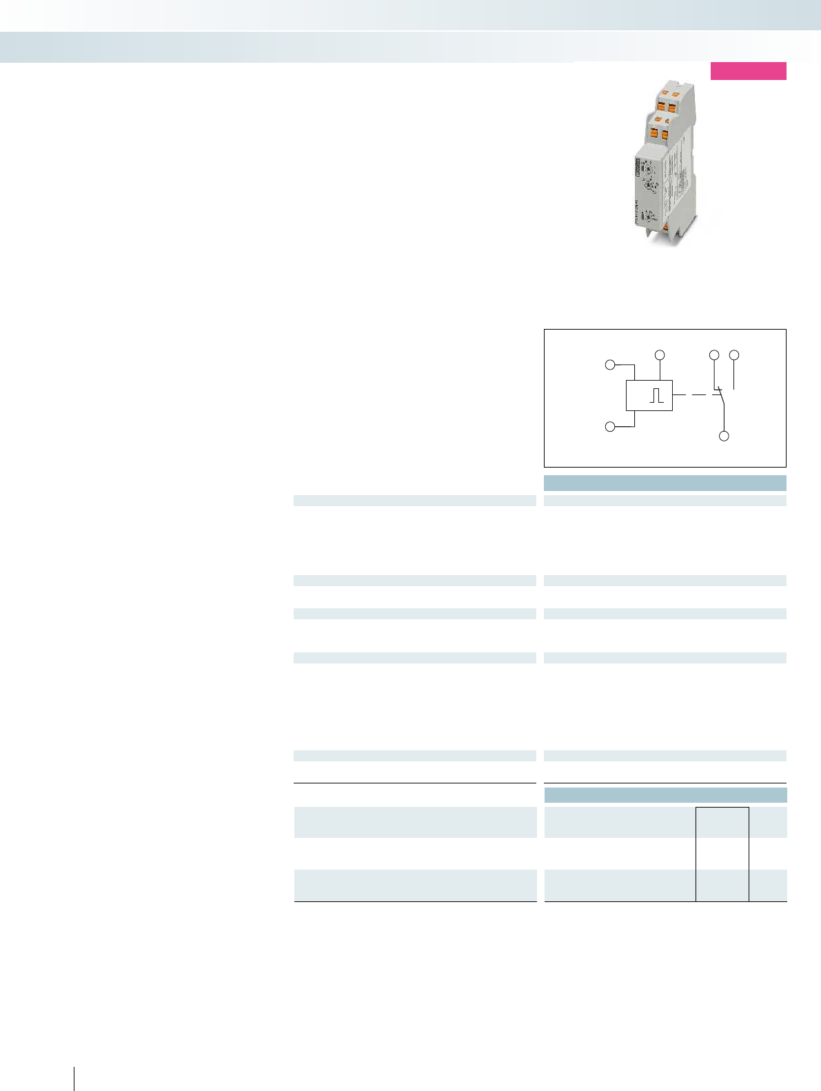
A1
t
A2
1618B1
15
U = 85...240V AC/DC
Technical data
Functions
E: With switch-on delay
R: With release delay and control contact
Es: With switch-on delay and control contact
Ws: With single shot leading edge and control contact
Control contact
Connection Non-floating, terminals A1-B1
Control pulse length 50 ms (DC)
Relay output
Contact type 1 floating PDT
Switching capacity 1250 VA (5 A/250 V AC)
Mechanical service life 15 x 10
6
cycles
General data
Supply voltage 85 V AC/DC ... 240 V AC/DC -15% ... +10%
Degree of protection IP40 (housing) / IP20 (connection terminal blocks)
Ambient temperature range -25 °C ... 55 °C
Housing material -
Dimensions W / H / D 17.5 / 88 / 65.5 mm
Screw connection solid / stranded / AWG 0.5 ... 2.5 mm² / 0.5 ... 2.5 mm² / 20 - 14
Push-in connection solid / stranded / AWG 0.5 ... 2.5 mm² / 0.5 ... 2.5 mm² / 20 - 14
Conformance / approvals
Conformance CE-compliant
UL, USA / Canada UL/C-UL listed UL 508
Ordering data
Description Type Order No. Pcs. /
Pkt.
Compact time relay, multifunctional, with screw connection
ETD-BL-1T-230 2905813 1
Compact time relay, multifunctional, with push-in connection
ETD-BL-1T-230-PT 2905814 1
306
PHOENIX CONTACT
new
The multifunctional time relay offers
universal use thanks to a variety of functions
and various time settings. The rotary
switches on the front of the housing allow
easy parameterization. The compact design
also allows flexible use.
Main features:
– Adjustable time
– Time range: 50 ms to 1 h
– Non-floating control input
– Delay functions
– Wiper functions
– Output: one floating PDT
– Clear diagnostics via status LED
Compact time relay
Monitoring
Monitoring and diagnostics
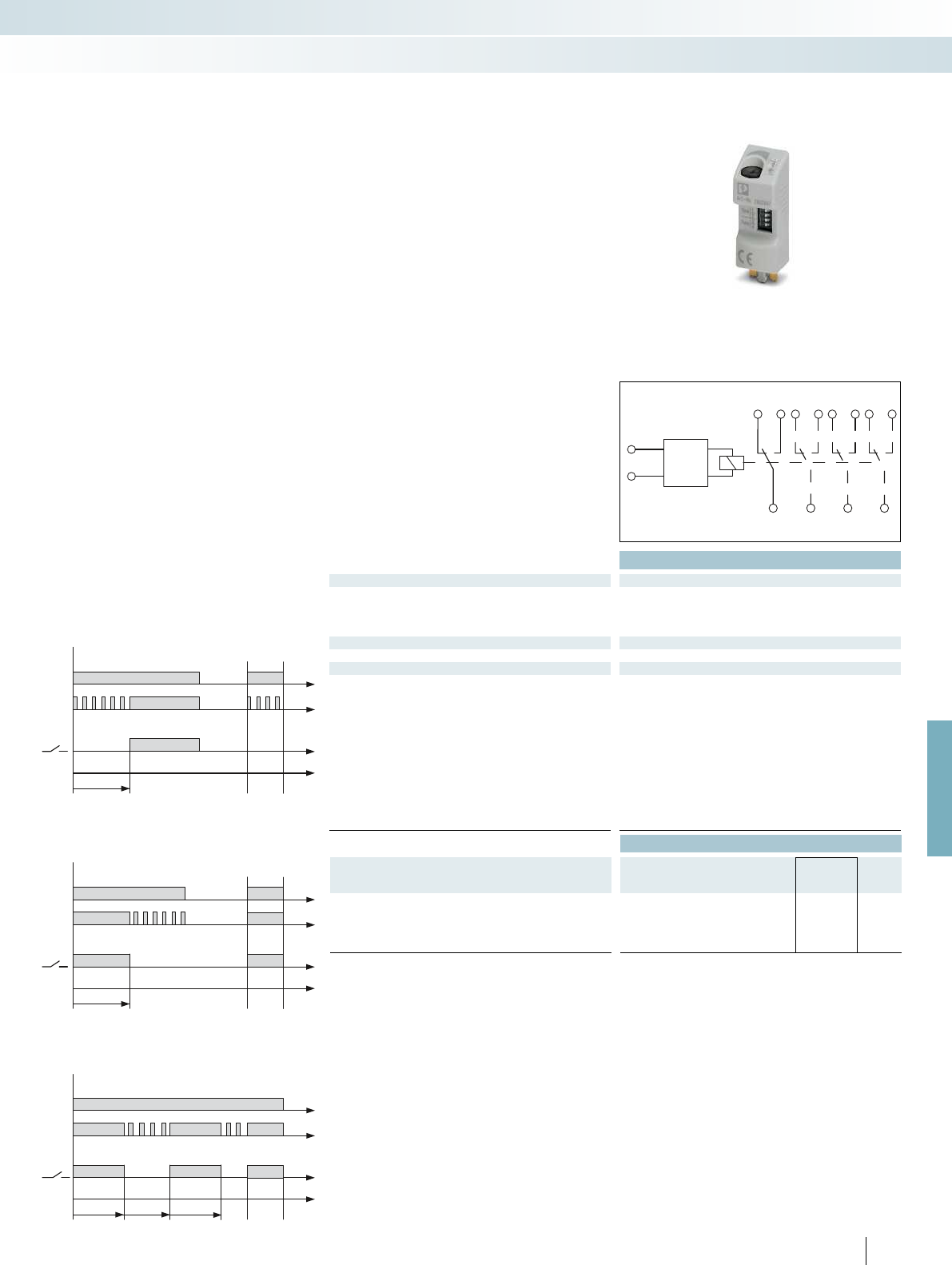
t
A1+
A2-
44
42
34
32
24
22
14
12
11 21 31 41
Tt<T t
U
LED
Tt<T t
U
LED
Tt<T
U
LED
T T t
For further information and full technical data, visit phoenixcontact.net/products
Technical data
Input data
Nominal input voltage U
N
24 V DC (AC operation only permitted for RIF-1)
Nominal input voltage range with reference to U
N
0.4 ... 1.2
Input circuit Varistor, yellow LED
Output data
Limiting continuous current 250 mA (relay coil current)
General data
Mounting position any
Repeat accuracy 1 %
Ambient temperature (operation) -25 °C ... 50 °C (RIF-1, AC coil, 2 PDTs at 6 A)
-25 °C ... 50 °C (RIF-1, DC coil, 2 PDTs at 5 A)
-25 °C ... 40 °C (RIF-2, DC coil, 2 PDTs at 8 A)
-25 °C ... 40 °C (RIF-2, DC coil, 4 PDTs at 5 A)
-25 °C ... 40 °C (RIF-3, DC coil, 3 PDTs at 6.75 A)
-25 °C ... 40 °C (RIF-3, DC coil, 2 PDTs at 8 A)
-25 °C ... 35 °C (RIF-4, DC coil, 3 PDTs at 8 A)
-25 °C ... 25 °C (RIF-4, DC coil, 3 N/O contacts at 8 A)
Standards/specifications DIN EN 50178
Rated insulation voltage 50 V DC
Rated surge voltage 0.4 kV
Ordering data
Description Type Order No. Pcs. /
Pkt.
Timer module, for mounting on RIF-1 to RIF-4, with LED status
indicator for extending a relay module to create a timer relay with an
input voltage of 24 V AC/DC
RIF-T3-24UC 2902647 1
307
PHOENIX CONTACT
Timer relay
Monitoring
Monitoring and diagnostics
Time module
With switch-on delay
With passing make contact
Flasher/pulse generator
Plug-in timer module for
RIF-1, RIF-2, RIF-3, and RIF-4
The multifunctional plug-in timer module
transforms the relay module into a timer
relay. The RIF-1 to RIF-4 bases can be fitted
with this module. Using DIP switches, you
can choose from three time ranges and
select four time functions. Fine adjustments
to the time are made using a potentiometer.
Relays can be operated with an input
voltage of 24 V AC/DC.
Functions:
– With switch-on delay
– With passing make contact
– Flasher/pulse generator
Time ranges:
– 0.5 s - 10 s
– 5 s - 100 s
– 0.5 min - 10 min
– 5 min - 100 min
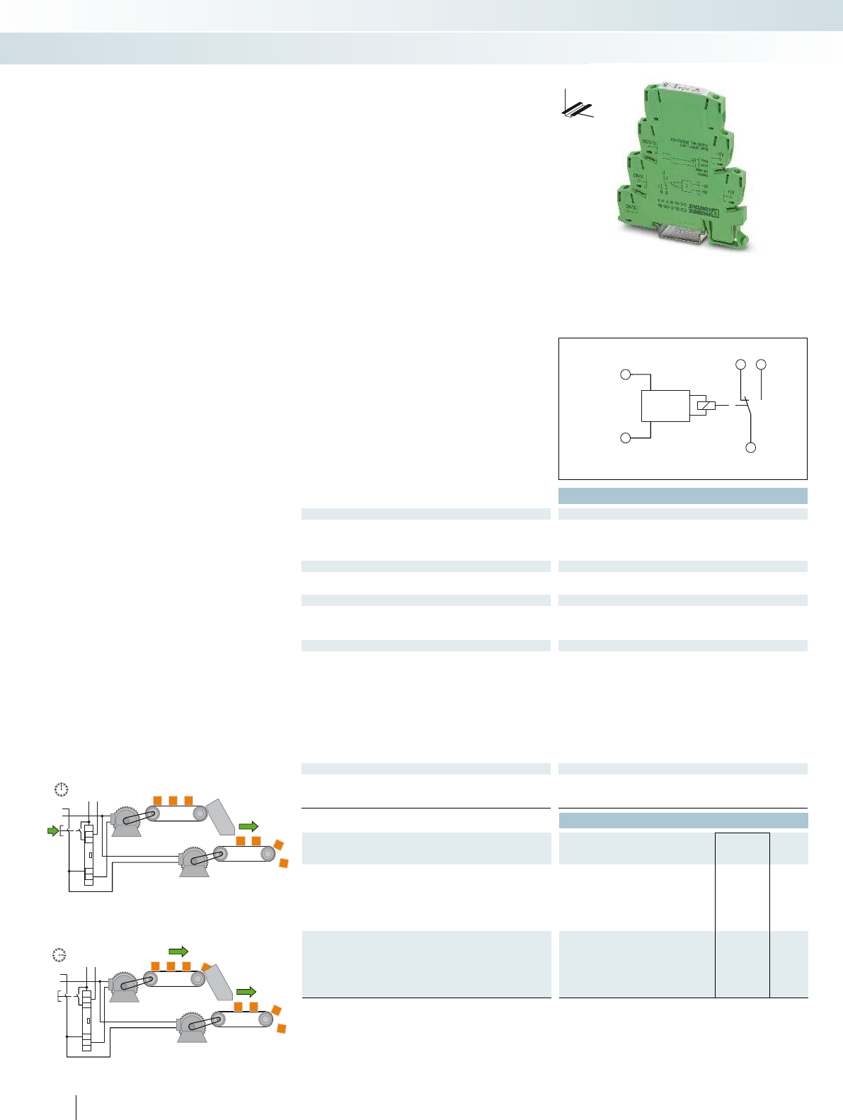
L1
24 VDC
N
A2-
A1+
14
12
11
B1
+–
1
2
L1
24 VDC
N
A2-
A1+
14
12
11
B1
+–
1
2
A1 +
t
A2 –
12 14
11
U=24VDC
Ex:
Technical data
Functions
ON: With switch-on delay ON-CC: With switch-on delay with control contact OFF-CC: Off delay with control contact F: Flashing begin
Control contact
Connection -
Control pulse length min. 50 ms
Relay output
Contact type 1 floating PDT
Switching capacity 1500 VA (6 A / 250 V AC) 1500 VA (6 A / 250 V AC) 1500 VA (6 A / 250 V AC) 1500 VA (6 A / 250 V AC)
Mechanical service life Approx. 2 x 10
7
cycles Approx. 2 x 10
General data
Supply voltage 24 V DC (19,2 V DC ...30 V DC) 24 V DC (19,2 V DC ...30 V DC) 24 V DC (19,2 V DC ...30 V DC) 24 V DC (19,2 V DC ...3
Nominal current typ. 15 mA (relay ON)
7 mA (relay OFF)
Impulse withstand voltage 6 kV (according to EN 50178) 6 kV (according to EN 50178) 6 kV (according to EN 50178) 6 kV (according to
Degree of protection IP20
Ambient temperature range -20 °C ... 65 °C
Housing material Polyamide PA, self-extinguishing Polyamide PA, se
Dimensions W / H / D 6.2 / 80 / 86 mm
Screw connection solid / stranded / AWG 0.14 ... 2.5 mm² / 0.14 ... 2.5 mm² / 30 - 12 0.14 ... 2.5 mm² / 0.14 ... 2.5 mm² / 30 - 12
Push-in connection solid / stranded / AWG 0.14 ... 2.5 mm² / 0.14 ... 2.5 mm² / 26 - 14 0.14 ... 2.5 mm² / 0.14 ... 2.5 mm² / 26 -
Conformance / approvals
Conformance CE-compliant
ATEX
II 3 G Ex nA nC IIC T4 Gc X
UL, USA / Canada UL/C-UL listed UL 508 UL/C-UL listed UL 508 UL/C-UL listed UL 508 UL/C-UL listed UL 508
Ordering data
Description Type Order No. Pcs. /
Pkt.
Compact timer relay, with screw connection
Time range 0.1...10 s ETD-BL-1T-ON- 10S 2917379 1
Time range 3...300 s ETD-BL-1T-ON-300S 2917382 1
Time range 0.3...30 min ETD-BL-1T-ON- 30MIN 2917395 1
Time range 3...300 min ETD-BL-1T-ON-300MIN 2917405 1
Compact timer relay, with push-in technology
Time range 0.1...10 s ETD-BL-1T-ON- 10S-PT 2901476 1
Time range 3...300 s ETD-BL-1T-ON-300S-PT 2901477 1
Time range 0.3...30 min ETD-BL-1T-ON- 30MIN-PT 2901478 1
Time range 3...300 min ETD-BL-1T-ON-300MIN-PT 2901479 1
308
PHOENIX CONTACT
Ultra-narrow timer relays
The ETD-BL-1T-... ultra-narrow timer
relays show their strengths in applications
that involve set parameters for functionality
and time range.
– Purposeful device selection: one function,
one time range
– High level of setting accuracy thanks to
labeled and illuminated thumbwheel
– Narrow overall width of just 6.2 mm
Conveyor belt 2 stars with a time delay
Conveyor belt 1 starts immediately
Monitoring
Monitoring and diagnostics
DW
H
Timer relay with switch-on delay,
voltage controlled
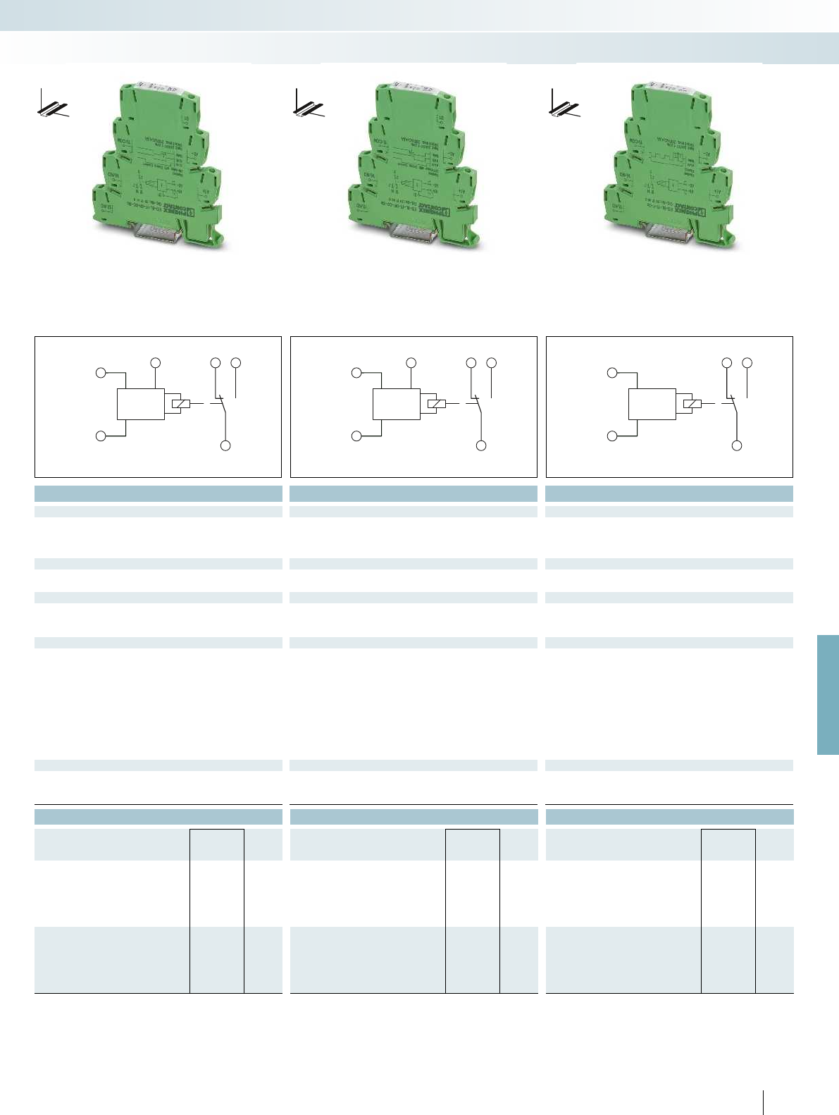
A1 +
t
A2 –
12 14
B1
11
U=24VDC
A1 +
t
A2 –
12 14
B1
11
U=24VDC
A1 +
t
A2 –
12 14
11
U=24VDC
For further information and full technical data, visit phoenixcontact.net/products
Ex:
Ex:
Ex:
Technical data Technical data Technical data
ON: With switch-on delay ON-CC: With switch-on delay with control contact OFF-CC: Off delay with control contact F: Flashing beginning with pulse
Non-floating, terminals A1-B1 Non-floating, terminals A1-B1 -
min. 50 ms min. 50 ms min. 50 ms
1 floating PDT 1 floating PDT 1 floating PDT
Switching capacity 1500 VA (6 A / 250 V AC) 1500 VA (6 A / 250 V AC) 1500 VA (6 A / 250 V AC) 1500 VA (6 A / 250 V AC)
cycles Approx. 2 x 10
7
cycles Approx. 2 x 10
7
cycles Approx. 2 x 10
7
cycles
Supply voltage 24 V DC (19,2 V DC ...30 V DC) 24 V DC (19,2 V DC ...30 V DC) 24 V DC (19,2 V DC ...30 V DC) 24 V DC (19,2 V DC ...30 V DC)
15 mA (relay ON)
7 mA (relay OFF)
15 mA (relay ON)
7 mA (relay OFF)
15 mA (relay ON)
7 mA (relay OFF)
Impulse withstand voltage 6 kV (according to EN 50178) 6 kV (according to EN 50178) 6 kV (according to EN 50178) 6 kV (according to EN 50178)
IP20 IP20 IP20
-20 °C ... 65 °C -20 °C ... 65 °C -20 °C ... 65 °C
Housing material Polyamide PA, self-extinguishing Polyamide PA, self-extinguishing Polyamide PA, self-extinguishing Polyamide PA, self-extinguishing
6.2 / 80 / 86 mm 6.2 / 80 / 86 mm 6.2 / 80 / 86 mm
Screw connection solid / stranded / AWG 0.14 ... 2.5 mm² / 0.14 ... 2.5 mm² / 30 - 12 0.14 ... 2.5 mm² / 0.14 ... 2.5 mm² / 30 - 12 0.14 ... 2.5 mm² / 0.14 ... 2.5 mm² / 30 - 12 0.14 ... 2.5 mm² / 0.14 ... 2.5 mm² / 30 - 12
Push-in connection solid / stranded / AWG 0.14 ... 2.5 mm² / 0.14 ... 2.5 mm² / 26 - 14 0.14 ... 2.5 mm² / 0.14 ... 2.5 mm² / 26 - 14 0.14 ... 2.5 mm² / 0.14 ... 2.5 mm² / 26 - 14 0.14 ... 2.5 mm² / 0.14 ... 2.5 mm² / 26 - 14
CE-compliant CE-compliant CE-compliant
II 3 G Ex nA nC IIC T4 Gc X
II 3 G Ex nA nC IIC T4 Gc X
II 3 G Ex nA nC IIC T4 Gc X
UL, USA / Canada UL/C-UL listed UL 508 UL/C-UL listed UL 508 UL/C-UL listed UL 508 UL/C-UL listed UL 508
Ordering data Ordering data Ordering data
Type Order No. Pcs. /
Pkt. Type Order No. Pcs. /
Pkt. Type Order No. Pcs. /
Pkt.
ETD-BL-1T-ON-CC- 10S 2917418 1ETD-BL-1T-OFF-CC- 10S 2917450 1ETD-BL-1T-F- 10S 2917492 1
ETD-BL-1T-ON-CC-300S 2917421 1ETD-BL-1T-OFF-CC-300S 2917463 1ETD-BL-1T-F-300S 2917502 1
ETD-BL-1T-ON-CC- 30MIN 2917434 1ETD-BL-1T-OFF-CC- 30MIN 2917467 1ETD-BL-1T-F- 30MIN 2917515 1
ETD-BL-1T-ON-CC-300MIN 2917447 1ETD-BL-1T-OFF-CC-300MIN 2917489 1ETD-BL-1T-F-300MIN 2917528 1
ETD-BL-1T-ON-CC- 10S-PT 2901480 1ETD-BL-1T-OFF-CC- 10S-PT 2901485 1ETD-BL-1T-F- 10S-PT 2901489 1
ETD-BL-1T-ON-CC-300S-PT 2901481 1ETD-BL-1T-OFF-CC-300S-PT 2901486 1ETD-BL-1T-F-300S-PT 2901490 1
ETD-BL-1T-ON-CC- 30MIN-PT 2901483 1ETD-BL-1T-OFF-CC- 30MIN-PT 2901487 1ETD-BL-1T-F- 30MIN-PT 2901491 1
ETD-BL-1T-ON-CC-300MIN-PT 2901484 1ETD-BL-1T-OFF-CC-300MIN-PT 2901488 1ETD-BL-1T-F-300MIN-PT 2901492 1
309
PHOENIX CONTACT
Monitoring
Monitoring and diagnostics
DW
H
DW
H
DW
H
Timer relay with switch-on delay,
with control contact
Timer relay with off delay,
with control contact
Timer relay with flashing indic. function,
beginning with the pulse
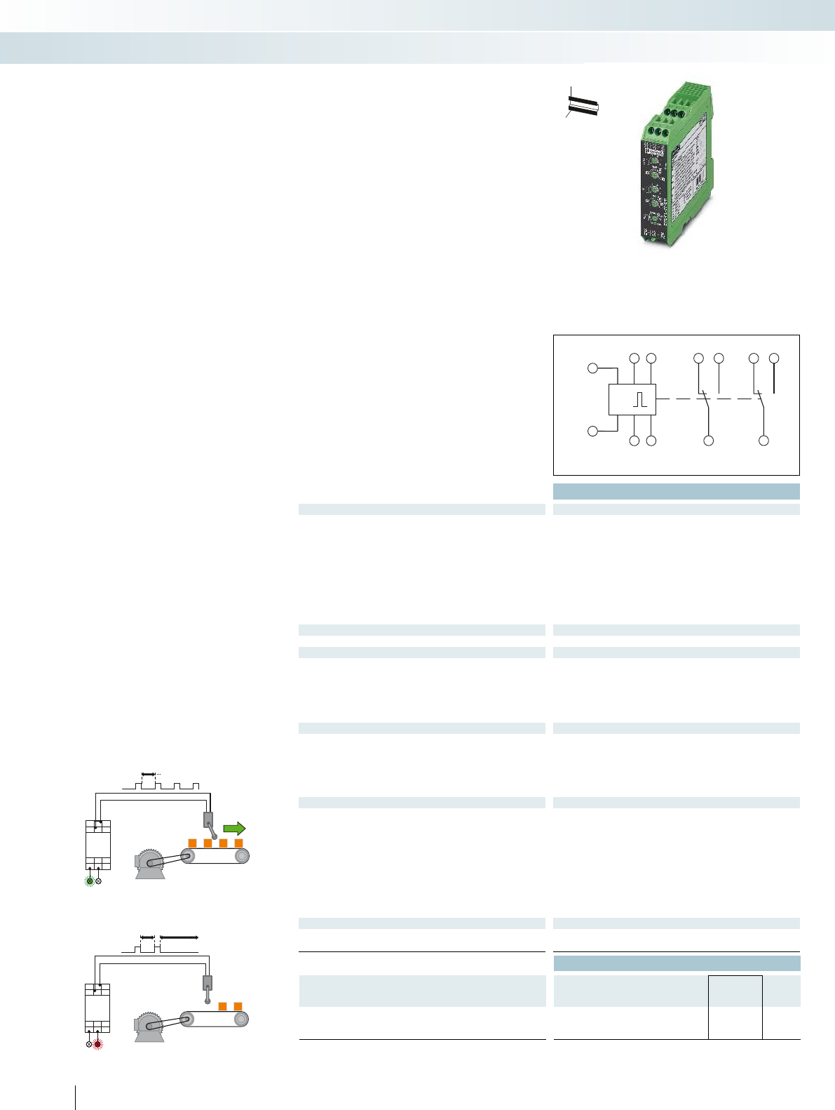
A1 25
16 18
Y2
26
WATCHDOG
25 28
Y1
A2
T<T1TT1>
A1 25
16 18
Y2
26
WATCHDOG
25 28
Y1
A2
T<T1
A1
t
A2
Y1 16 261828Y2
Z2Z115 25
U = 24...240V AC/DC
Housing width 22.5 mm Housing width 22.5 mm Housing width 22.5 mm
Technical data
Functions
lp: Switched-mode beginning with the pause
li: Switched-mode beginning with the pulse
ER: With switch-on and release delay with control contact
EWu: With switch-on delay and single shot leading edge, voltage
controlled
EWs: With switch-on delay and single shot leading edge with control
contact
WsWa: With single shot leading edge and single shot trailing edge
with control contact
Wt: Pulse sequence evaluation (retriggerable release delay)
Time ranges
Setting range 50 ms ... 10 h (10 time end ranges) 50 ms ... 100
Control contact
Connection Floating, basic insulation between connection and
input/output/bridge Y1-Y2
Load capacity Cannot carry load
Cable length < 10 m
Control pulse length min. 50 ms (only with Wt function: > 7 ms) min. 70 ms -
Relay output
Contact type 2 floating PDT contacts 2 floating PDT contacts 2 floating PDT contacts
Switching capacity 750 VA (3 A/250 V AC, module aligned, 5 mm spacing)
1250 VA (5 A/250 V AC, module not aligned, 5 mm spacing)
Mechanical service life Approx. 2 x 10
7
cycles Approx. 2 x 10
General data
Supply voltage 24 V DC ... 240 V DC -20% ... +25%
24 V AC ... 240 V AC -15% ... +10%
Nominal power consumption 2.5 VA (1 W)
Degree of protection IP40 (housing) / IP20 (connection terminal blocks) IP40 (housing) / IP20 (connection terminal blocks) IP40 (h
Ambient temperature range -25 °C ... 55 °C
Housing material Polyamide PA, self-extinguishing Polyamide PA, self-extinguishing Polyamide PA, self-extinguishing
Dimensions W / H / D 22.5 / 90 / 113 mm
Screw connection solid / stranded / AWG 0.5 ... 2.5 mm² / 0.5 ... 2.5 mm² / 20 - 14 0.5 ... 2.5 mm² / 0.5 ... 2.5 mm² / 20 - 14 0.5
EMC note Class A product, see page 625 Class A product, see page 625 Class A product, see page 625
Conformance / approvals
Conformance CE-compliant
UL, USA / Canada UL/C-UL listed UL 508 UL/C-UL listed UL 508 UL/C-UL listed UL 508
Ordering data
Description Type Order No. Pcs. /
Pkt.
Electronic timer relay with adjustable functions and times
ETD-FL-2T-DTI 2866187 1
310
PHOENIX CONTACT
Multifunctional timer relays
The full range of conventional applications
can be accommodated by the three versions
of the ETD multifunctional timer relay.
– Suitable for universal use thanks to varied
functions and selectable time ranges
– Time ranges from a few milliseconds to
several days
– Variable supply voltage range
– 2 floating PDT outputs
Message for incorrect pulse
Function: pulse sequence evaluation
Monitoring
Monitoring and diagnostics
H
W
D
Multifunctional timer relay,
two adjustable times
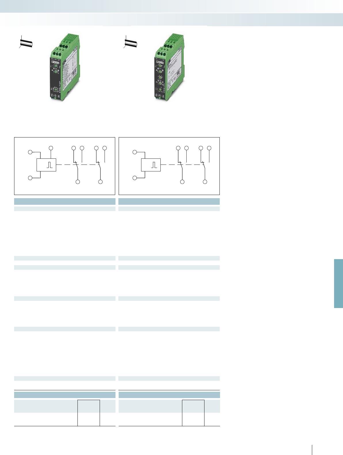
A1
t
A2
16 261828B1
15 25
U = 24...240V AC/DC
A1
t
A2
16 261828
15 25
U = 24...240V AC/DC
For further information and full technical data, visit phoenixcontact.net/products
Housing width 22.5 mm Housing width 22.5 mm Housing width 22.5 mm
Technical data Technical data
E: With switch-on delay
R: With release delay and control contact
Es: With switch-on delay and control contact
Wu: With single shot leading edge, voltage controlled
Ws: With single shot leading edge and control contact
Wa: With single shot trailing edge and control contact
Bi: Flashing beginning with pulse
Bp: Flashing beginning with pause
lp: Switched-mode beginning with the pause
li: Switched-mode beginning with the pulse
Setting range 50 ms ... 10 h (10 time end ranges) 50 ms ... 100 h (7 time end ranges) 50 ms ... 100 h (7 time end ranges)
Non-floating, terminals A1-B1 -
Parallel switched minimum load current 1 VA (0.5 W), terminals A2-B1
-
< 10 m -
Control pulse length min. 50 ms (only with Wt function: > 7 ms) min. 70 ms -
Contact type 2 floating PDT contacts 2 floating PDT contacts 2 floating PDT contacts
750 VA (3 A/250 V AC, module aligned, 5 mm spacing)
1250 VA (5 A/250 V AC, module not aligned, 5 mm spacing)
750 VA (3 A/250 V AC, module aligned, 5 mm spacing)
1250 VA (5 A/250 V AC, module not aligned, 5 mm spacing)
cycles Approx. 2 x 10
7
cycles Approx. 2 x 10
7
cycles
24 V DC ... 240 V DC -20% ... +25%
24 V AC ... 240 V AC -15% ... +10%
24 V DC ... 240 V DC -20% ... +25%
24 V AC ... 240 V AC -15% ... +10%
2.5 VA (1 W) 2.5 VA (1 W)
Degree of protection IP40 (housing) / IP20 (connection terminal blocks) IP40 (housing) / IP20 (connection terminal blocks) IP40 (housing) / IP20 (connection terminal blocks)
-25 °C ... 55 °C -25 °C ... 55 °C
Housing material Polyamide PA, self-extinguishing Polyamide PA, self-extinguishing Polyamide PA, self-extinguishing
22.5 / 90 / 113 mm 22.5 / 90 / 113 mm
Screw connection solid / stranded / AWG 0.5 ... 2.5 mm² / 0.5 ... 2.5 mm² / 20 - 14 0.5 ... 2.5 mm² / 0.5 ... 2.5 mm² / 20 - 14 0.5 ... 2.5 mm² / 0.5 ... 2.5 mm² / 20 - 14
EMC note Class A product, see page 625 Class A product, see page 625 Class A product, see page 625
CE-compliant CE-compliant
UL, USA / Canada UL/C-UL listed UL 508 UL/C-UL listed UL 508 UL/C-UL listed UL 508
Ordering data Ordering data
Type Order No. Pcs. /
Pkt. Type Order No. Pcs. /
Pkt.
ETD-SL-1T-DTF 2866161 1ETD-SL-2T-I 2866174 1
311
PHOENIX CONTACT
Monitoring
Monitoring and diagnostics
H
W
D
H
W
D
Multifunctional timer relay,
one adjustable time
Impulse encoder,
adjustable pulse and pause times
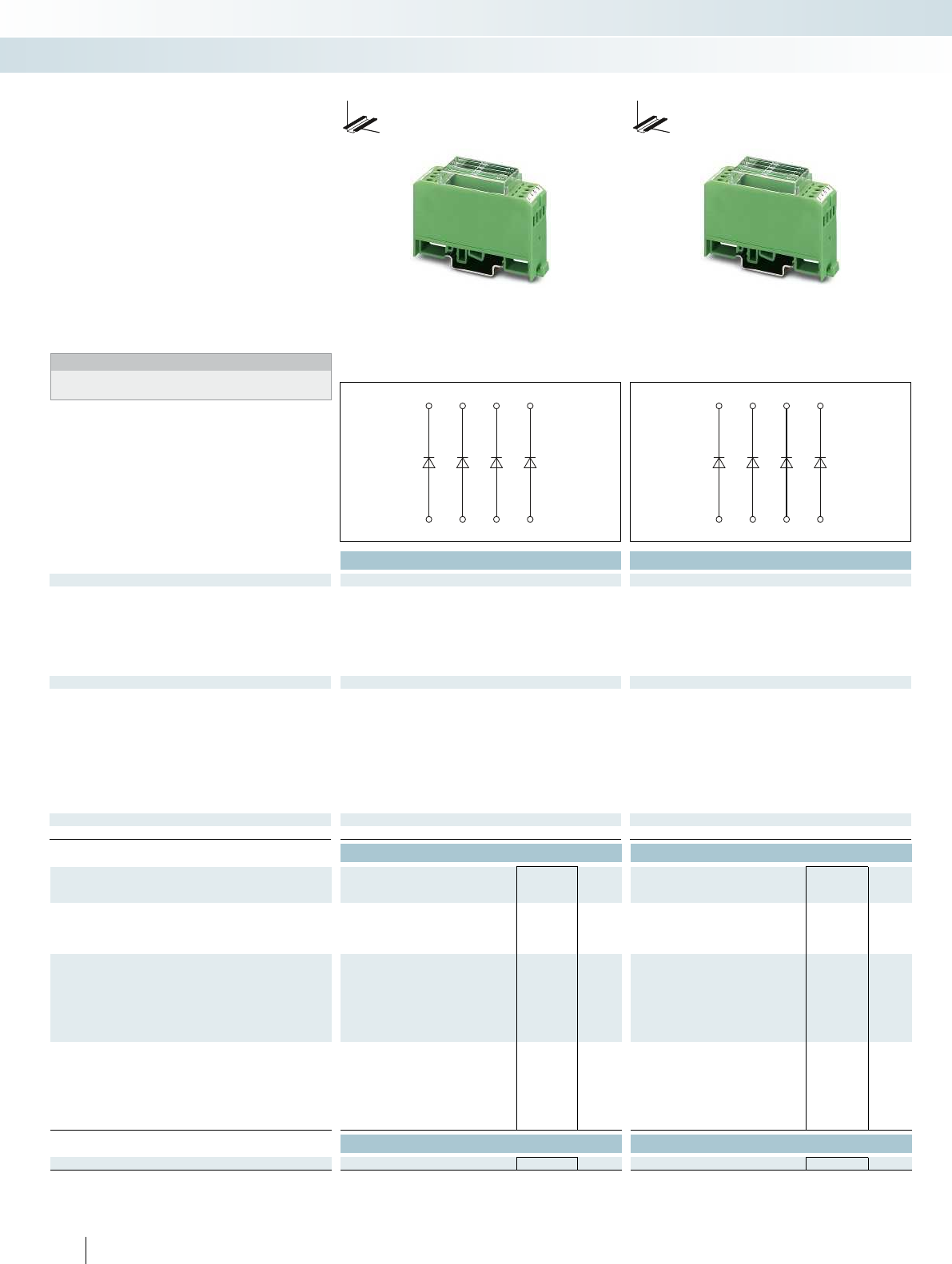
7531
8642
7531
8642
Technical data Technical data
Diodes 4E / 8E / 17E / 7P / 7M 14P / 14M / 32P / 32M 4E-... / 4P-... / 4M-... / 8E-... 8P-... / 8M-...
Max. operating voltage U
max
250 V AC 250 V AC 250 V AC 250 V AC
Peak reverse voltage per diode 1300 V 1300 V 1000 V 1000 V
Reverse current per diode 5 µA 5 µA 10 µA 10 µA
Conducting state voltage per diode approx. 0.8 V approx. 0.8 V approx. 0.8 V approx. 0.8 V
Conducting state current per diode
with single load 0.7 A 0.7 A 1.5 A 1.5 A
with simultaneous loads 0.5 A 0.2 A 1 A 0.3 A
General data
Ambient temperature range -20 °C ... 50 °C -20 °C ... 50 °C
Rated insulation voltage 300 V (according to EN 50178)
Pollution degree / Surge voltage category III, basic insulation (as per EN 50178) III, basic insulation (as per EN 50178)
Pollution degree / Surge voltage category 2 (according to EN 50178) 2 (according to EN 50178)
Mounting position any any
Mounting Can be aligned without spacing Can be aligned without spacing
Dimensions H / D 75 / 55 mm 75 / 55 mm
Screw connection solid / stranded / AWG 0.2 ... 4 mm² / 0.2 ... 2.5 mm² / 24 - 12 0.2 ... 4 mm² / 0.2 ... 2.5 mm² / 24 - 12
Conformance / approvals
Conformance CE-compliant CE-compliant
Ordering data Ordering data
Description Housing width Type Order No. Pcs. /
Pkt. Type Order No. Pcs. /
Pkt.
Diode module, can be individually wired
4 diodes 22.5 mm EMG 22-DIO 4E 2950048 10 EMG 22-DIO 4E-1N5408 2952790 10
8 diodes 45 mm EMG 45-DIO 8E 2950103 5EMG 45-DIO 8E-1N5408 2949389 5
17 diodes 90 mm EMG 90-DIO 17E 2954895 5
Diode module, with P-polarity (common cathode)
4 diodes 22.5 mm EMG 22-DIO 4P-1N5408 2952198 10
7 diodes 22.5 mm EMG 22-DIO 7P 2950064 10
8 diodes 45 mm EMG 45-DIO 8P-1N5408 2954879 5
14 diodes 45 mm EMG 45-DIO14P 2950116 5
32 diodes 90 mm EMG 90-DIO 32P 2954918 5
Diode module, with M polarity (common anode)
4 diodes 22.5 mm EMG 22-DIO 4M-1N5408 2952211 10
7 diodes 22.5 mm EMG 22-DIO 7M 2950077 10
8 diodes 45 mm EMG 45-DIO 8M-1N5408 2954882 5
14 diodes 45 mm EMG 45-DIO14M 2950129 5
32 diodes 90 mm EMG 90-DIO 32M 2954934 5
Accessories Accessories
Equipment marker EMG-GKS 12 2947035 50 EMG-GKS 12 2947035 50
312
PHOENIX CONTACT
Diode modules
Diode circuits perform various tasks in
electrical control systems, particularly in
electronic ones:
– Electrical decoupling of messages in fault
signaling systems
– Spark-suppression diodes for limiting
surge voltages of inductive loads,
(solenoid valves, DC relays or similar)
– Can be supplied as “diode gates”
combined with anode or cathode or as
freely assignable diodes
Notes:
Further circuit diagrams can be found in the data sheet at
phoenixcontact.net/products.
DW
H
DW
H
Monitoring
Monitoring and diagnostics
With diode type 1 N 4007 With diode type 1 N 5408

10741
11852 12963
3241
76 05
For further information and full technical data, visit phoenixcontact.net/products
Technical data Technical data
Diodes 8E/16E 14M/32M LA 7S LED 7S/LED 14S
Max. operating voltage U
max
250 V AC 250 V AC
Peak reverse voltage per diode 1300 V 1300 V
Reverse current per diode 5 µA 5 µA
Conducting state voltage per diode approx. 0.8 V approx. 0.8 V
Conducting state current per diode
with single load 0.7 A 0.7 A
with simultaneous loads 0.4 A 0.2 A
Input
Current required per light indicator approx. 1 mA approx. 3 mA
General data
Ambient temperature range -20 °C ... 50 °C -20 °C ... 45 °C
Rated insulation voltage 300 V (according to EN 50178)
Pollution degree / Surge voltage category III, basic insulation (as per EN 50178) III, basic insulation (as per EN 50178)
Pollution degree / Surge voltage category 2 (according to EN 50178) 2 (according to EN 50178)
Mounting position any any
Mounting Can be aligned without spacing Can be aligned without spacing
Dimensions H / D 75 / 55 mm 75 / 47.5 mm
Screw connection solid / stranded / AWG 0.2 ... 4 mm² / 0.2 ... 2.5 mm² / 24 - 12 0.2 ... 4 mm² / 0.2 ... 2.5 mm² / 24 - 12
Conformance / approvals
Conformance CE-compliant CE-compliant
Ordering data Ordering data
Description Housing width Type Order No. Pcs. /
Pkt. Type Order No. Pcs. /
Pkt.
Lamp testing module, for individual wiring
4-pair 45 mm EMG 45-DIO 8E/LP 2954798 5
8-pair 90 mm EMG 90-DIO 16E/LP 2954808 5
Lamp testing module, with common control
7-pair 45 mm EMG 45-DIO14M/LP 2950132 5
16-pair 90 mm EMG 90-DIO 32M/LP 2954785 5
Light indicator module, 110 ... 230 V AC input voltage
7 glow lamps 22.5 mm EMG 22-LA 7S/230 2949677 10
Light indicator module, 24 V DC input voltage
7 LEDs 22.5 mm EMG 22-LED 7S/24 2952305 10
14 LEDs 45 mm EMG 45-LED 14S/24 2952334 5
Accessories Accessories
Equipment marker EMG-GKS 12 2947035 50 EMG-GKS 12 2947035 50
313
PHOENIX CONTACT
Lamp testing modules
Lamp testing modules for checking lamps
that are installed and ready for operation:
– Individual checking of separate lamps
(EMG...-E/LP)
– Centrally controlled checking of lamps
(EMG...-M/LP)
Display modules
– Light indicator modules facilitate the
monitoring of processes on electronic
control systems during troubleshooting
Notes:
Further circuit diagrams can be found in the data sheet at
phoenixcontact.net/products.
DW
H
DW
H
Monitoring
Monitoring and diagnostics
Lamp testing module,
groups of 2 diodes with common cathode
Light indicator module,
with common return line

314
PHOENIX CONTACT

Product range overview
Product overview 316
Basics of relay technology 318
Basics of solid-state relay technology 322
Sensor/actuator configuration aids and
handling of interference signals
324
Industrial relay system with push-in connection -
RIFLINE complete
326
Industrial relay system with screw connection -
PR series
376
Highly compact relay modules -
PLC-INTERFACE
398
Programmable logic relay system -
PLC logic
452
Relay modules in terminal block design -
DEK series
460
Special relay and solid-state relay modules 466
315
PHOENIX CONTACT
The importance of the reliability of
industrial automation equipment is growing
with the increase in use of electronic
modules.
Modern relay or solid-state relay
interfaces perform a wide range of tasks.
Whether in production engineering, for the
electrical equipment of machines or in
control engineering for energy distribution,
building automation and materials
processing – the main aim is to guarantee
the exchange of signals between the process
peripherals and the superior, central control
systems. This exchange must provide
reliable operation, be floating and
electrically unambiguous. Safe electrical
interface modules that meet the
requirements of modern system concepts
must include the following features:
– Coupling of different signal levels
– Safe electrical isolation between input and
output
– High degree of resistance to interference
In practice, a relay interface comes into
use when dealing with a flexible interface
configuration with a large switching capacity
range and the possibility of combining
different types of contact. Further
important features of relay interfaces are:
– Electrical isolation between open
contacts
– Switching of independent switching
current types
– High short-term overload resistance in
the event of a short circuit or voltage
peaks
– Practically impervious to electromagnetic
fields
– Easy handling
Solid-state relay modules are used when
an interface between the process
peripherals and electronics is subject to the
following requirements:
– Low control power
– High switching frequencies
– Wear-free switching with no contact
bounce
– Resistance to vibration and impacts
– Long service life
Relay modules

RIFLINE complete
RIF-0 for miniature and solid-state relays
Page 328
RIF-1 for miniature and solid-state relays
Page 334
RIF-2 for industrial relays
Page 342
RIF-3 for octal relays
Page 346
PR series
PR1 for miniature or solid-state relays
Page 378
As sensor/actuator version
Page 404
PR2 for industrial relays
Page 384
Resistant to interference currents/voltages
Page 414
PR3 for octal relays
Page 388
For railway applications
Page 441
Accessories
Page 379
Types of electronics
Page 447
PLC logic DEK series
Programmable logic relay system - PLC logic
Page 454
With miniature relay
Page 461
Actuator series with miniature relays
Page 463
Sensor series with miniature relays
Page 463
Special relay and solid-state relay modules
Relay terminal blocks with switch
Page 467
Interference-free relays and
solid-state relays Page 468
Relays for switching lamp loads
Page 471
Solid-state power relays with
400 V AC/400 V AC/3 A output Page 472
316
PHOENIX CONTACT
Relay modules
Product overview
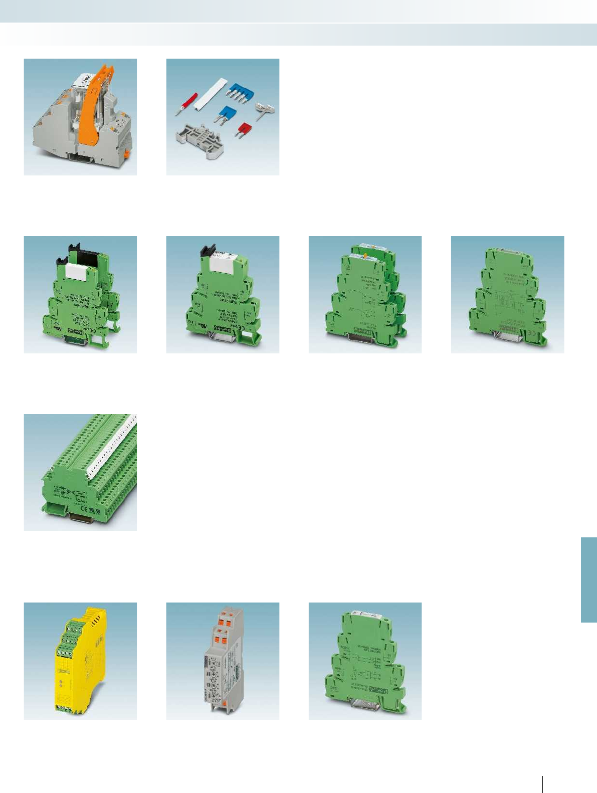
For further information and full technical data, visit phoenixcontact.net/products
RIF-4 for high-power relays
Page 350
Accessories
Page 356
PLC-INTERFACE
With relay/solid-state relay
Page 400
As sensor/actuator version
Page 404
For high inrush/continuous currents
Page 410
Resistant to interference currents/voltages
Page 414
With switch
Page 430
For railway applications
Page 441
For NAMUR initiators
Page 446
Types of electronics
Page 447
With solid-state relay
Page 464
Safety devices Monitoring relays Timer relays
Safety devices
See Catalog 8 Page 378
Monitoring relays
Page 298
Timer relays
Page 308
317
PHOENIX CONTACT
Relay modules
Product overview
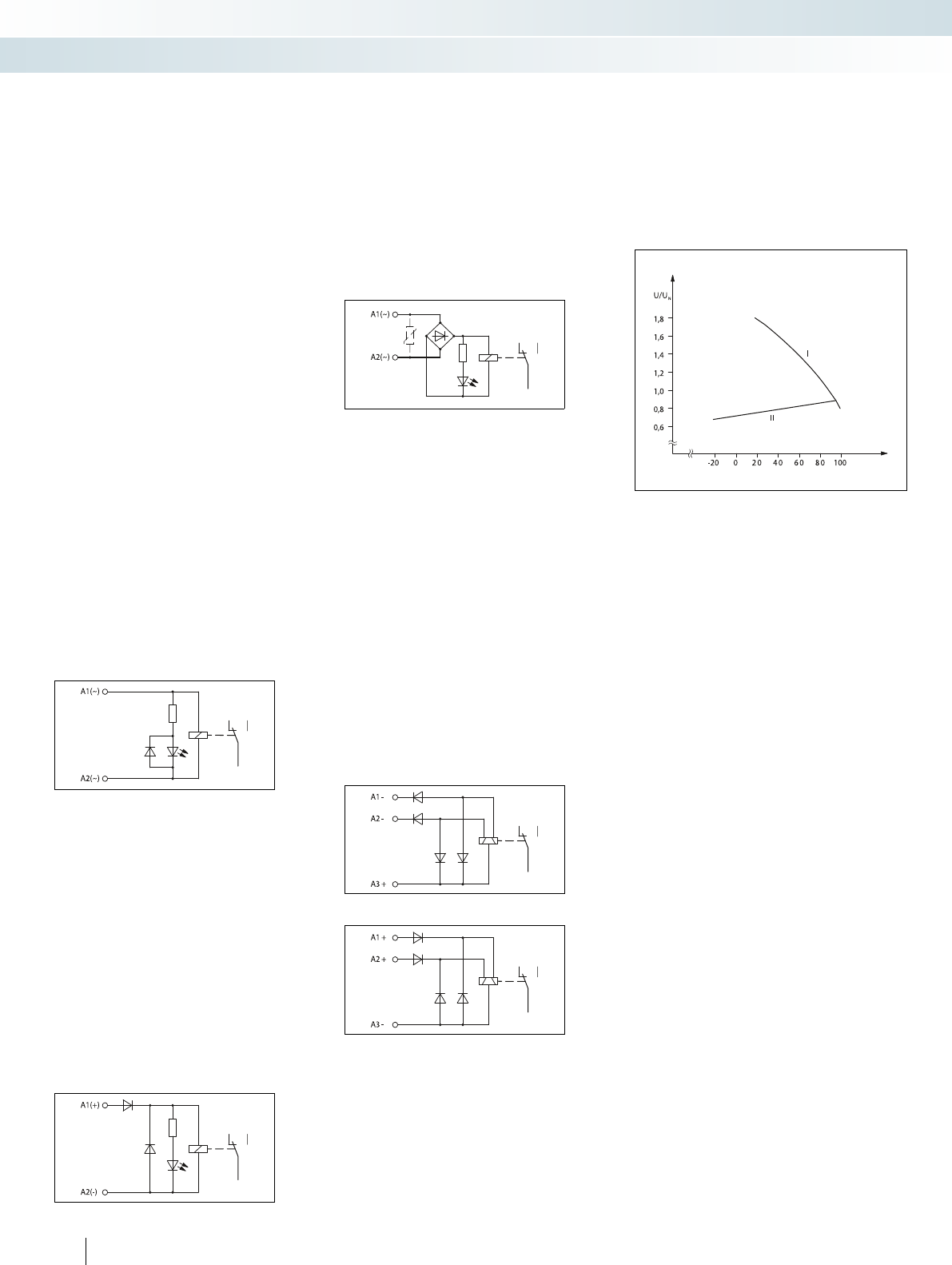
In the case of a pure DC input, the most
important addition to the circuit is a
freewheeling diode. This limits the voltages
induced on the coil on circuit interruption
to a value of approximately 0.7 V, which
does not pose a danger to any connected
control electronics.
As the freewheeling diode can only
perform its required function if the polarity
of the voltage connection is correct, a
reverse polarity protection diode is also
integrated into the input circuit.
To allow DC or AC voltage operation, a
bridge rectifier is connected in the input
circuit. The diodes are simultaneously
responsible for performing rectification,
freewheeling, and polarity reversal
protection functions. The interrupting
voltage of the coil is limited to
approximately 1.4 V.
To protect the input circuit against surge
voltages, a varistor is also connected
(depending on the type) upstream of the
bridge rectifier.
Basic construction of a relay with AC input
Basic construction of a relay with DC input
Basic construction of a relay with AC/DC input
General
Electromechanical relays are used as
interface modules between the process I/O
devices, on the one hand, and the open-
loop/closed-loop control and signaling
equipment, on the other, for level and
power adjustment purposes.
Essentially, electromechanical relays can
be divided into two main groups:
monostable and bistable relays.
With monostable DC or AC relays, the
contacts automatically return to the release
state as soon as they are de-energized.
In the case of bistable relays, the
contacts remain in their present switch
position when the excitation current is
switched off.
Coil side
Input circuits and voltage types
There are various kinds of input circuit
depending on the type of relay used and the
nature of the control voltage.
If pure AC relays are used (AC input),
the input circuit is generally nothing more
than a visual switching status indicator.
Unless otherwise specified, the
frequency of the control voltage is
50/60 Hz.
Bistable latching relays with duplex
winding are operated solely with DC
voltage.
With these types of relay, there are
three coil connections on the coil side. In
addition to the common connection, there
are separate connections for “setting” and
“resetting”; these are controlled by short
pulses only. As a result, the relays hardly
heat up at all. Simultaneous control of both
control inputs is not permitted.
A distinction is made between negative
switching (M) and positive switching (P)
types, depending on the polarity of the
freewheeling and polarity protection
diodes.
Block diagram of a bistable relay, negative switching type
Block diagram of bistable relay, positive switching type
I: Maximum permitted voltage with 100%
operating time (OT) and assuming
compliance with the coil temperature
limit
II: Minimum response voltage
Basic curve of a relay operating voltage
Operating voltage range
The ambient temperature prevailing at
the location of use has a major impact on
certain relay operating parameters.
As the ambient temperature increases,
the coil winding heats up, causing the
response and release voltages to rise. At the
same time, the maximum permitted coil
voltage decreases, which means that the
Interference voltages and
interference currents on the coil side
When inductive or capacitive
interference voltages are coupled into the
long supply lines of a relay, this can prevent
the relay from operating safely.
If the coupled-in voltage exceeds the
release voltage required by the IEC 61810-1
“relay standard”, in extreme cases the relay
may fail to release. In the case of DC relays,
this release voltage is
0.05 x U
N
and for
purely AC relays, it is
0.15 x U
N
.
The same disturbances can occur when
a relay with a low input power is controlled
by an electronics module with an AC
voltage output featuring an RC circuit. The
typical leakage current from RC elements of
this kind (generally in the region of several
mA) provides sufficient control power to
prevent the downstream relay from
releasing or even enough power to excite it.
The disturbance level of any
interference voltages that are present can
be reduced by connecting an RC element
parallel to the relay coil. This measure also
subjects the interference voltage to a
capacitive load, causing it to collapse.
usable working range becomes restricted as
a result.
The diagram below illustrates how the
operating voltage behaves as a function of
the ambient temperature.
Ambient temperature in °C
Operating voltage
318
PHOENIX CONTACT
Relay modules
Basics of relay technology
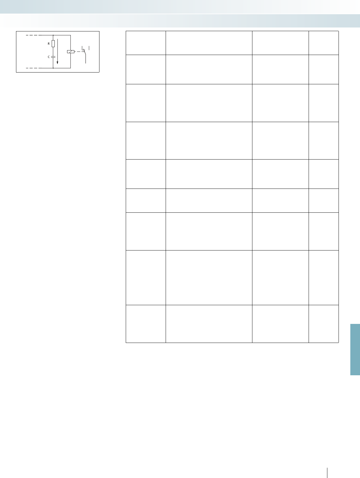
For further information and full technical data, visit phoenixcontact.net/products
External RC interference suppressor to prevent interference
voltage coupling
The following values are recommended
for the purpose of dimensioning the
RC element:
– R = 100 ... 220
– C = 220 ... 470 nF
The SO46 series have been developed
to provide even higher levels of immunity to
interference. These products already
contain an integrated RCZ filter. See, for
example, PLC...SO46.
Contact side, contact materials
Given the wide variety of potential
applications in the different industrial
sectors, the relays used must be matched to
the various tasks that need to be performed
by selecting the right kind of contact
material.
The voltage, current, and power values
play an important role when determining
the suitability of contact materials. Other
criteria include:
– Contact resistance
– Erosion resistance
– Material migration
– Welding tendency
– Chemical influences
In this way, the various contact materials
(generally noble metal alloys) can be
matched to the relevant usage ranges.
The adjacent table provides details of
some of the key materials.
Contact protection circuit
Every electrical load constitutes a mixed
load with ohmic, capacitive, and inductive
components.
When these loads are switched, the
switching contact is in turn subjected to a
load, to either a lesser or greater extent.
This load can be reduced by including a
suitable contact protection circuit.
In view of the fact that loads with a large
inductive component are predominantly
used in practice (e.g., contactors, solenoid
valves, motors, etc.), these application
scenarios are worth considering in more
detail.
On interruption, voltage peaks with
values of up to several thousand volts occur
due to the energy stored in the coil.
These high voltages cause an electric arc
on the switching contact which can destroy
the contact due to material vaporization
and material migration. The electrical
service life is reduced considerably as a
result. In extreme cases, the relay may fail in
the very first switching cycle with DC
voltage and an electric arc.
A protective circuit must be used to
suppress the formation of an electric arc.
With optimum dimensioning, almost the
same number of cycles can be achieved as
with an ohmic load.
Contact material Typ. properties Typ. applications Guide values
for the usage
range*
Gold Au Largely insensitive to industrial atmospheres; low
and constant contact resistances in the range of
small switching capacities with nickel (AuNi) or silver
(AuAg) alloys.
Dry measuring and switching
circuits, control inputs
A ... 0.2 A
V ... 30 V
Silver Ag High electrical conductivity; sensitive to sulfur,
therefore often gold-flashed (approximately 0.2 m)
as protection; nickel (AgNi) or copper (AgCu) alloys
increase the mechanical resistance and erosion
resistance and reduce the welding tendency.
Universal; suitable for medium
loads; nickel alloys (AgNi 0.15)
for DC circuits with medium to
large loads.
12 V
10 mA
Silver, hard gold-
plated Ag+Au
Properties similar to gold Au, when switching loads >
30 V/0.2 A, the hard gold plating
(5 - 10 m) is destroyed and the values and
properties of the Ag contact are applicable. However,
a reduction in the service life is then to be expected.
Suitable for control inputs and
other small loads.
100 mV
1 mA
Tungsten W Highest melting point; very high erosion resistance;
greater contact resistances; very low welding
tendency; susceptible to corrosion; often used as
lead contact.
Loads with very high switch-on
currents, e.g., glow lamps,
fluorescent lamps.
60 V
1 A
Silver nickel
AgNi
High erosion resistance; low welding tendency;
higher contact resistances than with pure silver.
Universal; suitable for medium to
high loads; DC circuits, and
inductive loads.
12 V
10 mA
Silver nickel
AgNi+Au
Properties similar to gold Au, when switching loads >
30 V/0.2 A, the hard gold plating
(5-10 m) is destroyed and the values and
properties of the AgNi contact are applicable.
However, a reduction in the service life is then to be
expected.
Suitable for control inputs and
other small loads.
100 mV
1 mA
Silver tin oxide
AgSnO
Low welding tendency; very high erosion resistance
for high switching capacities; low material migration
Application depends heavily on
the relay type; switching circuits
with high make and break loads,
e.g. glow lamps and fluorescent
lamps, AC and DC circuits. Due to
different alloys and production
procedures, partly also suitable
for smaller loads.
12 V
100 mA
( 10 mA)
Silver tin oxide,
hard gold-plated
AgSnO+Au
Properties similar to gold Au, when switching loads >
30 V/0.2 A the hard gold plating
(5 - 10 m) is destroyed and the values and
properties of the AgSnO contact are applicable.
However, a reduction in the service life is then to be
expected.
Suitable for control inputs and
other small loads.
100 mV
1 mA
* Values depend on the relay used and on further operating conditions.
U
INTERF
319
PHOENIX CONTACT
Relay modules
Basics of relay technology
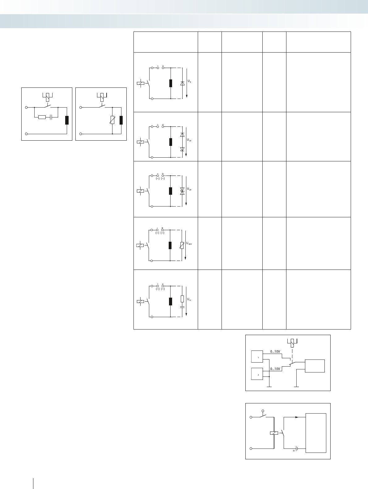
Load wiring Additional
dropout
delay
Defined
induction voltage
limitation
Effective
bipolar
attenuation
Advantages/disadvantages
Diode Large Yes (U
D
) No Advantages:
• Good effect in terms of extending
the service life of contacts
• Easy implementation
• Inexpensive
• Reliable
• Dimensioning not critical
• Low induction voltage
Disadvantages:
• Attenuation only via load resistor
• Long dropout delay
Diode/Zener diode,
series connection
Medium to
small
Yes (U
ZD
) No Advantages:
• Dimensioning not critical
Disadvantages:
• Attenuation only above U
ZD
• Minimal effect in terms of extending
the service life of contacts
Suppressor diode Medium to
small
Yes (U
ZD
) Yes Advantages:
• Inexpensive
• Dimensioning not critical
• Limitation of positive peaks
• Suitable for AC voltages
Disadvantages:
• Attenuation only above U
ZD
• Minimal effect in terms of extending
the service life of contacts
Varistor Medium to
small
Yes (U
VDR
) Yes Advantages:
• High energy absorption
• Dimensioning not critical
• Suitable for AC voltages
Disadvantages:
• Attenuation only above U
VDR
• Minimal effect in terms of extending
the service life of contacts
R/C combination Medium to
small
No Yes Advantages:
• HF attenuation due to energy
storage
• Suitable for AC voltages
• Level-independent damping
Disadvantages:
• Precise dimensioning required
• High inrush current surge
• Minimal effect in terms of extending
the service life of contacts
In principle, there are a number of
possible ways of achieving an effective
circuit:
1. Contact wiring
2. Load wiring
3. Combination of both wiring methods
In principle, protective measures should
intervene directly at the source of the
interference.
Wiring a load should therefore be given
priority over wiring the contact.
The following points are advantageous
for the load circuit (image on right):
1. The circuit is only loaded with the
induction voltage during interruption.
By contrast, the sum of the operating
voltage and the induction voltage is
applied to the contact circuit.
2. When the contact is open, the load is
electrically isolated from the operating
voltage.
3. It is not possible for the load to be
activated or to “stick” due to undesired
operating currents, e.g., from RC
elements.
4. Cut-off peaks of the load cannot be
coupled into parallel control lines.
Nowadays, solenoid valves are usually
connected using valve connectors that are
also supplied with LEDs and components
that limit the induction voltage. Valve
connectors with an RC element, varistor or
Zener diode often do not quench the arc and
only serve to comply with legislation
governing EMC. Only valve connectors with
an integrated 1N4007 freewheeling diode
quench the arc quickly and safely, thereby
increasing the service life of the relay by a
factor of 5 to 10. Valve connectors with LED,
integrated 1N4007, and free cable end can be
supplied on request as part of the SAC range.
Contact wiring Inductive load wiring
Application example: measurement point changeover
Application example: PLC input signal
Switching small loads
Small loads must be processed mainly in
applications where signals must be
forwarded to control inputs (e.g., of a PLC).
With these loads, no switching sparks
(electric arcs) occur on the contacts in the
small load range.
In addition to the constant cleaning
effect due to contact friction, this switching
spark assumes the function of penetrating
non-conductive contamination layers that
are formed on the contact surfaces of
power contacts.
Load
Load
Load
Load
Load
Evaluation
electronics
Limit switch
PLC
input card
320
PHOENIX CONTACT
Relay modules
Basics of relay technology
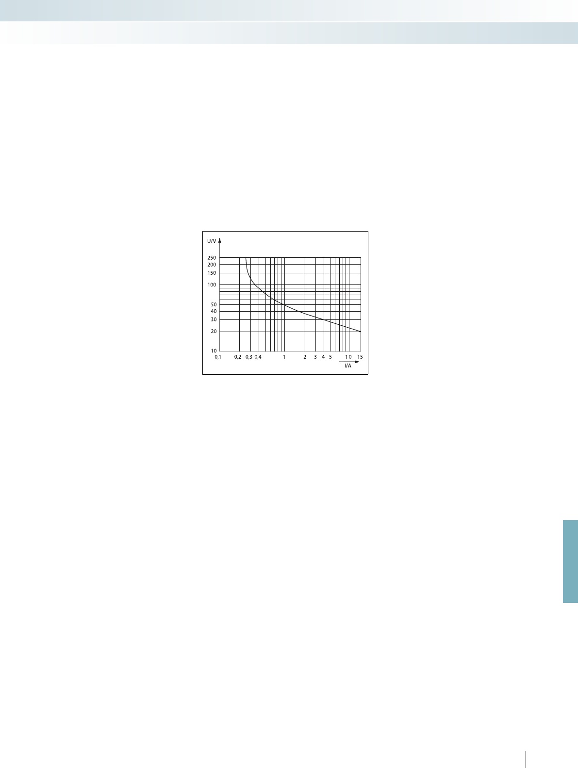
For further information and full technical data, visit phoenixcontact.net/products
These contamination layers are usually
oxidation or sulfidation products of the
contact materials silver (Ag) or silver alloys
such as silver nickel (AgNi) or silver tin
oxide (AgSnO). As a result, the contact
resistance may rise so considerably within a
short time that reliable switching is no
longer possible in the case of small loads.
Due to these properties, the high-
performance contact materials mentioned
are not suitable for small load applications.
Gold (Au) has become accepted as the
contact material of choice for these usage
ranges mainly on account of its low and
constant contact resistances even with
small loads and its insensitivity to sulfurous
atmospheres.
For the smallest of loads and even
greater contact reliability, double contact
relays with gold contacts are used.
The slotted contact spring in this design
provides two parallel contact points with
even lower contact resistances and
considerably higher contact reliability.
Switching large loads
A few important points also need to be
considered with regard to switching
operations in the large load range that
involve power contacts made of either silver
(Ag) or silver tin oxide (AgSnO).
A basic distinction must be made
between switching DC and AC loads.
Switching large AC loads
When switching large AC loads, the
relay can be operated up to the
corresponding maximum values for
switching voltage, current, and power. The
electric arc that occurs during interruption
depends on the current, voltage, and phase
relation. This cut-off arc usually disappears
automatically the next time the load current
passes through zero.
In applications with an inductive load, an
effective protective circuit must be
provided, otherwise the service life of the
system will be reduced considerably.
Switching large DC loads
Conventional switching relays can only
switch off relatively small direct currents
(which contrasts with their ability to switch
off the maximum permitted AC current),
since there is no zero crossing to extinguish
the arc automatically. This maximum DC
value is also dependent to a large extent on
the switching voltage and is determined,
among other things, by constructional
features such as contact spacing and contact
opening speed.
The corresponding current and voltage
values are documented by relay
manufacturers in electric arc or load limit
curves.
A non-attenuated inductive DC load
further reduces the values given for
switchable currents. The energy stored in
the inductance can cause an electric arc to
occur, which forwards the current through
the open contacts.
With an effective contact protection
circuit, preferably freewheeling diodes of
the type 1N4007, the service life can be
increased by a factor of 5 to 10 in relation
to unprotected or unfavorably protected
inductive loads (see also “Contact
protection circuit” section).
If higher DC loads than those
documented are to be switched or if the
electrical service life is to be increased,
several contacts of a relay can be connected
in series. See, for example, REL-IR...
industrial relays.
Alternatively, solid-state relays with DC
voltage output can also be used.
Example of a load limit curve (dependent on the type)
Switching lamps and capacitive loads
Regardless of the type of voltage, all
kinds of lamps and loads with a capacitive
component impose extreme requirements
on the switching contacts. The moment it is
switched on, in other words precisely in the
dynamic chattering phase of the relay,
extremely powerful current peaks occur.
These are often in the region of several tens
of amps, and not infrequently are known to
exceed 100 A, which results in welding of
the contact. This can be remedied by using
specially optimized “lamp load relays” that
can cope with these inrush peaks. See, for
example, PLC...IC type.
Switching capacity according to
utilization categories AC15 and DC13
(IEC 60947)
In practice, both the maximum
interrupting rating for AC loads and the DC
cut-off values taken from the load limit
curves provide only a rough guide for
selecting a relay. In reality, this is insufficient,
since real loads in the vast majority of
industrial applications have inductive or
capacitive components and the wiring of the
loads can be totally different. As already
described, this sometimes leads to
considerable variations in terms of service
life.
The IEC 60947 contactor standard
seeks to avoid these disadvantages by
dividing the loads into various utilization
categories (DC13, AC15, etc.). This
standard is also partly applied to relays.
However, users must be aware of the fact
that these values are only applicable in
practice to a limited extent as well, since all
DC13 and AC15 test loads are highly
inductive and are also operated without any
protective circuits at all (see “Contact
protection circuit” section). Moreover, the
switching capacity test according to
IEC 60947 only requires 6060 cycles to be
performed by way of a minimum
requirement.
A much more reliable way to determine
the switching capacity and the anticipated
service life is to refer to the specific
application data. Using a comprehensive
data bank, the service life can be accurately
estimated for most applications and, if
necessary, suggestions for improvement can
be made. In the case of critical applications,
the user is advised to gather service life
information based on empirical data.
321
PHOENIX CONTACT
Relay modules
Basics of relay technology
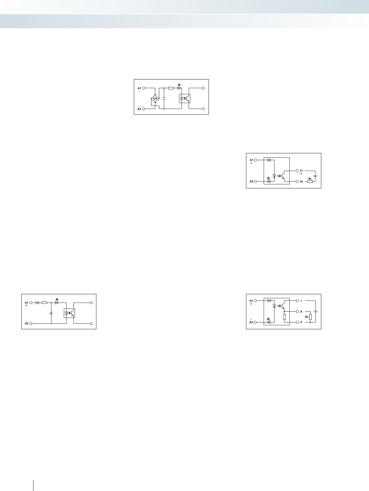
Control side
Solid-state relays for various voltage and
power levels are available from Phoenix
Contact for use as interface modules
designed to match process I/O devices to
control, signaling, and regulating devices.
The solid-state relay element which is
actually located in the module is limited to
one defined voltage range by virtue of its
design. The current consumption on the
input side fluctuates depending on the
circuit architecture and voltage level.
To accommodate all industrial voltages
between 5 V and 230 V, an input circuit is
provided. The inputs for DC voltage and AC
voltage must always be differentiated.
DC input
Adjustments are made in accordance
with the various voltage levels by adding
electronics which have been specially
adapted to the desired voltage range. In the
case of most modules, a polarity protection
diode provides reliable protection against
destruction in the event of a control voltage
being connected incorrectly. Specially
coordinated filters reliably suppress possible
high-frequency noise emissions.
Figure 4: 3-wire outputFigure 1: block diagram for DC input
Figure 2: block diagram for AC input
Figure 3: 2-wire output
Load side
Depending on the application and the
type of load, the solid-state relay output
must meet various requirements. The
following are crucial:
– Power amplification
– Matching the switching voltage and the
switching current (AC/DC)
– Short-circuit protection
For these different applications, the
solid-state relay element must also be
processed using additional electronics on
the output side.
state power relays. This shows the
maximum load current as a function of
the ambient temperature.
3. Output circuit
The 2-wire output is similar to a
mechanical contact. Only the polarity of
the connections is specified and must be
observed.
The 3-wire output is non-isolated and
requires both potentials from the voltage
source on the output side to be connected
if it is to operate reliably.
When switched off, a permanent
reference to ground (negative potential) is
established. In addition, this output circuit
offers the advantage of an almost constant
internal resistance.
continuous through-switching.
AC input
The solid-state relay element requires a
stable control voltage to ensure reliable
operation. In the case of the AC input, this
is achieved by connecting a rectifier and
filter capacitor upstream. Rectifying is
followed, in principle, by the same circuit
architecture as the DC input.
The switching frequency always lies
below half the mains frequency. Due to the
filter capacitor, a higher switching frequency
cannot be achieved. This would result in
DC output
In order to achieve the necessary output
power, the solid-state relay element is
supplemented by one or more
semiconductor components.
The on-site user should nevertheless
simply regard the connection terminal
blocks of the output as conventional switch
connections. Observing the specified
polarity is the only essential requirement.
For practical reasons, the following
criteria should be taken into account when
selecting a suitable solid-state relay:
1. Operating voltage range
(e.g., 12 ... 60 V DC)
This determines the minimum or
maximum voltage to be switched. The
lower value must be observed in order
to ensure reliable operation. In order to
protect the output transistor, the upper
value must not be exceeded.
2. Maximum continuous current (e.g., 1 A)
This value indicates the maximum
continuous current. If this value is
exceeded continuously, the output
semiconductor will be destroyed. The
dependence of the output current on
the ambient temperature of the solid-
state relay should also be taken into
consideration. A derating curve is
therefore generally specified for solid-
AC output
In order to control the switching and
control devices for AC voltage, a
semiconductor for AC voltage (TRIAC or
thyristor) is connected downstream of the
solid-state relay element.
As with the DC output, it is particularly
important to consider the maximum
operating voltage range and the maximum
continuous load current as a function of the
ambient temperature.
322
PHOENIX CONTACT
Relay modules
Basics of solid-state relay technology

For further information and full technical data, visit phoenixcontact.net/products
Figure 5: basic circuit diagram of AC output
Figure 6: protective circuit with DC voltage output
Figure 7: protective circuit with AC voltage output
Example: load contactor monitoring (DC contactor)
Example: load contactor monitoring (AC contactor)
Example: position indication with limit stop contact or initiator
Example: switching the contactor, solenoid valve or motor
(DC load)
Example: switching the contactor, solenoid valve or motor
(AC load)
In addition, the maximum peak reverse
voltage of the TRIAC (e.g., 600 V) is crucial
with AC outputs. This must not be
exceeded even in the case of voltage
fluctuations or interference voltage peaks in
order to prevent destruction. That is why
the AC outputs of all solid-state relays from
Phoenix Contact have an internal RC
protective circuit to protect against
interference voltage peaks.
Protective circuits
The moment inductive loads
(contactors, solenoid valves, motors) are
switched off, surge voltages occur and these
can reach very high amplitudes. Electronic
components and switching elements are
particularly susceptible to these. A
protective circuit should therefore always
be provided to prevent destruction.
A parallel connection to the load
effectively reduces the switching surge
voltage to a harmless level. Depending on
the solid-state relay output and type of load:
– A freewheeling diode/suppressor diode
(DC only)
– A varistor (AC and DC)
– Or an RC element (AC only)
can provide the necessary protection.
Application notes
Input solid-state relays acting in the
direction from the I/O devices to the
controller (signaling, controlling,
monitoring)
Plug-in version:
– PLC-O...
Modular version:
– DEK-OE...
– EMG 10-OE...
– SIM-EI...
– OPT...
Output (power) solid-state relays acting
in the direction from the controller to the
I/O devices (switching, amplifying,
controlling)
Plug-in version:
– PLC-O...
Modular version:
– DE K-OV...
– EMG 10-OV
– EMG 12-OV
– EMG 17-OV
– OV...
– OPT...
Remarks:
1
) Ground (negative) potential from the input and output of the solid-
state relay must not be connected.
2
) DC loads must be provided with an effective protective circuit
(e.g., diode).
3
) AC loads must be protected with a varistor or an RC element.
Zero voltage
switch
Protection
Load
Protection
Load
e.g., PLC
IN
e.g., PLC
IN
e.g., PLC
IN
e.g., PLC
OUT
e.g., PLC
OUT
323
PHOENIX CONTACT
Relay modules
Basics of solid-state relay technology

11
14
12
A2
A1
11
14
12
+
-
-
A2
A1
13
BB
14
13
BB
14
+
-
-
A2
A1
A2
A1
11
14
12
-
+
+
If sensors such as proximity switches are
connected via a universal relay to a
controller with a PDT contact, an additional
terminal block strip must be used for the
common sensor supply voltage. It must also
be observed that either the wiring in the
control cabinet must be the other way
round since control of the relay is now from
the field level and not via the controller. Or
the relay module is installed in the control
cabinet rotated at 180°. The negative
potential of the sensors is applied at
connection terminal block A2 on the relay
module. This can be distributed over all
relay modules using jumpers. This means
only the direct connection to a relay is
necessary. The sensors are connected to
connection terminal block A1. The
necessary positive potential is supplied to a
terminal block and distributed to further
terminal blocks by means of jumpers.
However, the supply for the individual
sensors is applied to every terminal block.
This results in a common supply signal for all
sensors via the additional terminal blocks.
Due to increased space requirements
and additional wiring to the terminal block,
the use of additional terminal blocks for
distributing potential is extremely
time-consuming.
The PLC...ACT relay modules enable
fast and easy connection of actuators. The
positive potential of the loads is applied to
connection terminal block 13. This can be
distributed over all relay modules using
jumpers. This only makes direct connection
to a module necessary. The actuators are
connected to contact 14 (N/O contact).
In the case of PLC...ACT relay modules, an
N/C contact is not required. Instead, the
BB connection serves as an option for
connecting the load return line. Here the
common negative potential is supplied and
distributed by means of jumpers.
Conventional wiring of the terminal block is
not necessary due to direct connection of
the load return line potential to the relay
module. This means that no additional space
is required in the control cabinet and
simpler wiring minimizes the risk of error.
If actuators such as solenoid valves are
connected to the controller via a universal
relay with PDT contact, an additional
terminal block strip must be used for the
common load return line. The positive
potential of the loads is applied to
connection terminal block 11 (PDT contact)
at the relay modules. This can be distributed
over all relay modules using jumpers. This
means only the direct connection of the
potential to a relay is necessary. The loads
are connected to connection terminal
blocks 14 (N/O contact). The negative
potential required is supplied at a terminal
block. This is then distributed to further
terminal blocks by means of jumpers.
However, load return lines for the individual
actuators are applied to every terminal
block. This results in a common load return
line potential for all actuators via the
additional terminal block.
Due to increased space requirements
and additional wiring to the terminal block,
the use of additional terminal blocks for
distributing potential is extremely
time-consuming.
Configuration aid for connecting
sensors and actuators
Conventional connection
of sensors
Electromechanical relays or solid-state
relays are used as a coupling element
between the controller and the sensors or
actuators in the field. This interface ensures
appropriate signal conditioning with respect
to current and voltage between the
controller and field level.
Easy wiring of actuators
Conventional connection
of actuators
324
PHOENIX CONTACT
Relay modules
Sensor/actuator configuration aids and handling of interference signals

A2
BB
A1
13
14
A2
BB
A1
-
+
+
N
A1
U
A2
L1
L2
L3
L
230 VAC
(10m)>
VR
C
N
L
A1
U
A2
For further information and full technical data, visit phoenixcontact.net/products
Easy wiring of sensors
Configuration aid for handling
interference signals
Leakage current with AC voltage
output card
Sensors can be efficiently coupled with
the controller with the PLC...SEN relay
modules. The input and output side at the
module are already interchanged so that the
signal direction from the field to the
controller can be ideally represented.
Therefore, three connection terminal
blocks A1, A2, and BB are located on the
control side of the relay. The common
negative potential of the sensors is then
connected to A2 and distributed to further
relay modules by means of jumpers. The
sensors are connected directly to the A1
connections. Connection BB is used for the
common supply potential of the sensors.
The potential is distributed to all connected
sensors by means of the jumpers. However,
only connections 13 and 14 for the N/O
contact are located on the contact side.
Signal feedback to the controller takes place
via these connections. The terminal block
for conventional wiring can be saved by
connecting the sensor supply voltage
directly to the relay module. This means
that no additional space is required in the
control cabinet and simpler wiring
minimizes the risk of error.
Leakage current on the signal line occurs
if control of a relay takes place via an output
card with AC voltage. This is caused by the
RC wiring of the AC voltage output.
Typically, the leakage current has a control
power that is large enough not to switch off
the relay reliably.
According to IEC 61810-1, the standard
release voltage of a relay is 5% of the
nominal voltage for DC coils and 15% for
AC coils. That means that a relay with a
nominal voltage of 230 V AC is switched off
only when the control voltage is 0.15 x
230 V AC = 34.5 V AC. If interference
signals occur on the control side of a relay
that are greater than the release voltage,
defined switch-off is no longer possible. In
the worst case, the interference is large
enough to energize the relay. The
application is still in a switched-on state
although no signal is applied by the
controller. There can be various reasons for
this.
Long signal line (> 10 m)
Parallel signal lines or load lines
Load
Leakage current
E.g.,
Coupling of interference signals from
parallel lines
If the control lines to the relay are very
long, interference can occur from parallel-
running cables. These influence the actual
control line and couple the signals to them.
This interference voltage can be measured
on the control side, even if no signal is
applied by the controller.
Leakage current
Output
Signal cable Load
Safe shutdown even with interference
signals
The PLC...SO46 series is equipped with
RCZ wiring in the base. The release voltage
of the relay is increased by this circuit of
resistor, capacitor, and Zener diode so that
the relay is resistant to interference voltage.
In the case of a 230 V AC relay, the standard
release voltage is 34.5 V AC. The
PLC...230UC...SO46 modules have a release
voltage of 80 V AC. This enables the relay to
switch off reliably at interference voltages of
80 V AC. The PLC...SO46 bases are also
available with further voltages. Fitting is
possible with both electromechanical relays
or solid-state relays. Screw connection or
push-in connection is available as
connection technology.
325
PHOENIX CONTACT
Relay modules
Sensor/actuator configuration aids and handling of interference signals
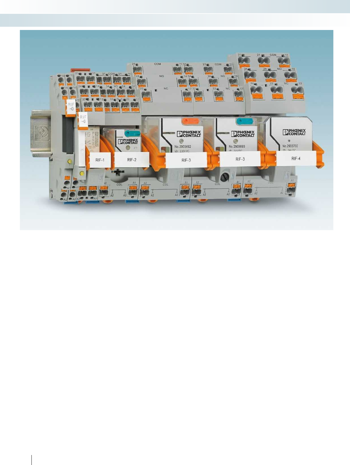
326
PHOENIX CONTACT
Relay modules
Industrial relay system with push-in connection - RIFLINE complete
RIFLINE complete is an inexpensive relay
system with various accessories. It consists
of DIN rail bases, electromechanical or
solid-state relays, plug-in input/interference
suppression modules, marking material, and
bridging material. The range of accessories
is rounded off with a timer module. This can
be used to transform a basic relay into a
timer relay with three different functions.
The RIFLINE complete relay range
consists of seven different base versions
from RIF-0 to RIF-4 – these range from one
N/O contact up to four PDT contacts. The
field of application of this product group
ranges from coupling relay applications with
switching currents of one milliamp to
replacement for miniature contactors with
currents up to 16 A.
The relay bases feature push-in
connection technology, which enables quick
and tool-free conductor contacting. The
RIF-1 to RIF-4 bases offer double the
contact options on both the input and
output side.
On the input side of all bases, the negative
potential (A2) can be bridged – regardless of
the base size. On the output side, the
grouped contact (11) can be bridged within
the RIF-0 base version. This connection can
also be bridged within the RIF-1 base size.
To offer diverse marking options, the
engagement lever can be fitted with a zack
marker strip. In addition, marker carriers
can be mounted on the bases so that
additional marking surfaces are available.
RIFLINE complete can be extended using
many elements from the CLIPLINE
complete accessories range. This includes
marking material, bridges, and test adapters.
To make ordering and management easy,
RIFLINE complete modules are provided in
the most popular voltages as complete
modules with relay and input/interference
suppression module. For individual
assembly, tailored to the requirements of
the application, additional voltage levels are
offered in the modular system.
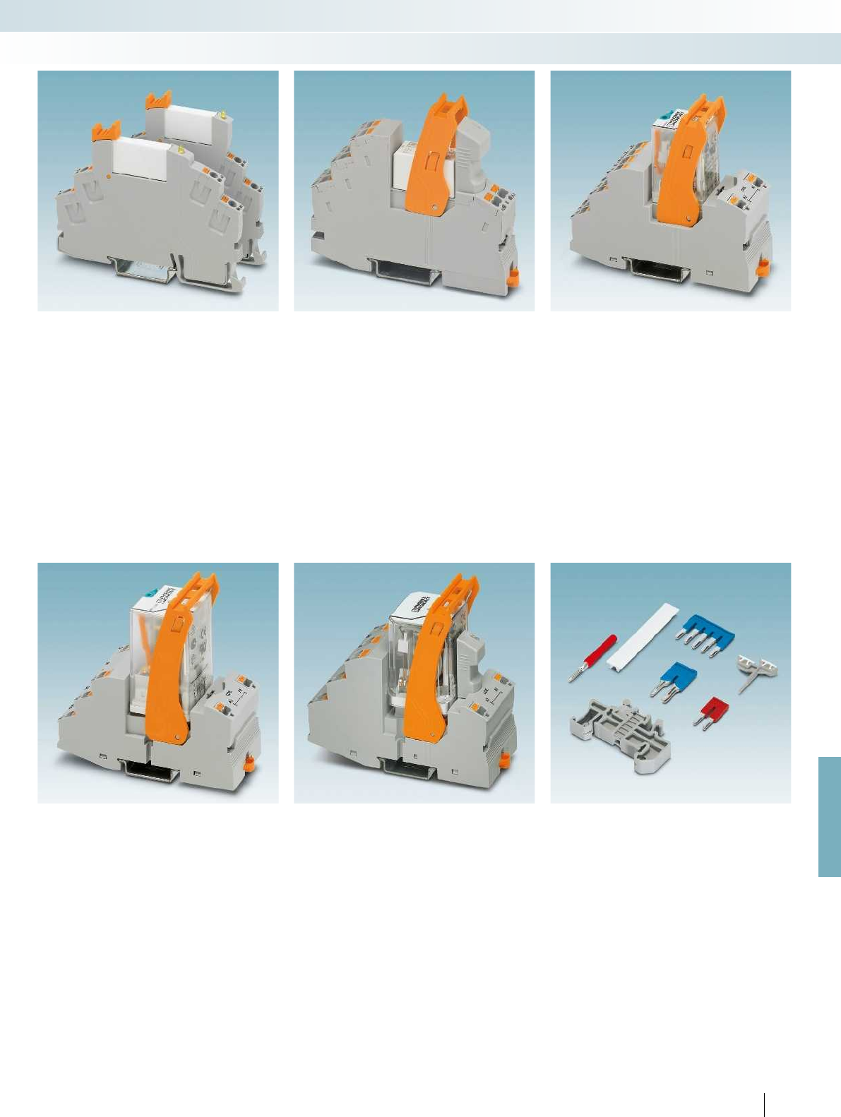
For further information and full technical data, visit phoenixcontact.net/products
327PHOENIX CONTACT
Relay modules
Industrial relay system with push-in connection - RIFLINE complete
RIF-0
The narrow 6.2 mm RIF-0 base series is
designed for miniature relays with one
contact. Switching currents up to 6 A are
implemented here. Two base versions are
available: 1 N/O contact and 1 PDT contact.
RIF-0 is therefore a good choice for all
coupling applications.
RIF-1
The narrow 16 mm RIF-1 base series is
designed for miniature relays with
2 contacts. Currents up to 13 A can be
switched when using the FBS 2-8 jumper.
This is the ideal relay for applications that
require coupling, power switching, and
signal duplication.
RIF-2
The 31 mm wide RIF-2 base series is
designed for industrial relays with up to
4 contacts. Currents up to 12 A are no
problem for these bases. This relay is ideal
for applications that require power and
signal multiplication.
RIF-3
The 40 mm wide RIF-3 base series is
designed for octal relays with up to
3 contacts. Switching currents up to 10 A
can be implemented here. Two base
versions are available: 2 PDT contacts and
3 PDT contacts. RIF-3 bases are ideal for all
applications that require power and signal
multiplication.
RIF-4
The 43 mm wide RIF-4 base series is
designed for power relays with up to
3 contacts. Currents up to 16A can be
switched. RIF-4 bases are a good choice for
applications that require power and signal
multiplication, e.g., in miniature contactor
applications.
Accessories
A wide range of accessories are available
for the RIFLINE complete relay system that
round off the range. These include bridges,
professional marking material, function
modules, test plugs, and end brackets.
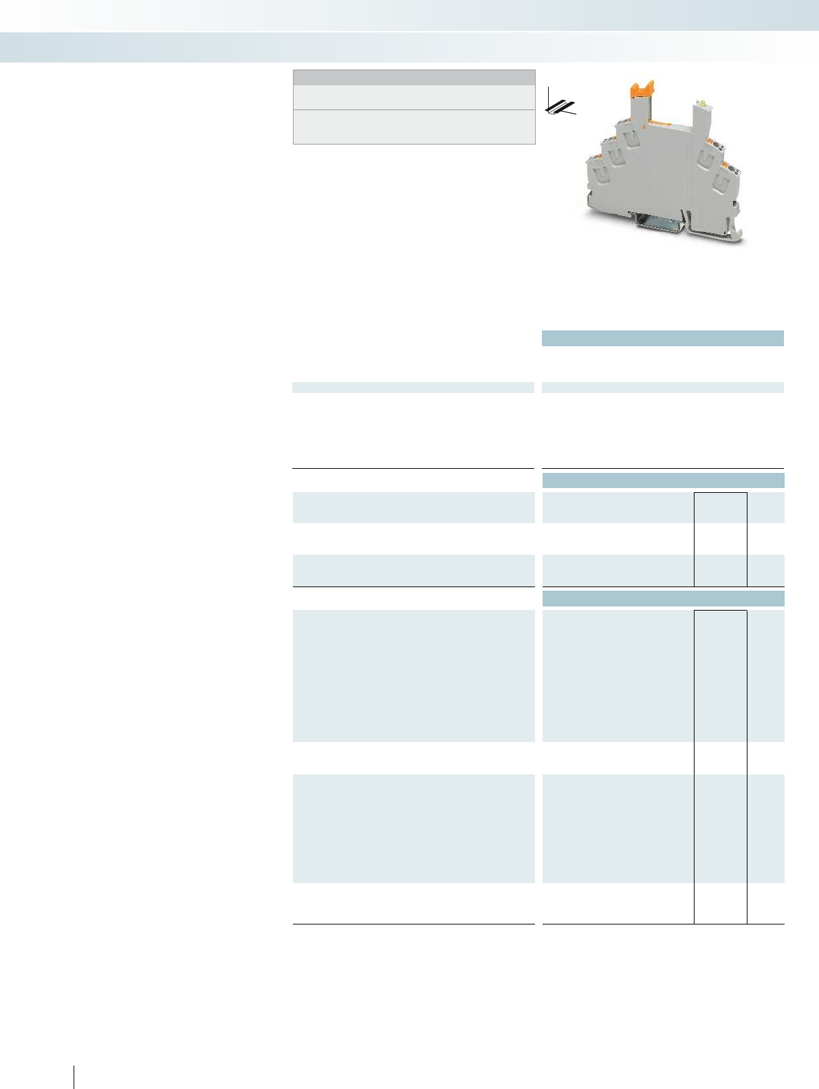
Technical data
Nominal voltage U
N
250 V AC/DC (contact side) 250 V AC/DC (contact side)
Nominal current at U
N
max. 8 A (depending on application/assembly) max. 8 A (depending on application/assembly)
General data
Ambient temperature (operation) -40 °C ... 85 °C (depending on application/assembly) -40 °C ... 85 °C (depending on application/a
Connection data solid / stranded / AWG 0.14 ... 1.5 mm² / 0.14 ... 1.5 mm² / 26 - 16 0.14 ... 1.5 mm² / 0.14 ... 1.5 mm² / 26 - 16
Dimensions
Width 6.2 mm
Depth 78 mm
Height 93 mm
Ordering data
Description Type Order No. Pcs. /
Pkt.
RIF-0 relay base, PDT version, safe isolation I/O
With push-in connection
RIF-0-BPT/21 2900958 10
RIF-0 relay base, N/O contact version, safe isolation I/O
With push-in connection
Accessories
Jumper
2-pos. red, 24 A FBSR 2-6 3033715 50
2-pos. red, 32 A FBS 2-6 3030336 50
2-pos. blue, 32 A FBS 2-6 BU 3036932 50
2-pos. gray, 32 A FBS 2-6 GY 3032237 50
3-pos. red, 24 A FBSR 3-6 3001594 50
4-pos. red, 24 A FBSR 4-6 3001595 50
5-pos. red, 24 A FBSR 5-6 3001596 50
5-pos. red, 32 A FBS 5-6 3030349 50
10-pos. red, 32 A FBS 10-6 3030271 10
20-pos. red, 32 A FBS 20-6 3030365 10
50-pos. red, 32 A FBS 50-6 3032224 10
End bracket, for snapping onto NS 35, 9.5 mm wide, can be
marked with ZB 6, ZB 8/27, KLM...
CLIPFIX 35 3022218 50
Test plug, consisting of:
Metal part for 2.3 mm Ø socket hole and silver MPS-MT 0201744 10
Insulating sleeve, for MPS metal part red MPS-IH RD 0201676 10
white MPS-IH WH 0201663 10
blue MPS-IH BU 0201689 10
yellow MPS-IH YE 0201692 10
green MPS-IH GN 0201702 10
gray MPS-IH GY 0201728 10
black MPS-IH BK 0201731 10
Zack marker strip, 10-section, unprinted: pack contains enough
to mark 100 terminal blocks
10-section ZB 6:UNBEDRUCKT 1051003 10
328
PHOENIX CONTACT
DW
H
Modular RIF-0 relay base
Notes:
Type of insulating housing:
Polyamide PA non-reinforced, color: gray.
For further marking systems and mounting material, see
Catalog 5.
Relay base that can be fitted with
miniature power relays or solid-state relays
with a nominal voltage of 12 to 24 V DC.
The advantages:
– Integrated freewheeling diode for input
circuit and interference suppression
circuit
– LED for status display
– Safe isolation according to DIN EN 50178
between coil and contact
– Professional marking material
– Holders for test plugs
– Professional bridging of adjacent modules
saves wiring time (A2 and 11/13)
– FBS 2-6 jumpers for the input and output
side
Relay modules
Industrial relay system with push-in connection - RIFLINE complete
1 PDT relay base for
miniature power relay
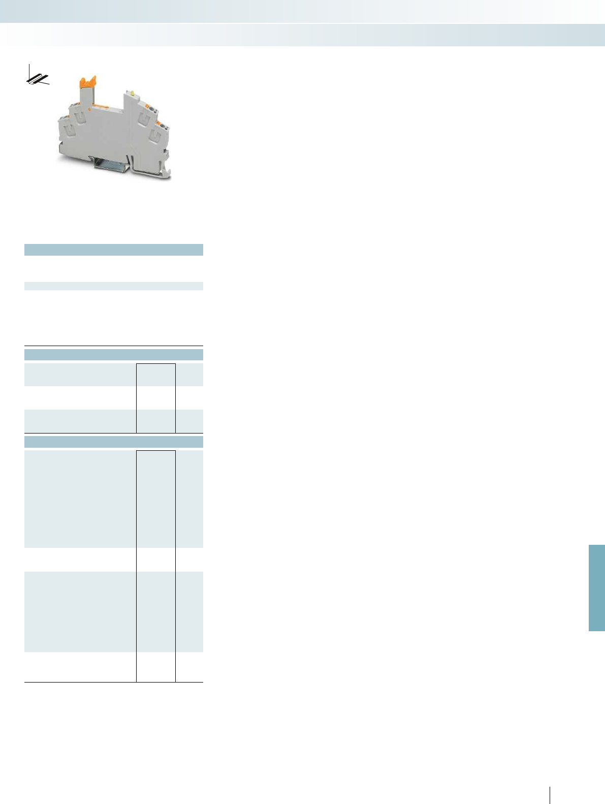
For further information and full technical data, visit phoenixcontact.net/products
Technical data
250 V AC/DC (contact side) 250 V AC/DC (contact side)
max. 8 A (depending on application/assembly) max. 8 A (depending on application/assembly)
Ambient temperature (operation) -40 °C ... 85 °C (depending on application/assembly) -40 °C ... 85 °C (depending on application/assembly)
Connection data solid / stranded / AWG 0.14 ... 1.5 mm² / 0.14 ... 1.5 mm² / 26 - 16 0.14 ... 1.5 mm² / 0.14 ... 1.5 mm² / 26 - 16
6.2 mm
66 mm
93 mm
Ordering data
Type Order No. Pcs. /
Pkt.
RIF-0-BPT/1 2901873 10
Accessories
FBSR 2-6 3033715 50
FBS 2-6 3030336 50
FBS 2-6 BU 3036932 50
FBS 2-6 GY 3032237 50
FBSR 3-6 3001594 50
FBSR 4-6 3001595 50
FBSR 5-6 3001596 50
FBS 5-6 3030349 50
FBS 10-6 3030271 10
FBS 20-6 3030365 10
FBS 50-6 3032224 10
CLIPFIX 35 3022218 50
MPS-MT 0201744 10
MPS-IH RD 0201676 10
MPS-IH WH 0201663 10
MPS-IH BU 0201689 10
MPS-IH YE 0201692 10
MPS-IH GN 0201702 10
MPS-IH GY 0201728 10
MPS-IH BK 0201731 10
ZB 6:UNBEDRUCKT 1051003 10
329PHOENIX CONTACT
DW
H
Relay modules
Industrial relay system with push-in connection - RIFLINE complete
1 N/O contact relay base for
miniature power relay
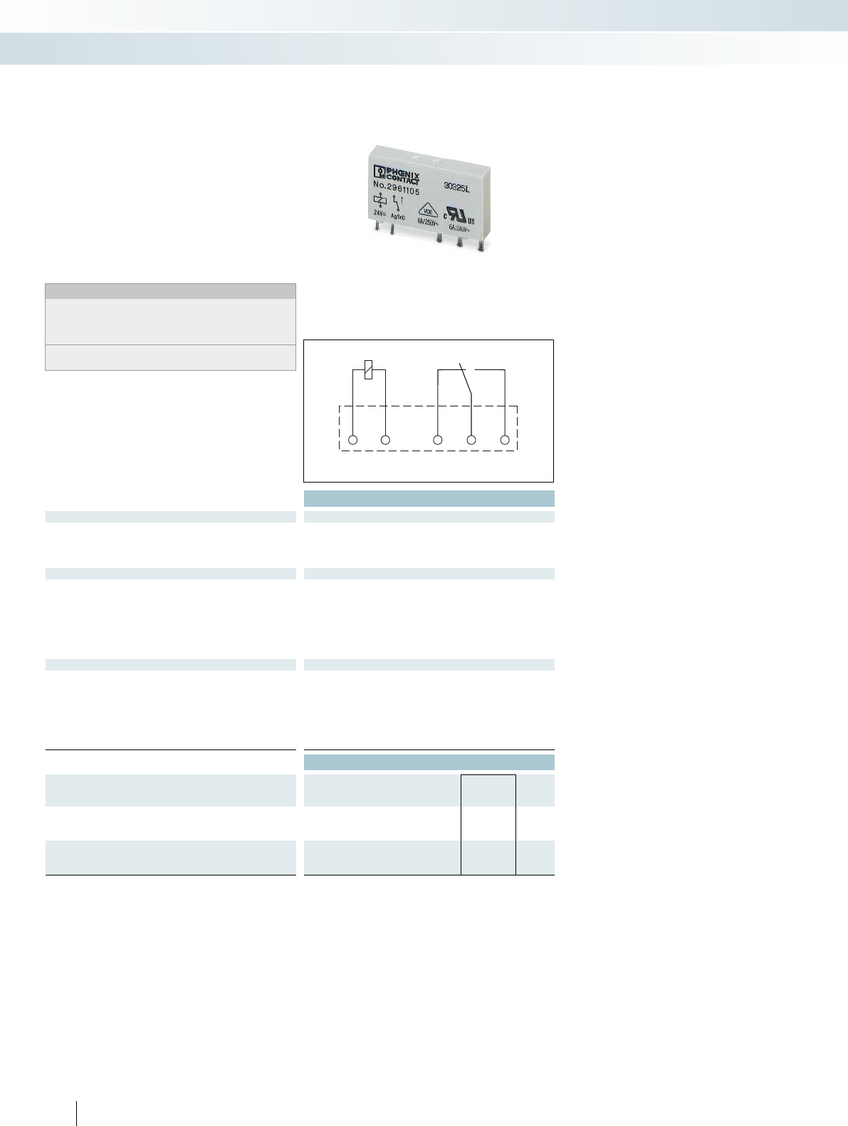
A2 A1 1112 14
330
PHOENIX CONTACT
Plug-in miniature power relays
Plug-in miniature power relays suitable for
RIF-0 and PLC-INTERFACE relay bases.
The advantages:
– Power contacts up to 6 A
– Multi-layer gold contact or power contact
– High degree of protection RT III
(comparable with IP67)
– Safe isolation according to DIN EN 50178
between coil and contact
– Can be soldered in on PCB
Notes:
If the specified maximum values for multi-layer contact relays are
exceeded, the gold plating is destroyed. The maximum values of
the power contact relay are then valid. This can result in a shorter
service life than with a pure power contact.
For dimensional drawings and perforations for assembly, see
page 424
Technical data
Input data ① ②
Permissible range (with reference to U
N
) see diagram
Typ. input current at U
N
[mA] 14 7
Typ. response time at U
N
[ms] 5 5
Typ. release time at U
N
[ms] 2.5 2.5
Output data
Contact type 1 PDT 1 PDT
Contact material AgSnO AgSnO, hard gold-plated
Max. switching voltage 250 V AC/DC 30 V AC / 36 V DC
Min. switching voltage 5 V (at 100 mA) 100 mV (at 10 mA)
Limiting continuous current 6 A 50 mA
Max. inrush current on request 50 mA
Min. switching current 10 mA (at 12 V) 1 mA (at 24 V)
General data
Test voltage (winding/contact) 4 kV AC (50 Hz, 1 min.)
Ambient temperature (operation) -40 °C ... 85 °C
Nominal operating mode 100% operating factor
Mechanical service life 2 x 10
7
cycles
Standards/regulations IEC 60664, EN 50178, IEC 62103
Mounting position / mounting any / can be aligned without spacing
Dimensions W / H / D 5 mm / 28 mm / 15 mm
Ordering data
Description Input voltage
U
N
Type Order No. Pcs. /
Pkt.
Plug-in miniature power relay
with power contacts ①12 V DC REL-MR- 12DC/21 2961150 10
with power contacts ②24 V DC REL-MR- 24DC/21 2961105 10
Plug-in miniature power relay
with multi-layer gold contacts ①12 V DC REL-MR- 12DC/21AU 2961163 10
with multi-layer gold contacts ②24 V DC REL-MR- 24DC/21AU 2961121 10
Relay modules
Industrial relay system with push-in connection - RIFLINE complete
1 PDT
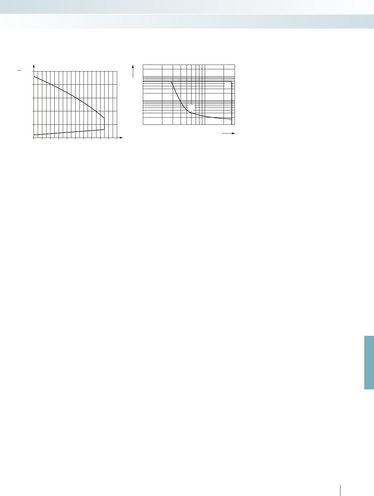
0,5
1020304050607080901000
1
1,5
2
2,5
3
U
N
U
T[°C]
U
A
B
0,1
0,2
0,3
0,5
1
2
4
10
20
1020305070100 300200
1
2
1
2
6
For further information and full technical data, visit phoenixcontact.net/products
331PHOENIX CONTACT
REL-MR-.../21... (1 PDT)
Input voltage range Interrupting rating
AC, ohmic load
DC, ohmic load
Switching voltage [V]
Switching current [A]
Relay modules
Industrial relay system with push-in connection - RIFLINE complete
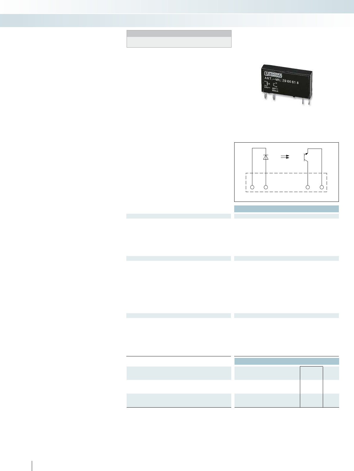
A2 A1 13+ 14
332
PHOENIX CONTACT
Plug-in solid-state relays suitable for
RIF-0 and PLC-INTERFACE relay bases.
The advantages:
– Switching capacity of up to 24 V DC/3 A
– RT III wash tight (comparable to IP67)
– Vibration and shock-resistant
– Wear-free and long-lasting
– Zero voltage switch at AC output
– Can be soldered in on PCB
Plug-in solid-state relays
Technical data
Input data ①
Permissible range (with reference to U
N
) 0.8 -
1.2
Switching level 1 signal ("H") [V DC] 16
0 signal ("L") [V DC] 10
Typ. input current at U
N
[mA] 7
Typ. switch-on time at U
N
[µs] 20
Typ. shutdown time at U
N
[µs] 300
Transmission frequency f
limit
[Hz] 300
Output data
Max. switching voltage 33 V DC
Min. switching voltage 3 V DC
Limiting continuous current 3 A (see derating curve) 100 mA 0.75 A (see derating curve)
Min. load current -
Max. inrush current 15 A (10 ms)
Leakage current in off state -
Phase angle (cos )-
Output circuit 2-wire, floating
Max. load value -
Output protection Protection against polarity reversal, surge protection Protection against polarity reversal, surge protection RC
Voltage drop at max. limiting continuous current 150 mV
General data
Rated surge voltage Basic insulation
Test voltage input/output 2.5 kV (50 Hz, 1 min.)
Ambient temperature (operation) -25 °C ... 60 °C
Nominal operating mode 100% operating factor 100% operating factor 100% operating factor
Standards/regulations IEC 60664, EN 50178, IEC 62103 IEC 60664, EN 50178, IEC 62103 IEC 60664, EN 50178, IEC 62103
Pollution degree / surge voltage category 2 / III
Mounting position / mounting any / can be aligned without spacing any / can be aligned without spacing any / can be aligned without
Dimensions W / H / D 5 mm / 28 mm / 15 mm 5 mm / 28 mm / 15 mm 5 mm / 28 mm / 15 mm
Ordering data
Description Input voltage
U
N
Type Order No. Pcs. /
Pkt.
Plug-in solid-state relay
Solid-state power relay ①24 V DC OPT-24DC/ 24DC/ 2 2966595 10
Plug-in solid-state relay
Solid-state input relay ①24 V DC
Notes:
For dimensional drawings and perforations for assembly, see
page 425
Relay modules
Industrial relay system with push-in connection - RIFLINE complete
Max. DC voltage output of 3 A Max. DC voltage output of 100 mA Max. AC voltage output of 750 mA
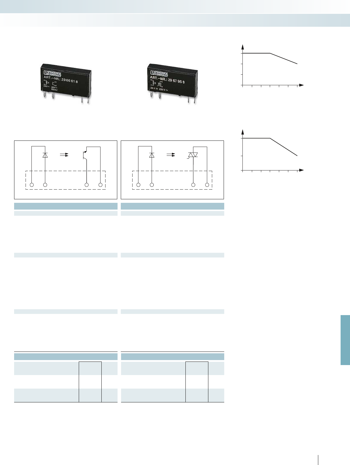
0
300
750
0 10 20 30 40 50 60
0
1
2
3
0 10 20 30 40 50 60
A2 A1 13+ 14
A2 A1 13+ 14
For further information and full technical data, visit phoenixcontact.net/products
333
PHOENIX CONTACT
Technical data Technical data
① ①
0.8 -
1.2
0.8 -
1.2
16 10
10 5
73
20 6000
300 500
300 10
48 V DC 253 V AC
3 V DC 24 V AC
Limiting continuous current 3 A (see derating curve) 100 mA 0.75 A (see derating curve)
- 10 mA
- 30 A (10 ms)
- < 1 mA
- 0.5
2-wire, floating 2-wire floating, zero voltage switch
- 4.5 A
2
s
Output protection Protection against polarity reversal, surge protection Protection against polarity reversal, surge protection RCV circuit
1 V < 1 V
Basic insulation Basic insulation
2.5 kV (50 Hz, 1 min.) 2.5 kV (50 Hz, 1 min.)
-25 °C ... 60 °C -25 °C ... 60 °C
Nominal operating mode 100% operating factor 100% operating factor 100% operating factor
Standards/regulations IEC 60664, EN 50178, IEC 62103 IEC 60664, EN 50178, IEC 62103 IEC 60664, EN 50178, IEC 62103
2 / III 2 / III
Mounting position / mounting any / can be aligned without spacing any / can be aligned without spacing any / can be aligned without spacing
Dimensions W / H / D 5 mm / 28 mm / 15 mm 5 mm / 28 mm / 15 mm 5 mm / 28 mm / 15 mm
Ordering data Ordering data
Type Order No. Pcs. /
Pkt. Type Order No. Pcs. /
Pkt.
OPT-24DC/230AC/ 1 2967950 10
OPT-24DC/ 48DC/100 2966618 10
Derating curve for OPT...DC/230AC/1 and PLC-OS.../230AC/1
solid-state relays
Ambient temperature range [°C]
Load current [mA]
Derating curve for OPT...DC/24DC/2 and PLC-OS.../24DC/2
solid-state relays
Ambient temperature range [°C]
Load current [A]
Relay modules
Industrial relay system with push-in connection - RIFLINE complete
Max. DC voltage output of 3 A Max. DC voltage output of 100 mA Max. AC voltage output of 750 mA
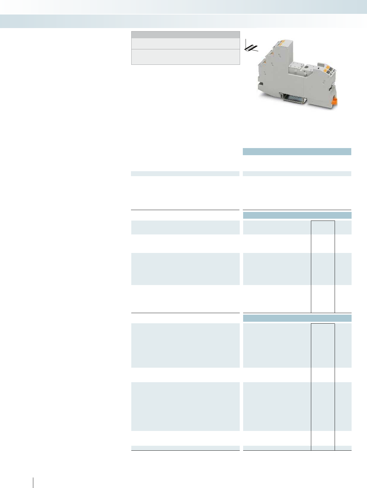
Technical data
Nominal voltage U
N
250 V AC/DC
Nominal current at U
N
max. 13 A (depending on application/assembly) - -
General data
Ambient temperature (operation) -40 °C ... 85 °C (depending on application/assembly) - -
Connection data solid / stranded / AWG 0.14 ... 1.5 mm² / 0.14 ... 1.5 mm² / 26 - 16 - -
Dimensions
Width 16 mm
Depth with retaining bracket 75 mm
Height 96 mm
Ordering data
Description Type Order No. Pcs. /
Pkt.
RIF-1 relay base, plug-in option for input/interference suppression
module, safe isolation I/O with push-in connection
RIF-1-BPT/2X21 2900931 10
Relay retaining bracket, with ejector function and holder for
marking material, suitable for RIF-1 relay base
- for 16 mm high miniature power and solid-state relays
- for 25 mm high miniature power relays
Relay retaining bracket, wire model, suitable for RIF-1 relay base
- for 16 mm high miniature power and solid-state relays
- for 25 mm high miniature power relays
Accessories
Jumper
2-pos. red, 32 A FBS 2-6 3030336 50
2-pos. red, 24 A FBSR 2-6 3033715 50
2-pos. red, 32 A FBSR 2-8 3033808 10
2-pos. blue, 32 A FBS 2-6 BU 3036932 50
2-pos. gray, 32 A FBS 2-6 GY 3032237 50
2-pos. red, 41 A FBS 2-8 3030284 10
2-pos. blue, 41 A FBS 2-8 BU 3032567 10
2-pos. gray, 41 A FBS 2-8 GY 7042 3032541 10
End bracket, for snapping onto NS 35, 9.5 mm wide, can be
marked with ZB 6, ZB 8/27, KLM...
CLIPFIX 35 3022218 50
Test plug, consisting of:
Metal part for 2.3 mm Ø socket hole and silver MPS-MT 0201744 10
Insulating sleeve, for MPS metal part red MPS-IH RD 0201676 10
white MPS-IH WH 0201663 10
blue MPS-IH BU 0201689 10
yellow MPS-IH YE 0201692 10
green MPS-IH GN 0201702 10
gray MPS-IH GY 0201728 10
black MPS-IH BK 0201731 10
Zack marker strip, unprinted
10-section ZB 5 :UNBEDRUCKT 1050004 10
5-section ZB 15:UNBEDRUCKT 0811972 10
Double marker carrier for ZB 5 STP 5-2 0800967 100
334
PHOENIX CONTACT
DW
H
Modular RIF-1 relay base
Notes:
Type of insulating housing:
Polyamide PA non-reinforced, color: gray.
For further marking systems and mounting material, see
Catalog 5.
Relay base that can be fitted with
1 or 2 PDT relays or solid-state relays.
Range of accessories includes:
– Plug-in input and interference suppression
module
– Plug-in timer module
– Relay retaining bracket with ejector
function and holder for marking material
– Comprehensive range of marking material
– Test plug
– FBS 2-6 jumpers for the input side (A2)
– FBS 2-8 jumpers for the output side
(11/21)
Relay modules
Industrial relay system with push-in connection - RIFLINE complete
2 PDT relay base for
miniature power relay

For further information and full technical data, visit phoenixcontact.net/products
Technical data Technical data
--
max. 13 A (depending on application/assembly) - -
Ambient temperature (operation) -40 °C ... 85 °C (depending on application/assembly) - -
Connection data solid / stranded / AWG 0.14 ... 1.5 mm² / 0.14 ... 1.5 mm² / 26 - 16 - -
--
--
--
Ordering data Ordering data
Type Order No. Pcs. /
Pkt. Type Order No. Pcs. /
Pkt.
RIF-RH-1 2900953 10
RIF-RH-1-H 2904468 10
RIF-RHM-1 2905986 10
RIF-RHM-1-H 2905985 10
Accessories Accessories
335PHOENIX CONTACT
Relay modules
Industrial relay system with push-in connection - RIFLINE complete
Relay retaining bracket Relay retaining bracket
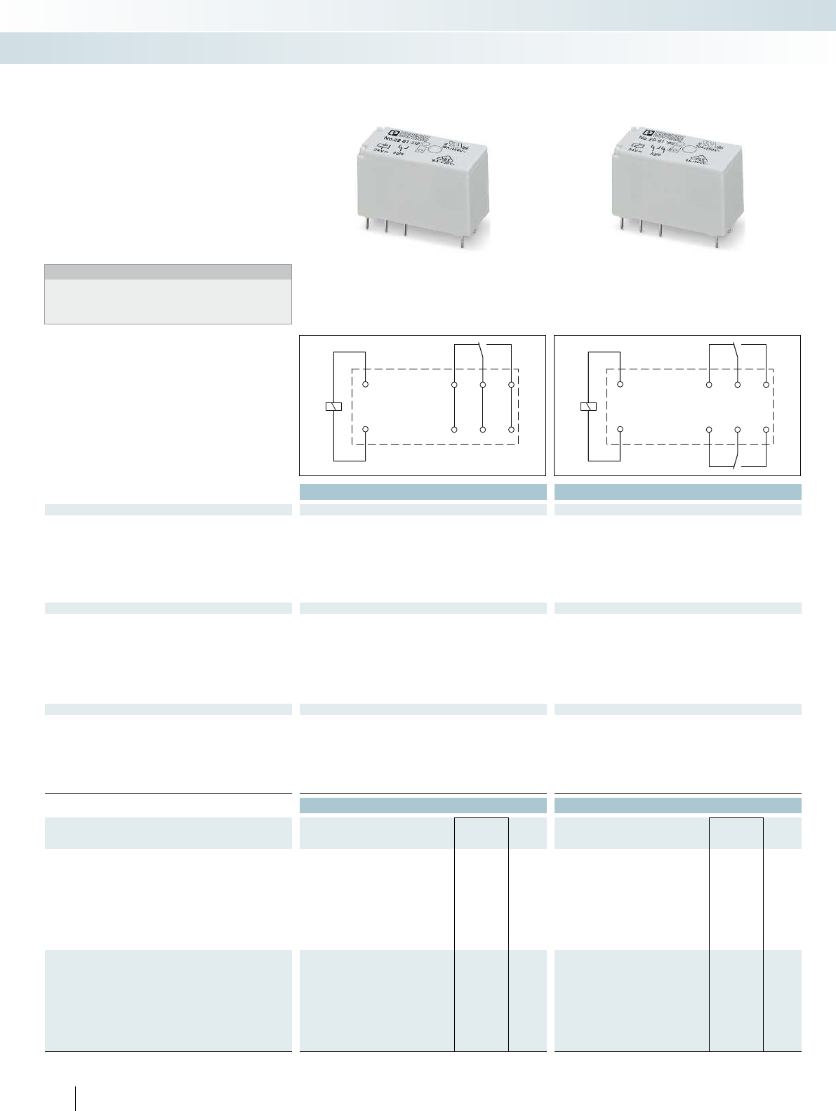
14
A1
1112
A2
24
14
A1
21
11
22
12
A2
336
PHOENIX CONTACT
Plug-in miniature power relays
Plug-in miniature power relays with
1 or 2 PDT contacts, suitable for RIF-1, PR1,
and PLC-INTERFACE relay bases.
The advantages:
– Power contacts up to 16 A
– Multi-layer gold contact or power contact
– High degree of protection up to RT III
(comparable with IP67) depending on
type
Notes:
If the specified maximum values for multi-layer contact relays are
exceeded, the gold plating is destroyed. The maximum values of
the power contact relay are then valid. This can result in a shorter
service life than with a pure power contact.
Technical data Technical data
Input data ① ② ③ ④ ⑤ ⑥ ⑦ ⑧ ① ② ③ ④ ⑤ ⑥ ⑦ ⑧
Permissible range (with reference to U
N
) see diagram see diagram
Typ. input current at U
N
[mA] 33 17 8.7 8.2 4.1 32 7 3 33 17 8.7 8.2 4.1 32 7 3
Typ. response time at U
N
[ms]77777 77777
Typ. response time at U
N
(depending on phase relation)
[ms] 3 - 12 3 - 12 3 - 12 3 - 12 3 - 12 3 - 12
Typ. release time at U
N
[ms]33333 33333
Typ. release time at U
N
(depending on phase relation)
[ms] 2 - 9 2 - 9 2 - 9 2 - 9 2 - 9 2 - 9
Output data
Contact type 1 PDT 1 PDT 2 PDT 2 PDT
Contact material AgNi AgNi, hard gold-plated AgNi AgNi, hard gold-plated
Max. switching voltage 250 V AC/DC 30 V AC / 36 V DC 250 V AC/DC 30 V AC / 36 V DC
Min. switching voltage 12 V (at 10 mA) 100 mV (at 10 mA) 5 V (at 10 mA) 100 mV (at 10 mA)
Limiting continuous current 16 A 50 mA 8 A 50 mA
Max. inrush current, AC 25 A (20 ms) 50 mA 12 A (20 ms) 50 mA
Max. inrush current, DC 50 A (20 ms) 50 mA 25 A (20 ms) 50 mA
Min. switching current 10 mA (at 12 V) 1 mA (at 24 V) 10 mA (at 5 V) 1 mA (at 24 V)
General data
Test voltage (winding/contact) 5 kV AC (50 Hz, 1 min.) 5 kV AC (50 Hz, 1 min.)
Test voltage (contact/contact) - 2.5 kV AC (50 Hz, 1 min.)
Ambient temperature (operation), AC -40 °C ... 85 °C -40 °C ... 85 °C
Ambient temperature (operation), DC -40 °C ... 85 °C -40 °C ... 85 °C
Mechanical service life, AC 1 x 10
7
cycles 1 x 10
7
cycles
Mechanical service life, DC 3 x 10
7
cycles 3 x 10
7
cycles
Standards/regulations IEC 60664, EN 50178, IEC 62103 IEC 60664, EN 50178, IEC 62103
Ordering data Ordering data
Description Input voltage
U
N
Type Order No. Pcs. /
Pkt. Type Order No. Pcs. /
Pkt.
Plug-in miniature power relay
with power contacts ①12 V DC REL-MR- 12DC/21HC 2961309 10 REL-MR- 12DC/21-21 2961257 10
with power contacts ②24 V DC REL-MR- 24DC/21HC 2961312 10 REL-MR- 24DC/21-21 2961192 10
with power contacts ③48 V DC REL-MR- 48DC/21HC 2834821 10 REL-MR- 48DC/21-21 2834834 10
with power contacts ④60 V DC REL-MR- 60DC/21HC 2961325 10 REL-MR- 60DC/21-21 2961273 10
with power contacts ⑤110 V DC REL-MR-110DC/21HC 2961338 10 REL-MR-110DC/21-21 2961202 10
with power contacts ⑥24 V AC REL-MR- 24AC/21HC 2961406 10 REL-MR- 24AC/21-21 2961435 10
with power contacts ⑦120 V AC REL-MR-120AC/21HC 2961419 10 REL-MR-120AC/21-21 2961448 10
with power contacts ⑧230 V AC REL-MR-230AC/21HC 2961422 10 REL-MR-230AC/21-21 2961451 10
Plug-in miniature power relay
with multi-layer gold contacts ①12 V DC REL-MR- 12DC/21HC AU 2961532 10 REL-MR- 12DC/21-21AU 2961299 10
with multi-layer gold contacts ②24 V DC REL-MR- 24DC/21HC AU 2961545 10 REL-MR- 24DC/21-21AU 2961215 10
with multi-layer gold contacts ③48 V DC REL-MR- 48DC/21-21AU 2834847 10
with multi-layer gold contacts ④60 V DC REL-MR- 60DC/21-21AU 2961286 10
with multi-layer gold contacts ⑤110 V DC REL-MR-110DC/21HC AU 2961561 10 REL-MR-110DC/21-21AU 2961228 10
with multi-layer gold contacts ⑥24 V AC REL-MR- 24AC/21HC AU 2961503 10 REL-MR- 24AC/21-21AU 2961464 10
with multi-layer gold contacts ⑦120 V AC REL-MR-120AC/21HC AU 2961516 10 REL-MR-120AC/21-21AU 2961477 10
with multi-layer gold contacts ⑧230 V AC REL-MR-230AC/21HC AU 2961529 10 REL-MR-230AC/21-21AU 2961480 10
Relay modules
Industrial relay system with push-in connection - RIFLINE complete
1 PDT relay 2 PDT relay

0,6
0,8
1
1,2
1,4
1,6
1,8
2
2,2
2,4
2,6
2,8
0 10 20 30 40 50 60 70 80 90 100
1
1
2
2
1
2
0,1
0,2
0,3
0,5
1
2
4
6
10
20
10 20 30 50 70 100 300200
1
2
3
3
1
2
1
0,9
0,3
0,4
0,5
0,6
0,7
0,8
0,9
1
0,80,70,60,50,40,30,2
0,6
0,8
1
1,2
1,4
1,6
1,8
2
2,2
2,4
2,6
2,8
0 10 20 30 40 50 60 70 80 90 100
1
2
2
1
1
2
0,1
0,2
0,3
0,5
1
2
4
6
10
20
10 20 30 50 70 100 300200
1
2
3
4
3
1
42
1
0,9
0,3
0,4
0,5
0,6
0,7
0,8
0,9
1
0,80,70,60,50,40,30,2
0 1 4 8 12 16
107
106
105
104
2 3 5 6 7 11910 151413
1
2
21
0 1 4 8 12 16
107
106
105
104
2 3 5 6 7 11910 151413
1
2
2
1
For further information and full technical data, visit phoenixcontact.net/products
337
PHOENIX CONTACT
REL-MR...21HC... (1 PDT)
Operating voltage range Interrupting rating
Ambient temperature [°C]
Coil voltage U/U
N
DC coils
AC coils
AC, ohmic load
DC, ohmic load
DC, L/R = 40 ms
Switching voltage [V]
Switching current [A]
Service life reduction factor with various cos phi
COS j
Reduction factor
REL-MR...21-21... (2 PDTs)
Operating voltage range Interrupting rating
Ambient temperature [°C]
Coil voltage U/U
N
DC coils
AC coils
AC, ohmic load
DC, ohmic load, contacts in series
DC, ohmic load
DC, L/R = 40 ms
Switching voltage [V]
Switching current [A]
Service life reduction factor with various cos phi
COS j
Reduction factor
Electrical service life
Cycles
Switching current [A]
250 V AC, ohmic load (DC coils)
250 V AC, ohmic load (AC coils)
Electrical service life
Cycles
Switching current [A]
250 V AC, ohmic load (DC coils)
250 V AC, ohmic load (AC coils)
Relay modules
Industrial relay system with push-in connection - RIFLINE complete
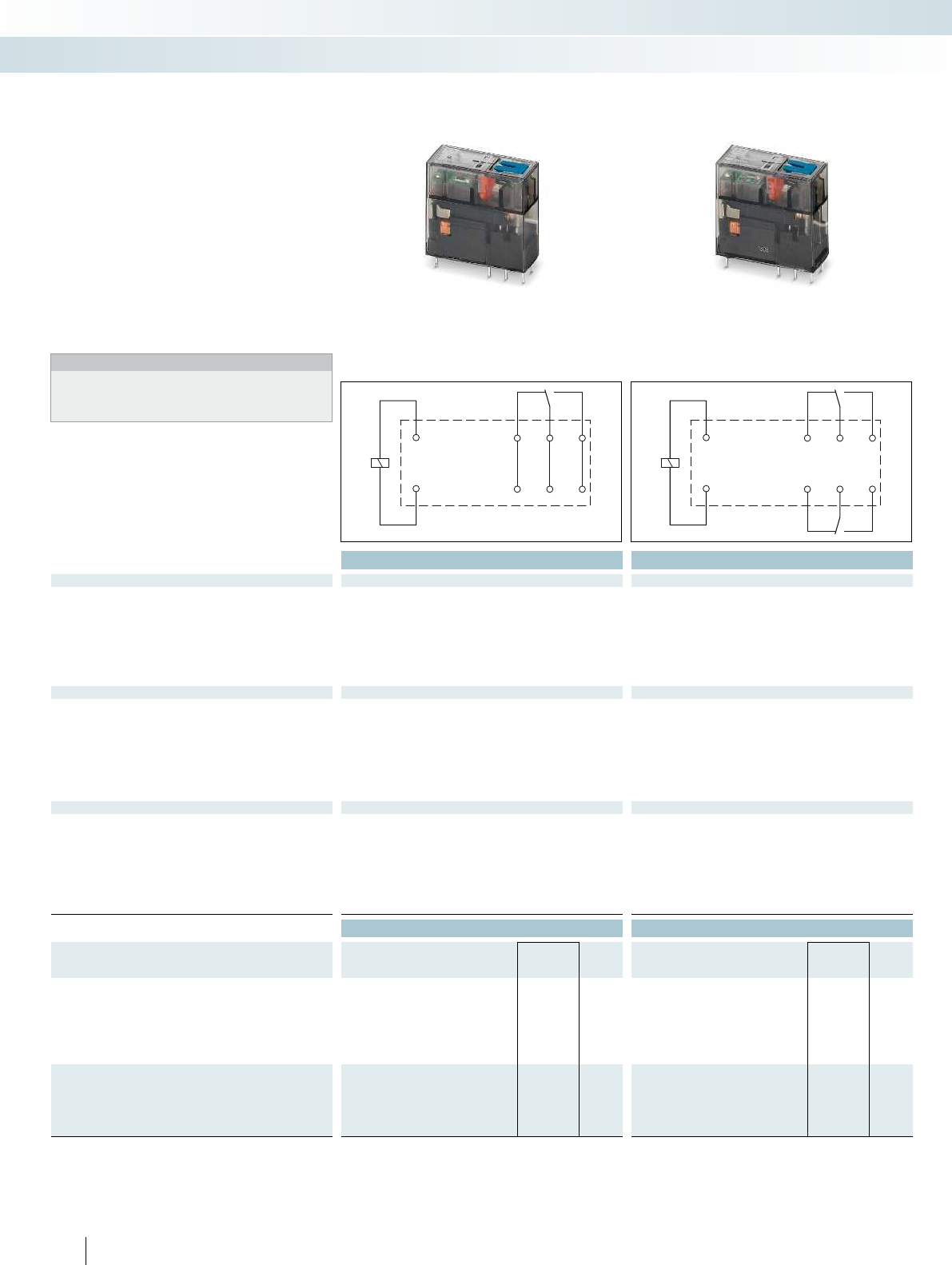
14
A1
1112
A2
24
14
A1
21
11
22
12
A2
338
PHOENIX CONTACT
Plug-in miniature power relays
Plug-in miniature power relays with
1 or 2 PDT contacts, suitable for RIF-1 and
PR1 relay bases.
The advantages:
– Switching current of up to 16 A
– With lockable manual operation
– Mechanical switch position indicator
– Integrated status LED
– Multi-layer gold contact or power contact
– DC types with integrated freewheeling
diode
– Can be soldered in on PCB
Notes:
If the specified maximum values for multi-layer contact relays are
exceeded, the gold plating is destroyed. The maximum values of
the power contact relay are then valid. This can result in a shorter
service life than with a pure power contact.
Technical data Technical data
Input data ① ② ③ ④ ① ② ③ ④
Permissible range (with reference to U
N
) see diagram see diagram
Typ. input current at U
N
[mA] 18 32 7 3.5 18 32 7 3.5
Typ. response time at U
N
[ms] 9 9
Typ. response time at U
N
(depending on phase relation)
[ms] 3 - 12 3 - 12 3 - 12 3 - 12 3 - 12
Typ. release time at U
N
[ms] 6 6
Typ. release time at U
N
(depending on phase relation)
[ms] 2 - 8 2 - 8 2 - 8 2 - 8 2 - 8 2 - 8
Output data
Contact type 1 PDT 1 PDT 2 PDT 2 PDT
Contact material AgNi AgNi, hard gold-plated AgNi AgNi, hard gold-plated
Max. switching voltage 250 V AC/DC 30 V AC / 36 V DC 250 V AC/DC 30 V AC / 36 V DC
Min. switching voltage 12 V (at 10 mA) 12 V (at 1 mA) 12 V (at 10 mA) 12 V (at 1 mA)
Limiting continuous current 16 A 50 mA 8 A 50 mA
Max. inrush current, AC 32 A (20 ms) 50 mA 16 A (20 ms) 50 mA
Max. inrush current, DC 32 A (20 ms) 50 mA 16 A (20 ms) 50 mA
Min. switching current 10 mA (at 12 V) 1 mA (at 12 V) 10 mA (at 12 V) 1 mA (at 12 V)
General data
Test voltage (winding/contact) 5 kV AC (50 Hz, 1 min.) 5 kV AC (50 Hz, 1 min.)
Test voltage (contact/contact) - 2.5 kV AC (50 Hz, 1 min.)
Ambient temperature (operation), AC -40 °C ... 70 °C -40 °C ... 70 °C
Ambient temperature (operation), DC -40 °C ... 70 °C -40 °C ... 70 °C
Mechanical service life, AC 5 x 10
6
cycles 5 x 10
6
cycles
Mechanical service life, DC 5 x 10
6
cycles 5 x 10
6
cycles
Standards/regulations DIN EN 61810-1, VDE 0435-201, EN 50178, IEC 62103 DIN EN 61810-1, VDE 0435-201, EN 50178, IEC 62103
Ordering data Ordering data
Description Input voltage
U
N
Type Order No. Pcs. /
Pkt. Type Order No. Pcs. /
Pkt.
Plug-in miniature power relay, with power contacts
- Status LED, freewheeling diode A1+,
A2-
①24 V DC REL-MR- 24DC/21HC/MS 2987888 10 REL-MR- 24DC/21-21/MS 2987943 10
- Status LED ②24 V AC REL-MR- 24AC/21HC/MS 2987891 10 REL-MR- 24AC/21-21/MS 2987956 10
- Status LED ③120 V AC REL-MR-120AC/21HC/MS 2987901 10 REL-MR-120AC/21-21/MS 2987969 10
- Status LED ④230 V AC REL-MR-230AC/21HC/MS 2987914 10 REL-MR-230AC/21-21/MS 2987972 10
Plug-in miniature power relay, with multi-layer gold contacts,
with manual operation, mechanical switch position indicator
- Status LED, freewheeling diode A1+, A2-
①24 V DC REL-MR- 24DC/21HC AU/MS 2987927 10 REL-MR- 24DC/21-21AU/MS 2987985 10
- Status LED ④230 V AC REL-MR-230AC/21HC AU/MS 2987930 10 REL-MR-230AC/21-21AU/MS 2987998 10
Relay modules
Industrial relay system with push-in connection - RIFLINE complete
1 PDT relay 2 PDT relay
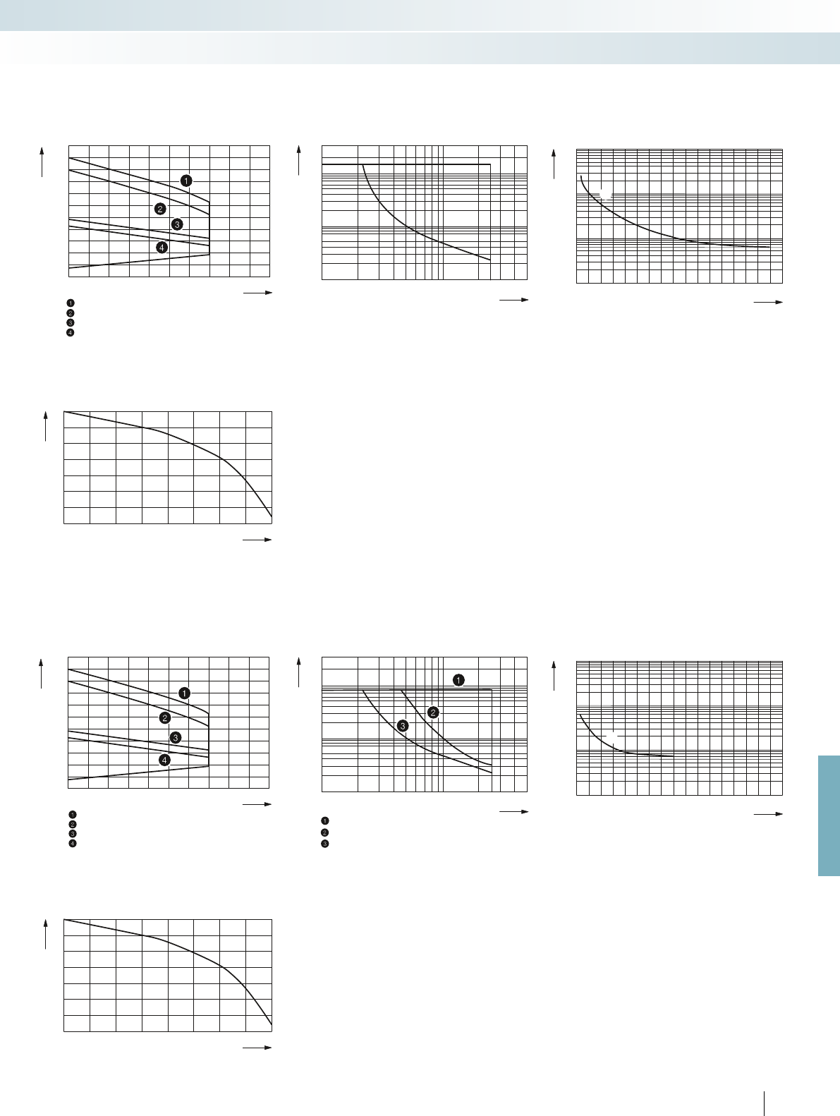
0,6
0,8
1
1,2
1,4
1,6
1,8
2
2,2
2,4
2,6
0102030405060 70 80 90
100
1
2
20
10
5
2
1
0,5
0,2
0,1
1020305070100 200 300 400 500
1
2
1
0,9
0,3
0,4
0,5
0,6
0,7
0,8
0,9
1
0,80,70,60,50,40,30,2
0,6
0,8
1
1,2
1,4
1,6
1,8
2
2,2
2,4
2,6
0102030405060 70 80 90
100
20
10
5
2
1
0,5
0,2
0,1
10203050 70 100 200 300 400 500
1
0,9
0,3
0,4
0,5
0,6
0,7
0,8
0,9
1
0,80,70,60,50,40,30,2
014 812 16
107
106
105
104
2 3 5 6 7 11910151413
1
1
014 812 16
107
106
105
104
2 3 5 6 7 11910151413
1
1
For further information and full technical data, visit phoenixcontact.net/products
339PHOENIX CONTACT
REL-MR...21HC...MS (1 PDT)
Operating voltage range Interrupting rating
Ambient temperature [°C]
Coil voltage U/U
N
DC coils, 0 A contact current
AC coils, 0 A contact current
DC coils, 16 A contact current
AC coils, 16 A contact current
Switching voltage [V]
Switching current [A]
AC, ohmicload
DC, ohmicload
Service life reduction factor with various cos phi
COS j
Reduction factor
REL-MR...21-21...MS (2 PDTs)
Operating voltage range Interrupting rating
Ambient temperature [°C]
Coil voltage U/U
N
DC coils, 0 A contact current
AC coils, 0 A contact current
DC coils, 8 A contact current
AC coils, 8 A contact current
AC, ohmic load
DC, ohmic load, contacts in series
DC, ohmic load
Switching voltage [V]
Switching current [A]
Service life reduction factor with various cos phi
COS j
Reduction factor
Electrical service life
Cycles
Switching current [A]
250 V AC, ohmic load
Electrical service life
Cycles
Switching current [A]
250 V AC, ohmic load
Relay modules
Industrial relay system with push-in connection - RIFLINE complete
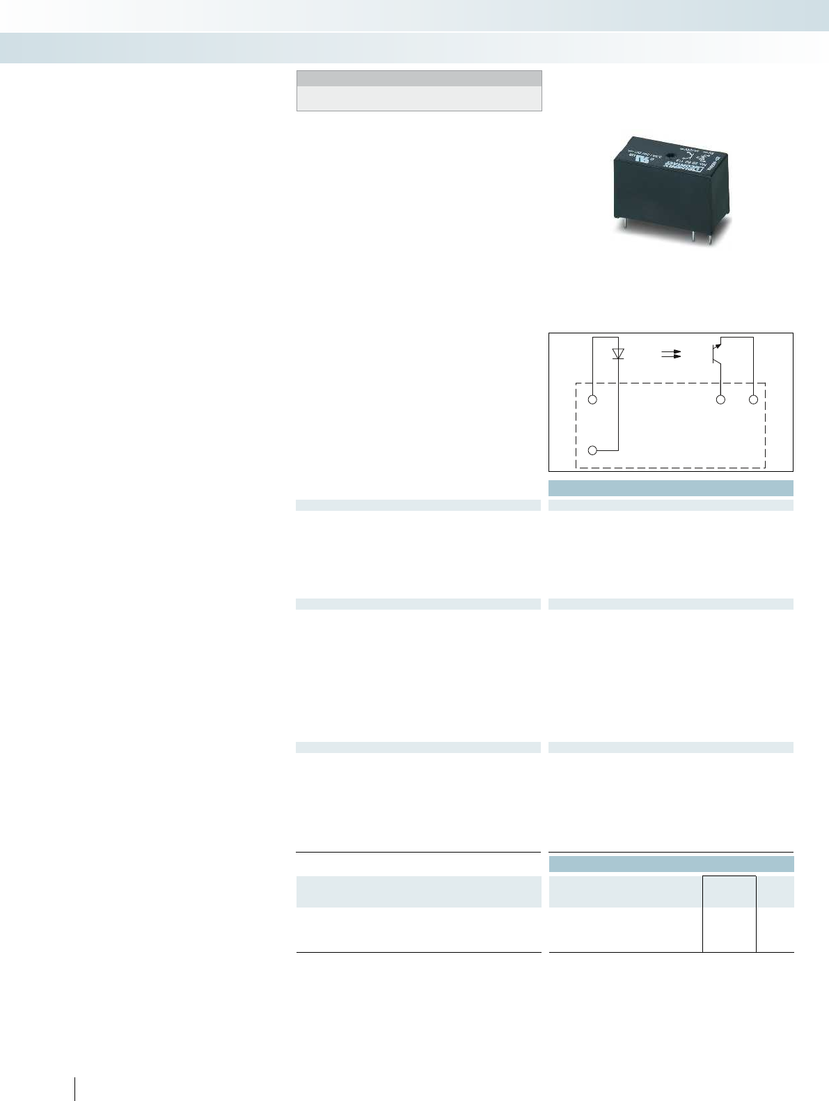
A1
A2
13+ 14
340
PHOENIX CONTACT
Plug-in solid-state relays suitable for RIF-1,
PR1, and PLC-INTERFACE relay bases.
The advantages:
– Switching capacity of up to 24 V DC/5 A
– RT III wash tight (comparable to IP67)
– Vibration and shock-resistant
– Wear-free and long-lasting
– Zero voltage switch at AC output
– Can be soldered in on PCB
Plug-in solid-state relays
Technical data
Input data ① ② ③
Permissible range (with reference to U
N
) 0.8 -
1.2
0.8 -
1.2
0.9 -
1.1
Switching level 1 signal ("H") [V DC] 2.5 16 35
0 signal ("L") [V DC] 0.8 10 20
Typ. input current at U
N
[mA]973
Typ. switch-on time at U
N
[µs] 10 20 25
Typ. shutdown time at U
N
[µs] 400 400 400
Transmission frequency f
limit
[Hz] 300 300 300
Output data
Max. switching voltage 33 V DC
Min. switching voltage 3 V DC
Limiting continuous current 5 A (see derating curve) 2 A (see derating curve)
Min. load current -
Max. inrush current 15 A (10 ms)
Leakage current in off state -
Phase angle (cos )-
Output circuit 2-wire, floating
Max. load value -
Output protection Protection against polarity reversal, surge protection Surge protection
Voltage drop at max. limiting continuous current 200 mV
General data
Rated surge voltage Basic insulation
Test voltage input/output 2.5 kV (50 Hz, 1 min.)
Ambient temperature (operation) -25 °C ... 60 °C
Nominal operating mode 100% operating factor 100% operating factor
Standards/regulations IEC 60664, EN 50178, IEC 62103 IEC 60664, EN 50178, IEC 62103
Pollution degree / surge voltage category 2 / III
Mounting position / mounting any / can be aligned without spacing any / see derating curve
Dimensions W / H / D 12.7 mm / 29 mm / 15.7 mm 12.7 mm / 29 mm / 15.7 mm
Ordering data
Description Input voltage
U
N
Type Order No. Pcs. /
Pkt.
Plug-in solid-state relay
Solid-state power relay ①5 V DC OPT- 5DC/ 24DC/ 5 2982113 10
Solid-state power relay ②24 V DC OPT-24DC/ 24DC/ 5 2982100 10
Solid-state power relay ③60 V DC OPT-60DC/ 24DC/ 5 2982126 10
Notes:
For dimensional drawings and perforations for assembly, see
page 425
Relay modules
Industrial relay system with push-in connection - RIFLINE complete
Max. DC voltage output of 5 A Max. AC voltage output of 2 A

0
2
1,8
1,6
1,4
1,2
1
0,8
0,6
0 25 30 35 40 45 50 55 60
1
2
1
2
0
1
2
3
4
5
0 25 30 35 40 45 50 55 60
A1 13 14
A2
For further information and full technical data, visit phoenixcontact.net/products
341
PHOENIX CONTACT
Technical data
① ② ③
0.8 -
1.2
0.8 -
1.2
0.9 -
1.1
3 18 40
1 8.4 20
15 7 2.6
10000 10000 10000
10000 10000 10000
10 10 10
253 V AC
24 V AC
Limiting continuous current 5 A (see derating curve) 2 A (see derating curve)
25 mA
30 A (10 ms)
< 1 mA
-
2-wire floating, zero voltage switch
4 A
2
s (tp = 10 ms, at 25 °C)
Output protection Protection against polarity reversal, surge protection Surge protection
1 V
Basic insulation
2.5 kV (50 Hz, 1 min.)
-25 °C ... 60 °C
Nominal operating mode 100% operating factor 100% operating factor
Standards/regulations IEC 60664, EN 50178, IEC 62103 IEC 60664, EN 50178, IEC 62103
2 / III
Mounting position / mounting any / can be aligned without spacing any / see derating curve
Dimensions W / H / D 12.7 mm / 29 mm / 15.7 mm 12.7 mm / 29 mm / 15.7 mm
Ordering data
Type Order No. Pcs. /
Pkt.
OPT- 5DC/230AC/ 2 2982168 10
OPT-24DC/230AC/ 2 2982171 10
OPT-60DC/230AC/ 2 2982184 10
Ambient temperature range [°C]
Load current [A]
Aligned with > 10 mm spacing
Aligned without spacing
Derating curve for OPT...DC/24DC/5 solid-state relays
Ambient temperature range [°C]
Load current [A]
Derating curve for OPT...DC/230AC/2 solid-state relays
Relay modules
Industrial relay system with push-in connection - RIFLINE complete
Max. DC voltage output of 5 A Max. AC voltage output of 2 A
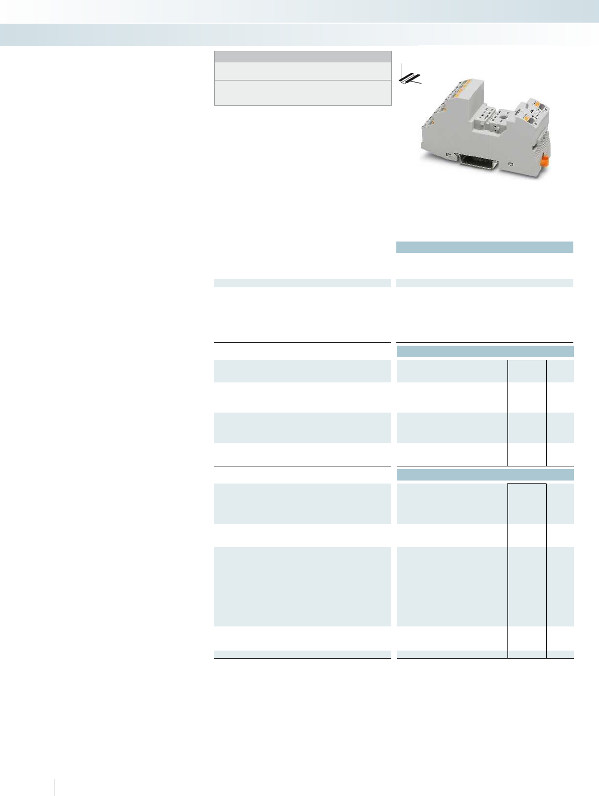
Technical data
Nominal voltage U
N
250 V AC/DC
Nominal current at U
N
max. 12 A (depending on application/assembly) - -
General data
Ambient temperature (operation) -40 °C ... 85 °C (depending on application/assembly) - -
Connection data solid / stranded / AWG 0.14 ... 1.5 mm² / 0.14 ... 1.5 mm² / 26 - 16 - -
Dimensions
Width 31 mm
Depth with retaining bracket 75 mm
Height 96 mm
Ordering data
Description Type Order No. Pcs. /
Pkt.
RIF-2 relay base, plug-in option for input/interference suppression
module, safe isolation I/O with push-in connection
RIF-2-BPT/4X21 2900934 10
Relay retaining bracket, with ejector function and holder for
marking material, suitable for RIF-2 relay base
Relay retaining bracket, wire model, suitable for RIF-2 relay base
Accessories
Jumper
2-pos. red, 32 A FBS 2-6 3030336 50
2-pos. red, 24 A FBSR 2-6 3033715 50
2-pos. blue, 32 A FBS 2-6 BU 3036932 50
2-pos. gray, 32 A FBS 2-6 GY 3032237 50
End bracket, for snapping onto NS 35, 9.5 mm wide, can be
marked with ZB 6, ZB 8/27, KLM...
CLIPFIX 35 3022218 50
Test plug, consisting of:
Metal part for 2.3 mm Ø socket hole and silver MPS-MT 0201744 10
Insulating sleeve, for MPS metal part red MPS-IH RD 0201676 10
white MPS-IH WH 0201663 10
blue MPS-IH BU 0201689 10
yellow MPS-IH YE 0201692 10
green MPS-IH GN 0201702 10
gray MPS-IH GY 0201728 10
black MPS-IH BK 0201731 10
Zack marker strip, unprinted
10-section ZB 5 :UNBEDRUCKT 1050004 10
5-section ZB 15:UNBEDRUCKT 0811972 10
Double marker carrier for ZB 5 STP 5-2 0800967 100
342
PHOENIX CONTACT
DW
H
Modular RIF-2 relay base
Notes:
Type of insulating housing:
Polyamide PA non-reinforced, color: gray.
For further marking systems and mounting material, see
Catalog 5.
Relay base that can be fitted with
2 or 4 PDT relays.
Range of accessories includes:
– Plug-in input and interference suppression
module
– Plug-in timer module
– Relay retaining bracket with ejector
function and holder for marking material
– Comprehensive range of marking material
– Test plug
– FBS 2-6 jumpers for the input side (A2)
Relay modules
Industrial relay system with push-in connection - RIFLINE complete
4 PDT relay base for
industrial relay

For further information and full technical data, visit phoenixcontact.net/products
Technical data Technical data
--
max. 12 A (depending on application/assembly) - -
Ambient temperature (operation) -40 °C ... 85 °C (depending on application/assembly) - -
Connection data solid / stranded / AWG 0.14 ... 1.5 mm² / 0.14 ... 1.5 mm² / 26 - 16 - -
--
--
--
Ordering data Ordering data
Type Order No. Pcs. /
Pkt. Type Order No. Pcs. /
Pkt.
RIF-RH-2 2900954 10
RIF-RHM-2 2905984 10
Accessories Accessories
343PHOENIX CONTACT
Relay modules
Industrial relay system with push-in connection - RIFLINE complete
Relay retaining bracket Relay retaining bracket
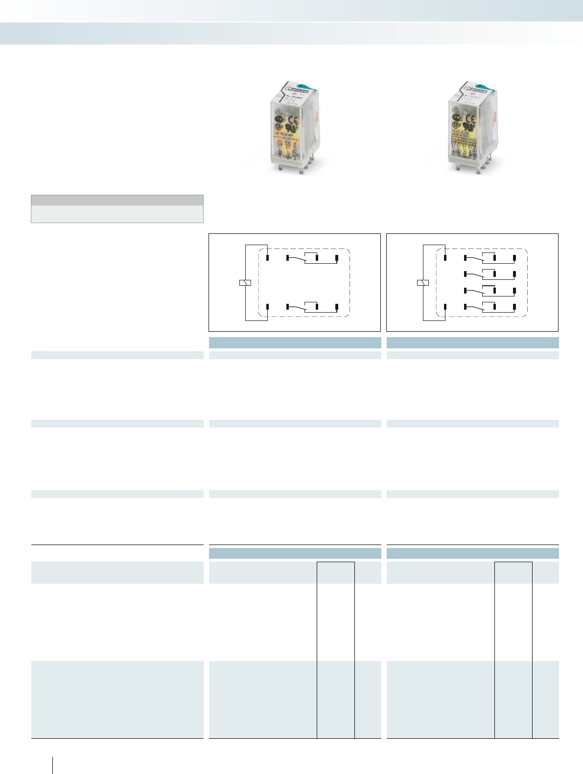
12
A1
11 14
4241 44
A2
12
A1
11 14
2221 24
3231 34
4241 44
A2
344
PHOENIX CONTACT
Plug-in industrial relays
Plug-in industrial relays with 2 or 4 PDT
contacts, suitable for RIF-2 and PR2 relay
bases.
The advantages:
– With detectable manual operation
– Mechanical switch position indicator
– Integrated status LED
– Multi-layer gold contact or power contact
– DC types with integrated freewheeling
diode
Notes:
For other voltages, see
phoenixcontact.net/products
Technical data Technical data
Input data ① ② ③ ④ ⑤ ⑥ ⑦ ⑧ ① ② ③ ④ ⑤ ⑥ ⑦ ⑧
Permissible range (with reference to U
N
) see diagram see diagram
Typ. input current at U
N
[mA] 78 42 8 7.7 4 66 13 6.5 78 42 8 7.7 4 66 13 6.5
Typ. response time at U
N
[ms] 13 13 13 13 13 13 13 13 13 13
Typ. response time at U
N
(depending on phase relation)
[ms] 5 - 15 5 - 15 5 - 15 5 - 15 5 - 15 5 - 15
Typ. release time at U
N
[ms] 14 14 14 14 14 14 14 14 14 14
Typ. release time at U
N
(depending on phase relation)
[ms] 5 - 20 5 - 20 5 - 20 5 - 20 5 - 20 5 - 20
Output data
Contact type 2 PDT 4 PDTs 4 PDTs
Contact material AgNi AgNi AgNi, hard gold-plated
Max. switching voltage 250 V AC/DC 250 V AC/DC 30 V AC / 36 V DC
Min. switching voltage 5 V (at 24 mA) 5 V (at 24 mA) 5 V (at 24 mA)
Limiting continuous current 12 A 6 A 50 mA
Max. inrush current, AC 30 A (20 ms, N/O contact) 16 A (20 ms, N/O contact) 50 mA
Max. inrush current, DC 30 A (20 ms, N/O contact) 16 A (20 ms, N/O contact) 50 mA
Min. switching current 5 mA (at 24 V) 5 mA (at 24 V) -
General data
Test voltage (winding/contact) 2.5 kV
rms
(50 Hz, 1 min.) 2.5 kV
rms
(50 Hz, 1 min.)
Ambient temperature (operation), AC -40 °C ... 55 °C -40 °C ... 55 °C
Ambient temperature (operation), DC -40 °C ... 70 °C -40 °C ... 70 °C
Mechanical service life, AC Approx. 2 x 10
7
cycles Approx. 2 x 10
7
cycles
Mechanical service life, DC Approx. 2 x 10
7
cycles Approx. 2 x 10
7
cycles
Standards/regulations IEC 60664 IEC 60664
Ordering data Ordering data
Description Input voltage
U
N
Type Order No. Pcs. /
Pkt. Type Order No. Pcs. /
Pkt.
Plug-in industrial relay, with power contacts
With freewheeling diode ①12 V DC REL-IR2/LDP- 12DC/2X21 2903659 10 REL-IR4/LDP- 12DC/4X21 2903676 10
With freewheeling diode ②24 V DC REL-IR2/LDP- 24DC/2X21 2903660 10 REL-IR4/LDP- 24DC/4X21 2903677 10
With freewheeling diode ③110 V DC REL-IR2/LDP-110DC/2X21 2903663 10 REL-IR4/LDP-110DC/4X21 2903680 10
With freewheeling diode ④125 V DC REL-IR2/LDP-125DC/2X21 2903664 10 REL-IR4/LDP-125DC/4X21 2903681 10
With freewheeling diode ⑤220 V DC REL-IR2/LDP-220DC/2X21 2903665 10 REL-IR4/LDP-220DC/4X21 2903682 10
⑥24 V AC REL-IR2/L- 24AC/2X21 2903666 10 REL-IR4/L- 24AC/4X21 2903686 10
⑦120 V AC REL-IR2/L-120AC/2X21 2903667 10 REL-IR4/L-120AC/4X21 2903687 10
⑧230 V AC REL-IR2/L-230AC/2X21 2903668 10 REL-IR4/L-230AC/4X21 2903688 10
Plug-in industrial relay, with multi-layer gold contacts
With freewheeling diode ①12 V DC REL-IR4/LDP- 12DC/4X21AU 2903669 10
With freewheeling diode ②24 V DC REL-IR4/LDP- 24DC/4X21AU 2903670 10
With freewheeling diode ③110 V DC REL-IR4/LDP-110DC/4X21AU 2903673 10
With freewheeling diode ④125 V DC REL-IR4/LDP-125DC/4X21AU 2903674 10
With freewheeling diode ⑤220 V DC REL-IR4/LDP-220DC/4X21AU 2903675 10
⑥24 V AC REL-IR4/L- 24AC/4X21AU 2903683 10
⑦120 V AC REL-IR4/L-120AC/4X21AU 2903684 10
⑧230 V AC REL-IR4/L-230AC/4X21AU 2903685 10
Relay modules
Industrial relay system with push-in connection - RIFLINE complete
2 PDT relay 4 PDT relay

0,6
0,8
1
1,2
1,4
1,6
1,8
2
2,2
2,4
0102030405060 70 80
0,1
0,2
0,3
0,5
1
2
4
6
10
20
10203050 70 100 300200
1
0,9
0,3
0,4
0,5
0,6
0,7
0,8
0,9
1
0,80,70,60,50,40,30,2
0,6
0,8
1
1,2
1,4
1,6
1,8
2
2,2
2,4
0102030405060 70 80
0,1
0,2
0,3
0,5
1
2
4
6
10
20
10203050 70 100 300200
1
0,9
0,3
0,4
0,5
0,6
0,7
0,8
0,9
1
0,80,70,60,50,40,30,2
0123
10
5
10
6
10
7
0123
10
5
10
6
10
7
For further information and full technical data, visit phoenixcontact.net/products
345PHOENIX CONTACT
REL-IR2... (2 PDTs)
Operating voltage range Interrupting rating
Ambient temperature [°C]
Coil voltage U/U
N
DC coils
AC coils
DC, ohmic load
Switching voltage [V]
Switching current [A]
AC, ohmic load
Service life reduction factor
COS j
Reduction factor
REL-IR4... (4 PDTs)
Operating voltage range Interrupting rating
Ambient temperature [°C]
Coil voltage U/U
N
DC coils
AC coils
Switching voltage [V]
Switching current [A]
AC, ohmic load
DC, ohmic load
Service life reduction factor
COS j
Reduction factor
Electrical service life
250 V AC, ohmic load
Cycles
Switching capacity [kVA]
Electrical service life
250 V AC, ohmic load
Cycles
Switching capacity [kVA]
Relay modules
Industrial relay system with push-in connection - RIFLINE complete
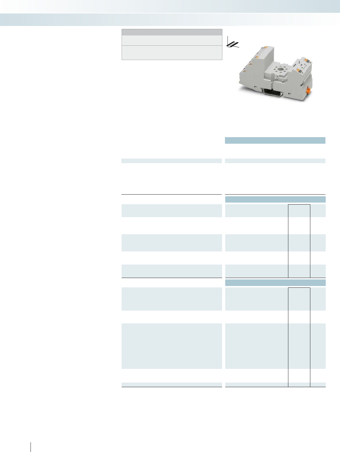
Technical data
Nominal voltage U
N
250 V AC/DC
Nominal current at U
N
max. 12 A (depending on application/assembly) max. 12 A (depending on application/assembly) - -
General data
Ambient temperature (operation) -40 °C ... 85 °C (depending on application/assembly) -40 °C ... 85 °C (depending on application/a
Connection data solid / stranded / AWG 0.14 ... 1.5 mm² / 0.14 ... 1.5 mm² / 26 - 16 0.14 ... 1.5 mm² / 0.14 ... 1.5 mm² / 26 - 16 - -
Dimensions
Width 40 mm
Depth with retaining bracket 90 mm
Height 103 mm
Ordering data
Description Type Order No. Pcs. /
Pkt.
RIF-3 relay base, 2 PDT version, plug-in option for
input/interference suppression module, safe isolation I/O with push-
in connection
RIF-3-BPT/2X21 2900937 10
RIF-3 relay base, 3 PDT version, plug-in option for
input/interference suppression module, safe isolation I/O with
push-in connection
Relay retaining bracket, with holder for marking material, suitable
for RIF-3 relay base
Relay retaining bracket, wire model, suitable for
RIF-3 and PR3 relay base
Accessories
Jumper
2-pos. red, 32 A FBS 2-6 3030336 50
2-pos. red, 24 A FBSR 2-6 3033715 50
2-pos. blue, 32 A FBS 2-6 BU 3036932 50
2-pos. gray, 32 A FBS 2-6 GY 3032237 50
End bracket, for snapping onto NS 35, 9.5 mm wide, can be
marked with ZB 6, ZB 8/27, KLM...
CLIPFIX 35 3022218 50
Test plug, consisting of:
Metal part for 2.3 mm Ø socket hole and silver MPS-MT 0201744 10
Insulating sleeve, for MPS metal part red MPS-IH RD 0201676 10
white MPS-IH WH 0201663 10
blue MPS-IH BU 0201689 10
yellow MPS-IH YE 0201692 10
green MPS-IH GN 0201702 10
gray MPS-IH GY 0201728 10
black MPS-IH BK 0201731 10
Zack marker strip, unprinted
10-section ZB 5 :UNBEDRUCKT 1050004 10
5-section ZB 15:UNBEDRUCKT 0811972 10
Double marker carrier for ZB 5 STP 5-2 0800967 100
346
PHOENIX CONTACT
DW
H
Modular RIF-3 relay base
Notes:
Type of insulating housing:
Polyamide PA non-reinforced, color: gray.
For further marking systems and mounting material,
see Catalog 5.
Relay base that can be fitted with
2 or 3 PDT relays.
Range of accessories includes:
– Plug-in input and interference suppression
module
– Plug-in timer module
– Relay retaining bracket with ejector
function and holder for marking material
– Comprehensive range of marking material
– Test plug
– FBS 2-6 jumpers for the input side (A2)
Relay modules
Industrial relay system with push-in connection - RIFLINE complete
2 PDT relay base for
octal relay
For further information and full technical data, visit phoenixcontact.net/products
Technical data Technical data Technical data
250 V AC/DC - -
max. 12 A (depending on application/assembly) max. 12 A (depending on application/assembly) - -
Ambient temperature (operation) -40 °C ... 85 °C (depending on application/assembly) -40 °C ... 85 °C (depending on application/assembly) - -
Connection data solid / stranded / AWG 0.14 ... 1.5 mm² / 0.14 ... 1.5 mm² / 26 - 16 0.14 ... 1.5 mm² / 0.14 ... 1.5 mm² / 26 - 16 - -
40 mm - -
90 mm - -
103 mm - -
Ordering data Ordering data Ordering data
Type Order No. Pcs. /
Pkt. Type Order No. Pcs. /
Pkt. Type Order No. Pcs. /
Pkt.
RIF-3-BPT/3X21 2900938 10
RIF-RH-3 2900955 10
EL3-M52 2833628 10
Accessories Accessories Accessories
FBS 2-6 3030336 50
FBSR 2-6 3033715 50
FBS 2-6 BU 3036932 50
FBS 2-6 GY 3032237 50
CLIPFIX 35 3022218 50
MPS-MT 0201744 10
MPS-IH RD 0201676 10
MPS-IH WH 0201663 10
MPS-IH BU 0201689 10
MPS-IH YE 0201692 10
MPS-IH GN 0201702 10
MPS-IH GY 0201728 10
MPS-IH BK 0201731 10
ZB 5 :UNBEDRUCKT 1050004 10
ZB 15:UNBEDRUCKT 0811972 10
STP 5-2 0800967 100
347PHOENIX CONTACT
DW
H
Relay modules
Industrial relay system with push-in connection - RIFLINE complete
3 PDT relay base for
octal relay
Relay retaining bracket Relay retaining bracket
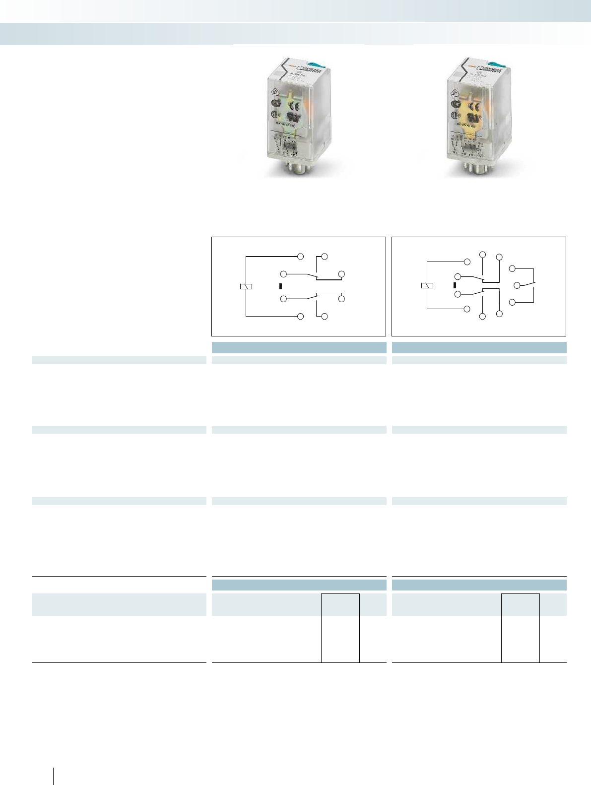
(11)
2 3
4
5
67
8
1
(21)
(A1)
(14)
(12)
(22)
(A2)
(24)
34
5
6
7
8
1
9
11
2
10
(11)
(31)
(A1)
(14)
(22)
(24)
(A2)
(32)
(12)
(21)
(34)
348
PHOENIX CONTACT
Plug-in octal relays
Plug-in octal relays with 2 or 3 PDT
contacts, suitable for RIF-3 and PR3 relay
bases.
The advantages:
– With detectable manual operation
– Mechanical switch position indicator
– Integrated status LED
– DC types with integrated freewheeling
diode
Technical data Technical data
Input data ① ② ③ ④ ① ② ③ ④
Permissible range (with reference to U
N
) see diagram see diagram
Typ. input current at U
N
[mA] 60 108 23 13 60 108 23 13
Typ. response time at U
N
[ms] 18 18
Typ. response time at U
N
(depending on phase relation)
[ms] 5 - 15 5 - 15 5 - 15 5 - 15 5 - 15 5 - 15
Typ. release time at U
N
[ms]
Typ. release time at U
N
(depending on phase relation)
[ms] 5 - 20 5 - 20 5 - 20 5 - 20 5 - 20 5 - 20
Output data
Contact type 2 PDTs 3 PDTs
Contact material AgNi AgNi
Max. switching voltage 250 V AC/DC 250 V AC/DC
Min. switching voltage 10 V (at 24 mA) 10 V (at 24 mA)
Limiting continuous current 10 A 10 A
Max. inrush current, AC 30 A (20 ms, N/O contact) 30 A (20 ms, N/O contact)
Max. inrush current, DC 30 A (20 ms, N/O contact) 30 A (20 ms, N/O contact)
Min. switching current 10 mA (at 24 V) 10 mA (at 24 V)
General data
Test voltage (winding/contact) 2.5 kV
rms
(50 Hz, 1 min.) 2.5 kV
rms
(50 Hz, 1 min.)
Ambient temperature (operation), AC -40 °C ... 55 °C -40 °C ... 55 °C
Ambient temperature (operation), DC -40 °C ... 70 °C -40 °C ... 70 °C
Nominal operating mode 100% operating factor 100% operating factor
Mechanical service life, AC Approx. 2 x 10
7
cycles Approx. 2 x 10
7
cycles
Mechanical service life, DC Approx. 2 x 10
7
cycles Approx. 2 x 10
7
cycles
Standards/regulations IEC 60664 IEC 60664
Mounting position / mounting any any
Dimensions W / H / D 35 mm / 54.4 mm / 35 mm 35 mm / 54.4 mm / 35 mm
Ordering data Ordering data
Description Input voltage
U
N
Type Order No. Pcs. /
Pkt. Type Order No. Pcs. /
Pkt.
Plug-in octal relay, with power contacts
With freewheeling diode ①24 V DC REL-OR2/LDP- 24DC/2X21 2903689 10 REL-OR3/LDP-24DC/3X21 2903693 10
②24 V AC REL-OR2/L- 24AC/2X21 2903690 10 REL-OR3/L- 24AC/3X21 2903694 10
③120 V AC REL-OR2/L-120AC/2X21 2903691 10 REL-OR3/L-120AC/3X21 2903695 10
④230 V AC REL-OR2/L-230AC/2X21 2903692 10 REL-OR3/L-230AC/3X21 2903696 10
Relay modules
Industrial relay system with push-in connection - RIFLINE complete
2 PDT relay 3 PDT relay

0,6
0,8
1,0
1,2
1,4
1,6
1,8
0102030405060 70 80
0,1
0,2
0,3
0,5
1
2
4
6
10
20
10203050 70 100 300200
1
0,9
0,3
0,4
0,5
0,6
0,7
0,8
0,9
1
0,80,70,60,50,40,30,2
0,6
0,8
1,0
1,2
1,4
1,6
1,8
0102030405060 70 80
0,1
0,2
0,3
0,5
1
2
4
6
10
20
10203050 70 100 300200
1
0,9
0,3
0,4
0,5
0,6
0,7
0,8
0,9
1
0,80,70,60,50,40,30,2
0 0,20,40,60,8 1,0 1,21,41,61,8 2,0 2,22,42,6
10
4
10
5
10
5
10
6
10
7
0 0,20,40,60,8 1,0 1,21,41,61,8 2,0 2,22,42,6
10
4
10
5
10
5
10
6
10
7
For further information and full technical data, visit phoenixcontact.net/products
349PHOENIX CONTACT
REL-OR2... (2 PDTs)
Operating voltage range Interrupting rating
Ambient temperature [°C]
Coil voltage U/U
N
DC coils
AC coils
Switching voltage [V]
Switching current [A]
AC, ohmic load
DC, ohmic load
Service life reduction factor
COS j
Reduction factor
REL-OR3... (3 PDTs)
Operating voltage range Interrupting rating
Ambient temperature [°C]
Coil voltage U/U
N
DC coils
AC coils
Switching voltage [V]
Switching current [A]
AC, ohmic load
DC, ohmic load
Service life reduction factor
COS j
Reduction factor
Electrical service life
250 V AC, ohmic load
Cycles
Switching capacity [kVA]
Electrical service life
250 V AC, ohmic load
Cycles
Switching capacity [kVA]
Relay modules
Industrial relay system with push-in connection - RIFLINE complete
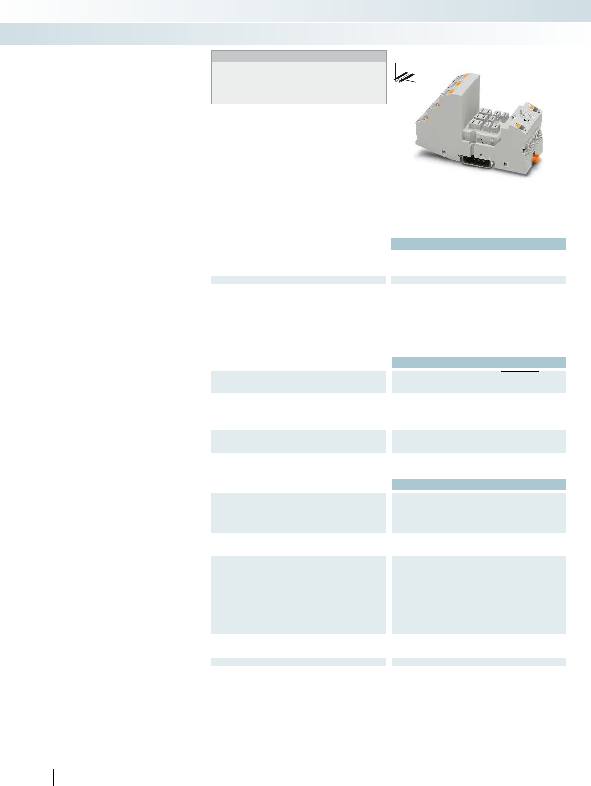
Technical data
Nominal voltage U
N
440 V AC
Nominal current at U
N
max. 16 A (depending on application/assembly) - -
General data
Ambient temperature (operation) -40 °C ... 85 °C (depending on application/assembly) - -
Connection data solid / stranded / AWG
Input side 0.14 ... 1.5 mm² / 0.14 ... 1.5 mm² / 26 - 16 - -
Output side 0.14 ... 2.5 mm² / 0.14 ... 2.5 mm² / 26 - 14 - -
Dimensions
Width 43 mm
Depth with retaining bracket 90 mm
Height 111 mm
Ordering data
Description Type Order No. Pcs. /
Pkt.
RIF-4 relay base, plug-in option for input/interference suppression
module, safe isolation I/O with push-in connection
RIF-4-BPT/3X21 2900961 10
Relay retaining bracket, with holder for marking material, suitable
for RIF-4 relay base
Relay retaining bracket, wire model, suitable for RIF-4 relay base
Accessories
Jumper
2-pos. red, 32 A FBS 2-6 3030336 50
2-pos. red, 24 A FBSR 2-6 3033715 50
2-pos. blue, 32 A FBS 2-6 BU 3036932 50
2-pos. gray, 32 A FBS 2-6 GY 3032237 50
End bracket, for snapping onto NS 35, 9.5 mm wide, can be
marked with ZB 6, ZB 8/27, KLM...
CLIPFIX 35 3022218 50
Test plug, consisting of:
Metal part for 2.3 mm Ø socket hole and silver MPS-MT 0201744 10
Insulating sleeve, for MPS metal part red MPS-IH RD 0201676 10
white MPS-IH WH 0201663 10
blue MPS-IH BU 0201689 10
yellow MPS-IH YE 0201692 10
green MPS-IH GN 0201702 10
gray MPS-IH GY 0201728 10
black MPS-IH BK 0201731 10
Zack marker strip, unprinted
10-section ZB 5 :UNBEDRUCKT 1050004 10
5-section ZB 15:UNBEDRUCKT 0811972 10
Double marker carrier for ZB 5 STP 5-2 0800967 100
350
PHOENIX CONTACT
DW
H
Modular RIF-4 relay base
Notes:
Type of insulating housing:
Polyamide PA non-reinforced, color: gray.
For further marking systems and mounting material,
see Catalog 5.
Relay base that can be fitted with
2 or 3 PDT relays or 3 N/O relays.
Range of accessories includes:
– Plug-in input and interference suppression
module
– Plug-in timer module
– Relay retaining bracket with ejector
function and holder for marking material
– Comprehensive range of marking material
– Test plug
– FBS 2-6 jumpers for the input side (A2)
Relay modules
Industrial relay system with push-in connection - RIFLINE complete
3 PDT relay base for
high-power relay

For further information and full technical data, visit phoenixcontact.net/products
Technical data Technical data
--
max. 16 A (depending on application/assembly) - -
Ambient temperature (operation) -40 °C ... 85 °C (depending on application/assembly) - -
Input side 0.14 ... 1.5 mm² / 0.14 ... 1.5 mm² / 26 - 16 - -
Output side 0.14 ... 2.5 mm² / 0.14 ... 2.5 mm² / 26 - 14 - -
--
--
--
Ordering data Ordering data
Type Order No. Pcs. /
Pkt. Type Order No. Pcs. /
Pkt.
RIF-RH-4 2900956 10
RIF-RHM-4 2905983 10
Accessories Accessories
351PHOENIX CONTACT
Relay modules
Industrial relay system with push-in connection - RIFLINE complete
Relay retaining bracket Relay retaining bracket

12
A1
11 14
3231 34
A2
12
A1
11 14
2221 24
3231 34
A2
352
PHOENIX CONTACT
Plug-in high-power relays
Plug-in high-power relays with 2 or 3 PDT
contacts for the RIF-4 relay base.
The advantages:
– Use in miniature contactor applications
– Switching current of up to 16 A
– Up to 440 V AC switching voltage
Technical data Technical data
Input data ① ② ③ ④ ① ② ③ ④
Permissible range (with reference to U
N
) see diagram see diagram
Typ. input current at U
N
[mA] 56 116 23 12 56 116 23 12
Typ. response time at U
N
[ms] 20 20
Typ. response time at U
N
(depending on phase relation)
[ms] 5 - 25 5 - 25 5 - 25 5 - 25 5 - 25 5 - 25
Typ. release time at U
N
[ms] 15 15
Typ. release time at U
N
(depending on phase relation)
[ms] 5 - 20 5 - 20 5 - 20 5 - 20 5 - 20 5 - 20
Output data
Contact type 2 PDTs 3 PDTs
Contact material AgNi AgNi
Max. switching voltage 440 V AC / 250 V DC 440 V AC / 250 V DC
Min. switching voltage 10 V (at 24 mA) 10 V (at 24 mA)
Limiting continuous current 16 A 16 A
Max. inrush current, AC 50 A (20 ms, N/O contact) 50 A (20 ms, N/O contact)
Max. inrush current, DC 50 A (20 ms, N/O contact) 50 A (20 ms, N/O contact)
Min. switching current 10 mA (at 24 V) 10 mA (at 24 V)
Max. interrupting rating, ohmic load
250 V AC 4000 VA 4000 VA
440 V AC 4000 VA 4000 VA
Motor load according to UL 508 1/3 HP, 120 V AC (single-phase AC motor)
1/2 HP, 240 V AC (single-phase AC motor)
1/3 HP, 120 V AC (single-phase AC motor)
1/2 HP, 240 V AC (single-phase AC motor)
1/2 HP, 240 V AC (three-phase induction motor)
General data
Test voltage (winding/contact) 2.5 kV
rms
(50 Hz, 1 min.) 2.5 kV
rms
(50 Hz, 1 min.)
Ambient temperature (operation), AC -40 °C ... 55 °C -40 °C ... 55 °C
Ambient temperature (operation), DC -40 °C ... 70 °C -40 °C ... 70 °C
Nominal operating mode 100% operating factor 100% operating factor
Mechanical service life, AC Approx. 10
7
cycles Approx. 10
7
cycles
Mechanical service life, DC Approx. 10
7
cycles Approx. 10
7
cycles
Standards/regulations IEC 60664 IEC 60664
Mounting position / mounting any any
Dimensions W / H / D 38.6 mm / 45.5 mm / 36.1 mm 38.6 mm / 45.5 mm / 36.1 mm
Ordering data Ordering data
Description Input voltage
U
N
Type Order No. Pcs. /
Pkt. Type Order No. Pcs. /
Pkt.
Plug-in high-power relay, 2 PDTs with power contacts
①24 V DC REL-PR2- 24DC/2X21 2903698 1
②24 V AC REL-PR2- 24AC/2X21 2903699 1
③120 V AC REL-PR2-120AC/2X21 2903700 1
④230 V AC REL-PR2-230AC/2X21 2903701 1
Plug-in high-power relay, 3 PDTs with power contacts
①24 V DC REL-PR3- 24DC/3X21 2903702 1
②24 V AC REL-PR3- 24AC/3X21 2903703 1
③120 V AC REL-PR3-120AC/3X21 2903704 1
④230 V AC REL-PR3-230AC/3X21 2903705 1
Relay modules
Industrial relay system with push-in connection - RIFLINE complete
2 PDT relay 3 PDT relay
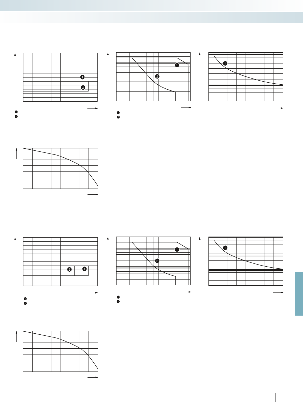
0,6
0,8
1,0
1,2
1,4
1,6
1,8
0102030405060 70 80
0,1
0,2
0,3
0,5
10
20
10203050 70 100 300200 500
1
2
5
1
0,9
0,3
0,4
0,5
0,6
0,7
0,8
0,9
1
0,80,70,60,50,40,30,2
0,6
0,8
1,0
1,2
1,4
1,6
1,8
0102030405060 70 80
0,1
0,2
0,3
0,5
10
20
10203050 70 100 300200 500
1
2
5
1
0,9
0,3
0,4
0,5
0,6
0,7
0,8
0,9
1
0,80,70,60,50,40,30,2
01234
10
4
10
5
10
5
10
6
10
7
01234
10
4
10
5
10
5
10
6
10
7
For further information and full technical data, visit phoenixcontact.net/products
353PHOENIX CONTACT
REL-PR2... (2 PDTs)
Operating voltage range Interrupting rating
Ambient temperature [°C]
Coil voltage U/U
N
Maximum continuous voltage at limiting continuous current = 16A
Minimum operate voltage
For pre-excitation with UN and limiting continuous current = 16A
Switching voltage [V]
Switching current [A]
AC, ohmic load
DC, ohmic load
Service life reduction factor
COS j
Reduction factor
REL-PR3... (3 PDTs)
Operating voltage range Interrupting rating
Ambient temperature [°C]
Coil voltage U/U
N
DC coils
AC coils
Switching voltage [V]
Switching current [A]
AC, ohmic load
DC, ohmic load
Service life reduction factor
COS j
Reduction factor
Electrical service life
250 V AC, ohmic load
Cycles
Switching capacity [kVA]
Electrical service life
250 V AC, ohmic load
Cycles
Switching capacity [kVA]
Relay modules
Industrial relay system with push-in connection - RIFLINE complete

A1
11 14
21 24
31 34
A2
354
PHOENIX CONTACT
Plug-in high-power relays
Plug-in high-power relays with 3 N/O
contacts suitable for the RIF-4 relay base.
The advantages:
– Use in miniature contactor applications
– Switching current of up to 16 A
– Up to 440 V AC switching voltage
– Full shutdown by means of ≥ 3 mm
contact opening
Technical data
Input data ① ② ③ ④
Permissible range (with reference to U
N
) see diagram
Typ. input current at U
N
[mA] 70 116 23 12
Typ. response time at U
N
[ms] 20
Typ. response time at U
N
(depending on phase relation)
[ms] 5 - 25 5 - 25 5 - 25
Typ. release time at U
N
[ms] 15
Typ. release time at U
N
(depending on phase relation)
[ms] 5 - 20 5 - 20 5 - 20
Output data
Contact type 3 N/O contacts
Contact material AgNi
Max. switching voltage 440 V AC / 250 V DC
Min. switching voltage 10 V (at 24 mA)
Limiting continuous current 16 A
Max. inrush current, AC 50 A (20 ms, N/O contact)
Max. inrush current, DC 50 A (20 ms, N/O contact)
Min. switching current 10 mA (at 24 V)
Max. interrupting rating, ohmic load
250 V AC 4000 VA
440 V AC 4000 VA
Motor load according to UL 508 1/3 HP, 120 V AC (single-phase AC motor)
1/2 HP, 240 V AC (single-phase AC motor)
1/2 HP, 240 V AC (three-phase induction motor)
General data
Test voltage (winding/contact) 2.5 kV
rms
(50 Hz, 1 min.)
Ambient temperature (operation), AC -40 °C ... 55 °C
Ambient temperature (operation), DC -40 °C ... 70 °C
Nominal operating mode 100% operating factor
Mechanical service life, AC Approx. 10
7
cycles
Mechanical service life, DC Approx. 10
7
cycles
Standards/regulations IEC 60664
Mounting position / mounting any
Dimensions W / H / D 38.6 mm / 45.5 mm / 36.1 mm
Ordering data
Description Input voltage
U
N
Type Order No. Pcs. /
Pkt.
Plug-in high-power relay, 3 N/O contacts with power contacts
①24 V DC REL-PR3- 24DC/3X1 2903706 1
②24 V AC REL-PR3- 24AC/3X1 2903707 1
③120 V AC REL-PR3-120AC/3X1 2903708 1
④230 V AC REL-PR3-230AC/3X1 2903709 1
Relay modules
Industrial relay system with push-in connection - RIFLINE complete
3 N/O relay
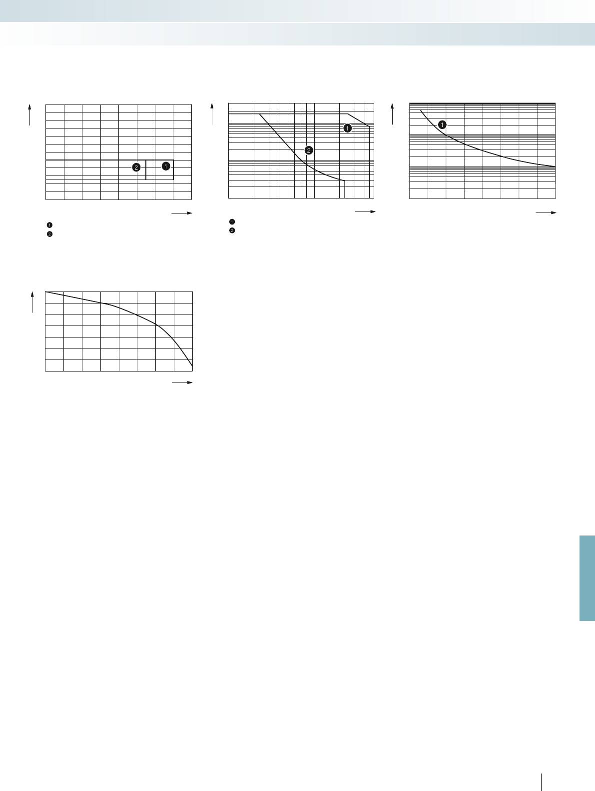
0,6
0,8
1,0
1,2
1,4
1,6
1,8
0102030405060 70 80
0,1
0,2
0,3
0,5
10
20
10203050 70 100 300200 500
1
2
5
1
0,9
0,3
0,4
0,5
0,6
0,7
0,8
0,9
1
0,80,70,60,50,40,30,2
01234
10
4
10
5
10
5
10
6
10
7
For further information and full technical data, visit phoenixcontact.net/products
355PHOENIX CONTACT
REL-PR2... (3 N/O contacts)
Operating voltage range Interrupting rating
Ambient temperature [°C]
Coil voltage U/U
N
DC coils
AC coils
Switching voltage [V]
Switching current [A]
AC, ohmic load
DC, ohmic load
Service life reduction factor
COS j
Reduction factor
Electrical service life
250 V AC, ohmic load
Cycles
Switching capacity [kVA]
Relay modules
Industrial relay system with push-in connection - RIFLINE complete

Ordering data
Description Type Order No. Pcs. /
Pkt.
Plug-in module, with LED status indicator and freewheeling diode
to effectively limit the coil induction voltage, polarity: A1+, A2-,
input voltage:
- 12-24 V DC ±20% RIF-LDP-12-24 DC 2900939 10
- 48-60 V DC ±20% RIF-LDP-48-60 DC 2900940 10
- 110 V DC ±20% RIF-LDP-110 DC 2900941 10
Plug-in module, with LED status indicator and varistor to limit the
coil induction voltage and/or external interference peaks,
input voltage:
- 12-24 V AC/DC ±20% (30 V varistor) RIF-LV-12-24 UC 2900942 10
- 48-60 V AC/DC ±20% (75 V varistor) RIF-LV-48-60 UC 2900943 10
- 120-230 V AC/110 V DC ±20% (275 V varistor) RIF-LV-120-230 AC/110 DC 2900944 10
Plug-in module, with varistor to limit the coil induction voltage
and/or external interference peaks,
input voltage:
- 12-24 V AC/DC ±20% (30 V varistor) RIF-V-12-24 UC 2900945 10
- 48-60 V AC/DC ±20% (75 V varistor) RIF-V-48-60 UC 2900947 10
- 120-230 V AC/110 V DC ±20% (275 V varistor) RIF-V-120-230 UC 2900948 10
Plug-in module, with RC element to limit the coil induction voltage
and/or external interference peaks, input voltage:
- 12-24 V AC/DC ±20% (220 nF/100 )RIF-RC-12-24 UC 2900949 10
- 48-60 V AC/DC ±20% (220 nF/220 )RIF-RC-48-60 UC 2900950 10
- 120 - 230 V AC/110 DC ±20% (100 nF/470 )RIF-RC-120-230 UC 2900951 10
356
PHOENIX CONTACT
Plug-in input modules/interference
suppression modules for optional fitting of
RIF-1 to RIF-4 relay bases.
The advantages:
– Attenuation of reverse voltage induced in
coil
– Mechanical coding to protect against
incorrect connection
Input modules/interference
suppression modules for RIF-1, RIF-2,
RIF-3, and RIF-4
Relay modules
Industrial relay system with push-in connection - RIFLINE complete
Input/interference suppression module

t
A1+
A2-
44
42
34
32
24
22
14
12
11 21 31 41
Tt<T t
U
LED
Tt<T t
U
LED
Tt<T
U
LED
T T t
For further information and full technical data, visit phoenixcontact.net/products
Technical data
Input data
Nominal input voltage U
N
24 V DC (AC operation only permitted for RIF-1)
Nominal input voltage range with reference to U
N
0.4 ... 1.2
Input circuit Varistor, yellow LED
Output data
Limiting continuous current 250 mA (relay coil current)
General data
Mounting position any
Repeat accuracy 1 %
Ambient temperature (operation) -25 °C ... 50 °C (RIF-1, AC coil, 2 PDTs at 6 A)
-25 °C ... 50 °C (RIF-1, DC coil, 2 PDTs at 5 A)
-25 °C ... 40 °C (RIF-2, DC coil, 2 PDTs at 8 A)
-25 °C ... 40 °C (RIF-2, DC coil, 4 PDTs at 5 A)
-25 °C ... 40 °C (RIF-3, DC coil, 3 PDTs at 6.75 A)
-25 °C ... 40 °C (RIF-3, DC coil, 2 PDTs at 8 A)
-25 °C ... 35 °C (RIF-4, DC coil, 3 PDTs at 8 A)
-25 °C ... 25 °C (RIF-4, DC coil, 3 N/O contacts at 8 A)
Standards/specifications DIN EN 50178
Rated insulation voltage 50 V DC
Rated surge voltage 0.4 kV
Ordering data
Description Type Order No. Pcs. /
Pkt.
Timer module, for mounting on RIF-1 to RIF-4, with LED status
indicator for extending a relay module to create a timer relay with an
input voltage of 24 V AC/DC
RIF-T3-24UC 2902647 1
357
PHOENIX CONTACT
Timer relay
Relay modules
Industrial relay system with push-in connection - RIFLINE complete
Timer module
With switch-on delay
With passing make contact
Flasher/pulse generator
Plug-in timer module for
RIF-1, RIF-2, RIF-3, and RIF-4
The multifunctional plug-in timer module
transforms the relay module into a timer
relay. The RIF-1 to RIF-4 bases can be fitted
with this module. Using DIP switches, you
can choose from three time ranges and
select four time functions. Fine adjustments
to the time are made using a potentiometer.
Relays can be operated with an input
voltage of 24 V AC/DC.
Functions:
– With switch-on delay
– With passing make contact
– Flasher/pulse generator
Time ranges:
– 0.5 s - 10 s
– 5 s - 100 s
– 0.5 min - 10 min
– 5 min - 100 min
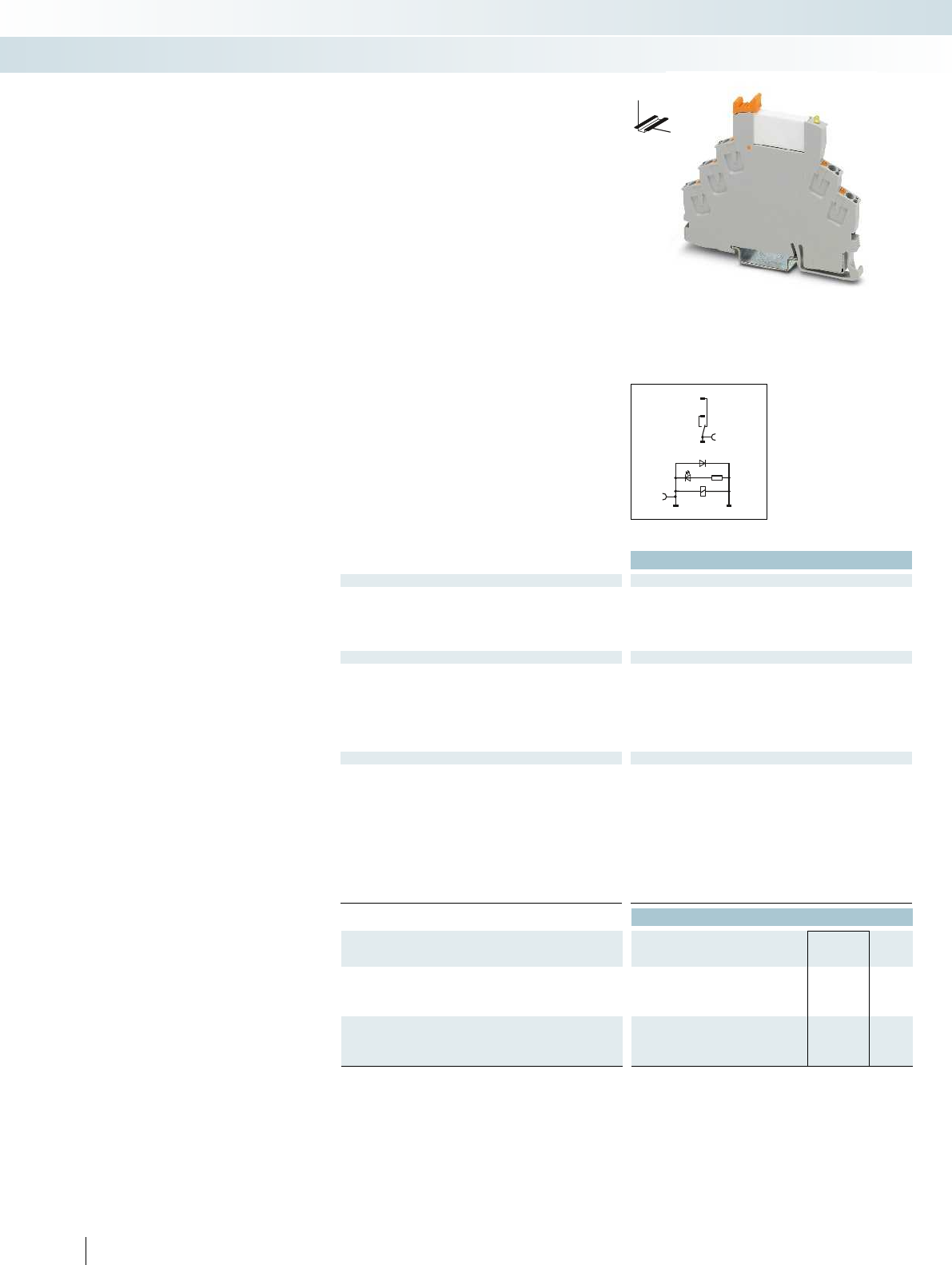
12
A1+A2-
14
11
Technical data
Input data ① ②
Permissible range (with reference to U
N
) see diagram
Typ. input current at U
N
[mA] 16 9
Typ. response time at U
N
[ms] 5 5
Typ. release time at U
N
[ms] 8 8
Input protection: Yellow LED, freewheeling diode Yellow LED, freewheeling diode
Output data
Contact type 1 PDT 1 PDT 1 N/O contact 1 N/O contact
Contact material AgSnO AgSnO, hard gold-plated AgSnO AgSnO, hard gold-plated
Max. switching voltage 250 V AC/DC 30 V AC / 36 V DC 250 V AC/DC 30 V AC / 36 V DC
Min. switching voltage 5 V (at 100 mA) 100 mV (at 10 mA) 5 V (at 100 mA) 100 mV (at 10 mA)
Limiting continuous current 6 A 50 mA 6 A 50 mA
Min. switching current 10 mA (at 12 V) 1 mA 10 mA (at 12 V) 1 mA (at 12 V)
General data
Test voltage (winding/contact) 4 kV
rms
(50 Hz, 1 min.) 4 kV
Ambient temperature (operation) -40 °C ... 60 °C
Nominal operating mode 100% operating factor 100% operating factor
Mechanical service life Approx. 2 x 10
7
cycles Approx. 2 x 10
Standards/regulations DIN EN 50178, IEC 62103 DIN EN 50178, IEC 62103
Pollution degree / surge voltage category 2 / III
Mounting position / mounting any / can be aligned without spacing any / can be aligned without spacing
Connection data solid / stranded / AWG 0.14 - 1.5 mm² / 0.14 - 1.5 mm² / 26 - 16 0.14 - 1.5 mm² / 0.14 - 1.5 mm² / 26 - 16
Dimensions W / H / D 6.2 mm / 93 mm / 78 mm 6.2 mm / 93 mm / 66 mm
EMC note Class A product, see page 625 Class A product, see page 625
Ordering data
Description Input voltage
U
N
Type Order No. Pcs. /
Pkt.
Coupling relay modules with power contact relay and
push-in connection
①12 V DC RIF-0-RPT-12DC/21 2903371 10
②24 V DC RIF-0-RPT-24DC/21 2903370 10
Coupling relay modules with power contact relay, gold contacts,
and push-in connection
①12 V DC RIF-0-RPT-12DC/21AU 2903369 10
②24 V DC RIF-0-RPT-24DC/21AU 2903368 10
358
PHOENIX CONTACT
DC coils
DW
H
Fully mounted RIF-0 relay modules
Fully mounted RIF-0 relay modules,
consisting of:
– Relay base with push-in connection
– 1 N/O contact or 1 PDT relay
– Relay ejector lever on the housing
The advantages:
– Status LED integrated in the relay base
– Operational reliability thanks to sealed
relay
– Safe isolation between coil and contact
side
– Professional bridging of adjacent modules
saves wiring time
– For FBS 2-6 jumpers for the input and
output side, see page 374.
Relay modules
Industrial relay system with push-in connection - RIFLINE complete
RIF-0 relay module with
1 PDT relay

0,6
0,7
0,8
0,9
1,0
1,1
1,2
1,3
1,4
1,5
1,6
1,7
1,8
2030405060 70 80
0,1
0,2
0,3
0,5
1
2
4
10
20
1020305070100 300200
1
2
1
2
6
1
0,9
0,3
0,4
0,5
0,6
0,7
0,8
0,9
1
0,80,70,60,50,40,30,2
106
105
02468
104
1
1
0,6
0,7
0,8
0,9
1,0
1,1
1,2
1,3
1,4
1,5
1,6
1,7
1,8
2030405060 70 80
0,1
0,2
0,3
0,5
1
2
4
10
20
1020305070100 300200
1
2
1
2
6
1
0,9
0,3
0,4
0,5
0,6
0,7
0,8
0,9
1
0,80,70,60,50,40,30,2
106
105
02468
104
1
1
A2- A1+
14
13
For further information and full technical data, visit phoenixcontact.net/products
Technical data
① ②
see diagram
16 9
55
88
Input protection: Yellow LED, freewheeling diode Yellow LED, freewheeling diode
Contact type 1 PDT 1 PDT 1 N/O contact 1 N/O contact
Contact material AgSnO AgSnO, hard gold-plated AgSnO AgSnO, hard gold-plated
Max. switching voltage 250 V AC/DC 30 V AC / 36 V DC 250 V AC/DC 30 V AC / 36 V DC
Min. switching voltage 5 V (at 100 mA) 100 mV (at 10 mA) 5 V (at 100 mA) 100 mV (at 10 mA)
Limiting continuous current 6 A 50 mA 6 A 50 mA
Min. switching current 10 mA (at 12 V) 1 mA 10 mA (at 12 V) 1 mA (at 12 V)
(50 Hz, 1 min.) 4 kV
rms
(50 Hz, 1 min.)
-40 °C ... 60 °C
Nominal operating mode 100% operating factor 100% operating factor
cycles Approx. 2 x 10
7
cycles
Standards/regulations DIN EN 50178, IEC 62103 DIN EN 50178, IEC 62103
2 / III
Mounting position / mounting any / can be aligned without spacing any / can be aligned without spacing
Connection data solid / stranded / AWG 0.14 - 1.5 mm² / 0.14 - 1.5 mm² / 26 - 16 0.14 - 1.5 mm² / 0.14 - 1.5 mm² / 26 - 16
Dimensions W / H / D 6.2 mm / 93 mm / 78 mm 6.2 mm / 93 mm / 66 mm
EMC note Class A product, see page 625 Class A product, see page 625
Ordering data
Type Order No. Pcs. /
Pkt.
RIF-0-RPT-12DC/ 1 2903362 10
RIF-0-RPT-24DC/ 1 2903361 10
RIF-0-RPT-12DC/ 1AU 2903360 10
RIF-0-RPT-24DC/ 1AU 2903359 10
359
PHOENIX CONTACT
RIF-0-RPT.../21... (1 PDT)
Operating voltage range Interrupting rating
Ambient temperature [°C]
Coil voltage U/U
N
Maximum continuous voltage at limiting continuous current=6A
Minimum operate voltage
For pre-excitation with U and limiting continuous current = 6 A
N
AC, ohmic load
DC, ohmic load
Switching voltage [V]
Switching current [A]
Service life reduction factor Electrical service life
COS j
Reduction factor
Cycles
Switching current [A]
250 V AC, ohmic load
RIF-0-RPT.../1... (1 N/O contact)
Operating voltage range Interrupting rating
Ambient temperature [°C]
Coil voltage U/U
N
Maximum continuous voltage at limiting continuous current=6A
Minimum operate voltage
For pre-excitation with U and limiting continuous current = 6 A
N
AC, ohmic load
DC, ohmic load
Switching voltage [V]
Switching current [A]
Service life reduction factor Electrical service life
COS j
Reduction factor
Cycles
Switching current [A]
250 V AC, ohmic load
DC coils
DW
H
Relay modules
Industrial relay system with push-in connection - RIFLINE complete
RIF-0 relay module with
1 N/O relay
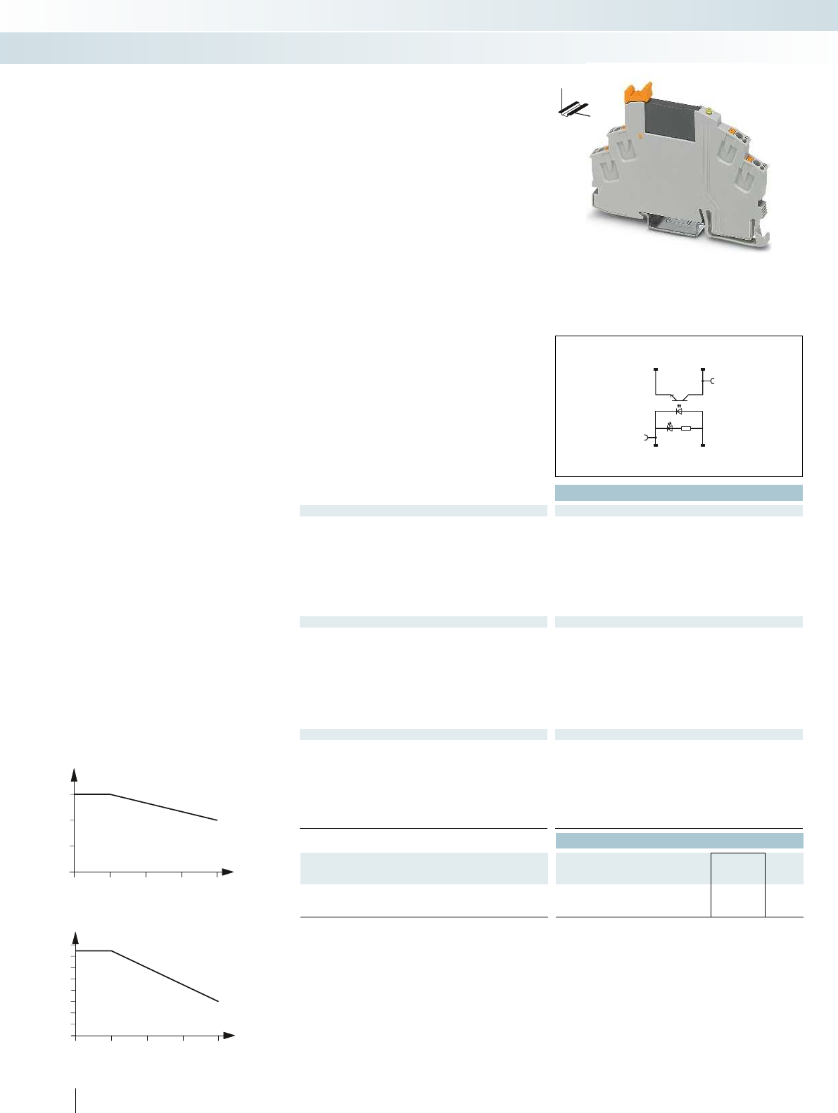
30
20405060
0
0,1
0,2
0,3
0,4
0,5
0,6
0,7
0,8
30
20405060
0
1
2
3
14 13+
A2- A1+
Technical data
Input data ①
Rated actuating voltage range with reference to U
C
0.8 -
1.2
Rated actuating current I
C
[mA] 8.5
Switching level (with reference to U
C
) 1 signal ("H") > 0.8
0 signal ("L") < 0.4
Typ. switch-on time at U
N
[ms] 0.02
Typ. shutdown time at U
N
[ms] 0.3
Transmission frequency f
limit
[Hz] 300
Input circuit DC Yellow LED, freewheeling diode Yellow LED, freewheeling diode Yellow LED, freewheeling diode
Output data
Max. switching voltage 33 V DC
Min. switching voltage 3 V DC
Max. inrush current 15 A (10 ms)
Min. / max. switching current - / 3 A (see derating curve) - / 100 mA 10 mA / 0.75 A (see derating curve)
Output protection Protection against polarity reversal, surge protection Protection against polarity reversal, surge protection RC
Voltage drop at max. limiting continuous current < 200 mV
Leakage current in off state -
Phase angle (cos )-
Max. load value -
General data
Test voltage input/output 2.5 kV
rms
(50 Hz, 1 min.) 2.5 kV
Ambient temperature (operation) -25 °C ... 60 °C
Standards/regulations DIN EN 50178
Pollution degree / surge voltage category 2 / III
Connection data solid / stranded / AWG 0.14 - 1.5 mm² / 0.14 - 1.5 mm² / 26 - 16 0.14 - 1.5 mm² / 0.14 - 1.5 mm² / 26 - 16 0.14 - 1.5
Dimensions W / H / D 6.2 mm / 93 mm / 66 mm 6.2 mm / 93 mm / 66 mm 6.2 mm / 93 mm / 66 mm
EMC note Class A product, see page 625 Class A product, see page 625 Class A product, see page 625
Ordering data
Description Rated actuating voltage
U
C
Type Order No. Pcs. /
Pkt.
Coupling relay modules with solid-state relay and push-in
connection
①24 V DC RIF-0-OPT-24DC/24DC/2 2905293 10
360
PHOENIX CONTACT
Fully mounted RIF-0 relay modules
Fully mounted RIF-0 relay modules,
consisting of:
– Relay base with push-in connection
– Solid-state relay
– Relay ejector lever on the housing
The advantages:
– Status LED integrated into the base
– RTIII sealed solid-state relay
– Zero voltage switch at AC output
– Professional bridging of adjacent modules
saves wiring time
Ambient temperature [°C]
Load current [A]
Derating curve for RIF-0-OPT-24DC/230AC/1
Ambient temperature [°C]
Load current [A]
Derating curve for RIF-0-OPT-24DC/24DC/2
Relay modules
Industrial relay system with push-in connection - RIFLINE complete
DW
H
Max. DC voltage output of 3 A Max. DC voltage output of 100 mA Max. AC voltage output of 750 mA
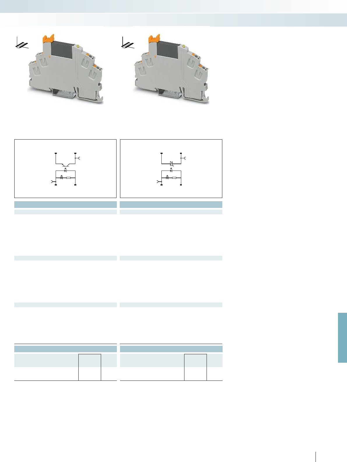
14 13+
A2- A1+
14 13+
A2- A1+
For further information and full technical data, visit phoenixcontact.net/products
Technical data Technical data
① ①
0.8 -
1.2
0.8 -
1.2
8.5 8
> 0.8 > 0.8
< 0.4 < 0.4
0.02 10
0.3 10
300 10
Input circuit DC Yellow LED, freewheeling diode Yellow LED, freewheeling diode Yellow LED, freewheeling diode
48 V DC 253 V AC
3 V DC 24 V AC
- 30 A (10 ms)
curve) - / 100 mA 10 mA / 0.75 A (see derating curve)
Output protection Protection against polarity reversal, surge protection Protection against polarity reversal, surge protection RCV circuit
< 1 V < 1 V
- 1 mA (in off state)
- 0.5
- 4.5 A
2
s (tp = 10 ms, at 25 °C)
(50 Hz, 1 min.) 2.5 kV
rms
(50 Hz, 1 min.) 2.5 kV
rms
(50 Hz, 1 min.)
-25 °C ... 60 °C -25 °C ... 60 °C
DIN EN 50178 DIN EN 50178
2 / III 2 / III
Connection data solid / stranded / AWG 0.14 - 1.5 mm² / 0.14 - 1.5 mm² / 26 - 16 0.14 - 1.5 mm² / 0.14 - 1.5 mm² / 26 - 16 0.14 - 1.5 mm² / 0.14 - 1.5 mm² / 26 - 16
Dimensions W / H / D 6.2 mm / 93 mm / 66 mm 6.2 mm / 93 mm / 66 mm 6.2 mm / 93 mm / 66 mm
EMC note Class A product, see page 625 Class A product, see page 625 Class A product, see page 625
Ordering data Ordering data
Type Order No. Pcs. /
Pkt. Type Order No. Pcs. /
Pkt.
RIF-0-OPT-24DC/48DC/100 2905294 10 RIF-0-OPT-24DC/230AC/1 2905295 10
361
PHOENIX CONTACT
Relay modules
Industrial relay system with push-in connection - RIFLINE complete
DW
H
DW
H
Max. DC voltage output of 3 A Max. DC voltage output of 100 mA Max. AC voltage output of 750 mA
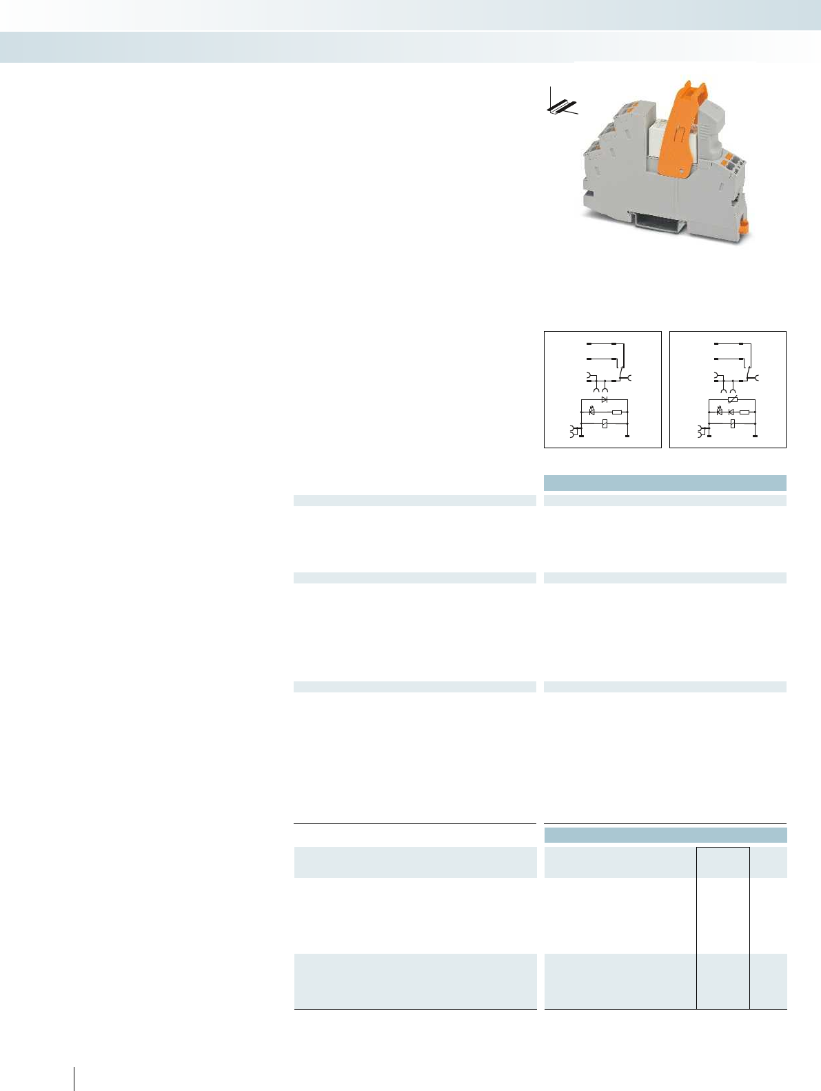
A2 A1
1222
14
24
1121
A2- A1+
1222
1424
1121
Technical data
Input data ① ② ③ ④ ⑤
Permissible range (with reference to U
N
) see diagram
Typ. input current at U
N
[mA] 33 18 33 8 6 33 18 33 8 6
Typ. response time at U
N
[ms] 8 8 3 - 12 3 - 12 3 - 12 8 8 3 - 12 3 - 12 3 - 12
Typ. release time at U
N
[ms] 10 10 3 - 20 3 - 20 3 - 20 10 10 3 - 20 3 - 20 3 - 20
Input circuit AC Yellow LED, varistor
Input circuit DC Yellow LED, freewheeling diode Yellow LED, freewheeling diode
Output data
Contact type 1 PDT 1 PDT 2 PDTs 2 PDTs
Contact material AgNi AgNi, hard gold-plated AgNi AgNi, hard gold-plated
Max. switching voltage 250 V AC/DC 30 V AC / 36 V DC 250 V AC/DC 30 V AC / 36 V DC
Min. switching voltage 12 V (at 10 mA) 100 mV (at 10 mA) 5 V (at 10 mA) 100 mV (at 10 mA)
Limiting continuous current 11 A (see diagram) 50 mA 8 A (see diagram) 50 mA
Max. inrush current, AC 25 A (20 ms, N/O contact) 50 mA 12 A (20 ms, N/O contact) 50 mA
Max. inrush current, DC 50 A (20 ms, N/O contact) 50 mA 25 A (20 ms, N/O contact) 50 mA
Min. switching current 10 mA (at 12 V) 1 mA (at 24 V) 10 mA (at 5 V) 1 mA (at 24 V)
General data
Test voltage (winding/contact) 4 kV
rms
(50 Hz, 1 min.) 4 kV
Ambient temperature (operation), AC -40 °C ... 50 °C
Ambient temperature (operation), DC -40 °C ... 70 °C
Nominal operating mode 100% operating factor 100% operating factor
Mechanical service life, AC Approx. 10
7
cycles
Mechanical service life, DC Approx. 3 x 10
7
cycles Approx. 3 x 10
Standards/regulations DIN EN 50178, IEC 62103 DIN EN 50178, IEC 62103
Pollution degree / surge voltage category 2 / III
Mounting position / mounting any / can be aligned without spacing any / can be aligned without spacing
Connection data solid / stranded / AWG 0.14 - 1.5 mm² / 0.14 - 1.5 mm² / 26 - 16 0.14 - 1.5 mm² / 0.14 - 1.5 mm² / 26 - 16
Dimensions W / H / D 16 mm / 93 mm / 75 mm 16 mm / 93 mm / 75 mm
Ordering data
Description Input voltage
U
N
Type Order No. Pcs. /
Pkt.
Coupling relay modules with power contact relay and push-in
connection
①12 V DC RIF-1-RPT-LDP-12DC/1X21 2906224 10
②24 V DC RIF-1-RPT-LDP-24DC/1X21 2903342 10
③24 V AC RIF-1-RPT-LV-24AC/1X21 2903341 10
④120 V AC RIF-1-RPT-LV-120AC/1X21 2903340 10
⑤230 V AC RIF-1-RPT-LV-230AC/1X21 2903339 10
②24 V DC RIF-1-RPT-LDP-24DC/1X21AU 2903338 10
③24 V AC RIF-1-RPT-LV-24AC/1X21AU 2903337 10
④120 V AC RIF-1-RPT-LV-120AC/1X21AU 2903336 10
⑤230 V AC RIF-1-RPT-LV-230AC/1X21AU 2903335 10
362
PHOENIX CONTACT
DC coils AC coils DC coils
DW
H
Fully mounted RIF-1 relay modules
Fully mounted RIF-1 relay modules,
consisting of:
– Relay base with push-in connection
– 1 or 2 PDT relay
– Relay retaining bracket
– Input module/interference suppr. module
The advantages:
– Logical contact arrangement thanks to
1/3-level relay base
– Operational reliability thanks to sealed
relay
– Safe isolation between coil and contact
side
– Professional bridging of adjacent modules
saves wiring time
– For FBS 2-6 jumpers for the input side
(A2), see page 374.
– For FBS 2-8 jumpers for the output side
(11/21), see page 374.
Relay modules
Industrial relay system with push-in connection - RIFLINE complete
RIF-1 relay module with
1 PDT relay
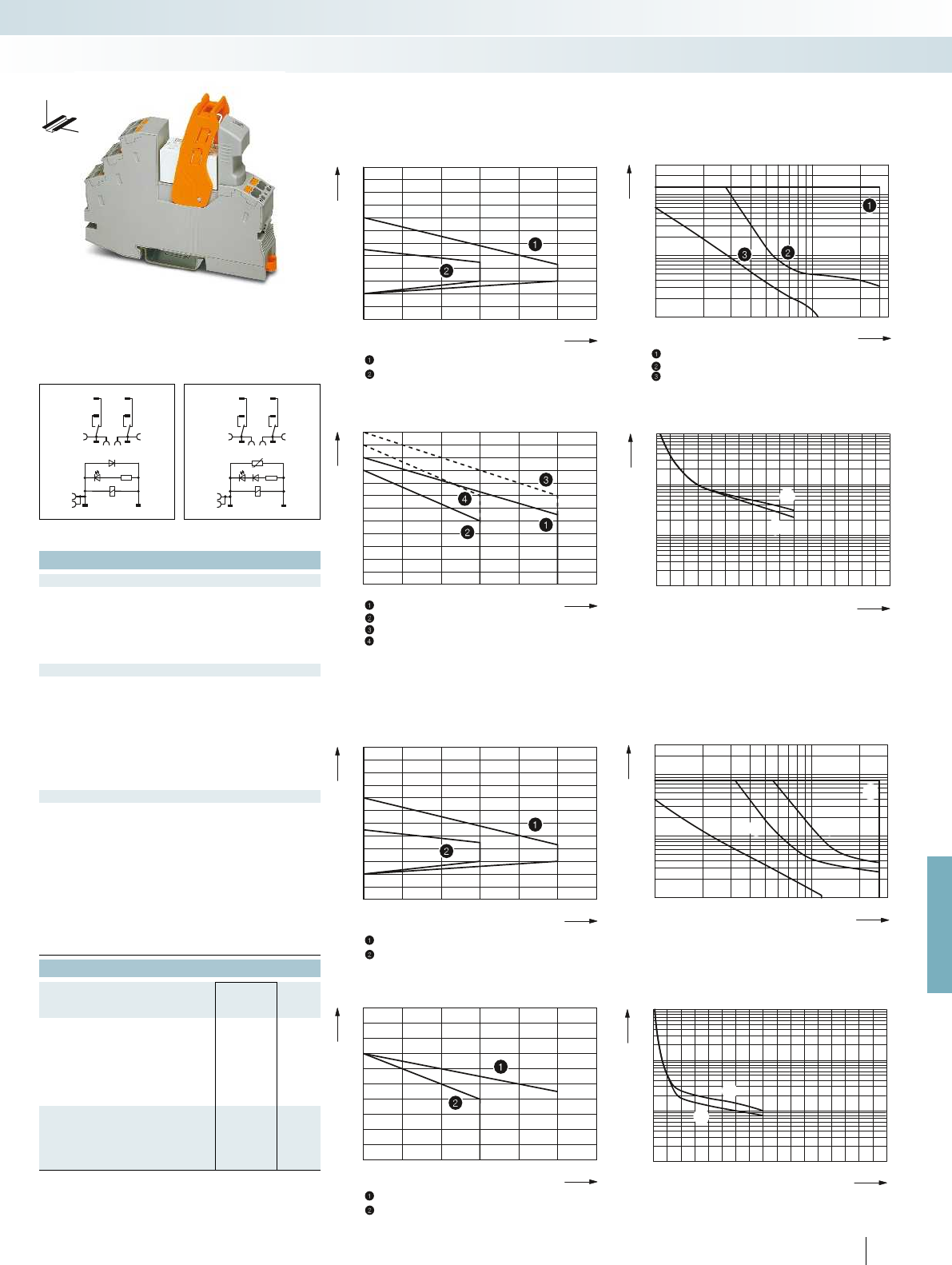
0,6
0,7
0,8
0,9
1,0
1,1
1,2
1,3
1,4
1,5
1,6
1,7
1,8
20 30 40 50 60 70 80
0,1
0,2
0,3
0,5
1
2
4
6
10
20
10 20 30 50 70 100 300200
20 30 40 50 60 70 80
1
2
3
4
5
6
7
8
9
10
11
12
13
2
014 8 12 16
107
106
105
104
23 567 11910 151413
1
1
2
0,6
0,7
0,8
0,9
1,0
1,1
1,2
1,3
1,4
1,5
1,6
1,7
1,8
20 30 40 50 60 70 80
0,1
0,2
0,3
0,5
1
2
4
6
10
20
10 20 30 50 70 100 300200
1
2
3
4
3
1
42
20 30 40 50 60 70 80
1
2
3
4
5
6
7
8
9
10
11
014 8 12 16
107
106
105
104
23 567 11910 151413
1
2
2
1
1222
A1+
A2-
1424
1121
1222
1424
1121
A2A1
For further information and full technical data, visit phoenixcontact.net/products
Technical data
① ② ③ ④ ⑤
see diagram
[mA] 33 18 33 8 6 33 18 33 8 6
[ms] 8 8 3 - 12 3 - 12 3 - 12 8 8 3 - 12 3 - 12 3 - 12
[ms] 10 10 3 - 20 3 - 20 3 - 20 10 10 3 - 20 3 - 20 3 - 20
Yellow LED, varistor
Input circuit DC Yellow LED, freewheeling diode Yellow LED, freewheeling diode
Contact type 1 PDT 1 PDT 2 PDTs 2 PDTs
Contact material AgNi AgNi, hard gold-plated AgNi AgNi, hard gold-plated
Max. switching voltage 250 V AC/DC 30 V AC / 36 V DC 250 V AC/DC 30 V AC / 36 V DC
Min. switching voltage 12 V (at 10 mA) 100 mV (at 10 mA) 5 V (at 10 mA) 100 mV (at 10 mA)
Limiting continuous current 11 A (see diagram) 50 mA 8 A (see diagram) 50 mA
Max. inrush current, AC 25 A (20 ms, N/O contact) 50 mA 12 A (20 ms, N/O contact) 50 mA
Max. inrush current, DC 50 A (20 ms, N/O contact) 50 mA 25 A (20 ms, N/O contact) 50 mA
Min. switching current 10 mA (at 12 V) 1 mA (at 24 V) 10 mA (at 5 V) 1 mA (at 24 V)
(50 Hz, 1 min.) 4 kV
rms
(50 Hz, 1 min.)
-40 °C ... 50 °C
-40 °C ... 70 °C
Nominal operating mode 100% operating factor 100% operating factor
Approx. 10
7
cycles
cycles Approx. 3 x 10
7
cycles
Standards/regulations DIN EN 50178, IEC 62103 DIN EN 50178, IEC 62103
2 / III
Mounting position / mounting any / can be aligned without spacing any / can be aligned without spacing
Connection data solid / stranded / AWG 0.14 - 1.5 mm² / 0.14 - 1.5 mm² / 26 - 16 0.14 - 1.5 mm² / 0.14 - 1.5 mm² / 26 - 16
Dimensions W / H / D 16 mm / 93 mm / 75 mm 16 mm / 93 mm / 75 mm
Ordering data
Type Order No. Pcs. /
Pkt.
RIF-1-RPT-LDP-12DC/2X21 2906223 10
RIF-1-RPT-LDP-24DC/2X21 2903334 10
RIF-1-RPT-LV-24AC/2X21 2903333 10
RIF-1-RPT-LV-120AC/2X21 2903332 10
RIF-1-RPT-LV-230AC/2X21 2903331 10
RIF-1-RPT-LDP-24DC/2X21AU 2903330 10
RIF-1-RPT-LV-24AC/2X21AU 2903329 10
RIF-1-RPT-LV-120AC/2X21AU 2903328 10
RIF-1-RPT-LV-230AC/2X21AU 2903327 10
363
PHOENIX CONTACT
RIF-1-RPT.../1X21... (1 PDT)
Operating voltage range Interrupting rating
Ambient temperature [°C]
Coil voltage U/U
N
DC coils
AC coils
Switching voltage [V]
Switching current [A]
AC, ohmic load
DC, ohmic load
DC, L/R = 40 ms
Contact derating Electrical service life
Ambient temperature [°C]
Limiting continuous current per contact [A]
DC coil
AC coil
DC coil, jumper between 11 and 21
AC coil, jumper between 11 and 21
250 V AC, ohmic load (DC coils)
250 V AC, ohmic load (AC coils)
Cycles
Switching current [A]
RIF-1-RPT.../2X21... (2 PDTs)
Operating voltage range Interrupting rating
Ambient temperature [°C]
Coil voltage U/U
N
DC coils
AC coils
Switching voltage [V]
Switching current [A]
AC, ohmic load
DC, ohmic load
DC, L/R = 40 ms
Contact derating Electrical service life
Ambient temperature [°C]
Limiting continuous current per contact [A]
DC coil
AC coil
Cycles
Switching current [A]
250 V AC, ohmic load (DC coils)
250 V AC, ohmic load (AC coils)
DC coils AC coils DC coils
DW
H
Relay modules
Industrial relay system with push-in connection - RIFLINE complete
RIF-1 relay module with
2 PDT relay
AC coils
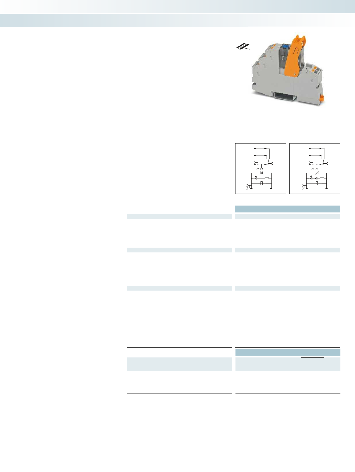
A2 A1
1222
14
24
1121
A2- A1+
1222
1424
1121
Technical data
Input data ① ②
Permissible range (with reference to U
N
) see diagram
Typ. input current at U
N
[mA] 18 4.5
Typ. response time at U
N
[ms] 9 4 - 12
Typ. release time at U
N
[ms] 10 4 - 20
Input circuit AC Yellow LED, varistor
Input circuit DC Yellow LED, freewheeling diode Yellow LED, freewheeling diode
Output data
Contact type 1 PDT
Contact material AgNi
Max. switching voltage 250 V AC/DC
Min. switching voltage 12 V (at 10 mA)
Limiting continuous current see diagram
Max. inrush current 32 A (20 ms, N/O contact) 16 A (20 ms, N/O contact)
Min. switching current 10 mA (at 12 V)
General data
Test voltage (winding/contact) 4 kV
rms
(50 Hz, 1 min.) 4 kV
Ambient temperature (operation), AC -40 °C ... 50 °C
Ambient temperature (operation), DC -40 °C ... 70 °C
Nominal operating mode 100% operating factor 100% operating factor
Mechanical service life Approx. 5 x 10
6
cycles Approx. 5 x 10
Standards/regulations DIN EN 50178, IEC 62103 DIN EN 50178, IEC 62103
Pollution degree / surge voltage category 2 / III
Mounting position / mounting any / can be aligned without spacing any / can be aligned without spacing
Connection data solid / stranded / AWG 0.14 - 1.5 mm² / 0.14 - 1.5 mm² / 26 - 16 0.14 - 1.5 mm² / 0.14 - 1.5 mm² / 26 - 16
Dimensions W / H / D 16 mm / 93 mm / 75 mm 16 mm / 93 mm / 75 mm
EMC note Class A product, see page 625 Class A product, see page 625
Ordering data
Description Input voltage
U
N
Type Order No. Pcs. /
Pkt.
Coupling relay modules with power contact relay with manual
operation and push-in connection
①24 V DC RIF-1-RPT-LDP-24DC/1X21MS 2905289 10
②230 V AC RIF-1-RPT-LV-230AC/1X21MS 2905290 10
364
PHOENIX CONTACT
DC coils AC coils DC coils
DW
H
Fully mounted RIF-1 relay modules
Fully mounted RIF-1 relay modules,
consisting of:
– Relay base with push-in connection
– 1 or 2 PDT relay with detectable manual
operation
– Relay retaining bracket
– Input module/interference suppr. module
(AC types only)
The advantages:
– Relay with lockable manual operation and
status LED
– With DC types, freewheeling diode is
integrated into relay
– Mechanical switch position indicator
– Professional bridging of adjacent modules
saves wiring time
Relay modules
Industrial relay system with push-in connection - RIFLINE complete
RIF-1 relay module with 1 PDT relay with
manual operation
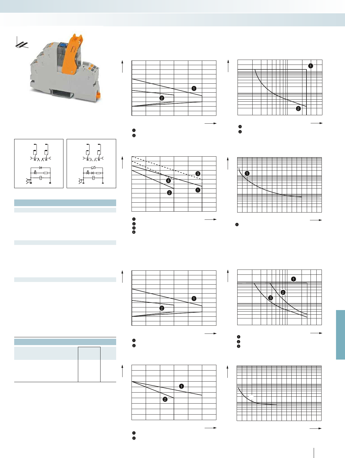
0,6
0,7
0,8
0,9
1,0
1,1
1,2
1,3
1,4
1,5
1,6
1,7
1,8
2030405060 70 80
20
10
5
2
1
0,5
0,2
0,1
10203050 70 100 200 300 400 500
2030405060 70 80
1
2
3
4
5
6
7
8
9
10
11
12
13
014 812 16
10
7
10
6
10
5
10
4
23 56711910151413
0,6
0,7
0,8
0,9
1,0
1,1
1,2
1,3
1,4
1,5
1,6
1,7
1,8
2030405060 70 80
20
10
5
2
1
0,5
0,2
0,1
10203050 70 100 200 300 400 500
2030405060 70 80
1
2
3
4
5
6
7
8
9
10
11
014 812 16
107
106
105
104
2 3 5 6 7 11910151413
1
1
1222
A1+
A2-
1424
1121
1222
1424
1121
A2 A1
For further information and full technical data, visit phoenixcontact.net/products
Technical data
① ②
see diagram
18 4.5
9 4 - 12
10 4 - 20
Yellow LED, varistor
Input circuit DC Yellow LED, freewheeling diode Yellow LED, freewheeling diode
2 PDTs
AgNi
250 V AC/DC
12 V (at 10 mA)
see diagram
Max. inrush current 32 A (20 ms, N/O contact) 16 A (20 ms, N/O contact)
10 mA (at 12 V)
(50 Hz, 1 min.) 4 kV
rms
(50 Hz, 1 min.)
-40 °C ... 50 °C
-40 °C ... 70 °C
Nominal operating mode 100% operating factor 100% operating factor
cycles Approx. 5 x 10
6
cycles
Standards/regulations DIN EN 50178, IEC 62103 DIN EN 50178, IEC 62103
2 / III
Mounting position / mounting any / can be aligned without spacing any / can be aligned without spacing
Connection data solid / stranded / AWG 0.14 - 1.5 mm² / 0.14 - 1.5 mm² / 26 - 16 0.14 - 1.5 mm² / 0.14 - 1.5 mm² / 26 - 16
Dimensions W / H / D 16 mm / 93 mm / 75 mm 16 mm / 93 mm / 75 mm
EMC note Class A product, see page 625 Class A product, see page 625
Ordering data
Type Order No. Pcs. /
Pkt.
RIF-1-RPT-LDP-24DC/2X21MS 2905291 10
RIF-1-RPT-LV-230AC/2X21MS 2905292 10
365
PHOENIX CONTACT
RIF-1-RPT.../1X21... (1 PDT)
Operating voltage range Interrupting rating
Ambient temperature [°C]
Coil voltage U/U
N
DC coils
AC coils
Switching voltage [V]
Switching current [A]
= AC, ohmic load
= DC, ohmic load
Contact derating Electrical service life
Ambient temperature [°C]
Limiting continuous current per contact [A]
DC coil
AC coil
DC coil, jumper between 11 and 21
AC coil, jumper between 11 and 21
Cycles
Switching current [A]
=250 V AC, ohmic load
RIF-1-RPT.../2X21... (2 PDTs)
Operating voltage range Interrupting rating
Ambient temperature [°C]
Coil voltage U/U
N
DC coils
AC coils
AC, ohmic load
DC, ohmic load, contacts in series
DC, ohmic load
Switching voltage [V]
Switching current [A]
Contact derating Electrical service life
Ambient temperature [°C]
Limiting continuous current per contact [A]
DC coil
AC coil
Cycles
Switching current [A]
250 V AC, ohmic load
DC coils AC coils DC coils
DW
H
Relay modules
Industrial relay system with push-in connection - RIFLINE complete
RIF-1 relay module with 2 PDT relay with
manual operation
AC coils

12
42
14
44
11
41
A2 A1
A2- A1+
12
42
14
44
11
41
Technical data
Input data ① ② ③ ④
Permissible range (with reference to U
N
) see diagram
Typ. input current at U
N
[mA] 42 66 13 6.5 42 66 13 6.5
Typ. response time at U
N
[ms] 13 5 - 15 5 - 15 5 - 15 13 5 - 15 5 - 15 5 - 15
Typ. release time at U
N
[ms] 14 5 - 20 5 - 20 5 - 20 14 5 - 20 5 - 20 5 - 20
Input circuit AC Yellow LED, varistor
Input circuit DC Yellow LED, freewheeling diode Yellow LED, freewheeling diode
Output data
Contact type 2 PDTs
Contact material AgNi
Max. switching voltage 250 V AC/DC
Min. switching voltage 5 V (at 24 mA)
Limiting continuous current 10 A (see diagram)
Max. inrush current, AC 30 A (20 ms, N/O contact) 16 A (20 ms, N/O contact)
Max. inrush current, DC 30 A (20 ms, N/O contact) 16 A (20 ms, N/O contact)
Min. switching current 5 mA (at 24 V)
General data
Test voltage (winding/contact) 2.5 kV
rms
(50 Hz, 1 min.) 2.5 kV
Ambient temperature (operation), AC -40 °C ... 50 °C
Ambient temperature (operation), DC -40 °C ... 60 °C
Nominal operating mode 100% operating factor 100% operating factor
Mechanical service life, AC Approx. 2 x 10
7
cycles Approx. 2 x 10
Mechanical service life, DC Approx. 2 x 10
7
cycles Approx. 2 x 10
Standards/regulations DIN EN 50178, IEC 62103 DIN EN 50178, IEC 62103
Pollution degree / surge voltage category 2 / III
Mounting position / mounting any / can be aligned without spacing any / can be aligned without spacing
Connection data solid / stranded / AWG 0.14 - 1.5 mm² / 0.14 - 1.5 mm² / 26 - 16 0.14 - 1.5 mm² / 0.14 - 1.5 mm² / 26 - 16
Dimensions W / H / D 31 mm / 96 mm / 75 mm 31 mm / 96 mm / 75 mm
EMC note Class A product, see page 625 Class A product, see page 625
Ordering data
Description Input voltage
U
N
Type Order No. Pcs. /
Pkt.
Pre-assembled coupling relay modules with power contact
relay and push-in connection
①24 V DC RIF-2-RPT-LDP-24DC/2X21 2903315 10
②24 V AC RIF-2-RPT-LV-24AC/2X21 2903313 10
③120 V AC RIF-2-RPT-LV-120AC/2X21 2903311 10
④230 V AC RIF-2-RPT-LV-230AC/2X21 2903310 10
366
PHOENIX CONTACT
DC coils AC coils DC coils
DW
H
Fully mounted RIF-2 relay modules
Fully mounted RIF-2 relay modules,
consisting of:
– Relay base with push-in connection
– 1 or 2 PDT relay
– Relay retaining bracket
– Input module/interference suppr. module
(AC types only)
The advantages:
– Relay with lockable manual operation and
status LED
– With DC types, freewheeling diode is
integrated into relay
– Mechanical switch position indicator
– Logical contact arrangement thanks to
1/3-level relay base
– Professional bridging of adjacent modules
saves wiring time
– For FBS 2-6 jumpers for the input side
(A2), see page 374.
Relay modules
Industrial relay system with push-in connection - RIFLINE complete
RIF-2 relay module with
2 PDT relay
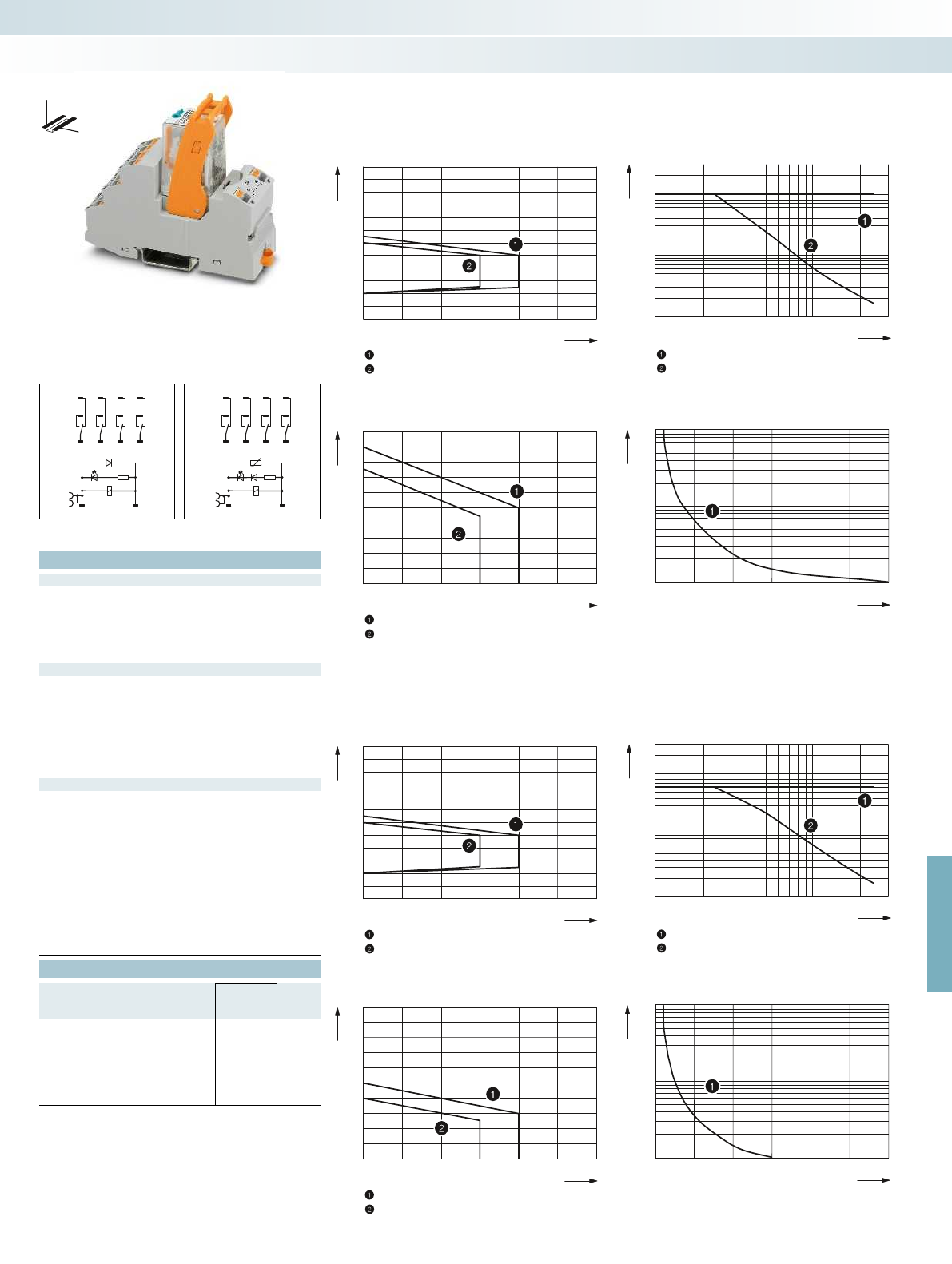
0,6
0,7
0,8
0,9
1,0
1,1
1,2
1,3
1,4
1,5
1,6
1,7
1,8
2030405060 70 80
0,1
0,2
0,3
0,5
1
2
4
6
10
20
10203050 70 100 300200
2030405060 70 80
1
2
3
4
5
6
7
8
9
10
11
0123
10
5
10
6
10
7
0,6
0,7
0,8
0,9
1,0
1,1
1,2
1,3
1,4
1,5
1,6
1,7
1,8
2030405060 70 80
0,1
0,2
0,3
0,5
1
2
4
6
10
20
10203050 70 100 300200
2030405060 70 80
1
2
3
4
5
6
7
8
9
10
11
0123
10
5
10
6
10
7
A2- A1+
12
32 22
42
14
34 24
44
11
31 21
41
12
32 22
42
14
34 24
44
11
31 21
41
A2 A1
For further information and full technical data, visit phoenixcontact.net/products
Technical data
① ② ③ ④
see diagram
[mA] 42 66 13 6.5 42 66 13 6.5
[ms] 13 5 - 15 5 - 15 5 - 15 13 5 - 15 5 - 15 5 - 15
[ms] 14 5 - 20 5 - 20 5 - 20 14 5 - 20 5 - 20 5 - 20
Yellow LED, varistor
Input circuit DC Yellow LED, freewheeling diode Yellow LED, freewheeling diode
4 PDTs
AgNi
250 V AC/DC
5 V (at 24 mA)
6 A (see diagram)
Max. inrush current, AC 30 A (20 ms, N/O contact) 16 A (20 ms, N/O contact)
Max. inrush current, DC 30 A (20 ms, N/O contact) 16 A (20 ms, N/O contact)
5 mA (at 24 V)
(50 Hz, 1 min.) 2.5 kV
rms
(50 Hz, 1 min.)
-40 °C ... 50 °C
-40 °C ... 60 °C
Nominal operating mode 100% operating factor 100% operating factor
cycles Approx. 2 x 10
7
cycles
cycles Approx. 2 x 10
7
cycles
Standards/regulations DIN EN 50178, IEC 62103 DIN EN 50178, IEC 62103
2 / II
Mounting position / mounting any / can be aligned without spacing any / can be aligned without spacing
Connection data solid / stranded / AWG 0.14 - 1.5 mm² / 0.14 - 1.5 mm² / 26 - 16 0.14 - 1.5 mm² / 0.14 - 1.5 mm² / 26 - 16
Dimensions W / H / D 31 mm / 96 mm / 75 mm 31 mm / 96 mm / 75 mm
EMC note Class A product, see page 625 Class A product, see page 625
Ordering data
Type Order No. Pcs. /
Pkt.
RIF-2-RPT-LDP-24DC/4X21 2903308 10
RIF-2-RPT-LV-24AC/4X21 2903306 10
RIF-2-RPT-LV-120AC/4X21 2903305 10
RIF-2-RPT-LV-230AC/4X21 2903304 10
367
PHOENIX CONTACT
RIF-2-RPT.../2X21 (2 PDTs)
Operating voltage range Interrupting rating
Ambient temperature [°C]
Coil voltage U/U
N
DC coil (observe contact derating)
AC coil (observe contact derating)
Switching voltage [V]
Switching current [A]
AC, ohmic load
DC, ohmic load
Contact derating Electrical service life
Ambient temperature [°C]
Limiting continuous current per contact [A]
DC coil
AC coil
250 V AC, ohmic load
Cycles
Switching capacity [kVA]
RIF-2-RPT.../4X21 (4 PDTs)
Operating voltage range Interrupting rating
Ambient temperature [°C]
Coil voltage U/U
N
DC coil (observe contact derating)
AC coil (observe contact derating)
Switching voltage [V]
Switching current [A]
AC, ohmic load
DC, ohmic load
Contact derating Electrical service life
Ambient temperature [°C]
Limiting continuous current per contact [A]
DC coil
AC coil
250 V AC, ohmic load
Cycles
Switching capacity [kVA]
DC coils AC coils DC coils
DW
H
Relay modules
Industrial relay system with push-in connection - RIFLINE complete
RIF-2 relay module with
4 PDT relay
AC coils
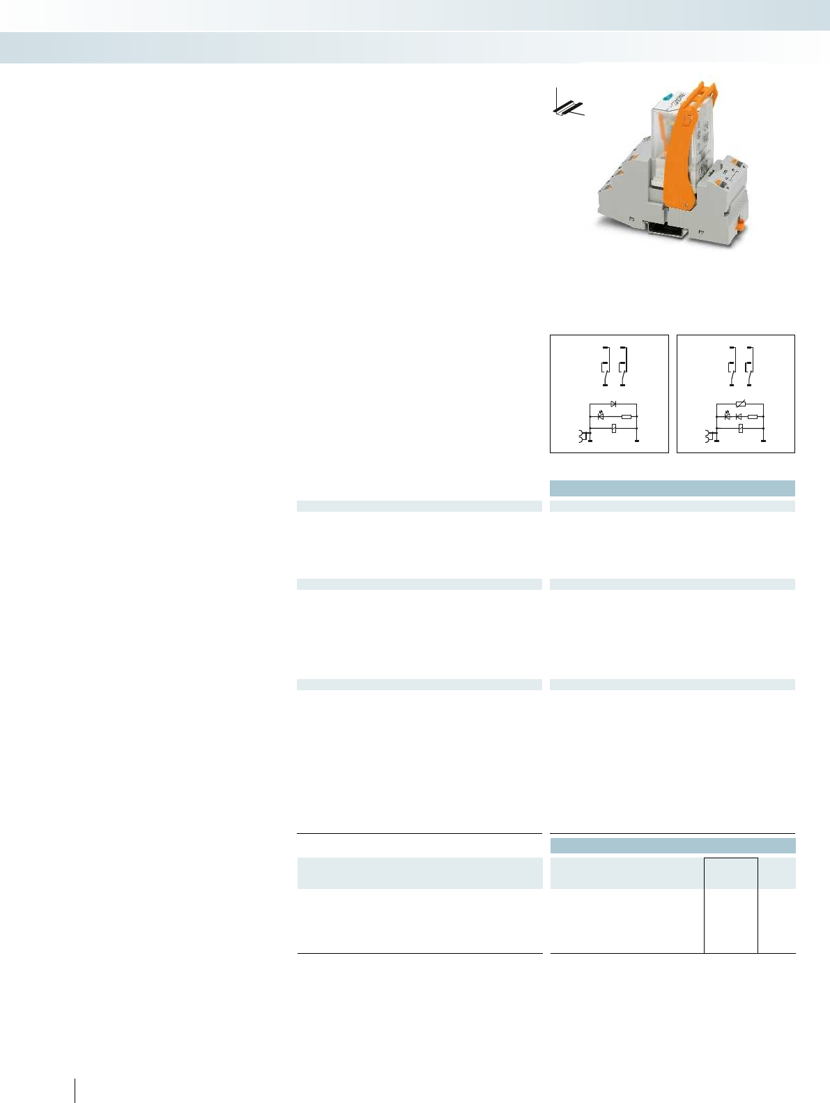
1222
1424
1121
A2 A1
1222
A1+
A2-
1424
1121
Technical data
Input data ① ② ③
Permissible range (with reference to U
N
) see diagram
Typ. input current at U
N
[mA] 60 23 13
Typ. response time at U
N
[ms] 18 5 - 15 5 - 15 18 5 - 15 5 - 15
Typ. release time at U
N
[ms] 20 5 - 20 5 - 20 20 5 - 20 5 - 20
Input circuit AC Yellow LED, varistor
Input circuit DC Yellow LED, freewheeling diode Yellow LED, freewheeling diode
Output data
Contact type 2 PDTs
Contact material AgNi
Max. switching voltage 250 V AC/DC
Min. switching voltage 10 V (at 24 mA)
Limiting continuous current 10 A (see diagram)
Max. inrush current, AC 30 A (20 ms, N/O contact) 30 A (20 ms, N/O contact)
Max. inrush current, DC 30 A (20 ms, N/O contact) 30 A (20 ms, N/O contact)
Min. switching current 10 mA (at 24 V)
General data
Test voltage (winding/contact) 2.5 kV
rms
(50 Hz, 1 min.) 2.5 kV
Ambient temperature (operation), AC -40 °C ... 50 °C
Ambient temperature (operation), DC -40 °C ... 60 °C
Nominal operating mode 100% operating factor 100% operating factor
Mechanical service life, AC Approx. 2 x 10
7
cycles Approx. 2 x 10
Mechanical service life, DC Approx. 2 x 10
7
cycles Approx. 2 x 10
Standards/regulations DIN EN 50178, IEC 62103 DIN EN 50178, IEC 62103
Pollution degree / surge voltage category 2 / III
Mounting position / mounting any / can be aligned without spacing any / can be aligned without spacing
Connection data solid / stranded / AWG 0.14 - 1.5 mm² / 0.14 - 1.5 mm² / 26 - 16 0.14 - 1.5 mm² / 0.14 - 1.5 mm² / 26 - 16
Dimensions W / H / D 40 mm / 103 mm / 90 mm 40 mm / 103 mm / 90 mm
EMC note Class A product, see page 625 Class A product, see page 625
Ordering data
Description Input voltage
U
N
Type Order No. Pcs. /
Pkt.
Pre-assembled coupling relay modules with power contact
relay and push-in connection
①24 V DC RIF-3-RPT-LDP-24DC/2X21 2903297 5
②120 V AC RIF-3-RPT-LV-120AC/2X21 2903296 5
③230 V AC RIF-3-RPT-LV-230AC/2X21 2903295 5
368
PHOENIX CONTACT
DC coils AC coils DC coils
DW
H
Fully mounted RIF-3 relay modules
Fully mounted RIF-3 relay modules,
consisting of:
– Relay base with push-in connection
– 2 or 3 PDT relay
– Relay retaining bracket
– Input module/interference suppr. module
(AC types only)
The advantages:
– Relay with lockable manual operation and
status LED
– With DC types, freewheeling diode is
integrated into relay
– Mechanical switch position indicator
– Logical contact arrangement thanks to
1/3-level relay base
– Professional bridging of adjacent modules
saves wiring time
– For FBS 2-6 jumpers for the input side
(A2), see page 374.
Relay modules
Industrial relay system with push-in connection - RIFLINE complete
RIF-3 relay module with
2 PDT relay
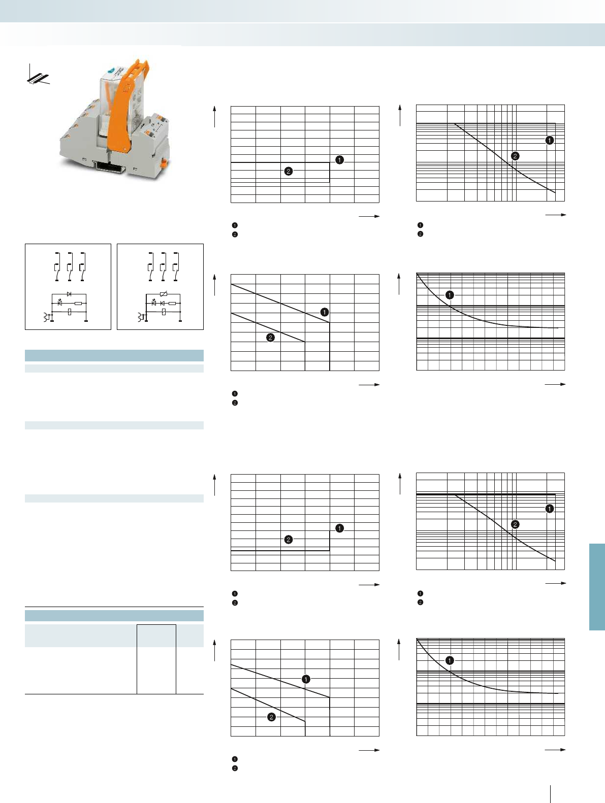
0,6
0,7
0,8
0,9
1,0
1,1
1,2
1,3
1,4
1,5
1,6
1,7
1,8
2030405060 70 80
0,1
0,2
0,3
0,5
1
2
4
6
10
20
10203050 70 100 300200
2030405060 70 80
1
2
3
4
5
6
7
8
9
10
11
0 0,20,40,60,8 1,0 1,21,41,61,8 2,0 2,22,42,6
10
4
10
5
10
5
10
6
10
7
0,6
0,7
0,8
0,9
1,0
1,1
1,2
1,3
1,4
1,5
1,6
1,7
1,8
2030405060 70 80
0,1
0,2
0,3
0,5
1
2
4
6
10
20
10203050 70 100 300200
2030405060 70 80
1
2
3
4
5
6
7
8
9
10
11
0 0,20,40,60,8 1,0 1,21,41,61,8 2,0 2,22,42,6
10
4
10
5
10
5
10
6
10
7
A2- A1+
12
32 22
14
34 24
11
31 21
A2 A1
12
32 22
14
34 24
11
31 21
For further information and full technical data, visit phoenixcontact.net/products
Technical data
① ② ③
see diagram
60 23 13
[ms] 18 5 - 15 5 - 15 18 5 - 15 5 - 15
[ms] 20 5 - 20 5 - 20 20 5 - 20 5 - 20
Yellow LED, varistor
Input circuit DC Yellow LED, freewheeling diode Yellow LED, freewheeling diode
3 PDTs
AgNi
250 V AC/DC
10 V (at 24 mA)
8.5 A (see diagram)
Max. inrush current, AC 30 A (20 ms, N/O contact) 30 A (20 ms, N/O contact)
Max. inrush current, DC 30 A (20 ms, N/O contact) 30 A (20 ms, N/O contact)
10 mA (at 24 V)
(50 Hz, 1 min.) 2.5 kV
rms
(50 Hz, 1 min.)
-40 °C ... 50 °C
-40 °C ... 60 °C
Nominal operating mode 100% operating factor 100% operating factor
cycles Approx. 2 x 10
7
cycles
cycles Approx. 2 x 10
7
cycles
Standards/regulations DIN EN 50178, IEC 62103 DIN EN 50178, IEC 62103
2 / III
Mounting position / mounting any / can be aligned without spacing any / can be aligned without spacing
Connection data solid / stranded / AWG 0.14 - 1.5 mm² / 0.14 - 1.5 mm² / 26 - 16 0.14 - 1.5 mm² / 0.14 - 1.5 mm² / 26 - 16
Dimensions W / H / D 40 mm / 103 mm / 90 mm 40 mm / 103 mm / 90 mm
EMC note Class A product, see page 625 Class A product, see page 625
Ordering data
Type Order No. Pcs. /
Pkt.
RIF-3-RPT-LDP-24DC/3X21 2903294 5
RIF-3-RPT-LV-120AC/3X21 2903293 5
RIF-3-RPT-LV-230AC/3X21 2903292 5
369
PHOENIX CONTACT
RIF-3-RPT.../2X21 (2 PDTs)
Operating voltage range Interrupting rating
Ambient temperature [°C]
Coil voltage U/U
N
DC coil (observe contact derating)
AC coil (observe contact derating)
Switching voltage [V]
Switching current [A]
AC, ohmic load
DC, ohmic load
Contact derating Electrical service life
Ambient temperature [°C]
Limiting continuous current per contact [A]
DC coil
AC coil
250 V AC, ohmic load
Cycles
Switching capacity [kVA]
RIF-3-RPT.../3X21 (3 PDTs)
Operating voltage range Interrupting rating
Ambient temperature [°C]
Coil voltage U/U
N
DC coil (observe contact derating)
AC coil (observe contact derating)
Switching voltage [V]
Switching current [A]
AC, ohmic load
DC, ohmic load
Contact derating Electrical service life
Ambient temperature [°C]
Limiting continuous current per contact [A]
DC coil
AC coil
250 V AC, ohmic load
Cycles
Switching capacity [kVA]
DC coils AC coils DC coils
DW
H
Relay modules
Industrial relay system with push-in connection - RIFLINE complete
RIF-3 relay module with
3 PDT relay
AC coils
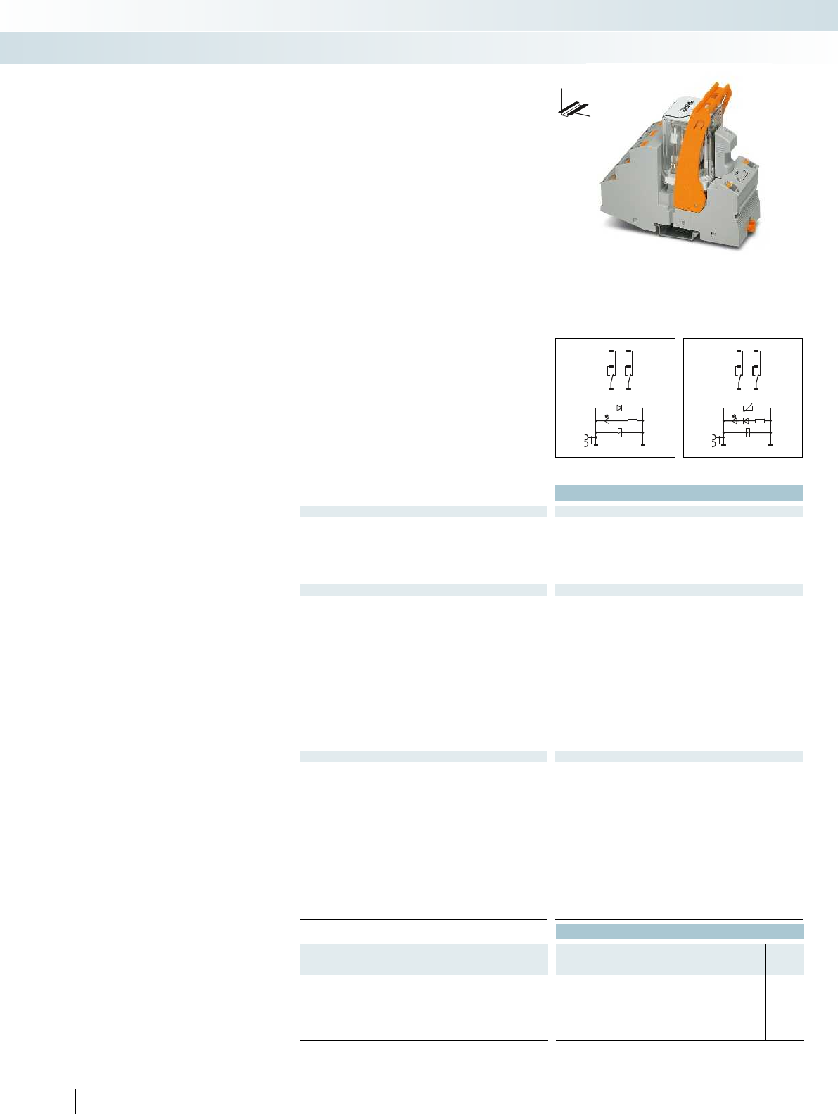
1222
1424
1121
A2 A1
1222
A1+
A2-
1424
1121
Technical data
Input data ① ② ③
Permissible range (with reference to U
N
) see diagram
Typ. input current at U
N
[mA] 56 24 14
Typ. response time at U
N
[ms] 20 5 - 25 5 - 25 20 5 - 25 5 - 25
Typ. release time at U
N
[ms] 20 5 - 20 5 - 20 20 5 - 20 5 - 20
Input circuit AC Yellow LED, varistor
Input circuit DC Yellow LED, freewheeling diode, polarity protection diode Yellow LED, freewheeling diode, polarity protection di
Output data
Contact type 2 PDTs
Contact material AgNi
Max. switching voltage 440 V AC / 250 V DC
Min. switching voltage 10 V (at 24 mA)
Limiting continuous current 11 A (see diagram)
Max. inrush current, AC 50 A (20 ms, N/O contact) 50 A (20 ms, N/O contact)
Max. inrush current, DC 50 A (20 ms, N/O contact) 50 A (20 ms, N/O contact)
Min. switching current 10 mA (at 24 V)
Max. interrupting rating, ohmic load
250 V AC 2500 VA
440 V AC 4000 VA
Motor load according to UL 508 1/3 HP, 120 V AC (single-phase AC motor)
1/2 HP, 240 V AC (single-phase AC motor)
General data
Test voltage (winding/contact) 2.5 kV
rms
(50 Hz, 1 min.) 2.5 kV
Ambient temperature (operation), AC -40 °C ... 40 °C
Ambient temperature (operation), DC -40 °C ... 60 °C
Nominal operating mode 100% operating factor 100% operating factor
Mechanical service life, AC Approx. 10
7
cycles
Mechanical service life, DC Approx. 10
7
cycles
Standards/regulations DIN EN 50178, IEC 62103 DIN EN 50178, IEC 62103
Pollution degree / surge voltage category 2 / III
Mounting position / mounting any / can be aligned without spacing any / can be aligned without spacing
Connection data solid / stranded / AWG
Input side 0.14 ... 1.5 mm² / 0.14 ... 1.5 mm² / 26 - 16 0.14 ... 1.5 mm² / 0.14 ... 1.5 mm² / 26 - 16
Output side 0.14 ... 2.5 mm² / 0.14 ... 2.5 mm² / 26 - 14 0.14 ... 2.5 mm² / 0.14 ... 2.5 mm² / 26 - 14
Dimensions W / H / D 43 mm / 111 mm / 90 mm 43 mm / 111 mm / 90 mm
EMC note Class A product, see page 625 Class A product, see page 625
Ordering data
Description Input voltage
U
N
Type Order No. Pcs. /
Pkt.
Pre-assembled coupling relay modules with power contact
relay and push-in connection
①24 V DC RIF-4-RPT-LDP-24DC/2X21 2903281 5
②120 V AC RIF-4-RPT-LV-120AC/2X21 2903280 5
③230 V AC RIF-4-RPT-LV-230AC/2X21 2903279 5
370
PHOENIX CONTACT
DC coils AC coils DC coils
DW
H
Fully mounted RIF-4 relay modules
Fully mounted RIF-4 relay modules,
consisting of:
– Relay base with push-in connection
– 2 or 3 PDT relay
– Relay retaining bracket
– Input module/interference suppr. module
The advantages:
– Logical contact arrangement thanks to
1/3-level relay base
– Professional bridging of adjacent modules
saves wiring time
– For FBS 2-6 jumpers for the input side
(A2), see page 374.
Relay modules
Industrial relay system with push-in connection - RIFLINE complete
RIF-4 relay module with
2 PDT relay

0,6
0,7
0,8
0,9
1,0
1,1
1,2
1,3
1,4
1,5
1,6
1,7
1,8
2030405060 70 80
0,1
0,2
0,3
0,5
10
20
10203050 70 100 300200 500
1
2
5
2030405060 70 80
1
2
3
4
5
6
7
8
9
10
11
01234
10
4
10
5
10
5
10
6
10
7
0,6
0,7
0,8
0,9
1,0
1,1
1,2
1,3
1,4
1,5
1,6
1,7
1,8
2030405060 70 80
0,1
0,2
0,3
0,5
10
20
10203050 70 100 300200 500
1
2
5
2030405060 70 80
1
2
3
4
5
6
7
8
9
10
11
01234
10
4
10
5
10
5
10
6
10
7
A2- A1+
12
32 22
14
34 24
11
31 21
A2 A1
12
32 22
14
34 24
11
31 21
For further information and full technical data, visit phoenixcontact.net/products
Technical data
① ② ③
see diagram
56 24 14
[ms] 20 5 - 25 5 - 25 20 5 - 25 5 - 25
[ms] 20 5 - 20 5 - 20 20 5 - 20 5 - 20
Yellow LED, varistor
Input circuit DC Yellow LED, freewheeling diode, polarity protection diode Yellow LED, freewheeling diode, polarity protection diode
3 PDTs
AgNi
440 V AC / 250 V DC
10 V (at 24 mA)
10 A (see diagram)
Max. inrush current, AC 50 A (20 ms, N/O contact) 50 A (20 ms, N/O contact)
Max. inrush current, DC 50 A (20 ms, N/O contact) 50 A (20 ms, N/O contact)
10 mA (at 24 V)
2500 VA
4000 VA
1/3 HP, 120 V AC (single-phase AC motor)
1/2 HP, 240 V AC (single-phase AC motor)
1/2 HP, 240 V AC (three-phase induction motor)
(50 Hz, 1 min.) 2.5 kV
rms
(50 Hz, 1 min.)
-40 °C ... 40 °C
-40 °C ... 60 °C
Nominal operating mode 100% operating factor 100% operating factor
Approx. 10
7
cycles
Approx. 10
7
cycles
Standards/regulations DIN EN 50178, IEC 62103 DIN EN 50178, IEC 62103
2 / III
Mounting position / mounting any / can be aligned without spacing any / can be aligned without spacing
Input side 0.14 ... 1.5 mm² / 0.14 ... 1.5 mm² / 26 - 16 0.14 ... 1.5 mm² / 0.14 ... 1.5 mm² / 26 - 16
Output side 0.14 ... 2.5 mm² / 0.14 ... 2.5 mm² / 26 - 14 0.14 ... 2.5 mm² / 0.14 ... 2.5 mm² / 26 - 14
Dimensions W / H / D 43 mm / 111 mm / 90 mm 43 mm / 111 mm / 90 mm
EMC note Class A product, see page 625 Class A product, see page 625
Ordering data
Type Order No. Pcs. /
Pkt.
RIF-4-RPT-LDP-24DC/3X21 2903278 5
RIF-4-RPT-LV-120AC/3X21 2903277 5
RIF-4-RPT-LV-230AC/3X21 2903276 5
371
PHOENIX CONTACT
RIF-4-RPT.../2X21 (2 PDTs)
Operating voltage range Interrupting rating
Ambient temperature [°C]
Coil voltage U/U
N
DC coil (observe contact derating)
AC coil (observe contact derating)
Switching voltage [V]
Switching current [A]
AC, ohmic load
DC, ohmic load
Contact derating Electrical service life
Ambient temperature [°C]
Limiting continuous current per contact [A]
DC coil
AC coil
250 V AC, ohmic load
Cycles
Switching capacity [kVA]
RIF-4-RPT.../3X21 (3 PDTs)
Operating voltage range Interrupting rating
Ambient temperature [°C]
Coil voltage U/U
N
DC coil (observe contact derating)
AC coil (observe contact derating)
Switching voltage [V]
Switching current [A]
AC, ohmic load
DC, ohmic load
Contact derating Electrical service life
Ambient temperature [°C]
Limiting continuous current per contact [A]
DC coil
AC coil
250 V AC, ohmic load
Cycles
Switching capacity [kVA]
DC coils AC coils DC coils
DW
H
Relay modules
Industrial relay system with push-in connection - RIFLINE complete
RIF-4 relay module with
3 PDT relay
AC coils

A2 A1
14
34 24
11
31 21
A2- A1+
14
34 24
11
31 21
Technical data
Input data ① ② ③
Permissible range (with reference to U
N
) see diagram
Typ. input current at U
N
[mA] 70 24 14
Typ. response time at U
N
[ms] 20 5 - 25 5 - 25
Typ. release time at U
N
[ms] 20 5 - 20 5 - 20
Input circuit AC Yellow LED, varistor
Input circuit DC Yellow LED, freewheeling diode, polarity protection diode
Output data
Contact type 3 N/O contacts
Contact material AgNi
Max. switching voltage 440 V AC / 250 V DC
Min. switching voltage 10 V (at 24 mA)
Limiting continuous current 10 A (see diagram)
Max. inrush current, AC 50 A (20 ms, N/O contact)
Max. inrush current, DC 50 A (20 ms, N/O contact)
Min. switching current 10 mA (at 24 V)
Max. interrupting rating, ohmic load
250 V AC 2500 VA
440 V AC 4000 VA
Motor load according to UL 508 1/3 HP, 120 V AC (single-phase AC motor)
1/2 HP, 240 V AC (single-phase AC motor)
1/2 HP, 240 V AC (three-phase induction motor)
General data
Test voltage (winding/contact) 2.5 kV
rms
(50 Hz, 1 min.)
Ambient temperature (operation), AC -40 °C ... 40 °C
Ambient temperature (operation), DC -40 °C ... 60 °C
Nominal operating mode 100% operating factor
Mechanical service life, AC Approx. 10
7
cycles
Mechanical service life, DC Approx. 10
7
cycles
Standards/regulations DIN EN 50178, IEC 62103
Pollution degree / surge voltage category 2 / III
Mounting position / mounting any / can be aligned without spacing
Connection data solid / stranded / AWG
Input side 0.14 ... 1.5 mm² / 0.14 ... 1.5 mm² / 26 - 16
Output side 0.14 ... 2.5 mm² / 0.14 ... 2.5 mm² / 26 - 14
Dimensions W / H / D 43 mm / 111 mm / 90 mm
EMC note Class A product, see page 625
Ordering data
Description Input voltage
U
N
Type Order No. Pcs. /
Pkt.
Pre-assembled coupling relay modules with power contact
relay and push-in connection
①24 V DC RIF-4-RPT-LDP-24DC/3X1 2903275 5
②120 V AC RIF-4-RPT-LV-120AC/3X1 2903274 5
③230 V AC RIF-4-RPT-LV-230AC/3X1 2903273 5
372
PHOENIX CONTACT
DC coils AC coils
DW
H
Fully mounted RIF-4 relay modules
Fully mounted RIF-4 relay modules,
consisting of:
– Relay base with push-in connection
– 3 N/O relay
– Relay retaining bracket
– Input module/interference suppr. module
The advantages:
– Logical contact arrangement thanks to
1/3-level relay base
– Full shutdown by means of ≥ 3 mm
contact opening
– Professional bridging of adjacent modules
saves wiring time
– For FBS 2-6 jumpers for the input side
(A2), see page 374.
Relay modules
Industrial relay system with push-in connection - RIFLINE complete
RIF-4 relay module with
3 N/O relay
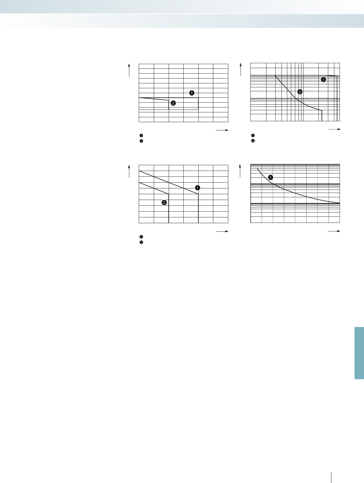
0,6
0,7
0,8
0,9
1,0
1,1
1,2
1,3
1,4
1,5
1,6
1,7
1,8
2030405060 70 80
0,1
0,2
0,3
0,5
10
20
10203050 70 100 300200 500
1
2
5
2030405060 70 80
1
2
3
4
5
6
7
8
9
10
11
01234
10
4
10
5
10
5
10
6
10
7
For further information and full technical data, visit phoenixcontact.net/products
373PHOENIX CONTACT
RIF-4-RPT.../3X1 (3 N/O contacts)
Operating voltage range Interrupting rating
Ambient temperature [°C]
Coil voltage U/U
N
DC coil (observe contact derating)
AC coil (observe contact derating)
Switching voltage [V]
Switching current [A]
AC, ohmic load
DC, ohmic load
Contact derating Electrical service life
Ambient temperature [°C]
Limiting continuous current per contact [A]
DC coil
AC coil
250 V AC, ohmic load
Cycles
Switching capacity [kVA]
Relay modules
Industrial relay system with push-in connection - RIFLINE complete
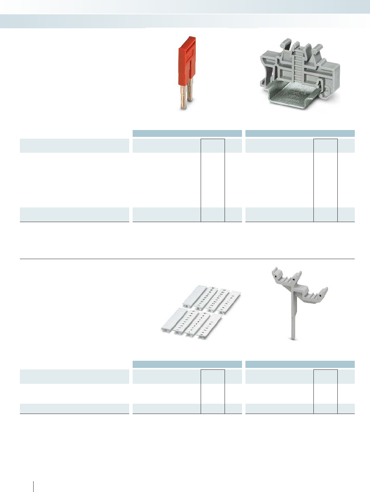
Ordering data Ordering data
Description Color Type Order No. Pcs. /
Pkt. Type Order No. Pcs. /
Pkt.
Jumper
2-pos. red, 32 A FBS 2-6 3030336 50
2-pos. blue, 32 A FBS 2-6 BU 3036932 50
2-pos. gray, 32 A FBS 2-6 GY 3032237 50
5-pos. red, 32 A FBS 5-6 3030349 50
10-pos. red, 32 A FBS 10-6 3030271 10
20-pos. red, 32 A FBS 20-6 3030365 10
50-pos. red, 32 A FBS 50-6 3032224 10
2-pos. red, 41 A FBS 2-8 3030284 10
2-pos. blue, 41 A FBS 2-8 BU 3032567 10
2-pos. gray, 41 A FBS 2-8 GY 7042 3032541 10
End bracket, for snapping onto NS 35, 9.5 mm wide, can be
marked with ZB 6, ZB 8/27, KLM...
CLIPFIX 35 3022218 50
The jumpers can be used for simple
potential distribution via all relay bases.
The end bracket is used for safe isolation
between adjacent modules and to visually
separate the various function groups.
RIFLINE complete accessories
Jumpers
Relay modules
Industrial relay system with push-in connection - RIFLINE complete
Ordering data Ordering data
Description Color Type Order No. Pcs. /
Pkt. Type Order No. Pcs. /
Pkt.
Zack marker strip, unprinted
10-section white ZB 5 :UNBEDRUCKT 1050004 10
10-section white ZB 6:UNBEDRUCKT 1051003 10
5-section white ZB 15:UNBEDRUCKT 0811972 10
Double marker carrier for ZB 5
gray STP 5-2 0800967 100
374
PHOENIX CONTACT
The ZB zack band system offers
numerous marking options that can be
attached directly to the relay retaining
brackets. In addition, further markings can
be fixed to the relay base by means of
double marker carriers.
RIFLINE complete accessories
Marking material
5.2 mm, 6.2 mm, and 15.2 mm wide Double marker carrier

.0.1 .2 .3 .4 .5 .6 .7
A2 A1 A2 A1 A2 A1 A2 A1 A2 A1 A2 A1 A2 A1 A2 A1
1234567891011 12 13 14
FLK 14
++ --
For further information and full technical data, visit phoenixcontact.net/products
Ordering data
Description Color Type Order No. Pcs. /
Pkt.
Test plug, consisting of:
Metal part for 2.3 mm Ø socket hole and silver MPS-MT 0201744 10
Insulating sleeve, for MPS metal part red MPS-IH RD 0201676 10
white MPS-IH WH 0201663 10
blue MPS-IH BU 0201689 10
yellow MPS-IH YE 0201692 10
green MPS-IH GN 0201702 10
gray MPS-IH GY 0201728 10
black MPS-IH BK 0201731 10
The two-piece test plug offers individual
plug color combinations. The test plug is
inserted directly in the function shaft of the
push-in connection.
RIFLINE complete accessories
Test plug
Relay modules
Industrial relay system with push-in connection - RIFLINE complete
Technical data
Max. perm. operating voltage 30 V DC
Max. perm. current (per branch) 1 A (per signal path)
Max total current (voltage supply) 3 A
Rated surge voltage 0.6 kV (functional insulation)
Ambient temperature (operation) -40 °C ... 60 °C
Mounting position any
Standards/regulations IEC 60664, IEC 62103, DIN EN 50178
Connection data solid / stranded / AWG 0.2 ... 1.5 mm² / 0.2 ... 1.5 mm² / 24 - 16
Dimensions H / D 101 mm / 75 mm
Ordering data
Description No. of
pos.
Module width
WType Order No. Pcs. /
Pkt.
V8 adapter, for eight RIF-1 relay modules, with FLK connection for
PLC system cabling, positive switching
128 mm RIF-1-V8/PT/FLK14/OUT 2905195 1
375
PHOENIX CONTACT
new
RIF-1-V8... is the VARIOFACE adapter
which connects the RIF-1 relay modules
with the VARIOFACE system cabling. This
allows easy connection of eight relay
modules to a controller.
Adapter for RIFLINE complete
VARIOFACE adapter for
RIFLINE complete RIF-1
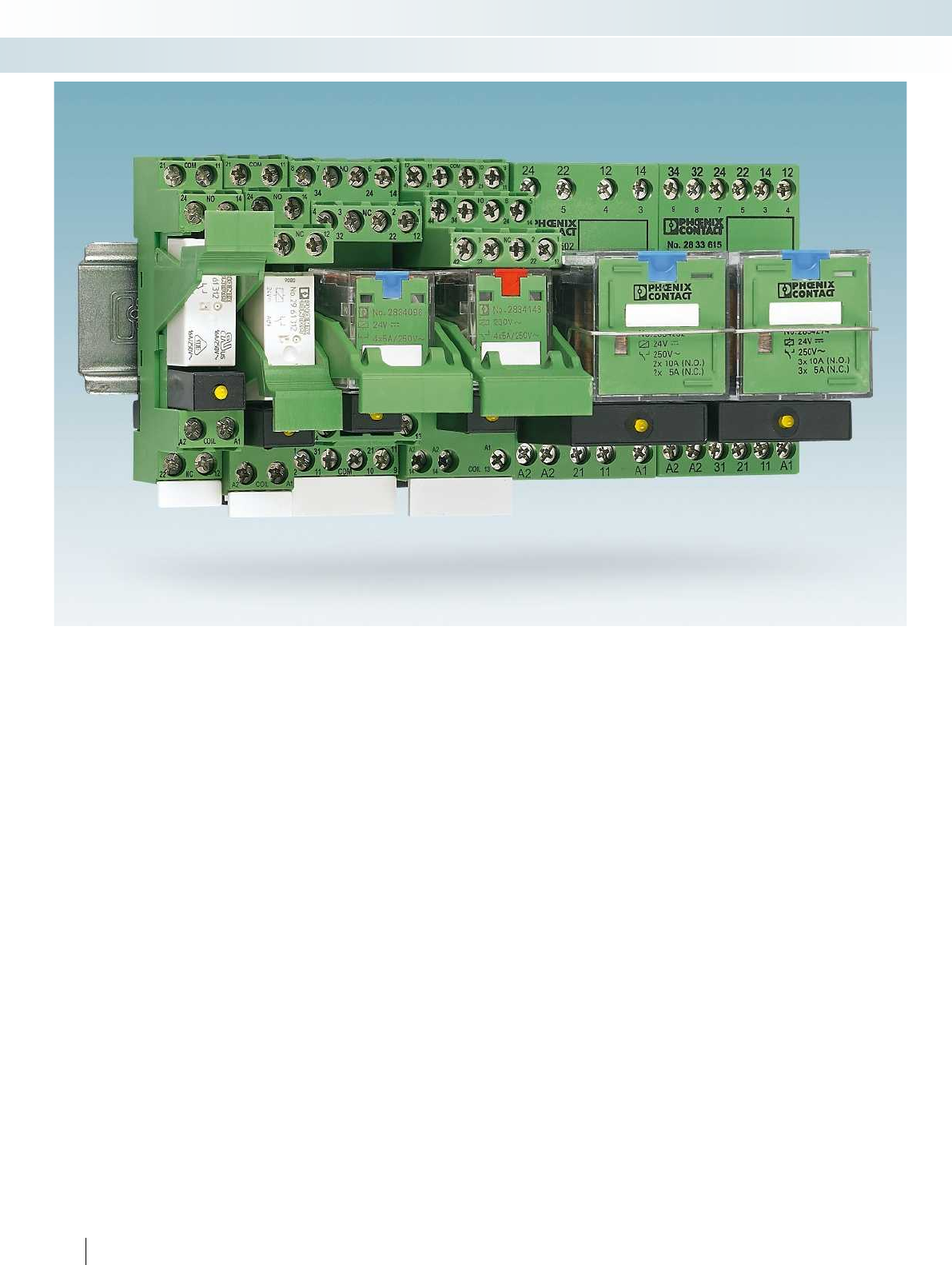
376
PHOENIX CONTACT
Relay modules
Industrial relay system with screw connection - PR series
The PR series is a low-priced relay
modular system, consisting of DIN rail
bases, relays, plug-in input/interference
suppression modules, engagement levers
and the matching marking labels and
universal bridging materials for all bases.
The modules are largely compatible with
the usual standards on the market, have the
major international approvals, and are
therefore accepted worldwide.
The PR series also boasts its own
particular features:
– Relay retaining bracket: the EL... plastic
relay retaining brackets, with which the
relays can be held and, if necessary,
ejected, have an exposed, smooth, large
equipment marking area for standard
self-adhesive labels that can be printed
easily and inexpensively using standard
printers. When fitted, the engagement
lever is securely connected to the base,
which means that the marking cannot be
lost.
– Industrial relays: as standard, all REL-IR...
industrial relays have an LED status
display and all DC types also have an
integrated freewheeling diode. In most
cases, this eliminates the plug-in input
modules that are otherwise also used.
– Plug-in input modules with RC element:
most standard input/interference
suppression modules with an RC element
used for compensation of interference
coupling on long lines or in the event of
leakage currents from electronic
AC outputs have only low capacitance
values. This greatly limits the filter effect.
In contrast, the RC-120-230UC and
RC3-120-230UC plug-in module series
for mains voltage applications have a filter
function that is improved up to a factor of
10. Unlike with the discharge resistors
that are normally used for such
applications, using RC plug-in modules
does not result in any additional heating.
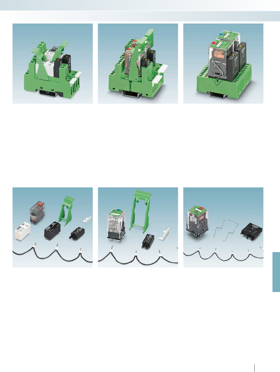
For further information and full technical data, visit phoenixcontact.net/products
377PHOENIX CONTACT
Relay modules
Industrial relay system with screw connection - PR series
PR1 series
The narrow 16 mm PR1 base series for
relays with one or two contacts.
Traditional 2/2-level bases are available
and there is also a choice of two modern
“logical” 1/3-level versions with fully
opposite coil and contact connections.
PR2 series
The PR2 base series accommodates plug-
in industrial relays with two or four PDT
contacts.
Just like the PR1 series, the bases are
available in traditional 2/2-level and the
modern “logical” 1/3-level versions.
PR3 series
The robust octal relays with two or three
PDT contacts that are widely used in some
areas fit on the PR3 base with shock-proof
screw connections. All the base
connections have a wide connection cross
section and are arranged on one level with
good accessibility.
The active components of the PR1
modular system include various miniature
power relays (optionally available with
manual test function) and electronic solid-
state relays. Matching relay retaining
brackets with integrated marking area
prevent them from being shaken loose.
Depending on requirements,
input/interference suppression modules
with various functions can also be plugged
in. Marking labels and loop bridges in
various colors that are suitable for universal
use with all PR bases complete the range of
accessories.
The PR2 modular system is specifically
designed for plug-in industrial relays.
Industrial relays from Phoenix Contact
feature the following as standard: a manual
test button, switch position indicator, status
LED, and freewheeling diode (DC coils
only). Interference suppression modules
with a varistor or RC element can also be
plugged in as an option. Relay retaining
brackets with integrated marking areas
prevent the relays from being shaken loose.
Marking labels and loop bridges in various
colors that are suitable for universal use
with all PR bases complete the range of
accessories.
The PR3 modular system is specifically
designed for the robust octal relays. The
relays have a switch position indicator and a
manual test button and there is a wire
bracket to prevent them from being shaken
loose. Input/interference suppression
modules with various functions can also be
plugged in as an option. The base can be
marked with an 8 x 20 mm standard
adhesive label. Loop bridges in various
colors for universal use round off the range
of accessories.
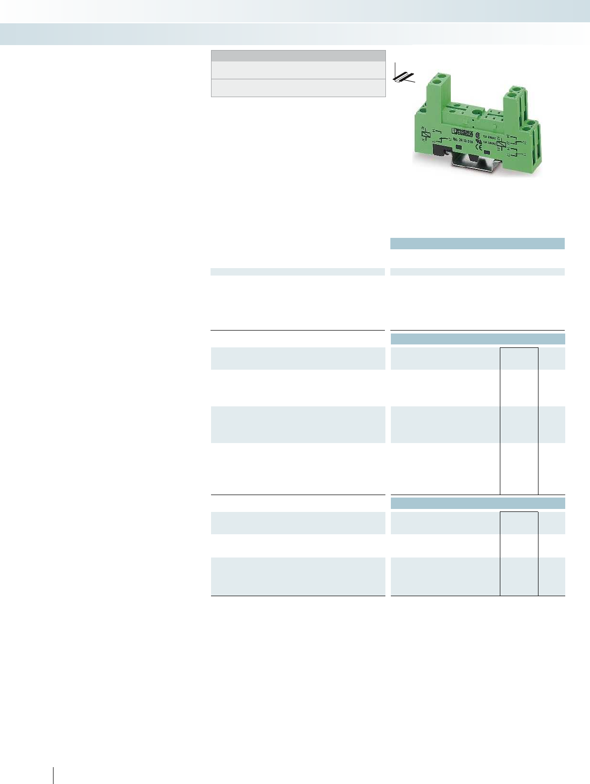
Technical data
Nominal voltage U
N
300 V AC/DC
Nominal current at U
N
12 A
General data
Ambient temperature (operation) -25 °C ... 85 °C
Connection data solid / stranded / AWG 0.2 ... 2.5 mm² / 0.2 ... 2.5 mm² / 26 - 14 0.2 ... 2.5 mm² / 0.2 ... 2.5 mm² / 26 - 14 -
Dimensions
Width 16 mm
Depth with retaining bracket 63 mm (EL1-P16)
71 mm (EL1-P25)
Height 75 mm
Ordering data
Description Type Order No. Pcs. /
Pkt.
PR1 relay base, 2/2-level design, plug-in option for
input/interference suppression module, safe isolation I/O, including
ten MP1 marking labels per pack
With screw connection PR1-BSC2/2X21 2833518 10
PR1 relay base, 1/3-level design, plug-in option for
input/interference suppression module, safe isolation I/O, including
ten MP1 marking labels per pack
With screw connection
Relay retaining bracket, with ejector function and integrated
equipment marking area (7.5 x 15 mm), suitable for PR1 relay base
for 16 mm tall miniature power relay and solid-state relay EL1-P16 2833547 10
for 25 mm tall miniature power relay and solid-state relay EL1-P25 2833550 10
Accessories
Equipment marking label, marking area 6 x 15 mm
MP 1 2833631 10
Device marking label, for thermal transfer printer, marking area 6
x 15 mm
2500 labels per roll EML (15X6) R YE 0819288 1
Loop bridge
, 50-pos., divisible, max. bridging distance 60 mm, 0.5 mm²
blue DB 50- 90 BU 2821180 1
black DB 50- 90 BK 2820916 1
gray DB 50- 90 GY 2820929 1
378
PHOENIX CONTACT
DW
H
Modular PR1 relay base
Notes:
Type of housing:
Polyamide fiber reinforced PA-F, color: green.
Marking systems and mounting material
See Catalog 5
Relay base family that can be fitted with
1 PDT or 2 PDT relay or solid-state relay
Range of accessories includes:
– Plug-in input modules/interference suppr.
modules
– Relay retaining bracket with marking field
and ejection function
– Marking labels
– Loop bridges
Relay modules
Industrial relay system with screw connection - PR series
2/2-level design with
screw connection

For further information and full technical data, visit phoenixcontact.net/products
Technical data Technical data
300 V AC/DC -
12 A -
-25 °C ... 85 °C -
Connection data solid / stranded / AWG 0.2 ... 2.5 mm² / 0.2 ... 2.5 mm² / 26 - 14 0.2 ... 2.5 mm² / 0.2 ... 2.5 mm² / 26 - 14 -
16 mm -
71 mm (EL1-P16)
79 mm (EL1-P25)
-
78.5 mm -
Ordering data Ordering data
Type Order No. Pcs. /
Pkt. Type Order No. Pcs. /
Pkt.
PR1-BSC3/2X21 2833521 10
EL1-P16 2833547 10 EL1-P16 2833547 10
EL1-P25 2833550 10 EL1-P25 2833550 10
Accessories Accessories
MP 1 2833631 10
EML (15X6) R YE 0819288 1
DB 50- 90 BU 2821180 1
DB 50- 90 BK 2820916 1
DB 50- 90 GY 2820929 1
379PHOENIX CONTACT
DW
H
Relay modules
Industrial relay system with screw connection - PR series
1/3-level design with
screw connection
Relay retaining bracket

14
A1
1112
A2
24
14
A1
21
11
22
12
A2
380
PHOENIX CONTACT
Plug-in miniature power relays
Plug-in miniature power relays with
1 or 2 PDT contacts, suitable for RIF-1, PR1,
and PLC-INTERFACE relay bases.
The advantages:
– Power contacts up to 16 A
– Multi-layer gold contact or power contact
– High degree of protection up to RT III
(comparable with IP67) depending on
type
Notes:
If the specified maximum values for multi-layer contact relays are
exceeded, the gold plating is destroyed. The maximum values of
the power contact relay are then valid. This can result in a shorter
service life than with a pure power contact.
Technical data Technical data
Input data ① ② ③ ④ ⑤ ⑥ ⑦ ⑧ ① ② ③ ④ ⑤ ⑥ ⑦ ⑧
Permissible range (with reference to U
N
) see diagram see diagram
Typ. input current at U
N
[mA] 33 17 8.7 8.2 4.1 32 7 3 33 17 8.7 8.2 4.1 32 7 3
Typ. response time at U
N
[ms]77777 77777
Typ. response time at U
N
(depending on phase relation)
[ms] 3 - 12 3 - 12 3 - 12 3 - 12 3 - 12 3 - 12
Typ. release time at U
N
[ms]33333 33333
Typ. release time at U
N
(depending on phase relation)
[ms] 2 - 9 2 - 9 2 - 9 2 - 9 2 - 9 2 - 9
Output data
Contact type 1 PDT 1 PDT 2 PDTs 2 PDTs
Contact material AgNi AgNi, hard gold-plated AgNi AgNi, hard gold-plated
Max. switching voltage 250 V AC/DC 30 V AC / 36 V DC 250 V AC/DC 30 V AC / 36 V DC
Min. switching voltage 12 V (at 10 mA) 100 mV (at 10 mA) 5 V (at 10 mA) 100 mV (at 10 mA)
Limiting continuous current 16 A 50 mA 8 A 50 mA
Max. inrush current 25 A (20 ms) 50 mA 12 A (20 ms) 50 mA
Min. switching current 10 mA (at 12 V) 1 mA (at 24 V) 10 mA (at 5 V) 1 mA (at 24 V)
Max. interrupting rating, ohmic load
250 V AC 4000 VA - 2000 VA -
General data
Test voltage (winding/contact) 5 kV AC (50 Hz, 1 min.) 5 kV AC (50 Hz, 1 min.)
Test voltage (contact/contact) - 2.5 kV AC (50 Hz, 1 min.)
Ambient temperature (operation) -40 °C ... 85 °C -40 °C ... 85 °C
Mechanical service life 1 x 10
7
cycles 1 x 10
7
cycles
Electrical service life see diagram see diagram
Standards/regulations IEC 60664, EN 50178, IEC 62103 IEC 60664, EN 50178, IEC 62103
Ordering data Ordering data
Description Input voltage
U
N
Type Order No. Pcs. /
Pkt. Type Order No. Pcs. /
Pkt.
Plug-in miniature power relay
with power contacts ①12 V DC REL-MR- 12DC/21HC 2961309 10 REL-MR- 12DC/21-21 2961257 10
with power contacts ②24 V DC REL-MR- 24DC/21HC 2961312 10 REL-MR- 24DC/21-21 2961192 10
with power contacts ③48 V DC REL-MR- 48DC/21HC 2834821 10 REL-MR- 48DC/21-21 2834834 10
with power contacts ④60 V DC REL-MR- 60DC/21HC 2961325 10 REL-MR- 60DC/21-21 2961273 10
with power contacts ⑤110 V DC REL-MR-110DC/21HC 2961338 10 REL-MR-110DC/21-21 2961202 10
with power contacts ⑥24 V AC REL-MR- 24AC/21HC 2961406 10 REL-MR- 24AC/21-21 2961435 10
with power contacts ⑦120 V AC REL-MR-120AC/21HC 2961419 10 REL-MR-120AC/21-21 2961448 10
with power contacts ⑧230 V AC REL-MR-230AC/21HC 2961422 10 REL-MR-230AC/21-21 2961451 10
Plug-in miniature power relay
with multi-layer gold contacts ①12 V DC REL-MR- 12DC/21HC AU 2961532 10 REL-MR- 12DC/21-21AU 2961299 10
with multi-layer gold contacts ②24 V DC REL-MR- 24DC/21HC AU 2961545 10 REL-MR- 24DC/21-21AU 2961215 10
with multi-layer gold contacts ③48 V DC REL-MR- 48DC/21-21AU 2834847 10
with multi-layer gold contacts ④60 V DC REL-MR- 60DC/21-21AU 2961286 10
with multi-layer gold contacts ⑤110 V DC REL-MR-110DC/21HC AU 2961561 10 REL-MR-110DC/21-21AU 2961228 10
with multi-layer gold contacts ⑥24 V AC REL-MR- 24AC/21HC AU 2961503 10 REL-MR- 24AC/21-21AU 2961464 10
with multi-layer gold contacts ⑦120 V AC REL-MR-120AC/21HC AU 2961516 10 REL-MR-120AC/21-21AU 2961477 10
with multi-layer gold contacts ⑧230 V AC REL-MR-230AC/21HC AU 2961529 10 REL-MR-230AC/21-21AU 2961480 10
Relay modules
Industrial relay system with screw connection - PR series
1 PDT relay 2 PDT relay
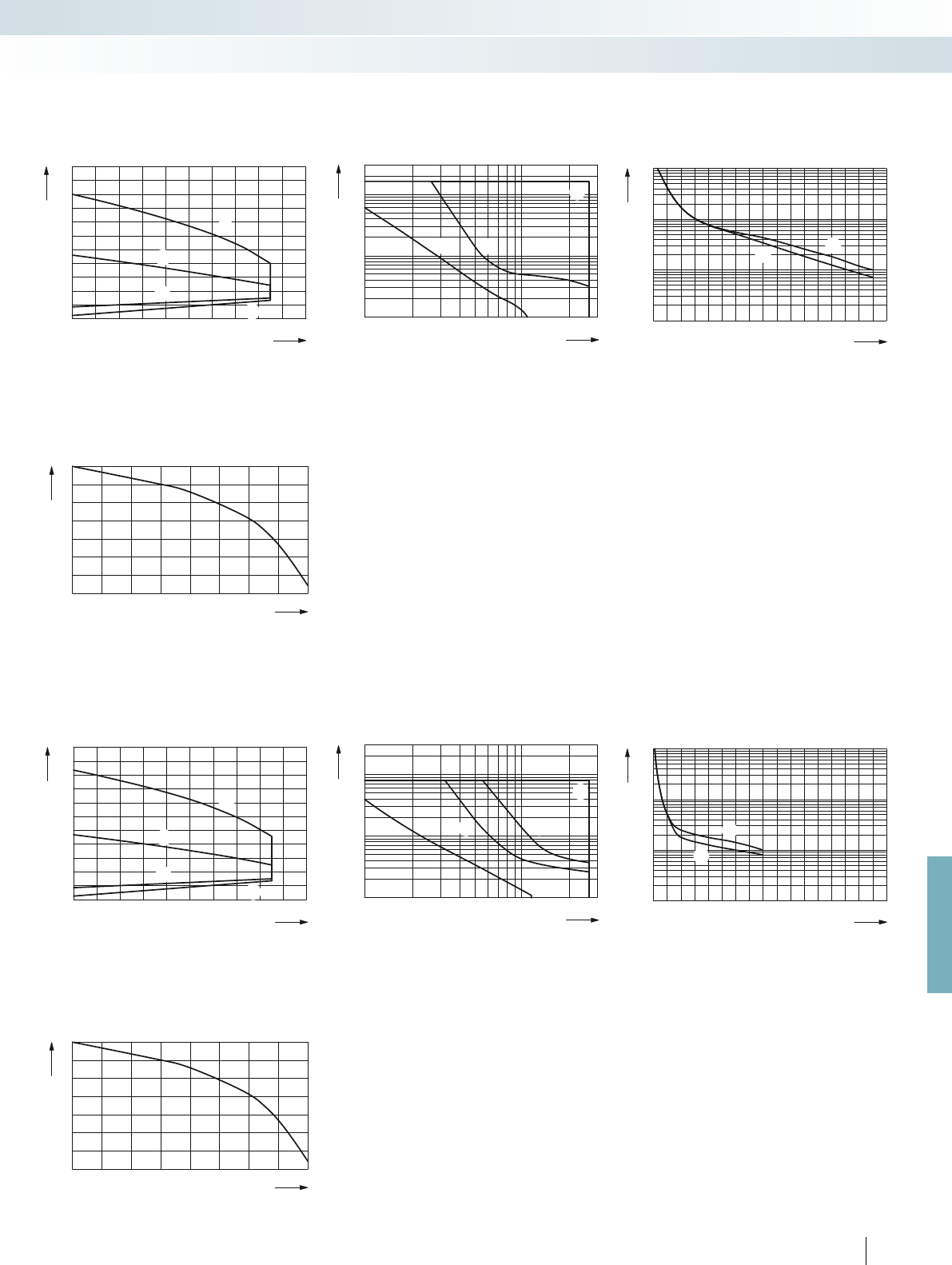
0,6
0,8
1
1,2
1,4
1,6
1,8
2
2,2
2,4
2,6
2,8
0 10 20 30 40 50 60 70 80 90 100
1
1
2
2
1
2
0,1
0,2
0,3
0,5
1
2
4
6
10
20
10 20 30 50 70 100 300200
1
2
3
3
1
2
1
0,9
0,3
0,4
0,5
0,6
0,7
0,8
0,9
1
0,80,70,60,50,40,30,2
0,6
0,8
1
1,2
1,4
1,6
1,8
2
2,2
2,4
2,6
2,8
0 10 20 30 40 50 60 70 80 90 100
1
2
2
1
1
2
0,1
0,2
0,3
0,5
1
2
4
6
10
20
10 20 30 50 70 100 300200
1
2
3
4
3
1
42
1
0,9
0,3
0,4
0,5
0,6
0,7
0,8
0,9
1
0,80,70,60,50,40,30,2
0 1 4 8 12 16
107
106
105
104
23 56711910 151413
1
2
21
0 1 4 8 12 16
107
106
105
104
23 56711910 151413
1
2
2
1
For further information and full technical data, visit phoenixcontact.net/products
381
PHOENIX CONTACT
REL-MR...21HC... (1 PDT)
Operating voltage range Interrupting rating
Ambient temperature [°C]
Coil voltage U/U
N
DC coils
AC coils
AC, ohmic load
DC, ohmic load
DC, L/R = 40 ms
Switching voltage [V]
Switching current [A]
Service life reduction factor with various cos phi
COS j
Reduction factor
REL-MR...21-21... (2 PDTs)
Operating voltage range Interrupting rating
Ambient temperature [°C]
Coil voltage U/U
N
DC coils
AC coils
AC, ohmic load
DC, ohmic load, contacts in series
DC, ohmic load
DC, L/R = 40 ms
Switching voltage [V]
Switching current [A]
Service life reduction factor with various cos phi
COS j
Reduction factor
Electrical service life
Cycles
Switching current [A]
250 V AC, ohmic load (DC coils)
250 V AC, ohmic load (AC coils)
Electrical service life
Cycles
Switching current [A]
250 V AC, ohmic load (DC coils)
250 V AC, ohmic load (AC coils)
Relay modules
Industrial relay system with screw connection - PR series
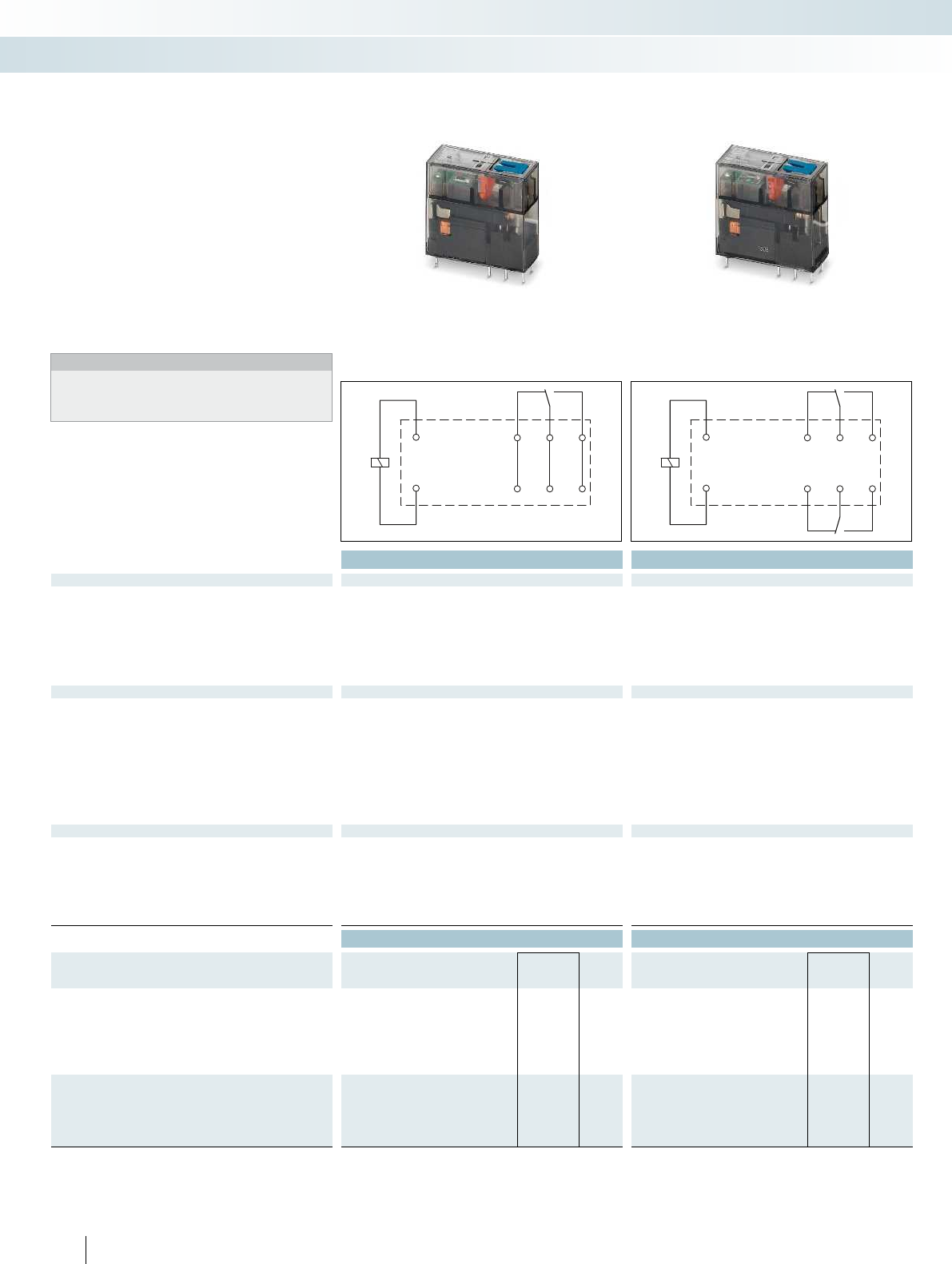
14
A1
1112
A2
24
14
A1
21
11
22
12
A2
382
PHOENIX CONTACT
Plug-in miniature power relays
Plug-in miniature power relays with
1 or 2 PDT contacts, suitable for RIF-1 and
PR1 relay bases.
The advantages:
– Switching current of up to 16 A
– With lockable manual operation
– Mechanical switch position indicator
– Integrated status LED
– Multi-layer gold contact or power contact
– DC types with integrated freewheeling
diode
– Can be soldered in on PCB
Notes:
If the specified maximum values for multi-layer contact relays are
exceeded, the gold plating is destroyed. The maximum values of
the power contact relay are then valid. This can result in a shorter
service life than with a pure power contact.
Technical data Technical data
Input data ① ② ③ ④ ① ② ③ ④
Permissible range (with reference to U
N
) see diagram see diagram
Typ. input current at U
N
[mA] 18 32 7 3.5 18 32 7 3.5
Typ. response time at U
N
[ms] 9 9
Typ. response time at U
N
(depending on phase relation)
[ms] 3 - 12 3 - 12 3 - 12 3 - 12 3 - 12
Typ. release time at U
N
[ms] 6 6
Typ. release time at U
N
(depending on phase relation)
[ms] 2 - 8 2 - 8 2 - 8 2 - 8 2 - 8 2 - 8
Output data
Contact type 1 PDT 1 PDT 2 PDTs 2 PDTs
Contact material AgNi AgNi, hard gold-plated AgNi AgNi, hard gold-plated
Max. switching voltage 250 V AC/DC 30 V AC / 36 V DC 250 V AC/DC 30 V AC / 36 V DC
Min. switching voltage 12 V (at 10 mA) 12 V (at 1 mA) 12 V (at 10 mA) 12 V (at 1 mA)
Limiting continuous current 16 A 50 mA 8 A 50 mA
Max. inrush current 32 A (20 ms) 50 mA 16 A (20 ms) 50 mA
Min. switching current 10 mA (at 12 V) 1 mA (at 12 V) 10 mA (at 12 V) 1 mA (at 12 V)
Max. interrupting rating, ohmic load
250 V AC 4000 VA - 2000 VA -
General data
Test voltage (winding/contact) 5 kV AC (50 Hz, 1 min.) 5 kV AC (50 Hz, 1 min.)
Test voltage (contact/contact) - 2.5 kV AC (50 Hz, 1 min.)
Ambient temperature (operation) -40 °C ... 70 °C -40 °C ... 70 °C
Mechanical service life 5 x 10
6
cycles 5 x 10
6
cycles
Electrical service life see diagram see diagram
Standards/regulations DIN EN 61810-1, VDE 0435-201, EN 50178, IEC 62103 DIN EN 61810-1, VDE 0435-201, EN 50178, IEC 62103
Ordering data Ordering data
Description Input voltage
U
N
Type Order No. Pcs. /
Pkt. Type Order No. Pcs. /
Pkt.
Plug-in miniature power relay, with power contacts
- Status LED, freewheeling diode A1+, A2-
①24 V DC REL-MR- 24DC/21HC/MS 2987888 10 REL-MR- 24DC/21-21/MS 2987943 10
- Status LED ②24 V AC REL-MR- 24AC/21HC/MS 2987891 10 REL-MR- 24AC/21-21/MS 2987956 10
- Status LED ③120 V AC REL-MR-120AC/21HC/MS 2987901 10 REL-MR-120AC/21-21/MS 2987969 10
- Status LED ④230 V AC REL-MR-230AC/21HC/MS 2987914 10 REL-MR-230AC/21-21/MS 2987972 10
Plug-in miniature power relay, with multi-layer gold contacts,
with manual operation, mechanical switch position indicator
- Status LED, freewheeling diode A1+, A2-
①24 V DC REL-MR- 24DC/21HC AU/MS 2987927 10 REL-MR- 24DC/21-21AU/MS 2987985 10
- Status LED ④230 V AC REL-MR-230AC/21HC AU/MS 2987930 10 REL-MR-230AC/21-21AU/MS 2987998 10
Relay modules
Industrial relay system with screw connection - PR series
1 PDT relay 2 PDT relay

0,6
0,8
1
1,2
1,4
1,6
1,8
2
2,2
2,4
2,6
0102030405060 70 80 90
100
1
2
20
10
5
2
1
0,5
0,2
0,1
1020305070100 200 300 400 500
1
2
1
0,9
0,3
0,4
0,5
0,6
0,7
0,8
0,9
1
0,80,70,60,50,40,30,2
0,6
0,8
1
1,2
1,4
1,6
1,8
2
2,2
2,4
2,6
0102030405060 70 80 90
100
20
10
5
2
1
0,5
0,2
0,1
10203050 70 100 200 300 400 500
1
0,9
0,3
0,4
0,5
0,6
0,7
0,8
0,9
1
0,80,70,60,50,40,30,2
014 812 16
107
106
105
104
2 3 5 6 7 11910151413
1
1
014 812 16
107
106
105
104
2 3 5 6 7 11910151413
1
1
For further information and full technical data, visit phoenixcontact.net/products
383PHOENIX CONTACT
REL-MR...21HC...MS (1 PDT)
Operating voltage range Interrupting rating
Ambient temperature [°C]
Coil voltage U/U
N
DC coils, 0 A contact current
AC coils, 0 A contact current
DC coils, 16 A contact current
AC coils, 16 A contact current
Switching voltage [V]
Switching current [A]
AC, ohmicload
DC, ohmicload
Service life reduction factor with various cos phi
COS j
Reduction factor
REL-MR...21-21...MS (2 PDTs)
Operating voltage range Interrupting rating
Ambient temperature [°C]
Coil voltage U/U
N
DC coils, 0 A contact current
AC coils, 0 A contact current
DC coils, 8 A contact current
AC coils, 8 A contact current
AC, ohmic load
DC, ohmic load, contacts in series
DC, ohmic load
Switching voltage [V]
Switching current [A]
Service life reduction factor with various cos phi
COS j
Reduction factor
Electrical service life
Cycles
Switching current [A]
250 V AC, ohmic load
Electrical service life
Cycles
Switching current [A]
250 V AC, ohmic load
Relay modules
Industrial relay system with screw connection - PR series
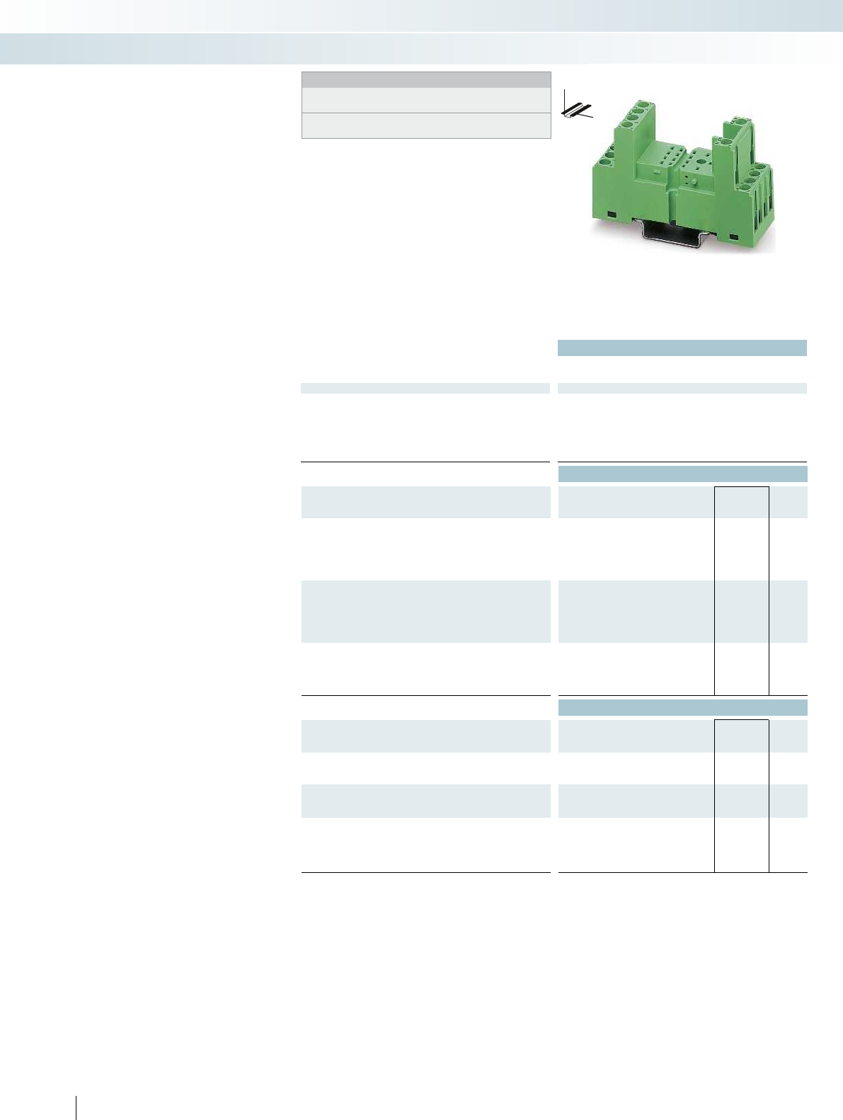
Technical data
Nominal voltage U
N
300 V AC/DC
Nominal current at U
N
12 A
General data
Ambient temperature (operation) -25 °C ... 85 °C
Connection data solid / stranded / AWG 0.2 ... 2.5 mm² / 0.2 ... 2.5 mm² / 26 - 14 0.2 ... 2.5 mm² / 0.2 ... 2.5 mm² / 26 - 14 -
Dimensions
Width 27 mm
Depth with retaining bracket 84 mm (EL2-P35)
Height 75 mm
Ordering data
Description Type Order No. Pcs. /
Pkt.
PR2-B relay base, for industrial relay, REL-IR with two or four
PDTs, 2/2-level design, connection option for input/interference
suppression module, including ten MP2 marking labels per pack
With screw connection PR2-BSC2/4X21 2833563 10
PR2-B relay base, for industrial relay, REL-IR with two or four
PDTs, 1/3-level design, connection option for input/interference
suppression module, including ten MP2 marking labels per pack
With screw connection
Relay retaining bracket, with ejector function and integrated
equipment marking area (8 x 25 mm), suitable for PR2 relay base
EL2-P35 2833592 10
Accessories
Equipment marking label, marking area 9 x 25 mm
MP 2 2833644 10
Device marking label, for thermal transfer printer, marking area 6
x 15 mm
2500 labels per roll EML (15X6) R YE 0819288 1
Device marking label, for thermal transfer printer, marking area 6
x 15 mm
2500 labels per roll EML (15X6) R YE 0819288 1
Loop bridge, 50-pos., divisible, max. bridging distance 60 mm,
0.5 mm²
blue DB 50- 90 BU 2821180 1
black DB 50- 90 BK 2820916 1
gray DB 50- 90 GY 2820929 1
384
PHOENIX CONTACT
DW
H
Modular PR2 relay base
Notes:
Type of housing:
Polyamide fiber reinforced PA-F, color: green.
Marking systems and mounting material
See Catalog 5
Relay base family that can be fitted with
2 PDT or 4 PDT relays
Range of accessories includes:
– Plug-in input modules/interference suppr.
modules
– Relay retaining bracket with marking field
and ejection function
– Marking labels
– Loop bridges
Relay modules
Industrial relay system with screw connection - PR series
2/2-level design with
screw connection
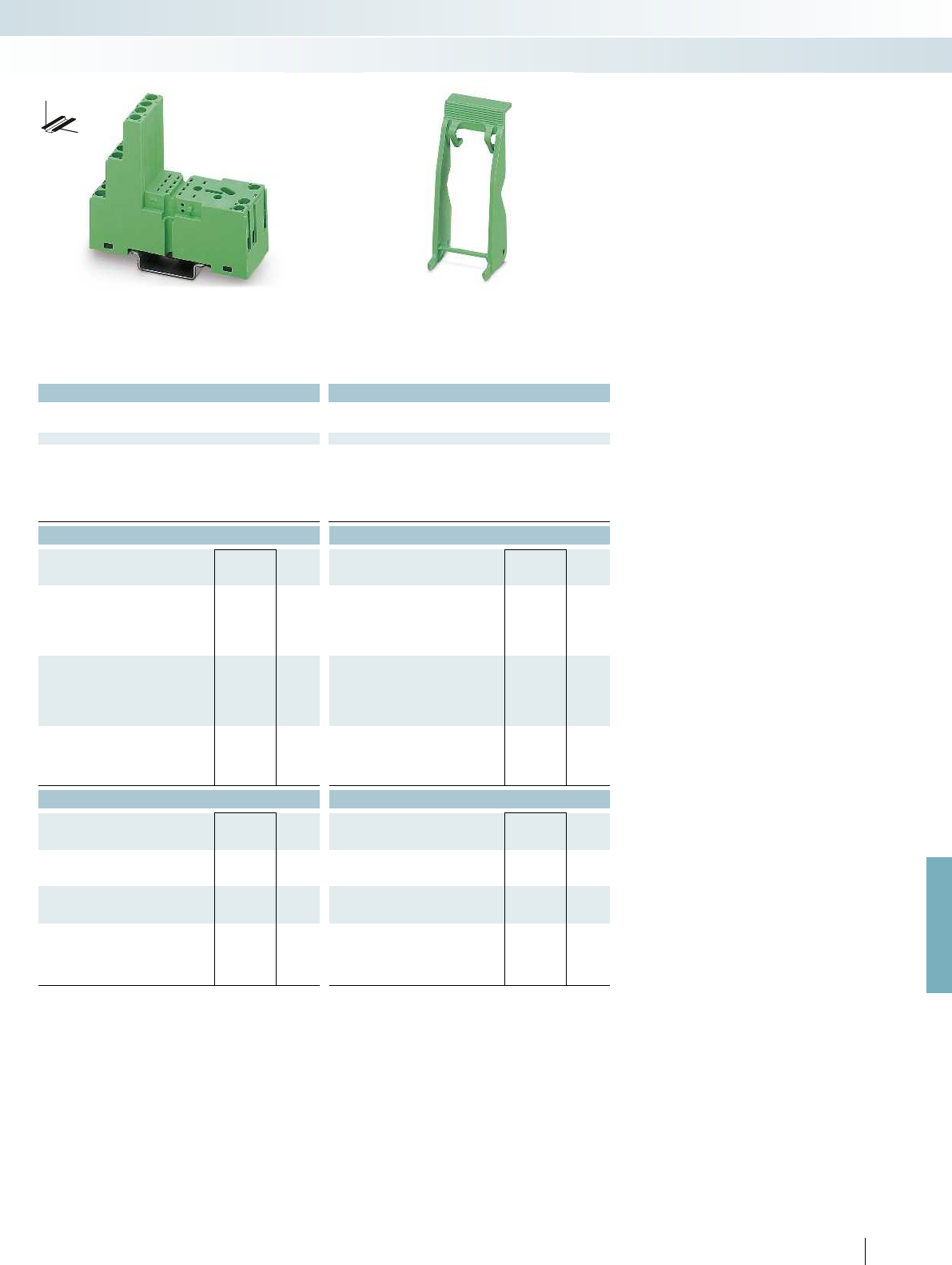
For further information and full technical data, visit phoenixcontact.net/products
Technical data Technical data
300 V AC/DC -
12 A -
-25 °C ... 85 °C -
Connection data solid / stranded / AWG 0.2 ... 2.5 mm² / 0.2 ... 2.5 mm² / 26 - 14 0.2 ... 2.5 mm² / 0.2 ... 2.5 mm² / 26 - 14 -
27 mm -
86 mm (EL2-P35) -
78.5 mm -
Ordering data Ordering data
Type Order No. Pcs. /
Pkt. Type Order No. Pcs. /
Pkt.
PR2-BSC3/4X21 2833576 10
EL2-P35 2833592 10 EL2-P35 2833592 10
Accessories Accessories
MP 2 2833644 10
EML (15X6) R YE 0819288 1
EML (15X6) R YE 0819288 1
DB 50- 90 BU 2821180 1
DB 50- 90 BK 2820916 1
DB 50- 90 GY 2820929 1
385PHOENIX CONTACT
DW
H
Relay modules
Industrial relay system with screw connection - PR series
1/3-level design with
screw connection
Relay retaining bracket
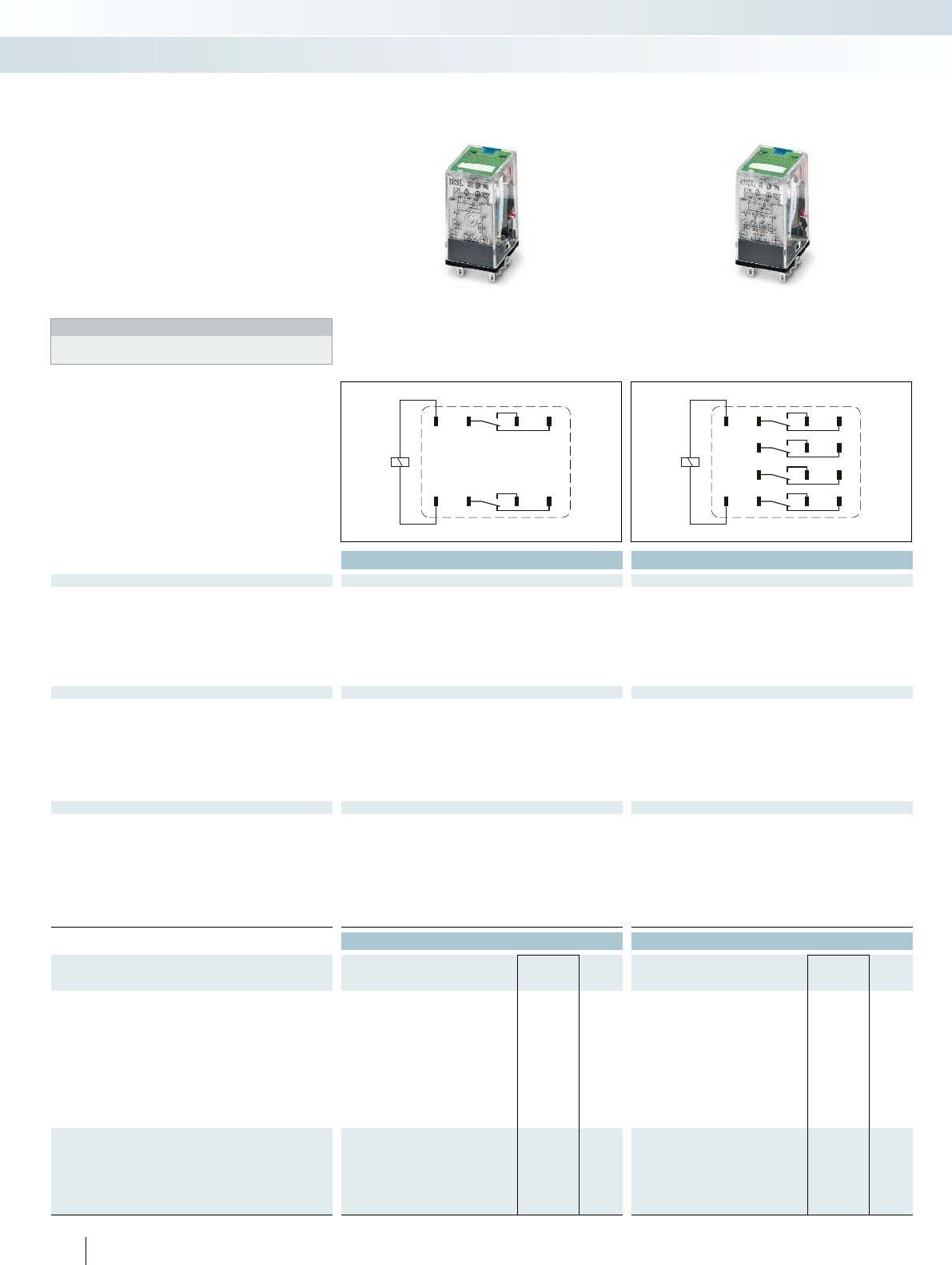
22
A1
21 24
1211 14
A2
42
A1
41 44
3231 34
2221 24
1211 14
A2
386
PHOENIX CONTACT
Plug-in industrial relays suitable for
PR2 relay base
Plug-in industrial relays with 2 or 4 PDT
contacts, suitable for PR2 and RIF-2 relay
bases.
The advantages:
– With lockable manual operation
– Mechanical switch position indicator
– Integrated status LED
– Multi-layer gold contact or power contact
– DC types with integrated freewheeling
diode
Notes:
For 48 V DC and 60 V DC types, see
phoenixcontact.net/products
Technical data Technical data
Input data ① ② ③ ④ ⑤ ⑥ ⑦ ⑧ ① ② ③ ④ ⑤ ⑥ ⑦ ⑧
Permissible range (with reference to U
N
) see diagram see diagram
Typ. input current at U
N
[mA] 75 38 10 7.2 3.6 54 11 5 75 38 10 7.2 3.6 54 11 5
Typ. response time at U
N
[ms] 13 13 13 13 13 13 13 13 13 13
Typ. response time at U
N
(AC, depending on phase relation)
[ms] 4 - 10 4 - 10 4 - 10 4 - 10 4 - 10 4 - 10
Typ. release time at U
N
[ms]55555 55555
Typ. release time at U
N
(AC, depending on phase relation)
[ms] 3 - 12 3 - 12 3 - 12 3 - 12 3 - 12 3 - 12
Output data
Contact type 2 PDTs 4 PDTs
Contact material Ag AgNi, hard gold-plated
Max. switching voltage 250 V AC/DC 250 V AC/DC
Min. switching voltage 5 V 1 V
Limiting continuous current 10 A 5 A
Min. switching current 1 mA 1 mA
Max. interrupting rating, ohmic load
250 V AC 2500 VA 1250 VA
General data
Test voltage (winding/contact) 2 kV AC (50 Hz, 1 min.) 2 kV AC (50 Hz, 1 min.)
Test voltage (contact/contact) 2 kV AC (50 Hz, 1 min.) 2 kV AC (50 Hz, 1 min.)
Ambient temperature (operation) -55 °C ... 70 °C -55 °C ... 70 °C
Nominal operating mode 100% operating factor 100% operating factor
Mechanical service life 5 x 10
7
cycles 5 x 10
7
cycles
Electrical service life see diagram see diagram
Standards/regulations DIN EN 61810-1, VDE 0435-201, EN 50178, IEC 62103 DIN EN 61810-1, VDE 0435-201, EN 50178, IEC 62103
Mounting position / mounting any / on PR2 relay base any / on PR2 relay base
Ordering data Ordering data
Description Input voltage
U
N
Type Order No. Pcs. /
Pkt. Type Order No. Pcs. /
Pkt.
Plug-in industrial relay with a test button, status LED, mechanical
switch position indicator
with freewheeling diode, A1 +, A2 - ①12 V DC REL-IR/LDP- 12DC/2X21 2834012 10 REL-IR/LDP- 12DC/4X21AU 2834083 10
with freewheeling diode, A1 +, A2 - ②24 V DC REL-IR/LDP- 24DC/2X21 2834025 10 REL-IR/LDP- 24DC/4X21AU 2834096 10
with freewheeling diode, A1 +, A2 - ③110 V DC REL-IR/LDP-110DC/2X21 2834041 10 REL-IR/LDP-110DC/4X21AU 2834119 10
with freewheeling diode, A1 +, A2 - ④125 V DC REL-IR/LDP-125DC/2X21 2834960 10 REL-IR/LDP-125DC/4X21AU 2834313 10
with freewheeling diode, A1 +, A2 - ⑤220 V DC REL-IR/LDP-220DC/2X21 2834957 10 REL-IR/LDP-220DC/4X21AU 2834973 10
⑥24 V AC REL-IR/L- 24AC/2X21 2834054 10 REL-IR/L- 24AC/4X21AU 2834122 10
⑦120 V AC REL-IR/L-120AC/2X21 2834067 10 REL-IR/L-120AC/4X21AU 2834135 10
⑧230 V AC REL-IR/L-230AC/2X21 2834070 10 REL-IR/L-230AC/4X21AU 2834148 10
Plug-in industrial relay with a test button, status LED, mechanical
switch position indicator, (Japanese standard)
with freewheeling diode, A1 -, A2 + ①12 V DC REL-IR/LDM- 12DC/2X21 2834151 10 REL-IR/LDM- 12DC/4X21AU 2834193 10
with freewheeling diode, A1 -, A2 + ②24 V DC REL-IR/LDM- 24DC/2X21 2834164 10 REL-IR/LDM- 24DC/4X21AU 2834203 10
with freewheeling diode, A1 -, A2 + ③48 V DC REL-IR/LDM- 48DC/2X21 2834177 10 REL-IR/LDM- 48DC/4X21AU 2834216 10
with freewheeling diode, A1 -, A2 + ④110 V DC REL-IR/LDM-110DC/2X21 2834180 10 REL-IR/LDM-110DC/4X21AU 2834229 10
Relay modules
Industrial relay system with screw connection - PR series
2 PDT relay with
power contacts
4 PDT relay with
multi-layer gold contact
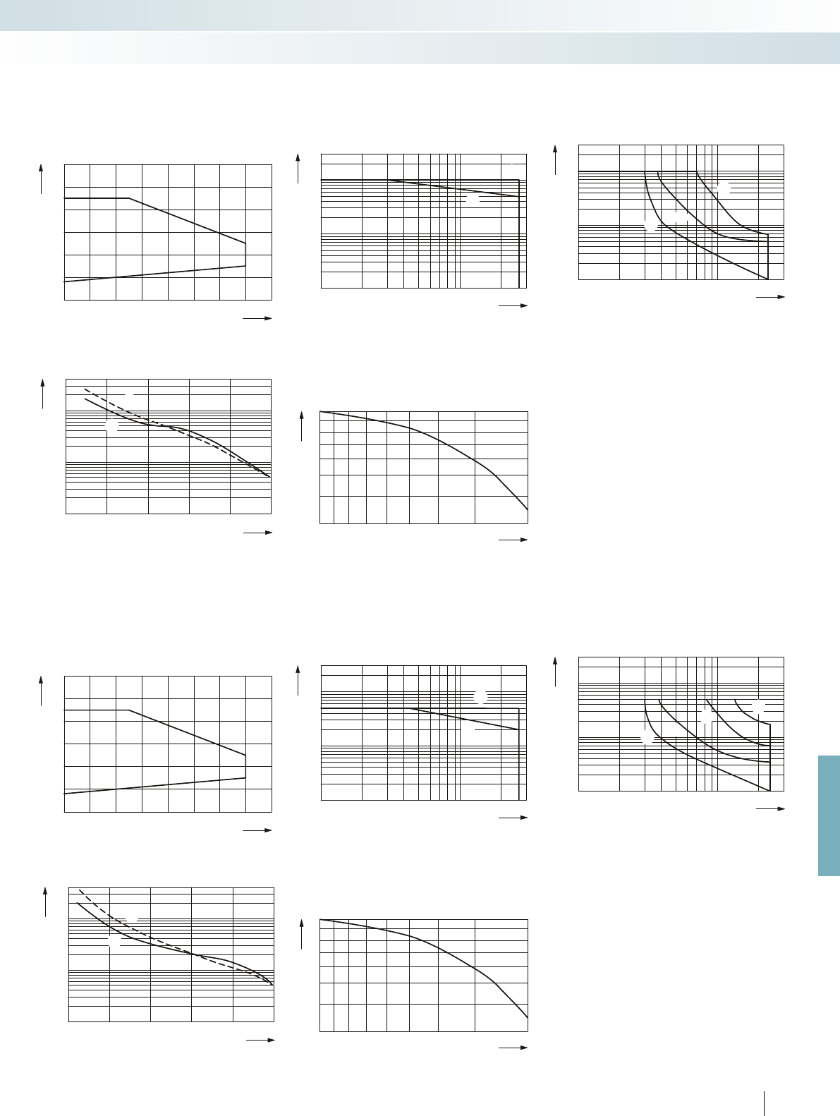
0
0,6
0,8
1
1,2
1,4
1,6
1,8
20 40 60 8010 30 50 70
0,1
0,2
0,3
0,5
1
2
4
6
10
20
10 20 30 50 70 100 300200
1
2
1
2
106
105
0246810
104
2
1
1
2
1
0,3
0,4
0,6
0,8
1
0,80,60,40,2
0
0,6
0,8
1
1,2
1,4
1,6
1,8
20 40 60 8010 30 50 70
0,1
0,2
0,3
0,5
1
2
4
6
10
20
10 20 30 50 70 100 300200
1
2
1
2
106
105
012345
104
2
1
1
2
1
0,3
0,4
0,6
0,8
1
0,80,60,40,2
0,1
0,2
0,3
0,5
1
2
4
6
10
20
10 20 30 50 70 100 300200
1
2
3
31
2
0,1
0,2
0,3
0,5
1
2
4
6
10
20
10 20 30 50 70 100 300200
1
2
3
4
12
4
3
For further information and full technical data, visit phoenixcontact.net/products
387PHOENIX CONTACT
REL-IR...2x21 (2 PDTs)
Operating voltage range AC interrupting rating
Ambient temperature [°C]
Coil voltage U/U
N
Ohmic load
cos = 0.4j
Switching voltage [V]
Switching current [A]
Electrical service life Service life reduction factor
Cycles
Switching current [A]
250 V AC, ohmic load
30 V DC, ohmic load
COS j
Reduction factor
REL-IR...4x21AU (4 PDTs)
Operating voltage range AC interrupting rating
Ambient temperature [°C]
Coil voltage U/U
N
Ohmic load
cos = 0.4j
Switching voltage [V]
Switching current [A]
Electrical service life Service life reduction factor
Cycles
Switching current [A]
250 VAC, ohmicload
30VDC, ohmicload
COS j
Reduction factor
DC interrupting rating
Ohmic load
ohmic load, contacts in series
L/R < 7 ms
Switching voltage [V]
Switching current [A]
DC interrupting rating
L/R < 7 ms
ohmic load
ohmic load, 2 contacts in series
ohmic load, 4 contacts in series
Switching voltage [V]
Switching current [A]
Relay modules
Industrial relay system with screw connection - PR series
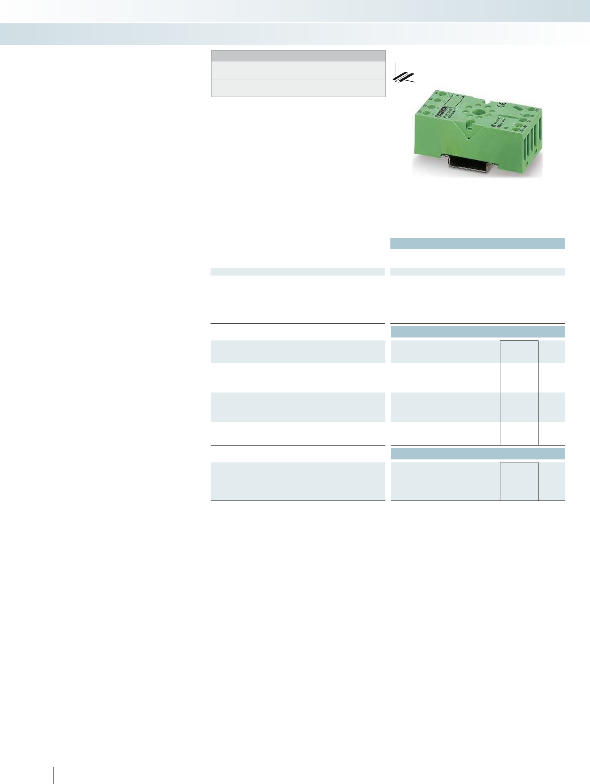
Technical data
Nominal voltage U
N
400 V AC/DC
Nominal current at U
N
10 A
General data
Ambient temperature (operation) -40 °C ... 85 °C
Connection data solid / stranded / AWG 0.2 ... 2.5 mm² / 0.2 ... 2.5 mm² / 26 - 14 0.2 ... 2.5 mm² / 0.2 ... 2.5 mm² / 26 - 14 -
Dimensions
Width 38 mm
Depth with retaining bracket 84 mm (EL3-M52)
Height 75 mm
Ordering data
Description Type Order No. Pcs. /
Pkt.
PR3 relay base, for REL-OR octal relay with two PDTs, plug-in
option for input/interference suppression modules
With screw connection PR3-BSC1/2X21 2833602 10
PR3 relay base, for REL-OR octal relay with three PDTs, plug-in
option for input/interference suppression modules
With screw connection
Relay retaining bracket, wire model, suitable for RIF-3 and
PR3 relay base
EL3-M52 2833628 10
Accessories
Loop bridge
, 50-pos., divisible, max. bridging distance 60 mm, 0.5 mm²
blue DB 50- 90 BU 2821180 1
black DB 50- 90 BK 2820916 1
gray DB 50- 90 GY 2820929 1
388
PHOENIX CONTACT
DW
H
Modular PR3 relay base
Notes:
Type of housing:
Polyamide fiber reinforced PA-F, color: green.
Marking systems and mounting material
See Catalog 5
Relay base family that can be fitted with
2 PDT or 3 PDT relays
Range of accessories includes:
– Plug-in input modules/interference suppr.
modules
– Relay retaining bracket
– Loop bridges
Relay modules
Industrial relay system with screw connection - PR series
Relay base for
2 PDT octal relay

For further information and full technical data, visit phoenixcontact.net/products
Technical data Technical data
400 V AC/DC -
10 A -
-40 °C ... 85 °C -
Connection data solid / stranded / AWG 0.2 ... 2.5 mm² / 0.2 ... 2.5 mm² / 26 - 14 0.2 ... 2.5 mm² / 0.2 ... 2.5 mm² / 26 - 14 -
38 mm -
84 mm (EL3-M52) -
75 mm -
Ordering data Ordering data
Type Order No. Pcs. /
Pkt. Type Order No. Pcs. /
Pkt.
PR3-BSC1/3X21 2833615 10
EL3-M52 2833628 10 EL3-M52 2833628 10
Accessories Accessories
DB 50- 90 BU 2821180 1
DB 50- 90 BK 2820916 1
DB 50- 90 GY 2820929 1
389PHOENIX CONTACT
DW
H
Relay modules
Industrial relay system with screw connection - PR series
Relay base for
3 PDT octal relay
Relay retaining bracket
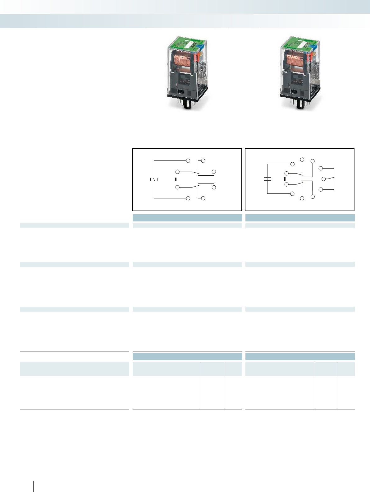
(11)
2 3
4
5
67
8
1
(21)
(A1)
(14)
(12)
(22)
(A2)
(24)
34
5
6
7
8
1
9
11
2
10
(11)
(31)
(A1)
(14)
(22)
(24)
(A2)
(32)
(12)
(21)
(34)
390
PHOENIX CONTACT
Plug-in octal relays suitable for PR3
relay base
Plug-in octal relays with 2 or 3 PDT
contacts, suitable for PR3 and RIF-3 relay
bases.
The advantages:
– With lockable manual operation
– Mechanical switch position indicator
– Extremely robust design
Technical data Technical data
Input data ① ② ③ ④ ① ② ③ ④
Typ. input current at U
N
[mA] 56 110 22 10 56 110 22 10
Typ. response time at U
N
[ms] 12 12
Typ. response time at U
N
(AC, depending on phase relation)
[ms] 5 - 20 5 - 20 5 - 20 5 - 20 5 - 20 5 - 20
Typ. release time at U
N
[ms] 6 6
Typ. release time at U
N
(AC, depending on phase relation)
[ms] 5 - 20 5 - 20 5 - 20 5 - 20 5 - 20 5 - 20
Output data
Contact type 2 PDTs 3 PDTs
Contact material AgSnIn AgSnIn
Max. switching voltage 250 V AC/DC 250 V AC/DC
Min. switching voltage 1 V 1 V
Limiting continuous current 10 A (N/O contact) 10 A (N/O contact)
Min. switching current 10 mA 10 mA
Max. interrupting rating, ohmic load
250 V AC 2500 VA 2500 VA
General data
Test voltage (winding/contact) 2.5 kV AC (50 Hz, 1 min.) 2.5 kV AC (50 Hz, 1 min.)
Test voltage (contact/contact) 2.5 kV AC (50 Hz, 1 min.) 2.5 kV AC (50 Hz, 1 min.)
Ambient temperature (operation) -40 °C ... 60 °C -40 °C ... 60 °C
Nominal operating mode 100% operating factor 100% operating factor
Mechanical service life 10 x 10
6
cycles 10 x 10
6
cycles
Electrical service life see diagram see diagram
Standards/regulations IEC 60664 IEC 60664
Mounting position / mounting any / on PR3 relay base any / on PR3 relay base
Ordering data Ordering data
Description Input voltage
U
N
Type Order No. Pcs. /
Pkt. Type Order No. Pcs. /
Pkt.
Plug-in octal relay with power contacts, with a test button and
mechanical switch position indicator
①24 V DC REL-OR- 24DC/2X21 2834232 10 REL-OR- 24DC/3X21 2834274 10
②24 V AC REL-OR- 24AC/2X21 2834245 10 REL-OR- 24AC/3X21 2834287 10
③120 V AC REL-OR-120AC/2X21 2834258 10 REL-OR-120AC/3X21 2834290 10
④230 V AC REL-OR-230AC/2X21 2834261 10 REL-OR-230AC/3X21 2834300 10
Relay modules
Industrial relay system with screw connection - PR series
2 PDT relay with
power contacts
3 PDT relay with power contacts
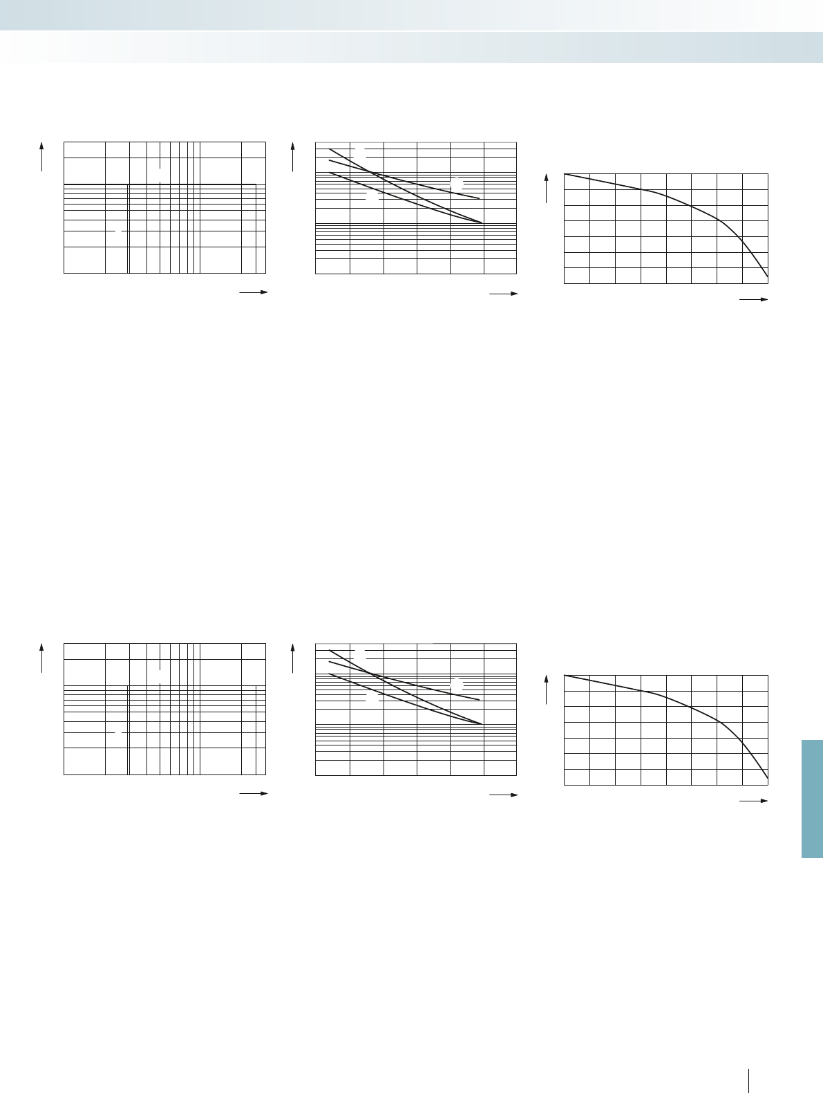
1
3
5
7
10
20
10 20 30 50 70 100 300200
1
2
1
2
10
4
10
5
10
6
0 2 4 6 8 10 12
1
2
3
3
1
2
1
3
5
7
10
20
10 20 30 50 70 100 300200
1
2
1
2
10
4
10
5
10
6
0 2 4 6 8 10 12
1
2
3
3
1
2
1
0,9
0,3
0,4
0,5
0,6
0,7
0,8
0,9
1
0,80,70,60,50,40,30,2
1
0,9
0,3
0,4
0,5
0,6
0,7
0,8
0,9
1
0,80,70,60,50,40,30,2
For further information and full technical data, visit phoenixcontact.net/products
391PHOENIX CONTACT
REL-OR...2x21 (2 PDTs)
Interrupting rating Electrical service life
Switching voltage [V]
Switching current [A]
AC, ohmic load
DC, ohmic load
250V AC, ohmic load
120VDC, ohmic load
28V DC, ohmic load
Switching current [A]
Cycles
REL-OR...3x21 (3 PDTs)
Interrupting rating Electrical service life
Switching voltage [V]
Switching current [A]
AC, ohmic load
DC, ohmic load
250V AC, ohmic load
120VDC, ohmic load
28V DC, ohmic load
Switching current [A]
Cycles
Service life reduction factor with various cos phi
COS j
Reduction factor
Service life reduction factor with various cos phi
COS j
Reduction factor
Relay modules
Industrial relay system with screw connection - PR series
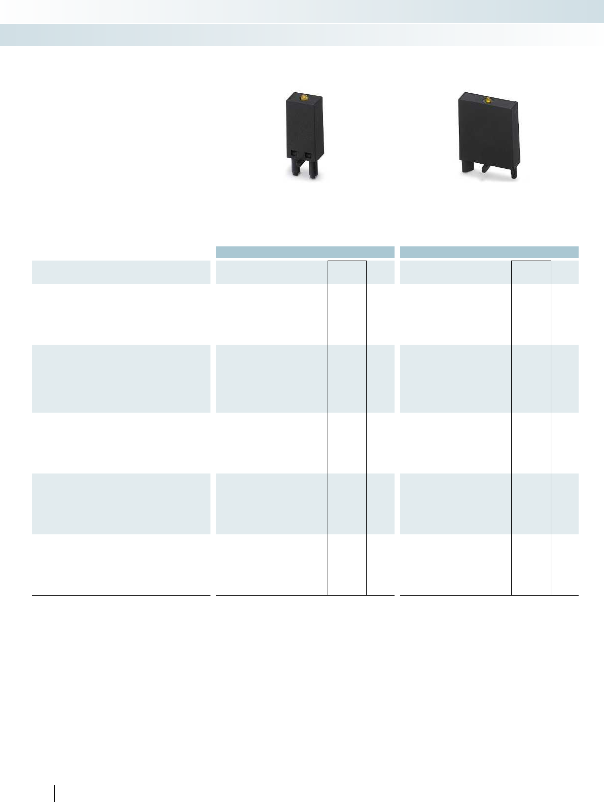
Ordering data Ordering data
Description Type Order No. Pcs. /
Pkt. Type Order No. Pcs. /
Pkt.
Plug-in module, for mounting on PR..., with LED status indicator
and freewheeling diode to limit the coil induction voltage effectively,
polarity: A1 +, A2 –,
Input voltage:
- 12-24 V DC ±20% LDP- 12- 24DC 2833657 10 LDP3- 12- 24DC 2833770 10
- 48-60 V DC ±20% LDP- 48- 60DC 2833660 10 LDP3- 48- 60DC 2833783 10
- 110 V DC ±20% LDP-110DC 2833673 10 LDP3-110DC 2833796 10
Plug-in module, for mounting on PR..., with LED status indicator
and freewheeling diode to limit the coil induction voltage effectively,
polarity: A1 –, A2 + (Japanese standard),
Input voltage:
- 12-24 V DC ±20% LDM- 12- 24DC 2833686 10 LDM3- 12- 24DC 2833806 10
- 48-60 V DC ±20% LDM- 48- 60DC 2833699 10 LDM3- 48- 60DC 2833819 10
- 110 V DC ±20% LDM-110DC 2833709 10 LDM3-110DC 2833822 10
Plug-in module, for mounting on PR..., with LED status indicator
and varistor to limit the coil induction voltage and/or external
interference peaks,
Input voltage:
- 12-24 V AC/DC ±20% (30 V varistor) LV- 12- 24UC 2833712 10 LV3- 12- 24UC 2833835 10
- 48-60 V AC/DC ±20%(75 V varistor) LV- 48- 60UC 2833725 10 LV3- 48- 60UC 2833848 10
- 120-230 V AC/110 V DC ±20% (275 V varistor) LV-120-230AC/110DC 2833738 10 LV3-120-230AC/110DC 2833851 10
Plug-in module, for mounting on PR..., with varistor to limit the coil
induction voltage and/or external interference peaks,
Input voltage:
- 12-24 V AC/DC ±20% (30 V varistor) V- 12- 24UC 2833864 10 V3- 12- 24UC 2833929 10
- 48-60 V AC/DC ±20% (75 V varistor) V- 48- 60UC 2833877 10 V3- 48- 60UC 2833932 10
- 120-230 V AC/DC ±20% (275 V varistor) V-120-230UC 2833880 10 V3-120-230UC 2833945 10
Plug-in module
, for mounting on PR..., with RD element to attenuate
the coil induction voltage and/or external interference peaks,
Input voltage:
- 12-24 V AC/DC ±20% (220 nF/100 )RC- 12- 24UC 2833741 10 RC3- 12- 24UC 2833893 10
- 48-60 V AC/DC ±20% (220 nF/220 )RC- 48- 60UC 2833754 10 RC3- 48- 60UC 2833903 10
- 120-230 V AC/DC ±20% (100 nF/470 )RC-120-230UC 2833767 10 RC3-120-230UC 2833916 10
392
PHOENIX CONTACT
Relay modules
Industrial relay system with screw connection - PR series
Input/interference suppression module to
match PR1 and PR2
Input/interference suppression module to
match PR3
Plug-in input modules/interference
suppression modules for optional fitting of
PR... relay bases.
The advantages:
– Attenuation of reverse voltage induced in
coil
– Mechanical coding to protect against
incorrect connection
Input modules/interference
suppression modules for PR1, PR2,
and PR3

For further information and full technical data, visit phoenixcontact.net/products
393PHOENIX CONTACT
Terminal assignment of PR1 base/solid-state relay
Terminal blocks, PR1 base
A1 A2 11 12 14 21 22 24
Solid-state relays
SIM-EI...48DC/100 A2 (-) A1 (+) A +
SIM-EI...TTL/100 A2 (-) A1 (+) A + 0
SIM-EI...48DC/100RC A2 (-) A1 (+) A +
SIM-EI-OV-24DC/24DC/3 A2 (-) A1 (+) A +
OPT-...24DC/5 A1 (+) A2 (-) 13 14
OPT-...230AC/2 A1 (+) A2 (-) 13 14
The relay bases of the PR1 series can also be equipped with wear-free solid-state relays (OPT… or
SIM-EI...) as an alternative to the electromechanical relay.
LDP… and LV… plug-in modules cannot be used in conjunction with SIM-EI... solid-state relays.
Relay modules
Industrial relay system with screw connection - PR series
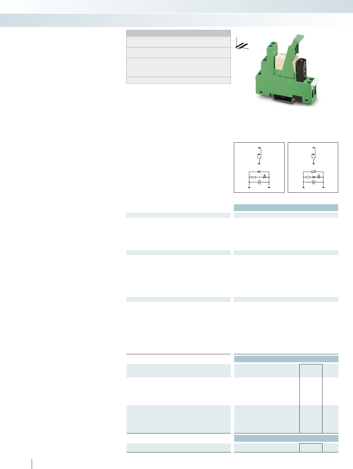
12
A1A2
14
11
12
A1+ A2-
14
11
Technical data
Input data ① ② ③ ④
Permissible range (with reference to U
N
) see diagram
Typ. input current at U
N
[mA] 19 34 9 6 19 34 9 6
Typ. response time at U
N
[ms] 8 3 - 12 3 - 12 3 - 12 8 3 - 12 3 - 12 3 - 12
Typ. release time at U
N
[ms] 10 1.5 -
14
1.5 -
16
2 - 22 10 1.5 -
Input circuit AC Yellow LED, varistor
Input circuit DC Yellow LED, freewheeling diode Yellow LED, freewheeling diode
Output data
Contact type 1 PDT 1 PDT 2 PDTs 2 PDTs
Contact material AgNi AgNi, hard gold-plated AgNi AgNi, hard gold-plated
Max. switching voltage 250 V AC/DC 30 V AC / 36 V DC 250 V AC/DC 30 V AC / 36 V DC
Min. switching voltage 12 V (at 10 mA) 100 mV (at 10 mA) 5 V (at 10 mA) 100 mV (at 10 mA)
Limiting continuous current 12 A 50 mA 8 A 50 mA
Max. inrush current 30 A (300 ms) 50 mA 15 A (300 ms) 50 mA
Min. switching current 10 mA (at 12 V) 1 mA (at 24 V) 10 mA (at 5 V) 1 mA (at 24 V)
Interrupting rating (ohmic load) 3000 W (for 250 V AC) 1.2 W (at 24 V DC) 2000 W (for 250 V AC) 1.2 W (at 24 V DC)
General data
Test voltage (winding/contact) 4 kV (50 Hz, 1 min.)
Test voltage (contact/contact) -
Ambient temperature (operation) -25 °C ... 60 °C
Nominal operating mode 100% operating factor 100% operating factor
Mechanical service life 3 x 10
7
cycles
Standards/regulations IEC 60664, EN 50178, IEC 62103 IEC 60664, EN 50178, IEC 62103
Pollution degree / surge voltage category 3 / III
Mounting position / mounting any / can be aligned without spacing any / can be aligned without spacing
Connection data solid / stranded / AWG 0.14 - 2.5 mm² / 0.14 - 2.5 mm² / 26 - 14 0.14 - 2.5 mm² / 0.14 - 2.5 mm² / 26 - 14
Dimensions W / H / D 16 mm / 78.5 mm / 71 mm 16 mm / 78.5 mm / 71 mm
EMC note Class A product, see page 625 Class A product, see page 625
Ordering data
Description Input voltage
U
N
Type Order No. Pcs. /
Pkt.
Pre-assembled coupling relay modules with
miniature power contact relay
①24 V DC PR1-RSC3-LDP-24DC/21 2834326 5
②24 V AC PR1-RSC3-LV- 24AC/21 2834339 5
③120 V AC PR1-RSC3-LV-120AC/21 2834342 5
④230 V AC PR1-RSC3-LV-230AC/21 2834355 5
Pre-assembled coupling relay modules with
multi-layer contact relay
①24 V DC PR1-RSC3-LDP-24DC/21AU 2834368 5
②24 V AC PR1-RSC3-LV- 24AC/21AU 2834371 5
③120 V AC PR1-RSC3-LV-120AC/21AU 2834384 5
④230 V AC PR1-RSC3-LV-230AC/21AU 2834397 5
Accessories
Device marking label, for thermal transfer printer, marking area 6
x 15 mm
EML (15X6) R YE 0819288 1
394
PHOENIX CONTACT
DC coils AC coils DC coils
DW
H
Fully mounted PR1 relay modules
with screw connection
Fully mounted PR1 relay modules,
consisting of:
– Relay base
– 1/2 PDT relay
– Relay retaining bracket
– Input module/interference suppr. module
– Marking labels
The advantages:
– Logical contact arrangement thanks to
1/3-level relay base
– Operational reliability thanks to sealed
relay
– Safe isolation between coil and contact
side
Notes:
Type of housing:
Polyamide fiber reinforced PA-F, color: green.
For the protection of input and output, inductive loads must be
dampened with an effective protection circuit.
If the specified maximum values for multi-layer contact relays are
exceeded, the gold plating is destroyed. The maximum values of
the power contact relay are then valid. This can result in a shorter
service life than with a pure power contact.
Other input voltages on request.
Relay modules
Industrial relay system with screw connection - PR series
PR1 relay module with
1 PDT relay
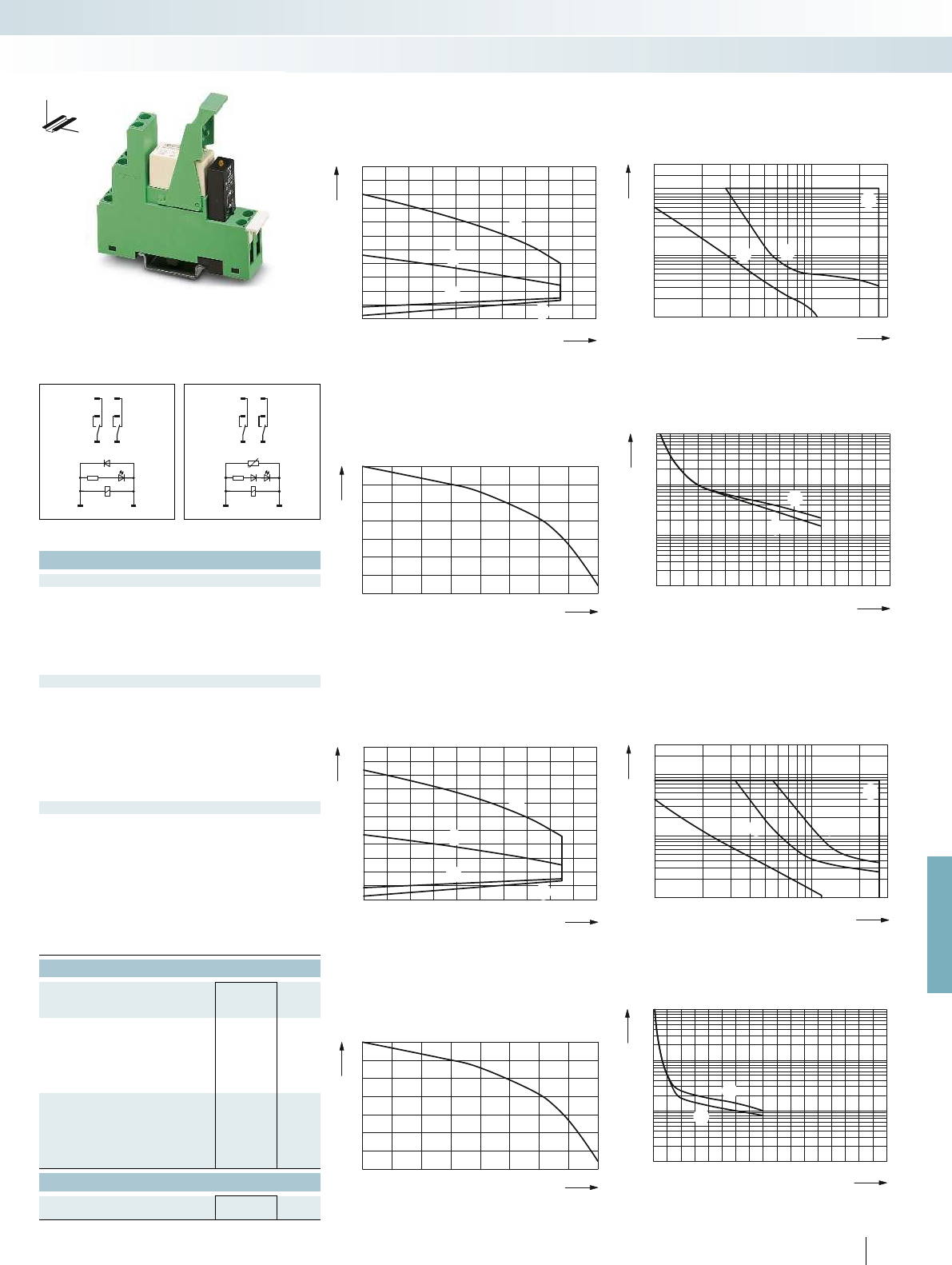
0,6
0,8
1
1,2
1,4
1,6
1,8
2
2,2
2,4
2,6
2,8
0 10 20 30 40 50 60 70 80 90 100
1
1
2
2
1
2
0,1
0,2
0,3
0,5
1
2
4
6
10
20
10 20 30 50 70 100 300200
1
2
3
1
2
3
1
0,9
0,3
0,4
0,5
0,6
0,7
0,8
0,9
1
0,80,70,60,50,40,30,2
2
01 4 8 12 16
107
106
105
104
23 56711910 151413
1
1
2
0,6
0,8
1
1,2
1,4
1,6
1,8
2
2,2
2,4
2,6
2,8
0 10 20 30 40 50 60 70 80 90 100
1
2
2
1
1
2
0,1
0,2
0,3
0,5
1
2
4
6
10
20
10 20 30 50 70 100 300200
1
2
3
4
3
1
42
1
0,9
0,3
0,4
0,5
0,6
0,7
0,8
0,9
1
0,80,70,60,50,40,30,2
0 1 4 8 12 16
107
106
105
104
23 56711910 151413
1
2
2
1
2212
A1+ A2-
2414
2111
A1 A2
2212
2414
2111
For further information and full technical data, visit phoenixcontact.net/products
Technical data
① ② ③ ④
see diagram
[mA] 19 34 9 6 19 34 9 6
[ms] 8 3 - 12 3 - 12 3 - 12 8 3 - 12 3 - 12 3 - 12
2 - 22 10 1.5 -
14
1.5 -
16
2 - 22
Yellow LED, varistor
Input circuit DC Yellow LED, freewheeling diode Yellow LED, freewheeling diode
Contact type 1 PDT 1 PDT 2 PDTs 2 PDTs
Contact material AgNi AgNi, hard gold-plated AgNi AgNi, hard gold-plated
Max. switching voltage 250 V AC/DC 30 V AC / 36 V DC 250 V AC/DC 30 V AC / 36 V DC
Min. switching voltage 12 V (at 10 mA) 100 mV (at 10 mA) 5 V (at 10 mA) 100 mV (at 10 mA)
Limiting continuous current 12 A 50 mA 8 A 50 mA
Max. inrush current 30 A (300 ms) 50 mA 15 A (300 ms) 50 mA
Min. switching current 10 mA (at 12 V) 1 mA (at 24 V) 10 mA (at 5 V) 1 mA (at 24 V)
Interrupting rating (ohmic load) 3000 W (for 250 V AC) 1.2 W (at 24 V DC) 2000 W (for 250 V AC) 1.2 W (at 24 V DC)
4 kV (50 Hz, 1 min.)
2.5 kV (50 Hz, 1 min.)
-25 °C ... 60 °C
Nominal operating mode 100% operating factor 100% operating factor
3 x 10
7
cycles
Standards/regulations IEC 60664, EN 50178, IEC 62103 IEC 60664, EN 50178, IEC 62103
3 / III
Mounting position / mounting any / can be aligned without spacing any / can be aligned without spacing
Connection data solid / stranded / AWG 0.14 - 2.5 mm² / 0.14 - 2.5 mm² / 26 - 14 0.14 - 2.5 mm² / 0.14 - 2.5 mm² / 26 - 14
Dimensions W / H / D 16 mm / 78.5 mm / 71 mm 16 mm / 78.5 mm / 71 mm
EMC note Class A product, see page 625 Class A product, see page 625
Ordering data
Type Order No. Pcs. /
Pkt.
PR1-RSC3-LDP-24DC/2X21 2834481 5
PR1-RSC3-LV- 24AC/2X21 2834494 5
PR1-RSC3-LV-120AC/2X21 2834504 5
PR1-RSC3-LV-230AC/2X21 2834517 5
PR1-RSC3-LDP-24DC/2X21AU 2834520 5
PR1-RSC3-LV- 24AC/2X21AU 2834533 5
PR1-RSC3-LV-120AC/2X21AU 2834546 5
PR1-RSC3-LV-230AC/2X21AU 2834559 5
Accessories
EML (15X6) R YE 0819288 1
395
PHOENIX CONTACT
PR1-RSC3.../21 (1 PDT)
Operating voltage range of the relay Interrupting rating
Ambient temperature [°C]
Coil voltage U/U
N
DC coils
AC coils
Switching voltage [V]
Switching current [A]
AC, ohmic load
DC, ohmic load
DC, L/R = 40 ms
Service life reduction factor Electrical service life
COS j
Reduction factor
250 V AC, ohmic load (DC coils)
250 V AC, ohmic load (AC coils)
Cycles
Switching current [A]
PR1-RSC3.../2x21 (2 PDTs)
Operating voltage range of the relay Interrupting rating
Ambient temperature [°C]
Coil voltage U/U
N
DC coils
AC coils
AC, ohmic load
DC, ohmic load, contacts in series
DC, ohmic load
DC, L/R = 40 ms
Switching voltage [V]
Switching current [A]
Service life reduction factor with various cos phi Electrical service life
COS j
Reduction factor
Cycles
Switching current [A]
250 V AC, ohmic load (DC coils)
250 V AC, ohmic load (AC coils)
DC coils AC coils DC coils
DW
H
Relay modules
Industrial relay system with screw connection - PR series
PR1 relay module with
2 PDT relay
AC coils
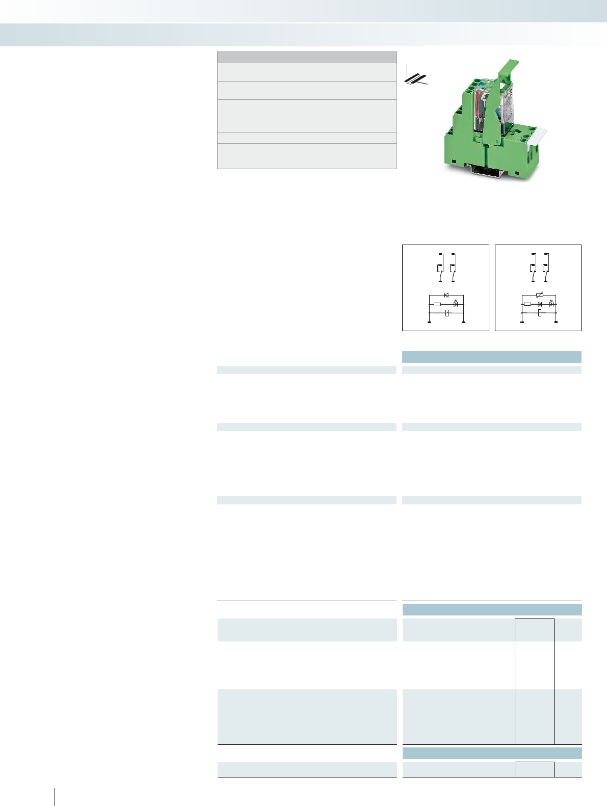
A1 A2
22 12
24 14
21 11
1222
A1+A2-
1424
1121
Technical data
Input data ① ② ③ ④
Permissible range (with reference to U
N
) see diagram
Typ. input current at U
N
[mA] 38 54 11 5 38 54 11 5
Typ. response time at U
N
[ms] 13 4 - 10 4 - 10 4 - 10 13 4 - 10 4 - 10 4 - 10
Typ. release time at U
N
[ms] 5 3 - 12 3 - 12 3 - 12 5 3 - 12 3 - 12 3 - 12
Input circuit AC Red LED, varistor
Input circuit DC Green LED, freewheeling diode Green LED, freewheeling diode
Output data
Contact type 2 PDTs
Contact material Ag
Max. switching voltage 250 V AC/DC
Min. switching voltage 5 V
Limiting continuous current 10 A
Max. inrush current 20 A (15 ms)
Min. switching current 1 mA
Interrupting rating (ohmic load) 2500 VA (for 250 V AC) 1250 VA (for 250 V AC)
General data
Test voltage (winding/contact) 2 kV (50 Hz, 1 min.)
Test voltage (contact/contact) 2 kV (50 Hz, 1 min.)
Ambient temperature (operation) -25 °C ... 60 °C
Nominal operating mode 100% operating factor 100% operating factor
Mechanical service life 5 x 10
7
cycles
Standards/regulations IEC 60664, EN 50178, IEC 62103 IEC 60664, EN 50178, IEC 62103
Pollution degree / surge voltage category 3 / II
Mounting position / mounting any / can be aligned without spacing any / can be aligned without spacing
Connection data solid / stranded / AWG 0.14 - 2.5 mm² / 0.14 - 2.5 mm² / 26 - 14 0.14 - 2.5 mm² / 0.14 - 2.5 mm² / 26 - 14
Dimensions W / H / D 27 mm / 78.5 mm / 86 mm 27 mm / 78.5 mm / 86 mm
EMC note Class A product, see page 625 Class A product, see page 625
Ordering data
Description Input voltage
U
N
Type Order No. Pcs. /
Pkt.
Pre-assembled coupling relay modules with
2-PDT contact relay
①24 V DC PR2-RSC3-LDP-24DC/2X21 2834643 5
②24 V AC PR2-RSC3-LV- 24AC/2X21 2834656 5
③120 V AC PR2-RSC3-LV-120AC/2X21 2834669 5
④230 V AC PR2-RSC3-LV-230AC/2X21 2834672 5
Pre-assembled coupling relay modules with
4-PDT contact relay and additional hard gold-plating
①24 V DC
②24 V AC
③120 V AC
④230 V AC
Accessories
Device marking label, for thermal transfer printer, marking area 6
x 15 mm
EML (15X6) R YE 0819288 1
396
PHOENIX CONTACT
DC coils AC coils DC coils
DW
H
Fully mounted PR2 relay modules
Fully mounted PR2 relay modules,
consisting of:
– Relay base
– 2/4 PDT relay
– Relay retaining bracket
– Input module/interference suppr. module
(AC types only)
– Marking labels
The advantages:
– Relay with lockable manual operation and
status LED
– With DC types, freewheeling diode is
integrated into relay
– Mechanical switch position indicator
– Logical contact arrangement thanks to
1/3-level relay base
– 4 PDT types with multi-layer gold
contacts
Notes:
Type of housing:
Polyamide fiber reinforced PA-F, color: green.
For the protection of input and output, inductive loads must be
dampened with an effective protection circuit.
If the specified maximum values for multi-layer contact relays are
exceeded, the gold plating is destroyed. The maximum values of
the power contact relay are then valid. This can result in a shorter
service life than with a pure power contact.
Other input voltages on request.
The DC types do not have a plug-in module because the status
LED and the freewheeling diode are integrated directly into the
relay.
Relay modules
Industrial relay system with screw connection - PR series
PR2 relay module with
2 PDT relay
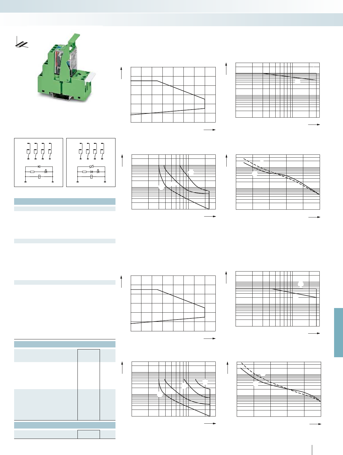
0
0,6
0,8
1
1,2
1,4
1,6
1,8
20 40 60 8010 30 50 70
0,1
0,2
0,3
0,5
1
2
4
6
10
20
10 20 30 50 70 100 300200
1
2
1
2
0,1
0,2
0,3
0,5
1
2
4
6
10
20
10 20 30 50 70 100 300200
1
2
3
31
2
106
105
0246810
104
2
1
1
2
0
0,6
0,8
1
1,2
1,4
1,6
1,8
20 40 60 8010 30 50 70
0,1
0,2
0,3
0,5
1
2
4
6
10
20
10 20 30 50 70 100 300200
1
2
1
2
0,1
0,2
0,3
0,5
1
2
4
6
10
20
10 20 30 50 70 100 300200
1
2
3
4
12
4
3
106
105
012345
104
2
1
1
2
A1+ A2-
22 123242
24 143444
21 113141
A1A2
22 123242
24 143444
21 113141
For further information and full technical data, visit phoenixcontact.net/products
Technical data
① ② ③ ④
see diagram
[mA] 38 54 11 5 38 54 11 5
[ms] 13 4 - 10 4 - 10 4 - 10 13 4 - 10 4 - 10 4 - 10
[ms] 5 3 - 12 3 - 12 3 - 12 5 3 - 12 3 - 12 3 - 12
Red LED, varistor
Input circuit DC Green LED, freewheeling diode Green LED, freewheeling diode
4 PDTs
AgNi, hard gold-plated
250 V AC/DC
1 V
5 A
12 A (15 ms)
1 mA
Interrupting rating (ohmic load) 2500 VA (for 250 V AC) 1250 VA (for 250 V AC)
2 kV (50 Hz, 1 min.)
2 kV (50 Hz, 1 min.)
-25 °C ... 60 °C
Nominal operating mode 100% operating factor 100% operating factor
5 x 10
7
cycles
Standards/regulations IEC 60664, EN 50178, IEC 62103 IEC 60664, EN 50178, IEC 62103
2 / II
Mounting position / mounting any / can be aligned without spacing any / can be aligned without spacing
Connection data solid / stranded / AWG 0.14 - 2.5 mm² / 0.14 - 2.5 mm² / 26 - 14 0.14 - 2.5 mm² / 0.14 - 2.5 mm² / 26 - 14
Dimensions W / H / D 27 mm / 78.5 mm / 86 mm 27 mm / 78.5 mm / 86 mm
EMC note Class A product, see page 625 Class A product, see page 625
Ordering data
Type Order No. Pcs. /
Pkt.
PR2-RSC3-LDP-24DC/4X21AU 2834724 5
PR2-RSC3-LV- 24AC/4X21AU 2834737 5
PR2-RSC3-LV-120AC/4X21AU 2834740 5
PR2-RSC3-LV-230AC/4X21AU 2834753 5
Accessories
EML (15X6) R YE 0819288 1
397
PHOENIX CONTACT
PR2-RS.../2x21 (2 PDTs)
Operating voltage range of relay T
a
=T
coil
AC interrupting rating
Ambient temperature [°C]
Coil voltage U/U
N
Ohmic load
cos = 0.4j
Switching voltage [V]
Switching current [A]
DC interrupting rating Electrical service life
Ohmic load
ohmic load, contacts in series
L/R < 7 ms
Switching voltage [V]
Switching current [A]
Cycles
Switching current [A]
250 V AC, ohmic load
30 V DC, ohmic load
PR2-RS.../4x21 (4 PDTs)
Operating voltage range of relay T
a
=T
coil
AC interrupting rating
Ambient temperature [°C]
Coil voltage U/U
N
Ohmic load
cos = 0.4j
Switching voltage [V]
Switching current [A]
DC interrupting rating Electrical service life
L/R < 7 ms
ohmic load
ohmic load, 2 contacts in series
ohmic load, 4 contacts in series
Switching voltage [V]
Switching current [A]
Cycles
Switching current [A]
250 VAC, ohmicload
30VDC, ohmicload
DC coils AC coils DC coils
DW
H
Relay modules
Industrial relay system with screw connection - PR series
PR2 relay module with
4 PDT relay
AC coils
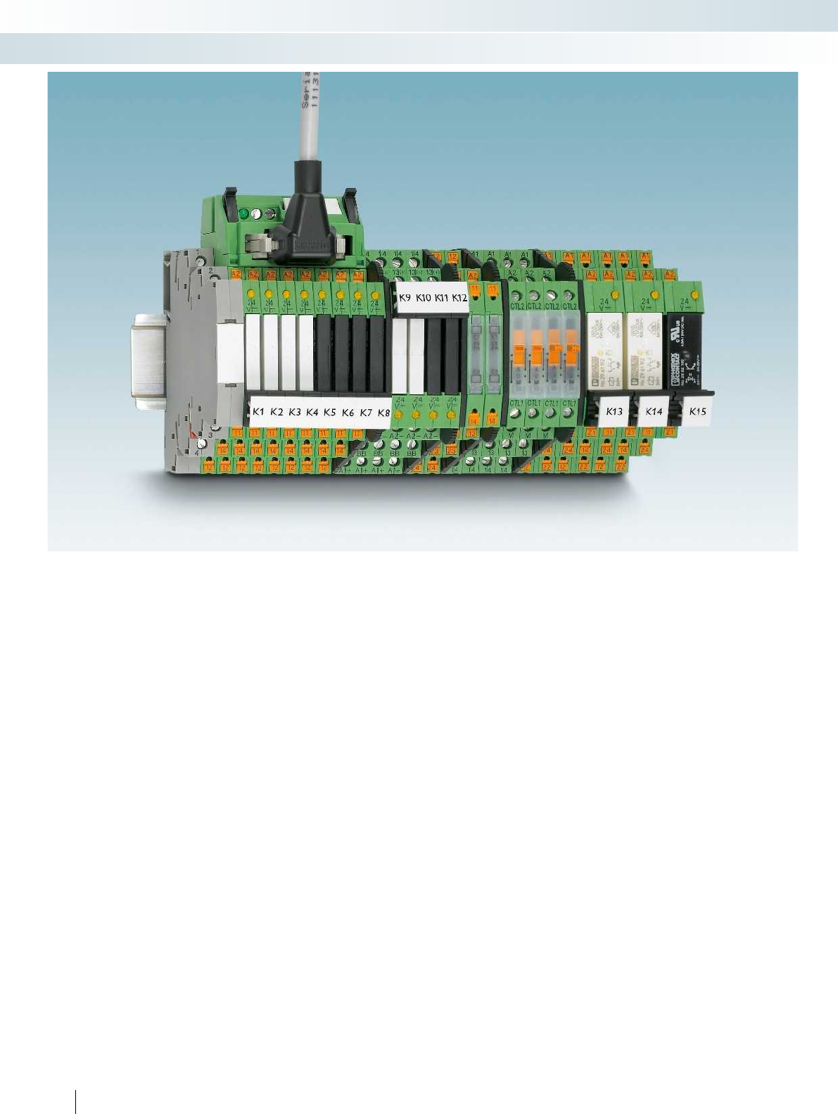
398
PHOENIX CONTACT
Relay modules
Highly compact relay modules - PLC-INTERFACE
The PLC-INTERFACE relay system is the
interface between the controller and
system I/O devices.
The universal design is compact and
space-saving. While the narrow 6.2 mm
module has one contact, the 14 mm version
is available with two contacts. The modules
can be equipped with either an
electromechanical or a solid-state relay.
They are protected against environmental
influences by RTIII (IP67). The relays also
offer safe isolation according to
DIN EN 50178 (VDE 0160).
PLC-INTERFACE is available in three
connection technologies. Depending on the
usage range, screw or push-in connection
can be selected.
In addition to the universal types,
PLC-INTERFACE is also available in
numerous special versions. These include:
– Sensor and actuator modules that can
accommodate all connections directly on
the interface
– Modules for high inrush or continuous
currents
– Railway modules, which meet specific
railway requirements
– Filter modules, which filter out
interference on the input side
Jumpers are available for all modules for
simple potential distribution. In addition,
solutions from system cabling applications
offer easy connection to the plant control
system. VARIOFACE adapters can be used
to reduce wiring effort considerably.
Installation is simplified significantly thanks
to the integrated input and protective
circuit.
Standard marking material from
CLIPLINE complete modular terminal
blocks can be used to mark
PLC-INTERFACE.
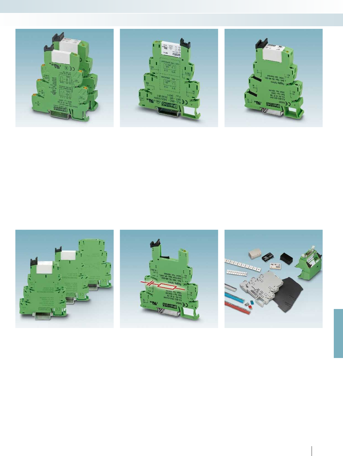
For further information and full technical data, visit phoenixcontact.net/products
399PHOENIX CONTACT
Relay modules
Highly compact relay modules - PLC-INTERFACE
Universal modules
PLC-R... and PLC-O... relay and solid-state
relay modules with PDT or N/O contact,
designed for universal use. Available in an
overall width of 6.2 mm with one contact or
in 14 mm with two contacts.
Available either with screw or push-in
connection.
Sensors/actuators
PLC...SEN and PLC...ACT offer space-
saving sensor and actuator wiring without
additional supply or output terminal blocks.
The sensor or actuator connections are
incorporated directly at the relay module.
Available either with screw or push-in
connection.
High currents
PLC...IC is particularly suitable for
applications with high switch-on currents,
e.g. from lamp loads. The PLC...HC relay
modules are designed for applications with
high continuous currents.
Available either with screw or push-in
connection.
Railway applications
PLC...RW relay or solid-state relay
modules are suitable for railway
requirements. These cover, for example, the
extended temperature and input voltage
range of railway applications.
Interference signals on the input side
PLC-B...SO46 basic terminal blocks are
used for filtering interference currents and
interference voltages on the input side.
Available either with screw or push-in
connection.
Accessories
The entire PLC-INTERFACE system can
be extended by a range of accessories such
as power terminals, adapters for system
cabling or jumpers for potential
distribution.
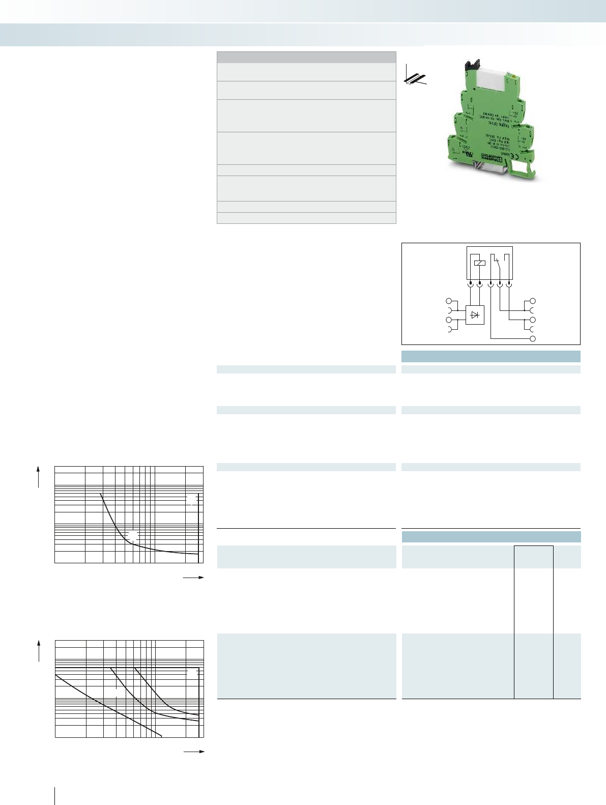
A1
A2 11
14
12
0,1
0,2
0,3
0,5
1
2
4
6
10
20
10203050 70 100 300200
1
2
3
4
3
1
42
0,1
0,2
0,3
0,5
1
2
4
10
20
1020305070100 300200
1
2
1
2
6
Technical data
Input data ① ② ③ ④ ⑤ ⑥ ⑦
Typ. input current at U
N
[mA] 15.3 9 11 9.2 4.8 3.5 3.2 15.3 9 11 9.2 4.8 3.5 3.2 33 18 17.5 20 10 4.5 4.5 33 18 17.5 20 10 4.5 4.5
Response/release time at U
N
[ms] 5 / 8 5 / 8 6 / 15 5 / 8 5 / 8 6 / 15 7 / 15 5 / 8 5 / 8 6 / 15 5 / 8 5 / 8 6 / 15 7 / 15 8 / 10 8 / 10 8 / 10 8 / 10 8 / 10 7 / 10 7 / 10 8 / 1
Input circuit DC
Yellow LED, protection against polarity reversal, freewheeling diode Yellow LED, protection against polarity reversal, freewheel
Input circuit AC/DC Yellow LED, bridge rectifier Yellow LED, bridge rectifier Yellow LED, bridge rectifier Yellow LED, bridge recti
Output data
Contact material AgSnO
Max. switching voltage 250 V AC/DC
Min. switching voltage 5 V (at 100 mA)
Limiting continuous current 6 A
Max. inrush current on request
Min. switching current 10 mA (at 12 V)
General data
Test voltage input/output 4 kV AC (50 Hz, 1 min.) 4 kV AC (50 Hz, 1 min.) 4 kV AC (50 Hz, 1 min.) 4 kV AC (50 Hz, 1 min.)
Ambient temperature (operation) -40 °C ... 60 °C
1
)
Mechanical service life 2 x 10
7
cycles
Standards/regulations IEC 60664, EN 50178, IEC 62103 IEC 60664, EN 50178, IEC 62103 IEC 60664, EN 50178, IEC 62103 IEC 60664, EN 50
Connection data solid / stranded / AWG 0.14 - 2.5 mm² / 0.14 - 2.5 mm² / 26 - 14 0.14 - 2.5 mm² / 0.14 - 2.5 mm² / 26 - 14 0.14 - 2.5
Dimensions W / H / D 6.2 mm / 80 mm / 94 mm 6.2 mm / 80 mm / 94 mm 14 mm / 80 mm / 94 mm 14 mm / 80 mm / 94 mm
EMC note Class A product, see page 625 Class A product, see page 625 Class A product, see page 625 Class A product, see page 625
Ordering data
Description Input voltage
U
N
Type Order No. Pcs. /
Pkt.
PLC-INTERFACE, with screw connection
①12 V DC PLC-RSC- 12DC/21 2966906 10
②24 V DC PLC-RSC- 24DC/21 2966171 10
③24 V AC/DC PLC-RSC- 24UC/21 2966184 10
④48 V DC PLC-RSC- 48DC/21 2966113 10
⑤60 V DC PLC-RSC- 60DC/21 2966139 10
⑥120 V AC (110 V DC) PLC-RSC-120UC/21 2966197 10
⑦230 V AC (220 V DC) PLC-RSC-230UC/21 2966207 10
PLC-INTERFACE, with push-in connection
①12 V DC PLC-RPT- 12DC/21 2900316 10
②24 V DC PLC-RPT- 24DC/21 2900299 10
③24 V AC/DC PLC-RPT- 24UC/21 2900300 10
④48 V DC PLC-RPT- 48DC/21 2900301 10
⑤60 V DC PLC-RPT- 60DC/21 2900303 10
⑥120 V AC (110 V DC) PLC-RPT-120UC/21 2900304 10
⑦230 V AC (220 V DC) PLC-RPT-230UC/21 2900305 10
400
PHOENIX CONTACT
Universal PLC series with
PDT relay
Relay modules
Highly compact relay modules - PLC-INTERFACE
DW
H
Notes:
Type of housing:
Polyamide PA non-reinforced, color: green.
Marking systems and mounting material
See Catalog 5
Separating plate PLC-ATP must be installed for voltages larger
than 250 V (L1, L2, L3) between identical terminal blocks in
adjacent modules. Potential bridging is then carried out with
FBST 8-PLC... or FBST 500....
If the specified maximum values for multi-layer contact relays are
exceeded, the gold plating is destroyed. The maximum values of
the power contact relay are then valid. This can result in a shorter
service life than with a pure power contact.
For diagrams of operating voltage ranges, see page 423
Note: for marking material (ZB 6), see “CLIPLINE industrial
connection technology, marking material for terminals,
conductors, and cables”.
1
) 120 and 230 V types up to 55 °C
2
) 230 V types up to 55 °C
1 PDT with power contact 1 PDT with multi-layer gold contact 2
Switching voltage [V]
AC, ohmic load
DC, ohmic load, contacts in series
DC, ohmic load
DC, L/R = 40 ms
Switching voltage [V]
Switching current [A]
AC, ohmic load
DC, ohmic load
Electrical interrupting rating for PLC...21
with 1-PDT relay
Electrical interrupting rating for PLC...21-21
with 2-PDT relay
Switching current [A]
PLC-R... is the relay series that can be
used universally and consists of basic
terminal blocks and plug-in relays with
PDT contacts.
The advantages:
– Slim design
– Screw and push-in connection technology
– Functional jumpers
– Integrated input and interference
suppression circuit
– RT III sealed relay
– Safe isolation according to DIN EN 50178
between coil and contact
– Efficient connection to system cabling
using V8 adapter
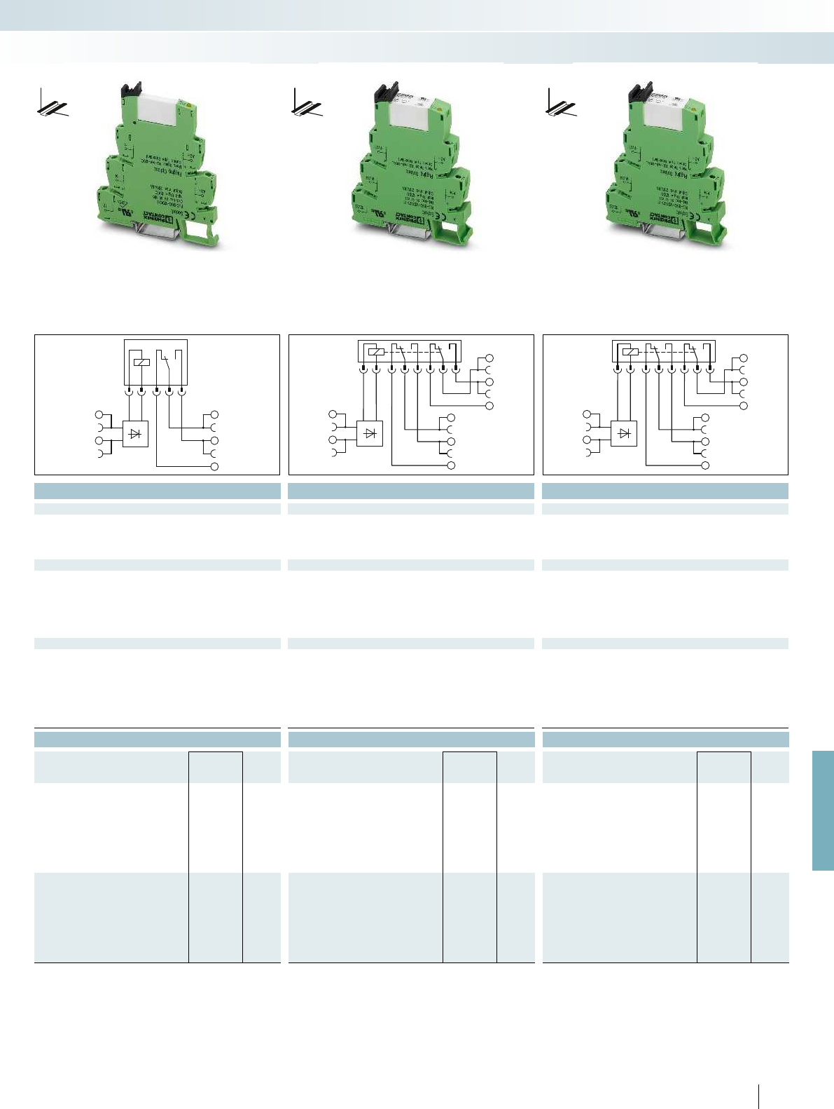
A1
A2 11
14
12
A2
24
21
22
14
11
12
A1
A2
24
21
22
14
11
12
A1
For further information and full technical data, visit phoenixcontact.net/products
Technical data Technical data Technical data
① ② ③ ④ ⑤ ⑥ ⑦ ① ② ③ ④ ⑤ ⑥ ⑦ ① ② ③ ④ ⑤ ⑥ ⑦
[mA] 15.3 9 11 9.2 4.8 3.5 3.2 15.3 9 11 9.2 4.8 3.5 3.2 33 18 17.5 20 10 4.5 4.5 33 18 17.5 20 10 4.5 4.5
[ms] 5 / 8 5 / 8 6 / 15 5 / 8 5 / 8 6 / 15 7 / 15 5 / 8 5 / 8 6 / 15 5 / 8 5 / 8 6 / 15 7 / 15 8 / 10 8 / 10 8 / 10 8 / 10 8 / 10 7 / 10 7 / 10 8 / 10 8 / 10 8 / 10 8 / 10 8 / 10 7 / 10 7 / 10
Yellow LED, protection against polarity reversal, freewheeling diode Yellow LED, protection against polarity reversal, freewheeling diode Yellow LED, protection against polarity reversal, freewheeling diode Yellow LED, protection against polarity reversal, freewheeling diode
Input circuit AC/DC Yellow LED, bridge rectifier Yellow LED, bridge rectifier Yellow LED, bridge rectifier Yellow LED, bridge rectifier
AgSnO, hard gold-plated AgNi AgNi, hard gold-plated
30 V AC / 36 V DC 250 V AC/DC 30 V AC / 36 V DC
100 mV (at 10 mA) 5 V AC/DC (at 10 mA) 100 mV (at 10 mA)
50 mA 6 A 50 mA
50 mA 15 A (300 ms) 50 mA
1 mA (at 24 V) 10 mA (at 5 V) 1 mA (at 24 V)
Test voltage input/output 4 kV AC (50 Hz, 1 min.) 4 kV AC (50 Hz, 1 min.) 4 kV AC (50 Hz, 1 min.) 4 kV AC (50 Hz, 1 min.)
-40 °C ... 60 °C
1
) -40 °C ... 60 °C
2
) -40 °C ... 60 °C
2
)
2 x 10
7
cycles 3 x 10
7
cycles 3 x 10
7
cycles
Standards/regulations IEC 60664, EN 50178, IEC 62103 IEC 60664, EN 50178, IEC 62103 IEC 60664, EN 50178, IEC 62103 IEC 60664, EN 50178, IEC 62103
Connection data solid / stranded / AWG 0.14 - 2.5 mm² / 0.14 - 2.5 mm² / 26 - 14 0.14 - 2.5 mm² / 0.14 - 2.5 mm² / 26 - 14 0.14 - 2.5 mm² / 0.14 - 2.5 mm² / 26 - 14 0.14 - 2.5 mm² / 0.14 - 2.5 mm² / 26 - 14
Dimensions W / H / D 6.2 mm / 80 mm / 94 mm 6.2 mm / 80 mm / 94 mm 14 mm / 80 mm / 94 mm 14 mm / 80 mm / 94 mm
EMC note Class A product, see page 625 Class A product, see page 625 Class A product, see page 625 Class A product, see page 625
Ordering data Ordering data Ordering data
Type Order No. Pcs. /
Pkt. Type Order No. Pcs. /
Pkt. Type Order No. Pcs. /
Pkt.
PLC-RSC- 12DC/21AU 2966919 10 PLC-RSC- 12DC/21-21 2967235 10 PLC-RSC- 12DC/21-21AU 2967277 10
PLC-RSC- 24DC/21AU 2966265 10 PLC-RSC- 24DC/21-21 2967060 10 PLC-RSC- 24DC/21-21AU 2967125 10
PLC-RSC- 24UC/21AU 2966278 10 PLC-RSC- 24UC/21-21 2967073 10 PLC-RSC- 24UC/21-21AU 2967112 10
PLC-RSC- 48DC/21AU 2966126 10 PLC-RSC- 48DC/21-21 2967248 10 PLC-RSC- 48DC/21-21AU 2967280 10
PLC-RSC- 60DC/21AU 2966142 10 PLC-RSC- 60DC/21-21 2967293 10 PLC-RSC- 60DC/21-21AU 2967303 10
PLC-RSC-120UC/21AU 2966281 10 PLC-RSC-120UC/21-21 2967086 10 PLC-RSC-120UC/21-21AU 2967138 10
PLC-RSC-230UC/21AU 2966294 10 PLC-RSC-230UC/21-21 2967099 10 PLC-RSC-230UC/21-21AU 2967141 10
PLC-RPT- 12DC/21AU 2900317 10 PLC-RPT- 12DC/21-21 2900329 10 PLC-RPT- 12DC/21-21AU 2900337 10
PLC-RPT- 24DC/21AU 2900306 10 PLC-RPT- 24DC/21-21 2900330 10 PLC-RPT- 24DC/21-21AU 2900338 10
PLC-RPT- 24UC/21AU 2900307 10 PLC-RPT- 24UC/21-21 2900332 10 PLC-RPT- 24UC/21-21AU 2900339 10
PLC-RPT- 48DC/21AU 2900308 10 PLC-RPT- 48DC/21-21 2900333 10 PLC-RPT- 48DC/21-21AU 2900340 10
PLC-RPT- 60DC/21AU 2900309 10 PLC-RPT- 60DC/21-21 2900334 10 PLC-RPT- 60DC/21-21AU 2900341 10
PLC-RPT-120UC/21AU 2900310 10 PLC-RPT-120UC/21-21 2900335 10 PLC-RPT-120UC/21-21AU 2900342 10
PLC-RPT-230UC/21AU 2900311 10 PLC-RPT-230UC/21-21 2900336 10 PLC-RPT-230UC/21-21AU 2900343 10
401
PHOENIX CONTACT
Relay modules
Highly compact relay modules - PLC-INTERFACE
DW
H
DW
H
DW
H
1 PDT with power contact 1 PDT with multi-layer gold contact 2 PDT with power contact 2 PDT with multi-layer gold contact
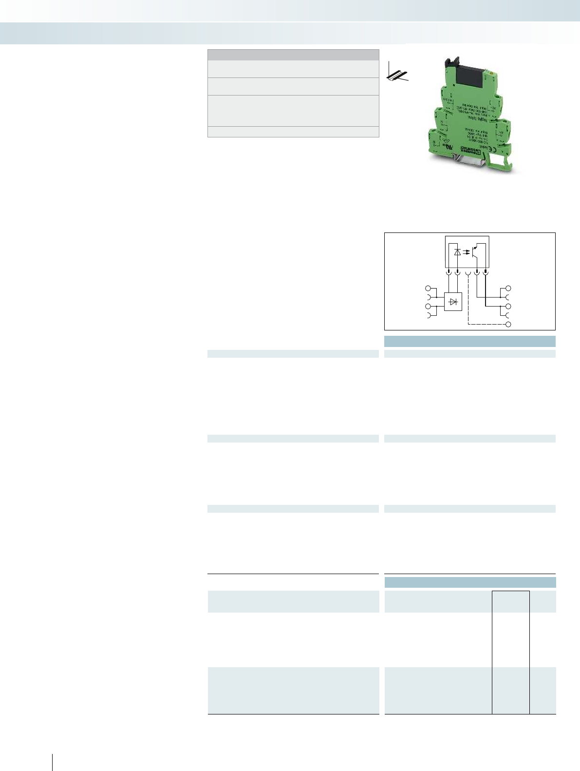
A2
A1
13+
14
Technical data
Input data ① ② ③ ④ ⑤ ⑥
Permissible range (with reference to U
N
) 0.8 -
1.2
0.8 -
1.2
0.8 -
1.2
0.8 -
1.1
0.9 -
1.1
0.9 -
1.1
Switching level (with reference to U
N
) 1 signal ("H") 0.8 0.8 0.8 0.8 0.9 0.8
0 signal ("L") 0.4 0.3 0.4 0.4 0.3 0.3
Typ. input current at U
N
[mA] 8.5 9 5 3 3.5 3.5 8.5 9 5 3 3.5 3.5 8 9 6 3.5 4 3.5
Typ. switch-on time at U
N
[ms] 0.02 0.03 0.04 1 3 3 0.02 0.03 0.04 0.04 3.5 4 10 10 10 10 10 10
Typ. shutdown time at U
N
[ms] 0.3 0.3 2 3 4 5 0.3 0.3 0.5 0.6 7 7 10 10 10 10 10 10
Transmission frequency f
limit
[Hz] 300 300 100 50 10 10 300 300 100 100 10 10 10 10 10 10 3 3
Input circuit DC
Yellow LED, protection against polarity reversal, freewheeling diode Yellow LED, protection against polarity reversal, freewheel
Input circuit AC/DC Yellow LED, bridge rectifier Yellow LED, bridge rectifier Yellow LED, bridge rectifier
Output data
Max. switching voltage 48 V DC
Min. switching voltage 3 V DC
Max. inrush current -
Min. / max. switching current - / 100 mA
Output protection Protection against polarity reversal, surge protection Protection against polarity reversal, surge protection RC
Voltage drop at max. limiting continuous current 1 V
Leakage current in off state -
Max. load value -
General data
Test voltage input/output 2.5 kV (50 Hz, 1 min.)
Ambient temperature (operation) -25 °C ... 60 °C
Standards/regulations IEC 60664, EN 50178, IEC 62103 IEC 60664, EN 50178, IEC 62103 IEC 60664, EN 50178, IEC 62103
Pollution degree / surge voltage category 2 / III
Connection data solid / stranded / AWG 0.14 - 2.5 mm² / 0.14 - 2.5 mm² / 26 - 14 0.14 - 2.5 mm² / 0.14 - 2.5 mm² / 26 - 14 0.14 - 2.5
Dimensions W / H / D 6.2 mm / 80 mm / 94 mm 6.2 mm / 80 mm / 94 mm 6.2 mm / 80 mm / 94 mm
EMC note Class A product, see page 625 Class A product, see page 625 Class A product, see page 625
Ordering data
Description Input voltage
U
N
Type Order No. Pcs. /
Pkt.
PLC-INTERFACE, with screw connection
①24 V DC PLC-OSC- 24DC/ 48DC/100 2966728 10
②48 V DC PLC-OSC- 48DC/ 48DC/100 2966993 10
③60 V DC PLC-OSC- 60DC/ 48DC/100 2967455 10
④125 V DC PLC-OSC-125DC/ 48DC/100 2980047 10
⑤120 V AC (110 V DC) PLC-OSC-120UC/ 48DC/100 2966744 10
⑥230 V AC (220 V DC) PLC-OSC-230UC/ 48DC/100 2966757 10
PLC-INTERFACE, with push-in connection
①24 V DC PLC-OPT- 24DC/ 48DC/100 2900352 10
②48 V DC PLC-OPT- 48DC/ 48DC/100 2900353 10
③60 V DC PLC-OPT- 60DC/ 48DC/100 2900354 10
⑤120 V AC (110 V DC) PLC-OPT-120UC/ 48DC/100 2900355 10
⑥230 V AC (220 V DC) PLC-OPT-230UC/ 48DC/100 2900356 10
402
PHOENIX CONTACT
Universal PLC series with
solid-state relays
PLC-O... is the solid-state relay series that
can be used universally comprising basic
terminal blocks and plug-in solid-state
relays.
The advantages:
– Slim design
– Screw and push-in connection technology
– Functional jumpers
– Integrated input circuit
– RT-III sealed solid-state relays
– High switching capacity
– Zero voltage switch at AC output
– Efficient connection to system cabling
using V8 adapter
Relay modules
Highly compact relay modules - PLC-INTERFACE
DW
H
Notes:
Type of housing:
Polyamide PA non-reinforced, color: green.
Marking systems and mounting material
See Catalog 5
Separating plate PLC-ATP must be installed for voltages larger
than 250 V (L1, L2, L3) between identical terminal blocks in
adjacent modules. Potential bridging is then carried out with
FBST 8-PLC... or FBST 500....
For derating curves see page 425
Max. DC voltage output of 100 mA Max. DC voltage output of 3 A Max. AC voltage output of 750 mA
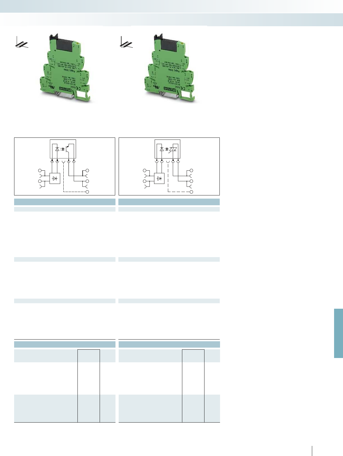
A2
A1
13+
14
13+
14
A2
A1
For further information and full technical data, visit phoenixcontact.net/products
Technical data Technical data
① ② ③ ④ ⑤ ⑥ ① ② ③ ④ ⑤ ⑥
0.8 -
1.2
0.8 -
1.2
0.8 -
1.2
0.8 -
1.1
0.9 -
1.1
0.9 -
1.1
0.8 -
1.2
0.8 -
1.2
0.8 -
1.2
0.8 -
1.1
0.9 -
1.1
0.8 -
1.1
0.8 0.8 0.8 0.8 0.8 0.8 0.8 0.8 0.8 0.8 0.8 0.8
0.4 0.4 0.3 0.3 0.3 0.3 0.25 0.25 0.3 0.3 0.25 0.25
[mA] 8.5 9 5 3 3.5 3.5 8.5 9 5 3 3.5 3.5 8 9 6 3.5 4 3.5
[ms] 0.02 0.03 0.04 1 3 3 0.02 0.03 0.04 0.04 3.5 4 10 10 10 10 10 10
[ms] 0.3 0.3 2 3 4 5 0.3 0.3 0.5 0.6 7 7 10 10 10 10 10 10
[Hz] 300 300 100 50 10 10 300 300 100 100 10 10 10 10 10 10 3 3
Yellow LED, protection against polarity reversal, freewheeling diode Yellow LED, protection against polarity reversal, freewheeling diode Yellow LED, protection against polarity reversal, freewheeling diode
Input circuit AC/DC Yellow LED, bridge rectifier Yellow LED, bridge rectifier Yellow LED, bridge rectifier
33 V DC 253 V AC
3 V DC 24 V AC
15 A (10 ms) 30 A (10 ms)
- / 3 A (see derating curve) 10 mA / 0.75 A (see derating curve)
Output protection Protection against polarity reversal, surge protection Protection against polarity reversal, surge protection RCV circuit
200 mV < 1 V
- < 1 mA (in off state)
- 4.5 A
2
s
2.5 kV (50 Hz, 1 min.) 2.5 kV (50 Hz, 1 min.)
-25 °C ... 60 °C -25 °C ... 60 °C
Standards/regulations IEC 60664, EN 50178, IEC 62103 IEC 60664, EN 50178, IEC 62103 IEC 60664, EN 50178, IEC 62103
2 / III 2 / III
Connection data solid / stranded / AWG 0.14 - 2.5 mm² / 0.14 - 2.5 mm² / 26 - 14 0.14 - 2.5 mm² / 0.14 - 2.5 mm² / 26 - 14 0.14 - 2.5 mm² / 0.14 - 2.5 mm² / 26 - 14
Dimensions W / H / D 6.2 mm / 80 mm / 94 mm 6.2 mm / 80 mm / 94 mm 6.2 mm / 80 mm / 94 mm
EMC note Class A product, see page 625 Class A product, see page 625 Class A product, see page 625
Ordering data Ordering data
Type Order No. Pcs. /
Pkt. Type Order No. Pcs. /
Pkt.
PLC-OSC- 24DC/ 24DC/ 2 2966634 10 PLC-OSC- 24DC/230AC/ 1 2967840 10
PLC-OSC- 48DC/ 24DC/ 2 2967002 10 PLC-OSC- 48DC/230AC/ 1 2967853 10
PLC-OSC- 60DC/ 24DC/ 2 2967468 10 PLC-OSC- 60DC/230AC/ 1 2967866 10
PLC-OSC-125DC/ 24DC/ 2 2980050 10 PLC-OSC-125DC/230AC/ 1 2980063 10
PLC-OSC-120UC/ 24DC/ 2 2966650 10 PLC-OSC-120UC/230AC/ 1 2967879 10
PLC-OSC-230UC/ 24DC/ 2 2966663 10 PLC-OSC-230UC/230AC/ 1 2967882 10
PLC-OPT- 24DC/ 24DC/2 2900364 10 PLC-OPT- 24DC/230AC/1 2900369 10
PLC-OPT- 48DC/ 24DC/2 2900365 10 PLC-OPT- 48DC/230AC/1 2900370 10
PLC-OPT- 60DC/ 24DC/2 2900366 10 PLC-OPT- 60DC/230AC/1 2900371 10
PLC-OPT-120UC/ 24DC/2 2900367 10 PLC-OPT-120UC/230AC/1 2900372 10
PLC-OPT-230UC/ 24DC/2 2900368 10 PLC-OPT-230UC/230AC/1 2900374 10
403
PHOENIX CONTACT
Relay modules
Highly compact relay modules - PLC-INTERFACE
DW
H
DW
H
Max. DC voltage output of 100 mA Max. DC voltage output of 3 A Max. AC voltage output of 750 mA
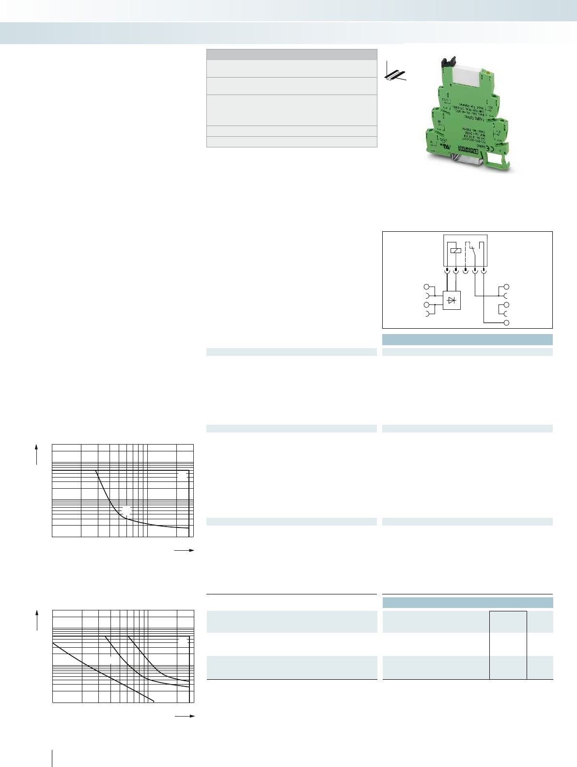
A2
A1
13
BB
14
0,1
0,2
0,3
0,5
1
2
4
10
20
1020305070100 300200
1
2
1
2
6
0,1
0,2
0,3
0,5
1
2
4
6
10
20
10203050 70 100 300200
1
2
3
4
3
1
42
Technical data
Input data ②
Permissible range (with reference to U
N
) See diagram
Switching level (with reference to U
N
) 1 signal ("H")
0 signal ("L")
Typ. input current at U
N
[mA] 9
Typ. response time/switch-on time at U
N
[ms] 5
Typ. release time/shutdown time at U
n
[ms] 8
Transmission frequency f
limit
[Hz]
Input circuit DC
Yellow LED, protection against polarity reversal, freewheeling diode Yellow LED, protection against polarity reversal, freewheel
Output data
Contact material AgSnO
Max. switching voltage 250 V AC/DC
Min. switching voltage 5 V (at 100 mA)
Limiting continuous current 6 A
Max. inrush current on request
Min. switching current 10 mA (at 12 V)
Output protection -
Voltage drop at max. limiting continuous current -
Leakage current in off state -
Phase angle (cos )-
Max. load value -
General data
Test voltage input/output 4 kV AC (50 Hz, 1 min.) 4 kV AC (50 Hz, 1 min.) 2.5 kV (50 Hz, 1 min.) 2.5 kV (50 Hz, 1 min.)
Ambient temperature (operation) -40 °C ... 60 °C
Mechanical service life 2 x 10
7
cycles
Standards/regulations IEC 60664, EN 50178, IEC 62103 IEC 60664, EN 50178, IEC 62103 IEC 60664, EN 50178, IEC 62103 IEC 60664, EN 50
Pollution degree / surge voltage category 3 / III
Connection data solid / stranded / AWG 0.14 - 2.5 mm² / 0.14 - 2.5 mm² / 26 - 14 0.14 - 2.5 mm² / 0.14 - 2.5 mm² / 26 - 14 0.14 - 2.5
Dimensions W / H / D 6.2 mm / 80 mm / 94 mm 14 mm / 80 mm / 94 mm 6.2 mm / 80 mm / 94 mm 6.2 mm / 80 mm / 94 mm
EMC note Class A product, see page 625 Class A product, see page 625 Class A product, see page 625 Class A product, see page 625
Ordering data
Description Input voltage
U
N
Type Order No. Pcs. /
Pkt.
PLC-INTERFACE, with screw connection
①5 V DC
②24 V DC PLC-RSC- 24DC/ 1/ACT 2966210 10
PLC-INTERFACE, with push-in connection
①5 V DC
②24 V DC PLC-RPT- 24DC/ 1/ACT 2900312 10
404
PHOENIX CONTACT
PLC actuator series for output
functions
Relay modules
Highly compact relay modules - PLC-INTERFACE
DW
H
Notes:
Type of housing:
Polyamide PA non-reinforced, color: green.
Marking systems and mounting material
See Catalog 5
Separating plate PLC-ATP must be installed for voltages larger
than 250 V (L1, L2, L3) between identical terminal blocks in
adjacent modules. Potential bridging is then carried out with
FBST 8-PLC... or FBST 500....
For diagrams of operating voltage ranges, see page 423
For derating curves see page 425
1 N/O contact with power contact 2 N/O contacts with power contac
Switching voltage [V]
Switching current [A]
AC, ohmic load
DC, ohmic load
Switching voltage [V]
AC, ohmic load
DC, ohmic load, contacts in series
DC, ohmic load
DC, L/R = 40 ms
Electrical interrupting rating for PLC...24DC/1/ACT
with 1-N/O relay
Electrical interrupting rating for PLC...24DC/1-1/ACT
with 2-N/O relay
Switching current [A]
PLC actuator series for coupling
controller and actuators, such as motors,
contactors, valves, etc.
The advantages:
– Actuator connected directly to relay
module
– No need for additional modular terminal
blocks
– Space savings of up to 80%
– Time savings of up to 60%
– Screw and push-in connection technology
– Relay modules with safe isolation
according to DIN EN 50178 between coil
and contact
– Functional jumpers
– Efficient connection to system cabling
using V8 adapter
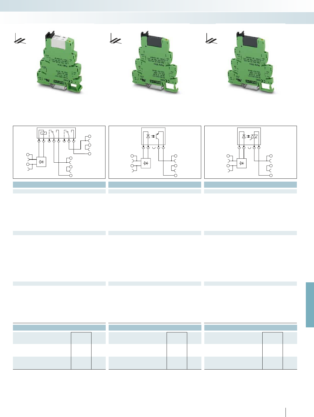
A2
A1
13
BB
14
23
BB
24
A2
A1
13+
BB
14
A2
A1
13+
BB
14
For further information and full technical data, visit phoenixcontact.net/products
Technical data Technical data Technical data
② ① ② ②
See diagram 0.8 -
1.2
0.8 -
1.2
0.8 -
1.2
0.8 0.8 0.8
0.25 0.4 0.25
18 9.5 8.5 9
8 0.02 0.02 3
10 0.3 0.3 9
300 300 10
Yellow LED, protection against polarity reversal, freewheeling diode Yellow LED, protection against polarity reversal, freewheeling diode Yellow LED, protection against polarity reversal, freewheeling diode Yellow LED, protection against polarity reversal, freewheeling diode
AgNi - -
250 V AC/DC 33 V DC 253 V AC
5 V AC/DC 3 V DC 24 V AC
6 A 3 A (see derating curve) 0.75 A (see derating curve)
8 A 15 A (10 ms) 30 A (10 ms)
10 mA - 10 mA
- Protection against polarity reversal, surge protection RCV circuit
- 200 mV < 1 V
- - < 1 mA (in off state)
--0.5
--4.5 A
2
s
Test voltage input/output 4 kV AC (50 Hz, 1 min.) 4 kV AC (50 Hz, 1 min.) 2.5 kV (50 Hz, 1 min.) 2.5 kV (50 Hz, 1 min.)
-40 °C ... 60 °C -25 °C ... 60 °C -25 °C ... 60 °C
3 x 10
7
cycles - -
Standards/regulations IEC 60664, EN 50178, IEC 62103 IEC 60664, EN 50178, IEC 62103 IEC 60664, EN 50178, IEC 62103 IEC 60664, EN 50178, IEC 62103
3 / III 2 / III 2 / III
Connection data solid / stranded / AWG 0.14 - 2.5 mm² / 0.14 - 2.5 mm² / 26 - 14 0.14 - 2.5 mm² / 0.14 - 2.5 mm² / 26 - 14 0.14 - 2.5 mm² / 0.14 - 2.5 mm² / 26 - 14 0.14 - 2.5 mm² / 0.14 - 2.5 mm² / 26 - 14
Dimensions W / H / D 6.2 mm / 80 mm / 94 mm 14 mm / 80 mm / 94 mm 6.2 mm / 80 mm / 94 mm 6.2 mm / 80 mm / 94 mm
EMC note Class A product, see page 625 Class A product, see page 625 Class A product, see page 625 Class A product, see page 625
Ordering data Ordering data Ordering data
Type Order No. Pcs. /
Pkt. Type Order No. Pcs. /
Pkt. Type Order No. Pcs. /
Pkt.
PLC-OSC- 5DC/ 24DC/ 2/ACT 2980144 10
PLC-RSC- 24DC/ 1- 1/ACT 2967109 10 PLC-OSC- 24DC/ 24DC/ 2/ACT 2966676 10 PLC-OSC- 24DC/230AC/ 1/ACT 2967947 10
PLC-OPT- 5DC/ 24DC/2/ACT 2900375 10
PLC-OPT- 24DC/ 24DC/2/ACT 2900376 10
405
PHOENIX CONTACT
Relay modules
Highly compact relay modules - PLC-INTERFACE
DW
H
DW
H
DW
H
1 N/O contact with power contact 2 N/O contacts with power contact Max. DC voltage output of 3 A Max. AC voltage output of 750 mA

A2
A1
13
BB
14
23
BB
24
A2
A1
13
BB
14
23
BB
24
Technical data Technical data
Input data ① ①
Permissible range (with reference to U
N
) 0.8 -
1.2
0.8 -
1.2
Switching level (with reference to U
N
) 1 signal ("H") 0.8 0.8
0 signal ("L") 0.4 0.4
Typ. input current at U
N
[mA] 9 9
Typ. switch-on time at U
N
[ms] 0.02 10
Typ. shutdown time at U
N
[ms] 0.4 10
Transmission frequency f
limit
[Hz] 300 10
Input circuit DC
Yellow LED, protection against polarity reversal, freewheeling diode Yellow LED, protection against polarity reversal, freewheeling diode
Output data
Max. / min. switching voltage 33 V DC / 3 V DC 253 V AC / 24 V AC
Max. inrush current 15 A (10 ms) 30 A (10 ms)
Min. / max. switching current - / 5 A (see derating curve) 25 mA / 2 A (see derating curve)
Output protection Protection against polarity reversal, surge protection Surge protection
Voltage drop at max. limiting continuous current 200 mV 1 V
Leakage current in off state - typ. 1 mA
Phase angle (cos ) - 0.5
Max. load value - 4 A
2
s (tp = 10 ms, at 25 °C)
General data
Rated insulation voltage - -
Rated surge voltage Basic insulation Basic insulation
Ambient temperature (operation) -20 °C ... 60 °C -20 °C ... 60 °C
Standards/regulations IEC 60664, EN 50178, IEC 62103 IEC 60664, EN 50178, IEC 62103
Pollution degree / surge voltage category 2 / III 2 / III
Mounting position / mounting see derating / can be aligned without spacing see derating / can be aligned without spacing
Connection data solid / stranded / AWG 0.14 - 2.5 mm² / 0.14 - 2.5 mm² / 26 - 14 0.14 - 2.5 mm² / 0.14 - 2.5 mm² / 26 - 14
Dimensions W / H / D 14 mm / 80 mm / 94 mm 14 mm / 80 mm / 94 mm
Ordering data Ordering data
Description Input voltage
U
N
Type Order No. Pcs. /
Pkt. Type Order No. Pcs. /
Pkt.
PLC-INTERFACE, with screw connection
①24 V DC PLC-OSC- 24DC/ 24DC/ 5/ACT 2982786 10 PLC-OSC- 24DC/230AC/ 2/ACT 2982760 10
406
PHOENIX CONTACT
PLC actuator series with solid-state
power relays for coupling the controller and
actuators, such as motors, contactors,
valves, etc.
Notes:
Type of housing:
Polyamide PA non-reinforced, color: green.
Marking systems and mounting material
See Catalog 5
Separating plate PLC-ATP must be installed for voltages larger
than 250 V (L1, L2, L3) between identical terminal blocks in
adjacent modules. Potential bridging is then carried out with
FBST 8-PLC... or FBST 500....
For derating curves see page 425
DW
H
DW
H
PLC actuator series for
output functions
Relay modules
Highly compact relay modules - PLC-INTERFACE
Max. DC voltage output of 5 A Max. AC voltage output of 2 A

A2
A1
13
BB
14
A2
A1
13
BB
14
13
BB
14
A2
A1
DC AC
For further information and full technical data, visit phoenixcontact.net/products
Technical data Technical data
Input data
Permissible range (with reference to U
N
) 0.8 ... 1.2 0.8 ... 1.2
Typ. input current with U
N
(50 /60 Hz) 15.6 mA / 8.5 mA 15 mA / 8.3 mA
Typ. response time at U
N
5 ms 10 ms
Typ. release time at U
N
30 ms 20 ms
Input circuit Yellow LED, bridge rectifier Yellow LED, bridge rectifier
Output data with: REL-MR-24DC/21AU REL-MR-24DC/21 OPT...48DC/... OPT...24DC/... OPT...230AC/...
Contact type Single contact, 1 N/O contact Single contact, 1 N/O contact - - -
Contact material AgSnO, hard gold-plated AgSnO - - -
Max. switching voltage 30 V AC / 36 V DC 250 V AC/DC 48 V DC 33 V DC 253 V AC
Min. switching voltage 100 mV (at 10 mA) 5 V (at 100 mA) 3 V DC 3 V DC 24 V AC
Limiting continuous current 50 mA 6 A 100 mA 3 A (see
derating curve)
0.75 A (see derating curve)
Min. switching current 1 mA (at 24 V) 10 mA (at 12 V) -
Output protection - -
Protection
against polarity
reversal, surge
protection
Protection
against polarity
reversal, surge
protection
RCV circuit
Voltage drop at limiting continuous current - - 1 V 150 mV 1 V
Leakage current in off state - - - - 1 mA
Max. load value I
2
x t (t = 10 ms) - - - - 4.5 A
2
s (tp = 10 ms, at 25 °C)
General data
Rated insulation voltage 250 V AC 250 V AC
Rated surge voltage / insulation 6 kV / Safe isolation, increased insulation 6 kV / Safe isolation, increased insulation
Ambient temperature (operation) -20 °C ... 60 °C -20 °C ... 60 °C
Clearance and creepage distances EN 50178 , IEC 62103 EN 50178 , IEC 62103
Pollution degree / Surge voltage category 2 / III 2 / III
Connection data solid / stranded / AWG 0.14 - 2.5 mm² / 0.14 - 2.5 mm² / 26 - 14 0.14 - 2.5 mm² / 0.14 - 2.5 mm² / 26 - 14
Dimensions W / H / D 6.2 mm / 80 mm / 94 mm 6.2 mm / 80 mm / 94 mm
Ordering data Ordering data
Description Voltage U
N
Type Order No. Pcs. /
Pkt. Type Order No. Pcs. /
Pkt.
PLC-INTERFACE, with screw connection
24 V AC/DC PLC-BSC- 24UC/ 1/ACT 2982799 10 PLC-BSC- 24UC/ 1/ACT 2982799 10
PLC-INTERFACE, with push-in connection
24 V AC/DC PLC-BPT- 24UC/ 1/ACT 2900450 10 PLC-BPT- 24UC/ 1/ACT 2900450 10
Accessories Accessories
Plug-in miniature relay
with multi-layer gold contacts REL-MR- 24DC/21AU 2961121 10
with power contacts REL-MR- 24DC/21 2961105 10
Plug-in solid-state relay
Solid-state input relay OPT-24DC/ 48DC/100 2966618 10
Solid-state power relay OPT-24DC/ 24DC/ 2 2966595 10
Solid-state power relay OPT-24DC/230AC/ 1 2967950 10
407
PHOENIX CONTACT
PLC actuator basic terminal blocks that
can be fitted with a mechanical or solid-
state relay. For coupling the controller and
actuators, such as motors, contactors,
valves, etc.
Notes:
Maximum interrupting rating diagrams, see page 426
For derating curves see page 425
DW
H
DW
H
PLC actuator series for
output functions
Relay modules
Highly compact relay modules - PLC-INTERFACE
Basic terminal block that can be fitted with
mech. relay
Basic terminal block that can be fitted with
solid-state relay
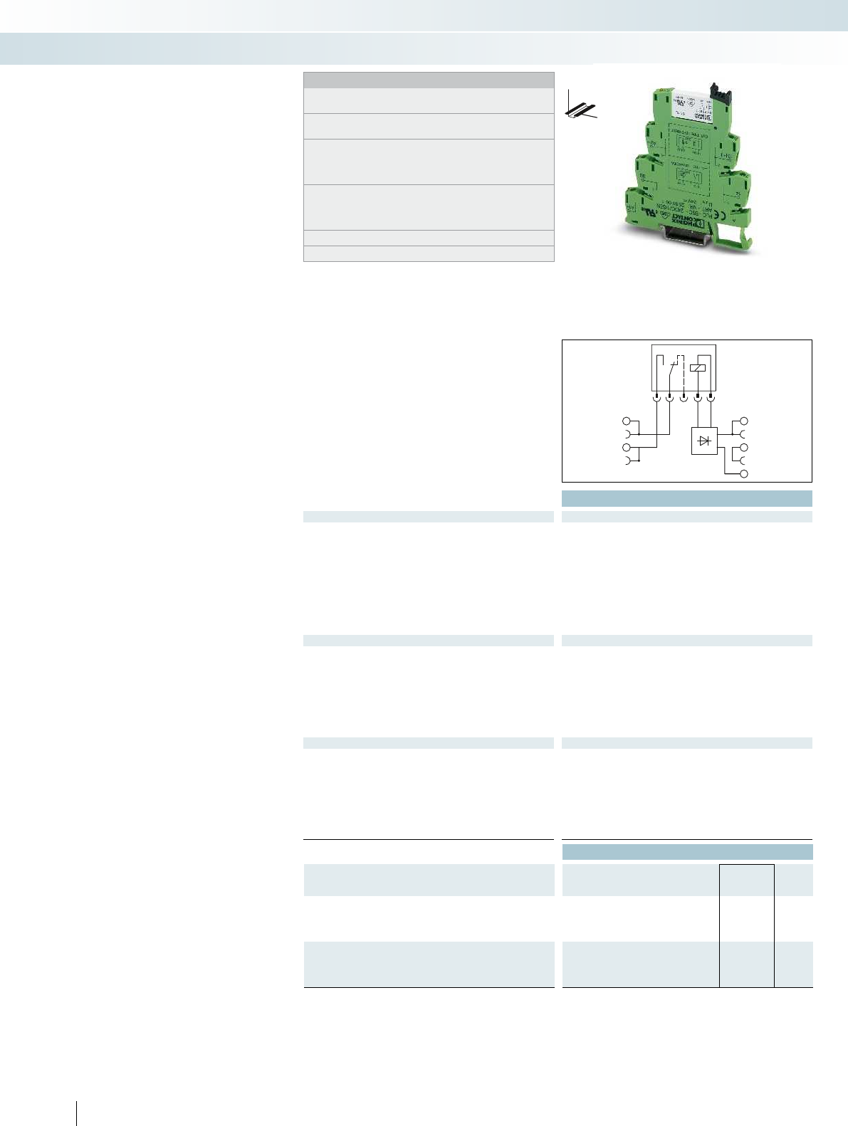
A2
BB
A1
13
14
Technical data
Input data ① ② ③
Permissible range (with reference to U
N
) See diagram
Switching level (with reference to U
N
) 1 signal ("H")
0 signal ("L")
Typ. input current at U
N
[mA] 9 3.5 3.2
Typ. response time/switch-on time at U
N
[ms] 5 6 7
Typ. release time/shutdown time at U
n
[ms] 8 15 15
Transmission frequency f
limit
[Hz]
Input circuit DC
Yellow LED, protection against polarity reversal, freewheeling diode Yellow LED, protection against polarity reversal, freewheel
Input circuit AC/DC Yellow LED, bridge rectifier Yellow LED, bridge rectifier
Output data
Contact material AgSnO, hard gold-plated -
Max. switching voltage 30 V AC / 36 V DC
Min. switching voltage 100 mV (at 10 mA)
Limiting continuous current 50 mA
Max. inrush current 50 mA
Min. switching current 1 mA (at 24 V)
Output protection -
Voltage drop at max. limiting continuous current -
General data
Test voltage input/output 4 kV AC (50 Hz, 1 min.) 2.5 kV (50 Hz, 1 min.)
Ambient temperature (operation) -40 °C ... 60 °C
1
)
Mechanical service life 2 x 10
7
cycles
Standards/regulations IEC 60664, EN 50178, IEC 62103 IEC 60664, EN 50178, IEC 62103
Pollution degree / surge voltage category 3 / III
Connection data solid / stranded / AWG 0.14 - 2.5 mm² / 0.14 - 2.5 mm² / 26 - 14 0.14 - 2.5 mm² / 0.14 - 2.5 mm² / 26 - 14
Dimensions W / H / D 6.2 mm / 80 mm / 94 mm 6.2 mm / 80 mm / 94 mm
EMC note Class A product, see page 625 Class A product, see page 625
Ordering data
Description Input voltage
U
N
Type Order No. Pcs. /
Pkt.
PLC-INTERFACE, with screw connection
①24 V DC PLC-RSC- 24DC/ 1AU/SEN 2966317 10
②120 V AC (110 V DC) PLC-RSC-120UC/ 1AU/SEN 2966320 10
③230 V AC (220 V DC) PLC-RSC-230UC/ 1AU/SEN 2966333 10
PLC-INTERFACE, with push-in connection
①24 V DC PLC-RPT- 24DC/ 1AU/SEN 2900313 10
②120 V AC (110 V DC) PLC-RPT-120UC/ 1AU/SEN 2900314 10
③230 V AC (220 V DC) PLC-RPT-230UC/ 1AU/SEN 2900315 10
408
PHOENIX CONTACT
PLC sensor series for
input functions
PLC sensor series for coupling controller
and sensors, such as proximity switches,
limit switches or auxiliary contacts
The advantages:
– Direct connection of sensor to relay
module
– No need for additional modular terminal
blocks
– Space savings of up to 80%
– Time savings of up to 60%
– Screw and push-in connection technology
– Relay modules with safe isolation
according to DIN EN 50178 between coil
and contact
– Functional jumpers
– Efficient connection to system cabling
using V8 adapter
Relay modules
Highly compact relay modules - PLC-INTERFACE
DW
H
Notes:
Type of housing:
Polyamide PA non-reinforced, color: green.
Marking systems and mounting material
See Catalog 5
Separating plate PLC-ATP must be installed for voltages larger
than 250 V (L1, L2, L3) between identical terminal blocks in
adjacent modules. Potential bridging is then carried out with
FBST 8-PLC... or FBST 500....
If the specified maximum values for multi-layer contact relays are
exceeded, the gold plating is destroyed. The maximum values of
the power contact relay are then valid. This can result in a shorter
service life than with a pure power contact.
For diagrams of operating voltage ranges, see page 423
1
) 120 and 230 V types up to 55 °C
Relay module
1 N/O contact
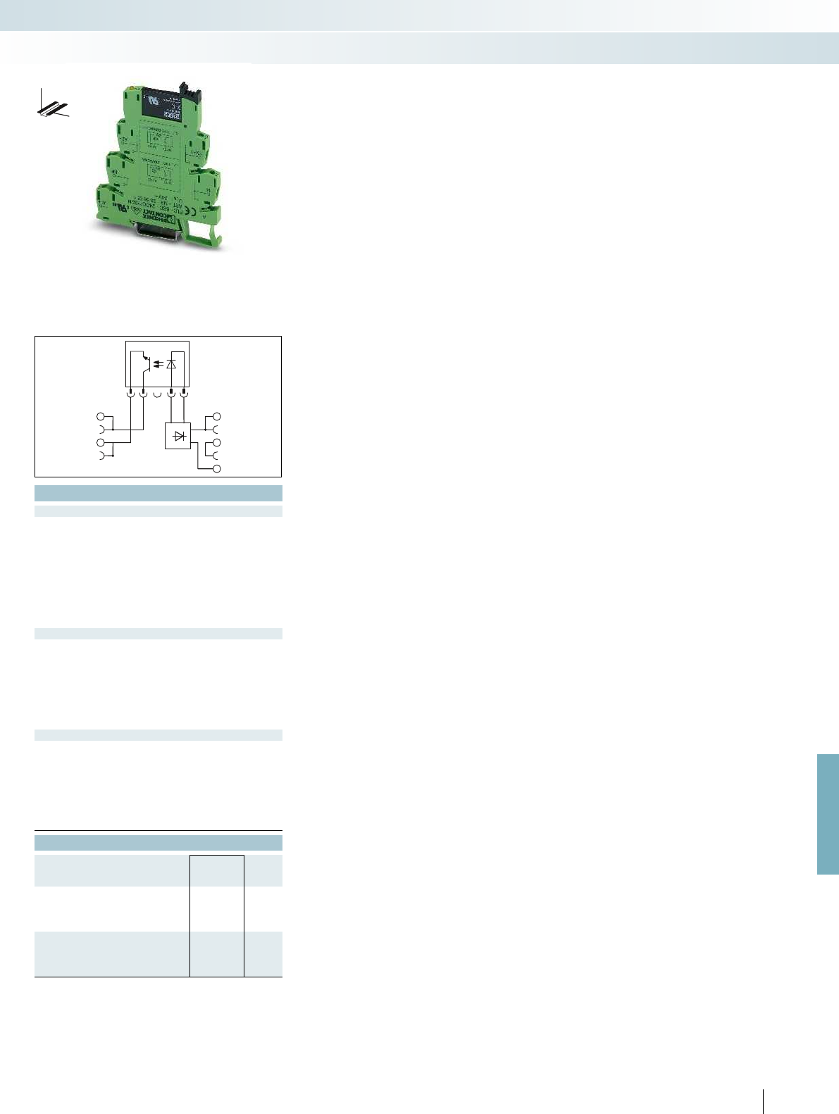
A2
BB
A1
13+
14
For further information and full technical data, visit phoenixcontact.net/products
Technical data
① ② ③
0.8 -
1.2
0.8 -
1.1
0.8 -
1.1
0.8 0.8 0.8
0.4 0.3 0.3
8.5 3.5 3.5
0.02 6 3
0.3 10 5
300 10 10
Yellow LED, protection against polarity reversal, freewheeling diode Yellow LED, protection against polarity reversal, freewheeling diode
Input circuit AC/DC Yellow LED, bridge rectifier Yellow LED, bridge rectifier
Contact material AgSnO, hard gold-plated -
48 V DC
3 V DC
100 mA
-
-
Protection against polarity reversal, surge protection
1 V
Test voltage input/output 4 kV AC (50 Hz, 1 min.) 2.5 kV (50 Hz, 1 min.)
-25 °C ... 60 °C
-
Standards/regulations IEC 60664, EN 50178, IEC 62103 IEC 60664, EN 50178, IEC 62103
2 / III
Connection data solid / stranded / AWG 0.14 - 2.5 mm² / 0.14 - 2.5 mm² / 26 - 14 0.14 - 2.5 mm² / 0.14 - 2.5 mm² / 26 - 14
Dimensions W / H / D 6.2 mm / 80 mm / 94 mm 6.2 mm / 80 mm / 94 mm
EMC note Class A product, see page 625 Class A product, see page 625
Ordering data
Type Order No. Pcs. /
Pkt.
PLC-OSC- 24DC/ 48DC/100/SEN 2966773 10
PLC-OSC-120UC/ 48DC/100/SEN 2966799 10
PLC-OSC-230UC/ 48DC/100/SEN 2966809 10
PLC-OPT- 24DC/ 48DC/100/SEN 2900358 10
PLC-OPT-120UC/ 48DC/100/SEN 2900359 10
PLC-OPT-230UC/ 48DC/100/SEN 2900361 10
409
PHOENIX CONTACT
Relay modules
Highly compact relay modules - PLC-INTERFACE
DW
H
Max. DC voltage output
of 100 mA
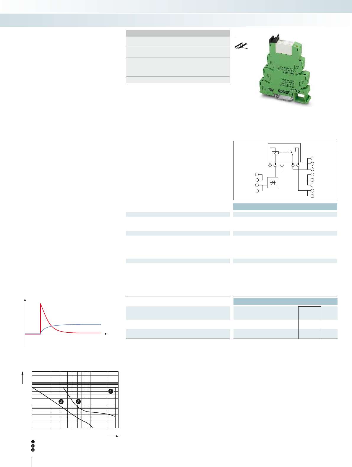
A2
13
BB
14
A1
0,1
0,2
0,3
0,5
1
2
4
6
10
20
10203050 70 100 300200
U
I
t
Technical data
Input data ①
Typ. input current at U
N
[mA] 18
Response/release time at U
N
[ms] 8 / 10
Input circuit DC
Yellow LED, protection against polarity reversal, freewheeling diode
Output data
Contact material AgSnO
Max. switching voltage 250 V AC/DC
Min. switching voltage 12 V AC/DC (at 100 mA)
Max. inrush current 80 A (for 20 ms) / 130 A (peak, at capacitive load, 230 V AC, 24 F)
General data
Test voltage input/output 4 kV AC (50 Hz, 1 min.)
Ambient temperature (operation) -40 °C ... 60 °C
Mechanical service life 3 x 10
7
cycles
Standards/regulations IEC 60664, EN 50178, IEC 62103
Connection data solid / stranded / AWG 0.14 - 2.5 mm² / 0.14 - 2.5 mm² / 26 - 14
Dimensions W / H / D 14 mm / 80 mm / 94 mm
EMC note Class A product, see page 625
Ordering data
Description Input voltage
U
N
Type Order No. Pcs. /
Pkt.
PLC-INTERFACE, with screw connection
①24 V DC PLC-RSC- 24DC/ 1IC/ACT 2967604 10
PLC-INTERFACE, with push-in connection
①24 V DC PLC-RPT- 24DC/ 1IC/ACT 2900298 10
410
PHOENIX CONTACT
Notes:
Type of housing:
Polyamide PA non-reinforced, color: green.
Marking systems and mounting material
See Catalog 5
Separating plate PLC-ATP must be installed for voltages larger
than 250 V (L1, L2, L3) between identical terminal blocks in
adjacent modules. Potential bridging is then carried out with
FBST 8-PLC... or FBST 500....
For diagrams of operating voltage ranges, see page 423
DW
H
PLC-INTERFACE for
high inrush currents
Relay modules
Highly compact relay modules - PLC-INTERFACE
1 N/O contact of up to 130 A peak
Switching voltage [V]
AC, ohmic load
DC, ohmic load
DC, L/R = 40 ms
Basic behavior of capacitive loads:
- Very high input current
- Voltage increases with an e-function
Maximum interrupting rating
Switching current [A]
PLC relay modules for high inrush
currents due, for example, to capacitive
loads
The advantages:
– Max. inrush current of 130 A
– Direct connection of load return line
thanks to actuator type
– Screw and push-in connection technology
– Safe isolation according to DIN EN 50178
between coil and contact
– Functional jumpers
– Efficient connection to system cabling
using V8 adapter
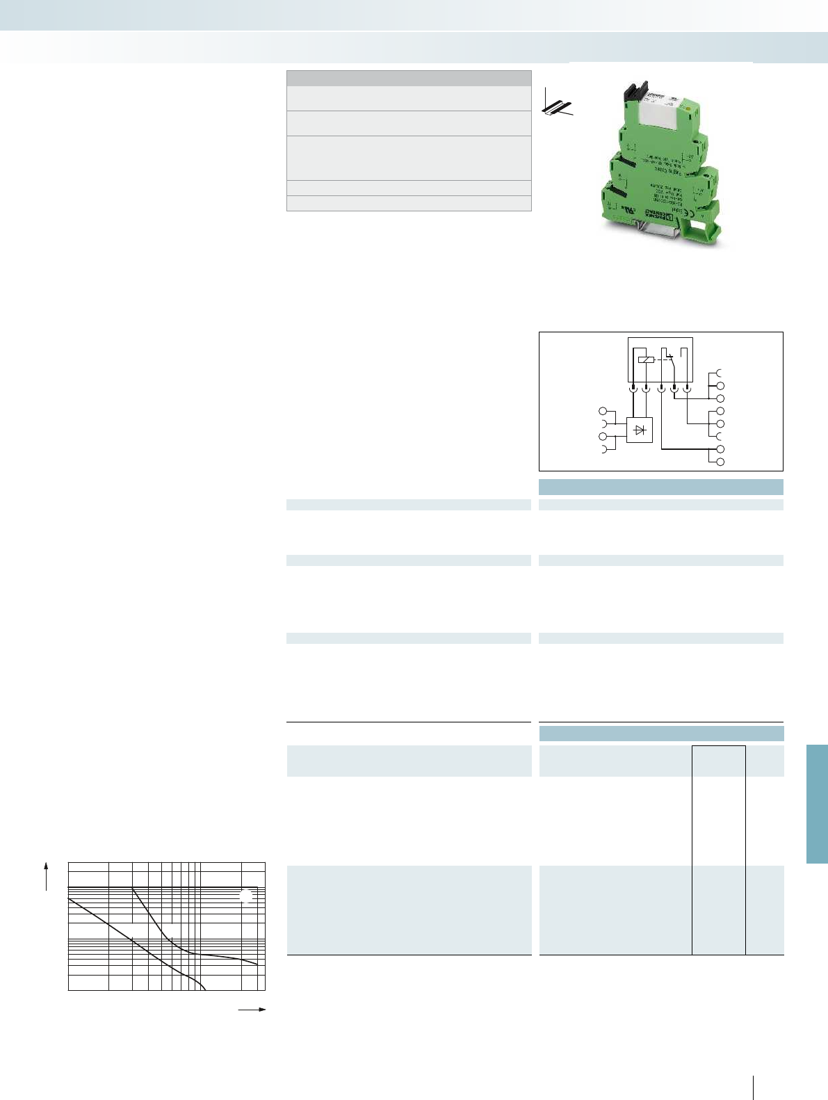
1
2
3
3
1
2
A2
11
14
12
A1
For further information and full technical data, visit phoenixcontact.net/products
Technical data
Input data ① ② ③ ④ ⑤ ⑥ ⑦
Typ. input current at U
N
[mA] 33 18 17.5 20 10 4.5 4.5
Response/release time at U
N
[ms] 8 / 10 8 / 10 8 / 10 8 / 10 8 / 10 7 / 10 7 / 10
Input circuit DC
Yellow LED, protection against polarity reversal, freewheeling diode
Input circuit AC/DC Yellow LED, bridge rectifier
Output data
Contact material AgNi
Max. switching voltage 250 V AC/DC
Min. switching voltage 12 V AC/DC
Limiting continuous current 10 A
Max. inrush current 30 A (300 ms)
Min. switching current 100 mA
General data
Test voltage input/output 4 kV AC (50 Hz, 1 min.)
Ambient temperature (operation) -40 °C ... 60 °C
1
)
Mechanical service life 3 x 10
7
cycles
Standards/regulations IEC 60664, EN 50178, IEC 62103
Connection data solid / stranded / AWG 0.14 - 2.5 mm² / 0.14 - 2.5 mm² / 26 - 14
Dimensions W / H / D 14 mm / 80 mm / 94 mm
EMC note Class A product, see page 625
Ordering data
Description Input voltage
U
N
Type Order No. Pcs. /
Pkt.
PLC-INTERFACE, with screw connection
①12 V DC PLC-RSC- 12DC/21HC 2967617 10
②24 V DC PLC-RSC- 24DC/21HC 2967620 10
③24 V AC/DC PLC-RSC- 24UC/21HC 2967633 10
④48 V DC PLC-RSC- 48DC/21HC 2967646 10
⑤60 V DC PLC-RSC- 60DC/21HC 2967659 10
⑥120 V AC (110 V DC) PLC-RSC-120UC/21HC 2967662 10
⑦230 V AC (220 V DC) PLC-RSC-230UC/21HC 2967675 10
PLC-INTERFACE, with push-in connection
①12 V DC PLC-RPT- 12DC/21HC 2900290 10
②24 V DC PLC-RPT- 24DC/21HC 2900291 10
③24 V AC/DC PLC-RPT- 24UC/21HC 2900293 10
④48 V DC PLC-RPT- 48DC/21HC 2900294 10
⑤60 V DC PLC-RPT- 60DC/21HC 2900295 10
⑥120 V AC (110 V DC) PLC-RPT-120UC/21HC 2900296 10
⑦230 V AC (220 V DC) PLC-RPT-230UC/21HC 2900297 10
411
PHOENIX CONTACT
0,1
0,2
0,3
0,5
1
2
4
6
10
20
10 20 30 50 70 100 300200
AC, ohmic load
Switching voltage [V]
Switching current [A]
DC, ohmic load
DC, L/R = 40 ms
Max. interrupting rating
Notes:
Type of housing:
Polyamide PA non-reinforced, color: green.
Marking systems and mounting material
See Catalog 5
Separating plate PLC-ATP must be installed for voltages larger
than 250 V (L1, L2, L3) between identical terminal blocks in
adjacent modules. Potential bridging is then carried out with
FBST 8-PLC... or FBST 500....
For diagrams of operating voltage ranges, see page 423
1
) 230 V types up to 55 °C
DW
H
PLC relay modules for high continuous
switching currents
The advantages:
– Max. continuous current of 10 A
– Safe isolation according to DIN EN 50178
between coil and contact
– Screw and push-in connection technology
– Functional jumpers
– Efficient connection to system cabling
using V8 adapter
– Long electrical service life thanks to
16 A relay
– All common input voltages of
12 V DC to 230 V AC
PLC-INTERFACE for
high continuous currents
Relay modules
Highly compact relay modules - PLC-INTERFACE
1 PDT up to 10 A

A2
24
21
22
14
11
12
A1
A1
A2 11
14
12
Ex:
Ex:
Technical data Technical data
Input data ② ② ③
Permissible range (with reference to U
N
) See diagram See diagram
Switching level (with reference to U
N
) 1 signal ("H")
0 signal ("L")
Typ. input current at U
N
[mA] 18 9 3.5
Typ. response time/switch-on time at U
N
[ms] 8 5 6
Typ. release time/shutdown time at U
n
[ms] 10 8 15
Transmission frequency f
limit
[Hz]
Input circuit DC Yellow LED, protection against polarity reversal, surge protection Yellow LED, protection against polarity reversal, freewheeling diode Yellow LED, protection against polarity reversal, protection against
Input circuit AC/DC Yellow LED, bridge rectifier Yellow LED, bridge rectifier Y
Output data
Contact material AgNi AgSnO
Max. switching voltage 250 V AC/DC 250 V AC/DC
Min. switching voltage 5 V AC/DC (at 10 mA) 5 V (at 100 mA)
Limiting continuous current 6 A 6 A
Max. inrush current 15 A (300 ms) on request
Min. switching current 10 mA (at 5 V) 10 mA (at 12 V)
Output protection - -
Voltage drop at max. limiting continuous current - -
General data
Test voltage input/output 4 kV (50 Hz, 1 min.) 4 kV AC (50 Hz, 1 min.) 4 kV AC (50 Hz, 1 min.) 2.5 kV (50 Hz, 1 min.) 2.5 kV (50 Hz,
Ambient temperature (operation) -20 °C ... 60 °C (UL) -20 °C ... 60 °C
Mechanical service life 3 x 10
7
cycles 2 x 10
7
cycles
Standards/regulations IEC 60664, EN 50178, IEC 62103, EN 60079-0, EN 60079-15 IEC 60664, EN 50178, IEC 62103, EN 60079-0, EN 60079-15 IEC 60664, EN 50178, IEC 62103, EN 60079-0, EN 60079-15 IEC 60664, EN 50178, IEC 62103 IEC 60664, EN 50178, IEC 62103
Pollution degree / surge voltage category 2 / III 3 / III
Connection data solid / stranded / AWG 0.14 - 2.5 mm² / 0.14 - 2.5 mm² / 26 - 14 0.14 - 2.5 mm² / 0.14 - 2.5 mm² / 26 - 14 0.14 - 2.5
Dimensions W / H / D 14 mm / 80 mm / 94 mm 6.2 mm / 80 mm / 94 mm 6.2 mm / 80 mm / 94 mm 6.2 mm / 80 mm / 94 mm 6.2 mm / 80 mm / 94 m
EMC note
Conformance / approvals
Conformance CE-compliant CE-compliant
ATEX DEMKO 03 ATEX 0326050U; II 3G Ex nA nC IIC Gc DEMKO 11 ATEX 1111531U; II 3G Ex nC IIC Gc - - -
UL, USA Class I, Zone 2, AEx nA nC IIC T6 Class I, Zone 2, AEx nA nC IIC T6 Class I, Zone 2, AEx nA nC IIC T6 Class I, Zone 2, AEx
UL, USA / Canada Class I, Div. 2, Groups A, B, C, D Class I, Div. 2, Groups A, B, C, D Class I, Div. 2, Groups A, B, C, D Class I,
UL, Canada Class I, Zone 2, Ex nA nC IIC Gc T6 X Class I, Zone 2, Ex nA nC IIC Gc T6 X Class I, Zone 2, Ex nA nC IIC Gc T6 X Class
Ordering data Ordering data
Description Input voltage
U
N
Type Order No. Pcs. /
Pkt. Type Order No. Pcs. /
Pkt.
PLC-INTERFACE, with screw connection
①12 V DC
②24 V DC PLC-RSC- 24DC/21-21ATEX 2980461 10 PLC-RSC- 24DC/21 ATEX 2902955 1
③120 V AC (110 V DC) PLC-RSC-120UC/21 ATEX 2902956 1
④230 V AC
PLC-INTERFACE, with spring-cage connection
①12 V DC
③120 V AC (110 V DC)
412
PHOENIX CONTACT
Relay modules with ATEX and/or Class 1,
Division 2 approval for potentially explosive
applications.
The advantages:
– Slim design
– Functional jumpers
– Integrated input and interference
suppression circuit
– RTIII-sealed relays
– Safe isolation according to DIN EN 50178
between coil and contact
– Efficient connection to system cabling
using V8 adapter
Notes:
Type of housing:
Polyamide PA non-reinforced, color: green.
Marking systems and mounting material
See Catalog 5
Separating plate PLC-ATP must be installed for voltages larger
than 250 V (L1, L2, L3) between identical terminal blocks in
adjacent modules. Potential bridging is then carried out with
FBST 8-PLC... or FBST 500....
PLC-INTERFACE for
hazardous areas
Relay modules
Highly compact relay modules - PLC-INTERFACE
2 PDT with power contact 1 PDT with power contact 1 PDT with power
DW
H
new
DW
H
new
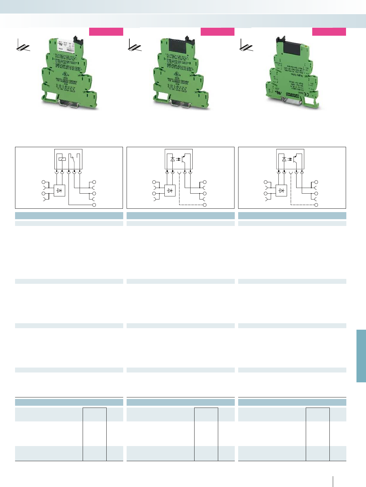
A1
A2 11
14
12
A2
A1
13+
14
A2
A1
13+
14
For further information and full technical data, visit phoenixcontact.net/products
Ex:
Ex:
Technical data Technical data Technical data
① ② ③ ④ ② ③ ② ③
See diagram 0.8 -
1.2
0.9 -
1.1
0.8 -
1.2
0.9 -
1.1
0.8 0.8 0.8 0.9
0.4 0.3 0.4 0.3
15.3 9 3.5 3.2 8.5 3.5 8.5 3.5
5 5 6 7 0.02 3.5 0.02 3
8 8 15 15 0.3 7 0.3 4
300 10 300 10
sal, freewheeling diode Yellow LED, protection against polarity reversal, protection against
polarity reversal
Yellow LED, protection against polarity reversal, freewheeling diode Yellow LED, protection against polarity reversal, freewheeling diode
Yellow LED, bridge rectifier Yellow LED, bridge rectifier Yellow LED, bridge rectifier Yellow LED, bridge rectifier
AgSnO - -
250 V AC/DC 33 V DC 48 V DC
12 V AC/DC 3 V DC 3 V DC
6 A 3 A 100 mA
- 15 A (10 ms) -
10 mA - -
- Protection against polarity reversal, surge protection Protection against polarity reversal, surge protection
- 200 mV 1 V
Test voltage input/output 4 kV (50 Hz, 1 min.) 4 kV AC (50 Hz, 1 min.) 4 kV AC (50 Hz, 1 min.) 2.5 kV (50 Hz, 1 min.) 2.5 kV (50 Hz, 1 min.)
-25 °C ... 60 °C -20 °C ... 60 °C -25 °C ... 60 °C
2 x 10
7
cycles - -
9-15 IEC 60664, EN 50178, IEC 62103, EN 60079-0, EN 60079-15 IEC 60664, EN 50178, IEC 62103 IEC 60664, EN 50178, IEC 62103
3 / III 2 / III 2 / III
Connection data solid / stranded / AWG 0.14 - 2.5 mm² / 0.14 - 2.5 mm² / 26 - 14 0.14 - 2.5 mm² / 0.14 - 2.5 mm² / 26 - 14 0.14 - 2.5 mm² / 0.14 - 2.5 mm² / 26 - 14 0.14 - 2.5 mm² / 0.14 - 2.5 mm² / 26 - 14 0.14 - 2.5 mm² / 0.14 - 2.5 mm² / 26 - 14
Dimensions W / H / D 14 mm / 80 mm / 94 mm 6.2 mm / 80 mm / 94 mm 6.2 mm / 80 mm / 94 mm 6.2 mm / 80 mm / 94 mm 6.2 mm / 80 mm / 94 mm
Class A product, see page 625 Class A product, see page 625 Class A product, see page 625
CE-compliant CE-compliant CE-compliant
ATEX DEMKO 03 ATEX 0326050U; II 3G Ex nA nC IIC Gc DEMKO 11 ATEX 1111531U; II 3G Ex nC IIC Gc - - -
UL, USA Class I, Zone 2, AEx nA nC IIC T6 Class I, Zone 2, AEx nA nC IIC T6 Class I, Zone 2, AEx nA nC IIC T6 Class I, Zone 2, AEx nA nC IIC T6 Class I, Zone 2, AEx nA nC IIC T6
UL, USA / Canada Class I, Div. 2, Groups A, B, C, D Class I, Div. 2, Groups A, B, C, D Class I, Div. 2, Groups A, B, C, D Class I, Div. 2, Groups A, B, C, D Class I, Div. 2, Groups A, B, C, D
UL, Canada Class I, Zone 2, Ex nA nC IIC Gc T6 X Class I, Zone 2, Ex nA nC IIC Gc T6 X Class I, Zone 2, Ex nA nC IIC Gc T6 X Class I, Zone 2, Ex nA nC IIC Gc T6 X Class I, Zone 2, Ex nA nC IIC Gc T6 X
Ordering data Ordering data Ordering data
Type Order No. Pcs. /
Pkt. Type Order No. Pcs. /
Pkt. Type Order No. Pcs. /
Pkt.
PLC-RSC-12DC/21-C1D2 5606331 1
PLC-RSC-24DC/21 C1D2 5603154 1PLC-OSC- 24DC/ 24DC/ 2 C1D2 5603260 1PLC-OSC- 24DC/ 48DC/100 C1D2 5603261 1
PLC-RSC-120UC/21 C1D2 5603157 1PLC-OSC-120UC/ 24DC/ 2 C1D2 5603262 1PLC-OSC-120UC/ 48DC/100 C1D2 5603263 1
PLC-RSC-230UC/21-CID2 5607072 1
PLC-RSP-12DC/21 CID2 5606332 1
PLC-RSP-120UC/21 C1D2 5603683 1
413
PHOENIX CONTACT
Relay modules
Highly compact relay modules - PLC-INTERFACE
DW
H
new
2 PDT with power contact 1 PDT with power contact 1 PDT with power contact Max. DC voltage output of 3 A Max. DC voltage output of 100 mA
DW
H
new
DW
H
new
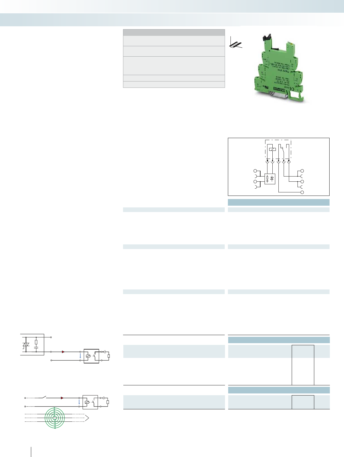
N
A1
U
A2
L1
L2
L3
L
230 VAC
(10m)>
VR
C
N
L
A1
U
A2
A2
A1
11
14
12
Technical data
Input data
Nominal input voltage U
N
120 V AC 230 V AC 120 V AC 230 V AC 120 V AC 230 V AC 120 V AC 230 V AC
Permissible range (with reference to U
N
) 0.8 ... 1.4 0.78 ... 1.14 0.8 ... 1.4 0.78 ... 1.14 0.78 ... 1.4 0.78 ... 1.14 0.85 ... 1.4 0.78 ... 1.14
Typ. release voltage (with relay) 50 V AC 80 V AC 50 V AC 80 V AC 16 V AC 70 V AC 16 V AC 70 V AC
Typ. input current with U
N
(50 /60 Hz) 7 mA / 8 mA 8.8 mA / 10 mA 7 mA / 8 mA 8.8 mA / 10 mA 6 mA / 7 mA 8.5 mA / 10 mA 6 mA / 7 mA 8.5 mA / 10 mA
Typ. response time at U
N
7 ms 7 ms 7 ms 7 ms 7 ms 7 ms 7 ms 7 ms
Typ. release time at U
N
20 ms 20 ms 20 ms 20 ms 10 ms 10 ms 20 ms 20 ms
Input circuit Yellow LED, bridge rectifier, filter Yellow LED, brid
Output data with: REL-MR-60DC/21 REL-MR-60DC/21AU
Contact type Single contact, 1-PDT Single contact, 1-PDT Single contact, 1 N/O contact Single contact, 1 N/O contact Single contact,
Contact material AgSnO AgSnO, hard gold-plated AgSnO AgSnO, hard gold-plated AgNi AgNi, + 5 µm Au AgNi
Max. switching voltage 250 V AC/DC 30 V AC / 36 V DC 250 V AC/DC 30 V AC / 36 V DC 250 V AC/DC 30 V AC / 36 V DC 250 V AC/DC
Min. switching voltage 5 V (at 100 mA) 100 mV (at 10 mA) 5 V (at 100 mA) 100 mV (at 10 mA) 5 V AC/DC 100 mV 12 V AC/DC
Limiting continuous current 6 A 50 mA 6 A 50 mA 6 A 50 mA 10 A
Max. inrush current on request 50 mA on request 50 mA 15 A (300 ms) 50 mA 30 A (300 ms)
Min. switching current 10 mA (at 12 V) 1 mA (at 24 V) 10 mA (at 12 V) 1 mA (at 24 V) 10 mA 1 mA 100 mA
General data
Test voltage input/output 4 kV (50 Hz, 1 min.)
Ambient temperature (operation) -20 °C ... 55 °C
Mechanical service life 2 x 10
7
cycles
Standards/regulations IEC 60664, EN 50178, IEC 62103 IEC 60664, EN 50178, IEC 62103 IEC 60664, EN 50178, IEC 62103 IEC 60664, EN 50
Pollution degree / Surge voltage category 3 / III
Connection data solid / stranded / AWG 0.14 - 2.5 mm² / 0.14 - 2.5 mm² / 26 - 14 0.14 - 2.5 mm² / 0.14 - 2.5 mm² / 26 - 14 0.14 - 2.5
Dimensions W / H / D 6.2 mm / 80 mm / 94 mm 6.2 mm / 80 mm / 94 mm 14 mm / 80 mm / 94 mm 14 mm / 80 mm / 94 mm
EMC note Class A product, see page 625 Class A product, see page 625 Class A product, see page 625 Class A product, see page 625
Ordering data
Description Voltage U
N
Type Order No. Pcs. /
Pkt.
PLC-INTERFACE basic terminal block, for
plug-in miniature relays or solid-state relays
With screw connection 120 V AC PLC-BSC-120UC/21/SO46 2980319 10
With screw connection 230 V AC PLC-BSC-230UC/21/SO46 2980335 10
With push-in connection 120 V AC PLC-BPT-120UC/21/SO46 2900453 10
With push-in connection 230 V AC PLC-BPT-230UC/21/SO46 2900455 10
Accessories
Plug-in miniature relay
with gold contact REL-MR- 60DC/21AU 2961134 10
with power contact REL-MR- 60DC/21 2961118 10
414
PHOENIX CONTACT
Basic terminal blocks with
interference current filter that can be
fitted with relays
PLC basic terminal blocks with integrated
filter to protect against interference
voltages or currents due, for example, to
long control lines
The advantages:
– Resistant to interference currents
– High relay release voltage
Typical applications:
– Applications with long control lines
– Use of AC output boards, resulting in
residual AC currents
– Screw and push-in connection technology
Parallel signal cables or load cables
Long signal cable
Leakage current Load
E.g.
Occurrence of interference signals
Scenario 2: long signal cables
Output
Leakage current
Load
Signal cable
Occurrence of interference signals
Scenario 1: controller - AC output card
Relay modules
Highly compact relay modules - PLC-INTERFACE
DW
H
Notes:
Type of housing:
Polyamide PA non-reinforced, color: green.
Marking systems and mounting material
See Catalog 5
Separating plate PLC-ATP must be installed for voltages larger
than 250 V (L1, L2, L3) between identical terminal blocks in
adjacent modules. Potential bridging is then carried out with
FBST 8-PLC... or FBST 500....
For diagrams of operating voltage ranges, see page 423
Maximum interrupting rating diagrams, see page 426
Universal design Sensor design 2 PDT universal design 1 PDT for high continuous currents
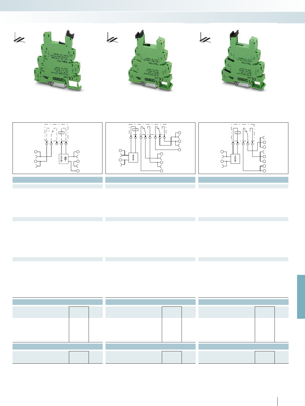
13
14
A2
BB
A1
A2
A1
11
14
12
21
24
22
11
14
12
A2
A1
For further information and full technical data, visit phoenixcontact.net/products
Technical data Technical data Technical data
120 V AC 230 V AC 120 V AC 230 V AC 120 V AC 230 V AC 120 V AC 230 V AC
) 0.8 ... 1.4 0.78 ... 1.14 0.8 ... 1.4 0.78 ... 1.14 0.78 ... 1.4 0.78 ... 1.14 0.85 ... 1.4 0.78 ... 1.14
Typ. release voltage (with relay) 50 V AC 80 V AC 50 V AC 80 V AC 16 V AC 70 V AC 16 V AC 70 V AC
(50 /60 Hz) 7 mA / 8 mA 8.8 mA / 10 mA 7 mA / 8 mA 8.8 mA / 10 mA 6 mA / 7 mA 8.5 mA / 10 mA 6 mA / 7 mA 8.5 mA / 10 mA
7 ms 7 ms 7 ms 7 ms 7 ms 7 ms 7 ms 7 ms
20 ms 20 ms 20 ms 20 ms 10 ms 10 ms 20 ms 20 ms
Input circuit Yellow LED, bridge rectifier, filter Yellow LED, bridge rectifier, filter Yellow LED, bridge rectifier, filter Yellow LED, bridge rectifier, filter
REL-MR-60DC/21 REL-MR-60DC/21AU REL-MR-110DC/21-21 REL-MR-110DC/21-21AU REL-MR-110DC/21HC
Contact type Single contact, 1-PDT Single contact, 1-PDT Single contact, 1 N/O contact Single contact, 1 N/O contact Single contact, 2-PDT Single contact, 2-PDT Single contact, 1-PDT
Contact material AgSnO AgSnO, hard gold-plated AgSnO AgSnO, hard gold-plated AgNi AgNi, + 5 µm Au AgNi
Max. switching voltage 250 V AC/DC 30 V AC / 36 V DC 250 V AC/DC 30 V AC / 36 V DC 250 V AC/DC 30 V AC / 36 V DC 250 V AC/DC
Min. switching voltage 5 V (at 100 mA) 100 mV (at 10 mA) 5 V (at 100 mA) 100 mV (at 10 mA) 5 V AC/DC 100 mV 12 V AC/DC
Limiting continuous current 6 A 50 mA 6 A 50 mA 6 A 50 mA 10 A
Max. inrush current on request 50 mA on request 50 mA 15 A (300 ms) 50 mA 30 A (300 ms)
Min. switching current 10 mA (at 12 V) 1 mA (at 24 V) 10 mA (at 12 V) 1 mA (at 24 V) 10 mA 1 mA 100 mA
4 kV (50 Hz, 1 min.) 4 kV (50 Hz, 1 min.) 4 kV (50 Hz, 1 min.)
-20 °C ... 55 °C -20 °C ... 55 °C -20 °C ... 55 °C
2 x 10
7
cycles 3 x 10
7
cycles 3 x 10
7
cycles
Standards/regulations IEC 60664, EN 50178, IEC 62103 IEC 60664, EN 50178, IEC 62103 IEC 60664, EN 50178, IEC 62103 IEC 60664, EN 50178, IEC 62103
3 / III 3 / III 3 / III
Connection data solid / stranded / AWG 0.14 - 2.5 mm² / 0.14 - 2.5 mm² / 26 - 14 0.14 - 2.5 mm² / 0.14 - 2.5 mm² / 26 - 14 0.14 - 2.5 mm² / 0.14 - 2.5 mm² / 26 - 14 0.14 - 2.5 mm² / 0.14 - 2.5 mm² / 26 - 14
Dimensions W / H / D 6.2 mm / 80 mm / 94 mm 6.2 mm / 80 mm / 94 mm 14 mm / 80 mm / 94 mm 14 mm / 80 mm / 94 mm
EMC note Class A product, see page 625 Class A product, see page 625 Class A product, see page 625 Class A product, see page 625
Ordering data Ordering data Ordering data
Type Order No. Pcs. /
Pkt. Type Order No. Pcs. /
Pkt. Type Order No. Pcs. /
Pkt.
PLC-BSC-120UC/ 1/SEN/SO46 2980322 10 PLC-BSC-120UC/21-21/SO46 2980416 10 PLC-BSC-120UC/21HC/SO46 2980432 10
PLC-BSC-230UC/ 1/SEN/SO46 2980348 10 PLC-BSC-230UC/21-21/SO46 2980429 10 PLC-BSC-230UC/21HC/SO46 2980445 10
PLC-BPT-120UC/ 1/SEN/SO46 2900456 10
PLC-BPT-230UC/ 1/SEN/SO46 2900457 10
Accessories Accessories Accessories
REL-MR- 60DC/21AU 2961134 10 REL-MR-110DC/21-21AU 2961228 10
REL-MR- 60DC/21 2961118 10 REL-MR-110DC/21-21 2961202 10 REL-MR-110DC/21HC 2961338 10
415
PHOENIX CONTACT
Relay modules
Highly compact relay modules - PLC-INTERFACE
DW
H
DW
H
DW
H
Universal design Sensor design 2 PDT universal design 1 PDT for high continuous currents

A2
A1
11
14
12
AC
A2
A1
11
14
12
DC
Technical data
Input data
Nominal input voltage U
N
120 V AC 230 V AC 120 V AC 230 V AC
Permissible range (with reference to U
N
) 0.85 ... 1.1 0.8 ... 1.1 0.85 ... 1.1 0.8 ... 1.1
Switching level (with optocoupler) 0 signal ("L") 0.4 0.4
Typ. input current with U
N
(50 /60 Hz) 7 mA / 8 mA 8.8 mA / 10 mA 7 mA / 8 mA 8.8 mA / 10 mA
Typ. response time/switch-on time at U
N
6 ms 6 ms 6 ms 6 ms
Typ. shutdown time at U
N
10 ms 10 ms 10 ms 10 ms
Input circuit Yellow LED, bridge rectifier, filter Yellow LED, bridge rectifier, filter
Output data with: OPT...48DC/... OPT...24DC/... OPT...230AC/...
Max. switching voltage 48 V DC 30 V DC 253 V AC 48 V DC 30 V DC 253 V AC
Min. switching voltage 3 V DC 3 V DC 24 V AC 3 V DC 3 V DC 24 V AC
Limiting continuous current 100 mA 3 A 0.75 A 100 mA 3 A 0.75 A
Max. inrush current 15 A (10 ms) 30 A (10 ms) 15 A (10 ms) 30 A (10 ms)
Output protection
Protection
against polarity
reversal, surge
protection
Protection
against polarity
reversal, surge
protection
RCV circuit
Voltage drop at limiting continuous current < 1 V DC < 200 mV < 1 V AC < 1 V < 200 mV < 1 V
Leakage current in off state - - < 1 mA - - < 1 mA
Max. phase shift (inductive load) - - 0.5 - - 0.5
Max. load value I
2
x t (t = 10 ms) - - 4.5 A
2
s - - 4.5 A
General data
Test voltage input/output 2.5 kV (50 Hz, 1 min.)
Ambient temperature (operation) -20 °C ... 55 °C
Standards/regulations IEC 60664, EN 50178, IEC 62103 IEC 60664, EN 50178, IEC 62103
Pollution degree / Surge voltage category 2 / III
Connection data solid / stranded / AWG 0.14 - 2.5 mm² / 0.14 - 2.5 mm² / 26 - 14 0.14 - 2.5 mm² / 0.14 - 2.5 mm² / 26 - 14
Dimensions W / H / D 6.2 mm / 80 mm / 94 mm 6.2 mm / 80 mm / 94 mm
EMC note Class A product, see page 625 Class A product, see page 625
Ordering data
Description Voltage U
N
Type Order No. Pcs. /
Pkt.
PLC-INTERFACE basic terminal block, for plug-in miniature
relays or solid-state relays
With screw connection 120 V AC PLC-BSC-120UC/21/SO46 2980319 10
With screw connection 230 V AC PLC-BSC-230UC/21/SO46 2980335 10
With push-in connection 120 V AC PLC-BPT-120UC/21/SO46 2900453 10
With push-in connection 230 V AC PLC-BPT-230UC/21/SO46 2900455 10
Accessories
Plug-in solid-state relay
Solid-state input relay OPT-60DC/ 48DC/100 2966621 10
Solid-state power relay OPT-60DC/ 24DC/ 2 2966605 10
Solid-state power relay OPT-60DC/230AC/ 1 2967963 10
416
PHOENIX CONTACT
Basic terminal blocks with
interference current filter that can be
fitted with solid-state relays
PLC basic terminal blocks with integrated
filter to protect against interference
voltages or currents due, for example, to
long control lines
The advantages:
– Resistant to interference currents
– High relay release voltage
Typical applications:
– Applications with long control lines
– Use of AC output boards, resulting in
residual AC currents
– Screw and push-in connection technology
Relay modules
Highly compact relay modules - PLC-INTERFACE
DW
H
Notes:
Type of housing:
Polyamide PA non-reinforced, color: green.
Marking systems and mounting material
See Catalog 5
Separating plate PLC-ATP must be installed for voltages larger
than 250 V (L1, L2, L3) between identical terminal blocks in
adjacent modules. Potential bridging is then carried out with
FBST 8-PLC... or FBST 500....
For derating curves see page 425
Universal design Sensor design
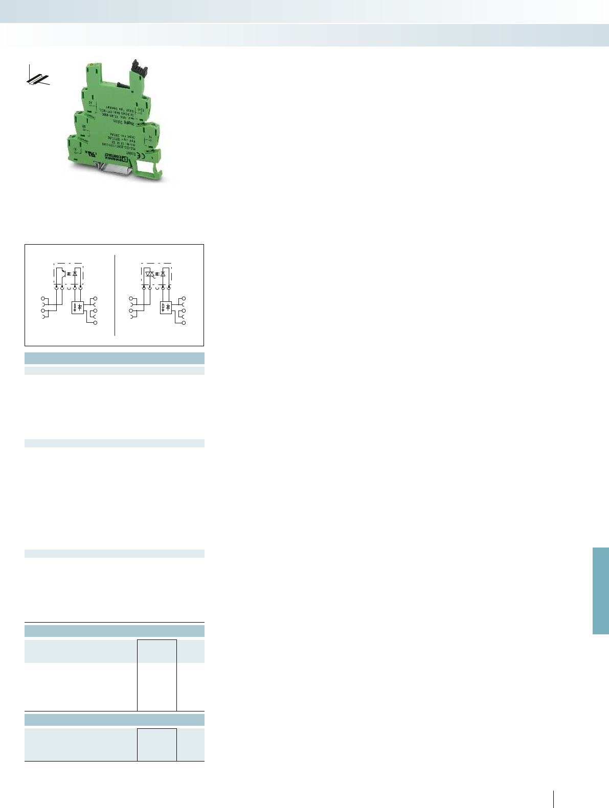
ACDC
A2
BB
A1
13
14
13
14
A2
BB
A1
For further information and full technical data, visit phoenixcontact.net/products
Technical data
120 V AC 230 V AC 120 V AC 230 V AC
) 0.85 ... 1.1 0.8 ... 1.1 0.85 ... 1.1 0.8 ... 1.1
0.4 0.4
(50 /60 Hz) 7 mA / 8 mA 8.8 mA / 10 mA 7 mA / 8 mA 8.8 mA / 10 mA
6 ms 6 ms 6 ms 6 ms
10 ms 10 ms 10 ms 10 ms
filter Yellow LED, bridge rectifier, filter
OPT...48DC/... OPT...24DC/... OPT...230AC/...
Max. switching voltage 48 V DC 30 V DC 253 V AC 48 V DC 30 V DC 253 V AC
Min. switching voltage 3 V DC 3 V DC 24 V AC 3 V DC 3 V DC 24 V AC
Limiting continuous current 100 mA 3 A 0.75 A 100 mA 3 A 0.75 A
Max. inrush current 15 A (10 ms) 30 A (10 ms) 15 A (10 ms) 30 A (10 ms)
Protection
against polarity
reversal, surge
protection
Protection
against polarity
reversal, surge
protection
RCV circuit
Voltage drop at limiting continuous current < 1 V DC < 200 mV < 1 V AC < 1 V < 200 mV < 1 V
Leakage current in off state - - < 1 mA - - < 1 mA
Max. phase shift (inductive load) - - 0.5 - - 0.5
s - - 4.5 A
2
s
2.5 kV (50 Hz, 1 min.)
-20 °C ... 55 °C
Standards/regulations IEC 60664, EN 50178, IEC 62103 IEC 60664, EN 50178, IEC 62103
2 / III
Connection data solid / stranded / AWG 0.14 - 2.5 mm² / 0.14 - 2.5 mm² / 26 - 14 0.14 - 2.5 mm² / 0.14 - 2.5 mm² / 26 - 14
Dimensions W / H / D 6.2 mm / 80 mm / 94 mm 6.2 mm / 80 mm / 94 mm
EMC note Class A product, see page 625 Class A product, see page 625
Ordering data
Type Order No. Pcs. /
Pkt.
PLC-BSC-120UC/ 1/SEN/SO46 2980322 10
PLC-BSC-230UC/ 1/SEN/SO46 2980348 10
PLC-BPT-120UC/ 1/SEN/SO46 2900456 10
PLC-BPT-230UC/ 1/SEN/SO46 2900457 10
Accessories
OPT-60DC/ 48DC/100 2966621 10
OPT-60DC/ 24DC/ 2 2966605 10
OPT-60DC/230AC/ 1 2967963 10
417
PHOENIX CONTACT
Relay modules
Highly compact relay modules - PLC-INTERFACE
DW
H
Universal design Sensor design
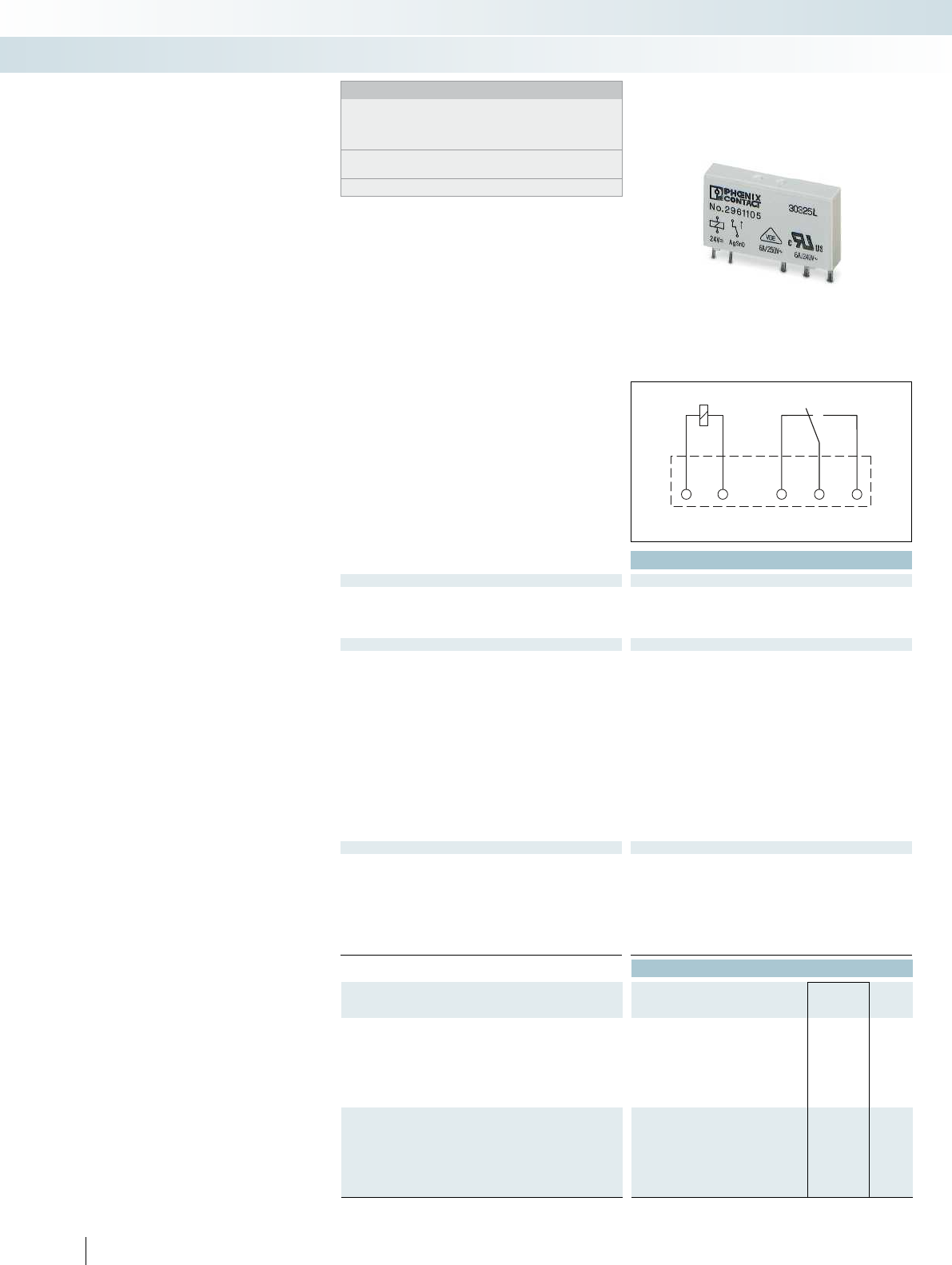
A2 A1 1112 14
Technical data
Input data ① ② ③ ④ ⑤
Permissible range (with reference to U
N
) see diagram
Typ. input current at U
N
[mA] 38 14 9 7 3 33 17 8.2 4.1 17 33 17 8.2 4.1
Typ. response time at U
N
[ms]55555 7 777 8 7 777
Typ. release time at U
N
[ms] 2.5 2.5 2.5 2.5 2.5 3 3 3 3 3 3 3 3 3
Output data
Contact type 1 PDT 1 PDT 2 PDT 2 PDT 1 N/O contact 1 PDT
Contact material AgSnO AgSnO, hard gold-plated AgNi AgNi, hard gold-plated AgSnO AgNi
Max. switching voltage 250 V AC/DC 30 V AC / 36 V DC 250 V AC/DC 30 V AC / 36 V DC 250 V AC/DC 250 V AC/DC
Min. switching voltage 5 V (at 100 mA) 100 mV (at 10 mA) 5 V (at 10 mA) 100 mV (at 10 mA) 12 V (at 100 mA) 12 V (at 10 mA)
Limiting continuous current 6 A 50 mA 8 A 50 mA 16 A 16 A
Max. inrush current on request on request 25 A (20 ms) 50 mA 80 A (20 ms) 50 A (20 ms)
Min. switching current 10 mA (at 12 V) 1 mA (at 24 V) 10 mA (at 5 V) 1 mA (at 24 V) 100 mA (at 12 V DC) 10 mA (at 12 V)
Max. interrupting rating, ohmic load
24 V DC 140 W 1.2 W 190 W 1.2 W 384 W 384 W
48 V DC 20 W - 85 W - 58 W 58 W
60 V DC 18 W - 60 W - 48 W 48 W
110 V DC 23 W - 44 W - 50 W 50 W
220 V DC 40 W - 60 W - 80 W 80 W
250 V AC 1500 VA - 2000 VA - 4000 VA 4000 VA
General data
Test voltage (winding/contact) 4 kV AC (50 Hz, 1 min.) 5 kV AC (50 Hz, 1 min.) 5 kV AC (50 Hz, 1 min.) 5 kV AC (50 Hz, 1 min.)
Ambient temperature (operation) -40 °C ... 85 °C
Nominal operating mode 100% operating factor 100% operating factor 100% operating factor 100% operating factor
Mechanical service life 2 x 10
7
cycles
Standards/regulations IEC 60664, EN 50178, IEC 62103 IEC 60664, EN 50178, IEC 62103 IEC 60664, EN 50178, IEC 62103 IEC 60664, EN 50
Mounting position / mounting any / can be aligned without spacing any / can be aligned without spacing (> 70 °C
Dimensions W / H / D 5 mm / 28 mm / 15 mm 12.7 mm / 29 mm / 15.7 mm 12.7 mm / 29 mm / 15.7 mm 12.7 mm / 29 mm / 15.7 mm
Ordering data
Description Input voltage
U
N
Type Order No. Pcs. /
Pkt.
Plug-in miniature power relay
with power contact ①4.5 V DC REL-MR- 4,5DC/21 2961367 10
with power contacts ②12 V DC REL-MR- 12DC/21 2961150 10
with power contact ③18 V DC REL-MR- 18DC/21 2961383 10
with power contacts ④24 V DC REL-MR- 24DC/21 2961105 10
with power contact ⑤60 V DC REL-MR- 60DC/21 2961118 10
with power contact ⑥110 V DC
Plug-in miniature power relay
with gold contact ①4.5 V DC REL-MR 4,5DC/21AU 2961370 10
with multi-layer gold contacts ②12 V DC REL-MR- 12DC/21AU 2961163 10
with gold contact ③18 V DC REL-MR- 18DC/21AU 2961493 10
with multi-layer gold contacts ④24 V DC REL-MR- 24DC/21AU 2961121 10
with gold contact ⑤60 V DC REL-MR- 60DC/21AU 2961134 10
with gold contact ⑥110 V DC
418
PHOENIX CONTACT
Plug-in miniature power relays
Plug-in miniature power relays suitable for
PLC-INTERFACE and RIF-0, RIF-1, and PR1
relay bases.
The advantages:
– Power contacts up to 16 A
– Multi-layer gold contact or power contact
– High degree of protection up to RT III
(comparable with IP67) depending on
type
– Safe isolation according to DIN EN 50178
between coil and contact
Relay modules
Highly compact relay modules - PLC-INTERFACE
Notes:
If the specified maximum values for multi-layer contact relays are
exceeded, the gold plating is destroyed. The maximum values of
the power contact relay are then valid. This can result in a shorter
service life than with a pure power contact.
For dimensional drawings and perforations for assembly, see
page 424
For diagrams of operating voltage ranges, see page 423
1 PDT 2 PDT 1 N/O contact,
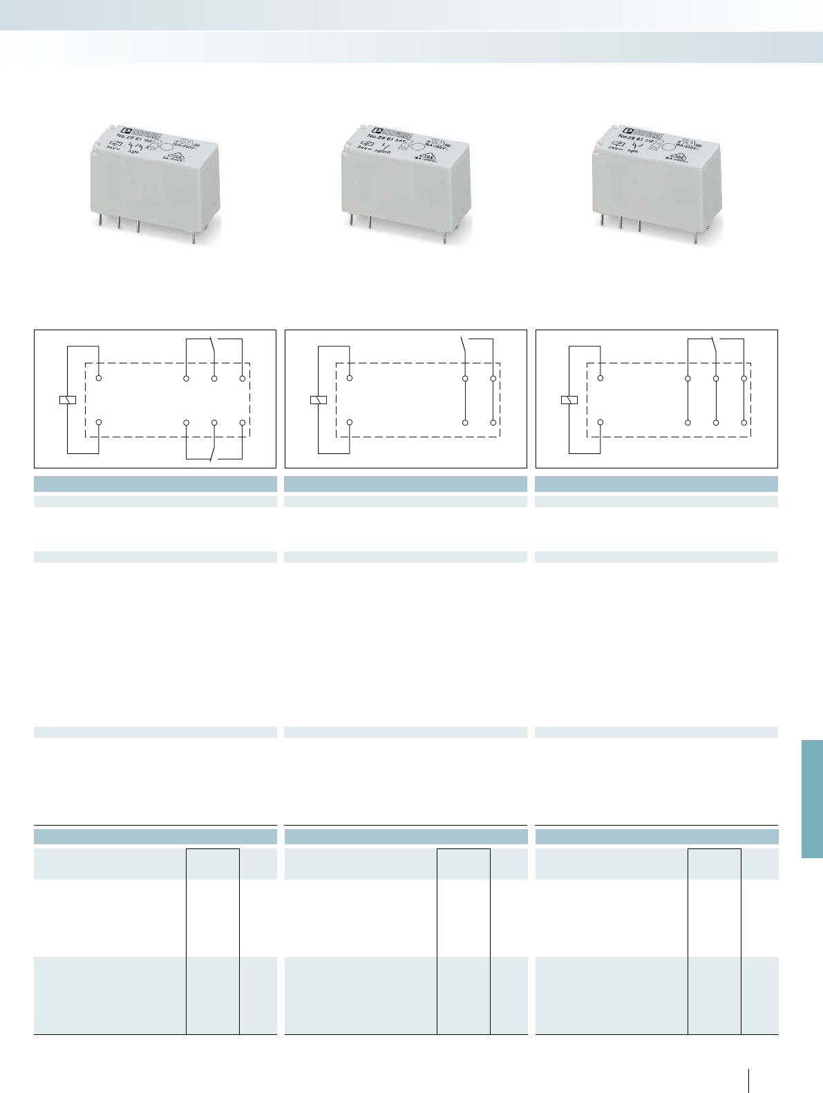
24
14
A1
21
11
22
12
A2
14
A1
13
A2
14
A1
1112
A2
For further information and full technical data, visit phoenixcontact.net/products
Technical data Technical data Technical data
② ④ ⑤ ⑥ ④ ② ④ ⑤ ⑥
see diagram see diagram see diagram
[mA] 38 14 9 7 3 33 17 8.2 4.1 17 33 17 8.2 4.1
[ms]55555 7 777 8 7 777
[ms] 2.5 2.5 2.5 2.5 2.5 3 3 3 3 3 3 3 3 3
Contact type 1 PDT 1 PDT 2 PDT 2 PDT 1 N/O contact 1 PDT
Contact material AgSnO AgSnO, hard gold-plated AgNi AgNi, hard gold-plated AgSnO AgNi
Max. switching voltage 250 V AC/DC 30 V AC / 36 V DC 250 V AC/DC 30 V AC / 36 V DC 250 V AC/DC 250 V AC/DC
Min. switching voltage 5 V (at 100 mA) 100 mV (at 10 mA) 5 V (at 10 mA) 100 mV (at 10 mA) 12 V (at 100 mA) 12 V (at 10 mA)
Limiting continuous current 6 A 50 mA 8 A 50 mA 16 A 16 A
Max. inrush current on request on request 25 A (20 ms) 50 mA 80 A (20 ms) 50 A (20 ms)
Min. switching current 10 mA (at 12 V) 1 mA (at 24 V) 10 mA (at 5 V) 1 mA (at 24 V) 100 mA (at 12 V DC) 10 mA (at 12 V)
24 V DC 140 W 1.2 W 190 W 1.2 W 384 W 384 W
48 V DC 20 W - 85 W - 58 W 58 W
60 V DC 18 W - 60 W - 48 W 48 W
110 V DC 23 W - 44 W - 50 W 50 W
220 V DC 40 W - 60 W - 80 W 80 W
250 V AC 1500 VA - 2000 VA - 4000 VA 4000 VA
Test voltage (winding/contact) 4 kV AC (50 Hz, 1 min.) 5 kV AC (50 Hz, 1 min.) 5 kV AC (50 Hz, 1 min.) 5 kV AC (50 Hz, 1 min.)
-40 °C ... 85 °C -40 °C ... 85 °C -40 °C ... 85 °C
Nominal operating mode 100% operating factor 100% operating factor 100% operating factor 100% operating factor
3 x 10
7
cycles 3 x 10
7
cycles 3 x 10
7
cycles
Standards/regulations IEC 60664, EN 50178, IEC 62103 IEC 60664, EN 50178, IEC 62103 IEC 60664, EN 50178, IEC 62103 IEC 60664, EN 50178, IEC 62103
Mounting position / mounting any / can be aligned without spacing any / can be aligned without spacing (> 70 °C 2.5 mm) any / can be aligned without spacing (> 70 °C 2.5 mm) any / can be aligned without spacing (> 70 °C 2.5 mm)
Dimensions W / H / D 5 mm / 28 mm / 15 mm 12.7 mm / 29 mm / 15.7 mm 12.7 mm / 29 mm / 15.7 mm 12.7 mm / 29 mm / 15.7 mm
Ordering data Ordering data Ordering data
Type Order No. Pcs. /
Pkt. Type Order No. Pcs. /
Pkt. Type Order No. Pcs. /
Pkt.
REL-MR- 12DC/21-21 2961257 10 REL-MR- 12DC/21HC 2961309 10
REL-MR- 24DC/21-21 2961192 10 REL-MR- 24DC/1IC 2961341 10 REL-MR- 24DC/21HC 2961312 10
REL-MR- 60DC/21-21 2961273 10 REL-MR- 60DC/21HC 2961325 10
REL-MR-110DC/21-21 2961202 10 REL-MR-110DC/21HC 2961338 10
REL-MR- 12DC/21-21AU 2961299 10
REL-MR- 24DC/21-21AU 2961215 10
REL-MR- 60DC/21-21AU 2961286 10
REL-MR-110DC/21-21AU 2961228 10
419
PHOENIX CONTACT
Relay modules
Highly compact relay modules - PLC-INTERFACE
1 PDT 2 PDT 1 N/O contact,
for high inrush currents
1 PDT
for high continuous currents
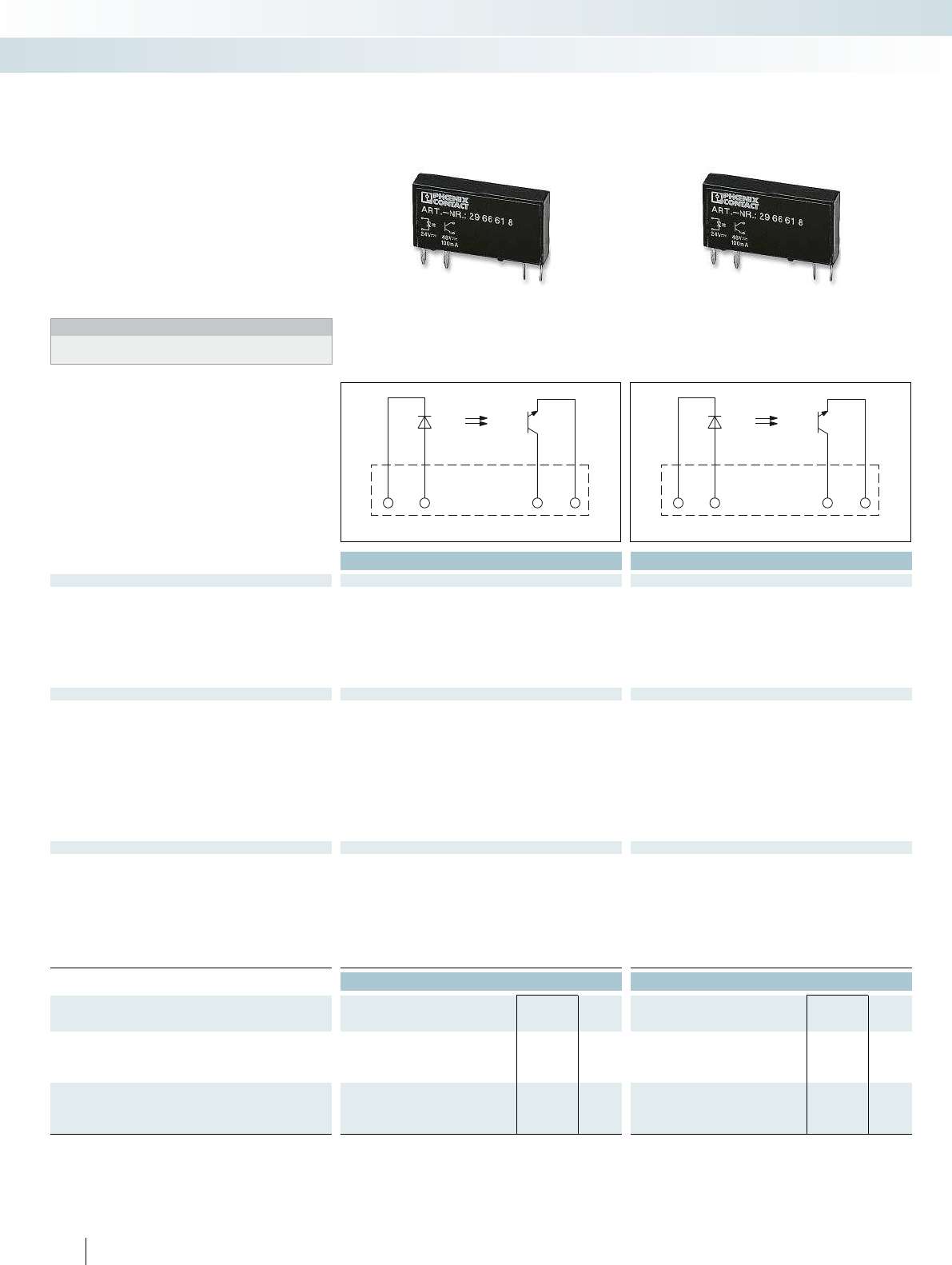
A2 A1 13+ 14
A2 A1 13+ 14
Technical data Technical data
Input data ① ② ③ ① ② ③
Permissible range (with reference to U
N
) 0.8 -
1.2
0.8 -
1.2
0.8 -
1.2
0.8 -
1.2
0.8 -
1.2
0.9 -
1.1
Switching level 1 signal ("H") [V DC] 2.5 16 35 2.5 16 52
0 signal ("L") [V DC] 0.8 10 20 0.8 10 40
Typ. input current at U
N
[mA]973 473
Typ. switch-on time at U
N
[µs] 20 20 40 20 20 50
Typ. shutdown time at U
N
[µs] 300 300 500 300 300 800
Transmission frequency f
limit
[Hz] 300 300 300 300 300 100
Output data
Max. switching voltage 33 V DC 48 V DC
Min. switching voltage 3 V DC 3 V DC
Limiting continuous current 3 A (see derating curve) 100 mA
Min. load current - -
Max. inrush current 15 A (10 ms) -
Leakage current in off state - -
Phase angle (cos )- -
Output circuit 2-wire, floating 2-wire, floating
Max. load value - -
Output protection Protection against polarity reversal, surge protection Protection against polarity reversal, surge protection Pr
Voltage drop at max. limiting continuous current 150 mV 1 V
General data
Rated surge voltage Basic insulation Basic insulation
Test voltage input/output 2.5 kV (50 Hz, 1 min.) 2.5 kV (50 Hz, 1 min.)
Ambient temperature (operation) -25 °C ... 60 °C -25 °C ... 60 °C
Nominal operating mode 100% operating factor 100% operating factor 100% operating factor 100% operating factor 100% operating factor
Standards/regulations IEC 60664, EN 50178, IEC 62103 IEC 60664, EN 50178, IEC 62103 IEC 60664, EN 50178, IEC 62103 IEC 60664, EN 50
Pollution degree / surge voltage category 2 / III 2 / III
Mounting position / mounting any / can be aligned without spacing any / can be aligned without spacing any / can be aligned without
Dimensions W / H / D 5 mm / 28 mm / 15 mm 5 mm / 28 mm / 15 mm 12.7 mm / 29 mm / 15.7 mm 5 mm / 28 mm / 15 mm 12.7 mm / 29 mm / 15.7
Ordering data Ordering data
Description Input voltage
U
N
Type Order No. Pcs. /
Pkt. Type Order No. Pcs. /
Pkt.
Plug-in solid-state relay
Solid-state power relay ①5 V DC OPT- 5DC/ 24DC/ 2 2967989 10
Solid-state power relay ②24 V DC OPT-24DC/ 24DC/ 2 2966595 10
Solid-state power relay ③60 V DC OPT-60DC/ 24DC/ 2 2966605 10
Plug-in solid-state relay
Solid-state input relay ①5 V DC OPT- 5DC/ 48DC/100 2967992 10
Solid-state input relay ②24 V DC OPT-24DC/ 48DC/100 2966618 10
Solid-state input relay ③60 V DC OPT-60DC/ 48DC/100 2966621 10
420
PHOENIX CONTACT
Plug-in solid-state relays suitable for
PLC-INTERFACE and RIF-0, RIF-1, and
PR1 relay bases.
The advantages:
– Switching capacity of up to 24 V DC/5 A
– RT III wash tight (comparable to IP67)
– Vibration and shock-resistant
– Wear-free and long-lasting
– Zero voltage switch at AC output
– Can be soldered in on PCB
Notes:
For dimensional drawings and perforations for assembly, see
page 425
Plug-in solid-state relays
Relay modules
Highly compact relay modules - PLC-INTERFACE
Max. DC voltage output
of 3 A
Max. DC voltage output
of 100 mA
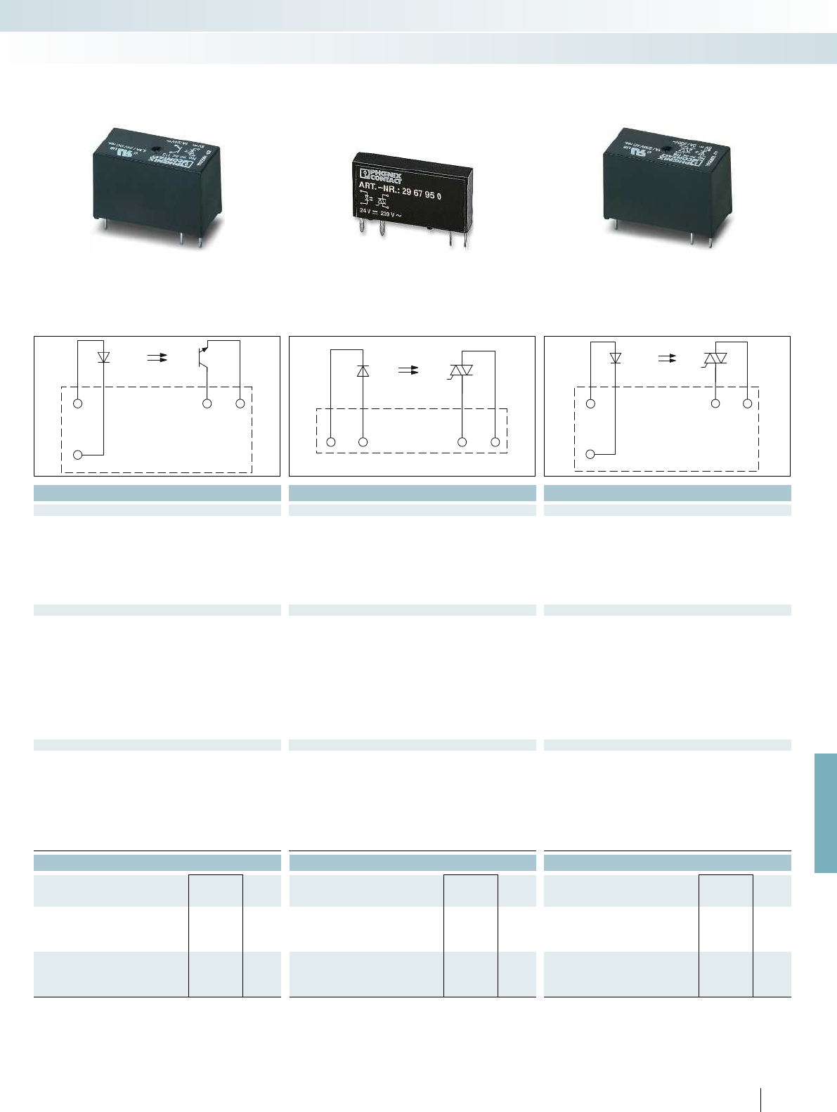
A1
A2
13+ 14
A2 A1 13+ 14
A1 13 14
A2
For further information and full technical data, visit phoenixcontact.net/products
Technical data Technical data Technical data
① ② ③ ② ③ ① ② ③
0.8 -
1.2
0.8 -
1.2
0.9 -
1.1
0.8 -
1.2
0.9 -
1.1
0.8 -
1.2
0.8 -
1.2
0.9 -
1.1
2.5 16 35 10 50 3 18 40
0.8 10 20 5 15 1 8.4 20
973 33 1572.6
10 20 25 6000 9000 10000 10000 10000
400 400 400 500 700 10000 10000 10000
300 300 300 10 10 10 10 10
33 V DC 253 V AC 253 V AC
3 V DC 24 V AC 24 V AC
5 A (see derating curve) 0.75 A (see derating curve) 2 A (see derating curve)
- 10 mA 25 mA
15 A (10 ms) 30 A (10 ms) 30 A (10 ms)
- < 1 mA < 1 mA
- 0.5 -
2-wire, floating 2-wire floating, zero voltage switch 2-wire floating, zero voltage switch
- 4.5 A
2
s 4 A
2
s (tp = 10 ms, at 25 °C)
Output protection Protection against polarity reversal, surge protection Protection against polarity reversal, surge protection Protection against polarity reversal, surge protection RCV circuit Surge protection
200 mV < 1 V 1 V
Basic insulation Basic insulation Basic insulation
2.5 kV (50 Hz, 1 min.) 2.5 kV (50 Hz, 1 min.) 2.5 kV (50 Hz, 1 min.)
-25 °C ... 60 °C -25 °C ... 60 °C -25 °C ... 60 °C
Nominal operating mode 100% operating factor 100% operating factor 100% operating factor 100% operating factor 100% operating factor
Standards/regulations IEC 60664, EN 50178, IEC 62103 IEC 60664, EN 50178, IEC 62103 IEC 60664, EN 50178, IEC 62103 IEC 60664, EN 50178, IEC 62103 IEC 60664
2 / III 2 / III 2 / III
Mounting position / mounting any / can be aligned without spacing any / can be aligned without spacing any / can be aligned without spacing any / can be aligned without spacing any / see derating curve
Dimensions W / H / D 5 mm / 28 mm / 15 mm 5 mm / 28 mm / 15 mm 12.7 mm / 29 mm / 15.7 mm 5 mm / 28 mm / 15 mm 12.7 mm / 29 mm / 15.7 mm
Ordering data Ordering data Ordering data
Type Order No. Pcs. /
Pkt. Type Order No. Pcs. /
Pkt. Type Order No. Pcs. /
Pkt.
OPT- 5DC/ 24DC/ 5 2982113 10 OPT- 5DC/230AC/ 2 2982168 10
OPT-24DC/ 24DC/ 5 2982100 10 OPT-24DC/230AC/ 1 2967950 10 OPT-24DC/230AC/ 2 2982171 10
OPT-60DC/ 24DC/ 5 2982126 10 OPT-60DC/230AC/ 1 2967963 10 OPT-60DC/230AC/ 2 2982184 10
421
PHOENIX CONTACT
Relay modules
Highly compact relay modules - PLC-INTERFACE
Max. DC voltage output
of 5 A
Max. AC voltage output
of 750 mA
Max. AC voltage output
of 2 A

Screw connection
1 PDT basic terminal block
2980225
2966896
2966016
2966029
2966090
2966100
2966032
2980018
2966045
2 PDT basic terminal block
2967251
2967015
2967028
2967264
2967316
2967031
2967044
HC basic terminal block
2967769
2967772
2967785
2967798
2967808
2967811
2967824
Sensor basic terminal block
2980267
2966061
2966074
2966087
Actuator basic terminal block
2980241
2966058
2982799
IC basic terminal block
2967837
PLC-BSC-5DC/21
PLC-BSC-12DC/21
PLC-BSC-24DC/21
PLC-BSC-24UC/21
PLC-BSC-48DC/21
PLC-BSC-60DC/21
PLC-BSC-120DC/21
PLC-BSC-125DC/21
PLC-BSC-230UC/21
PLC-BSC-12DC/21-21
PLC-BSC-24DC/21-21
PLC-BSC-24UC/21-21
PLC-BSC-48DC/21-21
PLC-BSC-60DC/21-21
PLC-BSC-120DC/21-21
PLC-BSC-230UC/21-21
PLC-BSC-12DC/21HC
PLC-BSC-24DC/21HC
PLC-BSC-24UC/21HC
PLC-BSC-48DC/21HC
PLC-BSC-60DC/21HC
PLC-BSC-120DC/21HC
PLC-BSC-230UC/21HC
PLC-BSC-5DC/1/SEN
PLC-BSC-24DC/1/SEN
PLC-BSC-120UC/1/SEN
PLC-BSC-230UC/1/SEN
PLC-BSC-5DC/1/ACT
PLC-BSC-24DC/1/ACT
PLC-BSC-24UC/1/ACT
PLC-BSC-24DC/1IC/ACT
Push-in connection
2900443
2900444
2900445
2900446
2900447
2900279
2900280
2900281
2900282
2900283
2900284
2900285
2900286
2900287
2900288
2900253
2900254
2900255
2900256
2900257
2900258
2900259
2900262
2900451
2900452
2900448
2900449
2900450
2900261
2900260
Relay and
solid-state
relay
options
PLC-BPT-5DC/21
PLC-BPT-12DC/21
PLC-BPT-24DC/21
PLC-BPT-24UC/21
PLC-BPT-48DC/21
PLC-BPT-60DC/21
PLC-BPT-120DC/21
PLC-BPT-230UC/21
PLC-BPT-12DC/21-21
PLC-BPT-24DC/21-21
PLC-BPT-24UC/21-21
PLC-BPT-48DC/21-21
PLC-BPT-60DC/21-21
PLC-BPT-120DC/21-21
PLC-BPT-230UC/21-21
PLC-BPT-12DC/21HC
PLC-BPT-24DC/21HC
PLC-BPT-24UC/21HC
PLC-BPT-48DC/21HC
PLC-BPT-60DC/21HC
PLC-BPT-120DC/21HC
PLC-BPT-230UC/21HC
PLC-BPT-24DC/1/SEN
PLC-BPT-120UC/1/SEN
PLC-BPT-230UC/1/SEN
PLC-BPT-5DC/1/ACT
PLC-BPT-24DC/1/ACT
PLC-BPT-24UC/1/ACT
PLC-BPT-24DC/21RW
PLC-BPT-24DC/1IC/ACT
REL-MR-4,5DC/21 2961367 X X X
REL-MR-4,5DC/21AU 2961370 X X
REL-MR-12DC/21 2961150 X
REL-MR-12DC/21AU 2961163 X
REL-MR-24DC/21 2961105 X X X X X X
REL-MR-24DC/21AU 2961121 XXX XXX
REL-MR-60DC/21 2961118 X X X X X X
REL-MR-60DC/21AU 2961134 XXXX XX
REL-MR-24DC/1IC 2961341 X
REL-MR-18DC/21 2961383 X
REL-MR-18DC/21AU 2961493 X
REL-MR-12DC/21-21 2961257 X
REL-MR-12DC/21-21AU 2961299 X
REL-MR-24DC/21-21 2961192 XXX
REL-MR-24DC/21-21AU 2961215 X X X
REL-MR-60DC/21-21 2961273 X
REL-MR-60DC/21-21AU 2961286 X
REL-MR-110DC/21-21 2961202 XX
REL-MR-110DC/21-21AU 2961228 X X
REL-MR-12DC/21HC 2961309 X
REL-MR-24DC/21HC 2961312 X X X
REL-MR-60DC/21HC 2961325 X
REL-MR-110DC/21HC 2961338 X X
OPT-24DC/230AC/1 2967950 XX XXX
OPT-60DC/230AC/1 2967963 X X X X X
OPT-5DC/24DC/2 2967989 X X X
OPT-24DC/24DC/2 2966595 X X X X X
OPT-60DC/24DC/2 2966605 XX X XX
OPT-5DC/48DC/100 2967992 X X X
OPT-24DC/48DC/100 2966618 XX XXX
OPT-60DC/48DC/100 2966621 X X X X X
OPT-24DC/24DC/5 2982100 XX XX X
OPT-60DC/24DC/5 2982126 X X
OPT-24DC/230AC/2 2982171 XX XX X
OPT-60DC/230AC/2 2982184 X X
Relay options for PLC basic terminal blocks
422
PHOENIX CONTACT
Relay modules
Tables, diagrams, dimensional drawings

0,7
25 30 35 40 45 50 55 60 6520
1
1,3
0,8
0,9
1,1
1,2
1,4
U
U
N
T[
°
C]
U
A
B
U=220 V DC
N
U=230 V AC
N
U=230 V AC
N
U=220 V DC
N
0,7
25 3035 4045 5055 606520
1
1,3
0,8
0,9
1,1
1,2
1,4
U
U
N
T[
°
C]
U
A
B
U = 110V DC
N
U = 120V DC
N
U = 110V DC
N
U = 120V AC
N
0,7
25 30 35 40 45 50 55 60 6520
1
1,3
0,8
0,9
1,1
1,2
1,4
U
U
N
T[
°
C]
U
A
B
U=60 V DC
N
0,7
25 3035 4045 5055 606520
1
1,3
0,8
0,9
1,1
1,2
1,4
U
U
N
T[
°
C]
U
A
B
U=48V DC
N
0,7
25 3035 4045 5055 606520
1
1,3
0,8
0,9
1,1
1,2
1,4
U
U
N
T[
°
C]
U
A
B
U=24VDC/24VAC
N
0,7
25 3035 4045 5055 606520
1
1,3
0,8
0,9
1,1
1,2
1,4
U
U
N
T[
°
C]
U
A
B
U=24VDC
N
0,7
25 3035 4045 5055 606520
1
1,3
0,8
0,9
1,1
1,2
1,4
U
U
N
T[
°
C]
U
A
B
U=12VDC
N
0,7
25 3035 4045 5055 606520
1
1,3
0,8
0,9
1,1
1,2
1,4
U
U
N
T[
°
C]
U
A
B
U = 220VDC/230V AC
N
0,7
25 3035 4045 5055 606520
1
1,3
0,8
0,9
1,1
1,2
1,4
U
U
N
T[
°
C]
U
A
B
U = 125 V DC
N
0,7
25 3035 4045 5055 606520
1
1,3
0,8
0,9
1,1
1,2
1,4
U
U
N
T[
°
C]
U
A
B
U = 110VDC/120V AC
N
0,7
25 3035 4045 5055 606520
1
1,3
0,8
0,9
1,1
1,2
1,4
U
U
N
T[
°
C]
U
A
B
U=60V DC
N
0,7
25 3035 4045 5055 606520
1
1,3
0,8
0,9
1,1
1,2
1,4
U
U
N
T[
°
C]
U
A
B
U=48V DC
N
0,7
25 30 35 40 45 50 55 60 6520
1
1,3
0,8
0,9
1,1
1,2
1,4
U
U
N
T[
°
C]
U
A
B
U=24 VDC/24 V AC
N
0,7
25 3035 4045 5055 606520
1
1,3
0,8
0,9
1,1
1,2
1,4
U
U
N
T[
°
C]
U
A
B
U=24 V DC
N
0,7
25 3035 4045 5055 606520
1
1,3
0,8
0,9
1,1
1,2
1,4
U
U
N
T[
°
C]
U
A
B
U=12 V DC
N
For further information and full technical data, visit phoenixcontact.net/products
General conditions:
Direct alignment in the block, all devices 100% operating time, horizontal
or vertical mounting.
Curve A
Maximum permitted continuous voltage U
max
with limiting continuous
current on the contact side (see relevant technical data).
Curve B
Minimum permitted pick-up voltage U
op
after pre-excitation
1
)
(see relevant technical data).
1
)Pre-excitation: relay has been operated in a thermally steady
state at the ambient temperature T
A
with nominal voltage U
N
and
limiting continuous current on the contact side (see relevant
technical data) (warm coil). After being switched off for a short
time, the relay must reliably pick up again at U
op
. The U
op
values
for cold coils (T
coil
=T
A
= 20°C) indicated by other manufacturers
yield better values, but are not practical.
PLC-R...-120UC... PLC-R...-230UC...
PLC-R...-60DC...PLC-R...-48DC...PLC-R...-24UC...
PLC-R...-24DC...PLC-R...-12DC...
Operating voltage ranges for
PLC-INTERFACE, 14 mm versions,
equipped with relay
PLC-R...-230UC...PLC-R...-125DC...PLC-R...-120UC...
PLC-R...-48DC... PLC-R...-60DC...PLC-R...-24UC...
PLC-R...-24DC...PLC-R...-12DC...
Operating voltage ranges for
PLC-INTERFACE, 6.2 mm versions,
equipped with relay
423
PHOENIX CONTACT
Relay modules
Tables, diagrams, dimensional drawings

0,5
1020304050607080901000
1
1,5
2
2,5
3
U
N
U
T[°C]
U
A
B
1,3 55 1,28
1 1,3
1,2
1,9
28
15
3,5
5
29
15,7
3,6
12,7
0,5
1020304050607080901000
1
1,5
2
2,5
3
U
N
U
T[°C]
U
A
B
Plug-in miniature power relays
REL-MR...21
Perforations for assembly: view of the connections
Pitch division: 1.25 mm and 1.27 mm
Perforations for assembly: view of the connections
Pitch division: 2.5 mm
Permitted input voltage range
for REL-MR...21
Permitted input voltage range
for REL-MR...21-21, REL-MR-24DC/1IC, REL-MR...21HC
5 mm overall width 12.7 mm overall width
General conditions:
Direct alignment in the block, all devices 100% operating time,
horizontal or vertical mounting.
Curve A
Maximum permitted continuous voltage U
max
with limiting
continuous current on the contact side (see relevant technical
data).
Curve B
Minimum permitted pick-up voltage U
op
after pre-excitation
1
)
(see relevant technical data).
1
)Pre-excitation: relay has been operated in a thermally steady
state at the ambient temperature T
A
with nominal voltage U
N
and
limiting continuous current on the contact side (see relevant
technical data) (warm coil). After being switched off for a short
time, the relay must reliably pick up again at U
op
. The U
op
values
for cold coils (T
coil
=T
A
= 20°C) indicated by other manufacturers
yield better values, but are not practical.
REL-MR...21-21
424
PHOENIX CONTACT
Relay modules
Tables, diagrams, dimensional drawings
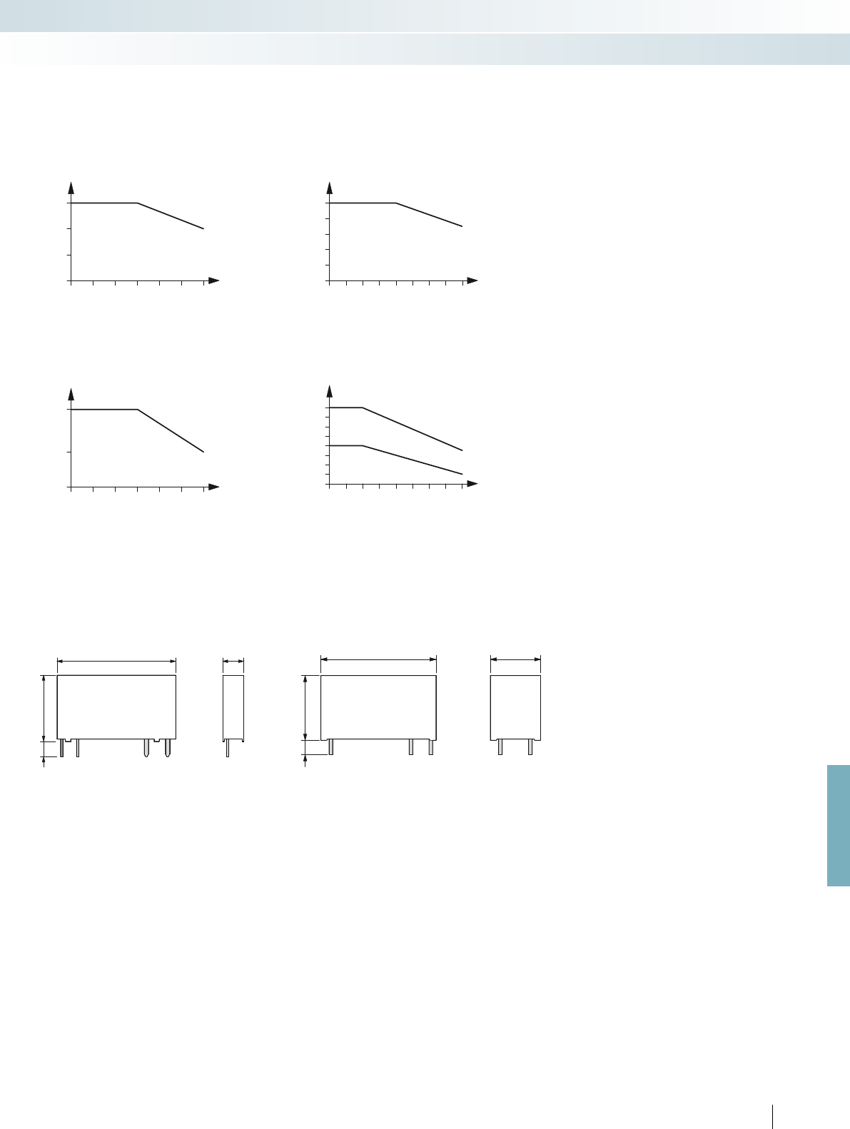
0
2
1,8
1,6
1,4
1,2
1
0,8
0,6
0 25 30 35 40 45 50 55 60
1
2
1
2
0
300
750
0 10 20 30 40 50 60
0
1
2
3
4
5
0 25 30 35 40 45 50 55 60
0
1
2
3
0 10 20 30 40 50 60
28
15
3,5
5
29
15,7
3,6
12,7
For further information and full technical data, visit phoenixcontact.net/products
12.7 mm overall width
Ambient temperature range [°C]
Load current [A]
Derating curve for OPT...DC/230AC/1 and
PLC-OS.../230AC/1 solid-state relays
Ambient temperature range [°C]
Load current [mA]
Aligned with > 10 mm spacing
Aligned without spacing
Plug-in solid-state relays
OPT...DC/24DC/2
OPT...DC/230AC/1
Derating curve for OPT...DC/24DC/5 and
PLC-OS.../24DC/5/ACT solid-state relays
Ambient temperature range [°C]
Load current [A]
Derating curve for OPT...DC/24DC/2 and
PLC-OS.../24DC/2 solid-state relays
Ambient temperature range [°C]
Load current [A]
Derating curve for OPT...DC/230AC/2 and
PLC-OS.../230AC/2/ACT solid-state relays
5 mm overall width
OPT...DC/24DC/5
OPT...DC/230AC/2
425
PHOENIX CONTACT
Relay modules
Tables, diagrams, dimensional drawings
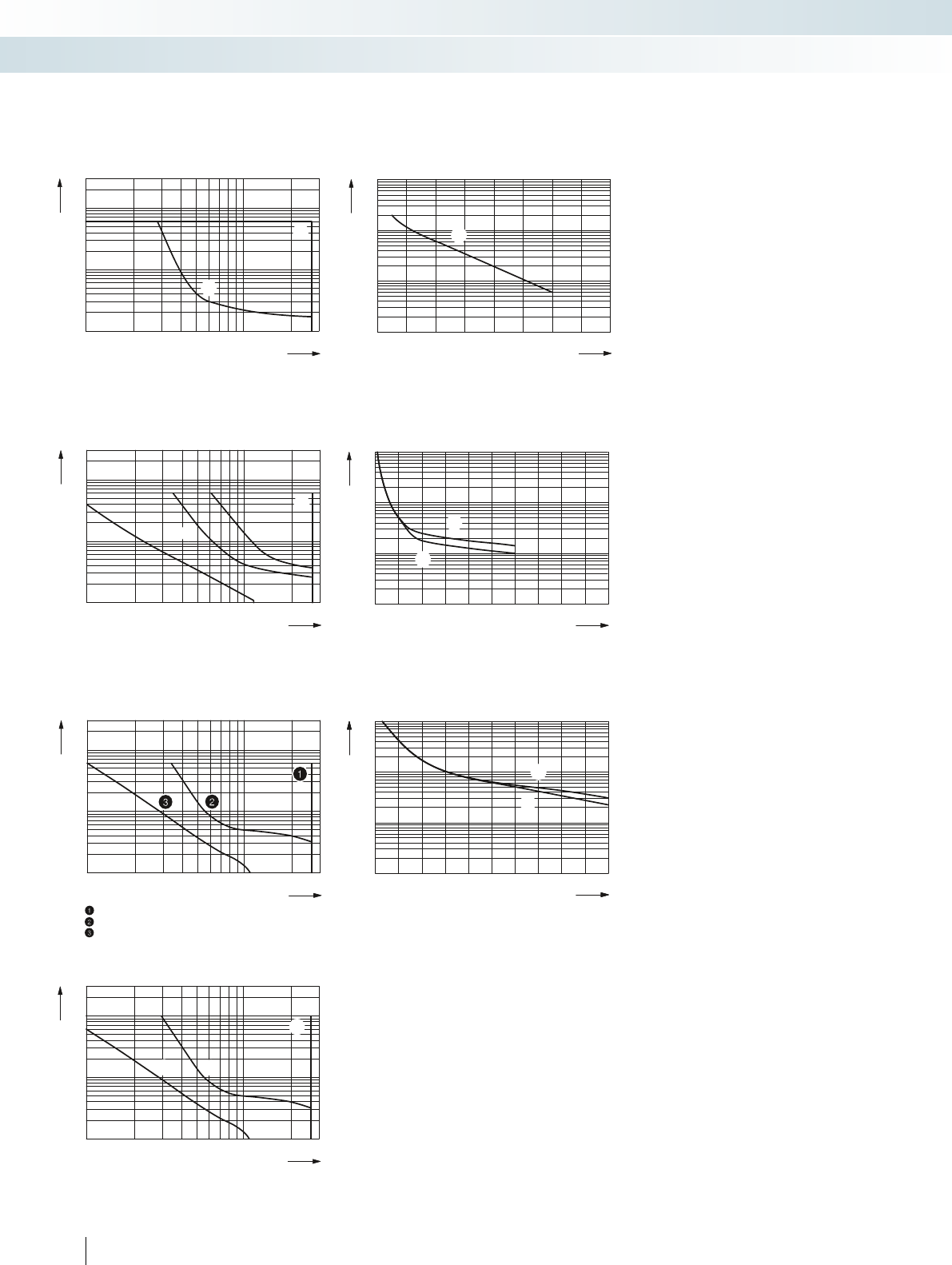
0,1
0,2
0,3
0,5
1
2
4
6
10
20
10203050 70 100 300200
0,1
0,2
0,3
0,5
1
2
4
10
20
1020305070100 300200
1
2
1
2
6
1
2
3
3
1
2
0,1
0,2
0,3
0,5
1
2
4
6
10
20
10203050 70 100 300200
1
2
3
4
3
1
42
106
105
02468
104
1
1
1
2
014 8
107
106
105
104
23 567 910
2
1
1
2
014 8
107
106
105
104
23 567910
2
1
0,1
0,2
0,3
0,5
1
2
4
6
10
20
10 20 30 50 70 100 300200
PLC-INTERFACE for railway
applications
Switching current [A]
Cycles
250 V AC, ohmic load
Electrical service life for PLC-RSP...UC/21RW
Switching current [A]
Cycles
250 V AC, ohmic load (DC coils)
250 V AC, ohmic load (AC coils)
Electrical service life for PLC-RSP...UC/21-21/RW
Switching current [A]
Cycles
250 V AC, ohmic load (DC coils)
250 V AC, ohmic load (AC coils)
Electrical service life for PLC-RSP...UC/21HC/RW
Switching voltage [V]
Switching current [A]
AC, ohmic load
DC, ohmic load
Switching voltage [V]
Switching current [A]
AC, ohmic load
DC, ohmic load
DC, L/R = 40 ms
Switching voltage [V]
AC, ohmic load
DC, ohmic load, contacts in series
DC, ohmic load
DC, L/R = 40 ms
Switching voltage [V]
Switching current [A]
AC, ohmic load
DC, ohmic load
DC, L/R = 40 ms
Electrical interrupting rating for
PLC-INTERFACE
Electrical interrupting rating for PLC...21
with 1 PDT relay
Electrical interrupting rating for PLC...21-21
with 2 PDT relay
Electrical interrupting rating for PLC...21HC
for high continuous currents
Electrical interrupting rating for PLC...1IC/ACT
for high inrush currents
Switching current [A]
426
PHOENIX CONTACT
Relay modules
Tables, diagrams, dimensional drawings
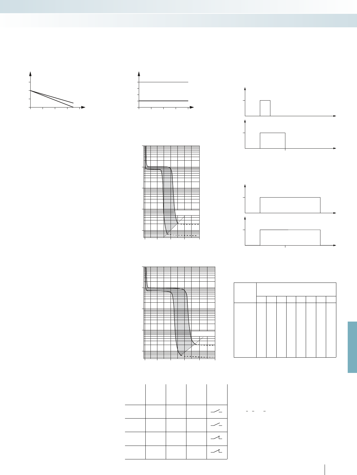
1
2
1
2
30
20
0
3
1
2
40 50 60
1000
100
10
1
0,1
I [A]80
604020
I
N
1000
100
10
1
0,1
302010
I
N
I [A]
30
20
0
4
3
2
1
40 50 60
U
E
t
0
t
E
t
24 V
U
A
t
0
t
24 V
U
E
t
0
t
E
t
24 V
U
A
t
0
t
24 V
For further information and full technical data, visit phoenixcontact.net/products
ST-OV 4-24DC/24DC...PRO
power circuit breaker solid-state relays
with signal logic
State diagram
Operating
state
Switching
level
Input
Light
indicator,
yellow LED
Light
indicator,
red LED
Alarm
contact/
CONTROL
Not
activated LLL
Normal
operation H H L
Overload/s
hort circuit HHH
Open circuit L L H
Time-current characteristic, 1 A version
Time-current characteristic, 4 A version
Current limitation
Switching time [ms]
Current limitation
Switching time [ms]
Derating curve for ST-OV 4-24DC/24DC...PRO
4 A type
1 A type
Ambient temperature [°C]
Load current [A]
t
A
t
A
t
A
Set
Output pulse t
O
UEGM-OE/AV logic pulse expansion
module
Time diagrams for UEGM-OE/AV-24DC/24DC/100
Operating voltage present
Scenario 2: input pulse t
I
output pulse t
O
set
: t
I
= t
O
Scenario 1: input pulse t
I
< output pulse t
O
set
Operating voltage present
DIP switches
1
)
S1 S2 S3 S4 S5 S6 S7 S8
Length of
output
pulses [ms]
(when in
“on” switch
position)
10 –––––––
–20 ––––––
– – 50 –––––
– – – 100 – – – –
– – – – 200 – – –
–––––500 – –
––––––1000 –
–––––––1500
1
) If no switch is actuated, the output voltage is not defined.
If the input pulse is longer than the set time, the output is switched
off almost simultaneously with the input.
Intermediate values can be obtained by combining several DIP
switches according to the following formula:
T
tot
= ––––––––––––
1
1
+
t
1
1
+ ... +
t
2
1
t
n
Table of adjustable output pulse lengths
Set
Output pulse t
O
Derating curve for EMG 17-OV...48DC/2
Ambient temperature [°C]
Load current [A]
EMG-OV solid-state power relays
Aligned without spacing
Stand-alone device
427
PHOENIX CONTACT
Relay modules
Tables, diagrams, dimensional drawings
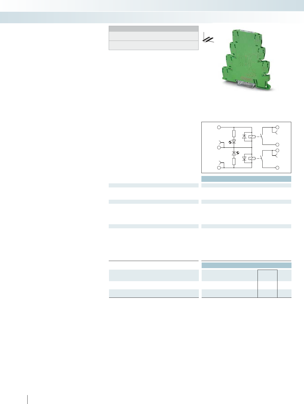
A1.1+
A2–
A1.2+
13
K1
K2
23
14
24
Technical data
Input data ①
Typ. input current at U
N
[mA] 7
Response/release time at U
N
[ms] 4 / 6
Input circuit DC
Yellow LED, protection against polarity reversal, freewheeling diode
Output data
Contact material AgNi
Max. switching voltage 250 V AC/DC
Min. switching voltage 24 V AC/DC
Limiting continuous current 3.5 A
Min. switching current 5 mA
General data
Test voltage input/output 3 kV AC (50 Hz, 1 min.)
Test voltage output/output 3 kV AC (50 Hz, 1 min.)
Ambient temperature (operation) -20 °C ... 60 °C
Mechanical service life 2 x 10
7
cycles
Standards/regulations IEC 60664, EN 50178, IEC 62103
Connection data solid / stranded / AWG 0.14 - 2.5 mm² / 0.14 - 2.5 mm² / 26 - 14
Dimensions W / H / D 6.2 mm / 80 mm / 86 mm
EMC note Class A product, see page 625
Ordering data
Description Input voltage
U
N
Type Order No. Pcs. /
Pkt.
PLC-INTERFACE, with screw connection
①24 V DC PLC-2RSC-24DC/ 1 2987309 10
PLC-INTERFACE, with push-in connection
①24 V DC PLC-2RPT-24DC/1 2901639 10
428
PHOENIX CONTACT
Notes:
Type of housing:
Polyamide PA non-reinforced, color: green.
Marking systems and mounting material
See Catalog 5
DW
H
Relay module with two permanently
soldered-in power relays
The advantages:
– 100% more channel density than the
conventional 6.2 mm relay
– Two switching channels in a 6.2 mm
housing
– Integrated input circuit/protective circuit
– Safe isolation according to DIN EN 50178
between coil and contacts and between
contacts
– Screw and push-in connection technology
PLC-INTERFACE with
two integrated relays
Relay modules
Highly compact relay modules - PLC-INTERFACE
Two integrated relays

0,1
0,2
0,3
0,5
1
2
4
6
10
20
10203050 70 100 300200
1
1
V
CC
+-
A1.2
A2–
A1.1
14
13
23
24
A1.2
A2–
A1.1
14
13
23
24
y1y2y3y4
0,7
25 3035 4045 5055 606520
1
1,3
0,8
0,9
1,1
1,2
1,4
U
U
N
T[
°
C]
U
A
B
U=24 V DC
N
For further information and full technical data, visit phoenixcontact.net/products
429PHOENIX CONTACT
Application example for PLC-2RS...24DC/1
Interrupting rating
Operating voltage range
Ambient temperature
Input voltage
Switching voltage [V]
Switching current [A]
DC, ohmic load
Relay modules
Highly compact relay modules - PLC-INTERFACE
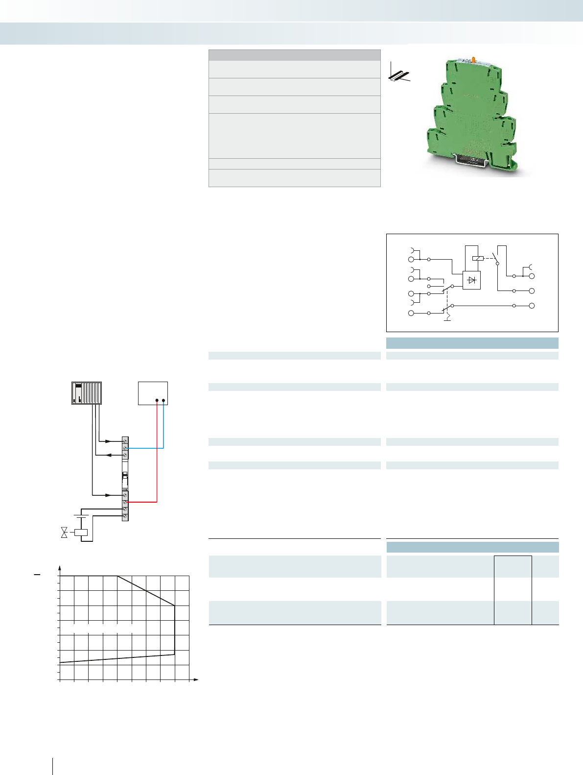
A1
A2
1(CTL)
M
2(CTL)
14
13
0
0,7
25 30 35 40 45 50 55 60 6520
1
1,3
0,8
0,9
1,1
1,2
1,4
U
U
N
T[
°
C]
U
A
B
U=24 VDC/24 V AC
N
A
O
M
A1
A2
CTL2
CTL1
M
13
14
V
CC
+-
Technical data
Input data ① ②
Typ. input current at U
N
[mA] 11 11
Response/release time at U
N
[ms] 6 / 15 6 / 15
Input circuit AC/DC Yellow LED, bridge rectifier
Output data
Contact material AgSnO
Max. switching voltage 250 V AC/DC
Min. switching voltage 5 V (at 100 mA)
Limiting continuous current 6 A
Max. inrush current on request
Min. switching current 10 mA (at 12 V)
Feedback
Operating mode “Automatic” floating max. 30 V AC/DC / 50 mA
min. 2 V AC/DC / 1 mA
General data
Rated insulation voltage 250 V AC
Rated surge voltage 6 kV
Ambient temperature (operation) -20 °C ... 60 °C
Standards/regulations IEC 60664, EN 50178, IEC 62103
Pollution degree / surge voltage category 2 / III
Connection data solid / stranded / AWG 0.14 - 2.5 mm² / 0.14 - 2.5 mm² / 26 - 14
Dimensions W / H / D 6.2 mm / 80 mm / 90 mm
EMC note Class A product, see page 625
Ordering data
Description Input voltage
U
N
Type Order No. Pcs. /
Pkt.
PLC-INTERFACE, with screw connection
①24 V AC/DC PLC-RSC- 24UC/ 1/S/H 2982236 10
②24 V AC/DC PLC-RSC- 24UC/ 1/S/L 2834876 10
PLC-INTERFACE, with push-in connection
①24 V AC/DC PLC-RPT- 24UC/ 1/S/H 2900328 10
②24 V AC/DC PLC-RPT- 24UC/ 1/S/L 2900327 10
430
PHOENIX CONTACT
Notes:
Type of housing:
Polyester PBT non-reinforced, color: green.
Marking systems and mounting material
See Catalog 5
For the protection of input and output, inductive loads must be
dampened with an effective protection circuit.
Separating plate PLC-ATP is to be used in the following cases:
always at the start and end of a PLC terminal strip, for voltages
greater than 250 V (L1, L2, L3) between the same terminal points
of neighboring modules (potential bridging then takes place with
FBST 8-PLC... or FBST 500...) and with safe isolation between
neighboring modules.
Module height: PLC-...-S/H = 90 mm; PLC-...-S/L: = 86 mm
PLC...H - manual operation
PLC...L - operation using screwdriver
DW
H
PLC-INTERFACE with
manual switch and relay
Relay modules
Highly compact relay modules - PLC-INTERFACE
Relay module with manual switch
and integrated relay
Application example PLC-RS...24UC/1/S...
Permissible input voltage range for PLC-RS...24UC/1/S...
Curve A
maximum continuous voltage at limiting continuous current = 6 A
Curve B
minimum operating voltage for pre-excitation with U
N
and limiting
continuous current = 6 A
Relay module with manual switch and
integrated power relay for manual, zero, and
automatic functions
The advantages are:
– Max. switching current of 6 A
– Only 6.2 mm wide
– Floating confirmation contact
– Safe isolation according to DIN EN 50178
between coil and contact
– Screw and push-in connection technology
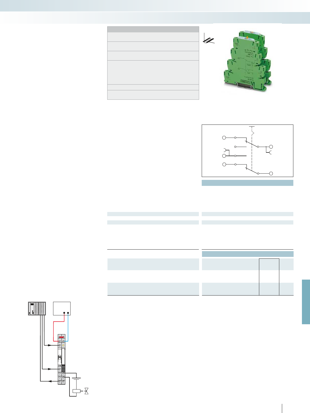
AUTO
MANUAL
I
A1
2(CTL)
0
OUT
1(CTL)
A
O
M
OUT
A1
I
1
2
A1
A2
12
14
11
V
CC
+-
For further information and full technical data, visit phoenixcontact.net/products
Technical data
Max. switching voltage 72 V DC
Min. switching voltage 2 V DC
Max. inrush current 50 mA
Min. switching current 1 mA
Cycles, max. 100 (at 72 V DC / 50 mA) / 10000 (at 12 V DC / 100 mA)
Feedback
Operating mode “Automatic” floating 72 V DC / 50 mA
General data
Rated insulation voltage 85 V AC
Rated surge voltage 0.5 kV / basic insulation
Ambient temperature (operation) -20 °C ... 60 °C
Standards/regulations IEC 60664, EN 50178, IEC 62103
Pollution degree / surge voltage category 2 / III
Dimensions W / H / D 6.2 mm / 80 mm / 90 mm
Ordering data
Description Type Order No. Pcs. /
Pkt.
PLC-INTERFACE, with screw connection
PLC-SC-S/H 2980733 10
PLC-SC-S/L 2980775 10
PLC-INTERFACE, with spring-cage connection
PLC-SP-S/H 2980746 10
PLC-SP-S/L 2980788 10
431
PHOENIX CONTACT
Notes:
Type of housing:
Polyester PBT non-reinforced, color: green.
Marking systems and mounting material
See Catalog 5
For the protection of input and output, inductive loads must be
dampened with an effective protection circuit.
Separating plate PLC-ATP is to be used in the following cases:
always at the start and end of a PLC terminal strip, for voltages
greater than 250 V (L1, L2, L3) between the same terminal points
of neighboring modules (potential bridging then takes place with
FBST 8-PLC... or FBST 500...) and with safe isolation between
neighboring modules.
Module height: PLC-...-S/H = 90 mm; PLC-...-S/L: = 86 mm
PLC...H - manual operation
PLC...L - operation using screwdriver
DW
H
PLC-INTERFACE with
manual switch without relay
Relay modules
Highly compact relay modules - PLC-INTERFACE
Module with manual switch without relay
Application example PLC-S...S...
Switching module without relay for
manual, zero, and automatic functions
The advantages:
– Only 6.2 mm wide
– Floating confirmation contact
– Screw and spring-cage connection
technology

A1
A2
A2
14
14
13+
13+
432
PHOENIX CONTACT
The slim 6.2 mm PLC housing with
integrated electronics in various versions
offers the following advantages:
– Option of bridging adjacent modules
– Status display
– Protection circuits in input and output
– Wear-resistant and bounce-free switching
– Integrated protection circuit
– DC outputs of up to 300 V DC/1 A or up
to 24 V DC/10 A
– Electronic PDT output of up to
48 V DC/500 mA
– Screw and push-in connection technology
PLC RELAY with
an integrated solid-state relay
Technical data
Input data ① ② ③ ④ ⑤ ⑥ ⑦ ⑧
Permissible range (with reference to U
N
) 0.8 -
1.2
0.8 -
1.2
0.8 -
1.2
0.8 -
1.2
0.8 -
1.2
0.8 -
1.2
0.8 -
1.1
0.8 -
1.1
Switching level (with reference to U
N
) 1 signal ("H") 0.8 0.8 0.8 0.8 0.8 0.8 0.8 0.8
0 signal ("L") 0.4 0.4 0.4 0.4 0.4 0.4 0.4 0.4
Typ. input current at U
N
[mA] 15 6 8 5 5 3 5.6 8.4 3 3
Transmission frequency f
limit
[Hz] 50 50 50 50 50 50 10 10 100 1000
Alarm output
Operating range - / -
Output data
Max. / min. switching voltage 300 V DC / 12 V DC
Limiting continuous current 1 A (see derating curve) 10 A (see derating curve) 500 mA (see derating curve)
Voltage drop at max. limiting continuous current < 500 mV
General data
Rated insulation voltage 300 V
Rated surge voltage 4 kV / basic insulation
Ambient temperature (operation) -25 °C ... 60 °C
Standards/regulations IEC 60664, EN 50178, IEC 62103 IEC 60664, EN 50178, IEC 62103 IEC 60664, EN 50178, IEC 62103
Connection data solid / stranded / AWG 0.14 - 2.5 mm² / 0.14 - 2.5 mm² / 26 - 14 0.14 - 2.5 mm² / 0.14 - 2.5 mm² / 26 - 14 0.14 - 2.5
Dimensions W / H / D 6.2 mm / 80 mm / 86 mm 6.2 mm / 80 mm / 86 mm 6.2 mm / 80 mm / 86 mm
EMC note Class A product, see page 625 Class A product, see page 625 Class A product, see page 625
Ordering data
Description Input voltage
U
N
Type Order No. Pcs. /
Pkt.
PLC-INTERFACE, with screw connection
①5 V DC PLC-OSC- 5DC/300DC/ 1 2980652 10
②12 V DC PLC-OSC- 12DC/300DC/ 1 2980665 10
③24 V DC PLC-OSC- 24DC/300DC/ 1 2980678 10
48 V DC ... 60 V DC ④60 V DC PLC-OSC- 60DC/300DC/ 1 2980681 10
⑤110 V DC PLC-OSC-110DC/300DC/ 1 2980694 10
⑥220 V DC PLC-OSC-220DC/300DC/ 1 2980704 10
⑦120 V AC PLC-OSC-120AC/300DC/ 1 2980717 10
⑧230 V AC PLC-OSC-230AC/300DC/ 1 2980720 10
PLC-INTERFACE, with push-in connection
①5 V DC PLC-OPT- 5DC/300DC/1 2900381 10
②12 V DC PLC-OPT- 12DC/300DC/1 2900382 10
③24 V DC PLC-OPT- 24DC/300DC/1 2900383 10
48 V DC ... 60 V DC ④60 V DC PLC-OPT- 60DC/300DC/1 2900384 10
⑤110 V DC PLC-OPT-110DC/300DC/1 2900385 10
⑥220 V DC PLC-OPT-220DC/300DC/1 2900387 10
⑦120 V AC PLC-OPT-120AC/300DC/1 2900388 10
⑧230 V AC PLC-OPT-230AC/300DC/1 2900389 10
DW
H
Notes:
Type of housing:
Polyester PBT non-reinforced, color: green.
Marking systems and mounting material
See Catalog 5
For the protection of input and output, inductive loads must be
dampened with an effective protection circuit.
Separating plate PLC-ATP is to be used in the following cases:
always at the start and end of a PLC terminal strip, for voltages
greater than 250 V (L1, L2, L3) between the same terminal points
of neighboring modules (potential bridging then takes place with
FBST 8-PLC... or FBST 500...) and with safe isolation between
neighboring modules.
The housings of the following modules are open on one side:
- PLC-OS...-...-300DC/1
- PLC-OS...-24DC/24DC/10/R
Relay modules
Highly compact relay modules - PLC-INTERFACE
Power solid-state relay with
DC voltage output, max. 1 A
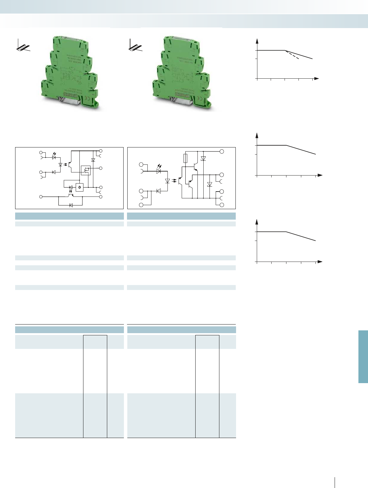
30
0
0,7
1
40 50 60
1
1
30
0
7
10
405060
30
0
0,35
0,5
40 50 60
A1
A2
+24V
0
A
+
Err
A1
A2
A2
12
14
11
11
For further information and full technical data, visit phoenixcontact.net/products
433
PHOENIX CONTACT
Technical data Technical data
③ ③
0.8 -
1.2
0.8 -
1.2
0.8 0.8
0.4 0.4
[mA] 15 6 8 5 5 3 5.6 8.4 3 3
[Hz] 50 50 50 50 50 50 10 10 100 1000
3 V DC ... 33 V DC (High active) / 100 mA - / -
33 V DC / 5 V DC 48 V DC / 3 V DC
Limiting continuous current 1 A (see derating curve) 10 A (see derating curve) 500 mA (see derating curve)
50 mV < 1.2 V
300 V 300 V
4 kV / basic insulation 4 kV / basic insulation
-25 °C ... 60 °C -25 °C ... 60 °C
Standards/regulations IEC 60664, EN 50178, IEC 62103 IEC 60664, EN 50178, IEC 62103 IEC 60664, EN 50178, IEC 62103
Connection data solid / stranded / AWG 0.14 - 2.5 mm² / 0.14 - 2.5 mm² / 26 - 14 0.14 - 2.5 mm² / 0.14 - 2.5 mm² / 26 - 14 0.14 - 2.5 mm² / 0.14 - 2.5 mm² / 26 - 14
Dimensions W / H / D 6.2 mm / 80 mm / 86 mm 6.2 mm / 80 mm / 86 mm 6.2 mm / 80 mm / 86 mm
EMC note Class A product, see page 625 Class A product, see page 625 Class A product, see page 625
Ordering data Ordering data
Type Order No. Pcs. /
Pkt. Type Order No. Pcs. /
Pkt.
PLC-OSC- 24DC/ 24DC/ 10/R 2982702 10 PLC-OSC- 24DC/ 48DC/500/W 2980636 10
PLC-OPT- 24DC/ 24DC/10/R 2900398 10 PLC-OPT- 24DC/ 48DC/500/W 2900378 10
Derating curve for PLC-...24DC/24DC/10/R
Derating curve for PLC...300DC/1
Ambient temperature [°C]
Load current [A]
Ambient temperature [°C]
Load current [A]
Derating curve for PLC...24DC/48DC/500/W
Ambient temperature [°C]
Load current [mA]
For input voltages 220 V DC and 230 V AC
DW
H
DW
H
Relay modules
Highly compact relay modules - PLC-INTERFACE
Power solid-state relay with
short-circuit-proof DC voltage output,
max. 10 A, with feedback
Input solid-state relay with
DC voltage output,
max. 500 mA, with electronic PDT

30
20405060
0
0,5
1
1,5
2
2,5
100
A1+
A2-
A2-
14
BB
13+
13+
Technical data
Input data ①
Rated actuating voltage range with reference to U
C
0.8 -
1.2
Rated actuating current I
C
[mA] 8
Switching level (with reference to U
C
) 1 signal ("H") > 0.8
0 signal ("L") < 0.4
Typ. switch-on time at U
N
[ms] 10
Typ. shutdown time at U
N
[ms] 10
Transmission frequency f
limit
[Hz] 10
Input circuit DC Yellow LED, protection against polarity reversal, surge protection
Output data
Max. switching voltage 253 V AC
Min. switching voltage 24 V AC
Max. inrush current 250 A (20 ms)
Min. / max. switching current 10 mA / 2.4 A (see to derating)
Output protection RCV circuit
Voltage drop at max. limiting continuous current < 1 V
Leakage current in off state < 1 mA
Phase angle (cos )-
Max. load value 340 A
2
s (tp = 10 ms, at 25 °C)
General data
Rated insulation voltage 260 V AC
Rated surge voltage 4 kV
Insulation Basic insulation
Ambient temperature (operation) -25 °C ... 60 °C
Standards/regulations DIN EN 50178
Pollution degree / surge voltage category 2 / III
Connection data solid / stranded / AWG 0.14 - 2.5 mm² / 0.14 - 2.5 mm² / 26 - 14
Dimensions W / H / D 6.2 mm / 80 mm / 86 mm
EMC note Class A product, see page 625
Ordering data
Description Rated actuating voltage
U
C
Type Order No. Pcs. /
Pkt.
PLC-INTERFACE, with screw connection
①24 V DC PLC-OSC- 24DC/230AC/2.4/ACT 2904631 10
PLC-INTERFACE, with push-in connection
①24 V DC PLC-OPT- 24DC/230AC/2.4/ACT 2904632 10
434
PHOENIX CONTACT
= aligned with > 20 mm spacing
= aligned without spacing
Ambient temperature [°C]
Load current [A]
Load current as a function of the ambient temperature
Operating time: 100% operating factor
DW
H
6.2 mm narrow solid-state relay for
switching AC loads
– Status display
– Protection circuits in input and output
– Wear-free
– Switching capacity up to 230 V AC/2.4 A
– Screw and push-in connection technology
PLC RELAY with
an integrated solid-state relay
Relay modules
Highly compact relay modules - PLC-INTERFACE
Solid-state power relay with
AC voltage output, max. 2.4 A
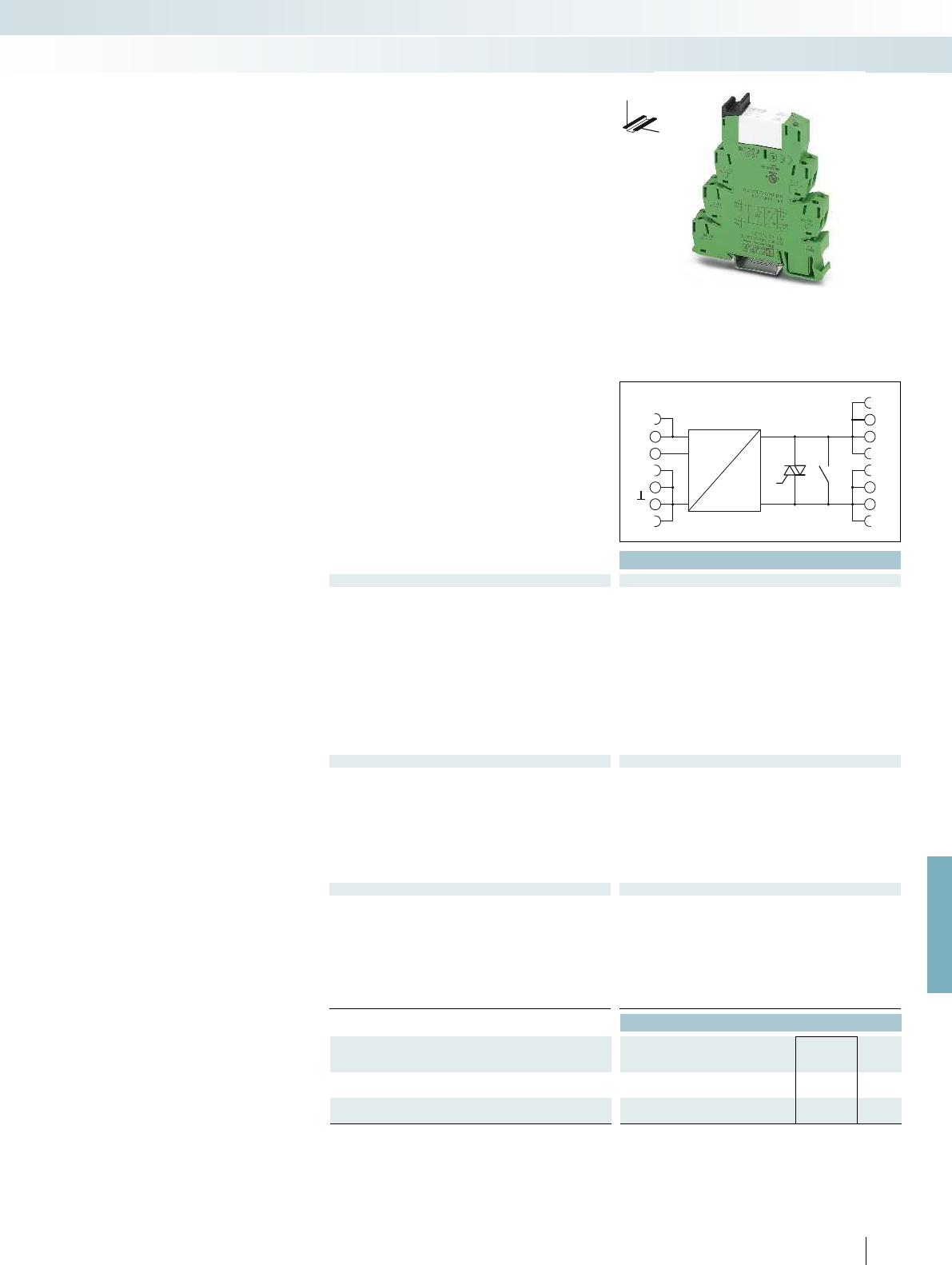
DC
DC
Us
ON
14
14
13
13
For further information and full technical data, visit phoenixcontact.net/products
Technical data
Input data ①
Rated control supply voltage U
S
[V DC] 24
Rated control supply voltage range with reference to U
S
0.8 -
1.2
Rated control supply current I
S
14 mA (input low, output low)
19 mA (input high, output high)
Rated actuation voltage U
C
ON [V DC] 24
Rated actuating voltage range with reference to U
C
0.8 -
1.2
Rated actuating current I
C
[mA] 6.8
Input circuit DC Yellow LED, protection against polarity reversal, surge protection
Output data
Max. switching voltage 253 V AC
Min. switching voltage 24 V AC
Max. inrush current -
Min. / max. switching current 100 mA / 10 A (see derating curve)
Output protection RCV circuit
Voltage drop at max. limiting continuous current -
Leakage current in off state < 1 mA
Phase angle (cos )-
Max. load value 350 A
2
s (tp = 10 ms, at 25 °C)
General data
Rated insulation voltage 260 V AC
Rated surge voltage 6 kV
Insulation safe isolation
Ambient temperature (operation) -25 °C ... 60 °C
Standards/regulations DIN EN 50178
Pollution degree / surge voltage category 2 / III
Connection data solid / stranded / AWG 0.14 - 2.5 mm² / 0.14 - 2.5 mm² / 26 - 14
Dimensions W / H / D 6.2 mm / 80 mm / 86 mm
Ordering data
Description Rated actuating voltage
U
C
Type Order No. Pcs. /
Pkt.
PLC-INTERFACE, with screw connection
①24 V DC PLC-HSC-24DC/230AC/10 2905214 1
PLC-INTERFACE, with push-in connection
①24 V DC PLC-HPT-24DC/230AC/10 2905215 1
435
PHOENIX CONTACT
DW
H
The solid-state relay, combined with a
mechanical relay, offers the following
advantages:
– Higher electrical service life
– Lower power dissipation
– Option of bridging adjacent modules
– Status display
– Protection circuits in input and output
– Switching capacity up to 230 V AC/10 A
– Screw and push-in connection technology
PLC-INTERFACE with
hybrid solid-state relay
Relay modules
Highly compact relay modules - PLC-INTERFACE
Hybrid solid-state relay
with AC voltage output, max. 10 A

A1
+
A2
A2
–
–
+
+
0
A
Technical data
Input data ① ②
Permissible range (with reference to U
N
) 0.8 -
1.2
0.8 -
1.2
Switching level with reference to U
N
1 signal ("H") > 0.8 > 0.8
0 signal ("L") < 0.4 < 0.4
Typ. input current at U
N
[mA] 7 6
Typ. switch-on time at U
N
[µs] 1.5 1.5
Typ. shutdown time at U
N
[µs] 2 2
Transmission frequency f
limit
[kHz] 100 100
Input protection: Yellow LED, protection against polarity reversal, surge protection Yellow LED, protection against polarity reve
Output data
Operating voltage range 4 V DC ... 30 V DC
Limiting continuous current 50 mA
Quiescent current 4.3 mA
Residual voltage drop at "H" < 0.5 V
Output circuit 3-conductor, ground-referenced 3-conductor push-pull, ground referenced 3-conductor push-pull, ground referenced
Output protection Protection against polarity reversal, surge protection Protection against polarity reversal, surge protection Pr
General data
Test voltage input/output 2.5 kV
rms
(50 Hz, 1 min.) 2.5 kV
Ambient temperature (operation) -20 °C ... 60 °C
Standards/regulations DIN EN 50178
Pollution degree / surge voltage category 2 / II
Connection data solid / stranded / AWG 0.14 - 2.5 mm² / 0.14 - 2.5 mm² / 26 - 14 0.14 - 2.5 mm² / 0.14 - 2.5 mm² / 26 - 14 0.14 - 2.5
Dimensions W / H / D 6.2 mm / 80 mm / 86 mm 6.2 mm / 80 mm / 86 mm 6.2 mm / 80 mm / 86 mm
EMC note Class A product, see page 625 Class A product, see page 625 Class A product, see page 625
Ordering data
Description Input voltage
U
N
Type Order No. Pcs. /
Pkt.
Input solid-state relay with screw connection
①5 V DC PLC-OSC- 5DC/ 24DC/100KHZ 2902963 1
②24 V DC PLC-OSC- 24DC/ 24DC/100KHZ 2902964 1
Input solid-state relay with push-in connection
①5 V DC PLC-OPT- 5DC/ 24DC/100KHZ 2902969 1
②24 V DC PLC-OPT- 24DC/24DC/100KHZ 2902970 1
436
PHOENIX CONTACT
PLC-INTERFACE
Solid-state relays up to 100 kHz
A solid-state relay for the safe acquisition
of short pulses.
– Status display
– Bridging options
– Cut-off frequency of up to 100 kHz
– Push-pull stage on output side
– Features a capacitor on the input side for
interference suppression
Relay modules
Highly compact relay modules - PLC-INTERFACE
Notes:
Type of housing:
Polyamide PA non-reinforced, color: green.
Marking systems and mounting material
See Catalog 5
With DC voltage output
Transmission frequency 100 kHz
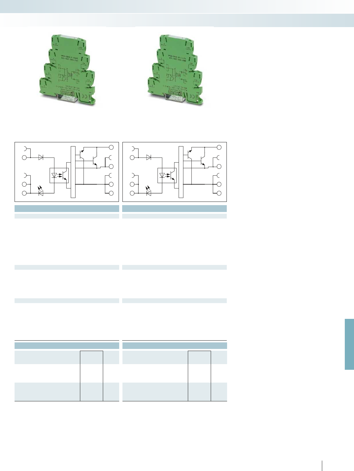
A1
+
A2
A2
–
–
+
+
0
A
A1
+
A2
A2
–
–
+
+
0
A
For further information and full technical data, visit phoenixcontact.net/products
Technical data Technical data
① ② ① ②
0.5 -
1.2
0.8 -
1.2
0.5 -
1.2
0.8 -
1.2
> 0.5 > 0.8 > 0.5 > 0.8
< 0.3 < 0.4 < 0.3 < 0.4
88 88
11 11
22 22
100 100 100 100
Input protection: Yellow LED, protection against polarity reversal, surge protection Yellow LED, protection against polarity reversal, surge protection Yellow LED, protection against polarity reversal, surge protection
4 V DC ... 18 V DC 14 V DC ... 30 V DC
50 mA 50 mA
8.5 mA 15 mA
< 1.2 V < 2.2 V
Output circuit 3-conductor, ground-referenced 3-conductor push-pull, ground referenced 3-conductor push-pull, ground referenced
Output protection Protection against polarity reversal, surge protection Protection against polarity reversal, surge protection Protection against polarity reversal, surge protection
(50 Hz, 1 min.) 2.5 kV
rms
(50 Hz, 1 min.) 2.5 kV
rms
(50 Hz, 1 min.)
-20 °C ... 60 °C -20 °C ... 60 °C
DIN EN 50178 DIN EN 50178
2 / II 2 / II
Connection data solid / stranded / AWG 0.14 - 2.5 mm² / 0.14 - 2.5 mm² / 26 - 14 0.14 - 2.5 mm² / 0.14 - 2.5 mm² / 26 - 14 0.14 - 2.5 mm² / 0.14 - 2.5 mm² / 26 - 14
Dimensions W / H / D 6.2 mm / 80 mm / 86 mm 6.2 mm / 80 mm / 86 mm 6.2 mm / 80 mm / 86 mm
EMC note Class A product, see page 625 Class A product, see page 625 Class A product, see page 625
Ordering data Ordering data
Type Order No. Pcs. /
Pkt. Type Order No. Pcs. /
Pkt.
PLC-OSC- 5DC/ 5DC/100KHZ-G 2902965 1PLC-OSC- 5DC/ 24DC/100KHZ-G 2902967 1
PLC-OSC- 24DC/ 5DC/100KHZ-G 2902966 1PLC-OSC- 24DC/ 24DC/100KHZ-G 2902968 1
PLC-OPT- 5DC/ 5DC/100KHZ-G 2902971 1PLC-OPT- 5DC/24DC/100KHZ-G 2902973 1
PLC-OPT- 24DC/ 5DC/100KHZ-G 2902972 1PLC-OPT- 24DC/24DC/100KHZ-G 2902974 1
437
PHOENIX CONTACT
Relay modules
Highly compact relay modules - PLC-INTERFACE
With DC voltage output push-pull
Transmission frequency 100 kHz
With DC voltage output push-pull
Transmission frequency 100 kHz
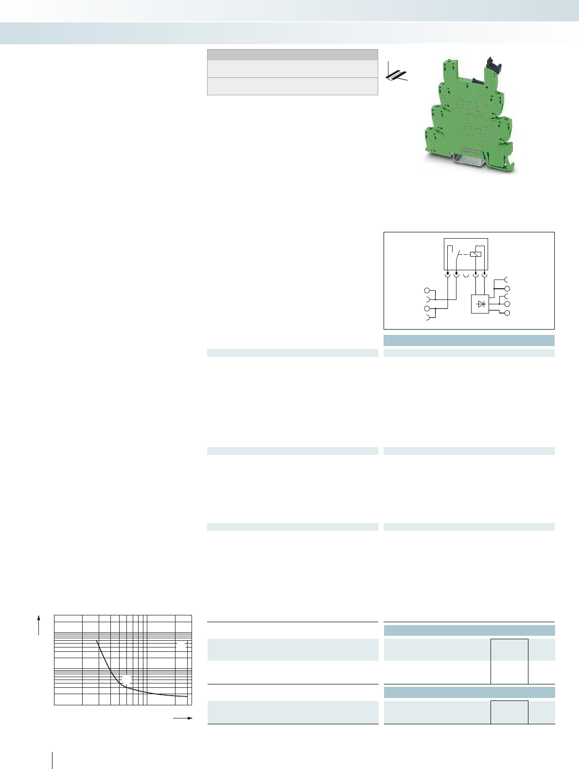
0,1
0,2
0,3
0,5
1
2
4
10
20
1020305070100 300200
1
2
1
2
6
GND
U
VN
IN
13+
14
Technical data
Input data
Rated control supply voltage U
VN
5 V DC
Rated control supply voltage range with reference to U
VN
0.9 ... 1.2
Rated control supply current I
VN
41 mA
Rated actuating voltage U
c
(IN) 5 V DC (TTL)
Rated actuating voltage range with reference to U
C
0.9 ... 1.2
Rated actuating current I
C
2.5 mA
Typ. response time at U
c
4.5 ms
Typ. release time for U
c
3.5 ms
Input circuit Yellow LED, protection against polarity reversal, surge protection
Output data with: REL-MR-4,5DC/21 AU REL-MR-4,5DC/21
Contact type Single contact, 1 N/O contact Single contact, 1 N/O contact
Contact material AgSnO, hard gold-plated AgSnO
Max. switching voltage 30 V AC / 36 V DC 250 V AC/DC
Min. switching voltage 100 mV (at 10 mA) 5 V (at 100 mA)
Limiting continuous current 50 mA 6 A
Max. inrush current 50 mA on request
Min. switching current 1 mA (at 24 V) 10 mA (at 12 V)
General data
Rated insulation voltage 250 V
Rated surge voltage / insulation 6 kV
Ambient temperature (operation) -20 °C ... 60 °C
Mechanical service life 2 x 10
7
cycles
Clearance and creepage distances between the power circuits IEC 60664, EN 50178, IEC 62103
Pollution degree / Surge voltage category 2 / III
Mounting position / mounting any / can be aligned without spacing
Connection data solid / stranded / AWG 0.14 - 2.5 mm² / 0.14 - 2.5 mm² / 26 - 14
Dimensions W / H / D 6.2 mm / 80 mm / 94 mm
EMC note Class A product, see page 625
Ordering data
Description Type Order No. Pcs. /
Pkt.
PLC-INTERFACE
With screw connection PLC-BSC-TTL/1 2982689 10
With push-in connection PLC-BPT-TTL/1 2900458 10
Accessories
Plug-in miniature power relay
with gold contact REL-MR 4,5DC/21AU 2961370 10
with power contact REL-MR- 4,5DC/21 2961367 10
438
PHOENIX CONTACT
AC, ohmic load
DC, ohmic load
Switching voltage [V]
Switching current [A]
Max. interrupting rating
Notes:
Type of housing:
Polyester PBT non-reinforced, color: green.
Marking systems and mounting material
See Catalog 5
DW
H
The PLC-BS...TTL/1 basic terminal block
is controlled using a TTL (5 V) input signal
and can be equipped with a mechanical relay
or a solid-state relay as an option. The basic
terminal block equipped with a robust
miniature relay offers the following
advantages:
– 6.2 mm slim overall width
– Bridging options
– Status display
– RTIII degree of protection
– Safe isolation in accordance with
EN 50178 (VDE 0160)
– 4 kV
rms
electrical isolation between coil
and contact
– Screw and push-in connection technology
PLC-INTERFACE for
the TTL signal at input
Relay modules
Highly compact relay modules - PLC-INTERFACE
Basic terminal block, for fitting
with relay for TTL(5 V)
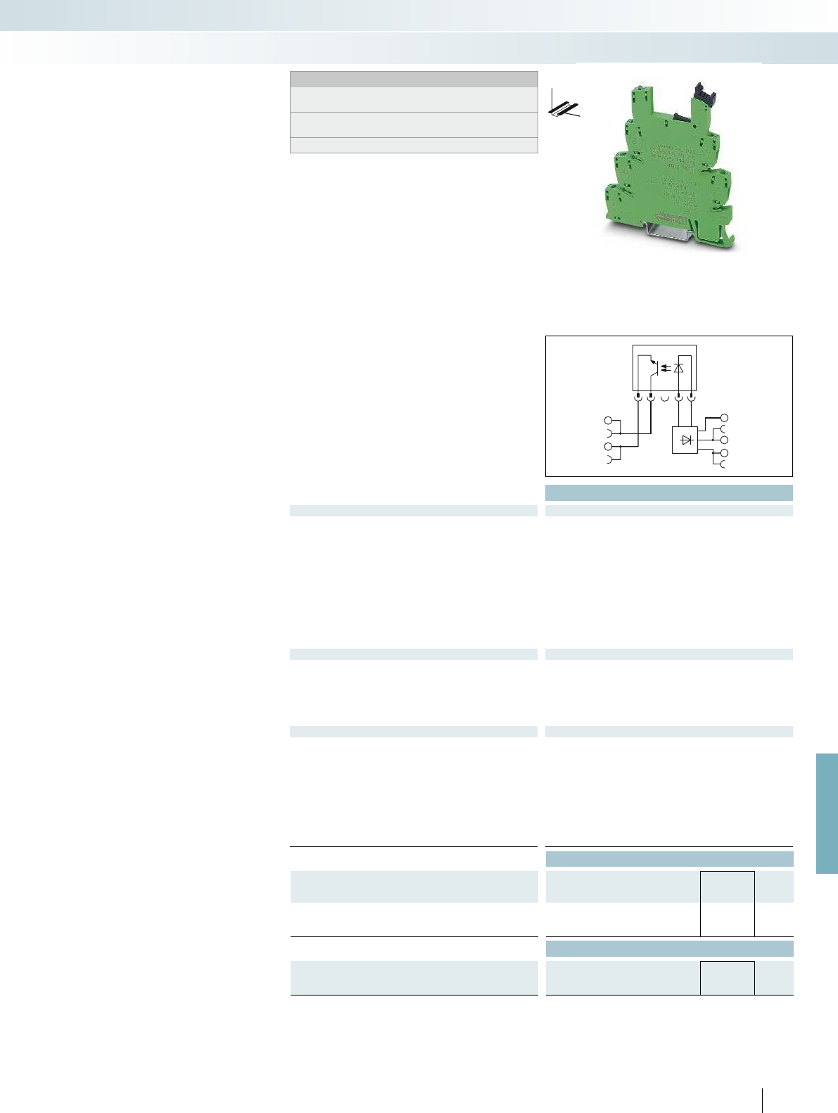
GND
U
VN
IN
13+
14
For further information and full technical data, visit phoenixcontact.net/products
Technical data
Input data
Rated control supply voltage U
VN
5 V DC
Rated control supply voltage range with reference to U
VN
0.9 ... 1.2
Rated control supply current I
VN
11.5 mA
Rated actuating voltage U
c
(IN) 5 V DC (TTL)
Switching level 1 signal ("H") (TTL signal) > 2 V DC
Switching level 0 signal ("L") (TTL signal) < 0.8 V DC
Rated actuating current I
C
2.5 mA
Typ. response time/switch-on time at U
c
35 µs
Typ. shutdown time at U
C
320 µs
Input circuit Yellow LED, protection against polarity reversal, surge protection
Output data with: OPT-5DC/48DC/100 OPT-5DC/24DC/2
Max. switching voltage 48 V DC 33 V DC
Min. switching voltage 3 V DC 3 V DC
Limiting continuous current 100 mA 3 A
Output protection Protection against polarity
reversal, surge protection
Protection against polarity
reversal, surge protection
Voltage drop at limiting continuous current < 1 V < 200 mV
General data
Rated insulation voltage 250 V
Rated surge voltage / insulation 6 kV / Basic insulation
Ambient temperature (operation) -20 °C ... 60 °C
Clearance and creepage distances between the power circuits IEC 60664, EN 50178, IEC 62103
Pollution degree / Surge voltage category 2 / III
Connection data solid / stranded / AWG 0.14 - 2.5 mm² / 0.14 - 2.5 mm² / 26 - 14
Dimensions W / H / D 6.2 mm / 80 mm / 94 mm
EMC note Class A product, see page 625
Ordering data
Description Type Order No. Pcs. /
Pkt.
PLC-INTERFACE
With screw connection PLC-BSC-TTL/1 2982689 10
With push-in connection PLC-BPT-TTL/1 2900458 10
Accessories
Plug-in solid-state relay
Solid-state input relay OPT- 5DC/ 48DC/100 2967992 10
Solid-state power relay OPT- 5DC/ 24DC/ 2 2967989 10
439
PHOENIX CONTACT
Notes:
Type of housing:
Polyester PBT non-reinforced, color: green.
Marking systems and mounting material
See Catalog 5
For derating curves see page 425
DW
H
The PLC-BS...TTL/1 basic terminal block
is controlled using a TTL (5 V) input signal
and can be equipped with a mechanical relay
or a solid-state relay as an option. The basic
terminal block equipped with a solid-state
relay offers the following advantages:
– 6.2 mm slim overall width
– Bridging options
– Status display
– IP67-protected solid-state relay
electronic unit
– Switching capacity of up to 24 V DC/3 A
– Alternative input or power solid-state
relay
– Wear-free and output-free
– Integrated protective circuit
– 2.5 kV
rms
electrical isolation between
input and output
– Screw and push-in connection technology
PLC-INTERFACE for
the TTL signal at input
Relay modules
Highly compact relay modules - PLC-INTERFACE
Basic terminal block for fitting
with solid-state relay for TTL(5 V)

A1
A1
+
+
A2
A2
A2
–
–
–
+
+
+
A
0
0
0
20 35 40 50 60 70
3,5
3
2,5
2
1,5
1
0,5
1
20 30 40 50 60 70
1,5
2
2,5
3
1
2
1
2
Technical data
Input data
Rated actuating voltage U
C
24 V DC
Rated actuating voltage range with reference to U
C
0.8 ... 1.2
Switching level 1 signal ("H") > 0.8
Switching level 0 signal ("L") < 0.4
Rated actuating current I
C
3.4 mA
Typ. switch-on time for U
c
35 µs
Typ. shutdown time at U
C
35 µs
Transmission frequency f
limit
1 kHz
Input circuit DC Yellow LED, protection against polarity reversal, surge protection
Output data with:
Rated control supply voltage U
S
5 V DC
Rated control supply voltage range with reference to U
S
0.9 ... 1.2
Limiting continuous current A TTL load (Fan out = 1)/50 mA for switching mode
Output protection Protection against polarity reversal, surge protection
Voltage drop at max. limiting continuous current < 80 mV
General data
Rated insulation voltage 250 V DC
Rated surge voltage / insulation 4 kV / basic insulation
Ambient temperature (operation) -25 °C ... 60 °C
Clearance and creepage distances between the power circuits IEC 60664, EN 50178, IEC 62103
Pollution degree / surge voltage category 2 / III
Connection data solid / stranded / AWG 0.14 - 2.5 mm² / 0.14 - 2.5 mm² / 26 - 14
Dimensions W / H / D 6.2 mm / 80 mm / 86 mm
EMC note Class A product, see page 625
Ordering data
Description Type Order No. Pcs. /
Pkt.
PLC-INTERFACE
With screw connection PLC-OSC- 24DC/TTL 2982728 10
With push-in connection PLC-OPT- 24DC/TTL 2900363 10
440
PHOENIX CONTACT
Notes:
Type of housing:
Polyester PBT non-reinforced, color: green.
Marking systems and mounting material
See Catalog 5
DW
H
PLC-INTERFACE for
the TTL signal at output
Relay modules
Highly compact relay modules - PLC-INTERFACE
Input solid-state relay
with TTL (5 V) output
Derating curve for PLC-OSP...24DC/3RW
Ambient temperature [°C]
Load current [A]
Aligned without spacing
Aligned with 20 mm spacing
Derating curve for PLC-OSP...110DC/3RW
Ambient temperature [°C]
Load current [A]
The PLC-OS...24DC/TTL with a built-in
solid-state relay can be used for fast and
wear-free switching of TTL (5 V) signals.
The module offers the following
advantages:
– Switching capacity TTL (5 V), fan out = 1
– 6.2 mm slim overall width
– Bridging options
– Status display
– Integrated protective circuit
– Screw and push-in connection technology

A1
A2
A2
14
14
13+
13+
A1
A2
A2
14
14
13+
13+
For further information and full technical data, visit phoenixcontact.net/products
Technical data Technical data
Input data ① ⑥ ① ② ③ ④ ⑤ ⑥
Permissible range (with reference to U
N
) 0.7 -
1.25
0.7 -
1.25
0.7 -
1.25
0.7 -
1.25
0.7 -
1.25
0.7 -
1.25
0.7 -
1.25
0.7 -
1.25
Switching level (with reference to U
N
) 1 signal ("H") 0.6 0.6 > 0.6 > 0.6 > 0.6 > 0.6 > 0.6 > 0.6
0 signal ("L") 0.3 0.3 < 0.4 < 0.4 < 0.3 < 0.3 < 0.3 < 0.3
Typ. input current at U
N
[mA] 8.5 3 12 12 5.5 5.5 5.5 5.5
Typ. switch-on time at U
N
[ms] 0.04 0.08 0.4 0.4 0.04 0.04 0.04 0.4
Typ. shutdown time at U
N
[ms] 0.2 0.6 0.2 0.1 0.2 0.2 0.2 0.2
Transmission frequency f
limit
[Hz] 300 100 50 50 300 300 300 300
Input circuit DC Yellow LED, protection against polarity reversal Yellow LED, protection against polarity reversal, surge protection
Output data
Max. switching voltage 33 V DC 140 V DC
Min. switching voltage 3 V DC 12 V DC
Limiting continuous current 3 A (see derating curve) 3 A (see derating curve)
Output protection Protection against polarity reversal, surge protection Protection against polarity reversal, surge protection
Voltage drop at max. limiting continuous current < 200 mV < 150 mV
General data
Rated insulation voltage 250 V 160 V DC
Rated surge voltage 4 kV / basic insulation 4 kV / basic insulation
Ambient temperature (operation) -25 °C ... 70 °C -25 °C ... 70 °C
Standards/regulations IEC 60664, EN 50178, IEC 62103 IEC 60664, EN 50178, IEC 62103
Pollution degree / surge voltage category 2 / III 2 / III
Connection data solid / stranded / AWG 0.14 - 2.5 mm² / 0.14 - 2.5 mm² / 26 - 14 0.14 - 2.5 mm² / 0.14 - 2.5 mm² / 26 - 14
Dimensions W / H / D 6.2 mm / 80 mm / 86 mm 6.2 mm / 80 mm / 86 mm
EMC note Class A product, see page 625
Ordering data Ordering data
Description Input voltage
U
N
Type Order No. Pcs. /
Pkt. Type Order No. Pcs. /
Pkt.
PLC-INTERFACE, with spring-cage connection
①24 V DC PLC-OSP- 24DC/ 24DC/ 3RW 2980513 10 PLC-OSP- 24DC/110DC/ 3RW 2982511 10
②36 V DC PLC-OSP- 36DC/110DC/ 3RW 2982524 10
③48 V DC PLC-OSP- 48DC/110DC/ 3RW 2982537 10
④72 V DC PLC-OSP- 72DC/110DC/ 3RW 2982540 10
⑤96 V DC PLC-OSP- 96DC/110DC/ 3RW 2982553 10
⑥110 V DC PLC-OSP-110DC/ 24DC/ 3RW 2980526 10 PLC-OSP-110DC/110DC/ 3RW 2982566 10
PLC-INTERFACE, with push-in connection
①24 V DC PLC-OPT- 24DC/ 24DC/3RW 2900379 10 PLC-OPT- 24DC/110DC/3RW 2900391 10
②36 V DC PLC-OPT- 36DC/110DC/3RW 2900392 10
③48 V DC PLC-OPT- 48DC/110DC/3RW 2900393 10
④72 V DC PLC-OPT- 72DC/110DC/3RW 2900394 10
⑤96 V DC PLC-OPT- 96DC/110DC/3RW 2900395 10
⑥110 V DC PLC-OPT-110DC/ 24DC/3RW 2900380 10 PLC-OPT-110DC/110DC/3RW 2900396 10
441
PHOENIX CONTACT
The PLC-OSP...RW interface modules are
intended for use as per DIN EN 50155
(VDE 0115 Part 200) “Railway applications,
Part 200: Electronic equipment used on
rolling stock”.
The advantages:
– Temperature range -25°C to +70°C
– Input voltage range 0.7-1.25 x U
N
– Shock resistance in acc. with DIN 50155
(requirements in acc. with EN 61373)
– Spring-cage and push-in connection
technology
Notes:
Type of housing:
Polyester PBT non-reinforced, color: green.
Marking systems and mounting material
See Catalog 5
For derating curves see page 440
DW
H
DW
H
PLC RELAY with
solid-state relays for
railway applications
Relay modules
Highly compact relay modules - PLC-INTERFACE
Power solid-state relay
with DC voltage output, max. 3 A
Power solid-state relay
with DC voltage output, max. 3 A
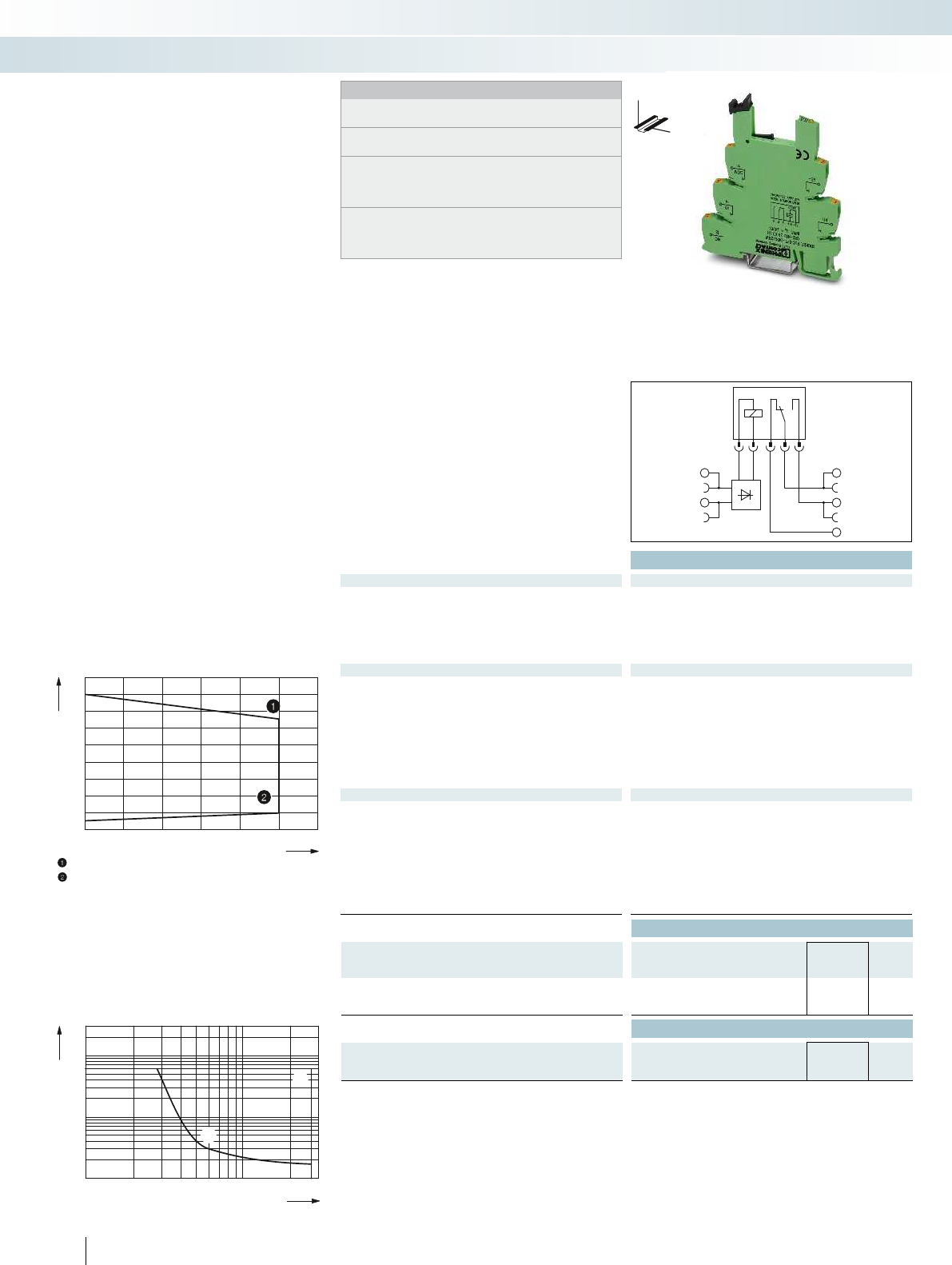
A1
A2 11
14
12
0,1
0,2
0,3
0,5
1
2
4
10
20
1020305070100 300200
1
2
1
2
6
0,6
0,8
1,0
1,2
1,4
2030405060 70 80
Technical data
Input data
Nominal input voltage U
N
24 V DC
Permissible range (with reference to U
N
) See diagram
Typ. input current at U
N
12 mA
Typ. response time at U
N
5 ms
Typ. release time at U
N
8 ms
Input circuit
Yellow LED, protection against polarity reversal, freewheeling diode
Output data with: REL-MR-18DC/21 REL-MR-18DC/21AU
Contact type Single contact, 1-PDT Single contact, 1-PDT
Contact material AgSnO AgSnO, hard gold-plated
Max. switching voltage 250 V AC/DC 30 V AC / 36 V DC
Min. switching voltage 5 V (at 100 mA) 100 mV (at 10 mA)
Limiting continuous current 3 A 50 mA
Max. inrush current on request 50 mA
Min. switching current 10 mA (at 12 V) 1 mA (at 24 V)
General data
Test voltage input/output 4 kV (50 Hz, 1 min.)
Ambient temperature (operation) -25 °C ... 70 °C
Mechanical service life 2 x 10
7
cycles
Standards/regulations IEC 60664, EN 50178, IEC 62103
Pollution degree / Surge voltage category 3 / III
Connection data solid / stranded / AWG 0.14 - 2.5 mm² / 0.14 - 2.5 mm² / 26 - 14
Dimensions W / H / D 6.2 mm / 80 mm / 94 mm
EMC note Class A product, see page 625
Ordering data
Description Voltage U
N
Type Order No. Pcs. /
Pkt.
PLC-INTERFACE basic terminal block, for
plug-in miniature relay
With push-in connection 24 V DC PLC-BPT- 24DC/21RW 2900261 10
Accessories
Plug-in miniature relay
with power contact REL-MR- 18DC/21 2961383 10
with gold contact REL-MR- 18DC/21AU 2961493 10
442
PHOENIX CONTACT
Notes:
Type of housing:
Polyamide PA non-reinforced, color: green.
Marking systems and mounting material
See Catalog 5
Separating plate PLC-ATP must be installed for voltages larger
than 250 V (L1, L2, L3) between identical terminal blocks in
adjacent modules. Potential bridging is then carried out with
FBST 8-PLC... or FBST 500....
If the specified maximum values for multi-layer contact relays are
exceeded, the gold plating is destroyed. The maximum values of
the power contact relay are then valid. This can result in a shorter
service life than with a pure power contact.
DW
H
PLC-INTERFACE for
railway applications
Relay modules
Highly compact relay modules - PLC-INTERFACE
Basic terminal block for fitting
with 1 PDT relay
Permitted input voltage range for
PLC-BSP-24DC/21RW
(with REL-MR-18DC/21... relay)
Ambient temperature [°C]
Input voltage U/U
N
Maximum continuous voltage at limiting continuous current = 3 A
Minimum pick-up voltage for pre-excitation with U
N
and limiting
continuous current = 3 A
Switching voltage [V]
Switching current [A]
AC, ohmic load
DC, ohmic load
Electrical interrupting rating for PLC...21
with 1 PDT relay
Relay modules with extended input
voltage and temperature range, specifically
for use in railway applications
The advantages:
– Temperature range -25°C to + 70°C
– Input voltage range 0.7 to 1.25 x UN
– Vibration and shock resistance according
to EN 50155
– Safe isolation according to DIN EN 50178
between coil and contact
– Push-in connection technology
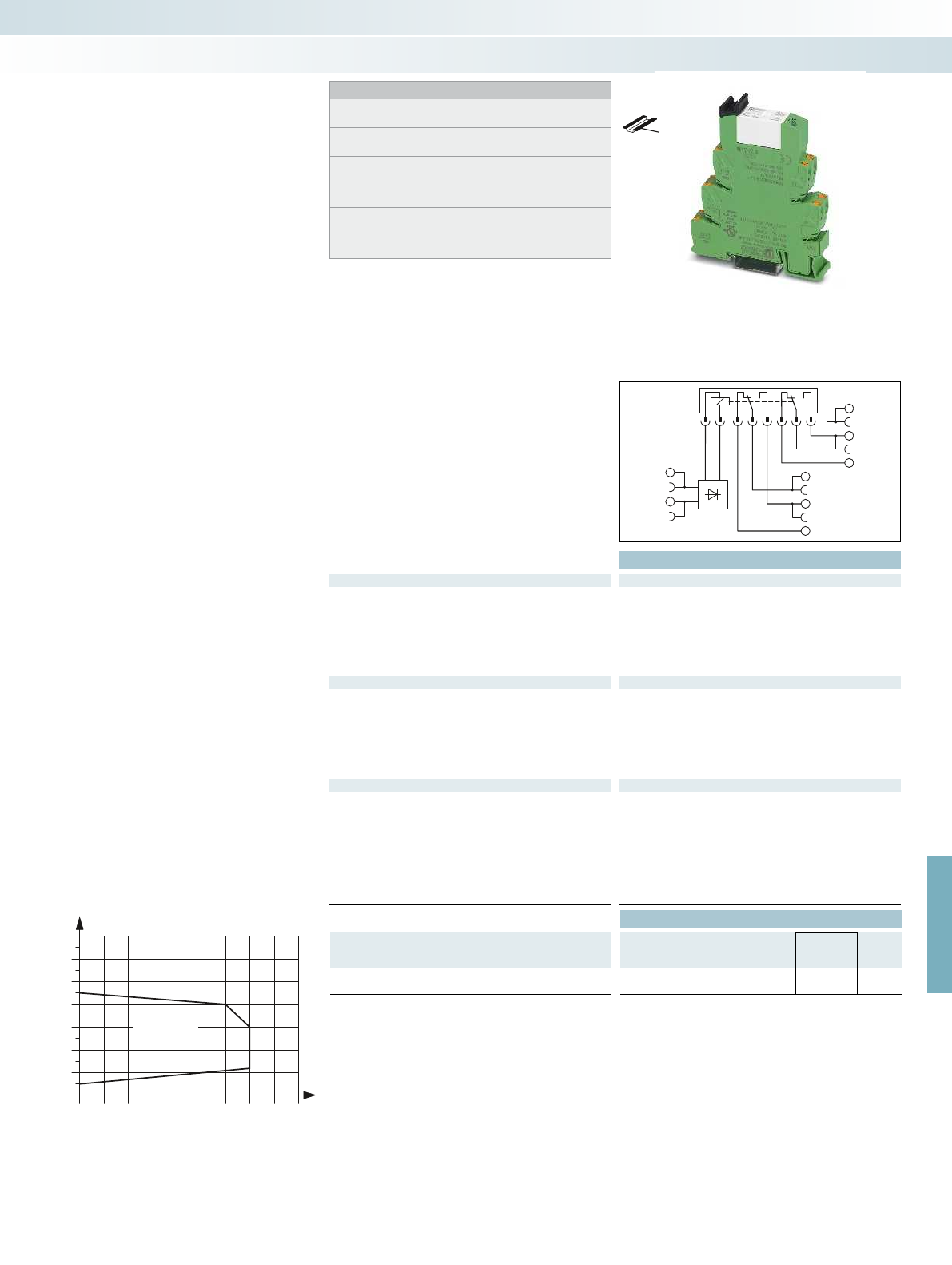
A2
24
21
22
14
11
12
A1
20 25 30 35 40 45 50 55 60 65
0,7
0,8
0,9
1
1,1
1,2
1,3
1,4
A
B
U=230 V AC
N
For further information and full technical data, visit phoenixcontact.net/products
Technical data
Input data
Nominal input voltage U
N
230 V AC
Input nominal frequency 16.67 Hz
Permissible range (with reference to U
N
) see diagram
Typ. input current at U
N
-
Typ. response time at U
N
20 ms
Typ. release time at U
N
60 ms
Input circuit Yellow LED, bridge rectifier
Output data
Contact type 2 PDT
Contact material AgNi, hard gold-plated
Max. switching voltage 30 V AC / 36 V DC ( 250 V AC/DC )
Min. switching voltage 100 mV ( 5 V AC/DC )
Limiting continuous current 50 mA ( 6 A )
Max. inrush current 50 mA ( 8 A )
Min. switching current 1 mA ( 10 mA )
General data
Test voltage input/output 6 kV
Ambient temperature (operation) -25 °C ... 55 °C
Mechanical service life Approx. 3 x 10
7
cycles
Standards/regulations IEC 60664, EN 50178, IEC 62103
Pollution degree / Surge voltage category 2 / III
Connection data solid / stranded / AWG 0.14 - 2.5 mm² / 0.14 - 2.5 mm² / 26 - 14
Dimensions W / H / D 14 mm / 80 mm / 94 mm
EMC note Class A product, see page 625
Ordering data
Description Voltage U
N
Type Order No. Pcs. /
Pkt.
PLC-INTERFACE
With push-in connection 230 V AC PLC-RPT-230UC/21-21AU/RWF 2900345 10
443
PHOENIX CONTACT
Notes:
Type of housing:
Polyamide PA non-reinforced, color: green.
Marking systems and mounting material
See Catalog 5
Separating plate PLC-ATP must be installed for voltages larger
than 250 V (L1, L2, L3) between identical terminal blocks in
adjacent modules. Potential bridging is then carried out with
FBST 8-PLC... or FBST 500....
If the specified maximum values for multi-layer contact relays are
exceeded, the gold plating is destroyed. The values in
parentheses then apply for further operation. This can result in a
shorter service life than with a pure power contact.
DW
H
PLC-INTERFACE for
railway applications
Relay modules
Highly compact relay modules - PLC-INTERFACE
For 16.7 Hz input frequency
with 2 PDTs
Permitted input voltage range
for PLC-RSP-230UC/21-21AU/RWF
Ambient temperature [°C]
Input voltage U/U
N
Curve A
Maximum continuous voltage at limiting continuous current = 6 A
Curve B
Minimum pick-up voltage for pre-excitation with U
N
and limiting
continuous current = 6 A
Relay module for input voltages with a
nominal frequency of 16.7 Hz
The advantages:
– Input nominal frequency 16.7 Hz
– Vibration and shock resistance according
to EN 50155
– Safe isolation according to DIN EN 50178
between coil and contact
– Push-in connection technology
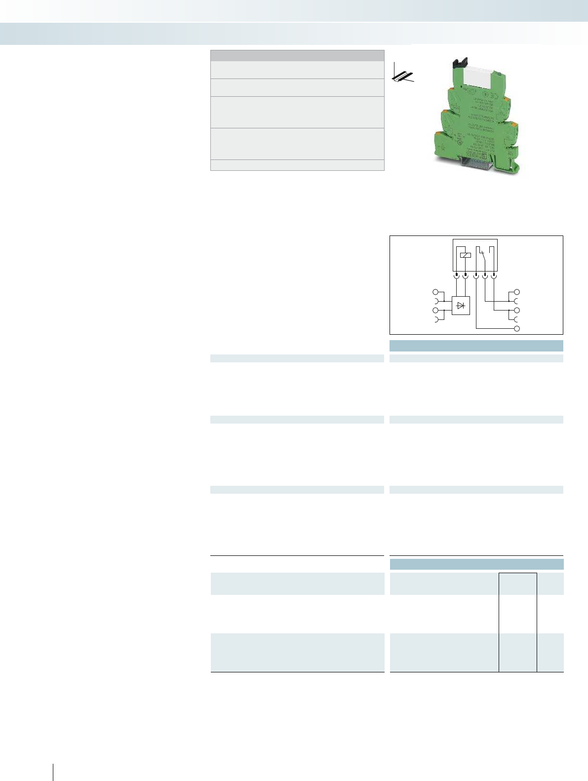
A1
A2 11
14
12
444
PHOENIX CONTACT
Relay modules with extended input
voltage and temperature range, specifically
designed for railway applications
The advantages:
– Certified to EN 50155
– Optimum relay operation thanks to wide-
range electronics
– Temperature range from -40°C to +70°C
(short-term 85°C)
– Input voltage range 0.7 to 1.25 x U
N
(short-term 1.4 x U
N
)
– Vibration and shock resistance according
to EN 50155
– Safe isolation according to DIN EN 50178
between coil and contact
– Push-in connection technology
PLC-INTERFACE for
railway applications
Technical data
Input data ① ② ③
Permissible range (with reference to U
N
) 0.7 -
1.25
0.7 -
1.25
0.7 -
1.25
Typ. input current at U
N
[mA]932
Typ. response time at U
N
[ms] 4 4 4
Typ. release time at U
N
[ms] 4 4 4
Input protection: Yellow LED, bridge rectifier, freewheeling diode Yellow LED, bridge rectifier, freewheeling diode Yellow LED, br
Output data
Contact type 1 PDT 1 PDT 2 PDTs 2 PDTs 1 PDT
Contact material AgSnO AgSnO, hard gold-plated AgNi AgNi, hard gold-plated AgNi
Max. switching voltage 250 V AC/DC 30 V AC / 36 V DC 250 V AC/DC 30 V AC / 36 V DC 250 V AC/DC
Min. switching voltage 5 V (at 100 mA) 100 mV (at 10 mA) 5 V (at 10 mA) 100 mV (at 10 mA) 12 V (at 10 mA)
Limiting continuous current 6 A 50 mA 6 A 50 mA 10 A (with inserted bridge 2967691)
Max. inrush current on request 50 mA 15 A (300 ms) 50 mA 30 A (300 ms)
Min. switching current 10 mA (at 12 V) 1 mA (at 24 V) 10 mA (at 5 V) 1 mA (at 24 V) 10 mA (at 12 V)
General data
Test voltage (winding/contact) 4 kV
rms
(50 Hz, 1 min.) 5 kV
Ambient temperature (operation) -40 °C ... 70 °C (temperature class TX) -40 °C ... 70 °C (temperature class TX) -40 °C ... 70 °C (
Mechanical service life Approx. 2 x 10
7
cycles Approx. 3 x 10
Standards/regulations
EN 50155 (VDE 0115 part 200), EN 50178, IEC 62103, EN61373,
EN50121
Connection data solid / stranded / AWG 0.14 - 2.5 mm² / 0.14 - 2.5 mm² / 26 - 14 0.14 - 2.5 mm² / 0.14 - 2.5 mm² / 26 - 14 0.14 - 2.5
Dimensions W / H / D 6.2 mm / 80 mm / 94 mm 14 mm / 80 mm / 94 mm 14 mm / 80 mm / 94 mm
EMC note Class A product, see page 625 Class A product, see page 625 Class A product, see page 625
Ordering data
Description Input voltage
U
N
Type Order No. Pcs. /
Pkt.
PLC-INTERFACE, with power contact
With push-in connection ①24 V DC PLC-RPT- 24UC/21/RW 2900318 10
②72 V DC PLC-RPT- 72UC/21/RW 2900319 10
③110 V DC PLC-RPT-110UC/21/RW 2900320 10
PLC-INTERFACE, with hard gold-plated contact
With push-in connection ①24 V DC PLC-RPT- 24UC/21AU/RW 2900321 10
②72 V DC PLC-RPT- 72UC/21AU/RW 2900322 10
③110 V DC PLC-RPT-110UC/21AU/RW 2900323 10
DW
H
Notes:
Type of housing:
Polyamide PA non-reinforced, color: green.
Marking systems and mounting material
See Catalog 5
Separating plate PLC-ATP must be installed for voltages larger
than 250 V (L1, L2, L3) between identical terminal blocks in
adjacent modules. Potential bridging is then carried out with
FBST 8-PLC... or FBST 500....
If the specified maximum values for multi-layer contact relays are
exceeded, the gold plating is destroyed. The maximum values of
the power contact relay are then valid. This can result in a shorter
service life than with a pure power contact.
Electrical service life diagrams, see page 426
Relay modules
Highly compact relay modules - PLC-INTERFACE
1 PDT 2 PDTs 1 PDT up to 10 A
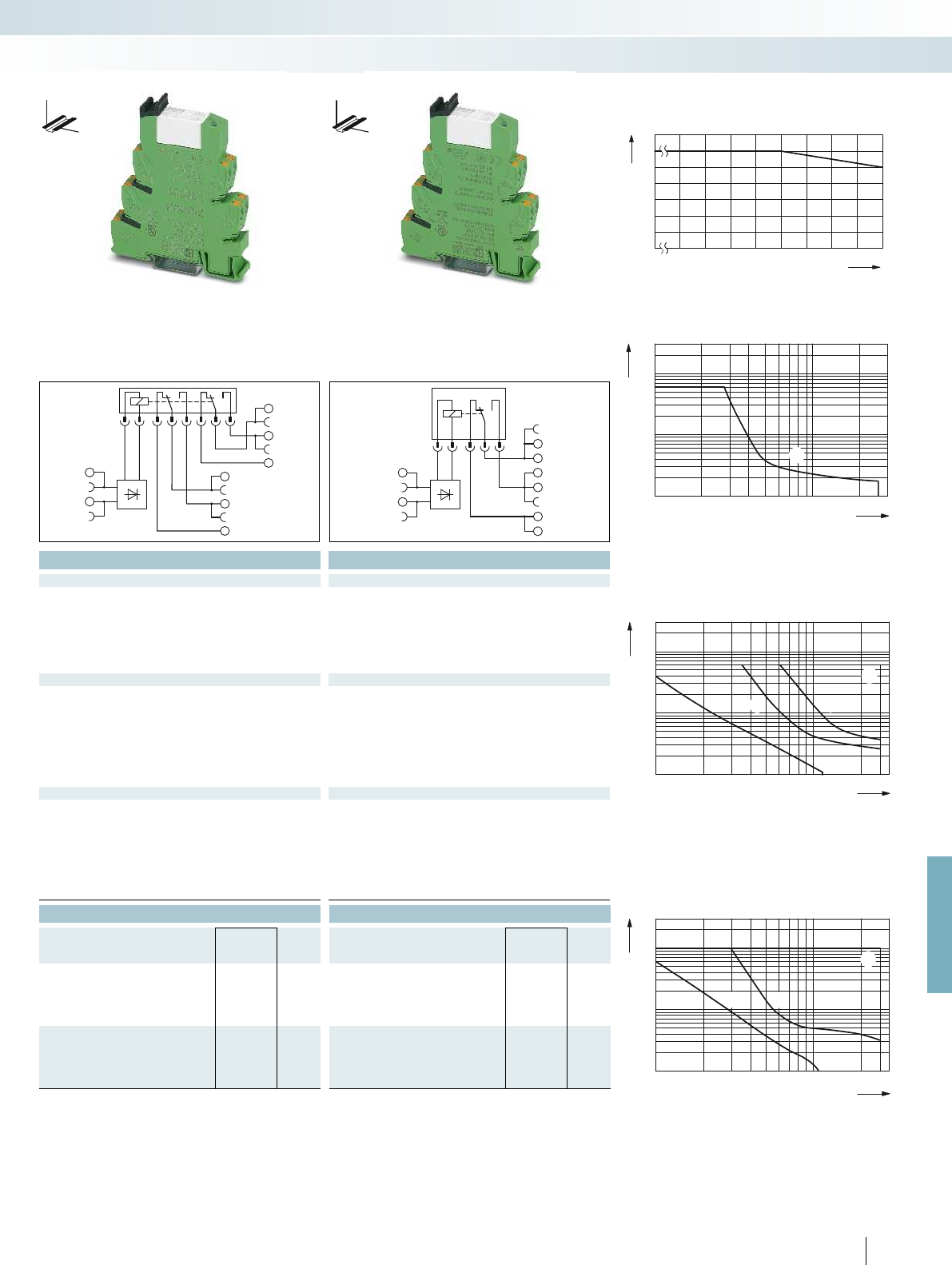
0,1
0,2
0,3
0,5
1
2
4
6
10
20
10203050 70 100 300200
1
2
3
4
3
1
42
1
2
3
0,1
0,2
0,3
0,5
1
2
4
6
10
20
10 20 30 50 70 100 300200
3
1
2
0,1
0,2
0,3
0,5
1
2
4
6
10
20
10 20 30 50 70 100 300200
1
1
706065
55
5045403530
3
4
7
5
6
2
1
00
A2
24
21
22
14
11
12
A1
A2
11
14
12
A1
For further information and full technical data, visit phoenixcontact.net/products
445
PHOENIX CONTACT
Technical data Technical data
① ② ③ ① ② ③
0.7 -
1.25
0.7 -
1.25
0.7 -
1.25
0.7 -
1.25
0.7 -
1.25
0.7 -
1.25
20 6 4.5 20 6 4.5
555 555
11 11 11 11 11 11
Input protection: Yellow LED, bridge rectifier, freewheeling diode Yellow LED, bridge rectifier, freewheeling diode Yellow LED, bridge rectifier, freewheeling diode
Contact type 1 PDT 1 PDT 2 PDTs 2 PDTs 1 PDT
Contact material AgSnO AgSnO, hard gold-plated AgNi AgNi, hard gold-plated AgNi
Max. switching voltage 250 V AC/DC 30 V AC / 36 V DC 250 V AC/DC 30 V AC / 36 V DC 250 V AC/DC
Min. switching voltage 5 V (at 100 mA) 100 mV (at 10 mA) 5 V (at 10 mA) 100 mV (at 10 mA) 12 V (at 10 mA)
Limiting continuous current 6 A 50 mA 6 A 50 mA 10 A (with inserted bridge 2967691)
Max. inrush current on request 50 mA 15 A (300 ms) 50 mA 30 A (300 ms)
Min. switching current 10 mA (at 12 V) 1 mA (at 24 V) 10 mA (at 5 V) 1 mA (at 24 V) 10 mA (at 12 V)
(50 Hz, 1 min.) 5 kV
rms
(50 Hz, 1 min.) 5 kV
rms
(50 Hz, 1 min.)
Ambient temperature (operation) -40 °C ... 70 °C (temperature class TX) -40 °C ... 70 °C (temperature class TX) -40 °C ... 70 °C (temperature class TX)
cycles Approx. 3 x 10
7
cycles Approx. 3 x 10
7
cycles
EN 50155 (VDE 0115 part 200), EN 50178, IEC 62103, EN61373,
EN50121
EN 50155 (VDE 0115 part 200), EN 50178, IEC 62103, EN61373,
EN50121
Connection data solid / stranded / AWG 0.14 - 2.5 mm² / 0.14 - 2.5 mm² / 26 - 14 0.14 - 2.5 mm² / 0.14 - 2.5 mm² / 26 - 14 0.14 - 2.5 mm² / 0.14 - 2.5 mm² / 26 - 14
Dimensions W / H / D 6.2 mm / 80 mm / 94 mm 14 mm / 80 mm / 94 mm 14 mm / 80 mm / 94 mm
EMC note Class A product, see page 625 Class A product, see page 625 Class A product, see page 625
Ordering data Ordering data
Type Order No. Pcs. /
Pkt. Type Order No. Pcs. /
Pkt.
PLC-RPT- 24UC/21-21/RW 2900346 10 PLC-RPT- 24UC/21HC/RW 2900324 10
PLC-RPT- 72UC/21-21/RW 2900347 10 PLC-RPT- 72UC/21HC/RW 2900325 10
PLC-RPT-110UC/21-21/RW 2900348 10 PLC-RPT-110UC/21HC/RW 2900326 10
PLC-RPT- 24UC/21-21AU/RW 2900349 10
PLC-RPT- 72UC/21-21AU/RW 2900350 10
PLC-RPT-110UC/21-21AU/RW 2900351 10
Derating curve for PLC-RSP...21/RW
PLC-RSP...21AU/RW
PLC-RSP...21-21/RW
PLC-RSP...21-21AU/RW
Ambient temperature [°C]
Switching current [A]
Switching voltage [V]
Switching current [A]
Ohmic load
Interrupting rating for PLC-RSP...UC/21RW
Switching current [A]
AC, ohmic load
DC, ohmic load, contacts in series
DC, ohmic load
DC, L/R = 40 ms
Interrupting rating for PLC-RSP...UC/21-21/RW
Switching voltage [V]
Switching voltage [V]
Switching current [A]
AC, ohmic load
DC, ohmic load
DC, L/R = 40 ms
Interrupting rating for PLC-RSP...UC/21HC/RW
DW
H
DW
H
Relay modules
Highly compact relay modules - PLC-INTERFACE
1 PDT 2 PDTs 1 PDT up to 10 A

+
GND
-
UVN
Out
ERR
UVN
Out
ERR
24V
(M)(P)
UKK 5-2R/NAMUR
10k
1k
+
-
ERR
OUT
GND
U
VN
ERR
OUT
GND
U
+
-
VN
Technical data
Supply
Input supply nominal voltage U
VN
24 V DC ±20 %
Typ. input current at U
VN
approx. 14 mA
Transmission frequency f
limit
approx. 350 Hz
Input circuit Green LED, protection against polarity reversal, surge protection
Control circuit
No-load voltage 8.2 V DC ±10 %
Switching points in accordance with EN 60947-5-6: 2.1 mA (in conductive state)
1.2 mA (in blocking state)
6.3 mA ... 10 mA (in the event of a short-circuit)
0 mA ... 0.35 mA (in the event of an open circuit)
Protective circuit Surge protection
Alarm output
Operating voltage range (positive switching) U
VN
- U
Res
Limiting continuous current 50 mA
Voltage drop at max. limiting continuous current 1.5 V (U
R
)
Output protection Red LED, surge protection
Signal output
Limiting continuous current 50 mA
Voltage drop U
R
at max. limiting continuous current 1.5 V (U
R
)
Output protection Surge protection
General data
Rated insulation voltage 50 V DC
Rated surge voltage / insulation 0.4 kV / Basic insulation
Ambient temperature (operation) -25 °C ... 50 °C
Standards/regulations IEC 60664, EN 50178, IEC 62103
Pollution degree / Surge voltage category 2 / I
Connection data solid / stranded / AWG 0.14 - 2.5 mm² / 0.14 - 2.5 mm² / 26 - 12
Dimensions W / H / D 6.2 mm / 80 mm / 86 mm
EMC note Class A product, see page 625
Ordering data
Description Type Order No. Pcs. /
Pkt.
Switching amplifier electronic terminal block, positive
switching
With screw connection PLC-SC-EIK 1-SVN 24P/P 2982663 10
With push-in connection PLC-PT-EIK 1-SVN 24P/P 2900397 10
Accessories
Double-level terminal block, with pre-assembled resistors
With screw connection UKK 5-2R/NAMUR 2941662 50
446
PHOENIX CONTACT
Notes:
Type of housing:
Polyamide PA non-reinforced, color: green.
Marking systems and mounting material
See Catalog 5
Separating plate PLC-ATP is to be used in the following cases:
always at the start and end of a PLC terminal strip, for voltages
greater than 250 V (L1, L2, L3) between the same terminal points
of neighboring modules (potential bridging then takes place with
FBST 8-PLC... or FBST 500...) and with safe isolation between
neighboring modules.
DW
H
PLC electronic sensor terminal block
for NAMUR proximity sensors
Relay modules
Highly compact relay modules - PLC-INTERFACE
For inductive proximity sensors
acc. to NAMUR, with light indicators
for sensor signal and faults
Application 1
Application 2
NAMUR initiator
Limit switch
Initiator state Switching level LED
OUT ERR Green Red
conductive L L OFF OFF
blocking H L ON OFF
short circuit L H OFF ON
open circuit L H OFF ON
The PLC-...-EIK 1-SVN electronic sensor
terminal block converts the changeable
resistance of a NAMUR sensor unit into a
digital signal that can be read by all PLCs.
In addition, the electronics unit monitors
the sensor side for short-circuit or open
circuit and reports this error via an
integrated LED.
Due to a corresponding resistance circuit,
the PLC-...-EIK 1-SVN can be used to
monitor all mechanical switches
(N/C contact or N/O contact) for
short-circuit and/or open circuit.
In addition to a high packing density, this
switching amplifier features the following:
– Regulated power supply for the NAMUR
proximity switch
– 24 V/50 mA digital output for directly
connecting programmable logic controls
– Connection option for PLC-V8 adapter
– Screw and push-in connection technology
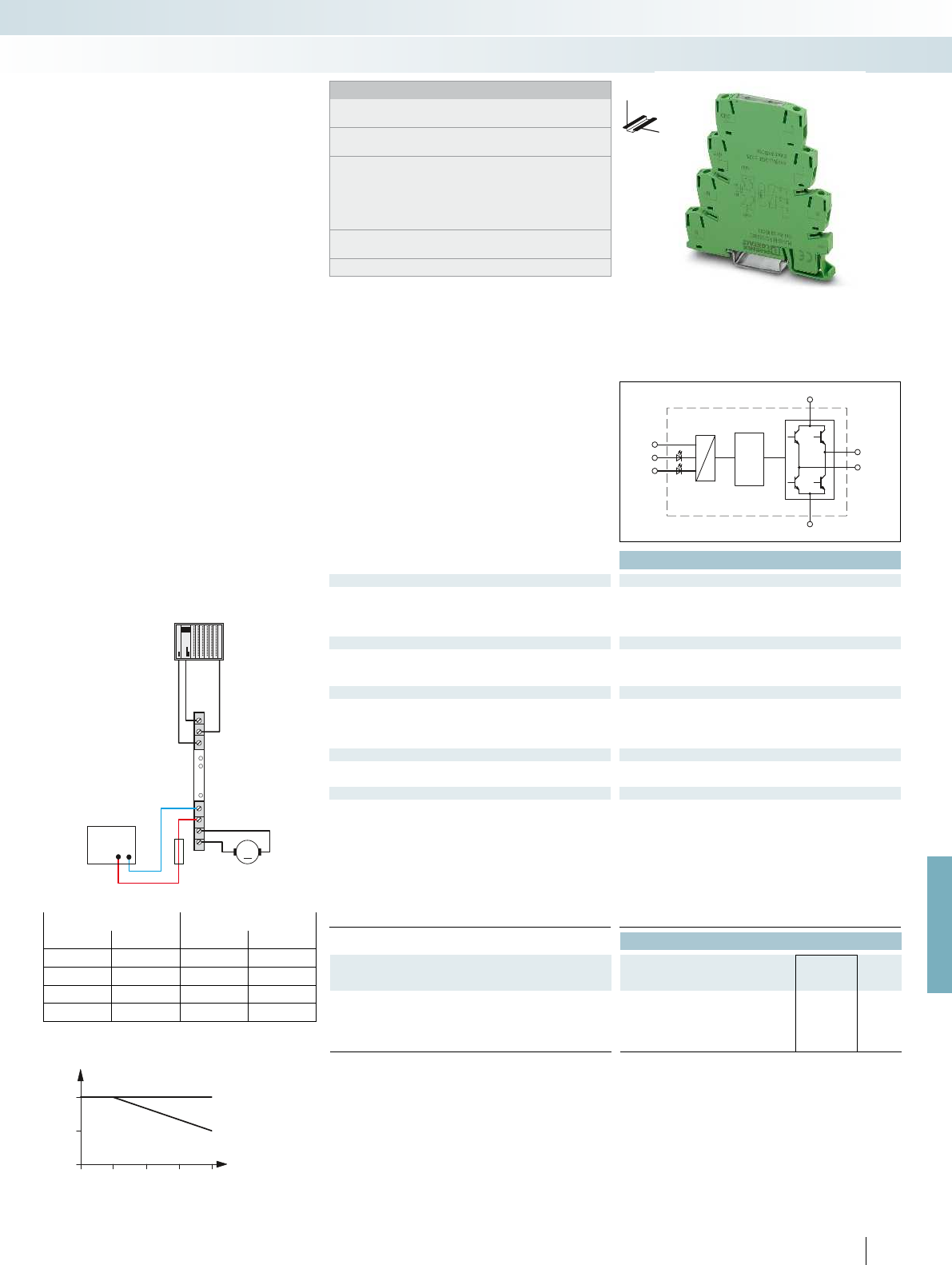
M+
U
V
GND
T
R
LM-
R
T
L
L
R
U
GND
24V
M+
M-
V
CC
+- M
30
20
1
2
1,5
40 50 60
1
2
1
2
For further information and full technical data, visit phoenixcontact.net/products
Technical data
Input data
Control voltage U
ST
right/left 24 V DC ±20 %
Control input current I
ST
right/left approx. 3 mA
Input protection: Yellow LED, protection against polarity reversal, surge protection
PWM option
Max. clock frequency of the PWM at the control inputs 1000 Hz
Pulse width repetition rate of the PWM 0 % ... 100 %
Output data
Supply voltage range U
V
10 V DC ... 30 V DC
Quiescent current 10 mA
Output protection Green LED, protection against polarity reversal, surge protection
Motor switching output
Continuous current I
A
max. 2 A (see derating curve)
Current limitation at short-circuits 15 A (during braking)
General data
Rated insulation voltage 50 V DC
Rated surge voltage / insulation 0.5 kV / basic insulation
Ambient temperature (operation) -25 °C ... 60 °C
Standards/regulations IEC 60664, EN 50178, IEC 62103
Pollution degree / Surge voltage category 2 / II
Mounting position Vertical (horizontal DIN rail)
Mounting Can be aligned without spacing
Connection data solid / stranded / AWG 0.14 - 2.5 mm² / 0.14 - 2.5 mm² / 26 - 14
Dimensions W / H / D 6.2 mm / 80 mm / 86 mm
EMC note Class A product, see page 625
Ordering data
Description Type Order No. Pcs. /
Pkt.
Electronic reversing load relay, for driving DC motors, with light
indicator and protection circuit
With screw connection PLC-SC-ELR W1/ 2-24DC 2980539 1
With spring-cage connection PLC-SP-ELR W1/ 2-24DC 2980555 1
447
PHOENIX CONTACT
Notes:
Type of housing:
Polyester PBT non-reinforced, color: green.
Marking systems and mounting material
See Catalog 5
Separating plate PLC-ATP is to be used in the following cases:
always at the start and end of a PLC terminal strip, for voltages
greater than 250 V (L1, L2, L3) between the same terminal points
of neighboring modules (potential bridging then takes place with
FBST 8-PLC... or FBST 500...) and with safe isolation between
neighboring modules.
For the protection of input and output, inductive loads must be
dampened with an effective protection circuit.
PWM = Pulse Width Modulation
DW
H
PLC series
Electronic reversing load relay for
DC motors
Relay modules
Highly compact relay modules - PLC-INTERFACE
With overload and short-circuit-proof output
Application example for PLC-S...ELR W 1/2-24DC
Status table
Input Output
Right Left M + M –
0 0 High resistance High resistance
1 0 +24 V GND
0 1 GND +24 V
1 1 GND GND
Derating curve for PLC-S...ELR W 1/2-24DC
Aligned without spacing
Aligned with > 20 mm spacing
Load current [A]
Ambient temperature [°C]
The PLC-S...-ELR W 1/2-24DC electronic
reversing load relays are used to switch
mechanically commutated DC motors up to
24 V/2 A.
– Wear-free reversing
– Braking by controlling both inputs
– Short-circuit and surge and overload-
proof output
– Integrated locking circuit and load wiring
– Screw-type, spring-cage, and push-in
technology
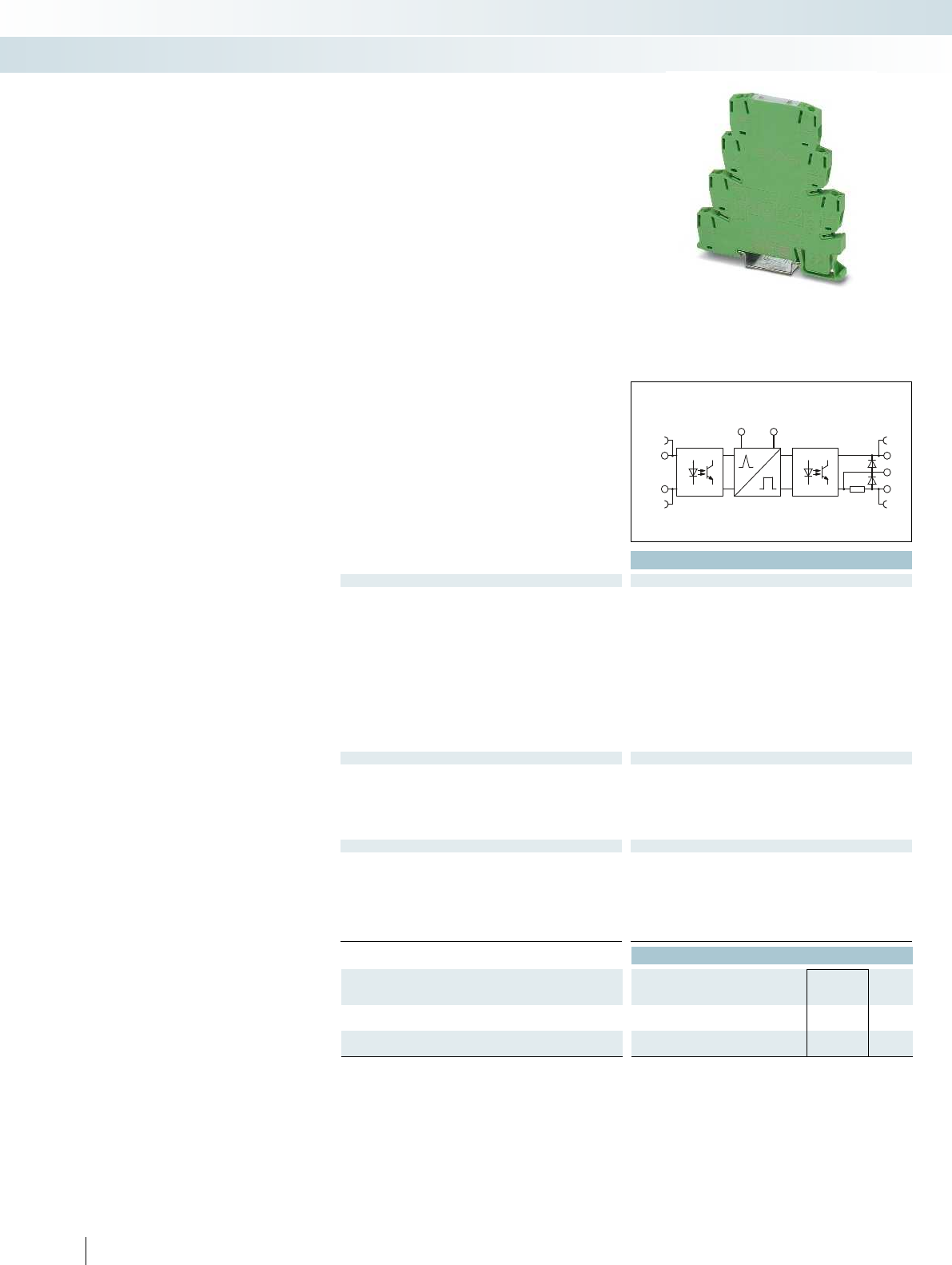
GNDU
S
A1+
A2- 0
+
A
Technical data
Input data
Rated control supply voltage U
S
24 V DC
Rated control supply voltage range with reference to U
S
0.8 ... 1.2
Rated control supply current I
S
- Input low, output low 13 mA
- Input high, output high 19 mA
Rated actuating voltage U
C
24 V DC
Rated actuating current I
C
3 mA
Switching threshold “0” signal in reference to U
C
< 0.4
Switching threshold “1” signal in reference to U
C
> 0.8
Status indication Yellow LED
Operating voltage display Green LED
Input circuit Protection against polarity reversal, surge protection
Output data
Output voltage range U
E
3 V DC ... 48 V DC
Limiting continuous current 100 mA
Voltage drop at max. limiting continuous current < 1 V DC
Output circuit 3-conductor, ground-referenced
Output protection Protection against polarity reversal, surge protection, freewheeling
General data
Rated insulation voltage 50 V DC
Rated surge voltage 0.5 kV
Ambient temperature (operation) -25 °C ... 60 °C
Standards/regulations DIN EN 50178
Connection data solid / stranded / AWG 0.14 - 2.5 mm² / 0.14 - 2.5 mm² / 26 - 14
Dimensions W / H / D 6.2 mm / 80 mm / 86 mm
EMC note Class A product, see page 625
Ordering data
Description Type Order No. Pcs. /
Pkt.
PLC-INTERFACE, with screw connection
PLC-OSC-LPE-24DC/48DC/100 2903171 1
PLC-INTERFACE, with push-in connection
PLC-OPT-LPE-24DC/48DC/100 2903173 1
448
PHOENIX CONTACT
A solid-state relay for acquiring and
extending short pulses.
– Pulse detection can be set
from > 0.1 ms or > 2 ms
– Status display
– Delay times of 10 to 2550, can be set via
DIP switches
– Bridging options
– Can be retriggered
– Screw and push-in connection technology
PLC-INTERFACE
Pulse expansion module
Relay modules
Highly compact relay modules - PLC-INTERFACE
With DC voltage output
Max. 100 mA
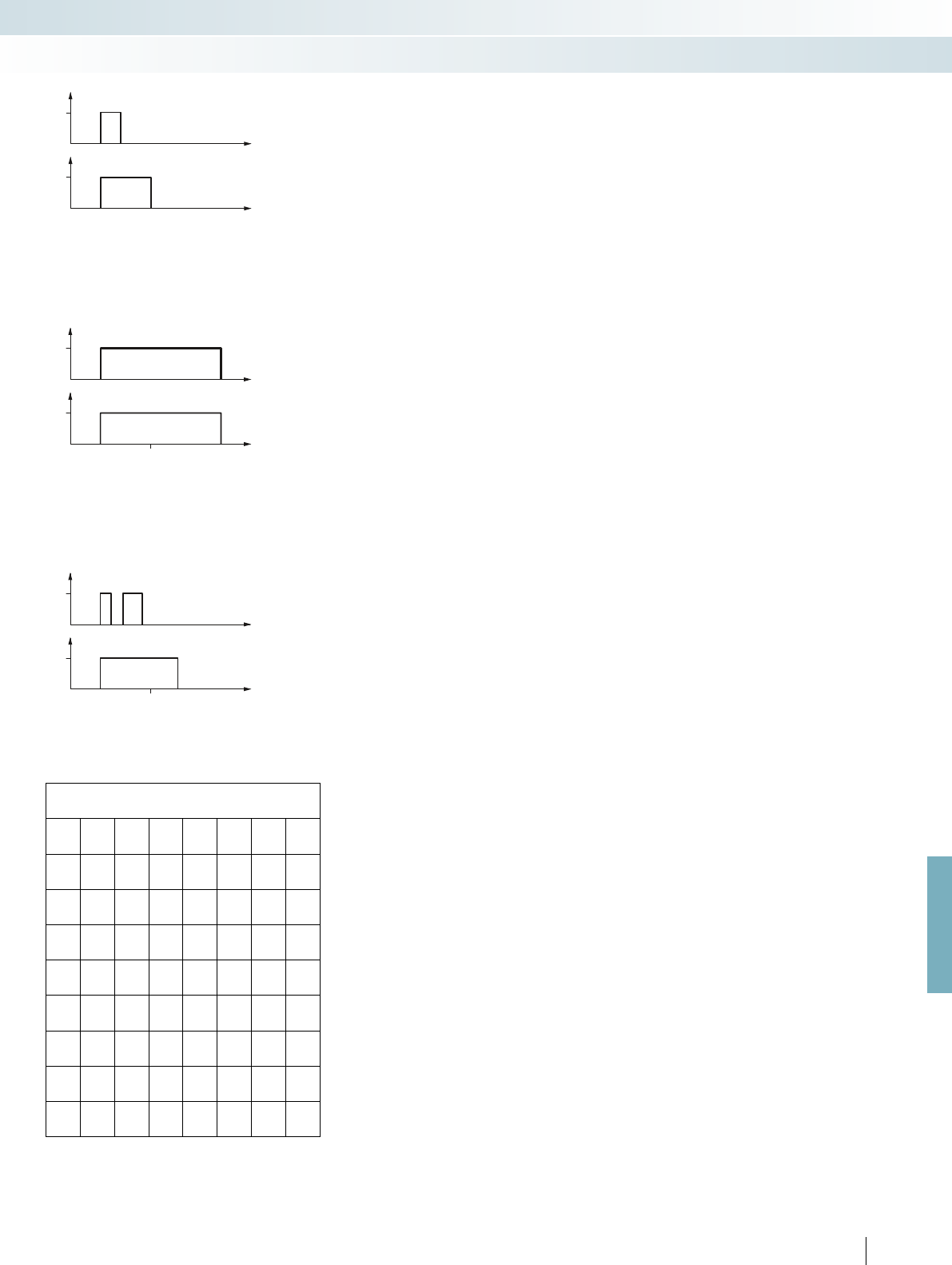
U
C
t
0
t
IN
t
24V
U
E
t
0
t
24V
t
DIP/OUT
U
C
t
0
t
IN
t
24V
U
E
t
0
t
24V
t
DIP
t
OUT
U
C
t
0
t
24V
t
IN
t
0
t
IN
U
E
t
0
t
24V
t
DIP
t
OUT
For further information and full technical data, visit phoenixcontact.net/products
449PHOENIX CONTACT
Input pulse t1 < set output pulse t3
(no restart when triggered again)
Input pulse t1 ≥ set output pulse t3,
then input pulse t1 = output pulse t2
(no restart when triggered again)
Input pulse t1 < set output pulse t3
(restart when triggered again)
DIP
S1 S2 S3 S4 S5 S6 S7 S8
10 -------
-20 - - - - - -
- - 40 -----
---80 - - - -
- - - - 160 - - -
-----320 - -
------640 -
-------1280
Relay modules
Highly compact relay modules - PLC-INTERFACE
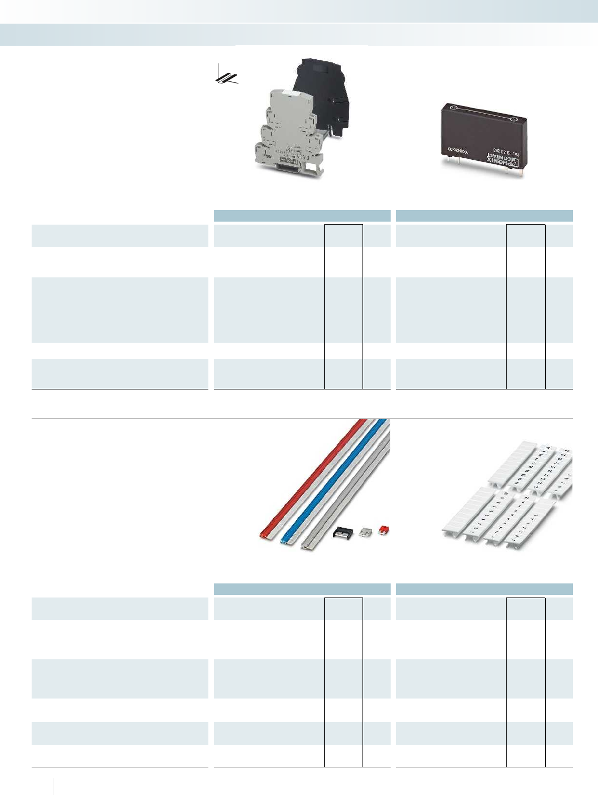
Ordering data Ordering data
Description Color Type Order No. Pcs. /
Pkt. Type Order No. Pcs. /
Pkt.
Power terminal, for supply of up to four potentials, with the same
shape as PLC standard series, max. 32 A/250 V AC
gray PLC-ESK GY 2966508 5
Separating plate, thickness 2 mm, required at the start and end of
a PLC terminal strip. It also serves in visual separation of groups,
safe isolation of different voltages of neighboring PLC interfaces as
per DIN EN 50178/VDE0160, separation of neighboring bridges of
different potentials and separation of PLC interfaces at voltages
>250 V
black PLC-ATP BK 2966841 25
Screwdriver
Blade: 0.6x3.5x100mm, length: 181mm SZF 1-0,6X3,5 1204517 10
Passive feed-through bridge, can be plugged in instead of relay
or solid-state relay, bridges terminal points A1 and 14
black PLC-BP A1-14 2980283 10
DW
H
The PLC-ESK power terminal helps in
supplying the bridge potentials, the
PLC-ATP partition plate helps in optical
and safe disconnection of the adjacent PLC
modules. The PLC-BP (A1-14) passive
feed-through bridge is used instead of a
relay and connects the A1 and 14 terminal
points.
PLC accessories
Relay modules
Highly compact relay modules - PLC-INTERFACE
Ordering data Ordering data
Description Color Type Order No. Pcs. /
Pkt. Type Order No. Pcs. /
Pkt.
Continuous bridge, 500 mm long, isolated, can be cut to length,
for potential distribution
Nominal current: 32 A red FBST 500-PLC RD 2966786 20
blue FBST 500-PLC BU 2966692 20
gray FBST 500-PLC GY 2966838 20
Jumper, 2-pos., 6 mm long, for potential distribution
Nominal current: 6Ared FBST 6-PLC RD 2966236 50
blue FBST 6-PLC BU 2966812 50
gray FBST 6-PLC GY 2966825 50
Jumper, 2-pos., 8 mm long, for potential distribution with a partition
plate
Nominal current: 6A gray FBST 8-PLC GY 2967688 50
Jumper, 2-pos., 14 mm long, insulated, for potential distribution
Nominal current: 10 A black FBST 14-PLC BK 2967691 50
Zack marker strip, printed horizontally, 10-section, with
consecutive numbers, e.g., 1-10, 11-20, etc. up to 91-100
ZB 6,LGS:FORTL.ZAHLEN 1051016 10
450
PHOENIX CONTACT
The colored isolated FBST jumpers save
up to 70% wiring time for PLC-INTERFACE.
The 500 mm long FBST 500-PLC
“continuous bridges” are especially
effective. The FBST 6 2-pos. individual
jumpers are particularly suitable for bridging
a smaller number of PLC modules.
PLC accessories
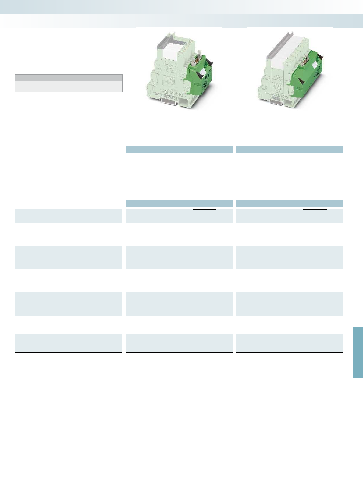
For further information and full technical data, visit phoenixcontact.net/products
Technical data Technical data
Max. perm. operating voltage 30 V DC 30 V DC
Max. perm. current (per branch) 1 A (per signal path) 1 A (per signal path)
Max total current (voltage supply) 3 A 3 A
Ambient temperature (operation) -40 °C ... 70 °C -40 °C ... 70 °C
Standards/regulations IEC 60664, DIN EN 50178, IEC 62103 IEC 60664, DIN EN 50178, IEC 62103
Connection method Power supply Screw connection Screw connection
Signal level IDC/FLK pin strip (2.54 mm) IDC/FLK pin strip (2.54 mm)
Connection data solid / stranded / AWG 0.2 ... 4 mm² / 0.2 ... 2.5 mm² / 24 - 12 0.2 ... 4 mm² / 0.2 ... 2.5 mm² / 24 - 12
Dimensions H / D 100 mm / 94 mm 100 mm / 94 mm
Ordering data Ordering data
Description No. of
pos.
Module width
WType Order No. Pcs. /
Pkt. Type Order No. Pcs. /
Pkt.
V8 adapter, for 8 PLC interfaces (6.2 mm), with FLK connection,
for PLC system cabling, positive switching
OUTPUT 14 49.6 mm PLC-V8/FLK14/OUT 2295554 1
INPUT 14 49.6 mm PLC-V8/FLK14/IN 2296553 1
V8 adapter, for 8 PLC interfaces (6.2 mm), with FLK connection,
for PLC system cabling, negative switching
OUTPUT 14 49.6 mm PLC-V8/FLK14/OUT/M 2304102 1
INPUT 14 49.6 mm PLC-V8/FLK14/IN/M 2304115 1
V8 output adapter, for 8 PLC interfaces (6.2 mm), with
15-pos. D-SUB connection
Pin strip 15 49.6 mm PLC-V8/D15S/OUT 2296058 1
Socket strip 15 49.6 mm PLC-V8/D15B/OUT 2296061 1
V8 input adapter, for 8 PLC interfaces (6.2 mm), with
15-pos. D-SUB connection
Pin strip 15 49.6 mm PLC-V8/D15S/IN 2296074 1
Socket strip 15 49.6 mm PLC-V8/D15B/IN 2296087 1
V8 adapter, for 8 PLC interfaces (14 mm), with FLK connection, for
PLC system cabling, positive switching
14 112.3 mm PLC-V8L/FLK14/OUT 2299660 1
V8 adapter, for 8 PLC interfaces (14 mm), with FLK connection, for
PLC system cabling, negative switching
14 112.3 mm PLC-V8L/FLK14/OUT/M 2304306 1
451PHOENIX CONTACT
Relay modules
Highly compact relay modules - PLC-INTERFACE
VARIOFACE adapter
for 6.2 mm PLC RELAY
VARIOFACE adapter
for 14 mm PLC RELAY
PLC-V8/...
are the VARIOFACE adapters
which connect the narrow PLC-INTERFACE
modules to the VARIOFACE system cabling:
Notes:
For cross-reference list with matching PLC-INTERFACE modules,
see page 572
Adapters for PLC-INTERFACE

452
PHOENIX CONTACT
Relay modules
Programmable logic relay system - PLC logic
Extremely compact control
The PLC logic programmable logic relay
system is the extremely compact way to
carry out small automation tasks easily and
flexibly. It consists of the PLC-V8C logic
modules, the PLC-INTERFACE relay
system, and the LOGIC+ software. The
logic modules are simply plugged into a row
of eight PLC-INTERFACE terminal blocks
and combine the logic and interface level in
one unit. Depending on the switching
requirements, plug-in electromechanical
and solid-state relays can be combined in
order to flexibly switch and control the I/O
signals.
PLC logic processes digital and analog
input signals as well as logic functions and
timer modules - and replaces conventional
switching and control devices. Up to 16 I/O
signals can be processed using the stand-
alone logic modules - that's with an overall
width of just 50 mm. If more I/O signals are
required, a maximum of 48 I/O signals can
be linked using the basic and extension
modules.
Switching and controlling with plug-in
relays
– PLC logic brings together the standard
combination of logic module and separate
plug-in relay and eliminates wiring effort
and additional switching elements
– Convenient connections with screw or
push-in connection technology, which
also accommodate return conductors,
eliminate the need for separate potential
terminal blocks
– Each relay channel can be freely configured
as an input or output. PLC logic therefore
perfectly adapts to fit the application at
hand
Intuitive programming
Programming is quick and easy with the
intuitive LOGIC+ programming software.
Ladder (LD) and function block diagrams
(FBD) can be created by selecting the
relevant functions and their connection
using drag & drop. The graphical
representation of PLC logic in the hardware
editor supports intuitive operation. The
programs created can be simulated offline
on the PC and tested online during
operation. Basic functions, such as AND,
OR, NOT, etc. are complemented by special
functions, such as counters, seven-day
timers, timer modules, and mathematical
functions, to name a few.
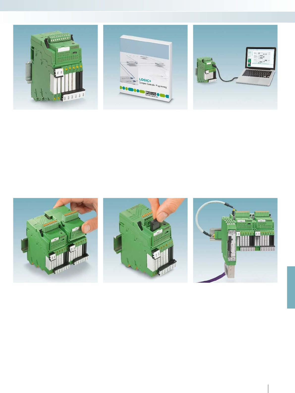
For further information and full technical data, visit phoenixcontact.net/products
453PHOENIX CONTACT
Relay modules
Programmable logic relay system - PLC logic
Logic module with plug-in relays
PLC logic combines a logic module and
plug-in relay and eliminates wiring effort and
additional switching elements. Each relay
channel can be flexibly equipped with an
electromechanical or a solid-state relay. PLC
logic processes 16 I/O signals with just one
logic module and boasts an extremely
compact overall width of just 50 mm.
Intuitive programming with LOGIC+
– Function block diagram or ladder diagram
– Numerous integrated function blocks
– Specific function blocks are available to
download
– Hardware view in the program
– Can be downloaded free of charge
Standard programming cable
PLC logic is connected to a PC via a
standard micro USB cable. The drivers for
PLC logic can be downloaded at
phoenixcontact.com.
Easily connect extension modules
The basic module and the extension
module are connected via integrated
connectors - no tools required. A maximum
of two extension modules can be
connected to a basic module. This means
that PLC logic can work with up to 48 I/Os.
Saving and copying data
PLC logic programs are saved by the
memory module or can be easily copied to
other devices.
If settings such as time or date are
required on the new device, these values
can be configured via the integrated web
server. The new device does not need
access to the LOGIC+ software for this.
Integration into common bus systems
PLC logic is integrated into various
networks via optional adaptable fieldbus
gateways. This enables bidirectional
communication with a higher-level
controller for remote control as well as
diagnostics and visualization.
Gateways are available for transmitting
data via PROFIBUS DP, RS-232, RS-485,
Modbus/TCP, DeviceNet™, CANopen
®
,
PROFINET, and EtherNet/IP™.
Your web code: #0139
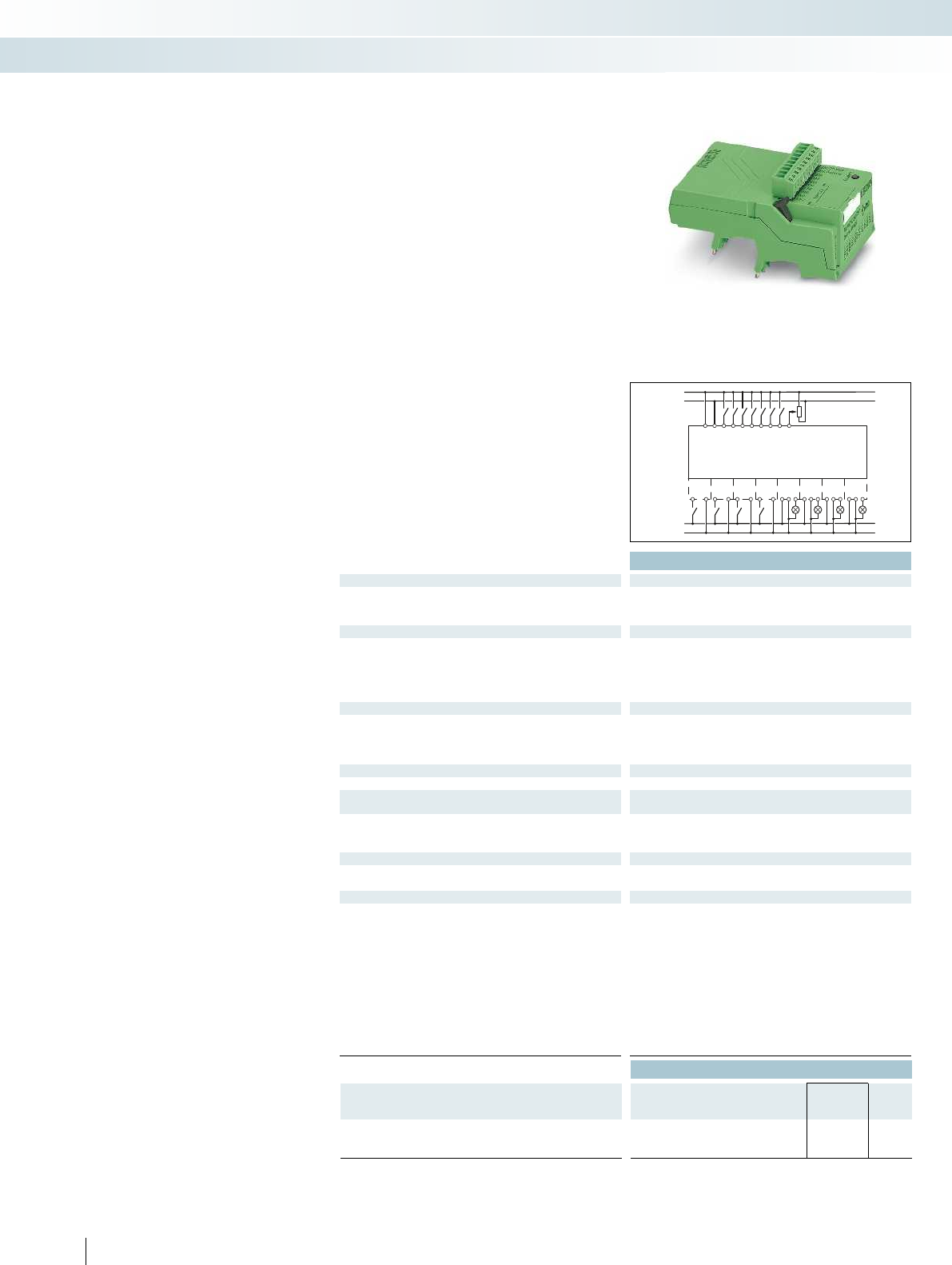
A1
A1
A1
A1
13
13
13
13
A2
A2
A2
A2
14
14
14
BB
BB
BB
BB
14
IO 8
IO 9
IO 10
IO 11
IO 12
IO 13
IO 14
IO 15
PLC-V8C/.../SAM
24 V
0 V
IN 0
IN 1
IN 2
IN 3
IN 4
IN 5
IN 6
IN 7
24 V
0 V
24 V
0 V
Technical data
Supply
Supply voltage 24 V DC
Supply voltage range 19.2 V DC ... 26.4 V DC 19.2 V DC ... 26.4 V DC 19.2 V DC ... 26.4 V DC
Max. input current at U
N
120 mA
Input data (digital)
Number of inputs 8 (2 configurable as analog) 8 (2 configurable as analog) 8 (2 configurable as analog)
Input voltage 24 V DC
Description of the input EN 61131-2, type 3
Input current 0-signal < 1 mA
Input current 1-signal typ. 2.5 mA
Input data (analog)
Number of inputs 2 (IN6 and IN7 are configurable as analog) 2 (IN6 and IN7 are configurable as analog) 2 (IN6 and IN7 are configur
Input voltage range 0 V ... 10 V
Input resistance > 3.5 k
Input data (PLC-INTERFACE)
Number of inputs 8
Output data (for controlling PLC-INTERFACE)
Number of outputs 8
Nominal voltage 24 V DC
Nominal current 9 mA
Realtime clock (basic module only)
Buffer time (capacitor) 24 h (capacitor)
Realtime clock accuracy ±2 s/d
General data
Ambient temperature (operation) -20 °C ... 45 °C
Ambient temperature (storage/transport) -20 °C ... 70 °C
Permissible humidity (operation) 95 %
Clearance and creepage distances between the power circuits DIN EN 50178
Rated insulation voltage 50 V
Rated surge voltage 0.8 kV
Insulation Basic insulation
Mounting type Can be plugged onto 8 x PLC-INTERFACE Can be plugged onto 8 x PLC-INTERFACE Can be plugged onto 8 x PLC-INTERFACE
Degree of protection IP20
Screw connection solid / stranded / AWG 0.14 - 1.5 mm² / 0.14 - 1.5 mm² / 28 - 16 0.14 - 1.5 mm² / 0.14 - 1.5 mm² / 28 - 16 0.14 - 1
Push-in connection solid / stranded / AWG 0.14 - 1.5 mm² / 0.14 - 1.5 mm² / 26 - 16 0.14 - 1.5 mm² / 0.14 - 1.5 mm² / 26 - 16 0.14 -
Ordering data
Description Type Order No. Pcs. /
Pkt.
PLC-V8C plug-in logic modules
With screw connection PLC-V8C/SC-24DC/SAM 2905082 1
With push-in connection PLC-V8C/PT-24DC/SAM 2905136 1
454
PHOENIX CONTACT
Logic modules
PLC-V8C are the plug-in logic modules
which form the PLC logic relay system in
conjunction with the narrow 6.2 mm
PLC-INTERFACE terminal blocks. Eight
freely-selectable PLC-INTERFACE terminal
blocks must be separately ordered for each
logic module. You can find an overview of
matching PLC-INTERFACE terminal blocks
on page 458.
All logic modules feature these
properties:
– 8 integrated digital inputs (of which two
inputs are configurable as analog inputs),
connection via connector with screw or
push-in connection technology
– A further 8 channels can be configured
with matching PLC-INTERFACE terminal
blocks as digital inputs or outputs
– Programming with the LOGIC+ software
PLC-V8C.../SAM
– Stand-alone logic module with 16 I/Os,
not extendable
– Connection to PC via micro USB socket
– Integrated realtime clock (RTC)
– Accommodates external IFS-
CONFSTICK memory module
PLC-V8C.../BM
– Basic logic module with 16 I/Os, can be
extended with a maximum of two
extension modules (PLC-V8C.../EM) to
48 I/Os
– Connection to PC via micro USB socket
– Integrated realtime clock (RTC)
– Accommodates external IFS-
CONFSTICK memory module
– Optional connection to IFS gateways
PLC-V8C.../EM
– Extension logic module with 16 I/Os, for
extending the basic module
Relay modules
Programmable logic relay system - PLC logic
Stand-alone module Basic module Extension module

A1
A1
A1
A1
13
13
13
13
A2
A2
A2
A2
14
14
14
BB
BB
BB
BB
14
IO8
IO9
IO 10
IO 11
IO 12
IO 13
IO 14
IO 15
PLC-V8C/.../BM
24 V
0 V
IN0
IN 1
IN 2
IN 3
IN 4
IN 5
IN 6
IN7
24 V
0V
24 V
0V
A1
A1
A1
A1
13
13
13
13
A2
A2
A2
A2
14
14
14
BB
BB
BB
BB
14
IO8
IO9
IO 10
IO 11
IO 12
IO 13
IO 14
IO 15
PLC-V8C/.../EM
24 V
0 V
IN0
IN 1
IN 2
IN 3
IN 4
IN 5
IN 6
IN7
24 V
0V
24 V
0V
For further information and full technical data, visit phoenixcontact.net/products
Technical data Technical data
24 V DC 24 V DC
Supply voltage range 19.2 V DC ... 26.4 V DC 19.2 V DC ... 26.4 V DC 19.2 V DC ... 26.4 V DC
120 mA 65 mA
Number of inputs 8 (2 configurable as analog) 8 (2 configurable as analog) 8 (2 configurable as analog)
24 V DC 24 V DC
EN 61131-2, type 3 EN 61131-2, type 3
< 1 mA < 1 mA
typ. 2.5 mA typ. 2.5 mA
Number of inputs 2 (IN6 and IN7 are configurable as analog) 2 (IN6 and IN7 are configurable as analog) 2 (IN6 and IN7 are configurable as analog)
0 V ... 10 V 0 V ... 10 V
> 3.5 k> 3.5 k
8 8
8 8
24 V DC 24 V DC
9 mA 9 mA
24 h (capacitor) -
±2 s/d -
-20 °C ... 45 °C -20 °C ... 45 °C
-20 °C ... 70 °C -20 °C ... 70 °C
95 % 95 %
DIN EN 50178 DIN EN 50178
50 V 50 V
0.8 kV 0.8 kV
Basic insulation Basic insulation
Mounting type Can be plugged onto 8 x PLC-INTERFACE Can be plugged onto 8 x PLC-INTERFACE Can be plugged onto 8 x PLC-INTERFACE
IP20 IP20
Screw connection solid / stranded / AWG 0.14 - 1.5 mm² / 0.14 - 1.5 mm² / 28 - 16 0.14 - 1.5 mm² / 0.14 - 1.5 mm² / 28 - 16 0.14 - 1.5 mm² / 0.14 - 1.5 mm² / 28 - 16
Push-in connection solid / stranded / AWG 0.14 - 1.5 mm² / 0.14 - 1.5 mm² / 26 - 16 0.14 - 1.5 mm² / 0.14 - 1.5 mm² / 26 - 16 0.14 - 1.5 mm² / 0.14 - 1.5 mm² / 26 - 16
Ordering data Ordering data
Type Order No. Pcs. /
Pkt. Type Order No. Pcs. /
Pkt.
PLC-V8C/SC-24DC/BM 2903094 1PLC-V8C/SC-24DC/EM 2903095 1
PLC-V8C/PT-24DC/BM 2905135 1PLC-V8C/PT-24DC/EM 2905137 1
455PHOENIX CONTACT
Contacting for
Extension module
Contacting for
Basic or
Extension module
Contacting for
Extension module
Relay modules
Programmable logic relay system - PLC logic
Stand-alone module Basic module Extension module

Technical data Technical data
General data
EMC note Class A product, see page 625
Ordering data Ordering data
Description Color Type Order No. Pcs. /
Pkt. Type Order No. Pcs. /
Pkt.
Programming cable
CAB-USB A/MICRO USB B/2,0M 2701626 1
Multifunctional memory module for the INTERFACE system
- Flat design IFS-CONFSTICK 2986122 1
– The programming cable (MICRO USB B
to USB A) is used to connect PLC logic to
a PC, length: 2 m
– PLC logic programs are saved by the
memory module or can be easily copied
to other devices
Accessories
Programming cable and memory
module
Relay modules
Programmable logic relay system - PLC logic
Ordering data
Description Color Type Order No. Pcs. /
Pkt.
PLC logic starter kit 1, 8 integrated inputs (24 V DC) and
8 outputs via PLC-INTERFACE
(switching capacity 250 V AC/DC, max. 6 A)
PLC-LOGIC-STARTERKIT1 2905504 1
456
PHOENIX CONTACT
The PLC logic starter kit contains all the
components needed to get started quickly
and easily with PLC logic with push-in
connection technology and 8 inputs and
8 outputs.
– PLC-V8C-PT/24DC/BM plug-in logic
module
– PLC-RPT-24DC/1/ACT eight relay output
terminal blocks
– Micro USB programming cable
– LOGIC+ software
– “PLC logic quick start guide” poster
Accessories
PLC logic starter kit
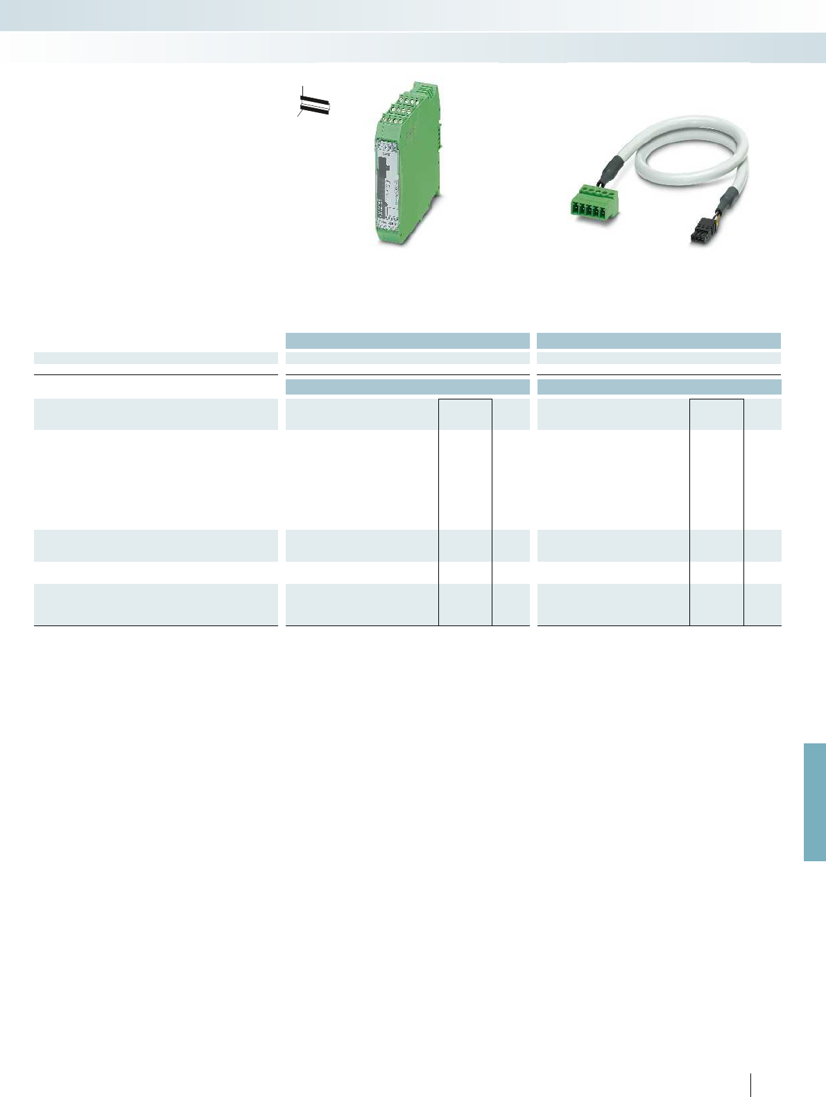
For further information and full technical data, visit phoenixcontact.net/products
Technical data Technical data
General data
EMC note Class A product, see page 625
Ordering data Ordering data
Description Color Type Order No. Pcs. /
Pkt. Type Order No. Pcs. /
Pkt.
IFS gateway for
PROFIBUS DP green EM-PB-GATEWAY-IFS 2297620 1
RS-232 green EM-RS232-GATEWAY-IFS 2901526 1
RS-485 green EM-RS485-GATEWAY-IFS 2901527 1
Modbus/TCP green EM-MODBUS-GATEWAY-IFS 2901528 1
DeviceNet™ green EM-DNET-GATEWAY-IFS 2901529 1
CANopen® green EM-CAN-GATEWAY-IFS 2901504 1
PROFINET green EM-PNET-GATEWAY-IFS 2904472 1
Ethernet/IP™ green EM-ETH-GATEWAY-IFS 2901988 1
Programming adapter for configuring modules with
S-PORT interface
Cable length: 3 m IFS-USB-DATACABLE 2320500 1
DIN rail connector
green ME 22,5 TBUS 1,5/ 5-ST-3,81 GN 2707437 50
Connecting cable for connecting PLC logic with the
ME 22,5 TBUS DIN rail connector, cable length: 0.3 m
PLC-V8C/CAB/TBUS/0,3M 2905263 1
457PHOENIX CONTACT
Relay modules
Programmable logic relay system - PLC logic
The gateways are connected to the
PLC-V8C.../BM PLC logic basic modules via
the ME 22,5 TBUS... DIN rail connector and
the PLC-V8C/CAB... connecting cable.
The gateways are connected to a PC and
configured via the integrated S-PORT
interface and the IFS-USB-DATACABLE.
H
W
D
Accessories
IFS gateways

458
PHOENIX CONTACT
Selection table for PLC-INTERFACE
Push-in connection Screw connection
Relay output Type Order No. Type Order No.
1 PDT, output data 6 A, 250 V AC/DC PLC-RPT-24DC/21
2900299
PLC-RSC-24DC/21
2966171
1 PDT, output data 50 mA, 36 V DC, gold contact PLC-RPT-24DC/21AU
2900306
PLC-RSC-24DC/21AU
2966265
1 N/O contact, output data 6 A, 250 V AC/DC, actuator type PLC-RPT-24DC/1/ACT
2900312
PLC-RSC-24DC/1/ACT
2966210
1 N/O contact with switch, output data 6 A, 250 V AC/DC PLC-RPT-24UC/1/S/H
2900328
PLC-RSC-24UC/1/S/H
2982236
Solid-state relay output
Output data 100 mA, 3 V DC - 48 V DC PLC-OPT-24DC/48DC/100
2900352
PLC-OSC-24DC/48DC/100
2966728
Output data 3 A, 3 V DC - 33 V DC PLC-OPT-24DC/24DC/2
2900364
PLC-OSC-24DC/24DC/2
2966634
Output data 750 mA, 24 V AC - 253 V AC PLC-OPT-24DC/230AC/1
2900369
PLC-OSC-24DC/230AC/1
2967840
Output data 3 A, 3 V DC - 33 V DC, actuator type PLC-OPT-24DC/24DC/2/ACT
2900376
PLC-OSC-24DC/24DC/2/ACT
2966676
Output data 750 mA, 24 V AC - 253 V AC, actuator type PLC-OSC-24DC/230AC/1/ACT
2967947
Output data 1 A, 12 V DC - 300 V DC PLC-OPT-24DC/300DC/1
2900383
PLC-OSC-24DC/300DC/1
2980678
Output data 10 A, 3 V DC - 33 V DC PLC-OPT-24DC/24 DC/10/R
2900398
PLC-OSC-24DC/24DC/10/R
2982702
Output data 500 mA, 3 V DC - 48 V DC, electronic PDT PLC-OPT-24DC/48DC/500/W
2900378
PLC-OSC-24DC/48DC/500/W
2980636
Output data, TTL, 50 mA, 5 V DC PLC-OPT-24DC/TTL
2900363
PLC-OSC-24DC/TTL
2982728
Relay input
Input voltage 24 V DC PLC-RPT-24DC/1AU/SEN
2900313
PLC-RSC-24DC/1AU/SEN
2966317
Input voltage 120 V AC/DC PLC-RPT-120UC/1AU/SEN
2900314
PLC-RSC-120UC/1AU/SEN
2966320
Input voltage 230 V AC/DC PLC-RPT-230UC/1AU/SEN
2900315
PLC-RSC-230UC/1AU/SEN
2966333
Input voltage 5 V DC (basic terminal block without relay) PLC-BSC- 5DC/ 1/SEN
2980267
Relay for 5 V DC basic terminal block REL-MR-4,5DC/21AU
2961370
Solid-state relay input
Input voltage 24 V DC PLC-OPT-24DC/48DC/100/V8C/SEN
2904693
PLC-OSC-24DC/48DC/100/V8C/SEN
2904690
Input voltage 120 V AC/DC PLC-OPT-120UC/48DC/100/V8C/SEN
2904694
PLC-OSC-120UC/48DC/100/V8C/SEN
2904691
Input voltage 230 V AC/DC PLC-OPT-230UC/48DC/100/V8C/SEN
2904695
PLC-OSC-230UC/48DC/100/V8C/SEN
2904692
Dummy or reserve
Basic terminal blocks output PLC-BPT-24DC/21
2900445
PLC-BSC-24DC/21
2966016
Basic terminal blocks input PLC-BPT-24DC/1/SEN
2900262
PLC-BSC-24DC/1/SEN
2966061
Relay modules
Programmable logic relay system - PLC logic
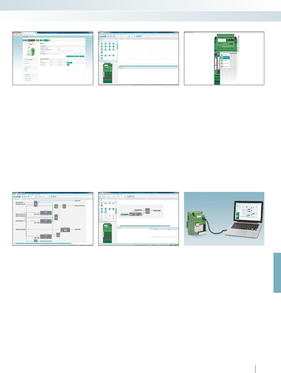
For further information and full technical data, visit phoenixcontact.net/products
459PHOENIX CONTACT
Relay modules
Programmable logic relay system - PLC logic
LOGIC+ programming software
Integrated web server
PLC logic basic settings are easily
configured via the integrated web server.
The LOGIC+ software does not need to be
installed in order to do so.
– Time and date
– Password and access control
– Firmware update
– Status indicators for inputs and outputs
– General device information
LOGIC+ user interface
– Clear separation in program editor,
toolbox, hardware view, and signaling
window
– All elements can be easily placed using
drag & drop
– Notes and errors are highlighted in color
in the program editor
Hardware configurator
– Each relay channel can be configured as an
input or output with an
electromechanical or a solid-state relay
– Clear assignment of the inputs and
outputs thanks to the graphical
representation of the hardware
connections
Function blocks
– Basic functions: AND, OR, NOT, XOR
– Mathematical functions: add, divide,
multiply, subtract, generate absolute value
– Positive and negative edge detection
– RS and SR flip-flops
– Switch-on and switch-off delay, pulse
encoder, pulse stretching, weekly clock
timer
– Up and down counter
– Analog and digital comparators
– Special functions, e.g., solar altitude
calculations are available for download
Simulation and online values
Offline simulation:
– Simulation of the created program
directly in LOGIC+
– Virtualization of the values in the program
editor, hardware view, and in the
observation window
Online values:
– Representation of the program running
on the hardware in LOGIC+ with online
values
– Overwriting of values from LOGIC+
Example programs
Numerous application examples make it
easy to get started with LOGIC+. These
include:
– Underground garage ventilation
– Conveyor belt
– Pumping plant
– Two-way control
– Tips for creating shift registers or surge
relays
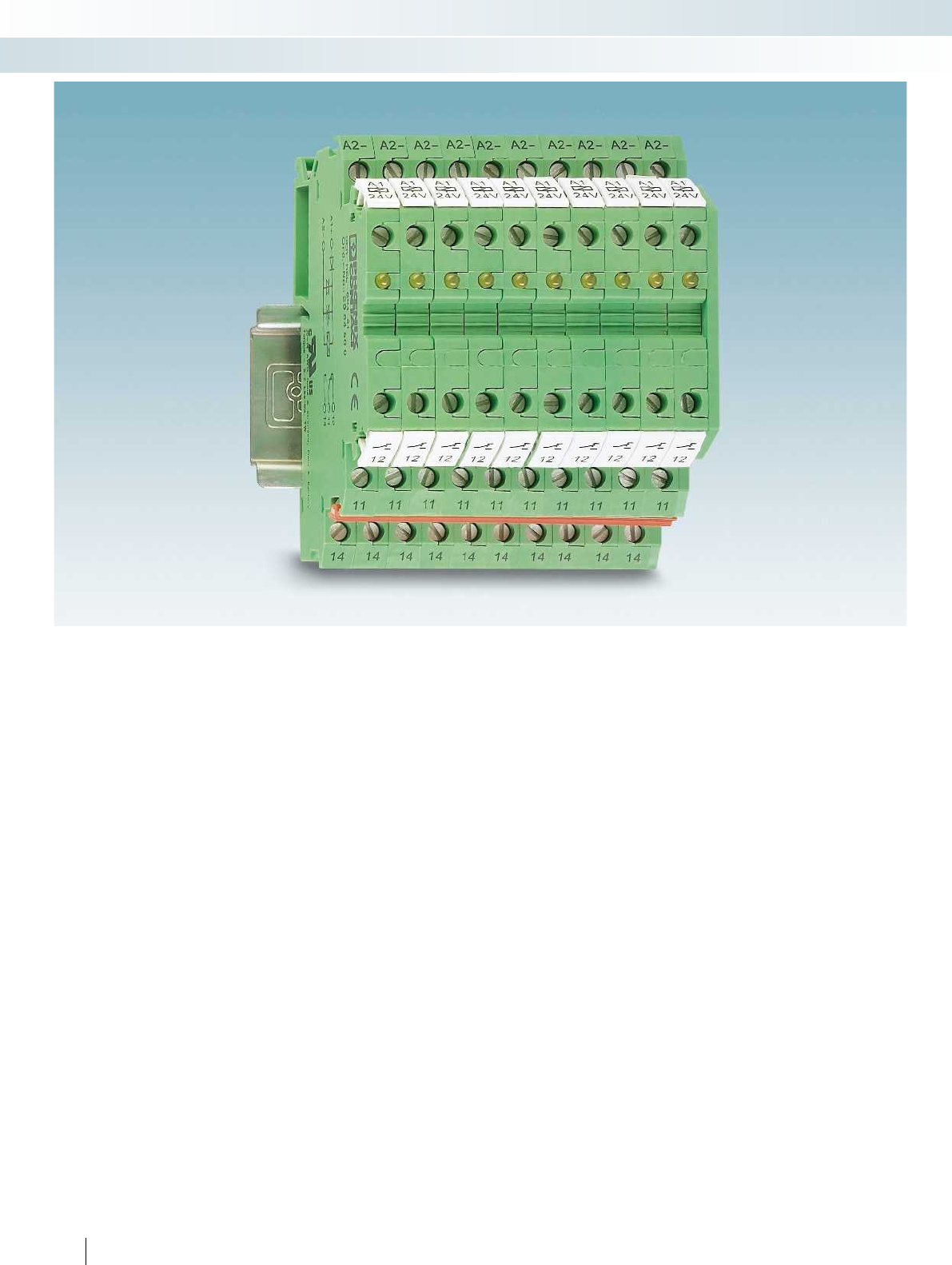
460
PHOENIX CONTACT
Relay modules
Relay modules in terminal block design - DEK series
The DEK interface terminal blocks from
Phoenix Contact provide complete
interface functions in modular terminal
block housing that is just 6.2 mm wide. In
conjunction with standard terminal block
accessories, these high capacity interfaces
have not only the design but also the high
level of user convenience of modular
terminal blocks.
The main common feature of all Phoenix
Contact interface terminal blocks is their
width of just 6.2 mm. This saves 60% space
in the control cabinet in comparison to
conventional 15 mm wide coupling relays
from modular systems.
The DEK range offers the best solution
for all industrial voltages both for signal
input and output.
High switching capacities are a matter
of course for the DEK-REL... relay terminal
block and the DEK-OV... solid-state relay
terminal block.
The DEK-OV... wear-free power solid-
state relay terminal block is used for
applications that require a greater switching
frequency in which electromechanical relays
reach the end of their service life in a short
time.
Integrated LEDs clearly indicate the
switching status of the electronic terminal
blocks and provide an excellent overview of
the coupling level and the system.
EB-DIK colored insertion bridges for the
supply and ground signals make it possible
to design the circuit simply and effectively.
Integrated protective circuits such as
freewheeling diodes, polarity reversal
protection diodes, and surge protection
elements protect the coupling modules and
ensure optimum availability of the system.
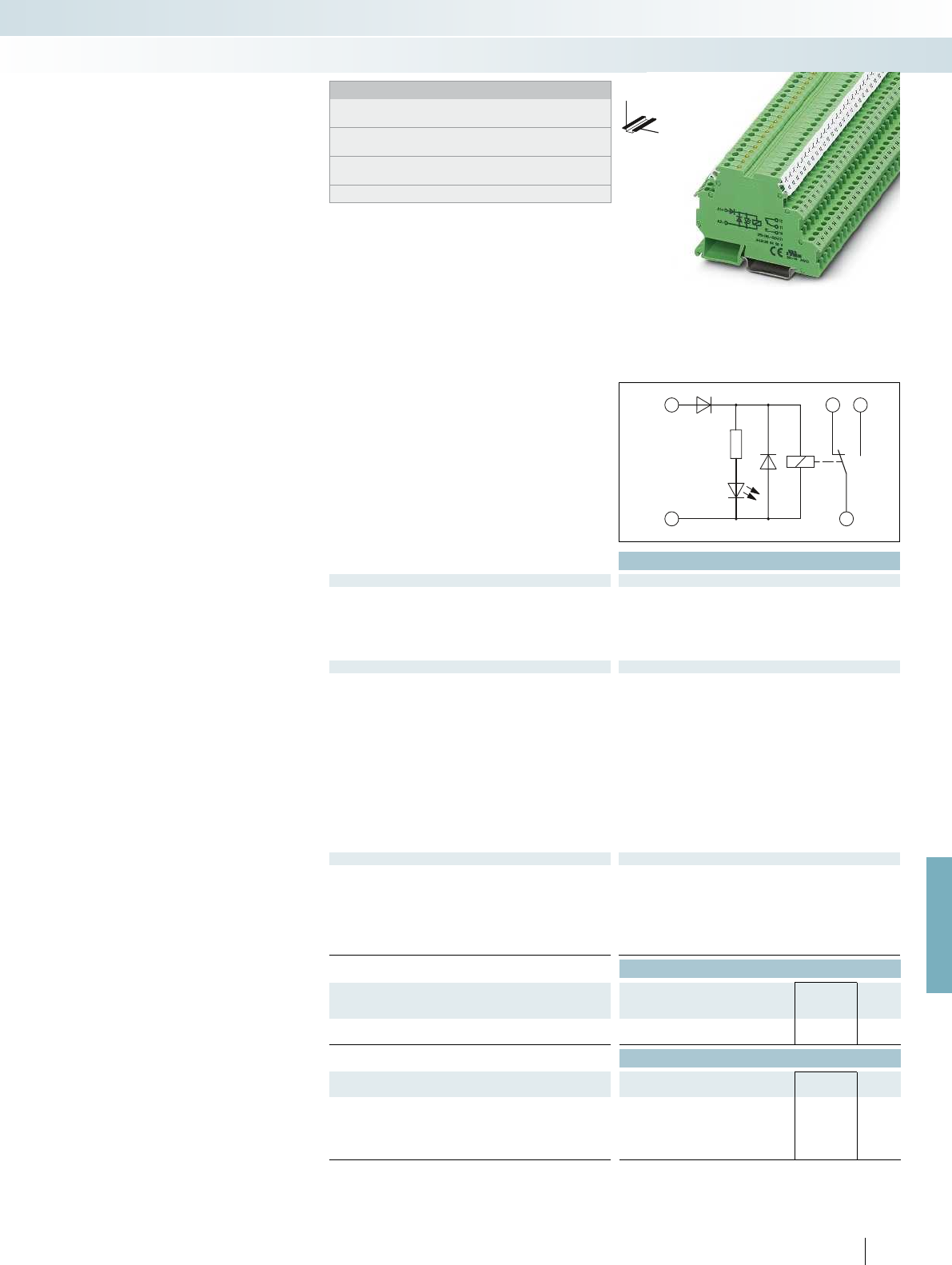
A1
+
A2
-
12 14
11
For further information and full technical data, visit phoenixcontact.net/products
Technical data
Input data ①
Permissible range (with reference to U
N
) 0.8 -
1.1
Typ. input current at U
N
[mA] 9
Response/release time at U
N
[ms] 8 / 5
Input protection:
Yellow LED, protection against polarity reversal, freewheeling diode
Output data
Contact type 1 PDT
Contact material AgSnO
Max. switching voltage 250 V AC/DC
Min. switching voltage 12 V AC/DC
Limiting continuous current 6 A
Max. inrush current 6 A
Min. switching current 10 mA
Max. interrupting rating, ohmic load
24 V DC 140 W
48 V DC 20 W
60 V DC 18 W
110 V DC 23 W
220 V DC 40 W
250 V AC 1500 VA
General data
Test voltage (winding/contact) 4 kV AC (50 Hz, 1 min.)
Ambient temperature (operation) -20 °C ... 50 °C
Mechanical service life Approx. 10
7
cycles
Standards/regulations IEC 60664, EN 50178, IEC 62103
Connection data solid / stranded / AWG 0.2 - 2.5 mm² / 0.2 - 2.5 mm² / 24 - 14
Dimensions W / H / D 6.2 mm / 80 mm / 56 mm
EMC note Class A product, see page 625
Ordering data
Description Input voltage
U
N
Type Order No. Pcs. /
Pkt.
Relay terminal block with power relay
①24 V DC DEK-REL-G24/21 2964500 10
Accessories
Cover
D-DEK 1,5 GN 2716949 10
Insertion bridge, for middle and lower
levels
No. of
pos.
Color
80 blue EB 80- DIK BU 26 A 2715940 1
80 red EB 80- DIK RD 26 A 2715953 1
80 white EB 80- DIK WH 26 A 2715788 1
461
PHOENIX CONTACT
Notes:
Type of housing:
Polyamide PA non-reinforced, color: green.
Marking systems and mounting material
See Catalog 5
For the protection of relay coils and contacts, inductive loads must
be dampened with an efficient protection circuit.
For other EB...DIK... insertion bridges refer to page 467
DW
H
The Phoenix relay terminal block with
PDT contact offers the following
advantages:
– Width of just 6.2 mm
– High switching capacity of 250 V AC / 6 A
– Less storage, since PDT, N/O or N/C
contacts can be wired
– Minimal wiring effort due to the use of
EB-DIK insertion bridges
– IP67 protected relay housing
– Cadmium-free relay contacts
– 4 kV electrical isolation of input and
output
– Safe isolation in acc. with DIN EN 50178
(VDE 0160)
– Light indicator for indicating the switching
status
DEK-REL-... relay terminal block
Relay modules
Relay modules in terminal block design - DEK series
For medium to large loads
1 PDT (21)
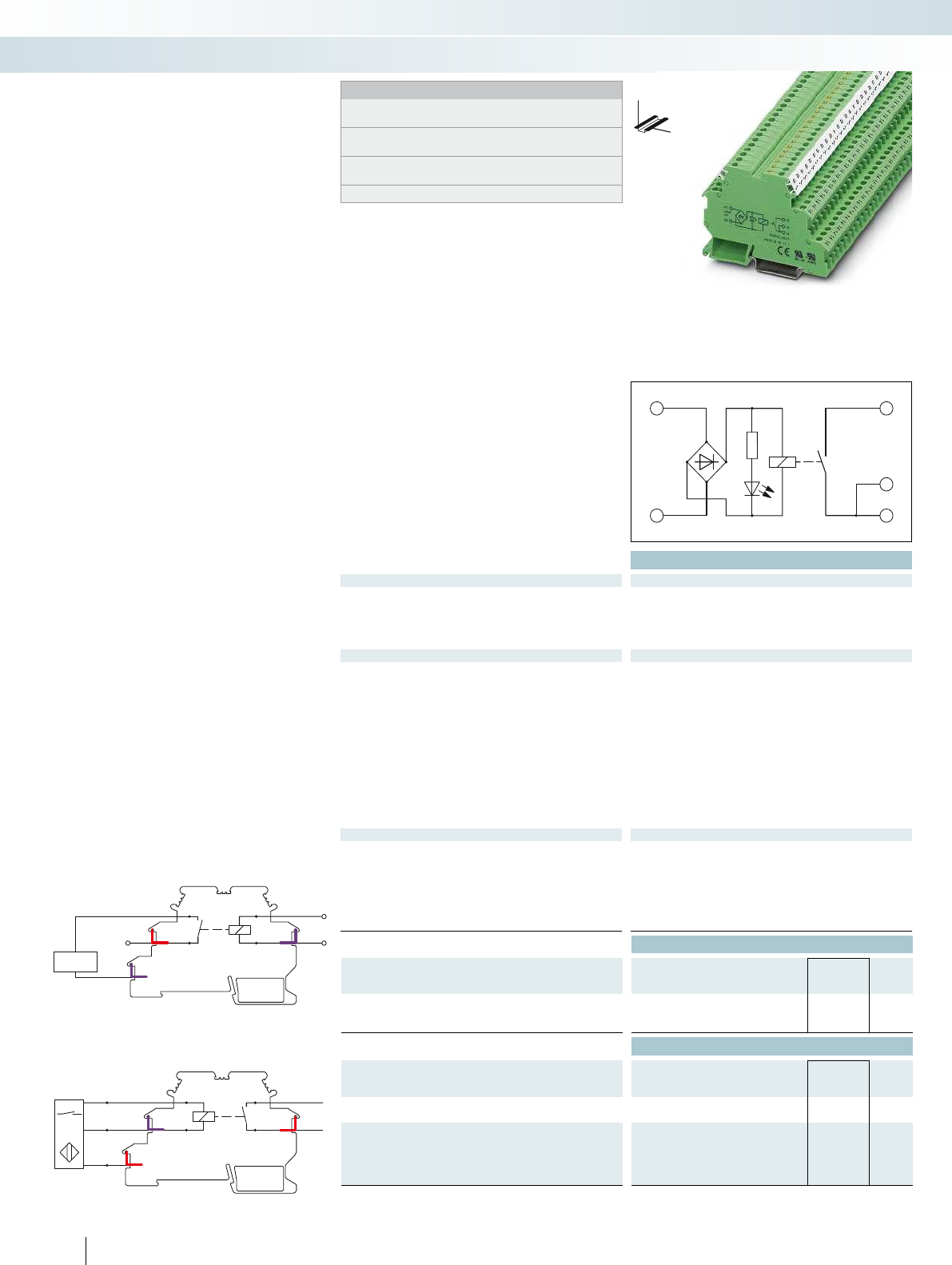
A
0
+
A1
A2
13
14
14
Technical data
Input data ① ②
Permissible range (with reference to U
N
) 0.9 -
1.1
0.8 -
1.1
Typ. input current at U
N
[mA] 23 6.5
Response/release time at U
N
[ms] 8 / 15 5 / 15
Input protection: Yellow LED, bridge rectifier Yellow LED, bridge
Output data
Contact type 1 N/O contact (double contact) 1 N/O contact (double contact) 1 N/O contact 1 N/O contact
Contact material AgNi, hard gold-plated AgNi, hard gold-plated AgNi, hard gold-plated AgNi, hard gold-plated
Max. switching voltage 250 V AC / 125 V DC
Min. switching voltage 0.1 V
Limiting continuous current 3 A (5 A up to 35°C at 24 V DC) 3 A (5 A up to 35°C at 24 V DC) 3 A (5 A up to 35°C at 24 V DC) 3 A (5
Max. inrush current 5 A
Min. switching current 1 mA
Max. interrupting rating, ohmic load
24 V DC 72 W
48 V DC 60 W
60 V DC 50 W
110 V DC 50 W
250 V AC 750 VA
General data
Test voltage (winding/contact) 2 kV AC (50 Hz, 1 min.) 2 kV AC (50 Hz, 1 min.) 2 kV AC (50 Hz, 1 min.) 2 kV AC (50 Hz, 1 min.)
Ambient temperature (operation) -20 °C ... 50 °C
Mechanical service life Approx. 2 x 10
7
cycles Approx. 2 x 10
Standards/regulations IEC 60664, EN 50178, IEC 62103 IEC 60664, EN 50178, IEC 62103 IEC 60664, EN 50178, IEC 62103 IEC 60664, EN 50
Connection data solid / stranded / AWG 0.2 - 2.5 mm² / 0.2 - 2.5 mm² / 24 - 14 0.2 - 2.5 mm² / 0.2 - 2.5 mm² / 24 - 14 0.2 - 2.5 mm² /
Dimensions W / H / D 6.2 mm / 80 mm / 56 mm 6.2 mm / 80 mm / 56 mm 6.2 mm / 80 mm / 56 mm 6.2 mm / 80 mm / 56 mm
EMC note Class A product, see page 625 Class A product, see page 625 Class A product, see page 625 Class A product, see page 625
Ordering data
Description Input voltage
U
N
Type Order No. Pcs. /
Pkt.
Relay terminal block with miniature relay
①5 V AC/DC DEK-REL- 5/I/1 2941183 10
②24 V AC/DC DEK-REL- 24/I/1 2940171 10
Accessories
Terminal block, with three through contacts,
for mounting on NS 35...
For busbar feeding
Cover
D-DEK 1,5 GN 2716949 10
Insertion bridge, for middle and lower
levels
No. of
pos.
Color
80 blue EB 80- DIK BU 26 A 2715940 1
80 red EB 80- DIK RD 26 A 2715953 1
80 white EB 80- DIK WH 26 A 2715788 1
462
PHOENIX CONTACT
DEK-REL-24/1/SEN input interface and
DEK-REL-24/1/AKT output interface
In addition to the familiar advantages of
the DEK-REL... electronic terminal blocks,
such as:
– 2-layer contact with hard gold-plating for
universal applications from 1 mA to 5 A
continuous current
– 2 kV
rms
electrical isolation of input and
output
– Integrated input circuit
With this terminal block, “ALL”
connections for a sensor or actuator are
provided over a width of just 6.2 mm!
This means that 16 outputs take up a
total overall width of just 105.4 mm
(including the power terminal).
Advantages:
– Lower costs as the N terminal block is no
longer required
– Wiring is reduced to a minimum
– Up to 73% more space
PLCIN
+PLC
Pin configuration DEK-REL-...SEN
Load
Supply
(+)
Signalload PLCOUT
-PLC
Ground load
Pin configuration, DEK-REL-...AKT
Relay modules
Relay modules in terminal block design - DEK series
DW
H
Notes:
Type of housing:
Polyamide PA non-reinforced, color: green.
Marking systems and mounting material
See Catalog 5
For the protection of relay coils and contacts, inductive loads must
be dampened with an efficient protection circuit.
For other EB...DIK... insertion bridges refer to page 467
for small to medium loads
1 N/O contact (1)

A1
A2
A2
13
14
A1
A2
13
14
A1
A2
13
14
For further information and full technical data, visit phoenixcontact.net/products
Technical data Technical data Technical data
① ② ② ②
0.9 -
1.1
0.8 -
1.1
0.8 -
1.1
0.8 -
1.1
23 6.5 6.5 6.5
8 / 15 5 / 15 5 / 15 5 / 15
Input protection: Yellow LED, bridge rectifier Yellow LED, bridge rectifier Yellow LED, bridge rectifier Yellow LED, bridge rectifier
Contact type 1 N/O contact (double contact) 1 N/O contact (double contact) 1 N/O contact 1 N/O contact
Contact material AgNi, hard gold-plated AgNi, hard gold-plated AgNi, hard gold-plated AgNi, hard gold-plated
250 V AC / 125 V DC 250 V AC / 125 V DC 250 V AC / 125 V DC
0.1 V 0.1 V 0.1 V
Limiting continuous current 3 A (5 A up to 35°C at 24 V DC) 3 A (5 A up to 35°C at 24 V DC) 3 A (5 A up to 35°C at 24 V DC) 3 A (5 A up to 35°C at 24 V DC)
5 A 5 A 5 A
1 mA 1 mA 1 mA
72 W 72 W 72 W
60 W 60 W 60 W
50 W 50 W 50 W
50 W 50 W 50 W
750 VA 750 VA 750 VA
Test voltage (winding/contact) 2 kV AC (50 Hz, 1 min.) 2 kV AC (50 Hz, 1 min.) 2 kV AC (50 Hz, 1 min.) 2 kV AC (50 Hz, 1 min.)
-20 °C ... 50 °C -20 °C ... 50 °C -20 °C ... 50 °C
cycles Approx. 2 x 10
7
cycles Approx. 2 x 10
7
cycles Approx. 2 x 10
7
cycles
Standards/regulations IEC 60664, EN 50178, IEC 62103 IEC 60664, EN 50178, IEC 62103 IEC 60664, EN 50178, IEC 62103 IEC 60664, EN 50178, IEC 62103
Connection data solid / stranded / AWG 0.2 - 2.5 mm² / 0.2 - 2.5 mm² / 24 - 14 0.2 - 2.5 mm² / 0.2 - 2.5 mm² / 24 - 14 0.2 - 2.5 mm² / 0.2 - 2.5 mm² / 24 - 14 0.2 - 2.5 mm² / 0.2 - 2.5 mm² / 24 - 14
Dimensions W / H / D 6.2 mm / 80 mm / 56 mm 6.2 mm / 80 mm / 56 mm 6.2 mm / 80 mm / 56 mm 6.2 mm / 80 mm / 56 mm
EMC note Class A product, see page 625 Class A product, see page 625 Class A product, see page 625 Class A product, see page 625
Ordering data Ordering data Ordering data
Type Order No. Pcs. /
Pkt. Type Order No. Pcs. /
Pkt. Type Order No. Pcs. /
Pkt.
DEK-REL- 5/O/1 2941170 10
DEK-REL- 24/O/1 2941154 10 DEK-REL- 24/1/AKT 2964063 10 DEK-REL- 24/1/SEN 2964050 10
Accessories Accessories Accessories
DIKD 1,5 2715979 50 DIKD 1,5 2715979 50
D-DEK 1,5 GN 2716949 10 D-DEK 1,5 GN 2716949 10 D-DEK 1,5 GN 2716949 10
EB 80- DIK BU 26 A 2715940 1EB 80- DIK BU 26 A 2715940 1EB 80- DIK BU 26 A 2715940 1
EB 80- DIK RD 26 A 2715953 1EB 80- DIK RD 26 A 2715953 1EB 80- DIK RD 26 A 2715953 1
EB 80- DIK WH 26 A 2715788 1EB 80- DIK WH 26 A 2715788 1EB 80- DIK WH 26 A 2715788 1
463
PHOENIX CONTACT
Relay modules
Relay modules in terminal block design - DEK series
DW
H
DW
H
DW
H
for small to medium loads
1 N/O contact (1)
for small to medium loads
1 N/O contact (1)
for small to medium loads
1 N/O contact (1)
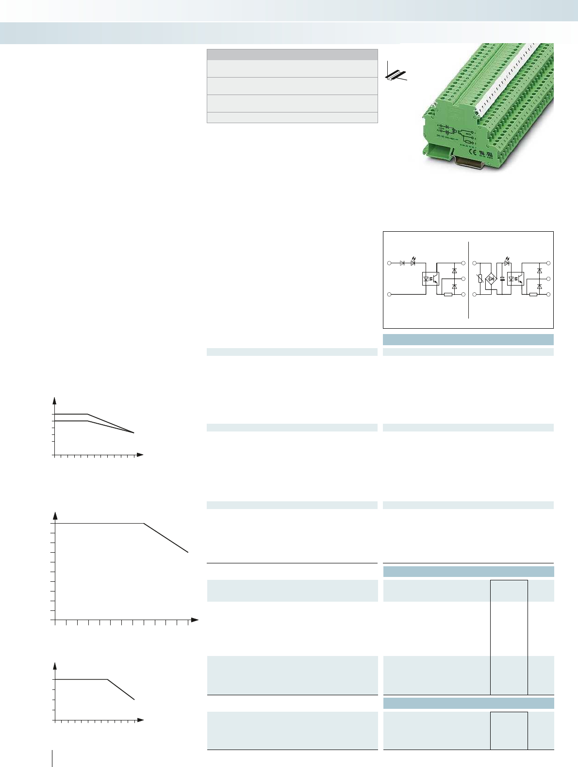
ACDC
A1
+
-
A2
+
A
0
A1
A2
+
A
0
10 20 30 40 50
0
0,8
0,6
0,4
0,2
0
60
1
2
1
2
10 20 30 40 50
0
0
3
1
2
60
10
020 30 40 50 60
10
9
8
7
6
5
4
3
2
1
0
Technical data
Input data ① ② ③ ④ ⑤ ⑥
Permissible range (with reference to U
N
) 0.9 -
1.1
0.8 -
1.2
0.8 -
1.2
0.8 -
1.2
0.9 -
1.1
0.9 -
1.1
Switching level with reference to U
N
1 signal ("H") 0.8 0.8 0.8 0.8 0.8 0.9
0 signal ("L") 0.4 0.4 0.4 0.4 0.4 0.4
Typ. input current at U
N
[mA] 6.5 11 7 4 3.2 2.5 11 8.5 7 7 5.1 4.7 3.5 10.2 10.5 10.7
Transmission frequency f
limit
[Hz] 300 300 300 300 3 3 300 300 300 300 100 100 100 10 10 10
Input circuit AC Yellow LED, protection against polarity reversal, surge protection
Input circuit DC Yellow LED, protection against polarity reversal Yellow LED, protection against polarity reversal Yellow LED, pro
Output data
Operating voltage range 3 V DC ... 48 V DC
Periodic peak reverse voltage -
Limiting continuous current 100 mA
Min. load current -
Surge current -
Leakage current in off state -
Max. load value -
Output protection Protection against polarity reversal, freewheeling diode Protection against polarity reversal, surge protection
Voltage drop at max. limiting continuous current 0.9 V
General data
Test voltage input/output 2.5 kV (50 Hz, 1 min.)
Ambient temperature (operation) -20 °C ... 60 °C
Standards/regulations IEC 60664, EN 50178, IEC 62103 IEC 60664, EN 50178, IEC 62103 IEC 60664, EN 50178, IEC 62103 IEC 60664, EN 50
Pollution degree / surge voltage category 2 / III
Connection data solid / stranded / AWG 0.2 - 2.5 mm² / 0.2 - 2.5 mm² / 24 - 14 0.2 - 2.5 mm² / 0.2 - 2.5 mm² / 24 - 14 0.2 - 2.5 mm² /
Dimensions W / H / D 6.2 mm / 80 mm / 56 mm 6.2 mm / 80 mm / 56 mm 6.2 mm / 80 mm / 56 mm 6.2 mm / 80 mm / 56 mm
EMC note Class A product, see page 625 Class A product, see page 625 Class A product, see page 625
Ordering data
Description Input voltage
U
N
Type Order No. Pcs. /
Pkt.
Solid-state input relay
①5 V DC DEK-OE- 5DC/ 48DC/100 2940223 10
②12 V DC DEK-OE- 12DC/ 48DC/100 2964487 10
③24 V DC DEK-OE- 24DC/ 48DC/100 2940207 10
④60 V DC DEK-OE- 60DC/ 48DC/100 2941536 10
⑤120 V AC DEK-OE-120AC/ 48DC/100 2941659 10
⑥230 V AC DEK-OE-230AC/ 48DC/100 2940210 10
Solid-state power relay
①5 V DC
②12 V DC
③24 V DC
Actuator principle ⑦24 V DC
Accessories
Insertion bridge, for middle and lower
levels
No. of
pos.
Color
80 blue EB 80- DIK BU 26 A 2715940 1
80 red EB 80- DIK RD 26 A 2715953 1
80 white EB 80- DIK WH 26 A 2715788 1
464
PHOENIX CONTACT
DEKOE... and DEK-OV... solid-state
relay terminal blocks
Relay modules
Relay modules in terminal block design - DEK series
DW
H
Notes:
Type of housing:
Polyamide PA non-reinforced, color: green.
Marking systems and mounting material
See Catalog 5
For the protection of input and output, inductive loads must be
dampened with an effective protection circuit.
For other EB...DIK... insertion bridges refer to page 467
with DC voltage output
max. = 100 mA
Derating curve for DEK-OV...240AC/800
Ambient temperature [°C]
Load current [A]
Derating curve for
DEK-OV...24DC/3 and DEK-OV-24DC/24DC/3/AKT
Ambient temperature [°C]
Horizontal mounting
Vertical mounting
Load current [A]
Derating curve for DEK-OV-24DC/24DC/10
Ambient temperature [°C]
Load current [A]
Phoenix Contact DEK-OE and DEK-OV
interface terminal blocks are only 6.2 mm
wide but still provide a complete input or
output interface with:
– Electrical isolation between input and
output at up to 2.5 kV
rms
– Integrated input circuit
– Status display
– EB-DIK insertion bridges
– Marking and mounting with modular
terminal block convenience
– Wear-free switching up to 24 V DC/10 A
and 240 V AC/800 mA
– Integrated output protection circuit
– Zero voltage switch at AC output
– Actuator version available
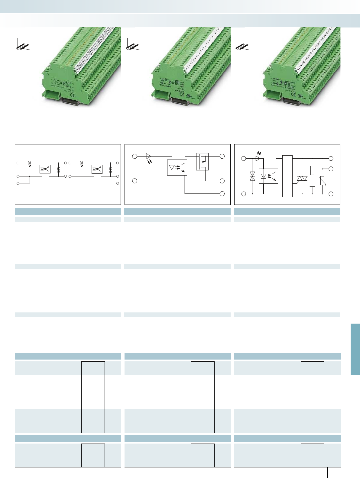
DEK-OV.../24DC/3/AKTDEK-OV.../24DC/3
A1+
A2-
14
13+
A1+
A2-
A2-
14
13+
A1
A2
A
+
0
A1
+
A2
-
13
13
14
For further information and full technical data, visit phoenixcontact.net/products
Technical data Technical data Technical data
① ② ③ ⑦ ① ② ③ ① ② ③
0.8 -
1.2
0.8 -
1.2
0.8 -
1.2
0.8 -
1.2
0.8 -
1.2
0.8 -
1.2
0.8 -
1.2
0.8 -
1.2
0.8 -
1.2
0.8 -
1.2
0.8 0.8 0.8 0.8 0.8 0.8 0.8 0.8 0.8 0.8
0.4 0.4 0.4 0.4 0.4 0.4 0.4 0.4 0.4 0.4
[mA] 6.5 11 7 4 3.2 2.5 11 8.5 7 7 5.1 4.7 3.5 10.2 10.5 10.7
[Hz] 300 300 300 300 3 3 300 300 300 300 100 100 100 10 10 10
Input circuit DC Yellow LED, protection against polarity reversal Yellow LED, protection against polarity reversal Yellow LED, protection against polarity reversal, surge protection Yellow LED, protection against polarity reversal, surge protection
3 V DC ... 30 V DC 5 V DC ... 30 V DC 10 V AC ... 253 V AC (50/60 Hz)
- - 600 V
3 A (see derating curve) 10 A (see derating curve) 0.8 A (see derating curve)
--10 mA
- 100 A (t = 20 ms) 30 A (t = 10 ms)
--1.2 mA
--4.5 A
2
s
Output protection Protection against polarity reversal, freewheeling diode Protection against polarity reversal, surge protection Protection against polarity reversal, surge protection RCV circuit
0.2 V < 50 mV 1 V
2.5 kV (50 Hz, 1 min.) 2.5 kV (50 Hz, 1 min.) 2.5 kV (50 Hz, 1 min.)
-20 °C ... 60 °C -20 °C ... 60 °C -20 °C ... 60 °C
Standards/regulations IEC 60664, EN 50178, IEC 62103 IEC 60664, EN 50178, IEC 62103 IEC 60664, EN 50178, IEC 62103 IEC 60664, EN 50178, IEC 62103
2 / III 2 / III 2 / III
Connection data solid / stranded / AWG 0.2 - 2.5 mm² / 0.2 - 2.5 mm² / 24 - 14 0.2 - 2.5 mm² / 0.2 - 2.5 mm² / 24 - 14 0.2 - 2.5 mm² / 0.2 - 2.5 mm² / 24 - 14 0.2 - 4 mm² / 0.2 - 2.5 mm² / 24 - 12
Dimensions W / H / D 6.2 mm / 80 mm / 56 mm 6.2 mm / 80 mm / 56 mm 6.2 mm / 80 mm / 56 mm 6.2 mm / 80 mm / 56 mm
EMC note Class A product, see page 625 Class A product, see page 625 Class A product, see page 625
Ordering data Ordering data Ordering data
Type Order No. Pcs. /
Pkt. Type Order No. Pcs. /
Pkt. Type Order No. Pcs. /
Pkt.
DEK-OV- 5DC/ 24DC/ 3 2941361 10 DEK-OV- 5DC/ 24DC/ 10 2961752 10 DEK-OV- 5DC/240AC/800 2964623 10
DEK-OV- 12DC/ 24DC/ 3 2941387 10 DEK-OV- 12DC/ 24DC/ 10 2961749 10 DEK-OV- 12DC/240AC/800 2964636 10
DEK-OV- 24DC/ 24DC/ 3 2941374 10 DEK-OV- 24DC/ 24DC/ 10 2964322 10 DEK-OV- 24DC/240AC/800 2964649 10
DEK-OV- 24DC/ 24DC/ 3/AKT 2964296 10
Accessories Accessories Accessories
EB 80- DIK BU 26 A 2715940 1EB 80- DIK BU 26 A 2715940 1EB 80- DIK BU 26 A 2715940 1
EB 80- DIK RD 26 A 2715953 1EB 80- DIK RD 26 A 2715953 1EB 80- DIK RD 26 A 2715953 1
EB 80- DIK WH 26 A 2715788 1EB 80- DIK WH 26 A 2715788 1EB 80- DIK WH 26 A 2715788 1
465
PHOENIX CONTACT
Relay modules
Relay modules in terminal block design - DEK series
DW
H
DW
H
DW
H
with DC voltage output
max. = 3 A
with DC voltage output
max. = 10 A
with AC voltage output
max. = 800 mA

466
PHOENIX CONTACT
Relay modules
Special relays and solid-state relays
Switch/relay terminal block
DEK-REL-24/1/S
The “Manual”, “0”, and “Automatic”
functions are provided in a narrow 6.2 mm
relay terminal block.
Interference-free relay and solid-state
relay interfaces
Coupled interference voltages on the
coil lines or leakage currents can cause
malfunctions in conventional modules.
These special interface modules, equipped
with high switching thresholds and/or
effective filters, ensure good functioning.
Relay interfaces for switching lamp loads
ST-REL... and EMG 17-REL...
Lamp loads and capacitive loads produce
extremely high inrush currents which weld
conventional relay contacts.
To prevent this, Phoenix Contact uses an
arc-resistant contact optimized for these
applications, which keeps these peaks under
control.
Plug-in solid-state power relay
ST-OV 3-24DC/400/3
The output of this component,
dimensioned with a peak reverse voltage of
800 V, allows, for example, 230 V motors to
be driven in simple reversible mode.
Power circuit breaker solid-state relay,
with signal logic
These modules combine the features of a
short-circuit-proof power solid-state relay
and those of a thermomagnetic protection
element.
100 kHz input solid-state relay
DEK-OE-...100KHZ
Input solid-state relay for reliable
transmission of high frequency signals of the
type that occur with, for example,
incremental encoders.
Electronic sensor terminal block for
NAMUR proximity sensors
For converting the changeable resistance
of a NAMUR sensor into a digital signal that
can be read by a PLC.
Inverter module
DEK-TR/INV
Module for converting NPN outputs to
PNP outputs and PNP to NPN.
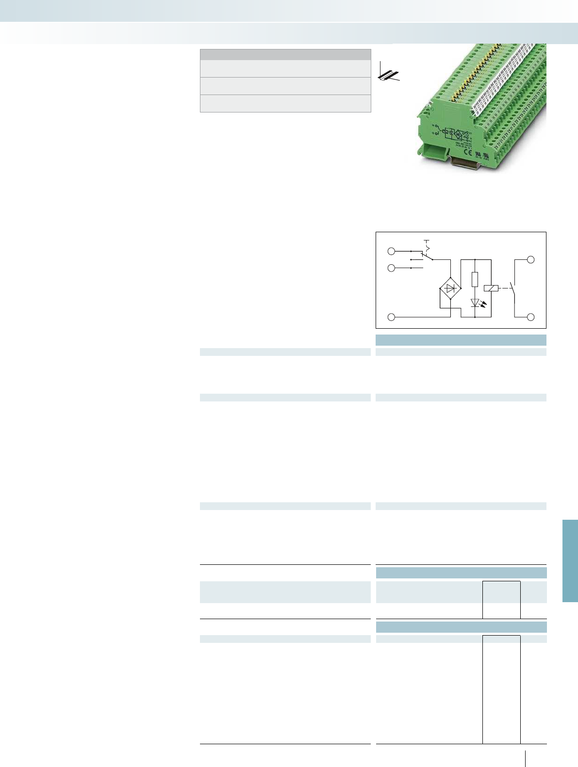
A
H
A2
13
14
For further information and full technical data, visit phoenixcontact.net/products
Technical data
Input data ①
Permissible range (with reference to U
N
) 0.8 -
1.1
Typ. input current at U
N
[mA] 6.5
Response/release time at U
N
[ms] 5 / 15
Input protection: Yellow LED, bridge rectifier
Output data
Contact type 1 N/O contact
Contact material AgNi, hard gold-plated
Max. switching voltage 250 V AC / 125 V DC
Min. switching voltage 0.1 V
Limiting continuous current 3 A (5 A up to 35°C at 24 V DC)
Max. inrush current 5 A
Min. switching current 1 mA
Max. interrupting rating, ohmic load
24 V DC 72 W
48 V DC 60 W
60 V DC 50 W
110 V DC 50 W
250 V AC 750 VA
General data
Test voltage (winding/contact) 2 kV AC (50 Hz, 1 min.)
Ambient temperature (operation) -20 °C ... 50 °C
Mechanical service life Approx. 2 x 10
7
cycles
Standards/regulations IEC 60664, EN 50178, IEC 62103
Connection data solid / stranded / AWG 0.2 - 2.5 mm² / 0.2 - 2.5 mm² / 24 - 14
Dimensions W / H / D 6.2 mm / 80 mm / 61 mm
EMC note Class A product, see page 625
Ordering data
Description Input voltage
U
N
Type Order No. Pcs. /
Pkt.
Relay module with power relay
①24 V AC/DC DEK-REL- 24/1/S 2964131 10
Accessories
Cover D-DEK 1,5 GN 2716949 10
Insertion bridge
No. of pos.
Color
2 red EB 2- DIK RD 2716693 10
3 red EB 3- DIK RD 2716745 10
4 red EB 4- DIK RD 2716758 10
5 red EB 5- DIK RD 2716761 10
10 red EB 10- DIK RD 2716774 10
2 blue EB 2- DIK BU 2716648 10
3 blue EB 3- DIK BU 2716651 10
4 blue EB 4- DIK BU 2716664 10
5 blue EB 5- DIK BU 2716677 10
10 blue EB 10- DIK BU 2716680 10
80 blue EB 80- DIK BU 2715940 1
80 red EB 80- DIK RD 2715953 1
467
PHOENIX CONTACT
Notes:
Type of housing:
Polyamide PA non-reinforced, color: green.
Marking systems and mounting material
See Catalog 5
For the protection of input and output, inductive loads must be
dampened with an effective protection circuit.
DW
H
Relay module with manual switch and
integrated power relay for manual, zero, and
automatic functions
The advantages:
– Max. switching current of 5 A
– Only 6.2 mm wide
– Increased contact stability thanks to
double contact
– Safe isolation according to DIN EN 50178
between coil and contact
Relay module with manual switch
Relay modules
Special relays and solid-state relays
Relay module with manual switch
and integrated relay
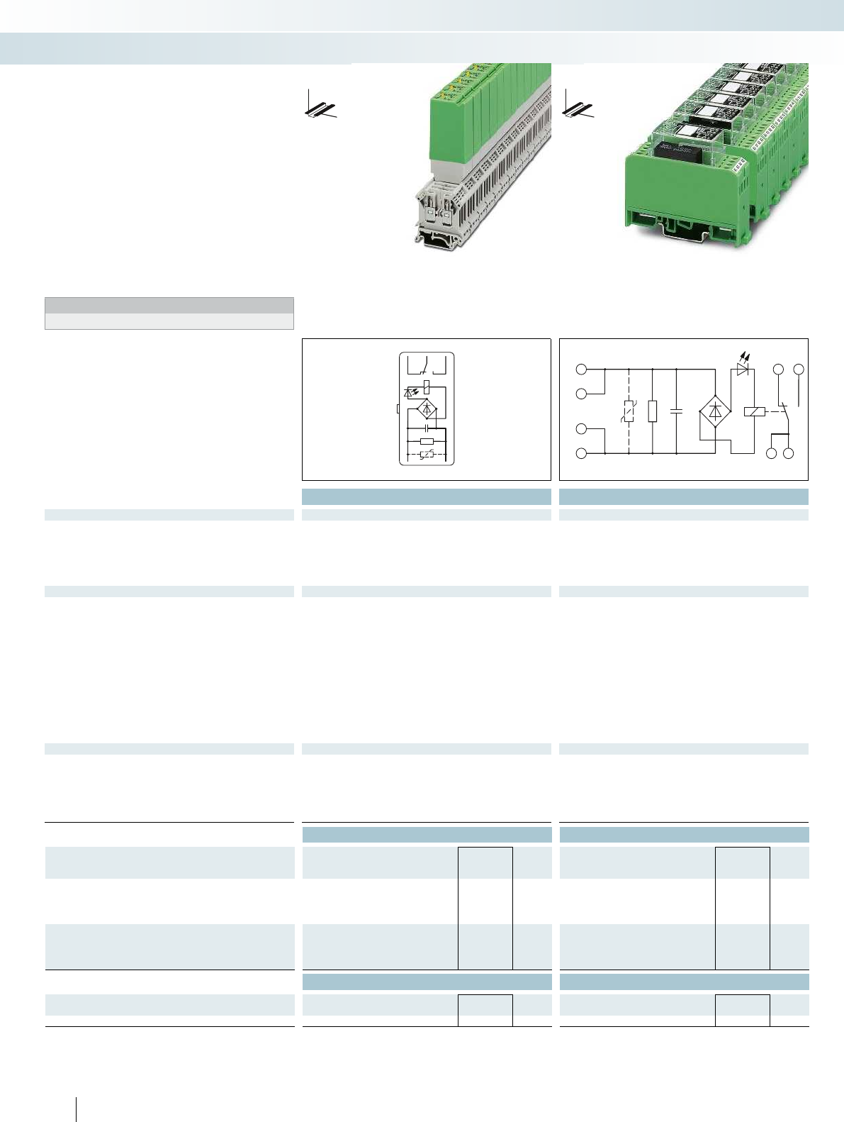
12 11 14
A1 A2
A1
+
A1
A2
-
A2
12 14
11 11
Technical data Technical data
Input data ① ② ③ ③
Permissible range (with reference to U
N
) 0.9 -
1.1
0.85 -
1.1
0.9 -
1.1
0.9 -
1.1
Typ. input current at U
N
[mA] 26 19 18 18
Response/release time at U
N
[ms] 8 / 10 8 / 11 10 / 8 10 / 8
Input protection: Yellow LED, bridge rectifier, surge protection Yellow LED, bridge rectifier, surge protection
Output data
Contact type Single contact, 1-PDT Double contact, 1 PDT Single contact, 1-PDT Double contact, 1 PDT
Contact material AgNi Au AgNi AgPd60, hard gold-plated
Max. switching voltage 250 V AC/DC 30 V AC / 36 V DC 250 V AC/DC 30 V AC / 36 V DC
Limiting continuous current 6 A 0.5 A 6 A 0.5 A
Max. inrush current 8 A 0.2 A 8 A 0.2 A
Max. interrupting rating, ohmic load
24 V DC 140 W 5 W 95 W 5 W
48 V DC 60 W - 50 W -
60 V DC 45 W - 45 W -
110 V DC 35 W - 35 W -
220 V DC 55 W - 55 W -
250 V AC 1500 VA - 1500 VA -
General data
Test voltage (winding/contact) 2.5 kV AC (50 Hz, 1 min.) 2.5 kV AC (50 Hz, 1 min.)
Ambient temperature (operation) -20 °C ... 50 °C -20 °C ... 40 °C
Mechanical service life Approx. 2 x 10
7
cycles Approx. 2 x 10
7
cycles
Standards/regulations IEC 60664, EN 50178, IEC 62103 IEC 60664, EN 50178, IEC 62103
Connection data solid / stranded / AWG - / - / - 0.2 - 4 mm² / 0.2 - 2.5 mm² / 24 - 12
Dimensions W / H / D 20.8 mm / 42.5 mm / 112 mm 22.5 mm / 75 mm / 62.5 mm
Ordering data Ordering data
Description Input voltage
U
N
Type Order No. Pcs. /
Pkt. Type Order No. Pcs. /
Pkt.
Relay module with power contact relay
①24 V AC ST-REL3-KG 24/21/SO46 2826091 10
②120 V AC ST-REL3-KG120/21/SO46 2833026 10
③230 V AC ST-REL3-KG230/21/SO46 2832027 10 EMG 22-REL/KSR-230/21/ SO46 2940760 10
Relay module with multi-layer contact relay
①24 V AC ST-REL3-KG 24/21/AU/SO46 2826981 10
②120 V AC ST-REL3-KG120/21/AU/SO46 2829797 10
③230 V AC ST-REL3-KG230/21/AU/SO46 2826266 10 EMG 22-REL/KSR-230/21/AU/SO46 2940061 10
Accessories Accessories
Basic terminal block, complete with end cover URELG 3 2820136 10
Equipment marker EMG-GKS 12 2947035 50
468
PHOENIX CONTACT
Relay and solid-state relay modules with
integrated filter to protect against
interference voltages or currents due, for
example, to long control lines
The advantages:
– Resistant to interference currents
– High relay release voltage
Typical applications:
– Applications with long control lines
– Use of AC output boards, resulting in
residual AC currents
Notes:
Load current diagrams, see page 427
DW
H
DW
H
Relay modules with interference
current filter
Relay modules
Special relays and solid-state relays
1 PDT, plug-in relay 1 PDT, soldered-in relay
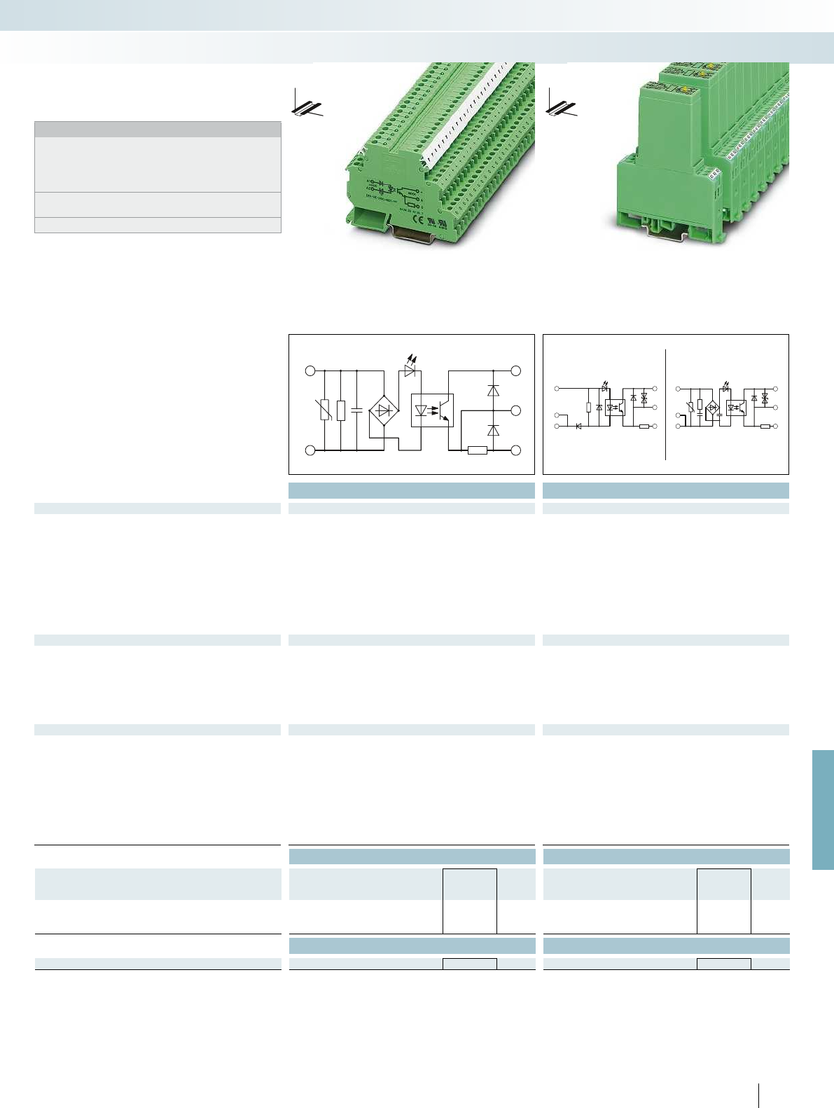
A1
A2
+
A
0
ACDC
A1 A1
++
A2 A2
--
A2 A2
AA
++
00
For further information and full technical data, visit phoenixcontact.net/products
Technical data Technical data
Input data ② ①
Permissible range (with reference to U
N
) 0.9 -
1.1
0.8 -
1.2
Switching level 1 signal ("H") [V DC] 207 16.8
0 signal ("L") [V DC] 92 16
Typ. input current at U
N
[mA] 2.5 8
Typ. switch-on time at U
N
[ms] 4.4 0.02
Typ. shutdown time at U
N
[ms] 14 0.2
Transmission frequency f
limit
[Hz] 5 300
Input circuit AC Yellow LED, surge protection, RC element
Input circuit DC Protection against polarity reversal
Output data
Max. switching voltage 48 V DC 48 V DC
Min. switching voltage 3 V DC 12 V DC
Limiting continuous current 100 mA 2 A (see derating curve)
Max. inrush current - 5 A (t = 1 s)
Output circuit 3-conductor, ground-referenced 3-conductor, ground-referenced
Output protection Protection against polarity reversal, freewheeling Protection against polarity reversal, surge protection
Voltage drop at max. limiting continuous current 0.9 V 1.1 V
General data
Test voltage input/output 2.5 kV AC 3.5 kV AC
Ambient temperature (operation) 0 °C ... 50 °C -10 °C ... 55 °C
Standards/regulations IEC 60664, EN 50178, IEC 62103 IEC 60664, EN 50178, IEC 62103
Pollution degree / surge voltage category 2 / III 2 / III
Mounting position / mounting any / can be aligned without spacing - / aligned without spacing: horizontal/not aligned: any
Connection data solid / stranded / AWG 0.2 - 4 mm² / 0.2 - 2.5 mm² / 24 - 12 0.2 - 4 mm² / 0.2 - 2.5 mm² / 24 - 12
Dimensions W / H / D 6.2 mm / 80 mm / 56 mm 17.5 mm / 75 mm / 102 mm
EMC note Class A product, see page 625
Ordering data Ordering data
Description Input voltage
U
N
Type Order No. Pcs. /
Pkt. Type Order No. Pcs. /
Pkt.
Solid-state power relay
①24 V DC EMG 17-OV- 24DC/ 48DC/2 2942810 10
②230 V AC DEK-OE-230AC/ 48DC/100/SO 46 2964678 10
Accessories Accessories
Equipment marker EMG-GKS 12 2947035 50
469
PHOENIX CONTACT
Notes:
Type of housing:
ST-REL: Polyamide non-reinforced PA, color: bottom part gray,
hood green
EMG: Polyamide fiber reinforced PA-F, color: green.
DEK: Polyamide non-reinforced PA, color: green.
Marking systems and mounting material
See Catalog 5
For derating curve, refer to page 425
DW
H
DW
H
Relay modules
Special relays and solid-state relays
Solid-state input relay
100 mA, maximum
Solid-state power relay
Max. 2 A
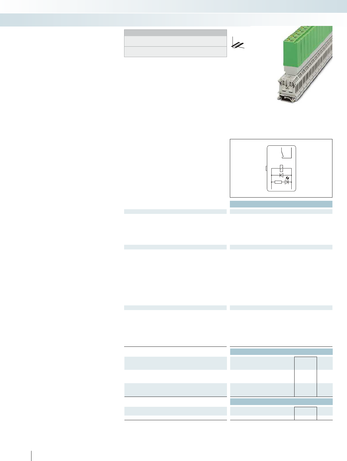
13 14
A1 A2
Technical data
Input data ①
Permissible range (with reference to U
N
) 0.85 -
1.1
Typ. input current at U
N
[mA] 28
Response/release time at U
N
[ms] 13 /
15
Input protection: Yellow LED, freewheeling diode Yellow LED, freewheeling diode Automatic: yellow LED, manual: red LED, freewheeli
Output data
Contact type 1 N/O contact with lead contact 1 N/O contact with lead contact Single contact, 1 N/O contact
Contact material AgCdO
Max. switching voltage 250 V AC
Limiting continuous current 10 A
Max. inrush current 80 A (20 ms)
Max. interrupting rating, ohmic load
24 V DC -
48 V DC -
60 V DC -
110 V DC -
220 V DC -
250 V AC 2500 VA
General data
Test voltage (winding/contact) 2.5 kV AC (50 Hz, 1 min.) 4 kV AC (50 Hz, 1 min.) 4 kV AC (50 Hz, 1 min.)
Ambient temperature (operation) -20 °C ... 50 °C
Mechanical service life Approx. 10
7
cycles
Standards/regulations IEC 60664, EN 50178, IEC 62103 IEC 60664, EN 50178, IEC 62103 IEC 60664, EN 50178, IEC 62103
Mounting position / mounting - / horizontal without spacing, vertical with spacing any any
Connection data solid / stranded / AWG - / - / -
Dimensions W / H / D 20.8 mm / 42.5 mm / 112 mm 17.5 mm / 75 mm / 62.5 mm 17.5 mm / 75 mm / 62.5 mm
Ordering data
Description Input voltage
U
N
Type Order No. Pcs. /
Pkt.
Relay module with power contact relay + wolfram lead contact
①24 V DC ST-REL3-KG 24/ 1/SO38 2829564 10
Relay module with power contact relay, with two inputs for
manual, automatic
①24 V DC
Accessories
Basic terminal block, complete with end cover URELG 3 2820136 10
Equipment marker
470
PHOENIX CONTACT
Relay modules for
high inrush currents
The Phoenix Contact relay modules of
the type SO 38 have been designed for
switching electrical equipment with high
inrush currents.
Areas of application are:
– Inductive loads (motors, power
contactors, etc.)
– Inductive/capacitive loads (fluorescent
lamps, etc.)
– Ohmic loads (glow lamps, heaters)
The module is based on a relay with a
special arc-resistant tungsten lead contact.
This takes over the high inrush and
interrupting current capacitively. The
inductive main contact made of AgCdO
takes over the continuous current up
to 10 A reliably. With the EMG
17-REL...2E/SO38 model, this switching
capacity is reached using a power relay with
a set of silver tin oxide (AgSnO) contacts.
The module is available in two versions:
– EMG modular DIN-rail-mountable housing
with an overall width of 17.5 mm
– Convenient ST-REL plug-in housing from
the Phoenix ST series for mounting on
URELG or UDK-RELG basic terminal
blocks
Further features are:
– Snap-on mounting on common EN DIN
rails
– Easy maintenance
– Clear marking of terminal blocks using
Phoenix Contact marking material
Relay modules
Special relays and solid-state relays
DW
H
Notes:
Type of housing:
Polycarbonate fiber reinforced PC-F, color: green or black.
Marking systems and mounting material
See Catalog 5
medium to large loads
1 N/O contact (1)
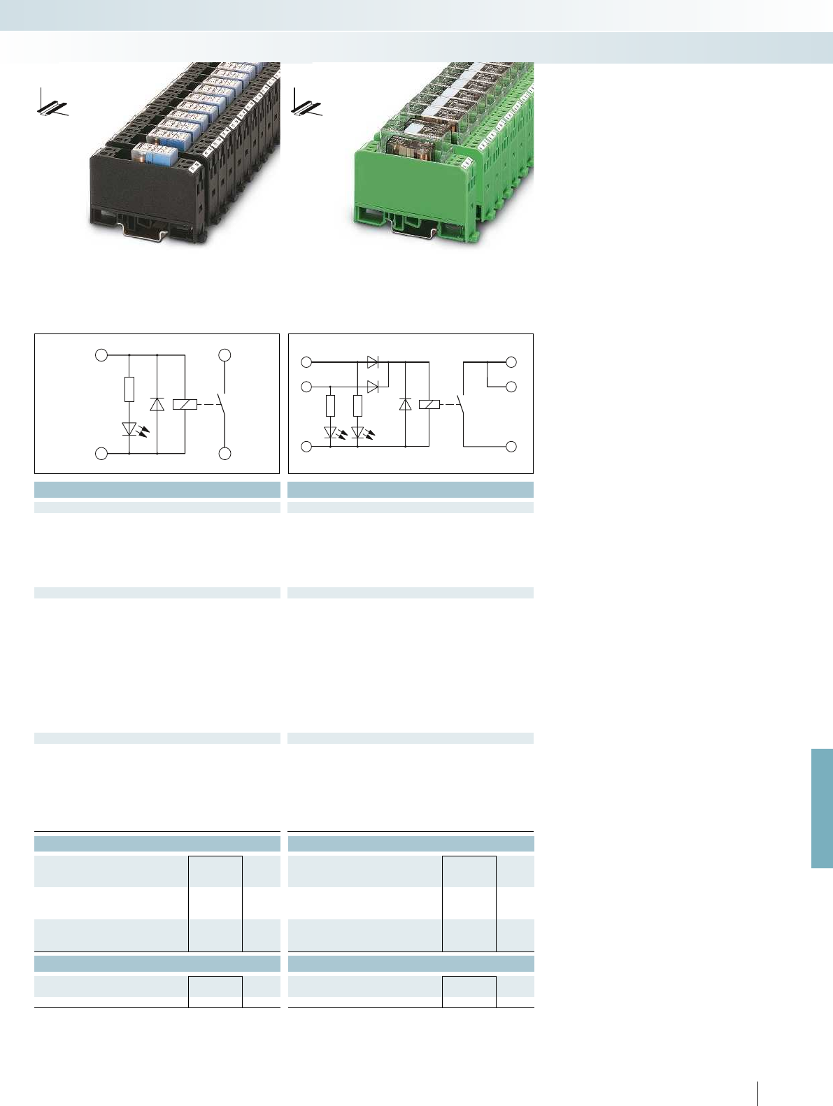
A1
+
A2
-
14
13
A
H
M
13
13
14
For further information and full technical data, visit phoenixcontact.net/products
Technical data Technical data
① ①
0.85 -
1.1
0.9 -
1.1
28 23
13 /
15
9 / 10
Input protection: Yellow LED, freewheeling diode Yellow LED, freewheeling diode Automatic: yellow LED, manual: red LED, freewheeling diode,
protection against polarity reversal
Contact type 1 N/O contact with lead contact 1 N/O contact with lead contact Single contact, 1 N/O contact
AgCdO AgSnO
250 V AC 250 V AC/DC
10 A 10 A
80 A (20 ms) 120 A (20 ms)
- 240 W
- 120 W
- 85 W
- 70 W
- 90 W
2500 VA 2500 VA
Test voltage (winding/contact) 2.5 kV AC (50 Hz, 1 min.) 4 kV AC (50 Hz, 1 min.) 4 kV AC (50 Hz, 1 min.)
-20 °C ... 50 °C -20 °C ... 50 °C
Approx. 10
7
cycles 3 x 10
7
cycles
Standards/regulations IEC 60664, EN 50178, IEC 62103 IEC 60664, EN 50178, IEC 62103 IEC 60664, EN 50178, IEC 62103
Mounting position / mounting - / horizontal without spacing, vertical with spacing any any
0.2 - 4 mm² / 0.2 - 2.5 mm² / 24 - 12 0.2 - 4 mm² / 0.2 - 2.5 mm² / 24 - 12
Dimensions W / H / D 20.8 mm / 42.5 mm / 112 mm 17.5 mm / 75 mm / 62.5 mm 17.5 mm / 75 mm / 62.5 mm
Ordering data Ordering data
Type Order No. Pcs. /
Pkt. Type Order No. Pcs. /
Pkt.
EMG 17-REL/KSR-G 24/SO38 BK 2949994 10
EMG 17-REL/KSR-G 24/2E/SO38 2941646 10
Accessories Accessories
EMG-GKS 12 2947035 50 EMG-GKS 12 2947035 50
471
PHOENIX CONTACT
Relay modules
Special relays and solid-state relays
DW
H
DW
H
medium to large loads
1 N/O contact (1)
medium to large loads
1 N/O contact (1)
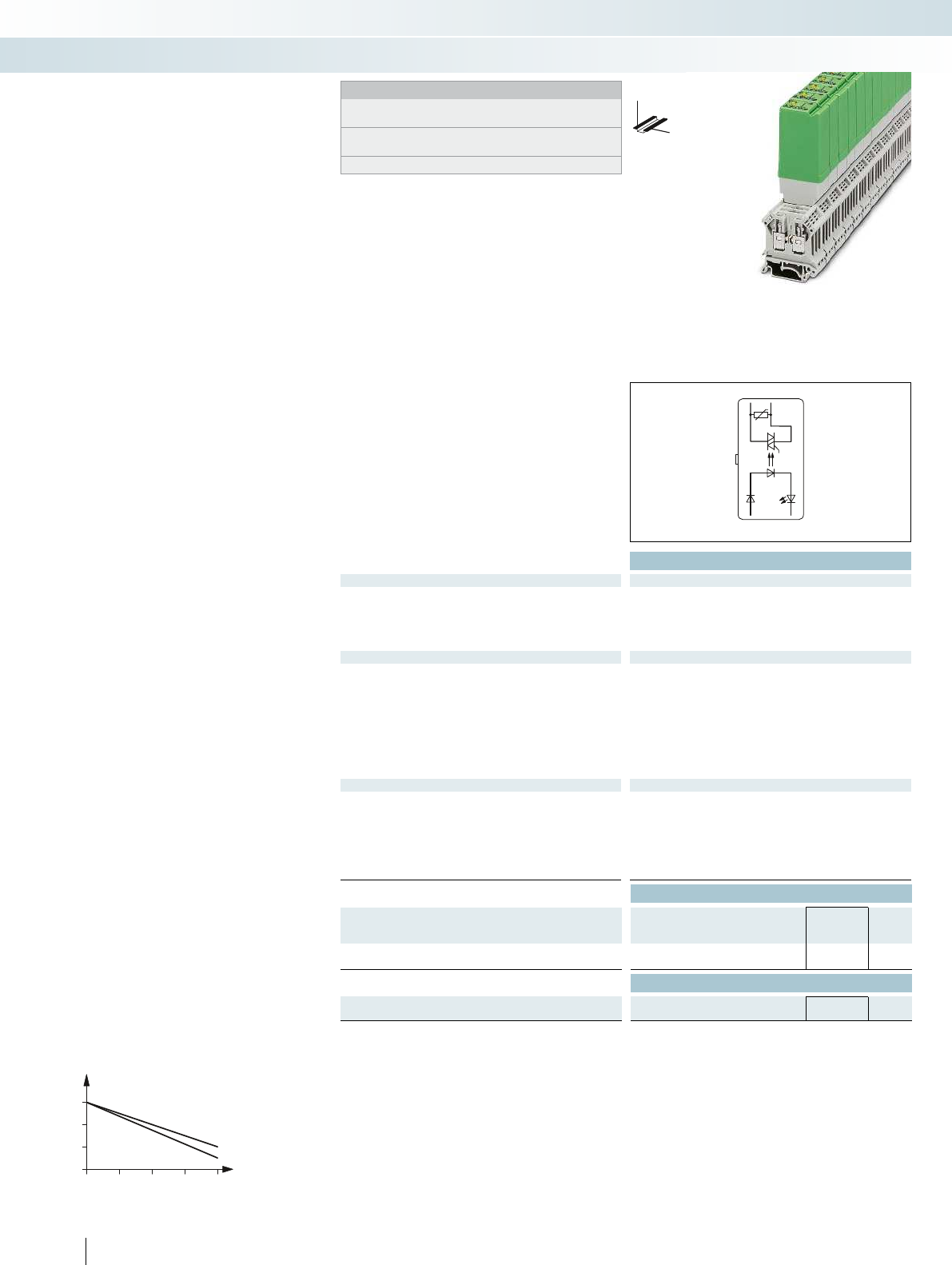
13 14
A1
+A2
-
1
2
1
2
30
20
0
3
1
2
40 50 60
Technical data
Input data ①
Switching level with reference to U
N
1 signal ("H") 0.8
0 signal ("L") 0.4
Typ. input current at U
N
[mA] 7
Transmission frequency f
limit
[Hz] 10
Input protection: Yellow LED, protection against polarity reversal, RC element
Output data
Operating voltage 400 V AC
Operating voltage range 24 V AC ... 420 V AC
Periodic peak reverse voltage 800 V
Limiting continuous current 3 A (see derating curve)
Min. load current 50 mA
Surge current 125 A (t = 10 ms)
Residual voltage drop at "H" 1.2 V
Leakage current in off state approx. 12 mA
Output protection Surge protection, RC element
General data
Test voltage input/output 2.5 kV AC
Ambient temperature (operation) 0 °C ... 60 °C
Standards/regulations IEC 60664, EN 50178, IEC 62103
Pollution degree / surge voltage category 2 / III
Mounting position / mounting Horizontal DIN rail / -
Dimensions W / H / D 20.8 mm / 42.5 mm / 112 mm
Ordering data
Description Input voltage
U
N
Type Order No. Pcs. /
Pkt.
Solid-state power relay
①24 V DC ST-OV3- 24DC/400AC/3 2905417 10
Accessories
Basic terminal block, complete with end cover URELG 3 2820136 10
472
PHOENIX CONTACT
Notes:
Type of insulating housing: polyamide PA non-reinforced, color:
bottom part gray, hood green
Ground (minus) potential from the input and output of the
optocoupler should not be connected.
AC loads must be protected with a varistor or an RC element.
DW
H
Plug-in solid-state power relays
ST-OV 3
Relay modules
Special relays and solid-state relays
with AC voltage output
max. = 3 A
Derating curve for ST-OV 3-24DC/400AC/3
Ambient temperature [°C]
Load current [A]
Aligned without spacing
Aligned with 20 mm spacing
The plug-in version of the module
provides all the advantages of the ST series,
such as:
– Switching of up to 400 V AC/3 A
– Control of 230 V motors in
straightforward reversing mode
(e.g., synchronous motor in single-phase
operation, see illustration)
– Plug-in
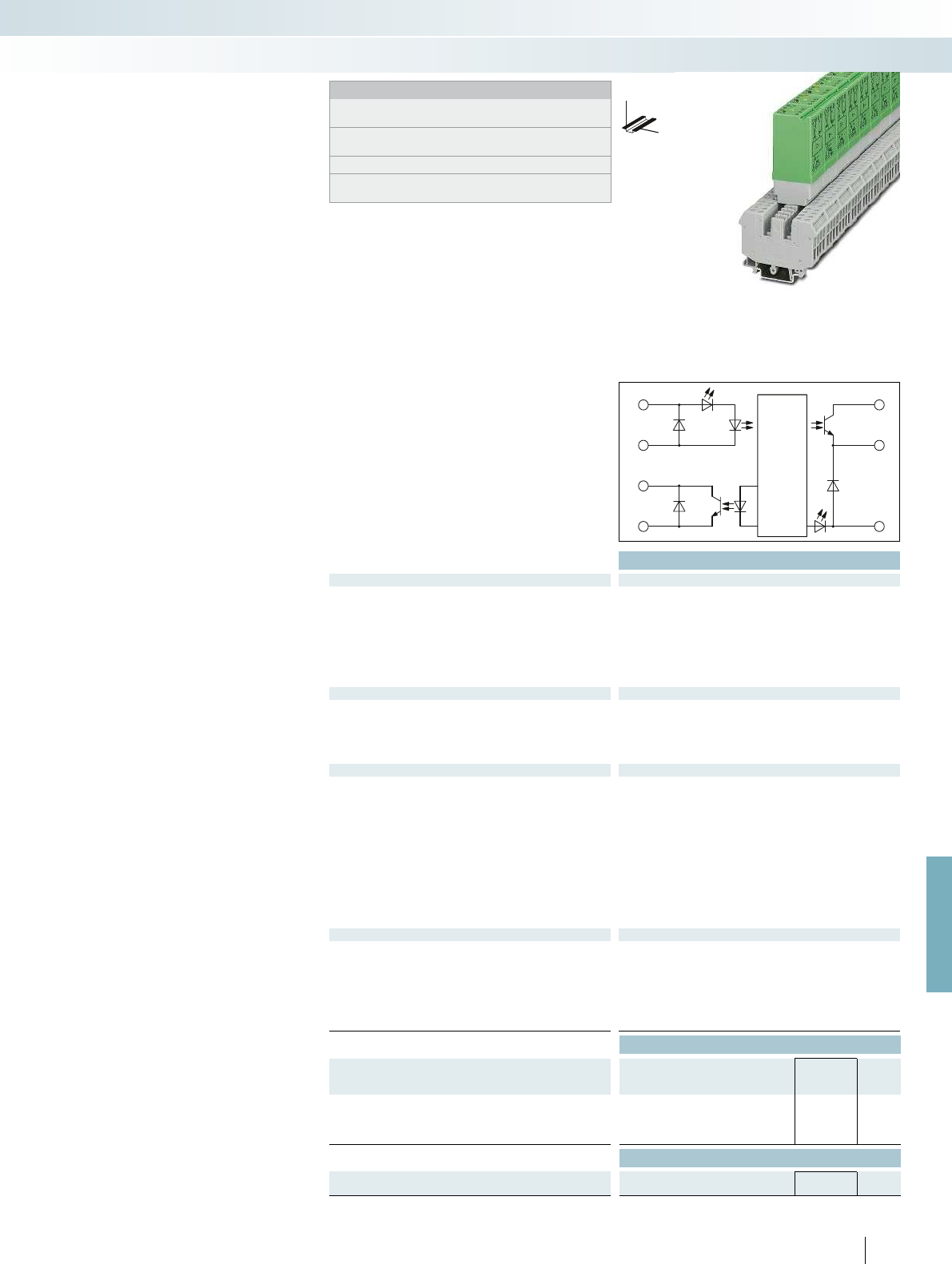
A1
A2
+
T
+
A
0
For further information and full technical data, visit phoenixcontact.net/products
Technical data
Input data ST-OV4- 24DC/ 24DC/1-PRO ST-OV4- 24DC/ 24DC/4-PRO
Operating voltage 24 V DC ± 50%
Switching level 1 signal ("H") 8.5 V DC
0 signal ("L") 5 V DC
Typ. input current at U
N
6.5 mA
Transmission frequency f
limit
100 Hz
Reset period after short-circuit / overload shutdown 1 ms
Input circuit Yellow LED, polarity protection diode
Output data signaling contact / CONTROL
Operating voltage range 5 V DC ... 36 V DC
Limiting continuous current 50 mA
Residual voltage drop at "H" 1.5 V
Output protection Polarity protection diode
Output circuit 3-conductor, ground-referenced
Output data load contact
Operating voltage range 18 V DC ... 36 V DC
Limiting continuous current 1 A (see derating curve) 4 A (see derating curve)
Min. load current 1 mA
Residual voltage drop at "H" 300 mV 200 mV
Open circuit alarm with load current < 100 µA
Overload disconnection (~ 1.4 x continuous current) 100 ms (see the time-current characteristic curve)
Short-circuit disconnection < 200 µs (see the time-current characteristic curve)
Current limitation at short-circuits approx. 25 A approx. 70 A
Switching time t
in
/t
out
300 µs / 700 µs
Output protection Red LED, freewheeling diode
Output circuit 3-conductor, ground-referenced
General data
Test voltage input/output 2.5 kV AC
Test voltage output/output 2.5 kV AC
Rated surge voltage Basic insulation
Ambient temperature (operation) 0 °C ... 60 °C
Standards/regulations IEC 60664 / EN 50178 / IEC 62103
Screw connection solid / stranded / AWG 0.2 - 4 mm² / 0.2 - 4 mm² / 24 - 12
Dimensions W / H / D 27 mm / 63.5 mm / 114 mm
Ordering data
Description Output current Type Order No. Pcs. /
Pkt.
Power circuit breaker solid-state relay, with signal logic
1 A ST-OV4- 24DC/ 24DC/1-PRO 2905572 10
4 A ST-OV4- 24DC/ 24DC/4-PRO 2905585 10
Accessories
Basic terminal block, complete with end cover UDK-RELG 4 2777056 10
473
PHOENIX CONTACT
Notes:
Type of housing:
Polyamide PA non-reinforced, color: bottom part gray, hood green
Marking systems and mounting material
See Catalog 5
For load current diagram, see page 427
Derating curve, time/current characteristic curves, and state
diagram, see page 427
DW
H
The ST-OV 4-...PRO provides protection
and monitoring functions that are
otherwise only known from
thermomagnetic protection elements.
The PROtect modules have the following
features:
– Fast disconnection with short-circuits
and simultaneous current limitation
– Time-dependent overload shutdown for
reliable protection against continuous
overloads
– Brief inrush peaks are ignored
– After an overload or short-circuit has
been triggered, a defined reset of the
control voltage must be carried out
– Reliable detection and indication of a line
break on the load side
– Feedback in the event of an error
Power protection circuit solid-state relay
with signal logic
ST-OV 4-24DC/24DC/...-PRO
Relay modules
Special relays and solid-state relays
with short-circuit-proof DC voltage output
max. = 1 A or 4 A
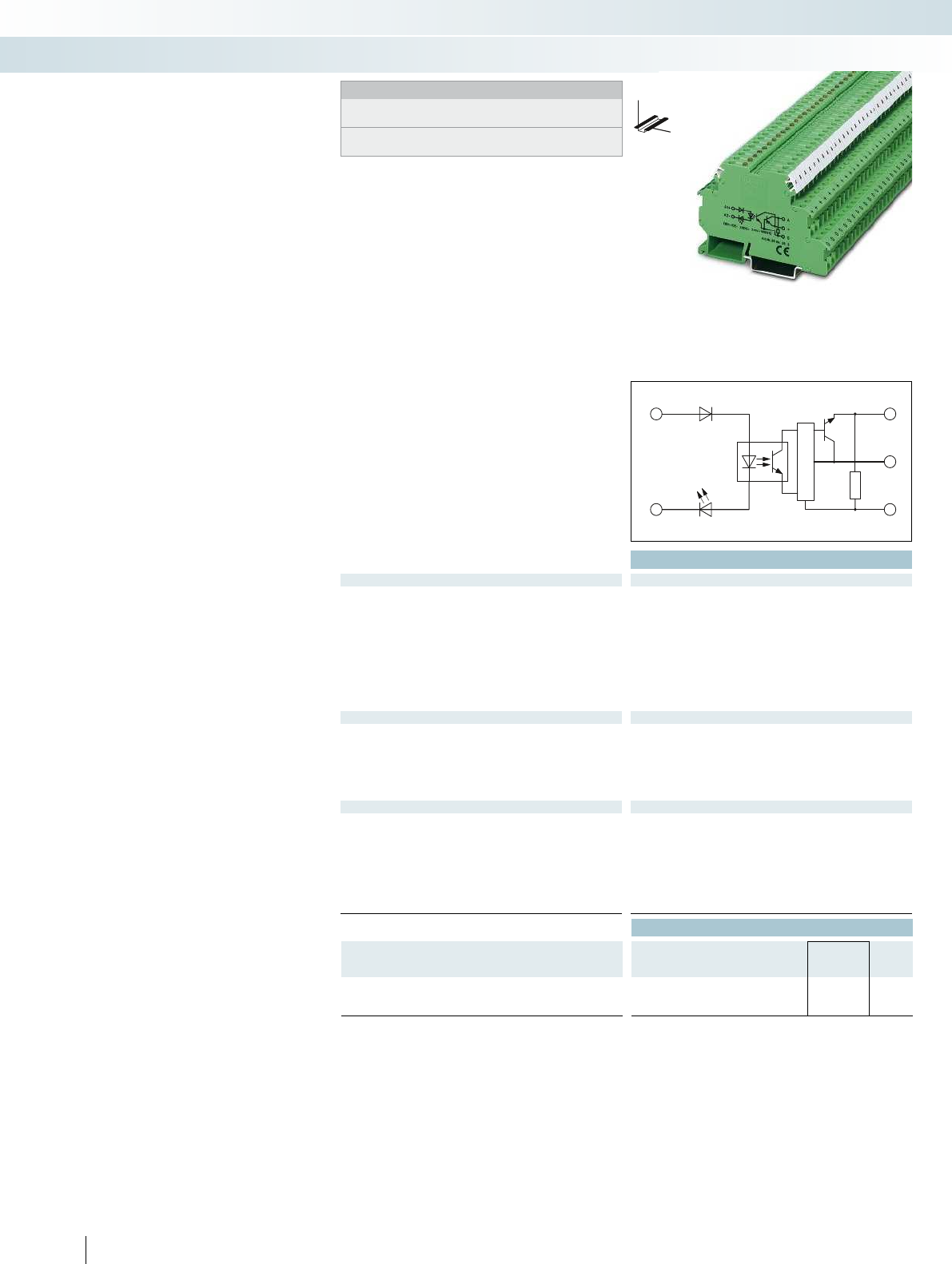
A1
+
A2
-
A
+
0
Technical data
Input data ① ②
Permissible range (with reference to U
N
) 0.8 -
1.2
0.8 -
1.2
Switching level with reference to U
N
1 signal ("H") 0.8 0.8
0 signal ("L") 0.4 0.4
Typ. input current at U
N
[mA] 7 6
Typ. switch-on time at U
N
[µs] 1.5 1.5
Typ. shutdown time at U
N
[µs] 2 2
Transmission frequency f
limit
[kHz] 100 100
Input protection: Yellow LED, protection against polarity reversal, surge protection Yellow LED, protection against polarity reve
Output data
Operating voltage range 4 V DC ... 30 V DC
Limiting continuous current 50 mA
Quiescent current 4.3 mA
Residual voltage drop at "H" 0.5 V DC
Output circuit 3-conductor, ground-referenced 3-conductor push-pull, ground referenced 3-conductor push-pull, ground referenced
Output protection Surge protection
General data
Test voltage input/output 2.5 kV AC
Ambient temperature (operation) -20 °C ... 60 °C
Standards/regulations IEC 60664, EN 50178, IEC 62103 IEC 60664, EN 50178, IEC 62103 IEC 60664, EN 50178, IEC 62103
Pollution degree / surge voltage category 2 / II
Connection data solid / stranded / AWG 0.2 - 4 mm² / 0.2 - 2.5 mm² / 24 - 12 0.2 - 4 mm² / 0.2 - 2.5 mm² / 24 - 12 0.2 - 4 mm² / 0.2 -
Dimensions W / H / D 6.2 mm / 80 mm / 56 mm 6.2 mm / 80 mm / 56 mm 6.2 mm / 80 mm / 56 mm
EMC note Class A product, see page 625 Class A product, see page 625 Class A product, see page 625
Ordering data
Description Input voltage
U
N
Type Order No. Pcs. /
Pkt.
Solid-state input relay
①5 V DC DEK-OE- 5DC/ 24DC/100KHZ 2964270 10
②24 V DC DEK-OE- 24DC/ 24DC/100KHZ 2964283 10
474
PHOENIX CONTACT
100 kHz input solid-state relay
DEK-OE
A solid-state relay for the reliable
detection of short pulses
– Cut-off frequency of up to 100 kHz
– Push-pull stage on output side
– Includes signal inputs on PLC counter
boards
– Features a capacitor on the input side for
interference suppression
Relay modules
Special relays and solid-state relays
DW
H
Notes:
Type of housing:
Polyamide PA non-reinforced, color: green.
Marking systems and mounting material
See Catalog 5
With DC voltage output
Transmission frequency 100 kHz
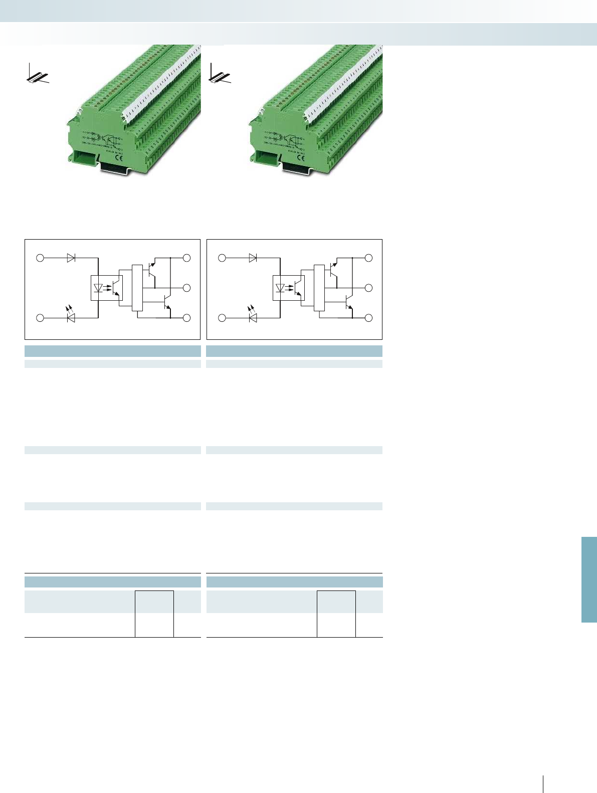
A1
+
A2
-
A
+
0
A1
+
A2
-
A
+
0
For further information and full technical data, visit phoenixcontact.net/products
Technical data Technical data
① ② ① ②
0.5 -
1.2
0.8 -
1.2
0.5 -
1.2
0.8 -
1.2
0.5 0.8 0.5 0.8
0.3 0.4 0.3 0.4
88 88
11 11
22 22
100 100 100 100
Input protection: Yellow LED, protection against polarity reversal, surge protection Yellow LED, protection against polarity reversal, surge protection Yellow LED, protection against polarity reversal, surge protection
4 V DC ... 18 V DC 14 V DC ... 30 V DC
50 mA 50 mA
8.5 mA 15 mA
1.2 V DC 2.2 V DC
Output circuit 3-conductor, ground-referenced 3-conductor push-pull, ground referenced 3-conductor push-pull, ground referenced
Surge protection Surge protection
2.5 kV AC 2.5 kV AC
-20 °C ... 60 °C -20 °C ... 60 °C
Standards/regulations IEC 60664, EN 50178, IEC 62103 IEC 60664, EN 50178, IEC 62103 IEC 60664, EN 50178, IEC 62103
2 / II 2 / II
Connection data solid / stranded / AWG 0.2 - 4 mm² / 0.2 - 2.5 mm² / 24 - 12 0.2 - 4 mm² / 0.2 - 2.5 mm² / 24 - 12 0.2 - 4 mm² / 0.2 - 2.5 mm² / 24 - 12
Dimensions W / H / D 6.2 mm / 80 mm / 56 mm 6.2 mm / 80 mm / 56 mm 6.2 mm / 80 mm / 56 mm
EMC note Class A product, see page 625 Class A product, see page 625 Class A product, see page 625
Ordering data Ordering data
Type Order No. Pcs. /
Pkt. Type Order No. Pcs. /
Pkt.
DEK-OE- 5DC/ 5DC/100KHZ-G 2964542 10 DEK-OE- 5DC/ 24DC/100KHZ-G 2964555 10
DEK-OE- 24DC/ 5DC/100KHZ-G 2964364 10 DEK-OE- 24DC/ 24DC/100KHZ-G 2964348 10
475
PHOENIX CONTACT
Relay modules
Special relays and solid-state relays
DW
H
DW
H
With DC voltage output push-pull
Transmission frequency 100 kHz
With DC voltage output push-pull
Transmission frequency 100 kHz
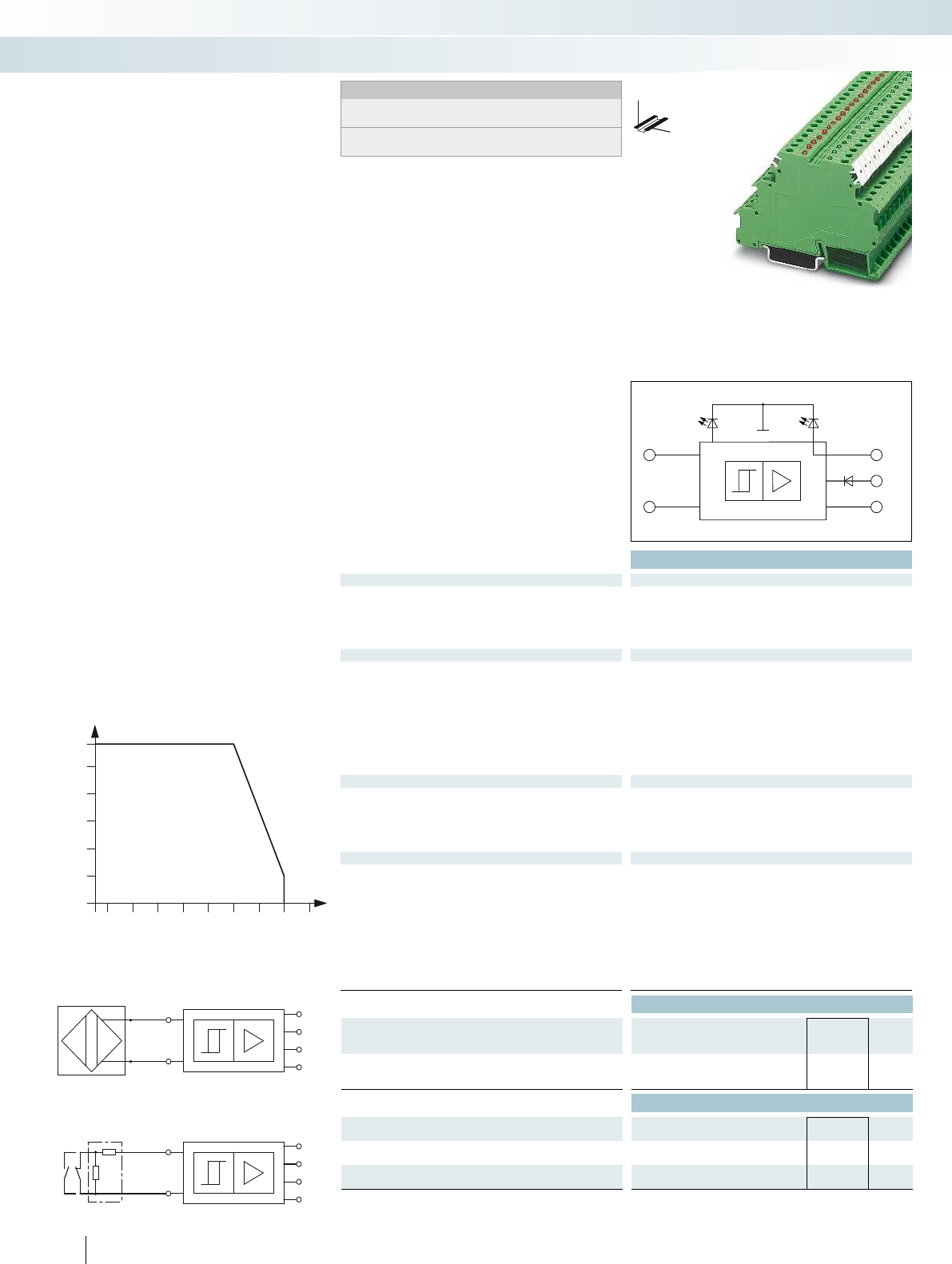
+
-
OUT
24V
0V
UKK 5-2R/NAMUR
10k
1k
+
-
ERR
OUT
GND
U
VN
ERR
OUT
GND
U
+
-
VN
6050403020100-10
-20
28,8
24
25
26
27
28
Technical data
Supply
Input supply nominal voltage U
VN
18.5 V DC ... 28.8 V DC (U
VN
, see derating curve)
Ripple in acc. with DIN 19240
Current consumption I
Imax
70 mA (at 50 mA output current)
Input circuit Green LED, polarity protection diode
Control circuit
No-load voltage 8.2 V DC ±10 %
Switching points in accordance with EN 60947-5-6: 2.1 mA (in conductive state)
1.2 mA (in blocking state)
6.3 mA ... 10 mA (in the event of a short-circuit)
0 mA ... 0.35 mA (in the event of an open circuit)
Switching hysteresis approx. 0.2 mA
Internal resistance approx. 1 k
Output protection visual short-circuit and open circuit check with LED (red),
12 V Zener diode
Signal output
Max. output current I
Omax
50 mA
Residual voltage U
R
with I
Omax
1.5 V (U
R
)
Output voltage U
O
100 mV (in conductive state)
U
VN
- U
R
; in blocking state
Output protection 36 V Zener diode as freewheeling diode
General data
Ambient temperature (operation) -25 °C ... 50 °C
Transmission frequency (INPUT/OUTPUT) 1 kHz
Input pulse length 0.5 ms
Input pause length 0.5 ms
Standards/regulations IEC 60664, EN 61000-6-2, EN 61000-6-4
Pollution degree / Surge voltage category 2 / III
Screw connection solid / stranded / AWG 0.2 - 4 mm² / 0.2 - 2.5 mm² / 24 - 12
Dimensions W / H / D 6.2 mm / 80 mm / 56 mm
EMC note Class A product, see page 625
Ordering data
Description Type Order No. Pcs. /
Pkt.
Switching amplifier electronic terminal block, for
inductive proximity initiators as per NAMUR, with light indicators for
sensor signal and faults
EIK1-SVN-24P 2940799 10
Accessories
Terminal block, with three through contacts, for mounting
on NS 35...
DIKD 1,5 2715979 50
Double-level terminal block, with pre-assembled resistors UKK 5-2R/NAMUR 2941662 50
Insertion bridge EB...-DIK...
Ordering data at DEK-REL...
476
PHOENIX CONTACT
Notes:
Type of housing:
Polyamide PA non-reinforced, color: green.
Marking systems and mounting material
See Catalog 5
DW
H
Electronic sensor terminal block for
NAMUR proximity sensors
Relay modules
Special relays and solid-state relays
For inductive proximity sensors acc. to
NAMUR
Derating curve for EIK 1-SVN 24 P
Ambient temperature [°C]
Supply voltage U
E
[V]
Application 1
Application 2
NAMUR initiator
Limit switch
The EIK 1-SVN 24-P electronic sensor
terminal block converts the changeable
resistance of a NAMUR sensor unit into a
digital signal that can be read by all PLCs.
– Monitoring of initiator side for
short-circuit or open circuit
– Suitable resistance circuit to enable
monitoring of mechanical switches (see
application 2)
– LED error display
– Status display (high signal) via green LED
– 24 V/50 mA digital output
– Bridging and marking with standard
terminal accessories
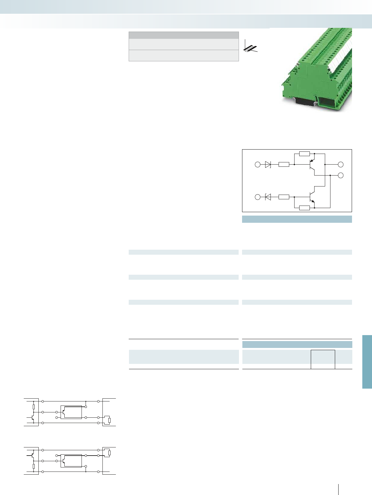
NPN+
–
PNP
24V
0V
DEK-
TRN/INV
NPN
PNP
+
-
C
E
PNP
24V
0V
DEK-
TR/INV
NPN
+
-
C
E
For further information and full technical data, visit phoenixcontact.net/products
Technical data
Supply voltage 20 V DC ... 30 V DC (U
V
)
Continuous current 200 mA
Residual voltage drop < 1 V
Leakage current < 1 mA
Max. transmission frequency 15 kHz
NPN input/PNP output
Switch-on threshold < 5 V (at U
V
= 24 V; < (U
V
- 19 V))
Switch-off threshold > 15 V (at U
V
= 24 V; > (U
V
- 9 V))
Min. limit values -2 V
Max. limit values 26 V (at U
V
= 24 V; U
V
+ 2 V)
Control circuit
Switch-on threshold > 19 V
Switch-off threshold < 9 V
Min. limit values -2 V
Max. limit values 26 V (at U
V
= 24 V; U
V
+ 2 V)
General data
Ambient temperature (operation) -20 °C ... 50 °C
Standards/regulations IEC 60664
Basic insulation
Pollution degree / Surge voltage category 2 / II
Screw connection solid / stranded / AWG 0.2 - 4 mm² / 0.2 - 2.5 mm² / 24 - 12
Dimensions W / H / D 6.2 mm / 80 mm / 56 mm
Ordering data
Description Type Order No. Pcs. /
Pkt.
Inverter module DEK-TR/INV 2964319 10
477
PHOENIX CONTACT
Notes:
Type of housing:
Polyamide PA non-reinforced, color: green.
Marking systems and mounting material
See Catalog 5
DW
H
Inverter module
DEK-TR/INV
Relay modules
Special relays and solid-state relays
Connection examples:
PNP output Load
NPN output Load
The Phoenix inverter module,
DEK-TR/INV, inverts the signals of ground
switching NPN transistor outputs into
positive switching PNP outputs, and vice
versa (see application example).
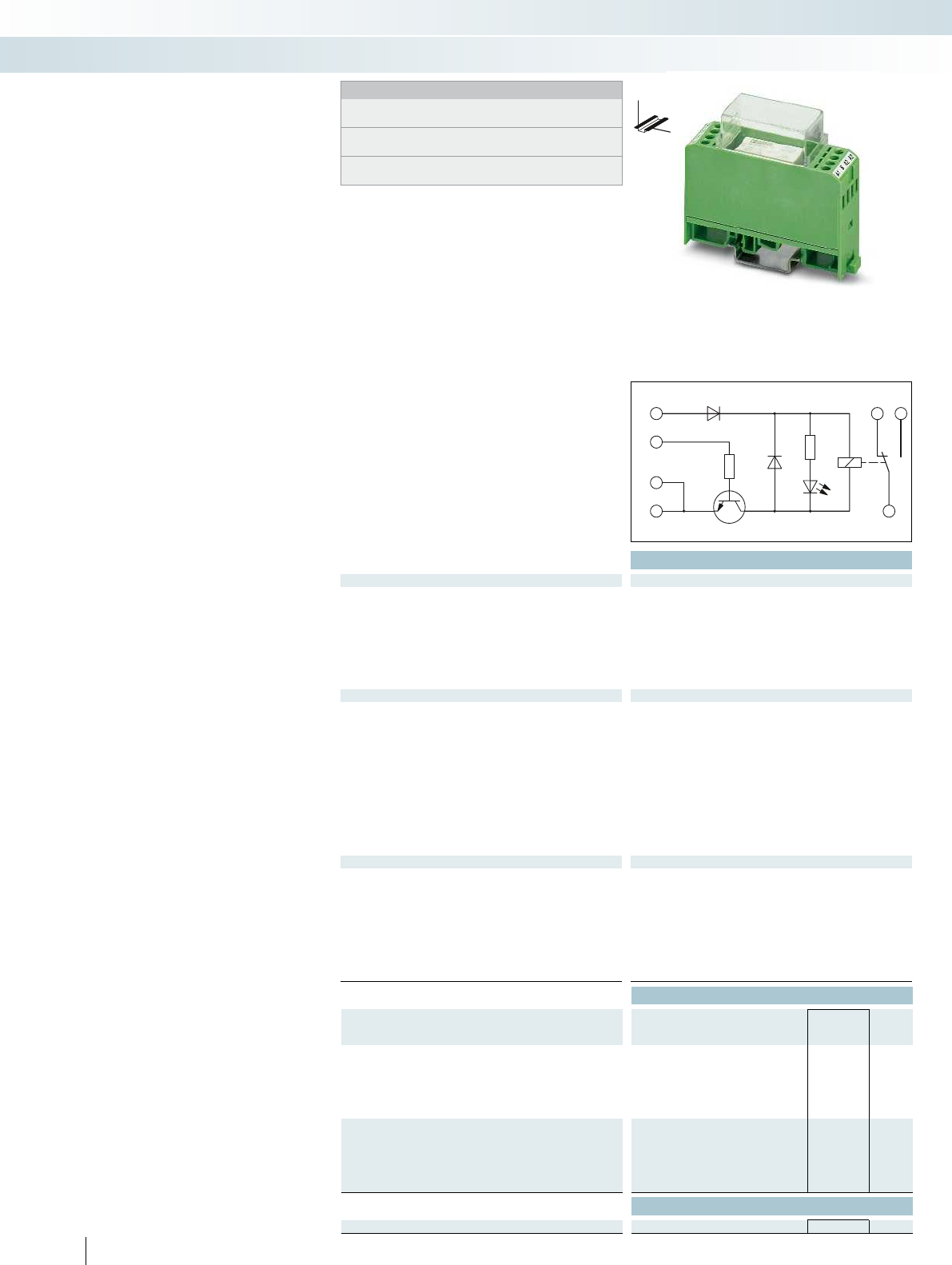
12 14
11
A1
+
B+
A2
-
A2
Technical data
Input data ① ② ③
Relay supply voltage U
N
± 10 % [V DC] 24 24 24
Min. control voltage [V DC] 2.7 5 15
Max. control voltage [V DC] 5.25 13.2 35
Min. control current [mA] 2.6 0.5 0.5
Max. control current [mA] 7.7 1 1
Typ. input current at U
N
[mA] 21 21 21
Response/release time at U
N
[ms] 9 / 10 9 / 10 9 / 10 9 / 10 9 / 10 9 / 10
Input protection:
Yellow LED, protection against polarity reversal, freewheeling diode Yellow LED, protection against polarity reversal, freewheel
Output data
Contact type Single contact, 1-PDT Single contact, 1-PDT
Contact material AgNi
Max. switching voltage 250 V AC/DC
Limiting continuous current 5 A
Max. inrush current 8 A
Max. interrupting rating, ohmic load
24 V DC 120 W
48 V DC 60 W
60 V DC 50 W
110 V DC 50 W
220 V DC 80 W
250 V AC 1250 VA
General data
Test voltage (winding/contact) 4 kV AC (50 Hz, 1 min.) 4 kV AC (50 Hz, 1 min.)
Ambient temperature (operation) -20 °C ... 50 °C
Mechanical service life Approx. 5 x 10
7
cycles Approx. 5 x 10
Standards/regulations IEC 60664, EN 50178, IEC 62103 IEC 60664, EN 50178, IEC 62103
Pollution degree / surge voltage category 2 / III
Connection data solid / stranded / AWG 0.2 - 4 mm² / 0.2 - 2.5 mm² / 24 - 12 0.2 - 4 mm² / 0.2 - 2.5 mm² / 24 - 12
Dimensions W / H / D 22.5 mm / 75 mm / 62.5 mm 22.5 mm / 75 mm / 62.5 mm
EMC note Class A product, see page 625 Class A product, see page 625
Ordering data
Description Nominal
control voltage Type Order No. Pcs. /
Pkt.
Relay module with miniature power contact relay with
integrated NPN transistor control, for low control currents
①5 V DC EMG 22-REL/KSR-G 24/TRN 5 2949787 10
②12 V DC EMG 22-REL/KSR-G 24/TRN12 2952363 10
③24 V DC EMG 22-REL/KSR-G 24/TRN35 2952350 10
Relay module with miniature power contact relay with
integrated PNP transistor control, for low control currents
①5 V DC
②12 V DC
③24 V DC
Accessories
Equipment marker EMG-GKS 12 2947035 50
478
PHOENIX CONTACT
Hybrid relay modules
With its integrated transistor level, the
hybrid relay module is able to amplify weak
input signals. This serves as the basis for
reliable relay operation.
The advantages:
– Low control current (terminal B),
type-dependent as of 0.5 mA
– Type-dependent positive or negative
control current
– Integrated input and interference
suppression circuit
– Safe isolation according to DIN EN 50178
between coil and contact
Relay modules
Special relays and solid-state relays
DW
H
Notes:
Type of housing:
Polycarbonate fiber reinforced PC-F, color: green.
Marking systems and mounting material
See Catalog 5
For the protection of relay coils and contacts, inductive loads must
be dampened with an efficient protection circuit.
Positive switching hybrid relay Negative switching hybrid relay

A1
+
B-
A2
-
A2
12 14
11
For further information and full technical data, visit phoenixcontact.net/products
Technical data
① ② ③
24 24 24
-2.4 -6.9 -17.5
-5.25 -13.2 -38.5
1.2 0.6 0.6
1.7 1 1.4
21 21 21
[ms] 9 / 10 9 / 10 9 / 10 9 / 10 9 / 10 9 / 10
Yellow LED, protection against polarity reversal, freewheeling diode Yellow LED, protection against polarity reversal, freewheeling diode
Contact type Single contact, 1-PDT Single contact, 1-PDT
AgNi
250 V AC/DC
5 A
8 A
120 W
60 W
50 W
50 W
80 W
1250 VA
Test voltage (winding/contact) 4 kV AC (50 Hz, 1 min.) 4 kV AC (50 Hz, 1 min.)
-20 °C ... 50 °C
cycles Approx. 5 x 10
7
cycles
Standards/regulations IEC 60664, EN 50178, IEC 62103 IEC 60664, EN 50178, IEC 62103
2 / III
Connection data solid / stranded / AWG 0.2 - 4 mm² / 0.2 - 2.5 mm² / 24 - 12 0.2 - 4 mm² / 0.2 - 2.5 mm² / 24 - 12
Dimensions W / H / D 22.5 mm / 75 mm / 62.5 mm 22.5 mm / 75 mm / 62.5 mm
EMC note Class A product, see page 625 Class A product, see page 625
Ordering data
Type Order No. Pcs. /
Pkt.
EMG 22-REL/KSR-G 24/TRP 5 2949790 10
EMG 22-REL/KSR-G 24/TRP12 2952156 10
EMG 22-REL/KSR-G 24/TRP35 2952169 10
Accessories
EMG-GKS 12 2947035 50
479
PHOENIX CONTACT
Relay modules
Special relays and solid-state relays
DW
H
Positive switching hybrid relay Negative switching hybrid relay
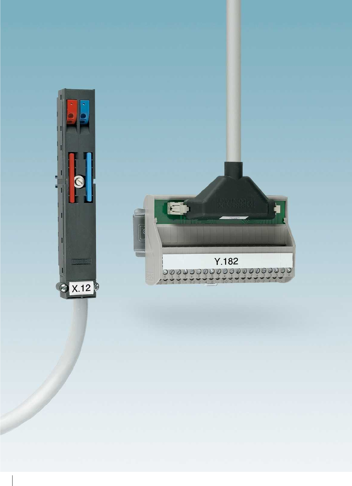
480
PHOENIX CONTACT

Product range overview
Introduction 482
Product overview 484
Customer-specific products 488
Controller-specific system cabling
For ABB S800 I/O 490
For Allen Bradley,
ControlLogix, SLC 500, and PlantScape
492
For Emerson DeltaV 498
For GE Fanuc RX3i and Series 90-30 502
For Honeywell C300 Series CI/O and PlantScape 504
For Mitsubishi A1S and Q, Melsec L, Honeywell ML 200 506
For Omron CJ1, CS1, and C200H 508
For Phoenix Contact Axioline and Inline 509
For Schneider Electric MODICON
®
511
For Siemens SIMATIC
®
S7-300 514
For Siemens SIMATIC
®
S7-1500 524
For Siemens SIMATIC
®
S7-400 526
For Siemens SIMATIC
®
S5-S7 conversion 527
For Yokogawa Centum VP, ProSafe-RS 534
Termination Carriers for
Yokogawa Centum VP and ProSafe-RS
540
Passive modules 542
Active modules 556
V8 adapters for PLC-INTERFACE 568
System and splitting cables 575
Universal modules
With flat-ribbon cable connectors 576
With D-SUB connectors 584
With high-density D-SUB connectors 591
With DIN strips 592
With ELCO connectors 594
With RJ45 connectors 598
With COMBICON connection 599
Universal cables
With flat-ribbon cable connectors 600
With D-SUB connectors 610
With ELCO connectors 616
Potential distributors 618
481
PHOENIX CONTACT
Wiring I/O modules with individual wires
is an extremely time-consuming process.
Wiring errors and tedious troubleshooting
cannot be ruled out.
VARIOFACE system components reduce
assembly costs by using plug-in components
to carry out wiring quickly, clearly, and
without errors.
In the case of controller-specific
system cabling, front adapters, system
cables, and modules are specially matched
to each other. Individual solutions exist for
the following controllers:
– ABB
– Allen Bradley
– Emerson
– Honeywell
– GE Fanuc
– Phoenix Contact
– Mitsubishi Electric
– OMRON
– Schneider Electric
– Siemens
– Yo k o g a w a
If automation components with high-pos.
connectors such as D-SUB are in the
control cabinet, universal modules and
cables are suitable for signal connection.
The 1:1 connection is characteristic for
these universal all-purpose modules. The
modules allow orderly connection of field
signals to screw, spring-cage or push-in
technology.
Universal cables connect the control
and signal level quickly and without errors.
A wide variety of potential
distributors are available for splitting the
control and operating voltage. The different
potential levels and the connection terminal
blocks make flexible use possible.
Individual application requirements can be
realized with customer-specific products
(see page 488).
System cabling for controllers
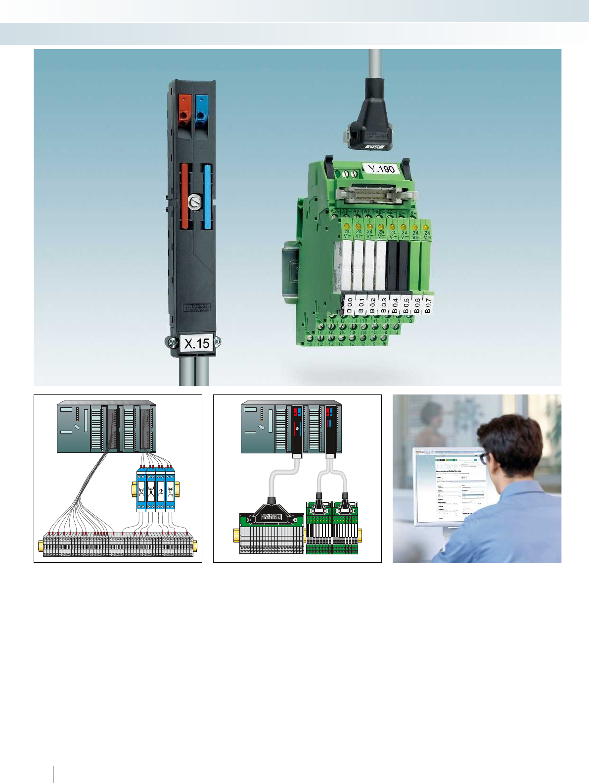
11
A1+
A2-
24
V
14
12
11
A1+
A2-
24
V
14
12
11
A1+
A2-
24
V
14
12
11
A1+
A2-
24
V
14
12
11
A1+
A2-
24
V
14
12
11
A1+
A2-
24
V
14
12
11
A1+
A2-
24
V
14
12
11
A1+
A2-
24
V
14
12
11
A1+
A2-
24
V
14
12
11
A1+
A2-
24
V
14
12
11
A1+
A2-
24
V
14
12
11
A1+
A2-
24
V
14
12
11
A1+
A2-
24
V
14
12
11
A1+
A2-
24
V
14
12
11
A1+
A2-
24
V
14
12
11
A1+
A2-
24
V
14
12
482
PHOENIX CONTACT
System cabling for controllers
Introduction
Wiring with single wires
– Time-consuming
– Confusing wiring
– Risk of mixing wires
– Time-consuming troubleshooting
Wiring with the controller-specific
system cabling:
– Fast, fault-free wiring
– Plug and Play solution
– Orderly structure
– Considerable time savings
The matching components are selected
with the help of the “system cabling for
controllers” online configurator:
– Front adapter
– System cables
– Module
For the online configurator, use the web
code:
Simply enter “#0007” into the search
field on our website.
Your web code: #0007

For further information and full technical data, visit phoenixcontact.net/products
483PHOENIX CONTACT
System cabling for controllers
Introduction
Front adapter
– Tailored to controller-specific I/O
modules
– Plug-in components
– Connection via system cables
8 and 32-channel modules
– Passive modules
– Relay modules
– Controller-specific layout
– Screw or push-in connection technology
PLC-V8 adapter
– Connection of 8 channels via the
“PLC series”
– Feasible functions: relay, solid-state relay
or feed-through
– Individual function selection per channel
– Screw, spring-cage or push-in connection
technology
Universal modules
– Connector: IDC/FLK, D-SUB, ELCO or
DIN
– 1:1 connection
– Screw, spring-cage or push-in connection
technology
– Optional status indicator
Universal cables
– With IDC/FLK connector
– With D-SUB connector
– With ELCO connector
– With open end as an option
Potential distributor
– Up to 30 A/250 V
– Two, three or six potential levels
– Screw or push-in connection technology
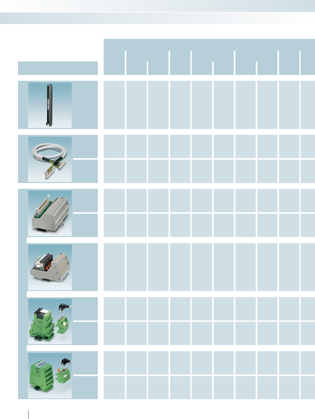
Controller-specific system cabling
Controller
ABB Allen Bradley Emerson GE-FANUC Honeywell Mitsubishi
System component Ve rsio n S800 I/O Control
Logix SLC 500 DeltaV RX3i 90-30
C300
Series CI/O
ML 200
PlantScape MELSEC
A, A1S, Q, L
Page Page Page Page Page Page Page Page Page Page Page Page Page Page Page Page Page Page Page
Front adapter
not required
492 494 not required
502 503 504 492 not required
System cables
Standard 610 574 574 606 574 574 610 574
Controller-
specific 491 496 498 507 506
Interface modules
Passive
Standard 542 542 542 542 542 542 505 542 542
Passive
Controller-
specific
490 545 495 499
Active
Standard 556 556 556 556 556 556 556 556 556
V8 adapter/
feed-through
terminal block
568 568 568 568 568 568 568 568 568
Relay/
optocoupler 398 398 398 398 398 398 398 398 398
MINI Analog
system adapter
MINI Analog
484 PHOENIX CONTACT
System cabling for controllers
Product overview

For further information and full technical data, visit phoenixcontact.net/products
OMRON CJ1 Phoenix
Contact Schneider Siemens Yo k o g a w a
CS1, CQM1,
C200H
Axioline
Inline
TSX
Qantum M340 S7 300 S7 1500 S7 400 Conversion
S5 to S7
Centum
VP ProSafe-RS
Page Page Page Page Page Page Page Page Page Page Page Page Page Page Page Page Page Page Page
not required
510 511 512 516 not required
526 527 not required
not required
574 574 574 574 574
508 513 521 524 534 534
542 542 542 542 542 542 542
545 544 544 536 538
556 556 556 556 556 556 556
568 568 568 568 568 568 568 568
398 398 398 398 398 398 398 398
122 122
120 120
485PHOENIX CONTACT
System cabling for controllers
Product overview
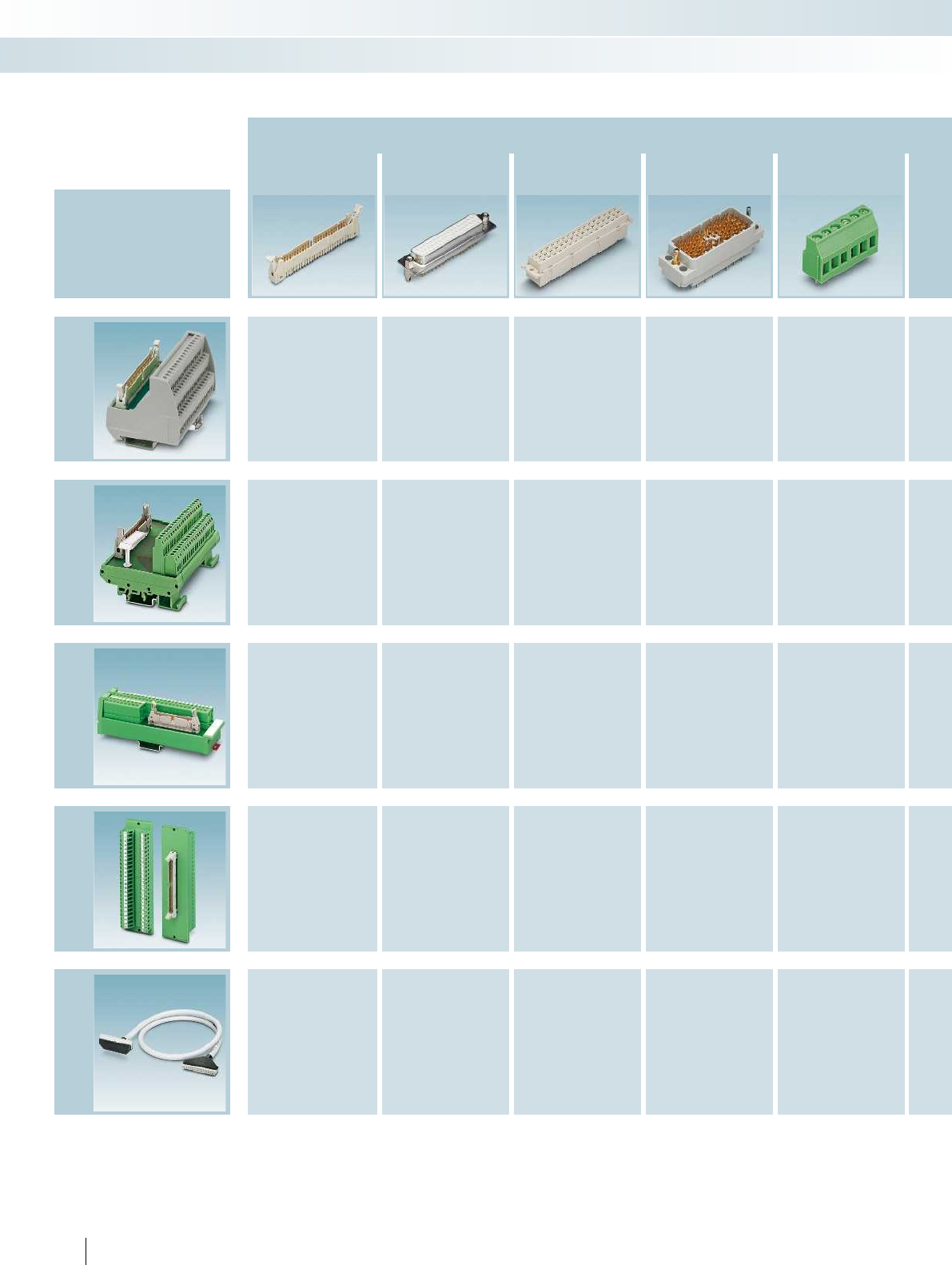
Universal modules and cables
Passive modules (connection technology)
Flat-ribbon cable
strip D-SUB strip DIN strip ELCO strip Potential
distributor
Device series
Page Page Page Page Page Page
VIP Line
576 584
591 618
Standard Line
592 596
Slim Line
580 588
Feed-through
modules
582 589
Cables
600 610
486
PHOENIX CONTACT
System cabling for controllers
Product overview

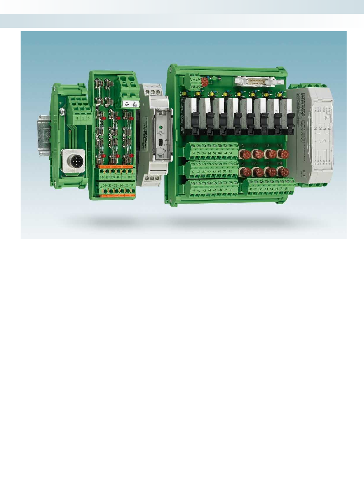
488
PHOENIX CONTACT
System cabling for controllers
Customer-specific products
From the enquiry to the product
We develop your product from the idea
to series production.
Concept phase
– Realization test according to your
specifications
– Personal consultation
– Tendering including draft drawing
Realization phase
– Development according to product
creation process
– Circuit diagram and PCB layout
– Component selection
– Creation of functional samples
– Creation of prototypes
– Tests in every phase of development
– EC conformance
– Preparation and implementation of
approval procedures
– Environmental tests according to
standards
– Documentation
Series phase
– Production according to IPC-A-610 Class
2
– 100% end test with automated test
systems
– Lifecycle management
Directives and standards
– Low-voltage directive
– EMC directive
– IEC 60664-1
Insulation coordination for electrical
equipment within low-voltage systems
– EN 50178
Electronic equipment for use in power
installations
– EN 61000-6
Electromagnetic compatibility
– IPC A-600
Acceptance criteria for PCBs
– IPC-A-610
Acceptance criteria for electronic
modules
Components used
We use connection technology and
housings from the comprehensive Phoenix
Contact portfolio.
Here you will find all common market
technologies:
– Screw and spring-cage connection
– Push-in spring connection
– Knife disconnection
– Modular component housing
– Building installation housings
– Profile module carriers
Furthermore, we use components,
connectors, cables as well as PCBs from
qualified and certified suppliers.
Product range
We create versions from catalog
production for you or new products
according to your specifications from the
following portfolio:
– Function modules such as diode gates
– Relay and optocoupler modules
– 1:1 installation modules (connector on
terminal block)
– Potential distributors
– System cables with high-pos. connectors
– System adapters for controllers and
control systems
– Transfer modules for use between
controller and field level
– Output modules with electrical isolation
– Module carriers for system cabling of
signal conditioners or safe coupling relays
Your direct line to us
Do you have a specific question? Talkto
us about it.
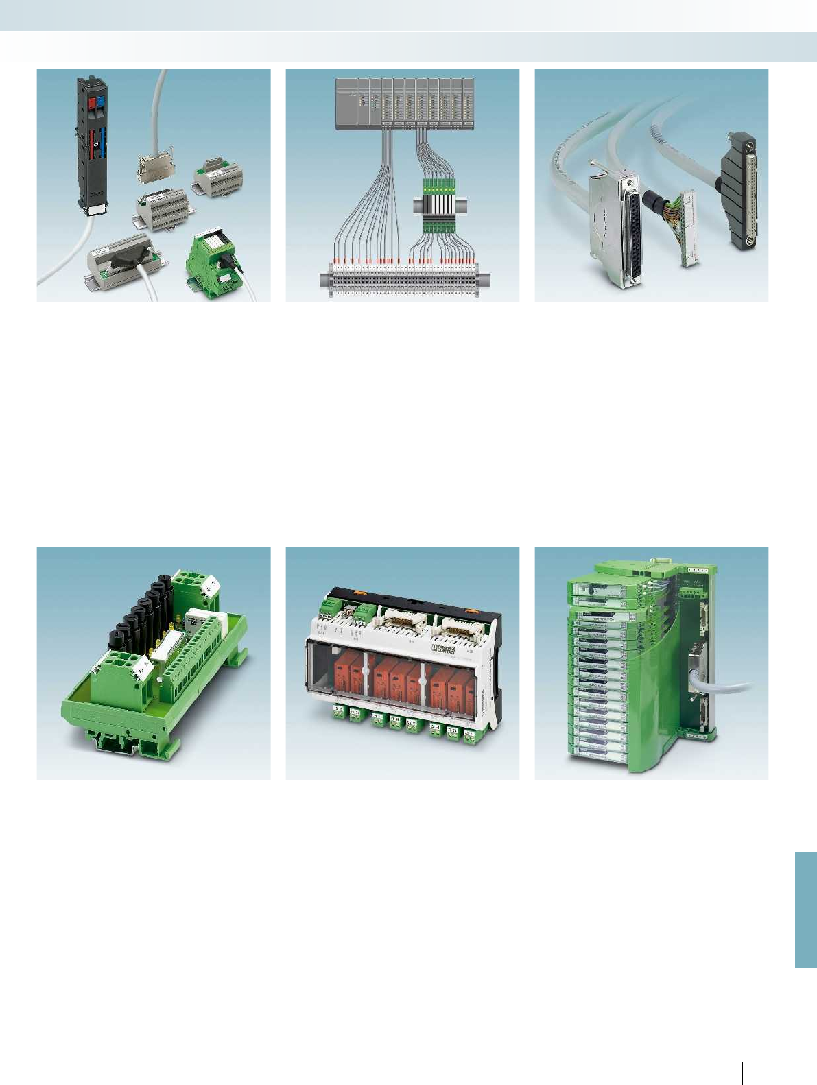
For further information and full technical data, visit phoenixcontact.net/products
489PHOENIX CONTACT
System cabling for controllers
Customer-specific products
Simplification of installation
Objectives
– Reduce assembly costs
– Minimize installation time
– Optimize space in the control cabinet
Implementation
– Analysis of the application
– Draft of concept
Result
– Tailor-made solution from system
components (standard and customer-
specific)
– Fault-free wiring
Retrofitting systems
Ta s k
– Extension
– Retrofitting
Objectives
– System availability
– Fulfillment of statutory specifications
Solution
– Use adaptation solutions and high-pos.
system cables
Result
– Minimum downtimes
Pre-assembled system cables
With high-position connectors
– D-SUB strips
– IDC/FLK pin strips (2.54 mm)
– Pre-assembled at one or both ends
Cables
– Shielded, unshielded, halogen-free
– 0.14 mm
2
/26 AWG and
0.25 mm
2
/24 AWG
Quality
– Continuity and dielectric test
Other versions available on request.
Installation modules
– 1:1 marshalling terminal block to high-
pos. connector (D-SUB, HE10, ELCO...)
– Passive transfer modules with system
connection
– Potential distributors
– Fuse modules
– Diode modules
– Other modules on request
Relay and optocoupler modules
– With electromechanical relays
– With solid-state relays
– Multi-channel
– With system connection
– N/O contact or PDT contact
– LED status display
– Freewheeling diode
– Protection against polarity reversal
– Redundant power supply
Termination Carrier module carrier
The compact Termination Carrier
connects
– Signal conditioners
– Signal conditioners for Ex i circuits
– Signal conditioners for SIL applications
– Safe coupling relays
easily with the automation system via
system cables.
The advantages are clear:
– Quick startup
– Fault minimization
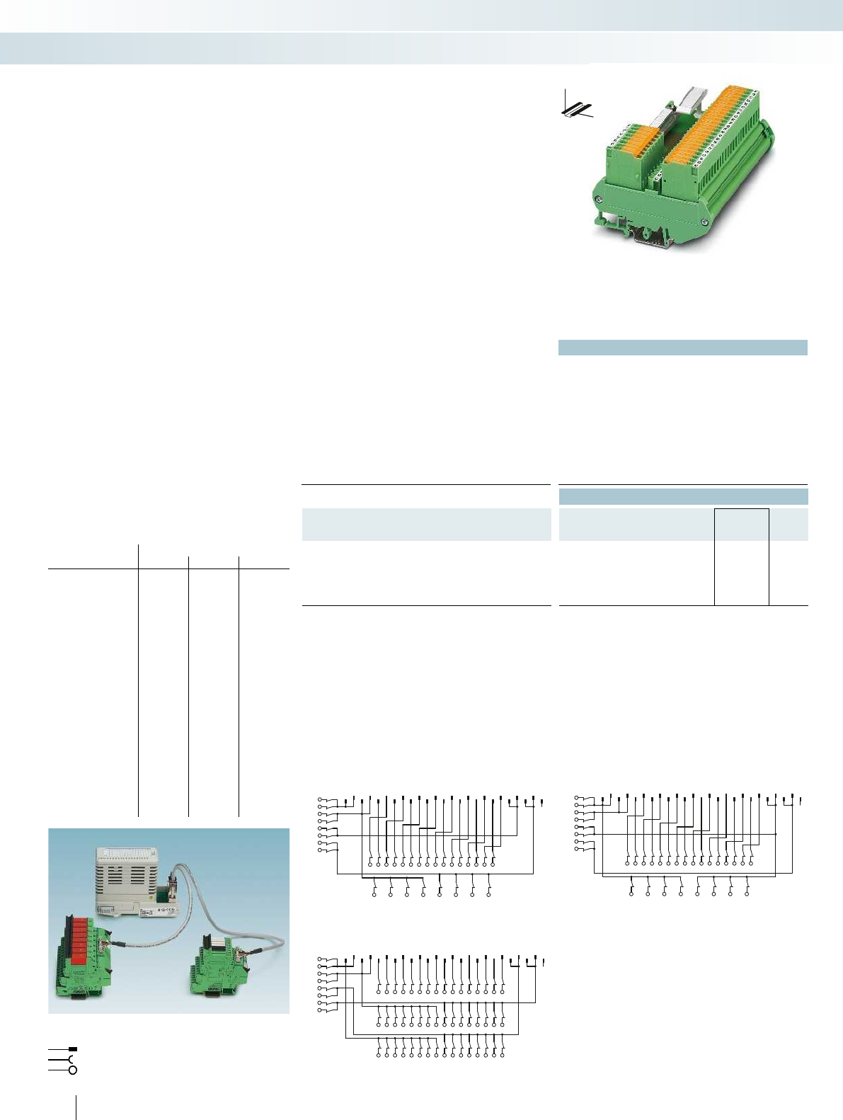
L1+
L1+
L1-
L1-
L2+
L2+
L2-
L2-
1234567891011 12 13
14 15 16 17 18192021 22 23 24 25
C1 C2 C3 C4 C5 C6 C7C8C9C10C11
C12C13
C14C15C16
A1 A2 A3 A4 A5 A6A7A8A9A10A11
A12
A13
A14A15A16
B1B2B3B4B5B6B7B8B9B10B11
B12B13
B14B15B16
L1+
L1+
L1-
L1-
L2+
L2+
L2-
L2-
1234567891011 12 13
25
2423
22
2120191817
16
1514
B1C 1B2C 2B3C3B4C4B5C5B6C6B7C 7B8C8
A1 A2 A3 A4 A5 A6 A7 A8
L1+
L1+
L1-
L1-
L2+
L2+
L2-
L2-
1234567891011 12 13
14 15 16 17 18192021 22 23 24 25
B1C1B2C 2B3C 3 B4C 4 B5C 5B6C 6 B7C 7B8C8
+1 +2 +3 +4 +5 +6 +7 +8
490
PHOENIX CONTACT
Technical data
Max. perm. operating voltage < 50 V AC / 60 V DC
Max. perm. current (per branch) 2 A
Max total current (voltage supply) 4 A (8 A L1-/L2-)
Ambient temperature (operation) -20 °C ... 50 °C
Mounting position any
Standards/regulations DIN EN 50178, IEC 60664, IEC 62103
Connection method Field level Screw connection with disconnect knife
Controller level D-SUB socket strip
Connection data solid / stranded / AWG 0.2 ... 4 mm² / 0.2 ... 2.5 mm² / 24 - 12
Dimensions H / D 90 mm / 61 mm
Ordering data
Description No. of
pos.
Module width
WType Order No. Pcs. /
Pkt.
VARIOFACE module, with knife disconnect terminal blocks in
ABB-specific marking:
- with 8 negative terminal blocks 25 126.5 mm FLKM-D25 SUB/B/KDS3-MT/TU810 2304513 1
- with 8 positive terminal blocks 25 126.5 mm FLKM-D25 SUB/B/KDS3-MT/TU810/P 2304539 1
- each with 16 positive and
negative terminal blocks
25 247.5 mm FLKM-D25 SUB/B/KDS3-MT/TU830 2304526 1
FLKM-D25 SUB/B/KDS3-MT/TU830 connection scheme
FLKM-D25 SUB/B/KDS3-MT/TU810 connection scheme FLKM-D25 SUB/B/KDS3-MT/TU810/P connection scheme
Connectable I/O modules
Card type FLKM-D25SUB...
...TU810 ...TU810/P ...TU830
Digital input
DI 814
DI 810
DI 811
DI 818
DI 830
DI 831
DI 840
DI 885
DI 810
DI 811
DI 814
DI 818
DI 830
DI 831
DI 840
DI 885
Digital output DO 810
DO 818
DO 840
DO 814
DO 810
DO 814
DO 818
DO 840
Analog input AI 810
AI 815
AI 820
AI 830
AI 835
AI 845
AI 810
AI 815
AI 845
AI 810
AI 815
AI 820
AI 830
AI 835
AI 845
Analog output AO 810
AO 815
AO 820
AO 845
AO 810
AO 815
AO 820
AO 845
Other DP 820 DP 820
Flat-ribbon cable strip
Connection to I/O card
Screw terminal blocks for separate supply
Explanation:
The ABB S800 I/O system offers the
possibility of realizing the process wiring with
D-SUB connectors. ABB TU 812 Compact
MTU are available for this purpose.
The FLKM-D25SUB/B/KDS3-MT/...
modules are connected to the I/O modules
via assembled D-SUB cables (see page 610).
In addition to screw connection with
knife disconnection for every channel and
ABB S800-specific marking, the modules
have the following features:
– Eight negative terminal blocks with knife
disconnection (TU810)
– Eight positive terminal blocks with knife
disconnection (TU810/P)
– For each channel, there is a positive and
negative terminal block with knife
disconnection (TU830)
Passive interface modules can also be
used for signal transmission
(e.g., VIP-3/SC/D25SUB/F, 2315188), see
page 585.
Web code for the online configurator
Your web code: #0007
ABB S800 I/O
Termination boards with
knife disconnection
System cabling for controllers
Controller-specific system cabling
DW
H
Interface module with
knife disconnect terminal blocks
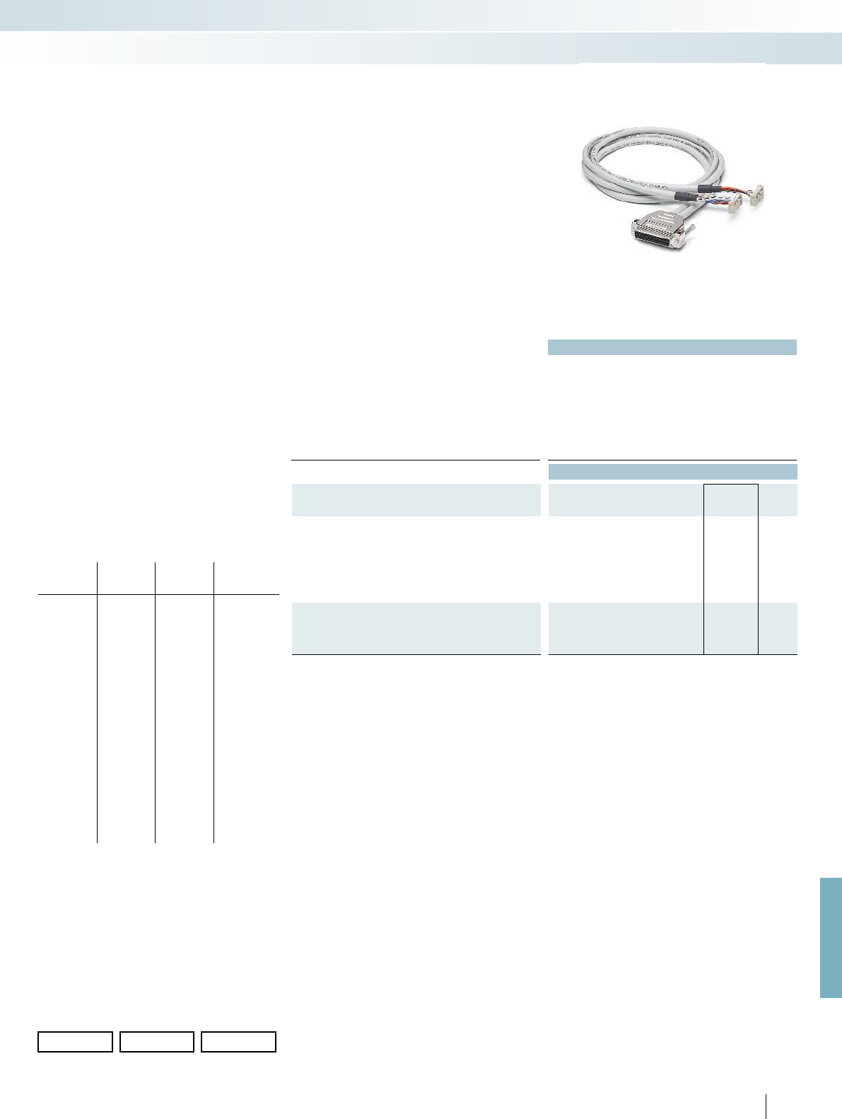
For further information and full technical data, visit phoenixcontact.net/products
491PHOENIX CONTACT
Technical data
Max. perm. operating voltage < 50 V AC / 60 V DC
Max. perm. current carrying capacity per path 1 A
Ambient temperature (operation) -20 °C ... 50 °C
Assembly Insulation displacement, IEC 60352-4/DIN EN 60352-4
Conductor cross section AWG - / 0.14 mm²
Conductor structure: stranded wires / material 7 / Cu tin-plated
Outside diameter
25-position 6.3 mm
Ordering data
Description No. of
pos. Cable length Type Order No. Pcs. /
Pkt.
VARIOFACE system cable, for S800 I/O, with a 25-pos. D-SUB
socket strip and two 14-pos. flat-ribbon cable connectors, in
standard lengths
25 1 m CABLE-D25SUB/B/2X14/100/TU812 2304649 1
25 2 m CABLE-D25SUB/B/2X14/200/TU812 2304652 1
25 3 m CABLE-D25SUB/B/2X14/300/TU812 2304665 1
25 5 m CABLE-D25SUB/B/2X14/500/TU812 2304678 1
VARIOFACE system cable for S800 I/O, with a 25-pos. D-SUB
socket strip and two 14-pos. flat-ribbon cable connectors, in
variable lengths
25 CABLE-D25SUB/B/2X14/TU812/... 2304681 1
Color code and pin assignment
CABLE-D25SUB/B/2X14...TU812
D-SUB
connector
25-pos.
FLK 14
1st
connector
FLK 14
2nd
connector
Conductor
color
1
2
3
4
5
6
7
8
9
10
11
12
13
14
15
16
17
18
19
20
21
22
23
24
25
9
10
1
3
5
7
NC
11
12
2
4
6
8
1
3
5
7
9
10
NC
2
4
6
8
11
12
Gray
White
Black
Red
Yellow
Blue
Black
Red
Yellow
Blue
Orange
White
–
White-black
White-brown
Brown
Orange
Green
Violet
Brown
Orange
Green
Violet
White-black
White-brown
Ordering example for system cable:
– Cable for ABB S800, 12.75 m long
Quantity Order No. Length [m]
1
)
12304681 /12.75
1
) min. 0.20 m
The ABB S800 I/O system offers the
possibility of realizing the process wiring
with D-SUB connectors. ABB TU 812
Compact MTU are available for this
purpose.
The CABLE-D25SUB/B/2X14/.../TU812
system cables convert digital signals from a
D-SUB socket strip to two flat-ribbon cable
connectors. Therefore, all 8-channel
interface modules of the system cabling can
be connected to S800 I/O modules. Two
interface modules are used per module.
ABB S800 I/O
System cable
System cabling for controllers
Controller-specific system cabling
System cable
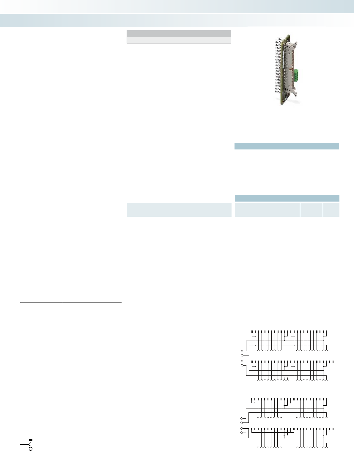
0-
0-
1-
1-
123456789101112131415161718192021222324
123456789101112131415161718
2526272829303132333435363738394041424344454647484950
NCNC
1920212223242526 27282930313233343536
0+
0-
1-
1+
123456789101112131415161718192021222324
123456789101112131415161718
2526272829303132333435363738394041424344454647484950
NCNC
1920212223242526 27282930313233343536
492
PHOENIX CONTACT
Technical data
Max. perm. operating voltage < 50 V AC / 60 V DC
Max. permissible current 1 A (per path)
8 A (per connection, supply via separate power supply)
Ambient temperature (operation) -20 °C ... 50 °C
Ambient temperature (storage/transport) -20 °C ... 70 °C
Connection data solid / stranded / AWG 0.14 ... 1.5 mm² / 0.14 ... 1.5 mm² / 28 - 16
Standards/regulations DIN EN 50178 / IEC 60664 / IEC 62103
Ordering data
Description No. of pos. Type Order No. Pcs. /
Pkt.
VARIOFACE front adapter, for ControlLogix:
- A maximum of 1 x 32 channels can be connected 50 FLKM 50-PA-AB/1756/EXTC 2302735 1
- IB 32 input board 50 FLKM 50-PA-AB/1756/IN/EXTC 2302748 1
Connection scheme: FLKM 50-PA-AB/1756/IN/EXTC
Connection scheme: FLKM 50-PA-AB/1756/EXTC
Front adapters for I/O modules of Allen Bradley
ControlLogix and Honeywell PlantScape automation
devices
Card type FLKM 50-PA-AB/1756/EXTC
Digital input 1756-IA 16 I* or TC-TDK 161*
1756-IB 16 D* or TC-TDX 161*
1756-IB 16 I* or TC-TDJ 161*
1756-IH 16 I*
Digital output 1756-OB 32 or TC-ODD 321
Analog input 1756-IF 8*
1756-IF 16 I* or TC-IAH 161*
1756-IF 8H* or TC-HAI 081*
Counter 1756-HSC*
Servo 1756-M02 AE*
Card type FLKM 50-PA-AB/1756/IN/EXTC
Digital input 1756-IB 32 or TC-IDD 321
* Only in conjunction with
VIP-2/SC/FLK50/AB-1756, Order No.: 2322317
VIP-2/PT/FLK50/AB-1756, Order No.: 2904286
There must be no voltage supply at the front adapter. Risk of short
circuit!
Flat-ribbon cable strip
Connection to I/O card
Screw terminal blocks for separate supply
Explanation:
I/O modules with 32 channels or of
this type
The front adapters are pushed into the
tall 1756-TBE covers (not supplied as
standard, original accessories must be
ordered directly from manufacturer) of the
controller. A 50-pos. system cable can
connect a maximum of 32 channels to the
field level.
Tailor-made VARIOFACE termination
boards round off this system concept.
Web code for the online configurator
Your web code: #0007
Allen Bradley ControlLogix,
Honeywell PlantScape
Front adapter
System cabling for controllers
Controller-specific system cabling
32-channel front adapter
with 50-pos. FLK strip
Notes:
Front adapters can also be used without cover.
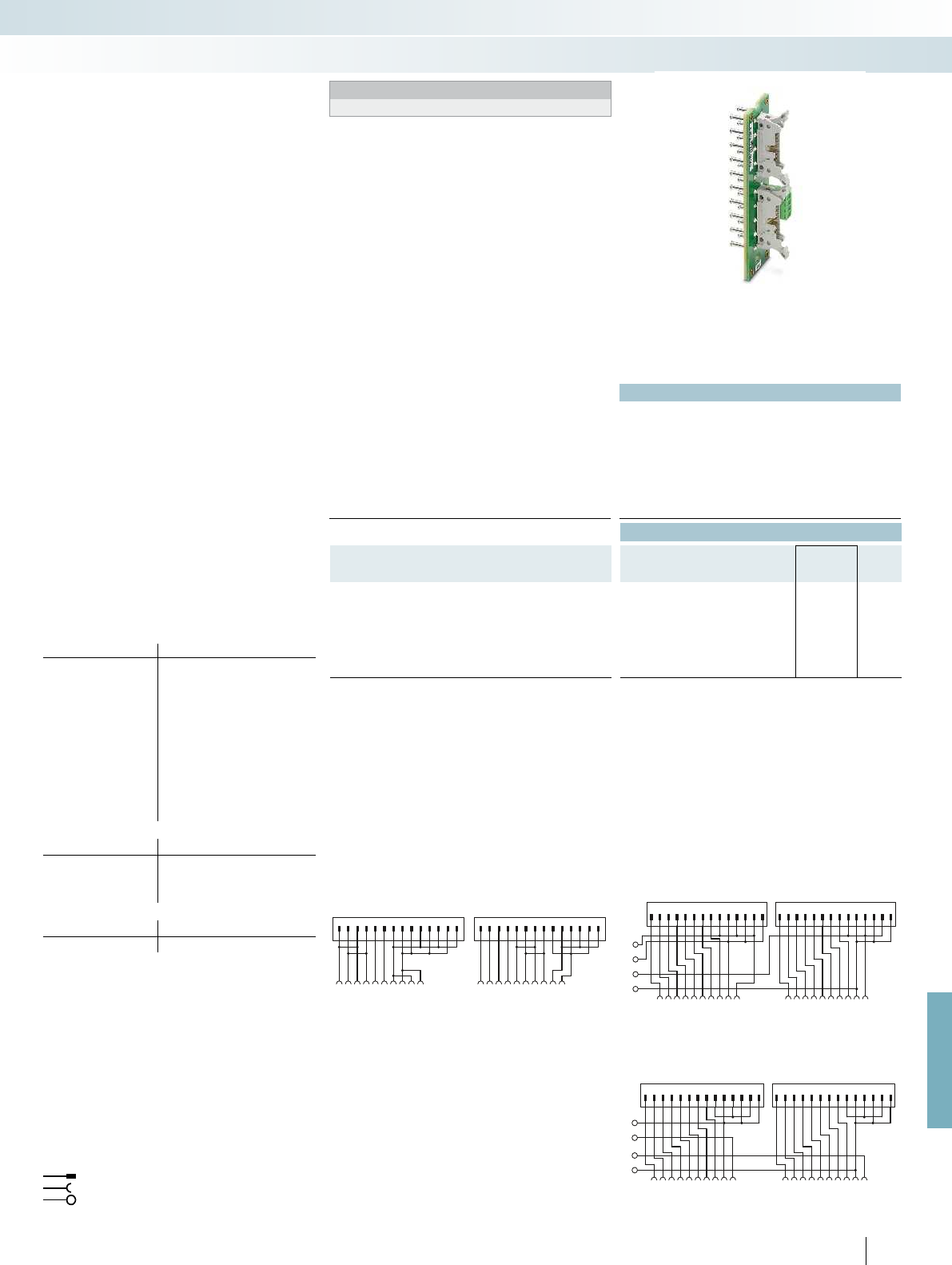
0-
0-
1-
1-
1234567891011121314 1234567891011121314
1234567891011121314151617181920
1234567891011
12
1314
1234567891011121314151617181920
1234567891011
12
1314
0+
0-
1+
1-
1234567891011121314 1 2 3 4 5 6 7 891011121314
1234567891011121314151617181920
For further information and full technical data, visit phoenixcontact.net/products
493
PHOENIX CONTACT
Technical data
Max. perm. operating voltage < 50 V AC / 60 V DC
Max. permissible current 1 A (per path)
8 A (per connection, supply via separate power supply)
Ambient temperature (operation) -20 °C ... 50 °C
Ambient temperature (storage/transport) -20 °C ... 70 °C
Connection data solid / stranded / AWG 0.14 ... 1.5 mm² / 0.14 ... 1.5 mm² / 28 - 16
Standards/regulations DIN EN 50178 / IEC 60664 / IEC 62103
Ordering data
Description No. of pos. Type Order No. Pcs. /
Pkt.
VARIOFACE front adapter, for ControlLogix:
– Up to 2 x 8 channels can be connected 14 FLKM 14-PA-AB/1756/EXTC 2302861 1
– IA 16, IB 16, IC 16, IN 16 input card 14 FLKM 14-PA-AB/1756/IN/EXTC 2302874 1
- IF6 I input card (only suitable for measuring
current; no power terminals on adapter)
14 FLKM 14-PA-AB/1756/IF6I/EXTC 2901037 1
Connection scheme: FLKM 14-PA-AB/1756/IN/EXTC
Connection scheme: FLKM 14-PA-AB/1756/IF6I/EXTC Connection scheme: FLKM 14-PA-AB/1756/EXTC
Front adapters for I/O modules of Allen Bradley
ControlLogix and Honeywell PlantScape automation
devices
Card type FLKM 14-PA-AB/1756/EXTC
Digital input 1756-IA 8 D** or TC-IDX 081**
Digital output 1756-OB 16 E
Analog input 1756-IF 6 CIS**
1756-IF 6 I** or TC-IAH 061**
1756-IR 6 I** or TC-IXR 061**
1756-IT 6 I** or TC-IXL 061**
Analog output 1756-OF 4 I**
1756-OF 6 CI** or TC-OAH 061**
1756-OF 6 VI** or TC-OAV 061**
1756-OF 8** or TC-OAV 081**
1756-OF 8 H**
Switch 1756-PLS**
Card type FLKM 14-PA-AB/1756/IN/EXTC
Digital input 1756-IN 16**
1756-IA 16 or TC-IDA 161**
1756-IB 16
1756-IC 16**
Card type FLKM 14-PA-AB/1756/IF6I/EXTC
Analog input IF6I**
** Only in conjunction with
VIP-2/SC/2FLK14/AB-1756, Order No.: 2322333
VIP-2/PT/2FLK14/AB-1756, Order No.: 2904288
There must be no voltage supply on the front adapter. Risk of
short circuit!
Flat-ribbon cable strip
Connection to I/O card
Screw terminal blocks for separate supply
Explanation:
I/O modules with 16 channels or of
this type
The front adapters are pushed into the
tall 1756-TBE covers (not supplied as
standard, original accessories must be
ordered directly from manufacturer) of the
controller. Two 14-pos. system cables are
used to connect up to 2 x 8 channels to the
field level.
Tailor-made VARIOFACE termination
boards round off this system concept.
Web code for the online configurator
Your web code: #0007
Allen Bradley ControlLogix,
Honeywell PlantScape
Front adapter
System cabling for controllers
Controller-specific system cabling
16-channel front adapter
with two 14-pos. FLK strips
Notes:
Front adapters can also be used without cover.

123579
4681012 14
11 13 15 17
16 182022 24 26 28
1921 23 25 27 2931 33 35 37 39
3032 34 36 384042 44 464850
41 43 45 47 49
VAC1
01234567
VAC2
98111013121514
X1
X2
1234567891011121314 1 2 3 4 5 6 7 891011121314
01234567 891011 121314 15 COMCOM
X1 X2
1234567891011121314 12345 67891011 12 1314
01234567891011 12 13 14 15 VDCVDC
X1 X2
1234567891011121314 1234567891011121314
VDC 01234567891011 12 13 14 15 COM
494
PHOENIX CONTACT
Technical data
FLKM 14-PA... FLKM 50-PA...
Max. perm. operating voltage < 50 V AC / 60 V DC < 50 V AC / 60 V DC
Max. permissible current 1 A (per path) 2 A (per path)
Max. perm. total current 2 A (per byte, for supply via
connector)
7 A (per byte, for supply via
connector)
Ambient temperature (operation) -20 °C ... 50 °C -20 °C ... 50 °C
Ambient temperature (storage/transport) -20 °C ... 70 °C -20 °C ... 70 °C
Mounting position any any
Standards/regulations IEC 60664 / DIN EN 50178 /
IEC 62103
IEC 60664 / DIN EN 50178 /
IEC 62103
Ordering data
Description No. of pos. Type Order No. Pcs. /
Pkt.
VARIOFACE front adapter, 2 x 8 channels can be connected for
Allen Bradley SLC 500 for:
- 1746 OB16, OV16, OG16 and IG16 14 FLKM 14-PA-SLC500/OUT 2293459 1
- 1746 IA16, IB16, ITB16 and IN16 14 FLKM 14-PA-SLC500/IN 2293462 1
- 1746 IV16 and IVT16 14 FLKM 14-PA-SLC500/IN/M 2293475 1
VARIOFACE front adapter, 1 x 16 channels can be connected for
Allen Bradley SLC 500 1746 OA16 and OW16
50 FLKM 50-PA-SLC500/OUT/2A 2293446 1
Connection scheme FLKM 50-PA-SLC500/OUT/2A Connection scheme FLKM 14-PA-SLC500/IN
Connection scheme FLKM 14-PA-SLC500/IN/M Connection scheme FLKM 14-PA-SLC500/OUT
Flat-ribbon cable strip
Connection to I/O card
Screw terminal blocks for separate supply
Explanation:
The front adapters mean that pre-
assembled system cables can be directly
connected to I/O modules.
– The FLKM 14-PA-SLC500... adapters
connect max. 2 x 8 channels via two
14-pos. system cables. Tailor-made
VARIOFACE termination boards with a
variety of functions and connection
options round off this system concept.
– With the FLKM50-PA-SLC500 OUT/2A
front adapters, the FLKM 50/16/SLC500
termination board and 50-position
system cables, the VARIOFACE system
cabling can also be coupled to the OA16
and OW16 power output cards.
Web code for the online configurator
Your web code: #0007
Allen Bradley SLC 500
Front adapter
System cabling for controllers
Controller-specific system cabling
Front adapter for SLC 500 1746,
2 x 8 channels can be connected
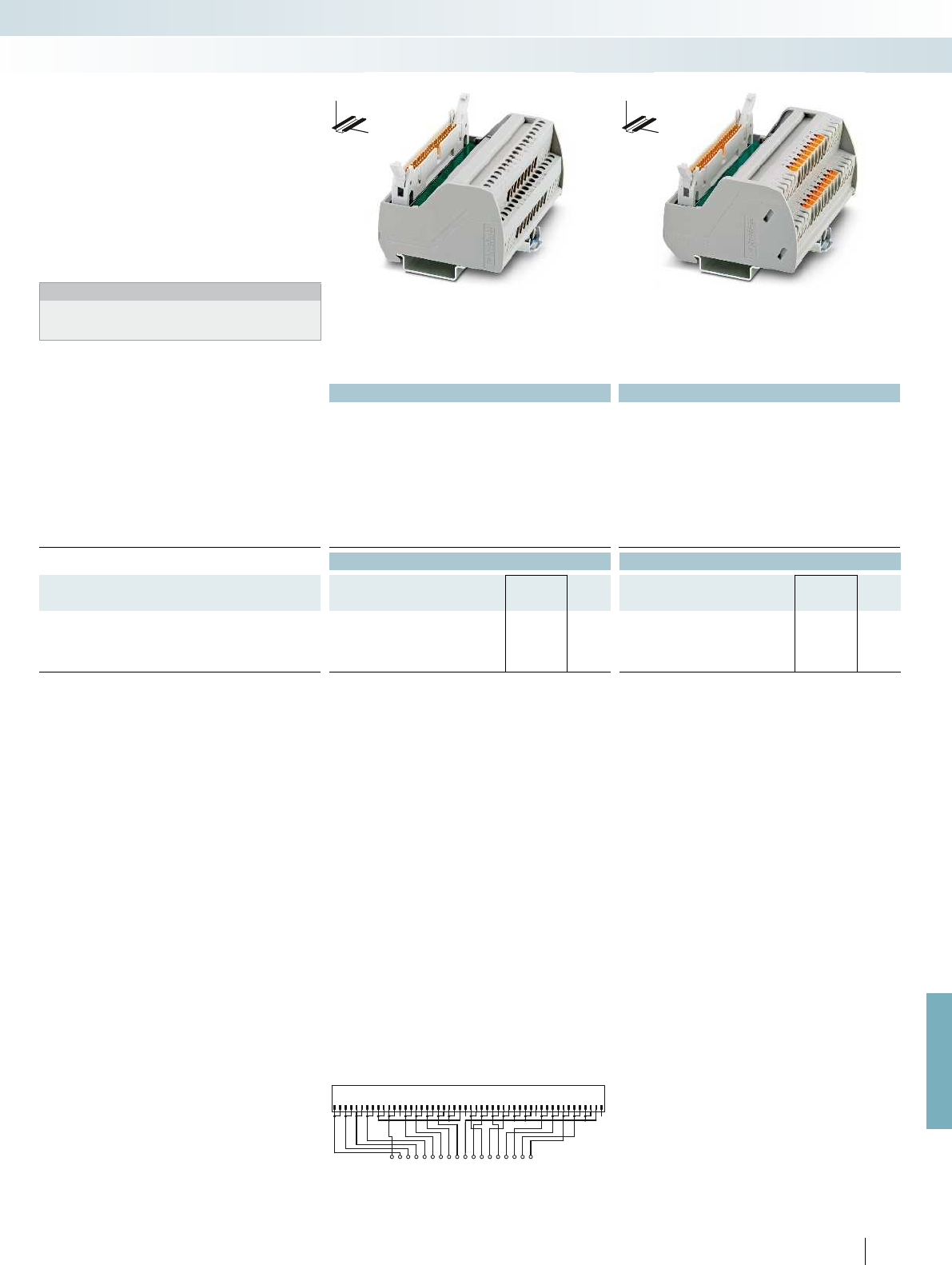
135
246810
7911 13 15 17 1921
12 14 16 182023 25 27 2931 33
22 24 26 283032 35 37 3941 43 45
34 36 384042 44 47 49
46 4850
VAC1
012345679
VAC2
81 11 013121514
For further information and full technical data, visit phoenixcontact.net/products
Technical data Technical data
Max. perm. operating voltage 120 V AC/DC 120 V AC/DC
Max. perm. current (per branch) 1 A 1 A
Max total current (voltage supply) 2 A (per channel) 2 A (per channel)
Ambient temperature (operation) -20 °C ... 50 °C -20 °C ... 50 °C
Mounting position any any
Standards/regulations IEC 60664, DIN EN 50178, IEC 62103 EN 50178
Connection method Field level Screw connection Push-in connection
Controller level IDC/FLK pin strip (2.54 mm) IDC/FLK pin strip (2.54 mm)
Connection data solid / stranded / AWG 0.2 ... 4 mm² / 0.2 ... 2.5 mm² / 24 - 12 0.14 ... 2.5 mm² / 0.14 ... 2.5 mm² / 26 - 14
Dimensions H / D 65.5 mm / 56 mm 72.1 mm / 56 mm
Ordering data Ordering data
Description No. of
pos.
Module width
WType Order No. Pcs. /
Pkt. Type Order No. Pcs. /
Pkt.
VARIOFACE controller board, for transfer of max. 16 channels,
only in connection with FLKM 50-PA-SLC500 OUT/2A
- with screw connection 50 90.8 mm VIP-2/SC/FLK50/16/SLC500 2322320 1
- with push-in connection 50 92.7 mm VIP-2/PT/FLK50/16/SLC500 2904287 1
Connection scheme VIP-2/.../FLK50/16/SLC500
495
PHOENIX CONTACT
System cabling for controllers
Controller-specific system cabling
VARIOFACE termination board for 16 channels
with screw connection
VARIOFACE termination board for 16 channels
with push-in connection
The VIP-2/.../FLK50/16/SLC500
VARIOFACE Professional (VIP) module has
been designed specifically for OA16 and
OW16 output modules. When used in
conjunction with the
FLKM 50-PA-SLC500/OUT/2A front
adapter, currents up to 2 A per channel can
be transferred with the system cabling.
Notes:
For marking systems (e.g., “ZB 22:UNBEDRUCKT”;
Order No. 0811862) and mounting material, see Catalog 5.
DW
H
DW
H
VIP termination board for
Allen Bradley SLC 500,
2 A output cards

496
PHOENIX CONTACT
Allen Bradley SLC 500
System cable for 32 channels
The 32-channel I/O cards of the SLC 500
are connected using 40-pos. connectors
(already integrated into the I/O modules).
Passive interface modules (-3/SC/FLK40,
etc.) are connected to the I/O cards using
the FLK 40/EZ-DR/.../SLC system cables.
32 channels are split into 4x8 channels
using the FLK 40/4X14/EZ-DR/... system
cables.
The following 8-channel system cabling
modules can be coupled:
– OB32 and IB32
passive and active modules plus
V8 adapter
– OV32 and IV32
passive modules without status indicator
Web code for the online configurator
Your web code: #0007
Technical data
Max. perm. operating voltage < 50 V AC / 60 V DC
Max. perm. current carrying capacity per path 1 A
Ambient temperature (operation) -20 °C ... 50 °C
Assembly Insulation displacement, IEC 60352-4/DIN EN 60352-4 Insulation displacement, IEC 60352-4/DIN EN 60352-4
Conductor cross section AWG 26 / 0.14 mm²
Conductor structure: stranded wires / material 7 / Cu tin-plated
Outside diameter
40-position 10 mm
Ordering data
Description No. of
pos. Cable length Type Order No. Pcs. /
Pkt.
Assembled round cable, with two 40-pos. socket strips in fixed
lengths (50 cm increments) for connection to 32-channel I/O cards
of the SLC 500
40 0.5 m FLK 40/EZ-DR/ 50/SLC 2294610 1
40 1 m FLK 40/EZ-DR/ 100/SLC 2294623 1
40 1.5 m FLK 40/EZ-DR/ 150/SLC 2294636 1
40 2 m FLK 40/EZ-DR/ 200/SLC 2294649 1
40 3 m FLK 40/EZ-DR/ 300/SLC 2294652 1
Assembled round cable, for connection to Allen-Bradley
SLC500, OB32 and IB32, with one 40-position socket strip and four
14-position socket strips, for splitting max. 32 channels into 4 x 8
channels.
for OB32 40 0.5 m
40 1 m
40 2 m
40 3 m
for IB32 40 0.5 m
40 1 m
40 2 m
40 3 m
System cabling for controllers
Controller-specific system cabling
System cable for
32-channel I/O cards of the SLC 500
(OB32, OV32, IB32, IV32)

For further information and full technical data, visit phoenixcontact.net/products
497
PHOENIX CONTACT
Technical data
< 50 V AC / 60 V DC
1 A
-20 °C ... 50 °C
2-4 Insulation displacement, IEC 60352-4/DIN EN 60352-4
AWG 26 / 0.14 mm²
7 / Cu tin-plated
7.8 mm
Ordering data
Type Order No. Pcs. /
Pkt.
FLK 40/4X14/EZ-DR/ 50/OB32 2296786 1
FLK 40/4X14/EZ-DR/ 100/OB32 2298483 1
FLK 40/4X14/EZ-DR/ 200/OB32 2298522 1
FLK 40/4X14/EZ-DR/ 300/OB32 2298535 1
FLK 40/4X14/EZ-DR/ 50/IB32 2296812 1
FLK 40/4X14/EZ-DR/ 100/IB32 2296825 1
FLK 40/4X14/EZ-DR/ 200/IB32 2296838 1
FLK 40/4X14/EZ-DR/ 300/IB32 2296841 1
System cabling for controllers
Controller-specific system cabling
System cable for
splitting max. 32 channels into 4 x 8 channels
(OB32, IB32)

Technical data
Max. perm. operating voltage < 50 V AC / 60 V DC
Max. perm. current carrying capacity per path 1 A
Max. conductor resistance 0.16 /m
Ambient temperature (operation) -20 °C ... 50 °C
Conductor cross section AWG 26 / 0.14 mm²
Outside diameter
16-position 6.8 mm
20-position 7.6 mm
24-position 6.5 mm
20-position 10.3 mm
Ordering data
Description No. of
pos. Cable length Type Order No. Pcs. /
Pkt.
System cable, for 16-pos. “mass termination blocks” with a
16-pos. and a 14-pos. flat-ribbon cable connector for connection to
PLC-INTERFACE
16 0.3 m FLK 16/14/DV-OUT/ 30 2304348 1
16 0.5 m FLK 16/14/DV-OUT/ 50 2304351 1
16 1 m FLK 16/14/DV-OUT/100 2300575 1
16 2 m FLK 16/14/DV-OUT/200 2300588 1
16 3 m FLK 16/14/DV-OUT/300 2304364 1
Variable cable length 16 FLK 16-14-DV-OUT/... 2304377 1
System cable, for 16-pos. “mass termination blocks” with a
16-pos. and a 14-pos. flat-ribbon cable connector for connection to
PLC-INTERFACE
16 0.5 m FLK 16/14/DV-IN/ 50 2304393 1
16 1 m FLK 16/14/DV-IN/100 2300559 1
16 2 m FLK 16/14/DV-IN/200 2300562 1
16 3 m FLK 16/14/DV-IN/300 2304403 1
16 4 m FLK 16/14/DV-IN/400 2305185 1
Variable cable length 16 FLK 16-14-DV-IN/... 2304416 1
System cable, for 40-pos. (2 x 20) “mass termination blocks”
with a 20-pos. and two 14-pos. flat-ribbon cable connectors for
connection to PLC-INTERFACE (two cables should be used
per 32-channel I/O card)
20 1 m FLK 20/2FLK14/EZ-DR/100/KONFEK 2298470 1
20 2 m FLK 20/2FLK14/EZ-DR/200/KONFEK 2298438 1
20 3 m FLK 20/2FLK14/EZ-DR/300/KONFEK 2300818 1
Variable cable length 20 FLK 20/2FLK14/EZ-DR/... 2304487 1
System cable, for 24-pos. “mass termination blocks” with a
24-pos. and a 16-pos. flat-ribbon cable connector for connection to
with UM-DELTAV/... modules
24 0.3 m FLK 16/24/DV-AI/EZ-DR/ 30 2304319 1
24 0.5 m FLK 16/24/DV-AI/EZ-DR/ 50 2304296 1
24 1 m FLK 16/24/DV-AI/EZ-DR/100 2301134 1
24 2 m FLK 16/24/DV-AI/EZ-DR/200 2301545 1
24 3 m FLK 16/24/DV-AI/EZ-DR/300 2304322 1
Variable cable length 24 FLK 16-24-DV-AI-EZ-DR/... 2304335 1
System cable, for 40-pos. “mass termination blocks” with two
20-pos. and one 50-pos. flat-ribbon cable connectors for
connection to 32-channel interface modules
20 0.5 m FLK 50/2FLK20/EZ-DR/ 50/DV 2304872 1
20 1 m FLK 50/2FLK20/EZ-DR/ 100/DV 2304898 1
20 2 m FLK 50/2FLK20/EZ-DR/ 200/DV 2304908 1
20 3 m FLK 50/2FLK20/EZ-DR/ 300/DV 2304911 1
20 6 m FLK 50/2FLK20/EZ-DR/ 600/DV 2304937 1
20 8 m FLK 50/2FLK20/EZ-DR/ 800/DV 2304940 1
20 10 m FLK 50/2FLK20/EZ-DR/1000/DV 2304953 1
Variable cable length 20 FLK 50-2FLK20-EZ-DR-DV/... 2304966 1
498
PHOENIX CONTACT
The DeltaV system allows you to install
the process wiring through “mass
termination blocks” (MTB) using flat-ribbon
cable connectors. In addition to the 10, 16,
and 20-pos. system cables of system cabling
(see page 574), the following system-specific
cables are available:
–FLK 16/14/DV-OUT/..., for digital
modules with 16-pos. MTB for
connection to PLC-INTERFACE
–FLK 16/14/DV-IN/..., for digital modules
with 16-pos. MTB for connection to
PLC-INTERFACE
–FLK 20/2FLK14/EZ-DR/..., for digital
modules with 40-pos. MTB for
connection to PLC-INTERFACE
–FLK 16/24/DV-AI/EZ-DR/..., for analog
modules with 24-pos. MTB
–FLK 50/2FLK20/EZ-DR/.../DV system
cables are specifically designed for
32-channel I/O modules with 40-pin MTB
for the purpose of connecting
I/O modules to 32-channel VARIOFACE
interface modules
Emerson DeltaV
System cable
System cabling for controllers
Controller-specific system cabling
System cable for DeltaV
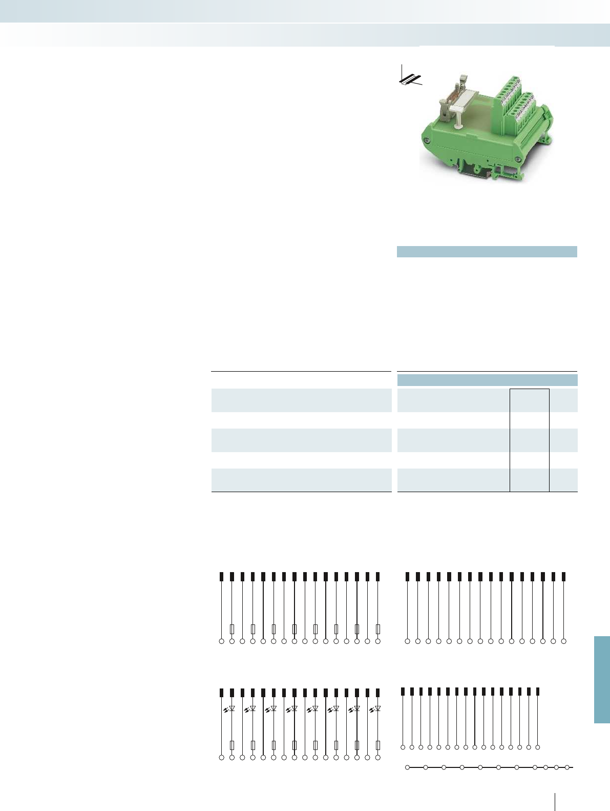
124681012 14 16357911 13 15
CH1CH1CH2CH3CH4CH5CH6CH7CH8CH2CH3CH4CH5CH6CH7CH8
+--------+++++++
124681012 14 16357911 13 15
CH1
COMCOMCOMCOMCOMCOMCOMCOMCOMCOMCOM
CH1CH2CH3CH4CH5CH6CH7CH8CH2CH3CH4CH5CH6CH7CH8
+--------+++++++
124681012 14 16357911 13 15
CH1CH1CH2CH3CH4CH5CH6CH7CH8CH2CH3CH4CH5CH6CH7CH8
+--------+++++++
+--------+++++++
1234567 891011 12 13 14 15 16
Ch1Ch1Ch2Ch2Ch3Ch3Ch4Ch4Ch5Ch5Ch6Ch6Ch7Ch7Ch8Ch8
For further information and full technical data, visit phoenixcontact.net/products
499PHOENIX CONTACT
Technical data
FLKM 16/.../DV FLKM 16/.../SI/.../DV
Max. perm. operating voltage < 50 V AC / 60 V DC < 50 V AC / 60 V DC
Max. perm. current (per branch) 1 A (per signal path) 50 mA (in delivered state, with
one 50 mA fuse, max. 1 A
permitted)
Ambient temperature (operation) -20 °C ... 50 °C -20 °C ... 50 °C
Mounting position any any
Standards/regulations DIN EN 50178, IEC 60664, IEC 62103
Connection method Field level Screw connection Screw connection
Controller level IDC/FLK pin strip (2.54 mm) IDC/FLK pin strip (2.54 mm)
Connection data solid / stranded / AWG 0.2 ... 4 mm² / 0.2 ... 2.5 mm² / 24 - 12
Dimensions H / D 90 mm / 68 mm
Ordering data
Description No. of
pos.
Module width
WType Order No. Pcs. /
Pkt.
Interface module, with 1:1 connection
16 45 mm FLKM 16/DV 2304432 1
Interface module, with 1:1 connection and separate potential
terminal blocks per channel
16 57 mm FLKM 16/AI/DV 2304429 1
Interface module, with fuses per channel
16 90 mm FLKM 16/AO/SI/DV 2304445 1
Transfer module, with LED and fuses per channel, max. permitted
operating voltage 30 V DC
16 90 mm FLKM 16/DI/SI/LA/DV 2304458 1
FLKM 16/DI/SI/LA/DV connection scheme FLKM 16/AI/DV connection scheme
FLKM 16/AO/SI/DV connection scheme FLKM 16/DV connection scheme
These system-specific interface modules
for DeltaV modules are used in combination
with the respective system cables. The
controller board is connected to 8-channel
modules through “mass termination blocks”
with flat-ribbon cable connection.
FLKM 16/DV
– Universal module
– 1:1 connection
FLKM 16/AI/DV
– 1:1 connection
– Separate equipotential terminals per
channel
FLKM 16/AO/SI/DV
– 1:1 connection
– Fuse 5 x 20, 50 mA T, IEC60127-2/3 per
channel
FLKM 16/DI/SI/LA/DV
– 1:1 connection
– Fuse 5 x 20, 50 mA T, IEC60127-2/3 per
channel
– LED status indicator per signal path
Emerson DeltaV
Controller board for eight channels
System cabling for controllers
Controller-specific system cabling
DW
H
Interface module for 8 channels
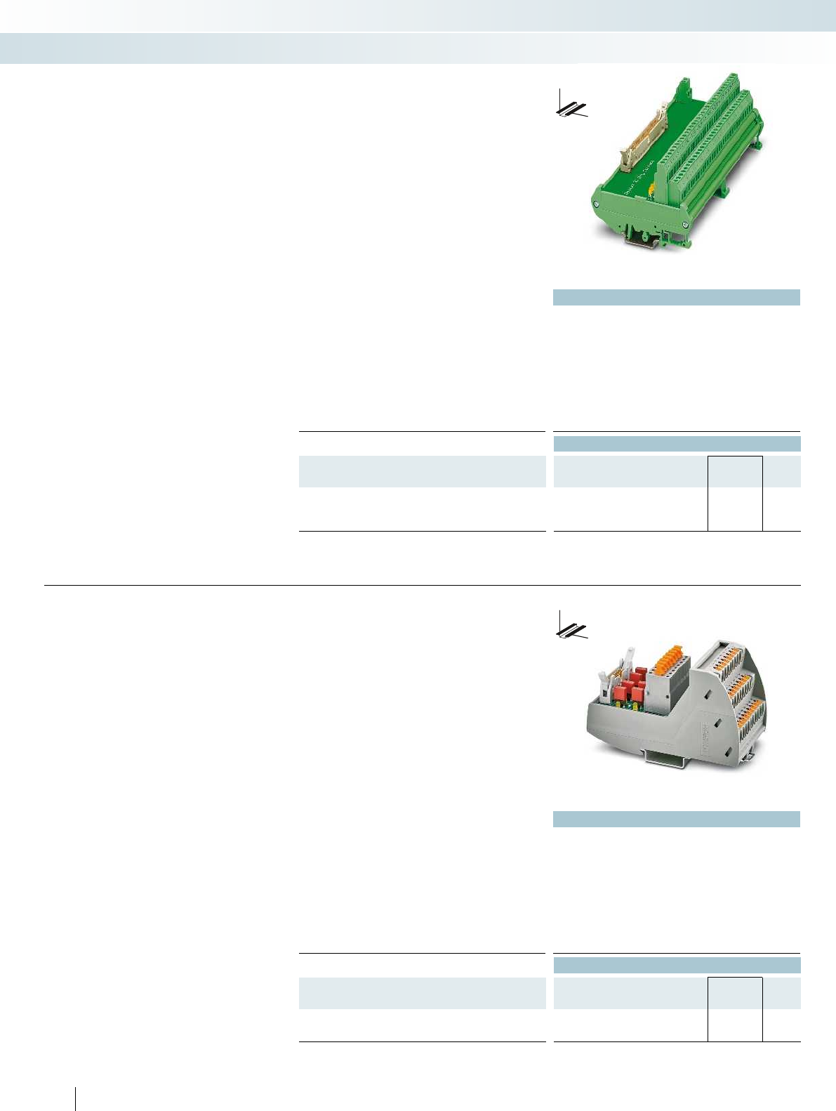
Technical data
FLKM 50/32M/DV FLKM 50/32M/IN/LA/DV
Max. perm. operating voltage < 50 V AC / 60 V DC 30 V DC
Max. perm. current (per branch) 1 A 1 A
Ambient temperature (operation) -20 °C ... 50 °C -20 °C ... 50 °C
Mounting position any any
Standards/regulations DIN EN 50178, IEC 60664, IEC 62103
Connection method Field level Screw connection Screw connection
Controller level IDC/FLK pin strip (2.54 mm) IDC/FLK pin strip (2.54 mm)
Connection data solid / stranded / AWG 0.2 ... 4 mm² / 0.2 ... 2.5 mm² / 24 - 12
Dimensions H / D 90 mm / 68 mm
Ordering data
Description No. of
pos.
Module width
WType Order No. Pcs. /
Pkt.
VARIOFACE interface modules, for 32-channel I/O modules:
- Input/output 50 169 mm FLKM 50/32M/DV 2304869 1
- Input with LED per signal 50 169 mm FLKM 50/32M/IN/LA/DV 2304856 1
DW
H
These system-specific interface modules
for DeltaV modules are used in combination
with the FLK 50/2FLK20/EZ-DR/.../DV
system cables. The controller board is
connected to 32-channel modules through
40-pos. “mass termination blocks” with
flat-ribbon cable connection.
FLKM 50/32M/DV
– Can be used for 32-channel input and
output cards
– Two-conductor connection with a
separate negative terminal per channel
FLKM 50/32M/IN/LA/DV
– Can be used for 32-channel input
modules
– LED status display per channel
– Two-conductor connection with a
separate negative terminal per channel
(Dry Contact)
Emerson DeltaV
Controller board for
32 channels
System cabling for controllers
Controller-specific system cabling
Interface module with two-conductor
connection technology for DeltaV
Technical data
Max. perm. operating voltage 24 V DC
Max. perm. current (per branch) 63 mA (in as supplied state, with one 63 mA fuse)
Ambient temperature (operation) -20 °C ... 60 °C
Mounting position any
Standards/regulations DIN EN 50178
Connection method Field level Push-in connection
Controller level IDC/FLK pin strip (2.54 mm)
Connection data solid / stranded / AWG 0.14 ... 2.5 mm² / 0.14 ... 2.5 mm² / 26 - 14
Dimensions H / D 109.8 mm / 63 mm
Ordering data
Description No. of
pos.
Module width
WType Order No. Pcs. /
Pkt.
Interface module for 16-pos. mass termination block
16 57.1 mm VIP-PT/FLK16/DS/FU/LED/AN/DV 2903599 1
500
PHOENIX CONTACT
DW
H
System-specific interface module for use
in combination with the respective system
cables. The controller board is connected
to 8-channel modules through 16-position
“mass termination blocks” with flat ribbon
cable connection.
Features:
– Fuse per channel
– Separate equipotential terminals per
channel
– Knife disconnection for each channel
– Push-in connection
Emerson DeltaV
VIP controller board with fuses for
8 channels
Interface module with fuses for 16-pos. mass
terminal block
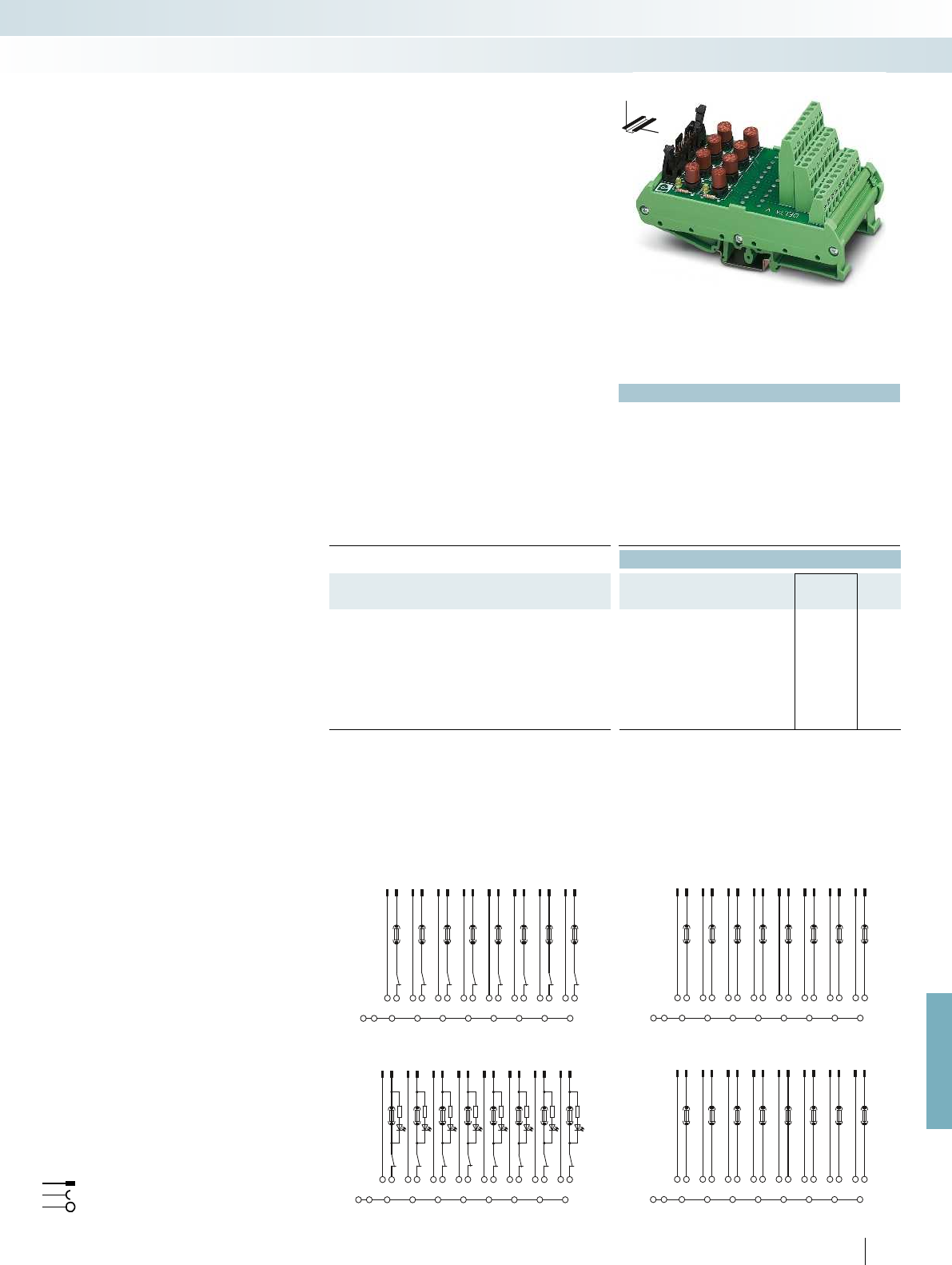
12 34 56 789101112 1314 1516
1- 1+ 2- 2+ 3- 3+ 4- 4+ 5- 5+ 6- 6+ 7- 7+ 8-8+
SHSHSHSHSHSHSHSHSHSH
12 34 56 789101112 1314 1516
1- 1+ 2- 2+ 3- 3+ 4- 4+ 5- 5+ 6- 6+ 7- 7+ 8-8+
SHSHSHSHSHSHSHSHSHSH
12 34 56 789101112 1314 1516
1- 1+ 2- 2+ 3- 3+ 4- 4+ 5- 5+ 6- 6+ 7- 7+ 8-8+
SHSHSHSHSHSHSHSHSHSH
123456789101112 1314 15 16
1- 1+ 2- 2+ 3- 3+ 4- 4+ 5- 5+ 6- 6+ 7- 7+ 8-8+
SHSHSHSHSHSHSHSHSHSH
For further information and full technical data, visit phoenixcontact.net/products
501
PHOENIX CONTACT
Technical data
Max. perm. operating voltage 24 V DC
Max. perm. current (per branch)
50 mA (in as-supplied state, with one 50 mAF fuse, max. 1 A permitted)
Ambient temperature (operation) -20 °C ... 50 °C
Mounting position any
Standards/regulations IEC 60664, DIN EN 50178, IEC 62103
Connection method Field level Screw connection
Controller level IDC/FLK pin strip (2.54 mm)
Connection data solid / stranded / AWG 0.2 ... 4 mm² / 0.2 ... 2.5 mm² / 24 - 12
Dimensions H / D 126 mm / 71 mm
Ordering data
Description No. of
pos.
Module width
WType Order No. Pcs. /
Pkt.
Interface modules for 16-pos. and 24-pos. “mass termination
blocks” with:
- Fuses 16 61 mm UM-DELTA V/D/SI 5603255 1
- Fuses and knife disconnect
terminal blocks
16 61 mm UM-DELTAV/D/SI/BFI/TP 5603257 1
- Fuses and fuse failure display 16 61 mm UM-DELTAV/A/SI 5603256 1
- Fuses, fuse failure display and knife
disconnect terminal blocks
16 61 mm UM-DELTAV/A/SI/BFI/TP 5603258 1
Connection scheme UM-DELTAV/A/SI/BFI/TP Connection scheme UM-DELTAV/D/SI/BFI/TP
Connection scheme UM-DELTAV/A/SI Connection scheme UM-DELTAV/D/SI
Flat-ribbon cable strip
Connection to I/O card
Screw terminal blocks for separate supply
Explanation:
These system-specific interface modules
for DeltaV modules are used in combination
with the respective system cables. The
controller board is connected to 8-channel
modules through 16-pos. or 24-pos. “mass
termination blocks” with flat-ribbon cable
connection.
UM-DELTA V/D/SI
– Fuse per channel
– Separate equipotential terminals per
channel
UM-DELTA V/D/SI
– Fuse per channel
– Separate equipotential terminals per
channel
– Knife disconnection for each channel
UM-DELTA V/D/SI/BFI/TP
– Fuse and LED status indicator per channel
– Separate equipotential terminals per
channel
Emerson DeltaV
Controller boards with fuses for
8 channels
System cabling for controllers
Controller-specific system cabling
DW
H
Interface module with fuses for
16-pos. and 24-pos. “mass termination blocks”
UM-DELTA V/D/SI
– Fuse and LED status indicator per channel
– Separate equipotential terminals per
channel
– Knife disconnection for each channel
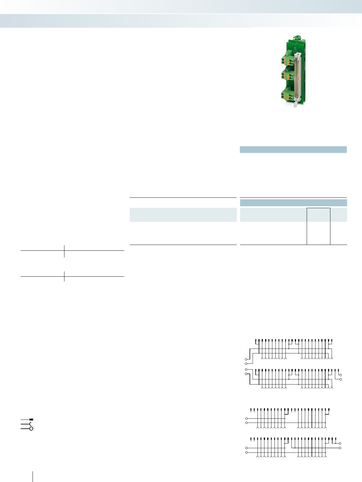
123456789101112131415161718192021222324
NCNC NCNC
NC
1–
2–
3–
A
4–
B
NC
123456789101112131415161718
252627282930
31
32333435363738394041424344454647484950
21
20
1922232425262731
30
29
283233343536
0+
0–
1–
1+
123456789101112131415161718192021222324
123456789101112131415161718
2526272829303132333435363738394041424344454647484950
1920212223242526 27282930313233343536
A
B
502
PHOENIX CONTACT
Technical data
Max. perm. operating voltage < 50 V AC / 60 V DC
Max. permissible current 1 A (per path)
8 A (per connection, supply via separate power supply)
Ambient temperature (operation) -20 °C ... 50 °C
Ambient temperature (storage/transport) -20 °C ... 70 °C
Mounting position any
Standards/regulations DIN EN 50178 / IEC 60664 / IEC 62103
Ordering data
Description No. of pos. Type Order No. Pcs. /
Pkt.
VARIOFACE front adapter, for PACSystems RX3i,
For digital output and analog modules 50 FLKM 50-PA-GE/TKFC/RXI 2321473 1
For digital input modules 50 FLKM 50-PA-GE/TKFC/RXI/IN 2321486 1
Connection scheme for FLKM 50-PA-GE/TKFC/RXI/IN
Connection scheme for FLKM 50-PA-GE/TKFC/RXI
Front adapter for I/O modules of RX3i series
Card type FLKM 50-PA/GE/TKFC/RXI
Digital output IC 694 MDL 754
Card type FLKM 50-PA/GE/TKFC/RXI/IN
Digital input IC 694 MDL 660
Flat-ribbon cable strip
Connection to I/O card
Screw terminal blocks for separate supply
Explanation:
The front adapters mean that pre-
assembled system cables can be directly
connected to I/O modules.
– Transfer of max. 32 channels over one
50-position system cable
– Can be plugged onto I/O modules
– Connection via suitable VARIOFACE
termination boards
Web code for the online configurator
Your web code: #0007
GE Fanuc/RX3i
Front adapters
System cabling for controllers
Controller-specific system cabling
Front adapter for GE Fanuc
RX3i
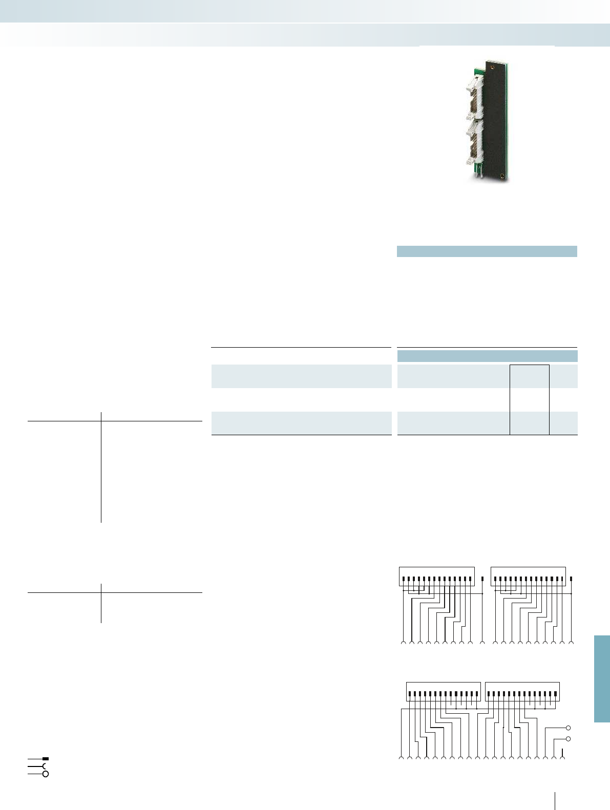
1
2
345678910
-
11 12 13 14 15 16 17 181920
0V
+24 V
1234567891011121314 1 2 3 4 5 6 7 891011121314
20191817 16 15 14 13 12 11
+-
109876543 2 1
-+
1413121110987654321 B1413121110987654321 A
For further information and full technical data, visit phoenixcontact.net/products
503
PHOENIX CONTACT
Technical data
Max. perm. operating voltage < 50 V AC / 60 V DC
Max. permissible current 1 A (per path)
4 A (per connection, supply via separate power supply)
Max. perm. total current 3 A (per byte, for supply via connector)
Ambient temperature (operation) -20 °C ... 50 °C
Ambient temperature (storage/transport) -20 °C ... 70 °C
Mounting position any
Standards/regulations IEC 60664 / DIN EN 50178 / IEC 62103
Ordering data
Description No. of pos. Type Order No. Pcs. /
Pkt.
VARIOFACE front adapter, for Series 90-30, max. 2 x 8 channels
can be connected, digital output
14 FLKM 14-PA/GE/DO 2290009 2
VARIOFACE front adapter, for Series 90-30, max. 2 x 8 channels
can be connected, digital input
14 FLKM 14-PA/GE/DI 2290038 5
Connection scheme FLKM 14-PA/GE/DI
Connection scheme FLKM 14-PA/GE/DO
Front adapter for Series 90-30 I/O modules
Card type FLKM 14-PA/GE/DO
Digital output IC 693 MDL 732
IC 693 MDL 733*
IC 693 MDL 740
IC 693 MDL 741*
IC 693 MDL 742
Analog IC 693 ALG 220*
IC 693 ALG 221*
IC 693 ALG 222*
IC 693 ALG 223*
IC 693 ALG 390*
IC 693 ALG 391*
IC 693 ALG 392*
IC 693 ALG 442*
Card type FLKM 14-PA/GE/DI
Digital input IC 693 MDL 241
IC 693 MDL 634
IC 693 MDL 645
IC 693 MDL 646
* Only in conjunction with VIP-2/SC/2FLK14(1-20)/S7, Order No.:
2315230 and UM 45-2FLK14/ZFKDS/S7, Order No.: 2965156.
All wire jumpers (DR) on the adapter must be disconnected.
There must be no voltage supply at the front adapter (flowing via
the slip-on connections)!
Flat-ribbon cable strip
Connection to I/O card
Screw terminal blocks for separate supply
Explanation:
The front adapters mean that pre-
assembled system cables can be directly
connected to I/O modules.
Up to 2 x 8 channels are connected via
two 14-pos. system cables.
Tailor-made VARIOFACE termination
boards with a variety of functions and
connection options round off this system
concept.
Web code for the online configurator
Your web code: #0007
GE-FANUC, Series 90-30
Front adapter
System cabling for controllers
Controller-specific system cabling
Front adapter for GE-FANUC
Series 90-30
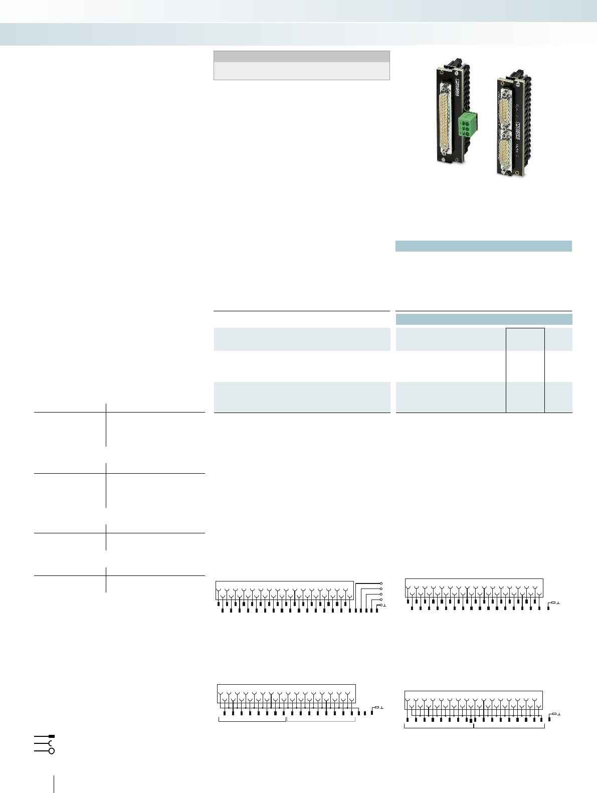
2
1
1
3
2
5
3
7
4
9
5
11
6
13
7
15
8
17
1
19
2
21
3
23
4
25
5
27
6
29
7
31
8
4681012 14 16 182022 24 26 283032
910Housing
D-SUB
Byte 0Byte 1
Byte 0 + 1
Byte 0 + 1
2
1
1
3
2
5
3
7
4
9
5
11
6
13
7
15
8
17
1
19
2
21
3
23
4
25
5
27
6
29
7
31
8
4681012 14 16
10
182022 24 26 283032
10Housing
D-SUB
Byte 0 Byte 1
2
20
1
1
3
2
5
3
7
4
9
5
11
6
13
7
15
8
17
9
19
10
21
11
23
12
25
13
27
14
29
15
31
16
4
21
6
22
8
23
10
24
12
25
14
26
16
27
18
28
20
29
22
30
24
31
26
32
28
33
30
34
32
35 17
1-
SP
1836 37
Housing
2-
3-
4-
D-SUB
2
20
1
1
3
2
5
3
7
4
9
5
11
6
13
7
15
8
17
9
19
10
21
11
23
12
25
13
27
14
29
15
31
16
4
21
6
22
8
23
10
24
12
25
14
26
16
27
18
28
20
29
22
30
24
31
26
32
28
33
30
34
32
35 Housing
D-SUB
504
PHOENIX CONTACT
Technical data
Max. perm. operating voltage 60 V DC
Max. permissible current 1 A (per path)
Ambient temperature (operation) -20 °C ... 50 °C
Ambient temperature (storage/transport) -20 °C ... 70 °C
Mounting position any
Standards/regulations IEC 60664 / DIN EN 50178 / IEC 62103
Ordering data
Description No. of pos. Type Order No. Pcs. /
Pkt.
VARIOFACE front adapter for Series CI/O, with
one D-SUB pin strip
- For digital I/O modules 37 FLKM-PA-D37/HW/DIO/C300 2901423 1
- For analog I/O modules 37 FLKM-PA-D37/HW/AN/C300 2900622 1
VARIOFACE front adapter for Series CI/O, with
two D-SUB pin strips
- For digital output modules 15 FLKM-PA-2D15/HW/DO/C300 2900924 1
- For digital input modules 15 FLKM-PA-2D15/HW/DI/C300 2901879 1
FLKM-PA-2D15/HW/DI/C300 connection scheme Connection scheme: FLKM-PA-2D15/HW/DO/C300
Connection scheme: FLKM-PA-D37/HW/AN/C300 Connection scheme: FLKM-PA-D37/HW/DIO/C300
Front adapter for I/O modules of Series C300, Series CI/O
Card type FLKM-PA-D37/HW/DIO/C300
Digital input TDIL 11*
TDIL 01*
Digital output TDOB 11*
TDOB 01*
Card type FLKM-PA-D37/HW/AN/C300
Analog input TAIX 01**
TAIX 11**
Analog output TAOX 01**
TAOX 11**
Card type FLKM-PA-2D15/HW/DO/C300
Digital output TDOB 01*
TDOB 11*
Card type FLKM-PA-2D15/HW/DI/C300
Digital input TDIL 01*
TDIL 11*
* Two front adapters are required for each module.
** For three-conductor operation (channels 13 - 16) of input modules:
only in conjunction with VIP-3/SC/D37SUB/M/HW/C300, Order
No. 2900675.
Connector
Connection to I/O card
Screw terminal blocks for separate supply
Explanation:
The front adapters mean that pre-
assembled system cables can be directly
connected to I/O modules.
FLKM-PA-D37/HW/DIO/C300
– Front adapter with D-SUB connector
– Connection of a maximum of 16 digital
channels
– Specifically for digital I/O cards
FLKM-PA-D37/HW/AN/C300
– Front adapter with D-SUB connector
– Connection of analog modules
FLKM-PA-2D15/HW/.../C300
– Front adapter with two 15-pos. D-SUB
connectors
– Connection of a maximum of
2 x 8 digital inputs/outputs per adapter
– Specifically for connecting
PLC-V8/D15.../OUT or PLC-V8/D15.../IN
Web code for the online configurator
Your web code: #0007
Honeywell C300, Series CI/O
Front adapters
System cabling for controllers
Controller-specific system cabling
Honeywell C300 front adapter
Notes:
Matching system cable fitted with D-SUB socket strip at both ends,
see page 611

1
1+
20
2-
2
3+
21
4-
3
5+
22
6-
4
7+
23
8-
5
9+
24
10-
6
11+
25
12-
7
13+
26
14-
8
15+
27
16-
9
17+
28
18-
19
nc
10
19+
29
20-
11
21+
30
22-
12
23+
31
24- 25+
13 32
26-
14
27+
33
28-
15
29+
34
30-
16
31+
35
32-
17
+
36
-
18
+
37
-
GND
GND
1202 21 3 22 4 23 5 24 6 25 7 26 827 928
1+
C1
2+
C2
3+
C3
4+
C4
5+
C5
6+
C6
7+
C7
8+
C8
9+
C9
GND
GND
19
102911301231
nc
10+
C10
11+
C11
12+
C12
13+
13321433 1534163517 361837
C13
14+
C14
15+
C15
16+
C16
15-
13-
16-
14-
123456789101112
1234567891011 12
313233343536 37 GND
GND
31323334353637
For further information and full technical data, visit phoenixcontact.net/products
505
PHOENIX CONTACT
Technical data
VIP-2/... VIP-3/...C300
Max. perm. operating voltage 125 V AC/DC 125 V AC/DC
Max. perm. current (per branch) 2 A 2 A
Ambient temperature (operation) -20 °C ... 50 °C -20 °C ... 50 °C
Mounting position any any
Standards/regulations DIN EN 50178
Connection method D-SUB connection D-SUB pin strip D-SUB pin strip
Dimensions H / D 72.1 mm / 46.6 mm 75.8 mm / 63 mm
Screw connection solid / stranded / AWG 0.2 ... 4 mm² / 0.2 ... 2.5 mm² / 24 - 12
Push-in connection solid / stranded / AWG 0.14 ... 4 mm² / 0.14 ... 2.5 mm² / 26 - 14
Ordering data
Description No. of
pos.
Module width
WType Order No. Pcs. /
Pkt.
VARIOFACE front module, with D-SUB pin strip and universal
marking,
- with screw connection 37 101 mm VIP-2/SC/D37SUB/M 2900676 1
- with push-in connection 37 102.8 mm VIP-2/PT/D37SUB/M 2904277 1
VARIOFACE front module, with D-SUB pin strip and
system specific marking,
- with screw connection 37 101 mm VIP-2/SC/D37SUB/M/SO 2900786 1
- with push-in connection 37 102.8 mm VIP-2/PT/D37SUB/M/SO 2904278 1
VARIOFACE front module, with D-SUB pin strip for analog input
modules,
- with screw connection 37 88 mm VIP-3/SC/D37SUB/M/HW/C300 2900675 1
- with push-in connection 37 87.6 mm VIP-3/PT/D37SUB/M/HW/C300 2904276 1
Connection scheme VIP-2/SC/D37SUB/M/SO
Connection scheme VIP-3/SC/D37SUB/M/HW/C300 Connection scheme VIP-2/SC/D37SUB/M
These VARIOFACE modules are used in
combination with 37-pos. D-SUB cables and
the relevant front adapters. The three
module versions are available with screw or
push-in connection technology.
VIP-2/.../D37SUB/M
– In conjunction with
FLKM-PA-D37/HW/C300 or
FLKM-PA-D37/HW/AN/C300 front
adapter
– Universal module
– Field connection via double-level terminal
blocks
VIP-2/.../D37SUB/M/SO
– In conjunction with
FLKM-PA-D37/HW/C300 front adapter
– System-specific marking
– Field connection via double-level terminal
blocks
Honeywell C300, Series CI/O
Interface modules
System cabling for controllers
Controller-specific system cabling
DW
H
37-pos. with screw or push-in connection
VIP-3/.../D37SUB/M/HW/C300
– In conjunction with
FLKM-PA-D37/HW/AN/C300 front adapter
– System-specific marking
– For TAIX01, TAIX11 analog input modules
– Field connection via three-level terminal
blocks
Web code for the online configurator
Your web code: #0007
Notes:
For marking systems (e.g., “ZB 22:UNBEDRUCKT”;
Order No. 0811862) and mounting material, see Catalog 5.
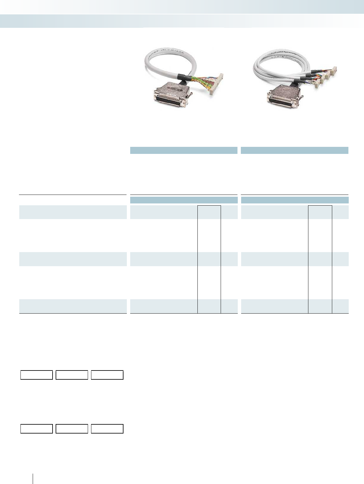
Technical data Technical data
Max. perm. operating voltage < 50 V AC / 60 V DC < 50 V AC / 60 V DC
Max. perm. current carrying capacity per path 1 A 1 A
Max. conductor resistance 0.16 /m 0.16 /m
Ambient temperature (operation) -20 °C ... 50 °C -20 °C ... 50 °C
Conductor cross section AWG 26 / 0.14 mm² AWG 26 / 0.14 mm²
Conductor structure: stranded wires / material 7 / Cu tin-plated 7 / Cu tin-plated
Outside diameter
37-position 10.5 mm 6.3 mm
Ordering data Ordering data
Description No. of
pos. Cable length Type Order No. Pcs. /
Pkt. Type Order No. Pcs. /
Pkt.
Round cable for output module MELSEC Q Y81 P,
MELSEC A1S Y81, and MELSEC A AY82EP, in standard lengths
37 0.5 m FLK 50/EZ-DR/D37SUB/ 50/Y81P-O 2302599 1CABLE-D37-M2,5/4X14/ 50/Y81P-O 2302476 1
37 1 m FLK 50/EZ-DR/D37SUB/100/Y81P-O 2302609 1CABLE-D37-M2,5/4X14/100/Y81P-O 2302489 1
37 2 m FLK 50/EZ-DR/D37SUB/200/Y81P-O 2302612 1CABLE-D37-M2,5/4X14/200/Y81P-O 2302492 1
37 3 m FLK 50/EZ-DR/D37SUB/300/Y81P-O 2302638 1CABLE-D37-M2,5/4X14/300/Y81P-O 2302502 1
Round cable, as above, however in variable lengths
37 FLK 50-EZ-DR-D37SUB-Y81P-O/... 2302625 1CABLE-D37-M2,5-4X14-Y81P-O/... 2302696 1
Round cable for input module MELSEC Q X81,
MELSEC A1S X81, and MELSEC A AX82, in standard lengths
37 0.5 m FLK 50/EZ-DR/D37SUB/ 50/X81-I 2302641 1CABLE-D37-M2,5/4X14/ 50/X81-I 2302515 1
37 1 m FLK 50/EZ-DR/D37SUB/100/X81-I 2302654 1CABLE-D37-M2,5/4X14/100/X81-I 2302528 1
37 2 m FLK 50/EZ-DR/D37SUB/200/X81-I 2302667 1CABLE-D37-M2,5/4X14/200/X81-I 2302531 1
37 3 m FLK 50/EZ-DR/D37SUB/300/X81-I 2302670 1CABLE-D37-M2,5/4X14/300/X81-I 2302544 1
Round cable, as above, however in variable lengths
37 FLK 50-EZ-DR-D37SUB-X81-I/... 2302683 1CABLE-D37-M2,5-4X14-X81-I/... 2302706 1
Ordering example for system cable:
– Cable for MELSEC Q Y81P, 12.75 m long
Quantity Order No. Length [m]
1
)
12302625 /12.75
1
) min. 0.20 m
Ordering examples for splitting cable:
– Cable for MELSEC Q Y81P, 11.00 m long
Quantity Order No. Length [m]
1
)
12302696 /11.00
1
) min. 0.20 m
506
PHOENIX CONTACT
System cabling for controllers
Controller-specific system cabling
System cable,
D-SUB socket strip on FLK,
number of positions: 37 on 50
Splitting cable,
D-SUB socket strip on FLK,
number of positions: 37 on 4 x 14
For 32/64-channel I/O cards with
37-pos. D-SUB connectors. System cables
are available for connecting 1 x 32 channels
or 4 x 8 channels.
Web code for the online configurator
Your web code: #0007
Mitsubishi Electric
MELSEC A, A1S, and Q
System cable

For further information and full technical data, visit phoenixcontact.net/products
Technical data Technical data
Max. perm. operating voltage < 50 V AC / 60 V DC < 50 V AC / 60 V DC
Max. perm. current carrying capacity per path 1 A 1 A
Max. conductor resistance 0.16 /m 0.16 /m
Ambient temperature (operation) -20 °C ... 50 °C -20 °C ... 50 °C
Conductor cross section AWG 26 / 0.14 mm² AWG 26 / 0.14 mm²
Conductor structure: stranded wires / material 7 / Cu tin-plated 7 / Cu tin-plated
Ordering data Ordering data
Description No. of
pos. Cable length Type Order No. Pcs. /
Pkt. Type Order No. Pcs. /
Pkt.
Round cable in variable lengths for
Mitsubishi Melsec L
LX41C4, LX42C4 (common positive connection to B01, B02)
LY41NT1P, LY42NT1P, LY41PT1P, LY42PT1P
Mitsubishi Melsec Q
QX41, QX41-S1, QX42, QX42-S1
QX71 and QX72 (common positive connection to B01, B02)
QY41P, QY42P, QY71, QH42P
Honeywell ML 200
2MLQ-TR4A, 2MLQ-TR8A, 2MLQ-TR4B, 2MLQ-TR8B
40 0.5 m CABLE-FCN40/1X50/ 0,5M/IM/MEL 2903468 1
40 1 m CABLE-FCN40/1X50/ 1,0M/IM/MEL 2903469 1
40 2 m CABLE-FCN40/1X50/ 2,0M/IM/MEL 2903470 1
40 3 m CABLE-FCN40/1X50/ 3,0M/IM/MEL 2903471 1
40 4 m CABLE-FCN40/1X50/ 4,0M/IM/MEL 2903472 1
40 6 m CABLE-FCN40/1X50/ 6,0M/IM/MEL 2903473 1
40 8 m CABLE-FCN40/1X50/ 8,0M/IM/MEL 2903474 1
40 10 m CABLE-FCN40/1X50/10,0M/IM/MEL 2903475 1
Round cable in variable lengths for
Mitsubishi Melsec L
LX41C4 and LX42C4 (common negative connection to B01, B02)
Mitsubishi Melsec Q
QX71 and QX72 (common negative connection to B01, B02)
QX82, QX82-S1
Honeywell ML 200
2MLI-D24A, 2MLI-D28B, 2MLF-SOEA
(common negative connection to B01, B02)
40 0.5 m CABLE-FCN40/1X50/ 0,5M/IP/MEL 2903476 1
40 1 m CABLE-FCN40/1X50/ 1,0M/IP/MEL 2903477 1
40 2 m CABLE-FCN40/1X50/ 2,0M/IP/MEL 2903478 1
40 3 m CABLE-FCN40/1X50/ 3,0M/IP/MEL 2903479 1
40 4 m CABLE-FCN40/1X50/ 4,0M/IP/MEL 2903480 1
40 6 m CABLE-FCN40/1X50/ 6,0M/IP/MEL 2903481 1
40 8 m CABLE-FCN40/1X50/ 8,0M/IP/MEL 2903482 1
40 10 m CABLE-FCN40/1X50/10,0M/IP/MEL 2903483 1
Round cable in variable lengths for
Mitsubishi Melsec L
LX41C4 and LX42C4 (common positive connection to B01, B02)
LY41NT1P, LY42NT1P, LY41PT1P, LY42PT1P
Mitsubishi Melsec Q
QX41, QX41-S1, QX42, QX42-S1
QY41P (24 V), QY42P (24 V), QH42P (24 V)
Honeywell ML 200
2MLQ-TR4A, 2MLQ-TR8A, 2MLQ-TR4B, 2MLQ-TR8B
40 0.5 m CABLE-FCN40/4X14/ 0,5M/IM/MEL 2903502 1
40 1 m CABLE-FCN40/4X14/ 1,0M/IM/MEL 2903503 1
40 2 m CABLE-FCN40/4X14/ 2,0M/IM/MEL 2903504 1
40 3 m CABLE-FCN40/4X14/ 3,0M/IM/MEL 2903505 1
40 4 m CABLE-FCN40/4X14/ 4,0M/IM/MEL 2903506 1
40 6 m CABLE-FCN40/4X14/ 6,0M/IM/MEL 2903507 1
40 8 m CABLE-FCN40/4X14/ 8,0M/IM/MEL 2903508 1
40 10 m CABLE-FCN40/4X14/10,0M/IM/MEL 2903509 1
507PHOENIX CONTACT
System cabling for controllers
Controller-specific system cabling
Fujitsu FCN connector on flat-ribbon cable,
number of positions: 40 on 50
Fujitsu FCN connector on flat-ribbon cable,
number of positions: 40 on 4 x 14
These system cables are plugged onto the
I/O cards that are connected using Fujitsu
connectors.
CABLE-FCN40/1X50/...
– Signal transmission of 32 channels
CABLE-FCN40/4X14/...
– Splitting up 32 channels into 4 x 8
channels
Web code for the online configurator
Your web code: #0007
Mitsubishi Electric
MELSEC L/Q and Honeywell ML 200
System cables

Technical data Technical data
Max. perm. operating voltage < 50 V AC / 60 V DC < 50 V AC / 60 V DC
Max. perm. current carrying capacity per path 1 A 1 A
Max. conductor resistance 0.16 /m 0.16 /m
Ambient temperature (operation) -20 °C ... 50 °C -20 °C ... 50 °C
Conductor cross section AWG 26 / 0.14 mm² AWG 26 / 0.14 mm²
Conductor structure: stranded wires / material 7 / Cu tin-plated 7 / Cu tin-plated
Ordering data Ordering data
Description No. of
pos. Cable length Type Order No. Pcs. /
Pkt. Type Order No. Pcs. /
Pkt.
Round cable in variable lengths for
CJ1: OD231, OD261
CS1, C200H: OD218, OD219
CQM1: OD213
40 1 m FLK 50/EZ-DR/FCN40/100/OMR-OUT 2304144 1CABLE-FCN40/4X14/100/OMR-OUT 2304186 1
40 2 m FLK 50/EZ-DR/FCN40/200/OMR-OUT 2304157 1CABLE-FCN40/4X14/200/OMR-OUT 2304199 1
Round cable, as above, however in variable lengths
40 FLK 50-EZ-DR-FCN40-OMR-OUT/... 2302829 1CABLE-FCN40-4X14-OMR-OUT/... 2302832 1
Round cable in variable lengths for
CJ1: ID231, ID261
CS1 and C200H: ID111, ID216, ID217,
CQM1: ID213; ID214;ID112
40 1 m FLK 50/EZ-DR/FCN40/100/OMR-IN 2304160 1CABLE-FCN40/4X14/100/OMR-IN 2304209 1
40 2 m FLK 50/EZ-DR/FCN40/200/OMR-IN 2304173 1CABLE-FCN40/4X14/200/OMR-IN 2304212 1
Round cable, as above, however in variable lengths
40 FLK 50-EZ-DR-FCN40-OMR-IN/... 2302803 1CABLE-FCN40-4X14-OMR-IN/... 2302816 1
Round cable in variable lengths for
CS1, C200H: OD215, MD115 (only output),
MD215 (only output)
24 1 m CABLE-FCN24/2X14/100/OMR-OUT 2304225 1
24 2 m CABLE-FCN24/2X14/200/OMR-OUT 2304238 1
Round cable, as above, however in variable lengths
24 CABLE-FCN24-2X14-OMR-OUT/... 2302858 1
Round cable in variable lengths for
CS1, C200H: ID215, MD115 (only input),
MD215 (only input)
24 1 m CABLE-FCN24/2X14/100/OMR-IN 2304241 1
24 2 m CABLE-FCN24/2X14/200/OMR-IN 2304254 1
Round cable, as above, however in variable lengths
24 CABLE-FCN24-2X14-OMR-IN/... 2302845 1
Ordering example for system cable:
– Cable for OMRON CJ1, ID231, 12.75 m long
Quantity Order No. Length [m]
1
)
12302803 /12.75
1
) min. 0.20 m
508
PHOENIX CONTACT
System cabling for controllers
Controller-specific system cabling
Fujitsu FCN connector on flat-ribbon cable,
number of positions: 40 on 50
Fujitsu FCN connector on flat-ribbon cable,
number of positions: 40 on 4 x 14 or 24 on 2 x 14
These system cables are plugged onto the
I/O cards that are connected using Fujitsu
connectors.
FLK 50/EZ-DR/...
– Signal transmission of 32 channels
CABLE-FCN40...
– Splitting up 32 channels into
4 x 8 channels
CABLE-FCN24...
– Splitting up 16 channels into
2 x 8 channels
OMRON CJ1, CS1, CQM1, and C200H
System cable
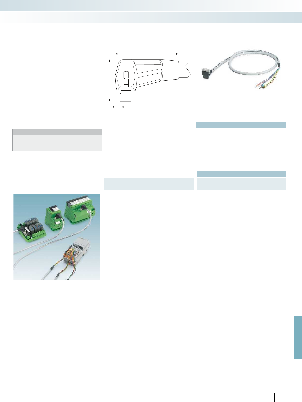
37
26,5
5
For further information and full technical data, visit phoenixcontact.net/products
509
PHOENIX CONTACT
Technical data
Max. perm. operating voltage < 50 V AC / 60 V DC
Max. perm. current carrying capacity per path 1 A
Max. conductor resistance 0.16 /m
Ambient temperature (operation) -20 °C ... 50 °C
Assembly Insulation displacement, IEC 60352-4/DIN EN 60352-4
Conductor cross section AWG - / 0.14 mm²
Conductor structure: stranded wires / material 7 / Cu tin-plated
Outside diameter
14-position 6.4 mm
Ordering data
Description No. of
pos. Cable length Type Order No. Pcs. /
Pkt.
Round cable with an open end (8 individual wires)
14 0.5 m VIP-CAB-FLK14/AXIO/0,14/0,5M 2901604 1
14 1 m VIP-CAB-FLK14/AXIO/0,14/1,0M 2901605 1
14 1.5 m VIP-CAB-FLK14/AXIO/0,14/1,5M 2901606 1
14 2 m VIP-CAB-FLK14/AXIO/0,14/2,0M 2901607 1
14 2.5 m VIP-CAB-FLK14/AXIO/0,14/2,5M 2901608 1
14 3 m VIP-CAB-FLK14/AXIO/0,14/3,0M 2901609 1
14 4 m VIP-CAB-FLK14/AXIO/0,14/4,0M 2901610 1
14 6 m VIP-CAB-FLK14/AXIO/0,14/6,0M 2901611 1
These cables have been specifically
developed for connecting VARIOFACE
termination boards to the Axioline realtime
I/O system. The push-in technology on the
I/O system ensures rapid connection.
The cables have the following features:
– 1:1 connection
– 14-pos. connector, molded
– 8 pre-assembled open ends, for
connection to the Axioline realtime
I/O system
– Transmission of groups of 8 channels
– Marking field on connector
Tailor-made VARIOFACE termination
boards round off this system concept.
Notes:
The following modules cannot be coupled due to the larger outer
contour of the molded connectors:
UM 45-FLK14/ 8IM/ZFKDS/PLC, 2965211
UM 45- 8RM/MR-G24/1/PLC, 2962900
Phoenix Contact Axioline realtime
I/O System cables
System cabling for controllers
Controller-specific system cabling
System cable for 8 channels
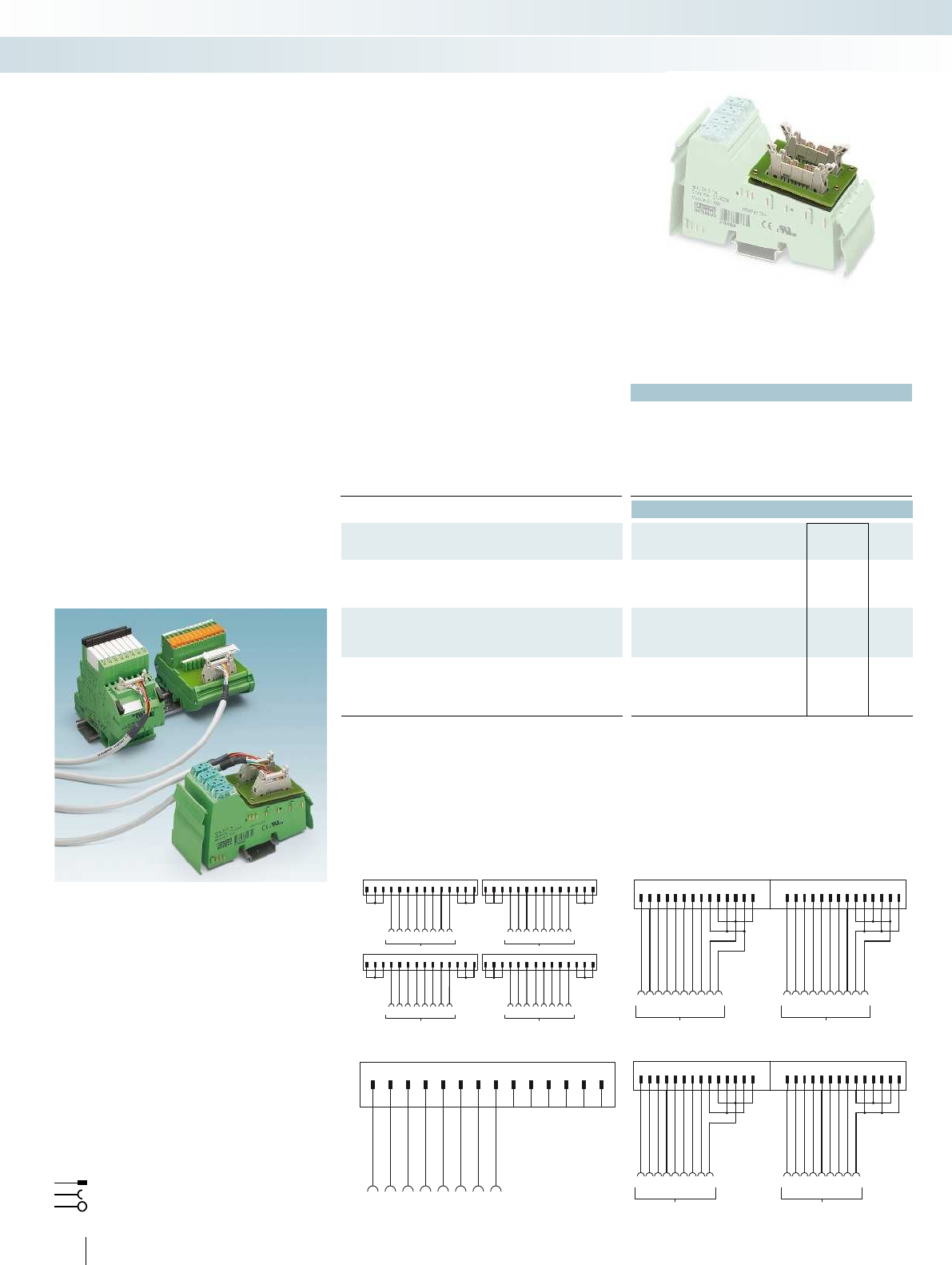
1.1
2.1
1.2
2.2
1.3
2.3
1.4
2.4
1234567891011
12
13 14
NC
X1
Byte 0
1.1
2.1
1.4
2.4
2.4
1.1
2.1
1.4
2.2
333344444
Byte 1
1.1
2.1
1.4
2.4
2.4
1.1
2.1
1.4
2.2
111122221
1234567891011121314 1234567891011121314
X1
7.1
Byte 0
Byte 2
Byte 1
Byte 3
8.1
7.2
8.2
7.3
8.3
7.4
8.4
5.1
6.1
5.2
6.2
5.3
6.3
5.4
6.4
7.1
8.1
7.2
8.2
7.3
8.3
7.4
8.4
5.1
6.1
5.2
6.2
5.3
6.3
5.4
6.4
X3
X2
X4
91113 12345678101214 91113 12345678101214
91113 12345678101214
91113 12345678101214
Byte 0
1.1
2.1
1.4
2.4
1.1
2.1
1.4
2.4
2.3
2.2
3333
Byte 1
444444
1.1
2.1
1.4
2.4
1.1
2.1
1.4
2.4
2.3
2.2
1111222211
12345678910111213141234567891011121314
510
PHOENIX CONTACT
Technical data
Max. perm. operating voltage 60 V DC
Max. permissible current 1 A (per path)
Ambient temperature (operation) -20 °C ... 50 °C
Ambient temperature (storage/transport) -20 °C ... 70 °C
Mounting position any
Standards/regulations IEC 60664 / DIN EN 50178 / IEC 62103
Ordering data
Description No. of pos. Type Order No. Pcs. /
Pkt.
VARIOFACE front adapter, for 8-channel Inline modules
Input: IB IL 24 D I8/HD-PAC
Output: IB IL 24 DO 8/HD-PAC
FLKM 14-PA-INLINE/DIO8 2900889 1
VARIOFACE front adapter, for 16-channel Inline modules
Input: IB IL 24 DI 16-PAC FLKM 14-PA-INLINE/IN16 2302751 1
Output: IB IL 24 DO 16-PAC FLKM 14-PA-INLINE/OUT16 2302764 1
VARIOFACE front adapter, for 32-channel Inline modules
Input: IB IL 24 DI 32/HD-PAC and IB IL 24 DI 32/HD-NPN-PAC
Output: IB IL 24 DO 32/HD-PAC
FLKM 14-PA-INLINE/32 2302777 1
Connection scheme for FLKM 14-PA-INLINE/DIO8 Connection scheme: FLKM 14-PA-INLINE/OUT16
Connection scheme: FLKM 14-PA-INLINE/32 Connection scheme: FLKM 14-PA-INLINE/IN16
Flat-ribbon cable strip
Connection to I/O card
Screw terminal blocks for separate supply
Explanation:
The front adapters are used to connect
pre-assembled system cables directly to
Inline. Front adapters are simply plugged
into the relevant Inline modules. Three
connection options are available:
– Transfer of 8 channels via a 14-pos.
system cable
– Transmission of 2 x 8 channels over two
14-position system cables
– Transmission of 4 x 8 channels over four
14-position system cables
Tailor-made VARIOFACE termination
boards round off this system concept.
Web code for the online configurator
Your web code: #0007
Phoenix Contact Inline
Front adapters
System cabling for controllers
Controller-specific system cabling
Front adapter for Inline
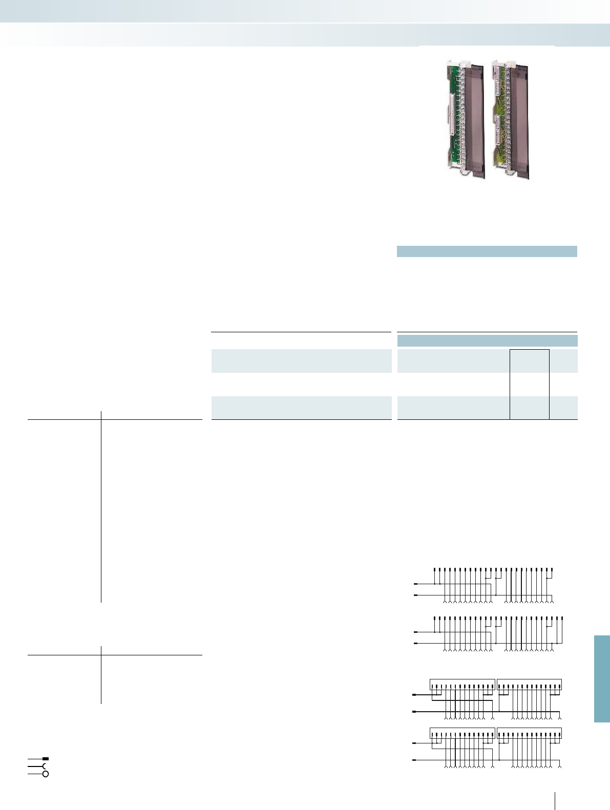
X1 9X2
111312345678101214 9111312345678101214
1+
-
2345678910+
-
1112131415161 71 81920
X3 9111312345678101214 X4
9111312345678101214
21 +
-
22232425262728293031 +
-
323334353637383940
0+
1+
2+
3+
123456789101112
1314151617
18
192021222324
12345678910
+-+-
11
121314151617181920
252627282930313233
34
353637
3839
40414243
44454647484950
21 -+-+
22232425262728
29
3031323334353637383940
0+
1+
2+
3+
For further information and full technical data, visit phoenixcontact.net/products
511
PHOENIX CONTACT
Technical data
Max. perm. operating voltage < 50 V AC / 60 V DC
Max. permissible current 1 A (per path)
4 A (per connection, supply via separate power supply)
Ambient temperature (operation) -20 °C ... 50 °C
Ambient temperature (storage/transport) -20 °C ... 70 °C
Mounting position any
Standards/regulations IEC 60664 / DIN EN 50178 / IEC 62103
Ordering data
Description No. of pos. Type Order No. Pcs. /
Pkt.
VARIOFACE front adapter, for MODICON
®
TSX Quantum,
1 x 32 channels can be connected
50 FLKM 50-PA-MODI-TSX/Q 2294306 1
VARIOFACE front adapter, for MODICON
®
TSX Quantum,
4 x 8 channels can be connected
14 FLKM 50/ 4-FLK14/PA-MODI-TSX/Q 2294416 1
Connection scheme FLKM 50/ 4-FLK14/PA-MODI-TSX/Q
Connection scheme FLKM 50-PA-MODI-TSX/Q
Front adapter for
I/O modules of MODICON
®
TSX Quantum automation
devices
Card type FLKM 50-PA-MODI-TSX/Q
Digital input DDI 353
DDI 841*
DDI 853
DAI 340*
DAI 353**
DAI 440*
DAI 453**
Digital output DDO 353
Digital input/output DDM 390*
Analog input ACI 030*
ACI 040*
ATI 030*
ARI 030*
AVI 030*
Analog output ACO 020*
ACO 130*
AVO 020*
Analog input/output AMM 090*
Counter ECH 105*
EHC 202*
* Only in conjunction with VIP-2/SC/FLK50/MODI-TSX/Q,
Order No. 2322304.
** Only in conjunction with Passive interface modules without
LED.
Card type FLKM 50/4-FLK14/PA-MODI-
Digital input DDI 353
DDI 853
DAI 353**
DAI 453**
Digital output DDO 353
** Only in conjunction with Passive interface modules without
LED.
Flat-ribbon cable strip
Connection to I/O card
Screw terminal blocks for separate supply
Explanation:
The front adapters mean that
pre-assembled system cables can be directly
connected to I/O modules. There are two
connection options available:
– Transfer of max. 32 channels over one
50-position system cable
– Transmission of 4 x 8 channels over four
14-position system cables
Tailor-made VARIOFACE termination
boards with a variety of functions and
connection options round off this system
concept.
Web code for the online configurator
Your web code: #0007
Schneider Electric
MODICON
®
TSX Quantum
Front adapters
System cabling for controllers
Controller-specific system cabling
Front adapter for
MODICON TSX Quantum

1
2
3
4
5
6
7
8
123456789101112 13 14
Byte 0
+
+
-
-
123456789101112 13 14
9
10
11
12
13
14
15
16
17
18
19
20
SP
Byte 1
512
PHOENIX CONTACT
Technical data
Max. perm. operating voltage < 50 V AC / 60 V DC
Max. permissible current 1 A (per path)
Max. perm. total current 3 A (per system cable when supplying from the module side)
10 A (when supplying via the front adapter)
Ambient temperature (operation) -20 °C ... 60 °C
Ambient temperature (storage/transport) -20 °C ... 60 °C
Mounting position any
Standards/regulations IEC 60664 / DIN EN 50178 / IEC 62103
Ordering data
Description No. of pos. Type Order No. Pcs. /
Pkt.
VARIOFACE front adapter, for MODICON
®
M340 with
two FLK pin strips
14 FLKM 14-PA-MODI/M340 2903208 1
Connection scheme FLKM 14-PA-MODI/M340
Front adapter for MODICON C340 series I/O modules
Card type FLKM 14-PA-MODI/M340
Digital input BMX DDI1602
BMX DDI1603
BMX DAI1602
BMX DAI1603
Digital output BMX DDO1602
BMX DDO1612
Assignment table
Contacts of
front adapter/
controller
Connector
(Byte 0)
Connector
(Byte 1)
11
22
33
44
55
66
77
88
91
10 2
11 3
12 4
13 5
14 6
15 7
16 8
17 10, 12, 14 (-) 10, 12, 14 (-)
18 9, 11, 13 (+) 9, 11, 13 (+)
19 10, 12, 14 (-) 10, 12, 14 (-)
20 9, 11, 13 (+) 9, 11, 13 (+)
Pre-assembled system cables are
connected directly to the 16-channel I/O
modules using the front adapter.
The adapters connect 2 x 8 channels of the
controller via two 14-pos. system cables.
Tailor-made VARIOFACE termination
boards with a variety of functions and
connection options are available for
connection to field level and round off this
system concept.
Web code for the online configurator
Your web code: #0007
Schneider Electric MODICON
®
M340
Front adapter
System cabling for controllers
Controller-specific system cabling
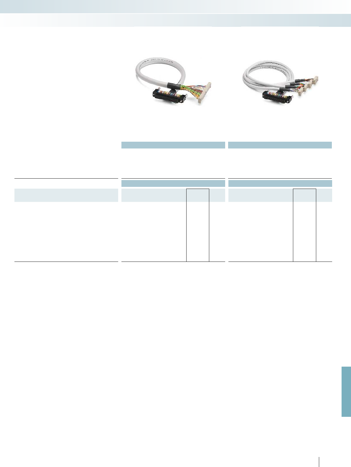
For further information and full technical data, visit phoenixcontact.net/products
Technical data Technical data
Max. perm. operating voltage < 50 V AC / 60 V DC < 50 V AC / 60 V DC
Max. perm. current carrying capacity per path 1 A 1 A
Max. conductor resistance 0.16 /m 0.16 /m
Ambient temperature (operation) -20 °C ... 50 °C -20 °C ... 50 °C
Conductor cross section AWG 26 / 0.14 mm² AWG 26 / 0.14 mm²
Conductor structure: stranded wires / material 7 / Cu tin-plated 7 / Cu tin-plated
Ordering data Ordering data
Description No. of
pos. Cable length Type Order No. Pcs. /
Pkt. Type Order No. Pcs. /
Pkt.
Round cable in variable lengths for
BMX DDI 3202K, BMX DDI 6402K,
BMX DD0 3202K, BMX DD0 6402K,
BMX DDM 3202K
40 0.5 m CABLE-FCN40/1X50/ 0,5M/M340 2321635 1CABLE-FCN40/4X14/ 0,5M/M340 2321716 1
40 1 m CABLE-FCN40/1X50/ 1,0M/M340 2321648 1CABLE-FCN40/4X14/ 1,0M/M340 2321729 1
40 2 m CABLE-FCN40/1X50/ 2,0M/M340 2321651 1CABLE-FCN40/4X14/ 2,0M/M340 2321732 1
40 3 m CABLE-FCN40/1X50/ 3,0M/M340 2321664 1CABLE-FCN40/4X14/ 3,0M/M340 2321745 1
40 4 m CABLE-FCN40/1X50/ 4,0M/M340 2321677 1CABLE-FCN40/4X14/ 4,0M/M340 2321758 1
40 6 m CABLE-FCN40/1X50/ 6,0M/M340 2321680 1CABLE-FCN40/4X14/ 6,0M/M340 2321761 1
40 8 m CABLE-FCN40/1X50/ 8,0M/M340 2321693 1CABLE-FCN40/4X14/ 8,0M/M340 2321774 1
40 10 m CABLE-FCN40/1X50/10,0M/M340 2321703 1CABLE-FCN40/4X14/10,0M/M340 2321787 1
40 15 m CABLE-FCN40/1X50/15,0M/M340 2903748 1CABLE-FCN40/4X14/15,0M/M340 2903749 1
513PHOENIX CONTACT
System cabling for controllers
Controller-specific system cabling
Fujitsu FCN connector on flat-ribbon cable,
number of positions: 40 on 50
Fujitsu FCN connector on flat-ribbon cable,
number of positions: 40 on 4 x 14
These system cables are plugged onto the
I/O cards that are connected using Fujitsu
connectors.
CABLE-FCN40/1X50/...
– Signal transmission of 32 channels
CABLE-FCN40/4X14/...
– Splitting up 32 channels into
4 x 8 channels
Web code for the online configurator
Your web code: #0007
Schneider Electric MODICON
®
M340
System cable
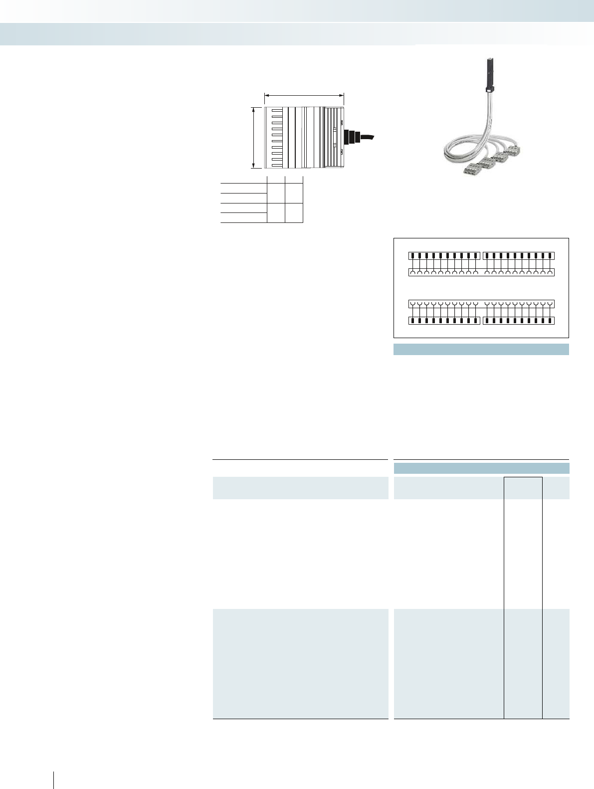
1234567891011 12 13 14 15 16 17 181920
1234567891011 12 13 14 15 16 17 181920
S7 - 300
COMBI
21 22 23 24 25 26 27 28293031 32 33 34 35 36 37 383940
21 22 23 24 25 26 27 28293031 32 33 34 35 36 37 383940
S7 - 300
COMBI
...4X10COMBI...
...2X10COMBI...
52
A
35
70
B
62
...4X10 PT...
...2X10 PT...
110
23456789
B
A
Technical data
Max. perm. operating voltage 250 V AC/DC
Max. perm. current carrying capacity per path 6 A (per single wire at 40°C)
4 A (per single wire at 60°C)
Max. perm. total current 20 A (per cable at 40 °C)
16 A (per cable at 60°C)
Max. conductor resistance 39 /km
Conductor cross section AWG 21 / 0.5 mm²
Conductor structure: stranded wires / material 16 / Cu uninsulated
Outside diameter 9 mm
Ambient temperature range -20 °C ... 60 °C
Standards/regulations DIN EN 50178, IEC 60664, IEC 62103 DIN EN 50178, IEC 60664, IEC 62103 DIN EN 50178, IEC 60664, IEC 62103 DIN
Connection method Front adapter Can be plugged onto 40-pos. I/O modules Can be plugged onto 20-pos. I/O modules Can be plugged onto
System cable COMBICON connectors COMBICON connectors Open cable end Open cable end
Ordering data
Description Cable length Type Order No. Pcs. /
Pkt.
VIP - power adapter, for universal connection of the
SIMATIC S7-300, with an overall width of 52 mm per connector
0.5 m VIP-PA-PWR/4X10COMBI/ 0,5M/S7 2904702 1
1 m VIP-PA-PWR/4X10COMBI/ 1,0M/S7 2904703 1
1.5 m VIP-PA-PWR/4X10COMBI/ 1,5M/S7 2904704 1
2 m VIP-PA-PWR/4X10COMBI/ 2,0M/S7 2904705 1
2.5 m VIP-PA-PWR/4X10COMBI/ 2,5M/S7 2904706 1
3 m VIP-PA-PWR/4X10COMBI/ 3,0M/S7 2904707 1
4 m VIP-PA-PWR/4X10COMBI/ 4,0M/S7 2904708 1
5 m VIP-PA-PWR/4X10COMBI/ 5,0M/S7 2904709 1
6 m VIP-PA-PWR/4X10COMBI/ 6,0M/S7 2904710 1
8 m VIP-PA-PWR/4X10COMBI/ 8,0M/S7 2904711 1
10 m VIP-PA-PWR/4X10COMBI/10,0M/S7 2904712 1
VIP - power adapter, for universal connection of the
SIMATIC S7-300, with reduced overall width of 35 mm per
connector
0.5 m VIP-PA-PWR/4X10 PT/ 0,5M/S7 2905516 1
1 m VIP-PA-PWR/4X10 PT/ 1,0M/S7 2905517 1
1.5 m VIP-PA-PWR/4X10 PT/ 1,5M/S7 2905518 1
2 m VIP-PA-PWR/4X10 PT/ 2,0M/S7 2905519 1
2.5 m VIP-PA-PWR/4X10 PT/ 2,5M/S7 2905520 1
3 m VIP-PA-PWR/4X10 PT/ 3,0M/S7 2905521 1
4 m VIP-PA-PWR/4X10 PT/ 4,0M/S7 2905522 1
5 m VIP-PA-PWR/4X10 PT/ 5,0M/S7 2905523 1
6 m VIP-PA-PWR/4X10 PT/ 6,0M/S7 2905524 1
8 m VIP-PA-PWR/4X10 PT/ 8,0M/S7 2905525 1
10 m VIP-PA-PWR/4X10 PT/10,0M/S7 2905526 1
514
PHOENIX CONTACT
VIP - power cabling
Universal front adapters for
SIMATIC
®
S7-300
Four connection options are available:
– Connection of 40-pos. modules via four
cables, each with a 10-pos. COMBI
connector
– Connection of 20-pos. modules via two
cables, each with a 10-pos. COMBI
connector
– Connection of 40-pos. modules via
40 individual wires in rope structure
(not assembled)
– Connection of 20-pos. modules via
20 individual wires in rope structure
(not assembled)
The front adapters have the following
features:
– Can be screwed on/snapped in with the
I/O module
– Suitable for all common S7-300 modules,
up to max. 250 V AC/DC, 6 A
– Universal 1:1 connection
– Numerically marked wires/connectors
Combination example:
A front adapter with punched-on 10-pos.
COMBI connectors can be combined with
the following modular terminal blocks for
field connection:
Overall width of 52 mm per connector:
–3045017 UT 2,5/1P
–3210033 PT 2,5/1P
–3040012 ST 2,5/1P
–3040766 ST 2,5-TWIN-MT/1P
Reduced overall width of 35 mm per
connector:
–3208582 PT 1,5/S/1P
–3212439 PTTB 1,5/S/2P
You can find further versions, accessories,
and combination options in Catalog 3
“Terminal blocks” in the “Plug-in COMBI
connection solutions” section or online at
phoenixcontact.net/products.
System cabling for controllers
Controller-specific system cabling
Front adapter with punched-on connectors for
40 plug-in modular terminal blocks
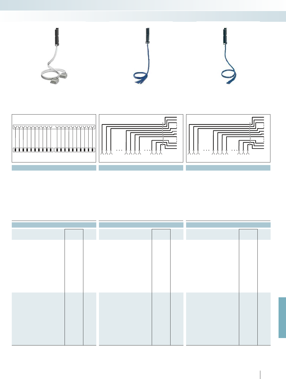
1234567891011 12 13 14 15 16 17 181920
1234567891011 12 13 14 15 16 17 181920
S7 - 300
COMBI
1
38
22
2
39
23
3
40
24
25
1 22
1 22
38
38
2 23
2 23
39
39
3 24 25
3 24 25
40
40
S7-300
1
18
8
2
19
9
3
20
10
11
18
18
18
18
29
29
19
19
31011
31011
20
20
S7-300
For further information and full technical data, visit phoenixcontact.net/products
Technical data Technical data Technical data
250 V AC/DC 250 V AC/DC 250 V AC/DC
6 A (per single wire at 40°C)
4 A (per single wire at 60°C)
6 A (per single wire at 40°C)
4 A (per single wire at 60°C)
6 A (per single wire at 40°C)
4 A (per single wire at 60°C)
20 A (per cable at 40 °C)
16 A (per cable at 60°C)
20 A (per cable at 40 °C)
16 A (per cable at 60°C)
20 A (per cable at 40 °C)
16 A (per cable at 60°C)
39 /km 39 /km 39 /km
AWG 21 / 0.5 mm² AWG 21 / 0.5 mm² AWG 21 / 0.5 mm²
16 / Cu uninsulated 16 / Cu uninsulated 16 / Cu uninsulated
9 mm 13 mm 9 mm
-20 °C ... 60 °C -20 °C ... 60 °C -20 °C ... 60 °C
Standards/regulations DIN EN 50178, IEC 60664, IEC 62103 DIN EN 50178, IEC 60664, IEC 62103 DIN EN 50178, IEC 60664, IEC 62103 DIN EN 50178, IEC 60664, IEC 62103
Connection method Front adapter Can be plugged onto 40-pos. I/O modules Can be plugged onto 20-pos. I/O modules Can be plugged onto 40-pos. I/O modules Can be plugged onto 20-pos. I/O modules
System cable COMBICON connectors COMBICON connectors Open cable end Open cable end
Ordering data Ordering data Ordering data
Type Order No. Pcs. /
Pkt. Type Order No. Pcs. /
Pkt. Type Order No. Pcs. /
Pkt.
VIP-PA-PWR/2X10COMBI/ 0,5M/S7 2904713 1
VIP-PA-PWR/2X10COMBI/ 1,0M/S7 2904714 1VIP-PA-PWR/40XOE/ 1,0M/S7 2904731 1VIP-PA-PWR/20XOE/ 1,0M/S7 2904724 1
VIP-PA-PWR/2X10COMBI/ 1,5M/S7 2904715 1
VIP-PA-PWR/2X10COMBI/ 2,0M/S7 2904716 1VIP-PA-PWR/40XOE/ 2,0M/S7 2904732 1VIP-PA-PWR/20XOE/ 2,0M/S7 2904725 1
VIP-PA-PWR/2X10COMBI/ 2,5M/S7 2904717 1
VIP-PA-PWR/2X10COMBI/ 3,0M/S7 2904718 1VIP-PA-PWR/40XOE/ 3,0M/S7 2904733 1VIP-PA-PWR/20XOE/ 3,0M/S7 2904726 1
VIP-PA-PWR/2X10COMBI/ 4,0M/S7 2904719 1VIP-PA-PWR/40XOE/ 4,0M/S7 2904734 1VIP-PA-PWR/20XOE/ 4,0M/S7 2904727 1
VIP-PA-PWR/2X10COMBI/ 5,0M/S7 2904720 1
VIP-PA-PWR/2X10COMBI/ 6,0M/S7 2904721 1VIP-PA-PWR/40XOE/ 6,0M/S7 2904735 1VIP-PA-PWR/20XOE/ 6,0M/S7 2904728 1
VIP-PA-PWR/2X10COMBI/ 8,0M/S7 2904722 1VIP-PA-PWR/40XOE/ 8,0M/S7 2904736 1VIP-PA-PWR/20XOE/ 8,0M/S7 2904729 1
VIP-PA-PWR/2X10COMBI/10,0M/S7 2904723 1VIP-PA-PWR/40XOE/10,0M/S7 2904737 1VIP-PA-PWR/20XOE/10,0M/S7 2904730 1
VIP-PA-PWR/2X10 PT/ 0,5M/S7 2905528 1
VIP-PA-PWR/2X10 PT/ 1,0M/S7 2905529 1
VIP-PA-PWR/2X10 PT/ 1,5M/S7 2905531 1
VIP-PA-PWR/2X10 PT/ 2,0M/S7 2905532 1
VIP-PA-PWR/2X10 PT/ 2,5M/S7 2905533 1
VIP-PA-PWR/2X10 PT/ 3,0M/S7 2905534 1
VIP-PA-PWR/2X10 PT/ 4,0M/S7 2905535 1
VIP-PA-PWR/2X10 PT/ 5,0M/S7 2905536 1
VIP-PA-PWR/2X10 PT/ 6,0M/S7 2905537 1
VIP-PA-PWR/2X10 PT/ 8,0M/S7 2905538 1
VIP-PA-PWR/2X10 PT/10,0M/S7 2905539 1
515
PHOENIX CONTACT
System cabling for controllers
Controller-specific system cabling
Front adapter with punched-on connectors for
20 plug-in modular terminal blocks
Front adapter with 40 open cable ends Front adapter with 20 open cable ends
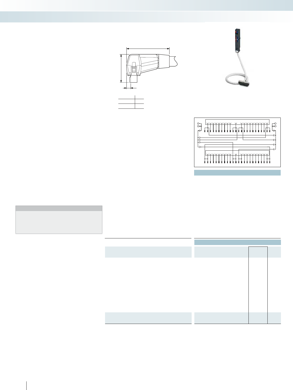
A
26,5
5
...FLK14...
...FLK50...
37
42
A
BR
bl
SPSP
BR
rd
1
2
3
4
5
6
7
8
9
10
11
12
13
14
15
16
17
18
19
20
1
2
3
4
5
6
7
8
9
10
11
12
13
14
15
16
17
18
19
20
21
22
23
24
21
22
23
24
25
26
27
28
29
30
31
32
33
34
35
36
37
38
39
40
25
26
27
28
29
30
31
32
33
34
35
36
37
38
39
40
41
42
43
44
45
46
47
48
-+
-+
516
PHOENIX CONTACT
Three connection options are
available:
– Transfer of max. 32 channels via two
50-pos. system cables (32-channel cards
or this type)
– Transfer of 4 x 8 channels via two
14-pos. system cables (32-channel cards
or this type)
– Transfer of 2 x 8 channels via two
14-pos. system cables (16-channel cards
or this type)
The front adapters have the following
features:
– Can be screwed with I/O module
– Voltage supply via terminal blocks with
spring-cage double connection
– Encapsulated socket strips for module
side
Special lengths can be configured using
separate order numbers.
Ordering example:
A front adapter with a connected
50-pos. system cable (32-channel cards),
12.75 m in length:
1 pcs. 2900885/12,75
Web code for the online configurator
Your web code: #0007
Notes:
The following modules cannot be coupled due to the larger outer
contour of the molded connectors:
UM 45-FLK14/ 8IM/ZFKDS/PLC, 2965211
UM 45-FLK50/32IM/ZFKDS/PLC, 2965224
UM 45- 8RM/MR-G24/1/PLC, 2962900
UM 45-16RM/MR-G24/1/PLC, 2962913
VIP – VARIOFACE Professional front
adapters for SIMATIC S7-300
Technical data
Max. perm. operating voltage < 50 V AC / 60 V DC
Max. perm. current carrying capacity per path 1 A (per path)
Max. perm. current (separate power supply) 8 A
Max. conductor resistance 0.16 /m
Conductor cross section AWG 26 / 0.14 mm²
Conductor structure: stranded wires / material 7 / Cu tin-plated
Outside diameter 10.3 mm
Ambient temperature range -20 °C ... 50 °C
Standards/regulations IEC 60664, IEC 62103, DIN EN 50178 IEC 60664, IEC 62103, DIN EN 50178 IEC 60664, IEC 62103, DIN EN 50178
Connection method Front adapter Can be plugged onto 40-pos. I/O modules / separate power supply
through terminal blocks with spring-cage double connection
System cable Flat-ribbon cable connector in acc. with IEC 60603-13 Flat-ribbon cable connector in acc. with IEC 60603-13 Flat-ribb
Connection data solid / stranded / AWG 0.2 ... 2.5 mm² / 0.2 ... 2.5 mm² / 24 - 14 0.2 ... 2.5 mm² / 0.2 ... 2.5 mm² / 24 - 14 0.2 ...
Ordering data
Description Cable length Type Order No. Pcs. /
Pkt.
VIP VARIOFACE front adapter, with connected system cables for
SIMATIC S7 300
0.5 m VIP-PA-FLK50/ 0,5M/S7 2322443 1
1 m VIP-PA-FLK50/ 1,0M/S7 2322456 1
1.5 m VIP-PA-FLK50/ 1,5M/S7 2322469 1
2 m VIP-PA-FLK50/ 2,0M/S7 2321800 1
2.5 m VIP-PA-FLK50/ 2,5M/S7 2322472 1
3 m VIP-PA-FLK50/ 3,0M/S7 2322485 1
4 m VIP-PA-FLK50/ 4,0M/S7 2322498 1
5 m VIP-PA-FLK50/ 5,0M/S7 2322508 1
6 m VIP-PA-FLK50/ 6,0M/S7 2322511 1
7 m VIP-PA-FLK50/ 7,0M/S7 2322524 1
8 m VIP-PA-FLK50/ 8,0M/S7 2322537 1
10 m VIP-PA-FLK50/10,0M/S7 2322540 1
VIP VARIOFACE front adapter, as above, in variable lengths
VIP-PA-FLK50-S7/... 2900885 1
System cabling for controllers
Controller-specific system cabling
Front adapter with system cable
1 x 32 channels can be connected
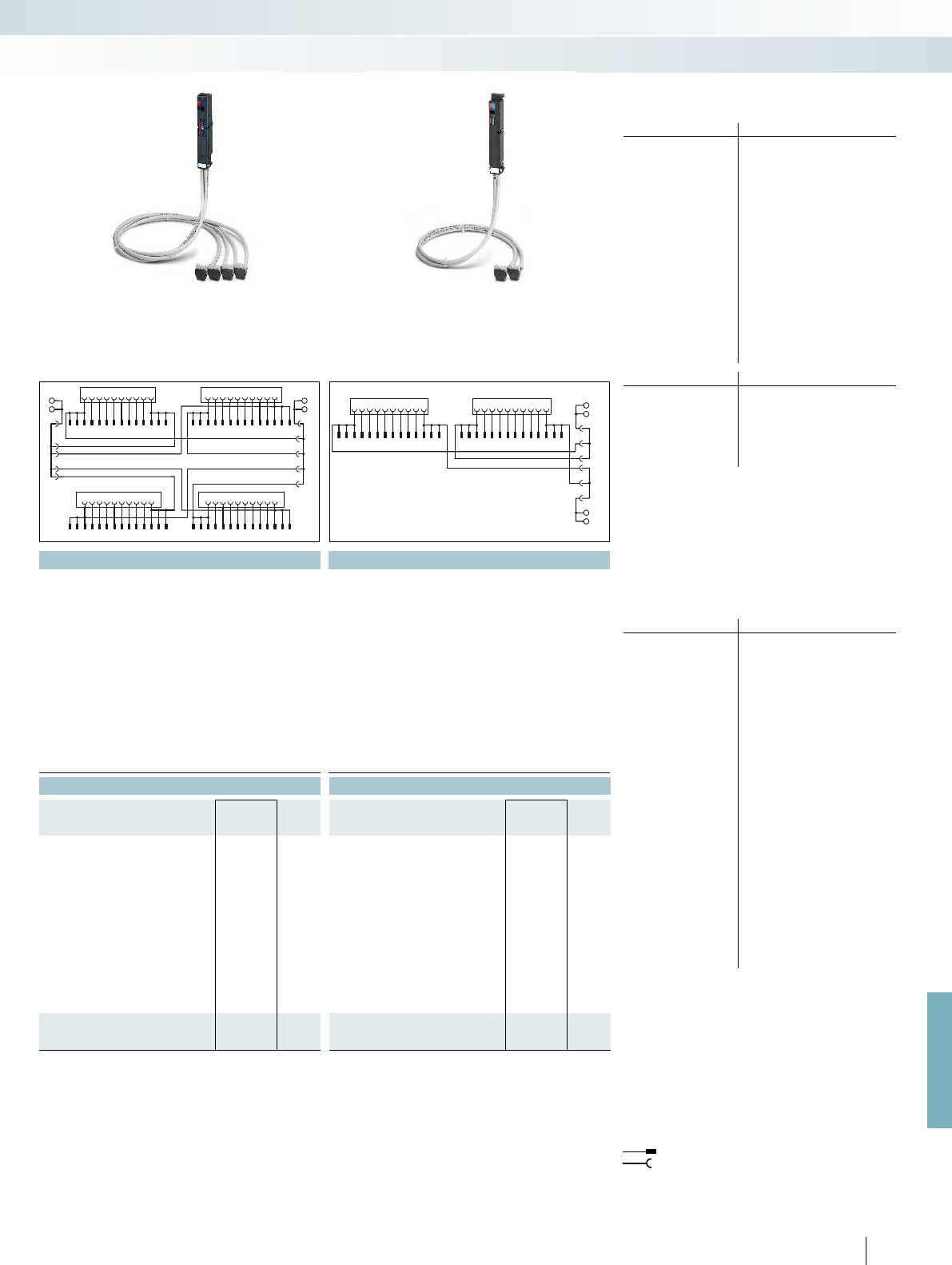
BR
bl
SPSP
BR
rd
-+
-+
1
2
3
4
5
6
7
8
9
10
11
12
13
14
15
16
17
18
19
20
9
11
13
1
2
3
4
5
6
7
8
10
12
14
9
11
13
1
2
3
4
5
6
7
8
10
12
14
21
22
23
24
25
26
27
28
29
30
31
32
33
34
35
36
37
38
39
40
9
11
13
1
2
3
4
5
6
7
8
10
12
14
9
11
13
1
2
3
4
5
6
7
8
10
12
14
1
11
2
12
3
13
4
14
5
15
6
16
7
17
8
18
9
19
10
20
Byte0Byte1
9
11
13
1
2
3
4
5
6
7
8
10
12
14
9
11
13
1
2
3
4
5
6
7
8
10
12
14
SP
SP
BR
rd
BR
bl
+
-
+
-
For further information and full technical data, visit phoenixcontact.net/products
517
PHOENIX CONTACT
Technical data Technical data
< 50 V AC / 60 V DC < 50 V AC / 60 V DC
1 A (per path) 1 A (per path)
8 A 8 A
0.16 Ω/m 0.16 Ω/m
AWG 26 / 0.14 mm² AWG 26 / 0.14 mm²
7 / Cu tin-plated 7 / Cu tin-plated
6.4 mm 6.4 mm
-20 °C ... 50 °C -20 °C ... 50 °C
Standards/regulations IEC 60664, IEC 62103, DIN EN 50178 IEC 60664, IEC 62103, DIN EN 50178 IEC 60664, IEC 62103, DIN EN 50178
Can be plugged onto 40-pos. I/O modules / separate power supply
through terminal blocks with spring-cage double connection
Can be plugged onto 20-pos. I/O modules / separate power supply
through terminal blocks with spring-cage double connection
System cable Flat-ribbon cable connector in acc. with IEC 60603-13 Flat-ribbon cable connector in acc. with IEC 60603-13 Flat-ribbon cable connector in acc. with IEC 60603-13
Connection data solid / stranded / AWG 0.2 ... 2.5 mm² / 0.2 ... 2.5 mm² / 24 - 14 0.2 ... 2.5 mm² / 0.2 ... 2.5 mm² / 24 - 14 0.2 ... 2.5 mm² / 0.2 ... 2.5 mm² / 24 - 14
Ordering data Ordering data
Type Order No. Pcs. /
Pkt. Type Order No. Pcs. /
Pkt.
VIP-PA-FLK50/4X14/ 0,5M/S7 2322553 1VIP-PA-FLK14/ 0,5M/S7 2322663 1
VIP-PA-FLK50/4X14/ 1,0M/S7 2322566 1VIP-PA-FLK14/ 1,0M/S7 2322676 1
VIP-PA-FLK50/4X14/ 1,5M/S7 2322579 1VIP-PA-FLK14/ 1,5M/S7 2322689 1
VIP-PA-FLK50/4X14/ 2,0M/S7 2321910 1VIP-PA-FLK14/ 2,0M/S7 2321790 1
VIP-PA-FLK50/4X14/ 2,5M/S7 2322582 1VIP-PA-FLK14/ 2,5M/S7 2322692 1
VIP-PA-FLK50/4X14/ 3,0M/S7 2322595 1VIP-PA-FLK14/ 3,0M/S7 2322702 1
VIP-PA-FLK50/4X14/ 4,0M/S7 2322605 1VIP-PA-FLK14/ 4,0M/S7 2322715 1
VIP-PA-FLK50/4X14/ 5,0M/S7 2322618 1VIP-PA-FLK14/ 5,0M/S7 2322728 1
VIP-PA-FLK50/4X14/ 6,0M/S7 2322621 1VIP-PA-FLK14/ 6,0M/S7 2322731 1
VIP-PA-FLK50/4X14/ 7,0M/S7 2322634 1VIP-PA-FLK14/ 7,0M/S7 2322744 1
VIP-PA-FLK50/4X14/ 8,0M/S7 2322647 1VIP-PA-FLK14/ 8,0M/S7 2322757 1
VIP-PA-FLK50/4X14/10,0M/S7 2322650 1VIP-PA-FLK14/10,0M/S7 2322760 1
VIP-PA-FLK50-4X14-S7/... 2900886 1VIP-PA-FLK14-S7/... 2900887 1
Front adapters for 32-channel cards of
SIMATIC
®
S7-300
Card type VIP-PA-FLK50/...M/S7
Digital input 6ES7 321-1BL00-0AA0
Digital output 6ES7 322-1BL00-0AA0
Digital input/output 6ES7 323-1BL00-0AA0
Analog input 6ES7 331-7PF01-0AB0*
6ES7 331-7PF11-0AB0*
6ES7 331-7NF00-0AB0*
6ES7 331-7NF10-0AB0*
6ES7 331-1KF01-0AB0*
Analog output 6ES7 332-5HF00-0AB0*
CPU 312C, 313C, 314C, 313C-2PtP
313C-2DP, 314C-2DP
Other modules 6ES7 350-2AH01-0AE0*
6ES7 357-4AH01-0AE0*
Card type VIP-PA-FLK50/4X14/...M/S7
Digital input 6ES7 321-1BL00-0AA0
Digital output 6ES7 322-1BL00-0AA0
Digital input/output 6ES7 323-1BL00-0AA0
CPU 313C, 314C, 313C-2PtP
313C-2DP, 314C-2DP
Front adapters for 16-channel cards of
SIMATIC
®
S7-300
Card type VIP-PA-FLK14/...M/S7
Digital input 6ES7 321-1BH02-0AA0
6ES7 321-1BH10-0AA0
6ES7 321-1BH50-0AA0*
6ES7 321-7BH01-0AB0*
Digital output 6ES7 322-1BH01-0AA0
6ES7 322-1BH10-0AA0
6ES7 322-8BF00-0AB0*
Digital input/output 6ES7 323-1BH01-0AA0
Analog input 6ES7 331-7KF02-0AB0*
6ES7 331-7HF01-0AB0*
6ES7 331-7KB02-0AB0*
6ES7 331-7TF01-0AB0*
Analog output 6ES7 332-5HD01-0AB0*
6ES7 332-5HB01-0AB0*
6ES7 332-7ND02-0AB0*
Analog input/output 6ES7 334-0CE01-0AA0*
6ES7 334-0KE00-0AB0*
6ES7 335-7HG01-0AB0*
Other modules 6ES7 338-4BC01-0AB0*
6ES7 350-1AH03-0AE0*
6ES7 351-1AH01-0AE0*
6ES7 352-1AH02-0AE0*
6ES7 353-1AH01-0AE0*
6ES7 354-1AH01-0AE0*
6ES7 355-0VH10-0AE0*
6ES7 355-1VH10-0AE0*
* Only in conjunction with
VIP-2/SC/FLK50 (1-40)/S7, Order No.:2315243,
VIP-2/PT/FLK50 (1-40)/S7, Order No.: 2903804,
FLKM 50/KDS3-MT/PPA/S7-300, Order No.: 2304490.
All bridges (BR) at the adapter must be removed!
* Only in conjunction with
VIP-2/SC/2FLK14 (1-20)/S7, Order No.: 2315230
VIP-2/PT/2FLK14 (1-20)/S7, Order No.: 2903802
FLKM-2FLK14/KDS 3-MT/PPA/S7, Order No.: 2295062
All bridges (BR) on the adapter must be disconnected.
Note:
The front adapters are non-isolated on delivery.
Removal of the bridges can achieve electrical isolation
(in groups of 8).
Flat-ribbon cable strip
Connection to I/O card
Explanation:
SP: Separate power terminals
BR
bl
: blue jumper
BR
rd
: red jumper
System cabling for controllers
Controller-specific system cabling
Front adapter with system cable
4 x 8 channels can be connected
Front adapter with system cable
2 x 8 channels can be connected

Byte 0
Byte 2Byte 3
Byte 1
123456789101112131415161 71 81920
911131 2 3 4 5 6 7 8101214 911131 2 3 4 5 6 7 8101214
0
1
2
3
FS
DR
DR
DR
2122232425262728293031323334353637383940
911
1312345678101214 911
1312345678101214
Byte 0Byte 1
Byte 2Byte 3
1234567891011121314151617181920
1234567891011121314 15161718
19
2021222324
0
1
2
3
FS
DR
DR
DR
2122232425262728293031323334353637383940
2526272829303132
33
343536 373839404142434445464748
518
PHOENIX CONTACT
Technical data
Max. perm. operating voltage < 50 V AC / 60 V DC
Max. permissible current
1 A (per path)
8 A (per connection, supply via separate power supply (2.8 x 0.8 mm))
Max. perm. total current 2 A (per byte, for supply via connector)
8 A (during supply via a separate bridged power supply)
Ambient temperature (operation) -20 °C ... 50 °C
Ambient temperature (storage/transport) -20 °C ... 70 °C
Standards/regulations IEC 60664 / DIN EN 50178 / IEC 62103
Connection method IDC/FLK pin strip (2.54 mm)
Ordering data
Description No. of pos. Type Order No. Pcs. /
Pkt.
VARIOFACE front adapter, for SIMATIC
®
S7-300
- 1 x 32 channels can be connected 50 FLKM 50-PA-S300 2294445 1
- 4 x 8 channels can be connected 14 FLKM 50/4-FLK14/PA-S300 2296281 1
Connection scheme FLKM 50/4-FLK14/PA-S300
Connection scheme FLKM 50-PA-S300
Front adapters for 32-channel cards of
SIMATIC
®
S7-300
Card type FLKM 50-PA-S300
Digital input 6ES7 321-1BL00-0AA0
Digital output 6ES7 322-1BL00-0AA0
Digital input/output 6ES7 323-1BL00-0AA0
Analog input 6ES7 331-7PF01-0AB0*
6ES7 331-7PF11-0AB0*
6ES7 331-7NF00-0AB0*
6ES7 331-7NF10-0AB0*
6ES7 331-1KF01-0AB0*
Analog output 6ES7 332-5HF00-0AB0*
CPU 312C, 313C, 314C, 313C-2PtP
313C-2DP, 314C-2DP
Other modules 6ES7 350-2AH01-0AE0*
6ES7 357-4AH01-0AE0*
Card type FLKM 50/4-FLK14/PA-S300
Digital input 6ES7 321-1BL00-0AA0
Digital output 6ES7 322-1BL00-0AA0
Digital input/output 6ES7 323-1BL00-0AA0
CPU 313C, 314C, 313C-2PtP
313C-2DP, 314C-2DP
* Only in conjunction with
VIP-2/SC/FLK50(1-40)/S7, Order No.: 2315243,
VIP-2/PT/FLK50(1-40)/S7, Order No.: 2903804,
FLKM 50/KDS3-MT/PPA/S7-300, Order No.: 2304490.
All wire jumpers (DR) on the adapter must be disconnected!
There must be no voltage supply at the front adapter (flowing via
the slip-on connections)!
Note:
The front adapters are non-isolated on delivery.
Removal of the wire jumpers can achieve electrical isolation
(in groups of 8).
Flat-ribbon cable strip
Connection to I/O card
Screw terminal blocks for separate supply
Explanation:
I/O modules with 32 channels or with
this design
There are two connection options
available:
– Transfer of max. 32 channels over one
50-position system cable
– Transmission of 4 x 8 channels over four
14-position system cables
Tailor-made VARIOFACE termination
boards with a variety of functions and
connection options round off this system
concept.
Web code for the online configurator
Your web code: #0007
Siemens SIMATIC
®
S7-300
Front adapter
System cabling for controllers
Controller-specific system cabling
Front adapter for SIMATIC
®
S7-300,
I/O cards with max. 32 channels

1
11
2
12
3
13
4
14
5
15
6
16
7
17
8
18
9
19
10
20
0+
1+
0
1-
Byte0Byte1
DR FS
911131 2 3 4 5 6 7 8101214 91113 1 2 3 4 5 6 7 8101214
For further information and full technical data, visit phoenixcontact.net/products
519
PHOENIX CONTACT
Technical data
Max. perm. operating voltage < 50 V AC / 60 V DC
Max. permissible current
1 A (per path)
8 A (per connection, supply via separate power supply (2.8 x 0.8 mm))
Max. perm. total current 2 A (per byte, for supply via connector)
8 A (during supply via a separate bridged power supply)
Ambient temperature (operation) -20 °C ... 50 °C
Ambient temperature (storage/transport) -20 °C ... 70 °C
Standards/regulations IEC 60664 / DIN EN 50178 / IEC 62103
Connection method IDC/FLK pin strip (2.54 mm)
Ordering data
Description No. of pos. Type Order No. Pcs. /
Pkt.
VARIOFACE front adapter, for SIMATIC
®
S7-300
- 2 x 8 channels can be connected 14 FLKM 14-PA-S300 2299770 1
Connection scheme FLKM 14-PA-S300
Front adapters for 16-channel cards of
SIMATIC
®
S7-300
Card type FLKM 14-PA-S300
Digital input 6ES7 321-1BH02-0AA0
6ES7 321-1BH10-0AA0
6ES7 321-1BH50-0AA0*
6ES7 321-7BH01-0AB0*
Digital output 6ES7 322-1BH01-0AA0
6ES7 322-1BH10-0AA0
6ES7 322-8BF00-0AB0*
Digital input/output 6ES7 323-1BH01-0AA0
Analog input 6ES7 331-7KF02-0AB0*
6ES7 331-7HF01-0AB0*
6ES7 331-7KB02-0AB0*
6ES7 331-7TF01-0AB0*
Analog output 6ES7 332-5HD01-0AB0*
6ES7 332-5HB01-0AB0*
6ES7 332-7ND02-0AB0*
Analog input/output 6ES7 334-0CE01-0AA0*
6ES7 334-0KE00-0AB0*
6ES7 335-7HG01-0AB0*
Other modules 6ES7 338-4BC01-0AB0*
6ES7 350-1AH03-0AE0*
6ES7 351-1AH01-0AE0*
6ES7 352-1AH02-0AE0*
6ES7 353-1AH01-0AE0*
6ES7 354-1AH01-0AE0*
6ES7 355-0VH10-0AE0*
6ES7 355-1VH10-0AE0*
* Only in conjunction with
VIP-2/SC/2FLK14 (1-20)/S7, Order No.: 2315230
VIP-2/PT/2FLK14 (1-20)/S7, Order No.: 2903802
FLKM-2FLK14/KDS 3-MT/PPA/S7, Order No.: 2295062
All wire jumpers (DR) on the adapter must be disconnected.
There must be no voltage supply at the front adapter (flowing via
the slip-on connections)!
Note:
The front adapters are non-isolated on delivery.
Removal of the wire jumpers can achieve electrical isolation
(in groups of 8).
Flat-ribbon cable strip
Connection to I/O card
Screw terminal blocks for separate supply
Explanation:
I/O modules with 16 channels or with
this design
– Up to 2 x 8 channels are connected via
two 14-position system cables.
Tailor-made VARIOFACE termination
boards with a variety of functions and
connection options round off this system
concept.
Web code for the online configurator
Your web code: #0007
Siemens SIMATIC
®
S7-300
Front adapter
System cabling for controllers
Controller-specific system cabling
Front adapter for SIMATIC
®
S7-300,
I/O cards with max. 16 channels

346811 14 18202 5791012 13 15 16 17 19
1
2346
7891011 12 13 14 15 16 17 181920
15
2+
2M
3+
3M
1+
1M
22 23 24 26 27 28293031 32 33 34 35 36 37 383940
21 25
23 24 26 27 3033 37 39
22 25 282931 32 34 35 36 38
21 40
1234567891011 12 13 14 15 16 17 181920
1234567891011 12 13 14 15 16 17 18192021 22 23 24
21 22 23 24 25 26 27 28293031 32 33 34 35 36 37 383940
25 26 27 28293031 32 33 34 35 36 37 38394041 42 43 44 45 46 47 48
520
PHOENIX CONTACT
Technical data
Max. perm. operating voltage < 50 V AC / 60 V DC
Max. permissible current 1 A (per path)
Max. perm. total current 2 A
Ambient temperature (operation) -20 °C ... 50 °C
Ambient temperature (storage/transport) -20 °C ... 70 °C
Standards/regulations IEC 60664 / DIN EN 50178 / IEC 62103
Connection method Flat-ribbon cable connector in acc. with IEC 60603-13
Ordering data
Description No. of pos. Type Order No. Pcs. /
Pkt.
VARIOFACE front adapter for failsafe I/O cards
6ES7 326-1BK02-0AB0
6ES7 326-1RF00-0AB0
6ES7 336-1HE00-0AB0
50 FLKM 50-PA-S300/SO167 2307662 1
VARIOFACE front adapter for failsafe I/O cards
6ES7 326-2BF01-0AB0 50 FLKM 50-PA/DO326/S7-300 2321952 1
Connection scheme FLKM 50-PA/DO326/S7-300
Connection scheme FLKM 50-PA-S300/SO167
Front adapter for I/O modules of
SIMATIC
®
S7-300
Card type FLKM 50-PA-S300/SO167
Digital input 6ES7 326-1BK02-0AB0*
6ES7 326-1RF00-0AB0*
1
)
Analog input 6ES7 336-1HE00-0AB0*
Card type FLKM 50-PA/DO326/S7-S300
Digital output 6ES7 326-2BF01-0AB0**
6ES7 326-2BF10-0AB0**
* Only in conjunction with
VIP-2/SC/FLK50 (1-40)/S7, Order No.: 2315243,
VIP-2/PT/FLK50 (1-40)/S7, Order No.: 2903804,
FLKM 50/KDS3-MT/PPA/S7-300, Order No.: 2304490.
** Only in conjunction with
FLKM 50/DO326/S7-300, Order No. 2321965.
1
) Not suitable for signals from the Ex area.
Flat-ribbon cable strip
Connection to I/O card
Screw terminal blocks for separate supply
Explanation:
The front adapters are coupled using
50-pos. system cables and convert the
signals for passive modules.
Siemens SIMATIC
®
S7-300
Front adapter for failsafe modules
System cabling for controllers
Controller-specific system cabling
Siemens SIMATIC S7-300 front adapter
for failsafe I/O cards

For further information and full technical data, visit phoenixcontact.net/products
Technical data Technical data
Max. perm. operating voltage < 50 V AC / 60 V DC < 50 V AC / 60 V DC
Max. perm. current carrying capacity per path 1 A 1 A
Max. conductor resistance 0.16 /m 0.16 /m
Ambient temperature (operation) -20 °C ... 50 °C -20 °C ... 50 °C
Conductor cross section AWG 26 / 0.14 mm² AWG 26 / 0.14 mm²
Conductor structure: stranded wires / material 7 / Cu tin-plated 7 / Cu tin-plated
Ordering data Ordering data
Description No. of
pos. Cable length Type Order No. Pcs. /
Pkt. Type Order No. Pcs. /
Pkt.
Round cable, for output module 6ES7 322-1BP00-0AA0 and
6ES7 322-1BP50-0AA0 (two cables per module)
40 0.5 m CABLE-FCN40/1X50/ 0,5M/S7-OUT 2321017 1CABLE-FCN40/4X14/ 0,5M/S7-OUT 2321172 1
40 1 m CABLE-FCN40/1X50/ 1,0M/S7-OUT 2321020 1CABLE-FCN40/4X14/ 1,0M/S7-OUT 2321185 1
40 2 m CABLE-FCN40/1X50/ 2,0M/S7-OUT 2321033 1CABLE-FCN40/4X14/ 2,0M/S7-OUT 2321198 1
40 3 m CABLE-FCN40/1X50/ 3,0M/S7-OUT 2321046 1CABLE-FCN40/4X14/ 3,0M/S7-OUT 2321208 1
40 4 m CABLE-FCN40/1X50/ 4,0M/S7-OUT 2321059 1CABLE-FCN40/4X14/ 4,0M/S7-OUT 2321211 1
40 6 m CABLE-FCN40/1X50/ 6,0M/S7-OUT 2321062 1CABLE-FCN40/4X14/ 6,0M/S7-OUT 2321224 1
40 8 m CABLE-FCN40/1X50/ 8,0M/S7-OUT 2321075 1CABLE-FCN40/4X14/ 8,0M/S7-OUT 2321237 1
40 10 m CABLE-FCN40/1X50/10,0M/S7-OUT 2321088 1CABLE-FCN40/4X14/10,0M/S7-OUT 2321240 1
Round cable, for input module 6ES7 321-1BP00-0AA0
(two cables per module). Plus-reading operation (sinking mode) of
the module
40 0.5 m CABLE-FCN40/1X50/ 0,5M/S7-IN 2321091 1CABLE-FCN40/4X14/ 0,5M/S7-IN 2321253 1
40 1 m CABLE-FCN40/1X50/ 1,0M/S7-IN 2321101 1CABLE-FCN40/4X14/ 1,0M/S7-IN 2321266 1
40 2 m CABLE-FCN40/1X50/ 2,0M/S7-IN 2321114 1CABLE-FCN40/4X14/ 2,0M/S7-IN 2321279 1
40 3 m CABLE-FCN40/1X50/ 3,0M/S7-IN 2321127 1CABLE-FCN40/4X14/ 3,0M/S7-IN 2321282 1
40 4 m CABLE-FCN40/1X50/ 4,0M/S7-IN 2321130 1CABLE-FCN40/4X14/ 4,0M/S7-IN 2321295 1
40 6 m CABLE-FCN40/1X50/ 6,0M/S7-IN 2321143 1CABLE-FCN40/4X14/ 6,0M/S7-IN 2321305 1
40 8 m CABLE-FCN40/1X50/ 8,0M/S7-IN 2321156 1CABLE-FCN40/4X14/ 8,0M/S7-IN 2321318 1
40 10 m CABLE-FCN40/1X50/10,0M/S7-IN 2321169 1CABLE-FCN40/4X14/10,0M/S7-IN 2321321 1
521PHOENIX CONTACT
System cabling for controllers
Controller-specific system cabling
System cable Splitting cable
These system cables are plugged onto the
64-channel (2x32) I/O cards that are
directly connected using connectors.
CABLE-FCN40/1X50/...
– Signal transmission of 1x32 channels
– System cable: 40-pos. connector on
50-pos. flat-ribbon cable strip
CABLE-FCN40/4X14/...
– Signal transmission of 4x8 channels
– Splitting cable: 40-pos. connector on four
14-pos. flat-ribbon cable strips
Siemens SIMATIC S7 -300
System cables for 64-channel I/O cards
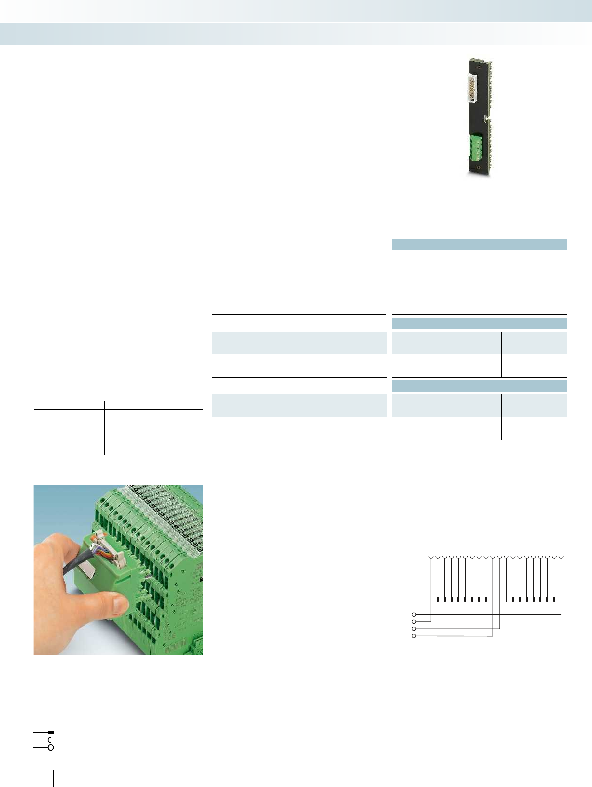
20191817 16 15 14 13 12 11
L+
M
10987654321
141516 13 12 11 10987654321
Comp.-
Comp.+
522
PHOENIX CONTACT
Technical data
FLKM 16-PA-S300/MINI-MCR
Max. perm. operating voltage < 50 V AC / 60 V DC
Max. permissible current 50 mA (per path)
500 mA (per connection, supply via separate power supply)
Ambient temperature (operation) -20 °C ... 60 °C
Ambient temperature (storage/transport) -20 °C ... 70 °C
Standards/regulations IEC 60664 / DIN EN 50178 / IEC 62103
Ordering data
Description No. of pos. Type Order No. Pcs. /
Pkt.
VARIOFACE front adapter, for SIMATIC
®
S7-300, only in
connection with MINI MCR-SL-V8-FLK 16-A
16 FLKM 16-PA-S300/MINI-MCR 2314749 1
Accessories
Assembled round cable, with two 16-pos. socket strips
FLK 16/EZ-DR/ 300/KONFEK 2299330 1
System adapter, for MINI Analog modules with screw connection
MINI MCR-SL-V8-FLK 16-A 2811268 1
FLKM 16-PA-S300/MINI-MCR connection scheme
Front adapter for analog cards of
SIMATIC
®
S7-300
Card type FLKM 16-PA-S300/MINI-MCR
Analog input 6ES7 331-7KF02-0AB0
6ES7 331-7KB02-0AB0
6ES7 331-7KB81-0AB0
6ES7 331-7TF00-0AB0
Analog output 6ES7 332-8TF01-0AB0
Flat-ribbon cable strip
Connection to I/O card
Screw terminal blocks for separate supply
Explanation:
This front adapter is used exclusively to
couple the MINI MCR-SL-V8-FLK 16 A
adapter. Changed standard analog signals
can be transmitted with the help of these
components.
Suitable isolators can be found from page 92.
For suitable 16-pos. system cable
(FLK 16/EZ-DR/...), refer to page 606.
Siemens SIMATIC
®
S7-300
Front adapter for MINI MCR
System cabling for controllers
Controller-specific system cabling
Front adapter for SIMATIC
®
S7-300,
20-pos. analog I/O cards
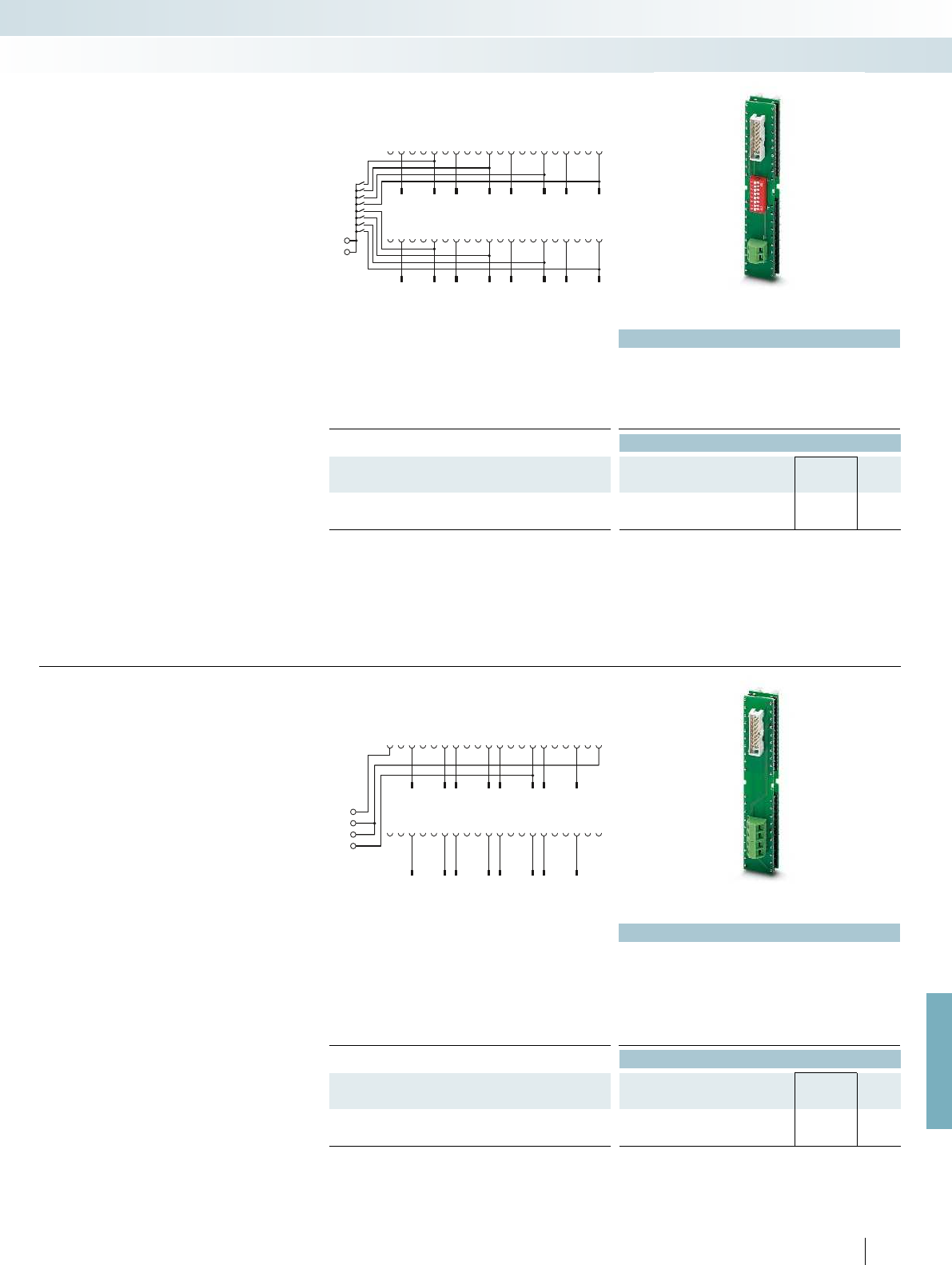
M–
M–21
1
22
2
23
3
24
4
25
5
26
6
27
7
28
8
29
9
30
10
31
11
32
12
33
13
34
14
35
15
36
16
37
17
38
18
39
19
40
20
9
1
10
2
11
3
12
4
13
5
14
6
15
7
16
8
0
1
2
3
4
5
6
7
M
ANA
M–
M–
L+
21
1
22
2
23
3
24
4
25
5
26
6
27
7
28
8
29
9
30
10
31
11
32
12
33
13
34
14
35
15
36
16
37
17
38
18
39
19
40
20
9
1
10
2
11
3
12
4
13
5
14
6
15
7
16
8
For further information and full technical data, visit phoenixcontact.net/products
Technical data
Max. perm. operating voltage < 50 V AC / 60 V DC
Max. permissible current 50 mA (per path)
Ambient temperature (operation) -20 °C ... 60 °C
Ambient temperature (storage/transport) -20 °C ... 70 °C
Standards/regulations IEC 60664 / DIN EN 50178 / IEC 62103
Ordering data
Description No. of pos. Type Order No. Pcs. /
Pkt.
VARIOFACE front adapter, for SIMATIC
®
S7-300, only in
connection with MINI MCR-SL-V8-FLK 16-A
16 FLKM 16-PA- 331-1KF/I/MINI-MCR 2318237 1
Connection scheme FLKM 16-PA-331-1KF/I/MINI-MCR
The FLKM 16-PA-331-1KF/I/MINI-MCR
front adapter helps in system cabling in
conjunction with the MINI Analog system
adapter and a 16-pos. system cable
FLK 16/EZ-DR/.../KONFEK, refer to
page 606.
Instead of the conventional front
connector, screw terminal blocks are used
to snap this component onto the analog
module.
The DIP switches can be used to connect
“M-” connections to each other and to the
central ground of the system.
The front adapter supports only current
signals.
The front adapter is suitable for the
following analog input card:
– 6ES7 331-1KF02-0AB0
Siemens SIMATIC
®
S7-300
Front adapter for
MINI Analog system cabling
System cabling for controllers
Controller-specific system cabling
Front adapter for SIMATIC
®
S7-300,
6ES7 331-1KF02-0AB0 analog I/O card
Technical data
Max. perm. operating voltage < 50 V AC / 60 V DC
Max. permissible current 50 mA (per path)
500 mA (per connection, supply via separate power supply)
Ambient temperature (operation) -20 °C ... 60 °C
Ambient temperature (storage/transport) -20 °C ... 70 °C
Standards/regulations IEC 60664 / DIN EN 50178 / IEC 62103
Ordering data
Description No. of pos. Type Order No. Pcs. /
Pkt.
VARIOFACE front adapter, for SIMATIC
®
S7-300, only in
connection with MINI MCR-SL-V8-FLK 16-A
16 FLKM 16-PA- 332-5HF/I/MINI-MCR 2318240 1
523
PHOENIX CONTACT
Connection scheme FLKM 16-PA-332-5HF/I/MINI-MCR
The FLKM 16-PA-332-5HF/I/MINI-MCR
front adapter helps in system cabling in
conjunction with the MINI Analog system
adapter and a 16-pos. system cable
FLK 16/EZ-DR/.../KONFEK, refer to
page 606.
Instead of the conventional front
connector, screw terminal blocks are used
to snap this component onto the analog
module.
The front adapter supports only current
signals.
The front adapter is suitable for the
following analog output cards:
– 6ES7 332-5HF00-0AB0
Siemens SIMATIC
®
S7-300
Front adapter for
MINI Analog system cabling
Front adapter for SIMATIC
®
S7-300,
6ES7 332-5HF00-0AB0 analog I/O card
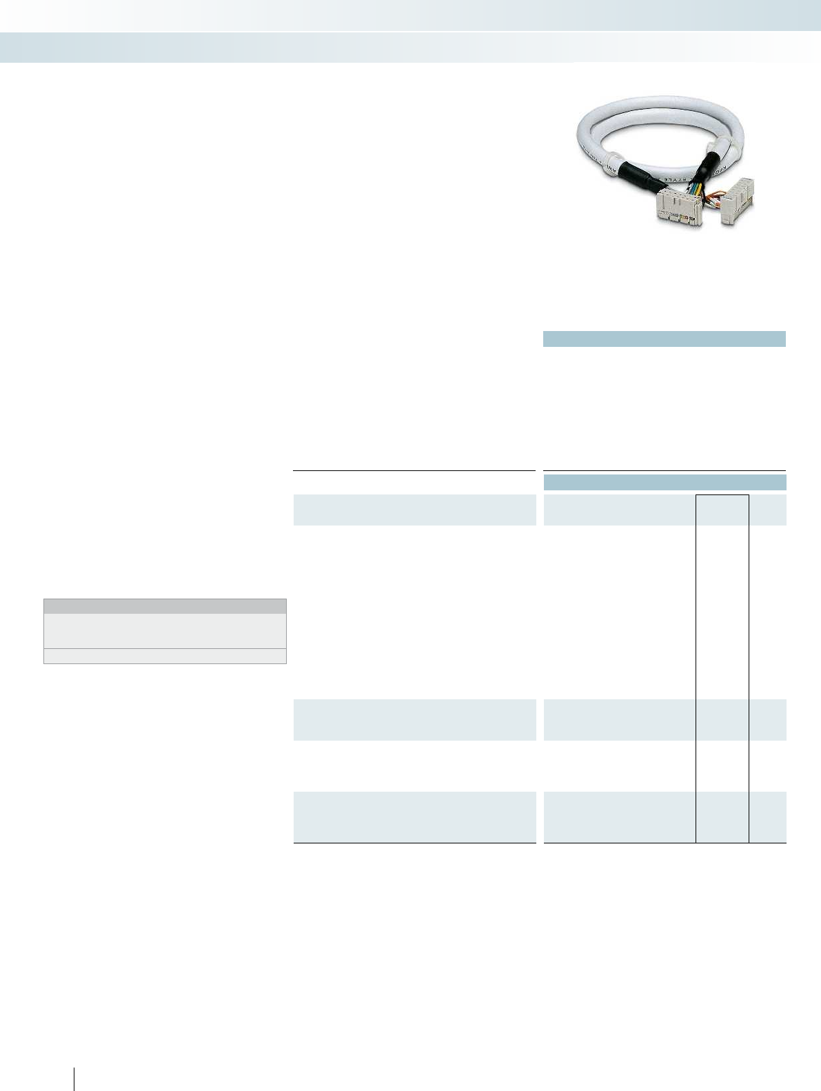
524
PHOENIX CONTACT
These system cables are connected
directly to Siemens “SIMATIC TOP
connect” front connectors. A VARIOFACE
front adapter is not required. The cables can
be used to connect existing 8-channel
Phoenix Contact interface modules.
– For passive signal transmission, e.g.,
VIP-2/SC/FLK14/PLC;
Order No. 2315214, see page 542.
– For relay or solid-state relay connection
via V8 adapters, e.g.,
PLC-V8/FLK14/OUT;
Order No. 2295554, see page 451.
The system cables are available in the
following versions:
– Unshielded
– Shielded
– Halogen-free
The following SIMATIC
®
S7-1500 cards
can be coupled:
Digital input:
– 6ES7 521-1BH00-0AB0
– 6ES7 521-1BH50-0AA0
– 6ES7 521-1BL00-0AB0
Digital output:
– 6ES7 522-1BH00-0AB0
– 6ES7 522-1BL00-0AB0
Web code for the online configurator
Your web code: #0007
Notes:
These system cables are connected directly to the
Siemens S7-1500 6ES7 921-5AB20-0AA0 or
6ES7 921-5AH20-0AA0 front connector modules.
The Siemens adapters are not supplied by Phoenix Contact.
Siemens SIMATIC
®
S7-1500
System cables for front connectors
from the “TOP connect” series
Technical data
Max. perm. operating voltage < 50 V AC / 60 V DC
Max. perm. current carrying capacity per path 1 A
Max. conductor resistance 0.16 /m
Ambient temperature (operation) -20 °C ... 50 °C
Assembly Insulation displacement, IEC 60352-4/DIN EN 60352-4 Insulation displacement, IEC 60352-4/DIN EN 60352-4
Number of positions, control side 16
Number of positions, module side 14
Conductor cross section AWG 26 / 0.14 mm²
Conductor structure: stranded wires / material 7 / Cu tin-plated
Outside diameter 6.4 mm
Ordering data
Description Cable length Type Order No. Pcs. /
Pkt.
Unshielded round cables, with one 16-pos. and one
14-pos. socket strip in fixed lengths for transmitting 8 channels
0.5 m FLK 14/16/EZ-DR/ 50/S7 2293815 5
1 m FLK 14/16/EZ-DR/ 100/S7 2293828 1
1.5 m FLK 14/16/EZ-DR/ 150/S7 2293831 1
2 m FLK 14/16/EZ-DR/ 200/S7 2293844 1
2.5 m FLK 14/16/EZ-DR/ 250/S7 2293857 1
3 m FLK 14/16/EZ-DR/ 300/S7 2293860 1
4 m FLK 14/16/EZ-DR/ 400/S7 2293886 1
5 m FLK 14/16/EZ-DR/ 500/S7 2293899 1
6 m FLK 14/16/EZ-DR/ 600/S7 2293909 1
7 m FLK 14/16/EZ-DR/ 700/S7 2293912 1
8 m FLK 14/16/EZ-DR/ 800/S7 2293925 1
9 m FLK 14/16/EZ-DR/ 900/S7 2293938 1
10 m FLK 14/16/EZ-DR/1000/S7 2293941 1
Unshielded round cables, as above, but in variable lengths of
type “FLK EZ-DR/14U/C52/...”
FLK EZ-DR.../.../... 2295059 1
Shielded round cables, with one 16-pos. and one 14-pos. socket
strip, for transmitting 8 channels in variable lengths of type
“FLK EZ-DR-S/14S/C52/...”
FLK EZ-DR-S.../.../... 2295046 1
Unshielded halogen-free round cables, with one 16-pos. and
one 14-pos. socket strip, for transmitting 8 channels in variable
lengths
System cabling for controllers
Controller-specific system cabling
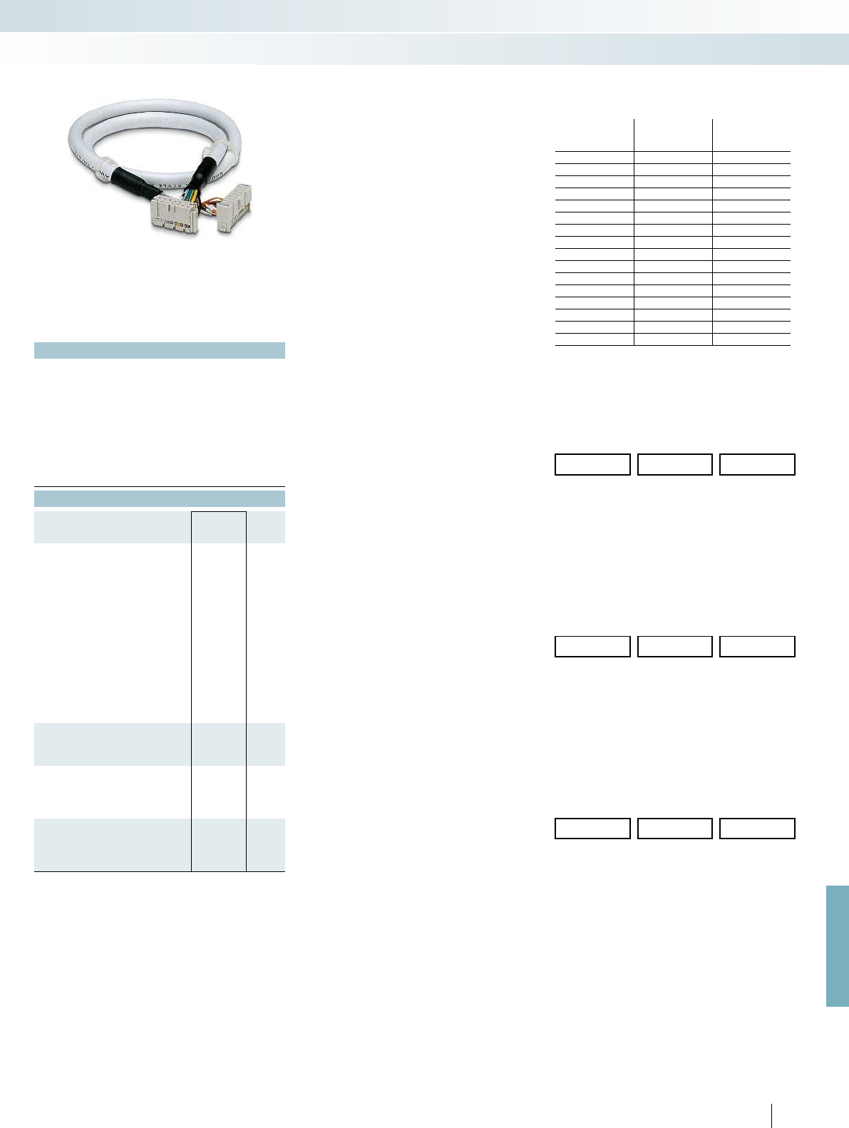
For further information and full technical data, visit phoenixcontact.net/products
Pin assignment and color code:
- FLK 14/16/EZ-DR/.../S7
- FLK 14/16/EZ-DR/HF/.../S7
14-pos. socket
strip
PIN
16-pos. socket
strip
PIN
Wire color
1 16 Black
2 14 Brown
3 12 Red
4 10 Orange
5 8 Yellow
6 6 Green
7 4 Blue
8 2 Violet
9 9 Gray
10 1 White
11 11 White-black
12 3 White-brown
13 13 White-red
14 5 White-orange
Not used 7 -
Not used 15 -
Ordering example for unshielded round cable:
Unshielded round cable, assembled with
one 14-pos. and one 16-pos. socket strip, 12.70 m long
Type: FLK EZ-DR /14U/C52/...
Quantity Order No. Length [m]
1
)
12295059/14U/C52 /12.70
1
) Min. 0.20 m
14U 14-pos. unshielded cable
C52 S7-1500 assembly with 14-pos. socket strip at one end
and 16-pos. socket strip at the other
Ordering example for shielded round cable:
Unshielded round cable, assembled with
one 14-pos. and one 16-pos. socket strip, 13.20 m long
Type: FLK EZ-DR-S /14S/C52/...
Quantity Order No. Length [m]
1
)
12295046/14S/C52 /13.20
1
) Min. 0.20 m
14S 14-pos. shielded cable
C52 S7-1500 assembly with 14-pos. socket strip at one end
and 16-pos. socket strip at the other
Ordering example for halogen-free round cable:
Halogen-free round cable, assembled with
one 14-pos. and one 16-pos. socket strip, 15.50 m long
Type: FLK 14-16-EZ-DR-HF-S7/...
Quantity Order No. Length [m]
1
)
12295693 /15.50
1
) Min. 0.20 m
525
PHOENIX CONTACT
Technical data
< 50 V AC / 60 V DC
1 A
0.16 /m
-20 °C ... 50 °C
2-4 Insulation displacement, IEC 60352-4/DIN EN 60352-4
16
14
AWG 26 / 0.14 mm²
7 / Cu tin-plated
6.4 mm
Ordering data
Type Order No. Pcs. /
Pkt.
FLK 14/16/EZ-DR/HF/ 50/S7 2296919 1
FLK 14/16/EZ-DR/HF/ 100/S7 2296922 1
FLK 14/16/EZ-DR/HF/ 150/S7 2296935 1
FLK 14/16/EZ-DR/HF/ 200/S7 2296948 1
FLK 14/16/EZ-DR/HF/ 250/S7 2296951 1
FLK 14/16/EZ-DR/HF/ 300/S7 2296964 1
FLK 14/16/EZ-DR/HF/ 400/S7 2904525 1
FLK 14/16/EZ-DR/HF/ 500/S7 2304704 1
FLK 14/16/EZ-DR/HF/ 600/S7 2904526 1
FLK 14/16/EZ-DR/HF/ 800/S7 2904527 1
FLK 14/16/EZ-DR/HF/1000/S7 2904528 1
FLK 14-16-EZ-DR-HF-S7/... 2295693 1
System cabling for controllers
Controller-specific system cabling
Halogen-free
(cable only)

87
5
46911 15 16 17 18192021 22 23
14
321 1012 13 24
5421131193 1412106785421131193 141210678
5421131193 1412106785421131193 141210678
302928272625 31 32 33 34 35 36 37 38403941 42 43 44 45 46 47 48
DR1
DR4
DR2
DR5
L
M
DR3
DR6
12345678910111213 1415 16171819202122232425
12345678910111213 1415 16171819202122232425
26272829303132333435 3637 38394041424344454647484950
26272829303132333435 3637 3839404142434445464748
12 34567891011
12131415161718192021222324
1234567891011
12 1 31 41 51 61 71 8192021222324
252 62 72829303132333435363738394041424344454647484950
252 62 7282930313233343536373839404142434445464748
DR1
DR2
DR3
0+
1+
2+
3+
–
526
PHOENIX CONTACT
Technical data
Max. perm. operating voltage < 50 V AC / 60 V DC
Max. permissible current 1 A (per path)
8 A (per connection, supply via separate power supply)
Max. perm. total current 2 A (per byte, for supply via connector)
8 A (during supply via a separate bridged power supply)
Ambient temperature (operation) -20 °C ... 50 °C
Ambient temperature (storage/transport) -20 °C ... 70 °C
Mounting position any
Standards/regulations IEC 60664 / DIN EN 50178 / IEC 62103
Ordering data
Description No. of pos. Type Order No. Pcs. /
Pkt.
VARIOFACE front adapter, for
- SIMATIC
®
S7-400, 1 x 32 channels can be
connected
50 FLKM 50-PA-S400 2294500 2
- SIMATIC
®
S7-400, 4 x 8 channels can be
connected
14 FLKM 50/ 4-FLK14/PA-S400 2294429 2
- SIMATIC
®
S7-400, only analog 50 FLKM 50-PA-S400(3-48) 2294908 2
Connection scheme: FLKM 50/4-FLK14/PA-S400
Connection scheme FLKM 50-PA-S400 (3-48) Connection scheme FLKM 50-PA-S400
Front adapter for I/O modules of the
Siemens automation devices
SIMATIC
®
S7-400
Card type FLKM 50-PA-S400
Digital input 6ES7 421-1BL01-0AA0
6ES7 421-7BH01-0AB0*
6ES7 421-7DH00-0AB0*
Digital output 6ES7 422-1BL00-0AA0
6ES7 422-7BL00-0AB0
Card type FLKM 50/4-FLK14/PA-S400
Digital input 6ES7 421-1BL01-0AA0
Digital output 6ES7 422-1BL00-0AA0
6ES7 422-7BL00-0AB0
Card type FLKM 50-PA-S400 (3-48)
Analog input 6ES7 431-0HH00-0AB0**
6ES7 431-1KF00-0AB0**
6ES7 431-1KF10-0AB0**
6ES7 431-1KF20-0AB0**
6ES7 431-7KF00-0AB0**
6ES7 431-7KF10-0AB0**
6ES7 431-7QH00-0AB0**
Analog output 6ES7 432-1HF00-0AB0**
* Only in conjunction with
VIP-2/SC/FLK50/S7/A-S400, Order No.: 2322359
VIP-2/PT/FLK50/S7/A-S400, Order No.: 2904289
all DR wire jumpers on the adapter must be disconnected.
** Only in conjunction with
VIP-3/SC/FLK50, Order No.: 2315081
VIP-3/PT/FLK50, Order No.: 2903794
FLKM 50/KDS 3-MT/PPA/AN/PLC, Order No.: 2291587
Flat-ribbon cable strip
Connection to I/O card
Screw terminal blocks for separate supply
Explanation:
The front adapters mean that pre-
assembled system cables can be directly
connected to I/O modules.
FLKM 50-PA-S400
– Transmission of max. 32 digital channels
over one 50-position system cable.
FLKM 50/4-FLK14/PA-S400
– Transmission of max. 32 digital channels
via one 14-position system cable.
Tailor-made VARIOFACE termination
boards with a variety of functions and
connection options round off this system
concept.
FLKM 50-PA-S400 (3-48)
– Analog channels are connected via a
50-position system cable.
The 1:1 connection of the adapter means
that corresponding 1:1 interface modules
are connected here
Web code for the online configurator
Your web code: #0007
Siemens SIMATIC
®
S7-400
Front adapter
System cabling for controllers
Controller-specific system cabling
Front adapter for
SIMATIC
®
S7-400
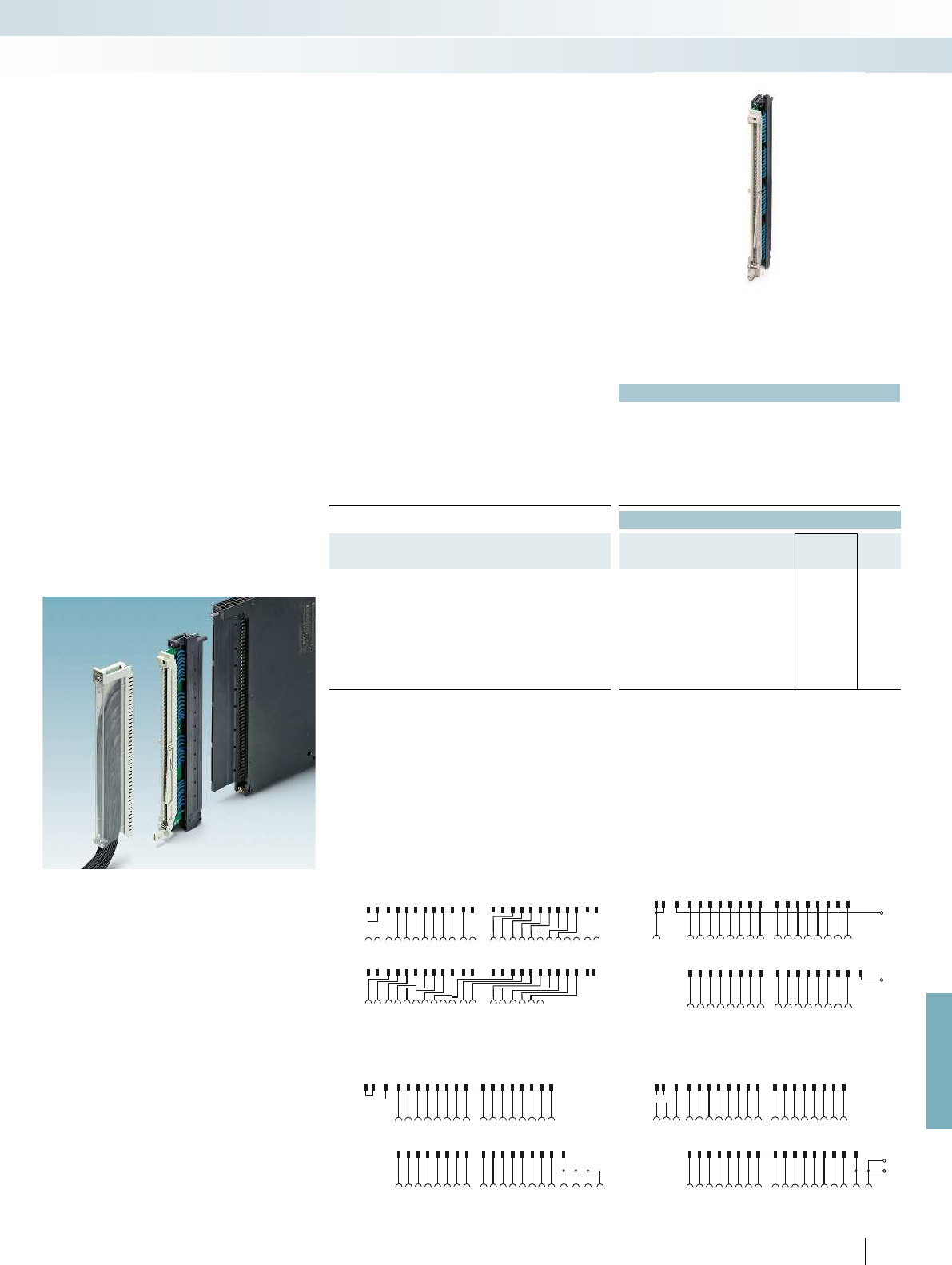
S7-400 31 41
32 4233 43 4534 44 46 48
272829393040
M
S5-135 567891019
11 20
1513 1614 17 18
44
S5-135 2936
303731 384041 21 42 12 3332 39
252627 342835
S7-400 12 3 567891021
11 22
4151617181920
L+
S7-400 31 41
32 4233 43 4534 44 46 48
272829393040
M
M
S5-135 12 567891019
11 20
1513 1614 17 18
43 4
S5-135 2936
303731 384041 21 4232 39
2526 27 342835
S7-400 12 3 567891021
11 22
41516 17 181920
S7-400
S7-400
S5-135
S5-135
1
13
23
123
2
2 1412 24
35
5
6
6
7
7
8
8
9
9
10 21
31
31
41
41
10 19
11 22
32
32
42
42
33
33
43 4534
34
35
35
36
36
44 46 4748
11 202122
415
1513
16
161412 24
17
27
27
26
26
25
25
17
18
28
28
18
19
29
29
39
39
38
38
37
37
20
30
30
40
40
434
S7-400
M
L+
S5-135 2936
303731 38404132 39
25 26 27 342835
S5-135 1567891019
11 20
1513 1614 1718
44
S7-400 31 41
32 4233 43 4534 44 46 48
27 2829393040
12 3 567891021
11 22
415 16 17 181920
For further information and full technical data, visit phoenixcontact.net/products
527PHOENIX CONTACT
Technical data
①②③④
Max. perm. operating voltage 60 V DC 60 V DC 60 V DC 60 V DC
Max. permissible current 4 A (per path) 2 A (per path) 4 A (per path) 4 A (per path)
Ambient temperature (operation) -20 °C ... 50 °C -20 °C ... 50 °C -20 °C ... 50 °C -20 °C ... 50 °C
Mounting position any any any any
Standards/regulations IEC 60664 / DIN EN 50178 / IEC 62103
Ordering data
Description No. of pos. Type Order No. Pcs. /
Pkt.
Digital IN 24 V from S5-135/155 to S7-400
6ES5 420-4UA14 to 6ES7 421-1BL01-0AA0 ①FLKM S135/S400/SO120 2301723 1
6ES5 430-4UA14 to 6ES7 421-1BL01-0AA0 ②FLKM S135/S400/SO121 2301736 1
6ES5 431-4UA12 to 6ES7 421-7DH00-0AB0 ③FLKM S135-431-4UA/S400 2314846 1
6ES5 432-4UA12 to 6ES7 421-1BL01-0AA0 ④FLKM S135/S400/SO122 2301749 1
Connection scheme: FLKM S135/S400/SO122 Connection scheme: FLKM S135/S400/SO121
FLKM S135-431-UA/S400 connection scheme Connection scheme: FLKM S135/S400/SO120
The FLKM S135/... adapters connect a
SIMATIC
®
S5 plug wired with individual
conductors directly with the
SIMATIC
®
S7-400 basic card.
The SIMATIC
®
S5 plug is plugged directly
onto an S7-400-I/O card with the help of
an FFLKM S135/... intermediate adapter.
A new SIMATIC
®
S7-400 is installed in
place of the SIMATIC
®
S5. The existing field
wiring remains intact.
Attention:
The LEDs of the S7-400 module are
hidden.
Siemens SIMATIC
®
S7-400
Adapter for conversion from
S5-135/155 to S7-400
System cabling for controllers
Controller-specific system cabling
Adapter for Siemens SIMATIC
®
S5-135/S7-400

S7-400
S7-400
S5-135 156789
31 41
1019
38
32 4233 43 4534 44 46 48
11 20
1513 1614
2726
17
28
18
29393040
434
48
1L+
S5-135 2936
303731 38404132 39
2524 26 27 342835
M2L+
2 21
12 3 567891021
1114 22
415 16 17 181920
S5-135 39
3041
32 27 36 402131
26 2835 37
S7-400 12 11 4 5 91017 22
615 16 20
S7-400
S5-135 11057 9
44
11 15
32
45
33 294134 46
19
14 16
27 28
1820
39
21
40
63
S7-400 31 41
38
32 4233 43 4534 44 46 48
2726 2829393040
M
S5-135 12 567891019
11 20
1513 1614 17 18
434
S5-135 2936
303731 38404132 39
2524 26 27 342835
S7-400 12 3 567891021
11 14 22
415 16 17 181920
528
PHOENIX CONTACT
Technical data
①②③
Max. perm. operating voltage 60 V DC 60 V DC 60 V DC
Max. permissible current 4 A (per path) 4 A (per path) 4 A (per path)
Ambient temperature (operation) -20 °C ... 50 °C -20 °C ... 50 °C -20 °C ... 50 °C
Mounting position any any any
Standards/regulations IEC 60664 / DIN EN 50178 / IEC 62103
Ordering data
Description No. of pos. Type Order No. Pcs. /
Pkt.
Digital OUT 24 V from S5-135/155 to S7-400
6ES5 441-4UA12 to 6ES7 422-1BL00-0AA0 ①FLKM S135/S400/SO125 2301778 1
6ES5 451-4UA14 to 6ES7 422-1BL00-0AA0 ②FLKM S135/S400/SO126 2301781 1
Digital OUT 24 V DC / 2 A from S5-135/155 to S7-400
6ES5 453-4UA12 to 6ES7 422-1HH00-0AA0 ③FLKM S135/S400/SO127 2301794 1
Connection scheme: FLKM S135/S400/SO126
Connection scheme: FLKM S135/S400/SO127 Connection scheme: FLKM S135/S400/SO125
The FLKM S135/... adapters connect a
SIMATIC
®
S5 plug wired with individual
conductors directly with the
SIMATIC
®
S7-400 basic card.
The SIMATIC
®
S5 plug is plugged directly
onto an S7-400-I/O card with the help of
an FFLKM S135/... intermediate adapter.
A new SIMATIC
®
S7-400 is installed in
place of the SIMATIC
®
S5. The existing field
wiring remains intact.
Attention:
The LEDs of the S7-400 module are
hidden.
Siemens SIMATIC
®
S7-400
Adapter for conversion from
S5-135/155 to S7-400
System cabling for controllers
Controller-specific system cabling
Front adapter for SIMATIC S5-135 S7 400
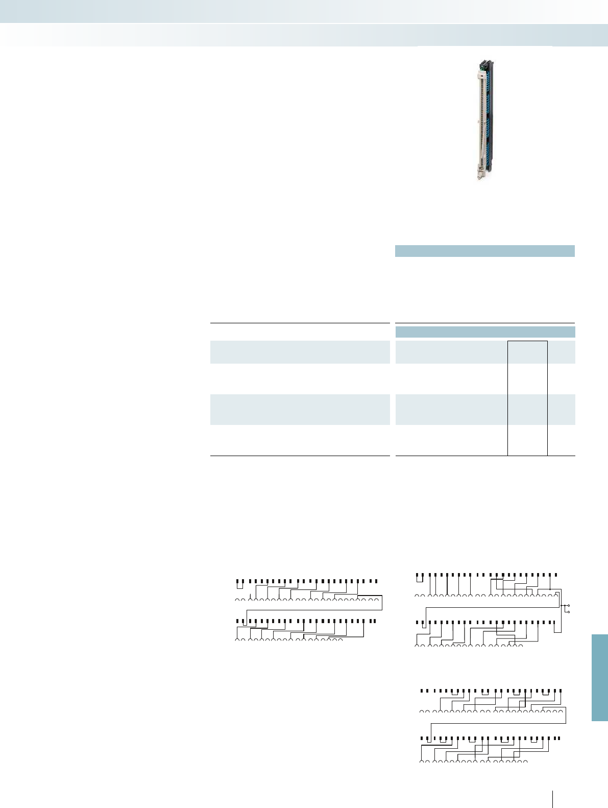
S7-400
S7-400
S5-135
S5-135
1
13
23
123
2
2 1412 24
35
5
6
6
7
7
8
8
9
9
10 21
31
31
41
41
10 19
11 22
32
32
42
42
33
33
43 4534
34
35
35
36
36
44 46 4748
11 202122
415
1513
16
161412 24
17
27
27
26
26
25
25
17
18
28
28
18
19
29
29
39
39
38
38
37
37
20
30
30
40
40
434
S7-400
S7-400
S5-135
S5-135
1
13
23
123
2
2 1412 24
35
5
6
6
7
7
8
8
9
9
10 21
31
31
41
41
10 19
11 22
32
32
42
42
33
33
43 4534
34
35
35
36
36
44 46 4748
11 202122
415
1513
16
161412 24
17
27
27
26
26
25
25
17
18
28
28
18
19
29
29
39
39
38
38
37
37
20
30
30
40
40
434
S7-400
S7-400
S5-135
S5-135
1
13
23
123
2
2 1412 24
35
5
6
6
7
7
8
8
9
9
10 21
31
31
41
41
10 19
11 22
32
32
42
42
33
33
43 4534
34
35
35
36
36
44 46 4748
11 202122
415
1513
16
161412 24
17
27
27
26
26
25
25
17
18
28
28
18
19
29
29
39
39
38
38
37
37
20
30
30
40
40
434 L-
L-
For further information and full technical data, visit phoenixcontact.net/products
529PHOENIX CONTACT
Technical data
①②③
Max. perm. operating voltage 60 V DC 60 V DC 60 V DC
Max. permissible current 4 A (per path) 4 A (per path) 4 A (per path)
Ambient temperature (operation) -20 °C ... 50 °C -20 °C ... 50 °C -20 °C ... 50 °C
Mounting position any any any
Standards/regulations IEC 60664 / DIN EN 50178 / IEC 62103
Ordering data
Description No. of pos. Type Order No. Pcs. /
Pkt.
Digital OUT 24 V DC / 2 A from S5-135/155 to S7-400
6ES5 454-4UA14 to 6ES7 422-1BH11-0AA0 ①FLKM S135-454-4UA/S400 2314859 1
Analog IN (only current measurement) from S5-135/155 to S7-400
6ES5 460-4UA13 to 6ES7 431-1KF00-0AB0 ②FLKM S135-460-4UA/I/S400 2314613 1
Analog IN (only voltage measurement) from S5-135/155 to S7-400
6ES5 460-4UA13 to 6ES7 431-1KF00-0AB0 ③FLKM S135-460-4UA/U/S400 2314862 1
FLKM S135-460-4UA/I/S400 connection scheme
Connection scheme: FLKM S135-460-4UA/U/S400 FLKM S135-454-4UA/S400 connection scheme
The FLKM S135/... adapters connect a
SIMATIC
®
S5 plug wired with individual
conductors directly with the
SIMATIC
®
S7-400 basic card.
The SIMATIC
®
S5 plug is plugged directly
onto an S7-400-I/O card with the help of
an FFLKM S135/... intermediate adapter.
A new SIMATIC
®
S7-400 is installed in
place of the SIMATIC
®
S5. The existing field
wiring remains intact.
Attention:
The LEDs of the S7-400 module are
hidden.
Siemens SIMATIC
®
S7-400
Adapter for conversion from S5-
135/155 to S7-400
System cabling for controllers
Controller-specific system cabling
Adapter for Siemens SIMATIC
®
S5-135/S7-400
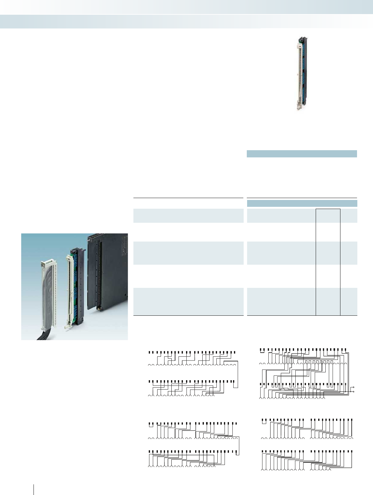
S7-400
S7-400
S5-135
S5-135
1
13
23
123
2
2 1412 24
35
5
6
6
7
7
8
8
9
9
10 21
31
31
41
41
10 19
11 22
32
32
42
42
33
33
43 4534
34
35
35
36
36
44 46 4748
11 202122
415
1513
16
161412 24
17
27
27
26
26
25
25
17
18
28
28
18
19
29
29
39
39
38
38
37
37
20
30
30
40
40
434
S7-400
S7-400
S5-135
S5-135
1
13
23
123
2
2 1412 24
35
5
6
6
7
7
8
8
9
9
10 21
31
31
41
41
10 19
11 22
32
32
42
42
33
33
43 4534
34
35
35
36
36
44 46 4748
11 202122
415
1513
16
161412 24
17
27
27
26
26
25
25
17
18
28
28
18
19
29
29
39
39
38
38
37
37
20
30
30
40
40
434
S7-400
S7-400
S5-135
S5-135
1
13
23
123
2
2 1412 24
35
5
6
6
7
7
8
8
9
9
10 21
31
31
41
41
10 19
11 22
32
32
42
42
33
33
43 4534
34
35
35
36
36
44 46 4748
11 202122
415
1513
16
161412 24
17
27
27
26
26
25
25
17
18
28
28
18
19
29
29
39
39
38
38
37
37
20
30
30
40
40
434
S7-400
S7-400
S5-135
S5-135
1
13
23
123
2
2 1412 24
35
5
6
6
7
7
8
8
9
9
10 21
31
31
41
41
10 19
11 22
32
32
42
42
33
33
43 4534
34
35
35
36
36
44 464748
11 202122
415
1513
16
161412 24
17
27
27
26
26
25
25
17
18
28
28
18
19
29
29
39
39
38
38
37
37
20
30
30
40
40
434
L-
L-
530
PHOENIX CONTACT
Technical data
①②③④
Max. perm. operating voltage 60 V DC 60 V DC 60 V DC 60 V DC
Max. permissible current 2 A (per path) 4 A (per path) 4 A (per path) 4 A (per path)
Ambient temperature (operation) -20 °C ... 50 °C -20 °C ... 50 °C -20 °C ... 50 °C -20 °C ... 50 °C
Mounting position any any any any
Standards/regulations IEC 60664 / DIN EN 50178 / IEC 62103
Ordering data
Description No. of pos. Type Order No. Pcs. /
Pkt.
Analog IN (only Pt 100) from S5-135/155 to S7-400
6ES5 465-4UA13 to 6ES7 431-7KF10-0AB0 ①FLKM S135-465-4UA/T/S400 2314875 1
Analog IN (only current and voltage measurement) from
S5-135/155 to S7-400
6ES5 465-4UA13 to 6ES7 431-0HH00-0AB0
6ES5 465-4UA13 to 6ES7 431-7QH00-0AB0
②FLKM S135-465-4UA/UI/S400 2314888 1
Analog OUT (only current output) from S5-135/155 to S7-400
6ES5 470-4UA13 to 6ES7 432-1HF00-0AB0
6ES5 470-4UC13 to 6ES7 432-1HF00-0AB0
③FLKM S135-470-4UC/I/S400 2314626 1
Analog OUT (only voltage output) from S5-135/155 to S7-400
6ES5 470-4UA13 to 6ES7 432-1HF00-0AB0
6ES5 470-4UB13 to 6ES7 432-1HF00-0AB0
6ES5 470-4UC13 to 6ES7 432-1HF00-0AB0
④FLKM S135-470-4UC/U/S400 2314891 1
Connection scheme FLKM S135-470-4UC/U/S400 FLKM S135-465-4UA/UI/S400 connection scheme
Connection scheme FLKM S135-470-4UC/I/S400 FLKM S135-465-4UA/T/S400 connection scheme
The FLKM S135/... adapters connect a
SIMATIC
®
S5 plug wired with individual
conductors directly with the
SIMATIC
®
S7-400 basic card.
The SIMATIC
®
S5 plug is plugged directly
onto an S7-400-I/O card with the help of
an FFLKM S135/... intermediate adapter.
A new SIMATIC
®
S7-400 is installed in
place of the SIMATIC
®
S5. The existing field
wiring remains intact.
Attention:
The LEDs of the S7-400 module are
hidden.
Siemens SIMATIC
®
S7-400
Adapter for conversion from
S5-135/155 to S7-400
System cabling for controllers
Controller-specific system cabling
Adapter for Siemens SIMATIC
®
S5-135/S7-400

2322 343332
31
302940423941383724252627283536
28272625 4140393837363534 494847464544 50
2930313233 4243
32
1141312
1110
92021
191817
456781516
L+
L-
L2+
DR1
DR3
DR4
DR2
4321 17161514131211102423222120567891819
FLK50
S5-135
FLK50
S5-135
1
40
2
41
3
42
1
1
40
40
2
2
41
41
3
3
42
42
S5-135
For further information and full technical data, visit phoenixcontact.net/products
Technical data
Max. perm. operating voltage 60 V DC
Max. permissible current 1 A (per path)
Ambient temperature (operation) -20 °C ... 50 °C
Ambient temperature (storage/transport) -20 °C ... 70 °C
Mounting position any
Standards/regulations IEC 60664 / DIN EN 50178 / IEC 62103
Ordering data
Description Type Order No. Pcs. /
Pkt.
Digital IN or OUT 24 V DC from S5-135 to S7-300
IN
6ES5 420-4UA14 to 6ES7 321-1BL00-0AA0
6ES5 430-4UA14 to 6ES7 321-1BL00-0AA0
OUT
6ES5 441-4UA14 to 6ES7 322-1BL00-0AA0
6ES5 451-4UA14 to 6ES7 322-1BL00-0AA0
FLKM S135/S7/FLK50/PLC 2314736 1
FLKM S135/S7/FLK50/PLC connection scheme
S5-S7 adapters connect the S5-135 front
adapters wired with individual wires to the
I/O modules of the S7.
With the help of the
FLKM S135/S7/FLK50 converter module,
the signals of the S5-135 front adapter can
be converted to a 50-pos. strip. A 50-pos.
system cable FLK 50/EZ-DR/.../KONFEK
and a front adapter for the SIMATIC
®
S7
(FLKM 50-PA-S300) now connect the
signals with the I/O module.
Notes:
Due to the geometry, it is not possible to couple any molded
FLK connectors (e.g., VIP-PA...S7).
Siemens SIMATIC
®
S7-300
Adapter for conversion from
S5-135/155 to S7-300
System cabling for controllers
Controller-specific system cabling
Converter for Siemens SIMATIC
®
S5-135 to
50-pos. FLK strip.
Technical data
Max. perm. operating voltage 250 V AC/DC
Max. permissible current 6 A (per path)
Ambient temperature (operation) -20 °C ... 50 °C
Ambient temperature (storage/transport) -20 °C ... 80 °C
Mounting position any
Standards/regulations IEC 60664 / DIN EN 50178 / IEC 62103
Ordering data
Description Type Order No. Pcs. /
Pkt.
Connection of all S5-135 connections
(1 to 42) at the open cable end
FLKM S135/42X0,75/3,0M/OE 2315007 1
FLKM S135/42X0,75/5,0M/OE 2318017 1
531
PHOENIX CONTACT
All signals of the existing S5-135 wiring
are extended by 3 or 5 meters with the help
of the universal startup adapters. The open
cable end can be connected to various
controllers such as S7-400 or S7-300. Thus,
the existing field wiring of S5-135 can
communicate with the new controller for
test purposes. Since the new control unit is
temporarily arranged before the control
cabinet, the original status of the system can
be restored if required.
If the system functions with the new
controller without problems, the S5-135
can now be replaced.
Startup adapters for extending the
existing S5-135/155 field wiring
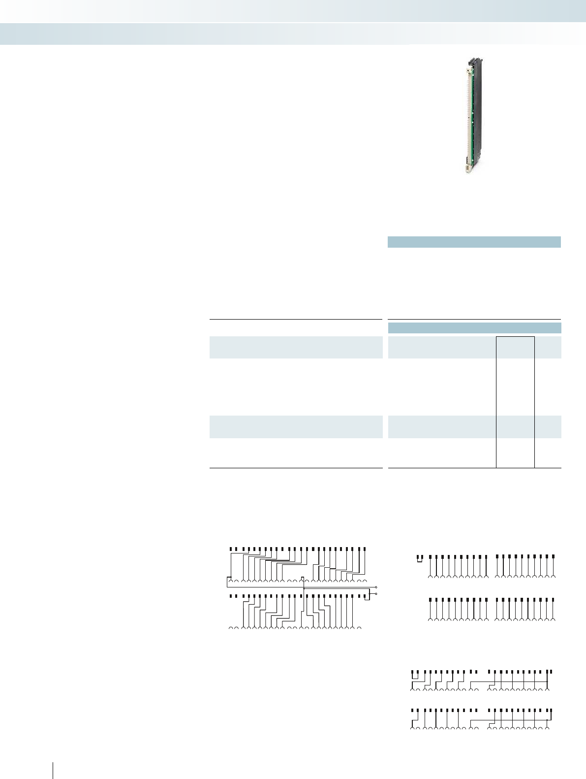
S7-400
S7-400
S5-115
S5-115
1
13
23
123
2
2 1412 24
35
5
6
6
7
7
8
8
9
9
10 21
31
31
41
41
10 19
11 22
32
32
42
42
33
33
43
43
45
45
34
34
35
35
36
36
44
44
46
46
47
47
48
11 202122
415
1513
16
161412
17
27
27
26
26
25
25
17
18
28
28
18
19
29
29
39
39
38
38
37
37
20
30
30
40
40
434
S7-400
S7-400
S5-115
S5-135
1
13
23
123
2
2 1412 24
35
5
6
6
7
7
8
8
9
9
10 21
31
31
41
41
10 19
11 22
32
32
42
424344
45
46 47
33
33
43 4534
34
35
35
36
36
44 46 4748
11 202122
415
1513
16
161412 24
17
27
27
26
26
25
25
17
18
28
28
18
19
29
29
39
39
38
38
37
37
20
30
30
40
40
434
L-
L+
S7-400
S7-400
S5-115
S5-115
12 3 5
5
6
6
7
7
8
8
9
9
10 21
31
31
31
31 41
41
10 21
11 12 22 23
32
32
32
32 42
42
33
33
33
33 43
43
45
45
34 35
34 35
34
34 44
44
46
46
48
47
11 22 23
41513
17
1513
16
1816
17
27
27
27
27
25
25
25
25
19
37
18
28
28
28
28
20
19
29
29
29
2939
39
37
20
30
30
30
30 40
40
4314
532
PHOENIX CONTACT
Technical data
Max. perm. operating voltage 60 V DC
Max. permissible current 4 A (per path)
4 A (per connection, supply via separate power supply)
Ambient temperature (operation) -20 °C ... 50 °C
Ambient temperature (storage/transport) -20 °C ... 70 °C
Mounting position any
Standards/regulations IEC 60664 / DIN EN 50178 / IEC 62103
Ordering data
Description Type Order No. Pcs. /
Pkt.
Digital IN or OUT 24 V DC from S5-115 to S7-400
IN
6ES5 420-7LA11 to 6ES7 421-1BL01-0AA0
6ES5 430-7LA11 to 6ES7 421-1BL01-0AA0
OUT
6ES5 441-7LA11 to 6ES7 422-1BL00-0AA0
6ES5 451-7LA11 to 6ES7 422-1BL00-0AA0
FLKM S115/S400/SO155 2307248 1
Digital OUT 24 V DC from S5-115 to S7-400
6ES5 454-7LA12 to 6ES7 422-1BH11-0AA0 FLKM S115-454-7LA/S400 2314901 1
Analog IN (only current and voltage measurement) from
S5-115 to S7-400
6ES5 465-7LA13 to 6ES7 431-0HH00-0AB0
6ES5 465-7LA13 to 6ES7 431-7QH00-0AB0
FLKM S115-465-7LA/UI/S400 2314914 1
FLKM S115-454-7LA/S400 connection scheme
FLKM S115-465-7LA/UI/S400 connection scheme Connection scheme: FLKM S115/S400/SO155
The FLKM S115/... adapters connect a
SIMATIC
®
S5 plug wired with individual
conductors directly with the
SIMATIC
®
S7-400 basic card.
The SIMATIC
®
S5 plug is plugged directly
onto an S7-400-I/O card with the help of
an FFLKM S115/... intermediate adapter.
A new SIMATIC
®
S7-400 is installed in
place of the SIMATIC
®
S5. The existing field
wiring remains intact.
Attention:
Due to the geometry, it is only possible to
use every other slot. The LEDs of the
S7-400 module are hidden by the S5-115
adapter.
Siemens SIMATIC
®
S7-400
Adapter for conversion from
S5-115 to S7-400
System cabling for controllers
Controller-specific system cabling
Adapter for Siemens SIMATIC
®
S5-115/S7-400
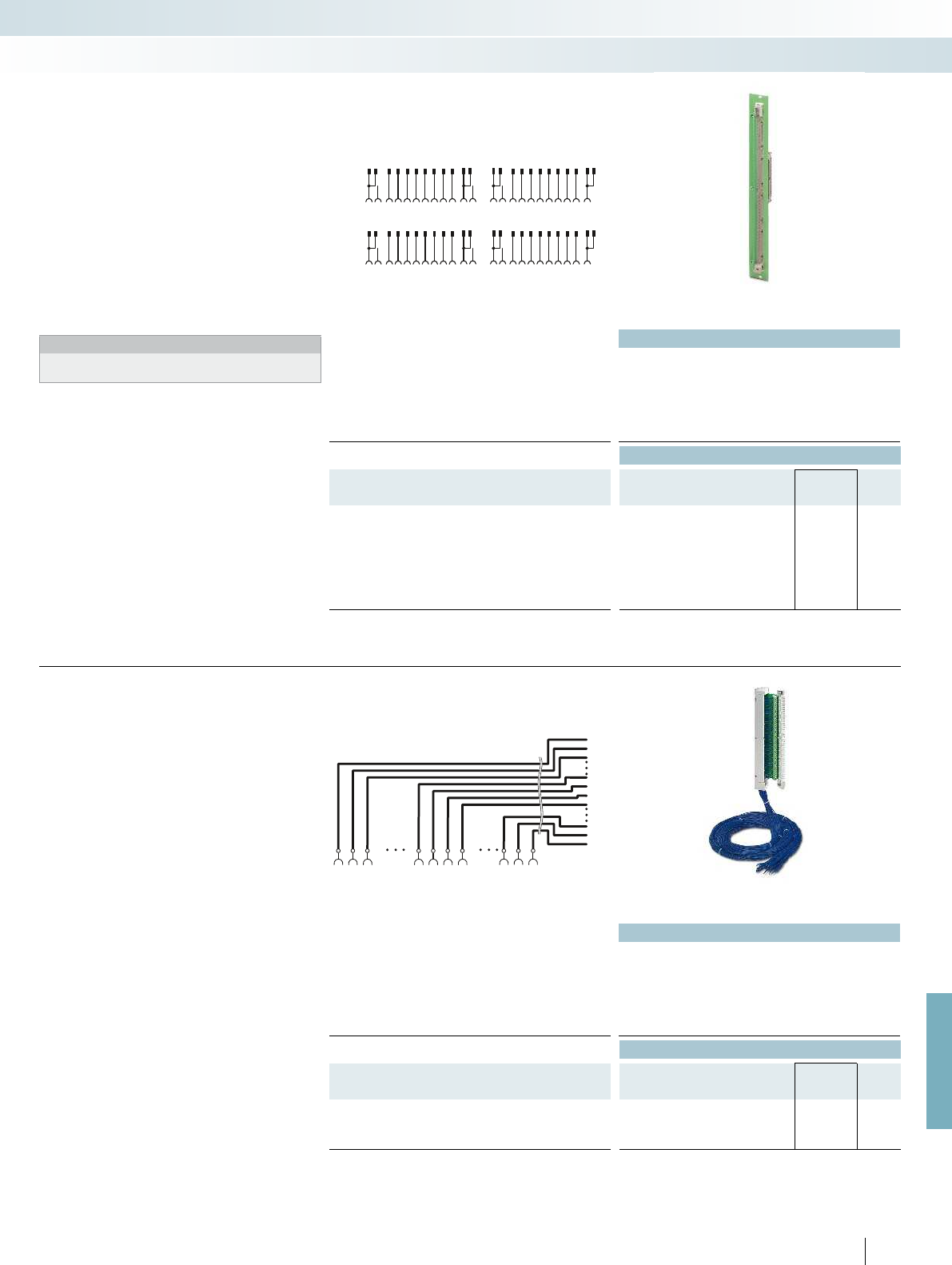
FLK50
FLK50
S5-115
S5-115
1
13
23
123
2
21412 24
35
5
6
6
7
7
8
8
9
9
1021
31
31
41
41
1019
11 22
32
32
42
42
33
33
43
43
45
45
34
34
35
35
36
36
44
44
46
46
47
47
48
11 202122
415
1513
16
161412
17
27
27
26
26
25
25
17
18
28
28
18
19
29
29
39
39
38
38
37
37
20
30
30
40
40
434
1
45
22
2
46
23
3
47
25
26
1 22
1 22
45
45
2 23
2 23
46
46
3 25 26
3 25 26
47
47
S5-115
For further information and full technical data, visit phoenixcontact.net/products
Technical data
Max. perm. operating voltage 60 V DC
Max. permissible current 1 A (per path)
Max. perm. total current 2 A (per byte)
Ambient temperature (operation) -20 °C ... 50 °C
Ambient temperature (storage/transport) -20 °C ... 70 °C
Standards/regulations IEC 60664 / DIN EN 50178 / IEC 62103
Ordering data
Description Type Order No. Pcs. /
Pkt.
Digital IN or OUT 24 V DC from S5-115 through converters,
system cables and front adapters to S7-300
IN
6ES5 420-7LA11 to 6ES7 321-1BL00-0AA0
6ES5 430-7LA11 to 6ES7 321-1BL00-0AA0
OUT
6ES5 441-7LA11 to 6ES7 322-1BL00-0AA0
6ES5 451-7LA11 to 6ES7 322-1BL00-0AA0
FLKM S115/S7/FLK50/PLC/SO137 2306294 1
Connection scheme: FLKM S115/S7/FLK50/PLC/SO137
S5-S7 adapters connect the S5-115 front
adapters wired with individual wires to the
I/O modules of S7-300.
With the aid of the FLKM
S115/S7/FLK50/SO137 converter module,
the signals of the S5-115 front adapter can
be converted to a 50-pos. strip. A 50-pos.
system cable FLK 50/EZ-DR/.../KONFEK
and a front adapter for the SIMATIC
®
S7
(FLKM 50-PA-S300) now connect the
signals with the I/O module.
Notes:
Due to the geometry, it is not possible to couple any molded
FLK connectors (e.g., VIP-PA...S7).
Siemens SIMATIC
®
S7-300
Adapter for conversion from
S5-115 to S7-300
System cabling for controllers
Controller-specific system cabling
Converter for Siemens SIMATIC
®
S5-115 to
50-pos. FLK strip.
Technical data
Max. perm. operating voltage 250 V AC/DC
Max. permissible current 6 A (per path)
Ambient temperature (operation) -20 °C ... 50 °C
Ambient temperature (storage/transport) -20 °C ... 80 °C
Mounting position any
Standards/regulations DIN EN 50178 / IEC 60664 / IEC 62103
Ordering data
Description Type Order No. Pcs. /
Pkt.
Connection of all S5-115 connections (1 to 23, 25 to 47) at the
open cable end
FLKM S115/47X0,75/3,0M/OE 2314985 1
FLKM S115/47X0,75/5,0M/OE 2314998 1
533
PHOENIX CONTACT
All signals of the existing S5-115 wiring
are extended by 3 or 5 meters with the help
of the universal startup adapters. The open
cable end can be connected to various
controllers such as S7-400 or S7-300. Thus,
the existing field wiring of S5-115 can
communicate with the new controller for
test purposes. Since the new control unit is
temporarily arranged before the control
cabinet, the original status of the system can
be restored if required.
If the system functions with the new
controller without problems, the S5-115
can now be replaced.
Startup adapters for extending the
existing S5-115 field wiring

Technical data Technical data
Max. perm. operating voltage 30 V DC 30 V DC
Max. perm. current carrying capacity per path 500 mA 500 mA
Max. conductor resistance 0.16 /m 0.16 /m
Ambient temperature (operation) -20 °C ... 50 °C -20 °C ... 50 °C
Conductor cross section AWG 26 / 0.14 mm² AWG 26 / 0.14 mm²
Conductor structure: stranded wires / material 7 / Cu tin-plated 7 / Cu tin-plated
Outside diameter
50-position 11 mm 11 mm
40-position 11 mm 11 mm
Ordering data Ordering data
Description No. of
pos. Cable length Type Order No. Pcs. /
Pkt. Type Order No. Pcs. /
Pkt.
50-pos. YUC cables, for digital I/O modules
50 1 m FLK 50-PA/EZ-DR/KS/ 100/YUC 2900991 1FLK 50-PA/EZ-DR/HF/KS/ 100/YUC 2904739 1
50 2 m FLK 50-PA/EZ-DR/KS/ 200/YUC 2314299 1FLK 50-PA/EZ-DR/HF/KS/ 200/YUC 2904740 1
50 3 m FLK 50-PA/EZ-DR/KS/ 300/YUC 2314309 1FLK 50-PA/EZ-DR/HF/KS/ 300/YUC 2904741 1
50 4 m FLK 50-PA/EZ-DR/KS/ 400/YUC 2314312 1FLK 50-PA/EZ-DR/HF/KS/ 400/YUC 2904742 1
50 5 m FLK 50-PA/EZ-DR/KS/ 500/YUC 2321499 1FLK 50-PA/EZ-DR/HF/KS/ 500/YUC 2904636 1
50 6 m FLK 50-PA/EZ-DR/KS/ 600/YUC 2314927 1FLK 50-PA/EZ-DR/HF/KS/ 600/YUC 2904743 1
50 7 m FLK 50-PA/EZ-DR/KS/ 700/YUC 2321509 1FLK 50-PA/EZ-DR/HF/KS/ 700/YUC 2904744 1
50 8 m FLK 50-PA/EZ-DR/KS/ 800/YUC 2314930 1FLK 50-PA/EZ-DR/HF/KS/ 800/YUC 2904745 1
50 9 m FLK 50-PA/EZ-DR/KS/ 900/YUC 2321512 1FLK 50-PA/EZ-DR/HF/KS/ 900/YUC 2904746 1
50 10 m FLK 50-PA/EZ-DR/KS/1000/YUC 2314325 1FLK 50-PA/EZ-DR/HF/KS/1000/YUC 2904637 1
50 15 m FLK 50-PA/EZ-DR/KS/1500/YUC 2314338 1FLK 50-PA/EZ-DR/HF/KS/1500/YUC 2904638 1
50 20 m FLK 50-PA/EZ-DR/KS/2000/YUC 2314503 1FLK 50-PA/EZ-DR/HF/KS/2000/YUC 2904487 1
50 25 m FLK 50-PA/EZ-DR/KS/2500/YUC 2314516 1FLK 50-PA/EZ-DR/HF/KS/2500/YUC 2904639 1
50 30 m FLK 50-PA/EZ-DR/KS/3000/YUC 2314529 1FLK 50-PA/EZ-DR/HF/KS/3000/YUC 2904640 1
40-pos. YUC cables, for analog I/O modules
40 1 m FLK 40-PA/EZ-DR/KS/ 100/YUC 2322786 1FLK 40-PA/EZ-DR/HF/KS/ 100/YUC 2904747 1
40 2 m FLK 40-PA/EZ-DR/KS/ 200/YUC 2314341 1FLK 40-PA/EZ-DR/HF/KS/ 200/YUC 2904748 1
40 3 m FLK 40-PA/EZ-DR/KS/ 300/YUC 2314354 1FLK 40-PA/EZ-DR/HF/KS/ 300/YUC 2904749 1
40 4 m FLK 40-PA/EZ-DR/KS/ 400/YUC 2314367 1FLK 40-PA/EZ-DR/HF/KS/ 400/YUC 2904750 1
40 5 m FLK 40-PA/EZ-DR/KS/ 500/YUC 2321570 1FLK 40-PA/EZ-DR/HF/KS/ 500/YUC 2904645 1
40 6 m FLK 40-PA/EZ-DR/KS/ 600/YUC 2314943 1FLK 40-PA/EZ-DR/HF/KS/ 600/YUC 2904751 1
40 7 m FLK 40-PA/EZ-DR/KS/ 700/YUC 2321583 1FLK 40-PA/EZ-DR/HF/KS/ 700/YUC 2904752 1
40 8 m FLK 40-PA/EZ-DR/KS/ 800/YUC 2314956 1FLK 40-PA/EZ-DR/HF/KS/ 800/YUC 2904753 1
40 9 m FLK 40-PA/EZ-DR/KS/ 900/YUC 2321415 1FLK 40-PA/EZ-DR/HF/KS/ 900/YUC 2904754 1
40 10 m FLK 40-PA/EZ-DR/KS/1000/YUC 2314370 1FLK 40-PA/EZ-DR/HF/KS/1000/YUC 2904646 1
40 15 m FLK 40-PA/EZ-DR/KS/1500/YUC 2314383 1FLK 40-PA/EZ-DR/HF/KS/1500/YUC 2904647 1
40 20 m FLK 40-PA/EZ-DR/KS/2000/YUC 2314532 1FLK 40-PA/EZ-DR/HF/KS/2000/YUC 2904488 1
40 25 m FLK 40-PA/EZ-DR/KS/2500/YUC 2314545 1FLK 40-PA/EZ-DR/HF/KS/2500/YUC 2904648 1
40 30 m FLK 40-PA/EZ-DR/KS/3000/YUC 2314558 1FLK 40-PA/EZ-DR/HF/KS/3000/YUC 2904649 1
534
PHOENIX CONTACT
System cabling for controllers
Controller-specific system cabling
Shielded shielded and halogen-free
These shielded system cables for digital
(50-pos.) and analog (40-pos.) I/O modules
are connected directly to the modules. An
intermediate adapter is not required.
Features:
– Molded connector
– Can be screwed
– Lateral cable outlet of the I/O module
– KS/AKB-compatible connectors on the
module side
YOKOGAWA Centum
VP and ProSafe-RS
System cables
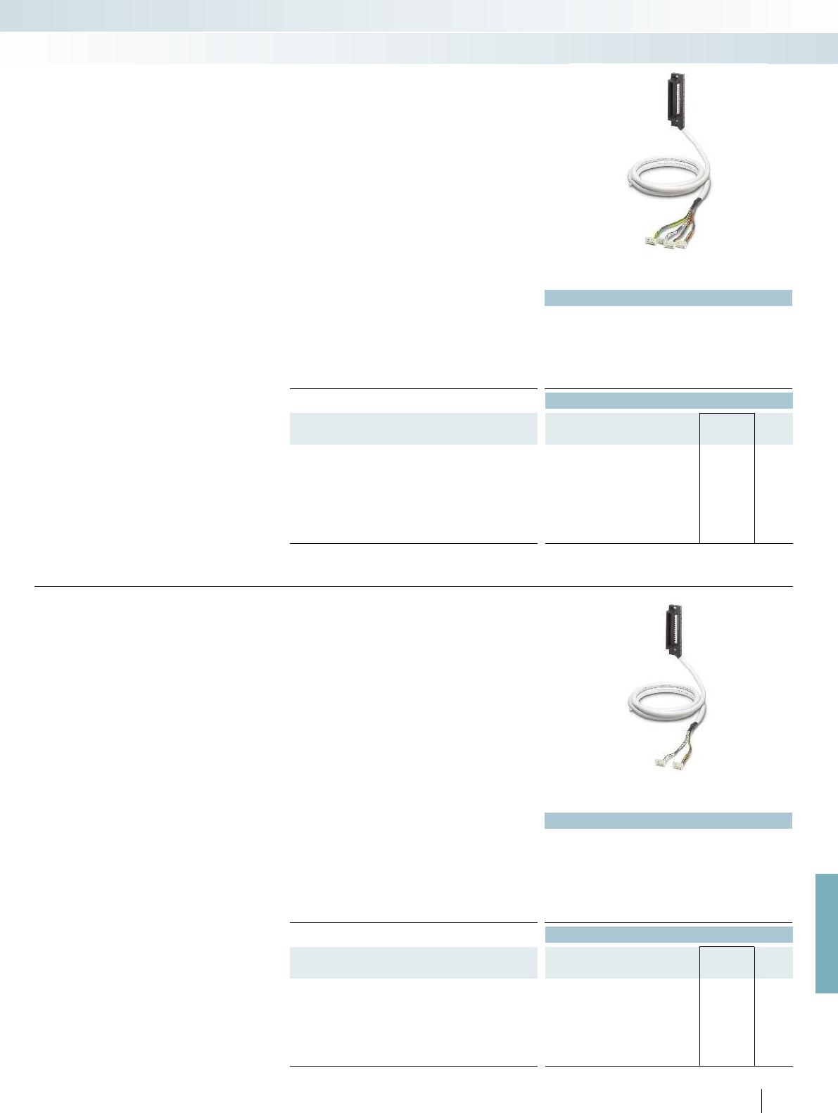
For further information and full technical data, visit phoenixcontact.net/products
Technical data
Max. perm. operating voltage 30 V DC
Max. perm. current carrying capacity per path 500 mA
Max. conductor resistance 0.16 /m
Ambient temperature (operation) -20 °C ... 50 °C
Conductor cross section AWG 26 / 0.14 mm²
Outside diameter
50-position 11 mm
Ordering data
Description No. of
pos. Cable length Type Order No. Pcs. /
Pkt.
System cable for digital I/O modules for coupling four
8-channel VARIOFACE modules
50 2 m CABLE-50/4FLK14/ 2,0M/YUC 2314655 1
50 4 m CABLE-50/4FLK14/ 4,0M/YUC 2314671 1
50 6 m CABLE-50/4FLK14/ 6,0M/YUC 2318978 1
50 10 m CABLE-50/4FLK14/10,0M/YUC 2314684 1
50 15 m CABLE-50/4FLK14/15,0M/YUC 2322773 1
50 20 m CABLE-50/4FLK14/20,0M/YUC 2314778 1
These system cables for digital I/O
modules are connected directly to the
modules. An intermediate adapter is not
required. Features:
– Lateral cable outlet of the I/O module
– Four 14-pos. connectors on the module
side for connection of four 8-channel
VARIOFACE modules of the system
cabling
YOKOGAWA Centum VP
System cables
System cabling for controllers
Controller-specific system cabling
Shielded
Technical data
Max. perm. operating voltage 30 V DC
Max. perm. current carrying capacity per path 500 mA
Max. conductor resistance 0.16 /m
Ambient temperature (operation) -20 °C ... 50 °C
Conductor cross section AWG 26 / 0.14 mm²
Conductor structure: stranded wires / material 7 / Cu tin-plated
Outside diameter
40-position 11 mm
Ordering data
Description No. of
pos. Cable length Type Order No. Pcs. /
Pkt.
System cable, for analog I/O modules for coupling two
8-channel MINI Analog system adapters
40 2 m CABLE-40/2FLK16/ 2,0M/YUC 2321334 1
40 4 m CABLE-40/2FLK16/ 4,0M/YUC 2321347 1
40 10 m CABLE-40/2FLK16/10,0M/YUC 2321350 1
40 15 m CABLE-40/2FLK16/15,0M/YUC 2321376 1
40 20 m CABLE-40/2FLK16/20,0M/YUC 2321363 1
535
PHOENIX CONTACT
The Yokogawa system cable
CABLE-40/2FLK16/.../YUC makes it
possible to connect 16 MINI Analog
modules to a Yokogawa control system. In
conjunction with two MINI Analog system
adapters MINI MCR-SL-V8-FLK-16-A, the
Yokogawa system cable provides a simple
and cost-effective Plug and Play solution.
The system cable is plugged directly into
Yokogawa module. Two 16-pos. flat-ribbon
cable connectors are provided for
connecting the module to the MINI Analog
system adapters.
The system cable in conjunction with
4-wire measuring transducers is
suitable for the following analog cards:
– AAI 141
– AAI 143
YOKOGAWA Centum VP
System cables for
MINI Analog system cabling
Shielded
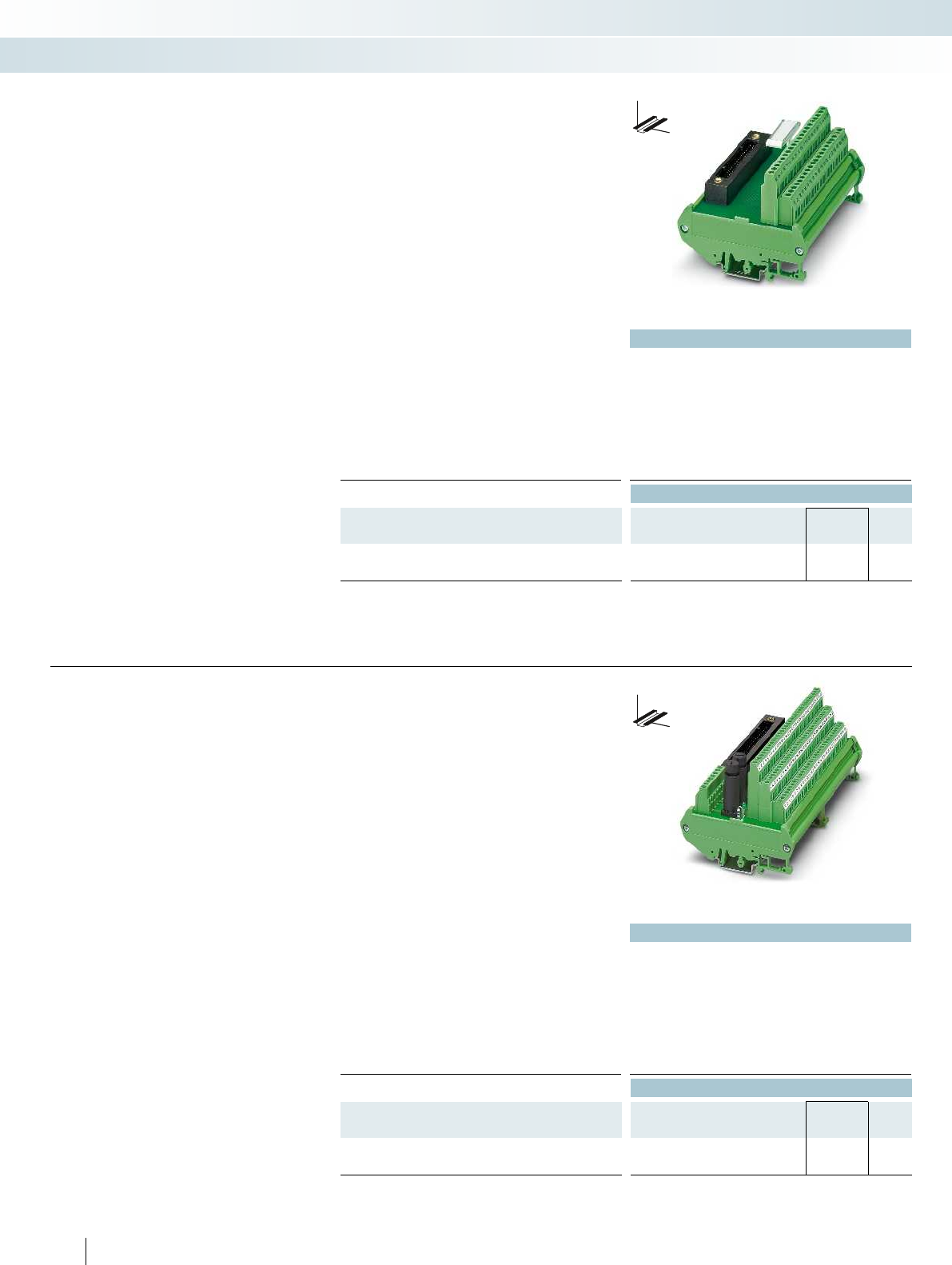
Technical data
Max. perm. operating voltage < 25 V AC / 30 V DC
Max. perm. current (per branch) 1 A
Ambient temperature (operation) -20 °C ... 50 °C
Mounting position any
Standards/regulations DIN EN 50178, IEC 60664, IEC 62103
Connection method Field level Screw connection
Controller level Yokogawa KS-compatible
Connection data solid / stranded / AWG 0.2 ... 4 mm² / 0.2 ... 2.5 mm² / 24 - 12
Dimensions H / D 90 mm / 68 mm
Ordering data
Description No. of
pos.
Module width
WType Order No. Pcs. /
Pkt.
Controller board, for analog I/O modules
40 112 mm FLKM-KS40/YCS 2314642 1
DW
H
These modules are connected to the
I/O modules via the YUC system cable
(on page 534).
FLKM-KS40/YCS:
– For analog modules
– Universal interface module with
40 connection terminal blocks
For more cabling solutions for Yokogawa
visit: phoenixcontact.com
YOKOGAWA Centum VP
Interface modules
System cabling for controllers
Controller-specific system cabling
Passive interface modules
Technical data
Max. perm. operating voltage 30 V DC
Max. perm. current (per branch) 1 A
Ambient temperature (operation) -20 °C ... 50 °C
Mounting position any
Standards/regulations DIN EN 50178, IEC 60664, IEC 62103
Connection method Field level Screw connection
Controller level Yokogawa KS-compatible
Connection data solid / stranded / AWG 0.2 ... 4 mm² / 0.2 ... 2.5 mm² / 24 - 12
Dimensions H / D 90 mm / 81 mm
Ordering data
Description No. of
pos.
Module width
WType Order No. Pcs. /
Pkt.
Controller board, for digital I/O modules ADV 151 and ADV 551
50 174 mm FLKMS-KS50/32IM/YCS 2314451 1
536
PHOENIX CONTACT
DW
H
These modules are connected to the
I/O modules via the YUC system cable
(on page 534).
FLKMS-KS50/32IM/YCS:
– For digital modules ADV 151 and
ADV 551
– Three-conductor connection (signal, plus,
minus)
– Redundant voltage supply
(fuse IEC 127-2, 5 x 20, 2 A)
For more cabling solutions for Yokogawa
visit: phoenixcontact.com
YOKOGAWA Centum VP
Interface modules
Passive interface modules
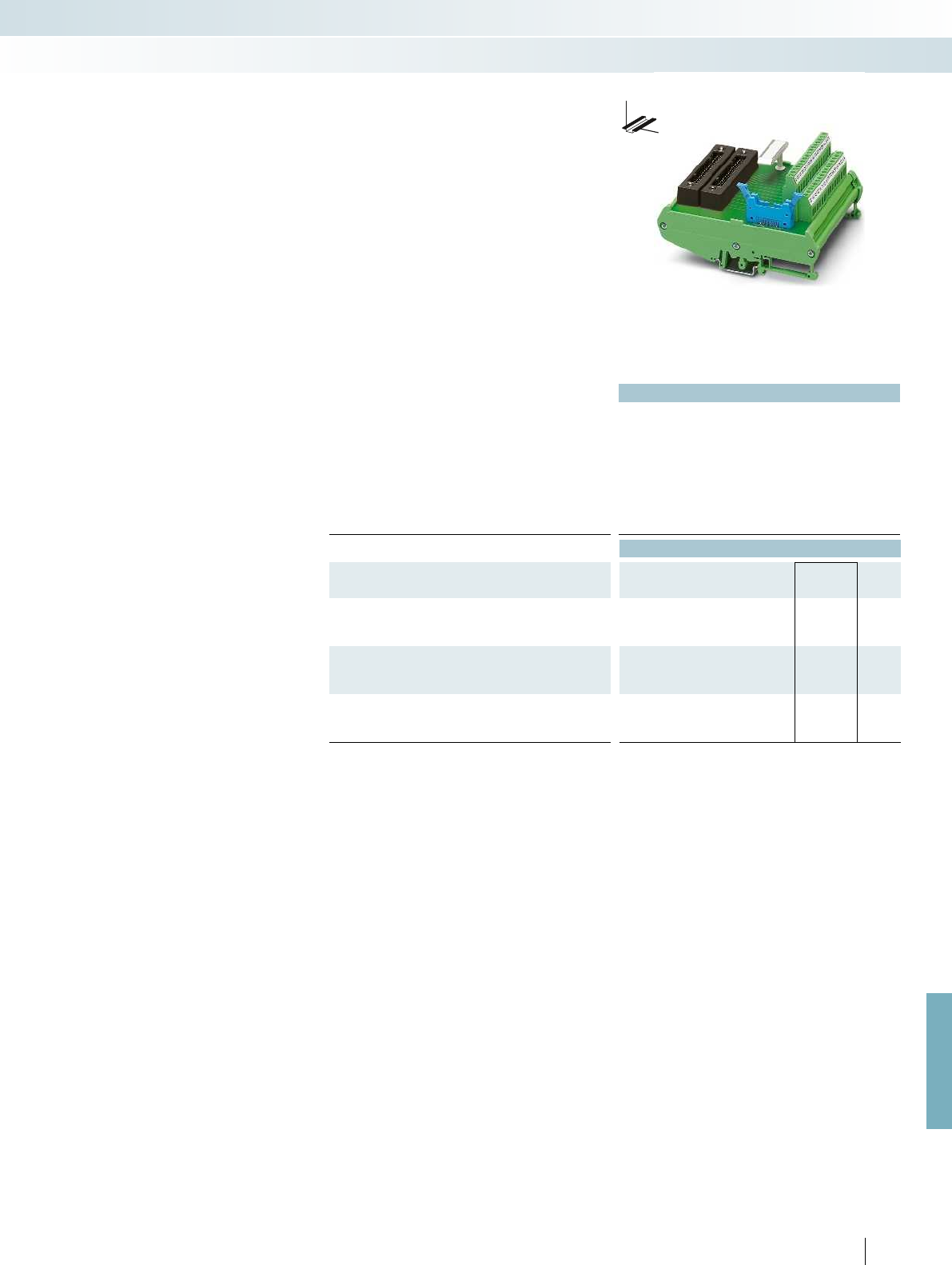
For further information and full technical data, visit phoenixcontact.net/products
Technical data
Max. perm. operating voltage 30 V DC
Max. perm. current (per branch) 100 mA
Ambient temperature (operation) -20 °C ... 50 °C
Mounting position any
Standards/regulations DIN EN 50178, IEC 60664, IEC 62103
Connection method Field level Screw connection
Controller level Yokogawa KS-compatible
Connection data solid / stranded / AWG 0.2 ... 4 mm² / 0.2 ... 2.5 mm² / 24 - 12
Dimensions H / D 126 mm / 68 mm
Ordering data
Description No. of
pos.
Module width
WType Order No. Pcs. /
Pkt.
Controller board, for analog output modules AAI 543
40 108 mm FLKM-KS40/AO16/YCS 2314260 1
Controller board, with fuses and LED, for analog input modules
AAI 141 and AAI 143
40 214 mm FLKMS-KS40/SI/AI16/YCS 2314273 1
Controller board, for analog input modules AAI 141 and AAI 143,
without fuses and LED
40 214 mm FLKMS-KS40/AI/YCS 2314286 1
537PHOENIX CONTACT
These modules are connected to the
analog I/O modules via the 40-pos. YUC
system cable (on page 534).
The modules are designed for redundant
signal transmission (two connectors
parallel). A separate connection to the
HART multiplexer is possible.
FLKM-KS40/AO16/YCS
– For analog module AAI 543
FLKMS-KS40/SI/AI16/YCS
– For analog modules AAI 141 and AAI 143
(operation of modules in 4-wire mode)
– Transfer of 16 channels with separate
positive and negative connections
– 16 plug-in fuses (IEC 127-2, 5 x 20, 0.1 A)
per positive supply and LED status
indicator
– Redundant voltage supply
(fuse IEC 127-2, 5 x 20, 2 A)
FLKMS-KS40/AI/YCS
– For analog modules AAI 141 and AAI 143
(operation of modules in 4-wire mode)
– Transfer of 16 channels with separate
positive and negative connections
– Redundant voltage supply
(fuse IEC 127-2, 5 x 20, 2 A)
For more cabling solutions for Yokogawa
visit: phoenixcontact.com
YOKOGAWA Centum VP
Interface modules
System cabling for controllers
Controller-specific system cabling
DW
H
Interface modules for analog I/O modules
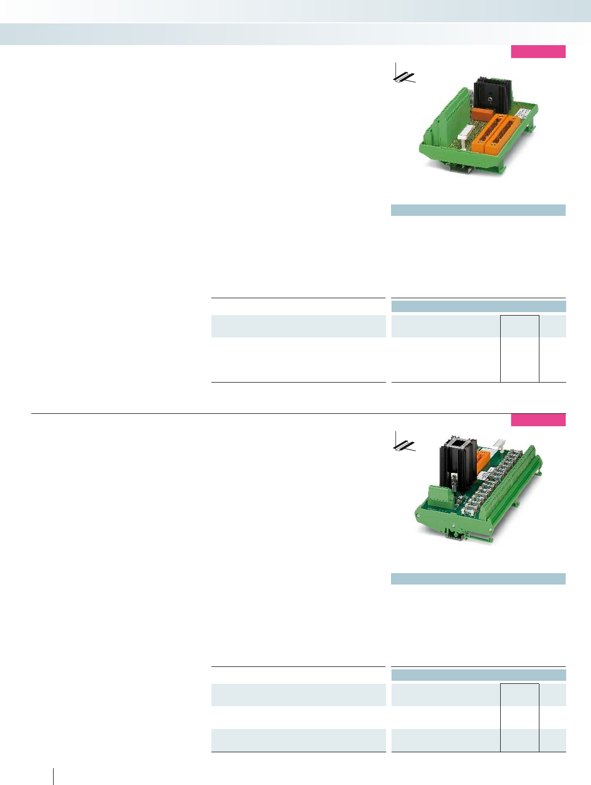
Technical data
Max. perm. operating voltage 24 V DC ±5 %
Max. perm. current (per branch) 100 mA
Ambient temperature (operation) -20 °C ... 70 °C
Mounting position any
Standards/regulations DIN EN 50178
Connection method Field level Screw connection
Controller level Yokogawa KS-compatible
Connection data solid / stranded / AWG 0.2 ... 2.5 mm² / 0.2 ... 1.5 mm² / 24 - 14
Dimensions H / D 112 mm / 80 mm
Ordering data
Description No. of
pos.
Module width
WType Order No. Pcs. /
Pkt.
Interface module, for I/O card: SDV144
- with LED status indicator 50 162 mm UM-2KS50/16DI/RS/MKDS 2900173 1
- with fuse and LED status indicator 50 181 mm UM-2KS50/DI16/RS/K-MT/SO241 2319618 1
DW
H
new
These modules are connected to the I/O
module via the 50-pos. YUC system cable
(on page 534).
– For SDV144 digital module
– Redundant signal transmission
(two parallel connectors)
– 16 channels
UM-2KS50/16DI/RS/MKDS
– Screw connection
– Redundant voltage supply with signaling
relay and fuse (IEC 127-2, 5 x 20, 3,15 AT)
– LED status display per channel
UM-2KS50/DI16/RS/K-MT/SO241
– Screw connection with knife
disconnection
– Redundant voltage supply with signaling
relay and fuse (TR5, 2 AT)
– Plug-in fuses (TR5, 0,1 AT) and LED
status indicator per channel
Yokogawa ProSafe-RS
Interface modules
System cabling for controllers
Controller-specific system cabling
Passive interface modules
Technical data
Max. perm. operating voltage 30 V DC
Max. perm. current (per branch) 1 A
Ambient temperature (operation) -20 °C ... 55 °C
Mounting position any
Standards/regulations DIN EN 50178
Connection method Field level Screw connection
Controller level Yokogawa KS-compatible
Connection data solid / stranded / AWG 0.2 ... 4 mm² / 0.2 ... 2.5 mm² / 24 - 12
Dimensions H / D 126 mm / 96 mm
Ordering data
Description No. of
pos.
Module width
WType Order No. Pcs. /
Pkt.
Interface module, for I/O card: SAI143
50 250 mm UM-2KS40/16AI/SI/RS/SO225 2319841 1
Interface module, for I/O card: SAI143, SAV144, and SAI533
50 168 mm UM-2KS40/16AIO/RS/SO225 2319838 1
538
PHOENIX CONTACT
DW
H
new
These modules are connected to the I/O
modules via the 40-pos. YUC system cable
(on page 534).
– Redundant signal transmission (two
parallel connectors)
UM-2KS40/16AI/SI/RS/SO225
– For SAI143 analog module
– Screw connection
– Redundant voltage supply with signaling
relay and fuse (IEC 127-2, 5 x 20, 10 AT)
– Plug-in fuses (IEC 127-2, 5 x 20, 1 AT) and
LED status indicator per channel
UM-2KS40/16AIO/RS/SO225
– For SAI143, SAV144, SAI533 analog
modules
– Screw connection
– 16 analog inputs or 8 analog outputs
Yokogawa ProSafe-RS
Interface modules
Passive interface modules
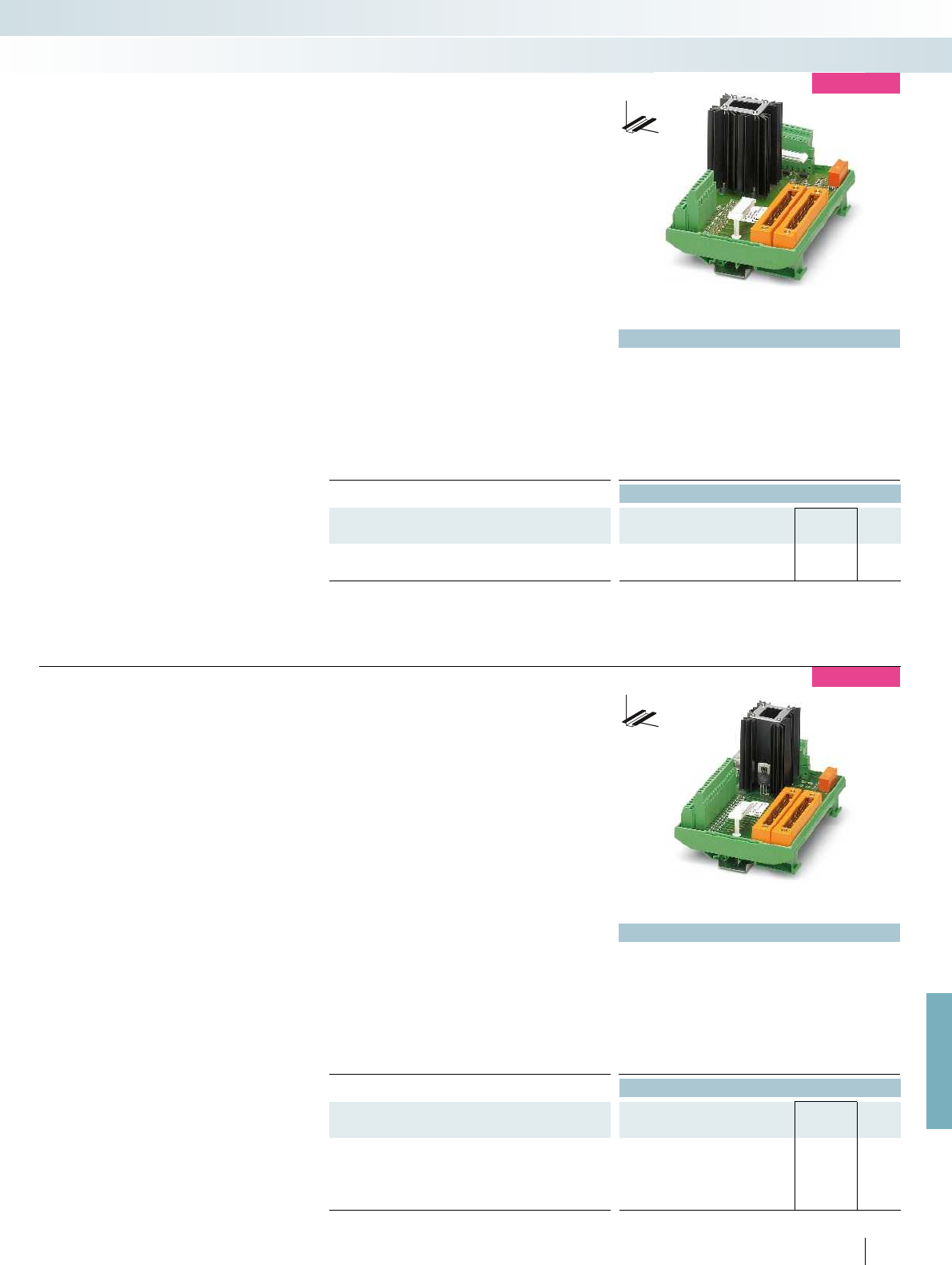
For further information and full technical data, visit phoenixcontact.net/products
Technical data
Max. perm. operating voltage 24 V DC ±5 %
Max. perm. current (per branch) 100 mA
Ambient temperature (operation) -20 °C ... 70 °C
Mounting position any
Standards/regulations DIN EN 50178
Connection method Field level Screw connection
Controller level Yokogawa KS-compatible
Connection data solid / stranded / AWG 0.2 ... 2.5 mm² / 0.2 ... 1.5 mm² / 24 - 14
Dimensions H / D 112 mm / 80 mm
Ordering data
Description No. of
pos.
Module width
WType Order No. Pcs. /
Pkt.
Interface module, for I/O card: SDV531 and SDV531L
50 162 mm UM-2KS50/ 8DO/RS/MKDS 2900174 1
DW
H
new
These modules are connected to the I/O
modules via the 50-pos. YUC system cable
(on page 534).
UM-2KS50/8DO/RS/MKDS
– For SDV531 and SDV531L digital modules
– Redundant signal transmission (two
parallel connectors)
– Screw terminal blocks
– Redundant voltage supply with signaling
relay and fuse (IEC 127-2, 5 x 20, 3,15 AT)
– LED status display per channel
Yokogawa ProSafe-RS
Interface modules
System cabling for controllers
Controller-specific system cabling
Passive interface modules
Technical data
Max. perm. operating voltage 24 V DC ±5 %
Max. perm. current (per branch) 100 mA
Ambient temperature (operation) -20 °C ... 70 °C
Mounting position any
Standards/regulations DIN EN 50178
Connection method Field level Screw connection
Controller level Yokogawa KS-compatible
Connection data solid / stranded / AWG 0.2 ... 2.5 mm² / 0.2 ... 1.5 mm² / 24 - 14
Dimensions H / D 112 mm / 80 mm
Ordering data
Description No. of
pos.
Module width
WType Order No. Pcs. /
Pkt.
Interface module, for I/O card: SDV541
- with LED status indicator 50 162 mm UM-2KS50/16DO/RS/MKDS 2900175 1
- with fuse and LED status indicator 50 215 mm UM-2KS50/DO16/RS/K-MT/SO241 2319595 1
539
PHOENIX CONTACT
DW
H
new
These modules are connected to the I/O
modules via the 50-pos. YUC system cable
(on page 534).
– Redundant signal transmission (two
parallel connectors)
– Redundant voltage supply with signaling
relay and fuse (IEC 127-2, 5 x 20, 6,3 AT)
– For SDV541 digital modules
UM-2KS50/DO16/RS/K-MT/SO241
– Screw connection with knife
disconnection
– Plug-in fuses (TR5, 0,2 AT) and LED
status indicator per channel
UM-2KS50/16DO/RS/MKDS
– Screw connection
– LED status display per channel
Yokogawa ProSafe-RS
Interface modules
Passive interface modules

540
PHOENIX CONTACT
new
Termination Carriers for Yokogawa
Centum VP and ProSafe-RS
The Termination Carriers are a compact
solution for connecting signal conditioners
and coupling relays to the Yokogawa
Centum VP systems and ProSafe-RS.
– Mechanically decoupled PCB
– Redundant system connection
– Simple or redundant supply (diode
decoupling, polarity reversal protection)
and monitoring function. Implementation
via separate DIN rail module or
integrated switching on the PCB
Termination Carrier for
MINI Analog signal conditioners
TC-2KS40-AI16-M-PRH-CS
– For AAI141/AAI143 analog I/O modules
TC-2KS40-AO16-M-PRH-CS
– For AAI543 analog I/O module
Termination Carrier for
Ex i signal conditioners of the
MACX Analog Ex series
TC-2KS50-DI32-2EX-PR-CS
– For ADV151/ADV161 digital I/O modules
TC-2KS50-DO32-EX-PR-CS
– For ADV551/ADV digital I/O modules
TC-2KS40-AO16-EX-PR-CS
– For AAI543 analog I/O module
TC-2KS40-AI16-EX-PR-CS
– For AAI141/AAI143 analog I/O modules
TC-2KS50-DO16-EX-PR-RS
– For SDV541 digital I/O module
TC-2KS50-DI16-EX-PR-RS
– For SDV144 digital I/O modules
TC-2KS40-AI16-EX-PR-RS
– For SAI143 analog I/O module
TC-2KS40-AO8-EX-PR-RS
– For SAI533 analog I/O module
Termination Carrier for
coupling relays from the PSR-ETP or
PSR-FSP series
TC-2KS50-DO16-F&G-AR-RS
– For SDV541 digital I/O modules
TC-2KS50-DO16-ESD-AR-RS
– For SDV541 digital I/O modules
Technical data
General data
Connection to the control system level Yokogawa KS-compatible Yokogawa KS-compatible Yokogawa KS-compatible Yokogawa KS-compatible
Max. operating voltage < 50 V DC (per signal/channel) < 50 V DC (per signal/channel) < 50 V DC (per signal/channel) 24 V DC (21.1 V
Max. permissible current 23 mA (signal/channel)
Pollution degree / surge voltage category 2 / II
Clearance and creepage distances DIN EN 50178 (basic insulation) DIN EN 50178 (basic insulation) DIN EN 50178 (basic insulation) DI
Ambient temperature range -20 °C ... 60 °C (please observe module specifications) -20 °C ... 60 °C (please observe module specifi
Shock 15g, according to IEC 60068-2-27 15g, according to IEC 60068-
Vibration (operation) 2g, according to IEC 60068-2-6 2g, according to IEC 60068-2-6 2g, according to IEC 60068-2-6 2g, according to
Dimensions H / D 170 / 160 mm
EMC note
Power supply via power module
Input voltage range 19.2 V DC ... 30 V DC
Redundant supply yes, decoupled from diodes yes, decoupled from diodes yes, decoupled from diodes yes, decoupled from diodes
Polarization and surge protection Yes
Fuse 2x 2.5 A on PCB, slow-blow (replaceable) 2x 2.5 A on PCB, slow-blow (replaceable) 2x 2.5 A on PCB, slow-blow (replaceable) 2.5
Status indication 2 x red LED (error)
2x green LEDs (PWR1 and PWR2)
Switching output 1 N/C contact (alarm = open) 1 N/C contact (alarm = open) 1 N/C contact (alarm = open) 1 N/C contact (alarm = open
Ordering data
Description Module width
WType Order No. Pcs. /
Pkt.
Termination Carrier for 16 highly compact signal conditioners
- For AAI141 and AAI143 analog I/O modules 148 mm TC-2KS40-AI16-M-PRH-CS 2905257 1
- For AAI543 analog I/O modules 148 mm TC-2KS40-AO16-M-PRH-CS 2905905 1
Termination Carrier for 16/32 Ex i signal conditioners (SIL 2)
- For ADV151 and ADV161 digital I/O modules 242 mm
- For ADV551 and ADV561 digital I/O modules 448 mm
- For AAI543 analog I/O module 242 mm
- For AAI141 and AAI143 analog I/O modules 242 mm
Termination Carrier for 8/16 Ex i signal conditioners (SIL 2)
- For SDV144 digital I/O modules 242 mm
- For SDV541 digital I/O modules 242 mm
- For SAI143 analog I/O module 242 mm
- For SAI533 analog I/O module 148 mm
Termination Carrier for 16 PSR-FSP/PSR-ETP relays
- For SDV541 digital I/O modules
(low-demand application)
304 mm
- For SDV541 digital I/O module
(high-demand application)
304 mm
Accessories
MINI Analog power terminal MINI MCR-SL-PTB-FM 2902958 1
MINI Analog fault signaling module MINI MCR-SL-FM-RC-NC 2902961 1
Power and fault signaling module
Cable set with 24 V module supply, suitable for
PSR-ETP/Order No.: 2986711
Cable set without use of confirmation contact, suitable for
PSR-FSP/Order No.: 2981978
Cable set with use of confirmation contact, suitable for
PSR-FSP/Order No.: 2986960 and 2986575
Jumper plug for occupying unused module slots, suitable for
PSR-FSP/Order No.: 2986960 and 2986575
System cabling for controllers
Controller-specific system cabling
Termination Carrier for Centum VP system,
can be used with signal conditioners of the
MINI Analog series
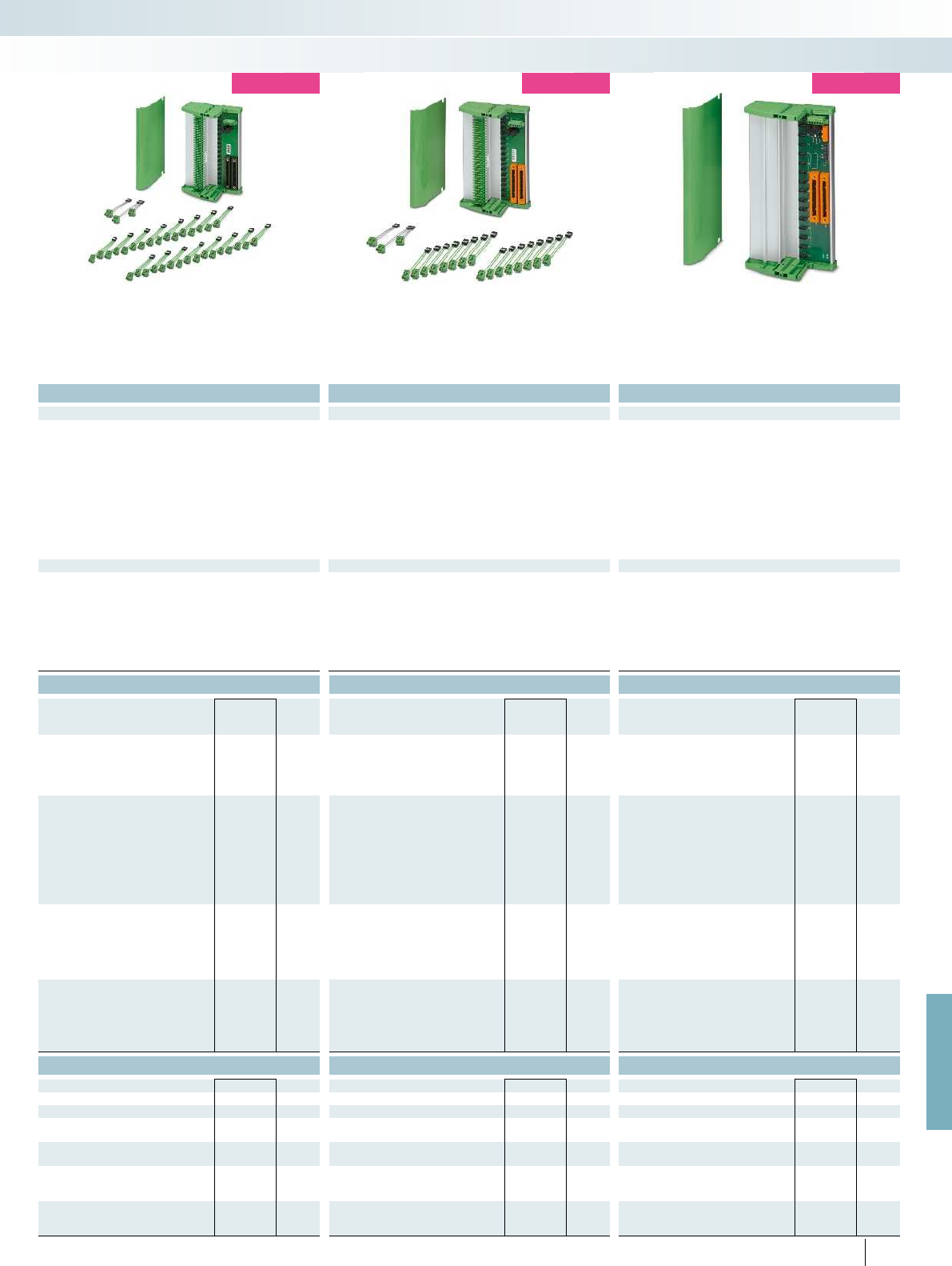
For further information and full technical data, visit phoenixcontact.net/products
541PHOENIX CONTACT
new
new
new
Technical data Technical data Technical data
Connection to the control system level Yokogawa KS-compatible Yokogawa KS-compatible Yokogawa KS-compatible Yokogawa KS-compatible
Max. operating voltage < 50 V DC (per signal/channel) < 50 V DC (per signal/channel) < 50 V DC (per signal/channel) 24 V DC (21.1 V ... 26.4 V)
1 A (signal/channel) 1 A (signal/channel) 1200 mA
2 / II 2 / II 2 / II
Clearance and creepage distances DIN EN 50178 (basic insulation) DIN EN 50178 (basic insulation) DIN EN 50178 (basic insulation) DIN EN 50178 (basic insulation)
Ambient temperature range -20 °C ... 60 °C (please observe module specifications) -20 °C ... 60 °C (please observe module specifications) -20 °C ... 60 °C (please observe module specifications) -20 °C ... 60 °C
Shock 15g, according to IEC 60068-2-27 15g, according to IEC 60068-2-27 15g, according to IEC 60068-2-27 15g, according to IEC 60068-2-27
Vibration (operation) 2g, according to IEC 60068-2-6 2g, according to IEC 60068-2-6 2g, according to IEC 60068-2-6 2g, according to IEC 60068-2-6
170 / 160 mm 170 / 160 mm 170 / 160 mm
Class A product, see page 625
19.2 V DC ... 30 V DC 19.2 V DC ... 30 V DC 21.1 V DC ... 26.4 V DC
Redundant supply yes, decoupled from diodes yes, decoupled from diodes yes, decoupled from diodes yes, decoupled from diodes
Yes Yes Yes
Fuse 2x 2.5 A on PCB, slow-blow (replaceable) 2x 2.5 A on PCB, slow-blow (replaceable) 2x 2.5 A on PCB, slow-blow (replaceable) 2.5 A on PCB, slow-blow (replaceable)
1 x red LED (error)
2x green LEDs (PWR1 and PWR2)
1 x red LED (error)
2x green LEDs (PWR1 and PWR2)
2 x red LED (error)
2x green LEDs (PWR1 and PWR2)
Switching output 1 N/C contact (alarm = open) 1 N/C contact (alarm = open) 1 N/C contact (alarm = open) 1 N/C contact (alarm = open)
Ordering data Ordering data Ordering data
Type Order No. Pcs. /
Pkt. Type Order No. Pcs. /
Pkt. Type Order No. Pcs. /
Pkt.
TC-2KS50-DI32-2EX-PR-CS 2904676 1
TC-2KS50-DO32-EX-PR-CS 2905199 1
TC-2KS40-AO16-EX-PR-CS 2905201 1
TC-2KS40-AI16-EX-PR-CS 2905677 1
TC-2KS50-DI16-EX-PR-RS 2905202 1
TC-2KS50-DO16-EX-PR-RS 2905678 1
TC-2KS40-AI16-EX-PR-RS 2905203 1
TC-2KS40-AO8-EX-PR-RS 2905204 1
TC-2KS50-DO16-F&G-AR-RS 2904112 1
TC-2KS50-DO16-ESD-AR-RS 2904113 1
Accessories Accessories Accessories
TC-MACX-MCR-PTB 2904673 1TC-MACX-MCR-PTB 2904673 1
TC-C-PSR3-SC-A100V+A20000 2903391 16
TC-C-PSR3-SC-A10000A20000 2903389 16
TC-C-PSR3-SC-A10000A23132 2903390 16
TC-C-PTSM-50-00000000J1J1 2903388 8
System cabling for controllers
Controller-specific system cabling
Termination Carrier for Centum VP System, can
be used with Ex i signal conditioners of the
MACX Analog Ex series
Termination Carrier for ProSafe-RS system,
can be used with Ex i signal conditioners of the
MACX Analog Ex series
Termination Carrier for ProSafe-RS system,
can be used with coupling relays from the
PSR-ETP or PSR-FSP series

12345678911 13 1012 14
1234567
0++ - -
12345678911 13 1012 14
01234567 ++ - -
Technical data Technical data
VIP-2/.../FLK14/PLC VIP-2/.../FLK14/LED/PLC VIP-2/.../FLK14/PLC VIP-2/.../FLK14/LED/PLC
Max. perm. operating voltage 60 V AC/DC 24 V DC 60 V AC/DC 24 V DC
Max. perm. current (per branch) 1 A 1 A 1 A 1 A
Max total current (voltage supply) 3 A 3 A 3 A 3 A
Ambient temperature (operation) -20 °C ... 50 °C -20 °C ... 50 °C -20 °C ... 50 °C -20 °C ... 50 °C
Mounting position any any any any
Standards/regulations IEC 60664, DIN EN 50178, IEC 62103 IEC 60664, DIN EN 50178, IEC 62103
Connection method Field level Screw connection Screw connection Push-in connection Push-in connection
Controller level IDC/FLK pin strip (2.54 mm) IDC/FLK pin strip (2.54 mm) IDC/FLK pin strip (2.54 mm) IDC/FLK pin strip (2.54 mm)
Connection data solid / stranded / AWG 0.2 ... 4 mm² / 0.2 ... 2.5 mm² / 24 - 12 0.14 ... 2.5 mm² / 0.14 ... 2.5 mm² / 26 - 14
Dimensions H / D 65.5 mm / 56 mm 72.1 mm / 56 mm
Ordering data Ordering data
Description No. of
pos.
Module width
WType Order No. Pcs. /
Pkt. Type Order No. Pcs. /
Pkt.
VARIOFACE interface module, for eight channels,
- with screw connection 14 39.8 mm VIP-2/SC/FLK14/PLC 2315214 1
- with push-in connection 14 41.9 mm VIP-2/PT/FLK14/PLC 2903801 1
VARIOFACE interface module, for eight channels with
light indicator,
- with screw connection 14 39.8 mm VIP-2/SC/FLK14/LED/PLC 2322249 1
- with push-in connection 14 41.9 mm VIP-2/PT/FLK14/LED/PLC 2904279 1
VIP-2/SC/FLK14/PLC connection scheme Connection scheme VIP-2/SC/FLK14/LED/PLC
542 PHOENIX CONTACT
System cabling for controllers
Controller-specific system cabling
Passive interface modules for input/output
with screw connection
Passive interface modules for input/output
with push-in connection
These VIP - VARIOFACE Professional
modules are used in combination with
14-pos. system cables and the relevant front
adapters.
Features:
– Byte-by-byte marking
– For digital I/O modules
– With LED as an option
Notes:
For marking systems (e.g., “ZB 22:UNBEDRUCKT”;
Order No. 0811862) and mounting material, see Catalog 5.
DW
H
DW
H
VIP termination boards for 8 channels
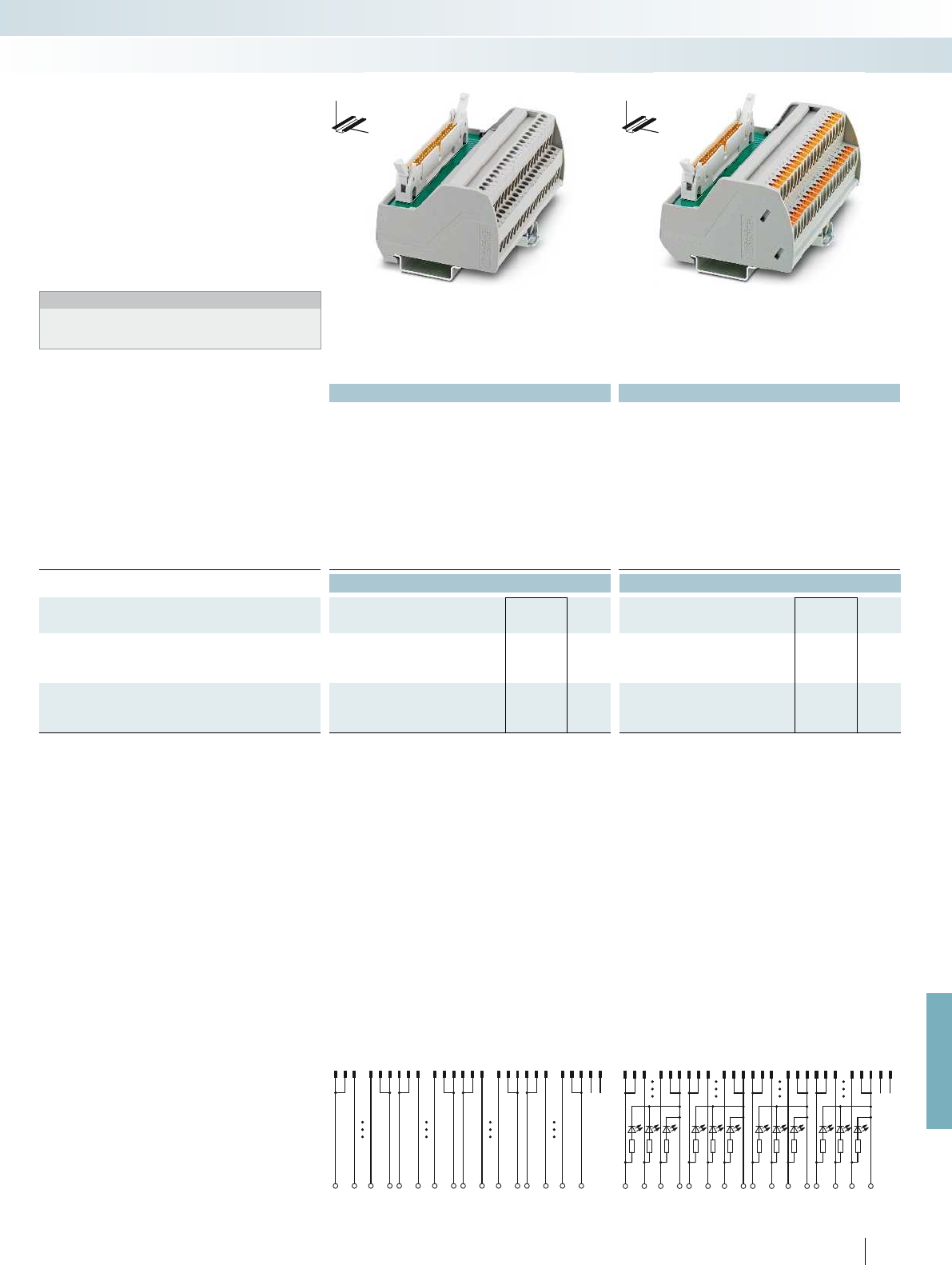
123 1011121314 15 222324252627 343536 3738394647484950
+B0.0 B0.7 +- B1.0B1.7 +- B2.0B2.7 +- B3.0B3.7 -
123 1011 121314 15 222324252627 3435363738394647484950
B0.0
+B0.7 +- B1.0B1.7 +- B2.0B2.7 +- B3.0B3.7 -
For further information and full technical data, visit phoenixcontact.net/products
Technical data Technical data
VIP-2/.../FLK50/PLC VIP-2/.../FLK50/LED/PLC VIP-2/.../FLK50/PLC VIP-2/.../FLK50/LED/PLC
Max. perm. operating voltage 60 V AC/DC 24 V DC 60 V AC/DC 24 V DC
Max. perm. current (per branch) 1 A 1 A 1 A 1 A
Max total current (voltage supply) 2 A (per byte) 2 A (per byte) 2 A (per byte) 2 A (per byte)
Ambient temperature (operation) -20 °C ... 50 °C -20 °C ... 50 °C -20 °C ... 50 °C -20 °C ... 50 °C
Mounting position any any any any
Standards/regulations IEC 60664, DIN EN 50178, IEC 62103 IEC 60664, DIN EN 50178, IEC 62103
Connection method Field level Screw connection Screw connection Push-in connection Push-in connection
Controller level IDC/FLK pin strip (2.54 mm) IDC/FLK pin strip (2.54 mm) IDC/FLK pin strip (2.54 mm) IDC/FLK pin strip (2.54 mm)
Connection data solid / stranded / AWG 0.2 ... 4 mm² / 0.2 ... 2.5 mm² / 24 - 12 0.14 ... 2.5 mm² / 0.14 ... 2.5 mm² / 26 - 14
Dimensions H / D 65.5 mm / 56 mm 72.1 mm / 56 mm
Ordering data Ordering data
Description No. of
pos.
Module width
WType Order No. Pcs. /
Pkt. Type Order No. Pcs. /
Pkt.
VARIOFACE interface module, for 32 channels,
- with screw connection 50 106.1 mm VIP-2/SC/FLK50/PLC 2315227 1
- with push-in connection 50 107.9 mm VIP-2/PT/FLK50/PLC 2903803 1
VARIOFACE interface module, for 32 channels with
light indicator,
- with screw connection 50 106.1 mm VIP-2/SC/FLK50/LED/PLC 2322252 1
- with push-in connection 50 107.9 mm VIP-2/PT/FLK50/LED/PLC 2904280 1
VIP-2/SC/FLK50/PLC connection scheme Connection scheme VIP-2/SC/FLK50/LED/PLC
543
PHOENIX CONTACT
System cabling for controllers
Controller-specific system cabling
Passive interface modules for input/output
with screw connection
Passive interface modules for input/output
with push-in connection
These VIP - VARIOFACE Professional
modules are used in combination with
50-pos. system cables and the relevant front
adapters.
Features:
– Byte-by-byte marking
– For digital I/O modules
– With LED as an option
Notes:
For marking systems (e.g., “ZB 22:UNBEDRUCKT”;
Order No. 0811862) and mounting material, see Catalog 5.
DW
H
DW
H
VIP termination boards for 32 channels

123 101112131415 22 2324 252627 34 35363738394647484950
1291011 12 192021 22 293031 32 3940
123 10111213 1415 22 2324252627 3435363738394647484950
34 11 1213 15 22 23 26 27 34 35 383946 48
Technical data Technical data
Max. perm. operating voltage 60 V AC/DC 60 V AC/DC
Max. perm. current (per branch) 1 A 1 A
Ambient temperature (operation) -20 °C ... 50 °C -20 °C ... 50 °C
Mounting position any any
Standards/regulations IEC 60664, DIN EN 50178, IEC 62103 IEC 60664, DIN EN 50178, IEC 62103
Connection method Field level Screw connection Push-in connection
Controller level IDC/FLK pin strip (2.54 mm) IDC/FLK pin strip (2.54 mm)
Connection data solid / stranded / AWG 0.2 ... 4 mm² / 0.2 ... 2.5 mm² / 24 - 12 0.14 ... 2.5 mm² / 0.14 ... 2.5 mm² / 26 - 14
Dimensions H / D 65.5 mm / 56 mm 72.1 mm / 56 mm
Ordering data Ordering data
Description No. of
pos.
Module width
WType Order No. Pcs. /
Pkt. Type Order No. Pcs. /
Pkt.
VARIOFACE interface module, with
SIMATIC
®
S7-300-specific marking from 1 to 40
- with screw connection 50 106.1 mm VIP-2/SC/FLK50 (1-40) /S7 2315243 1
- with push-in connection 50 107.9 mm VIP-2/PT/FLK50 (1-40) /S7 2903804 1
VARIOFACE interface module, with
SIMATIC
®
S7-400-specific marking from 3 to 48
- with screw connection 50 106.1 mm VIP-2/SC/FLK50/S7/A-S400 2322359 1
- with push-in connection 50 107.9 mm VIP-2/PT/FLK50/S7/A-S400 2904289 1
Connection scheme VIP-2/.../FLK50 (1-40) /S7 Connection scheme VIP-2/.../FLK50/S7/A-S400
544
PHOENIX CONTACT
System cabling for controllers
Controller-specific system cabling
Passive interface modules for input/output,
with SIMATIC
®
-specific marking
and screw connection
Passive interface modules for input/output,
with SIMATIC
®
-specific marking
and push-in connection
These VIP - VARIOFACE Professional
modules are used in combination with
50-pos. system cables and the relevant front
adapters for SIMATIC® S7.
Features:
– Numerical marking
– Specifically for S7-300 or S7-400
Notes:
For marking systems (e.g., “ZB 22:UNBEDRUCKT”;
Order No. 0811862) and mounting material, see Catalog 5.
DW
H
DW
H
VIP termination boards for
SIMATIC
®
S7
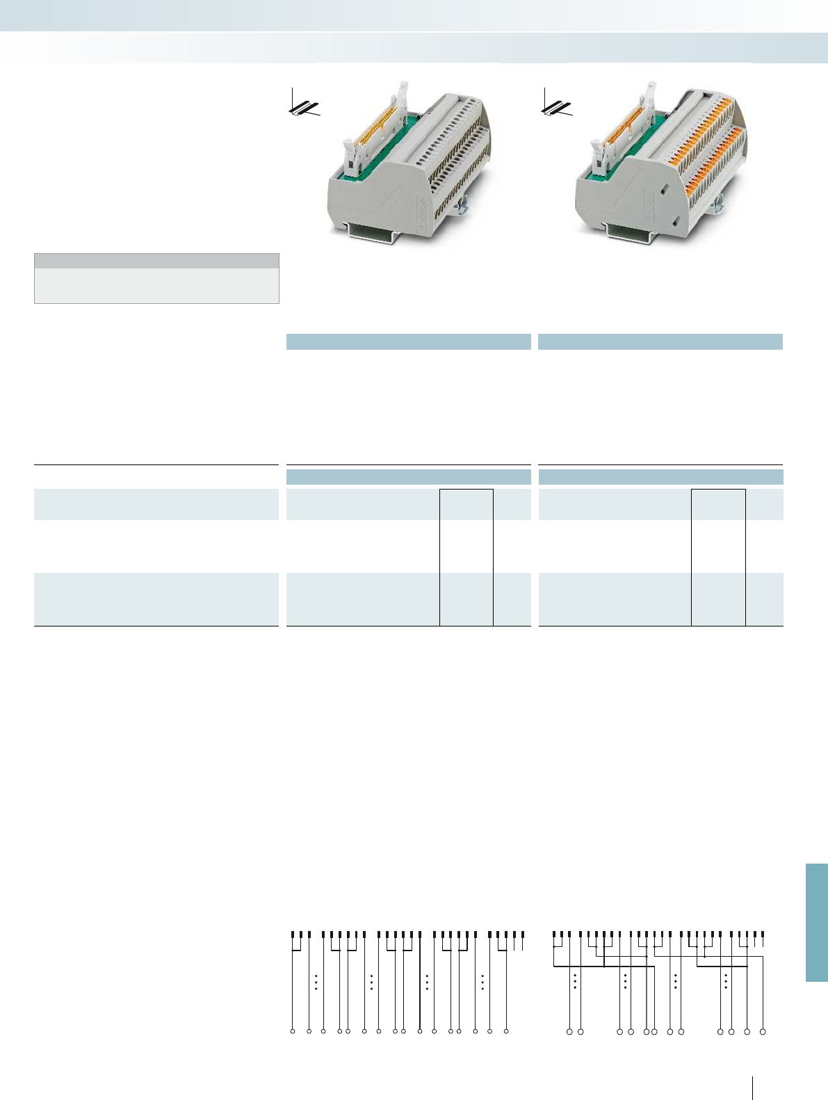
123 1011 121314 15 22 2324252627 3435363738394647484950
101892011 18193021 28294031 3839
1927198 2616 3417351836
123 15 3927103411 3523 4712 3624 4813 3725 4914 3826 5022 46
For further information and full technical data, visit phoenixcontact.net/products
Technical data Technical data
Max. perm. operating voltage 60 V AC/DC 60 V AC/DC
Max. perm. current (per branch) 1 A 1 A
Ambient temperature (operation) -20 °C ... 50 °C -20 °C ... 50 °C
Mounting position any any
Standards/regulations IEC 60664, DIN EN 50178, IEC 62103 IEC 60664, DIN EN 50178, IEC 62103
Connection method Field level Screw connection Push-in connection
Controller level IDC/FLK pin strip (2.54 mm) IDC/FLK pin strip (2.54 mm)
Connection data solid / stranded / AWG 0.2 ... 4 mm² / 0.2 ... 2.5 mm² / 24 - 12 0.14 ... 2.5 mm² / 0.14 ... 2.5 mm² / 26 - 14
Dimensions H / D 65.5 mm / 56 mm 72.1 mm / 56 mm
Ordering data Ordering data
Description No. of
pos.
Module width
WType Order No. Pcs. /
Pkt. Type Order No. Pcs. /
Pkt.
VARIOFACE interface module, with
MODICON
®
TSX Quantum-specific marking from 1 to 40
- with screw connection 50 106.1 mm VIP-2/SC/FLK50/MODI-TSX/Q 2322304 1
- with push-in connection 50 107.9 mm VIP-2/PT/FLK50/MODI-TSX/Q 2904285 1
VARIOFACE interface module, with
ControlLogix-specific marking from 1 to 36
- with screw connection 50 95.9 mm VIP-2/SC/FLK50/AB-1756 2322317 1
- with push-in connection 50 97.7 mm VIP-2/PT/FLK50/AB-1756 2904286 1
Connection scheme VIP-2/.../FLK50/MODI-TSX/Q Connection scheme VIP-2/.../FLK50/AB-1756
545
PHOENIX CONTACT
System cabling for controllers
Controller-specific system cabling
Passive interface modules for input/output,
with specific marking
and screw connection
Passive interface modules for input/output,
with specific marking
and push-in connection
These VIP - VARIOFACE Professional
modules are used in combination with
50-pos. system cables and the relevant front
adapters.
Features:
– Specific marking
– Specifically for MODICON TSX Quantum
or ControlLogix
Notes:
For marking systems (e.g., “ZB 22:UNBEDRUCKT”;
Order No. 0811862) and mounting material, see Catalog 5.
DW
H
DW
H
VIP termination boards for
MODICON
®
TSX Quantum and
Allen Bradley ControlLogix
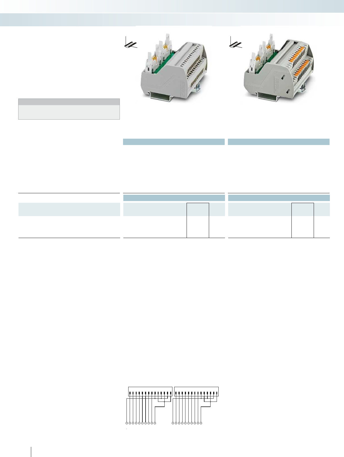
X1 X2
1234567891011121314 1234567891011121314
1234567891011121314151617181920
Technical data Technical data
Max. perm. operating voltage 60 V AC/DC 60 V AC/DC
Max. perm. current (per branch) 1 A 1 A
Ambient temperature (operation) -20 °C ... 50 °C -20 °C ... 50 °C
Mounting position any any
Standards/regulations IEC 60664, DIN EN 50178, IEC 62103 IEC 60664, DIN EN 50178, IEC 62103
Connection method Field level Screw connection Push-in connection
Controller level IDC/FLK pin strip (2.54 mm) IDC/FLK pin strip (2.54 mm)
Connection data solid / stranded / AWG 0.2 ... 4 mm² / 0.2 ... 2.5 mm² / 24 - 12 0.14 ... 2.5 mm² / 0.14 ... 2.5 mm² / 26 - 14
Dimensions H / D 65.5 mm / 56 mm 72.1 mm / 56 mm
Ordering data Ordering data
Description No. of
pos.
Module width
WType Order No. Pcs. /
Pkt. Type Order No. Pcs. /
Pkt.
VARIOFACE interface module, with SIMATIC
®
S7-300-specific
marking from 1 to 20
- with screw connection 14 80.6 mm VIP-2/SC/2FLK14 (1-20) /S7 2315230 1
- with push-in connection 14 82.5 mm VIP-2/PT/2FLK14 (1-20) /S7 2903802 1
Connection diagram: VIP-2/.../2FLK14 (1-20) /S7
546
PHOENIX CONTACT
System cabling for controllers
Controller-specific system cabling
Passive interface modules for
SIMATIC
®
S7-300
with screw connection
Passive interface modules for
SIMATIC
®
S7-300
with push-in connection
These VIP - VARIOFACE Professional
modules are used in combination with two
14-pos. system cables and the relevant front
adapters for Siemens SIMATIC® S7-300.
Features:
– Numerical marking (1-20)
– Specifically for S7-300
Notes:
For marking systems (e.g., “ZB 22:UNBEDRUCKT”;
Order No. 0811862) and mounting material, see Catalog 5.
DW
H
DW
H
VIP termination boards for
Siemens SIMATIC
®
S7-300
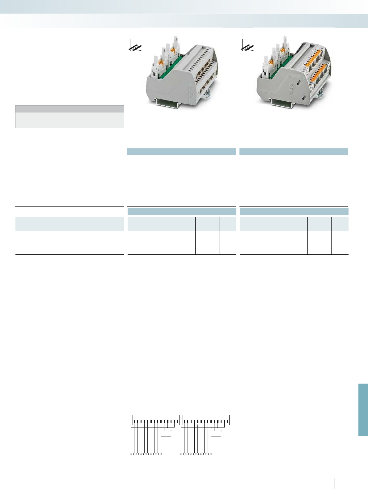
X2X1 1234567891011121314 1234567891011121314
123456789
1020111213141516171819
For further information and full technical data, visit phoenixcontact.net/products
Technical data Technical data
Max. perm. operating voltage 60 V AC/DC 60 V AC/DC
Max. perm. current (per branch) 1 A 1 A
Ambient temperature (operation) -20 °C ... 50 °C -20 °C ... 50 °C
Mounting position any any
Standards/regulations IEC 60664, DIN EN 50178, IEC 62103 IEC 60664, DIN EN 50178, IEC 62103
Connection method Field level Screw connection Push-in connection
Controller level IDC/FLK pin strip (2.54 mm) IDC/FLK pin strip (2.54 mm)
Connection data solid / stranded / AWG 0.2 ... 4 mm² / 0.2 ... 2.5 mm² / 24 - 12 0.2 ... 4 mm² / 0.2 ... 2.5 mm² / 24 - 12
Dimensions H / D 65.5 mm / 56 mm 72.1 mm / 56 mm
Ordering data Ordering data
Description No. of
pos.
Module width
WType Order No. Pcs. /
Pkt. Type Order No. Pcs. /
Pkt.
VARIOFACE interface module, with
ControlLogix-specific marking from 1 to 20
- with screw connection 14 80.6 mm VIP-2/SC/2FLK14/AB-1756 2322333 1
- with push-in connection 14 82.5 mm VIP-2/PT/2FLK14/AB-1756 2904288 1
Connection scheme VIP-2/.../2FLK14/AB-1756
547
PHOENIX CONTACT
System cabling for controllers
Controller-specific system cabling
Passive interface modules
for Allen Bradley ControlLogix
with screw connection
Passive interface modules
for Allen Bradley ControlLogix
with push-in connection
These VIP - VARIOFACE Professional
modules are used in combination with two
14-pos. system cables and the relevant front
adapters for Allen Bradley.
Features:
– Numerical marking (1-20)
– Specifically for ControlLogix
Notes:
For marking systems (e.g., “ZB 22:UNBEDRUCKT”;
Order No. 0811862) and mounting material, see Catalog 5.
DW
H
DW
H
VIP termination boards for
Allen Bradley
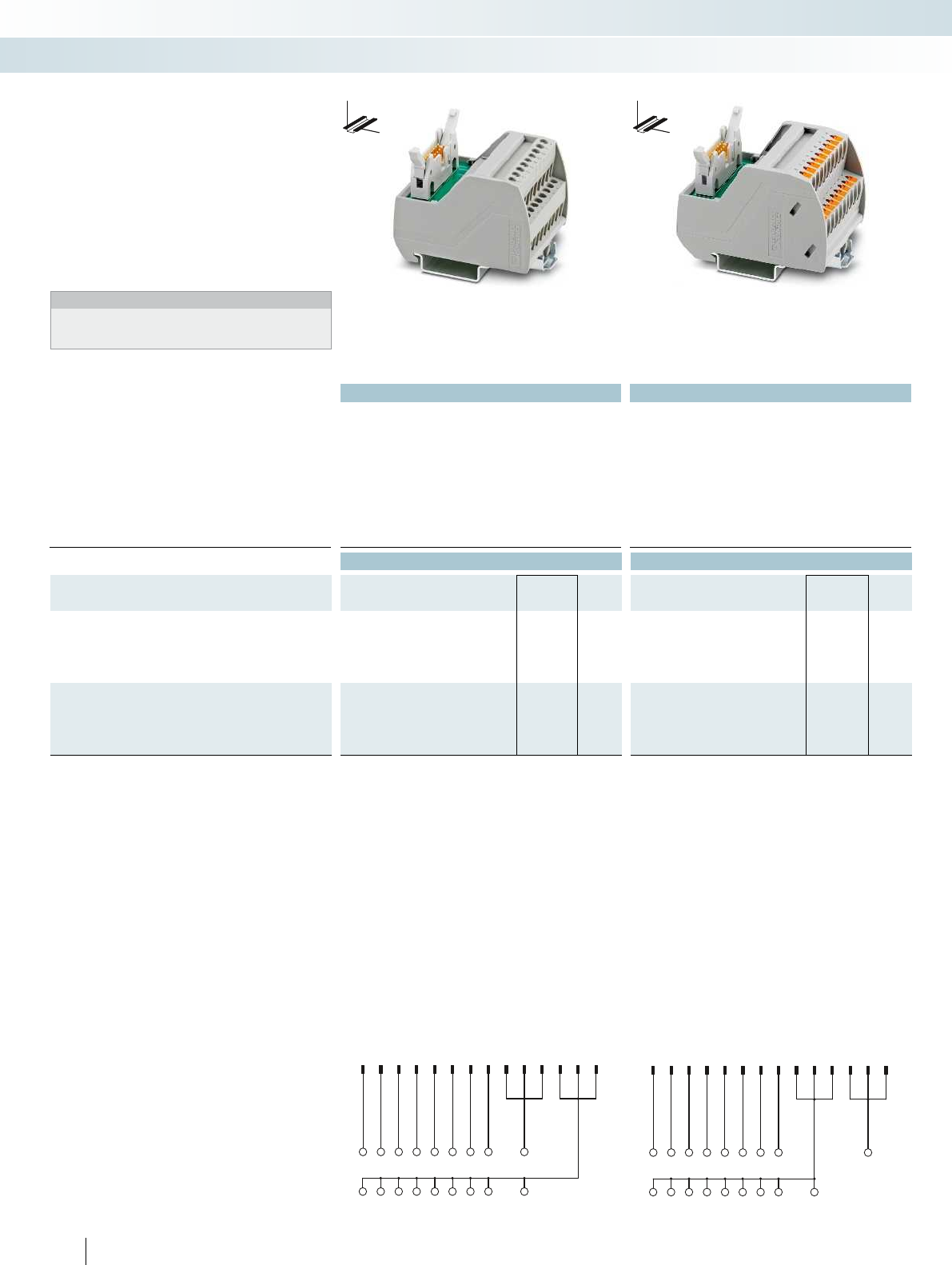
123 45 67 8911 13 1012 14
123 45 670+
---------
12345678911 13 1012 14
12345670
+ + + + ++ ++ +
-
Technical data Technical data
Max. perm. operating voltage 60 V DC 60 V AC/DC
Max. perm. current (per branch) 1 A 1 A
Max total current (voltage supply) 3 A (per byte) 3 A (per byte)
Ambient temperature (operation) -20 °C ... 50 °C -20 °C ... 50 °C
Mounting position any any
Standards/regulations IEC 60664, DIN EN 50178, IEC 62103 IEC 60664, DIN EN 50178, IEC 62103
Connection method Field level Screw connection Push-in connection
Controller level IDC/FLK pin strip (2.54 mm) IDC/FLK pin strip (2.54 mm)
Connection data solid / stranded / AWG 0.2 ... 4 mm² / 0.2 ... 2.5 mm² / 24 - 12 0.14 ... 2.5 mm² / 0.14 ... 2.5 mm² / 26 - 14
Dimensions H / D 65.5 mm / 56 mm 72.1 mm / 56 mm
Ordering data Ordering data
Description No. of
pos.
Module width
WType Order No. Pcs. /
Pkt. Type Order No. Pcs. /
Pkt.
VARIOFACE interface module, for eight channels, each with an
additional terminal block per signal for a common minus potential
- with screw connection 14 50 mm VIP-2/SC/FLK14/8M/PLC 2322281 1
- with push-in connection 14 52 mm VIP-2/PT/FLK14/8M/PLC 2904283 1
VARIOFACE interface module, for eight channels, each with an
additional terminal block per signal for a common plus potential
- with screw connection 14 50 mm VIP-2/SC/FLK14/8P/PLC 2322294 1
- with push-in connection 14 52 mm VIP-2/PT/FLK14/8P/PLC 2904284 1
Connection scheme VIP-2/.../FLK14/8M/PLC Connection scheme VIP-2/.../FLK14/8P/PLC
548
PHOENIX CONTACT
System cabling for controllers
Controller-specific system cabling
Passive interface modules
with screw connection
Passive interface modules
with push-in connection
These VIP VARIOFACE modules are used
in combination with 14-pos. system cables
and the relevant front adapters.
Features:
– Byte-by-byte marking
– For digital I/O modules
– Negative or positive connection per
signal
Notes:
For marking systems (e.g., “ZB 22:UNBEDRUCKT”;
Order No. 0811862) and mounting material, see Catalog 5.
DW
H
DW
H
VIP termination boards in
2-conductor connection technology
for 8 channels

1234 10111213141516 2223242526272834353637383940464748
B3.0B3.1B3.7- -
B2.0B2.1 B2.7-
B1.0B1.1 B1.7-
B0.0B0.1 B0.7
+
++ + +++ + +++ + +++ +
DR3
DR2
DR1
1234 10111213141516 2223242526272834353637383940464748
B3.0B3.1 B3.7+B2.0B2.1 B2.7+
B1.0B1.1 B1.7+
B0.0B0.1 B0.7+
- -- - --- - --- - --- -
DR3
DR2
DR1
For further information and full technical data, visit phoenixcontact.net/products
Technical data
Max. perm. operating voltage 60 V DC
Max. perm. current (per branch) 1 A
Max total current (voltage supply) 8 A (per byte)
Ambient temperature (operation) -20 °C ... 50 °C
Mounting position any
Standards/regulations DIN EN 50178, IEC 60664, IEC 62103
Connection method Field level Screw connection
Controller level IDC/FLK pin strip (2.54 mm)
Connection data solid / stranded / AWG 0.2 ... 4 mm² / 0.2 ... 2.5 mm² / 24 - 12
Dimensions H / D 90 mm / 68 mm
Ordering data
Description No. of
pos.
Module width
WType Order No. Pcs. /
Pkt.
VARIOFACE interface module, for 32 channels, each with an
additional terminal block per signal for a common minus potential
50 192 mm FLKM 50/32M/PLC 2289719 1
VARIOFACE interface module, for 32 channels, each with an
additional terminal block per signal for a common plus potential
50 192 mm FLKM 50/32P/PLC 2291121 1
549PHOENIX CONTACT
Connection scheme: FLKM 50/32P/PLC Connection scheme: FLKM 50/32M/PLC
These VARIOFACE modules are used in
combination with 50-pos. system cables and
the relevant front adapters.
The following module types with
2-conductor connection technology are
available:
FLKM 50/32M/PLC
– Byte-by-byte marking
– For digital I/O modules
– Negative connection per signal
FLKM 50/32P/PLC
– Byte-by-byte marking
– For digital I/O modules
– Positive connection per signal
Termination boards in
2-conductor connection technology
for 32 channels
System cabling for controllers
Controller-specific system cabling
DW
H
Passive interface modules
with screw connection
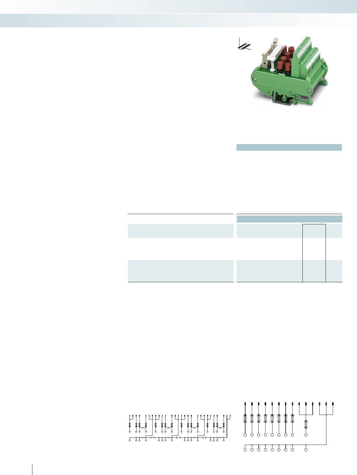
1234 10111213141516 2223242526272834353637383940464748
F1F1 F1F2F1 F1 F1F2F1F1 F1F2
F1F1 F1F2
B3.0B3.1B3.7
+
B2.0B2.1B2.7
+
B1.0B1.1B1.7
+
B0.0B0.1B0.7
+
---- ---- ---- ----
DR3DR2DR1
1234567 8911 13 1012 14
F2
F1 F1 F1 F1 F1 F1 F1 F1
12345670+
-------- -
550
PHOENIX CONTACT
Technical data
FLKM 14/8M/SI/PLC FLKM 50/32M/SI/PLC
Max. perm. operating voltage 60 V DC 60 V DC
Max. perm. current (per branch) 1 A 1 A
Max total current (voltage supply) 2 A 2 A (per byte)
Ambient temperature (operation) -20 °C ... 50 °C -20 °C ... 50 °C
Mounting position any any
Standards/regulations DIN EN 50178, IEC 60664, IEC 62103
Connection method Field level Screw connection Screw connection
Controller level IDC/FLK pin strip (2.54 mm) IDC/FLK pin strip (2.54 mm)
Connection data solid / stranded / AWG 0.2 ... 4 mm² / 0.2 ... 2.5 mm² / 24 - 12
Dimensions H / D 90 mm / 68 mm
Ordering data
Description No. of
pos.
Module width
WType Order No. Pcs. /
Pkt.
VARIOFACE module, for eight channels, each with an additional
terminal block and fuse per signal, (common minus potential)
14 57 mm FLKM 14/8M/SI/PLC 2294487 1
VARIOFACE module, for 32 channels, each with an additional
terminal block and fuse per signal, (common minus potential)
50 192 mm FLKM 50/32M/SI/PLC 2294490 1
Connection scheme: FLKM 50/32M/SI/PLC Connection scheme: FLKM 14/8M/SI/PLC
These VARIOFACE modules are used in
combination with 14 or 50-pos. system
cables and the relevant front adapters.
The following module types with fuses
and 2-conductor connection technology are
available:
FLKM 14/8M/SI/PLC (for 8 channels)
FLKM 50/32M/SI/PLC (for 32
channels)
– Byte-by-byte marking
– Can be used for digital I/O modules
– Plug-in fuse (IEC 127-3, 1AF) per signal
path (F1)
– Plug-in fuse (IEC 127-3, 2AF) per voltage
supply (F2)
– Negative connection per signal.
Termination boards with fuses in
2-conductor connection technology
System cabling for controllers
Controller-specific system cabling
DW
H
Passive fuse modules
for 8 or 32 channels
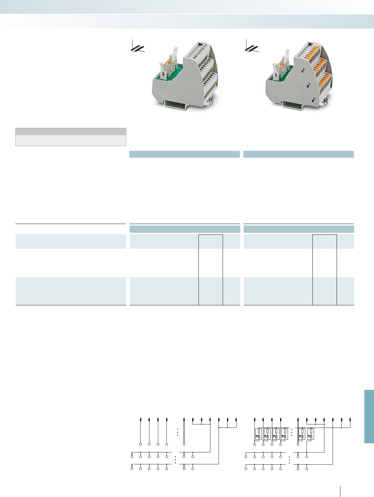
1 234 8911 13 1012 14
12307
+++++++
----- --
1 234 8911 13 1012 14
12307
+++++++
----- --
For further information and full technical data, visit phoenixcontact.net/products
Technical data Technical data
VIP-3/SC/FLK14/8IM/PLC VIP-3/SC/FLK14/8IM/LED/PLC VIP-3/PT/FLK14/8IM/PLC VIP-3/PT/FLK14/8IM/LED/PLC
Max. perm. operating voltage 60 V DC 24 V DC 60 V AC/DC 24 V DC
Max. perm. current (per branch) 1 A 1 A 1 A 1 A
Max total current (voltage supply) 3 A 3 A 3 A 3 A
Ambient temperature (operation) -20 °C ... 50 °C -20 °C ... 50 °C -20 °C ... 50 °C -20 °C ... 50 °C
Mounting position any any any any
Standards/regulations IEC 60664, DIN EN 50178, IEC 62103 IEC 60664, DIN EN 50178, IEC 62103
Connection method Field level Screw connection Screw connection Push-in connection Push-in connection
Controller level IDC/FLK pin strip (2.54 mm) IDC/FLK pin strip (2.54 mm) IDC/FLK pin strip (2.54 mm) IDC/FLK pin strip (2.54 mm)
Connection data solid / stranded / AWG 0.2 ... 4 mm² / 0.2 ... 2.5 mm² / 24 - 12 0.14 ... 2.5 mm² / 0.14 ... 2.5 mm² / 26 - 14
Dimensions H / D 69 mm / 62 mm 75.8 mm / 63 mm
Ordering data Ordering data
Description No. of
pos.
Module width
WType Order No. Pcs. /
Pkt. Type Order No. Pcs. /
Pkt.
VARIOFACE initiator module, for connecting 8 PNP initiators,
with an additional positive and negative terminal block each per
signal
- with screw connection 14 52.3 mm VIP-3/SC/FLK14/8IM/PLC 2322278 1
- with push-in connection 14 52 mm VIP-3/PT/FLK14/8IM/PLC 2904282 1
VARIOFACE initiator module with LED, for connecting 8 PNP
initiators, with an additional positive and negative terminal block
each per signal
- with screw connection 14 52.3 mm VIP-3/SC/FLK14/8IM/LED/PLC 2322265 1
- with push-in connection 14 52 mm VIP-3/PT/FLK14/8IM/LED/PLC 2904281 1
Connection scheme VIP-3/.../FLK14/8IM/PLC Connection scheme VIP-3/.../FLK14/8IM/LED/PLC
551PHOENIX CONTACT
System cabling for controllers
Controller-specific system cabling
Initiator modules
with screw connection
Initiator modules
with push-in connection
These VIP - VARIOFACE Professional
modules are used in combination with
14-pos. system cables and the relevant front
adapters.
Features:
– Byte-by-byte marking
– For digital I/O modules
– Positive and negative connection per
signal
– With LED as an option
Notes:
For marking systems (e.g., “ZB 22:UNBEDRUCKT”;
Order No. 0811862) and mounting material, see Catalog 5.
DW
H
DW
H
VIP initiator modules for 8 channels
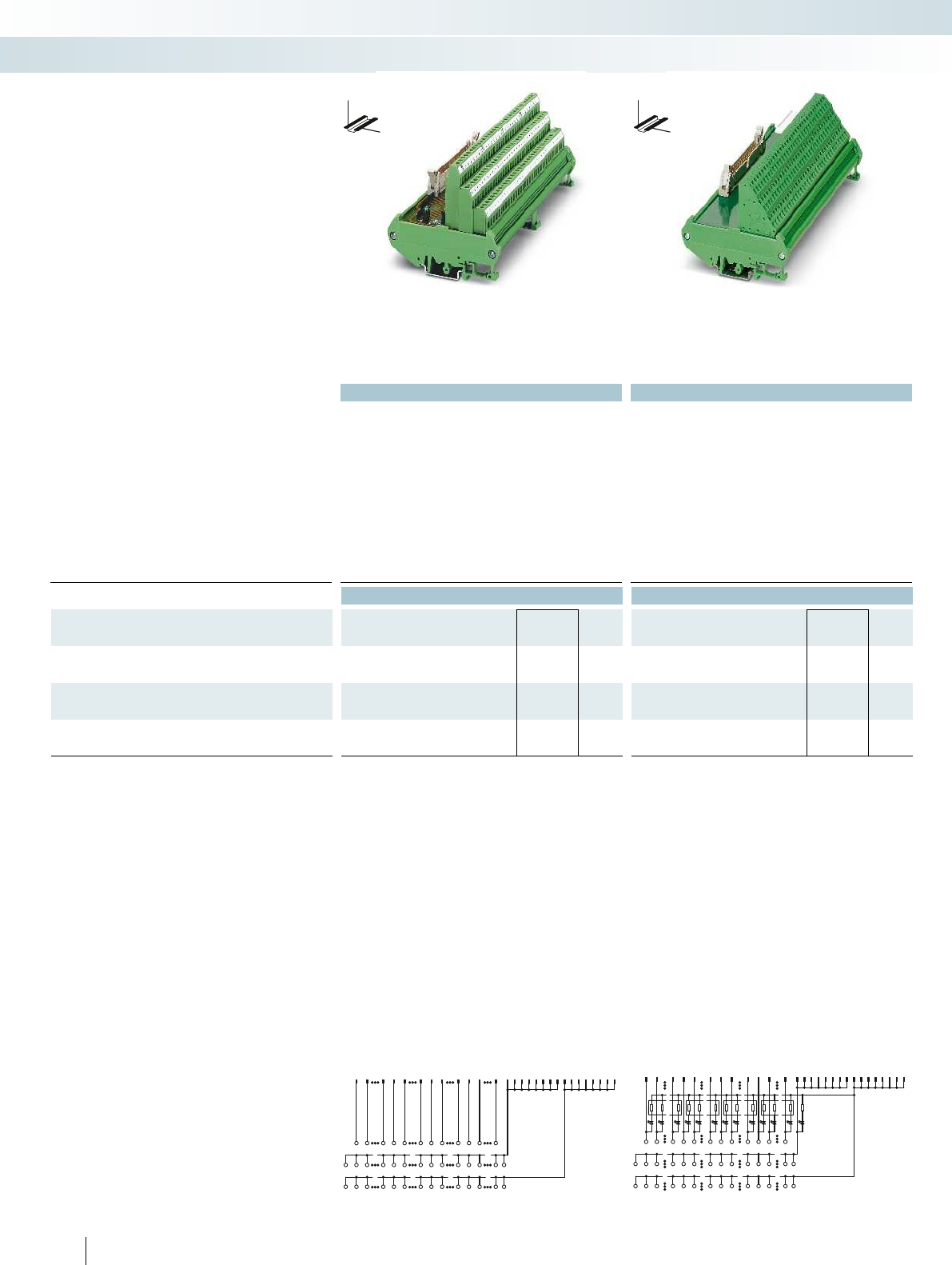
34 1015 16 22 27 2834 394046 1 213
14
25
26
37
3811
12
23
2435
36
47
48
B0.0B0.1B0.7B1.0B1.1B1.7B2.0B2.1B2.7B3.0B3.1B3.7
+++ +++ +++ +++ ++
--------------
48
47
36
35
2324
1112
3738
2526
1314
12
46
403934
2827
22
161534 10
B2.7 B3.0B3.1 B3.7
B2.1B2.0B1.7B1.1B1.0B0.7
B0.1
B0.0
+
-
+
-
+
-
+
-
+
-
+
-
+
-
+
-
+
-
+
-
+
-
+
-
+
-
+
-
Technical data Technical data
... 50/32 IM ... 50/32 IM/LA
Max. perm. operating voltage 60 V DC 30 V DC 60 V DC
Max. perm. current (per branch) 1 A 1 A 1 A
Max total current (voltage supply) 2 A (per byte) 2 A (per byte) 2 A (per byte)
Status indication - LED -
Ambient temperature (operation) -20 °C ... 50 °C -20 °C ... 50 °C -20 °C ... 50 °C
Mounting position any any any
Standards/regulations DIN EN 50178, IEC 60664, IEC 62103 DIN EN 50178, IEC 60664, IEC 62103
Connection method Field level Screw connection Screw connection Spring-cage connection
Controller level IDC/FLK pin strip (2.54 mm) IDC/FLK pin strip (2.54 mm) IDC/FLK pin strip (2.54 mm)
Connection data solid / stranded / AWG 0.2 ... 4 mm² / 0.2 ... 2.5 mm² / 24 - 12 0.2 ... 2.5 mm² / 0.2 ... 1.5 mm² / 24 - 12
Dimensions H / D 90 mm / 81 mm 90 mm / 73.5 mm
Ordering data Ordering data
Description No. of
pos.
Module width
WType Order No. Pcs. /
Pkt. Type Order No. Pcs. /
Pkt.
VARIOFACE initiator module, for connection of 32 PNP initiators
50 180 mm FLKMS 50/32IM/PLC 2284523 1
VARIOFACE initiator module, as above, however with light
indicator
50 180 mm FLKMS 50/32IM/LA/PLC 2284510 1
VARIOFACE initiator module, for connection of 32 PNP initiators
50 180 mm FLKMS 50/32IM/ZFKDS/PLC 2901389 1
Connection scheme: FLKMS 50/32IM/PLC,
...50/32IM/ZFKDS/PLC
FLKMS 50/32IM/LA/PLC connection scheme
552
PHOENIX CONTACT
System cabling for controllers
Controller-specific system cabling
Initiator modules for 32 channels,
with screw connection
Initiator modules for 32 channels,
with spring-cage connection
These VARIOFACE modules are used in
combination with 50-pos. system cables and
the relevant front adapters for digital I/O
modules.
Features:
– Byte-by-byte marking
– Positive and negative connection per
signal
– With LED as an option
DW
H
DW
H
Initiator modules for 32 channels

For further information and full technical data, visit phoenixcontact.net/products
553PHOENIX CONTACT
System cabling for controllers
Controller-specific system cabling
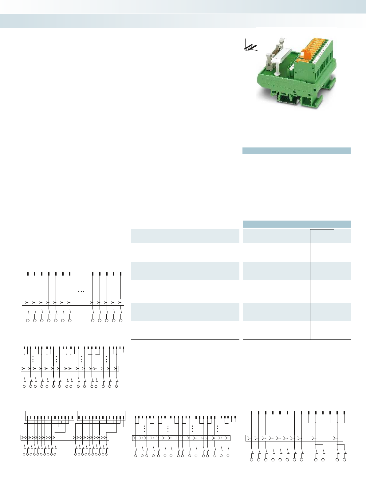
123 101112 131415 22 23 24 2526 27 34 3536 3738394647484950
+B0.0B0.7 -+B1.0B1.7 -+B2.0B2.7 -+B3.0B3.7 -
12345678911 13 1012 14
1234567
0++ - -
1234567891011121314 1234567891011121314
1234567891011121314151617181920
123 101112 131415 222324 25 26 27 34 35363738394647484950
1291011 12 192021 22 293031 32 3940
1 2 3 4 5 6 7 46 47 484950
1234567 46 47 484950
Technical data
FLKM...14/KDS 3-MT... FLKM 50/KDS 3-MT...
Max. perm. operating voltage 60 V DC 60 V DC
Max. perm. current (per branch) 1 A 1 A
Max total current (voltage supply) 3 A 2 A (per byte)
Ambient temperature (operation) -20 °C ... 50 °C -20 °C ... 50 °C
Mounting position any any
Standards/regulations DIN EN 50178, IEC 60664, IEC 62103
Connection method Field level Screw connection with
disconnect knife
Screw connection with
disconnect knife
Controller level IDC/FLK pin strip (2.54 mm) IDC/FLK pin strip (2.54 mm)
Connection data solid / stranded / AWG 0.2 ... 4 mm² / 0.2 ... 2.5 mm² / 24 - 12
Dimensions H / D 77 mm / 61 mm
Ordering data
Description No. of
pos.
Module width
WType Order No. Pcs. /
Pkt.
VARIOFACE interface module, for eight channels, with knife
disconnect terminal blocks and test sockets to the field and the
system
14 67 mm FLKM 14/KDS3-MT/PPA/PLC 2290423 1
VARIOFACE interface module, for 32 channels, with knife
disconnect terminal blocks and test sockets to the field and the
system
50 214 mm FLKM 50/KDS3-MT/PPA/PLC 2290614 1
VARIOFACE interface module, for SIMATIC S7-300 with
SIMATIC-specific marking (1-20), knife disconnect terminal blocks
and test sockets to the field and the system
14 113 mm FLKM-2FLK14/KDS3-MT/PPA/S7 2295062 1
VARIOFACE interface module, as above, however, with
SIMATIC-specific marking (1-40)
50 214 mm FLKM 50/KDS3-MT/PPA/S7-300 2304490 1
VARIOFACE interface module, as above, however, for SIMATIC
S7-400 with SIMATIC-specific marking (3-48)
50 259 mm FLKM 50/KDS3-MT/PPA/AN/PLC 2291587 1
554
PHOENIX CONTACT
FLKM 50/KDS3-MT/PPA/PLC connection scheme FLKM 14/KDS3-MT/PPA/PLC connection schemeFLKM-2FLK14/KDS3-MT/PPA/S7 connection scheme
FLKM 50/KDS3-MT/PPA/S7-300 connection scheme
FLKM 50/KDS3-MT/PPA/AN/PLC connection scheme
These VARIOFACE modules with knife
disconnection and test connection for each
signal (2 or 2.3 mm Ø test plug) are used in
combination with the respective front
adapters.
FLKM14/KDS3-MT/PPA/PLC
(for 8 channels)
FLKM 50/KDS3-MT/PPA/PLC
(for 32 channels)
– Byte-by-byte marking
– Can be used for digital I/O modules
FLKM-2FLK14/KDS3-MT/PPA/S7
– Numerical marking (1-20)
– Specifically for S7-300
(in conjunction with the front adapter
FLKM 14-PA-S300, Order No.: 2299770)
FLKM 50/KDS3-MT/PPA/7-300
– Numerical marking (1-40)
– Specifically for S7-300
(in conjunction with the front adapter
FLKM 50-PA-S300, Order No.: 2294445).
FLKM 50/KDS3-MT/PPA/AN/PLC
– Numerical marking (1-50)
– Specifically for S7-400
(in conjunction with the front adapter
FLKM 50-PA-S400 (3-48)
Order No.: 2294908).
Controller boards with knife
disconnect terminal blocks
System cabling for controllers
Controller-specific system cabling
DW
H
Passive interface modules for eight or 32 channels
with knife disconnect terminal blocks
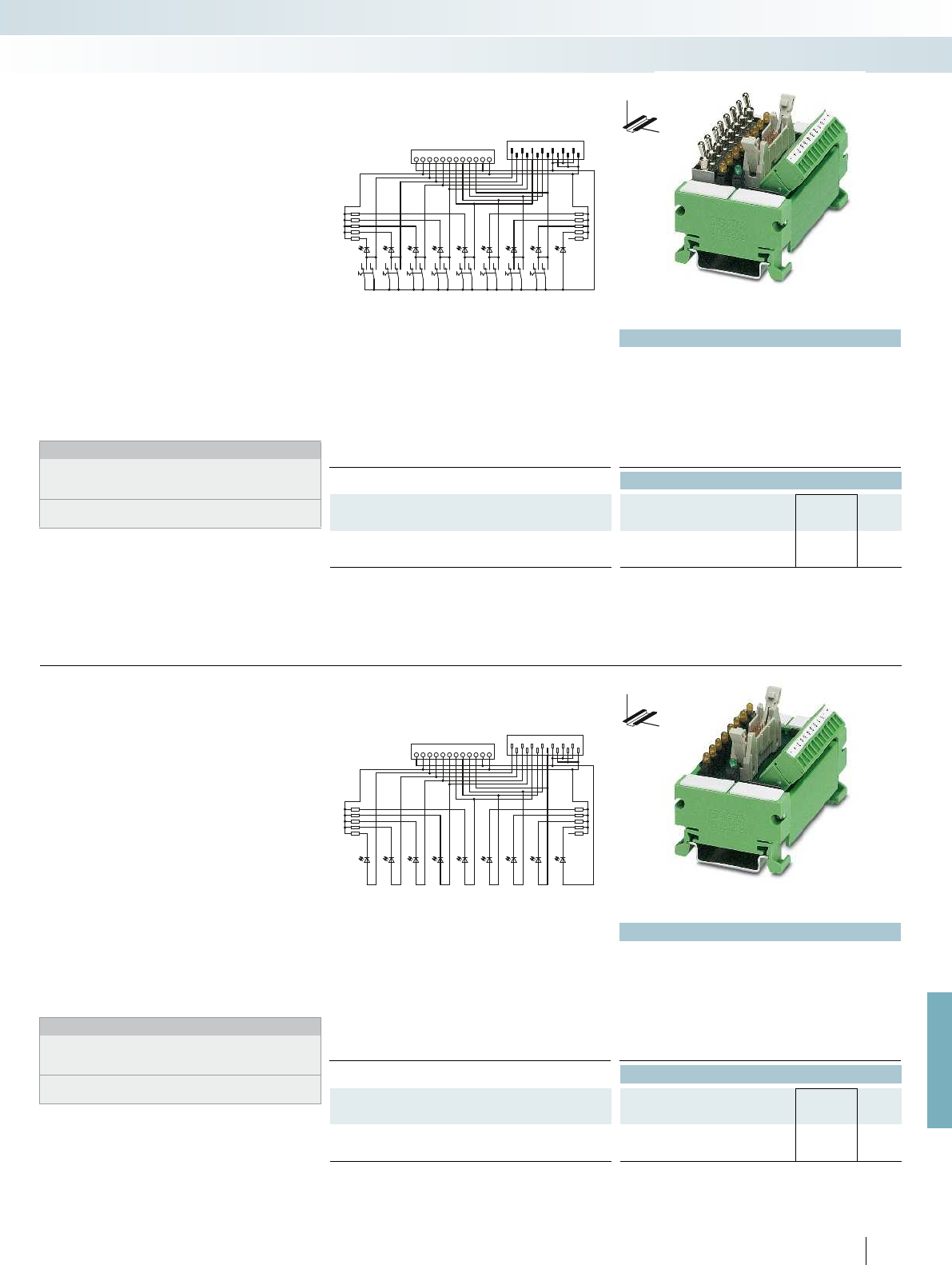
01234567-+
-+SMC 1,5
FLK 14
1234681012 14
57911 13
SCM1,5
FLK 14
+-01234567+-
124681012 14
347 911 13
For further information and full technical data, visit phoenixcontact.net/products
Technical data
Max. perm. operating voltage 30 V DC
Max. perm. current (per branch) 1 A
Max total current (voltage supply) 8 A (+, - terminal block)
Ambient temperature (operation) -20 °C ... 50 °C
Mounting position any
Standards/regulations DIN EN 50178, IEC 60664, IEC 62103
Connection data solid / stranded / AWG 0.14 ... 1.5 mm² / 0.14 ... 1.5 mm² / 28 - 16
Dimensions H / D 45 mm / 51 mm
Ordering data
Description No. of
pos.
Module width
WType Order No. Pcs. /
Pkt.
VARIOFACE switch module, for simulation
75 mm UM 45-DI/DO/S/LA/SIM8 2968205 1
DW
H
These VARIOFACE modules enable
simple simulation of the control and
peripheral hardware for 8 signals.
The UM 45-DI/DO/S/LA/SIM8 switch
module is assembled for signal transmission
with COMBICON screw connector for
single-conductor wiring. Alternatively,
connection to the PLC system cabling is
established through a 14-pos. flat-ribbon
cable pin strip. Connection to the front
adapters of the PLC system cabling is
established through 14-pos. system cables
with socket strips.
Each signal path is allocated an LED which
signals the “high active” signal state. The
supply voltage to the modules is signaled via
a green LED.
Notes:
Type of housing:
Terminal blocks: Polyamide PA non-reinforced, color: green.
Housing: PVC
Marking systems and mounting material
See Catalog 5
Simulation module with switches
System cabling for controllers
Controller-specific system cabling
Switch module
Technical data
Max. perm. operating voltage 30 V DC
Max. perm. current (per branch) 1 A
Max total current (voltage supply) 8 A (+, - terminal block)
Ambient temperature (operation) -20 °C ... 50 °C
Mounting position any
Standards/regulations DIN EN 50178, IEC 60664, IEC 62103
Connection data solid / stranded / AWG 0.14 ... 1.5 mm² / 0.14 ... 1.5 mm² / 28 - 16
Dimensions H / D 45 mm / 51 mm
Ordering data
Description No. of
pos.
Module width
WType Order No. Pcs. /
Pkt.
VARIOFACE display module, for simulation
75 mm UM 45-DO/LA/SIM8 2968195 1
555
PHOENIX CONTACT
DW
H
These VARIOFACE modules enable
simple simulation of the control and
peripheral hardware for 8 signals.
The UM 45-DO/LA/SIM8 display module
is assembled for signal transmission with
COMBICON screw connector for single-
conductor wiring. Alternatively, connection
to the PLC system cabling is established
through a 14-pos. flat-ribbon cable pin strip.
Connection to the front adapters of the
PLC system cabling is established through
14-pos. system cables with socket strips.
Each signal path is allocated an LED which
signals the “high active” signal state. The
supply voltage to the modules is signaled via
a green LED.
Notes:
Type of housing:
Terminal blocks: Polyamide PA non-reinforced, color: green.
Housing: PVC
Marking systems and mounting material
See Catalog 5
Simulation module for display
Indicator module

123 891113101214
1238
14 13 24 23 34 33 8483 +-
Technical data
Coil side
Operating voltage U
N
24 V DC
Typ. input current at U
N
6.5 mA
Typ. response time at U
N
5 ms
Typ. release time at U
N
15 ms
Input circuit Freewheeling diode, protection against polarity reversal Freewheeling diode, protection against polarity reversal Fr
Status display/channel Yellow LED
Connection method IDC/FLK pin strip (2.54 mm) IDC/FLK pin strip (2.54 mm) IDC/FLK pin strip (2.54 mm)
No. of pos. 14
Contact side
Contact type 1 N/O contact (double contact) 1 N/O contact (double contact) 1 N/O contact (double contact)
Contact material AgNi, 5 µm hard gold-plated AgNi, 5 µm hard gold-plated AgNi, 5 µm hard gold-plated
Max. switching voltage 250 V AC / 125 V DC
Min. switching voltage 5 V
Max. inrush current 5 A
Limiting continuous current 3 A
Min. switching current 1 mA
Max. interrupting rating: 24 V DC 72 W
48 V DC 60 W
60 V DC 50 W
110 V DC 50 W
250 V AC 750 VA
Connection method Screw connection
Connection data solid / stranded / AWG 0.14 ... 1.5 mm² / 0.14 ... 1.5 mm² / 26 - 14 0.14 ... 1.5 mm² / 0.14 ... 1.5 mm² / 26 - 14 0.1
General data
Rated insulation voltage 260 V AC
Rated surge voltage 4 kV (basic insulation) 4 kV (basic insulation) 4 kV (basic insulation)
Pollution degree / Surge voltage category 2 / III
Ambient temperature (operation) -20 °C ... 50 °C
Nominal operating mode 100% operating factor 100% operating factor 100% operating factor
Mechanical service life 2 x 10
7
cycles
Standards/regulations DIN EN 50178, IEC 60664, IEC 62103 DIN EN 50178, IEC 60664, IEC 62103 DIN EN 50178, IEC 60664, IEC 62103
Mounting position any
Mounting Can be aligned without spacing Can be aligned without spacing Can be aligned without spacing
Dimensions H / D 45 mm / 50 mm
EMC note Class A product, see page 625 Class A product, see page 625 Class A product, see page 625
Ordering data
Description Module width
WType Order No. Pcs. /
Pkt.
VARIOFACE COMPACT LINE output module, for 24 V DC
(including relays)
- with 8 miniature relays 103 UM 45- 8RM/MR-G24/1/PLC 2962900 1
- with 16 miniature relays (basic module) 215
- with 16 miniature relays (extension module) 200
Accessories
Plug-in miniature relay REL-MR-G 24/1 2961037 8
556
PHOENIX CONTACT
COMPACT LINE output modules
with relays, one N/O contact
These VARIOFACE Compact Line output
modules are used in combination with the
respective front adapters.
Like the front adapters, the modules are
connected via 14-pos. or 50-pos. system
cables. The following features characterize
these relay modules:
– Plug-in miniature relays, each with an N/O
contact
– Universal applications from 1 mA to 3 A
continuous current through 2-layer
double contact with hard gold plating
– Low construction height of only 45 mm
– LED status display for each signal path and
supply voltage
– Freewheeling and reverse polarity
protection diode for each signal path
With the 32-channel version, the system
cable is connected to the 16-channel base
module UM 45-16RM/MR-G24/1/PLC.
The output extension module
UM 45-16RM/MR-G24/1/E/PLC with a
further 16 channels is coupled to the base
module via a 20-position flat-ribbon cable
(length: 10 cm).
System cabling for controllers
Controller-specific system cabling
DW
H
Notes:
The connecting cable between the base and the extension
modules is delivered with the extension unit.
Due to the geometry, it is not possible to couple any molded
FLK connectors (e.g., VIP-PA...S7).
Output module
with eight miniature relays,
1 N/O contact
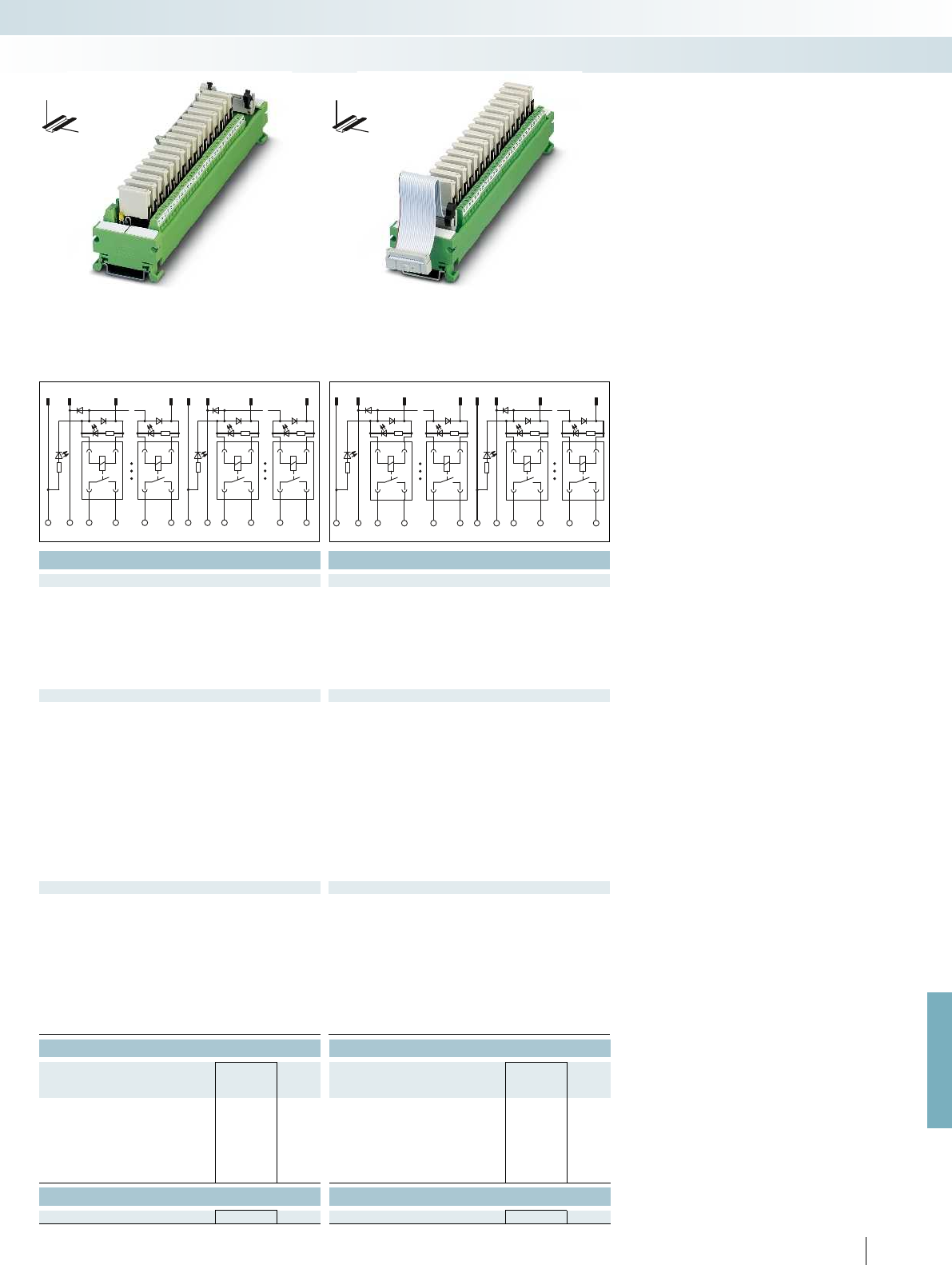
1,2 11,12 31013,14 23,24 15 22
18916
B0
+-
B0 14 13 8483
+-
B1B19493 164 163
22017 12 1 199 4
322524
17
B2B2
+-
174 173 244 243 B3B3254 253 324 323
+-
For further information and full technical data, visit phoenixcontact.net/products
Technical data Technical data
24 V DC 24 V DC
6.5 mA 6.5 mA
5 ms 5 ms
15 ms 15 ms
Input circuit Freewheeling diode, protection against polarity reversal Freewheeling diode, protection against polarity reversal Freewheeling diode, protection against polarity reversal
Yellow LED Yellow LED
Connection method IDC/FLK pin strip (2.54 mm) IDC/FLK pin strip (2.54 mm) IDC/FLK pin strip (2.54 mm)
50 20
Contact type 1 N/O contact (double contact) 1 N/O contact (double contact) 1 N/O contact (double contact)
Contact material AgNi, 5 µm hard gold-plated AgNi, 5 µm hard gold-plated AgNi, 5 µm hard gold-plated
250 V AC / 125 V DC 250 V AC / 125 V DC
5 V 5 V
5 A 5 A
3 A 3 A
1 mA 1 mA
72 W 72 W
60 W 60 W
50 W 50 W
50 W 50 W
750 VA 750 VA
Screw connection Screw connection
Connection data solid / stranded / AWG 0.14 ... 1.5 mm² / 0.14 ... 1.5 mm² / 26 - 14 0.14 ... 1.5 mm² / 0.14 ... 1.5 mm² / 26 - 14 0.14 ... 1.5 mm² / 0.14 ... 1.5 mm² / 26 - 14
260 V AC 260 V AC
Rated surge voltage 4 kV (basic insulation) 4 kV (basic insulation) 4 kV (basic insulation)
2 / III 2 / III
-20 °C ... 50 °C -20 °C ... 50 °C
Nominal operating mode 100% operating factor 100% operating factor 100% operating factor
2 x 10
7
cycles 2 x 10
7
cycles
Standards/regulations DIN EN 50178, IEC 60664, IEC 62103 DIN EN 50178, IEC 60664, IEC 62103 DIN EN 50178, IEC 60664, IEC 62103
any any
Mounting Can be aligned without spacing Can be aligned without spacing Can be aligned without spacing
45 mm / 50 mm 45 mm / 50 mm
EMC note Class A product, see page 625 Class A product, see page 625 Class A product, see page 625
Ordering data Ordering data
Type Order No. Pcs. /
Pkt. Type Order No. Pcs. /
Pkt.
UM 45-16RM/MR-G24/1/PLC 2962913 1
UM 45-16RM/MR-G24/1/E/PLC 2962926 1
Accessories Accessories
REL-MR-G 24/1 2961037 8REL-MR-G 24/1 2961037 8
557
PHOENIX CONTACT
System cabling for controllers
Controller-specific system cabling
DW
H
DW
H
Output base module
with 16 miniature relays,
1 N/O contact
Output extension module
with 16 miniature relays,
1 N/O contact

123 891113101214
1238
14 13 24 23 34 33 8483 +-
1,2 11,12 310
13,14
23,24 15 46
32981
B0
+-
B0 14 13 8483
+-
B1B19493324 323
Technical data Technical data
Coil side
Operating voltage U
N
24 V DC 24 V DC
Typ. input current at U
N
6.5 mA 6.5 mA
Typ. response time at U
N
5 ms 5 ms
Typ. release time at U
N
15 ms 15 ms
Input circuit Freewheeling diode, protection against polarity reversal Freewheeling diode, protection against polarity reversal
Status display/channel Yellow LED Yellow LED
Connection method IDC/FLK pin strip (2.54 mm) IDC/FLK pin strip (2.54 mm)
No. of pos. 14 50
Contact side
Contact type 1 N/O contact (double contact) 1 N/O contact (double contact)
Contact material AgNi, 5 µm hard gold-plated AgNi, 5 µm hard gold-plated
Max. switching voltage 250 V AC / 125 V DC 250 V AC / 125 V DC
Min. switching voltage 5 V 5 V
Max. inrush current 5 A 5 A
Limiting continuous current 3 A 3 A
Min. switching current 1 mA 1 mA
Max. interrupting rating: 24 V DC 72 W 72 W
48 V DC 60 W 60 W
60 V DC 50 W 50 W
110 V DC 50 W 50 W
250 V AC 750 VA 750 VA
Connection method Screw connection Screw connection
Connection data solid / stranded / AWG 0.14 ... 1.5 mm² / 0.14 ... 1.5 mm² / 26 - 14 0.14 ... 1.5 mm² / 0.14 ... 1.5 mm² / 26 - 16
General data
Rated insulation voltage 260 V AC 260 V AC
Rated surge voltage 4 kV (basic insulation) 4 kV (basic insulation)
Pollution degree / Surge voltage category 2 / III 2 / III
Ambient temperature (operation) -20 °C ... 50 °C -20 °C ... 50 °C
Nominal operating mode 100% operating factor 100% operating factor
Mechanical service life 2 x 10
7
cycles 2 x 10
7
cycles
Standards/regulations DIN EN 50178, IEC 60664, IEC 62103 DIN EN 50178, IEC 60664, IEC 62103
Mounting position any any
Mounting Can be aligned without spacing Can be aligned without spacing
Dimensions H / D 90 mm / 58 mm 90 mm / 58 mm
EMC note Class A product, see page 625 Class A product, see page 625
Ordering data Ordering data
Description Module width
WType Order No. Pcs. /
Pkt. Type Order No. Pcs. /
Pkt.
VARIOFACE output module, with 8 miniature relays, plugged in,
for 24 V DC (including relays)
56 UMK- 8 RM/MR-G24/ 1/PLC 2979469 1
VARIOFACE output module, with 32 miniature relays, plugged in,
for 24 V DC (including relays)
202 UMK-32 RM/MR-G24/1/PLC 2979472 1
Accessories Accessories
Plug-in miniature relay REL-MR-G 24/1 2961037 8REL-MR-G 24/1 2961037 8
558
PHOENIX CONTACT
These VARIOFACE output modules are
used in combination with the respective
front adapters.
– Plug-in miniature relays, each with an
N/O contact
– Universal applications from 1 mA to 3 A
continuous current through 2-layer
double contact with hard gold plating
– Narrow overall width of just 55 mm
(8 channels) or 202 mm (32 channels)
– LED status display for each signal path and
supply voltage
– Freewheeling and reverse polarity
protection diode for each signal path
DW
H
DW
H
Output modules with relays,
one N/O contact
System cabling for controllers
Controller-specific system cabling
Output module
with eight miniature relays,
1 N/O contact
Output module
with 32 miniature relays,
1 N/O contact
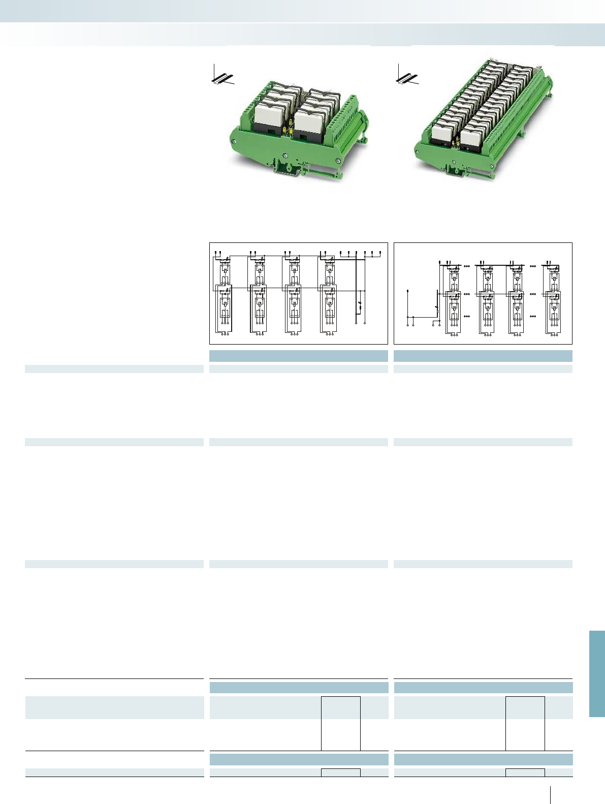
12 34 5 6 78 911 13 1012 14
24 6 8
75
31
22
21
24
12
11
14
32
31
34
42
41
44
52
51
54
62
61
64
72
71
74
82
81
84
+-
1,2,13,14,25,26,37,38
11,12,23,24,35,36,47,48
3
4
9
10
15
16
45
46
17
28
9
10
31
32
22
21
24
12
11
14
+
+
--
82
81
84
72
71
74
102
101
104
92
91
94
312
311
314
322
321
324
For further information and full technical data, visit phoenixcontact.net/products
Technical data Technical data
Coil side
Operating voltage U
N
24 V DC 24 V DC
Typ. input current at U
N
18 mA 18 mA
Typ. response time at U
N
8 ms 8 ms
Typ. release time at U
N
10 ms 10 ms
Input circuit Freewheeling diode Freewheeling diode
Status display/channel Yellow LED Yellow LED
Connection method IDC/FLK pin strip (2.54 mm) IDC/FLK pin strip (2.54 mm)
No. of pos. 14 50
Contact side
Contact type Single contact, 1-PDT Single contact, 1-PDT
Contact material AgNi AgNi
Max. switching voltage 250 V AC/DC 250 V AC/DC
Min. switching voltage 12 V AC/DC 12 V AC/DC
Limiting continuous current 5 A 5 A
Min. switching current 100 mA 100 mA
Max. interrupting rating: 24 V DC 120 W 120 W
48 V DC 58 W 58 W
60 V DC 48 W 48 W
110 V DC 50 W 50 W
220 V DC 80 W 80 W
250 V AC 1250 VA 1250 VA
Connection method Screw connection Screw connection
Connection data solid / stranded / AWG 0.2 ... 4 mm² / 0.2 ... 2.5 mm² / 24 - 12 0.2 ... 4 mm² / 0.2 ... 2.5 mm² / 24 - 12
General data
Rated insulation voltage 260 V AC 260 V AC
Rated surge voltage 4 kV (basic insulation between output contact current paths)
6 kV (safe isolation and reinforced insulation between input circuit
and output contact paths)
4 kV (basic insulation between output contact current paths)
6 kV (safe isolation and reinforced insulation between input circuit
and output contact paths)
Pollution degree / Surge voltage category 2 / III 2 / III
Ambient temperature (operation) -20 °C ... 50 °C -20 °C ... 50 °C
Nominal operating mode 100% operating factor 100% operating factor
Mechanical service life 3 x 10
7
cycles 3 x 10
7
cycles
Standards/regulations DIN EN 50178, IEC 60664, IEC 62103 DIN EN 50178, IEC 60664, IEC 62103
Mounting position any any
Mounting Can be aligned without spacing Can be aligned without spacing
Dimensions H / D 123 mm / 68 mm 123 mm / 68 mm
EMC note Class A product, see page 625 Class A product, see page 625
Ordering data Ordering data
Description Module width
WType Order No. Pcs. /
Pkt. Type Order No. Pcs. /
Pkt.
VARIOFACE output module, for 24 V DC (incl. relay)
- with 8 miniature relays 80 UM- 8 RM/RT-G24/21/PLC 2968386 1
- with 32 miniature relays 271 UM-32 RM/RT-G24/21/PLC 2968373 1
Accessories Accessories
Plug-in miniature relay REL-MR- 24DC/21HC 2961312 10 REL-MR- 24DC/21HC 2961312 10
559
PHOENIX CONTACT
These VARIOFACE output modules are
used in combination with the respective
front adapters.
Like the front adapters, the modules are
connected via 14-pos. or 50-pos. system
cables. The following features characterize
these relay modules:
– Plug-in miniature relays, each with a
PDT cont act
– Narrow overall width of just 80 mm
(8 channels) or 271 mm (32 channels)
– LED status display for each signal path and
supply voltage
– Freewheeling diode for each signal path
DW
H
DW
H
Output modules with relay,
1 PDT
System cabling for controllers
Controller-specific system cabling
Output module
with eight miniature relays,
1 PDT
Output module
with 32 miniature relays,
1 PDT
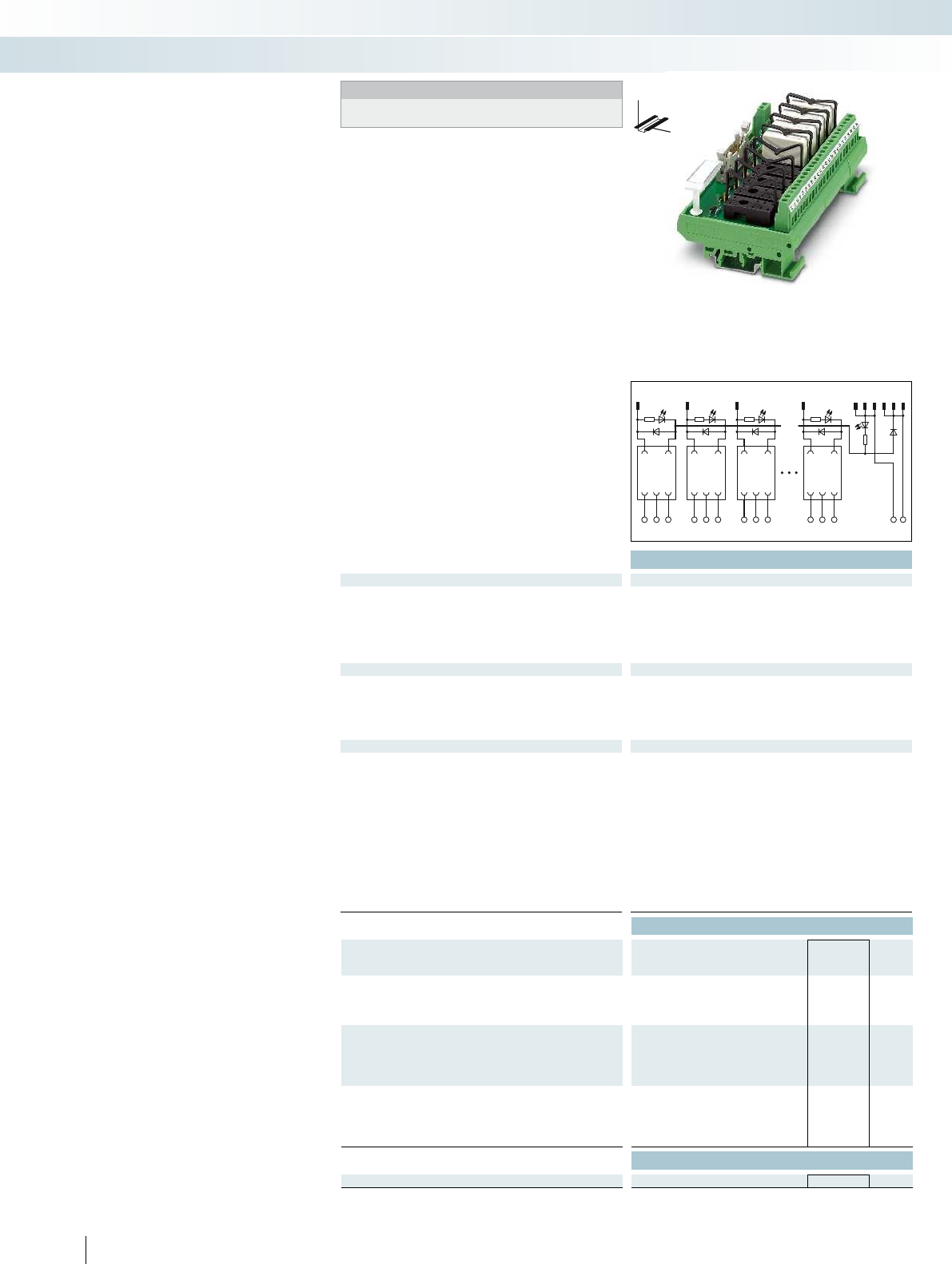
123 8911 13101214
83
21
12 11 14 22 21 24 32 31 34 828184+-
Technical data
Coil side
Operating voltage U
N
24 V DC ±10 %
Input circuit Freewheeling diode, protection against polarity reversal Freewheeling diode, protection against polarity reversal Fr
Operating voltage display Green LED
Status display/channel Yellow LED
Connection method IDC/FLK pin strip (2.54 mm) IDC/FLK pin strip (2.54 mm) IDC/FLK pin strip (2.54 mm)
No. of pos. 14
Contact side
Contact type 1 PDT
Max. switching voltage 250 V AC/DC
Limiting continuous current 5 A
Connection method Screw connection
Connection data solid / stranded / AWG 0.2 ... 4 mm² / 0.2 ... 2.5 mm² / 24 - 12 0.2 ... 4 mm² / 0.2 ... 2.5 mm² / 24 - 12 0.2 ... 4 m
General data
Rated insulation voltage 260 V AC
Rated surge voltage 4 kV (basic insulation between output contact current paths)
6 kV (safe isolation and reinforced insulation between input circuit
and output contact paths)
Pollution degree / Surge voltage category 2 / III
Ambient temperature (operation) -20 °C ... 50 °C
Standards/regulations DIN EN 50178, IEC 60664, IEC 62103 DIN EN 50178, IEC 60664, IEC 62103 DIN EN 50178, IEC 60664, IEC 62103
Mounting position any
Mounting Can be aligned without spacing Can be aligned without spacing Can be aligned without spacing
Dimensions H / D 77 mm / 59 mm
EMC note Class A product, see page 625 Class A product, see page 625 Class A product, see page 625
Ordering data
Description Module width
WType Order No. Pcs. /
Pkt.
VARIOFACE output module, for 24 V DC
- with 8 plug-in bases including relay 135 UMK- 8 RM/KSR-G 24/21/PLC 2979485 1
- with 8 plug-in bases without relay 135 UMK- 8 RELS/KSR-G24/21/PLC 2974914 1
VARIOFACE output basic module, for 24 V DC
- with 16 plug-in bases including relay 259
- with 16 plug-in bases without relay 259
VARIOFACE output extension module, for 24 V DC
- with 16 plug-in bases including relay 259
- with 16 plug-in bases without relay 259
Accessories
Plug-in miniature relay REL-MR- 24DC/21HC 2961312 10
560
PHOENIX CONTACT
Output modules with relay,
1 PDT
These VARIOFACE output modules are
used in combination with the respective
front adapters.
Like the front adapters, the modules are
connected via 14-pos. or 50-pos. system
cables. The following features characterize
these relay modules:
– Plug-in miniature relays, each with a
PDT cont act
– LED status display for each signal path and
supply voltage
– Freewheeling and reverse polarity
protection diode for each signal path
With the 32-channel version, the system
cable is connected to the base module with
the 16-channel UMK-16R.../KSR-
G24/21/PLC. The output extension module
UMK-16R.../ KSR-G24/21/E/PLC with a
further 16 channels is coupled to the base
module via a 20-position flat-ribbon cable
(length: 10 cm).
System cabling for controllers
Controller-specific system cabling
DW
H
Notes:
The connecting cable between the base and the extension
modules is delivered with the extension unit.
Output module
with eight miniature relays,
1 PDT
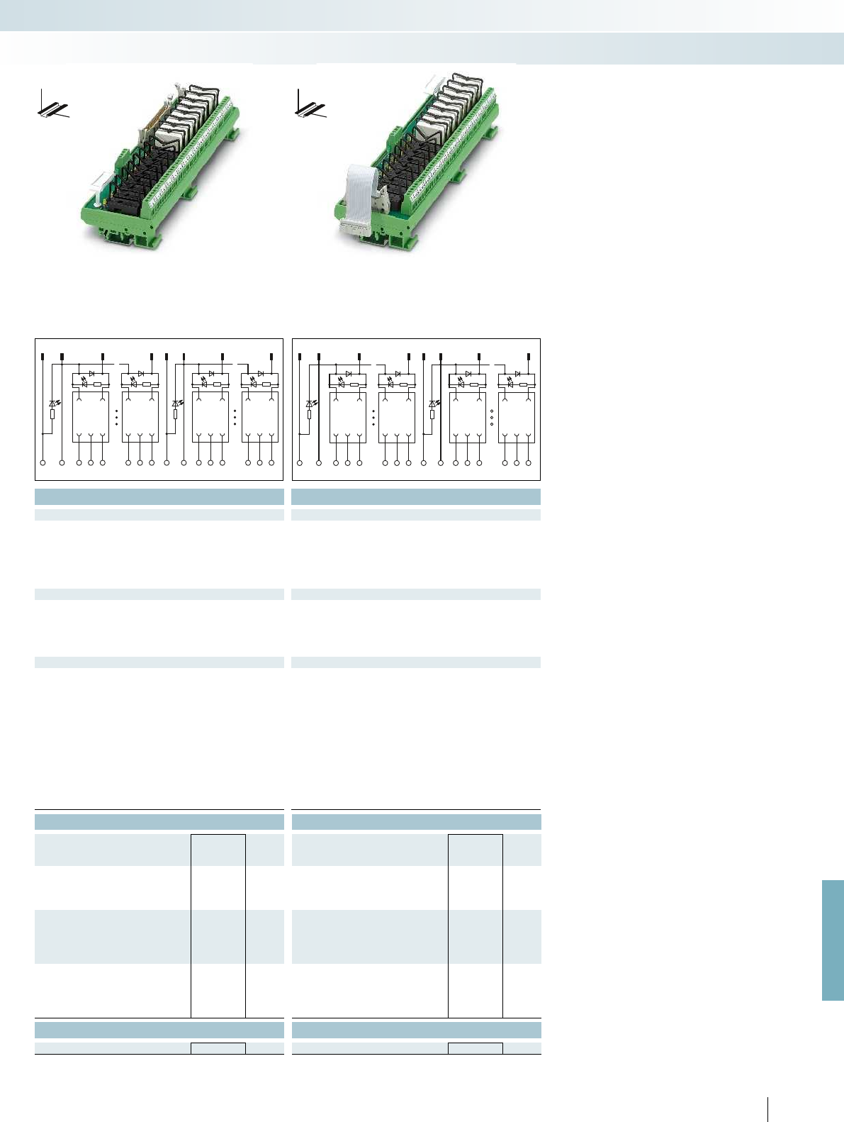
1,2 11,12 31013,14 23,24 15 22
16
981
B0 B0
+-
11 14 12 818482B1B1
+-
919492 161164162
22017 12 1 1994
3225
2417
B2B2
+- +-
171 174 172 241 244 242 B3B3251254 252 321 324 322
For further information and full technical data, visit phoenixcontact.net/products
Technical data Technical data
24 V DC ±10 % 24 V DC ±10 %
Input circuit Freewheeling diode, protection against polarity reversal Freewheeling diode, protection against polarity reversal Freewheeling diode, protection against polarity reversal
Green LED Green LED
Yellow LED Yellow LED
Connection method IDC/FLK pin strip (2.54 mm) IDC/FLK pin strip (2.54 mm) IDC/FLK pin strip (2.54 mm)
50 20
1 PDT 1 PDT
250 V AC/DC 250 V AC/DC
5 A 5 A
Screw connection Screw connection
Connection data solid / stranded / AWG 0.2 ... 4 mm² / 0.2 ... 2.5 mm² / 24 - 12 0.2 ... 4 mm² / 0.2 ... 2.5 mm² / 24 - 12 0.2 ... 4 mm² / 0.2 ... 2.5 mm² / 24 - 12
260 V AC 260 V AC
4 kV (basic insulation between output contact current paths)
6 kV (safe isolation and reinforced insulation between input circuit
and output contact paths)
4 kV (basic insulation between output contact current paths)
6 kV (safe isolation and reinforced insulation between input circuit
and output contact paths)
2 / III 2 / III
-20 °C ... 50 °C -20 °C ... 50 °C
Standards/regulations DIN EN 50178, IEC 60664, IEC 62103 DIN EN 50178, IEC 60664, IEC 62103 DIN EN 50178, IEC 60664, IEC 62103
any any
Mounting Can be aligned without spacing Can be aligned without spacing Can be aligned without spacing
77 mm / 59 mm 77 mm / 59 mm
EMC note Class A product, see page 625 Class A product, see page 625 Class A product, see page 625
Ordering data Ordering data
Type Order No. Pcs. /
Pkt. Type Order No. Pcs. /
Pkt.
UMK-16 RM/KSR-G 24/21/PLC 2979498 1
UMK-16 RELS/KSR-G24/21/PLC 2974901 1
UMK-16 RM/KSR-G 24/21/E/PLC 2979508 1
UMK-16 RELS/KSR-G24/21/E/PLC 2974891 1
Accessories Accessories
REL-MR- 24DC/21HC 2961312 10 REL-MR- 24DC/21HC 2961312 10
561PHOENIX CONTACT
System cabling for controllers
Controller-specific system cabling
DW
H
DW
H
Output base module
with 16 miniature relays,
1 PDT
Output extension module
with 16 miniature relays,
1 PDT
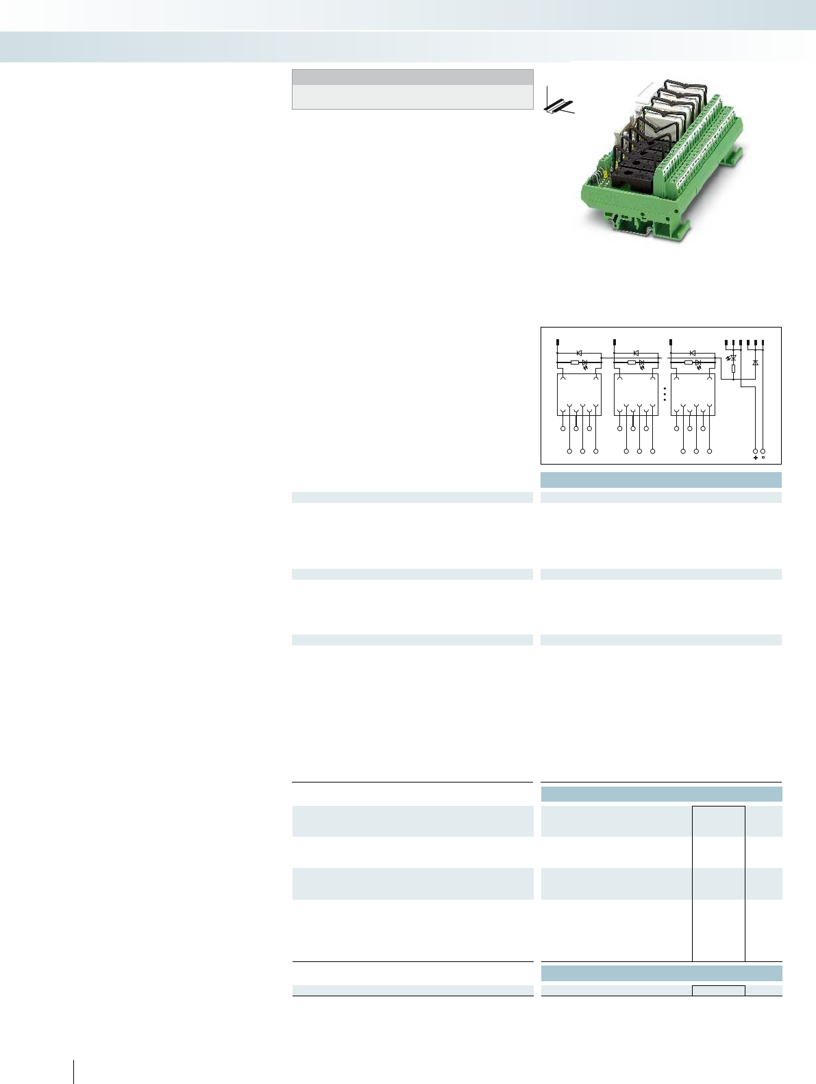
+
-
128911
13101214
8
21
12 11 14 22 21 24 828184
112 111 114 122 121 124 182181184
Technical data
Coil side
Operating voltage U
N
24 V DC
Input circuit Freewheeling diode
Operating voltage display Green LED
Status display/channel Yellow LED
Connection method IDC/FLK pin strip (2.54 mm) IDC/FLK pin strip (2.54 mm) IDC/FLK pin strip (2.54 mm)
No. of pos. 14
Contact side
Contact type 2 PDT
Max. switching voltage 250 V AC/DC
Limiting continuous current 3 A
Connection method Screw connection
Connection data solid / stranded / AWG 0.14 ... 1.5 mm² / 0.14 ... 1.5 mm² / 26 - 14 0.2 ... 4 mm² / 0.2 ... 2.5 mm² / 24 - 12 0.2 ...
General data
Rated insulation voltage 260 V AC
Rated surge voltage 4 kV (basic insulation between output contact current paths)
6 kV (safe isolation and reinforced insulation between input circuit
and output contact paths)
Pollution degree / Surge voltage category 2 / III
Ambient temperature (operation) -20 °C ... 50 °C
Standards/regulations DIN EN 50178, IEC 60664, IEC 62103 DIN EN 50178, IEC 60664, IEC 62103 DIN EN 50178, IEC 60664, IEC 62103
Mounting position any
Mounting Can be aligned without spacing Can be aligned without spacing Can be aligned without spacing
Dimensions H / D 77 mm / 59 mm
EMC note Class A product, see page 625 Class A product, see page 625 Class A product, see page 625
Ordering data
Description Module width
WType Order No. Pcs. /
Pkt.
VARIOFACE output module, for 24 V DC (2 PDTs)
- with 8 plug-in bases without relay 135 UMK- 8 RELS/KSR-G24/21-21/PLC 2976187 1
VARIOFACE output module with disconnect terminal blocks,
for 24 V DC (1 PDT)
- with 8 plug-in bases without relay 145
VARIOFACE output module with disconnect terminal blocks,
for 24 V DC (1 PDT)
- basic module with 16 plug-in bases without relay 285
- extension module with 16 plug-in bases without
relay
285
Accessories
Plug-in miniature relay REL-MR- 24DC/21-21 2961192 10
562
PHOENIX CONTACT
Output module for relays
- 2 P DTs
- 1 PDT with disconnect terminal blocks
These VARIOFACE output modules are
used in combination with the respective
front adapters.
8 channels are controlled via 14-pos.
cables. All modules feature the following:
– Plug-in miniature relays
– LED status indicator and freewheeling
diode per signal path
– Supply voltage indicator (LED)
– Polarity protection diode
With the 32-channel version (1 PDT with
knife disconnect terminal blocks), the
50-pos. system cable is connected to the
base module with 16 channels.
The output extension module with a
further 16 channels is coupled to the base
module via a 20-pos. flat-ribbon cable
(length: 10 cm).
System cabling for controllers
Controller-specific system cabling
DW
H
Notes:
The connecting cable between the base and the extension
modules is delivered with the extension unit.
Output module for 8 miniature relays,
2 PDTs
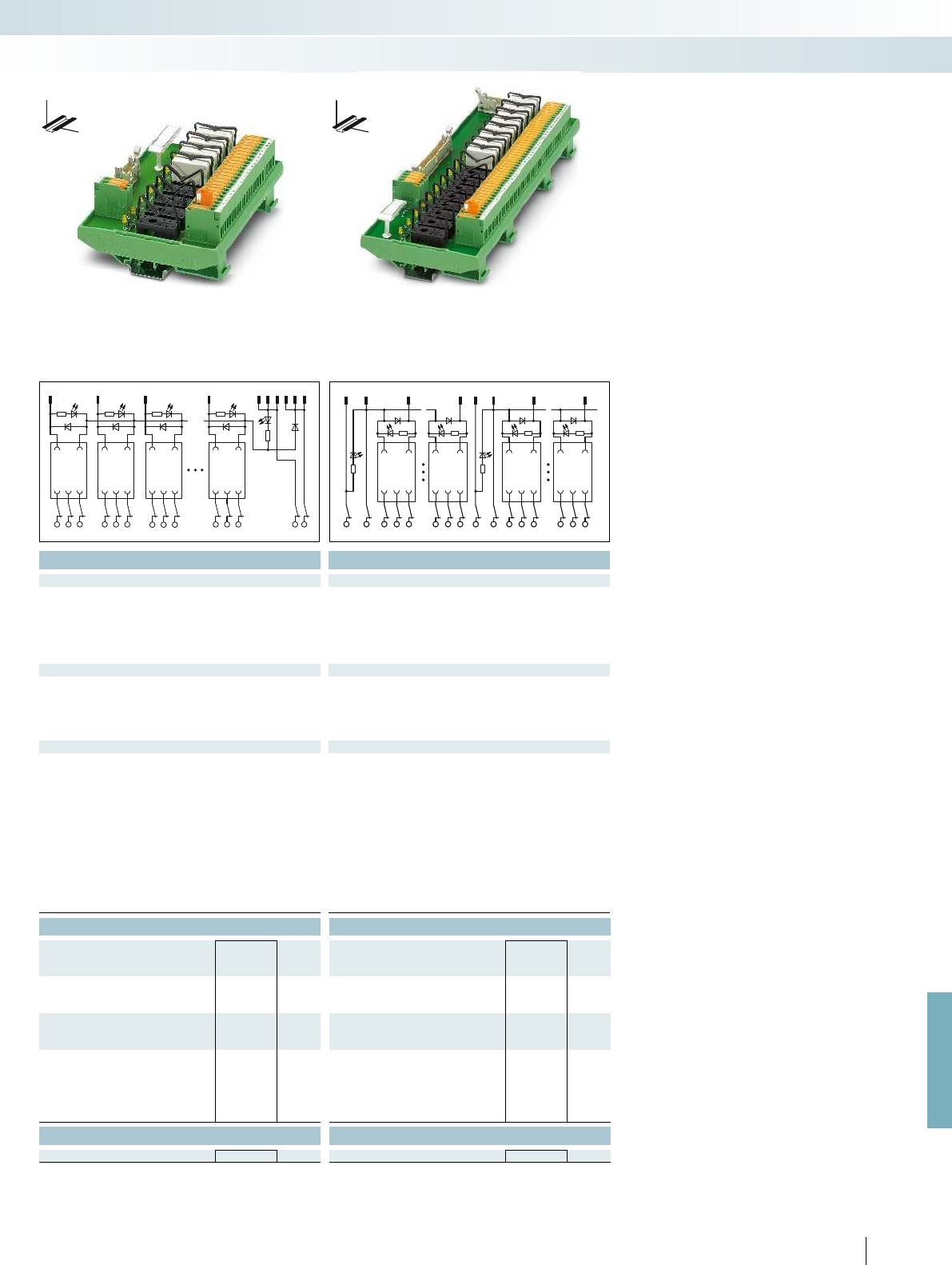
123 891113101214
8321
12 11 14 22 21 24 32 31 34 828184 +-
B1B1
848281949291 164 162161
+
-
14 1211
B0 B0
+
-
1,2
3
11,12 22
10
18
13,14
15
23,24
916
For further information and full technical data, visit phoenixcontact.net/products
Technical data Technical data
24 V DC 24 V DC
Freewheeling diode, protection against polarity reversal Freewheeling diode
Green LED Green LED
Yellow LED Yellow LED
Connection method IDC/FLK pin strip (2.54 mm) IDC/FLK pin strip (2.54 mm) IDC/FLK pin strip (2.54 mm)
14 50
1 PDT 1 PDT
250 V AC/DC 250 V AC/DC
5 A 5 A
Screw connection with disconnect knife Screw connection with disconnect knife
Connection data solid / stranded / AWG 0.14 ... 1.5 mm² / 0.14 ... 1.5 mm² / 26 - 14 0.2 ... 4 mm² / 0.2 ... 2.5 mm² / 24 - 12 0.2 ... 4 mm² / 0.2 ... 2.5 mm² / 24 - 12
260 V AC 260 V AC
4 kV (basic insulation between output contact current paths)
6 kV (safe isolation and reinforced insulation between input circuit
and output contact paths)
4 kV (basic insulation between output contact current paths)
6 kV (safe isolation and reinforced insulation between input circuit
and output contact paths)
2 / III 2 / III
-20 °C ... 50 °C -20 °C ... 50 °C
Standards/regulations DIN EN 50178, IEC 60664, IEC 62103 DIN EN 50178, IEC 60664, IEC 62103 DIN EN 50178, IEC 60664, IEC 62103
any any
Mounting Can be aligned without spacing Can be aligned without spacing Can be aligned without spacing
111.5 mm / 59 mm 111.5 mm / 59 mm
EMC note Class A product, see page 625 Class A product, see page 625 Class A product, see page 625
Ordering data Ordering data
Type Order No. Pcs. /
Pkt. Type Order No. Pcs. /
Pkt.
UM- 8 RELS/KSR-G24/21/MT/PLC 2962463 1
UM-16 RELS/KSR-G24/21/MT/PLC 2962382 1
UM-16 RELS/KSR-G24/21/E/MT/PLC 2962379 1
Accessories Accessories
REL-MR- 24DC/21HC 2961312 10 REL-MR- 24DC/21HC 2961312 10
563PHOENIX CONTACT
System cabling for controllers
Controller-specific system cabling
DW
H
DW
H
Output module for 8 miniature relays with
knife/disconnect terminal blocks,
1 PDT
Output module for 16 miniature relays with
knife/disconnect terminal blocks,
1 PDT
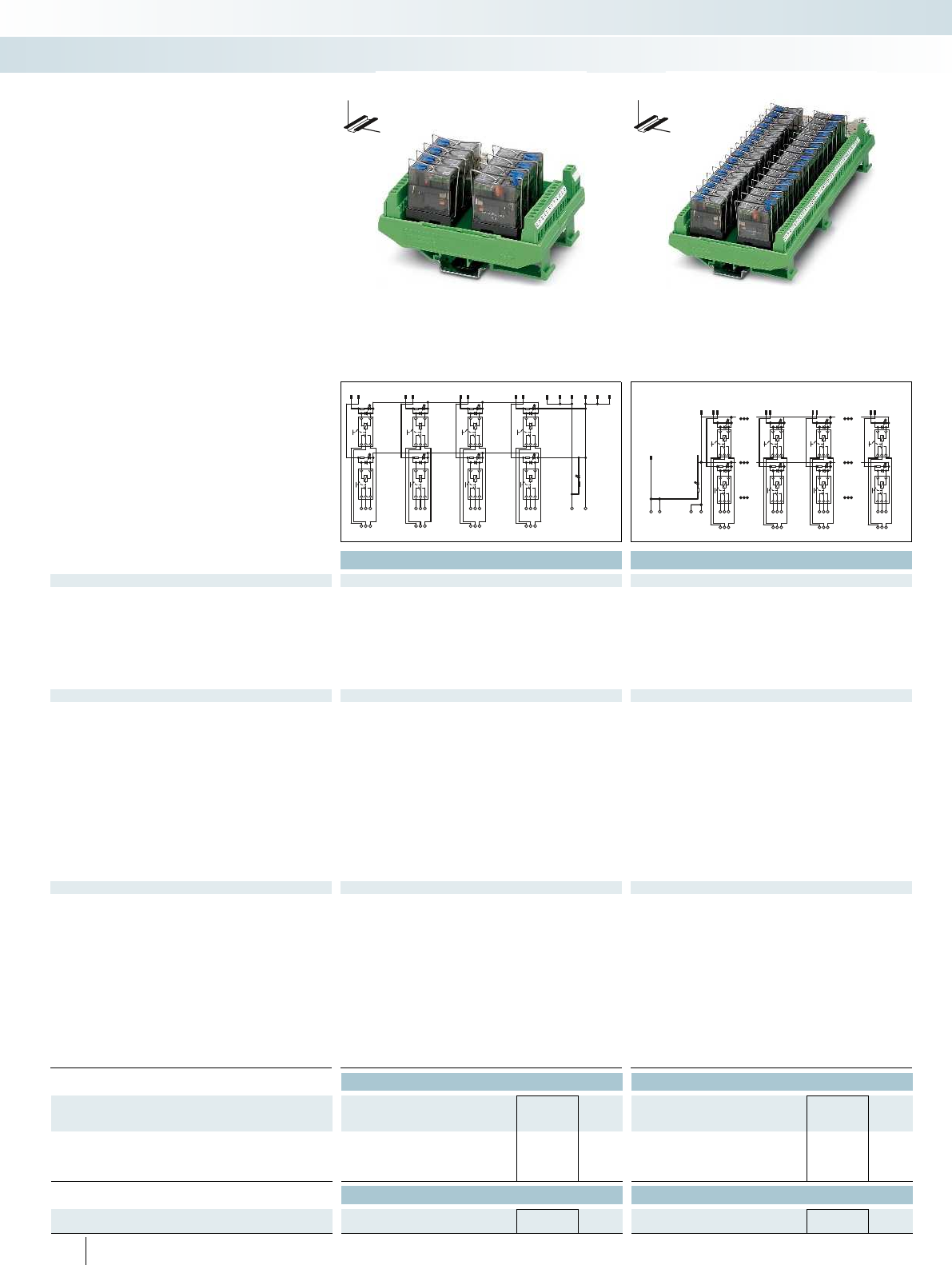
911 13 1012 14
+-
12
2
1
22
21
24
12
11
14
34
4
3
32
31
34
42
41
44
56
6
5
52
51
54
62
61
64
78
8
7
72
71
74
82
81
84
1,2,13,14,25,26,37,38
11,12,23,24,35,36,47,48
3
4
9
10
15
16
45
46
17
28
9
10
31
32
22
21
24
12
11
14
+
+
--
82
81
84
72
71
74
102
101
104
92
91
94
312
311
314
322
321
324
Technical data Technical data
Coil side
Operating voltage U
N
24 V DC 24 V DC
Typ. input current at U
N
18 mA 18 mA
Typ. response time at U
N
9 ms 9 ms
Typ. release time at U
N
6 ms 6 ms
Input circuit Freewheeling diode (integrated in relay) Freewheeling diode (integrated in relay)
Status display/channel Yellow LED (integrated in relay) Yellow LED (integrated in relay)
Connection method IDC/FLK pin strip (2.54 mm) IDC/FLK pin strip (2.54 mm)
No. of pos. 14 50
Contact side
Contact type Single contact, 1-PDT Single contact, 1-PDT
Contact material AgNi AgNi
Max. switching voltage 250 V AC/DC 250 V AC/DC
Min. switching voltage 12 V AC/DC 12 V AC/DC
Limiting continuous current 5 A 5 A
Min. switching current 100 mA 100 mA
Max. interrupting rating: 24 V DC 120 W 120 W
48 V DC 62 W 62 W
60 V DC 42 W 42 W
110 V DC 55 W 55 W
220 V DC 66 W 66 W
250 V AC 1250 VA 1250 VA
Connection method Screw connection Screw connection
Connection data solid / stranded / AWG 0.2 ... 4 mm² / 0.2 ... 2.5 mm² / 24 - 12 0.2 ... 4 mm² / 0.2 ... 2.5 mm² / 24 - 12
General data
Rated insulation voltage 260 V AC 260 V AC
Rated surge voltage 4 kV (basic insulation between output contact current paths)
6 kV (safe isolation and reinforced insulation between input circuit
and output contact paths)
4 kV (basic insulation between output contact current paths)
6 kV (safe isolation and reinforced insulation between input circuit
and output contact paths)
Pollution degree / Surge voltage category 2 / III 2 / III
Ambient temperature (operation) -20 °C ... 50 °C -20 °C ... 50 °C
Nominal operating mode 100% operating factor 100% operating factor
Mechanical service life 5 x 10
6
cycles 5 x 10
6
cycles
Standards/regulations DIN EN 50178, IEC 60664, IEC 62103 DIN EN 50178, IEC 60664, IEC 62103
Mounting position any any
Mounting Can be aligned without spacing Can be aligned without spacing
Dimensions H / D 111 mm / 64 mm 111 mm / 64 mm
EMC note Class A product, see page 625 Class A product, see page 625
Ordering data Ordering data
Description Module width
WType Order No. Pcs. /
Pkt. Type Order No. Pcs. /
Pkt.
VARIOFACE output module, for 24 V DC (incl. relay)
- with 8 miniature relays 92 UM- 8RM/KSR-G24/21/MS/PLC 2900890 1
- with 32 miniature relays 285 UM-32RM/KSR-G24/21/MS/PLC 2900891 1
Accessories Accessories
Plug-in miniature power relay, with power contacts REL-MR- 24DC/21HC/MS 2987888 10 REL-MR- 24DC/21HC/MS 2987888 10
564
PHOENIX CONTACT
These VARIOFACE output modules are
used in combination with the respective
front adapters.
The modules are connected via 14 or
50-pos. system cable. These relay modules
offer the following features:
– Plug-in miniature relays each with a PDT
contact and detectable manual operation
– Narrow overall width of just 92 mm (8
channels) or 285 mm (32 channels)
– LED status indicator and freewheeling
diode per signal path (integrated in relay)
– Supply voltage indicator (LED)
DW
H
DW
H
Output modules with relays, 1 PDT
with detectable manual operation
System cabling for controllers
Controller-specific system cabling
Output module with 8 miniature relays,
1 PDT with detectable manual operation
Output module with 32 miniature relays,
1 PDT with detectable manual operation
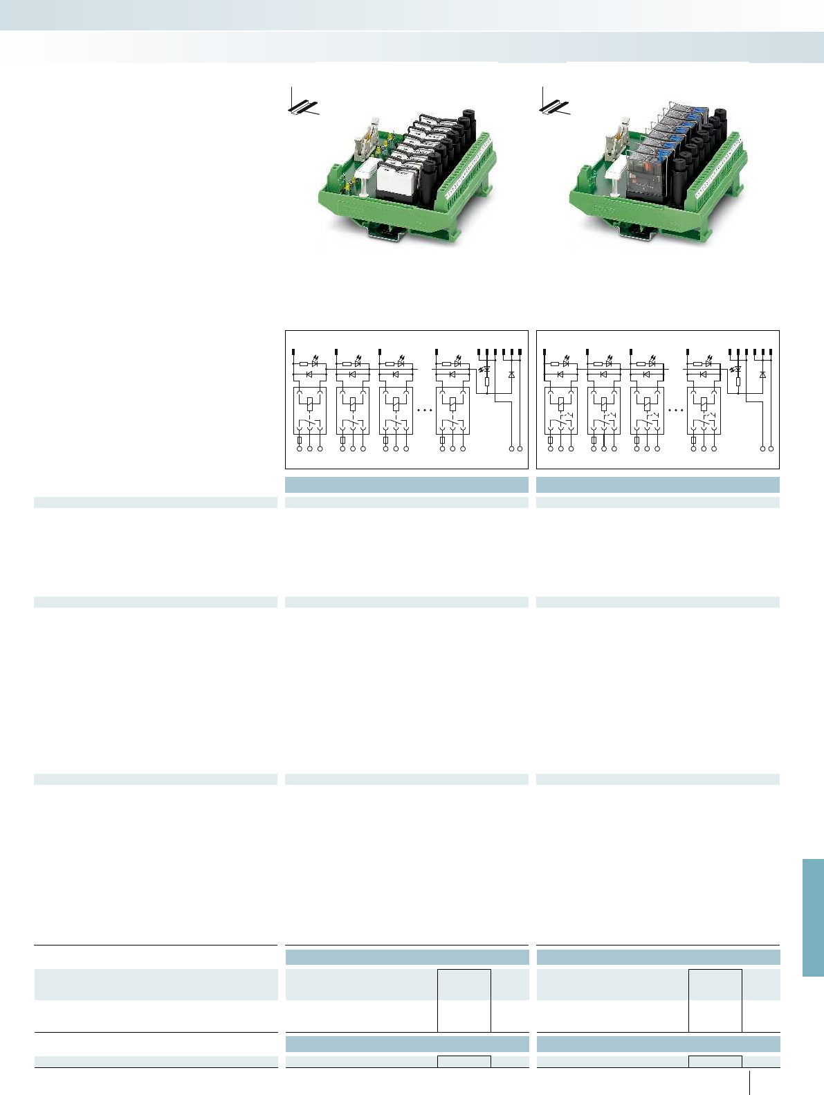
123 89
11
13
10
12
14
1238
11 14 21 24 31 34 8184+-
12 22 32 82
F2F3F8F1
123 89
11
13
10
12
14
1238
11 14 21 24 31 34 8184+-
12 22 32 82
F2F3F8F1
For further information and full technical data, visit phoenixcontact.net/products
Technical data Technical data
Coil side
Operating voltage U
N
24 V DC 24 V DC
Typ. input current at U
N
17 mA 18 mA
Typ. response time at U
N
8 ms 9 ms
Typ. release time at U
N
10 ms 6 ms
Input circuit Freewheeling diode Freewheeling diode (integrated in relay)
Status display/channel Yellow LED Yellow LED (integrated in relay)
Connection method IDC/FLK pin strip (2.54 mm) IDC/FLK pin strip (2.54 mm)
No. of pos. 14 14
Contact side
Contact type Single contact, 1-PDT Single contact, 1-PDT
Contact material AgNi AgNi
Max. switching voltage 250 V AC/DC 250 V AC/DC
Min. switching voltage 12 V AC/DC 12 V AC/DC
Output fuse 4 A 5x20 fuse (slow-blow) 4 A 5x20 fuse (slow-blow)
Limiting continuous current 3.9 A (observe derating) 3.9 A (observe derating)
Min. switching current 100 mA 100 mA
Max. interrupting rating: 24 V DC 93 W 93 W
48 V DC 58 W 62 W
60 V DC 48 W 42 W
110 V DC 50 W 55 W
220 V DC 80 W 66 W
250 V AC 975 VA 975 VA
Connection method Screw connection Screw connection
Connection data solid / stranded / AWG 0.2 ... 4 mm² / 0.2 ... 2.5 mm² / 24 - 12 0.2 ... 4 mm² / 0.2 ... 2.5 mm² / 24 - 12
General data
Rated insulation voltage 260 V AC 260 V AC
Rated surge voltage 4 kV (basic insulation between output contact current paths)
6 kV (safe isolation and reinforced insulation between input circuit
and output contact paths)
4 kV (basic insulation between output contact current paths)
6 kV (safe isolation and reinforced insulation between input circuit
and output contact paths)
Pollution degree / Surge voltage category 2 / III 2 / III
Ambient temperature (operation) -20 °C ... 50 °C -20 °C ... 50 °C
Nominal operating mode 100% operating factor 100% operating factor
Mechanical service life 3 x 10
7
cycles 5 x 10
6
cycles
Standards/regulations DIN EN 50178, IEC 60664, IEC 62103 DIN EN 50178, IEC 60664, IEC 62103
Mounting position any any
Mounting Can be aligned without spacing Can be aligned without spacing
Dimensions H / D 111 mm / 60 mm 111 mm / 64 mm
EMC note Class A product, see page 625 Class A product, see page 625
Ordering data Ordering data
Description Module width
WType Order No. Pcs. /
Pkt. Type Order No. Pcs. /
Pkt.
VARIOFACE output module, with 8 miniature relays, plugged in,
for 24 V DC (including relays)
127 UM- 8RM/KSR-G24/21/SI/PLC 2900892 1UM- 8RM/KSR-G24/21/MS/SI/PLC 2900893 1
Accessories Accessories
Plug-in miniature relay REL-MR- 24DC/21HC 2961312 10 REL-MR- 24DC/21HC/MS 2987888 10
565
PHOENIX CONTACT
These VARIOFACE output modules are
used in combination with the respective
front adapters.
The modules are connected via 14-pos.
system cable. These relay modules offer the
following features:
– Plug-in miniature relays each with a
PDT contact with or without manual
operation
– Fuse per output circuit as short-circuit
protection
– Narrow overall width of just 127 mm
– LED status indicator and freewheeling
diode per signal path
– Supply voltage indicator (LED)
– Polarity protection diode
DW
H
DW
H
Output modules with relays, 1 PDT
with or without manual operation and
fuses
System cabling for controllers
Controller-specific system cabling
Output module with 8 miniature relays,
1 PDT and fuse per output circuit
Output module with 8 miniature relays,
1 PDT with detectable manual operation
and fuse per output circuit

1
0
0NC
0NO
0C
F0
9
11
13
14
10
12
++ --
2
1
1NC
1NO
1C
F1
8
7
7NC
7NO
7C
F7
Technical data
Coil side
Operating voltage U
N
24 V DC
Typ. input current at U
N
9 mA
Typ. response time at U
N
5 ms
Typ. release time at U
N
8 ms
Input circuit Freewheeling diode
Status display/channel Yellow LED
Connection method IDC/FLK pin strip (2.54 mm)
No. of pos. 14
Contact side
Contact type Single contact, 1-PDT
Contact material AgSnO
Max. switching voltage 250 V AC/DC
Min. switching voltage 12 V AC/DC
Limiting continuous current 5 A (observe derating)
Min. switching current 10 mA
Max. interrupting rating: 24 V DC 120 W
48 V DC 20 W
60 V DC 18 W
110 V DC 23 W
220 V DC 40 W
250 V AC 1250 VA
Connection method Push-in connection
Connection data solid / stranded / AWG 0.14 ... 2.5 mm² / 0.14 ... 2.5 mm² / 26 - 14
General data
Ambient temperature (operation) -20 °C ... 60 °C
Nominal operating mode 100% operating factor
Mechanical service life 2 x 10
7
cycles
Standards/regulations DIN EN 50178
Mounting position any
Mounting Can be aligned without spacing
Dimensions H / D 109.8 mm / 63 mm
EMC note Class A product, see page 625
Ordering data
Description Module width
WType Order No. Pcs. /
Pkt.
VARIOFACE output module, with eight miniature relays, plugged in,
for 24 V DC (incl. relays)
87.6 VIP-8RPT-24DC/21/D0/FU/PLC 2903601 1
566
PHOENIX CONTACT
DW
H
This VIP VARIOFACE output module is
used in combination with the respective
front adapters. Like the front adapters, the
module is connected via 14-pos. system
cables.
Features:
– Plug-in miniature relays, each with a
PDT cont act
– LED status display for each signal path and
supply voltage
– Freewheeling diode for each signal path
– Push-in connection
VIP output module
System cabling for controllers
Controller-specific system cabling
Output module with 8 miniature relays,
1 PDT and fuse per output circuit

1
0
0.0
-
+
2
1
0.1
-
+
8
7
0.7
-
+
+
9
11
13 + +
14
12
10--
9
11
13 + +
14
12
10--
-
+
1
0
0.0
-
+
2
1
0.1
-
+
8
7
0.7
-
+
For further information and full technical data, visit phoenixcontact.net/products
Technical data Technical data
Coil side
Operating voltage U
N
24 V DC ±10 % (supply, 2 A ) 120 V AC ±10 % (supply, 2 A )
Typ. input current at U
N
9 mA (per channel) 3.5 mA (per channel)
Typ. response time at U
N
5 ms 6 ms
Typ. release time at U
N
8 ms 15 ms
Input circuit Freewheeling diode Freewheeling diode
Status display/channel Yellow LED Yellow LED
Connection method Push-in connection Push-in connection
Connection data solid / stranded / AWG 0.14 ... 2.5 mm² / 0.14 ... 2.5 mm² / 26 - 14 0.14 ... 2.5 mm² / 0.14 ... 2.5 mm² / 26 - 26
Contact side
Contact type 1 N/O contact 1 N/O contact
Contact material AgSnO, hard gold-plated AgSnO, hard gold-plated
Limiting continuous current 50 mA 50 mA
Connection method IDC/FLK pin strip (2.54 mm) IDC/FLK pin strip (2.54 mm)
No. of pos. 14 14
General data
Ambient temperature (operation) -20 °C ... 60 °C -20 °C ... 60 °C
Nominal operating mode 100% operating factor 100% operating factor
Mechanical service life 2 x 10
7
cycles 2 x 10
7
cycles
Standards/regulations DIN EN 50178 DIN EN 50178
Mounting position any any
Mounting Can be aligned without spacing Can be aligned without spacing
Dimensions H / D 109.8 mm / 63 mm 109.8 mm / 63 mm
EMC note Class A product, see page 625 Class A product, see page 625
Ordering data Ordering data
Description Module width
WType Order No. Pcs. /
Pkt. Type Order No. Pcs. /
Pkt.
VARIOFACE interface module, for eight channels,
24 V DC (incl. relays) 92.7 VIP-8RPT-24DC/1AU/DI/PLC 2903600 1
120 V AC (incl. relays) 92.7 VIP-8RPT-120AC/1AU/DI/PLC 2904576 1
567
PHOENIX CONTACT
These VIP VARIOFACE input modules
are used in combination with the respective
front adapters. Like the front adapters, the
modules are connected via 14-pos. system
cables.
Features:
– Plug-in miniature relays, each with an
N/O contact
– LED status display for each signal path and
supply voltage
– Freewheeling diode for each signal path
– Push-in connection
DW
H
DW
H
VIP input modules
System cabling for controllers
Controller-specific system cabling
Digital input module with 8 channels for
24VDC
Digital input module with 8 channels for
120VAC
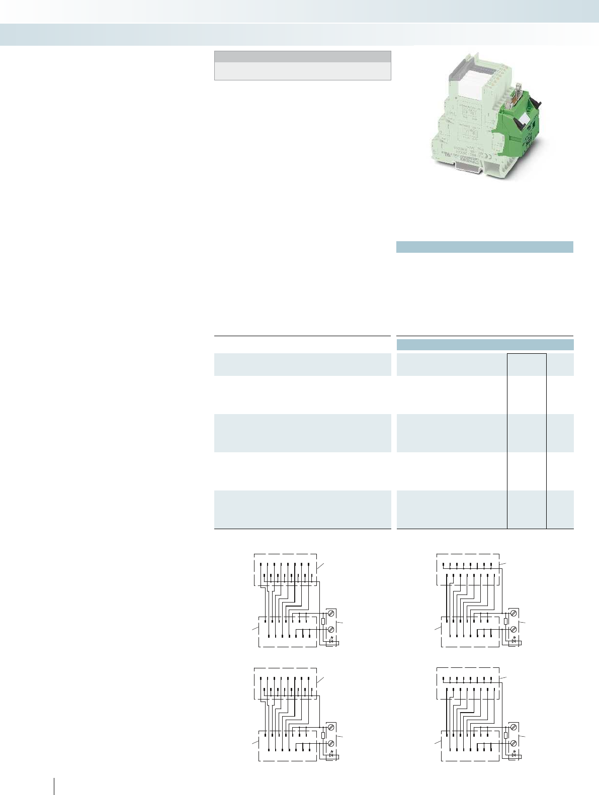
1/1
1357911 13
24681012 14
+
-
2/1
1/2
2/2
1/3
2/3
1/4
2/4
1/5
2/5
1/6
2/6
1/7
2/7
1/8
2/8
1/1
1357911 13
24681012 14
+
-
2/1
1/2
2/2
1/3
2/3
1/4
2/4
1/5
2/5
1/6
2/6
1/7
2/7
1/8
2/8
1/1
1357911 13
24681012 14
+
-
2/1
1/2
2/2
1/3
2/3
1/4
2/4
1/5
2/5
1/6
2/6
1/7
2/7
1/8
2/8
1/1
1357911 13
24681012 14
+
-
2/1
1/2
2/2
1/3
2/3
1/4
2/4
1/5
2/5
1/6
2/6
1/7
2/7
1/8
2/8
568
PHOENIX CONTACT
Technical data
Max. perm. operating voltage 30 V DC
Max. perm. current (per branch) 1 A (per signal path)
Max total current (voltage supply) 3 A
Ambient temperature (operation) -40 °C ... 70 °C
Standards/regulations IEC 60664, DIN EN 50178, IEC 62103
Connection method Power supply Screw connection
Signal level IDC/FLK pin strip (2.54 mm)
Connection data solid / stranded / AWG 0.2 ... 4 mm² / 0.2 ... 2.5 mm² / 24 - 12
Dimensions H / D 100 mm / 94 mm
Ordering data
Description No. of
pos.
Module width
WType Order No. Pcs. /
Pkt.
V8 adapter, for 8 PLC interfaces (6.2 mm), with FLK connection,
for PLC system cabling, positive switching
OUTPUT 14 49.6 mm PLC-V8/FLK14/OUT 2295554 1
INPUT 14 49.6 mm PLC-V8/FLK14/IN 2296553 1
V8 adapter, for 8 PLC interfaces (6.2 mm), with FLK connection,
for PLC system cabling, negative switching
OUTPUT 14 49.6 mm PLC-V8/FLK14/OUT/M 2304102 1
INPUT 14 49.6 mm PLC-V8/FLK14/IN/M 2304115 1
V8 output adapter, for 8 PLC interfaces (6.2 mm), with
15-pos. D-SUB connection
Pin strip 15 49.6 mm PLC-V8/D15S/OUT 2296058 1
Socket strip 15 49.6 mm PLC-V8/D15B/OUT 2296061 1
V8 input adapter, for 8 PLC interfaces (6.2 mm), with
15-pos. D-SUB connection
Pin strip 15 49.6 mm PLC-V8/D15S/IN 2296074 1
Socket strip 15 49.6 mm PLC-V8/D15B/IN 2296087 1
Contacting
PLC terminal blocks
Power
terminals
FLK14
Connection scheme: PLC-V8/FLK14/IN
Contacting
PLC terminal blocks
Power
terminals
FLK14
Connection scheme: PLC-V8/FLK14/IN/M
Contacting
PLC terminal blocks
Power
terminals
FLK14
PLC-V8/FLK14/OUT connection scheme
Contacting
PLC terminal blocks
Power
terminals
FLK14
PLC-V8/FLK14/OUT/M connection scheme
PLC-V8/... are the VARIOFACE adapters
connecting the eight slim 6.2 mm
PLC-INTERFACE modules to the
VARIOFACE system cabling:
– Can be plugged into the bridge shafts of
eight aligned PLC RELAY modules
– Freely definable configuration with relays,
optocouplers, and passive feed-through
terminal blocks
– With D-SUB connection as an option for
universal connections
Adapters for PLC RELAY (6.2 mm)
System cabling for controllers
Controller-specific system cabling
VARIOFACE adapter
for 6.2 mm PLC RELAY
Notes:
For cross-reference list with matching PLC-INTERFACE modules,
see page 572

1/1
1357911 13
24681012 14
+
-
2/1
1/2
2/2
1/3
2/3
1/4
2/4
1/5
2/5
1/6
2/6
1/7
2/7
1/8
2/8
1/1
1357911 13
24681012 14
+
-
2/1
1/2
2/2
1/3
2/3
1/4
2/4
1/5
2/5
1/6
2/6
1/7
2/7
1/8
2/8
For further information and full technical data, visit phoenixcontact.net/products
569
PHOENIX CONTACT
Technical data
Max. perm. operating voltage 30 V DC
Max. perm. current (per branch) 1 A (per signal path)
Max total current (voltage supply) 3 A
Ambient temperature (operation) -40 °C ... 70 °C
Mounting position any
Standards/regulations IEC 60664, DIN EN 50178, IEC 62103
Connection method Power supply Screw connection
Signal level IDC/FLK pin strip (2.54 mm)
Connection data solid / stranded / AWG 0.2 ... 4 mm² / 0.2 ... 2.5 mm² / 24 - 12
Dimensions H / D 100 mm / 94 mm
Ordering data
Description No. of
pos.
Module width
WType Order No. Pcs. /
Pkt.
V8 adapter, for 8 PLC interfaces (14 mm), with FLK connection, for
PLC system cabling, positive switching
14 112.3 mm PLC-V8L/FLK14/OUT 2299660 1
V8 adapter, for 8 PLC interfaces (14 mm), with FLK connection, for
PLC system cabling, negative switching
14 112.3 mm PLC-V8L/FLK14/OUT/M 2304306 1
Contacting
PLC terminal blocks
Power
terminals
FLK14
PLC-V8L/FLK14/OUT/M connection scheme
Contacting
PLC terminal blocks
Power
terminals
FLK14
PLC-V8L/FLK14/OUT connection scheme
PLC-V8L/... are the VARIOFACE
adapters connecting the eight 14 mm
PLC-INTERFACE modules (2 PDT, HC, and
IC types) to the system cabling:
– Can be plugged into the bridge shafts of
eight aligned PLC RELAY modules
– Freely definable configuration with relays
or optocouplers
Adapters for PLC RELAY (14 mm)
System cabling for controllers
Controller-specific system cabling
VARIOFACE adapter
for 14 mm PLC RELAY
Notes:
For cross-reference list with matching PLC-INTERFACE modules,
see page 572

2
1
3
4
5
NC
2
1
3
4
5
2
1
3
4
5
NC
2
1
3
4
5
570
PHOENIX CONTACT
Technical data
PLC-VT, PLC-VT/ACT PLC-VT/LA, PLC-VT/ACT/LA
Max. perm. operating voltage 250 V AC/DC 30 V DC
Max. perm. current (per branch) 6 A (per signal conductor) 6 A (per signal conductor)
Ambient temperature (operation) -40 °C ... 70 °C -40 °C ... 70 °C
Mounting position any any
Standards/regulations DIN EN 50178, IEC 60664, IEC 62103
Connection data solid / stranded / AWG 0.2 ... 4 mm² / 0.2 ... 2.5 mm² / 24 - 12
Dimensions H / D 80 mm / 94 mm
Ordering data
Description No. of
pos.
Module width
WType Order No. Pcs. /
Pkt.
VARIOFACE feed-through terminal block (two-conductor
connection), for PLC RELAY universal series
6.2 mm PLC-VT 2296870 10
VARIOFACE feed-through terminal block, as above, however,
with 24 V DC light indicator
6.2 mm PLC-VT/LA 2296854 10
VARIOFACE feed-through terminal block (three-conductor
connection), for PLC-INTERFACE actuator series
6.2 mm PLC-VT/ACT 2295567 10
VARIOFACE feed-through terminal block, as above, however,
with 24 V DC light indicator
6.2 mm PLC-VT/ACT/LA 2296867 10
PLC-VT/LA connection scheme PLC-VT/ACT/LA connection scheme
PLC-VT connection scheme PLC-VT/ACT connection scheme
The VARIOFACE PLC-VT terminals are
passive feed-through terminal blocks, with
the same shape as the 6.2 mm slim relays
and PLC RELAY optocoupler interfaces. It is
thus possible to implement 8-channel
interface blocks for the system cabling,
which can be adapted to the specific
application with bit accuracy. For individual
requirements, the relay, optocoupler or the
PLC-VT terminal blocks for passive signal
transmission can be combined as needed.
PLC-VT
PLC-VT/LA
– Can be combined with PLC RELAY
universal series
– Signal path with additional potential level
for free assignment (two-conductor
connection)
– With LED as an option
Feed-through terminal blocks for PLC
RELAY
System cabling for controllers
Controller-specific system cabling
DW
H
VARIOFACE feed-through terminal blocks for
PLC-INTERFACE universal series
PLC-VT/ACT
PLC-VT/ACT/LA
– Can be combined with PLC RELAY
actuator series
– Signal path with two additional potential
levels for free assignment (three-
conductor connection)
– With LED as an option
The system connection is made via the
PLC-V8 adapter.

.0.1 .2 .3 .4 .5 .6 .7
A2 A1 A2 A1 A2 A1 A2 A1 A2 A1 A2 A1 A2 A1 A2 A1
K 14
For further information and full technical data, visit phoenixcontact.net/products
571
PHOENIX CONTACT
Technical data
Max. perm. operating voltage 30 V DC
Max. perm. current (per branch) 1 A (per signal path)
Max total current (voltage supply) 3 A
Ambient temperature (operation) -40 °C ... 60 °C
Mounting position any
Standards/regulations IEC 60664, IEC 62103, DIN EN 50178
Connection method Power supply Spring-cage connection
Signal level IDC/FLK pin strip (2.54 mm)
Connection data solid / stranded / AWG 0.2 ... 1.5 mm² / 0.2 ... 1.5 mm² / 24 - 16
Dimensions H / D 101 mm / 75 mm
Ordering data
Description No. of
pos.
Module width
WType Order No. Pcs. /
Pkt.
V8 adapter, for eight RIF-1 relay modules, with FLK connection for
PLC system cabling, positive switching
128 mm RIF-1-V8/PT/FLK14/OUT 2905195 1
RIF-1-V8/... are the VARIOFACE adapters
that connect the eight RIF-1 relay modules
with the system cabling:
– Can be plugged into eight RIF-1 relay
modules in series
– The adapter has one LED indicator and
one freewheeling diode per relay
The following RIF-1 relay modules can be
connected with the adapter:
– RIF-1-BPT/2X21,
Order No. 2900931
– RIF-1-RPT-LDP-24DC/1X21,
Order No. 2903342
– RIF-1-RPT-LDP-24DC/1X21 AU,
Order No. AU 2903338
– RIF-1-RPT-LDP-24DC/2X21,
Order No. 2903334
– RIF-1-RPT-LDP-24DC/2X21 AU,
Order No. 2903330
If fully assembled RIF-1 relay modules are
used, the indicator/interference
suppression modules must be removed
before installation.
Adapter for RIFLINE complete RF-1
System cabling for controllers
Controller-specific system cabling
new
VARIOFACE adapter for
RIFLINE complete RIF-1
Cross-reference list for PLC-V8 adapters with matching PLC-INTERFACE modules
Series
Function Contact Input Output Page Spring-cage connection Order No.
Universal
Relay
1 PDT
24 V DC 250 V AC/DC/ 6 A 400 PLC-RSP-24DC/21 2966472
24 V DC 250 V AC/DC/10 A 411 PLC-RSP-24DC/21HC 2912277
12 V DC 30 V AC/36 V DC/50 mA 401 PLC-RSP-12DC/21AU 2967442
24 V DC 30 V AC/36 V DC/50 mA 401 PLC-RSP-24DC/21AU 2966540
24 V AC/DC 30 V AC/36 V DC/50 mA 401 PLC-RSP-24UC/21AU 2966553
48 V DC 30 V AC/36 V DC/50 mA 401 PLC-RSP-48DC/21AU 2966566
60 V DC 30 V AC/36 V DC/50 mA 401 PLC-RSP-60DC/21AU 2966579
120 V AC/DC 30 V AC/36 V DC/50 mA 401 PLC-RSP-120UC/21AU 2966582
230 V AC/DC 30 V AC/36 V DC/50 mA 401 PLC-RSP-230UC/21AU 2966647
120 V AC 30 V AC/36 V DC/50 mA
1
) 414 PLC-BSP-120UC/21/SO46 2980351
3
)
230 V AC 30 V AC/36 V DC/50 mA
1
) 414 PLC-BSP-230UC/21/SO46 2980377
3
)
2 PDTs 24 V DC 250 V AC/DC/ 6 A 401 PLC-RSP-24DC/21-21 2912507
24 V DC 30 V AC/DC/50 mA 401 PLC-RSP-24DC/21-21AU 2912578
Relay switch 1 N/O contact 24 V AC/DC 250 V AC/DC/ 6 A 430 PLC-RSP-24UC/1/S/H 2982249
24 V AC/DC 250 V AC/DC/ 6 A 430 PLC-RSP-24UC/1/S/L 2834889
Optocoupler
1 N/O contact, electronic
24 V DC 24 V DC/ 3 A 403 PLC-OSP-24DC/24DC/2 2967471
24 V DC 24 V DC/10 A 433 PLC-OSP-24DC/24DC/10/R 2982715
24 V DC 250 V AC/0.75 A 403 PLC-OSP-24DC/230AC/1 2967895
24 V DC 300 V DC/1 A 432 PLC-OSP-24DC/300DC/1 2980830
24 V DC 48 V DC/100 mA 402 PLC-OSP-24DC/48DC/100 2967549
48 V DC 48 V DC/100 mA 402 PLC-OSP-48DC/48DC/100 2967743
60 V DC 48 V DC/100 mA 402 PLC-OSP-60DC/48DC/100 2967756
120 V AC/DC 48 V DC/100 mA 402 PLC-OSP-120UC/48DC/100 2967552
230 V AC/DC 48 V DC/100 mA 402 PLC-OSP-230UC/48DC/100 2967565
NAMUR 24 V DC/50 mA 446 PLC-SP-EIK 1-SVN 24P/P 2982676
120 V AC 48 V DC/100 mA
2
) 414 PLC-BSP-120UC/21/SO46 2980351
3
)
230 V AC 48 V DC/100 mA
2
) 414 PLC-BSP-230UC/21/SO46 2980377
3
)
1 PDT, electronic 24 V DC 48 V DC/0.5 A 433 PLC-OSP-24DC/48DC/500/W 2980649
Feed-through –250 V AC/DC 250 V AC/DC 570 –
24 V DC 24 V DC 570 –
Actuator
Relay 1 N/O contact
24 V DC 250 V AC/DC/6 A 404 PLC-RSP-24DC/1/ACT 2967345
24 V DC 250 V AC/DC/10 A
(80 A; 20 ms) 410 PLC-RSP-24DC/1IC/ACT 2912413
2 N/O contacts 24 V DC 250 V AC/DC/6 A 405 –
Optocoupler 1 N/O contact, electronic
24 V DC 24 V DC/3 A 405 PLC-OSP-24DC/24DC/2/ACT 2967507
24 V DC 24 V DC/5 A 406 –
24 V DC 250 V AC/0.75 A 405 –
24 V DC 250 V AC/2 A 406 –
Feed-through –250 V AC/DC 250 V AC/DC 570 –
24 V DC 24 V DC 570 –
Sensor
4
)
Relay 1 N/O contact
24 V DC 30 V AC/36 V DC/50 mA 408 PLC-RSP-24DC/1AU/SEN 2967374
120 V AC/DC 30 V AC/36 V DC/50 mA 408 PLC-RSP-120UC/1AU/SEN 2967390
230 V AC/DC 30 V AC/36 V DC/50 mA 408 PLC-RSP-230UC/1AU/SEN 2967413
120 V AC 30 V AC/36 V DC/50 mA
1
) 415 PLC-BSP-120UC/1/SEN/SO46 2980364
3
)
230 V AC 30 V AC/36 V DC/50 mA
1
) 415 PLC-BSP-230UC/1/SEN/SO46 2980380
3
)
Optocoupler 1 N/O contact, electronic
24 V DC 48 V DC/100 mA 409 PLC-OSP-24DC/48DC/100/SEN 2967578
120 V AC/DC 48 V DC/100 mA 409 PLC-OSP-120UC/48DC/100/SEN 2967581
230 V AC/DC 48 V DC/100 mA 409 PLC-OSP-230UC/48DC/100/SEN 2967594
120 V AC 48 V DC/100 mA
2
) 415 PLC-BSP-120UC/1/SEN/SO46 2980364
3
)
230 V AC 48 V DC/100 mA
2
) 415 PLC-BSP-230UC/1/SEN/SO46 2980380
3
)
1
) Plug-in miniature relay insert: REL-MR-60DC/21AU, 2961134
2
) Plug-in solid-state relay insert: OPT-60DC/48DC/100, 2966621
3
) PLC-...SO46 is supplied as a basic terminal block with filter, but without relay or solid-state relay.
4
) Cannot be combined with the universal series (within a byte)
572 PHOENIX CONTACT
System cabling for controllers
Controller-specific system cabling
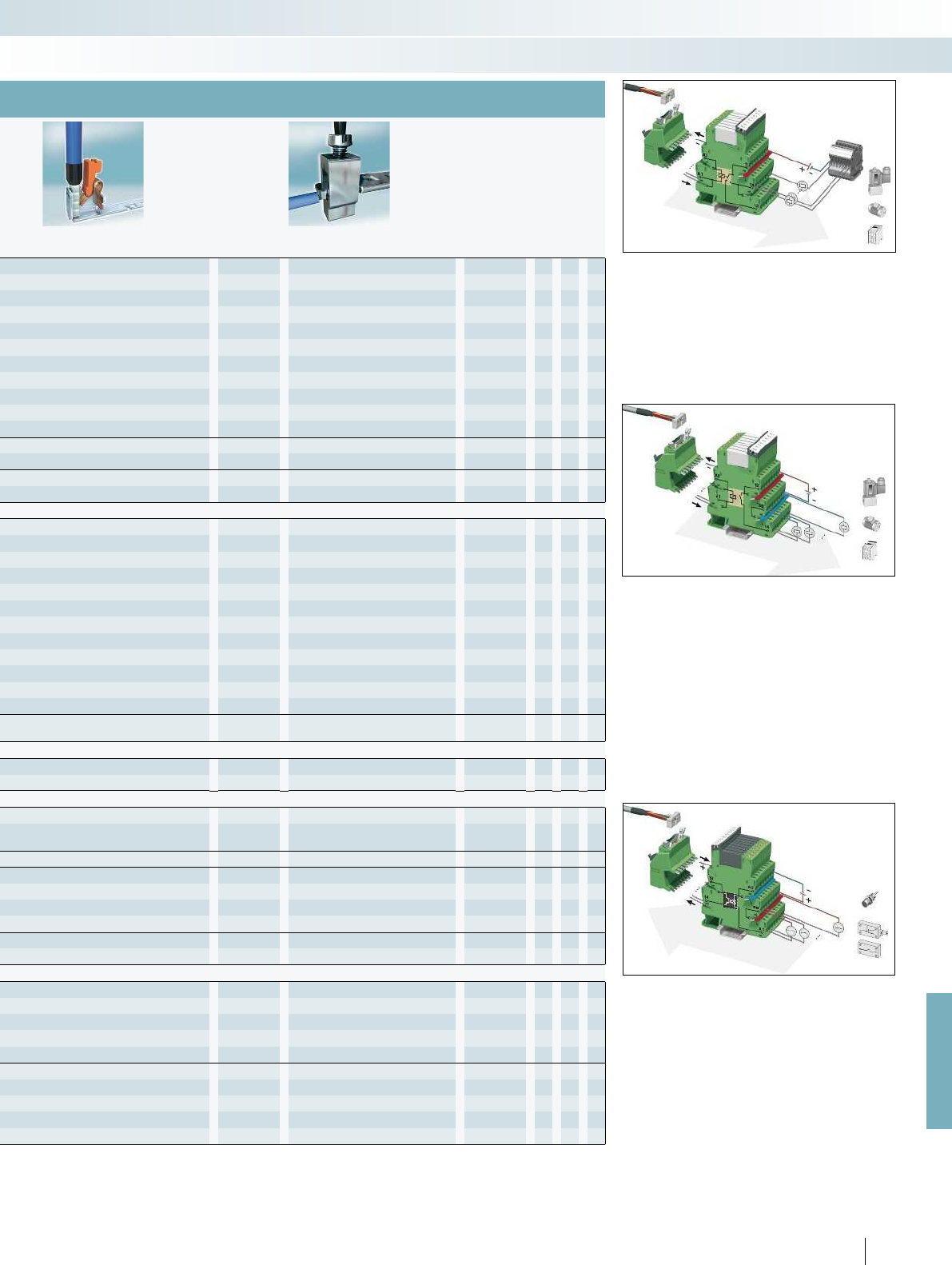
For further information and full technical data, visit phoenixcontact.net/products
PLC-V8...OUT(/M)
PLC-V8...IN(/M)
PLC-V8L...OUT
Push-in connection Order No. Screw connection Order No.
PLC-RPT-24DC/21 2900299 PLC-RSC-24DC/21 2966171 X
PLC-RPT-24DC/21HC 2900291 PLC-RSC-24DC/21HC 2967620 X
PLC-RPT-12DC/21AU 2900317 PLC-RSC-12DC/21AU 2966919 X
PLC-RPT-24DC/21AU 2900306 PLC-RSC-24DC/21AU 2966265 X X
PLC-RPT-24UC/21AU 2900307 PLC-RSC-24UC/21AU 2966278 X X
PLC-RPT-48DC/21AU 2900308 PLC-RSC-48DC/21AU 2966126 X
PLC-RPT-60DC/21AU 2900309 PLC-RSC-60DC/21AU 2966142 X
PLC-RPT-120UC/21AU 2900310 PLC-RSC-120UC/21AU 2966281 X
PLC-RPT-230UC/21AU 2900311 PLC-RSC-230UC/21AU 2966294 X
PLC-RPT-120UC/21/SO46 2900453
3
)PLC-BSC-120UC/21/SO46 2980319
3
)X
PLC-RPT-230UC/21/SO46 2900455
3
)PLC-BSC-230UC/21/SO46 2980335
3
)X
PLC-RPT-24DC/21-21 2900330 PLC-RSC-24DC/21-21 2967060 X
PLC-RPT-24DC/21-21AU 2900338 PLC-RSC-24DC/21-21AU 2967125 X
PLC-RPT-24UC/1/S/H 2900328 PLC-RSC-24UC/1/S/H 2982236 X
PLC-RPT-24UC/1/S/L 2900327 PLC-RSC-24UC/1/S/L 2834876 X
PLC-OPT-24DC/24DC/2 2900364 PLC-OSC-24DC/24DC/2 2966634 X
PLC-OPT-24DC/24DC/10/R 2900398 PLC-OSC-24DC/24DC/10/R 2982702 X
PLC-OPT-24DC/230AC/1 2900369 PLC-OSC-24DC/230AC/1 2967840 X
PLC-OPT-24DC/300DC/1 2900383 PLC-OSC-24DC/300DC/1 2980678 X
PLC-OPT-24DC/48DC/100 2900352 PLC-OSC-24DC/48DC/100 2966728 X X
PLC-OPT-48DC/48DC/100 2900353 PLC-OSC-48DC/48DC/100 2966993 X
PLC-OPT-60DC/48DC/100 2900354 PLC-OSC-60DC/48DC/100 2967455 X
PLC-OPT-120UC/48DC/100 2900355 PLC-OSC-120UC/48DC/100 2966744 X
PLC-OPT-230UC/48DC/100 2900356 PLC-OSC-230UC/48DC/100 2966757 X
PLC-PT-EIK 1-SVN 24P/P 2900397 PLC-SC-EIK 1-SVN 24P/P 2982663 X
PLC-BPT-120UC/21/SO46 2900453
3
)PLC-BSC-120UC/21/SO46 2980319
3
)X
PLC-BPT-230UC/21/SO46 2900455
3
)PLC-BSC-230UC/21/SO46 2980335
3
)X
PLC-OPT-24DC/48DC/500/W 2900378 PLC-OSC-24DC/48DC/500/W 2980636 X
–PLC-VT 2296870 X X
–PLC-VT/LA 2296854 X X
PLC-RPT-24DC/1/ACT 2900312 PLC-RSC-24DC/1/ACT 2966210 X
PLC-RPT-24DC/1IC/ACT 2900298 PLC-RSC-24DC/1IC/ACT 2967604 X
–PLC-RSC-24DC/1-1/ACT 2967109 X
PLC-OPT-24DC/24DC/2/ACT 2900376 PLC-OSC-24DC/24DC/2/ACT 2966676 X
–PLC-OSC-24DC/24DC/5/ACT 2982786 X
–PLC-OSC-24DC/230AC/1/ACT 2967947 X
–PLC-OSC-24DC/230AC/2/ACT 2982760 X
–PLC-VT/AKT 2295567 X
–PLC-VT/AKT/LA 2296867 X
PLC-RPT-24DC/1AU/SEN 2900313 PLC-RSC-24DC/1AU/SEN 2966317 X
PLC-RPT-120UC/1AU/SEN 2900314 PLC-RSC-120UC/1AU/SEN 2966320 X
PLC-RPT-230UC/1AU/SEN 2900315 PLC-RSC-230UC/1AU/SEN 2966333 X
PLC-BPT-120UC/1/SEN/SO46 2900456
3
)PLC-BSC-120UC/1/SEN/SO46 2980322
3
)X
PLC-BPT-230UC/1/SEN/SO46 2900457
3
)PLC-BSC-230UC/1/SEN/SO46 2980348
3
)X
PLC-OPT-24DC/48DC/100/SEN 2900358 PLC-OSC-24DC/48DC/100/SEN 2966773 X
PLC-OPT-120UC/48DC/100/SEN 2900359 PLC-OSC-120UC/48DC/100/SEN 2966799 X
PLC-OPT-230UC/48DC/100/SEN 2900361 PLC-OSC-230UC/48DC/100/SEN 2966809 X
PLC-BPT-120UC/1/SEN/SO46 2900456
3
)PLC-BSC-120UC/1/SEN/SO46 2980322
3
)X
PLC-BPT-230UC/1/SEN/SO46 2900457
3
)PLC-BSC-230UC/1/SEN/SO46 2980348
3
)X
PLC universal series
The universal series of products can be
used as either input or output interfaces.
Each product consists of a basic terminal
block with a plug-in miniature relay (PDT)
or a plug-in solid-state relay.
PLC actuator series
When used as an interface between the
PLC and actuators, such as motors,
contactors or solenoid valves, only one
N/O contact function is normally required.
In such cases, the PLC...ACT output
interface is used. All actuator connections,
including the load return line, are connected
directly. This eliminates the need for
additional output terminal blocks.
PLC sensor series
When used as an interface between the
PLC and sensors, such as proximity
switches, limit switches or auxiliary
contacts, only one N/O contact function is
normally required. In such cases, the
PLC…SEN input interface is used. All
sensor connections, including the supply
voltage for the sensors/switches, are
connected directly. This eliminates the need
for additional terminal blocks.
573
PHOENIX CONTACT
System cabling for controllers
Controller-specific system cabling
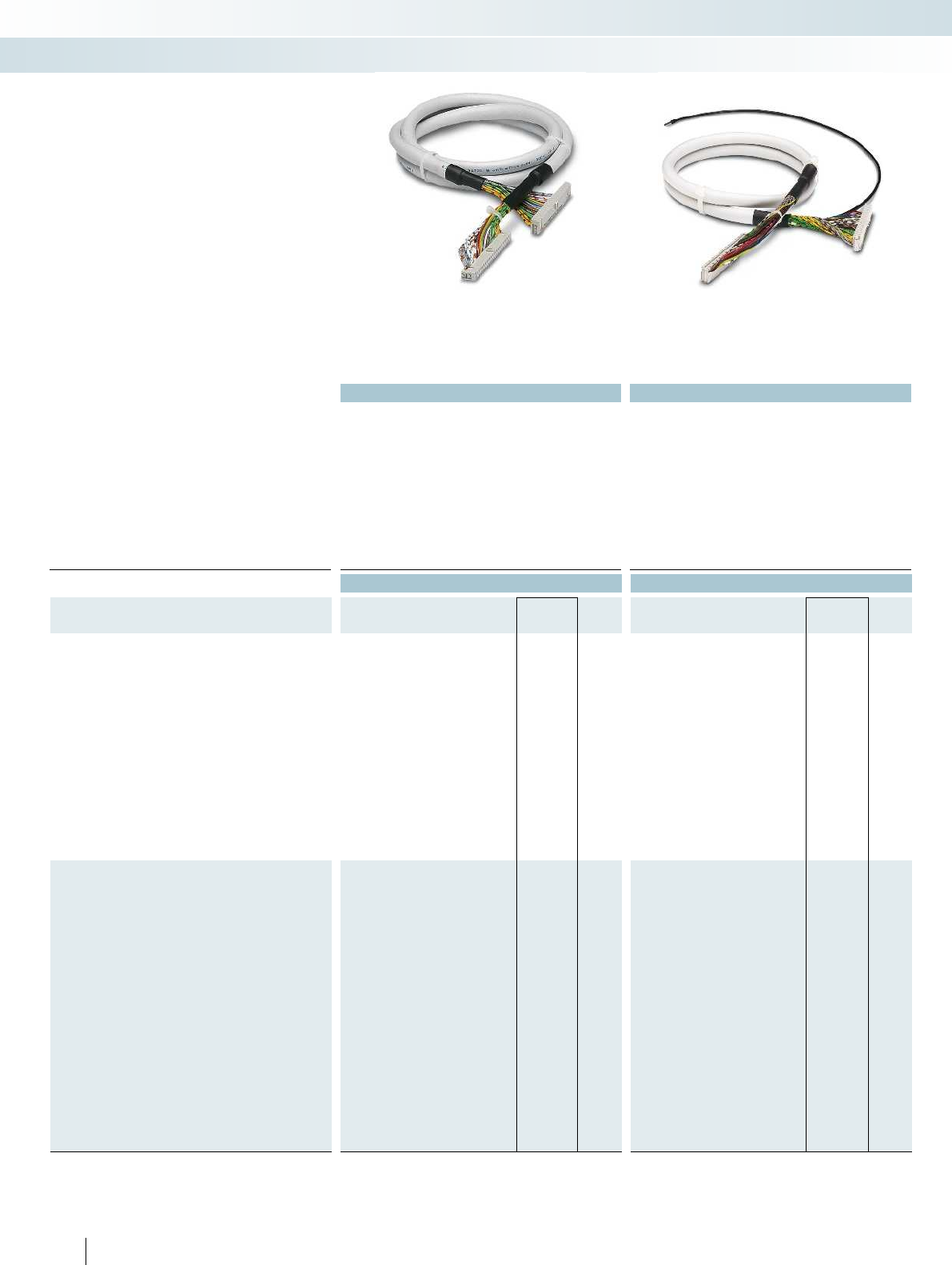
Applied for: cUL / UL
Technical data Technical data
Max. perm. operating voltage < 50 V AC / 60 V DC < 50 V AC / 60 V DC
Max. perm. current carrying capacity per path 1 A 1 A
Max. conductor resistance 0.16 /m 0.16 /m
Ambient temperature (operation) -20 °C ... 50 °C -20 °C ... 50 °C
Shield - Tinned copper-braided shield, approx. 85% covering
Assembly Insulation displacement, IEC 60352-4/DIN EN 60352-4 Insulation displacement, IEC 60352-4/DIN EN 60352-4
Conductor cross section AWG 26 / 0.14 mm² AWG 26 / 0.14 mm²
Conductor structure: stranded wires / material 7 / Cu tin-plated 7 / Cu tin-plated
Outside diameter
14-position 6.4 mm 6.7 mm
50-position 10.3 mm 11 mm
Ordering data Ordering data
Description No. of
pos. Cable length Type Order No. Pcs. /
Pkt. Type Order No. Pcs. /
Pkt.
Assembled round cable, with two 14-pos. socket strips in fixed
lengths for transfer of 8 channels
14 0.3 m FLK 14/EZ-DR/ 30/KONFEK 2295729 5
14 0.5 m FLK 14/EZ-DR/ 50/KONFEK 2288901 5FLK 14/EZ-DR/ 50/KONFEK/S 2296977 1
14 1 m FLK 14/EZ-DR/ 100/KONFEK 2288914 1FLK 14/EZ-DR/ 100/KONFEK/S 2296980 1
14 1.5 m FLK 14/EZ-DR/ 150/KONFEK 2288927 1FLK 14/EZ-DR/ 150/KONFEK/S 2296993 1
14 2 m FLK 14/EZ-DR/ 200/KONFEK 2288930 1FLK 14/EZ-DR/ 200/KONFEK/S 2297002 1
14 2.5 m FLK 14/EZ-DR/ 250/KONFEK 2288943 1
14 3 m FLK 14/EZ-DR/ 300/KONFEK 2288956 1FLK 14/EZ-DR/ 300/KONFEK/S 2299013 1
14 3.5 m FLK 14/EZ-DR/ 350/KONFEK 2288969 1
14 4 m FLK 14/EZ-DR/ 400/KONFEK 2288972 1FLK 14/EZ-DR/ 400/KONFEK/S 2299026 1
14 4.5 m FLK 14/EZ-DR/ 450/KONFEK 2290847 1
14 5 m FLK 14/EZ-DR/ 500/KONFEK 2290834 1
14 5.5 m FLK 14/EZ-DR/ 550/KONFEK 2290850 1
14 6 m FLK 14/EZ-DR/ 600/KONFEK 2290863 1FLK 14/EZ-DR/ 600/KONFEK/S 2299039 1
14 8 m FLK 14/EZ-DR/ 800/KONFEK 2299563 1FLK 14/EZ-DR/ 800/KONFEK/S 2299042 1
14 10 m FLK 14/EZ-DR/1000/KONFEK 2299576 1FLK 14/EZ-DR/1000/KONFEK/S 2299055 1
Assembled round cable, with two 50-pos. socket strips in fixed
lengths for transfer of 32 channels
50 0.5 m FLK 50/EZ-DR/ 50/KONFEK 2289065 5FLK 50/EZ-DR/ 50/KONFEK/S 2299097 1
50 1 m FLK 50/EZ-DR/ 100/KONFEK 2289078 1FLK 50/EZ-DR/ 100/KONFEK/S 2299107 1
50 1.5 m FLK 50/EZ-DR/ 150/KONFEK 2289081 1FLK 50/EZ-DR/ 150/KONFEK/S 2299110 1
50 2 m FLK 50/EZ-DR/ 200/KONFEK 2289094 1FLK 50/EZ-DR/ 200/KONFEK/S 2299123 1
50 2.5 m FLK 50/EZ-DR/ 250/KONFEK 2289104 1
50 3 m FLK 50/EZ-DR/ 300/KONFEK 2289117 1FLK 50/EZ-DR/ 300/KONFEK/S 2299136 1
50 3.5 m FLK 50/EZ-DR/ 350/KONFEK 2289120 1
50 4 m FLK 50/EZ-DR/ 400/KONFEK 2289133 1FLK 50/EZ-DR/ 400/KONFEK/S 2299149 1
50 4.5 m FLK 50/EZ-DR/ 450/KONFEK 2289573 1
50 5 m FLK 50/EZ-DR/ 500/KONFEK 2289586 1
50 5.5 m FLK 50/EZ-DR/ 550/KONFEK 2289599 1
50 6 m FLK 50/EZ-DR/ 600/KONFEK 2289609 1FLK 50/EZ-DR/ 600/KONFEK/S 2299152 1
50 6.5 m FLK 50/EZ-DR/ 650/KONFEK 2289612 1
50 7 m FLK 50/EZ-DR/ 700/KONFEK 2289625 1
50 7.5 m FLK 50/EZ-DR/ 750/KONFEK 2289638 1
50 8 m FLK 50/EZ-DR/ 800/KONFEK 2289641 1FLK 50/EZ-DR/ 800/KONFEK/S 2299165 1
50 8.5 m FLK 50/EZ-DR/ 850/KONFEK 2289654 1
50 9 m FLK 50/EZ-DR/ 900/KONFEK 2289667 1
50 9.5 m FLK 50/EZ-DR/ 950/KONFEK 2289670 1
50 10 m FLK 50/EZ-DR/1000/KONFEK 2289683 1FLK 50/EZ-DR/1000/KONFEK/S 2299178 1
574
PHOENIX CONTACT
System cabling for controllers
Controller-specific system cabling
Unshielded Shield connection at one end
– 1:1 connection
– 14 and 50-pos.
– Connectors as per IEC 60603-13
– Unshielded
– Shielded
– Halogen-free see page 605
– Special lengths see page 609
System cable with flat-ribbon cable
connector
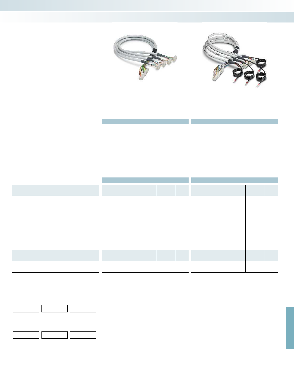
For further information and full technical data, visit phoenixcontact.net/products
Technical data Technical data
Max. perm. operating voltage < 50 V AC / 60 V DC < 50 V AC / 60 V DC
Max. perm. current carrying capacity per path 1 A 1 A
Max. conductor resistance 0.16 /m 0.16 /m
Ambient temperature (operation) -20 °C ... 50 °C -20 °C ... 50 °C
Shield - Tinned copper-braided shield, approx. 85% covering
Assembly Insulation displacement, IEC 60352-4/DIN EN 60352-4 Insulation displacement, IEC 60352-4/DIN EN 60352-4
Conductor cross section AWG 26 / 0.14 mm² AWG 26 / 0.14 mm²
Conductor structure: stranded wires / material 7 / Cu tin-plated 7 / Cu tin-plated
Number of plugs on the module side 4 4
Outside diameter
50-position 6.3 mm 6.3 mm
Ordering data Ordering data
Description No. of
pos. Cable length Type Order No. Pcs. /
Pkt. Type Order No. Pcs. /
Pkt.
Assembled round cable, with a 50-pos. socket strip and four
14-pos. socket strips, for splitting 32 channels into 4 x 8 channels.
50 0.5 m FLK 50/4X14/EZ-DR/ 50/KONFEK 2296689 1
50 1 m FLK 50/4X14/EZ-DR/ 100/KONFEK 2296692 1
50 1.5 m FLK 50/4X14/EZ-DR/ 150/KONFEK 2296702 1
50 2 m FLK 50/4X14/EZ-DR/ 200/KONFEK 2296715 1
50 2.5 m FLK 50/4X14/EZ-DR/ 250/KONFEK 2305402 1
50 3 m FLK 50/4X14/EZ-DR/ 300/KONFEK 2296728 1
50 4 m FLK 50/4X14/EZ-DR/ 400/KONFEK 2296731 1
50 6 m FLK 50/4X14/EZ-DR/ 600/KONFEK 2296744 1
50 8 m FLK 50/4X14/EZ-DR/ 800/KONFEK 2296757 1
50 10 m FLK 50/4X14/EZ-DR/1000/KONFEK 2296773 1
Assembled round cable, as above, however in variable lengths
50 FLK 50-4X14-EZ-DR ... 2302405 1
Assembled round cable, as above, however shielded and in
variable lengths
50 FLK 50-4X14-EZ-DR-S ... 2302447 1
Ordering example for system cable:
– Unshielded splitting cable 12.75 m long
Quantity Order No. Length [m]
1
)
12302405 /12.75
1
) min. 0.30 m
– Shielded splitting cable 11.00 m long
Quantity Order No. Length [m]
1
)
12302447 /11.00
1
) min. 0.30 m
575
PHOENIX CONTACT
System cabling for controllers
Controller-specific system cabling
Splitting cable unshielded
50 positions on 4 x 14
Splitting cable shielded
50 positions on 4 x 14
– Splitting of 32 channels to 4 x 8 channels
– 50-pos. connector at one end
– 4 x 14-pos. connector at one end
– Connectors as per IEC 60603-13
– Unshielded
– Shielded
– Special lengths
Splitting cable with
flat-ribbon cable connector

1
1
2
2
3
3
n
n
-
Technical data
Operating voltage 60 V AC/DC
Max. perm. current (per branch) 1 A
Ambient temperature (operation) -20 °C ... 50 °C
Mounting position any
Standards/regulations IEC 60664, DIN EN 50178, IEC 62103 IEC 60664, DIN EN 50178, IEC 62103 IEC 60664, DIN EN 50178, IEC 62103 IEC
Connection data solid / stranded / AWG 0.2 - 4 mm² / 0.2 - 2.5 mm² / 24 - 12 0.2 - 4 mm² / 0.2 - 2.5 mm² / 24 - 12 0.2 - 4 mm² / 0.2 -
Dimensions H / D 65.5 mm / 56 mm
Ordering data
Description No. of
pos.
Module width
WType Order No. Pcs. /
Pkt.
VARIOFACE module, with pin strip
10 34.70 VIP-2/SC/FLK10 2315010 1
14 39.80 VIP-2/SC/FLK14 2315023 1
16 45.00 VIP-2/SC/FLK16 2315036 1
20 55.10 VIP-2/SC/FLK20 2315049 1
VARIOFACE module, with pin strip and light indicator
10 34.70
14 44.90
16 50.00
20 60.20
VARIOFACE module, with pin strip
26 57.10
34 67.30
40 77.40
50 92.70
60 108.00
64 118.00
VARIOFACE module, with pin strip and light indicator
26 57.40
34 67.60
40 77.80
50 93.10
60 113.50
64 118.60
576
PHOENIX CONTACT
DW
H
VIP – VARIOFACE Professional modules
with flat-ribbon cable connectors
Notes:
For marking systems (e.g., “ZB 22:UNBEDRUCKT”;
Order No. 0811862) and mounting material, see Catalog 5.
– 1:1 connection
– 10 to 64-pos.
– Screw connection
– Metal foot
– As per IEC 60603-13
– With status indicator as an option
Low and high engagement latches are
supplied with all modules.
System cabling for controllers
Universal modules
10 to 20 positions
with screw connection
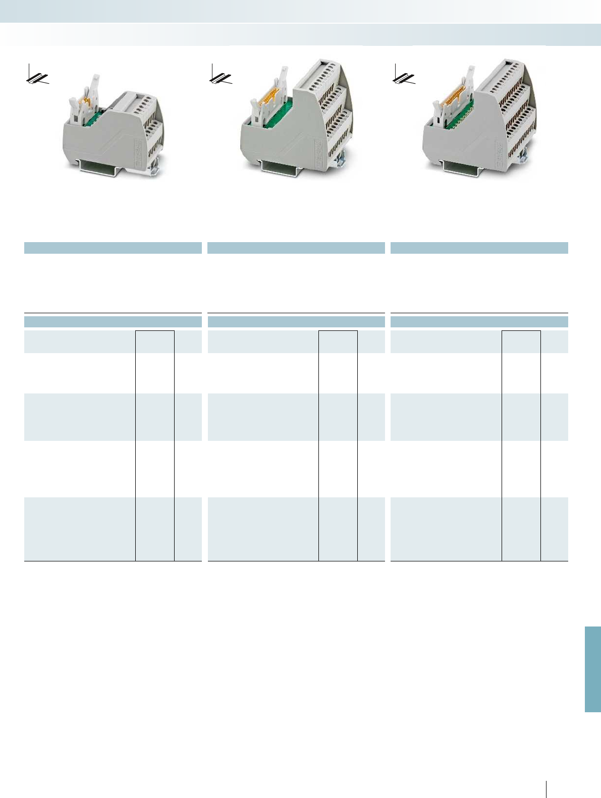
For further information and full technical data, visit phoenixcontact.net/products
Technical data Technical data Technical data
24 V DC 60 V AC/DC 24 V DC
1 A 1 A 1 A
-20 °C ... 50 °C -20 °C ... 50 °C -20 °C ... 50 °C
any any any
Standards/regulations IEC 60664, DIN EN 50178, IEC 62103 IEC 60664, DIN EN 50178, IEC 62103 IEC 60664, DIN EN 50178, IEC 62103 IEC 60664, DIN EN 50178, IEC 62103
Connection data solid / stranded / AWG 0.2 - 4 mm² / 0.2 - 2.5 mm² / 24 - 12 0.2 - 4 mm² / 0.2 - 2.5 mm² / 24 - 12 0.2 - 4 mm² / 0.2 - 2.5 mm² / 24 - 12 0.2 - 4 mm² / 0.2 - 2.5 mm² / 24 - 12
65.5 mm / 56 mm 69 mm / 62 mm 69 mm / 62 mm
Ordering data Ordering data Ordering data
Type Order No. Pcs. /
Pkt. Type Order No. Pcs. /
Pkt. Type Order No. Pcs. /
Pkt.
VIP-2/SC/FLK10/LED 2322045 1
VIP-2/SC/FLK14/LED 2322058 1
VIP-2/SC/FLK16/LED 2322061 1
VIP-2/SC/FLK20/LED 2322074 1
VIP-3/SC/FLK26 2315052 1
VIP-3/SC/FLK34 2315065 1
VIP-3/SC/FLK40 2315078 1
VIP-3/SC/FLK50 2315081 1
VIP-3/SC/FLK60 2315094 1
VIP-3/SC/FLK64 2315104 1
VIP-3/SC/FLK26/LED 2322087 1
VIP-3/SC/FLK34/LED 2322090 1
VIP-3/SC/FLK40/LED 2322100 1
VIP-3/SC/FLK50/LED 2322113 1
VIP-3/SC/FLK60/LED 2322126 1
VIP-3/SC/FLK64/LED 2322139 1
577PHOENIX CONTACT
DW
H
DW
H
DW
H
System cabling for controllers
Universal modules
10 to 20 positions
with screw connection and light indicator
26 to 64 positions
with screw connection
26 to 64 positions
with screw connection and light indicator

1
1
2
2
3
3
n
n
-
Technical data
Operating voltage 60 V AC/DC
Max. perm. current (per branch) 1 A
Ambient temperature (operation) -20 °C ... 50 °C
Mounting position any
Standards/regulations IEC 60664, DIN EN 50178, IEC 62103 IEC 60664, DIN EN 50178, IEC 62103 IEC 60664, DIN EN 50178, IEC 62103 IEC
Connection data solid / stranded / AWG 0.14 - 2.5 mm² / 0.14 - 2.5 mm² / 26 - 14 0.14 - 2.5 mm² / 0.14 - 2.5 mm² / 26 - 14 0.14 - 2.5
Dimensions H / D 72.1 mm / 56 mm
Ordering data
Description No. of
pos.
Module width
WType Order No. Pcs. /
Pkt.
VARIOFACE module, with pin strip
10 36.80 VIP-2/PT/FLK10 2903787 1
14 41.90 VIP-2/PT/FLK14 2903788 1
16 46.90 VIP-2/PT/FLK16 2903789 1
20 57.10 VIP-2/PT/FLK20 2903790 1
VARIOFACE module, with pin strip and light indicator
10 36.80
14 41.90
16 46.90
20 57.10
VARIOFACE module, with pin strip
26 57.10
34 67.30
40 77.40
50 92.70
60 107.90
64 118.10
VARIOFACE module, with pin strip and light indicator
26 57.10
34 67.30
40 77.40
50 92.70
60 107.90
64 118.10
578
PHOENIX CONTACT
DW
H
VIP – VARIOFACE Professional modules
with flat-ribbon cable connectors
Notes:
For marking systems (e.g., “ZB 22:UNBEDRUCKT”;
Order No. 0811862) and mounting material, see Catalog 5.
– 1:1 connection
– 10 to 64-pos.
– Push-in connection
– Metal foot
– As per IEC 60603-13
– With status indicator as an option
Low and high engagement latches are
supplied with all modules.
System cabling for controllers
Universal modules
10 to 20 positions
with push-in connection
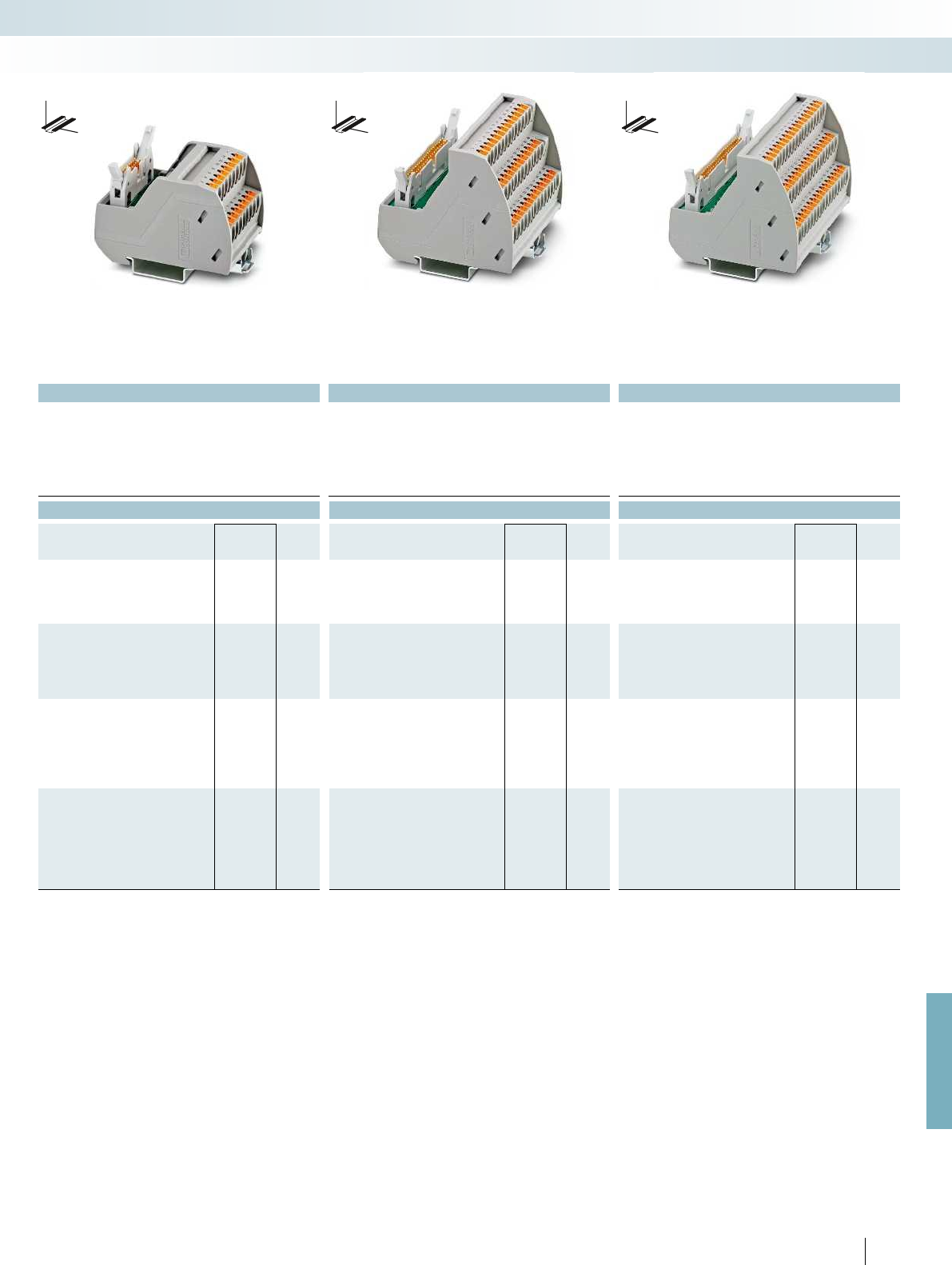
For further information and full technical data, visit phoenixcontact.net/products
Technical data Technical data Technical data
24 V DC 60 V AC/DC 24 V DC
1 A 1 A 1 A
-20 °C ... 50 °C -20 °C ... 50 °C -20 °C ... 50 °C
any any any
Standards/regulations IEC 60664, DIN EN 50178, IEC 62103 IEC 60664, DIN EN 50178, IEC 62103 IEC 60664, DIN EN 50178, IEC 62103 IEC 60664, DIN EN 50178, IEC 62103
Connection data solid / stranded / AWG 0.14 - 2.5 mm² / 0.14 - 2.5 mm² / 26 - 14 0.14 - 2.5 mm² / 0.14 - 2.5 mm² / 26 - 14 0.14 - 2.5 mm² / 0.14 - 2.5 mm² / 26 - 14 0.14 - 2.5 mm² / 0.14 - 2.5 mm² / 26 - 14
72.1 mm / 56 mm 75.8 mm / 63 mm 75.8 mm / 63 mm
Ordering data Ordering data Ordering data
Type Order No. Pcs. /
Pkt. Type Order No. Pcs. /
Pkt. Type Order No. Pcs. /
Pkt.
VIP-2/PT/FLK10/LED 2904248 1
VIP-2/PT/FLK14/LED 2904249 1
VIP-2/PT/FLK16/LED 2904250 1
VIP-2/PT/FLK20/LED 2904251 1
VIP-3/PT/FLK26 2903791 1
VIP-3/PT/FLK34 2903792 1
VIP-3/PT/FLK40 2903793 1
VIP-3/PT/FLK50 2903794 1
VIP-3/PT/FLK60 2903795 1
VIP-3/PT/FLK64 2903796 1
VIP-3/PT/FLK26/LED 2904252 1
VIP-3/PT/FLK34/LED 2904253 1
VIP-3/PT/FLK40/LED 2904254 1
VIP-3/PT/FLK50/LED 2904255 1
VIP-3/PT/FLK60/LED 2904256 1
VIP-3/PT/FLK64/LED 2904257 1
579PHOENIX CONTACT
DW
H
DW
H
DW
H
System cabling for controllers
Universal modules
10 to 20 positions
with push-in connection and light indicator
26 to 64 positions
with push-in connection
26 to 64 positions
with push-in connection and light indicator
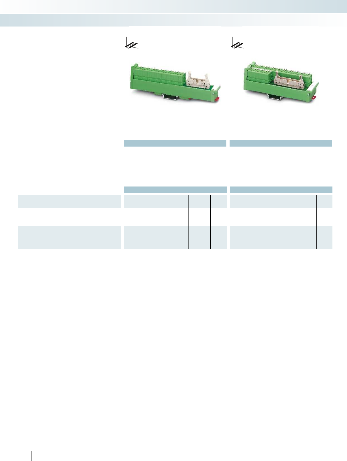
Technical data Technical data
Operating voltage < 50 V AC / 60 V DC < 50 V AC / 60 V DC
Max. perm. current (per branch) 0.8 A (data valid for 100% simultaneity factor) 1 A (data valid for 100% simultaneity factor)
Ambient temperature (operation) -10 °C ... 50 °C -10 °C ... 50 °C
Mounting position any any
Standards/regulations DIN EN 50178, IEC 60664, IEC 62103 DIN EN 50178, IEC 60664, IEC 62103
Screw connection solid / stranded / AWG 0.2 ... 4 mm² / 0.2 ... 2.5 mm² / 24 - 12 0.2 ... 4 mm² / 0.2 ... 2.5 mm² / 24 - 12
Dimensions D / W 45 mm / 25 mm 45 mm / 45 mm
Ordering data Ordering data
Description No. of
pos.
Module height
HType Order No. Pcs. /
Pkt. Type Order No. Pcs. /
Pkt.
VARIOFACE SLIM-LINE module, with pin strip
20 177.00 UM 25-FLK20/FRONT/Q 2959515 1
26 217.00 UM-25 FLK26/FRONT/Q 2959528 1
VARIOFACE SLIM-LINE module, with pin strip
34 147.00 UM 45-FLK34/FRONT/Q 2959531 1
40 167.00 UM 45-FLK40/FRONT/Q 2959544 1
50 197.00 UM 45-FLK50/FRONT/Q 2959557 1
580
PHOENIX CONTACT
System cabling for controllers
Universal modules
20 and 26-pos.
With screw connection
34 to 50 positions
With screw connection
VARIOFACE SLIM-LINE modules
connect flat-ribbon cable connectors in
accordance with IEC 60603-13/DIN 41651
to front connection terminal blocks.
The modules are provided with low and
high engagement catches to protect the flat-
ribbon cable connector against being
accidentally released.
DW
H
DW
H
SLIM-LINE modules for
flat-ribbon cable connectors

For further information and full technical data, visit phoenixcontact.net/products
581PHOENIX CONTACT
System cabling for controllers
Universal modules
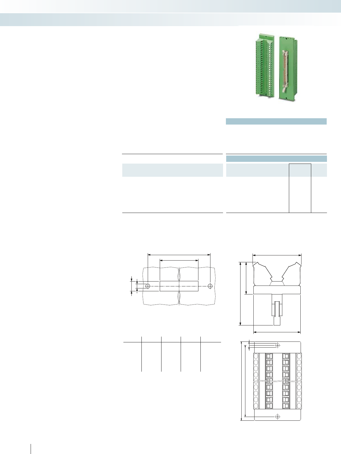
b
c
+0,2
d
+0,2
4
39
38
49
24,3
a
b
3,2
Technical data
Operating voltage < 50 V AC / 60 V DC
Max. perm. current (per branch) 1 A
Ambient temperature (operation) -20 °C ... 50 °C
Mounting position any
Standards/regulations DIN EN 50178, IEC 60664, IEC 62103
Connection data solid / stranded / AWG 0.2 - 4 mm² / 0.2 - 2.5 mm² / 24 - 12
Ordering data
Description No. of
pos.
Module width
WType Order No. Pcs. /
Pkt.
VARIOFACE feed-through module, with pin strip
16 39.00 DFLK 16 2280239 5
20 39.00 DFLK 20 2280242 5
26 39.00 DFLK 26 2280255 5
34 39.00 DFLK 34 2280268 5
40 39.00 DFLK 40 2280271 5
50 39.00 DFLK 50 2280284 5
VARIOFACE DFLK... feed-through
modules connect the flat-ribbon cable
connectors in accordance with
IEC 60603-13/DIN 41651 to the screw
connection terminal blocks.
These modules are suitable for mounting
on a side panel with an appropriate housing
cutout (see dimensioning table).
The modules are provided with low and
high engagement catches to protect the flat-
ribbon cable connector against being
accidentally released.
Feed-through modules for
IDC/FLK connectors (pitch 2.54 mm)
with screw connection
System cabling for controllers
Universal modules
16 to 50 positions
with screw connection
Dimensioning of the housing cutout Dimensional drawing DFLK:
Type a b c d
DFLK 16 58.4 52.5 40.1 + 0.2 9 + 0.2
DFLK 20 68.4 62.5 45.2 + 0.2 9 + 0.2
DFLK 26 83.4 77.5 52.8 + 0.2 9 + 0.2
DFLK 34 103.4 97.5 63.0 + 0.2 9 + 0.2
DFLK 40 128.4 122.5 70.6 + 0.2 9 + 0.2
DFLK 50 143.4 137.5 83.3 + 0.2 9 + 0.2
582
PHOENIX CONTACT
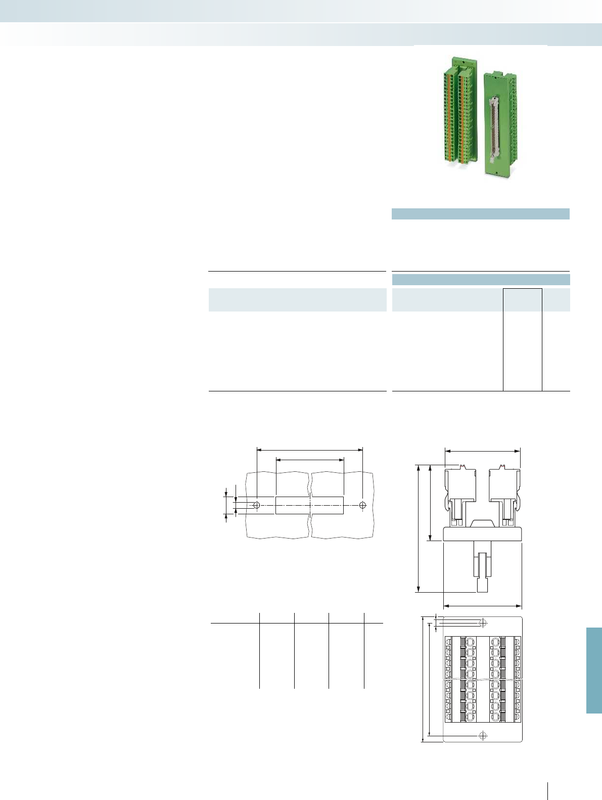
36,5
38
36
60
b
c
+0,2
d
+0,2
Ø3,2
Ø3,2
a
b
For further information and full technical data, visit phoenixcontact.net/products
Technical data
Operating voltage < 50 V AC / 60 V DC
Max. perm. current (per branch) 1 A
Ambient temperature (operation) -20 °C ... 50 °C
Mounting position any
Standards/regulations DIN EN 50178, IEC 60664, IEC 62103
Connection data solid / stranded / AWG 0.2 - 2.5 mm² / 0.2 - 2.5 mm² / 24 - 12
Ordering data
Description No. of
pos.
Module width
WType Order No. Pcs. /
Pkt.
VARIOFACE feed-through module, with pin strip
10 36.50 DFLK 10/FKCT 2903034 1
14 36.50 DFLK 14/FKCT 2903035 1
16 36.50 DFLK 16/FKCT 2903036 1
20 36.50 DFLK 20/FKCT 2903038 1
26 36.50 DFLK 26/FKCT 2903039 1
34 36.50 DFLK 34/FKCT 2903041 1
40 36.50 DFLK 40/FKCT 2903042 1
50 36.50 DFLK 50/FKCT 2903043 1
– 1:1 connection
– 10 to 50-pos.
– Plug-in push-in spring-cage connection
– Connectors as per IEC 60603-13
– Short and long catches are supplied with
the module
– Select housing cutout for side panel
mounting according to dimensioning table
Feed-through modules for
IDC/FLK connectors (pitch 2.54 mm)
with spring-cage connection
System cabling for controllers
Universal modules
With pin strip and
push-in spring-cage connection
Type a b c d
DFLK 10/FKCT 58.4 52.5 40.1 + 0.2 9 + 0.2
DFLK 14/FKCT 58.4 52.5 40.1 + 0.2 9 + 0.2
DFLK 16/FKCT 58.4 52.5 40.1 + 0.2 9 + 0.2
DFLK 20/FKCT 68.4 62.5 45.2 + 0.2 9 + 0.2
DFLK 26/FKCT 83.4 77.5 52.8 + 0.2 9 + 0.2
DFLK 34/FKCT 103.4 97.5 63.0 + 0.2 9 + 0.2
DFLK 40/FKCT 128.4 122.5 70.6 + 0.2 9 + 0.2
DFLK 50/FKCT 143.4 137.5 83.3 + 0.2 9 + 0.2
Dimensioning of the housing cutout Dimensional drawing DFLK...FKCT
583
PHOENIX CONTACT
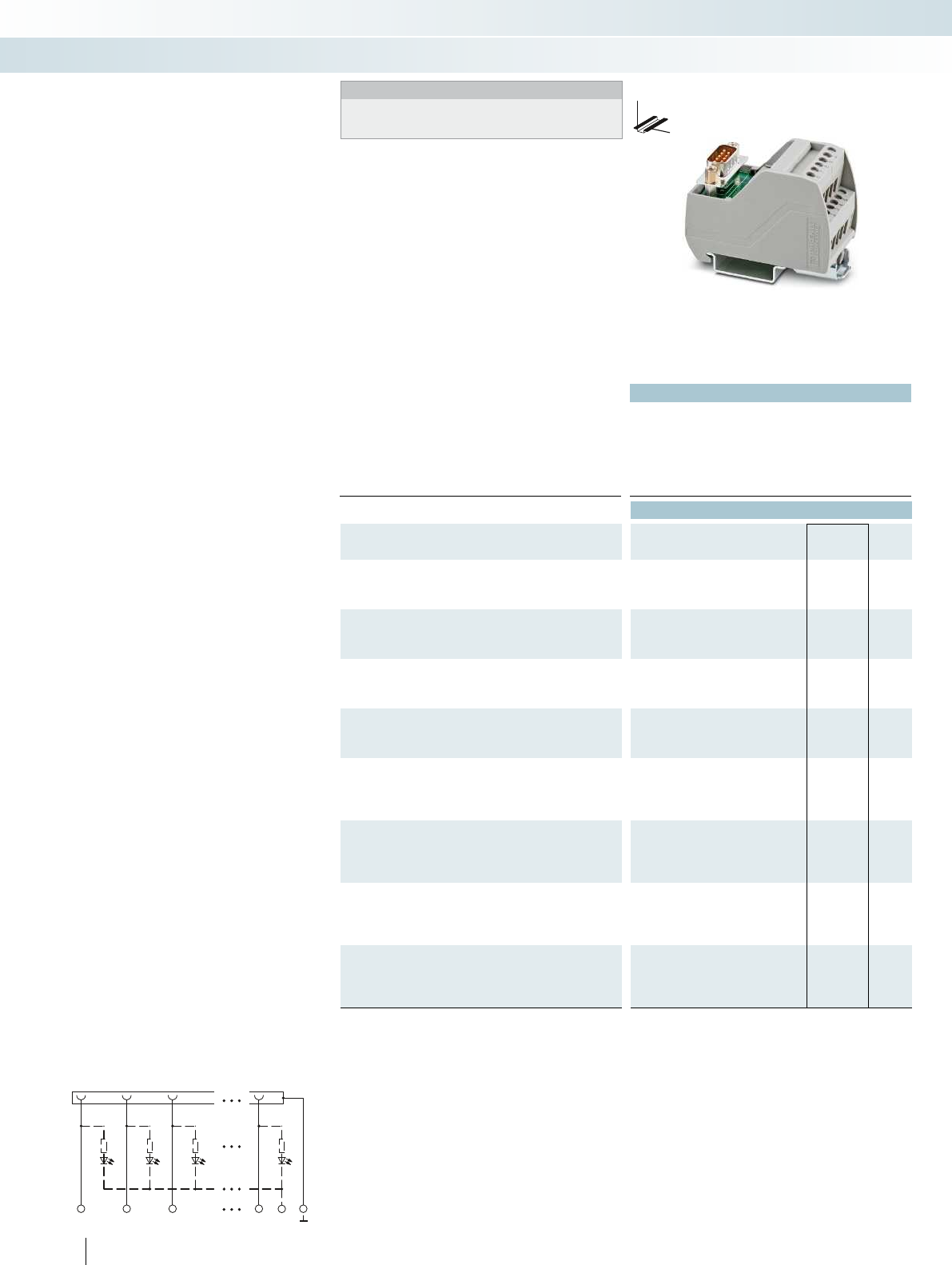
1
1
2
2
3
3
n
n
-
Technical data
Operating voltage 125 V AC/DC
Max. perm. current (per branch) 2 A
Ambient temperature (operation) -20 °C ... 50 °C
Mounting position any
Standards/regulations IEC 60664, DIN EN 50178, IEC 62103 IEC 60664, DIN EN 50178, IEC 62103 IEC 60664, DIN EN 50178, IEC 62103 IEC
Connection data solid / stranded / AWG 0.2 - 4 mm² / 0.2 - 2.5 mm² / 24 - 12 0.2 - 4 mm² / 0.2 - 2.5 mm² / 24 - 12 0.2 - 4 mm² / 0.2 -
Dimensions H / D 65.5 mm / 45.1 mm
Ordering data
Description No. of
pos.
Module width
WType Order No. Pcs. /
Pkt.
VARIOFACE module, with D-Subminiature pin strip
9 34.70 VIP-2/SC/D 9SUB/M 2315117 1
15 45.00 VIP-2/SC/D15SUB/M 2315120 1
VARIOFACE module, with D-Subminiature pin strip and
light indicator
934.70
15 50.00
VARIOFACE module, with D-Subminiature socket strip
9 34.70 VIP-2/SC/D 9SUB/F 2315162 1
15 45.00 VIP-2/SC/D15SUB/F 2315175 1
VARIOFACE module, with D-Subminiature socket strip and
light indicator
934.70
15 50.00
VARIOFACE module, with D-Subminiature pin strip
25 57.40
37 72.70
50 98.20
VARIOFACE module, with D-Subminiature pin strip and
light indicator
25 57.40
37 72.70
50 98.20
VARIOFACE module, with D-Subminiature socket strip
25 57.40
37 72.70
50 98.20
VARIOFACE module, with D-Subminiature socket strip and
light indicator
25 57.40
37 72.70
50 98.20
584
PHOENIX CONTACT
DW
H
VIP – VARIOFACE Professional
modules with D-SUB connectors
Notes:
For marking systems (e.g., “ZB 22:UNBEDRUCKT”;
Order No. 0811862) and mounting material, see Catalog 5.
– 1:1 connection
– 9 to 50-pos.
– Screw connection
– Metal foot
– As per IEC 60807-2
– With status indicator as an option
The D-SUB-4-40 UNC threads are led
directly to a connection terminal block.
System cabling for controllers
Universal modules
9 to 15 positions
with screw connection

For further information and full technical data, visit phoenixcontact.net/products
Technical data Technical data Technical data
24 V DC 125 V AC/DC 24 V DC
2.5 A 2 A 2.5 A
-20 °C ... 50 °C -20 °C ... 50 °C -20 °C ... 50 °C
any any any
Standards/regulations IEC 60664, DIN EN 50178, IEC 62103 IEC 60664, DIN EN 50178, IEC 62103 IEC 60664, DIN EN 50178, IEC 62103 IEC 60664, DIN EN 50178, IEC 62103
Connection data solid / stranded / AWG 0.2 - 4 mm² / 0.2 - 2.5 mm² / 24 - 12 0.2 - 4 mm² / 0.2 - 2.5 mm² / 24 - 12 0.2 - 4 mm² / 0.2 - 2.5 mm² / 24 - 12 0.2 - 4 mm² / 0.2 - 2.5 mm² / 24 - 12
65.5 mm / 45.1 mm 69 mm / 62 mm 69 mm / 62 mm
Ordering data Ordering data Ordering data
Type Order No. Pcs. /
Pkt. Type Order No. Pcs. /
Pkt. Type Order No. Pcs. /
Pkt.
VIP-2/SC/D 9SUB/M/LED 2322142 1
VIP-2/SC/D15SUB/M/LED 2322155 1
VIP-2/SC/D 9SUB/F/LED 2322197 1
VIP-2/SC/D15SUB/F/LED 2322207 1
VIP-3/SC/D25SUB/M 2315133 1
VIP-3/SC/D37SUB/M 2315146 1
VIP-3/SC/D50SUB/M 2315159 1
VIP-3/SC/D25SUB/M/LED 2322168 1
VIP-3/SC/D37SUB/M/LED 2322171 1
VIP-3/SC/D50SUB/M/LED 2322184 1
VIP-3/SC/D25SUB/F 2315188 1
VIP-3/SC/D37SUB/F 2315191 1
VIP-3/SC/D50SUB/F 2315201 1
VIP-3/SC/D25SUB/F/LED 2322210 1
VIP-3/SC/D37SUB/F/LED 2322223 1
VIP-3/SC/D50SUB/F/LED 2322236 1
585PHOENIX CONTACT
DW
H
DW
H
DW
H
System cabling for controllers
Universal modules
9 to 15 positions
with screw connection and light indicator
25 to 50 positions
with screw connection
25 to 50 positions
with screw connection and light indicator

1
1
2
2
3
3
n
n
-
Technical data
Operating voltage 125 V AC/DC
Max. perm. current (per branch) 2 A
Ambient temperature (operation) -20 °C ... 50 °C
Mounting position any
Standards/regulations IEC 60664, DIN EN 50178, IEC 62103 IEC 60664, DIN EN 50178, IEC 62103 IEC 60664, DIN EN 50178, IEC 62103 IEC
Connection data solid / stranded / AWG 0.14 - 2.5 mm² / 0.14 - 2.5 mm² / 26 - 14 0.14 - 2.5 mm² / 0.14 - 2.5 mm² / 26 - 14 0.14 - 2.5
Dimensions H / D 72.1 mm / 46.6 mm
Ordering data
Description No. of
pos.
Module width
WType Order No. Pcs. /
Pkt.
VARIOFACE module, with D-Subminiature pin strip
9 36.80 VIP-2/PT/D 9SUB/M 2903777 1
15 46.90 VIP-2/PT/D15SUB/M 2903779 1
VARIOFACE module, with D-Subminiature pin strip and
light indicator
936.80
15 52.00
VARIOFACE module, with D-Subminiature socket strip
9 36.80 VIP-2/PT/D 9SUB/F 2903778 1
15 46.90 VIP-2/PT/D15SUB/F 2903780 1
VARIOFACE module, with D-Subminiature socket strip and
light indicator
936.80
15 52.00
VARIOFACE module, with D-Subminiature pin strip
25 57.10
37 72.30
50 97.70
VARIOFACE module, with D-Subminiature pin strip and
light indicator
25 57.10
37 72.30
50 97.70
VARIOFACE module, with D-Subminiature socket strip
25 57.10
37 72.30
50 97.70
VARIOFACE module, with D-Subminiature socket strip and
light indicator
25 57.10
37 72.30
50 97.70
586
PHOENIX CONTACT
DW
H
VIP – VARIOFACE Professional
modules with D-SUB connectors
Notes:
For marking systems (e.g., “ZB 22:UNBEDRUCKT”;
Order No. 0811862) and mounting material, see Catalog 5.
– 1:1 connection
– 9 to 50-pos.
– Push-in connection
– Metal foot
– As per IEC 60807-2
– With status indicator as an option
The D-SUB-4-40 UNC threads are led
directly to a connection terminal block.
System cabling for controllers
Universal modules
9 to 15 positions
with push-in connection

For further information and full technical data, visit phoenixcontact.net/products
Technical data Technical data Technical data
24 V DC 125 V AC/DC 24 V DC
2 A 2 A 2 A
-20 °C ... 50 °C -20 °C ... 50 °C -20 °C ... 50 °C
any any any
Standards/regulations IEC 60664, DIN EN 50178, IEC 62103 IEC 60664, DIN EN 50178, IEC 62103 IEC 60664, DIN EN 50178, IEC 62103 IEC 60664, DIN EN 50178, IEC 62103
Connection data solid / stranded / AWG 0.14 - 2.5 mm² / 0.14 - 2.5 mm² / 26 - 14 0.14 - 2.5 mm² / 0.14 - 2.5 mm² / 26 - 14 0.14 - 2.5 mm² / 0.14 - 2.5 mm² / 26 - 14 0.14 - 2.5 mm² / 0.14 - 2.5 mm² / 26 - 14
72.1 mm / 46.6 mm 75.8 mm / 63 mm 75.8 mm / 63 mm
Ordering data Ordering data Ordering data
Type Order No. Pcs. /
Pkt. Type Order No. Pcs. /
Pkt. Type Order No. Pcs. /
Pkt.
VIP-2/PT/D 9SUB/M/LED 2904258 1
VIP-2/PT/D15SUB/M/LED 2904259 1
VIP-2/PT/D 9SUB/F/LED 2904263 1
VIP-2/PT/D15SUB/F/LED 2904264 1
VIP-3/PT/D25SUB/M 2903781 1
VIP-3/PT/D37SUB/M 2903783 1
VIP-3/PT/D50SUB/M 2903785 1
VIP-3/PT/D25SUB/M/LED 2904260 1
VIP-3/PT/D37SUB/M/LED 2904261 1
VIP-3/PT/D50SUB/M/LED 2904262 1
VIP-3/PT/D25SUB/F 2903782 1
VIP-3/PT/D37SUB/F 2903784 1
VIP-3/PT/D50SUB/F 2903786 1
VIP-3/PT/D25SUB/F/LED 2904265 1
VIP-3/PT/D37SUB/F/LED 2904266 1
VIP-3/PT/D50SUB/F/LED 2904267 1
587PHOENIX CONTACT
DW
H
DW
H
DW
H
System cabling for controllers
Universal modules
9 to 15 positions
with push-in connection and light indicator
25 to 50 positions
with push-in connection
25 to 50 positions
with push-in connection and light indicator
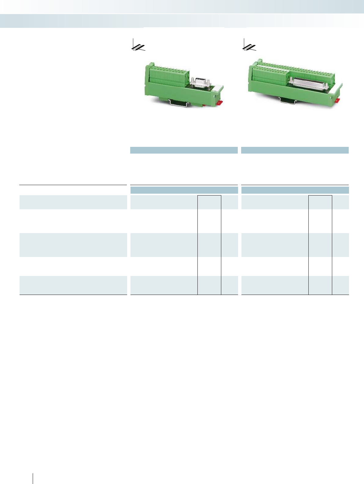
Technical data Technical data
Operating voltage 125 V AC/DC 125 V AC/DC
Max. perm. current (per branch) 2.5 A 2.5 A
Ambient temperature (operation) -10 °C ... 50 °C -10 °C ... 50 °C
Mounting position any any
Standards/regulations DIN EN 50178, IEC 60664, IEC 62103 DIN EN 50178, IEC 60664, IEC 62103
Dimensions D / W 45 mm / 25 mm 45 mm / 45 mm
Ordering data Ordering data
Description No. of
pos.
Module height
HType Order No. Pcs. /
Pkt. Type Order No. Pcs. /
Pkt.
VARIOFACE SLIM-LINE module, with D-Subminiature pin strip
9 117.00 UM 25-D 9SUB/S/FRONT/Q 2959573 1
15 147.00 UM 25-D15SUB/S/FRONT/Q 2959599 1
25 217.00 UM 25-D25SUB/S/FRONT/Q 2959612 1
VARIOFACE SLIM-LINE module
, with D-Subminiature socket strip
9117.00 UM 25-D 9SUB/B/FRONT/Q 2959560 1
15 147.00 UM 25-D15SUB/B/FRONT/Q 2959586 1
25 217.00 UM 25-D25SUB/B/FRONT/Q 2959609 1
VARIOFACE SLIM-LINE module, with D-Subminiature pin strip
37 157.00 UM 45-D37SUB/S/FRONT/Q 2959638 1
50 187.00 UM 45-D50SUB/S/FRONT/Q 2959654 1
VARIOFACE SLIM-LINE module
, with D-Subminiature socket strip
37 157.00 UM 45-D37SUB/B/FRONT/Q 2959625 1
50 187.00 UM 45-D50SUB/B/FRONT/Q 2959641 1
588
PHOENIX CONTACT
System cabling for controllers
Universal modules
9 to 25 positions
With screw connection
37 to 50 positions
With screw connection
These VARIOFACE modules connect
D-SUB strips with front connection
terminal blocks in accordance with
IEC 60807-2/DIN 41652.
To make the ground connection, the
metallic plug shell (4-40 UNC thread)
makes contact with a connection terminal
block.
DW
H
DW
H
SLIM-LINE modules for
D-SUB connectors
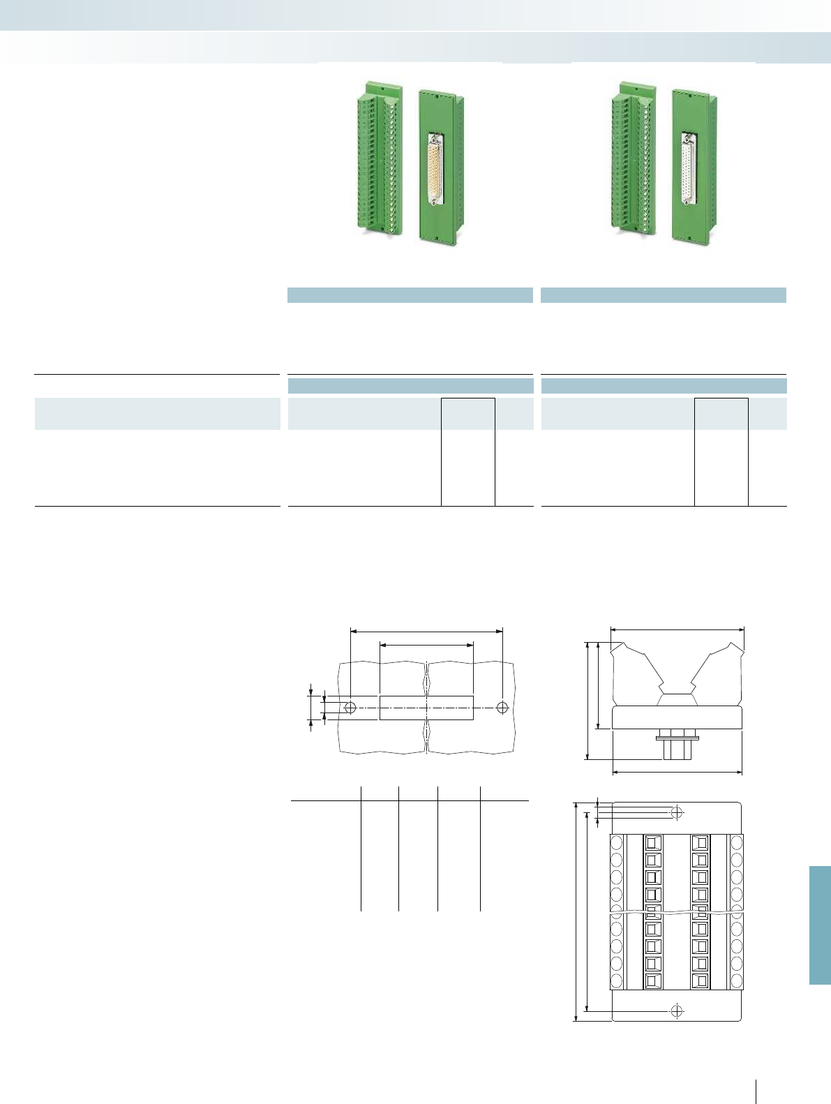
b
c
+0,2
d
+0,2
4
39
38
33
24,3
a
b
3,2
For further information and full technical data, visit phoenixcontact.net/products
Technical data Technical data
Operating voltage 125 V AC/DC 125 V AC/DC
Max. perm. current (per branch) 2.5 A 2.5 A
Ambient temperature (operation) -20 °C ... 50 °C -20 °C ... 50 °C
Mounting position any any
Standards/regulations IEC 60664, DIN EN 50178, IEC 62103 IEC 60664, DIN EN 50178, IEC 62103
Connection data solid / stranded / AWG 0.2 - 4 mm² / 0.2 - 2.5 mm² / 24 - 12 0.2 - 4 mm² / 0.2 - 2.5 mm² / 24 - 12
Ordering data Ordering data
Description No. of
pos.
Module width
WType Order No. Pcs. /
Pkt. Type Order No. Pcs. /
Pkt.
VARIOFACE feed-through module, with
D-subminiature connector
9 39.00 DFLK-D 9 SUB/S 2283870 5DFLK-D 9 SUB/B 2287135 5
15 39.00 DFLK-D15 SUB/S 2280297 5DFLK-D15 SUB/B 2280307 5
25 39.00 DFLK-D25 SUB/S 2280310 5DFLK-D25 SUB/B 2280323 5
37 39.00 DFLK-D37 SUB/S 2280336 5DFLK-D37 SUB/B 2280349 5
50 39.00 DFLK-D50 SUB/S 2291286 5DFLK-D50 SUB/B 2287669 5
– 1:1 connection
– 9 to 50-pos.
– Screw connection
– As per IEC 60807-2
– D-SUB 4-40 UNC thread
– 9 to 37-pos.: separate ground tap
– 50-pos.: no ground tap
Feed-through modules for
D-SUB connectors with
screw connection
System cabling for controllers
Universal modules
With D-SUB pin strip With D-SUB socket strip
Dimensioning of the housing cutout Dimensional drawing: DFLK-D...SUB:
Type a b c d
DFLK-D 9 SUB/S 58.4 52.5 40.2 + 0.2 13 + 0.2
DFLK-D 15 SUB/S 58.4 52.5 40.2 + 0.2 13 + 0.2
DFLK-D 25 SUB/S 83.4 77.5 54.2 + 0.2 13 + 0.2
DFLK-D 37 SUB/S 128.4 122.5 70.6 + 0.2 13 + 0.2
DFLK-D 50 SUB/S 143.4 137.5 67.8 + 0.2 15.8 + 0.2
DFLK-D 9 SUB/B 58.4 52.5 40.2 + 0.2 13 + 0.2
DFLK-D 15 SUB/B 58.4 52.5 40.2 + 0.2 13 + 0.2
DFLK-D 25 SUB/B 83.4 77.5 54.2 + 0.2 13 + 0.2
DFLK-D 37 SUB/B 128.4 122.5 70.6 + 0.2 13 + 0.2
DFLK-D 50 SUB/B 143.4 137.5 67.8 + 0.2 15.8 + 0.2
589
PHOENIX CONTACT

b
c
+0,2
d
+0,2
Ø3,2
36,5
38
36
46
Ø3,2
a
b
Technical data Technical data
Operating voltage 125 V AC/DC 125 V AC/DC
Max. perm. current (per branch) 2.5 A 2.5 A
Ambient temperature (operation) -20 °C ... 50 °C -20 °C ... 50 °C
Mounting position any any
Standards/regulations DIN EN 50178, IEC 60664, IEC 62103 DIN EN 50178, IEC 60664, IEC 62103
Connection data solid / stranded / AWG 0.2 - 2.5 mm² / 0.2 - 2.5 mm² / 24 - 12 0.2 - 2.5 mm² / 0.2 - 2.5 mm² / 24 - 12
Ordering data Ordering data
Description No. of
pos.
Module width
WType Order No. Pcs. /
Pkt. Type Order No. Pcs. /
Pkt.
VARIOFACE feed-through module, with
D-subminiature connector
9 36.50 DFLK-D 9 SUB/M/FKCT 2903052 1DFLK-D 9 SUB/F/FKCT 2903063 1
15 36.50 DFLK-D15 SUB/M/FKCT 2903054 1DFLK-D15 SUB/F/FKCT 2903065 1
25 36.50 DFLK-D25 SUB/M/FKCT 2903055 1DFLK-D25 SUB/F/FKCT 2903067 1
37 36.50 DFLK-D37 SUB/M/FKCT 2903056 1DFLK-D37 SUB/F/FKCT 2903069 1
50 36.50 DFLK-D50 SUB/M/FKCT 2903058 1DFLK-D50 SUB/F/FKCT 2903070 1
– 1:1 connection
– 9 to 50-pos.
– Plug-in push-in spring-cage connection
– Connector according to IEC 60807-2
– D-SUB 4-40 UNC thread
– 9 to 37-pos. with separate ground tap
– 50-pos.: no ground tap
– Select housing cutout for side panel
mounting according to dimensions table
Feed-through modules for
D-SUB connectors with
push-in connection
System cabling for controllers
Universal modules
With D-SUB pin strip and
push-in connection
With D-SUB socket strip and
push-in connection
Dimensioning of the housing cutout Dimensional drawing DFLK-D...SUB...FKCT
Type a b c d
DFLK-D 9 SUB/M/FKCT 58.4 52.5 40.2 + 0.2 13 + 0.2
DFLK-D15 SUB/M/FKCT 58.4 52.5 40.2 + 0.2 13 + 0.2
DFLK-D25 SUB/M/FKCT 83.4 77.5 54.2 + 0.2 13 + 0.2
DFLK-D37 SUB/M/FKCT 128.4 122.5 70.6 + 0.2 13 + 0.2
DFLK-D50 SUB/M/FKCT 143.4 137.5 67.8 + 0.2 15.8 + 0.2
DFLK-D 9 SUB/F/FKCT 58.4 52.5 40.2 + 0.2 13 + 0.2
DFLK-D15 SUB/F/FKCT 58.4 52.5 40.2 + 0.2 13 + 0.2
DFLK-D25 SUB/F/FKCT 83.4 77.5 54.2 + 0.2 13 + 0.2
DFLK-D37 SUB/F/FKCT 128.4 122.5 70.6 + 0.2 13 + 0.2
DFLK-D50 SUB/F/FKCT 143.4 137.5 67.8 + 0.2 15.8 + 0.2
590
PHOENIX CONTACT
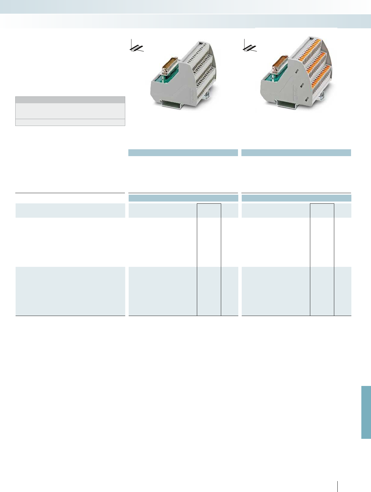
For further information and full technical data, visit phoenixcontact.net/products
Technical data Technical data
Operating voltage 125 V AC/DC 125 V AC/DC
Max. perm. current (per branch) 1 A 1 A
Ambient temperature (operation) -20 °C ... 50 °C -20 °C ... 50 °C
Mounting position any any
Standards/regulations EN 50178 EN 50178
Connection data solid / stranded / AWG 0.2 - 4 mm² / 0.2 - 2.5 mm² / 24 - 12 0.14 - 2.5 mm² / 0.14 - 2.5 mm² / 26 - 14
Dimensions H / D 69 mm / 62 mm 75.8 mm / 63 mm
Ordering data Ordering data
Description No. of
pos.
Module width
WType Order No. Pcs. /
Pkt. Type Order No. Pcs. /
Pkt.
VARIOFACE module, with D-Subminiature pin strip
With screw connection
1
) 15 44.90 VIP-2/SC/HD15SUB/M 2322326 1
With screw connection 26 52.30 VIP-3/SC/HD26SUB/M 2322375 1
With screw connection 44 82.90 VIP-3/SC/HD44SUB/M 2322388 1
With screw connection 62 113.50 VIP-3/SC/HD62SUB/M 2322391 1
With push-in connection
1
) 15 46.90 VIP-2/PT/HD15SUB/M 2904268 1
With push-in connection 26 52.00 VIP-3/PT/HD26SUB/M 2904269 1
With push-in connection 44 82.50 VIP-3/PT/HD44SUB/M 2904270 1
With push-in connection 62 113.00 VIP-3/PT/HD62SUB/M 2904271 1
VARIOFACE module, with D-Subminiature socket strip
With screw connection
1
)15 44.90 VIP-2/SC/HD15SUB/F 2322401 1
With screw connection 26 52.30 VIP-3/SC/HD26SUB/F 2322414 1
With screw connection 44 82.90 VIP-3/SC/HD44SUB/F 2322427 1
With screw connection 62 113.50 VIP-3/SC/HD62SUB/F 2322430 1
With push-in connection
1
)15 46.90 VIP-2/PT/HD15SUB/F 2904272 1
With push-in connection 26 52.00 VIP-3/PT/HD26SUB/F 2904273 1
With push-in connection 44 82.50 VIP-3/PT/HD44SUB/F 2904274 1
With push-in connection 62 113.00 VIP-3/PT/HD62SUB/F 2904275 1
591
PHOENIX CONTACT
System cabling for controllers
Universal modules
15 to 62 positions
with screw connection
15 to 62 positions
with push-in connection
– 1:1 connection
– 15 to 62-pos.
– Screw and push-in connection
– Metal foot
The D-SUB-4-40 UNC threads are led
directly to a connection terminal block.
Notes:
For marking systems (e.g., “ZB 22:UNBEDRUCKT”;
Order No. 0811862) and mounting material, see Catalog 5.
1
) Module with double-level terminal blocks
DW
H
DW
H
VIP – VARIOFACE Professional
modules for high density
D-SUB connectors

Technical data
Operating voltage 125 V AC/DC
Max. perm. current (per branch) 1 A
Ambient temperature (operation) -20 °C ... 50 °C
Mounting position any
Standards/regulations DIN EN 50178, IEC 60664, IEC 62103 DIN EN 50178, IEC 60664, IEC 62103 DIN EN 50178, IEC 60664, IEC 62103 DIN
Connection data solid / stranded / AWG 0.2 - 4 mm² / 0.2 - 2.5 mm² / 24 - 12 0.2 - 4 mm² / 0.2 - 2.5 mm² / 24 - 12 0.2 - 4 mm² / 0.2 -
Dimensions H / D 77 mm / 72 mm
Ordering data
Description No. of
pos.
Module width
WType Order No. Pcs. /
Pkt.
VARIOFACE module, C 64-pos., screw-on cable housing, with:
- Pin contact strip 64 135.00 UMKS- C64M-VS 2970565 1
VARIOFACE module, E 48-pos., screw-on cable housing, with:
- Pin contact strip 48 123.80
VARIOFACE module, F 48-pos., screw-on cable housing, with:
- Pin contact strip 48 112.50
VARIOFACE module, F 48-pos., snap-on cable housing, with:
- Pin contact strip 48 112.50
VARIOFACE module, D 32-pos., screw-on cable housing, with:
- Pin contact strip 32 135.00
592
PHOENIX CONTACT
DW
H
Modules for connectors
IEC 60603/DIN 41612
Notes:
Suitable cable housings, see the table on page 620
These VARIOFACE interface modules
connect high-position connectors in acc.
with IEC 60603/DIN 41612 to screw
connection terminal blocks.
The following VARIOFACE modules are
available:
–UMK modules with double-level
connection terminal blocks
–UMKS modules with three-level
connection terminal blocks
System cabling for controllers
Universal modules
Type C,
64-position, a, c assembled
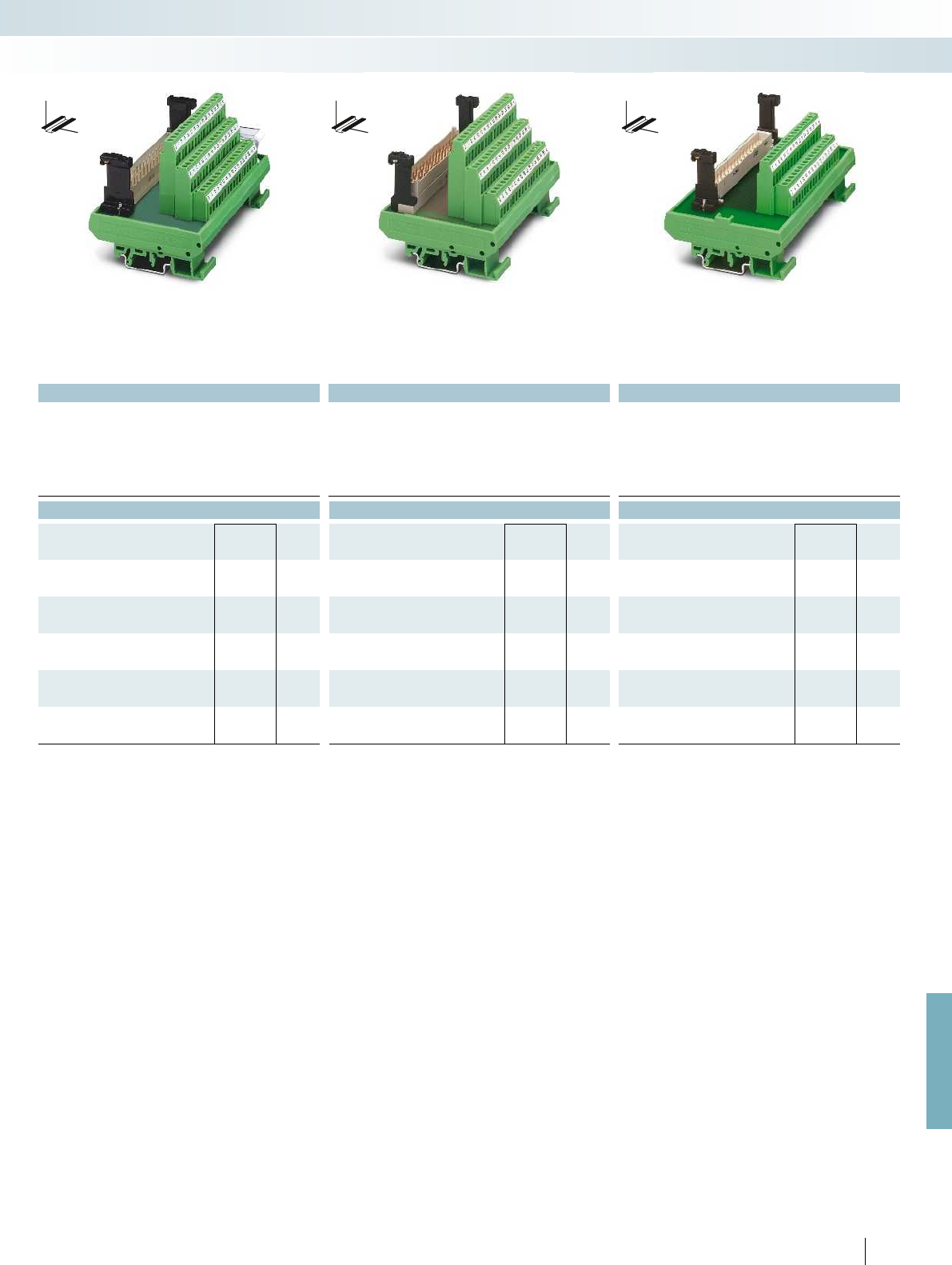
For further information and full technical data, visit phoenixcontact.net/products
Technical data Technical data Technical data
125 V AC/DC 250 V AC/DC 250 V AC/DC
4 A 4 A 2 A
-20 °C ... 50 °C -20 °C ... 45 °C -20 °C ... 50 °C
any any any
Standards/regulations DIN EN 50178, IEC 60664, IEC 62103 DIN EN 50178, IEC 60664, IEC 62103 DIN EN 50178, IEC 60664, IEC 62103 DIN EN 50178, IEC 60664, IEC 62103
Connection data solid / stranded / AWG 0.2 - 4 mm² / 0.2 - 2.5 mm² / 24 - 12 0.2 - 4 mm² / 0.2 - 2.5 mm² / 24 - 12 0.2 - 4 mm² / 0.2 - 2.5 mm² / 24 - 12 0.2 - 4 mm² / 0.2 - 2.5 mm² / 24 - 12
77 mm / 72 mm 77 mm / 72 mm 77 mm / 62.5 mm
Ordering data Ordering data Ordering data
Type Order No. Pcs. /
Pkt. Type Order No. Pcs. /
Pkt. Type Order No. Pcs. /
Pkt.
UMKS- E48M-VS 2970154 1
UMKS- F48M-VS 2970714 1
UMKS- F48M-VR 2970167 1
UMK- D32M-VS 2970060 1
593PHOENIX CONTACT
DW
H
DW
H
DW
H
System cabling for controllers
Universal modules
Type E,
48-position, a, c, e assembled
Type F,
48-position, z, b, d assembled
Type D,
32-position, a, c assembled

Technical data
Operating voltage 25 V AC / 60 V DC
Max. perm. current (per branch) 2 A
Total current 76 A
Ambient temperature (operation) -20 °C ... 40 °C
Mounting position any
Standards/regulations IEC 60664, DIN EN 50178, IEC 62103 IEC 60664, DIN EN 50178, IEC 62103 IEC 60664, DIN EN 50178, IEC 62103 IEC
Connection data solid / stranded / AWG 0.2 - 4 mm² / 0.2 - 2.5 mm² / 24 - 12 0.2 - 4 mm² / 0.2 - 2.5 mm² / 24 - 12 0.2 - 2.5 mm² / 0.2
Dimensions H / D 77 mm / 58.5 mm
Ordering data
Description No. of
pos.
Module width
WType Order No. Pcs. /
Pkt.
VARIOFACE module, with:
- Pin strip 8016 right 38 101.50 UMK- EC38/38-XOR 2976297 1
- Pin strip 8016 left 38 101.50 UMK- EC38/38-XOL 2976284 1
VARIOFACE module, with:
- Pin strip 8016 right 56 157.50
- Pin strip 8016 left 56 157.50
VARIOFACE module, with:
- Pin strip 8016 right 56 77.00
- Pin strip 8016 left 56 77.00
VARIOFACE module, with:
- Pin strip 8016 right above 32 101.30
- Pin strip 8016 right below 32 101.30
- Pin strip 8016 left above 32 101.30
- Pin strip 8016 left below 32 101.30
594
PHOENIX CONTACT
DW
H
Modules for ELCO connectors
Notes:
Dimensional drawings and pin assignments, see page 620
These modules can be used to connect
ELCO connectors of the 8016 series to
screw connection terminal blocks.
The diagonal position of the ELCO
connector means that the wires leading out
of the cable housing at the side can be led
away without restricting neighboring
modules.
System cabling for controllers
Universal modules
38-pos. 56-pos. 56-pos.,
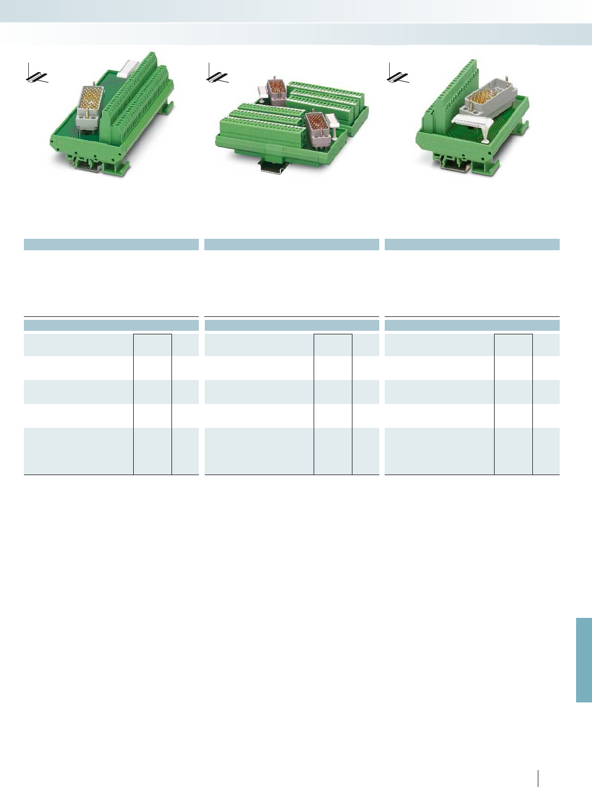
For further information and full technical data, visit phoenixcontact.net/products
Technical data Technical data Technical data
125 V AC/DC 25 V AC / 60 V DC 25 V AC / 60 V DC
1.5 A 1.5 A 2 A
28 A (56 branches with 0.5 A each) 28 A (56 branches with 0.5 A each) 32 A (32 branches with 1 A each)
-20 °C ... 50 °C -20 °C ... 50 °C -20 °C ... 40 °C
any any any
Standards/regulations IEC 60664, DIN EN 50178, IEC 62103 IEC 60664, DIN EN 50178, IEC 62103 IEC 60664, DIN EN 50178, IEC 62103 IEC 60664, DIN EN 50178, IEC 62103
Connection data solid / stranded / AWG 0.2 - 4 mm² / 0.2 - 2.5 mm² / 24 - 12 0.2 - 4 mm² / 0.2 - 2.5 mm² / 24 - 12 0.2 - 2.5 mm² / 0.2 - 1.5 mm² / 26 - 16 0.2 - 4 mm² / 0.2 - 2.5 mm² / 24 - 12
77 mm / 58.5 mm 146.3 mm / 47.5 mm 77 mm / 58.5 mm
Ordering data Ordering data Ordering data
Type Order No. Pcs. /
Pkt. Type Order No. Pcs. /
Pkt. Type Order No. Pcs. /
Pkt.
UMK- EC56/56-XOR 2975900 1
UMK- EC56/56-XOL 2975890 1
UMK- EC56/FRONT 2,5V/R 2976161 1
UMK- EC56/FRONT 2,5V/L 2976158 1
UMK- EC56/32-XOR 2975858 1
UMK- EC56/32-XUR 2975777 1
UMK- EC56/32-XOL 2975764 1
UMK- EC56/32-XUL 2975780 1
595PHOENIX CONTACT
DW
H
DW
H
DW
H
System cabling for controllers
Universal modules
38-pos. 56-pos. 56-pos.,
with front connection terminal blocks
32-pos.
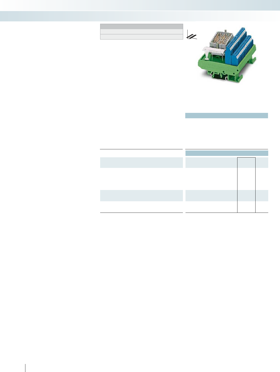
Technical data
Operating voltage max. 30 V DC
(max. voltage between two intrinsically safe circuits: 60 V DC)
Max. perm. current (per branch) 500 mA
Ambient temperature (operation) -20 °C ... 50 °C
Mounting position any
Standards/regulations DIN EN 60079-11
Connection data solid / stranded / AWG 0.2 - 4 mm² / 0.2 - 2.5 mm² / 24 - 12 0.2 - 4 mm² / 0.2 - 2.5 mm² / 24 - 12 0.2 - 2.5 mm² / 0.2
Dimensions H / D 77 mm / 58.5 mm
Ordering data
Description No. of
pos.
Module width
WType Order No. Pcs. /
Pkt.
VARIOFACE module, with:
- Pin strip 8016 right above 32 101.30 UMK- EC90/32/EX-XOR 2900109 1
- Pin strip 8016 right below 32 101.30 UMK- EC90/32/EX-XUR 2969068 1
- Pin strip 8016 left above 32 101.30 UMK- EC90/32/EX-XOL 2900110 1
- Pin strip 8016 left above 32 101.30 UMK- EC90/32/EX-XUL 2969071 1
VARIOFACE module, with:
- Pin strip 8016 right 25 78.80
- Pin strip 8016 left 25 78.80
VARIOFACE module, with:
- Pin strip 8016 right 25 77.00
- Pin strip 8016 left 25 77.00
596
PHOENIX CONTACT
DW
H
Modules for ELCO connectors for
use in Ex i circuits
Notes:
Dimensional drawings and pin assignments, see page 621
Facts about explosion protection, see page 144
The VARIOFACE modules connect ELCO
connectors of the 8016 series to screw
connection terminal blocks. The modules for
ELCO connectors can be used as simple
electrical equipment for applications in
intrinsically safe circuits as per EN 60079-14.
They fulfill the requirements of intrinsic
safety as per EN 60079-11 (EN 50020) and
can be used for various intrinsically safe
circuits taking into account the pin
configuration.
The voltage of an intrinsically safe circuit
may not exceed 30 V. The voltage difference
between two intrinsically safe circuits can
be up to 60 V.
For clear identification for intrinsically
safe circuits, the modules are fitted with
blue screw connection terminal blocks.
The arrangement of angled ELCO
connectors makes it possible to lead the
lines led out from the cable housing away
from the adjacent modules without any
negative effects.
To separate intrinsically safe and non-
intrinsically safe circuits, a distance of at
least 50 mm should be kept between the
connection points using partition plates or
spaces.
System cabling for controllers
Universal modules
32-pos. 25-pos. 25-pos.,
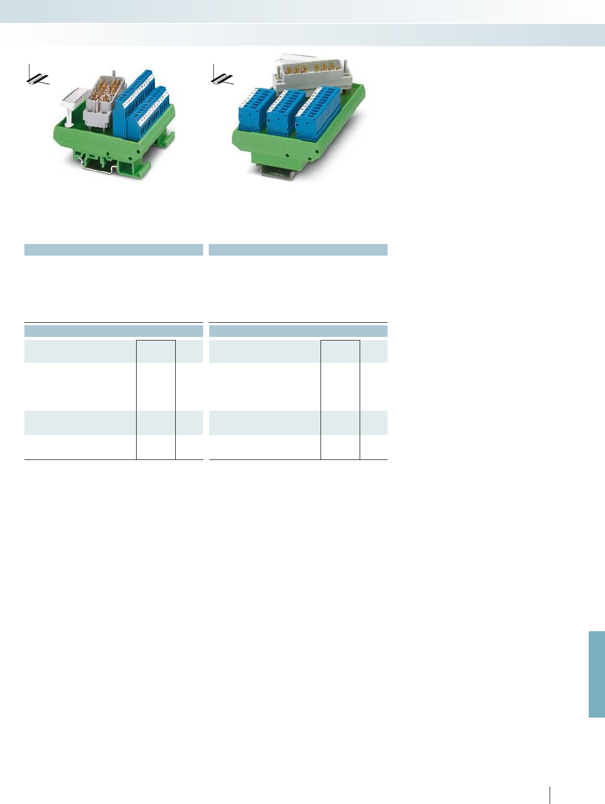
For further information and full technical data, visit phoenixcontact.net/products
Technical data Technical data
max. 30 V DC
(max. voltage between two intrinsically safe circuits: 60 V DC)
max. 30 V DC
(max. voltage between two intrinsically safe circuits: 60 V DC)
500 mA 500 mA
-20 °C ... 50 °C -20 °C ... 50 °C
any any
DIN EN 60079-11 DIN EN 60079-11
Connection data solid / stranded / AWG 0.2 - 4 mm² / 0.2 - 2.5 mm² / 24 - 12 0.2 - 4 mm² / 0.2 - 2.5 mm² / 24 - 12 0.2 - 2.5 mm² / 0.2 - 2.5 mm² / 24 - 14
77 mm / 58.5 mm 112.5 mm / 52.5 mm
Ordering data Ordering data
Type Order No. Pcs. /
Pkt. Type Order No. Pcs. /
Pkt.
UMK- EC56/25/EX -R 2900112 1
UMK- EC56/25/EX -L 2900113 1
UMK- EC56/25/EX -FRONT 2,5V/R 2900114 1
UMK- EC56/25/EX -FRONT 2,5V/L 2900115 1
597PHOENIX CONTACT
DW
H
DW
H
System cabling for controllers
Universal modules
32-pos. 25-pos. 25-pos.,
with front connection terminal blocks

1
1
2
2
3
3
8
8
1
1
2
2
3
3
8
8
Technical data Technical data
Operating voltage 48 V AC/DC 48 V AC/DC
Max. perm. current (per branch) 1 A 1 A
Ambient temperature (operation) -20 °C ... 50 °C -20 °C ... 50 °C
Mounting position any any
Standards/regulations DIN EN 50178 EN 50178
Connection data solid / stranded / AWG 0.2 - 4 mm² / 0.2 - 2.5 mm² / 24 - 12 0.14 - 2.5 mm² / 0.14 - 2.5 mm² / 26 - 14
Dimensions H / D 69 mm / 62 mm 75.8 mm / 63 mm
Ordering data Ordering data
Description No. of
pos.
Module width
WType Order No. Pcs. /
Pkt. Type Order No. Pcs. /
Pkt.
VARIOFACE module, with RJ45 connector
With screw connection 8 26.90 VIP-3/SC/RJ45 2900701 1
With push-in connection 8 26.60 VIP-3/PT/RJ45 2904290 1
598
PHOENIX CONTACT
– 1:1 connection
– 8-pos., RJ45 connector
– Screw or push-in connection
(direct plug-in technology)
– Connector housing led to separate
connection terminal blocks
Notes:
For marking systems (e.g., “ZB 22:UNBEDRUCKT”;
Order No. 0811862) and mounting material, see Catalog 5.
DW
H
DW
H
Modules with RJ45 connector
System cabling for controllers
Universal modules
8-pos.
With srew connection
8-pos.
With push-in connection
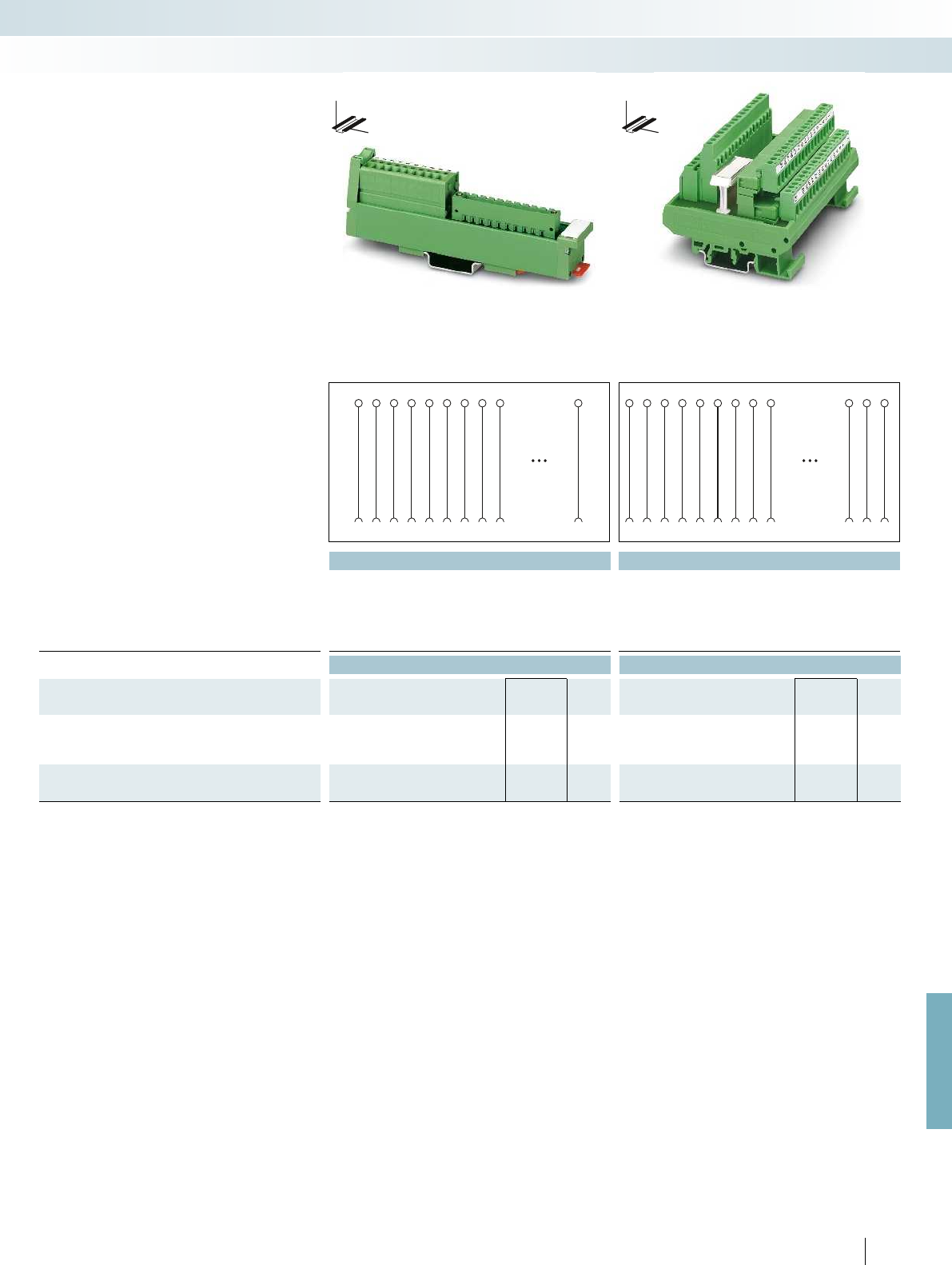
1
1
2
2
3
3
4
4
5
5
6
6
7
7
8
8
9n
9n
1
1
2
2
3
3
4
4
5
5
6
6
7
7
8
8
93031 32
93031 32
For further information and full technical data, visit phoenixcontact.net/products
Technical data Technical data
Operating voltage 250 V AC/DC 250 V AC/DC
Max. perm. current (per branch) 2.5 A 3 A
Ambient temperature (operation) -10 °C ... 50 °C -20 °C ... 50 °C
Mounting position any any
Standards/regulations IEC 60664, DIN EN 50178, IEC 62103 IEC 60664, DIN EN 50178, IEC 62103
Dimensions D / W 45 mm / 25 mm 58.5 mm / 112.5 mm
Ordering data Ordering data
Description No. of
pos.
Module height
HType Order No. Pcs. /
Pkt. Type Order No. Pcs. /
Pkt.
VARIOFACE SLIM-LINE module, with a COMBICON header
(without a COMBICON connector)
10 137.00 UM 25-10 MSTB/FRONT/Q 2959803 1
18 217.00 UM 25-18 MSTB/FRONT/Q 2959502 1
VARIOFACE module,with COMBICON connector, coded
32 77.00 UMK-32 MDSTB/MKKDS3/R 2970196 1
599
PHOENIX CONTACT
– The slim 10 and 18-pos. VARIOFACE
SLIM-LINE modules connect the front
connection terminal blocks to a
COMBICON header. The corresponding
COMBICON connectors (5.0 mm pitch)
can be found in the COMBICON catalog,
PCB connection technology.
– The 32-pos. module UMK-32
MDSTB/MKKDS 3/R connects screw
connection terminal blocks with coded
COMBICON plug-in screw connectors.
DW
H
DW
H
Modules with COMBICON connection
System cabling for controllers
Universal modules
10 and 18-pos.
With screw connection
32-pos.
With screw connection
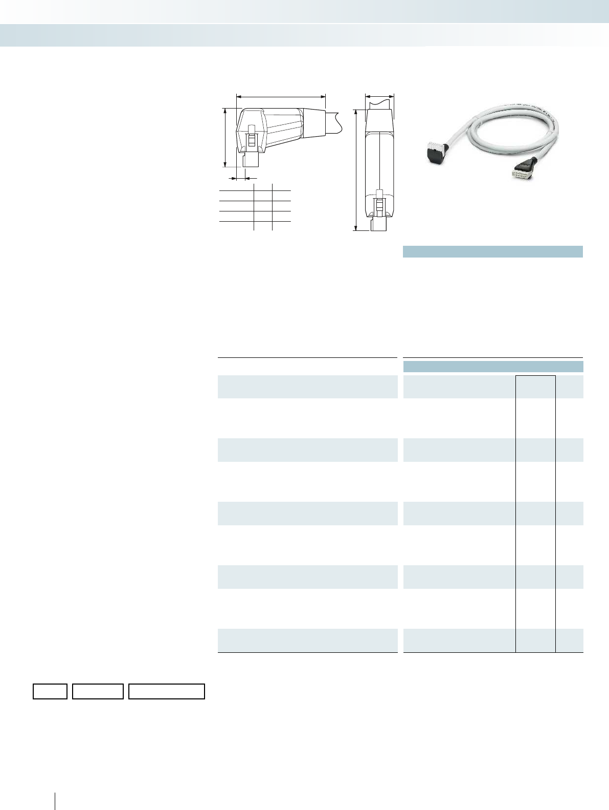
...FLK10...
...FLK14...
...FLK16...
...FLK20...
A
26,5
B
13,5
5
34
51
49
49
46
37
37
39
AB
Technical data
Max. perm. operating voltage < 50 V AC / 60 V DC
Max. perm. current carrying capacity per path 1 A
Max. conductor resistance 0.16 /m
Ambient temperature (operation) -20 °C ... 50 °C
Assembly Insulation displacement, IEC 60352-4/DIN EN 60352-4
Conductor cross section AWG 26 / 0.14 mm²
Outside diameter
10-position 6.1 mm
14-position 6.4 mm
16-position 6.8 mm
20-position 7.6 mm
Ordering data
Description No. of
pos. Cable length Type Order No. Pcs. /
Pkt.
Round cable, with two molded socket strips
10 1 m VIP-CAB-FLK10/0,14/1,0M 2318318 1
10 2 m VIP-CAB-FLK10/0,14/2,0M 2318334 1
10 3 m VIP-CAB-FLK10/0,14/3,0M 2318347 1
Round cable, as above, in variable lengths (minimum ordering
quantity five pieces)
10 VIP-CAB-FLK10-0,14/... 2318376 1
Round cable, with two molded socket strips
14 1 m VIP-CAB-FLK14/0,14/1,0M 2318392 1
14 2 m VIP-CAB-FLK14/0,14/2,0M 2318415 1
14 3 m VIP-CAB-FLK14/0,14/3,0M 2318428 1
Round cable, as above, in variable lengths (minimum ordering
quantity five pieces)
14 VIP-CAB-FLK14-0,14/... 2318457 1
Round cable, with two molded socket strips
16 1 m VIP-CAB-FLK16/0,14/1,0M 2318473 1
16 2 m VIP-CAB-FLK16/0,14/2,0M 2318499 1
16 3 m VIP-CAB-FLK16/0,14/3,0M 2318509 1
Round cable, as above, in variable lengths (minimum ordering
quantity five pieces)
16 VIP-CAB-FLK16-0,14/... 2318538 1
Round cable, with two molded socket strips
20 1 m VIP-CAB-FLK20/0,14/1,0M 2318554 1
20 2 m VIP-CAB-FLK20/0,14/2,0M 2318570 1
20 3 m VIP-CAB-FLK20/0,14/3,0M 2318583 1
Round cable, as above, in variable lengths (minimum ordering
quantity five pieces)
20 VIP-CAB-FLK20-0,14/... 2318619 1
600
PHOENIX CONTACT
– 1:1 connection
– 10 to 20-pos.
– Connectors as per IEC 60603-13
– In the desired lengths
– Individual serial number
Note:
Due to the enlarged outer contour of the
molded connectors, module types with
UM45 profile and three-level terminal
blocks cannot be connected with the
VIP-CAB-FLK... system cable.
The following module types
(10 to 50-pos.) can be connected.
For example, for 20 positions:
– VIP-2/SC/FLK 20
– VIP-2/SC/FLK20/LED
– FLKM 20/ZFKDS
– UM45-FLK 20/ZFKDS
(double-level connection)
The VIP-CAB-FLK... system cables are
not suitable for front adapters
(see the dimensional drawing).
VIP – VARIOFACE Professional
system cables with
flat-ribbon connectors
Ordering example for system cable:
– 10-pos. cable, 7.6 m long
Quantity Order No. Length [m]
12318376 /7.6
Min.
Max.
Increment
0.5 m
100.0 m
0.1 m
System cabling for controllers
Universal cables
Unshielded
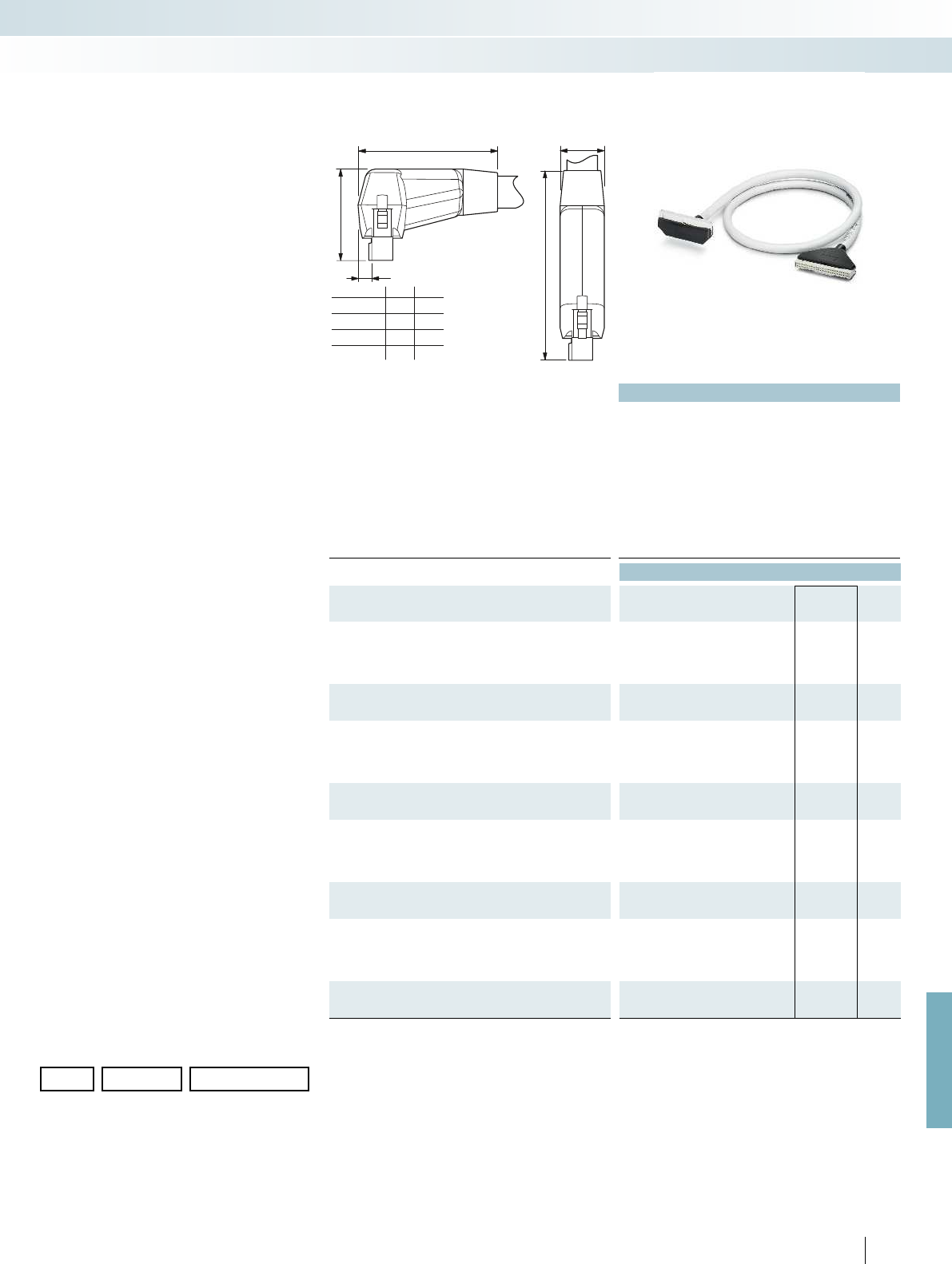
...FLK26...
...FLK34...
...FLK40...
...FLK50...
A
26,5
B
13,5
5
39
55
52
52
51
40
40
42
AB
For further information and full technical data, visit phoenixcontact.net/products
Technical data
Max. perm. operating voltage < 50 V AC / 60 V DC
Max. perm. current carrying capacity per path 1 A
Max. conductor resistance 0.16 /m
Ambient temperature (operation) -20 °C ... 50 °C
Assembly Insulation displacement, IEC 60352-4/DIN EN 60352-4
Conductor cross section AWG 26 / 0.14 mm²
Outside diameter
26-position 8.3 mm
34-position 8.7 mm
40-position 9.9 mm
50-position 10.3 mm
Ordering data
Description No. of
pos. Cable length Type Order No. Pcs. /
Pkt.
Round cable, with two molded socket strips
26 1 m VIP-CAB-FLK26/0,14/1,0M 2318635 1
26 2 m VIP-CAB-FLK26/0,14/2,0M 2318651 1
26 3 m VIP-CAB-FLK26/0,14/3,0M 2318664 1
Round cable, as above, in variable lengths
(minimum ordering quantity five pieces)
26 VIP-CAB-FLK26-0,14/... 2318693 1
Round cable, with two molded socket strips
34 1 m VIP-CAB-FLK34/0,14/1,0M 2318716 1
34 2 m VIP-CAB-FLK34/0,14/2,0M 2318732 1
34 3 m VIP-CAB-FLK34/0,14/3,0M 2318745 1
Round cable, as above, in variable lengths
(minimum ordering quantity five pieces)
34 VIP-CAB-FLK34-0,14/... 2318774 1
Round cable, with two molded socket strips
40 1 m VIP-CAB-FLK40/0,14/1,0M 2318790 1
40 2 m VIP-CAB-FLK40/0,14/2,0M 2318813 1
40 3 m VIP-CAB-FLK40/0,14/3,0M 2318826 1
Round cable, as above, in variable lengths
(minimum ordering quantity five pieces)
40 VIP-CAB-FLK40-0,14/... 2318855 1
Round cable, with two molded socket strips
50 1 m VIP-CAB-FLK50/0,14/1,0M 2318871 1
50 2 m VIP-CAB-FLK50/0,14/2,0M 2318897 1
50 3 m VIP-CAB-FLK50/0,14/3,0M 2318907 1
Round cable, as above, in variable lengths
(minimum ordering quantity five pieces)
50 VIP-CAB-FLK50-0,14/... 2318936 1
601PHOENIX CONTACT
– 1:1 connection
– 26 to 50-pos.
– Connectors as per IEC 60603-13
– In the desired lengths
– Individual serial number
Note:
Due to the enlarged outer contour of the
molded connectors, module types with
UM45 profile and three-level terminal
blocks cannot be connected with the
VIP-CAB-FLK... system cable.
The following module types
(10 to 50-pos.) can be connected.
For example, for 20 positions:
– VIP-2/SC/FLK 20
– VIP-2/SC/FLK20/LED
– FLKM 20/ZFKDS
– UM45-FLK 20/ZFKDS
(double-level connection)
The VIP-CAB-FLK... system cables are
not suitable for front adapters
(see the dimensional drawing).
VIP – VARIOFACE Professional
system cables with
flat-ribbon connectors
Ordering example for system cable:
– 26-pos. cable, 12.6 m long
Quantity Order No. Length [m]
12318693 /12.6
Min.
Max.
Increment
0.5 m
100.0 m
0.1 m
System cabling for controllers
Universal cables
Unshielded
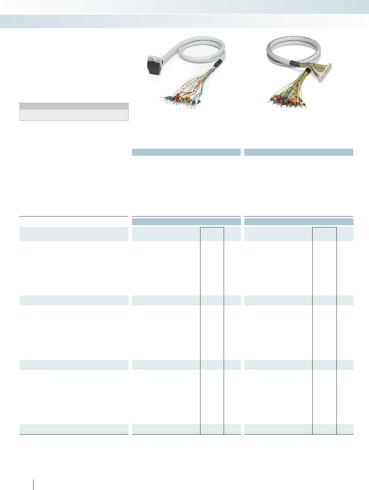
Technical data Technical data
Max. perm. operating voltage < 50 V AC / 60 V DC < 50 V AC / 60 V DC
Max. perm. current carrying capacity per path 1 A 1 A
Max. conductor resistance 0.16 /m 0.16 /m
Ambient temperature (operation) -20 °C ... 50 °C -20 °C ... 50 °C
Assembly Insulation displacement, IEC 60352-4/DIN EN 60352-4 Insulation displacement, IEC 60352-4/DIN EN 60352-4
Conductor cross section AWG 26 / 0.14 mm² AWG 26 / 0.14 mm²
Conductor structure: stranded wires / material 7 / Cu tin-plated 7 / Cu tin-plated
Outside diameter
10-position 6.1 mm 6.1 mm
14-position 6.4 mm 6.4 mm
16-position 6.5 mm 6.5 mm
Ordering data Ordering data
Description No. of
pos. Cable length Type Order No. Pcs. /
Pkt. Type Order No. Pcs. /
Pkt.
Round cable with an open end
10 0.5 m CABLE-FLK10/OE/0,14/ 0,5M 2904073 1
10 1 m CABLE-FLK10/OE/0,14/ 1,0M 2904074 1
10 1.5 m CABLE-FLK10/OE/0,14/ 1,5M 2904075 1
10 2 m CABLE-FLK10/OE/0,14/ 2,0M 2904076 1
10 2.5 m CABLE-FLK10/OE/0,14/ 2,5M 2904077 1
10 3 m CABLE-FLK10/OE/0,14/ 3,0M 2904078 1
10 4 m CABLE-FLK10/OE/0,14/ 4,0M 2904079 1
10 6 m CABLE-FLK10/OE/0,14/ 6,0M 2904080 1
10 8 m CABLE-FLK10/OE/0,14/ 8,0M 2904081 1
10 10 m CABLE-FLK10/OE/0,14/10,0M 2904082 1
Round cable, as above, however in variable lengths
10 CABLE-FLK10-OE-0,14/... 2904331 1
Round cable with an open end
14 0.5 m VIP-CAB-FLK14/FR/OE/0,14/0,5M 2900122 1CABLE-FLK14/OE/0,14/ 50 2305761 1
14 1 m VIP-CAB-FLK14/FR/OE/0,14/1,0M 2900123 1CABLE-FLK14/OE/0,14/ 100 2305253 1
14 1.5 m VIP-CAB-FLK14/FR/OE/0,14/1,5M 2900125 1CABLE-FLK14/OE/0,14/ 150 2305266 1
14 2 m VIP-CAB-FLK14/FR/OE/0,14/2,0M 2900126 1CABLE-FLK14/OE/0,14/ 200 2305279 1
14 2.5 m CABLE-FLK14/OE/0,14/ 250 2305282 1
14 3 m VIP-CAB-FLK14/FR/OE/0,14/3,0M 2900127 1CABLE-FLK14/OE/0,14/ 300 2305295 1
14 4 m CABLE-FLK14/OE/0,14/ 400 2305774 1
14 6 m CABLE-FLK14/OE/0,14/ 600 2305787 1
14 8 m CABLE-FLK14/OE/0,14/ 800 2305790 1
14 10 m CABLE-FLK14/OE/0,14/1000 2305800 1
Round cable, as above, however in variable lengths
14 CABLE-FLK14/OE/0,14/... 2305732 1
Round cable with an open end
16 0.5 m VIP-CAB-FLK16/FR/OE/0,14/0,5M 2900130 1CABLE-FLK16/OE/0,14/ 0,5M 2318127 1
16 1 m VIP-CAB-FLK16/FR/OE/0,14/1,0M 2900131 1CABLE-FLK16/OE/0,14/ 1,0M 2318130 1
16 1.5 m VIP-CAB-FLK16/FR/OE/0,14/1,5M 2900132 1CABLE-FLK16/OE/0,14/ 1,5M 2318143 1
16 2 m VIP-CAB-FLK16/FR/OE/0,14/2,0M 2900133 1CABLE-FLK16/OE/0,14/ 2,0M 2318156 1
16 2.5 m CABLE-FLK16/OE/0,14/ 2,5M 2318169 1
16 3 m VIP-CAB-FLK16/FR/OE/0,14/3,0M 2900134 1CABLE-FLK16/OE/0,14/ 3,0M 2318172 1
16 4 m CABLE-FLK16/OE/0,14/ 4,0M 2318185 1
16 6 m CABLE-FLK16/OE/0,14/ 6,0M 2318198 1
16 8 m CABLE-FLK16/OE/0,14/ 8,0M 2318208 1
16 10 m CABLE-FLK16/OE/0,14/10,0M 2318211 1
Round cable, as above, however in variable lengths
16 CABLE-FLK16/OE/0,14/... 2318224 1
602
PHOENIX CONTACT
System cabling for controllers
Universal cables
Molded connectors, unshielded Unshielded
– 1:1 connection
– 10, 14, and 16-pos.
– Connectors as per IEC 60603-13
– Open end at the other end
The individual wires at the open end are
marked (1, 2, 3, 4, ...) and fitted with a
ferrule.
Notes:
In the case of molded connectors, please observe the dimensional
drawing and note, see page 600
System cable with
a flat-ribbon cable connector and
an open end
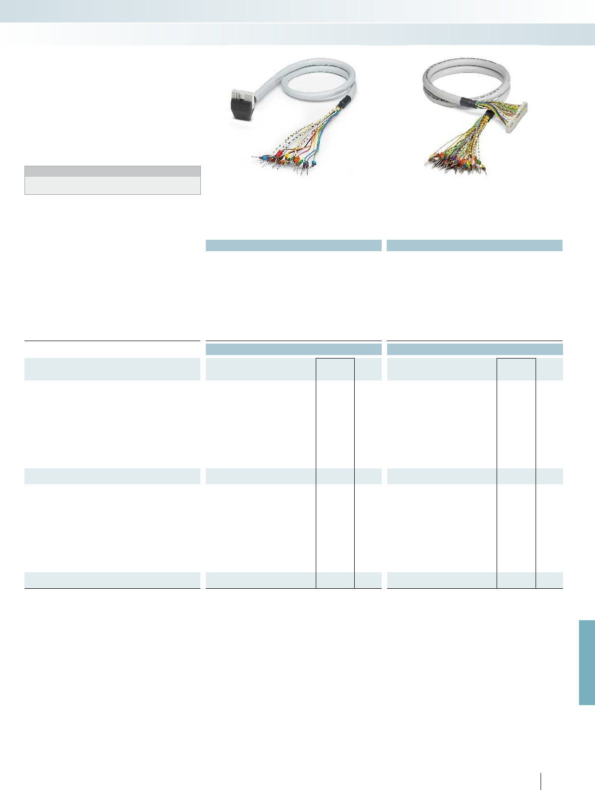
For further information and full technical data, visit phoenixcontact.net/products
Technical data Technical data
Max. perm. operating voltage < 50 V AC / 60 V DC < 50 V AC / 60 V DC
Max. perm. current carrying capacity per path 1 A 1 A
Max. conductor resistance 0.16 /m 0.16 /m
Ambient temperature (operation) -20 °C ... 50 °C -20 °C ... 50 °C
Assembly Insulation displacement, IEC 60352-4/DIN EN 60352-4 Insulation displacement, IEC 60352-4/DIN EN 60352-4
Conductor cross section AWG 26 / 0.14 mm² AWG 26 / 0.14 mm²
Conductor structure: stranded wires / material 7 / Cu tin-plated 7 / Cu tin-plated
Outside diameter
20-position 7.6 mm 7.6 mm
50-position 10.3 mm 10.3 mm
Ordering data Ordering data
Description No. of
pos. Cable length Type Order No. Pcs. /
Pkt. Type Order No. Pcs. /
Pkt.
Round cable with an open end
20 0.5 m CABLE-FLK20/OE/0,14/ 50 2305826 1
20 1 m VIP-CAB-FLK20/FR/OE/0,14/1,0M 2900139 1CABLE-FLK20/OE/0,14/ 100 2305305 1
20 1.5 m CABLE-FLK20/OE/0,14/ 150 2305318 1
20 2 m VIP-CAB-FLK20/FR/OE/0,14/2,0M 2900142 1CABLE-FLK20/OE/0,14/ 200 2305321 1
20 2.5 m CABLE-FLK20/OE/0,14/ 250 2305334 1
20 3 m VIP-CAB-FLK20/FR/OE/0,14/3,0M 2900143 1CABLE-FLK20/OE/0,14/ 300 2305347 1
20 4 m CABLE-FLK20/OE/0,14/ 400 2305839 1
20 6 m CABLE-FLK20/OE/0,14/ 600 2305842 1
20 8 m CABLE-FLK20/OE/0,14/ 800 2305855 1
20 10 m CABLE-FLK20/OE/0,14/1000 2305868 1
Round cable, as above, however in variable lengths
20 CABLE-FLK20/OE/0,14/... 2305745 1
Round cable with an open end
50 0.5 m CABLE-FLK50/OE/0,14/ 50 2305871 1
50 1 m VIP-CAB-FLK50/FR/OE/0,14/1,0M 2900147 1CABLE-FLK50/OE/0,14/ 100 2305350 1
50 1.5 m CABLE-FLK50/OE/0,14/ 150 2305363 1
50 2 m VIP-CAB-FLK50/FR/OE/0,14/2,0M 2900149 1CABLE-FLK50/OE/0,14/ 200 2305376 1
50 2.5 m CABLE-FLK50/OE/0,14/ 250 2305389 1
50 3 m VIP-CAB-FLK50/FR/OE/0,14/3,0M 2900150 1CABLE-FLK50/OE/0,14/ 300 2305392 1
50 4 m CABLE-FLK50/OE/0,14/ 400 2305884 1
50 6 m CABLE-FLK50/OE/0,14/ 600 2305897 1
50 8 m CABLE-FLK50/OE/0,14/ 800 2305907 1
50 10 m CABLE-FLK50/OE/0,14/1000 2305910 1
Round cable, as above, however in variable lengths
50 CABLE-FLK50/OE/0,14/... 2305758 1
603PHOENIX CONTACT
System cabling for controllers
Universal cables
Molded connectors, unshielded Unshielded
– 1:1 connection
– 20 and 50-pos.
– Connectors as per IEC 60603-13
– Open end at the other end
The individual wires at the open end are
marked (1, 2, 3, 4, ...) and fitted with a
ferrule.
Notes:
In the case of molded connectors, please observe the dimensional
drawing and note, see page 600
System cable with
a flat-ribbon cable connector and
an open end

604
PHOENIX CONTACT
Standard lengths
Pre-assembled round cables are used to
connect the PLC front adapters to the
corresponding VARIOFACE controller
boards.
The following versions are available with
14 and 50 positions:
– Unshielded
– Shielded
– Halogen-free
Connector strips are fitted on both ends
of the cables in accordance with
IEC 60603-13/DIN 41651 (1:1 connection).
In case of shielded cables, a cable end with
a ferrule is additionally provided as a shield
connection (length: approx. 0.5 m; cable
H05V-K 1 mm, black).
Special lengths are defined using an order
key, refer to page 608.
System cable with
flat-ribbon cable connector
Technical data
Max. perm. operating voltage < 50 V AC / 60 V DC
Max. perm. current carrying capacity per path 1 A
Max. conductor resistance 0.16 /m
Ambient temperature (operation) -20 °C ... 50 °C
Shield -
Assembly Insulation displacement, IEC 60352-4/DIN EN 60352-4 Insul
Conductor cross section AWG 26 / 0.14 mm²
Conductor structure: stranded wires / material 7 / Cu tin-plated
Outside diameter
14-position 6.4 mm
50-position 10.3 mm
Ordering data
Description No. of
pos. Cable length Type Order No. Pcs. /
Pkt.
Assembled round cable
1
), with two 14-pos. socket strips in fixed
lengths, for transfer of eight channels among other things
14 0.3 m FLK 14/EZ-DR/ 30/KONFEK 2295729 5
14 0.5 m FLK 14/EZ-DR/ 50/KONFEK 2288901 5
14 1 m FLK 14/EZ-DR/ 100/KONFEK 2288914 1
14 1.5 m FLK 14/EZ-DR/ 150/KONFEK 2288927 1
14 2 m FLK 14/EZ-DR/ 200/KONFEK 2288930 1
14 2.5 m FLK 14/EZ-DR/ 250/KONFEK 2288943 1
14 3 m FLK 14/EZ-DR/ 300/KONFEK 2288956 1
14 3.5 m FLK 14/EZ-DR/ 350/KONFEK 2288969 1
14 4 m FLK 14/EZ-DR/ 400/KONFEK 2288972 1
14 4.5 m FLK 14/EZ-DR/ 450/KONFEK 2290847 1
14 5 m FLK 14/EZ-DR/ 500/KONFEK 2290834 1
14 5.5 m FLK 14/EZ-DR/ 550/KONFEK 2290850 1
14 6 m FLK 14/EZ-DR/ 600/KONFEK 2290863 1
14 7 m
14 8 m FLK 14/EZ-DR/ 800/KONFEK 2299563 1
14 10 m FLK 14/EZ-DR/1000/KONFEK 2299576 1
Assembled round cable
2
), with two 50-pos. socket strips in fixed
lengths, for transfer of 32 channels among other things
50 0.5 m FLK 50/EZ-DR/ 50/KONFEK 2289065 5
50 1 m FLK 50/EZ-DR/ 100/KONFEK 2289078 1
50 1.5 m FLK 50/EZ-DR/ 150/KONFEK 2289081 1
50 2 m FLK 50/EZ-DR/ 200/KONFEK 2289094 1
50 2.5 m FLK 50/EZ-DR/ 250/KONFEK 2289104 1
50 3 m FLK 50/EZ-DR/ 300/KONFEK 2289117 1
50 3.5 m FLK 50/EZ-DR/ 350/KONFEK 2289120 1
50 4 m FLK 50/EZ-DR/ 400/KONFEK 2289133 1
50 4.5 m FLK 50/EZ-DR/ 450/KONFEK 2289573 1
50 5 m FLK 50/EZ-DR/ 500/KONFEK 2289586 1
50 5.5 m FLK 50/EZ-DR/ 550/KONFEK 2289599 1
50 6 m FLK 50/EZ-DR/ 600/KONFEK 2289609 1
50 6.5 m FLK 50/EZ-DR/ 650/KONFEK 2289612 1
50 7 m FLK 50/EZ-DR/ 700/KONFEK 2289625 1
50 7.5 m FLK 50/EZ-DR/ 750/KONFEK 2289638 1
50 8 m FLK 50/EZ-DR/ 800/KONFEK 2289641 1
50 8.5 m FLK 50/EZ-DR/ 850/KONFEK 2289654 1
50 9 m FLK 50/EZ-DR/ 900/KONFEK 2289667 1
50 9.5 m FLK 50/EZ-DR/ 950/KONFEK 2289670 1
50 10 m FLK 50/EZ-DR/1000/KONFEK 2289683 1
System cabling for controllers
Universal cables
Unshielded Shield connection at one end Halogen-free
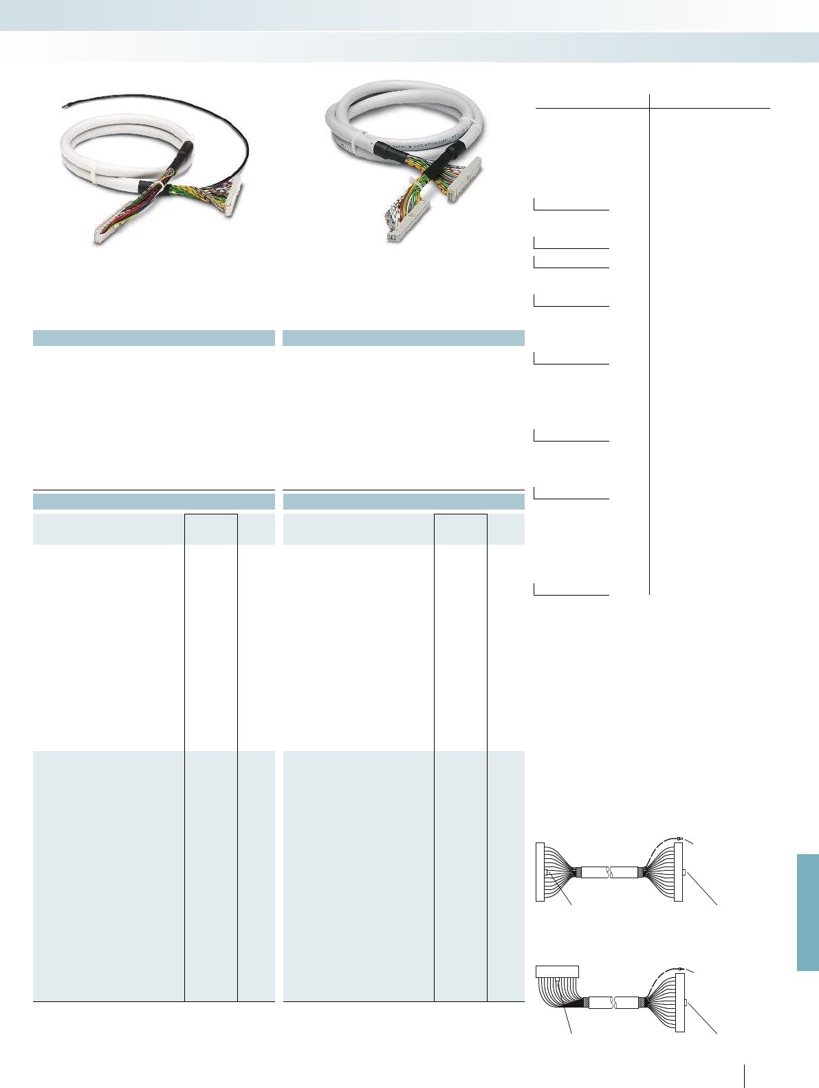
For further information and full technical data, visit phoenixcontact.net/products
1
) Socket strips assembled straight at both ends.
Polarization lug
Shield connection
(for shielded
cables)
Polarization lug
2
) Socket strips assembled straight at one end and angled at
the other.
Polarization lug Polarization lug
Shield connection
(for shielded cables)
Wire No. PIN Wire color
1 Black
2 Brown
3 Red
4 Orange
5 Yellow
6 Green
7 Blue
8 Violet
9 Gray
10-pos. 10 White
11 White-black
12 White-brown
13 White-red
14-pos. 14 White-orange
15 White-yellow
16-pos. 16 White-green
17 White-blue
18 White-violet
19 White-gray
20-pos. 20 Brown-black
21 Brown-red
22 Brown-orange
23 Brown-yellow
24 Brown-green
25 Brown-blue
26-pos. 26 Brown-violet
27 Brown-gray
28 Brown-white
29 Green-black
30 Green-brown
31 Green-red
32 Green-orange
33 Green-blue
34-pos. 34 Green-violet
35 Green-gray
36 Green-white
37 Yellow-black
38 Yellow-brown
39 Yellow-red
40-pos. 40 Yellow-orange
41 Yellow-blue
42 Yellow-violet
43 Yellow-gray
44 Yellow-white
45 Gray-black
46 Gray-brown
47 Gray-red
48 Gray-orange
49 Gray-yellow
50-pos. 50 Gray-green
Color code of system cables
Applied for: cUL / UL
605
PHOENIX CONTACT
Technical data Technical data
< 50 V AC / 60 V DC < 50 V AC / 60 V DC
1 A 1 A
0.16 /m 0.16 /m
-20 °C ... 50 °C -20 °C ... 50 °C
Tinned copper-braided shield, approx. 85% covering -
Assembly Insulation displacement, IEC 60352-4/DIN EN 60352-4 Insulation displacement, IEC 60352-4/DIN EN 60352-4 Insulation displacement, IEC 60352-4/DIN EN 60352-4
AWG 26 / 0.14 mm² AWG 26 / 0.14 mm²
7 / Cu tin-plated 7 / Cu tin-plated
6.7 mm 6.4 mm
11 mm 10.3 mm
Ordering data Ordering data
Type Order No. Pcs. /
Pkt. Type Order No. Pcs. /
Pkt.
FLK 14/EZ-DR/ 50/KONFEK/S 2296977 1FLK 14/EZ-DR/HF/ 50/KONFEK 2305952 1
FLK 14/EZ-DR/ 100/KONFEK/S 2296980 1FLK 14/EZ-DR/HF/ 100/KONFEK 2305965 1
FLK 14/EZ-DR/ 150/KONFEK/S 2296993 1FLK 14/EZ-DR/HF/ 150/KONFEK 2305978 1
FLK 14/EZ-DR/ 200/KONFEK/S 2297002 1FLK 14/EZ-DR/HF/ 200/KONFEK 2305981 1
FLK 14/EZ-DR/HF/ 250/KONFEK 2305994 1
FLK 14/EZ-DR/ 300/KONFEK/S 2299013 1FLK 14/EZ-DR/HF/ 300/KONFEK 2304759 1
FLK 14/EZ-DR/ 400/KONFEK/S 2299026 1FLK 14/EZ-DR/HF/ 400/KONFEK 2304762 1
FLK 14/EZ-DR/HF/ 500/KONFEK 2304717 1
FLK 14/EZ-DR/ 600/KONFEK/S 2299039 1FLK 14/EZ-DR/HF/ 600/KONFEK 2306003 1
FLK 14/EZ-DR/HF/ 700/KONFEK 2314011 1
FLK 14/EZ-DR/ 800/KONFEK/S 2299042 1FLK 14/EZ-DR/HF/ 800/KONFEK 2314024 1
FLK 14/EZ-DR/1000/KONFEK/S 2299055 1FLK 14/EZ-DR/HF/1000/KONFEK 2314037 1
FLK 50/EZ-DR/ 50/KONFEK/S 2299097 1CABLE-FLK50/0,14/HF/ 0,5M 2314134 1
FLK 50/EZ-DR/ 100/KONFEK/S 2299107 1CABLE-FLK50/0,14/HF/ 1,0M 2314147 1
FLK 50/EZ-DR/ 150/KONFEK/S 2299110 1CABLE-FLK50/0,14/HF/ 1,5M 2314150 1
FLK 50/EZ-DR/ 200/KONFEK/S 2299123 1CABLE-FLK50/0,14/HF/ 2,0M 2314163 1
CABLE-FLK50/0,14/HF/ 2,5M 2314176 1
FLK 50/EZ-DR/ 300/KONFEK/S 2299136 1CABLE-FLK50/0,14/HF/ 3,0M 2314189 1
FLK 50/EZ-DR/ 400/KONFEK/S 2299149 1CABLE-FLK50/0,14/HF/ 4,0M 2314192 1
CABLE-FLK50/0,14/HF/ 5,0M 2314202 1
FLK 50/EZ-DR/ 600/KONFEK/S 2299152 1CABLE-FLK50/0,14/HF/ 6,0M 2314215 1
CABLE-FLK50/0,14/HF/ 7,0M 2314228 1
FLK 50/EZ-DR/ 800/KONFEK/S 2299165 1CABLE-FLK50/0,14/HF/ 8,0M 2314231 1
FLK 50/EZ-DR/1000/KONFEK/S 2299178 1CABLE-FLK50/0,14/HF/10,0M 2314244 1
System cabling for controllers
Universal cables
Unshielded Shield connection at one end Halogen-free
(cable only)
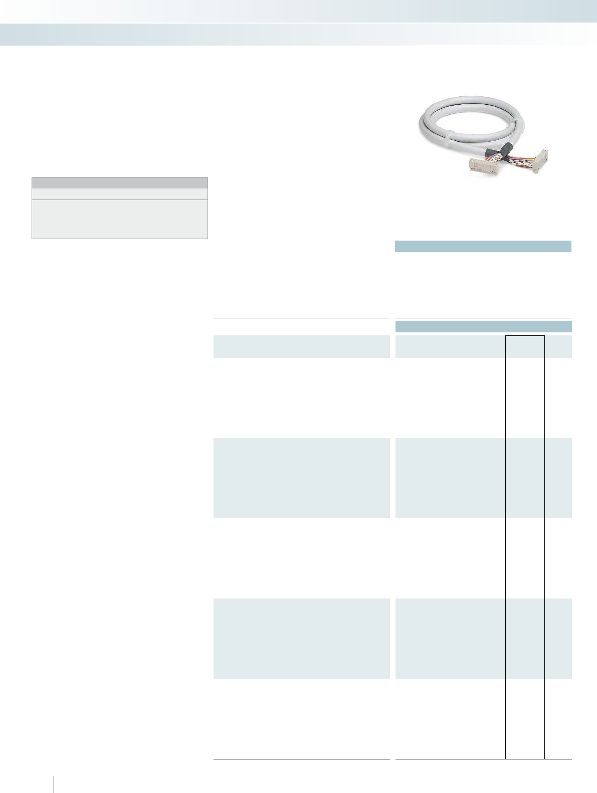
Applied for: cUL / UL
Technical data
Max. perm. operating voltage < 50 V AC / 60 V DC
Max. perm. current carrying capacity per path 1 A
Max. conductor resistance 0.16 /m
Ambient temperature (operation) -20 °C ... 50 °C
Assembly Insulation displacement, IEC 60352-4/DIN EN 60352-4
Conductor cross section AWG 26 / 0.14 mm²
Conductor structure: stranded wires / material 7 / Cu tin-plated
Ordering data
Description No. of
pos. Cable length Type Order No. Pcs. /
Pkt.
Round cable
1
), with two socket strips
10 0.5 m FLK 10/EZ-DR/ 50/KONFEK 2299204 1
10 1 m FLK 10/EZ-DR/ 100/KONFEK 2299217 1
10 1.5 m FLK 10/EZ-DR/ 150/KONFEK 2299220 1
10 2 m FLK 10/EZ-DR/ 200/KONFEK 2299233 1
10 3 m FLK 10/EZ-DR/ 300/KONFEK 2299246 1
10 4 m FLK 10/EZ-DR/ 400/KONFEK 2299259 1
10 6 m FLK 10/EZ-DR/ 600/KONFEK 2299262 1
10 8 m FLK 10/EZ-DR/ 800/KONFEK 2299275 1
10 10 m FLK 10/EZ-DR/1000/KONFEK 2299288 1
Round cable
1
), with two socket strips
16 0.5 m FLK 16/EZ-DR/ 50/KONFEK 2299291 1
16 1 m FLK 16/EZ-DR/ 100/KONFEK 2299301 1
16 1.5 m FLK 16/EZ-DR/ 150/KONFEK 2299314 1
16 2 m FLK 16/EZ-DR/ 200/KONFEK 2299327 1
16 3 m FLK 16/EZ-DR/ 300/KONFEK 2299330 1
16 4 m FLK 16/EZ-DR/ 400/KONFEK 2299343 1
16 6 m FLK 16/EZ-DR/ 600/KONFEK 2299356 1
16 8 m FLK 16/EZ-DR/ 800/KONFEK 2299369 1
16 10 m FLK 16/EZ-DR/1000/KONFEK 2299372 1
Round cable
1
), with two socket strips
20 0.5 m FLK 20/EZ-DR/ 50KONFEK 2296391 1
20 1 m FLK 20/EZ-DR/ 100KONFEK 2296401 1
20 1.5 m FLK 20/EZ-DR/ 150KONFEK 2296472 1
20 2 m FLK 20/EZ-DR/ 200KONFEK 2296485 1
20 3 m FLK 20/EZ-DR/ 300KONFEK 2296498 1
20 4 m FLK 20/EZ-DR/ 400KONFEK 2296508 1
20 6 m FLK 20/EZ-DR/ 600KONFEK 2296511 1
20 8 m FLK 20/EZ-DR/ 800KONFEK 2296524 1
20 10 m FLK 20/EZ-DR/1000KONFEK 2296537 1
Round cable
1
), with two socket strips
26 0.5 m FLK 26/EZ-DR/ 50/KONFEK 2299385 1
26 1 m FLK 26/EZ-DR/ 100/KONFEK 2299398 1
26 1.5 m FLK 26/EZ-DR/ 150/KONFEK 2299408 1
26 2 m FLK 26/EZ-DR/ 200/KONFEK 2299411 1
26 3 m FLK 26/EZ-DR/ 300/KONFEK 2299424 1
26 4 m FLK 26/EZ-DR/ 400/KONFEK 2299437 1
26 6 m FLK 26/EZ-DR/ 600/KONFEK 2299440 1
26 8 m FLK 26/EZ-DR/ 800/KONFEK 2299453 1
26 10 m FLK 26/EZ-DR/1000/KONFEK 2299466 1
Round cable
1
), with two socket strips
34 0.5 m FLK 34/EZ-DR/ 50/KONFEK 2299479 1
34 1 m FLK 34/EZ-DR/ 100/KONFEK 2299482 1
34 1.5 m FLK 34/EZ-DR/ 150/KONFEK 2299495 1
34 2 m FLK 34/EZ-DR/ 200/KONFEK 2299505 1
34 3 m FLK 34/EZ-DR/ 300/KONFEK 2299518 1
34 4 m FLK 34/EZ-DR/ 400/KONFEK 2299521 1
34 6 m FLK 34/EZ-DR/ 600/KONFEK 2299534 1
34 8 m FLK 34/EZ-DR/ 800/KONFEK 2299547 1
34 10 m FLK 34/EZ-DR/1000/KONFEK 2299550 1
606
PHOENIX CONTACT
Standard lengths
Pre-assembled round cables to couple the
VARIOFACE interface modules.
Connector strips are fitted on both ends
of the cables in accordance with
IEC 60603-13/DIN 41651 (1:1 connection).
Special lengths are defined using an order
key, refer to page 608.
Notes:
Outside diameter of the cable
10-pos.: 6 mm
16-pos.: 6.5 mm
20-pos.: 7.6 mm
26-pos.: 7.8 mm
34-pos.: 10 mm
System cable with
flat-ribbon cable connector
System cabling for controllers
Universal cables
Unshielded
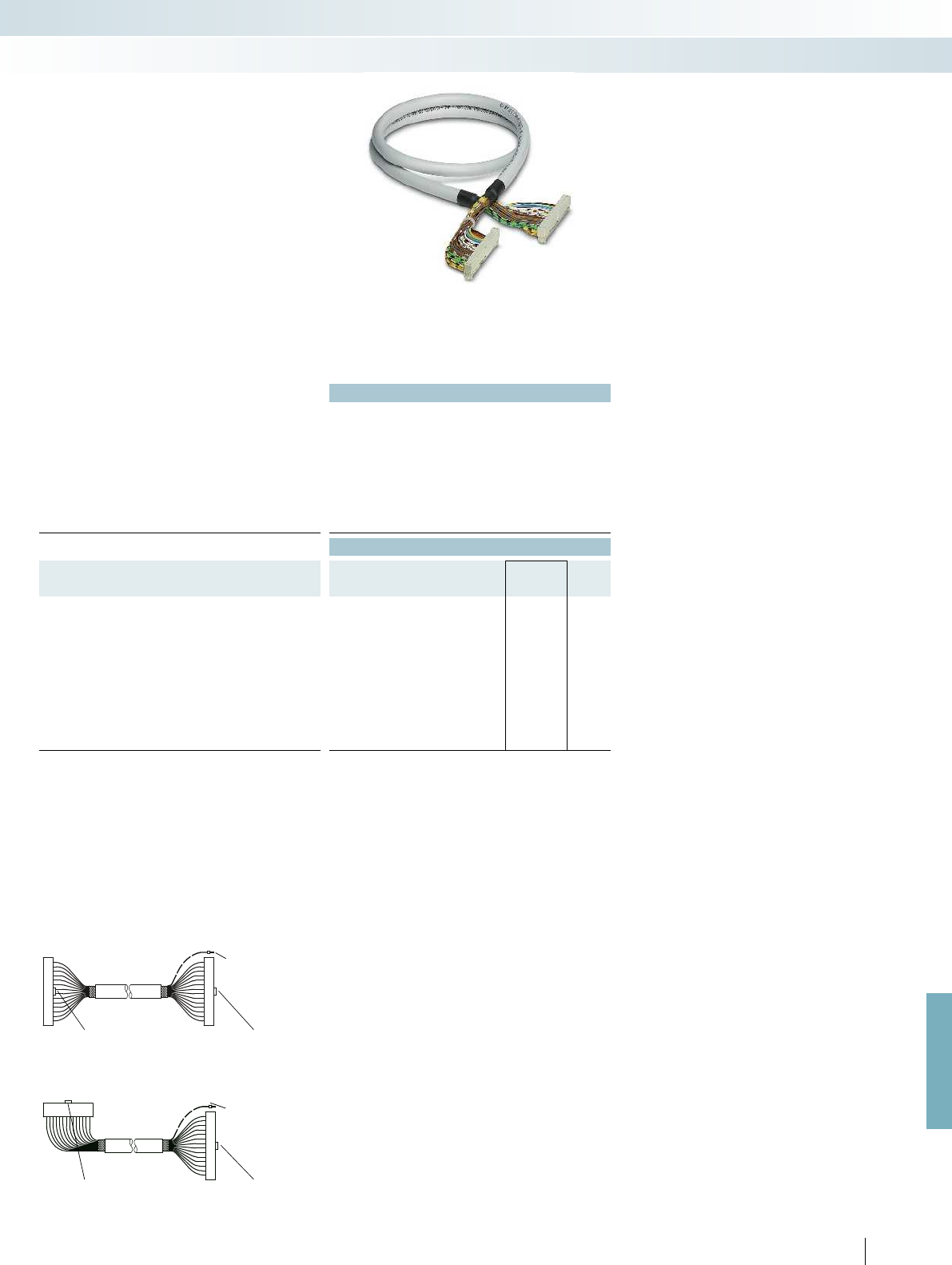
For further information and full technical data, visit phoenixcontact.net/products
Technical data
Max. perm. operating voltage < 50 V AC / 60 V DC
Max. perm. current carrying capacity per path 1 A
Max. conductor resistance 0.16 /m
Ambient temperature (operation) -20 °C ... 50 °C
Assembly Insulation displacement, IEC 60352-4/DIN EN 60352-4
Conductor cross section AWG 26 / 0.14 mm²
Conductor structure: stranded wires / material 7 / Cu tin-plated
Outside diameter
40-position 9.9 mm
Ordering data
Description No. of
pos. Cable length Type Order No. Pcs. /
Pkt.
Round cable
2
), with two socket strips
40 0.5 m FLK 40/EZ-DR/ 50/KONFEK 2288985 5
40 1 m FLK 40/EZ-DR/ 100/KONFEK 2288998 1
40 1.5 m FLK 40/EZ-DR/ 150/KONFEK 2289007 1
40 2 m FLK 40/EZ-DR/ 200/KONFEK 2289010 1
40 2.5 m FLK 40/EZ-DR/ 250/KONFEK 2289023 1
40 3 m FLK 40/EZ-DR/ 300/KONFEK 2289036 1
40 3.5 m FLK 40/EZ-DR/ 350/KONFEK 2289049 1
40 4 m FLK 40/EZ-DR/ 400/KONFEK 2289052 1
40 6 m FLK 40/EZ-DR/ 600/KONFEK 2299589 1
40 8 m FLK 40/EZ-DR/ 800/KONFEK 2299592 1
40 10 m FLK 40/EZ-DR/1000/KONFEK 2299602 1
1
) Socket strips assembled straight at both ends.
Polarization lug
2
) Socket strips assembled straight at one end and angled at
the other.
Polarization lug Polarization lug
Shield connection
(for shielded
cables)
Shield connection
(for shielded
cables)
Polarization lug
607
PHOENIX CONTACT
System cabling for controllers
Universal cables
Unshielded
Standard lengths
Pre-assembled round cables are used to
connect the PLC front adapters to the
corresponding VARIOFACE controller
boards.
Connector strips are fitted on both ends
of the cables in accordance with
IEC 60603-13/DIN 41651 (1:1 connection).
Special lengths are defined using an order
key, refer to page 608.
System cable with
flat-ribbon cable connector
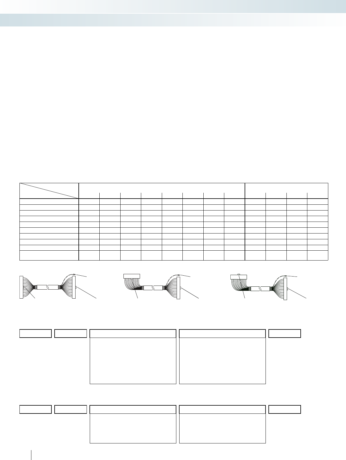
608
PHOENIX CONTACT
System cable with
flat-ribbon cable connector
Cable type Unshielded round cables
FLK EZ-DR.../.../...
Shielded round cables
FLK EZ-DR-S.../.../...
Assembly 10-pos. 14-pos. 16-pos. 20-pos. 26-pos. 34-pos. 40-pos. 50-pos. 14-pos. 16-pos. 40-pos. 50-pos.
No assembly 10U/C00/... 14U/C00/... 16U/C00/... 20U/C00/... 26U/C00/... 34U/C00/... 40U/C00/... 50U/C00/... 14S/C00/... 16S/C00/.... 40S/C00/... 50S/C00/...
10-pos. socket strip at both ends 10U/C55/...
1
)
14-pos. socket strip at both ends 14U/C23/...
1
)14S/C23/...
1
)
16-pos. socket strip at both ends 16U/C58/...
1
)16S/C58/...
1
)
20-pos. socket strip at both ends 20U/C61/...
1
)
26-pos. socket strip at both ends 26U/C63/...
1
)
34-pos. socket strip at both ends 34U/C65/...
1
)
40-pos. socket strip at both ends 40U/C30/...
3
)40S/C30/...
3
)
50-pos. socket strip at both ends 50U/C38/...
2
)50S/C38/...
2
)
14-pos. socket strip at one end;
16-pos. socket strip at one end 14U/C52/...
1
)14S/C52/...
1
)
Features of permissible assemblies:
1
) Socket strips assembled straight at both ends.
Polarization lug
2
) Socket strips assembled straight at one end and angled at
the other.
Polarization lug Polarization lug
Shield connection
(for shielded
cables)
Shield connection
(for shielded cables)
Polarization lug
Ordering example for unshielded round cable:
– Unshielded 50-pos. round cable, assembled with two 50-pos. socket strips, 11.5 m long
Quantity Order No. Cable type Assembly Length [m]
4
)
12295059 /50U /C38 /11.50
10U =10-pos. unshielded
14U =14-pos. unshielded
16U =16-pos. unshielded
20U =20-pos. unshielded
26U =26-pos. unshielded
34U =34-pos. unshielded
40U =40-pos. unshielded
50U =50-pos. unshielded
C00 =No assembly
C55 =10-pos. socket strip at both ends
C23 =14-pos. socket strip at both ends
C52 =14-pos. socket strip at one end,
16-pos. socket strip at the other (for S7)
C58 =16-pos. socket strip at both ends
C61 =20-pos. socket strip at both ends
C63 =26-pos. socket strip at both ends
C65 =34-pos. socket strip at both ends
C30 =40-pos. socket strip at both ends
C38 =50-pos. socket strip at both ends
4
) Min. 0.20 m
Ordering example for shielded round cable:
– Shielded 14-pos. round cable, assembled with two 14-pos. socket strips, 12.75 m long
Quantity Order No. Cable type Assembly Length [m]
4
)
12295046 /14S /C23 /12.75
14S =14-pos. shielded
16S =16-pos. shielded
40S =40-pos. shielded
50S =50-pos. shielded
C00 =No assembly
C23 =14-pos. socket strip at both ends
C52 =14-pos. socket strip at one end,
16-pos. socket strip at the other (for S7)
C58 =16-pos. socket strip at both ends
C30 =40-pos. socket strip at both ends
C38 =50-pos. socket strip at both ends
4
) Min. 0.20 m
Special lengths
Pre-assembled round cables for
connecting, e.g., PLC front adapters to the
corresponding VARIOFACE termination
boards. The cables are assembled with
connector strips at both ends according to
IEC 60603-13/DIN 41651. For shielded
cables, a cable end with ferrule is available
additionally as a shielded connection (length:
approx. 0.5 m; cable: H05V-K 1 mm
2
, black).
The order key for special lengths is
described using three features.
The order of the features is as follows:
– Cable type
– Assembly
– Length in meters
There are two order keys, one for
unshielded round cables, FLK EZ-DR/.../.../...,
and one for shielded round cables,
FLK EZ-DR-S/.../.../.... To ensure clear
specification when ordering, the features are
described in detail below:
Cable type
– This specifies the number of individual
conductors of the specific cable.
Assembly
– None,
the cable is not assembled at either end;
– 10-pos. socket strip at both ends, the
cable is assembled with 10-pos.
connectors at both ends
(1:1 connection);
– 14-pos. socket strip at both ends,
the cable is assembled with 14-pos.
connectors at both ends
(1:1 connection); and so on up to
– 50-pos. socket strip at both ends, the
cable is assembled with 50-pos.
connectors at both ends
(1:1 connection);
– 14-pos. socket strip at one end,
16-pos. socket strip at one end,
the cable is assembled with a 14-pos.
connector at one end and a
16-pos. connector at the other end (for
SIMATIC S7; no 1:1 connection).
3
) Socket strips assembled straight at one end and angled at
the other.
Polarization lug Polarization lug
Shield connection
(for shielded
cables)
System cabling for controllers
Universal cables
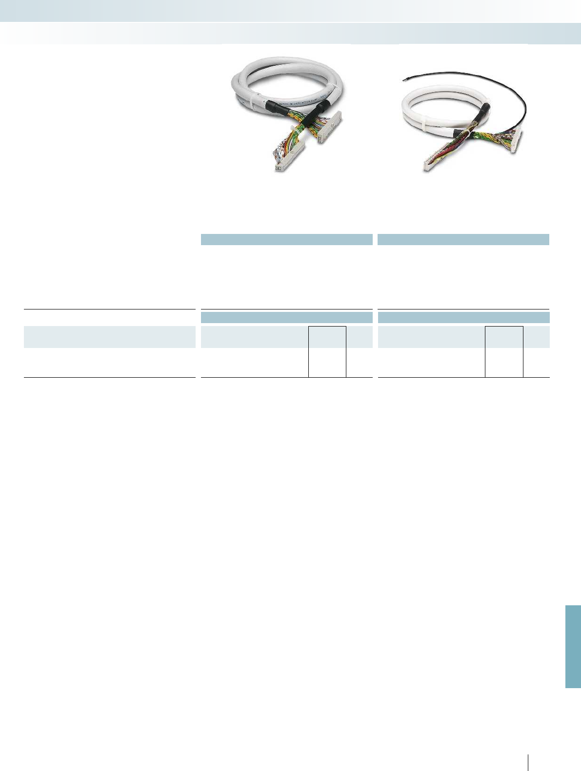
For further information and full technical data, visit phoenixcontact.net/products
Technical data Technical data
Max. perm. operating voltage < 50 V AC / 60 V DC < 50 V AC / 60 V DC
Max. perm. current carrying capacity per path 1 A 1 A
Max. conductor resistance 0.16 /m 0.16 /m
Ambient temperature (operation) -20 °C ... 50 °C -20 °C ... 50 °C
Shield - Tinned copper-braided shield, approx. 85% covering
Conductor cross section AWG 26 / 0.14 mm² AWG 26 / 0.14 mm²
Conductor structure: stranded wires / material 7 / Cu tin-plated 7 / Cu tin-plated
Ordering data Ordering data
Description No. of
pos. Cable length Type Order No. Pcs. /
Pkt. Type Order No. Pcs. /
Pkt.
Unshielded round cable, as above, but in variable lengths of type
“FLK EZ-DR/14U/C52/...”
FLK EZ-DR.../.../... 2295059 1FLK EZ-DR-S.../.../... 2295046 1
609PHOENIX CONTACT
System cabling for controllers
Universal cables
Unshielded Shielded
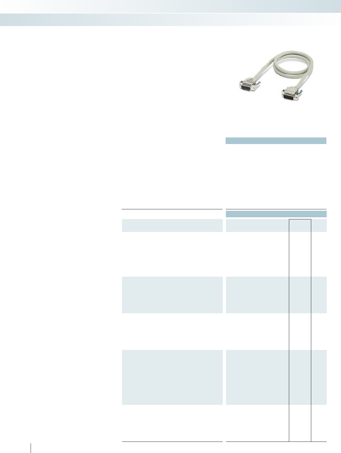
610
PHOENIX CONTACT
Standard lengths
Pre-assembled shielded round cables
to connect the control level with the
corresponding VARIOFACE interface
modules.
Assembly with D-SUB strips as per
IEC 60807-2/DIN 41652, (1:1 connection).
– D-SUB socket strip on one end and
D-SUB pin strip on the other
– D-SUB sockets on both ends
– DSUB pin strips on both ends
– Cable outlet: straight
– Screw connection: 2 UNC 4-40 screws
Special lengths and assembly versions are
defined using an order key, refer to page 612.
System cable with
DSUB socket and pin strip
Technical data
Max. perm. operating voltage 125 V AC/DC
Max. perm. current carrying capacity per path 2 A
Max. conductor resistance 0.09 /m
Ambient temperature (operation) -20 °C ... 50 °C
Shield Tinned copper-braided shield, approx. 85% covering Tinned copper-braided shield, approx. 85% covering Tinned copper-braided
Insertion/withdrawal cycles > 200
Conductor cross section AWG 24 / 0.25 mm²
Outside diameter
9-position 7.5 mm
15-position 9 mm
25-position 10.5 mm
37-position 12.5 mm
50-position 13.5 mm
Ordering data
Description No. of
pos. Cable length Type Order No. Pcs. /
Pkt.
Shielded round cable, fitted with two D-SUB strips, various
numbers of positions and lengths
9 0.5 m CABLE-D 9SUB/B/S/ 50/KONFEK/S 2299987 1
9 1 m CABLE-D 9SUB/B/S/100/KONFEK/S 2299990 1
9 1.5 m CABLE-D 9SUB/B/S/150/KONFEK/S 2300009 1
9 2 m CABLE-D 9SUB/B/S/200/KONFEK/S 2302010 1
9 3 m CABLE-D 9SUB/B/S/300/KONFEK/S 2302023 1
9 4 m CABLE-D 9SUB/B/S/400/KONFEK/S 2302036 1
9 6 m CABLE-D 9SUB/B/S/600/KONFEK/S 2302049 1
15 0.5 m CABLE-D15SUB/B/S/ 50/KONFEK/S 2302052 1
15 1 m CABLE-D15SUB/B/S/100/KONFEK/S 2302065 1
15 1.5 m CABLE-D15SUB/B/S/150/KONFEK/S 2302078 1
15 2 m CABLE-D15SUB/B/S/200/KONFEK/S 2302081 1
15 3 m CABLE-D15SUB/B/S/300/KONFEK/S 2302094 1
15 4 m CABLE-D15SUB/B/S/400/KONFEK/S 2302104 1
15 6 m CABLE-D15SUB/B/S/600/KONFEK/S 2302117 1
25 0.5 m CABLE-D25SUB/B/S/ 50/KONFEK/S 2302120 1
25 1 m CABLE-D25SUB/B/S/100/KONFEK/S 2302133 1
25 1.5 m CABLE-D25SUB/B/S/150/KONFEK/S 2302146 1
25 2 m CABLE-D25SUB/B/S/200/KONFEK/S 2302159 1
25 3 m CABLE-D25SUB/B/S/300/KONFEK/S 2302162 1
25 4 m CABLE-D25SUB/B/S/400/KONFEK/S 2302175 1
25 6 m CABLE-D25SUB/B/S/600/KONFEK/S 2302188 1
37 0.5 m CABLE-D37SUB/B/S/ 50/KONFEK/S 2302191 1
37 1 m CABLE-D37SUB/B/S/100/KONFEK/S 2302201 1
37 1.5 m CABLE-D37SUB/B/S/150/KONFEK/S 2302214 1
37 2 m CABLE-D37SUB/B/S/200/KONFEK/S 2302227 1
37 3 m CABLE-D37SUB/B/S/300/KONFEK/S 2302230 1
37 4 m CABLE-D37SUB/B/S/400/KONFEK/S 2302243 1
37 6 m CABLE-D37SUB/B/S/600/KONFEK/S 2302256 1
37 8 m
37 10 m
37 15 m
37 20 m
50 0.5 m CABLE-D50SUB/B/S/ 50/KONFEK/S 2302269 1
50 1 m CABLE-D50SUB/B/S/100/KONFEK/S 2302272 1
50 1.5 m CABLE-D50SUB/B/S/150/KONFEK/S 2302285 1
50 2 m CABLE-D50SUB/B/S/200/KONFEK/S 2302298 1
50 3 m CABLE-D50SUB/B/S/300/KONFEK/S 2302308 1
50 4 m CABLE-D50SUB/B/S/400/KONFEK/S 2302311 1
50 6 m CABLE-D50SUB/B/S/600/KONFEK/S 2302324 1
System cabling for controllers
Universal cables
Socket strip at one end and pin strip
at the other
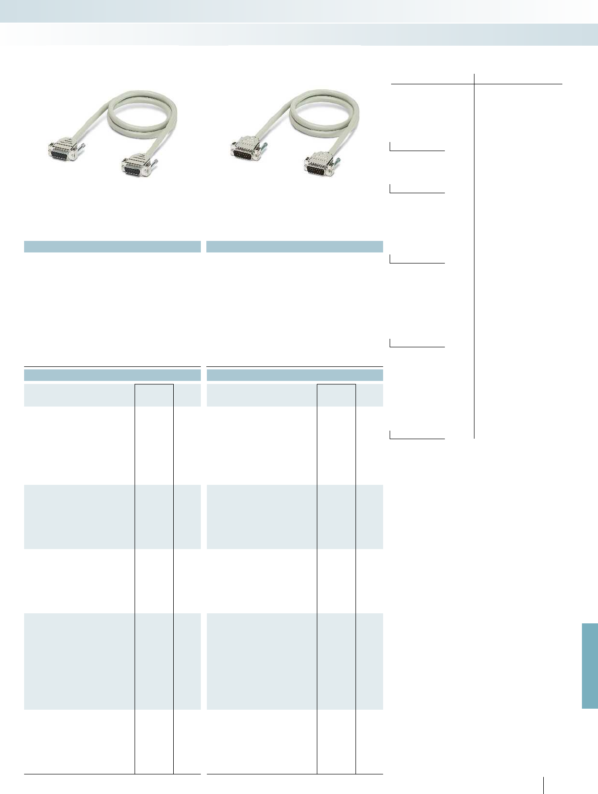
For further information and full technical data, visit phoenixcontact.net/products
No. of cores PIN Core color
1 white
2 brown
3 green
4 yellow
5 gray
6 pink
7 blue
8 red
9-pos. 9 black
10 violet
11 gray-pink
12 red-blue
13 white-green
14 brown-green
15-pos. 15 white-yellow
16 yellow-brown
17 white-gray
18 gray-brown
19 white-pink
20 pink-brown
21 white-blue
22 brown-blue
23 white-red
24 brown-red
25-pos. 25 white-black
26 brown-black
27 gray-green
28 yellow-gray
29 pink-green
30 yellow-pink
31 green-blue
32 yellow-blue
33 green-red
34 yellow-red
35 green-black
36 yellow-black
37-pos. 37 gray-blue
38 pink-blue
39 gray-red
40 pink-red
41 gray-black
42 pink-black
43 blue-black
44 red-black
45 white-brown-black
46 yellow-green-black
47 gray-pink-black
48 blue-red-black
49 white-green-black
50-pos. 50 green-brown-black
Color code of the system cables
CABLE-D...SUB/...
611PHOENIX CONTACT
Technical data Technical data
125 V AC/DC 125 V AC/DC
2 A 2 A
0.09 /m 0.09 /m
-20 °C ... 50 °C -20 °C ... 50 °C
Shield Tinned copper-braided shield, approx. 85% covering Tinned copper-braided shield, approx. 85% covering Tinned copper-braided shield, approx. 85% covering
> 200 > 200
AWG 24 / 0.25 mm² AWG 24 / 0.25 mm²
7.5 mm 7.5 mm
9 mm 9 mm
10.5 mm 10.5 mm
12 mm 12 mm
13.5 mm 13.5 mm
Ordering data Ordering data
Type Order No. Pcs. /
Pkt. Type Order No. Pcs. /
Pkt.
CABLE-D 9SUB/B/B/100/KONFEK/S 2305415 1CABLE-D 9SUB/S/S/100/KONFEK/S 2305570 1
CABLE-D 9SUB/B/B/200/KONFEK/S 2305428 1CABLE-D 9SUB/S/S/200/KONFEK/S 2305583 1
CABLE-D 9SUB/B/B/300/KONFEK/S 2305431 1CABLE-D 9SUB/S/S/300/KONFEK/S 2305596 1
CABLE-D15SUB/B/B/100/KONFEK/S 2305444 1CABLE-D15SUB/S/S/100/KONFEK/S 2305606 1
CABLE-D15SUB/B/B/200/KONFEK/S 2305457 1CABLE-D15SUB/S/S/200/KONFEK/S 2305619 1
CABLE-D15SUB/B/B/300/KONFEK/S 2305460 1CABLE-D15SUB/S/S/300/KONFEK/S 2305622 1
CABLE-D25SUB/B/B/100/KONFEK/S 2305473 1CABLE-D25SUB/S/S/100/KONFEK/S 2305635 1
CABLE-D25SUB/B/B/200/KONFEK/S 2305486 1CABLE-D25SUB/S/S/200/KONFEK/S 2305648 1
CABLE-D25SUB/B/B/300/KONFEK/S 2305499 1CABLE-D25SUB/S/S/300/KONFEK/S 2305651 1
CABLE-D37SUB/B/B/ 100/KONFEK/S 2305509 1CABLE-D37SUB/S/S/100/KONFEK/S 2305664 1
CABLE-D37SUB/B/B/ 200/KONFEK/S 2305512 1CABLE-D37SUB/S/S/200/KONFEK/S 2305677 1
CABLE-D37SUB/B/B/ 300/KONFEK/S 2305525 1CABLE-D37SUB/S/S/300/KONFEK/S 2305680 1
CABLE-D37SUB/B/B/ 400/KONFEK/S 2900759 1
CABLE-D37SUB/B/B/ 600/KONFEK/S 2900760 1
CABLE-D37SUB/B/B/ 800/KONFEK/S 2900761 1
CABLE-D37SUB/B/B/1000/KONFEK/S 2900762 1
CABLE-D37SUB/B/B/1500/KONFEK/S 2900763 1
CABLE-D37SUB/B/B/2000/KONFEK/S 2900764 1
CABLE-D50SUB/B/B/100/KONFEK/S 2305541 1CABLE-D50SUB/S/S/100/KONFEK/S 2305693 1
CABLE-D50SUB/B/B/200/KONFEK/S 2305554 1CABLE-D50SUB/S/S/200/KONFEK/S 2305703 1
CABLE-D50SUB/B/B/300/KONFEK/S 2305567 1CABLE-D50SUB/S/S/300/KONFEK/S 2305716 1
System cabling for controllers
Universal cables
Socket strip at both ends Pin strip at both ends
612
PHOENIX CONTACT
System cable with D-SUB socket and
pin strip
Special lengths
Pre-assembled shielded round cables
for connecting VARIOFACE termination
boards. The cables are assembled with
D-SUB strips in accordance with
IEC 60807-2/DIN 41652.
The order key is defined by three features.
The features in the appropriate
sequence are:
– Cable type
– Assembly
– Length in meters
There are three assembly variants of the
shielded round cable:
– CABLE D-SUB-S/.../.../...
D-SUB socket strip on one end and
D-SUB pin strip on the other
– CABLE D-SUB-B-B-S/.../.../... D-SUB
socket strip at both ends
– CABLE D-SUB-S-S-S/.../.../... D-SUB pin
strip at both ends
The features necessary for clear
identification of an order are described
below:
Cable type
– The number of individual conductors of
the cable is defined here.
Assembly
– (example for CABLE D-SUB-S/.../.../...)
– None,
the cable is not assembled at either end
– 9-pos. D-SUB socket strip at one end
and 9-pos. D-SUB pin strip at the other
end, the cable connects (1:1) a 9-pos.
D-SUB socket and pin strip
– 15-pos. D-SUB socket strip at one end
15-pos. D-SUB pin strip at the other
end, the cable connects (1:1) a 15-pos.
D-SUB socket and pin strip; or up to
– 50-pos. D-SUB socket strip at one end
50-pos. D-SUB pin strip at the other
end, the cable connects (1:1) a 50-pos.
D-SUB socket and pin strip.
Ordering example for round cable assembled with pin strip on one end and socket strip on the other end
– Unshielded 25-pos. round cable, assembled with one 25-pos. D-SUB socket strip and one 25-pos. D-SUB pin strip, 11.5 mm long
Quantity Order No. Cable type Assembly Length [m]
1
)
12302340 /25S /C36 /11.50
09S =9-pos. shielded
15S =15-pos. shielded
25S =25-pos. shielded
37S =37-pos. shielded
50S =50-pos. shielded
C00 =no assembly
C01 =9-pos. D-SUB socket strip at one end
9-pos. D-SUB pin strip at one end
C28 =15-pos. D-SUB socket strip at one end
15-pos. D-SUB pin strip at one end
C36 =25-pos. D-SUB socket strip at one end
25-pos. D-SUB pin strip at one end
C43 =37-pos. D-SUB socket strip at one end
37-pos. D-SUB pin strip at one end
C49 =50-pos. D-SUB socket strip at one end
50-pos. D-SUB pin strip at one end
1
) min. 0.20 m
Ordering example for round cable assembled with socket strip at both ends
– Shielded 37-pos. round cable, assembled with two 37-pos. D-SUB socket strips, 12.75 m long
Quantity Order No. Cable type Assembly Length [m]
1
)
12302421 /37S /C44 /12.75
09S =9-pos. shielded
15S =15-pos. shielded
25S =25-pos. shielded
37S =37-pos. shielded
50S =50-pos. shielded
C00 =no assembly
C22 =9-pos. D-SUB socket strip at both ends
C29 =15-pos. D-SUB socket strip at both ends
C37 =25-pos. D-SUB socket strip at both ends
C44 =37-pos. D-SUB socket strip at both ends
C50 =50-pos. D-SUB socket strip at both ends
1
) min. 0.20 m
Ordering example for round cable assembled with pin strip at both ends
– Shielded 15-pos. round cable, assembled with two 15-pos. D-SUB pin strips, 8.5 m long
Quantity Order No. Cable type Assembly Length [m]
1
)
12302434 /15S /C71 /8.50
09S =9-pos. shielded
15S =15-pos. shielded
25S =25-pos. shielded
37S =37-pos. shielded
50S =50-pos. shielded
C00 =no assembly
C70 =9-pos. D-SUB pin strip at both ends
C71 =15-pos. D-SUB pin strip at both ends
C72 =25-pos. D-SUB pin strip at both ends
C73 =37-pos. D-SUB pin strip at both ends
C74 =50-pos. D-SUB pin strip at both ends
1
) min. 0.20 m
System cabling for controllers
Universal cables
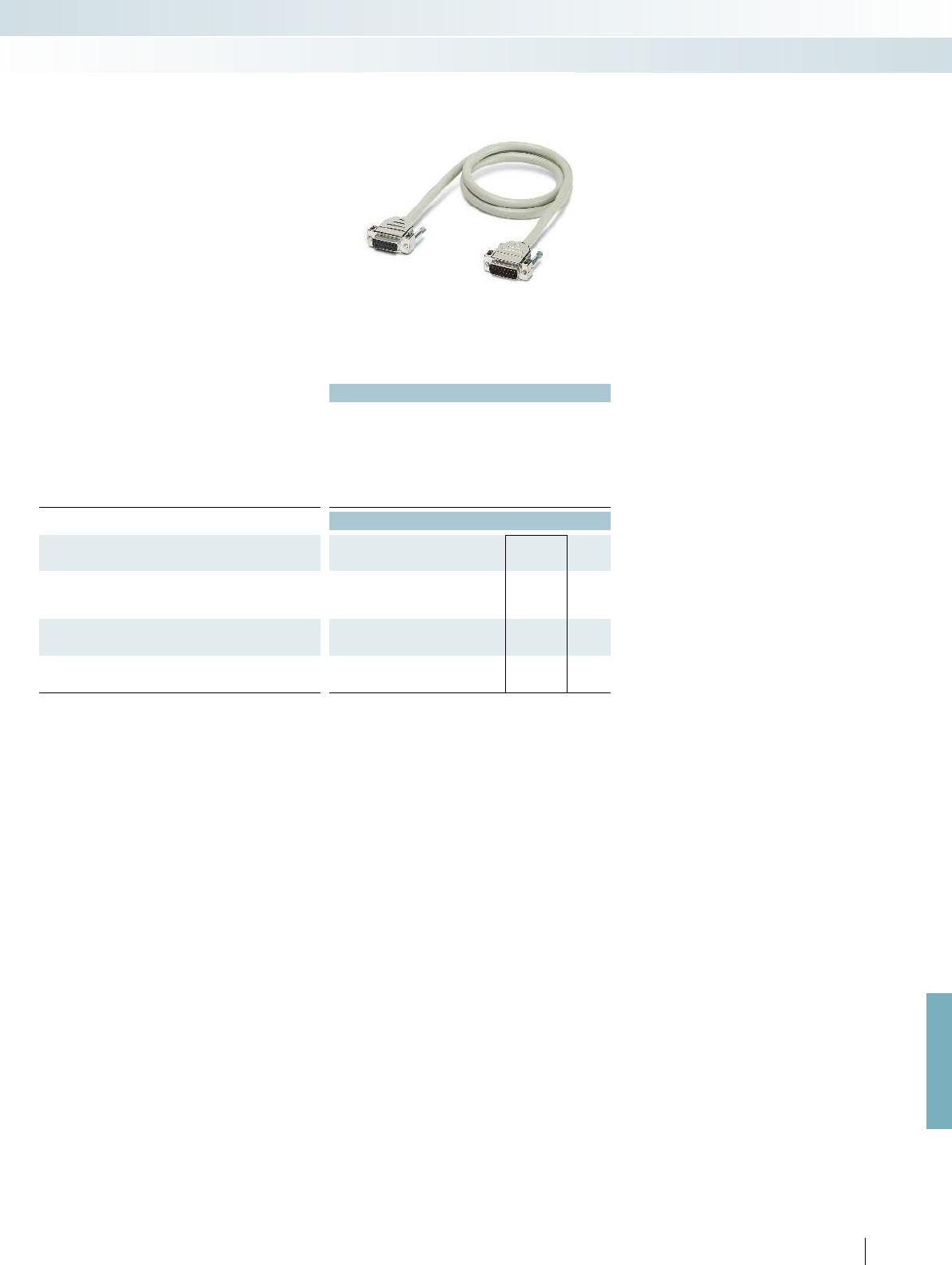
For further information and full technical data, visit phoenixcontact.net/products
Technical data
Max. perm. operating voltage 125 V AC/DC
Max. perm. current carrying capacity per path 2 A
Max. conductor resistance 0.09 /m
Ambient temperature (operation) -20 °C ... 50 °C
Shield Tinned copper-braided shield, approx. 85% covering
Insertion/withdrawal cycles > 200
Conductor cross section AWG 24 / 0.25 mm²
Ordering data
Description No. of
pos. Cable length Type Order No. Pcs. /
Pkt.
Assembled round cable, in variable lengths, pin strip on one
end and socket strip on the other end
CABLE D-SUB-S/.../.../... 2302340 1
Assembled round cable, in variable lengths, socket strip on
both ends
CABLE D-SUB-B-B-S/.../.../... 2302421 1
Assembled round cable, in variable lengths, pin strip on both
ends
CABLE D-SUB-S-S-S/.../.../... 2302434 1
613PHOENIX CONTACT
System cabling for controllers
Universal cables
Shielded

Technical data Technical data
Max. perm. operating voltage 125 V AC/DC 125 V AC/DC
Max. perm. current carrying capacity per path 2 A 2 A
Max. conductor resistance 0.09 /m 0.09 /m
Ambient temperature (operation) -20 °C ... 50 °C -20 °C ... 50 °C
Shield Tinned copper-braided shield, approx. 85% covering Tinned copper-braided shield, approx. 85% covering
Insertion/withdrawal cycles > 200 > 200
Conductor cross section AWG 24 / 0.25 mm² AWG 24 / 0.25 mm²
Outside diameter
9-position 7.5 mm 7.5 mm
15-position 9 mm 9 mm
25-position 10.5 mm 10.5 mm
Ordering data Ordering data
Description No. of
pos. Cable length Type Order No. Pcs. /
Pkt. Type Order No. Pcs. /
Pkt.
Round cable with an open end
9 0.5 m CABLE-D- 9SUB/F/OE/0,25/S/0,5M 2926014 1CABLE-D- 9SUB/M/OE/0,25/S/0,5M 2926360 1
9 1 m CABLE-D- 9SUB/F/OE/0,25/S/1,0M 2926027 1CABLE-D- 9SUB/M/OE/0,25/S/1,0M 2926373 1
9 1.5 m CABLE-D- 9SUB/F/OE/0,25/S/1,5M 2926030 1CABLE-D- 9SUB/M/OE/0,25/S/1,5M 2926386 1
9 2 m CABLE-D- 9SUB/F/OE/0,25/S/2,0M 2926043 1CABLE-D- 9SUB/M/OE/0,25/S/2,0M 2926399 1
9 3 m CABLE-D- 9SUB/F/OE/0,25/S/3,0M 2926056 1CABLE-D- 9SUB/M/OE/0,25/S/3,0M 2926409 1
9 4 m CABLE-D- 9SUB/F/OE/0,25/S/4,0M 2926069 1CABLE-D- 9SUB/M/OE/0,25/S/4,0M 2926412 1
9 6 m CABLE-D- 9SUB/F/OE/0,25/S/6,0M 2926072 1CABLE-D- 9SUB/M/OE/0,25/S/6,0M 2926425 1
Round cable, as above, however in variable lengths
9CABLE-D- 9SUB-F-OE-0,25-S/... 2900903 1CABLE-D- 9SUB-M-OE-0,25-S/... 2900909 1
Round cable with an open end
15 0.5 m CABLE-D-15SUB/F/OE/0,25/S/0,5M 2926085 1CABLE-D-15SUB/M/OE/0,25/S/0,5M 2926438 1
15 1 m CABLE-D-15SUB/F/OE/0,25/S/1,0M 2926098 1CABLE-D-15SUB/M/OE/0,25/S/1,0M 2926441 1
15 1.5 m CABLE-D-15SUB/F/OE/0,25/S/1,5M 2926108 1CABLE-D-15SUB/M/OE/0,25/S/1,5M 2926454 1
15 2 m CABLE-D-15SUB/F/OE/0,25/S/2,0M 2926111 1CABLE-D-15SUB/M/OE/0,25/S/2,0M 2926467 1
15 3 m CABLE-D-15SUB/F/OE/0,25/S/3,0M 2926124 1CABLE-D-15SUB/M/OE/0,25/S/3,0M 2926470 1
15 4 m CABLE-D-15SUB/F/OE/0,25/S/4,0M 2926137 1CABLE-D-15SUB/M/OE/0,25/S/4,0M 2926483 1
15 6 m CABLE-D-15SUB/F/OE/0,25/S/6,0M 2926140 1CABLE-D-15SUB/M/OE/0,25/S/6,0M 2926496 1
Round cable, as above, however in variable lengths
15 CABLE-D-15SUB-F-OE-0,25-S/... 2900905 1CABLE-D-15SUB-M-OE-0,25-S/... 2900910 1
Round cable with an open end
25 0.5 m CABLE-D-25SUB/F/OE/0,25/S/0,5M 2926153 1CABLE-D-25SUB/M/OE/0,25/S/0,5M 2926506 1
25 1 m CABLE-D-25SUB/F/OE/0,25/S/1,0M 2926166 1CABLE-D-25SUB/M/OE/0,25/S/1,0M 2926519 1
25 1.5 m CABLE-D-25SUB/F/OE/0,25/S/1,5M 2926179 1CABLE-D-25SUB/M/OE/0,25/S/1,5M 2926522 1
25 2 m CABLE-D-25SUB/F/OE/0,25/S/2,0M 2926182 1CABLE-D-25SUB/M/OE/0,25/S/2,0M 2926535 1
25 3 m CABLE-D-25SUB/F/OE/0,25/S/3,0M 2926195 1CABLE-D-25SUB/M/OE/0,25/S/3,0M 2926548 1
25 4 m CABLE-D-25SUB/F/OE/0,25/S/4,0M 2926205 1CABLE-D-25SUB/M/OE/0,25/S/4,0M 2926551 1
25 6 m CABLE-D-25SUB/F/OE/0,25/S/6,0M 2926218 1CABLE-D-25SUB/M/OE/0,25/S/6,0M 2926564 1
Round cable, as above, however in variable lengths
25 CABLE-D-25SUB-F-OE-0,25-S/... 2900906 1CABLE-D-25SUB-M-OE-0,25-S/... 2900911 1
614
PHOENIX CONTACT
System cabling for controllers
Universal cables
Socket strip at one end and
open end at the other end
Pin strip at one end and
open end at the other end
– 1:1 connection
– D-SUB socket or pin strip at one end
– Connector according to
IEC 60807-2/DIN 41652
– Gland: 2 UNC 4-40 screws
– Open end at the other end
– Individual wire marking: 1, 2, 3, 4, etc.
– Individual wires fitted with ferrules
– Shield connection: H05V-K 1 mm cable,
black, 0.5 m in length
System cable with
D-SUB socket or pin strip and one open
end
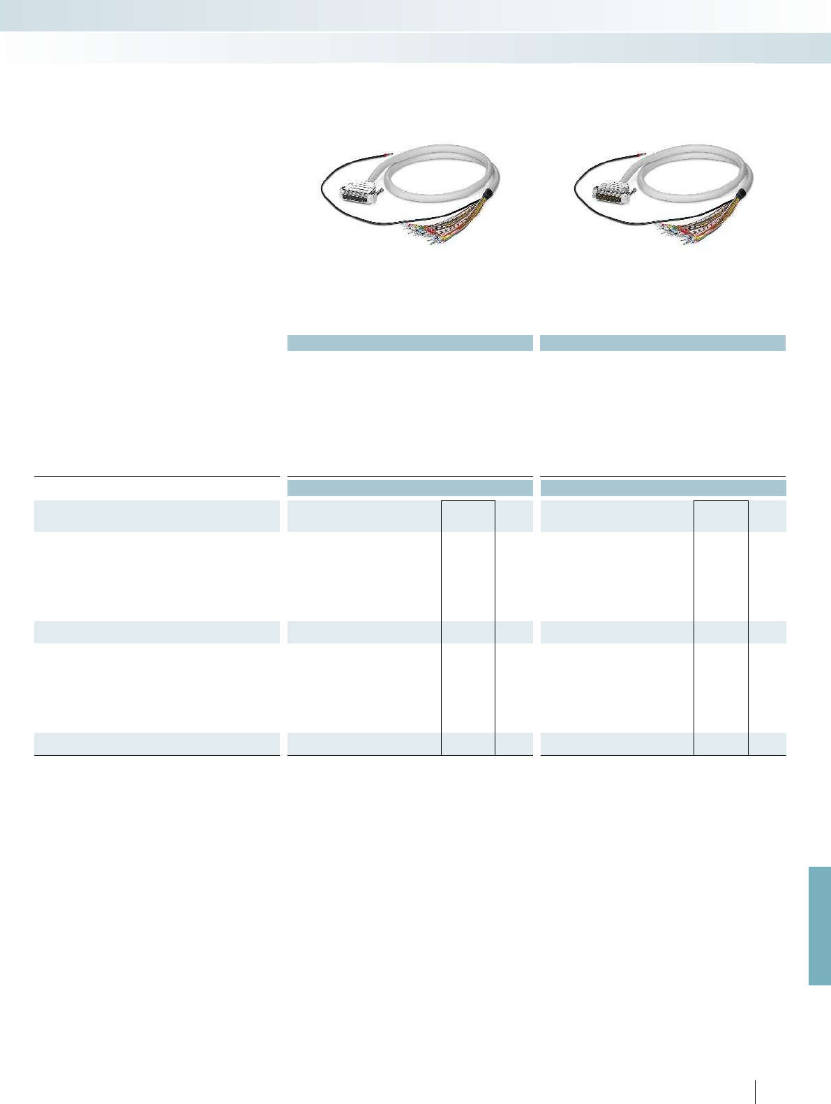
For further information and full technical data, visit phoenixcontact.net/products
Technical data Technical data
Max. perm. operating voltage 125 V AC/DC 125 V AC/DC
Max. perm. current carrying capacity per path 2 A 2 A
Max. conductor resistance 0.09 /m 0.09 /m
Ambient temperature (operation) -20 °C ... 50 °C -20 °C ... 50 °C
Shield Tinned copper-braided shield, approx. 85% covering Tinned copper-braided shield, approx. 85% covering
Insertion/withdrawal cycles > 200 > 200
Conductor cross section AWG 24 / 0.25 mm² AWG 24 / 0.25 mm²
Outside diameter
37-position 12 mm 12 mm
50-position 13.5 mm 13.5 mm
Ordering data Ordering data
Description No. of
pos. Cable length Type Order No. Pcs. /
Pkt. Type Order No. Pcs. /
Pkt.
Round cable with an open end
37 0.5 m CABLE-D-37SUB/F/OE/0,25/S/0,5M 2926221 1CABLE-D-37SUB/M/OE/0,25/S/0,5M 2926577 1
37 1 m CABLE-D-37SUB/F/OE/0,25/S/1,0M 2926234 1CABLE-D-37SUB/M/OE/0,25/S/1,0M 2926580 1
37 1.5 m CABLE-D-37SUB/F/OE/0,25/S/1,5M 2926247 1CABLE-D-37SUB/M/OE/0,25/S/1,5M 2926593 1
37 2 m CABLE-D-37SUB/F/OE/0,25/S/2,0M 2926250 1CABLE-D-37SUB/M/OE/0,25/S/2,0M 2926603 1
37 3 m CABLE-D-37SUB/F/OE/0,25/S/3,0M 2926263 1CABLE-D-37SUB/M/OE/0,25/S/3,0M 2926616 1
37 4 m CABLE-D-37SUB/F/OE/0,25/S/4,0M 2926276 1CABLE-D-37SUB/M/OE/0,25/S/4,0M 2926629 1
37 6 m CABLE-D-37SUB/F/OE/0,25/S/6,0M 2926289 1CABLE-D-37SUB/M/OE/0,25/S/6,0M 2926632 1
Round cable, as above, however in variable lengths
37 CABLE-D-37SUB-F-OE-0,25-S/... 2900907 1CABLE-D-37SUB-M-OE-0,25-S/... 2900912 1
Round cable with an open end
50 0.5 m CABLE-D-50SUB/F/OE/0,25/S/0,5M 2926292 1CABLE-D-50SUB/M/OE/0,25/S/0,5M 2926645 1
50 1 m CABLE-D-50SUB/F/OE/0,25/S/1,0M 2926302 1CABLE-D-50SUB/M/OE/0,25/S/1,0M 2926658 1
50 1.5 m CABLE-D-50SUB/F/OE/0,25/S/1,5M 2926315 1CABLE-D-50SUB/M/OE/0,25/S/1,5M 2926661 1
50 2 m CABLE-D-50SUB/F/OE/0,25/S/2,0M 2926328 1CABLE-D-50SUB/M/OE/0,25/S/2,0M 2926674 1
50 3 m CABLE-D-50SUB/F/OE/0,25/S/3,0M 2926331 1CABLE-D-50SUB/M/OE/0,25/S/3,0M 2926687 1
50 4 m CABLE-D-50SUB/F/OE/0,25/S/4,0M 2926344 1CABLE-D-50SUB/M/OE/0,25/S/4,0M 2926690 1
50 6 m CABLE-D-50SUB/F/OE/0,25/S/6,0M 2926357 1CABLE-D-50SUB/M/OE/0,25/S/6,0M 2926700 1
Round cable, as above, however in variable lengths
50 CABLE-D-50SUB-F-OE-0,25-S/... 2900908 1CABLE-D-50SUB-M-OE-0,25-S/... 2900913 1
615PHOENIX CONTACT
System cabling for controllers
Universal cables
Socket strip at one end and
open end at the other end
Pin strip at one end and
open end at the other end
Special lengths of D-SUB cable with open
ends can be configured using separate order
numbers.
Ordering example:
One system cable assembled with a
37-pos. D-SUB socket strip and one open
end, 12.75 m in length:
1 pcs. 2900907/12,75
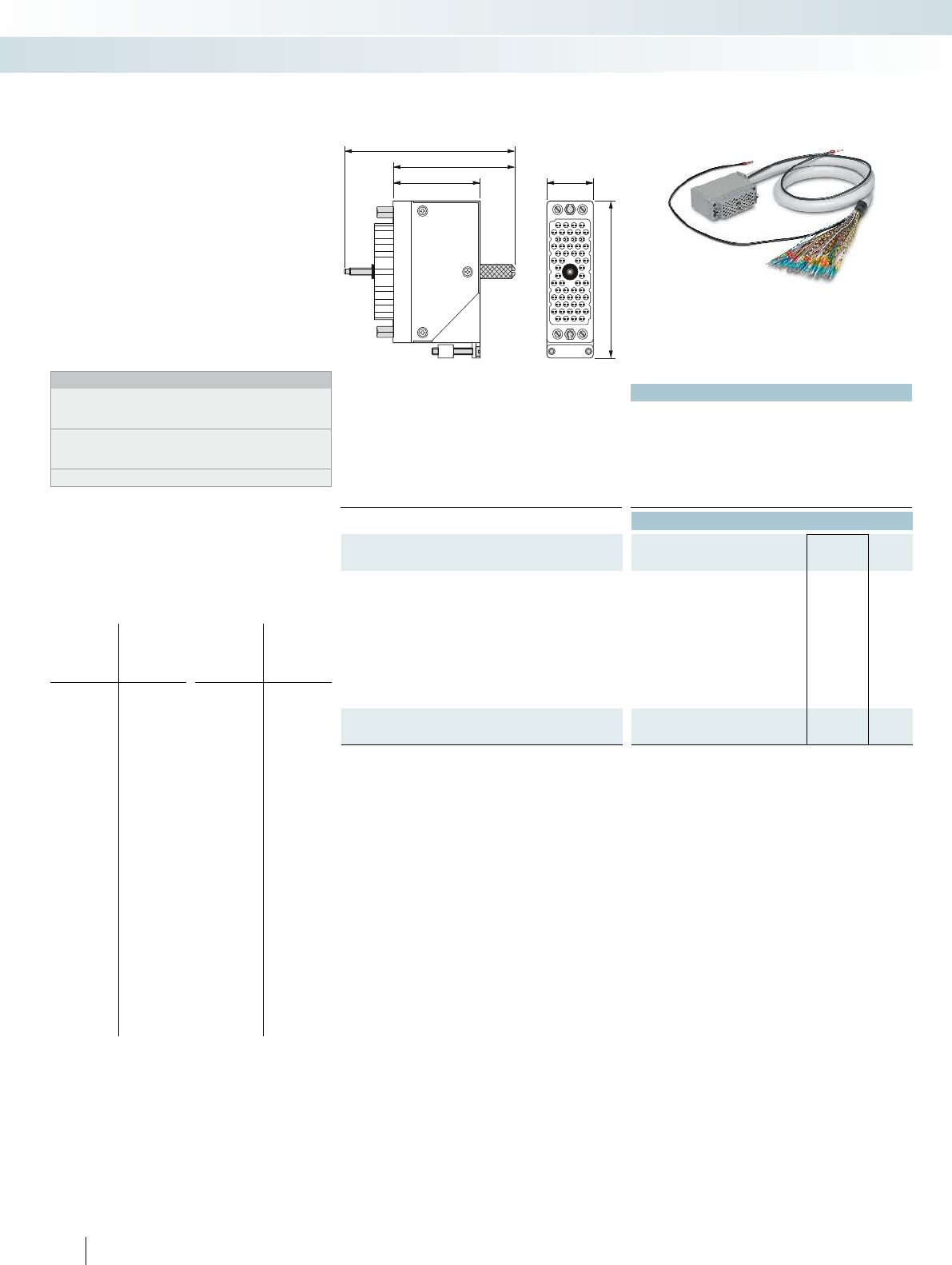
46,5
60,5
81
A
N
N
22,5
71,2
616
PHOENIX CONTACT
Technical data
Max. perm. operating voltage 25 V AC / 60 V DC
Max. perm. current carrying capacity per path 1.5 A
Max. conductor resistance 0.056 /m
Ambient temperature (operation) -20 °C ... 60 °C
Shield Tinned copper-braided shield, approx. 85% covering
Conductor cross section AWG 22 / 0.34 mm²
Conductor structure: stranded wires / material 19 / Cu uninsulated
Ordering data
Description No. of
pos. Cable length Type Order No. Pcs. /
Pkt.
Shielded round cable, assembled with EDAC socket connector at
one end and an open end at the other
56 1 m CABLE-EC56/F/OE/0,34/S/ 1,0M 2903395 1
56 2 m CABLE-EC56/F/OE/0,34/S/ 2,0M 2903396 1
56 4 m CABLE-EC56/F/OE/0,34/S/ 4,0M 2903397 1
56 6 m CABLE-EC56/F/OE/0,34/S/ 6,0M 2903398 1
56 8 m CABLE-EC56/F/OE/0,34/S/ 8,0M 2903399 1
56 10 m CABLE-EC56/F/OE/0,34/S/10,0M 2903400 1
56 15 m CABLE-EC56/F/OE/0,34/S/15,0M 2903401 1
56 20 m CABLE-EC56/F/OE/0,34/S/20,0M 2903402 1
Shielded round cable, as above, but in variable lengths
56 CABLE-EC56-F-OE-0,34-S/... 2904025 1
Pin assignment
Single wire
marking
EDAC socket
connector
Single wire
marking
EDAC socket
connector
Z
1
2
3
4
5
6
7
8
9
10
11
12
13
14
15
16
17
18
19
20
21
22
23
24
25
26
27
28
29
30
Z
A
B
C
D
E
F
H
J
K
L
M
N
P
R
S
T
U
V
W
X
a
b
c
d
e
f
h
j
k
l
31
32
33
34
35
36
37
38
39
40
41
42
43
44
45
46
47
48
49
50
51
52
53
54
Y
m
n
p
r
s
t
u
v
w
x
y
z
AA
BB
CC
DD
EE
FF
HH
JJ
KK
LL
MM
NN
Y
Assembled system cable for connecting
56-pos. EDAC connectors from the
516 series or ELCO connectors from the
8016 series.
– Series 516 EDAC socket connector at
one end
– Metal housing with lateral cable outlet
– Coding sockets in location 1 by default
– Open end at the other end
– Single wire marking: 1, 2, 3, ... 53, 54, Y, Z
(see pin assignment)
– Shield connection on both ends:
H05V-K 1 mm cable, black, length: 0.5 m
Notes:
The system cables are designed specifically for the
UMK-EC56/56-XOR (2975900) and UMK-EC56/56-XOL
(2975890) modules.
When using the UMK-EC56/FRONT 2,5V/R (2976161) or
UMK-EC56/FRONT 2,5V/L (2976158) modules, the coding
sockets must be adapted accordingly.
Observe the module and system cable layouts.
System cable with a 56-pos.
ELCO/EDAC connector and
an open end
System cabling for controllers
Universal cables
56-pos. system cable

46,5
60,5
81
A
N
N
22,5
71,2
For further information and full technical data, visit phoenixcontact.net/products
Technical data
Max. perm. operating voltage 25 V AC / 60 V DC
Max. perm. current carrying capacity per path 1.5 A
Max. conductor resistance 0.056 /m
Ambient temperature (operation) -20 °C ... 60 °C
Shield Tinned copper-braided shield, approx. 85% covering
Conductor cross section AWG 22 / 0.34 mm²
Conductor structure: stranded wires / material 19 / Cu uninsulated
Ordering data
Description No. of
pos. Cable length Type Order No. Pcs. /
Pkt.
Shielded round cable, assembled in various lengths with
EDAC socket connectors at both ends
56 CABLE-EC56-F-F-0,34-S/... 2906066 1
617PHOENIX CONTACT
Assembled system cable for connecting
56-pos. EDAC connectors from the 516
series or ELCO connectors from the 8016
series.
– Series 516 EDAC socket connectors at
both ends
– Metal housing with lateral cable outlet
– Coding sockets in location 1 by default
– Shield connection at both ends:
H05V-K 1 mm
2
cable, black, length: 0.5 m
Notes:
The system cables are designed specifically for the
UMK-EC56/56-XOR (2975900) and
UMK-EC56/56-XOL (2975890) modules.
When using the UMK-EC56/FRONT 2,5V/R (2976161) or
UMK-EC56/FRONT 2,5V/L (2976158) modules, the coding
sockets must be adapted accordingly.
Observe the module and system cable layouts.
System cable with 56-pos.
EDAC/ELCO connector
Ordering example for system cable:
– 56-pos. cable, 13.50 m long
Quantity Order No. Length [m]
12906066 /13.50
Min.
Max.
Increment
0.5 m
100.0 m
0.1 m
System cabling for controllers
Universal cables

P2
P1
P2
P1
P2
P1
P2
P1
P2
P1
P2
P1
P2
P1
P2
P1
P2
P1
P2
P1
.1 .2 .3 .4 .5 .6 .7 .n
.1 .2 .3 .4 .5 .6 .7 .n
.01.02.03.04.05.06.07
P1 P1
.nn
.01.02.03.04.05.06.07
P2 P2
.nn
Technical data Technical data
Operating voltage 250 V AC/DC 250 V AC/DC
Max. perm. current (per branch) 15 A 15 A
Total current 30 A (per potential) 30 A (per potential)
Ambient temperature (operation) -20 °C ... 50 °C -20 °C ... 50 °C
Mounting position any any
Standards/regulations IEC 60664, DIN EN 50178, IEC 62103 IEC 60664, DIN EN 50178, IEC 62103 IEC 60664, DIN EN 50178, IEC 62103 IEC
Supply connection data solid / stranded / AWG 0.2 - 6 mm² / 0.2 - 4 mm² / 24 - 10 0.25 - 6 mm² / 0.25 - 4 mm² / 24 - 10 0.2 - 10 mm² /
Distribution connection data solid / stranded / AWG 0.2 - 4 mm² / 0.2 - 2.5 mm² / 24 - 12 0.14 - 2.5 mm² / 0.14 - 2.5 mm² / 26 - 14 0.
Dimensions H / D 65.5 mm / 50 mm 75.8 mm / 63 mm
Ordering data Ordering data
Description No. of
pos.
Module width
WType Order No. Pcs. /
Pkt. Type Order No. Pcs. /
Pkt.
VARIOFACE module, with two busbars (P1, P2) for
potential distribution, per potential:
2 power terminals/8 distributor terminal blocks
50.00 VIP-2/SC/PDM-2/16 2315256 1
2 power terminals/12 distributor terminal blocks
70.40 VIP-2/SC/PDM-2/24 2315269 1
2 power terminals/16 distributor terminal blocks
90.80 VIP-2/SC/PDM-2/32 2315272 1
2 power terminals/24 distributor terminal blocks
131.50 VIP-2/SC/PDM-2/48 2903717 1
VARIOFACE module, with two busbars (P1, P2) for
potential distribution, per potential:
2 power terminals/8 distributor terminal blocks
41.90 VIP-3/PT/PDM-2/16 2903797 1
2 power terminals/12 distributor terminal blocks
57.10 VIP-3/PT/PDM-2/24 2903798 1
2 power terminals/16 distributor terminal blocks
67.30 VIP-3/PT/PDM-2/32 2903799 1
2 power terminals/24 distributor terminal blocks
97.70 VIP-3/PT/PDM-2/48 2903800 1
VARIOFACE module with 2 busbars for potential distribution
- 2 power terminals/8 distributor terminal blocks 97.70
VARIOFACE module, with three busbars (+, -, PE) for
potential distribution, per potential:
(+) two power terminals/48 distributor terminal blocks
(-) two power terminals/24 distributor terminal blocks
(PE) 2 power terminals/72 distributor terminal blocks
168.80
VARIOFACE module, with six busbars (P1 to P6) for
potential distribution, per potential:
2 power terminals/12 distributor terminal blocks
123.80
618
PHOENIX CONTACT
The VIP-2/.../PDM... modules offer the
following features:
– Two potential levels
– Separate supply
– Screw or push-in connection
– Consecutive marking
– With fuse as an option
The modules UMK-PVB and UMK-PVB 6
have three or six potential levels.
Notes:
Marking systems and mounting material
See Catalog 5
Modules as compact potential
distributors
System cabling for controllers
Potential distributors
With screw connection and
2 potential levels
With push-in connection and
2 potential levels
DW
H
DW
H
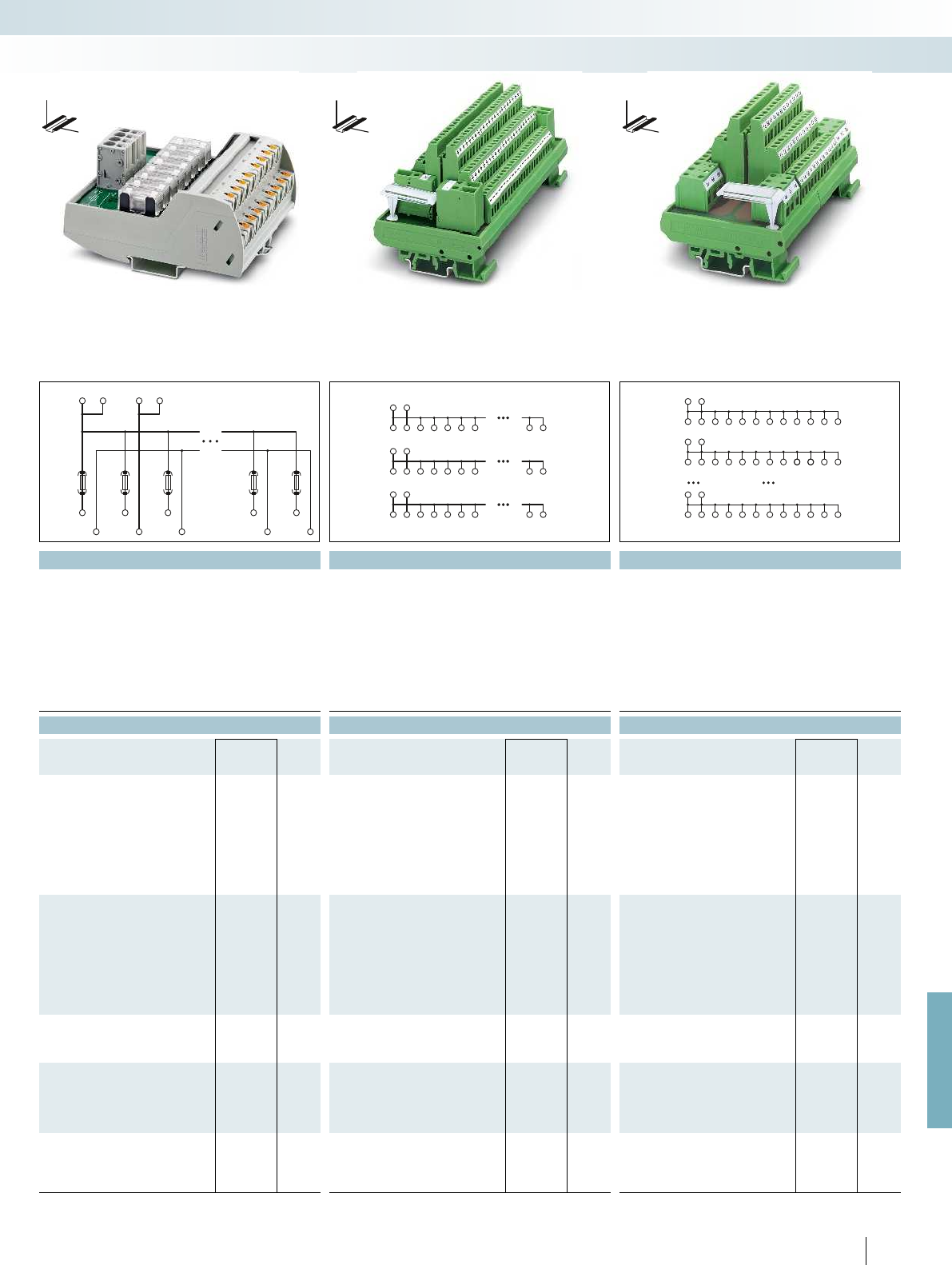
.08
.08
P1P1P2P2
.07
.07
P1
P2
.01.02.03
.01.02.03
++
++++++ +++
--
------ ---
PEPE
PEPEPEPEPEPEPEPEPE
P1P1
P1P1P1P1P1P1P1P1P1P1P1P1
P2P2
P2P2P2P2P2P2P2P2P2P2P2P2
P6P6
P6P6P6P6P6P6P6P6P6P6P6P6
For further information and full technical data, visit phoenixcontact.net/products
Technical data Technical data Technical data
250 V AC/DC 250 V AC/DC 250 V AC/DC
6.3 A (fuse limited) 16 A 16 A
30 A (per potential) 16 A (per potential) 16 A (per potential)
-20 °C ... 60 °C -20 °C ... 50 °C -20 °C ... 50 °C
any any any
Standards/regulations IEC 60664, DIN EN 50178, IEC 62103 IEC 60664, DIN EN 50178, IEC 62103 IEC 60664, DIN EN 50178, IEC 62103 IEC 60664, DIN EN 50178, IEC 62103 IEC 60664, DIN EN 50178, IEC 62103
Supply connection data solid / stranded / AWG 0.2 - 6 mm² / 0.2 - 4 mm² / 24 - 10 0.25 - 6 mm² / 0.25 - 4 mm² / 24 - 10 0.2 - 10 mm² / 0.2 - 6 mm² / 24 - 8 0.5 - 6 mm² / 0.5 - 4 mm² / 20 - 10 0.2 - 6 mm² / 0.2 - 4 mm² / 24 - 10
Distribution connection data solid / stranded / AWG 0.2 - 4 mm² / 0.2 - 2.5 mm² / 24 - 12 0.14 - 2.5 mm² / 0.14 - 2.5 mm² / 26 - 14 0.14 - 2.5 mm² / 0.14 - 2.5 mm² / 26 - 14 0.2 - 4 mm² / 0.2 - 2.5 mm² / 24 - 12 0.2 - 4 mm² / 0.2 - 2.5 mm² / 24 - 12
109.8 mm / 51 mm 77 mm / 72 mm 77 mm / 72 mm
Ordering data Ordering data Ordering data
Type Order No. Pcs. /
Pkt. Type Order No. Pcs. /
Pkt. Type Order No. Pcs. /
Pkt.
VIP-2/PT/PDM-2/16/FU 6.3A 2903603 1
UMK- PVB 2971302 1
UMK- PVB 6 2972136 1
619PHOENIX CONTACT
System cabling for controllers
Potential distributors
DW
H
With push-in connection and
2 potential levels and eight 6.3 A fuses
With screw connection and
3 potential levels
With screw connection and
6 potential levels
DW
H
DW
H
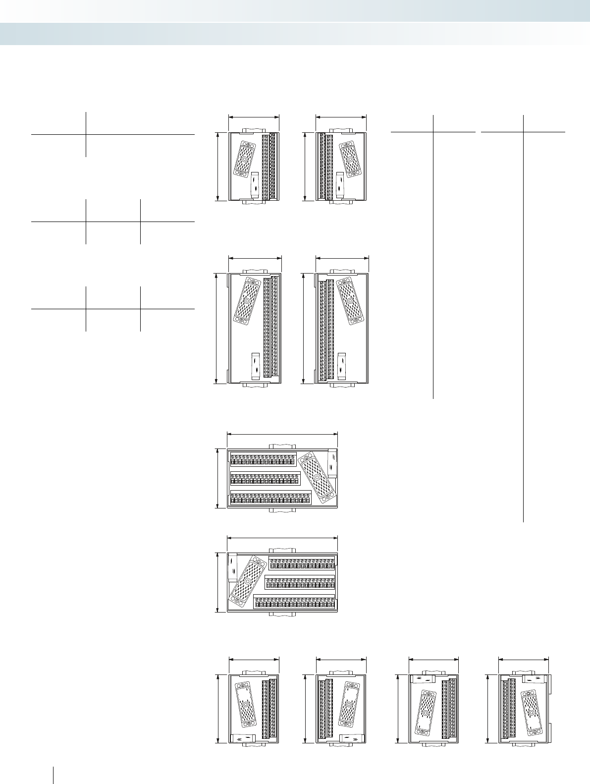
77
101,3
77
101,3
77
157,5
A
NN
1
3
5
7
9
11
13
15
17
19
21
23
25
27
29
31
3335
37
39
41
4345
47
49
51
53
Y
Z
2
4
6
8
10
12
14
16
1820
22
24
262830
32
34
3638
40
42
44
46
4850
52 54
X11
X10
X5 X9
X7
X3 X6 X8
X4X2
77
157,5
A
NN
1
3
5
7
9
11
13
15
17
19
21
23
25
27
29
31
3335
37
39
41
4345
47
49
51
53
Y
Z
2
4
6
810
12
14
16
18
20
22
24
26
28
30
32
34
36
38
40
42
44
46
48
50
52 54
X11
X10X5
X9X7 X3
X6
X8X4 X2
146,3
77
146,3
77
77
101,3
77
101,3
A
NN
77
101,3
77
101,3
Modules for ELCO connectorsModules for IEC 60603/DIN 41612
connectors
Cable housing suitable for screw locking:
Manufacturer Type
C, 64-pos.
Type
D, 32-pos.
ERNI
AMP
KSG 173...
826196-1
KSG 173...
826196-1
Cable housing suitable for screw locking:
Manufacturer Type
E, 48-pos.
Type
F, 32 and 48-pos.
ERNI
AMP
KSG 173...
–
KSG 203...
826198-1
Cable housing suitable for snap-in locking:
Manufacturer
Type F
32 and 48-pos.
HARTING
Types “B” and “D”
Dimensional drawing for
UMK-EC38/38-XOL
Dimensional drawing for
UMK-EC38/38-XOR
Dimensional drawing for
UMK-EC56/32-XOL
Dimensional drawing for
UMK-EC56/32-XOR
Dimensional drawing for UMK-EC56/FRONT 2,5V/R
Dimensional drawing for UMK-EC56/FRONT 2,5V/L
Dimensional drawing for
UMK-EC56/32-XUL
Dimensional drawing for
UMK-EC56/32-XUR
Dimensional drawing for
UMK-EC56/56-XOL
Dimensional drawing for
UMK-EC56/56-XOR
Pin assignment
UMK-EC38/38...
Terminal
block
Pin strip
1
2
3
4
5
6
7
8
9
10
11
12
13
14
15
16
17
18
19
20
21
22
23
24
25
26
27
28
29
30
31
32
33
34
35
36
37
CC
A
B
C
D
E
F
H
J
K
L
M
N
P
R
S
T
U
V
W
X
Y
Z
AA
BB
DD
EE
FF
HH
JJ
KK
LL
MM
NN
PP
RR
SS
TT
CC
Pin assignment
UMK-EC56/56...
Terminal
block
Pin strip
Z
1
2
3
4
5
6
7
8
9
10
11
12
13
14
15
16
17
18
19
20
21
22
23
24
25
26
27
28
29
30
31
32
33
34
35
36
37
38
39
40
41
42
43
44
45
46
47
48
49
50
51
52
53
54
Y
Z
A
B
C
D
E
F
H
J
K
L
M
N
P
R
S
T
U
V
W
X
a
b
c
d
e
f
h
j
k
l
m
n
p
r
s
t
u
v
w
x
y
z
AA
BB
CC
DD
EE
FF
HH
JJ
KK
LL
MM
NN
Y (shield)
620
PHOENIX CONTACT
System cabling for controllers
Tables, dimensional drawings
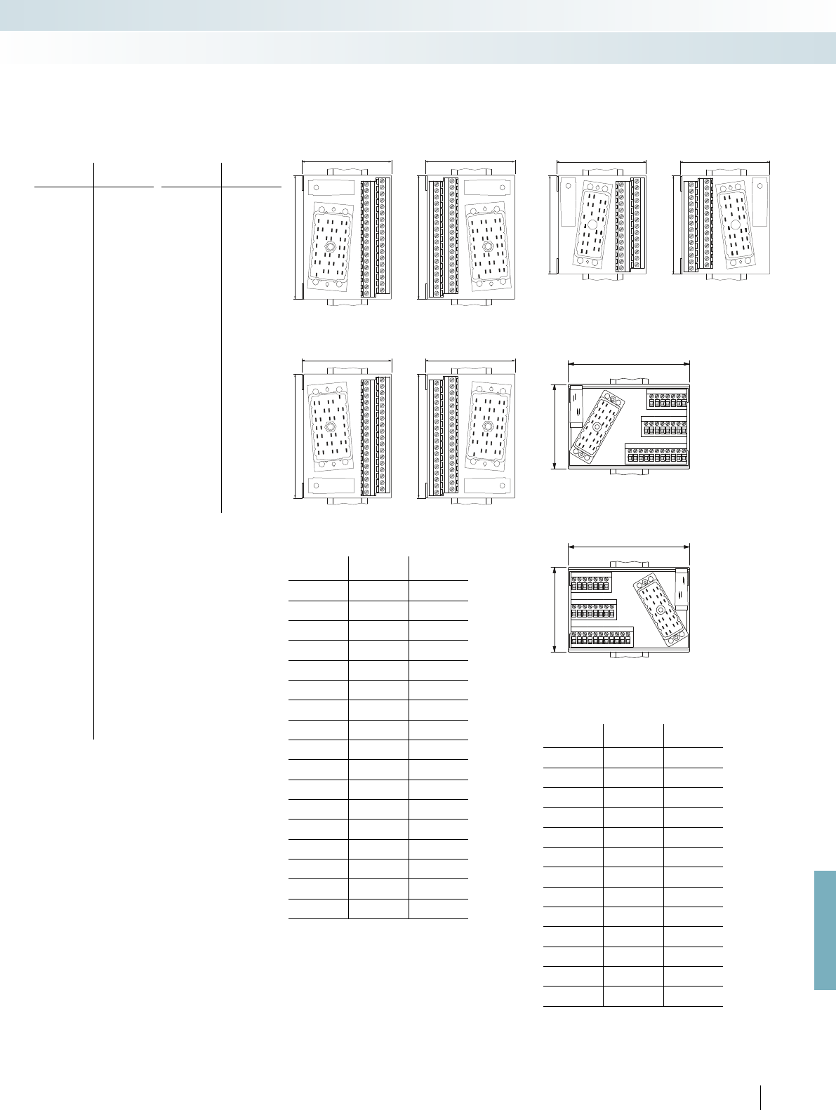
77
101,3
A
DB
Y
Y
32
30
28
26
24
22
20
18
16
14
12
10
8
6
4
2
Y
Y
31
29
27
25
23
21
19
17
15
13
11
9
7
5
3
1
77
101,3
2
4
6
8
10
12
14
16
18
20
22
24
26
28
30
32
Y
Y
1
3
5
7
9
11
13
15
17
19
21
23
25
27
29
31
Y
Y
A
DB
77
78,8
2
4
6
8
10
12
14
16
18
20
22
24
Y
Y
1
3
5
7
9
11
13
15
17
19
21
23
Y
Y
A
NN
77
78,8
2
4
6
8
10
12
14
16
18
20
22
24
Y
Y
1
3
5
7
9
11
13
15
17
19
21
23
Y
Y
A
NN
77
101,3
Y
Y
32
30
28
26
24
22
20
18
16
14
12
10
8
6
4
2
Y
Y
31
29
27
25
23
21
19
17
15
13
11
9
7
5
3
1
A
DB
77
101,3
2
4
6
8
10
12
14
16
18
20
22
24
26
28
30
32
Y
Y
1
3
5
7
9
11
13
15
17
19
21
23
25
27
29
31
Y
Y
A
DB
112,5
77
112,5
77
For further information and full technical data, visit phoenixcontact.net/products
Modules for ELCO connectors with
protection type Ex i
Dimensional drawing for UMK-EC 56/25/EX/FRONT 2,5 V/L
Dimensional drawing for UMK-EC 56/25/EX/FRONT 2,5 V/R
Dimensional drawing for
UMK-EC90/32/EX-XUL
Dimensional drawing for
UMK-EC90/32/EX-XUR
Dimensional drawing for
UMK-EC90/32/EX-XOL
Dimensional drawing for
UMK-EC90/32/EX-XOR
Dimensional drawing for
UMK-EC56/25/EX-L
Dimensional drawing for
UMK-EC56/25/EX-R
Pin assignment
UMK-EC56/FRONT 2,5V/...
Terminal
block
ELCO
connector
X
1
2
3
4
5
6
7
8
9
10
11
12
13
14
15
16
17
18
19
20
21
22
23
24
25
26
27
28
29
30
31
32
33
34
35
36
37
38
39
40
41
42
43
44
45
46
47
48
49
50
51
52
53
54
Y
N.C.
A
B
C
D
E
F
H
J
K
L
M
N
P
R
S
T
U
V
W
X
a
b
c
d
e
f
h
j
k
l
m
n
p
r
s
t
u
v
w
x
y
z
AA
BB
CC
DD
EE
FF
HH
JJ
KK
LL
MM
NN
Y (shield)
Pin assignment
UMK-EC56/32-...
Terminal
block
ELCO
connector
1
2
3
4
5
6
7
8
9
10
11
12
13
14
15
16
17
18
19
20
21
22
23
24
25
26
27
28
29
30
31
32
Y
A
B
C
D
E
F
H
J
K
L
M
N
P
R
S
T
U
V
W
X
Z
a
b
c
d
e
f
h
j
k
l
m
NN + Y
Pin assignment
UMK-EC90/32/EX...
Terminal
block
Pin strip Channel
1
2
H
J1
3
4
L
M2
5
6
P
X3
7
8
Z
AA 4
9
10
AC
AD 5
11
12
AM
ON 6
13
14
AR
AS 7
15
16
AU
BC 8
17
18
AZ
BA 9
19
20
BJ
BK 10
21
22
BM
BN 11
23
24
BR
BY 12
25
26
CA
CB 13
27
28
CD
CE 14
29
30
CN
CP 15
31
32
CS
CT 16
Y DB
Pin assignment
UMK-EC 56/25/EX/...
Terminal
block
Pin strip Channel
1
2
C
D1
3
4
E
F2
5
6
N
P3
7
8
R
S4
9
10
a
b5
11
12
d
j6
13
14
k
l7
15
16
s
t8
17
18
u
v9
19
20
BB
CC 10
21
22
DD
EE 11
23
24
MM
NN 12
YY
621
PHOENIX CONTACT
System cabling for controllers
Tables, dimensional drawings

622
PHOENIX CONTACT
accordance with EMC Directive 2004/108/EC
and according to R&TTE Directive 1999/5/EC
for radio and telecommunications terminal
equipment. As a “Telecom Certification
Body” (TCB), Phoenix Testlab may also
approve these products for markets in the
USA, Canada, and Japan.
Standards and regulations
All relevant standards and regulations are
used as the basis for the development and
maintenance of our products.
International standards are subject to
continuous changes as a result of
harmonization and new developments. In line
with this process, the current version of all
standards that are relevant to our products is
documented in the product area on our
website at
www.phoenixcontact.net/products.
Online product information service on
the web
Phoenix Contact's product range is growing
constantly.
Due to our commitment to product
monitoring, all products are subject to
improvement.
The Internet is an ideal platform to quickly
communicate new product developments and
improvements to the market.
You can quickly access the relevant Phoenix
Contact website for your region via
www.phoenixcontact.com. Here, you will
always find the latest overview of products,
solutions, and services from Phoenix
Contact. This includes technical documents,
such as data sheets and user manuals, the
latest driver and demo software, plus a means
of contacting the appropriate contact person
directly.
marketing the product within the EU.
Where applicable, the products that our
company currently manufactures fall within
the scope of the following directives:
– 2006/95/EC and 2014/35/EU
Electrical equipment designed for use
within certain voltage limits (Low-Voltage
Directive)
– 2004/108/EC and 2014/30/EU
Electromagnetic compatibility
(EMC Directive)
– 2004/22/EC and 2014/32/EU
Measuring instruments
– 2006/42/EC
Safety of machinery
(Machinery Directive)
– 94/9/EC and 2014/34/EU
Equipment and protective systems
intended for use in potentially explosive
areas (ATEX Directive)
– 1999/5/EC
R&TTE Directive and
2014/53/EU
Radio Equipment Directive
The standards upon which the specified
directives are based have been part of our
standard of development for a long time. This
guarantees conformance with European
directives. The numbers of the directives
indicate their version at the time of
publication. In the event of changes to
directives and/or standards, our products will
undergo conformity assessment again in good
time and a new declaration of conformity will
be issued promptly. The current declarations
for each product can also be found in our
download area.
The EMC Directive occupies a special place
among the European directives listed. It
defines electromagnetic compatibility as a
fundamental property of devices based on
mandatory guidelines. European Law
therefore acknowledges the electromagnetic
compatibility of devices and systems as an
important condition for error-free operation
of machinery and systems. Phoenix Contact is
one of the leading international companies in
surge protection, and therefore possesses
broad expertise in EMC. This expertise and
the experience gained over years of
developing and applying industrial interface
and communication technology have resulted
in our products having an extremely high
standard of quality with regard to
electromagnetic compatibility. It was with a
view to providing other companies with this
expertise that our associate company,
Phoenix Testlab, was founded. Phoenix
Testlab GmbH is an independent, accredited
service provider offering EMC testing that
conforms to European standards. At Phoenix
Testlab, devices are also tested with regard to
their electrical safety, mechanical influences,
and their behavior in relation to
environmental influences. Furthermore,
Phoenix Testlab is a “Notified Body” in
Integrated management system
The aim of the Phoenix Contact integrated
management system is to coordinate all the
requirements regarding products, processes,
and organization.
Statutory and regulatory requirements, as
well as those of international standards and
our customers, are met and, in some cases,
even exceeded in all phases of the product
lifecycle.
The Phoenix Contact management system
is monitored by internationally recognized
independent bodies each year to ensure that
quality, environmental protection, energy
efficiency, and occupational safety have been
integrated in conformance with the relevant
requirements. Certification in accordance
with international standards ISO 9001,
ISO 14001, ISO 50001, and BS OHSAS 18001
is the result of our corporate philosophy of
meeting the needs of our customers, staff,
and environment as best as possible. They
serve as the basis for innovative products
with the familiar high Phoenix quality
standard, actively practiced environmental
protection through efficient production and
products that conserve resources, and
responsibility in the field of occupational
health and safety. It goes without saying that
we integrate all further requirements of
standards, international approvals or special
customer requirements into our company
processes.
This system provides a building block for
the success of the Phoenix Contact Group
and its products and services.
CE marking
CE marking was introduced as an
important instrument for the free movement
of goods and services within the single
European market. By attaching the mark to a
product, the manufacturer confirms that it
complies with all applicable European Union
(EU) directives. EC directives describe the
product properties with regard to device
safety and avoiding danger. These are legally
binding regulations of the European Union
(EU). In other words, compliance with the
requirements is a statutory condition for
Quality in quantity
Technical information
60
200
For further information and full technical data, visit phoenixcontact.net/products
623PHOENIX CONTACT
Finger safety
Back of hand safety
Example: pressure actuation
Shock protection
Finger safety Back of hand safety
The most important thing is that an area
formed by an even envelope curve 30 mm in
radius must surround the live parts. This
area must be touch proof, i.e., the live
parts of the electrical device must not be
within reach of the VDE test finger
according to IEC 60529/DIN VDE 0470-1
(test finger).
Back of hand safety is specified for the
“rest of the area” up to 100 mm around the
operating element. Back of hand safety
means that when a force of 50 N is applied
to a ball with a diameter of 50 mm, this does
not come into contact with the live parts of
the equipment. No special measures for
ensuring contact safety are stipulated
outside this area.
Note: systems and equipment that are
operated with SELV up to 25 V ~ or 60 V –
are considered to be protected against
“direct contact”.
According to § 5, Subsection 4 of the BGV
A 2 regulations, there is no need to test the
condition of the system prior to initial
startup if the company has confirmation
from the manufacturer or installer that the
electrical systems and equipment conform
to BGV A 2. The confirmation required
relates to systems and equipment that have
been installed and are ready for operation
and can only be issued by the installer or
installation company. The manufacturer of
the electrical equipment can only issue a
confirmation that products have been
produced in accordance with the relevant
electrotechnical DIN VDE regulations
stipulated in BGV A 2. The installer must
bear this in mind when selecting the
equipment to be used.
In the field of connection technology,
Phoenix Contact offers a wide range of
products that are touch proof or that can
be protected against contact using covers.
Depending on the conditions, all of this
The accident prevention regulations
BGV A 2 issued by the German employer's
liability insurance association for precision
mechanics and electrical engineering apply
to the operators of electrical systems and
are aimed at the prevention of electrical
accidents by means of special safety
requirements.
These regulations contain specifications
regarding the safety distances for work,
operation, and occasional handling in the
proximity of “live parts” in low-voltage
systems up to 1000 V ~ or 1500 V –.
– Work with live parts is only permitted
once they have been de-energized.
Operational activities are only permitted
in the vicinity of live parts if these parts
are de-energized or are protected against
direct contact (§ 6). The following safety
measures apply when working in the
vicinity of live parts:
– Provision of the de-energized state for
the duration of the work
– Ensure shock protection is in place in the
form of covers or barriers during the work
– Assurance that the permitted proximity
limits will not be violated (§ 7).
The term “occasional handling” has been
introduced for the operation of elements
such as pushbuttons, rocker arms or rotary
buttons in the proximity of live parts.
According to VDE 0105-1, this is covered
by “operation with partial protection
against direct contact”.
Detailed specifications for “occasional
handling” can be found in DIN VDE 0106-
100. This specifies to what degree live parts
in the proximity of operating elements are
to be protected against contact. The basis
for this is the definition
of a “protection area for occasional
handling”; this is the area into which the
user must reach in order to handle the
machine.
must be taken into account when selecting
the individual types of terminal block and
accessories.
Technical information

Quality features of insulating housing
Thermoplastics
The majority of our insulating housing
is made from thermoplastic materials. Roughly
speaking, these can be divided into
amorphous and semi-crystalline substances.
Thermoplastics are processed using the
efficient and environmentally-friendly injection
molding process. They have good recycling
properties and can be re-used. We use many
materials that are modified in different ways to
meet the demanding requirements that
electrical and electronic modules, devices, and
systems have to meet with regard to their
mechanical, thermal, and electrical properties.
Behavior of plastics under the
influence of temperature (operating
temperatures, mechanical influences)
All plastics undergo a process referred to as
thermal aging when they are subjected to heat
over long periods. This process causes
changes in the mechanical and electrical
properties of the material. External influences,
e.g., radiation, additional mechanical, chemical
or electrical stresses, amplify this effect.
Special tests on samples can yield
characteristic data which provides a good
means of drawing comparisons between
different plastics. However, applying these
characteristics to an evaluation of molded
plastic parts is only possible to a limited
extent, and can only give the designer a rough
guide when it comes to selecting a plastic
material. This catalog uses the following
assessment criteria: the RTI value according
to UL746B/ANSI 746 B (elec. based on
electric strength) and the Ti value according
to IEC 60216-1 (based on a 50% reduction in
tensile strength after 20,000 hours).
IEC 60947-7-1/EN 60947-7-1 specifies a
permissible temperature increase of 45 K for
terminal blocks under nominal load. Phoenix
Contact terminal blocks meet this
requirement.
The properties of plastics are not only
affected by the influence of heat as described
above; they also undergo changes as a result of
cold influences. When subjected to cold as
well as low levels of humidity, plastics become
increasingly brittle with the result that they
are no longer capable of withstanding the
same mechanical loads. As the table on the
right shows, the plastics concerned can be
used down to a temperature of -40°C, but
only without a mechanical load. As far as the
products presented in the catalog are
concerned, it is the ambient temperature
specified in each case that is to be regarded as
definitive for operation. Regardless of the
plastics used, this may be subject to further
restrictions (e.g., limited to -20°C) as a result
of the components used or other restrictive
parameters.
At very low temperatures, this means that
any form of mechanical load on the plastic
components must be avoided (e.g., mounting
of products on/removal of products from the
DIN rail, actuation of terminal points,
locking/ejection of relays from bases, prizing
out of jumpers, bending of cables and lines,
etc.), as there is always an associated risk of
damage. Unless otherwise indicated, it is
recommended that you carry out the
specified mounting/operational tasks in a
temperature range from -10°C to +40°C.
Inflammability characteristics of
plastics (UL 94)
The inflammability tests for plastics have
been defined by the Underwriters Laboratory
(USA) in regulation UL 94. This applies to all
usage ranges, but in particular to electrical
engineering. A horizontal or vertical test is
carried out at the test laboratory to
determine the inflammability of the plastic
material with a naked flame. In order of
increasing flame-retardant behavior, the
evaluation classes are HB, V2, V1, V0, and 5V.
Test results are recorded on “yellow cards”
and are published annually in the Recognized
Component Directory.
Thermoplastics:
non-reinforced polyamide, PA
We use the modern, semi-crystalline
polyamide insulation material, which has now
become an essential component in electrical
engineering and electronics. It has long
occupied a leading position and is authorized
for use by the relevant approval authorities
such as the CSA, NEMKO, KEMA, PTB, SEV,
UL, VDE, etc.
Polyamide also has excellent electrical,
mechanical, chemical, and other properties,
even at high operating temperatures. Brief
peak temperatures up to approximately
200°C are permitted as a result of heat aging
stabilization. Depending on the type (PA 4.6,
6.6, 6.10, etc.), its melting point is in the region
of 215°C to 295°C.
Polyamide absorbs moisture from its
surroundings, on average 2.8%. However, this
moisture is not in the form of crystallization
water in the plastic itself, but chemically
bonded H
2
O groups in the molecule
structure. This makes the plastic flexible and
resistant to breakage, even at temperatures as
low as -40°C. According to UL 94, PA belongs
to inflammability class V2 to V0.
Thermoplastics: polyester, PBT
We use the semi-crystalline thermoplastic
polyester in non-reinforced and fiberglass-
reinforced variants for special applications
which require increased dimensional and form
stability.
In addition to the high operating
temperature, the material is characterized by
excellent mechanical strength and hardness,
and does not absorb moisture from its
surroundings. PBT is therefore particularly
suitable for strips, for example, which are
soldered onto PCBs and subsequently have to
pass a burn-in test while they are subjected to
heat. According to UL 94, PBT belongs to
inflammability class V2 to V0.
Thermoplastics: polycarbonate, PC
Polycarbonate combines many advantages
such as rigidity, impact strength, transparency,
dimensional stability, good insulation
properties, and resistance to heat.
This amorphous material only absorbs
moisture to a very limited degree, and is used
for items such as large, rigid electronic
component housing.
In its transparent form, polycarbonate is
particularly suitable for use as a material for
cover profiles or marking materials.
PC has good resistance properties against
mineral acids, saturated aliphatic
hydrocarbons, gasoline, greases, and oils.
The material is less resistant to solvents,
benzene, lyes, acetone, and ammonia. Strain
cracks may result from contact with certain
chemicals.
According to UL 94, PC belongs to
inflammability class V2 to V0.
Thermoplastics:
polycarbonate fiber-reinforced, PC-F
Compared to non-reinforced materials,
fiber-reinforced polycarbonates feature
greater rigidity, impact strength, and operating
temperature. In other respects, their
properties are largely identical to those of
non-reinforced polycarbonate.
624
PHOENIX CONTACT
Technical information

For further information and full technical data, visit phoenixcontact.net/products
Properties Unit/level Polyamide
PA
Polyester
PBT
Polycarbonate
PC
Polycarbonate
PC-F
ABS
Operating temperature RTI */** °C 105 105 125 120 80
Minimum temperature (without mechanical load) °C -40 -40 -40 -40 -40
Electric strength acc. to IEC 60243-1/DIN VDE 0303-21 kV/cm 600 400 > 300 850
Resistance to creepage IEC 60112/DIN VDE 0303-1 CTI...M 550 225 175 200
CTI... 600 225 175 175 600
Tropical and termite resistance Good Good Good
Specific contact resistance
IEC 60093/VDE 0303 Part 30; IEC 60167/VDE 0303 Part 31 cm 10
12
10
16
> 10
16
> 10
14
10
14
Surface resistance
IEC 60093/VDE 0303 Part 30; IEC 60167/VDE 0303 Part 31 10
10
10
13
> 10
14
10
13
Inflammability class according to UL 94 V2-V0 V0 V2-V0 V0 HB - V0
* According to UL 746 B/ANSI 746 B (elec.) ** Minimum value
Thermoplastics: ABS
We use the thermoplastic molding
compound ABS for products which must have
good impact and notched impact properties in
addition to high mechanical stability and
rigidity. The products are resistant to
chemicals and stress cracking due to their
special surface quality and hardness.
The characteristic thermal properties
provide good dimensional stability at both low
and high temperatures. Products made from
ABS can be coated with metallic surfaces, e.g.,
nickel.
The inflammability class of the molding
compound used is HB to V0 according to
UL 94.
Dimensions: Width/Height/Depth
D
H
W
DW
H
Dimensions
Subject to changes that serve
the purpose of technical progress.
In accordance with statutory regulations,
our products are indicated with this
footnote if they are intended for use in
industrial environments. This means that
the permitted limit values for residential
applications may be exceeded in the event
of conducted and emitted disturbance
variables. In such cases, the operator may
have to take additional safety measures in
order to ensure electromagnetic
compatibility in residential applications.
EMC: Class A product: Note:
The dimensions “Width/Height/Depth”
are defined as follows for all DIN-rail-
mountable products in the INTERFACE
range:
–Width: measurement taken along the
DIN rail
–Height: measurement taken across the
DIN rail
–Depth: measurement taken starting from
the mounting plate and including the
NS 35/7,5 DIN rail (EN 60715)
The width, height, and depth never change,
even if the products shown in this catalog
happen to be photographed from two
different perspectives (horizontal or vertical).
To make things easier for you, one of the
above two symbols has been included next to
each product photo:
625
PHOENIX CONTACT
Technical information

626
PHOENIX CONTACT
Connection cross section
strand) or stranded (fine-strand).
These values can be found in the product-
specific technical data.
The rated connection capacity of Phoenix
Contact terminal blocks usually exceeds
standard requirements, which specify that it
must only be possible to connect one
conductor with one of the two next smallest
cross sections, excluding the rated cross
section (standardized for the cross section
range from 0.2 to 35 mm
2
).
In addition, conductors with a rated cross
section can usually be wired with ferrules with
plastic sleeve.
Phoenix Contact terminal blocks are
The rated cross section of terminal blocks
must be specified by the manufacturer
according to IEC 60947-7-1. The rated cross
section is the maximum conductor cross
section that can be connected in single, multi
or fine-strand versions subject to specific
thermal, mechanical, and electrical
requirements.
The manufacturer must also specify the
rated connection capacity, i.e., the area of
the conductor that can be connected, as well
as the number of conductors that can be
connected simultaneously and the necessary
preparation of the conductor ends. The
conductors can be solid (single or multi-
designed to allow copper cables to be
connected to them without any special
treatment. “Special treatment” or the use of
ferrules – both permitted according to
IEC 60947-7-1 – are not required. If ferrules
are nevertheless used to protect stranded
conductors against splicing, the connection
capacity of the stranded conductor is
generally reduced by one level.
Structure and dimensions of connecting cables
Cross
section
Single-strand Multi-strand Fine-strand American Wire Gauge [AWG]
Diameter
max.
dimension
Number of
wires
Diameter
max.
dimension
Number of
wires
(minimum
number)
Diameter
max.
dimension
Number of
wires
(guide
value)
Gauge No. Solid wires Stranded wires
[mm
2
]AWG [ mm] [circ. mils] [mm
2
] [ mm] [circ. mils] [mm
2
]
0.2 0.5 1––––24 0.51 404 0.21 –––
0.5 0.9 11.1 71.1 16 20 0.81 1022 0.52 0.97 1111 0.56
0.75 1.0 11.2 71.3 24 18 1.02 1620 0.82 1.16 1600 0.82
11.2 11.4 71.5 32 (17) 1.15 2050 1.04 – – _
–––––––16 1.29 2580 1.31 1.50 2580 1.32
1.5 1.5 11.7 71.8 30 (15) 1.45 3260 1.65 – – _
–––––––14 1.63 4110 2.08 1.85 4100 2.09
2.5 1.9 12.2 72.3 50 (13) 1.83 5180 2.63 –––
–––––––12 2.05 6530 3.31 2.41 6500 3.32
42.4 12.7 72.9 56 (11) 2.30 8230 4.17 – – _
–––––––10 2.59 10380 5.26 2.95 10530 5.37
62.9 13.3 73.9 84 (9) 2.91 13100 6.63 – – _
–––––––83.26 16510 8.37 3.73 16625 8.48
Extract from IEC 60947-1/EN 60947-1, Table 4
The torque according to IEC and the recommended torque for Phoenix Contact terminal blocks are specified
Thread Head screw with slot
Torque Recommended
tightening torque
[Nm] [Nm]
M2.5 (M2.6) 0.4 0.4-0.5
M3 0.5 0.5-0.6
M3.5 0.8 0.8-1.0
M4 1.2 1.2-1.5
Standard IEC 60947-7-1/
EN 60947-7-1/DIN VDE 0611-1 specifies the
test currents for the individual conductor
cross sections listed in the adjacent table. The
corresponding currents are listed with the
connection data for the individual terminal
blocks. The type tests of terminal blocks are
based on this data.
Test currents according to IEC 60947-7-1/EN 60947-7-1, Table 5
Rated cross section [mm
2
]0.2 0.5 0.75 1.0 1.5 2.5 4 6 10 16
Test current [A] 4 6 9 13.5 17.5 24 32 41 57 76
Tightening torque of terminal block screws
Current carrying capacity
IEC 60947-1/EN 60947-1, modified, Table 4
specifies tightening torques for screw
connections based on the screw size for
electrical and mechanical type tests.
Technical information
X
j
FR
CCA
NL
F
DE
C
+
CA
p
DE
x
GB
&
US NL
m
JP
,
*
CA
US
CH
o
NO
A
US
!
FI
z
PL
a
CA
DE
y
RU
u
US
CA
w
BR
d
KR
g
IT
$
DE
l
US
BY
KZ
RU
DE
NL
C
CA
K
AT
&
US
s
CH
,
CA
US
J
V
DE
A
US
DE
a
CA
US
u
US
CA
CA
f
US
US
CA
BY
KZ
RU
T
DE
CN
For further information and full technical data, visit phoenixcontact.net/products
627
PHOENIX CONTACT
Certification bodies and approvals Country
code Explosion protection Country
code Ship classification societies Country
code
IECEE CB Scheme
(in combination with certifying body)
Interna-
tional
International
Electrotechnical Commission
Interna-
tional Bureau Veritas
CENELEC Certification Agreement
(CCA inspection report)
(in combination with certifying body)
EU DEKRA Certification B.V. Germanischer Lloyd AG
Canadian Standards Association (CSA) Physikalisch-Technische Bundesanstalt Lloyd's Register of Shipping
Canadian Standards Association (CSA)
- CSA approval for the USA - KIWA Nederland B.V. Nippon Kaiji Kyokai
Canadian Standards Association.
(CSA) Combined logo
- CSA approval for Canada and the USA -
QS Schaffhausen AG Det Norske Veritas
Underwriters Laboratories Inc. (UL) VTT Expert Services Oy Polski Rejestr Statków
Underwriters Laboratories Inc. (UL)
- UL approval for Canada -
IBExU Institut für Sicherheitstechnik
GmbH Russian Maritime Register of Shipping
Underwriters Laboratories Inc.
(UL) Combined logo
- UL approval for the USA and Canada -
TÜV Rheinland do Brasil Korean Register of Shipping
INSIEME PER LA QUALITA'E LA
SICUREZZA Technischer Überwachungsverein Nord American Bureau of Shipping
Eurasian Conformity DEKRA EXAM GmbH
DEKRA Certification B.V. Canadian Standards Association (CSA)
Österreichischer Verband für
Elektrotechnik
Canadian Standards Association (CSA)
- CSA approval for the USA -
electrosuisse SEV
Verband für Elektro-,
Energie- und Informationstechnik
Canadian Standards Association.
(CSA) Combined logo
- CSA approval for Canada and the USA -
Verband Deutscher Elektrotechniker e.V.
(VDE)
– Approval of drawings
– Reports with production monitoring
Underwriters Laboratories Inc. (UL)
Berufsgenossenschaft (BG)
GS - Geprüfte Sicherheit
Underwriters Laboratories Inc. (UL)
- UL approval for Canada -
Intertek ETL Listed
- Approval for the USA -
Underwriters Laboratories Inc.
(UL) Combined logo
- UL approval for the USA and Canada -
Intertek ETL Listed
- Approval for Canada - FM Approvals
Intertek ETL Listed
- Approval for the USA and Canada - Eurasian Conformity for Ex-products
TÜV Rheinland Industrie Service GmbH
China Compulsory Certificate
Certification bodies and safety marks
Technical information

Type Order No. Page Type Order No. Page Type Order No. Page Type Order No. Page
B
BRIDGE- 2 2900746 30
BRIDGE- 2-3M 2901543 31
BRIDGE- 3 2900747 30
BRIDGE- 3-3M 2901656 31
BRIDGE- 4 2900748 30
BRIDGE- 4-3M 2901659 31
BRIDGE- 5 2900749 30
BRIDGE- 5-3M 2901545 31
BRIDGE- 6 2900750 30
BRIDGE- 6-3M 2901697 31
BRIDGE- 7 2900751 30
BRIDGE- 7-3M 2901698 31
BRIDGE- 8 2900752 30
BRIDGE- 8-3M 2901700 31
BRIDGE- 9 2900753 30
BRIDGE- 9-3M 2901701 31
BRIDGE-10 2900754 30
BRIDGE-10-3M 2901702 31
BRIDGE-PT 2 2904490 31
BRIDGE-PT 3 2904491 31
BRIDGE-PT 4 2904492 31
BRIDGE-PT 5 2904493 31
BRIDGE-PT 6 2904494 31
BRIDGE-PT 7 2904495 31
BRIDGE-PT 8 2904496 31
BRIDGE-PT 9 2904497 31
BRIDGE-PT 10 2904498 31
C
CAB-USB A/MICRO USB B/2,0M 2701626 456
CABLE D-SUB-B-B-S/.../.../... 2302421 613
CABLE D-SUB-S-S-S/.../.../... 2302434 613
CABLE D-SUB-S/.../.../... 2302340 613
CABLE-40/2FLK16/ 2,0M/YUC 2321334 535
CABLE-40/2FLK16/ 4,0M/YUC 2321347 535
CABLE-40/2FLK16/10,0M/YUC 2321350 535
CABLE-40/2FLK16/15,0M/YUC 2321376 535
CABLE-40/2FLK16/20,0M/YUC 2321363 535
CABLE-50/4FLK14/ 2,0M/YUC 2314655 535
CABLE-50/4FLK14/ 4,0M/YUC 2314671 535
CABLE-50/4FLK14/ 6,0M/YUC 2318978 535
CABLE-50/4FLK14/10,0M/YUC 2314684 535
CABLE-50/4FLK14/15,0M/YUC 2322773 535
CABLE-50/4FLK14/20,0M/YUC 2314778 535
CABLE-D 9SUB/B/B/100/KONFEK/S 2305415 611
CABLE-D 9SUB/B/B/200/KONFEK/S 2305428 611
CABLE-D 9SUB/B/B/300/KONFEK/S 2305431 611
CABLE-D 9SUB/B/S/ 50/KONFEK/S 2299987 610
CABLE-D 9SUB/B/S/100/KONFEK/S 2299990 610
CABLE-D 9SUB/B/S/150/KONFEK/S 2300009 610
CABLE-D 9SUB/B/S/200/KONFEK/S 2302010 610
CABLE-D 9SUB/B/S/300/KONFEK/S 2302023 610
CABLE-D 9SUB/B/S/400/KONFEK/S 2302036 610
CABLE-D 9SUB/B/S/600/KONFEK/S 2302049 610
CABLE-D 9SUB/S/S/100/KONFEK/S 2305570 611
CABLE-D 9SUB/S/S/200/KONFEK/S 2305583 611
CABLE-D 9SUB/S/S/300/KONFEK/S 2305596 611
CABLE-D- 9SUB-F-OE-0,25-S/... 2900903 614
CABLE-D- 9SUB-M-OE-0,25-S/... 2900909 614
CABLE-D- 9SUB/F/OE/0,25/S/0,5M 2926014 614
CABLE-D- 9SUB/F/OE/0,25/S/1,0M 2926027 614
CABLE-D- 9SUB/F/OE/0,25/S/1,5M 2926030 614
CABLE-D- 9SUB/F/OE/0,25/S/2,0M 2926043 614
CABLE-D- 9SUB/F/OE/0,25/S/3,0M 2926056 614
CABLE-D- 9SUB/F/OE/0,25/S/4,0M 2926069 614
CABLE-D- 9SUB/F/OE/0,25/S/6,0M 2926072 614
CABLE-D- 9SUB/M/OE/0,25/S/0,5M 2926360 614
CABLE-D- 9SUB/M/OE/0,25/S/1,0M 2926373 614
CABLE-D- 9SUB/M/OE/0,25/S/1,5M 2926386 614
CABLE-D- 9SUB/M/OE/0,25/S/2,0M 2926399 614
CABLE-D- 9SUB/M/OE/0,25/S/3,0M 2926409 614
CABLE-D- 9SUB/M/OE/0,25/S/4,0M 2926412 614
CABLE-D- 9SUB/M/OE/0,25/S/6,0M 2926425 614
CABLE-D-15SUB-F-OE-0,25-S/... 2900905 614
CABLE-D-15SUB-M-OE-0,25-S/... 2900910 614
CABLE-D-15SUB/F/OE/0,25/S/0,5M 2926085 614
CABLE-D-15SUB/F/OE/0,25/S/1,0M 2926098 614
CABLE-D-15SUB/F/OE/0,25/S/1,5M 2926108 614
CABLE-D-15SUB/F/OE/0,25/S/2,0M 2926111 614
CABLE-D-15SUB/F/OE/0,25/S/3,0M 2926124 614
CABLE-D-15SUB/F/OE/0,25/S/4,0M 2926137 614
CABLE-D-15SUB/F/OE/0,25/S/6,0M 2926140 614
CABLE-D-15SUB/M/OE/0,25/S/0,5M 2926438 614
CABLE-D-15SUB/M/OE/0,25/S/1,0M 2926441 614
CABLE-D-15SUB/M/OE/0,25/S/1,5M 2926454 614
CABLE-D-15SUB/M/OE/0,25/S/2,0M 2926467 614
CABLE-D-15SUB/M/OE/0,25/S/3,0M 2926470 614
CABLE-D-15SUB/M/OE/0,25/S/4,0M 2926483 614
CABLE-D-15SUB/M/OE/0,25/S/6,0M 2926496 614
CABLE-D-25SUB-F-OE-0,25-S/... 2900906 614
CABLE-D-25SUB-M-OE-0,25-S/... 2900911 614
CABLE-D-25SUB/F/OE/0,25/S/0,5M 2926153 614
CABLE-D-25SUB/F/OE/0,25/S/1,0M 2926166 614
CABLE-D-25SUB/F/OE/0,25/S/1,5M 2926179 614
CABLE-D-25SUB/F/OE/0,25/S/2,0M 2926182 614
CABLE-D-25SUB/F/OE/0,25/S/3,0M 2926195 614
CABLE-D-25SUB/F/OE/0,25/S/4,0M 2926205 614
CABLE-D-25SUB/F/OE/0,25/S/6,0M 2926218 614
CABLE-D-25SUB/M/OE/0,25/S/0,5M 2926506 614
CABLE-D-25SUB/M/OE/0,25/S/1,0M 2926519 614
CABLE-D-25SUB/M/OE/0,25/S/1,5M 2926522 614
CABLE-D-25SUB/M/OE/0,25/S/2,0M 2926535 614
CABLE-D-25SUB/M/OE/0,25/S/3,0M 2926548 614
CABLE-D-25SUB/M/OE/0,25/S/4,0M 2926551 614
CABLE-D-25SUB/M/OE/0,25/S/6,0M 2926564 614
CABLE-D-37SUB-F-OE-0,25-S/... 2900907 615
CABLE-D-37SUB-M-OE-0,25-S/... 2900912 615
CABLE-D-37SUB/F/OE/0,25/S/0,5M 2926221 615
CABLE-D-37SUB/F/OE/0,25/S/1,0M 2926234 615
CABLE-D-37SUB/F/OE/0,25/S/1,5M 2926247 615
CABLE-D-37SUB/F/OE/0,25/S/2,0M 2926250 615
CABLE-D-37SUB/F/OE/0,25/S/3,0M 2926263 615
CABLE-D-37SUB/F/OE/0,25/S/4,0M 2926276 615
CABLE-D-37SUB/F/OE/0,25/S/6,0M 2926289 615
CABLE-D-37SUB/M/OE/0,25/S/0,5M 2926577 615
CABLE-D-37SUB/M/OE/0,25/S/1,0M 2926580 615
CABLE-D-37SUB/M/OE/0,25/S/1,5M 2926593 615
CABLE-D-37SUB/M/OE/0,25/S/2,0M 2926603 615
CABLE-D-37SUB/M/OE/0,25/S/3,0M 2926616 615
CABLE-D-37SUB/M/OE/0,25/S/4,0M 2926629 615
CABLE-D-37SUB/M/OE/0,25/S/6,0M 2926632 615
CABLE-D-50SUB-F-OE-0,25-S/... 2900908 615
CABLE-D-50SUB-M-OE-0,25-S/... 2900913 615
CABLE-D-50SUB/F/OE/0,25/S/0,5M 2926292 615
CABLE-D-50SUB/F/OE/0,25/S/1,0M 2926302 615
CABLE-D-50SUB/F/OE/0,25/S/1,5M 2926315 615
CABLE-D-50SUB/F/OE/0,25/S/2,0M 2926328 615
CABLE-D-50SUB/F/OE/0,25/S/3,0M 2926331 615
CABLE-D-50SUB/F/OE/0,25/S/4,0M 2926344 615
CABLE-D-50SUB/F/OE/0,25/S/6,0M 2926357 615
CABLE-D-50SUB/M/OE/0,25/S/0,5M 2926645 615
CABLE-D-50SUB/M/OE/0,25/S/1,0M 2926658 615
CABLE-D-50SUB/M/OE/0,25/S/1,5M 2926661 615
CABLE-D-50SUB/M/OE/0,25/S/2,0M 2926674 615
CABLE-D-50SUB/M/OE/0,25/S/3,0M 2926687 615
CABLE-D-50SUB/M/OE/0,25/S/4,0M 2926690 615
CABLE-D-50SUB/M/OE/0,25/S/6,0M 2926700 615
CABLE-D15SUB/B/B/100/KONFEK/S 2305444 611
CABLE-D15SUB/B/B/200/KONFEK/S 2305457 611
CABLE-D15SUB/B/B/300/KONFEK/S 2305460 611
CABLE-D15SUB/B/S/ 50/KONFEK/S 2302052 610
CABLE-D15SUB/B/S/100/KONFEK/S 2302065 610
CABLE-D15SUB/B/S/150/KONFEK/S 2302078 610
CABLE-D15SUB/B/S/200/KONFEK/S 2302081 610
CABLE-D15SUB/B/S/300/KONFEK/S 2302094 610
CABLE-D15SUB/B/S/400/KONFEK/S 2302104 610
CABLE-D15SUB/B/S/600/KONFEK/S 2302117 610
CABLE-D15SUB/S/S/100/KONFEK/S 2305606 611
CABLE-D15SUB/S/S/200/KONFEK/S 2305619 611
CABLE-D15SUB/S/S/300/KONFEK/S 2305622 611
CABLE-D25SUB/B/2X14/100/TU812 2304649 491
CABLE-D25SUB/B/2X14/200/TU812 2304652 491
CABLE-D25SUB/B/2X14/300/TU812 2304665 491
CABLE-D25SUB/B/2X14/500/TU812 2304678 491
CABLE-D25SUB/B/2X14/TU812/... 2304681 491
CABLE-D25SUB/B/B/100/KONFEK/S 2305473 611
CABLE-D25SUB/B/B/200/KONFEK/S 2305486 611
CABLE-D25SUB/B/B/300/KONFEK/S 2305499 611
CABLE-D25SUB/B/S/ 50/KONFEK/S 2302120 610
CABLE-D25SUB/B/S/100/KONFEK/S 2302133 610
CABLE-D25SUB/B/S/150/KONFEK/S 2302146 610
CABLE-D25SUB/B/S/200/KONFEK/S 2302159 610
CABLE-D25SUB/B/S/300/KONFEK/S 2302162 610
CABLE-D25SUB/B/S/400/KONFEK/S 2302175 610
CABLE-D25SUB/B/S/600/KONFEK/S 2302188 610
CABLE-D25SUB/S/S/100/KONFEK/S 2305635 611
CABLE-D25SUB/S/S/200/KONFEK/S 2305648 611
CABLE-D25SUB/S/S/300/KONFEK/S 2305651 611
CABLE-D37-M2,5-4X14-X81-I/... 2302706 506
CABLE-D37-M2,5-4X14-Y81P-O/... 2302696 506
CABLE-D37-M2,5/4X14/ 50/X81-I 2302515 506
CABLE-D37-M2,5/4X14/ 50/Y81P-O 2302476 506
CABLE-D37-M2,5/4X14/100/X81-I 2302528 506
CABLE-D37-M2,5/4X14/100/Y81P-O 2302489 506
CABLE-D37-M2,5/4X14/200/X81-I 2302531 506
CABLE-D37-M2,5/4X14/200/Y81P-O 2302492 506
CABLE-D37-M2,5/4X14/300/X81-I 2302544 506
CABLE-D37-M2,5/4X14/300/Y81P-O 2302502 506
CABLE-D37SUB/B/B/ 100/KONFEK/S 2305509 611
CABLE-D37SUB/B/B/ 200/KONFEK/S 2305512 611
CABLE-D37SUB/B/B/ 300/KONFEK/S 2305525 611
CABLE-D37SUB/B/B/ 400/KONFEK/S 2900759 611
CABLE-D37SUB/B/B/ 600/KONFEK/S 2900760 611
CABLE-D37SUB/B/B/ 800/KONFEK/S 2900761 611
CABLE-D37SUB/B/B/1000/KONFEK/S 2900762 611
CABLE-D37SUB/B/B/1500/KONFEK/S 2900763 611
CABLE-D37SUB/B/B/2000/KONFEK/S 2900764 611
CABLE-D37SUB/B/S/ 50/KONFEK/S 2302191 610
CABLE-D37SUB/B/S/100/KONFEK/S 2302201 610
CABLE-D37SUB/B/S/150/KONFEK/S 2302214 610
CABLE-D37SUB/B/S/200/KONFEK/S 2302227 610
CABLE-D37SUB/B/S/300/KONFEK/S 2302230 610
CABLE-D37SUB/B/S/400/KONFEK/S 2302243 610
CABLE-D37SUB/B/S/600/KONFEK/S 2302256 610
CABLE-D37SUB/S/S/100/KONFEK/S 2305664 611
CABLE-D37SUB/S/S/200/KONFEK/S 2305677 611
CABLE-D37SUB/S/S/300/KONFEK/S 2305680 611
CABLE-D50SUB/B/B/100/KONFEK/S 2305541 611
CABLE-D50SUB/B/B/200/KONFEK/S 2305554 611
CABLE-D50SUB/B/B/300/KONFEK/S 2305567 611
CABLE-D50SUB/B/S/ 50/KONFEK/S 2302269 610
CABLE-D50SUB/B/S/100/KONFEK/S 2302272 610
CABLE-D50SUB/B/S/150/KONFEK/S 2302285 610
CABLE-D50SUB/B/S/200/KONFEK/S 2302298 610
CABLE-D50SUB/B/S/300/KONFEK/S 2302308 610
CABLE-D50SUB/B/S/400/KONFEK/S 2302311 610
CABLE-D50SUB/B/S/600/KONFEK/S 2302324 610
CABLE-D50SUB/S/S/100/KONFEK/S 2305693 611
CABLE-D50SUB/S/S/200/KONFEK/S 2305703 611
CABLE-D50SUB/S/S/300/KONFEK/S 2305716 611
CABLE-EC56-F-F-0,34-S/... 2906066 617
CABLE-EC56-F-OE-0,34-S/... 2904025 616
CABLE-EC56/F/OE/0,34/S/ 1,0M 2903395 616
CABLE-EC56/F/OE/0,34/S/ 2,0M 2903396 616
CABLE-EC56/F/OE/0,34/S/ 4,0M 2903397 616
CABLE-EC56/F/OE/0,34/S/ 6,0M 2903398 616
CABLE-EC56/F/OE/0,34/S/ 8,0M 2903399 616
CABLE-EC56/F/OE/0,34/S/10,0M 2903400 616
CABLE-EC56/F/OE/0,34/S/15,0M 2903401 616
CABLE-EC56/F/OE/0,34/S/20,0M 2903402 616
CABLE-FCN24-2X14-OMR-IN/... 2302845 508
CABLE-FCN24-2X14-OMR-OUT/... 2302858 508
CABLE-FCN24/2X14/100/OMR-IN 2304241 508
CABLE-FCN24/2X14/100/OMR-OUT 2304225 508
CABLE-FCN24/2X14/200/OMR-IN 2304254 508
CABLE-FCN24/2X14/200/OMR-OUT 2304238 508
CABLE-FCN40-4X14-OMR-IN/... 2302816 508
CABLE-FCN40-4X14-OMR-OUT/... 2302832 508
CABLE-FCN40/1X50/ 0,5M/IM/MEL 2903468 507
CABLE-FCN40/1X50/ 0,5M/IP/MEL 2903476 507
CABLE-FCN40/1X50/ 0,5M/M340 2321635 513
CABLE-FCN40/1X50/ 0,5M/S7-IN 2321091 521
CABLE-FCN40/1X50/ 0,5M/S7-OUT 2321017 521
CABLE-FCN40/1X50/ 1,0M/IM/MEL 2903469 507
CABLE-FCN40/1X50/ 1,0M/IP/MEL 2903477 507
CABLE-FCN40/1X50/ 1,0M/M340 2321648 513
CABLE-FCN40/1X50/ 1,0M/S7-IN 2321101 521
CABLE-FCN40/1X50/ 1,0M/S7-OUT 2321020 521
CABLE-FCN40/1X50/ 2,0M/IM/MEL 2903470 507
CABLE-FCN40/1X50/ 2,0M/IP/MEL 2903478 507
CABLE-FCN40/1X50/ 2,0M/M340 2321651 513
CABLE-FCN40/1X50/ 2,0M/S7-IN 2321114 521
CABLE-FCN40/1X50/ 2,0M/S7-OUT 2321033 521
CABLE-FCN40/1X50/ 3,0M/IM/MEL 2903471 507
CABLE-FCN40/1X50/ 3,0M/IP/MEL 2903479 507
CABLE-FCN40/1X50/ 3,0M/M340 2321664 513
CABLE-FCN40/1X50/ 3,0M/S7-IN 2321127 521
CABLE-FCN40/1X50/ 3,0M/S7-OUT 2321046 521
CABLE-FCN40/1X50/ 4,0M/IM/MEL 2903472 507
CABLE-FCN40/1X50/ 4,0M/IP/MEL 2903480 507
CABLE-FCN40/1X50/ 4,0M/M340 2321677 513
CABLE-FCN40/1X50/ 4,0M/S7-IN 2321130 521
CABLE-FCN40/1X50/ 4,0M/S7-OUT 2321059 521
CABLE-FCN40/1X50/ 6,0M/IM/MEL 2903473 507
CABLE-FCN40/1X50/ 6,0M/IP/MEL 2903481 507
CABLE-FCN40/1X50/ 6,0M/M340 2321680 513
CABLE-FCN40/1X50/ 6,0M/S7-IN 2321143 521
CABLE-FCN40/1X50/ 6,0M/S7-OUT 2321062 521
CABLE-FCN40/1X50/ 8,0M/IM/MEL 2903474 507
CABLE-FCN40/1X50/ 8,0M/IP/MEL 2903482 507
CABLE-FCN40/1X50/ 8,0M/M340 2321693 513
CABLE-FCN40/1X50/ 8,0M/S7-IN 2321156 521
CABLE-FCN40/1X50/ 8,0M/S7-OUT 2321075 521
CABLE-FCN40/1X50/10,0M/IM/MEL 2903475 507
CABLE-FCN40/1X50/10,0M/IP/MEL 2903483 507
CABLE-FCN40/1X50/10,0M/M340 2321703 513
CABLE-FCN40/1X50/10,0M/S7-IN 2321169 521
CABLE-FCN40/1X50/10,0M/S7-OUT 2321088 521
CABLE-FCN40/1X50/15,0M/M340 2903748 513
CABLE-FCN40/4X14/ 0,5M/IM/MEL 2903502 507
CABLE-FCN40/4X14/ 0,5M/M340 2321716 513
CABLE-FCN40/4X14/ 0,5M/S7-IN 2321253 521
CABLE-FCN40/4X14/ 0,5M/S7-OUT 2321172 521
CABLE-FCN40/4X14/ 1,0M/IM/MEL 2903503 507
CABLE-FCN40/4X14/ 1,0M/M340 2321729 513
CABLE-FCN40/4X14/ 1,0M/S7-IN 2321266 521
CABLE-FCN40/4X14/ 1,0M/S7-OUT 2321185 521
CABLE-FCN40/4X14/ 2,0M/IM/MEL 2903504 507
CABLE-FCN40/4X14/ 2,0M/M340 2321732 513
CABLE-FCN40/4X14/ 2,0M/S7-IN 2321279 521
CABLE-FCN40/4X14/ 2,0M/S7-OUT 2321198 521
CABLE-FCN40/4X14/ 3,0M/IM/MEL 2903505 507
CABLE-FCN40/4X14/ 3,0M/M340 2321745 513
CABLE-FCN40/4X14/ 3,0M/S7-IN 2321282 521
CABLE-FCN40/4X14/ 3,0M/S7-OUT 2321208 521
CABLE-FCN40/4X14/ 4,0M/IM/MEL 2903506 507
CABLE-FCN40/4X14/ 4,0M/M340 2321758 513
CABLE-FCN40/4X14/ 4,0M/S7-IN 2321295 521
CABLE-FCN40/4X14/ 4,0M/S7-OUT 2321211 521
CABLE-FCN40/4X14/ 6,0M/IM/MEL 2903507 507
CABLE-FCN40/4X14/ 6,0M/M340 2321761 513
CABLE-FCN40/4X14/ 6,0M/S7-IN 2321305 521
CABLE-FCN40/4X14/ 6,0M/S7-OUT 2321224 521
CABLE-FCN40/4X14/ 8,0M/IM/MEL 2903508 507
CABLE-FCN40/4X14/ 8,0M/M340 2321774 513
CABLE-FCN40/4X14/ 8,0M/S7-IN 2321318 521
CABLE-FCN40/4X14/ 8,0M/S7-OUT 2321237 521
CABLE-FCN40/4X14/10,0M/IM/MEL 2903509 507
CABLE-FCN40/4X14/10,0M/M340 2321787 513
CABLE-FCN40/4X14/10,0M/S7-IN 2321321 521
CABLE-FCN40/4X14/10,0M/S7-OUT 2321240 521
CABLE-FCN40/4X14/100/OMR-IN 2304209 508
CABLE-FCN40/4X14/100/OMR-OUT 2304186 508
CABLE-FCN40/4X14/15,0M/M340 2903749 513
CABLE-FCN40/4X14/200/OMR-IN 2304212 508
CABLE-FCN40/4X14/200/OMR-OUT 2304199 508
CABLE-FLK10-OE-0,14/... 2904331 602
CABLE-FLK10/OE/0,14/ 0,5M 2904073 602
CABLE-FLK10/OE/0,14/ 1,0M 2904074 602
CABLE-FLK10/OE/0,14/ 1,5M 2904075 602
CABLE-FLK10/OE/0,14/ 2,0M 2904076 602
CABLE-FLK10/OE/0,14/ 2,5M 2904077 602
CABLE-FLK10/OE/0,14/ 3,0M 2904078 602
628
PHOENIX CONTACT
Index
Alphabetical

Type Order No. Page Type Order No. Page Type Order No. Page Type Order No. Page
CABLE-FLK10/OE/0,14/ 4,0M 2904079 602
CABLE-FLK10/OE/0,14/ 6,0M 2904080 602
CABLE-FLK10/OE/0,14/ 8,0M 2904081 602
CABLE-FLK10/OE/0,14/10,0M 2904082 602
CABLE-FLK14/OE/0,14/ 50 2305761 602
CABLE-FLK14/OE/0,14/ 100 2305253 602
CABLE-FLK14/OE/0,14/ 150 2305266 602
CABLE-FLK14/OE/0,14/ 200 2305279 602
CABLE-FLK14/OE/0,14/ 250 2305282 602
CABLE-FLK14/OE/0,14/ 300 2305295 602
CABLE-FLK14/OE/0,14/ 400 2305774 602
CABLE-FLK14/OE/0,14/ 600 2305787 602
CABLE-FLK14/OE/0,14/ 800 2305790 602
CABLE-FLK14/OE/0,14/... 2305732 602
CABLE-FLK14/OE/0,14/1000 2305800 602
CABLE-FLK16/OE/0,14/ 0,5M 2318127 602
CABLE-FLK16/OE/0,14/ 1,0M 2318130 602
CABLE-FLK16/OE/0,14/ 1,5M 2318143 602
CABLE-FLK16/OE/0,14/ 2,0M 2318156 602
CABLE-FLK16/OE/0,14/ 2,5M 2318169 602
CABLE-FLK16/OE/0,14/ 3,0M 2318172 602
CABLE-FLK16/OE/0,14/ 4,0M 2318185 602
CABLE-FLK16/OE/0,14/ 6,0M 2318198 602
CABLE-FLK16/OE/0,14/ 8,0M 2318208 602
CABLE-FLK16/OE/0,14/... 2318224 602
CABLE-FLK16/OE/0,14/10,0M 2318211 602
CABLE-FLK20/OE/0,14/ 50 2305826 603
CABLE-FLK20/OE/0,14/ 100 2305305 603
CABLE-FLK20/OE/0,14/ 150 2305318 603
CABLE-FLK20/OE/0,14/ 200 2305321 603
CABLE-FLK20/OE/0,14/ 250 2305334 603
CABLE-FLK20/OE/0,14/ 300 2305347 603
CABLE-FLK20/OE/0,14/ 400 2305839 603
CABLE-FLK20/OE/0,14/ 600 2305842 603
CABLE-FLK20/OE/0,14/ 800 2305855 603
CABLE-FLK20/OE/0,14/... 2305745 603
CABLE-FLK20/OE/0,14/1000 2305868 603
CABLE-FLK50/0,14/HF/ 0,5M 2314134 605
CABLE-FLK50/0,14/HF/ 1,0M 2314147 605
CABLE-FLK50/0,14/HF/ 1,5M 2314150 605
CABLE-FLK50/0,14/HF/ 2,0M 2314163 605
CABLE-FLK50/0,14/HF/ 2,5M 2314176 605
CABLE-FLK50/0,14/HF/ 3,0M 2314189 605
CABLE-FLK50/0,14/HF/ 4,0M 2314192 605
CABLE-FLK50/0,14/HF/ 5,0M 2314202 605
CABLE-FLK50/0,14/HF/ 6,0M 2314215 605
CABLE-FLK50/0,14/HF/ 7,0M 2314228 605
CABLE-FLK50/0,14/HF/ 8,0M 2314231 605
CABLE-FLK50/0,14/HF/10,0M 2314244 605
CABLE-FLK50/OE/0,14/ 50 2305871 603
CABLE-FLK50/OE/0,14/ 100 2305350 603
CABLE-FLK50/OE/0,14/ 150 2305363 603
CABLE-FLK50/OE/0,14/ 200 2305376 603
CABLE-FLK50/OE/0,14/ 250 2305389 603
CABLE-FLK50/OE/0,14/ 300 2305392 603
CABLE-FLK50/OE/0,14/ 400 2305884 603
CABLE-FLK50/OE/0,14/ 600 2305897 603
CABLE-FLK50/OE/0,14/ 800 2305907 603
CABLE-FLK50/OE/0,14/... 2305758 603
CABLE-FLK50/OE/0,14/1000 2305910 603
CLIPFIX 35 3022218 374
CM-KBL-RS232/USB 2881078 226
D
D-DEK 1,5 GN 2716949 461
D-UKK 3/5 2770024 180
D-UKK 3/5 BU 2770105 180
DB 50- 90 BK 2820916 378
DB 50- 90 BU 2821180 378
DB 50- 90 GY 2820929 378
DEK-OE- 5DC/ 5DC/100KHZ-G 2964542 475
DEK-OE- 5DC/ 24DC/100KHZ 2964270 474
DEK-OE- 5DC/ 24DC/100KHZ-G 2964555 475
DEK-OE- 5DC/ 48DC/100 2940223 464
DEK-OE- 12DC/ 48DC/100 2964487 464
DEK-OE- 24DC/ 5DC/100KHZ-G 2964364 475
DEK-OE- 24DC/ 24DC/100KHZ 2964283 474
DEK-OE- 24DC/ 24DC/100KHZ-G 2964348 475
DEK-OE- 24DC/ 48DC/100 2940207 464
DEK-OE- 60DC/ 48DC/100 2941536 464
DEK-OE-120AC/ 48DC/100 2941659 464
DEK-OE-230AC/ 48DC/100 2940210 464
DEK-OE-230AC/ 48DC/100/SO 46 2964678 469
DEK-OV- 5DC/ 24DC/ 3 2941361 465
DEK-OV- 5DC/ 24DC/ 10 2961752 465
DEK-OV- 5DC/240AC/800 2964623 465
DEK-OV- 12DC/ 24DC/ 3 2941387 465
DEK-OV- 12DC/ 24DC/ 10 2961749 465
DEK-OV- 12DC/240AC/800 2964636 465
DEK-OV- 24DC/ 24DC/ 3 2941374 465
DEK-OV- 24DC/ 24DC/ 3/AKT 2964296 465
DEK-OV- 24DC/ 24DC/ 10 2964322 465
DEK-OV- 24DC/240AC/800 2964649 465
DEK-REL- 5/I/1 2941183 462
DEK-REL- 5/O/1 2941170 463
DEK-REL- 24/1/AKT 2964063 463
DEK-REL- 24/1/S 2964131 467
DEK-REL- 24/1/SEN 2964050 463
DEK-REL- 24/I/1 2940171 462
DEK-REL- 24/O/1 2941154 463
DEK-REL-G24/21 2964500 461
DEK-TR/INV 2964319 477
DFLK 10/FKCT 2903034 583
DFLK 14/FKCT 2903035 583
DFLK 16 2280239 582
DFLK 16/FKCT 2903036 583
DFLK 20 2280242 582
DFLK 20/FKCT 2903038 583
DFLK 26 2280255 582
DFLK 26/FKCT 2903039 583
DFLK 34 2280268 582
DFLK 34/FKCT 2903041 583
DFLK 40 2280271 582
DFLK 40/FKCT 2903042 583
DFLK 50 2280284 582
DFLK 50/FKCT 2903043 583
DFLK-D 9 SUB/B 2287135 589
DFLK-D 9 SUB/F/FKCT 2903063 590
DFLK-D 9 SUB/M/FKCT 2903052 590
DFLK-D 9 SUB/S 2283870 589
DFLK-D15 SUB/B 2280307 589
DFLK-D15 SUB/F/FKCT 2903065 590
DFLK-D15 SUB/M/FKCT 2903054 590
DFLK-D15 SUB/S 2280297 589
DFLK-D25 SUB/B 2280323 589
DFLK-D25 SUB/F/FKCT 2903067 590
DFLK-D25 SUB/M/FKCT 2903055 590
DFLK-D25 SUB/S 2280310 589
DFLK-D37 SUB/B 2280349 589
DFLK-D37 SUB/F/FKCT 2903069 590
DFLK-D37 SUB/M/FKCT 2903056 590
DFLK-D37 SUB/S 2280336 589
DFLK-D50 SUB/B 2287669 589
DFLK-D50 SUB/F/FKCT 2903070 590
DFLK-D50 SUB/M/FKCT 2903058 590
DFLK-D50 SUB/S 2291286 589
DIKD 1,5 2715979 463
E
EB 2- DIK BU 2716648 467
EB 2- DIK RD 2716693 467
EB 3- DIK BU 2716651 467
EB 3- DIK RD 2716745 467
EB 4- DIK BU 2716664 467
EB 4- DIK RD 2716758 467
EB 5- DIK BU 2716677 467
EB 5- DIK RD 2716761 467
EB 10- DIK BU 2716680 467
EB 10- DIK RD 2716774 467
EB 80- DIK BU 2715940 461
EB 80- DIK RD 2715953 461
EB 80- DIK WH 2715788 461
EEM-2AO-MA600 2901475 240
EEM-2DIO-MA600 2901371 240
EEM-ETH-MA600 2901373 241
EEM-ETH-RS485-MA600 2901374 241
EEM-IMP-MA400 2904314 242
EEM-IMP-MA600 2904313 242
EEM-MA200 2901362 239
EEM-MA250 2901363 239
EEM-MA400 2901364 239
EEM-MA600 2901366 238
EEM-MA600-24DC 2902352 238
EEM-MEMO-MA600 2901370 240
EEM-MKT-DRA 2902078 243
EEM-PB 12-MA600 2901418 241
EEM-RS485-MA400 2901365 241
EEM-RS485-MA600 2901367 241
EEM-TEMP-MA600 2901949 243
EIK1-SVN-24P 2940799 476
EL1-P16 2833547 378
EL1-P25 2833550 378
EL2-P35 2833592 384
EL3-M52 2833628 347
ELR 1- 24DC/600AC-20 2297138 44
ELR 1- 24DC/600AC-30 2297154 45
ELR 1- 24DC/600AC-50 2297170 45
ELR 1-230AC/600AC-20 2297141 44
ELR 1-230AC/600AC-30 2297167 45
ELR 1-230AC/600AC-50 2297183 45
ELR 2+1- 24DC/500AC-37 2297277 39
ELR 2+1-230AC/500AC-37 2297280 39
ELR 3- 24DC/500AC- 2 2297196 38
ELR 3- 24DC/500AC- 9 2297219 39
ELR 3- 24DC/500AC-16 2297235 39
ELR 3-230AC/500AC- 2 2297206 38
ELR 3-230AC/500AC- 9 2297222 39
ELR 3-230AC/500AC-16 2297248 39
ELR 5011 IP PN 2700745 46
ELR 5011-2 IP PN 2701007 46
ELR 5030 IP PN 2701006 47
ELR 5030-2 IP PN 2701008 47
ELR H3-I-PT- 24DC/500AC-0,6 2903920 27
ELR H3-I-PT- 24DC/500AC-2 2903922 27
ELR H3-I-PT- 24DC/500AC-9 2903924 27
ELR H3-I-PT-SWD/500AC-06 2905076 24
ELR H3-I-PT-SWD/500AC-3 2905078 24
ELR H3-I-PT/500AC-06-IFS 2905148 25
ELR H3-I-PT/500AC-3-IFS 2905149 25
ELR H3-I-SC- 24DC/500AC-0,6 2900542 27
ELR H3-I-SC- 24DC/500AC-2 2900543 27
ELR H3-I-SC- 24DC/500AC-9 2900545 27
ELR H3-I-SC-230AC/500AC-0,6 2900685 27
ELR H3-I-SC-230AC/500AC-2 2900544 27
ELR H3-I-SC-230AC/500AC-9 2900546 27
ELR H3-I-SC/500AC-06-IFS 2905162 25
ELR H3-I-SC/500AC-3-IFS 2905163 25
ELR H3-IES-PT- 24DC/500AC-0,6 2903914 26
ELR H3-IES-PT- 24DC/500AC-2 2903916 26
ELR H3-IES-PT- 24DC/500AC-9 2903918 26
ELR H3-IES-PT/500AC-06-IFS 2905141 25
ELR H3-IES-PT/500AC-3-IFS 2905142 25
ELR H3-IES-SC- 24DC/500AC-0,6 2900566 26
ELR H3-IES-SC- 24DC/500AC-2 2900567 26
ELR H3-IES-SC- 24DC/500AC-9 2900569 26
ELR H3-IES-SC-230AC/500AC-0,6 2900689 26
ELR H3-IES-SC-230AC/500AC-2 2900568 26
ELR H3-IES-SC-230AC/500AC-9 2900570 26
ELR H3-IES-SC/500AC-06-IFS 2905154 25
ELR H3-IES-SC/500AC-3-IFS 2905155 25
ELR H3-SC- 24DC/500AC-9 2900530 27
ELR H3-SC-230AC/500AC-9 2900531 27
ELR H5-I-PT- 24DC/500AC-0,6 2903908 23
ELR H5-I-PT- 24DC/500AC-2 2903910 23
ELR H5-I-PT- 24DC/500AC-9 2903912 23
ELR H5-I-PT-SWD/500AC-06 2905073 20
ELR H5-I-PT-SWD/500AC-3 2905074 20
ELR H5-I-PT/500AC-06-IFS 2905144 21
ELR H5-I-PT/500AC-3-IFS 2905146 21
ELR H5-I-SC- 24DC/500AC-0,6 2900573 23
ELR H5-I-SC- 24DC/500AC-2 2900574 23
ELR H5-I-SC- 24DC/500AC-9 2900576 23
ELR H5-I-SC-230AC/500AC-0,6 2900691 23
ELR H5-I-SC-230AC/500AC-2 2900575 23
ELR H5-I-SC-230AC/500AC-9 2900578 23
ELR H5-I-SC/500AC-06-IFS 2905157 21
ELR H5-I-SC/500AC-3-IFS 2905159 21
ELR H5-IES-PT- 24DC/500AC-0,6 2903902 22
ELR H5-IES-PT- 24DC/500AC-2 2903904 22
ELR H5-IES-PT- 24DC/500AC-9 2903906 22
ELR H5-IES-PT/500AC-06-IFS 2905138 21
ELR H5-IES-PT/500AC-3-IFS 2905139 21
ELR H5-IES-SC- 24DC/500AC-0,6 2900582 22
ELR H5-IES-SC- 24DC/500AC-2 2900414 22
ELR H5-IES-SC- 24DC/500AC-9 2900421 22
ELR H5-IES-SC-230AC/500AC-0,6 2900692 22
ELR H5-IES-SC-230AC/500AC-2 2900420 22
ELR H5-IES-SC-230AC/500AC-9 2900422 22
ELR H5-IES-SC/500AC-06-IFS 2905151 21
ELR H5-IES-SC/500AC-3-IFS 2905152 21
ELR H5-SC- 24DC/500AC-9 2900538 23
ELR H5-SC-230AC/500AC-9 2900539 23
ELR H51-0.6-DIN-RAIL-SET 2902952 29
ELR H51-2.4-DIN-RAIL-SET 2902953 29
ELR H51-9-DIN-RAIL-SET 2902954 29
ELR H51-IESSC-24DC500AC-06 2902746 29
ELR H51-IESSC-24DC500AC-2 2902744 29
ELR H51-IESSC-24DC500AC-9 2902745 29
ELR W1/ 2-24DC 2963598 42
ELR W1/ 6-24DC 2982090 42
ELR W2+1- 24DC/500AC-37 2297374 37
ELR W2+1-230AC/500AC-37 2297387 37
ELR W3- 24DC/500AC- 2 2297293 36
ELR W3- 24DC/500AC- 9 2297316 37
ELR W3- 24DC/500AC-16 2297332 37
ELR W3-230AC/500AC- 2 2297303 36
ELR W3-230AC/500AC- 9 2297329 37
ELR W3-230AC/500AC-16 2297345 37
ELR W3/ 9-400 S 2963569 40
ELR-H51-0,6-BUSBAR-CLASSIC-SET 2904334 29
ELR-H51-0,6-BUSBAR-COMPACT-SET 2904333 29
ELR-H51-2,4-BUSBAR-CLASSIC-SET 2904336 29
ELR-H51-2,4-BUSBAR-COMPACT-SET 2904335 29
ELR-H51-9-BUSBAR-CLASSIC-SET 2904338 29
ELR-H51-9-BUSBAR-COMPACT-SET 2904337 29
EM RD-ADAPTER 2902747 29
EM RI-ADAPTER CLASSIC 2902831 29
EM RI-ADAPTER COMPACT 2902748 29
EM SWD-ADAPTER 2902776 32
EM-CAN-GATEWAY-IFS 2901504 16
EM-CP-PP-ETH 2902802 292
EM-DNET-GATEWAY-IFS 2901529 16
EM-ETH-GATEWAY-IFS 2901988 16
EM-EV-CLR-12V 2903246 292
EM-MODBUS-GATEWAY-IFS 2901528 16
EM-PB-GATEWAY-IFS 2297620 16
EM-PNET-GATEWAY-IFS 2904472 16
EM-RS232-GATEWAY-IFS 2901526 16
EM-RS485-GATEWAY-IFS 2901527 16
EMD-BL-3V-400 2903525 299
EMD-BL-3V-400-PT 2903526 299
EMD-BL-C-10 2903521 298
EMD-BL-C-10-PT 2903522 298
EMD-BL-PH-480 2903527 299
EMD-BL-PH-480-PT 2903528 299
EMD-BL-V-230 2903523 298
EMD-BL-V-230-PT 2903524 298
EMD-FL-3V-230 2885773 302
EMD-FL-3V-400 2866064 302
EMD-FL-3V-500 2867979 302
EMD-FL-3V-690 2885249 302
EMD-FL-C-10 2866022 300
EMD-FL-PF-400 2885809 304
EMD-FL-RP-480 2900177 304
EMD-FL-V-300 2866048 301
EMD-SL-3V-400 2866051 303
EMD-SL-3V-400-N 2885278 303
EMD-SL-C-OC-10 2866019 300
EMD-SL-C-UC-10 2867937 300
EMD-SL-LL-110 2901137 305
EMD-SL-LL-230 2885906 305
629
PHOENIX CONTACT
Index
Alphabetical

Type Order No. Page Type Order No. Page Type Order No. Page Type Order No. Page
EMD-SL-PH-400 2866077 303
EMD-SL-PH-690 2905597 303
EMD-SL-PS- 24AC 2866103 300
EMD-SL-PS- 24DC 2885359 300
EMD-SL-PS-110AC 2866116 300
EMD-SL-PS-120AC 2885731 300
EMD-SL-PS-230AC 2866129 300
EMD-SL-PS45-110AC 2885281 302
EMD-SL-PS45-120AC 2885744 302
EMD-SL-PS45-230AC 2885294 302
EMD-SL-PS45-400AC 2885304 302
EMD-SL-PS45-500AC 2885317 304
EMD-SL-PTC 2866093 305
EMD-SL-V-UV-300 2866035 301
EMG 17-OV- 24DC/ 48DC/2 2942810 469
EMG 17-REL/KSR-G 24/2E/SO38 2941646 471
EMG 17-REL/KSR-G 24/SO38 BK 2949994 471
EMG 22-DIO 4E 2950048 312
EMG 22-DIO 4E-1N5408 2952790 312
EMG 22-DIO 4M-1N5408 2952211 312
EMG 22-DIO 4P-1N5408 2952198 312
EMG 22-DIO 7M 2950077 312
EMG 22-DIO 7P 2950064 312
EMG 22-LA 7S/230 2949677 313
EMG 22-LED 7S/24 2952305 313
EMG 22-REL/KSR-230/21/ SO46 2940760 468
EMG 22-REL/KSR-230/21/AU/SO46 2940061 468
EMG 22-REL/KSR-G 24/TRN 5 2949787 478
EMG 22-REL/KSR-G 24/TRN12 2952363 478
EMG 22-REL/KSR-G 24/TRN35 2952350 478
EMG 22-REL/KSR-G 24/TRP 5 2949790 479
EMG 22-REL/KSR-G 24/TRP12 2952156 479
EMG 22-REL/KSR-G 24/TRP35 2952169 479
EMG 30-SP- 4K7LIN 2940252 139
EMG 30-SP-10K LIN 2942124 139
EMG 45-DIO 8E 2950103 312
EMG 45-DIO 8E-1N5408 2949389 312
EMG 45-DIO 8E/LP 2954798 313
EMG 45-DIO 8M-1N5408 2954882 312
EMG 45-DIO 8P-1N5408 2954879 312
EMG 45-DIO14M 2950129 312
EMG 45-DIO14M/LP 2950132 313
EMG 45-DIO14P 2950116 312
EMG 45-LED 14S/24 2952334 313
EMG 90-DIO 16E/LP 2954808 313
EMG 90-DIO 17E 2954895 312
EMG 90-DIO 32M 2954934 312
EMG 90-DIO 32M/LP 2954785 313
EMG 90-DIO 32P 2954918 312
EMG-GKS 12 2947035 312
EML (15X6) R YE 0819288 378
EMM 3- 24DC/500AC-16-IFS 2297523 14
EMM 3- 24DC/500AC-IFS 2297497 14
EMM 3-230AC/500AC-16-IFS 2297536 14
EMM 3-230AC/500AC-IFS 2297507 14
ETD-BL-1T-230 2905813 306
ETD-BL-1T-230-PT 2905814 306
ETD-BL-1T-F- 10S 2917492 309
ETD-BL-1T-F- 10S-PT 2901489 309
ETD-BL-1T-F- 30MIN 2917515 309
ETD-BL-1T-F- 30MIN-PT 2901491 309
ETD-BL-1T-F-300MIN 2917528 309
ETD-BL-1T-F-300MIN-PT 2901492 309
ETD-BL-1T-F-300S 2917502 309
ETD-BL-1T-F-300S-PT 2901490 309
ETD-BL-1T-OFF-CC- 10S 2917450 309
ETD-BL-1T-OFF-CC- 10S-PT 2901485 309
ETD-BL-1T-OFF-CC- 30MIN 2917467 309
ETD-BL-1T-OFF-CC- 30MIN-PT 2901487 309
ETD-BL-1T-OFF-CC-300MIN 2917489 309
ETD-BL-1T-OFF-CC-300MIN-PT 2901488 309
ETD-BL-1T-OFF-CC-300S 2917463 309
ETD-BL-1T-OFF-CC-300S-PT 2901486 309
ETD-BL-1T-ON- 10S 2917379 308
ETD-BL-1T-ON- 10S-PT 2901476 308
ETD-BL-1T-ON- 30MIN 2917395 308
ETD-BL-1T-ON- 30MIN-PT 2901478 308
ETD-BL-1T-ON-300MIN 2917405 308
ETD-BL-1T-ON-300MIN-PT 2901479 308
ETD-BL-1T-ON-300S 2917382 308
ETD-BL-1T-ON-300S-PT 2901477 308
ETD-BL-1T-ON-CC- 10S 2917418 309
ETD-BL-1T-ON-CC- 10S-PT 2901480 309
ETD-BL-1T-ON-CC- 30MIN 2917434 309
ETD-BL-1T-ON-CC- 30MIN-PT 2901483 309
ETD-BL-1T-ON-CC-300MIN 2917447 309
ETD-BL-1T-ON-CC-300MIN-PT 2901484 309
ETD-BL-1T-ON-CC-300S 2917421 309
ETD-BL-1T-ON-CC-300S-PT 2901481 309
ETD-FL-2T-DTI 2866187 310
ETD-SL-1T-DTF 2866161 311
ETD-SL-2T-I 2866174 311
EU4A-RJ45-USB-CAB1 PXC 2903465 34
EU5C-SWD-CAN PXC 2903098 33
EU5C-SWD-DP PXC 2903100 33
EU5C-SWD-EIP-MODTCP PXC 2903244 33
EU5C-SWD-PF2-1 PXC 2903113 33
EU5E-SWD-2A2A PXC 2903104 33
EU5E-SWD-4D4D PXC 2903101 33
EU5E-SWD-4DX PXC 2903102 33
EU5E-SWD-X8D PXC 2903103 33
EV-CC-AC1-M3-CBC-SER-HS 1622452 293
EV-CC-AC1-M3-CBC-SER-PCB 1622453 293
EV-CC-AC1-M3-CC-SER-HS 1622459 294
EV-CC-AC1-M3-CC-SER-PCB 1622460 294
EV-RCM-C1-AC30-DC6 1622450 295
EV-RCM-C2-AC30-DC6 1622451 295
F
FASTCON PRO-SET 2906227 85
FASTCON PRO-SET-PT 2906228 85
FBS 2-6 3030336 374
FBS 2-6 BU 3036932 374
FBS 2-6 GY 3032237 374
FBS 2-8 3030284 374
FBS 2-8 BU 3032567 374
FBS 2-8 GY 7042 3032541 374
FBS 5-6 3030349 374
FBS 10-6 3030271 374
FBS 20-6 3030365 374
FBS 50-6 3032224 374
FBSR 2-6 3033715 328
FBSR 2-8 3033808 334
FBSR 3-6 3001594 328
FBSR 4-6 3001595 328
FBSR 5-6 3001596 328
FBST 6-PLC BU 2966812 450
FBST 6-PLC GY 2966825 450
FBST 6-PLC RD 2966236 450
FBST 8-PLC GY 2967688 450
FBST 14-PLC BK 2967691 450
FBST 500-PLC BU 2966692 450
FBST 500-PLC GY 2966838 450
FBST 500-PLC RD 2966786 450
FL CRIMPTOOL 2744869 46
FL PLUG RJ45 GN/2 2744571 46
FL PLUG RJ45 GR/2 2744856 46
FLK 10/EZ-DR/ 50/KONFEK 2299204 606
FLK 10/EZ-DR/ 100/KONFEK 2299217 606
FLK 10/EZ-DR/ 150/KONFEK 2299220 606
FLK 10/EZ-DR/ 200/KONFEK 2299233 606
FLK 10/EZ-DR/ 300/KONFEK 2299246 606
FLK 10/EZ-DR/ 400/KONFEK 2299259 606
FLK 10/EZ-DR/ 600/KONFEK 2299262 606
FLK 10/EZ-DR/ 800/KONFEK 2299275 606
FLK 10/EZ-DR/1000/KONFEK 2299288 606
FLK 14-16-EZ-DR-HF-S7/... 2295693 525
FLK 14/16/EZ-DR/ 50/S7 2293815 524
FLK 14/16/EZ-DR/ 100/S7 2293828 524
FLK 14/16/EZ-DR/ 150/S7 2293831 524
FLK 14/16/EZ-DR/ 200/S7 2293844 524
FLK 14/16/EZ-DR/ 250/S7 2293857 524
FLK 14/16/EZ-DR/ 300/S7 2293860 524
FLK 14/16/EZ-DR/ 400/S7 2293886 524
FLK 14/16/EZ-DR/ 500/S7 2293899 524
FLK 14/16/EZ-DR/ 600/S7 2293909 524
FLK 14/16/EZ-DR/ 700/S7 2293912 524
FLK 14/16/EZ-DR/ 800/S7 2293925 524
FLK 14/16/EZ-DR/ 900/S7 2293938 524
FLK 14/16/EZ-DR/1000/S7 2293941 524
FLK 14/16/EZ-DR/HF/ 50/S7 2296919 525
FLK 14/16/EZ-DR/HF/ 100/S7 2296922 525
FLK 14/16/EZ-DR/HF/ 150/S7 2296935 525
FLK 14/16/EZ-DR/HF/ 200/S7 2296948 525
FLK 14/16/EZ-DR/HF/ 250/S7 2296951 525
FLK 14/16/EZ-DR/HF/ 300/S7 2296964 525
FLK 14/16/EZ-DR/HF/ 400/S7 2904525 525
FLK 14/16/EZ-DR/HF/ 500/S7 2304704 525
FLK 14/16/EZ-DR/HF/ 600/S7 2904526 525
FLK 14/16/EZ-DR/HF/ 800/S7 2904527 525
FLK 14/16/EZ-DR/HF/1000/S7 2904528 525
FLK 14/EZ-DR/ 30/KONFEK 2295729 574
FLK 14/EZ-DR/ 50/KONFEK 2288901 574
FLK 14/EZ-DR/ 50/KONFEK/S 2296977 574
FLK 14/EZ-DR/ 100/KONFEK 2288914 574
FLK 14/EZ-DR/ 100/KONFEK/S 2296980 574
FLK 14/EZ-DR/ 150/KONFEK 2288927 574
FLK 14/EZ-DR/ 150/KONFEK/S 2296993 574
FLK 14/EZ-DR/ 200/KONFEK 2288930 574
FLK 14/EZ-DR/ 200/KONFEK/S 2297002 574
FLK 14/EZ-DR/ 250/KONFEK 2288943 574
FLK 14/EZ-DR/ 300/KONFEK 2288956 574
FLK 14/EZ-DR/ 300/KONFEK/S 2299013 574
FLK 14/EZ-DR/ 350/KONFEK 2288969 574
FLK 14/EZ-DR/ 400/KONFEK 2288972 574
FLK 14/EZ-DR/ 400/KONFEK/S 2299026 574
FLK 14/EZ-DR/ 450/KONFEK 2290847 574
FLK 14/EZ-DR/ 500/KONFEK 2290834 574
FLK 14/EZ-DR/ 550/KONFEK 2290850 574
FLK 14/EZ-DR/ 600/KONFEK 2290863 574
FLK 14/EZ-DR/ 600/KONFEK/S 2299039 574
FLK 14/EZ-DR/ 800/KONFEK 2299563 574
FLK 14/EZ-DR/ 800/KONFEK/S 2299042 574
FLK 14/EZ-DR/1000/KONFEK 2299576 574
FLK 14/EZ-DR/1000/KONFEK/S 2299055 574
FLK 14/EZ-DR/HF/ 50/KONFEK 2305952 605
FLK 14/EZ-DR/HF/ 100/KONFEK 2305965 605
FLK 14/EZ-DR/HF/ 150/KONFEK 2305978 605
FLK 14/EZ-DR/HF/ 200/KONFEK 2305981 605
FLK 14/EZ-DR/HF/ 250/KONFEK 2305994 605
FLK 14/EZ-DR/HF/ 300/KONFEK 2304759 605
FLK 14/EZ-DR/HF/ 400/KONFEK 2304762 605
FLK 14/EZ-DR/HF/ 500/KONFEK 2304717 605
FLK 14/EZ-DR/HF/ 600/KONFEK 2306003 605
FLK 14/EZ-DR/HF/ 700/KONFEK 2314011 605
FLK 14/EZ-DR/HF/ 800/KONFEK 2314024 605
FLK 14/EZ-DR/HF/1000/KONFEK 2314037 605
FLK 16-14-DV-IN/... 2304416 498
FLK 16-14-DV-OUT/... 2304377 498
FLK 16-24-DV-AI-EZ-DR/... 2304335 498
FLK 16/14/DV-IN/ 50 2304393 498
FLK 16/14/DV-IN/100 2300559 498
FLK 16/14/DV-IN/200 2300562 498
FLK 16/14/DV-IN/300 2304403 498
FLK 16/14/DV-IN/400 2305185 498
FLK 16/14/DV-OUT/ 30 2304348 498
FLK 16/14/DV-OUT/ 50 2304351 498
FLK 16/14/DV-OUT/100 2300575 498
FLK 16/14/DV-OUT/200 2300588 498
FLK 16/14/DV-OUT/300 2304364 498
FLK 16/24/DV-AI/EZ-DR/ 30 2304319 498
FLK 16/24/DV-AI/EZ-DR/ 50 2304296 498
FLK 16/24/DV-AI/EZ-DR/100 2301134 498
FLK 16/24/DV-AI/EZ-DR/200 2301545 498
FLK 16/24/DV-AI/EZ-DR/300 2304322 498
FLK 16/EZ-DR/ 50/KONFEK 2299291 606
FLK 16/EZ-DR/ 100/KONFEK 2299301 606
FLK 16/EZ-DR/ 150/KONFEK 2299314 606
FLK 16/EZ-DR/ 200/KONFEK 2299327 606
FLK 16/EZ-DR/ 300/KONFEK 2299330 606
FLK 16/EZ-DR/ 400/KONFEK 2299343 606
FLK 16/EZ-DR/ 600/KONFEK 2299356 606
FLK 16/EZ-DR/ 800/KONFEK 2299369 606
FLK 16/EZ-DR/1000/KONFEK 2299372 606
FLK 20/2FLK14/EZ-DR/... 2304487 498
FLK 20/2FLK14/EZ-DR/100/KONFEK 2298470 498
FLK 20/2FLK14/EZ-DR/200/KONFEK 2298438 498
FLK 20/2FLK14/EZ-DR/300/KONFEK 2300818 498
FLK 20/EZ-DR/ 50KONFEK 2296391 606
FLK 20/EZ-DR/ 100KONFEK 2296401 606
FLK 20/EZ-DR/ 150KONFEK 2296472 606
FLK 20/EZ-DR/ 200KONFEK 2296485 606
FLK 20/EZ-DR/ 300KONFEK 2296498 606
FLK 20/EZ-DR/ 400KONFEK 2296508 606
FLK 20/EZ-DR/ 600KONFEK 2296511 606
FLK 20/EZ-DR/ 800KONFEK 2296524 606
FLK 20/EZ-DR/1000KONFEK 2296537 606
FLK 26/EZ-DR/ 50/KONFEK 2299385 606
FLK 26/EZ-DR/ 100/KONFEK 2299398 606
FLK 26/EZ-DR/ 150/KONFEK 2299408 606
FLK 26/EZ-DR/ 200/KONFEK 2299411 606
FLK 26/EZ-DR/ 300/KONFEK 2299424 606
FLK 26/EZ-DR/ 400/KONFEK 2299437 606
FLK 26/EZ-DR/ 600/KONFEK 2299440 606
FLK 26/EZ-DR/ 800/KONFEK 2299453 606
FLK 26/EZ-DR/1000/KONFEK 2299466 606
FLK 34/EZ-DR/ 50/KONFEK 2299479 606
FLK 34/EZ-DR/ 100/KONFEK 2299482 606
FLK 34/EZ-DR/ 150/KONFEK 2299495 606
FLK 34/EZ-DR/ 200/KONFEK 2299505 606
FLK 34/EZ-DR/ 300/KONFEK 2299518 606
FLK 34/EZ-DR/ 400/KONFEK 2299521 606
FLK 34/EZ-DR/ 600/KONFEK 2299534 606
FLK 34/EZ-DR/ 800/KONFEK 2299547 606
FLK 34/EZ-DR/1000/KONFEK 2299550 606
FLK 40-PA/EZ-DR/HF/KS/ 100/YUC 2904747 534
FLK 40-PA/EZ-DR/HF/KS/ 200/YUC 2904748 534
FLK 40-PA/EZ-DR/HF/KS/ 300/YUC 2904749 534
FLK 40-PA/EZ-DR/HF/KS/ 400/YUC 2904750 534
FLK 40-PA/EZ-DR/HF/KS/ 500/YUC 2904645 534
FLK 40-PA/EZ-DR/HF/KS/ 600/YUC 2904751 534
FLK 40-PA/EZ-DR/HF/KS/ 700/YUC 2904752 534
FLK 40-PA/EZ-DR/HF/KS/ 800/YUC 2904753 534
FLK 40-PA/EZ-DR/HF/KS/ 900/YUC 2904754 534
FLK 40-PA/EZ-DR/HF/KS/1000/YUC 2904646 534
FLK 40-PA/EZ-DR/HF/KS/1500/YUC 2904647 534
FLK 40-PA/EZ-DR/HF/KS/2000/YUC 2904488 534
FLK 40-PA/EZ-DR/HF/KS/2500/YUC 2904648 534
FLK 40-PA/EZ-DR/HF/KS/3000/YUC 2904649 534
FLK 40-PA/EZ-DR/KS/ 100/YUC 2322786 534
FLK 40-PA/EZ-DR/KS/ 200/YUC 2314341 534
FLK 40-PA/EZ-DR/KS/ 300/YUC 2314354 534
FLK 40-PA/EZ-DR/KS/ 400/YUC 2314367 534
FLK 40-PA/EZ-DR/KS/ 500/YUC 2321570 534
FLK 40-PA/EZ-DR/KS/ 600/YUC 2314943 534
FLK 40-PA/EZ-DR/KS/ 700/YUC 2321583 534
FLK 40-PA/EZ-DR/KS/ 800/YUC 2314956 534
FLK 40-PA/EZ-DR/KS/ 900/YUC 2321415 534
FLK 40-PA/EZ-DR/KS/1000/YUC 2314370 534
FLK 40-PA/EZ-DR/KS/1500/YUC 2314383 534
FLK 40-PA/EZ-DR/KS/2000/YUC 2314532 534
FLK 40-PA/EZ-DR/KS/2500/YUC 2314545 534
FLK 40-PA/EZ-DR/KS/3000/YUC 2314558 534
FLK 40/4X14/EZ-DR/ 50/IB32 2296812 497
FLK 40/4X14/EZ-DR/ 50/OB32 2296786 497
FLK 40/4X14/EZ-DR/ 100/IB32 2296825 497
FLK 40/4X14/EZ-DR/ 100/OB32 2298483 497
FLK 40/4X14/EZ-DR/ 200/IB32 2296838 497
FLK 40/4X14/EZ-DR/ 200/OB32 2298522 497
FLK 40/4X14/EZ-DR/ 300/IB32 2296841 497
FLK 40/4X14/EZ-DR/ 300/OB32 2298535 497
FLK 40/EZ-DR/ 50/KONFEK 2288985 607
FLK 40/EZ-DR/ 50/SLC 2294610 496
FLK 40/EZ-DR/ 100/KONFEK 2288998 607
FLK 40/EZ-DR/ 100/SLC 2294623 496
FLK 40/EZ-DR/ 150/KONFEK 2289007 607
FLK 40/EZ-DR/ 150/SLC 2294636 496
FLK 40/EZ-DR/ 200/KONFEK 2289010 607
FLK 40/EZ-DR/ 200/SLC 2294649 496
FLK 40/EZ-DR/ 250/KONFEK 2289023 607
FLK 40/EZ-DR/ 300/KONFEK 2289036 607
FLK 40/EZ-DR/ 300/SLC 2294652 496
FLK 40/EZ-DR/ 350/KONFEK 2289049 607
FLK 40/EZ-DR/ 400/KONFEK 2289052 607
FLK 40/EZ-DR/ 600/KONFEK 2299589 607
FLK 40/EZ-DR/ 800/KONFEK 2299592 607
FLK 40/EZ-DR/1000/KONFEK 2299602 607
630
PHOENIX CONTACT
Index
Alphabetical

Type Order No. Page Type Order No. Page Type Order No. Page Type Order No. Page
FLK 50-2FLK20-EZ-DR-DV/... 2304966 498
FLK 50-4X14-EZ-DR ... 2302405 575
FLK 50-4X14-EZ-DR-S ... 2302447 575
FLK 50-EZ-DR-D37SUB-X81-I/... 2302683 506
FLK 50-EZ-DR-D37SUB-Y81P-O/... 2302625 506
FLK 50-EZ-DR-FCN40-OMR-IN/... 2302803 508
FLK 50-EZ-DR-FCN40-OMR-OUT/... 2302829 508
FLK 50-PA/EZ-DR/HF/KS/ 100/YUC 2904739 534
FLK 50-PA/EZ-DR/HF/KS/ 200/YUC 2904740 534
FLK 50-PA/EZ-DR/HF/KS/ 300/YUC 2904741 534
FLK 50-PA/EZ-DR/HF/KS/ 400/YUC 2904742 534
FLK 50-PA/EZ-DR/HF/KS/ 500/YUC 2904636 534
FLK 50-PA/EZ-DR/HF/KS/ 600/YUC 2904743 534
FLK 50-PA/EZ-DR/HF/KS/ 700/YUC 2904744 534
FLK 50-PA/EZ-DR/HF/KS/ 800/YUC 2904745 534
FLK 50-PA/EZ-DR/HF/KS/ 900/YUC 2904746 534
FLK 50-PA/EZ-DR/HF/KS/1000/YUC 2904637 534
FLK 50-PA/EZ-DR/HF/KS/1500/YUC 2904638 534
FLK 50-PA/EZ-DR/HF/KS/2000/YUC 2904487 534
FLK 50-PA/EZ-DR/HF/KS/2500/YUC 2904639 534
FLK 50-PA/EZ-DR/HF/KS/3000/YUC 2904640 534
FLK 50-PA/EZ-DR/KS/ 100/YUC 2900991 534
FLK 50-PA/EZ-DR/KS/ 200/YUC 2314299 534
FLK 50-PA/EZ-DR/KS/ 300/YUC 2314309 534
FLK 50-PA/EZ-DR/KS/ 400/YUC 2314312 534
FLK 50-PA/EZ-DR/KS/ 500/YUC 2321499 534
FLK 50-PA/EZ-DR/KS/ 600/YUC 2314927 534
FLK 50-PA/EZ-DR/KS/ 700/YUC 2321509 534
FLK 50-PA/EZ-DR/KS/ 800/YUC 2314930 534
FLK 50-PA/EZ-DR/KS/ 900/YUC 2321512 534
FLK 50-PA/EZ-DR/KS/1000/YUC 2314325 534
FLK 50-PA/EZ-DR/KS/1500/YUC 2314338 534
FLK 50-PA/EZ-DR/KS/2000/YUC 2314503 534
FLK 50-PA/EZ-DR/KS/2500/YUC 2314516 534
FLK 50-PA/EZ-DR/KS/3000/YUC 2314529 534
FLK 50/2FLK20/EZ-DR/ 50/DV 2304872 498
FLK 50/2FLK20/EZ-DR/ 100/DV 2304898 498
FLK 50/2FLK20/EZ-DR/ 200/DV 2304908 498
FLK 50/2FLK20/EZ-DR/ 300/DV 2304911 498
FLK 50/2FLK20/EZ-DR/ 600/DV 2304937 498
FLK 50/2FLK20/EZ-DR/ 800/DV 2304940 498
FLK 50/2FLK20/EZ-DR/1000/DV 2304953 498
FLK 50/4X14/EZ-DR/ 50/KONFEK 2296689 575
FLK 50/4X14/EZ-DR/ 100/KONFEK 2296692 575
FLK 50/4X14/EZ-DR/ 150/KONFEK 2296702 575
FLK 50/4X14/EZ-DR/ 200/KONFEK 2296715 575
FLK 50/4X14/EZ-DR/ 250/KONFEK 2305402 575
FLK 50/4X14/EZ-DR/ 300/KONFEK 2296728 575
FLK 50/4X14/EZ-DR/ 400/KONFEK 2296731 575
FLK 50/4X14/EZ-DR/ 600/KONFEK 2296744 575
FLK 50/4X14/EZ-DR/ 800/KONFEK 2296757 575
FLK 50/4X14/EZ-DR/1000/KONFEK 2296773 575
FLK 50/EZ-DR/ 50/KONFEK 2289065 574
FLK 50/EZ-DR/ 50/KONFEK/S 2299097 574
FLK 50/EZ-DR/ 100/KONFEK 2289078 574
FLK 50/EZ-DR/ 100/KONFEK/S 2299107 574
FLK 50/EZ-DR/ 150/KONFEK 2289081 574
FLK 50/EZ-DR/ 150/KONFEK/S 2299110 574
FLK 50/EZ-DR/ 200/KONFEK 2289094 574
FLK 50/EZ-DR/ 200/KONFEK/S 2299123 574
FLK 50/EZ-DR/ 250/KONFEK 2289104 574
FLK 50/EZ-DR/ 300/KONFEK 2289117 574
FLK 50/EZ-DR/ 300/KONFEK/S 2299136 574
FLK 50/EZ-DR/ 350/KONFEK 2289120 574
FLK 50/EZ-DR/ 400/KONFEK 2289133 574
FLK 50/EZ-DR/ 400/KONFEK/S 2299149 574
FLK 50/EZ-DR/ 450/KONFEK 2289573 574
FLK 50/EZ-DR/ 500/KONFEK 2289586 574
FLK 50/EZ-DR/ 550/KONFEK 2289599 574
FLK 50/EZ-DR/ 600/KONFEK 2289609 574
FLK 50/EZ-DR/ 600/KONFEK/S 2299152 574
FLK 50/EZ-DR/ 650/KONFEK 2289612 574
FLK 50/EZ-DR/ 700/KONFEK 2289625 574
FLK 50/EZ-DR/ 750/KONFEK 2289638 574
FLK 50/EZ-DR/ 800/KONFEK 2289641 574
FLK 50/EZ-DR/ 800/KONFEK/S 2299165 574
FLK 50/EZ-DR/ 850/KONFEK 2289654 574
FLK 50/EZ-DR/ 900/KONFEK 2289667 574
FLK 50/EZ-DR/ 950/KONFEK 2289670 574
FLK 50/EZ-DR/1000/KONFEK 2289683 574
FLK 50/EZ-DR/1000/KONFEK/S 2299178 574
FLK 50/EZ-DR/D37SUB/ 50/X81-I 2302641 506
FLK 50/EZ-DR/D37SUB/ 50/Y81P-O 2302599 506
FLK 50/EZ-DR/D37SUB/100/X81-I 2302654 506
FLK 50/EZ-DR/D37SUB/100/Y81P-O 2302609 506
FLK 50/EZ-DR/D37SUB/200/X81-I 2302667 506
FLK 50/EZ-DR/D37SUB/200/Y81P-O 2302612 506
FLK 50/EZ-DR/D37SUB/300/X81-I 2302670 506
FLK 50/EZ-DR/D37SUB/300/Y81P-O 2302638 506
FLK 50/EZ-DR/FCN40/100/OMR-IN 2304160 508
FLK 50/EZ-DR/FCN40/100/OMR-OUT 2304144 508
FLK 50/EZ-DR/FCN40/200/OMR-IN 2304173 508
FLK 50/EZ-DR/FCN40/200/OMR-OUT 2304157 508
FLK EZ-DR-S.../.../... 2295046 524
FLK EZ-DR.../.../... 2295059 524
FLKM 14-PA-AB/1756/EXTC 2302861 493
FLKM 14-PA-AB/1756/IF6I/EXTC 2901037 493
FLKM 14-PA-AB/1756/IN/EXTC 2302874 493
FLKM 14-PA-INLINE/32 2302777 510
FLKM 14-PA-INLINE/DIO8 2900889 510
FLKM 14-PA-INLINE/IN16 2302751 510
FLKM 14-PA-INLINE/OUT16 2302764 510
FLKM 14-PA-MODI/M340 2903208 512
FLKM 14-PA-S300 2299770 519
FLKM 14-PA-SLC500/IN 2293462 494
FLKM 14-PA-SLC500/IN/M 2293475 494
FLKM 14-PA-SLC500/OUT 2293459 494
FLKM 14-PA/GE/DI 2290038 503
FLKM 14-PA/GE/DO 2290009 503
FLKM 14/8M/SI/PLC 2294487 550
FLKM 14/KDS3-MT/PPA/PLC 2290423 554
FLKM 16-PA- 331-1KF/I/MINI-MCR 2318237 523
FLKM 16-PA- 332-5HF/I/MINI-MCR 2318240 523
FLKM 16-PA-S300/MINI-MCR 2314749 522
FLKM 16/AI/DV 2304429 499
FLKM 16/AO/SI/DV 2304445 499
FLKM 16/DI/SI/LA/DV 2304458 499
FLKM 16/DV 2304432 499
FLKM 50-PA-AB/1756/EXTC 2302735 492
FLKM 50-PA-AB/1756/IN/EXTC 2302748 492
FLKM 50-PA-GE/TKFC/RXI 2321473 502
FLKM 50-PA-GE/TKFC/RXI/IN 2321486 502
FLKM 50-PA-MODI-TSX/Q 2294306 511
FLKM 50-PA-S300 2294445 518
FLKM 50-PA-S300/SO167 2307662 520
FLKM 50-PA-S400 2294500 526
FLKM 50-PA-S400(3-48) 2294908 526
FLKM 50-PA-SLC500/OUT/2A 2293446 494
FLKM 50-PA/DO326/S7-300 2321952 520
FLKM 50/ 4-FLK14/PA-MODI-TSX/Q 2294416 511
FLKM 50/ 4-FLK14/PA-S400 2294429 526
FLKM 50/32M/DV 2304869 500
FLKM 50/32M/IN/LA/DV 2304856 500
FLKM 50/32M/PLC 2289719 549
FLKM 50/32M/SI/PLC 2294490 550
FLKM 50/32P/PLC 2291121 549
FLKM 50/4-FLK14/PA-S300 2296281 518
FLKM 50/KDS3-MT/PPA/AN/PLC 2291587 554
FLKM 50/KDS3-MT/PPA/PLC 2290614 554
FLKM 50/KDS3-MT/PPA/S7-300 2304490 554
FLKM S115-454-7LA/S400 2314901 532
FLKM S115-465-7LA/UI/S400 2314914 532
FLKM S115/47X0,75/3,0M/OE 2314985 533
FLKM S115/47X0,75/5,0M/OE 2314998 533
FLKM S115/S400/SO155 2307248 532
FLKM S115/S7/FLK50/PLC/SO137 2306294 533
FLKM S135-431-4UA/S400 2314846 527
FLKM S135-454-4UA/S400 2314859 529
FLKM S135-460-4UA/I/S400 2314613 529
FLKM S135-460-4UA/U/S400 2314862 529
FLKM S135-465-4UA/T/S400 2314875 530
FLKM S135-465-4UA/UI/S400 2314888 530
FLKM S135-470-4UC/I/S400 2314626 530
FLKM S135-470-4UC/U/S400 2314891 530
FLKM S135/42X0,75/3,0M/OE 2315007 531
FLKM S135/42X0,75/5,0M/OE 2318017 531
FLKM S135/S400/SO120 2301723 527
FLKM S135/S400/SO121 2301736 527
FLKM S135/S400/SO122 2301749 527
FLKM S135/S400/SO125 2301778 528
FLKM S135/S400/SO126 2301781 528
FLKM S135/S400/SO127 2301794 528
FLKM S135/S7/FLK50/PLC 2314736 531
FLKM-2FLK14/KDS3-MT/PPA/S7 2295062 554
FLKM-D25 SUB/B/KDS3-MT/TU810 2304513 490
FLKM-D25 SUB/B/KDS3-MT/TU810/P 2304539 490
FLKM-D25 SUB/B/KDS3-MT/TU830 2304526 490
FLKM-KS40/AO16/YCS 2314260 537
FLKM-KS40/YCS 2314642 536
FLKM-PA-2D15/HW/DI/C300 2901879 504
FLKM-PA-2D15/HW/DO/C300 2900924 504
FLKM-PA-D37/HW/AN/C300 2900622 504
FLKM-PA-D37/HW/DIO/C300 2901423 504
FLKMS 50/32IM/LA/PLC 2284510 552
FLKMS 50/32IM/PLC 2284523 552
FLKMS 50/32IM/ZFKDS/PLC 2901389 552
FLKMS-KS40/AI/YCS 2314286 537
FLKMS-KS40/SI/AI16/YCS 2314273 537
FLKMS-KS50/32IM/YCS 2314451 536
FUSE-10X38-16A-GR 2903126 29
FUSE-10X38-20A-GR 2903384 29
FUSE-10X38-30A-MR 2903119 29
I
IB IL 24 FLM-PAC 2736903 48
IBS IP 400 MBH -F 2732868 46
IBS PG SET 2836599 46
IBS RBC/F-T/ 2740151 48
IFS-CONFSTICK 2986122 456
IFS-CONFSTICK-L 2901103 14
IFS-OP-CRADLE 2811886 170
IFS-OP-UNIT 2811899 170
IFS-USB-DATACABLE 2320500 457
IFS-USB-PROG-ADAPTER 2811271 89
IMC 1,5/ 5-ST-3,81 1857919 14
L
LDM- 12- 24DC 2833686 392
LDM- 48- 60DC 2833699 392
LDM-110DC 2833709 392
LDM3- 12- 24DC 2833806 392
LDM3- 48- 60DC 2833819 392
LDM3-110DC 2833822 392
LDP- 12- 24DC 2833657 392
LDP- 48- 60DC 2833660 392
LDP-110DC 2833673 392
LDP3- 12- 24DC 2833770 392
LDP3- 48- 60DC 2833783 392
LDP3-110DC 2833796 392
LV- 12- 24UC 2833712 392
LV- 48- 60UC 2833725 392
LV-120-230AC/110DC 2833738 392
LV3- 12- 24UC 2833835 392
LV3- 48- 60UC 2833848 392
LV3-120-230AC/110DC 2833851 392
M
MACX MCR-CJC 2924993 163
MACX MCR-EX-SL-2NAM-R-UP 2865984 204
MACX MCR-EX-SL-2NAM-R-UP-SP 2924249 204
MACX MCR-EX-SL-2NAM-RO 2865476 203
MACX MCR-EX-SL-2NAM-RO-SP 2924087 203
MACX MCR-EX-SL-2NAM-T 2865489 206
MACX MCR-EX-SL-2NAM-T-SP 2924090 206
MACX MCR-EX-SL-IDSI-I 2865405 194
MACX MCR-EX-SL-IDSI-I-SP 2924032 194
MACX MCR-EX-SL-NAM-2RO 2865450 202
MACX MCR-EX-SL-NAM-2RO-SP 2924061 202
MACX MCR-EX-SL-NAM-2T 2865463 205
MACX MCR-EX-SL-NAM-2T-SP 2924074 205
MACX MCR-EX-SL-NAM-NAM 2866006 207
MACX MCR-EX-SL-NAM-NAM-SP 2924883 207
MACX MCR-EX-SL-NAM-R 2865434 201
MACX MCR-EX-SL-NAM-R-SP 2924045 201
MACX MCR-EX-SL-RPSS-2I-2I 2865382 192
MACX MCR-EX-SL-RPSS-2I-2I-SP 2924676 192
MACX MCR-EX-SL-RPSSI-2I 2865366 191
MACX MCR-EX-SL-RPSSI-2I-SP 2924236 191
MACX MCR-EX-SL-RPSSI-I 2865340 190
MACX MCR-EX-SL-RPSSI-I-SP 2924016 190
MACX MCR-EX-SL-RPSSI-I-UP 2865793 193
MACX MCR-EX-SL-RPSSI-I-UP-SP 2924029 193
MACX MCR-EX-SL-RTD-I 2865939 195
MACX MCR-EX-SL-RTD-I-NC 2865573 195
MACX MCR-EX-SL-RTD-I-SP 2924142 195
MACX MCR-EX-SL-RTD-I-SP-NC 2924168 195
MACX MCR-EX-SL-SD-21-25-LP 2865492 210
MACX MCR-EX-SL-SD-21-25-LP-SP 2924113 210
MACX MCR-EX-SL-SD-21-40-LP 2865764 211
MACX MCR-EX-SL-SD-21-40-LP-SP 2924139 211
MACX MCR-EX-SL-SD-21-60-LP 2865515 211
MACX MCR-EX-SL-SD-21-60-LP-SP 2924100 211
MACX MCR-EX-SL-SD-23-48-LFD 2924867 209
MACX MCR-EX-SL-SD-23-48-LFD-SP 2924870 209
MACX MCR-EX-SL-SD-24-48-LP 2865609 211
MACX MCR-EX-SL-SD-24-48-LP-SP 2924126 211
MACX MCR-EX-SL-TC-I 2865942 196
MACX MCR-EX-SL-TC-I-NC 2865586 196
MACX MCR-EX-T-UI-UP 2865654 198
MACX MCR-EX-T-UI-UP-C 2811763 198
MACX MCR-EX-T-UI-UP-SP 2924689 198
MACX MCR-EX-T-UI-UP-SP-C 2924692 198
MACX MCR-EX-T-UIREL-UP 2865751 200
MACX MCR-EX-T-UIREL-UP-SP 2924799 200
MACX MCR-I20 2905680 186
MACX MCR-PTB 2865625 178
MACX MCR-PTB-SP 2924184 178
MACX MCR-S-MUX 2865599 222
MACX MCR-S-MUX-TB 2308124 222
MACX MCR-SL-2NAM-R-UP 2865052 175
MACX MCR-SL-2NAM-R-UP-SP 2924304 175
MACX MCR-SL-2NAM-RO 2865049 174
MACX MCR-SL-2NAM-RO-SP 2924294 174
MACX MCR-SL-2NAM-T 2865036 177
MACX MCR-SL-2NAM-T-SP 2924281 177
MACX MCR-SL-CAC- 5-I 2810612 276
MACX MCR-SL-CAC- 5-I-UP 2810625 276
MACX MCR-SL-CAC-12-I-UP 2810638 276
MACX MCR-SL-IDSI-I 2865971 162
MACX MCR-SL-IDSI-I-SP 2924223 162
MACX MCR-SL-NAM-2RO 2865010 173
MACX MCR-SL-NAM-2RO-SP 2924265 173
MACX MCR-SL-NAM-2T 2865023 176
MACX MCR-SL-NAM-2T-SP 2924278 176
MACX MCR-SL-NAM-R 2865997 172
MACX MCR-SL-NAM-R-SP 2924252 172
MACX MCR-SL-RPSS-2I-2I 2904089 161
MACX MCR-SL-RPSS-2I-2I-SP 2904090 161
MACX MCR-SL-RPSSI-2I 2924825 159
MACX MCR-SL-RPSSI-2I-SP 2924838 159
MACX MCR-SL-RPSSI-I 2865955 158
MACX MCR-SL-RPSSI-I-SP 2924207 158
MACX MCR-SL-RPSSI-I-UP 2865968 160
MACX MCR-SL-RPSSI-I-UP-SP 2924210 160
MACX MCR-SL-RTD-I 2865065 166
MACX MCR-SL-RTD-I-NC 2865078 166
MACX MCR-SL-RTD-I-SP 2924317 166
MACX MCR-SL-RTD-I-SP-NC 2924320 166
MACX MCR-SL-TC-I 2924333 168
MACX MCR-SL-TC-I-NC 2924346 168
MACX MCR-T-UI-UP 2811394 164
MACX MCR-T-UI-UP-C 2811873 164
MACX MCR-T-UI-UP-SP 2811860 164
MACX MCR-T-UI-UP-SP-C 2811970 164
MACX MCR-T-UIREL-UP 2811378 163
MACX MCR-T-UIREL-UP-SP 2811828 163
MACX MCR-UI-UI 2811284 154
MACX MCR-UI-UI-NC 2811446 154
MACX MCR-UI-UI-SP 2811572 154
631
PHOENIX CONTACT
Index
Alphabetical

Type Order No. Page Type Order No. Page Type Order No. Page Type Order No. Page
MACX MCR-UI-UI-SP-NC 2811556 154
MACX MCR-UI-UI-UP 2811459 156
MACX MCR-UI-UI-UP-NC 2811297 156
MACX MCR-UI-UI-UP-SP 2811585 156
MACX MCR-UI-UI-UP-SP-NC 2811569 156
MACX PL-EX-RPSS-2I-2I 2904963 220
MACX PL-EX-RPSS-2I-2I-SP 2904964 220
MACX PL-EX-RPSSI-2I 2904959 219
MACX PL-EX-RPSSI-2I-SP 2904960 219
MACX PL-EX-T-UIREL-UP 2904910 221
MACX PL-EX-T-UIREL-UP-SP 2904912 221
MACX PL-RPSSI-2I 2904961 185
MACX PL-RPSSI-2I-SP 2904962 185
MACX PL-T-UIREL-UP 2904901 186
MACX PL-T-UIREL-UP-SP 2904903 186
MC 1,5/ 5-ST-3,81 1803604 14
MCR-ET 38X35 WH 2814317 280
MCR-F-UI-DC 2814605 136
MCR-FL-C-UI-2UI-DCI 2814854 130
MCR-FL-C-UI-2UI-DCI-NC 2814867 130
MCR-FL-HT-T-I 2864529 134
MCR-FL-HT-T-I-EX 2864532 225
MCR-FL-HT-TS-I-EX 2864545 224
MCR-FL-T-LP-I 2864561 133
MCR-FL-T-LP-I-EX 2864574 223
MCR-FL-TS-LP-I-EX 2864587 223
MCR-PAC-T-USB 2309000 226
MCR-PSP 2811912 138
MCR-PSP-DC 2811925 138
MCR-S-1-5-UI-DCI 2814634 274
MCR-S-1-5-UI-DCI-NC 2814715 274
MCR-S-1-5-UI-SW-DCI 2814650 274
MCR-S-1-5-UI-SW-DCI-NC 2814731 274
MCR-S-10-50-UI-DCI 2814647 274
MCR-S-10-50-UI-SW-DCI 2814663 274
MCR-S10-50-UI-DCI-NC 2814728 274
MCR-S10-50-UI-SW-DCI-NC 2814744 274
MCR-SL-CUC-100-I 2308027 273
MCR-SL-CUC-100-U 2308108 272
MCR-SL-CUC-200-I 2308030 273
MCR-SL-CUC-200-U 2308205 272
MCR-SL-CUC-300-I 2308043 273
MCR-SL-CUC-300-U 2308302 272
MCR-SL-CUC-400-I 2308072 273
MCR-SL-CUC-500-I 2308085 273
MCR-SL-CUC-600-I 2308098 273
MCR-SL-D-RA 2810081 140
MCR-SL-D-SPA-UI 2710314 141
MCR-SL-D-U-I 2864011 140
MCR-SL-HT-PT 100-I 2864516 135
MCR-SL-PT100-SP 2814948 132
MCR-SL-S- 16-SP- 24 2864464 279
MCR-SL-S-100-I-LP 2813486 277
MCR-SL-S-100-U 2813457 277
MCR-SL-S-200-I-LP 2813499 277
MCR-SL-S-200-U 2813460 277
MCR-SLP-1-5-UI-0 2814359 278
MCR-TTL-RS232 2814391 138
MCR-TTL-RS232-E 2814388 280
MCR/PI-CONF-WIN 2814799 226
ME 17,5 TBUS 1,5/ 5-ST-3,81 GN 2709561 87
ME 22,5 TBUS 1,5/ 5-ST-3,81 GN 2707437 457
ME 6,2 TBUS-2 1,5/5-ST-3,81 GN 2869728 86
ME 6,2 TBUS-2 1,5/5-ST-3,81 GY 2695439 86
MINI MCR DKL 2308111 117
MINI MCR-2-CVCS 2902064 84
MINI MCR-2-CVCS-PT 2902065 84
MINI MCR-2-FM-RC 2904504 88
MINI MCR-2-FM-RC-PT 2904508 88
MINI MCR-2-I-I 2901998 70
MINI MCR-2-I-I-PT 2901999 70
MINI MCR-2-I0-U 2902000 70
MINI MCR-2-I0-U-PT 2902001 70
MINI MCR-2-I4-U 2902002 70
MINI MCR-2-I4-U-PT 2902003 70
MINI MCR-2-NAM-2RO 2902004 82
MINI MCR-2-NAM-2RO-PT 2902005 82
MINI MCR-2-POT-UI 2902016 80
MINI MCR-2-POT-UI-C 2905005 80
MINI MCR-2-POT-UI-PT 2902017 80
MINI MCR-2-POT-UI-PT-C 2905006 80
MINI MCR-2-PTB 2902066 86
MINI MCR-2-PTB-PT 2902067 86
MINI MCR-2-RPSS-I-I 2902014 71
MINI MCR-2-RPSS-I-I-PT 2902015 71
MINI MCR-2-RTD-UI 2902049 74
MINI MCR-2-RTD-UI-C 2902048 74
MINI MCR-2-RTD-UI-PT 2902052 74
MINI MCR-2-RTD-UI-PT-C 2902051 74
MINI MCR-2-TB 2902068 88
MINI MCR-2-TC-UI 2902055 76
MINI MCR-2-TC-UI-C 2902053 76
MINI MCR-2-TC-UI-PT 2905249 76
MINI MCR-2-TC-UI-PT-C 2905248 76
MINI MCR-2-U-I0 2902022 70
MINI MCR-2-U-I0-PT 2902023 70
MINI MCR-2-U-I4 2902029 70
MINI MCR-2-U-I4-PT 2902030 70
MINI MCR-2-U-U 2902042 70
MINI MCR-2-U-U-PT 2902043 70
MINI MCR-2-UI-FRO 2902031 78
MINI MCR-2-UI-FRO-C 2906201 78
MINI MCR-2-UI-FRO-PT 2902032 78
MINI MCR-2-UI-FRO-PT-C 2906202 78
MINI MCR-2-UI-I-OLP 2902061 72
MINI MCR-2-UI-I-OLP-C 2902060 72
MINI MCR-2-UI-I-OLP-PT 2902063 72
MINI MCR-2-UI-I-OLP-PT-C 2902062 72
MINI MCR-2-UI-REL 2902033 83
MINI MCR-2-UI-REL-PT 2902035 83
MINI MCR-2-UI-UI 2902037 68
MINI MCR-2-UI-UI-C 2902036 68
MINI MCR-2-UI-UI-PT 2902040 68
MINI MCR-2-UI-UI-PT-C 2902039 68
MINI MCR-2-UNI-UI-UIRO 2902026 66
MINI MCR-2-UNI-UI-UIRO-C 2902024 66
MINI MCR-2-UNI-UI-UIRO-PT 2902028 66
MINI MCR-2-UNI-UI-UIRO-PT-C 2902027 66
MINI MCR-DKL-LABEL 2810272 117
MINI MCR-RTD-UI-NC 2902849 103
MINI MCR-RTD-UI-SP-NC 2902850 103
MINI MCR-SL-1CP-I-I 2864419 101
MINI MCR-SL-1CP-I-I-SP 2864749 101
MINI MCR-SL-2CP-I-I 2864655 101
MINI MCR-SL-2CP-I-I-SP 2864781 101
MINI MCR-SL-CVS-24-5-10-NC 2902822 114
MINI MCR-SL-CVS-24-5-10-SP-NC 2902823 114
MINI MCR-SL-F-UI-NC 2902832 109
MINI MCR-SL-F-UI-SP-NC 2902833 109
MINI MCR-SL-FM-RC-NC 2902961 116
MINI MCR-SL-FM-RC-SP-NC 2902962 116
MINI MCR-SL-I-I 2864406 97
MINI MCR-SL-I-I-SP 2864723 97
MINI MCR-SL-I-U-0 2813541 97
MINI MCR-SL-I-U-0-SP 2813554 97
MINI MCR-SL-I-U-4 2813538 97
MINI MCR-SL-I-U-4-SP 2813567 97
MINI MCR-SL-IDS-I-I 2905577 100
MINI MCR-SL-IDS-I-I-SP 2905578 100
MINI MCR-SL-MUX-V8-FLK 16 2811815 123
MINI MCR-SL-NAM-2RNO 2864105 112
MINI MCR-SL-NAM-2RNO-SP 2810269 112
MINI MCR-SL-PT100-LP 2810298 106
MINI MCR-SL-PT100-LP-NC 2810308 106
MINI MCR-SL-PT100-LP-NC-SP 2810395 106
MINI MCR-SL-PT100-LP-SP 2810382 106
MINI MCR-SL-PT100-UI 2864435 105
MINI MCR-SL-PT100-UI-200 2864309 104
MINI MCR-SL-PT100-UI-200-NC 2864370 104
MINI MCR-SL-PT100-UI-200-SP 2864192 104
MINI MCR-SL-PT100-UI-200-SP-NC 2864202 104
MINI MCR-SL-PT100-UI-NC 2864273 105
MINI MCR-SL-PT100-UI-SP 2864736 105
MINI MCR-SL-PT100-UI-SP-NC 2864286 105
MINI MCR-SL-PTB 2864134 118
MINI MCR-SL-PTB-FM 2902958 117
MINI MCR-SL-PTB-FM-SP 2902959 117
MINI MCR-SL-PTB-SP 2864147 118
MINI MCR-SL-R-UI 2864095 111
MINI MCR-SL-R-UI-SP 2810256 111
MINI MCR-SL-RPS-I-I 2864422 99
MINI MCR-SL-RPS-I-I-SP 2864752 99
MINI MCR-SL-RPSS-I-I 2864079 99
MINI MCR-SL-RPSS-I-I-SP 2810230 99
MINI MCR-SL-SHUNT-UI 2810858 94
MINI MCR-SL-SHUNT-UI-NC 2810780 94
MINI MCR-SL-SHUNT-UI-SP 2810874 94
MINI MCR-SL-SHUNT-UI-SP-NC 2810793 94
MINI MCR-SL-TB 2811420 116
MINI MCR-SL-TC-UI 2864448 108
MINI MCR-SL-TC-UI-NC 2864299 108
MINI MCR-SL-U-I-0 2813512 97
MINI MCR-SL-U-I-0-SP 2813570 97
MINI MCR-SL-U-I-4 2813525 97
MINI MCR-SL-U-I-4-SP 2813583 97
MINI MCR-SL-U-U 2864684 97
MINI MCR-SL-U-U-SP 2864697 97
MINI MCR-SL-U-UI 2864053 96
MINI MCR-SL-U-UI-NC 2865007 96
MINI MCR-SL-U-UI-SP 2811213 96
MINI MCR-SL-U-UI-SP-NC 2810078 96
MINI MCR-SL-UI-2I 2864794 98
MINI MCR-SL-UI-2I-NC 2864176 98
MINI MCR-SL-UI-2I-SP 2864804 98
MINI MCR-SL-UI-2I-SP-NC 2864189 98
MINI MCR-SL-UI-F 2864082 110
MINI MCR-SL-UI-F-SP 2810243 110
MINI MCR-SL-UI-I-LP-NC 2902829 102
MINI MCR-SL-UI-I-LP-SP-NC 2902830 102
MINI MCR-SL-UI-REL 2864480 113
MINI MCR-SL-UI-REL-SP 2864493 113
MINI MCR-SL-UI-UI 2864383 92
MINI MCR-SL-UI-UI-NC 2864150 92
MINI MCR-SL-UI-UI-SP 2864710 92
MINI MCR-SL-UI-UI-SP-NC 2864163 92
MINI MCR-SL-V8-FLK 16-A 2811268 122
MINI MCR-TC-UI-NC 2902851 107
MINI-PS-100-240AC/24DC/1.5/EX 2866653 87
MINI-SYS-PS-100-240AC/24DC/1.5 2866983 87
MM-CONF-SET 2297992 17
MP 1 2833631 378
MP 2 2833644 384
MPS-IH BK 0201731 180
MPS-IH BU 0201689 180
MPS-IH GN 0201702 180
MPS-IH GY 0201728 180
MPS-IH RD 0201676 180
MPS-IH WH 0201663 180
MPS-IH YE 0201692 180
MPS-MT 0201744 180
N
NFC-USB-PROG-ADAPTER 2900013 89
O
OPT- 5DC/ 24DC/ 2 2967989 420
OPT- 5DC/ 24DC/ 5 2982113 340
OPT- 5DC/ 48DC/100 2967992 420
OPT- 5DC/230AC/ 2 2982168 341
OPT-24DC/ 24DC/ 2 2966595 332
OPT-24DC/ 24DC/ 5 2982100 340
OPT-24DC/ 48DC/100 2966618 333
OPT-24DC/230AC/ 1 2967950 333
OPT-24DC/230AC/ 2 2982171 341
OPT-60DC/ 24DC/ 2 2966605 420
OPT-60DC/ 24DC/ 5 2982126 340
OPT-60DC/ 48DC/100 2966621 420
OPT-60DC/230AC/ 1 2967963 421
OPT-60DC/230AC/ 2 2982184 341
P
PACT MCR-CB-21- 8 2277569 263
PACT MCR-CB-21-12 2277556 263
PACT MCR-CB-28-12 2277543 263
PACT MCR-CB-42-12 2277530 263
PACT MCR-ETC-60 2277572 263
PACT MCR-ETC-75 2277585 263
PACT MCR-ICAP 2277608 263
PACT MCR-RA 2277598 263
PACT MCR-V1-21-44 2277268 253
PACT MCR-V1-21-44- 50-5A-1 2277019 253
PACT MCR-V1-21-44- 75-5A-1 2277611 253
PACT MCR-V1-21-44-100-5A-1 2277022 253
PACT MCR-V1-21-44-125-5A-1 2277763 253
PACT MCR-V1-21-44-150-5A-1 2277035 253
PACT MCR-V1-21-44-200-5A-1 2277776 253
PACT MCR-V1-21-44-250-5A-1 2277048 253
PACT MCR-V1-21-44-300-5A-1 2277789 253
PACT MCR-V1-21-44-400-5A-1 2277051 253
PACT MCR-V1-21-44-500-5A-1 2277792 253
PACT MCR-V2- 3015- 60 2277271 254
PACT MCR-V2- 3015- 60- 75-5A-1 2276502 254
PACT MCR-V2- 3015- 60-150-5A-1 2277077 254
PACT MCR-V2- 3015- 60-250-5A-1 2276544 254
PACT MCR-V2- 3015- 60-250-5A-1 2277080 254
PACT MCR-V2- 3015- 60-400-5A-1 2277093 254
PACT MCR-V2- 4012- 70 2277284 255
PACT MCR-V2- 5012- 85 2277297 256
PACT MCR-V2- 6015- 85 2277336 257
PACT MCR-V2- 6040- 96 2277349 258
PACT MCR-V2- 6315- 95 2277307 258
PACT MCR-V2- 8015-105 2277352 259
PACT MCR-V2- 8020-105 2277365 259
PACT MCR-V2-10020-129 2277378 260
PACT MCR-V2-10020-129-2500-5A 2276395 260
PACT MCR-V2-10036-129 2277381 260
PACT MCR-V2-10036-129-3000-5A 2276405 260
PACT MCR-V2-12020-159 2277394 261
PACT MCR-V2-12040-159 2277404 261
PACT MCR-V2-12040-159-4000-5A 2276418 261
PACT MCR-V2-3015- 60- 60-5A-1 2277815 254
PACT MCR-V2-3015- 60- 75-5A-1 2277828 254
PACT MCR-V2-3015- 60- 80-5A-1 2277831 254
PACT MCR-V2-3015- 60- 100-5A-1 2277064 254
PACT MCR-V2-3015- 60- 125-5A-1 2277624 254
PACT MCR-V2-3015- 60- 150-5A-1 2277844 254
PACT MCR-V2-3015- 60- 200-5A-1 2277637 254
PACT MCR-V2-3015- 60- 200-5A-1 2277857 254
PACT MCR-V2-3015- 60- 250-5A-1 2277860 254
PACT MCR-V2-3015- 60- 300-5A-1 2277640 254
PACT MCR-V2-3015- 60- 500-5A-1 2277653 254
PACT MCR-V2-3015- 60- 600-5A-1 2277103 254
PACT MCR-V2-3015- 60- 750-5A-1 2277666 254
PACT MCR-V2-4012- 70- 250-5A-1 2277116 255
PACT MCR-V2-4012- 70- 300-5A-1 2277679 255
PACT MCR-V2-4012- 70- 400-5A-1 2277129 255
PACT MCR-V2-4012- 70- 500-5A-1 2277682 255
PACT MCR-V2-4012- 70- 600-5A-1 2277132 255
PACT MCR-V2-4012- 70- 750-5A-1 2277695 255
PACT MCR-V2-4012- 70- 800-5A-1 2277145 255
PACT MCR-V2-4012- 70-1000-5A-1 2277158 255
PACT MCR-V2-5012- 85- 150-5A-1 2276117 256
PACT MCR-V2-5012- 85- 200-5A-1 2276120 256
PACT MCR-V2-5012- 85- 250-5A-1 2276133 256
PACT MCR-V2-5012- 85- 300-5A-1 2276146 256
PACT MCR-V2-5012- 85- 400-5A-1 2277161 256
PACT MCR-V2-5012- 85- 500-5A-1 2276159 256
PACT MCR-V2-5012- 85- 600-5A-1 2277174 256
PACT MCR-V2-5012- 85- 600-5A-1 2276162 256
PACT MCR-V2-5012- 85- 750-5A-1 2276175 256
PACT MCR-V2-5012- 85- 800-5A-1 2277187 256
PACT MCR-V2-5012- 85-1000-5A-1 2276463 256
PACT MCR-V2-5012- 85-1000-5A-1 2277190 256
PACT MCR-V2-5012- 85-1250-5A-1 2277200 256
PACT MCR-V2-5012- 85-1500-5A-1 2276188 256
PACT MCR-V2-6015- 85- 200-5A-1 2277873 257
PACT MCR-V2-6015- 85- 250-5A-1 2277886 257
632
PHOENIX CONTACT
Index
Alphabetical

Type Order No. Page Type Order No. Page Type Order No. Page Type Order No. Page
PACT MCR-V2-6015- 85- 300-5A-1 2277899 257
PACT MCR-V2-6015- 85- 400-5A-1 2277909 257
PACT MCR-V2-6015- 85- 500-5A-1 2277912 257
PACT MCR-V2-6015- 85- 600-5A-1 2277925 257
PACT MCR-V2-6015- 85- 750-5A-1 2277938 257
PACT MCR-V2-6015- 85- 800-5A-1 2277941 257
PACT MCR-V2-6015- 85-1000-5A-1 2277954 257
PACT MCR-V2-6015- 85-1250-5A-1 2277967 257
PACT MCR-V2-6015- 85-1500-5A-1 2277970 257
PACT MCR-V2-6015- 85-1600-5A-1 2277983 257
PACT MCR-V2-6040- 96- 600-5A-1 2276191 258
PACT MCR-V2-6040- 96- 750-5A-1 2276201 258
PACT MCR-V2-6040- 96- 800-5A-1 2276214 258
PACT MCR-V2-6040- 96-1000-5A-1 2277705 258
PACT MCR-V2-6040- 96-1250-5A-1 2276227 258
PACT MCR-V2-6040- 96-1500-5A-1 2277718 258
PACT MCR-V2-6040- 96-1600-5A-1 2276230 258
PACT MCR-V2-6040- 96-2000-5A-1 2276243 258
PACT MCR-V2-6315- 95- 800-5A-1 2277213 258
PACT MCR-V2-6315- 95-1000-5A-1 2277226 258
PACT MCR-V2-6315- 95-1250-5A-1 2277239 258
PACT MCR-V2-6315- 95-1500-5A-1 2277242 258
PACT MCR-V2-6315- 95-1600-5A-1 2277255 258
PACT MCR-V2-8015-105- 400-5A-1 2276256 259
PACT MCR-V2-8015-105- 500-5A-1 2276269 259
PACT MCR-V2-8015-105- 600-5A-1 2276272 259
PACT MCR-V2-8015-105- 750-5A-1 2276285 259
PACT MCR-V2-8015-105- 800-5A-1 2276298 259
PACT MCR-V2-8015-105-1000-5A-1 2277721 259
PACT MCR-V2-8015-105-1000-5A-1 2276308 259
PACT MCR-V2-8015-105-1250-5A-1 2276311 259
PACT MCR-V2-8015-105-1500-5A-1 2277734 259
PACT MCR-V2-8015-105-1600-5A-1 2276324 259
PACT MCR-V2-8015-105-2000-5A-1 2276337 259
PACT MCR-V2-8015-105-2500-5A-1 2276340 259
PACT MCR-V2-8020-105-1000-5A-1 2277747 259
PACT MCR-V2-8020-105-1500-5A-1 2277750 259
PACT MCR-V2-8020-105-2000-5A-1 2276382 259
PACT MCR-V3-60 2277417 262
PACT RCP-4000A-1A-D140 2904922 268
PACT RCP-4000A-1A-D190 2904923 268
PACT RCP-4000A-1A-D95 2904921 268
PACT RCP-4000A-UIRO-D140 2906232 269
PACT RCP-4000A-UIRO-D190 2906233 269
PACT RCP-4000A-UIRO-D95 2906231 269
PACT RCP-4000A-UIRO-PT-D140 2906235 269
PACT RCP-4000A-UIRO-PT-D190 2906236 269
PACT RCP-4000A-UIRO-PT-D95 2906234 269
PACT RCP-CLAMP 2904895 268
PACT-FAST-MNT-W13-L40 2276612 263
PACT-FAST-MNT-W13-L65 2276625 263
PACT-FAST-MNT-W16-L40 2276638 263
PACT-FAST-MNT-W16-L65 2276641 263
PLC-2RPT-24DC/1 2901639 428
PLC-2RSC-24DC/ 1 2987309 428
PLC-ATP BK 2966841 450
PLC-BP A1-14 2980283 450
PLC-BPT- 24DC/21RW 2900261 442
PLC-BPT- 24UC/ 1/ACT 2900450 407
PLC-BPT-120UC/ 1/SEN/SO46 2900456 415
PLC-BPT-120UC/21/SO46 2900453 414
PLC-BPT-230UC/ 1/SEN/SO46 2900457 415
PLC-BPT-230UC/21/SO46 2900455 414
PLC-BPT-TTL/1 2900458 438
PLC-BSC- 24UC/ 1/ACT 2982799 407
PLC-BSC-120UC/ 1/SEN/SO46 2980322 415
PLC-BSC-120UC/21-21/SO46 2980416 415
PLC-BSC-120UC/21/SO46 2980319 414
PLC-BSC-120UC/21HC/SO46 2980432 415
PLC-BSC-230UC/ 1/SEN/SO46 2980348 415
PLC-BSC-230UC/21-21/SO46 2980429 415
PLC-BSC-230UC/21/SO46 2980335 414
PLC-BSC-230UC/21HC/SO46 2980445 415
PLC-BSC-TTL/1 2982689 438
PLC-ESK GY 2966508 450
PLC-HPT-24DC/230AC/10 2905215 435
PLC-HSC-24DC/230AC/10 2905214 435
PLC-LOGIC-STARTERKIT1 2905504 456
PLC-OPT- 5DC/ 24DC/100KHZ 2902969 436
PLC-OPT- 5DC/ 24DC/2/ACT 2900375 405
PLC-OPT- 5DC/ 5DC/100KHZ-G 2902971 437
PLC-OPT- 5DC/24DC/100KHZ-G 2902973 437
PLC-OPT- 5DC/300DC/1 2900381 432
PLC-OPT- 12DC/300DC/1 2900382 432
PLC-OPT- 24DC/ 24DC/10/R 2900398 433
PLC-OPT- 24DC/ 24DC/2 2900364 403
PLC-OPT- 24DC/ 24DC/2/ACT 2900376 405
PLC-OPT- 24DC/ 24DC/3RW 2900379 441
PLC-OPT- 24DC/ 48DC/100 2900352 402
PLC-OPT- 24DC/ 48DC/100/SEN 2900358 409
PLC-OPT- 24DC/ 48DC/500/W 2900378 433
PLC-OPT- 24DC/ 5DC/100KHZ-G 2902972 437
PLC-OPT- 24DC/110DC/3RW 2900391 441
PLC-OPT- 24DC/230AC/1 2900369 403
PLC-OPT- 24DC/230AC/2.4/ACT 2904632 434
PLC-OPT- 24DC/24DC/100KHZ 2902970 436
PLC-OPT- 24DC/24DC/100KHZ-G 2902974 437
PLC-OPT- 24DC/300DC/1 2900383 432
PLC-OPT- 24DC/TTL 2900363 440
PLC-OPT- 36DC/110DC/3RW 2900392 441
PLC-OPT- 48DC/ 24DC/2 2900365 403
PLC-OPT- 48DC/ 48DC/100 2900353 402
PLC-OPT- 48DC/110DC/3RW 2900393 441
PLC-OPT- 48DC/230AC/1 2900370 403
PLC-OPT- 60DC/ 24DC/2 2900366 403
PLC-OPT- 60DC/ 48DC/100 2900354 402
PLC-OPT- 60DC/230AC/1 2900371 403
PLC-OPT- 60DC/300DC/1 2900384 432
PLC-OPT- 72DC/110DC/3RW 2900394 441
PLC-OPT- 96DC/110DC/3RW 2900395 441
PLC-OPT-110DC/ 24DC/3RW 2900380 441
PLC-OPT-110DC/110DC/3RW 2900396 441
PLC-OPT-110DC/300DC/1 2900385 432
PLC-OPT-120AC/300DC/1 2900388 432
PLC-OPT-120UC/ 24DC/2 2900367 403
PLC-OPT-120UC/ 48DC/100 2900355 402
PLC-OPT-120UC/ 48DC/100/SEN 2900359 409
PLC-OPT-120UC/230AC/1 2900372 403
PLC-OPT-220DC/300DC/1 2900387 432
PLC-OPT-230AC/300DC/1 2900389 432
PLC-OPT-230UC/ 24DC/2 2900368 403
PLC-OPT-230UC/ 48DC/100 2900356 402
PLC-OPT-230UC/ 48DC/100/SEN 2900361 409
PLC-OPT-230UC/230AC/1 2900374 403
PLC-OPT-LPE-24DC/48DC/100 2903173 448
PLC-OSC- 5DC/ 5DC/100KHZ-G 2902965 437
PLC-OSC- 5DC/ 24DC/ 2/ACT 2980144 405
PLC-OSC- 5DC/ 24DC/100KHZ 2902963 436
PLC-OSC- 5DC/ 24DC/100KHZ-G 2902967 437
PLC-OSC- 5DC/300DC/ 1 2980652 432
PLC-OSC- 12DC/300DC/ 1 2980665 432
PLC-OSC- 24DC/ 5DC/100KHZ-G 2902966 437
PLC-OSC- 24DC/ 24DC/ 2 2966634 403
PLC-OSC- 24DC/ 24DC/ 2 C1D2 5603260 413
PLC-OSC- 24DC/ 24DC/ 2/ACT 2966676 405
PLC-OSC- 24DC/ 24DC/ 5/ACT 2982786 406
PLC-OSC- 24DC/ 24DC/ 10/R 2982702 433
PLC-OSC- 24DC/ 24DC/100KHZ 2902964 436
PLC-OSC- 24DC/ 24DC/100KHZ-G 2902968 437
PLC-OSC- 24DC/ 48DC/100 2966728 402
PLC-OSC- 24DC/ 48DC/100 C1D2 5603261 413
PLC-OSC- 24DC/ 48DC/100/SEN 2966773 409
PLC-OSC- 24DC/ 48DC/500/W 2980636 433
PLC-OSC- 24DC/230AC/ 1 2967840 403
PLC-OSC- 24DC/230AC/ 1/ACT 2967947 405
PLC-OSC- 24DC/230AC/ 2/ACT 2982760 406
PLC-OSC- 24DC/230AC/2.4/ACT 2904631 434
PLC-OSC- 24DC/300DC/ 1 2980678 432
PLC-OSC- 24DC/TTL 2982728 440
PLC-OSC- 48DC/ 24DC/ 2 2967002 403
PLC-OSC- 48DC/ 48DC/100 2966993 402
PLC-OSC- 48DC/230AC/ 1 2967853 403
PLC-OSC- 60DC/ 24DC/ 2 2967468 403
PLC-OSC- 60DC/ 48DC/100 2967455 402
PLC-OSC- 60DC/230AC/ 1 2967866 403
PLC-OSC- 60DC/300DC/ 1 2980681 432
PLC-OSC-110DC/300DC/ 1 2980694 432
PLC-OSC-120AC/300DC/ 1 2980717 432
PLC-OSC-120UC/ 24DC/ 2 2966650 403
PLC-OSC-120UC/ 24DC/ 2 C1D2 5603262 413
PLC-OSC-120UC/ 48DC/100 2966744 402
PLC-OSC-120UC/ 48DC/100 C1D2 5603263 413
PLC-OSC-120UC/ 48DC/100/SEN 2966799 409
PLC-OSC-120UC/230AC/ 1 2967879 403
PLC-OSC-125DC/ 24DC/ 2 2980050 403
PLC-OSC-125DC/ 48DC/100 2980047 402
PLC-OSC-125DC/230AC/ 1 2980063 403
PLC-OSC-220DC/300DC/ 1 2980704 432
PLC-OSC-230AC/300DC/ 1 2980720 432
PLC-OSC-230UC/ 24DC/ 2 2966663 403
PLC-OSC-230UC/ 48DC/100 2966757 402
PLC-OSC-230UC/ 48DC/100/SEN 2966809 409
PLC-OSC-230UC/230AC/ 1 2967882 403
PLC-OSC-LPE-24DC/48DC/100 2903171 448
PLC-OSP- 24DC/ 24DC/ 3RW 2980513 441
PLC-OSP- 24DC/110DC/ 3RW 2982511 441
PLC-OSP- 36DC/110DC/ 3RW 2982524 441
PLC-OSP- 48DC/110DC/ 3RW 2982537 441
PLC-OSP- 72DC/110DC/ 3RW 2982540 441
PLC-OSP- 96DC/110DC/ 3RW 2982553 441
PLC-OSP-110DC/ 24DC/ 3RW 2980526 441
PLC-OSP-110DC/110DC/ 3RW 2982566 441
PLC-PT-EIK 1-SVN 24P/P 2900397 446
PLC-RPT- 12DC/21 2900316 400
PLC-RPT- 12DC/21-21 2900329 401
PLC-RPT- 12DC/21-21AU 2900337 401
PLC-RPT- 12DC/21AU 2900317 401
PLC-RPT- 12DC/21HC 2900290 411
PLC-RPT- 24DC/ 1/ACT 2900312 404
PLC-RPT- 24DC/ 1AU/SEN 2900313 408
PLC-RPT- 24DC/ 1IC/ACT 2900298 410
PLC-RPT- 24DC/21 2900299 400
PLC-RPT- 24DC/21-21 2900330 401
PLC-RPT- 24DC/21-21AU 2900338 401
PLC-RPT- 24DC/21AU 2900306 401
PLC-RPT- 24DC/21HC 2900291 411
PLC-RPT- 24UC/ 1/S/H 2900328 430
PLC-RPT- 24UC/ 1/S/L 2900327 430
PLC-RPT- 24UC/21 2900300 400
PLC-RPT- 24UC/21-21 2900332 401
PLC-RPT- 24UC/21-21/RW 2900346 445
PLC-RPT- 24UC/21-21AU 2900339 401
PLC-RPT- 24UC/21-21AU/RW 2900349 445
PLC-RPT- 24UC/21/RW 2900318 444
PLC-RPT- 24UC/21AU 2900307 401
PLC-RPT- 24UC/21AU/RW 2900321 444
PLC-RPT- 24UC/21HC 2900293 411
PLC-RPT- 24UC/21HC/RW 2900324 445
PLC-RPT- 48DC/21 2900301 400
PLC-RPT- 48DC/21-21 2900333 401
PLC-RPT- 48DC/21-21AU 2900340 401
PLC-RPT- 48DC/21AU 2900308 401
PLC-RPT- 48DC/21HC 2900294 411
PLC-RPT- 60DC/21 2900303 400
PLC-RPT- 60DC/21-21 2900334 401
PLC-RPT- 60DC/21-21AU 2900341 401
PLC-RPT- 60DC/21AU 2900309 401
PLC-RPT- 60DC/21HC 2900295 411
PLC-RPT- 72UC/21-21/RW 2900347 445
PLC-RPT- 72UC/21-21AU/RW 2900350 445
PLC-RPT- 72UC/21/RW 2900319 444
PLC-RPT- 72UC/21AU/RW 2900322 444
PLC-RPT- 72UC/21HC/RW 2900325 445
PLC-RPT-110UC/21-21/RW 2900348 445
PLC-RPT-110UC/21-21AU/RW 2900351 445
PLC-RPT-110UC/21/RW 2900320 444
PLC-RPT-110UC/21AU/RW 2900323 444
PLC-RPT-110UC/21HC/RW 2900326 445
PLC-RPT-120UC/ 1AU/SEN 2900314 408
PLC-RPT-120UC/21 2900304 400
PLC-RPT-120UC/21-21 2900335 401
PLC-RPT-120UC/21-21AU 2900342 401
PLC-RPT-120UC/21AU 2900310 401
PLC-RPT-120UC/21HC 2900296 411
PLC-RPT-230UC/ 1AU/SEN 2900315 408
PLC-RPT-230UC/21 2900305 400
PLC-RPT-230UC/21-21 2900336 401
PLC-RPT-230UC/21-21AU 2900343 401
PLC-RPT-230UC/21-21AU/RWF 2900345 443
PLC-RPT-230UC/21AU 2900311 401
PLC-RPT-230UC/21HC 2900297 411
PLC-RSC- 12DC/21 2966906 400
PLC-RSC- 12DC/21-21 2967235 401
PLC-RSC- 12DC/21-21AU 2967277 401
PLC-RSC- 12DC/21AU 2966919 401
PLC-RSC- 12DC/21HC 2967617 411
PLC-RSC- 24DC/ 1- 1/ACT 2967109 405
PLC-RSC- 24DC/ 1/ACT 2966210 404
PLC-RSC- 24DC/ 1AU/SEN 2966317 408
PLC-RSC- 24DC/ 1IC/ACT 2967604 410
PLC-RSC- 24DC/21 2966171 400
PLC-RSC- 24DC/21 ATEX 2902955 412
PLC-RSC- 24DC/21-21 2967060 401
PLC-RSC- 24DC/21-21ATEX 2980461 412
PLC-RSC- 24DC/21-21AU 2967125 401
PLC-RSC- 24DC/21AU 2966265 401
PLC-RSC- 24DC/21HC 2967620 411
PLC-RSC- 24UC/ 1/S/H 2982236 430
PLC-RSC- 24UC/ 1/S/L 2834876 430
PLC-RSC- 24UC/21 2966184 400
PLC-RSC- 24UC/21-21 2967073 401
PLC-RSC- 24UC/21-21AU 2967112 401
PLC-RSC- 24UC/21AU 2966278 401
PLC-RSC- 24UC/21HC 2967633 411
PLC-RSC- 48DC/21 2966113 400
PLC-RSC- 48DC/21-21 2967248 401
PLC-RSC- 48DC/21-21AU 2967280 401
PLC-RSC- 48DC/21AU 2966126 401
PLC-RSC- 48DC/21HC 2967646 411
PLC-RSC- 60DC/21 2966139 400
PLC-RSC- 60DC/21-21 2967293 401
PLC-RSC- 60DC/21-21AU 2967303 401
PLC-RSC- 60DC/21AU 2966142 401
PLC-RSC- 60DC/21HC 2967659 411
PLC-RSC-120UC/ 1AU/SEN 2966320 408
PLC-RSC-120UC/21 2966197 400
PLC-RSC-120UC/21 ATEX 2902956 412
PLC-RSC-120UC/21 C1D2 5603157 413
PLC-RSC-120UC/21-21 2967086 401
PLC-RSC-120UC/21-21AU 2967138 401
PLC-RSC-120UC/21AU 2966281 401
PLC-RSC-120UC/21HC 2967662 411
PLC-RSC-12DC/21-C1D2 5606331 413
PLC-RSC-230UC/ 1AU/SEN 2966333 408
PLC-RSC-230UC/21 2966207 400
PLC-RSC-230UC/21-21 2967099 401
PLC-RSC-230UC/21-21AU 2967141 401
PLC-RSC-230UC/21-CID2 5607072 413
PLC-RSC-230UC/21AU 2966294 401
PLC-RSC-230UC/21HC 2967675 411
PLC-RSC-24DC/21 C1D2 5603154 413
PLC-RSP-120UC/21 C1D2 5603683 413
PLC-RSP-12DC/21 CID2 5606332 413
PLC-SC-EIK 1-SVN 24P/P 2982663 446
PLC-SC-ELR W1/ 2-24DC 2980539 447
PLC-SC-S/H 2980733 431
PLC-SC-S/L 2980775 431
PLC-SP-ELR W1/ 2-24DC 2980555 447
PLC-SP-S/H 2980746 431
PLC-SP-S/L 2980788 431
PLC-V8/D15B/IN 2296087 451
PLC-V8/D15B/OUT 2296061 451
PLC-V8/D15S/IN 2296074 451
PLC-V8/D15S/OUT 2296058 451
PLC-V8/FLK14/IN 2296553 451
PLC-V8/FLK14/IN/M 2304115 451
PLC-V8/FLK14/OUT 2295554 451
PLC-V8/FLK14/OUT/M 2304102 451
PLC-V8C/CAB/TBUS/0,3M 2905263 457
PLC-V8C/PT-24DC/BM 2905135 455
PLC-V8C/PT-24DC/EM 2905137 455
PLC-V8C/PT-24DC/SAM 2905136 454
PLC-V8C/SC-24DC/BM 2903094 455
PLC-V8C/SC-24DC/EM 2903095 455
PLC-V8C/SC-24DC/SAM 2905082 454
PLC-V8L/FLK14/OUT 2299660 451
PLC-V8L/FLK14/OUT/M 2304306 451
PLC-VT 2296870 570
PLC-VT/ACT 2295567 570
PLC-VT/ACT/LA 2296867 570
633
PHOENIX CONTACT
Index
Alphabetical

Type Order No. Page Type Order No. Page Type Order No. Page Type Order No. Page
PLC-VT/LA 2296854 570
PR1-BSC2/2X21 2833518 378
PR1-BSC3/2X21 2833521 379
PR1-RSC3-LDP-24DC/21 2834326 394
PR1-RSC3-LDP-24DC/21AU 2834368 394
PR1-RSC3-LDP-24DC/2X21 2834481 395
PR1-RSC3-LDP-24DC/2X21AU 2834520 395
PR1-RSC3-LV- 24AC/21 2834339 394
PR1-RSC3-LV- 24AC/21AU 2834371 394
PR1-RSC3-LV- 24AC/2X21 2834494 395
PR1-RSC3-LV- 24AC/2X21AU 2834533 395
PR1-RSC3-LV-120AC/21 2834342 394
PR1-RSC3-LV-120AC/21AU 2834384 394
PR1-RSC3-LV-120AC/2X21 2834504 395
PR1-RSC3-LV-120AC/2X21AU 2834546 395
PR1-RSC3-LV-230AC/21 2834355 394
PR1-RSC3-LV-230AC/21AU 2834397 394
PR1-RSC3-LV-230AC/2X21 2834517 395
PR1-RSC3-LV-230AC/2X21AU 2834559 395
PR2-BSC2/4X21 2833563 384
PR2-BSC3/4X21 2833576 385
PR2-RSC3-LDP-24DC/2X21 2834643 396
PR2-RSC3-LDP-24DC/4X21AU 2834724 397
PR2-RSC3-LV- 24AC/2X21 2834656 396
PR2-RSC3-LV- 24AC/4X21AU 2834737 397
PR2-RSC3-LV-120AC/2X21 2834669 396
PR2-RSC3-LV-120AC/4X21AU 2834740 397
PR2-RSC3-LV-230AC/2X21 2834672 396
PR2-RSC3-LV-230AC/4X21AU 2834753 397
PR3-BSC1/2X21 2833602 388
PR3-BSC1/3X21 2833615 389
PSK AFS2000IOL 2700709 247
PSK AFS5000IOL 2700705 247
PSK AFS6000IOL 2700707 246
PSK AFS6050IOL 2700704 246
PSK AFS8000IOL 2700708 247
PSK APS7004IOL 2700710 248
PSK RTU 50 2400018 245
PSM-KAD 9 SUB 25/BS 2761295 226
PSM-ME-RS232/RS485-P 2744416 222
PSM-ME-RS485/RS485-P 2744429 222
R
RC- 12- 24UC 2833741 392
RC- 48- 60UC 2833754 392
RC-120-230UC 2833767 392
RC3- 12- 24UC 2833893 392
RC3- 48- 60UC 2833903 392
RC3-120-230UC 2833916 392
RCM-A-SCT- 20 2806045 289
RCM-A-SCT- 30 2806058 289
RCM-A-SCT- 35 2806061 289
RCM-A-SCT- 70 2806074 289
RCM-A-SCT-105 2806087 289
RCM-A-SCT-140 2806090 289
RCM-A-SCT-210 2806100 289
RCM-A/50/85-264V 2806016 289
RCM-B-SCT- 35 2806223 288
RCM-B-SCT- 70 2806236 288
RCM-B-SCT-105 2806249 288
RCM-B/50/85-264V 2806210 288
REL-IR/L- 24AC/2X21 2834054 386
REL-IR/L- 24AC/4X21AU 2834122 386
REL-IR/L-120AC/2X21 2834067 386
REL-IR/L-120AC/4X21AU 2834135 386
REL-IR/L-230AC/2X21 2834070 386
REL-IR/L-230AC/4X21AU 2834148 386
REL-IR/LDM- 12DC/2X21 2834151 386
REL-IR/LDM- 12DC/4X21AU 2834193 386
REL-IR/LDM- 24DC/2X21 2834164 386
REL-IR/LDM- 24DC/4X21AU 2834203 386
REL-IR/LDM- 48DC/2X21 2834177 386
REL-IR/LDM- 48DC/4X21AU 2834216 386
REL-IR/LDM-110DC/2X21 2834180 386
REL-IR/LDM-110DC/4X21AU 2834229 386
REL-IR/LDP- 12DC/2X21 2834012 386
REL-IR/LDP- 12DC/4X21AU 2834083 386
REL-IR/LDP- 24DC/2X21 2834025 386
REL-IR/LDP- 24DC/4X21AU 2834096 386
REL-IR/LDP-110DC/2X21 2834041 386
REL-IR/LDP-110DC/4X21AU 2834119 386
REL-IR/LDP-125DC/2X21 2834960 386
REL-IR/LDP-125DC/4X21AU 2834313 386
REL-IR/LDP-220DC/2X21 2834957 386
REL-IR/LDP-220DC/4X21AU 2834973 386
REL-IR2/L- 24AC/2X21 2903666 344
REL-IR2/L-120AC/2X21 2903667 344
REL-IR2/L-230AC/2X21 2903668 344
REL-IR2/LDP- 12DC/2X21 2903659 344
REL-IR2/LDP- 24DC/2X21 2903660 344
REL-IR2/LDP-110DC/2X21 2903663 344
REL-IR2/LDP-125DC/2X21 2903664 344
REL-IR2/LDP-220DC/2X21 2903665 344
REL-IR4/L- 24AC/4X21 2903686 344
REL-IR4/L- 24AC/4X21AU 2903683 344
REL-IR4/L-120AC/4X21 2903687 344
REL-IR4/L-120AC/4X21AU 2903684 344
REL-IR4/L-230AC/4X21 2903688 344
REL-IR4/L-230AC/4X21AU 2903685 344
REL-IR4/LDP- 12DC/4X21 2903676 344
REL-IR4/LDP- 12DC/4X21AU 2903669 344
REL-IR4/LDP- 24DC/4X21 2903677 344
REL-IR4/LDP- 24DC/4X21AU 2903670 344
REL-IR4/LDP-110DC/4X21 2903680 344
REL-IR4/LDP-110DC/4X21AU 2903673 344
REL-IR4/LDP-125DC/4X21 2903681 344
REL-IR4/LDP-125DC/4X21AU 2903674 344
REL-IR4/LDP-220DC/4X21 2903682 344
REL-IR4/LDP-220DC/4X21AU 2903675 344
REL-MR 4,5DC/21AU 2961370 418
REL-MR- 4,5DC/21 2961367 418
REL-MR- 12DC/21 2961150 330
REL-MR- 12DC/21-21 2961257 336
REL-MR- 12DC/21-21AU 2961299 336
REL-MR- 12DC/21AU 2961163 330
REL-MR- 12DC/21HC 2961309 336
REL-MR- 12DC/21HC AU 2961532 336
REL-MR- 18DC/21 2961383 418
REL-MR- 18DC/21AU 2961493 418
REL-MR- 24AC/21-21 2961435 336
REL-MR- 24AC/21-21/MS 2987956 338
REL-MR- 24AC/21-21AU 2961464 336
REL-MR- 24AC/21HC 2961406 336
REL-MR- 24AC/21HC AU 2961503 336
REL-MR- 24AC/21HC/MS 2987891 338
REL-MR- 24DC/1IC 2961341 419
REL-MR- 24DC/21 2961105 330
REL-MR- 24DC/21-21 2961192 336
REL-MR- 24DC/21-21/MS 2987943 338
REL-MR- 24DC/21-21AU 2961215 336
REL-MR- 24DC/21-21AU/MS 2987985 338
REL-MR- 24DC/21AU 2961121 330
REL-MR- 24DC/21HC 2961312 336
REL-MR- 24DC/21HC AU 2961545 336
REL-MR- 24DC/21HC AU/MS 2987927 338
REL-MR- 24DC/21HC/MS 2987888 338
REL-MR- 48DC/21-21 2834834 336
REL-MR- 48DC/21-21AU 2834847 336
REL-MR- 48DC/21HC 2834821 336
REL-MR- 60DC/21 2961118 418
REL-MR- 60DC/21-21 2961273 336
REL-MR- 60DC/21-21AU 2961286 336
REL-MR- 60DC/21AU 2961134 418
REL-MR- 60DC/21HC 2961325 336
REL-MR-110DC/21-21 2961202 336
REL-MR-110DC/21-21AU 2961228 336
REL-MR-110DC/21HC 2961338 336
REL-MR-110DC/21HC AU 2961561 336
REL-MR-120AC/21-21 2961448 336
REL-MR-120AC/21-21/MS 2987969 338
REL-MR-120AC/21-21AU 2961477 336
REL-MR-120AC/21HC 2961419 336
REL-MR-120AC/21HC AU 2961516 336
REL-MR-120AC/21HC/MS 2987901 338
REL-MR-230AC/21-21 2961451 336
REL-MR-230AC/21-21/MS 2987972 338
REL-MR-230AC/21-21AU 2961480 336
REL-MR-230AC/21-21AU/MS 2987998 338
REL-MR-230AC/21HC 2961422 336
REL-MR-230AC/21HC AU 2961529 336
REL-MR-230AC/21HC AU/MS 2987930 338
REL-MR-230AC/21HC/MS 2987914 338
REL-MR-G 24/1 2961037 556
REL-OR- 24AC/2X21 2834245 390
REL-OR- 24AC/3X21 2834287 390
REL-OR- 24DC/2X21 2834232 390
REL-OR- 24DC/3X21 2834274 390
REL-OR-120AC/2X21 2834258 390
REL-OR-120AC/3X21 2834290 390
REL-OR-230AC/2X21 2834261 390
REL-OR-230AC/3X21 2834300 390
REL-OR2/L- 24AC/2X21 2903690 348
REL-OR2/L-120AC/2X21 2903691 348
REL-OR2/L-230AC/2X21 2903692 348
REL-OR2/LDP- 24DC/2X21 2903689 348
REL-OR3/L- 24AC/3X21 2903694 348
REL-OR3/L-120AC/3X21 2903695 348
REL-OR3/L-230AC/3X21 2903696 348
REL-OR3/LDP-24DC/3X21 2903693 348
REL-PR2- 24AC/2X21 2903699 352
REL-PR2- 24DC/2X21 2903698 352
REL-PR2-120AC/2X21 2903700 352
REL-PR2-230AC/2X21 2903701 352
REL-PR3- 24AC/3X1 2903707 354
REL-PR3- 24AC/3X21 2903703 352
REL-PR3- 24DC/3X1 2903706 354
REL-PR3- 24DC/3X21 2903702 352
REL-PR3-120AC/3X1 2903708 354
REL-PR3-120AC/3X21 2903704 352
REL-PR3-230AC/3X1 2903709 354
REL-PR3-230AC/3X21 2903705 352
RIF-0-BPT/1 2901873 329
RIF-0-BPT/21 2900958 328
RIF-0-OPT-24DC/230AC/1 2905295 361
RIF-0-OPT-24DC/24DC/2 2905293 360
RIF-0-OPT-24DC/48DC/100 2905294 361
RIF-0-RPT-12DC/ 1 2903362 359
RIF-0-RPT-12DC/ 1AU 2903360 359
RIF-0-RPT-12DC/21 2903371 358
RIF-0-RPT-12DC/21AU 2903369 358
RIF-0-RPT-24DC/ 1 2903361 359
RIF-0-RPT-24DC/ 1AU 2903359 359
RIF-0-RPT-24DC/21 2903370 358
RIF-0-RPT-24DC/21AU 2903368 358
RIF-1-BPT/2X21 2900931 334
RIF-1-RPT-LDP-12DC/1X21 2906224 362
RIF-1-RPT-LDP-12DC/2X21 2906223 363
RIF-1-RPT-LDP-24DC/1X21 2903342 362
RIF-1-RPT-LDP-24DC/1X21AU 2903338 362
RIF-1-RPT-LDP-24DC/1X21MS 2905289 364
RIF-1-RPT-LDP-24DC/2X21 2903334 363
RIF-1-RPT-LDP-24DC/2X21AU 2903330 363
RIF-1-RPT-LDP-24DC/2X21MS 2905291 365
RIF-1-RPT-LV-120AC/1X21 2903340 362
RIF-1-RPT-LV-120AC/1X21AU 2903336 362
RIF-1-RPT-LV-120AC/2X21 2903332 363
RIF-1-RPT-LV-120AC/2X21AU 2903328 363
RIF-1-RPT-LV-230AC/1X21 2903339 362
RIF-1-RPT-LV-230AC/1X21AU 2903335 362
RIF-1-RPT-LV-230AC/1X21MS 2905290 364
RIF-1-RPT-LV-230AC/2X21 2903331 363
RIF-1-RPT-LV-230AC/2X21AU 2903327 363
RIF-1-RPT-LV-230AC/2X21MS 2905292 365
RIF-1-RPT-LV-24AC/1X21 2903341 362
RIF-1-RPT-LV-24AC/1X21AU 2903337 362
RIF-1-RPT-LV-24AC/2X21 2903333 363
RIF-1-RPT-LV-24AC/2X21AU 2903329 363
RIF-1-V8/PT/FLK14/OUT 2905195 375
RIF-2-BPT/4X21 2900934 342
RIF-2-RPT-LDP-24DC/2X21 2903315 366
RIF-2-RPT-LDP-24DC/4X21 2903308 367
RIF-2-RPT-LV-120AC/2X21 2903311 366
RIF-2-RPT-LV-120AC/4X21 2903305 367
RIF-2-RPT-LV-230AC/2X21 2903310 366
RIF-2-RPT-LV-230AC/4X21 2903304 367
RIF-2-RPT-LV-24AC/2X21 2903313 366
RIF-2-RPT-LV-24AC/4X21 2903306 367
RIF-3-BPT/2X21 2900937 346
RIF-3-BPT/3X21 2900938 347
RIF-3-RPT-LDP-24DC/2X21 2903297 368
RIF-3-RPT-LDP-24DC/3X21 2903294 369
RIF-3-RPT-LV-120AC/2X21 2903296 368
RIF-3-RPT-LV-120AC/3X21 2903293 369
RIF-3-RPT-LV-230AC/2X21 2903295 368
RIF-3-RPT-LV-230AC/3X21 2903292 369
RIF-4-BPT/3X21 2900961 350
RIF-4-RPT-LDP-24DC/2X21 2903281 370
RIF-4-RPT-LDP-24DC/3X1 2903275 372
RIF-4-RPT-LDP-24DC/3X21 2903278 371
RIF-4-RPT-LV-120AC/2X21 2903280 370
RIF-4-RPT-LV-120AC/3X1 2903274 372
RIF-4-RPT-LV-120AC/3X21 2903277 371
RIF-4-RPT-LV-230AC/2X21 2903279 370
RIF-4-RPT-LV-230AC/3X1 2903273 372
RIF-4-RPT-LV-230AC/3X21 2903276 371
RIF-LDP-110 DC 2900941 356
RIF-LDP-12-24 DC 2900939 356
RIF-LDP-48-60 DC 2900940 356
RIF-LV-12-24 UC 2900942 356
RIF-LV-120-230 AC/110 DC 2900944 356
RIF-LV-48-60 UC 2900943 356
RIF-RC-12-24 UC 2900949 356
RIF-RC-120-230 UC 2900951 356
RIF-RC-48-60 UC 2900950 356
RIF-RH-1 2900953 335
RIF-RH-1-H 2904468 335
RIF-RH-2 2900954 343
RIF-RH-3 2900955 347
RIF-RH-4 2900956 351
RIF-RHM-1 2905986 335
RIF-RHM-1-H 2905985 335
RIF-RHM-2 2905984 343
RIF-RHM-4 2905983 351
RIF-T3-24UC 2902647 307
RIF-V-12-24 UC 2900945 356
RIF-V-120-230 UC 2900948 356
RIF-V-48-60 UC 2900947 356
S
SCK-C-MODBUS 2901674 284
SCK-M-I-4S-20A 2903242 285
SCK-M-I-8S-20A 2903241 285
SCK-M-U-1500V 2903591 285
SD FLASH 2GB EMWISE EXTENDED 2701747 244
SD FLASH 2GB EMWISE IMP ANALOG 2701746 244
SD FLASH 2GB EMWISE IMPULS 2701745 244
SK 5,0 WH:REEL 0805221 89
SSA 3-6 2839295 227
SSA 5-10 2839512 227
ST-OV3- 24DC/400AC/3 2905417 472
ST-OV4- 24DC/ 24DC/1-PRO 2905572 473
ST-OV4- 24DC/ 24DC/4-PRO 2905585 473
ST-REL3-KG 24/ 1/SO38 2829564 470
ST-REL3-KG 24/21/AU/SO46 2826981 468
ST-REL3-KG 24/21/SO46 2826091 468
ST-REL3-KG120/21/AU/SO46 2829797 468
ST-REL3-KG120/21/SO46 2833026 468
ST-REL3-KG230/21/AU/SO46 2826266 468
ST-REL3-KG230/21/SO46 2832027 468
STP 5-2 0800967 374
SWD4-100LF-8-24 PXC 2903111 34
SWD4-3LF8-24-2S PXC 2903112 34
SWD4-8MF2 PXC 2903108 34
SWD4-8SF2-5 PXC 2903107 34
SWD4-8SFF2-5 PXC 2903109 34
SWD4-CRP-1 PXC 2903110 34
SWD4-CRP-2 PXC 2903114 34
SWD4-RC8-10 PXC 2903106 34
SZF 1-0,6X3,5 1204517 450
634
PHOENIX CONTACT
Index
Alphabetical

Type Order No. Page Type Order No. Page Type Order No. Page Type Order No. Page
T
TC-2KS40-AI16-EX-PR-CS 2905677 541
TC-2KS40-AI16-EX-PR-RS 2905203 541
TC-2KS40-AI16-M-PRH-CS 2905257 540
TC-2KS40-AO16-EX-PR-CS 2905201 541
TC-2KS40-AO16-M-PRH-CS 2905905 540
TC-2KS40-AO8-EX-PR-RS 2905204 541
TC-2KS50-DI16-EX-PR-RS 2905202 541
TC-2KS50-DI32-2EX-PR-CS 2904676 541
TC-2KS50-DO16-ESD-AR-RS 2904113 541
TC-2KS50-DO16-EX-PR-RS 2905678 541
TC-2KS50-DO16-F&G-AR-RS 2904112 541
TC-2KS50-DO32-EX-PR-CS 2905199 541
TC-C-PSR3-SC-A10000A20000 2903389 541
TC-C-PSR3-SC-A10000A23132 2903390 541
TC-C-PSR3-SC-A100V+A20000 2903391 541
TC-C-PTSM-50-00000000J1J1 2903388 541
TC-D37SUB-ADIO16-EX-P-UNI 2924854 183
TC-D37SUB-ADIO16-M-P-UNI 2902933 125
TC-D37SUB-AIO16-EX-PS-UNI 2902932 183
TC-D37SUB-AIO16-M-PS-UNI 2902934 125
TC-MACX-MCR-PTB 2904673 183
THERMAL FUSE TF104 2900796 36
U
UC-EMLP (11X9) 0819291 179
UC-EMLP (11X9) CUS 0824547 179
UC-EMLP (15X5) 0819301 89
UC-EMLP (15X5) CUS 0824550 89
UCT-EM (30X5) 0801505 89
UCT-EM (30X5) CUS 0801589 89
UDK-RELG 4 2777056 473
UKK 5-2R/NAMUR 2941662 180
UM 25-10 MSTB/FRONT/Q 2959803 599
UM 25-18 MSTB/FRONT/Q 2959502 599
UM 25-D 9SUB/B/FRONT/Q 2959560 588
UM 25-D 9SUB/S/FRONT/Q 2959573 588
UM 25-D15SUB/B/FRONT/Q 2959586 588
UM 25-D15SUB/S/FRONT/Q 2959599 588
UM 25-D25SUB/B/FRONT/Q 2959609 588
UM 25-D25SUB/S/FRONT/Q 2959612 588
UM 25-FLK20/FRONT/Q 2959515 580
UM 45- 8RM/MR-G24/1/PLC 2962900 556
UM 45-16RM/MR-G24/1/E/PLC 2962926 557
UM 45-16RM/MR-G24/1/PLC 2962913 557
UM 45-D37SUB/B/FRONT/Q 2959625 588
UM 45-D37SUB/S/FRONT/Q 2959638 588
UM 45-D50SUB/B/FRONT/Q 2959641 588
UM 45-D50SUB/S/FRONT/Q 2959654 588
UM 45-DI/DO/S/LA/SIM8 2968205 555
UM 45-DO/LA/SIM8 2968195 555
UM 45-FLK34/FRONT/Q 2959531 580
UM 45-FLK40/FRONT/Q 2959544 580
UM 45-FLK50/FRONT/Q 2959557 580
UM- 8 RELS/KSR-G24/21/MT/PLC 2962463 563
UM- 8 RM/RT-G24/21/PLC 2968386 559
UM- 8RM/KSR-G24/21/MS/PLC 2900890 564
UM- 8RM/KSR-G24/21/MS/SI/PLC 2900893 565
UM- 8RM/KSR-G24/21/SI/PLC 2900892 565
UM-16 RELS/KSR-G24/21/E/MT/PLC 2962379 563
UM-16 RELS/KSR-G24/21/MT/PLC 2962382 563
UM-25 FLK26/FRONT/Q 2959528 580
UM-2KS40/16AI/SI/RS/SO225 2319841 538
UM-2KS40/16AIO/RS/SO225 2319838 538
UM-2KS50/ 8DO/RS/MKDS 2900174 539
UM-2KS50/16DI/RS/MKDS 2900173 538
UM-2KS50/16DO/RS/MKDS 2900175 539
UM-2KS50/DI16/RS/K-MT/SO241 2319618 538
UM-2KS50/DO16/RS/K-MT/SO241 2319595 539
UM-32 RM/RT-G24/21/PLC 2968373 559
UM-32RM/KSR-G24/21/MS/PLC 2900891 564
UM-DELTA V/D/SI 5603255 501
UM-DELTAV/A/SI 5603256 501
UM-DELTAV/A/SI/BFI/TP 5603258 501
UM-DELTAV/D/SI/BFI/TP 5603257 501
UMK- 8 RELS/KSR-G24/21-21/PLC 2976187 562
UMK- 8 RELS/KSR-G24/21/PLC 2974914 560
UMK- 8 RM/KSR-G 24/21/PLC 2979485 560
UMK- 8 RM/MR-G24/ 1/PLC 2979469 558
UMK- D32M-VS 2970060 593
UMK- EC38/38-XOL 2976284 594
UMK- EC38/38-XOR 2976297 594
UMK- EC56/25/EX -FRONT 2,5V/L 2900115 597
UMK- EC56/25/EX -FRONT 2,5V/R 2900114 597
UMK- EC56/25/EX -L 2900113 597
UMK- EC56/25/EX -R 2900112 597
UMK- EC56/32-XOL 2975764 595
UMK- EC56/32-XOR 2975858 595
UMK- EC56/32-XUL 2975780 595
UMK- EC56/32-XUR 2975777 595
UMK- EC56/56-XOL 2975890 595
UMK- EC56/56-XOR 2975900 595
UMK- EC56/FRONT 2,5V/L 2976158 595
UMK- EC56/FRONT 2,5V/R 2976161 595
UMK- EC90/32/EX-XOL 2900110 596
UMK- EC90/32/EX-XOR 2900109 596
UMK- EC90/32/EX-XUL 2969071 596
UMK- EC90/32/EX-XUR 2969068 596
UMK- PVB 2971302 619
UMK- PVB 6 2972136 619
UMK-16 RELS/KSR-G24/21/E/PLC 2974891 561
UMK-16 RELS/KSR-G24/21/PLC 2974901 561
UMK-16 RM/KSR-G 24/21/E/PLC 2979508 561
UMK-16 RM/KSR-G 24/21/PLC 2979498 561
UMK-32 MDSTB/MKKDS3/R 2970196 599
UMK-32 RM/MR-G24/1/PLC 2979472 558
UMKS- C64M-VS 2970565 592
UMKS- E48M-VS 2970154 593
UMKS- F48M-VR 2970167 593
UMKS- F48M-VS 2970714 593
URELG 3 2820136 468
UT 4-MTD-R/CVC 690/SET 2901667 14
V
V- 12- 24UC 2833864 392
V- 48- 60UC 2833877 392
V-120-230UC 2833880 392
V3- 12- 24UC 2833929 392
V3- 48- 60UC 2833932 392
V3-120-230UC 2833945 392
VFD 5007 IL IB 2701054 48
VFD 5015 IL IB 2701055 49
VFD 5022 IL IB 2701057 49
VFD 5040 IL IB 2701058 49
VIP-2/PT/2FLK14 (1-20) /S7 2903802 546
VIP-2/PT/2FLK14/AB-1756 2904288 547
VIP-2/PT/D 9SUB/F 2903778 586
VIP-2/PT/D 9SUB/F/LED 2904263 587
VIP-2/PT/D 9SUB/M 2903777 586
VIP-2/PT/D 9SUB/M/LED 2904258 587
VIP-2/PT/D15SUB/F 2903780 586
VIP-2/PT/D15SUB/F/LED 2904264 587
VIP-2/PT/D15SUB/M 2903779 586
VIP-2/PT/D15SUB/M/LED 2904259 587
VIP-2/PT/D37SUB/M 2904277 505
VIP-2/PT/D37SUB/M/SO 2904278 505
VIP-2/PT/FLK10 2903787 578
VIP-2/PT/FLK10/LED 2904248 579
VIP-2/PT/FLK14 2903788 578
VIP-2/PT/FLK14/8M/PLC 2904283 548
VIP-2/PT/FLK14/8P/PLC 2904284 548
VIP-2/PT/FLK14/LED 2904249 579
VIP-2/PT/FLK14/LED/PLC 2904279 542
VIP-2/PT/FLK14/PLC 2903801 542
VIP-2/PT/FLK16 2903789 578
VIP-2/PT/FLK16/LED 2904250 579
VIP-2/PT/FLK20 2903790 578
VIP-2/PT/FLK20/LED 2904251 579
VIP-2/PT/FLK50 (1-40) /S7 2903804 544
VIP-2/PT/FLK50/16/SLC500 2904287 495
VIP-2/PT/FLK50/AB-1756 2904286 545
VIP-2/PT/FLK50/LED/PLC 2904280 543
VIP-2/PT/FLK50/MODI-TSX/Q 2904285 545
VIP-2/PT/FLK50/PLC 2903803 543
VIP-2/PT/FLK50/S7/A-S400 2904289 544
VIP-2/PT/HD15SUB/F 2904272 591
VIP-2/PT/HD15SUB/M 2904268 591
VIP-2/PT/PDM-2/16/FU 6.3A 2903603 619
VIP-2/SC/2FLK14 (1-20) /S7 2315230 546
VIP-2/SC/2FLK14/AB-1756 2322333 547
VIP-2/SC/D 9SUB/F 2315162 584
VIP-2/SC/D 9SUB/F/LED 2322197 585
VIP-2/SC/D 9SUB/M 2315117 584
VIP-2/SC/D 9SUB/M/LED 2322142 585
VIP-2/SC/D15SUB/F 2315175 584
VIP-2/SC/D15SUB/F/LED 2322207 585
VIP-2/SC/D15SUB/M 2315120 584
VIP-2/SC/D15SUB/M/LED 2322155 585
VIP-2/SC/D37SUB/M 2900676 505
VIP-2/SC/D37SUB/M/SO 2900786 505
VIP-2/SC/FLK10 2315010 576
VIP-2/SC/FLK10/LED 2322045 577
VIP-2/SC/FLK14 2315023 576
VIP-2/SC/FLK14/8M/PLC 2322281 548
VIP-2/SC/FLK14/8P/PLC 2322294 548
VIP-2/SC/FLK14/LED 2322058 577
VIP-2/SC/FLK14/LED/PLC 2322249 542
VIP-2/SC/FLK14/PLC 2315214 542
VIP-2/SC/FLK16 2315036 576
VIP-2/SC/FLK16/LED 2322061 577
VIP-2/SC/FLK20 2315049 576
VIP-2/SC/FLK20/LED 2322074 577
VIP-2/SC/FLK50 (1-40) /S7 2315243 544
VIP-2/SC/FLK50/16/SLC500 2322320 495
VIP-2/SC/FLK50/AB-1756 2322317 545
VIP-2/SC/FLK50/LED/PLC 2322252 543
VIP-2/SC/FLK50/MODI-TSX/Q 2322304 545
VIP-2/SC/FLK50/PLC 2315227 543
VIP-2/SC/FLK50/S7/A-S400 2322359 544
VIP-2/SC/HD15SUB/F 2322401 591
VIP-2/SC/HD15SUB/M 2322326 591
VIP-2/SC/PDM-2/16 2315256 618
VIP-2/SC/PDM-2/24 2315269 618
VIP-2/SC/PDM-2/32 2315272 618
VIP-2/SC/PDM-2/48 2903717 618
VIP-3/PT/D25SUB/F 2903782 587
VIP-3/PT/D25SUB/F/LED 2904265 587
VIP-3/PT/D25SUB/M 2903781 587
VIP-3/PT/D25SUB/M/LED 2904260 587
VIP-3/PT/D37SUB/F 2903784 587
VIP-3/PT/D37SUB/F/LED 2904266 587
VIP-3/PT/D37SUB/M 2903783 587
VIP-3/PT/D37SUB/M/HW/C300 2904276 505
VIP-3/PT/D37SUB/M/LED 2904261 587
VIP-3/PT/D50SUB/F 2903786 587
VIP-3/PT/D50SUB/F/LED 2904267 587
VIP-3/PT/D50SUB/M 2903785 587
VIP-3/PT/D50SUB/M/LED 2904262 587
VIP-3/PT/FLK14/8IM/LED/PLC 2904281 551
VIP-3/PT/FLK14/8IM/PLC 2904282 551
VIP-3/PT/FLK26 2903791 579
VIP-3/PT/FLK26/LED 2904252 579
VIP-3/PT/FLK34 2903792 579
VIP-3/PT/FLK34/LED 2904253 579
VIP-3/PT/FLK40 2903793 579
VIP-3/PT/FLK40/LED 2904254 579
VIP-3/PT/FLK50 2903794 579
VIP-3/PT/FLK50/LED 2904255 579
VIP-3/PT/FLK60 2903795 579
VIP-3/PT/FLK60/LED 2904256 579
VIP-3/PT/FLK64 2903796 579
VIP-3/PT/FLK64/LED 2904257 579
VIP-3/PT/HD26SUB/F 2904273 591
VIP-3/PT/HD26SUB/M 2904269 591
VIP-3/PT/HD44SUB/F 2904274 591
VIP-3/PT/HD44SUB/M 2904270 591
VIP-3/PT/HD62SUB/F 2904275 591
VIP-3/PT/HD62SUB/M 2904271 591
VIP-3/PT/PDM-2/16 2903797 618
VIP-3/PT/PDM-2/24 2903798 618
VIP-3/PT/PDM-2/32 2903799 618
VIP-3/PT/PDM-2/48 2903800 618
VIP-3/PT/RJ45 2904290 598
VIP-3/SC/D25SUB/F 2315188 585
VIP-3/SC/D25SUB/F/LED 2322210 585
VIP-3/SC/D25SUB/M 2315133 585
VIP-3/SC/D25SUB/M/LED 2322168 585
VIP-3/SC/D37SUB/F 2315191 585
VIP-3/SC/D37SUB/F/LED 2322223 585
VIP-3/SC/D37SUB/M 2315146 585
VIP-3/SC/D37SUB/M/HW/C300 2900675 505
VIP-3/SC/D37SUB/M/LED 2322171 585
VIP-3/SC/D50SUB/F 2315201 585
VIP-3/SC/D50SUB/F/LED 2322236 585
VIP-3/SC/D50SUB/M 2315159 585
VIP-3/SC/D50SUB/M/LED 2322184 585
VIP-3/SC/FLK14/8IM/LED/PLC 2322265 551
VIP-3/SC/FLK14/8IM/PLC 2322278 551
VIP-3/SC/FLK26 2315052 577
VIP-3/SC/FLK26/LED 2322087 577
VIP-3/SC/FLK34 2315065 577
VIP-3/SC/FLK34/LED 2322090 577
VIP-3/SC/FLK40 2315078 577
VIP-3/SC/FLK40/LED 2322100 577
VIP-3/SC/FLK50 2315081 577
VIP-3/SC/FLK50/LED 2322113 577
VIP-3/SC/FLK60 2315094 577
VIP-3/SC/FLK60/LED 2322126 577
VIP-3/SC/FLK64 2315104 577
VIP-3/SC/FLK64/LED 2322139 577
VIP-3/SC/HD26SUB/F 2322414 591
VIP-3/SC/HD26SUB/M 2322375 591
VIP-3/SC/HD44SUB/F 2322427 591
VIP-3/SC/HD44SUB/M 2322388 591
VIP-3/SC/HD62SUB/F 2322430 591
VIP-3/SC/HD62SUB/M 2322391 591
VIP-3/SC/RJ45 2900701 598
VIP-8RPT-120AC/1AU/DI/PLC 2904576 567
VIP-8RPT-24DC/1AU/DI/PLC 2903600 567
VIP-8RPT-24DC/21/D0/FU/PLC 2903601 566
VIP-CAB-FLK10-0,14/... 2318376 600
VIP-CAB-FLK10/0,14/1,0M 2318318 600
VIP-CAB-FLK10/0,14/2,0M 2318334 600
VIP-CAB-FLK10/0,14/3,0M 2318347 600
VIP-CAB-FLK14-0,14/... 2318457 600
VIP-CAB-FLK14/0,14/1,0M 2318392 600
VIP-CAB-FLK14/0,14/2,0M 2318415 600
VIP-CAB-FLK14/0,14/3,0M 2318428 600
VIP-CAB-FLK14/AXIO/0,14/0,5M 2901604 509
VIP-CAB-FLK14/AXIO/0,14/1,0M 2901605 509
VIP-CAB-FLK14/AXIO/0,14/1,5M 2901606 509
VIP-CAB-FLK14/AXIO/0,14/2,0M 2901607 509
VIP-CAB-FLK14/AXIO/0,14/2,5M 2901608 509
VIP-CAB-FLK14/AXIO/0,14/3,0M 2901609 509
VIP-CAB-FLK14/AXIO/0,14/4,0M 2901610 509
VIP-CAB-FLK14/AXIO/0,14/6,0M 2901611 509
VIP-CAB-FLK14/FR/OE/0,14/0,5M 2900122 602
VIP-CAB-FLK14/FR/OE/0,14/1,0M 2900123 602
VIP-CAB-FLK14/FR/OE/0,14/1,5M 2900125 602
VIP-CAB-FLK14/FR/OE/0,14/2,0M 2900126 602
VIP-CAB-FLK14/FR/OE/0,14/3,0M 2900127 602
VIP-CAB-FLK16-0,14/... 2318538 600
VIP-CAB-FLK16/0,14/1,0M 2318473 600
VIP-CAB-FLK16/0,14/2,0M 2318499 600
VIP-CAB-FLK16/0,14/3,0M 2318509 600
VIP-CAB-FLK16/FR/OE/0,14/0,5M 2900130 602
VIP-CAB-FLK16/FR/OE/0,14/1,0M 2900131 602
VIP-CAB-FLK16/FR/OE/0,14/1,5M 2900132 602
VIP-CAB-FLK16/FR/OE/0,14/2,0M 2900133 602
VIP-CAB-FLK16/FR/OE/0,14/3,0M 2900134 602
VIP-CAB-FLK20-0,14/... 2318619 600
VIP-CAB-FLK20/0,14/1,0M 2318554 600
VIP-CAB-FLK20/0,14/2,0M 2318570 600
VIP-CAB-FLK20/0,14/3,0M 2318583 600
VIP-CAB-FLK20/FR/OE/0,14/1,0M 2900139 603
VIP-CAB-FLK20/FR/OE/0,14/2,0M 2900142 603
VIP-CAB-FLK20/FR/OE/0,14/3,0M 2900143 603
VIP-CAB-FLK26-0,14/... 2318693 601
VIP-CAB-FLK26/0,14/1,0M 2318635 601
VIP-CAB-FLK26/0,14/2,0M 2318651 601
635
PHOENIX CONTACT
Index
Alphabetical

Type Order No. Page Type Order No. Page Type Order No. Page Type Order No. Page
VIP-CAB-FLK26/0,14/3,0M 2318664 601
VIP-CAB-FLK34-0,14/... 2318774 601
VIP-CAB-FLK34/0,14/1,0M 2318716 601
VIP-CAB-FLK34/0,14/2,0M 2318732 601
VIP-CAB-FLK34/0,14/3,0M 2318745 601
VIP-CAB-FLK40-0,14/... 2318855 601
VIP-CAB-FLK40/0,14/1,0M 2318790 601
VIP-CAB-FLK40/0,14/2,0M 2318813 601
VIP-CAB-FLK40/0,14/3,0M 2318826 601
VIP-CAB-FLK50-0,14/... 2318936 601
VIP-CAB-FLK50/0,14/1,0M 2318871 601
VIP-CAB-FLK50/0,14/2,0M 2318897 601
VIP-CAB-FLK50/0,14/3,0M 2318907 601
VIP-CAB-FLK50/FR/OE/0,14/1,0M 2900147 603
VIP-CAB-FLK50/FR/OE/0,14/2,0M 2900149 603
VIP-CAB-FLK50/FR/OE/0,14/3,0M 2900150 603
VIP-PA-FLK14-S7/... 2900887 517
VIP-PA-FLK14/ 0,5M/S7 2322663 517
VIP-PA-FLK14/ 1,0M/S7 2322676 517
VIP-PA-FLK14/ 1,5M/S7 2322689 517
VIP-PA-FLK14/ 2,0M/S7 2321790 517
VIP-PA-FLK14/ 2,5M/S7 2322692 517
VIP-PA-FLK14/ 3,0M/S7 2322702 517
VIP-PA-FLK14/ 4,0M/S7 2322715 517
VIP-PA-FLK14/ 5,0M/S7 2322728 517
VIP-PA-FLK14/ 6,0M/S7 2322731 517
VIP-PA-FLK14/ 7,0M/S7 2322744 517
VIP-PA-FLK14/ 8,0M/S7 2322757 517
VIP-PA-FLK14/10,0M/S7 2322760 517
VIP-PA-FLK50-4X14-S7/... 2900886 517
VIP-PA-FLK50-S7/... 2900885 516
VIP-PA-FLK50/ 0,5M/S7 2322443 516
VIP-PA-FLK50/ 1,0M/S7 2322456 516
VIP-PA-FLK50/ 1,5M/S7 2322469 516
VIP-PA-FLK50/ 2,0M/S7 2321800 516
VIP-PA-FLK50/ 2,5M/S7 2322472 516
VIP-PA-FLK50/ 3,0M/S7 2322485 516
VIP-PA-FLK50/ 4,0M/S7 2322498 516
VIP-PA-FLK50/ 5,0M/S7 2322508 516
VIP-PA-FLK50/ 6,0M/S7 2322511 516
VIP-PA-FLK50/ 7,0M/S7 2322524 516
VIP-PA-FLK50/ 8,0M/S7 2322537 516
VIP-PA-FLK50/10,0M/S7 2322540 516
VIP-PA-FLK50/4X14/ 0,5M/S7 2322553 517
VIP-PA-FLK50/4X14/ 1,0M/S7 2322566 517
VIP-PA-FLK50/4X14/ 1,5M/S7 2322579 517
VIP-PA-FLK50/4X14/ 2,0M/S7 2321910 517
VIP-PA-FLK50/4X14/ 2,5M/S7 2322582 517
VIP-PA-FLK50/4X14/ 3,0M/S7 2322595 517
VIP-PA-FLK50/4X14/ 4,0M/S7 2322605 517
VIP-PA-FLK50/4X14/ 5,0M/S7 2322618 517
VIP-PA-FLK50/4X14/ 6,0M/S7 2322621 517
VIP-PA-FLK50/4X14/ 7,0M/S7 2322634 517
VIP-PA-FLK50/4X14/ 8,0M/S7 2322647 517
VIP-PA-FLK50/4X14/10,0M/S7 2322650 517
VIP-PA-PWR/20XOE/ 1,0M/S7 2904724 515
VIP-PA-PWR/20XOE/ 2,0M/S7 2904725 515
VIP-PA-PWR/20XOE/ 3,0M/S7 2904726 515
VIP-PA-PWR/20XOE/ 4,0M/S7 2904727 515
VIP-PA-PWR/20XOE/ 6,0M/S7 2904728 515
VIP-PA-PWR/20XOE/ 8,0M/S7 2904729 515
VIP-PA-PWR/20XOE/10,0M/S7 2904730 515
VIP-PA-PWR/2X10 PT/ 0,5M/S7 2905528 515
VIP-PA-PWR/2X10 PT/ 1,0M/S7 2905529 515
VIP-PA-PWR/2X10 PT/ 1,5M/S7 2905531 515
VIP-PA-PWR/2X10 PT/ 2,0M/S7 2905532 515
VIP-PA-PWR/2X10 PT/ 2,5M/S7 2905533 515
VIP-PA-PWR/2X10 PT/ 3,0M/S7 2905534 515
VIP-PA-PWR/2X10 PT/ 4,0M/S7 2905535 515
VIP-PA-PWR/2X10 PT/ 5,0M/S7 2905536 515
VIP-PA-PWR/2X10 PT/ 6,0M/S7 2905537 515
VIP-PA-PWR/2X10 PT/ 8,0M/S7 2905538 515
VIP-PA-PWR/2X10 PT/10,0M/S7 2905539 515
VIP-PA-PWR/2X10COMBI/ 0,5M/S7 2904713 515
VIP-PA-PWR/2X10COMBI/ 1,0M/S7 2904714 515
VIP-PA-PWR/2X10COMBI/ 1,5M/S7 2904715 515
VIP-PA-PWR/2X10COMBI/ 2,0M/S7 2904716 515
VIP-PA-PWR/2X10COMBI/ 2,5M/S7 2904717 515
VIP-PA-PWR/2X10COMBI/ 3,0M/S7 2904718 515
VIP-PA-PWR/2X10COMBI/ 4,0M/S7 2904719 515
VIP-PA-PWR/2X10COMBI/ 5,0M/S7 2904720 515
VIP-PA-PWR/2X10COMBI/ 6,0M/S7 2904721 515
VIP-PA-PWR/2X10COMBI/ 8,0M/S7 2904722 515
VIP-PA-PWR/2X10COMBI/10,0M/S7 2904723 515
VIP-PA-PWR/40XOE/ 1,0M/S7 2904731 515
VIP-PA-PWR/40XOE/ 2,0M/S7 2904732 515
VIP-PA-PWR/40XOE/ 3,0M/S7 2904733 515
VIP-PA-PWR/40XOE/ 4,0M/S7 2904734 515
VIP-PA-PWR/40XOE/ 6,0M/S7 2904735 515
VIP-PA-PWR/40XOE/ 8,0M/S7 2904736 515
VIP-PA-PWR/40XOE/10,0M/S7 2904737 515
VIP-PA-PWR/4X10 PT/ 0,5M/S7 2905516 514
VIP-PA-PWR/4X10 PT/ 1,0M/S7 2905517 514
VIP-PA-PWR/4X10 PT/ 1,5M/S7 2905518 514
VIP-PA-PWR/4X10 PT/ 2,0M/S7 2905519 514
VIP-PA-PWR/4X10 PT/ 2,5M/S7 2905520 514
VIP-PA-PWR/4X10 PT/ 3,0M/S7 2905521 514
VIP-PA-PWR/4X10 PT/ 4,0M/S7 2905522 514
VIP-PA-PWR/4X10 PT/ 5,0M/S7 2905523 514
VIP-PA-PWR/4X10 PT/ 6,0M/S7 2905524 514
VIP-PA-PWR/4X10 PT/ 8,0M/S7 2905525 514
VIP-PA-PWR/4X10 PT/10,0M/S7 2905526 514
VIP-PA-PWR/4X10COMBI/ 0,5M/S7 2904702 514
VIP-PA-PWR/4X10COMBI/ 1,0M/S7 2904703 514
VIP-PA-PWR/4X10COMBI/ 1,5M/S7 2904704 514
VIP-PA-PWR/4X10COMBI/ 2,0M/S7 2904705 514
VIP-PA-PWR/4X10COMBI/ 2,5M/S7 2904706 514
VIP-PA-PWR/4X10COMBI/ 3,0M/S7 2904707 514
VIP-PA-PWR/4X10COMBI/ 4,0M/S7 2904708 514
VIP-PA-PWR/4X10COMBI/ 5,0M/S7 2904709 514
VIP-PA-PWR/4X10COMBI/ 6,0M/S7 2904710 514
VIP-PA-PWR/4X10COMBI/ 8,0M/S7 2904711 514
VIP-PA-PWR/4X10COMBI/10,0M/S7 2904712 514
VIP-PT/FLK16/DS/FU/LED/AN/DV 2903599 500
VS-937/... 1402611 46
Z
ZB 15:UNBEDRUCKT 0811972 374
ZB 5 :UNBEDRUCKT 1050004 374
ZB 6,LGS:FORTL.ZAHLEN 1051016 450
ZB 6:UNBEDRUCKT 1051003 374
636
PHOENIX CONTACT
Index
Alphabetical

