Product Detail Manual
2014-07-05
: Pdf 112210-Attachment 112210-Attachment 781087 Batch5 unilog
Open the PDF directly: View PDF ![]() .
.
Page Count: 5
Atlas Full Line Catalog 2012-2013
ELECTRONIC FLUORESCENT BALLASTS
1-10
Electronic
Fluorescent Ballasts
Ballast Life
Philips Advance fluorescent electronic and magnetic ballasts are
designed and manufactured to engineering standards correlating to
an average life expectancy of 50,000 hours of operation at maximum
rated case temperature. Since Philips Advance ballasts operate below
their maximum case temperature in the majority of applications,
increased ballast life can be expected. As a rule of thumb, ballast
life may be doubled for every 10°C reduction in ballast case
operating temperature. However, there are many variables,
such as input voltage, ambient temperature, etc. which affect
ballast operating temperatures, and therefore ballast life.
Lamp Operating Frequency
Electromagnetic ballasts and the lamps connected to them operate
at an input voltage frequency of 60 Hertz (Hz), 60 cycles per
second — which is the standard alternating voltage/current frequency
provided in North America. Electronic ballasts, on the other hand,
convert this 60 Hz input to operate lamps at much higher
frequencies above 20 Kilohertz (kHz), 20,000 cycles per second.
Philips Advance ballasts operate above 20 kHz, but avoid certain
ranges such as 30-40 kHz (infrared) and 54-62 kHz (theft deterrent
systems) due to interference issues.
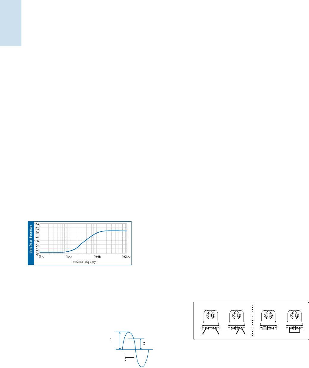
Because electronic ballasts function at high frequency, the fluorescent
lighting systems that they operate can convert power to light more
efficiently than systems operated by electromagnetic ballasts (See
chart below). For example, lamps operated on electronic ballasts
can produce over 10 percent more light then if operated on electro-
magnetic ballasts at the same power levels. In effect, today’s electronic
ballasts provide additional energy savings by matching the light output
from electromagnetic ballasts while operating the lamps at lower
power. This is the main reason why electronic ballast systems are
more efficient than magnetic ballast system.
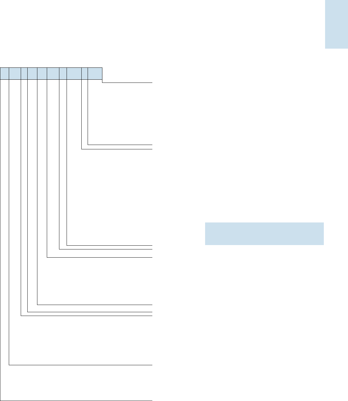
Crest Factor
Lamp manufacturers use crest factor to determine ballast
performance as it relates to lamp life. Lamp Current Crest Factor
is a measurement of current supplied by a ballast to start and
operate the lamp. It is basically the ratio of peak current to RMS
(average) current. High crest factor currents may cause the lamp
electrodes to wear out faster, reducing lamp life. Crest factor
requirements are regulated by ANSI (American National Standards
Institute) standards and specified by lamp manufacturers. For rapid
start and instant start T8 lamps
the ratio is 1.7 maximum, and for
instant start slimline lamps, it is 1
.85 maximum.
Weight and Size Advantages
Since electronic components in electronic ballasts are smaller and
lighter than the core-and-coil assembly in electromagnetic ballasts,
electronic ballasts can weigh less than half as much as comparable
electromagnetic models. Almost all Philips Advance electronic
ballasts have a smaller cross-section than electromagnetic ballasts
but maintain the same mounting dimensions. This means that they
can fit into all new fixture designs and can be easily retrofitted into
existing fluorescent lighting systems.
Controllability
The ability of a building’s occupants to control how they light their
space is becoming an increasingly important factor for organizations
in determining what real estate they will lease, buy or invest in.
The ability to dim the lights or easily shut them off completely is a
trend fueled not just by a desire to help the environment, but also
by significant economic benefits. These benefits include greater
energy efficiency — in terms of reduced HVAC costs as well as
energy savings for lighting — more comfortable and productive
working environments, and compliance with ever tighter energy
efficiency regulations. Philips Advance offers five families of electronic
controllable ballasts — ROVR, Mark 7 0-10V, Mark 10 Powerline,
PowerSpec HDF, EssentiaLine 0-10V and EssentiaLine Powerline.
Compatibility With Powerline Carrier Systems
A powerline carrier system (PLC) uses electronic wiring devices to
send information via a high frequency signal over the 120V or 277V
electrical power distribution system of a building. For example, PLC
systems are used in automatic clock systems (master time systems)
to synchronize all of the clocks in a building or reset the time after a
power outage. They eliminate the need for maintenance personnel
to reset hundreds of clocks throughout a facility.
In a PLC system, a generator is used to impose a 1 to 4V high fre-
quency signal on top of the existing voltage sine wave (60 Hz). This
signal is generally in the 2500 to 9500Hz range, with some older
systems operating at 19,500Hz or higher. Some electronic ballasts
which are capacitive can absorb the signal from a PLC system. As a
result, the signal becomes too weak to be “heard” by the receiver
(like a timeclock) connected to the powerline.
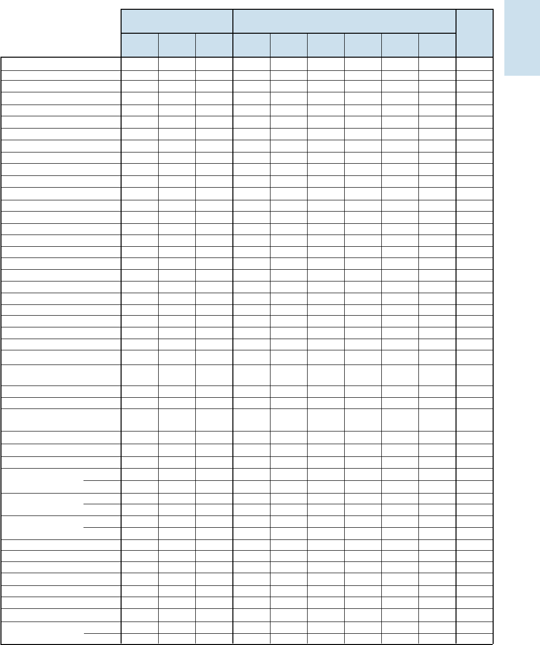
Instant Start vs. Rapid Start Sockets for Dimming
When using dimming ballasts in fixtures, sockets must be of the
Rapid Start type. Many fixtures with T-8 Instant Start electronic
ballasts use jumpered or “shunted” Instant Start sockets. Controllable
ballasts require two distinctly separate wires for each lamp socket. If
you encounter shunted or jumpered sockets in a retrofit application,
they must be removed and replaced with Rapid Start sockets.
Fluorescent Lamp Burn-In
Today, most lamp manufacturers do not require the burn-in of
linear fluorescent lamps prior to dimming in order to attain rated
lamp life and stable electrical measurements. However, some
manufacturers of compact fluorescent lamp sources do require a
100 hour burn-in prior to dimming. Consult your lamp manufacturer
for their latest requirements.
Peak
I
R.M.S.
I
Crest Factor =
R.M.S.
I
Peak
I
Rapid Start Sockets
YES NO NO NO
Instant Start Sockets
Shunted Jumpered
Color
‘A’
Color
‘A’
Color
‘A’
Color
‘A’
Improper socket application will damage the ballast and void the ballast warranty.
Refer to ballast wiring diagram for proper installation.
1-11
Atlas Full Line Catalog 2012-2013
ELECTRONIC FLUORESCENT BALLASTS
Electronic
Fluorescent Ballasts
Ordering Information
How to Order
Philips Lighting Systems and Controls has developed the industry’s broadest distribution system for electronic ballasts. More than 3000
stocking distributors nationwide. For information on the distributor best able to serve your needs, please call 800-372-3331.
• Plan your lighting installation carefully; consider
using the services of a qualified lighting designer
• Consult your local electric utility regarding demand
side management rebate programs.
• Select the Philips Advance electronic ballast which
best matches the requirements of your application.
The technical specifications in this catalog (located
on pages 9-6 to 9-13) will be useful in obtaining
bids from electrical contractors.
• Contact your local Philips Lighting distributor.
You will find them to be a helpful supplier of
both products and information.
* Many current and all future electronic ballast part numbers will not use the “RH-TP” suffixes even though these ballasts will be thermally protected.
** Parallel Wiring Configuration. However, if one lamp fails, all other lamps in the circuit will extinguish.
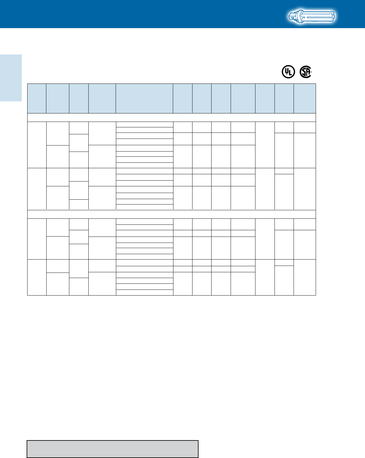
Electronic Ballast Part Number Breakdown
CFL Mounting/Connector Options
BL = Bottom leads
BLS = Bottom leads with mounting studs
BS = Bottom mounting studs with single entry color coded connectors
EL = End leads
LD = Length mounting feet with SmartMate® dual entry color coded connectors
QS = QuikStart
Linear Fluorescent Mounting/Connector Options
2LS = 2 Level Switching
I CF – – –
2 S 26 H1 LD
Input Voltage
G = 347V
H = IntelliVolt 347V to 480V 50/60 Hz
I = IntelliVolt 120V to 277V 50/60 Hz
R = 120V
V = 277V
Family Name
CF = Compact Fluorescent CN = Centium
DA = ROVR DL = ROVR
EB = AmbiStar ELB = AmbiStar
EZ = Mark 10® Powerline LV = EssentiaLine 0-10V
MB = AmbiStar OP = Optanium
TR = EssentiaLine Powerline UV = PureVolt
ZT = Mark 7® 0-10V
Maximum Number of Lamps
Wiring Configuration
D = 2D, series
M = Modified parallel**
P = Parallel
PSP = Programmed Start Parallel
Q = Quad CFL, series
S = Series
T = Triple CFL, series
TTS = Long twin tube, series
TTP = Long twin tube, parallel
Lamp Watts (Primary lamp)
CFL Can Desription
H1 = Hybrid metal / plastic case, size 1
M1 = Metal case, size 1
M2 = Metal case, size 2
M3 = Metal case, size 3
M4 = Metal case, size 4
M5 = Metal case, size 5
M6 = Metal case, size 6
Linear Fluorescent Can Desription
90C = 90°C maximum case temperature rating
A = ‘A’ can
D = ‘D’ can
G = ‘G’ can
HL = High light output
L = ‘L’ can
LW = Low watt
MC = Micro can
N = ‘N’ can
SC = Small can
Visit our web site at
www.philips.com/advance
Customer Support/Technical Service
(800) 372-3331
(+) 1 847 390-5000 (International)
Corporate Offices
(800) 322-2086
1-17
Atlas Full Line Catalog 2012-2013
ELECTRONIC FLUORESCENT BALLASTS
Electronic
Fluorescent Ballasts
20’
Yes Yes
20’
20’
1
8’
1
8’
1 (e)
10’ Yes Yes 10’ 4’ 4’ 10’ 7 (d)
10’ Yes Yes 10’ 4’ 4’ 10’ 7 (d)
20’ Yes Yes 20’ 20’ 8’
1
(
e
)
20’ Yes Yes 20’ 20’ 8’
1
(
e
)
20’
Yes Yes
20’
20’
1
8’
1
8’
1
8’
1
(
e
)
20’
Yes Yes
20’
20’
1
8’
1
8’
1
8’
1
(
e
)
20’
Yes Yes
20’
20’
15’ 15’ 15’ 1
(
e
)
10’ Yes Yes 10’ 4’ 4’ 10’ 10’ 7 (d)
10’ Yes Yes 10’ 4’ 4’ 10’ 10’ 7 (d)
20’ NA NA 20’ 20’
1
(
e
)
20’ NA NA 20’ 20’
1
(
e
)
20’ NA NA 20’ 20’
1
(
e
)
20’ Yes Yes 20’ 20’’
1
(
e
)
20’ Yes Yes 20’ 20’
1
(
e
)
20’ Yes Yes 20’ 20’’
1
(
e
)
20’ Yes Yes 20’ 20’’
1
(
e
)
20’ Yes Yes 20’ 20’
1
(
e
)
20’ Yes Yes 20’ 20’’
1
(
e
)
20’ Yes Yes 20’ 20’
8’
1
(
e
)
20’ Yes Yes 20’ 20’
8’
1
(
e
)
20’ Yes Yes 20’ 20’
8’
1
(
e
)
20’ Yes Yes 20’ 20’
8’
1
(
e
)
6’ NA NA 4
6’ NA NA 4
No NA NA 5
No No No 5
6’ Yes Yes 6’ 6’ 6’ 1
6’ Yes Yes 6’ 6’ 6’ 1
No No No 5
6’ No No 4
No No No 5
No No Yes 1’ 1.25’ 5.2’ 1.25’ 4.2’ 3
1-Lamp 15’ No No 4
2-Lamp 6’ Yes Yes 2’ 6’ 6’ 2
1-Lamp 15’ No No 4
2-Lamp 6’ Yes Yes 2’ 6’ 6’ 2
1-Lamp 15’ No No 4
2-Lamp 6’ Yes Yes 2’ 6’ 6’ 2
No No No 5
No No No 5
No No No 5
No No No 5
No No No 5
No No No 5
20” Yes Yes 20’ 20’ 1
20” No No 4
No Yes Yes 12’ 2’ 12’ 3
IOP-3PSP32-SC
IOP-3S32-LW-SC
IOP-3S32-SC
IOP-4P32-LW-SC
IOP-4P32-SC
IOP-4PSP32-LW-SC
IOP-4PSP32-SC
IOP-4PSP54-2LS-G
IOP-4S32-LW-SC
IOP-4S32-SC
IOPA-1P32-HL-N
IOPA-1P32-LW-N
IOPA-1P32-N
IOPA-2P32-HL-N
IOPA-2P32-LW-N
IOPA-2P32-N
IOPA-3P32-HL-N
IOPA-3P32-LW-N
IOPA-3P32-N
IOPA-4P32-HL-90C-G
IOPA-4P32-HL-SC
IOPA-4P32-LW-N
IOPA-4P32-N
IZT-128-D
IZT-132-SC
IZT-180
IZT-2S26-M5-BS
IZT-2S26-M5-LD
IZT-2S28D
IZT-2S32-SC
IZT-2T42-M5-BS
IZT-2T42-M5-LD
IZT-2TTS40-SC
IZT-3S32-SC
IZT-4S32
RCF-2S13-MI-LD
RCF-2S13-M1-BS
RCF-2S18-M1-BS
RCF-2S26-H1-LD
RCF-2S26-M1-BS
REB-113-M6-BLS
REB-113-M6-EL
REB-118-M6-BLS
REB-118-M6-EL
REB-126-M6-BLS
REB-126-M6-EL
REB-2P32-SC
1-LAMP
2-LAMP
REB-2S26-M1-LD-DIM
Maximum Lead Length (Feet) for Tandem or Through Wiring
(Total length of all wires between ballast and lamp sockets)
Application
Note
Remote
(max length)
Tandem Through Blue Red Yellow
Blue/White
Brown Orange
Allowed Wiring Configuration
For nominal input voltage and 25°C ambient temperature. See all notes on page 1-19.
Atlas Full Line Catalog 2012-2013
1-22
ELECTRONIC FLUORESCENT BALLASTS
Electronic
Fluorescent Ballasts
HIGH POWER FACTOR SOUND RATED A
T4
For 13-18W Quad Lamps
REB-113-M6-BLS*
CFQ13W/G24q - 13W CFL Quad Tube Lamp (PL-C13W/4P, F13DBX/4P, CF13DD/E)
1 0/-18
120
IS
AmbiStar
0.23
13 1.00 150
160A
Size 6
REB-113-M6-EL*
* Normal Power Factor
❿
Replacement/Retrofit ballast kits indicated with suffix K are available to distributors. Refer to page 1-21 for details.
REB-118-M6-EL*
CFQ18W/G24q - 18W CFL Quad Tube Lamp (PL-C18W/4 P, F18DBX/4P, CF18DD/E)
10/-18
120 IS REB-118-M6-BLS*
AmbiStar
0.2918 1.00 150 160A
Size 6
160
SmartMate
RS
0.1316 1.00 10
Size 1
RCF-2S13-H1-LD-QS
RCF-2S13-M1-BS-QS
120-277
ICF-2S13-M1-BS-QS
ICF-2S13-H1-LD
ICF-2S13-H1-LD-K ❿
PS 0.13-0.06
16 1.00 10
ICF-2S13-M1-BS
20/-18
120 AmbiStar
IS
159
REB-2S13-M6-EL* 0.4227 0.88 135 Size 6
RCF-2S13-H1-LD-QS
RS
0.2529 1.00 10
Size 1
RCF-2S13-M1-BS-QS
120-277
ICF-2S13-M1-BS-QS
ICF-2S13-H1-LD
ICF-2S13-H1-LD-K ❿
PS
0.25-0.1129 1.00 10
ICF-2S13-M1-BS
SmartMate
REB-2S18-M6-EL*
SmartMate
RS
0.1619 1.00 10
Size 1 160
RCF-2S18-M1-BS-QS
120-277
ICF-2S18-M1-BS-QS
ICF-2S18-H1-LD
ICF-2S18-H1-LD-K ❿
PS
0.16-0.0719 1.00 10
ICF-2S18-M1-BS
20/-18
120
SmartMate
AmbiStar
RS
Size 6
0.5537 0.90 135
0.3035 0.95 10
Size 1 159
120-277
RCF-2S18-M1-BS-QS
ICF-2S18-M1-BS-QS
ICF-2S18-H1-LD
ICF-2S18-H1-LD-K ❿
PS 0.30-0.1335 0.95 10
ICF-2S18-M1-BS
No. of
Lamps Dim. Wiring
Dia.
Min.
Starting
Temp.
(°F/°C)
Input
Volts
Ballast
Family
Lamp
Starting
Method
Catalog Number
Line
Current
(Amps)
Input
Power
ANSI
(Watts)
Ballast
Factor
Max.
THD
%
Refer to page 1-27 for dimensions and wiring diagrams
Refer to pages 9-23 to 9-27 for lead lengths and shipping data
Atlas Full Line Catalog 2012-2013
1-24
ELECTRONIC FLUORESCENT BALLASTS
Electronic
Fluorescent Ballasts
* Normal Power Factor
❿
Replacement/Retrofit ballast kits indicated with suffix K are available to distributors. Refer to page 1-21 for details.
CFTR18W/GX24q - 18W CFL Triple Tube Lamp (PL-T18W, F18TBX/4P, CF18DT/E)
10/-18
120 IS REB-118-M6-BLS*
AmbiStar REB-118-M6-EL*
RCF-2S18-M1-BS-QS
IS
RS 0.1720 1.05 10
Size 1 160
120-277
ICF-2S18-M1-BS-QS
ICF-2S18-H1-LD
ICF-2S18-H1-LD-K ❿
PS 0.17-0.0820 1.05 10
ICF-2S18-M1-BS
20/-18
120 AmbiStar
SmartMate
SmartMate
RS
0.3339 1.05 10
Size 6
0.5537 0.90 135
Size 1 159
RCF-2S18-M1-BS-QS
REB-2S18-M6-EL*
120-277
ICF-2S18-M1-BS-QS
ICF-2S18-H1-LD
ICF-2S18-H1-LD-K ❿
PS 0.33-0.1439 1.05 10
ICF-2S18-M1-BS
0.2918 1.00 150 Size 6 160A
No. of
Lamps
HIGH POWER FACTOR SOUND RATED A
Dim. Wiring
Dia.
Min.
Starting
Temp.
(°F/°C)
Input
Volts
Ballast
Family
Lamp
Starting
Method
Catalog Number
Line
Current
(Amps)
Input
Power
ANSI
(Watts)
Ballast
Factor
Max.
THD
%
T4
For 18-26W Triple Lamps
Refer to page 1-27 for dimensions and wiring diagrams
Refer to pages 9-23 to 9-27 for lead lengths and shipping data
CFTR26W/GX24q - 26W CFL Triple Tube Lamp (PL-T26W, F26TBX/4P, CF26DT/E)
10/-18
120
IS
REB-126-M6-BLS
*
AmbiStar REB-126-M6-EL
*
0.3825 1.00 150 160A
Size 6
RCF-2S26-H1-LD-QS
Size 1
Size 1
Size 2
RCF-2S26-M1-BS-QS 0.2429 1.10 10
RS
RS
160
159
ICF-2S26-M1-BS-QS
ICF-2S26-H1-LD
ICF-2S26-H1-LD-K
❿
120-277
ICF-2S26-M1-BS
0.24-0.11
0.45
0.45-0.20
0.46-0.21
29
54
54
55
1.10
1.00
1.00
1.00
10
10
Size 6
0.5552 0.88 135
10
10
PS
IS
PS
RCF-2S26-H1-LD-QS
REB-2S26-M6-EL*
RCF-2S26-M1-BS-QS
20/-18
SmartMate
AmbiStar
SmartMate
ICF-2S26-M1-BS-QS
ICF-2S26-H1-LD
ICF-2S26-H1-LD-K
❿
120
120-277
ICF-2S26-M1-BS
ICF-2S42-M2-BS
ICF-2S42-M2-LD
ICF-2S42-M2-LD-K
❿
ICF-2S42-90C-M2-BS
ICF-2S42-90C-M2-LD
