Product Detail Manual
2014-07-05
: Pdf 112493-Attachment 112493-Attachment 662019 Batch5 unilog
Open the PDF directly: View PDF ![]() .
.
Page Count: 392 [warning: Documents this large are best viewed by clicking the View PDF Link!]
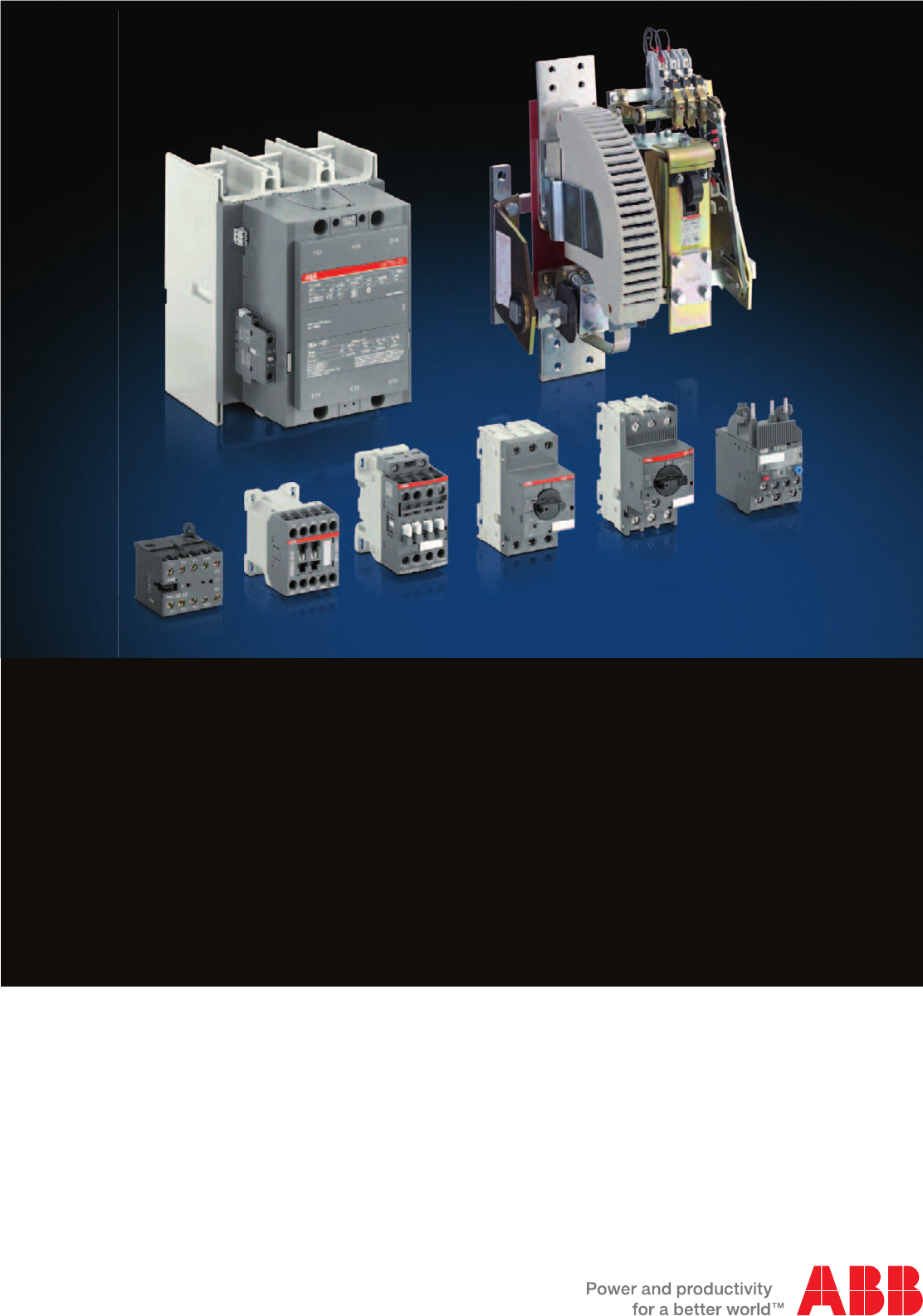
Motor protection and control
Manual motor starters, contactors
and overload relays
Catalogue

Motor rated operational powers and currents
The currents given below concern standard three-phase four-pole cage motors (1500 r.p.m. at 50 Hz 1800 r.p.m. at 60 Hz).
These values are given for guidance and may vary according to the motor manufacturer and depending on the number of poles.
IEC Motor nominal current: standardized values in blue colour
(according to IEC 60947-4-1 Annex G)
Motor
power
220 V 230 V 240 V 380 V 400 V 415 V 440 V 500 V 660 V 690 V
kW
AAAAAAAAAA
0.06 0.37 0.35 0.34 0.21 0.2 0.19 0.18 0.16 0.13 0.12
0.09 0.54 0.52 0.50 0.32 0.3 0.29 0.26 0.24 0.18 0.17
0.12 0.73 0.7 0.67 0.46 0.44 0.42 0.39 0.32 0.24 0.23
0.18 111 0.63 0.6 0.58 0.53 0.48 0.37 0.35
0.25 1.6 1.5 1.4 0.9 0.85 0.82 0.74 0.68 0.51 0.49
0.37 2.0 1.9 1.8 1.2 1.1 1.1 1 0.88 0.67 0.64
0.55 2.7 2.6 2.5 1.6 1.5 1.4 1.3 1.2 0.91 0.87
0.75 3.5 3.3 3.2 2.0 1.9 1.8 1.7 1.5 1.15 1.1
1.1 4.9 4.7 4.5 2.8 2.7 2.6 2.4 2.2 1.7 1.6
1.5 6.6 6.3 6 3.8 3.6 3.5 3.2 2.9 2.2 2.1
2.2 8.9 8.5 8.1 5.2 4.9 4.7 4.3 3.9 2.9 2.8
311.8 11.3 10.8 6.8 6.5 6.3 5.7 5.2 43.8
415.7 15 14.4 8.9 8.5 8.2 7.4 6.8 5.1 4.9
5.5 20.9 20 19.2 12.1 11.5 11.1 10.1 9.2 76.7
7.5 28.2 27 25.9 16.3 15.5 14.9 13.6 12.4 9.3 8.9
11 39.7 38 36.4 23.2 22 21.2 19.3 17.6 13.4 12.8
15 53.3 51 48.9 30.5 29 28 25.4 23 17.8 17
18.5 63.8 61 58.5 36.8 35 33.7 30.7 28 22 21
22 75.3 72 69 43.2 41 39.5 35.9 33 25.1 24
30 100 96 92 57.9 55 53 48.2 44 33.5 32
37 120 115 110 69 66 64 58 53 40.8 39
45 146 140 134 84 80 77 70 64 49.1 47
55 177 169 162 102 97 93 85 78 59.6 57
75 240 230 220 139 132 127 116 106 81 77
90 291 278 266 168 160 154 140 128 97 93
110 355 340 326 205 195 188 171 156 118 113
132 418 400 383 242 230 222 202 184 140 134
160 509 487 467 295 280 270 245 224 169 162
200 637 609 584 368 350 337 307 280 212 203
250 782 748 717 453 430 414 377 344 261 250
315 983 940 901 568 540 520 473 432 327 313
355 1109 1061 1017 642 610 588 535 488 370 354
400 1255 1200 1150 726 690 665 605 552 418 400
500 1545 1478 1416 895 850 819 745 680 515 493
560 1727 1652 1583 1000 950 916 832 760 576 551
630 1928 1844 1767 1116 1060 1022 929 848 643 615
710 2164 2070 1984 1253 1190 1147 1043 952 721 690
800 2446 2340 2243 1417 1346 1297 1179 1076 815 780
900 2760 2640 2530 1598 1518 1463 1330 1214 920 880
1000 3042 2910 2789 1761 1673 1613 1466 1339 1014 970
UL / CSA Motor nominal current: standardized values
(according to IEC 60947-4-1 Annex G and UL 508)
Motor
power
208 V 220-240 V 380-415 V 440-480 V 550-600 V
hp
AAAAA
1/2 2.4 2.2 1.3 1.1 0.9
3/4 3.5 3.2 1.8 1.6 1.3
14.6 4.2 2.3 2.1 1.7
1-1/2 6.6 6 3.3 3 2.4
27.5 6.8 4.3 3.4 2.7
310.6 9.6 6.1 4.8 3.9
516.7 15.2 9.7 7.6 6.1
7-1/2 24.2 22 14 11 9
10 30.8 28 18 14 11
15 46.2 42 27 21 17
20 59.4 54 34 27 22
25 74.8 68 44 34 27
30 88 80 51 40 32
40 114 104 66 52 41
50 143 130 83 65 52
60 169 154 103 77 62
75 211 192 128 96 77
100 273 248 165 124 99
125 343 312 208 156 125
150 396 360 240 180 144
200 528 480 320 240 192
250 – 604 403 302 242
300 – 722 482 361 289
350 – 828 560 414 336
400 – 954 636 477 382
450 – 1030 – 515 412
500 – 1180 786 590 472
1SBC101589S0201

Motor protection and control
Manual motor starters, contactors and overload relays
11
2
3
4
5
6
7
8
9
10
Overview
Manual motor starters
B mini contactors
AS contactors
AF, A and EK contactors
Overload relays
R contactors
Motor management system
Coordination with short-circuit protection devices
Index
1SBC101622C0201
ABB | 1/1
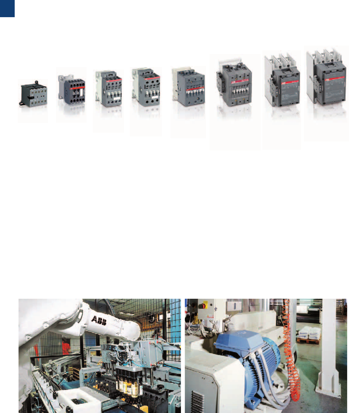
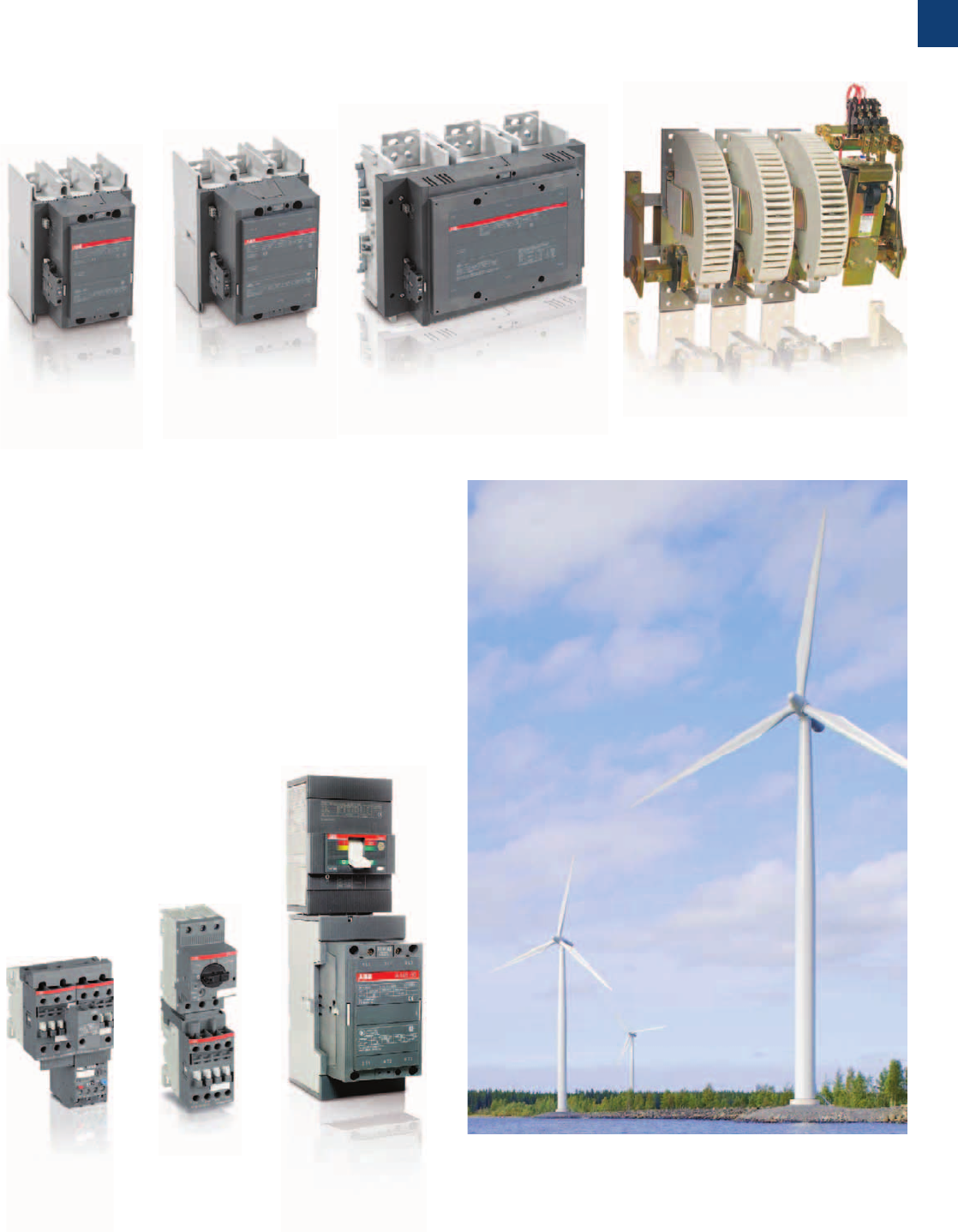
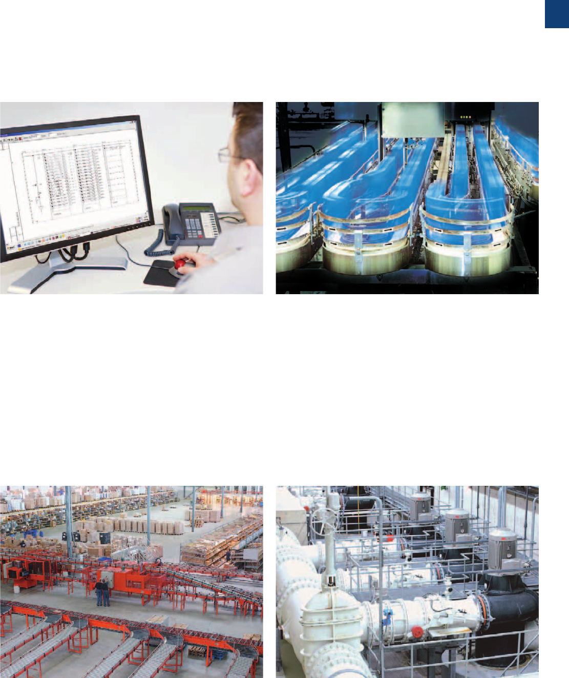
Extensive range of contactors
The right choice for many applications
– Pumps
–HVAC
– Compressors
– Power supply solutions
– Packing machines
– Cranes
– Elevators and escalators
– Moulding machines
Wood machines
– Robot
– Windmill
– Solar system
– Water heating
– Fuel cells
– Traction
Mini contactors for compact equipments - up to 5.5 kW / 5 hp
Contactors for all industrial applications up to 2050A and
motor starting-up to 560 kW (400 V) / 900 hp (480 V)
Contactors for heavy duty applications - up to 5000 A,
1000 V AC / 1500 V DC
– Complete and harmonized 3 and 4-pole ranges.
– High performance and high quality materials.
– Compact dimensions easy to integrate in all designs.
– AF contactors with electronic coil interface:
- wide voltage range AC / DC, sag and dips immunity,
- built-in surge suppressor.
– Complying with the latest international standards.
High performance contactors for your applications
from 9 to 5000 A
1/2 | ABB
1
1SBC101623C0201
Motor starting solutions
– Perfect match in starter assembly with a large range
of accessories.
– Short-circuit protection, type 1 and 2 coordination.
– Large offer of accessories for direct-on-line, reversing and
star-delta starters which allows:
- time / cost saving,
- secure connection,
- aesthetic starters,
- easy assembly and wiring.
ABB | 1/3
1
1SBC101623C0201
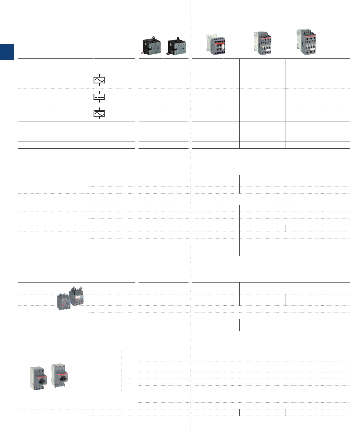
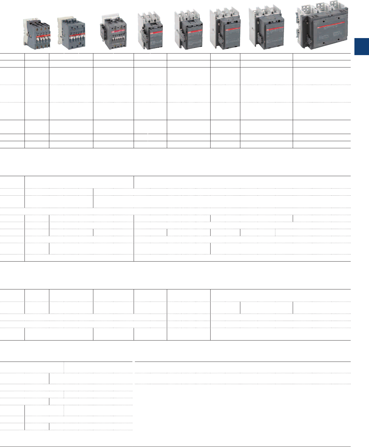
IEC
AC-3 Rated operational power
θ ≤ 55 °C*, 400 V
kW 4 5.5 4 5.5 7.5 4 5.5 7.5 11 15 18.5
UL/CSA
3-phase motor rating
480 V
hp 3 5 5 7.5 10 5 7.5 10 15 20 20
AC Control supply Type
B6 B7 AS09 AS12 AS16 AF09 AF12 AF16 AF26 AF30 AF38
DC Control supply Type
BC6 BC7 ASL09 ASL12 ASL16 AF09 AF12 AF16 AF26 AF30 AF38
AC / DC Control supply Type —————
AF09 AF12 AF16 AF26 AF30 AF38
IEC
AC-3 Rated operational current
θ ≤ 55 °C*, 400 V
A 9 12 9 12 15.5 9 12 18 26 32 38
AC-1 Rated operational current
θ ≤ 40 °C, 690 V
A 16 20 22 24 24 25 28 30 455050
UL/CSA
General use rating
600 V
A 12
(300 V)
16 20 20 20 25 28 30 45 50 50
NEMA
NEMA Size
— — 00 00 0 00 0 — 1 — —
* θ ≤ 60 °C for AS(L)09 ... AS(L)16 and AF09 ... AF38 contactors
Main accessories
Auxiliary contact blocks
Front mounting
CAF6 CA3-10
(1 x N.O.)
,
CA3-01
(1 x N.C.)
CA4-10
(1 x N.O.),
CA4-01
(1 x N.C.)
Side mounting
CA6 CAL4-11
(1 x N.O. + 1 x N.C.)
Timers
Pneumatic
(Front mounting)
Electronic
TEF3-ON, TEF3-OFF
Interlocking units (1)
Mechanical
VM3 VM4
Mechanical / Electrical
VEM4
Connection
sets
For reversing contactors
BSM6-30 BER16C-3 BER16-4 BER38-4
Surge suppressors
AF contactors have built-in surge
protection
Varistor (AC/DC)
RV-BC6 RV5
(24…440 V)
RC type (AC)
RC5-1
(24…440 V)
Transil diode (DC)
RD7 RT5
(12…264 V)
(1) See available reversing contactors VB6, VB7 and VAS09 ... VAS16
Overload relays
Thermal relays
Class 10
(10A or 20 for TA42DU to TA80DU)
T16
(0.10…16 A)
T16
(0.10…16 A)
TF42
(0.10…38 A)
Electronic relays
Class 10E, 20E, 30E
E16DU
(0.10…18.9 A)
EF19
(0.10…18.9 A)
EF19
(0.10…18.9 A),
EF45
(9…45 A)
Accessories
for thermal
overload relays
Remote tripping coil
Remote reset coil
Wall/separate mounting kit
DB16
(T16 only),
DB16E
(E16DU only)
DB42
(TF42 only)
Manual motor starters
Thermal / magnetic
protection
Class
10
MS116
for class 10A (0.16…32 A)
Ics up to 50 kA
MS116
for class 10A (0.16…32 A)
Ics up to 50 kA
MS450
MS132
(0.10…32 A)
Ics up to 100 kA
MS132
(0.10…32 A) Ics up to 100 kA
MS497
Class
20
MS451
Magnetic only types
MO132
(0.10…32 A)
Accessories
For contactor mounting
BEA7/132 BEA16-3 BEA16-4 BEA38-4
Auxiliary trip units, auxiliary
contacts, busbars
HKF1, HK1, UA1, AA1,
PS1, S1, SK1, CK1
(MS132 only)
HKF1, HK1, UA1, AA1, PS1, S1, SK1, CK1
(MS132, MO132 only)
HK4,
Contactors for all industrial 3-pole contactors Mini contactors
1/4 | ABB
1
18.5 22 30 37 45 55 75 90 110 140 160 200 250
315 400 —
475 560 —
30 40 60 60 60 75 100 125 150 200 250 350 400
500 600 —
800 900 —
A40 A50 A63 A75 A95 A110 A145 A185 A210 A260 A300 AF400 AF460 AF580 AF750 AF1250 AF1350 AF1650 AF2050
AL40 AE50 AE63 AE75 AF95 AF110 AF145 AF185 AF210 AF260 AF300 AF400 AF460 AF580 AF750 AF1250 AF1350 AF1650 AF2050
—
AF50 AF63 AF75 AF95 AF110 AF145 AF185 AF210 AF260 AF300 AF400 AF460 AF580 AF750 AF1250 AF1350 AF1650 AF2050
37 50 65 75 96 110 145 185 210 260 305 400 460
580 750 —
860 1050 —
60 100 115 125 145 160 250 275 350 400 500 600 700
800 1050 1260
1350 1650 2050
60 80 90 105 125 140 230 250 300 350 400 550 650
750 900 1210
1350 1650 2100
—2—3——4——5——6
—7—
—8 —
CA5-10
(1 x N.O.),
CA5-01
(1 x N.C.)
CAL5-11
(1 x N.O. + 1 x N.C.)
CAL18-11
(1 x N.O. + 1 x N.C.)
TP40DA, TP180DA
Direct timing
TP40IA, TP180IA
Inverse timing
VM5-1 VM300H / VM300V VM750H / VM750V VM1650H
VE5-1 VE5-2
BER40V BEM75-30 BEM110-30 BEM185-30 BEM300-30 BEM460-30 BEM750-30
RV5
(24…440 V)
RC5-1
(24…440 V)
RC5-2
(24…440 V)
RC5-3
(250...440V)
RT5
(12…264 V)
TA42DU
(18…42 A)
TA75DU
(18…80 A)
TA80DU
(29…80 A)
TA110DU
(65…110 A)
TA200DU
(66…200 A)
TA450DU/SU
(130…310 A) class 30 for SU
E45DU
(9...45 A)
E80DU
(27…80 A)
E140DU
(50…140 A)
E200D-U
(60…200 A)
E320DU
(100…320 A)
E500DU
(150…500 A)
E800DU
(250…800 A)
E1250DU
(375…1250 A)
DS25-A
DR25-A
DB80, DB45E, DB80E DB80, DB200,
D140E
DB200 DT450/A
Circuit breakers
(40…50 A) Ics up to 50 kA
MS495
(28…100 A) Ics up to 50 kA
Tmax
Circuit breaker and accessories
(11…100 A) Ics up to 100 kA
(11…50 A) Ics up to 50 kA
MS496
(28…100 A) Ics up to 100 kA
MO450
(16…50 A) Ics up to 50 kA
MO495
(40…100 A) Ics up to 50 kA
MO496
(16…100 A) Ics up to 100 kA
BEA40/450
BEA50/450, BEA75/495
HKS4, UA4, AA4, PS4, S4, SK4
applications and motor starting
ABB | 1/5
1
1SBC101637S0201
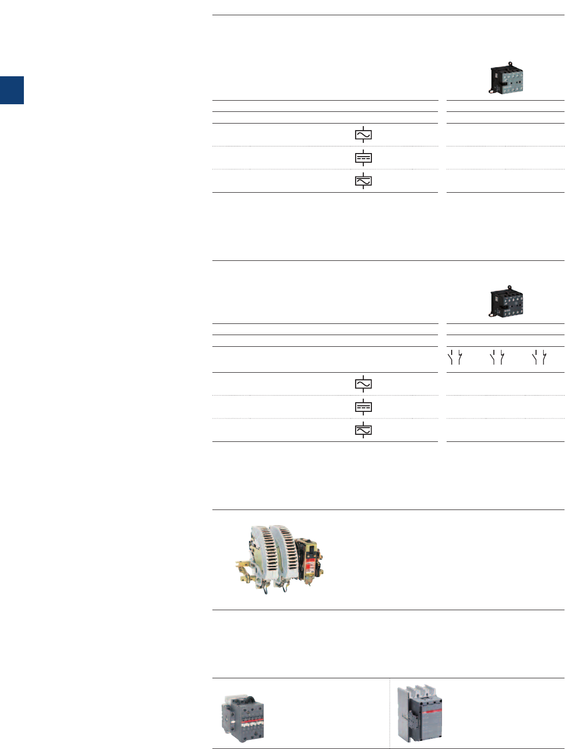
Mini contactors
IEC
AC-1 Rated operational current
θ ≤ 40 °C, 690 V
A16 20
UL/CSA
General use rating
600 V A12
(300 V)
16
AC Control supply Type B6 B7
DC Control supply Type BC6 BC7
AC / DC Control supply Type ——
4-pole contactors
Mini contactor relays
IEC
AC-15 Rated operational current
400 V A3
UL/CSA
Pilot duty
A 600
2 2 3 1 4 0
AC Control supply Type K6-22Z K6-31Z K6-40E
DC Control supply Type KC6-22Z KC6-31Z KC6-0E
AC / DC Control supply Type ———
Contactor relays
DC Circuit switching
DC-1 Rated current up to 5000 A
DC-3/DC-5 Rated current up to 2000 A
1500 V with poles in series
IOR.. 63-..-CC to IOR.. 5100-..-CC
R contactors
DC Circuit switching
100 A, 440 V, DC-1
GA75, GAE75 types
275 to 2050 A, 1000 V, DC-1
GAF185 to GAF2050 types
Specific contactors
1/6 | ABB
1
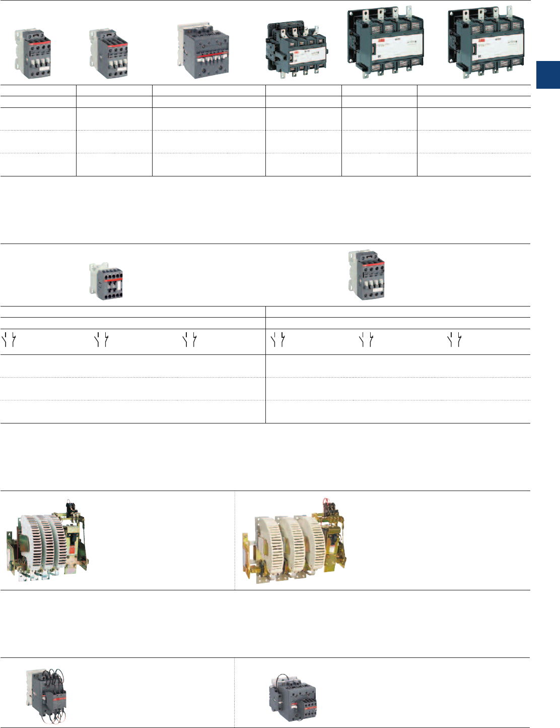
Contactors
25 30 45 55 70 100 125 200 250 300 350 550 800 1000
25 30 45 55 80 80 105 170 200 250 300 420 540 —
AF09 AF16 AF26 AF38 A45 A50 A75 EK110 EK150 EK175 EK210 EK370 EK550 EK1000
AF09 AF16 AF26 AF38 AE45 AE50 AE75 EK110 EK150 EK175 EK210 EK370 EK550 EK1000
AF09 AF16 AF26 AF38 AF45 AF50 AF75 ———————
Contactor relays
3 3
A 600, Q 300 A 600, Q 600
2 2 3 1 4 0 2 2 3 1 4 0
NS22E NS31E NS40E NF22E NF31E NF40E
NSL22E NSL31E NSL40E NF22E NF31E NF40E
— — — NF22E NF31E NF40E
AC Circuit switching Special versions
AC-1 Rated current up to 5000 A
AC-3 Rated power up to 1500 kW
(1520 A - 440 V)
IOR.. 63-..-MT to IOR.. 5100-..-MT
AC/DC Coupling: LOR.. contactors
Slip ring motor control: FOR .. contactors
Field discharge: AM(F)-CC-JORE contactors
AC/DC Switching (N.C./N.O. main poles):
NOR & JOR contactors
Latching contactors for energy saving
and safety requirements: AMA or AME contactors
Capacitor switching Magnetical latching
12.5 to 80 kvar
UA16..RA to UA110..RA types
UA16 to UA110 types
3 N.O. poles,
22 to 160 kW, 400 V, AC-3
2 N.O. + 2 N.C. poles,
70 to 125 A, AC-1
AM45 to AM300 types
ABB | 1/7
1
1SBC101638S0201
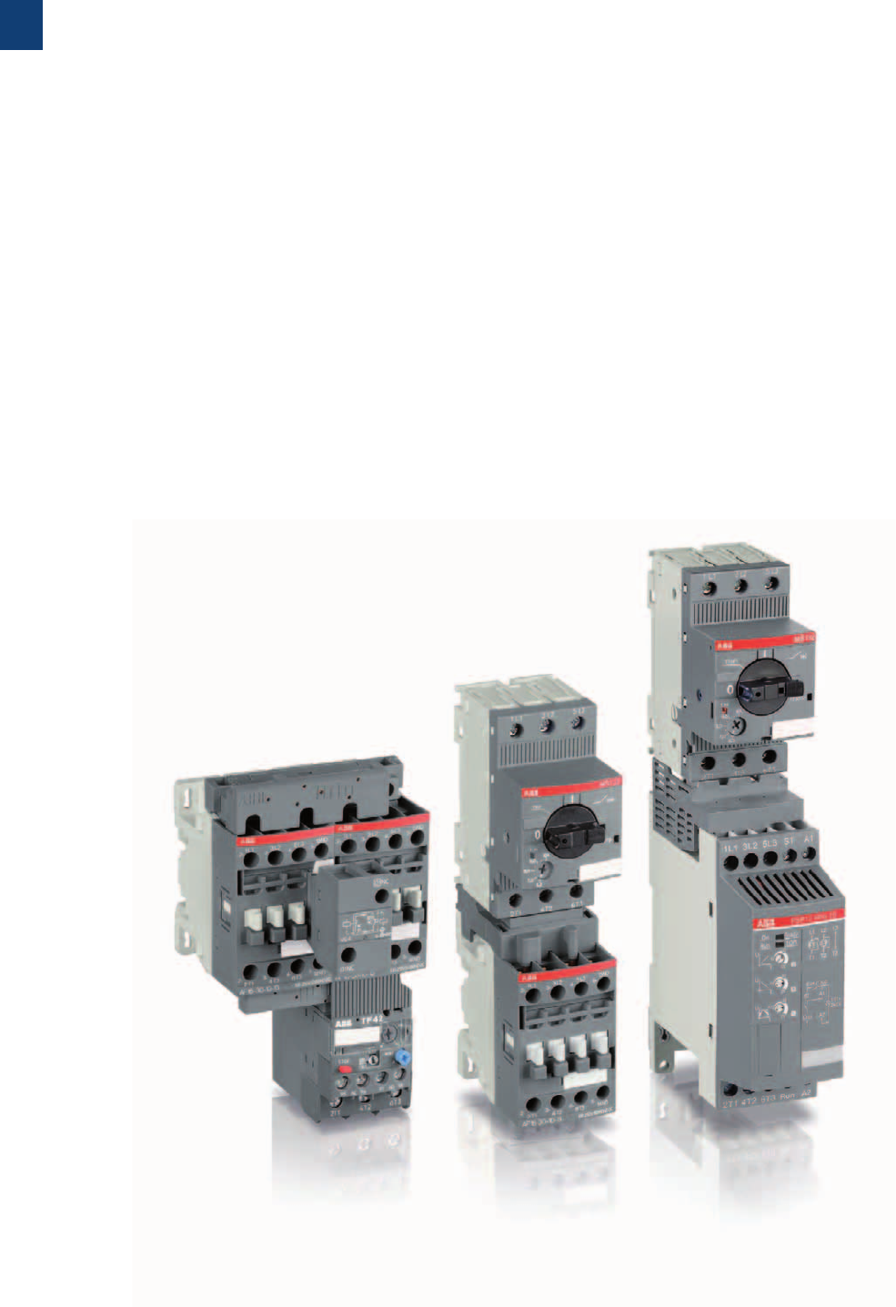
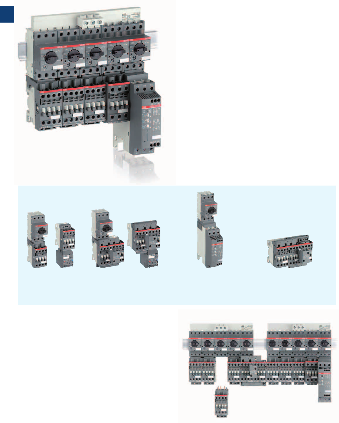
One product family
ABB presents a new generation of first-class specialized
components: manual motor starters, contactors, overload
relays and softstarters for motor starting solutions up to
18.5 kW / 20 hp
– Harmonized design & colour
– Compact and modular
– Low energy consumption
– Small number of parts
– Minimum need for accessories
– Optimized wiring and configuration
– High ratings and service capability
– Increased application possibilities
– Reliability proven over many years of experience
ABB’s new control and protection devices
Up to 18.5 kW / 20 hp
1/8 | ABB
1
1SBC101105S0202
Simplicity for your design
Our engineers have taken modularity and uniformity to the
next level in terms of flexibility and practicality for your appli-
cations. We offer you flexibility, increased application possi-
bilities, exchangeability and reduced panel size.
Increased availability for your equipment
Designing with simplicity in mind, our engineers have made it
possible to integrate the entire family into just a few components.
We offer you reduced inventory, greater exchangeability, to help
you to have fewer mistakes and shortages and less down time.
Safety and reliability
ABB’s new line of industrial motor control and protection
devices has been developed in order to meet the main safety
standards of the toughest industrial scenarios where high reli-
ability and safety level are required.
Energy efficiency and sustainability
Reducing energy consumption and protecting the environ-
ment has long been at the top of ABB’s list of priorities, and
we are proud to introduce a first-class proposal.
ABB | 1/9
1
1SBC101105S0202
Short-circuit and overload protection
– Type 1 or type 2 coordination guaranteed with manual
motor starters
– Choice of thermal or electronic overload relays
Simple construction
– All starters in 45 mm width module
Time/cost saving
– Same frame size for AC or DC control supply
– Easy, fast and secure assembly, fitting and wiring of
components
Softstarters
Protection by manual motor starters
or by fuses with overload relays
Star-delta starters
Protection by fuses with overload relays
Standardized busbars and optimized interconnection
accessories
– Same 3-phase busbar and feeder range up to 100 A for
manual motor starters
– Direct 35 mm rail mounting: no additional mounting plate
required
– Complete range of connection links with manual motor
starters and connection sets to build reversing and star-
delta starters
– Easy installation and dismounting of contactors: no unwiring
of manual motor starters
Direct-on-line and reversing starters
– Protection by manual motor starters or by fuses with overload relays
– Reversing starters in 90 mm width including mechanical and electrical
interlocking
Large choice of starting solutions in kit form
1/10 | ABB
1
1SBC101105S0202
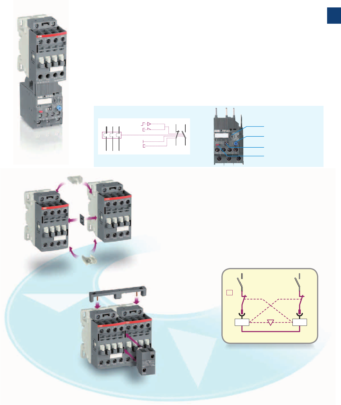
Protect your motors with thermal or electronic overload relays
– One range of TF42 thermal overload relays, trip class 10
– One range of EF19 and EF45 electronic overload relays up to 45 A, 7 setting ranges,
trip class 10E, 20E, 30E
– Adjustable current setting ranges
– Overload protection with phase loss sensitivity
– Temperature compensation:
- up to +60 °C for thermal overload relays
- up to +70 °C for electronic overload relays
– Automatic or manual reset, sealable
– Stop and test function
Interlock your reversing contactors quickly in 90 mm width:
– Easy with VM4 mechanical interlock unit
– Simple with VEM4 set including mechanical interlock unit and
electrical interlock block with A2-A2 connection
– 50% wiring cost savings in one click!
Fixing the electrical interlock block to the contactor front face
connects the 2 built-in N.C. interlocking contacts with the two
coil supplies
95
96
97
98
A
M
2/T1
4/T2
6/T3
RESET
STOP
TEST
Stop function
Test function
Current setting range
Reset function
A2 A2
01NC
01NC
KM1 KM2
VEM4
KM1 KM2
ABB | 1/11
1
1SBC101105S0202
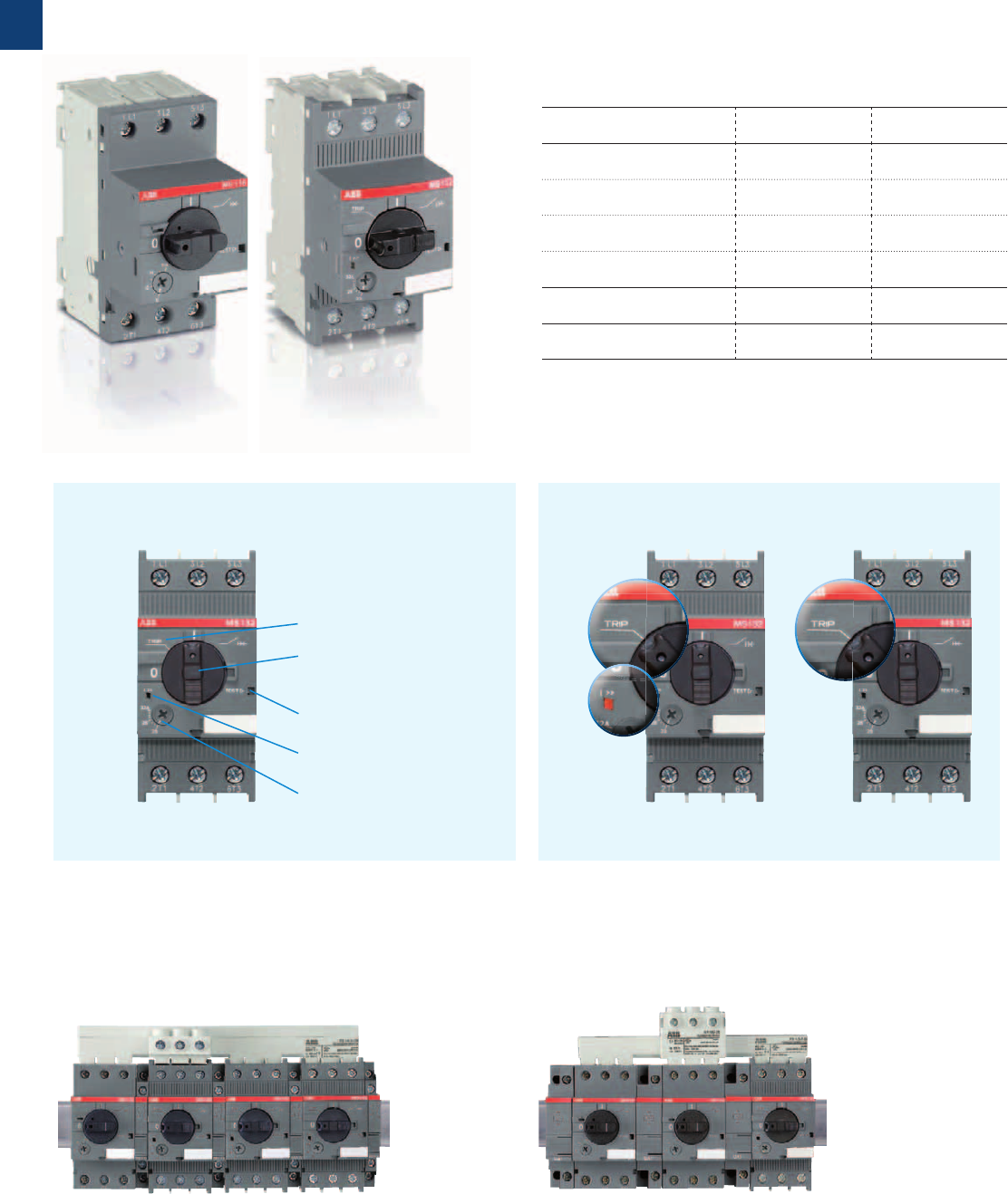
One range of accessories for MS116 and MS132
– Common auxiliary contacts, signaling contacts and auxiliary
trip units
– Common busbar systems
Types MS116 MS132
Setting range 0.1 ... 32 A 0.1 ... 32 A
Switch position ON / OFF ON / OFF / TRIP
Magnetic trip indication − yes
Lockable handle without ac-
cessories − yes
Max. breaking capacity Ics up to 50 kA up to 100 kA
Trip class 10A 10
ON/OFF switch functionality
TRIP indication
Lockable handle
without accessory
Test function
Magnetic tripping
Current setting
Magnetic tripping Thermal tripping
MS116 and MS132 manual motor starters
Harmonized design in 45 mm width
Optical indication
in I >> window
Handle in
TRIP position
Clear tripping identification
Handle in
TRIP position
1/12 | ABB
1
1SBC101105S0202
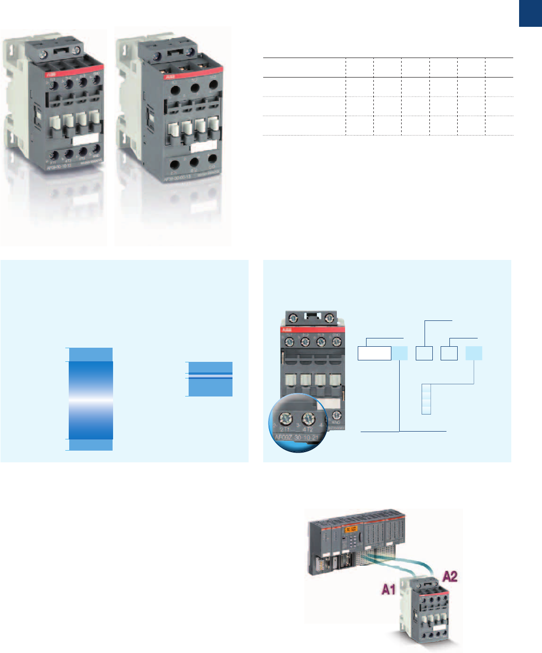
A unique contactor for AC or DC control supply
– Manages large control voltage variations
– Includes an electronic coil interface with extended operating
limits 0.85 x Uc min. ... 1.1 x Uc max.
Reduced panel energy consumption
– With low holding AC and DC coil consumption
– From 30% (AF coil) to 80% (AF..Z coil) reduction of AC
pull-in consumption
Built-in surge protection
– No extra surge suppressor required
Improve your equipment reliability with AF..Z contactors
– Withstands control voltage short dips
– Withstands control voltage sags according to
SEMI F47-0706 standards
– Additional AF..Z coils available for control voltages
between 12...20 V DC and 48...250 V 50/60 Hz - DC
Only four coils for easier selection
Control voltages covering 24...500 V 50/60 Hz and
20...500 V DC
21 24...60 V 50/60 Hz / 20...60 V DC
12 48...130 V 50/60 Hz - DC
13 100...250 V 50/60 Hz - DC
14 250...500 V 50/60 Hz - DC
Direct control by PLC-output ≥ 500 mA, 24 V DC
Types AF09 AF12 AF16 AF26 AF30 AF38
Rated operational power
400 V AC-3
4 kW 5.5 kW 7.5 kW 11 kW 15 kW
18.5 kW
Rated operational current
AC-1 (40 °C)
25 A 28 A 30 A 45 A 50 A 50 A
UL 3-phase motor power
480 V
5 hp 7.5 hp 10 hp 15 hp 20 hp 20 hp
AF09 ... AF38 3-pole contactors
Simple design with 2 frame sizes in 45 mm width
Auxiliary contacts
N.O. / N.C.
Contactor type
Main contacts
N.O. / N.C.
Blank: standard coil consumption
Z: low coil consumption
Coil code
AF09 Z - 30 - 10 - 21
No use of interface relay
Conventional
operating limits
for coil 220...230 V 50 Hz
0.85 x Uc min. (85 V)
Uc min. (100 V)
1.1 x Uc max. (275 V)
1.1 x Uc (253 V)
0.85 x Uc (187 V)
Uc = 220...230 V
50 Hz
Uc max. (250 V)
Uc min. ... Uc max. =
100...250 V
50/60 Hz - DC
AF operating limits
for coil 100...250 V 50/60 Hz - DC
AC
AC
AC / DC
ABB | 1/13
1
1SBC101105S0202
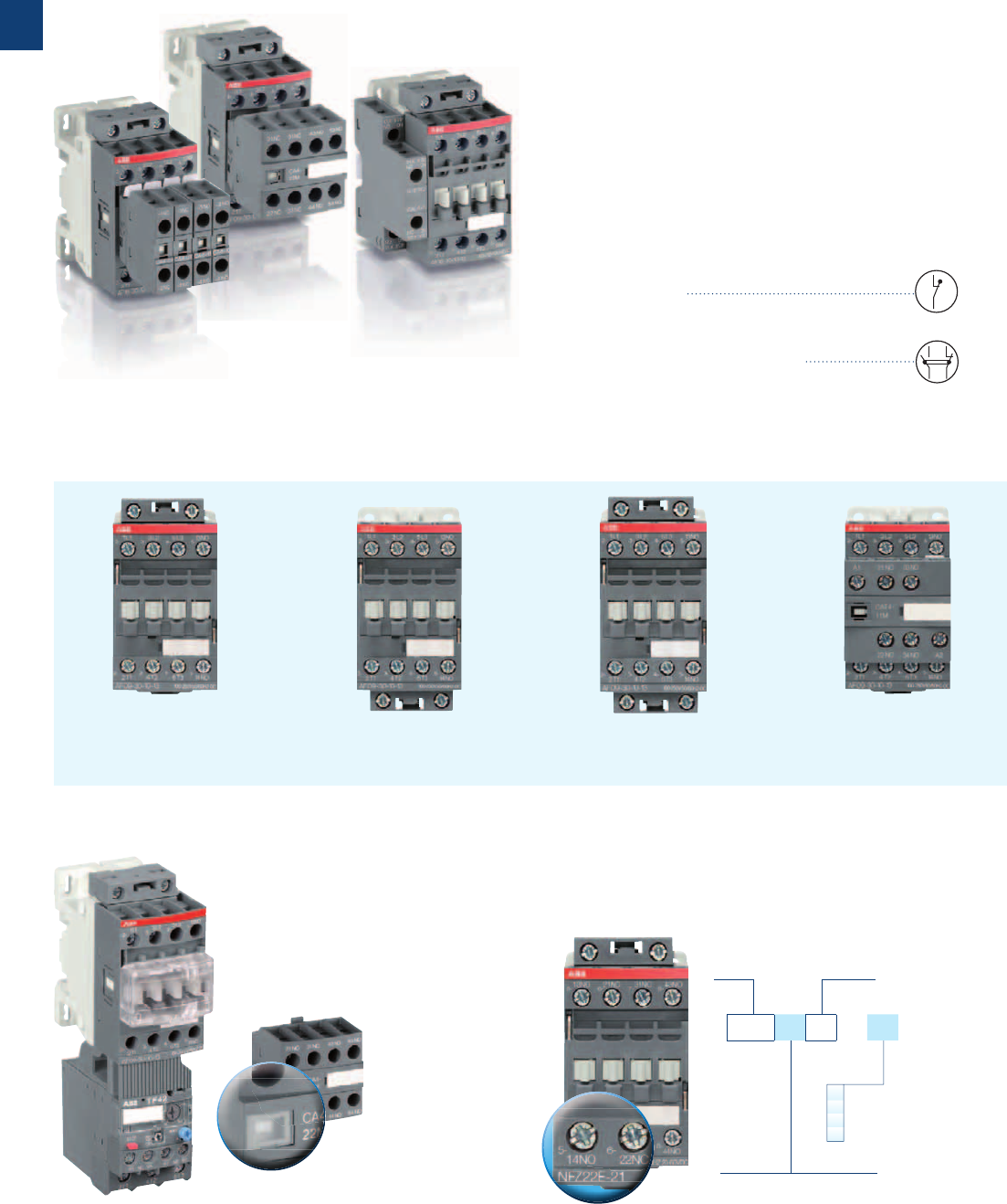
Make your control circuit safe
–Mirror contact
according to IEC 60947-4-1 Annex F 2.1
–Mechanically linked contacts
according to IEC 60947-5-1 Annex L 3.0
Optimize your auxiliary contact block configuration
– AF09...AF16 3-pole contactors equipped with a built-in
auxiliary contact N.O. or N.C.
– Up to 6 additional auxiliary contacts:
- front-mounted 1 or 4-pole CA4 blocks
- side-mounted 2-pole CAL4 blocks
– Reduced panel dimension using up to 2 side-mounted
2-pole CAL4 blocks
Free choice of your coil terminal access
Protect your equipment against accidental contact
Switching of auxiliary and control circuits
Complete choice of contactor relays
– Same advantages and accessories as AF contactors
– Only four coils for easier selection
Additional LDC4 coil terminal
block mounted in bottom
position
Coil terminal block transferable
to bottom position
Top-mounted coil terminal
block
Front-mounted 2-pole CAT4
auxiliary contact block for
front coil connection
Sealable and transparent protective
covers on contactors (BX4) and
overload relays
Non-removable
protective covers
(BX4-CA) for
auxiliary contact
blocks
Contactor relay
type
Auxiliary contacts
N.O. / N.C.
Blank: standard coil consumption
Z: low coil consumption
Coil code
21 24...60 V 50/60 Hz / 20...60 V DC
12 48...130 V 50/60 Hz - DC
13 100...250 V 50/60 Hz - DC
14 250...500 V 50/60 Hz - DC
NF Z 22 E - 21
1/14 | ABB
1
1SBC101105S0202
ABB | 1/15
1
J2
2/0 | ABB
2
Somm_MMS

Manual motor starters
ABB | 2/1
2
Somm_MMS
0.10 to 32 A – with thermal and electromagnetic protection
Ics up to 50 kA
MS116 manual motor starters 2/2
Technical data 2/3
Main accessories 2/6
Ics up to 100 kA
MS132 manual motor starters 2/10
Technical data 2/11
Main accessories 2/14
0.10 to 32 A – with electromagnetic protection
MO132 manual motor starters 2/18
Technical data 2/19
Main accessories 2/23
22 to 100 A – with thermal and electromagnetic protection
MS450, MS495, MS497 manual motor starters 2/24
Technical data 2/25
Main accessories 2/27
16 to 100 A – with electromagnetic protection
MO450, MO495, MO496 manual motor starters 2/32
Technical data 2/33
Main accessories 2/35
0.10 to 25 A – with thermal and electromagnetic protection
MS325 manual motor starters 2/40
Technical data 2/41
Main accessories 2/44
0.4 to 25 A – with electromagnetic protection
MO325 manual motor starters 2/49
Technical data 2/50
Main accessories 2/52
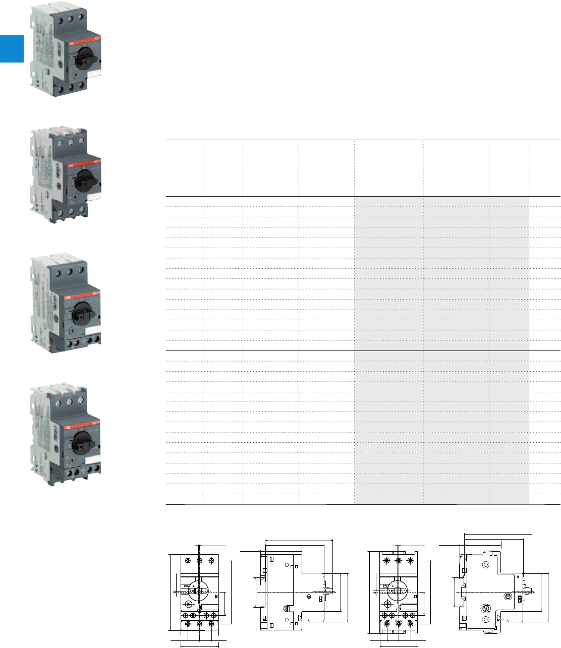
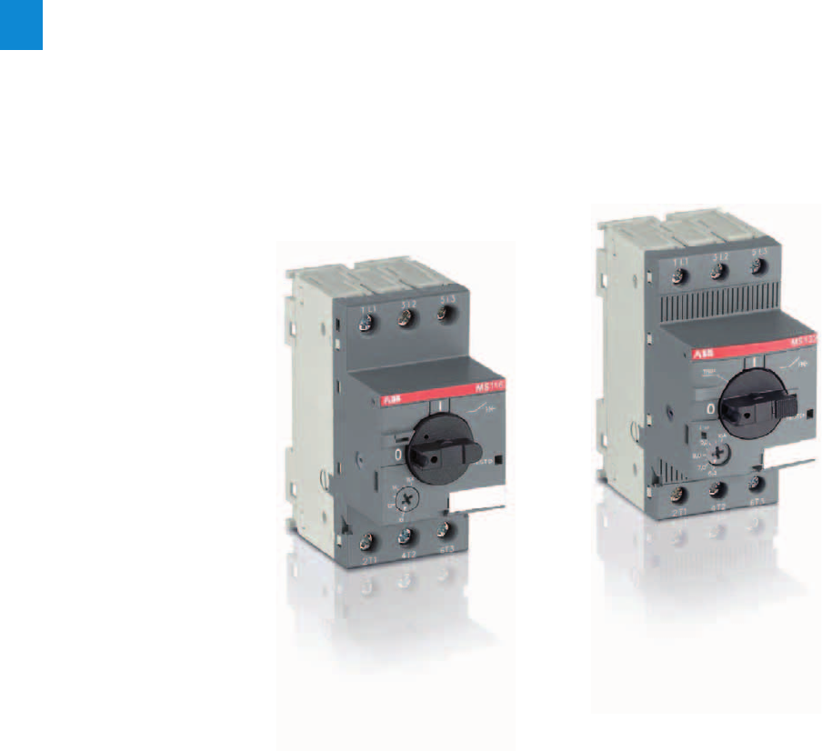
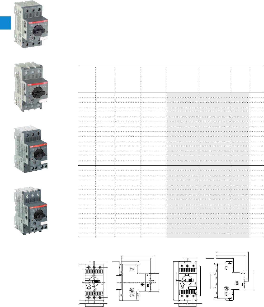
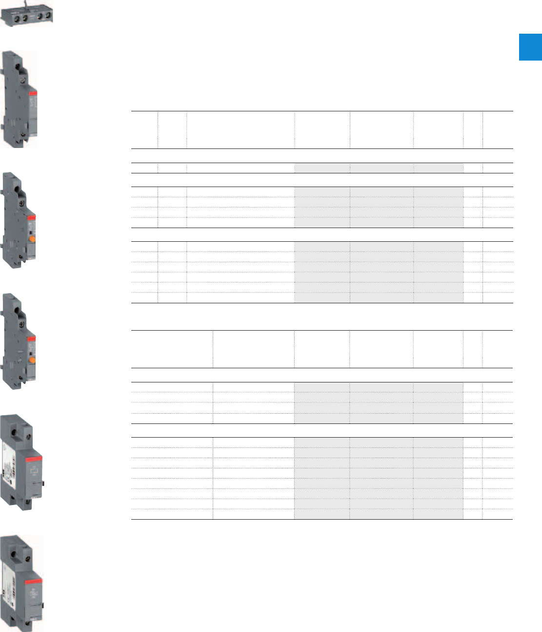
MS116 manual motor starters
0.10 to 32 A – with thermal and electromagnetic protection
Description
Manual motor starters (MMS) are protection devices for the main circuit. They combine motor control and
protection in a single device. MMS are used mainly to switch motors manually ON/OFF and protect them
and the installation fuse less against short-circuit, overload and phase failures. Fuse less protection with
a manual motor starter saves costs, space and ensures a quick reaction under short-circuit condition, by
switching off the motor within milliseconds.
MS116 is a compact and economic range for motor protection up to 7.5 kW (400 V) / 32 A in width of 45mm.
Further features are the build-in disconnect function, temperature compensation, trip-free mechanism and
a rotary handle with a clear switch position indication. The manual motor starter is suitable for three- and
single-phase applications. Auxiliary contacts, signalling contacts, undervoltage releases, shunt trips, three-
phase bus bars, power in-feed blocks and locking devices for protection against unauthorized changes
are available as accessory.
Ordering details
Rated
operational
power
400 V
AC-3
Rated
operational
current
Short-circuit
breaking
capacity I
CS
at
400 V AC
Rated instan-
taneous short-
circuit current
setting l
i
Type Order code Weight
(1 pce)
kW A kA A kg
0.03 0.10 ... 0.16 50 1.56 MS116-0.16 1SAM250000R1001 0.225
0.06 0.16 ... 0.25 50 2.44 MS116-0.25 1SAM250000R1002 0.225
0.09 0.25 ... 0.40 50 3.90 MS116-0.4 1SAM250000R1003 0.225
0.12 0.40 ... 0.63 50 6.14 MS116-0.63 1SAM250000R1004 0.225
0.25 0.63 ... 1.00 50 11.50 MS116-1.0 1SAM250000R1005 0.225
0.55 1.00 ... 1.60 50 18.40 MS116-1.6 1SAM250000R1006 0.265
0.75 1.60 ... 2.50 50 28.75 MS116-2.5 1SAM250000R1007 0.265
1.5 2.50 ... 4.00 50 50.00 MS116-4.0 1SAM250000R1008 0.265
2.2 4.00 ... 6.30 50 78.75 MS116-6.3 1SAM250000R1009 0.265
4.0 6.30 ... 10.0 50 150 MS116-10 1SAM250000R1010 0.265
5.5 8.00 ... 12.0 25 180 MS116-12 1SAM250000R1012 0.265
7.5 10.0 ... 16.0 16 240 MS116-16 1SAM250000R1011 0.265
9.0 16.0 ... 20.0 10 300 MS116-20 1SAM250000R1013 0.310
12.5 20.0 ... 25.0 10 375 MS116-25 1SAM250000R1014 0.310
15.5 25.0 ... 32.0 10 480 MS116-32 1SAM250000R1015 0.310
0.03 0.10 ... 0.16 50 1.56 MS116-0.16-HKF1-11 1SAM250005R1001 0.240
0.06 0.16 ... 0.25 50 2.44 MS116-0.25-HKF1-11 1SAM250005R1002 0.240
0.09 0.25 ... 0.40 50 3.90 MS116-0.4-HKF1-11 1SAM250005R1003 0.240
0.12 0.40 ... 0.63 50 6.14 MS116-0.63-HKF1-11 1SAM250005R1004 0.240
0.25 0.63 ... 1.00 50 11.50 MS116-1.0-HKF1-11 1SAM250005R1005 0.240
0.55 1.00 ... 1.60 50 18.40 MS116-1.6-HKF1-11 1SAM250005R1006 0.280
0.75 1.60 ... 2.50 50 28.75 MS116-2.5-HKF1-11 1SAM250005R1007 0.280
1.5 2.50 ... 4.00 50 50.00 MS116-4.0-HKF1-11 1SAM250005R1008 0.280
2.2 4.00 ... 6.30 50 78.75 MS116-6.3-HKF1-11 1SAM250005R1009 0.280
4.0 6.30 ... 10.0 50 150 MS116-10.0-HKF1-11 1SAM250005R1010 0.280
5.5 8.00 ... 12.0 25 180 MS116-12.0-HKF1-11 1SAM250005R1012 0.280
7.5 10.0 ... 16.0 16 240 MS116-16.0-HKF1-11 1SAM250005R1011 0.280
9.0 16.0 ... 20.0 10 300 MS116-20-HKF1-11 1SAM250005R1013 0.326
12.5 20.0 ... 25.0 10 375 MS116-25-HKF1-11 1SAM250005R1014 0.326
15.5 25.0 ... 32.0 10 480 MS116-32-HKF1-11 1SAM250005R1015 0.326
Main dimensions mm, inches
1,5 / 0,06"
1,7 / 0,07"
14 / 0,55" 14 /
90 / 3,54"
45 / 1,77"
0,55"
35 / 1,38"
5,5 / 0,22"
45 / 1,77"
57,8 / 2,3"
70 / 2,76"
43,5 / 1,71"
80,1 / 3,15"
27,5 / 1,1"
75 / 2,95"
2CDC242002F0010
1,5 / 0,06"
1,7 / 0,07"
27,5 / 1,1"
45 / 1,77"
57,8 / 2,3"
35 / 1,38"
5,5 / 0,22"
69,8 / 2,75"
43,3 / 1,7"
79,9 / 3,15"
14 / 0,55" 14 /
75 / 2,95"
97,8 / 3,85"
45 / 1,77"
0,55"
2CDC242001F0011
MS116 ≤ 16 A & MS116-HKF1-11 ≤ 16 A MS116 ≥ 20 A & MS116-HKF1-11 ≥ 20 A
2CDC241010F0011
MS116-16
2CDC241001F0011
MS116-25
2CDC241013F0011
MS116-0.16-HKF1-11
2CDC241012F0011
MS116-32-HKF1-11
2/2 | ABB
2
2CDC131039C0201_1s10

MS116 manual motor starters
Technical data
Main circuit – Utilization characteristics according to IEC/EN
Type MS116
Standards
IEC/EN 60947–2, IEC/EN 60947-4-1, IEC/EN 60947-1
Rated operational voltage U
e
690 V AC
Rated frequency
50/60 Hz
Trip class
10A
Number of poles
3
Duty time
100 %
Rated impulse withstand voltage U
imp
6 kV
Rated insulation voltage U
i
690 V AC
Rated operational current I
e
See ordering details
Rated instantaneous short-circuit current setting I
i
See ordering details
Rated service short-circuit breaking capacity I
cs
See table "Short-circuit breaking capacity and back-up fuses"
Rated ultimate short-circuit breaking capacity I
cu
See table "Short-circuit breaking capacity and back-up fuses"
Short-circuit breaking capacity and back-up fuses
lCS Rated service short-circuit breaking capacity
lCU Rated ultimate short-circuit breaking capacity
ICC Prospective short-circuit current at installation location
Note: Maximum rated current of the back-up fuses if ICC > ICS
Type 230 V AC 400 V AC 440 V AC 500 V AC 690 V AC
I
CS
kA
I
CU
kA
gG, aM
A
I
CS
kA
I
CU
kA
gG, aM
A
I
CS
kA
I
CU
kA
gG, aM
A
I
CS
kA
I
CU
kA
gG, aM
A
I
CS
kA
I
CU
kA
gG, aM
A
MS116-0.16
No back-up fuse required up to I
CC
= 50 kA
No back-up fuse required up to I
CC
= 30 kA
MS116-0.25
MS116-0.4
MS116-0.63
MS116-1.0
MS116-1.6
MS116-2.5 10 10 25 10 10 25 5 5 25
MS116-4.0 6 6 25 6 6 25 2 2 25
MS116-6.3 6 6 63 6 6 63 2 2 40
MS116-10 6 6 63 6 6 63 2 2 50
MS116-12 25 25 80 25 25 80 6 6 63 6 6 63 2 2 50
MS116-16 16 16 80 16 16 80 6 6 63 4 4 63 2 2 63
MS116-20 10 15 - 10 15 - 3 6 - 3 4 - 2 2 -
MS116-25 10 15 - 10 15 - 3 6 - 3 4 - 2 2 -
MS116-32 10 10 - 10 10 - 3 6 - 3 4 - 2 2 -
MS116-10: No need for back-up fuse in networks with a prospective current of up to 50 kA at 400 V.
MS116-16: No need for back-up fuse in networks with a prospective current of up to 16 kA at 400 V.
With an approbiate 80 A type gG fuse the device can be used in a network with a prospective current of up to 100 kA.
MS116-32: No need for back-up fuse in networks with a prospective current of up to 15 kA at 400 V.
ABB | 2/3
2
2CDC131039C0201_2s10
MS116 manual motor starters
Technical data
Main circuit – Utilization characteristics according to UL/CSA
Type MS116
Standards
UL 508, CSA 22.2 No. 14
Maximum operational voltage
600 V AC
Manual motor controller ratings
See table "UL 508 – Manual motor controller"
Trip rating
125 % FLA
Motor ratings
Horse power
See table "Motor rating, three phase"
Full load amps (FLA)
See table "Motor rating, three phase"
Locked rotor amps (LRA)
See table "Motor rating, three phase"
Motor rating, three phase
hp Horse power
FLA Full load amps
LRA Locked rotor amps
Type 110-120 V AC 220-240 V AC 440-480 V AC 500-600 V AC
hp FLA LRA hp FLA LRA hp FLA LRA hp FLA LRA
MS116-0.16
- 0.16 0.96 - 0.16 0.96 - 0.16 0.96 - 0.16 0.96
MS116-0.25
- 0.25 1.5 - 0.25 1.5 - 0.25 1.5 - 0.25 1.5
MS116-0.4
- 0.4 2.4 - 0.4 2.4 - 0.4 2.4 - 0.4 2.4
MS116-0.63
- 0.63 3.78 - 0.63 3.78 - 0.63 3.78 - 0.63 3.78
MS116-1.0
- 1.0 6.0 - 1.0 6.0 1.0 6.0 1/2 0.9 8
MS116-1.6
- 1.6 9.6 - 1.6 9.6 3/4 1.6 12.5 3/4 1.3 10
MS116-2.5
- 2.5 15.0 1/2 2.2 20 1 2.1 15 1-1/2 2.4 16
MS116-4.0
- 4.0 16.0 1 4.2 30 2 3.4 25 3 3.9 25.6
MS116-6.3
1/2 4.4 40 1-1/2 6.4 40 3 4.8 32 5 6.1 36.8
MS116-10
1 8.4 60 3 9.6 64 5 7.6 46 7-1/2 9 50.8
MS116-12
1-1/2 12 80 3 9.6 64 7-1/2 11 63.5 10 11 64.8
MS116-16
2 13.6 100 5 15.2 92 10 14 81 10 11 64.8
MS116-20
3 19.2 128 5 15.2 92 10 14 81 15 17 93
MS116-25
3 19.2 128 7-1/2 22 127 15 21 116 20 22 116
MS116-32
5 30.4 184 10 28 162 20 27 145 25 27 146
UL 508 – Manual motor controller
Type Maximum fuse type K5 o. RK5
per UL/NEC
Maximum short-circuit current
for motor disconnect
1)
for group installation
480 V / 600 V
A
480 V
kA
600 V
kA
480 V
kA
600 V
kA
MS116-0.16
100 30 5 18 5
MS116-0.25
100 30 5 18 5
MS116-0.4
100 30 5 18 5
MS116-0.63
100 30 5 18 5
MS116-1.0
100 30 5 18 5
MS116-1.6
100 30 5 18 5
MS116-2.5
100 30 5 18 5
MS116-4.0
100 18 5 18 5
MS116-6.3
100 18 5 18 5
MS116-10
100 18 5 18 5
MS116-12
100 18 5 18 5
MS116-16
100 18 5 18 5
MS116-20
100 18 5 18 5
MS116-25
100 18 5 18 5
MS116-32
100 18 5 18 5
1) Suitable as motor disconnect only when provided with padlock SA1 or SA3...
2/4 | ABB
2
2CDC131039C0201_3s10

MS116 manual motor starters
Technical data
General technical data
Type MS116
Pollution degree
3
Phase loss sensitive
Yes
Ambient air temperature
Operation Open - compensated without derating
-25 ... +55 °C
Open
-25 ... +70 °C
Enclosed (IB132)
0 ... +40 °C
Storage
-50 ... +80 °C
Ambient air temperature compensation
Continuous
Maximum operating altitude permissible
2000 m
Resistance to shock acc. to IEC 60068-2-27
25 g / 11 ms
Resistance to vibrations acc. to IEC 60068-2-6
5 g / 3 ... 150 Hz
Mounting position
Position 1-6 (optional for single mounting)
Mounting
DIN-rail (EN 60715)
Group mounting
On request
Minimum distance to other
units same type
Horizontal
0 mm
Vertical
150 mm
Minimum distance to
electrical conductive board
Horizontal, up to 400 V
0 mm
Horizontal, up to 690 V
> 1.5 mm
Vertical
75 mm
Degree of protection
Enclosure / terminals
IP20
Connecting characteristics
Main circuit
Type MS116 ≤ 16 A MS116 ≥ 20 A
Connecting capacity
Solid
1 or 2 x
1 ... 4 mm² 2.5 ... 6 mm²
Flexible
1 or 2 x
0.75 ... 2.5 mm² 1 ... 6 mm²
Stranded acc. to UL/CSA
1 or 2 x
AWG 16-12 AWG 12-8
Flexible acc. to UL/CSA
1 or 2 x
AWG 16-12 AWG 12-8
Stripping length
9 mm 10 mm
Tightening torques
0.8 ... 1.2 Nm / 10 … 12 Ib.in 2.0 Nm / 18 Ib.in
Connection screw
M3.5 (Pozidriv 2 / 5.5 mm) M4 (Pozidriv 2 / 6.5 mm)
ABB | 2/5
2
2CDC131039C0201_4s10
MS116 manual motor starters
Main accessories
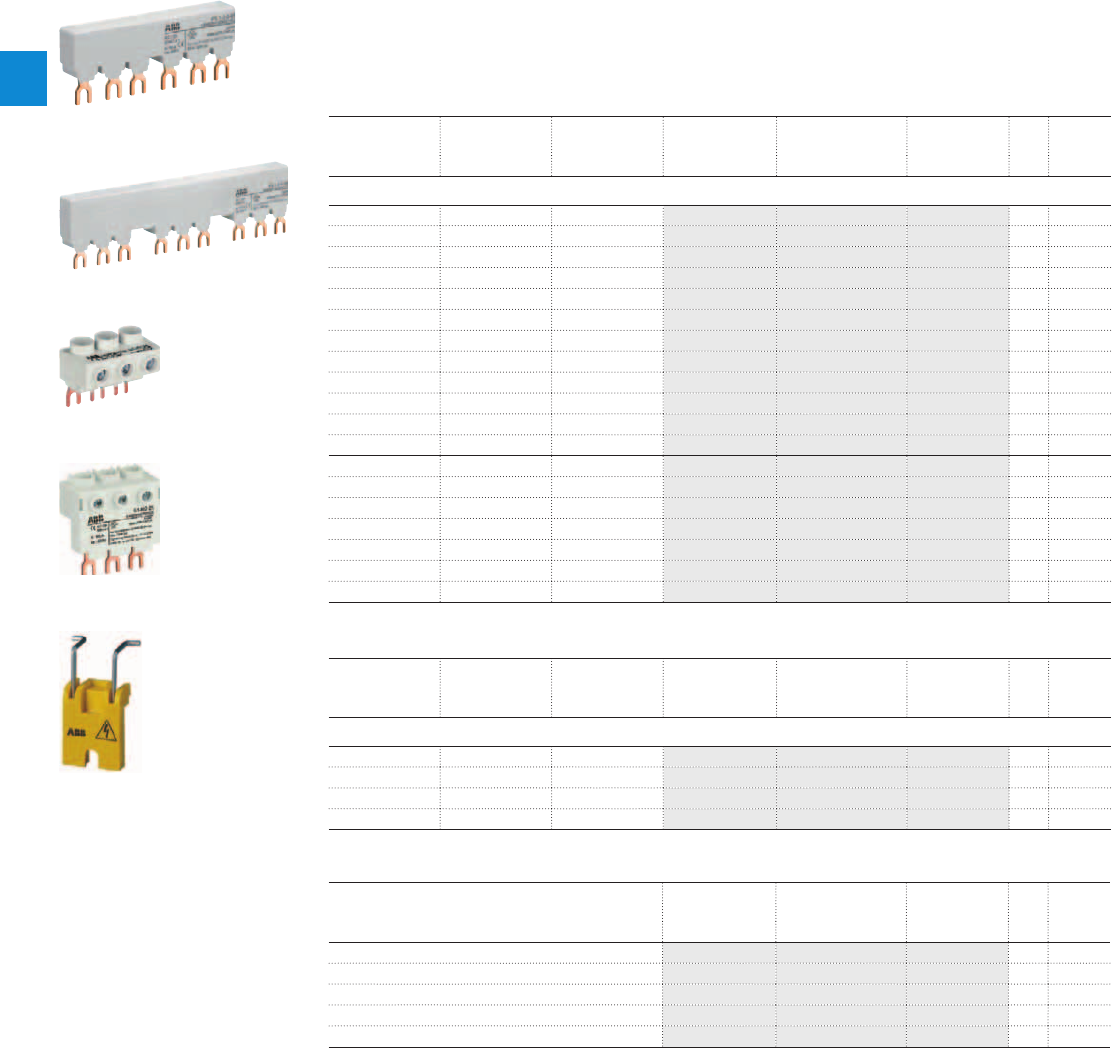
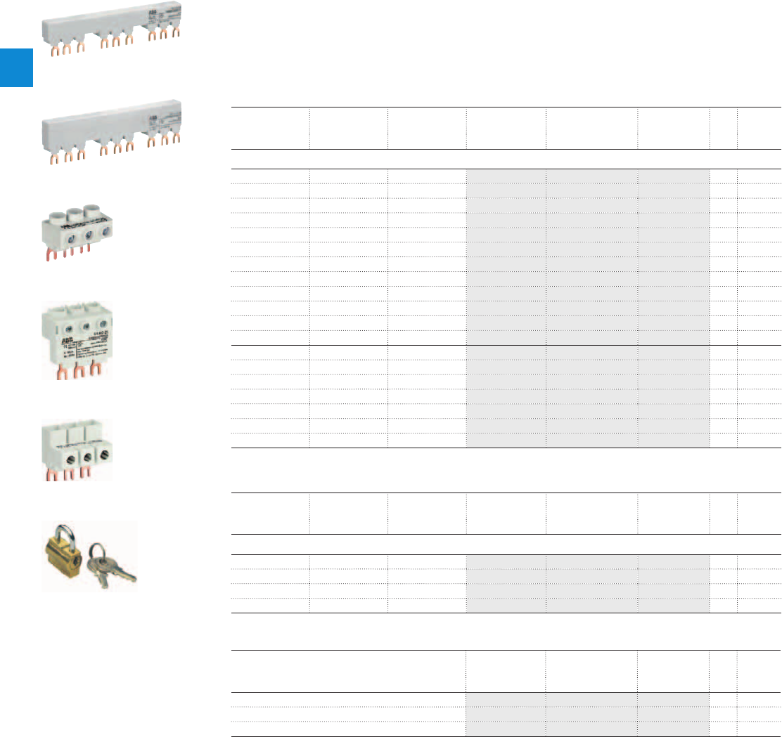
Description
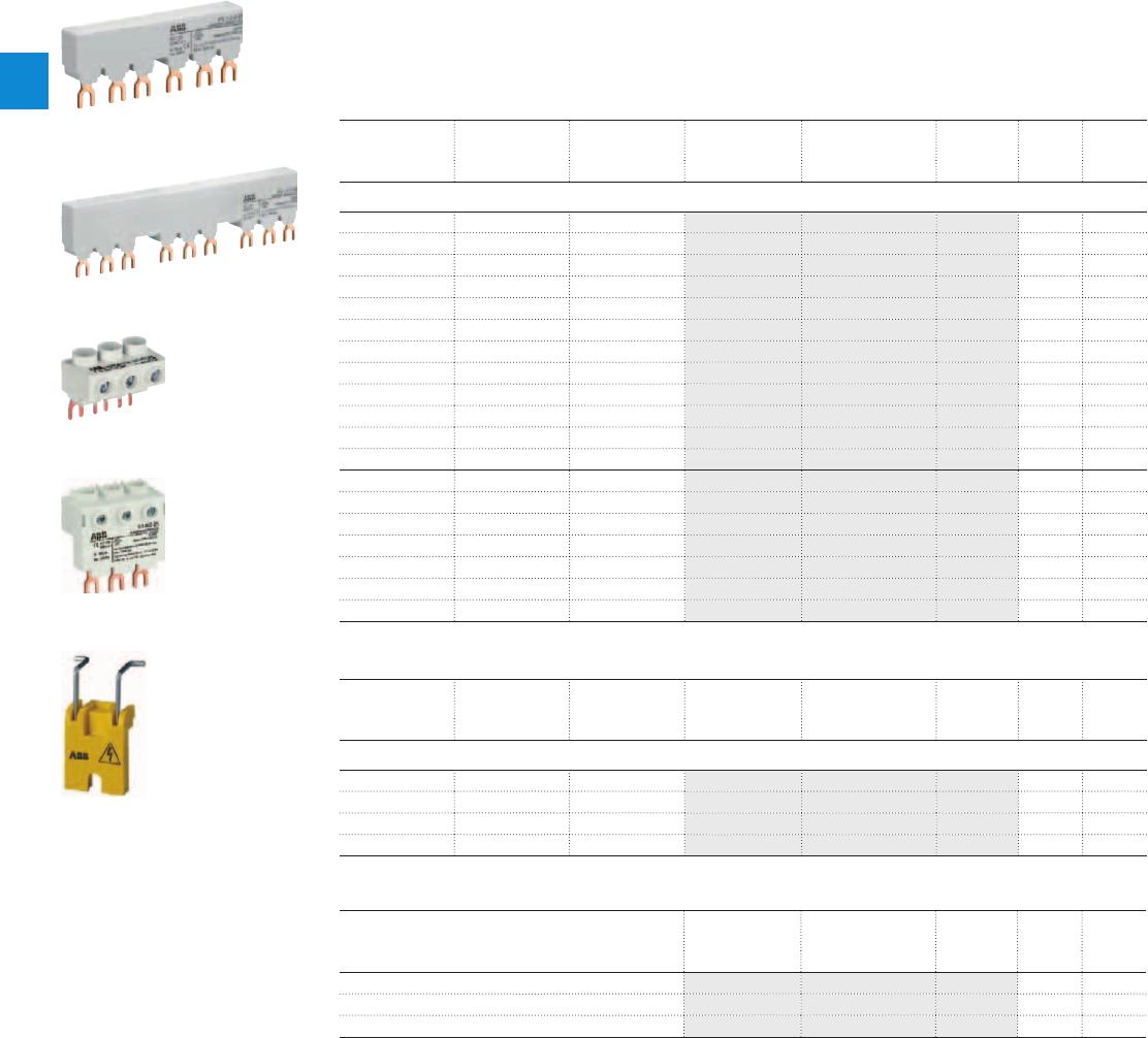
Three-phase busbars ensure a quick and safe connection and are therefore a cost effective solution.
Avariety of different three-phase busbars up to 100 A are in the assortment. Between 2 and 5 manual
motor starters with none, one or two lateral auxiliary contacts can be connected. Different three-phase
feeder terminals are available according to the application.
Ordering details
Rated operational
current
Number of MMS Number of lateral
aux.
Type Order code Pkg
qty
Weight
(1 pce)
A kg
Three-phase busbars
65 2 0 PS1-2-0-65 1SAM201906R1102 10 0.034
65 3 0 PS1-3-0-65 1SAM201906R1103 10 0.055
65 4 0 PS1-4-0-65 1SAM201906R1104 10 0.077
65 5 0 PS1-5-0-65 1SAM201906R1105 10 0.098
65 2 1 PS1-2-1-65 1SAM201906R1112 10 0.036
65 3 1 PS1-3-1-65 1SAM201906R1113 10 0.060
65 4 1 PS1-4-1-65 1SAM201906R1114 10 0.087
65 5 1 PS1-5-1-65 1SAM201906R1115 10 0.108
65 2 2 PS1-2-2-65 1SAM201906R1122 10 0.040
65 3 2 PS1-3-2-65 1SAM201906R1123 10 0.067
65 4 2 PS1-4-2-65 1SAM201906R1124 10 0.095
65 5 2 PS1-5-2-65 1SAM201906R1125 10 0.122
100 3 0 PS1-3-0-100 1SAM201916R1103 10 0.084
100 4 0 PS1-4-0-100 1SAM201916R1104 10 0.117
100 5 0 PS1-5-0-100 1SAM201916R1105 10 0.154
100 3 1 PS1-3-1-100 1SAM201916R1113 10 0.094
100 4 1 PS1-4-1-100 1SAM201916R1114 10 0.134
100 5 1 PS1-5-1-100 1SAM201916R1115 10 0.172
100 3 2 PS1-3-2-100 1SAM201916R1123 10 0.105
Rated operational
current
Rated cross
section
Mounting form Type Order code Pkg
qty
Weight
(1 pce)
A mm² kg
Three-phase feeder terminals
65 25 Flat S1-M1-25 1SAM201907R1101 10 0.038
65 25 High S1-M2-25 1SAM201907R1102 10 0.051
65 25 UL type E and IEC S1-M3-25 1SAM201907R1103 10 0.042
100 35 UL type E and IEC S1-M3-35 1SAM201913R1103 10 0.060
Description Type Order code Pkg
qty
Weight
(1 pce)
kg
Protection cover for busbars BS1-3 1SAM201908R1001 50 0.003
Lock handle SA1 GJF1101903R0001 10 0.003
Padlock SA2 GJF1101903R0002 10 0.020
Lock handle box SA1/SA2 SA3 GJF1101903R0003 10 0.050
Screw fixing kit FS116 1SAM201909R1001 1 0.020
PS1-2-0-65
PS1-3-1-100
S1-M1-25
S1-M2-25
SA1
2CDC241014F0010
1SBC101226F0014
1SBC101266F0014
SK0108B91
2CDC241017F0010
2/6 | ABB
2
2CDC131039C0201_5s10
MS116 manual motor starters
Main accessories
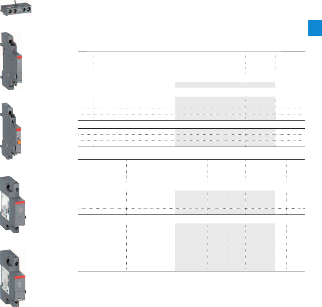
Description
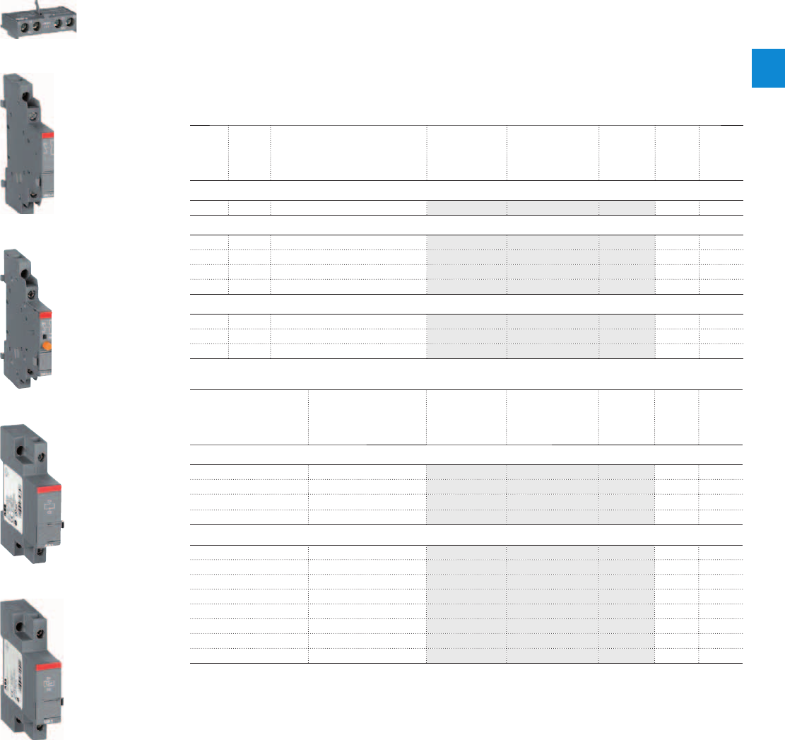
MS116 manual motor starters can be equipped with auxiliary contacts for lateral/front mounting, signalling
contact for lateral mounting, undervoltage release and shunt trips. The accessories can be fitted wiring
free and without tools. A variety of combinations is possible as required for the application. The auxiliary
contacts change position with the main contacts. The signalling contact signals tripping regardless if it was
caused by short-circuit or overload. Undervoltage release are used for remote tripping of the manual motor
starter especially for emergency stop circuits. Shunt trips release the MMS used for remote tripping.
Ordering details
Auxiliary
contacts
N.O.
Auxiliary
contacts
N.C.
Description Type Order code Pkg
qty
Weight
(1 pce)
kg
Auxiliary contacts – mountable on the front
1 1 HKF1-11 1SAM201901R1001 10 0.015
Auxiliary contacts – mountable on the right
1 1 max. 2 pieces HK1-11 1SAM201902R1001 2 0.035
2 0 max. 2 pieces HK1-20 1SAM201902R1002 2 0.035
0 2 max. 2 pieces HK1-02 1SAM201902R1003 2 0.035
2 0 with lead contacts HK1-20L 1SAM201902R1004 2 0.035
Signalling contacts – mountable on the right
1 1 for tripped alarm, max. 2 pieces SK1-11 1SAM201903R1001 2 0.035
2 0 for tripped alarm, max. 2 pieces SK1-20 1SAM201903R1002 2 0.035
0 2 for tripped alarm, max. 2 pieces SK1-02 1SAM201903R1003 2 0.035
Rated control supply
voltage
Frequency Type Order code Pkg
qty
Weight
(1 pce)
VHz kg
Shunt trip units – mountable on the left
24 50/60 AA1-24 1SAM201910R1001 1 0.100
110 50/60 AA1-110 1SAM201910R1002 1 0.100
200 ... 240 50/60 AA1-230 1SAM201910R1003 1 0.100
350 ... 415 50/60 AA1-400 1SAM201910R1004 1 0.100
Undervoltage releases – mountable on the left
24 50 UA1-24 1SAM201904R1001 1 0.100
48 50 UA1-48 1SAM201904R1002 1 0.100
60 50 UA1-60 1SAM201904R1003 1 0.100
110 ... 120 50/60 UA1-120 1SAM201904R1004 1 0.100
208 60 UA1-208 1SAM201904R1005 1 0.100
230 ... 240 50/60 UA1-230 1SAM201904R1006 1 0.100
400 50 UA1-400 1SAM201904R1007 1 0.100
415 ... 480 50/60 UA1-415 1SAM201904R1008 1 0.100
HKF1-11
HK1-11
SK1-11
AA1-24
UA1-24
1SBC101208F0014
1SBC101209F0014
1SBC101210F0014
1SBC101211F0014
1SBC101212F0014
ABB | 2/7
2
2CDC131039C0201_6s10
MS116 manual motor starters
Main accessories
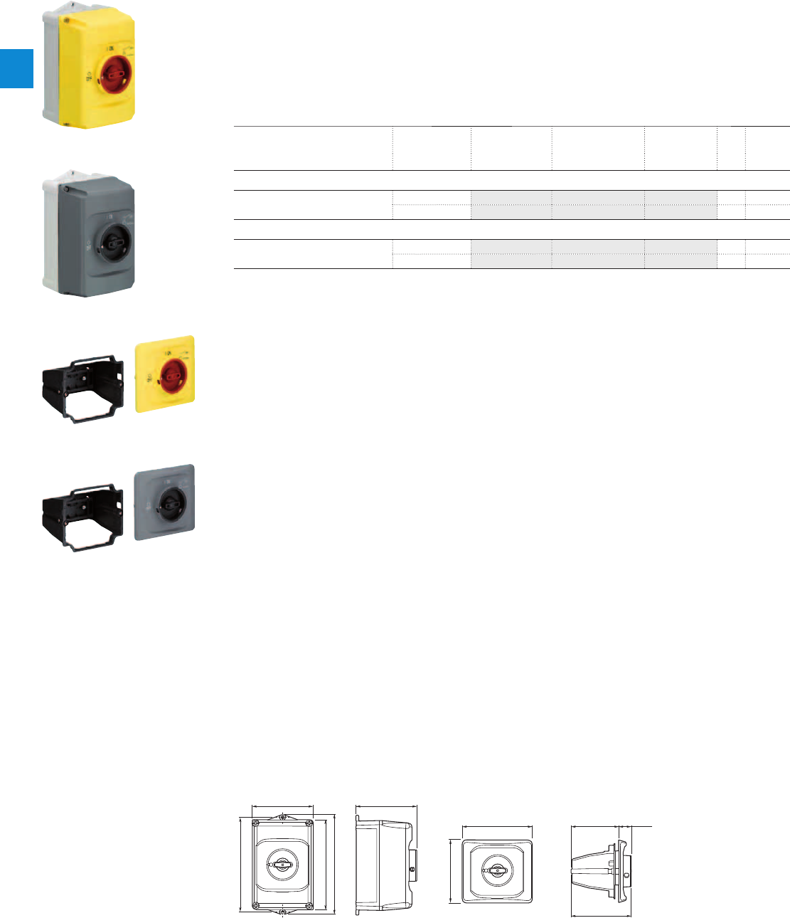
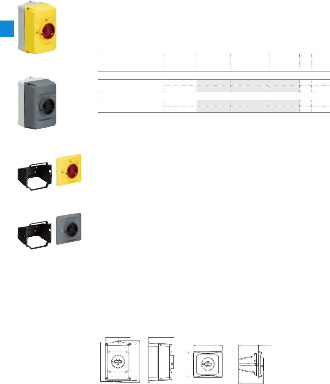
Description
IB132 are IP65 enclosures for single MMS installation. Additional mounting of auxiliary and signalling
contacts, shunt trips and undervoltage release is possible. The handle is lockable in OFF position. For
detailed specification see installation instruction.
DMS132 are IP65 door mounting kits for MMS installation in any enclosure. Additional mounting of
auxiliary, signalling, shunt trips and undervoltage release is possible. The handle is lockable in OFF
position. For detailed specification see installation instruction.
Ordering details
Description Color Type Order code Pkg
qty
Weight
(1 pce)
kg
Enclosures IP65
Padlockable max. 3 padlocks with bail
diameter 4 ... 6.5 mm
Yellow/red IB132-Y 1SAM201911R1011 1 0.370
Grey/black IB132-G 1SAM201911R1010 1 0.370
Door mounting kit IP65
Padlockable max. 3 padlocks with bail
diameter 4 ... 6.5 mm
Yellow/red DMS132-Y 1SAM201912R1011 1 0.170
Grey/black DMS132-G 1SAM201912R1010 1 0.170
Indication I-O-T and ON-OFF-T
Main dimensions mm, inches
119 4.69"
I
ON
0
OFF
183 7.2"
174 6.85"
194 7.64"
118 4.65"
2CDC242011F0011
121 4.76"
135.7 5.34" 92 3.62" 24 .94"
116.15 4.57"
I
ON
0
OFF
2CDC242012F0011
IB132 DMS132
2CDC241004F0010
IB132-Y
2CDC241003F0010
IB132-G
2CDC241002F0010
DMS132-Y
2CDC241001F0010
DMS132-G
2/8 | ABB
2
2CDC131039C0201_9s10
MS116 manual motor starters
Main accessories
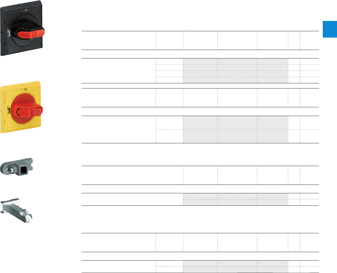
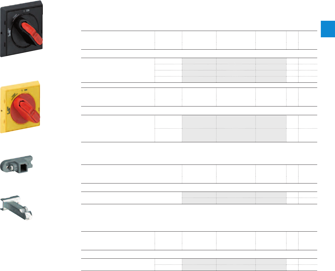
Description
The complete set includes handle, shaft and driver. All accessories fit 6 mm shafts of maximum 180 mm
length. The degree of protection for handles MSHD is IP64.
Ordering details
Description Shaft length Type Order code Pkg
qty
Weight
(1 pce)
mm kg
Shafts
For selector type handles. Shaft diameter
6 mm. Shaft extension for door coupling
driver.
85 OXS6X85 1SCA101647R1001 1 0.020
105 OXS6X105 1SCA108043R1001 1 0.020
130 OXS6X130 1SCA101655R1001 1 0.030
180 OXS6X180 1SCA101659R1001 1 0.040
Description Color Type Order code Pkg
qty
Weight
(1 pce)
kg
Selector type handles IP64
Padlockable max. 3 padlocks with bail
diameter 5 … 8 mm, door interlock in ON
position defeatable, for use with 6 mm
OXS6…types up to 180 mm or driver
shafts MSOX.
Black MSHD-LB 1) 1SAM201920R1001 1 0.065
Yellow MSHD-LY 1SAM201920R1002 1 0.065
1) Indication I-O and ON-OFF
Description Type Order code Pkg
qty
Weight
(1 pce)
kg
Driver
Coupling driver for use with 6 mm OXS6… types up to
180 mm.
MSMN 1) 1SAM101923R0002 1 0.002
MSMNO 2) 1SAM101923R0012 1 0.002
1) Coded - Positioning of ON indication dependent from mounting orientation of the MS
2) Uncoded - Positioning of ON indication independent from mounting orientation of the MS
Description Shaft length Type Order code Pkg
qty
Weight
(1 pce)
mm kg
Driver shafts
Driver shaft - combination driver & shaft.
Shaft diameter 6 mm.
32 MSOX-32 1) 1SAM101924R0003 1 0.010
30 MSOX-30 2) 1SAM101924R0013 1 0.010
1) MSOX-32 is for normal vertical use
2) MSOX-30 is for horizontal use
2CDC241003F0011
MSHD-LB
2CDC241002S0011
MSHD-LY
MSMN
MSOX-30
2CDC241004S0011
2CDC241005S0011
ABB | 2/9
2
2CDC131039C0201_10s10
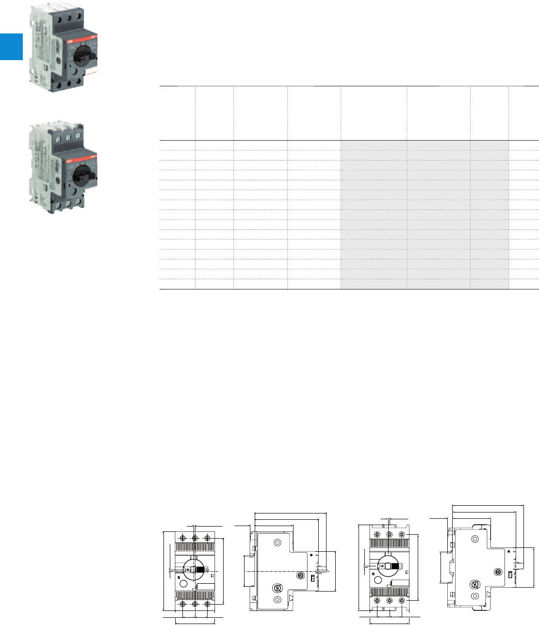
MS132 manual motor starters
0.10 to 32 A – with thermal and electromagnetic protection
Description
Manual motor starters (MMS) are protection devices for the main circuit. They combine motor control and
protection in a single device. MMS are used mainly to switch motors manually ON/OFF and protect them and
the installation fuse less against short-circuit, overload and phase failures. Fuse less protection with a manual
motor starter saves costs, space and ensures a quick reaction under short-circuit condition, by switching off
the motor within milliseconds.
MS132 is a compact and powerful range for motor protection up 15 kW (400 V) / 32 A in width of 45 mm.
Further features are the build-in disconnect function, temperature compensation, trip-free mechanism
and a rotary handle with a clear switch position indication. The manual motor starter is suitable for three-
and single-phase applications. The handle is lockable to protect against unauthorized changes. Auxiliary
contacts, signalling contacts, undervoltage releases, shunt trips, three-phase bus bars, power in-feed
blocks.
Ordering details
Rated
operational
power
400 V
AC-3
Setting
range
Short-circuit
breaking
capacity I
CS
at
400 V AC
Rated instan-
taneous short-
circuit current
setting l
i
Type Order code Weight
(1 pce)
kW A kA A kg
0.03 0.10 … 0.16 100 1.56 MS132-0.16 1SAM350000R1001 0.215
0.06 0.16 … 0.25 100 2.44 MS132-0.25 1SAM350000R1002 0.215
0.09 0.25 … 0.40 100 3.90 MS132-0.4 1SAM350000R1003 0.215
0.12 0.40 … 0.63 100 6.14 MS132-0.63 1SAM350000R1004 0.215
0.25 0.63 … 1.00 100 11.50 MS132-1.0 1SAM350000R1005 0.215
0.55 1.00 … 1.60 100 18.40 MS132-1.6 1SAM350000R1006 0.265
0.75 1.60 … 2.50 100 28.75 MS132-2.5 1SAM350000R1007 0.265
1.5 2.50 … 4.00 100 50.00 MS132-4.0 1SAM350000R1008 0.265
2.2 4.00 … 6.30 100 78.75 MS132-6.3 1SAM350000R1009 0.265
4.0 6.30 … 10.0 100 150 MS132-10 1SAM350000R1010 0.265
5.5 8.00 … 12.0 100 180 MS132-12 1SAM350000R1012 0.310
7.5 10.0 … 16.0 100 240 MS132-16 1SAM350000R1011 0.310
9.0 16.0 … 20.0 100 300 MS132-20 1SAM350000R1013 0.310
12.5 20.0 … 25.0 50 375 MS132-25 1SAM350000R1014 0.310
15.5 25.0 … 32.0 25 480 MS132-32 1SAM350000R1015 0.310
0.03 0.10 ... 0.16 100 1.56 MS132-0.16-HKF1-11 1SAM350005R1001 0.231
0.06 0.16 ... 0.25 100 2.44 MS132-0.25-HKF1-11 1SAM350005R1002 0.231
0.09 0.25 ... 0.40 100 3.90 MS132-0.4-HKF1-11 1SAM350005R1003 0.231
0.12 0.40 ... 0.63 100 6.14 MS132-0.63-HKF1-11 1SAM350005R1004 0.231
0.25 0.63 ... 1.00 100 11.50 MS132-1.0-HKF1-11 1SAM350005R1005 0.231
0.55 1.00 ... 1.60 100 18.40 MS132-1.6-HKF1-11 1SAM350005R1006 0.281
0.75 1.60 ... 2.50 100 28.75 MS132-2.5-HKF1-11 1SAM350005R1007 0.281
1.5 2.50 ... 4.00 100 50.00 MS132-4.0-HKF1-11 1SAM350005R1008 0.281
2.2 4.00 ... 6.30 100 78.75 MS132-6.3-HKF1-11 1SAM350005R1009 0.281
4.0 6.30 ... 10.0 100 150 MS132-10.0-HKF1-11 1SAM350005R1010 0.281
5.5 8.00 ... 12.0 100 180 MS132-12.0-HKF1-11 1SAM350005R1012 0.326
7.5 10.0 ... 16.0 100 240 MS132-16.0-HKF1-11 1SAM350005R1011 0.326
9.0 16.0 ... 20.0 100 300 MS132-20-HKF1-11 1SAM350005R1013 0.326
12.5 20.0 ... 25.0 50 375 MS132-25-HKF1-11 1SAM350005R1014 0.326
15.5 25.0 ... 32.0 25 480 MS132-32-HKF1-11 1SAM350005R1015 0.326
Main dimensions mm, inches
75 / 2,95"
1,7 / 0,1"
1,5 / 0,06"
90 / 3,54"
14 / 0,55"
45 / 1,77"
14 / 0,55"
72,4 / 2,85"
81,25 / 3,2"
45 / 1,77"
5,5 / 0,22" 43,5 / 1,71"
35 / 1,38"
mm / inch
2CDC242002F0010
45 / 1,77"
35 / 1,38"
1,5 / 0,06"
75 / 2,95"
1,7 / 0,1"
97,8 / 3,85"
14 / 0,55" 14 / 0,55"
45 / 1,77"
5,5 / 0,22" 43,3 / 0,22"
72,2 / 2,84"
81,05 / 3,19"
mm / inch
2CDC242001F0011
MS132 ≤ 10 A MS132 ≥ 12 A
1SBC101232F0010
MS132-10
2CDC241001F0011
MS132-32
2CDC241014F0011
MS132-0.16-HKF1-11
2CDC241015F0011
MS132-32-HKF1-11
2/10 | ABB
2
2CDC131040C0201_1s10

MS132 manual motor starters
Technical data
Main circuit – Utilization characteristics according to IEC/EN
Type MS132
Standards
IEC/EN 60947–2, IEC/EN 60947-4-1, IEC/EN 60947-1
Rated operational voltage U
e
690 V AC / 250 V DC
Rated frequency
DC, 50/60 Hz
Trip class
10 (10A for 1SAM350000R1001)
Number of poles
3
Duty time
100 %
Rated impulse withstand voltage U
imp
6 kV
Rated insulation voltage U
i
690 V AC
Rated operational current I
e
See ordering details
Rated instantaneous short-circuit current setting I
i
See ordering details
Rated service short-circuit breaking capacity I
cs
See table "Short-circuit breaking capacity and back-up fuses"
Rated ultimate short-circuit breaking capacity I
cu
See table "Short-circuit breaking capacity and back-up fuses"
Short-circuit breaking capacity and back-up fuses
lCS Rated service short-circuit breaking capacity
lCU Rated ultimate short-circuit breaking capacity
ICC Prospective short-circuit current at installation location
Note: Maximum rated current of the back-up fuses if ICC > ICS
Type 230 V AC 400 V AC 440 V AC 500 V AC 690 V AC
I
CS
kA
I
CU
kA
gG, aM
A
I
CS
kA
I
CU
kA
gG, aM
A
I
CS
kA
I
CU
kA
gG, aM
A
I
CS
kA
I
CU
kA
gG, aM
A
I
CS
kA
I
CU
kA
gG, aM
A
MS132-0.16
No back-up fuse required up to
ICC = 100 kA
MS132-0.25
MS132-0.4
MS132-0.63
MS132-1.0
MS132-1.6
MS132-2.5
MS132-4.0
20 20
*
20 20
*
33
*
MS132-6.3
20 20
*
20 20
*
33
*
MS132-10
20 20
*
20 20
*
33
*
MS132-12
20 20
*
20 20
*
33
*
MS132-16
20 20
*
20 20
*
33
*
MS132-20
20 20
*
20 20
*
33
*
MS132-25
50 50 100 50 50 100 20 20
*
10 10
*
33
*
MS132-32
25 50 125 25 50 125 20 20
*
10 10
*
33
*
MS132-16: No need for back-up fuse in networks with a prospective current of up to 100 kA at 400 V.
MS132-32: No need for back-up fuse in networks with a prospective current of up to 50 kA at 400 V.
With an approbiate 125 A type gG fuse the device can be used in a network with a prospective current of up to 100 kA
* not available yet
ABB | 2/11
2
2CDC131040C0201_2s10

MS132 manual motor starters
Technical data
Main circuit – Utilization characteristics according to UL/CSA
Type MS132
Standards
UL 508, CSA 22.2 No. 14
Maximum operational voltage
600 V AC
Manual motor controller ratings
See table "UL 508 – Manual motor controller"
Trip rating
125 % FLA
Motor ratings
Horse power
See table "Motor rating, three phase"
Full load amps (FLA)
See table "Motor rating, three phase"
Locked rotor amps (LRA)
See table "Motor rating, three phase"
Motor rating, three phase
hp Horse power
FLA Full load amps
LRA Locked rotor amps
Type 110-120 V AC 220-240 V AC 440-480 V AC 500-600 V AC
hp FLA LRA hp FLA LRA hp FLA LRA hp FLA LRA
MS132-0.16
- 0.16 0.96 - 0.16 0.96 - 0.16 0.96 - 0.16 0.96
MS132-0.25
- 0.25 1.5 - 0.25 1.5 - 0.25 1.5 - 0.25 1.5
MS132-0.4
- 0.4 2.4 - 0.4 2.4 - 0.4 2.4 - 0.4 2.4
MS132-0.63
- 0.63 3.78 - 0.63 3.78 - 0.63 3.78 - 0.63 3.78
MS132-1.0
- 1.0 6.0 - 1.0 6.0 - 1.0 6.0 1/2 1.0 6.0
MS132-1.6
- 1.6 9.6 - 1.6 9.6 3/4 1.6 9.6 3/4 1.6 9.6
MS132-2.5
- 2.5 15.0 1/2 2.5 15.0 1 2.5 15.0 1-1/2 2.5 15.0
MS132-4.0
- 4.0 24.0 1 4.0 24.0 2 4.0 24.0 3 3.9 26.0
MS132-6.3
1/2 6.3 37.8 1-1/2 6.3 37.8 3 4.8 32.0 5 6.1 37.0
MS132-10
3/4 10.0 60.0 3 9.6 64.0 5 7.6 46.0 7-1/2 9.0 51.0
MS132-12
1-1/2 12.0 72.0 3 9.6 64.0 7-1/2 11.0 64.0 10 11.0 65.0
MS132-16
2 16.0 84.0 5 15.2 92.0 10 14.0 81.0 10 11.0 65.0
MS132-20
3 19.2 128.0 5 15.2 92.0 10 14.0 81.0 15 17.0 93.0
MS132-25
3 19.2 128.0 7-1/2 22.0 127.0 15 21.0 116.0 20 22.0 116.0
MS132-32
5 30.4 184.0 10 28.0 162.0 20 27.0 145.0 25 27.0 146.0
UL 508 – Manual motor controller
Type Maximum short-circuit current
for motor disconnect
1)
for group installation for self-protected combination motor
controller (type E) in combination with
feeder block S1-M3-xx
for tap conductor protection
480 V
kA
600 V
kA
480 V
kA
600 V
kA
480Y / 277 V
kA
600Y / 347 V
kA
480 V
kA
600 V
kA
MS132-0.16
65 47 65 47 65 47 65 47
MS132-0.25
65 47 65 47 65 47 65 47
MS132-0.4
65 47 65 47 65 47 65 47
MS132-0.63
65 47 65 47 65 47 65 47
MS132-1.0
65 47 65 47 65 47 65 47
MS132-1.6
65 47 65 47 65 47 65 47
MS132-2.5
65 47 65 47 65 47 65 47
MS132-4.0
65 18 65 30 65 18 65 18
MS132-6.3
65 18 65 30 65 - 65 18
MS132-10
65 18 65 30 65 - 65 18
MS132-12
30 18 30 30 30 - 30 18
MS132-16
30 18 30 30 30 - 30 18
MS132-20
30 18 30 30 30 - 30 18
MS132-25
30 18 30 30 30 - 30 18
MS132-32
30 18 30 30 30 - 30 18
2/12 | ABB
2
2CDC131040C0201_3s10

MS132 manual motor starters
Technical data
General technical data
Type MS132
Pollution degree
3
Phase loss sensitive
Yes
Ambient air temperature
Operation Open - compensated without derating
-25 ... +60 °C
Open
-25 ... +70 °C
Enclosed (IB132)
0 ... +40 °C
Storage
-50 ... +80 °C
Ambient air temperature compensation
Continuous
Maximum operating altitude permissible
2000 m
Resistance to shock acc. to IEC 60068-2-27
25 g / 11 ms
Resistance to vibrations acc. to IEC 60068-2-6
5 g / 3 ... 150 Hz
Mounting position
Position 1-6 (optional for single mounting)
Mounting
DIN-rail (EN 60715)
Group mounting
On request
Minimum distance to other
units same type
Horizontal
0 mm
Vertical
150 mm
Minimum distance to
electrical conductive board
Horizontal, up to 400 V
0 mm
Horizontal, up to 690 V
> 1.5 mm
Vertical
75 mm
Degree of protection
Enclosure / terminals
IP20
Connecting characteristics
Main circuit
Type MS132-0.16 … MS132-10 MS132-12 … MS132-16 MS132-20 … MS132-32
Connecting capacity
Solid
1 or 2 x
1 ... 4 mm² 1 ... 4 mm² 2.5 ... 6 mm²
Flexible
1 or 2 x
0.75 ... 2.5 mm² 0.75 ... 2.5 mm² 1 ... 6 mm²
Stranded acc. to UL/CSA
1 or 2 x
AWG 16-12 AWG 16-12 AWG 12-8
Flexible acc. to UL/CSA
1 or 2 x
AWG 16-12 AWG 16-12 AWG 12-8
Stripping length
9 mm 10 mm 10 mm
Tightening torques
0.8 ... 1.2 Nm / 10 … 12 Ib.in 1.5 Nm / 14 Ib.in 2.0 Nm / 18 Ib.in
Connection screw
M3.5 (Pozidriv 2) M4 (Pozidriv 2) M4 (Pozidriv 2)
ABB | 2/13
2
2CDC131040C0201_4s10
MS132 manual motor starters
Main accessories
Description
Three-phase busbars ensure a quick and safe connection and are therefore a cost effective solution.
Avariety of different three-phase busbars up to 100 A are in the assortment. Between 2 and 5 manual
motor starters with none, one or two lateral auxiliary contacts can be connected. Different three-phase
feeder terminals are available according to the application.
Ordering details
Rated operational
current
Number of MMS Number of lateral
aux.
Type Order code Pkg
qty
Weight
(1 pce)
A kg
Three-phase busbars
65 2 0 PS1-2-0-65 1SAM201906R1102 10 0.034
65 3 0 PS1-3-0-65 1SAM201906R1103 10 0.055
65 4 0 PS1-4-0-65 1SAM201906R1104 10 0.077
65 5 0 PS1-5-0-65 1SAM201906R1105 10 0.098
65 2 1 PS1-2-1-65 1SAM201906R1112 10 0.036
65 3 1 PS1-3-1-65 1SAM201906R1113 10 0.060
65 4 1 PS1-4-1-65 1SAM201906R1114 10 0.087
65 5 1 PS1-5-1-65 1SAM201906R1115 10 0.108
65 2 2 PS1-2-2-65 1SAM201906R1122 10 0.040
65 3 2 PS1-3-2-65 1SAM201906R1123 10 0.067
65 4 2 PS1-4-2-65 1SAM201906R1124 10 0.095
65 5 2 PS1-5-2-65 1SAM201906R1125 10 0.122
100 3 0 PS1-3-0-100 1SAM201916R1103 10 0.084
100 4 0 PS1-4-0-100 1SAM201916R1104 10 0.117
100 5 0 PS1-5-0-100 1SAM201916R1105 10 0.154
100 3 1 PS1-3-1-100 1SAM201916R1113 10 0.094
100 4 1 PS1-4-1-100 1SAM201916R1114 10 0.134
100 5 1 PS1-5-1-100 1SAM201916R1115 10 0.172
100 3 2 PS1-3-2-100 1SAM201916R1123 10 0.105
Rated operational
current
Rated cross
section
Mounting form Type Order code Pkg
qty
Weight
(1 pce)
A mm² kg
Three-phase feeder terminals
65 25 Flat S1-M1-25 1SAM201907R1101 10 0.038
65 25 High S1-M2-25 1SAM201907R1102 10 0.051
65 25 UL type E and IEC S1-M3-25 1SAM201907R1103 10 0.042
100 35 UL type E and IEC S1-M3-35 1SAM201913R1103 10 0.060
Description Type Order code Pkg
qty
Weight
(1 pce)
kg
Protection cover for busbars BS1-3 1SAM201908R1001 50 0.003
Padlock SA2 GJF1101903R0002 10 0.020
Screw fixing kit FS116 1SAM201909R1001 1 0.020
PS1-3-1-65
PS1-3-1-100
S1-M1-25
S1-M2-25
S1-M3-25
SA2
2CDC241014F0010
1SBC101226F00141SBC101266F0014
2CDC241007F0010
1SBC101214F0014
SK0109B91
2/14 | ABB
2
2CDC131040C0201_5s10
MS132 manual motor starters
Main accessories
Description
MS132 manual motor starters can be equipped with auxiliary contacts for lateral/front mounting, signalling
contact for lateral mounting, undervoltage release and shunt trips. Two different signalling contacts are
available. The accessories can be fitted wiring free and without tools. A variety of combinations is possible
as required for the application. The auxiliary contacts change position with the main contacts. The
signalling contact SK signals tripping regardless if it was caused by short-circuit or overload. The signalling
contact CK signals tripping in case it was caused by short-circuit. Undervoltage release are used for
remote tripping of the manual motor starter especially for emergency stop circuits. Shunt trips release the
MMS used for remote tripping.
Ordering details
Auxiliary
contacts
N.O.
Auxiliary
contacts
N.C.
Description Type Order code Pkg
qty
Weight
(1 pce)
kg
Auxiliary contacts – mountable on the front
1 1 HKF1-11 1SAM201901R1001 10 0.015
Auxiliary contacts – mountable on the right
1 1 max. 2 pieces HK1-11 1SAM201902R1001 2 0.035
2 0 max. 2 pieces HK1-20 1SAM201902R1002 2 0.035
0 2 max. 2 pieces HK1-02 1SAM201902R1003 2 0.035
2 0 with lead contacts HK1-20L 1SAM201902R1004 2 0.035
Signalling contacts – mountable on the right
1 1 for tripped alarm, max. 2 pieces SK1-11 1SAM201903R1001 2 0.035
2 0 for tripped alarm, max. 2 pieces SK1-20 1SAM201903R1002 2 0.035
0 2 for tripped alarm, max. 2 pieces SK1-02 1SAM201903R1003 2 0.035
1 1 for short-circuit alarm, max. 2 pieces CK1-11 1SAM301901R1001 2 0.035
2 0 for short-circuit alarm, max. 2 pieces CK1-20 1SAM301901R1002 2 0.035
0 2 for short-circuit alarm, max. 2 pieces CK1-02 1SAM301901R1003 2 0.035
Rated control supply
voltage
Frequency Type Order code Pkg
qty
Weight
(1 pce)
VHz kg
Shunt trip units – mountable on the left
24 50/60 AA1-24 1SAM201910R1001 1 0.100
110 50/60 AA1-110 1SAM201910R1002 1 0.100
200 ... 240 50/60 AA1-230 1SAM201910R1003 1 0.100
350 ... 415 50/60 AA1-400 1SAM201910R1004 1 0.100
Undervoltage releases – mountable on the left
24 50 UA1-24 1SAM201904R1001 1 0.100
48 50 UA1-48 1SAM201904R1002 1 0.100
60 50 UA1-60 1SAM201904R1003 1 0.100
110 ... 120 50/60 UA1-120 1SAM201904R1004 1 0.100
208 60 UA1-208 1SAM201904R1005 1 0.100
230 ... 240 50/60 UA1-230 1SAM201904R1006 1 0.100
400 50 UA1-400 1SAM201904R1007 1 0.100
415 ... 480 50/60 UA1-415 1SAM201904R1008 1 0.100
HKF1-11
HK1-11
SK1-11
CK1-11
AA1-24
UA1-24
1SBC101208F0014
1SBC101209F0014
1SBC101210F00141SBC101286F0014
1SBC101211F0014
1SBC101212F0014
ABB | 2/15
2
2CDC131040C0201_6s10
MS132 manual motor starters
Main accessories
Description
IB132 are IP65 enclosures for single MMS installation. Additional mounting of auxiliary and signalling
contacts, shunt trips and undervoltage release is possible. The handle is lockable in OFF position. For
detailed specification see installation instruction.
DMS132 are IP65 door mounting kits for MMS installation in any enclosure. Additional mounting of
auxiliary, signalling, shunt trips and undervoltage release is possible. The handle is lockable in OFF
position. For detailed specification see installation instruction.
Ordering details
Description Colour Type Order code Pkg
qty
Weight
(1 pce)
kg
Enclosures IP65
Padlockable max. 3 padlocks with bail
diameter 4 ... 6.5 mm
Yellow/red IB132-Y 1SAM201911R1011 1 0.370
Grey/black IB132-G 1SAM201911R1010 1 0.370
Door mounting kit IP65
Padlockable max. 3 padlocks with bail
diameter 4 ... 6.5 mm
Yellow/red DMS132-Y 1SAM201912R1011 1 0.170
Grey/black DMS132-G 1SAM201912R1010 1 0.170
Indication I-O-T and ON-OFF-T
Main dimensions mm, inches
119 4.69"
I
ON
0
OFF
183 7.2"
174 6.85"
194 7.64"
118 4.65"
2CDC242011F0011
121 4.76"
135.7 5.34" 92 3.62" 24 .94"
116.15 4.57"
I
ON
0
OFF
2CDC242012F0011
IB132 DMS132
2CDC241004F0010
IB132-Y
2CDC241003F0010
IB132-G
2CDC241002F0010
DMS132-Y
2CDC241001F0010
DMS132-G
2/16 | ABB
2
2CDC131040C0201_9s10
MS132 manual motor starters
Main accessories
Description
The complete set includes handle, shaft and driver. All accessories fit 6 mm shafts of maximum 180 mm
length. The degree of protection for handles MSHD is IP64.
Ordering details
Description Shaft length Type Order code Pkg
qty
Weight
(1 pce)
mm kg
Shafts
For selector type handles. Shaft diameter
6 mm. Shaft extension for door coupling
driver.
85 OXS6X85 1SCA101647R1001 1 0.020
105 OXS6X105 1SCA108043R1001 1 0.020
130 OXS6X130 1SCA101655R1001 1 0.030
180 OXS6X180 1SCA101659R1001 1 0.040
Description Colour Type Order code Pkg
qty
Weight
(1 pce)
kg
Selector type handles IP64
Padlockable max. 3 padlocks with bail
diameter 5 … 8 mm, door interlock in ON
position defeatable, for use with 6 mm
OXS6…types up to 180 mm or driver
shafts MSOX.
Black MSHD-LTB 1) 1SAM201920R1011 1 0.065
Yellow MSHD-LTY 1) 1SAM201920R1012 1 0.065
1) Indication I-O-T and ON-OFF-T
Description Type Order code Pkg
qty
Weight
(1 pce)
kg
Driver
Coupling driver for use with 6 mm OXS6… types up to
180 mm.
MSMN 1) 1SAM101923R0002 1 0.002
MSMNO 2) 1SAM101923R0012 1 0.002
1) Coded - Positioning of ON indication dependent from mounting orientation of the MS
2) Uncoded - Positioning of ON indication independent from mounting orientation of the MS
Description Shaft length Type Order code Pkg
qty
Weight
(1 pce)
mm kg
Driver shafts
Driver shaft - combination driver & shaft.
Shaft diameter 6 mm.
32 MSOX-32 1) 1SAM101924R0003 1 0.010
30 MSOX-30 2) 1SAM101924R0013 1 0.010
1) MSOX-32 is for normal vertical use
2) MSOX-30 is for horizontal use
2CDC241007F0011
MSHD-LTB
2CDC241006F0011
MSHD-LTY
MSMN
MSOX-30
2CDC241004S0011
2CDC241005S0011
ABB | 2/17
2
2CDC131040C0201_10s10
MO132 manual motor starters magnetic only
0.10 to 32 A – with electromagnetic protection
Description
Manual motor starters magnetic only are electromechanical protection devices for the main circuit. They are
used mainly to switch motors manually ON/OFF and protect them fuse less against short-circuit.
Fuse less protection with a manual motor starter saves costs, space and ensures a quick reaction under
short-circuit condition, by switching off the motor within milliseconds. Fuse less starter combinations are setup
together with contactors and overload relays.
Ordering details
Rated
operational
power
400 V
AC-3
1)
Rated
operational
current
Short-circuit
breaking
capacity I
CS
at
400 V AC
Rated instan-
taneous short-
circuit current
setting l
i
Type Order code Weight
(1 pce)
kW A kA A kg
0.03 0.16 100 1.56 MO132-0.16 1SAM360000R1001 0.215
0.06 0.25 100 2.44 MO132-0.25 1SAM360000R1002 0.215
0.09 0.40 100 3.90 MO132-0.4 1SAM360000R1003 0.215
0.12 0.63 100 6.14 MO132-0.63 1SAM360000R1004 0.215
0.25 1.0 100 11.50 MO132-1.0 1SAM360000R1005 0.215
0.55 1.6 100 18.40 MO132-1.6 1SAM360000R1006 0.265
0.75 2.5 100 28.75 MO132-2.5 1SAM360000R1007 0.265
1.5 4.0 50 50.00 MO132-4.0 1SAM360000R1008 0.265
2.2 6.3 50 78.75 MO132-6.3 1SAM360000R1009 0.265
4.0 10 50 125.00 MO132-10 1SAM360000R1010 0.265
5.5 12 50 150.00 MO132-12 1SAM360000R1012 0.310
7.5 16 50 200.00 MO132-16 1SAM360000R1011 0.310
9.0 20 50 250.00 MO132-20 1SAM360000R1013 0.310
12.5 25 50 313.00 MO132-25 1SAM360000R1014 0.310
15.5 32 25 400.00 MO132-32 1SAM360000R1015 0.310
1) For overload protection of motors, an appropriate thermal or electronic overload relay must be used
Main dimensions mm, inches
75 / 2,95"
1,7 / 0,1"
1,5 / 0,06"
90 / 3,54"
14 / 0,55"
45 / 1,77"
14 / 0,55"
72,4 / 2,85"
81,25 / 3,2"
45 / 1,77"
5,5 / 0,22" 43,5 / 1,71"
35 / 1,38"
mm / inch
2CDC242005F0011
45 / 1,77"
35 / 1,38"
1,5 / 0,06"
75 / 2,95"
1,7 / 0,1"
97,8 / 3,85"
14 / 0,55" 14 / 0,55"
45 / 1,77"
5,5 / 0,22" 43,3 / 0,22"
72,2 / 2,84"
81,05 / 3,19"
mm / inch
2CDC242006F0011
MO132 ≤ 10 A MO132 ≥ 12 A
2CDC241009F0011
MO132-6.3
2CDC241008F0011
MO132-32
2/18 | ABB
2
2CDC131036C0201_1s9
MO132 manual motor starters magnetic only
Technical data
Main circuit – Utilization characteristics according to IEC/EN
Type MO132
Standards
IEC/EN 60947–2, IEC/EN 60947-4-1, IEC/EN 60947-1
Rated operational voltage U
e
690 V AC
Rated frequency
50/60 Hz
Number of poles
3
Duty time
100 %
Rated impulse withstand voltage U
imp
6 kV
Rated insulation voltage U
i
690 V AC
Rated operational current I
e
See ordering details
Rated instantaneous short-circuit current setting I
i
See ordering details
Rated service short-circuit breaking capacity I
cs
See table "Short-circuit breaking capacity and back-up fuses"
Rated ultimate short-circuit breaking capacity I
cu
See table "Short-circuit breaking capacity and back-up fuses"
Short-circuit breaking capacity and back-up fuses
lCS Rated service short-circuit breaking capacity
lCU Rated ultimate short-circuit breaking capacity
ICC Prospective short-circuit current at installation location
Note: Maximum rated current of the back-up fuses if ICC > ICS
Type 230 V AC 400 V AC 440 V AC 500 V AC 690 V AC
I
CS
kA
I
CU
kA
gG, aM
A
I
CS
kA
I
CU
kA
gG, aM
A
I
CS
kA
I
CU
kA
gG, aM
A
I
CS
kA
I
CU
kA
gG, aM
A
I
CS
kA
I
CU
kA
gG, aM
A
MO132-0.16
No back-up fuse required up to I
CC
= 100 kA
MO132-0.25
MO132-0.4
MO132-0.63
MO132-1.0
MO132-1.6
MO132-2.5
MO132-4.0
5050*5050****2020*33*
MO132-6.3
5050*5050****2020*33*
MO132-10
5050*5050****2020*33*
MO132-12
5050*5050****2020*33*
MO132-16
5050*5050****2020*33*
MO132-20
5050*5050****2020*33*
MO132-25
5050*5050****1010*33*
MO132-32
2550*2550****1010*33*
*not available yet
General technical data
Type MO132
Pollution degree
3
Phase loss sensitive
Yes
Ambient air temperature
Operation Open
-25 ... +60 °C
Storage
-50 ... +80 °C
Ambient air temperature compensation
Continuous
Maximum operating altitude permissible
2000 m
Resistance to shock acc. to IEC 60068-2-27
25 g / 11 ms
Resistance to vibrations acc. to IEC 60068-2-6
5 g / 3 ... 150 Hz
Mounting position
Position 1-6 (optional for single mounting)
Mounting
DIN-rail (EN 60715)
Group mounting
On request
Minimum distance to other units same type
Horizontal
0 mm
Vertical
150 mm
Minimum distance to
electrical conductive board
Horizontal, up to 400 V
0 mm
Horizontal, up to 690 V
> 1.5 mm
Vertical
75 mm
Degree of protection
Enclosure / terminals
IP20
Connecting characteristics
Main circuit
Type MO132-0.16 … MO132-10 MO132-12 … MO132-16 MO132-20 … MO132-32
Connecting capacity
Solid
1 or 2 x
1 ... 4 mm² 1 ... 4 mm² 2.5 ... 6 mm²
Flexible
1 or 2 x
0.75 ... 2.5 mm² 0.75 ... 2.5 mm² 1 ... 6 mm²
Stranded acc. to UL/CSA
1 or 2 x
AWG 16-12 AWG 16-12 AWG 12-8
Flexible acc. to UL/CSA
1 or 2 x
AWG 16-12 AWG 16-12 AWG 12-8
Stripping length
9 mm 10 mm 10 mm
Tightening torques
0.8 ... 1.2 Nm / 10 … 12 Ib.in 1.5 Nm / 14 Ib.in 2.0 Nm / 18 Ib.in
Connection screw
M3.5 (Pozidriv 2) M4 (Pozidriv 2) M4 (Pozidriv 2)
ABB | 2/19
2
2CDC131036C0201_2s9
MO132 manual motor starters magnetic only
Main accessories
Description
Three-phase busbars ensure a quick and safe connection and are therefore a cost effective solution.
Avariety of different three-phase busbars up to 100 A are in the assortment. Between 2 and 5 manual
motor starters with none, one or two lateral auxiliary contacts can be connected. Different three-phase
feeder terminals are available according to the application.
Ordering details
Rated operational
current
Number of MMS Number of lateral
aux.
Type Order code Pkg
qty
Weight
(1 pce)
A kg
Three-phase busbars
65 2 0 PS1-2-0-65 1SAM201906R1102 10 0.034
65 3 0 PS1-3-0-65 1SAM201906R1103 10 0.055
65 4 0 PS1-4-0-65 1SAM201906R1104 10 0.077
65 5 0 PS1-5-0-65 1SAM201906R1105 10 0.098
65 2 1 PS1-2-1-65 1SAM201906R1112 10 0.036
65 3 1 PS1-3-1-65 1SAM201906R1113 10 0.060
65 4 1 PS1-4-1-65 1SAM201906R1114 10 0.087
65 5 1 PS1-5-1-65 1SAM201906R1115 10 0.108
65 2 2 PS1-2-2-65 1SAM201906R1122 10 0.040
65 3 2 PS1-3-2-65 1SAM201906R1123 10 0.067
65 4 2 PS1-4-2-65 1SAM201906R1124 10 0.095
65 5 2 PS1-5-2-65 1SAM201906R1125 10 0.122
100 3 0 PS1-3-0-100 1SAM201916R1103 10 0.084
100 4 0 PS1-4-0-100 1SAM201916R1104 10 0.117
100 5 0 PS1-5-0-100 1SAM201916R1105 10 0.154
100 3 1 PS1-3-1-100 1SAM201916R1113 10 0.094
100 4 1 PS1-4-1-100 1SAM201916R1114 10 0.134
100 5 1 PS1-5-1-100 1SAM201916R1115 10 0.172
100 3 2 PS1-3-2-100 1SAM201916R1123 10 0.105
Rated operational
current
Rated cross
section
Mounting form Type Order code Pkg
qty
Weight
(1 pce)
A mm² kg
Three-phase feeder terminals
65 25 Flat S1-M1-25 1SAM201907R1101 10 0.038
65 25 High S1-M2-25 1SAM201907R1102 10 0.051
65 25 UL type E and IEC S1-M3-25 1SAM201907R1103 10 0.042
100 35 UL type E and IEC S1-M3-35 1SAM201913R1103 10 0.060
Description Type Order code Pkg
qty
Weight
(1 pce)
kg
Protection cover for busbars BS1-3 1SAM201908R1001 50 0.003
Padlock + two keys SA2 GJF1101903R0002 10 0.020
Screw fixing kit FS116 1SAM201909R1001 1 0.020
PS1-2-0-65
PS1-3-1-100
S1-M1-25
S1-M2-25
SA1
2CDC241014F0010
1SBC101226F00141SBC101266F0014
SK0108B91
2CDC241017F0010
2/20 | ABB
2
2CDC131036C0201_4s9
MO132 manual motor starters magnetic only
Main accessories
Description
MO132 manual motor starters can be equipped with auxiliary contacts for lateral/front mounting, signalling
contact for lateral mounting, undervoltage release and shunt trips. The accessories can be fitted wiring
free and without tools. A variety of combinations is possible as required for the application. The auxiliary
contacts change position with the main contacts. Undervoltage release are used for remote tripping of the
manual motor starter especially for emergency stop circuits. Shunt trips release the MMS used for remote
tripping.
Ordering details
Auxiliary
contacts
N.O.
Auxiliary
contacts
N.C.
Description Type Order code Pkg
qty
Weight
(1 pce)
kg
Auxiliary contacts – mountable on the front
1 1 HKF1-11 1SAM201901R1001 10 0.015
Auxiliary contacts – mountable on the right
1 1 Max. 2 pieces HK1-11 1SAM201902R1001 2 0.035
2 0 Max. 2 pieces HK1-20 1SAM201902R1002 2 0.035
0 2 Max. 2 pieces HK1-02 1SAM201902R1003 2 0.035
2 0 With lead contacts HK1-20L 1SAM201902R1004 2 0.035
Signalling contacts – mountable on the right
1 1 For tripped alarm, max. 2 pieces SK1-11 1SAM201903R1001 2 0.035
2 0 For tripped alarm, max. 2 pieces SK1-20 1SAM201903R1002 2 0.035
0 2 For tripped alarm, max. 2 pieces SK1-02 1SAM201903R1003 2 0.035
Rated control supply
voltage
Frequency Type Order code Pkg
qty
Weight
(1 pce)
VHz kg
Shunt trip units – mountable on the left
24 50/60 AA1-24 1SAM201910R1001 1 0.100
110 50/60 AA1-110 1SAM201910R1002 1 0.100
200 ... 240 50/60 AA1-230 1SAM201910R1003 1 0.100
350 ... 415 50/60 AA1-400 1SAM201910R1004 1 0.100
Undervoltage releases – mountable on the left
24 50 UA1-24 1SAM201904R1001 1 0.100
48 50 UA1-48 1SAM201904R1002 1 0.100
60 50 UA1-60 1SAM201904R1003 1 0.100
110 ... 120 50/60 UA1-120 1SAM201904R1004 1 0.100
208 60 UA1-208 1SAM201904R1005 1 0.100
230 ... 240 50/60 UA1-230 1SAM201904R1006 1 0.100
400 50 UA1-400 1SAM201904R1007 1 0.100
415 ... 480 50/60 UA1-415 1SAM201904R1008 1 0.100
HKF1-11
HK1-11
SK1-11
AA1-24
UA1-24
1SBC101208F0014
1SBC101209F0014
1SBC101210F0014
1SBC101211F0014
1SBC101212F0014
ABB | 2/21
2
2CDC131036C0201_5s9
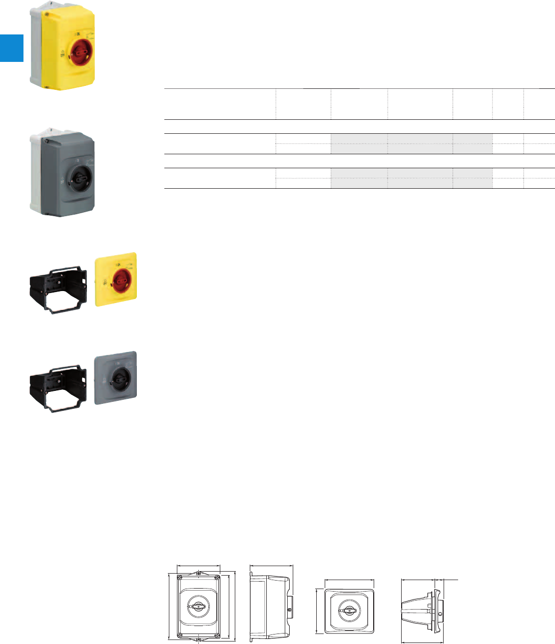
Description
IB132 are IP65 enclosures for single MMS installation. Additional mounting of auxiliary and signalling
contacts, shunt trips and undervoltage release is possible. The handle is lockable in OFF position. For
detailed specification see installation instruction.
DMS132 are IP65 door mounting kits for MMS installation in any enclosure. Additional mounting of
auxiliary, signalling, shunt trips and undervoltage release is possible. The handle is lockable in OFF
position. For detailed specification see installation instruction.
Ordering details
Description Color Type Order code Pkg
qty
Weight
(1 pce)
kg
Enclosures IP65
Padlockable max. 3 padlocks with bail
diameter 4 ... 6.5 mm
Yellow/red IB132-Y 1SAM201911R1011 1 0.370
Grey/black IB132-G 1SAM201911R1010 1 0.370
Door mounting kit IP65
Padlockable max. 3 padlocks with bail
diameter 4 ... 6.5 mm
Yellow/red DMS132-Y 1SAM201912R1011 1 0.170
Grey/black DMS132-G 1SAM201912R1010 1 0.170
Indication I-O-T and ON-OFF-T
Main dimensions mm, inches
119 4.69"
I
ON
0
OFF
183 7.2"
174 6.85"
194 7.64"
118 4.65"
2CDC242011F0011
121 4.76"
135.7 5.34" 92 3.62" 24 .94"
116.15 4.57"
I
ON
0
OFF
2CDC242012F0011
IB132 DMS132
2CDC241004F0010
IB132-Y
2CDC241003F0010
IB132-G
2CDC241002F0010
DMS132-Y
2CDC241001F0010
DMS132-G
MO132 manual motor starters magnetic only
Main accessories
2/22 | ABB
2
2CDC131036C0201_8s9
Description
The complete set includes handle, shaft and driver. All accessories fit 6 mm shafts of maximum 180 mm
length. The degree of protection for handles MSHD is IP64.
Ordering details
Description Shaft length Type Order code Pkg
qty
Weight
(1 pce)
mm kg
Shafts
For selector type handles. Shaft diameter
6 mm. Shaft extension for door coupling
driver.
85 OXS6X85 1SCA101647R1001 1 0.020
105 OXS6X105 1SCA108043R1001 1 0.020
130 OXS6X130 1SCA101655R1001 1 0.030
180 OXS6X180 1SCA101659R1001 1 0.040
Description Color Type Order code Pkg
qty
Weight
(1 pce)
kg
Selector type handles IP64
Padlockable max. 3 padlocks with bail
diameter 5 … 8 mm, door interlock in ON
position defeatable, for use with 6 mm
OXS6…types up to 180 mm or driver
shafts MSOX.
Black MSHD-LTB 1) 1SAM201920R1011 1 0.065
Yellow MSHD-LTY 1) 1SAM201920R1012 1 0.065
1) Indication I-O-T and ON-OFF-T
Description Type Order code Pkg
qty
Weight
(1 pce)
kg
Driver
Coupling driver for use with 6 mm OXS6… types up to
180 mm.
MSMN 1) 1SAM101923R0002 1 0.002
MSMNO 2) 1SAM101923R0012 1 0.002
1) Coded - Positioning of ON indication dependent from mounting orientation of the MS
2) Uncoded - Positioning of ON indication independent from mounting orientation of the MS
Description Shaft length Type Order code Pkg
qty
Weight
(1 pce)
mm kg
Driver shafts
Driver shaft - combination driver & shaft.
Shaft diameter 6 mm.
32 MSOX-32 1) 1SAM101924R0003 1 0.010
30 MSOX-30 2) 1SAM101924R0013 1 0.010
1) MSOX-32 is for normal vertical use
2) MSOX-30 is for horizontal use
MO132 manual motor starters magnetic only
Main accessories
2CDC241007F0011
MSHD-LTB
2CDC241006F0011
MSHD-LTY
MSMN
MSOX-30
2CDC241004S0011
2CDC241005S0011
ABB | 2/23
2
2CDC131036C0201_9s9
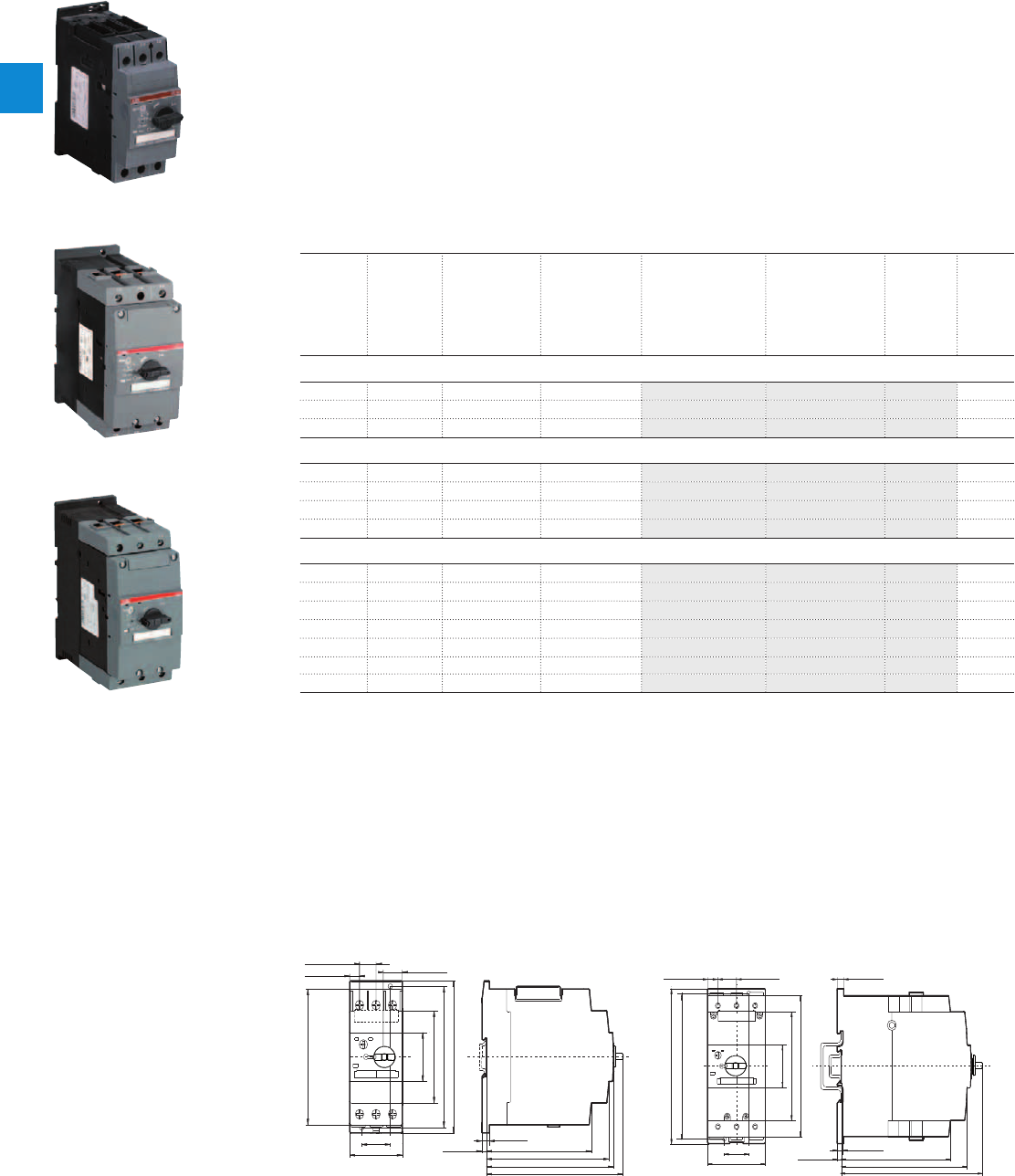
MS450, MS495, MS497 manual motor starters
22 to 100 A – with thermal and electromagnetic protection
Description
Manual motor starters (MMS) are protection devices for the main circuit. They combine motor control and
protection in a single device. MMS are used mainly to switch motors manually ON/OFF and protect them
and the installation fuse less against short-circuit, overload and phase failures. Fuse less protection with
a manual motor starter saves costs, space and ensures a quick reaction under short-circuit condition, by
switching off the motor within milliseconds.
Further features are the build-in disconnect function, temperature compensation, trip-free mechanism
and a rotary handle with a clear switch position indication. The manual motor starter is suitable for three-
and single-phase applications. The handle is lockable to protect against unauthorized changes. Auxiliary
contacts, signalling contacts, undervoltage releases, shunt trips, three-phase busbars, power in-feed
blocks are available as accessory.
Ordering details
Rated
operational
power
400 V
AC-3
Setting
range
Short-circuit
breaking
capacity I
CS
at
400 V AC
Rated instan-
taneous short-
circuit current
setting l
i
Type Order code Weight
(1 pce)
kW A kA A kg
MS450 manual motor starter
15.8 28.0 … 40.0 25 520.00 MS450-40 1SAM450000R1005 1.047
22 36.0 … 45.0 25 585.00 MS450-45 1SAM450000R1006 1.039
22 40.0 … 50.0 25 650.00 MS450-50 1SAM450000R1007 1.027
MS495 manual motor starter
30 45.0 … 63.0 25 819.00 MS495-63 1SAM550000R1007 2.247
37 57.0 … 75.0 25 975.00 MS495-75 1SAM550000R1008 2.253
45 70.0 … 90.0 25 1170.00 MS495-90 1SAM550000R1009 2.280
55 80.0 … 100.0 25 1235.00 MS495-100 1SAM550000R1010 2.295
MS497 manual motor starter
15 22.0 … 32.0 50 416.00 MS497-32 1SAM580000R1004 2.222
18.5 28.0 … 40.0 50 520.00 MS497-40 1SAM580000R1005 2.203
22 36.0 … 50.0 50 650.00 MS497-50 1SAM580000R1006 2.230
30 45.0 … 63.0 50 819.00 MS497-63 1SAM580000R1007 2.255
37 57.0 … 75.0 50 975.00 MS497-75 1SAM580000R1008 2.266
45 70.0 … 90.0 50 1170.00 MS497-90 1SAM580000R1009 2.268
55 80.0 … 100.0 50 1235.00 MS497-100 1SAM580000R1010 2.275
Main dimensions mm, inches
4.29
"
109
5.0
"
127
5.2
"
132
4.92
"
125
3.35
"
85
5.12
"
130
5.51
"
140
1.77
"
45
5.67
"
144
1.18
"
30
2.17
"
55
0.67
"
17
0.39
"
10 0.79
"
20
0.20
"
5
0.32
"
8
2CDC242013F0011
5.20
"
132
6.02
"
153
6.65
"
169
6.10
"
155
6.50
"
165
5.91
"
150
4.57
"
116
1.77
"
45
2.56
"
70
0.31
"
8
0.28
"
7
0.20
"
5
1.18
"
30
0.47
"
12 0.91
"
23
2CDC242014F0011
MS450 MS495, MS497
2CDC241004F0009
MS450-40
1SBC101184F0014
MS495-40
2CDC241020F0011
MS497-100
2/24 | ABB
2
2CDC131042C0201
MS450, MS495, MS497 manual motor starters
Technical data
Main circuit – Utilization characteristics according to IEC/EN
Type MS450, MS495, MS497
Standards
IEC/EN 60947–2, IEC/EN 60947-4-1, IEC/EN 60947-1
Rated operational voltage U
e
690 V AC / 450 V DC
Rated frequency
50/60 Hz
Trip class
10
Number of poles
3
Duty time
100 %
Rated impulse withstand voltage U
imp
6 kV
Rated insulation voltage U
i
690 V AC
Rated operational current I
e
See ordering details
Rated instantaneous short-circuit current setting I
i
See ordering details
Rated service short-circuit breaking capacity I
cs
See table "Short-circuit breaking capacity and back-up fuses"
Rated ultimate short-circuit breaking capacity I
cu
See table "Short-circuit breaking capacity and back-up fuses"
Short-circuit breaking capacity and back-up fuses
lCS Rated service short-circuit breaking capacity
lCU Rated ultimate short-circuit breaking capacity
ICC Prospective short-circuit current at installation location
Note: Maximum rated current of the back-up fuses if ICC > ICS
Type 240 V AC 400 V AC 440 V AC 500 V AC 690 V AC
I
CS
kA
I
CU
kA
gG, aM
A
I
CS
kA
I
CU
kA
gG, aM
A
I
CS
kA
I
CU
kA
gG, aM
A
I
CS
kA
I
CU
kA
gG, aM
A
I
CS
kA
I
CU
kA
gG, aM
A
Short-circuit protection MS450
MS450-40
No back-up fuse required up to
ICC = 100 kA
25 50 160 15 50 125 5 10 100 2 4 63
MS450-45
25 50 160 15 50 125 5 10 100 2 4 63
MS450-50
25 50 160 15 50 125 5 10 100 2 4 80
MS450: No need for back-up fuse in networks with a prospective current of up to 50 kA at 400 V.
With an approbiate 160 A type gG fuse the device can be used in a network with a prospective current of up to 100 kA.
Short-circuit protection MS495
MS495-40
No back-up fuse required up to
ICC = 100 kA
25 50 125 20 50 125 6 12 125 3 6 63
MS495-50
25 50 125 20 50 125 6 12 125 3 6 80
MS495-63
25 50 160 20 50 160 6 12 160 3 6 80
MS495-75
25 50 160 20 50 160 6 8 160 3 5 100
MS495-90
25 50 160 20 50 160 6 8 160 3 5 125
MS495-100
25 50 160 20 50 160 6 8 160 3 5 125
MS495-40: No need for back-up fuse in networks with a prospective current of up to 50 kA at 400 V.
With an approbiate 125 A type gG fuse the device can be used in a network with a prospective current of up to 100 kA.
MS495-100: No need for back-up fuse in networks with a prospective current of up to 50 kA at 400 V.
With an approbiate 160 A type gG fuse the device can be used in a network with a prospective current of up to 100 kA.
Short-circuit protection MS497
MS497-32
No back-up fuse required up to
ICC = 100 kA
50 100
No back-
up fuse
required
up to ICC
= 100 kA
50 100
No back-up
fuse required
up to
ICC = 100 kA
11 22 100 7 12 63
MS497-40
50 100 50 100 9 18 160 6 12 80
MS497-50
50 100 50 100 7.5 15 160 5 10 100
MS497-63
50 100 50 70 200 7.5 15 160 4 7.5 100
MS497-75
50 100 50 70 200 5 10 160 3 6 125
MS497-90
50 100 50 70 200 5 10 160 3 6 160
MS497-100
50 100 50 70 200 5 10 160 3 6 160
MS497-32: No need for back-up fuse in networks with a prospective current of up to 100 kA at 440 V.
MS497-90: No need for back-up fuse in networks with a prospective current of up to 70 kA at 440 V.
With an approbiate 200 A type gG fuse the device can be used in a network with a prospective current of up to 100 kA.
ABB | 2/25
2
2CDC131042C0201

MS450, MS495, MS497 manual motor starters
Technical data
General technical data
Type MS450 MS495 MS497
Pollution degree
3
Phase loss sensitive
Yes
Ambient air temperature
Operation Open - compensated without derating
-20 ... +60 °C
Open
-20 ... +70 °C
Enclosed
-20 ... +35 °C
Storage
-50 ... +80 °C
Ambient air temperature compensation
Continuous
Maximum operating altitude permissible
2000 m
Resistance to shock acc. to IEC 60068-2-27
25 g / 11 ms -
Resistance to vibrations acc. to IEC 60068-2-6
2 g / 5-150 Hz
Mounting position
Position 1-6 (optional for single mounting)
Mounting
DIN-rail 35 mm (EN 60715) DIN-rail 15 mm / 75 mm (EN 60715)
Minimum distance to other
units same type
Horizontal
0 mm 0 mm
Vertical - up to 240 V
- 50 mm
Vertical - up to 440 V
- 70 mm
Vertical - up to 500 V
- 110 mm
Vertical - up to 690 V
- 150 mm
Vertical
50 mm -
Minimum distance to
electrical conductive board
Horizontal
10 mm -
Horizontal - up to 500 V
- 10 mm
Horizontal - up to 690 V
- 30 mm
Vertical - up to 240 V
- 50 mm
Vertical - up to 440 V
- 70 mm
Vertical - up to 500 V
- 110 mm
Vertical - up to 690 V
- 150 mm
Vertical
50 mm -
Degree of protection
Enclosure / terminals
IP20
Connecting characteristics
Main circuit
Type MS450 MS495 MS497
Connecting capacity
Solid
1 or 2 x
0.75 ... 16 mm² 2.5 ... 16 mm² 2.5 ... 16 mm²
Flexible
1 x
2 x
0.75 ... 35 mm²
0.75 ... 25 mm²
10 ... 70 mm²
10 ... 50 mm²
10 ... 70 mm²
10 ... 50 mm²
Stranded acc. to UL/CSA
1 x
2 x
AWG 18-2
AWG 18-2
AWG 10-2/0
AWG 10-1/0
AWG 10-2/0
AWG 10-1/0
Flexible acc. to UL/CSA
1 x
2 x
AWG 18-2
AWG 18-2
AWG 10-2/0
AWG 10-1/0
AWG 10-2/0
AWG 10-1/0
Stripping length
13 mm 17 mm 17 mm
Tightening torques
3 - 4.5 Nm / 27 … 40 Ib.in 4 - 6 Nm / 35 - 53 Ib.in 4 - 6 Nm / 35 - 53 Ib.in
Connection screw
Pozidriv 2 Hexagon 4 Hexagon 4
2/26 | ABB
2
2CDC131042C0201
MS450, MS495, MS497 manual motor starters
Main accessories
Description
Three-phase busbars ensure a quick and safe connection and are therefor a cost effective solution.
A variety of different three-phase busbars up to 108A are in the assortment. Between 2 and 4 manual
motor starter with none or two lateral auxiliary contacts can be connected.
Ordering details
Rated operational
current
Number of MMS Number of lateral
aux.
Type Order code Pkg
qty
Weight
(1 pce)
A kg
Three-phase busbars for MS450 only
108 2 0 PS4-2-0 1SAM401911R1001 5 0.134
108 3 0 PS4-3-0 1SAM401911R1002 5 0.206
108 4 0 PS4-4-0 1SAM401911R1003 5 0.280
108 2 1 PS4-2-2 1SAM401911R1004 5 0.148
108 3 1 PS4-3-2 1SAM401911R1005 5 0.250
108 4 1 PS4-4-2 1SAM401911R1006 5 0.362
Rated operational
current
Rated cross
section
Mounting form Type Order code Pkg
qty
Weight
(1 pce)
A mm² kg
Three-phase feeder terminals for MS450 only
108 25 Flat S4-M1 1SAM401911R1007 2 0.106
Description For MMS Type Order code Pkg
qty
Weight
(1 pce)
kg
Protection cover for busbar PS4 BS4-3 1SAM401911R1008 10 0.001
Disconnector module MS450 TB450 1SAM401910R1001 1 0.315
Terminal shroud MS450 KA450 1SAM401908R1001 1 0.154
Terminal shroud MS495 KA495 1SAM501901R1001 10 0.018
Terminal shroud MS495 KA495C 1) 1SAM501902R1001 10 0.038
Terminal insulation barrier for UL508E MS495 DX495 1SAM401912R1001 1 0.154
Padlock + 2 keys MS450, MS495,
MS497
SA2 GJF1101903R0002 10 0.020
1) Is plugged onto the housing after removing the box terminals, if using cable lugs.
SK0109B91
SA2
ABB | 2/27
2
2CDC131042C0201
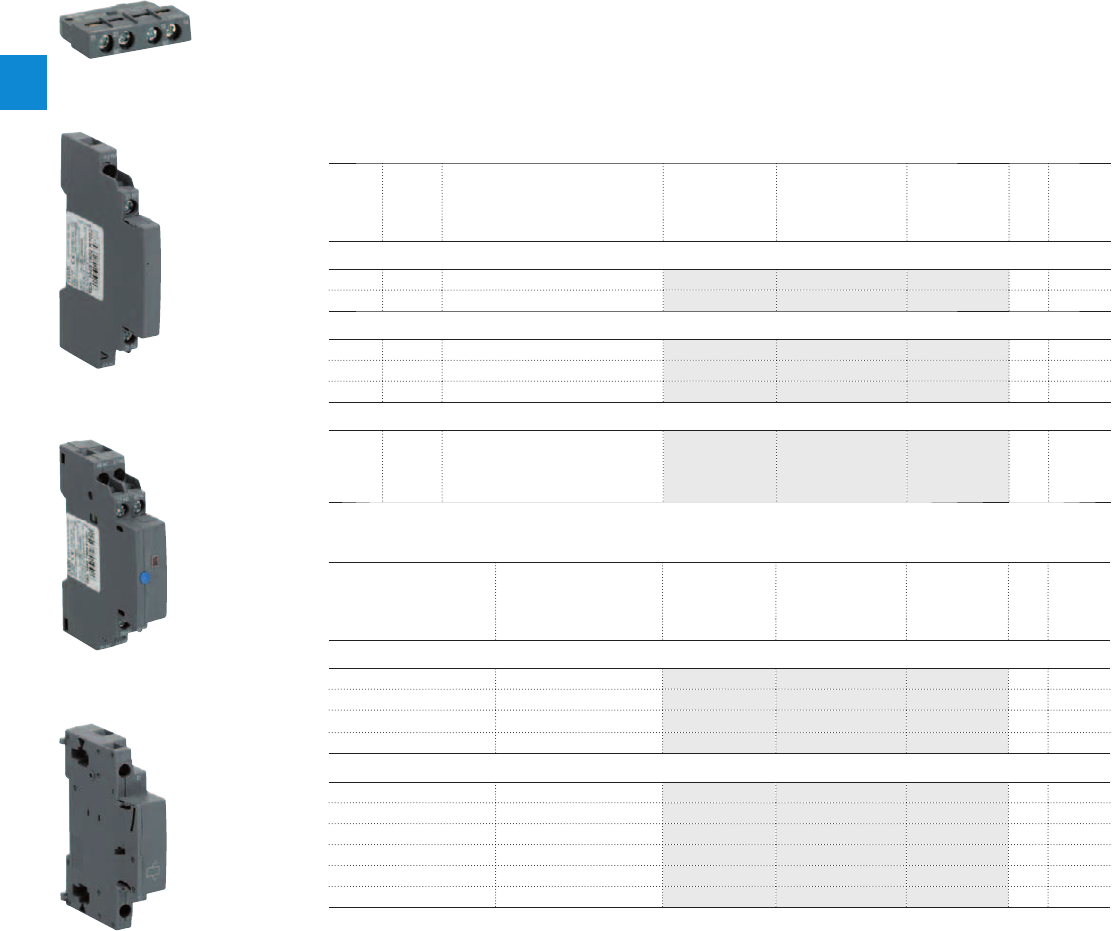
MS450, MS495, MS497 manual motor starters
Main accessories
Description
MS450, MS495, MS497 manual motor starters can be equipped with auxiliary contacts for lateral/front
mounting, signalling contact for lateral mounting, undervoltage release and shunt trips. The accessories
can be fitted wiring free and without tools. A variety of combinations is possible as required for the
application. The auxiliary contacts change position with the main contacts. Undervoltage release are used
for remote tripping of the manual motor starter especially for emergency stop circuits. Shunt trips release
the MMS used for remote tripping.
Ordering details
Auxiliary
contacts
N.O.
Auxiliary
contacts
N.C.
Description Type Order code Pkg
qty
Weight
(1 pce)
kg
Auxiliary contacts – mountable on the front
1 1 HK4-11 1SAM401901R1001 10 0.017
Changeover HK4-W 1SAM401901R1002 10 0.015
Auxiliary contacts – mountable on the left
1 1 Max. 1 pieces HKS4-11 1SAM401902R1001 2 0.045
2 0 Max. 1 pieces HKS4-20 1SAM401902R1002 2 0.045
0 2 Max. 1 pieces HKS4-02 1SAM401902R1003 2 0.045
Signalling contacts – mountable on the right
2 2 Separate signalling acc. UL508E
1N.O. + 1 N.C. for short circuit and
1NO+NC for general tripping , max.
2 pieces
SK4-11 1SAM401904R1001 1 0.093
Rated control supply
voltage
Frequency Type Order code Pkg
qty
Weight
(1 pce)
VHz kg
Shunt trip units – mountable on the left
20 ... 24 50/60 AA4-24 1SAM401907R1001 1 0.135
90 ... 110 50/60 AA4-110 1SAM401907R1002 1 0.135
200 ... 240 50/60 AA4-230 1SAM401907R1003 1 0.128
350 ... 415 50/60 AA4-400 1SAM401907R1004 1 0.125
Undervoltage releases – mountable on the left
24 50/60 UA4-24 1SAM401905R1004 1 0.134
110/120 50/60 UA4-110 1SAM401905R1001 1 0.134
230/240 50/60 UA4-230 1SAM401905R1002 1 0.131
400/440 50/60 UA4-400 1SAM401905R1003 1 0.129
230/240 50/60 UA4-HK-230 1SAM401906R1001 1 0.140
400/440 50/60 UA4-HK-400 1SAM401906R1002 1 0.137
HK4-11
HKS4-20
SK4-11
AA4-24
2CDC241026S0011
2CDC241022S0011
2CDC241024S0011
2CDC241023S0011
2/28 | ABB
2
2CDC131042C0201
MS450, MS495, MS497 manual motor starters
Main accessories
General technical data
Type PS4-xxx S4-M1
Standards
IEC/EN 60947-1
Rated operational voltage U
e
690 V AC
Rated operational current I
e
108 A
Rated frequency
50/60 Hz
Rated impulse withstand voltage U
imp
6 kV
Rated insulation voltage U
i
690 V AC
Pollution degree
3
Cross-section
10 mm² 25 mm²
Ambient air temperature
Operation
-25 ... +70 °C
Storage
-50 ... +80 °C
Electrical connection
Main circuit
Type S4-M1
Connecting capacity
Solid
1 x
2.5 ... 50 mm²
Flexible
1 x
4 ... 16 mm²
Stranded acc. to UL/CSA
1 x
AWG 14-4
Flexible acc. to UL/CSA
1 x
AWG 14-4
Tightening torques
4 Nm
Connection screw
Pozidriv 2
ABB | 2/29
2
2CDC131042C0201
MS450, MS495, MS497 manual motor starters
Main accessories
General technical data
Type HK4-11 HK4-W HKS4 SK4
Standards
IEC/EN 60947–1, IEC/EN 60947-5-1, UL 508, CSA22.2 No. 14
Rated operational voltage U
e
230 V AC / 220 V DC 690 V AC / 220 V DC 690 V AC 690 V AC
Conventional free-air thermal current I
th
2.5 A 5 A 10 A 10 A
Rated frequency
DC, 50/60 Hz
Rated impulse withstand voltage U
imp
6 kV
Rated insulation voltage U
i
300 V 300 V 690 V 690 V
Pollution degree
3
Ambient air temperature
Operation
-20 ... +70 °C
Storage
-50 ... +80 °C
Resistance to shock acc. to IEC 60068-2-27
25 g / 11 ms
Resistance to vibrations acc. to IEC 60068-2-6
2 g / 5 ... 150Hz
Number of poles
1 N.C. + 1 N.O. Changeover 1 N.C. + 1 N.O. /
2 N.O. / 2 N.C.
2 N.C. + 2 N.O.
I
e
/ Rated operational current AC-15
acc. to IEC/EN 60947-5-1 for utilization category
24 V, 50/60 Hz 2 A4 A6 A6 A
230 V, 50/60 Hz 0.5 A 3 A 4 A 4 A
400 V, 50/60 Hz - 1.5 A 3 A 3 A
690 V, 50/60 Hz - 0.5 A 1 A 1 A
I
e
/ Rated operational current DC-13
acc. to IEC/EN 60947-5-1 for utilization category
24 V 1 A1 A2 A2 A
48 V 0.3 A - - -
60 V 0.15 A - - -
110 V - 0.22 A 0.5 A 0.5 A
230 V - 0.1 A 0.25 A 0.25 A
Minimum switching capacity
17 V / 1 mA - -
Short-circuit protective device
10 A Type gG
Duty time
100 %
Mounting
Front of MMS Front of MMS Left side of MMS Left side of MMS
Mounting positions
1-6
Mechanical durability
100000 cycles
Electrical durability
100000 cycles
Electrical connection
Main circuit
Type HK4-11 HK4-W HKS4 SK4
Connecting capacity
Solid
1 x
2 x
0.5... 2.5 mm²
0.5 ... 1.5 mm² or 0.75 ... 2.5 mm
Flexible
1 x
2 x
0.5 ... 2.5 mm²
0.5 ... 1.5 mm² or 0.75 ... 2.5 mm
Stranded acc. to UL/CSA
1 or 2 x
AWG 18-14
Flexible acc. to UL/CSA
1 or 2 x
AWG 18-14
Stripping length
10 mm
Tightening torques
0.8 ... 1.2 Nm / 7 ... 10.3 Ib.in
Connection screw
Pozidriv 2
2/30 | ABB
2
2CDC131042C0201

MS450, MS495, MS497 manual motor starters
Main accessories
Description
The complete set includes handle, shaft and driver. All accessories fit 6 mm shafts of maximum 180 mm
length. The degree of protection for handles MSHD is IP64.
Ordering details
Description Shaft length Type Order code Pkg
qty
Weight
(1 pce)
mm kg
Shafts
For selector type handles. Shaft diameter
6 mm. Shaft extension for door coupling
driver.
85 OXS6X85 1SCA101647R1001 1 0.020
105 OXS6X105 1SCA108043R1001 1 0.020
130 OXS6X130 1SCA101655R1001 1 0.030
180 OXS6X180 1SCA101659R1001 1 0.040
Description Color Type Order code Pkg
qty
Weight
(1 pce)
kg
Selector type handles IP64
Padlockable max. 3 padlocks with bail
diameter 5 … 8 mm, door interlock in ON
position defeatable, for use with 6 mm
OXS6…types up to 180 mm or driver
shafts MSOX.
Black MSHD-LTB 1) 1SAM201920R1011 1 0.065
Yellow MSHD-LTY 1) 1SAM201920R1012 1 0.065
1) Indication I-O-T and ON-OFF-T
Description Type Order code Pkg
qty
Weight
(1 pce)
kg
Driver
Coupling driver for use with 6 mm OXS6… types up to
180 mm.
MSMN 1) 1SAM101923R0002 1 0.002
MSMNO 2) 1SAM101923R0012 1 0.002
1) Coded - Positioning of ON indication dependent from mounting orientation of the MS
2) Uncoded - Positioning of ON indication independent from mounting orientation of the MS
Description Shaft length Type Order code Pkg
qty
Weight
(1 pce)
mm kg
Driver shafts
Driver shaft - combination driver & shaft.
Shaft diameter 6 mm.
32 MSOX-32 1) 1SAM101924R0003 1 0.010
30 MSOX-30 2) 1SAM101924R0013 1 0.010
1) MSOX-32 is for normal vertical use
2) MSOX-30 is for horizontal use
2CDC241007F0011
MSHD-LTB
2CDC241006F0011
MSHD-LTY
2CDC241004F0011
MSMN
2CDC241005F0011
MSOX-30
ABB | 2/31
2
2CDC131042C0201
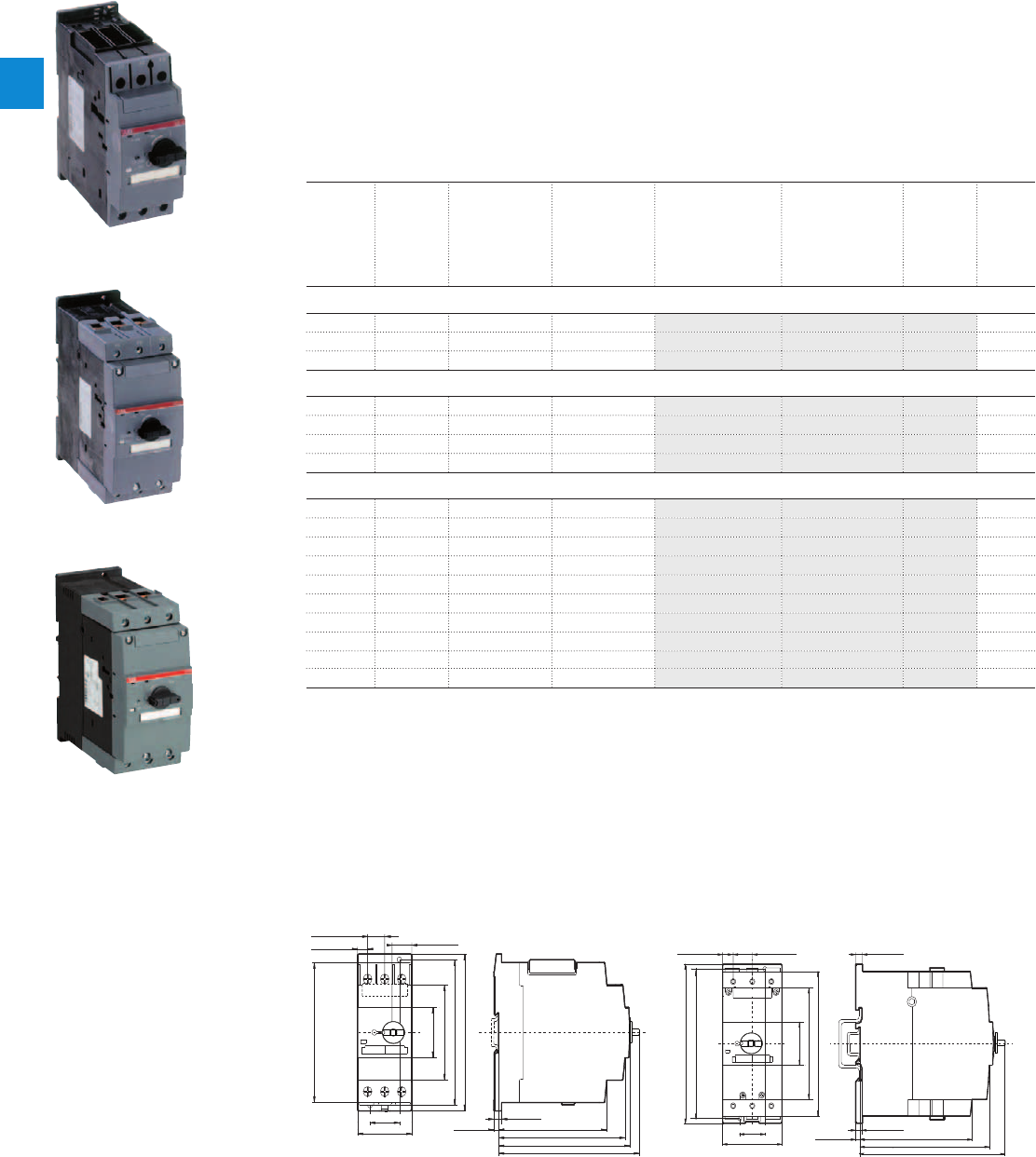
MO450, MO495, MO496 manual motor starters magnetic only
16 to 100 A – with electromagnetic protection
Description
The manual motor starter magnetic only is used to manually switch on and off motors and to protect them
reliably and without the need for a fuse from short-circuits.
Further features are the build-in disconnect function, trip-free mechanism and a rotary handle with a clear
switch position indication. The manual motor starter magnetic only is suitable for three- and single-phase
applications. The handle is lockable to protect against unauthorized changes. Auxiliary contacts, signalling
contacts, undervoltage releases, shunt trips, three-phase busbars, power in-feed blocks are available as
accessory.
Ordering details
Rated
operational
power
400 V
AC-3
1)
Rated
operational
current
Short-circuit
breaking
capacity I
CS
at
400 V AC
Rated instan-
taneous short-
circuit current
setting l
i
Type Order code Weight
(1 pce)
kW A kA A kg
MO450 manual motor starter
15.8 40 25 520.00 MO450-40 1SAM460000R1005 1.033
22 45 25 585.00 MO450-45 1SAM460000R1006 1.040
22 50 25 650.00 MO450-50 1SAM460000R1007 1.019
MO495 manual motor starter
30 63 25 819.00 MO495-63 1SAM560000R1007 2.244
37 75 25 975.00 MO495-75 1SAM560000R1008 2.247
45 90 25 1170.00 MO495-90 1SAM560000R1009 2.269
55 100 25 1235.00 MO495-100 1SAM560000R1010 2.292
MO496 manual motor starter
7.5 16 50 208.00 MO496-16 1SAM590000R1001 2.175
9.0 20 50 260.00 MO496-20 1SAM590000R1002 2.188
12.5 25 50 325.00 MO496-25 1SAM590000R1003 2.219
15 32 50 416.00 MO496-32 1SAM590000R1004 2.208
18.5 40 50 520.00 MO496-40 1SAM590000R1005 2.218
22 50 50 650.00 MO496-50 1SAM590000R1006 2.218
30 63 50 819.00 MO496-63 1SAM590000R1007 2.248
37 75 50 975.00 MO496-75 1SAM590000R1008 2.278
45 90 50 1170.00 MO496-90 1SAM590000R1009 2.266
55 100 50 1235.00 MO496-100 1SAM590000R1010 2.293
1) For overload protection of motors, an appropriate thermal or electronic overload relay must be used
Main dimensions mm, inches
4.29
"
109
5.0
"
127
5.2
"
132
4.92
"
125
3.35
"
85
5.12
"
130
5.51
"
140
1.77
"
45
5.67
"
144
1.18
"
30
2.17
"
55
0.67
"
17
0.39
"
10 0.79
"
20
0.20
"
5
0.32
"
8
2CDC242015F0011
5.20
"
132
6.02
"
153
6.65
"
169
6.10
"
155
6.50
"
165
5.91
"
150
4.57
"
116
1.77
"
45
2.56
"
70
0.31
"
8
0.28
"
7
0.20
"
5
1.18
"
30
0.47
"
12 0.91
"
23
2CDC242016F0011
MO450 MO495, MO496
ST02501
MO450-40
ST02601
MO495-75
MO496-100
2CDC241021S0011
2/32 | ABB
2
2CDC131038C0201
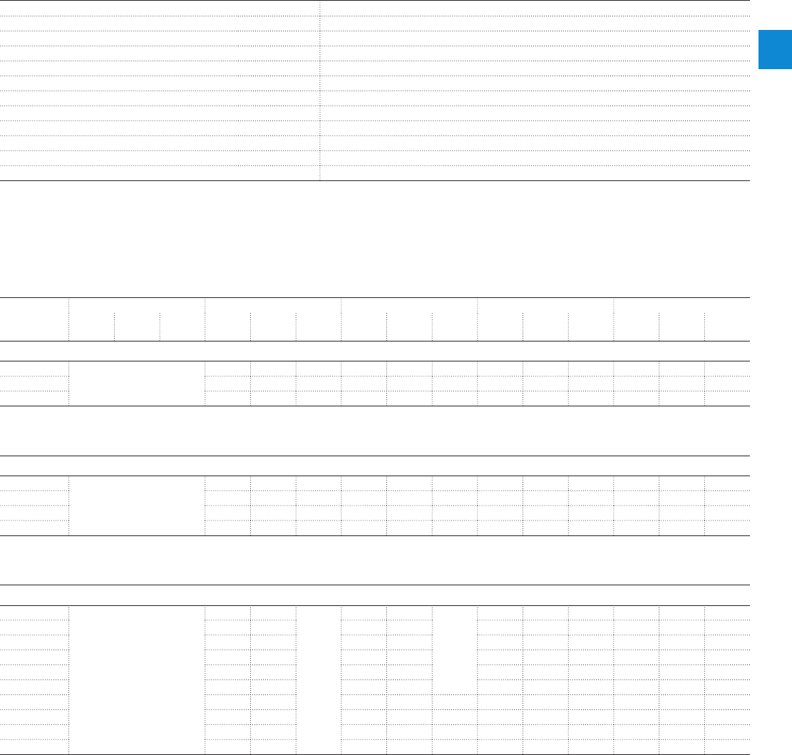
MO450, MO495, MO496 manual motor starters magnetic only
Technical data
Main circuit – Utilization characteristics according to IEC/EN
Type MO450, MO495, MO496
Standards
IEC/EN 60947–2, IEC/EN 60947-4-1, IEC/EN 60947-1
Rated operational voltage U
e
690 V AC / 450 V DC
Rated frequency
50/60 Hz
Number of poles
3
Duty time
100 %
Rated impulse withstand voltage U
imp
6 kV
Rated insulation voltage U
i
690 V AC
Rated operational current I
e
See ordering details
Rated instantaneous short-circuit current setting I
i
See ordering details
Rated service short-circuit breaking capacity I
cs
See table "Short-circuit breaking capacity and back-up fuses"
Rated ultimate short-circuit breaking capacity I
cu
See table "Short-circuit breaking capacity and back-up fuses"
Short-circuit breaking capacity and back-up fuses
lCS Rated service short-circuit breaking capacity
lCU Rated ultimate short-circuit breaking capacity
ICC Prospective short-circuit current at installation location
Note: Maximum rated current of the back-up fuses if ICC > ICS
Type 240 V AC 400 V AC 440 V AC 500 V AC 690 V AC
I
CS
kA
I
CU
kA
gG, aM
A
I
CS
kA
I
CU
kA
gG, aM
A
I
CS
kA
I
CU
kA
gG, aM
A
I
CS
kA
I
CU
kA
gG, aM
A
I
CS
kA
I
CU
kA
gG, aM
A
Short-circuit protection MO450
MO450-40
No back-up fuse required up to
ICC = 100 kA
25 50 160 15 50 125 5 10 100 2 4 63
MO450-45
25 50 160 15 50 125 5 10 100 2 4 63
MO450-50
25 50 160 15 50 125 5 10 100 2 4 80
MO450: No need for back-up fuse in networks with a prospective current of up to 50 kA at 400 V.
With an approbiate 160 A type gG fuse the device can be used in a network with a prospective current of up to 100 kA.
Short-circuit protection MO495
MO495-63
25 50 160 20 50 160 6 12 160 3 6 80
MO495-75
25 50 160 20 50 160 6 8 160 3 5 100
MO495-90
25 50 160 20 50 160 6 8 160 3 5 125
MO495-100
25 50 160 20 50 160 6 8 160 3 5 125
MO495-100: No need for back-up fuse in networks with a prospective current of up to 50 kA at 400 V.
With an approbiate 160 A type gG fuse the device can be used in a network with a prospective current of up to 100 kA.
Short-circuit protection MO496
MO496-16
No back-up fuse required up to
ICC = 100 kA
50 100
No back-
up fuse
required
up to ICC
= 100 kA
50 100
No back-up
fuse required
up to
ICC = 100 kA
11 22 100 7 12 63
MO496-20
50 100 50 100 11 22 100 7 12 63
MO496-25
50 100 50 100 11 22 100 7 12 63
MO496-32
50 100 50 100 11 22 100 7 12 63
MO496-40
50 100 50 100 9 18 160 6 12 80
MO496-50
50 100 50 100 7.5 15 160 5 10 100
MO496-63
50 100 50 70 200 7.5 15 160 4 7.5 100
MO496-75
50 100 50 70 200 5 10 160 3 6 125
MO496-90
50 100 50 70 200 5 10 160 3 6 160
MO496-100
50 100 50 70 200 5 10 160 3 6 160
MO496-32: No need for back-up fuse in networks with a prospective current of up to 100 kA at 440 V.
MO496-90: No need for back-up fuse in networks with a prospective current of up to 70 kA at 440 V.
With an approbiate 200 A type gG fuse the device can be used in a network with a prospective current of up to 100 kA.
ABB | 2/33
2
2CDC131038C0201

MO450, MO495, MO496 manual motor starters magnetic only
Technical data
General technical data
Type MO450 MO495 MO496
Pollution degree
3
Phase loss sensitive
Yes
Ambient air temperature
Operation Open - compensated without derating
-20 ... +60 °C
Open
-20 ... +70 °C
Enclosed
-20 ... +35 °C
Storage
-50 ... +80 °C
Ambient air temperature compensation
Continuous
Maximum operating altitude permissible
2000 m
Resistance to shock acc. to IEC 60068-2-27
25 g / 11 ms
Resistance to vibrations acc. to IEC 60068-2-6
2 g / 5-150 Hz -
Mounting position
Position 1-6 (optional for single mounting)
Mounting
DIN-rail 35 mm (EN 60715) DIN-rail 15 mm / 75 mm (EN 60715)
Minimum distance to other
units same type
Horizontal
0 mm 0 mm
Vertical - up to 240 V
- 50 mm
Vertical - up to 440 V
- 70 mm
Vertical - up to 500 V
- 110 mm
Vertical - up to 690 V
- 150 mm
Vertical
50 mm -
Minimum distance to
electrical conductive board
Horizontal
10 mm -
Horizontal - up to 500 V
- 10 mm
Horizontal - up to 690 V
- 30 mm
Vertical - up to 240 V
- 50 mm
Vertical - up to 440 V
- 70 mm
Vertical - up to 500 V
- 110 mm
Vertical - up to 690 V
- 150 mm
Vertical
50 mm -
Degree of protection
Enclosure / terminals
IP20
Connecting characteristics
Main circuit
Type MO450 MO495 MO496
Connecting capacity
Solid
1 or 2 x
0.75 ... 16 mm² 2.5 ... 16 mm² 2.5 ... 16 mm²
Flexible
1 x
2 x
0.75 ... 35 mm²
0.75 ... 25 mm²
10 ... 70 mm²
10 ... 50 mm²
10 ... 70 mm²
10 ... 50 mm²
Stranded acc. to UL/CSA
1 x
2 x
AWG 18-2
AWG 18-2
AWG 10-2/0
AWG 10-1/0
AWG 10-2/0
AWG 10-1/0
Flexible acc. to UL/CSA
1 x
2 x
AWG 18-2
AWG 18-2
AWG 10-2/0
AWG 10-1/0
AWG 10-2/0
AWG 10-1/0
Stripping length
13 mm 17 mm 17 mm
Tightening torques
3 - 4.5 Nm / 27 … 40 Ib.in 4 - 6 Nm / 35 - 53 Ib.in 4 - 6 Nm / 35 - 53 Ib.in
Connection screw
Pozidriv 2 Hexagon 4 Hexagon 4
2/34 | ABB
2
2CDC131038C0201

MO450, MO495, MO496 manual motor starters magnetic only
Main accessories
Description
Three-phase busbars ensure a quick and safe connection and are therefor a cost effective solution.
Avariety of different three-phase busbars up to 108 A are in the assortment. Between 2 and 4 manual
motor starter with none or two lateral auxiliary contacts can be connected.
Ordering details
Rated operational
current
Number of MMS Number of lateral
aux.
Type Order code Pkg
qty
Weight
(1 pce)
A kg
Three-phase busbars for MO450 only
108 2 0 PS4-2-0 1SAM401911R1001 5 0.134
108 3 0 PS4-3-0 1SAM401911R1002 5 0.206
108 4 0 PS4-4-0 1SAM401911R1003 5 0.280
108 2 1 PS4-2-2 1SAM401911R1004 5 0.148
108 3 1 PS4-3-2 1SAM401911R1005 5 0.250
108 4 1 PS4-4-2 1SAM401911R1006 5 0.362
Rated operational
current
Rated cross
section
Mounting form Type Order code Pkg
qty
Weight
(1 pce)
A mm² kg
Three-phase feeder terminals for MO450 only
108 25 Flat S4-M1 1SAM401911R1007 2 0.106
Description for MMS Type Order code Pkg
qty
Weight
(1 pce)
kg
Protection cover for busbar PS4 BS4-3 1SAM401911R1008 10 0.001
Disconnector module MO450 TB450 1SAM401910R1001 1 0.315
Terminal shroud MO450 KA450 1SAM401908R1001 1 0.154
Terminal shroud MO495 KA495 1SAM501901R1001 10 0.018
Terminal shroud MO495 KA495C (1) 1SAM501902R1001 10 0.038
Terminal insulation barrier for UL508E MO495 DX495 1SAM401912R1001 1 0.154
Padlock + 2 keys MO450, MO495,
MO496
SA2 GJF1101903R0002
(1) is plugged onto the housing after removing the box terminals, if using cable lugs or buses
SK0109B91
SA2
ABB | 2/35
2
2CDC131038C0201

MO450, MO495, MO496 manual motor starters magnetic only
Main accessories
Description
MO450, MO495, MO497 manual motor starters can be equipped with auxiliary contacts for lateral/front
mounting, signalling contact for lateral mounting, undervoltage release and shunt trips. The accessories
can be fitted wiring free and without tools. A variety of combinations is possible as required for the
application. The auxiliary contacts change position with the main contacts. Undervoltage release are used
for remote tripping of the manual motor starter especially for emergency stop circuits. Shunt trips release
the MMS used for remote tripping.
Ordering details
Auxiliary
contacts
N.O.
Auxiliary
contacts
N.C.
Description Type Order code Pkg
qty
Weight
(1 pce)
kg
Auxiliary contacts – mountable on the front
1 1 HK4-11 1SAM401901R1001 10 0.017
- - Changeover HK4-W 1SAM401901R1002 10 0.015
Auxiliary contacts – mountable on the left
1 1 Max. 1 pieces HKS4-11 1SAM401902R1001 2 0.045
2 0 Max. 1 pieces HKS4-20 1SAM401902R1002 2 0.045
0 2 Max. 1 pieces HKS4-02 1SAM401902R1003 2 0.045
Signalling contacts – mountable on the right
2 2 Separate signalling acc. UL508E
1N.O. + 1 N.C. for short circuit and
1N.O. + 1 N.C. for general tripping,
max. 2 pieces
SK4-11 1SAM401904R1001 1 0.093
Rated control supply
voltage
Frequency Type Order code Pkg
qty
Weight
(1 pce)
VHz kg
Shunt trip units – mountable on the left
20 ... 24 50/60 AA4-24 1SAM401907R1001 1 0.135
90 ... 110 50/60 AA4-110 1SAM401907R1002 1 0.135
200 ... 240 50/60 AA4-230 1SAM401907R1003 1 0.128
350 ... 415 50/60 AA4-400 1SAM401907R1004 1 0.125
Undervoltage releases – mountable on the left
24 50/60 UA4-24 1SAM401905R1004 1 0.134
110/120 50/60 UA4-110 1SAM401905R1001 1 0.134
230/240 50/60 UA4-230 1SAM401905R1002 1 0.131
400/440 50/60 UA4-400 1SAM401905R1003 1 0.129
230/240 50/60 UA4-HK-230 1SAM401906R1001 1 0.140
400/440 50/60 UA4-HK-400 1SAM401906R1002 1 0.137
HK4-11
HKS4-20
SK4-11
AA4-24
2CDC241026S0011
2CDC241022S0011
2CDC241024S0011
2CDC241023S0011
2/36 | ABB
2
2CDC131038C0201

MO450, MO495, MO496 manual motor starters magnetic only
Main accessories
General technical data
Type PS4-xxx S4-M1
Standards
IEC/EN 60947-1
Rated operational voltage U
e
690 V AC
Rated operational current I
e
108 A
Rated frequency
50/60 Hz
Rated impulse withstand voltage U
imp
6 kV
Rated insulation voltage U
i
690 V AC
Pollution degree
3
Cross-section
10 mm² 25 mm²
Ambient air temperature
Operation
-25 ... +70 °C
Storage
-50 ... +80 °C
Electrical connection
Main circuit
Type S4-M1
Connecting capacity
Solid
1 x
2.5 ... 50 mm²
Flexible
1 x
4 ... 16 mm²
Stranded acc. to UL/CSA
1 x
AWG 14-4
Flexible acc. to UL/CSA
1 x
AWG 14-4
Tightening torques
4 Nm
Connection screw
Pozidriv 2
ABB | 2/37
2
2CDC131038C0201

MO450, MO495, MO496 manual motor starters magnetic only
Main accessories
General technical data
Type HK4-11 HK4-W HKS4 SK4
Standards
IEC/EN 60947–1, IEC/EN 60947-5-1, UL 508, CSA22.2 No. 14
Rated operational voltage U
e
230 V AC / 220 V DC 690 V AC / 220 V DC 690 V AC 690 V AC
Conventional free-air thermal current I
th
2.5 A 5 A 10 A 10 A
Rated frequency
DC, 50/60 Hz
Rated impulse withstand voltage U
imp
6 kV
Rated insulation voltage U
i
300 V 300 V 690 V 690 V
Pollution degree
3
Ambient air temperature
Operation
-20 ... +70 °C
Storage
-50 ... +80 °C
Resistance to shock acc. to IEC 60068-2-27
25 g / 11 ms
Resistance to vibrations acc. to IEC 60068-2-6
2 g / 5 ... 150Hz
Number of poles
1 N.C. + 1 N.O. Changeover 1 N.C. + 1 N.O. /
2 N.O. / 2 N.C.
2 N.C. + 2 N.O.
I
e
/ Rated operational current AC-15
acc. to IEC/EN 60947-5-1 for utilization category
24 V, 50/60 Hz 2 A4 A6 A6 A
230 V, 50/60 Hz 0.5 A 3 A 4 A 4 A
400 V, 50/60 Hz - 1.5 A 3 A 3 A
690 V, 50/60 Hz - 0.5 A 1 A 1 A
I
e
/ Rated operational current DC-13
acc. to IEC/EN 60947-5-1 for utilization category
24 V 1 A1 A2 A2 A
48 V 0.3 A - - -
60 V 0.15 A - - -
110 V - 0.22 A 0.5 A 0.5 A
230 V - 0.1 A 0.25 A 0.25 A
Minimum switching capacity
17 V / 1 mA - -
Short-circuit protective device
10 A Type gG
Duty time
100 %
Mounting
Front of MMS Front of MMS Left side of MMS Left side of MMS
Mounting positions
1-6
Mechanical durability
100000 cycles
Electrical durability
100000 cycles
Electrical connection
Main circuit
Type HK4-11 HK4-W HKS4 SK4
Connecting capacity
Solid
1 x
2 x
0.5... 2.5 mm²
0.5 ... 1.5 mm² or 0.75 ... 2.5 mm
Flexible
1 x
2 x
0.5 ... 2.5 mm²
0.5 ... 1.5 mm² or 0.75 ... 2.5 mm
Stranded acc. to UL/CSA
1 or 2 x
AWG 18-14
Flexible acc. to UL/CSA
1 or 2 x
AWG 18-14
Stripping length
10 mm
Tightening torques
0.8 ... 1.2 Nm / 7 ... 10.3 Ib.in
Connection screw
Pozidriv 2
2/38 | ABB
2
2CDC131038C0201
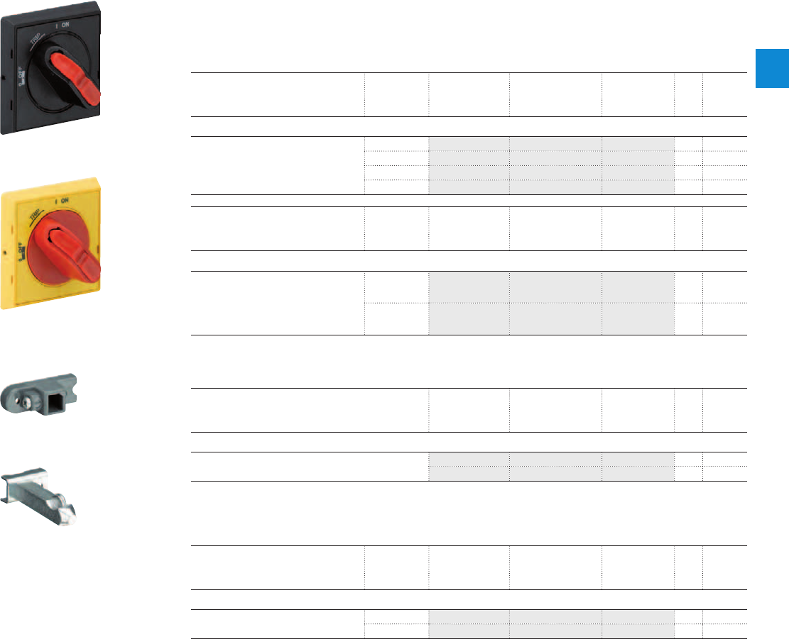
MO450, MO495, MO496 manual motor starters magnetic only
Main accessories
Description
The complete set includes handle, shaft and driver. All accessories fit 6 mm shafts of maximum 180 mm
length. The degree of protection for handles MSHD is IP64.
Ordering details
Description Shaft length Type Order code Pkg
qty
Weight
(1 pce)
mm kg
Shafts
For selector type handles. Shaft diameter
6 mm. Shaft extension for door coupling
driver.
85 OXS6X85 1SCA101647R1001 1 0.020
105 OXS6X105 1SCA108043R1001 1 0.020
130 OXS6X130 1SCA101655R1001 1 0.030
180 OXS6X180 1SCA101659R1001 1 0.040
Description Color Type Order code Pkg
qty
Weight
(1 pce)
kg
Selector type handles IP64
Padlockable max. 3 padlocks with bail
diameter 5 … 8 mm, door interlock in ON
position defeatable, for use with 6 mm
OXS6…types up to 180 mm or driver
shafts MSOX.
Black MSHD-LTB 1) 1SAM201920R1011 1 0.065
Yellow MSHD-LTY 1) 1SAM201920R1012 1 0.065
1) Indication I-O-T and ON-OFF-T
Description Type Order code Pkg
qty
Weight
(1 pce)
kg
Driver
Coupling driver for use with 6 mm OXS6… types up to
180 mm.
MSMN 1) 1SAM101923R0002 1 0.002
MSMNO 2) 1SAM101923R0012 1 0.002
1) Coded - Positioning of ON indication dependent from mounting orientation of the MS
2) Uncoded - Positioning of ON indication independent from mounting orientation of the MS
Description Shaft length Type Order code Pkg
qty
Weight
(1 pce)
mm kg
Driver shafts
Driver shaft - combination driver & shaft.
Shaft diameter 6 mm.
32 MSOX-32 1) 1SAM101924R0003 1 0.010
30 MSOX-30 2) 1SAM101924R0013 1 0.010
1) MSOX-32 is for normal vertical use
2) MSOX-30 is for horizontal use
2CDC241007F0011
MSHD-LTB
2CDC241006F0011
MSHD-LTY
2CDC241004F0011
MSMN
2CDC241005F0011
MSOX-30
ABB | 2/39
2
2CDC131038C0201
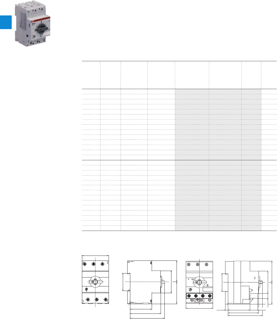
MS325 manual motor starters
0.10 to 25 A – with thermal and electromagnetic protection
Description
Manual motor starters (MMS) are protection devices for the main circuit. They combine motor control and
protection in a single device. MMS are used mainly to switch motors manually ON/OFF and protect them and
the installation fuse less against short-circuit, overload and phase failures. Fuse less protection with a manual
motor starter saves costs, space and ensures a quick reaction under short-circuit condition, by switching off
the motor within milliseconds.
MS325 is a compact and powerful range for motor protection up to 12.5 kW (400 V) / 25 A in width of 54 mm.
Further features are the build-in disconnect function, temperature compensation, trip-free mechanism and
a rotary handle with a clear switch position indication. The manual motor starters are suitable for three-
and single-phase applications. Auxiliary contacts, signalling contacts, undervoltage releases, shunt trips,
three-phase busbars, power in-feed blocks are available as accessories.
Ordering details
Rated
operational
power
400 V
AC-3
Setting
range
Short-circuit
breaking
capacity I
CS
at
400 V AC
Rated instan-
taneous short-
circuit current
setting l
i
Type Order code Weight
(1 pce)
kW A kA A kg
0.03 0.10 … 0.16 100 1.56 MS325-0.16 1SAM150000R1001 0.280
0.06 0.16 … 0.25 100 2.44 MS325-0.25 1SAM150000R1002 0.280
0.09 0.25 … 0.40 100 3.9 MS325-0.4 1SAM150000R1003 0.280
0.12 0.40 … 0.63 100 6.14 MS325-0.63 1SAM150000R1004 0.280
0.25 0.63 … 1.00 100 11.5 MS325-1 1SAM150000R1005 0.310
0.55 1.00 … 1.60 100 18.4 MS325-1.6 1SAM150000R1006 0.340
0.75 1.60 … 2.50 100 28.75 MS325-2.5 1SAM150000R1007 0.340
1.5 2.50 … 4.00 100 50 MS325-4 1SAM150000R1008 0.340
2.2 4.00 … 6.30 100 78.75 MS325-6.3 1SAM150000R1009 0.340
4.0 6.30 … 9.00 100 135 MS325-9 1SAM150000R1010 0.340
5.5 9.00 … 12.5 75 180 MS325-12.5 1SAM150000R1011 0.340
7.5 12.5 … 16.0 60 240 MS325-16 1SAM150000R1012 0.340
9.0 16.0 … 20.0 55 300 MS325-20 1SAM150000R1013 0.340
12.5 20.0 … 25.0 50 375 MS325-25 1SAM150000R1014 0.340
0.03 0.10 … 0.16 100 1.56 MS325-0.16-HKF11 1SAM150005R0001 0.300
0.06 0.16 … 0.25 100 2.44 MS325-0.25-HKF11 1SAM150005R0002 0.300
0.09 0.25 … 0.40 100 3.9 MS325-0.4-HKF11 1SAM150005R0003 0.300
0.12 0.40 … 0.63 100 6.14 MS325-0.63-HKF11 1SAM150005R0004 0.300
0.25 0.63 … 1.00 100 11.5 MS325-1-HKF11 1SAM150005R0005 0.330
0.55 1.00 … 1.60 100 18.4 MS325-1.6-HKF11 1SAM150005R0006 0.360
0.75 1.60 … 2.50 100 28.75 MS325-2.5-HKF11 1SAM150005R0007 0.360
1.5 2.50 … 4.00 100 50 MS325-4-HKF11 1SAM150005R0008 0.360
2.2 4.00 … 6.30 100 78.75 MS325-6.3-HKF11 1SAM150005R0009 0.360
4.0 6.30 … 9.00 100 135 MS325-9-HKF11 1SAM150005R0010 0.360
5.5 9.00 … 12.5 75 180 MS325-12.5-HKF11 1SAM150005R0011 0.360
7.5 12.5 … 16.0 60 240 MS325-16-HKF11 1SAM150005R0012 0.360
9.0 16.0 … 20.0 55 300 MS325-20-HKF11 1SAM150005R0013 0.360
12.5 20.0 … 25.0 50 375 MS325-25-HKF11 1SAM150005R0014 0.360
Main dimensions mm, inches
54
45
4344.5
44
62
70
35
1.77"
1.69"1.75"
1.38"
2.13"
1.73"
2.44"
2.76"
2CDC242010F0011
HKF
-11
4344.5
45
10.5
54
44 16
62
69.5
5.5
35
.63"
.41"
2.44"
2.74"
1.75"
1.73"
1.77"
1.69"
2.13"
.22"
2CDC242017F0011
MS325 MS325 + HKF11
2CDC241500F0009
MS325-16
2/40 | ABB
2
2CDC131041C0201

MS325 manual motor starters
Technical data
Main circuit – Utilization characteristics according to IEC/EN
Type MS325
Standards
IEC/EN 60947–2, IEC/EN 60947-4-1, IEC/EN 60947-1
Rated operational voltage U
e
690 V AC / 440 V DC
Rated frequency
50/60 Hz
Trip class
10A
Number of poles
3
Duty time
100 %
Rated impulse withstand voltage U
imp
6 kV
Rated insulation voltage U
i
690 V AC
Rated operational current I
e
See ordering details
Rated instantaneous short-circuit current setting I
i
See ordering details
Rated service short-circuit breaking capacity I
cs
See table "Short-circuit breaking capacity and back-up fuses"
Rated ultimate short-circuit breaking capacity I
cu
See table "Short-circuit breaking capacity and back-up fuses"
Short-circuit breaking capacity and back-up fuses
lCS Rated service short-circuit breaking capacity
lCU Rated ultimate short-circuit breaking capacity
ICC Prospective short-circuit current at installation location
Note: Maximum rated current of the back-up fuses if ICC > ICS
Type 230 V AC 400 V AC 440 V AC 500 V AC 690 V AC
I
CS
kA
I
CU
kA
gG, aM
A
I
CS
kA
I
CU
kA
gG, aM
A
I
CS
kA
I
CU
kA
gG, aM
A
I
CS
kA
I
CU
kA
gG, aM
A
I
CS
kA
I
CU
kA
gG, aM
A
MS325-0.16
No back-up fuse required up to
ICC = 100 kA
MS325-0.25
MS325-0.4
MS325-0.63
MS325-1
MS325-1.6
MS325-2.5 40 40 25
MS325-4 60 60 40 10 10 40
MS325-6.3 70 70 50 40 40 50 7 7 40
MS325-9 50 50 80 30 30 80 5 5 50
MS325-12.5 75 75 80 45 45 80 27 27 80 4.5 4.5 50
MS325-16 60 60 100 40 40 100 25 25 100 4 4 50
MS325-20 55 55 100 35 35 100 22 22 100 3.5 3.5 50
MS325-25 50 50 125 30 30 125 20 20 125 3 3 50
MS325-9: No need for back-up fuse in networks with a prospective current of up to 100 kA at 400 V.
MS325-16: No need for back-up fuse in networks with a prospective current of up to 60 kA at 400 V.
With an approbiate 100 A type gG fuse the device can be used in a network with a prospective current of up to 100 kA
ABB | 2/41
2
2CDC131041C0201
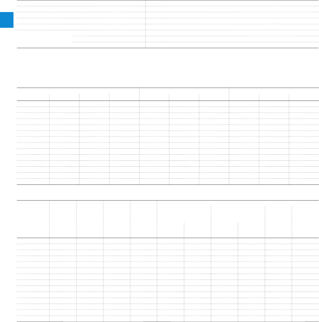
MS325 manual motor starters
Technical data
Main circuit – Utilization characteristics according to UL/CSA
Type MS325
Standards
UL 508, CSA 22.2 No. 14
Maximum operational voltage
600 V AC
Manual motor controller ratings
See table "UL 508 – Manual motor controller"
Trip rating
125 % FLA
Motor ratings
Horse power
See table "Motor rating, three phase"
Full load amps (FLA)
See table "Motor rating, three phase"
Locked rotor amps (LRA)
See table "Motor rating, three phase"
Motor rating, three phase
hp Horse power
FLA Full load amps
LRA Locked rotor amps
Type 220-240 V AC 440-480 V AC 500-600 V AC
hp FLA LRA hp FLA LRA hp FLA LRA
MS325-0.16
- 0.16 0.96 - 0.16 0.96 - 0.16 0.96
MS325-0.25
- 0.25 1.5 - 0.25 1.5 - 0.25 1.5
MS325-0.4
- 0.4 2.4 - 0.4 2.4 - 0.4 2.4
MS325-0.63
- 0.63 3.78 - 0.63 3.78 - 0.63 3.78
MS325-1
- 1.0 6.0 1/2 1.1 10.0 1/2 0.9 8.0
MS325-1.6
- 1.6 9.6 3/4 1.6 12.5 3/4 1.3 10.0
MS325-2.5
1/2 2.2 20.0 1 2.1 15.0 1-1/2 2.4 16.0
MS325-4
1 4.2 30.0 2 3.4 25.0 3 3.9 25.6
MS325-6.3
1-1/2 6.0 40.0 3 4.8 32.0 5 6.1 36.8
MS325-9
2-1/2 5 7.6 46.0 7-1/2 9.0 50.8
MS325-12.5
3 9.6 64.0 7-1/2 11.0 63.5 10 11.0 64.8
MS325-16
5 15.2 92.0 10 14.0 81.0 10 11.0 64.8
MS325-20
5 15.2 92.0 10 14.0 81.0 15 27.0 93.0
MS325-25
7-1/2 22.0 127.0 15 21.0 116.0 20 35.0 116.0
UL 508 – Manual motor controller
Type Max. Circuit
Breaker UL/
NEC
Max. Circuit
Breaker UL/
NEC
Max. fuse type
UL/NEC
Maximum fuse
type K5 o.
RK5 per UL/
NEC
Maximum short-circuit current
for motor disconnect
1)
for group installation for Tap
Conductor
Protection
UL 508
Type E
480 V 600 V 480 V 600 V 480 V 600 V 480 V 600 V 480Y/277V 480Y/277V
A A kAkAkAkAkAkA
MS325-0.16
- S7H1200 1600 (class L) 1200 85 50 85 50 18 18
MS325-0.25
- S7H1200 1600 (class L) 1200 85 50 85 50 18 18
MS325-0.4
- S7H1200 1600 (class L) 1200 85 50 85 50 18 18
MS325-0.63
- S7H1200 1600 (class L) 1200 85 50 85 50 18 18
MS325-1
- S7H1200 1600 (class L) 1200 85 50 85 50 18 18
MS325-1.6
- S7H1200 1600 (class L) 1200 85 50 85 50 18 18
MS325-2.5
- S7H1200 1600 (class L) 1200 85 50 85 50 18 18
MS325-4
- S7H1200 1600 (class L) 1200 85 50 85 50 18 18
MS325-6.3
S7H1200 S7H1200 600 (class K5) 1200 50 50 50 50 18 18
MS325-9
S7H1200 S4H2500 600 (class K5) 250 50 50 50 50 18 18
MS325-12.5
S4H250 S7H1200 400 (class K5) 1200 50 30 50 30 18 18
MS325-16
S4H250 S7H1200 400 (class K5) 1200 50 30 50 30 18 18
MS325-20
S4H250 S4H250 400 (class K5) 250 50 30 50 30 18 18
MS325-25
S4H250 S4H250 400 (class K5) 250 50 30 50 30 18 18
1) Suitable as motor disconnect only when provided with padlock SA1 or SA3...
2/42 | ABB
2
2CDC131041C0201

MS325 manual motor starters
Technical data
General technical data
Type MS325
Pollution degree
3
Phase loss sensitive
Yes
Ambient air temperature
Operation Open - compensated without derating
-25 ... +70 °C
Open
-25 ... +70 °C
Enclosed (IB325)
0 ... +40 °C
Storage
-50 ... +80 °C
Ambient air temperature compensation
Continuous
Maximum operating altitude permissible
2000 m
Resistance to shock acc. to IEC 60068-2-27
15 g / 1/2 sinusoidal shock for 11 ms
Resistance to vibrations acc. to IEC 60068-2-6
5 g / 3 ... 150 Hz
Mounting position
Position 1-6 (optional for single mounting)
Mounting
DIN-rail (EN 60715)
Minimum distance to other
units same type
Horizontal
0 mm
Vertical
100 mm
Minimum distance to
electrical conductive board
Horizontal, up to 400 V
> 1.5 mm
Horizontal, up to 690 V
> 1.5 mm
Vertical
75 mm
Degree of protection
Enclosure / terminals
IP20
Connecting characteristics
Main circuit
Type MS325
Connecting capacity
Solid
1 x
2 x
1 x 1 ... 10 mm²
2 x 1 ... 6 mm²
Flexible
1 x
2 x
1 x 1 ... 6 mm²
2 x 0.75 ... 4 mm²
Stranded acc. to UL/CSA
1 or 2 x
AWG 14-8
Flexible acc. to UL/CSA
1 or 2 x
AWG 14-8
Stripping length
10 mm
Tightening torques
1.4 Nm / 14 Ib.in
Connection screw
M3.5 (Pozidriv 2)
ABB | 2/43
2
2CDC131041C0201

MS325 manual motor starters
Main accessories
Description
Three-phase busbars ensure a quick and safe connection and are therefore a cost effective solution.
A variety of different three-phase busbars up to 63 A are in the assortment. Between 2 and 5 manual mo-
tor starters with none, one or two lateral auxiliary contacts can be connected. Different three-phase feeder
terminals are available according to the application.
Ordering details
Rated operational
current
Number of MMS Number of lateral
aux.
Type Order code Pkg
qty
Weight
(1 pce)
A kg
Three-phase busbars
63 2 0 PS3-2-0 1SAM101937R0012 10 0.038
63 3 0 PS3-3-0 1SAM101937R0013 10 0.062
63 4 0 PS3-4-0 1SAM101937R0014 10 0.087
63 5 0 PS3-5-0 1SAM101937R0015 10 0.115
63 6 0 PS3-6-0 1SAM101937R0016 10 0.137
63 2 1 PS3-2-1 1SAM101937R0022 10 0.040
63 3 1 PS3-3-1 1SAM101937R0023 10 0.068
63 4 1 PS3-4-1 1SAM101937R0024 10 0.097
63 5 1 PS3-5-1 1SAM101937R0025 10 0.126
63 3 2 PS3-2-2 1SAM101937R0032 10 0.043
63 4 2 PS3-4-2 1SAM101937R0034 10 0.106
Rated operational
current
Rated cross
section
Mounting form Type Order code Pkg
qty
Weight
(1 pce)
A mm² kg
Three-phase feeder terminals
63 25 Flat S3-M1 1SAM101938R0001 10 0.041
63 25 High S3-M2 1SAM101938R0002 10 0.053
63 35 UL type E and IEC S3-M3 1SAM101938R0004 10 0.050
Description Type Order code Pkg
qty
Weight
(1 pce)
kg
Protection cover for busbars BS3-3 1SAM101938R0003 50 0.001
Lock handle SA1 GJF1101903R0001 10 0.003
Padlock SA2 GJF1101903R0002 10 0.020
Lock handle box SA1/SA2 SA3 GJF1101903R0003 10 0.050
SA1
SK0109B91
SA2
SK0110B91
SA3
SK0108B91
2/44 | ABB
2
2CDC131041C0201
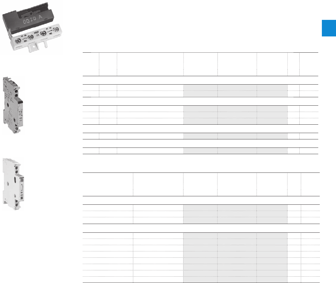
MS325 manual motor starters
Main accessories
Description
MS325 manual motor starters can be equipped with auxiliary contacts for lateral/front mounting, signalling
contact for lateral mounting, undervoltage release and shunt trips. A variety of combinations is possible as
required for the application. The auxiliary contacts change position with the main contacts. The signalling
contact signals tripping regardless if it was caused by short-circuit or overload. Undervoltage release are
used for remote tripping of the manual motor starter especially for emergency stop circuits. Shunt trips
release the MMS used for remote tripping
Ordering details
Auxiliary
contacts
N.O.
Auxiliary
contacts
N.C.
Description Type Order code Pkg
qty
Weight
(1 pce)
kg
Auxiliary contacts – mountable on the front
1 1 HKF-11 1SAM101928R0001 10 0.015
2 0 HKF-20 1SAM101928R0002 10 0.020
Auxiliary contacts – mountable on the left
1 1 Max. 2 pieces HK-11 1SAM101901R0001 2 0.030
2 0 Max. 2 pieces HK-20 1SAM101901R0002 2 0.030
0 2 Max. 2 pieces HK-02 1SAM101901R0003 2 0.030
Signalling contacts – mountable on the left
1 1 For tripped alarm, max. 1 pieces SK-11 1SAM101904R0003 10 0.030
Signalling contacts – mountable on the right
1 1 For short-circuit alarm CK-11 1SAM101943R0001 10 0.035
Rated control supply
voltage
Frequency Type Order code Pkg
qty
Weight
(1 pce)
VHz kg
Shunt trip units – mountable as slide in
24 ... 60 50/60 AA-24 1SAM101909R0001 10 0.025
110 ... 240 50/60 AA-230 1SAM101909R0002 10 0.025
220 ... 415 50/60 AA-400 1SAM101909R0003 10 0.025
Undervoltage releases – mountable as slide in
24 50 UAF-24 1SAM101903R0024 10 0.02
48 50 UAF-48 1SAM101903R0048 10 0.02
60 50 UAF-60 1SAM101903R0060 10 0.02
110 50 UAF-110 1SAM101903R0110 10 0.02
230 50 UAF-230 1SAM101903R0230 10 0.02
400 50 UAF-400 1SAM101903R0400 10 0.02
415 50 UAF-415 1SAM101903R0415 10 0.02
500 50 UAF-500 1SAM101903R0500 10 0.02
HKF
63-00
HK
SST 016 97
SK
SST 290 92 R
ABB | 2/45
2
2CDC131041C0201

MS325 manual motor starters
Main accessories
General technical data
Type PS3 S3-M1/S3-M2 S3-M3
Standards
IEC/EN 60947-2, IEC/EN 60947-4-1, IEC/EN 60947-1
Rated operational voltage U
e
690 V AC
Rated operational current I
e
63 A
Rated frequency
50/60 Hz
Rated impulse withstand voltage U
imp
6 kV
Rated insulation voltage U
i
690 V AC
Pollution degree
3
Cross-section
10 mm² 25 mm²
Ambient air temperature
Operation
-25 ... +70 °C
Storage
-50 ... +80 °C
Resistance to shock acc. to IEC 60068-2-27
15 g / 11 ms
Resistance to vibrations acc. to IEC 60068-2-6
3 g / 3 ... 150 Hz
Electrical connection
Main circuit
Type PS3, S3-Mx
Connecting capacity
Solid
1 x
6 ... 25 mm²
Flexible
1 x
6 ... 16 mm²
Stranded acc. to UL/CSA
1 x
AWG 10-4
Flexible acc. to UL/CSA
1 x
AWG 10-6
Stripping length
10 mm
Tightening torques
2.5 Nm / 22 Ib.in
Connection screw
PZ2 (6 mm)
2/46 | ABB
2
2CDC131041C0201
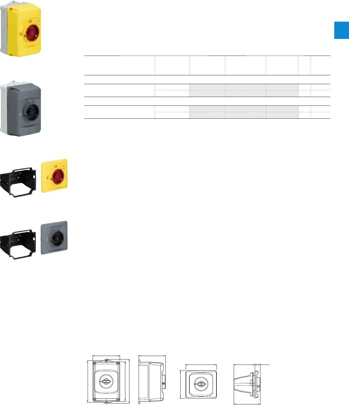
MS325 manual motor starters
Main accessories
Description
IB325 are IP65 enclosures for single MMS installation. Additional mounting of auxiliary and signalling con-
tacts, shunt trips and undervoltage release is possible. The handle is lockable in OFF position. For detailed
specification see installation instruction.
DMS325 are IP65 door mounting kits for MMS installation in any enclosure. Additional mounting of aux-
iliary, signalling, shunt trips and undervoltage release is possible. The handle is lockable in OFF position.
For detailed specification see installation instruction.
Ordering details
Description Color Type Order code Pkg
qty
Weight
(1 pce)
kg
Enclosures IP65
Padlockable max. 3 padlocks with bail
diameter 4 ... 6.5 mm
Yellow/red IB325-G 1SAM101940R1000 1 0.370
Grey/black IB325-Y 1SAM101940R1001 1 0.370
Door mounting kit IP65
Padlockable max. 3 padlocks with bail
diameter 4 ... 6.5 mm
Yellow/red DMS325-G 1SAM101941R1000 1 0.170
Grey/black DMS325-Y 1SAM101941R1001 1 0.170
Indication I-O and ON-OFF
Main dimensions mm, inches
119 4.69"
I
ON
0
OFF
183 7.2"
174 6.85"
194 7.64"
118 4.65"
2CDC242011F0011
121 4.76"
135.7 5.34" 92 3.62" 24 .94"
116.15 4.57"
I
ON
0
OFF
2CDC242012F0011
IB325 DMS325
2CDC241004F0010
IB325-Y
2CDC241003F0010
IB325-G
2CDC241002F0010
DMS325-Y
2CDC241001F0010
DMS325-G
ABB | 2/47
2
2CDC131041C0201
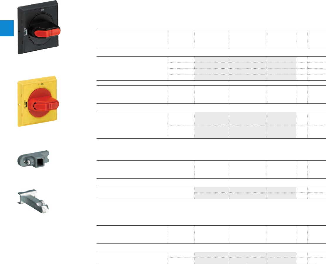
MS325 manual motor starters
Main accessories
Description
The complete set includes handle, shaft and driver. All accessories fit 6 mm shafts of maximum 180 mm
length. The degree of protection for handles MSHD is IP64.
Ordering details
Description Shaft length Type Order code Pkg
qty
Weight
(1 pce)
mm kg
Shafts
For selector type handles. Shaft diameter
6 mm. Shaft extension for door coupling
driver.
85 OXS6X85 1SCA101647R1001 1 0.020
105 OXS6X105 1SCA108043R1001 1 0.020
130 OXS6X130 1SCA101655R1001 1 0.030
180 OXS6X180 1SCA101659R1001 1 0.040
Description Color Type Order code Pkg
qty
Weight
(1 pce)
kg
Selector type handles IP64
Padlockable max. 3 padlocks with bail
diameter 5 … 8 mm, door interlock in ON
position defeatable, for use with 6 mm
OXS6…types up to 180 mm or driver
shafts MSOX.
Black MSHD-LB 1) 1SAM201920R1001 1 0.065
Yellow MSHD-LY 1SAM201920R1002 1 0.065
1) Indication I-O and ON-OFF
Description Type Order code Pkg
qty
Weight
(1 pce)
kg
Driver
Coupling driver for use with 6 mm OXS6… types up to
180 mm.
MSMN 1) 1SAM101923R0002 1 0.002
MSMNO 2) 1SAM101923R0012 1 0.002
1) Coded - Positioning of ON indication dependent from mounting orientation of the MS
2) Uncoded - Positioning of ON indication independent from mounting orientation of the MS
Description Shaft length Type Order code Pkg
qty
Weight
(1 pce)
mm kg
Driver shafts
Driver shaft - combination driver & shaft.
Shaft diameter 6 mm.
32 MSOX-32 1) 1SAM101924R0003 1 0.010
30 MSOX-30 2) 1SAM101924R0013 1 0.010
1) MSOX-32 is for normal vertical use
2) MSOX-30 is for horizontal use
2CDC241003F0011
MSHD-LB
2CDC241002F0011
MSHD-LY
MSMN
MSOX-30
2CDC241004S0011
2CDC241005S0011
2/48 | ABB
2
2CDC131041C0201
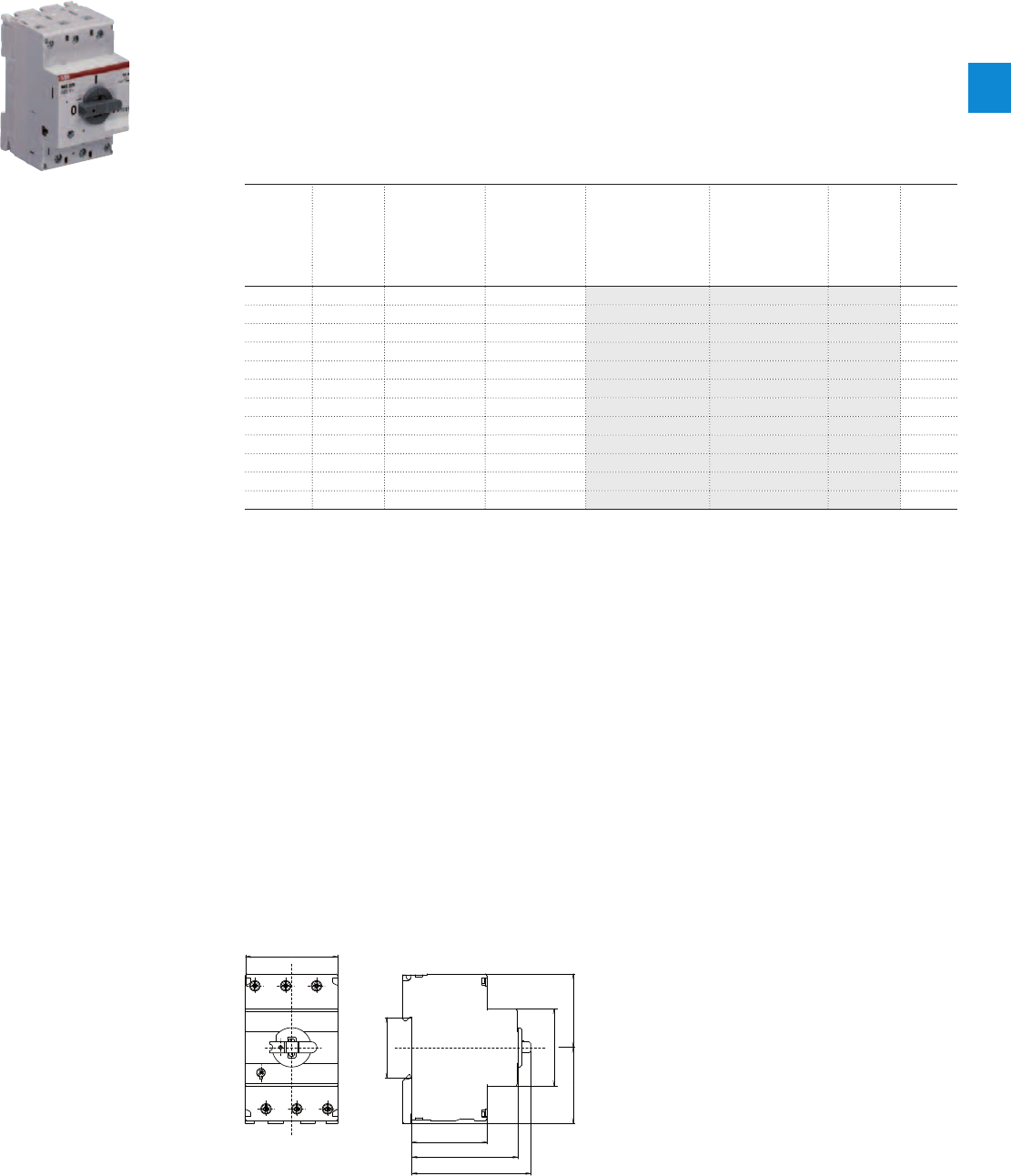
MO325 manual motor starters magnetic only
0.4 to 25 A – with electromagnetic protection
Description
The MO325 manual motor starters magnetic only are 54 mm width devices. These devices are used to
manually switch on and off motors and to protect them reliably and without the need for a fuse from short-
circuits.
Further features are the build-in disconnect function, trip-free mechanism and a rotary handle with a clear
switch position indication. The manual motor starter magnetic only is suitable for three- and single-phase
applications. Auxiliary contacts, signalling contacts, undervoltage releases, shunt trips, three-phase busbars,
power in-feed blocks are available as accessory.
Ordering details
Rated
operational
power
400 V
AC-3
1)
Rated
operational
current
Short-circuit
breaking
capacity I
CS
at
400 V AC
Rated instan-
taneous short-
circuit current
setting l
i
Type Order code Weight
(1 pce)
kW A kA A kg
0.09 0.40 100 3.9 MO325-0.4 1SAM160000R1003 0.280
0.12 0.63 100 6.14 MO325-0.63 1SAM160000R1004 0.280
0.25 1.0 100 11.5 MO325-1 1SAM160000R1005 0.310
0.55 1.6 100 18.4 MO325-1.6 1SAM160000R1006 0.340
0.75 2.5 100 28.75 MO325-2.5 1SAM160000R1007 0.340
1.5 4.0 100 50 MO325-4 1SAM160000R1008 0.340
2.2 6.3 100 78.75 MO325-6.3 1SAM160000R1009 0.340
4.0 9.0 100 135 MO325-9 1SAM160000R1010 0.340
5.5 12.5 75 180 MO325-12.5 1SAM160000R1011 0.340
7.5 16 60 240 MO325-16 1SAM160000R1012 0.340
9.0 20 55 300 MO325-20 1SAM160000R1013 0.340
12.5 25 50 375 MO325-25 1SAM160000R1014 0.340
1) For overload protection of motors, an appropriate thermal or electronic overload relay must be used
Main dimensions mm, inches
54
45
4344.5
44
62
70
35
1.77"
1.69"1.75"
1.38"
2.13"
1.73"
2.44"
2.76"
2CDC242010F0011
MO325
2CDC241003F0009
MO325-16
ABB | 2/49
2
2CDC131037C0201

MO325 manual motor starters magnetic only
Technical data
Main circuit – Utilization characteristics according to IEC/EN
Type MO325
Standards
IEC/EN 60947–2, IEC/EN 60947-4-1, IEC/EN 60947-1
Rated operational voltage U
e
690 V AC / 440 V DC
Rated frequency
50/60 Hz
Number of poles
3
Duty time
100 %
Rated impulse withstand voltage U
imp
6 kV
Rated insulation voltage U
i
690 V AC
Rated operational current I
e
See ordering details
Rated instantaneous short-circuit current setting I
i
See ordering details
Rated service short-circuit breaking capacity I
cs
See table "Short-circuit breaking capacity and back-up fuses"
Rated ultimate short-circuit breaking capacity I
cu
See table "Short-circuit breaking capacity and back-up fuses"
Short-circuit breaking capacity and back-up fuses
lCS Rated service short-circuit breaking capacity
lCU Rated ultimate short-circuit breaking capacity
ICC Prospective short-circuit current at installation location
Note: Maximum rated current of the back-up fuses if ICC > ICS
Type 230 V AC 400 V AC 440 V AC 500 V AC 690 V AC
I
CS
kA
I
CU
kA
gG, aM
A
I
CS
kA
I
CU
kA
gG, aM
A
I
CS
kA
I
CU
kA
gG, aM
A
I
CS
kA
I
CU
kA
gG, aM
A
I
CS
kA
I
CU
kA
gG, aM
A
MO325-0.4
No back-up fuse required up to
I
CC
= 100 kA
MO325-0.63
MO325-1
MO325-1.6
MO325-2.5
MO325-4
MO325-6.3
40 40 25
MO325-9
60 60 40 10 10 40
MO325-12.5
70 70 50 40 40 50 7 7 40
MO325-16
50 50 80 30 30 80 5 5 50
MO325-20
75 75 80 45 45 80 27 27 80 4.5 4.5 50
MO325-25
60 60 100 40 40 100 25 25 100 4 4 50
MO325-9: No need for back-up fuse in networks with a prospective current of up to 100 kA at 400 V.
MO325-16: No need for back-up fuse in networks with a prospective current of up to 60 kA at 400 V.
With an approbiate 100 A type gG fuse the device can be used in a network with a prospective current of up to 100 kA
2/50 | ABB
2
2CDC131037C0201

MO325 manual motor starters magnetic only
Technical data
General technical data
Type MO325
Pollution degree
3
Phase loss sensitive
Yes
Ambient air temperature
Operation Open - compensated without derating
-25 ... +70 °C
Open
-25 ... +70 °C
Enclosed (IB132)
0 ... +40 °C
Storage
-50 ... +80 °C
Ambient air temperature compensation
Continuous
Maximum operating altitude permissible
2000 m
Resistance to shock acc. to IEC 60068-2-27
15 g / 1/2 sinusoidal shock for 11 ms
Resistance to vibrations acc. to IEC 60068-2-6
5 g / 3 ... 150 Hz
Mounting position
Position 1-6 (optional for single mounting)
Group mounting
Minimum distance to other
units same type
Horizontal
0 mm
Vertical
100 mm
Minimum distance to
electrical conductive board
Horizontal, up to 400 V
> 1.5 mm
Horizontal, up to 690 V
> 1.5 mm
Vertical
75 mm
Degree of protection
Enclosure / terminals
IP20
Connecting characteristics
Main circuit
Type MO325
Connecting capacity
Solid
1 x
2 x
1 x 1 ... 10 mm²
2 x 1 ... 6 mm²
Flexible
1 x
2 x
1 x 1 ... 6 mm²
2 x 0.75 ... 4 mm²
Stranded acc. to UL/CSA
1 or 2 x
AWG 14-8
Flexible acc. to UL/CSA
1 or 2 x
AWG 14-8
Stripping length
10 mm
Tightening torques
1.4 Nm / 14 Ib.in
Connection screw
M3.5 (Pozidriv 2)
ABB | 2/51
2
2CDC131037C0201
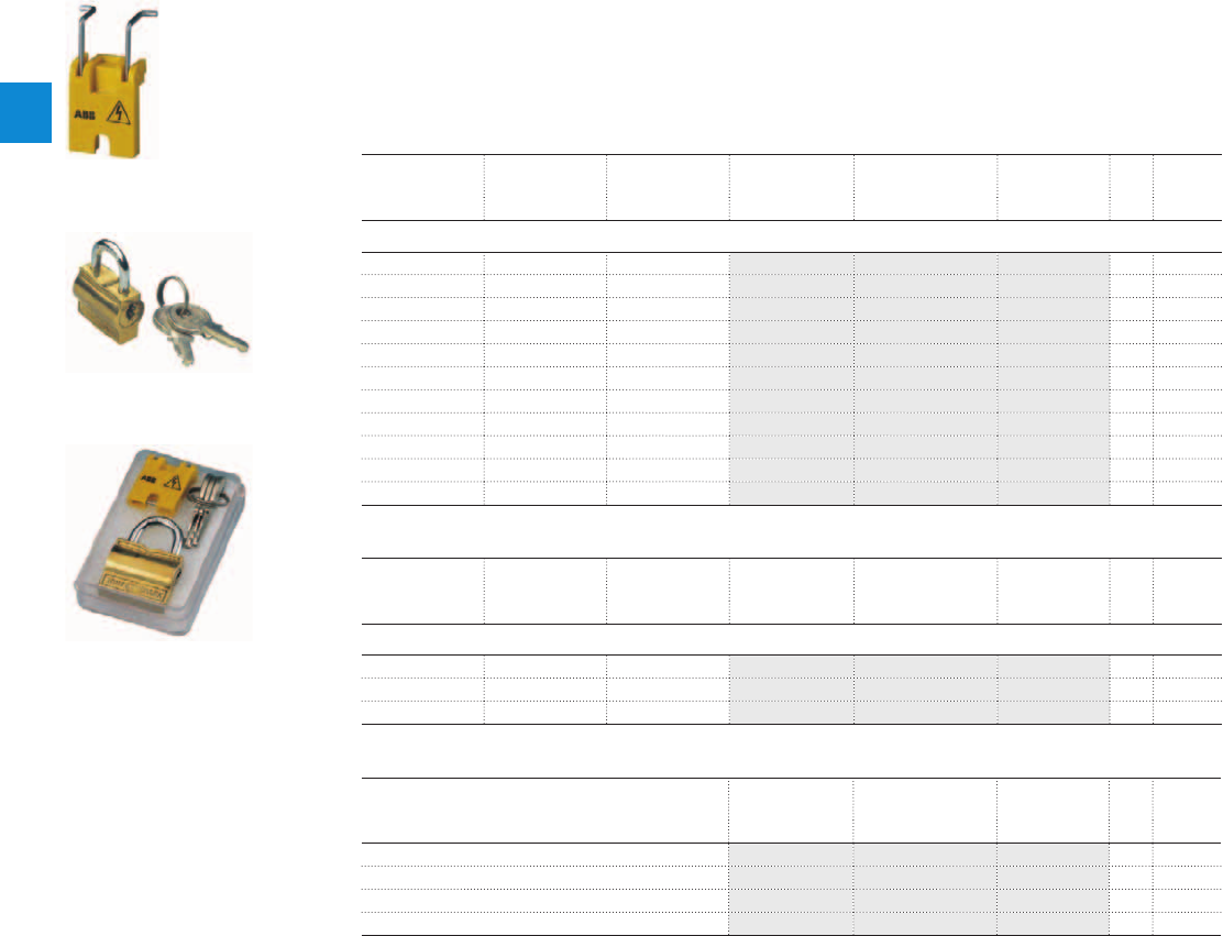
MO325 manual motor starters magnetic only
Main accessories
Description
Three-phase busbars ensure a quick and safe connection and are therefore a cost effective solution.
A variety of different three-phase busbars up to 63 A are in the assortment. Between 2 and 5 manual
motor starters with none, one or two lateral auxiliary contacts can be connected. Different three-phase
feeder terminals are available according to the application.
Ordering details
Rated operational
current
Number of MMS Number of lateral
aux.
Type Order code Pkg
qty
Weight
(1 pce)
A kg
Three-phase busbars
63 2 0 PS3-2-0 1SAM101937R0012 10 0.038
63 3 0 PS3-3-0 1SAM101937R0013 10 0.062
63 4 0 PS3-4-0 1SAM101937R0014 10 0.087
63 5 0 PS3-5-0 1SAM101937R0015 10 0.115
63 6 0 PS3-6-0 1SAM101937R0016 10 0.137
63 2 1 PS3-2-1 1SAM101937R0022 10 0.040
63 3 1 PS3-3-1 1SAM101937R0023 10 0.068
63 4 1 PS3-4-1 1SAM101937R0024 10 0.097
63 5 1 PS3-5-1 1SAM101937R0025 10 0.126
63 3 2 PS3-2-2 1SAM101937R0032 10 0.043
63 4 2 PS3-4-2 1SAM101937R0034 10 0.106
Rated operational
current
Rated cross
section
Mounting form Type Order code Pkg
qty
Weight
(1 pce)
A mm² kg
Three-phase feeder terminals
63 25 Flat S3-M1 1SAM101938R0001 10 0.041
63 25 High S3-M2 1SAM101938R0002 10 0.053
63 35 UL type E and IEC S3-M3 1SAM101938R0004 10 0.050
Description Type Order code Pkg
qty
Weight
(1 pce)
kg
Protection cover for busbars BS3-3 1SAM101938R0003 50 0.001
Lock handle SA1 GJF1101903R0001 10 0.003
Padlock SA2 GJF1101903R0002 10 0.020
Lock handle box SA1/SA2 SA3 GJF1101903R0003 10 0.050
SA1
SK0109B91
SA2
SK0110B91
SA3
SK0108B91
2/52 | ABB
2
2CDC131037C0201

MO325 manual motor starters magnetic only
Main accessories
Description
MS325 manual motor starters can be equipped with auxiliary contacts for lateral/front mounting, signalling
contact for lateral mounting, undervoltage release and shunt trips. A variety of combinations is possible as
required for the application. The auxiliary contacts change position with the main contacts. The signalling
contact signals tripping regardless if it was caused by short-circuit or overload. Undervoltage release are
used for remote tripping of the manual motor starter especially for emergency stop circuits. Shunt trips
release the MMS used for remote tripping
Ordering details
Auxiliary
contacts
N.O.
Auxiliary
contacts
N.C.
Description Type Order code Pkg
qty
Weight
(1 pce)
kg
Auxiliary contacts – mountable on the front
1 1 HKF-11 1SAM101928R0001 10 0.015
2 0 HKF-20 1SAM101928R0002 10 0.020
Auxiliary contacts – mountable on the left
1 1 Max. 2 pieces HK-11 1SAM101901R0001 2 0.030
2 0 Max. 2 pieces HK-20 1SAM101901R0002 2 0.030
0 2 Max. 2 pieces HK-02 1SAM101901R0003 2 0.030
Signalling contacts – mountable on the left
1 1 For tripped alarm, max. 1 pieces SK-11 1SAM101904R0003 10 0.030
Signalling contacts – mountable on the right
1 1 For short-circuit alarm CK-11 1SAM101943R0001 10 0.035
Rated control supply
voltage
Frequency Type Order code Pkg
qty
Weight
(1 pce)
VHz kg
Shunt trip units – mountable as slide in
24 ... 60 50/60 AA-24 1SAM101909R0001 10 0.025
110 ... 240 50/60 AA-230 1SAM101909R0002 10 0.025
220 ... 415 50/60 AA-400 1SAM101909R0003 10 0.025
Undervoltage releases – mountable as slide in
24 50 UAF-24 1SAM101903R0024 10 0.02
48 50 UAF-48 1SAM101903R0048 10 0.02
60 50 UAF-60 1SAM101903R0060 10 0.02
110 50 UAF-110 1SAM101903R0110 10 0.02
230 50 UAF-230 1SAM101903R0230 10 0.02
400 50 UAF-400 1SAM101903R0400 10 0.02
415 50 UAF-415 1SAM101903R0415 10 0.02
500 50 UAF-500 1SAM101903R0500 10 0.02
HKF
63-00
HK
SST 016 97
SK
SST 290 92 R
ABB | 2/53
2
2CDC131037C0201

MO325 manual motor starters magnetic only
Main accessories
General technical data
Type PS3 S3-M1/S3-M2 S3-M3
Standards
IEC/EN 60947-2, IEC/EN 60947-4-1, IEC/EN 60947-1
Rated operational voltage U
e
690 V AC
Rated operational current I
e
63 A
Rated frequency
50/60 Hz
Rated impulse withstand voltage U
imp
6 kV
Rated insulation voltage U
i
690 V AC
Pollution degree
3
Cross-section
10 mm² 25 mm²
Ambient air temperature
Operation
-25 ... +70 °C
Storage
-50 ... +80 °C
Resistance to shock acc. to IEC 60068-2-27
15 g / 11 ms
Resistance to vibrations acc. to IEC 60068-2-6
3 g / 3 ... 150 Hz
Electrical connection
Main circuit
Type PS3, S3-Mx
Connecting capacity
Solid
1 x
6 ... 25 mm²
Flexible
1 x
6 ... 16 mm²
Stranded acc. to UL/CSA
1 x
AWG 10-4
Flexible acc. to UL/CSA
1 x
AWG 10-6
Stripping length
10 mm
Tightening torques
2.5 Nm / 22 Ib.in
Connection screw
PZ2 (6 mm)
2/54 | ABB
2
2CDC131037C0201
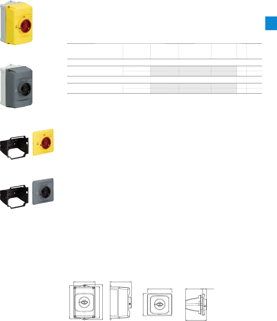
MO325 manual motor starters magnetic only
Main accessories
Description
IB325 are IP65 enclosures for single MMS installation. Additional mounting of auxiliary and signalling con-
tacts, shunt trips and undervoltage release is possible. The handle is lockable in OFF position. For detailed
specification see installation instruction.
DMS325 are IP65 door mounting kits for MMS installation in any enclosure. Additional mounting of aux-
iliary, signalling, shunt trips and undervoltage release is possible. The handle is lockable in OFF position.
For detailed specification see installation instruction.
Ordering details
Description Color Type Order code Pkg
qty
Weight
(1 pce)
kg
Enclosures IP65
Padlockable max. 3 padlocks with bail
diameter 4 ... 6.5 mm
Yellow/red IB325-G 1SAM101940R1000 1 0.370
Grey/black IB325-Y 1SAM101940R1001 1 0.370
Door mounting kit IP65
Padlockable max. 3 padlocks with bail
diameter 4 ... 6.5 mm
Yellow/red DMS325-G 1SAM101941R1000 1 0.170
Grey/black DMS325-Y 1SAM101941R1001 1 0.170
Indication I-O and ON-OFF
Main dimensions mm, inches
119 4.69"
I
ON
0
OFF
183 7.2"
174 6.85"
194 7.64"
118 4.65"
2CDC242011F0011
121 4.76"
135.7 5.34" 92 3.62" 24 .94"
116.15 4.57"
I
ON
0
OFF
2CDC242012F0011
IB325 DMS325
2CDC241004F0010
IB325-Y
2CDC241003F0010
IB325-G
2CDC241002F0010
DMS325-Y
2CDC241001F0010
DMS325-G
ABB | 2/55
2
2CDC131037C0201
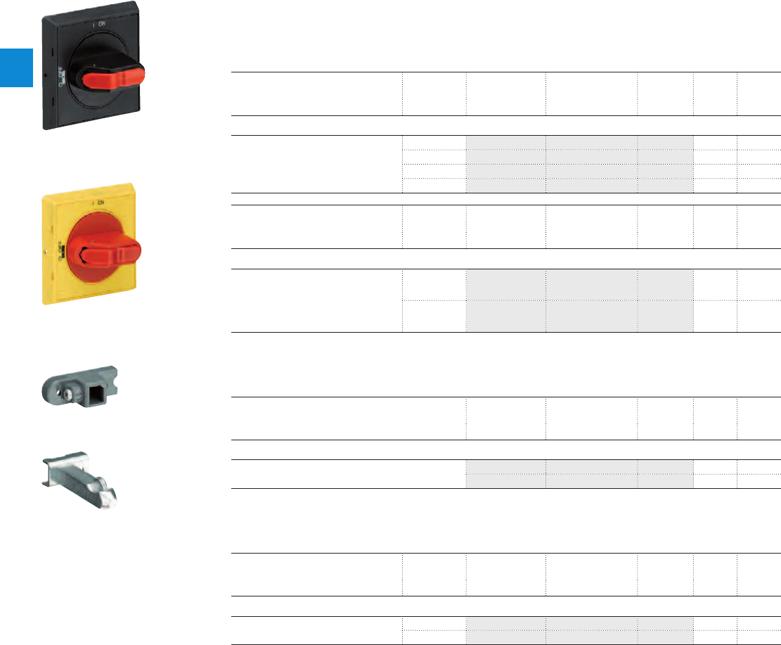
Description
The complete set includes handle, shaft and driver. All accessories fit 6 mm shafts of maximum 180 mm
length. The degree of protection for handles MSHD is IP64.
Ordering details
Description Shaft length Type Order code Pkg
qty
Weight
(1 pce)
mm kg
Shafts
For selector type handles. Shaft diameter
6 mm. Shaft extension for door coupling
driver.
85 OXS6X85 1SCA101647R1001 1 0.020
105 OXS6X105 1SCA108043R1001 1 0.020
130 OXS6X130 1SCA101655R1001 1 0.030
180 OXS6X180 1SCA101659R1001 1 0.040
Description Color Type Order code Pkg
qty
Weight
(1 pce)
kg
Selector type handles IP64
Padlockable max. 3 padlocks with bail
diameter 5 … 8 mm, door interlock in ON
position defeatable, for use with 6 mm
OXS6…types up to 180 mm or driver
shafts MSOX.
Black MSHD-LB 1) 1SAM201920R1001 1 0.065
Yellow MSHD-LY 2) 1SAM201920R1002 1 0.065
1) Indication I-O and ON-OFF
2) Indication I-O-T and ON-OFF-T
Description Type Order code Pkg
qty
Weight
(1 pce)
kg
Driver
Coupling driver for use with 6 mm OXS6… types up to
180 mm.
MSMN 1) 1SAM101923R0002 1 0.002
MSMNO 2) 1SAM101923R0012 1 0.002
1) Coded - Positioning of ON indication dependent from mounting orientation of the MS
2) Uncoded - Positioning of ON indication independent from mounting orientation of the MS
Description Shaft length Type Order code Pkg
qty
Weight
(1 pce)
mm kg
Driver shafts
Driver shaft - combination driver & shaft.
Shaft diameter 6 mm.
32 MSOX-32 1) 1SAM101924R0003 1 0.010
30 MSOX-30 2) 1SAM101924R0013 1 0.010
1) MSOX-32 is for normal vertical use
2) MSOX-30 is for horizontal use
MO325 manual motor starters magnetic only
Main accessories
2CDC241003F0011
MSHD-LB
2CDC241002S0011
MSHD-LY
MSMN
MSOX-30
2CDC241004S0011
2CDC241005S0011
2/56 | ABB
2
2CDC131037C0201
ABB | 2/57
2
J1
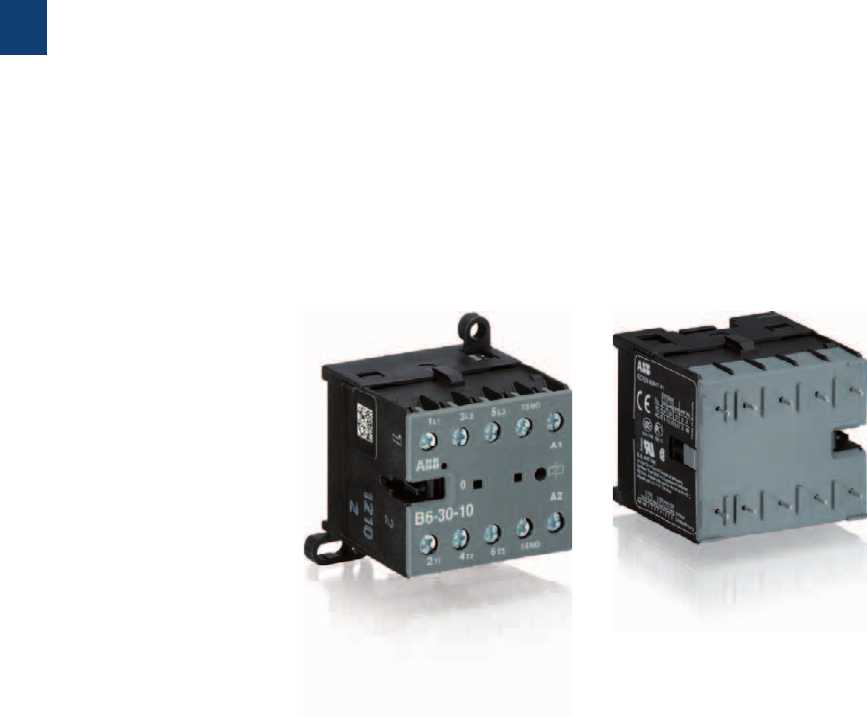
3/0 | ABB
3
Somm_Mini

B mini contactors
K mini contactor relays
With screw terminals
3-pole contactors
B6, B7 AC operated 3/2
BC6, BC7, B7D DC operated 3/3
3-pole reversing contactors
VB6, VB7 AC operated 3/4
VBC6, VBC7 DC operated 3/5
3-pole interface contactors
BC6, BC7 DC operated 3/6
3-pole contactors - large coil voltage range
TBC7 DC operated 3/7
4-pole contactors
B6, B7 AC operated 3/8
BC6, BC7 DC operated 3/9
4-pole contactors - large coil voltage range
TBC7 DC operated 3/10
Contactor relays
K6 AC operated 3/12
KC6 DC operated 3/13
Interface contactor relays
KC6 DC operated 3/14
Contactor relays - large coil voltage range
TKC6 DC operated 3/15
With soldering pins
3-pole contactors
B6, B7 AC operated 3/16
BC6, BC7 DC operated 3/17
3-pole reversing contactors
VB6, VB7 AC operated 3/18
VBC6, VBC7 DC operated 3/19
Contactor relays
K6 AC operated 3/20
KC6 DC operated 3/21
3-pole interface contactors
BC6, BC7 DC operated 3/22
Interface contactors relays
KC6 DC operated 3/23
Accessories 3/24
Technical data 3/26
ABB | 3/1
3
Somm_Mini
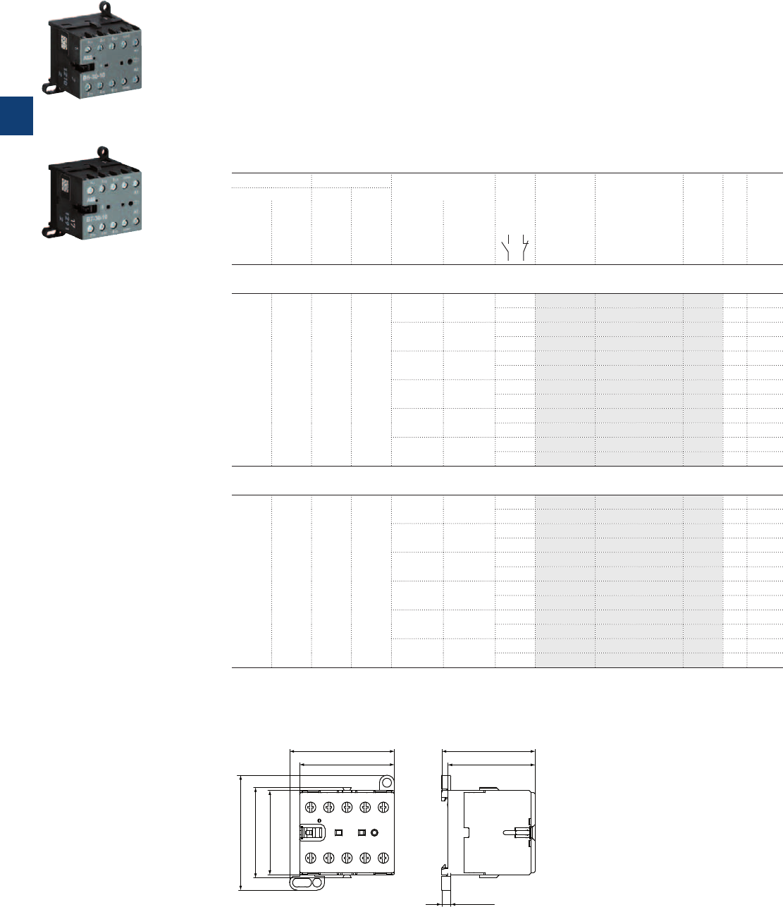
Description
B6, B7 3-pole mini contactors are compact control products mainly used for switching resistive or motor
loads up to 690 V AC.
These contactors are designed with:
– 3 main poles and one built-in auxiliary contact
– control circuit: AC operated, low coil consumption (3.5 VA at pull-in and at holding)
– add-on auxiliary contact blocks for front or side mounting and a wide range of accessories
– hum-free coil
– designed for rail or wall mounting
Ordering details
IEC UL/CSA Rated control circuit
voltage U
C
Auxiliary
contacts
fi tted
Type Order code
Pkg
qty
Weight
(1 pce)
Rated operational 3-phase
motor
rating
480 V
General
use
rating
600 V AC
power
400 V
AC-3
current
ș≤ 55 °C
AC-1
50 Hz 60 Hz
kW A hp A V AC V AC kg
B6 mini contactors
4 16 3 3.4 24 24 1 0 B6-30-10-01 GJL1211001R0101 10 0.175
0 1 B6-30-01-01 GJL1211001R0011 10 0.175
42 42 1 0 B6-30-10-02 GJL1211001R0102 10 0.175
0 1 B6-30-01-02 GJL1211001R0012 10 0.175
48 48 1 0 B6-30-10-03 GJL1211001R0103 10 0.175
0 1 B6-30-01-03 GJL1211001R0013 10 0.175
110 … 127 110 … 127 1 0 B6-30-10-84 GJL1211001R8104 10 0.175
0 1 B6-30-01-84 GJL1211001R8014 10 0.175
220 … 240 220 … 240 1 0 B6-30-10-80 GJL1211001R8100 10 0.175
0 1 B6-30-01-80 GJL1211001R8010 10 0.175
380 … 415 380 … 415 1 0 B6-30-10-85 GJL1211001R8105 10 0.175
0 1 B6-30-01-85 GJL1211001R8015 10 0.175
B7 mini contactors
5.5 20 5 7.6 24 24 1 0 B7-30-10-01 GJL1311001R0101 10 0.175
0 1 B7-30-01-01 GJL1311001R0011 10 0.175
42 42 1 0 B7-30-10-02 GJL1311001R0102 10 0.175
0 1 B7-30-01-02 GJL1311001R0012 10 0.175
48 48 1 0 B7-30-10-03 GJL1311001R0103 10 0.175
0 1 B7-30-01-03 GJL1311001R0013 10 0.175
110 … 127 110 … 127 1 0 B7-30-10-84 GJL1311001R8104 10 0.175
0 1 B7-30-01-84 GJL1311001R8014 10 0.175
220 … 240 220 … 240 1 0 B7-30-10-80 GJL1311001R8100 10 0.175
0 1 B7-30-01-80 GJL1311001R8010 10 0.175
380 … 415 380 … 415 1 0 B7-30-10-85 GJL1311001R8105 10 0.175
0 1 B7-30-01-85 GJL1311001R8015 10 0.175
Other types on request
Main dimensions mm, inches
47.5 1.87"
52.5 2.07"
57.5 2.26"
42.2 1.66"
45.2 1.78"
4.5 0.18"
43.7 1.72"
46.7 1.84"
2CDC212001F0011
B6, B7
2CDC211001F0010
B6-30-10
2CDC211014F0011
B7-30-10
B6, B7 3-pole mini contactors – with screw terminals
4 to 5.5 kW
AC operated
3/2 | ABB
3
2CDC102008C0201
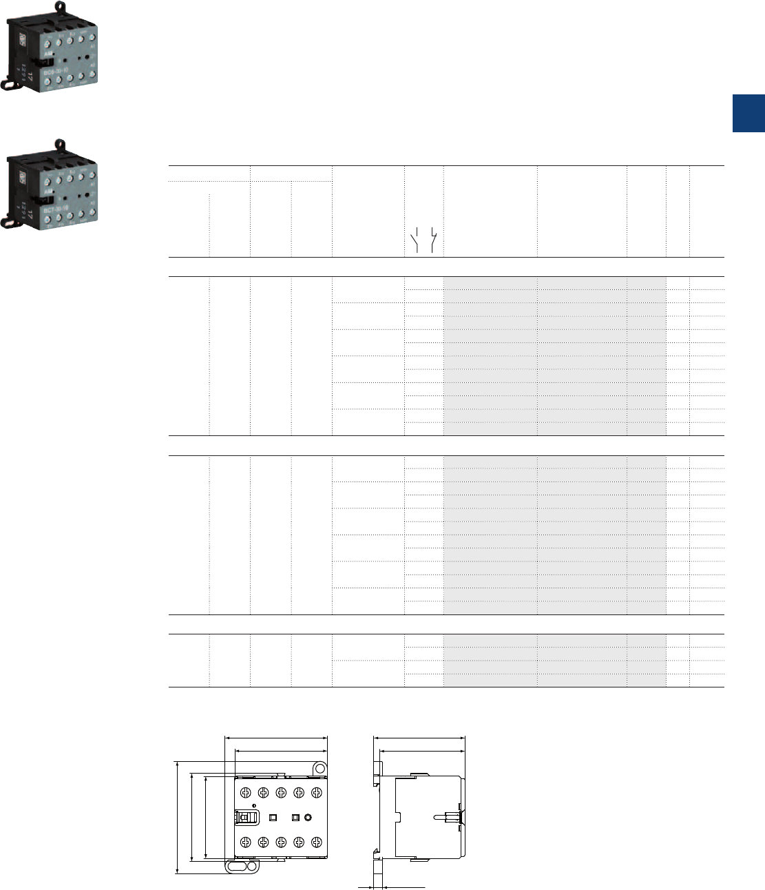
BC6, BC7, B7D 3-pole mini contactors – with screw terminals
4 to 5.5 kW
DC operated
Description
BC6, BC7, B7D 3-pole mini contactors are compact control products mainly used for switching resistive or
motor loads up to 690 V AC.
These contactors are designed with:
– 3 main poles and one built-in auxiliary contact
– control circuit: DC operated, low consumption (3.5 W at pull-in and at holding)
– hum-free coil
– add-on auxiliary contact blocks for front or side mounting and a wide range of accessories
– designed for rail or wall mounting
Ordering details
IEC UL/CSA Rated control
circuit voltage
U
C
Auxiliary
contacts
fitted
Type Order code
Pkg
qty
Weight
(1 pce)
Rated operational 3-phase
motor
rating
480 V
General
use
rating
600 V AC
power
400 V
AC-3
current
ș≤ 55 °C
AC-1
kW A hp A V DC kg
BC6 mini contactors
4 16 3 3.4 12 1 0 BC6-30-10-07 GJL1213001R0107 10 0.175
0 1 BC6-30-01-07 GJL1213001R0017 10 0.175
24 1 0 BC6-30-10-01 GJL1213001R0101 10 0.175
0 1 BC6-30-01-01 GJL1213001R0011 10 0.175
48 1 0 BC6-30-10-16 GJL1213001R1106 10 0.175
0 1 BC6-30-01-16 GJL1213001R1016 10 0.175
60 1 0 BC6-30-10-03 GJL1213001R0103 10 0.175
0 1 BC6-30-01-03 GJL1213001R0013 10 0.175
110 … 125 1 0 BC6-30-10-04 GJL1213001R0104 10 0.175
0 1 BC6-30-01-04 GJL1213001R0014 10 0.175
220 … 240 1 0 BC6-30-10-05 GJL1213001R0105 10 0.175
0 1 BC6-30-01-05 GJL1213001R0015 10 0.175
BC7 mini contactors
5.5 20 5 7.6 12 1 0 BC7-30-10-07 GJL1313001R0107 10 0.175
0 1 BC7-30-01-07 GJL1313001R0017 10 0.175
24 1 0 BC7-30-10-01 GJL1313001R0101 10 0.175
0 1 BC7-30-01-01 GJL1313001R0011 10 0.175
48 1 0 BC7-30-10-16 GJL1313001R1106 10 0.175
0 1 BC7-30-01-16 GJL1313001R1016 10 0.175
60 1 0 BC7-30-10-03 GJL1313001R1103 10 0.175
0 1 BC7-30-01-03 GJL1313001R0013 10 0.175
110 … 125 1 0 BC7-30-10-04 GJL1313001R0104 10 0.175
0 1 BC7-30-01-04 GJL1313001R0014 10 0.175
220 … 240 1 0 BC7-30-10-05 GJL1313001R0105 10 0.175
0 1 BC7-30-01-05 GJL1313001R0015 10 0.175
B7D mini contactors with integrated suppressor diode
5.5 20 5 7.6 24 1 0 B7D-30-10-01 GJL1317001R0101 10 0.175
0 1 B7D-30-01-01 GJL1317001R0011 10 0.175
220 1 0 B7D-30-10-05 GJL1317001R0105 10 0.175
0 1 B7D-30-01-05 GJL1317001R0015 10 0.175
Other types on request
Main dimensions mm, inches
47.5 1.87"
52.5 2.07"
57.5 2.26"
42.2 1.66"
45.2 1.78"
4.5 0.18"
43.7 1.72"
46.7 1.84"
2CDC212001F0011
BC6, BC7, B7D
2CDC211040F0011
BC6-30-10
2CDC211013F0011
BC7-30-10
ABB | 3/3
3
2CDC102015C0201

VB6, VB7 3-pole mini reversing contactors – with screw terminals
4 to 5.5 kW
AC operated
Description
VB6, VB7 3-pole compact design reversing contactors are space optimized control products mainly used
for switching resistive or motor loads up to 690 V AC.
These reversing contactors are designed with:
– built-in mechanical interlock. The coils must be mutually interlocked electrically and coils must be de-
energised for 50 ms at least to prevent phase to phase short circuit on the arc.
– control circuit: AC operated, low coil consumption (3.5 VA at pull-in and at holding)
– hum-free coil
– add-on auxiliary contact blocks for front mounting
– designed for rail or wall mounting
Ordering details
IEC UL/CSA Rated control circuit
voltage U
C
Auxiliary
contacts
fitted
Type Order code
Pkg
qty
Weight
(1 pce)
Rated operational 3-phase
motor
rating
480 V
General
use
rating
600 V AC
power
400 V
AC-3
current
ș≤ 55 °C
AC-1 50 Hz 60 Hz
kW A hp A V AC V AC kg
VB6 mini reversing contactors
4 16 3 3.4 24 24 1 0 VB6-30-10-01 GJL1211901R0101 5 0.355
0 1 VB6-30-01-01 GJL1211901R0011 5 0.355
42 42 1 0 VB6-30-10-02 GJL1211901R0102 5 0.355
0 1 VB6-30-01-02 GJL1211901R0012 5 0.355
48 48 1 0 VB6-30-10-03 GJL1211901R0103 5 0.355
0 1 VB6-30-01-03 GJL1211901R0013 5 0.355
110 … 127 110 … 127
1 0 VB6-30-10-84 GJL1211901R8104 5 0.355
0 1 VB6-30-01-84 GJL1211901R8014 5 0.355
220 … 240 220 … 240
1 0 VB6-30-10-80 GJL1211901R8100 5 0.355
0 1 VB6-30-01-80 GJL1211901R8010 5 0.355
380 … 415 380 … 415
1 0 VB6-30-10-85 GJL1211901R8105 5 0.355
0 1 VB6-30-01-85 GJL1211901R8015 5 0.355
VB7 mini reversing contactors
5.5 20 5 7.6 24 24 1 0 VB7-30-10-01 GJL1311901R0101 5 0.355
0 1 VB7-30-01-01 GJL1311901R0011 5 0.355
42 42 1 0 VB7-30-10-02 GJL1311901R0102 5 0.355
0 1 VB7-30-01-02 GJL1311901R0012 5 0.355
48 48 1 0 VB7-30-10-03 GJL1311901R0103 5 0.355
0 1 VB7-30-01-03 GJL1311901R0013 5 0.355
110 … 127 110 … 127
1 0 VB7-30-10-84 GJL1311901R8104 5 0.355
0 1 VB7-30-01-84 GJL1311901R8014 5 0.355
220 … 240 220 … 240
1 0 VB7-30-10-80 GJL1311901R8100 5 0.355
0 1 VB7-30-01-80 GJL1311901R8010 5 0.355
380 … 415 380 … 415
1 0 VB7-30-10-85 GJL1311901R8105 5 0.355
0 1 VB7-30-01-85 GJL1311901R8015 5 0.355
Other types on request
Main dimensions mm, inches
4.5 0.18"
43.7 1.72"
46.7 1.84"
96.2 3.79"
42.2 1.66"
45.2 1.78"
57.5 2.26"
2CDC212005F0011
VB6, VB7
2CDC211006F0011
VB7-30-10
3/4 | ABB
3
2CDC102016C0201
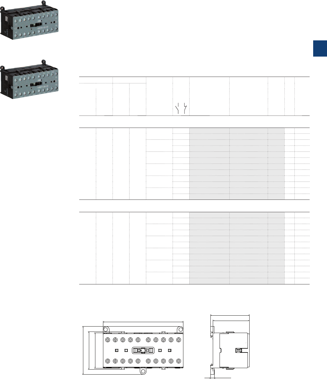
VBC6, VBC7 3-pole mini reversing contactors – with screw terminals
4 to 5.5 kW
DC operated
Description
VBC6, VBC7 3-pole compact design reversing contactors are space optimized control products mainly
used for switching resistive or motor loads up to 690 V AC.
These reversing contactors are designed with:
– built-in mechanical interlock. The coils must be mutually interlocked electrically and coils must be de-
energised for 50 ms at least to prevent phase to phase short circuit on the arc.
– control circuit: DC operated, low coil consumption (3.5 W at pull-in and at holding)
– hum-free coil
– add-on auxiliary contact blocks for front mounting
– designed for rail or wall mounting
Ordering details
IEC UL/CSA Rated control
circuit voltage
U
C
Auxiliary
contacts
fitted
Type Order code
Pkg
qty
Weight
(1 pce)
Rated operational 3-phase
motor
rating
480 V
General
use
rating
600 V AC
power
400 V
AC-3
current
ș≤ 55 °C
AC-1
kW A hp A V DC kg
VBC6 mini reversing contactors
4 16 3 3.4 12 1 0 VBC6-30-10-07 GJL1213901R0107 5 0.355
0 1 VBC6-30-01-07 GJL1213901R0017 5 0.355
24 1 0 VBC6-30-10-01 GJL1213901R0101 5 0.355
0 1 VBC6-30-01-01 GJL1213901R0011 5 0.355
48 1 0 VBC6-30-10-16 GJL1213901R1106 5 0.355
0 1 VBC6-30-01-16 GJL1213901R1016 5 0.355
60 1 0 VBC6-30-10-03 GJL1213901R0103 5 0.355
0 1 VBC6-30-01-03 GJL1213901R0013 5 0.355
110 ... 125 1 0 VBC6-30-10-04 GJL1213901R0104 5 0.355
0 1 VBC6-30-01-04 GJL1213901R0014 5 0.355
220 … 240 1 0 VBC6-30-10-05 GJL1213901R0105 5 0.355
0 1 VBC6-30-01-05 GJL1213901R0015 5 0.355
VBC7 mini reversing contactors
5.5 20 5 7.6 12 1 0 VBC7-30-10-07 GJL1313901R0107 5 0.355
0 1 VBC7-30-01-07 GJL1313901R0017 5 0.355
24 1 0 VBC7-30-10-01 GJL1313901R0101 5 0.355
0 1 VBC7-30-01-01 GJL1313901R0011 5 0.355
48 1 0 VBC7-30-10-16 GJL1313901R1106 5 0.355
0 1 VBC7-30-01-16 GJL1313901R1016 5 0.355
60 1 0 VBC7-30-10-03 GJL1313901R0103 5 0.355
0 1 VBC7-30-01-03 GJL1313901R0013 5 0.355
110 ... 125 1 0 VBC7-30-10-04 GJL1313901R0104 5 0.355
0 1 VBC7-30-01-04 GJL1313901R0014 5 0.355
220 … 240 1 0 VBC7-30-10-05 GJL1313901R0105 5 0.355
0 1 VBC7-30-01-05 GJL1313901R0015 5 0.355
Other types on request
Main dimensions mm, inches
4.5 0.18"
43.7 1.72"
46.7 1.84"
96.2 3.79"
42.2 1.66"
45.2 1.78"
57.5 2.26"
2CDC212005F0011
VBC6, VBC7
2CDC211042F0011
VBC6-30-10
2CDC211001F0011
VBC7-30-10
ABB | 3/5
3
2CDC102017C0201
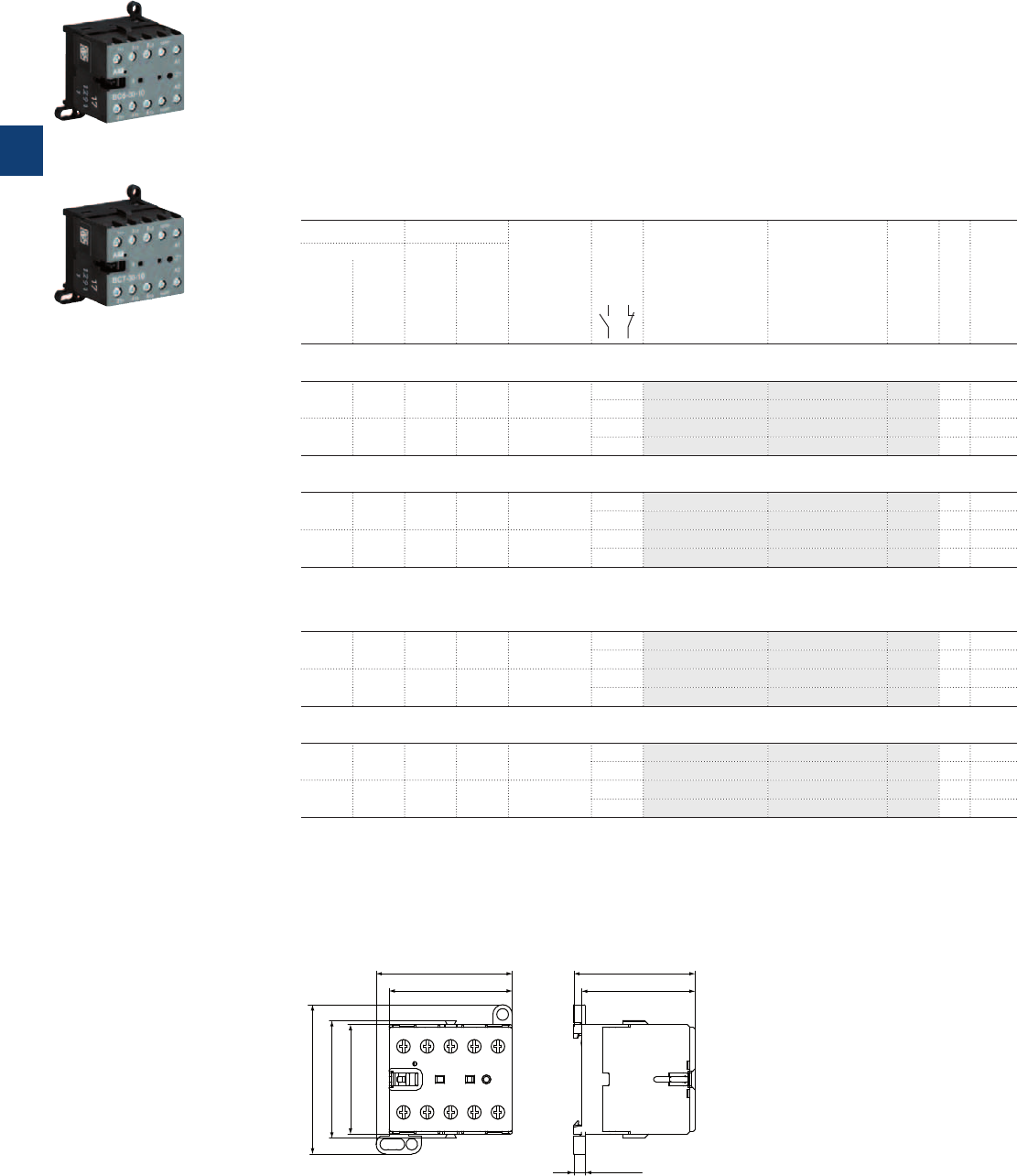
BC6, BC7 3-pole interface mini contactors – with screw terminals
4 to 5.5 kW
DC operated
Description
BC6, BC7 3-pole interface mini contactors are compact control products mainly used for switching
resistive or motor loads up to 690 V AC.
These contactors are designed with:
– 3 main poles and one built-in auxiliary contact
– control circuit: DC operated, very low coil consumption. Suitable for direct control by PLC outputs
– hum-free coil
– no auxiliary contact block permitted for mounting
– designed for rail or wall mounting
Ordering details
IEC UL/CSA Rated control
circuit voltage
U
C
Auxiliary
contacts
fitted
Type Order code
Pkg
qty
Weight
(1 pce)
Rated operational 3-phase
motor
rating
480 V
General
use
rating
600 V AC
power
400 V
AC-3
current
ș≤ 55 °C
AC-1
kW A hp A V DC kg
DC operation 24 V / 1.4 W
4 16 3 3.4 24 1 0 BC6-30-10-1.4-81 GJL1213001R8101 10 0.175
0 1 BC6-30-01-1.4-81 GJL1213001R8011 10 0.175
5.5 20 5 7.6 24 1 0 BC7-30-10-1.4-81 GJL1313001R8101 10 0.175
0 1 BC7-30-01-1.4-81 GJL1313001R8011 10 0.175
DC operation 17 … 32 V / 2.4 W
4 16 3 3.4 17 ... 32 (1) 1 0 BC6-30-10-2.4-51 GJL1213001R5101 10 0.175
0 1 BC6-30-01-2.4-51 GJL1213001R5011 10 0.175
5.5 20 5 7.6 17 ... 32 (1) 1 0 BC7-30-10-2.4-51 GJL1313001R5101 10 0.175
0 1 BC7-30-01-2.4-51 GJL1313001R5011 10 0.175
Connection to PLCs with integrated protective circuit
DC operation 24 V / 1.7 W
4 16 3 3.4 24 1 0 B6S-30-10-1.7-71 GJL1213001R7101 10 0.175
0 1 B6S-30-01-1.7-71 GJL1213001R7011 10 0.175
5.5 20 5 7.6 24 1 0 B7S-30-10-1.7-71 GJL1313001R7101 10 0.175
0 1 B7S-30-01-1.7-71 GJL1313001R7011 10 0.175
DC operation 17 … 32 V / 2.8 W
4 16 3 3.4 17 ... 32 (1) 1 0 B6S-30-10-2.8-72 GJL1213001R7102 10 0.175
0 1 B6S-30-01-2.8-72 GJL1213001R7012 10 0.175
5.5 20 5 7.6 17 ... 32 (1) 1 0 B7S-30-10-2.8-72 GJL1313001R7102 10 0.175
0 1 B7S-30-01-2.8-72 GJL1313001R7012 10 0.175
Other types on request
(1) Uc min. and Uc max. limit values, including the voltage variation tolerances (-15 % and +10 %).
Main dimensions mm, inches
47.5 1.87"
52.5 2.07"
57.5 2.26"
42.2 1.66"
45.2 1.78"
4.5 0.18"
43.7 1.72"
46.7 1.84"
2CDC212001F0011
BC6, BC7
2CDC211040F0011
BC6-30-10
2CDC211013F0011
BC7-30-10
3/6 | ABB
3
2CDC102010C0201
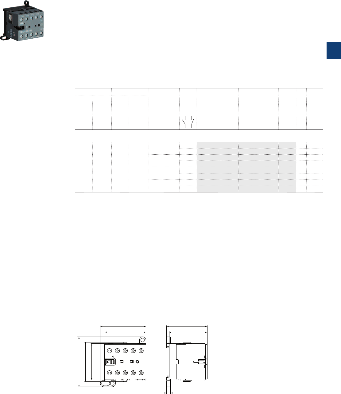
TBC7 3-pole mini contactors – with screw terminals
4 to 5.5 kW
DC operated – large coil voltage range
Description
TBC7 3-pole mini contactors are compact control products mainly used for switching resistive or motor loads
up to 690 V AC.
These contactors are designed with:
– 3 main poles and one built-in auxiliary contact
– control circuit: DC operated, low coil consumption (5 W at pull-in and at holding)
– hum-free coil
– expanded ambient temperature range -30 … +70 °C and wide range voltage supply
– no auxiliary contact block permitted for mounting
– designed for rail or wall mounting
– material is approved for railway applications
Ordering details
IEC UL/CSA Rated control
circuit voltage
U
Cmin
... U
Cmax
(1)
Auxiliary
contacts
fitted
Type Order code
Pkg
qty
Weight
(1 pce)
Rated operational 3-phase
motor
rating
480 V
General
use
rating
600 V AC
power
400 V
AC-3
current
ș≤ 55 °C
AC-1
kW A hp A V DC kg
TBC7 mini contactors
5.5 20 5 7.6 17 ... 32 1 0 TBC7-30-10-51 GJL1313061R5101 10 0.185
0 1 TBC7-30-01-51 GJL1313061R5011 10 0.185
50 ... 90 1 0 TBC7-30-10-55 GJL1313061R5105 10 0.185
0 1 TBC7-30-01-55 GJL1313061R5015 10 0.185
77 ... 143 1 0 TBC7-30-10-62 GJL1313061R6102 10 0.185
0 1 TBC7-30-01-62 GJL1313061R6012 10 0.185
140 ... 260 1 0 TBC7-30-10-68 GJL1313061R6108 10 0.185
0 1 TBC7-30-01-68 GJL1313061R6018 10 0.185
Other types on request
(1) Uc min. and Uc max. limit values, including the voltage variation tolerances (-15 % and +10 %).
Main dimensions mm, inches
47.5 1.87"
52.5 2.07"
57.5 2.26"
42.2 1.66"
45.2 1.78"
4.5 0.18"
43.7 1.72"
46.7 1.84"
2CDC212001F0011
TBC7
2CDC211015F0011
TBC7-30-10
ABB | 3/7
3
2CDC102020C0201
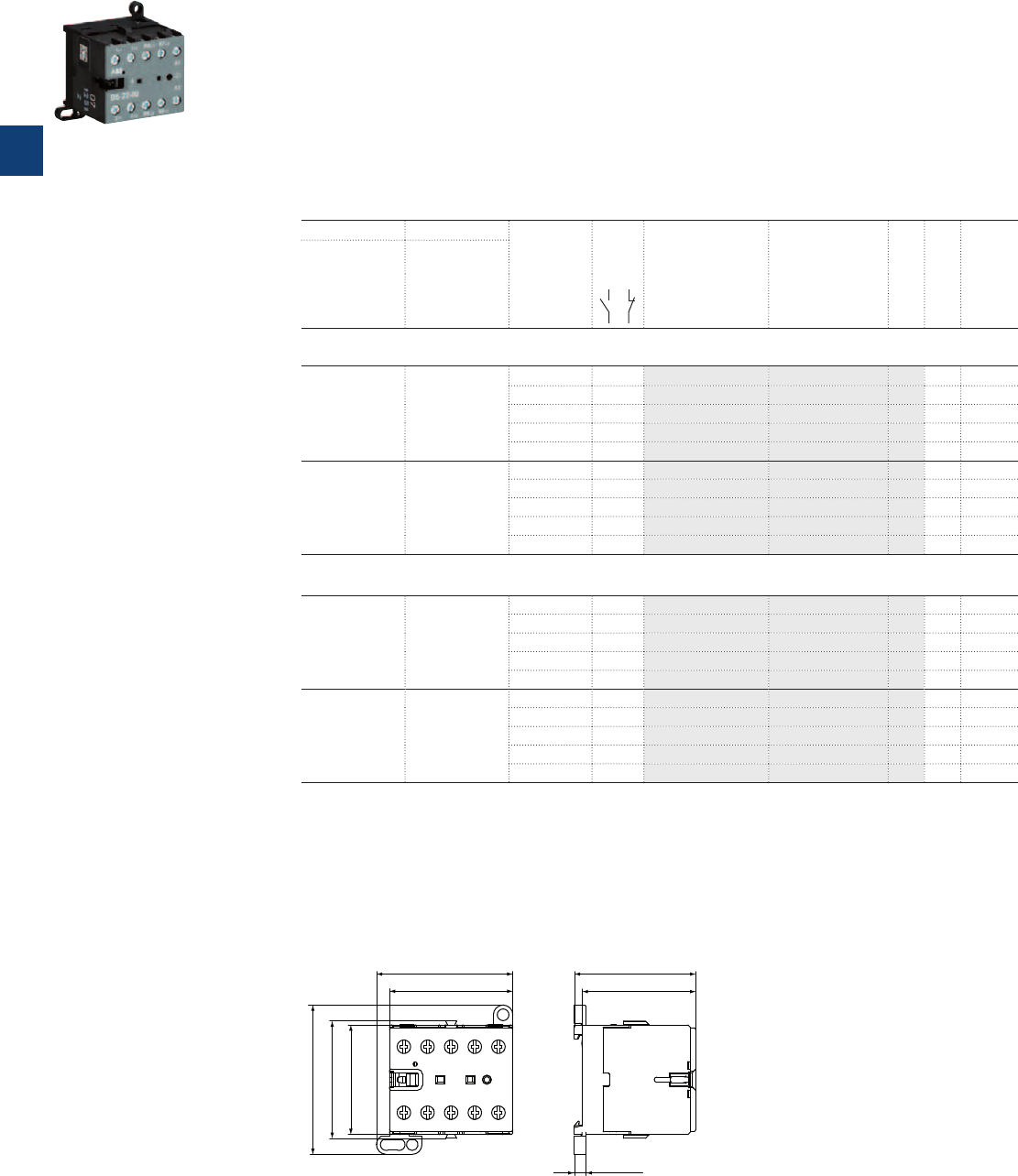
B6, B7 4-pole mini contactors – with screw terminals
4 to 5.5 kW
AC operated
Description
B6, B7 4-pole mini contactors are compact control products mainly used for switching resistive loads up
to 690 V AC.
These contactors are designed with:
– 4 main poles
– control circuit: AC operated, low coil consumption (3.5 VA at pull-in and at holding)
– add-on auxiliary contact blocks for front or side mounting and a wide range of accessories
– hum-free coil
– designed for rail or wall mounting
Ordering details
IEC UL/CSA Rated control
circuit voltage
U
C
50/60 HZ
Auxiliary
contacts
fitted
Type Order code
Pkg
qty
Weight
(1 pce)
Rated operational
current
ș≤ 55 °C
AC-1
General use
rating
600 V AC
A A V AC kg
4 N.O. main poles
16 8.4 24 0 0 B6-40-00-01 GJL1211201R0001 10 0.175
42 0 0 B6-40-00-02 GJL1211201R0002 10 0.175
48 0 0 B6-40-00-03 GJL1211201R0003 10 0.175
110 ... 127 0 0 B6-40-00-84 GJL1211201R8004 10 0.175
220 ... 240 0 0 B6-40-00-80 GJL1211201R8000 10 0.175
20 13.8 24 0 0 B7-40-00-01 GJL1311201R0001 10 0.175
42 0 0 B7-40-00-02 GJL1311201R0002 10 0.175
48 0 0 B7-40-00-03 GJL1311201R0003 10 0.175
110 ... 127 0 0 B7-40-00-84 GJL1311201R8004 10 0.175
220 ... 240 0 0 B7-40-00-80 GJL1311201R8000 10 0.175
2 N.O. + 2 N.C. main poles
16 8.4 24 0 0 B6-22-00-01 GJL1211501R0001 10 0.175
42 0 0 B6-22-00-02 GJL1211501R0002 10 0.175
48 0 0 B6-22-00-03 GJL1211501R0003 10 0.175
110 ... 127 0 0 B6-22-00-84 GJL1211501R8004 10 0.175
220 ... 240 0 0 B6-22-00-80 GJL1211501R8000 10 0.175
20 13.8 24 0 0 B7-22-00-01 GJL1311501R0001 10 0.175
42 0 0 B7-22-00-02 GJL1311501R0002 10 0.175
48 0 0 B7-22-00-03 GJL1311501R0003 10 0.175
110 ... 127 0 0 B7-22-00-84 GJL1311501R8004 10 0.175
220 ... 240 0 0 B7-22-00-80 GJL1311501R8000 10 0.175
Other types on request
Main dimensions mm, inches
47.5 1.87"
52.5 2.07"
57.5 2.26"
42.2 1.66"
45.2 1.78"
4.5 0.18"
43.7 1.72"
46.7 1.84"
2CDC212001F0011
B6, B7
2CDC211028F0011
B6-22-00
3/8 | ABB
3
2CDC102009C0201

BC6, B7D 4-pole mini contactors – with screw terminals
4 to 5.5 kW
DC operated
Description
BC6, B7D 4-pole mini contactors are compact control products mainly used for switching resistive loads
up to 690 V AC.
These contactors are designed with:
– 4 main poles
– control circuit: DC operated, low coil consumption (3.5 W at pull-in and at holding)
– hum-free coil
– add-on auxiliary contact blocks for front or side mounting
– designed for rail or wall mounting
Ordering details
IEC UL/CSA Rated control
circuit voltage
U
C
Auxiliary
contacts
fitted
Type Order code
Pkg
qty
Weight
(1 pce)
Rated operational
current
ș≤ 55 °C
AC-1
General use
rating
600 V AC
A A V DC kg
4 N.O. main poles
20 13.8 24 0 0 B7D-40-00-01 GJL1317201R0001 10 0.175
220 0 0 B7D-40-00-05 GJL1317201R0005 10 0.175
2 N.O. + 2 N.C. main poles
16 8.4 12 0 0 BC6-22-00-07 GJL1213501R0007 10 0.175
24 0 0 BC6-22-00-01 GJL1213501R0001 10 0.175
42 0 0 BC6-22-00-02 GJL1213501R0002 10 0.175
48 0 0 BC6-22-00-16 GJL1213501R1006 10 0.175
60 0 0 BC6-22-00-03 GJL1213501R0003 10 0.175
110 ... 125 0 0 BC6-22-00-04 GJL1213501R0004 10 0.175
220 ... 240 0 0 BC6-22-00-05 GJL1213501R0005 10 0.175
Other types on request
Main dimensions mm, inches
47.5 1.87"
52.5 2.07"
57.5 2.26"
42.2 1.66"
45.2 1.78"
4.5 0.18"
43.7 1.72"
46.7 1.84"
2CDC212001F0011
BC6, B7D
2CDC211032F0011
BC6-22-00
ABB | 3/9
3
2CDC102021C0201
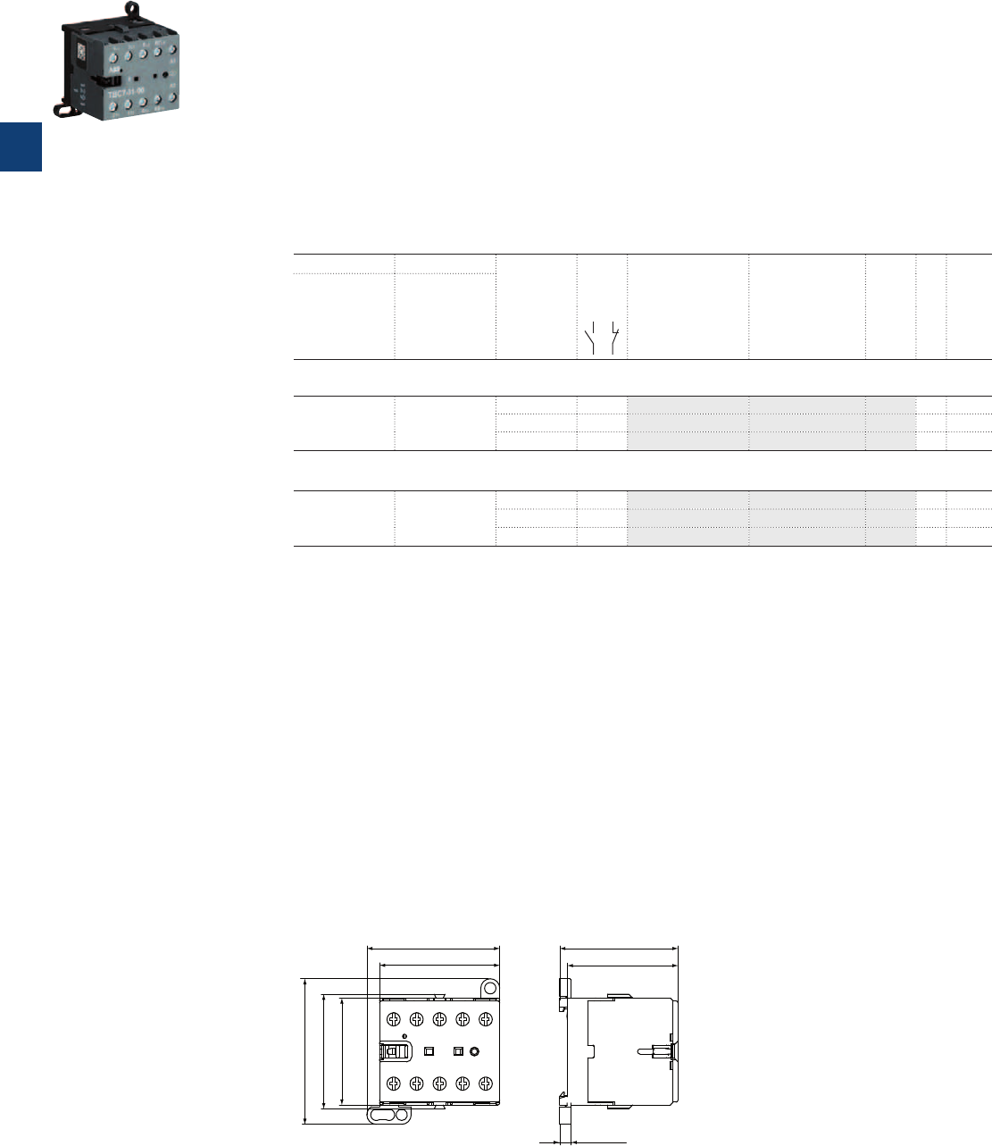
TBC7 4-pole mini contactors – with screw terminals
4 to 5.5 kW
DC operated – large coil voltage range
Description
TBC7 4-pole mini contactors are compact control products mainly used for switching resistive or motor
loads up to 690 V AC.
These contactors are designed with:
– 4 main poles
– control circuit: DC operated, low coil consumption (5 W at pull-in and at holding)
– hum-free coil
– expanded ambient temperature range -30 … +70 °C and wide range voltage supply
– no auxiliary contact block permitted for mounting
– designed for rail or wall mounting
– material is approved for railway applications
Ordering details
IEC UL/CSA Rated control
circuit voltage
U
C min
... U
C max
(1)
Auxiliary
contacts
fitted
Type Order code
Pkg
qty
Weight
(1 pce)
Rated operational
current
ș≤ 55 °C
AC-1
General use
rating
600 V AC
A A V DC kg
3 N.O. + 1 N.C. main poles
5.5 20 50 ... 90 0 0 TBC7-31-00-55 GJL1313461R5005 10 0.185
77 ... 143 0 0 TBC7-31-00-62 GJL1313461R6002 10 0.185
140 ... 260 0 0 TBC7-31-00-68 GJL1313461R6008 10 0.185
2 N.O. + 2 N.C. main poles
5.5 20 50 ... 90 0 0 TBC7-22-00-55 GJL1313561R5005 10 0.185
77 ... 143 0 0 TBC7-22-00-62 GJL1313561R6002 10 0.185
140 ... 260 0 0 TBC7-22-00-68 GJL1313561R6008 10 0.185
Other types on request
(1) Uc min. and Uc max. limit values, including the voltage variation tolerances (-15 % and +10 %).
Main dimensions mm, inches
47.5 1.87"
52.5 2.07"
57.5 2.26"
42.2 1.66"
45.2 1.78"
4.5 0.18"
43.7 1.72"
46.7 1.84"
2CDC212001F0011
TBC7
2CDC211026F0011
TBC7-31-00
3/10 | ABB
3
2CDC102022C0201

Notes
ABB | 3/11
3
N1
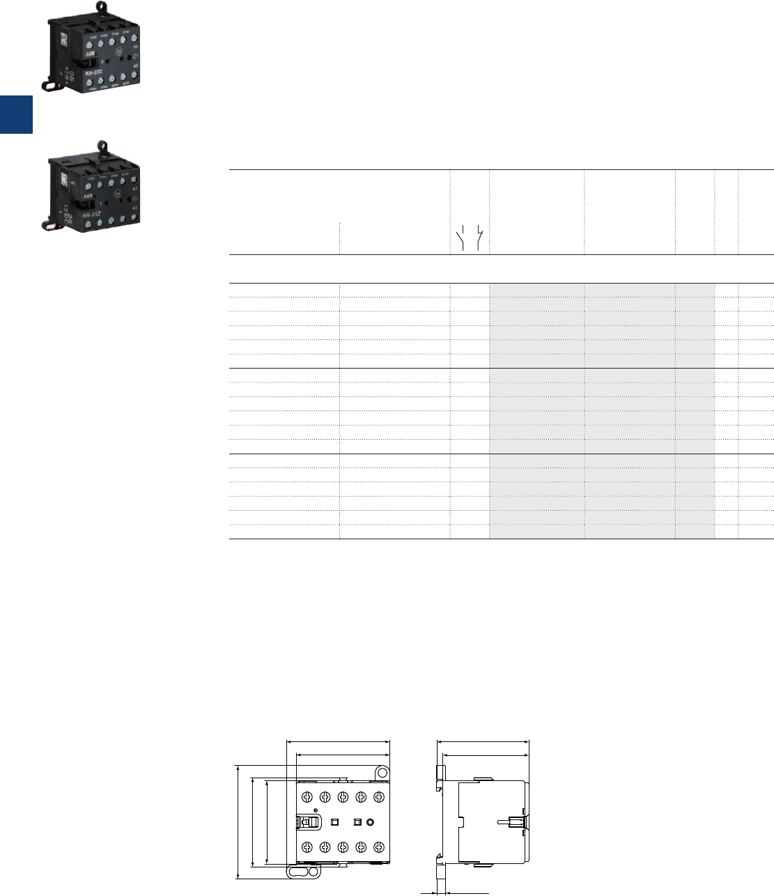
K6 4-pole mini contactor relays – with screw terminals
AC operated
Description
K6 4-pole mini contactor relays are space optimized control products mainly used for control functions or
for small loads up to 4 A.
These contactors are designed with:
– 4 poles with various contact combinations
– control circuit: AC operated, low coil consumption (3.5 VA at pull-in and at holding)
– hum-free coil
– add-on auxiliary contact blocks for front or side mounting
– designed for rail or wall mounting
Ordering details
Rated control circuit voltage U
C
Auxiliary
contacts
fitted
Type Order code
Pkg
qty
Weight
(1 pce)
50 Hz 60 Hz
V AC V AC kg
K6 4-pole mini contactor relays
24 24 2 2 K6-22Z-01 GJH1211001R0221 10 0.175
42 42 2 2 K6-22Z-02 GJH1211001R0222 10 0.175
48 48 2 2 K6-22Z-03 GJH1211001R0223 10 0.175
110 ...127 110 ...127 2 2 K6-22Z-84 GJH1211001R8224 10 0.175
220 ... 240 220 ... 240 2 2 K6-22Z-80 GJH1211001R8220 10 0.175
380 ... 415 380 ... 415 2 2 K6-22Z-85 GJH1211001R8225 10 0.175
24 24 3 1 K6-31Z-01 GJH1211001R0311 10 0.175
42 42 3 1 K6-31Z-02 GJH1211001R0312 10 0.175
48 48 3 1 K6-31Z-03 GJH1211001R0313 10 0.175
110 ...127 110 ...127 3 1 K6-31Z-84 GJH1211001R8314 10 0.175
220 ... 240 220 ... 240 3 1 K6-31Z-80 GJH1211001R8310 10 0.175
380 ... 415 380 ... 415 3 1 K6-31Z-85 GJH1211001R8315 10 0.175
24 24 4 0 K6-40E-01 GJH1211001R0401 10 0.175
42 42 4 0 K6-40E-02 GJH1211001R0402 10 0.175
48 48 4 0 K6-40E-03 GJH1211001R0403 10 0.175
110 ...127 110 ...127 4 0 K6-40E-84 GJH1211001R8404 10 0.175
220 ... 240 220 ... 240 4 0 K6-40E-80 GJH1211001R8400 10 0.175
380 ... 415 380 ... 415 4 0 K6-40E-85 GJH1211001R8405 10 0.175
Other types on request
Main dimensions mm, inches
47.5 1.87"
52.5 2.07"
57.5 2.26"
42.2 1.66"
45.2 1.78"
4.5 0.18"
43.7 1.72"
46.7 1.84"
2CDC212001F0011
K6
2CDC211012F0011
K6-22Z
2CDC211004F0010
K6-31Z
3/12 | ABB
3
2CDC102011C0201
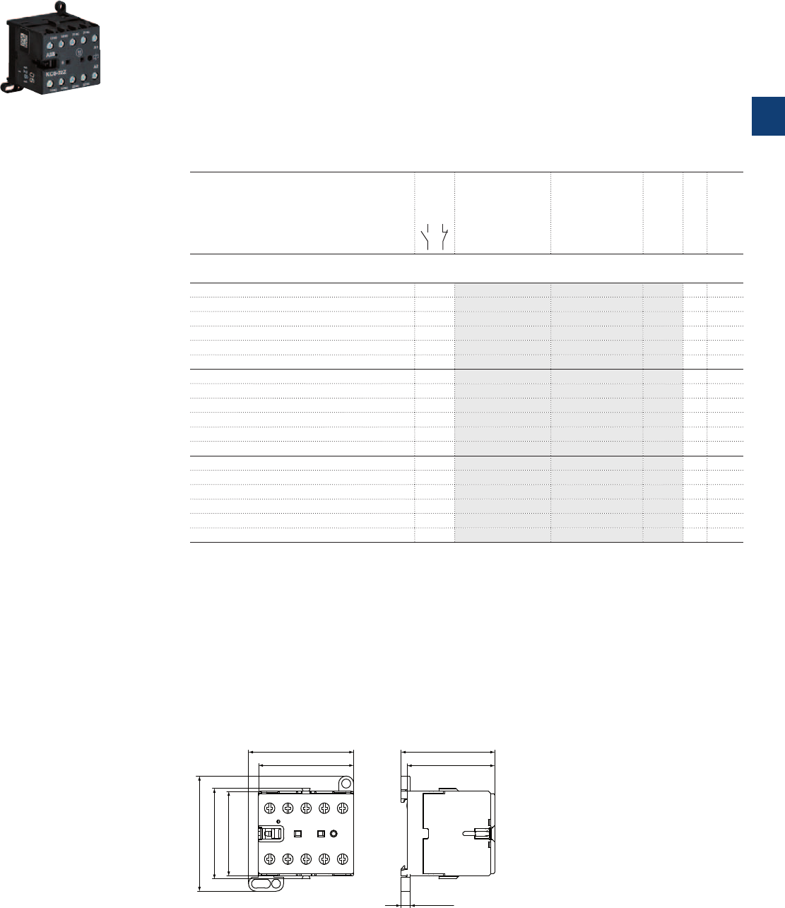
KC6 4-pole mini contactor relays – with screw terminals
DC operated
Description
KC6 4-pole mini contactor relays are space optimized control products mainly used for control functions or
for small loads up to 4 A.
These contactors are designed with:
– 4 poles with various contact combinations
– control circuit: DC operated, low coil consumption (3.5 W at pull-in and at holding)
– hum-free coil
– add-on auxiliary contact blocks for front or side mounting
– designed for rail or wall mounting
Ordering details
Rated control circuit voltage U
C
Auxiliary
contacts
fitted
Type Order code
Pkg
qty
Weight
(1 pce)
V DC kg
KC6 4-pole mini contactor relays
12 2 2 KC6-22Z-07 GJH1213001R0227 10 0.175
24 2 2 KC6-22Z-01 GJH1213001R0221 10 0.175
48 2 2 KC6-22Z-16 GJH1213001R1226 10 0.175
60 2 2 KC6-22Z-13 GJH1213001R1223 10 0.175
110 ... 125 2 2 KC6-22Z-04 GJH1213001R0224 10 0.175
220 ... 240 2 2 KC6-22Z-05 GJH1213001R0225 10 0.175
12 3 1 KC6-31Z-07 GJH1213001R0317 10 0.175
24 3 1 KC6-31Z-01 GJH1213001R0311 10 0.175
48 3 1 KC6-31Z-16 GJH1213001R1316 10 0.175
60 3 1 KC6-31Z-13 GJH1213001R1313 10 0.175
110 ... 125 3 1 KC6-31Z-04 GJH1213001R0314 10 0.175
220 ... 240 3 1 KC6-31Z-05 GJH1213001R0315 10 0.175
12 4 0 KC6-40E-07 GJH1213001R0407 10 0.175
24 4 0 KC6-40E-01 GJH1213001R0401 10 0.175
48 4 0 KC6-40E-16 GJH1213001R1406 10 0.175
60 4 0 KC6-40E-13 GJH1213001R1403 10 0.175
110 ... 125 4 0 KC6-40E-04 GJH1213001R0404 10 0.175
220 ... 240 4 0 KC6-40E-05 GJH1213001R0405 10 0.175
Other types on request
Main dimensions mm, inches
47.5 1.87"
52.5 2.07"
57.5 2.26"
42.2 1.66"
45.2 1.78"
4.5 0.18"
43.7 1.72"
46.7 1.84"
2CDC212001F0011
KC6
2CDC211016F0011
KC6-22Z
ABB | 3/13
3
2CDC102012C0201
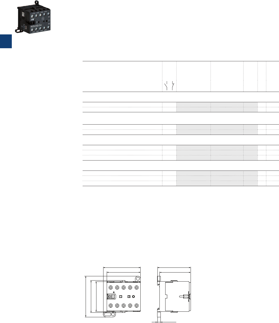
KC6 4-pole interface mini contactor relays – with screw terminals
DC operated
Description
KC6 4-pole interface mini contactor relays are space optimized control products mainly used for control
functions or for small loads up to 4 A.
These contactors are designed with:
– 4 poles with various contact combinations
– control circuit: DC operated, low coil consumption (1.4 ... 2.8 W at pull-in and at holding)
– hum-free coil
– no auxiliary contact block permitted for mounting
– designed for rail or wall mounting
Ordering details
Rated control circuit voltage U
C
Auxiliary
contacts
fitted
Type Order code
Pkg
qty
Weight
(1 pce)
V DC kg
DC operation 24 V / 1.4 W
24 3 1 KC6-31Z-1.4-81 GJH1213001R8311 10 0.175
24 4 0 KC6-40E-1.4-81 GJH1213001R8401 10 0.175
DC operation 17 ... 32 V / 2.4 W
17 ... 32 (1) 3 1 KC6-31Z-2.4-51 GJH1213001R5311 10 0.175
17 ... 32 (1) 4 0 KC6-40E-2.4-51 GJH1213001R5401 10 0.175
DC operation 24 V / 1.7 W
24 2 2 K6S-22Z-1.7-71 GJH1213001R7221 10 0.175
24 3 1 K6S-31Z-1.7-71 GJH1213001R7311 10 0.175
24 4 0 K6S-40E-1.7-71 GJH1213001R7401 10 0.175
DC operation 17 ... 32 V / 2.8 W
17 ... 32 (1) 2 2 K6S-22Z-2.8-72 GJH1213001R7222 10 0.175
17 ... 32 (1) 3 1 K6S-31Z-2.8-72 GJH1213001R7312 10 0.175
17 ... 32 (1) 4 0 K6S-40E-2.8-72 GJH1213001R7402 10 0.175
Other types on request
(1) Uc min. and Uc max. limit values, including the voltage variation tolerances (-15 % and +10 %).
Main dimensions mm, inches
47.5 1.87"
52.5 2.07"
57.5 2.26"
42.2 1.66"
45.2 1.78"
4.5 0.18"
43.7 1.72"
46.7 1.84"
2CDC212001F0011
KC6
2CDC211017F0011
KC6-31Z
3/14 | ABB
3
2CDC102013C0201
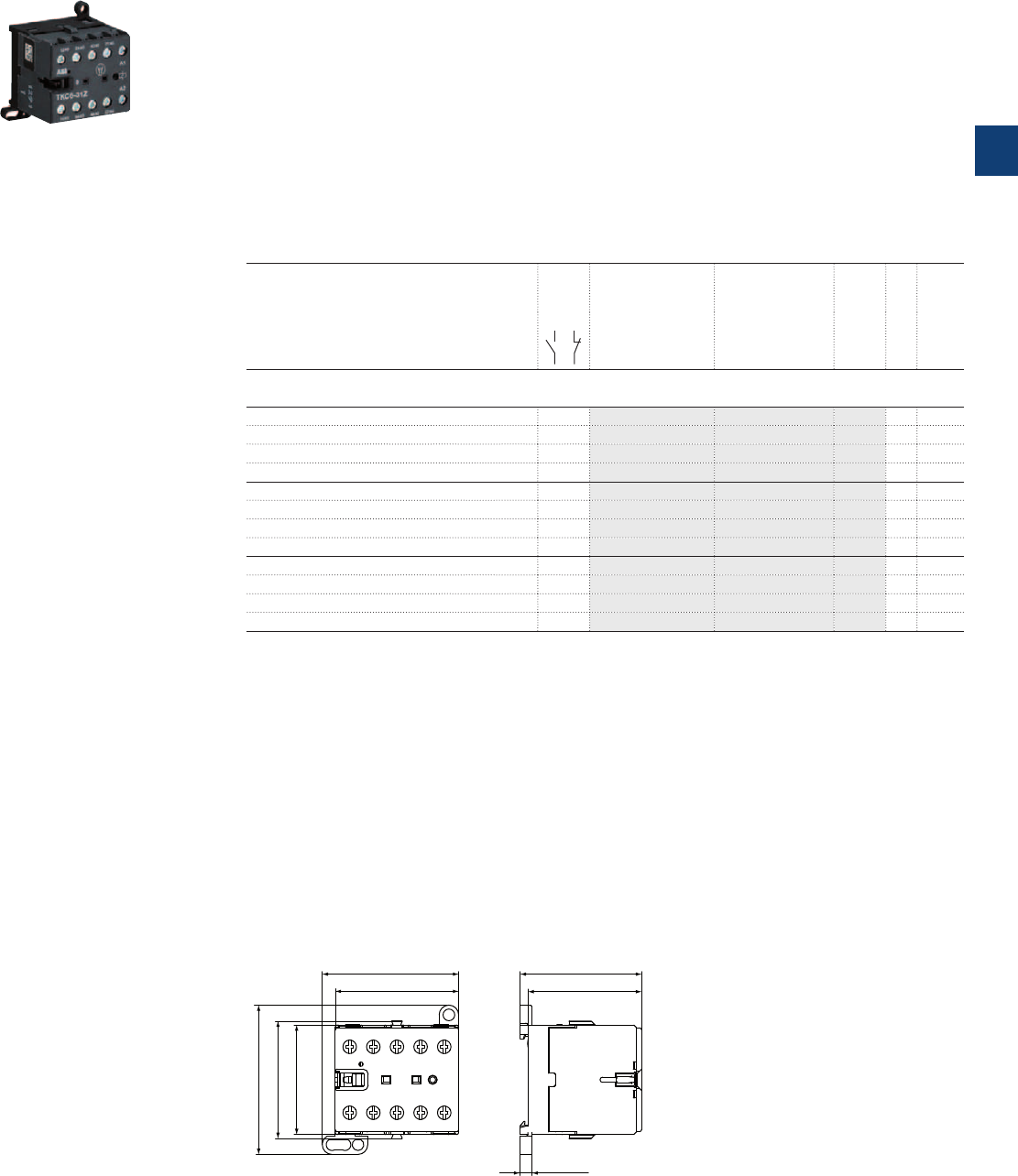
TKC6 4-pole mini contactor relays – with screw terminals
DC operated – large coil voltage range
Description
TKC6 4-pole mini contactors are space optimized control products mainly used for control functions or for
small loads up to 4 A.
These contactors are designed with:
– 4 poles with various contact combinations
– control circuit: DC operated, hum free, low consumption (5 W at pull-in and at holding)
– expanded ambient temperature range -30 … +70 °C and wide range voltage supply
– material is suitable for railway applications
– humfree operating DC coil
– no auxiliary contact block permitted for mounting
– designed for rail or wall mounting
Ordering details
Rated control circuit voltage U
C min
... U
C max
(1)
Auxiliary
contacts
fitted
Type Order code
Pkg
qty
Weight
(1 pce)
V DC kg
17 ... 32 2 2 TKC6-22Z-51 GJH1213061R5221 10 0.180
50 ... 90 2 2 TKC6-22Z-55 GJH1213061R5225 10 0.180
77 ... 143 2 2 TKC6-22Z-62 GJH1213061R6222 10 0.180
140 ... 260 2 2 TKC6-22Z-68 GJH1213061R6228 10 0.180
17 ... 32 3 1 TKC6-31Z-51 GJH1213061R5311 10 0.180
50 ... 90 3 1 TKC6-31Z-55 GJH1213061R5315 10 0.180
77 ... 143 3 1 TKC6-31Z-62 GJH1213061R6312 10 0.180
140 ... 260 3 1 TKC6-31Z-68 GJH1213061R6318 10 0.180
17 ... 32 4 0 TKC6-40E-51 GJH1213061R5401 10 0.180
50 ... 90 4 0 TKC6-40E-55 GJH1213061R5405 10 0.180
77 ... 143 4 0 TKC6-40E-62 GJH1213061R6402 10 0.180
140 ... 260 4 0 TKC6-40E-68 GJH1213061R6408 10 0.180
Other types on request
(1) Uc min. and Uc max. limit values, including the voltage variation tolerances (-15 % and +10 %).
Main dimensions mm, inches
47.5 1.87"
52.5 2.07"
57.5 2.26"
42.2 1.66"
45.2 1.78"
4.5 0.18"
43.7 1.72"
46.7 1.84"
2CDC212001F0011
TKC6
2CDC211021F0011
TKC6-31Z
ABB | 3/15
3
2CDC102014C0201
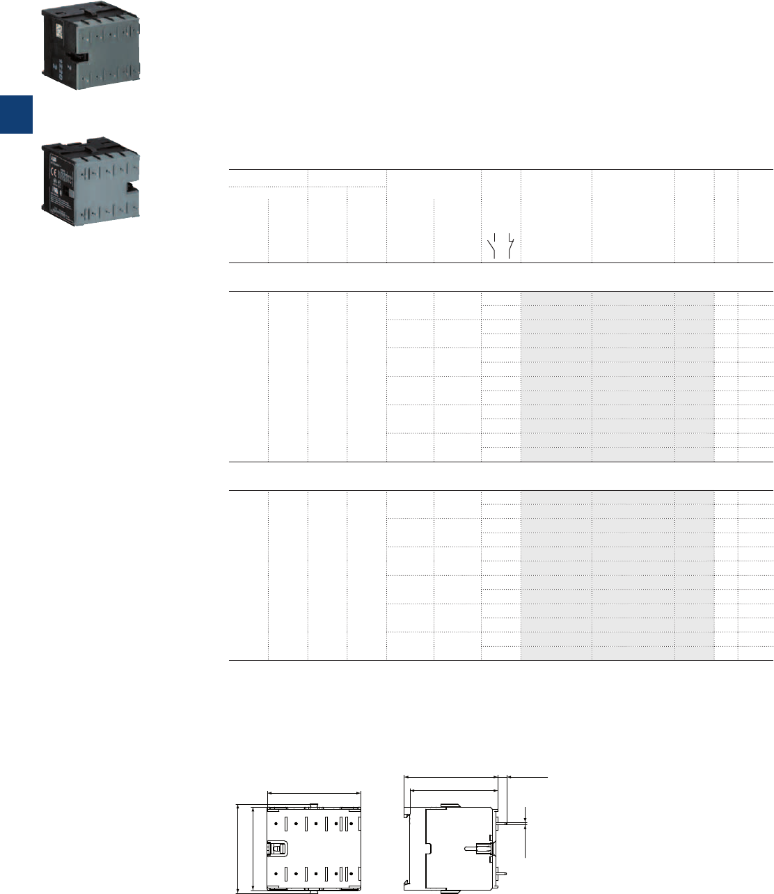
B6, B7 3-pole mini contactors – with soldering pins
4 to 5.5 kW
AC operated
Description
B6..P and B7..P 3-pole mini contactors are compact control products mainly used for switching resistive
or motor loads up to 690 V AC.
These contactors are designed with:
– 3 main poles and one built-in auxiliary contact
– control circuit: AC operated, low coil consumption (3.5 VA at pull-in and at holding)
– hum-free coil
– add-on auxiliary contact blocks for side mounting
– designed for soldering on PCB boards
Ordering details
IEC UL/CSA Rated control circuit
voltage U
C
Auxiliary
contacts
fitted
Type Order code
Pkg
qty
Weight
(1 pce)
Rated operational 3-phase
motor
rating
480 V
General
use
rating
600 V AC
power
400 V
AC-3
current
ș≤ 55 °C
AC-1
50 Hz 60 Hz
kW A hp A V AC V AC kg
B6 mini contactors
4 12 3 3.4 24 24 1 0 B6-30-10-P-01 GJL1211009R0101 10 0.170
0 1 B6-30-01-P-01 GJL1211009R0011 10 0.170
42 42 1 0 B6-30-10-P-02 GJL1211009R0102 10 0.170
0 1 B6-30-01-P-02 GJL1211009R0012 10 0.170
48 48 1 0 B6-30-10-P-03 GJL1211009R0103 10 0.170
0 1 B6-30-01-P-03 GJL1211009R0013 10 0.170
110 … 127 110 … 127
1 0 B6-30-10-P-84 GJL1211009R8104 10 0.170
0 1 B6-30-01-P-84 GJL1211009R8014 10 0.170
220 … 240 220 … 240
1 0 B6-30-10-P-80 GJL1211009R8100 10 0.170
0 1 B6-30-01-P-80 GJL1211009R8010 10 0.170
380 … 415 380 … 415
1 0 B6-30-10-P-85 GJL1211009R8105 10 0.170
0 1 B6-30-01-P-85 GJL1211009R8015 10 0.170
B7 mini contactors
5.5 12 5 7.6 24 24 1 0 B7-30-10-P-01 GJL1311009R0101 10 0.170
0 1 B7-30-01-P-01 GJL1311009R0011 10 0.170
42 42 1 0 B7-30-10-P-02 GJL1311009R0102 10 0.170
0 1 B7-30-01-P-02 GJL1311009R0012 10 0.170
48 48 1 0 B7-30-10-P-03 GJL1311009R0103 10 0.170
0 1 B7-30-01-P-03 GJL1311009R0013 10 0.170
110 … 127 110 … 127
1 0 B7-30-10-P-84 GJL1311009R8104 10 0.170
0 1 B7-30-01-P-84 GJL1311009R8014 10 0.170
220 … 240 220 … 240
1 0 B7-30-10-P-80 GJL1311009R8100 10 0.170
0 1 B7-30-01-P-80 GJL1311009R8010 10 0.170
380 … 415 380 … 415
1 0 B7-30-10-P-85 GJL1311009R8105 10 0.170
0 1 B7-30-01-P-85 GJL1311009R8015 10 0.170
Other types on request
Main dimensions mm, inches
1 0.04"
47.5 1.87"
42.2 1.66"
45.2 1.78"
44.7 1.76"
47.7 1.88" 4.3 0.17"
2CDC212003F0011
B6, B7
2CDC211003F0010
B6-30-10-P
2CDC211011F0011
B7-30-10-P
3/16 | ABB
3
2CDC102023C0201
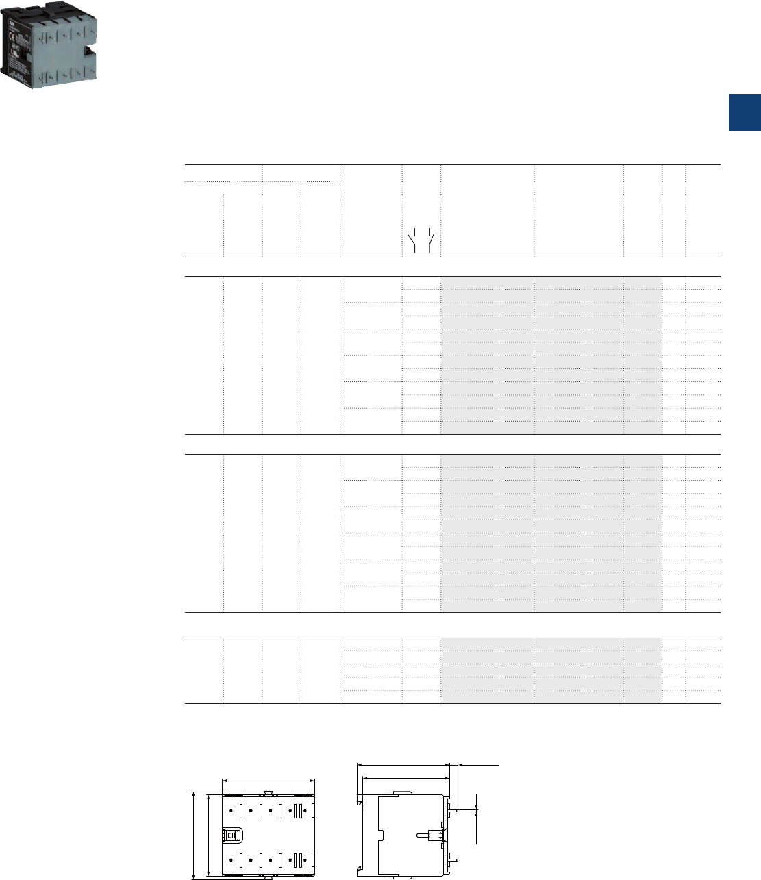
BC6, BC7 3-pole mini contactors – with soldering pins
4 to 5.5 kW
DC operated
Description
BC6, BC7 3-pole mini contactors are compact control products mainly used for switching resistive or
motor loads up to 690 V AC.
These contactors are designed with:
– 3 main poles and one built-in auxiliary contact
– control circuit: DC operated, low coil consumption (3.5 W at pull-in and at holding)
– hum-free coil
– add-on auxiliary contact blocks for side mounting
– designed for soldering on PCB boards
Ordering details
IEC UL/CSA Rated control
circuit voltage
U
C
Auxiliary
contacts
fitted
Type Order code
Pkg
qty
Weight
(1 pce)
Rated operational 3-phase
motor
rating
480 V
General
use
rating
600 V AC
power
400 V
AC-3
current
ș≤ 55 °C
AC-1
kW A hp A V DC kg
BC6 mini contactors with 3 N.O. main poles
4 12 3 3.4 12 1 0 BC6-30-10-P-07 GJL1213009R0107 10 0.170
0 1 BC6-30-01-P-07 GJL1213009R0017 10 0.170
24 1 0 BC6-30-10-P-01 GJL1213009R0101 10 0.170
0 1 BC6-30-01-P-01 GJL1213009R0011 10 0.170
48 1 0 BC6-30-10-P-16 GJL1213009R1106 10 0.170
0 1 BC6-30-01-P-16 GJL1213009R1016 10 0.170
60 1 0 BC6-30-10-P-03 GJL1213009R0103 10 0.170
0 1 BC6-30-01-P-03 GJL1213009R0013 10 0.170
110 … 125 1 0 BC6-30-10-P-04 GJL1213009R0104 10 0.170
0 1 BC6-30-01-P-04 GJL1213009R0014 10 0.170
220 … 240 1 0 BC6-30-10-P-05 GJL1213009R0105 10 0.170
0 1 BC6-30-01-P-05 GJL1213009R0015 10 0.170
BC7 mini contactors with 3 N.O. main poles
5.5 12 5 7.6 12 1 0 BC7-30-10-P-07 GJL1313009R0107 10 0.170
0 1 BC7-30-01-P-07 GJL1313009R0017 10 0.170
24 1 0 BC7-30-10-P-01 GJL1313009R0101 10 0.170
0 1 BC7-30-01-P-01 GJL1313009R0011 10 0.170
48 1 0 BC7-30-10-P-16 GJL1313009R1106 10 0.170
0 1 BC7-30-01-P-16 GJL1313009R1016 10 0.170
60 1 0 BC7-30-10-P-03 GJL1313009R0103 10 0.170
0 1 BC7-30-01-P-03 GJL1313009R0013 10 0.170
110 … 125 1 0 BC7-30-10-P-04 GJL1313009R0104 10 0.170
0 1 BC7-30-01-P-04 GJL1313009R0014 10 0.170
220 … 240 1 0 BC7-30-10-P-05 GJL1313009R0105 10 0.170
0 1 BC7-30-01-P-05 GJL1313009R0015 10 0.170
BC6 mini contactors 2 N.O. + 1 N.C. main poles
4 12 3 3.4 24 1 0 BC6-21-10-P-01 GJL1213109R0101 10 0.170
48 1 0 BC6-21-10-P-16 GJL1213109R1106 10 0.170
60 1 0 BC6-21-10-P-03 GJL1213109R0103 10 0.170
110 … 125 1 0 BC6-21-10-P-04 GJL1213109R0104 10 0.170
220 … 240 1 0 BC6-21-10-P-05 GJL1213109R0105 10 0.170
Other types on request
Main dimensions mm, inches
1 0.04"
47.5 1.87"
42.2 1.66"
45.2 1.78"
44.7 1.76"
47.7 1.88" 4.3 0.17"
2CDC212003F0011
B6, B7
2CDC211030F0011
BC7-30-10-P
ABB | 3/17
3
2CDC102024C0201
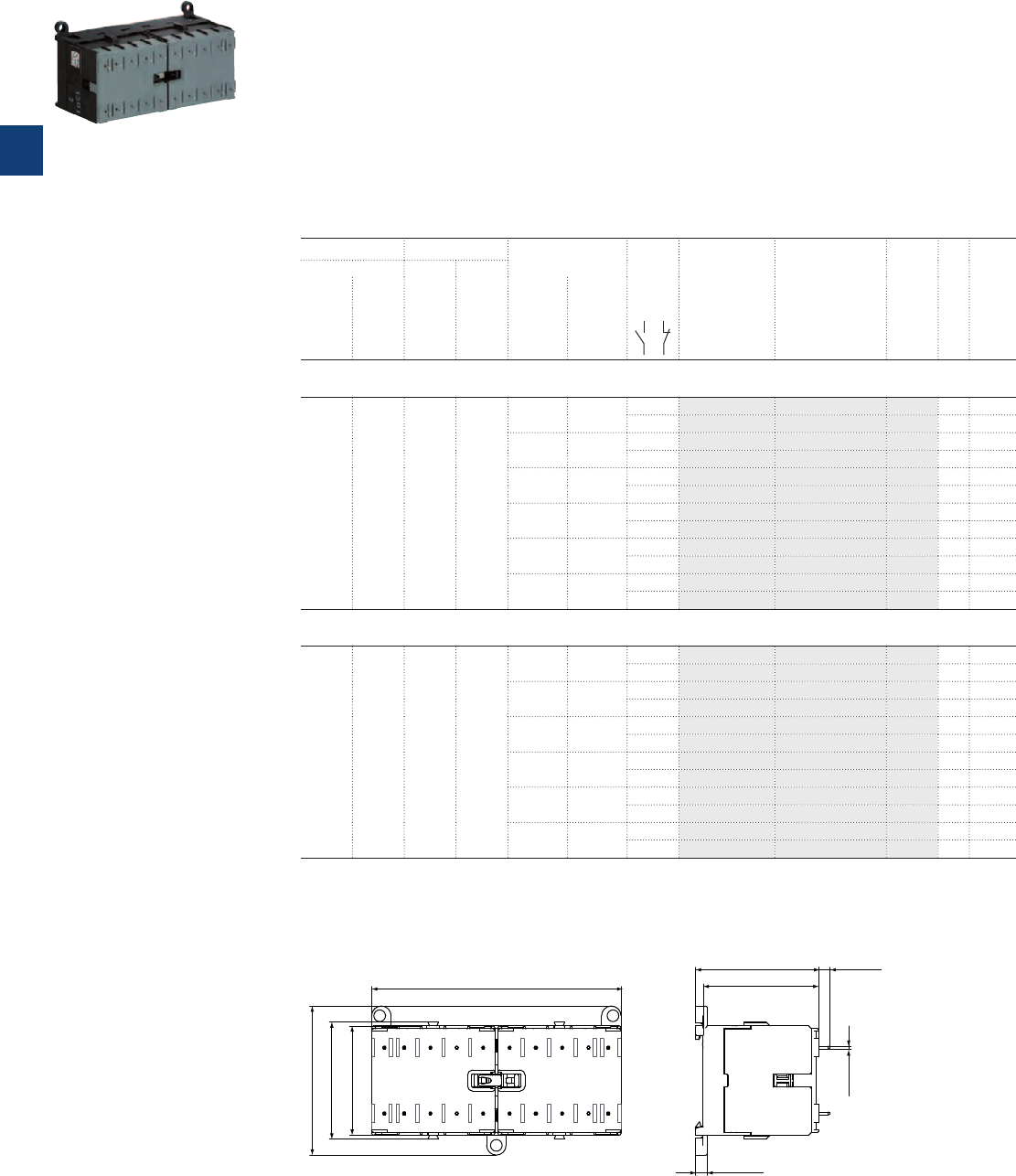
VB6, VB7 3-pole mini reversing contactors – with soldering pins
4 to 5.5 kW
AC operated
Description
VB6, VB7 3-pole compact design reversing contactors are space optimized control products mainly used
for switching resistive or motor loads up to 690 V AC.
These reversing contactors are designed with:
– built-in mechanical interlock. The coils must be mutually interlocked electrically and coils must be de-
energised for 50 ms at least to prevent phase to phase short circuit on the arc
– control circuit: AC operated, low coil consumption (3.5 VA at pull-in and at holding)
– hum-free coil
– no auxiliary contact block permitted for mounting
– designed for soldering on PCB boards
Ordering details
IEC UL/CSA Rated control circuit
voltage U
C
Auxiliary
contacts
fitted
Type Order code
Pkg
qty
Weight
(1 pce)
Rated operational 3-phase
motor
rating
480 V
General
use
rating
600 V AC
power
400 V
AC-3
current
ș≤ 55 °C
AC-1
50 Hz 60 Hz
kW A hp A V AC V AC kg
VB6 mini reversing contactors
4 12 3 3.4 24 24 1 0 VB6-30-10-P-01 GJL1211909R0101 5 0.345
0 1 VB6-30-01-P-01 GJL1211909R0011 5 0.345
42 42 1 0 VB6-30-10-P-02 GJL1211909R0102 5 0.345
0 1 VB6-30-01-P-02 GJL1211909R0012 5 0.345
48 48 1 0 VB6-30-10-P-03 GJL1211909R0103 5 0.345
0 1 VB6-30-01-P-03 GJL1211909R0013 5 0.345
110 … 127 110 … 127
1 0 VB6-30-10-P-84 GJL1211909R8104 5 0.345
0 1 VB6-30-01-P-84 GJL1211909R8014 5 0.345
220 … 240 220 … 240
1 0 VB6-30-10-P-80 GJL1211909R8100 5 0.345
0 1 VB6-30-01-P-80 GJL1211909R8010 5 0.345
380 … 415 380 … 415
1 0 VB6-30-10-P-85 GJL1211909R8105 5 0.345
0 1 VB6-30-01-P-85 GJL1211909R8015 5 0.345
VB7 mini reversing contactors
5.5 12 5 7.6 24 24 1 0 VB7-30-10-P-01 GJL1311909R0101 5 0.345
0 1 VB7-30-01-P-01 GJL1311909R0011 5 0.345
42 42 1 0 VB7-30-10-P-02 GJL1311909R0102 5 0.345
0 1 VB7-30-01-P-02 GJL1311909R0012 5 0.345
48 48 1 0 VB7-30-10-P-03 GJL1311909R0103 5 0.345
0 1 VB7-30-01-P-03 GJL1311909R0013 5 0.345
110 … 127 110 … 127
1 0 VB7-30-10-P-84 GJL1311909R8104 5 0.345
0 1 VB7-30-01-P-84 GJL1311909R8014 5 0.345
220 … 240 220 … 240
1 0 VB7-30-10-P-80 GJL1311909R8100 5 0.345
0 1 VB7-30-01-P-80 GJL1311909R8010 5 0.345
380 … 415 380 … 415
1 0 VB7-30-10-P-85 GJL1311909R8105 5 0.345
0 1 VB7-30-01-P-85 GJL1311909R8015 5 0.345
Other types on request
Main dimensions mm, inches
45.2 1.78"
57.5 2.26"
96.2 3.79" 44.7 1.76"
47.7 1.88" 4.3 0.17"
1 0.04"
4.5 0.18"
42.2 1.66"
2CDC212007F0011
VB6, VB7
2CDC211010S0011
VB7-30-10-P
3/18 | ABB
3
2CDC102025C0201
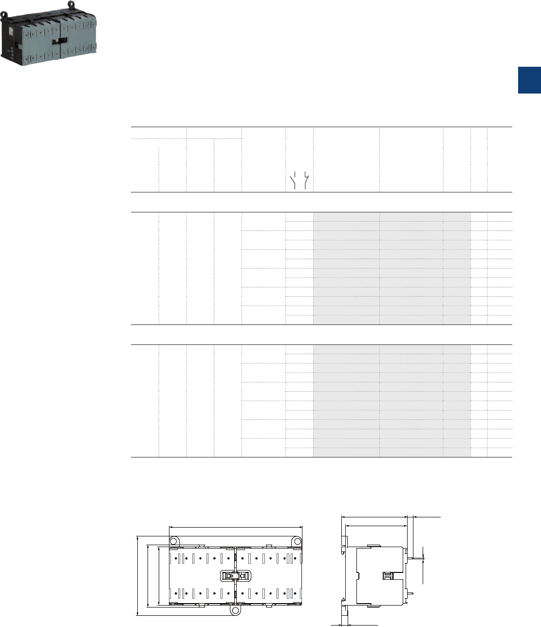
VBC6, VBC7 3-pole mini reversing contactors – with soldering pins
4 to 5.5 kW
DC operated
Description
VBC6, VBC7 3-pole compact design reversing contactors are space optimized control products mainly
used for switching resistive or motor loads up to 690 V AC.
These reversing contactors are designed with:
– built-in mechanical interlock. The coils must be mutually interlocked electrically and coils must be de-
energised for 50 ms at least to prevent phase to phase short circuit on the arc
– control circuit: DC operated, low coil consumption (3.5 W at pull-in and at holding)
– hum-free coil
– no auxiliary contact block permitted for mounting
– designed for soldering on PCB boards
Ordering details
IEC UL/CSA Rated control
circuit voltage
U
C
Auxiliary
contacts
fitted
Type Order code
Pkg
qty
Weight
(1 pce)
Rated operational 3-phase
motor
rating
480 V
General
use
rating
600 V AC
power
400 V
AC-3
current
ș≤ 55 °C
AC-1
kW A hp A V DC kg
VBC6 mini reversing contactors
4 12 3 3.4 12 1 0 VBC6-30-10-P-07 GJL1213909R0107 5 0.345
0 1 VBC6-30-01-P-07 GJL1213909R0017 5 0.345
24 1 0 VBC6-30-10-P-01 GJL1213909R0101 5 0.345
0 1 VBC6-30-01-P-01 GJL1213909R0011 5 0.345
48 1 0 VBC6-30-10-P-06 GJL1213909R0106 5 0.345
0 1 VBC6-30-06-P-06 GJL1213909R0016 5 0.345
60 1 0 VBC6-30-10-P-03 GJL1213909R0103 5 0.345
0 1 VBC6-30-01-P-03 GJL1213909R0013 5 0.345
110 ... 125 1 0 VBC6-30-10-P-04 GJL1213909R0104 5 0.345
0 1 VBC6-30-01-P-04 GJL1213909R0014 5 0.345
220 … 240 1 0 VBC6-30-10-P-05 GJL1213909R0105 5 0.345
0 1 VBC6-30-01-P-05 GJL1213909R0015 5 0.345
VBC7 mini reversing contactors
5.5 12 5 7.6 12 1 0 VBC7-30-10-P-07 GJL1313909R0107 5 0.345
0 1 VBC7-30-01-P-07 GJL1313909R0017 5 0.345
24 1 0 VBC7-30-10-P-01 GJL1313909R0101 5 0.345
0 1 VBC7-30-01-P-01 GJL1313909R0011 5 0.345
48 1 0 VBC7-30-10-P-16 GJL1313909R1106 5 0.345
0 1 VBC7-30-01-P-16 GJL1313909R1016 5 0.345
60 1 0 VBC7-30-10-P-03 GJL1313909R0103 5 0.345
0 1 VBC7-30-01-P-03 GJL1313909R0013 5 0.345
110 ... 125 1 0 VBC7-30-10-P-04 GJL1313909R0104 5 0.345
0 1 VBC7-30-01-P-04 GJL1313909R0014 5 0.345
220 … 240 1 0 VBC7-30-10-P-05 GJL1313909R0105 5 0.345
0 1 VBC7-30-01-P-05 GJL1313909R0015 5 0.345
Other types on request
Main dimensions mm, inches
45.2 1.78"
57.5 2.26"
96.2 3.79" 44.7 1.76"
47.7 1.88" 4.3 0.17"
1 0.04"
4.5 0.18"
42.2 1.66"
2CDC212007F0011
VBC6, VBC7
2CDC211009F0011
VBC7-30-10-P
ABB | 3/19
3
2CDC102026C0201
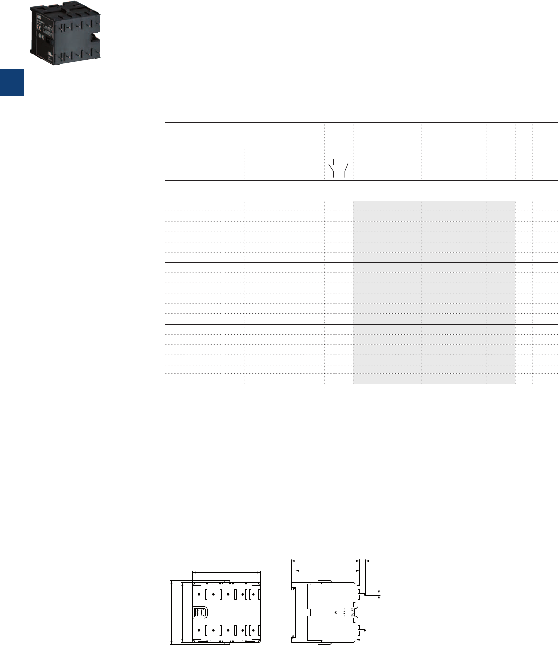
K6 4-pole mini contactor relays – with soldering pins
AC operated
Description
K6 4-pole mini contactor relays are space optimized control products mainly used for control functions or
for small loads up to 4 A.
These contactors are designed with:
– 4 poles with various contact combinations
– control circuit: AC operated, low coil consumption (3.5 VA at pull-in and at holding)
– hum-free coil
– add-on auxiliary contact block for side mounting
– designed for soldering on PCB boards
Ordering details
Rated control circuit voltage U
C
Auxiliary
contacts
fitted
Type Order code
Pkg
qty
Weight
(1 pce)
50 Hz
V AC
60 Hz
V AC kg
K6 4-pole mini contactor relays
24 24 2 2 K6-22Z-P-01 GJH1211009R0221 10 0.170
42 42 2 2 K6-22Z-P-02 GJH1211009R0222 10 0.170
48 48 2 2 K6-22Z-P-03 GJH1211009R0223 10 0.170
110 ...127 110 ...127 2 2 K6-22Z-P-84 GJH1211009R8224 10 0.170
220 ... 240 220 ... 240 2 2 K6-22Z-P-80 GJH1211009R8220 10 0.170
380 ... 415 380 ... 415 2 2 K6-22Z-P-85 GJH1211009R8225 10 0.170
24 24 3 1 K6-31Z-P-01 GJH1211009R0311 10 0.170
42 42 3 1 K6-31Z-P-02 GJH1211009R0312 10 0.170
48 48 3 1 K6-31Z-P-03 GJH1211009R0313 10 0.170
110 ...127 110 ...127 3 1 K6-31Z-P-84 GJH1211009R8314 10 0.170
220 ... 240 220 ... 240 3 1 K6-31Z-P-80 GJH1211009R8310 10 0.170
380 ... 415 380 ... 415 3 1 K6-31Z-P-85 GJH1211009R8315 10 0.170
24 24 4 0 K6-40E-P-01 GJH1211009R0401 10 0.170
42 42 4 0 K6-40E-P-02 GJH1211009R0402 10 0.170
48 48 4 0 K6-40E-P-03 GJH1211009R0403 10 0.170
110 ...127 110 ...127 4 0 K6-40E-P-84 GJH1211009R8404 10 0.170
220 ... 240 220 ... 240 4 0 K6-40E-P-80 GJH1211009R8400 10 0.170
380 ... 415 380 ... 415 4 0 K6-40E-P-85 GJH1211009R8405 10 0.170
Other types on request
Main dimensions mm, inches
1 0.04"
47.5 1.87"
42.2 1.66"
45.2 1.78"
44.7 1.76"
47.7 1.88" 4.3 0.17"
2CDC212003F0011
K6
2CDC211022F0011
K6-22Z-P
3/20 | ABB
3
2CDC102030C0201
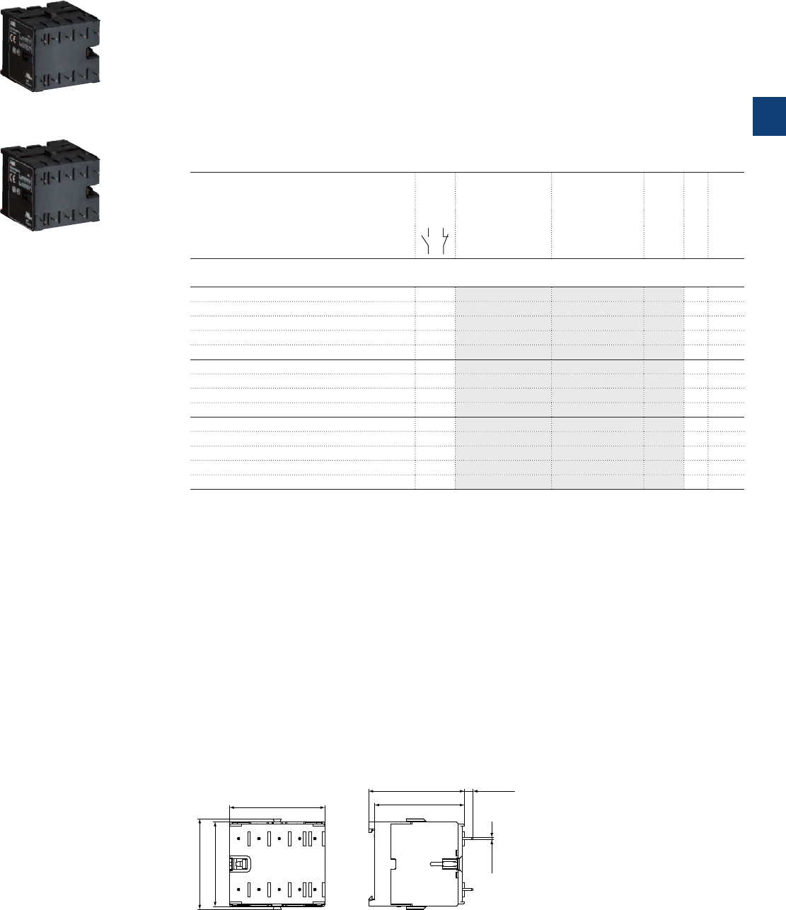
KC6 4-pole mini contactor relays – with soldering pins
DC operated
Description
KC6 4-pole mini contactor relays are space optimized control products mainly used for control functions or
for small loads up to 4 A.
These contactors are designed with:
– 4 poles with various contact combinations
– control circuit: DC operated, low coil consumption (3.5 W at pull-in and at holding)
– hum-free coil
– add-on auxiliary contact block for side mounting
– designed for soldering on PCB boards
Ordering details
Rated control circuit voltage U
C
Auxiliary
contacts
fitted
Type Order code
Pkg
qty
Weight
(1 pce)
V DC kg
K6 4-pole mini contactor relays
12 2 2 KC6-22Z-P-07 GJH1213009R0227 10 0.170
24 2 2 KC6-22Z-P-01 GJH1213009R0221 10 0.170
48 2 2 KC6-22Z-P-16 GJH1213009R1226 10 0.170
110 ... 125 2 2 KC6-22Z-P-04 GJH1213009R0224 10 0.170
220 ... 240 2 2 KC6-22Z-P-05 GJH1213009R0225 10 0.170
24 3 1 KC6-31Z-P-01 GJH1213009R0311 10 0.170
48 3 1 KC6-31Z-P-16 GJH1213009R1316 10 0.170
110 ... 125 3 1 KC6-31Z-P-04 GJH1213009R0314 10 0.170
220 ... 240 3 1 KC6-31Z-P-05 GJH1213009R0315 10 0.170
12 4 0 KC6-40E-P-07 GJH1213009R0407 10 0.170
24 4 0 KC6-40E-P-01 GJH1213009R0401 10 0.170
48 4 0 KC6-40E-P-16 GJH1213009R1406 10 0.170
110 ... 125 4 0 KC6-40E-P-04 GJH1213009R0404 10 0.170
220 ... 240 4 0 KC6-40E-P-05 GJH1213009R0405 10 0.170
Other types on request
Main dimensions mm, inches
1 0.04"
47.5 1.87"
42.2 1.66"
45.2 1.78"
44.7 1.76"
47.7 1.88" 4.3 0.17"
2CDC212003F0011
KC6
2CDC211025F0011
KC6-22Z-P
2CDC211023F0011
KC6-31Z-P
ABB | 3/21
3
2CDC102031C0201
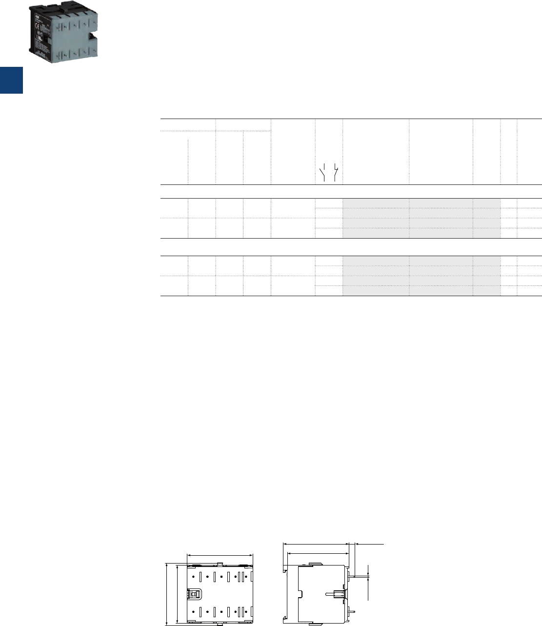
BC6, BC7 3-pole interface mini contactors – with soldering pins
4 to 5.5 kW
DC operated
Description
BC6, BC7 3-pole interface mini contactors are compact control products mainly used for switching
resistive or motor loads up to 690 V AC.
These contactors are designed with:
– 3 main poles and one built-in auxiliary contact
– control circuit: DC operated, low coil consumption (1.4 ... 2.4 W at pull-in and at holding)
– hum-free coil
– no auxiliary contact block permitted for mounting
– designed for soldering on PCB boards
Ordering details
IEC UL/CSA Rated control
circuit voltage
U
C
Auxiliary
contacts
fitted
Type Order code
Pkg
qty
Weight
(1 pce)
Rated operational 3-phase
motor
rating
480 V
General
use
rating
600 V AC
power
400 V
AC-3
current
ș≤ 55 °C
AC-1
kW A hp A V DC kg
DC operation 24 V / 1.4 W
4 12 3 3.4 24 1 0 BC6-30-10-P-1.4-81 GJL1213009R8101 10 0.170
0 1 BC6-30-01-P-1.4-81 GJL1213009R8011 10 0.170
5.5 12 5 7.6 24 1 0 BC7-30-10-P-1.4-81 GJL1313009R8101 10 0.170
0 1 BC7-30-01-P-1.4-81 GJL1313009R8011 10 0.170
DC operation 17 … 32 V / 2.4 W, Ith < 8 A
4 12 3 3.4 17 ... 32 1 0 BC6-30-10-P-2.4-51 GJL1213009R5101 10 0.170
0 1 BC6-30-01-P-2.4-51 GJL1213009R5011 10 0.170
5.5 12 5 7.6 17 ... 32 1 0 BC7-30-10-P-2.4-51 GJL1313009R5101 10 0.170
0 1 BC7-30-01-P-2.4-51 GJL1313009R5011 10 0.170
Other types on request
Main dimensions mm, inches
1 0.04"
47.5 1.87"
42.2 1.66"
45.2 1.78"
44.7 1.76"
47.7 1.88" 4.3 0.17"
2CDC212003F0011
BC6, BC7
2CDC211030F0011
BC7-30-10-P
3/22 | ABB
3
2CDC102029C0201
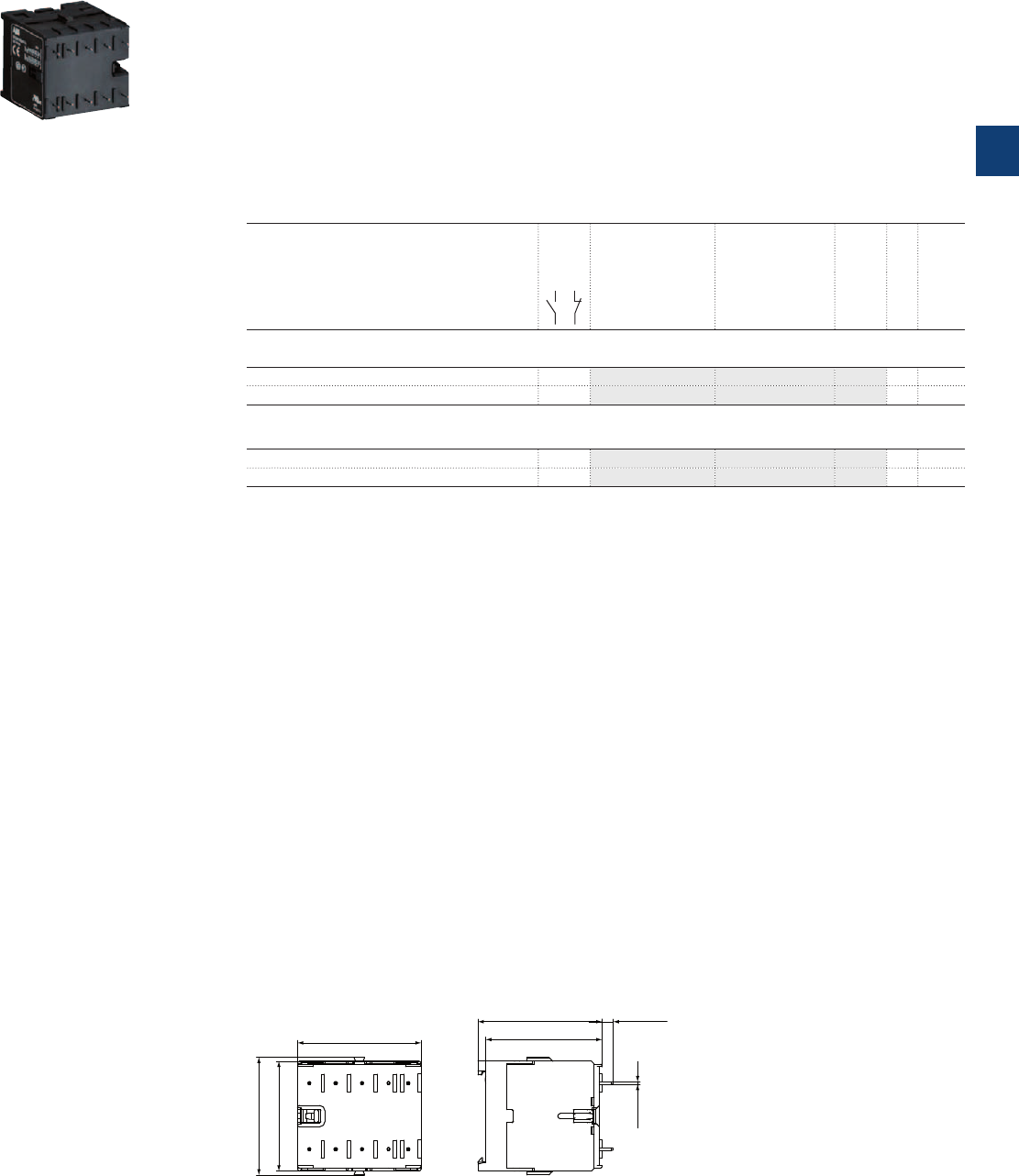
KC6 4-pole interface mini contactor relays – with solderings pins
DC operated
Description
KC6 4-pole interface mini contactor relays are space optimized control products mainly used for control
functions or for small loads up to 4 A.
These contactors are designed with:
– 4 poles with various contact combinations
– control circuit: DC operated, low coil consumption (3.5 W at pull-in and at holding)
– hum-free coil
– add-on auxiliary contact block for side mounting
– designed for soldering on PCB boards
Ordering details
Rated control circuit voltage U
C
Auxiliary
contacts
fitted
Type Order code
Pkg
qty
Weight
(1 pce)
V DC kg
DC operation 24 V / 1.4 W
24 3 1 KC6-31Z-P-1.4-81 GJH1213009R8311 10 0.170
24 4 0 KC6-40E-P-1.4-81 GJH1213009R8401 10 0.170
DC operation 17 ... 32 V / 2.4 W
17 ... 32 3 1 KC6-31Z-P-2.4-51 GJH1213009R5311 10 0.170
17 ... 32 4 0 KC6-40E-P-2.4-51 GJH1213009R5401 10 0.170
Other types on request
Main dimensions mm, inches
1 0.04"
47.5 1.87"
42.2 1.66"
45.2 1.78"
44.7 1.76"
47.7 1.88" 4.3 0.17"
2CDC212003F0011
KC6
2CDC211023F0011
KC6-31Z-P-1.4
ABB | 3/23
3
2CDC102032C0201
B6, B7, BC6, BC7 3- and 4-pole mini contactors
VB6, VB7, VBC6, VBC7 3-pole mini reversing contactors
Accessories
Ordering details
For contactors
Auxiliary
contacts
Type Order code
Pkg
qty
Weight
(1 pce)
kg
Front-mounted instantaneous auxiliary contact blocks (not allowed for mounting on TBC, B6S, B7S, interface contactors)
1)
B6-, B7-40-00, BC6-, BC7-40-00
VB6, VB7, VBC6, VBC7, VB6A, VB7A
VBC6A, VBC7A
1 1 CAF6-11E GJL1201330R0002 10 0.020
2 0 CAF6-20E GJL1201330R0006 10 0.020
0 2 CAF6-02E GJL1201330R0010 10 0.020
B6-, B7-30-10, BC6-, BC7-30-10
VB6, VB7, VBC6, VBC7, VB6A, VB7A
VBC6A, VBC7A
1 1 CAF6-11M GJL1201330R0003 10 0.020
2 0 CAF6-20M GJL1201330R0007 10 0.020
0 2 CAF6-02M GJL1201330R0011 10 0.020
B6-, B7-30-01, BC6-, BC7-30-01
VB6, VB7, VBC6, VBC7, VB6A, VB7A
VBC6A, VBC7A
1 1 CAF6-11N GJL1201330R0004 10 0.020
2 0 CAF6-20N GJL1201330R0008 10 0.020
0 2 CAF6-02N GJL1201330R0012 10 0.020
Side-mounted instantaneous auxiliary contact block 1)
B6-, B7-40-00, BC6-, BC7-40-00 1 1 CA6-11E GJL1201317R0002 10 0.030
B6-, B7-30-10, BC6-, BC7-30-10 1 1 CA6-11M GJL1201317R0003 10 0.030
B6-, B7-30-01, BC6-, BC7-30-01 1 1 CA6-11N GJL1201317R0004 10 0.030
Side-mounted instantaneous auxiliary contact block with soldering pins 1)
B6-, B7-40-00-P, BC6-,BC7-40-00-P 1 1 CA6-11E-P GJL1201319R0002 10 0.025
B6-, B7-30-10-P, BC6-, BC7-30-10-P 1 1 CA6-11M-P GJL1201319R0003 10 0.025
B6-, B7-30-01-P, BC6-, BC7-30-01-P 1 1 CA6-11N-P GJL1201319R0004 10 0.025
Soldering receptacle ( Ie < 8 A )
B6, B7, BC6, BC7 LB6 GJL1201902R0001 10 0.020
2-pole aux.contact blocks CA LB6-CA GJL1201903R0001 10 0.010
1) CA6 and CAF6 must not be fitted simultaneously.
For contactors Rated control
circuit voltage U
C
Connection type Type Order code
Pkg
qty
Weight
(1 pce)
V DC kg
Surge suppressors for contactor coils
BC6, BC7 24 ... 60 Cable lug RV-BC6/60 GHV2501902R0002 10 0.005
Flat pin, 2.8 mm RV-BC6-F/60 GHV2501902R0003 10 0.005
50 ... 250 Cable lug RV-BC6/250 GHV2501903R0002 10 0.005
Flat pin, 2.8 mm RV-BC6-F/250 GHV2501903R0003 10 0.010
380 Cable lug RV-BC6/380 GHV2501904R0002 10 0.005
Flat pin, 2.8 mm RV-BC6-F/380 GHV2501904R0003 10 0.010
Note: Mini contactors for AC operation have an integrated protective circuit
Connecting links with manual motor starters
To connect B..VB.. mini contactor to MS116, MS132 BEA7/132 1SBN080906R1002 10 0.013
To connect B..VB.. mini contactors to MS325 BEA7/325 1SBN080906R1001 10 0.021
Connection sets for reversing contactors
VB6, VB7, VBC6, VBC7, VB6A, VB7A, VBC6A, VBC7A,
cross-section 1.8 mm²
BSM6-30 GJL1201908R0001 10 0.010
Parallel connecting link
B6, B7, BC6, BC7 LP6 GJL1201907R0001 100 0.009
Cover cap, transparent fitting to DIN rail design, sealable
B6, B7, BC6, BC7 LT6-B GJL1201906R0001 10 0.015
Overload relays fitting details 2)
Contactor types Thermal overload relays Electronic overload relays
B6, B7, BC6, BC7 T16 (0.10...16 A) E16DU (0.10...18.9 A)
2) Direct mounting - No kit required. Ordering details, see overload relays section.
CAF6-11N
RV-BC6/250
CA6-11E
CA6-11E-P
BSM6-30
2CDC231012F0011
T16
2CDC211012S0010
2CDC211007S0010
2CDC211008S0010
2CDC211018S0011
SST27792R
3/24 | ABB
3
1SBC101635S0201
K6, KC6 4-pole mini contactor relays
Accessories
Ordering details
For contactors
Auxiliary
contacts
Type Order code
Pkg
qty
Weight
(1 pce)
kg
Front-mounted instantaneous auxiliary contact blocks 1)
K6, KC6 1 1 CAF6-11K GJL1201330R0001 10 0.020
2 0 CAF6-20K GJL1201330R0005 10 0.020
0 2 CAF6-02K GJL1201330R0009 10 0.020
Side-mounted instantaneous auxiliary contact block 1)
K6, KC6 1 1 CA6-11K GJL1201317R0001 10 0.030
Side-mounted instantaneous auxiliary contact block with soldering pins 1)
K6..P, KC6..P 1 1 CA6-11K-P GJL1201319R0001 10 0.025
Soldering receptacle ( Ie < 8 A )
K6, KC6 LB6 GJL1201902R0001 10 0.020
2-pole auxiliary contact blocks CA LB6-CA GJL1201903R0001 10 0.010
1) CA6 and CAF6 must not be fitted simultaneously.
For contactors Rated control
circuit voltage U
C
Connection type Type Order code
Pkg
qty
Weight
(1 pce)
V DC kg
Surge suppressors for contactor coils
KC6 24 ... 60 Cable lug RV-BC6/60 GHV2501902R0002 10 0.005
Flat pin, 2.8 mm RV-BC6-F/60 GHV2501902R0003 10 0.005
50 ... 250 Cable lug RV-BC6/250 GHV2501903R0002 10 0.005
Flat pin, 2.8 mm RV-BC6-F/250 GHV2501903R0003 10 0.010
380 Cable lug RV-BC6/380 GHV2501904R0002 10 0.005
Flat pin, 2.8 mm RV-BC6-F/380 GHV2501904R0003 10 0.010
Note: Mini contactors for AC operation have an integrated protective circuit
Cover cap, transparent fitting to DIN rail design, sealable
K6, KC6 LT6-B GJL1201906R0001 10 0.015
CAF6-11K
CA6-11K
CA6-11K-P
LT6-B
RV-BC6/250
2CDC211019S0011
2CDC211009S0010
2CDC211011S0010
2CDC211006S0010
2CDC211007S0010
ABB | 3/25
3
1SBC101635S0201
B6, B7, BC6, BC7, TBC7 3- and 4-pole mini contactors
VB6, VB7, VBC6, VBC7 3- and 4-pole mini reversing contactors
Technical data
Main pole – Utilization characteristics according to IEC
Contactor types
AC operated
B6, VB6, VB6A B7, VB7, VB7A
DC operated
BC6, VBC6, VBC6A BC7, TBC7, VBC7, VBC7A
Standards
IEC 60947-1 / 60947-4-1 and EN 60947-1 / 60947-4-1
Rated operational voltage U
e max
690 V AC
Rated frequency (without derating)
DC or 50 / 60 Hz
Conventional free-air thermal current l
th
acc. to IEC 60947-4-1, open contactors, T ≤ 40 °C,
with conductor cross-sectional area
20 A
AC-1 Utilization category for air temperature close to contactor ș ≤ 40 °C
I
e
/ Rated operational current AC-1
U
e max
≤ 690 V, 50/60 Hz
220-230-240 V Screw terminal types: 20 A
Soldering pin types: 12 A
Flat pin types: 16 A
380-400 V Screw terminal types: 20 A
Soldering pin types: 12 A
Flat pin types: 16 A
440 V Screw terminal types: 20 A
Soldering pin types: 12 A
Flat pin types: 16 A
500 V 12 A
690 V 6 A
AC-1 Utilization category for air temperature close to contactor ș ≤ 55 °C
I
e
/ Rated operational current AC-1
U
e max
≤ 690 V, 50/60 Hz
220-230-240 V Screw terminal types: 16 A
Soldering pin types: 12 A
Flat pin types: 16 A
Screw terminal types: 20 A
Soldering pin types: 12 A
Flat pin types: 16 A
380-400 V Screw terminal types: 16 A
Soldering pin types: 12 A
Flat pin types: 16 A
Screw terminal types: 20 A
Soldering pin types: 12 A
Flat pin types: 16 A
440 V Screw terminal types: 16 A
Soldering pin types: 12 A
Flat pin types: 16 A
Screw terminal types: 20 A
Soldering pin types: 12 A
Flat pin types: 16 A
500 V 12 A
690 V 6 A
AC-3 Utilization category for air temperature close to contactor ș ≤ 55 °C
Ie / Rated operational current AC-3 220-230-240 V 9 A 12 A
3-phase motors
380-400 V 8 A 12 A
440 V 8 A 12 A
500 V 6.5 A 9 A
690 V 3.5 A 3.5 A
Rated operational power AC-3
220-230-240 V 2.2 kW 3 kW
1500 r.p.m. 50 Hz
1800 r.p.m. 60 Hz
3-phase motors
380-400 V 4 kW 5.5 kW
440 V 4 kW 5.5 kW
500 V 3 kW 4 kW
690 V 3 kW 3 kW
DC-1 Utilization category for air temperature close to contactor ș ≤ 55 °C
I
e
/ Rated operational current DC-1 110 V
-4 A
220 V
- 0.6 A
DC-3 Utilization category for air temperature close to contactor ș ≤ 55 °C
I
e
/ Rated operational current DC-3 110 V
- 1.5 A
220 V
- 0.25 A
DC-5 Utilization category for air temperature close to contactor ș ≤ 55 °C
I
e
/ Rated operational current DC-5 110 V
- 0.4 A
220 V
- 0.2 A
Rated making capacity AC-3
10 x I
e
AC-3 acc. to IEC 60947-4-1
Rated breaking capacity AC-3
8 x I
e
AC-3 acc. to IEC 60947-4-1
Short-circuit protection device for contactors
without thermal O/L relay - motor protection excluded
U
e
≤ 500 V AC - gG type fuse Coordination type 1: 25 A / Coordination type 2: 20 A
Rated short-time withstand current I
CW
at 40 °C ambient temperature, in free air from a cold state 10 s 64 A 96 A
Maximum breaking capacity cos ࢥ = 0.45
at 400 V 64 A 96 A
Maximum electrical switching frequency
AC-1 300 cycles/h
AC-3 600 cycles/h
DC-1, DC-3, DC-5 600 cycles/h
M
3
M
3
M
3
M
3
3/26 | ABB
3
2CDC102043C0201

B6, B7, BC6, BC7, TBC7 3- and 4-pole mini contactors
VB6, VB7, VBC6, VBC7 3- and 4-pole mini reversing contactors
Technical data
Main pole – Utilization characteristics according to UL/NEMA/CSA
Contactor types
AC operated
B6, VB6, VB6A B7, VB7, VB7A
DC operated
BC6, VBC6, VBC6A BC7, TBC7, VBC7, VBC7A
Standards
UL 508, CSA C22.2 N°14
Maximum operational voltage
600 V
UL/CSA general use rating
12 A 16 A
UL/CSA maximum 1-phase motor rating
Full load current 120 V AC 8.4 A 13.8 A
240 V AC 6.8 A 10.0 A
Horse power rating 120 V AC 1 hp 0.75 hp
240 V AC 2 hp 1.5 hp
UL/CSA maximum 3-phase motor rating
Full load current
1)
200-208 V AC 4.6 A 7.5 A
220-240 V AC 6.8 A 9.6 A
440-480 V AC 3.4 A 7.6 A
550-600 V AC 1.7 A 6.1 A
Horse power rating
1)
200-208 V AC 1 hp 2 hp
220-240 V AC 2 hp 3 hp
440-480 V AC 3 hp 5 hp
550-600 V AC 1 hp 5 hp
Short-circuit protection device for contactors
without thermal overload relay - motor protection excluded
Fuse rating 600 V 40 A
Fuse type 600 V Class J
Maximum electrical switching frequency
For resitive loads AC-1 300 cycles/h
For motor loads AC-3 600 cycles/h
1)
For the corresponding kW/A or hp/A values of 1500 r.p.m, 50 Hz or 1800 r.p.m, 60 Hz, 3-phase motors, see "Motor rated operational powers and currents".
General technical data
Contactor types
AC operated
B6, VB6, VB6A B7, VB7, VB7A
DC operated
BC6, VBC6, VBC6A BC7, TBC7, VBC7, VBC7A
Rated insulation voltage U
i
acc. to IEC 60947-4-1 690 V
acc. to UL/CSA 600 V
Rated impulse withstand voltage U
imp
6 kV
Ambient air temperature, close to contactor
Operation Fitted with thermal overload relay -25 ... +55 °C
Without thermal overload relay -25 ... +55 °C
Storage -40 ... +80 °C
Climatic withstand
acc. to IEC 60947-1 Annex Q
Maximum operating altitude (without derating)
2000 m
Mechanical durability
10
7
operating cycles
Resistance to shock
Half-sine
acc. to IEC 60068-2-27 and EN 60068-2-27 15 g / 11 ms
acc. to IEC/EN 60947-1 Annex. Q Category E
Resistance to vibrations
Sinusoidal
acc. to IEC 60068-2-27 and EN 60068-2-27 5 g / 3 ... 150 Hz
acc. to IEC/EN 60947-1 Annex. Q Category E
ABB | 3/27
3
2CDC102043C0201
B6, B7, BC6, BC7, TBC7 3- and 4-pole mini contactors
VB6, VB7, VBC6, VBC7 3- and 4-pole mini reversing contactors
Technical data
Magnet system characteristics for B6, B7 contactors
Contactor types
AC operated
B6, VB6 B7, VB7
Coil operating limits acc. to IEC 60947-4-1
AC supply 0.85 ... 1.1 x U
c
AC control voltage
Rated control circuit voltage U
C
See ordering tables
Coil consumption Average pull-in value 3.5 VA / 3.5 W
Average holding value 3.5 VA / 3.5 W
Drop-out voltage
0.20 ... 0.75 % of U
c
Magnet system characteristics for BC6, BC7 contactors
Contactor types
DC operated
BC6, VBC6 BC7, VBC7
Coil operating limits acc. to IEC 60947-4-1
DC supply 0.85 ... 1.1 x U
c
AC control voltage
Rated control circuit voltage U
C
See ordering tables
Coil consumption
1)
Average pull-in value 3.5 VA / 3.5 W
Average holding value 3.5 VA / 3.5 W
Drop-out voltage in % of U
C min
0.10 ... 0.75 x U
C
1) Interface mini-contactors: see coil consumption on ordering details pages
Magnet system characteristics for TBC7 contactors
Contactor types
DC operated
TBC7
Coil operating limits acc. to IEC 60947-4-1
DC supply Wide range voltage supply see ordering tables, U
Cmin
... U
Cmax
AC control voltage
Rated control circuit voltage U
C
See ordering tables
Coil consumption Average pull-in value 5 VA / 5 W
Average holding value 5 VA / 5 W
Drop-out voltage in % of U
C min
≤
0.20 % of U
Cmin
Mounting characteristics and conditions for use
Contactor types
AC operated
B6, VB6, VB6A B7, VB7, VB7A
DC operated
BC6, VBC6, VBC6A BC7, TBC7, VBC7, VBC7A
Mounting positions
Pos. 1
Pos. 2
Pos. 4
Pos. 1 ± 30°
- 30°+ 30°
Pos. 5 Pos. 6
Pos. 3
Mounting distances
The contactors can be assembled side by side
Fixing
On rail acc. to IEC 60715, EN 60715 35 x 7.5 mm or 35 x 15 mm
By screws (not supplied) 2 x M4 screws placed diagonally
3/28 | ABB
3
2CDC102043C0201

B6, B7, BC6, BC7, TBC7 3- and 4-pole mini contactors
VB6, VB7, VBC6, VBC7 3- and 4-pole mini reversing contactors
Technical data
Built-in auxiliary contacts according to IEC
Contactor types
AC operated
B6, VB6, VB6A B7, VB7, VB7A
DC operated
BC6, VBC6, VBC6A BC7, TBC7, VBC7, VBC7A
Standards
IEC 60947-1 / 60947-4-1 and EN 60947-1 / 60947-4-1
Rated operational voltage Ue max
690 V
Rated frequency (without derating)
DC or 50 / 60 Hz
Conventional free-air thermal current l
th
ș ≤ 40 °C
6 A
I
e
/ Rated operational current AC-15
acc. to IEC 60947-5-1
24 V 50/60 Hz
4 A
110-120 V 50/60 Hz
4 A
220-230-240 V 50/60 Hz
4 A
380-400 V 50/60 Hz
3 A
440 V 50/60 Hz
3 A
I
e
/ Rated operational current DC-13
acc. to IEC 60947-5-1
24 V DC 2.5 A
110 V DC
0.7 A
220 - 240 V DC 0.4 A
Short-circuit protection device
6 A, Type gG
Minimum switching capacity with failure rate acc. to IEC 60947-5-4
17 V / 5 mA
Maximum electrical switching frequency
AC-15 600 cycles/h
DC-13 600 cycles/h
Built-in auxiliary contacts according to UL/CSA
Contactor types
AC operated
B6, VB6, VB6A B7, VB7, VB7A
DC operated
BC6, VBC6, VBC6A BC7, VBC7, VBC7A
Max. operational voltage
600 V AC
Pilot duty
A600
AC thermal rated current 5 A
ABB | 3/29
3
2CDC102043C0201
B6, B7, BC6, BC7, TBC7 3- and 4-pole mini contactors
VB6, VB7, VBC6, VBC7 3- and 4-pole mini reversing contactors
Technical data
Connection characteristics
Contactor types
AC operated
B6, VB6, VB6A B7, VB7, VB7A
DC operated
BC6, VBC6, VBC6A BC7, TBC7, VBC7, VBC7A
Main terminals
1)
Screw terminals with cable clamp
Connection capacity
Main conductors (poles)
Rigid: solid
1 or 2 x
1 ... 4 mm²
Flexible without ferrule
1 or 2 x
1 ... 2.5 mm²
Connection capacity acc. to UL/CSA
1 or 2 x
AWG 22 ... 10
Stripping length
9 mm
Tightening torques
0.8 ... 1.1 Nm / 7 lb.in
Connection capacity – auxiliary conductors
(built-in auxiliary terminals + coil terminals)
Rigid: solid
1 or 2 x
1 ... 4 mm²
Flexible without ferrule
1 or 2 x
1 ... 2.5 mm²
Connection capacity acc. to UL/CSA
1 or 2 x
AWG 22 ... 10
Stripping length
9 mm
Tightening torques
Coil terminals
0.8 ... 1.1 Nm / 7 lb.in
Built-in auxiliary terminals
0.8 ... 1.1 Nm / 7 lb.in
Degree of protection
acc. to IEC 60947-1 / EN 60947-1 and IEC 60529 / EN 60529
Main terminals
IP20
Coil terminals
IP20
Built-in auxiliary terminals
IP20
Screw terminals
(Delivered in open position, screws of unused terminals must be tightened)
All terminals
M3
Screwdriver type
Flat Ø 5.5 mm / Pozidriv 1
1) Soldering pin connection acc. to DIN 40801: 0.8 x 1 mm / 0.8 x 2.54 mm
Flat pin connection acc. to DIN 46248: 1 x 6.3 mm / 1 x 2.8 mm
3/30 | ABB
3
2CDC102043C0201

Main pole – Utilization characteristics according to IEC
Contactor types
AC operated
K6
DC operated
KC6, TKC6
Standards
IEC 60947-1 / 60947-5-1 and EN 60947-1 / 60947-5-1
Rated operational voltage U
emax
690 V
Rated frequency (without derating)
DC or 50 / 60 Hz
Conventional free-air thermal current l
th
T ≤ 40 °C
6 A
I
e
/ Rated operational current AC-15
acc. to IEC 60947-5-1
24 V 50/60 Hz 4 A
110-120 V 50/60 Hz 4 A
220-230-240 V 50/60 Hz
4 A
380-400 V 50/60 Hz 3 A
440 V 50/60 Hz 3 A
480-500 V 50/60 Hz 2 A
I
e
/ Rated operational current DC-13
acc. to IEC 60947-5-1
24 V DC
2.5 A
110 V DC
0.7 A
220 - 240 V DC
0.4 A
Short-circuit protection device for contactors U
e
≤ 500 V AC, gG fuse type
6 A
Minimum switching capacity
17 V / 5 mA
Maximum electrical switching frequency
AC-15 600 cycles/h
DC-13 600 cycles/h
Main pole – Utilization characteristics according to UL/NEMA/CSA
Contactor types
AC operated
K6
DC operated
KC6
Standards
UL 508, CSA C22.2 No14
Maximum operational voltage
600 V AC
Pilot duty
A600
K6, KC6, TKC6 4-pole mini contactor relays
Technical data
ABB | 3/31
3
2CDC102043C0201

General technical data
Contactor relay types
AC operated
K6
DC operated
KC6, TKC6
Rated insulation voltage U
i
acc. to IEC 60947-5-1
690 V
acc. to UL/CSA
600 V
Rated impulse withstand voltage U
imp
6 kV
Electromagnetic compatibility
Ambient air temperature close to contactor relay
Operation in free air
-25 ... +55 °C
Storage
-40 ... +80 °C
Climatic withstand
acc. to IEC 60068-2-30
Maximum operating altitude (without derating)
2000 m
Mechanical durability
10
7
operating cycles
Resistance to shock
Half-sine
acc. IEC 60068-2-27 and EN 60068-2-27
15 g / 11ms
acc. to IEC/EN 60947-1 Annex. Q
Category E
Resistance to vibrations
Sinusoidal
acc. IEC 60068-2-27 and EN 60068-2-27
5 g / 3 ... 150 Hz
acc. to IEC/EN 60947-1 Annex. Q
Kategorie E
Magnet system characteristics for K6 contactor relays
Contactor relay types
AC operated
K6
Coil operating limits acc. to IEC 60947-4-1
AC supply 0.85 ... 1.1 x U
C
AC control voltage
Coil consumption Average pull-in value
3.5 VA / 3.5 W
Average holding value
3.5 VA / 3.5 W
Drop-out voltage in % of U
C
min.
Approx. 20 ... 75%
Magnet system characteristics for KC6, TKC6 contactor relays
Contactor relay types
DC operated
KC6 TKC6
Coil operating limits acc. to IEC 60947-5-1
DC supply 0.85 ... 1.1 x U
C
See ordering details
DC control voltage
Coil consumption Average pull-in value
3.5 VA / 3.5 W 5 VA / 5 W
Average holding value
3.5 VA / 3.5 W 5 VA / 5 W
Drop-out voltage in % of U
C
min.
10 ... 75 % 10 ... 75 %
K6, KC6, TKC6 4-pole mini contactor relays
Technical data
3/32 | ABB
3
2CDC102043C0201
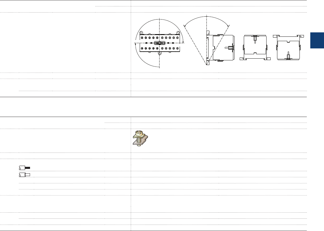
Mounting characteristics and conditions for use
Contactor types
AC operated
K6
DC operated
KC6, TKC6
Mounting positions
Pos. 1
Pos. 2
Pos. 4
Pos. 1 ± 30°
- 30°+ 30°
Pos. 5 Pos. 6
Pos. 3
Mounting distances
The contactors can be assembled side by side.
Fixing
On rail acc. to IEC 60715, EN 60715
35 x 7.5 mm or 35 x 15 mm
By screws (not supplied)
2 x M4 screws placed diagonally
Connecting characteristics
Contactor relay types AC operated K6
DC operated KC6, TKC6
Main terminals
1)
Screw terminals with cable clamp
Connection capacity
Main conductors (poles)
Rigid: solid
1 or 2 x
1 ... 4 mm²
Flexible without ferrule
1 or 2 x
1 ... 2.5 mm²
Connection capacity acc. to UL/CSA
1 or 2 x
AWG 22 ... 10
Stripping length
9 mm
Tightening torques
0.8 ... 1.1 Nm / 7 lb.in
Degree of protection
acc. to IEC 60947-1 / EN 60947-1 and IEC 60529 / EN 60529
All
IP20
Screw terminals
(Delivered in open position, screws of unused terminals must be tightened)
All terminals
M3
Screwdriver type
Flat Ø 5.5 / Pozidriv 1
1) Soldering pin connection acc. to DIN 40801: 0.8 x 1 mm / 0.8 x 2.54 mm
Flat pin connection acc. to DIN 46248: 1 x 6.3 mm / 1 x 2.8 mm
K6, KC6, TKC6 4-pole mini contactor relays
Technical data
ABB | 3/33
3
2CDC102043C0201
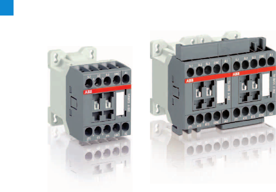
4/0 | ABB
4
Somm_AS contactors

AS contactors
NS contactor relays
3-pole contactors
Overview 4/2
AS09...AS16 AC operated 4/4
ASL09...ASL16 DC operated 4/5
AS09...AS16 AC operated - 2-stack 4/6
ASL09...ASL16 DC operated - 2-stack 4/7
Main accessories 4/8
Technical data 4/10
3-pole reversing contactors
VAS09...VAS16 AC operated 4/16
VASL09...VASL16 DC operated 4/17
Technical data 4/18
Contactor relays
Overview 4/22
NS AC operated 4/24
NSL DC operated 4/25
Main accessories 4/26
Technical data 4/28
Accessories 4/31
Voltage coil table 4/37
ABB | 4/1
4
Somm_AS contactors
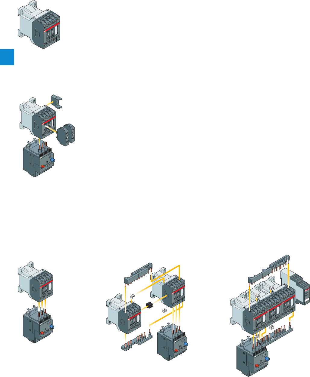
Main accessories for starting solutions
Direct-on-line starter Reversing starter Star-delta starter
Main accessories for contactors
T16
Thermal overload relay
RV5, RT5 or RC5-1
Surge suppressor
CA-3
1-pole auxiliary contact block
T16
Thermal overload relay
AS
ASL
Contactors
T16
Thermal overload relay
AS
ASL
Contactors
AS
ASL
Contactors
BER16C-3
Connection set
Timer
BEY16C-3
Connection set
T16
Thermal overload relay
VM3
Mechanical
interlock unit
3-pole contactors
Main accessories
AS09...AS16
3-pole contactors
VM3
Mechanical
interlock unit
4/2 | ABB
4
1SBC101292S0201
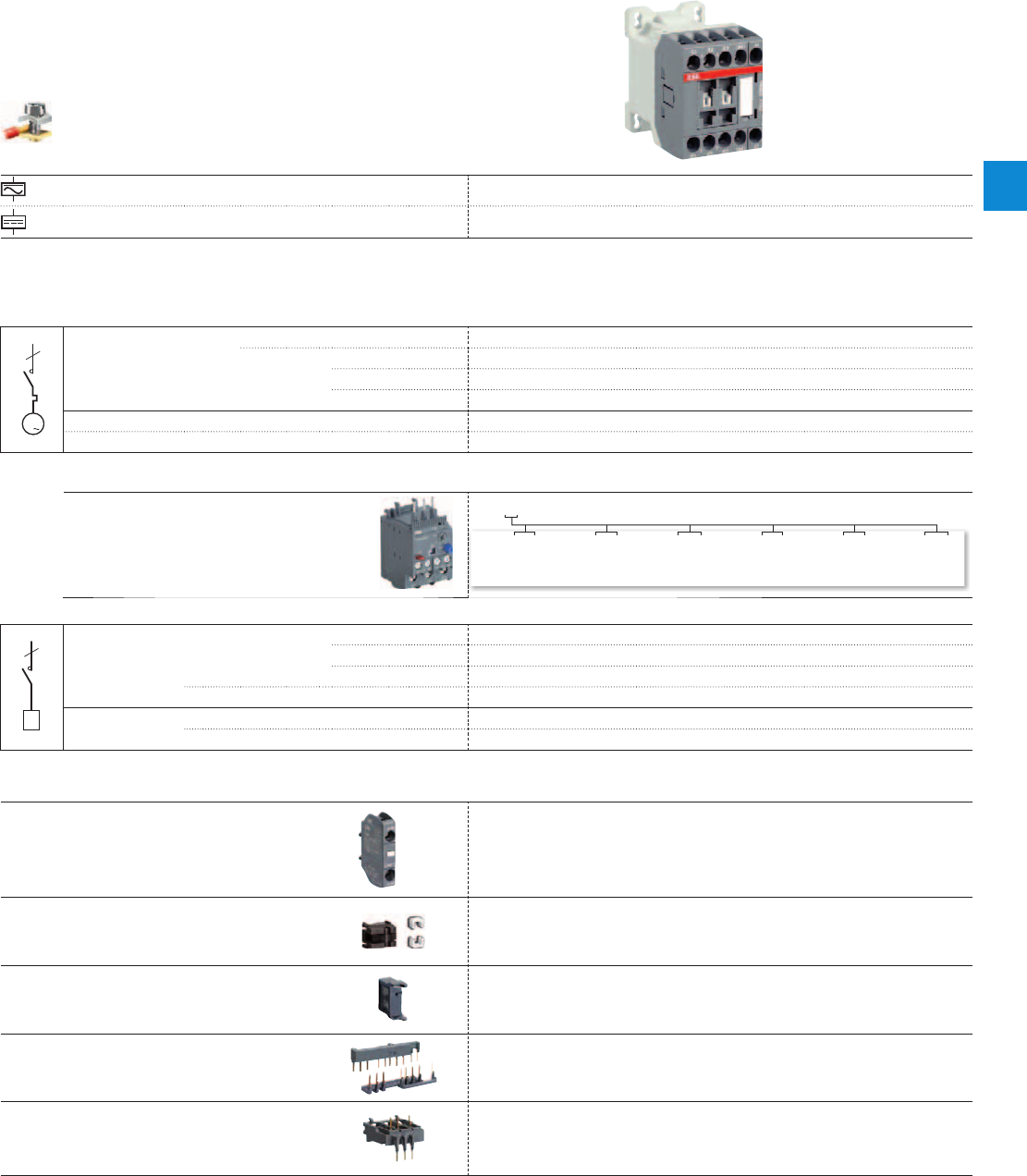
3-pole contactors
Screw terminals
AC control voltage AS09 AS12 AS16
DC control voltage ASL09 ASL12 ASL16
Switching of 3-phase cage motors
3
M
3
3
IEC AC-3
Rated operational power
400 V
4 kW 5.5 kW 7.5 kW
Rated
operational
current
θ ≤ 60 °C
400 V
9 A 12 A 15.5 A
θ ≤ 60 °C
415 V
9 A 12 A 15.5 A
θ ≤ 60 °C
690 V
5 A7 A9 A
UL / CSA 3-phase motor rating
440-480 V
5 hp 7.5 hp 10 hp
NEMA size 00 00 0
Protection of 3-phase motors
Thermal overload relays
T16...
Switching of resistive circuits
R
3
R
3IEC AC-1
Rated
operational
current
θ ≤ 40 °C
690 V
22 A 24 A 24 A
θ ≤ 60 °C
690 V
18 A 20 A 20 A
θ ≤ 70 °C
690 V
15 A 16 A 16 A
With conductor cross-sectional area 2.5 mm22.5 mm22.5 mm2
UL / CSA General use rating 600 V AC 20 A 20 A 20 A
With conductor cross-sectional area AWG 12 AWG 12 AWG 12
Main accessories
Auxiliary
contact
blocks
Front mounting 1-pole CA3-10 or CA3-01
Interlocks Mechanical VM3
Surge
suppressors
Side-mounted
(without additional
width)
RV5 (Varistor) AC / DC
RC5-1 (Capacitor) AC
RT5 (Transil diode) DC
Connection
sets
Reversing starters
Star-delta starters
BER16C-3
BEY16C-3
Connecting
link
With manual motor
starter BEA16-3
0.10...0.13 0.23...0.31 0.55...0.74 1.30...1.70 3.10...4.20 7.60...10.0
0.13...0.17 0.31...0.41 0.74...1.00 1.70...2.30 4.20...5.70 10.0...13.0
0.17...0.23 0.41...0.55 1.00...1.30 2.30...3.10 5.70...7.60 13.0...16.0
ABB | 4/3
4
1SBC101292S0201
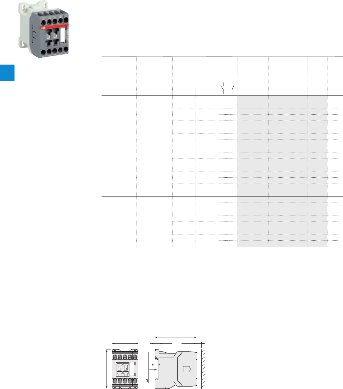
AS09 ... AS16 3-pole contactors
4 to 7.5 kW
AC operated
Description
AS09 ... AS16 contactors are mainly used for controlling 3-phase motors and power circuits up to 690 V AC and
220 V DC.
These contactors are of the block type design with:
– 3 main poles and 1 built-in auxiliary contact
– control circuit: AC operated
– add-on auxiliary contact blocks for front mounting and a comprehensive range of accessories.
Ordering details
IEC UL/CSA Rated control circuit Auxiliary Type Order code Weight
Rated operational 3-phase General voltage contacts
power current motor use Uc fitted Pkg
θ≤ 40 °C rating rating (1) (1 pce)
400 V 480 V 600 V AC
AC-3 AC-1
kW A hp A V 50 Hz V 60 Hz kg
4 22 5 20 24 24 1 0 AS09-30-10-20 1SBL101001R2010 0.220
0 1 AS09-30-01-20 1SBL101001R2001 0.220
- 120 1 0 AS09-30-10-16 1SBL101001R1610 0.220
0 1 AS09-30-01-16 1SBL101001R1601 0.220
230 230 1 0 AS09-30-10-26 1SBL101001R2610 0.220
0 1 AS09-30-01-26 1SBL101001R2601 0.220
400 400 1 0 AS09-30-10-28 1SBL101001R2810 0.220
0 1 AS09-30-01-28 1SBL101001R2801 0.220
5.5 24 7.5 20 24 24 1 0 AS12-30-10-20 1SBL111001R2010 0.220
0 1 AS12-30-01-20 1SBL111001R2001 0.220
- 120 1 0 AS12-30-10-16 1SBL111001R1610 0.220
0 1 AS12-30-01-16 1SBL111001R1601 0.220
230 230 1 0 AS12-30-10-26 1SBL111001R2610 0.220
0 1 AS12-30-01-26 1SBL111001R2601 0.220
400 400 1 0 AS12-30-10-28 1SBL111001R2810 0.220
0 1 AS12-30-01-28 1SBL111001R2801 0.220
7.5 24 10 20 24 24 1 0 AS16-30-10-20 1SBL121001R2010 0.220
0 1 AS16-30-01-20 1SBL121001R2001 0.220
- 120 1 0 AS16-30-10-16 1SBL121001R1610 0.220
0 1 AS16-30-01-16 1SBL121001R1601 0.220
230 230 1 0 AS16-30-10-26 1SBL121001R2610 0.220
0 1 AS16-30-01-26 1SBL121001R2601 0.220
400 400 1 0 AS16-30-10-28 1SBL121001R2810 0.220
0 1 AS16-30-01-28 1SBL121001R2801 0.220
Note: for multiple packaging, please contact your ABB local sales organization.
(1) Other control voltages see voltage code table.
Main dimensions mm, inches
72.5 2.85"
45 1.77"
68 2.68"
5.5 0.22"
7 0.28"
35 mm
EN/IEC 60715
10 0.39"
AS09, AS12, AS16
1SBC101007F0014
AS09-30-10
4/4 | ABB
4
1SBC101301S0201
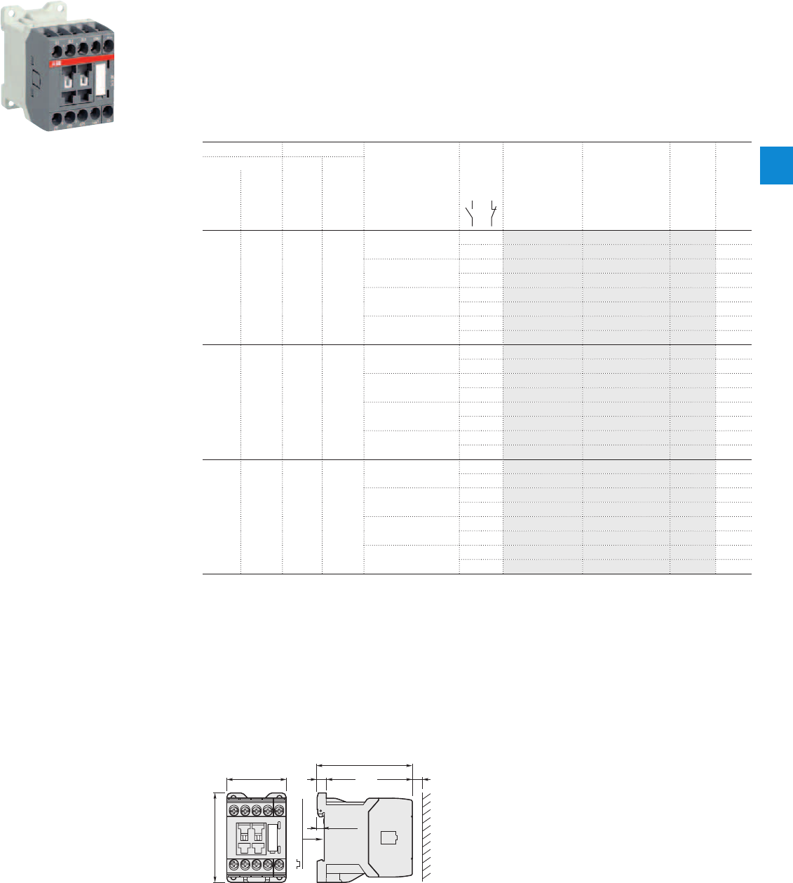
1SBC101010F0014
ASL09-30-10
Description
ASL09 ... ASL16 contactors are mainly used for controlling 3-phase motors and power circuits up to 690 V AC
and 220 V DC.
These contactors are of the block type design with:
– 3 main poles and 1 built-in auxiliary contact
– control circuit: low consumption (3 W at pull-in and holding) DC operated with solid core magnet. Suitable for
direct control by PLC outputs (the polarity on the coil terminals A1+ and A2- must be respected)
– add-on auxiliary contact blocks for front mounting and a comprehensive range of accessories.
Ordering details
IEC UL/CSA Rated control circuit Auxiliary Type Order code Weight
Rated operational 3-phase General voltage contacts
power current motor use Uc fitted Pkg
θ≤ 40 °C rating rating (1) (1 pce)
400 V 480 V 600 V AC
AC-3 AC-1
kW A hp A V DC kg
4 22 5 20 24 1 0 ASL09-30-10-81 1SBL103001R8110 0.280
0 1 ASL09-30-01-81 1SBL103001R8101 0.280
48 1 0 ASL09-30-10-83 1SBL103001R8310 0.280
0 1 ASL09-30-01-83 1SBL103001R8301 0.280
110 1 0 ASL09-30-10-86 1SBL103001R8610 0.280
0 1 ASL09-30-01-86 1SBL103001R8601 0.280
220 1 0 ASL09-30-10-88 1SBL103001R8810 0.280
0 1 ASL09-30-01-88 1SBL103001R8801 0.280
5.5 24 7.5 20 24 1 0 ASL12-30-10-81 1SBL113001R8110 0.280
0 1 ASL12-30-01-81 1SBL113001R8101 0.280
48 1 0 ASL12-30-10-83 1SBL113001R8310 0.280
0 1 ASL12-30-01-83 1SBL113001R8301 0.280
110 1 0 ASL12-30-10-86 1SBL113001R8610 0.280
0 1 ASL12-30-01-86 1SBL113001R8601 0.280
220 1 0 ASL12-30-10-88 1SBL113001R8810 0.280
0 1 ASL12-30-01-88 1SBL113001R8801 0.280
7.5 24 10 20 24 1 0 ASL16-30-10-81 1SBL123001R8110 0.280
0 1 ASL16-30-01-81 1SBL123001R8101 0.280
48 1 0 ASL16-30-10-83 1SBL123001R8310 0.280
0 1 ASL16-30-01-83 1SBL123001R8301 0.280
110 1 0 ASL16-30-10-86 1SBL123001R8610 0.280
0 1 ASL16-30-01-86 1SBL123001R8601 0.280
220 1 0 ASL16-30-10-88 1SBL123001R8810 0.280
0 1 ASL16-30-01-88 1SBL123001R8801 0.280
Note: for multiple packaging, please contact your ABB local sales organization.
(1) Other control voltages see voltage code table.
Main dimensions mm, inches
45 1.77"
68 2.68"
72.5 2.85"
5.5 0.22"
7 0.28"
35 mm
EN/IEC 60715
10 0.39"
ASL09, ASL12, ASL16
ASL09 ... ASL16 3-pole contactors
4 to 7.5 kW
DC operated
ABB | 4/5
4
1SBC101302S0201
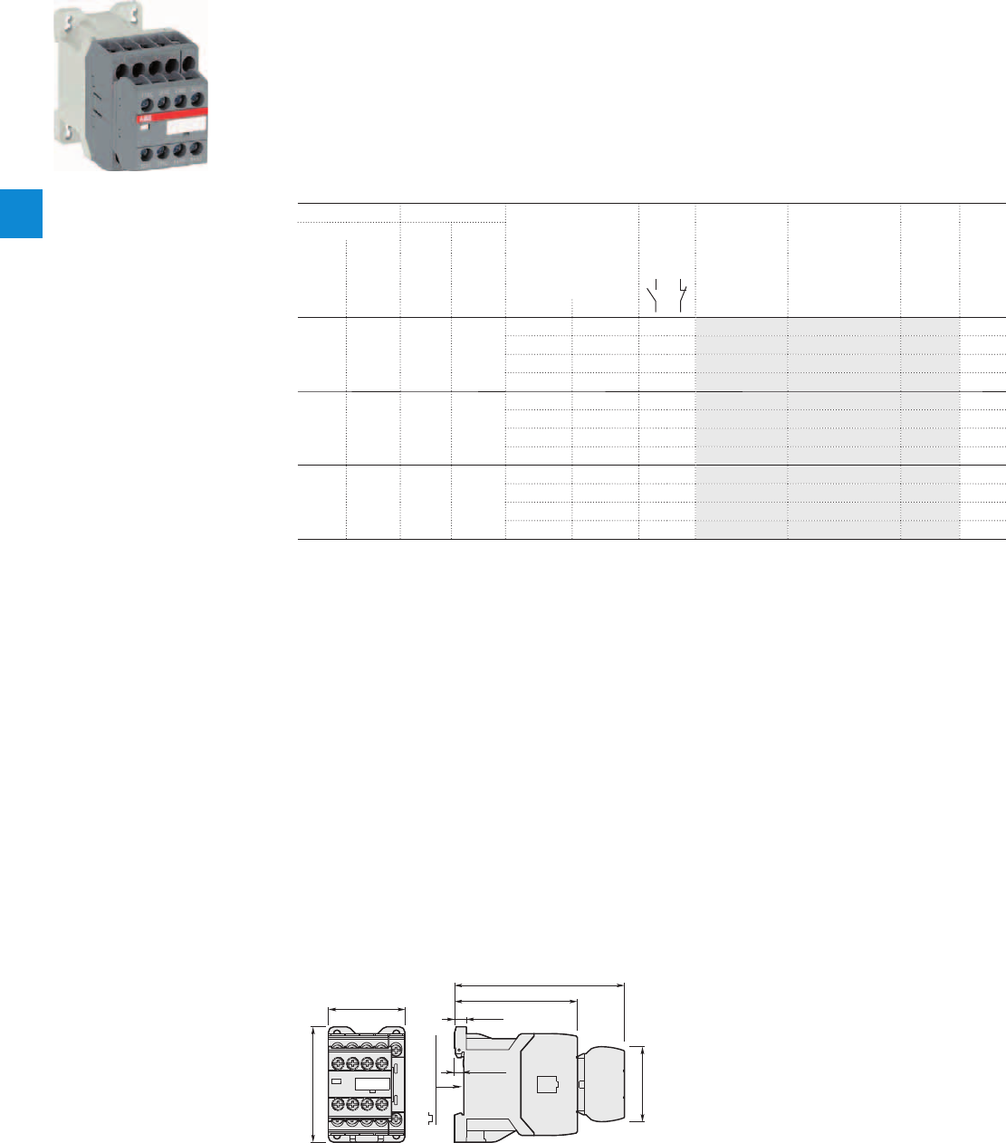
AS09 ... AS16 2-stack 3-pole contactors
4 to 7.5 kW
AC operated
Description
AS09 ... AS16 contactors are mainly used for controlling 3-phase motors and power circuits up to 690 V AC and
220 V DC.
These contactors are of the block type design with:
– 1st stack with 3 main poles and 1 N.O. built-in auxiliary contact
– 2nd stack with permanently fixed 2 N.O. + 2 N.C. auxiliary contact block. The auxiliary contact elements are
mechanically linked (side-marked symbol) and the N.C. auxiliary contacts are mirror contacts
– control circuit: AC operated
– a comprehensive range of accessories.
Ordering details
IEC UL/CSA Rated control circuit Auxiliary Type Order code Weight
Rated operational 3-phase General voltage contacts
power current motor use Uc fitted Pkg
θ≤ 40 °C rating rating (1) (1 pce)
400 V 480 V 600 V AC
AC-3 AC-1
kW A hp A V 50 Hz V 60 Hz kg
4 22 5 20 24 24 3 2 AS09-30-32-20 1SBL101001R2032 0.260
- 120 3 2 AS09-30-32-16 1SBL101001R1632 0.260
230 230 3 2 AS09-30-32-26 1SBL101001R2632 0.260
400 400 3 2 AS09-30-32-28 1SBL101001R2832 0.260
5.5 24 7.5 20 24 24 3 2 AS12-30-32-20 1SBL111001R2032 0.260
- 120 3 2 AS12-30-32-16 1SBL111001R1632 0.260
230 230 3 2 AS12-30-32-26 1SBL111001R2632 0.260
400 400 3 2 AS12-30-32-28 1SBL111001R2832 0.260
7.5 24 10 20 24 24 3 2 AS16-30-32-20 1SBL121001R2032 0.260
- 120 3 2 AS16-30-32-16 1SBL121001R1632 0.260
230 230 3 2 AS16-30-32-26 1SBL121001R2632 0.260
400 400 3 2 AS16-30-32-28 1SBL121001R2832 0.260
Note: for multiple packaging, please contact your ABB local sales organization.
(1) Other control voltages see voltage code table.
Main dimensions mm, inches
45 1.77"
68 2.68"
72.5 2.85"
5.5 0.22"
7 0.28"
35 mm
EN/IEC 60715
100.2 3.94"
44.2 1.74"
AS09, AS12, AS16
1SBC101332F0014
AS09-30-32
4/6 | ABB
4
1SBC101303S0201
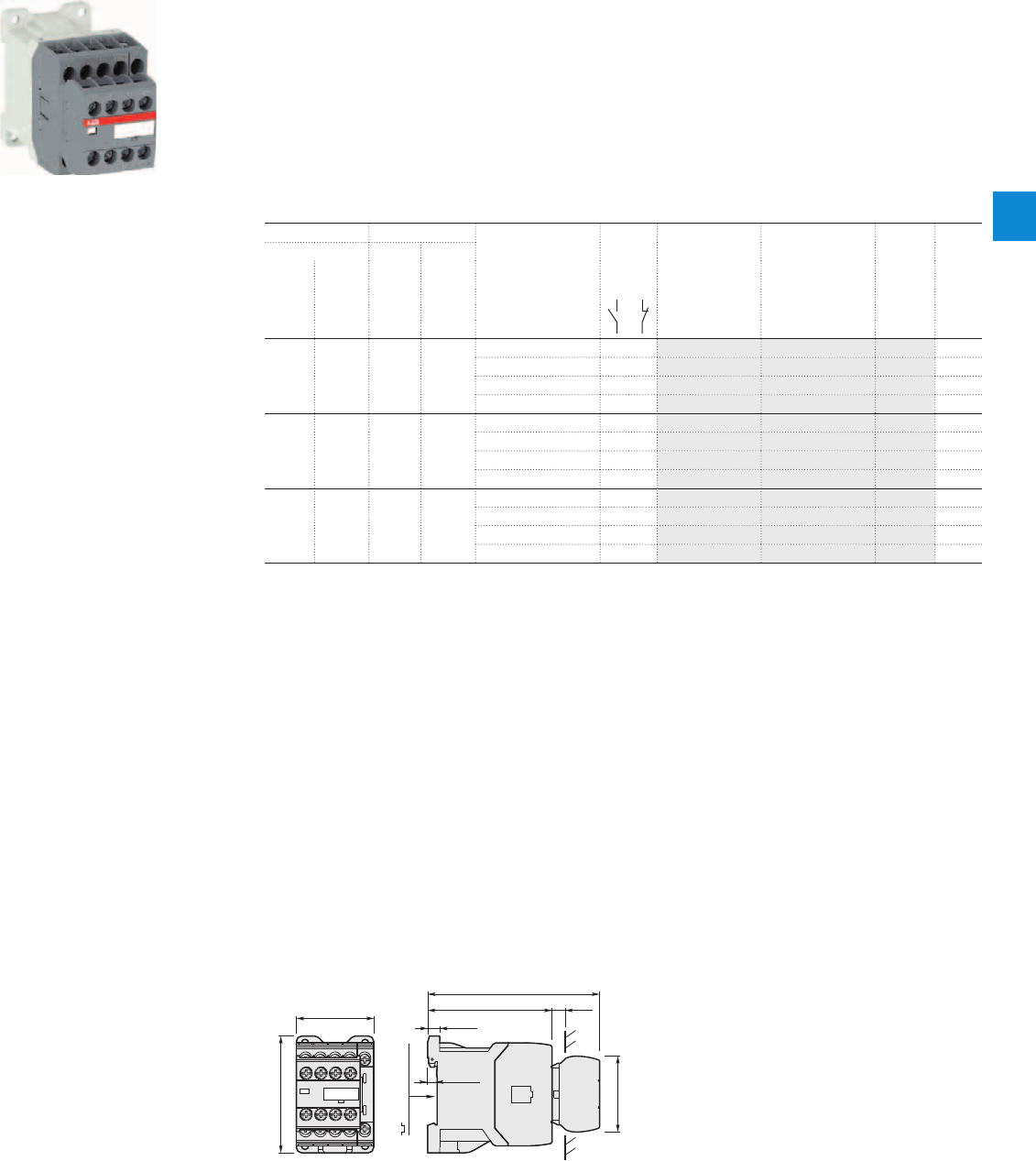
1SBC101334F0014
ASL09-30-32
Description
ASL09 ... ASL16 contactors are mainly used for controlling 3-phase motors and power circuits up to 690 V AC
and 220 V DC.
These contactors are of the block type design with:
– 1st stack with 3 main poles and 1 N.O. built-in auxiliary contact
– 2nd stack with permanently fixed 2 N.O. + 2 N.C. auxiliary contact block. The auxiliary contact elements are
mechanically linked (side-marked symbol) and the N.C. auxiliary contacts are mirror contacts
– control circuit: low consumption (3 W at pull-in and holding) DC operated with solid core magnet. Suitable for
direct control by PLC outputs (the polarity on the coil terminals A1+ and A2- must be respected)
– a comprehensive range of accessories.
Ordering details
IEC UL/CSA Rated control circuit Auxiliary Type Order code Weight
Rated operational 3-phase General voltage contacts
power current motor use Uc fitted Pkg
θ≤ 40 °C rating rating (1) (1 pce)
400 V 480 V 600 V AC
AC-3 AC-1
kW A hp A V DC kg
4 22 5 20 24 3 2 ASL09-30-32-81 1SBL103001R8132 0.320
48 3 2 ASL09-30-32-83 1SBL103001R8332 0.320
110 3 2 ASL09-30-32-86 1SBL103001R8632 0.320
220 3 2 ASL09-30-32-88 1SBL103001R8832 0.320
5.5 24 7.5 20 24 3 2 ASL12-30-32-81 1SBL113001R8132 0.320
48 3 2 ASL12-30-32-83 1SBL113001R8332 0.320
110 3 2 ASL12-30-32-86 1SBL113001R8632 0.320
220 3 2 ASL12-30-32-88 1SBL113001R8832 0.320
7.5 24 10 20 24 3 2 ASL16-30-32-81 1SBL123001R8132 0.320
48 3 2 ASL16-30-32-83 1SBL123001R8332 0.320
110 3 2 ASL16-30-32-86 1SBL123001R8632 0.320
220 3 2 ASL16-30-32-88 1SBL123001R8832 0.320
Note: for multiple packaging, please contact your ABB local sales organization.
(1) Other control voltages see voltage code table.
Main dimensions mm, inches
10
0.39"
45 1.77"
68 2.68"
72.5 2.85"
5.5 0.22"
7 0.28"
35 mm
EN/IEC 60715
100.2 3.94"
44.2 1.74"
ASL09, ASL12, ASL16
ASL09 ... ASL16 2-stack 3-pole contactors
4 to 7.5 kW
DC operated
ABB | 4/7
4
1SBC101453S0201
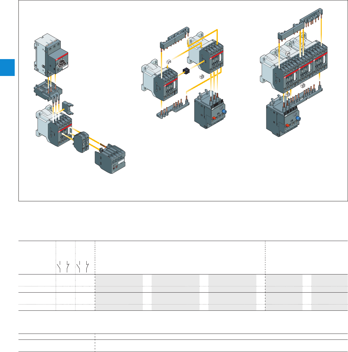
AS09...AS16 and
ASL09...ASL16 3-pole contactors
Main accessories
Main accessory fitting details
Many configurations of accessories are possible depending on whether these are front-mounted or side-mounted.
Contactor
types
Main
poles
Built-in
auxiliary
contacts
Front-mounted accessories Side-mounted accessories
Auxiliary contact blocks Electronic timer Mechanical interlock unit
(between 2 contactors)
1-pole CA3 TEF3 VM3 Surge suppressors
AS09...AS16 3 0 1 0 2 max.
or
1
+
1
+
RV5
or
RC5-1
30 01
AS09...AS16 3 0 3 2 – – 1
+
RV5
or
RC5-1
ASL09...ASL16 3 0 1 0 2 max.
or
1
+
1
+
RV5
or
RT5
30 01
ASL09...ASL16 3 0 3 2 – – 1
+
RV5
or
RT5
Overload relays fitting details (1)
Contactor types Thermal overload relays
AS09…AS16 T16 (0.10...16 A)
ASL09…ASL16
The addition of an overload relay on the contactor does not prevent fitting of many other accessories as shown above.
(1) Direct mounting - No kit required.
Contactor and main accessories (other accessories available)
BEY16C-3
BER16C-3
BEA16-3
MS116
VM3
(optional)
VM3
T16
T16
AS
ASL
Contactors TEF3
CA3
RV5, RC5-1 or RT5
AS
ASL
Contactors
AS
ASL
Contactors
4/8 | ABB
4
1SBC101297S0201
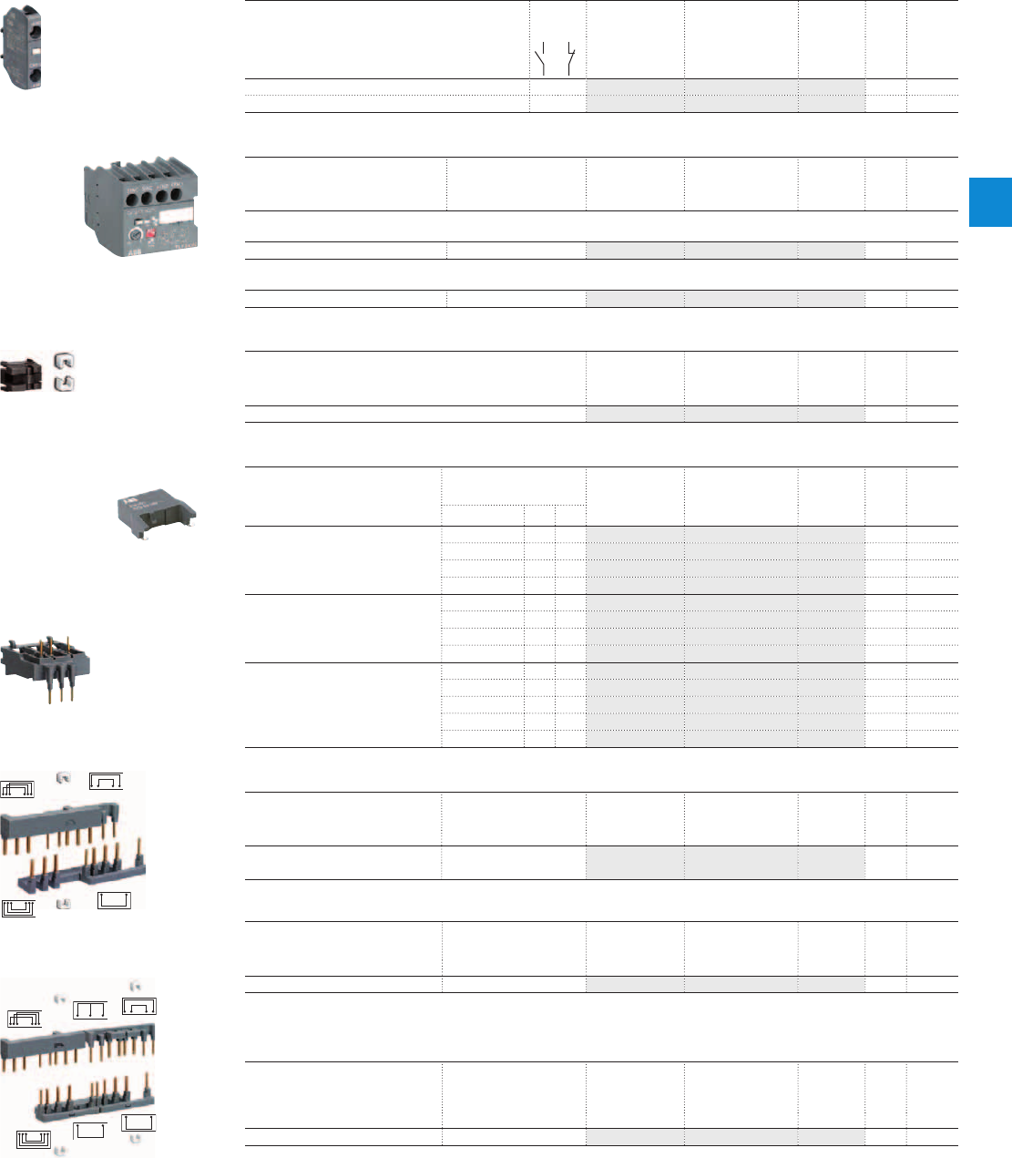
AS09...AS16 and
ASL09...ASL16 3-pole contactors
Main accessories
Front-mounted instantaneous auxiliary contact blocks
For contactors Auxiliary
contacts
Type Order code Pkg
qty
Weight
(1 pce)
kg
AS09…AS16 1 0 CA3-10 1SBN011010T1010 10 0.011
ASL09…ASL16 0 1 CA3-01 1SBN011010T1001 10 0.011
Front-mounted electronic timer
For contactors Rated control circuit
voltage - Uc
Type Order code Pkg
qty
Weight
(1 pce)
V kg
ON-delay
AS09…AS16, ASL09…ASL16 24...240VAC/DC TEF3-ON 1SBN021012R1000 1 0.065
OFF-delay
AS09…AS16, ASL09…ASL16 24...240VAC/DC TEF3-OFF 1SBN021014R1000 1 0.065
Mechanical interlock unit
For contactors Type Order code Pkg
qty
Weight
(1 pce)
kg
AS09…AS16, ASL09…ASL16 VM3 1SBN031005T1000 10 0.002
Surge suppressors
For contactors Rated control circuit
voltage - Uc
Type Order code Pkg
qty
Weight
(1 pce)
VACDC kg
AS09...AS16,
ASL09...ASL16
24...50
●●
RV5/50 1SBN050010R1000 2 0.015
50...133
●●
RV5/133 1SBN050010R1001 2 0.015
110...250
●●
RV5/250 1SBN050010R1002 2 0.015
250...440
●●
RV5/440 1SBN050010R1003 2 0.015
AS09...AS16 24...50
●
– RC5-1/50 1SBN050100R1000 2 0.012
50...133
●
– RC5-1/133 1SBN050100R1001 2 0.012
110...250
●
– RC5-1/250 1SBN050100R1002 2 0.012
250...440
●
– RC5-1/440 1SBN050100R1003 2 0.012
ASL09...ASL16 12...32 –
●
RT5/32 1SBN050020R1000 2 0.015
25...65 –
●
RT5/65 1SBN050020R1001 2 0.015
50...90 –
●
RT5/90 1SBN050020R1002 2 0.015
77...150 –
●
RT5/150 1SBN050020R1003 2 0.015
150...264 –
●
RT5/264 1SBN050020R1004 2 0.015
Connecting links with manual motor starters
For contactors Manual motor
starter
Type Order code Pkg
qty
Weight
(1 pce)
kg
AS09…AS16 MS116-0.16 ... MS116-16
MS132-0.16 ... MS132-16
BEA16-3 1SBN081006T1000 10 0.019
ASL09…ASL16
Connection sets for reversing contactors
For contactors Mechanical
interlock unit
Type Order code Pkg
qty
Weight
(1 pce)
kg
AS09…AS16, ASL09…ASL16 with or without VM3 BER16C-3 1SBN081012R1000 1 0.035
Note: BER16C-3 connection set includes two BB3 fixing clips, and an electrical interlocking when fitted on contactors with built-in
N.C. auxiliary contacts. BER16C-3 can be used with or without VM3 mechanical interlock unit.
Connection sets for star-delta starting
For contactors Mech. interlock unit
between Star & Delta
contactors
Type Order code Pkg
qty
Weight
(1 pce)
kg
AS09…AS12, ASL09…ASL12 with or without VM3 BEY16C-3 1SBN081018R2000 1 0.041
Note: BEY16C-3 connection set includes two BB3 fixing clips, and an electrical interlocking when fitted on Star and Delta contactors
with built-in N.C. auxiliary contacts. BEY16C-3 can be used with or without VM3 mechanical interlock unit.
1SBC101036F0014
CA3-10
1SBC101337F0014
TEF3-ON
1SBC101069F0014
VM3
1SBC574001F0301
RV5
1SBC101034F0014
BEA16-3
1SBC101070F0014
BEY16C-3
1SBC101071F0014
BER16C-3
ABB | 4/9
4
1SBC101297S0201
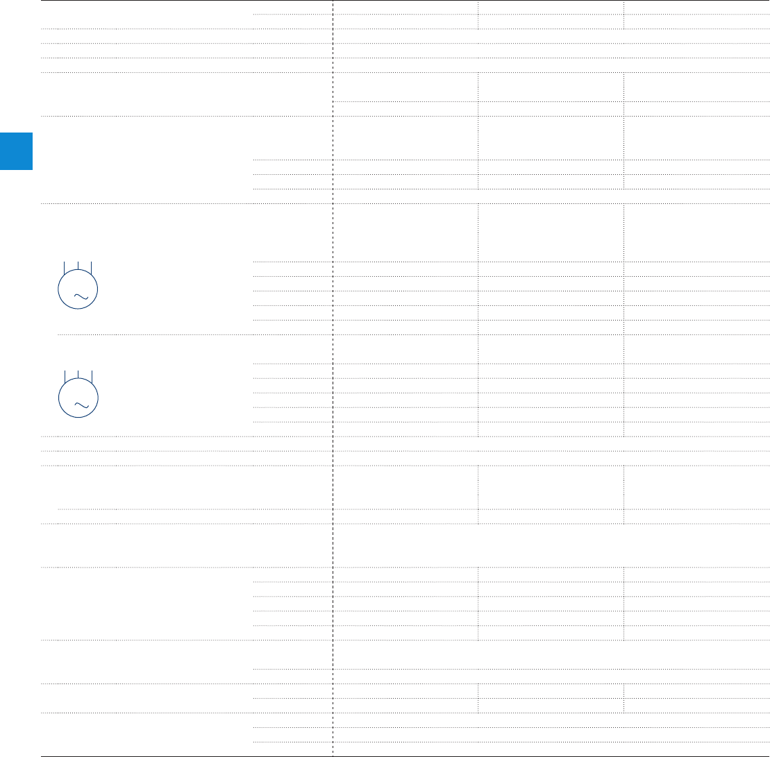
Main pole - Utilization characteristics according to IEC
Contactor types
AC operated
AS09 AS12 AS16
DC operated
ASL09 ASL12 ASL16
Standards
IEC 60947-1 / 60947-4-1 and EN 60947-1 / 60947-4-1
Rated operational voltage Ue max.
690 V
Rated frequency (without derating)
50 / 60 Hz
Conventional free-air thermal current Ith
acc. to IEC 60947-4-1, open contactors, θ ≤ 40 °C 22 A 25 A 25 A
With conductor cross-sectional area 2.5 mm² 4 mm² 4 mm²
AC-1 Utilization category
For air temperature close to contactor
Ie / Rated operational current AC-1
θ ≤ 40 °C 22 A 24 A 24 A
Ue max. ≤ 690 V, 50/60 Hz θ ≤ 60 °C 18 A 20 A 20 A
θ ≤ 70 °C 15 A 16 A 16 A
With conductor cross-sectional area 2.5 mm²
AC-3 Utilization category
For air temperature close to contactor θ ≤ 60 °C
Ie / Max. rated operational current AC-3 (1)
3-phase motors
220-230-240 V 9 A 12 A 15.7 A
400 V 9 A 12 A 15.5 A
415 V 9 A 12 A 15.5 A
440 V 8 A 11 A 13.6 A
500 V 8 A 11 A 12.5 A
690 V 5 A 7 A 9 A
Rated operational power AC-3 (1)
220-230-240 V
2.2 kW 3 kW 4 kW
400 V 4 kW 5.5 kW 7.5 kW
1500 r.p.m. 50 Hz
415 V 4 kW 5.5 kW 7.5 kW
1800 r.p.m. 60 Hz
440 V 4 kW 5.5 kW 7.5 kW
3-phase motors
500 V 4 kW 5.5 kW 7.5 kW
690 V 4 kW 5.5 kW 7.5 kW
Rated making capacity AC-3
10 x Ie AC-3 acc. to IEC 60947-4-1
Rated breaking capacity AC-3
8 x Ie AC-3 acc. to IEC 60947-4-1
AC-8a Utilization category
(without thermal overload relay - Ue 400 V 50/60 Hz - θ ≤ 40 °C)
Ie / Rated operational current AC-8a
12 A 16 A 22 A
Rated operational power AC-8a
5.5 kW 7.5 kW 11 kW
Short-circuit protection device for contactors
without thermal overload relay - Motor protection excluded
(2)
Ue ≤ 500 V AC - gG type fuse 25 A
Rated short-time withstand current Icw
1 s 230 A 250 A 250 A
at 40 °C ambient temperature, 10 s 100 A 124 A 124 A
in free air from a cold state 30 s 65 A 75 A 75 A
1 min 50 A 55 A 55 A
15 min 22 A 24 A 24 A
Maximum breaking capacity
cos φ = 0.45 at 440 V 155 A
at 690 V 90 A
Power dissipation per pole
Ie / AC-1 1 W 1.2 W 1.2 W
Ie / AC-3 0.16 W 0.3 W 0.5 W
Max. electrical switching frequency
AC-1 600 cycles/h
AC-3 1200 cycles/h
AC-4 300 cycles/h
(1) For the corresponding kW/A or hp/A values of 1500 r.p.m, 50 Hz or 1800 r.p.m, 60 Hz, 3-phase motors, see "Motor rated operational powers and currents".
(2) For the protection of motor starters against short circuits, see "Coordination with short-circuit protection devices".
AS09...AS16 and
ASL09...ASL16 3-pole contactors
Technical data
M
3
M
3
4/10 | ABB
4
1SBC101489S0201
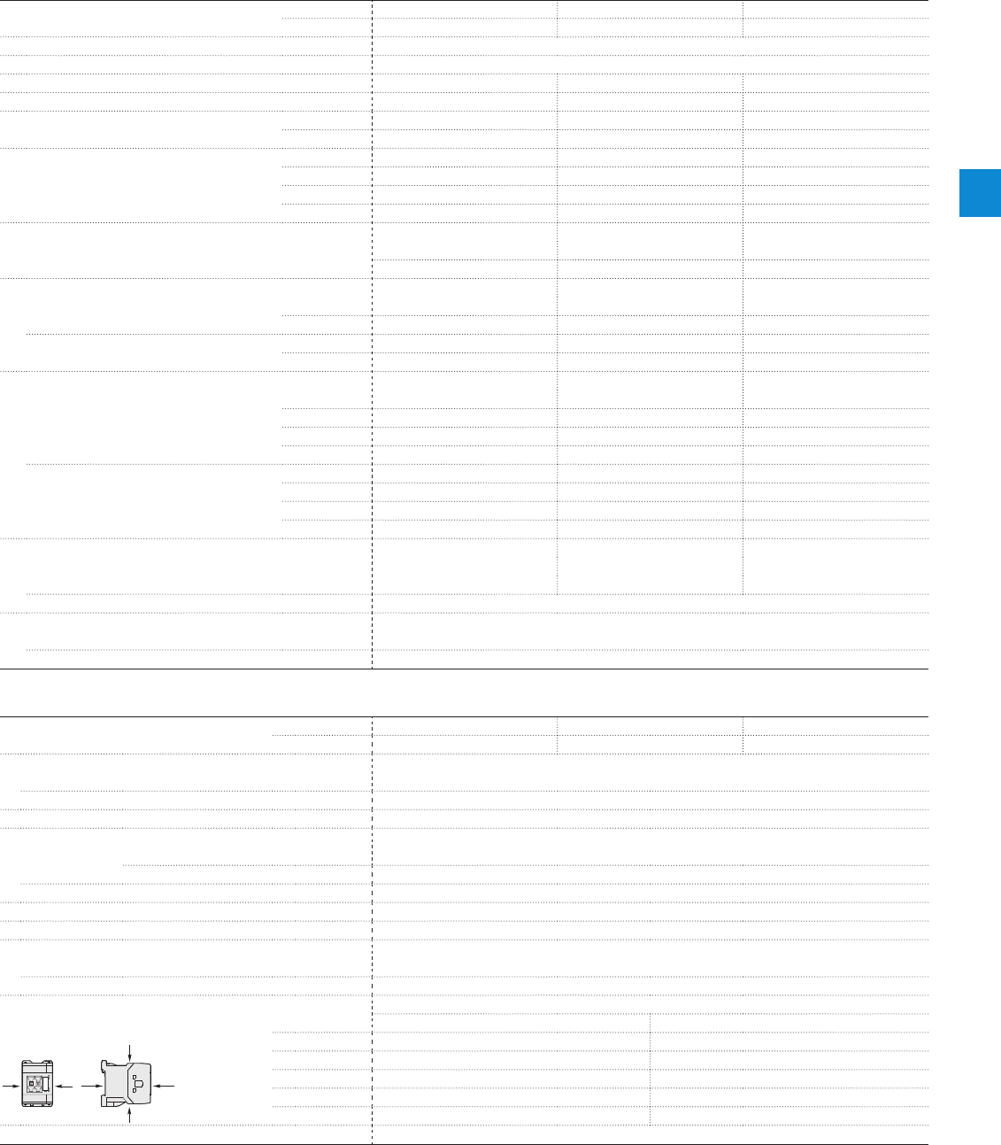
Main pole - Utilization characteristics according to UL / NEMA / CSA
Contactor types
AC operated
AS09 AS12 AS16
DC operated
ASL09 ASL12 ASL16
Standards
UL 508, CSA C22.2 N°14
Max. operational voltage
690 V
NEMA size
00 00 0
NEMA continuous amp rating
Thermal current 9 A 9 A 18 A
NEMA maximum horse power ratings 1-phase, 60 Hz
115 V AC 1/3 hp 1/3 hp 1 hp
230 V AC 1 hp 1 hp 2 hp
NEMA maximum horse power ratings 3-phase, 60 Hz
200 V AC 1 1/2 hp 1 1/2 hp 3 hp
230 V AC 1 1/2 hp 1 1/2 hp 3 hp
460 V AC 2 hp 2 hp 5 hp
575 V AC 2 hp 2 hp 5 hp
UL / CSA general use rating
600 V AC 20 A 20 A 20 A
With conductor cross-sectional area AWG 12 AWG 12 AWG 12
UL / CSA maximum 1-phase motor rating
Full load current 120 V AC 7.2 A 9.8 A 13.8 A
240 V AC 8 A 10 A 12 A
Horse power rating 120 V AC 1/3 hp 1/2 hp 3/4 hp
240 V AC 1 hp 1-1/2 hp 2 hp
UL / CSA maximum 3-phase motor rating
Full load current (1) 200-208 V AC 7.8 A 7.8 A 11 A
220-240 V AC 6.8 A 9.6 A 15.2 A
440-480 V AC 7.6 A 11 A 14 A
550-600 V AC 9 A 11 A 11 A
Horse power rating (1) 200-208 V AC 2 hp 2 hp 3 hp
220-240 V AC 2 hp 3 hp 5 hp
440-480 V AC 5 hp 7-1/2 hp 10 hp
550-600 V AC 7-1/2 hp 10 hp 10 hp
Short-circuit protection device for contactors
without thermal overload relay - Motor protection excluded
Fuse rating 40 A 50 A 60 A
Fuse type, 600 V J
Max. electrical switching frequency
For general use 600 cycles/h
For motor use 1200 cycles/h
(1) For the corresponding kW/A or hp/A values of 1500 r.p.m, 50 Hz or 1800 r.p.m, 60 Hz, 3-phase motors, see "Motor rated operational powers and currents".
General technical data
Contactor types
AC operated
AS09 AS12 AS16
DC operated
ASL09 ASL12 ASL16
Rated insulation voltage Ui
acc. to IEC 60947-4-1 690 V
acc. to UL / CSA 600 V
Rated impulse withstand voltage Uimp.
6 kV
Ambient air temperature close to contactor
Operation Fitted with thermal overload relay -25...+60 °C
Without thermal overload relay -40...+70 °C
Storage -60...+80 °C
Climatic withstand
Category B according to IEC 60947-1 Annex Q
Maximum operating altitude (without derating)
3000 m
Mechanical durability
Number of operating cycles 10 millions operating cycles
Max. switching frequency 3600 cycles/h
Shock withstand
1/2 sinusoidal shock for 11 ms: no change in contact position, closed or open position
acc. to IEC 60068-2-27 and EN 60068-2-27 Shock direction AS contactors - AC operated ASL contactors - DC operated
Mounting position 1 A20 g 20 g closed position / 10 g open position
B1 10 g closed position / 5 g open position 15 g closed position / 5 g open position
B2 15 g 10 g
C1 20 g closed position / 9 g open position 15 g closed position / 8 g open position
C2 20 g closed position / 14 g open position 14 g closed position / 8 g open position
Vibration withstand acc. to IEC 60068-2-6
5...300 Hz / 3 g closed position / 2 g open position
AS09...AS16 and
ASL09...ASL16 3-pole contactors
Technical data
B2
AAB1
C2
C1
ABB | 4/11
4
1SBC101489S0201
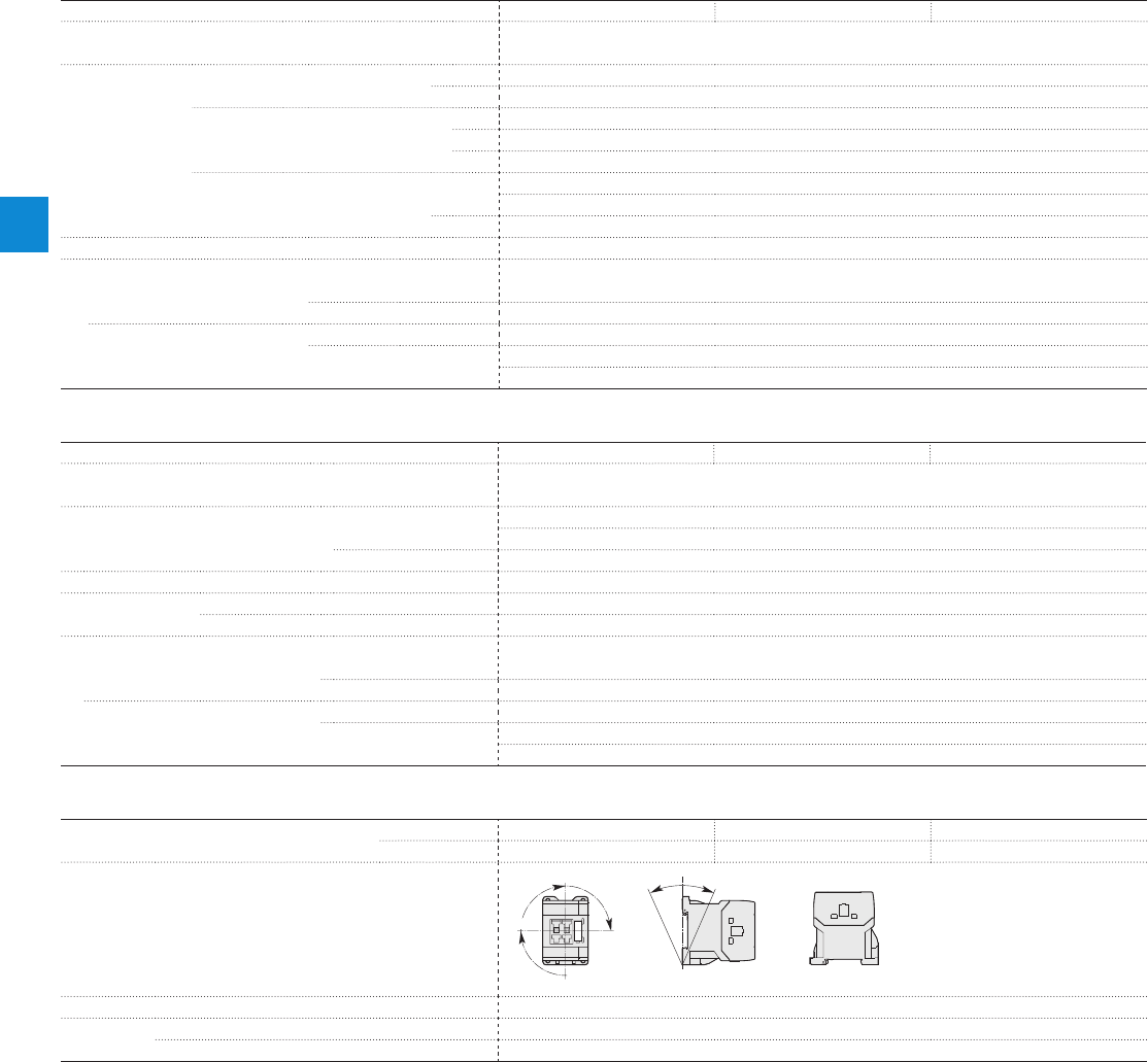
Magnet system characteristics for AS09…AS16 contactors
Contactor types AC operated
AS09 AS12 AS16
Coil operating limits AC supply
acc. to IEC 60947-4-1 0.85...1.1 x Uc (at θ ≤ 60 °C); Uc (at θ ≤ 70 °C)
AC control voltage Rated control circuit voltage Uc at 50 Hz 24...415 V
at 60 Hz 24...415 V
Coil consumption Average pull-in value 50 Hz 33 VA
60 Hz 33 VA
50/60 Hz 33 VA
Average holding value 50 Hz 6.5 VA / 1.5 W
60 Hz 5 VA / 1.2 W
50/60 Hz 6.5 VA / 1.5 W
Drop-out voltage Approx. 30...50 % of Uc
Operating time
Between coil energization and: N.O. contact closing 9...24 ms
N.C. contact opening 6...18 ms
Between coil de-energization and: N.O. contact opening (1) 5...19 ms
N.C. contact closing (1) 7...22 ms
(1) The use of RC5-1 surge suppressor increases opening time by a factor of 2 to 3
Magnet system characteristics for ASL09…ASL16 contactors
Contactor types DC operated
ASL09 ASL12 ASL16
Coil operating limits DC supply
acc. to IEC 60947-4-1 0.85...1.1 x Uc (at θ ≤ 60 °C); Uc (at θ ≤ 70 °C)
DC control voltage Rated control circuit voltage Uc 12...240 V DC
Coil consumption Average pull-in value 3 W
Average holding value 3 W
Drop-out voltage Approx. 10...40 % of Uc
Coil time constant Open L/R 12 ms
Closed L/R 40 ms
Operating time
Between coil energization and: N.O. contact closing 36...59 ms
N.C. contact opening 31...53 ms
Between coil de-energization and: N.O. contact opening (1) 13...17 ms
N.C. contact closing (1) 15...20 ms
(1) The use of RT5 surge suppressor increases opening time by a factor of 1.1 to 1.2
Mounting characteristics and conditions for use
Contactor types AC operated
AS09 AS12 AS16
DC operated
ASL09 ASL12 ASL16
Mounting positions
Pos. 1 ± 30°
+30° -30°
Pos. 3
Pos. 2
Pos. 1
Pos. 4
Pos. 5
Mounting distances The contactors can be assembled side by side.
Fixing On rail according to IEC 60715, EN 60715 35 x 7.5 mm or 35 x 15 mm
By screws (not supplied) 2 x M4 screws placed diagonally
AS09...AS16 and
ASL09...ASL16 3-pole contactors
Technical data
4/12 | ABB
4
1SBC101489S0201
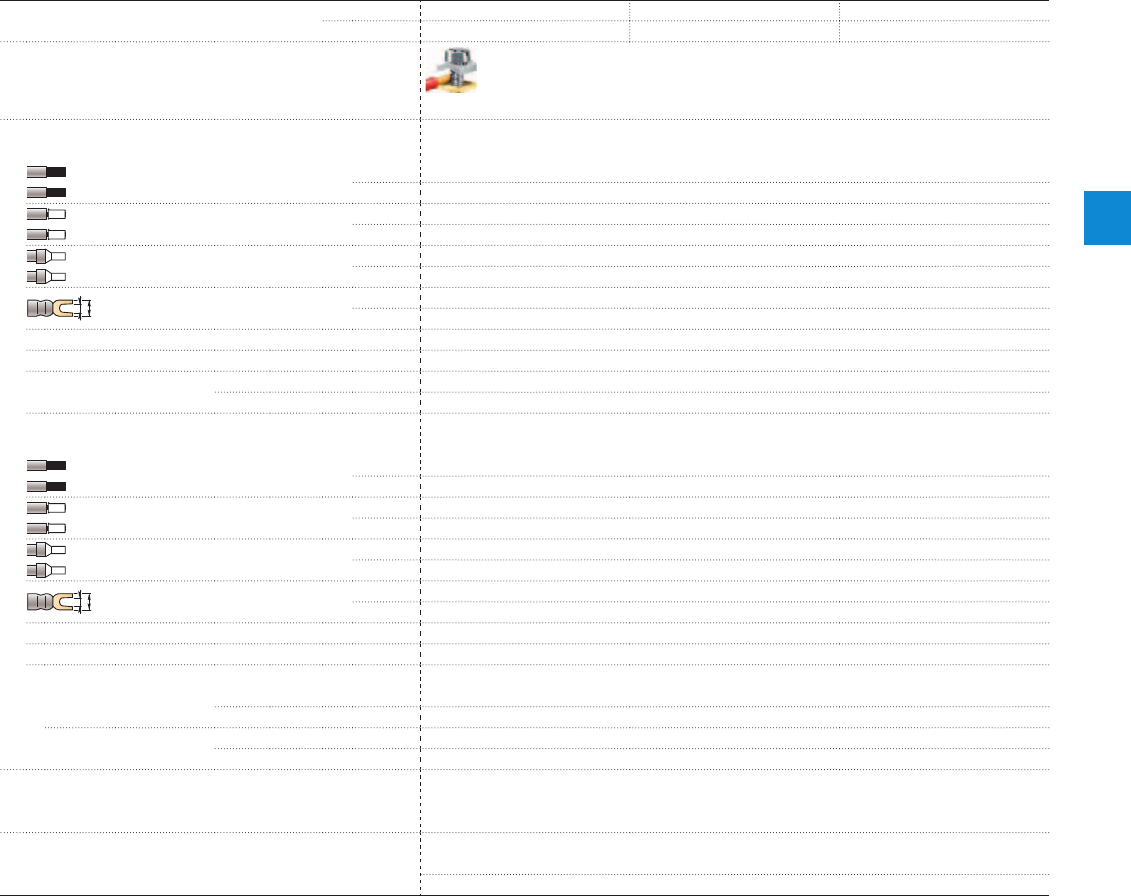
Connecting characteristics
Contactor types
AC operated
AS09 AS12 AS16
DC operated
ASL09 ASL12 ASL16
Main terminals
Screw terminals with cable clamp
Connection capacity (min. ... max.)
Main conductors (poles)
Rigid solid 1 x 0.75...4 mm²
2 x 0.75...4 mm²
Flexible with non insulated ferrule 1 x 0.75...2.5 mm²
2 x 0.75...2.5 mm²
Flexible with insulated ferrule 1 x 0.75...2.5 mm²
2 x 0.75...1.5 mm²
L
l
Bars or lugs L ≤ 7.7 mm
l > 3.2 mm
Connection capacity acc. to UL / CSA 1 or 2 x AWG 18...12
Stripping length 9 mm
Tightening torque Recommended 1.00 Nm / 9 lb.in
Max. 1.20 Nm
Auxiliary conductors
(built-in auxiliary terminals + coil terminals)
Rigid solid 1 x 0.75...2.5 mm²
2 x 0.75...2.5 mm²
Flexible with non insulated ferrule 1 x 0.75...2.5 mm²
2 x 0.75...2.5 mm²
Flexible with insulated ferrule 1 x 0.75...2.5 mm²
2 x 0.75...1.5 mm²
L
l
Lugs L ≤ 7.7 mm
l > 3.2 mm
Connection capacity acc. to UL / CSA 1 or 2 x
AWG 18...14
Stripping length
Tightening torque
Coil terminals Recommended 1.00 Nm / 9 lb.in
Max. 1.20 Nm
Built-in auxiliary terminals Recommended 1.00 Nm / 9 lb.in
Max. 1.20 Nm
Degree of protection
acc. to IEC 60947-1 / EN 60947-1 and IEC 60529 / EN 60529
All terminals IP20
Screw terminals
Delivered in open position, screws of unused terminals must be tightened
All terminals M3
Screwdriver type Flat Ø 5.5 / Pozidriv 2
AS09...AS16 and
ASL09...ASL16 3-pole contactors
Technical data
ABB | 4/13
4
1SBC101489S0201

Built-in auxiliary contacts according to IEC
Contactor types
AC operated
AS09 AS12 AS16
DC operated
ASL09 ASL12 ASL16
Rated operational voltage Ue max.
690 V
Rated frequency (without derating)
50 / 60 Hz
Conventional free-air thermal current Ith - θ ≤ 40 °C
10 A
Ie / Rated operational current AC-15
acc. to IEC 60947-5-1 24-127 V 50/60 Hz 6 A
220-240 V 50/60 Hz 4 A
400-440 V 50/60 Hz 3 A
500 V 50/60 Hz 2 A
690 V 50/60 Hz 2 A
Making capacity AC-15
10 x Ie AC-15 acc. to IEC 60947-5-1
Breaking capacity AC-15
10 x Ie AC-15 acc. to IEC 60947-5-1
Ie / Rated operational current DC-13
acc. to IEC 60947-5-1 24 V DC 6 A / 144 W
48 V DC 2.8 A / 134 W
72 V DC 1 A / 72 W
110 V DC 0.55 A / 60 W
125 V DC 0.55 A / 69 W
220 V DC 0.27 A / 60 W
250 V DC 0.27 A / 68 W
Short-circuit protection device gG type fuse
10 A
Rated short-time withstand current Icw
for 1.0 s 100 A
for 0.1 s 140 A
Minimum switching capacity
12 V / 3 mA
with failure rate acc. to IEC 60947-5-4 10
-7
Non-overlapping time between N.O. and N.C. contacts
1.5 ms
Power dissipation per pole at 6 A
0.1 W
Max. electrical switching frequency
AC-15 1200 cycles/h
DC-13 900 cycles/h
Mechanically linked contacts
Built-in N.O. or N.C. auxiliary contacts and additional N.O. or N.C. auxiliary contacts (CA3 aux.
contact blocks) are mechanically linked contacts.
acc. to annex L of IEC 60947-5-1
Mirror contacts
Built-in N.C. auxiliary contacts or additional N.C. auxiliary contacts (CA3 aux. contact blocks) are
mirror contacts.
acc. to annex F of IEC 60947-4-1
Built-in auxiliary contacts according to UL / CSA
Contactor types
AC operated
AS09 AS12 AS16
DC operated
ASL09 ASL12 ASL16
Max. operational voltage
600 V AC, 250 V DC
Pilot duty
A600, Q300
AC thermal rated current
10 A
AC maximum volt-ampere making
7200 VA
AC maximum volt-ampere breaking
720 VA
DC thermal rated current
2.5 A
DC maximum volt-ampere making-breaking
69 VA
AS09...AS16 and
ASL09...ASL16 3-pole contactors
Technical data
4/14 | ABB
4
1SBC101489S0201

Notes
ABB | 4/15
4
N1
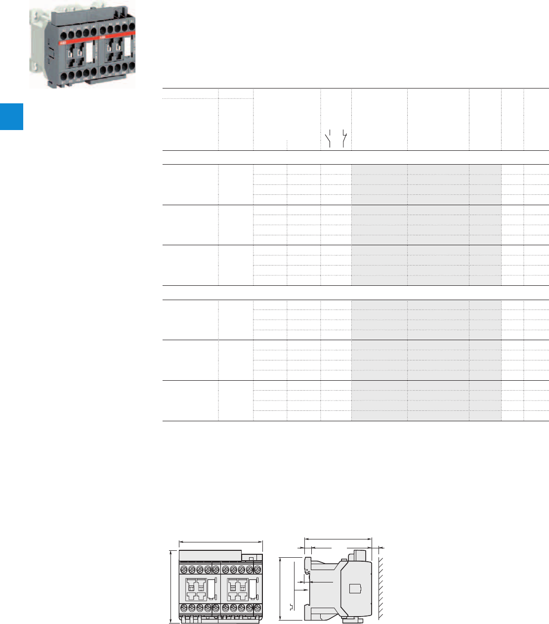
1SBC101080F0014
VAS09EM
Description
VAS09 ... VAS16 reversing contactors are used for controlling 3-phase motors up to 690 V AC.
These reversing contactors include 2 AS09 ... AS16 contactors fitted with 1 N.C. auxiliary contact,
1 VM3 mechanical interlock and BER16C-3 reversing connection set including electrical interlocking.
Up to 2 add-on CA3 1-pole auxiliary contact blocks can be mounted per contactor.
The reversing contactors are available with or without surge suppressor mounted on each contactor.
Ordering details
IEC UL/CSA Rated control circuit Auxiliary Type Order code Pkg Weight
Rated operational 3-phase voltage contacts qty (1 pce)
power motor Uc fitted
rating (1)
400 V 480 V
AC-3
kW hp V 50 Hz V 60 Hz kg
Reversing contactors without integrated surge suppressor
4 5 24 24 0 2 VAS09EM-20M 1SBK103600M2000 18 0.480
- 120 0 2 VAS09EM-16M 1SBK103600M1600 18 0.480
230 230 0 2 VAS09EM-26M 1SBK103600M2600 18 0.480
400 400 0 2 VAS09EM-28M 1SBK103600M2800 18 0.480
5.5 7.5 24 24 0 2 VAS12EM-20M 1SBK113600M2000 18 0.480
- 120 0 2 VAS12EM-16M 1SBK113600M1600 18 0.480
230 230 0 2 VAS12EM-26M 1SBK113600M2600 18 0.480
400 400 0 2 VAS12EM-28M 1SBK113600M2800 18 0.480
7.5 10 24 24 0 2 VAS16EM-20M 1SBK123600M2000 18 0.480
- 120 0 2 VAS16EM-16M 1SBK123600M1600 18 0.480
230 230 0 2 VAS16EM-26M 1SBK123600M2600 18 0.480
400 400 0 2 VAS16EM-28M 1SBK123600M2800 18 0.480
Reversing contactors with RC5-1 integrated surge suppressor
4 5 24 24 0 2 VAS09SEM-20M 1SBK103800M2000 18 0.510
- 120 0 2 VAS09SEM-16M 1SBK103800M1600 18 0.510
230 230 0 2 VAS09SEM-26M 1SBK103800M2600 18 0.510
400 400 0 2 VAS09SEM-28M 1SBK103800M2800 18 0.510
5.5 7.5 24 24 0 2 VAS12SEM-20M 1SBK113800M2000 18 0.510
- 120 0 2 VAS12SEM-16M 1SBK113800M1600 18 0.510
230 230 0 2 VAS12SEM-26M 1SBK113800M2600 18 0.510
400 400 0 2 VAS12SEM-28M 1SBK113800M2800 18 0.510
7.5 10 24 24 0 2 VAS16SEM-20M 1SBK123800M2000 18 0.510
- 120 0 2 VAS16SEM-16M 1SBK123800M1600 18 0.510
230 230 0 2 VAS16SEM-26M 1SBK123800M2600 18 0.510
400 400 0 2 VAS16SEM-28M 1SBK123800M2800 18 0.510
(1) Other control voltages see voltage code table.
Note: Minimum switchover delay of 50 ms must be introduced between respective opening and closing of AC operated reversing
contactors.
Main dimensions mm, inches
5.5 0.22"
7 0.28"
35 mm
EN/IEC 60715
72.5 2.85"
68 2.68"
78.5 3.09"
90 3.54"
10 0.39"
VAS09, VAS12, VAS16
VAS09 ... VAS16 3-pole reversing contactors
4 to 7.5 kW
AC operated
4/16 | ABB
4
1SBC101462S0201
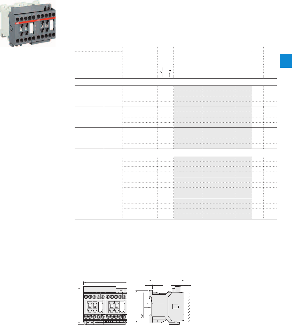
1SBC101082F0014
VASL09EM
Description
VASL09 ... VASL16 reversing contactors are used for controlling 3-phase motors up to 690 V AC.
These reversing contactors include 2 ASL09 ... ASL16 contactors fitted with 1 N.C. auxiliary contact,
1 VM3 mechanical interlock and BER16C-3 reversing connection set including electrical interlocking.
Up to 2 add-on CA3 1-pole auxiliary contact blocks can be mounted per contactor.
The reversing contactors are available with or without surge suppressor mounted on each contactor.
Ordering details
IEC UL/CSA Rated control circuit Auxiliary Type Order code Pkg Weight
Rated operational 3-phase voltage contacts qty (1 pce)
power motor Uc fitted
rating (1)
400 V 480 V
AC-3
kW hp V DC kg
Reversing contactors without integrated surge suppressor
4 5 24 0 2 VASL09EM-81M 1SBK103700M8100 18 0.600
48 0 2 VASL09EM-83M 1SBK103700M8300 18 0.600
110 0 2 VASL09EM-86M 1SBK103700M8600 18 0.600
220 0 2 VASL09EM-88M 1SBK103700M8800 18 0.600
5.5 7.5 24 0 2 VASL12EM-81M 1SBK113700M8100 18 0.600
48 0 2 VASL12EM-83M 1SBK113700M8300 18 0.600
110 0 2 VASL12EM-86M 1SBK113700M8600 18 0.600
220 0 2 VASL12EM-88M 1SBK113700M8800 18 0.600
7.5 10 24 0 2 VASL16EM-81M 1SBK123700M8100 18 0.600
48 0 2 VASL16EM-83M 1SBK123700M8300 18 0.600
110 0 2 VASL16EM-86M 1SBK123700M8600 18 0.600
220 0 2 VASL16EM-88M 1SBK123700M8800 18 0.600
Reversing contactors with RV5 integrated surge suppressor
4 5 24 0 2 VASL09SEM-81M 1SBK103900M8100 18 0.630
48 0 2 VASL09SEM-83M 1SBK103900M8300 18 0.630
110 0 2 VASL09SEM-86M 1SBK103900M8600 18 0.630
220 0 2 VASL09SEM-88M 1SBK103900M8800 18 0.630
5.5 7.5 24 0 2 VASL12SEM-81M 1SBK113900M8100 18 0.630
48 0 2 VASL12SEM-83M 1SBK113900M8300 18 0.630
110 0 2 VASL12SEM-86M 1SBK113900M8600 18 0.630
220 0 2 VASL12SEM-88M 1SBK113900M8800 18 0.630
7.5 10 24 0 2 VASL16SEM-81M 1SBK123900M8100 18 0.630
48 0 2 VASL16SEM-83M 1SBK123900M8300 18 0.630
110 0 2 VASL16SEM-86M 1SBK123900M8600 18 0.630
220 0 2 VASL16SEM-88M 1SBK123900M8800 18 0.630
(1) Other control voltages see voltage code table.
Main dimensions mm, inches
5.5 0.22"
7 0.28"
35 mm
EN/IEC 60715
72.5 2.85"
68 2.68"
78.5 3.09"
90 3.54"
10 0.39"
VASL09, VASL12, VASL16
VASL09 ... VASL16 3-pole reversing contactors
4 to 7.5 kW
DC operated
ABB | 4/17
4
1SBC101473S0201
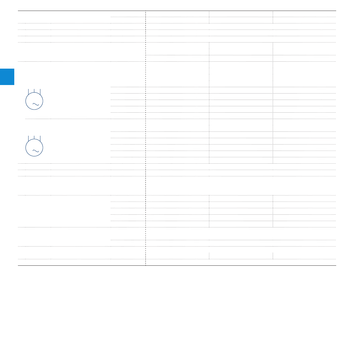
M
3
M
3
Main pole - Utilization characteristics according to IEC
Contactor types
AC operated
VAS09 VAS12 VAS16
DC operated
VASL09 VASL12 VASL16
Standards
IEC 60947-1 / 60947-4-1 and EN 60947-1 / 60947-4-1
Rated operational voltage Ue max.
690 V
Rated frequency (without derating)
50 / 60 Hz
Conventional free-air thermal current Ith
acc. to IEC 60947-4-1, open contactors, θ ≤ 40 °C 22 A 25 A 25 A
With conductor cross-sectional area 2.5 mm² 4 mm² 4 mm²
AC-3 Utilization category
For air temperature close to contactor θ ≤ 60 °C
Ie / Max. rated operational current AC-3 (1)
3-phase motors
220-230-240 V 9 A 12 A 15.7 A
400 V 9 A 12 A 15.5 A
415 V 9 A 12 A 15.5 A
440 V 8 A 11 A 13.6 A
500 V 8 A 11 A 12.5 A
690 V 5 A 7 A 9 A
Rated operational power AC-3 (1)
220-230-240 V 2.2 kW 3 kW 4 kW
400 V 4 kW 5.5 kW 7.5 kW
1500 r.p.m. 50 Hz
415 V 4 kW 5.5 kW 7.5 kW
1800 r.p.m. 60 Hz
440 V 4 kW 5.5 kW 7.5 kW
3-phase motors
500 V 4 kW 5.5 kW 7.5 kW
690 V 4 kW 5.5 kW 7.5 kW
Rated making capacity AC-3
10 x Ie AC-3 acc. to IEC 60947-4-1
Rated breaking capacity AC-3
8 x Ie AC-3 acc. to IEC 60947-4-1
Short-circuit protection device for contactors
without thermal overload relay - Motor protection excluded
(2)
Ue ≤ 500 V AC - gG type fuse 25 A
Rated short-time withstand current Icw
1 s 230 A 250 A 250 A
at 40 °C ambient temperature, 10 s 100 A 124 A 124 A
in free air from a cold state 30 s 65 A 75 A 75 A
1 min 50 A 55 A 55 A
15 min 22 A 24 A 24 A
Maximum breaking capacity
cos φ = 0.45 at 440 V 155 A
at 690 V 90 A
Power dissipation per pole
Ie / AC-3 0.16 W 0.3 W 0.5 W
Max. electrical switching frequency
AC-3 600 cycles/h
(1) For the corresponding kW/A or hp/A values of 1500 r.p.m, 50 Hz or 1800 r.p.m, 60 Hz, 3-phase motors, see "Motor rated operational powers and currents".
(2) For the protection of motor starters against short circuits, see "Coordination with short-circuit protection devices".
VAS09...VAS16 and
VASL09...VASL16 3-pole reversing contactors
Technical data
4/18 | ABB
4
1SBC101500S0201

Main pole - Utilization characteristics according to UL / NEMA / CSA
Contactor types
AC operated
VAS09 VAS12 VAS16
DC operated
VASL09 VASL12 VASL16
Standards
UL 508, CSA C22.2 N°14
Max. operational voltage
690 V
NEMA size
00 00 0
NEMA continuous amp rating
Thermal current 9 A 9 A 18 A
NEMA maximum horse power ratings 1-phase, 60 Hz
115 V AC 1/3 hp 1/3 hp 1 hp
230 V AC 1 hp 1 hp 2 hp
NEMA maximum horse power ratings 3-phase, 60 Hz
200 V AC 1 1/2 hp 1 1/2 hp 3 hp
230 V AC 1 1/2 hp 1 1/2 hp 3 hp
460 V AC 2 hp 2 hp 5 hp
575 V AC 2 hp 2 hp 5 hp
UL / CSA maximum 1-phase motor rating
Full load current 120 V AC 7.2 A 9.8 A 13.8 A
240 V AC 8 A 10 A 12 A
Horse power rating 120 V AC 1/3 hp 1/2 hp 3/4 hp
240 V AC 1 hp 1-1/2 hp 2 hp
UL / CSA maximum 3-phase motor rating
Full load current (1) 200-208 V AC 7.8 A 7.8 A 11 A
220-240 V AC 6.8 A 9.6 A 15.2 A
440-480 V AC 7.6 A 11 A 14 A
550-600 V AC 9 A 11 A 11 A
Horse power rating (1) 200-208 V AC 2 hp 2 hp 3 hp
220-240 V AC 2 hp 3 hp 5 hp
440-480 V AC 5 hp 7-1/2 hp 10 hp
550-600 V AC 7-1/2 hp 10 hp 10 hp
Short-circuit protection device for contactors
without thermal overload relay - Motor protection excluded
Fuse rating 40 A 50 A 60 A
Fuse type, 600 V J
Max. electrical switching frequency
For motor use 600 cycles/h
(1) For the corresponding kW/A or hp/A values of 1500 r.p.m, 50 Hz or 1800 r.p.m, 60 Hz, 3-phase motors, see "Motor rated operational powers and currents".
General technical data
Contactor types
AC operated
VAS09 VAS12 VAS16
DC operated
VASL09 VASL12 VASL16
Rated insulation voltage Ui
acc. to IEC 60947-4-1 690 V
acc. to UL / CSA 600 V
Rated impulse withstand voltage Uimp.
6 kV
Ambient air temperature close to contactor
Operation Fitted with thermal overload relay -25...+60 °C
Without thermal overload relay -40...+70 °C
Storage -60...+80 °C
Climatic withstand
Category B according to IEC 60947-1 Annex Q
Maximum operating altitude (without derating)
3000 m
Mechanical durability
Number of operating cycles 5 millions operating cycles
Max. switching frequency 1800 cycles/h
VAS09...VAS16 and
VASL09...VASL16 3-pole reversing contactors
Technical data
ABB | 4/19
4
1SBC101500S0201
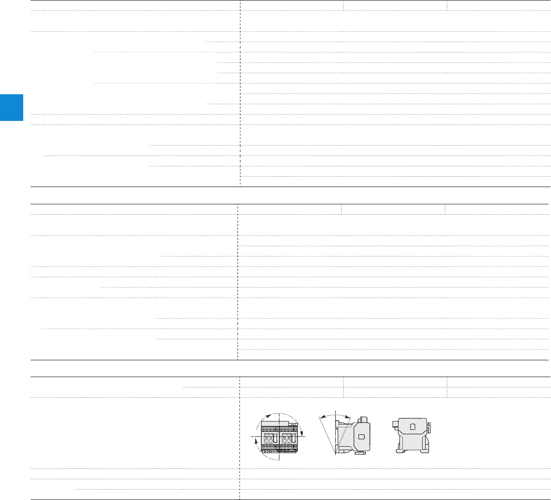
Magnet system characteristics for VAS09…VAS16 contactors
Contactor types AC operated
VAS09 VAS12 VAS16
Coil operating limits AC supply
acc. to IEC 60947-4-1 0.85...1.1 x Uc (at θ ≤ 60 °C); Uc (at θ ≤ 70 °C)
AC control voltage Rated control circuit voltage Uc at 50 Hz 24...415 V
at 60 Hz 24...415 V
Coil consumption Average pull-in value 50 Hz 33 VA
60 Hz 33 VA
50/60 Hz 33 VA
Average holding value 50 Hz 6.5 VA / 1.5 W
60 Hz 5 VA / 1.2 W
50/60 Hz 6.5 VA / 1.5 W
Drop-out voltage Approx. 30...50 % of Uc
Operating time
Between coil energization and: N.O. contact closing 9...24 ms
N.C. contact opening 6...18 ms
Between coil de-energization and: N.O. contact opening (1) 5...19 ms
N.C. contact closing (1) 7...22 ms
(1) The use of RC5-1 surge suppressor increases opening time by a factor of 2 to 3.
Magnet system characteristics for VASL09…VASL16 contactors
Contactor types DC operated
VASL09 VASL12 VASL16
Coil operating limits DC supply
acc. to IEC 60947-4-1 0.85...1.1 x Uc (at θ ≤ 60 °C); Uc (at θ ≤ 70 °C)
DC control voltage Rated control circuit voltage Uc 12...240 V DC
Coil consumption Average pull-in value 3 W
Average holding value 3 W
Drop-out voltage Approx. 10...40 % of Uc
Coil time constant Open L/R 12 ms
Closed L/R 40 ms
Operating time
Between coil energization and: N.O. contact closing 36...59 ms
N.C. contact opening 31...53 ms
Between coil de-energization and: N.O. contact opening (1) 13...17 ms
N.C. contact closing (1) 15...20 ms
(1) The use of RT5 surge suppressor increases opening time by a factor of 1.1 to 1.2
Mounting characteristics and conditions for use
Contactor types
AC operated
VAS09 VAS12 VAS16
DC operated
VASL09 VASL12 VASL16
Mounting positions
Pos. 1 ± 30°
+30° -30°
Pos. 3
Pos. 2
Pos. 1
Pos. 4
Pos. 5
Mounting distances
The reversing contactors can be assembled side by side.
Fixing
On rail according to IEC 60715, EN 60715 35 x 7.5 mm or 35 x 15 mm
By screws (not supplied) 2 x M4 screws placed diagonally
VAS09...VAS16 and
VASL09...VASL16 3-pole reversing contactors
Technical data
4/20 | ABB
4
1SBC101500S0201
Connecting characteristics
Contactor types
AC operated
VAS09 VAS12 VAS16
DC operated
VASL09 VASL12 VASL16
Main terminals
Screw terminals with cable clamp
Connection capacity (min. ... max.)
Main conductors (poles)
Rigid solid 1 x 0.75...4 mm²
Flexible with non insulated ferrule 1 x 0.75...2.5 mm²
Flexible with insulated ferrule 1 x 0.75...1.5 mm²
Connection capacity acc. to UL / CSA 1 x AWG 18...12
Stripping length 9 mm
Tightening torque Recommended 1.00 Nm / 9 lb.in
Max. 1.20 Nm
Auxiliary conductors
(built-in auxiliary terminals + coil terminals)
Rigid solid 1 x 0.75...2.5 mm²
Flexible with non insulated ferrule 1 x 0.75...2.5 mm²
Flexible with insulated ferrule 1 x 0.75...1.5 mm²
Connection capacity acc. to UL / CSA 1 x AWG 18...14
Stripping length 9 mm
Tightening torque
Coil terminals Recommended 1.00 Nm / 9 lb.in
Max. 1.20 Nm
Built-in auxiliary terminals Recommended 1.00 Nm / 9 lb.in
Max. 1.20 Nm
Degree of protection
acc. to IEC 60947-1 / EN 60947-1 and IEC 60529 / EN 60529
All terminals IP20
Screw terminals
Delivered in open position, screws of unused terminals must be tightened
All terminals M3
Screwdriver type Flat Ø 5.5 / Pozidriv 2
VAS09...VAS16 and
VASL09...VASL16 3-pole reversing contactors
Technical data
ABB | 4/21
4
1SBC101500S0201
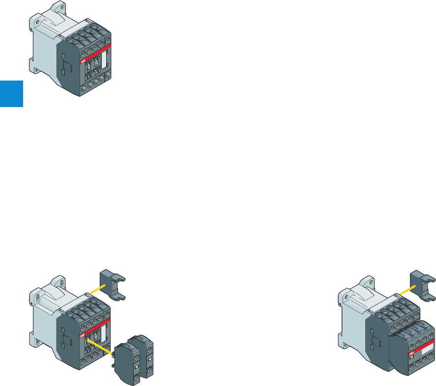
Contactor relays
Main accessories
4-pole contactor relays
NS, NSL
Contactor relays
RV5, RT5 or RC5-1
Surge suppressor
NS
NSL
Contactor relays
NS
NSL
Contactor relays
RV5, RT5 or RC5-1
Surge suppressor
CA-3
1-pole auxiliary contact block
8-pole contactor relays
4/22 | ABB
4
1SBC101409S0201
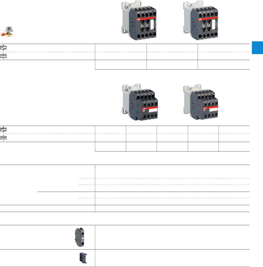
Contactor relays
Screw terminals
AC control voltage NS22E NS31E NS40E
DC control voltage NSL22E NSL31E NSL40E
2 N.O. + 2 N.C. 3 N.O. + 1 N.C. 4 N.O.
AC control voltage NS44E NS53E NS62E NS71E NS80E
DC control voltage NSL44E NSL53E NSL62E NSL71E NSL80E
4 N.O. + 4 N.C. 5 N.O. + 3 N.C. 6 N.O. + 2 N.C. 7 N.O. + 1 N.C. 8 N.O.
Control circuit switching
IEC
Rated operational current
AC-15
240 V
4 A
400 V
3 A
690 V
2 A
DC-13
24 V
6 A / 144 W
250 V
0.27 A / 68 W
UL / CSA Pilot Duty A600, Q300
Main accessories
Auxiliary
contact
blocks
Front mounting 1-pole CA3-10 or CA3-01
Surge
suppressors
Side-mounted
(without additional
width)
RV5 (Varistor) AC / DC
RC5-1 (Capacitor) AC
RT5 (Transil diode) DC
NS
NS
NSL
NSL
ABB | 4/23
4
1SBC101409S0201
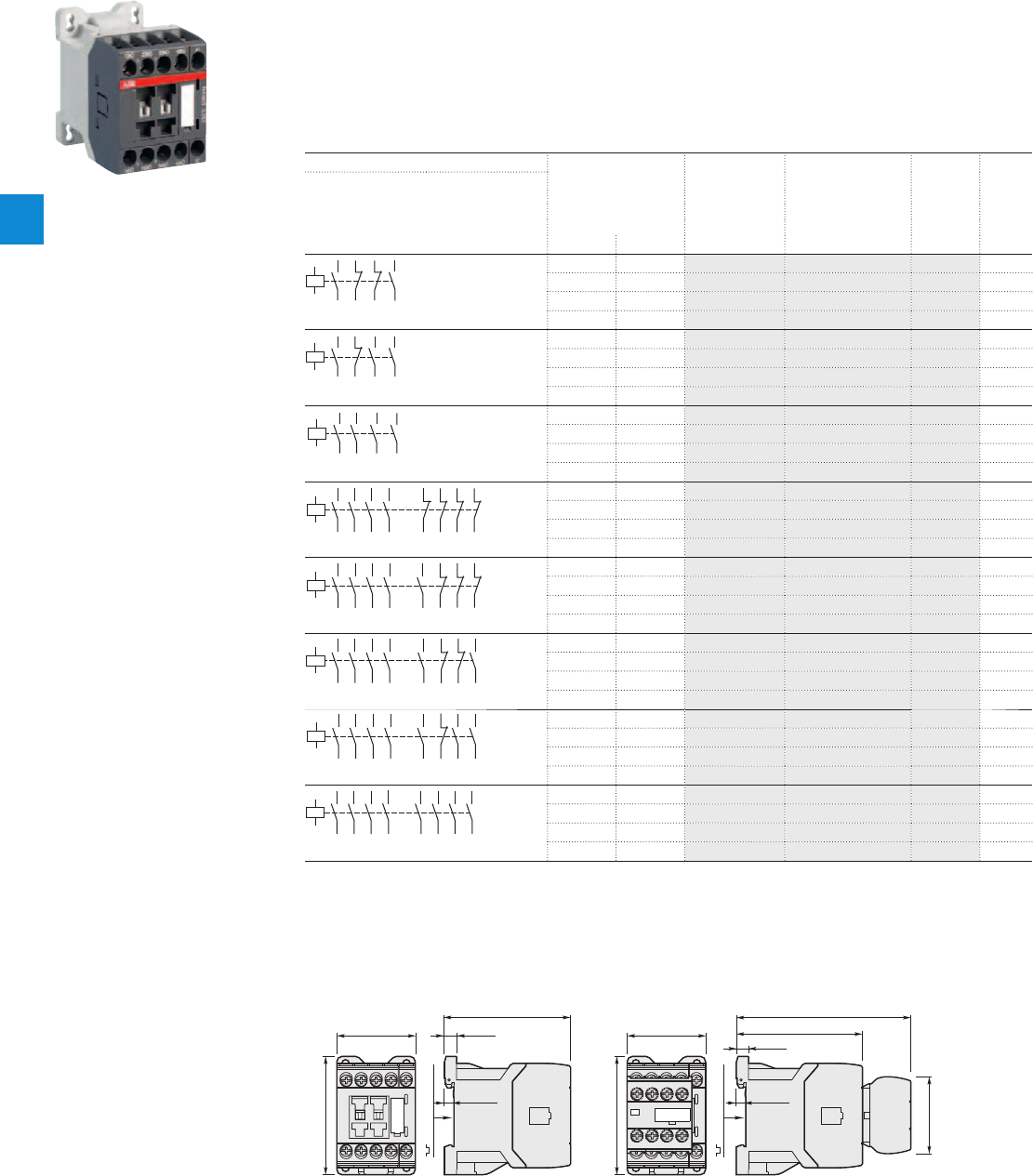
1SBC101012F0014
NS22E
Description
NS contactor relays are used for switching auxiliary and control circuits.
These contactor relays are designed with:
– 4 poles or 8 poles. Contactor relays have mechanically linked auxiliary contact elements (side-marked symbol)
– control circuit: AC operated
– add-on auxiliary contact blocks for front mounting and a comprehensive range of accessories.
Ordering details
Number of contacts Rated control circuit Type Order code Weight
1st stack 2nd stack voltage
Uc
(1) Pkg
(1 pce)
V 50 Hz V 60 Hz kg
43
NO
NO
44
31
NC
NC
32
21
NC
NC
22
13
NO
NO
14
A1
A2
24 24 NS22E-20 1SBH101001R2022 0.220
- 120 NS22E-16 1SBH101001R1622 0.220
230 230 NS22E-26 1SBH101001R2622 0.220
400 400 NS22E-28 1SBH101001R2822 0.220
33
NO
NO
34
21
NC
NC
22
13
NO
NO
14
43
NO
NO
44
A1
A2
24 24 NS31E-20 1SBH101001R2031 0.220
- 120 NS31E-16 1SBH101001R1631 0.220
230 230 NS31E-26 1SBH101001R2631 0.220
400 400 NS31E-28 1SBH101001R2831 0.220
43
NO
NO
44
33
NO
NO
34
23
NO
NO
24
13
NO
NO
14
A1
A2
24 24 NS40E-20 1SBH101001R2040 0.220
- 120 NS40E-16 1SBH101001R1640 0.220
230 230 NS40E-26 1SBH101001R2640 0.220
400 400 NS40E-28 1SBH101001R2840 0.220
43
NO
NO
44
33
NO
NO
34
23
NO
NO
24
13
NO
NO
14
81
NC
NC
82
71
NC
NC
72
61
NC
NC
62
51
NC
NC
52
A1
A2
24 24 NS44E-20 1SBH101001R2044 0.260
- 120 NS44E-16 1SBH101001R1644 0.260
230 230 NS44E-26 1SBH101001R2644 0.260
400 400 NS44E-28 1SBH101001R2844 0.260
43
NO
NO
44
33
NO
NO
34
23
NO
NO
24
13
NO
NO
14
81
NC
NC
82
71
NC
NC
72
61
NC
NC
62
53
NO
NO
54
A1
A2
24 24 NS53E-20 1SBH101001R2053 0.260
- 120 NS53E-16 1SBH101001R1653 0.260
230 230 NS53E-26 1SBH101001R2653 0.260
400 400 NS53E-28 1SBH101001R2853 0.260
43
NO
NO
44
33
NO
NO
34
23
NO
NO
24
13
NO
NO
14
83
NO
NO
84
71
NC
NC
72
61
NC
NC
62
53
NO
NO
54
A1
A2
24 24 NS62E-20 1SBH101001R2062 0.260
- 120 NS62E-16 1SBH101001R1662 0.260
230 230 NS62E-26 1SBH101001R2662 0.260
400 400 NS62E-28 1SBH101001R2862 0.260
43
NO
NO
44
33
NO
NO
34
23
NO
NO
24
13
NO
NO
14
83
NO
NO
84
73
NO
NO
74
61
NC
NC
62
53
NO
NO
54
A1
A2
24 24 NS71E-20 1SBH101001R2071 0.260
- 120 NS71E-16 1SBH101001R1671 0.260
230 230 NS71E-26 1SBH101001R2671 0.260
400 400 NS71E-28 1SBH101001R2871 0.260
43
NO
NO
44
33
NO
NO
34
23
NO
NO
24
13
NO
NO
14
83
NO
NO
84
73
NO
NO
74
63
NO
NO
64
53
NO
NO
54
A1
A2
24 24 NS80E-20 1SBH101001R2080 0.260
- 120 NS80E-16 1SBH101001R1680 0.260
230 230 NS80E-26 1SBH101001R2680 0.260
400 400 NS80E-28 1SBH101001R2880 0.260
Note: for multiple packaging, please contact your ABB local sales organization.
(1) Other control voltages see voltage code table.
Main dimensions mm, inches
72.5 2.85"
45 1.77"
68 2.68"
5.5 0.22"
7 0.28"
35 mm
EN/IEC 60715
45 1.77"
68 2.68"
72.5 2.85"
5.5 0.22"
7 0.28"
35 mm
EN/IEC 60715
100.2 3.94"
44.2 1.74"
NS22E, NS31E, NS40E NS44E, NS53E, NS62E, NS71E, NS80E
NS contactor relays
AC operated
4/24 | ABB
4
1SBC101475S0201
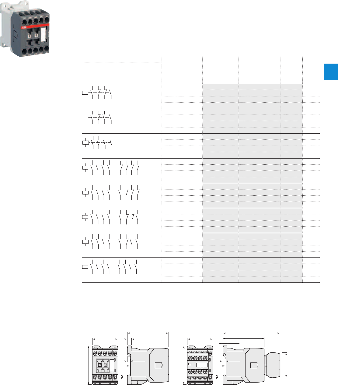
1SBC101018F0014
NSL22E
Description
NSL contactor relays are used for switching auxiliary and control circuits.
These contactor relays are designed with:
– 4 poles or 8 poles. Contactor relays have mechanically linked auxiliary contact elements (side-marked symbol)
– control circuit: low coil consumption (3W at pull-in and holding) DC operated with solid core magnet. Suitable
for direct control by PLC outputs (the polarity on the coil terminals A1+ and A2- must be respected)
– add-on auxiliary contact blocks for front mounting and a comprehensive range of accessories.
Ordering details
Number of contacts Rated control circuit Type Order code Weight
1st stack 2nd stack voltage
Uc Pkg
(1) (1 pce)
V DC kg
43
NO
NO
44
31
NC
NC
32
21
NC
NC
22
13
NO
NO
14
A1+
A2-
24 NSL22E-81 1SBH103001R8122 0.280
48 NSL22E-83 1SBH103001R8322 0.280
110 NSL22E-86 1SBH103001R8622 0.280
220 NSL22E-88 1SBH103001R8822 0.280
33
NO
NO
34
21
NC
NC
22
13
NO
NO
14
43
NO
NO
44
A1+
A2-
24 NSL31E-81 1SBH103001R8131 0.280
48 NSL31E-83 1SBH103001R8331 0.280
110 NSL31E-86 1SBH103001R8631 0.280
220 NSL31E-88 1SBH103001R8831 0.280
43
NO
NO
44
33
NO
NO
34
23
NO
NO
24
13
NO
NO
14
A1+
A2-
24 NSL40E-81 1SBH103001R8140 0.280
48 NSL40E-83 1SBH103001R8340 0.280
110 NSL40E-86 1SBH103001R8640 0.280
220 NSL40E-88 1SBH103001R8840 0.280
43
NO
NO
44
33
NO
NO
34
23
NO
NO
24
13
NO
NO
14
81
NC
NC
82
71
NC
NC
72
61
NC
NC
62
51
NC
NC
52
A1+
A2-
24 NSL44E-81 1SBH103001R8144 0.320
48 NSL44E-83 1SBH103001R8344 0.320
110 NSL44E-86 1SBH103001R8644 0.320
220 NSL44E-88 1SBH103001R8844 0.320
43
NO
NO
44
33
NO
NO
34
23
NO
NO
24
13
NO
NO
14
81
NC
NC
82
71
NC
NC
72
61
NC
NC
62
53
NO
NO
54
A1+
A2-
24 NSL53E-81 1SBH103001R8153 0.320
48 NSL53E-83 1SBH103001R8353 0.320
110 NSL53E-86 1SBH103001R8653 0.320
220 NSL53E-88 1SBH103001R8853 0.320
43
NO
NO
44
33
NO
NO
34
23
NO
NO
24
13
NO
NO
14
83
NO
NO
84
71
NC
NC
72
61
NC
NC
62
53
NO
NO
54
A1+
A2-
24 NSL62E-81 1SBH103001R8162 0.320
48 NSL62E-83 1SBH103001R8362 0.320
110 NSL62E-86 1SBH103001R8662 0.320
220 NSL62E-88 1SBH103001R8862 0.320
43
NO
NO
44
33
NO
NO
34
23
NO
NO
24
13
NO
NO
14
83
NO
NO
84
73
NO
NO
74
61
NC
NC
62
53
NO
NO
54
A1+
A2-
24 NSL71E-81 1SBH103001R8171 0.320
48 NSL71E-83 1SBH103001R8371 0.320
110 NSL71E-86 1SBH103001R8671 0.320
220 NSL71E-88 1SBH103001R8871 0.320
43
NO
NO
44
33
NO
NO
34
23
NO
NO
24
13
NO
NO
14
83
NO
NO
84
73
NO
NO
74
63
NO
NO
64
53
NO
NO
54
A1+
A2-
24 NSL80E-81 1SBH103001R8180 0.320
48 NSL80E-83 1SBH103001R8380 0.320
110 NSL80E-86 1SBH103001R8680 0.320
220 NSL80E-88 1SBH103001R8880 0.320
Note: for multiple packaging, please contact your ABB local sales organization.
(1) Other control voltages see voltage code table.
Main dimensions mm, inches
72.5 2.85"
45 1.77"
68 2.68"
5.5 0.22"
7 0.28"
35 mm
EN/IEC 60715
45 1.77"
68 2.68"
72.5 2.85"
5.5 0.22"
7 0.28"
35 mm
EN/IEC 60715
100.2 3.94"
44.2 1.74"
NSL22E, NSL31E, NSL40E NSL44E, NSL53E, NSL62E, NSL71E, NSL80E
NSL contactor relays
DC operated
ABB | 4/25
4
1SBC101479S0201
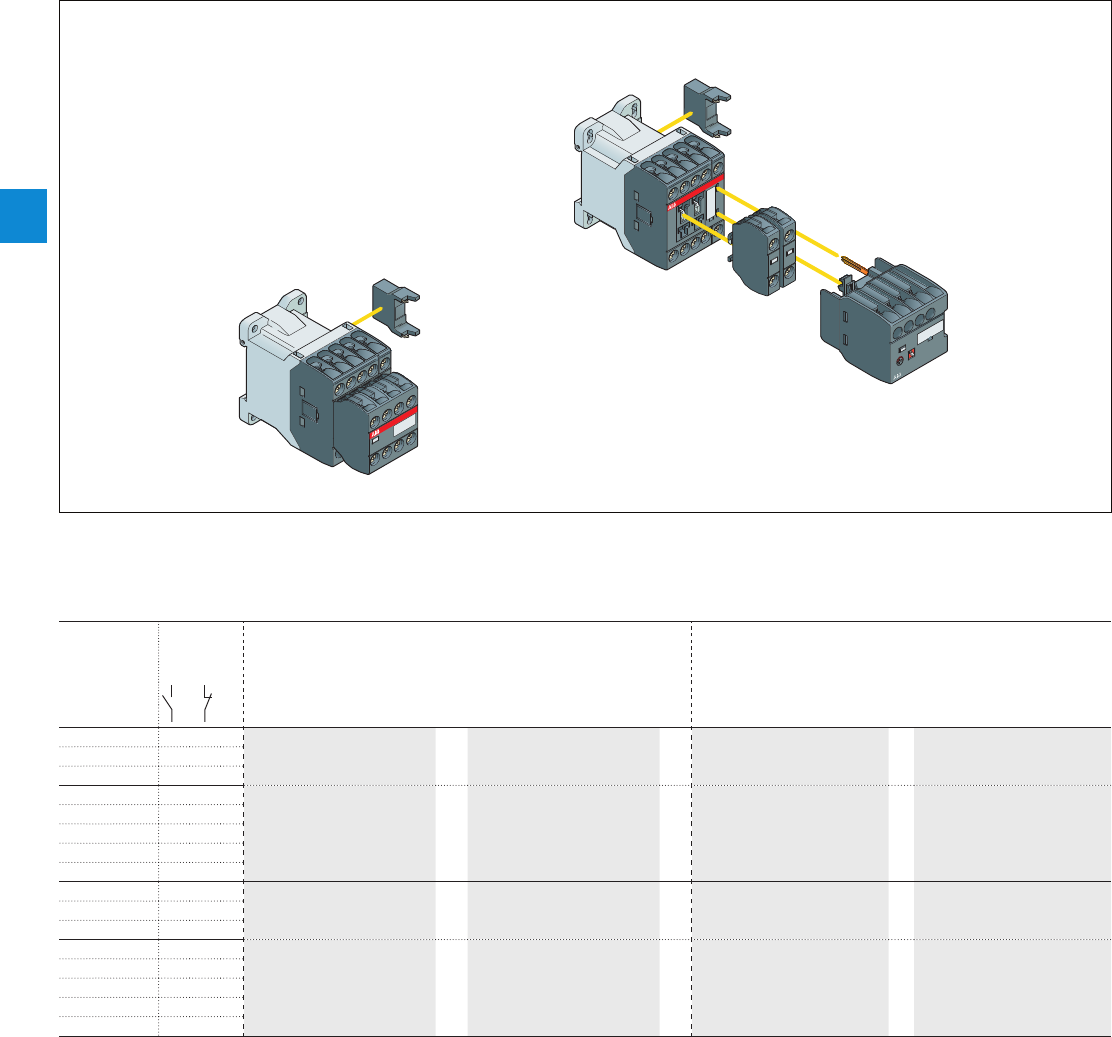
NS and NSL contactor relays
Main accessories
Main accessory fitting details
Contactor
types
Main
poles
Front-mounted accessories Side-mounted accessories
Auxiliary contact blocks Electronic timer
1-pole CA3 TEF3 Surge suppressors
NS.. 2 2 E 2 max.
or
1
+
RV5
or
RC5-1
NS.. 3 1 E
NS.. 4 0 E
NS.. 4 4 E – – RV5
or
RC5-1
NS.. 5 3 E
NS.. 6 2 E
NS.. 7 1 E
NS.. 8 0 E
NSL.. 2 2 E 2 max.
or
1
+
RV5
or
RT5
NSL.. 3 1 E
NSL.. 4 0 E
NSL.. 4 4 E – – RV5
or
RT5
NSL.. 5 3 E
NSL.. 6 2 E
NSL.. 7 1 E
NSL.. 8 0 E
Contactor relays and main accessories (other accessories available)
RV5, RC5-1 or RT5
RV5, RC5-1 or RT5
CA3
TEF3
4-pole contactor relay
8-pole contactor relay
NS
NSL
Contactor relays
NS
NSL
Contactor relays
4/26 | ABB
4
1SBC101298S0201
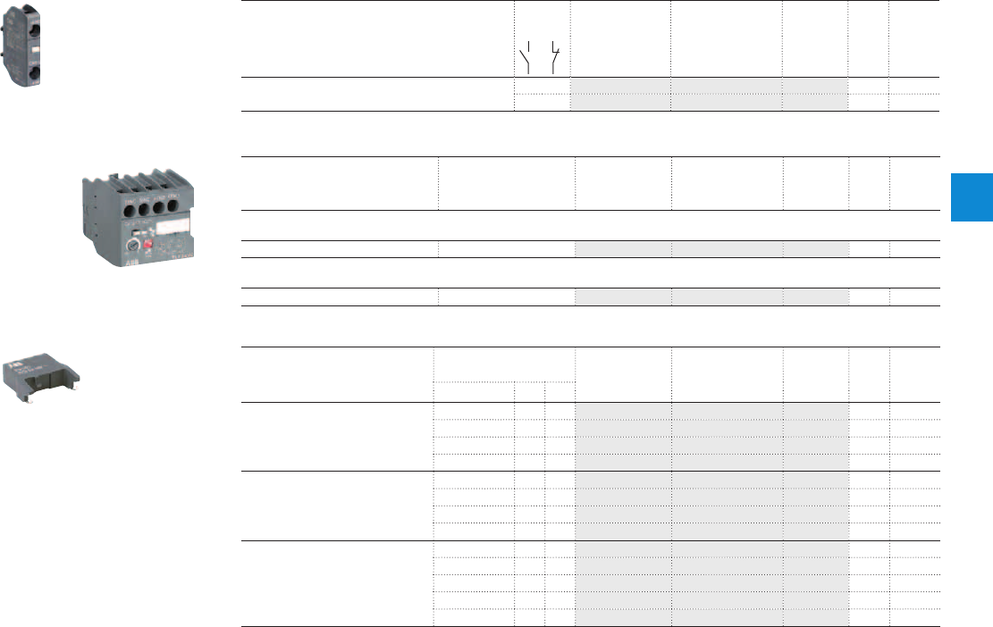
NS and NSL contactor relays
Main accessories
Front-mounted instantaneous auxiliary contact blocks
For contactor relays Auxiliary
contacts
Type Order code Pkg
qty
Weight
(1 pce)
kg
NS, NSL 1 0 CA3-10 1SBN011010T1010 10 0.011
0 1 CA3-01 1SBN011010T1001 10 0.011
Front-mounted electronic timer
For contactors Rated control circuit
voltage - Uc
Type Order code Pkg
qty
Weight
(1 pce)
V kg
ON-delay
NS, NSL 24...240VAC/DC TEF3-ON 1SBN021012R1000 1 0.065
OFF-delay
NS, NSL 24...240VAC/DC TEF3-OFF 1SBN021014R1000 1 0.065
Surge suppressors
For contactor relays Rated control circuit
voltage - Uc
Type Order code Pkg
qty
Weight
(1 pce)
VACDC kg
NS,
NSL
24...50
●●
RV5/50 1SBN050010R1000 2 0.015
50...133
●●
RV5/133 1SBN050010R1001 2 0.015
110...250
●●
RV5/250 1SBN050010R1002 2 0.015
250...440
●●
RV5/440 1SBN050010R1003 2 0.015
NS 24...50
●
– RC5-1/50 1SBN050100R1000 2 0.012
50...133
●
– RC5-1/133 1SBN050100R1001 2 0.012
110...250
●
– RC5-1/250 1SBN050100R1002 2 0.012
250...440
●
– RC5-1/440 1SBN050100R1003 2 0.012
NSL 12...32 –
●
RT5/32 1SBN050020R1000 2 0.015
25...65 –
●
RT5/65 1SBN050020R1001 2 0.015
50...90 –
●
RT5/90 1SBN050020R1002 2 0.015
77...150 –
●
RT5/150 1SBN050020R1003 2 0.015
150...264 –
●
RT5/264 1SBN050020R1004 2 0.015
1SBC101036F0014
CA3-10
1SBC574001F0301
RV5
1SBC101337F0014
TEF3-ON
ABB | 4/27
4
1SBC101298S0201

Contact utilization characteristics according to IEC
Contactor relay types
AC operated
NS
DC operated
NSL
Standards
IEC 60947-5-1 and EN 60947-5-1
Rated operational voltage Ue max.
690V
Rated frequency (without derating)
50 / 60Hz
Conventional free-air thermal current Ith - θ ≤ 40 °C
10A
Ie / Rated operational current AC-15
acc. to IEC 60947-5-1 24-127V 50/60Hz 6A
220-240V 50/60Hz 4A
400-440V 50/60Hz 3A
500V 50/60Hz 2A
690V 50/60Hz 2A
Making capacity AC-15
10 x Ie AC-15 acc. to IEC 60947-5-1
Breaking capacity AC-15
10 x Ie AC-15 acc. to IEC 60947-5-1
Ie / Rated operational current DC-13
acc. to IEC 60947-5-1 24V DC 6A / 144W
48V DC 2.8A / 134W
72V DC 1A / 72W
110V DC 0.55A / 60W
125V DC 0.55A / 69W
220V DC 0.27A / 60W
250V DC 0.27A / 68W
Short-circuit protection device for contactors
Ue ≤ 500V AC - gG type fuse 10A
Rated short-time withstand current Icw
for 1.0s 100A
for 0.1s 140A
Minimum switching capacity
12V / 3mA
with failure rate acc. to IEC 60947-5-4 10
-7
Non-overlapping time between N.O. and N.C. contacts
1.5 ms
Power dissipation per pole at 6 A
0.1W
Max. electrical switching frequency
AC-15 1200 cycles/h
DC-13 900 cycles/h
Mechanically linked contacts
Built-in N.O. or N.C. auxiliary contacts and additional N.O. or N.C. auxiliary contacts (CA3 aux. con-
tact blocks) are mechanically linked contacts.
acc. to annex L of IEC 60947-5-1
Contact utilization characteristics according to UL / CSA
Contactor relay types
AC operated
NS
DC operated
NSL
Standards
UL 508, CSA C22.2N°14
Max. operational voltage
600V AC, 250V DC
Pilot duty
A600, Q300
AC thermal rated current
10A
AC maximum volt-ampere making
7200VA
AC maximum volt-ampere breaking
720VA
DC thermal rated current
2.5A
DC maximum volt-ampere making-breaking
69VA
NS and NSL contactor relays
Technical data
4/28 | ABB
4
1SBC101502S0201
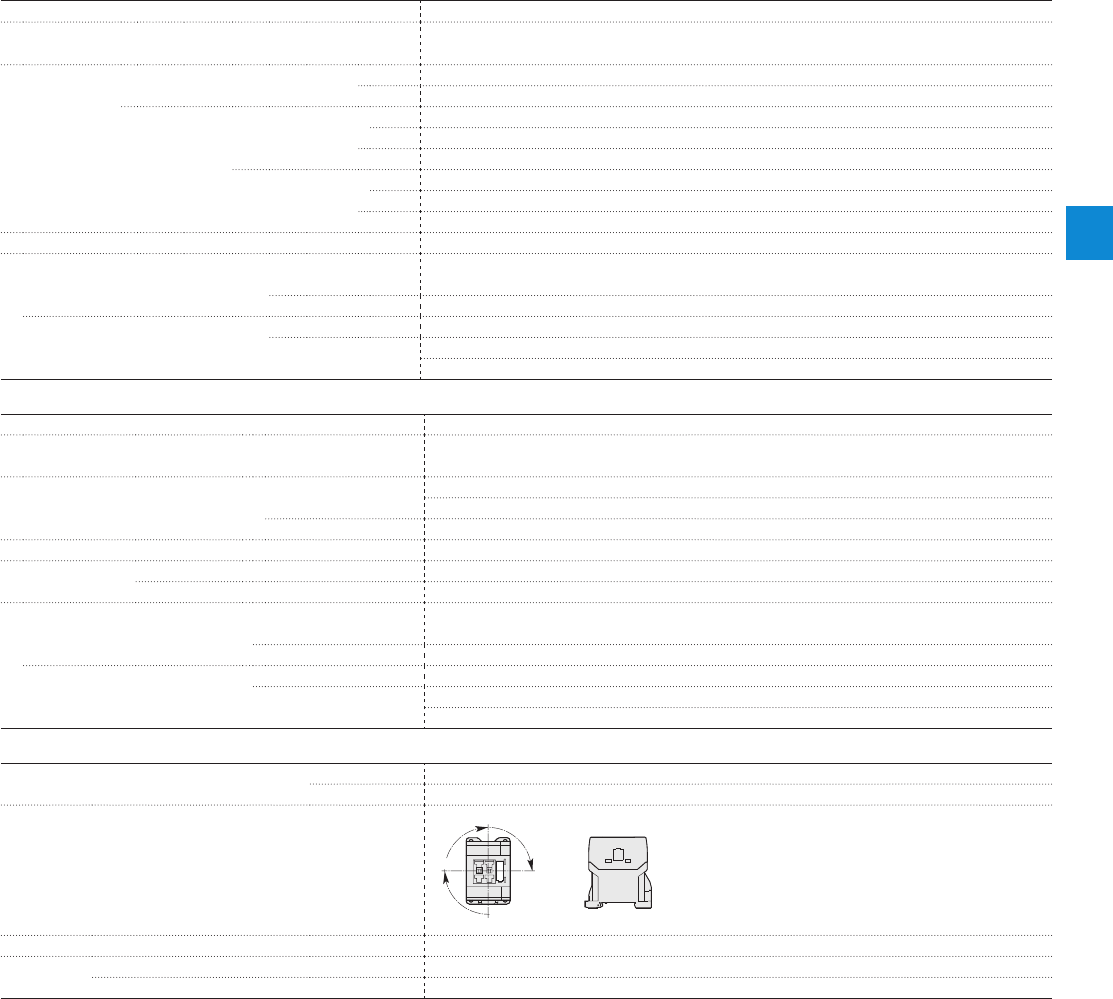
Magnet system characteristics for NS contactor relays
Contactor relay types
AC operated
NS
Coil operating limits
AC supply
acc. to IEC 60947-5-1 0.85...1.1 x Uc (at θ ≤ 60°C); Uc (at θ ≤ 70°C)
AC control voltage
Rated control circuit voltage Uc at 50Hz 24...415V
at 60Hz 24...415V
Coil consumption Average pull-in value 50Hz 33VA
60Hz 33VA
50/60Hz 33VA
Average holding value 50Hz 6.5VA / 1.5W
60Hz 5VA / 1.2W
50/60Hz 6.5VA / 1.5W
Drop-out voltage
Approx. 30...50% of Uc
Operating time
Between coil energization and: N.O. contact closing 9...24 ms
N.C. contact opening 6...18 ms
Between coil de-energization and: N.O. contact opening (1) 5...19 ms
N.C. contact closing (1) 7...22 ms
(1) The use of RC5-1 surge suppressor increases opening time by a factor of 2 to 3.
Magnet system characteristics for NSL contactor relays
Contactor
relay
types DC operated
NSL
Coil operating limits DC supply
acc. to IEC 60947-5-1 0.85...1.1 x Uc (at θ ≤ 60°C); Uc (at θ ≤ 70°C)
DC control voltage Rated control circuit voltage Uc 12...240V DC
Coil consumption Average pull-in value 3W
Average holding value 3W
Drop-out voltage Approx. 10...40% of Uc
Coil time constant Open L/R 12 ms
Closed L/R 40 ms
Operating time
Between coil energization and: N.O. contact closing 36...59 ms
N.C. contact opening 31...53 ms
Between coil de-energization and: N.O. contact opening (1) 13...17 ms
N.C. contact closing (1) 15...20 ms
(1) The use of RT5 surge suppressor increases opening time by a factor of 1.1 to 1.2.
Mounting characteristics and conditions for use
Contactor relay types
AC operated
NS
DC operated
NSL
Mounting positions
Pos. 3
Pos. 2
Pos. 1
Pos. 4
Pos. 5
Mounting distances
The contactor relays can be assembled side by side.
Fixing
On rail according to IEC 60715, EN 60715 35 x 7.5mm or 35 x 15mm
By screws (not supplied) 2 x M4 screws placed diagonally
NS and NSL contactor relays
Technical data
ABB | 4/29
4
1SBC101502S0201
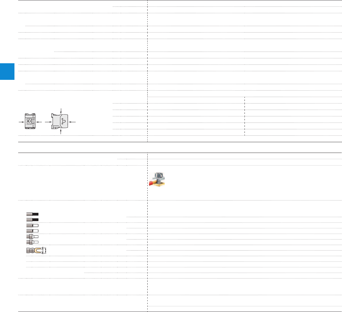
General technical data
Contactor relay types
AC operated
NS
DC operated
NSL
Rated insulation voltage Ui
acc. to IEC 60947-5-1 690V
acc. to UL / CSA 600V
Rated impulse withstand voltage Uimp.
6kV
Ambient air temperature close to contactor relay
Operation in free air -40...+70°C
Storage -60...+80°C
Climatic withstand
Category B according to IEC 60947-1 Annex Q
Maximum operating altitude (without derating)
3000m
Mechanical durability
Number of operating cycles 20 millions operating cycles
Max. switching frequency 3600 cycles/h
Shock withstand
1/2 sinusoidal shock for 11 ms: no change in contact position, closed or open position
acc. to IEC 60068-2-27 and EN 60068-2-27 Shock direction NS contactor relays - AC operated NSL contactor relays - DC operated
Mounting position 1 A20g 20g closed position / 10g open position
B1 5g 15g closed position / 5g open position
B2 15g 10g
C1 19g closed position / 8g open position 19g closed position / 8g open position
C2 16g closed position / 13g open position 14g closed position / 8g open position
Vibration withstand acc. to IEC 60068-2-6
5...300Hz / 3g closed position / 2g open position
Connecting characteristics
Contactor relay types
AC operated
NS
DC operated
NSL
Main terminals
Screw terminals with cable clamp
Connection capacity (min. ... max.)
Pole and coil terminals
Rigid solid 1 x 0.75...2.5mm²
2 x 0.75...2.5mm²
Flexible with non insulated ferrule 1 x 0.75...2.5mm²
2 x 0.75...2.5mm²
Flexible with insulated ferrule 1 x 0.75...2.5mm²
2 x 0.75...1.5mm²
L
l
Lugs L ≤ 7.7mm
l > 3.2mm
Connection capacity acc. to UL / CSA 1 or 2 x AWG 18...14
Stripping length 9mm
Tightening torque Recommended 1.00Nm / 9 lb.in
Max. 1.20Nm
Degree of protection
acc. to IEC 60947-1 / EN 60947-1 and IEC 60529 / EN 60529
All terminals IP20
Screw terminals
Delivered in open position, screws of unused terminals must be tightened
All terminals M3
Screwdriver type Flat Ø 5.5 / Pozidriv 2
NS and NSL contactor relays
Technical data
B2
AAB1
C2
C1
4/30 | ABB
4
1SBC101502S0201

Accessories for AS contactors and
NS contactor relays
Auxiliary contact blocks 4/32
Frontal electronic timers 4/33
Surge suppressors 4/34
Mechanical interlock unit and fixing clips 4/35
Connection accessories for starting solutions 4/36
ABB | 4/31
4
Somm_accessoires
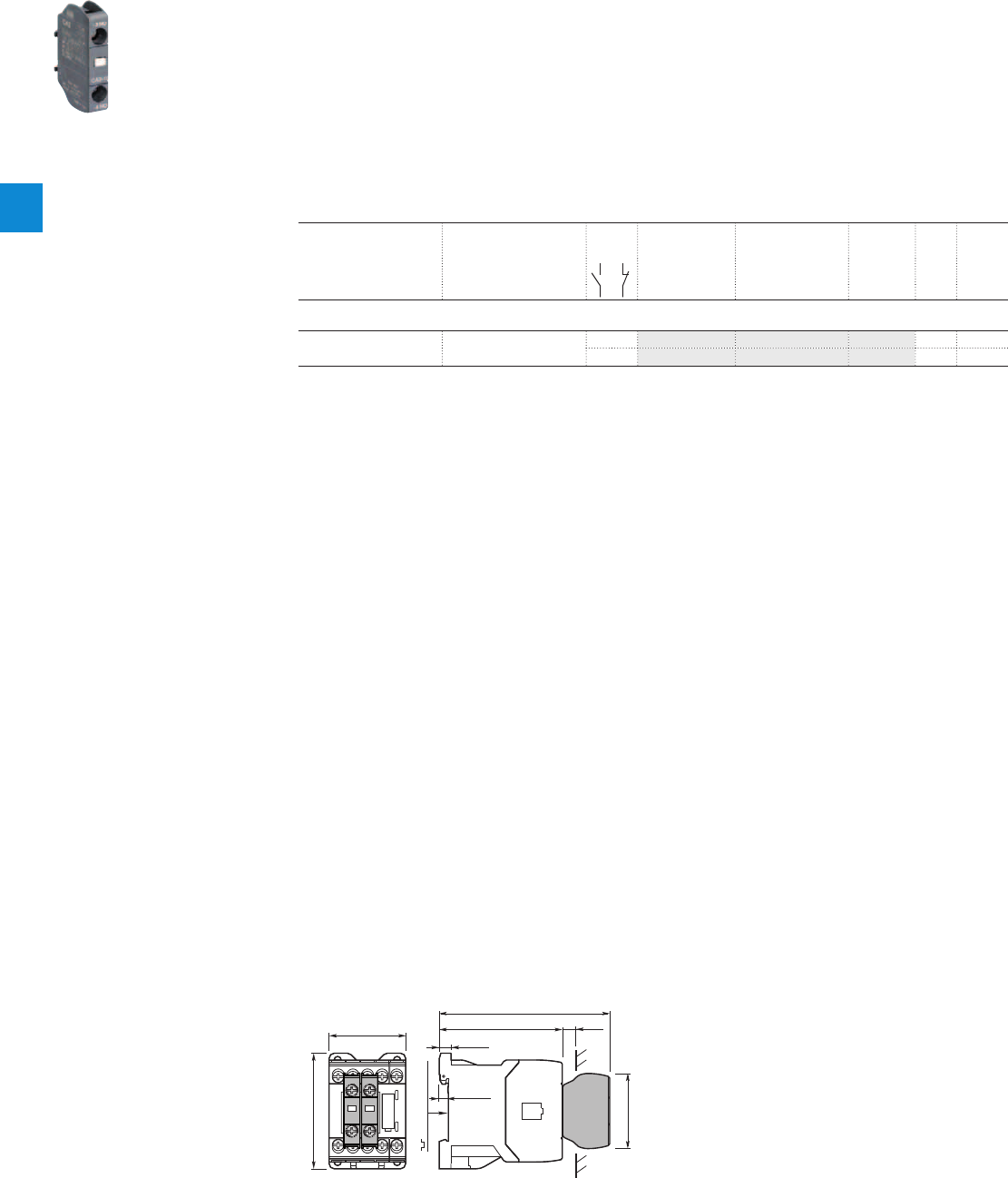
CA3-10
Auxiliary contact blocks
Accessories
Description
The auxiliary contact blocks are used for the operation of auxiliary circuits and control circuits.
CA3 1-pole auxiliary contact blocks, designed for standard industrial environments, are equipped with:
– N.O. or N.C. contacts.
– Screw-type connecting terminals with cage clamp delivered open.
All 1-pole auxiliary contact blocks are protected against accidental direct contact and bear the
corresponding function marking.
A maximum of two 1-pole auxiliary contact blocks can be front-mounted on 1-stack contactors or 1-stack
contactor relays.
Ordering details
For contactors For contactor relays Contact
blocks
Type Order code Pkg
qty
Weight
(1 pce)
kg
1-pole auxiliary contact blocks with screw terminals
AS09 ... AS16
ASL09 ... ASL16
NS, NSL
1 – CA3-10 1SBN011010T1010 10 0.011
– 1 CA3-01 1SBN011010T1001 10 0.011
1SBC101036F0014
Main dimensions mm, inches
10
0.39"
45 1.77"
68 2.68"
72.5 2.85"
5.5 0.22"
7 0.28"
35 mm
EN/IEC 60715
44.2 1.74"
100.2 3.94"
4/32 | ABB
4
1SBC101492S0201
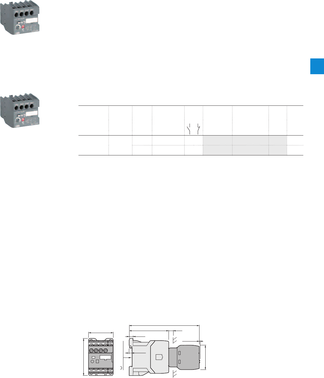
TEF3-OFF
TEF3-ON
Electronic timers
Description
TEF3 frontal electronic timers are used for realizing timing function independently of the control system
and are available in ON-delay and OFF-delay versions.
Compact solution in cabinet compared to separate timers
TEF3 electronic timers are front-mounted and locked on AS/ASL contactors or NS/NSL contactor relays.
A mechanical indicator allows to show the state of the contactor.
Safe and cost-reduced wiring
TEF3 electronic timers are supplied by a direct plug-in parallel connection to the coil terminals A1 - A2 of
the contactor or contactor relay. A varistor is integrated on the timer to offer a built-in protection against
surges in the contactor coil.
Available for a wide control voltage range 24...240 V AC/DC
TEF3-ON or TEF3-OFF allow time-delayed functions up to 100s in 3 distinct time ranges, independently
of the control system. The time delay ranges are selected by a switch and the time delay can be adjusted
by means of a rotary switch. The timing function is activated by closing the device on which the timer is
mounted. The OFF-delay version operates without additional control supply.
Ordering details
For contactors,
contactor relays
Time delay
range
selected by
switch
Delay
type
Rated control
circuit voltage
Uc
Auxiliary
contacts
Type Order code Weight
Pkg
(1 pce)
V 50/60 Hz or DC kg
AS09 ... AS16
ASL09 ... ASL16
NS, NSL
0.1...1s
1...10s
10...100s
ON-delay 24...240 1 1 TEF3-ON 1SBN021012R1000 0.065
OFF-delay 24...240 1 1 TEF3-OFF 1SBN021014R1000 0.065
Main dimensions mm, inches
10
0.39"
45 1.77"
68 2.68"
72.5 2.85"
5.5 0.22"
7 0.28"
1.1 0.05"
35 mm
EN/IEC 60715
44.2 1.74"
128.1 5.04"
44.4 1.75"
1SBC101336F0010 1SBC101337F0010
ABB | 4/33
4
1SBC101504S0201
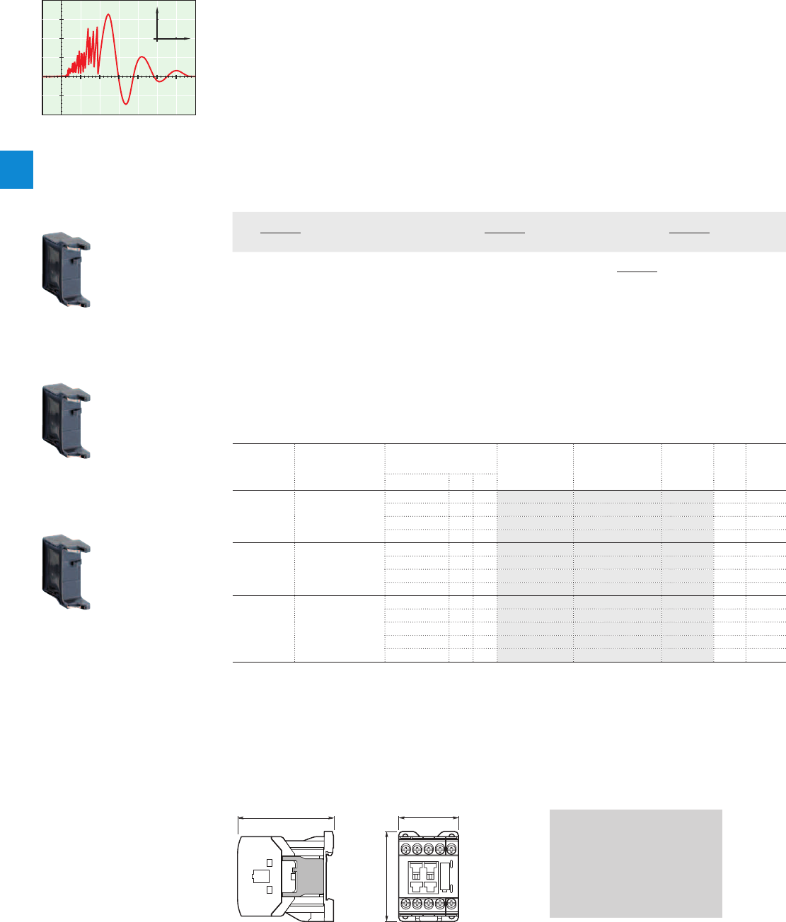
Surge suppressors for contactor coils
Description
The operation of inductive circuits causes overvoltages, in particular on opening the contactor coil.
The electromagnetic energy stored in the coil during contactor closing is restored on opening in the form
of surges, the slope and amplitude of which may rise to several kilovolts. A number of drawbacks are
observed ranging from interference on the electronic devices to the breakdown of insulators and even the
destruction of certain sensitive components.
The graph opposite reproduces the oscillogram showing voltage discharges at the terminals of a 42 V / 50 Hz
coil without peak clipping. The coil was switched by 8 series-connected poles of a contactor relay.
Following a burst of discharges with a very steep slope, a damped oscillation emerges with a peak value
of 3500 V.
Overvoltage Factor
The overvoltage factor k is defined as the ratio of the maximum overvoltage peak value Ûs to the peak
value Ûc of the coil rated control voltage Uc:
Ûs max.
k =
Ûc
Ûs max.
in DC k =
Uc
Ûs max.
in AC k =
Uc √2
For example the following is obtained for the above graph: 3500
k = ≈ 60
42 √2
To reduce the harmful effects of these overvoltages, ABB has developed a range of surge suppressors de-
signed to reduce the k factor defined above and to limit or even completely eliminate the high pre-damping
voltage frequencies.
Each case is different, but the technical data tolerances and generous sizing of parts have enabled us to
reduce the number of variants.
We have chosen the following solutions: transil diodes, varistors and RC blocks.
Note: A varistor is a resistor whose value decreases to a very large extent when a certain voltage is ap-
plied at its terminals.
Ordering details
For
contactors
For
contactor
relays
Rated control circuit
voltage - Uc
Type Order code Pkg
qty
Weight
(1 pce)
VACDC kg
AS, ASL NS, NSL 24...50
●●
RV5/50 1SBN050010R1000 2 0.015
50...133
●●
RV5/133 1SBN050010R1001 2 0.015
110...250
●●
RV5/250 1SBN050010R1002 2 0.015
250...440
●●
RV5/440 1SBN050010R1003 2 0.015
AS NS 24...50
●
– RC5-1/50 1SBN050100R1000 2 0.012
50...133
●
– RC5-1/133 1SBN050100R1001 2 0.012
110...250
●
– RC5-1/250 1SBN050100R1002 2 0.012
250...440
●
– RC5-1/440 1SBN050100R1003 2 0.012
ASL NSL 12...32 –
●
RT5/32 1SBN050020R1000 2 0.015
25...65 –
●
RT5/65 1SBN050020R1001 2 0.015
50...90 –
●
RT5/90 1SBN050020R1002 2 0.015
77...150 –
●
RT5/150 1SBN050020R1003 2 0.015
150...264 –
●
RT5/264 1SBN050020R1004 2 0.015
0
1000
100
(V)
T (μs)
0
1000
100
RV5
1SBC101042F0014
RT5
1SBC101042F0014
RC5-1
1SBC101042F0014
Main dimensions mm, inches
72.5 2.85" 45 1.77"
68 2.68"
Easy connection to the coil terminals
(parallel mounting)
Clip-on for both fixing and connection.
No additional space
Clipped onto the right side part of
the contactor base without changing
contactor overall dimensions and
keeping a free access to coil terminals.
4/34 | ABB
4
1SBC101494S0201
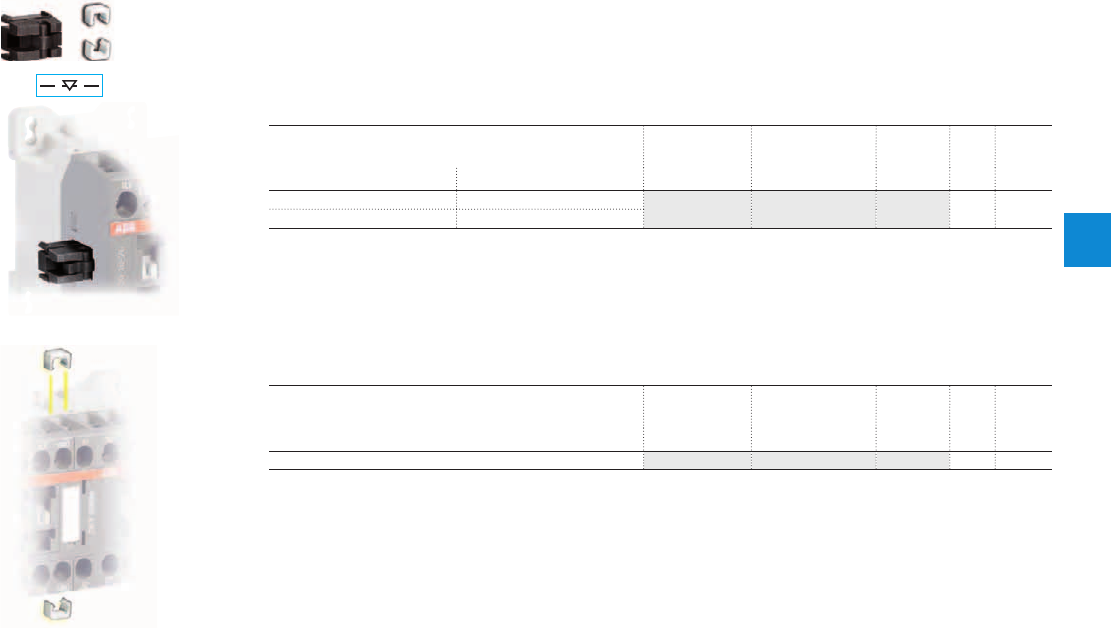
Mechanical interlock unit and fixing clips
Mechanical interlock unit
When mounted between two contactors without additional width, the VM3 mechanical interlock unit pre-
vents one of the contactors from closing as long as the other contactor is closed.
The mechanical interlock unit includes 2 fixing clips.
Ordering details
For contactors Type Order code Pkg
qty
Weight
(1 pce)
Left Right kg
AS AS VM3 1SBN031005T1000 10
0.002
ASL ASL
Note : VM3 mechanical durability, 5 millions of operating cycles on both reversing contactors.
Fixing clips
BB3 is a set of 50 fixing clips.
Ordering details
For contactors Type Order code Pkg
qty
Weight
(1 pce)
kg
AS, ASL BB3 1SBN111020R1000 1
0.009
VM3
BB3
ABB | 4/35
4
1SBC101496S0201
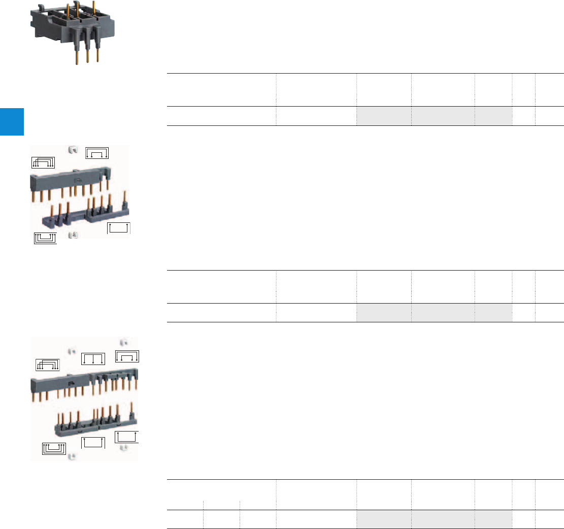
Connection accessories for starting solutions
Connecting links
The BEA16-3 insulated 3-pole connecting links are used to connect an AC or DC operated contactors with
manual motor starters.
The connecting links ensure the electrical and mechanical connection between the contactor and the
manual motor starter.
Ordering details
For contactors Manual motor
starter
Type Order code Pkg
qty
Weight
(1 pce)
kg
AS09...AS16
ASL09...ASL16
MS116-0.16 ... MS116-16
MS132-0.16 ... MS132-16
BEA16-3 1SBN081006T1000 10
0.019
Connection sets for reversing contactors
The BER16C-3 connection sets are used for the connections between the main poles of two 3-pole
contactors mounted side by side as reversing contactors, including electrical interlocking between built-in
N.C. auxiliary contact and coil terminals.
The connection sets are made up of:
– 1 upstream and 1 downstream connections: insulated, solid copper bars,
– 2 connections to realize electrical interlocking between contactors equipped with built-in N.C. auxiliary
contacts,
– 2 fixing clips.
Ordering details
For contactors Mechanical
interlock unit
Type Order code Pkg
qty
Weight
(1 pce)
kg
2 x AS09…AS16
2 x ASL09…ASL16
with or without VM3 BER16C-3 1SBN081012R1000 1
0.035
Connection sets for star-delta starting
BEY16C-3 connection sets are designed for star-delta starters whose contactors are assembled according
to line delta star mounting.
The connection sets are made up of:
– Line contactor / delta contactor: upstream phase-to-phase connection,
– Delta contactor / star contactor: downstream connection in parallel,
– Star contactor: star point upstream,
– An electrical interlocking between delta and star contactors equipped with built-in N.C. auxiliary con-
tacts,
– 4 fixing clips.
Ordering details
For contactors Mech. interlock unit
between star & delta
contactors
Type Order code Pkg
qty
Weight
(1 pce)
Line Delta Star kg
AS09 AS09 AS09 with or without VM3 BEY16C-3 1SBN081018R2000 1
0.041
AS12 AS12 AS09
BEA16-3
1SBC101034F0014
BER16C-3
1SBC101071F0014
1SBC101070F0014
BEY16C-3
4/36 | ABB
4
1SBC101495S0201
Voltage code table
The below tables indicate the available coil voltages and corresponding digits for order codes. When placing an order, please
give either type or order code. Select a standard contactor from ordering detail pages. Change the coil voltage code in the
type or in the order code according to the table below. Example: for contactor AS09-30-10 and coil 42 V 50/60 Hz, type is
AS09-30-10-21 and order code is 1SBL101001R2110.
Auxiliary contacts
N.O. N.C.
N.O. N.C.
Number contacts
N.O. N.C.
Main contacts
Type
Type
Order code
Order code
Contactor type
Contactor type
AS16 - 30 - 10 - 26
NS 40 E - 26
AS AC operated
ASL DC operated
NS AC operated
NSL DC operated
AC coil code
AC coil code
AC coil code
50 Hz 60 Hz
20 24V 24V
21 42V 42V
22 48V 48V
23 110V 110V
24 115V 115V
16 – 120V
25 220V 220V
26 230V 230V
27 240V 240V
17 – 277V
13 380V –
28 400V 400V
29 415V 415V
50 Hz 60 Hz
20 24V 24V
21 42V 42V
22 48V 48V
23 110V 110V
24 115V 115V
16 – 120V
25 220V 220V
26 230V 230V
27 240V 240V
17 – 277V
13 380V –
28 400V 400V
29 415V 415V
50 Hz 60 Hz
20 24V 24V
21 42V 42V
22 48V 48V
23 110V 110V
24 115V 115V
16 – 120V
25 220V 220V
26 230V 230V
27 240V 240V
17 – 277V
13 380V –
28 400V 400V
29 415V 415V
1SBL121001R 26 10
1SBH101001R 26 40
Type Order code
Surge suppressor
Contactor type
VAS12 S EM - 26 M
VAS AC operated
VASL DC operated
DC coil code
80 12 V
81 24 V
83 48 V
84 60 V
86 110 V
87 125 V
88 220 V
89 240 V
DC coil code
80 12 V
81 24 V
83 48 V
84 60 V
86 110 V
87 125 V
88 220 V
89 240 V
1SBK113800M 26 00
3-pole contactors
Contactor relays
3-pole reversing contactors
DC coil code
80 12 V (1)
81 24 V
83 48 V
84 60 V
86 110 V
87 125 V
88 220 V
89 240 V
(1) Not for VASL..SEM
ABB | 4/37
4
1SBC101600S0201
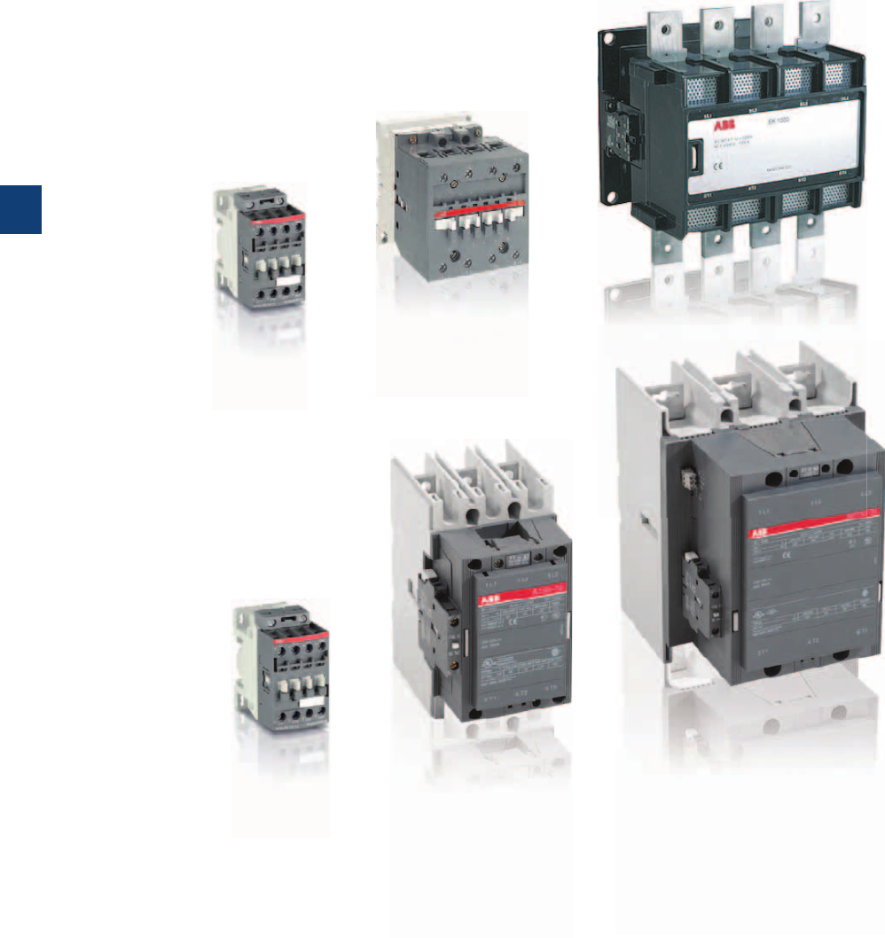
5/0 | ABB
5
1SBC101639S0201

A, AF, EK contactors and NF contactor relays
AF, A 3-pole contactors
Contents 5/3
Overview 3-pole contactors 5/4
Ordering details 3-pole contactors 5/6
Technical data 3-pole contactors 5/28
AF, A and EK 4-pole contactors
Contents 5/55
Overview 4-pole contactors 5/56
Ordering details 4-pole contactors 5/58
Technical data 4-pole contactors 5/76
Contactors for capacitor switching
Contents 5/93
Overview 5/94
UA16..RA up to UA110..RA - Unlimited peak Î 5/96
UA16 up to UA110 - Peak current Î ≤ 100 times the rms current 5/101
NF 4-pole contactor relays
Contents 5/107
Ordering details 5/108
Main accessories 5/110
Technical data 5/112
Accessories for A, AF, EK contactors and NF contactor relays
Accessories for AF09 ... AF38 contactors and NF contactor relays
5/115
Accessories for A40 … AF2050 contactors 5/121
Accessories for EK100 … EK1000 contactors 5/147
Voltage code table 5/157
ABB | 5/1
5
1SBC101639S0201
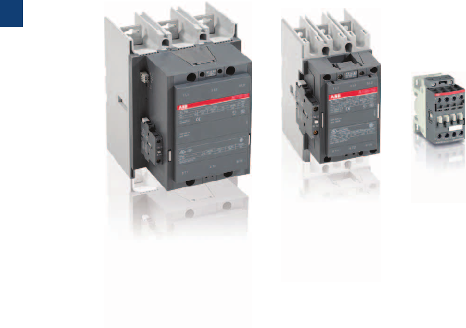
5/2 | ABB
5
1SBC101608S0201

AF, A 3-pole contactors
Overview 5/4
Ordering details
4 to 18.5 kW / 5 to 20 hp
AF09 … AF38 AC / DC operated 5/6
AF09Z … AF38Z AC / DC operated - low consumption 5/7
Main accessories 5/8
18.5 to 37 kW / 30 to 60 hp
A40 AC operated 5/10
A50 … A75 AC operated 5/11
AL40 DC operated 5/12
AE50 ... AE75 DC operated 5/13
AF50 … AF75 AC / DC operated 5/14
Main accessories 5/16
45 to 55 kW / 60 to 75 hp
A95 … A110 AC operated 5/18
AF95 … AF110 AC / DC operated 5/19
Main accessories 5/20
75 to 560 kW / 100 to 900 hp
A145 … A300 AC operated 5/22
AF145 … AF300 AC / DC operated 5/23
AF400 … AF750 AC / DC operated 5/24
AF1250 … AF2050 AC / DC operated 5/25
Main accessories 5/26
Technical data
Main pole - Utilization characteristics according to IEC 5/28
Main pole - Utilization characteristics according to UL/NEMA/CSA 5/32
General technical data 5/32
Magnet system and mounting characteristics 5/36
Connecting characteristics 5/43
Built-in auxiliary contacts 5/47
Electrical durability 5/49
Accessories
Accessories for
AF09 ... AF38 contactors and NF contactor relays
5/115
Accessories for A40 ... AF2050 contactors 5/121
Voltage code table 5/157
ABB | 5/3
5
1SBC101608S0201
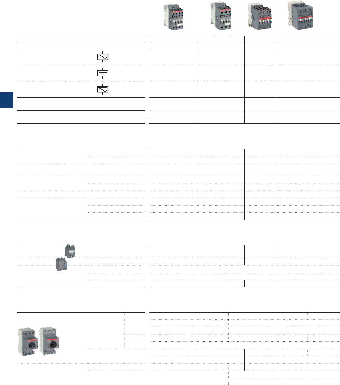
3-pole contactors, for all industrial applications
and motor starting
CA4-10
(1 x N.O.)
, CA4-01
(1 x N.C.)
CA5-10
(1 x N.O.)
, CA5-01
(1 x N.C.)
CAL4-11
(1 x N.O. + 1 x N.C.)
CAL5-11
(1 x N.O. + 1 x N.C.)
TP40DA, TP180DA Direct timing
TP40IA, TP180IA Inverse timing
VM4 VM5-1
VEM4 VE5-1 VE5-2
BER16-4 BER38-4 BER40V BEM75-30
RV5
(24…440 V)
RC5-1
(24…440 V)
RC5-2
(24…440 V)
RT5
(12…264 V)
4 5.5 7.5 11 15 18.5 18.5 22 30 37
5 7.5 10 15 20 20 30 40 60 60
AF09 AF12 AF16 AF26 AF30 AF38 A40 A50 A63 A75
AF09 AF12 AF16 AF26 AF30 AF38 AL40 AE50 AE63 AE75
AF09 AF12 AF16 AF26 AF30 AF38 — AF50 AF63 AF75
9121826323837 506575
25 28 30 45 50 50 60 100 115 125
25 28 30 45 50 50 60 80 90 105
000—1——— 2—3
MS116
for class 10A (0.16…32 A) Ics up to 50 kA
MS450
(40…50 A) Ics up to 50 kA
MS132
(0.10…32 A) Ics up to 100 kA
MS495
(28…100 A) Ics up to 50 kA
MS497
(11…100 A) Ics up to 100 kA
MS451
(11…50 A) Ics up to 50 kA
MS496
(28…100 A) Ics up to 100 kA
MO132
(0.10…32 A)
MO450
(16…50 A) Ics up to 50 kA
MO495
MO496
(16…100 A) Ics up to 100 kA
BEA16-4 BEA38-4
BEA40/450
BEA50/450,
HKF1, HK1, UA1, AA1, PS1, S1, SK1
CK1
(MS132, MO132 only)
HK4, HKS4, UA4, AA4, PS4, S4, SK4
TF42
(0.10…38 A)
TA42DU (18…42 A)
TA75DU
(18…80 A)
EF19
(0.10…18.9 A)
EF19 (0.10…18.9 A), EF45 (9…45 A)
E45DU
(9...45 A)
E80DU
(27…80 A)
DB42
(TF42 only)
DB80, DB45E, DB80E
Main accessories
Auxiliary contact blocks
Front mounting
Side mounting
Timers
Pneumatic
(Front mounting)
Interlocking units Mechanical
Mechanical / Electrical
Connection
sets
For reversing contactors
Surge suppressors
AF contactors have built-in surge
protection
Varistor (AC / DC)
RC type (AC)
Transil diode (DC)
IEC
AC-3 Rated operational
power
θ ≤ 55 °C*, 400 V
kW
UL/CSA
3-phase motor rating
480 V hp
AC Control supply Type
DC Control supply Type
AC / DC Control supply Type
IEC
AC-3 Rated
operational
current θ ≤ 55 °C*, 400 V
A
AC-1 Rated
operational
current θ ≤ 40 °C, 690 V
A
UL/CSA
General use rating
600 V A
NEMA
NEMA Size
* θ ≤ 60 °C for AF09 ... AF38 contactors
Manual motor starters
Thermal / magnetic
protection
Class 10
Class 20
Magnetic only types
Accessories
For contactor mounting
Auxiliary trip units,
auxiliary contacts, busbars
Overload relays
Thermal relays
Class 10
(10A or 20 for TA42DU to TA80DU)
Electronic relays Class 10E, 20E, 30E
Accessories
for thermal overload relays
Remote tripping coil
Remote reset coil
Wall/separate mounting kit
5/4 | ABB
5
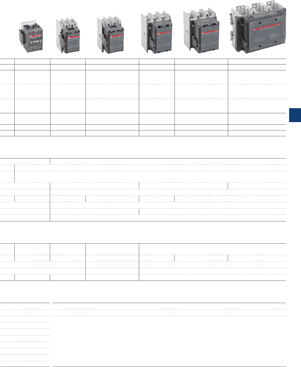
CAL18-11
(1 x N.O. + 1 x N.C.)
VM300H / VM300V VM750H / VM750V VM1650H
BEM110-30 BEM185-30 BEM300-30 BEM460-30 BEM750-30
RC5-3
(250...440V)
45 55 75 90 110 140 160 200 250
315 400 —
475 560 —
60 75 100 125 150 200 250 350 400
500 600 —
800 900 —
A95 A110 A145 A185
A210 A260 A300 AF400 AF460
AF580 AF750 AF1250
AF1350 AF1650 AF2050
AF95 AF110 AF145 AF185
AF210 AF260 AF300 AF400 AF460
AF580 AF750 AF1250
AF1350 AF1650 AF2050
AF95 AF110 AF145 AF185
AF210 AF260 AF300 AF400 AF460
AF580 AF750 AF1250
AF1350 AF1650 AF2050
96 110 145 185 210 260 305 400 460
580 750 —
860 1050 —
145 160 250 275 350 400 500 600 700
800 1050 1260
1350 1650 2050
125 140 230 250 300 350 400 550 650
750 900 1210
1350 1650 2100
— —4 ——5 ——6
—7 —
—8 —
Circuit breakers
Tmax
Circuit breaker and accessories
(40…100 A) Ics up to 50 kA
BEA75/495
TA80DU
(29…80 A)
TA110DU
(65…110 A)
TA200DU
(66…200 A)
TA450DU/SU
(130…310 A)
class 30 for SU
E140DU
(50…140 A)
E200D-U
(60…200 A)
E320DU
(100…320 A)
E500DU
(150…500 A)
E800DU
(250…800 A)
E1250DU
(375…1250 A)
DS25-A
DR25-A
DB80, DB200, D140E
DB200 DT450/A
ABB | 5/5
5
1SBC101555S0201
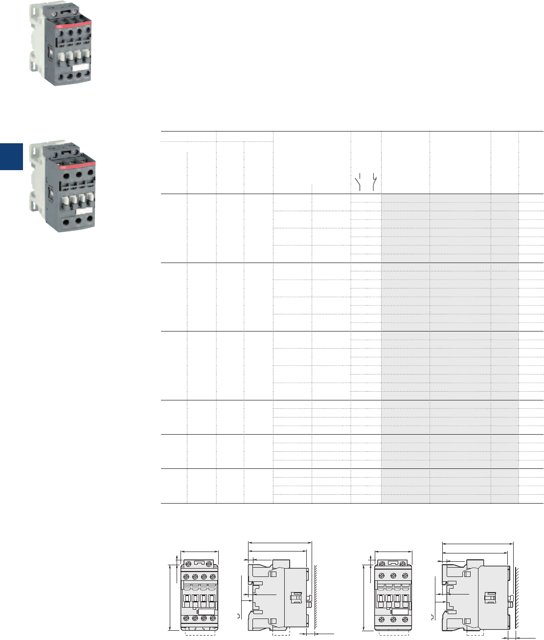
1SBC101090F0014
AF09-30-10
1SBC101091F0014
AF26-30-00
AF09 ... AF38 3-pole contactors
4 to 18.5kW
AC / DC operated
Main dimensions mm, inches
45 1.77"
80 3.15"
6 0.24"
77 3.03"
71 2.80"
5.5 0.22"
35 mm
EN/IEC 60715
10 0.39"
5.5 0.22"
AF09, AF12, AF16
45 1.77"
80 3.15"
6 0.24"
86 3.39"
80 3.15"
10 0.39"
35 mm
EN/IEC 60715
5.5 0.22"
5.5 0.22"
AF26, AF30, AF38
Description
AF09 ... AF38 contactors are mainly used for controlling 3-phase motors and power circuits up to 690VAC
and 220VDC. These contactors are of the block type design with 3 main poles.
– control circuit: AC or DC operated with electronic coil interface accepting a wide control voltage range
(e.g. 100...250VAC and DC), only 4 coils to cover control voltages between 24...500V 50/60Hz and
20...500VDC
- can manage large control voltage variations
- reduced panel energy consumption
- very distinct closing and opening.
– built-in surge suppression
– add-on auxiliary contact blocks for front or side mounting and a wide range of accessories.
Ordering details
IEC UL/CSA Rated control circuit
voltage
Uc min. … Uc max.
Auxiliary
contacts
fitted
Type Order code Weight
Pkg
(1 pce)
Rated operational 3-phase
motor
rating
General
use
rating
power current
θ ≤ 40°C
400V 480V 600VAC
AC-3 AC-1
kW A hp A V 50/60Hz V DC kg
425 525 24...60 20...60 (1) 1 0 AF09-30-10-11 1SBL137001R1110 0.270
0 1 AF09-30-01-11 1SBL137001R1101 0.270
48...130 48...130 1 0 AF09-30-10-12 1SBL137001R1210 0.270
0 1 AF09-30-01-12 1SBL137001R1201 0.270
100...250 100...250 1 0 AF09-30-10-13 1SBL137001R1310 0.270
0 1 AF09-30-01-13 1SBL137001R1301 0.270
250...500 250...500 1 0 AF09-30-10-14 1SBL137001R1410 0.310
0 1 AF09-30-01-14 1SBL137001R1401 0.310
5.5 28 7.5 28 24...60 20...60 (1) 1 0 AF12-30-10-11 1SBL157001R1110 0.270
0 1 AF12-30-01-11 1SBL157001R1101 0.270
48...130 48...130 1 0 AF12-30-10-12 1SBL157001R1210 0.270
0 1 AF12-30-01-12 1SBL157001R1201 0.270
100...250 100...250 1 0 AF12-30-10-13 1SBL157001R1310 0.270
0 1 AF12-30-01-13 1SBL157001R1301 0.270
250...500 250...500 1 0 AF12-30-10-14 1SBL157001R1410 0.310
0 1 AF12-30-01-14 1SBL157001R1401 0.310
7.5 30 10 30 24...60 20...60 (1) 1 0 AF16-30-10-11 1SBL177001R1110 0.270
0 1 AF16-30-01-11 1SBL177001R1101 0.270
48...130 48...130 1 0 AF16-30-10-12 1SBL177001R1210 0.270
0 1 AF16-30-01-12 1SBL177001R1201 0.270
100...250 100...250 1 0 AF16-30-10-13 1SBL177001R1310 0.270
0 1 AF16-30-01-13 1SBL177001R1301 0.270
250...500 250...500 1 0 AF16-30-10-14 1SBL177001R1410 0.310
0 1 AF16-30-01-14 1SBL177001R1401 0.310
11 45 15 45 24...60 20...60 (1) 0 0 AF26-30-00-11 1SBL237001R1100 0.310
48...130 48...130 0 0 AF26-30-00-12 1SBL237001R1200 0.310
100...250 100...250 0 0 AF26-30-00-13 1SBL237001R1300 0.310
250...500 250...500 0 0 AF26-30-00-14 1SBL237001R1400 0.350
15 50 20 50 24...60 20...60 (1) 0 0 AF30-30-00-11 1SBL277001R1100 0.310
48...130 48...130 0 0 AF30-30-00-12 1SBL277001R1200 0.310
100...250 100...250 0 0 AF30-30-00-13 1SBL277001R1300 0.310
250...500 250...500 0 0 AF30-30-00-14 1SBL277001R1400 0.350
18.5 50 20 50 24...60 20...60 (1) 0 0 AF38-30-00-11 1SBL297001R1100 0.310
48...130 48...130 0 0 AF38-30-00-12 1SBL297001R1200 0.310
100...250 100...250 0 0 AF38-30-00-13 1SBL297001R1300 0.310
250...500 250...500 0 0 AF38-30-00-14 1SBL297001R1400 0.350
(1) AF..-30-..-11 not suitable for direct control by PLC-output.
5/6 | ABB
5
1SBC101371S0201
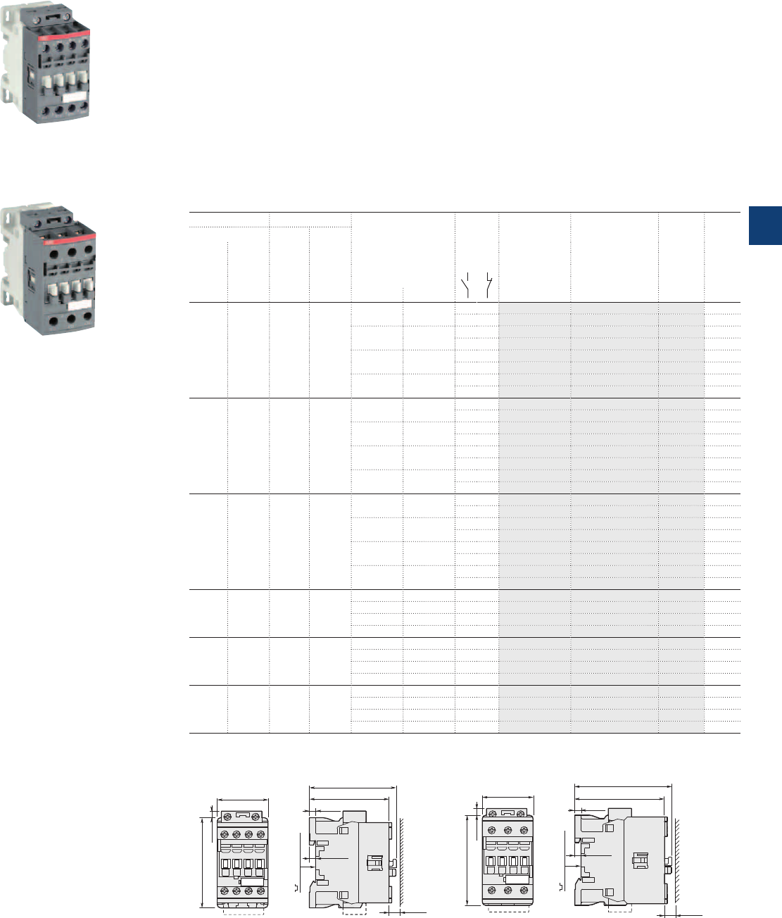
1SBC101090F0014
AF09Z-30-10
1SBC101091F0014
AF26Z-30-00
AF09Z ... AF38Z 3-pole contactors
4 to 18.5kW
AC / DC operated - low consumption
Main dimensions mm, inches
45 1.77"
80 3.15"
6 0.24"
77 3.03"
71 2.80"
5.5 0.22"
35 mm
EN/IEC 60715
10 0.39"
5.5 0.22"
AF09Z, AF12Z, AF16Z
45 1.77"
80 3.15"
6 0.24"
86 3.39"
80 3.15"
10 0.39"
35 mm
EN/IEC 60715
5.5 0.22"
5.5 0.22"
AF26Z, AF30Z, AF38Z
Description
AF09Z ... AF38Z contactors are mainly used for controlling 3-phase motors and power circuits up to
690VAC and 220VDC. These contactors are of the block type design with 3 main poles.
– control circuit: AC or DC operated with electronic coil interface accepting a wide control voltage range
(e.g. 100...250VAC and DC), only 4 coils to cover control voltages between 24...250V 50/60Hz and
12...250VDC
- can manage large control voltage variations
- allow direct control by PLC-output ≥ 24 V DC 500 mA
- reduced panel energy consumption
- very distinct closing and opening
- can withstand short voltage dips and voltage sags (SEMI F47-0706 conditions of use on request).
– built-in surge suppression
– add-on auxiliary contact blocks for front or side mounting and a wide range of accessories.
Ordering details
IEC UL/CSA Rated control circuit
voltage
Uc min. … Uc max.
Auxiliary
contacts
fitted
Type Order code Weight
Pkg
(1 pce)
Rated operational 3-phase
motor
rating
General
use
rating
power current
θ ≤ 40°C
400V 480V 600VAC
AC-3 AC-1
kW A hp A V 50/60Hz V DC kg
425 525 - 12...20 1 0 AF09Z-30-10-20 1SBL136001R2010 0.310
0 1 AF09Z-30-01-20 1SBL136001R2001 0.310
24...60 20...60 1 0 AF09Z-30-10-21 1SBL136001R2110 0.310
0 1 AF09Z-30-01-21 1SBL136001R2101 0.310
48...130 48...130 1 0 AF09Z-30-10-22 1SBL136001R2210 0.310
0 1 AF09Z-30-01-22 1SBL136001R2201 0.310
100...250 100...250 1 0 AF09Z-30-10-23 1SBL136001R2310 0.310
0 1 AF09Z-30-01-23 1SBL136001R2301 0.310
5.5 28 7.5 28 - 12...20 1 0 AF12Z-30-10-20 1SBL156001R2010 0.310
0 1 AF12Z-30-01-20 1SBL156001R2001 0.310
24...60 20...60 1 0 AF12Z-30-10-21 1SBL156001R2110 0.310
0 1 AF12Z-30-01-21 1SBL156001R2101 0.310
48...130 48...130 1 0 AF12Z-30-10-22 1SBL156001R2210 0.310
0 1 AF12Z-30-01-22 1SBL156001R2201 0.310
100...250 100...250 1 0 AF12Z-30-10-23 1SBL156001R2310 0.310
0 1 AF12Z-30-01-23 1SBL156001R2301 0.310
7.5 30 10 30 - 12...20 1 0 AF16Z-30-10-20 1SBL176001R2010 0.310
0 1 AF16Z-30-01-20 1SBL176001R2001 0.310
24...60 20...60 1 0 AF16Z-30-10-21 1SBL176001R2110 0.310
0 1 AF16Z-30-01-21 1SBL176001R2101 0.310
48...130 48...130 1 0 AF16Z-30-10-22 1SBL176001R2210 0.310
0 1 AF16Z-30-01-22 1SBL176001R2201 0.310
100...250 100...250 1 0 AF16Z-30-10-23 1SBL176001R2310 0.310
0 1 AF16Z-30-01-23 1SBL176001R2301 0.310
11 45 15 45 - 12...20 0 0 AF26Z-30-00-20 1SBL236001R2000 0.350
24...60 20...60 0 0 AF26Z-30-00-21 1SBL236001R2100 0.350
48...130 48...130 0 0 AF26Z-30-00-22 1SBL236001R2200 0.350
100...250 100...250 0 0 AF26Z-30-00-23 1SBL236001R2300 0.350
15 50 20 50 - 12...20 0 0 AF30Z-30-00-20 1SBL276001R2000 0.350
24...60 20...60 0 0 AF30Z-30-00-21 1SBL276001R2100 0.350
48...130 48...130 0 0 AF30Z-30-00-22 1SBL276001R2200 0.350
100...250 100...250 0 0 AF30Z-30-00-23 1SBL276001R2300 0.350
18.5 50 20 50 - 12...20 0 0 AF38Z-30-00-20 1SBL296001R2000 0.350
24...60 20...60 0 0 AF38Z-30-00-21 1SBL296001R2100 0.350
48...130 48...130 0 0 AF38Z-30-00-22 1SBL296001R2200 0.350
100...250 100...250 0 0 AF38Z-30-00-23 1SBL296001R2300 0.350
Note: Only AF..Z contactors with DC control voltage 12...20VDC need to respect the connection polarities indicated close to the coil
terminals: A1+ for the positive pole and A2- for the negative pole.
ABB | 5/7
5
1SBC101372S0201
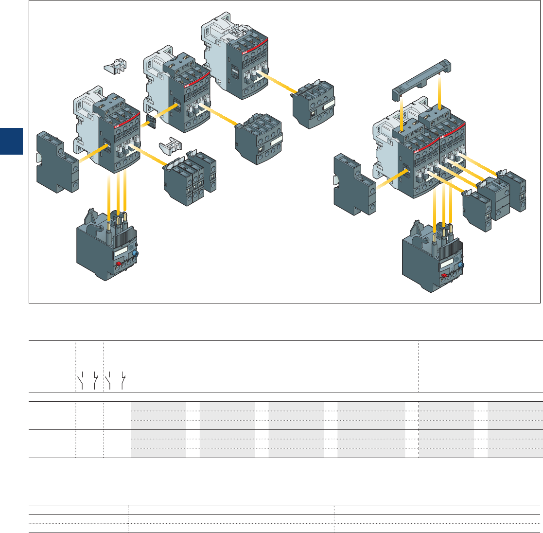
AF09 ... AF38 3-pole contactors
Main accessories
Main accessory fitting details
Many configurations of accessories are possible depending on whether these are front-mounted or side-mounted.
Contactor
types
Main
poles
Built-in
auxiliary
contacts
Front-mounted accessories Side-mounted accessories
Auxiliary contact blocks Electrical and Auxiliary contact blocks
mechanical interlock set
1-pole CA4 (between 2 contactors) Left side Right side
1-pole CC4 2-pole CAT4-11 4-pole CA4 VEM4 2-pole CAL4-11
Max. N.C. built-in and add-on N.C. auxiliary contacts: 4 N.C. max. on positions 1, 2, 3, 4 and 3 N.C. max. on positions 1 ±30°, 5
AF09 ... AF16 3 0 0 1 4 max.
or
1
or
1–
+
1–
2 max. – – –
+
1
+
1
3 max. – –
+
1
+
1
or
1
AF09 ... AF16
AF26 ... AF38
3
3
0
0
1
0
0
0
4 max.
or
1
or
1–
+
1–
2 max.
or
1––
+
1
+
1
3 max. – –
+
1
+
1
or
1
Overload relays fitting details (1)
Contactor types Thermal overload relays Electronic overload relays
AF09 ... AF38 TF42 (0.10...38 A) EF19 (0.10...18.9 A)
AF26 ... AF38 – EF45 (9...38 A)
The addition of an overload relay on the contactor does not prevent fitting of many other accessories as shown above.
(1) Direct mounting - No kit required.
Contactor and main accessories (other accessories available)
VEM4 mechanical and electrical interlock set including:
– VM4 mechanical interlock unit with 2 fixing clips
– VE4 electrical interlock block with A2-A2 connection
A2
VE4
AF contactor
4-pole CA4
2-pole CAT4-11
1-pole CA4, CC4
VM4
1-pole
CA4, CC4
2-pole CAL4-11
2-pole CAL4-11
AF contactor
(without top mounted
coil terminal block)
TF42
EF..
Fixing clips
TF42
EF..
A2
AF contactor
1-pole
CA4, CC4
5/8 | ABB
5
1SBC101384S0201
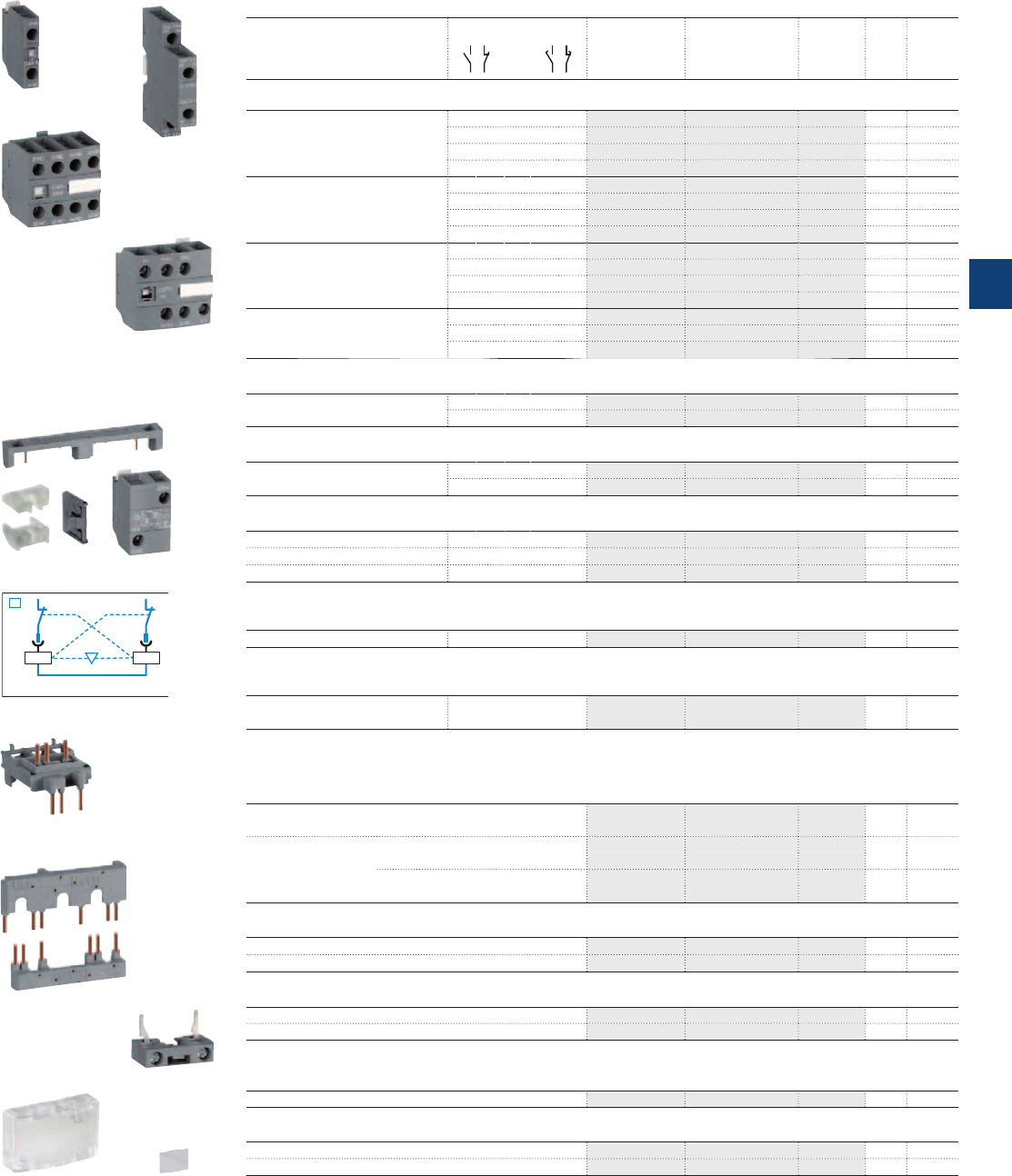
A2 A2
01NC
01NC
VEM4
KM1 KM2
1SBC101108F0014
1SBC101112F0014
1SBC101121F0014
1SBC101114F0014
1SBC101130F0014
1SBC101128F0014
1SBC101129F0014
1SBC101138F0014
1SBC101136F0014
1SBC101133F0014
1SBC101142F0014
1SBC101140F0014
AF09 ... AF38 3-pole contactors
Main accessories
Ordering details (1)
For contactors Auxiliary contacts Type Order code Pkg
qty
Weight
(1 pce)
kg
Front-mounted instantaneous auxiliary contact blocks
AF09 ... AF38 1 0 – – CA4-10 1SBN010110R1010 1 0.014
1 0 – – CA4-10-T 1SBN010110T1010 10 0.014
0 1 – – CA4-01 1SBN010110R1001 1 0.014
0 1 – – CA4-01-T 1SBN010110T1001 10 0.014
AF09 ... AF16..-30-10 2 2 – – CA4-22M 1SBN010140R1122 1 0.055
3 1 – – CA4-31M 1SBN010140R1131 1 0.055
1 3 – – CA4-13M 1SBN010140R1113 1 0.055
0 4 – – CA4-04M 1SBN010140R1104 1 0.055
AF26 ... AF38..-30-00 2 2 – – CA4-22E 1SBN010140R1022 1 0.055
3 1 – – CA4-31E 1SBN010140R1031 1 0.055
4 0 – – CA4-40E 1SBN010140R1040 1 0.055
0 4 – – CA4-04E 1SBN010140R1004 1 0.055
AF09 ... AF16..-30-01 2 2 – – CA4-22U 1SBN010140R1322 1 0.055
3 1 – – CA4-31U 1SBN010140R1331 1 0.055
4 0 – – CA4-40U 1SBN010140R1340 1 0.055
Front-mounted auxiliary contact blocks with N.O. leading contact and N.C. lagging contact
AF09 ... AF38 – – 1 0 CC4-10 1SBN010111R1010 1 0.014
– – 0 1 CC4-01 1SBN010111R1001 1 0.014
Side-mounted instantaneous auxiliary contact blocks
AF09 ... AF38 1 1 – – CAL4-11 1SBN010120R1011 1 0.040
1 1 – – CAL4-11-T 1SBN010120T1011 10 0.040
Front-mounted instantaneous auxiliary contact and A1/A2 coil terminal blocks
AF09 ... AF16..-30-10 1 1 – – CAT4-11M 1SBN010151R1111 1 0.040
AF26 ... AF38..-30-00 1 1 – – CAT4-11E 1SBN010151R1011 1 0.040
AF09 ... AF16..-30-01 1 1 – – CAT4-11U 1SBN010151R1311 1 0.040
Note: CAT4 not fittable on AF..Z contactors with DC control voltage 12...20 V DC.
Mechanical interlock unit
AF09 ... AF38 VM4 1SBN030105T1000 10 0.005
Note: VM4 includes 2 fixing clips (BB4) to maintain together both contactors.
Mechanical and electrical interlock set
AF09 ... AF16
AF26 ... AF38
1 1 – – VEM4 1SBN030111R1000 1 0.035
Note: - VEM4 includes a VM4 mechanical interlock unit with 2 fixing clips (BB4), a VE4 electrical interlock block. VE4 block must be used with A2-A2
connection to respect the electrical connection diagram.
- VEM4 not fittable on AF..Z contactors with DC control voltage 12...20 V DC.
Connecting links with manual motor starters
AF09 ... AF16 with MS116-0.16 … MS116-25, BEA16-4 1SBN081306T1000 10 0.025
MS132-0.16 … MS132-25
AF26 ... AF38 with MS116-0.16 … MS116-16, BEA26-4 1SBN082306T1000 10 0.025
MS132-0.16 ... MS132-10
with MS116-20 … MS116-32, BEA38-4 1SBN082306T2000 10 0.030
MS132-12 ... MS132-32
Connection sets for reversing contactors
AF09 ... AF16 BER16-4 1SBN081311R1000 1 0.045
AF26 ... AF38 BER38-4 1SBN082311R1000 1 0.100
Connection sets for star-delta starting
AF09 ... AF16 BEY16-4 1SBN081313R2000 1 0.050
AF26 ... AF38 BEY38-4 1SBN082713R2000 1 0.110
Note: with or without VM4 or VEM4
Additional coil terminal block
AF09 ... AF38 LDC4 1SBN070156T1000 10 0.010
Protective covers
All 1-stack contactors BX4 1SBN110108T1000 10 0.006
For 4-pole CA4 and 2-pole CAT4 auxiliary contact blocks BX4-CA 1SBN110109W1000 50 0.001
(1) See "Main accessory fitting details" table.
CA4-10
CA4-22M
BEA16-4
BER16-4
BX4
LDC4
BX4-CA
VEM4
CAT4-11E
CAL4-11
ABB | 5/9
5
1SBC101385S0201
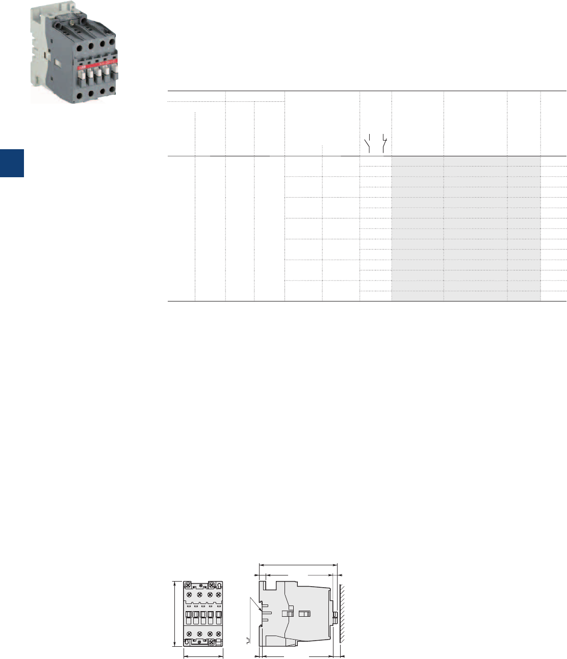
A40 3-pole contactors
18.5 kW
AC operated
Main dimensions mm, inches
54 2.13"
90 3.54"
A40
108.3 4.26"
9 0.35" 6.3 0.25"
4 0.16" 10 0.39"
35 mm
EN/IEC 60715
Description
A40 contactors are mainly used for controlling 3-phase motors and power circuits up to 690 V AC or 220 V DC.
These contactors are of the block type design with:
– 3 main poles and 1 built-in auxiliary contact
– control circuit: AC operated
– add-on auxiliary contact blocks for front or side mounting and a wide range of accessories.
Ordering details
IEC UL/CSA Rated control circuit
voltage
Uc
(1)
Auxiliary
contacts
fitted
Type Order code Weight
Pkg
(1 pce)
Rated operational 3-phase
motor
rating
General
use
rating
power current
θ ≤ 40 °C
400 V 480 V 600 V AC
AC-3 AC-1
kW A hp A V 50 Hz V 60 Hz kg
18.5 60 30 60 24 24 10 A40-30-10 1SBL321001R8110 0.710
01 A40-30-01 1SBL321001R8101 0.710
48 48 10 A40-30-10 1SBL321001R8310 0.710
01 A40-30-01 1SBL321001R8301 0.710
110 110…120 10 A40-30-10 1SBL321001R8410 0.710
01 A40-30-01 1SBL321001R8401 0.710
220…230 230…240 10 A40-30-10 1SBL321001R8010 0.710
01 A40-30-01 1SBL321001R8001 0.710
230…240 240…260 10 A40-30-10 1SBL321001R8810 0.710
01 A40-30-01 1SBL321001R8801 0.710
380…400 400…415 10 A40-30-10 1SBL321001R8510 0.710
01 A40-30-01 1SBL321001R8501 0.710
400…415 415…440 10 A40-30-10 1SBL321001R8610 0.710
01 A40-30-01 1SBL321001R8601 0.710
(1) Other control voltages see voltage code table.
1SBC101355F0014
A40-30-10
5/10 | ABB
5
1SBC101362S0201
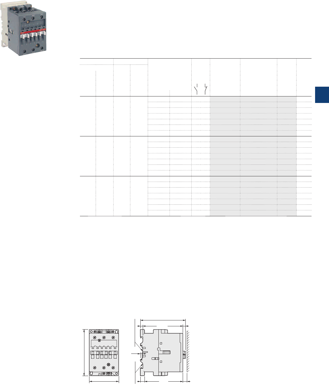
A50 ... A75 3-pole contactors
22 to 37 kW
AC operated
1SBC580752F0301
A50-30-00
Main dimensions mm, inches
70 2.76"
110 4.33"
A50, A63, A75
6.5 0.26"6 0.24"
10 0.39"
4
0.16"
10 0.39"
75 mm
EN/IEC 60715
35 mm x15
EN/IEC 60715
108 4.25"
Description
A50 ... A75 contactors are mainly used for controlling 3-phase motors and power circuits up to 690 V AC / 1000VAC
or 220 V DC.
These contactors are of the block type design with:
– 3 main poles
– control circuit: AC operated
– add-on auxiliary contact blocks for front or side mounting and a wide range of accessories.
Ordering details
IEC UL/CSA Rated control circuit
voltage
Uc
(1)
Auxiliary
contacts
fitted
Type Order code Weight
Pkg
(1 pce)
Rated operational 3-phase
motor
rating
General
use
rating
power current
θ ≤ 40 °C
400 V 480 V 600 V AC
AC-3 AC-1
kW A hp A V 50 Hz V 60 Hz kg
22 100 40 80 24 24 0 0 A50-30-00 1SBL351001R8100 1.160
48 48 0 0 A50-30-00 1SBL351001R8300 1.160
110 110…120 0 0 A50-30-00 1SBL351001R8400 1.160
220…230 230…240 0 0 A50-30-00 1SBL351001R8000 1.160
230…240 240…260 0 0 A50-30-00 1SBL351001R8800 1.160
380…400 400…415 0 0 A50-30-00 1SBL351001R8500 1.160
400…415 415…440 0 0 A50-30-00 1SBL351001R8600 1.160
30 115 60 90 24 24 0 0 A63-30-00 1SBL371001R8100 1.160
48 48 0 0 A63-30-00 1SBL371001R8300 1.160
110 110…120 0 0 A63-30-00 1SBL371001R8400 1.160
220…230 230…240 0 0 A63-30-00 1SBL371001R8000 1.160
230…240 240…260 0 0 A63-30-00 1SBL371001R8800 1.160
380…400 400…415 0 0 A63-30-00 1SBL371001R8500 1.160
400…415 415…440 0 0 A63-30-00 1SBL371001R8600 1.160
37 125 60 105 24 24 0 0 A75-30-00 1SBL411001R8100 1.160
48 48 0 0 A75-30-00 1SBL411001R8300 1.160
110 110…220 0 0 A75-30-00 1SBL411001R8400 1.160
220…230 230…240 0 0 A75-30-00 1SBL411001R8000 1.160
230…240 240…260 0 0 A75-30-00 1SBL411001R8800 1.160
380…400 400…415 0 0 A75-30-00 1SBL411001R8500 1.160
400…415 415…440 0 0 A75-30-00 1SBL411001R8600 1.160
(1) Other control voltages see voltage code table.
ABB | 5/11
5
1SBC101363S0201
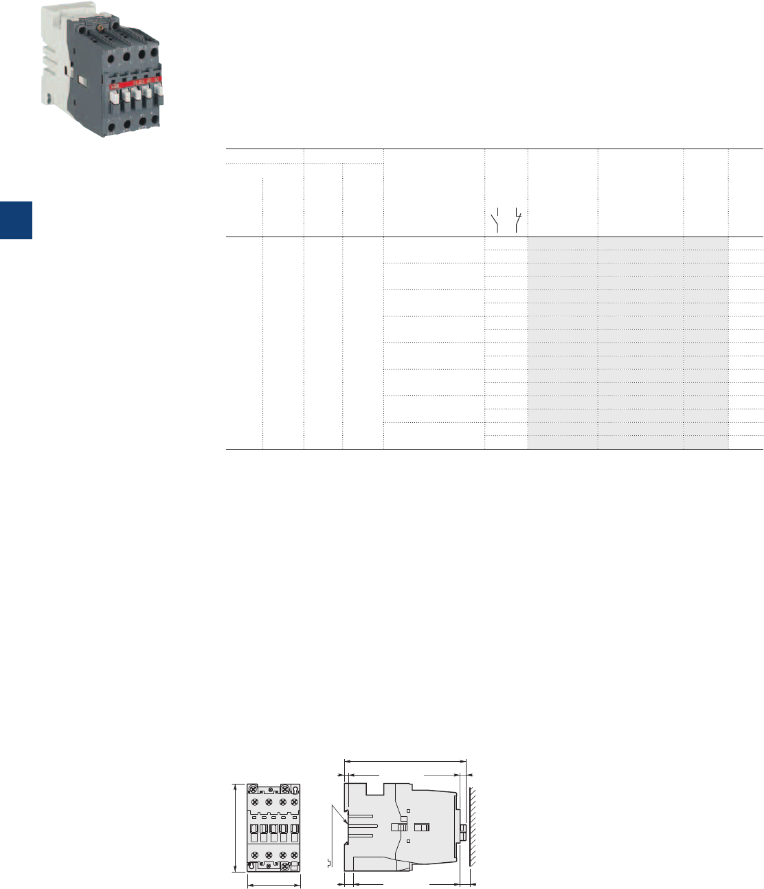
AL40 3-pole contactors
18.5 kW
DC operated
1SBC587834F0301
AL40-30-10
Main dimensions mm, inches
54 2.13"
90 3.54"
AL40
125.3 4.93"
4 0.16" 6.3 0.25"
9 0.35" 10 0.39"
35 mm
EN/IEC 60715
Description
AL40 contactors are mainly used for controlling 3-phase motors and power circuits up to 690 V AC or 220 V DC.
These contactors are of the block type design with:
– 3 main poles and 1 built-in auxiliary contact
– control circuit: low consumption (3.5 W at pull-in and holding) DC operated with solid core magnet
Suitable for direct control by PLC outputs (the polarity on the coil terminals A1+ and A2- must be
respected)
– add-on auxiliary contact blocks for front or side mounting and a wide range of accessories.
Ordering details
IEC UL/CSA Rated control circuit
voltage
Uc
(1)
Auxiliary
contacts
fitted
Type Order code Weight
Pkg
(1 pce)
Rated operational 3-phase
motor
rating
General
use
rating
power current
θ ≤ 40 °C
400 V 480 V 600 V AC
AC-3 AC-1
kW A hp A V DC kg
18.5 60 30 60 12 1 0 AL40-30-10 1SBL323001R8010 0.850
0 1 AL40-30-01 1SBL323001R8001 0.850
24 1 0 AL40-30-10 1SBL323001R8110 0.850
0 1 AL40-30-01 1SBL323001R8101 0.850
48 1 0 AL40-30-10 1SBL323001R8310 0.850
0 1 AL40-30-01 1SBL323001R8301 0.850
60 1 0 AL40-30-10 1SBL323001R8410 0.850
0 1 AL40-30-01 1SBL323001R8401 0.850
110 1 0 AL40-30-10 1SBL323001R8610 0.850
0 1 AL40-30-01 1SBL323001R8601 0.850
125 1 0 AL40-30-10 1SBL323001R8710 0.850
0 1 AL40-30-01 1SBL323001R8701 0.850
220 1 0 AL40-30-10 1SBL323001R8810 0.850
0 1 AL40-30-01 1SBL323001R8801 0.850
240 1 0 AL40-30-10 1SBL323001R8910 0.850
0 1 AL40-30-01 1SBL323001R8901 0.850
(1) Other control voltages see voltage code table.
5/12 | ABB
5
1SBC101365S0201
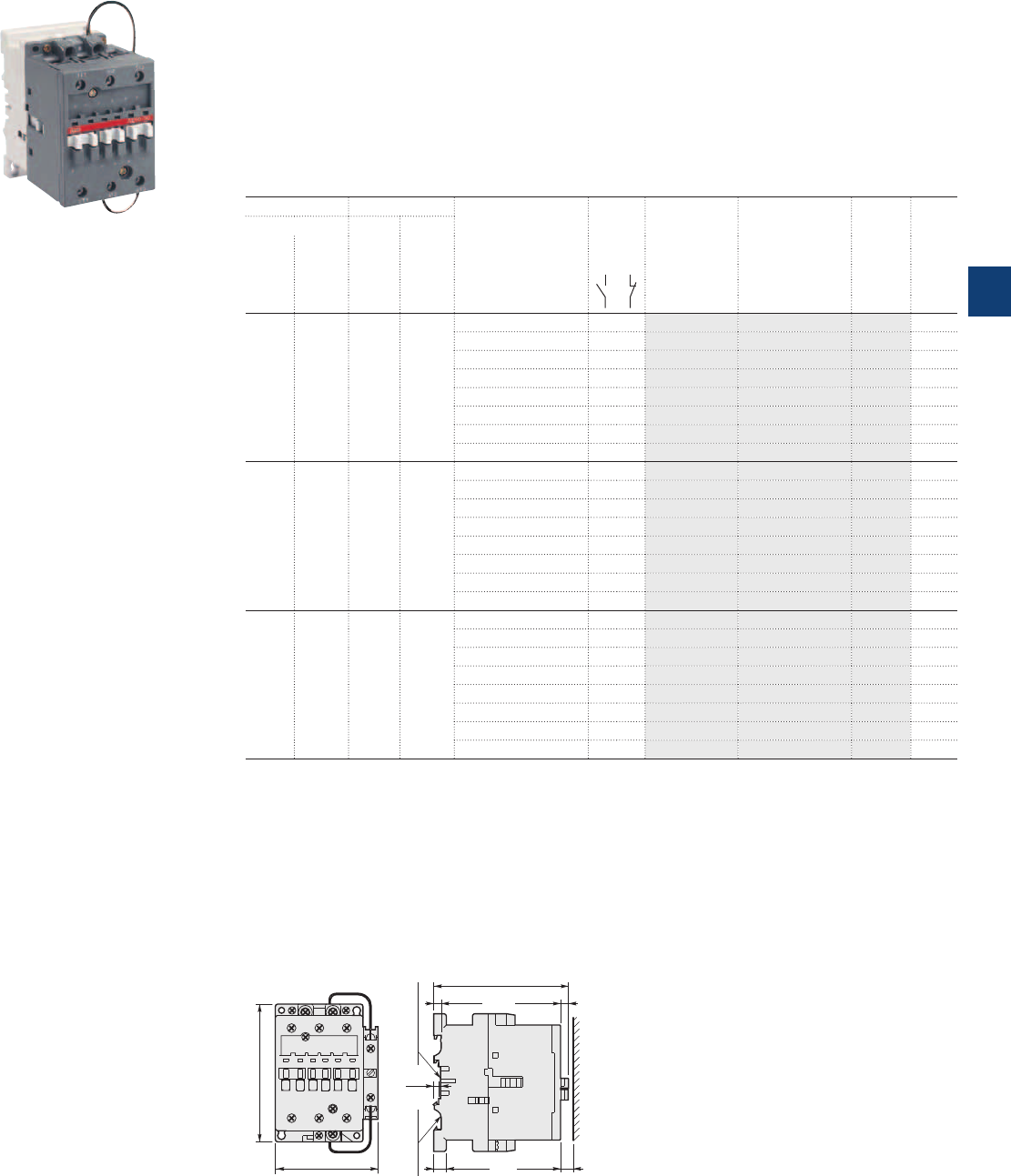
AE50 ... AE75 3-pole contactors
22 to 37 kW
DC operated
1SBC592084F0304
AE50-30-00
Main dimensions mm, inches
6.5 0.26"6 0.24"
10 0.39"
4
0.16"
10 0.39"
75 mm
EN/IEC 60715
35 mm x15
EN/IEC 60715
108 4.25"
82 3.23"
110 4.33"
AE50, AE63, AE75
Description
AE50 ... AE75 contactors are mainly used for controlling 3-phase motors and power circuits up to 690VAC/
1000VAC or 220VDC.
These contactors are of the block type design with:
– 3 main poles
– control circuit: DC operated with double winding coil (and factory-mounted lagging contact for "holding"
winding insertion)
– add-on auxiliary contact blocks for front or side mounting and a wide range of accessories.
Ordering details
IEC UL/CSA Rated control circuit
voltage
Uc
(1)
Auxiliary
contacts
fitted
Type Order code Weight
Pkg
(1 pce)
Rated operational 3-phase
motor
rating
General
use
rating
power current
θ ≤ 40 °C
400 V 480 V 600 V AC
AC-3 AC-1
kW A hp A V DC kg
22 100 40 80 12 0 0 AE50-30-00 1SBL359001R8000 1.200
24 0 0 AE50-30-00 1SBL359001R8100 1.200
48 0 0 AE50-30-00 1SBL359001R8300 1.200
60 0 0 AE50-30-00 1SBL359001R8400 1.200
110 0 0 AE50-30-00 1SBL359001R8600 1.200
125 0 0 AE50-30-00 1SBL359001R8700 1.200
220 0 0 AE50-30-00 1SBL359001R8800 1.200
240 0 0 AE50-30-00 1SBL359001R8900 1.200
30 115 60 90 12 0 0 AE63-30-00 1SBL379001R8000 1.200
24 0 0 AE63-30-00 1SBL379001R8100 1.200
48 0 0 AE63-30-00 1SBL379001R8300 1.200
60 0 0 AE63-30-00 1SBL379001R8400 1.200
110 0 0 AE63-30-00 1SBL379001R8600 1.200
125 0 0 AE63-30-00 1SBL379001R8700 1.200
220 0 0 AE63-30-00 1SBL379001R8800 1.200
240 0 0 AE63-30-00 1SBL379001R8900 1.200
37 125 60 105 12 0 0 AE75-30-00 1SBL419001R8000 1.200
24 0 0 AE75-30-00 1SBL419001R8100 1.200
48 0 0 AE75-30-00 1SBL419001R8300 1.200
60 0 0 AE75-30-00 1SBL419001R8400 1.200
110 0 0 AE75-30-00 1SBL419001R8600 1.200
125 0 0 AE75-30-00 1SBL419001R8700 1.200
220 0 0 AE75-30-00 1SBL419001R8800 1.200
240 0 0 AE75-30-00 1SBL419001R8900 1.200
(1) Other control voltages see voltage code table.
ABB | 5/13
5
1SBC101366S0201
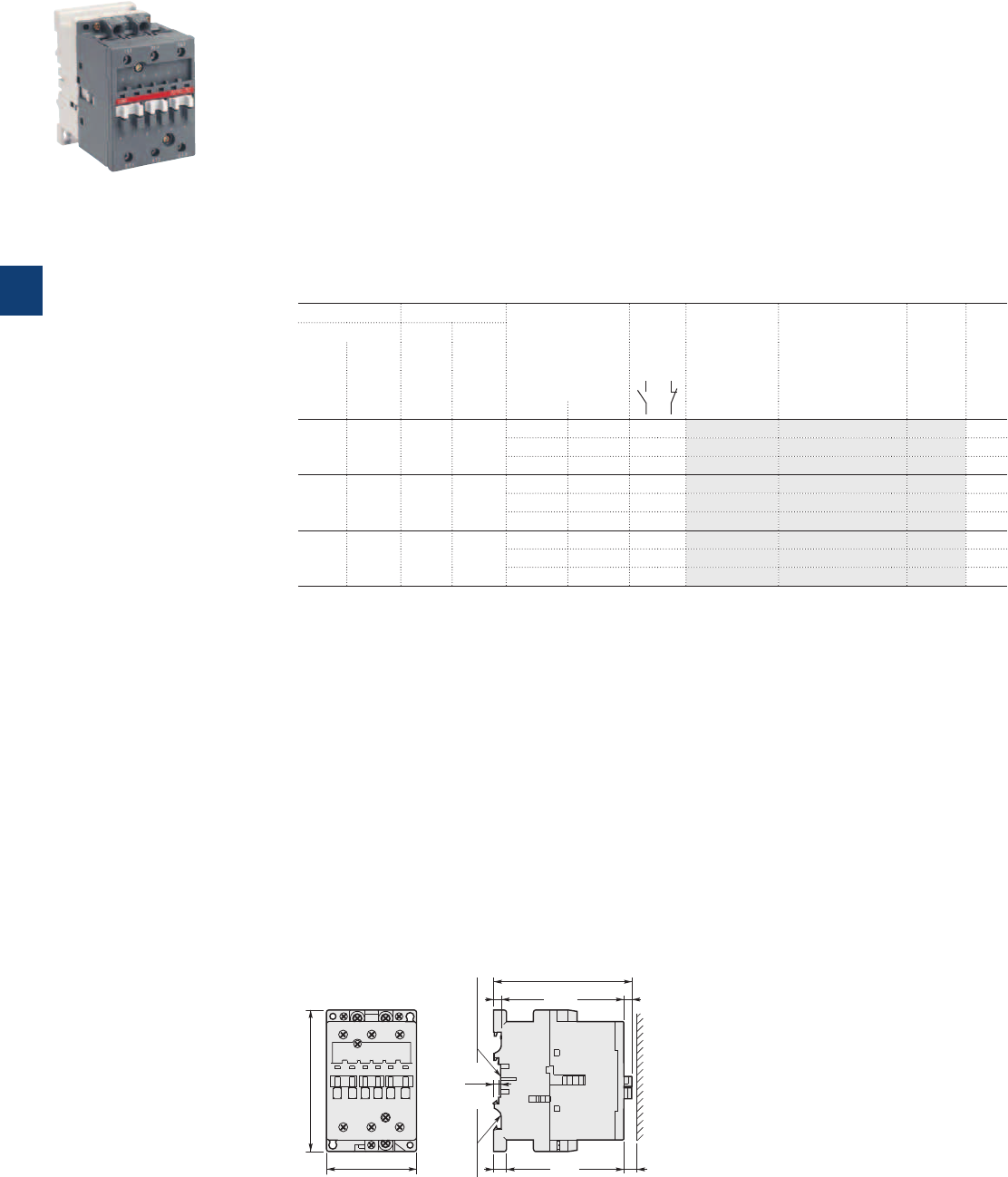
AF50 ... AF75 3-pole contactors
22 to 37 kW
AC / DC operated
1SBC582714F0304
AF50-30-00
Main dimensions mm, inches
6.5 0.26"6 0.24"
10 0.39"
4
0.16"
10 0.39"
75 mm
EN/IEC 60715
35 mm x15
EN/IEC 60715
108 4.25"
70 2.76"
110 4.33"
AF50, AF63, AF75
Description
AF50 ... AF75 contactors are mainly used for controlling 3-phase motors and generally for controlling power
circuits up to 690 V AC and 220 V DC.
These contactors are of the block type design with:
– 3 main poles
– control circuit: AC or DC operated with electronic coil interface accepting a wide control voltage range
(e.g. 100...250 V AC and DC)
- can manage large control voltage variations
- only 3 coils to cover control voltages between 48...250 V 50/60 Hz and 20...250 V DC
- reduced panel energy consumption
- very distinct closing and opening
- can withstand short voltage dips and voltage sags (SEMI F47 conditions of use on request).
– built-in surge suppression
– add-on auxiliary contact blocks for front or side mounting and a wide range of accessories.
Ordering details
IEC UL/CSA Rated control circuit
voltage
Uc min. ... Uc max.
Auxiliary
contacts
fitted
Type Order code Weight
Pkg
(1 pce)
Rated operational 3-phase
motor
rating
General
use
rating
power current
θ ≤ 40 °C
400 V 480 V 600 V AC
AC-3 AC-1
kW A hp A V 50 Hz V 60 Hz kg
22 100 40 80 - 20…60 0 0 AF50-30-00 1SBL357001R7200 (1) 1.180
48…130 48…130 0 0 AF50-30-00 1SBL357001R6900 1.180
100…250 100…250 0 0 AF50-30-00 1SBL357001R7000 1.180
30 115 60 90 - 20…60 0 0 AF63-30-00 1SBL377001R7200 (1) 1.180
48…130 48…130 0 0 AF63-30-00 1SBL377001R6900 1.180
100…250 100…250 0 0 AF63-30-00 1SBL377001R7000 1.180
37 125 60 105 - 20…60 0 0 AF75-30-00 1SBL417001R7200 (1) 1.180
48…130 48…130 0 0 AF75-30-00 1SBL417001R6900 1.180
100…250 100…250 0 0 AF75-30-00 1SBL417001R7000 1.180
(1) The connection polarities indicated close to the coil terminals must be respected: A1 for the positive pole and A2 for the
negative pole.
5/14 | ABB
5
1SBC101368S0201

Notes
ABB | 5/15
5
N1
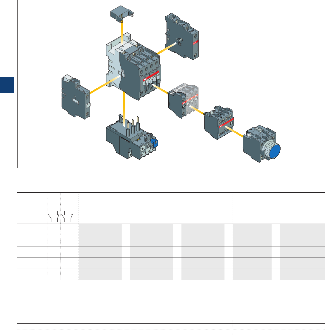
A40 … A75, AL, AE and
AF50 … AF75 3-pole contactors
Main accessories
Main accessory fitting details
Many configurations of accessories are possible depending on whether these are front-mounted or side-mounted.
Contactor
types
Main
poles
Built-in
auxiliary
contacts
Front-mounted accessories Side-mounted accessories
Auxiliary contact blocks Pneumatic timer Auxiliary contact
blocks
Interlock unit
1-pole CA5-.. 4-pole CA5-.. TP.. A 2-pole CAL5-11 VM5-.. or VE5-..
A40 3 0 1 0 1 to 5 x CA5-..
or
1 x CA5-.. (4-pole)
or
1 x TP .. A
+
1 to 2 x CAL5-11
or
1 x VM5-1 or VE5-1
3001
(2) + 1 x 1-pole CA5-.. + 1 x CA5-.. (1-pole) +1 x CAL5-11
A50 ... A75 3 0 0 0 1 to 6 x CA5-..
or
1 x CA5-.. (4-pole)
or
1 x TP .. A
+
1 to 2 x CAL5-11
or
1 x VE5-2
+ 2 x 1-pole CA5-.. + 2 x CA5-.. (1-pole) +1 x CAL5-11
AL40 3 0 1 0 1 to 5 x CA5-.. (2)
or
1 x CA5-.. (4-pole) (2) –
or
1 x CAL5-11 (3)
+
1 x VM5-1 or VE5-1 (1)
3001 + 1 x 1-pole CA5-..
AE50 ... AE75 3 0 0 0 1 to 6 x CA5-..
or
1 x CA5-.. (4-pole)
or
1 x TP .. A
+
1 x CAL5-11
or
1 x VE5-2
+ 2 x 1-pole CA5-.. + 2 x CA5-.. (1-pole)
AF50 ... AF75 3 0 0 0 1 to 6 x CA5-..
or
1 x CA5-.. (4-pole)
or
1 x TP .. A
+
1 to 2 x CAL5-11
or
1 x VE5-2
+ 2 x 1-pole CA5-.. + 2 x CA5-.. (1-pole) +1 x CAL5-11
(1) With VE5-1 interlock unit, a maximum of 3 N.O. auxiliary contacts are permitted. VE5-1, VM5-1 not allowed in mounting position 1 ±30°.
(2) 2 N.C. CA5-.. auxiliary contacts maximum in mounting position 5.
(3) CAL5-11 not allowed in mounting position 1±30°.
Overload relays fitting details (4)
Contactor types Thermal overload relays Electronic overload relays
A40, AL40 TA25DU (0.1...32 A) or TA42DU (18...42 A) E45DU (9...45 A)
A50 … A75, AE50 … AE75, AF50 … AF75 TA75DU (18...80 A) E80DU (27...80 A)
The addition of an overload relay on the contactor does not prevent fitting of many other accessories as shown above.
(4) Direct mounting - No kit required.
Contactor and main accessories (other accessories available)
RV5/..
VE5-1
CAL5-11
TA
overload relay
A.. contactor
CA5-10
CA5-22M
TP40DA
5/16 | ABB
5
1SBC101386S0201
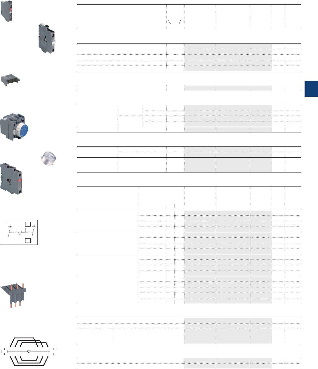
01
02
NC
E0085D1
01
02
NC
A1
A2
A1
A2
315 315
42 6 426
VE5-1
A40…A75, AL, AE and
AF50…AF75 3-pole contactors
Main accessories
Ordering details (1)
For contactors Auxiliary
contacts
Type Order code Pkg
qty
Weight
(1 pce)
kg
Front-mounted instantaneous auxiliary contact blocks
A40…A75, AL40, AE50...AE75,
AF50…AF75
1 – CA5-10 1SBN010010R1010 10 0.014
– 1 CA5-01 1SBN010010R1001 10 0.014
A40-30-10, AL40-30-10 2 2 CA5-22M 1SBN010040R1122 2 0.060
A40-30-01, AL40-30-01 2 2 CA5-22U 1SBN010040R1322 2 0.060
A50...A75, AE50...AE75, AF50...AF75 2 2 CA5-22E 1SBN010040R1022 2 0.060
Side-mounted instantaneous auxiliary contact block
A40…A75, AL40, AE50…AE75, AF50…AF75 1 1 CAL5-11 1SBN010020R1011 2 0.050
Pneumatic timer blocks
A40…A75,
AE50…AE75,
AF50…AF75
delay on
energization
0.1...40 s 1 1 TP40DA 1SBN020300R1000 1 0.070
10...180 s 1 1 TP180DA 1SBN020300R1001 1 0.070
delay on de-
energization
0.1...40 s 1 1 TP40IA 1SBN020301R1000 1 0.070
10...180 s 1 1 TP180IA 1SBN020301R1001 1 0.070
Timer accessory plastic sealable cover – – BX-TP FPTN472657R0001 1 0.006
Interlock units
A40, AL40 Mechanical – – VM5-1 1SBN030100R1000 1 0.066
Mechanical and electrical – 2 VE5-1 1SBN030110R1000 1 0.076
A50...A75,
AE50...AE75,
AF50…AF75
Mechanical and electrical – 2 VE5-2 1SBN030210R1000 1 0.146
Surge suppressors
For contactors Rated control circuit
voltage
Uc
Type Order code Pkg
qty
Weight
(1 pce)
VACDC kg
A40…A75
AL40
AE40…AE75
24...50
●●
RV5/50 1SBN050010R1000 2 0.015
50...133
●●
RV5/133 1SBN050010R1001 2 0.015
110...250
●●
RV5/250 1SBN050010R1002 2 0.015
250...440
●●
RV5/440 1SBN050010R1003 2 0.015
A40 24...50
●
– RC5-1/50 1SBN050100R1000 2 0.012
50...133
●
– RC5-1/133 1SBN050100R1001 2 0.012
110...250
●
– RC5-1/250 1SBN050100R1002 2 0.012
250...440
●
– RC5-1/440 1SBN050100R1003 2 0.012
A50…A75 24...50
●
– RC5-2/50 1SBN050200R1000 2 0.015
50...133
●
– RC5-2/133 1SBN050200R1001 2 0.015
110...250
●
– RC5-2/250 1SBN050200R1002 2 0.015
250...440
●
– RC5-2/440 1SBN050200R1003 2 0.015
AL40
AE50…AE75
12...32 –
●
RT5/32 1SBN050020R1000 2 0.015
25...65 –
●
RT5/65 1SBN050020R1001 2 0.015
50...90 –
●
RT5/90 1SBN050020R1002 2 0.015
77...150 –
●
RT5/150 1SBN050020R1003 2 0.015
150...264 –
●
RT5/264 1SBN050020R1004 2 0.015
Connecting links with manual motor starters
A40 For MS450 manual motor starter BEA40/450 1SBN083206R1000 1 0.061
A50, AE50, AF50 For MS450 manual motor starter BEA50/450 1SBN083506R1000 1 0.062
A50...A75,
AE50...AE75,
AF50…AF75
For MS495 manual motor starter BEA75/495 1SBN084106R1000 1 0.120
Connection sets for reversing contactors
A40 BER40V 1SBN082411R1000 1 0.085
A50...A75, AE50...AE75, AF50…AF75 BEM75-30 1SBN083501R1000 1 0.243
(1) See "Main accessory fitting details" table.
CA5-10
1SBC574001F0301
RV5/50
TP40DA
BX-TP
VE5-1, VE5-2
Terminal marking and positioning
BER, BEM connection sets
BEA40/450
1SBC580992F0301
CAL5-11
1SBC573752F0301
1SBC575893F0302
1SBC586522F0301
1SBC582763F0301
1SBC572822F0301
ABB | 5/17
5
1SBC101387S0201
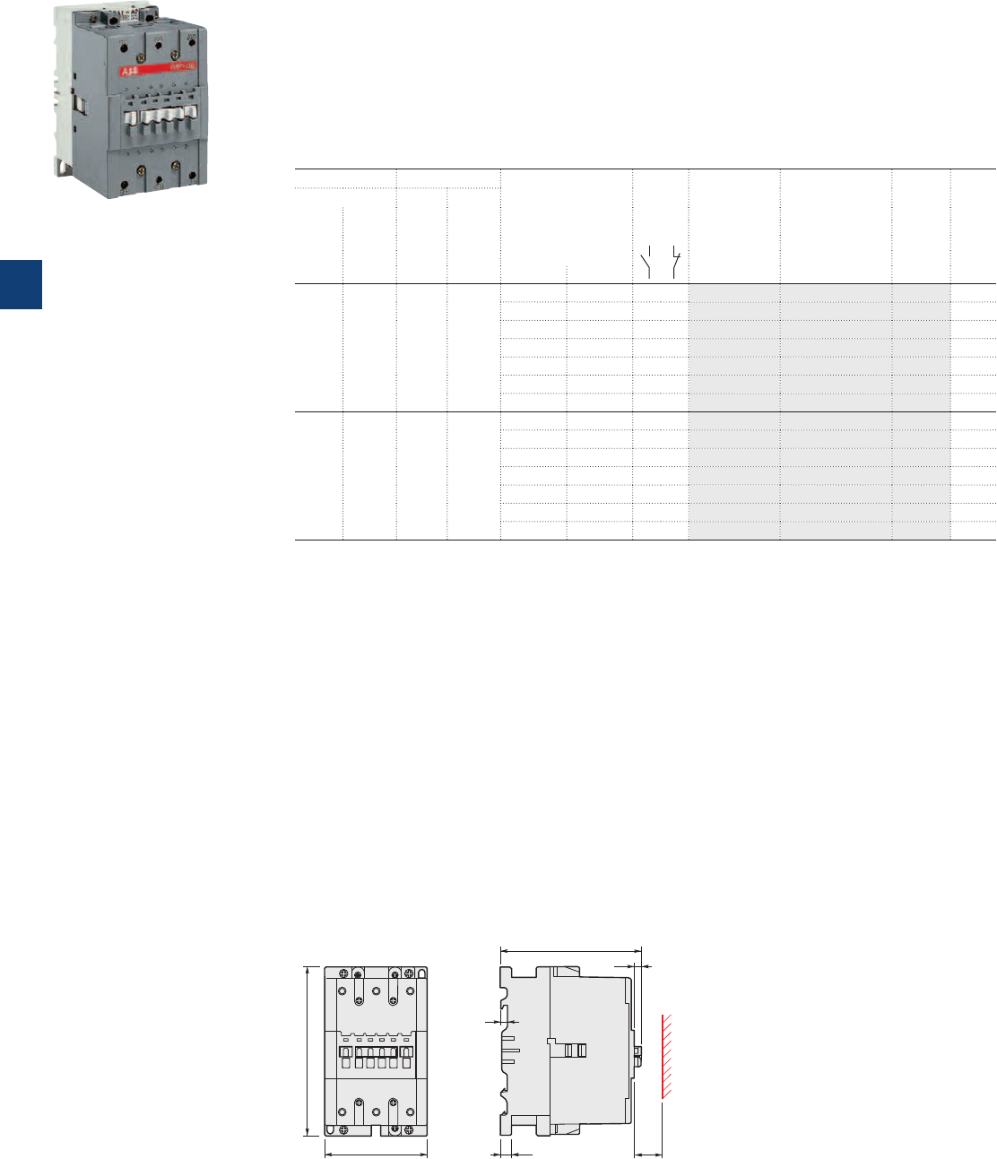
A95 … A110 3-pole contactors
45 to 55 kW
AC operated
Description
A95 ... A110 contactors are mainly used for controlling 3-phase motors and power circuits up to
690 / 1000 V AC or 220 V DC.
These contactors are of the block type design with:
– 3 main poles
– control circuit: AC operated
– add-on auxiliary contact blocks for front or side mounting and a wide range of accessories.
Ordering details
IEC UL/CSA Rated control circuit
voltage
Uc
(1)
Auxiliary
contacts
fitted
Type Order code Weight
Pkg
(1 pce)
Rated operational 3-phase
motor
rating
General
use
rating
power current
θ ≤ 40 °C
400 V 690 V 480 V 600 V AC
AC-3 AC-1
kW A hp A V 50 Hz V 60 Hz kg
45 145 60 125 24 24 0 0 A95-30-00 1SFL431001R8100 2.000
48 48 0 0 A95-30-00 1SFL431001R8300 2.000
110 110…120 0 0 A95-30-00 1SFL431001R8400 2.000
220…230 230…240 0 0 A95-30-00 1SFL431001R8000 2.000
230…240 240…260 0 0 A95-30-00 1SFL431001R8800 2.000
380…400 400…415 0 0 A95-30-00 1SFL431001R8500 2.000
400…415 415…440 0 0 A95-30-00 1SFL431001R8600 2.000
55 160 75 140 24 24 0 0 A110-30-00 1SFL451001R8100 2.000
48 48 0 0 A110-30-00 1SFL451001R8300 2.000
110 110…120 0 0 A110-30-00 1SFL451001R8400 2.000
220…230 230…240 0 0 A110-30-00 1SFL451001R8000 2.000
230…240 240…260 0 0 A110-30-00 1SFL451001R8800 2.000
380…400 400…415 0 0 A110-30-00 1SFL451001R8500 2.000
400…415 415…440 0 0 A110-30-00 1SFL451001R8600 2.000
(1) Other control voltages see voltage code table.
1SBC573242F0301
A95-30-00
Main dimensions mm, inches
123.5 4.86"
6 0.24"
E0784D1
20 0.79"
10 0.39"
6.5 0.26"
90 3.54"
148 5.83"
E0783D
A95, A110
5/18 | ABB
5
1SFC101007C0201
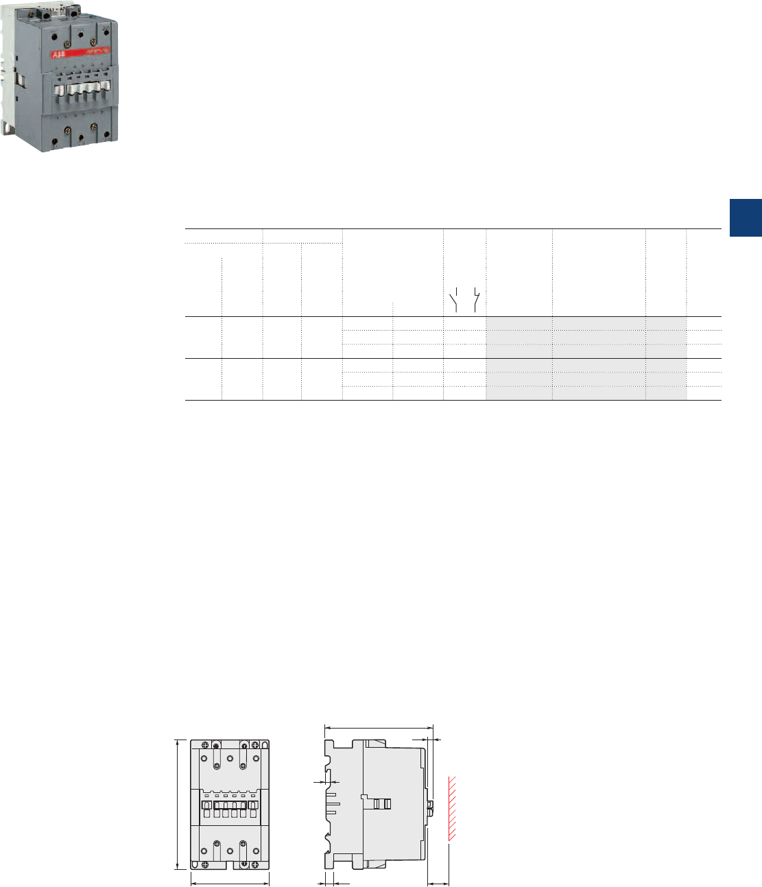
AF95 ... AF110 3-pole contactors
45 to 55 kW
AC / DC operated
Description
AF95 ... AF110 contactors are mainly used for controlling 3-phase motors and power circuits up to
690 / 1000 V AC or 220 V DC.
These contactors are of the block type design with:
– 3 main poles
– control circuit: AC or DC operated with electronic coil interface accepting a wide control voltage range
(e.g. 100...250 V AC and DC)
– can manage large control voltage variations
- only 3 coils to cover control voltages between 48...250 V 50/60 Hz and 20...250 V DC
- reduced panel energy consumption
- very distinct closing and opening
- can withstand short voltage dips and voltages sags (SEMI F47 conditions of use on request).
– built-in surge suppression
– add-on auxiliary contact blocks for front or side mounting and a wide range of accessories.
Ordering details
IEC UL/CSA Rated control circuit
voltage
Uc min. ... Uc max.
Auxiliary
contacts
fitted
Type Order code Weight
Pkg
(1 pce)
Rated operational 3-phase
motor
rating
General
use
rating
power current
θ ≤ 40 °C
400 V 690 V 480 V 600 V AC
AC-3 AC-1
kW A hp A V 50/60 Hz V DC kg
45 145 60 125 - 20…60 0 0 AF95-30-00 1SFL437001R7200 (1) 2.030
48…130 48…130 0 0 AF95-30-00 1SFL437001R6900 2.030
100…250 100…250 0 0 AF95-30-00 1SFL437001R7000 2.030
55 160 75 140 - 20…60 0 0 AF110-30-00 1SFL457001R7200 (1) 2.030
48…130 48…130 0 0 AF110-30-00 1SFL457001R6900 2.030
100…250 100…250 0 0 AF110-30-00 1SFL457001R7000 2.030
(1)
The connection polarities indicated close to the coil terminals must be respected: A1 for the positive pole and A2 for the negative pole.
1SBC101374F0014
AF95-30-00
Main dimensions mm, inches
123.5 4.86"
6 0.24"
E0784D1
20 0.79"
10 0.39"
6.5 0.26"
90 3.54"
148 5.83"
E0783D
AF95, AF110
ABB | 5/19
5
1SFC101008C0201
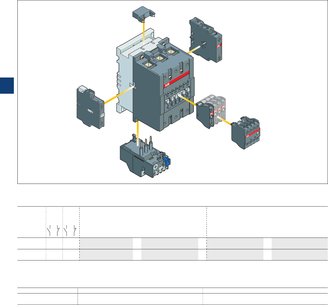
A95, A110 and
AF95, AF110 3-pole contactors
Main accessories
Main accessory fitting details
Many configurations of accessories are possible depending on whether these are front-mounted or side-mounted.
Contactor
types
Main
poles
Available
auxiliary
contacts
Front-mounted accessories Side-mounted accessories
Auxiliary contact blocks Auxiliary contact blocks Interlock unit
1-pole CA5- .. 4-pole CA5- .. 2-pole CAL.. VE5-2
A95, A110 3 0 0 0 1 to 6 x CA5-..
or
1 x CA5-.. (4-pole)
+
1 to 2 x CAL18-11
or
1 x VE5-2
+ 2 x 1-pole CA5-.. +1 x CAL18-11
AF95, AF110 3 0 0 0 1 to 6 x CA5-..
or
1 x CA5-.. (4-pole)
+
1 to 2 x CAL18-11
or
1 x VE5-2
+ 2 x 1-pole CA5-.. +1 x CAL18-11
Overload relays fitting details (1)
Contactor types Thermal overload relays Electronic overload relays
A95, A110 TA80DU (29...80 A) or TA110DU (65...110 A) E140DU (50...140 A)
AF95, AF110
The addition of an overload relay on the contactor does not prevent fitting of many other accessories as shown above.
(1) Direct mounting - No kit required.
Contactor and main accessories (other accessories available)
RV5/..
VE5-2
CAL18-11
TA
overload relay
A.. contactor
CA5-10
CA5-22E
5/20 | ABB
5
1SFC101026C0201
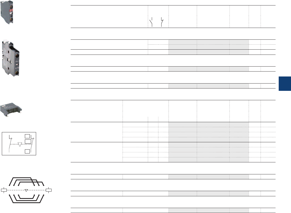
A95, A110 and
AF95, AF110 3-pole contactors
Main accessories
Ordering details (1)
For contactors Auxiliary
contacts
Type Order code Pkg
qty
Weight
(1 pce)
kg
Front-mounted instantaneous auxiliary contact blocks
A95, A110 and AF95, AF110 1 – CA5-10 1SBN010010R1010 10 0.014
– 1 CA5-01 1SBN010010R1001 10 0.014
A95, A110 and AF95, AF110 2 2 CA5-22E 1SBN010040R1022 2 0.060
Side-mounted instantaneous auxiliary contact blocks
A95, A110 and AF95, AF110 1 1 CAL18-11 1SFN010720R1011 2 0.050
Mechanical and electrical interlock unit
A95, A110 and AF95, AF110 – 2 VE5-2 1SBN030210R1000 1 0.146
Surge suppressors
For contactors Rated control circuit Type Order code Pkg Weight
voltage qty (1 pce)
Uc
VACDC kg
A95 ... A110 24...50
●●
RV5/50 1SBN050010R1000 2 0.015
50...133
●●
RV5/133 1SBN050010R1001 2 0.015
110...250
●●
RV5/250 1SBN050010R1002 2 0.015
250...440
●●
RV5/440 1SBN050010R1003 2 0.015
A95 ... A110 24...50
●
– RC5-2/50 1SBN050200R1000 2 0.015
50...133
●
– RC5-2/133 1SBN050200R1001 2 0.015
110...250
●
– RC5-2/250 1SBN050200R1002 2 0.015
250...440
●
– RC5-2/440 1SBN050200R1003 2 0.015
Connecting links with manual motor starters
A95, A110 and AF95, AF110 For MS495 BEA110/495 1SBN084506R1000 1 0.124
Connection set for reversing contactors
A95, A110 and AF95, AF110 BEM110-30 1SFN084301R1000 1 0.450
Mounting plate for mechanical interlocked contactors
A95, A110 and AF95, AF110 PN110-21 1SFN094301R1000 1 0.600
(1) See "Main accessory fitting details" table.
1SBC580992F0301
CA5-10
1SFC101033F0201
CAL18-11
1SBC574001F0301
RV5/50
01
02
NC
E0085D1
01
02
NC
VE5-1, VE5-2
Terminal marking and positioning
A1
A2
A1
A2
315 315
42 6 426
BEM... connection set
ABB | 5/21
5
1SFC101076C0201
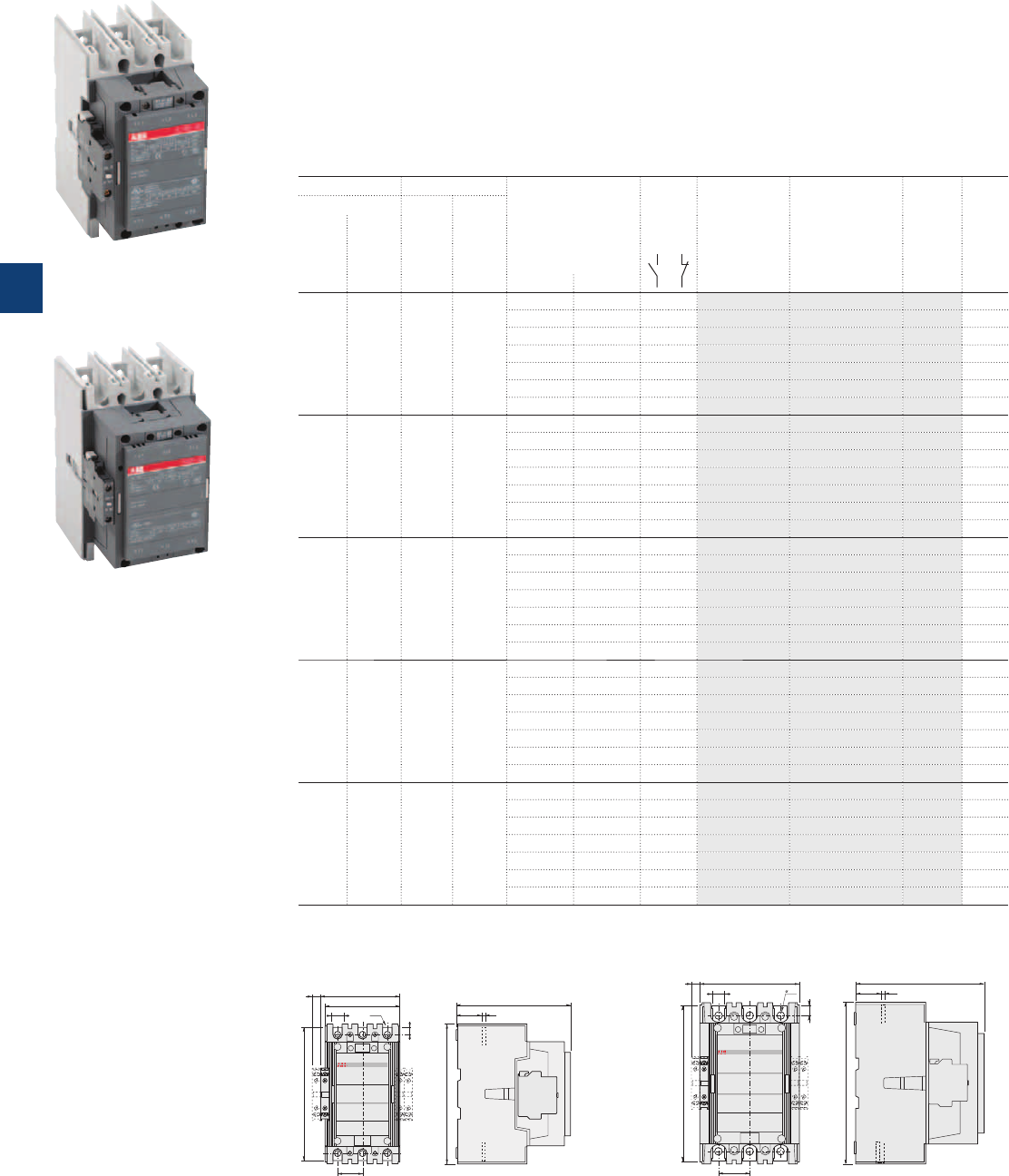
Main dimensions mm, inches
12 0.47"
17.5 0.69"
105 4.13"
111.5 4.39"
ø 8.5 0.33"
35 1.38"
10 0.39"
187 7.36"
E2001D
E2002D
160 6.3"
35.5 1.4"
196 7.72"
5 0.2"
E2016D
43.75 1.72"
10.2 0.4"
14 0.55"
140 5.51"
12 0.47"
19.5 0.77"
225 8.86"
E2017D
180.5 7.11"
5
0.2"
35.5
1.4"
227 8.94"
A145 ... A185 A210 ... A300
A145 ... A300 3-pole contactors
75 to 160 kW
AC operated with 1 N.O. + 1 N.C. auxiliary contacts
Description
A145 ... A300 contactors are mainly used for controlling 3-phase motors and power circuits up to
690 / 1000 V AC (2) or 220 V DC.
These contactors are of the block type design with:
– 3 main poles
– control circuit: AC operated
– add-on auxiliary contact blocks for side mounting and a wide range of accessories.
Ordering details
IEC UL/CSA Rated control circuit
voltage
Uc
(1)
Auxiliary
contacts
fitted
Type Order code Weight
Pkg
(1 pce)
Rated operational 3-phase
motor
rating
General
use
rating
power current
θ ≤ 40 °C
400 V 690 V 480 V 600 V AC
AC-3 AC-1
kW A hp A V 50 Hz V 60 Hz kg
75 250 100 230 24 24 1 1 A145-30-11 1SFL471001R8111 3.500
48 48 1 1 A145-30-11 1SFL471001R8311 3.500
110 110…120 1 1 A145-30-11 1SFL471001R8411 3.500
220…230 230…240 1 1 A145-30-11 1SFL471001R8011 3.500
230…240 240…260 1 1 A145-30-11 1SFL471001R8811 3.500
380…400 400…415 1 1 A145-30-11 1SFL471001R8511 3.500
400…415 415…440 1 1 A145-30-11 1SFL471001R8611 3.500
90 275 125 250 24 24 1 1 A185-30-11 1SFL491001R8111 3.500
48 48 1 1 A185-30-11 1SFL491001R8311 3.500
110 110…120 1 1 A185-30-11 1SFL491001R8411 3.500
220…230 230…240 1 1 A185-30-11 1SFL491001R8011 3.500
230…240 240…260 1 1 A185-30-11 1SFL491001R8811 3.500
380…400 400…415 1 1 A185-30-11 1SFL491001R8511 3.500
400…415 415…440 1 1 A185-30-11 1SFL491001R8611 3.500
110 350 150 300 24 24 1 1 A210-30-11 1SFL511001R8111 6.100
48 48 1 1 A210-30-11 1SFL511001R8311 6.100
110 110…120 1 1 A210-30-11 1SFL511001R8411 6.100
220…230 230…240 1 1 A210-30-11 1SFL511001R8011 6.100
230…240 240…260 1 1 A210-30-11 1SFL511001R8811 6.100
380…400 400…415 1 1 A210-30-11 1SFL511001R8511 6.100
400…415 415…440 1 1 A210-30-11 1SFL511001R8611 6.100
140 400 200 350 24 24 1 1 A260-30-11 1SFL531001R8111 6.100
48 48 1 1 A260-30-11 1SFL531001R8311 6.100
110 110…120 1 1 A260-30-11 1SFL531001R8411 6.100
220…230 230…240 1 1 A260-30-11 1SFL531001R8011 6.100
230…240 240…260 1 1 A260-30-11 1SFL531001R8811 6.100
380…400 400…415 1 1 A260-30-11 1SFL531001R8511 6.100
400…415 415…440 1 1 A260-30-11 1SFL531001R8611 6.100
160 500 250 400 24 24 1 1 A300-30-11 1SFL551001R8111 6.100
48 48 1 1 A300-30-11 1SFL551001R8311 6.100
110 110…120 1 1 A300-30-11 1SFL551001R8411 6.100
220…230 230…240 1 1 A300-30-11 1SFL551001R8011 6.100
230…240 240…260 1 1 A300-30-11 1SFL551001R8811 6.100
380…400 400…415 1 1 A300-30-11 1SFL551001R8511 6.100
400…415 415…440 1 1 A300-30-11 1SFL551001R8611 6.100
(1) Other control voltages see voltage code table.
(2) 690 V AC for A210 ... A300, 1000 V AC for A145, A185.
1SFC101029F0201
A185-30-11
1SFC101030F0201
A300-30-11
5/22 | ABB
5
1SFC101009C0201
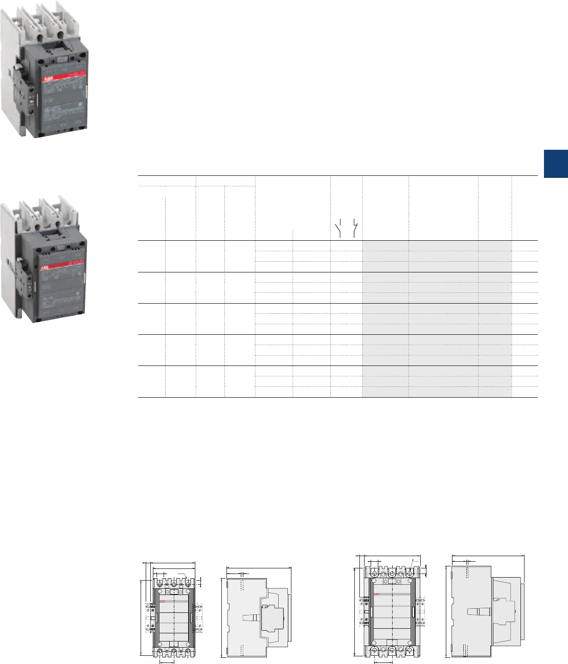
AF145 ... AF300 3-pole contactors
75 to 160 kW
AC / DC operated with 1 N.O. + 1N.C. auxiliary contacts
Description
AF145 ... AF300 contactors are mainly used for controlling 3-phase motors and power circuits up to
690 / 1000 V AC (2) or 220 V DC.
These contactors are of the block type design with:
– 3 main poles
– control circuit: AC or DC operated with electronic coil interface accepting a wide control voltage range
(e.g. 100...250 V AC and DC)
- can manage large control voltage variations
- only 3 coils to cover control voltages between 48...250 V 50/60 Hz and 20...250 V DC
- reduced panel energy consumption
- very distinct closing and opening
- can withstand short voltage dips and voltages sags (SEMI F47 conditions of use on request).
– built-in surge suppression
– add-on auxiliary contact blocks for side mounting and a wide range of accessories.
Ordering details
IEC UL/CSA Rated control circuit
voltage
Uc min. ... Uc max.
Auxiliary
contacts
fitted
Type Order code Weight
Pkg
(1 pce)
Rated operational 3-phase
motor
rating
General
use
rating
power current
θ ≤ 40 °C
400 V 690 V 480 V 600 V AC
AC-3 AC-1
kW A hp A V 50/60 Hz V DC kg
75 250 100 230 - 20…60 1 1 AF145-30-11 1SFL477001R7211 (1) 3.600
48…130 48…130 1 1 AF145-30-11 1SFL477001R6911 3.600
100…250 100…250 1 1 AF145-30-11 1SFL477001R7011 3.600
90 275 125 250 - 20…60 1 1 AF185-30-11 1SFL497001R7211 (1) 3.600
48…130 48…130 1 1 AF185-30-11 1SFL497001R6911 3.600
100…250 100…250 1 1 AF185-30-11 1SFL497001R7011 3.600
110 350 150 300 - 20…60 1 1 AF210-30-11 1SFL517001R7211 (1) 6.200
48…130 48…130 1 1 AF210-30-11 1SFL517001R6911 6.200
100…250 100…250 1 1 AF210-30-11 1SFL517001R7011 6.200
140 400 200 350 - 20…60 1 1 AF260-30-11 1SFL537001R7211 (1) 6.200
48…130 48…130 1 1 AF260-30-11 1SFL537001R6911 6.200
100…250 100…250 1 1 AF260-30-11 1SFL537001R7011 6.200
160 500 250 400 - 20…60 1 1 AF300-30-11 1SFL557001R7211 (1) 6.200
48…130 48…130 1 1 AF300-30-11 1SFL557001R6911 6.200
100…250 100…250 1 1 AF300-30-11 1SFL557001R7011 6.200
(1)
The connection polarities indicated close to the coil terminals must be respected: A1 for the positive pole and A2 for the negative pole.
(2) 690 V AC for AF210 ... AF300, 1000 V AC for AF145, AF185.
1SFC101029F0201
AF185-30-11
1SFC101044F201
AF300-30-11
Main dimensions mm, inches
12 0.47"
17.5 0.69"
105 4.13"
111.5 4.39"
ø 8.5 0.33"
35 1.38"
10 0.39"
187 7.36"
E2001D
E2002D
160 6.3"
35.5 1.4"
196 7.72"
5 0.2"
E2016D
43.75 1.72"
10.2 0.4"
14 0.55"
140 5.51"
12 0.47"
19.5 0.77"
225 8.86"
E2017D
180.5 7.11"
5
0.2"
35.5
1.4"
227 8.94"
AF145 ... AF185 AF210 ... AF300
ABB | 5/23
5
1SFC101011C0201
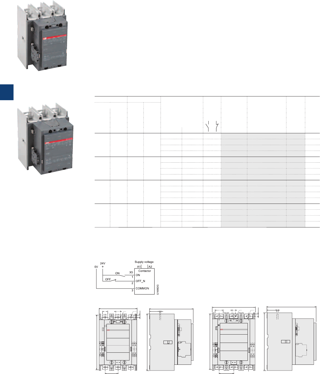
AF400 ... AF750 3-pole contactors
200 to 400 kW
AC / DC operated with 1 N.O. + 1 N.C. auxiliary contacts
Description
AF400 ... AF750 contactors are mainly used for controlling 3-phase motors and power circuits up to
1000 V AC or 600 V DC (2).
These contactors are of the block type design with:
– 3 main poles
– control circuit: AC or DC operated with electronic coil interface accepting a wide control voltage range
(e.g. 100...500 V AC and DC)
- can manage large control voltage variations
- only 4 coils to cover control voltages between 48...500 V 50/60 Hz and 24...500 V DC
- reduced panel energy consumption
- very distinct closing and opening
- can withstand short voltage dips and voltages sags (SEMI F47 conditions of use on request).
– built-in surge suppression
– add-on auxiliary contact blocks for side mounting and a wide range of accessories.
Ordering details
IEC UL/CSA Rated control circuit
voltage
Uc min. ... Uc max.
Auxiliary
contacts
fitted
Type Order code Weight
Pkg
(1 pce)
Rated operational 3-phase
motor
rating
General
use
rating
power current
θ ≤ 40 °C
400 V 690 V 480 V 600 V AC
AC-3 AC-1
kW A hp A V 50/60 Hz V DC kg
200 600 350 550 - 24…60 1 1 AF400-30-11 1SFL577001R6811 (1) 12.000
48…130 48…130 1 1 AF400-30-11 1SFL577001R6911 12.000
100…250 100…250 1 1 AF400-30-11 1SFL577001R7011 12.000
250…500 250…500 1 1 AF400-30-11 1SFL577001R7111 12.000
250 700 400 650 - 24…60 1 1 AF460-30-11 1SFL597001R6811 (1) 12.000
48…130 48…130 1 1 AF460-30-11 1SFL597001R6911 12.000
100…250 100…250 1 1 AF460-30-11 1SFL597001R7011 12.000
250…500 250…500 1 1 AF460-30-11 1SFL597001R7111 12.000
315 800 500 750 - 24…60 1 1 AF580-30-11 1SFL617001R6811 (1) 15.000
48…130 48…130 1 1 AF580-30-11 1SFL617001R6911 15.000
100…250 100…250 1 1 AF580-30-11 1SFL617001R7011 15.000
250…500 250…500 1 1 AF580-30-11 1SFL617001R7111 15.000
400 1050 600 900 - 24…60 1 1 AF750-30-11 1SFL637001R6811 (1) 15.000
48…130 48…130 1 1 AF750-30-11 1SFL637001R6911 15.000
100…250 100…250 1 1 AF750-30-11 1SFL637001R7011 15.000
250…500 250…500 1 1 AF750-30-11 1SFL637001R7111 15.000
(1)
The connection polarities indicated close to the coil terminals must be respected: A1 for the positive pole and A2 for the negative pole.
(2) Up to 850 V DC for AF580, AF750.
AF400 ... AF750 are equipped with low voltage inputs for control, for example by a PLC.
Control inputs
1SFC101031F0201
AF460-30-11
1SFC101032F0201
AF750-30-11
Main dimensions mm, inches
63 2.48"
186 7.32"
25
0.98"
22.5
0.89"
11.5
0.45"
268 10.55"
ø 10.5
0.41"
ø 6.5
0.26"
E1626D1
216 8.5"
48.5
1.91"
6
0.24"
E1627D1
278 10.94"
72 2.83"
210 8.27"
40 1.57" 22.5 0.89"
11.5 0.45"
273 10.75"
ø12.5 0.49"ø6.5 0.26"
E1632D
242 9.53"
48.5 1.91" 6 0.24"
E1633D
283 11.14"
AF400, AF460 AF580, AF750
5/24 | ABB
5
1SFC101013C0201
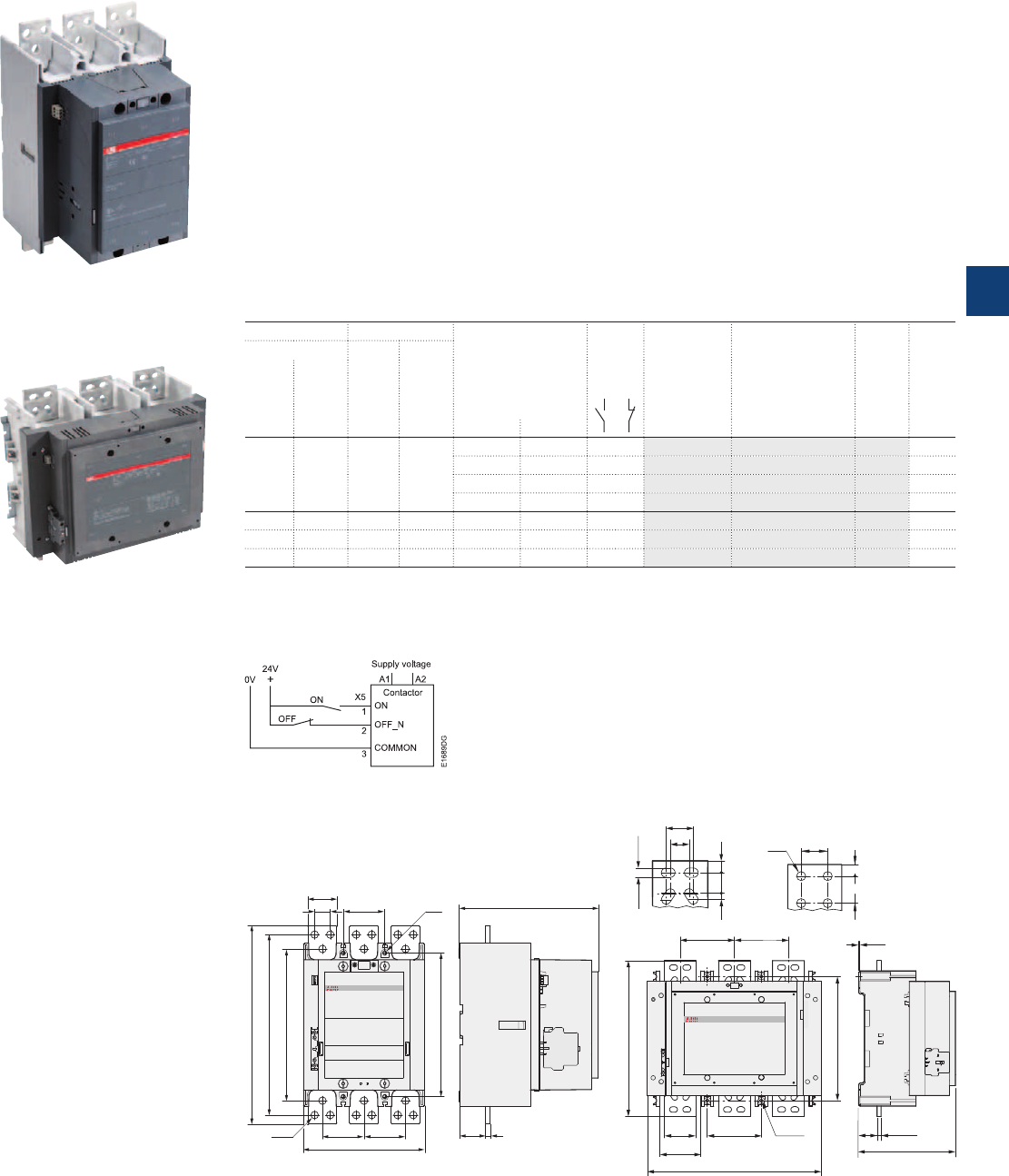
AF1250 ... AF2050 3-pole contactors
475 to 560 kW and 1250 to 2050 A AC-1
AC / DC operated with 1 N.O. + 1 N.C. auxiliary contacts
Description
AF1250 ... AF2050 contactors are mainly used for controlling power circuits up to 1000 V AC or 850 V DC.
These contactors are of the block type design with:
– 3 main poles
– control circuit: AC or DC operated with electronic coil interface accepting a wide control voltage range
(e.g. 100...250 V AC and DC)
- can manage large control voltage variations
- only 4 coils for AF1250 to cover control voltages between 48...500 V 50/60 Hz and 24...500 V DC
- only 1 coil for AF1350 ... AF2050 to cover control voltages between 100...250 V 50/60 Hz and
100...250 V DC
- reduced panel energy consumption
- very distinct closing and opening
- can withstand short voltage dips and voltages sags (SEMI F47 conditions of use on request).
– built-in surge suppression
– add-on auxiliary contact blocks for side mounting and a wide range of accessories.
Ordering details
IEC UL/CSA Rated control circuit
voltage
Uc min. ... Uc max.
(1)
Auxiliary
contacts
fitted
Type Order code Weight
Pkg
(1 pce)
Rated operational 3-phase
motor
rating
General
use
rating
power current
θ ≤ 40 °C
400 V 690 V 480 V 600 V AC
AC-3 AC-1
kW A hp A V 50/60 Hz V DC kg
- 1260 - 1210 - 24…60 1 1 AF1250-30-11 1SFL647001R6811 (1) 16.000
48…130 48…130 1 1 AF1250-30-11 1SFL647001R6911 16.000
100…250 100…250 1 1 AF1250-30-11 1SFL647001R7011 16.000
250…500 250…500 1 1 AF1250-30-11 1SFL647001R7111 16.000
475 1350 800 1350 100…250 100…250 1 1 AF1350-30-11 1SFL657001R7011 34.000
560 1650 900 1650 100…250 100…250 1 1 AF1650-30-11 1SFL677001R7011 35.000
- 2050 - 2100 100…250 100…250 1 1 AF2050-30-11 1SFL707001R7011 35.000
(1)
The connection polarities indicated close to the coil terminals must be respected: A1 for the positive pole and A2 for the negative pole.
AF1250 ... AF2050 are equipped with low voltage inputs for control, for example by a PLC.
Control inputs
AF1250-30-11
1SFC101097F0001
1SFC101026F0201
AF1650-30-11
Main dimensions mm, inches
50 1.97"
72 2.83"
72 2.83"
210 8.27"
344 13.54"
313 12.32"
263 10.35"
72 2.83"
ø 7 0.28"
ø 7 0.28"
27 1.06" 210 8.27"
46.5
1.83"
8
0.31"
136 5.35"136 5.35"
80 136 5.35" ø9 0.35"
104
438 17.24"
132 5.2"
132 5.2"
3
0.12"
47
1.85"
10 0.39"
244 9.61"
3.15"
4.09"
40 1.57"
27
13 0.51"
30 1.18"
17 0.67"
10 0.39"
1.06"
AF1350, AF1650 AF2050
40
1.57"
ø13
0.51"
40 1.57"
17 0.67"
AF1250 AF1350 ... AF2050
ABB | 5/25
5
1SFC101015C0201
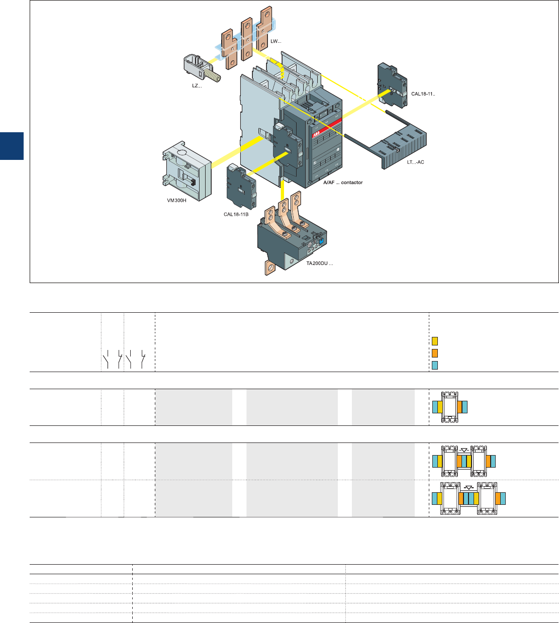
A145 ... A300 and
AF145 ... AF2050 3-pole contactors
with 1 N.O. + 1 N.C. auxiliary contacts
Main accessory fitting details
Contactor
types
Main
poles
Available
auxiliary
contacts
Side-mounted accessories
Add-on auxiliary contact blocks Mechanical
interlock units
Mounting and positioning
Factory mounted auxiliary contacts
Add-on CAL18-11 auxiliary contacts
Add-on CAL18-11B auxiliary contacts
CAL18-11, CAL18-11B (3)
(for two horizontal
mounted contactors)
Contactors + auxiliary contact blocks
A145 ... A300
AF145 ... AF2050 3 0 1 1 1 x CAL18-11
+
2 x CAL18-11B –
BB
Contactors with mechanical interlocking + auxiliary contact blocks
A145 ... A185
AF145 ... AF185 3 0 1 1 2 x CAL18-11 (1)
+
3 x CAL18-11B (1)
+
VM...H (2)
BB B
A210 ... A300
AF210 ... AF2050 3 0 1 1 2 x CAL18-11 (1)
+
4 x CAL18-11B (1)
+
VM...H (2)
BB
B B
(1) Total number of auxiliary contact blocks for the two contactors. (2) Interlock type, according to the contactor ratings (see "Accessories").
(3) The CEL18-.. auxiliary contact blocks can replace the CAL18-11 and CAL18-11B. Though, no auxiliary contact block can be mounted outside the CEL18-..
Main accessories (other accessories available) AF185 shown on picture
Overload relays fitting details
Contactor types Thermal overload relays Electronic overload relays
A145, A185 TA200DU (80...200 A) (4) E200DU (60...200 A) (4)
A210, A300 TA450DU (100...310 A) (4) or TA450SU (130...310 A) (5) E320DU (100...320 A) (4)
AF400, AF460 – E500DU (150...500 A) (5)
AF580, AF750 – E800DU (250...800 A) (5)
AF1350, AF1650 – E1250DU (375...1250 A) (5)
The addition of a thermal or electronic overload relay on the contactor does not prevent fitting of many other accessories as shown in "Main accessory fitting details" table.
(4) Direct mounting - No kit required.
(5) Mounting kit required (see "Motor protection").
5/26 | ABB
5
1SFC101027C0201
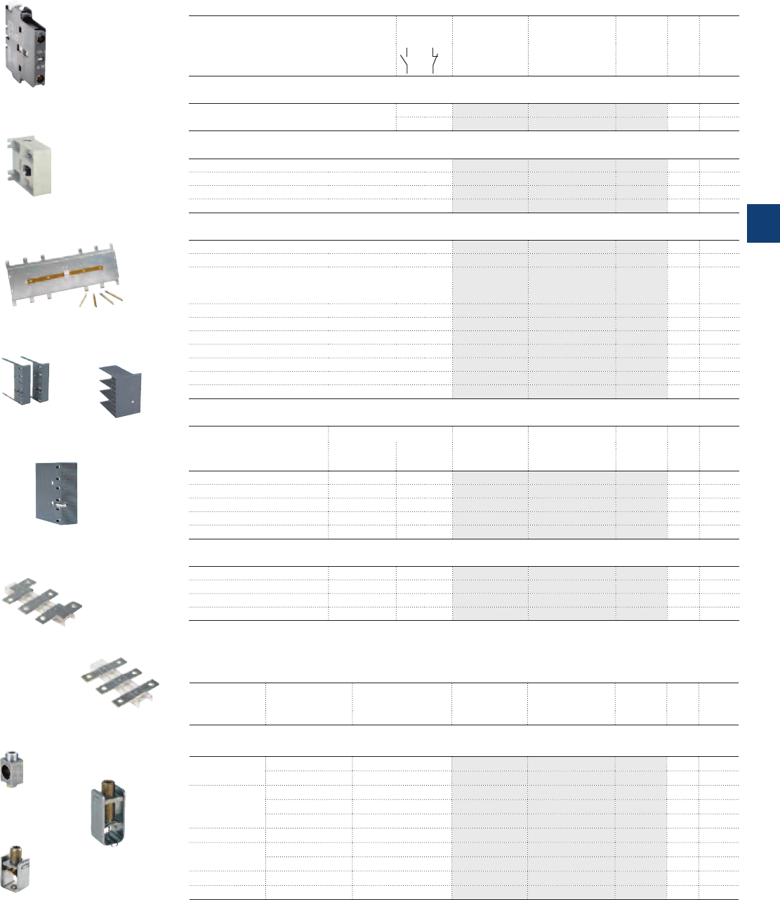
A145...A300 and
AF145...AF2050 3-pole contactors
Main accessories
Ordering details (1)
For contactors Auxiliary
contacts
Type Order code Pkg
qty
Weight
(1 pce)
kg
Side-mounted instantaneous auxiliary contact blocks
A145 ... A300 and AF145 ... AF2050 1 1 CAL18-11 1SFN010720R1011 2 0.050
1 1 CAL18-11B 1SFN010720R3311 2 0.050
Mechanical interlock unit for two horizontal mounted contactors
A145 ... A300 VM300H 1SFN034700R1000 1 0.150
A210 ... A300 VM300/460H 1SFN035100R1000 1 0.150
AF400 ... AF1250 VM750H 1SFN035700R1000 1 0.200
AF1350 ... AF2050 VM1650H 1SFN036503R1000 1 6.000
Terminal shrouds
A145 ... A185 with connectors LT185-AC 1SFN124701R1000 2 0.050
A145 ... A185 with lugs LT185-AL 1SFN124703R1000 2 0.220
A145 ... A185 with short. bar LY185
or between A145 and TA200DU
or between A185 and TA200DU
LT185-AY 1SFN124704R1000 1 0.050
A210 ... A300 with connectors LT300-AC 1SFN125101R1000 2 0.070
A210 ... A300 with lugs LT300-AL 1SFN125103R1000 2 0.280
A210 ... A300 with short bar LY300 LT300-AY 1SFN125104R1000 1 0.075
AF400 ... AF460 with connectors LT460-AC 1SFN125701R1000 2 0.100
AF400 ... AF460 with lugs LT460-AL 1SFN125703R1000 2 0.800
AF580 ... AF750 with connectors LT750-AC 1SFN126101R1000 2 0.120
AF580 ... AF750 with lugs LT750-AL 1SFN126103R1000 2 0.825
Terminal enlargements
For contactors Dimensions Type Order code Pkg Weight
hole Ø
mm
bar
mm
qty (1 pce)
kg
A145, A185 10.5 20 x 5 LW185 1SFN074707R1000 1 0.250
A210 ... A300 10.5 25 x 5 LW300 1SFN075107R1000 1 0.450
AF400, AF460 10.5 25 x 5 LW460 1SFN075707R1000 1 0.730
AF580, AF750 13 40 x 6 LW750 1SFN076107R1000 1 1.230
AF1250 13 50 x 10 LW1250 1SFN076407R1000 1 2.000
Terminal extension
A145, A185 8.5 20 x 5 LX185 1SFN074710R1000 1 0.250
A210 ... A300 10.5 20 x 5 LX300 1SFN075110R1000 1 0.350
AF400, AF460 10.5 25 x 5 LX460 1SFN075710R1000 1 0.500
AF580, AF750 13 40 x 6 LX750 1SFN076110R1000 1 0.850
(1) For each contactor type, refer to "Main accessory fitting details" table.
1SFT98099-019C3
LT... AC
1SFC101033F0201
CAL18-11
1SBC580411F0301
VM300H
1SFC101024F0201
VM1650H
Ordering details (1)
Cables For contactors Cable cross section Type Order code Pkg
qty
Weight
(1 pce)
mm² kg
Connector terminals
Single Cu A145, A185 6...185 – 1SDA023354R0001 3 0.200
A210 ... A300 16...240 – 1SDA023368R0001 3 0.400
Single Al & Cu A145, A185 35...95 – 1SDA023356R0001 3 0.100
A145, A185 25...150 – 1SDA023357R0001 3 0.100
A210 ... A300 120...240 – 1SDA023370R0001 3 0.200
Double Cu A145, A185 2 x (50...120) LZ185-2C/120 1SFN074709R1000 3 0.300
Double Al & Cu A210 ... A300 2 x (95...120) – 1SDA025766R0001 3 0.400
AF400 ... AF750 2 x (120...240) – 1SDA023380R0001 3 0.110
Triple Al & Cu AF400 ... AF750 3 x (70...185) – 1SDA023384R0001 3 0.265
Multi Al & Cu AF1350, AF1650 4 x (120...240) – 1SDA023387R0001 3 0.400
(1) For each contactor type, refer to "Main accessory fitting details" table.
Note: Connectors provided for the A... contactors can be used for the AF types.
1SFT9099-125
LT...AL
1SFT98000-014
LT...AY
1SFT98000-011C3
LW
1SFT98000-012C3
LX
1SFT98099-011C1
LZ...
1SFT98099-095C2
LZ...
1SBC580542F0302
LZ...
ABB | 5/27
5
1SFC101077C0201
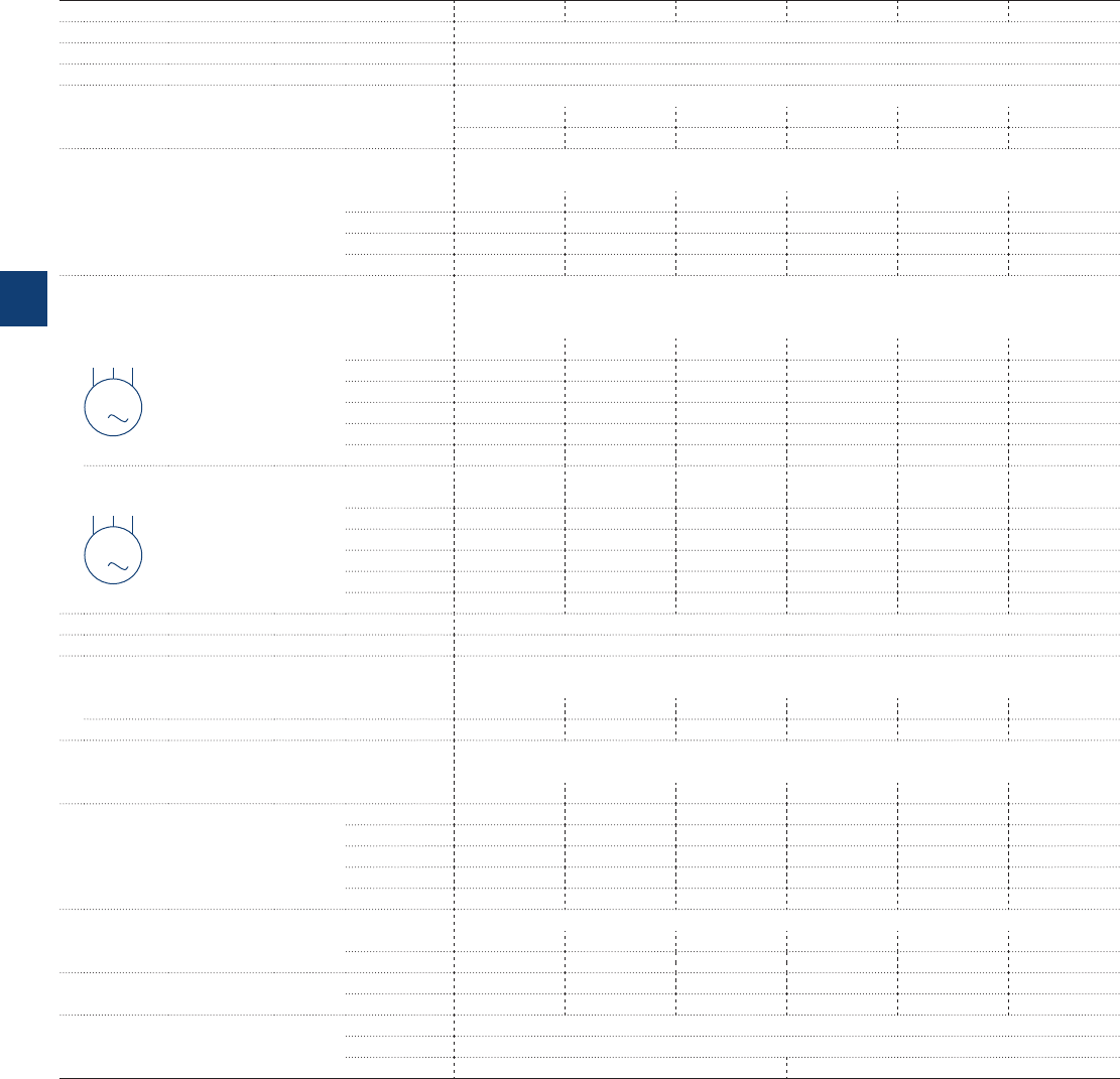
AF09 ... AF38 3-pole contactors
Technical data
Main pole - Utilization characteristics according to IEC
Contactor types AC / DC operated AF09 AF12 AF16 AF26 AF30 AF38
Standards IEC 60947-1 / 60947-4-1 and EN 60947-1 / 60947-4-1
Rated operational voltage Ue max. 690 V
Rated frequency (without derating) 50 / 60 Hz
Conventional free-air thermal current Ith
acc. to IEC 60947-4-1, open contactors, θ ≤ 40 °C 35 A 35 A 35 A 50 A 50 A 50 A
With conductor cross-sectional area 6 mm² 6 mm² 6 mm² 10 mm² 10 mm² 10 mm²
AC-1 Utilization category
For air temperature close to contactor
Ie / Rated operational current AC-1 θ ≤ 40 °C 25 A 28 A 30 A 45 A 50 A 50 A
Ue max. ≤ 690 V, 50/60 Hz θ ≤ 60 °C 25 A 28 A 30 A 40 A 42 A 42 A
θ ≤ 70 °C 22 A 24 A 26 A 32 A 37 A 37 A
With conductor cross-sectional area 4 mm² 6 mm² 6 mm² 10 mm² 10 mm² 10 mm²
AC-3 Utilization category
For air temperature close to contactor θ ≤ 60 °C
Ie / Max. rated operational current AC-3 (1)
M
3
3-phase motors
220-230-240 V 9 A 12 A 18 A 26 A 33 A 40 A
380-400 V 9 A 12 A 18 A 26 A 32 A 38 A
415 V 9 A 12 A 18 A 26 A 32 A 38 A
440 V 9 A 12 A 18 A 26 A 32 A 38 A
500 V 9.5 A 12.5 A 15 A 23 A 28 A 33 A
690 V 7 A 9 A 10.5 A 17 A 21 A 24 A
Rated operational power AC-3 (1)
M
3
1500 r.p.m. 50 Hz
1800 r.p.m. 60 Hz
3-phase motors
220-230-240 V 2.2 kW 3 kW 4 kW 6.5 kW 9 kW 11 kW
380-400 V 4 kW 5.5 kW 7.5 kW 11 kW 15 kW 18.5 kW
415 V 4 kW 5.5 kW 9 kW 11 kW 15 kW 18.5 kW
440 V 4 kW 5.5 kW 9 kW 15 kW 18.5 kW 22 kW
500 V 5.5 kW 7.5 kW 9 kW 15 kW 18.5 kW 22 kW
690 V 5.5 kW 7.5 kW 9 kW 15 kW 18.5 kW 22 kW
Rated making capacity AC-3 10 x Ie AC-3 acc. to IEC 60947-4-1
Rated breaking capacity AC-3 8 x Ie AC-3 acc. to IEC 60947-4-1
AC-8a Utilization category
(without thermal overload relay - Ue 400 V 50/60 Hz - θ ≤ 40 °C)
Ie / Rated operational current AC-8a 12 A 16 A 22 A 30 A 40 A 50 A
Rated operational power AC-8a 5.5 kW 7.5 kW 11 kW 15 kW 20 kW 25 kW
Short-circuit protection device for contactors
without thermal overload relay - Motor protection excluded (2)
Ue ≤ 500 V AC - gG type fuse 25 A 32 A 32 A 50 A 63 A 63 A
Rated short-time withstand current Icw 1 s 300 A 300 A 300 A 700 A 700 A 700 A
at 40 °C ambient temperature,
in free air from a cold state
10 s 150 A 150 A 150 A 350 A 350 A 350 A
30 s 80 A 80 A 80 A 225 A 225 A 225 A
1 min 60 A 60 A 60 A 150 A 150 A 150 A
15 min 35 A 35 A 35 A 50 A 50 A 50 A
Maximum breaking capacity
cos φ = 0.45 at 440 V 250 A 250 A 250 A 500 A 500 A 500 A
at 690 V 106 A 106 A 106 A 200 A 200 A 200 A
Power dissipation per pole Ie / AC-1 0.8 W 1 W 1.2 W 1.8 W 2.4 W 2.4 W
Ie / AC-3 0.1 W 0.2 W 0.35 W 0.6 W 0.9 W 1.3 W
Max. electrical switching frequency AC-1 600 cycles/h
AC-3 1200 cycles/h
AC-2, AC-4 300 cycles/h 150 cycles/h
(1) For the corresponding kW/A or hp/A values of 1500 r.p.m, 50 Hz or 1800 r.p.m, 60 Hz, 3-phase motors, see "Motor rated operational powers and currents".
(2) For the protection of motor starters against short circuits, see "Coordination with short-circuit protection devices".
5/28 | ABB
5
1SBC101425S0201
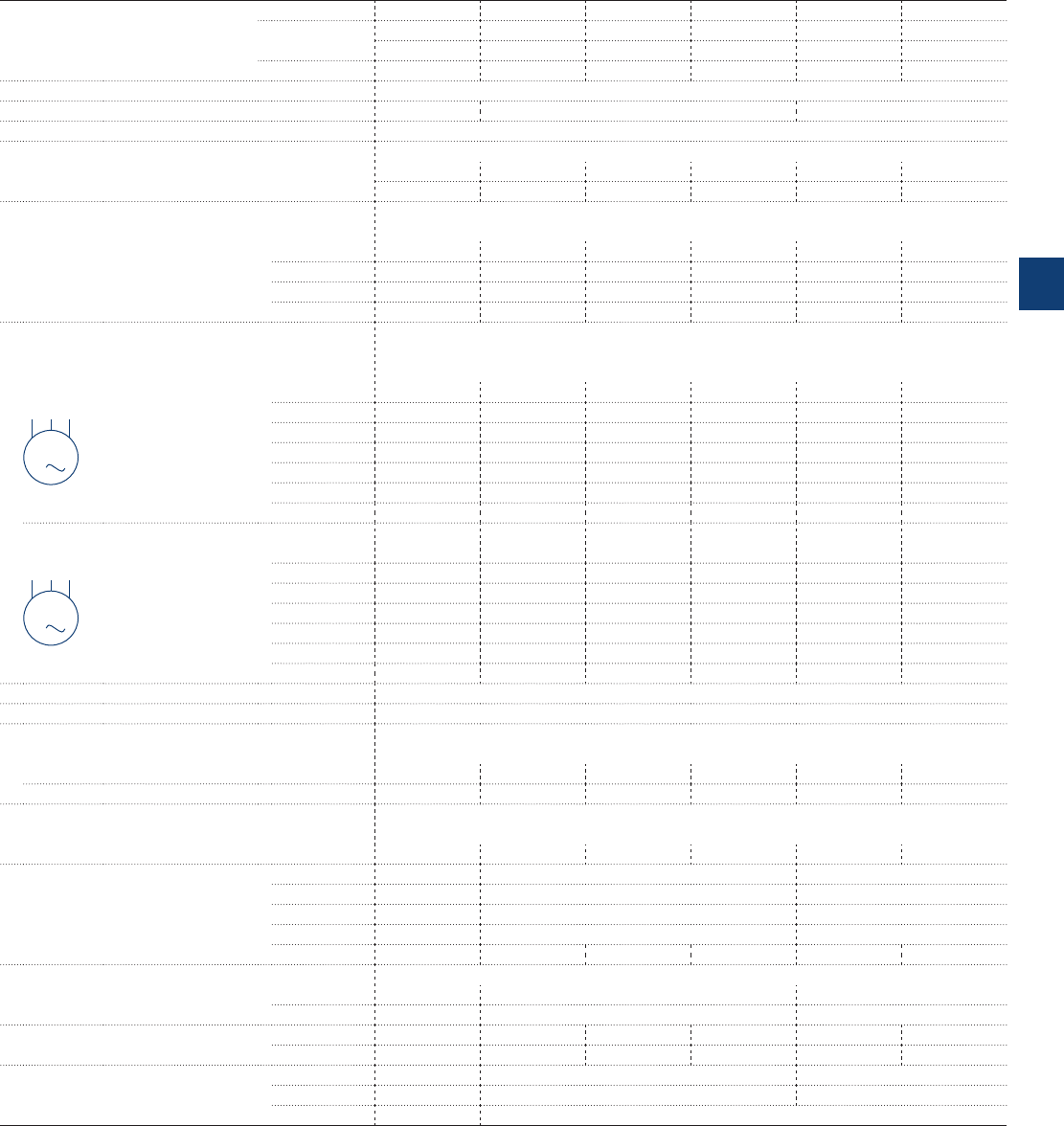
A40 … A110, AL, AE, TAL, TAE and
AF50 … AF110 3-pole contactors
Technical data
Main pole - Utilization characteristics according to IEC
Contactor types AC operated A40 A50 A63 A75 A95 A110
DC operated AL40 AE50 AE63 AE75 ––
TAL40 TAE50 –TAE75 ––
AC / DC operated –AF50 AF63 AF75 AF95 AF110
Standards IEC 60947-1 / 60947-4-1 and EN 60947-1 / 60947-4-1
Rated operational voltage Ue max. 690 V 1000 V (690 V for AF.. contactors) 1000 V
Rated frequency (without derating) 50/60 Hz
Conventional free-air thermal current Ith
acc. to IEC 60947-4-1, open contactors, θ ≤ 40 °C 65 A 100 A 125 A 125 A 145 A 160 A
With conductor cross-sectional area 16 mm² 35 mm² 50 mm² 50 mm² 50 mm² 70 mm²
AC-1 Utilization category
For air temperature close to contactor
Ie / Rated operational current AC-1 θ ≤ 40 °C 60 A 100 A 115 A 125 A 145 A 160 A
Ue max. ≤ 690 V, 50/60 Hz θ ≤ 55 °C 60 A 85 A 95 A 105 A 135 A 145 A
θ ≤ 70 °C (3) 42 A 70 A 80 A 85 A 115 A 130 A
With conductor cross-sectional area 16 mm² 35 mm² 50 mm² 50 mm² 50 mm² 70 mm²
AC-3 Utilization category
For air temperature close to contactor θ ≤ 55 °C
Ie / Max. rated operational current AC-3 (1)
M
3
3-phase motors
220-230-240 V 40 A 53 A 65 A 75 A 96 A 110 A
380-400 V 37 A 50 A 65 A 75 A 96 A 110 A
415 V 37 A 50 A 65 A 75 A 96 A 110 A
440 V 37 A 45 A 65 A 70 A 93 A 100 A
500 V 33 A 45 A 55 A 65 A 80 A 100 A
690 V 25 A (4) 35 A 43 A 46 A 65 A 82 A
1000 V – 23 A (6) 25 A (6) 28 A (6) 30 A 30 A
Rated operational power AC-3 (1)
M
3
1500 r.p.m. 50 Hz
1800 r.p.m. 60 Hz
3-phase motors
220-230-240 V 11 kW 15 kW 18.5 kW 22 kW 25 kW 30 kW
380-400 V 18.5 kW 22 kW 30 kW 37 kW 45 kW 55 kW
415 V 18.5 kW 25 kW 37 kW 40 kW 55 kW 59 kW
440 V 22 kW 25 kW 37 kW 40 kW 55 kW 59 kW
500 V 22 kW 30 kW 37 kW 45 kW 55 kW 59 kW
690 V 22 kW (4) 30 kW 37 kW 40 kW 55 kW 75 kW
1000 V – 30 kW (6) 33 kW (6) 37 kW (6) 40 kW 40 kW
Rated making capacity AC-3 10 x Ie AC-3 acc. to IEC 60947-4-1
Rated breaking capacity AC-3 8 x Ie AC-3 acc. to IEC 60947-4-1
AC-8a Utilization category
(without thermal overload relay - Ue 400 V 50/60 Hz - θ ≤ 40 °C)
Ie / Rated operational current AC-8a 50 A 63 A 85 A 95 A 120 A 140 A
Rated operational power AC-8a 22 kW 30 kW 45 kW 45 kW 55 kW 75 kW
Short-circuit protection device for contactors
without thermal overload relay - Motor protection excluded (2)
Ue ≤ 500 V AC - gG type fuse 63 A 100 A 125 A 160 A 160 A 200 A
Rated short-time withstand current Icw 1 s 600 A 1000 A 1320 A
at 40 °C ambient temperature,
in free air from a cold state
10 s 400 A 650 A 800 A
30 s 225 A 370 A 500 A
1 min 150 A 250 A 350 A
15 min 65 A 110 A 135 A 135 A 160 A 175 A
Maximum breaking capacity
cos φ = 0.45 at 440 V 820 A (5) 1300 A 1160 A
(cos φ = 0.35 for Ie > 100 A) at 690 V 340 A (5) 630 A 800 A
Power dissipation per pole Ie / AC-1 3 W 5 W 6.5 W 7 W 6.5 W 7.5 W
Ie / AC-3 1.3 W 1.3 W 1.5 W 2 W 2.7 W 3.6 W
Max. electrical switching frequency AC-1 600 cycles/h 600 cycles/h (300 for AF.., AE.., TAE..) 300 cycles/h
AC-3 1200 cycles/h 600 cycles/h (300 for AF.., AE.., TAE..) 300 cycles/h
AC-2, AC-4 300 cycles/h 150 cycles/h
(1) For the corresponding kW/A or hp/A values of 1500 r.p.m, 50 Hz or 1800 r.p.m, 60 Hz, 3-phase motors, see "Motor rated operational powers and currents".
(2) For the protection of motor starters against short circuits, see "Coordination with short-circuit protection devices".
(3) Unauthorized for TAL.., TAE.. contactors.
(4) AC-3, 690 V values for AL40 and TAL40 contactors: 18.5 kW, Ie = 21 A.
(5) Max. breaking capacity for AL40 and TAL40 contactors: 470 A at 440 V, 175 A at 690 V.
(6) AF contactors excluded.
ABB | 5/29
5
1SBC101429S0201

A145 … A300 and
AF145 … AF300 3-pole contactors
Technical data
Main pole - Utilization characteristics according to IEC
Contactor types AC operated A145 A185 A210 A260 A300
AC / DC operated AF145 AF185 AF210 AF260 AF300
Standards IEC 60947-1 / 60947-4-1 and EN 60947-1 / 60947-4-1
Rated operational voltage Ue max. 1000 V 690 V
Rated frequency (without derating) 50/60 Hz
Conventional free-air thermal current Ith
acc. to IEC 60947-4-1, open contactors, θ ≤ 40 °C 250 A 275 A 350 A 400 A 500 A (4)
With conductor cross-sectional area (3) 120 mm² 150 mm² 185 mm² 240 mm² 300 mm² (4)
AC-1 Utilization category
For air temperature close to contactor
Ie / Rated operational current AC-1 θ ≤ 40 °C 250 A 275 A 350 A 400 A 500 A (4)
Ue max. ≤ 690 V, 50/60 Hz θ ≤ 55 °C 230 A 250 A 300 A 350 A 400 A (4)
θ ≤ 70 °C 180 A 180 A 240 A 290 A 325 A (4)
Ie / Rated operational current AC-1 θ ≤ 40 °C 180 A 200 A – – –
Ue max. ≤ 1000 V, 50/60 Hz θ ≤ 55 °C 180 A 200 A – – –
θ ≤ 70 °C 180 A 180 A – – –
With conductor cross-sectional area 120 mm² 150 mm² 185 mm² 240 mm² 300 mm² (4)
AC-3 Utilization category
For air temperature close to contactor θ ≤ 55 °C
Ie / Max. rated operational current AC-3 (1)
M
3
3-phase motors
220-230-240 V 145 A 185 A 210 A 260 A 305 A
380-400 V 145 A 185 A 210 A 260 A 305 A
415 V 145 A 185 A 210 A 260 A 300 A
440 V 145 A 185 A 210 A 240 A 280 A
500 V 145 A 170 A 210 A 240 A 280 A
690 V 120 A 170 A 210 A 220 A 280 A
1000 V 80 A 95 A – – –
Rated operational power AC-3 (1)
M
3
1500 r.p.m. 50 Hz
1800 r.p.m. 60 Hz
3-phase motors
220-230-240 V 45 kW 55 kW 59 kW 80 kW 90 kW
380-400 V 75 kW 90 kW 110 kW 140 kW 160 kW
415 V 75 kW 90 kW 110 kW 140 kW 160 kW
440 V 75 kW 90 kW 110 kW 140 kW 160 kW
500 V 90 kW 110 kW 132 kW 180 kW 200 kW
690 V 110 kW 132 kW 160 kW 200 kW 250 kW
1000 V 110 kW 132 kW – – –
Rated making capacity AC-3 10 x Ie AC-3 acc. to IEC 60947-4-1
Rated breaking capacity AC-3 8 x Ie AC-3 acc. to IEC 60947-4-1
Short-circuit protection device for contactors
without thermal overload relay - Motor protection excluded (2)
Ue ≤ 500 V AC - gG type fuse 315 A 355 A 400 A 500 A 500 A
Rated short-time withstand current Icw 1 s 1800 A 2000 A 2500 A 3500 A 3500 A
at 40 °C ambient temperature,
in free air from a cold state
10 s 1200 A 1500 A 1700 A 2400 A 2400 A
30 s 800 A 1000 A 1200 A 1500 A 1500 A
1 min 600 A 800 A 1000 A 1100 A 1100 A
15 min 280 A 320 A 400 A 500 A 500 A
Maximum breaking capacity
cos φ = 0.45 at 440 V 1500 A 2000 A 2300 A 2600 A 3000 A
(cos φ = 0.35 for Ie > 100 A) at 690 V 1200 A 1600 A 2000 A 2400 A 2500 A
Power dissipation per pole Ie / AC-1 13 W 16 W 18 W 25 W 32 W
Ie / AC-3 5 W 8 W 9 W 14 W 18 W
Max. electrical switching frequency AC-1 300 cycles/h 300 cycles/h
AC-3 300 cycles/h 300 cycles/h
AC-2, AC-4 150 cycles/h 150 cycles/h
(1) For the corresponding kW/A or hp/A values of 1500 r.p.m, 50 Hz or 1800 r.p.m, 60 Hz, 3-phase motors, see "Motor rated operational powers and currents".
(2) For the protection of motor starters against short circuits, see "Coordination with short-circuit protection devices".
(3) Conductors with preparation.
(4) Use terminal extension / enlargement pieces (LX 300 / LW 300).
5/30 | ABB
5
1SFC101035C0201

AF400 … AF2050 3-pole contactors
Technical data
Main pole - Utilization characteristics according to IEC
Contactor types AC / DC operated AF400 AF460 AF580 AF750 AF1250 AF1350 AF1650 AF2050
Standards IEC 60947-1 / 60947-4-1 and EN 60947-1 / 60947-4-1
Rated operational voltage Ue max. 1000 V
Rated frequency (without derating) 50/60 Hz
Conventional free-air thermal current Ith
acc. to IEC 60947-4-1, open contactors, θ ≤ 40 °C 600 A 700 A 800 A 1050 A 1260 A 1350 A 1650 A 2050 A
With conductor cross-sectional area (3)
2x185 mm² 2x240 mm² 2x240 mm² 800 mm² (4) 1000 mm² (4) 1000 mm² (5) 1500 mm² (5) 2000 mm² (5)
AC-1 Utilization category
For air temperature close to contactor
Ie / Rated operational current AC-1 θ ≤ 40 °C 600 A 700 A 800 A 1050 A 1260 A 1350 A 1650 A 2050 A
Ue max. ≤ 690 V, 50/60 Hz θ ≤ 55 °C 500 A 600 A 700 A 875 A 1040 A 1150 A 1450 A 1750 A
θ ≤ 70 °C 400 A 480 A 580 A 720 A 875 A 1000 A 1270 A 1500 A
Ie / Rated operational current AC-1 θ ≤ 40 °C 600 A 700 A 800 A 1000 A 1260 A 1350 A 1650 A 2050 A
Ue max. ≤ 1000 V, 50/60 Hz θ ≤ 55 °C 500 A 600 A 700 A 875 A 1040 A 1150 A 1450 A 1750 A
θ ≤ 70 °C 400 A 480 A 580 A 720 A 875 A 1000 A 1270 A 1500 A
With conductor cross-sectional area
2x185 mm² 2x240 mm² 2x240 mm² 800 mm² (4) 1000 mm² (4) 1000 mm² (5) 1500 mm² (5) 2000 mm² (5)
AC-3 Utilization category
For air temperature close to contactor θ ≤ 55 °C
Ie / Max. rated operational current AC-3 (1)
M
3
3-phase motors
220-230-240 V 400 A 460 A 580 A 750 A – 860 A 1050 A –
380-400 V 400 A 460 A 580 A 750 A – 860 A 1050 A –
415 V 400 A 460 A 580 A 750 A – 860 A 1050 A –
440 V 400 A 460 A 580 A 750 A – 860 A 1050 A –
500 V 400 A 460 A 580 A 750 A – 800 A 950 A –
690 V 350 A 400 A 500 A 650 A – 800 A 950 A –
1000 V 155 A 200 A 250 A 300 A – – – –
Rated operational power AC-3 (1)
M
3
1500 r.p.m. 50 Hz
1800 r.p.m. 60 Hz
3-phase motors
220-230-240 V 110 kW 132 kW 160 kW 220 kW – 257 kW 315 kW –
380-400 V 200 kW 250 kW 315 kW 400 kW – 475 kW 560 kW –
415 V 220 kW 250 kW 355 kW 425 kW – 500 kW 600 kW –
440 V 220 kW 250 kW 355 kW 450 kW – 560 kW 670 kW –
500 V 250 kW 315 kW 400 kW 520 kW – 560 kW 700 kW –
690 V 315 kW 355 kW 500 kW 600 kW – 750 kW 900 kW –
1000 V 220 kW 280 kW 355 kW 400 kW – – – –
Rated making capacity AC-3 10 x Ie AC-3 acc. to IEC 60947-4-1
Rated breaking capacity AC-3 8 x Ie AC-3 acc. to IEC 60947-4-1
Short-circuit protection device for contactors
without thermal overload relay - Motor protection excluded (2)
Ue ≤ 500 V AC - gG type fuse 630 A 800 A 1000 A 1000 A Please consult us for coordination with circuit-breaker
Rated short-time withstand current Icw 1 s 4600 A 4600 A 7000 A 7000 A 8000 A 10000 A 12000 A 12000 A
at 40 °C ambient temperature,
in free air from a cold state
10 s 4400 A 4400 A 6400 A 6400 A 7200 A 8000 A 10000 A 10000 A
30 s 3100 A 3100 A 4500 A 4500 A 5200 A 6000 A 7500 A 7500 A
1 min 2500 A 2500 A 3500 A 3500 A 4000 A 4500 A 5500 A 5500 A
15 min 840 A 840 A 1300 A 1300 A 1500 A 1600 A 2200 A 2200 A
Maximum breaking capacity
cos φ = 0.45 at 440 V 4000 A 5000 A 6000 A 7500 A 10000 A 12000 A 8400 A
(cos φ = 0.35 for Ie > 100 A) at 690 V 3500 A 4500 A 5000 A 7000 A – – –
Power dissipation per pole Ie / AC-1 30 W 42 W 32 W 50 W 80 W 80 W 80 W 125W
Ie / AC-3 16 W 21 W 17 W 28 W – 50 W 50 W –
Max. electrical switching frequency AC-1 300 cycles/h 300 cycles/h 300 cycles/h 60 cycles/h 60 cycles/h
AC-3 300 cycles/h 300 cycles/h – 60 cycles/h –
AC-2, AC-4 60 cycles/h 60 cycles/h – 60 cycles/h –
(1) For the corresponding kW/A or hp/A values of 1500 r.p.m, 50 Hz or 1800 r.p.m, 60 Hz, 3-phase motors, see "Motor rated operational powers and currents".
(2) For the protection of motor starters against short circuits, see "Coordination with short-circuit protection devices".
(3) Conductors with preparation.
(4) Max. connection bar width 50 mm.
(5) Max. connection bar width 100 mm.
ABB | 5/31
5
1SFC101036C0201
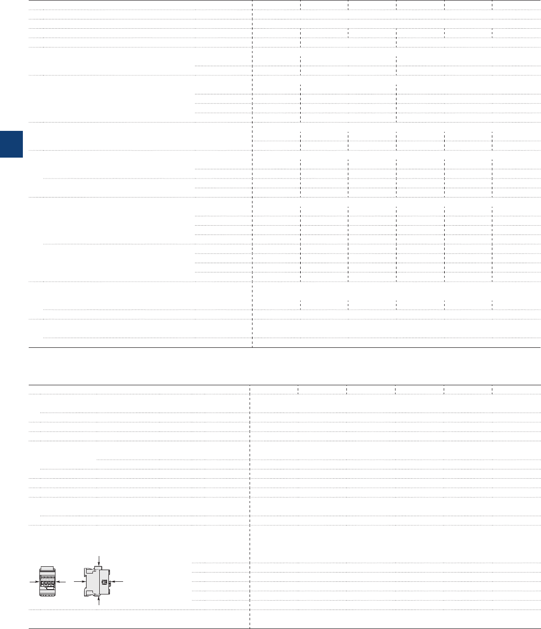
AF09 ... AF38 3-pole contactors
Technical data
Main pole - Utilization characteristics according to UL / NEMA / CSA
Contactor types AC / DC operated AF09 AF12 AF16 AF26 AF30 AF38
Standards UL 508, CSA C22.2 N°14
Max. operational voltage 600 V
NEMA size 000–1––
NEMA continuous amp rating Thermal current 9 A 18 A 27 A
NEMA maximum horse power ratings 1-phase, 60 Hz
115 V AC 1/3 hp 1 hp 2 hp
230 V AC 1 hp 2 hp 3 hp
NEMA maximum horse power ratings 3-phase, 60 Hz
200 V AC 1-1/2 hp 3 hp 7-1/2 hp
230 V AC 1-1/2 hp 3 hp 7-1/2 hp
460 V AC 2 hp 5 hp 10 hp
575 V AC 2 hp 5 hp 10 hp
UL / CSA general use rating
600 V AC 25 A 28 A 30 A 45 A 50 A 50 A
With conductor cross-sectional area AWG 10 AWG 10 AWG 10 AWG 8 AWG 8 AWG 8
UL / CSA maximum 1-phase motor rating
Full load current 120 V AC 13.8 A 16 A 20 A 24 A 24 A 24 A
240 V AC 10 A 12 A 17 A 17 A 28 A 28 A
Horse power rating 120 V AC 3/4 hp 1 hp 1-1/2 hp 2 hp 2 hp 2 hp
240 V AC 1-1/2 hp 2 hp 3 hp 3 hp 5 hp 5 hp
UL / CSA maximum 3-phase motor rating
Full load current (1) 200-208 V AC 7.8 A 11 A 17.5 A 25.3 A 32.2 A 32.2 A
220-240 V AC 6.8 A 9.6 A 15.2 A 22 A 28 A 28 A
440-480 V AC 7.6 A 11 A 14 A 21 A 27 A 27 A
550-600 V AC 9 A 11 A 17 A 22 A 27 A (2) 27 A (2)
Horse power rating (1) 200-208 V AC 2 hp 3 hp 5 hp 7-1/2 hp 10 hp 10 hp
220-240 V AC 2 hp 3 hp 5 hp 7-1/2 hp 10 hp 10 hp
440-480 V AC 5 hp 7-1/2 hp 10 hp 15 hp 20 hp 20 hp
550-600 V AC 7-1/2 hp 10 hp 15 hp 20 hp 25 hp (2) 25 hp (2)
Short-circuit protection device for contactors
without thermal overload relay - Motor protection excluded
Fuse rating 60 A 60 A 60 A 150 A 150 A 150 A
Fuse type, 600 V NTD
Max. electrical switching frequency
For general use 600 cycles/h
For motor use 1200 cycles/h
(1) For the corresponding kW/A or hp/A values of 1500 r.p.m, 50 Hz or 1800 r.p.m, 60 Hz, 3-phase motors, see “Motor rated operational powers and currents”.
(2) For contactors produced since week 49-2011.
General technical data
Contactor types AC / DC operated AF09 AF12 AF16 AF26 AF30 AF38
Rated insulation voltage Ui
acc. to IEC 60947-4-1 690 V
acc. to UL / CSA 600 V
Rated impulse withstand voltage Uimp. 6 kV
Electromagnetic compatibility Devices complying with IEC 60947-1 / EN 60947-1 - Environment A
Ambient air temperature close to contactor
Operation Fitted with thermal overload relay -25...+60 °C
Without thermal overload relay -40...+70 °C
Storage -60...+80 °C
Climatic withstand Category B according to IEC 60947-1 Annex Q
Maximum operating altitude (without derating) 3000 m
Mechanical durability
Number of operating cycles 10 millions operating cycles
Max. switching frequency 3600 cycles/h
Shock withstand
acc. to IEC 60068-2-27 and EN 60068-2-27
Mounting position 1
B2
AAB1
C2
C1
Shock direction 1/2 sinusoidal shock for 11 ms: no change in contact position, closed or open position
A30 g
B1 25 g closed position / 5 g open position
B2 15 g
C1 25 g
C2 25 g
Vibration withstand 5...300 Hz
acc. to IEC 60068-2-6 4 g closed position / 2 g open position
5/32 | ABB
5
1SBC101426S0201
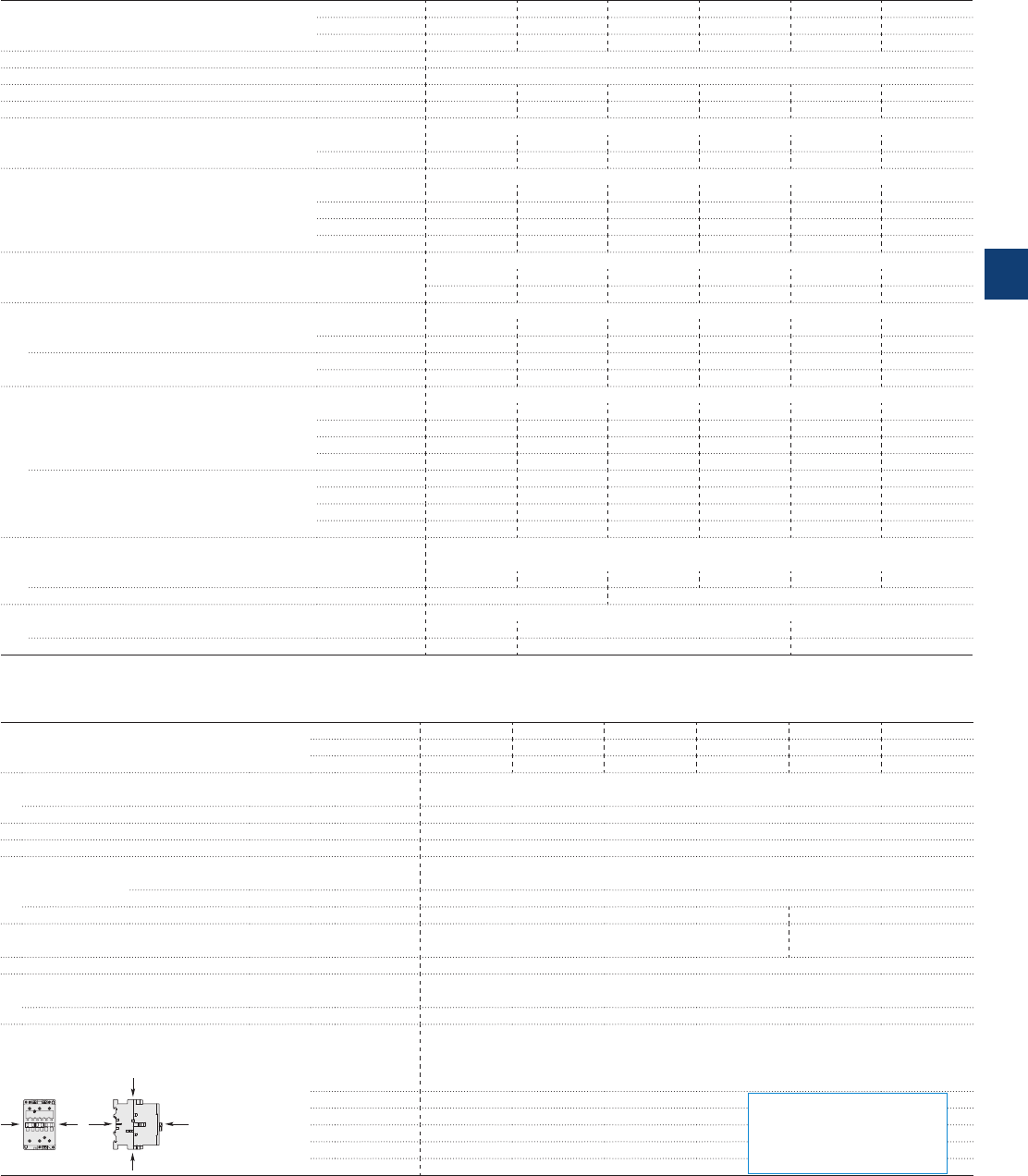
Main pole - Utilization characteristics according to UL / NEMA / CSA
Contactor types AC operated A40 A50 A63 A75 A95 A110
DC operated AL40, TAL40 AE50, TAE50 AE63 AE75, TAE75 – –
AC / DC operated – AF50 AF63 AF75 AF95 AF110
Standards UL 508, CSA C22.2 N°14
Max. operational voltage 600 V
NEMA size –2–3––
NEMA continuous amp rating Thermal current – 45 A – 90 A – –
NEMA maximum horse power ratings 1-phase, 60 Hz
115 V AC –3 hp––––
230 V AC – 7-1/2 – – – –
NEMA maximum horse power ratings 3-phase, 60 Hz
200 V AC – 10 hp – 25 hp – –
230 V AC – 15 hp – 30 hp – –
460 V AC – 25 hp – 50 hp – –
575 V AC – 25 hp – 50 hp – –
UL / CSA general use rating
600 V AC 60 A 80 A 90 A 105 A 125 A 150 A
With conductor cross-sectional area AWG 6 AWG 4 AWG 3 AWG 2 AWG 1 AWG 1/0
UL / CSA maximum 1-phase motor rating
Full load current 120 V AC 34 A 34 A 56 A 80 A 80 A 100 A
240 V AC 40 A 40 A 50 A 68 A 88 A 110 A
Horse power rating 120 V AC 3 hp 3 hp 5 hp 7.5 hp 7.5 hp 10 hp
240 V AC 7.5 hp 7.5 hp 10 hp 15 hp 20 hp 25 hp
UL / CSA maximum 3-phase motor rating
Full load current (1) 200-208 V AC 32.2 A 48.3 A 62.1 A 78.2 A 92 A 92 A
220-240 V AC 42 A 54 A 68 A 80 A 80 A 104 A
440-480 V AC 40 A 52 A 77 A 77 A 77 A 96 A
550-600 V AC 41 A 52 A 77 A 77 A 77 A 99 A
Horse power rating (1) 200-208 V AC 10 hp 15 hp 20 hp 25 hp 30 hp 30 hp
220-240 V AC 15 hp 20 hp 25 hp 30 hp 30 hp 40 hp
440-480 V AC 30 hp 40 hp 60 hp 60 hp 60 hp 75 hp
550-600 V AC 40 hp 50 hp 75 hp 75 hp 75 hp 100 hp
Short-circuit protection device for contactors
without thermal overload relay - Motor protection excluded
Fuse rating 150 A 175 A 200 A 200 A 200 A 200 A
Fuse type, 600 V FRS-R J
Max. electrical switching frequency
For general use 600 cycles/h 600 cycles/h (300 for AF.., AE..) 300 cycles/h
For motor use 1200 cycles/h 600 cycles/h (300 for AF.., AE..) 300 cycles/h
(1) For the corresponding kW/A or hp/A values of 1500 r.p.m, 50 Hz or 1800 r.p.m, 60 Hz, 3-phase motors, see “Motor rated operational powers and currents”.
A40 … A110, AL, AE, TAL, TAE and
AF50 … AF110 3-pole contactors
Technical data
General technical data
Contactor types AC operated A40 A50 A63 A75 A95 A110
DC operated AL40, TAL40 AE50, TAE50 AE63 AE75, TAE75 ––
AC / DC operated –AF50 AF63 AF75 AF95 AF110
Rated insulation voltage Ui
acc. to IEC 60947-4-1 1000 V
acc. to UL 600 V
Rated impulse withstand voltage Uimp. 8 kV
Electromagnetic compatibility AF contactors complying with IEC 60947-1 / EN 60947-1 - Environment A
Ambient air temperature close to contactor
Operation Fitted with thermal overload relay -25...+55 °C
Without thermal overload relay -40…+70 °C (
55 °C max. for TAL.., and TAE.. contactor
)
Storage -60...+80 °C -40...+70 °C
Climatic withstand acc. to IEC 60068-2-30 and 60068-2-11
UTE C 63-100 specification II
acc. to IEC 60068-2-30
Maximum operating altitude (without derating) 3000 m
Mechanical durability
Number of operating cycles 10 millions operating cycles (5 millions for AE.. and TAE..)
Max. switching frequency 3600 cycles/h (300 for AF contactors)
Shock withstand
acc. to IEC 60068-2-27 and EN 60068-2-27
Mounting position 1
B2
AAB1
C2
C1
Shock direction 1/2 sinusoidal shock for 11 ms: no change in contact position, closed or open position (2)
A20 g
B1 10 g closed position / 5 g open position
B2 15 g
C1 20 g
C2 20 g
(2) These values are not valid for rail mounting with contactors A95 ... A110 and AF95 ... AF110.
For AL40, TAL40
A : 20 g closed position / 10 g open position
B1 : 15 g closed position / 5 g open position
B2 : 10 g closed position / 10 g open position
C1 : 20 g closed position / 8 g open position
C2 : 14 g closed position / 8 g open position
ABB | 5/33
5
1SBC101432S0201
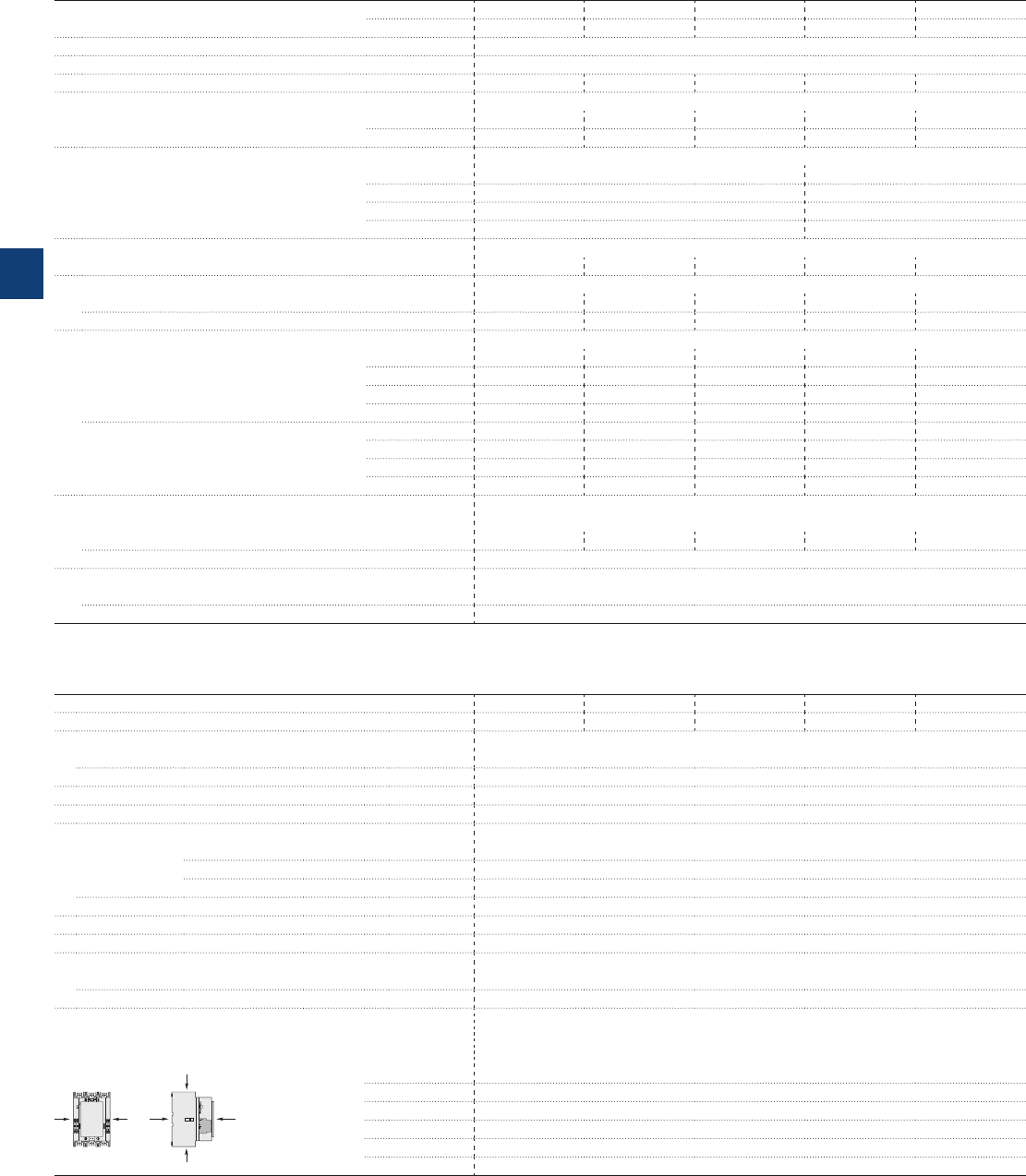
A145 … A300 and
AF145 … AF300 3-pole contactors
Technical data
Main pole - Utilization characteristics according to UL / NEMA / CSA
Contactor types AC operated A145 A185 A210 A260 A300
AC / DC operated AF145 AF185 AF210 AF260 AF300
Standards UL 508, CSA C22.2 N°14
Max. operational voltage 600 V
NEMA size 4––5–
NEMA maximum horse power ratings 1-phase, 60 Hz
115 V AC –––––
230 V AC –––––
NEMA maximum horse power ratings 3-phase, 60 Hz
200 V AC 40 hp 75 hp
230 V AC 50 hp 100 hp
460 V AC 100 hp 200 hp
575 V AC 200 hp 200 hp
UL / CSA general use rating
600 V AC 230 A 250 A 300 A 350 A 400 A
UL / CSA maximum 1-phase motor rating
Full load current 240 V AC –––––
Horse power rating 240 V AC –––––
UL / CSA maximum 3-phase motor rating
Full load current (1) 200-208 V AC 119.6 A 149.5 A 166.8 A 220.8 A 285.2 A
220-240 V AC 130 A 145 A 192 A 248 A 248 A
440-480 V AC 124 A 156 A 180 A 240 A 302 A
550-600 V AC 125 A 144 A 192 A 242 A 289 A
Horse power rating (1) 200-208 V AC 40 hp 50 hp 60 hp 75 hp 100 hp
220-240 V AC 50 hp 60 hp 75 hp 100 hp 100 hp
440-480 V AC 100 hp 125 hp 150 hp 200 hp 250 hp
550-600 V AC 125 hp 150 hp 200 hp 250 hp 300 hp
Short-circuit protection device for contactors
without thermal overload relay - Motor protection excluded
Fuse rating 300 A 400 A 800 A 800 A 800 A
Fuse type, 600 V J/K5
Max. electrical switching frequency
For general use 300 cycles/h
For motor use 300 cycles/h
(1) For the corresponding kW/A or hp/A values of 1500 r.p.m, 50 Hz or 1800 r.p.m, 60 Hz, 3-phase motors, see “Motor rated operational powers and currents”.
General technical data
Contactor types AC operated A145 A185 A210 A260 A300
AC / DC operated AF145 AF185 AF210 AF260 AF300
Rated insulation voltage Ui
acc. to IEC 60947-4-1 1000 V
acc. to UL 600 V
Rated impulse withstand voltage Uimp. 8 kV
Electromagnetic compatibility AF contactors complying with IEC 60947-1 / EN 60947-1 - Environment A
Ambient air temperature close to contactor
Operation Fitted with thermal overload relay -25 to +55 °C
Fitted with electronic overload relay -25 to +70 °C
Without electronic overload relay -40 to +70 °C
Storage -40 to +70 °C
Climatic withstand acc. to IEC 60068-2-30
Maximum operating altitude (without derating) 3000 m
Mechanical durability
Number of operating cycles 5 millions operating cycles
Max. switching frequency 3600 cycles/h (300 for AF… contactors)
Shock withstand
acc. to IEC 60068-2-27 and EN 60068-2-27
Mounting position 1
B2
AAB1
C2
C1
ABB
Shock direction 1/2 sinusoidal shock for 30 ms: no change in contact position, closed or open position
A5 g
B1 5 g
B2 5 g
C1 5 g
C2 5 g
5/34 | ABB
5
1SFC101037C0201
AF400 ... AF2050 3-pole contactors
Technical data
Main pole - Utilization characteristics according to UL / NEMA / CSA
Contactor types AC / DC operated AF400 AF460 AF580 AF750 AF1250 AF1350 AF1650 AF2050
Standards UL 508, CSA C22.2 N°14
Max. operational voltage 600 V
NEMA size –6–7 –8–
NEMA maximum horse power ratings 1-phase, 60 Hz
115 V AC –
230 V AC –
NEMA maximum horse power ratings 3-phase, 60 Hz
200 V AC – 150 hp – – – – –
230 V AC – 200 hp – 300 hp – 450 hp –
460 V AC – 400 hp – 600 hp – 900 hp –
575 V AC – 400 hp – 600 hp – 900 hp –
UL / CSA general use rating
600 V AC 550 A 650 A 750 A 900 A 1210 A 1350 A 1650 A 2100 A
UL / CSA maximum 1-phase motor rating
Full load current 120 V AC ––––––––
240 V AC ––––––––
Horse power rating 120 V AC ––––––––
240 V AC ––––––––
UL / CSA maximum 3-phase motor rating
Full load current (1) 200-208 V AC 358.8 A 414 A 552 A 692.3 A – 954 A 1030 A –
220-240 V AC 360 A 480 A 604 A 722 A – 954 A 1030 A –
440-480 V AC 414 A 477 A 590 A 722 A – 954 A 1030 A –
550-600 V AC 382 A 472 A 578 A 672 A – 944A 1050 A –
Horse power rating (1) 200-208 V AC 125 hp 150 hp 200 hp 250 hp – – – –
220-240 V AC 150 hp 200 hp 250 hp 300 hp – 400 A 450 hp –
440-480 V AC 350 hp 400 hp 500 hp 600 hp – 800 A 900 hp –
550-600 V AC 400 hp 500 hp 600 hp 700 hp – 1000 A 1150 hp –
Short-circuit protection device for contactors
without thermal overload relay - Motor protection excluded
Fuse rating 1000 A 1200 A Please consult us for coordination
with circuit-breaker
Fuse type, 600 V L
Max. electrical switching frequency
For general use 300 cycles/h 60 cycles/h
For motor use 300 cycles/h 60 cycles/h
(1) For the corresponding kW/A or hp/A values of 1500 r.p.m, 50 Hz or 1800 r.p.m, 60 Hz, 3-phase motors, see “Motor rated operational powers and currents”.
General technical data
Contactor types AC / DC operated AF400 AF460 AF580 AF750 AF1250 AF1350 AF1650 AF2050
Rated insulation voltage Ui
acc. to IEC 60947-4-1 1000 V
acc. to UL 600 V
Rated impulse withstand voltage Uimp. 8 kV
Electromagnetic compatibility AF contactors complying with IEC 60947-1 / EN 60947-1 - Environment A
Ambient air temperature close to contactor
Operation Fitted with electronic overload relay -25 to +70 °C
Without electronic overload relay -40 to +70 °C
Storage -40 to +70 °C
Climatic withstand acc. to IEC 60068-2-30
Maximum operating altitude (without derating) 3000 m
Mechanical durability
Number of operating cycles 3 millions operating cycles 0.5 million operating cycles
Max. switching frequency 300 cycles/h 60 cycles/h
Shock withstand
acc. to IEC 60068-2-27 and EN 60068-2-27
Mounting position 1
B2
AAB1
C2
C1
ABB
Shock direction 1/2 sinusoidal shock for 30 ms: no change in contact position, closed or open position
A5 g –
B1 5 g –
B2 5 g –
C1 5 g –
C2 5 g –
ABB | 5/35
5
1SFC101038C0201
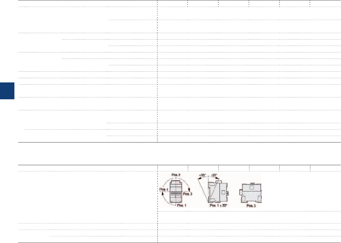
AF09 ... AF38 3-pole contactors
Technical data
Magnet system characteristics
Contactor types AC / DC operated AF09 AF12 AF16 AF26 AF30 AF38
Coil operating limits AC supply At θ ≤ 60 °C 0.85 x Uc min...1.1 x Uc max.
At θ ≤ 70 °C 0.85 x Uc min...Uc max.
acc. to IEC 60947-4-1
DC supply At θ ≤ 60 °C 0.85 x Uc min...1.1 x Uc max.
At θ ≤ 70 °C (AF) 0.85 x Uc min...Uc max. - (AF..Z) 0.85 x Uc min...1.1 x Uc max.
AC control voltage Rated control circuit voltage Uc 24...500 V AC
50/60 Hz Coil consumption Average pull-in value (AF) 50 VA - (AF..Z) 16 VA
Average holding value (AF) 2.2 VA / 2 W - (AF..Z) 1.7 VA / 1.5 W
DC control voltage Rated control circuit voltage Uc 12...500 V DC
Coil consumption Average pull-in value (AF) 50 W - (AF..Z) 12...16 W
Average holding value (AF) 2 W - (AF..Z) 1.7 W
PLC-output control (AF..Z) ≥ 500 mA 24 V DC
Drop-out voltage ≤ 60 % of Uc min.
Voltage sag immunity (AF..Z) conditions of use on request
acc. to SEMI F47-0706
Dips withstand (AF..Z) 22 ms average
-20 °C ≤ θ ≤ +60°C
Operating time
Between coil energization and: N.O. contact closing 40...95 ms
N.C. contact opening 38...90 ms
Between coil de-energization and: N.O. contact opening 11...95 ms
N.C. contact closing 13...98 ms
Mounting characteristics and conditions for use
Contactor types AC / DC operated AF09 AF12 AF16 AF26 AF30 AF38
Mounting positions
Max. N.C. built-in and add-on N.C. auxiliary contacts:
see accessory fitting details for a 3-pole contactor AF09 ... AF38
Mounting distances The contactors can be assembled side by side
Fixing On rail according to IEC 60715, EN 60715 35 x 7.5 mm or 35 x 15 mm
By screws (not supplied) 2 x M4 screws placed diagonally
5/36 | ABB
5
1SBC101427S0201
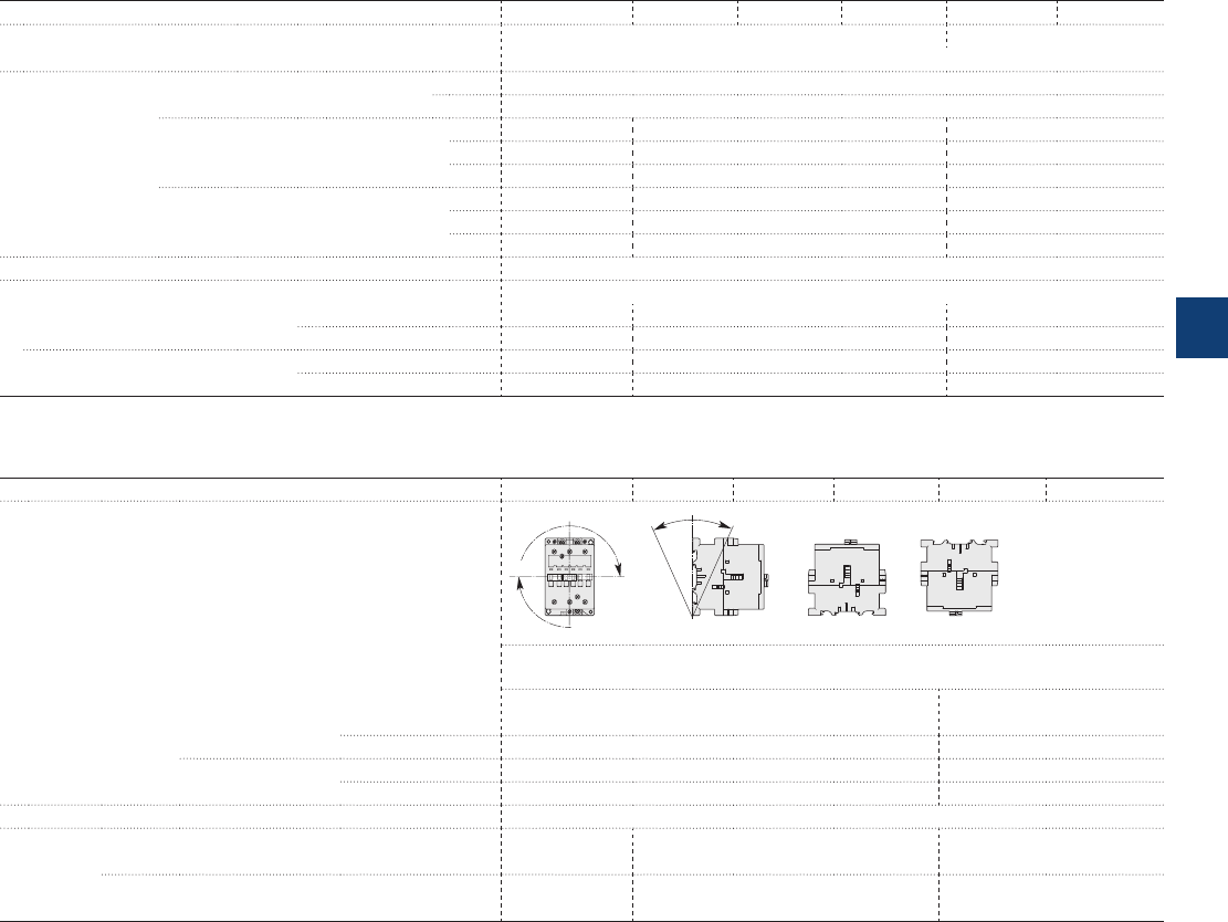
A40 … A110 3-pole contactors
Technical data
Magnet system characteristics
Contactor types AC operated A40 A50 A63 A75 A95 A110
Coil operating limits AC supply At θ ≤ 55 °C 0.85...1.1 x Uc at θ ≤ 70 °C 0.85...1.1 x Uc
acc. to IEC 60947-4-1 Please also refer to "Mounting characteristics and conditions for use"
AC control voltage Rated control circuit voltage Uc at 50 Hz 24…690 V
at 60 Hz 24…690 V
Coil consumption Average pull-in value 50 Hz 120 VA 180 VA 350 VA
60 Hz 140 VA 210 VA 450 VA
50/60 Hz (1) 125 VA / 120 VA 190 VA / 180 VA 410 VA / 365 VA
Average holding value 50 Hz 12 VA / 3 W 18 VA / 5.5 W 22 VA / 6.5 W
60 Hz 12 VA / 3 W 18 VA / 5.5 W 26 VA / 8 W
50/60 Hz (1) 12 VA / 3 W 18 VA / 5.5 W 27 VA / 7.5 W
Drop-out voltage Approx. 40...65 % of Uc
Operating time
Between coil energization and: N.O. contact closing 8…21 ms 8…27 ms 10…25 ms
N.C. contact opening 6…18 ms 7…22 ms 7…22 ms
Between coil de-energization and: N.O. contact opening 4…11 ms 4…11 ms 7…15 ms
N.C. contact closing 7…14 ms 7…14 ms 10…18 ms
(1) 50/60 Hz coils: see "Voltage code table".
Mounting characteristics and conditions for use
Contactor types AC operated A40 A50 A63 A75 A95 A110
Mounting positions
Pos. 5 Pos. 6
Pos. 3
Pos. 2
Pos. 1 Pos. 1 ± 30°
+30° -30°
Pos. 4
Max. built-in and add-on N.O. or N.C. auxiliary contacts: see accessory fitting details for 3-pole
contactor A40 ... A110
Control voltage / Ambient temperature
Mounting
positions
1, 1±30°, 2, 3, 4, 5 at θ ≤ 55 °C 0.85…1.1 x Uc 0.85…1.1 x Uc
at θ ≤ 70 °C Uc 0.85…1.1 x Uc
6at θ ≤ 55 °C
0.95...1.1 x Uc
Unauthorized
at θ ≤ 70 °C Unauthorized Unauthorized
Mounting distances The contactors can be assembled side by side
Fixing On rail according to IEC 60715, EN 60715 35 x 7.5 mm or
35 x 15 mm
35 x 15 mm or
75 x 25 mm
–
By screws (not supplied) 2 x M4 screws
placed diagonally
2 x M6 screws
placed diagonally
2 x M6 screws
placed diagonally
ABB | 5/37
5
1SBC101436S0201
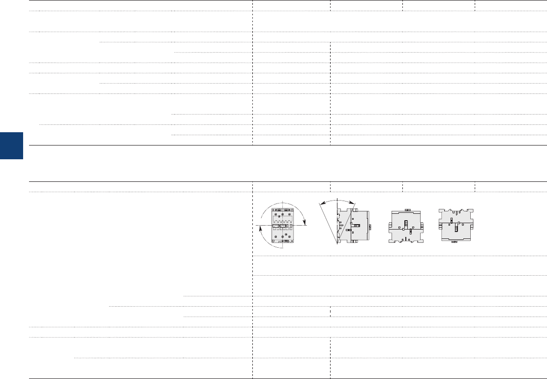
AL40 and AE50 … AE75 3-pole contactors
Technical data
Magnet system characteristics
Contactor types DC operated AL40 AE50 AE63 AE75
Coil operating limits DC supply at θ ≤ 55 °C 0.85...1.1 x Uc
Please also refer to "Mounting characteristics and conditions for use"
acc. to IEC 60947-4-1
DC control voltage Rated control circuit voltage Uc 12...250 V DC
Coil consumption Average pull-in value 3.5 W 200 W
Average holding value 3.5 W 4 W
Drop-out voltage approx. 10...30 % of Uc approx. 15...40 % of Uc
Coil time constant Open L/R 38 ms 3 ms
Closed L/R 62 ms 15 ms
Operating time
Between coil energization and: N.O. contact closing 55…110 ms 13…30 ms
N.C. contact opening 25…75 ms 10…27 ms
Between coil de-energization and: N.O. contact opening (1) 12…18 ms 5…15 ms
N.C. contact closing (1) 18…28 ms 8…18 ms
(1) The use of surge suppressors increases the opening time with a factor of 1.1 to 1.5 for a RV5 surge suppressor and a factor of 1.5 to 3 for a RT5 surge suppressor.
Mounting characteristics and conditions for use
Contactor types DC operated AL40 AE50 AE63 AE75
Mounting positions
Pos. 5 Pos. 6
Pos. 3
Pos. 2
Pos. 1 Pos. 1 ± 30°
+30° -30°
Pos. 4
Max. built-in and add-on N.O. or N.C. auxiliary contacts:
see accessory fitting details for 3-pole contactor AL40, AE50 … AE75
Control voltage / Ambient temperature
Mounting
positions
1, 1±30°, 2, 3, 4, 5 at θ ≤ 55 °C 0.85 x Uc…1.1 x Uc
at θ ≤ 70 °C Uc
6at θ ≤ 55 °C Unauthorized 0.95 x Uc…1.1 x Uc
at θ ≤ 70 °C Unauthorized
Mounting distances The contactors can be assembled side by side
Fixing On rail according to IEC 60715, EN 60715 35 x 7.5 mm or
35 x 15 mm
35 x 15 mm or 75 x 25 mm
By screws (not supplied) 2 x M4 screws
placed diagonally
2 x M6 screws placed diagonally
5/38 | ABB
5
1SBC101438S0201
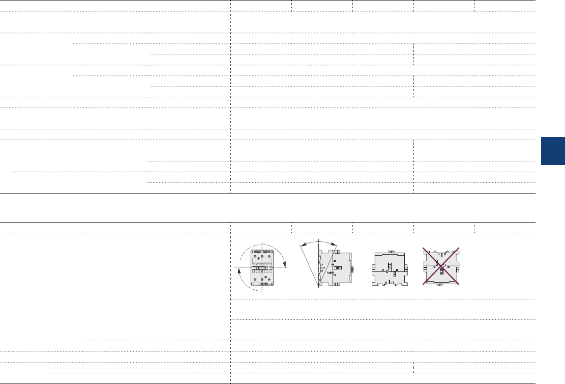
AF50 … AF110 3-pole contactors
Technical data
Magnet system characteristics
Contactor types AC / DC operated AF50 AF63 AF75 AF95 AF110
Coil operating limits AC or DC supply At θ ≤ 70 °C 0.85 x Uc min...1.1 x Uc max.
Please also refer to "Mounting characteristics and conditions for use"
acc. to IEC 60947-4-1
AC control voltage Rated control circuit voltage Uc 48…250 V 50/60 Hz
50/60 Hz Coil consumption Average pull-in value 210 VA 350 VA
Average holding value 7 VA / 2.8 W 7 VA / 3.5 W
DC control voltage Rated control circuit voltage Uc 20…250 V DC
Coil consumption Average pull-in value 190 W 400 W
Average holding value 2.8 W 2 W
Drop-out voltage 55 % of Uc min.
Voltage sag immunity Conditions of use on request
acc. to SEMI F47
Dips withstand ≥ 20 ms
Operating time
Between coil energization and: N.O. contact closing 30…100 ms 30…80 ms
N.C. contact opening 27…95 ms 27…77 ms
Between coil de-energization and: N.O. contact opening 30…110 ms 55…125 ms
N.C. contact closing 35…115 ms 60…130 ms
Mounting characteristics and conditions for use
Contactor types AC / DC operated AF50 AF63 AF75 AF95 AF110
Mounting positions
Pos. 5 Pos. 6
Pos. 3
Pos. 2
Pos. 1 Pos. 1 ± 30°
+30° -30°
Pos. 4
Max. built-in and add-on N.O. or N.C. auxiliary contacts:
see accessory fitting details for 3-pole contactor AF50 ... AF110
Control voltage / Ambient temperature
Mounting
positions
1, 1±30°, 2, 3, 4, 5 at θ ≤ 70 °C 0.85 x Uc min…1.1 x Uc max.
6 Unauthorized
Mounting distances The contactors can be assembled side by side
Fixing On rail according to IEC 60715, EN 60715 35 x 15 mm or 75 x 25 mm –
By screws (not supplied) 2 x M6 screws placed diagonally
ABB | 5/39
5
1SBC101437S0201
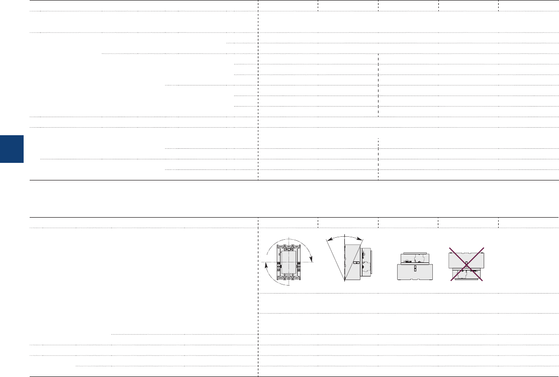
A145 … A300 3-pole contactors
Technical data
Magnet system characteristics
Contactor types AC operated A145 A185 A210 A260 A300
Coil operating limits AC supply At θ ≤ 70 °C 0.85...1.1 x Uc
acc. to IEC 60947-4-1 Please also refer to "Mounting characteristics and conditions for use"
AC control voltage Rated control circuit voltage Uc at 50 Hz 24…690 V
at 60 Hz 24…690 V
Coil consumption Average pull-in value 50 Hz 550 VA 1350 VA
60 Hz 600 VA 1550 VA
50/60 Hz (1) 700 VA / 650 VA 1700 VA / 1550 VA
Average holding value 50 Hz 35 VA / 11 W 60 VA / 16 W
60 Hz 40 VA / 12 W 65 VA / 19 W
50/60 Hz (1) 44 VA / 13 W 80 VA / 21 W
Drop-out voltage Approx. 40…65% of Uc min.
Operating time
Between coil energization and: N.O. contact closing 13…27 ms 17…35 ms
N.C. contact opening 8…22 ms 12…30 ms
Between coil de-energization and: N.O. contact opening 5…10 ms 7…13 ms
N.C. contact closing 9…13 ms 10…16 ms
(1) 50/60 Hz coils: see "Voltage code table".
Mounting characteristics and conditions for use
Contactor types AC operated A145 A185 A210 A260 A300
Mounting positions
Pos. 5
Pos. 3
Pos. 2
Pos. 1 Pos. 1 ± 30°
+30° -30°
Pos. 4
Pos. 6
Max. add-on N.O. or N.C. auxiliary contacts: see accessory fitting details for 3-pole contactor
A145 ... A300
Control voltage / Ambient temperature
Mounting
positions
1, 1±30°, 2, 3, 4, 5 at θ ≤ 70 °C 0.85 x Uc…1.1 x Uc
6 Unauthorized
Mounting distances The contactors can be assembled side by side
Fixing On rail according to IEC 60715, EN 60715 –
By screws (not supplied) 4 x M5
5/40 | ABB
5
1SFC101039C0201

AF145 … AF300 3-pole contactors
Technical data
Magnet system characteristics
Contactor types AC / DC operated AF145 AF185 AF210 AF260 AF300
Coil operating limits AC or DC supply At θ ≤ 70 °C 0.85 x Uc min...1.1 x Uc max.
Please also refer to "Mounting characteristics and conditions for use"
acc. to IEC 60947-4-1
AC control voltage Rated control circuit voltage Uc 48…250 V AC
50/60 Hz Coil consumption Average pull-in value 430 VA 470 VA
Average holding value 12 VA / 3.5 W 10 VA / 2.5 W
DC control voltage Rated control circuit voltage Uc 20…250 V DC
Coil consumption Average pull-in value 500 W 520 W
Average holding value 2 W 2 W
Drop-out voltage 55 % of Uc min.
Voltage sag immunity Conditions of use on request
acc. to SEMI F47
Dips withstand ≥ 20 ms
Operating time
Between coil energization and: N.O. contact closing 30…115 ms
N.C. contact opening 30…115 ms
Between coil de-energization and: N.O. contact opening 25…80 ms
N.C. contact closing 25…80 ms
Mounting characteristics and conditions for use
Contactor types AC / DC operated AF145 AF185 AF210 AF260 AF300
Mounting positions
Pos. 5 Pos. 6
Pos. 3
Pos. 2
Pos. 1 Pos. 1 ± 30°
+30° -30°
Pos. 4
Max. add-on N.O. or N.C. auxiliary contacts: see accessory fitting details for 3-pole contactor
AF145 ... AF2050
Control voltage / Ambient temperature
Mounting
positions
1, 1±30°, 2, 3, 4, 5 at θ ≤ 70 °C 0.85 x Uc min…1.1 x Uc max.
6 Unauthorized
Mounting distances The contactors can be assembled side by side
Fixing On rail according to IEC 60715, EN 60715 –
By screws (not supplied) 4 x M5
ABB | 5/41
5
1SFC101040C0201
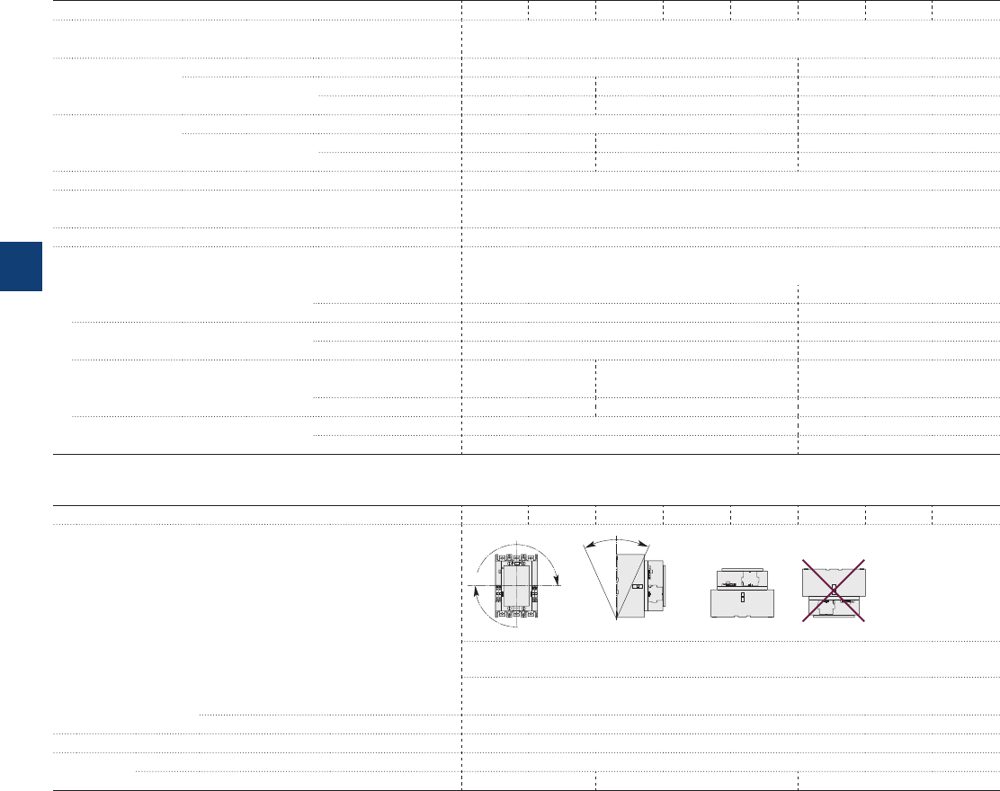
AF400 ... AF2050 3-pole contactors
Technical data
Magnet system characteristics
Contactor types AC / DC operated AF400 AF460 AF580 AF750 AF1250 AF1350 AF1650 AF2050
Coil operating limits AC or DC supply At θ ≤ 70 °C 0.85 x Uc min...1.1 x Uc max.
Please also refer to "Mounting characteristics and conditions for use"
acc. to IEC 60947-4-1
AC control voltage Rated control circuit voltage Uc 48…500 V AC 100…250 V
50/60 Hz Coil consumption Average pull-in value 890 VA 850 VA 1900 VA
Average holding value 12 VA / 4 W 12 VA / 4.5 W 48 VA / 17 W
DC control voltage Rated control circuit voltage Uc 24…500 V DC 100…250 V
Coil consumption Average pull-in value 990 W 950 W 1700 W
Average holding value 4 W 4.5 W 16 W
Drop-out voltage 55 % of Uc min.
Voltage sag immunity Conditions of use on request
acc. to SEMI F47
Dips withstand ≥ 20 ms
Operating time
Coil supply between A1 - A2
Between coil energization and: N.O. contact closing 50…120 ms 50…80 ms
N.C. contact opening 50…120 ms 50…80 ms
Between coil de-energization and: N.O. contact opening 33…70 ms 35…55 ms
N.C. contact closing 33…70 ms 35…55 ms
Control input for PLC's
Between coil energization and: N.O. contact closing 40…60 ms 40...90 ms 40…65 ms
N.C. contact opening 40…60 ms 40...90 ms 40…65 ms
Between coil de-energization and: N.O. contact opening 10…30 ms 10…30 ms
N.C. contact closing 10…30 ms 10…30 ms
Mounting characteristics and conditions for use
Contactor types AC / DC operated AF400 AF460 AF580 AF750 AF1250 AF1350 AF1650 AF2050
Mounting positions
Pos. 5 Pos. 6
Pos. 3
Pos. 2
Pos. 1 Pos. 1 ± 30°
+30° -30°
Pos. 4
Max. add-on N.O. or N.C. auxiliary contacts: see accessory fitting details for 3-pole contactor
AF400 ... AF2050
Control voltage / Ambient temperature
Mounting
positions
1, 1±30°, 2, 3, 4, 5 at θ ≤ 70 °C 0.85 x Uc min…1.1 x Uc max.
6 Unauthorized
Mounting distances The contactors can be assembled side by side
Fixing On rail according to IEC 60715, EN 60715 –
By screws (not supplied) 4 x M5 4 x M6 4 x M8
5/42 | ABB
5
1SFC101041C0201
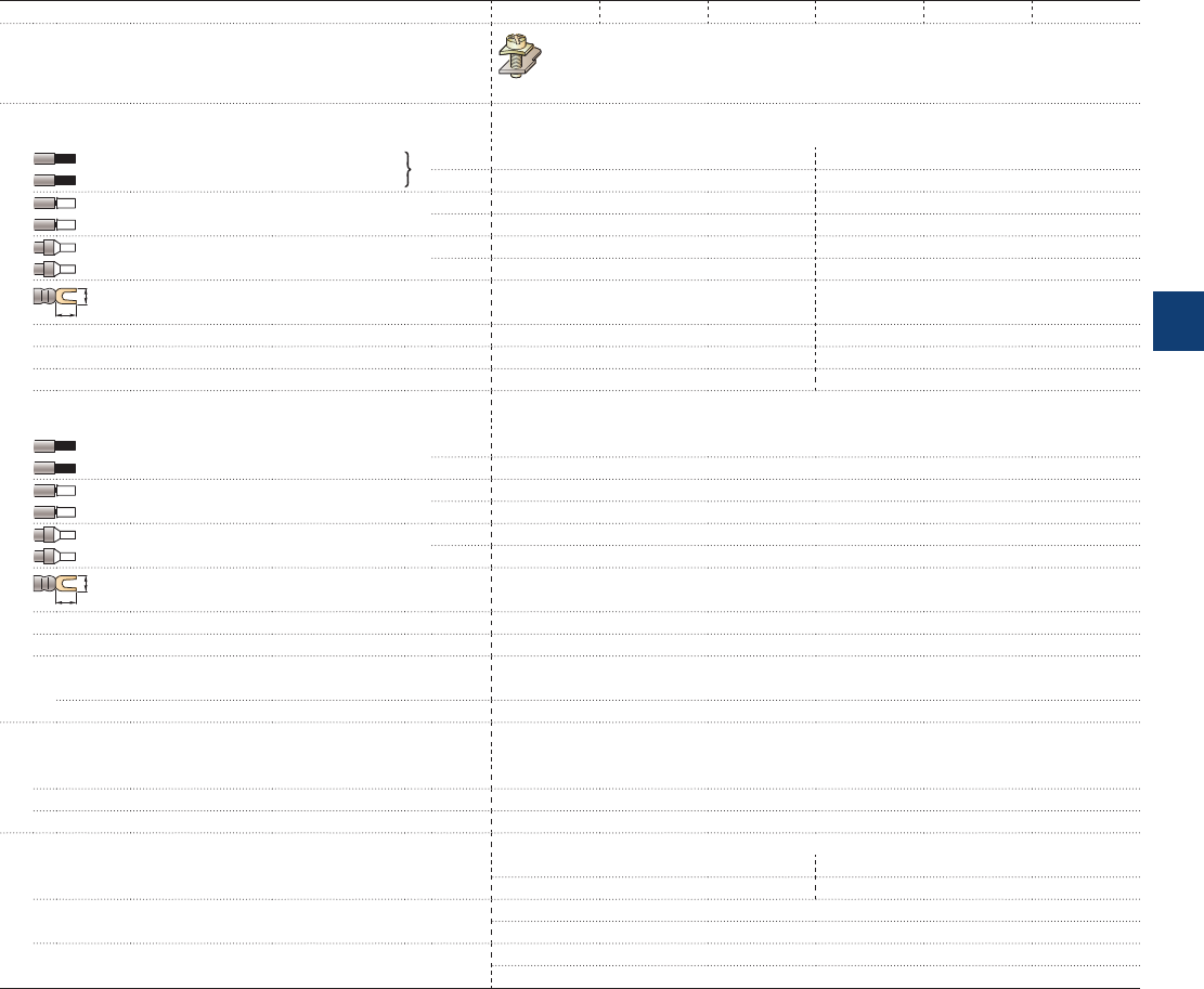
AF09 ... AF38 3-pole contactors
Technical data
Connecting characteristics
Contactor types AC / DC operated AF09 AF12 AF16 AF26 AF30 AF38
Main terminals
Screw terminals with cable clamp
Connection capacity (min. ... max.)
Main conductors (poles)
Rigid Solid (≤ 4 mm²) 1 x 1...6 mm² 2.5...10 mm²
Stranded (≥ 6 mm²) 2 x 1...6 mm² 2.5...10 mm²
Flexible with non insulated ferrule 1 x 0.75...6 mm² 1.5...10 mm²
2 x 0.75...6 mm² 1.5...10 mm²
Flexible with insulated ferrule 1 x 0.75...4 mm² 1.5...10 mm²
2 x 0.75...2.5 mm² 1.5...4 mm²
L
6
Bars or lugs L < 9.6 mm 12.5 mm
Connection capacity acc. to UL/CSA 1 or 2 x AWG 16...10 AWG 14...8
Stripping length 10 mm 14 mm
Tightening torque 1.5 Nm / 13 lb.in 2.5 Nm / 22 lb.in
Auxiliary conductors
(built-in auxiliary terminals + coil terminals)
Rigid solid 1 x 1...2.5 mm²
2 x 1...2.5 mm²
Flexible with non insulated ferrule 1 x 0.75...2.5 mm²
2 x 0.75...2.5 mm²
Flexible with insulated ferrule 1 x 0.75...2.5 mm²
2 x 0.75...1.5 mm²
L
6
Lugs L < 8 mm
Connection capacity acc. to UL/CSA 1 or 2 x AWG 18...14
Stripping length 10 mm
Tightening torque
Coil terminals 1.2 Nm / 11 lb.in
Built-in auxiliary terminals 1.2 Nm / 11 lb.in
Degree of protection
acc. to IEC 60947-1 / EN 60947-1 and IEC 60529 / EN 60529
Main terminals IP20
Coil terminals IP20
Built-in auxiliary terminals IP20
Screw terminals Delivered in open position, screws of unused terminals must be tightened
Main terminals M3.5 M4
Screwdriver type Flat Ø 5.5 / Pozidriv 2 Flat Ø 6.5 / Pozidriv 2
Coil terminals M3.5
Screwdriver type Flat Ø 5.5 / Pozidriv 2
Built-in auxiliary terminals M3.5
Screwdriver type Flat Ø 5.5 / Pozidriv 2
ABB | 5/43
5
1SBC101428S0201
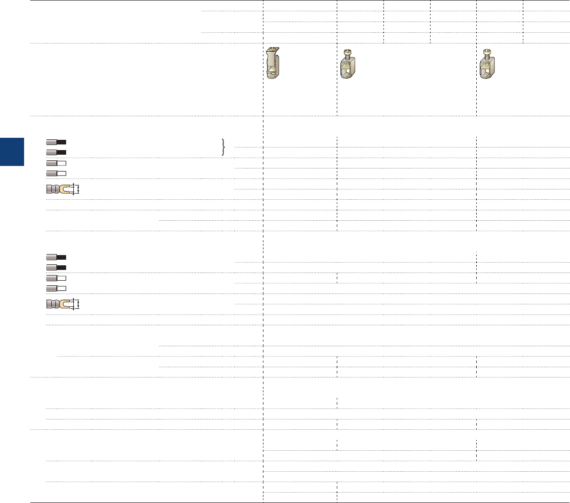
A40 … A110, AL, AE, TAL, TAE and
AF50 … AF110 3-pole contactors
Technical data
Connecting characteristics
Contactor types AC operated A40 A50 A63 A75 A95 A110
DC operated AL40 AE50 AE63 AE75 ––
TAL40 TAE50 –TAE75 ––
AC / DC operated –AF50 AF63 AF75 AF95 AF110
Main terminals
Screw terminals
with double
connector
2 x (5.6 x 6.5 mm)
Screw terminals
with single
connector
(13 x 10 mm)
Screw terminals
with single
connector
(14 x 14 mm)
Connection capacity (min. ... max.)
Main conductors (poles)
Rigid Solid (≤ 4 mm²) 1 x 2.5...16 mm² 6...50 mm² 10...95 mm²
Stranded (≥ 6 mm²) 2 x 2.5...16 mm² 6...25 mm² 6...35 mm²
Flexible with ferrule 1 x 2.5...10 mm² 6...35 mm² 10…70 mm² (1)
2 x 2.5...10 mm² 6...16 mm² 6…35 mm² (1)
L
l
Bars or lugs L ≤ – – 30 mm (2)
l > – – 6 mm
Connection capacity acc. to UL/CSA 1 or 2 x AWG 8…4 AWG 8…1 AWG 6…2/0
Tightening torque Recommended 2.30 Nm / 20 lb.in 4.00 Nm / 35 lb.in 8 Nm / 71 lb.in
Max. 2.60 Nm 4.50 Nm 9 Nm
Auxiliary conductors
(built-in auxiliary terminals + coil terminals)
Rigid solid 1 x 1…4 mm² 0.75…2.5 mm²
2 x 1…4 mm² 0.75…2.5 mm²
Flexible with ferrule 1 x 0.75…2.5 mm² 1…2.5 mm² 0.75…2.5 mm²
2 x 0.75…2.5 mm²
L
l
Lugs L ≤ 8 mm
l > 3.7 mm
Connection capacity acc. to UL/CSA 1 or 2 x AWG 18...14
Tightening torque
Coil terminals Recommended 1.00 Nm / 9 lb.in
Max. 1.20 Nm
Built-in auxiliary terminals Recommended 1.00 Nm / 9 lb.in – –
Max. 1.20 Nm – –
Degree of protection
acc. to IEC 60947-1 / EN 60947-1 and IEC 60529 / EN 60529
Main terminals IP20 IP10
Coil terminals IP20
Built-in auxiliary terminals IP20 – –
Screw terminals Delivered in open position, screws of unused terminals must be tightened
Main terminals M5 M6 M8
Screwdriver type Flat Ø 6.5 / Pozidriv 2 Hexagon socket (s = 4 mm)
Coil terminals M3.5
Screwdriver type Flat Ø 5.5 / Pozidriv 2
Built-in auxiliary terminals M3.5 –
Screwdriver type Flat Ø 5.5 / Pozidriv 2 –
(1) A(F)95 / A(F)110: use flexible without ferrule.
(2) With LW110 enlargement piece, see “Accessories”.
5/44 | ABB
5
1SBC101441S0201
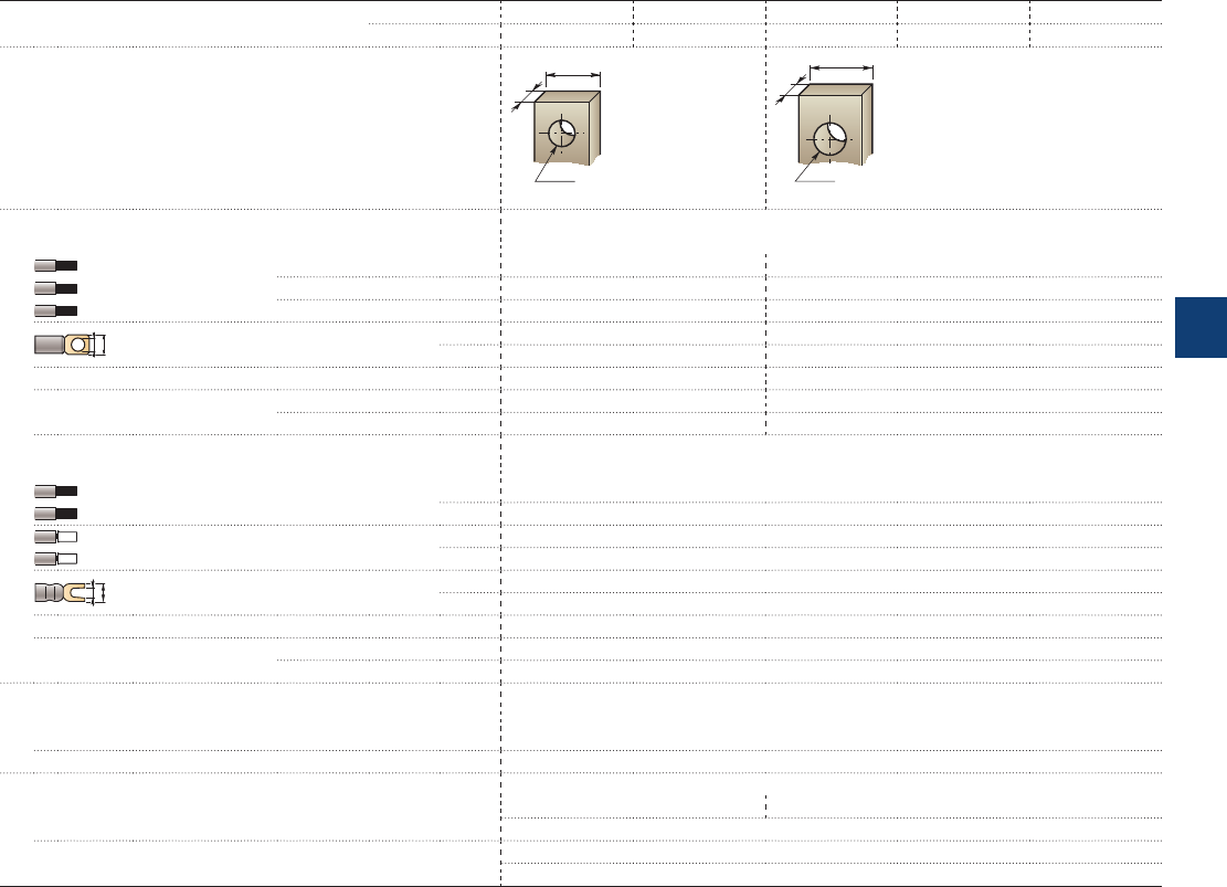
A145 … A300 and
AF145 … AF300 3-pole contactors
Technical data
Connecting characteristics
Contactor types AC operated A145 A185 A210 A260 A300
AC / DC operated AF145 AF185 AF210 AF260 AF300
Main terminals
Flat type
E1858D
17.5
ø 8.5
5
E1859D
20
ø 10.2
5
Connection capacity (min. ... max.)
Main conductors (poles)
Rigid with
connector
Single for Cu cable 6…185 mm² 16…240 mm²
Single for Al/Cu cable 25…150 mm² 120…240 mm²
Double for Al/Cu cable – 2 x 95…120 mm²
L
ø
Bars or lugs L ≤ 24 mm 32 mm
Ø > 8 mm 10 mm
Connection capacity acc. to UL/CSA 1 or 2 x 6 - 250 MCM 4 - 500 MCM (1)
Tightening torque Recommended 18 Nm / 160 Ib.in 28 Nm / 247 lb.in
Max. 20 Nm 30 Nm
Auxiliary conductors
(coil terminals)
Rigid solid 1 x 1…4 mm²
2 x 1…4 mm²
Flexible with ferrule 1 x 0.75…2.5 mm²
2 x 0.75…2.5 mm²
L
l
Lugs L ≤ 8 mm
l > 3.7 mm
Connection capacity acc. to UL/CSA 1 or 2 x AWG 18…14
Tightening torque Recommended 1.00 Nm / 9 lb.in
Max. 1.20 Nm
Degree of protection
acc. to IEC 60947-1 / EN 60947-1 and IEC 60529 / EN 60529
Main terminals IP00
Coil terminals IP20
Screw terminals
Main terminals M8 M10
Screws and bolts
Coil terminals (delivered in open position) M3.5
Screwdriver type Flat Ø 5.5 mm / Pozidriv 2
(1) With LW110 enlargement piece: see "Accessories".
ABB | 5/45
5
1SFC101042C0201
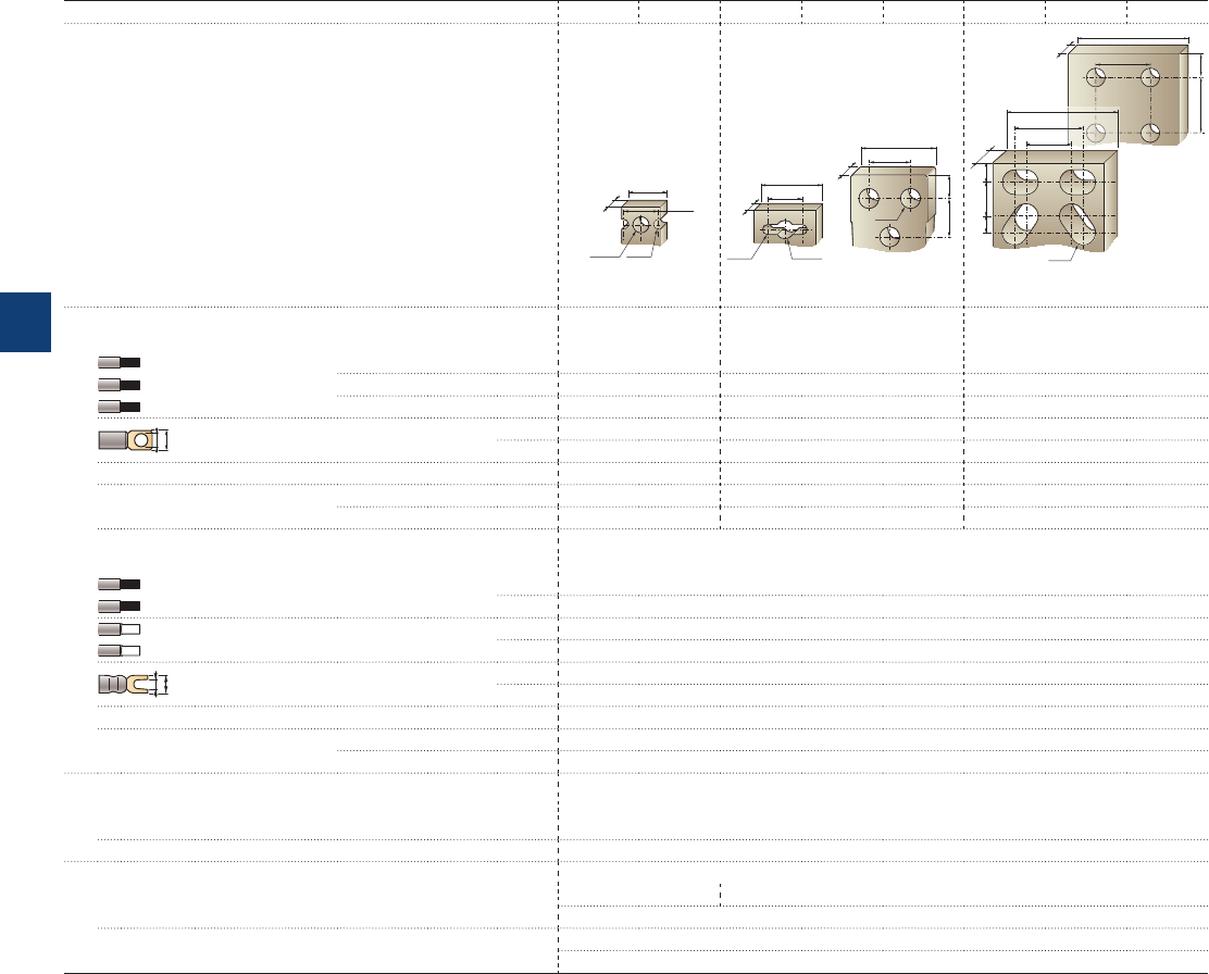
AF400 ... AF2050 3-pole contactors
Technical data
Connecting characteristics
Contactor types AC / DC operated AF400 AF460 AF580 AF750 AF1250 AF1350 AF1650 AF2050
Main terminals
Flat type
ø 10.5
25
ø 6.5
22.5
6
50
8
ø 13
27
25 15.5
ø 12.5
40
ø 6.5
22.5
6
AF1250AF580
AF750
AF2050
AF1350
AF1650
80
10
40
40
17
17
10
ø 13
80
1
0
27
40
30
Connection capacity (min. ... max.)
Main conductors (poles)
Rigid with
connector
Single for Cu cable 240 mm² 300 mm² –
Single for Al/Cu cable 240 mm² 300 mm² –
Double for Al/Cu cable 2 x 240 mm² 3 x 185 mm² –
L
ø
Bars or lugs L ≤ 47 mm 52 mm 100 mm
Ø > 10 mm 12 mm 12 mm
Connection capacity acc. to UL/CSA 1 or 2 x 2//250 - 500 MCM 3// 2/0 - 500 MCM 1/0 - 750 MCM
Tightening torque Recommended 35 Nm / 310 Ib.in 45 Nm / 398 lb.in 45 Nm / 398 lb.in
Max. 40 Nm 49 Nm 49 Nm
Auxiliary conductors
(coil terminals)
Rigid solid 1 x 1…4 mm²
2 x 1…4 mm²
Flexible with ferrule 1 x 0.75…2.5 mm²
2 x 0.75…2.5 mm²
L
l
Lugs L ≤ 8 mm
l > 3.7 mm
Connection capacity acc. to UL/CSA 1 or 2 x AWG 18…14
Tightening torque Recommended 1.00 Nm / 9 lb.in
Max. 1.20 Nm
Degree of protection
acc. to IEC 60947-1 / EN 60947-1 and IEC 60529 / EN 60529
Main terminals IP00
Coil terminals IP20
Screw terminals
Main terminals M10 M12
Screws and bolts
Coil terminals (delivered in open position) M3.5
Screwdriver type Flat Ø 5.5 mm / Pozidriv 2
5/46 | ABB
5
1SFC101043C0201

Built-in auxiliary contacts according to IEC
Contactor types
AC / DC operated
AF09 AF12 AF16 AF26 AF30 AF38
Rated operational voltage Ue max.
690 V
Rated frequency (without derating)
50 / 60 Hz
Conventional free air thermal current Ith - θ ≤ 40 °C
16 A
Ie / Rated operational current AC-15
acc. to IEC 60947-5-1 24-127 V 50/60 Hz 6 A
220-240 V 50/60 Hz 4 A
400-440 V 50/60 Hz 3 A
500 V 50/60 Hz 2 A
690 V 50/60 Hz 2 A
Making capacity AC-15
10 x Ie AC-15 acc. to IEC 60947-5-1
Breaking capacity AC-15
10 x Ie AC-15 acc. to IEC 60947-5-1
Ie / Rated operational current DC-13
acc. to IEC 60947-5-1 24 V DC 6 A / 144 W
48 V DC 2.8 A / 134 W
72 V DC 1 A / 72 W
110 V DC 0.55 A / 60 W
125 V DC 0.55 A / 69 W
220 V DC 0.27 A / 60 W
250 V DC 0.27 A / 68 W
400 V DC 0.15 A / 60 W
500 V DC 0.13 A / 65 W
600 V DC 0.1 A / 60 W
Short-circuit protection device gG type fuse
10 A
Rated short-time withstand current Icw
for 1.0 s 100 A
for 0.1 s 140 A
Minimum switching capacity
12 V / 3 mA
with failure rate acc. to IEC 60947-5-4 10
-7
Non-overlapping time between N.O. and N.C. contacts
≥ 2 ms
Power dissipation per pole at 6 A
0.1 W
Max. electrical switching frequency
AC-15 1200 cycles/h
DC-13 900 cycles/h
Mechanically linked contacts
Built-in N.O. or N.C. auxiliary contacts and additional N.O. or N.C. auxiliary contacts (CA4, CAL4, CAT4
aux. contact blocks) are mechanically linked contacts.
acc. to annex L of IEC 60947-5-1
Mirror contacts
Built-in N.C. auxiliary contacts or additional N.C. auxiliary contacts (CA4, CAL4, CAT4 aux. contact blocks)
are mirror contacts.
acc. to annex F of IEC 60947-4-1
Built-in auxiliary contacts according to UL / CSA
Contactor types
AC / DC operated
AF09 AF12 AF16 AF26 AF30 AF38
Max. operational voltage
600 V AC, 600 V DC
Pilot duty
A600, Q600
AC thermal rated current 10 A
AC maximum volt-ampere making 7200 VA
AC maximum volt-ampere breaking 720 VA
DC thermal rated current 2.5 A
DC maximum volt-ampere making-breaking 69 VA
AF09 ... AF38 3-pole contactors
Technical data
ABB | 5/47
5
1SBC101445S0201

Built-in auxiliary contacts according to IEC
Contactor types
AC operated
A40
DC operated
AL40, TAL40
Rated operational voltage Ue max.
690 V
Rated frequency (without derating)
50/60 Hz
Conventional free air thermal current Ith - θ ≤ 40 °C
16 A
Ie / Rated operational current AC-15
acc. to IEC 60947-5-1 24-127 V 50/60 Hz 6 A
220-240 V 50/60 Hz 4 A
380-440 V 50/60 Hz 3 A
500 V 50/60 Hz 2 A
690 V 50/60 Hz 2 A
Making capacity AC-15
10 x Ie AC-15 acc. to IEC 60947-5-1
Breaking capacity AC-15
10 x Ie AC-15 acc. to IEC 60947-5-1
Ie / Rated operational current DC-13
acc. to IEC 60947-5-1 24 V DC 6 A / 144 W
48 V DC 2.8 A / 134 W
72 V DC 2 A / 144 W
110 V DC 1.1 A / 121 W
125 V DC 1.1 A / 138 W
220 V DC 0.55 A / 121 W
250 V DC 0.55 A / 138 W
Short-circuit protection device gG type fuse
10 A
Rated short-time withstand current Icw
for 1.0 s 100 A
for 0.1 s 140 A
Minimum switching capacity
17 V / 5 mA
with failure rate acc. to IEC 60947-5-4 ≤ 10
-7
for AL40 and TAL40 contactors
Non-overlapping time between N.O. and N.C. contacts
≥ 2 ms
Power dissipation per pole at 6 A
0.1 W
Max. electrical switching frequency
AC-15 1200 cycles/h
DC-13 900 cycles/h
Mechanically linked contacts
Built-in N.O. or N.C. auxiliary contacts and additional N.O. or N.C. auxiliary contacts of 4-pole CA5 are
mechanically linked contacts.
acc. to annex L of IEC 60947-5-1
Mirror contacts
Built-in N.C. auxiliary contacts or additional N.C. auxiliary contacts (CA5, CAL5-11) are mirror contacts.
acc. to annex F of IEC 60947-4-1
Built-in auxiliary contacts according to UL / CSA
Contactor types
AC operated
A40
DC operated
AL40, TAL40
Max. operational voltage
600 V AC, 600 V DC
Pilot duty
A600, P300
AC thermal rated current 10 A
AC maximum volt-ampere making 7200 VA
AC maximum volt-ampere breaking 720 VA
DC thermal rated current 5 A
DC maximum volt-ampere making-breaking 138 VA
A40, AL40 and TAL40 3-pole contactors
Technical data
5/48 | ABB
5
1SBC101446S0201

3-pole contactors
Electrical durability and utilization categories
General
Utilization categories determine the current making and breaking conditions relating to the characteristics of the loads to be
controlled by the contactors. International standard IEC 60947-4-1 and European standard EN 60947-4-1 are the standards to
be referred to.
If Ic is the current to be broken by the contactor and Ie the rated operational current normally drawn by the load, then:
– Categories AC-1 and AC-3: Ic = Ie
– Category AC-2: Ic = 2.5 x Ie
– Category AC-4: Ic = 6 x Ie
Generally speaking Ic = m x Ie where m is a multiple of the load operational current.
On next pages, the curves corresponding to categories AC-1, AC-3 and AC-4 represent the electrical durability variation of
standard contactors in relation to the breaking current Ic.
Electrical durability is expressed in millions of operating cycles.
Curve utilization mode
Electrical durability forecast and contactor selection for categories AC-1, AC-2, AC-3 or AC-4
t Note the characteristics of the load to be controlled:
– Operational voltage .......................................... Ue
– Current normally drawn .................................... Ie (Ue / Ie / kW relation for motors, see "Motor rated operational powers and currents").
– Utilization category .......................................... AC-1, AC-2, AC-3 or AC-4
– Breaking current .............................................. Ic = Ie for AC-1 and for AC-3 ; Ic = 2.5 x Ie for AC-2 ; Ic = 6 x Ie for AC-4
t Define the number of operating cycles N required.
t On the diagram corresponding to the operational category, select the contactor with the curve immediately above the inter-
section point (Ic ; N).
Electrical durability forecast and contactor selection for mixed duty motor control: AC-3 (Ic = Ie) type switching off while
"motor running" and, occasionally, AC-4 (Ic = 6 x Ie) type switching off while "motor accelerating"
t Note the characteristics of the motor to be controlled:
– Operational voltage ...................................................... Ue
– Current normally drawn while "motor running" ...............Ie
(Ue / Ie / kW relation for motors, see "Motor rated operational powers and currents")
– Breaking current for AC-3 ............................................Ic = Ie
– Breaking current for AC-4 while "motor accelerating" ..... Ic = 6 x Ie
– Percentage of AC-4 operating cycles ............................ K (on the basis of the total number of operating cycles)
t Define the total number of operating cycles N required.
t Note the smallest contactor rating compatible for AC-3 (Ue / Ie) on Main pole utilization characteristic table (see “Technical data”).
t For the selected contactor make a note of the following in relation to the voltage using diagram AC-3 in next pages:
– The number of operating cycles A for Ic = Ie (AC-3)
– The number of operating cycles B for Ic = 6 x Ie (AC-4)
t Calculate the estimated number of cycles N’ (N’ is always below A)
N'= A
1 + 0.01 K (A/B - 1)
t If N' is too low in relation to the target N, calculate the estimated number of cycles for a higher contactor rating.
Case of uninterrupted duty
For uninterrupted duty, some verifications of preventing maintenance are necessary to check the functionality of the concerned
product (consult us).
The combinated effect of environmental conditions and the proper temperature of the product may require some disposals. As
a matter of fact, for this duty, the use duration prevails over the number of operating cycles.
ABB | 5/49
5
1SBC101314S0201
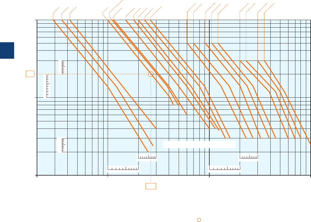
3-pole contactors
Electrical durability
Electrical durability for AC-1 utilization category - Ue ≤ 690 V
Ambient temperature ≤ 60 °C for AF09 ... AF38, ≤ 55 °C for A40 ... AF2050
Switching non-inductive or slightly inductive loads. The breaking current Ic for AC-1 is equal to the rated operational current of
the load.
Maximum electrical switching frequency: see "Technical data".
13579
13579
1
3
5
7
9
1
3
5
7
9
13579
13579
1
3
5
7
9
10
1
0.1
0.2
0.3
0.5
3
5
10 100 10002 3 5 20 30 50 200 300 500
A145
A40
A50
A63
A75
A95
A110
A185
A210
A300
A260
AF400
AF460
AF580
AF750
2
26.5
AF09
AF12
AF16
AF26
AF30, AF38
The curves provided for the A50 ... A300 contactors
can be used for the AE, TAE and AF equivalent types
Millions of
operating
cycles
Breaking current Ic (A)
AF1250, AF1350,
AF1650, AF2050:
The electrical durability at
the rated current is 50000
operating cycles.
Example:
Ic / AC-1 = 26.5 A – Electrical durability required = 2 millions operating cycles.
Using the AC-1 curves above select the AF26 contactor at intersection " " (26.5 A / 2 millions operating cycles).
5/50 | ABB
5
1SBC101511S0201
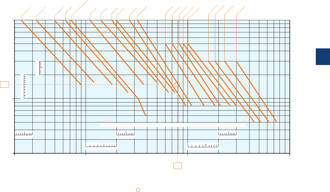
3-pole contactors
Electrical durability
Electrical durability for AC-3 utilization category - Ue ≤ 440 V
Ambient temperature ≤ 60 °C for AF09 ... AF38, ≤ 55 °C for A40 ... AF1650
Switching cage motors: starting and switching off running motors. The breaking current Ic for AC-3 is equal to the rated opera-
tional current Ie (Ie = motor full load current). Maximum electrical switching frequency: see "Technical data".
10
1
10 100 10002 3 5 20 30 50 200 300 500
0.2
0.3
0.5
2
3
5
13579
1
3
5
7
9
1
3
5
7
9
13579 13579
13579 13579
A50
A63
A75
A95
A110
A145
A185
A210
A260
A300
AF400
AF460
AF580
AF750
1.5
79
AF09
AF12
AF16
AF26
A40
AF30, AF38
The curves provided for the A50 ... A300 contactors can be used for the AE, TAE and AF equivalent types
Millions of
operating
cycles
Breaking current Ic (A)
AF1350, AF1650:
The electrical durability at
the rated current is 50000
operating cycles.
Example:
Motor power 40 kW for AC-3 - Ue = 400 V and Ie = 79 A utilization – Electrical durability required = 1.5 million operating cycles.
For AC-3: Ic = Ie. Select the A110 contactor at intersection " " (79 A / 1.5 million operating cycles) on the curves (AC-3 - Ue ≤ 440 V).
ABB | 5/51
5
1SBC101512S0201
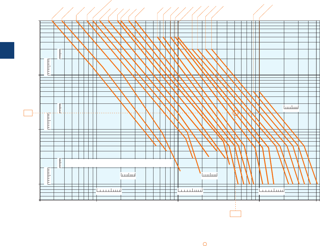
3-pole contactors
Electrical durability
Electrical durability for AC-2 or AC-4 utilization category - Ue < 440 V
Ambient temperature ≤ 60 °C for AF09 ... AF38, ≤ 55 °C for A40 ... AF1650
Switching cage motors: starting, reverse operation and step-by-step operation. The breaking current Ic is equal to 2.5 x Ie for
AC-2 and 6 x Ie for AC-4, keeping in mind that Ie is the motor rated operational current (Ie = motor full-load current).
Maximum electrical switching frequency: see "Technical data".
30001000100102 3 5 20 30 50 200 300 500 2000 5000
10
1
0.1
0.005
0.01
0.02
0.03
0.05
0.3
0.5
2
3
5
13579
13579
13579
13579
13579
13579
1
3
5
7
9
1
3
5
7
9
1
3
5
7
9
1
3
5
7
9
1
3
5
7
9
1
3
5
7
9
A40
A50
A63
A75
A95
A110
A260
A300
A145
A185
A210
0.2
510
AF400
AF460
AF580
AF750
AF1350
AF1650
0.2
510
AF12
AF16
AF09
AF26
AF30, AF38
The curves provided for the A50 ... A300 contactors can be used for the AE,
TAE and AF equivalent types
Millions of
operating
cycles
Breaking current Ic (A)
Example:
Motor power 45 kW for AC-4 - Ue = 400 V and Ie = 85 A utilization – Electrical durability required = 0.2 million operating cycles.
For AC-4: Ic = 6 x Ie = 510 A - Select the A260 contactor at intersection " " (510 A / 0.2 million operating cycles) on the
curves (AC-4 - Ue ≤ 440 V).
5/52 | ABB
5
1SBC101516S0201

Notes
ABB | 5/53
5
N2
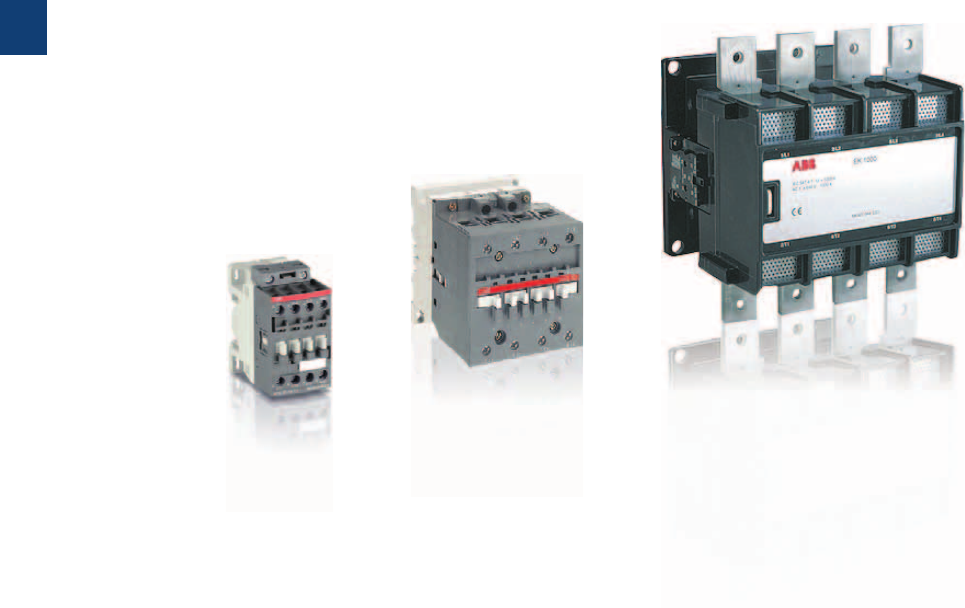
5/54 | ABB
5
1SBC101610S0201

AF, A and EK 4-pole contactors
Overview 5/56
Ordering details
25 to 55 A AC-1
AF09 … AF38 AC / DC operated 5/58
AF09Z … AF38Z AC / DC operated - low consumption 5/59
Main accessories 5/60
70 to 125 A AC-1
A45 … A75 AC operated 5/63
AE45 … AE75 DC operated 5/64
AF45 … AF75 AC / DC operated 5/65
Main accessories 5/66
200 to 1000 A AC-1
EK110 … EK150 AC operated 5/68
EK110 … EK150 DC operated 5/69
EK175 … EK550 AC operated 5/70
EK175 … EK550 DC operated 5/71
EK1000 AC operated 5/72
EK1000 DC operated 5/73
Main accessories 5/74
Technical data
Main pole - Utilization characteristics according to IEC 5/76
Main pole - Utilization characteristics according to UL / CSA 5/76
Magnet system and mounting characteristics 5/79
General technical data 5/84
Connecting characteristics 5/87
Electrical durability 5/90
Accessories
Accessories for
AF09 ... AF38 contactors and NF contactor relays
5/115
Accessories for A40 ... AF2050 contactors 5/121
Accessories for EK100 ... EK1000 contactors 5/147
Voltage code table 5/157
ABB | 5/55
5
1SBC101610S0201
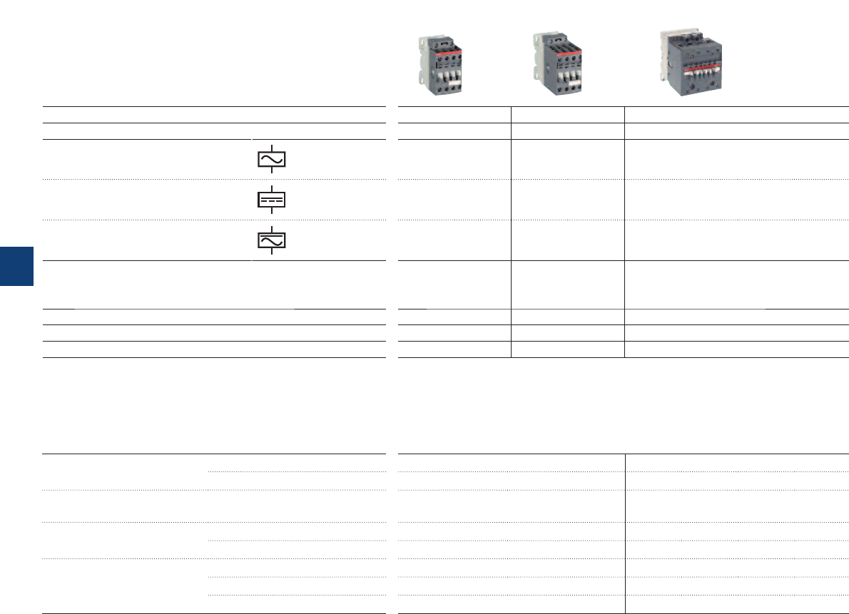
4-pole contactors
Main accessories
Auxiliary contact blocks
Front mounting
Side mounting
Timers
Pneumatic
(Front mounting)
Interlocking units
(compact reversing contactors)
Mechanical
Mechanical / Electrical
Surge suppressors
AF contactors have built-in surge
protection
Varistor (AC / DC)
RC Type (AC)
Transil diode (DC)
CA4-10 (1 x N.O.), CA4-01 (1 x N.C.) CA5-10 (1 x N.O.), CA5-01 (1 x N.C.)
CAL4-11 (1 x N.O. + 1 x N.C.) CAL5-11 (1 x N.O. + 1 x N.C.)
TP40DA, TP180DA Direct timing
TP40IA, TP180IA Inverse timing
VM4
VEM4 VE5-2
RV5 (24…440 V)
RC5-2 (24…440 V)
RT5 (12…264 V)
IEC
AC-1 Rated
operational
current
θ ≤ 40 °C, 690 V
A 25 30455570100125
UL/CSA
General use rating
600 V A25 30 45 55 80 80 105
AC Control supply Type AF09 AF16 AF26 AF38 A45 A50 A75
DC Control supply Type AF09 AF16 AF26 AF38 AE45 AE50 AE75
AC / DC Control supply Type AF09 AF16 AF26 AF38 AF45 AF50 AF75
IEC
AC-1 Rated operational current
θ ≤ 40 °C
A 25 30455570100125
θ ≤ 55 °C (1)
A253040456085105
θ ≤ 70 °C
A22263237507085
With conductor cross sectional area
mm2461016253550
Rated operational voltage Ue max.
V 690 690 690 690 690 690 690
UL/CSA
General use rating
600 V A25 30 45 55 65 80 105
(1)
θ
≤ 60 °C for AF09 ... AF38 contactors
5/56 | ABB
5
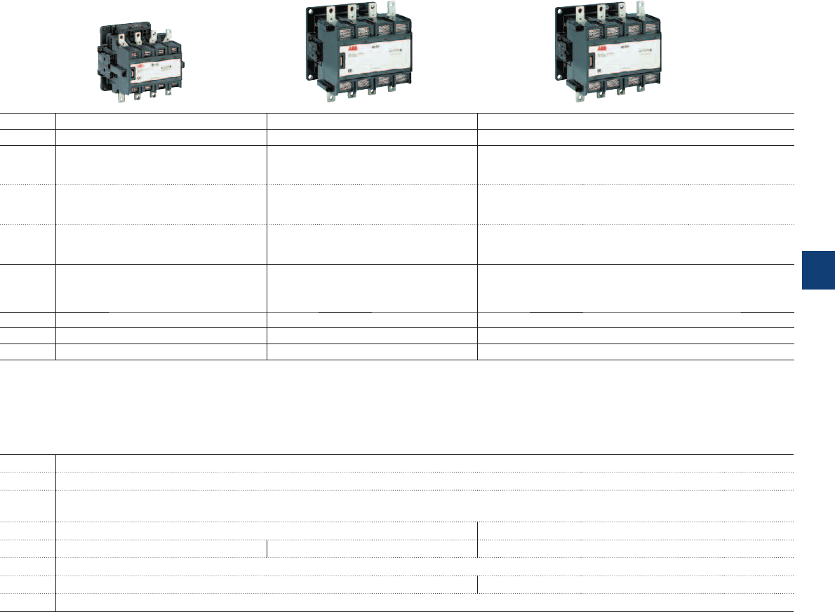
CAL16-11 (1 x N.O. + 1 x N.C.)
VH800
VH145 VH300
RC-EH300 RC-EH800
200 250 300 350 550 800 1000
170 200 250 300 420 540 —
EK110 EK150 EK175 EK210 EK370 EK550 EK1000
EK110 EK150 EK175 EK210 EK370 EK550 EK1000
———————
200 250 300 350 550 800 1000
180 230 270 310 470 650 800
155 200 215 250 400 575 720
95 150 185 240 2 x 185 2 x 240 2 x 300
1000 1000 1000 1000 1000 1000 1000
170 200 250 300 420 540 —
ABB | 5/57
5
1SBC101569S0201
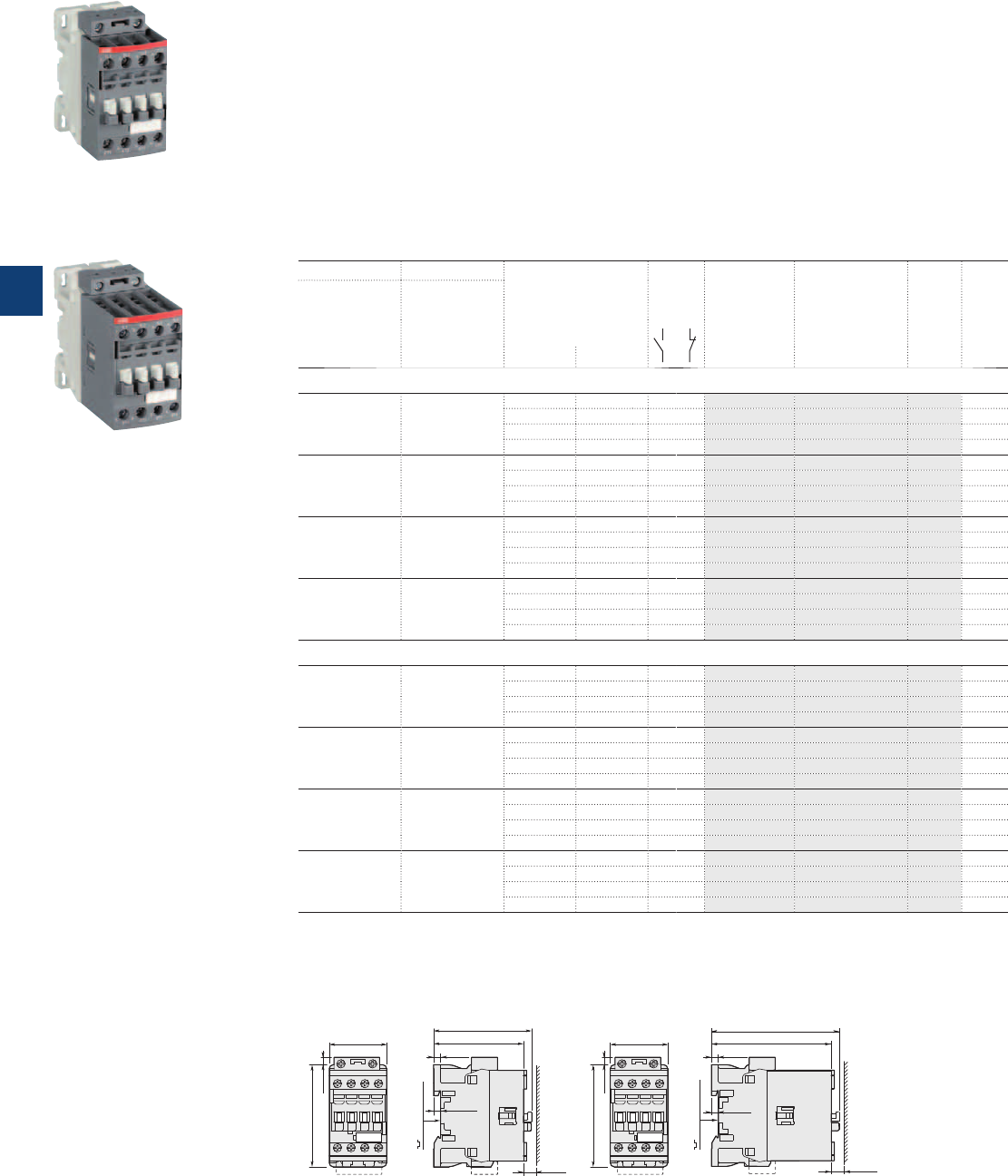
AF09 ... AF38 4-pole contactors
25 to 55 A AC-1
AC / DC operated
Description
AF09...AF38 4-pole contactors are mainly used for controlling non-inductive or slightly inductive loads (i.e.
resistance furnaces...) and generally for controlling power circuits up to 690VAC and 440VDC. These
contactors are of the block type design with 4 main poles.
– control circuit: AC or DC operated with electronic coil interface accepting a wide control voltage range
(e.g. 100...250 V AC and DC), only 4 coils to cover control voltages between 24...500V 50/60Hz and
20...500VDC
- can manage large control voltage variations
- reduced panel energy consumption
- very distinct closing and opening.
– built-in surge suppression
– add-on auxiliary contact blocks for front or side mounting and a wide range of accessories.
Ordering details
IEC UL/CSA Rated control circuit
voltage
Uc min. … Uc max.
Auxiliary
contacts
fitted
Type Order code Weight
Pkg
(1 pce)
Rated operational
current
θ ≤ 40 °C
AC-1
General use
rating
600 V AC
A A V 50/60 Hz V DC kg
4 N.O. main poles
25 25 24...60 20...60 (1) 0 0 AF09-40-00-11 1SBL137201R1100 0.270
48...130 48...130 0 0 AF09-40-00-12 1SBL137201R1200 0.270
100...250 100...250 0 0 AF09-40-00-13 1SBL137201R1300 0.270
250...500 250...500 0 0 AF09-40-00-14 1SBL137201R1400 0.310
30 30 24...60 20...60 (1) 0 0 AF16-40-00-11 1SBL177201R1100 0.270
48...130 48...130 0 0 AF16-40-00-12 1SBL177201R1200 0.270
100...250 100...250 0 0 AF16-40-00-13 1SBL177201R1300 0.270
250...500 250...500 0 0 AF16-40-00-14 1SBL177201R1400 0.310
45 45 24...60 20...60 (1) 0 0 AF26-40-00-11 1SBL237201R1100 0.360
48...130 48...130 0 0 AF26-40-00-12 1SBL237201R1200 0.360
100...250 100...250 0 0 AF26-40-00-13 1SBL237201R1300 0.360
250...500 250...500 0 0 AF26-40-00-14 1SBL237201R1400 0.400
55
55
24...60 20...60 (1) 0 0 AF38-40-00-11 1SBL297201R1100 0.360
48...130 48...130 0 0 AF38-40-00-12 1SBL297201R1200 0.360
100...250 100...250 0 0 AF38-40-00-13 1SBL297201R1300 0.360
250...500 250...500 0 0 AF38-40-00-14 1SBL297201R1400 0.400
2 N.O. + 2 N.C. main poles
25 25 24...60 20...60 (1) 0 0 AF09-22-00-11 1SBL137501R1100 0.270
48...130 48...130 0 0 AF09-22-00-12 1SBL137501R1200 0.270
100...250 100...250 0 0 AF09-22-00-13 1SBL137501R1300 0.270
250...500 250...500 0 0 AF09-22-00-14 1SBL137501R1400 0.310
30 30 24...60 20...60 (1) 0 0 AF16-22-00-11 1SBL177501R1100 0.270
48...130 48...130 0 0 AF16-22-00-12 1SBL177501R1200 0.270
100...250 100...250 0 0 AF16-22-00-13 1SBL177501R1300 0.270
250...500 250...500 0 0 AF16-22-00-14 1SBL177501R1400 0.310
45 45 24...60 20...60 (1) 0 0 AF26-22-00-11 1SBL237501R1100 0.360
48...130 48...130 0 0 AF26-22-00-12 1SBL237501R1200 0.360
100...250 100...250 0 0 AF26-22-00-13 1SBL237501R1300 0.360
250...500 250...500 0 0 AF26-22-00-14 1SBL237501R1400 0.400
55 55 24...60 20...60 (1) 0 0 AF38-22-00-11 1SBL297501R1100 0.360
48...130 48...130 0 0 AF38-22-00-12 1SBL297501R1200 0.360
100...250 100...250 0 0 AF38-22-00-13 1SBL297501R1300 0.360
250...500 250...500 0 0 AF38-22-00-14 1SBL297501R1400 0.400
(1) AF..-..-..-11 not suitable for direct control by PLC-output.
Main dimensions mm, inches
AF09, AF16 AF26, AF38
45 1.77"
80 3.15"
6 0.24"
77 3.03"
71 2.80"
5.5 0.22"
35 mm
EN/IEC 60715
10 0.39"
5.5 0.22"
35 mm
EN/IEC 60715
5.5 0.22"
95 3.74"
101 3.98"
10 0.39"
5.5 0.22"
45 1.77"
80 3.15"
6 0.24"
1SBC101095F0014
AF09-40-00
1SBC101097F0014
AF26-40-00
5/58 | ABB
5
1SBC101375S0201
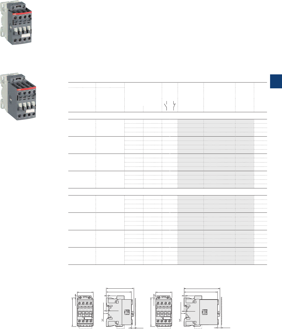
1SBC101095F0014
AF09Z-40-00
1SBC101097F0014
AF26Z-40-00
AF09Z ... AF38Z 4-pole contactors
25 to 55 A AC-1
AC / DC operated - low consumption
Description
AF09Z...AF38Z 4-pole contactors are mainly used for controlling non-inductive or slightly inductive loads
(i.e. resistance furnaces...) and generally for controlling power circuits up to 690VAC and 440VDC. These
contactors are of the block type design with 4 main poles.
– control circuit: AC or DC operated with electronic coil interface accepting a wide control voltage range
(e.g. 100...250VAC and DC), only 4 coils to cover control voltages between 24...250V 50/60Hz and
12...250VDC
- can manage large control voltage variations
- allow direct control by PLC-output ≥ 24VDC 500mA
- reduced panel energy consumption
- very distinct closing and opening
- can withstand short voltage dips and voltage sags (SEMI F47-0706 conditions of use on request).
– built-in surge suppression
– add-on auxiliary contact blocks for front or side mounting and a wide range of accessories.
Ordering details
IEC UL/CSA Rated control circuit
voltage
Uc min. … Uc max.
Auxiliary
contacts
fitted
Type Order code Weight
Pkg
(1 pce)
Rated operational
current
θ ≤ 40 °C
AC-1
General use
rating
600 V AC
A A V 50/60 Hz V DC kg
4 N.O. main poles
25 25 - 12...20 0 0 AF09Z-40-00-20 1SBL136201R2000 0.310
24...60 20...60 0 0 AF09Z-40-00-21 1SBL136201R2100 0.310
48...130 48...130 0 0 AF09Z-40-00-22 1SBL136201R2200 0.310
100...250 100...250 0 0 AF09Z-40-00-23 1SBL136201R2300 0.310
30 30 - 12...20 0 0 AF16Z-40-00-20 1SBL176201R2000 0.310
24...60 20...60 0 0 AF16Z-40-00-21 1SBL176201R2100 0.310
48...130 48...130 0 0 AF16Z-40-00-22 1SBL176201R2200 0.310
100...250 100...250 0 0 AF16Z-40-00-23 1SBL176201R2300 0.310
45 45 - 12...20 0 0 AF26Z-40-00-20 1SBL236201R2000 0.400
24...60 20...60 0 0 AF26Z-40-00-21 1SBL236201R2100 0.400
48...130 48...130 0 0 AF26Z-40-00-22 1SBL236201R2200 0.400
100...250 100...250 0 0 AF26Z-40-00-23 1SBL236201R2300 0.400
55 55 - 12...20 0 0 AF38Z-40-00-20 1SBL296201R2000 0.400
24...60 20...60 0 0 AF38Z-40-00-21 1SBL296201R2100 0.400
48...130 48...130 0 0 AF38Z-40-00-22 1SBL296201R2200 0.400
100...250 100...250 0 0 AF38Z-40-00-23 1SBL296201R2300 0.400
2 N.O. + 2 N.C. main poles
25 25 - 12...20 0 0 AF09Z-22-00-20 1SBL136501R2000 0.310
24...60 20...60 0 0 AF09Z-22-00-21 1SBL136501R2100 0.310
48...130 48...130 0 0 AF09Z-22-00-22 1SBL136501R2200 0.310
100...250 100...250 0 0 AF09Z-22-00-23 1SBL136501R2300 0.310
30 30 - 12...20 0 0 AF16Z-22-00-20 1SBL176501R2000 0.310
24...60 20...60 0 0 AF16Z-22-00-21 1SBL176501R2100 0.310
48...130 48...130 0 0 AF16Z-22-00-22 1SBL176501R2200 0.310
100...250 100...250 0 0 AF16Z-22-00-23 1SBL176501R2300 0.310
45 45 - 12...20 0 0 AF26Z-22-00-20 1SBL236501R2000 0.400
24...60 20...60 0 0 AF26Z-22-00-21 1SBL236501R2100 0.400
48...130 48...130 0 0 AF26Z-22-00-22 1SBL236501R2200 0.400
100...250 100...250 0 0 AF26Z-22-00-23 1SBL236501R2300 0.400
55 55 - 12...20 0 0 AF38Z-22-00-20 1SBL296501R2000 0.400
24...60 20...60 0 0 AF38Z-22-00-21 1SBL296501R2100 0.400
48...130 48...130 0 0 AF38Z-22-00-22 1SBL296501R2200 0.400
100...250 100...250 0 0 AF38Z-22-00-23 1SBL296501R2300 0.400
Note: Only AF..Z contactors with DC control voltage 12...20 V DC need to respect the connection polarities indicated close to the
coil terminals: A1+ for the positive pole and A2- for the negative pole.
Main dimensions mm, inches
AF09Z, AF16Z AF26Z, AF38Z
45 1.77"
80 3.15"
6 0.24"
77 3.03"
71 2.80"
5.5 0.22"
35 mm
EN/IEC 60715
10 0.39"
5.5 0.22"
35 mm
EN/IEC 60715
5.5 0.22"
95 3.74"
101 3.98"
10 0.39"
5.5 0.22"
45 1.77"
80 3.15"
6 0.24"
ABB | 5/59
5
1SBC101376S0201
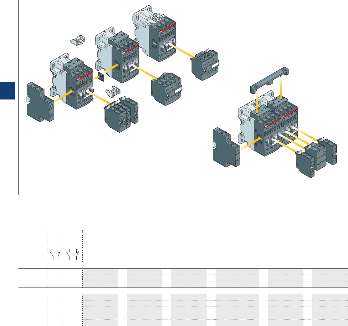
AF09 ... AF38 4-pole contactors
Main accessories
Main accessory fitting details
Many configurations of accessories are possible depending on whether these are front-mounted or side-mounted.
Contactor
types
Main
poles
Built-in
auxiliary
contacts
Front-mounted accessories Side-mounted accessories
Auxiliary contact blocks Electrical and
mechanical interlock set
Auxiliary contact blocks
1-pole CA4
(between 2 contactors)
Left side Right side
1-pole CC4 2-pole CAT4-11 4-pole CA4 VEM4 2-pole CAL4-11
Max. add-on N.C. auxiliary contacts: 4 N.C. max. on positions 1, 2, 3, 4 and 3 N.C. max. on positions 1 ±30°, 5
AF09, AF16 4 0 0 0
4 max.
or
1
or
1–
+
1–
2 max.
or
1––
+
1
+
1
3 max. – –
+
1
+
1
or
1
Max. add-on N.C. auxiliary contacts: 3 N.C. max. on positions 1, 2, 3, 4 and 2 N.C. max. on positions 1 ±30°, 5
AF26, AF38 4 0 0 0
4 max.
or
1
or
1–
+
1–
2 max.
or
1––
+
1
+
1
3 max. – –
+
1
+
1
or
1
AF09, AF16 2 2 0 0
0
4 max.
or
1
or
1–
+
1–
AF26, AF38 2 2 0 2 max.
or
1––
+
1
+
1
Contactor and main accessories (other accessories available)
VEM4 mechanical and electrical interlock set including:
– VM4 mechanical interlock unit with 2 fixing clips
– VE4 electrical interlock block with A2-A2 connection
A2
VE4
AF contactor
4-pole CA4
2-pole CAT4-11
1-pole CA4, CC4
VM4
1-pole
CA4, CC4
2-pole CAL4-11
2-pole CAL4-11
AF contactor
(without top mounted
coil terminal block)
Fixing clips
A2
AF contactor
1-pole
CA4, CC4
5/60 | ABB
5
1SBC101392S0201
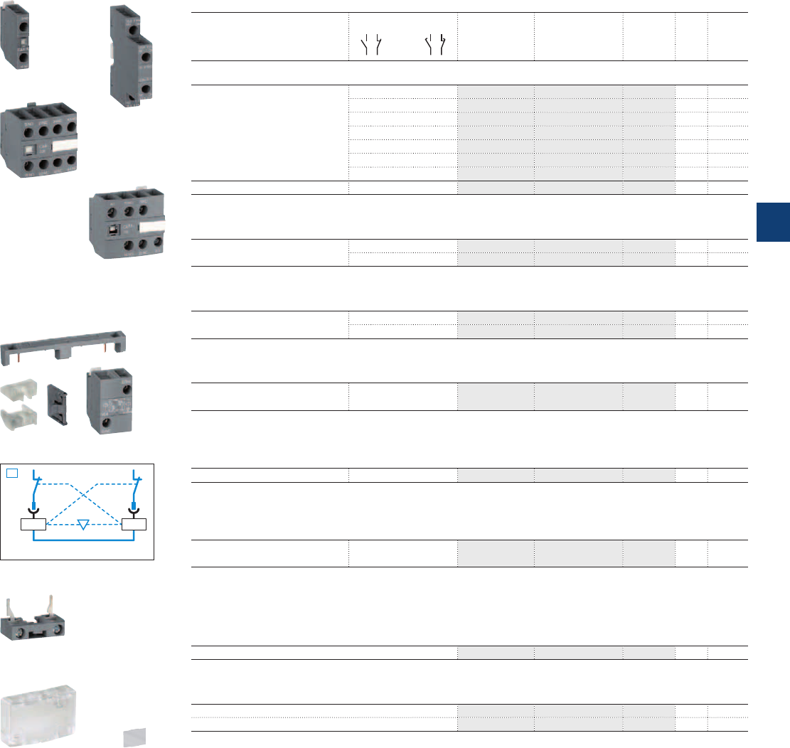
A2 A2
01NC
01NC
VEM4
KM1 KM2
1SBC101108F0014
1SBC101112F0014
1SBC101120F0014
1SBC101114F0014
1SBC101130F0014
1SBC101128F0014
1SBC101129F0014
1SBC101138F0014
1SBC101136F0014
1SBC101133F0014
AF09 ... AF38 4-pole contactors
Main accessories
Ordering details (1)
For contactors Auxiliary contacts Type Order code Pkg
qty
Weight
(1 pce)
kg
Front-mounted instantaneous auxiliary contact blocks
AF09 ... AF38..-40-00
AF09 ... AF38..-22-00
1 0 – – CA4-10 1SBN010110R1010 1 0.014
1 0 – – CA4-10-T 1SBN010110T1010 10 0.014
0 1 – – CA4-01 1SBN010110R1001 1 0.014
0 1 – – CA4-01-T 1SBN010110T1001 10 0.014
2 2 – – CA4-22E 1SBN010140R1022 1 0.055
3 1 – – CA4-31E 1SBN010140R1031 1 0.055
4 0 – – CA4-40E 1SBN010140R1040 1 0.055
AF09 ... AF16..-40-00 0 4 – – CA4-04E 1SBN010140R1004 1 0.055
Front-mounted auxiliary contact blocks with N.O. leading contact and N.C. lagging contact
AF09 ... AF38..-40-00
AF09 ... AF38..-22-00
– – 1 0 CC4-10 1SBN010111R1010 1 0.014
– – 0 1 CC4-01 1SBN010111R1001 1 0.014
Side-mounted instantaneous auxiliary contact blocks
AF09 ... AF38..-40-00
AF09 ... AF38..-22-00
1 1 – – CAL4-11 1SBN010120R1011 1 0.040
1 1 – – CAL4-11-T 1SBN010120T1011 10 0.040
Front-mounted instantaneous auxiliary contact and A1/A2 coil terminal blocks
AF09 ... AF38..-40-00
AF09 ... AF38..-22-00
1 1 – – CAT4-11E 1SBN010151R1011 1 0.040
Note: CAT4 not fittable on AF..Z contactors with DC control voltage 12...20 V DC.
Mechanical interlock unit
AF09 ... AF38..-40-00 VM4 1SBN030105T1000 10 0.005
Note: VM4 includes 2 fixing clips (BB4) to maintain together both contactors.
Mechanical and electrical interlock set
AF09, AF16..-40-00
AF26, AF38..-40-00
1 1 – – VEM4 1SBN030111R1000 1 0.035
Note: – VEM4 includes a VM4 mechanical interlock unit with 2 fixing clips (BB4), a VE4 electrical interlock block. VE4 block must
be used with A2-A2 connection to respect the electrical connection diagram.
– VEM4 not fittable on AF..Z contactors with DC control voltage 12...20 V DC.
Additional coil terminal block
AF09 ... AF38 LDC4 1SBN070156T1000 10 0.010
Protective covers
All 1-stack contactors BX4 1SBN110108T1000 10 0.006
For 4-pole CA4 and 2-pole CAT4 auxiliary contact blocks BX4-CA 1SBN110109W1000 50 0.001
(1) See "Main accessory fitting details" table.
CA4-10
CA4-22E
BX4
LDC4
BX4-CA
VEM4
CAT4-11E
CAL4-11
ABB | 5/61
5
1SBC101393S0201

Notes
5/62 | ABB
5
N3
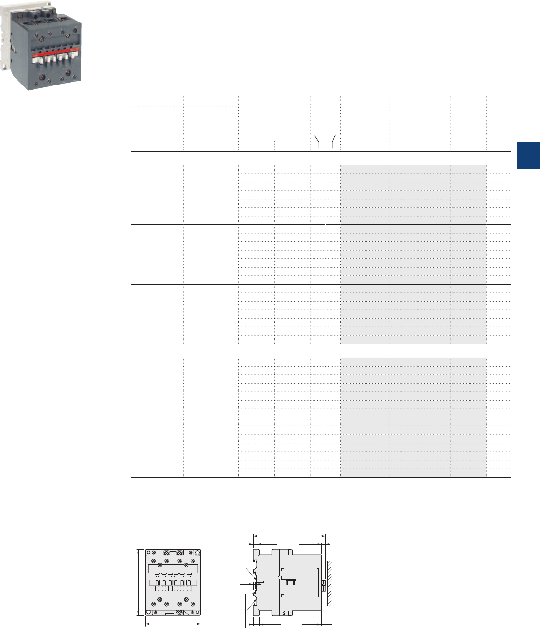
1SBC580873F0301
A45-40-00
A45 … A75 4-pole contactors
70 to 125 A AC-1
AC operated
Description
A45 ... A75 4-pole contactors are mainly used for controlling non-inductive or slightly inductive loads (i.e.
resistance furnaces...) and generally for controlling power circuits up to 690 V AC and 220 V DC.
These contactors are of the block type design with:
– 4 main poles
– control circuit: AC operated
– add-on auxiliary contact blocks for front or side mounting and a wide range of accessories.
Ordering details
IEC UL/CSA Rated control circuit
voltage
Uc
(1)
Auxiliary
contacts
fitted
Type Order code Weight
Pkg
(1 pce)
Rated operational
current General use
rating
θ ≤ 40 °C 600 V AC
AC-1
A A V 50 Hz V 60 Hz kg
4 N.O. main poles
70 80 24 24 0 0 A45-40-00 1SBL331201R8100 1.390
48 48 0 0 A45-40-00 1SBL331201R8300 1.390
110 110…120 0 0 A45-40-00 1SBL331201R8400 1.390
220…230 230…240 0 0 A45-40-00 1SBL331201R8000 1.390
230…240 240…260 0 0 A45-40-00 1SBL331201R8800 1.390
380…400 400…415 0 0 A45-40-00 1SBL331201R8500 1.390
400…415 415…440 0 0 A45-40-00 1SBL331201R8600 1.390
100 80 24 24 0 0 A50-40-00 1SBL351201R8100 1.390
48 48 0 0 A50-40-00 1SBL351201R8300 1.390
110 110…120 0 0 A50-40-00 1SBL351201R8400 1.390
220…230 230…240 0 0 A50-40-00 1SBL351201R8000 1.390
230…240 240…260 0 0 A50-40-00 1SBL351201R8800 1.390
380…400 400…415 0 0 A50-40-00 1SBL351201R8500 1.390
400…415 415…440 0 0 A50-40-00 1SBL351201R8600 1.390
125 105 24 24 0 0 A75-40-00 1SBL411201R8100 1.390
48 48 0 0 A75-40-00 1SBL411201R8300 1.390
110 110…120 0 0 A75-40-00 1SBL411201R8400 1.390
220…230 230…240 0 0 A75-40-00 1SBL411201R8000 1.390
230…240 240…260 0 0 A75-40-00 1SBL411201R8800 1.390
380…400 400…415 0 0 A75-40-00 1SBL411201R8500 1.390
400…415 415…440 0 0 A75-40-00 1SBL411201R8600 1.390
2 N.O. + 2 N.C. main poles (2)
70 80 24 24 0 0 A45-22-00 1SBL331501R8100 1.400
48 48 0 0 A45-22-00 1SBL331501R8300 1.400
110 110…120 0 0 A45-22-00 1SBL331501R8400 1.400
220…230 230…240 0 0 A45-22-00 1SBL331501R8000 1.400
230…240 240…260 0 0 A45-22-00 1SBL331501R8800 1.400
380…400 400…415 0 0 A45-22-00 1SBL331501R8500 1.400
400…415 415…440 0 0 A45-22-00 1SBL331501R8600 1.400
125 105 24 24 0 0 A75-22-00 1SBL411501R8100 1.400
48 48 0 0 A75-22-00 1SBL411501R8300 1.400
110 110…120 0 0 A75-22-00 1SBL411501R8400 1.400
220…230 230…240 0 0 A75-22-00 1SBL411501R8000 1.400
230…240 240…260 0 0 A75-22-00 1SBL411501R8800 1.400
380…400 400…415 0 0 A75-22-00 1SBL411501R8500 1.400
400…415 415…440 0 0 A75-22-00 1SBL411501R8600 1.400
(1) Other control voltages see voltage code table.
(2) These contactors are not suitable for a reversing starter or star-delta starter or for controlling a single load from 2 separate supplies.
Please see technical data.
Main dimensions mm, inches
A45, A50, A75 4-pole
92 3.62"
110 4.33"
4
0.16"
6.5 0.26"
6 0.24"
10 0.39" 10 0.39"
75 mm
EN/IEC 60715
35 mm x 15
EN/IEC 60715
119.5 4.7"
ABB | 5/63
5
1SBC101377S0201
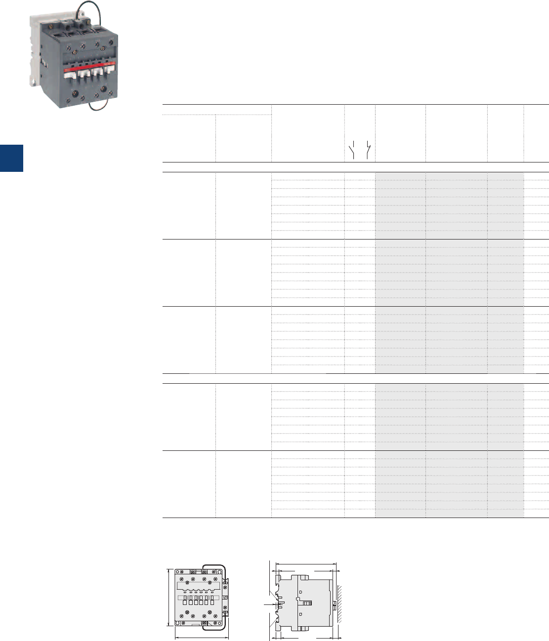
1SBC581913F0303
AE50-40-00
AE45 … AE75 4-pole contactors
70 to 125 A AC-1
DC operated
Description
AE45 ... AE75 4-pole contactors are mainly used for controlling non-inductive or slightly inductive loads
(i.e. resistance furnaces...) and generally for controlling power circuits up to 690 V AC and 220 V DC.
These contactors are of the block type design with:
– 4 main poles
– control circuit: DC operated with double winding coil (and factory-mounted lagging contact for "holding"
winding insertion)
– add-on auxiliary contact blocks for front or side mounting and a wide range of accessories.
Ordering details
IEC UL/CSA Rated control circuit
voltage
Uc
(1)
Auxiliary
contacts
fitted
Type Order code Weight
Pkg
(1 pce)
Rated operational
current
θ ≤ 40 °C
AC-1
General use
rating
600 V AC
AAV DC kg
4 N.O. main poles
70 80 12 0 0 AE45-40-00 1SBL339201R8000 1.430
24 0 0 AE45-40-00 1SBL339201R8100 1.430
48 0 0 AE45-40-00 1SBL339201R8300 1.430
60 0 0 AE45-40-00 1SBL339201R8400 1.430
110 0 0 AE45-40-00 1SBL339201R8600 1.430
125 0 0 AE45-40-00 1SBL339201R8700 1.430
220 0 0 AE45-40-00 1SBL339201R8800 1.430
240 0 0 AE45-40-00 1SBL339201R8900 1.430
100 80 12 0 0 AE50-40-00 1SBL359201R8000 1.430
24 0 0 AE50-40-00 1SBL359201R8100 1.430
48 0 0 AE50-40-00 1SBL359201R8300 1.430
60 0 0 AE50-40-00 1SBL359201R8400 1.430
110 0 0 AE50-40-00 1SBL359201R8600 1.430
125 0 0 AE50-40-00 1SBL359201R8700 1.430
220 0 0 AE50-40-00 1SBL359201R8800 1.430
240 0 0 AE50-40-00 1SBL359201R8900 1.430
125 105 12 0 0 AE75-40-00 1SBL419201R8000 1.430
24 0 0 AE75-40-00 1SBL419201R8100 1.430
48 0 0 AE75-40-00 1SBL419201R8300 1.430
60 0 0 AE75-40-00 1SBL419201R8400 1.430
110 0 0 AE75-40-00 1SBL419201R8600 1.430
125 0 0 AE75-40-00 1SBL419201R8700 1.430
220 0 0 AE75-40-00 1SBL419201R8800 1.430
240 0 0 AE75-40-00 1SBL419201R8900 1.430
2 N.O. + 2 N.C. main poles (2)
70 80 12 0 0 AE45-22-00 1SBL339501R8000 1.440
24 0 0 AE45-22-00 1SBL339501R8100 1.440
48 0 0 AE45-22-00 1SBL339501R8300 1.440
60 0 0 AE45-22-00 1SBL339501R8400 1.440
110 0 0 AE45-22-00 1SBL339501R8600 1.440
125 0 0 AE45-22-00 1SBL339501R8700 1.440
220 0 0 AE45-22-00 1SBL339501R8800 1.440
240 0 0 AE45-22-00 1SBL339501R8900 1.440
125 105 12 0 0 AE75-22-00 1SBL419501R8000 1.440
24 0 0 AE75-22-00 1SBL419501R8100 1.440
48 0 0 AE75-22-00 1SBL419501R8300 1.440
60 0 0 AE75-22-00 1SBL419501R8400 1.440
110 0 0 AE75-22-00 1SBL419501R8600 1.440
125 0 0 AE75-22-00 1SBL419501R8700 1.440
220 0 0 AE75-22-00 1SBL419501R8800 1.440
240 0 0 AE75-22-00 1SBL419501R8900 1.440
(1) Other control voltages see voltage code table.
(2) These contactors are not suitable for a reversing starter or star-delta starter or for controlling a single load from 2 separate supplies.
Please see technical data.
Main dimensions mm, inches
4
0.16"
6.5 0.26"
6 0.24"
10 0.39" 10 0.39"
75 mm
EN/IEC 60715
35 mm x 15
EN/IEC 60715
119.5 4.7"
104 4.09"
110 4.33"
AE45, AE50, AE75 4-pole
5/64 | ABB
5
1SBC101378S0201
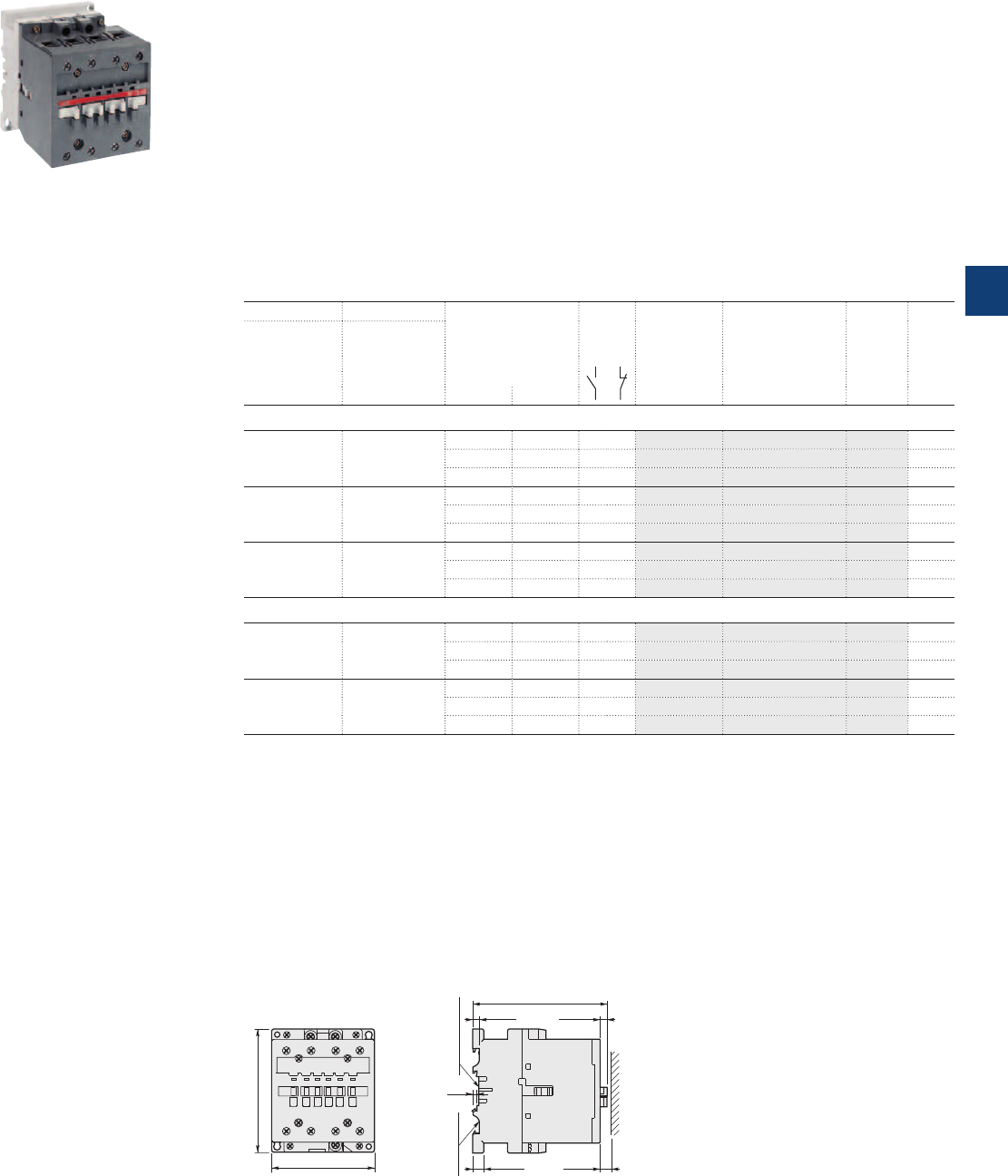
1SBC582703F0301
AF45-40-00
AF45 ... AF75 4-pole contactors
70 to 125 A AC-1
AC / DC operated
Description
AF45...AF75 4-pole contactors are mainly used for controlling non-inductive or slightly inductive loads
(i.e. resistance furnaces...) and generally for controlling power circuits up to 690VAC and 220VDC.
These contactors are of the block type design with:
– 4 main poles
– control circuit: AC or DC operated with electronic coil interface accepting a wide control voltage range
(e.g. 100...250VAC and DC)
- can manage large control voltage variations
- only 3 coils to cover control voltages between 48...250V 50/60Hz and 20...250VDC
- reduced panel energy consumption
- very distinct closing and opening
- can withstand short voltage dips and voltage sags (SEMI F47 conditions of use on request).
– built-in surge suppression
– add-on auxiliary contact blocks for front or side mounting and a wide range of accessories.
Ordering details
IEC UL/CSA Rated control circuit
voltage
Uc min. ... Uc max.
Auxiliary
contacts
fitted
Type Order code Weight
Pkg
(1 pce)
Rated operational
current General use
rating
θ ≤ 40 °C 600 V AC
AC-1
A A V 50/60 Hz V DC kg
4 N.O. main poles
70 80 - 20…60 0 0 AF45-40-00 1SBL337201R7200 (1) 1.420
48…130 48…130 0 0 AF45-40-00 1SBL337201R6900 1.420
100…250 100…250 0 0 AF45-40-00 1SBL337201R7000 1.420
100 80 - 20…60 0 0 AF50-40-00 1SBL357201R7200 (1) 1.420
48…130 48…130 0 0 AF50-40-00 1SBL357201R6900 1.420
100…250 100…250 0 0 AF50-40-00 1SBL357201R7000 1.420
125 105 - 20…60 0 0 AF75-40-00 1SBL417201R7200 (1) 1.420
48…130 48…130 0 0 AF75-40-00 1SBL417201R6900 1.420
100…250 100…250 0 0 AF75-40-00 1SBL417201R7000 1.420
2 N.O. + 2 N.C. main poles (2)
70 80 - 20…60 0 0 AF45-22-00 1SBL337501R7200 (1) 1.420
48…130 48…130 0 0 AF45-22-00 1SBL337501R6900 1.420
100…250 100…250 0 0 AF45-22-00 1SBL337501R7000 1.420
125 105 - 20…60 0 0 AF75-22-00 1SBL417501R7200 (1) 1.420
48…130 48…130 0 0 AF75-22-00 1SBL417501R6900 1.420
100…250 100…250 0 0 AF75-22-00 1SBL417501R7000 1.420
(1) The connection polarities indicated close to the coil terminals must be respected: A1 for the positive pole and A2 for the negative pole.
(2) These contactors are not suitable for a reversing starter or star-delta starter or for controlling a single load from 2 separate supplies.
Please see technical data.
Main dimensions mm, inches
AF45, AF50, AF75 4-pole
92 3.62"
110 4.33"
4
0.16"
6.5 0.26"
6 0.24"
10 0.39" 10 0.39"
75 mm
EN/IEC 60715
35 mm x 15
EN/IEC 60715
119.5 4.7"
ABB | 5/65
5
1SBC101379S0201
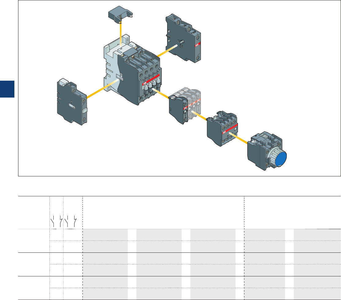
A45 … A75, AE and
AF45 … AF75 4-pole contactors
Main accessories
Main accessory fitting details
Many configurations of accessories are possible depending on whether these are front-mounted or side-mounted.
Contactor
types
Main
poles
Available
auxiliary
contacts
Front-mounted accessories Side-mounted accessories
Auxiliary contact blocks Pneumatic timer Auxiliary contact
blocks
Interlock unit
1-pole CA5-.. 4-pole CA5-.. TP.. A 2-pole CAL5-11 VE5-..
A45 ... A75 4 0 0 0 1 to 6 x CA5-..
or
1 x CA5-.. (4-pole)
or
1 x TP .. A
+
1 to 2 x CAL5-11
or
1 x VE5-2
+ 2 x 1-pole CA5-.. + 2 x CA5-.. (1-pole) + 1 x CAL5-11
2200
(1) 1 to 6 x CA5-..
or
1 x CA5-.. (4-pole)
or
1 x TP .. A
+
1 to 2 x CAL5-11 –
+ 2 x 1-pole CA5-.. + 2 x CA5-.. (1-pole)
AE45 ... AE75 4 0 0 0 1 to 6 x CA5-..
or
1 x CA5-.. (4-pole)
or
1 x TP .. A
+
1 x CAL5-11
or
1 x VE5-2
+ 2 x 1-pole CA5-.. + 2 x CA5-.. (1-pole)
2200
(1) 1 to 6 x CA5-..
or
1 x CA5-.. (4-pole)
or
1 x TP .. A
+
1 x CAL5-11 –
+ 2 x 1-pole CA5-.. + 2 x CA5-.. (1-pole)
AF50 ... AF75 4 0 0 0 1 to 6 x CA5-..
or
1 x CA5-.. (4-pole)
or
1 x TP .. A
+
1 to 2 x CAL5-11
or
1 x VE5-2
+ 2 x 1-pole CA5-.. + 2 x CA5-.. (1-pole) + 1 x CAL5-11
2200
(1) 1 to 6 x CA5-..
or
1 x CA5-.. (4-pole)
or
1 x TP .. A
+
1 to 2 x CAL5-11 –
+ 2 x 1-pole CA5-.. + 2 x CA5-.. (1-pole)
(1) 2 x N.C. CA 5-.. auxiliary contacts maximum.
Contactor and main accessories (other accessories available)
RV5/..
VE5-1
CAL5-11
A.. contactor
CA5-10
CA5-22E
TP40DA
5/66 | ABB
5
1SBC101394S0201
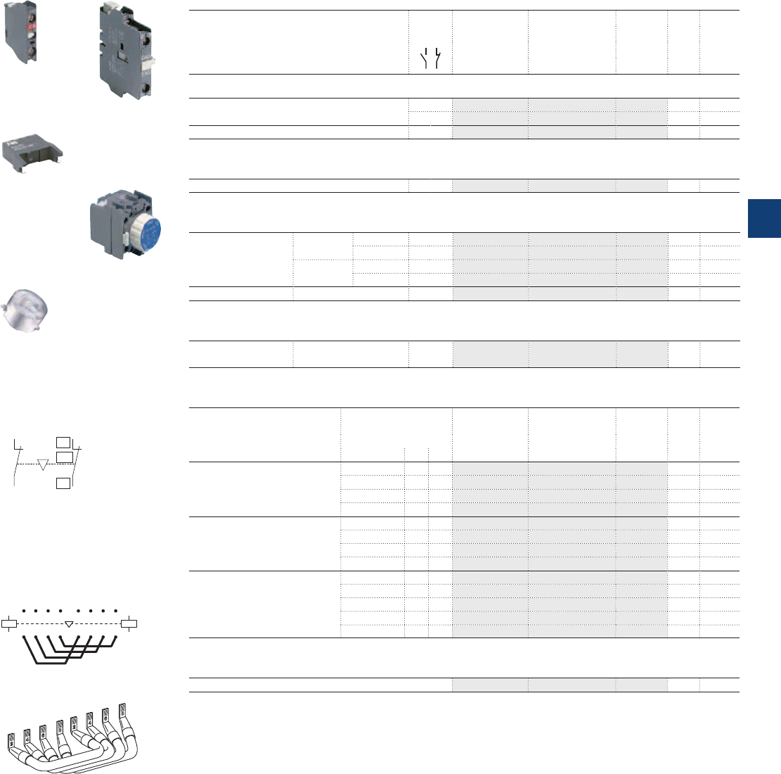
1SBC580992F0301
1SBC573752F0301
1SBC574001F0301
1SBC575893F0302
1SBC586522F0301
01
02
NC
E0085D1
01
02
NC
A45 … A75, AE and
AF50 … AF75 4-pole contactors
Main accessories
Ordering details (1)
For contactors Auxiliary
contacts
Type Order code Pkg
qty
Weight
(1 pce)
kg
Front-mounted instantaneous auxiliary contact blocks
A45 ... A75, AE45 ... AE75,
AF50 … AF75
1 – CA5-10 1SBN010010R1010 10 0.014
– 1 CA5-01 1SBN010010R1001 10 0.014
A45 ... A75, AE45 ... AE75, AF45 … AF75 2 2 CA5-22E 1SBN010040R1022 2 0.060
Side-mounted instantaneous auxiliary contact blocks
A45 ... A75, AE45 ... AE75, AF45 … AF75 1 1 CAL5-11 1SBN010020R1011 2 0.050
Pneumatic timer blocks
A45 ... A75,
AE45 … AE75,
AF45 ... AF75
delay on
energization
0.1...40 s 1 1 TP40DA 1SBN020300R1000 1 0.070
10...180 s 1 1 TP180DA 1SBN020300R1001 1 0.070
delay on de-
energization
0.1...40 s 1 1 TP40IA 1SBN020301R1000 1 0.070
10...180 s 1 1 TP180IA 1SBN020301R1001 1 0.070
Timer accessory plastic sealable cover – – BX-TP FPTN472657R0001 1 0.006
Interlock unit
A45 ... A75-40-00,
AF45 … AF75-40-00
Mechanical and electrical – 2 VE5-2 1SBN030210R1000 1 0.146
Surge suppressors
For contactors Rated control circuit
voltage
Uc
Type Order code Pkg
qty
Weight
(1 pce)
VACDC kg
A45 … A75,
AE45 ... AE75 24...50
●●
RV5/50 1SBN050010R1000 2 0.015
50...133
●●
RV5/133 1SBN050010R1001 2 0.015
110...250
●●
RV5/250 1SBN050010R1002 2 0.015
250...440
●●
RV5/440 1SBN050010R1003 2 0.015
A45 … A75 24...50
●
– RC5-2/50 1SBN050200R1000 2 0.015
50...133
●
– RC5-2/133 1SBN050200R1001 2 0.015
110...250
●
– RC5-2/250 1SBN050200R1002 2 0.015
250...440
●
– RC5-2/440 1SBN050200R1003 2 0.015
AE45 … AE75 12...32 –
●
RT5/32 1SBN050020R1000 2 0.015
25...65 –
●
RT5/65 1SBN050020R1001 2 0.015
50...90 –
●
RT5/90 1SBN050020R1002 2 0.015
77...150 –
●
RT5/150 1SBN050020R1003 2 0.015
150...264 –
●
RT5/264 1SBN050020R1004 2 0.015
Connection sets for 4-pole changeover contactors
A45 ... A75-40-00, AE45 ... AE75-40-00, AF45 … AF75-40-00 BES75-40 1SBN083302R1000 1 0.400
(1) See "Main accessory fitting details" table.
CA5-10
RV5/50
BX-TP
TP40DA
CAL5-11
VE5-2
Terminal marking and positioning
BES... for 4 N.O. main pole
connection
BES75-40
E0461D1
A1
A2
A1
A2
315 537
426 648
71
8 2
E0743D
ABB | 5/67
5
1SBC101395S0201
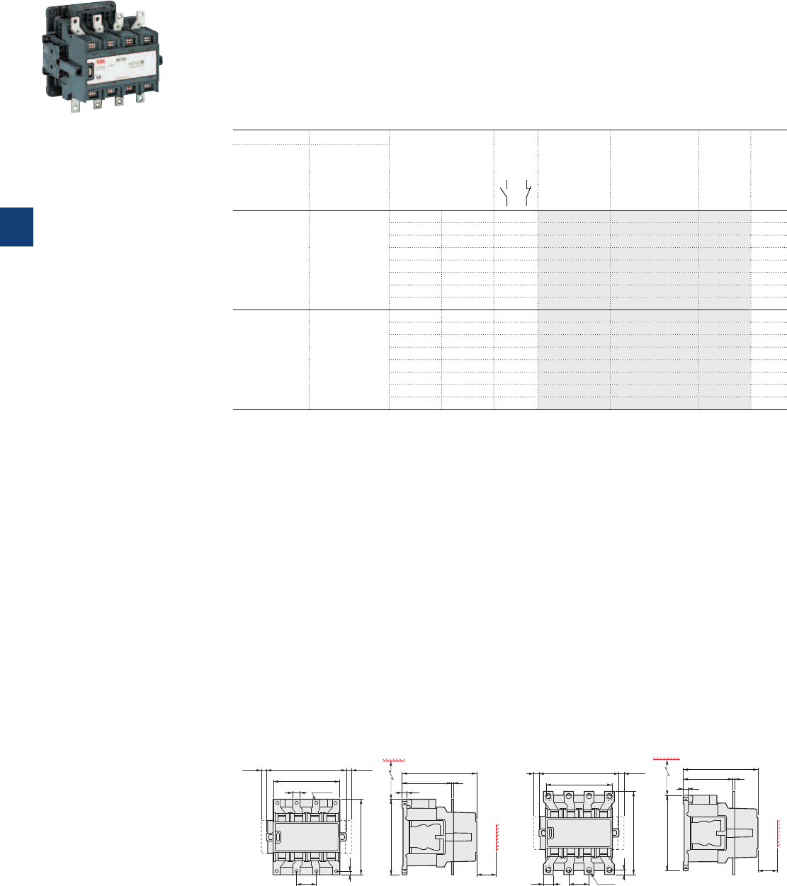
EK110 … EK150 4-pole contactors
200 to 250 A AC-1
AC operated - with 1 N.O. + 1 N.C. auxiliary contacts
Description
EK110 ... EK150 4-pole contactors are mainly used for controlling non-inductive or slightly inductive loads
(i.e. resistance furnaces...) and for controlling power circuits up to 1000 V AC and 440 V DC.
These contactors are of the block type design with:
– 4 main poles
– control circuit: AC operated
– add-on auxiliary contact blocks for side mounting and a wide range of accessories.
Ordering details
IEC UL/CSA Rated control circuit
voltage
Uc
(1)
Auxiliary
contacts
fitted
Type Order code Weight
Pkg
(1 pce)
Rated operational
current General use
rating
θ ≤ 40 °C 600 V AC
AC-1
A A V 50 Hz V 60 Hz kg
200 170 48 - 1 1 EK110-40-11 SK824440-AD 4.300
- 110 1 1 EK110-40-11 SK824440-AE 4.300
110 120 1 1 EK110-40-11 SK824440-AF 4.300
220…230 - 1 1 EK110-40-11 SK824440-AL 4.300
230…240 - 1 1 EK110-40-11 SK824440-AM 4.300
- 380 1 1 EK110-40-11 SK824440-AN 4.300
380…400 440 1 1 EK110-40-11 SK824440-AP 4.300
400…415 - 1 1 EK110-40-11 SK824440-AR 4.300
250 200 48 - 1 1 EK150-40-11 SK824441-AD 4.350
- 110 1 1 EK150-40-11 SK824441-AE 4.350
110 120 1 1 EK150-40-11 SK824441-AF 4.350
220…230 - 1 1 EK150-40-11 SK824441-AL 4.350
230…240 - 1 1 EK150-40-11 SK824441-AM 4.350
- 380 1 1 EK150-40-11 SK824441-AN 4.350
380…400 440 1 1 EK150-40-11 SK824441-AP 4.350
400…415 - 1 1 EK150-40-11 SK824441-AR 4.350
(1) Other control voltages see voltage code table.
Main dimensions mm, inches
15 0.59"
136 5.35"
165 6.5"
10.5 0.41" 10.5 0.41"
ø 6.6 0.26"
1.61"
156 6.14"
0.3"
1)
1)
1/L1 3/L2 5/L3 7/L4
2/T1 4/T2 6/T3 8/T4
E0246D6
41
7.5
4 0.16"
156 6.14"
40
102.5 4.04"
154.5 6.08"
10 0.39"
134 5.28"2)
E0247D6
1.57"
20
0.79"
136 5.35"
165 6.5"
10.5 0.41" 10.5 0.41"
42
172 6.77"
10
0.39"
1)1)
1/L1 3/L2 5/L3 7/L4
2/T1 4/T2 6/T3 8/T4
E0249D6
1.65"
ø 11
0.43"
4 0.16"
156 6.14"
40
102.5 4.04"
154.5 6.08"
10 0.39"
134 5.28"2)
E0250D6
1.57"
EK110 EK150
1) Dimension for extra auxiliary contact block.
2) Min. distance to uninsulated wall.
1SBC573401F0301
EK150-40-11
5/68 | ABB
5
1SFC101017C0201
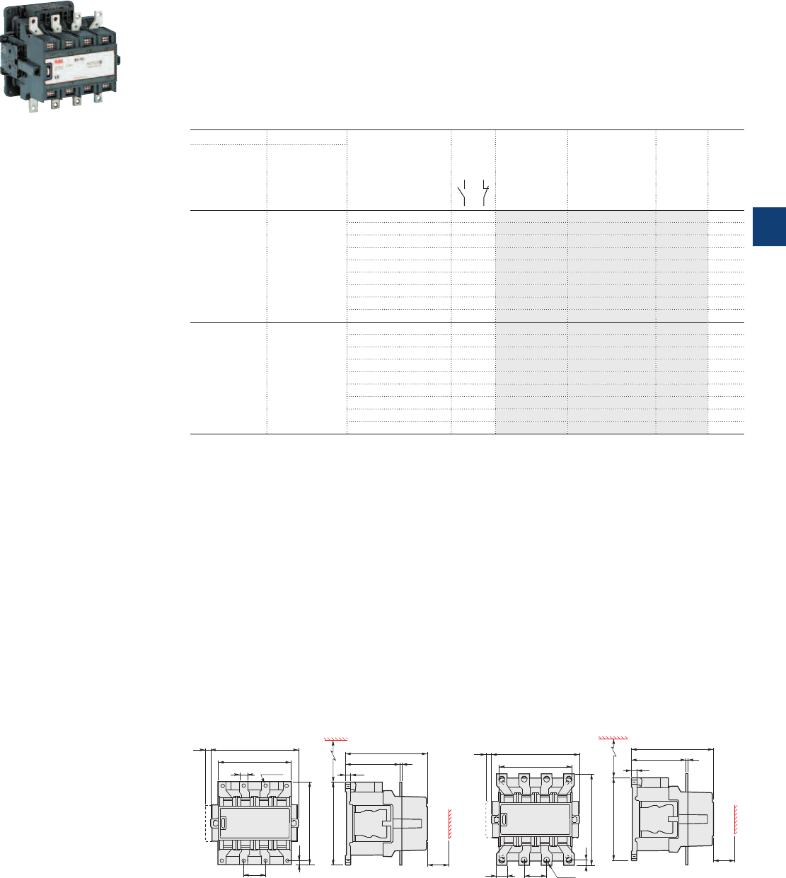
EK110 … EK150 4-pole contactors
200 to 250 A AC-1
DC operated - with 2 N.O. + 1 N.C. auxiliary contacts
Description
EK110 ... EK150 4-pole contactors are mainly used for controlling non-inductive or slightly inductive loads
(i.e. resistance furnaces...) and for controlling power circuits up to 1000 V AC and 440 V DC.
These contactors are of the block type design with:
– 4 main poles
– control circuit: DC operated
– add-on auxiliary contact blocks for side mounting and a wide range of accessories.
Ordering details
IEC UL/CSA Rated control circuit
voltage
Uc
Auxiliary
contacts
fitted
Type Order code Weight
Pkg
(1 pce)
Rated operational
current General use
rating
θ ≤ 40 °C 600 V AC
AC-1
AAV DC kg
200 170 12 2 1 EK110-40-21 SK824440-DA 4.350
24 2 1 EK110-40-21 SK824440-DB 4.350
36 2 1 EK110-40-21 SK824440-DC 4.350
48 2 1 EK110-40-21 SK824440-DD 4.350
60 2 1 EK110-40-21 SK824440-DT 4.350
75 2 1 EK110-40-21 SK824440-DG 4.350
110 2 1 EK110-40-21 SK824440-DE 4.350
125 2 1 EK110-40-21 SK824440-DU 4.350
220 2 1 EK110-40-21 SK824440-DF 4.350
250 200 12 2 1 EK150-40-21 SK824441-DA 4.400
24 2 1 EK150-40-21 SK824441-DB 4.400
36 2 1 EK150-40-21 SK824441-DC 4.400
48 2 1 EK150-40-21 SK824441-DD 4.400
60 2 1 EK150-40-21 SK824441-DT 4.400
75 2 1 EK150-40-21 SK824441-DG 4.400
110 2 1 EK150-40-21 SK824441-DE 4.400
125 2 1 EK150-40-21 SK824441-DU 4.400
220 2 1 EK150-40-21 SK824441-DF 4.400
Main dimensions mm, inches
15 0.59"
136 5.35"
165 6.5"
10.5 0.41"
41
156 6.14"
7.5
0.3"
1)
1/L1 3/L2 5/L3 7/L4
2/T1 4/T2 6/T3 8/T4
1.61"
ø 6.6
0.26"
4 0.16"
156 6.14"
40
102.5 4.04"
154.5 6.08"
10 0.39"
134 5.28"2)
1.57"
20
0.79"
136 5.35"
165 6.5"
10.5 0.41"
42
172 6.77"
10 0.39"
1)
1/L1 7/L43/L2 5/L3
2/T1 4/T2 6/T3 8/T4
ø 11
0.43"
1.65"
4 0.16"
156 6.14"
40
102.5 4.04"
154.5 6.08"
10 0.39"
134 5.28"2)
E0250D6
1.57"
EK110 EK150
1) Dimension for extra auxiliary contact block.
2) Min. distance to uninsulated wall.
1SBC573401F0301
EK150-40-21
ABB | 5/69
5
1SFC101061C0201
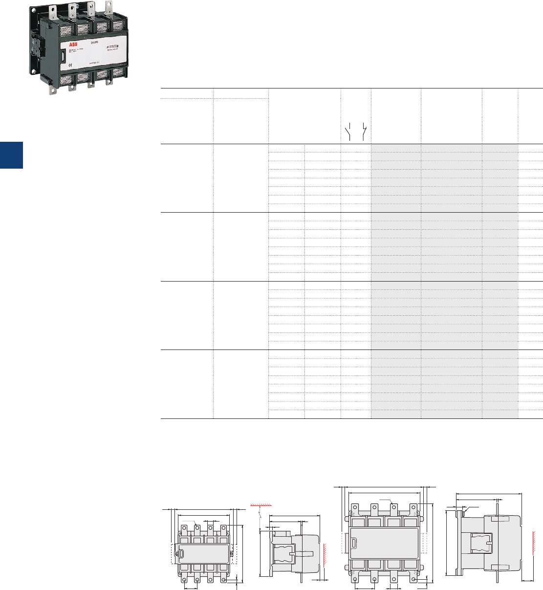
EK175 … EK550 4-pole contactors
300 to 800 A AC-1
AC operated - with 1 N.O. + 1 N.C. auxiliary contacts
Description
EK175 ... EK550 4-pole contactors are mainly used for controlling non-inductive or slightly inductive loads
(i.e. resistance furnaces...) and for controlling power circuits up to 1000 V AC and 600 V DC.
These contactors are of the block type design with:
– 4 main poles
– control circuit: AC operated
– add-on auxiliary contact blocks for side mounting and a wide range of accessories.
Ordering details
IEC UL/CSA Rated control circuit
voltage
Uc
(1)
Auxiliary
contacts
fitted
Type Order code Weight
Pkg
(1 pce)
Rated operational
current General use
rating
θ ≤ 40 °C 600 V AC
AC-1
A A V 50 Hz V 60 Hz kg
300 250 48 - 1 1 EK175-40-11 SK825440-AD 6.600
- 110 1 1 EK175-40-11 SK825440-AE 6.600
110 120 1 1 EK175-40-11 SK825440-AF 6.600
220…230 - 1 1 EK175-40-11 SK825440-AL 6.600
230…240 - 1 1 EK175-40-11 SK825440-AM 6.600
- 380 1 1 EK175-40-11 SK825440-AN 6.600
380…400 440 1 1 EK175-40-11 SK825440-AP 6.600
400…415 - 1 1 EK175-40-11 SK825440-AR 6.600
350 300 48 - 1 1 EK210-40-11 SK825441-AD 6.600
- 110 1 1 EK210-40-11 SK825441-AE 6.600
110 120 1 1 EK210-40-11 SK825441-AF 6.600
220…230 - 1 1 EK210-40-11 SK825441-AL 6.600
230…240 - 1 1 EK210-40-11 SK825441-AM 6.600
- 380 1 1 EK210-40-11 SK825441-AN 6.600
380…400 440 1 1 EK210-40-11 SK825441-AP 6.600
400…415 - 1 1 EK210-40-11 SK825441-AR 6.600
550 420 48 - 1 1 EK370-40-11 SK827040-AD 17.200
110 110…120 1 1 EK370-40-11 SK827040-EF 17.200
110…115 115…127 1 1 EK370-40-11 SK827040-EG 17.200
220 220…240 1 1 EK370-40-11 SK827040-EL 17.200
220…230 230…255 1 1 EK370-40-11 SK827040-EM 17.200
380 380…415 1 1 EK370-40-11 SK827040-EP 17.200
380…400 400…440 1 1 EK370-40-11 SK827040-ER 17.200
400…415 - 1 1 EK370-40-11 SK827040-AR 17.200
800 540 48 - 1 1 EK550-40-11 SK827041-AD 17.200
110 110…120 1 1 EK550-40-11 SK827041-EF 17.200
110…115 115…127 1 1 EK550-40-11 SK827041-EG 17.200
220 220…240 1 1 EK550-40-11 SK827041-EL 17.200
220…230 230…255 1 1 EK550-40-11 SK827041-EM 17.200
380 380…415 1 1 EK550-40-11 SK827041-EP 17.200
380…400 400…440 1 1 EK550-40-11 SK827041-ER 17.200
400…415 - 1 1 EK550-40-11 SK827041-AR 17.200
(1) Other control voltages see voltage code table.
1SBC573432F0301
EK370-40-11
Main dimensions mm, inches
10 0.39"
198 7.8"
45
20 0.79"
176 6.93"
201 7.91"
12 0.47" 1) 12 0.47" 1)
1/L1 3/L2 5/L3 7/L4
2/T1 4/T2 6/T3 8/T4
E0261D6
1.77"
ø 11 0.43"
134 5.28"2)
156 6.14"
106.7 4.2" 5 0.2"
171.7 6.76"
15 0.59"
10 0.39"
E0262D6
270 10.63"
11 0.43" 11 0.43"
244 9.61"
67
2.64"
25
0.98"
272 10.71"
12.5
0.49"
1) 1)
ø 11 0.43"
1/L1 3/L2 5/L3 7/L4
2/T1 4/T2 6/T3 8/T4
E0263D6 11
2)
40
139.5 5.49" 6 0.24"
225.5 8.88"
23 0.91"
223 8.78"
(M10)
E0264D6
4) 5)
3)
1.57"
EK175, EK210 EK370, EK550
1) Dimension for extra auxiliary contact block. 1) Dimension for extra auxiliary contact block.
2) Min. distance to uninsulated wall. 2) Screw, nut and washer by-packed.
3) Min. distance to uninsulated wall.
4) Damping elements are included.
5) Earthing screw.
5/70 | ABB
5
1SFC101019C0201
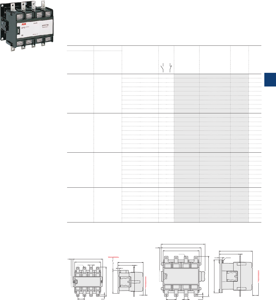
EK175 … EK550 4-pole contactors
300 to 800 A AC-1
DC operated - with 2 N.O. + 1 N.C. auxiliary contacts
Description
EK175 ... EK550 4-pole contactors are mainly used for controlling non-inductive or slightly inductive loads
(i.e. resistance furnaces...) and generally for controlling power circuits up to 1000 V AC and 600 V DC.
These contactors are of the block type design with:
– 4 main poles
– control circuit: DC operated with
– add-on auxiliary contact blocks for side mounting and a wide range of accessories.
Ordering details
IEC UL/CSA Rated control circuit
voltage
Uc
Auxiliary
contacts
fitted
Type Order code Weight
Pkg
(1 pce)
Rated operational
current General use
rating
θ ≤ 40 °C 600 V AC
AC-1
AAV DC kg
300 250 12 2 1 EK175-40-21 SK825440-DA 6.650
24 2 1 EK175-40-21 SK825440-DB 6.650
36 2 1 EK175-40-21 SK825440-DC 6.650
48 2 1 EK175-40-21 SK825440-DD 6.650
60 2 1 EK175-40-21 SK825440-DT 6.650
75 2 1 EK175-40-21 SK825440-DG 6.650
110 2 1 EK175-40-21 SK825440-DE 6.650
125 2 1 EK175-40-21 SK825440-DU 6.650
220 2 1 EK175-40-21 SK825440-DF 6.650
350 300 12 2 1 EK210-40-21 SK825441-DA 6.650
24 2 1 EK210-40-21 SK825441-DB 6.650
36 2 1 EK210-40-21 SK825441-DC 6.650
48 2 1 EK210-40-21 SK825441-DD 6.650
60 2 1 EK210-40-21 SK825441-DT 6.650
75 2 1 EK210-40-21 SK825441-DG 6.650
110 2 1 EK210-40-21 SK825441-DE 6.650
125 2 1 EK210-40-21 SK825441-DU 6.650
220 2 1 EK210-40-21 SK825441-DF 6.650
550 420 24 2 1 EK370-40-21 SK827040-DB 17.200
36 2 1 EK370-40-21 SK827040-DC 17.200
48 2 1 EK370-40-21 SK827040-DD 17.200
60 2 1 EK370-40-21 SK827040-DT 17.200
75 2 1 EK370-40-21 SK827040-DG 17.200
110 2 1 EK370-40-21 SK827040-DE 17.200
125 2 1 EK370-40-21 SK827040-DU 17.200
220 2 1 EK370-40-21 SK827040-DF 17.200
800 540 24 2 1 EK550-40-21 SK827041-DB 17.200
36 2 1 EK550-40-21 SK827041-DC 17.200
48 2 1 EK550-40-21 SK827041-DD 17.200
60 2 1 EK550-40-21 SK827041-DT 17.200
75 2 1 EK550-40-21 SK827041-DG 17.200
110 2 1 EK550-40-21 SK827041-DE 17.200
125 2 1 EK550-40-21 SK827041-DU 17.200
220 2 1 EK550-40-21 SK827041-DF 17.200
Main dimensions mm, inches
10
0.39"
198 7.8"
20 0.79"
176 6.93"
201 7.91"
12 0.47" 1)
1/L1 3/L2 5/L3 7/L4
2/T1 4/T2 6/T3 8/T4
ø 11 0.43"
45
1.77"
134 5.28"2)
156 6.14"
106.7 4.2" 5 0.2"
171.7 6.76"
15 0.59"
10 0.39"
270 10.63"
11 0.43"
244 9.61"
67
2.64"
25
0.98"
272 10.71"
12.5
0.49"
1)
1/L1 3/L2 5/L3 7/L4
2/T1 4/T2 6/T3 8/T4
296 11.65"
2)
ø 11 0.43"
40
139.5 5.49" 6 0.24"
225.5 8.88"
23 0.91"
223 8.78"
(M10)
E0264D6
4) 5)
3)
1.57"
EK175 ... EK210 EK370 ... EK550
1) Dimension for extra auxiliary contact block. 1) Dimension for extra auxiliary contact block.
2) Min. distance to uninsulated wall. 2) Screw, nut and washer by-packed.
3) Min. distance to uninsulated wall.
4) Damping elements are included.
5) Earthing screw.
1SBC573432F0301
EK370-40-21
ABB | 5/71
5
1SFC101062C0201
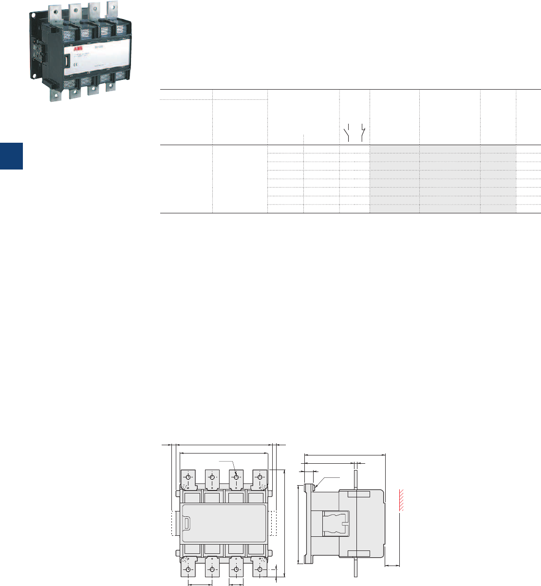
EK1000 4-pole contactors
1000 A AC-1
AC operated - with 1 N.O. + 1 N.C. auxiliary contacts
Description
EK1000 4-pole contactors are mainly used for controlling non-inductive or slightly inductive loads (i.e. resist-
ance furnaces...) and generally for controlling power circuits up to 1000 V AC.
These contactors are of the block type design with:
– 4 main poles
– control circuit: AC operated
– add-on auxiliary contact blocks for side mounting and a wide range of accessories.
Ordering details
IEC UL/CSA Rated control circuit
voltage
Uc
(1)
Auxiliary
contacts
fitted
Type Order code Weight
Pkg
(1 pce)
Rated operational
current General use
rating
θ ≤ 40 °C 600 V AC
AC-1
A A V 50 Hz V 60 Hz kg
1000 - 48 - 1 1 EK1000-40-11 SK827044-AD 17.500
110 110…120 1 1 EK1000-40-11 SK827044-EF 17.500
110…115 115…127 1 1 EK1000-40-11 SK827044-EG 17.500
220 220…240 1 1 EK1000-40-11 SK827044-EL 17.500
220…230 230…255 1 1 EK1000-40-11 SK827044-EM 17.500
380 380…415 1 1 EK1000-40-11 SK827044-EP 17.500
380…400 400…440 1 1 EK1000-40-11 SK827044-ER 17.500
400…415 - 1 1 EK1000-40-11 SK827044-AR 17.500
(1) Other control voltages see voltage code table.
Main dimensions mm, inches
1/L1 3/L2 5/L3 7/L4
2/T1 4/T2 6/T3 8/T4
E1692D 11
299 11.77"
20
67
2.64"
40
244 9.61"
ø
270 10.63"11 0.43" 1)
11 0.43" 2)
11 0.43" 1)
1.57"
0.79"
E1694D
8 0.31"139.5 5.49"
225.5 8.88"
23 0.91" 4)
(M10) 5)
223 8.78"
40
3)
1.57"
EK1000
1) Dimension for extra auxiliary contact block.
2) Screw, nut and washer by-packed.
3) Min. distance to uninsulated wall.
4) Damping elements are included.
5) Earthing screw.
1SFC98099-069
EK1000-40-11
5/72 | ABB
5
1SFC101021C0201
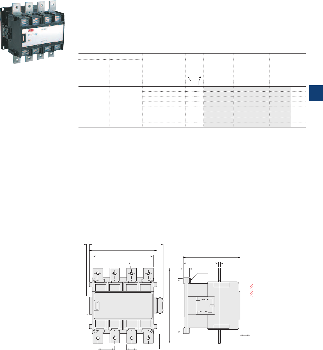
EK1000 4-pole contactors
1000 A AC-1
DC operated - with 2 N.O. + 1 N.C. auxiliary contacts
Description
EK1000 4-pole contactors are mainly used for controlling non-inductive or slightly inductive loads
(i.e. resistance furnaces...) and generally for controlling power circuits up to 1000 V AC.
These contactors are of the block type design with:
– 4 main poles
– control circuit: DC operated
– add-on auxiliary contact blocks for side mounting and a wide range of accessories.
Ordering details
IEC UL/CSA Rated control circuit
voltage
Uc
Auxiliary
contacts
fitted
Type Order code Weight
Pkg
(1 pce)
Rated operational
current General use
rating
θ ≤ 40 °C 600 V AC
AC-1
AAV DC kg
1000 - 24 2 1 EK1000-40-21 SK827044-DB 17.500
36 2 1 EK1000-40-21 SK827044-DC 17.500
48 2 1 EK1000-40-21 SK827044-DD 17.500
60 2 1 EK1000-40-21 SK827044-DT 17.500
75 2 1 EK1000-40-21 SK827044-DG 17.500
110 2 1 EK1000-40-21 SK827044-DE 17.500
125 2 1 EK1000-40-21 SK827044-DU 17.500
220 2 1 EK1000-40-21 SK827044-DF 17.500
Main dimensions mm, inches
1/L1 3/L2 5/L3 7/L4
2/T1 4/T2 6/T3 8/T4
E1693D
299 11.77"
20
0.79"
67
2.64"
40
1.57"
244 9.61"
270 10.63"
ø 11 0.43" 2)
296 11.65"11 0.43"1)
E1694D
8 0.31"139.5 5.49"
225.5 8.88"
23 0.91" 4)
(M10) 5)
223 8.78"
40
3)
1.57"
EK1000
1) Dimension for extra auxiliary contact block.
2) Screw, nut and washer by-packed.
3) Min. distance to uninsulated wall.
4) Damping elements are included.
5) Earthing screw.
1SFC98099-069
EK1000-40-21
ABB | 5/73
5
1SFC101063C0201
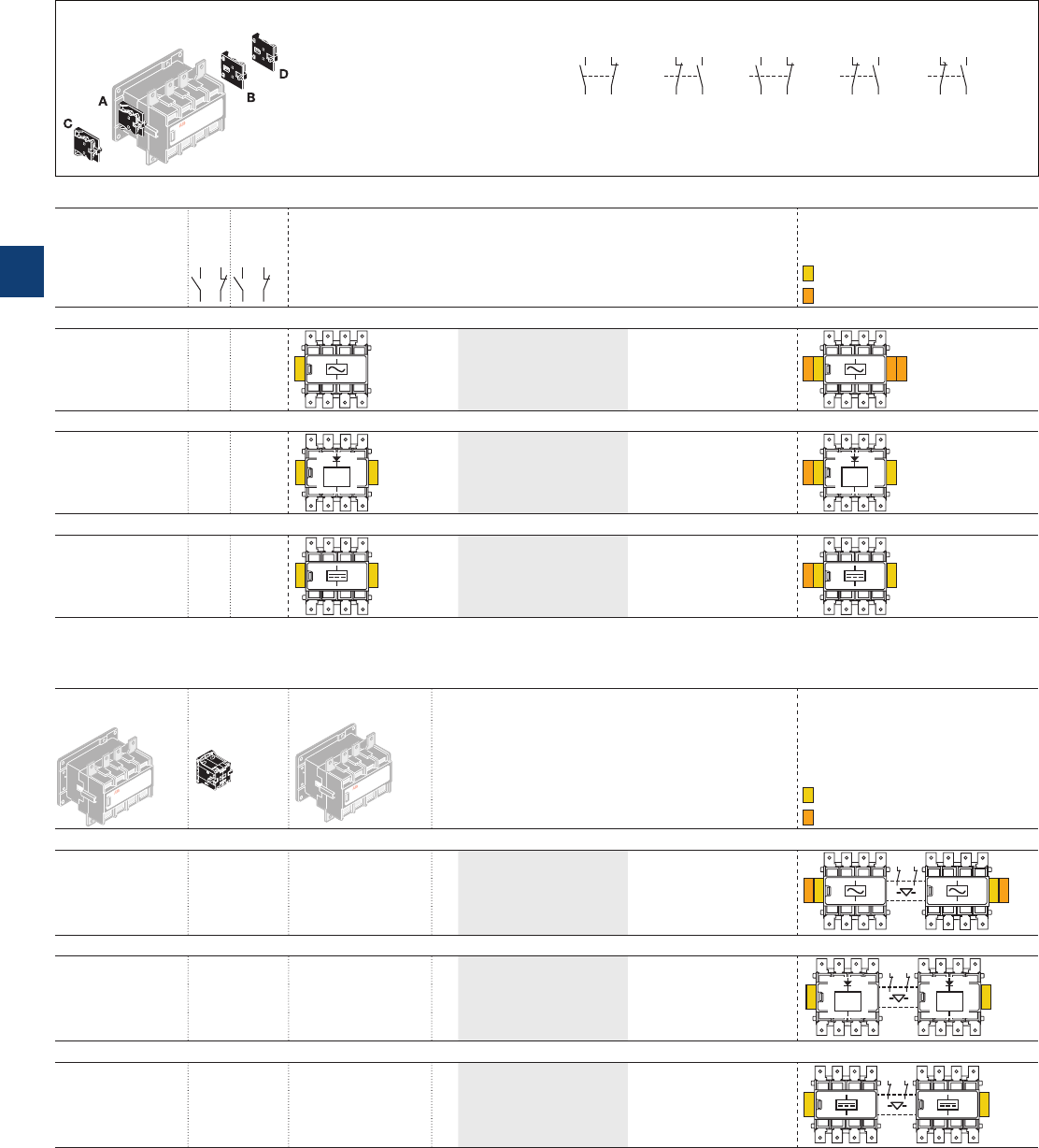
Mounting positions of the auxiliary contact Auxiliary contact types and connecting diagrams
21
22
13
14
CAL16-11 A CAL16-11 B
43
44
31
32
CAL16-11 C
61
62
53
54
CAL16-11 D
83
84
71
72
CCL16-11 E
47
48
35
36
(1)
(1) Contact 35-36 used for some
types of EK... contactors
EK110 ... EK1000 4-pole contactors
with 1 N.O. + 1 N.C. auxiliary contacts
and 2 N.O. + 1 N.C. auxiliary contacts
EK... 4-pole contactors
Contactor
types
Main
poles
Available
auxiliary
contacts
Add-on auxiliary contact
blocks
2-pole CAL16-11 ...
Mounting and positioning
Factory mounted auxiliary contacts
Add-on CAL16-11 auxiliary contacts
AC operated, 50 Hz, 60 Hz or 50/60 Hz
EK110 ... EK1000 4 0 1 1
A
+
1 x CAL16-11B
AC DB
+
1 x CAL16-11C
+
1 x CAL16-11D
AC operated, 40...400 Hz
EK110 ... EK210 4 0 2 1
A
40 ...
400 Hz
E
+
1 x CAL16-11C
AC E
40 ...
400 Hz
DC operated
EK110 ... EK1000 4 0 2 1
AE
+
1 x CAL16-11C
AC E
EK ... 4-pole reversing contactors with VH145 / VH300 mechanical and electrical interlock units
"Left hand"
contactors
Interlocking
"Right hand"
contactors
Add-on auxiliary contact
blocks
2-pole CAL16-11 ...
Mounting and positioning
Factory mounted auxiliary contacts
Add-on CAL16-11 auxiliary contacts
AC operated, 50 Hz, 60 Hz or 50/60 Hz
EK110 ... EK150 VH145 EK110, EK150
+
1 x CAL16-11C
AC DB
EK175, EK210 VH300 EK175, EK210 1 x CAL16-11D
EK370 ... EK1000 VH800 EK370 ... EK1000
AC operated, 40...400 Hz
EK110 ... EK150 VH145 EK110, EK150
–
E E
40 ...
400 Hz
40 ...
400 Hz
EK175, EK210 VH300 EK175, EK210
EK370 ... EK1000 VH800 EK370 ... EK1000
DC operated, 50 Hz, 60 Hz or 50/60 Hz
EK110 ... EK150 VH145 EK110, EK150
–
EE
EK175, EK210 VH300 EK175, EK210
EK370 ... EK1000 VH800 EK370 ... EK1000
Main accessory fitting details
5/74 | ABB
5
1SFC101080C0201
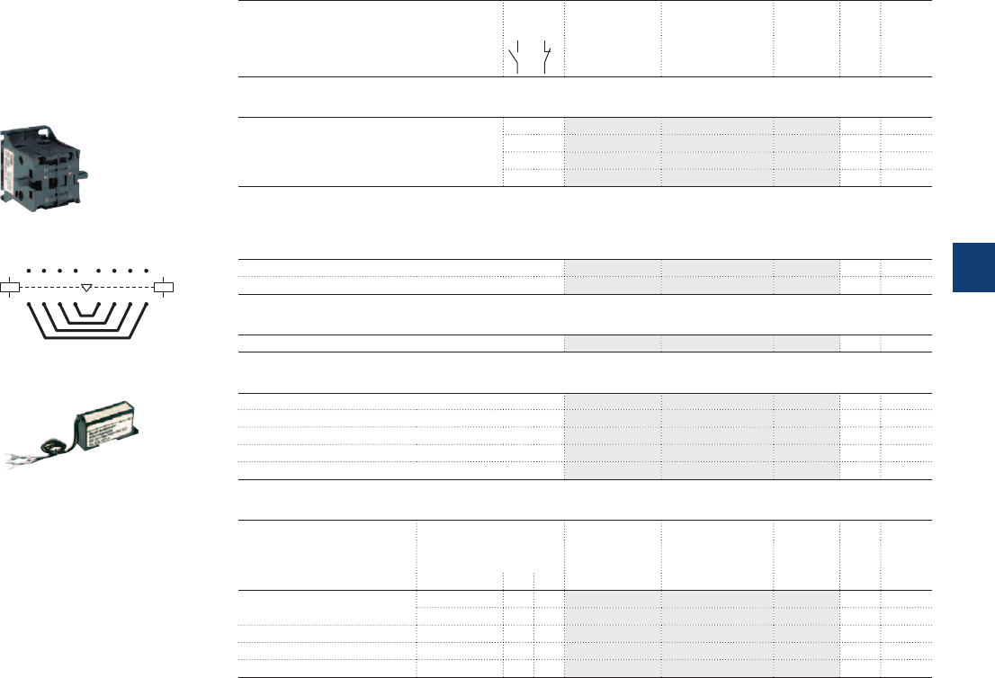
EK110 ... EK1000 4-pole contactors
with 1 N.O. + 1 N.C. auxiliary contacts
and 2 N.O. + 1 N.C. auxiliary contacts
1SBC573592F0301
VH145
A1
A2
A1
A2
315 351
426 462
77
8 8
E0747D
BSS100 ... BSS100
A078
RC-EH300/48
Ordering details (1)
For contactors Auxiliary
contacts
Type Order code Pkg
qty
Weight
(1 pce)
kg
Side-mounted auxiliary contact blocks
EK... 1 1 CAL16-11B SK829002-B 1 0.050
1 1 CAL16-11C SK829002-C 1 0.050
1 1 CAL16-11D SK829002-D 1 0.050
1 1 CCL16-11E (2) SK829002-E 1 0.050
(2) Mounting of CCL16-11E blocks does not allow an additional second block to be added on top of it.
All DC operated EK... contactors are equipped with one CCL16-11E on the right side.
Mechanical and electrical interlock unit for two horizontal mounted contactors
EK110, EK150 VH145 SK829071-A 1 0.130
EK175, EK210 VH300 SK829071-B 1 0.130
Mechanical interlock unit for two horizontal mounted contactors
EK370 ... EK1000 VH800 SK829070-F 1 6.000
Connecting sets
EK110 BSS100 SK829090-B 1 0.400
EK150 BSS145 SK829090-F 1 0.700
EK175, EK210 BSS210 SK829090-G 1 1.000
EK370, EK550 BSS550 SK829090-E 1 3.300
EK1000 BSS1000 SK829090-H 1 5.500
Surge suppressors
For contactors Rated control circuit
voltage
Uc
Type Order code Pkg Weight
qty (1 pce)
VACDC kg
EK110 ... EK210 24...48
●
– RC-EH300/48 SK829007-A 1 0.015
110...415
●
– RC-EH300/415 SK829007-B 1 0.015
EK370 ... EK1000 48...110
●
– RC-EH800/110 SK829007-C 1 0.015
EK110 ... EK1000 24...125 –
●
RC-EH800/110 SK829007-C 1 0.015
EK370 ... EK1000 220...600
●
– RC-EH800/600 SK829007-D 1 0.015
(1) See "Main accessory fitting details" table.
ABB | 5/75
5
1SFC101080C0201
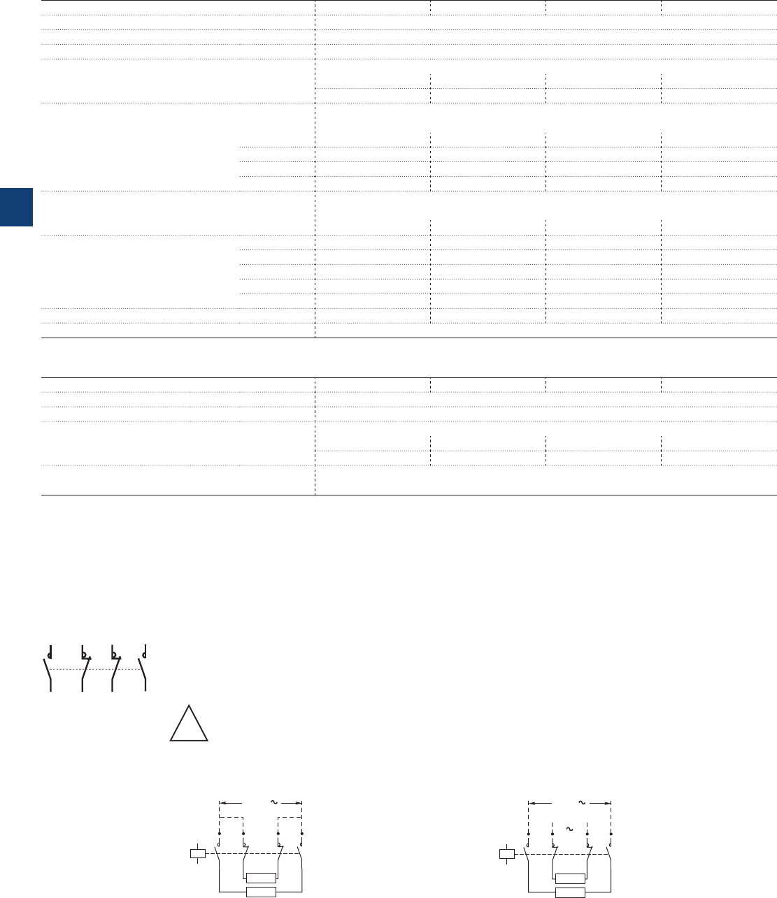
AF09 ... AF38 4-pole contactors
Technical data
Main pole - Utilization characteristics according to IEC
Contactor types AC / DC operated AF09 AF16 AF26 AF38
Standards IEC 60947-1 / 60947-4-1 and EN 60947-1 / 60947-4-1
Rated operational voltage Ue max. 690 V
Rated frequency (without derating) 50 / 60 Hz
Conventional free-air thermal current Ith
acc. to IEC 60947-4-1, open contactors, θ ≤ 40 °C 35 A 35 A 55 A 55 A
With conductor cross-sectional area 6 mm² 6 mm² 16 mm² 16 mm²
AC-1 Utilization category
For air temperature close to contactor
Ie / Rated operational current AC-1 θ ≤ 40 °C 25 A 30 A 45 A 55 A
Ue max. ≤ 690 V, 50/60 Hz θ ≤ 60 °C 25 A 30 A 40 A 45 A
θ ≤ 70 °C 22 A 26 A 32 A 37 A
With conductor cross-sectional area 4 mm² 6 mm² 10 mm² 16 mm²
Short-circuit protection device for contactors
Without thermal overload relay - Motor protection excluded
Ue ≤ 500 V AC - gG type fuse 25 A 32 A 50 A 63 A
Rated short-time withstand current Icw 1 s 300 A 300 A 450 A 450 A
At 40 °C ambient temperature,
in free air from a cold state
10 s 150 A 150 A 300 A 300 A
30 s 80 A 80 A 225 A 225 A
1 min 60 A 60 A 150 A 150 A
15 min 35 A 35 A 55 A 55 A
Power dissipation per pole Ie / AC-1 0.8 W 1.2 W 1.6 W 2.3 W
Max. electrical switching frequency AC-1 600 cycles/h
Main pole - Utilization characteristics according to UL / CSA
Contactor types AF09 AF16 AF26 AF38
Standards UL 508, CSA C22.2 N°14
Max. operational voltage 600 V
UL / CSA general use rating
600 V AC 25 A 30 A 45 A 55 A
With conductor cross-sectional area AWG 10 AWG 10 AWG 8 AWG 6
Max. electrical switching frequency
For general use 600 cycles/h
Remark for 4-pole contactors fitted with 2 N.O. + 2 N.C. main poles
These contactors are suitable for controlling 2 separate circuits, i.e. 2 loads with 2 separate supplies, or 1 circuit comprising
2 separate loads with a single supply (see diagrams below). When the contactor operates there is no mechanical overlapping
between the N.O. poles and the N.C. poles: BREAK before MAKE.
!
These contactors are not suitable for a reversing starter or for controlling a single load from 2 separate supplies.
Block diagrams
– Single supply and 2 separate loads – 2 separate supplies and 2 separate loads
1
2
R5
R6
R3
R4
7
8
A1
A2
1
2
R5
R6
R3
R4
7
8
Load
Load
Back-up
supply
Main
supply
A1
A2
1
2
R5
R6
R3
R4
7
8
Load
Load
Supply
5/76 | ABB
5
1SBC101547S0201
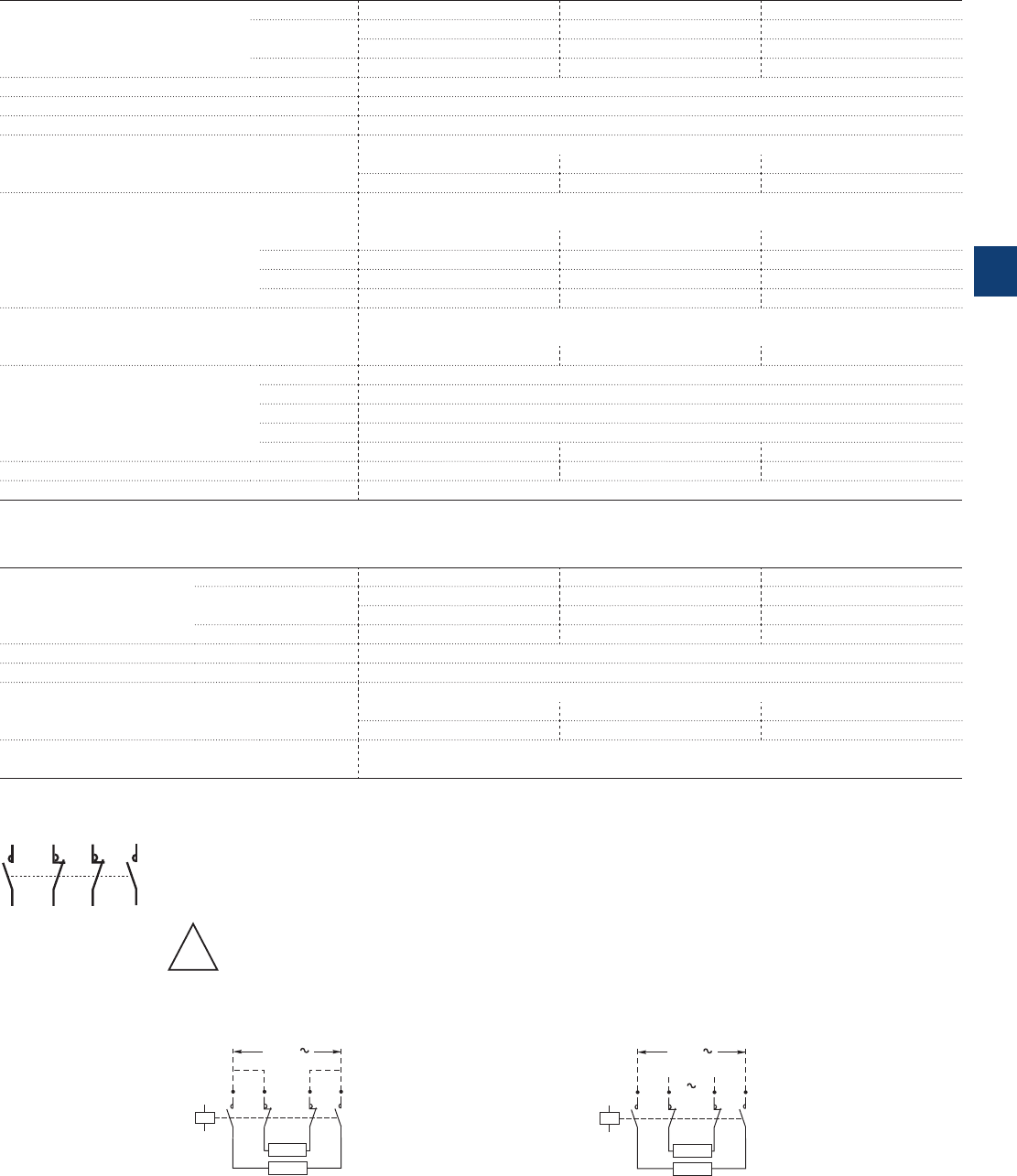
A45 ... A75, AE, TAE and
AF45 … AF75 4-pole contactors
Technical data
Main pole - Utilization characteristics according to IEC
Contactor types AC operated A45 A50 A75
DC operated AE45 AE50 AE75
TAE45 TAE50 TAE75
AC / DC operated AF45 AF50 AF75
Standards IEC 60947-1 / 60947-4-1 and EN 60947-1 / 60947-4-1
Rated operational voltage Ue max. 1000 V (690 V for AF.. contactors)
Rated frequency (without derating) 50 / 60 Hz
Conventional free-air thermal current Ith
acc. to IEC 60947-4-1, open contactors, θ ≤ 40 °C 100 A 100 A 125 A
With conductor cross-sectional area 35 mm² 35 mm² 50 mm²
AC-1 Utilization category
For air temperature close to contactor
Ie / Rated operational current AC-1 θ ≤ 40 °C 70 A 100 A 125 A
Ue max. ≤ 690 V, 50/60 Hz θ ≤ 55 °C 60 A 85 A 105 A
θ ≤ 70 °C (1) 50 A 70 A 85 A
With conductor cross-sectional area 25 mm² 35 mm² 50 mm²
Short-circuit protection device for contactors
without thermal overload relay - Motor protection excluded
Ue ≤ 500 V AC - gG type fuse 80 A 100 A 160 A
Rated short-time withstand current Icw 1 s 1000 A
At 40 °C ambient temperature,
in free air from a cold state
10 s 650 A
30 s 370 A
1 min 250 A
15 min 110 A 110 A 135 A
Power dissipation per pole Ie / AC-1 2.5 W 5 W 7 W
Max. electrical switching frequency AC-1 600 cycles/h (300 for AF.., AE.., TAE..)
(1) Unauthorized for TAE.. contactors
Main pole - Utilization characteristics according to UL / CSA
Contactor types AC operated A45 A50 A75
DC operated AE45 AE50 AE75
TAE45 TAE50 TAE75
AC / DC operated AF45 AF50 AF75
Standards UL 508, CSA C22.2 N°14
Max. operational voltage 600 V
UL / CSA general use rating
600 V AC 65 A 80 A 105 A
With conductor cross-sectional area AWG 6 AWG 4 AWG 2
Max. electrical switching frequency
For general use 600 cycles/h (300 for AF.., AE.. TAE..)
Remark for 4-pole contactors fitted with 2 N.O. + 2 N.C. main poles
These contactors are suitable for controlling 2 separate circuits, i.e. 2 loads with 2 separate supplies, or 1 circuit comprising
2 separate loads with a single supply (see diagrams below). When the contactor operates there is no mechanical overlapping
between the N.O. poles and the N.C. poles: BREAK before MAKE.
!
These contactors are not suitable for a reversing starter or for controlling a single load from 2 separate supplies.
Block diagrams
– Single supply and 2 separate loads – 2 separate supplies and 2 separate loads
1
2
R5
R6
R3
R4
7
8
A1
A2
1
2
R5
R6
R3
R4
7
8
Load
Load
Back-up
supply
Main
supply
A1
A2
1
2
R5
R6
R3
R4
7
8
Load
Load
Supply
ABB | 5/77
5
1SBC101548S0201
Main pole - Utilization characteristics according to IEC
Contactor types AC or DC operated EK110 EK150 EK175 EK210 EK370 EK550 EK1000
Standards
IEC 60947-1 / 60947-4-1 and EN 60947-1 / 60947-4-1
Rated operational voltage Ue max.
1000 V
Rated frequency (without derating)
50 / 60 Hz
Conventional free-air thermal current Ith
acc. to IEC 60947-4-1, open contactors, T ≤ 40 °C 200 A 250 A 300 A 350 A 550 A 800 A 1000 A
With conductor cross-sectional area 95 mm² 150 mm² 185 mm² 240 mm² 2x 185 mm² 2x 240 mm² 2x 300 mm²
AC-1 Utilization category
For air temperature close to contactor
Ie / Rated operational current AC-1
T ≤ 40 °C 200 A 250 A 300 A 350 A 550 A 800 A 1000 A
Ue max. ≤ 1000 V, 50/60 Hz T ≤ 55 °C 180 A 230 A 270 A 310 A 470 A 650 A 800 A
T ≤ 70 °C 155 A 200 A 215 A 250 A 400 A 575 A 720 A
With conductor cross-sectional area 95 mm² 150 mm² 185 mm² 240 mm² 2x 185 mm² 2x 240 mm² 2x 300 mm²
AC-3 Utilization category
For air temperature close to contactor T ≤ 55 °C
Ie / Max. rated operational current AC-3 (1)
M
3
3-phase motors
220-230-240 V 120 A 145 A 210 A 210 A 400 A 550 A -
380-400 V 120 A 145 A 210 A 210 A 400 A 550 A -
415 V 120 A 145 A 210 A 210 A 400 A 550 A -
440 V 120 A 145 A 210 A 210 A 370 A 550 A -
500 V 120 A 145 A 210 A 210 A 370 A 550 A -
690 V 120 A 120 A 210 A 210 A 370 A 550 A -
1000 V 64 A 80 A 113 A 113 A 155 A 175 A -
Rated operational power AC-3 (1)
M
3
1500 r.p.m. 50 Hz
1800 r.p.m. 60 Hz
3-phase motors
220-230-240 V 30 kW 45 kW 59 kW 59 kW 110 kW 160 kW -
380-400 V 55 kW 75 kW 110 kW 110 kW 200 kW 280 kW -
415 V 55 kW 75 kW 110 kW 110 kW 220 kW 315 kW -
440 V 59 kW 75 kW 110 kW 110 kW 220 kW 315 kW -
500 V 75 kW 90 kW 132 kW 132 kW 250 kW 400 kW -
690 V 110 kW 110 kW 160 kW 160 kW 355 kW 500 kW -
1000 V 90 kW 110 kW 160 kW 160 kW 220 kW 250 A -
Rated making capacity AC-3
10 x Ie AC-3 acc. to IEC 60947-4-1
Rated breaking capacity AC-3
8 x Ie AC-3 acc. to IEC 60947-4-1
Short-circuit protection device for contactors
without thermal overload relay - Motor protection excluded
Ue ≤ 500 V AC - gG type fuse 250 A 250 A 355 A 355 A 630 A 800 A 1000 A
Rated short-time withstand current Icw
1 s 1700 A 1800 A 2300 A 2300 A 5500 A 5500 A 6800 A
at 40 °C ambient temperature,
in free air from a cold state
10 s 900 A 1200 A 1680 A 1680 A 5300 A 5300 A 6400 A
30 s 600 A 700 A 1000 A 1000 A 3700 A 3700 A 4400 A
1 min 450 A 550 A 800 A 800 A 3000 A 3000 A 3400 A
15 min 210 A 250 A 320 A 320 A 1000 A 1000 A 1200 A
Maximum breaking capacity
cos M = 0.45 at 440 V 1400 A 1500 A 2000 A 2000 A 5000 A 5400 A -
(cos M= 0.35 for Ie > 100 A) at 690 V 1100 A 1200 A 1700 A 1700 A 5000 A 5400 A -
Power dissipation per pole
Ie / AC-1 10 W 13 W 18 W 18 W 40 W 60 W 80 W
Ie / AC-3 3 W 5 W 9 W 9 W 15 W 25 W -
Max. electrical switching frequency
AC-1 300 cycles/h
AC-3 300 cycles/h -
AC-2, AC-4 150 cycles/h 120 cycles/h -
Main pole - Utilization characteristics according to UL / CSA
Contactor types AC or DC operated EK110 EK150 EK175 EK210 EK370 EK550 EK1000
Standards
UL 508, CSA C22.2 N°14 -
Max. operational voltage
600 V -
UL / CSA general use rating
600 V AC
170 A 200 A 250 A 300 A 420 A 540 A -
Short-circuit protection device for contactors
without thermal overload relay - Motor protection excluded
Fuse rating
400 A 1200 A
Fuse type, 600 V
JL
Max. electrical switching frequency
For general use
300 cycles/h
(1) For the corresponding kW/A or hp/A values of 1500 r.p.m, 50 Hz or 1800 r.p.m, 60 Hz, 3-phase motors, see "Motor rated operational powers and currents".
EK110 … EK1000 4-pole contactors
Technical data
5/78 | ABB
5
1SFC101029C0201
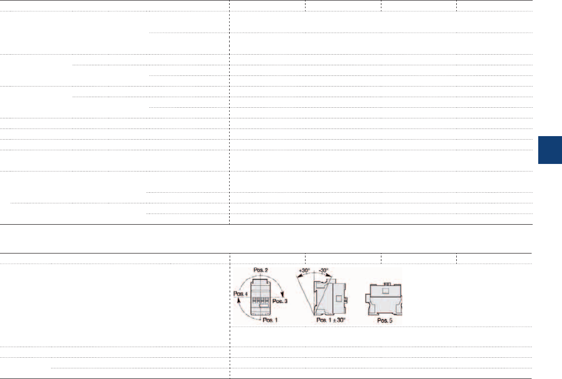
AF09 ... AF38 4-pole contactors
Technical data
Magnet system characteristics
Contactor types AC / DC operated AF09 AF16 AF26 AF38
Coil operating limits AC supply At θ ≤ 60 °C 0.85 x Uc min...1.1 x Uc max.
At θ ≤ 70 °C 0.85 x Uc min...Uc max.
acc. to IEC 60947-4-1
DC supply At θ ≤ 60 °C 0.85 x Uc min...1.1 x Uc max.
At θ ≤ 70 °C (AF) 0.85 x Uc min...Uc max. - (AF..Z) 0.85 x Uc min...1.1 x Uc max.
AC control voltage Rated control circuit voltage Uc 24...500 V AC
50/60 Hz Coil consumption Average pull-in value (AF) 50 VA - (AF..Z) 16 VA
Average holding value (AF) 2.2 VA / 2 W - (AF..Z) 1.7 VA / 1.5 W
DC control voltage Rated control circuit voltage Uc 12...500 V DC
Coil consumption Average pull-in value (AF) 50 W - (AF..Z) 12...16 W
Average holding value (AF) 2 W - (AF..Z) 1.7 W
PLC-output control (AF..Z) ≥ 500 mA 24 V DC
Drop-out voltage ≤ 60 % of Uc min.
Voltage sag immunity acc. to SEMI F47-0706 (AF..Z) conditions of use on request
Dips withstand (AF..Z) 22 ms average
-20 °C ≤ θ ≤ +60°C
Operating time
Between coil energization and: N.O. contact closing 40...95 ms
N.C. contact opening 38...90 ms
Between coil de-energization and: N.O. contact opening 11...95 ms
N.C. contact closing 13...98 ms
Mounting characteristics and conditions for use
Contactor types AF09 AF16 AF26 AF38
Mounting positions
Max. add-on N.C. auxiliary contacts:
see accessory fitting details for a 4-pole contactor AF09 ... AF38
Mounting distances The contactors can be assembled side by side
Fixing On rail according to IEC 60715, EN 60715 35 x 7.5 mm or 35 x 15 mm
By screws (not supplied) 2 x M4 screws placed diagonally
ABB | 5/79
5
1SBC101549S0201
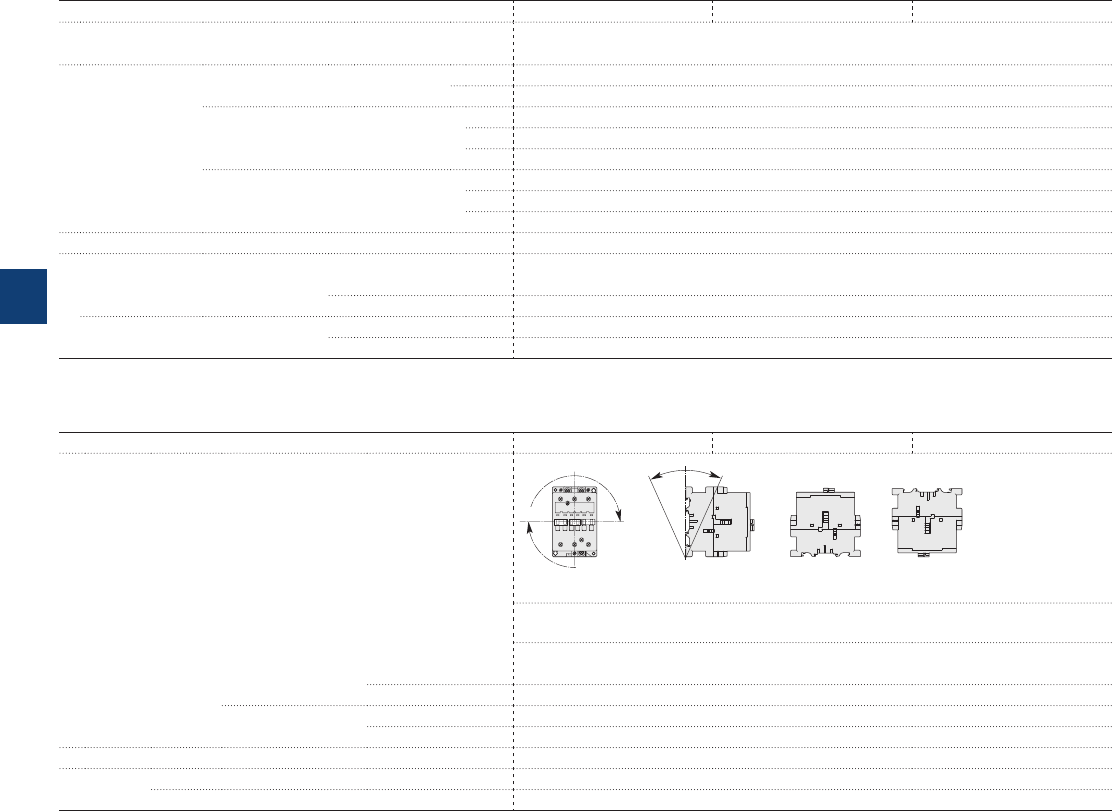
A45 ... A75 4-pole contactors
Technical data
Magnet system characteristics
Contactor types AC operated A45 A50 A75
Coil operating limits AC supply At θ ≤ 55 °C 0.85...1.1 x Uc
acc. to IEC 60947-4-1 Please also refer to "Mounting characteristics and conditions for use"
AC control voltage Rated control circuit voltage Uc at 50 Hz 24…690 V
at 60 Hz 24…690 V
Coil consumption Average pull-in value 50 Hz 180 VA
60 Hz 210 VA
50/60 Hz (1) 190 VA / 180 VA
Average holding value 50 Hz 18 VA / 5.5 W
60 Hz 18 VA / 5.5 W
50/60 Hz (1) 18 VA / 5.5 W
Drop-out voltage approx. 40...65 % of Uc
Operating time
Between coil energization and: N.O. contact closing 8…27 ms
N.C. contact opening 7…22 ms
Between coil de-energization and: N.O. contact opening 4…11 ms
N.C. contact closing 7…14 ms
(1) 50/60 Hz coils: see "Coil voltage code table".
Mounting characteristics and conditions for use
Contactor types AC operated A45 A50 A75
Mounting positions
Pos. 5 Pos. 6
Pos. 3
Pos. 2
Pos. 1 Pos. 1 ± 30°
+30° -30°
Pos. 4
Pos. 5 unauthorized for A45-22-00, A75-22-00
Max. add-on N.O. or N.C. auxiliary contacts: see accessory fitting details for 4-pole contactor
A45 ... A75
Control voltage / Ambient temperature
Mounting
positions (1)
1, 1±30°, 2, 3, 4, 5 at θ ≤ 55 °C 0.85…1.1 x Uc
at θ ≤ 70 °C Uc
6at θ ≤ 55 °C 0.95…1.1 x Uc
at θ ≤ 70 °C Unauthorized
Mounting distances The contactors can be assembled side by side
Fixing On rail according to IEC 60715, EN 60715 35 x 15 mm or 75 x 25 mm
By screws (not supplied) 2 x M6 screws placed diagonally
(1) For 60 Hz coil voltage: (only for devices fitted with CA 5-.. and CAL 5-11 auxiliary contacts or TP timer).
– A45-40-00, A50-40-00 and A75-40-00 contactors.
Mounting positions 1 to 5 and ambient temperature ≤ 55 °C: tolerance reduced to 0.9...1.1 Uc (instead of 0.85...1.1 Uc) for coil voltage codes 70 to 79 and 80 to 89.
– A45-22-00 and A75-22-00 contactors.
Mounting positions 1 to 4 and ambient temperature ≤ 55 °C: tolerance reduced to 0.9...1.1 Uc (instead of 0.85...1.1 Uc) for coil voltage codes 70 to 79 and 80 to 89.
For mounting position 6 or ambient temperature of 55 to 70 °C the information given on this page remains applicable.
5/80 | ABB
5
1SBC101550S0201
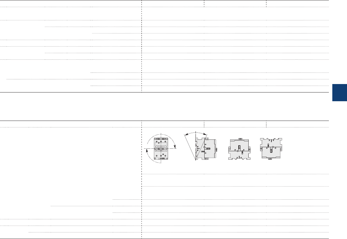
AE45 … AE75 4-pole contactors
Technical data
Magnet system characteristics
Contactor types DC operated AE45 AE50 AE75
Coil operating limits DC supply At θ ≤ 55 °C 0.85...1.1 x Uc
acc. to IEC 60947-4-1 Please also refer to "Mounting characteristics and conditions for use"
DC control voltage Rated control circuit voltage Uc 12…250 V DC
Coil consumption Average pull-in value 200 W
Average holding value 4 W
Drop-out voltage approx. 15...40 % of Uc
Coil time constant Open L/R 3 ms
Closed L/R 15 ms
Operating time
Between coil energization and: N.O. contact closing 13…30 ms
N.C. contact opening 10…27 ms
Between coil de-energization and: N.O. contact opening (1) 5…15 ms
N.C. contact closing (1) 8…18 ms
(1) The use of surge suppressors increases the opening time with a factor of 1.1 to 1.5 for RV5 surge suppressor and a factor of 1.5 to 3 for RT5 surge suppressor.
Mounting characteristics and conditions for use
Contactor types DC operated AE45 AE50 AE75
Mounting positions
Pos. 5 Pos. 6
Pos. 3
Pos. 2
Pos. 1 Pos. 1 ± 30°
+30° -30°
Pos. 4
Pos. 5 unauthorized for AE45-22-00, AE75-22-00
Max. add-on N.O. or N.C. auxiliary contacts: see accessory fitting details for 4-pole contactor
AE45 … AE75 (1)(2)
Control voltage / Ambient temperature
Mounting
positions
1, 1±30°, 2, 3, 4, 5 at θ ≤ 55 °C 0.85…1.1 x Uc
at θ ≤ 70 °C Uc
6at θ ≤ 55 °C 0.95…1.1 x Uc
at θ ≤ 70 °C Unauthorized
Mounting distances The contactors can be assembled side by side
Fixing On rail according to IEC 60715, EN 60715 35 x 15 mm or 75 x 25 mm
By screws (not supplied) 2 x M6 screws placed diagonally
ABB | 5/81
5
1SBC101552S0201
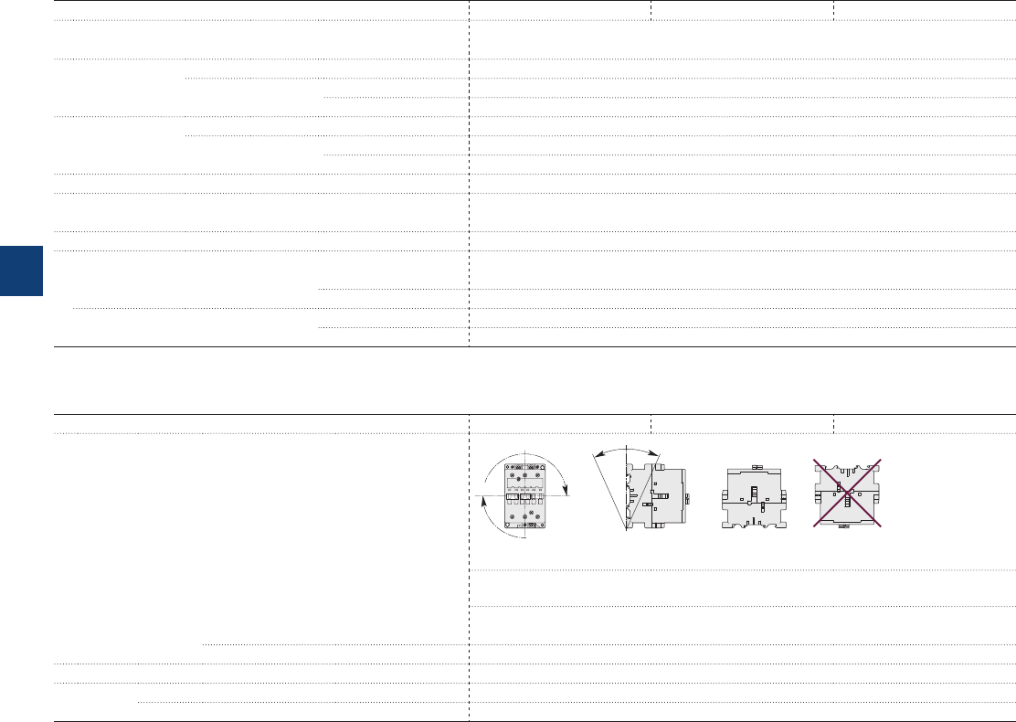
AF45 … AF75 4-pole contactors
Technical data
Magnet system characteristics
Contactor types AC / DC operated AF45 AF50 AF75
Coil operating limits AC or DC supply At θ ≤ 70 °C 0.85 x Uc min...1.1 x Uc max.
Please also refer to "Mounting characteristics and conditions for use"
acc. to IEC 60947-4-1
AC control voltage Rated control circuit voltage Uc 48…250 V
50/60 Hz Coil consumption Average pull-in value 210 VA
Average holding value 7 VA / 2.8 W
DC control voltage Rated control circuit voltage Uc 20…250 V DC
Coil consumption Average pull-in value 190 W
Average holding value 2.8 W
Drop-out voltage 55 % of Uc min.
Voltage sag immunity Conditions of use on request
acc. to SEMI F47
Dips withstand ≥ 20 ms
Operating time
Between coil energization and: N.O. contact closing 30…100 ms
N.C. contact opening 27…95 ms
Between coil de-energization and: N.O. contact opening 30…110 ms
N.C. contact closing 35…115 ms
Mounting characteristics and conditions for use
Contactor types AC / DC operated AF45 AF50 AF75
Mounting positions
Pos. 5 Pos. 6
Pos. 3
Pos. 2
Pos. 1 Pos. 1 ± 30°
+30° -30°
Pos. 4
Pos. 5 unauthorized for AF45-22-00, AF75-22-00 contactors
Max. and add-on N.O. or N.C. auxiliary contacts: see accessory fitting details for 4-pole con-
tactor AF45 ... AF110
Control voltage / Ambient temperature
Mounting 1, 1±30°, 2, 3, 4, 5 at θ ≤ 70 °C 0.85 x Uc min…1.1 x Uc max.
positions 6 Unauthorized
Mounting distances The contactors can be assembled side by side
Fixing On rail according to IEC 60715, EN 60715 35 x 15 mm or 75 x 25 mm
By screws (not supplied) 2 x M6 screws placed diagonally
5/82 | ABB
5
1SBC101551S0201
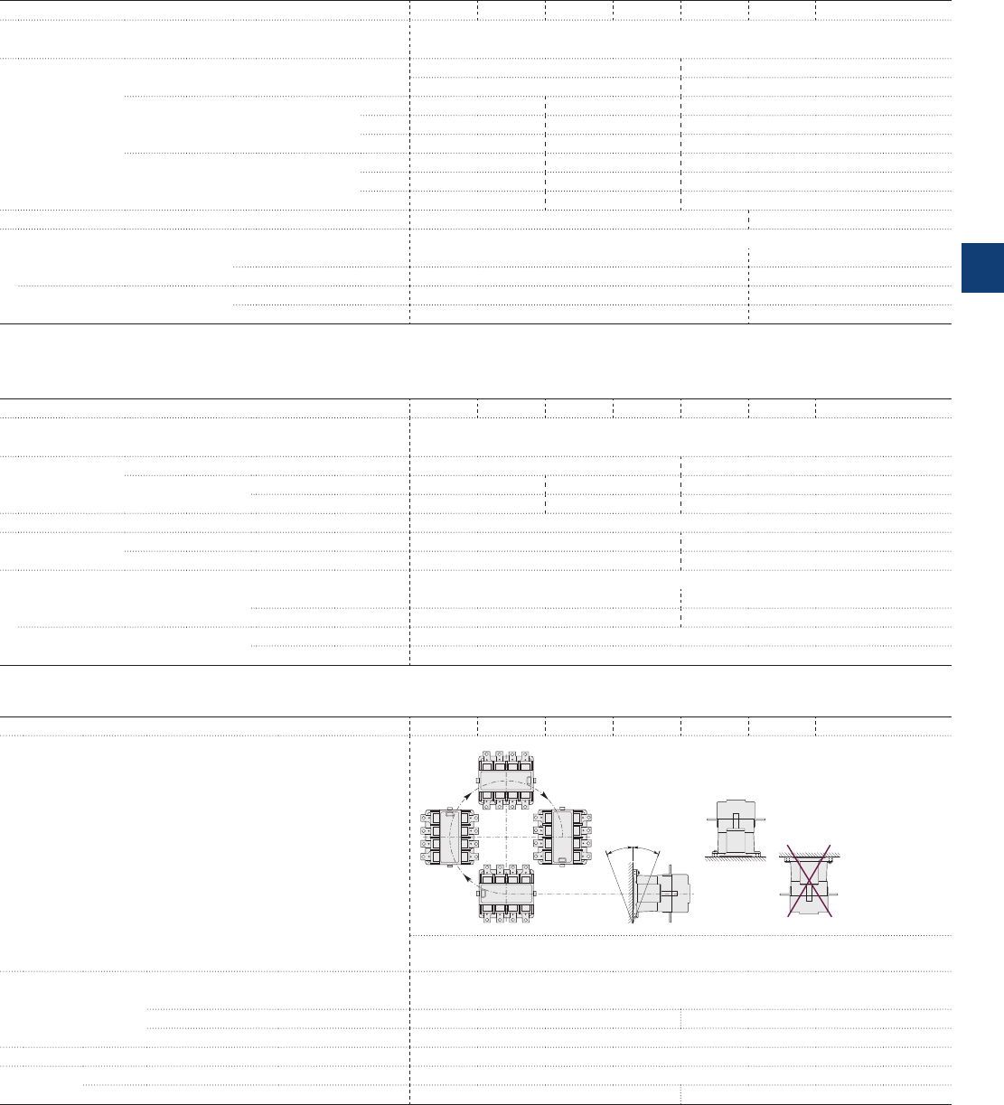
EK110 ... EK1000 4-pole contactors
Technical data
Magnet system characteristics
Contactor types AC operated EK110 EK150 EK175 EK210 EK370 EK550 EK1000
Coil operating limits AC supply At θ ≤ 70 °C 0.85 x Uc min...1.1 x Uc max.
Please also refer to "Mounting characteristics and conditions for use"
acc. to IEC 60947-4-1
AC control voltage Rated control circuit voltage 50 Hz 24...500 V 48...500 V
60 Hz 24...600 V 110...600 V
Coil consumption Average pull-in value 50 Hz 800 VA 1100 VA 3500 VA
60 Hz 900 VA 1200 VA 4000 VA
50/60 Hz (1) 500 /500 VA 630 / 630 VA 3800 / 3400 VA
Average holding value 50 Hz 44 VA / 15 W 52 VA / 18 W 125 VA / 50 W
60 Hz 52 VA /18 W 65 VA / 22 W 140 VA / 60 W
50/60 Hz (1) 2.5 VA / 2.5 W 2.5 VA / 2.5 W 140 VA /60 W
Drop-out voltage in % of Uc min. approx. 45...65 % (20...50 % for "E" coil voltage codes) approx. 45...65 %
Operating time
Between coil energization and: N.O. contact closing 20...40 (1) / 30...50 (2) ms 30...60 ms
N.C. contact opening 15...35 (1)
/ 25...45 (2)
ms 25...55 ms
Between coil de-energization and: N.O. contact opening 7.5...15 (1)
/ 95...120 (2) ms 10...20 ms
N.C. contact closing 10...18 (1) / 100...125 (2)
ms 13...23 ms
(1) "A" coil voltage: see "Coil voltage code table".
(2) 50/60 Hz "E" coil voltage codes, see "Coil voltage code table".
Magnet system characteristics
Contactor types DC operated EK110 EK150 EK175 EK210 EK370 EK550 EK1000
Coil operating limits DC supply At θ ≤ 70 °C 0.85 x Uc min...1.1 x Uc max.
Please also refer to "Mounting characteristics and conditions for use"
acc. to IEC 60947-4-1
DC control voltage Rated control circuit voltage 12...220 24...220
Coil consumption Average pull-in value 500 W 630 W 1100 W
Average holding value 2.5 W 2.5 W 20 W
Drop-out voltage approx. 15...50 % of Uc min.
Coil time constant Open L/R 8 ms 12 ms
Closed L/R 50 ms 60 ms
Operating time
Between coil energization and: N.O. contact closing 30...50 ms 60...80 ms
N.C. contact opening 27...47 ms 55...75 ms
Between coil de-energization and: N.O. contact opening 10...35 ms
N.C. contact closing 13...38 ms
Mounting characteristics and conditions for use
Contactor types AC / DC operated EK110 EK150 EK175 EK210 EK370 EK550 EK1000
Mounting positions
ABB
ABB
ABB
ABB
E1863D1
Position 1
Position 3
Position 4
Position 2
Position 5
Position 1 30
+30
-30
Position 6
Max. N.O. or N.C. built-in and add-on N.O. or N.C. auxiliary contacts: see accessory fitting
details for 4-pole contactor EK110 ... EK1000
Control voltage / Ambient temperature
Mounting
positions
1, 1±30°, 2, 3, 4, 5 at θ ≤ 70 °C 0.85…1.1 x Uc
2at θ ≤ 70 °C Unauthorized 0.85...1.1 x Uc
6at θ ≤ 70 °C Unauthorized
Mounting distances The contactors can be assembled side by side
Fixing On rail according to IEC 60715, EN 60715 –
By screws (supplied) 4 x M6 4 x M6 (1)
(1) Damping elements are supplied.
ABB | 5/83
5
1SFC101032C0201
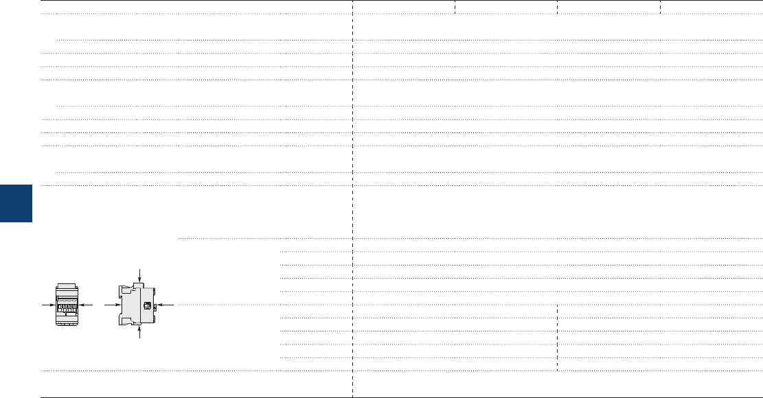
AF09 ... AF38 4-pole contactors
Technical data
General technical data
Contactor types AF09 AF16 AF26 AF38
Rated insulation voltage Ui
acc. to IEC 60947-4-1 690 V
acc. to UL / CSA 600 V
Rated impulse withstand voltage Uimp. 6 kV
Electromagnetic compatibility Devices complying with IEC 60947-1 / EN 60947-1 - Environment A
Ambient air temperature close to contactor
Operation -40...+70 °C
Storage -60...+80 °C
Climatic withstand Category B according to IEC 60947-1 Annex Q
Maximum operating altitude (without derating) 3000 m
Mechanical durability
Number of operating cycles 10 millions operating cycles
Max. switching frequency 3600 cycles/h
Shock withstand
acc. to IEC 60068-2-27 and EN 60068-2-27
Mounting position 1
Shock direction 1/2 sinusoidal shock for 11 ms: no change in contact position, closed or open position
B2
AAB1
C2
C1
4 N.O.
Main poles
A30 g
B1 25 g closed position / 5 g open position
B2 15 g
C1 25 g
C2 25 g
2 N.O. + 2 N.C.
Main poles
A30 g 30 g closed position / 25 g open position
B1 25 g closed position / 5 g open position 25 g closed position / 5 g open position
B2 15 g 15 g closed position / 10 g open position
C1 25 g 25 g closed position / 20 g open position
C2 25 g 25 g closed position / 20 g open position
Vibration withstand 5...300 Hz
acc. to IEC 60068-2-6 4 g closed position / 2 g open position
5/84 | ABB
5
1SBC101556S0201
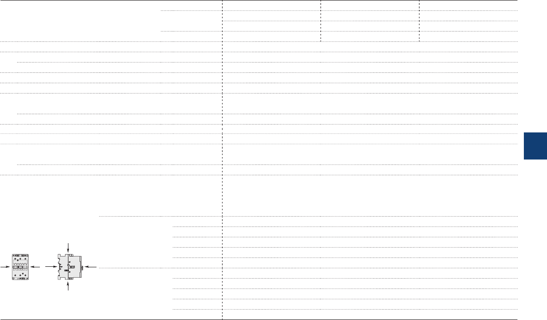
A45 ... A75, AE, TAE and
AF45 … AF75 4-pole contactors
Technical data
General technical data
Contactor types AC operated A45 A50 A75
DC operated AE45 AE50 AE75
TAE45 TAE50 TAE75
AC / DC operated AF45 AF50 AF75
Rated insulation voltage Ui
acc. to IEC 60947-4-1 1000 V
acc. to UL / CSA 600 V
Rated impulse withstand voltage Uimp. 8 kV
Electromagnetic compatibility AF contactors complying with IEC 60947-1 / EN 60947-1 - Environment A
Ambient air temperature close to contactor
Operation -40...+70 °C (1)
Storage -60...+80 °C
Climatic withstand acc. to IEC 60068-2-30 and 60068-2-11 - UTE C 63-100 specification II
Maximum operating altitude (without derating) 3000 m
Mechanical durability
Number of operating cycles 10 millions operating cycles (5 millions for AE... and TAE... contactors)
Max. switching frequency 3600 cycles/h (300 for AF...)
Shock withstand
acc. to IEC 60068-2-27 and EN 60068-2-27
Mounting position 1
Shock direction 1/2 sinusoidal shock for 11 ms: no change in contact position, closed or open position
B2
AAB1
C2
C1
4 N.O.
Main poles
A20 g
B1 10 g closed position / 5 g open position
B2 15 g
C1 20 g
C2 20 g
2 N.O. + 2 N.C.
Main poles
A20 g
B1 10 g closed position / 5 g open position (2)
B2 15 g (3)
C1 20 g
C2 20 g
(1) 55 °C max. for TAE... contactors.
(2) 3 g in open position for AF 45-22, AE 45-22, AF 75-22 and AE 75-22.
(3) 10 g for AF 45-22, AE 45-22, AF 75-22 and AE 75-22.
ABB | 5/85
5
1SBC101557S0201
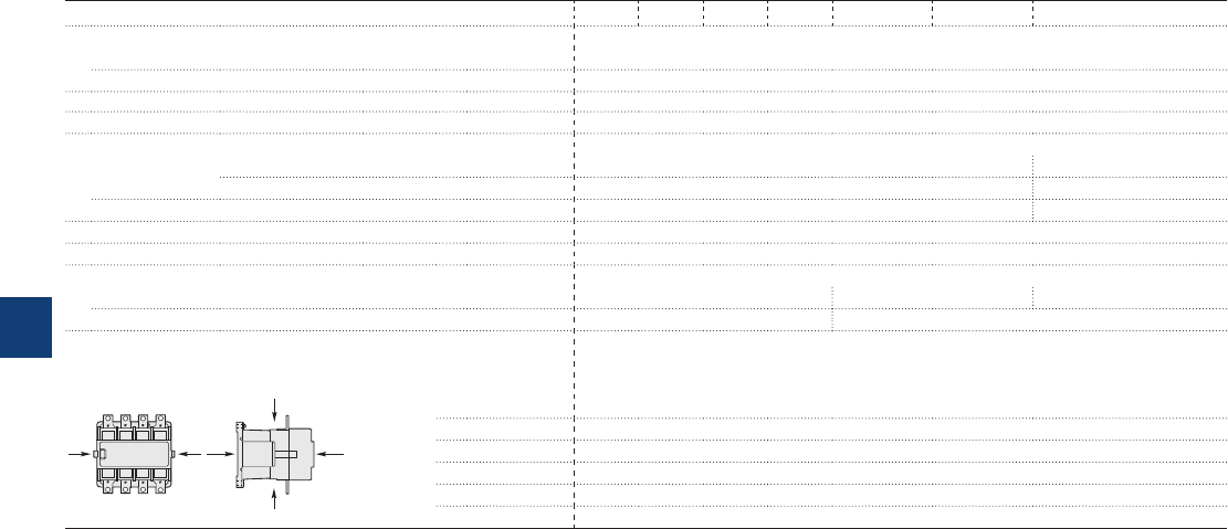
EK110 ... EK1000 4-pole contactors
Technical data
General technical data
Contactor types AC or DC operated EK110 EK150 EK175 EK210 EK370 EK550 EK1000
Rated insulation voltage Ui
acc. to IEC 60947-4-1 1000 V
acc. to UL 600 V
Rated impulse withstand voltage Uimp. 8 kV
Electromagnetic compatibility EK contactors complying with IEC 60947-1 / EN 60947-1 - Environment A
Ambient air temperature close to contactor
Operation Fitted with thermal overload relay -25 to +55 °C -
Without thermal overload relay -40 to +70 °C -
Storage -50 to +70 °C -
Climatic withstand Category B acc. to IEC 60068-2-30
Maximum operating altitude (without derating) ≤ 3000 m
Mechanical durability
Number of operating cycles 10 millions operating cycles 5 millions operating cycles 3 millions operating cycles
Max. switching frequency 3600 cycles/h 60 cycles/h
Shock withstand
acc. to IEC 60068-2-27 and EN 60068-2-27
Mounting position 1
B2
AAB1
C2
C1
E1862D
ABB
Closed
or open
position
Shock direction 1/2 sinusoidal shock for 15 ms: no change in contact position, closed or open position
A10 g
B1 10 g
B2 10 g
C1 10 g
C2 10 g
5/86 | ABB
5
1SFC101031C0201
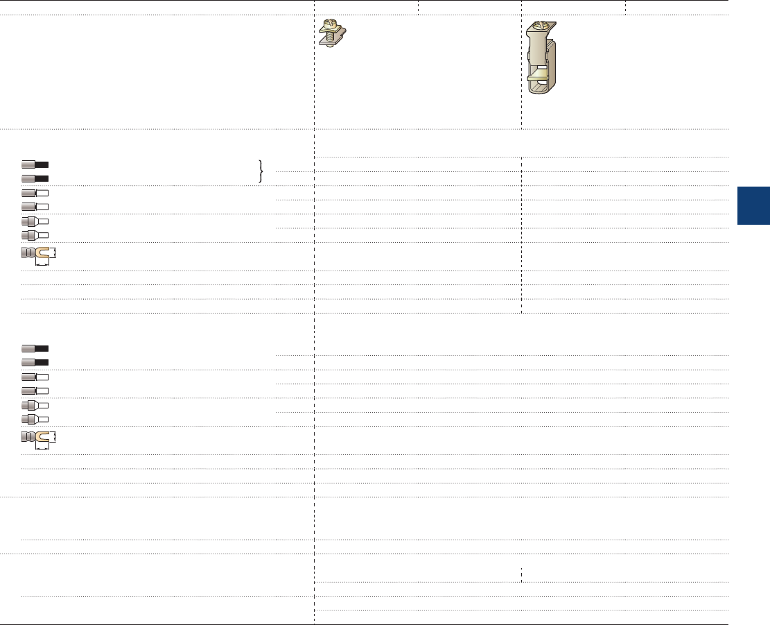
AF09 ... AF38 4-pole contactors
Technical data
Connecting characteristics
Contactor types AF09 AF16 AF26 AF38
Main terminals
Screw terminals with cable clamp Screw terminals with double connector
2 x (5.5 width x 6.8 depth)
Connection capacity (min. ... max.)
Main conductors (poles)
Rigid Solid (≤ 4 mm²) 1 x 1...6 mm² 1.5...16 mm²
Stranded (≥ 6 mm²) 2 x 1...6 mm² 1.5...16 mm²
Flexible with non insulated ferrule 1 x 0.75...6 mm² 1.5...16 mm²
2 x 0.75...6 mm² 1.5...16 mm²
Flexible with insulated ferrule 1 x 0.75...4 mm² 1.5...16 mm²
2 x 0.75...2.5 mm² 1.5...16 mm²
L
6
Bars or lugs L < 9.6 mm -
Connection capacity acc. to UL/CSA 1 or 2 x AWG 16...10 AWG 16...6
Stripping length 10 mm 12 mm
Tightening torque 1.5 Nm / 13 lb.in 2.5 Nm / 22 lb.in
Auxiliary conductors
(coil terminals)
Rigid solid 1 x 1...2.5 mm²
2 x 1...2.5 mm²
Flexible with non insulated ferrule 1 x 0.75...2.5 mm²
2 x 0.75...2.5 mm²
Flexible with insulated ferrule 1 x 0.75...2.5 mm²
2 x 0.75...1.5 mm²
L
6
Lugs L < 8 mm
Connection capacity acc. to UL/CSA 1 or 2 x AWG 18...14
Stripping length 10 mm
Tightening torque 1.2 Nm / 11 lb.in
Degree of protection
acc. to IEC 60947-1 / EN 60947-1 and IEC 60529 / EN 60529
Main terminals IP20
Coil terminals IP20
Screw terminals Delivered in open position, screws of unused terminals must be tightened
Main terminals M3.5 M4.5
Screwdriver type Flat Ø 5.5 / Pozidriv 2
Coil terminals M3.5
Screwdriver type Flat Ø 5.5 / Pozidriv 2
ABB | 5/87
5
1SBC101565S0201
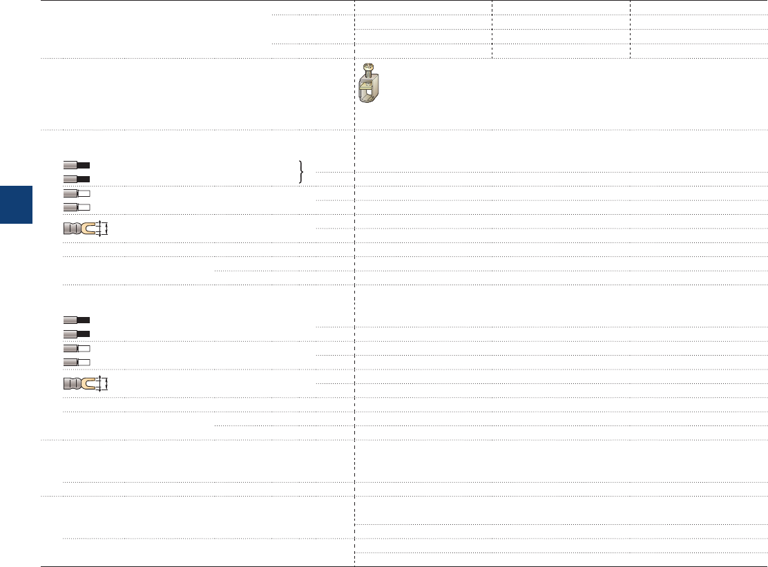
A45 ... A75, AE, TAE and
AF45 … AF75 4-pole contactors
Technical data
Connecting characteristics
Contactor types AC operated A45 A50 A75
DC operated AE45 AE50 AE75
TAE45 TAE50 TAE75
AC / DC operated AF45 AF50 AF75
Main terminals
Screw terminals with single connector
(13 x 10 mm)
Connection capacity (min. ... max.)
Main conductors (poles)
Rigid Solid (≤ 4 mm²) 1 x 6…50 mm²
Stranded (≥ 6 mm²) 2 x 6…25 mm²
Flexible with ferrule 1 x 6…35 mm²
2 x 6…16 mm²
L
l
Bars or lugs L ≤ -
l > -
Connection capacity acc. to UL/CSA 1 or 2 x AWG 8…1
Tightening torque Recommended 4.00 Nm / 35 lb.in
Max. 4.50 Nm
Auxiliary conductors
(built-in auxiliary terminals + coil terminals)
Rigid solid 1 x 1…4 mm²
2 x 1…4 mm²
Flexible with ferrule 1 x 1…2.5 mm²
2 x 0.75…2.5 mm²
L
l
Lugs L ≤ 8 mm
l > 3.7 mm
Connection capacity acc. to UL/CSA 1 or 2 x AWG 18…14
Tightening torque Recommended 1.00 Nm / 9 lb.in
Max. 1.20 Nm
Degree of protection
acc. to IEC 60947-1 / EN 60947-1 and IEC 60529 / EN 60529
Main terminals IP10
Coil terminals IP20
Screw terminals Delivered in open position, screws of unused terminals must be tightened
Main terminals M6
Screwdriver type Flat Ø 6.5 / Pozidriv 2
Coil terminals M3.5
Screwdriver type Flat Ø 5.5 / Pozidriv 2
5/88 | ABB
5
1SBC101567S0201
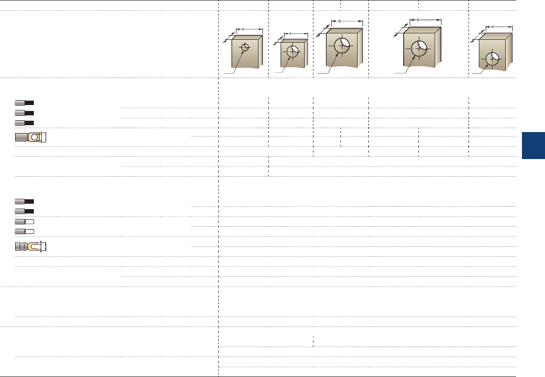
EK110 ... EK1000 4-pole contactors
Technical data
Connecting characteristics
Contactor types AC or DC operated EK110 EK150 EK175 EK210 EK370 EK550 EK1000
Main terminals
Flat type
E1864D
15
ø 6.6
4.5
E1865D
20
ø 11
4
E1866D
20
ø 11
5
E1867D
25
ø 11
6
E1868D
40
ø 11
8
Connection capacity (min. ... max.)
Main conductors (poles)
Rigid with
connector
Single for Cu cable
25...120 mm² 25...185 mm² 25...185 mm² 70...300 mm² -
Single for Al/Cu cable
10...70 mm² 35...120 mm² 35...120 mm² 70...300 mm² 95...300 mm²
Double for Al/Cu cable
- - - 2 x 35...185 2 x 95...300
L
ø
Bars or lugs L ≤
30 mm 30 mm 33 mm 33 mm 55 mm 55 mm 55 mm
Ø >
6 mm 10 mm 10 mm 10 mm 10 mm 10 mm 10 mm
Connection capacity acc. to UL/CSA 1 or 2 x
8 -3 /0 AWG 6 - 250 MCM
2 x 4 - 500 MCM 3 x 4 - 500 MCM
-
Tightening torque Recommended
5 Nm/44 Ib.in
18 Nm / 160 Ib.in
Max. 6 Nm 22 Nm
Auxiliary conductors
(coil terminals)
Rigid solid 1 x 0.5…2.5 mm²
2 x 0.5…2.5 mm²
Flexible with ferrule 1 x 0.5…2.5 mm²
2 x 0.5…2.5 mm²
L
l
Bars or lugs L ≤ 8 mm
l > 3.7 mm
Connection capacity acc. to UL/CSA 1 or 2 x 18…14 AWG
Tightening torque Recommended 1.00 Nm / 9 lb.in
Max. 1.20 Nm
Degree of protection
acc. to IEC 60947-1 / EN 60947-1 and IEC 60529 / EN 60529
Main terminals IP00
Coil terminals IP20
Screw terminals
Main terminals M6 M10
Screws and bolts
Coil terminals (delivered in open positions) M3.5
Screwdriver type Flat Ø 5.5 mm / Pozidriv 2
ABB | 5/89
5
1SFC101034C0201

4-pole contactors
Electrical durability and utilization categories
General
Utilization categories determine the current making and breaking conditions relating to the characteristics of the loads to be
controlled by the contactors. International standard IEC 60947-4-1 and European standard EN 60947-4-1 are the standards
to be referred to. If Ic is the current to be broken by the contactor and Ie the rated operational current normally drawn by the
load, then Ic = Ie for category AC-1. The curve corresponding to category AC-1 represents the electrical durability variation of
standard contactors in relation to the breaking current Ic.
Electrical durability is expressed in millions of operating cycles.
Curve utilization mode
Electrical durability forecast and contactor selection for category AC-1
t Note the characteristics of the load to be controlled:
– Operational voltage ........................................................................... Ue
– Current normally drawn ..................................................................... Ie
– Utilization category ........................................................................... AC-1
– Breaking current ............................................................................... Ic = Ie for AC-1
t Define the number of operating cycles N required.
t On the diagram corresponding to the operational category, select the contactor with the curve immediately above the inter-
section point (Ic ; N).
Case of uninterrupted duty
For uninterrupted duty, some verifications of preventing maintenance are necessary to check the functionality of the concerned
product (consult us). The combinated effect of environmental conditions and the proper temperature of the product may require
some disposals. As a matter of fact, for this duty, the use duration prevails over the number of operating cycles.
5/90 | ABB
5
1SBC101546S0201
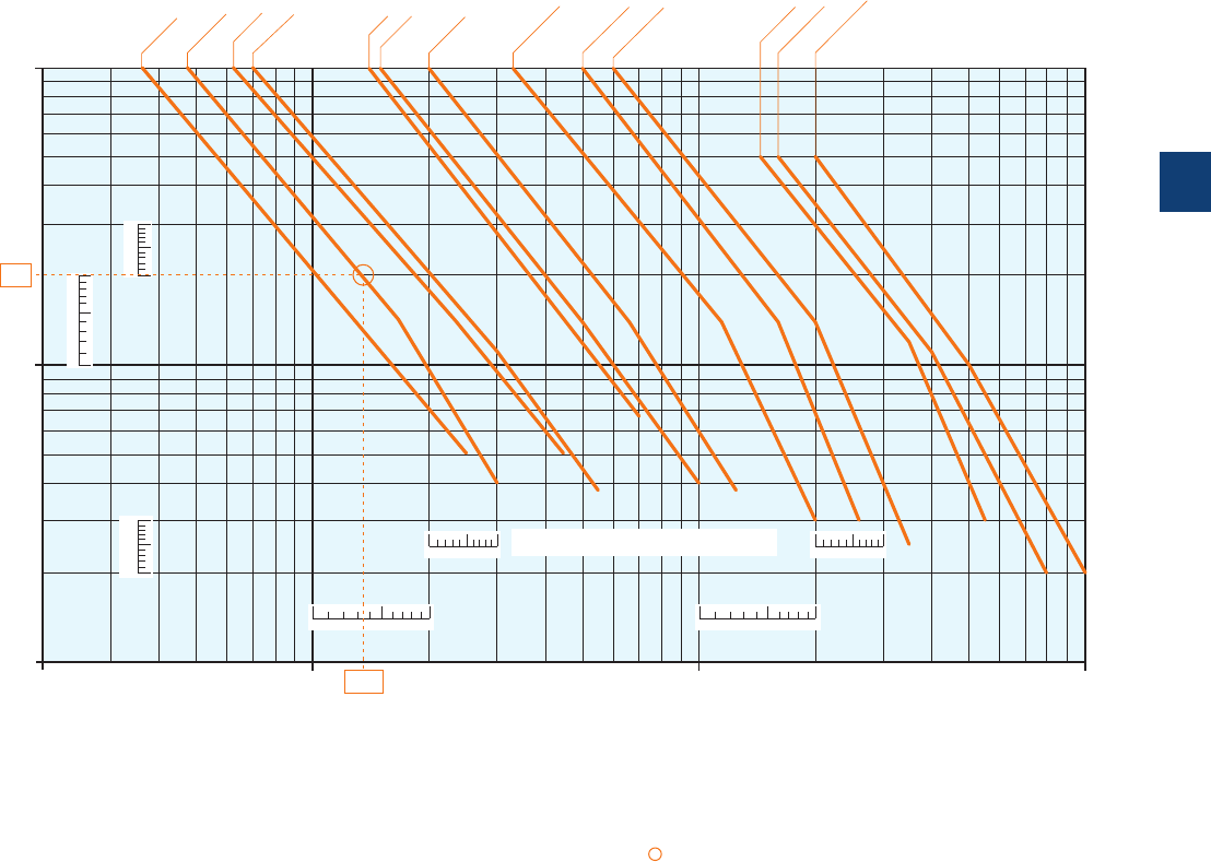
4-pole contactors
Electrical durability
Electrical durability for AC-1 utilization category - Ue ≤ 690 V
Ambient temperature ≤ 60 °C for AF09 ... AF38, ≤ 55 °C for A45 ... EK1000
Switching non-inductive or slightly inductive loads. The breaking current Ic for AC-1 is equal to the rated operational current of
the load.
Maximum electrical switching frequency: see "Technical data".
13579
13579
1
3
5
7
9
1
3
5
7
9
13579
13579
1
3
5
7
9
10
1
0.1
0.2
0.3
0.5
3
5
10 100 10002 3 5 20 30 50 200 300 500
A45
A50
A75
13.5
2
EK1000
EK110
EK150
EK175
EK210
EK370
EK550
AF09
AF16
AF26
AF38
The curves provided for the A45 ... A75 contactors
can be used for the AE, TAE and AF equivalent types
Millions of
operating
cycles
Breaking current Ic (A)
Example:
Ic / AC-1 = 13.5 A – Electrical durability required = 2 millions operating cycles.
Using the AC-1 curves above select the AF16 contactor at intersection " " (13.5 A / 2 millions operating cycles).
ABB | 5/91
5
1SBC101568S0201
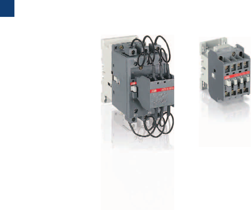
5/92 | ABB
5
1SBC101611S0201

Contactors for capacitor switching
Overview 5/94
UA16..RA up to UA110..RA - Unlimited peak Î
Ordering details 5/96
Technical data 5/99
UA16 up to UA110 - Peak current Î ≤ 100 times the rms current
Ordering details 5/101
Technical data 5/104
ABB | 5/93
5
1SBC101611S0201
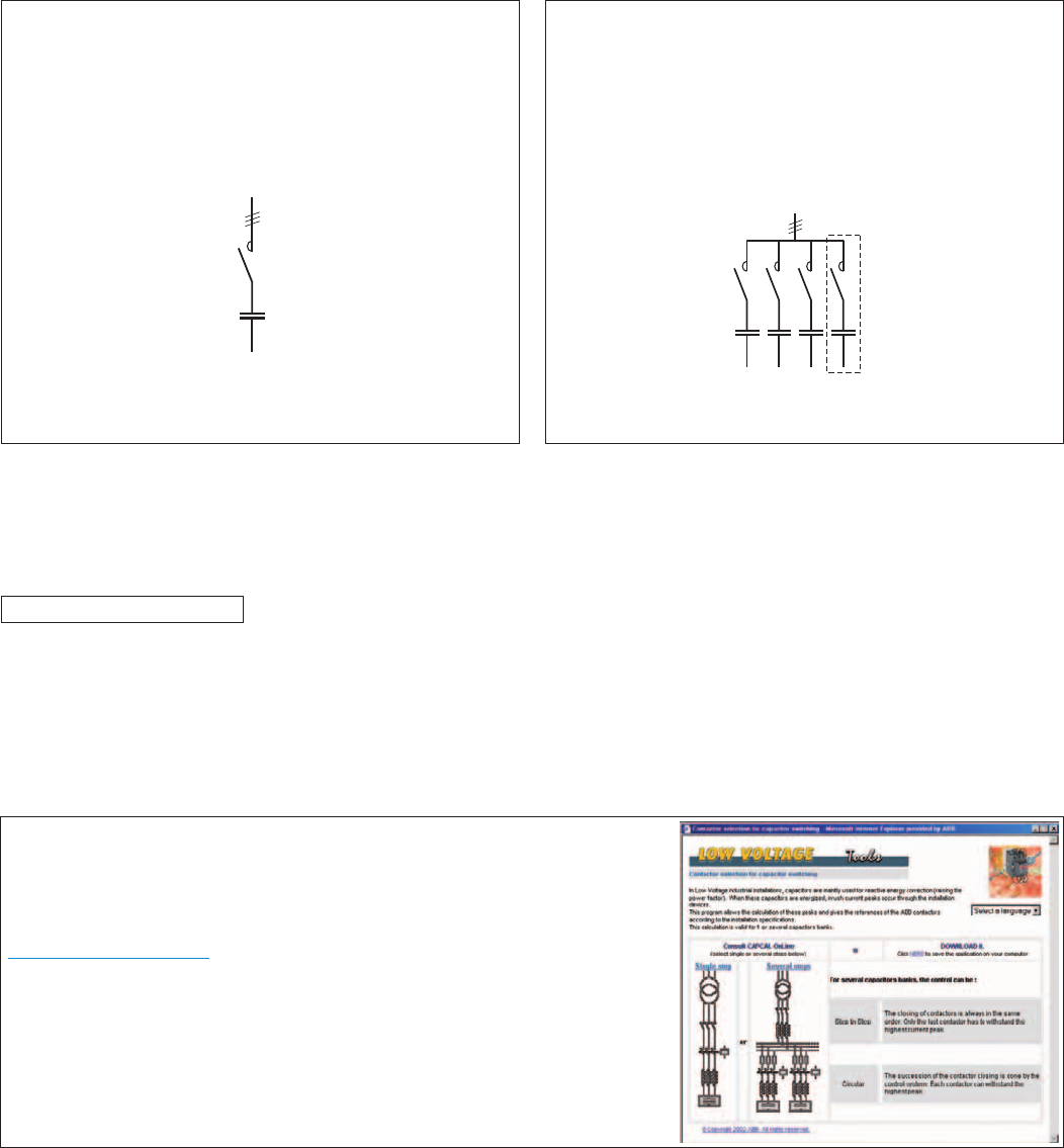
Contactors for capacitor switching
AC-6b utilization category according to IEC 60947-4-1
E1178D
E1179D
Capacitor transient conditions
In Low Voltage industrial installations, capacitors are mainly used for reactive energy correction (raising the power factor). When these capacitors
are energized, overcurrents of high amplitude and high frequencies (3 to 15 kHz) occur during the transient period (1 to 2 ms).
The amplitude of these current peaks, also known as "inrush current peaks", depends on the following factors:
– The network inductances.
– The transformer power and short-circuit voltage.
– The type of power factor correction.
There are 2 types of power factor correction: fixed or automatic.
Fixed power factor correction consists of inserting, in parallel on
the network, a capacitor bank whose total power is provided by the
assembly of capacitors of identical or different ratings.
The bank is energized by a contactor that simultaneously supplies all
the capacitors (a single step).
The inrush current peak, in the case of fixed correction, can reach 30
times the nominal current of the capacitor bank.
Single-step capacitor bank scheme
Use the A/AF... contactor ranges.
An automatic power factor correction system, on the other hand,
consists of several capacitor banks of identical or different ratings
(several steps), energized separately according to the value of the
power factor to be corrected.
An electronic device automatically determines the power of the
steps to be energized and activates the relevant contactors.
The inrush current peak, in the case of automatic correction, de-
pends on the power of the steps already on duty, and can reach 100
times the nominal current of the step to be energized.
Multi-step capacitor bank scheme
Use the UA... or UA..RA contactor ranges.
Steady state condition data
The presence of harmonics and the network's voltage tolerance lead to a current, estimated to be 1.3 times the nominal current In of the capaci-
tor, permanently circulating in the circuit.
Taking into account the manufacturing tolerances, the exact power of a capacitor can reach 1.15 times its nominal power.
Standard IEC 60831-1 Edition 2002 specifies that the capacitor must therefore have a maximum thermal current IT of:
IT = 1.3 x 1.15 x In = 1.5 x In
Consequences for the contactors
To avoid malfunctions (welding of main poles, abnormal temperature rise, etc.), contactors for capacitor bank switching must be sized to with-
stand:
–A permanent current that can reach 1.5 times the nominal current of the capacitor bank.
–The short but high peak current on pole closing (maximum permissible peak current Î ).
Contactor selection tool for capacitor switching
In a given application, if the user does not know the value of the inrush current peak,
this value can be approximately calculated using the formulas given on the pages
"Calculation and dimensioning".
Alternatively by the CAPCAL selection tool, available on the ABB Website:
www.abb.com/lowvoltage
right hand side menu
search: "Online product selection tools"
select: "Contactors: AC-6b capacitor switching"
This program allows the calculation of these peaks and gives the references of the
ABB contactors according to the installation specifications. This calculation is valid for
one or several capacitor banks.
5/94 | ABB
1SBC101603S0201
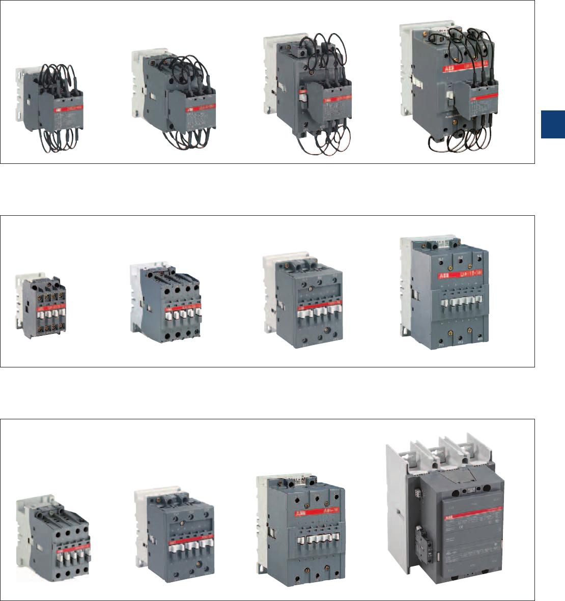
Contactors for capacitor switching
The ABB solutions
1SBC580783F0303
1SBC580105F0303
1SBC573242F0301
1SBC587774F0301
1SBC587794F0301
1SBC587764F0301
1SFC101034F0201
1SBC591694F0303
1SBC591444F0302
1SBC580093F0303
1SBC580753F0301
1SBC101355F0014
ABB offers 3 contactor versions according to the value of the inrush current peak and the power of the capacitor bank.
UA..RA contactors for capacitor switching (UA16..RA to UA110..RA) with insertion of damping resistors.
The insertion of damping resistors protects the contactor and the capacitor from the highest inrush currents.
UA... contactors for capacitor switching (UA16 to UA110)
Maximum permissible peak current Î ≤ 100 times the nominal rms current of the switched capacitor.
A... and AF... standard contactors
Maximum permissible peak current Î ≤ 30 times the nominal rms current of the switched capacitor.
Please consult us.
ABB | 5/95
5
1SBC101604S0201
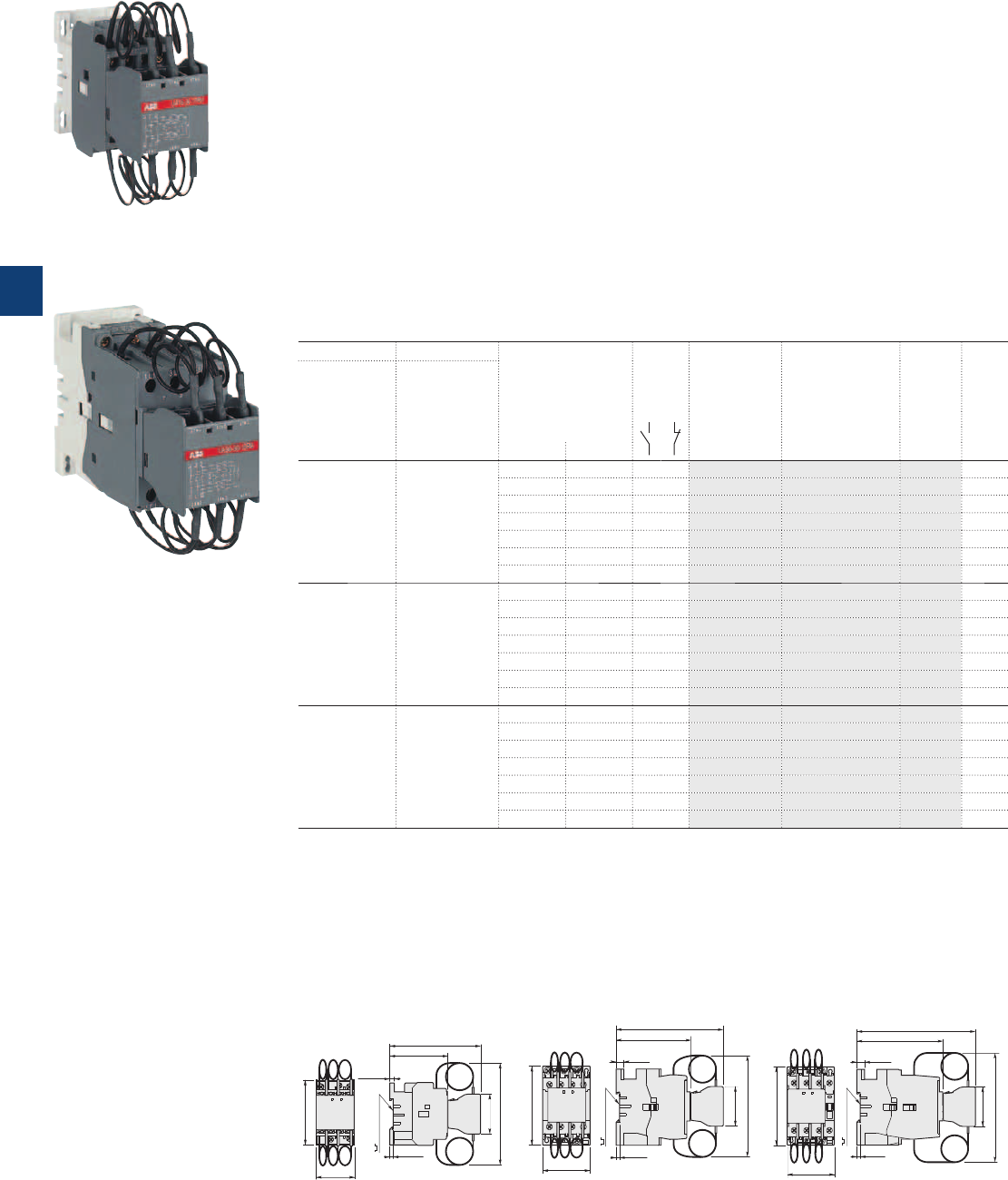
1SBC587794F0301
UA16-30-10RA
1SBC587774F0301
UA30-30-10RA
UA16..RA … UA30..RA 3-pole contactors for capacitor switching
12.5 to 30 kvar - Unlimited peak current Î
AC operated
Description
UA..RA contactors for capacitor switching can be used for installations in which the peak current far
exceeds 100 times nominal rms current. The contactors are delivered complete with their damping resistors
and must be used without additional inductances.
The capacitors must be discharged (maximum residual voltage at terminals ≤ 50 V) before being re-energized
when the contactors are making.
These contactors are of the block type design with:
– 3 main poles and 1 built-in auxiliary contact
– the UA..RA contactors are fitted with a special front-mounted block, which ensures the serial insertion of 3
damping resistors into the circuit to limit the current peak on energization of the capacitor bank
- their connection also ensures capacitor precharging in order to limit the second current peak occurring
upon making of the main poles
- the insertion of resistors allows to damp the highest current peak of the capacitor when switching on,
whatever its level.
– control circuit: AC operated
– add-on auxiliary contact blocks for side mounting and a wide range of accessories.
Ordering details
IEC UL/CSA Rated control circuit
voltage
Uc
(1)
Auxiliary
contacts
fitted
Type Order code Weight
Pkg
(1 pce)
Rated operational
power Rated operational
power
θ ≤ 40 °C θ ≤ 40 °C
400V 480V
AC-6b
kvar kvar V 50Hz V 60Hz kg
12.5 16 24 24 1 0 UA16-30-10RA 1SBL181024R8110 0.460
48 48 1 0 UA16-30-10RA 1SBL181024R8310 0.460
110 110…120 1 0 UA16-30-10RA 1SBL181024R8410 0.460
220…230 230…240 1 0 UA16-30-10RA 1SBL181024R8010 0.460
230…240 240…260 1 0 UA16-30-10RA 1SBL181024R8810 0.460
380…400 400…415 1 0 UA16-30-10RA 1SBL181024R8510 0.460
400…415 415…440 1 0 UA16-30-10RA 1SBL181024R8610 0.460
22 22 24 24 1 0 UA26-30-10RA 1SBL241024R8110 0.710
48 48 1 0 UA26-30-10RA 1SBL241024R8310 0.710
110 110…120 1 0 UA26-30-10RA 1SBL241024R8410 0.710
220…230 230…240 1 0 UA26-30-10RA 1SBL241024R8010 0.710
230…240 240…260 1 0 UA26-30-10RA 1SBL241024R8810 0.710
380…400 400…415 1 0 UA26-30-10RA 1SBL241024R8510 0.710
400…415 415…440 1 0 UA26-30-10RA 1SBL241024R8610 0.710
30 28 24 24 1 0 UA30-30-10RA 1SBL281024R8110 0.810
48 48 1 0 UA30-30-10RA 1SBL281024R8310 0.810
110 110…120 1 0 UA30-30-10RA 1SBL281024R8410 0.810
220…230 230…240 1 0 UA30-30-10RA 1SBL281024R8010 0.810
230…240 240…260 1 0 UA30-30-10RA 1SBL281024R8810 0.810
380…400 400…415 1 0 UA30-30-10RA 1SBL281024R8510 0.810
400…415 415…440 1 0 UA30-30-10RA 1SBL281024R8610 0.810
(1) Other control voltages see voltage code table.
Main dimensions mm, inches
68 2.68"
47 1.85"
107 4.21"
5.5 0.22"
4 0.16"
35 mm
EN/IEC 60715
+10 +.394"
120 4.72"
44 1.73"
74 2.91"
UA16..RA
47 1.85"
87.3 3.44"
126.3 4.97"
9 0.35"
4 0.16"
35 mm
EN/IEC 60715
+10
120 4.72" +.394"
54 2.13"
90 3.54"
UA26..RA
102 4.02"
9 0.35"
4 0.16"
47 1.85"
130 5.12"
+10 +.394"
141 5.55"
35 mm
EN/IEC 60715
54 2.13"
90 3.54"
UA30..RA
5/96 | ABB
5
1SBC101507S0201
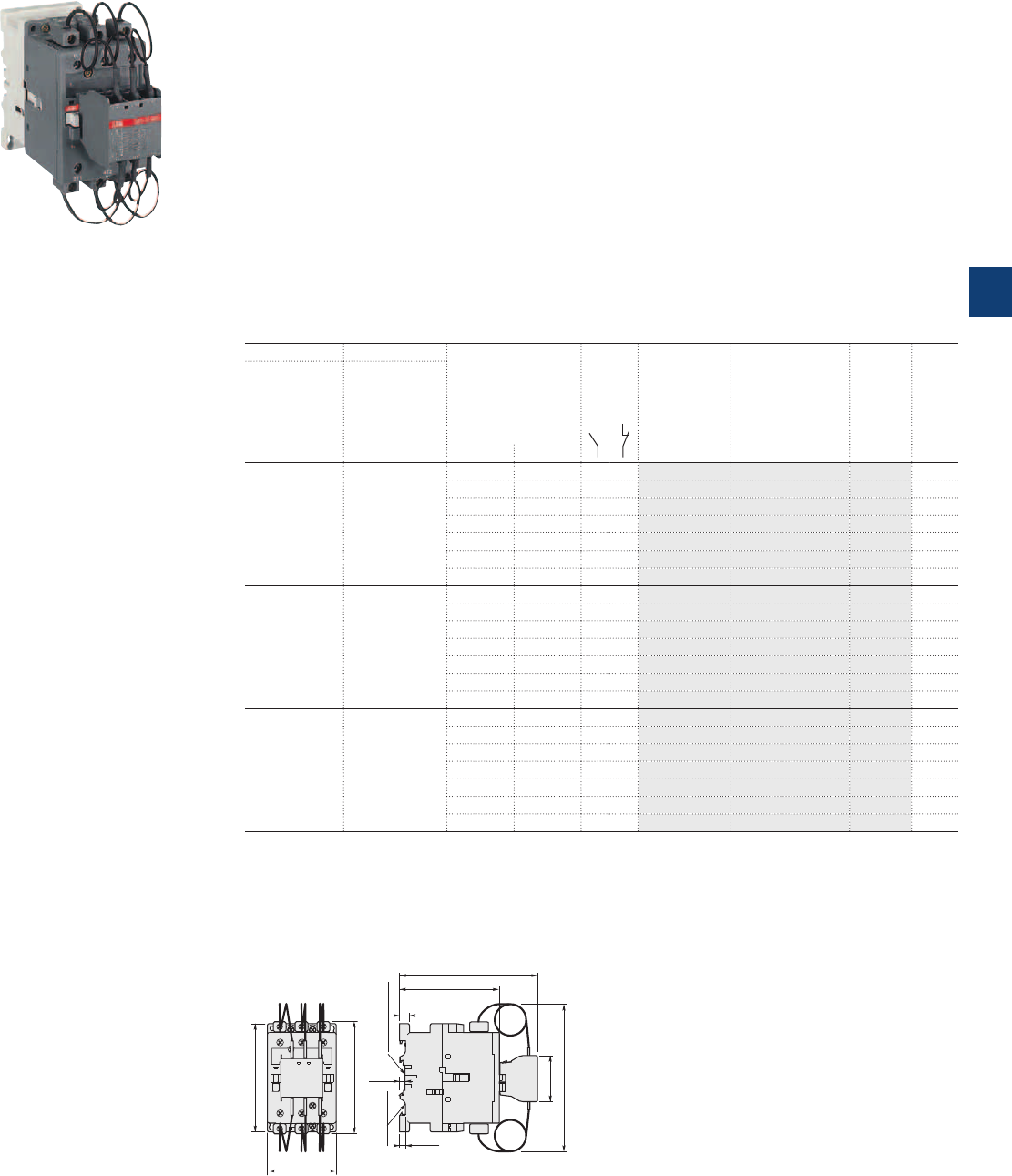
1SBC587764F0301
UA75-30-00 RA
UA50..RA … UA75..RA
3-pole
contactors for capacitor switching
40 to 60 kvar - Unlimited peak current Î
AC operated
Description
UA..RA contactors for capacitor switching can be used for installations in which the peak current far
exceeds 100 times nominal rms current. The contactors are delivered complete with their damping resistors
and must be used without additional inductances.
The capacitors must be discharged (maximum residual voltage at terminals ≤ 50 V) before being re-energized
when the contactors are making.
These contactors are of the block type design with:
– 3 main poles
– the UA..RA contactors are fitted with a special front-mounted block, which ensures the serial insertion of 3
damping resistors into the circuit to limit the current peak on energization of the capacitor bank
- their connection also ensures capacitor precharging in order to limit the second current peak occurring
upon making of the main poles
- the insertion of resistors allows to damp the highest current peak of the capacitor when switching on,
whatever its level.
– control circuit: AC operated
– add-on auxiliary contact blocks for side mounting and a wide range of accessories.
Ordering details
IEC UL/CSA Rated control circuit
voltage
Uc
(1)
Auxiliary
contacts
fitted
Type Order code Weight
Pkg
(1 pce)
Rated operational
power
θ ≤ 40 °C
400V
AC-6b
Rated operational
power
θ ≤ 40 °C
480V
kvar kvar V 50Hz V 60Hz kg
40 50 24 24 0 0 UA50-30-00RA 1SBL351024R8100 1.350
48 48 0 0 UA50-30-00RA 1SBL351024R8300 1.350
110 110…120 0 0 UA50-30-00RA 1SBL351024R8400 1.350
220…230 230…240 0 0 UA50-30-00RA 1SBL351024R8000 1.350
230…240 240…260 0 0 UA50-30-00RA 1SBL351024R8800 1.350
380…400 400…415 0 0 UA50-30-00RA 1SBL351024R8500 1.350
400…415 415…440 0 0 UA50-30-00RA 1SBL351024R8600 1.350
50 55 24 24 0 0 UA63-30-00RA 1SBL371024R8100 1.350
48 48 0 0 UA63-30-00RA 1SBL371024R8300 1.350
110 110…120 0 0 UA63-30-00RA 1SBL371024R8400 1.350
220…230 230…240 0 0 UA63-30-00RA 1SBL371024R8000 1.350
230…240 240…260 0 0 UA63-30-00RA 1SBL371024R8800 1.350
380…400 400…415 0 0 UA63-30-00RA 1SBL371024R8500 1.350
400…415 415…440 0 0 UA63-30-00RA 1SBL371024R8600 1.350
60 64 24 24 0 0 UA75-30-00RA 1SBL411024R8100 1.350
48 48 0 0 UA75-30-00RA 1SBL411024R8300 1.350
110 110…120 0 0 UA75-30-00RA 1SBL411024R8400 1.350
220…230 230…240 0 0 UA75-30-00RA 1SBL411024R8000 1.350
230…240 240…260 0 0 UA75-30-00RA 1SBL411024R8800 1.350
380…400 400…415 0 0 UA75-30-00RA 1SBL411024R8500 1.350
400…415 415…440 0 0 UA75-30-00RA 1SBL411024R8600 1.350
(1) Other control voltages see voltage code table.
Main dimensions mm, inches
6 0.24"
10 0.39"
4 0.16"
75 mm
EN/IEC 60715
35 mm x 15
EN/IEC 60715
140.4 5.53"
47 1.85"
+10 +10"
150 5.91"
101.5 4"
70 2.76"
110 4.33"
114 4.49"
UA50..RA, UA63..RA, UA75..RA
ABB | 5/97
5
1SBC101508S0201
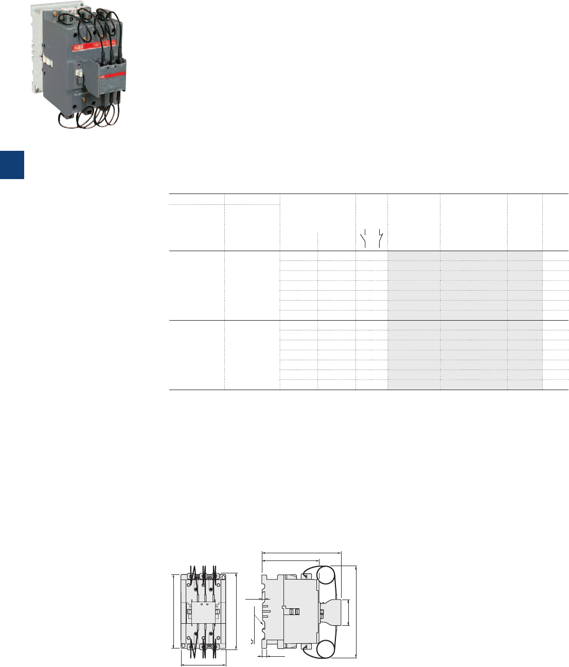
1SBC591444F0302
UA110-30-00 RA
UA95..RA … UA110..RA
3-pole
contactors for capacitor switching
70 to 80 kvar - Unlimited peak current Î
AC operated
Description
UA..RA contactors for capacitor switching can be used for installations in which the peak current far ex-
ceeds 100 times nominal rms current. The contactors are delivered complete with their damping resistors
and must be used without additional inductances.
The capacitors must be discharged (maximum residual voltage at terminals ≤ 50 V) before being re-ener-
gized when the contactors are making.
These contactors are of the block type design with:
– 3 main poles
– the UA..RA contactors are fitted with a special front-mounted block, which ensures the serial insertion of
3 damping resistors into the circuit to limit the current peak on energization of the capacitor bank
- their connection also ensures capacitor precharging in order to limit the second current peak occurring
upon making of the main poles
- the insertion of resistors allows to damp the highest current peak of the capacitor when switching on,
whatever its level.
– control circuit: AC operated
– add-on auxiliary contact blocks for side mounting and a wide range of accessories.
Ordering details
IEC UL/CSA Rated control circuit
voltage
Uc
(1)
Auxiliary
contacts
fitted
Type Order code Weight
Pkg
(1 pce)
Rated operational
power Rated operational
power
θ ≤ 40 °C θ ≤ 40 °C
400V 480V
AC-6b V 50Hz V 60Hz kg
70 80 24 24 0 0 UA95-30-00RA 1SFL431024R8100 2.000
48 48 0 0 UA95-30-00RA 1SFL431024R8300 2.000
110 110…120 0 0 UA95-30-00RA 1SFL431024R8400 2.000
220…230 230…240 0 0 UA95-30-00RA 1SFL431024R8000 2.000
230…240 240…260 0 0 UA95-30-00RA 1SFL431024R8800 2.000
380…400 400…415 0 0 UA95-30-00RA 1SFL431024R8500 2.000
400…415 415…440 0 0 UA95-30-00RA 1SFL431024R8600 2.000
80 95 24 24 0 0 UA110-30-00RA 1SFL451024R8100 2.000
48 48 0 0 UA110-30-00RA 1SFL451024R8300 2.000
110 110…120 0 0 UA110-30-00RA 1SFL451024R8400 2.000
220…230 230…240 0 0 UA110-30-00RA 1SFL451024R8000 2.000
230…240 240…260 0 0 UA110-30-00RA 1SFL451024R8800 2.000
380…400 400…415 0 0 UA110-30-00RA 1SFL451024R8500 2.000
400…415 415…440 0 0 UA110-30-00RA 1SFL451024R8600 2.000
(1) Other control voltages see voltage code table.
Main dimensions mm, inches
47 1.85"
+10 +10"
170 6.69"
114.4 4.5"
6 0.24"
75 mm
EN/IEC 60715
10 0.39"
155.6 6.13"
155.3 6.11"
90 3.54"
148 5.83"
UA95..RA, UA100..RA
5/98 | ABB
5
1SBC101553S0201
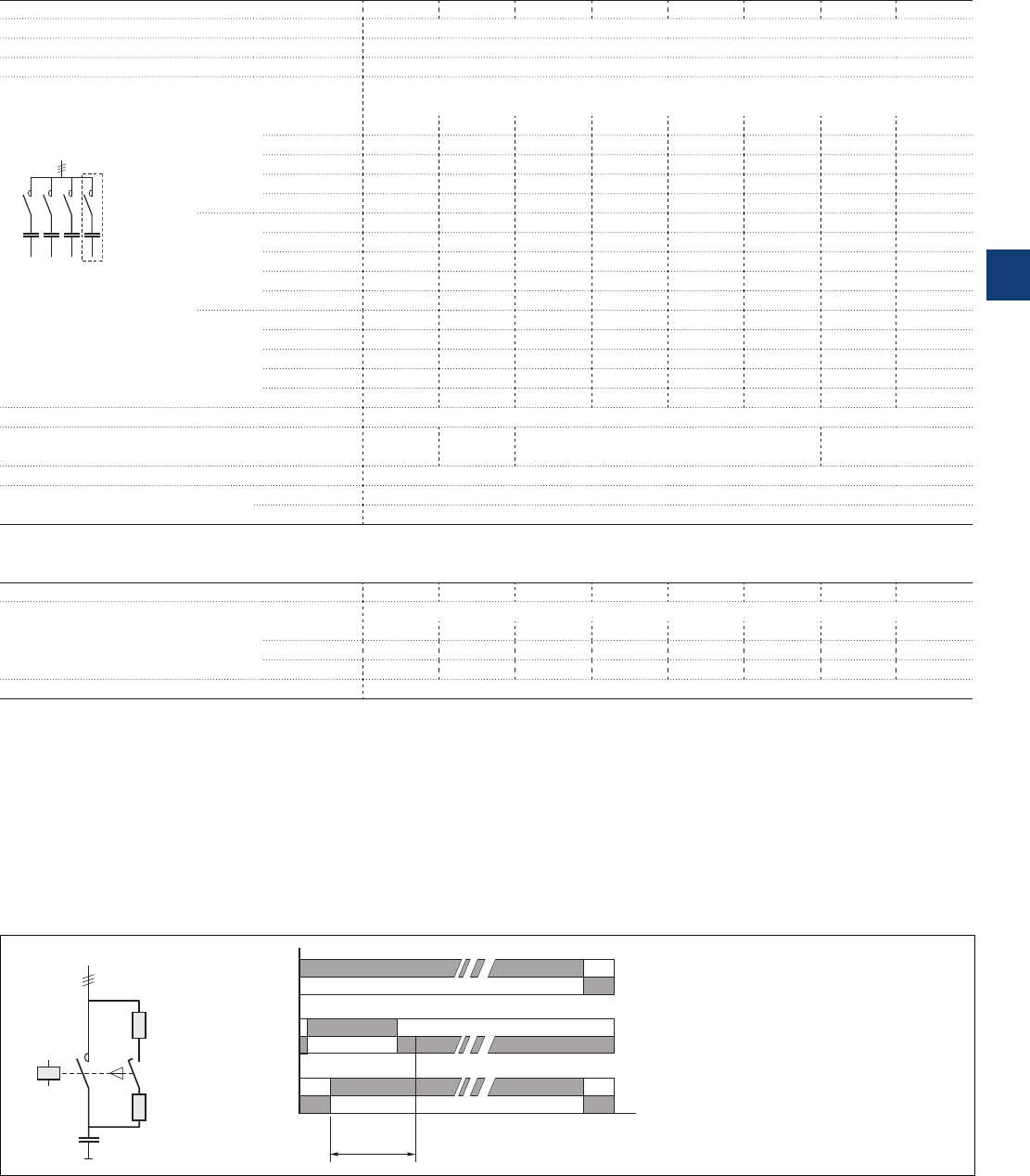
UA16..RA … UA110..RA
3-pole contactors for capacitor switching
Unlimited peak current Î
Technical data
Main pole - Utilization characteristics according to IEC
Contactor types AC operated UA16..RA UA26..RA UA30..RA UA50..RA UA63..RA UA75..RA UA95..RA UA110..RA
Standards IEC 60947-1 / 60947-4-1 and EN 60947-1 / 60947-4-1
Rated operational voltage Ue max. 690 V
Rated frequency (without derating) 50 / 60 Hz
AC-6b Utilization category
Rated operational power AC-6b
For air temperature close
to contactor θ ≤ 40 °C 230-240 V 8 kvar 12.5 kvar 16 kvar 25 kvar 30 kvar 35 kvar 40 kvar 45 kvar
400-415 V 12.5 kvar 22 kvar 30 kvar 40 kvar 50 kvar 60 kvar 70 kvar 80 kvar
440 V 15 kvar 24 kvar 32 kvar 50 kvar 55 kvar 65 kvar 75 kvar 85 kvar
500-550 V 18 kvar 30 kvar 34 kvar 55 kvar 65 kvar 75 kvar 85 kvar 95 kvar
690 V 22 kvar 35 kvar 45 kvar 72 kvar 80 kvar 100 kvar 120 kvar 130 kvar
θ ≤ 55 °C 230-240 V 7.5 kvar 11.5 kvar 16 kvar 24 kvar 27 kvar 30 kvar 35 kvar 40 kvar
400-415 V 12.5 kvar 20 kvar 27.5 kvar 40 kvar 45 kvar 50 kvar 60 kvar 70 kvar
440 V 13 kvar 20 kvar 30 kvar 43 kvar 48 kvar 53 kvar 65 kvar 75 kvar
Multi-step capacitor
bank scheme
500-550 V 16 kvar 25 kvar 34 kvar 50 kvar 60 kvar 65 kvar 75 kvar 82 kvar
690 V 21 kvar 31 kvar 45 kvar 65 kvar 75 kvar 80 kvar 105 kvar 110 kvar
θ ≤ 70 °C 230-240 V 6 kvar 9 kvar 11 kvar 20 kvar 23 kvar 25 kvar 30 kvar 35 kvar
400-415 V 10 kvar 15.5 kvar 19.5 kvar 35 kvar 39 kvar 41 kvar 53 kvar 60 kvar
440 V 11 kvar 17 kvar 20.5 kvar 37 kvar 42.5 kvar 45 kvar 58 kvar 70 kvar
500-550 V 12.5 kvar 20 kvar 25 kvar 46 kvar 50 kvar 55 kvar 70 kvar 78 kvar
690 V 17 kvar 26 kvar 32 kvar 60 kvar 65 kvar 70 kvar 85 kvar 100 kvar
Max. permissible peak current Î Unlimited
Short-circuit protection device for contactors
gG type fuse (1) 80 A 125 A 200 A 250 A
Max. electrical switching frequency 240 cycles/h
Electrical durability AC-6b Ue ≤ 440V 250 000 operating cycles
500 V ≤ Ue ≤ 690V 100 000 operating cycles
(1) The fuse ratings given represent the maximum ratings ensuring type 1 coordination according to the definition of standard IEC 60947-4-1.
Main pole - Utilization characteristics according to UL / CSA
Contactor types AC operated UA16..RA UA26..RA UA30..RA UA50..RA UA63..RA UA75..RA UA95..RA UA110..RA
Power - 60Hz
For air temperature close
to contactor θ ≤ 40 °C 240 V 8 kvar 11 kvar 14 kvar 25 kvar 27.5 kvar 32 kvar 40 kvar 45 kvar
480 V 16 kvar 22 kvar 28 kvar 50 kvar 55 kvar 64 kvar 80 kvar 95 kvar
600 V 20 kvar 27 kvar 35 kvar 62 kvar 70 kvar 80 kvar 100 kvar 120 kvar
Max. permissible peak Current Î Unlimited
Operating principle
The front-mounted block mechanism of the UA..RA contactors ensures:
– early making of the auxiliary "PA" poles with respect to the main "PP" poles
– automatic return to the open position of the auxiliary "PA" poles after the main poles are closed.
When the coil is energized, the early making auxiliary poles connect the capacitor to the network via the set of 3 resistors. The damping
resistors attenuate the first current peak and the second inrush current when the main contacts begin to make. Once the main poles are in the
closed position, the auxiliary poles automatically break.
When the coil is de-energized, the main poles break ensuring the breaking of the capacitor bank.
The contactor can then begin a new cycle.
The insertion of resistors allows to damp the highest current peak of the capacitor when switching on, whatever its level.
A1
A2
PA
R
PP
R
C
Coil voltage
Uc
Aux. poles
PA
Main poles
PP
Total
closing time
ABB | 5/99
5
1SBC101510S0201
Connecting characteristics
Contactor types
AC operated
UA16..RA UA26..RA UA30..RA UA50..RA UA95..RA
UA63..RA UA110..RA
UA75..RA
Connection capacity (min. ... max.)
Main conductors (poles)
Rigid Solid (≤ 4 mm²) 1 x 1...4 mm² 1.5...6 mm² 2.5...16 mm² 6...50 mm² 10...95 mm²
Stranded (≥ 6 mm²) 2 x --
2.5...16 + 2.5...6 mm² 6…25 + 6…16 mm²
6...35 mm²
Flexible with ferrule 1 x 0.75...2.5 mm² 1.5...4 mm² 2.5...10 mm² 6...35 mm² 10...70 mm²
2 x --
2.5...10 + 2.5...4 mm² 6...16 + 6...10 mm²
6...35 mm²
L
l
Bars or lugs L ≤ 7.7mm 10 mm - - -
l > 3.7 mm 4.2 mm - - -
Connection capacity acc. to UL/CSA 1 or 2 x AWG 18...10 AWG 12...8 AWG 8...4 AWG 8...1 AWG 6...2/0
Tightening torque Recommended 1 Nm / 9 Ib.in 1.7 Nm / 15 Ib.in 2.3 Nm / 20 Ib.in 4 Nm / 35 Ib.in 8 Nm / 53 Ib.in
Max. 1.2 Nm 2.2 Nm 2.6 Nm 4.5 Nm 9 Nm
Auxiliary conductors
(built-in auxiliary terminals + coil terminals)
Rigid solid 1 x 1...4 mm² 0.75…2.5 mm²
2 x 1...4 mm² 0.75…2.5 mm²
Flexible with ferrule 1 x 0.75...2.5 mm² 1…2.5 mm² 0.75…2.5 mm²
2 x 0.75...2.5 mm²
L
l
Lugs Coil terminals L ≤ 8 mm
l > 3.7 mm
Built-in auxiliary L ≤ 7.7 mm 10 mm 8 mm - -
terminals l > 3.7 mm 4.2 mm 3.7 mm - -
Connection capacity acc. to UL/CSA 1 or 2 x AWG 18...14
Tightening torque
Coil terminals Recommended 1 Nm / 9 Ib.in
Max. 1.2 Nm
Built-in auxiliary terminals Recommended 1 Nm / 9 Ib.in
Max. 1.2 Nm
Degree of protection
acc. to IEC 60947-1 / EN 60947-1 and IEC 60529 / EN 60529
Main terminals IP20 IP10
Coil terminals IP20
Built-in auxiliary terminals IP20 - -
Screw terminals
Delivered in open position, screws of unused terminals must be tightened
Main terminals M 3.5 M 4 M 5 M6 M8
Screwdriver type Flat Ø 5.5 / Pozidriv 2 Flat Ø 6.5 / Pozidriv 2 Hexagon socket
(s = 4 mm)
Coil terminals M 3.5
Screwdriver type Flat Ø 5.5 / Pozidriv 2
Built-in auxiliary terminals
M 3.5 M 4 M 3.5 - -
Screwdriver type Flat Ø 5.5 / Pozidriv 2 - -
Other technical characteristics are the same as those of standard A contactors.
UA16..RA … UA110..RA
3-pole contactors for capacitor switching
Unlimited peak current Î
Technical data
5/100 | ABB
5
1SBC101513S0201
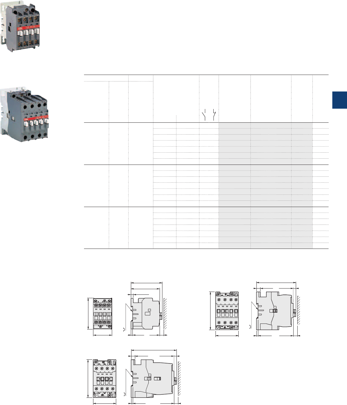
1SBC591694F0304
UA16-30-10
1SBC580093F0303
UA30-30-10
UA16 … UA30 3-pole contactors for capacitor switching
12.5 to 27.5 kvar - peak current Î ≤ 100 times the rms current
AC operated
Description
UA contactors can be used for the switching of capacitor banks whose inrush current peaks are less than or
equal to 100 times nominal rms current.
The capacitors must be discharged (maximum residual voltage at terminals ≤ 50 V) before being re-energized
when the contactors are making.
These contactors are of the block type design with:
– 3 main poles and 1 built-in auxiliary contact
– control circuit: AC operated
– add-on auxiliary contact blocks for front or side mounting and a wide range of accessories.
Ordering details
IEC UL/CSA Rated control circuit
voltage
Uc
(1)
Auxiliary
contacts
fitted
Type Order code Weight
Pkg
(1 pce)
Rated Max Rated
operational peak operational
power current power
θ ≤ 40 °C θ ≤ 40 °C
400V 480V
AC-6b Î
kvar kA kvar V 50Hz V 60Hz kg
12.5 1.8 - 24 24 1 0 UA16-30-10 1SBL181022R8110 0.340
48 48 1 0 UA16-30-10 1SBL181022R8310 0.340
110 110…120 1 0 UA16-30-10 1SBL181022R8410 0.340
220…230 230…240 1 0 UA16-30-10 1SBL181022R8010 0.340
230…240 240…260 1 0 UA16-30-10 1SBL181022R8810 0.340
380…400 400…415 1 0 UA16-30-10 1SBL181022R8510 0.340
400…415 415…440 1 0 UA16-30-10 1SBL181022R8610 0.340
20 3 25 24 24 1 0 UA26-30-10 1SBL241022R8110 0.600
48 48 1 0 UA26-30-10 1SBL241022R8310 0.600
110 110…120 1 0 UA26-30-10 1SBL241022R8410 0.600
220…230 230…240 1 0 UA26-30-10 1SBL241022R8010 0.600
230…240 240…260 1 0 UA26-30-10 1SBL241022R8810 0.600
380…400 400…415 1 0 UA26-30-10 1SBL241022R8510 0.600
400…415 415…440 1 0 UA26-30-10 1SBL241022R8610 0.600
27.5 3.5 32 24 24 1 0 UA30-30-10 1SBL281022R8110 0.710
48 48 1 0 UA30-30-10 1SBL281022R8310 0.710
110 110…120 1 0 UA30-30-10 1SBL281022R8410 0.710
220…230 230…240 1 0 UA30-30-10 1SBL281022R8010 0.710
230…240 240…260 1 0 UA30-30-10 1SBL281022R8810 0.710
380…400 400…415 1 0 UA30-30-10 1SBL281022R8510 0.710
400…415 415…440 1 0 UA30-30-10 1SBL281022R8610 0.710
(1) Other control voltages see voltage code table.
Main dimensions mm, inches
44 1.73"
74 2.91"
68 2.68"
74 2.91"
5.5 0.22"
4
0.16"
10
0.39"
35 mm
EN/IEC 60715
UA16
4 0.16" 10 0.39"
6.3 0.25"
93.6 3.69"
9 0.35"
35 mm
EN/IEC 60715
54 2.13"
90 3.54"
UA26
108.3 4.26"
9 0.35" 6.3 0.25"
4 0.16" 10 0.39"
35 mm
EN/IEC 60715
54 2.13"
90 3.54"
UA30
ABB | 5/101
5
1SBC101514S0201
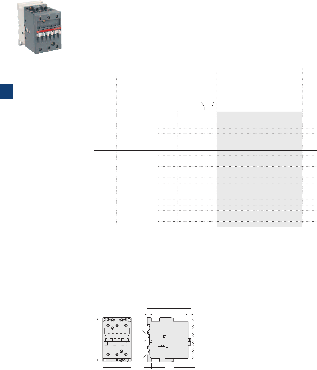
1SBC580783F0303
UA50-30-00
UA50 … UA75
3-pole contactors for capacitor switching
33 to 50 kvar - peak current Î ≤ 100 times the rms current
AC operated
Description
UA contactors can be used for the switching of capacitor banks whose inrush current peaks are less than or
equal to 100 times nominal rms current.
The capacitors must be discharged (maximum residual voltage at terminals ≤ 50 V) before being re-energized
when the contactors are making.
These contactors are of the block type design with:
– 3 main poles
– control circuit: AC operated
– add-on auxiliary contact blocks for front or side mounting and a wide range of accessories.
Ordering details
IEC UL/CSA Rated control circuit
voltage
Uc
(1)
Auxiliary
contacts
fitted
Type Order code Weight
Pkg
(1 pce)
Rated Max Rated
operational peak operational
power current power
θ ≤ 40 °C θ ≤ 40 °C
400V 480V
AC-6b Î
kvar kA kvar V 50Hz V 60Hz kg
33 5 40 24 24 0 0 UA50-30-00 1SBL351022R8100 1.160
48 48 0 0 UA50-30-00 1SBL351022R8300 1.160
110 110…120 0 0 UA50-30-00 1SBL351022R8400 1.160
220…230 230…240 0 0 UA50-30-00 1SBL351022R8000 1.160
230…240 240…260 0 0 UA50-30-00 1SBL351022R8800 1.160
380…400 400…415 0 0 UA50-30-00 1SBL351022R8500 1.160
400…415 415…440 0 0 UA50-30-00 1SBL351022R8600 1.160
45 6.5 - 24 24 0 0 UA63-30-00 1SBL371022R8100 1.160
48 48 0 0 UA63-30-00 1SBL371022R8300 1.160
110 110…120 0 0 UA63-30-00 1SBL371022R8400 1.160
220…230 230…240 0 0 UA63-30-00 1SBL371022R8000 1.160
230…240 240…260 0 0 UA63-30-00 1SBL371022R8800 1.160
380…400 400…415 0 0 UA63-30-00 1SBL371022R8500 1.160
400…415 415…440 0 0 UA63-30-00 1SBL371022R8600 1.160
50 7.5 55 24 24 0 0 UA75-30-00 1SBL411022R8100 1.160
48 48 0 0 UA75-30-00 1SBL411022R8300 1.160
110 110…120 0 0 UA75-30-00 1SBL411022R8400 1.160
220…230 230…240 0 0 UA75-30-00 1SBL411022R8000 1.160
230…240 240…260 0 0 UA75-30-00 1SBL411022R8800 1.160
380…400 400…415 0 0 UA75-30-00 1SBL411022R8500 1.160
400…415 415…440 0 0 UA75-30-00 1SBL411022R8600 1.160
(1) Other control voltages see voltage code table.
Main dimensions mm, inches
70 2.76"
110 4.33"
6.5 0.26"6 0.24"
10 0.39"
4
0.16"
10 0.39"
75 mm
EN/IEC 60715
35 mm x15
EN/IEC 60715
108 4.25"
UA50, UA63, UA75
5/102 | ABB
5
1SBC101521S0201
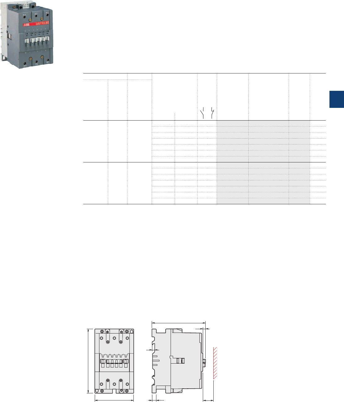
UA95 ... UA110 3-pole contactors for capacitor switching
65 to 75 kvar - peak current Î ≤ 100 times the rms current
AC operated
Description
UA contactors can be used for the switching of capacitor banks whose inrush current peaks are less or
equal to 100 times nominal rms current.
The capacitors must be discharges (maximum residual voltage at terminals ≤ 50 V) before being re-energized
when the contactors are making.
These contactors are of the block type design with:
– 3 main poles
– control circuit: AC operated
– add-on auxiliary contact blocks for front or side mounting and a wide range of accessories.
Ordering details
IEC UL/CSA Rated control circuit
voltage
Uc
(1)
Auxiliary
contacts
fitted
Type Order code Weight
Pkg
(1 pce)
Rated Max Rated
operational peak operational
power current power
θ ≤ 40 °C θ ≤ 40 °C
400V 480V
AC-6b Î
kvar kA kvar V 50Hz V 60Hz kg
65 9.3 70 24 24 0 0 UA95-30-00 1SFL431022R8100 2.000
48 48 0 0 UA95-30-00 1SFL431022R8300 2.000
110 110…120 0 0 UA95-30-00 1SFL431022R8400 2.000
220…230 230…240 0 0 UA95-30-00 1SFL431022R8000 2.000
230…240 240…260 0 0 UA95-30-00 1SFL431022R8800 2.000
380…400 400…415 0 0 UA95-30-00 1SFL431022R8500 2.000
400…415 415…440 0 0 UA95-30-00 1SFL431022R8600 2.000
75 10.5 80 24 24 0 0 UA110-30-00 1SFL451022R8100 2.000
48 48 0 0 UA110-30-00 1SFL451022R8300 2.000
110 110…120 0 0 UA110-30-00 1SFL451022R8400 2.000
220…230 230…240 0 0 UA110-30-00 1SFL451022R8000 2.000
230…240 240…260 0 0 UA110-30-00 1SFL451022R8800 2.000
380…400 400…415 0 0 UA110-30-00 1SFL451022R8500 2.000
400…415 415…440 0 0 UA110-30-00 1SFL451022R8600 2.000
(1) Other control voltages see voltage code table.
1SBC580105F0303
UA110-30-00
Main dimensions mm, inches
90 3.54"
148 5.83"
E0783D
123.5 4.86"
6 0.24"
E0784D1
20 0.79"
10 0.39"
6.5 0.26"
UA95, UA110
ABB | 5/103
5
1SFC101059C0201
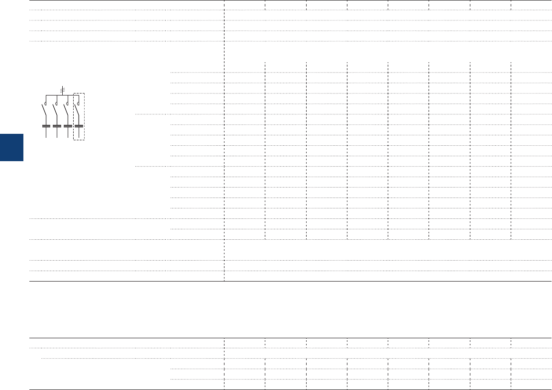
UA16 … UA110
3-pole contactors for capacitor switching
Peak current Î ≤ 100 times the rms current
Technical data
Main pole - Utilization characteristics according to IEC
Contactor types AC operated UA16 UA26 UA30 UA50 UA63 UA75 UA95 UA110
Standards IEC 60947-1 / 60947-4-1 and EN 60947-1 / 60947-4-1
Rated operational voltage Ue max. 690 V
Rated frequency (without derating) 50 / 60 Hz
AC-6b Utilization category
Rated operational power AC-6b (1)
For air temperature close
to contactor θ ≤ 40 °C 230-240 V 7.5 kvar 12 kvar 16 kvar 20 kvar 25 kvar 30 kvar 35 kvar 40 kvar
400-415 V 12.5 kvar 20 kvar 27.5 kvar 33 kvar 45 kvar 50 kvar 65 kvar 75 kvar
440 V 13.7 kvar 22 kvar 30 kvar 36 kvar 50 kvar 55 kvar 65 kvar 75 kvar
500-550 V 15.5 kvar 22 kvar 34 kvar 40 kvar 50 kvar 62 kvar 70 kvar 80 kvar
690 V 21.5 kvar 30 kvar 45 kvar 55 kvar 70 kvar 75 kvar 80 kvar 90 kvar
θ ≤ 55 °C 230-240 V 6.7 kvar 11 kvar 16 kvar 20 kvar 25 kvar 30 kvar 35 kvar 40 kvar
400-415 V 11.7 kvar 18.5 kvar 27.5 kvar 33 kvar 43 kvar 50 kvar 65 kvar 70 kvar
440 V 13 kvar 20 kvar 30 kvar 36 kvar 48 kvar 53 kvar 65 kvar 75 kvar
Multi-step capacitor
bank scheme
500-550 V 14.7 kvar 22 kvar 34 kvar 40 kvar 50 kvar 62 kvar 70 kvar 80 kvar
690 V 20 kvar 30 kvar 45 kvar 55 kvar 70 kvar 75 kvar 80 kvar 90 kvar
θ ≤ 70 °C 230-240 V 6 kvar 8.5 kvar 11 kvar 19 kvar 21 kvar 22 kvar 30 kvar 35 kvar
400-415 V 10 kvar 14.5 kvar 19 kvar 32 kvar 37 kvar 39 kvar 55 kvar 65 kvar
440 V 11 kvar 16 kvar 20 kvar 35 kvar 41 kvar 43 kvar 55 kvar 70 kvar
500-550 V 12.5 kvar 19.5 kvar 23.5 kvar 40 kvar 45 kvar 47.5 kvar 60 kvar 75 kvar
690 V 17 kvar 25 kvar 32 kvar 52 kvar 60 kvar 65 kvar 70 kvar 85 kvar
Max. permissible peak current Î Ue ≤ 500 V 1.8 kA 3 kA 3.5 kA 5 kA 6.5 kA 7.5 kA 9.3 kA 10.5 kA
Ue > 500 V 1.6 kA 2.7 kA 3.1 kA 4.5 kA 5.8 kA 6.75 kA 8 kA 9 kA
Short-circuit protection device for contactors
gG type fuse sized 1.5…1.8 In of the capacitor
Max. electrical switching frequency 240 cycles/h
Electrical durability AC-6b Ue ≤ 690V 100 000 operating cycles
(1) For 220 V and 380 V, multiply by 0.9 the rated values at 230 V and 400 V respectively.
Example: 50 kvar / 400 V corresponding to 0.9 x 50 = 45 kvar/380 V.
If, in an application, the current peak is greater than the maximum peak current Î specified in the tables above, select a higher rating, refer to the UA..RA contactors, or add induct-
ances. (see application guide "Contactors for capacitor switching").
Main pole - Utilization characteristics according to UL / CSA
Contactor types AC operated UA16 UA26 UA30 UA50 UA63 UA75 UA95 UA110
Power - 60Hz
For air temperature close
to contactor θ ≤ 40 °C 240 V - 12.5 kvar 16 kvar 20 kvar - 27.5 kvar 35 kvar 40 kvar
480 V - 25 kvar 32 kvar 40 kvar - 55 kvar 70 kvar 80 kvar
600 V - 30 kvar 40 kvar 50 kvar - 70 kvar 75 kvar 85 kvar
If, in an application, the current peak is greater than the maximum peak current Î specified in the tables above, select a higher rating, refer to the UA..RA contactors, or add induct-
ances. (see application guide "Contactors for capacitor switching").
5/104 | ABB
5
1SBC101536S0201
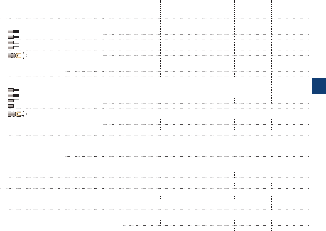
Connecting characteristics
Contactor types
AC operated
UA16 UA26 UA30 UA50 UA95
UA63 UA110
UA75
Connection capacity (min. ... max.)
Main conductors (poles)
Rigid Solid (≤ 4 mm²) 1 x 1...4 mm² 1.5...6 mm² 2.5...16 mm² 6...50 mm² 10...95 mm²
Stranded (≥ 6 mm²) 2 x 1...4 mm² 1.5...6 mm² 2.5...16 mm² 6...25 mm² 6...35 mm²
Flexible with ferrule 1 x 0.75...2.5 mm² 0.75...4 mm² 2.5...10 mm² 6...35 mm² 10...70 mm²
2 x 0.75...2.5 mm² 0.75...4 mm² 2.5...10 mm² 6...16 mm² 6...35 mm²
L
l
Bars or lugs L ≤ 7.7mm 10 mm - - -
l > 3.7 mm 4.2 mm - - -
Connection capacity acc. to UL/CSA 1 or 2 x AWG 18...10 AWG 12...8 AWG 8...4 AWG 8...1 AWG 6...2/0
Tightening torque Recommended 1 Nm / 9 Ib.in 1.7 Nm / 15 Ib.in 2.3 Nm / 20 Ib.in 4 Nm / 35 Ib.in 8 Nm / 71 Ib.in
Max. 1.2 Nm 2.2 Nm 2.6 Nm 4.5 Nm 9 Nm
Auxiliary conductors
(built-in auxiliary terminals + coil terminals)
Rigid solid 1 x 1...4 mm² 0.75…2.5 mm²
2 x 1...4 mm² 0.75…2.5 mm²
Flexible with ferrule 1 x 0.75...2.5 mm² 1…2.5 mm² 0.75…2.5 mm²
2 x 0.75...2.5 mm²
L
l
Lugs Coil terminals L ≤ 8 mm
l > 3.7 mm
Built-in auxiliary L ≤ 7.7 mm 10 mm 8 mm - -
terminals l > 3.7 mm 4.2 mm 3.7 mm - -
Connection capacity acc. to UL/CSA AWG 18...14
Tightening torque
Coil terminals Recommended 1 Nm / 9 Ib.in
Max. 1.2 Nm
Built-in auxiliary terminals Recommended 1 Nm / 9 Ib.in
Max. 1.2 Nm
Degree of protection
acc. to IEC 60947-1 / EN 60947-1 and IEC 60529 / EN 60529
Main terminals IP20 IP10
Coil terminals IP20
Built-in auxiliary terminals IP20 - -
Screw terminals
Delivered in open position, screws of unused terminals must be tightened
Main terminals M3.5 M4 M5 M6 M8
Screwdriver type Flat Ø 5.5 / Pozidriv 2 Flat Ø 6.5 / Pozidriv 2 Hexagon socket
(s = 4mm)
Coil terminals M3.5
Screwdriver type Flat Ø 5.5 / Pozidriv 2
Built-in auxiliary terminals
M3.5 M4 M3.5 - -
Screwdriver type Flat Ø 5.5 / Pozidriv 2 - -
Other technical characteristics are the same as those of standard A contactors.
UA16 … UA110
3-pole contactors for capacitor switching
Peak current Î ≤ 100 times the rms current
Technical data
ABB | 5/105
5
1SBC101537S0201
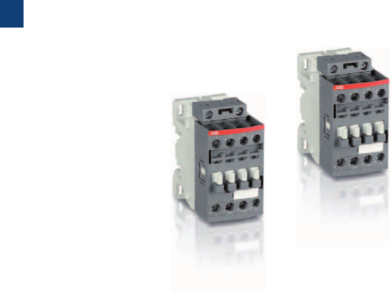
5/106 | ABB
5
1SBC101613S0201

NF 4-pole contactor relays
Ordering details
NF AC / DC operated 5/108
NFZ AC / DC operated - low consumption 5/109
Main accessories 5/110
Technical data
Contacts utilization characteristics according to IEC 5/112
Contacts utilization characteristics according to UL / CSA 5/112
General technical data 5/113
Magnet system 5/113
Mounting characteristics 5/113
Connecting characteristics 5/114
Accessories
Accessories for
NF contactor relays
5/115
ABB | 5/107
5
1SBC101613S0201
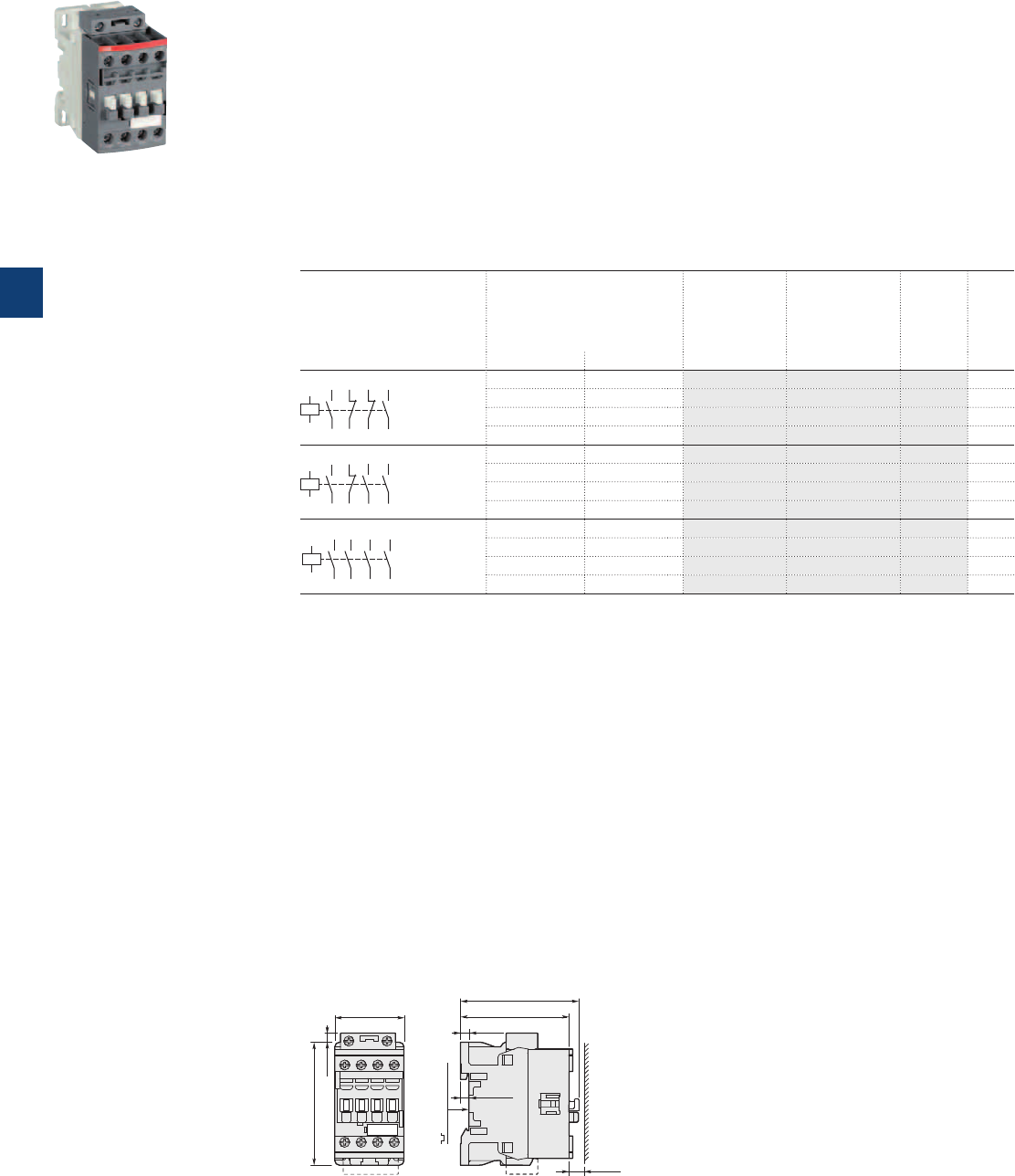
Description
NF contactor relays are used for switching auxiliary and control circuits.
These contactor relays are of the block type design with:
– 4 poles. Contactor relays have mechanically linked auxiliary contact elements (side-marked symbol)
– control circuit: AC or DC operated with electronic coil interface accepting a wide control voltage range
(e.g. 100...250 V AC and DC)
- can manage large control voltage variations
- only 4 coils to cover control voltages between 24...500 V 50/60 Hz and 20...500 V DC
- reduced panel energy consumption
- very distinct closing and opening.
– built-in surge suppression
– add-on auxiliary contact blocks for front or side mounting and a wide range of accessories.
Ordering details
Number of contacts Rated control circuit
voltage
Uc min. ... Uc max.
Type Order code Weight
Pkg
(1 pce)
V 50/60 Hz V DC kg
43
NO
NO
44
31
NC
NC
32
21
NC
NC
22
13
NO
NO
14
A1
A2
24...60 20...60 (1) NF22E-11 1SBH137001R1122 0.270
48...130 48...130 NF22E-12 1SBH137001R1222 0.270
100...250 100...250 NF22E-13 1SBH137001R1322 0.270
250...500 250...500 NF22E-14 1SBH137001R1422 0.310
33
NO
NO
34
21
NC
NC
22
13
NO
NO
14
43
NO
NO
44
A1
A2
24...60 20...60 (1) NF31E-11 1SBH137001R1131 0.270
48...130 48...130 NF31E-12 1SBH137001R1231 0.270
100...250 100...250 NF31E-13 1SBH137001R1331 0.270
250...500 250...500 NF31E-14 1SBH137001R1431 0.310
43
NO
NO
44
33
NO
NO
34
23
NO
NO
24
13
NO
NO
14
A1
A2
24...60 20...60 (1) NF40E-11 1SBH137001R1140 0.270
48...130 48...130 NF40E-12 1SBH137001R1240 0.270
100...250 100...250 NF40E-13 1SBH137001R1340 0.270
250...500 250...500 NF40E-14 1SBH137001R1440 0.310
(1) NF..E-11 not suitable for direct control by PLC-output.
Main dimensions mm, inches
45 1.77"
80 3.15"
6 0.24"
77 3.03"
71 2.80"
5.5 0.22"
35 mm
EN/IEC 60715
10 0.39"
5.5 0.22"
NF22E, NF31E, NF40E
NF 4-pole contactor relays
AC / DC operated
1SBC101104F0014
NF22E
5/108 | ABB
5
1SBC101558S0201
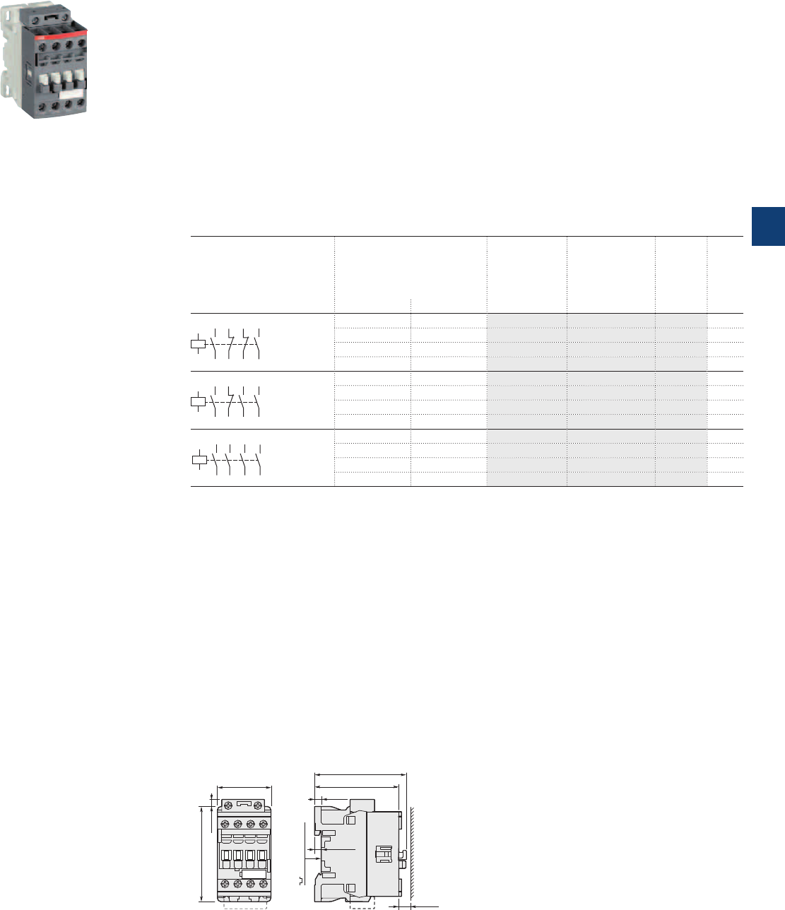
Description
NFZ contactor relays are used for switching auxiliary circuits and control circuits.
These contactor relays are of the block type design with:
– 4 poles. Contactor relays have mechanically linked auxiliary contact elements (side-marked symbol)
– control circuit: AC or DC operated with electronic coil interface accepting a wide control voltage range
(e.g. 100...250 V AC and DC)
- can manage large control voltage variations
- only 4 coils to cover control voltages between 24...250 V 50/60 Hz and 12...250 V DC
- allow direct control by PLC-output ≥ 24 V DC 500 mA
- reduced panel energy consumption
- very distinct closing and opening
- can withstand short voltage dips and voltage sags (SEMI F47-0706 conditions of use on request).
– built-in surge suppression
– add-on auxiliary contact blocks for front or side mounting and a wide range of accessories.
Ordering details
Number of contacts Rated control circuit
voltage
Uc min. ... Uc max.
Type Order code Weight
Pkg
(1 pce)
V 50/60 Hz V DC kg
43
NO
NO
44
31
NC
NC
32
21
NC
NC
22
13
NO
NO
14
A1
A2
– 12...20 NFZ22E-20 1SBH136001R2022 0.310
24...60 20...60 NFZ22E-21 1SBH136001R2122 0.310
48...130 48...130 NFZ22E-22 1SBH136001R2222 0.310
100...250 100...250 NFZ22E-23 1SBH136001R2322 0.310
33
NO
NO
34
21
NC
NC
22
13
NO
NO
14
43
NO
NO
44
A1
A2
– 12...20 NFZ31E-20 1SBH136001R2031 0.310
24...60 20...60 NFZ31E-21 1SBH136001R2131 0.310
48...130 48...130 NFZ31E-22 1SBH136001R2231 0.310
100...250 100...250 NFZ31E-23 1SBH136001R2331 0.310
43
NO
NO
44
33
NO
NO
34
23
NO
NO
24
13
NO
NO
14
A1
A2
– 12...20 NFZ40E-20 1SBH136001R2040 0.310
24...60 20...60 NFZ40E-21 1SBH136001R2140 0.310
48...130 48...130 NFZ40E-22 1SBH136001R2240 0.310
100...250 100...250 NFZ40E-23 1SBH136001R2340 0.310
Note: Only NFZ contactor relays with DC control voltage 12...20 V DC need to respect the connection polarities indicated close to the
coil terminals: A1+ for the positive pole and A2- for the negative pole.
Main dimensions mm, inches
45 1.77"
80 3.15"
6 0.24"
77 3.03"
71 2.80"
5.5 0.22"
35 mm
EN/IEC 60715
10 0.39"
5.5 0.22"
NFZ22E, NFZ31E, NFZ40E
NFZ 4-pole contactor relays
AC / DC operated - low consumption
1SBC101104F0014
NFZ22E
ABB | 5/109
5
1SBC101559S0201
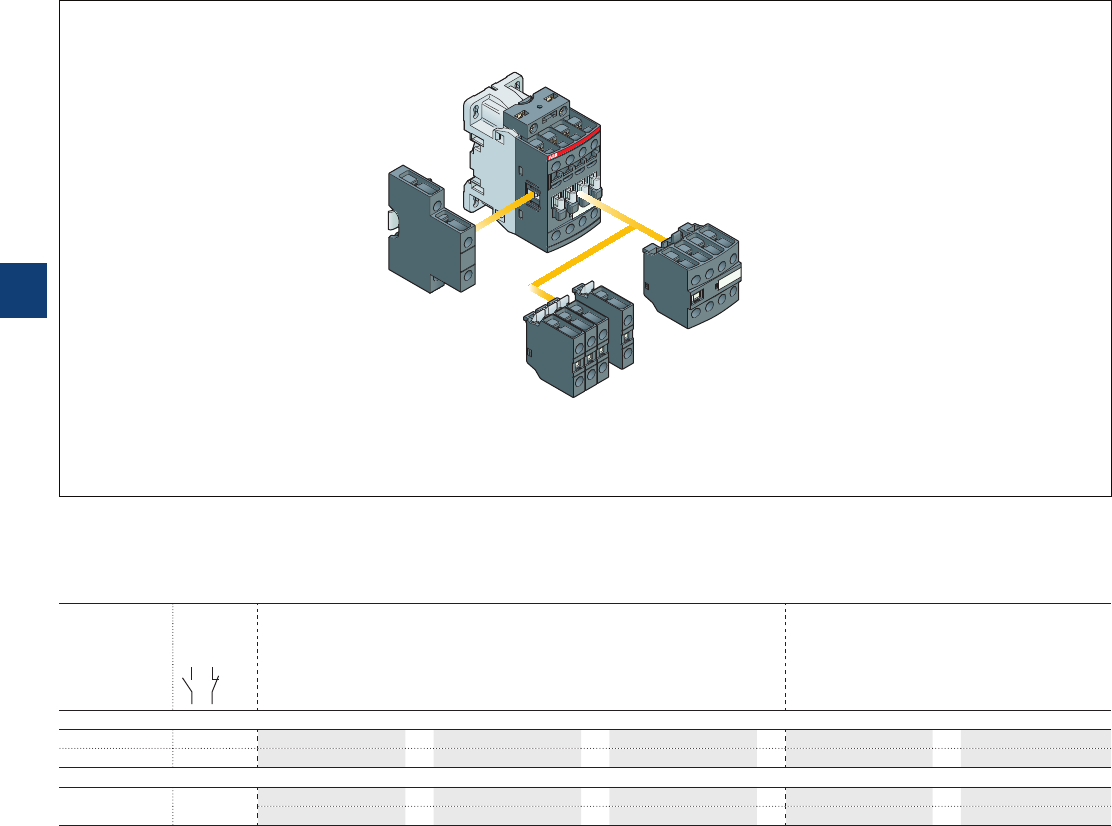
NF 4-pole contactor relays
Main accessories
Main accessory fitting details
Many configurations of accessories are possible depending on whether these are front-mounted or side-mounted.
Contactor relay
types
Main
poles
Front-mounted accessories Side-mounted accessories
Auxiliary contact blocks Auxiliary contact blocks
1-pole CA4 Left side Right side
1-pole CC4 4-pole CA4 2-pole CAL4-11
Max. add-on N.C. auxiliary contacts: 3 N.C. max. on positions 1, 2, 3, 4 and 2 N.C. max. on positions 1 ±30°, 5
NF.. 2 2 E 4 max.
or
1
+
1–
NF.. 3 1 E 2 max. –
+
1
+
1
Max. add-on N.C. auxiliary contacts: 4 N.C. max. on positions 1, 2, 3, 4 and 3 N.C. max. on positions 1 ±30°, 5
NF.. 4 0 E 4 max.
or
1
+
1–
2 max. –
+
1
+
1
Contactor relays and main accessories (other accessories available)
NF contactor relay
4-pole CA4
1-pole CA4, CC4
2-pole CAL4-11
5/110 | ABB
5
1SBC101518S0201
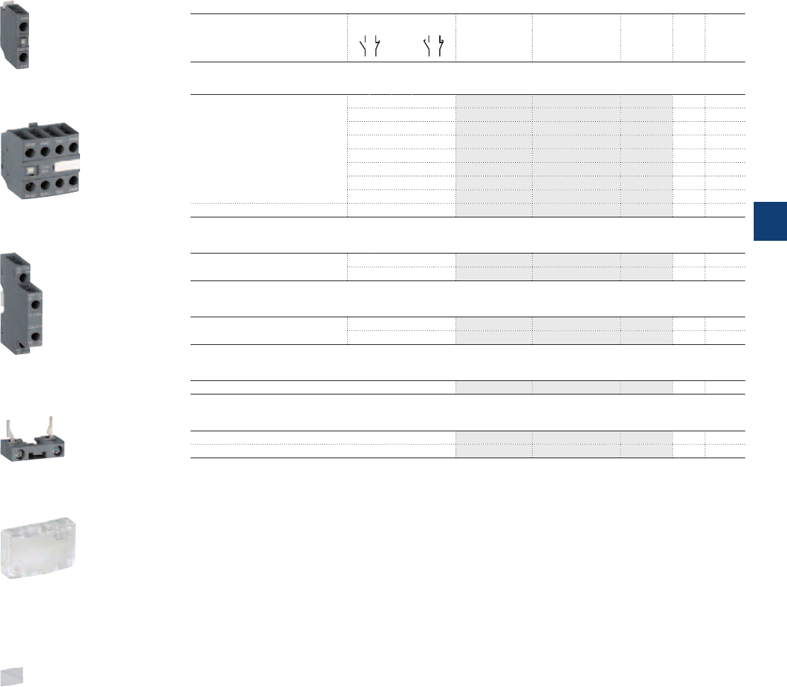
NF 4-pole contactor relays
Main accessories
Ordering details (1)
For contactor relays Auxiliary contacts Type Order code Pkg
qty
Weight
(1 pce)
kg
Front-mounted instantaneous auxiliary contact blocks
4-pole NF 1 0 – – CA4-10 1SBN010110R1010 1 0.014
1 0 – – CA4-10-T 1SBN010110T1010 10 0.014
0 1 – – CA4-01 1SBN010110R1001 1 0.014
0 1 – – CA4-01-T 1SBN010110T1001 10 0.014
4 0 – – CA4-40N 1SBN010140R1240 1 0.055
3 1 – – CA4-31N 1SBN010140R1231 1 0.055
2 2 – – CA4-22N 1SBN010140R1222 1 0.055
1 3 – – CA4-13N 1SBN010140R1213 1 0.055
NF..40E 0 4 – – CA4-04N 1SBN010140R1204 1 0.055
Front-mounted auxiliary contact blocks with N.O. leading contact and N.C. lagging contact
4-pole NF – – 1 0 CC4-10 1SBN010111R1010 1 0.014
– – 0 1 CC4-01 1SBN010111R1001 1 0.014
Side-mounted instantaneous auxiliary contact blocks
NF 1 1 – – CAL4-11 1SBN010120R1011 1 0.040
1 1 – – CAL4-11-T 1SBN010120T1011 10 0.040
Additional coil terminal block
NF LDC4 1SBN070156T1000 10 0.010
Protective covers
All 1-stack contactor relays BX4 1SBN110108T1000 10 0.006
For 4-pole CA4 auxiliary contact blocks BX4-CA 1SBN110109W1000 50 0.001
(1) See "Main accessory fitting details" table.
1SBC101108F0014
CA4-10
1SBC101136F0014
BX4
1SBC101133F0014
LDC4
1SBC101138F0014
BX4-CA
1SBC101112F0014
CAL4-11
CA4-22N
1SBC101123F0014
ABB | 5/111
5
1SBC101519S0201

NF contactor relays
Technical data
Contact utilization characteristics according to IEC
Contactor relay types AC / DC operated NF
Standards IEC 60947-1 / 60947-5-1 and EN 60947-1 / 60947-5-1
Rated operational voltage Ue max. 690 V
Rated frequency (without derating) 50 / 60 Hz
Conventional free-air thermal current Ith θ ≤ 40 °C 16 A
Ie / Rated operational current AC-15
acc. to IEC 60947-5-1 24-127 V 50/60 Hz 6 A
220-240 V 50/60 Hz 4 A
400-440 V 50/60 Hz 3 A
500 V 50/60 Hz 2 A
690 V 50/60 Hz 2 A
Rated making capacity AC-15 10 x Ie AC-15 acc. to IEC 60947-5-1
Rated breaking capacity AC-15 10 x Ie AC-15 acc. to IEC 60947-5-1
Ie / Rated operational current DC-13
acc. to IEC 60947-5-1 24 V DC 6 A / 144 W
48 V DC 2.8 A / 134 W
72 V DC 1 A / 72 W
110 V DC 0.55 A / 60 W
125 V DC 0.55 A / 69 W
220 V DC 0.27 A / 60 W
250 V DC 0.27 A / 68 W
400 V DC 0.15 A / 60 W
500 V DC 0.13 A / 65 W
600 V DC 0.1 A / 60 W
Short-circuit protection device gG type fuse 10 A
Rated short-time withstand current Icw for 1.0 s 100 A
for 0.1 s 140 A
Minimum switching capacity 12 V / 3 mA
with failure rate acc. to IEC 60947-5-4 10
-7
Non-overlapping time between N.O. and N.C. contacts ≥ 2 ms
Power dissipation per pole at 6 A 0.1 W
Max. electrical switching frequency AC-15 1200 cycles/h
DC-13 900 cycles/h
Mechanically linked contacts
Built-in N.O. or N.C. auxiliary contacts and additional N.O. or N.C. auxiliary contacts (CA4, CAL4 aux. contact blocks)
are mechanically linked contacts.
acc. to annex L of IEC 60947-5-1
Contact utilization characteristics according to UL / CSA
Contactor relay types AC / DC operated NF
Standards UL 508, CSA C22.2 N°14
Max. operational voltage 600 V AC, 600 V DC
Pilot duty A600, Q600
AC thermal rated current 10 A
AC maximum volt-ampere making 7200 VA
AC maximum volt-ampere breaking 720 VA
DC thermal rated current 2.5 A
DC maximum volt-ampere making-breaking 69 VA
5/112 | ABB
5
1SBC101562S0201
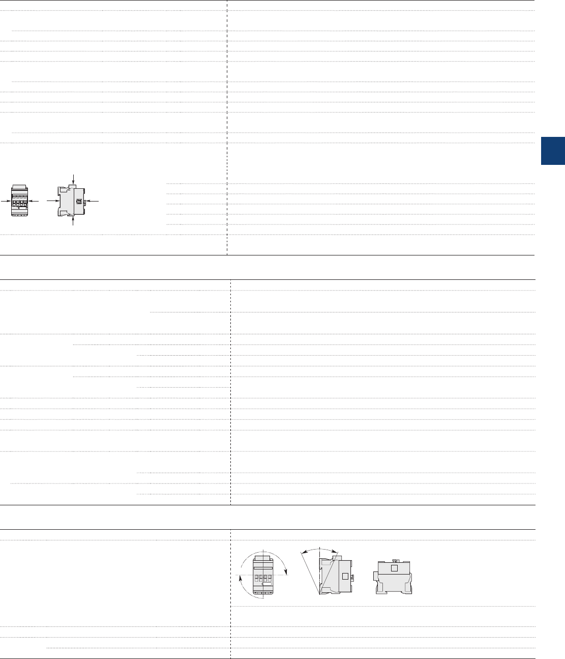
NF contactor relays
Technical data
General technical data
Contactor types AC / DC operated NF
Rated insulation voltage Ui
acc. to IEC 60947-5-1 690 V
acc. to UL / CSA 600 V
Rated impulse withstand voltage Uimp. 6 kV
Electromagnetic compatibility Devices complying with IEC 60947-1 / EN 60947-1 - Environment A
Ambient air temperature close to contactor
Operation in free air -40...+70 °C
Storage -60...+80 °C
Climatic withstand Category B according to IEC 60947-1 Annex Q
Maximum operating altitude (without derating) 3000 m
Mechanical durability
Number of operating cycles 20 millions operating cycles
Max. switching frequency 6000 cycles/h
Shock withstand
acc. to IEC 60068-2-27 and EN 60068-2-27
Mounting position 1
B2
AAB1
C2
C1
Shock direction 1/2 sinusoidal shock for 11 ms: no change in contact position, closed or open position
A30 g
B1 25 g closed position / 5 g open position
B2 15 g
C1 25 g
C2 25 g
Vibration withstand 5...300 Hz
acc. to IEC 60068-2-6 4 g closed position / 2 g open position
Magnet system characteristics
Contactor relay types AC / DC operated NF
Coil operating limits AC supply At θ ≤ 60 °C 0.85 x Uc min...1.1 x Uc max.
acc. to IEC 60947-5-1 At θ ≤ 70 °C 0.85 x Uc min...Uc max.
DC supply At θ ≤ 60 °C 0.85 x Uc min...1.1 x Uc max.
At θ ≤ 70 °C (AF) 0.85 x Uc min...Uc max. - (NFZ) 0.85 x Uc min...1.1 x Uc max.
AC control voltage Rated control circuit voltage Uc 24...500 V AC
50/60 Hz Coil consumption Average pull-in value (NF) 50 VA - (NFZ) 16 VA
Average holding value (NF) 2.2 VA / 2 W - (NFZ) 1.7 VA / 1.5 W
DC control voltage Rated control circuit voltage Uc 12...500 V DC
Coil consumption Average pull-in value (NF) 50 W - (NFZ) 12...16 W
Average holding value (NF) 2 W - (NFZ) 1.7 W
PLC-output control (NFZ) ≥ 500 mA 24 V DC
Drop-out voltage ≤ 60 % of Uc min.
Voltage sag immunity acc. to SEMI F47-0706 (NFZ) conditions of use on request
Dips withstand
-20 °C ≤ θ ≤ +60°C (NFZ) 22 ms average
Operating time
Between coil energization and: N.O. contact closing 40...95 ms
N.C. contact opening 38...90 ms
Between coil de-energization and: N.O. contact opening 11...95 ms
N.C. contact closing 13...98 ms
Mounting characteristics
Contactor types AC / DC operated NF
Mounting positions
Pos. 5
Pos. 3
Pos. 2
Pos. 1 Pos. 1 ± 30°
+30° -30°
Pos. 4
Max. add-on N.C. auxiliary contacts:
see accessory fitting details for a NF contactor relay
Mounting distances The contactor relays can be assembled side by side.
Fixing On rail according to IEC 60715, EN 60715 35 x 7.5 mm or 35 x 15 mm
By screws (not supplied) 2 x M4 screws placed diagonally
ABB | 5/113
5
1SBC101563S0201
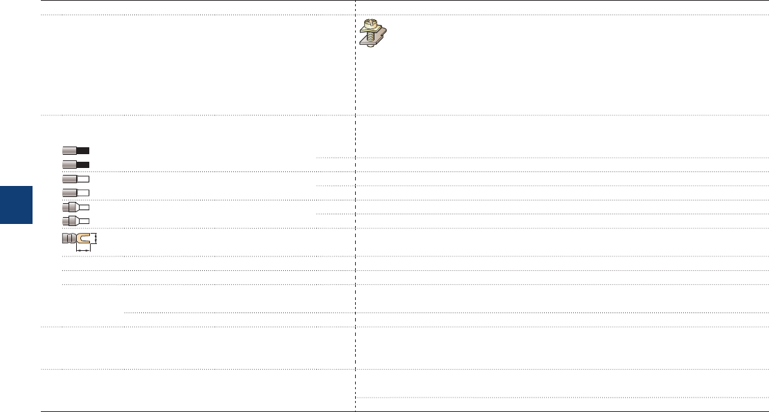
NF contactor relays
Technical data
Connecting characteristics
Contactor types AC / DC operated NF
Main terminals
Screw terminals with cable clamp
Connection capacity (min. ... max.)
Pole and coil terminals
Rigid 1 x 1...2.5 mm²
2 x 1...2.5 mm²
Flexible with non insulated ferrule 1 x 0.75...2.5 mm²
2 x 0.75...2.5 mm²
Flexible with insulated ferrule 1 x 0.75...2.5 mm²
2 x 0.75...1.5 mm²
L
6
Lugs L < 8 mm
Connection capacity acc. to UL/CSA 1 or 2 x AWG 18...14
Stripping length 10 mm
Tightening torque
Pole terminals 1.2 Nm / 11 lb.in
Coil terminals 1.2 Nm / 11 lb.in
Degree of protection
acc. to IEC 60947-1 / EN 60947-1 and IEC 60529 / EN 60529
All terminals IP20
Screw terminals Delivered in open position, screws of unused terminals must be tightened
All terminals M3.5
Screwdriver type Flat Ø 5.5 / Pozidriv 2
5/114 | ABB
5
1SBC101564S0201

Accessories for AF09 … AF38 contactors and
NF contactor relays
Auxiliary contact blocks 5/116
Interlocks 5/117
Mechanical latching unit 5/118
Connection accessories for starting solutions 5/119
Other accessories 5/120
ABB | 5/115
5
1SBC101615S0201

Auxiliary contact blocks
Description
The auxiliary contact blocks are used for the operation of auxiliary circuits and control circuits for standard
industrial environments.
Types of auxiliary contact blocks for front mounting:
– CA4 1 or 4-pole block, with instantaneous N.O., N.C. contacts
– CC4 1-pole block, with N.O. leading contact or N.C. lagging contact
– CAT4 2-pole block, with instantaneous N.O. + N.C. contacts and A1 / A2 coil terminal connection on
front face.
Select the 4-pole auxiliary contact blocks CA4-..E, CA4-..M, CA4-..U or CA4-..N type, according to the
contactor or contactor relay type for compliance with the standard requirements (see "Terminal marking and
positioning").
Types of auxiliary contact blocks for side mounting:
– CAL4 2-pole block, with instantaneous N.O. + N.C. contacts.
For clipping onto the right and/or lefthand side of the contactors.
The auxiliary contact blocks are equipped with screw type connecting terminals delivered open, protected
against accidental direct contact and bear the corresponding function marking.
Ordering details (1)
For contactors Auxiliary contacts Type Order code Pkg
qty
Weight
(1 pce)
kg
Front-mounted instantaneous auxiliary contact blocks
AF09 ... AF38
4-pole NF
1 0 – – CA4-10 1SBN010110R1010 1 0.014
1 0 – – CA4-10-T 1SBN010110T1010 10 0.014
0 1 – – CA4-01 1SBN010110R1001 1 0.014
0 1 – – CA4-01-T 1SBN010110T1001 10 0.014
AF09 ... AF16..-30-10 2 2 – – CA4-22M 1SBN010140R1122 1 0.055
3 1 – – CA4-31M 1SBN010140R1131 1 0.055
1 3 – – CA4-13M 1SBN010140R1113 1 0.055
0 4 – – CA4-04M 1SBN010140R1104 1 0.055
AF26 ... AF38..-30-00
AF09 ... AF38..-40-00
AF09 ... AF38..-22-00
2 2 – – CA4-22E 1SBN010140R1022 1 0.055
3 1 – – CA4-31E 1SBN010140R1031 1 0.055
4 0 – – CA4-40E 1SBN010140R1040 1 0.055
AF26 ... AF38..-30-00
AF09 ... AF16..-40-00
0 4 – – CA4-04E 1SBN010140R1004 1 0.055
AF09 ... AF16..-30-01 2 2 – – CA4-22U 1SBN010140R1322 1 0.055
3 1 – – CA4-31U 1SBN010140R1331 1 0.055
4 0 – – CA4-40U 1SBN010140R1340 1 0.055
4-pole NF 4 0 – – CA4-40N 1SBN010140R1240 1 0.055
3 1 – – CA4-31N 1SBN010140R1231 1 0.055
2 2 – – CA4-22N 1SBN010140R1222 1 0.055
1 3 – – CA4-13N 1SBN010140R1213 1 0.055
NF..40E 0 4 – – CA4-04N 1SBN010140R1204 1 0.055
Front-mounted auxiliary contact blocks with N.O. leading contact and N.C. lagging contact
AF09 ... AF38
4-pole NF
– – 1 0 CC4-10 1SBN010111R1010 1 0.014
– – 0 1 CC4-01 1SBN010111R1001 1 0.014
Side-mounted instantaneous auxiliary contact blocks
AF09 ... AF38
NF
1 1 – – CAL4-11 1SBN010120R1011 1 0.040
1 1 – – CAL4-11-T 1SBN010120T1011 10 0.040
Front-mounted instantaneous auxiliary contact and A1/A2 coil terminal blocks
AF09 ... AF16..-30-10 1 1 – – CAT4-11M 1SBN010151R1111 1 0.040
AF26 ... AF38..-30-00
AF09 ... AF38..-40-00
AF09 ... AF38..-22-00
1 1 – – CAT4-11E 1SBN010151R1011 1 0.040
AF09 ... AF16..-30-01 1 1 – – CAT4-11U 1SBN010151R1311 1 0.040
(1) For each contactor or contactor relay type, refer to "Accessory fitting details" table.
Note: CAT4 not fittable on AF..Z contactors with DC control voltage 12…20 V DC.
1SBC101108F0014
CA4-10
1SBC101121F0014
CA4-22M
1SBC101114F0014
CAT4-11E
1SBC101112F0014
CAL4-11
5/116 | ABB
5
1SBC101573S0201
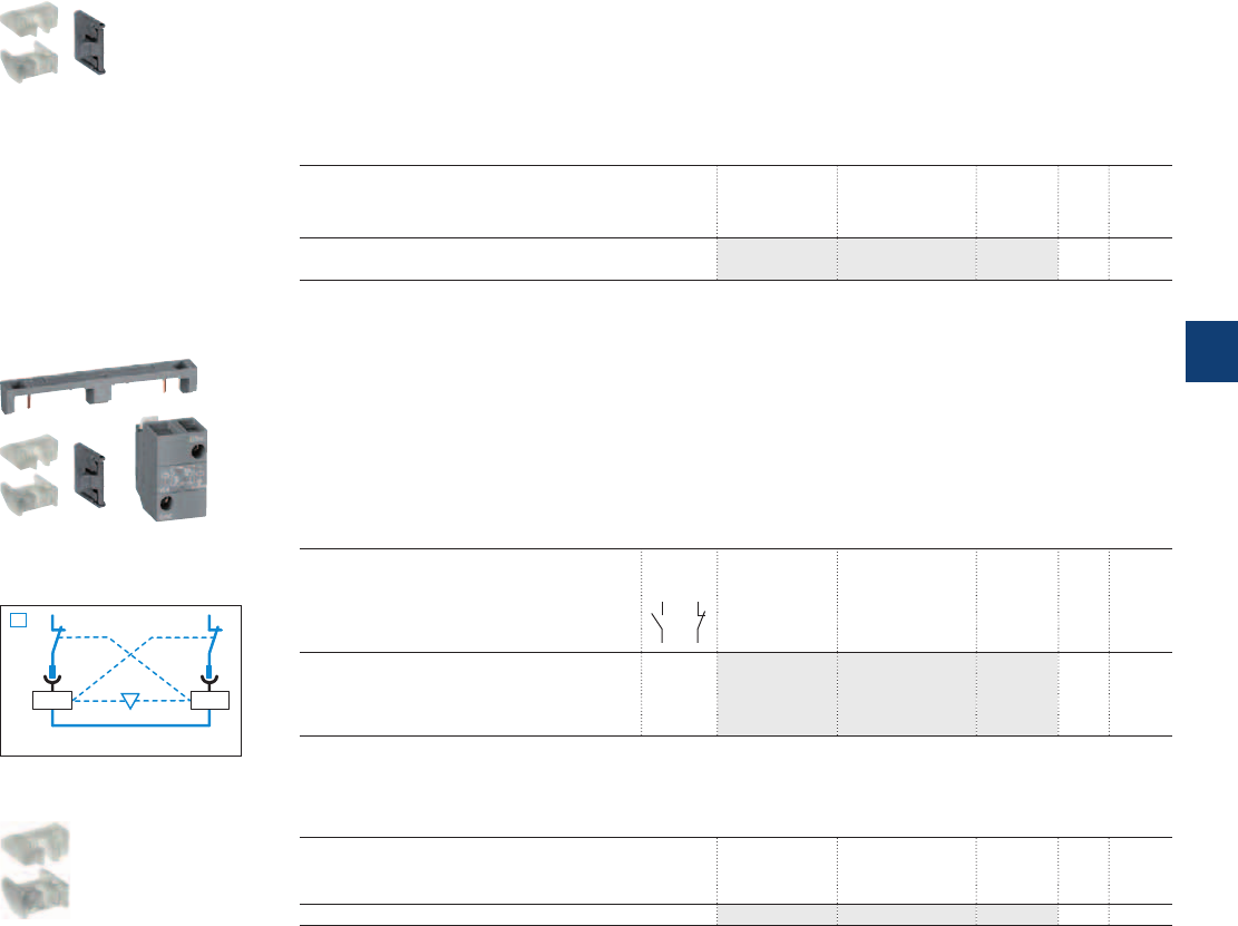
A2 A2
01NC
01NC
VEM4
KM1 KM2
1SBC101130F0014
1SBC101128F0014 1SBC101128F0014
1SBC101129F0014
Interlocks
Mechanical interlock unit
VM4 mechanical interlock unit for the interlocking of two AF contactors.
When mounted between two contactors without additional width, the VM4 mechanical interlock unit pre-
vents one of the contactors from closing as long as the other contactor is closed.
The mechanical interlock unit includes 2 fixing clips (BB4).
Ordering details
For contactors Type Order code Pkg
qty
Weight
(1 pce)
kg
AF09 ... AF38..-30-.. VM4 1SBN030105T1000 10 0.005
AF09 ... AF38..-40-00
Mechanical and electrical interlock set
VEM4 mechanical and electrical interlock set for the interlocking of two AF contactors.
VEM4 set includes a mechanical interlock unit VM4 with 2 fixing clips (BB4) and a VE4 electrical interlock
block with A2-A2 connection.
Fixing the electrical interlock block to the contactor front face connects the 2 built-in N.C. interlocking
contacts with the two coils. VE4 block must be used with A2-A2 connection to respect the electrical con-
nection diagram.
Ordering details
For contactors
Auxiliary
contacts
Type Order code Pkg
qty
Weight
(1 pce)
kg
AF09 ... AF16..-30-.. 1 1 VEM4 1SBN030111R1000 1 0.035
AF26 ... AF38..-30-00
AF09, AF16..-40-00
AF26, AF38..40-00
Note: VEM4 not fittable on AF..Z contactors with DC control voltage 12...20 V DC.
Fixing clips
For contactors Type Order code Pkg
qty
Weight
(1 pce)
kg
AF09 ... AF38 BB4 1SBN110120W1000 50 0.002
VEM4
VM4
BB4
1SBC101127F0014
ABB | 5/117
5
1SBC101595S0201
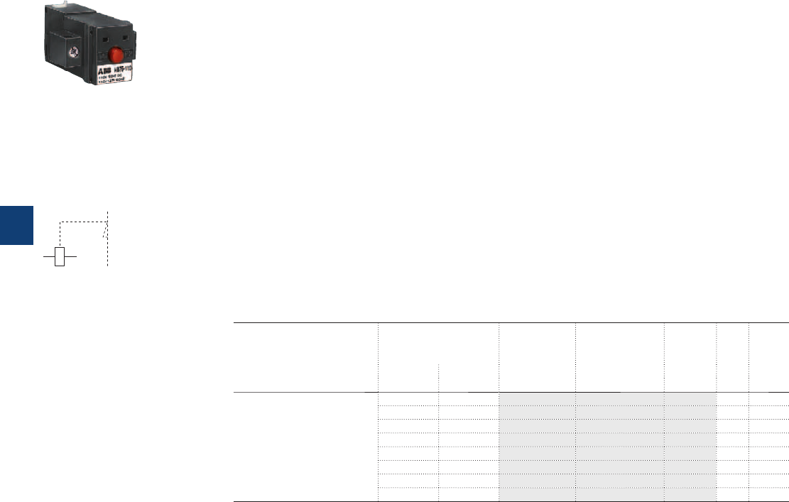
Mechanical latching unit
Description
For converting standard contactors into latched contactors.
The WB75-A block contains a mechanical latching device with electromagnetic impulse unlatching (AC or
DC) or manual unlatching.
Captive screw type connecting terminals, built-in cable clamps, M3.5 (+,-) pozidriv 2 screw with screw-
driver guidance; delivered untightened and protected against accidental direct contact.
Operation
After closing, the contactor continues to be held in the closed position by the latching mechanism should
the supply voltage fail at the contactor coil terminals.
Contactor opening can be controlled:
– electrically by an impulse* (AC or DC) on the WB75-A block coil.
* the coil is not designed to be permanently energized.
– manually by pressing the pushbutton on the front face of the WB75-A block.
Mounting
The WB75-A block is clipped onto the front face of the 1-stack contactor where it takes up two slots. The
two other slots do not accept CA4 single pole auxiliary contacts. Up to 2 CAL4-11 auxiliary contact blocks
can be side-mounted on contactors.
Ordering details
For contactors Rated control circuit
voltage
Uc
Type Order code Pkg
qty
Weight
(1 pce)
V 50 Hz
or DC V 60 Hz kg
AF09 ... AF38 24 24...28 WB75-A FPTN372726R1001 1 0.120
42 42...48 WB75-A FPTN372726R1002 1 0.120
48 48...55 WB75-A FPTN372726R1003 1 0.120
110 110...127 WB75-A FPTN372726R1004 1 0.120
220...230 220...255 WB75-A FPTN372726R1006 1 0.120
230...240 230...277 WB75-A FPTN372726R1005 1 0.120
380...415 380...440 WB75-A FPTN372726R1007 1 0.120
415...440 440...480 WB75-A FPTN372726R1008 1 0.120
Note: For WB75-A produced since week 06-2012.
1SBC565483F0301
WB75-A
E2676D
E1 E2
Terminal marking
5/118 | ABB
5
1SBC101634S0201
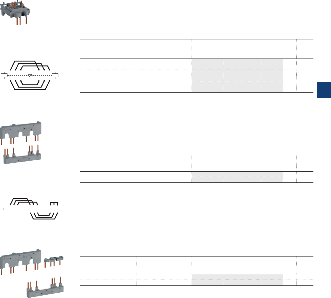
A1
A2
A1
A2
315 315
42 6 426
A1
A2
A1
A2
3 1 5 3 1 5
4 2 6 4 2 6
A1
A2
3 1 5
4 2 6
Connection accessories for starting solutions
Connecting links with manual motor starters
The BEA..-4 connecting links are used to connect AF09 ... AF38 contactors with the MS116 or MS132
manual motor starters.
The BEA..-4 insulated 3-pole connecting links ensure the electrical and mechanical connection between
the contactor and the associated manual motor starter.
Ordering details
For 3-pole contactors Manual motor starter Type Order code Pkg
qty
Weight
(1 pce)
kg
AF09 ... AF16 MS116-0.16 … MS116-25, BEA16-4 1SBN081306T1000 10 0.025
MS132-0.16… MS132-25
AF26 ... AF38 MS116-0.16 … MS116-16, BEA26-4 1SBN082306T1000 10 0.025
MS132-0.16 ... MS132-10
MS116-20 … MS116-32, BEA38-4 1SBN082306T2000 10 0.030
MS132-12 ... MS132-32
Connection sets for reversing contactors
BER16-4 and BER38-4 connection sets between the main poles of two 3-pole contactors mounted side
by side.
The connection sets are made up of 1 upstream and 1 downstream connections: insulated, solid copper
bars.
Ordering details
For 3-pole contactors Type Order code Pkg
qty
Weight
(1 pce)
kg
AF09 ... AF16 BER16-4 1SBN081311R1000 1 0.045
AF26 ... AF38 BER38-4 1SBN082311R1000 1 0.100
Connection sets for star-delta starting
BEY16-4 and BEY38-4 connection sets between the main poles of the Line, Delta and Star contactors of
a star-delta starter.
The connection sets are made up of:
– Line contactor / delta contactor: upstream phase-to-phase connection
– Delta contactor / star contactor: downstream connection in parallel
– Star contactor: star point upstream.
Ordering details
For 3-pole line, delta & star
contactors
Interlock unit between delta
& star contactors
Type Order code Pkg
qty
Weight
(1 pce)
kg
AF09 ... AF16 With or without VM4 or VEM4 BEY16-4 1SBN081313R2000 1 0.050
AF26 ... AF38 With or without VM4 or VEM4 BEY38-4 1SBN082713R2000 1 0.110
BEA16-4
BER16-4
BEY16-4
1SBC101140F0014
1SBC101144F0014
1SBC101142F0014
ABB | 5/119
5
1SBC101592S0201
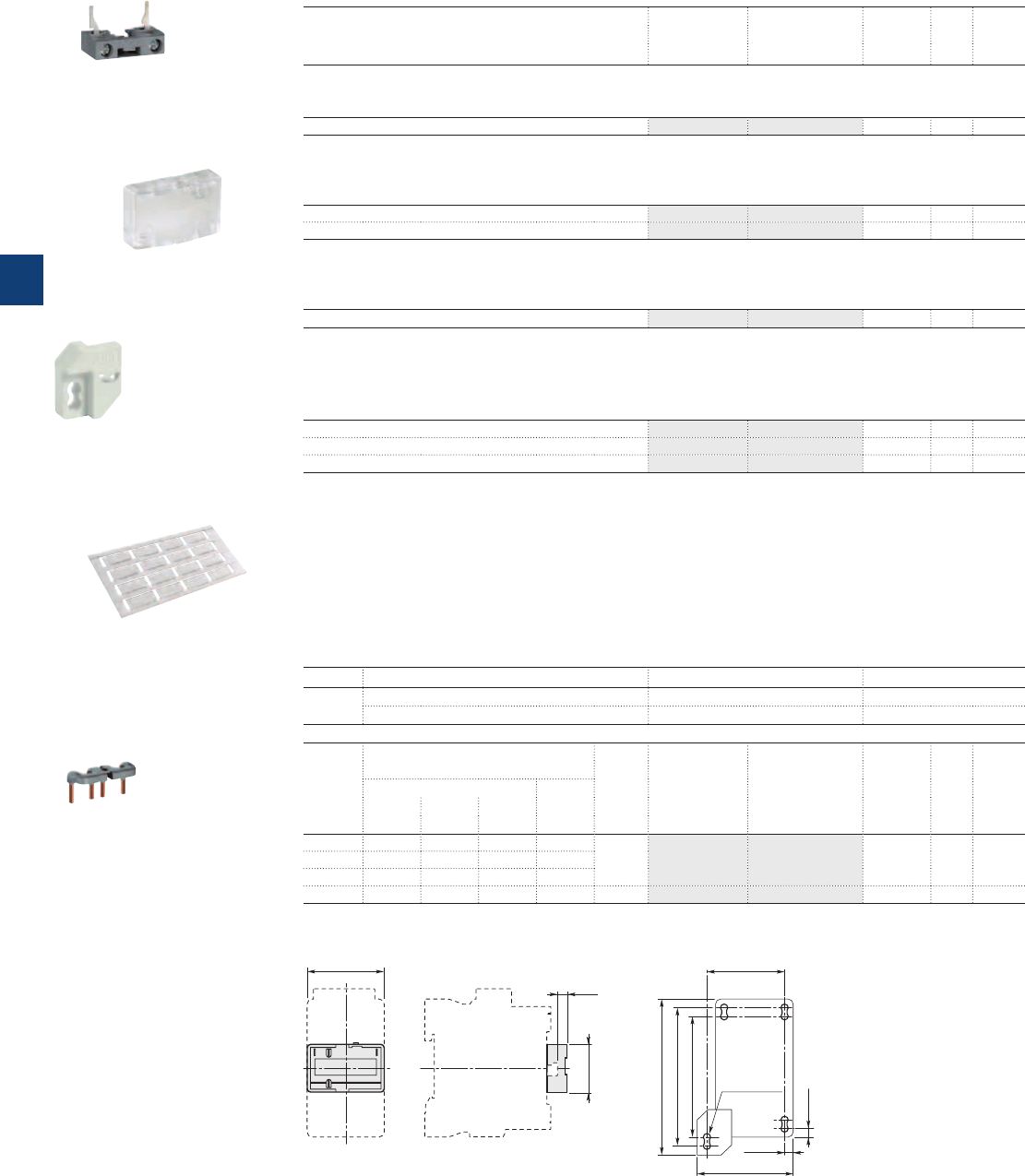
1SBC101136F0014
1SBC101133F0014
Other accessories
Ordering details
For contactors Type Order code Pkg
qty
Weight
(1 pce)
kg
Additional coil terminal block
Additional coil terminal block for a bottom access to the coil terminals of contactors or contactor relays.
AF09 ... AF38, NF LDC4 1SBN070156T1000 10 0.010
Protective covers
Sealable and transparent protective covers BX4 and non-removable BX4-CA to protect the devices against
accidental contact.
All 1-stack contactors and contactor relays BX4 1SBN110108T1000 10 0.006
For 4-pole CA4 and 2-pole CAT4 auxiliary contact blocks BX4-CA 1SBN110109W1000 50 0.001
Mounting piece
Mounting piece for replacement of A / AL26 ... A / AL40 contactors fixed by screws by AF contactors
in 45 mm width.
AF09 ... AF38 BP38-4 1SBN112303T1000 10 0.003
Function markers
Box of 16 blank cards (16 markers by card) printable on HTP500 thermal transfer printer and AMS 500 mark-
ing table to identify your contactors, overload relays or manual motor starters.
Marker dimensions: 7 x 20 mm (.276" x .787").
Box of 16 blank cards BA4 1SNA235156R2700 16 0.011
AMS 500 support plate for 8 BA4 SPRC 1 1SNA360010R1500 1 0.220
HTP500 support plate HTP500-BA4 1SNA235712R2400 1 0.290
Terminal connecting strips and shorting bars
Parallel and series connection of 3-pole contactor:
– To obtain a star point (3 parallel-connected poles)
– To connect poles in parallel and thus increase the AC load passing through the flow path made up of the
parallel-connected poles
The relevant cable cross-sectional area may limit the maximum permissible current. Consult the informa-
tion in the table below
– To connect poles in series and thus increase the DC load controlled by the poles: LY16-4 and LY38-4
secable strips.
Types for connection of "n" poles with terminal insulated
LY... n = 2 (secable LY16-4, LY38-4 connecting strips) no yes
n = 3 no yes
For
contactors
max. nominal continuous
current with "n" poles
Cable
cross-
sectional
area
Type Order code Pkg
qty
Weight
(1 pce)
in parallel in series
2 poles 3 poles 4 poles 2 poles
AAAAmm² kg
AF09 30 33 - 25 6 LY16-4 1SBN071303T1000 10 0.006
AF12 32 36 - 27
AF16 34 40 - 30
AF26 50 60 - 45 10 LY38-4 1SBN072303T1000 10 0.012
BX4
LDC4
BA4
LY16-4
BP38-4
1SNC160101F0014
Main dimensions mm, inches
45 1.77"
54 2.13"
70 2.76"
80 3.15"
90 3.54"
5 0.20"
5 0.20"
M4 8-32 UNC
ø 4.2 0.17"
BX4
28 1.10"
6
0.24"
44.8 1.76"
BP38-4
1SBC101144F0014
1SBC101383F0014
5/120 | ABB
5
1SBC101596S0201

Accessories for A40 … AF2050 contactors
Auxiliary contact blocks 5/122
Pneumatic timer blocks 5/123
Mechanical interlock units 5/124
Mechanical and electrical interlock units 5/124
Function markers - Mounting piece 5/125
Electronic timer for star-delta starters 5/126
Surge suppressors for contactor coils 5/127
Interface relays 5/128
Mechanical latching unit 5/129
Additional terminal blocks 5/130
Terminals for control lead connections 5/131
Terminal shrouds 5/132
Terminal enlargements - Terminal extensions 5/133
Connector terminals 5/134
Terminal connecting strips and shorting bars 5/135
Connecting links for contactors and manual motor starters 5/136
Connection bars for contactor and MCCB 5/137
Connection bars for contactor and switch fuse 5/138
Connection sets for reversing contactors 5/139
3-pole connections phase to phase 5/139
Connections for 4-pole changeover contactors 5/139
Connection sets for star-delta starter 5/140
Mounting plates for A95 ... AF750 contactors 5/141
Adapter plates for A95 ... AF750 contactors 5/142
Main contact sets - Arc chutes for 3-pole contactors 5/143
Contactor coils 5/144
ABB | 5/121
5
1SBC101616S0201
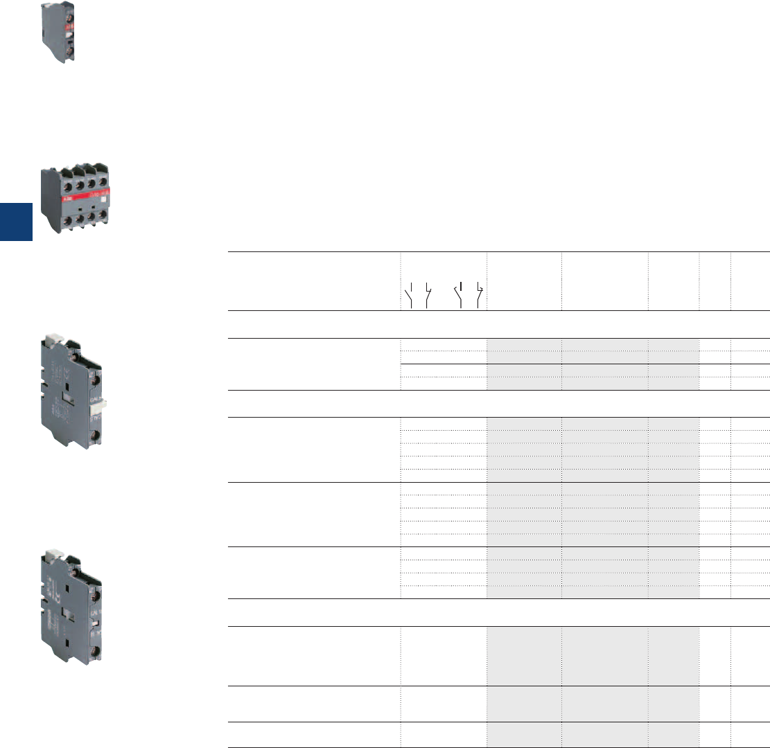
Auxiliary contact blocks
Description
The auxiliary contact blocks are used for the operation of auxiliary circuits and control circuits for standard
industrial environments.
Types of auxiliary contact blocks for front mounting:
– CA5 1 or 4-pole block, instantaneous with N.O., N.C. contacts
– CC5 1-pole block, with N.O. leading contact or N.C. lagging contact.
Select the 4-pole auxiliary contact blocks CA5-..E, CA5-..M or CA5-..U type, according to the contactor
type for compliance with the standard requirements (see "Terminal Marking and Positioning").
Types of auxiliary contact blocks for side mounting:
– CAL... 2-pole block instantaneous N.O. + N.C. contacts.
For clipping onto the right and/or lefthand side of the contactors.
The CAL18-11B is a second block for mounting in addition to a first CAL18-11 block, right and/or lefthand
of the A145 ... A300 and AF145 ... AF2050 contactors.
The auxiliary contact blocks are equipped with screw type connecting terminals delivered open, protected
against accidental direct contact and bear the corresponding function marking.
Ordering details
For contactors Number
of
blocks
(1)
Auxiliary contacts Type Order code Pkg
qty
Weight
(1 pce)
kg
Front-mounted instantaneous auxiliary contact blocks, 1-pole
A40, AL40, TAL40 .........................1-5
A45 ... A110 .................................. 1-6
AF45, AF110 .................................1-6
AE45 ... AE75, TAE45 ... TAE75
........1-6
1 0 – – CA5-10 1SBN010010R1010 10 0.014
0 1 – – CA5-01 1SBN010010R1001 10 0.014
– – 1 0 CC5-10 1SBN010011R1010 10 0.014
– – 0 1 CC5-01 1SBN010011R1001 10 0.014
Front-mounted instantaneous auxiliary contact blocks, 4-pole
A45 ... A110 ..................................... 1
AE45 ... AE75 ................................... 1
AF45 ... AF110 ................................. 1
TAE45 ... TAE75 ............................... 1
4 0 – – CA5-40E 1SBN010040R1040 2 0.060
3 1 – – CA5-31E 1SBN010040R1031 2 0.060
2 2 – – CA5-22E 1SBN010040R1022 2 0.060
0 4 – – CA5-04E 1SBN010040R1004 2 0.060
1 1 1 1 CA5-11/11E 1SBN010040R1018 2 0.060
A40-30-10 ....................................... 1
AL40-30-10 ...................................... 1
TAL40-30-10 .................................... 1
3 1 – – CA5-31M 1SBN010040R1131 2 0.060
2 2 – – CA5-22M 1SBN010040R1122 2 0.060
1 3 – – CA5-13M 1SBN010040R1113 2 0.060
0 4 – – CA5-04M 1SBN010040R1104 2 0.060
1 1 1 1 CA5-11/11M 1SBN010040R1118 2 0.060
A40-30-01 ....................................... 1
AL40-30-01 ...................................... 1
TAL40-30-01 .................................... 1
4 0 – – CA5-40U 1SBN010040R1340 2 0.060
3 1 – – CA5-31U 1SBN010040R1331 2 0.060
2 2 – – CA5-22U 1SBN010040R1322 2 0.060
0 4 – – CA5-04U 1SBN010040R1304 2 0.060
Side-mounted instantaneous auxiliary contact blocks, 2-pole
A40 … A75 ...................................1-2
AL40, TAL40 .................................... 1
AE45 ... AE75, TAE45 ... TAE75 ........ 1
AF45 ... AF75 ................................ 1-2
UA16 ... UA75 ............................... 1-2
1 1 – – CAL5-11 1SBN010020R1011 2 0.050
A95 ... A300 .................................. 1-2
AF95 ... AF2050 ............................ 1-2
UA95, UA110 ................................1-2
1 1 – – CAL18-11 1SFN010720R1011 2 0.050
A145 ... A300 ............................ 1-2(2)
AF145 ... AF2050 ...................... 1-2(2) 1 1 – – CAL18-11B 1SFN010720R3311 2 0.050
(1) For each contactor type, refer to "Accessory fitting details" table.
(2) 2 blocks CAL18-11 + 2 blocks CAL18-11B.
Note:
– The front-mounted auxiliary contact blocks provided for the A... contactors can be used for the UA..., GA... and GAE... types
– The CAL... auxiliary contact blocks can be used for GA... contactors:
GA75-10-00: 2 x CAL5-11 blocks
GA75-10-11: 1 x CAL5-11 block
GAE75-10-00: 1 x CAL5-11 block
GAE75-10-11: no add-on block.
– The CAL... auxiliary contact blocks can be used for UA..RA contactors. See "Accessory fitting details" for this contactor type.
1SBC580992F0301
CA5-10
1SBC573794F0302
CA5-40E
1SBC573752F0301
CAL5-11
1SFC101033F0201
CAL18-11
5/122 | ABB
5
1SBC101520S0201
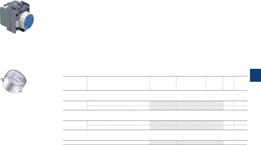
Pneumatic timer blocks
Description
The timer blocks are equipped with adjustable time delay auxiliary contacts.
Types
– TP40DA, TP180DA (blue button) for time delay on energization
– TP40IA, TP180IA (black button) for time delay on de-energization.
Pneumatic timer with 350° linear scale and setting via marked knurled knob.
Block equipped with 2 time-delayed auxiliary contacts: 1 N.O. and 1 N.C.
Captive screw type connecting terminals with built-in cable clamps. M3.5 (+,-) pozidriv 2 screw with
screwdriver guidance, supplied untightened and protected against accidental direct contact.
Clipped onto the front panel of A40 ... A75 1-stack contactors.
Accessory
BX-TP plastic sealed cover protecting access to the time delay setting.
Ordering details (1)
For contactors Time delay setting Type Order code Pkg
qty
Weight
(1 pce)
kg
Pneumatic timer blocks for time delay on energization
A40 ... A75
1-stack
0.1...40 s TP40DA 1SBN020300R1000 1 0.070
10...180 s TP180DA 1SBN020300R1001 1 0.070
Pneumatic timer blocks for time delay on de-energization
A40 ... A75
1-stack
0.1...40 s TP40IA 1SBN020301R1000 1 0.070
10...180 s TP180IA 1SBN020301R1001 1 0.070
Accessory
– BX-TP FPTN472657R0001 1 0.006
Note: The TP... timers provided for A40 ... A75 contactors can be used for the AF, AE, TAE, UA, GA and GAE contactors.
(1) For each contactor type, refer to "Accessory fitting details" table.
1SBC575893F0302
TP40DA
1SBC586522F0301
BX-TP
ABB | 5/123
5
1SBC101524S0201
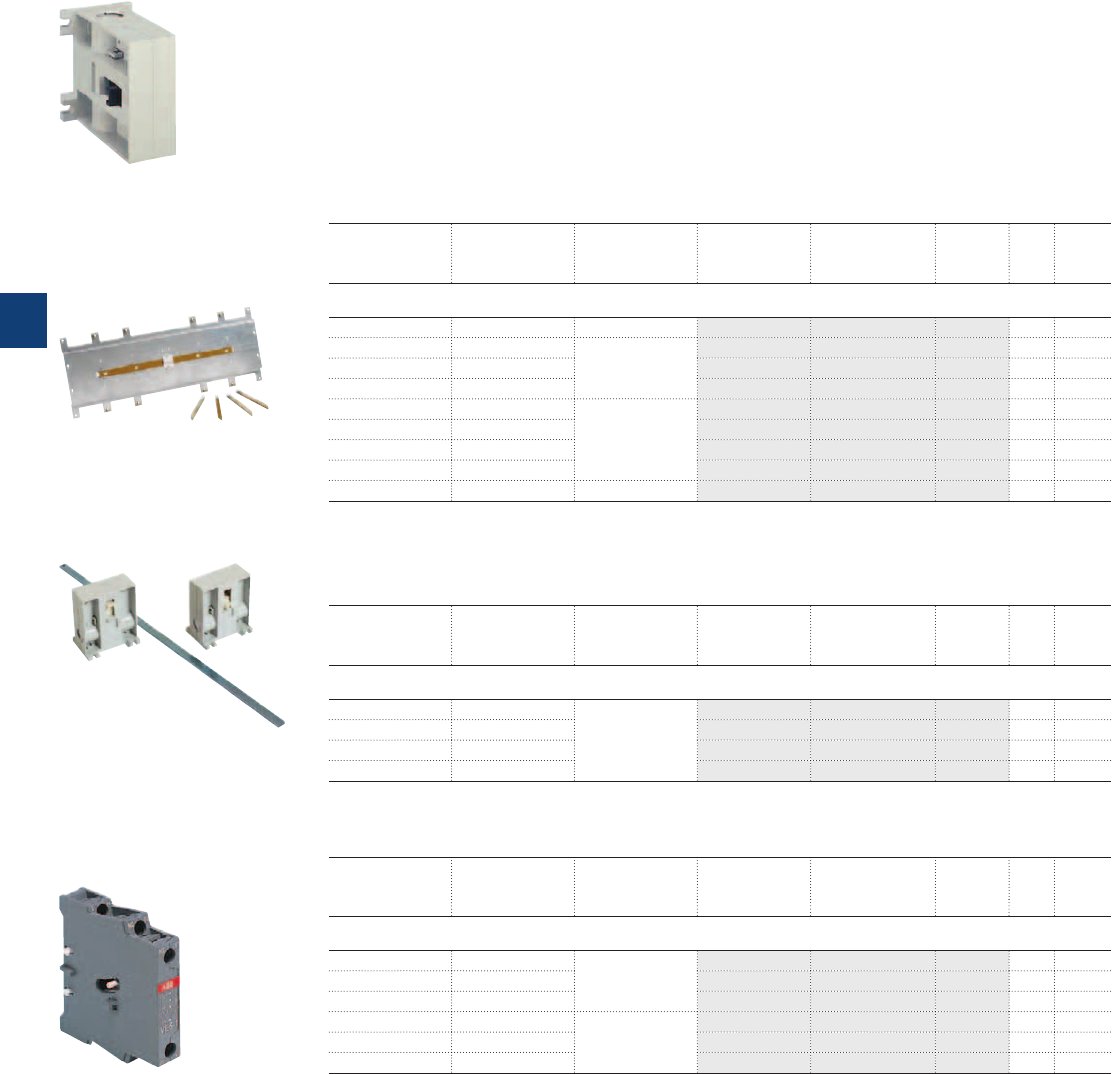
Mechanical interlock units
Mechanical and electrical interlock units
Description
When mounted between two contactors, the mechanical interlock unit prevents one of the contactors from
closing as long as the other contactor is closed.
– VM... interlock units for mechanical interlocking of two horizontal or vertical mounted AC or DC operated
contactors
– VE... interlock units for mechanical and electrical interlocking of two horizontal mounted AC or DC oper-
ated contactors.
Ordering details (1)
Left side
contactor
Right side
contactor
Mounting Type Order code Pkg
qty
Weight
(1 pce)
kg
Mechanical interlock units for two horizontal mounted contactors (1)
A40 A40 Rail mounting VM5-1 1SBN030100R1000 1 0.066
A40 A45 … A110 See table below
with VE5-.. type
–– ––
A45 … A75 A45 … A110 – – – –
A95 … A185 A45 … A110 – – – –
A95 … A185 A145 … A300 PN.. mounting
plate to be ordered
separately
VM300H 1SFN034700R1000 1 0.150
A210 … A300 A145 … A300 VM300H 1SFN034700R1000 1 0.150
A210 … A300 AF400 … AF460 VM300/460H 1SFN035100R1000 1 0.150
AF400 … AF1250 AF400 … AF1250 VM750H 1SFN035700R1000 1 0.200
AF1350 … AF2050 AF1350 … AF2050 Plate included VM1650H 1SFN036503R1000 1 6.000
(1) Mechanical durability: VM5-1 = 5 millions cycles, VM300H ... VM750H = 1 million cycles.
The interlock units provided for A... contactors can be used for AF types.
The interlock units provided for A40.. contactors can be used for AL40.. and TAL40.. types.
Up contactor Down contactor Mounting Type Order code Pkg
qty
Weight
(1 pce)
kg
Mechanical interlock units for two vertical mounted contactors (2)
A95 … A185 A145 … A300 Additional plate
(not supplied)
VM300V 1SFN034701R1000 1 0.150
A210 … A300 A145 … A300 VM300V 1SFN034701R1000 1 0.150
A210 … A300 AF400 … AF460 VM300/460V 1SFN035101R1000 1 0.150
AF400 … AF1250 AF400 … AF1250 VM750V 1SFN035701R1000 1 0.200
(2) Mechanical durability: VM300V ... VM750V = 1 million cycles.
Left side
contactor
Right side
contactor
Mounting Type Order code Pkg
qty
Weight
(1 pce)
kg
Mechanical and electrical interlock units for two horizontal mounted contactors
A40 A40 Rail mounting VE5-1 1SBN030110R1000 1 0.076
A40 … A75 A45 … A75 VE5-2 1SBN030210R1000 1 0.146
A45 ... A75 A40 ... A75 VE5-2 1SBN030210R1000 1 0.146
A45 … A75 A95 … A110 PN.. mounting
plate to be ordered
separately
VE5-2 (3) 1SBN030210R1000 1 0.146
A95 … A110 A45 … A75 VE5-2 (3) 1SBN030210R1000 1 0.146
A95 … A110 A95 … A110 VE5-2 1SBN030210R1000 1 0.146
(3) The combination of A45 ... A75 contactors interlocked with A95, A110 contactors cannot be mounted on symmetrical rail
(75 mm, IEC/EN 60715).
The interlock units provided for A... contactors can be used for AE, TAE, AF, GA and GAE types.
The interlock units provided for A40.. contactors can be used for AL40.. and TAL40.. types.
1SBC580411F0301
VM300H
1SBC580411F0301
VM1650H
1SBC580411F0301
VM300V
1SBC572822F0301
VE5-1
5/124 | ABB
5
1SBC101525S0201
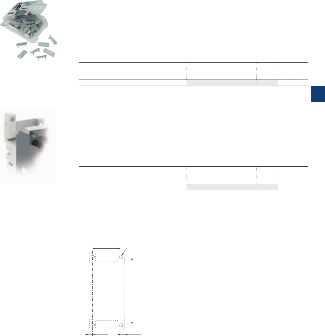
Function markers
Mounting piece
BA5-50 Function markers
Description
For marking contactors, thermal overload relays and accessories.
The BA5-50 is a set of 50 function markers designed to be clipped onto the front face of devices.
Effective marking surface: 7 x 19 mm.
Details can be added to these markers using a ball point pen, indelible felt-tip pen or pentel white.
Self-adhesive labels (not supplied) can also be added to them.
Ordering details
For contactors Type Order code Pkg
qty
Weight
(1 pce)
kg
Contactors, thermal overload relays and accessories BA5-50 1SBN110000R1000 1 0.017
BP16 Mounting piece
Description
Mounting piece for screw fixing (M4, not supplied) of UA, UA..RA series contactors indicated in the table
below.
Easy handling of screwdrivers and screw driving.
Add-on mounting piece on contactor's rear face, offering a wide fixing facility.
Ordering details
For contactors Type Order code Pkg
qty
Weight
(1 pce)
kg
UA16, UA16..RA BP16 1SBN111403R1000 100 0.141
BA5-50
BP16
1SBC586724F0302 1SBC575874F0301
35 1.38"
84 3.31"
4.5 0.18" 4.5 0.18"
ø 4.5 0.18"
M4 8-32 UNC
Drilling plan for UA16, UA16..RA
contactors with BP16
ABB | 5/125
5
1SBC101531S0201
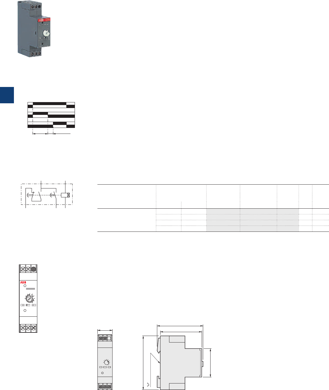
Electronic timer for star-delta starters
Description
When used in star-delta starters, the TE5S lags the star connection and provides a lapse of 50 ms before
the switch over to delta connection.
According to the type of device chosen, the electronic circuit has a 24VAC / DC, 110 to 120VAC,
220 to 240VAC or 380 to 440VAC supply. An output relay with reversing contact ensures high current
switching. A two-position switch allows selection of one of the two time delay ranges: 0.8 to 8 s or 6 to
60 s. The 0.1 to 1.0 graduated button allows an initial setting without steps within the previously selected
range which can then be adjusted using a chronometer.
Note: We recommend that you allow for temperature drift for the final adjustment of the time delay setting.
Drift: -0.2 % per °C.
For example, a setting made at 20 °C will yield a time delay shorter by 7 % at 55 °C in a cubicle (-0.2 %
per °C i.e. -0.2 x 35 = -7 %).
Regardless of these settings the TE5S provides a fixed "lapse" of 50 ms between the opening of contact
15-16 and the closing of contact 15-18. This time delay prevents from arc short-circuit during star to delta
switching.
Operation
On energization, the green U indicator light (voltage applied) comes on. Contact 15-16 then immediately
moves to the closed position.
Count-down of the programmed time immediately commences. When the time delay has elapsed, contact
15-16 opens and at the same time the 50 ms lapse, t2, begins after which contact 15-18 moves to the
closed position. The yellow R indicator light comes on.
On de-energization, the U and R indicator lights go out and, after the 250 ms resetting time, the device is
ready for a new cycle.
Mounting
On 35 x 7.5 mm or 35 x 15 mm mounting rail according to IEC/EN 60715.
Ordering details
For contactors Rated control circuit
voltage
Uc
Type Order code Pkg
qty
Weight
(1 pce)
V 50/60 Hz V DC kg
A40 ... A300 24 24 TE5S-24 1SBN020010R1001 1 0.080
110...120 – TE5S-120 1SBN020010R1002 1 0.080
220...240 – TE5S-240 1SBN020010R1003 1 0.080
380...440 – TE5S-440 1SBN020010R1004 1 0.080
Main dimensions mm, inches
23 0.91" 65 2.56"
75 2.95"
35 mm EN/IEC 60715
45 1.77"
85 3.35"
1SBC575582F0302
TE5S...
U
15-16
t
1
(t
2
= 50ms)
15-18
R
E0719D1
t
2
Chart
t1 t1+t2
A1A2
16
15
18
E0718D
Equivalent diagram
TE5S
R
Star-Delta Timer
U
x 0.1
0.5
1.0
8s t1
A1 15
A1 15
16 A218
16 A218
60s
E0720D1
Uc=
Front face
5/126 | ABB
5
1SBC101523S0201
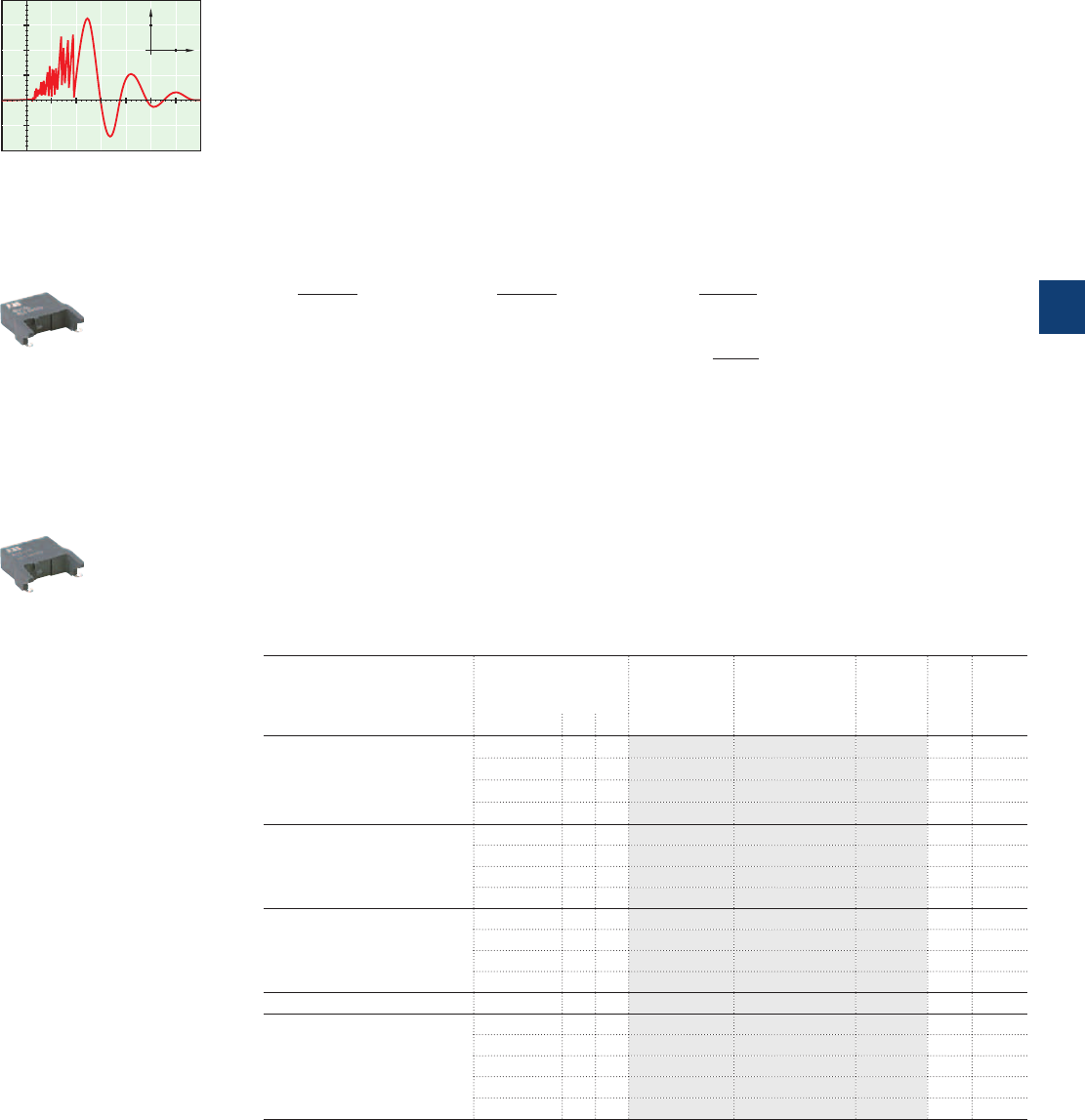
Surge suppressors for contactor coils
0
1000
100
(V)
T
(μs)
0
1000
100
A 884D
RV5/50
RC5-1/50
1SBC573891F0301 1SBC574001F0301
Description
The operation of inductive circuits causes overvoltages, in particular on opening of the contactor coil.
The electromagnetic energy stored in the coil during contactor closing is restored on opening in the form
of surges, the slope and amplitude of which may rise to several kilovolts. A number of drawbacks are
observed ranging from interference on the electronic devices to breakdown of insulators and even destruc-
tion of certain sensitive components.
The graph opposite reproduces the oscillogram showing voltage discharges at the terminals of a 42V / 50Hz
coil without peak clipping. The coil was switched by 8 series-connected poles of a contactor relay.
Following a burst of discharges with a very steep slope a damped oscillation emerges with a peak value of
3500V.
Overvoltage Factor
The overvoltage factor k is defined as the ratio of the maximum overvoltage peak value Ûs to the peak
value Ûc of the coil rated control voltage Uc:
Ûs max.
Ûs max.
Ûs max.
k = in DC: k = or in AC: k =
Ûc Uc Uc√2
3500
For example the following is obtained for the above graph: k = ≈ 60
42 √2
To reduce the harmful effects of these overvoltages, ABB has developed a range of surge suppressors de-
signed to reduce the k factor defined above and to limit or even completely eliminate the high pre-damping
voltage frequencies.
Each case is different, but the technical data tolerances and the generous sizing of parts have enabled us
to reduce the number of variants.
We have chosen the following solutions: transil diodes, varistors and RC blocks.
Note: A varistor is a resistor whose value decreases to a very large extent when a certain voltage is ap-
plied at its terminals.
Ordering details
For contactors Rated control circuit
voltage
Uc
Type Order code Pkg
qty
Weight
(1 pce)
VACDC kg
A40 ... A110,
AL40,
AE45 ... AE75,
TAL40,
TAE45 ... TAE75
24...50
●●
RV5/50 1SBN050010R1000 2 0.015
50...133
●●
RV5/133 1SBN050010R1001 2 0.015
110...250
●●
RV5/250 1SBN050010R1002 2 0.015
250...440
●●
RV5/440 1SBN050010R1003 2 0.015
A40 24...50
●
– RC5-1/50 1SBN050100R1000 2 0.012
50...133
●
– RC5-1/133 1SBN050100R1001 2 0.012
110...250
●
– RC5-1/250 1SBN050100R1002 2 0.012
250...440
●
– RC5-1/440 1SBN050100R1003 2 0.012
A45 ... A110 24...50
●
– RC5-2/50 1SBN050200R1000 2 0.015
50...133
●
– RC5-2/133 1SBN050200R1001 2 0.015
110...250
●
– RC5-2/250 1SBN050200R1002 2 0.015
250...440
●
– RC5-2/440 1SBN050200R1003 2 0.015
A145 ... A300 250...440
●
– RC5-3/440 1SFN050300R1003 2 0.028
AL40
AE45 ... AE75,
TAL40,
TAE45 ... TAE75
12...32 –
●
RT5/32 1SBN050020R1000 2 0.015
25...65 –
●
RT5/65 1SBN050020R1001 2 0.015
50...90 –
●
RT5/90 1SBN050020R1002 2 0.015
77...150 –
●
RT5/150 1SBN050020R1003 2 0.015
150...264 –
●
RT5/264 1SBN050020R1004 2 0.015
Note: The surge suppressors provided for A... contactors can be used for the UA, UA..RA and GA75 types.
The surge suppressors provided for AE45 ... AE75 contactors can be used for the GAE75 types.
ABB | 5/127
5
1SBC101527S0201
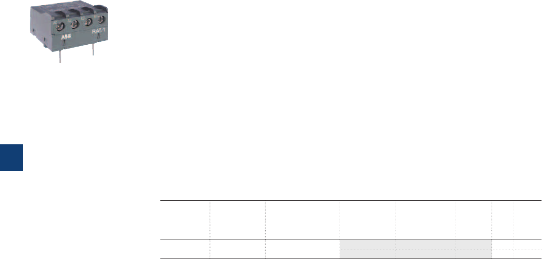
Interface relays
Description
RA5-1 interface relay is designed to receive 24 V DC signals delivered by PLC’s or other sources
with a low output power and to restore them with sufficient power to operate the coils of the relevant
A40 ... A110 contactors.
RA5-1 interface relay is made up of a miniature electromechanical relay equipped with a N.O. contact and
with a low consumption 24 V DC coil.
The interface relay coil is controlled by the PLC while the N.O. contact ensures switching of the power
contactor.
Coil switching gives rise to overvoltages which have adverse effects on the electronic devices, insulators
and, more generally, on component lifetime. The RA5-1 is equipped with surge suppressors:
– on the 24 V DC relay coil via a diode,
– on the power contactor coil via a varistor.
Furthermore, the RA5-1 is protected against relay pole reversal by a diode inserted between the E1 and
E2 input terminals.
Ordering details
For contactors Coil voltages Rated control circuit
voltage
Uc
Type Order code Pkg
qty
Weight
(1 pce)
V 50/60 Hz V DC kg
A40 ... A110 24...250 24 RA5-1 1SBN060300R1000 1 0.050
RA5-1 1SBN060300T1000 10 0.050
Note: The interface relays provided for the A... contactors can be used for the UA, UA..RA and GA types.
1SBC101005F0014
RA5-1
5/128 | ABB
5
1SBC101528S0201
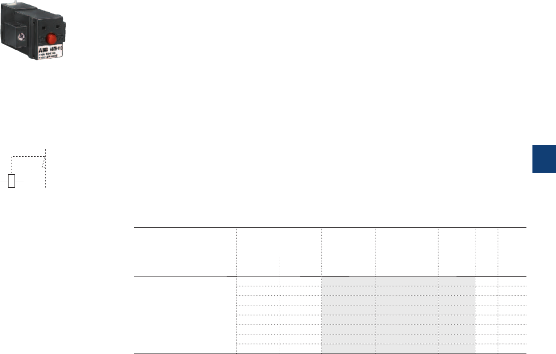
Mechanical latching unit
Description
For converting standard contactors into latched contactors.
The WB75-A block contains a mechanical latching device with electromagnetic impulse unlatching (AC or
DC) or manual unlatching.
Captive screw type connecting terminals, built-in cable clamps, M3.5 (+,-) pozidriv 2 screw with screw-
driver guidance; delivered untightened and protected against accidental direct contact.
Operation
After closing, the contactor continues to be held in the closed position by the latching mechanism should
the supply voltage fail at the contactor coil terminals.
Contactor opening can be controlled:
– electrically by an impulse* (AC or DC) on the WB75-A block coil.
* the coil is not designed to be permanently energized.
– manually by pressing the pushbutton on the front face of the WB75-A block.
Mounting
The WB75-A block is clipped onto the front face of the 1-stack contactor where it takes up two slots. The
two other slots may accept CA5... single pole auxiliary contacts (1 block on each side of the mechanical
latch).
Ordering details
For contactors Rated control circuit
voltage
Uc
Type Order code Pkg
qty
Weight
(1 pce)
V 50 Hz
or DC V 60 Hz kg
A40 ... A75,
AF45 ... AF75,
AL40,
AE45 ... AE75,
TAL40,
TAE45 ... TAE75,
UA16 ... UA75,
GA75, GAE75
24 24...28 WB75-A FPTN372726R1001 1 0.120
42 42...48 WB75-A FPTN372726R1002 1 0.120
48 48...55 WB75-A FPTN372726R1003 1 0.120
110 110...127 WB75-A FPTN372726R1004 1 0.120
220...230 220...255 WB75-A FPTN372726R1006 1 0.120
230...240 230...277 WB75-A FPTN372726R1005 1 0.120
380...415 380...440 WB75-A FPTN372726R1007 1 0.120
415...440 440...480 WB75-A FPTN372726R1008 1 0.120
1SBC565483F0301
WB75-A
E2676D
E1 E2
Terminal marking
ABB | 5/129
5
1SBC101526S0201
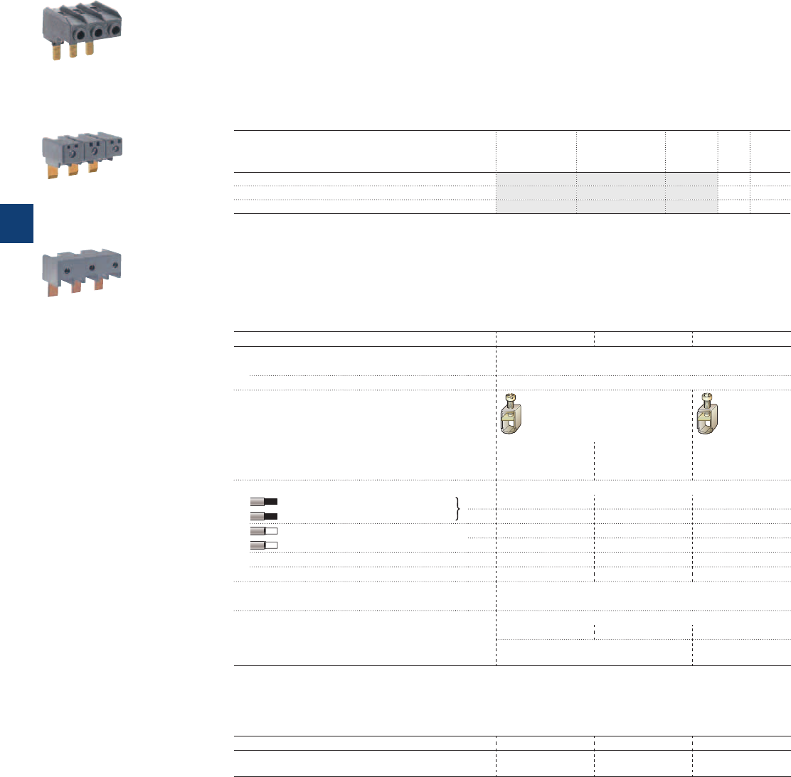
Additional terminal blocks
Description
The LD... terminal block is designed to increase the connecting capacity of the contactor on which it is
fitted and for preparation of the wiring before final connection on the contactor.
The LD... blocks are 3-pole terminal blocks with tunnel terminals. The available range can be used on A40
to A110 contactors.
The LD75 and LD110 terminal blocks are fixed in the 3 independent slots located above the built-in con-
nectors.
Ordering details
For contactors Type Order code Pkg
qty
Weight
(1 pce)
kg
A40 LD40 1SBN072808R1000 1 0.075
A45, A75 LD75 1SBN073508R1000 1 0.115
A95, A110 LD110 1SFN074308R1000 1 0.150
Note: The LD... terminal blocks provided for the A... contactors can be used for the AF, AL, AE, TAL, TAE and UA types.
LD40
LD75
LD110
1SBC583173F0301
1SBC580742F0301
1SBC580723F0301
Technical data
Types LD40 LD75 LD110
Rated insulation voltage Ui
acc. to IEC 60947-4-1 690 V
acc. to UL / CSA 600 V
Main terminals
Screw terminals
with
single connector
8x10 mm
Screw terminals
with
single connector
10x11 mm
Screw terminals
with
single connector
12x12 mm
Connection capacity (min. ... max.)
Rigid Solid (≤ 4 mm²) 1 x 4...35 mm² 6...50 mm² 10...70 mm²
Stranded (≥ 6 mm²) 2 x 4...16 mm² 6...25 mm² 10...35 mm²
Flexible with ferrule 1 x 4...25 mm² 6...35 mm² 10...50 mm²
2 x 4...10 mm² 6...16 mm² 10...25 mm²
Bars 8 mm 10 mm 12 mm
Tightening torque 2.5 Nm 4 Nm 6 Nm
Degree of protection
IP10
acc. to IEC 60947-1 / EN 60947-1 and IEC 60529 / EN 60529
Screw terminals
Delivered in closed position
M5 M6 M8
Screwdriver type pozidriv 2 Hexagon socket
(s = 4 mm)
Note: The utilization of LD... additional terminal blocks keeps the possibility to connect the following cables
directly in the contactor main terminals but the BED and BEM connecting sets can no longer be used.
LD40 LD75 LD110
Possible cross section of rigid cable in the contactor
terminals
10 mm² 50 mm² 95 mm²
5/130 | ABB
5
1SBC101534S0201
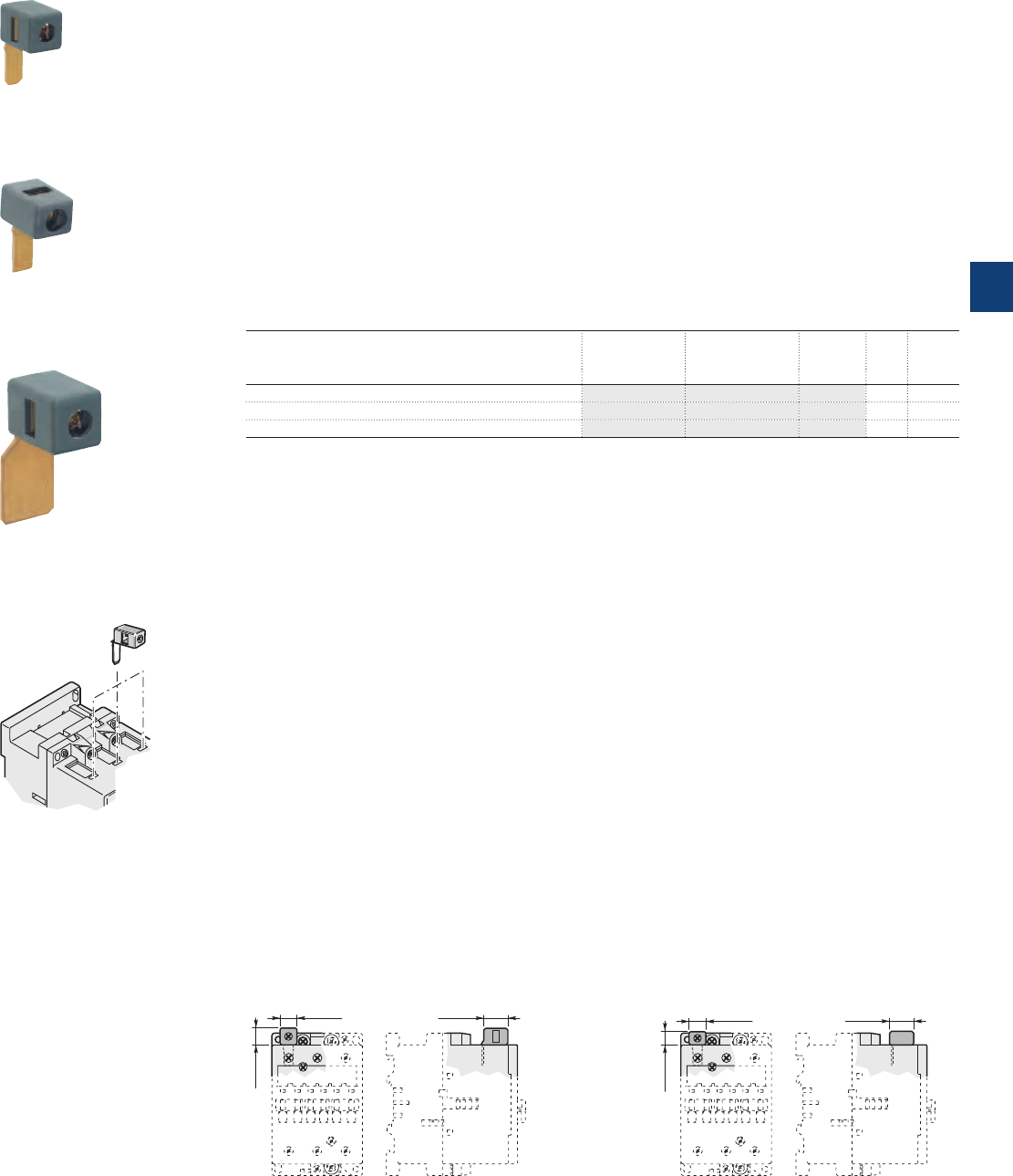
Terminals for control lead connections
Description
Terminals designed to connect the control conductors to the main poles of the A45 ... A110 contactors
and derivative versions.
Accessories clipped into the slots placed above each power terminal connector.
The LK75... are fitted with a pin designed to hold them in place until the connector has been fully clamped
with its power cable.
The LK110 must be held in place until the connector has been clamped.
– Degree of protection IP20
– Connecting terminal delivered in open position: cable clamp and M3.5 (+,-) pozidriv 2 screw.
– Cable cross-sectional area:
- 1 or 2 rigid conductors ........................................ 1...4 mm²
- 1 or 2 flexible conductors with cable end ............. 0.75...2.5 mm²
– Tightening torque for the LK... screw:
- recommended .................................................... 1.00 Nm
- maxi. .................................................................. 1.20 Nm
Ordering details
For contactors Type Order code Pkg
qty
Weight
(1 pce)
kg
Right and left on A45 ... A75 LK75-L 1SBN073552R1003 2 0.006
Opposite on A45 ... A75 LK75-F 1SBN073552R1002 2 0.006
Right and left on A95 ... A110 LK110 1SFN074352R1000 2 0.010
Note: The LK... terminals provided for the A... contactors can be used for the AF, AE, AM, TAE, UA, GA and GAE types.
Main dimensions mm, inches
LK75-L, LK110 LK75-F
13 0.51"
13 0.51"
19 0.75" 13 0.51"
11 0.43"
19 0.75"
LK75-L
LK110
LK75-F
LK... positioning
1SBC575763F0301
1SBC575753F0301
1SBC575773F0301
ABB | 5/131
5
1SBC101535S0201
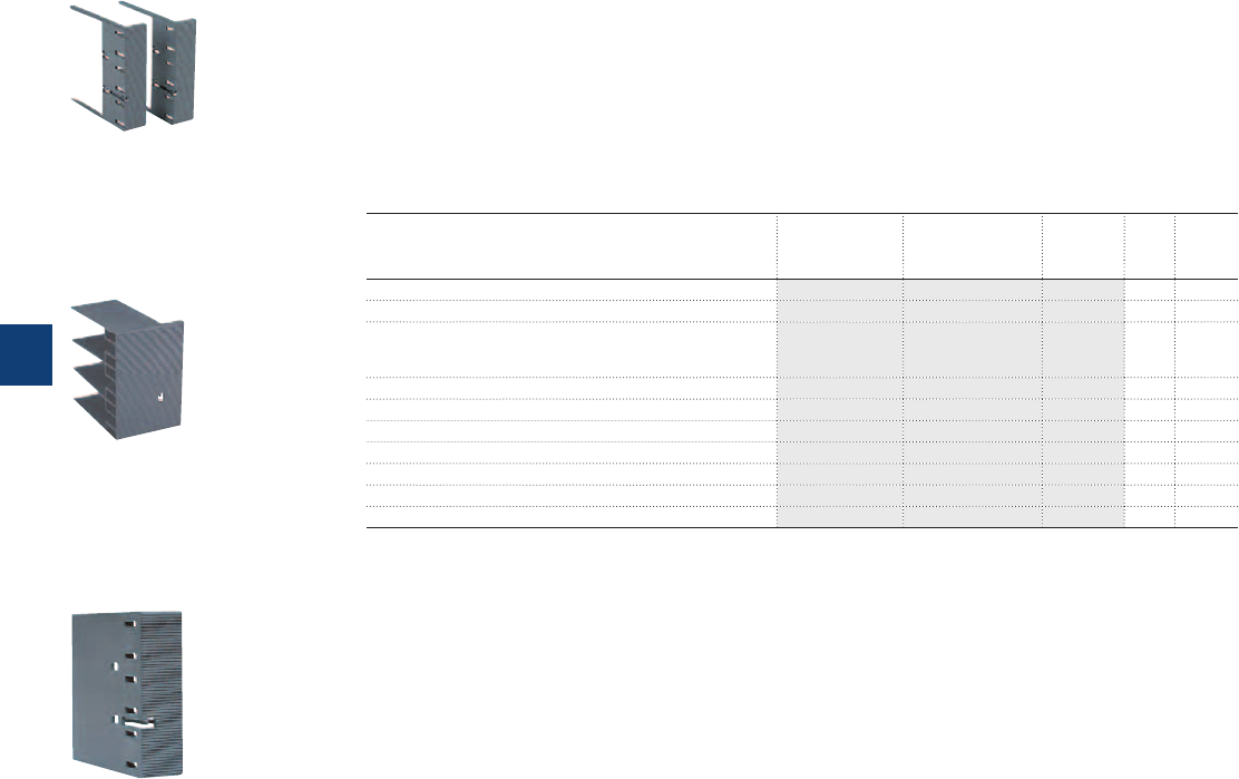
Terminal shrouds
Description
Main terminal protection for A145 ... AF750 contactors.
The auxiliary contact blocks and coils are designed to provide an IP20 degree of protection.
The main terminals, equipped with lugs or connectors, can be protected against accidental direct contact after wiring
(EN 50274) by the addition of terminal shrouds (see table below).
Ordering details
For contactors Type Order code Pkg
qty
Weight
(1 pce)
kg
A145 ... A185 with connectors LT185-AC 1SFN124701R1000 2 0.050
A145 ... A185 with lugs LT185-AL 1SFN124703R1000 2 0.220
A145 ... A185 with short. bar LY185
or between A145 and TA200DU
or between A185 and TA200DU
LT185-AY 1SFN124704R1000 1 0.050
A210 ... A300 with connectors LT300-AC 1SFN125101R1000 2 0.070
A210 ... A300 with lugs LT300-AL 1SFN125103R1000 2 0.280
A210 ... A300 with short. bar LY300 LT300-AY 1SFN125104R1000 1 0.075
AF400 ... AF460 with connectors LT460-AC 1SFN125701R1000 2 0.100
AF400 ... AF460 with lugs LT460-AL 1SFN125703R1000 2 0.800
AF580 ... AF750 with connectors LT750-AC 1SFN126101R1000 2 0.120
AF580 ... AF1250 with lugs LT750-AL 1SFN126103R1000 2 0.825
Note: The shrouds provided for the A... contactors can be used for the AF... types.
1AFT98099-019C3
LT...-AC
1SFT89099-019C3b
LT ...-AL
1SFT98000-014
LT...-AY
5/132 | ABB
5
1SFC101048C0201
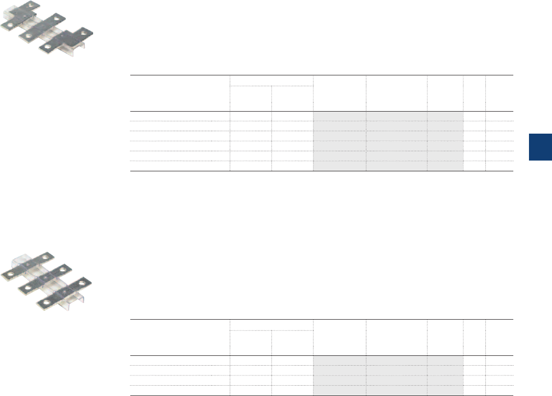
Terminal enlargements
Terminal extensions
LW... Terminal enlargements
Description
Enlargement pieces designed to increase the width of the contactor terminal pads in order to allow larger
connections to be mounted.
Sets containing 3 tin plated copper bars fixed by an isolating spacer.
Ordering details
For contactors Dimensions Type Order code Pkg
qty
Weight
(1 pce)
hole
Ø
mm
bar
mm kg
A95, A110 6.5 15 x 3 LW110 1SFN074307R1000 1 0.100
A145, A185 10.5 20 x 5 LW185 1SFN074707R1000 1 0.250
A210 ... A300 10.5 25 x 5 LW300 1SFN075107R1000 1 0.450
AF400, AF460 10.5 25 x 5 LW460 1SFN075707R1000 1 0.730
AF580, AF750 13 40 x 6 LW750 1SFN076107R1000 1 1.230
AF1250 13 50 x 10 LW1250 1SFN076407R1000 1 2.000
Note: The LW... pieces provided for the A... contactors can be used for the AF, AE, TAE and UA types.
LX... Terminal extension
Description
Extension pieces designed to extend the main terminals of contactors for combined mounting of
contactors and connection sets.
Sets containing 3 tin plated copper bars fixed by an isolating spacer.
Ordering details
For contactors Dimensions Type Order code Pkg
qty
Weight
(1 pce)
hole
Ø
mm
bar
mm kg
A145, A185 8.5 20 x 5 LX185 1SFN074710R1000 1 0.250
A210 ... A300 10.5 20 x 5 LX300 1SFN075110R1000 1 0.350
AF400, AF460 10.5 25 x 5 LX460 1SFN075710R1000 1 0.500
AF580, AF750 13 40 x 6 LX750 1SFN076110R1000 1 0.850
Note: The LX... pieces provided for the A... contactors can be used for the AF types.
1SFT98000-011C3
LW...
1SFT98000-012C3
LX...
ABB | 5/133
5
1SFC101049C0201
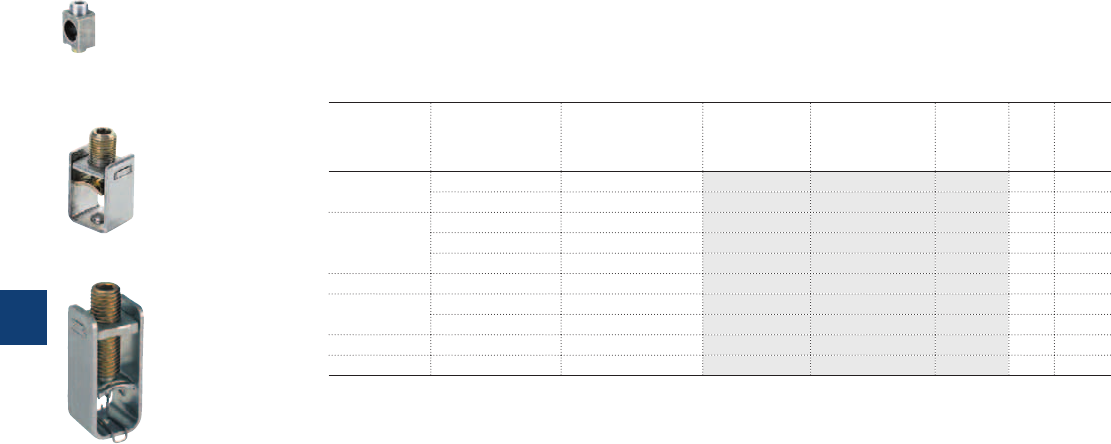
Connector terminals
Description
Connection of copper and aluminium cables to the terminal pads of the poles of A and AF contactors.
Ordering details
Cables For contactors Cable cross section Type Order code Pkg
qty
Weight
(1 pce)
mm² kg
Single Cu A145, A185 6...185 – 1SDA023354R0001 3 0.200
A210 ... A300 16...240 – 1SDA023368R0001 3 0.400
Single Al & Cu A145, A185 35...95 – 1SDA023356R0001 3 0.100
A145, A185 25...150 – 1SDA023357R0001 3 0.100
A210 ... A300 120...240 – 1SDA023370R0001 3 0.200
Double Cu A145, A185 2 x (50...120) LZ185-2C/120 1SFN074709R1000 3 0.300
Double A210 ... A300 2 x (95...120) – 1SDA025766R0001 3 0.400
Al & Cu AF400 ... AF750 2 x (120...240) – 1SDA023380R0001 3 0.110
Triple Al & Cu AF400 ... AF750 3 x (70...185) – 1SDA023384R0001 3 0.265
Multi Al & Cu AF1350, AF1650 4 x (120...240) – 1SDA023387R0001 3 0.400
Note: Connectors provided for the A... contactors can be used for the AF types.
1SFT98099-011C1
LZ...
1SFT98099-095C2
LZ...
1SBC580542F0302
LZ...
5/134 | ABB
5
1SFC101051C0201
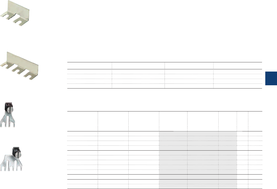
Terminal connecting strips and shorting bars
Description
Parallel and series connection of 3-pole and 4-pole contactor poles:
– To obtain a star point (3 parallel-connected poles): LY, LF, (LY allows 3 phases to be short-circuited).
– To connect poles in parallel and thus increase the AC load passing through the flow path made up of the
parallel-connected poles: LP and LH (2 poles); LY and LF (3 poles) ; LG (4 poles).
For the maximum permissible current values with parallel-connected poles see "Parallel connection of
main poles".
The relevant cable cross-sectional area may limit the maximum permissible current. Consult the informa-
tion in the table below.
– To connect poles in series and thus increase the DC load controlled by the poles: LP and LH.
Types for connection of "n" poles with terminal insulated
LP... n = 2 no yes (1)
LY... n = 3 no yes (1)
LH... n = 2 yes no
LF... n = 3 yes no
(1) LP460 ... LP750, LY185 ... LY750 not insulated. Use terminal shrouds.
Ordering details
For contactors max. nominal
continuous current
with "n" poles
Cable cross-
sectional area
Type Order code Pkg
qty
Weight
(1 pce)
A mm² kg
A145, A185 300 – LP185 1SFN074712R1000 2 0.300
A210 ... A300 475 – LP300 1SFN075112R1000 2 0.400
AF400, AF460 725 – LP460 1SFN075712R1000 4 0.550
AF580, AF750 1200 – LP750 1SFN076112R1000 4 0.950
A95, A110 240 – LY110 1SFN074303R1000 1 0.055
A145, A185 400 – LY185 1SFN074703R1000 1 0.200
A210 ... A300 670 – LY300 1SFN075103R1000 1 0.300
AF400, AF460 1000 – LY460 1SFN075703R1000 1 0.450
AF580, AF750 1650 – LY750 1SFN076103R1000 1 0.800
A45 ... A75 200 95 LH75 FPTN472734R0001 2 0.085
A40 140 50 LF40 1SBN073205R1000 2 0.037
A45 ... A75 275 150 LF75 FPTN472735R0001 2 0.095
Note: The strips and shorting bars provided for the A... contactors can be used for the AF, AL, AL..Z, AE, TAL and TAE types.
LH...
LF...
LP185
LY185
SB7170C3_1
SB7170C3_2
1SFT98000-010C3
1SFT98000-013C3
ABB | 5/135
5
1SBC101540S0201
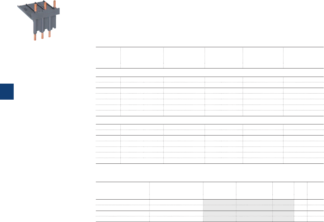
Connecting links for contactors and manual motor starters
Description
The BEA... connecting links are used to connect a contactor to associated manual motor starters. These
are then used together as DOL or reversing starters in type 1 or type 2 coordination, complying with IEC
60947-4-1 and EN 60947-4-1.
The BEA... insulated 3-pole connecting link (touch safe) ensures the electrical linking between the contac-
tor and the corresponding manual motor starter.
Selection table
Ie max.
AC-3
400 V
Contactor & fixing
screws not
supplied
Connecting link MMS & fixing
screws not
supplied
Connection set for
the contactors
Interlock unit
(see "Accessory fitting
details")
A
Direct-on-line starter
37 A40 2xM4 BEA40/450 MS450 2xM5 – –
50 A50 2xM4 BEA50/450 MS450 2xM5 – –
50 A50 2xM6 BEA75/495 MS495 2xM5 – –
63 A63 2xM6 BEA75/495 MS495 2xM5 – –
75 A75 2xM6 BEA75/495 MS495 2xM5 – –
90 A95 2xM6 BEA110/495 MS495 2xM5 – –
100 A110 2xM6 BEA110/495 MS495 2xM5 – –
Reversing starter
37 2xA40 4xM4 BEA40/450 MS450 2xM5 BER40V VM5-1 / VE5-1
50 2xA50 4xM4 BEA50/450 MS450 2xM5 BEM75-30 VE5-2
50 2xA50 4xM6 BEA75/495 MS495 2xM5 BEM75-30 VE5-2
63 2xA63 4xM6 BEA75/495 MS495 2xM5 BEM75-30 VE5-2
75 2xA75 4xM6 BEA75/495 MS495 2xM5 BEM75-30 VE5-2
90 2xA95 4xM6 BEA110/495 MS495 2xM5 BEM110-30 VE5-2
100 2xA110 4xM6 BEA110/495 MS495 2xM5 BEM110-30 VE5-2
Ordering details
For contactors Manual motor starter Type Order code Pkg
qty
Weight
(1 pce)
kg
A40 MS450 BEA40/450 1SBN083206R1000 1 0.061
A50 MS450 BEA50/450 1SBN083506R1000 1 0.062
A50, A63, A75 MS495 BEA75/495 1SBN084106R1000 1 0.120
A95, A110 MS495 BEA110/495 1SBN084506R1000 1 0.124
The BEA... connecting links provided for the A... contactors can be used for the AF..., AE..., and TAE... types.
BEA40/450
1SBC582763F0301
5/136 | ABB
5
1SBC101538S0201
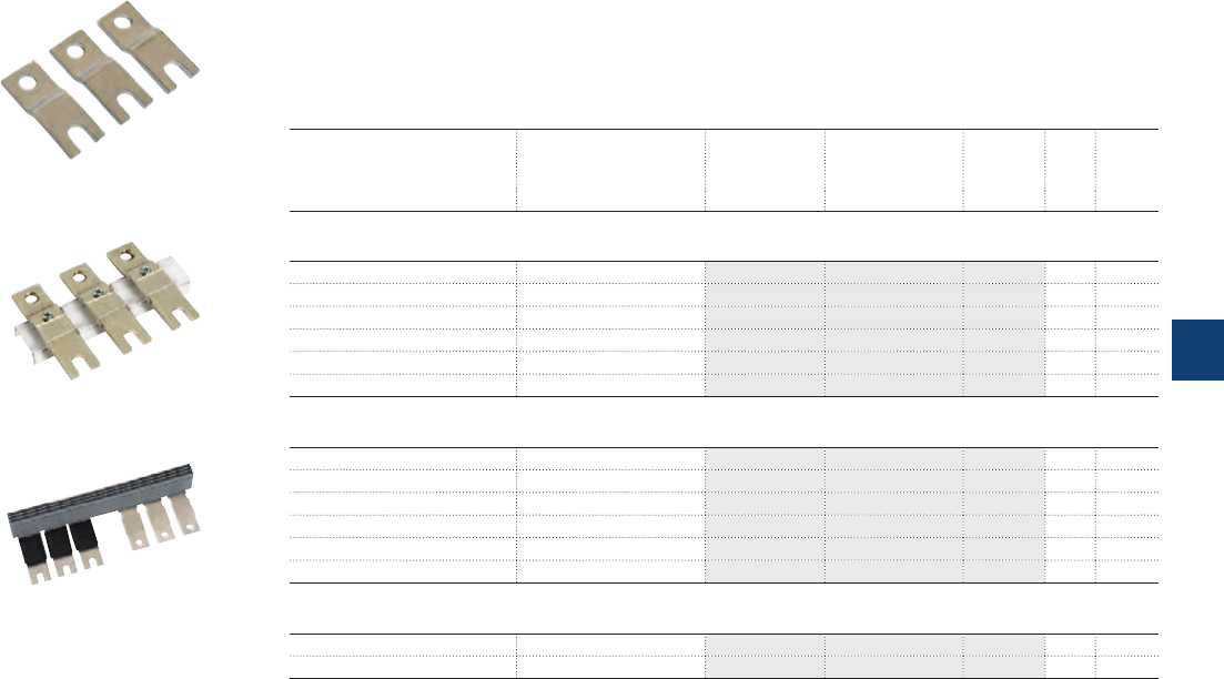
Connection bars for contactor and MCCB
Description
Connection between contactors/starters and moulded case circuit breakers.
These connection sets are solid copper bars.
Ordering details
For contactors MCCB Type Order code Pkg
qty
Weight
(1 pce)
kg
Vertical assembly
A145, A185, AF145, AF185 T3 BEA185/T3 1SFN084706R1003 1 0.150
A145, A185, AF145, AF185 T4 BEA185/T4 1SFN084706R1005 1 0.150
A210, AF210 T4 BEA210/T4 1SFN085106R1003 1 0.160
A210 ... A300, AF210 ... AF300 T5 BEA300/T5 1SFN085106R1004 1 0.200
AF400 ... AF750 T6 BEA750/T6 1SFN086106R1000 1 0.410
AF400 ... AF750 T5 BEA750/T5 1SFN086106R1001 1 0.410
Vertical assembly with control wire terminals
(also suitable when using busbar kits for starter combinations)
A145, A185, AF145, AF185 T3 BEA185D/T3 1SFN084706R1004 1 0.175
A145, A185, AF145, AF185 T4 BEA185D/T4 1SFN084706R1006 1 0.175
A210, AF210 T4 BEA210D/T4 1SFN085106R1005 1 0.270
A210 ... A300, AF210 ... AF300 T5 BEA300D7T5 1SFN085506R1003 1 0.320
AF400 ... AF750 T6 BEA750D/T6 1SFN086106R1002 1 0.720
AF400 ... AF750 T5 BEA750D/T5 1SFN086106R1003 1 0.720
Horizontal assembly (also suitable when using busbar kits for starter combinations)
A210 ... A300, AF210 ... AF300 T5 BEA300H/T5 1SFN085307R1002 1 1.280
AF400, AF460 T4 BEA460H/T4 1SFN085907R1000 1 2.450
1SFT98001-005C3
BEA300
1SFT98001-007C3
BEA...D
1SFC101001F0201C3
BEA300H
ABB | 5/137
5
1SFC101046C0201
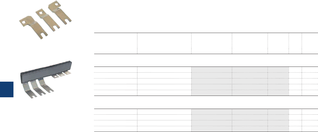
Connection bars for contactor and switch fuse
Description
Connection between contactors/starters and switch fuse.
These connection sets are solid copper bars.
Ordering details
For contactors Switch fuse Type Order code Pkg
qty
Weight
(1 pce)
kg
Vertical assembly
A185 OESA250 BEF185/OESA250 1SFN084908R1000 1 0.260
A210 ... A300 OESA250 to OESA400 BEF300/OESA400 1SFN085108R1000 1 0.330
A145 OS160 OSZA15 1SCA022509R0120 1 0.170
AF400, AF460 OESA400 BEF460/OESA400 1SFN085708R1000 1 0.340
AF460 ... AF750 OESA630 to OESA800 BEF750/OESA800 1SFN086108R1000 1 0.740
Horizontal assembly
A145 OS160...LR OSZA15 1SCA022509R0120 1 0.170
A145, A185 OESA250...LR BEF185H/OESA250 1SFN084709R1000 1 0.550
A210 ... A300 OESA250...LR to OESA400...LR BEF300H/OESA400 1SFN085109R1000 1 1.200
AF400, AF460 OESA400...LR OESA460H/OESA400 1SFN085709R1000 1 1.250
Note: The BEF... connection bars provided for the A145 ... A300 contactors can be used for the AF145 ... AF300 contactors.
1SFT98001-006C3
BEF300/OESA400
1SFT98001-009C3
BEF300H/OESA400
5/138 | ABB
5
1SFC101047C0201
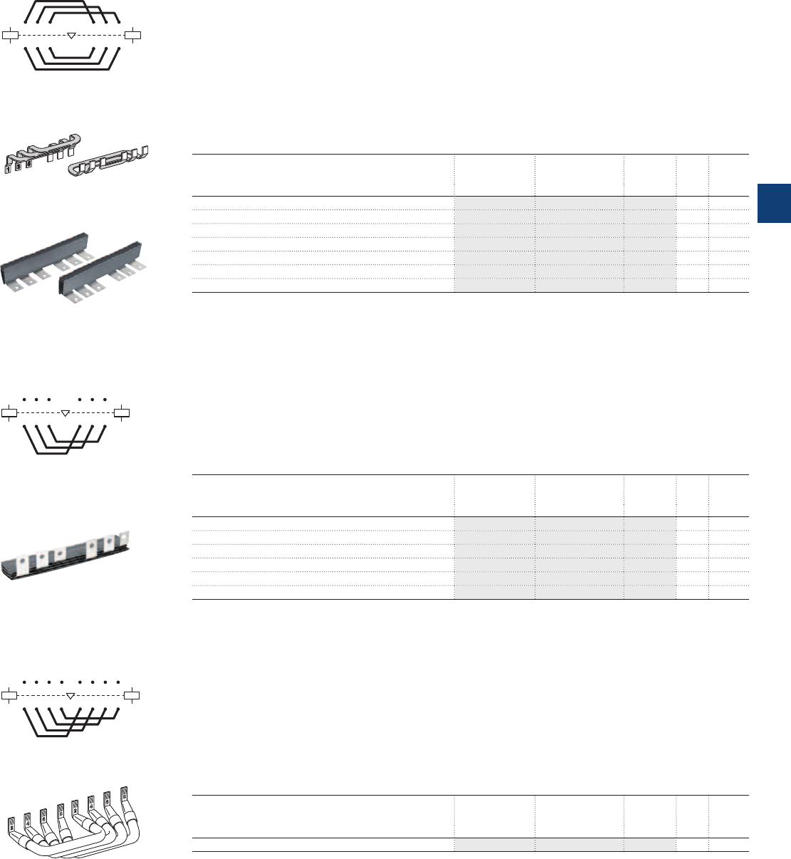
Connection sets
Connection sets for reversing contactors
Description
Connections between the main poles of two 3-pole contactors mounted side by side as reversing contactors.
The sets are made up of three upstream connections and three downstream connections.
BER40V – Insulated, stranded, rigid copper wires
BEM75-30 ... BEM750-30 – Insulated, solid copper bars
On the A... contactors, the power supply by bars or cables equipped with lugs is directly connected to the
terminal pads of the main poles. For flange connectors, LX… terminal extension pieces should be used.
Ordering details
For 3-pole contactors Type Order code Pkg
qty
Weight
(1 pce)
kg
A40 BER40V 1SBN082411R1000 1 0.085
A50 ... A75 BEM75-30 1SBN083501R1000 1 0.243
A95, A110 BEM110-30 1SFN084301R1000 1 0.450
A145, A185 BEM185-30 1SFN084701R1000 1 0.900
A210 ... A300 BEM300-30 1SFN085101R1000 1 1.100
AF400, AF460 BEM460-30 1SFN085701R1000 1 4.400
AF580, AF750 BEM750-30 1SFN086101R1000 1 7.300
Note: The connections provided for the A... contactors can be used for the AF, AL, TAL, AE and TAE types.
3-pole connections phase to phase
Description
Connections between the main poles of two 3-pole contactors horizontal mounted.
This set is made up of three downstream or upstream connections.
Ordering details
For 3-pole contactors Type Order code Pkg
qty
Weight
(1 pce)
kg
A50 ... A75 BES75-30 1SBN083504R1000 1 0.130
A95, A110 BES110 1SFN084304R1000 1 0.250
A145, A185 BES185 1SFN084704R1000 1 0.500
A210 ... A300 BES300 1SFN085104R1000 1 1.000
AF400, AF460 BES460 1SFN085704R1000 1 2.200
AF580, AF750 BES750 1SFN086104R1000 1 3.700
Note: The connections provided for the A... contactors can be used for the AF, AE and TAE types.
Connections for 4-pole changeover contactors
Description
Connection between the main poles of two 4-pole contactors mounted side by side so that they operate
as source reversing contactors.
These sets are made up of four downstream connections, with insulated, stranded, rigid copper cables.
Ordering details
For 4-pole contactors Type Order code Pkg
qty
Weight
(1 pce)
kg
A45, A50, A75 BES75-40 1SBN083302R1000 1 0.400
Note: The connections provided for the A... contactors can be used for the AF, AE and TAE types.
A1
A2
A1
A2
315 315
42 6 42 6
E0744D
BEM300-30
BEM75-30
E0618D1
E0461D1
BES75-40
BES…
A1
A2
A1
A2
315 53
426 6
4
1
2
E0860D
BES... for 3-pole connections
A1
A2
A1
A2
315 537
426 648
71
8 2
E0743D
BES... for 4 N.O. main pole
connections
BEM… connections
1SFT98001-011C3
1SFT98000-009C6
ABB | 5/139
5
1SBC101543S0201
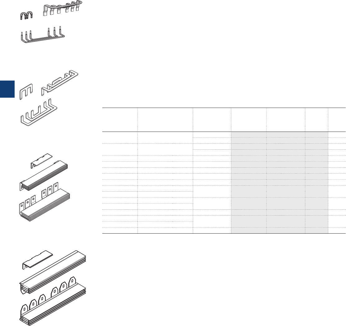
Connection sets
Connection sets for star-delta starter
Description
Connections between the main poles of a star-delta starter.
These sets are made up of:
– Three line contactor / delta contactor connections - Upstream side
– Three connections for star and delta contactors - Downstream side
– The necessary elements to create the star point upstream of the star contactor.
BED50 / BED50-1, BED75 / BED75-1 – Solid copper bars and insulated stranded copper wires.
BED95 ... BED750 – Insulated, solid copper bars.
BED50-1 ... BED75-1 connection sets are designed for star and delta contactors without mechanical inter-
lock unit (contactors mounting joined side by side).
For mechanically interlocked star and delta contactors use BED50 ... BED75 connection sets.
BED95 ... BED750 are designed for both star and delta contactors with or without mechanical interlock
unit.
Ordering details
For contactors Interlock unit
between star and
delta contactors
Type Order code Weight
Pkg
(1 pce)
Line and delta Star kg
A63 A40 – BED50-1 1SBN083503R1001 0.180
VE5-2 BED50 1SBN083503R1000 0.280
A75 A50 – BED75-1 1SBN084103R1001 0.180
VE5-2 BED75 1SBN084103R1000 0.250
A95 A75 VE5-2 BED95 1SFN084303R1000 0.400
A110 A95 VE5-2 BED110 1SFN084503R1000 0.500
A145 A110 VM300H BED145A 1SFN084703R1000 1.300
A185 A145 VM300H BED185 1SFN084903R1000 1.100
A210 A185 VM300H BED210 1SFN085103R1000 1.500
A260 A210 VM300H BED300 1SFN085303R1000 2.100
A300 A260
AF400 A260 VM300/460H BED400 1SFN085503R1000 3.500
AF460 A300
AF460 AF400 VM750H BED460 1SFN085703R1000 4.700
AF580 AF400 VM750H BED580 1SFN085903R1000 6.300
AF580 AF460
AF750 AF580 VM750H BED750 1SFN086103R1000 7.700
Note: The connections provided for A... contactors can be used for the AL, AE, TAL and TAE types.
BED 75-1
135
E1143D
BED 110
BED 185
BED 400
E2121D
E2122D
E2123D
5/140 | ABB
5
1SBC101545S0201
Mounting plates for A95 ... AF750 contactors
Description
Mounting plates with fixing holes for the specified contactors and overload relays.
Ordering details
For contactors For
overload relays
Type Order code Pkg
qty
Weight
(1 pce)
kg
Mounting plates for Direct on line starters
A145, A185 TA200DU, E200DU PN185-11 1SFN094705R1000 1 1.100
A210 ... A300 TA450DU, E320DU PN300A-11 1SFN095105R1000 1 1.650
AF400, AF460 E500DU PN460-11 1SFN095705R1000 1 2.120
AF580, AF750 E800DU PN750-11 1SFN096105R1000 1 2.500
For two contactors side
by side with space for
mechanical interlock
For one or two
overload relays
Type Order code Pkg
qty
Weight
(1 pce)
kg
Mounting plates for mechanical interlocked contactors,
reversing starters and two speed starters for double windings
A95, A110 TA80DU, TA110DU PN110-21 1SFN094301R1000 1 0.600
A145, A185 TA200DU, E200DU PN185-21 1SFN094701R1000 1 1.800
A210 ... A300 TA450DU, E320DU PN300-21 1SFN095101R1000 1 2.530
AF400, AF460 E500DU PN460-21 1SFN095701R1000 1 3.490
AF580, AF750 E800DU PN750-21 1SFN096101R1000 1 4.230
For main
and delta contactors
For star
contactor (1)
For
overload relays
Type Order code Pkg
qty
Weight
(1 pce)
kg
Mounting plates for star-delta starters and two speed starters for single windings
A95, A110 A75, A95 TA80DU or TA110DU PN110-41 1SFN094303R1000 1 0.950
A145, A185 A110, A145 E200DU or TA200DU PN185-41 1SFN094903R1000 1 2.440
A210 ... A300 A185 ... A300 E320DU or TA450DU PN300-41 1SFN095503R1000 1 3.440
AF400, AF460 A300, AF400 E500DU PN460-41 1SFN095703R1000 1 5.310
AF580, AF750 AF400 ... AF580 E800DU PN750-41 1SFN096103R1000 1 6.320
(1) Space for mechanical interlock included
Note: The mounting plates provided for A... contactors can be used for the AF... contactors.
1SFT98001-016C3
PN300A-11
1SFT98001-017C3
PN300-21
1SFT98001-018C3
PN300-41
ABB | 5/141
5
1SFC101052C0201
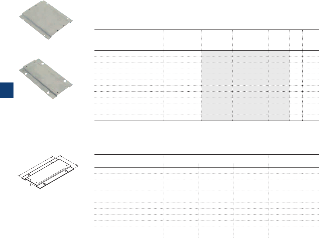
Adapter plates for A95 ... AF750 contactors
Description
Adapter plates with fixing holes for specified old contactors to new contactors.
Ordering details
From old contactors To new contactor Type Order code Pkg
qty
Weight
(1 pce)
kg
EH65, EH75, EH80, EH90, EG80 A95, A110 PR110-1 1SFN094500R1000 1 0.270
EH100, EH145 A110, A145 PR145-1 1SFN094700R1000 1 0.360
EH150, EH160, EH175, EH210, EG160 A185, A210 PR210-1 1SFN094900R1000 1 0.440
EH250, EH260, EH300 A210 ... A300 PR300-1 1SFN095300R1000 1 0.560
EH370, EH550, EG315 AF400 ... AF580 PR460-1 1SFN095700R1000 1 0.900
EH700, EH800 AF750 PR750-1 1SFN096100R1000 1 0.500
OKYM150, OKYM175 A185 PR185-2 1SFN095100R1001 1 0.500
OKYM200, OKYM250 A210 ... A300 PR300-2 1SFN095300R1001 1 0.500
OKYM315 AF400, AF460 PR400-2 1SFN095700R1002 1 0.820
OKYM400 AF400, AF460 PR460-2 1SFN095700R1001 1 0.800
OKYM500 AF580 PR580-2 1SFN096100R1002 1 0.700
EH550, EG630, OKYM630 AF580, AF750 PR750-2 1SFN096100R1001 1 1.100
Note: The adapter plates provided for the A... contactors can also be used for the AF... contactors.
1SFT98001-015C3
PR300-1
1SFT98001-014C3
PR400-2
E2119D
h
l
L
Dimensions (mm)
Type of the plate Dimensions Fixing holes
LI h
mm
PR110-1 151 106 11.2 2 x ø 7
PR145-1 180 122 11.5 4 x ø 7
PR210-1 200 132 11.5 4 x ø 7
PR300-1 200 172 11.5 4 x ø 7
PR460-1 278 198 11.5 4 x ø 7
PR750-1 283 244 11.5 4 x ø 7
PR185-2 202 152 11.2 4 x ø 11
PR300-2 202 152 11.2 4 x ø 11
PR400-2 278 151 11.5 4 x ø 11
PR460-2 278 176 11.5 4 x ø 11
PR580-2 283 176 11.5 4 x ø 11
PR750-2 283 255 11.5 4 x ø 14
Note: The adapter plates provided for the A... contactors can also be used for the AF... contactors.
Fixing holes according to the plate types
5/142 | ABB
5
1SFC101053C0201
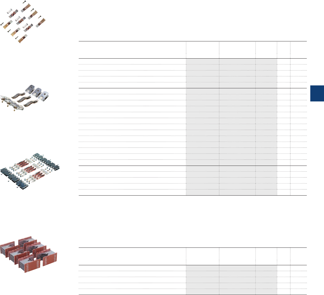
Main contact sets
Arc chutes
for 3-pole contactors
ZL..., ZLU... Main contact sets
Description
The contact sets for 3-pole contactors consists of six fixed contacts, three moving contacts, springs and
the required screws.
Ordering details
For contactors Type Order code Pkg
qty
Weight
(1 pce)
kg
A/AF/AE/TAE50-30 ZL50 1SBN163503R1000 1 0.115
A/AF/AE/TAE63-30 ZL63 1SBN163703R1000 1 0.130
A/AF/AE/TAE75-30 ZL75 1SBN164103R1000 1 0.145
A/AF95-30 ZL95 1SFN164303R1000 1 0.190
A/AF110-30 ZL110 1SFN164503R1000 1 0.190
A/AF145 ZL145 1SFN164703R1000 1 0.380
A/AF185 ZL185 1SFN164903R1000 1 0.380
A/AF210 ZL210 1SFN165103R1000 1 0.670
A/AF260 ZL260 1SFN165303R1000 1 0.670
A/AF300 ZL300 1SFN165503R1000 1 0.670
AF400 ZL400 1SFN165703R1000 1 1.320
AF460 ZL460 1SFN165903R1000 1 1.320
AF580 ZL580 1SFN166103R1000 1 1.840
AF750 ZL750 1SFN166303R1000 1 1.840
AF1250 ZL1250 1SFN166403R1000 1 1.840
AF1350 ZL1350 1SFN166503R1000 1 2.500
AF1650 ZL1650 1SFN166703R1000 1 3.500
AF2050 ZL2050 1SFN167003R1000 1 3.500
UA50 ZLU50 1SBN163502R1000 1 0.115
UA63 ZLU63 1SBN163702R1000 1 0.145
UA75 ZLU75 1SBN164102R1000 1 0.145
UA95 ZLU95 1SFN164302R1000 1 0.190
UA110 ZLU110 1SFN164502R1000 1 0.190
ZW... Arc chutes for 3-pole contactors
Ordering details
For contactors Type Order code Pkg
qty
Weight
(1 pce)
kg
A145 ... A185 and AF145 ... AF185 ZW185 1SFN164710R1000 1 0.360
A210 ... A300 and AF210 ... AF300 ZW300 1SFN165110R1000 1 0.410
AF400, AF460 ZW460 1SFN165710R1000 1 1.380
AF580, AF750, AF1250 ZW750 1SFN166110R1000 1 1.500
AF1350, AF1650, AF2050 ZW1650 1SFN166510R1000 1 4.000
1SBC565433F0301
ZL50
1SFT98099-007C3
ZL185
1SFT101009F0201
ZL1650
1SFT98099-018
ZW...
ABB | 5/143
5
1SFC101054C0201
Contactor coils
Description
Coils for A40 ... A300, UA16 ... UA110 and UA16..RA ... UA110..RA AC operated contactors.
Ordering details
For contactors Rated control circuit
voltage
Uc
Type Order code Pkg
qty
Weight
(1 pce)
V 50 Hz V 60 Hz kg
UA16, 24 24 ZA16 1SBN151410R8106 1 0.093
UA16..RA 48 48 ZA16 1SBN151410R8306 1 0.093
110 110…120 ZA16 1SBN151410R8406 1 0.093
220…230 230…240 ZA16 1SBN151410R8006 1 0.093
230...240 240…260 ZA16 1SBN151410R8806 1 0.093
380…400 400…415 ZA16 1SBN151410R8506 1 0.093
400…415 415…440 ZA16 1SBN151410R8606 1 0.093
A40 24 24 ZA40 1SBN152410R8106 1 0.148
UA26, UA30, 48 48 ZA40 1SBN152410R8306 1 0.148
UA26..RA, UA30..RA 110 110…120 ZA40 1SBN152410R8406 1 0.148
220…230 230…240 ZA40 1SBN152410R8006 1 0.148
230...240 240…260 ZA40 1SBN152410R8806 1 0.148
380…400 400…415 ZA40 1SBN152410R8506 1 0.148
400…415 415…440 ZA40 1SBN152410R8606 1 0.148
A45 … A75 24 24 ZA75 1SBN153510R8106 1 0.166
UA50 … UA75 48 48 ZA75 1SBN153510R8306 1 0.166
UA50..RA ... UA75..RA 110 110…120 ZA75 1SBN153510R8406 1 0.166
GA75 220…230 230…240 ZA75 1SBN153510R8006 1 0.166
230...240 240…260 ZA75 1SBN153510R8806 1 0.166
380…400 400…415 ZA75 1SBN153510R8506 1 0.166
400…415 415…440 ZA75 1SBN153510R8606 1 0.166
A95, A110 24 24 ZA110 1SFN154310R8106 1 0.170
UA95, UA110 48 48 ZA110 1SFN154310R8306 1 0.170
UA95..RA, UA110..RA 110 110…120 ZA110 1SFN154310R8406 1 0.170
220…230 230…240 ZA110 1SFN154310R8006 1 0.170
230...240 240…260 ZA110 1SFN154310R8806 1 0.170
380…400 400…415 ZA110 1SFN154310R8506 1 0.170
400…415 415…440 ZA110 1SFN154310R8606 1 0.170
A145 … A185 24 24 ZA185 1SFN154710R8106 1 0.180
48 48 ZA185 1SFN154710R8306 1 0.180
110 110…120 ZA185 1SFN154710R8406 1 0.180
220…230 230…240 ZA185 1SFN154710R8006 1 0.180
230...240 240…260 ZA185 1SFN154710R8806 1 0.180
380…400 400…415 ZA185 1SFN154710R8506 1 0.180
400…415 415…440 ZA185 1SFN154710R8606 1 0.180
A210 … A300 24 24 ZA300 1SFN155110R8106 1 0.400
48 48 ZA300 1SFN155110R8306 1 0.400
110 110…120 ZA300 1SFN155110R8406 1 0.400
220…230 230…240 ZA300 1SFN155110R8006 1 0.400
230...240 240…260 ZA300 1SFN155110R8806 1 0.400
380…400 400…415 ZA300 1SFN155110R8506 1 0.400
400…415 415…440 ZA300 1SFN155110R8606 1 0.400
1SBC573802F0302
ZA16
1SFT98099-010C3
ZA185
5/144 | ABB
5
1SFC101057C0201
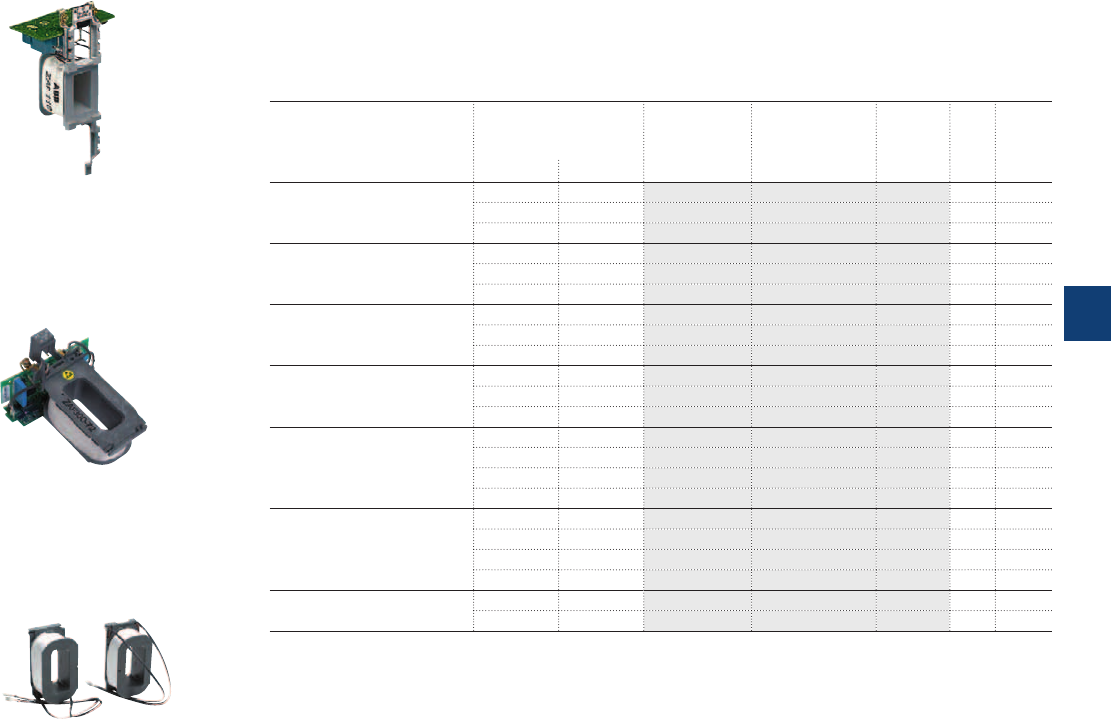
Contactor coils
Description
Coils for AF45 ... AF2050 AC / DC operated contactors.
Ordering details
For contactors Rated control circuit
voltage
Uc min. ... Uc max.
Type Order code Pkg
qty
Weight
(1 pce)
V 50/60 Hz V DC kg
AF45 … AF75 - 20…60 ZAF75 1SBN153570R7206 1 0.170
48…130 48…130 ZAF75 1SBN153570R6906 1 0.170
100…250 100…250 ZAF75 1SBN153570R7006 1 0.170
AF95, AF110 - 20…60 ZAF110 1SFN154370R7206 1 0.200
48…130 48…130 ZAF110 1SFN154370R6906 1 0.200
100…250 100…250 ZAF110 1SFN154370R7006 1 0.200
AF145, AF185 - 20…60 ZAF185 1SFN154770R7206 1 0.225
48…130 48…130 ZAF185 1SFN154770R6906 1 0.225
100…250 100…250 ZAF185 1SFN154770R7006 1 0.225
AF210 ... AF300 - 20…60 ZAF300 1SFN155170R7206 1 0.450
48…130 48…130 ZAF300 1SFN155170R6906 1 0.450
100…250 100…250 ZAF300 1SFN155170R7006 1 0.450
AF400, AF460 - 24…60 ZAF460 1SFN155770R6806 1 0.525
48…130 48…130 ZAF460 1SFN155770R6906 1 0.525
100…250 100…250 ZAF460 1SFN155770R7006 1 0.525
250…500 250…500 ZAF460 1SFN155770R7106 1 0.525
AF580 ... AF1250 - 24…60 ZAF750 1SFN156170R6806 1 1.335
48…130 48…130 ZAF750 1SFN156170R6906 1 1.335
100…250 100…250 ZAF750 1SFN156170R7006 1 1.335
250…500 250…500 ZAF750 1SFN156170R7106 1 1.335
AF1350 ... AF2050 100…250 100…250 ZAF1650 (1) 1SFN156570R7026 1 set 0.900
ZP1650 (2) 1SFN166521R1070 1 0.300
(1) One set of two coil.
(2) Printed circuit board.
1SBC578683F0302
ZAF110
1SFT98001-13
ZAF300
1SFC101007F0201
ZAF1650
ABB | 5/145
5
1SFC101057C0201

5/146 | ABB
5
1SBC101617S0201

Accessories for EK100 … EK1000 contactors
Auxiliary contact blocks 5/148
Terminal shrouds 5/149
Surge suppressors for contactor coils 5/150
Mounting plates 5/151
Connection sets 5/152
Mechanical interlock units 5/153
Mechanical and electrical interlock units 5/153
Main contact sets - Arc chutes 5/154
Contactor coils 5/155
ABB | 5/147
5
1SBC101617S0201
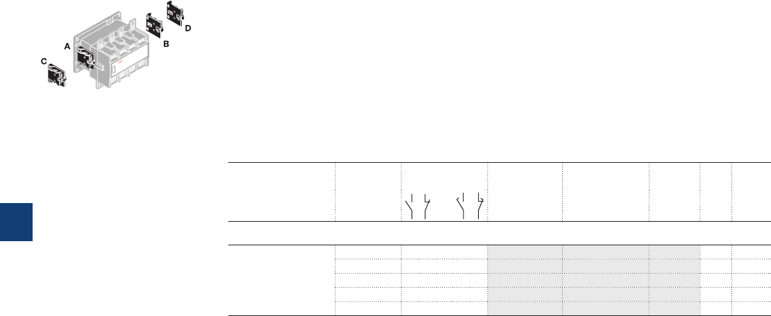
Auxiliary contact blocks
Description
The auxiliary contact blocks are used for the operation of auxiliary circuits and control circuits.
Types of auxiliary contact blocks for standard industrial environments:
– CAL instantaneous with N.O. + N.C. contacts
– CCL N.O. leading contact + N.C. lagging contact.
The auxiliary contact blocks are equipped with screw type connecting terminals delivered open, protected
against accidental direct contact, and bear the corresponding function marking.
Mounting: Screwed onto the right and / or lefthand side of the EK110 ... EK1000 contactors.
Ordering details
For contactors Number
of blocks
Auxiliary contacts Type Order code Pkg
qty
Weight
(1 pce)
kg
2-pole auxiliary contacts N.O. + N.C.
EK 1 1 1 – – CAL16-11A SK829002-A 1 0.050
1 1 1 – – CAL16-11B SK829002-B 1 0.050
1 1 1 – – CAL16-11C SK829002-C 1 0.050
1 1 1 – – CAL16-11D SK829002-D 1 0.050
1 1 – – 1 CCL16-11E (1) SK829002-E 1 0.050
(1) Mounting of CCL16-11E blocks does not allow an additional second block to be added on top of it.
All DC operated EK... contactors are equipped with one CCL16-11E on the right side.
E2074D
Mounting positions
of the CAL16-11
5/148 | ABB
5
1SFC101065C0201
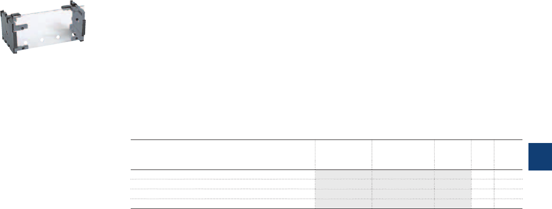
Terminal shrouds
Description
The use of terminal shrouds on the main terminals of EK... contactors is required in electrical panels or
cubicles to be built in compliance with the rules for protection against direct contact with live parts in acc.
with EN 50274.
On EK110 ... EK1000 contactors:
– The auxiliary contact blocks and coils are designed to provide an IP20 degree of protection
– The main terminals, equipped with lugs or connectors, can be protected against accidental direct con-
tact after wiring (EN 50274) by the addition of terminal shrouds (see table below).
Each terminal shroud protects all the terminals on one side of the contactor. Two terminal shrouds should
be provided for each separate contactor.
Ordering details
For contactors Type Order code Pkg
qty
Weight
(1 pce)
kg
EK110, EK150 LT150-EK SK178001-HB 1 0.139
EK175, EK210 LT210-EK SK178001-KB 1 0.152
EK370, EK550 LT550-EK SK178001-LB 1 0.190
EK1000 LT1000-EK SK178001-MB 1 0.200
1SFC01002F0201C3
LT210-EK
ABB | 5/149
5
1SFC101068C0201
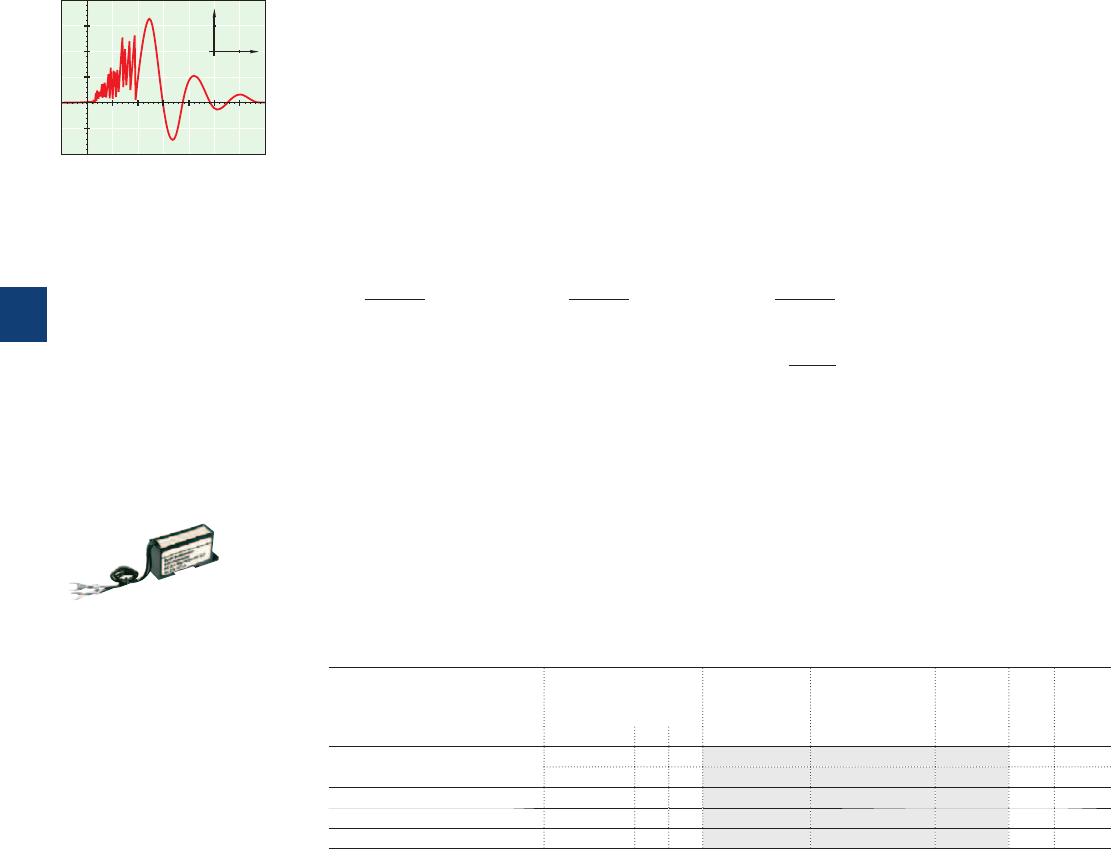
Surge suppressors for contactor coils
0
1000
100
(V)
T
(s)
0
1000
100
A 884D
Description
The operation of inductive circuits causes overvoltages, in particular on opening of the contactor coil.
The electromagnetic energy stored in the coil during contactor closing is restored on opening in the form
of surges, the slope and amplitude of which may rise to several kilovolts. A number of drawbacks are
observed ranging from interference on the electronic devices to breakdown of insulators and even destruc-
tion of certain sensitive components.
The graph opposite reproduces the oscillogram showing voltage discharges at the terminals of a 42 V / 50Hz
coil without peak clipping. The coil was switched by 8 series-connected poles of a contactor relay.
Following a burst of discharges with a very steep slope a damped oscillation emerges with a peak value of
3500V.
Overvoltage Factor
The overvoltage factor k is defined as the ratio of the maximum overvoltage peak value Ûs to the peak
value Ûc of the coil rated control voltage Uc:
Ûs max.
Ûs max.
Ûs max.
k = in DC: k = or in AC: k =
Ûc
Uc
Uc√2
3500
For example the following is obtained for the above graph: k = ≈ 60
42 √2
To reduce the harmful effects of these overvoltages, ABB has developed a range of surge suppressors de-
signed to reduce the k factor defined above and to limit or even completely eliminate the high pre-damping
voltage frequencies.
Each case is different, but the technical data tolerances and the generous sizing of parts have enabled us
to reduce the number of variants.
We have chosen the following solutions: transil diodes, varistors and RC blocks.
Note: A varistor is a resistor whose value decreases to a very large extent when a certain voltage is ap-
plied at its terminals.
Ordering details
For contactors Rated control circuit
voltage
Uc
Type Order code Pkg
qty
Weight
(1 pce)
VACDC kg
EK110 ... EK210 24...48
●
– RC-EH300/48 SK829007-A 1 0.015
110...415
●
– RC-EH300/415 SK829007-B 1 0.015
EK370 ... EK1000 48...110
●
– RC-EH800/110 SK829007-C 1 0.015
EK110 ... EK1000 24...125 –
●
RC-EH800/110 SK829007-C 1 0.015
EK370 ... EK1000 220...600
●
– RC-EH800/600 SK829007-D 1 0.015
A078
RC-EH300/48
5/150 | ABB
5
1SFC101070C0201
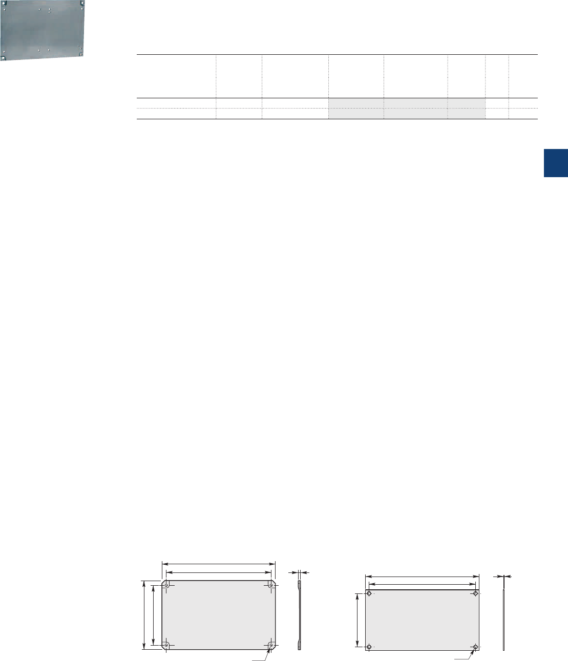
Mounting plates
Description
Mounting plates for two horizontal mounted contactors with or without a mechanical interlock unit.
Ordering details
To use with: Type Order code Pkg
qty
Weight
(1 pce)
Left hand
contactor Mechanical
interlock
Right hand
contactor
kg
EK110, EK150 VH145 EK110, EK150 PN210-22 SK829075-C 1 1.400
EK175, EK210 VH300 EK175, EK210 PN300-22 SK829075-E 1 2.070
(1) Space for mechanical interlock included.
1SBC585663F0302
PN...
Main dimensions mm
430
400
ø 15
200
E0748D1
3
E0748D3
320
340
ø 6.8
180
200
E0750D4
5
E0750D3
PN210-22 PN300-22
ABB | 5/151
5
1SFC101069C0201
Connection sets
Description
Connection between the main poles of two 4-pole contactors mounted side by side so that they operate as
source reversing contactors.
These sets are made up of four downstream connections.
BSS100 ... BSS210 – Insulated, flexible copper bars.
BSS550, BSS1000 – Bare, solid copper bars.
Ordering details
For contactors Type Order code Pkg
qty
Weight
(1 pce)
kg
Mechanical and electrical interlock units for two horizontal mounted contactors
EK110 BSS100 SK829090-B 1 0.400
EK150 BSS145 SK829090-F 1 0.700
EK175, EK210 BSS210 SK829090-G 1 1.000
EK370, EK550 BSS550 SK829090-E 1 3.300
EK1000 BSS1000 SK829090-H 1 5.500
A1
A2
A1
A2
315 351
426 462
77
8 8
E0747D
BSS100 ... BSS1000
5/152 | ABB
5
1SFC101064C0201
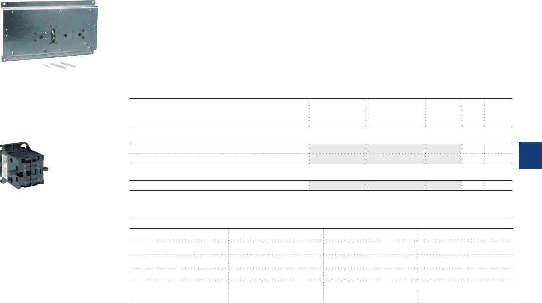
Mechanical interlock units
Mechanical and electrical interlock units
Description
The mechanical interlock unit prevents one of the contactors from closing as long as the other
contactor is closed.
– VH145, VH300 interlock units for mechanical and electrical interlocking of two horizontal mounted AC or
DC operated EK110 ... EK1000 contactors.
– VH800 interlock unit for mechanical interlocking of two horizontal mounted AC or DC operated
EK370 ... EK1000 contactors.
Ordering details
For contactors Type Order code Pkg
qty
Weight
(1 pce)
kg
Mechanical and electrical interlock units for two horizontal mounted contactors
EK110, EK150 VH145 SK829071-A 1 0.130
EK175, EK210 VH300 SK829071-B 1 0.130
Mechanical interlock unit for two horizontal mounted contactors
EK370 ... EK1000 VH800 SK829070-F 1 6.000
A090C4
1SBC573592F0301
VH145
Selection table
For contactors
Left Right
EK110, EK150 EK175, EK210 EK370...EK1000
EK110, EK150 VH145 – –
EK175, EK210 – VH300 –
EK370 ... EK1000 – – VH800
Fixing PN210-22 mounting plate
(to be supplied separately)
PN300-22 mounting plate
(to be supplied separately)
Mounting plate included
ABB | 5/153
5
1SFC101067C0201
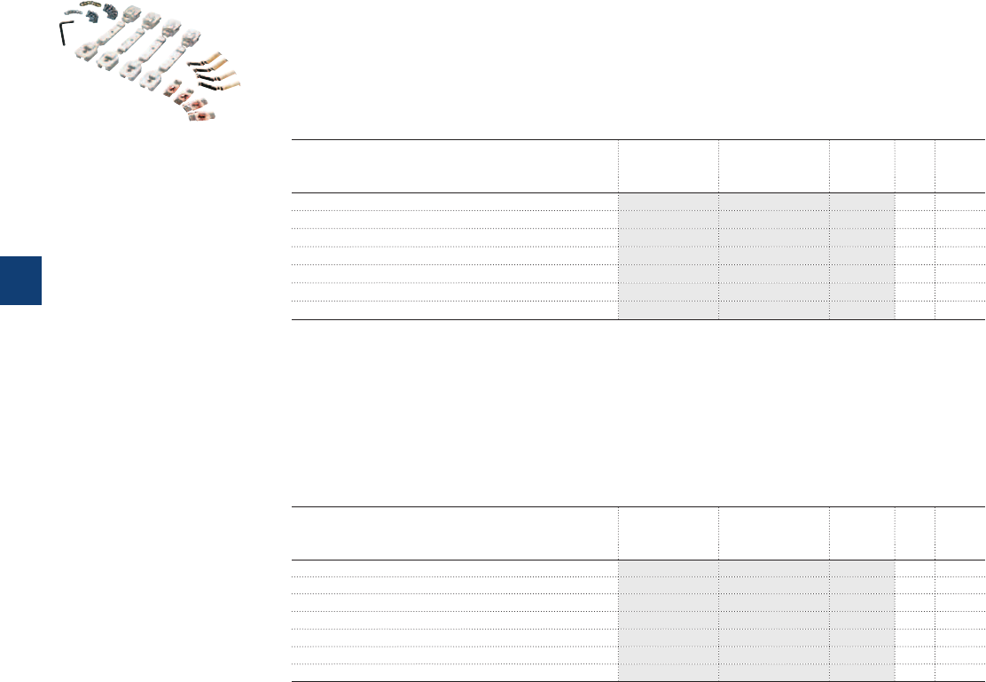
KZK... Main contact sets
KWK... Arc chutes
KZK main contact sets
Description
The contact sets for 4-pole contactors consist of eight fixed contacts, four moving contacts, springs and
the necessary screws. In addition, the sets include four moving arcing contacts for EK370 ... EK1000
contactors.
Ordering details
For contactors Type Order code Pkg
qty
Weight
(1 pce)
kg
EK110 KZK110 SK824204-A 1 0.450
EK150 KZK150 SK824204-B 1 0.450
EK175 KZK175 SK825204-A 1 0.700
EK210 KZK210 SK825204-B 1 0.700
EK370 KZK370 SK827204-A 1 2.400
EK550 KZK550 SK827204-B 1 2.400
EK1000 KZK1000 SK827204-F 1 3.000
Arc chutes
Description
The arc chutes sets for EK 4-pole contactors contain 8 pieces.
Ordering details
For contactors Type Order code Pkg
qty
Weight
(1 pce)
kg
EK110 KWK110 5223351-AH 1 0.660
EK150 KWK150 5223351-AK 1 0.660
EK175 KWK175 5223351-AL 1 1.260
EK210 KWK210 5223351-AM 1 1.260
EK370 KWK370 5223351-Y 1 3.170
EK550 KWK550 5223351-Z 1 3.170
EK1000 KWK1000 5223351-AN 1 3.170
1SBC586473F0304
KZK370
5/154 | ABB
5
1SFC101066C0201
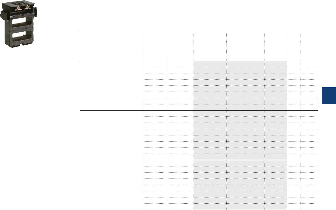
Contactor coils
Description
Coils for EK110 ... EK1000 - AC operated.
Ordering details
For contactors Rated control circuit
voltage
Uc
Type Order code Pkg Weight
qty (1 pce)
(1)
V 50 Hz V 60 Hz kg
EK110 ... EK150 48 - KH210 SK825400-AD 1 0.360
- 110 KH210 SK825400-AE 1 0.360
110 120 KH210 SK825400-AF 1 0.360
220…230 - KH210 SK825400-AL 1 0.360
230...240 - KH210 SK825400-AM 1 0.360
- 380 KH210 SK825400-AN 1 0.360
380…400 440 KH210 SK825400-AP 1 0.360
400…415 - KH210 SK825400-AR 1 0.360
EK175 ... EK210 48 - KH300 SK826400-AD 1 0.440
- 110 KH300 SK826400-AE 1 0.440
110 120 KH300 SK826400-AF 1 0.440
220…230 - KH300 SK826400-AL 1 0.440
230...240 - KH300 SK826400-AM 1 0.440
- 380 KH300 SK826400-AN 1 0.440
380…400 440 KH300 SK826400-AP 1 0.440
400…415 - KH300 SK826400-AR 1 0.440
EK370 ... EK1000 48 - KH800 SK828100-AD 1 0.950
110 110...120 KH800 SK828100-EF 1 0.950
110...115 115...127 KH800 SK828100-EG 1 0.950
220 220...240 KH800 SK828100-EL 1 0.950
220...230 230...255 KH800 SK828100-EM 1 0.950
380 380...415 KH800 SK828100-EP 1 0.950
380…400 400...440 KH800 SK828100-ER 1 0.950
400…415 - KH800 SK828100-AR 1 0.950
(1) Other control voltages, see voltage code table.
1SBC273813F0302
KH300
ABB | 5/155
5
1SFC101079C0201

Contactor coils
Description
– Coils for EK110 ... EK1000 - DC operated with sets including a DC coil, an economy resistor and a
insertion contact.
– Coils for EK110 ... EK210 - Multi-frequency coil and an insertion contact for contactor with built-in rectifier.
Ordering details
For contactors Rated control circuit
voltage
Uc
Type Order code Pkg Weight
qty (1 pce)
(1)
V DC kg
EK110 ... EK150 12 KP210 SK825450-DA 1 set 0.450
24 KP210 SK825450-DB 1 set 0.450
36 KP210 SK825450-DC 1 set 0.450
48 KP210 SK825450-DD 1 set 0.450
60 KP210 SK825450-DT 1 set 0.450
75 KP210 SK825450-DG 1 set 0.450
110 KP210 SK825450-DE 1 set 0.450
125 KP210 SK825450-DU 1 set 0.450
220 KP210 SK825450-DF 1 set 0.450
EK175 ... EK210 12 KP300 SK826450-DA 1 set 0.550
24 KP300 SK826450-DB 1 set 0.550
36 KP300 SK826450-DC 1 set 0.550
48 KP300 SK826450-DD 1 set 0.550
60 KP300 SK826450-DT 1 set 0.550
75 KP300 SK826450-DG 1 set 0.550
110 KP300 SK826450-DE 1 set 0.550
125 KP300 SK826450-DU 1 set 0.550
220 KP300 SK826450-DF 1 set 0.550
EK3700 ... EK1000 24 KP800 SK828150-DB 1 set 1.060
36 KP800 SK828150-DC 1 set 1.060
48 KP800 SK828150-DD 1 set 1.060
60 KP800 SK828150-DT 1 set 1.060
75 KP800 SK828150-DG 1 set 1.060
110 KP800 SK828150-DE 1 set 1.060
125 KP800 SK828150-DU 1 set 1.060
220 KP800 SK828150-DF 1 set 1.060
Ordering details
For contactors Rated control circuit
voltage
Uc
Type Order code Pkg Weight
qty (1 pce)
(1)
V AC 40...400 Hz kg
EK110 ... EK150 110…120 KP210 SK825450-EF 1 set 0.450
115…127 KP210 SK825450-EG 1 set 0.450
220...230 KP210 SK825450-EL 1 set 0.450
230…240 KP210 SK825450-EM 1 set 0.450
380…400 KP210 SK825450-EP 1 set 0.450
400…415 KP210 SK825450-ER 1 set 0.450
EK175 ... EK210 110…120 KP300 SK826450-EF 1 set 0.450
115…127 KP300 SK826450-EG 1 set 0.450
220...230 KP300 SK826450-EL 1 set 0.450
230…240 KP300 SK826450-EM 1 set 0.450
380…400 KP300 SK826450-EP 1 set 0.450
400…415 KP300 SK826450-ER 1 set 0.450
(1) Other control voltages, see voltage code table.
5/156 | ABB
5
1SFC101079C0201
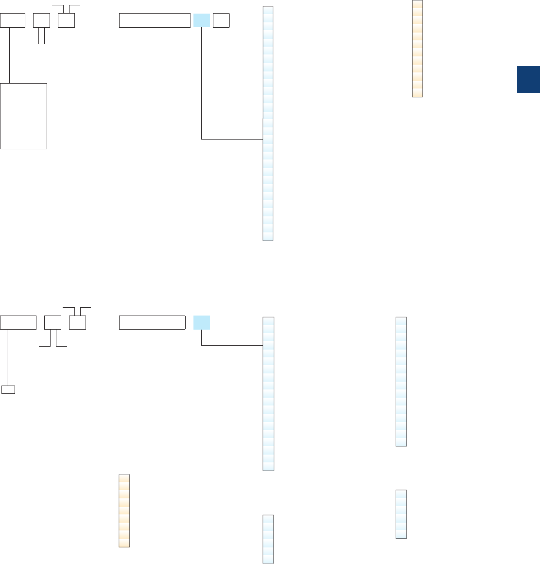
Voltage code table
The below tables indicate the available coil voltages and corresponding digits for order codes. When placing an order, please
give the order code. Select a standard contactor from ordering detail pages. Change the coil voltage code in the order code
according to the table below. Example: for contactor A50-30-00 and coil 42 V 50/60 Hz, the order code is 1SBL351001R8200.
Auxiliary contacts
N.O. N.C.
Auxiliary contacts
N.O. N.C.
N.O. N.C.
Main contacts
N.O. N.C.
Main contacts
Type
Type
Order code
Order code
Contactor type
Contactor type
A40-30-10
EK110 - 40 - 11
A AC operated
AL, AE DC operated
TAL, TAE (1) DC operated large coil voltage range
AF, NF, GAF (1) AC / DC operated with electronic coil interface
UA, UA..RA Capacitor switching - AC operated
GA DC switching - AC operated
GAE DC switching - DC operated
AM (1) Magnetically latched - DC operated
EK AC operated or DC operated
AC coil code
Contactors: A, UA, UA..RA, GA
AC coil code
Contactors: EK110 ... EK210
AC coil code
Contactors: EK370 ... EK1000
Multi-frequency coil code
Contactors: EK110 ... EK210
Dual frequency coil code
Contactors: EK370 ... EK1000
1SBL321001R 80 10
SK824440 - AD
Contactors
EK contactors
50 Hz 60 Hz
81 24 V 24 V
16 26 V 28 V
17 28 V 32 V
82 42 V 42 V
20 42 V 48 V
83 48 V 48 V
73 60 V 60 V
74 100 V (2) 100...110 V (2)
26 105 V (2) 110...127 V (2)
84 110 V 110...120 V
89 110...115 V 115...127 V (3)
29 120 V 140 V
30 125...127 V 150 V
34 175 V 208 V
36 190 V 220 V
40 210 V 240 V
80 220...230 V 230...240 V
88 230...240 V 240...260 V
42 230...240 V 277 V
85 380...400 V 400...415 V
86 400...415 V 415...440 V
50 400 V 440 V
51 400...415 V 480 V
87 415...440 V 440...460 V
53 440 V 500 V
55 500 V 600 V
56 550 V –
58 660...690 V –
59 – 690 V
Codes in bold for dual frequency coils.
(2) Not for A145 ... A300 contactors.
(3) A145 ... A300 contactors at 60 Hz 115 V only.
(1) TAL, TAE, AF, NF, GAF, AM all coil codes included in ordering detail pages.
50 Hz 60 Hz
AA – 24 V
AB 24 V –
AC – 48 V
AD 48 V –
AE – 110 V
AF 110 V 120 V
AG 127 V –
AZ – 208 V
AH 190 V 220 V
AK – 240 V
AL 220...230 V –
AM 230...240 V –
AN – 380 V
AP 380...400 V 440 V
AR 400...415 V –
AS – 480 V
AT 440 V –
AU 500 V –
AV – 600 V
50 Hz 60 Hz
AD 48 V –
AE – 110 V
AF 110 V 120 V
AG 127 V –
AZ – 208 V
AH 190 V 220 V
AK – 240 V
AL 220...230 V 240 V
AM 230...240 V –
AN – 380 V
AP 380...400 V 440 V
AR 400...415 V –
AS – 480 V
AT 440 V –
AU 500 V –
AV – 600 V
40...400 Hz
EF 110...120 V
EG 115...127 V
EL 220...230 V
EM 230...240 V
EP 380...400 V
ER 400...415 V
50 Hz 60 Hz
EF 110 V 110...120 V
EG 110...115 V 115...127 V
EL 220 V 220...240 V
EM 220...230 V 230...255 V
EP 380 V 380...415 V
ER 380...400 V 400...440 V
2 auxiliary contact blocks maximum per
contactor, ambient temperature ≤ 55 °C
and mounting positions 2 and 6 excluded.
DC coil code
Contactors: AL, AE, GAE
80 12 V
81 24 V
82 42 V
83 48 V
21 50 V
84 60 V
85 75 V
86 110 V
87 125 V
88 220 V
89 240 V
38 250 V
DC coil code
Contactors: EK110 ... EK1000
DA 12 V (4)
DB 24 V
DC 36 V
DD 48 V
DT 60 V
DG 75 V
DE 110 V
DU 125 V
DF 220 V
(4) Not for EK370 ... EK1000
contactors.
ABB | 5/157
5
1SBC101601S0201
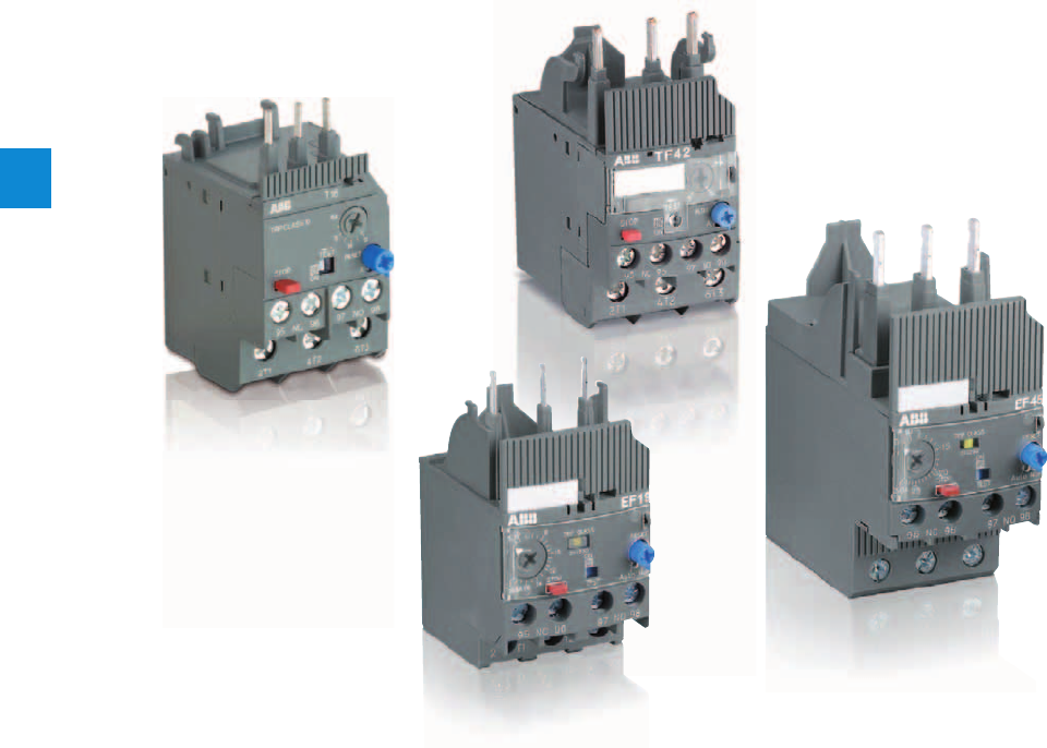
6/0 | ABB
6
Somm_OR

Overload relays
ABB | 6/1
6
Somm_OR
Thermal overload relays
T16 (0.10 … 16.0 A)
Ordering details 6/2
Technical data 6/3
TF42 (0.10 … 38.0 A)
Ordering details 6/6
Technical data 6/7
TA25DU (0.10 … 32.0 A)
Ordering details 6/10
Technical data 6/11
Accessories 6/14
TA42DU (18.0 … 42.0 A)
Ordering details 6/15
Technical data 6/16
TA75DU (18 … 80 A)
Ordering details 6/19
Technical data 6/20
TA80DU (29 … 80 A)
Ordering details 6/23
Technical data 6/24
TA110DU (66 … 110 A)
Ordering details 6/27
Technical data 6/28
TA200DU (66 … 200 A)
Ordering details 6/31
Technical data 6/32
TA450DU (130 ... 310 A)
Ordering details 6/35
Technical data 6/36
Electronic overload relays
E16DU, E45DU, E80DU, E140DU (0.10 to 140 A)
Ordering details 6/39
Technical data 6/40
Accessories 6/43
EF19, EF45 (0.10 to 45.0 A)
Ordering details 6/44
Technical data 6/45
E200DU, E320DU (60 to 320 A)
Ordering details 6/48
Technical data 6/49
E500DU, E800DU, E1250DU (150 to 1250 A)
Ordering details 6/51
Technical data 6/52
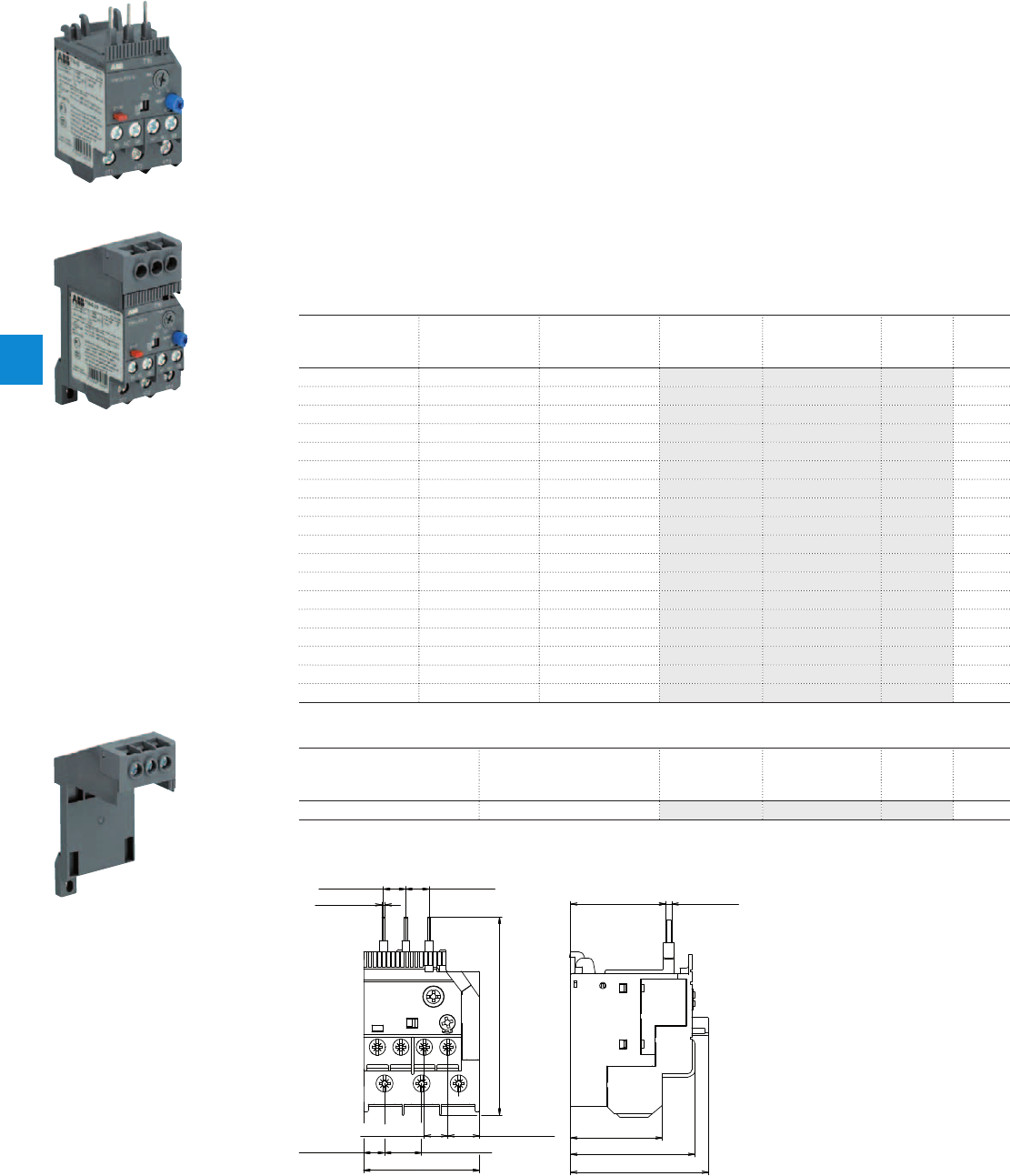
T16 thermal overload relays
0.10 … 16.0 A
Description
The T16 thermal overload relays are economic electromechanical protection devices for the main circuit.
They offer reliable protection for motors in the event of overload or phase failure. The devices have trip
class 10.
The thermal overload relays are three pole relays with bimetal tripping elements. The motor current flows
through the bimetal tripping elements and heats them directly and indirectly. In case of an overload (over
current), the bimetal elements bent as a result of the heating. This leads to a release of the relay and a
change of the contacts switching position (95-96 / 97-98).
– Manual or automatic reset selectable
– Phase loss sensitive acc. to IEC/EN 60947-4-1
– Two electrically isolated auxiliary contacts – 1 N.O. + 1 N.C.
– TEST and STOP function – Trip indication on the front
– Temperature compensation
– Suitable for three- and single-phase applications
Ordering details
Setting range Short-circuit
protective device
Trip class Type Order code Weight
(1 pce)
A kg
0.10 ... 0.13 0.5 A, Fuse type T 10 T16-0.13 1SAZ711201R1005 0.100
0.13 ... 0.17 1.0 A, Fuse type T 10 T16-0.17 1SAZ711201R1008 0.100
0.17 ... 0.23 1.0 A, Fuse type T 10 T16-0.23 1SAZ711201R1009 0.100
0.23 ... 0.31 1.0 A, Fuse type T 10 T16-0.31 1SAZ711201R1013 0.100
0.31 ... 0.41 2.0 A, Fuse type gG 10 T16-0.41 1SAZ711201R1014 0.100
0.41 ... 0.55 2.0 A, Fuse type gG 10 T16-0.55 1SAZ711201R1017 0.100
0.55 ... 0.74 4.0 A, Fuse type gG 10 T16-0.74 1SAZ711201R1021 0.100
0.74 ... 1.00 6.0 A, Fuse type gG 10 T16-1.0 1SAZ711201R1023 0.100
1.00 ... 1.30 6.0 A, Fuse type gG 10 T16-1.3 1SAZ711201R1025 0.100
1.30 ... 1.70 10.0 A, Fuse type gG 10 T16-1.7 1SAZ711201R1028 0.100
1.70 ... 2.30 10.0 A, Fuse type gG 10 T16-2.3 1SAZ711201R1031 0.100
2.30 ... 3.10 10.0 A, Fuse type gG 10 T16-3.1 1SAZ711201R1033 0.100
3.10 ... 4.20 20.0 A, Fuse type gG 10 T16-4.2 1SAZ711201R1035 0.100
4.20 ... 5.70 20.0 A, Fuse type gG 10 T16-5.7 1SAZ711201R1038 0.100
5.70 ... 7.60 35.0 A, Fuse type gG 10 T16-7.6 1SAZ711201R1040 0.100
7.60 ... 10.0 35.0 A, Fuse type gG 10 T16-10 1SAZ711201R1043 0.104
10.0 ... 13.0 40.0 A, Fuse type gG 10 T16-13 1SAZ711201R1045 0.104
13.0 ... 16.0 40.0 A, Fuse type gG 10 T16-16 1SAZ711201R1047 0.104
Ordering details accessories
For thermal overload relays Description Type Order code Weight
(1 pce)
kg
T16 Single mounting kit DB16 1SAZ701901R0001 0.032
2CDC231012F0011
T16-16
2CDC235002F0011
T16 + DB16
Main dimensions mm, inches
35.6 1.4"
48.2 1.9"
36.9 1.45" 2.4 0.09"
53.5 2.11"
1.2 0.05"
9.1 0.36"8.6 0.34"
76.7 3.02"
45 1.77"
8.1 0.32" 14.4 0.57"
12.35 0.49"9.1 0.36"
2CDC232008F0008
T16
2CDC231002F0011
DB16
6/2 | ABB
6
2CDC106036C0201
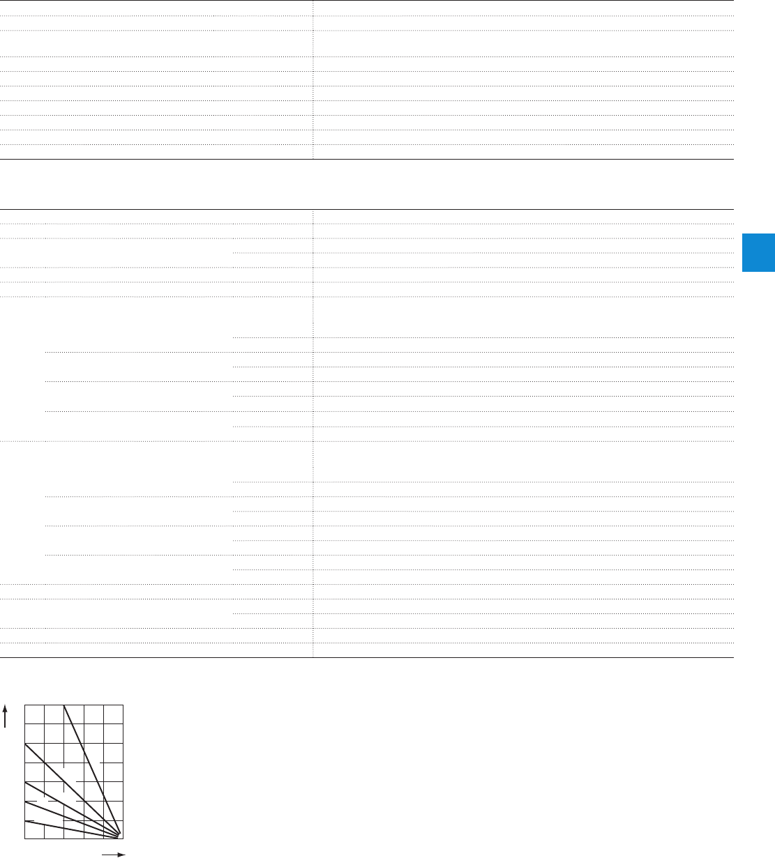
Main circuit – Utilization characteristics according to IEC/EN
Type T16
Standards
IEC/EN 60947–4–1, IEC/EN 60947-5-1, IEC/EN 60947-1
Rated operational voltage U
e
690 V AC
- V DC
Rated frequency
50/60 Hz
Trip class
10
Number of poles
3
Duty time
100 %
Operating frequency without early tripping
Up to 15 operations/h, see "Technical diagram – Intermittent periodic duty"
Rated impulse withstand voltage U
imp
6 kV
Rated insulation voltage U
i
690 V AC
Auxiliary circuit according to IEC/EN
Type T16
Rated operational voltage U
e
600 V
Conventional free air thermal current I
th
N.C., 95-96 6 A
N.O., 97-98 4 A
Rated frequency
DC, 50/60 Hz
Number of poles
1 N.O. + 1 N.C.
I
e
/ Rated operational current AC-15
acc. to IEC/EN 60947-5-1 for utilization category
110-120 V
N.C., 95-96 3.00 A
N.O., 97-98 0.75 A
220-230-240 V
N.C., 95-96 3.00 A
N.O., 97-98 0.75 A
440 V
N.C., 95-96 0.75 A
N.O., 97-98 0.75 A
480-500 V
N.C., 95-96 0.75 A
N.O., 97-98 0.75 A
I
e
/ Rated operational current DC-13
acc. to IEC/EN 60947-5-1 for utilization category
24 V
N.C., 95-96 1.25 A
N.O., 97-98 1.25 A
60 V
N.C., 95-96 0.55 A
N.O., 97-98 0.55 A
110-120-125 V
N.C., 95-96 0.55 A
N.O., 97-98 0.55 A
250 V
N.C., 95-96 0.27 A
N.O., 97-98 0.27 A
Minimum switching capacity
17 V / 3 mA
Short-circuit protective device
N.C., 95-96 6 A, Fuse type gG
N.O., 97-98 4 A, Fuse type gG
Rated impulse withstand voltage U
imp
6 kV
Rated insulation voltage U
i
690 V
Technical diagram – Intermittent periodic duty
140
120
0
20
40
60
80
100
0 20 40 60 80 100 (%)
t = 1 s
a
t = 1.5 s
a
t = 3 s
a
t = 5 s
a
t = 0.5 s
a
duty ratio
switching frequency
(Op/h)
2CDC232005F0211
ta: Motor starting time
T16 thermal overload relays
Technical data
ABB | 6/3
6
2CDC106036C0201

Main circuit – Utilization characteristics according to UL/CSA
Type T16
Standards
UL 508, CSA 22.2 No. 14
Maximum operational voltage
600 V AC
Trip rating
125 % of FLA
Full load amps (FLA)
See table "Full load amps and short-circuit protective device"
Short-circuit rating RMS symmetrical
See table "Full load amps and short-circuit protective device"
Short-circuit protective device
See table "Full load amps and short-circuit protective device"
Auxiliary circuit according to UL/CSA
Type T16
Contact rating
N.C., 95-96 B600, Q300
N.O., 97-98 D300, Q300
Conventional thermal current
N.C., 95-96 5 A
N.O., 97-98 2.5 A
Full load amps and short-circuit protective device
Type Full load amps (FLA) Short-circuit protective device
480 / 600 V AC 480 / 600 V AC
Short circuit rating RMS
symmetrical
Fuse type Short circuit rating RMS
symmetrical
Fuse type
T16-0.13
0.13 A 18 kA 1 A, K5 100 kA 30 A, Class J
T16-0.17
0.17 A 18 kA 1 A, K5 100 kA 30 A, Class J
T16-0.23
0.23 A 18 kA 1 A, K5 100 kA 30 A, Class J
T16-0.31
0.31 A 18 kA 3 A, K5 100 kA 30 A, Class J
T16-0.41
0.41 A 18 kA 3 A, K5 100 kA 30 A, Class J
T16-0.55
0.55 A 18 kA 3 A, K5 100 kA 30 A, Class J
T16-0.74
0.74 A 18 kA 3 A, K5 100 kA 30 A, Class J
T16-1.0
1.00 A 18 kA 6 A, K5 100 kA 30 A, Class J
T16-1.3
1.30 A 18 kA 6 A, K5 100 kA 30 A, Class J
T16-1.7
1.70 A 18 kA 6 A, K5 100 kA 30 A, Class J
T16-2.3
2.30 A 18 kA 10 A, K5 100 kA 30 A, Class J
T16-3.1
3.10 A 18 kA 10 A, K5 100 kA 30 A, Class J
T16-4.2
4.20 A 18 kA 15 A, K5 100 kA 30 A, Class J
T16-5.7
5.70 A 18 kA 20 A, K5 100 kA 30 A, Class J
T16-7.6
7.60 A 18 kA 25 A, K5 100 kA 30 A, Class J
T16-10
10.0 A 18 kA 35 A, K5 100 kA 45 A, Class J
T16-13
13.0 A 18 kA 40 A, K5 100 kA 45 A, Class J
T16-16
16.0 A 18 kA 60 A, K5 100 kA 45 A, Class J
T16 thermal overload relays
Technical data
6/4 | ABB
6
2CDC106036C0201

General technical data
Type T16
Pollution degree
3
Phase loss sensitive
Yes
Ambient air temperature
Operation Open - compensated without derating
-25 ... +60 °C
Open
-25 ... +60 °C
Storage
-50 ... +80 °C
Ambient air temperature compensation
Continuous
Maximum operating altitude permissible
2000 m
Resistance to shock acc. to IEC 60068-2-27
25 g / 11 ms
Resistance to vibrations acc. to IEC 60068-2-6
3 g / 3 ... 150 Hz
Mounting position
Position 1-5
Mounting
Mount on the contactor and tighten the screws of the main circuit terminals or with single
mounting kit on DIN rail (35 mm)
Degree of protection
IP20
Electrical connection
Main circuit
Type T16
Connecting capacity
Rigid
1 x
2 x
0.75 ... 4 mm²
0.75 ... 1.5 mm² or 1.5 ... 4 mm²
1)
Flexible
1 x or 2 x 0.75 ... 4 mm²
Stranded acc. to UL/CSA
1 x or 2 x AWG 18-10
Flexible acc. to UL/CSA
1 x or 2 x AWG 18-10
Stripping length
12 mm
Tightening torques
1.1 ... 1.5 Nm / 9 … 13 Ib.in
Connection screw
M4 (Pozidriv 2)
1) Combination of different wires not possible
Auxiliary circuit
Type T16
Connecting capacity
Rigid
1 x or 2 x 0.75 ... 4 mm²
Flexible with ferrule
1 x or 2 x 0.75 ... 2.5 mm²
Flexible with insulated ferrule
1 x
2 x
0.75 ... 2.5 mm²
0.75 ... 1.5 mm²
Flexible
1 x or 2 x 0.75 ... 1 mm² or 1 ... 2.5 mm²
Stranded acc. to UL/CSA
1 x or 2 x AWG 18-12
Flexible acc. to UL/CSA
1 x or 2 x AWG 18-12
Stripping length
9 mm
Tightening torques
1.1 ... 1.5 Nm / 9 … 13 Ib.in
Connection screw
M3 (Pozidriv 2)
T16 thermal overload relays
Technical data
ABB | 6/5
6
2CDC106036C0201
TF42 thermal overload relays
0.10 … 38.0 A
Description
The TF42 thermal overload relays are economic electromechanical protection devices for the main circuit.
They offer reliable protection for motors in the event of overload or phase failure. The devices have trip
class 10.
The thermal overload relays are three pole relays with bimetal tripping elements. The motor current flows
through the bimetal tripping elements and heats them directly and indirectly. In case of an overload (over
current), the bimetal elements bent as a result of the heating. This leads to a release of the relay and a
change of the contacts switching position (95-96 / 97-98).
– Phase loss sensitive acc. to IEC/EN 60947-4-1
– TEST and STOP function – Trip indication on the front
– Suitable for three- and single-phase applications
– Sealable cover
Ordering details
Setting range Short-circuit
protective device
Trip class Type Order code Weight
(1 pce)
A kg
0.10 ... 0.13 0.5 A, Fuse type T 10 TF42-0.13 1SAZ721201R1005 0.130
0.13 ... 0.17 1.0 A, Fuse type T 10 TF42-0.17 1SAZ721201R1008 0.130
0.17 ... 0.23 1.0 A, Fuse type T 10 TF42-0.23 1SAZ721201R1009 0.130
0.23 ... 0.31 1.0 A, Fuse type T 10 TF42-0.31 1SAZ721201R1013 0.130
0.31 ... 0.41 2.0 A, Fuse type gG 10 TF42-0.41 1SAZ721201R1014 0.130
0.41 ... 0.55 2.0 A, Fuse type gG 10 TF42-0.55 1SAZ721201R1017 0.130
0.55 ... 0.74 4.0 A, Fuse type gG 10 TF42-0.74 1SAZ721201R1021 0.130
0.74 ... 1.00 6.0 A, Fuse type gG 10 TF42-1.0 1SAZ721201R1023 0.130
1.00 ... 1.30 6.0 A, Fuse type gG 10 TF42-1.3 1SAZ721201R1025 0.130
1.30 ... 1.70 10.0 A, Fuse type gG 10 TF42-1.7 1SAZ721201R1028 0.130
1.70 ... 2.30 10.0 A, Fuse type gG 10 TF42-2.3 1SAZ721201R1031 0.130
2.30 ... 3.10 10.0 A, Fuse type gG 10 TF42-3.1 1SAZ721201R1033 0.130
3.10 ... 4.20 20.0 A, Fuse type gG 10 TF42-4.2 1SAZ721201R1035 0.130
4.20 ... 5.70 20.0 A, Fuse type gG 10 TF42-5.7 1SAZ721201R1038 0.130
5.70 ... 7.60 35.0 A, Fuse type gG 10 TF42-7.6 1SAZ721201R1040 0.130
7.60 ... 10.0 35.0 A, Fuse type gG 10 TF42-10 1SAZ721201R1043 0.130
10.0 ... 13.0 40.0 A, Fuse type gG 10 TF42-13 1SAZ721201R1045 0.130
13.0 ... 16.0 40.0 A, Fuse type gG 10 TF42-16 1SAZ721201R1047 0.130
16.0 ... 20.0 63.0 A, Fuse type gG 10 TF42-20 1SAZ721201R1049 0.145
20.0 ... 24.0 63.0 A, Fuse type gG 10 TF42-24 1SAZ721201R1051 0.145
24.0 ... 29.0 63.0 A, Fuse type gG 10 TF42-29 1SAZ721201R1052 0.145
29.0 ... 35.0 80.0 A, Fuse type gG 10 TF42-35 1SAZ721201R1053 0.145
35.0 ... 38.0/40.0 80.0 A, Fuse type gG 10 TF42-38 1SAZ721201R1055 0.145
Ordering details accessories
For thermal overload relays Description Type Order code Weight
(1 pce)
kg
TF42 Single mounting kit DB42 1SAZ701902R0001 0.087
1SBC101326F0010
TF42-38
2CDC231001F0011
DB42
Main dimensions mm, inches
2.3 0.09"
88.3 3.48"
12.35 0.49"
9.1 0.36"
14.4 0.57"8.1 0.32"
45 1.77"
16.2 0.64" 11.7 0.46"
50.25 1.98" 2.7 0.11"
52.6 2.07"
70.5 2.78"
66.4 2.61"
2CDC232005F0009
TF42
6/6 | ABB
6
2CDC106046C0201
Main circuit – Utilization characteristics according to IEC/EN
Type TF42
Standards
IEC/EN 60947–4–1, IEC/EN 60947-5-1, IEC/EN 60947-1
Rated operational voltage U
e
690 V AC
Rated frequency
50/60 Hz
Trip class
10
Number of poles
3
Duty time
100 %
Operating frequency without early tripping
Up to 15 operations/h, see "Technical diagram – Intermittent periodic duty"
Rated impulse withstand voltage U
imp
6 kV
Rated insulation voltage U
i
690 V AC
Auxiliary circuit according to IEC/EN
Type TF42
Rated operational voltage U
e
600 V
Conventional free air thermal current I
th
N.C., 95-96 6 A
N.O., 97-98 4 A
Rated frequency
DC, 50/60 Hz
Number of poles
1 N.O. + 1 N.C.
I
e
/ Rated operational current AC-15
acc. to IEC/EN 60947-5-1 for utilization category
110-120 V
N.C., 95-96 3.00 A
N.O., 97-98 0.75 A
220-230-240 V
N.C., 95-96 3.00 A
N.O., 97-98 0.75 A
440 V
N.C., 95-96 0.75 A
N.O., 97-98 0.75 A
480-500 V
N.C., 95-96 0.75 A
N.O., 97-98 0.75 A
I
e
/ Rated operational current DC-13
acc. to IEC/EN 60947-5-1 for utilization category
24 V
N.C., 95-96 1.25 A
N.O., 97-98 1.25 A
110-120-125 V
N.C., 95-96 0.55 A
N.O., 97-98 0.55 A
250 V
N.C., 95-96 0.27 A
N.O., 97-98 0.27 A
Minimum switching capacity
17 V / 3 mA
Short-circuit protective device
N.C., 95-96 6 A, Fuse type gG
N.O., 97-98 4 A, Fuse type gG
Rated impulse withstand voltage U
imp
6 kV
Rated insulation voltage U
i
690 V
Technical diagram – Intermittent periodic duty
140
120
0
20
40
60
80
100
0 20 40 60 80 100 (%)
t = 1 s
a
t = 1.5 s
a
t = 3 s
a
t = 5 s
a
t = 0.5 s
a
duty ratio
switching frequency
(Op/h)
2CDC232005F0211
ta: Motor starting time
TF42 thermal overload relays
Technical data
ABB | 6/7
6
2CDC106046C0201

Main circuit – Utilization characteristics according to UL/CSA
Type TF42
Standards
UL 508, CSA 22.2 No. 14
Maximum operational voltage
600 V AC
Trip rating
125 % of FLA
Full load amps (FLA)
See table "Full load amps and short-circuit protective device"
Short-circuit rating RMS symmetrical
See table "Full load amps and short-circuit protective device"
Short-circuit protective device
See table "Full load amps and short-circuit protective device"
Auxiliary circuit according to UL/CSA
Type TF42
Contact rating
N.C., 95-96 B600, Q300
N.O., 97-98 D300, Q300
Conventional thermal current
N.C., 95-96 5 A
N.O., 97-98 2.5 A
Full load amps and short-circuit protective device
Type Full load amps (FLA) Short-circuit protective device
480 / 600 V AC 480 / 600 V AC
Short circuit rating RMS
symmetrical
Fuse type Short circuit rating RMS
symmetrical
Fuse type
TF42-0.13
0.13 A 18 kA 1 A, K5 100 kA 30 A, Class J
TF42-0.17
0.17 A 18 kA 1 A, K5 100 kA 30 A, Class J
TF42-0.23
0.23 A 18 kA 1 A, K5 100 kA 30 A, Class J
TF42-0.31
0.31 A 18 kA 3 A, K5 100 kA 30 A, Class J
TF42-0.41
0.41 A 18 kA 3 A, K5 100 kA 30 A, Class J
TF42-0.55
0.55 A 18 kA 3 A, K5 100 kA 30 A, Class J
TF42-0.74
0.74 A 18 kA 3 A, K5 100 kA 30 A, Class J
TF42-1.0
1.00 A 18 kA 6 A, K5 100 kA 30 A, Class J
TF42-1.3
1.30 A 18 kA 6 A, K5 100 kA 30 A, Class J
TF42-1.7
1.70 A 18 kA 6 A, K5 100 kA 30 A, Class J
TF42-2.3
2.30 A 18 kA 10 A, K5 100 kA 30 A, Class J
TF42-3.1
3.10 A 18 kA 10 A, K5 100 kA 30 A, Class J
TF42-4.2
4.20 A 18 kA 15 A, K5 100 kA 30 A, Class J
TF42-5.7
5.70 A 18 kA 20 A, K5 100 kA 30 A, Class J
TF42-7.6
7.60 A 18 kA 25 A, K5 100 kA 30 A, Class J
TF42-10
10.0 A 18 kA 35 A, K5 100 kA 45 A, Class J
TF42-13
13.0 A 18 kA 40 A, K5 100 kA 45 A, Class J
TF42-16
16.0 A 18 kA 60 A, K5 100 kA 45 A, Class J
TF42-20
20.0 A 18 kA 80 A, K5 100 kA 60 A, Class J
TF42-24
24.0 A 18 kA 80 A, K5 100 kA 60 A, Class J
TF42-29
29.0 A 18 kA 100 A, K5 100 kA 100 A, Class J
TF42-35
35.0 A 18 kA 150 A, K5 100 kA 175 A, Class J
TF42-38
38.0 A 18 kA 150 A, K5 100 kA 175 A, Class J
TF42 thermal overload relays
Technical data
6/8 | ABB
6
2CDC106046C0201

General technical data
Type TF42
Pollution degree
3
Phase loss sensitive
Yes
Ambient air temperature
Operation Open - compensated without derating
-25 ... +60 °C
Open
-25 ... +60 °C
Storage
-50 ... +80 °C
Ambient air temperature compensation
Continuous
Maximum operating altitude permissible
2000 m
Resistance to shock acc. to IEC 60068-2-27
25 g / 11 ms
Resistance to vibrations acc. to IEC 60068-2-6
3 g / 3 ... 150 Hz
Mounting position
Position 1-5
Mounting
Mount on the contactor and tighten the screws of the main circuit terminals or with single
mounting kit on DIN rail (35 mm)
Degree of protection
IP20
Electrical connection
Main circuit
Type TF42
(TF42-0.13 … TF42-16)
TF42
(TF42-20 … TF42-38)
Connecting capacity
Rigid
1 x or 2 x 0.75 ... 4 mm² 1.5 ... 2.5 mm² or 2.5 ... 10 mm²
1)
Flexible with insulated ferrule
1 x or 2 x 0.75 ... 4 mm² 2.5 ... 4 mm² or 4 ... 6 mm²
Stranded acc. to UL/CSA
1 x or 2 x AWG 18-10 AWG 14-6
Flexible acc. to UL/CSA
1 x or 2 x AWG 18-10 AWG 14-6
Stripping length
12 mm
Tightening torques
1.5 - 2.5 Nm / 13 … 22 Ib.in 2.5 - 2.7 Nm / 22 Ib.in
Connection screw
M4 (Pozidriv 2)
1) Combination of different wires not possible
Auxiliary circuit
Type TF42
Connecting capacity
Rigid
1 x or 2 x 0.75 ... 4 mm²
Flexible with ferrule
1 x or 2 x 0.75 ... 2.5 mm²
Flexible with insulated ferrule
1 x
2 x
0.75 ... 2.5 mm²
0.75 ... 1.5 mm²
Flexible
1 x or 2 x 0.75 ... 1 mm² or 1 ... 2.5 mm²
Stranded acc. to UL/CSA
1 x or 2 x AWG 18-12
Flexible acc. to UL/CSA
1 x or 2 x AWG 18-12
Stripping length
9 mm
Tightening torques
1.1 ... 1.5 Nm / 9 … 13 Ib.in
Connection screw
M3 (Pozidriv 2)
TF42 thermal overload relays
Technical data
ABB | 6/9
6
2CDC106046C0201
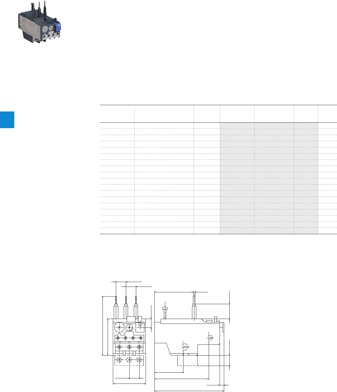
TA25DU thermal overload relays
With screw terminals - 0.10 … 32.0 A
Description
The TA25DU thermal overload relays are economic electromechanical protection devices for the main
circuit. They offer reliable protection for motors in the event of overload or phase failure. The devices have
trip class 10A.
The thermal overload relays are three pole relays with bimetal tripping elements. The motor current flows
through the bimetal tripping elements and heats them directly and indirectly. In case of an overload (over
current), the bimetal elements bent as a result of the heating. This leads to a release of the relay and a
change of the contacts switching position (95-96 / 97-98).
– Manual or automatic reset selectable
– Phase loss sensitive acc. to IEC/EN 60947-4-1
– Two electrically isolated auxiliary contacts – 1 N.O. + 1 N.C.
– TEST and STOP function – Trip indication on the front
– Temperature compensation
– Suitable for three- and single-phase applications
Ordering details
Setting range Short-circuit
protective device
Trip class Type Order code Weight
(1 pce)
A kg
0.10 ... 0.16 0.50 A, Fuse type F 10A TA25DU-0.16 1SAZ211201R1005 0.150
0.16 ... 0.25 0.63 A, Fuse type F 10A TA25DU-0.25 1SAZ211201R1009 0.150
0.25 ... 0.40 1.25 A, Fuse type F 10A TA25DU-0.4 1SAZ211201R1013 0.150
0.40 ... 0.63 2 A, Fuse type gG / - 10A TA25DU-0.63 1SAZ211201R1017 0.150
0.63 ... 1.00 4 A, Fuse type gG / 2 A aM 10A TA25DU-1.0 1SAZ211201R1021 0.150
1.00 ... 1.40 6 A, Fuse type gG / 2 A aM 10A TA25DU-1.4 1SAZ211201R1023 0.150
1.30 ... 1.80 6 A, Fuse type gG / 4 A aM 10A TA25DU-1.8 1SAZ211201R1025 0.150
1.70 ... 2.40 6 A, Fuse type gG / 4 A aM 10A TA25DU-2.4 1SAZ211201R1028 0.150
2.20 ... 3.10 10 A, Fuse type gG / 6 A aM 10A TA25DU-3.1 1SAZ211201R1031 0.150
2.80 ... 4.00 10 A, Fuse type gG / 6 A aM 10A TA25DU-4.0 1SAZ211201R1033 0.150
3.50 ... 5.00 16 A, Fuse type gG / 10 A aM 10A TA25DU-5.0 1SAZ211201R1035 0.150
4.50 ... 6.50 20 A, Fuse type gG / 16 A aM 10A TA25DU-6.5 1SAZ211201R1038 0.150
6.00 ... 8.50 20 A, Fuse type gG / 20 A aM 10A TA25DU-8.5 1SAZ211201R1040 0.150
7.50 ... 11.00 35 A, Fuse type gG / 25 A aM 10A TA25DU-11 1SAZ211201R1043 0.150
10.00 ... 14.00 35 A, Fuse type gG / 25 A aM 10A TA25DU-14 1SAZ211201R1045 0.150
13.00 ... 19.00 50 A, Fuse type gG / 35 A aM 10A TA25DU-19 1SAZ211201R1047 0.170
18.00 ... 25.00 63 A, Fuse type gG / 50 A aM 10A TA25DU-25 1SAZ211201R1051 0.170
24.00 ... 32.00 80 A, Fuse type gG / 63 A aM 10A TA25DU-32 1SAZ211201R1053 0.200
2CDC231002F0009
TA25DU-0.19
Main dimensions mm, inches
44 1.73"
13.5 0.53"
49.5 1.95"
80 3.15"
13.5 0.53"
13.5 0.53"
12 0.47"
73.5 2.89"
94 3.7"
6 0.24"
20 0.79"14* 0.55"*
39 1.54"
52.2 2.06" 2.5 0.1"
2CDC232023F0011
TA25DU + DX25
6/10 | ABB
6
2CDC106039C0201

Main circuit – Utilization characteristics according to IEC/EN
Type TA25DU
Standards
IEC/EN 60947–4–1, IEC/EN 60947-5-1, IEC/EN 60947-1
Rated operational voltage U
e
690 V AC
Rated frequency
DC, 50/60 Hz
Frequency range
0 ... 400 Hz
Trip class
10A
Number of poles
3
Duty time
100 %
Operating frequency without early tripping
Up to 15 operations/h, see "Technical diagram – Intermittent periodic duty"
Rated impulse withstand voltage U
imp
6 kV
Rated insulation voltage U
i
690 V AC
Auxiliary circuit according to IEC/EN
Type TA25DU
Rated operational voltage U
e
500 V AC, 440 V DC
Conventional free air thermal current I
th
N.C., 95-96 10 A
N.O., 97-98 6 A
Rated frequency
DC, 50/60 Hz
Number of poles
1 N.O. + 1 N.C.
I
e
/ Rated operational current AC-15
acc. to IEC/EN 60947-5-1 for utilization category
110-120 V
N.C., 95-96 3.00 A
N.O., 97-98 3.00 A
220-230-240 V
N.C., 95-96 3.00 A
N.O., 97-98 3.00 A
440 V
N.C., 95-96 1.90 A
N.O., 97-98 1.00 A
480-500 V
N.C., 95-96 1.00 A
N.O., 97-98 1.00 A
I
e
/ Rated operational current DC-13
acc. to IEC/EN 60947-5-1 for utilization category
24 V
N.C., 95-96 1.25 A
N.O., 97-98 1.25 A
60 V
N.C., 95-96 0.25 A
N.O., 97-98 0.25 A
110-120-125 V
N.C., 95-96 0.25 A
N.O., 97-98 0.25 A
250 V
N.C., 95-96 0.12 A
N.O., 97-98 0.04 A
Minimum switching capacity
17 V / 3 mA
Short-circuit protective device
N.C., 95-96 10 A, Fuse type gG
N.O., 97-98 6 A, Fuse type gG
Rated impulse withstand voltage U
imp
6 kV
Rated insulation voltage U
i
690 V
Technical diagram – Intermittent periodic duty
140
120
0
20
40
60
80
100
0 20 40 60 80 100 (%)
t = 1 s
a
t = 1.5 s
a
t = 3 s
a
t = 5 s
a
t = 0.5 s
a
duty ratio
switching frequency
(Op/h)
2CDC232005F0211
ta: Motor starting time
TA25DU thermal overload relays
Technical data
ABB | 6/11
6
2CDC106039C0201

Main circuit – Utilization characteristics according to UL/CSA
Type TA25DU
Standards
UL 508, CSA 22.2 No. 14
Maximum operational voltage
600 V AC
Trip rating
125 % of FLA
Full load amps (FLA)
See table "Full load amps and short-circuit protective device"
Short-circuit rating RMS symmetrical
See table "Full load amps and short-circuit protective device"
Short-circuit protective device
See table "Full load amps and short-circuit protective device"
Auxiliary circuit according to UL/CSA
Type TA25DU
Contact rating
N.C., 95-96 C600
N.O., 97-98 B600
Conventional thermal current
5 A
Full load amps and short-circuit protective device
Type Full load amps
(FLA)
Short-circuit protective device
480 / 600 V AC 480 / 600 V AC 480 / 600 V AC
Short circuit rating
RMS symmetrical
Fuse type Listed circuit
breaker
Short circuit rating
RMS symmetrical
Listed circuit
breaker
Short circuit rating
RMS symmetrical
Fuse type
TA25DU-0.16
0.16 A 5 kA 1.0 A, K5 / RK5 15 A 35 / 18 kA 15 A 50 kA 30 A, Class J
TA25DU-0.25
0.25 A 5 kA 1.0 A, K5 / RK5 15 A 35 / 18 kA 15 A 50 kA 30 A, Class J
TA25DU-0.4
0.40 A 5 kA 3.0 A, K5 / RK5 15 A 35 / 18 kA 15 A 50 kA 30 A, Class J
TA25DU-0.63
0.63 A 5 kA 3.0 A, K5 / RK5 15 A 35 / 18 kA 15 A 50 kA 30 A, Class J
TA25DU-1.0
1.0 A 5 kA 6.0 A, K5 / RK5 15 A 35 / 18 kA 15 A 50 kA 30 A, Class J
TA25DU-1.4
1.4 A 5 kA 6.0 A, K5 / RK5 15 A 35 / 18 kA 15 A 50 kA 30 A, Class J
TA25DU-1.8
1.8 A 5 kA 6.0 A, K5 / RK5 15 A 35 / 18 kA 15 A 50 kA 30 A, Class J
TA25DU-2.4
2.4 A 5 kA 10 A, K5 / RK5 15 A 35 / 18 kA 15 A 50 kA 30 A, Class J
TA25DU-3.1
3.1 A 5 kA 10 A, K5 / RK5 15 A 35 / 18 kA 15 A 50 kA 30 A, Class J
TA25DU-4.0
4.0 A 5 kA 15 A, K5 / RK5 15 A 35 / 18 kA 15 A 50 kA 30 A, Class J
TA25DU-5.0
5.0 A 5 kA 20 A, K5 / RK5 20 A 35 / 18 kA 20 A 50 kA 30 A, Class J
TA25DU-6.5
6.5 A 5 kA 25 A, K5 / RK5 20 A 35 / 18 kA 20 A 50 kA 30 A, Class J
TA25DU-8.5
8.5 A 5 kA 35 A, K5 / RK5 20 A 35 / 18 kA 20 A 50 kA 30 A, Class J
TA25DU-11
11 A 5 kA 45 A, K5 / RK5 50 A 35 / 18 kA 50 A 50 kA 35 A, Class J
TA25DU-14
14 A 5 kA 60 A, K5 / RK5 50 A 35 / 18 kA 50 A 50 kA 60 A, Class J
TA25DU-19
19 A 5 kA 60 A, K5 / RK5 50 A 35 / 18 kA 50 A 50 kA 60 A, Class J
TA25DU-25
25 A 5 kA 70 A, K5 / RK5 70 A 35 / 18 kA 70 A 50 kA 100 A, Class J
TA25DU-32
32 A 5 kA 100 A, K5 / RK5 100 A 35 / 18 kA 100 A 50 kA 100 A, Class J
TA25DU thermal overload relays
Technical data
6/12 | ABB
6
2CDC106039C0201

General technical data
Type TA25DU
Pollution degree
3
Phase loss sensitive
Yes
Ambient air temperature
Operation Open - compensated without derating
-25 ... +55 °C
Open
-25 ... +55 °C
Storage
-40 ... +70 °C
Ambient air temperature compensation
Continuous
Maximum operating altitude permissible
2000 m
Resistance to shock acc. to IEC 60068-2-27
12 g / 15 ms
Mounting position
Position 1-6
Mounting
Mount on the contactor and tighten the screws of the main circuit terminals or with single
mounting kit on DIN rail (35 mm)
Degree of protection
IP20
Electrical connection
Main circuit
Type TA25DU
(0.16-11 A)
TA25DU
(14-25 A)
TA25DU
(32 A)
Connecting capacity
Rigid
1 x
2 x
0.75 ... 4 mm²
0.75 ... 4 mm²
1.5 ... 6 mm²
1.5 ... 6 mm²
1.5 ... 10 mm²
-
Flexible with insulated ferrule
1 x or 2 x1) 0.75 ... 4 mm² 1.5 ... 4 mm² 1.5 ... 6 mm²
Stranded acc. to UL/CSA
1 x
2 x
AWG 16-8
AWG 16-8
AWG 16-8
AWG 16-8
AWG 10-8
-
Flexible acc. to UL/CSA
1 x
2 x
AWG 16-8
AWG 16-8
AWG 16-8
AWG 16-8
AWG 10-8
-
Stripping length
12 mm 12 mm 15 mm
Tightening torques
1.4 - 2.0 Nm / 12 Ib.in 1.4 - 2.0 Nm / 12 Ib.in 2.5 - 3.2 Nm / 20 Ib.in
Connection screw
M4 (Pozidriv 2) M4 (Pozidriv 2) M5 (Pozidriv 2)
1) Combination of different wires not possible
Auxiliary circuit
Type TA25DU
Connecting capacity
Rigid
1 x or 2 x 0.75 ... 4 mm²
Flexible
1 x or 2 x 0.75 ... 2.5 mm²
Stranded acc. to UL/CSA
1 x or 2 x AWG 18-14
Flexible acc. to UL/CSA
1 x or 2 x AWG 18-14
Stripping length
9 mm
Tightening torques
0.8 ... 1.3 Nm / 12 Ib.in
Connection screw
M3.5 (Pozidriv 2)
TA25DU thermal overload relays
Technical data
ABB | 6/13
6
2CDC106039C0201
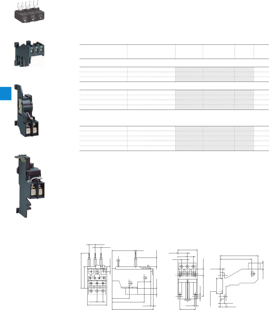
TA25DU thermal overload relays
Accessories
Description
The single mounting kits offer the possibility to mount the overload relays separately from the contactor.
The DS25-A allows electrically remote tripping of TA25DU. DR25-A coil for remote reset of TA25DU.
Ordering details
For thermal overload relays Description Type Order code Weight
(1 pce)
kg
Terminal block and mounting kits
TA25DU-0.16 … 25 / DB25/25 A Terminal block 10 mm² DX25 1SAZ201307R0002 0.030
TA25DU-0.16 … 25 Single mounting kit DB25/25A 1SAZ201108R0001 0.055
TA25DU-32 Single mounting kit DB25/32A 1SAZ201108R0002 0.080
Remote tripping coil
TA25DU 24/48 V, 50/60 Hz DS25-A-24 1SAZ201501R0001 0.050
TA25DU 110 V, 50/60Hz DS25-A-110 1SAZ201501R0003 0.050
TA25DU 220/380 V, 50/60 Hz DS25-A-220/380 1SAZ201501R0005 0.050
TA25DU 500 V, 50/60Hz DS25-A-500 1SAZ201501R0006 0.050
The remote tripping coil is to be connected to auxiliary contact 95-96 of TA25DU.
The coil is not suitable for Continuous operation. Impulse duration: maximum 0.2 seconds.
Remote reset coil
TA25DU 24 V, 50/60 Hz DR25-A-24 1SAZ201504R0001 0.050
TA25DU 48 V, 50/60 Hz DR25-A-48 1SAZ201504R0002 0.050
TA25DU 110 V, 50/60 Hz DR25-A-110 1SAZ201504R0003 0.050
TA25DU 220/380 V, 50/60 Hz DR25-A-220/380 1SAZ201504R0005 0.050
TA25DU 500 V, 50/60 Hz DR25-A-500 1SAZ201504R0006 0.050
The remote reset coil is to be connected to auxiliary contact 97-98 of TA25DU.
The coil is not suitable for Continuous operation. Impulse duration: maximum 0.2 seconds.
DX25
DB25/25A
DS25-A-220/380
DR25-A-220/380
Main dimensions mm, inches
44 1.73"
13.5 0.53"
49.5 1.95"
80 3.15"
13.5 0.53"
13.5 0.53"
12 0.47"
73.5 2.89"
94 3.7"
6 0.24"
20 0.79"14* 0.55"*
39 1.54"
52.2 2.06" 2.5 0.1"
2CDC232023F0011
4.2 0.17"
35 1.38"
7.5 0.3"
48 1.89"
14* 0.55" *
85.8 3.38"
71.5 2.81"
5.5 0.22"
35.5 1.4"
9 0.35"
14.5 0.57"
13 0.51"
21.5 0.85"
44 1.73"
13.5 0.53"
13.5 0.53"
DIN rail 35 EN60715
Hutschiene 35 EN60715
2CDC232024F0011
TA25DU + DX25 DB25
SST01494
2CDC231017F0006
SST20491
SST20591
6/14 | ABB
6
2CDC106039C0201
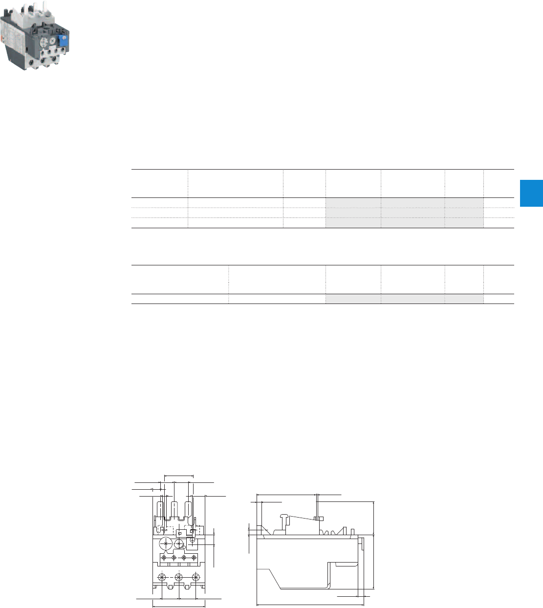
TA42DU thermal overload relays
18.0 … 42.0 A
Description
The TA42DU thermal overload relays are economic electromechanical protection devices for the main
circuit. They offer reliable protection for motors in the event of overload or phase failure. The devices have
trip class 10A.
The thermal overload relays are three pole relays with bimetal tripping elements. The motor current flows
through the bimetal tripping elements and heats them directly and indirectly. In case of an overload (over
current), the bimetal elements bent as a result of the heating. This leads to a release of the relay and a
change of the contacts switching position (95-96 / 97-98).
– Manual or automatic reset selectable
– Phase loss sensitive acc. to IEC/EN 60947-4-1
– Two electrically isolated auxiliary contacts – 1 N.O. + 1 N.C.
– TEST and STOP function – Trip indication on the front
– Temperature compensation
– Suitable for three- and single-phase applications
Ordering details
Setting range Short-circuit
protective device
Trip class Type Order code Weight
(1 pce)
A kg
18 ... 25 63 A, Fuse type gG / 50 A aM 10A TA42DU-25 1SAZ311201R1001 0.335
22 ... 32 80 A, Fuse type gG / 63 A aM 10A TA42DU-32 1SAZ311201R1002 0.335
29 ... 42 100 A, Fuse type gG / 80 A aM 10A TA42DU-42 1SAZ311201R1003 0.335
Ordering details accessories
For thermal overload relays Description Type Order code Weight
(1 pce)
kg
TA42DU Single mounting kit DB80 1SAZ301110R0001 0.155
2CDC231006F0011
TA42DU-32
Main dimensions mm, inches
10 0.39"
5 0.2"
30 1.18"
14.4 0.57" 14.4 0.57"
7.9 0.3"
0.17"4.3 13 0.51"
17.5 0.69" 17.5 0.69"
54 2.13"
61.5 2.42" 1.5 0.06"
5 0.2"
34 1.34"56 2.2"
60.24"
110.5 4.35"
2CDC232015F0011
TA42DU
ABB | 6/15
6
2CDC106040C0201

Main circuit – Utilization characteristics according to IEC/EN
Type TA42DU
Standards
IEC 60947-1 / 60947-4-1 and EN 60947-1 / 60947-4-1
Rated operational voltage U
e
690 V AC
Rated frequency
DC, 50/60 Hz
Trip class
10A
Number of poles
3
Duty time
100 %
Operating frequency without early tripping
Up to 15 operations/h, see "Technical diagram – Intermittent periodic duty"
Rated impulse withstand voltage U
imp
6 kV
Rated insulation voltage U
i
690 V AC
Auxiliary circuit according to IEC/EN
Type TA42DU
Rated operational voltage U
e
500 V AC, 440 V DC
Conventional free air thermal current I
th
N.C., 95-96 10 A
N.O., 97-98 6 A
Rated frequency
DC, 50/60 Hz
Number of poles
1 N.O. + 1 N.C.
I
e
/ Rated operational current AC-15
acc. to IEC/EN 60947-5-1 for utilization category
110-120 V
N.C., 95-96 3.00 A
N.O., 97-98 3.00 A
220-230-240 V
N.C., 95-96 3.00 A
N.O., 97-98 3.00 A
440 V
N.C., 95-96 1.90 A
N.O., 97-98 1.00 A
480-500 V
N.C., 95-96 1.00 A
N.O., 97-98 1.00 A
I
e
/ Rated operational current DC-13
acc. to IEC/EN 60947-5-1 for utilization category
24 V
N.C., 95-96 1.25 A
N.O., 97-98 1.25 A
60 V
N.C., 95-96 0.25 A
N.O., 97-98 0.25 A
110-120-125 V
N.C., 95-96 0.25 A
N.O., 97-98 0.25 A
250 V
N.C., 95-96 0.12 A
N.O., 97-98 0.04 A
Minimum switching capacity
17 V / 3 mA
Short-circuit protective device
N.C., 95-96 10 A, Fuse type gG
N.O., 97-98 6 A, Fuse type gG
Rated impulse withstand voltage U
imp
6 kV
Rated insulation voltage U
i
690 V
Technical diagram – Intermittent periodic duty
140
120
0
20
40
60
80
100
0 20 40 60 80 100 (%)
t = 1 s
a
t = 1.5 s
a
t = 3 s
a
t = 5 s
a
t = 0.5 s
a
duty ratio
switching frequency
(Op/h)
2CDC232005F0211
ta: Motor starting time
TA42DU thermal overload relays
Technical data
6/16 | ABB
6
2CDC106040C0201

Main circuit – Utilization characteristics according to UL/CSA
Type TA42DU
Standards
UL 508, CSA 22.2 No. 14
Maximum operational voltage
600 V AC
Trip rating
125 % of FLA
Full load amps (FLA)
See table "Full load amps and short-circuit protective device"
Short-circuit rating RMS symmetrical
See table "Full load amps and short-circuit protective device"
Short-circuit protective device
See table "Full load amps and short-circuit protective device"
Auxiliary circuit according to UL/CSA
Type TA42DU
Contact rating
N.C., 95-96 C600
N.O., 97-98 B600
Conventional thermal current
5 A
Full load amps and short-circuit protective device
Type Full load amps
(FLA)
Short-circuit protective device
480 / 600 V AC
Short circuit rating
RMS symmetrical
Fuse type Listed circuit
breaker
Short circuit rating
RMS symmetrical
Listed circuit
breaker
Short circuit rating
RMS symmetrical
Fuse type
TA42DU-25
25 A 5 kA 80 A, K5/ RK5 80 A 35 / 18 kA 80 A 50 kA 100 A, Class J
TA42DU-32
32 A 5 kA 100 A, K5/ RK5 80 A 35 / 18 kA 80 A 50 kA 100 A, Class J
TA42DU-42
42 A 5 kA 150 A, K5/ RK5 80 A 35 / 18 kA 80 A 50 kA 200 A, Class J
TA42DU thermal overload relays
Technical data
ABB | 6/17
6
2CDC106040C0201

General technical data
Type TA42DU
Pollution degree
3
Phase loss sensitive
Yes
Ambient air temperature
Operation Open - compensated without derating
-25 ... +55 °C
Open
-25 ... +55 °C
Storage
-40 ... +70 °C
Ambient air temperature compensation
Continuous
Maximum operating altitude permissible
2000 m
Resistance to shock acc. to IEC 60068-2-27
12 g / 15 ms
Mounting position
Position 1-6
Mounting
Mount on the contactor and tighten the screws of the main circuit terminals or with single
mounting kit on DIN rail (35 mm)
Degree of protection
IP20
Electrical connection
Main circuit
Type TA42DU
Connecting capacity
Rigid
1 x
2 x
2.5 ... 25 mm²
2.5 ... 16 mm²
Flexible with insulated ferrule
1 x
2 x
2.5 ... 25 mm²
2.5 ... 10 mm²
Stranded acc. to UL/CSA
1 x or 2 x AWG 8-1
Flexible acc. to UL/CSA
1 x or 2 x AWG 8-1
Stripping length
14 mm
Tightening torques
4.5 Nm / 40 Ib.in
Connection screw
M6 (Pozidriv 2)
Auxiliary circuit
Type TA42DU
Connecting capacity
Rigid
1 x or 2 x 0.75 ... 4 mm²
Flexible with ferrule
1 x or 2 x 0.75 ... 2.5 mm²
Flexible with insulated ferrule
1 x or 2 x 0.75 ... 2.5 mm²
Flexible
1 x or 2 x 0.75 ... 2.5 mm²
Stranded acc. to UL/CSA
1 x or 2 x AWG 18-14
Flexible acc. to UL/CSA
1 x or 2 x AWG 18-14
Stripping length
9 mm
Tightening torques
0.8 ... 1.3 Nm / 12 Ib.in
Connection screw
M3.5 (Pozidriv 2)
TA42DU thermal overload relays
Technical data
6/18 | ABB
6
2CDC106040C0201
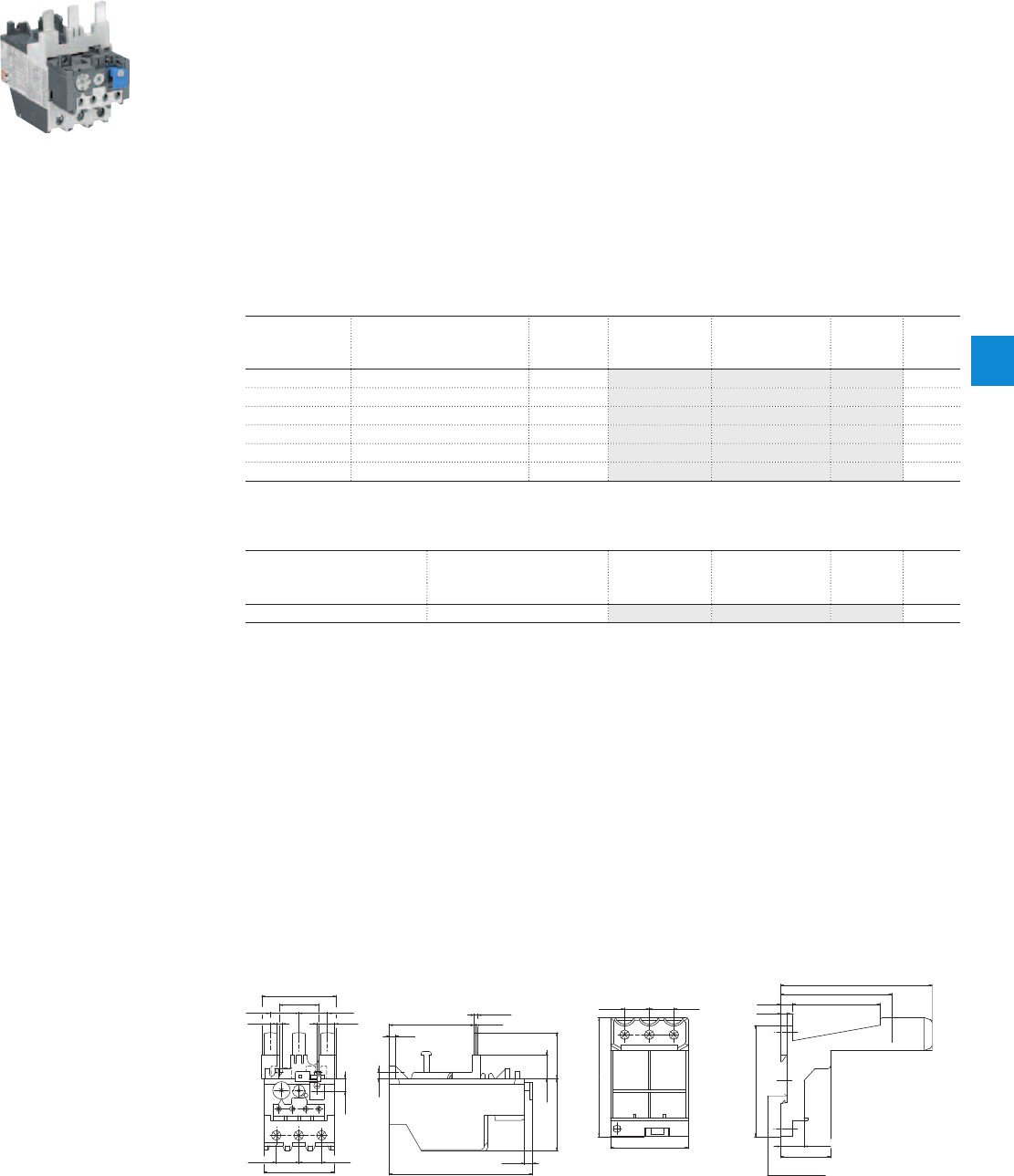
TA75DU thermal overload relays
18 … 80 A
Description
The TA75DU thermal overload relays are economic electromechanical protection devices for the main
circuit. They offer reliable protection for motors in the event of overload or phase failure. The devices have
trip class 10A.
The thermal overload relays are three pole relays with bimetal tripping elements. The motor current flows
through the bimetal tripping elements and heats them directly and indirectly. In case of an overload (over
current), the bimetal elements bent as a result of the heating. This leads to a release of the relay and a
change of the contacts switching position (95-96 / 97-98).
– Manual or automatic reset selectable
– Phase loss sensitive acc. to IEC/EN 60947-4-1
– Two electrically isolated auxiliary contacts – 1 N.O. + 1 N.C.
– TEST and STOP function – Trip indication on the front
– Temperature compensation
– Suitable for three- and single-phase applications
Ordering details
Setting range Short-circuit
protective device
Trip class Type Order code Weight
(1 pce)
A kg
18 ... 25 63 A, Fuse type gG / 50 A aM 10A TA75DU-25 1SAZ321201R1001 0.335
22 ... 32 80 A, Fuse type gG / 63 A aM 10A TA75DU-32 1SAZ321201R1002 0.335
29 ... 42 100 A, Fuse type gG / 80 A aM 10A TA75DU-42 1SAZ321201R1003 0.335
36 ... 52 125 A, Fuse type gG / 100 A aM 10A TA75DU-52 1SAZ321201R1004 0.335
45 ... 63 160 A, Fuse type gG / 125 A aM 10A TA75DU-63 1SAZ321201R1005 0.335
60 ... 80 200 A, Fuse type gG / 160 A aM 10A TA75DU-80 1SAZ321201R1006 0.370
Ordering details accessories
For thermal overload relays Description Type Order code Weight
(1 pce)
kg
TA75DU Single mounting kit DB80 1SAZ301110R0001 0.155
2CDC231007F0011
TA75DU-63
Main dimensions mm, inches
30 1.18"
22 0.87"
57.5 2.26"
22 0.87"
13 0.51"4.3 0.17" 67(65.5*) 2.64"(2.58")
10 0.39"
5 0.2"
5 0.2"
17.5 0.69" 17.5 0.69"
54 2.13"
6 0.24"
110.5 4.35"
18 0.71"
56 2.2" 35.5 1.4"
1.5 0.06"
(3*) (0.12"*)
2CDC232017F0011
19 0.75"19 0.75"
92 3.62"
60 2.36"
4.7 0.19"
9 0.35" 68 2.68"
86 3.39"
117 4.61"
86 3.39"
38.5 1.52"
18 0.71"
DIN rail 35 EN60715
Hutschiene 35 EN60715
2CDC232025F0011
TA75DU DB80
ABB | 6/19
6
2CDC106043C0201
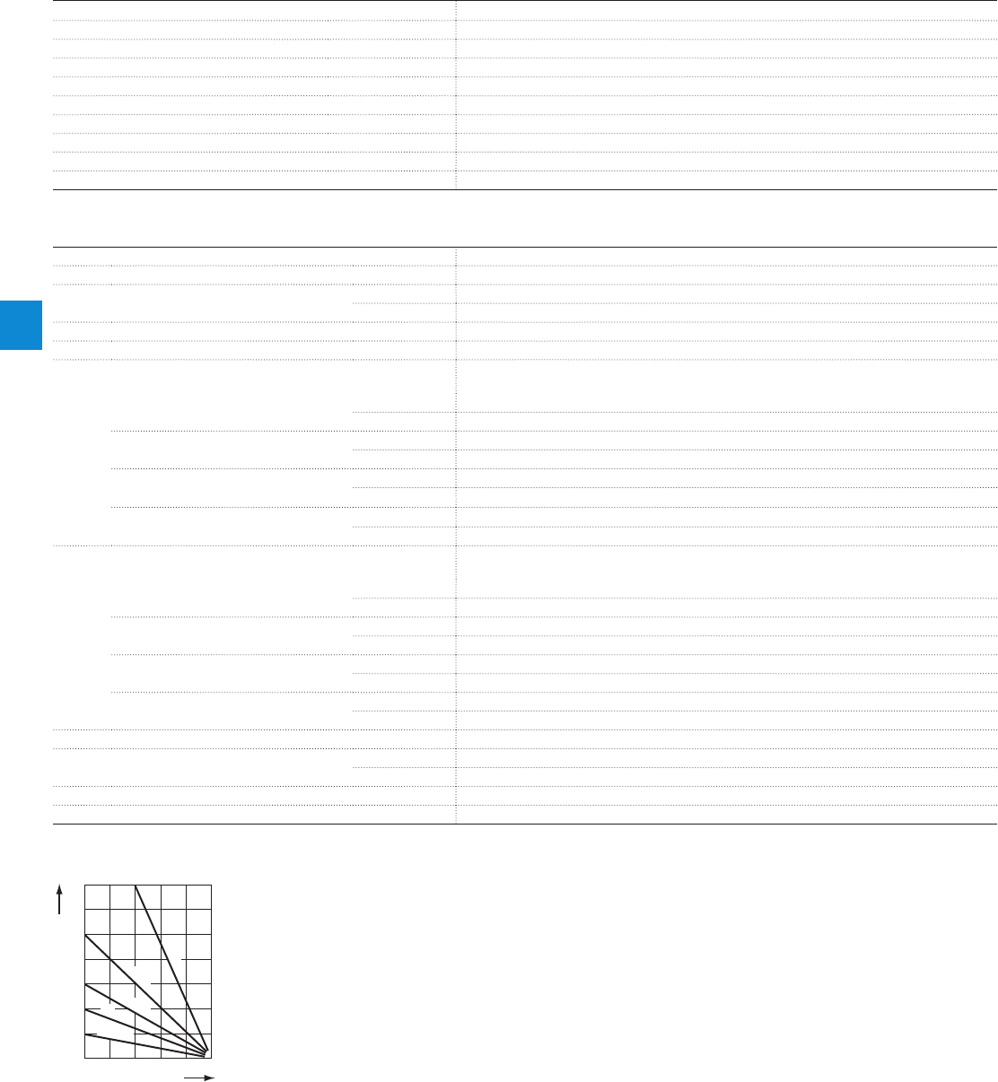
Main circuit – Utilization characteristics according to IEC/EN
Type TA75DU
Standards
IEC 60947-1 / 60947-4-1 and EN 60947-1 / 60947-4-1
Rated operational voltage U
e
690 V AC
Rated frequency
DC, 50/60 Hz
Trip class
10A
Number of poles
3
Duty time
100 %
Operating frequency without early tripping
Up to 15 operations/h, see "Technical diagram – Intermittent periodic duty"
Rated impulse withstand voltage U
imp
6 kV
Rated insulation voltage U
i
690 V AC
Auxiliary circuit according to IEC/EN
Type TA75DU
Rated operational voltage U
e
500 V AC, 440 V DC
Conventional free air thermal current I
th
N.C., 95-96 10 A
N.O., 97-98 6 A
Rated frequency
DC, 50/60 Hz
Number of poles
1 N.O. + 1 N.C.
I
e
/ Rated operational current AC-15
acc. to IEC/EN 60947-5-1 for utilization category
110-120 V
N.C., 95-96 3.00 A
N.O., 97-98 3.00 A
220-230-240 V
N.C., 95-96 3.00 A
N.O., 97-98 3.00 A
440 V
N.C., 95-96 1.90 A
N.O., 97-98 1.00 A
480-500 V
N.C., 95-96 1.00 A
N.O., 97-98 1.00 A
I
e
/ Rated operational current DC-13
acc. to IEC/EN 60947-5-1 for utilization category
24 V
N.C., 95-96 1.25 A
N.O., 97-98 1.25 A
60 V
N.C., 95-96 0.25 A
N.O., 97-98 0.25 A
110-120-125 V
N.C., 95-96 0.25 A
N.O., 97-98 0.25 A
250 V
N.C., 95-96 0.12 A
N.O., 97-98 0.04 A
Minimum switching capacity
17 V / 3 mA
Short-circuit protective device
N.C., 95-96 10 A, Fuse type gG
N.O., 97-98 6 A, Fuse type gG
Rated impulse withstand voltage U
imp
6 kV
Rated insulation voltage U
i
690 V
Technical diagram – Intermittent periodic duty
140
120
0
20
40
60
80
100
0 20 40 60 80 100 (%)
t = 1 s
a
t = 1.5 s
a
t = 3 s
a
t = 5 s
a
t = 0.5 s
a
duty ratio
switching frequency
(Op/h)
2CDC232005F0211
ta: Motor starting time
TA75DU thermal overload relays
Technical data
6/20 | ABB
6
2CDC106043C0201

Main circuit – Utilization characteristics according to UL/CSA
Type TA75DU
Standards
UL 508, CSA 22.2 No. 14
Maximum operational voltage
600 V AC
Trip rating
125 % of FLA
Full load amps (FLA)
See table "Full load amps and short-circuit protective device"
Short-circuit rating RMS symmetrical
See table "Full load amps and short-circuit protective device"
Short-circuit protective device
See table "Full load amps and short-circuit protective device"
Auxiliary circuit according to UL/CSA
Type TA75DU
Contact rating
N.C., 95-96 C600
N.O., 97-98 B600
Conventional thermal current
5 A
Full load amps and short-circuit protective device
Type Full load amps (FLA) Short-circuit protective device
480 / 600 V AC
Short circuit rating RMS symmetrical Fuse type Listed circuit breaker
TA75DU-25
25 A 5 kA 80 A, K5 / RK5 80 A
TA75DU-32
32 A 5 kA 100 A, K5 / RK5 80 A
TA75DU-42
42 A 5 kA 150 A, K5 / RK5 80 A
TA75DU-52
52 A 5 kA 175 A, K5 / RK5 125 A
TA75DU-63
63 A 10 kA 200 A, K5 / RK5 125 A
TA75DU-80
80 A 10 kA 250 A, K5 / RK5 125 A
TA75DU thermal overload relays
Technical data
ABB | 6/21
6
2CDC106043C0201

General technical data
Type TA75DU
Pollution degree
3
Phase loss sensitive
Yes
Ambient air temperature
Operation Open - compensated without derating
-25 ... +55 °C
Open
-25 ... +55 °C
Storage
-40 ... +70 °C
Ambient air temperature compensation
Continuous
Maximum operating altitude permissible
2000 m
Resistance to shock acc. to IEC 60068-2-27
12 g / 15 ms
Mounting position
Position 1-6
Mounting
Mount on the contactor and tighten the screws of the main circuit terminals or with single
mounting kit on DIN rail (35 mm)
Degree of protection
IP20
Electrical connection
Main circuit
Type TA75DU
Connecting capacity
Rigid
1 x
2 x
2.5 ... 25 mm²
2.5 ... 16 mm²
Flexible with insulated ferrule
1 x
2 x
2.5 ... 25 mm²
2.5 ... 10 mm²
Stranded acc. to UL/CSA
1 x or 2 x AWG 8-1
Flexible acc. to UL/CSA
1 x or 2 x AWG 8-1
Stripping length
14 mm
Tightening torques
4.5 Nm / 40 Ib.in
Connection screw
M6 (Pozidriv 2)
Auxiliary circuit
Type TA75DU
Connecting capacity
Rigid
1 x or 2 x 0.75 ... 4 mm²
Flexible with ferrule
1 x or 2 x 0.75 ... 2.5 mm²
Flexible with insulated ferrule
1 x or 2 x 0.75 ... 2.5 mm²
Flexible
1 x or 2 x 0.75 ... 2.5 mm²
Stranded acc. to UL/CSA
1 x or 2 x AWG 18-14
Flexible acc. to UL/CSA
1 x or 2 x AWG 18-14
Stripping length
9 mm
Tightening torques
0.8 ... 1.3 Nm / 12 Ib.in
Connection screw
M3.5 (Pozidriv 2)
TA75DU thermal overload relays
Technical data
6/22 | ABB
6
2CDC106043C0201
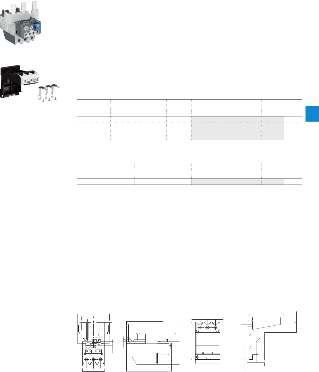
TA80DU thermal overload relays
29 … 80 A
Description
The TA80DU thermal overload relays are economic electromechanical protection devices for the main
circuit. They offer reliable protection for motors in the event of overload or phase failure. The devices have
trip class 10A.
The thermal overload relays are three pole relays with bimetal tripping elements. The motor current flows
through the bimetal tripping elements and heats them directly and indirectly. In case of an overload (over
current), the bimetal elements bent as a result of the heating. This leads to a release of the relay and a
change of the contacts switching position (95-96 / 97-98).
– Manual or automatic reset selectable
– Phase loss sensitive acc. to IEC/EN 60947-4-1
– Two electrically isolated auxiliary contacts – 1 N.O. + 1 N.C.
– TEST and STOP function – Trip indication on the front
– Temperature compensation
– Suitable for three- and single-phase applications
Ordering details
Setting range Short-circuit
protective device
Trip class Type Order code Weight
(1 pce)
A kg
29 ... 42 100 A, Fuse type gG / 80 A aM 10A TA80DU-42 1SAZ331201R1003 0.360
36 ... 52 125 A, Fuse type gG / 100 A aM 10A TA80DU-52 1SAZ331201R1004 0.365
45 ... 63 160 A, Fuse type gG / 125 A aM 10A TA80DU-63 1SAZ331201R1005 0.365
60 ... 80 200 A, Fuse type gG / 160 A aM 10A TA80DU-80 1SAZ331201R1006 0.375
Ordering details accessories
For thermal overload relay Description Type Order code Weight
(1 pce)
kg
TA80DU Single mounting kit DB80 1SAZ301110R0001 0.155
2CDC231008F0011
TA80DU-80
2CDC231007S0010
DB80
Main dimensions mm, inches
19 0.75"
56 2.2" 41 1.61"
6 0.24"
110.5 4.35"
10 0.39"
5 0.2"
70 2.76" 2.5 0.1"
5 0.2"
78 3.07"
17.5 0.69" 17.5 0.69"
54 2.13"
30 1.18" 30 1.18"
13 0.51"4.3 0.17"
30 1.18"
2CDC232018F0011
19 0.75"19 0.75"
92 3.62"
60 2.36"
4.7 0.19"
9 0.35" 68 2.68"
86 3.39"
117 4.61"
86 3.39"
38.5 1.52"
18 0.71"
DIN rail 35 EN60715
Hutschiene 35 EN60715
2CDC232025F0011
TA80DU DB80
ABB | 6/23
6
2CDC106044C0201

Main circuit – Utilization characteristics according to IEC/EN
Type TA80DU
Standards
IEC 60947-1 / 60947-4-1 and EN 60947-1 / 60947-4-1
Rated operational voltage U
e
690 V AC
Rated frequency
DC, 50/60 Hz
Frequency range
0 ... 400 Hz
Trip class
10A
Number of poles
3
Duty time
100 %
Operating frequency without early tripping
Up to 15 operations/h, see "Technical diagram – Intermittent periodic duty"
Rated impulse withstand voltage U
imp
6 kV
Rated insulation voltage U
i
690 V AC
Auxiliary circuit according to IEC/EN
Type TA80DU
Rated operational voltage U
e
500 V AC, 440 V DC
Conventional free air thermal current I
th
N.C., 95-96 10 A
N.O., 97-98 6 A
Rated frequency
DC, 50/60 Hz
Number of poles
1 N.O. + 1 N.C.
I
e
/ Rated operational current AC-15
acc. to IEC/EN 60947-5-1 for utilization category
110-120 V
N.C., 95-96 3.00 A
N.O., 97-98 3.00 A
220-230-240 V
N.C., 95-96 3.00 A
N.O., 97-98 3.00 A
440 V
N.C., 95-96 1.90 A
N.O., 97-98 1.00 A
480-500 V
N.C., 95-96 1.00 A
N.O., 97-98 1.00 A
I
e
/ Rated operational current DC-13
acc. to IEC/EN 60947-5-1 for utilization category
24 V
N.C., 95-96 1.25 A
N.O., 97-98 1.25 A
60 V
N.C., 95-96 0.25 A
N.O., 97-98 0.25 A
110-120-125 V
N.C., 95-96 0.25 A
N.O., 97-98 0.25 A
250 V
N.C., 95-96 0.12 A
N.O., 97-98 0.04 A
Minimum switching capacity
17 V / 3 mA
Short-circuit protective device
N.C., 95-96 10 A, Fuse type gG
N.O., 97-98 6 A, Fuse type gG
Rated impulse withstand voltage U
imp
6 kV
Rated insulation voltage U
i
690 V
Technical diagram – Intermittent periodic duty
140
120
0
20
40
60
80
100
0 20 40 60 80 100 (%)
t = 1 s
a
t = 1.5 s
a
t = 3 s
a
t = 5 s
a
t = 0.5 s
a
duty ratio
switching frequency
(Op/h)
2CDC232005F0211
ta: Motor starting time
TA80DU thermal overload relays
Technical data
6/24 | ABB
6
2CDC106044C0201

Main circuit – Utilization characteristics according to UL/CSA
Type TA80DU
Standards
UL 508, CSA 22.2 No. 14
Maximum operational voltage
600 V AC
Trip rating
125 % of FLA
Full load amps (FLA)
See table "Full load amps and short-circuit protective device"
Short-circuit rating RMS symmetrical
See table "Full load amps and short-circuit protective device"
Short-circuit protective device
See table "Full load amps and short-circuit protective device"
Auxiliary circuit according to UL/CSA
Type TA80DU
Contact rating
N.C., 95-96 C600
N.O., 97-98 B600
Conventional thermal current
5 A
Full load amps and short-circuit protective device
Type Full load amps (FLA) Short-circuit protective device
480 / 600 V AC
Short circuit rating RMS symmetrical Fuse type Listed circuit breaker
TA80DU-42
42 A 5 kA 150 A, K5 / RK5 80 A
TA80DU-52
52 A 5 kA 175 A, K5 / RK5 125 A
TA80DU-63
63 A 10 kA 200 A, K5 / RK5 125 A
TA80DU-80
80 A 10 kA 250 A, K5 / RK5 125 A
TA80DU thermal overload relays
Technical data
ABB | 6/25
6
2CDC106044C0201

General technical data
Type TA80DU
Pollution degree
3
Phase loss sensitive
Yes
Ambient air temperature
Operation Open - compensated without derating
-25 ... +55 °C
Open
-25 ... +55 °C
Storage
-40 ... +70 °C
Ambient air temperature compensation
Continuous
Maximum operating altitude permissible
2000 m
Resistance to shock acc. to IEC 60068-2-27
12 g / 15 ms
Mounting position
Position 1-6
Mounting
Mount on the contactor and tighten the screws of the main circuit terminals or with single
mounting kit on DIN rail (35 mm)
Degree of protection
IP20
Electrical connection
Main circuit
Type TA80DU
Connecting capacity
Rigid
1 x
2 x
2.5 ... 25 mm²
2.5 ... 16 mm²
Flexible with insulated ferrule
1 x
2 x
2.5 ... 25 mm²
2.5 ... 10 mm²
Stranded acc. to UL/CSA
1 x or 2 x AWG 8-1
Flexible acc. to UL/CSA
1 x or 2 x AWG 8-1
Stripping length
14 mm
Tightening torques
4.5 Nm / 40 Ib.in
Connection screw
M6 (Pozidriv 2)
Auxiliary circuit
Type TA80DU
Connecting capacity
Rigid
1 x or 2 x 0.75 ... 4 mm²
Flexible with ferrule
1 x or 2 x 0.75 ... 2.5 mm²
Flexible with insulated ferrule
1 x or 2 x 0.75 ... 2.5 mm²
Flexible
1 x or 2 x 0.75 ... 2.5 mm²
Stranded acc. to UL/CSA
1 x or 2 x AWG 18-14
Flexible acc. to UL/CSA
1 x or 2 x AWG 18-14
Stripping length
9 mm
Tightening torques
0.8 ... 1.3 Nm / 12 Ib.in
Connection screw
M3.5 (Pozidriv 2)
TA80DU thermal overload relays
Technical data
6/26 | ABB
6
2CDC106044C0201
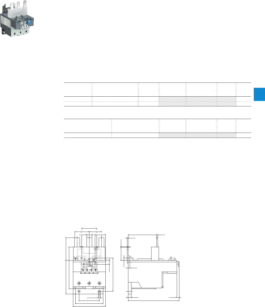
TA110DU thermal overload relays
66 … 110 A
Description
The TA110DU thermal overload relays are economic electromechanical protection devices for the main
circuit. They offer reliable protection for motors in the event of overload or phase failure. The devices have
trip class 10A.
The thermal overload relays are three pole relays with bimetal tripping elements. The motor current flows
through the bimetal tripping elements and heats them directly and indirectly. In case of an overload (over
current), the bimetal elements bent as a result of the heating. This leads to a release of the relay and a
change of the contacts switching position (95-96 / 97-98).
– Manual or automatic reset selectable
– Phase loss sensitive acc. to IEC/EN 60947-4-1
– Two electrically isolated auxiliary contacts – 1 N.O. + 1 N.C.
– TEST and STOP function – Trip indication on the front
– Temperature compensation
– Suitable for three- and single-phase applications
Ordering details
Setting range Short-circuit
protective device
Trip class Type Order code Weight
(1 pce)
A kg
66 ... 90 200 A, Fuse type gG / 160 A aM 10A TA110DU-90 1SAZ411201R1001 0.750
80 ... 110 224 A, Fuse type gG / 200 A aM 10A TA110DU-110 1SAZ411201R1002 0.755
Ordering details accessories
For thermal overload relays Description Type Order code Weight
(1 pce)
kg
TA110DU Single mounting kit DB200 1SAZ401110R0001 0.225
2CDC231009F0011
TA110DU-110
Main dimensions mm, inches
8 0.31"
126 4.96"
6 0.24"
6 0.24"
32 1.26"
10 0.39"
82.3 3.24"
4 0.16"
70 2.76" 3 0.12"
2 0.08"
2 0.08"
13 0.51" 26 1.02"
37 1.46"
30 1.18"30 1.4"
70 2.76" 33 1.3"
83 3.27" 56 2.2"
Ø 5.3 Ø 0.21"
50 1.97"
68 2.68"
80 3.15"
2CDC232020F0011
TA110DU
ABB | 6/27
6
2CDC106037C0201

Main circuit – Utilization characteristics according to IEC/EN
Type TA110DU
Standards
IEC 60947-1 / 60947-4-1 and EN 60947-1 / 60947-4-1
Rated operational voltage U
e
690 V AC
Rated frequency
DC, 50/60 Hz
Frequency range
0 ... 400 Hz
Trip class
10A
Number of poles
3
Duty time
100 %
Operating frequency without early tripping
Up to 15 operations/h, see "Technical diagram – Intermittent periodic duty"
Rated impulse withstand voltage U
imp
6 kV
Rated insulation voltage U
i
690 V AC
Auxiliary circuit according to IEC/EN
Type TA110DU
Rated operational voltage U
e
500 V AC, 440 V DC
Conventional free air thermal current I
th
N.C., 95-96 10 A
N.O., 97-98 6 A
Rated frequency
DC, 50/60 Hz
Number of poles
1 N.O. + 1 N.C.
I
e
/ Rated operational current AC-15
acc. to IEC/EN 60947-5-1 for utilization category
110-120 V
N.C., 95-96 3.00 A
N.O., 97-98 3.00 A
220-230-240 V
N.C., 95-96 3.00 A
N.O., 97-98 3.00 A
440 V
N.C., 95-96 1.90 A
N.O., 97-98 1.00 A
480-500 V
N.C., 95-96 1.00 A
N.O., 97-98 1.00 A
I
e
/ Rated operational current DC-13
acc. to IEC/EN 60947-5-1 for utilization category
24 V
N.C., 95-96 1.25 A
N.O., 97-98 1.25 A
60 V
N.C., 95-96 0.25 A
N.O., 97-98 0.25 A
110-120-125 V
N.C., 95-96 0.25 A
N.O., 97-98 0.25 A
250 V
N.C., 95-96 0.12 A
N.O., 97-98 0.04 A
Minimum switching capacity
17 V / 3 mA
Short-circuit protective device
N.C., 95-96 10 A, Fuse type gG
N.O., 97-98 6 A, Fuse type gG
Rated impulse withstand voltage U
imp
6 kV
Rated insulation voltage U
i
690 V
Technical diagram – Intermittent periodic duty
140
120
0
20
40
60
80
100
0 20 40 60 80 100 (%)
t = 1 s
a
t = 1.5 s
a
t = 3 s
a
t = 5 s
a
t = 0.5 s
a
duty ratio
switching frequency
(Op/h)
2CDC232005F0211
ta: Motor starting time
TA110DU thermal overload relays
Technical data
6/28 | ABB
6
2CDC106037C0201

Main circuit – Utilization characteristics according to UL/CSA
Type TA110DU
Standards
UL 508, CSA 22.2 No. 14
Maximum operational voltage
600 V AC
Trip rating
125 % of FLA
Full load amps (FLA)
See table "Full load amps and short-circuit protective device"
Short-circuit rating RMS symmetrical
See table "Full load amps and short-circuit protective device"
Short-circuit protective device
See table "Full load amps and short-circuit protective device"
Auxiliary circuit according to UL/CSA
Type TA110DU
Contact rating
N.C., 95-96 C600
N.O., 97-98 B600
Conventional thermal current
5 A
Full load amps and short-circuit protective device
Type Full load amps
(FLA)
Short-circuit protective device
480 / 600 V AC
Short circuit rating
RMS symmetrical
Fuse type Listed circuit
breaker
Short circuit rating
RMS symmetrical
Fuse type Short circuit rating
RMS symmetrical
Listed circuit
breaker
TA110DU-90
90 A 10 kA 250 A, K5 / RK5 150 A 65 kA 200 A, Class J 65 / 25 kA 150 A
TA110DU-110
110 A 10 kA 250 A, K5 / RK5 250 A 65 kA 200 A, Class J 65 / 25 kA 150 A
TA110DU thermal overload relays
Technical data
ABB | 6/29
6
2CDC106037C0201

General technical data
Type TA110DU
Pollution degree
3
Phase loss sensitive
Yes
Ambient air temperature
Operation Open - compensated without derating
-25 ... +55 °C
Open
-25 ... +55 °C
Storage
-40 ... +70 °C
Ambient air temperature compensation
Continuous
Maximum operating altitude permissible
2000 m
Resistance to shock acc. to IEC 60068-2-27
12 g / 15 ms
Mounting position
Position 1-6
Mounting
Mount on the contactor and tighten the screws of the main circuit terminals or with single
mounting kit
Degree of protection
IP20
Electrical connection
Main circuit
Type TA110DU
Connecting capacity
Rigid
1 x
2 x
16 ... 35 mm²
-
Flexible
1 x
2 x
16 ... 35 mm²
-
Stranded acc. to UL/CSA
1 x or 2 x AWG 6-2/0
Flexible acc. to UL/CSA
1 x or 2 x AWG 6-2/0
Stripping length
25 mm
Tightening torques
7.2 ... 9.6 Nm / 40 Ib.in
Connection screw
M8 (Hexagon)
Auxiliary circuit
Type TA110DU
Connecting capacity
Rigid
1 x or 2 x 0.75 ... 4 mm²
Flexible with ferrule
1 x or 2 x 0.75 ... 2.5 mm²
Flexible with insulated ferrule
1 x or 2 x 0.75 ... 2.5 mm²
Flexible
1 x or 2 x 0.75 ... 2.5 mm²
Stranded acc. to UL/CSA
1 x or 2 x AWG 18-14
Flexible acc. to UL/CSA
1 x or 2 x AWG 18-14
Stripping length
9 mm
Tightening torques
0.8 ... 1.3 Nm / 12 Ib.in
Connection screw
M3.5 (Pozidriv 2)
TA110DU thermal overload relays
Technical data
6/30 | ABB
6
2CDC106037C0201
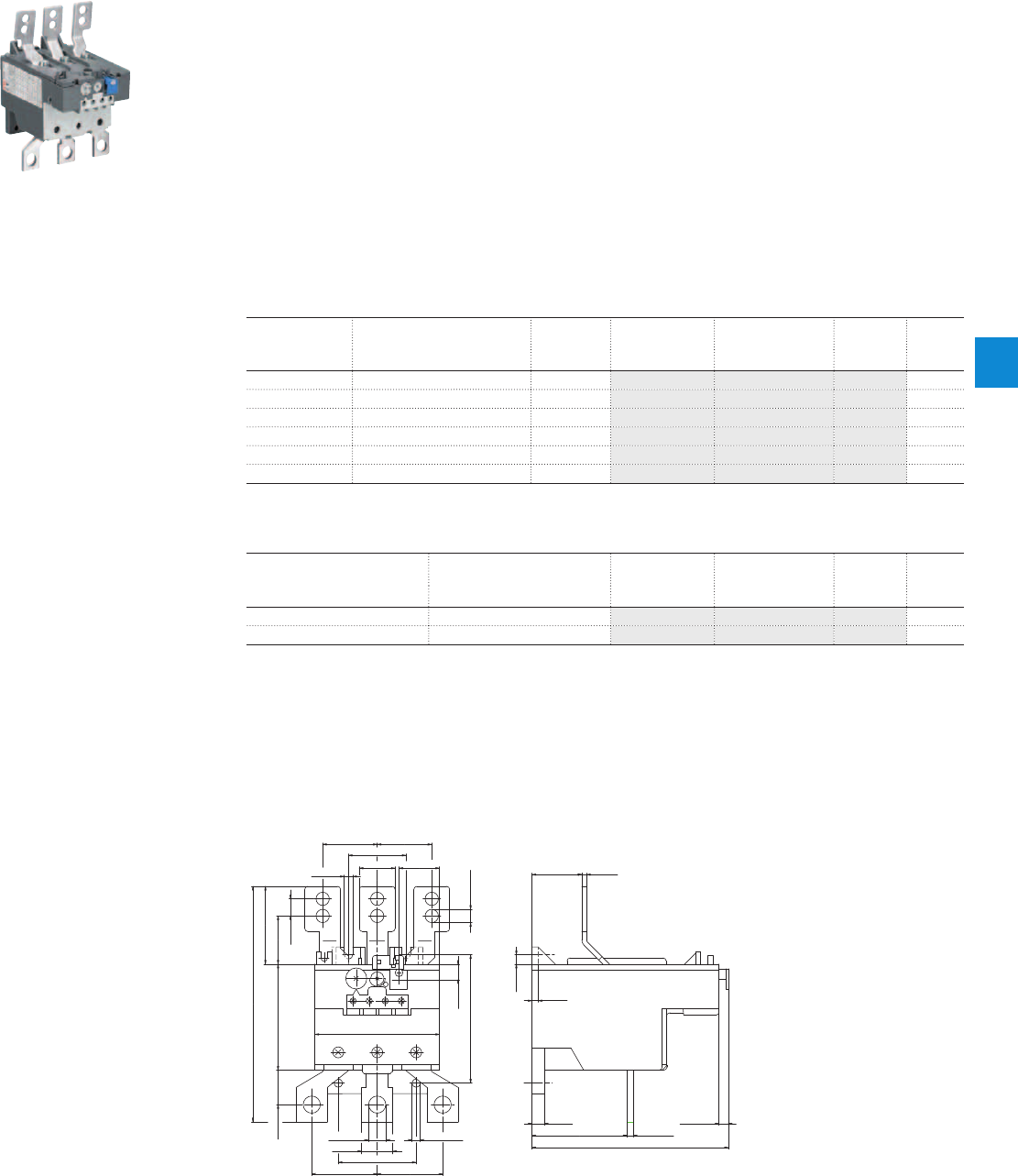
TA200DU thermal overload relays
66 … 200 A
Description
The TA200DU thermal overload relays are economic electromechanical protection devices for the main
circuit. They offer reliable protection for motors in the event of overload or phase failure. The devices have
trip class 10A.
The thermal overload relays are three pole relays with bimetal tripping elements. The motor current flows
through the bimetal tripping elements and heats them directly and indirectly. In case of an overload (over
current), the bimetal elements bent as a result of the heating. This leads to a release of the relay and a
change of the contacts switching position (95-96 / 97-98).
– Manual or automatic reset selectable
– Phase loss sensitive acc. to IEC/EN 60947-4-1
– Two electrically isolated auxiliary contacts – 1 N.O. + 1 N.C.
– TEST and STOP function – Trip indication on the front
– Temperature compensation
– Suitable for three- and single-phase applications
Ordering details
Setting range Short-circuit
protective device
Trip class Type Order code Weight
(1 pce)
A kg
66 ... 90 200 A, Fuse type gG / 160 A aM 10A TA200DU-90 1SAZ421201R1001 0.755
80 ... 110 224 A, Fuse type gG / 200 A aM 10A TA200DU-110 1SAZ421201R1002 0.760
100 ... 135 224 A, Fuse type gG / 200 A aM 10A TA200DU-135 1SAZ421201R1003 0.760
110 ... 150 250 A, Fuse type gG / 224 A aM 10A TA200DU-150 1SAZ421201R1004 0.760
130 ... 175 315 A, Fuse type gG / 250 A aM 10A TA200DU-175 1SAZ421201R1005 0.770
150 ... 200 315 A, Fuse type gG / 250 A aM 10A TA200DU-200 1SAZ421201R1006 0.785
Ordering details accessories
For thermal overload relays Description Type Order code Weight
(1 pce)
kg
TA200DU Terminal shroud LT200/A 1SAZ401901R1001 0.090
TA200DU Single mounting kit DB200 1SAZ401110R0001 0.225
2CDC231010F0011
TA200DU-200
Main dimensions mm, inches
4 0.16"61 2.4"
8 0.31"
126 4.96"
6 0.24"
4 0.16"
6 0.24"
32 1.26" 3 0.12"
23 0.91"
26 1.02"
37 1.46"
35 1.38"35 1.38"
Ø8.5 Ø0.33"
5.5 0.22"
82.3 3.24"
11 0.43"
30.9 1.22"
49.9 2"
151 5.94"
10 0.39"
68 2.68"
80 3.15"
Ø 11 Ø 0.43"
20 0.79"
22.1 0.87"
Ø 5.3 Ø 0.21"
42 1.65"42 1.65"
50 1.97"
2CDC232021F0011
TA200DU
ABB | 6/31
6
2CDC106038C0201

Main circuit – Utilization characteristics according to IEC/EN
Type TA200DU
Standards
IEC 60947-1 / 60947-4-1 and EN 60947-1 / 60947-4-1
Rated operational voltage U
e
690 V AC
Rated frequency
DC, 50/60 Hz
Frequency range
0 ... 400 Hz
Trip class
10A
Number of poles
3
Duty time
100 %
Operating frequency without early tripping
Up to 15 operations/h, see "Technical diagram – Intermittent periodic duty"
Rated impulse withstand voltage U
imp
6 kV
Rated insulation voltage U
i
690 V AC
Auxiliary circuit according to IEC/EN
Type TA200DU
Rated operational voltage U
e
500 V AC, 440 V DC
Conventional free air thermal current I
th
N.C., 95-96 10 A
N.O., 97-98 6 A
Rated frequency
DC, 50/60 Hz
Number of poles
1 N.O. + 1 N.C.
I
e
/ Rated operational current AC-15
acc. to IEC/EN 60947-5-1 for utilization category
110-120 V
N.C., 95-96 3.00 A
N.O., 97-98 3.00 A
220-230-240 V
N.C., 95-96 3.00 A
N.O., 97-98 3.00 A
440 V
N.C., 95-96 1.90 A
N.O., 97-98 1.00 A
480-500 V
N.C., 95-96 1.00 A
N.O., 97-98 1.00 A
I
e
/ Rated operational current DC-13
acc. to IEC/EN 60947-5-1 for utilization category
24 V
N.C., 95-96 1.25 A
N.O., 97-98 1.25 A
60 V
N.C., 95-96 0.25 A
N.O., 97-98 0.25 A
110-120-125 V
N.C., 95-96 0.25 A
N.O., 97-98 0.25 A
250 V
N.C., 95-96 0.12 A
N.O., 97-98 0.04 A
Minimum switching capacity
17 V / 3 mA
Short-circuit protective device
N.C., 95-96 10 A, Fuse type gG
N.O., 97-98 6 A, Fuse type gG
Rated impulse withstand voltage U
imp
6 kV
Rated insulation voltage U
i
690 V
Technical diagram – Intermittent periodic duty
140
120
0
20
40
60
80
100
0 20 40 60 80 100 (%)
t = 1 s
a
t = 1.5 s
a
t = 3 s
a
t = 5 s
a
t = 0.5 s
a
duty ratio
switching frequency
(Op/h)
2CDC232005F0211
ta: Motor starting time
TA200DU thermal overload relays
Technical data
6/32 | ABB
6
2CDC106038C0201

Main circuit – Utilization characteristics according to UL/CSA
Type TA200DU
Standards
UL 508, CSA 22.2 No. 14
Maximum operational voltage
600 V AC
Trip rating
125 % of FLA
Full load amps (FLA)
See table "Full load amps and short-circuit protective device"
Short-circuit rating RMS symmetrical
See table "Full load amps and short-circuit protective device"
Short-circuit protective device
See table "Full load amps and short-circuit protective device"
Auxiliary circuit according to UL/CSA
Type TA200DU
Contact rating
N.C., 95-96 C600
N.O., 97-98 B600
Conventional thermal current
5 A
Full load amps and short-circuit protective device
Type Full load amps
(FLA)
Short-circuit protective device
480 / 600 V AC
Short circuit rating
RMS symmetrical
Fuse type Listed circuit
breaker
Short circuit rating
RMS symmetrical
Fuse type Short circuit rating
RMS symmetrical
Listed circuit
breaker
TA200DU-90
90 A 10 kA 250 A, K5 / RK5 225 A ----
TA200DU-110
110 A 10 kA 250 A, K5 / RK5 225 A - - 18 kA 125 A
TA200DU-135
135 A 10 kA 300 A, K5 / RK5 225 A 50 kA 400 A, Class J 35 / 18 kA 225 A
TA200DU-150
150 A 10 kA 300 A, K5 / RK5 225 A 65 kA 400 A, Class J 35 / 18 kA 225 A
TA200DU-175
175 A 10 kA 300 A, K5 / RK5 225 A 65 kA 400 A, Class J 35 / 18 kA 225 A
TA200DU-200
200 A 10 kA 400 A, K5 / RK5 400 A 65 kA 400 A, Class J 35 / 18 kA 225 A
TA200DU thermal overload relays
Technical data
ABB | 6/33
6
2CDC106038C0201

General technical data
Type TA200DU
Pollution degree
3
Phase loss sensitive
Yes
Ambient air temperature
Operation Open - compensated without derating
-25 ... +55 °C
Open
-25 ... +55 °C
Storage
-40 ... +70 °C
Ambient air temperature compensation
Continuous
Maximum operating altitude permissible
2000 m
Resistance to shock acc. to IEC 60068-2-27
12 g / 15 ms
Mounting position
Position 1-6
Mounting
Mount on the contactor and tighten the screws of the main circuit terminals or with single
mounting kit
Degree of protection
IP20
Electrical connection
Main circuit
Type TA200DU
Connecting capacity
Rigid
1 x 25 ... 120 mm²
Flexible
1 x 16 ... 35 mm²
L
l
Lugs
L ≤ 12 mm / l > 6 mm
Tightening torques
4 Nm
Connection screw
M6
Auxiliary circuit
Type TA200DU
Connecting capacity
Rigid
1 x or 2 x 0.75 ... 4 mm²
Flexible with ferrule
1 x or 2 x 0.75 ... 2.5 mm²
Flexible with insulated ferrule
1 x or 2 x 0.75 ... 2.5 mm²
Flexible
1 x or 2 x 0.75 ... 2.5 mm²
Stranded acc. to UL/CSA
1 x or 2 x AWG 18-14
Flexible acc. to UL/CSA
1 x or 2 x AWG 18-14
Stripping length
9 mm
Tightening torques
0.8 ... 1.3 Nm / 12 Ib.in
Connection screw
M3.5 (Pozidriv 2)
TA200DU thermal overload relays
Technical data
6/34 | ABB
6
2CDC106038C0201
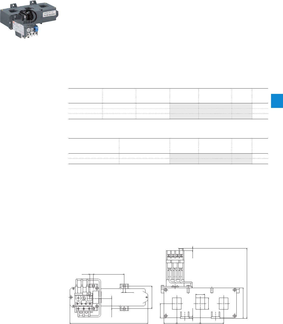
TA450DU thermal overload relays
130 ... 310 A
Description
The TA450DU thermal overload relays are economic electromechanical protection devices for the main
circuit. They offer reliable protection for motors in the event of overload or phase failure. The devices have
trip class 10A.
The thermal overload relays are three pole relays with bimetal tripping elements. The motor current flows
through the bimetal tripping elements and heats them directly and indirectly. In case of an overload (over
current), the bimetal elements bent as a result of the heating. This leads to a release of the relay and a
change of the contacts switching position (95-96 / 97-98).
– Manual or automatic reset selectable
– Phase loss sensitive acc. to IEC/EN 60947-4-1
– Two electrically isolated auxiliary contacts – 1 N.O. + 1 N.C.
– TEST and STOP function – Trip indication on the front
– Temperature compensation
– Suitable for three- and single-phase applications
Ordering details
Setting range Short-circuit
protective device
Trip class Type Order code Weight
(1 pce)
A kg
130 ... 185 not applicable 10A TA450DU-185 1SAZ511201R1001 1.500
165 ... 235 not applicable 10A TA450DU-235 1SAZ511201R1002 1.500
220 ... 310 not applicable 10A TA450DU-310 1SAZ511201R1003 1.500
Ordering details accessories
For thermal overload relays Description Type Order code Weight
(1 pce)
kg
TA450DU Terminal shroud DT450/A185 1SAZ501901R1001 1.070
TA450DU Terminal shroud DT450/A300 1SAZ501902R1001 1.180
2CDC231011F0011
TA450DU-310
Main dimensions mm, inches
193 7.6"
24.5 0.96"
76.3 3"
55 2.17"
5.5 0.22"
9.1 0.36"
75.5 2.97"
35.2 1.39"
58 2.28"58 2.28"32 1.26"
22 0.87"
28.4 1.12"
4.5 0.18"
173.4 6.83"
6 0.24"
2CDC232022F0011
TA450DU
ABB | 6/35
6
2CDC106041C0201

Main circuit – Utilization characteristics according to IEC/EN
Type TA450DU
Standards
IEC 60947-1 / 60947-4-1 and EN 60947-1 / 60947-4-1
Rated operational voltage U
e
1000 V AC
Rated frequency
50/60 Hz
Trip class
10A
Number of poles
3
Duty time
100 %
Operating frequency without early tripping
Up to 15 operations/h, see "Technical diagram – Intermittent periodic duty"
Rated impulse withstand voltage U
imp
8 kV
Rated insulation voltage U
i
1000 V AC
Auxiliary circuit according to IEC/EN
Type TA450DU
Rated operational voltage U
e
500 V AC, 440 V DC
Conventional free air thermal current I
th
N.C., 95-96 10 A
N.O., 97-98 6 A
Rated frequency
DC, 50/60 Hz
Number of poles
1 N.O. + 1 N.C.
I
e
/ Rated operational current AC-15
acc. to IEC/EN 60947-5-1 for utilization category
110-120 V
N.C., 95-96 3.00 A
N.O., 97-98 3.00 A
220-230-240 V
N.C., 95-96 3.00 A
N.O., 97-98 3.00 A
440 V
N.C., 95-96 1.90 A
N.O., 97-98 1.00 A
480-500 V
N.C., 95-96 1.00 A
N.O., 97-98 1.00 A
I
e
/ Rated operational current DC-13
acc. to IEC/EN 60947-5-1 for utilization category
24 V
N.C., 95-96 1.25 A
N.O., 97-98 1.25 A
60 V
N.C., 95-96 0.25 A
N.O., 97-98 0.25 A
110-120-125 V
N.C., 95-96 0.25 A
N.O., 97-98 0.25 A
250 V
N.C., 95-96 0.12 A
N.O., 97-98 0.04 A
Minimum switching capacity
17 V / 3 mA
Short-circuit protective device
N.C., 95-96 10 A, Fuse type gG
N.O., 97-98 6 A, Fuse type gG
Rated impulse withstand voltage U
imp
6 kV
Rated insulation voltage U
i
500 V
Technical diagram – Intermittent periodic duty
140
120
0
20
40
60
80
100
0 20 40 60 80 100 (%)
t = 1 s
a
t = 1.5 s
a
t = 3 s
a
t = 5 s
a
t = 0.5 s
a
duty ratio
switching frequency
(Op/h)
2CDC232005F0211
ta: Motor starting time
TA450DU thermal overload relays
Technical data
6/36 | ABB
6
2CDC106041C0201

Main circuit – Utilization characteristics according to UL/CSA
Type TA450DU
Standards
UL 508, CSA 22.2 No. 14
Maximum operational voltage
600 V AC
Trip rating
125 % of FLA
Full load amps (FLA)
See table "Full load amps and short-circuit protective device"
Short-circuit rating RMS symmetrical
See table "Full load amps and short-circuit protective device"
Short-circuit protective device
See table "Full load amps and short-circuit protective device"
Auxiliary circuit according to UL/CSA
Type TA450DU
Contact rating
N.C., 95-96 C600
N.O., 97-98 B600
Conventional thermal current
5 A
Full load amps and short-circuit protective device
Type Full load amps (FLA) Short-circuit protective device
480 / 600 V AC
Short circuit rating RMS symmetrical Fuse type Listed circuit breaker
TA450DU-185
185 A 10 kA na na
TA450DU-235
235 A 10 kA na na
TA450DU-310
310 A 18 kA na na
TA450DU thermal overload relays
Technical data
ABB | 6/37
6
2CDC106041C0201

General technical data
Type TA450DU
Pollution degree
3
Phase loss sensitive
Yes
Ambient air temperature
Operation Open - compensated without derating
-25 ... +55 °C
Open
-25 ... +55 °C
Storage
-40 ... +70 °C
Ambient air temperature compensation
Continuous
Maximum operating altitude permissible
2000 m
Resistance to shock acc. to IEC 60068-2-27
12 g / 15 ms
Mounting position
Position 1-6
Degree of protection
IP20
Electrical connection
Main circuit
Type TA450DU
Connecting capacity
Bar Max. 21 x 28.4 mm
Auxiliary circuit
Type TA450DU
Connecting capacity
Rigid
1 x or 2 x 0.75 ... 4 mm²
Flexible with ferrule
1 x or 2 x 0.75 ... 2.5 mm²
Flexible with insulated ferrule
1 x or 2 x 0.75 ... 2.5 mm²
Flexible
1 x or 2 x 0.75 ... 2.5 mm²
Stranded acc. to UL/CSA
1 x or 2 x AWG 18-14
Flexible acc. to UL/CSA
1 x or 2 x AWG 18-14
Stripping length
9 mm
Tightening torques
0.8 ... 1.3 Nm / 12 Ib.in
Connection screw
M3.5 (Pozidriv 2)
TA450DU thermal overload relays
Technical data
6/38 | ABB
6
2CDC106041C0201
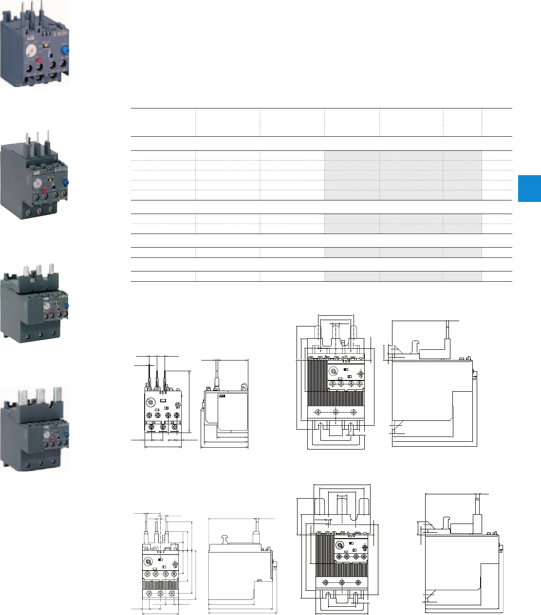
E16DU, E45DU, E80DU, E140DU electronic overload relays
0.10 to 140 A
Description
The E16DU up to E140DU are self-supplied electronic overload relays, which means no extra external
supply is needed. It offers reliable protection for motors in the event of overload or phase failure. Easy to
use like a thermal overload relay and compatible with standard motor applications, the electronic overload
relay is convincing, above all, due to its wide setting range, high accuracy, high operational temperature
range and the possibility to select a trip class (10E, 20E, 30E). Further features are the temperature
compensation, trip contact (N.C.), signal contact (N.O.), automatic or manual reset selectable, trip-free
mechanism, STOP and TEST function and a trip indication. The overload relays are connected directly to
the contactors. Single mounting kits are available as accessory.
Ordering details
Setting range Short-circuit
protective device
Trip class Type Order code Weight
(1 pce)
A kg
E16DU electronic overload relays
0.10 … 0.32 1 A, Fuse type gG 10E, 20E, 30E E16DU-0.32 1SAX111001R1101 0.150
0.30 … 1.00 4 A, Fuse type gG 10E, 20E, 30E E16DU-1.0 1SAX111001R1102 0.150
0.80 … 2.70 10 A, Fuse type gG 10E, 20E, 30E E16DU-2.7 1SAX111001R1103 0.150
1.90 … 6.30 20 A, Fuse type gG 10E, 20E, 30E E16DU-6.3 1SAX111001R1104 0.150
5.70 … 18.9 50 A, Fuse type gG 10E, 20E, 30E E16DU-18.9 1SAX111001R1105 0.150
E45DU electronic overload relays
9.00 … 30.0 160 A, Fuse type gG 10E, 20E, 30E E45DU-30 1SAX211001R1101 0.350
15.0 … 45.0 160 A, Fuse type gG 10E, 20E, 30E E45DU-45 1SAX211001R1102 0.350
E80DU electronic overload relay
27.0 ... 80.0 A 250 A 10E, 20E, 30E E80DU-80 1SAX311001R1101 0.770
E140DU electronic overload relay
50.0 ... 140.0 A 400 A 10E, 20E, 30E E140DU-140 1SAX321001R1101 0.915
Main dimensions mm, inches
37.5 1.48"
36.3 1.43"2,4 0.37"
74.6 2.94"
5.65 0.22"
10.3 0.41"
8.2 0.32" 14 0.55"
44.4 1.75"
9.3 0.37" 9.3 0.37"
1.2 0.5"
57 2.24"
53 2.09"
2CDC232007F0011
66.4 2.61"
74.5 2.93"
3 0.12"
99 3.90"
104.4 4.11"
3 0.12"
3 0.12"
8 0.32"
18 0.71"
8 0.32"
43.7 1.72"
37 1.46"
94.2 3.71"
14 0.55"
42 1.65"
15 0.59"
26.5 1.04"
38.4 1.51"
74.2 2.92"
85.2 3.35"
16 0.63"
37 1.46"
58 2.28"
70 2.76"
5.5 0.22"
2CDC232010F0011
E16DU E80DU
59.4 2.39" 2.5 0.10"
57 2.24"
79.7 3.14"
85.1 3.35"
17 0.67"
4 0.16"
2 0.08"
6.8 0.27"
14 0.55"
5.7 0.22"
8.5 0.33"
45 1.77"
9.6 0.38"
23.6 0.93"
36 1.42"
29.2 1.15"
38.4 1.51"
53.5 2.11"
61 2.40"
10.3 0.41"
2CDC232009F0011
94.2 3.71"
16 0.63" 5.5 0.22"
37 1.46"
58 2.28"
70 2.76"
74.2 2.92"
85.2 3.35"
2 0.08"
15 0.59"
49 1.93"
5.5 0.21"
37 1.46"
59.7 2.35
"
76 2.30
"
38.4 1.51"
14 0.55"
99 3.90"
104.4 4.11"
3 0.12"
8 0.12"
18 0.71"
67.6 2.66" 5 0.20"
74.5 2.93"
3 0.12"
13 0.51"
27.3 1.07"
2CDC232008F0011
E45DU E140DU
2CDC231001F0007
E16DU-1.0
2CDC231002F0006
E45DU-30
2CDC231003F0006
E80DU-80
2CDC231004F0006
E140DU-140
ABB | 6/39
6
2CDC107030C0201
Main circuit – Utilization characteristics according to IEC/EN
Type E16DU E45DU E80DU E140DU
Standards
IEC 60947-1 / 60947-4-1 / 60947-5-1 and EN 60947-1 / 60947-4-1 / 60947-5-1
Rated operational voltage U
e
690 V AC 1000 V AC
Rated frequency
50/60 Hz
Trip class
10E, 20E, 30E, selectable
Number of poles
3
Duty time
100 %
Operating frequency without early tripping
Up to 15 operations/h, see "Technical diagram – Intermittent periodic duty"
Rated impulse withstand voltage U
imp
6 kV
Rated insulation voltage U
i
690 V AC 1000 V AC
Auxiliary circuit according to IEC/EN
Type E16DU E45DU E80DU E140DU
Rated operational voltage U
e
600 V AC / DC
Conventional free air thermal current I
th
6 A
Rated frequency
DC, 50/60 Hz
Number of poles
1 N.C. + 1 N.O.
I
e
/ Rated operational current AC-15
acc. to IEC/EN 60947-5-1 for utilization category
110-120 V
50/60 Hz
3.00 A
220-230-240 V
50/60 Hz
3.00 A
440 V
50/60 Hz
1.10 A
480-500 V
50/60 Hz
0.72 A
I
e
/ Rated operational current DC-13
acc. to IEC/EN 60947-5-1 for utilization category
24 V
1.50 A
60 V
0.55 A
110-120-125 V
0.55 A
250 V
0.27 A
Minimum switching capacity
12 V / 3 mA
Short-circuit protective device
6 A, Fuse type gG
Rated impulse withstand voltage U
imp
6 kV
Rated insulation voltage U
i
690 V
Technical diagram – Intermittent periodic duty
140
120
0
20
40
60
80
100
0 20 40 60 80 100 (%)
t = 1 s
a
t = 1.5 s
a
t = 3 s
a
t = 5 s
a
t = 0.5 s
a
duty ratio
switching frequency
(Op/h)
2CDC232005F0211
ta: Motor starting time
E16DU, E45DU, E80DU, E140DU electronic overload relays
Technical data
6/40 | ABB
6
2CDC107030C0201

Main circuit – Utilization characteristics according to UL/CSA
Type E16DU E45DU E80DU E140DU
Standards
UL 508, CSA 22.2, No. 14
Maximum operational voltage
600 V AC
Trip rating
125 % of FLA
Full load amps (FLA)
See table "Full load amps and short-circuit protective device"
Short-circuit rating RMS symmetrical
See table "Full load amps and short-circuit protective device"
Short-circuit protective device
See table "Full load amps and short-circuit protective device"
Auxiliary circuit according to UL/CSA
Type E16DU E45DU E80DU E140DU
Contact rating
B600,Q300
Conventional thermal current
5 A
Full load amps and short-circuit protective device
Type Full load amps (FLA) Short-circuit protective device
480 V AC 600 V AC
SCCR Fuse type SCCR Fuse type SCCR Fuse type
E16DU-0.32
0.32 A 50 kA 2 A, Class J 5 kA 2 A, K5 / RK5 100 kA 2 A, Class J
E16DU-1.0
1.00 A 50 kA 2 A, K5 / RK5 5 kA 2 A, K5 / RK5 100 kA 2 A, Class J
E16DU-2.7
2.70 A 50 kA 4 A, K5 / RK5 5 kA 4 A, K5 / RK5 100 kA 4 A, Class J
E16DU-6.3
6.30 A 50 kA 15 A, K5 / RK5 5 kA 15 A, K5 / RK5 100 kA 15 A, Class J
E16DU-18.9
18.90 A 50 kA 30 A, K5 / RK5 5 kA 30 A, K5 / RK5 100 kA 30 A, Class J
Type Full load amps (FLA) Short-circuit protective device
600 V AC
SCCR Fuse type SCCR Fuse type
E45DU-30
30 A 18 kA 150 A, K5 / RK5 100 kA 150 A, Class J
E45DU-45
45 A 18 kA 200 A, K5 / RK5 100 kA 200 A, Class J
Type Full load amps (FLA) Short-circuit protective device
600 V AC
SCCR Fuse type
E80DU-80
80 A 18 kA 300 A, K5 / RK5
Type Full load amps (FLA) Short-circuit protective device
600 V AC
SCCR Fuse type
E140DU-140
140 A 18 kA 400 A, K5 / RK5
E16DU, E45DU, E80DU, E140DU electronic overload relays
Technical data
ABB | 6/41
6
2CDC107030C0201
General data
Type E16DU E45DU E80DU E140DU
Pollution degree
3
Phase loss sensitive
Yes
Ambient air temperature
Operation Open - compensated without derating
-25 ... +70 °C
Storage
-50 ... +85 °C
Ambient air temperature compensation
Continuous
Maximum operating altitude permissible
2000 m
Resistance to shock acc. to IEC 60068-2-27
15 g / 11 ms
Resistance to vibrations acc. to IEC 60068-2-6
5 g / 3 … 150 Hz
Mounting position
Position 1-6
Mounting
Mount on the contactor and tighten the screws of the main circuit terminals or with single
mounting kit
Degree of protection
IP20
Electrical connection
Main circuit
Type E16DU E45DU E80DU E140DU
Connecting capacity
Rigid
1 x
2 x
1 ... 4 mm²
1 ... 4 mm²
2.5 ... 16 mm²
2.5 ... 16 mm²
6 ... 95 mm²
6 ... 35 mm²
6 ... 95 mm²
6 ... 35 mm²
Flexible with insulated ferrule
1 x
2 x
0.75 ... 2.5 mm²
0.75 ... 2.5 mm²
2.5 ... 10 mm²
2.5 ... 10 mm²
6 ... 70 mm²
6 ... 35 mm²
6 ... 70 mm²
6 ... 35 mm²
Stranded acc. to UL/CSA
1 x
2 x
AWG 16-10
AWG 16-10
AWG 14-6
AWG 14-6
AWG 10-0
-
AWG 8-0
-
Flexible acc. to UL/CSA
1 x
2 x
AWG 16-10
AWG 16-10
AWG 14-6
AWG 14-6
AWG 10-0
-
AWG 8-0
-
Stripping length
9 mm 13 mm - -
Tightening torques
0.8 - 1.5 Nm / 7 Ib.in 2.3 - 2.6 Nm / 22 Ib.in 6 - 6.5 Nm / 53 Ib.in 6 - 6.5 Nm / 53 Ib.in
Connection screw
M3.5 (Pozidriv 2) M5 (Pozidriv 2) M8 (inbus 4) M8 (inbus 4)
Auxiliary circuit
Type E16DU E45DU E80DU E140DU
Connecting capacity
Rigid
1 or 2 x 1 ... 4 mm²
Flexible with ferrule
1 or 2 x 0.75 ... 2.5 mm²
Flexible with insulated ferrule
1 or 2 x 0.75 ... 2.5 mm²
Flexible
1 or 2 x 0.75 ... 2.5 mm²
Stranded acc. to UL/CSA
1 or 2 x AWG 16-10
Flexible acc. to UL/CSA
1 or 2 x AWG 16-10
Stripping length
9 mm
Tightening torques
0.8 ... 1.2 Nm / 7 Ib.in
Connection screw
M3.5 (Pozidriv 2)
E16DU, E45DU, E80DU, E140DU electronic overload relays
Technical data
6/42 | ABB
6
2CDC107030C0201
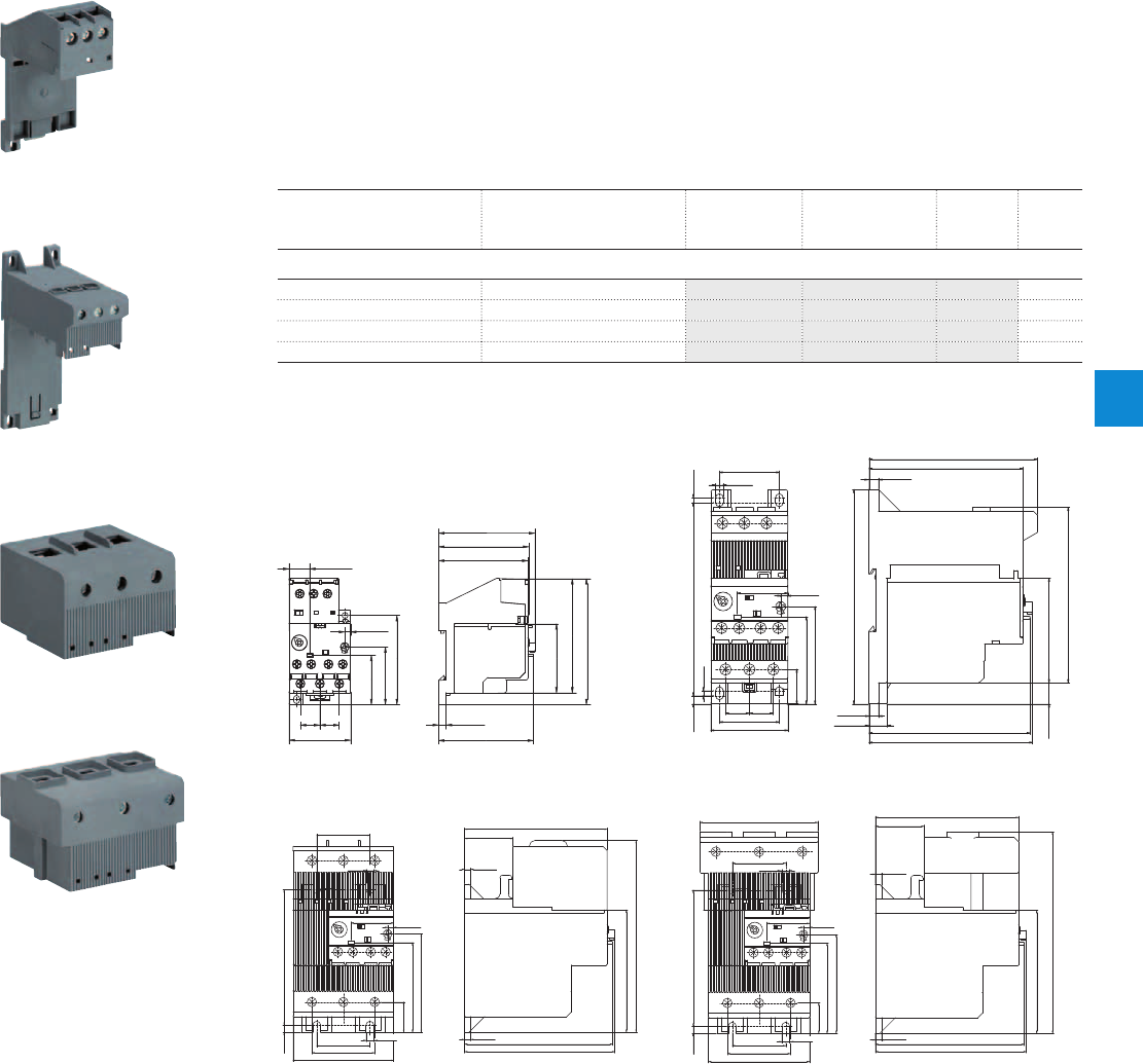
E16DU, E45DU, E80DU, E140DU electronic overload relays
Accessories
Description
Single mounting kits are available as accessory for E16DU, E45DU, E80DU, and E140DU. The single
mounting kits offer the possibility to mount the overload relay separately from the contactor.
Ordering details
For electronic overload relays Description Type Order code Weight
(1 pce)
kg
Single mounting kits
E16DU Single mounting kit DB16E 1SAX101110R0001 0.035
E45DU Single mounting kit DB45E 1SAX201110R1001 0.090
E80DU Single mounting kit DB80E 1SAX301110R1001 0.145
E140DU Single mounting kit DB140E 1SAX301110R1002 0.145
Main dimensions mm, inches
14 0.55"
4.2 0.17"
5.5 0.22"
82.6
3.25"
50
1.97"
91
3.59"
35.7
1.41"
68.5 2.70"
69.5 2.74"
65.2 2.57"
64.5 2.54"
41.7
1.64"
64.4
2.54"
14.5 0.57"
44.3 1.74"
14 0.55"
2CDC232030F0011
35 1.38"
113
4.45"
29.6 1.17" 4.2 0.17"
30.12"
4.5 0.18"
30.12"
4.8 0.19"
125.5
4.94"
102.5
4.04"
61
2.40"12.5
0.49"
98.5 3.88"
90.2 3.55"
5.5 0.22"
5.5 0.22"
10.5 0.41"
94.2 3.70"
95.6 3.76"
57
2.44"
20.2
0.80"
51
2.01"
35 1.38"
45 1.77"
14 0.55" 14 0.55"
2CDC232027F0011
DB16E DB45E
37
1.46"
29.6 1.17" 4.2 0.17"
50.20"
133.5
5.26"
70
2.76"
85.2
3.35"
99 3.90"
33.7 1.33"
4.3 0.17"
5.5 0.22"
94.2 3.71"
103 4.06"
104.4 4.11"
68.5
2.70"
21.1
0.83"
62.5
2.46"
37 1.46"
43.7 1.72"
4.3 0.17"
5.5 0.22"
2CDC232028F0011
81.5 3.21"
29.6 1.17" 4.2 0.17"
50.20"
139.5
5.50"
70
2.76"
85.2
3.35"
99 3.90"
33.7 1.33"
4.3 0.17"
5.5 0.22"
94.2 3.71"
103 4.06"
104.4 4.11"
68.5
2.70"
21.1
0.83"
62.5
2.46"
37 1.46"
43.7 1.72"
4.3 0.17"
5.5 0.22"
37
1.46"
2CDC232029F0011
DB80E DB140E
2CDC231003F0010
DB16E
2CDC231004F0010
DB45E
2CDC231005F0010
DB80E
2CDC231006F0010
DB140E
ABB | 6/43
6
2CDC107030C0201
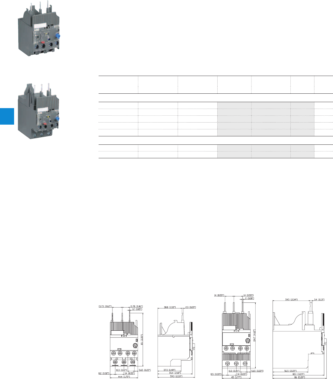
EF19, EF45 electronic overload relays
0.10 to 45.0 A
Description
The EF19 and EF45 are self-supplied electronic overload relays, which means no extra external supply
is needed. It offers reliable protection for motors in the event of overload or phase failure. Easy to use
like a thermal overload relay and compatible with standard motor applications, the electronic overload
relay is convincing, above all, due to its wide setting range, high accuracy, high operational temperature
range and the possibility to select a trip class (10E, 20E, 30E). Further features are the temperature
compensation, trip contact (N.C.), signal contact (N.O.), automatic or manual reset selectable, trip-free
mechanism, STOP and TEST function and a trip indication. The overload relays are connected directly to
the contactors.
Ordering details
Setting range Short-circuit
protective device
Trip class Type Order code Weight
(1 pce)
A kg
EF19 electronic overload relays
0.10 … 0.32 1 A, Fuse type gG 10E, 20E, 30E EF19-0.32 1SAX121001R1101 0.158
0.30 … 1.00 4 A, Fuse type gG 10E, 20E, 30E EF19-1.0 1SAX121001R1102 0.158
0.80 … 2.70 10 A, Fuse type gG 10E, 20E, 30E EF19-2.7 1SAX121001R1103 0.158
1.90 … 6.30 20 A, Fuse type gG 10E, 20E, 30E EF19-6.3 1SAX121001R1104 0.158
5.70 … 18.9 50 A, Fuse type gG 10E, 20E, 30E EF19-18.9 1SAX121001R1105 0.158
EF45 electronic overload relays
9.00 … 30.0 160 A, Fuse type gG 10E, 20E, 30E EF45-30 1SAX221001R1101 0.362
15.0 … 45.0 160 A, Fuse type gG 10E, 20E, 30E EF45-45 1SAX221001R1102 0.362
1SBC101147F0010
EF19-18.9
1SBC101148F0010
EF45-30
Main dimensions mm, inches
2CDC232007F0009
2CDC232008F0009
EF19 EF45
6/44 | ABB
6
2CDC107032C0201
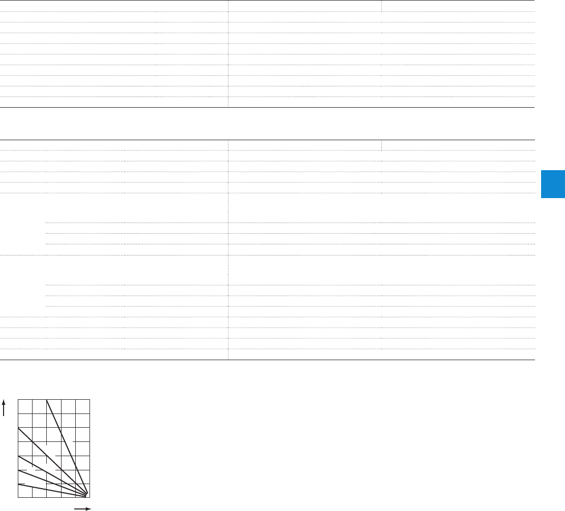
Main circuit – Utilization characteristics according to IEC/EN
Type EF19 EF45
Standards
IEC 60947-1 / 60947-4-1 / 60947-5-1 and EN 60947-1 / 60947-4-1 / 60947-5-1
Rated operational voltage U
e
690 V AC
Rated frequency
50/60 Hz
Trip class
10E, 20E, 30E, selectable
Number of poles
3
Duty time
100 %
Operating frequency without early tripping
Up to 15 operations/h, see "Technical diagram – Intermittent periodic duty"
Rated impulse withstand voltage U
imp
6 kV
Rated insulation voltage U
i
690 V AC
Auxiliary circuit according to IEC/EN
Type EF19 EF45
Rated operational voltage U
e
600 V AC / DC
Conventional free air thermal current I
th
6 A
Rated frequency
DC, 50/60 Hz
Number of poles
1 N.C. + 1 N.O.
I
e
/ Rated operational current AC-15
acc. to IEC/EN 60947-5-1 for utilization category
110-120 V
50/60 Hz
3.00 A
220-230-240 V
50/60 Hz
3.00 A
440 V
50/60 Hz
1.10 A
480-500 V
50/60 Hz
0.75 A
I
e
/ Rated operational current DC-13
acc. to IEC/EN 60947-5-1 for utilization category
24 V
1.50 A
60 V
0.55 A
110-120-125 V
0.55 A
250 V
0.27 A
Minimum switching capacity
12 V / 3 mA
Short-circuit protective device
6 A, Fuse type gG
Rated impulse withstand voltage U
imp
6 kV
Rated insulation voltage U
i
690 V
Technical diagram – Intermittent periodic duty
140
120
0
20
40
60
80
100
0 20 40 60 80 100 (%)
t = 1 s
a
t = 1.5 s
a
t = 3 s
a
t = 5 s
a
t = 0.5 s
a
duty ratio
switching frequency
(Op/h)
2CDC232005F0211
ta: Motor starting time
EF19, EF45 electronic overload relays
Technical data
ABB | 6/45
6
2CDC107032C0201

Main circuit – Utilization characteristics according to UL/CSA
Type EF19 EF45
Standards
UL 508, CSA 22.2 No. 14
Maximum operational voltage
600 V AC
Trip rating
125 % of FLA
Full load amps (FLA)
See table "Full load amps and short-circuit protective device"
Short-circuit rating RMS symmetrical
See table "Full load amps and short-circuit protective device"
Short-circuit protective device
See table "Full load amps and short-circuit protective device"
Auxiliary circuit according to UL/CSA
Type EF19 EF45
Contact rating
N.C., 95-96 B600, Q600
N.O., 97-98 B600, Q600
Conventional thermal current
5 A
Full load amps and short-circuit protective device
Type Full load amps (FLA) Short-circuit protective device
480 V AC 600 V AC
SCCR Fuse type SCCR Fuse type SCCR Fuse type
EF19-0.32
0.32 A 50 kA 2 A, Class J 5 kA 2 A, K5 / RK5 100 kA 2 A, Class J
EF19-1.0
1.00 A 50 kA 2 A, K5 / RK5 5 kA 2 A, K5 / RK5 100 kA 2 A, Class J
EF19-2.7
2.70 A 50 kA 4 A, K5 / RK5 5 kA 4 A, K5 / RK5 100 kA 4 A, Class J
EF19-6.3
6.30 A 50 kA 15 A, K5 / RK5 5 kA 15 A, K5 / RK5 100 kA 15 A, Class J
EF19-18.9
18.90 A 50 kA 30 A, K5 / RK5 5 kA 30 A, K5 / RK5 100 kA 30 A, Class J
Type Full load amps (FLA) Short-circuit protective device
480 V AC 600 V AC
SCCR Fuse type SCCR Fuse type SCCR Fuse type
EF45-30
30 kA 18 kA 150 A, K5 / RK5 18 kA 150 A, K5 / RK5 100 kA 150 A, Class J
EF45-45
45 kA 18 kA 200 A, K5 / RK5 18 kA 200 A, K5 / RK5 100 kA 200 A, Class J
EF19, EF45 electronic overload relays
Technical data
6/46 | ABB
6
2CDC107032C0201

General data
Type EF19 EF45
Pollution degree
3
Phase loss sensitive
Yes
Ambient air temperature
Operation Open - compensated without derating
-25 ... +70 °C
Storage
-50 ... +85 °C
Ambient air temperature compensation
Continuous
Maximum operating altitude permissible
2000 m
Resistance to shock acc. to IEC 60068-2-27
15 g / 11 ms
Resistance to vibrations acc. to IEC 60068-2-6
1 g / 3 … 150 Hz
Mounting position
Position 1-6
Mounting
Mount on the contactor and tighten the screws of the main circuit terminals
Degree of protection
IP20
Electrical connection
Main circuit
Type EF19 EF45
Connecting capacity
Rigid
1 or 2 x 1 ... 4 mm² 2.5 ... 16 mm²
Flexible with insulated ferrule
1 or 2 x 0.75 ... 2.5 mm² 2.5 ... 10 mm²
Stranded acc. to UL/CSA
1 or 2 x AWG 16-10 AWG 14-6
Flexible acc. to UL/CSA
1 or 2 x AWG 16-10 AWG 14-6
Stripping length
9 mm 13 mm
Tightening torques
0.8 ... 1.5 Nm / 7 … 13 Ib.in 2.3 ... 2.6 Nm / 20 … 22 Ib.in
Connection screw
M3.5 (Pozidriv 2)
Auxiliary circuit
Type EF19 EF45
Connecting capacity
Rigid
1 or 2 x 1 ... 4 mm²
Flexible with ferrule
1 or 2 x 0.75 ... 2.5 mm²
Flexible with insulated ferrule
1 or 2 x 0.75 ... 2.5 mm²
Flexible
1 or 2 x 0.75 ... 2.5 mm²
Stranded acc. to UL/CSA
1 or 2 x AWG 18-10
Flexible acc. to UL/CSA
1 or 2 x AWG 18-10
Stripping length
9 mm
Tightening torques
0.8 ... 1.2 Nm / 7 ... 11 Ib.in
Connection screw
M3 (Pozidriv 2)
EF19, EF45 electronic overload relays
Technical data
ABB | 6/47
6
2CDC107032C0201
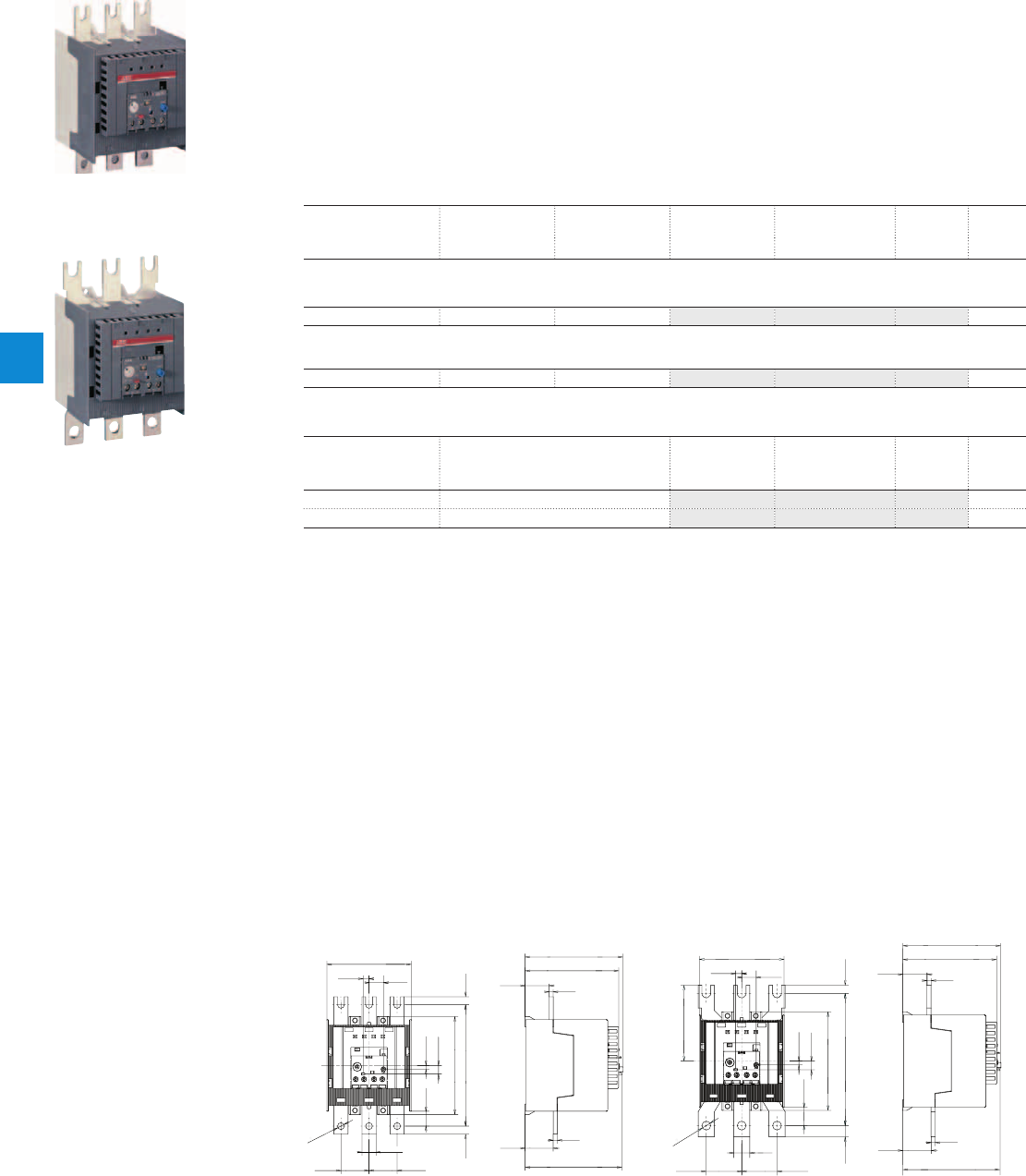
E200DU, E320DU electronic overload relays
60 to 320 A
Description
The E200DU and E320DU are self-supplied electronic overload relays, which means no extra external
supply is needed. It offers reliable protection for motors in the event of overload or phase failure. Easy to
use like a thermal overload relay and compatible with standard motor applications, the electronic overload
relay is convincing, above all, due to its wide setting range, high accuracy, high operational temperature
range and the possibility to select a trip class (10E, 20E, 30E). Further features are the temperature
compensation, trip contact (N.C.), signal contact (N.O.), automatic or manual reset selectable, trip-free
mechanism, STOP and TEST function and a trip indication. The overload relays are connected directly to
the contactors.
Ordering details
Setting range Short-circuit
protective device
Trip class Type Order code Weight
(1 pce)
A kg
E200DU electronic overload relay
60.0 ... 200.0 800 A 10E, 20E, 30E E200DU-200 1SAX511001R1101 1.210
E320DU electronic overload relay
100.0 ... 320.0 630 A 10E, 20E, 30E E320DU-320 1SAX521001R1101 1.430
Terminal shrouds for E200DU and E320DU electronic overload relay
For electronic overload
relays
Description Type Order code Weight
(1 pce)
kg
E200DU LT200E Terminal shroud for E200DU LT200E 1SAX501904R0001 0.085
E320DU LT320E Terminal shroud for E320DU LT320E 1SAX601904R0001 0.105
Main dimensions mm, inches
122 4.80"
151 5.94" 10 0.39"
4.7 0.19"
10.7 0.42"
17.5 0.69"
35 1.38"
7.4 0.29" 18 0.71"
105 4.13"
18.5 0.73"
?
8.5 0.33"
30 1.18"
116.5 4.59"
121.5 4.78"
5 0.20"
120.5 4.74"
10 0.39"
35 1.38"
35 1.38"
5 0.20"
2CDC232011F0011
?
11 0.43"
163.6 6.44"
14 0.55"
93.8 3.70"
22.8 0.90"
105 4.13"
18 0.71"
7.4 0.29"
4.7 0.19"
10.7 0.42"
122 4.80"
10 0.39"
20 0.79"
43.8 1.72"43.8 1.72"
30 1.18"
116.5 4.59"
121.5 4.78"
5 0.20"
5 0.20"
120.5 4.74"
35 1.38"
2CDC232012F0011
E200DU E320DU
2CDC231001F0008
E200DU-200
2CDC231002F0008
E320DU-320
6/48 | ABB
6
2CDC107029C0201

Main circuit – Utilization characteristics according to IEC/EN
Type E200DU E320DU
Standards
IEC 60947-1 / 60947-4-1 / 60947-5-1 and EN 60947-1 / 60947-4-1 / 60947-5-1
Rated operational voltage U
e
1000 V AC
Rated frequency
50/60 Hz
Trip class
10E, 20E, 30E, selectable
Number of poles
3
Duty time
100 %
Operating frequency without early tripping
Up to 15 operations/h, see "Technical diagram – Intermittent periodic duty"
Rated impulse withstand voltage U
imp
8 kV
Rated insulation voltage U
i
1000 V AC
Auxiliary circuit according to IEC/EN
Type E16DU E45DU
Rated operational voltage U
e
600 V AC / DC
Conventional free air thermal current I
th
6 A
Rated frequency
DC, 50/60 Hz
Number of poles
1 N.C. + 1 N.O.
I
e
/ Rated operational current AC-15
acc. to IEC/EN 60947-5-1 for utilization category
110-120 V
50/60 Hz
3.00 A
220-230-240 V
50/60 Hz
3.00 A
440 V
50/60 Hz
1.10 A
480-500 V
50/60 Hz
0.72 A
I
e
/ Rated operational current DC-13
acc. to IEC/EN 60947-5-1 for utilization category
24 V
1.50 A
60 V
0.55 A
110-120-125 V
0.55 A
250 V
0.27 A
Minimum switching capacity
12 V / 3 mA
Short-circuit protective device
6 A, Fuse type gG
Rated impulse withstand voltage U
imp
8 kV
Rated insulation voltage U
i
690 V
Technical diagram – Intermittent periodic duty
140
120
0
20
40
60
80
100
0 20 40 60 80 100 (%)
t = 1 s
a
t = 1.5 s
a
t = 3 s
a
t = 5 s
a
t = 0.5 s
a
duty ratio
switching frequency
(Op/h)
2CDC232005F0211
ta: Motor starting time
E200DU, E320DU electronic overload relays
Technical data
ABB | 6/49
6
2CDC107029C0201

Main circuit – Utilization characteristics according to UL/CSA
Type E200DU E320DU
Standards
UL 508, CSA 22.2 No. 14
Maximum operational voltage
600 V AC
Trip rating
125 % of FLA
Auxiliary circuit according to UL/CSA
Type E200DU E320DU
Contact rating
N.C., 95-96 B600, Q300
N.O., 97-98 B600, Q300
Conventional thermal current
5 A
General data
Type E200DU E320DU
Pollution degree
3
Phase loss sensitive
Yes
Ambient air temperature
Operation Open - compensated without derating
-25 ... +70 °C
Storage
-50 ... +85 °C
Ambient air temperature compensation
Continuous
Maximum operating altitude permissible
2000 m
Resistance to shock acc. to IEC 60068-2-27
15 g / 11 ms
Resistance to vibrations acc. to IEC 60068-2-6
5 g / 3 … 150 Hz
Mounting position
Position 1-6
Mounting
Mount on the contactor and tighten the screws of the main circuit terminals
Degree of protection
IP20
Electrical connection
Auxiliary circuit
Type E200DU E320DU
Connecting capacity
Rigid
1 or 2 x 1 ... 4 mm²
Flexible with ferrule
1 or 2 x 0.75 ... 2.5 mm²
Flexible with insulated ferrule
1 or 2 x 0.75 ... 2.5 mm²
Flexible
1 or 2 x 0.75 ... 2.5 mm²
Stranded acc. to UL/CSA
1 or 2 x AWG 16-10
Flexible acc. to UL/CSA
1 or 2 x AWG 16-10
Stripping length
9 mm
Tightening torques
0.8 ... 1.2 Nm / 7 Ib.in
Connection screw
M3.5 (Pozidriv 2)
E200DU, E320DU electronic overload relays
Technical data
6/50 | ABB
6
2CDC107029C0201
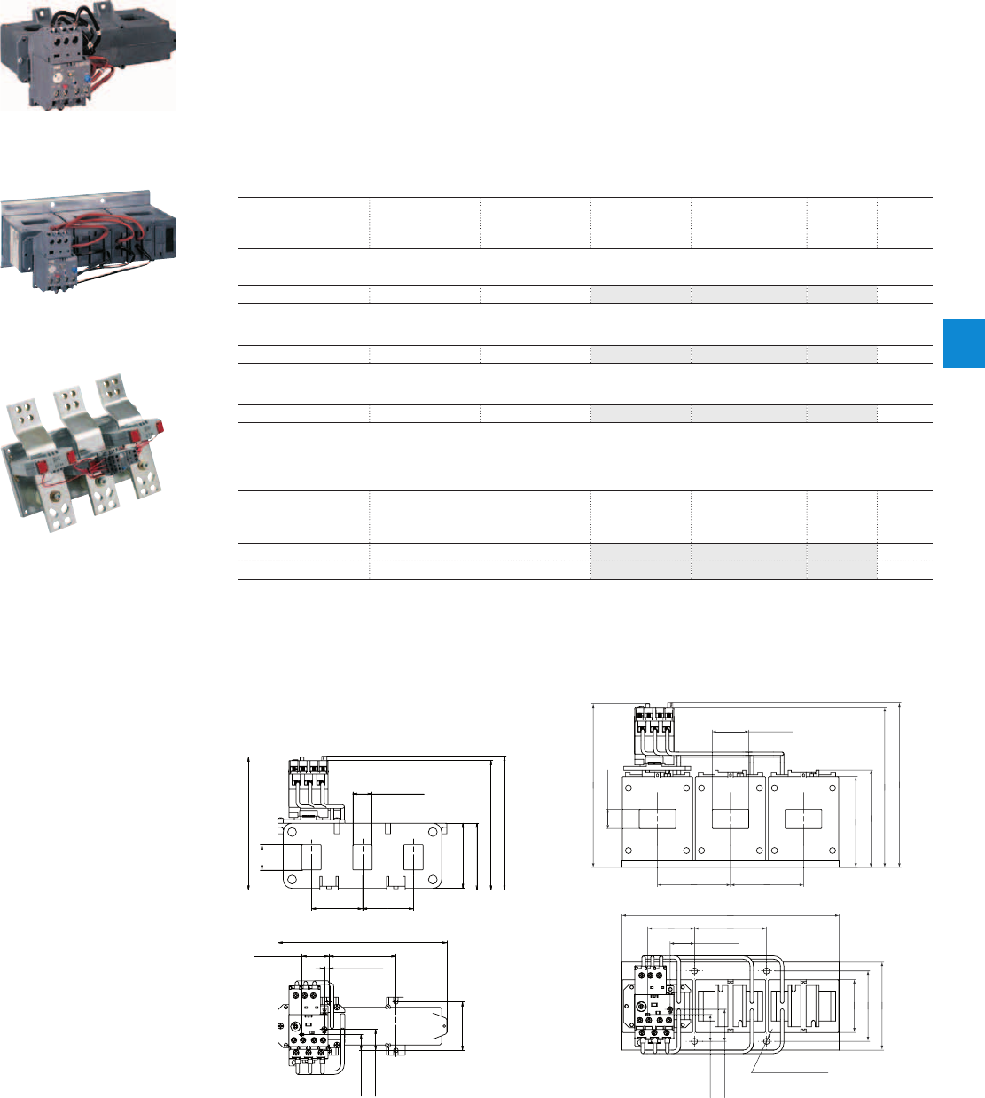
E500DU, E800DU, E1250DU electronic overload relays
150 to 1250 A
Description
The E500DU up to E1250DU are self-supplied electronic overload relays, which means no extra external
supply is needed. It offers reliable protection for motors in the event of overload or phase failure. Easy to
use like a thermal overload relay and compatible with standard motor applications, the electronic overload
relay is convincing, above all, due to its wide setting range, high accuracy, high operational temperature
range and the possibility to select a trip class (10E, 20E, 30E). Further features are the temperature
compensation, trip contact (N.C.), signal contact (N.O.), automatic or manual reset selectable, trip-free
mechanism, STOP and TEST function and a trip indication. The overload relays are connected directly to
the contactors. Busbar kits are available as accessory for contactor mounting.
Ordering details
Setting range Short-circuit
protective device
Trip class Type Order code Weight
(1 pce)
A kg
E500DU electronic overload relay
150 ... 500 1000 A 10E, 20E, 30E E500DU-500 1SAX711001R1101 1.170
E800DU electronic overload relay
250 ... 800 1250 A 10E, 20E, 30E E800DU-800 1SAX811001R1101 3.905
E1250DU electronic overload relay
375 ... 1250 - 10E, 20E, 30E E1250DU-1250 1SFA739001R1000 12.181
Terminal shrouds for E500DU and E800DU electronic overload relay
For electronic overload
relays
Description Type Order code Weight
(1 pce)
kg
E500DU LT500E Terminal shroud for E500DU LT500E 1SAX701904R0001 0.360
E800DU LT800E Terminal shroud for E800DU LT800E 1SAX801904R0001 0.105
Main dimensions mm, inches
151.1 5.95"
28.4 1.12"
22 0.87"
58 2.28" 58 2.28"
74 2.91"
76 2.99"
147.1 5.79"
152.1 5.99"
192 7.56"
17.9 0.7"
23.9 0.94"
5.3 0.21"
76 2.99"
30.7 1.21"
55 2.17"
2CDC232013F0011
103 4.06"
22 0.87"
185.6 7.31"
41.5 1.63"
83 3.27" 83 3.27"
27.6 1.09"
181.6 7.15"
110.5 4.35"
186.6 7.35"
247 9.72"
82 3.23"53 2.09"
30.4 1.2"
36.4 36.4"
Ø 7(M6) Ø 0.28"
60 2.36"
80 3.15"
100 3.94"
2CDC232014F0011
E500DU E800DU
2CDC231003F0008
E500DU-500
2CDC231004F0008
E800DU-800
1SFC101025F0201
E1250DU-1250
ABB | 6/51
6
2CDC107031C0201

Main circuit – Utilization characteristics according to IEC/EN
Type E500DU E800DU E1250DU
Standards
IEC 60947-1 / 60947-4-1 / 60947-5-1 and EN 60947-1 / 60947-4-1 / 60947-5-1
Rated operational voltage U
e
1000 V AC
Rated frequency
50/60 Hz
Trip class
10E, 20E, 30E, selectable
Number of poles
3
Duty time
100 %
Operating frequency without early tripping
Up to 15 operations/h, see "Technical diagram – Intermittent periodic duty"
Rated impulse withstand voltage U
imp
8 kV
Rated insulation voltage U
i
1000 V AC
Auxiliary circuit according to IEC/EN
Type E500DU E800DU E1250DU
Rated operational voltage U
e
600 V AC / DC
Conventional free air thermal current I
th
6 A
Rated frequency
DC, 50/60 Hz
Number of poles
1 N.C. + 1 N.O.
I
e
/ Rated operational current AC-15
acc. to IEC/EN 60947-5-1 for utilization category
110-120 V
50/60 Hz
3.00 A
220-230-240 V
50/60 Hz
3.00 A
440 V
50/60 Hz
1.10 A
480-500 V
50/60 Hz
0.72 A
I
e
/ Rated operational current DC-13
acc. to IEC/EN 60947-5-1 for utilization category
24 V
1.50 A
60 V
0.55 A
110-120-125 V
0.55 A
250 V
0.27 A
Minimum switching capacity
12 V / 3 mA
Short-circuit protective device
6 A, Fuse type gG
Rated impulse withstand voltage U
imp
8 kV
Rated insulation voltage U
i
690 V
Technical diagram – Intermittent periodic duty
140
120
0
20
40
60
80
100
0 20 40 60 80 100 (%)
t = 1 s
a
t = 1.5 s
a
t = 3 s
a
t = 5 s
a
t = 0.5 s
a
duty ratio
switching frequency
(Op/h)
2CDC232005F0211
ta: Motor starting time
E500DU, E800DU, E1250DU electronic overload relays
Technical data
6/52 | ABB
6
2CDC107031C0201

Main circuit – Utilization characteristics according to UL/CSA
Type E500DU E800DU E1250DU
Standards
UL 508, CSA 22.2 No. 14
Maximum operational voltage
600 V AC
Trip rating
125 % of FLA
Auxiliary circuit according to UL/CSA
Type E500DU E800DU E1250DU
Contact rating
N.C., 95-96 B600, Q300
N.O., 97-98 B600, Q300
Conventional thermal current
5 A
General data
Type E500DU E800DU E1250DU
Pollution degree
3
Phase loss sensitive
Yes
Ambient air temperature
Operation Open - compensated without derating
-25 ... +70 °C
Storage
-50 ... +85 °C
Ambient air temperature compensation
Continuous
Maximum operating altitude permissible
2000 m
Resistance to shock acc. to IEC 60068-2-27
15 g / 11 ms
Resistance to vibrations acc. to IEC 60068-2-6
5 g / 3 … 150 Hz
Degree of protection
IP20
Electrical connection
Auxiliary circuit
Type E500DU E800DU E1250DU
Connecting capacity
Rigid
1 or 2 x
1 ... 4 mm²
Flexible with ferrule
1 or 2 x
0.75 ... 2.5 mm²
Flexible with insulated ferrule
1 or 2 x
0.75 ... 2.5 mm²
Flexible
1 or 2 x
0.75 ... 2.5 mm²
Stranded acc. to UL/CSA
1 or 2 x
AWG 16-10
Flexible acc. to UL/CSA
1 or 2 x
AWG 16-10
Stripping length
9 mm
Tightening torques
0.8 ... 1.2 Nm / 7 Ib.in
Connection screw
M3.5 (Pozidriv 2)
E500DU, E800DU, E1250DU electronic overload relays
Technical data
ABB | 6/53
6
2CDC107031C0201
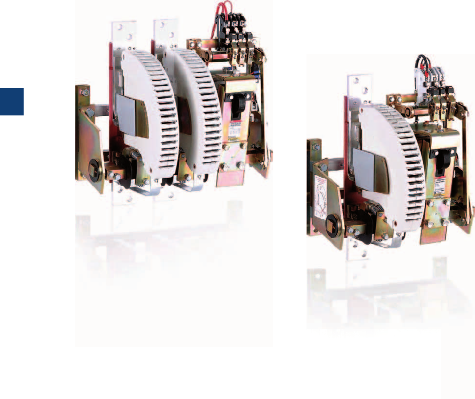
7/0 | ABB
7
1SBC101631C0201

R contactors
Presentation 7/2
Overview
R contactors for the AC circuits switching 7/4
R contactors for the DC circuits switching 7/6
Questionnaire 7/8
ABB | 7/1
7
1SBC101631C0201
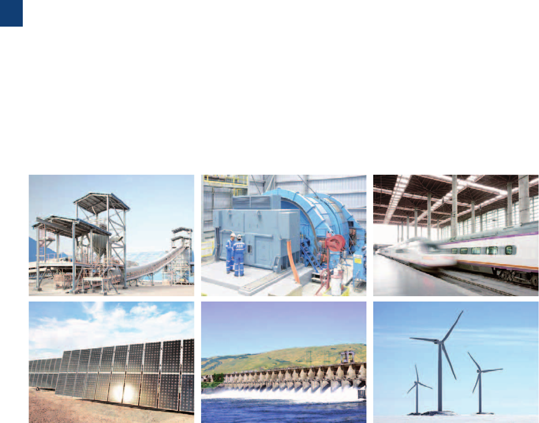
R contactors
85 to 5000 A
R contactors with variable number of poles and their
variants (contactors with N.C. + N.O. poles, couplers...)
are used for controlling power circuits up to 1000VAC
or 1500VDC. They are designed with common standard
components. With the combination of these elements
and the adaptation possibilities, special versions can
be provided. Designed for long-lasting operation and
demanding applications, the ABB R contactors are used
for many applications all over the world.
Flexibility of design
– Variable number of poles
– Adjustable number of auxiliary contacts
– Optional combination of N.O. and N.C. poles
– Mechanical or magnetic latching available.
Easy maintenance
– Direct access to all the components of the contactor
– Complete and didactic instruction manual
– Spare parts available
– Dedicated service for bar contactors.
Exceptional durability
– Mechanical durability up to 10 millions operating cycles
– Mechanical switching frequency up to 1200 cycles per hour
– Electrical durability up to 350 000 operating cycles.
Ideal for heavy duty applications
– High making and breaking capacity
– Fully compatible with the requirements of utilization
categories
AC-3, DC-3 and DC-5 (control of AC / DC
motors for mining, iron and steel industries...).
Custom-made solutions
– More than 60 years' experience in dealing with customers
projects
– Development of solutions from specifications
– Pre-sales support to identify and define customer
requirements
– Specialists available to help you, select your product or
optimize your configuration.
7/2 | ABB
7
1SBC104003S0201
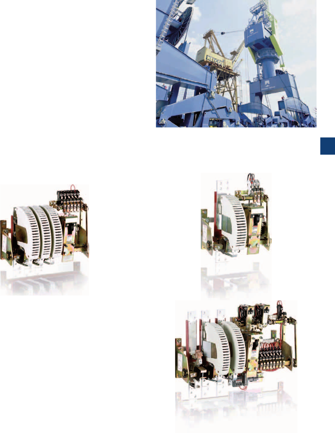
R contactors
For heavy duty applications
R contactors meet the particular requirements of each
AC / DC control application up to 5000 A, where the
demands are increasing:
– Power distribution
– Photovoltaic, hydroelectric power stations
– Batteries
– Mining
– Railway networks and rolling stock
– Induction furnaces
– Pump stations
– Travelling cranes.
Control your AC applications up to 5000 A
AC-1 Rated operational current up to 5000 A
AC-3 Rated power up to 1500 kW (1520 A - 440 V)
Control your DC applications up to 5000 A
DC-1 Rated operational current up to 5000 A
DC-3 / DC-5 Rated operational current up to 2000 A
1500 V with poles in series
Special applications
AC / DC coupling: LOR.. contactors
Slip ring motor control: FOR.. contactors
AC / DC switching (N.C. / N.O. main poles): NOR & JOR..
contactors
Latching contactors for energy saving and safety require-
ments: AMA or AME contactors
Field discharge: AM(F)-CC-JORE.. contactors
ABB | 7/3
7
1SBC104003S0201
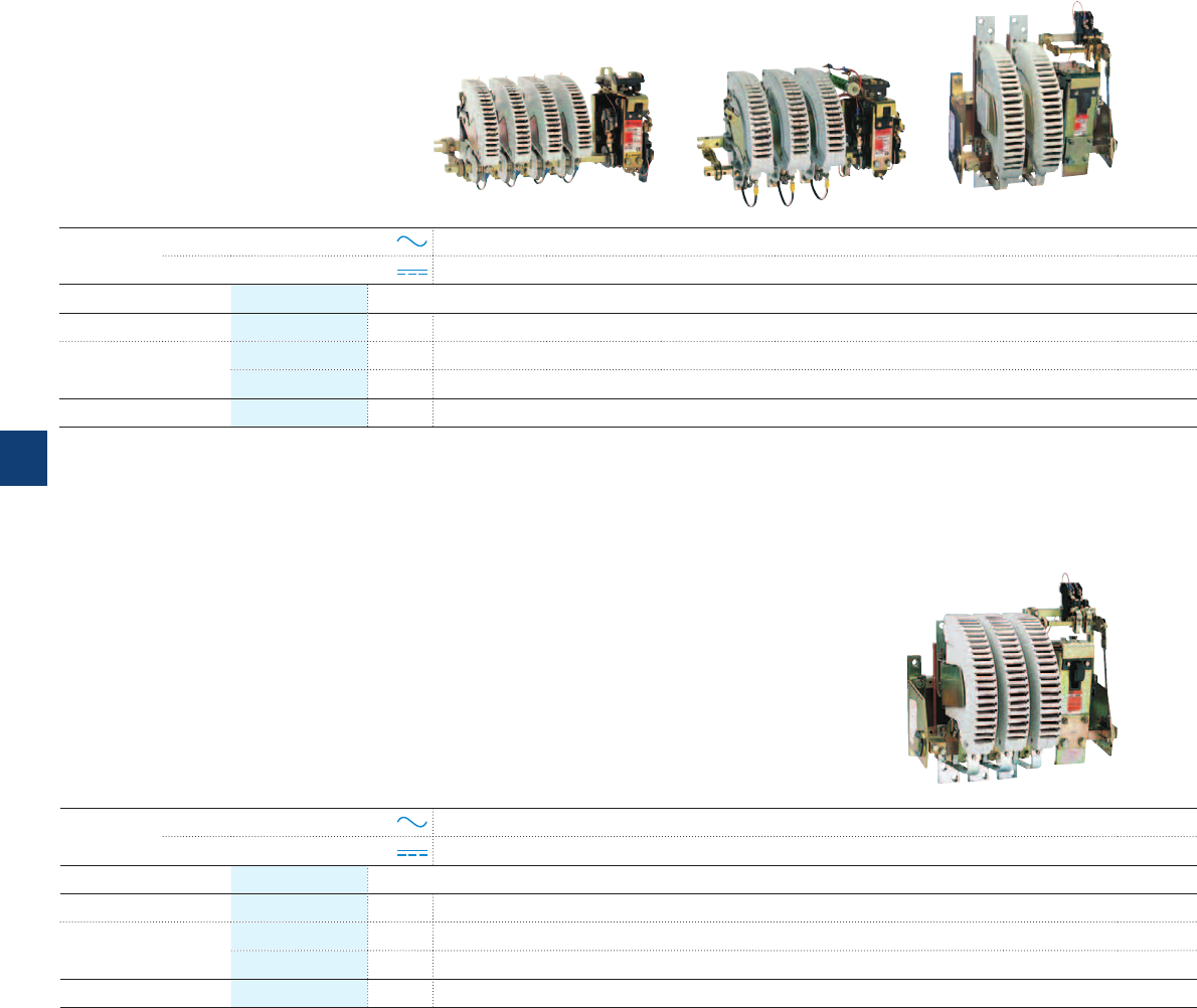
R contactors for the AC circuits switching
Recap:
All contactors fulfill the IEC 60947-4-1 / EN 60947-4-1 standards.
Utilization category AC-1: max. breaking current = 1.5 x Ie,
max. making current = 1.5 x Ie.
Utilization category AC-3: max. breaking current = 8 x Ie,
max. making current = 10 x Ie.
Contactors with NC poles, magnetic or mechanical latching devices
on request.
Voltage Ue up to 500 V AC
Current Ie up to 5000 A
Contactor
type
AC control circuit – IORR800
DC control circuit – IORE800
Categories Ue
AC-1 at 40 °C Ie From 85 A to 550 A, select above IOR..-MT 900 A
AC-3
380-415-440 V AC
Ie –800 A
500 V AC max. Ie –800 A
AC-3 400 V AC Power –450 kW
Voltage Ue up to 1000 V AC
Current Ie up to 4500 A
Contactor
type
AC control circuit
IORR63..-MT IORR125..-MT IORR200..-MT IORR400..-MT IORR500..-MT IORR800..-MT
DC control circuit
IORE63..-MT IORE125..-MT IORE200..-MT IORE400..-MT IORE500..-MT IORE800..-MT
Categories Ue
AC-1 at 40 °C Ie 85 A 170 A 260 A 400 A 550 A 800 A
AC-3 690 V AC Ie 85 A 160 A 260 A 400 A 550 A 800 A
1000 V AC max. Ie 56 A 105 A 180 A 280 A 380 A 580 A
AC-3 690 V AC Power 80 kW 150 kW 240 kW 400 kW 540 kW 780 kW
7/4 | ABB
7
1SBC104002S0201
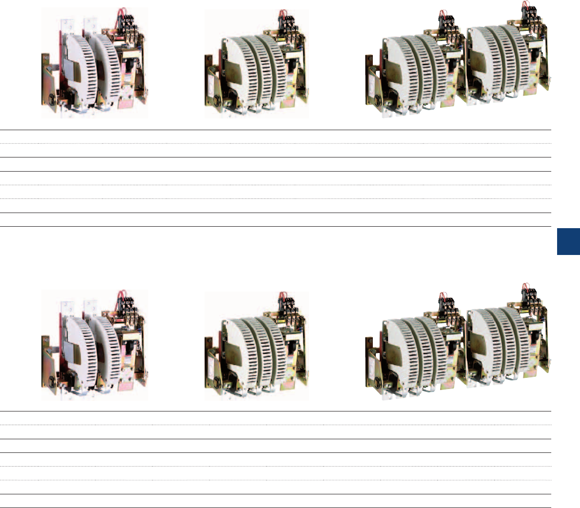
IORR1000 IORR1400 IORR1700 IORR2100 IORR2500 IORR3200 IORR3800 IORR4500 IORR5100
IORE1000 IORE1400 IORE1700 IORE2100 IORE2500 IORE3200 IORE3800 IORE4500 IORE5100
1000 A 1350 A 1650 A 2000 A 2400 A 3200 A 3800 A 4500 A 5000 A
800 A 1060 A 1260 A 1520 A –––––
800 A 1080 A 1220 A 1340 A – – – – –
450 kW 630 kW 750 kW 900 kW –––––
IORR1400..-MT IORR1700..-MT IORR2100..-MT IORR2500..-MT IORR3200..-MT IORR3800..-MT IORR4500..-MT IORR5100..-MT
IORE1400..-MT IORE1700..-MT IORE2100..-MT IORE2500..-MT IORE3200..-MT IORE3800..-MT IORE4500..-MT IORE5100..-MT
1250 A 1650 A 1850 A 2200 A 3000 A 3500 A 4000 A 4500 A
970 A 1170 A 1270 A – – –––
610 A680 A810 A–––––
1000 kW 1200 kW 1300 kW –––––
ABB | 7/5
7
1SBC104002S0201
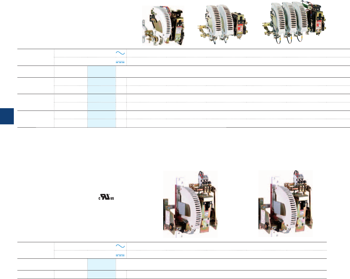
R contactors for the DC circuits switching
Voltage Ue up to 1500VDC
Current Ie up to 5000 A
Contactor
type
AC control circuit
IORR63..-CC IORR125..-CC IORR200..-CC IORR400..-CC IORR500..-CC
DC control circuit
IORE63..-CC IORE125..-CC IORE200..-CC IORE400..-CC IORE500..-CC
Number of poles
in series*
Categories Ue max.
1 pole DC-1 500VDC Ie 85 A 170 A 275 A 400 A 550 A
DC-3 / DC-5 500VDC Ie 68 A 140 A 205 A 350 A 500 A
2 poles DC-1 1000VDC Ie 85 A 170 A 275 A 400 A 550 A
DC-3 / DC-5 1000VDC Ie 68 A 140 A 205 A 350 A 500 A
3 poles DC-1 1500VDC Ie 85 A** 170 A** 275 A** 400 A** 550 A**
DC-3 / DC-5 1500VDC Ie 68 A** 140 A** 205 A** 350 A** 500 A**
*Number of poles to be fitted in series according to the operational voltage and the utilization categories.
**Version with increased insulation for 1000VDC < Ue ≤ 1500VDC, please consult us.
Contactor
type
AC control circuit
IORR800-10-CC IORR1000-10-CC IORR1400-10-CC IORR1700-10-CC IORR2100-10-CC
DC control circuit
IORE800-10-CC IORE1000-10-CC IORE1400-10-CC IORE1700-10-CC IORE2100-10-CC
U max.
1 pole General use 600VDC Ie 800 A 1000 A 1300 A 1700 A 2000 A
Recap:
All contactors fulfill the IEC 60947-4-1 / EN 60947-4-1 standards.
Utilization category DC-1: max. breaking current = 1.5 x Ie,
max. making current = 1.5 x Ie.
Utilization categories DC-3 / DC-5: max. breaking current = 4 x Ie,
max. making current = 4 x Ie.
Contactors with NC poles, magnetic or mechanical latching devices
on request.
Voltage Ue up to 600VDC
Current Ie up to 2000 A
Contactors
UL / CSA approved
7/6 | ABB
7
1SBC104001S0201
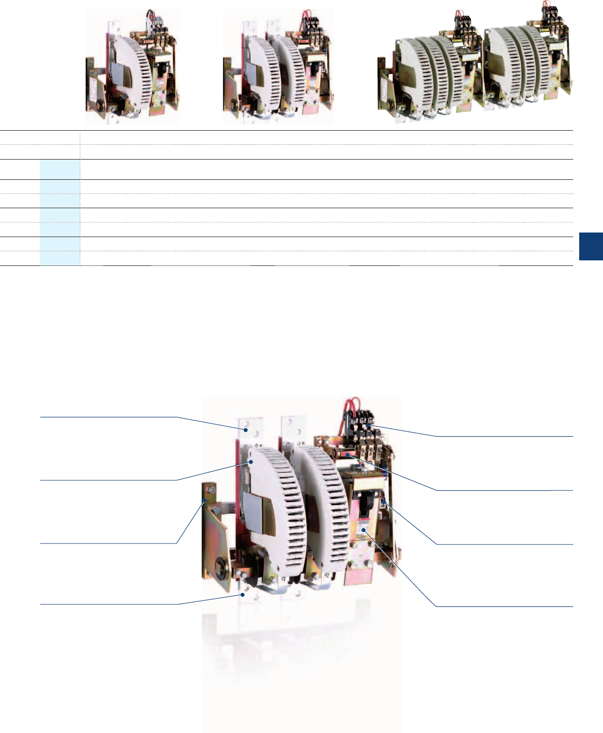
IORR800..-CC IORR1000..-CC IORR1400..-CC IORR1700..-CC IORR2100..-CC IORR2500..-CC IORR3200..-CC IORR3800..-CC IORR4500..-CC IORR5100..-CC
IORE800..-CC IORE1000..-CC IORE1400..-CC IORE1700..-CC IORE2100..-CC IORE2500..-CC IORE3200..-CC IORE3800..-CC IORE4500..-CC IORE5100..-CC
Ue max.
750VDC 800 A 1000 A 1250 A 1600 A 2000 A 2300 A 3200 A 3800 A 4500 A 5000 A
600VDC 720 A 1000 A 1250 A 1600 A 2000 A On request On request On request On request On request
1500VDC 800 A 1000 A 1250 A 1600 A 2000 A 2300 A 3200 A 3800 A 4500 A 5000 A
1000VDC 720 A 1000 A 1250 A 1600 A 2000 A On request On request On request On request On request
1500VDC 800 A 1000 A 1250 A 1600 A 2000 A 2300 A 3200 A 3800 A 4500 A 5000 A
1500VDC 720 A 1000 A 1250 A 1600 A 2000 A On request On request On request On request On request
Product overview
Upper terminal plate
for power circuit (network)
CA15.. auxiliary contacts
1 N.O. + 1 N.C. fitted as
standard (extra auxiliary
contacts on request)
2 N.O. main poles with arc chutes Auxiliary frame
for auxiliary contacts
Main frame
for contactor fixing
Connecting terminals
for coil supply
Lower terminal plate
for power circuit (utilization)
Electro-magnet (RR type),
laminated magnetic circuit,
AC coil, direct supply
ABB | 7/7
7
1SBC104001S0201
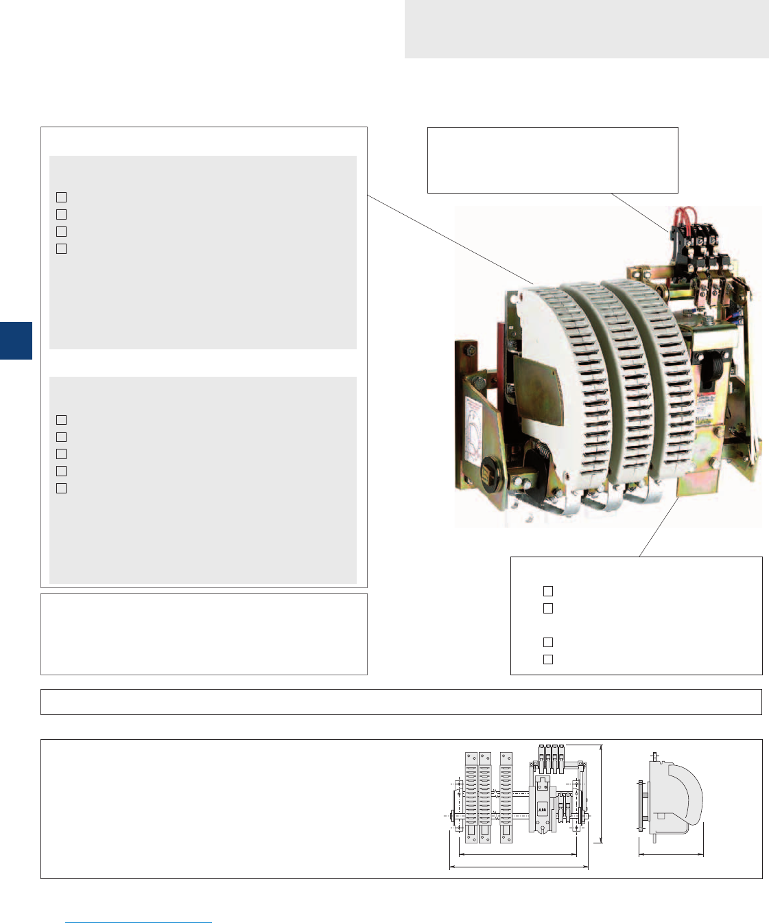
F
H
W
D
Questionnaire
Specification for R contactors
Control circuit (coil)
AC Voltage ..................... V ............... Hz
DC Voltage ..................... V DC
Options
Magnetical latching
Mechanical latching
Auxiliary contacts
Number of N.O. auxiliary contacts
............
Number of N.C. auxiliary contacts
.............
Replacement of an existing contactor
Brand ................................................................
Type ..................................................................
Fixing dimension F = ............... mm
Overall dimensions W = ............... mm
H = ............... mm
D = ............... mm
Customer .................................................................................................................
Contact person ...................................................... Date ..............................
Tel. .......................................................... e-mail ..................................................
ABB .............................................................................................................................
Contact person ....................................................................................................
Tel. ...............................................................................................................................
Operating conditions
Switching frequency ............................................. cycles/h
Mech. durability required (millions of operating cycles) ..............
Remarks ..........................................................................................
Please add any other useful documents for further information e.g. technical specification, drawing, wiring diagram, etc.
Accessories .............................................................................................................................................................................................................................................
Power circuit
AC switching
Application type
AC-1 (resistive load)
AC-3 (direct starting, switching off running motors)
No load breaking
Other ..............................................................................................
Number of poles: N.O. ..................... N.C. .....................
Rated operational current Ie .................. A
Max. making current ............................ A
Max. breaking current ......................... A
Rated operational voltage Ue ............... V ............... Hz
or
DC switching
Application type
DC-1 (resistive load)
DC-3 (shunt motors)
DC-5 (series motors)
No load breaking
Other ....................................... L/R .............. ms
Number of poles: N.O. ..................... N.C. .....................
Rated operational current Ie .................. A
Making current ........................................ A
Breaking current min. .......... A max. .......... A
Rated operational voltage Ue ............... V DC
Quantity ................... Requested delivery date .....................................
Project / Application ...........................................................................................................................................................................................................................................
Please photocopy and forward. Questionnaire also available on the ABB Website:
www.abb.com/lowvoltage Section: Our offering Select: Control Products > Contactors > Bar mounted contactors
7/8 | ABB
7
1SBC104004S0201

Questionnaire
Specification for R contactors
Please photocopy and forward. Questionnaire also available on the ABB Website:
www.abb.com/lowvoltage Section: Our offering Select: Control Products > Contactors > Bar mounted contactors
Other information / Application type
This document is used to define the contactor specification according to the complete information on the application
ABB | 7/9
7
1SBC104004S0201
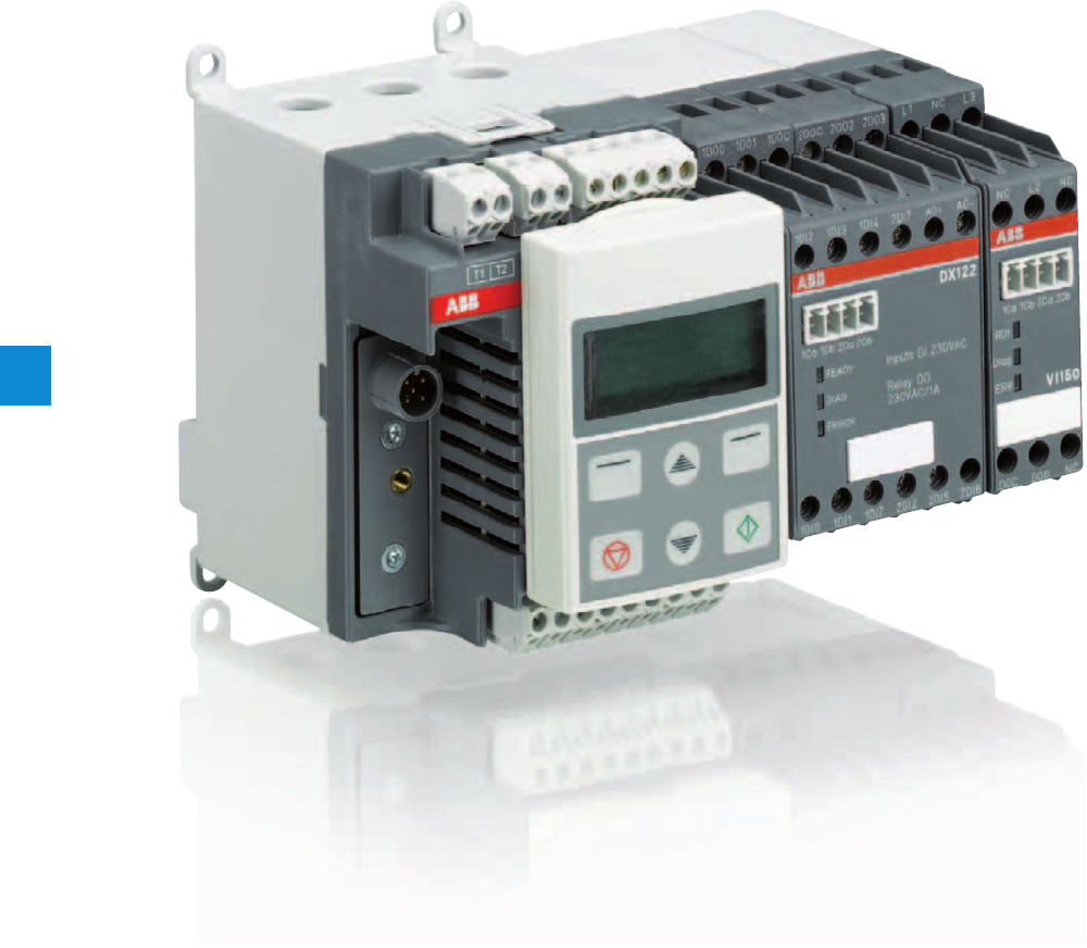
8
2CDC135025C0201
8/0 | ABB

Motor control and protection
Motor control and protection
Benefits and advantages 8/2
Technical data 8/3
ABB | 8/1
8
2CDC135025C0201

Motor control and protection
Benefits and advantages
Motor protection
쐍 Overload, underload
쐍 Overvoltage, undervoltage
쐍 Blocked rotor, low / high current
쐍 Phase failure, imbalance, phase sequence
쐍 Earth leakage
쐍 Thermistor protection
쐍 Limitation of starts per time
쐍 One single version with integrated measuring system covers the rated
쐍 motor current from 0,24 to 63 A
Motor control
쐍 Integrated and easy to parametrize motor starter functions like direct,
reverse, star-delta,...
쐍
Additionally free programmable logic for application specific control
functions
쐍
Expansion modules DX111, DX122 for more I/Os
쐍 Expansion modules VI150, VI155 for 3-phase voltage measuring
Motor diagnostics
쐍 Quick and comprehensive access to all relevant data
via fieldbus and/or operator panel
쐍 Current, thermal load
쐍 Phase voltages
쐍 Power factor
쐍 Energy
Communication
쐍 Communication-independent basic device
쐍 Freely selectable fieldbus protocol with FieldBusPlug
쐍 Profibus DP
쐍 DeviceNet
쐍 Modbus
쐍 CANopen
Typical application segments
쐍 Oil & gas
쐍 Cement
쐍 Paper
쐍 Mining
쐍 Steel
쐍 Chemical industry
UMC100-FBP is a flexible, modular and expandable motor management system for constant-speed low-voltage range motors.
It's most important tasks include motor protection, prevention of plant standstills and the reduction of down time. This is made possible by
early information relating to possible motor problems which avoids unplanned plant standstills. Even if a motor trips, quick diagnosis of the cause of
the fault serves to reduce downtime.
UMC100-FBP combines in a very compact unit:
Further information
UMC & FBP Catalogue 2CDC 190 022 D0204
UMC & FBP Brochure 2CDC 135 011 B0202
8/2 | ABB
8
2CDC135025C0201
Motor control and protection
Technical data
Basic device UMC100-FBP
UMC100-FBP allows the connection of one I/O-expansion module DX111 or DX122, and one voltage module VI150 or
VI155. Expansion modules are connected via 2-wire bus, the max. distance to UMC100-FBP is 3 m.
Main power
Voltage max 1000 V AC
Frequency 45 to 65 Hz
Rated motor current 0.24 to 63 A, without accessories
Greater currents with transformer
Transformer diameter 11 mm (max 25 mm²)
Tripping classes 5, 10, 20, 30, 40 in accordance with EN/IEC 60947-4-1
Short-circuit protection Separate fuse on network side
Control unit
Supply voltage 24 V DC
Reverse polarity protection yes
Inputs 6 digital inputs 24 V DC
1 PTC input
Outputs 3 relay outputs relay
1 digital output transistor
Interfaces 1 for ABB FieldBusPlug
1 for UMC100-PAN control station
1 for expansion module
Parametric assignment via fieldbus, control station and / or software
Addressing Control station or addressing set
LEDs 3 LEDs: green, yellow, red
Environment and mechanical data
Fastening on DIN busbar (EN50022-35) or with 4 screws x M4
Dimensions (W x H x D) 70 x 105 x 110 mm (incl. FieldBusPlug and control panel)
Weight 0.39 kg
Terminal cross-section max. 2.5 mm² or 2 x 1.5 mm²
Supply voltage 24 V DC
Inputs DX111 8 digital inputs 24 V DC
DX122 8 digital inputs 110/230 V AC
Outputs 4 relay outputs relay
1 analogue output, 0/4 to 20 mA / 0 to 10 V configurable
Fastening on DIN busbar (EN50022-35)
Dimensions (W x H x D) 45 x 77 x 100 mm (without terminal block)
I/O-expansion modules DX111 / DX122
Expansion modules to increase the number of I/Os of a UMC100-FBP. Easy use of inputs by parametrizing for fault or warn-
ing; individual message on operator panel configurable.
ABB | 8/3
8
2CDC135025C0201
Supply voltage 24 V DC
Inputs VI150 3 analogue inputs 150 - 690 V AC
For use in grounded networks
Maximum operation altitude 2000 m
VI155 3 analogue inputs 150 - 690 V AC
For use in all networks
Maximum operation altitude > 2000 m
Outputs 1 relay output
Fastening on DIN busbar (EN50022-35)
Dimensions (W x H x D) 22.5 x 77 x 100 mm (without terminal block)
Control panel UMC100-PAN
Installation on the device or on the switching cabinet door
Graphics-enabled and backlit display, 3 LEDs for status indication
Freely configurable error messages
Multilingual: German, English, French, Italian, Portuguese, Spanish, Russian
Voltage expansion modules
Measures the 3 phase voltages of a motor. Different versions for use in grounded and ungrounded networks.
Motor control and protection
Technical data
NEW
8/4 | ABB
8
2CDC135025C0201

Notes
ABB | 8/5
8
2CDC135025C0201

Coordination with short-circuit protection devices
In compliance with standards IEC 60947-4-1 and EN 60947-4-1, we define for the contactors and starters the type, rating
and characteristics of the short-circuit protection devices SCPD which allow selective protection against overloads and ensure
protection against short circuits.
Basic functions
Any starter is designed to:
– start motors,
– ensure continuous functioning of motors,
– disconnect motors from the supply line,
– guarantee protection of motors against overloads.
The starter is typically made up of a switching device (contactor) and an overload protection device (thermal overload relay TOR or electronic
overload relay EOR).
These two devices MUST be coordinated with equipment capable of providing protection against short circuit (SCPD: short circuit protective de-
vice): typically a circuit breaker with magnetic release only or a switch fuse. These are not necessarily part of the starter.
Applicable standards
IEC 60947-4-1 (EN 60947-4-1) precisely defines the different points to be considered in order to carry out correct coordination.
Complete coordination for a combination includes the following points:
– Selectivity test between the overload relay and the short-circuit protection device SCPD.
– Short-circuit condition tests:
- at prospective "r" currents - These currents depend on the rated operational current of the starter (Ie AC-3) and are given by the standard
(Table 11). For example:
r = 1kA for Ie AC-3 < 16 A
r = 3 kA for 16 A < Ie AC-3 < 63 A
r = 5 kA for 63 A < Ie AC-3 < 125 A etc.
- at the rated prospective short-circuit current "Iq" - This is the maximum current that the combination can withstand, for example 50 kA.
Types of coordination
IEC 60947-4-1 (EN 60947-4-1) defines two types of coordination according to the expected level of service continuity. Acceptable extreme dam-
age for the switchgear is divided into two types.
Type 1: In short-circuit conditions, the contactor or starter does not endanger persons or installations and will not be able to then operate without
being repaired or having parts replaced.
Type 2: In short-circuit conditions, the contactor or starter does not endanger persons or installations and will be able to operate afterwards.
The risk of contacts light welding is acceptable.
The complete ABB offer
ABB has acquired years of experience with respect to problems of coordination and is able to make a complete offer based on tests performed in
its qualified laboratories. This offer includes 400 V, 500 V, 690 V networks.
A complete data base of coordination tables, according to IEC 60947-4-1 (EN 60947-4-1), is available on the ABB Website.
In the coordination tables the following short-circuit protection devices are recommended:
– Moulded case circuit-breakers (MCCBs)
– Miniature circuit-breakers (MCBs)
– Switch-disconnector-fuses (aM, gG and BS)
– Manual Motor Starters (M.M.S.).
General remarks applicable to all tables
– Each table is defined for a maximum ambient temperature of 40 °C. For higher temperatures, apply a derating factor according to the following
rules:
- Fuses: factor of 0.8 applied to In for an ambient temperature of 70 °C
- MCCBs and MCBs: factor of 0.8 applied to In for an ambient temperature of 60 °C
- The starter derating factor depends on the operating conditions of thermal overload relays:
Factor of 0.9 applied to In for an ambient temperature of 70 °C.
– Each table is defined for motor currents: 3-phase motors, 4-pole
–Normal starting means a starting time < 2 s. - Difficult starting means an accelerating time 10 s < ts < 30 s
Tripping classes of thermal overload relays according to IEC 60947-4-1 (EN 60947-4-1): 10A and 10, and 30 for SU types
– In the tables with MCCBs, these are fitted with the magnetic relay alone. Setting is always carried out at > 12.3 Ie AC-3 so that the transient
current peak occurring during starting does not lead to tripping.
9/0 | ABB
9
1SBC101590S0201
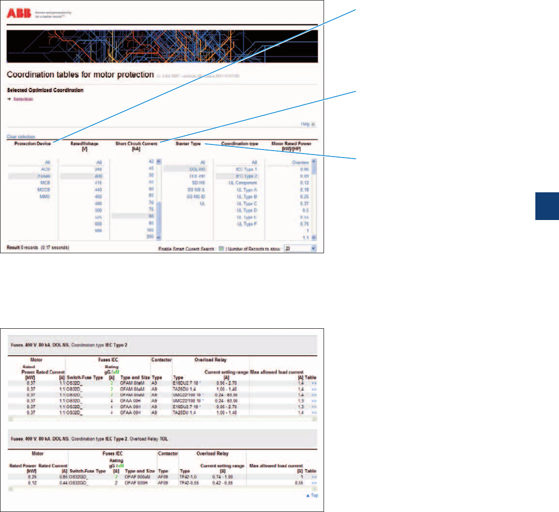
Coordination with short-circuit protection devices
A motor starter is typically made up of a switching device (contactor) and an overload protection device (see opposite page
"Basic functions").
These two devices must be coordinated with an equipment capable of providing protection against short circuit (SCPD: Short-Circuit Protection
Device).
A complete data base of coordination tables, according to IEC 60947-4-1 (EN 60947-4-1) or UL 508 / UL 60947-4-1, is available on the ABB
Website: see below.
Selection
Simple or multiple selections all from the same screen.
Results
– Search results displayed at the bottom of the selection page.
– Only the most appropriate solutions to your application, will be displayed at the bottom of the page.
"Enable Smart Current Search" function featured for the short-circuit current where "near to" selected values also are included in the result.
– Possible to print the page to a pdf file or from your printer.
– "Clear selection" function to deselect all selected.
Access
To find the coordination tables for motor protection, please see:
www.abb.com/lowvoltage then go to the right menu: "Support", select: "Online Product Selection Tools" then select "Coordination Tables for
motor protection"
Short-circuit protection devices
– Air circuit breakers
– Fuses "gG" or "aM"
– Miniature circuit breaker
– Moulded case circuit breaker
– Manual motor starter
Starter type
– Direct-on-line normal start
– Direct-on-line heavy duty
– Star-delta normal start
– Soft starter normal start
Coordination
– IEC type 1 or type 2
– UL type A to Type F
ABB | 9/1
9
1SBC101591S0201

Index
Order code classification
Order code Type
Pag
e Order code Type
Pag
e Order code Type
Pag
e
1SAM101901R0001 HK-11 2/45
1SAM101901R0002 HK-20 2/45
1SAM101901R0003 HK-02 2/45
1SAM101903R0024 UAF-24 2/45
1SAM101903R0048 UAF-48 2/45
1SAM101903R0060 UAF-60 2/45
1SAM101903R0110 UAF-110 2/45
1SAM101903R0230 UAF-230 2/45
1SAM101903R0400 UAF-400 2/45
1SAM101903R0415 UAF-415 2/45
1SAM101903R0500 UAF-500 2/45
1SAM101904R0003 SK-11 2/45
1SAM101909R0001 AA-24 2/45
1SAM101909R0002 AA-230 2/45
1SAM101909R0003 AA-400 2/45
1SAM101923R0002 MSMN 2/9
1SAM101923R0012 MSMNO 2/9
1SAM101924R0003 MSOX-32 2/9
1SAM101924R0013 MSOX-30 2/9
1SAM101928R0001 HKF-11 2/45
1SAM101928R0002 HKF-20 2/45
1SAM101937R0012 PS3-2-0 2/44
1SAM101937R0013 PS3-3-0 2/44
1SAM101937R0014 PS3-4-0 2/44
1SAM101937R0015 PS3-5-0 2/44
1SAM101937R0016 PS3-6-0 2/44
1SAM101937R0022 PS3-2-1 2/44
1SAM101937R0023 PS3-3-1 2/44
1SAM101937R0024 PS3-4-1 2/44
1SAM101937R0025 PS3-5-1 2/44
1SAM101937R0032 PS3-2-2 2/44
1SAM101937R0034 PS3-4-2 2/44
1SAM101938R0001 S3-M1 2/44
1SAM101938R0002 S3-M2 2/44
1SAM101938R0003 BS3-3 2/44
1SAM101938R0004 S3-M3 2/44
1SAM101940R1000 IB325-G 2/47
1SAM101940R1001 IB325-Y 2/47
1SAM101941R1000 DMS325-G 2/47
1SAM101941R1001 DMS325-Y 2/47
1SAM101943R0001 CK-11 2/45
1SAM150000R1001 MS325-0.16 2/40
1SAM150000R1002 MS325-0.25 2/40
1SAM150000R1003 MS325-0.4 2/40
1SAM150000R1004 MS325-0.63 2/40
1SAM150000R1005 MS325-1 2/40
1SAM150000R1006 MS325-1.6 2/40
1SAM150000R1007 MS325-2.5 2/40
1SAM150000R1008 MS325-4 2/40
1SAM150000R1009 MS325-6.3 2/40
1SAM150000R1010 MS325-9 2/40
1SAM150000R1011 MS325-12.5 2/40
1SAM150000R1012 MS325-16 2/40
1SAM150000R1013 MS325-20 2/40
1SAM150000R1014 MS325-25 2/40
1SAM150005R0001 MS325-0.16-HKF11 2/40
1SAM150005R0002 MS325-0.25-HKF11 2/40
1SAM150005R0003 MS325-0.4-HKF11 2/40
1SAM150005R0004 MS325-0.63-HKF11 2/40
1SAM150005R0005 MS325-1-HKF11 2/40
1SAM150005R0006 MS325-1.6-HKF11 2/40
1SAM150005R0007 MS325-2.5-HKF11 2/40
1SAM150005R0008 MS325-4-HKF11 2/40
1SAM150005R0009 MS325-6.3-HKF11 2/40
1SAM150005R0010 MS325-9-HKF11 2/40
1SAM150005R0011 MS325-12.5-HKF11 2/40
1SAM150005R0012 MS325-16-HKF11 2/40
1SAM150005R0013 MS325-20-HKF11 2/40
1SAM150005R0014 MS325-25-HKF11 2/40
1SAM160000R1003 MO325-0.4 2/49
1SAM160000R1004 MO325-0.63 2/49
1SAM160000R1005 MO325-1 2/49
1SAM160000R1006 MO325-1.6 2/49
1SAM160000R1007 MO325-2.5 2/49
1SAM160000R1008 MO325-4 2/49
1SAM160000R1009 MO325-6.3 2/49
1SAM160000R1010 MO325-9 2/49
1SAM160000R1011 MO325-12.5 2/49
1SAM160000R1012 MO325-16 2/49
1SAM160000R1013 MO325-20 2/49
1SAM160000R1014 MO325-25 2/49
1SAM201901R1001 HKF1-11 2/7
1SAM201902R1001 HK1-11 2/7
1SAM201902R1002 HK1-20 2/7
1SAM201902R1003 HK1-02 2/7
1SAM201902R1004 HK1-20L 2/7
1SAM201903R1001 SK1-11 2/7
1SAM201903R1002 SK1-20 2/7
1SAM201903R1003 SK1-02 2/7
1SAM201904R1001 UA1-24 2/7
1SAM201904R1002 UA1-48 2/7
1SAM201904R1003 UA1-60 2/7
1SAM201904R1004 UA1-120 2/7
1SAM201904R1005 UA1-208 2/7
1SAM201904R1006 UA1-230 2/7
1SAM201904R1007 UA1-400 2/7
1SAM201904R1008 UA1-415 2/7
1SAM201906R1102 PS1-2-0-65 2/6
1SAM201906R1103 PS1-3-0-65 2/6
1SAM201906R1104 PS1-4-0-65 2/6
1SAM201906R1105 PS1-5-0-65 2/6
1SAM201906R1112 PS1-2-1-65 2/6
1SAM201906R1113 PS1-3-1-65 2/6
1SAM201906R1114 PS1-4-1-65 2/6
1SAM201906R1115 PS1-5-1-65 2/6
1SAM201906R1122 PS1-2-2-65 2/6
1SAM201906R1123 PS1-3-2-65 2/6
1SAM201906R1124 PS1-4-2-65 2/6
1SAM201906R1125 PS1-5-2-65 2/6
1SAM201907R1101 S1-M1-25 2/6
1SAM201907R1102 S1-M2-25 2/6
1SAM201907R1103 S1-M3-25 2/6
1SAM201908R1001 BS1-3 2/6
1SAM201909R1001 FS116 2/6
1SAM201910R1001 AA1-24 2/7
1SAM201910R1002 AA1-110 2/7
1SAM201910R1003 AA1-230 2/7
1SAM201910R1004 AA1-400 2/7
1SAM201911R1010 IB132-G 2/8
1SAM201911R1011 IB132-Y 2/8
1SAM201912R1010 DMS132-G 2/8
1SAM201912R1011 DMS132-Y 2/8
1SAM201913R1103 S1-M3-35 2/6
1SAM201916R1103 PS1-3-0-100 2/6
1SAM201916R1104 PS1-4-0-100 2/6
1SAM201916R1105 PS1-5-0-100 2/6
1SAM201916R1113 PS1-3-1-100 2/6
1SAM201916R1114 PS1-4-1-100 2/6
1SAM201916R1115 PS1-5-1-100 2/6
1SAM201916R1123 PS1-3-2-100 2/6
1SAM201920R1001 MSHD-LB 2/9
1SAM201920R1002 MSHD-LY 2/9
1SAM201920R1011 MSHD-LTB 2/17
1SAM201920R1012 MSHD-LTY 2/17
1SAM250000R1001 MS116-0.16 2/2
1SAM250000R1002 MS116-0.25 2/2
1SAM250000R1003 MS116-0.4 2/2
1SAM250000R1004 MS116-0.63 2/2
1SAM250000R1005 MS116-1.0 2/2
1SAM250000R1006 MS116-1.6 2/2
1SAM250000R1007 MS116-2.5 2/2
1SAM250000R1008 MS116-4.0 2/2
1SAM250000R1009 MS116-6.3 2/2
1SAM250000R1010 MS116-10 2/2
1SAM250000R1011 MS116-16 2/2
1SAM250000R1012 MS116-12 2/2
1SAM250000R1013 MS116-20 2/2
1SAM250000R1014 MS116-25 2/2
1SAM250000R1015 MS116-32 2/2
1SAM250005R1001 MS116-0.16-HKF1-11 2/2
1SAM250005R1002 MS116-0.25-HKF1-11 2/2
1SAM250005R1003 MS116-0.4-HKF1-11 2/2
1SAM250005R1004 MS116-0.63-HKF1-11 2/2
1SAM250005R1005 MS116-1.0-HKF1-11 2/2
1SAM250005R1006 MS116-1.6-HKF1-11 2/2
1SAM250005R1007 MS116-2.5-HKF1-11 2/2
1SAM250005R1008 MS116-4.0-HKF1-11 2/2
1SAM250005R1009 MS116-6.3-HKF1-11 2/2
1SAM250005R1010 MS116-10.0-HKF1-11 2/2
1SAM250005R1011 MS116-16.0-HKF1-11 2/2
1SAM250005R1012 MS116-12.0-HKF1-11 2/2
1SAM250005R1013 MS116-20-HKF1-11 2/2
1SAM250005R1014 MS116-25-HKF1-11 2/2
1SAM250005R1015 MS116-32-HKF1-11 2/2
1SAM301901R1001 CK1-11 2/15
1SAM301901R1002 CK1-20 2/15
1SAM301901R1003 CK1-02 2/15
1SAM350000R1001 MS132-0.16 2/10
1SAM350000R1002 MS132-0.25 2/10
1SAM350000R1003 MS132-0.4 2/10
1SAM350000R1004 MS132-0.63 2/10
1SAM350000R1005 MS132-1.0 2/10
1SAM350000R1006 MS132-1.6 2/10
1SAM350000R1007 MS132-2.5 2/10
1SAM350000R1008 MS132-4.0 2/10
1SAM350000R1009 MS132-6.3 2/10
1SAM350000R1010 MS132-10 2/10
1SAM350000R1011 MS132-16 2/10
1SAM350000R1012 MS132-12 2/10
1SAM350000R1013 MS132-20 2/10
1SAM350000R1014 MS132-25 2/10
1SAM350000R1015 MS132-32 2/10
1SAM350005R1001 MS132-0.16-HKF1-11 2/10
1SAM350005R1002 MS132-0.25-HKF1-11 2/10
1SAM350005R1003 MS132-0.4-HKF1-11 2/10
1SAM350005R1004 MS132-0.63-HKF1-11 2/10
1SAM350005R1005 MS132-1.0-HKF1-11 2/10
1SAM350005R1006 MS132-1.6-HKF1-11 2/10
1SAM350005R1007 MS132-2.5-HKF1-11 2/10
1SAM350005R1008 MS132-4.0-HKF1-11 2/10
1SAM350005R1009 MS132-6.3-HKF1-11 2/10
1SAM350005R1010 MS132-10.0-HKF1-11 2/10
1SAM350005R1011 MS132-16.0-HKF1-11 2/10
1SAM350005R1012 MS132-12.0-HKF1-11 2/10
1SAM350005R1013 MS132-20-HKF1-11 2/10
1SAM350005R1014 MS132-25-HKF1-11 2/10
1SAM350005R1015 MS132-32-HKF1-11 2/10
1SAM360000R1001 MO132-0.16 2/18
1SAM360000R1002 MO132-0.25 2/18
1SAM360000R1003 MO132-0.4 2/18
1SAM360000R1004 MO132-0.63 2/18
1SAM360000R1005 MO132-1.0 2/18
1SAM360000R1006 MO132-1.6 2/18
1SAM360000R1007 MO132-2.5 2/18
1SAM360000R1008 MO132-4.0 2/18
1SAM360000R1009 MO132-6.3 2/18
1SAM360000R1010 MO132-10 2/18
1SAM360000R1011 MO132-16 2/18
1SAM360000R1012 MO132-12 2/18
1SAM360000R1013 MO132-20 2/18
1SAM360000R1014 MO132-25 2/18
1SAM360000R1015 MO132-32 2/18
1SAM401901R1001 HK4-11 2/28
1SAM401901R1002 HK4-W 2/28
1SAM401902R1001 HKS4-11 2/28
1SAM401902R1002 HKS4-20 2/28
1SAM401902R1003 HKS4-02 2/28
1SAM401904R1001 SK4-11 2/28
1SAM401905R1001 UA4-110 2/28
1SAM401905R1002 UA4-230 2/28
1SAM401905R1003 UA4-400 2/28
1SAM401905R1004 UA4-24 2/28
1SAM401906R1001 UA4-HK-230 2/28
1SAM401906R1002 UA4-HK-400 2/28
1SAM401907R1001 AA4-24 2/28
1SAM401907R1002 AA4-110 2/28
1SAM401907R1003 AA4-230 2/28
1SAM401907R1004 AA4-400 2/28
1SAM401908R1001 KA450 2/27
1SAM401910R1001 TB450 2/27
1SAM401911R1001 PS4-2-0 2/27
1SAM401911R1002 PS4-3-0 2/27
1SAM401911R1003 PS4-4-0 2/27
1SAM401911R1004 PS4-2-2 2/27
1SAM401911R1005 PS4-3-2 2/27
1SAM401911R1006 PS4-4-2 2/27
1SAM401911R1007 S4-M1 2/27
1SAM401911R1008 BS4-3 2/27
1SAM401912R1001 DX495 2/27
1SAM450000R1005 MS450-40 2/24
1SAM450000R1006 MS450-45 2/24
1SAM450000R1007 MS450-50 2/24
1SAM460000R1005 MO450-40 2/32
1SAM460000R1006 MO450-45 2/32
1SAM460000R1007 MO450-50 2/32
1SAM501901R1001 KA495 2/27
1SAM501902R1001 KA495C 2/27
1SAM550000R1007 MS495-63 2/24
1SAM550000R1008 MS495-75 2/24
1SAM550000R1009 MS495-90 2/24
1SAM550000R1010 MS495-100 2/24
1SAM560000R1007 MO495-63 2/32
1SAM560000R1008 MO495-75 2/32
1SAM560000R1009 MO495-90 2/32
1SAM560000R1010 MO495-100 2/32
1SAM580000R1004 MS497-32 2/24
1SAM580000R1005 MS497-40 2/24
1SAM580000R1006 MS497-50 2/24
1SAM580000R1007 MS497-63 2/24
1SAM580000R1008 MS497-75 2/24
1SAM580000R1009 MS497-90 2/24
1SAM580000R1010 MS497-100 2/24
1SAM590000R1001 MO496-16 2/32
1SAM590000R1002 MO496-20 2/32
1SAM590000R1003 MO496-25 2/32
1SAM590000R1004 MO496-32 2/32
1SAM590000R1005 MO496-40 2/32
1SAM590000R1006 MO496-50 2/32
1SAM590000R1007 MO496-63 2/32
1SAM590000R1008 MO496-75 2/32
1SAM590000R1009 MO496-90 2/32
1SAM590000R1010 MO496-100 2/32
1SAX101110R0001 DB16E 6/43
1SAX111001R1101 E16DU-0.32 6/39
1SAX111001R1102 E16DU-1.0 6/39
1SAX111001R1103 E16DU-2.7 6/39
1SAX111001R1104 E16DU-6.3 6/39
1SAX111001R1105 E16DU-18.9 6/39
1SAX121001R1101 EF19-0.32 6/44
1SAX121001R1102 EF19-1.0 6/44
1SAX121001R1103 EF19-2.7 6/44
1SAX121001R1104 EF19-6.3 6/44
1SAX121001R1105 EF19-18.9 6/44
1SAX201110R1001 DB45E 6/43
1SAX211001R1101 E45DU-30 6/39
1SAX211001R1102 E45DU-45 6/39
1SAX221001R1101 EF45-30 6/44
1SAX221001R1102 EF45-45 6/44
1SAX301110R1001 DB80E 6/43
1SAX301110R1002 DB140E 6/43
1SAX311001R1101 E80DU-80 6/39
1SAX321001R1101 E140DU-140 6/39
1SAX501904R0001 LT200E 6/48
1SAX511001R1101 E200DU-200 6/48
1SAX521001R1101 E320DU-320 6/48
1SAX601904R0001 LT320E 6/48
1SAX701904R0001 LT500E 6/51
1SAX711001R1101 E500DU-500 6/51
1SAX801904R0001 LT800E 6/51
1SAX811001R1101 E800DU-800 6/51
10
1SBC101640S0201
10/0 | ABB

Index
Order code classification
Order code Type
Pag
e Order code Type
Pag
e Order code Type
Pag
e
1SAZ201108R0001 DB25/25A 6/14
1SAZ201108R0002 DB25/32A 6/14
1SAZ201307R0002 DX25 6/14
1SAZ201501R0001 DS25-A-24 6/14
1SAZ201501R0003 DS25-A-110 6/14
1SAZ201501R0005 DS25-A-220/380 6/14
1SAZ201501R0006 DS25-A-500 6/14
1SAZ201504R0001 DR25-A-24 6/14
1SAZ201504R0002 DR25-A-48 6/14
1SAZ201504R0003 DR25-A-110 6/14
1SAZ201504R0005 DR25-A-220/380 6/14
1SAZ201504R0006 DR25-A-500 6/14
1SAZ211201R1005 TA25DU-0.16 6/10
1SAZ211201R1009 TA25DU-0.25 6/10
1SAZ211201R1013 TA25DU-0.4 6/10
1SAZ211201R1017 TA25DU-0.63 6/10
1SAZ211201R1021 TA25DU-1.0 6/10
1SAZ211201R1023 TA25DU-1.4 6/10
1SAZ211201R1025 TA25DU-1.8 6/10
1SAZ211201R1028 TA25DU-2.4 6/10
1SAZ211201R1031 TA25DU-3.1 6/10
1SAZ211201R1033 TA25DU-4.0 6/10
1SAZ211201R1035 TA25DU-5.0 6/10
1SAZ211201R1038 TA25DU-6.5 6/10
1SAZ211201R1040 TA25DU-8.5 6/10
1SAZ211201R1043 TA25DU-11 6/10
1SAZ211201R1045 TA25DU-14 6/10
1SAZ211201R1047 TA25DU-19 6/10
1SAZ211201R1051 TA25DU-25 6/10
1SAZ211201R1053 TA25DU-32 6/10
1SAZ301110R0001 DB80 6/15
1SAZ311201R1001 TA42DU-25 6/15
1SAZ311201R1002 TA42DU-32 6/15
1SAZ311201R1003 TA42DU-42 6/15
1SAZ321201R1001 TA75DU-25 6/19
1SAZ321201R1002 TA75DU-32 6/19
1SAZ321201R1003 TA75DU-42 6/19
1SAZ321201R1004 TA75DU-52 6/19
1SAZ321201R1005 TA75DU-63 6/19
1SAZ321201R1006 TA75DU-80 6/19
1SAZ331201R1003 TA80DU-42 6/23
1SAZ331201R1004 TA80DU-52 6/23
1SAZ331201R1005 TA80DU-63 6/23
1SAZ331201R1006 TA80DU-80 6/23
1SAZ401110R0001 DB200 6/27
1SAZ401901R1001 LT200/A 6/31
1SAZ411201R1001 TA110DU-90 6/27
1SAZ411201R1002 TA110DU-110 6/27
1SAZ421201R1001 TA200DU-90 6/31
1SAZ421201R1002 TA200DU-110 6/31
1SAZ421201R1003 TA200DU-135 6/31
1SAZ421201R1004 TA200DU-150 6/31
1SAZ421201R1005 TA200DU-175 6/31
1SAZ421201R1006 TA200DU-200 6/31
1SAZ501901R1001 DT450/A185 6/35
1SAZ501902R1001 DT450/A300 6/35
1SAZ511201R1001 TA450DU-185 6/35
1SAZ511201R1002 TA450DU-235 6/35
1SAZ511201R1003 TA450DU-310 6/35
1SAZ701901R0001 DB16 6/2
1SAZ701902R0001 DB42 6/6
1SAZ711201R1005 T16-0.13 6/2
1SAZ711201R1008 T16-0.17 6/2
1SAZ711201R1009 T16-0.23 6/2
1SAZ711201R1013 T16-0.31 6/2
1SAZ711201R1014 T16-0.41 6/2
1SAZ711201R1017 T16-0.55 6/2
1SAZ711201R1021 T16-0.74 6/2
1SAZ711201R1023 T16-1.0 6/2
1SAZ711201R1025 T16-1.3 6/2
1SAZ711201R1028 T16-1.7 6/2
1SAZ711201R1031 T16-2.3 6/2
1SAZ711201R1033 T16-3.1 6/2
1SAZ711201R1035 T16-4.2 6/2
1SAZ711201R1038 T16-5.7 6/2
1SAZ711201R1040 T16-7.6 6/2
1SAZ711201R1043 T16-10 6/2
1SAZ711201R1045 T16-13 6/2
1SAZ711201R1047 T16-16 6/2
1SAZ721201R1005 TF42-0.13 6/6
1SAZ721201R1008 TF42-0.17 6/6
1SAZ721201R1009 TF42-0.23 6/6
1SAZ721201R1013 TF42-0.31 6/6
1SAZ721201R1014 TF42-0.41 6/6
1SAZ721201R1017 TF42-0.55 6/6
1SAZ721201R1021 TF42-0.74 6/6
1SAZ721201R1023 TF42-1.0 6/6
1SAZ721201R1025 TF42-1.3 6/6
1SAZ721201R1028 TF42-1.7 6/6
1SAZ721201R1031 TF42-2.3 6/6
1SAZ721201R1033 TF42-3.1 6/6
1SAZ721201R1035 TF42-4.2 6/6
1SAZ721201R1038 TF42-5.7 6/6
1SAZ721201R1040 TF42-7.6 6/6
1SAZ721201R1043 TF42-10 6/6
1SAZ721201R1045 TF42-13 6/6
1SAZ721201R1047 TF42-16 6/6
1SAZ721201R1049 TF42-20 6/6
1SAZ721201R1051 TF42-24 6/6
1SAZ721201R1052 TF42-29 6/6
1SAZ721201R1053 TF42-35 6/6
1SAZ721201R1055 TF42-38 6/6
1SBH101001R1622 NS22E-16 4/24
1SBH101001R1631 NS31E-16 4/24
1SBH101001R1640 NS40E-16 4/24
1SBH101001R1644 NS44E-16 4/24
1SBH101001R1653 NS53E-16 4/24
1SBH101001R1662 NS62E-16 4/24
1SBH101001R1671 NS71E-16 4/24
1SBH101001R1680 NS80E-16 4/24
1SBH101001R2022 NS22E-20 4/24
1SBH101001R2031 NS31E-20 4/24
1SBH101001R2040 NS40E-20 4/24
1SBH101001R2044 NS44E-20 4/24
1SBH101001R2053 NS53E-20 4/24
1SBH101001R2062 NS62E-20 4/24
1SBH101001R2071 NS71E-20 4/24
1SBH101001R2080 NS80E-20 4/24
1SBH101001R2622 NS22E-26 4/24
1SBH101001R2631 NS31E-26 4/24
1SBH101001R2640 NS40E-26 4/24
1SBH101001R2644 NS44E-26 4/24
1SBH101001R2653 NS53E-26 4/24
1SBH101001R2662 NS62E-26 4/24
1SBH101001R2671 NS71E-26 4/24
1SBH101001R2680 NS80E-26 4/24
1SBH101001R2822 NS22E-28 4/24
1SBH101001R2831 NS31E-28 4/24
1SBH101001R2840 NS40E-28 4/24
1SBH101001R2844 NS44E-28 4/24
1SBH101001R2853 NS53E-28 4/24
1SBH101001R2862 NS62E-28 4/24
1SBH101001R2871 NS71E-28 4/24
1SBH101001R2880 NS80E-28 4/24
1SBH103001R8122 NSL22E-81 4/25
1SBH103001R8131 NSL31E-81 4/25
1SBH103001R8140 NSL40E-81 4/25
1SBH103001R8144 NSL44E-81 4/25
1SBH103001R8153 NSL53E-81 4/25
1SBH103001R8162 NSL62E-81 4/25
1SBH103001R8171 NSL71E-81 4/25
1SBH103001R8180 NSL80E-81 4/25
1SBH103001R8322 NSL22E-83 4/25
1SBH103001R8331 NSL31E-83 4/25
1SBH103001R8340 NSL40E-83 4/25
1SBH103001R8344 NSL44E-83 4/25
1SBH103001R8353 NSL53E-83 4/25
1SBH103001R8362 NSL62E-83 4/25
1SBH103001R8371 NSL71E-83 4/25
1SBH103001R8380 NSL80E-83 4/25
1SBH103001R8622 NSL22E-86 4/25
1SBH103001R8631 NSL31E-86 4/25
1SBH103001R8640 NSL40E-86 4/25
1SBH103001R8644 NSL44E-86 4/25
1SBH103001R8653 NSL53E-86 4/25
1SBH103001R8662 NSL62E-86 4/25
1SBH103001R8671 NSL71E-86 4/25
1SBH103001R8680 NSL80E-86 4/25
1SBH103001R8822 NSL22E-88 4/25
1SBH103001R8831 NSL31E-88 4/25
1SBH103001R8840 NSL40E-88 4/25
1SBH103001R8844 NSL44E-88 4/25
1SBH103001R8853 NSL53E-88 4/25
1SBH103001R8862 NSL62E-88 4/25
1SBH103001R8871 NSL71E-88 4/25
1SBH103001R8880 NSL80E-88 4/25
1SBH136001R2022 NFZ22E-20 5/109
1SBH136001R2031 NFZ31E-20 5/109
1SBH136001R2040 NFZ40E-20 5/109
1SBH136001R2122 NFZ22E-21 5/109
1SBH136001R2131 NFZ31E-21 5/109
1SBH136001R2140 NFZ40E-21 5/109
1SBH136001R2222 NFZ22E-22 5/109
1SBH136001R2231 NFZ31E-22 5/109
1SBH136001R2240 NFZ40E-22 5/109
1SBH136001R2322 NFZ22E-23 5/109
1SBH136001R2331 NFZ31E-23 5/109
1SBH136001R2340 NFZ40E-23 5/109
1SBH137001R1122 NF22E-11 5/108
1SBH137001R1131 NF31E-11 5/108
1SBH137001R1140 NF40E-11 5/108
1SBH137001R1222 NF22E-12 5/108
1SBH137001R1231 NF31E-12 5/108
1SBH137001R1240 NF40E-12 5/108
1SBH137001R1322 NF22E-13 5/108
1SBH137001R1331 NF31E-13 5/108
1SBH137001R1340 NF40E-13 5/108
1SBH137001R1422 NF22E-14 5/108
1SBH137001R1431 NF31E-14 5/108
1SBH137001R1440 NF40E-14 5/108
1SBK103600M1600 VAS09EM-16M 4/16
1SBK103600M2000 VAS09EM-20M 4/16
1SBK103600M2600 VAS09EM-26M 4/16
1SBK103600M2800 VAS09EM-28M 4/16
1SBK103700M8100 VASL09EM-81M 4/17
1SBK103700M8300 VASL09EM-83M 4/17
1SBK103700M8600 VASL09EM-86M 4/17
1SBK103700M8800 VASL09EM-88M 4/17
1SBK103800M1600 VAS09SEM-16M 4/16
1SBK103800M2000 VAS09SEM-20M 4/16
1SBK103800M2600 VAS09SEM-26M 4/16
1SBK103800M2800 VAS09SEM-28M 4/16
1SBK103900M8100 VASL09SEM-81M 4/17
1SBK103900M8300 VASL09SEM-83M 4/17
1SBK103900M8600 VASL09SEM-86M 4/17
1SBK103900M8800 VASL09SEM-88M 4/17
1SBK113600M1600 VAS12EM-16M 4/16
1SBK113600M2000 VAS12EM-20M 4/16
1SBK113600M2600 VAS12EM-26M 4/16
1SBK113600M2800 VAS12EM-28M 4/16
1SBK113700M8100 VASL12EM-81M 4/17
1SBK113700M8300 VASL12EM-83M 4/17
1SBK113700M8600 VASL12EM-86M 4/17
1SBK113700M8800 VASL12EM-88M 4/17
1SBK113800M1600 VAS12SEM-16M 4/16
1SBK113800M2000 VAS12SEM-20M 4/16
1SBK113800M2600 VAS12SEM-26M 4/16
1SBK113800M2800 VAS12SEM-28M 4/16
1SBK113900M8100 VASL12SEM-81M 4/17
1SBK113900M8300 VASL12SEM-83M 4/17
1SBK113900M8600 VASL12SEM-86M 4/17
1SBK113900M8800 VASL12SEM-88M 4/17
1SBK123600M1600 VAS16EM-16M 4/16
1SBK123600M2000 VAS16EM-20M 4/16
1SBK123600M2600 VAS16EM-26M 4/16
1SBK123600M2800 VAS16EM-28M 4/16
1SBK123700M8100 VASL16EM-81M 4/17
1SBK123700M8300 VASL16EM-83M 4/17
1SBK123700M8600 VASL16EM-86M 4/17
1SBK123700M8800 VASL16EM-88M 4/17
1SBK123800M1600 VAS16SEM-16M 4/16
1SBK123800M2000 VAS16SEM-20M 4/16
1SBK123800M2600 VAS16SEM-26M 4/16
1SBK123800M2800 VAS16SEM-28M 4/16
1SBK123900M8100 VASL16SEM-81M 4/17
1SBK123900M8300 VASL16SEM-83M 4/17
1SBK123900M8600 VASL16SEM-86M 4/17
1SBK123900M8800 VASL16SEM-88M 4/17
1SBL101001R1601 AS09-30-01-16 4/4
1SBL101001R1610 AS09-30-10-16 4/4
1SBL101001R1632 AS09-30-32-16 4/6
1SBL101001R2001 AS09-30-01-20 4/4
1SBL101001R2010 AS09-30-10-20 4/4
1SBL101001R2032 AS09-30-32-20 4/6
1SBL101001R2601 AS09-30-01-26 4/4
1SBL101001R2610 AS09-30-10-26 4/4
1SBL101001R2632 AS09-30-32-26 4/6
1SBL101001R2801 AS09-30-01-28 4/4
1SBL101001R2810 AS09-30-10-28 4/4
1SBL101001R2832 AS09-30-32-28 4/6
1SBL103001R8101 ASL09-30-01-81 4/5
1SBL103001R8110 ASL09-30-10-81 4/5
1SBL103001R8132 ASL09-30-32-81 4/7
1SBL103001R8301 ASL09-30-01-83 4/5
1SBL103001R8310 ASL09-30-10-83 4/5
1SBL103001R8332 ASL09-30-32-83 4/7
1SBL103001R8601 ASL09-30-01-86 4/5
1SBL103001R8610 ASL09-30-10-86 4/5
1SBL103001R8632 ASL09-30-32-86 4/7
1SBL103001R8801 ASL09-30-01-88 4/5
1SBL103001R8810 ASL09-30-10-88 4/5
1SBL103001R8832 ASL09-30-32-88 4/7
1SBL111001R1601 AS12-30-01-16 4/4
1SBL111001R1610 AS12-30-10-16 4/4
1SBL111001R1632 AS12-30-32-16 4/6
1SBL111001R2001 AS12-30-01-20 4/4
1SBL111001R2010 AS12-30-10-20 4/4
1SBL111001R2032 AS12-30-32-20 4/6
1SBL111001R2601 AS12-30-01-26 4/4
1SBL111001R2610 AS12-30-10-26 4/4
1SBL111001R2632 AS12-30-32-26 4/6
1SBL111001R2801 AS12-30-01-28 4/4
1SBL111001R2810 AS12-30-10-28 4/4
1SBL111001R2832 AS12-30-32-28 4/6
1SBL113001R8101 ASL12-30-01-81 4/5
1SBL113001R8110 ASL12-30-10-81 4/5
1SBL113001R8132 ASL12-30-32-81 4/7
1SBL113001R8301 ASL12-30-01-83 4/5
1SBL113001R8310 ASL12-30-10-83 4/5
1SBL113001R8332 ASL12-30-32-83 4/7
1SBL113001R8601 ASL12-30-01-86 4/5
1SBL113001R8610 ASL12-30-10-86 4/5
1SBL113001R8632 ASL12-30-32-86 4/7
1SBL113001R8801 ASL12-30-01-88 4/5
1SBL113001R8810 ASL12-30-10-88 4/5
1SBL113001R8832 ASL12-30-32-88 4/7
1SBL121001R1601 AS16-30-01-16 4/4
1SBL121001R1610 AS16-30-10-16 4/4
1SBL121001R1632 AS16-30-32-16 4/6
1SBL121001R2001 AS16-30-01-20 4/4
1SBL121001R2010 AS16-30-10-20 4/4
1SBL121001R2032 AS16-30-32-20 4/6
1SBL121001R2601 AS16-30-01-26 4/4
1SBL121001R2610 AS16-30-10-26 4/4
1SBL121001R2632 AS16-30-32-26 4/6
1SBL121001R2801 AS16-30-01-28 4/4
1SBL121001R2810 AS16-30-10-28 4/4
1SBL121001R2832 AS16-30-32-28 4/6
1SBL123001R8101 ASL16-30-01-81 4/5
1SBL123001R8110 ASL16-30-10-81 4/5
ABB | 10/1
10
1SBC101640S0201

Index
Order code classification
Order code Type
Pag
e Order code Type
Pag
e Order code Type
Pag
e
1SBL123001R8132 ASL16-30-32-81 4/7
1SBL123001R8301 ASL16-30-01-83 4/5
1SBL123001R8310 ASL16-30-10-83 4/5
1SBL123001R8332 ASL16-30-32-83 4/7
1SBL123001R8601 ASL16-30-01-86 4/5
1SBL123001R8610 ASL16-30-10-86 4/5
1SBL123001R8632 ASL16-30-32-86 4/7
1SBL123001R8801 ASL16-30-01-88 4/5
1SBL123001R8810 ASL16-30-10-88 4/5
1SBL123001R8832 ASL16-30-32-88 4/7
1SBL136001R2001 AF09Z-30-01-20 5/7
1SBL136001R2010 AF09Z-30-10-20 5/7
1SBL136001R2101 AF09Z-30-01-21 5/7
1SBL136001R2110 AF09Z-30-10-21 5/7
1SBL136001R2201 AF09Z-30-01-22 5/7
1SBL136001R2210 AF09Z-30-10-22 5/7
1SBL136001R2301 AF09Z-30-01-23 5/7
1SBL136001R2310 AF09Z-30-10-23 5/7
1SBL136201R2000 AF09Z-40-00-20 5/59
1SBL136201R2100 AF09Z-40-00-21 5/59
1SBL136201R2200 AF09Z-40-00-22 5/59
1SBL136201R2300 AF09Z-40-00-23 5/59
1SBL136501R2000 AF09Z-22-00-20 5/59
1SBL136501R2100 AF09Z-22-00-21 5/59
1SBL136501R2200 AF09Z-22-00-22 5/59
1SBL136501R2300 AF09Z-22-00-23 5/59
1SBL137001R1101 AF09-30-01-11 5/6
1SBL137001R1110 AF09-30-10-11 5/6
1SBL137001R1201 AF09-30-01-12 5/6
1SBL137001R1210 AF09-30-10-12 5/6
1SBL137001R1301 AF09-30-01-13 5/6
1SBL137001R1310 AF09-30-10-13 5/6
1SBL137001R1401 AF09-30-01-14 5/6
1SBL137001R1410 AF09-30-10-14 5/6
1SBL137201R1100 AF09-40-00-11 5/58
1SBL137201R1200 AF09-40-00-12 5/58
1SBL137201R1300 AF09-40-00-13 5/58
1SBL137201R1400 AF09-40-00-14 5/58
1SBL137501R1100 AF09-22-00-11 5/58
1SBL137501R1200 AF09-22-00-12 5/58
1SBL137501R1300 AF09-22-00-13 5/58
1SBL137501R1400 AF09-22-00-14 5/58
1SBL156001R2001 AF12Z-30-01-20 5/7
1SBL156001R2010 AF12Z-30-10-20 5/7
1SBL156001R2101 AF12Z-30-01-21 5/7
1SBL156001R2110 AF12Z-30-10-21 5/7
1SBL156001R2201 AF12Z-30-01-22 5/7
1SBL156001R2210 AF12Z-30-10-22 5/7
1SBL156001R2301 AF12Z-30-01-23 5/7
1SBL156001R2310 AF12Z-30-10-23 5/7
1SBL157001R1101 AF12-30-01-11 5/6
1SBL157001R1110 AF12-30-10-11 5/6
1SBL157001R1201 AF12-30-01-12 5/6
1SBL157001R1210 AF12-30-10-12 5/6
1SBL157001R1301 AF12-30-01-13 5/6
1SBL157001R1310 AF12-30-10-13 5/6
1SBL157001R1401 AF12-30-01-14 5/6
1SBL157001R1410 AF12-30-10-14 5/6
1SBL176001R2001 AF16Z-30-01-20 5/7
1SBL176001R2010 AF16Z-30-10-20 5/7
1SBL176001R2101 AF16Z-30-01-21 5/7
1SBL176001R2110 AF16Z-30-10-21 5/7
1SBL176001R2201 AF16Z-30-01-22 5/7
1SBL176001R2210 AF16Z-30-10-22 5/7
1SBL176001R2301 AF16Z-30-01-23 5/7
1SBL176001R2310 AF16Z-30-10-23 5/7
1SBL176201R2000 AF16Z-40-00-20 5/59
1SBL176201R2100 AF16Z-40-00-21 5/59
1SBL176201R2200 AF16Z-40-00-22 5/59
1SBL176201R2300 AF16Z-40-00-23 5/59
1SBL176501R2000 AF16Z-22-00-20 5/59
1SBL176501R2100 AF16Z-22-00-21 5/59
1SBL176501R2200 AF16Z-22-00-22 5/59
1SBL176501R2300 AF16Z-22-00-23 5/59
1SBL177001R1101 AF16-30-01-11 5/6
1SBL177001R1110 AF16-30-10-11 5/6
1SBL177001R1201 AF16-30-01-12 5/6
1SBL177001R1210 AF16-30-10-12 5/6
1SBL177001R1301 AF16-30-01-13 5/6
1SBL177001R1310 AF16-30-10-13 5/6
1SBL177001R1401 AF16-30-01-14 5/6
1SBL177001R1410 AF16-30-10-14 5/6
1SBL177201R1100 AF16-40-00-11 5/58
1SBL177201R1200 AF16-40-00-12 5/58
1SBL177201R1300 AF16-40-00-13 5/58
1SBL177201R1400 AF16-40-00-14 5/58
1SBL177501R1100 AF16-22-00-11 5/58
1SBL177501R1200 AF16-22-00-12 5/58
1SBL177501R1300 AF16-22-00-13 5/58
1SBL177501R1400 AF16-22-00-14 5/58
1SBL181022R8010 UA16-30-10 5/101
1SBL181022R8110 UA16-30-10 5/101
1SBL181022R8310 UA16-30-10 5/101
1SBL181022R8410 UA16-30-10 5/101
1SBL181022R8510 UA16-30-10 5/101
1SBL181022R8610 UA16-30-10 5/101
1SBL181022R8810 UA16-30-10 5/101
1SBL181024R8010 UA16-30-10RA 5/96
1SBL181024R8110 UA16-30-10RA 5/96
1SBL181024R8310 UA16-30-10RA 5/96
1SBL181024R8410 UA16-30-10RA 5/96
1SBL181024R8510 UA16-30-10RA 5/96
1SBL181024R8610 UA16-30-10RA 5/96
1SBL181024R8810 UA16-30-10RA 5/96
1SBL236001R2000 AF26Z-30-00-20 5/7
1SBL236001R2100 AF26Z-30-00-21 5/7
1SBL236001R2200 AF26Z-30-00-22 5/7
1SBL236001R2300 AF26Z-30-00-23 5/7
1SBL236201R2000 AF26Z-40-00-20 5/59
1SBL236201R2100 AF26Z-40-00-21 5/59
1SBL236201R2200 AF26Z-40-00-22 5/59
1SBL236201R2300 AF26Z-40-00-23 5/59
1SBL236501R2000 AF26Z-22-00-20 5/59
1SBL236501R2100 AF26Z-22-00-21 5/59
1SBL236501R2200 AF26Z-22-00-22 5/59
1SBL236501R2300 AF26Z-22-00-23 5/59
1SBL237001R1100 AF26-30-00-11 5/6
1SBL237001R1200 AF26-30-00-12 5/6
1SBL237001R1300 AF26-30-00-13 5/6
1SBL237001R1400 AF26-30-00-14 5/6
1SBL237201R1100 AF26-40-00-11 5/58
1SBL237201R1200 AF26-40-00-12 5/58
1SBL237201R1300 AF26-40-00-13 5/58
1SBL237201R1400 AF26-40-00-14 5/58
1SBL237501R1100 AF26-22-00-11 5/58
1SBL237501R1200 AF26-22-00-12 5/58
1SBL237501R1300 AF26-22-00-13 5/58
1SBL237501R1400 AF26-22-00-14 5/58
1SBL241022R8010 UA26-30-10 5/101
1SBL241022R8110 UA26-30-10 5/101
1SBL241022R8310 UA26-30-10 5/101
1SBL241022R8410 UA26-30-10 5/101
1SBL241022R8510 UA26-30-10 5/101
1SBL241022R8610 UA26-30-10 5/101
1SBL241022R8810 UA26-30-10 5/101
1SBL241024R8010 UA26-30-10RA 5/96
1SBL241024R8110 UA26-30-10RA 5/96
1SBL241024R8310 UA26-30-10RA 5/96
1SBL241024R8410 UA26-30-10RA 5/96
1SBL241024R8510 UA26-30-10RA 5/96
1SBL241024R8610 UA26-30-10RA 5/96
1SBL241024R8810 UA26-30-10RA 5/96
1SBL276001R2000 AF30Z-30-00-20 5/7
1SBL276001R2100 AF30Z-30-00-21 5/7
1SBL276001R2200 AF30Z-30-00-22 5/7
1SBL276001R2300 AF30Z-30-00-23 5/7
1SBL277001R1100 AF30-30-00-11 5/6
1SBL277001R1200 AF30-30-00-12 5/6
1SBL277001R1300 AF30-30-00-13 5/6
1SBL277001R1400 AF30-30-00-14 5/6
1SBL281022R8010 UA30-30-10 5/101
1SBL281022R8110 UA30-30-10 5/101
1SBL281022R8310 UA30-30-10 5/101
1SBL281022R8410 UA30-30-10 5/101
1SBL281022R8510 UA30-30-10 5/101
1SBL281022R8610 UA30-30-10 5/101
1SBL281022R8810 UA30-30-10 5/101
1SBL281024R8010 UA30-30-10RA 5/96
1SBL281024R8110 UA30-30-10RA 5/96
1SBL281024R8310 UA30-30-10RA 5/96
1SBL281024R8410 UA30-30-10RA 5/96
1SBL281024R8510 UA30-30-10RA 5/96
1SBL281024R8610 UA30-30-10RA 5/96
1SBL281024R8810 UA30-30-10RA 5/96
1SBL296001R2000 AF38Z-30-00-20 5/7
1SBL296001R2100 AF38Z-30-00-21 5/7
1SBL296001R2200 AF38Z-30-00-22 5/7
1SBL296001R2300 AF38Z-30-00-23 5/7
1SBL296201R2000 AF38Z-40-00-20 5/59
1SBL296201R2100 AF38Z-40-00-21 5/59
1SBL296201R2200 AF38Z-40-00-22 5/59
1SBL296201R2300 AF38Z-40-00-23 5/59
1SBL296501R2000 AF38Z-22-00-20 5/59
1SBL296501R2100 AF38Z-22-00-21 5/59
1SBL296501R2200 AF38Z-22-00-22 5/59
1SBL296501R2300 AF38Z-22-00-23 5/59
1SBL297001R1100 AF38-30-00-11 5/6
1SBL297001R1200 AF38-30-00-12 5/6
1SBL297001R1300 AF38-30-00-13 5/6
1SBL297001R1400 AF38-30-00-14 5/6
1SBL297201R1100 AF38-40-00-11 5/58
1SBL297201R1200 AF38-40-00-12 5/58
1SBL297201R1300 AF38-40-00-13 5/58
1SBL297201R1400 AF38-40-00-14 5/58
1SBL297501R1100 AF38-22-00-11 5/58
1SBL297501R1200 AF38-22-00-12 5/58
1SBL297501R1300 AF38-22-00-13 5/58
1SBL297501R1400 AF38-22-00-14 5/58
1SBL321001R8001 A40-30-01 5/10
1SBL321001R8010 A40-30-10 5/10
1SBL321001R8101 A40-30-01 5/10
1SBL321001R8110 A40-30-10 5/10
1SBL321001R8301 A40-30-01 5/10
1SBL321001R8310 A40-30-10 5/10
1SBL321001R8401 A40-30-01 5/10
1SBL321001R8410 A40-30-10 5/10
1SBL321001R8501 A40-30-01 5/10
1SBL321001R8510 A40-30-10 5/10
1SBL321001R8601 A40-30-01 5/10
1SBL321001R8610 A40-30-10 5/10
1SBL321001R8801 A40-30-01 5/10
1SBL321001R8810 A40-30-10 5/10
1SBL323001R8001 AL40-30-01 5/12
1SBL323001R8010 AL40-30-10 5/12
1SBL323001R8101 AL40-30-01 5/12
1SBL323001R8110 AL40-30-10 5/12
1SBL323001R8301 AL40-30-01 5/12
1SBL323001R8310 AL40-30-10 5/12
1SBL323001R8401 AL40-30-01 5/12
1SBL323001R8410 AL40-30-10 5/12
1SBL323001R8601 AL40-30-01 5/12
1SBL323001R8610 AL40-30-10 5/12
1SBL323001R8701 AL40-30-01 5/12
1SBL323001R8710 AL40-30-10 5/12
1SBL323001R8801 AL40-30-01 5/12
1SBL323001R8810 AL40-30-10 5/12
1SBL323001R8901 AL40-30-01 5/12
1SBL323001R8910 AL40-30-10 5/12
1SBL331201R8000 A45-40-00 5/63
1SBL331201R8100 A45-40-00 5/63
1SBL331201R8300 A45-40-00 5/63
1SBL331201R8400 A45-40-00 5/63
1SBL331201R8500 A45-40-00 5/63
1SBL331201R8600 A45-40-00 5/63
1SBL331201R8800 A45-40-00 5/63
1SBL331501R8000 A45-22-00 5/63
1SBL331501R8100 A45-22-00 5/63
1SBL331501R8300 A45-22-00 5/63
1SBL331501R8400 A45-22-00 5/63
1SBL331501R8500 A45-22-00 5/63
1SBL331501R8600 A45-22-00 5/63
1SBL331501R8800 A45-22-00 5/63
1SBL337201R6900 AF45-40-00 5/65
1SBL337201R7000 AF45-40-00 5/65
1SBL337201R7200 AF45-40-00 5/65
1SBL337501R6900 AF45-22-00 5/65
1SBL337501R7000 AF45-22-00 5/65
1SBL337501R7200 AF45-22-00 5/65
1SBL339201R8000 AE45-40-00 5/64
1SBL339201R8100 AE45-40-00 5/64
1SBL339201R8300 AE45-40-00 5/64
1SBL339201R8400 AE45-40-00 5/64
1SBL339201R8600 AE45-40-00 5/64
1SBL339201R8700 AE45-40-00 5/64
1SBL339201R8800 AE45-40-00 5/64
1SBL339201R8900 AE45-40-00 5/64
1SBL339501R8000 AE45-22-00 5/64
1SBL339501R8100 AE45-22-00 5/64
1SBL339501R8300 AE45-22-00 5/64
1SBL339501R8400 AE45-22-00 5/64
1SBL339501R8600 AE45-22-00 5/64
1SBL339501R8700 AE45-22-00 5/64
1SBL339501R8800 AE45-22-00 5/64
1SBL339501R8900 AE45-22-00 5/64
1SBL351001R8000 A50-30-00 5/11
1SBL351001R8100 A50-30-00 5/11
1SBL351001R8300 A50-30-00 5/11
1SBL351001R8400 A50-30-00 5/11
1SBL351001R8500 A50-30-00 5/11
1SBL351001R8600 A50-30-00 5/11
1SBL351001R8800 A50-30-00 5/11
1SBL351022R8000 UA50-30-00 5/102
1SBL351022R8100 UA50-30-00 5/102
1SBL351022R8300 UA50-30-00 5/102
1SBL351022R8400 UA50-30-00 5/102
1SBL351022R8500 UA50-30-00 5/102
1SBL351022R8600 UA50-30-00 5/102
1SBL351022R8800 UA50-30-00 5/102
1SBL351024R8000 UA50-30-00RA 5/97
1SBL351024R8100 UA50-30-00RA 5/97
1SBL351024R8300 UA50-30-00RA 5/97
1SBL351024R8400 UA50-30-00RA 5/97
1SBL351024R8500 UA50-30-00RA 5/97
1SBL351024R8600 UA50-30-00RA 5/97
1SBL351024R8800 UA50-30-00RA 5/97
1SBL351201R8000 A50-40-00 5/63
1SBL351201R8100 A50-40-00 5/63
1SBL351201R8300 A50-40-00 5/63
1SBL351201R8400 A50-40-00 5/63
1SBL351201R8500 A50-40-00 5/63
1SBL351201R8600 A50-40-00 5/63
1SBL351201R8800 A50-40-00 5/63
1SBL357001R6900 AF50-30-00 5/14
1SBL357001R7000 AF50-30-00 5/14
1SBL357001R7200 AF50-30-00 5/14
1SBL357201R6900 AF50-40-00 5/65
1SBL357201R7000 AF50-40-00 5/65
1SBL357201R7200 AF50-40-00 5/65
1SBL359001R8000 AE50-30-00 5/13
1SBL359001R8100 AE50-30-00 5/13
1SBL359001R8300 AE50-30-00 5/13
1SBL359001R8400 AE50-30-00 5/13
1SBL359001R8600 AE50-30-00 5/13
1SBL359001R8700 AE50-30-00 5/13
1SBL359001R8800 AE50-30-00 5/13
1SBL359001R8900 AE50-30-00 5/13
1SBL359201R8000 AE50-40-00 5/64
1SBL359201R8100 AE50-40-00 5/64
1SBL359201R8300 AE50-40-00 5/64
1SBL359201R8400 AE50-40-00 5/64
10/2 | ABB
10
1SBC101640S0201

Index
Order code classification
Order code Type
Pag
e Order code Type
Pag
e Order code Type
Pag
e
1SBL359201R8600 AE50-40-00 5/64
1SBL359201R8700 AE50-40-00 5/64
1SBL359201R8800 AE50-40-00 5/64
1SBL359201R8900 AE50-40-00 5/64
1SBL371001R8000 A63-30-00 5/11
1SBL371001R8100 A63-30-00 5/11
1SBL371001R8300 A63-30-00 5/11
1SBL371001R8400 A63-30-00 5/11
1SBL371001R8500 A63-30-00 5/11
1SBL371001R8600 A63-30-00 5/11
1SBL371001R8800 A63-30-00 5/11
1SBL371022R8000 UA63-30-00 5/102
1SBL371022R8100 UA63-30-00 5/102
1SBL371022R8300 UA63-30-00 5/102
1SBL371022R8400 UA63-30-00 5/102
1SBL371022R8500 UA63-30-00 5/102
1SBL371022R8600 UA63-30-00 5/102
1SBL371022R8800 UA63-30-00 5/102
1SBL371024R8000 UA63-30-00RA 5/97
1SBL371024R8100 UA63-30-00RA 5/97
1SBL371024R8300 UA63-30-00RA 5/97
1SBL371024R8400 UA63-30-00RA 5/97
1SBL371024R8500 UA63-30-00RA 5/97
1SBL371024R8600 UA63-30-00RA 5/97
1SBL371024R8800 UA63-30-00RA 5/97
1SBL377001R6900 AF63-30-00 5/14
1SBL377001R7000 AF63-30-00 5/14
1SBL377001R7200 AF63-30-00 5/14
1SBL379001R8000 AE63-30-00 5/13
1SBL379001R8100 AE63-30-00 5/13
1SBL379001R8300 AE63-30-00 5/13
1SBL379001R8400 AE63-30-00 5/13
1SBL379001R8600 AE63-30-00 5/13
1SBL379001R8700 AE63-30-00 5/13
1SBL379001R8800 AE63-30-00 5/13
1SBL379001R8900 AE63-30-00 5/13
1SBL411001R8000 A75-30-00 5/11
1SBL411001R8100 A75-30-00 5/11
1SBL411001R8300 A75-30-00 5/11
1SBL411001R8400 A75-30-00 5/11
1SBL411001R8500 A75-30-00 5/11
1SBL411001R8600 A75-30-00 5/11
1SBL411001R8800 A75-30-00 5/11
1SBL411022R8000 UA75-30-00 5/102
1SBL411022R8100 UA75-30-00 5/102
1SBL411022R8300 UA75-30-00 5/102
1SBL411022R8400 UA75-30-00 5/102
1SBL411022R8500 UA75-30-00 5/102
1SBL411022R8600 UA75-30-00 5/102
1SBL411022R8800 UA75-30-00 5/102
1SBL411024R8000 UA75-30-00RA 5/97
1SBL411024R8100 UA75-30-00RA 5/97
1SBL411024R8300 UA75-30-00RA 5/97
1SBL411024R8400 UA75-30-00RA 5/97
1SBL411024R8500 UA75-30-00RA 5/97
1SBL411024R8600 UA75-30-00RA 5/97
1SBL411024R8800 UA75-30-00RA 5/97
1SBL411201R8000 A75-40-00 5/63
1SBL411201R8100 A75-40-00 5/63
1SBL411201R8300 A75-40-00 5/63
1SBL411201R8400 A75-40-00 5/63
1SBL411201R8500 A75-40-00 5/63
1SBL411201R8600 A75-40-00 5/63
1SBL411201R8800 A75-40-00 5/63
1SBL411501R8000 A75-22-00 5/63
1SBL411501R8100 A75-22-00 5/63
1SBL411501R8300 A75-22-00 5/63
1SBL411501R8400 A75-22-00 5/63
1SBL411501R8500 A75-22-00 5/63
1SBL411501R8600 A75-22-00 5/63
1SBL411501R8800 A75-22-00 5/63
1SBL417001R6900 AF75-30-00 5/14
1SBL417001R7000 AF75-30-00 5/14
1SBL417001R7200 AF75-30-00 5/14
1SBL417201R6900 AF75-40-00 5/65
1SBL417201R7000 AF75-40-00 5/65
1SBL417201R7200 AF75-40-00 5/65
1SBL417501R6900 AF75-22-00 5/65
1SBL417501R7000 AF75-22-00 5/65
1SBL417501R7200 AF75-22-00 5/65
1SBL419001R8000 AE75-30-00 5/13
1SBL419001R8100 AE75-30-00 5/13
1SBL419001R8300 AE75-30-00 5/13
1SBL419001R8400 AE75-30-00 5/13
1SBL419001R8600 AE75-30-00 5/13
1SBL419001R8700 AE75-30-00 5/13
1SBL419001R8800 AE75-30-00 5/13
1SBL419001R8900 AE75-30-00 5/13
1SBL419201R8000 AE75-40-00 5/64
1SBL419201R8100 AE75-40-00 5/64
1SBL419201R8300 AE75-40-00 5/64
1SBL419201R8400 AE75-40-00 5/64
1SBL419201R8600 AE75-40-00 5/64
1SBL419201R8700 AE75-40-00 5/64
1SBL419201R8800 AE75-40-00 5/64
1SBL419201R8900 AE75-40-00 5/64
1SBL419501R8000 AE75-22-00 5/64
1SBL419501R8100 AE75-22-00 5/64
1SBL419501R8300 AE75-22-00 5/64
1SBL419501R8400 AE75-22-00 5/64
1SBL419501R8600 AE75-22-00 5/64
1SBL419501R8700 AE75-22-00 5/64
1SBL419501R8800 AE75-22-00 5/64
1SBL419501R8900 AE75-22-00 5/64
1SBN010010R1001 CA5-01 5/122
1SBN010010R1010 CA5-10 5/122
1SBN010011R1001 CC5-01 5/122
1SBN010011R1010 CC5-10 5/122
1SBN010020R1011 CAL5-11 5/122
1SBN010040R1004 CA5-04E 5/122
1SBN010040R1018 CA5-11/11E 5/122
1SBN010040R1022 CA5-22E 5/122
1SBN010040R1031 CA5-31E 5/122
1SBN010040R1040 CA5-40E 5/122
1SBN010040R1104 CA5-04M 5/122
1SBN010040R1113 CA5-13M 5/122
1SBN010040R1118 CA5-11/11M 5/122
1SBN010040R1122 CA5-22M 5/122
1SBN010040R1131 CA5-31M 5/122
1SBN010040R1304 CA5-04U 5/122
1SBN010040R1322 CA5-22U 5/122
1SBN010040R1331 CA5-31U 5/122
1SBN010040R1340 CA5-40U 5/122
1SBN010110R1001 CA4-01 5/116
1SBN010110R1010 CA4-10 5/116
1SBN010110T1001 CA4-01-T 5/116
1SBN010110T1010 CA4-10-T 5/116
1SBN010111R1001 CC4-01 5/116
1SBN010111R1010 CC4-10 5/116
1SBN010120R1011 CAL4-11 5/116
1SBN010120T1011 CAL4-11-T 5/116
1SBN010140R1004 CA4-04E 5/116
1SBN010140R1022 CA4-22E 5/116
1SBN010140R1031 CA4-31E 5/116
1SBN010140R1040 CA4-40E 5/116
1SBN010140R1104 CA4-04M 5/116
1SBN010140R1113 CA4-13M 5/116
1SBN010140R1122 CA4-22M 5/116
1SBN010140R1131 CA4-31M 5/116
1SBN010140R1204 CA4-04N 5/116
1SBN010140R1213 CA4-13N 5/116
1SBN010140R1222 CA4-22N 5/116
1SBN010140R1231 CA4-31N 5/116
1SBN010140R1240 CA4-40N 5/116
1SBN010140R1322 CA4-22U 5/116
1SBN010140R1331 CA4-31U 5/116
1SBN010140R1340 CA4-40U 5/116
1SBN010151R1011 CAT4-11E 5/116
1SBN010151R1111 CAT4-11M 5/116
1SBN010151R1311 CAT4-11U 5/116
1SBN011010T1001 CA3-01 4/9
1SBN011010T1010 CA3-10 4/9
1SBN020010R1001 TE5S-24 5/126
1SBN020010R1002 TE5S-120 5/126
1SBN020010R1003 TE5S-240 5/126
1SBN020010R1004 TE5S-440 5/126
1SBN020300R1000 TP40DA 5/123
1SBN020300R1001 TP180DA 5/123
1SBN020301R1000 TP40IA 5/123
1SBN020301R1001 TP180IA 5/123
1SBN021012R1000 TEF3-ON 4/9
1SBN021014R1000 TEF3-OFF 4/9
1SBN030100R1000 VM5-1 5/124
1SBN030105T1000 VM4 5/117
1SBN030110R1000 VE5-1 5/124
1SBN030111R1000 VEM4 5/117
1SBN030210R1000 VE5-2 5/124
1SBN031005T1000 VM3 4/9
1SBN050010R1000 RV5/50 5/127
1SBN050010R1001 RV5/133 5/127
1SBN050010R1002 RV5/250 5/127
1SBN050010R1003 RV5/440 5/127
1SBN050020R1000 RT5/32 5/127
1SBN050020R1001 RT5/65 5/127
1SBN050020R1002 RT5/90 5/127
1SBN050020R1003 RT5/150 5/127
1SBN050020R1004 RT5/264 5/127
1SBN050100R1000 RC5-1/50 5/127
1SBN050100R1001 RC5-1/133 5/127
1SBN050100R1002 RC5-1/250 5/127
1SBN050100R1003 RC5-1/440 5/127
1SBN050200R1000 RC5-2/50 5/127
1SBN050200R1001 RC5-2/133 5/127
1SBN050200R1002 RC5-2/250 5/127
1SBN050200R1003 RC5-2/440 5/127
1SBN060300R1000 RA5-1 5/128
1SBN060300T1000 RA5-1 5/128
1SBN070156T1000 LDC4 5/120
1SBN071303T1000 LY16-4 5/120
1SBN072303T1000 LY38-4 5/120
1SBN072808R1000 LD40 5/130
1SBN073205R1000 LF40 5/135
1SBN073508R1000 LD75 5/130
1SBN073552R1002 LK75-F 5/131
1SBN073552R1003 LK75-L 5/131
1SBN080906R1001 BEA7/325 3/24
1SBN080906R1002 BEA7/132 3/24
1SBN081006T1000 BEA16-3 4/9
1SBN081012R1000 BER16C-3 4/9
1SBN081018R2000 BEY16C-3 4/9
1SBN081306T1000 BEA16-4 5/119
1SBN081311R1000 BER16-4 5/119
1SBN081313R2000 BEY16-4 5/119
1SBN082306T1000 BEA26-4 5/119
1SBN082306T2000 BEA38-4 5/119
1SBN082311R1000 BER38-4 5/119
1SBN082411R1000 BER40V 5/139
1SBN082713R2000 BEY38-4 5/119
1SBN083206R1000 BEA40/450 5/136
1SBN083302R1000 BES75-40 5/139
1SBN083501R1000 BEM75-30 5/139
1SBN083503R1000 BED50 5/140
1SBN083503R1001 BED50-1 5/140
1SBN083504R1000 BES75-30 5/139
1SBN083506R1000 BEA50/450 5/136
1SBN084103R1000 BED75 5/140
1SBN084103R1001 BED75-1 5/140
1SBN084106R1000 BEA75/495 5/136
1SBN084506R1000 BEA110/495 5/136
1SBN110000R1000 BA5-50 5/125
1SBN110108T1000 BX4 5/120
1SBN110109W1000 BX4-CA 5/120
1SBN110120W1000 BB4 5/117
1SBN111020R1000 BB3 4/35
1SBN111403R1000 BP16 5/125
1SBN112303T1000 BP38-4 5/120
1SBN151410R8006 ZA16 5/144
1SBN151410R8106 ZA16 5/144
1SBN151410R8306 ZA16 5/144
1SBN151410R8406 ZA16 5/144
1SBN151410R8506 ZA16 5/144
1SBN151410R8606 ZA16 5/144
1SBN151410R8806 ZA16 5/144
1SBN152410R8006 ZA40 5/144
1SBN152410R8106 ZA40 5/144
1SBN152410R8306 ZA40 5/144
1SBN152410R8406 ZA40 5/144
1SBN152410R8506 ZA40 5/144
1SBN152410R8606 ZA40 5/144
1SBN152410R8806 ZA40 5/144
1SBN153510R8006 ZA75 5/144
1SBN153510R8106 ZA75 5/144
1SBN153510R8306 ZA75 5/144
1SBN153510R8406 ZA75 5/144
1SBN153510R8506 ZA75 5/144
1SBN153510R8606 ZA75 5/144
1SBN153510R8806 ZA75 5/144
1SBN153570R6906 ZAF75 5/145
1SBN153570R7006 ZAF75 5/145
1SBN153570R7206 ZAF75 5/145
1SBN163502R1000 ZLU50 5/143
1SBN163503R1000 ZL50 5/143
1SBN163702R1000 ZLU63 5/143
1SBN163703R1000 ZL63 5/143
1SBN164102R1000 ZLU75 5/143
1SBN164103R1000 ZL75 5/143
1SCA022509R0120 OSZA15 5/138
1SCA101647R1001 OXS6X85 2/9
1SCA101655R1001 OXS6X130 2/9
1SCA101659R1001 OXS6X180 2/9
1SCA108043R1001 OXS6X105 2/9
1SDA023354R0001 – 5/134
1SDA023356R0001 – 5/134
1SDA023357R0001 – 5/134
1SDA023368R0001 – 5/134
1SDA023370R0001 – 5/134
1SDA023380R0001 – 5/134
1SDA023384R0001 – 5/134
1SDA023387R0001 – 5/134
1SDA025766R0001 – 5/134
1SFA739001R1000 E1250DU-1250 6/51
1SFL431001R8000 A95-30-00 5/18
1SFL431001R8100 A95-30-00 5/18
1SFL431001R8300 A95-30-00 5/18
1SFL431001R8400 A95-30-00 5/18
1SFL431001R8500 A95-30-00 5/18
1SFL431001R8600 A95-30-00 5/18
1SFL431001R8800 A95-30-00 5/18
1SFL431022R8000 UA95-30-00 5/103
1SFL431022R8100 UA95-30-00 5/103
1SFL431022R8300 UA95-30-00 5/103
1SFL431022R8400 UA95-30-00 5/103
1SFL431022R8500 UA95-30-00 5/103
1SFL431022R8600 UA95-30-00 5/103
1SFL431022R8800 UA95-30-00 5/103
1SFL431024R8000 UA95-30-00RA 5/98
1SFL431024R8100 UA95-30-00RA 5/98
1SFL431024R8300 UA95-30-00RA 5/98
1SFL431024R8400 UA95-30-00RA 5/98
1SFL431024R8500 UA95-30-00RA 5/98
1SFL431024R8600 UA95-30-00RA 5/98
1SFL431024R8800 UA95-30-00RA 5/98
1SFL437001R6900 AF95-30-00 5/19
1SFL437001R7000 AF95-30-00 5/19
1SFL437001R7200 AF95-30-00 5/19
1SFL451001R8000 A110-30-00 5/18
1SFL451001R8100 A110-30-00 5/18
1SFL451001R8300 A110-30-00 5/18
1SFL451001R8400 A110-30-00 5/18
1SFL451001R8500 A110-30-00 5/18
ABB | 10/3
10
1SBC101640S0201

Index
Order code classification
Order code Type
Pag
e Order code Type
Pag
e Order code Type
Pag
e
1SFL451001R8600 A110-30-00 5/18
1SFL451001R8800 A110-30-00 5/18
1SFL451022R8000 UA110-30-00 5/103
1SFL451022R8100 UA110-30-00 5/103
1SFL451022R8300 UA110-30-00 5/103
1SFL451022R8400 UA110-30-00 5/103
1SFL451022R8500 UA110-30-00 5/103
1SFL451022R8600 UA110-30-00 5/103
1SFL451022R8800 UA110-30-00 5/103
1SFL451024R8000 UA110-30-00RA 5/98
1SFL451024R8100 UA110-30-00RA 5/98
1SFL451024R8300 UA110-30-00RA 5/98
1SFL451024R8400 UA110-30-00RA 5/98
1SFL451024R8500 UA110-30-00RA 5/98
1SFL451024R8600 UA110-30-00RA 5/98
1SFL451024R8800 UA110-30-00RA 5/98
1SFL457001R6900 AF110-30-00 5/19
1SFL457001R7000 AF110-30-00 5/19
1SFL457001R7200 AF110-30-00 5/19
1SFL471001R8011 A145-30-11 5/22
1SFL471001R8111 A145-30-11 5/22
1SFL471001R8311 A145-30-11 5/22
1SFL471001R8411 A145-30-11 5/22
1SFL471001R8511 A145-30-11 5/22
1SFL471001R8611 A145-30-11 5/22
1SFL471001R8811 A145-30-11 5/22
1SFL477001R6911 AF145-30-11 5/23
1SFL477001R7011 AF145-30-11 5/23
1SFL477001R7211 AF145-30-11 5/23
1SFL491001R8011 A185-30-11 5/22
1SFL491001R8111 A185-30-11 5/22
1SFL491001R8311 A185-30-11 5/22
1SFL491001R8411 A185-30-11 5/22
1SFL491001R8511 A185-30-11 5/22
1SFL491001R8611 A185-30-11 5/22
1SFL491001R8811 A185-30-11 5/22
1SFL497001R6911 AF185-30-11 5/23
1SFL497001R7011 AF185-30-11 5/23
1SFL497001R7211 AF185-30-11 5/23
1SFL511001R8011 A210-30-11 5/22
1SFL511001R8111 A210-30-11 5/22
1SFL511001R8311 A210-30-11 5/22
1SFL511001R8411 A210-30-11 5/22
1SFL511001R8511 A210-30-11 5/22
1SFL511001R8611 A210-30-11 5/22
1SFL511001R8811 A210-30-11 5/22
1SFL517001R6911 AF210-30-11 5/23
1SFL517001R7011 AF210-30-11 5/23
1SFL517001R7211 AF210-30-11 5/23
1SFL531001R8011 A260-30-11 5/22
1SFL531001R8111 A260-30-11 5/22
1SFL531001R8311 A260-30-11 5/22
1SFL531001R8411 A260-30-11 5/22
1SFL531001R8511 A260-30-11 5/22
1SFL531001R8611 A260-30-11 5/22
1SFL531001R8811 A260-30-11 5/22
1SFL537001R6911 AF260-30-11 5/23
1SFL537001R7011 AF260-30-11 5/23
1SFL537001R7211 AF260-30-11 5/23
1SFL551001R8011 A300-30-11 5/22
1SFL551001R8111 A300-30-11 5/22
1SFL551001R8311 A300-30-11 5/22
1SFL551001R8411 A300-30-11 5/22
1SFL551001R8511 A300-30-11 5/22
1SFL551001R8611 A300-30-11 5/22
1SFL551001R8811 A300-30-11 5/22
1SFL557001R6911 AF300-30-11 5/23
1SFL557001R7011 AF300-30-11 5/23
1SFL557001R7211 AF300-30-11 5/23
1SFL577001R6811 AF400-30-11 5/24
1SFL577001R6911 AF400-30-11 5/24
1SFL577001R7011 AF400-30-11 5/24
1SFL577001R7111 AF400-30-11 5/24
1SFL597001R6811 AF460-30-11 5/24
1SFL597001R6911 AF460-30-11 5/24
1SFL597001R7011 AF460-30-11 5/24
1SFL597001R7111 AF460-30-11 5/24
1SFL617001R6811 AF580-30-11 5/24
1SFL617001R6911 AF580-30-11 5/24
1SFL617001R7011 AF580-30-11 5/24
1SFL617001R7111 AF580-30-11 5/24
1SFL637001R6811 AF750-30-11 5/24
1SFL637001R6911 AF750-30-11 5/24
1SFL637001R7011 AF750-30-11 5/24
1SFL637001R7111 AF750-30-11 5/24
1SFL647001R6811 AF1250-30-11 5/25
1SFL647001R6911 AF1250-30-11 5/25
1SFL647001R7011 AF1250-30-11 5/25
1SFL647001R7111 AF1250-30-11 5/25
1SFL657001R7011 AF1350-30-11 5/25
1SFL677001R7011 AF1650-30-11 5/25
1SFL707001R7011 AF2050-30-11 5/25
1SFN010720R1011 CAL18-11 5/122
1SFN010720R3311 CAL18-11B 5/122
1SFN034700R1000 VM300H 5/124
1SFN034701R1000 VM300V 5/124
1SFN035100R1000 VM300/460H 5/124
1SFN035101R1000 VM300/460V 5/124
1SFN035700R1000 VM750H 5/124
1SFN035701R1000 VM750V 5/124
1SFN036503R1000 VM1650H 5/124
1SFN050300R1003 RC5-3/440 5/127
1SFN074303R1000 LY110 5/135
1SFN074307R1000 LW110 5/133
1SFN074308R1000 LD110 5/130
1SFN074352R1000 LK110 5/131
1SFN074703R1000 LY185 5/135
1SFN074707R1000 LW185 5/133
1SFN074709R1000 LZ185-2C/120 5/134
1SFN074710R1000 LX185 5/133
1SFN074712R1000 LP185 5/135
1SFN075103R1000 LY300 5/135
1SFN075107R1000 LW300 5/133
1SFN075110R1000 LX300 5/133
1SFN075112R1000 LP300 5/135
1SFN075703R1000 LY460 5/135
1SFN075707R1000 LW460 5/133
1SFN075710R1000 LX460 5/133
1SFN075712R1000 LP460 5/135
1SFN076103R1000 LY750 5/135
1SFN076107R1000 LW750 5/133
1SFN076110R1000 LX750 5/133
1SFN076112R1000 LP750 5/135
1SFN076407R1000 LW1250 5/133
1SFN084301R1000 BEM110-30 5/139
1SFN084303R1000 BED95 5/140
1SFN084304R1000 BES110 5/139
1SFN084503R1000 BED110 5/140
1SFN084701R1000 BEM185-30 5/139
1SFN084703R1000 BED145A 5/140
1SFN084704R1000 BES185 5/139
1SFN084706R1003 BEA185/T3 5/137
1SFN084706R1004 BEA185D/T3 5/137
1SFN084706R1005 BEA185/T4 5/137
1SFN084706R1006 BEA185D/T4 5/137
1SFN084709R1000 BEF185H/OESA250 5/138
1SFN084903R1000 BED185 5/140
1SFN084908R1000 BEF185/OESA250 5/138
1SFN085101R1000 BEM300-30 5/139
1SFN085103R1000 BED210 5/140
1SFN085104R1000 BES300 5/139
1SFN085106R1003 BEA210/T4 5/137
1SFN085106R1004 BEA300/T5 5/137
1SFN085106R1005 BEA210D/T4 5/137
1SFN085108R1000 BEF300/OESA400 5/138
1SFN085109R1000 BEF300H/OESA400 5/138
1SFN085303R1000 BED300 5/140
1SFN085307R1002 BEA300H/T5 5/137
1SFN085503R1000 BED400 5/140
1SFN085506R1003 BEA300D7T5 5/137
1SFN085701R1000 BEM460-30 5/139
1SFN085703R1000 BED460 5/140
1SFN085704R1000 BES460 5/139
1SFN085708R1000 BEF460/OESA400 5/138
1SFN085709R1000 OESA460H/OESA400 5/138
1SFN085903R1000 BED580 5/140
1SFN085907R1000 BEA460H/T4 5/137
1SFN086101R1000 BEM750-30 5/139
1SFN086103R1000 BED750 5/140
1SFN086104R1000 BES750 5/139
1SFN086106R1000 BEA750/T6 5/137
1SFN086106R1001 BEA750/T5 5/137
1SFN086106R1002 BEA750D/T6 5/137
1SFN086106R1003 BEA750D/T5 5/137
1SFN086108R1000 BEF750/OESA800 5/138
1SFN094301R1000 PN110-21 5/141
1SFN094303R1000 PN110-41 5/141
1SFN094500R1000 PR110-1 5/142
1SFN094700R1000 PR145-1 5/142
1SFN094701R1000 PN185-21 5/141
1SFN094705R1000 PN185-11 5/141
1SFN094900R1000 PR210-1 5/142
1SFN094903R1000 PN185-41 5/141
1SFN095100R1001 PR185-2 5/142
1SFN095101R1000 PN300-21 5/141
1SFN095105R1000 PN300A-11 5/141
1SFN095300R1000 PR300-1 5/142
1SFN095300R1001 PR300-2 5/142
1SFN095503R1000 PN300-41 5/141
1SFN095700R1000 PR460-1 5/142
1SFN095700R1001 PR460-2 5/142
1SFN095700R1002 PR400-2 5/142
1SFN095701R1000 PN460-21 5/141
1SFN095703R1000 PN460-41 5/141
1SFN095705R1000 PN460-11 5/141
1SFN096100R1000 PR750-1 5/142
1SFN096100R1001 PR750-2 5/142
1SFN096100R1002 PR580-2 5/142
1SFN096101R1000 PN750-21 5/141
1SFN096103R1000 PN750-41 5/141
1SFN096105R1000 PN750-11 5/141
1SFN124701R1000 LT185-AC 5/132
1SFN124703R1000 LT185-AL 5/132
1SFN124704R1000 LT185-AY 5/132
1SFN125101R1000 LT300-AC 5/132
1SFN125103R1000 LT300-AL 5/132
1SFN125104R1000 LT300-AY 5/132
1SFN125701R1000 LT460-AC 5/132
1SFN125703R1000 LT460-AL 5/132
1SFN126101R1000 LT750-AC 5/132
1SFN126103R1000 LT750-AL 5/132
1SFN154310R8006 ZA110 5/144
1SFN154310R8106 ZA110 5/144
1SFN154310R8306 ZA110 5/144
1SFN154310R8406 ZA110 5/144
1SFN154310R8506 ZA110 5/144
1SFN154310R8606 ZA110 5/144
1SFN154310R8806 ZA110 5/144
1SFN154370R6906 ZAF110 5/145
1SFN154370R7006 ZAF110 5/145
1SFN154370R7206 ZAF110 5/145
1SFN154710R8006 ZA185 5/144
1SFN154710R8106 ZA185 5/144
1SFN154710R8306 ZA185 5/144
1SFN154710R8406 ZA185 5/144
1SFN154710R8506 ZA185 5/144
1SFN154710R8606 ZA185 5/144
1SFN154710R8806 ZA185 5/144
1SFN154770R6906 ZAF185 5/145
1SFN154770R7006 ZAF185 5/145
1SFN154770R7206 ZAF185 5/145
1SFN155110R8006 ZA300 5/144
1SFN155110R8106 ZA300 5/144
1SFN155110R8306 ZA300 5/144
1SFN155110R8406 ZA300 5/144
1SFN155110R8506 ZA300 5/144
1SFN155110R8606 ZA300 5/144
1SFN155110R8806 ZA300 5/144
1SFN155170R6906 ZAF300 5/145
1SFN155170R7006 ZAF300 5/145
1SFN155170R7206 ZAF300 5/145
1SFN155770R6806 ZAF460 5/145
1SFN155770R6906 ZAF460 5/145
1SFN155770R7006 ZAF460 5/145
1SFN155770R7106 ZAF460 5/145
1SFN156170R6806 ZAF750 5/145
1SFN156170R6906 ZAF750 5/145
1SFN156170R7006 ZAF750 5/145
1SFN156170R7106 ZAF750 5/145
1SFN156570R7026 ZAF1650 5/145
1SFN164302R1000 ZLU95 5/143
1SFN164303R1000 ZL95 5/143
1SFN164502R1000 ZLU110 5/143
1SFN164503R1000 ZL110 5/143
1SFN164703R1000 ZL145 5/143
1SFN164710R1000 ZW185 5/143
1SFN164903R1000 ZL185 5/143
1SFN165103R1000 ZL210 5/143
1SFN165110R1000 ZW300 5/143
1SFN165303R1000 ZL260 5/143
1SFN165503R1000 ZL300 5/143
1SFN165703R1000 ZL400 5/143
1SFN165710R1000 ZW460 5/143
1SFN165903R1000 ZL460 5/143
1SFN166103R1000 ZL580 5/143
1SFN166110R1000 ZW750 5/143
1SFN166303R1000 ZL750 5/143
1SFN166403R1000 ZL1250 5/143
1SFN166503R1000 ZL1350 5/143
1SFN166510R1000 ZW1650 5/143
1SFN166521R1070 ZP1650 5/145
1SFN166703R1000 ZL1650 5/143
1SFN167003R1000 ZL2050 5/143
1SNA235156R2700 BA4 5/120
1SNA235712R2400 HTP500-BA4 5/120
1SNA360010R1500 SPRC 5/120
5223351-AH KWK110 5/154
5223351-AK KWK150 5/154
5223351-AL KWK175 5/154
5223351-AM KWK210 5/154
5223351-AN KWK1000 5/154
5223351-Y KWK370 5/154
5223351-Z KWK550 5/154
FPTN372726R1001 WB75-A 5/118
FPTN372726R1002 WB75-A 5/118
FPTN372726R1003 WB75-A 5/118
FPTN372726R1004 WB75-A 5/118
FPTN372726R1005 WB75-A 5/118
FPTN372726R1006 WB75-A 5/118
FPTN372726R1007 WB75-A 5/118
FPTN372726R1008 WB75-A 5/118
FPTN472657R0001 BX-TP 5/123
FPTN472734R0001 LH75 5/135
FPTN472735R0001 LF75 5/135
GHV2501902R0002 RV-BC6/60 3/25
GHV2501902R0003 RV-BC6-F/60 3/25
GHV2501903R0002 RV-BC6/250 3/25
GHV2501903R0003 RV-BC6-F/250 3/25
GHV2501904R0002 RV-BC6/380 3/25
GHV2501904R0003 RV-BC6-F/380 3/25
GJF1101903R0001 SA1 2/6
GJF1101903R0002 SA2 2/6
GJF1101903R0003 SA3 2/6
GJH1211001R0221 K6-22Z-01 3/12
GJH1211001R0222 K6-22Z-02 3/12
GJH1211001R0223 K6-22Z-03 3/12
GJH1211001R0311 K6-31Z-01 3/12
GJH1211001R0312 K6-31Z-02 3/12
GJH1211001R0313 K6-31Z-03 3/12
GJH1211001R0401 K6-40E-01 3/12
10/4 | ABB
10
1SBC101640S0201

Index
Order code classification
Order code Type
Pag
e Order code Type
Pag
e Order code Type
Pag
e
GJH1211001R0402 K6-40E-02 3/12
GJH1211001R0403 K6-40E-03 3/12
GJH1211001R8220 K6-22Z-80 3/12
GJH1211001R8224 K6-22Z-84 3/12
GJH1211001R8225 K6-22Z-85 3/12
GJH1211001R8310 K6-31Z-80 3/12
GJH1211001R8314 K6-31Z-84 3/12
GJH1211001R8315 K6-31Z-85 3/12
GJH1211001R8400 K6-40E-80 3/12
GJH1211001R8404 K6-40E-84 3/12
GJH1211001R8405 K6-40E-85 3/12
GJH1211009R0221 K6-22Z-P-01 3/20
GJH1211009R0222 K6-22Z-P-02 3/20
GJH1211009R0223 K6-22Z-P-03 3/20
GJH1211009R0311 K6-31Z-P-01 3/20
GJH1211009R0312 K6-31Z-P-02 3/20
GJH1211009R0313 K6-31Z-P-03 3/20
GJH1211009R0401 K6-40E-P-01 3/20
GJH1211009R0402 K6-40E-P-02 3/20
GJH1211009R0403 K6-40E-P-03 3/20
GJH1211009R8220 K6-22Z-P-80 3/20
GJH1211009R8224 K6-22Z-P-84 3/20
GJH1211009R8225 K6-22Z-P-85 3/20
GJH1211009R8310 K6-31Z-P-80 3/20
GJH1211009R8314 K6-31Z-P-84 3/20
GJH1211009R8315 K6-31Z-P-85 3/20
GJH1211009R8400 K6-40E-P-80 3/20
GJH1211009R8404 K6-40E-P-84 3/20
GJH1211009R8405 K6-40E-P-85 3/20
GJH1213001R0221 KC6-22Z-01 3/13
GJH1213001R0224 KC6-22Z-04 3/13
GJH1213001R0225 KC6-22Z-05 3/13
GJH1213001R0227 KC6-22Z-07 3/13
GJH1213001R0311 KC6-31Z-01 3/13
GJH1213001R0314 KC6-31Z-04 3/13
GJH1213001R0315 KC6-31Z-05 3/13
GJH1213001R0317 KC6-31Z-07 3/13
GJH1213001R0401 KC6-40E-01 3/13
GJH1213001R0404 KC6-40E-04 3/13
GJH1213001R0405 KC6-40E-05 3/13
GJH1213001R0407 KC6-40E-07 3/13
GJH1213001R1223 KC6-22Z-13 3/13
GJH1213001R1226 KC6-22Z-16 3/13
GJH1213001R1313 KC6-31Z-13 3/13
GJH1213001R1316 KC6-31Z-16 3/13
GJH1213001R1403 KC6-40E-13 3/13
GJH1213001R1406 KC6-40E-16 3/13
GJH1213001R5311 KC6-31Z-2.4-51 3/14
GJH1213001R5401 KC6-40E-2.4-51 3/14
GJH1213001R7221 K6S-22Z-1.7-71 3/14
GJH1213001R7222 K6S-22Z-2.8-72 3/14
GJH1213001R7311 K6S-31Z-1.7-71 3/14
GJH1213001R7312 K6S-31Z-2.8-72 3/14
GJH1213001R7401 K6S-40E-1.7-71 3/14
GJH1213001R7402 K6S-40E-2.8-72 3/14
GJH1213001R8311 KC6-31Z-1.4-81 3/14
GJH1213001R8401 KC6-40E-1.4-81 3/14
GJH1213009R0221 KC6-22Z-P-01 3/21
GJH1213009R0224 KC6-22Z-P-04 3/21
GJH1213009R0225 KC6-22Z-P-05 3/21
GJH1213009R0227 KC6-22Z-P-07 3/21
GJH1213009R0311 KC6-31Z-P-01 3/21
GJH1213009R0314 KC6-31Z-P-04 3/21
GJH1213009R0315 KC6-31Z-P-05 3/21
GJH1213009R0401 KC6-40E-P-01 3/21
GJH1213009R0404 KC6-40E-P-04 3/21
GJH1213009R0405 KC6-40E-P-05 3/21
GJH1213009R0407 KC6-40E-P-07 3/21
GJH1213009R1226 KC6-22Z-P-16 3/21
GJH1213009R1316 KC6-31Z-P-16 3/21
GJH1213009R1406 KC6-40E-P-16 3/21
GJH1213009R5311 KC6-31Z-P-2.4-51 3/23
GJH1213009R5401 KC6-40E-P-2.4-51 3/23
GJH1213009R8311 KC6-31Z-P-1.4-81 3/23
GJH1213009R8401 KC6-40E-P-1.4-81 3/23
GJH1213061R5221 TKC6-22Z-51 3/15
GJH1213061R5225 TKC6-22Z-55 3/15
GJH1213061R5311 TKC6-31Z-51 3/15
GJH1213061R5315 TKC6-31Z-55 3/15
GJH1213061R5401 TKC6-40E-51 3/15
GJH1213061R5405 TKC6-40E-55 3/15
GJH1213061R6222 TKC6-22Z-62 3/15
GJH1213061R6228 TKC6-22Z-68 3/15
GJH1213061R6312 TKC6-31Z-62 3/15
GJH1213061R6318 TKC6-31Z-68 3/15
GJH1213061R6402 TKC6-40E-62 3/15
GJH1213061R6408 TKC6-40E-68 3/15
GJL1201317R0001 CA6-11K 3/25
GJL1201317R0002 CA6-11E 3/24
GJL1201317R0003 CA6-11M 3/24
GJL1201317R0004 CA6-11N 3/24
GJL1201319R0001 CA6-11K-P 3/25
GJL1201319R0002 CA6-11E-P 3/24
GJL1201319R0003 CA6-11M-P 3/24
GJL1201319R0004 CA6-11N-P 3/24
GJL1201330R0001 CAF6-11K 3/25
GJL1201330R0002 CAF6-11E 3/24
GJL1201330R0003 CAF6-11M 3/24
GJL1201330R0004 CAF6-11N 3/24
GJL1201330R0005 CAF6-20K 3/25
GJL1201330R0006 CAF6-20E 3/24
GJL1201330R0007 CAF6-20M 3/24
GJL1201330R0008 CAF6-20N 3/24
GJL1201330R0009 CAF6-02K 3/25
GJL1201330R0010 CAF6-02E 3/24
GJL1201330R0011 CAF6-02M 3/24
GJL1201330R0012 CAF6-02N 3/24
GJL1201902R0001 LB6 3/25
GJL1201903R0001 LB6-CA 3/25
GJL1201906R0001 LT6-B 3/25
GJL1201907R0001 LP6 3/24
GJL1201908R0001 BSM6-30 3/24
GJL1211001R0011 B6-30-01-01 3/2
GJL1211001R0012 B6-30-01-02 3/2
GJL1211001R0013 B6-30-01-03 3/2
GJL1211001R0101 B6-30-10-01 3/2
GJL1211001R0102 B6-30-10-02 3/2
GJL1211001R0103 B6-30-10-03 3/2
GJL1211001R8010 B6-30-01-80 3/2
GJL1211001R8014 B6-30-01-84 3/2
GJL1211001R8015 B6-30-01-85 3/2
GJL1211001R8100 B6-30-10-80 3/2
GJL1211001R8104 B6-30-10-84 3/2
GJL1211001R8105 B6-30-10-85 3/2
GJL1211009R0011 B6-30-01-P-01 3/16
GJL1211009R0012 B6-30-01-P-02 3/16
GJL1211009R0013 B6-30-01-P-03 3/16
GJL1211009R0101 B6-30-10-P-01 3/16
GJL1211009R0102 B6-30-10-P-02 3/16
GJL1211009R0103 B6-30-10-P-03 3/16
GJL1211009R8010 B6-30-01-P-80 3/16
GJL1211009R8014 B6-30-01-P-84 3/16
GJL1211009R8015 B6-30-01-P-85 3/16
GJL1211009R8100 B6-30-10-P-80 3/16
GJL1211009R8104 B6-30-10-P-84 3/16
GJL1211009R8105 B6-30-10-P-85 3/16
GJL1211201R0001 B6-40-00-01 3/8
GJL1211201R0002 B6-40-00-02 3/8
GJL1211201R0003 B6-40-00-03 3/8
GJL1211201R8000 B6-40-00-80 3/8
GJL1211201R8004 B6-40-00-84 3/8
GJL1211501R0001 B6-22-00-01 3/8
GJL1211501R0002 B6-22-00-02 3/8
GJL1211501R0003 B6-22-00-03 3/8
GJL1211501R8000 B6-22-00-80 3/8
GJL1211501R8004 B6-22-00-84 3/8
GJL1211901R0011 VB6-30-01-01 3/4
GJL1211901R0012 VB6-30-01-02 3/4
GJL1211901R0013 VB6-30-01-03 3/4
GJL1211901R0101 VB6-30-10-01 3/4
GJL1211901R0102 VB6-30-10-02 3/4
GJL1211901R0103 VB6-30-10-03 3/4
GJL1211901R8010 VB6-30-01-80 3/4
GJL1211901R8014 VB6-30-01-84 3/4
GJL1211901R8015 VB6-30-01-85 3/4
GJL1211901R8100 VB6-30-10-80 3/4
GJL1211901R8104 VB6-30-10-84 3/4
GJL1211901R8105 VB6-30-10-85 3/4
GJL1211909R0011 VB6-30-01-P-01 3/18
GJL1211909R0012 VB6-30-01-P-02 3/18
GJL1211909R0013 VB6-30-01-P-03 3/18
GJL1211909R0101 VB6-30-10-P-01 3/18
GJL1211909R0102 VB6-30-10-P-02 3/18
GJL1211909R0103 VB6-30-10-P-03 3/18
GJL1211909R8010 VB6-30-01-P-80 3/18
GJL1211909R8014 VB6-30-01-P-84 3/18
GJL1211909R8015 VB6-30-01-P-85 3/18
GJL1211909R8100 VB6-30-10-P-80 3/18
GJL1211909R8104 VB6-30-10-P-84 3/18
GJL1211909R8105 VB6-30-10-P-85 3/18
GJL1213001R0011 BC6-30-01-01 3/3
GJL1213001R0013 BC6-30-01-03 3/3
GJL1213001R0014 BC6-30-01-04 3/3
GJL1213001R0015 BC6-30-01-05 3/3
GJL1213001R0017 BC6-30-01-07 3/3
GJL1213001R0101 BC6-30-10-01 3/3
GJL1213001R0103 BC6-30-10-03 3/3
GJL1213001R0104 BC6-30-10-04 3/3
GJL1213001R0105 BC6-30-10-05 3/3
GJL1213001R0107 BC6-30-10-07 3/3
GJL1213001R1016 BC6-30-01-16 3/3
GJL1213001R1106 BC6-30-10-16 3/3
GJL1213001R5011 BC6-30-01-2.4-51 3/6
GJL1213001R5101 BC6-30-10-2.4-51 3/6
GJL1213001R7011 B6S-30-01-1.7-71 3/6
GJL1213001R7012 B6S-30-01-2.8-72 3/6
GJL1213001R7101 B6S-30-10-1.7-71 3/6
GJL1213001R7102 B6S-30-10-2.8-72 3/6
GJL1213001R8011 BC6-30-01-1.4-81 3/6
GJL1213001R8101 BC6-30-10-1.4-81 3/6
GJL1213009R0011 BC6-30-01-P-01 3/17
GJL1213009R0013 BC6-30-01-P-03 3/17
GJL1213009R0014 BC6-30-01-P-04 3/17
GJL1213009R0015 BC6-30-01-P-05 3/17
GJL1213009R0017 BC6-30-01-P-07 3/17
GJL1213009R0101 BC6-30-10-P-01 3/17
GJL1213009R0103 BC6-30-10-P-03 3/17
GJL1213009R0104 BC6-30-10-P-04 3/17
GJL1213009R0105 BC6-30-10-P-05 3/17
GJL1213009R0107 BC6-30-10-P-07 3/17
GJL1213009R1016 BC6-30-01-P-16 3/17
GJL1213009R1106 BC6-30-10-P-16 3/17
GJL1213009R5011 BC6-30-01-P-2.4-51 3/22
GJL1213009R5101 BC6-30-10-P-2.4-51 3/22
GJL1213009R8011 BC6-30-01-P-1.4-81 3/22
GJL1213009R8101 BC6-30-10-P-1.4-81 3/22
GJL1213109R0101 BC6-21-10-P-01 3/17
GJL1213109R0103 BC6-21-10-P-03 3/17
GJL1213109R0104 BC6-21-10-P-04 3/17
GJL1213109R0105 BC6-21-10-P-05 3/17
GJL1213109R1106 BC6-21-10-P-16 3/17
GJL1213501R0001 BC6-22-00-01 3/9
GJL1213501R0002 BC6-22-00-02 3/9
GJL1213501R0003 BC6-22-00-03 3/9
GJL1213501R0004 BC6-22-00-04 3/9
GJL1213501R0005 BC6-22-00-05 3/9
GJL1213501R0007 BC6-22-00-07 3/9
GJL1213501R1006 BC6-22-00-16 3/9
GJL1213901R0011 VBC6-30-01-01 3/5
GJL1213901R0013 VBC6-30-01-03 3/5
GJL1213901R0014 VBC6-30-01-04 3/5
GJL1213901R0015 VBC6-30-01-05 3/5
GJL1213901R0017 VBC6-30-01-07 3/5
GJL1213901R0101 VBC6-30-10-01 3/5
GJL1213901R0103 VBC6-30-10-03 3/5
GJL1213901R0104 VBC6-30-10-04 3/5
GJL1213901R0105 VBC6-30-10-05 3/5
GJL1213901R0107 VBC6-30-10-07 3/5
GJL1213901R1016 VBC6-30-01-16 3/5
GJL1213901R1106 VBC6-30-10-16 3/5
GJL1213909R0011 VBC6-30-01-P-01 3/19
GJL1213909R0013 VBC6-30-01-P-03 3/19
GJL1213909R0014 VBC6-30-01-P-04 3/19
GJL1213909R0015 VBC6-30-01-P-05 3/19
GJL1213909R0016 VBC6-30-06-P-06 3/19
GJL1213909R0017 VBC6-30-01-P-07 3/19
GJL1213909R0101 VBC6-30-10-P-01 3/19
GJL1213909R0103 VBC6-30-10-P-03 3/19
GJL1213909R0104 VBC6-30-10-P-04 3/19
GJL1213909R0105 VBC6-30-10-P-05 3/19
GJL1213909R0106 VBC6-30-10-P-06 3/19
GJL1213909R0107 VBC6-30-10-P-07 3/19
GJL1311001R0011 B7-30-01-01 3/2
GJL1311001R0012 B7-30-01-02 3/2
GJL1311001R0013 B7-30-01-03 3/2
GJL1311001R0101 B7-30-10-01 3/2
GJL1311001R0102 B7-30-10-02 3/2
GJL1311001R0103 B7-30-10-03 3/2
GJL1311001R8010 B7-30-01-80 3/2
GJL1311001R8014 B7-30-01-84 3/2
GJL1311001R8015 B7-30-01-85 3/2
GJL1311001R8100 B7-30-10-80 3/2
GJL1311001R8104 B7-30-10-84 3/2
GJL1311001R8105 B7-30-10-85 3/2
GJL1311009R0011 B7-30-01-P-01 3/16
GJL1311009R0012 B7-30-01-P-02 3/16
GJL1311009R0013 B7-30-01-P-03 3/16
GJL1311009R0101 B7-30-10-P-01 3/16
GJL1311009R0102 B7-30-10-P-02 3/16
GJL1311009R0103 B7-30-10-P-03 3/16
GJL1311009R8010 B7-30-01-P-80 3/16
GJL1311009R8014 B7-30-01-P-84 3/16
GJL1311009R8015 B7-30-01-P-85 3/16
GJL1311009R8100 B7-30-10-P-80 3/16
GJL1311009R8104 B7-30-10-P-84 3/16
GJL1311009R8105 B7-30-10-P-85 3/16
GJL1311201R0001 B7-40-00-01 3/8
GJL1311201R0002 B7-40-00-02 3/8
GJL1311201R0003 B7-40-00-03 3/8
GJL1311201R8000 B7-40-00-80 3/8
GJL1311201R8004 B7-40-00-84 3/8
GJL1311501R0001 B7-22-00-01 3/8
GJL1311501R0002 B7-22-00-02 3/8
GJL1311501R0003 B7-22-00-03 3/8
GJL1311501R8000 B7-22-00-80 3/8
GJL1311501R8004 B7-22-00-84 3/8
GJL1311901R0011 VB7-30-01-01 3/4
GJL1311901R0012 VB7-30-01-02 3/4
GJL1311901R0013 VB7-30-01-03 3/4
GJL1311901R0101 VB7-30-10-01 3/4
GJL1311901R0102 VB7-30-10-02 3/4
GJL1311901R0103 VB7-30-10-03 3/4
GJL1311901R8010 VB7-30-01-80 3/4
GJL1311901R8014 VB7-30-01-84 3/4
GJL1311901R8015 VB7-30-01-85 3/4
GJL1311901R8100 VB7-30-10-80 3/4
GJL1311901R8104 VB7-30-10-84 3/4
GJL1311901R8105 VB7-30-10-85 3/4
GJL1311909R0011 VB7-30-01-P-01 3/18
GJL1311909R0012 VB7-30-01-P-02 3/18
GJL1311909R0013 VB7-30-01-P-03 3/18
GJL1311909R0101 VB7-30-10-P-01 3/18
GJL1311909R0102 VB7-30-10-P-02 3/18
GJL1311909R0103 VB7-30-10-P-03 3/18
GJL1311909R8010 VB7-30-01-P-80 3/18
GJL1311909R8014 VB7-30-01-P-84 3/18
GJL1311909R8015 VB7-30-01-P-85 3/18
GJL1311909R8100 VB7-30-10-P-80 3/18
GJL1311909R8104 VB7-30-10-P-84 3/18
GJL1311909R8105 VB7-30-10-P-85 3/18
ABB | 10/5
10
1SBC101640S0201

Index
Order code classification
Order code Type
Pag
e Order code Type
Pag
e Order code Type
Pag
e
GJL1313001R0011 BC7-30-01-01 3/3
GJL1313001R0013 BC7-30-01-03 3/3
GJL1313001R0014 BC7-30-01-04 3/3
GJL1313001R0015 BC7-30-01-05 3/3
GJL1313001R0017 BC7-30-01-07 3/3
GJL1313001R0101 BC7-30-10-01 3/3
GJL1313001R0104 BC7-30-10-04 3/3
GJL1313001R0105 BC7-30-10-05 3/3
GJL1313001R0107 BC7-30-10-07 3/3
GJL1313001R1016 BC7-30-01-16 3/3
GJL1313001R1103 BC7-30-10-03 3/3
GJL1313001R1106 BC7-30-10-16 3/3
GJL1313001R5011 BC7-30-01-2.4-51 3/6
GJL1313001R5101 BC7-30-10-2.4-51 3/6
GJL1313001R7011 B7S-30-01-1.7-71 3/6
GJL1313001R7012 B7S-30-01-2.8-72 3/6
GJL1313001R7101 B7S-30-10-1.7-71 3/6
GJL1313001R7102 B7S-30-10-2.8-72 3/6
GJL1313001R8011 BC7-30-01-1.4-81 3/6
GJL1313001R8101 BC7-30-10-1.4-81 3/6
GJL1313009R0011 BC7-30-01-P-01 3/17
GJL1313009R0013 BC7-30-01-P-03 3/17
GJL1313009R0014 BC7-30-01-P-04 3/17
GJL1313009R0015 BC7-30-01-P-05 3/17
GJL1313009R0017 BC7-30-01-P-07 3/17
GJL1313009R0101 BC7-30-10-P-01 3/17
GJL1313009R0103 BC7-30-10-P-03 3/17
GJL1313009R0104 BC7-30-10-P-04 3/17
GJL1313009R0105 BC7-30-10-P-05 3/17
GJL1313009R0107 BC7-30-10-P-07 3/17
GJL1313009R1016 BC7-30-01-P-16 3/17
GJL1313009R1106 BC7-30-10-P-16 3/17
GJL1313009R5011 BC7-30-01-P-2.4-51 3/22
GJL1313009R5101 BC7-30-10-P-2.4-51 3/22
GJL1313009R8011 BC7-30-01-P-1.4-81 3/22
GJL1313009R8101 BC7-30-10-P-1.4-81 3/22
GJL1313061R5011 TBC7-30-01-51 3/7
GJL1313061R5015 TBC7-30-01-55 3/7
GJL1313061R5101 TBC7-30-10-51 3/7
GJL1313061R5105 TBC7-30-10-55 3/7
GJL1313061R6012 TBC7-30-01-62 3/7
GJL1313061R6018 TBC7-30-01-68 3/7
GJL1313061R6102 TBC7-30-10-62 3/7
GJL1313061R6108 TBC7-30-10-68 3/7
GJL1313461R5005 TBC7-31-00-55 3/10
GJL1313461R6002 TBC7-31-00-62 3/10
GJL1313461R6008 TBC7-31-00-68 3/10
GJL1313561R5005 TBC7-22-00-55 3/10
GJL1313561R6002 TBC7-22-00-62 3/10
GJL1313561R6008 TBC7-22-00-68 3/10
GJL1313901R0011 VBC7-30-01-01 3/5
GJL1313901R0013 VBC7-30-01-03 3/5
GJL1313901R0014 VBC7-30-01-04 3/5
GJL1313901R0015 VBC7-30-01-05 3/5
GJL1313901R0017 VBC7-30-01-07 3/5
GJL1313901R0101 VBC7-30-10-01 3/5
GJL1313901R0103 VBC7-30-10-03 3/5
GJL1313901R0104 VBC7-30-10-04 3/5
GJL1313901R0105 VBC7-30-10-05 3/5
GJL1313901R0107 VBC7-30-10-07 3/5
GJL1313901R1016 VBC7-30-01-16 3/5
GJL1313901R1106 VBC7-30-10-16 3/5
GJL1313909R0011 VBC7-30-01-P-01 3/19
GJL1313909R0013 VBC7-30-01-P-03 3/19
GJL1313909R0014 VBC7-30-01-P-04 3/19
GJL1313909R0015 VBC7-30-01-P-05 3/19
GJL1313909R0017 VBC7-30-01-P-07 3/19
GJL1313909R0101 VBC7-30-10-P-01 3/19
GJL1313909R0103 VBC7-30-10-P-03 3/19
GJL1313909R0104 VBC7-30-10-P-04 3/19
GJL1313909R0105 VBC7-30-10-P-05 3/19
GJL1313909R0107 VBC7-30-10-P-07 3/19
GJL1313909R1016 VBC7-30-01-P-16 3/19
GJL1313909R1106 VBC7-30-10-P-16 3/19
GJL1317001R0011 B7D-30-01-01 3/3
GJL1317001R0015 B7D-30-01-05 3/3
GJL1317001R0101 B7D-30-10-01 3/3
GJL1317001R0105 B7D-30-10-05 3/3
GJL1317201R0001 B7D-40-00-01 3/9
GJL1317201R0005 B7D-40-00-05 3/9
SK178001-HB LT150-EK 5/149
SK178001-KB LT210-EK 5/149
SK178001-LB LT550-EK 5/149
SK178001-MB LT1000-EK 5/149
SK824204-A KZK110 5/154
SK824204-B KZK150 5/154
SK824440-AD EK110-40-11 5/68
SK824440-AE EK110-40-11 5/68
SK824440-AF EK110-40-11 5/68
SK824440-AL EK110-40-11 5/68
SK824440-AM EK110-40-11 5/68
SK824440-AN EK110-40-11 5/68
SK824440-AP EK110-40-11 5/68
SK824440-AR EK110-40-11 5/68
SK824440-DA EK110-40-21 5/69
SK824440-DB EK110-40-21 5/69
SK824440-DC EK110-40-21 5/69
SK824440-DD EK110-40-21 5/69
SK824440-DE EK110-40-21 5/69
SK824440-DF EK110-40-21 5/69
SK824440-DG EK110-40-21 5/69
SK824440-DT EK110-40-21 5/69
SK824440-DU EK110-40-21 5/69
SK824441-AD EK150-40-11 5/68
SK824441-AE EK150-40-11 5/68
SK824441-AF EK150-40-11 5/68
SK824441-AL EK150-40-11 5/68
SK824441-AM EK150-40-11 5/68
SK824441-AN EK150-40-11 5/68
SK824441-AP EK150-40-11 5/68
SK824441-AR EK150-40-11 5/68
SK824441-DA EK150-40-21 5/69
SK824441-DB EK150-40-21 5/69
SK824441-DC EK150-40-21 5/69
SK824441-DD EK150-40-21 5/69
SK824441-DE EK150-40-21 5/69
SK824441-DF EK150-40-21 5/69
SK824441-DG EK150-40-21 5/69
SK824441-DT EK150-40-21 5/69
SK824441-DU EK150-40-21 5/69
SK825204-A KZK175 5/154
SK825204-B KZK210 5/154
SK825400-AD KH210 5/155
SK825400-AE KH210 5/155
SK825400-AF KH210 5/155
SK825400-AL KH210 5/155
SK825400-AM KH210 5/155
SK825400-AN KH210 5/155
SK825400-AP KH210 5/155
SK825400-AR KH210 5/155
SK825440-AD EK175-40-11 5/70
SK825440-AE EK175-40-11 5/70
SK825440-AF EK175-40-11 5/70
SK825440-AL EK175-40-11 5/70
SK825440-AM EK175-40-11 5/70
SK825440-AN EK175-40-11 5/70
SK825440-AP EK175-40-11 5/70
SK825440-AR EK175-40-11 5/70
SK825440-DA EK175-40-21 5/71
SK825440-DB EK175-40-21 5/71
SK825440-DC EK175-40-21 5/71
SK825440-DD EK175-40-21 5/71
SK825440-DE EK175-40-21 5/71
SK825440-DF EK175-40-21 5/71
SK825440-DG EK175-40-21 5/71
SK825440-DT EK175-40-21 5/71
SK825440-DU EK175-40-21 5/71
SK825441-AD EK210-40-11 5/70
SK825441-AE EK210-40-11 5/70
SK825441-AF EK210-40-11 5/70
SK825441-AL EK210-40-11 5/70
SK825441-AM EK210-40-11 5/70
SK825441-AN EK210-40-11 5/70
SK825441-AP EK210-40-11 5/70
SK825441-AR EK210-40-11 5/70
SK825441-DA EK210-40-21 5/71
SK825441-DB EK210-40-21 5/71
SK825441-DC EK210-40-21 5/71
SK825441-DD EK210-40-21 5/71
SK825441-DE EK210-40-21 5/71
SK825441-DF EK210-40-21 5/71
SK825441-DG EK210-40-21 5/71
SK825441-DT EK210-40-21 5/71
SK825441-DU EK210-40-21 5/71
SK825450-DA KP210 5/156
SK825450-DB KP210 5/156
SK825450-DC KP210 5/156
SK825450-DD KP210 5/156
SK825450-DE KP210 5/156
SK825450-DF KP210 5/156
SK825450-DG KP210 5/156
SK825450-DT KP210 5/156
SK825450-DU KP210 5/156
SK825450-EF KP210 5/156
SK825450-EG KP210 5/156
SK825450-EL KP210 5/156
SK825450-EM KP210 5/156
SK825450-EP KP210 5/156
SK825450-ER KP210 5/156
SK826400-AD KH300 5/155
SK826400-AE KH300 5/155
SK826400-AF KH300 5/155
SK826400-AL KH300 5/155
SK826400-AM KH300 5/155
SK826400-AN KH300 5/155
SK826400-AP KH300 5/155
SK826400-AR KH300 5/155
SK826450-DA KP300 5/156
SK826450-DB KP300 5/156
SK826450-DC KP300 5/156
SK826450-DD KP300 5/156
SK826450-DE KP300 5/156
SK826450-DF KP300 5/156
SK826450-DG KP300 5/156
SK826450-DT KP300 5/156
SK826450-DU KP300 5/156
SK826450-EF KP300 5/156
SK826450-EG KP300 5/156
SK826450-EL KP300 5/156
SK826450-EM KP300 5/156
SK826450-EP KP300 5/156
SK826450-ER KP300 5/156
SK827040-AD EK370-40-11 5/70
SK827040-AR EK370-40-11 5/70
SK827040-DB EK370-40-21 5/71
SK827040-DC EK370-40-21 5/71
SK827040-DD EK370-40-21 5/71
SK827040-DE EK370-40-21 5/71
SK827040-DF EK370-40-21 5/71
SK827040-DG EK370-40-21 5/71
SK827040-DT EK370-40-21 5/71
SK827040-DU EK370-40-21 5/71
SK827040-EF EK370-40-11 5/70
SK827040-EG EK370-40-11 5/70
SK827040-EL EK370-40-11 5/70
SK827040-EM EK370-40-11 5/70
SK827040-EP EK370-40-11 5/70
SK827040-ER EK370-40-11 5/70
SK827041-AD EK550-40-11 5/70
SK827041-AR EK550-40-11 5/70
SK827041-DB EK550-40-21 5/71
SK827041-DC EK550-40-21 5/71
SK827041-DD EK550-40-21 5/71
SK827041-DE EK550-40-21 5/71
SK827041-DF EK550-40-21 5/71
SK827041-DG EK550-40-21 5/71
SK827041-DT EK550-40-21 5/71
SK827041-DU EK550-40-21 5/71
SK827041-EF EK550-40-11 5/70
SK827041-EG EK550-40-11 5/70
SK827041-EL EK550-40-11 5/70
SK827041-EM EK550-40-11 5/70
SK827041-EP EK550-40-11 5/70
SK827041-ER EK550-40-11 5/70
SK827044-AD EK1000-40-11 5/72
SK827044-AR EK1000-40-11 5/72
SK827044-DB EK1000-40-21 5/73
SK827044-DC EK1000-40-21 5/73
SK827044-DD EK1000-40-21 5/73
SK827044-DE EK1000-40-21 5/73
SK827044-DF EK1000-40-21 5/73
SK827044-DG EK1000-40-21 5/73
SK827044-DT EK1000-40-21 5/73
SK827044-DU EK1000-40-21 5/73
SK827044-EF EK1000-40-11 5/72
SK827044-EG EK1000-40-11 5/72
SK827044-EL EK1000-40-11 5/72
SK827044-EM EK1000-40-11 5/72
SK827044-EP EK1000-40-11 5/72
SK827044-ER EK1000-40-11 5/72
SK827204-A KZK370 5/154
SK827204-B KZK550 5/154
SK827204-F KZK1000 5/154
SK828100-AD KH800 5/155
SK828100-AR KH800 5/155
SK828100-EF KH800 5/155
SK828100-EG KH800 5/155
SK828100-EL KH800 5/155
SK828100-EM KH800 5/155
SK828100-EP KH800 5/155
SK828100-ER KH800 5/155
SK828150-DB KP800 5/156
SK828150-DC KP800 5/156
SK828150-DD KP800 5/156
SK828150-DE KP800 5/156
SK828150-DF KP800 5/156
SK828150-DG KP800 5/156
SK828150-DT KP800 5/156
SK828150-DU KP800 5/156
SK829002-A CAL16-11A 5/148
SK829002-B CAL16-11B 5/148
SK829002-C CAL16-11C 5/148
SK829002-D CAL16-11D 5/148
SK829002-E CCL16-11E 5/148
SK829007-A RC-EH300/48 5/150
SK829007-B RC-EH300/415 5/150
SK829007-C RC-EH800/110 5/150
SK829007-D RC-EH800/600 5/150
SK829070-F VH800 5/153
SK829071-A VH145 5/153
SK829071-B VH300 5/153
SK829075-C PN210-22 5/151
SK829075-E PN300-22 5/151
SK829090-B BSS100 5/152
SK829090-E BSS550 5/152
SK829090-F BSS145 5/152
SK829090-G BSS210 5/152
SK829090-H BSS1000 5/152
10/6 | ABB
10
1SBC101640S0201

Index
Type classification
Type Order code
Pag
e Type Order code
Pag
e Type Order code
Pag
e
A110-30-00 1SFL451001R8000 5/18
A145-30-11 1SFL471001R8011 5/22
A185-30-11 1SFL491001R8011 5/22
A210-30-11 1SFL511001R8011 5/22
A260-30-11 1SFL531001R8011 5/22
A300-30-11 1SFL551001R8011 5/22
A40-30-01 1SBL321001R8001 5/10
A40-30-10 1SBL321001R8010 5/10
A45-22-00 1SBL331501R8000 5/63
A45-40-00 1SBL331201R8000 5/63
A50-30-00 1SBL351001R8000 5/11
A50-40-00 1SBL351201R8000 5/63
A63-30-00 1SBL371001R8000 5/11
A75-22-00 1SBL411501R8000 5/63
A75-30-00 1SBL411001R8000 5/11
A75-40-00 1SBL411201R8000 5/63
A95-30-00 1SFL431001R8000 5/18
AA1-110 1SAM201910R1002 2/7
AA1-230 1SAM201910R1003 2/7
AA1-24 1SAM201910R1001 2/7
AA1-400 1SAM201910R1004 2/7
AA-230 1SAM101909R0002 2/45
AA-24 1SAM101909R0001 2/45
AA-400 1SAM101909R0003 2/45
AA4-110 1SAM401907R1002 2/28
AA4-230 1SAM401907R1003 2/28
AA4-24 1SAM401907R1001 2/28
AA4-400 1SAM401907R1004 2/28
AE45-22-00 1SBL339501R8100 5/64
AE45-40-00 1SBL339201R8100 5/64
AE50-30-00 1SBL359001R8100 5/13
AE50-40-00 1SBL359201R8100 5/64
AE63-30-00 1SBL379001R8100 5/13
AE75-22-00 1SBL419501R8100 5/64
AE75-30-00 1SBL419001R8100 5/13
AE75-40-00 1SBL419201R8100 5/64
AF09-22-00-11 1SBL137501R1100 5/58
AF09-22-00-12 1SBL137501R1200 5/58
AF09-22-00-13 1SBL137501R1300 5/58
AF09-22-00-14 1SBL137501R1400 5/58
AF09-30-01-11 1SBL137001R1101 5/6
AF09-30-01-12 1SBL137001R1201 5/6
AF09-30-01-13 1SBL137001R1301 5/6
AF09-30-01-14 1SBL137001R1401 5/6
AF09-30-10-11 1SBL137001R1110 5/6
AF09-30-10-12 1SBL137001R1210 5/6
AF09-30-10-13 1SBL137001R1310 5/6
AF09-30-10-14 1SBL137001R1410 5/6
AF09-40-00-11 1SBL137201R1100 5/58
AF09-40-00-12 1SBL137201R1200 5/58
AF09-40-00-13 1SBL137201R1300 5/58
AF09-40-00-14 1SBL137201R1400 5/58
AF09Z-22-00-20 1SBL136501R2000 5/59
AF09Z-22-00-21 1SBL136501R2100 5/59
AF09Z-22-00-22 1SBL136501R2200 5/59
AF09Z-22-00-23 1SBL136501R2300 5/59
AF09Z-30-01-20 1SBL136001R2001 5/7
AF09Z-30-01-21 1SBL136001R2101 5/7
AF09Z-30-01-22 1SBL136001R2201 5/7
AF09Z-30-01-23 1SBL136001R2301 5/7
AF09Z-30-10-20 1SBL136001R2010 5/7
AF09Z-30-10-21 1SBL136001R2110 5/7
AF09Z-30-10-22 1SBL136001R2210 5/7
AF09Z-30-10-23 1SBL136001R2310 5/7
AF09Z-40-00-20 1SBL136201R2000 5/59
AF09Z-40-00-21 1SBL136201R2100 5/59
AF09Z-40-00-22 1SBL136201R2200 5/59
AF09Z-40-00-23 1SBL136201R2300 5/59
AF110-30-00 1SFL457001R6900 5/19
AF12-30-01-11 1SBL157001R1101 5/6
AF12-30-01-12 1SBL157001R1201 5/6
AF12-30-01-13 1SBL157001R1301 5/6
AF12-30-01-14 1SBL157001R1401 5/6
AF12-30-10-11 1SBL157001R1110 5/6
AF12-30-10-12 1SBL157001R1210 5/6
AF12-30-10-13 1SBL157001R1310 5/6
AF12-30-10-14 1SBL157001R1410 5/6
AF1250-30-11 1SFL647001R6911 5/25
AF12Z-30-01-20 1SBL156001R2001 5/7
AF12Z-30-01-21 1SBL156001R2101 5/7
AF12Z-30-01-22 1SBL156001R2201 5/7
AF12Z-30-01-23 1SBL156001R2301 5/7
AF12Z-30-10-20 1SBL156001R2010 5/7
AF12Z-30-10-21 1SBL156001R2110 5/7
AF12Z-30-10-22 1SBL156001R2210 5/7
AF12Z-30-10-23 1SBL156001R2310 5/7
AF1350-30-11 1SFL657001R7011 5/25
AF145-30-11 1SFL477001R6911 5/23
AF16-22-00-11 1SBL177501R1100 5/58
AF16-22-00-12 1SBL177501R1200 5/58
AF16-22-00-13 1SBL177501R1300 5/58
AF16-22-00-14 1SBL177501R1400 5/58
AF16-30-01-11 1SBL177001R1101 5/6
AF16-30-01-12 1SBL177001R1201 5/6
AF16-30-01-13 1SBL177001R1301 5/6
AF16-30-01-14 1SBL177001R1401 5/6
AF16-30-10-11 1SBL177001R1110 5/6
AF16-30-10-12 1SBL177001R1210 5/6
AF16-30-10-13 1SBL177001R1310 5/6
AF16-30-10-14 1SBL177001R1410 5/6
AF16-40-00-11 1SBL177201R1100 5/58
AF16-40-00-12 1SBL177201R1200 5/58
AF16-40-00-13 1SBL177201R1300 5/58
AF16-40-00-14 1SBL177201R1400 5/58
AF1650-30-11 1SFL677001R7011 5/25
AF16Z-22-00-20 1SBL176501R2000 5/59
AF16Z-22-00-21 1SBL176501R2100 5/59
AF16Z-22-00-22 1SBL176501R2200 5/59
AF16Z-22-00-23 1SBL176501R2300 5/59
AF16Z-30-01-20 1SBL176001R2001 5/7
AF16Z-30-01-21 1SBL176001R2101 5/7
AF16Z-30-01-22 1SBL176001R2201 5/7
AF16Z-30-01-23 1SBL176001R2301 5/7
AF16Z-30-10-20 1SBL176001R2010 5/7
AF16Z-30-10-21 1SBL176001R2110 5/7
AF16Z-30-10-22 1SBL176001R2210 5/7
AF16Z-30-10-23 1SBL176001R2310 5/7
AF16Z-40-00-20 1SBL176201R2000 5/59
AF16Z-40-00-21 1SBL176201R2100 5/59
AF16Z-40-00-22 1SBL176201R2200 5/59
AF16Z-40-00-23 1SBL176201R2300 5/59
AF185-30-11 1SFL497001R6911 5/23
AF2050-30-11 1SFL707001R7011 5/25
AF210-30-11 1SFL517001R6911 5/23
AF260-30-11 1SFL537001R6911 5/23
AF26-22-00-11 1SBL237501R1100 5/58
AF26-22-00-12 1SBL237501R1200 5/58
AF26-22-00-13 1SBL237501R1300 5/58
AF26-22-00-14 1SBL237501R1400 5/58
AF26-30-00-11 1SBL237001R1100 5/6
AF26-30-00-12 1SBL237001R1200 5/6
AF26-30-00-13 1SBL237001R1300 5/6
AF26-30-00-14 1SBL237001R1400 5/6
AF26-40-00-11 1SBL237201R1100 5/58
AF26-40-00-12 1SBL237201R1200 5/58
AF26-40-00-13 1SBL237201R1300 5/58
AF26-40-00-14 1SBL237201R1400 5/58
AF26Z-22-00-20 1SBL236501R2000 5/59
AF26Z-22-00-21 1SBL236501R2100 5/59
AF26Z-22-00-22 1SBL236501R2200 5/59
AF26Z-22-00-23 1SBL236501R2300 5/59
AF26Z-30-00-20 1SBL236001R2000 5/7
AF26Z-30-00-21 1SBL236001R2100 5/7
AF26Z-30-00-22 1SBL236001R2200 5/7
AF26Z-30-00-23 1SBL236001R2300 5/7
AF26Z-40-00-20 1SBL236201R2000 5/59
AF26Z-40-00-21 1SBL236201R2100 5/59
AF26Z-40-00-22 1SBL236201R2200 5/59
AF26Z-40-00-23 1SBL236201R2300 5/59
AF300-30-11 1SFL557001R6911 5/23
AF30-30-00-11 1SBL277001R1100 5/6
AF30-30-00-12 1SBL277001R1200 5/6
AF30-30-00-13 1SBL277001R1300 5/6
AF30-30-00-14 1SBL277001R1400 5/6
AF30Z-30-00-20 1SBL276001R2000 5/7
AF30Z-30-00-21 1SBL276001R2100 5/7
AF30Z-30-00-22 1SBL276001R2200 5/7
AF30Z-30-00-23 1SBL276001R2300 5/7
AF38-22-00-11 1SBL297501R1100 5/58
AF38-22-00-12 1SBL297501R1200 5/58
AF38-22-00-13 1SBL297501R1300 5/58
AF38-22-00-14 1SBL297501R1400 5/58
AF38-30-00-11 1SBL297001R1100 5/6
AF38-30-00-12 1SBL297001R1200 5/6
AF38-30-00-13 1SBL297001R1300 5/6
AF38-30-00-14 1SBL297001R1400 5/6
AF38-40-00-11 1SBL297201R1100 5/58
AF38-40-00-12 1SBL297201R1200 5/58
AF38-40-00-13 1SBL297201R1300 5/58
AF38-40-00-14 1SBL297201R1400 5/58
AF38Z-22-00-20 1SBL296501R2000 5/59
AF38Z-22-00-21 1SBL296501R2100 5/59
AF38Z-22-00-22 1SBL296501R2200 5/59
AF38Z-22-00-23 1SBL296501R2300 5/59
AF38Z-30-00-20 1SBL296001R2000 5/7
AF38Z-30-00-21 1SBL296001R2100 5/7
AF38Z-30-00-22 1SBL296001R2200 5/7
AF38Z-30-00-23 1SBL296001R2300 5/7
AF38Z-40-00-20 1SBL296201R2000 5/59
AF38Z-40-00-21 1SBL296201R2100 5/59
AF38Z-40-00-22 1SBL296201R2200 5/59
AF38Z-40-00-23 1SBL296201R2300 5/59
AF400-30-11 1SFL577001R6911 5/24
AF45-22-00 1SBL337501R6900 5/65
AF45-40-00 1SBL337201R6900 5/65
AF460-30-11 1SFL597001R6911 5/24
AF50-30-00 1SBL357001R6900 5/14
AF50-40-00 1SBL357201R6900 5/65
AF580-30-11 1SFL617001R6911 5/24
AF63-30-00 1SBL377001R6900 5/14
AF750-30-11 1SFL637001R6911 5/24
AF75-22-00 1SBL417501R6900 5/65
AF75-30-00 1SBL417001R6900 5/14
AF75-40-00 1SBL417201R6900 5/65
AF95-30-00 1SFL437001R6900 5/19
AL40-30-01 1SBL323001R8101 5/12
AL40-30-10 1SBL323001R8110 5/12
AS09-30-01-16 1SBL101001R1601 4/4
AS09-30-01-20 1SBL101001R2001 4/4
AS09-30-01-26 1SBL101001R2601 4/4
AS09-30-01-28 1SBL101001R2801 4/4
AS09-30-10-16 1SBL101001R1610 4/4
AS09-30-10-20 1SBL101001R2010 4/4
AS09-30-10-26 1SBL101001R2610 4/4
AS09-30-10-28 1SBL101001R2810 4/4
AS09-30-32-16 1SBL101001R1632 4/6
AS09-30-32-20 1SBL101001R2032 4/6
AS09-30-32-26 1SBL101001R2632 4/6
AS09-30-32-28 1SBL101001R2832 4/6
AS12-30-01-16 1SBL111001R1601 4/4
AS12-30-01-20 1SBL111001R2001 4/4
AS12-30-01-26 1SBL111001R2601 4/4
AS12-30-01-28 1SBL111001R2801 4/4
AS12-30-10-16 1SBL111001R1610 4/4
AS12-30-10-20 1SBL111001R2010 4/4
AS12-30-10-26 1SBL111001R2610 4/4
AS12-30-10-28 1SBL111001R2810 4/4
AS12-30-32-16 1SBL111001R1632 4/6
AS12-30-32-20 1SBL111001R2032 4/6
AS12-30-32-26 1SBL111001R2632 4/6
AS12-30-32-28 1SBL111001R2832 4/6
AS16-30-01-16 1SBL121001R1601 4/4
AS16-30-01-20 1SBL121001R2001 4/4
AS16-30-01-26 1SBL121001R2601 4/4
AS16-30-01-28 1SBL121001R2801 4/4
AS16-30-10-16 1SBL121001R1610 4/4
AS16-30-10-20 1SBL121001R2010 4/4
AS16-30-10-26 1SBL121001R2610 4/4
AS16-30-10-28 1SBL121001R2810 4/4
AS16-30-32-16 1SBL121001R1632 4/6
AS16-30-32-20 1SBL121001R2032 4/6
AS16-30-32-26 1SBL121001R2632 4/6
AS16-30-32-28 1SBL121001R2832 4/6
ASL09-30-01-81 1SBL103001R8101 4/5
ASL09-30-01-83 1SBL103001R8301 4/5
ASL09-30-01-86 1SBL103001R8601 4/5
ASL09-30-01-88 1SBL103001R8801 4/5
ASL09-30-10-81 1SBL103001R8110 4/5
ASL09-30-10-83 1SBL103001R8310 4/5
ASL09-30-10-86 1SBL103001R8610 4/5
ASL09-30-10-88 1SBL103001R8810 4/5
ASL09-30-32-81 1SBL103001R8132 4/7
ASL09-30-32-83 1SBL103001R8332 4/7
ASL09-30-32-86 1SBL103001R8632 4/7
ASL09-30-32-88 1SBL103001R8832 4/7
ASL12-30-01-81 1SBL113001R8101 4/5
ASL12-30-01-83 1SBL113001R8301 4/5
ASL12-30-01-86 1SBL113001R8601 4/5
ASL12-30-01-88 1SBL113001R8801 4/5
ASL12-30-10-81 1SBL113001R8110 4/5
ASL12-30-10-83 1SBL113001R8310 4/5
ASL12-30-10-86 1SBL113001R8610 4/5
ASL12-30-10-88 1SBL113001R8810 4/5
ASL12-30-32-81 1SBL113001R8132 4/7
ASL12-30-32-83 1SBL113001R8332 4/7
ASL12-30-32-86 1SBL113001R8632 4/7
ASL12-30-32-88 1SBL113001R8832 4/7
ASL16-30-01-81 1SBL123001R8101 4/5
ASL16-30-01-83 1SBL123001R8301 4/5
ASL16-30-01-86 1SBL123001R8601 4/5
ASL16-30-01-88 1SBL123001R8801 4/5
ASL16-30-10-81 1SBL123001R8110 4/5
ASL16-30-10-83 1SBL123001R8310 4/5
ASL16-30-10-86 1SBL123001R8610 4/5
ASL16-30-10-88 1SBL123001R8810 4/5
ASL16-30-32-81 1SBL123001R8132 4/7
ASL16-30-32-83 1SBL123001R8332 4/7
ASL16-30-32-86 1SBL123001R8632 4/7
ASL16-30-32-88 1SBL123001R8832 4/7
B6-22-00-01 GJL1211501R0001 3/8
B6-22-00-02 GJL1211501R0002 3/8
B6-22-00-03 GJL1211501R0003 3/8
B6-22-00-80 GJL1211501R8000 3/8
B6-22-00-84 GJL1211501R8004 3/8
B6-30-01-01 GJL1211001R0011 3/2
B6-30-01-02 GJL1211001R0012 3/2
B6-30-01-03 GJL1211001R0013 3/2
B6-30-01-80 GJL1211001R8010 3/2
B6-30-01-84 GJL1211001R8014 3/2
B6-30-01-85 GJL1211001R8015 3/2
B6-30-01-P-01 GJL1211009R0011 3/16
B6-30-01-P-02 GJL1211009R0012 3/16
B6-30-01-P-03 GJL1211009R0013 3/16
B6-30-01-P-80 GJL1211009R8010 3/16
B6-30-01-P-84 GJL1211009R8014 3/16
B6-30-01-P-85 GJL1211009R8015 3/16
B6-30-10-01 GJL1211001R0101 3/2
B6-30-10-02 GJL1211001R0102 3/2
B6-30-10-03 GJL1211001R0103 3/2
B6-30-10-80 GJL1211001R8100 3/2
B6-30-10-84 GJL1211001R8104 3/2
B6-30-10-85 GJL1211001R8105 3/2
B6-30-10-P-01 GJL1211009R0101 3/16
B6-30-10-P-02 GJL1211009R0102 3/16
B6-30-10-P-03 GJL1211009R0103 3/16
B6-30-10-P-80 GJL1211009R8100 3/16
B6-30-10-P-84 GJL1211009R8104 3/16
B6-30-10-P-85 GJL1211009R8105 3/16
B6-40-00-01 GJL1211201R0001 3/8
B6-40-00-02 GJL1211201R0002 3/8
ABB | 10/7
10
1SBC101640S0201

Index
Type classification
Type Order code
Pag
e Type Order code
Pag
e Type Order code
Pag
e
B6-40-00-03 GJL1211201R0003 3/8
B6-40-00-80 GJL1211201R8000 3/8
B6-40-00-84 GJL1211201R8004 3/8
B6S-30-01-1.7-71 GJL1213001R7011 3/6
B6S-30-01-2.8-72 GJL1213001R7012 3/6
B6S-30-10-1.7-71 GJL1213001R7101 3/6
B6S-30-10-2.8-72 GJL1213001R7102 3/6
B7-22-00-01 GJL1311501R0001 3/8
B7-22-00-02 GJL1311501R0002 3/8
B7-22-00-03 GJL1311501R0003 3/8
B7-22-00-80 GJL1311501R8000 3/8
B7-22-00-84 GJL1311501R8004 3/8
B7-30-01-01 GJL1311001R0011 3/2
B7-30-01-02 GJL1311001R0012 3/2
B7-30-01-03 GJL1311001R0013 3/2
B7-30-01-80 GJL1311001R8010 3/2
B7-30-01-84 GJL1311001R8014 3/2
B7-30-01-85 GJL1311001R8015 3/2
B7-30-01-P-01 GJL1311009R0011 3/16
B7-30-01-P-02 GJL1311009R0012 3/16
B7-30-01-P-03 GJL1311009R0013 3/16
B7-30-01-P-80 GJL1311009R8010 3/16
B7-30-01-P-84 GJL1311009R8014 3/16
B7-30-01-P-85 GJL1311009R8015 3/16
B7-30-10-01 GJL1311001R0101 3/2
B7-30-10-02 GJL1311001R0102 3/2
B7-30-10-03 GJL1311001R0103 3/2
B7-30-10-80 GJL1311001R8100 3/2
B7-30-10-84 GJL1311001R8104 3/2
B7-30-10-85 GJL1311001R8105 3/2
B7-30-10-P-01 GJL1311009R0101 3/16
B7-30-10-P-02 GJL1311009R0102 3/16
B7-30-10-P-03 GJL1311009R0103 3/16
B7-30-10-P-80 GJL1311009R8100 3/16
B7-30-10-P-84 GJL1311009R8104 3/16
B7-30-10-P-85 GJL1311009R8105 3/16
B7-40-00-01 GJL1311201R0001 3/8
B7-40-00-02 GJL1311201R0002 3/8
B7-40-00-03 GJL1311201R0003 3/8
B7-40-00-80 GJL1311201R8000 3/8
B7-40-00-84 GJL1311201R8004 3/8
B7D-30-01-01 GJL1317001R0011 3/3
B7D-30-01-05 GJL1317001R0015 3/3
B7D-30-10-01 GJL1317001R0101 3/3
B7D-30-10-05 GJL1317001R0105 3/3
B7D-40-00-01 GJL1317201R0001 3/9
B7D-40-00-05 GJL1317201R0005 3/9
B7S-30-01-1.7-71 GJL1313001R7011 3/6
B7S-30-01-2.8-72 GJL1313001R7012 3/6
B7S-30-10-1.7-71 GJL1313001R7101 3/6
B7S-30-10-2.8-72 GJL1313001R7102 3/6
BA4 1SNA235156R2700 5/120
BA5-50 1SBN110000R1000 5/125
BB3 1SBN111020R1000 4/35
BB4 1SBN110120W1000 5/117
BC6-21-10-P-01 GJL1213109R0101 3/17
BC6-21-10-P-03 GJL1213109R0103 3/17
BC6-21-10-P-04 GJL1213109R0104 3/17
BC6-21-10-P-05 GJL1213109R0105 3/17
BC6-21-10-P-16 GJL1213109R1106 3/17
BC6-22-00-01 GJL1213501R0001 3/9
BC6-22-00-02 GJL1213501R0002 3/9
BC6-22-00-03 GJL1213501R0003 3/9
BC6-22-00-04 GJL1213501R0004 3/9
BC6-22-00-05 GJL1213501R0005 3/9
BC6-22-00-07 GJL1213501R0007 3/9
BC6-22-00-16 GJL1213501R1006 3/9
BC6-30-01-01 GJL1213001R0011 3/3
BC6-30-01-03 GJL1213001R0013 3/3
BC6-30-01-04 GJL1213001R0014 3/3
BC6-30-01-05 GJL1213001R0015 3/3
BC6-30-01-07 GJL1213001R0017 3/3
BC6-30-01-1.4-81 GJL1213001R8011 3/6
BC6-30-01-16 GJL1213001R1016 3/3
BC6-30-01-2.4-51 GJL1213001R5011 3/6
BC6-30-01-P-01 GJL1213009R0011 3/17
BC6-30-01-P-03 GJL1213009R0013 3/17
BC6-30-01-P-04 GJL1213009R0014 3/17
BC6-30-01-P-05 GJL1213009R0015 3/17
BC6-30-01-P-07 GJL1213009R0017 3/17
BC6-30-01-P-1.4-81 GJL1213009R8011 3/22
BC6-30-01-P-16 GJL1213009R1016 3/17
BC6-30-01-P-2.4-51 GJL1213009R5011 3/22
BC6-30-10-01 GJL1213001R0101 3/3
BC6-30-10-03 GJL1213001R0103 3/3
BC6-30-10-04 GJL1213001R0104 3/3
BC6-30-10-05 GJL1213001R0105 3/3
BC6-30-10-07 GJL1213001R0107 3/3
BC6-30-10-1.4-81 GJL1213001R8101 3/6
BC6-30-10-16 GJL1213001R1106 3/3
BC6-30-10-2.4-51 GJL1213001R5101 3/6
BC6-30-10-P-01 GJL1213009R0101 3/17
BC6-30-10-P-03 GJL1213009R0103 3/17
BC6-30-10-P-04 GJL1213009R0104 3/17
BC6-30-10-P-05 GJL1213009R0105 3/17
BC6-30-10-P-07 GJL1213009R0107 3/17
BC6-30-10-P-1.4-81 GJL1213009R8101 3/22
BC6-30-10-P-16 GJL1213009R1106 3/17
BC6-30-10-P-2.4-51 GJL1213009R5101 3/22
BC7-30-01-01 GJL1313001R0011 3/3
BC7-30-01-03 GJL1313001R0013 3/3
BC7-30-01-04 GJL1313001R0014 3/3
BC7-30-01-05 GJL1313001R0015 3/3
BC7-30-01-07 GJL1313001R0017 3/3
BC7-30-01-1.4-81 GJL1313001R8011 3/6
BC7-30-01-16 GJL1313001R1016 3/3
BC7-30-01-2.4-51 GJL1313001R5011 3/6
BC7-30-01-P-01 GJL1313009R0011 3/17
BC7-30-01-P-03 GJL1313009R0013 3/17
BC7-30-01-P-04 GJL1313009R0014 3/17
BC7-30-01-P-05 GJL1313009R0015 3/17
BC7-30-01-P-07 GJL1313009R0017 3/17
BC7-30-01-P-1.4-81 GJL1313009R8011 3/22
BC7-30-01-P-16 GJL1313009R1016 3/17
BC7-30-01-P-2.4-51 GJL1313009R5011 3/22
BC7-30-10-01 GJL1313001R0101 3/3
BC7-30-10-03 GJL1313001R1103 3/3
BC7-30-10-04 GJL1313001R0104 3/3
BC7-30-10-05 GJL1313001R0105 3/3
BC7-30-10-07 GJL1313001R0107 3/3
BC7-30-10-1.4-81 GJL1313001R8101 3/6
BC7-30-10-16 GJL1313001R1106 3/3
BC7-30-10-2.4-51 GJL1313001R5101 3/6
BC7-30-10-P-01 GJL1313009R0101 3/17
BC7-30-10-P-03 GJL1313009R0103 3/17
BC7-30-10-P-04 GJL1313009R0104 3/17
BC7-30-10-P-05 GJL1313009R0105 3/17
BC7-30-10-P-07 GJL1313009R0107 3/17
BC7-30-10-P-1.4-81 GJL1313009R8101 3/22
BC7-30-10-P-16 GJL1313009R1106 3/17
BC7-30-10-P-2.4-51 GJL1313009R5101 3/22
BEA110/495 1SBN084506R1000 5/136
BEA16-3 1SBN081006T1000 4/9
BEA16-4 1SBN081306T1000 5/119
BEA185/T3 1SFN084706R1003 5/137
BEA185/T4 1SFN084706R1005 5/137
BEA185D/T3 1SFN084706R1004 5/137
BEA185D/T4 1SFN084706R1006 5/137
BEA210/T4 1SFN085106R1003 5/137
BEA210D/T4 1SFN085106R1005 5/137
BEA26-4 1SBN082306T1000 5/119
BEA300/T5 1SFN085106R1004 5/137
BEA300D7T5 1SFN085506R1003 5/137
BEA300H/T5 1SFN085307R1002 5/137
BEA38-4 1SBN082306T2000 5/119
BEA40/450 1SBN083206R1000 5/136
BEA460H/T4 1SFN085907R1000 5/137
BEA50/450 1SBN083506R1000 5/136
BEA7/132 1SBN080906R1002 3/24
BEA7/325 1SBN080906R1001 3/24
BEA75/495 1SBN084106R1000 5/136
BEA750/T5 1SFN086106R1001 5/137
BEA750/T6 1SFN086106R1000 5/137
BEA750D/T5 1SFN086106R1003 5/137
BEA750D/T6 1SFN086106R1002 5/137
BED110 1SFN084503R1000 5/140
BED145A 1SFN084703R1000 5/140
BED185 1SFN084903R1000 5/140
BED210 1SFN085103R1000 5/140
BED300 1SFN085303R1000 5/140
BED400 1SFN085503R1000 5/140
BED460 1SFN085703R1000 5/140
BED50 1SBN083503R1000 5/140
BED50-1 1SBN083503R1001 5/140
BED580 1SFN085903R1000 5/140
BED75 1SBN084103R1000 5/140
BED750 1SFN086103R1000 5/140
BED75-1 1SBN084103R1001 5/140
BED95 1SFN084303R1000 5/140
BEF185/OESA250 1SFN084908R1000 5/138
BEF185H/OESA250 1SFN084709R1000 5/138
BEF300/OESA400 1SFN085108R1000 5/138
BEF300H/OESA400 1SFN085109R1000 5/138
BEF460/OESA400 1SFN085708R1000 5/138
BEF750/OESA800 1SFN086108R1000 5/138
BEM110-30 1SFN084301R1000 5/139
BEM185-30 1SFN084701R1000 5/139
BEM300-30 1SFN085101R1000 5/139
BEM460-30 1SFN085701R1000 5/139
BEM750-30 1SFN086101R1000 5/139
BEM75-30 1SBN083501R1000 5/139
BER16-4 1SBN081311R1000 5/119
BER16C-3 1SBN081012R1000 4/9
BER38-4 1SBN082311R1000 5/119
BER40V 1SBN082411R1000 5/139
BES110 1SFN084304R1000 5/139
BES185 1SFN084704R1000 5/139
BES300 1SFN085104R1000 5/139
BES460 1SFN085704R1000 5/139
BES750 1SFN086104R1000 5/139
BES75-30 1SBN083504R1000 5/139
BES75-40 1SBN083302R1000 5/139
BEY16-4 1SBN081313R2000 5/119
BEY16C-3 1SBN081018R2000 4/9
BEY38-4 1SBN082713R2000 5/119
BP16 1SBN111403R1000 5/125
BP38-4 1SBN112303T1000 5/120
BS1-3 1SAM201908R1001 2/6
BS3-3 1SAM101938R0003 2/44
BS4-3 1SAM401911R1008 2/27
BSM6-30 GJL1201908R0001 3/24
BSS100 SK829090-B 5/152
BSS1000 SK829090-H 5/152
BSS145 SK829090-F 5/152
BSS210 SK829090-G 5/152
BSS550 SK829090-E 5/152
BX4 1SBN110108T1000 5/120
BX4-CA 1SBN110109W1000 5/120
BX-TP FPTN472657R0001 5/123
CA3-01 1SBN011010T1001 4/9
CA3-10 1SBN011010T1010 4/9
CA4-01 1SBN010110R1001 5/116
CA4-01-T 1SBN010110T1001 5/116
CA4-04E 1SBN010140R1004 5/116
CA4-04M 1SBN010140R1104 5/116
CA4-04N 1SBN010140R1204 5/116
CA4-10 1SBN010110R1010 5/116
CA4-10-T 1SBN010110T1010 5/116
CA4-13M 1SBN010140R1113 5/116
CA4-13N 1SBN010140R1213 5/116
CA4-22E 1SBN010140R1022 5/116
CA4-22M 1SBN010140R1122 5/116
CA4-22N 1SBN010140R1222 5/116
CA4-22U 1SBN010140R1322 5/116
CA4-31E 1SBN010140R1031 5/116
CA4-31M 1SBN010140R1131 5/116
CA4-31N 1SBN010140R1231 5/116
CA4-31U 1SBN010140R1331 5/116
CA4-40E 1SBN010140R1040 5/116
CA4-40N 1SBN010140R1240 5/116
CA4-40U 1SBN010140R1340 5/116
CA5-01 1SBN010010R1001 5/122
CA5-04E 1SBN010040R1004 5/122
CA5-04M 1SBN010040R1104 5/122
CA5-04U 1SBN010040R1304 5/122
CA5-10 1SBN010010R1010 5/122
CA5-11/11E 1SBN010040R1018 5/122
CA5-11/11M 1SBN010040R1118 5/122
CA5-13M 1SBN010040R1113 5/122
CA5-22E 1SBN010040R1022 5/122
CA5-22M 1SBN010040R1122 5/122
CA5-22U 1SBN010040R1322 5/122
CA5-31E 1SBN010040R1031 5/122
CA5-31M 1SBN010040R1131 5/122
CA5-31U 1SBN010040R1331 5/122
CA5-40E 1SBN010040R1040 5/122
CA5-40U 1SBN010040R1340 5/122
CA6-11E GJL1201317R0002 3/24
CA6-11E-P GJL1201319R0002 3/24
CA6-11K GJL1201317R0001 3/25
CA6-11K-P GJL1201319R0001 3/25
CA6-11M GJL1201317R0003 3/24
CA6-11M-P GJL1201319R0003 3/24
CA6-11N GJL1201317R0004 3/24
CA6-11N-P GJL1201319R0004 3/24
CAF6-02E GJL1201330R0010 3/24
CAF6-02K GJL1201330R0009 3/25
CAF6-02M GJL1201330R0011 3/24
CAF6-02N GJL1201330R0012 3/24
CAF6-11E GJL1201330R0002 3/24
CAF6-11K GJL1201330R0001 3/25
CAF6-11M GJL1201330R0003 3/24
CAF6-11N GJL1201330R0004 3/24
CAF6-20E GJL1201330R0006 3/24
CAF6-20K GJL1201330R0005 3/25
CAF6-20M GJL1201330R0007 3/24
CAF6-20N GJL1201330R0008 3/24
CAL16-11A SK829002-A 5/148
CAL16-11B SK829002-B 5/148
CAL16-11C SK829002-C 5/148
CAL16-11D SK829002-D 5/148
CAL18-11 1SFN010720R1011 5/122
CAL18-11B 1SFN010720R3311 5/122
CAL4-11 1SBN010120R1011 5/116
CAL4-11-T 1SBN010120T1011 5/116
CAL5-11 1SBN010020R1011 5/122
CAT4-11E 1SBN010151R1011 5/116
CAT4-11M 1SBN010151R1111 5/116
CAT4-11U 1SBN010151R1311 5/116
CC4-01 1SBN010111R1001 5/116
CC4-10 1SBN010111R1010 5/116
CC5-01 1SBN010011R1001 5/122
CC5-10 1SBN010011R1010 5/122
CCL16-11E SK829002-E 5/148
CK1-02 1SAM301901R1003 2/15
CK-11 1SAM101943R0001 2/45
CK1-11 1SAM301901R1001 2/15
CK1-20 1SAM301901R1002 2/15
DB140E 1SAX301110R1002 6/43
DB16 1SAZ701901R0001 6/2
DB16E 1SAX101110R0001 6/43
DB200 1SAZ401110R0001 6/27
DB25/25A 1SAZ201108R0001 6/14
DB25/32A 1SAZ201108R0002 6/14
DB42 1SAZ701902R0001 6/6
DB45E 1SAX201110R1001 6/43
DB80 1SAZ301110R0001 6/15
DB80E 1SAX301110R1001 6/43
DMS132-G 1SAM201912R1010 2/8
DMS132-Y 1SAM201912R1011 2/8
10/8 | ABB
10
1SBC101640S0201

Index
Type classification
Type Order code
Pag
e Type Order code
Pag
e Type Order code
Pag
e
DMS325-G 1SAM101941R1000 2/47
DMS325-Y 1SAM101941R1001 2/47
DR25-A-110 1SAZ201504R0003 6/14
DR25-A-220/380 1SAZ201504R0005 6/14
DR25-A-24 1SAZ201504R0001 6/14
DR25-A-48 1SAZ201504R0002 6/14
DR25-A-500 1SAZ201504R0006 6/14
DS25-A-110 1SAZ201501R0003 6/14
DS25-A-220/380 1SAZ201501R0005 6/14
DS25-A-24 1SAZ201501R0001 6/14
DS25-A-500 1SAZ201501R0006 6/14
DT450/A185 1SAZ501901R1001 6/35
DT450/A300 1SAZ501902R1001 6/35
DX25 1SAZ201307R0002 6/14
DX495 1SAM401912R1001 2/27
E1250DU-1250 1SFA739001R1000 6/51
E140DU-140 1SAX321001R1101 6/39
E16DU-0.32 1SAX111001R1101 6/39
E16DU-1.0 1SAX111001R1102 6/39
E16DU-18.9 1SAX111001R1105 6/39
E16DU-2.7 1SAX111001R1103 6/39
E16DU-6.3 1SAX111001R1104 6/39
E200DU-200 1SAX511001R1101 6/48
E320DU-320 1SAX521001R1101 6/48
E45DU-30 1SAX211001R1101 6/39
E45DU-45 1SAX211001R1102 6/39
E500DU-500 1SAX711001R1101 6/51
E800DU-800 1SAX811001R1101 6/51
E80DU-80 1SAX311001R1101 6/39
EF19-0.32 1SAX121001R1101 6/44
EF19-1.0 1SAX121001R1102 6/44
EF19-18.9 1SAX121001R1105 6/44
EF19-2.7 1SAX121001R1103 6/44
EF19-6.3 1SAX121001R1104 6/44
EF45-30 1SAX221001R1101 6/44
EF45-45 1SAX221001R1102 6/44
EK1000-40-11 SK827044-AR 5/72
EK1000-40-21 SK827044-DC 5/73
EK110-40-11 SK824440-AE 5/68
EK110-40-21 SK824440-DB 5/69
EK150-40-11 SK824441-AE 5/68
EK150-40-21 SK824441-DB 5/69
EK175-40-11 SK825440-AE 5/70
EK175-40-21 SK825440-DB 5/71
EK210-40-11 SK825441-AE 5/70
EK210-40-21 SK825441-DB 5/71
EK370-40-11 SK827040-AR 5/70
EK370-40-21 SK827040-DC 5/71
EK550-40-11 SK827041-AR 5/70
EK550-40-21 SK827041-DC 5/71
FS116 1SAM201909R1001 2/6
HK-02 1SAM101901R0003 2/45
HK1-02 1SAM201902R1003 2/7
HK-11 1SAM101901R0001 2/45
HK1-11 1SAM201902R1001 2/7
HK1-20 1SAM201902R1002 2/7
HK1-20L 1SAM201902R1004 2/7
HK-20 1SAM101901R0002 2/45
HK4-11 1SAM401901R1001 2/28
HK4-W 1SAM401901R1002 2/28
HKF-11 1SAM101928R0001 2/45
HKF1-11 1SAM201901R1001 2/7
HKF-20 1SAM101928R0002 2/45
HKS4-02 1SAM401902R1003 2/28
HKS4-11 1SAM401902R1001 2/28
HKS4-20 1SAM401902R1002 2/28
HTP500-BA4 1SNA235712R2400 5/120
IB132-G 1SAM201911R1010 2/8
IB132-Y 1SAM201911R1011 2/8
IB325-G 1SAM101940R1000 2/47
IB325-Y 1SAM101940R1001 2/47
K6-22Z-01 GJH1211001R0221 3/12
K6-22Z-02 GJH1211001R0222 3/12
K6-22Z-03 GJH1211001R0223 3/12
K6-22Z-80 GJH1211001R8220 3/12
K6-22Z-84 GJH1211001R8224 3/12
K6-22Z-85 GJH1211001R8225 3/12
K6-22Z-P-01 GJH1211009R0221 3/20
K6-22Z-P-02 GJH1211009R0222 3/20
K6-22Z-P-03 GJH1211009R0223 3/20
K6-22Z-P-80 GJH1211009R8220 3/20
K6-22Z-P-84 GJH1211009R8224 3/20
K6-22Z-P-85 GJH1211009R8225 3/20
K6-31Z-01 GJH1211001R0311 3/12
K6-31Z-02 GJH1211001R0312 3/12
K6-31Z-03 GJH1211001R0313 3/12
K6-31Z-80 GJH1211001R8310 3/12
K6-31Z-84 GJH1211001R8314 3/12
K6-31Z-85 GJH1211001R8315 3/12
K6-31Z-P-01 GJH1211009R0311 3/20
K6-31Z-P-02 GJH1211009R0312 3/20
K6-31Z-P-03 GJH1211009R0313 3/20
K6-31Z-P-80 GJH1211009R8310 3/20
K6-31Z-P-84 GJH1211009R8314 3/20
K6-31Z-P-85 GJH1211009R8315 3/20
K6-40E-01 GJH1211001R0401 3/12
K6-40E-02 GJH1211001R0402 3/12
K6-40E-03 GJH1211001R0403 3/12
K6-40E-80 GJH1211001R8400 3/12
K6-40E-84 GJH1211001R8404 3/12
K6-40E-85 GJH1211001R8405 3/12
K6-40E-P-01 GJH1211009R0401 3/20
K6-40E-P-02 GJH1211009R0402 3/20
K6-40E-P-03 GJH1211009R0403 3/20
K6-40E-P-80 GJH1211009R8400 3/20
K6-40E-P-84 GJH1211009R8404 3/20
K6-40E-P-85 GJH1211009R8405 3/20
K6S-22Z-1.7-71 GJH1213001R7221 3/14
K6S-22Z-2.8-72 GJH1213001R7222 3/14
K6S-31Z-1.7-71 GJH1213001R7311 3/14
K6S-31Z-2.8-72 GJH1213001R7312 3/14
K6S-40E-1.7-71 GJH1213001R7401 3/14
K6S-40E-2.8-72 GJH1213001R7402 3/14
KA450 1SAM401908R1001 2/27
KA495 1SAM501901R1001 2/27
KA495C 1SAM501902R1001 2/27
KC6-22Z-01 GJH1213001R0221 3/13
KC6-22Z-04 GJH1213001R0224 3/13
KC6-22Z-05 GJH1213001R0225 3/13
KC6-22Z-07 GJH1213001R0227 3/13
KC6-22Z-13 GJH1213001R1223 3/13
KC6-22Z-16 GJH1213001R1226 3/13
KC6-22Z-P-01 GJH1213009R0221 3/21
KC6-22Z-P-04 GJH1213009R0224 3/21
KC6-22Z-P-05 GJH1213009R0225 3/21
KC6-22Z-P-07 GJH1213009R0227 3/21
KC6-22Z-P-16 GJH1213009R1226 3/21
KC6-31Z-01 GJH1213001R0311 3/13
KC6-31Z-04 GJH1213001R0314 3/13
KC6-31Z-05 GJH1213001R0315 3/13
KC6-31Z-07 GJH1213001R0317 3/13
KC6-31Z-1.4-81 GJH1213001R8311 3/14
KC6-31Z-13 GJH1213001R1313 3/13
KC6-31Z-16 GJH1213001R1316 3/13
KC6-31Z-2.4-51 GJH1213001R5311 3/14
KC6-31Z-P-01 GJH1213009R0311 3/21
KC6-31Z-P-04 GJH1213009R0314 3/21
KC6-31Z-P-05 GJH1213009R0315 3/21
KC6-31Z-P-1.4-81 GJH1213009R8311 3/23
KC6-31Z-P-16 GJH1213009R1316 3/21
KC6-31Z-P-2.4-51 GJH1213009R5311 3/23
KC6-40E-01 GJH1213001R0401 3/13
KC6-40E-04 GJH1213001R0404 3/13
KC6-40E-05 GJH1213001R0405 3/13
KC6-40E-07 GJH1213001R0407 3/13
KC6-40E-1.4-81 GJH1213001R8401 3/14
KC6-40E-13 GJH1213001R1403 3/13
KC6-40E-16 GJH1213001R1406 3/13
KC6-40E-2.4-51 GJH1213001R5401 3/14
KC6-40E-P-01 GJH1213009R0401 3/21
KC6-40E-P-04 GJH1213009R0404 3/21
KC6-40E-P-05 GJH1213009R0405 3/21
KC6-40E-P-07 GJH1213009R0407 3/21
KC6-40E-P-1.4-81 GJH1213009R8401 3/23
KC6-40E-P-16 GJH1213009R1406 3/21
KC6-40E-P-2.4-51 GJH1213009R5401 3/23
KH210 SK825400-AE 5/155
KH300 SK826400-AE 5/155
KH800 SK828100-AR 5/155
KP210 SK825450-DB 5/156
KP300 SK826450-DB 5/156
KP800 SK828150-DC 5/156
KWK1000 5223351-AN 5/154
KWK110 5223351-AH 5/154
KWK150 5223351-AK 5/154
KWK175 5223351-AL 5/154
KWK210 5223351-AM 5/154
KWK370 5223351-Y 5/154
KWK550 5223351-Z 5/154
KZK1000 SK827204-F 5/154
KZK110 SK824204-A 5/154
KZK150 SK824204-B 5/154
KZK175 SK825204-A 5/154
KZK210 SK825204-B 5/154
KZK370 SK827204-A 5/154
KZK550 SK827204-B 5/154
LB6 GJL1201902R0001 3/25
LB6-CA GJL1201903R0001 3/25
LD110 1SFN074308R1000 5/130
LD40 1SBN072808R1000 5/130
LD75 1SBN073508R1000 5/130
LDC4 1SBN070156T1000 5/120
LF40 1SBN073205R1000 5/135
LF75 FPTN472735R0001 5/135
LH75 FPTN472734R0001 5/135
LK110 1SFN074352R1000 5/131
LK75-F 1SBN073552R1002 5/131
LK75-L 1SBN073552R1003 5/131
LP185 1SFN074712R1000 5/135
LP300 1SFN075112R1000 5/135
LP460 1SFN075712R1000 5/135
LP6 GJL1201907R0001 3/24
LP750 1SFN076112R1000 5/135
LT1000-EK SK178001-MB 5/149
LT150-EK SK178001-HB 5/149
LT185-AC 1SFN124701R1000 5/132
LT185-AL 1SFN124703R1000 5/132
LT185-AY 1SFN124704R1000 5/132
LT200/A 1SAZ401901R1001 6/31
LT200E 1SAX501904R0001 6/48
LT210-EK SK178001-KB 5/149
LT300-AC 1SFN125101R1000 5/132
LT300-AL 1SFN125103R1000 5/132
LT300-AY 1SFN125104R1000 5/132
LT320E 1SAX601904R0001 6/48
LT460-AC 1SFN125701R1000 5/132
LT460-AL 1SFN125703R1000 5/132
LT500E 1SAX701904R0001 6/51
LT550-EK SK178001-LB 5/149
LT6-B GJL1201906R0001 3/25
LT750-AC 1SFN126101R1000 5/132
LT750-AL 1SFN126103R1000 5/132
LT800E 1SAX801904R0001 6/51
LW110 1SFN074307R1000 5/133
LW1250 1SFN076407R1000 5/133
LW185 1SFN074707R1000 5/133
LW300 1SFN075107R1000 5/133
LW460 1SFN075707R1000 5/133
LW750 1SFN076107R1000 5/133
LX185 1SFN074710R1000 5/133
LX300 1SFN075110R1000 5/133
LX460 1SFN075710R1000 5/133
LX750 1SFN076110R1000 5/133
LY110 1SFN074303R1000 5/135
LY16-4 1SBN071303T1000 5/120
LY185 1SFN074703R1000 5/135
LY300 1SFN075103R1000 5/135
LY38-4 1SBN072303T1000 5/120
LY460 1SFN075703R1000 5/135
LY750 1SFN076103R1000 5/135
LZ185-2C/120 1SFN074709R1000 5/134
MO132-0.16 1SAM360000R1001 2/18
MO132-0.25 1SAM360000R1002 2/18
MO132-0.4 1SAM360000R1003 2/18
MO132-0.63 1SAM360000R1004 2/18
MO132-1.0 1SAM360000R1005 2/18
MO132-1.6 1SAM360000R1006 2/18
MO132-10 1SAM360000R1010 2/18
MO132-12 1SAM360000R1012 2/18
MO132-16 1SAM360000R1011 2/18
MO132-2.5 1SAM360000R1007 2/18
MO132-20 1SAM360000R1013 2/18
MO132-25 1SAM360000R1014 2/18
MO132-32 1SAM360000R1015 2/18
MO132-4.0 1SAM360000R1008 2/18
MO132-6.3 1SAM360000R1009 2/18
MO325-0.4 1SAM160000R1003 2/49
MO325-0.63 1SAM160000R1004 2/49
MO325-1 1SAM160000R1005 2/49
MO325-1.6 1SAM160000R1006 2/49
MO325-12.5 1SAM160000R1011 2/49
MO325-16 1SAM160000R1012 2/49
MO325-2.5 1SAM160000R1007 2/49
MO325-20 1SAM160000R1013 2/49
MO325-25 1SAM160000R1014 2/49
MO325-4 1SAM160000R1008 2/49
MO325-6.3 1SAM160000R1009 2/49
MO325-9 1SAM160000R1010 2/49
MO450-40 1SAM460000R1005 2/32
MO450-45 1SAM460000R1006 2/32
MO450-50 1SAM460000R1007 2/32
MO495-100 1SAM560000R1010 2/32
MO495-63 1SAM560000R1007 2/32
MO495-75 1SAM560000R1008 2/32
MO495-90 1SAM560000R1009 2/32
MO496-100 1SAM590000R1010 2/32
MO496-16 1SAM590000R1001 2/32
MO496-20 1SAM590000R1002 2/32
MO496-25 1SAM590000R1003 2/32
MO496-32 1SAM590000R1004 2/32
MO496-40 1SAM590000R1005 2/32
MO496-50 1SAM590000R1006 2/32
MO496-63 1SAM590000R1007 2/32
MO496-75 1SAM590000R1008 2/32
MO496-90 1SAM590000R1009 2/32
MS116-0.16 1SAM250000R1001 2/2
MS116-0.16-HKF1-11 1SAM250005R1001 2/2
MS116-0.25 1SAM250000R1002 2/2
MS116-0.25-HKF1-11 1SAM250005R1002 2/2
MS116-0.4 1SAM250000R1003 2/2
MS116-0.4-HKF1-11 1SAM250005R1003 2/2
MS116-0.63 1SAM250000R1004 2/2
MS116-0.63-HKF1-11 1SAM250005R1004 2/2
MS116-1.0 1SAM250000R1005 2/2
MS116-1.0-HKF1-11 1SAM250005R1005 2/2
MS116-1.6 1SAM250000R1006 2/2
MS116-1.6-HKF1-11 1SAM250005R1006 2/2
MS116-10 1SAM250000R1010 2/2
MS116-10.0-HKF1-11 1SAM250005R1010 2/2
MS116-12 1SAM250000R1012 2/2
MS116-12.0-HKF1-11 1SAM250005R1012 2/2
MS116-16 1SAM250000R1011 2/2
MS116-16.0-HKF1-11 1SAM250005R1011 2/2
MS116-2.5 1SAM250000R1007 2/2
MS116-2.5-HKF1-11 1SAM250005R1007 2/2
MS116-20 1SAM250000R1013 2/2
MS116-20-HKF1-11 1SAM250005R1013 2/2
MS116-25 1SAM250000R1014 2/2
MS116-25-HKF1-11 1SAM250005R1014 2/2
MS116-32 1SAM250000R1015 2/2
ABB | 10/9
10
1SBC101640S0201

Index
Type classification
Type Order code
Pag
e Type Order code
Pag
e Type Order code
Pag
e
MS116-32-HKF1-11 1SAM250005R1015 2/2
MS116-4.0 1SAM250000R1008 2/2
MS116-4.0-HKF1-11 1SAM250005R1008 2/2
MS116-6.3 1SAM250000R1009 2/2
MS116-6.3-HKF1-11 1SAM250005R1009 2/2
MS132-0.16 1SAM350000R1001 2/10
MS132-0.16-HKF1-11 1SAM350005R1001 2/10
MS132-0.25 1SAM350000R1002 2/10
MS132-0.25-HKF1-11 1SAM350005R1002 2/10
MS132-0.4 1SAM350000R1003 2/10
MS132-0.4-HKF1-11 1SAM350005R1003 2/10
MS132-0.63 1SAM350000R1004 2/10
MS132-0.63-HKF1-11 1SAM350005R1004 2/10
MS132-1.0 1SAM350000R1005 2/10
MS132-1.0-HKF1-11 1SAM350005R1005 2/10
MS132-1.6 1SAM350000R1006 2/10
MS132-1.6-HKF1-11 1SAM350005R1006 2/10
MS132-10 1SAM350000R1010 2/10
MS132-10.0-HKF1-11 1SAM350005R1010 2/10
MS132-12 1SAM350000R1012 2/10
MS132-12.0-HKF1-11 1SAM350005R1012 2/10
MS132-16 1SAM350000R1011 2/10
MS132-16.0-HKF1-11 1SAM350005R1011 2/10
MS132-2.5 1SAM350000R1007 2/10
MS132-2.5-HKF1-11 1SAM350005R1007 2/10
MS132-20 1SAM350000R1013 2/10
MS132-20-HKF1-11 1SAM350005R1013 2/10
MS132-25 1SAM350000R1014 2/10
MS132-25-HKF1-11 1SAM350005R1014 2/10
MS132-32 1SAM350000R1015 2/10
MS132-32-HKF1-11 1SAM350005R1015 2/10
MS132-4.0 1SAM350000R1008 2/10
MS132-4.0-HKF1-11 1SAM350005R1008 2/10
MS132-6.3 1SAM350000R1009 2/10
MS132-6.3-HKF1-11 1SAM350005R1009 2/10
MS325-0.16 1SAM150000R1001 2/40
MS325-0.16-HKF11 1SAM150005R0001 2/40
MS325-0.25 1SAM150000R1002 2/40
MS325-0.25-HKF11 1SAM150005R0002 2/40
MS325-0.4 1SAM150000R1003 2/40
MS325-0.4-HKF11 1SAM150005R0003 2/40
MS325-0.63 1SAM150000R1004 2/40
MS325-0.63-HKF11 1SAM150005R0004 2/40
MS325-1 1SAM150000R1005 2/40
MS325-1.6 1SAM150000R1006 2/40
MS325-1.6-HKF11 1SAM150005R0006 2/40
MS325-12.5 1SAM150000R1011 2/40
MS325-12.5-HKF11 1SAM150005R0011 2/40
MS325-16 1SAM150000R1012 2/40
MS325-16-HKF11 1SAM150005R0012 2/40
MS325-1-HKF11 1SAM150005R0005 2/40
MS325-2.5 1SAM150000R1007 2/40
MS325-2.5-HKF11 1SAM150005R0007 2/40
MS325-20 1SAM150000R1013 2/40
MS325-20-HKF11 1SAM150005R0013 2/40
MS325-25 1SAM150000R1014 2/40
MS325-25-HKF11 1SAM150005R0014 2/40
MS325-4 1SAM150000R1008 2/40
MS325-4-HKF11 1SAM150005R0008 2/40
MS325-6.3 1SAM150000R1009 2/40
MS325-6.3-HKF11 1SAM150005R0009 2/40
MS325-9 1SAM150000R1010 2/40
MS325-9-HKF11 1SAM150005R0010 2/40
MS450-40 1SAM450000R1005 2/24
MS450-45 1SAM450000R1006 2/24
MS450-50 1SAM450000R1007 2/24
MS495-100 1SAM550000R1010 2/24
MS495-63 1SAM550000R1007 2/24
MS495-75 1SAM550000R1008 2/24
MS495-90 1SAM550000R1009 2/24
MS497-100 1SAM580000R1010 2/24
MS497-32 1SAM580000R1004 2/24
MS497-40 1SAM580000R1005 2/24
MS497-50 1SAM580000R1006 2/24
MS497-63 1SAM580000R1007 2/24
MS497-75 1SAM580000R1008 2/24
MS497-90 1SAM580000R1009 2/24
MSHD-LB 1SAM201920R1001 2/9
MSHD-LTB 1SAM201920R1011 2/17
MSHD-LTY 1SAM201920R1012 2/17
MSHD-LY 1SAM201920R1002 2/9
MSMN 1SAM101923R0002 2/9
MSMNO 1SAM101923R0012 2/9
MSOX-30 1SAM101924R0013 2/9
MSOX-32 1SAM101924R0003 2/9
NF22E-11 1SBH137001R1122 5/108
NF22E-12 1SBH137001R1222 5/108
NF22E-13 1SBH137001R1322 5/108
NF22E-14 1SBH137001R1422 5/108
NF31E-11 1SBH137001R1131 5/108
NF31E-12 1SBH137001R1231 5/108
NF31E-13 1SBH137001R1331 5/108
NF31E-14 1SBH137001R1431 5/108
NF40E-11 1SBH137001R1140 5/108
NF40E-12 1SBH137001R1240 5/108
NF40E-13 1SBH137001R1340 5/108
NF40E-14 1SBH137001R1440 5/108
NFZ22E-20 1SBH136001R2022 5/109
NFZ22E-21 1SBH136001R2122 5/109
NFZ22E-22 1SBH136001R2222 5/109
NFZ22E-23 1SBH136001R2322 5/109
NFZ31E-20 1SBH136001R2031 5/109
NFZ31E-21 1SBH136001R2131 5/109
NFZ31E-22 1SBH136001R2231 5/109
NFZ31E-23 1SBH136001R2331 5/109
NFZ40E-20 1SBH136001R2040 5/109
NFZ40E-21 1SBH136001R2140 5/109
NFZ40E-22 1SBH136001R2240 5/109
NFZ40E-23 1SBH136001R2340 5/109
NS22E-16 1SBH101001R1622 4/24
NS22E-20 1SBH101001R2022 4/24
NS22E-26 1SBH101001R2622 4/24
NS22E-28 1SBH101001R2822 4/24
NS31E-16 1SBH101001R1631 4/24
NS31E-20 1SBH101001R2031 4/24
NS31E-26 1SBH101001R2631 4/24
NS31E-28 1SBH101001R2831 4/24
NS40E-16 1SBH101001R1640 4/24
NS40E-20 1SBH101001R2040 4/24
NS40E-26 1SBH101001R2640 4/24
NS40E-28 1SBH101001R2840 4/24
NS44E-16 1SBH101001R1644 4/24
NS44E-20 1SBH101001R2044 4/24
NS44E-26 1SBH101001R2644 4/24
NS44E-28 1SBH101001R2844 4/24
NS53E-16 1SBH101001R1653 4/24
NS53E-20 1SBH101001R2053 4/24
NS53E-26 1SBH101001R2653 4/24
NS53E-28 1SBH101001R2853 4/24
NS62E-16 1SBH101001R1662 4/24
NS62E-20 1SBH101001R2062 4/24
NS62E-26 1SBH101001R2662 4/24
NS62E-28 1SBH101001R2862 4/24
NS71E-16 1SBH101001R1671 4/24
NS71E-20 1SBH101001R2071 4/24
NS71E-26 1SBH101001R2671 4/24
NS71E-28 1SBH101001R2871 4/24
NS80E-16 1SBH101001R1680 4/24
NS80E-20 1SBH101001R2080 4/24
NS80E-26 1SBH101001R2680 4/24
NS80E-28 1SBH101001R2880 4/24
NSL22E-81 1SBH103001R8122 4/25
NSL22E-83 1SBH103001R8322 4/25
NSL22E-86 1SBH103001R8622 4/25
NSL22E-88 1SBH103001R8822 4/25
NSL31E-81 1SBH103001R8131 4/25
NSL31E-83 1SBH103001R8331 4/25
NSL31E-86 1SBH103001R8631 4/25
NSL31E-88 1SBH103001R8831 4/25
NSL40E-81 1SBH103001R8140 4/25
NSL40E-83 1SBH103001R8340 4/25
NSL40E-86 1SBH103001R8640 4/25
NSL40E-88 1SBH103001R8840 4/25
NSL44E-81 1SBH103001R8144 4/25
NSL44E-83 1SBH103001R8344 4/25
NSL44E-86 1SBH103001R8644 4/25
NSL44E-88 1SBH103001R8844 4/25
NSL53E-81 1SBH103001R8153 4/25
NSL53E-83 1SBH103001R8353 4/25
NSL53E-86 1SBH103001R8653 4/25
NSL53E-88 1SBH103001R8853 4/25
NSL62E-81 1SBH103001R8162 4/25
NSL62E-83 1SBH103001R8362 4/25
NSL62E-86 1SBH103001R8662 4/25
NSL62E-88 1SBH103001R8862 4/25
NSL71E-81 1SBH103001R8171 4/25
NSL71E-83 1SBH103001R8371 4/25
NSL71E-86 1SBH103001R8671 4/25
NSL71E-88 1SBH103001R8871 4/25
NSL80E-81 1SBH103001R8180 4/25
NSL80E-83 1SBH103001R8380 4/25
NSL80E-86 1SBH103001R8680 4/25
NSL80E-88 1SBH103001R8880 4/25
OESA460H/OESA400 1SFN085709R1000 5/138
OSZA15 1SCA022509R0120 5/138
OXS6X105 1SCA108043R1001 2/9
OXS6X130 1SCA101655R1001 2/9
OXS6X180 1SCA101659R1001 2/9
OXS6X85 1SCA101647R1001 2/9
PN110-21 1SFN094301R1000 5/141
PN110-41 1SFN094303R1000 5/141
PN185-11 1SFN094705R1000 5/141
PN185-21 1SFN094701R1000 5/141
PN185-41 1SFN094903R1000 5/141
PN210-22 SK829075-C 5/151
PN300-21 1SFN095101R1000 5/141
PN300-22 SK829075-E 5/151
PN300-41 1SFN095503R1000 5/141
PN300A-11 1SFN095105R1000 5/141
PN460-11 1SFN095705R1000 5/141
PN460-21 1SFN095701R1000 5/141
PN460-41 1SFN095703R1000 5/141
PN750-11 1SFN096105R1000 5/141
PN750-21 1SFN096101R1000 5/141
PN750-41 1SFN096103R1000 5/141
PR110-1 1SFN094500R1000 5/142
PR145-1 1SFN094700R1000 5/142
PR185-2 1SFN095100R1001 5/142
PR210-1 1SFN094900R1000 5/142
PR300-1 1SFN095300R1000 5/142
PR300-2 1SFN095300R1001 5/142
PR400-2 1SFN095700R1002 5/142
PR460-1 1SFN095700R1000 5/142
PR460-2 1SFN095700R1001 5/142
PR580-2 1SFN096100R1002 5/142
PR750-1 1SFN096100R1000 5/142
PR750-2 1SFN096100R1001 5/142
PS1-2-0-65 1SAM201906R1102 2/6
PS1-2-1-65 1SAM201906R1112 2/6
PS1-2-2-65 1SAM201906R1122 2/6
PS1-3-0-100 1SAM201916R1103 2/6
PS1-3-0-65 1SAM201906R1103 2/6
PS1-3-1-100 1SAM201916R1113 2/6
PS1-3-1-65 1SAM201906R1113 2/6
PS1-3-2-100 1SAM201916R1123 2/6
PS1-3-2-65 1SAM201906R1123 2/6
PS1-4-0-100 1SAM201916R1104 2/6
PS1-4-0-65 1SAM201906R1104 2/6
PS1-4-1-100 1SAM201916R1114 2/6
PS1-4-1-65 1SAM201906R1114 2/6
PS1-4-2-65 1SAM201906R1124 2/6
PS1-5-0-100 1SAM201916R1105 2/6
PS1-5-0-65 1SAM201906R1105 2/6
PS1-5-1-100 1SAM201916R1115 2/6
PS1-5-1-65 1SAM201906R1115 2/6
PS1-5-2-65 1SAM201906R1125 2/6
PS3-2-0 1SAM101937R0012 2/44
PS3-2-1 1SAM101937R0022 2/44
PS3-2-2 1SAM101937R0032 2/44
PS3-3-0 1SAM101937R0013 2/44
PS3-3-1 1SAM101937R0023 2/44
PS3-4-0 1SAM101937R0014 2/44
PS3-4-1 1SAM101937R0024 2/44
PS3-4-2 1SAM101937R0034 2/44
PS3-5-0 1SAM101937R0015 2/44
PS3-5-1 1SAM101937R0025 2/44
PS3-6-0 1SAM101937R0016 2/44
PS4-2-0 1SAM401911R1001 2/27
PS4-2-2 1SAM401911R1004 2/27
PS4-3-0 1SAM401911R1002 2/27
PS4-3-2 1SAM401911R1005 2/27
PS4-4-0 1SAM401911R1003 2/27
PS4-4-2 1SAM401911R1006 2/27
RA5-1 1SBN060300T1000 5/128
1SBN060300R1000 5/128
RC5-1/133 1SBN050100R1001 5/127
RC5-1/250 1SBN050100R1002 5/127
RC5-1/440 1SBN050100R1003 5/127
RC5-1/50 1SBN050100R1000 5/127
RC5-2/133 1SBN050200R1001 5/127
RC5-2/250 1SBN050200R1002 5/127
RC5-2/440 1SBN050200R1003 5/127
RC5-2/50 1SBN050200R1000 5/127
RC5-3/440 1SFN050300R1003 5/127
RC-EH300/415 SK829007-B 5/150
RC-EH300/48 SK829007-A 5/150
RC-EH800/110 SK829007-C 5/150
RC-EH800/600 SK829007-D 5/150
RT5/150 1SBN050020R1003 5/127
RT5/264 1SBN050020R1004 5/127
RT5/32 1SBN050020R1000 5/127
RT5/65 1SBN050020R1001 5/127
RT5/90 1SBN050020R1002 5/127
RV5/133 1SBN050010R1001 5/127
RV5/250 1SBN050010R1002 5/127
RV5/440 1SBN050010R1003 5/127
RV5/50 1SBN050010R1000 5/127
RV-BC6/250 GHV2501903R0002 3/25
RV-BC6/380 GHV2501904R0002 3/25
RV-BC6/60 GHV2501902R0002 3/25
RV-BC6-F/250 GHV2501903R0003 3/25
RV-BC6-F/380 GHV2501904R0003 3/25
RV-BC6-F/60 GHV2501902R0003 3/25
S1-M1-25 1SAM201907R1101 2/6
S1-M2-25 1SAM201907R1102 2/6
S1-M3-25 1SAM201907R1103 2/6
S1-M3-35 1SAM201913R1103 2/6
S3-M1 1SAM101938R0001 2/44
S3-M2 1SAM101938R0002 2/44
S3-M3 1SAM101938R0004 2/44
S4-M1 1SAM401911R1007 2/27
SA1 GJF1101903R0001 2/6
SA2 GJF1101903R0002 2/6
SA3 GJF1101903R0003 2/6
SK1-02 1SAM201903R1003 2/7
SK-11 1SAM101904R0003 2/45
SK1-11 1SAM201903R1001 2/7
SK1-20 1SAM201903R1002 2/7
SK4-11 1SAM401904R1001 2/28
SPRC 1SNA360010R1500 5/120
T16-0.13 1SAZ711201R1005 6/2
T16-0.17 1SAZ711201R1008 6/2
T16-0.23 1SAZ711201R1009 6/2
T16-0.31 1SAZ711201R1013 6/2
T16-0.41 1SAZ711201R1014 6/2
T16-0.55 1SAZ711201R1017 6/2
T16-0.74 1SAZ711201R1021 6/2
T16-1.0 1SAZ711201R1023 6/2
T16-1.3 1SAZ711201R1025 6/2
T16-1.7 1SAZ711201R1028 6/2
10/10 | ABB
10
1SBC101640S0201

Index
Type classification
Type Order code
Pag
e Type Order code
Pag
e Type Order code
Pag
e
T16-10 1SAZ711201R1043 6/2
T16-13 1SAZ711201R1045 6/2
T16-16 1SAZ711201R1047 6/2
T16-2.3 1SAZ711201R1031 6/2
T16-3.1 1SAZ711201R1033 6/2
T16-4.2 1SAZ711201R1035 6/2
T16-5.7 1SAZ711201R1038 6/2
T16-7.6 1SAZ711201R1040 6/2
TA110DU-110 1SAZ411201R1002 6/27
TA110DU-90 1SAZ411201R1001 6/27
TA200DU-110 1SAZ421201R1002 6/31
TA200DU-135 1SAZ421201R1003 6/31
TA200DU-150 1SAZ421201R1004 6/31
TA200DU-175 1SAZ421201R1005 6/31
TA200DU-200 1SAZ421201R1006 6/31
TA200DU-90 1SAZ421201R1001 6/31
TA25DU-0.16 1SAZ211201R1005 6/10
TA25DU-0.25 1SAZ211201R1009 6/10
TA25DU-0.4 1SAZ211201R1013 6/10
TA25DU-0.63 1SAZ211201R1017 6/10
TA25DU-1.0 1SAZ211201R1021 6/10
TA25DU-1.4 1SAZ211201R1023 6/10
TA25DU-1.8 1SAZ211201R1025 6/10
TA25DU-11 1SAZ211201R1043 6/10
TA25DU-14 1SAZ211201R1045 6/10
TA25DU-19 1SAZ211201R1047 6/10
TA25DU-2.4 1SAZ211201R1028 6/10
TA25DU-25 1SAZ211201R1051 6/10
TA25DU-3.1 1SAZ211201R1031 6/10
TA25DU-32 1SAZ211201R1053 6/10
TA25DU-4.0 1SAZ211201R1033 6/10
TA25DU-5.0 1SAZ211201R1035 6/10
TA25DU-6.5 1SAZ211201R1038 6/10
TA25DU-8.5 1SAZ211201R1040 6/10
TA42DU-25 1SAZ311201R1001 6/15
TA42DU-32 1SAZ311201R1002 6/15
TA42DU-42 1SAZ311201R1003 6/15
TA450DU-185 1SAZ511201R1001 6/35
TA450DU-235 1SAZ511201R1002 6/35
TA450DU-310 1SAZ511201R1003 6/35
TA75DU-25 1SAZ321201R1001 6/19
TA75DU-32 1SAZ321201R1002 6/19
TA75DU-42 1SAZ321201R1003 6/19
TA75DU-52 1SAZ321201R1004 6/19
TA75DU-63 1SAZ321201R1005 6/19
TA75DU-80 1SAZ321201R1006 6/19
TA80DU-42 1SAZ331201R1003 6/23
TA80DU-52 1SAZ331201R1004 6/23
TA80DU-63 1SAZ331201R1005 6/23
TA80DU-80 1SAZ331201R1006 6/23
TB450 1SAM401910R1001 2/27
TBC7-22-00-55 GJL1313561R5005 3/10
TBC7-22-00-62 GJL1313561R6002 3/10
TBC7-22-00-68 GJL1313561R6008 3/10
TBC7-30-01-51 GJL1313061R5011 3/7
TBC7-30-01-55 GJL1313061R5015 3/7
TBC7-30-01-62 GJL1313061R6012 3/7
TBC7-30-01-68 GJL1313061R6018 3/7
TBC7-30-10-51 GJL1313061R5101 3/7
TBC7-30-10-55 GJL1313061R5105 3/7
TBC7-30-10-62 GJL1313061R6102 3/7
TBC7-30-10-68 GJL1313061R6108 3/7
TBC7-31-00-55 GJL1313461R5005 3/10
TBC7-31-00-62 GJL1313461R6002 3/10
TBC7-31-00-68 GJL1313461R6008 3/10
TE5S-120 1SBN020010R1002 5/126
TE5S-24 1SBN020010R1001 5/126
TE5S-240 1SBN020010R1003 5/126
TE5S-440 1SBN020010R1004 5/126
TEF3-OFF 1SBN021014R1000 4/9
TEF3-ON 1SBN021012R1000 4/9
TF42-0.13 1SAZ721201R1005 6/6
TF42-0.17 1SAZ721201R1008 6/6
TF42-0.23 1SAZ721201R1009 6/6
TF42-0.31 1SAZ721201R1013 6/6
TF42-0.41 1SAZ721201R1014 6/6
TF42-0.55 1SAZ721201R1017 6/6
TF42-0.74 1SAZ721201R1021 6/6
TF42-1.0 1SAZ721201R1023 6/6
TF42-1.3 1SAZ721201R1025 6/6
TF42-1.7 1SAZ721201R1028 6/6
TF42-10 1SAZ721201R1043 6/6
TF42-13 1SAZ721201R1045 6/6
TF42-16 1SAZ721201R1047 6/6
TF42-2.3 1SAZ721201R1031 6/6
TF42-20 1SAZ721201R1049 6/6
TF42-24 1SAZ721201R1051 6/6
TF42-29 1SAZ721201R1052 6/6
TF42-3.1 1SAZ721201R1033 6/6
TF42-35 1SAZ721201R1053 6/6
TF42-38 1SAZ721201R1055 6/6
TF42-4.2 1SAZ721201R1035 6/6
TF42-5.7 1SAZ721201R1038 6/6
TF42-7.6 1SAZ721201R1040 6/6
TKC6-22Z-51 GJH1213061R5221 3/15
TKC6-22Z-55 GJH1213061R5225 3/15
TKC6-22Z-62 GJH1213061R6222 3/15
TKC6-22Z-68 GJH1213061R6228 3/15
TKC6-31Z-51 GJH1213061R5311 3/15
TKC6-31Z-55 GJH1213061R5315 3/15
TKC6-31Z-62 GJH1213061R6312 3/15
TKC6-31Z-68 GJH1213061R6318 3/15
TKC6-40E-51 GJH1213061R5401 3/15
TKC6-40E-55 GJH1213061R5405 3/15
TKC6-40E-62 GJH1213061R6402 3/15
TKC6-40E-68 GJH1213061R6408 3/15
TP180DA 1SBN020300R1001 5/123
TP180IA 1SBN020301R1001 5/123
TP40DA 1SBN020300R1000 5/123
TP40IA 1SBN020301R1000 5/123
UA110-30-00 1SFL451022R8000 5/103
UA110-30-00RA 1SFL451024R8000 5/98
UA1-120 1SAM201904R1004 2/7
UA1-208 1SAM201904R1005 2/7
UA1-230 1SAM201904R1006 2/7
UA1-24 1SAM201904R1001 2/7
UA1-400 1SAM201904R1007 2/7
UA1-415 1SAM201904R1008 2/7
UA1-48 1SAM201904R1002 2/7
UA1-60 1SAM201904R1003 2/7
UA16-30-10 1SBL181022R8010 5/101
UA16-30-10RA 1SBL181024R8010 5/96
UA26-30-10 1SBL241022R8010 5/101
UA26-30-10RA 1SBL241024R8010 5/96
UA30-30-10 1SBL281022R8010 5/101
UA30-30-10RA 1SBL281024R8010 5/96
UA4-110 1SAM401905R1001 2/28
UA4-230 1SAM401905R1002 2/28
UA4-24 1SAM401905R1004 2/28
UA4-400 1SAM401905R1003 2/28
UA4-HK-230 1SAM401906R1001 2/28
UA4-HK-400 1SAM401906R1002 2/28
UA50-30-00 1SBL351022R8000 5/102
UA50-30-00RA 1SBL351024R8000 5/97
UA63-30-00 1SBL371022R8000 5/102
UA63-30-00RA 1SBL371024R8000 5/97
UA75-30-00 1SBL411022R8000 5/102
UA75-30-00RA 1SBL411024R8000 5/97
UA95-30-00 1SFL431022R8000 5/103
UA95-30-00RA 1SFL431024R8000 5/98
UAF-110 1SAM101903R0110 2/45
UAF-230 1SAM101903R0230 2/45
UAF-24 1SAM101903R0024 2/45
UAF-400 1SAM101903R0400 2/45
UAF-415 1SAM101903R0415 2/45
UAF-48 1SAM101903R0048 2/45
UAF-500 1SAM101903R0500 2/45
UAF-60 1SAM101903R0060 2/45
VAS09EM-16M 1SBK103600M1600 4/16
VAS09EM-20M 1SBK103600M2000 4/16
VAS09EM-26M 1SBK103600M2600 4/16
VAS09EM-28M 1SBK103600M2800 4/16
VAS09SEM-16M 1SBK103800M1600 4/16
VAS09SEM-20M 1SBK103800M2000 4/16
VAS09SEM-26M 1SBK103800M2600 4/16
VAS09SEM-28M 1SBK103800M2800 4/16
VAS12EM-16M 1SBK113600M1600 4/16
VAS12EM-20M 1SBK113600M2000 4/16
VAS12EM-26M 1SBK113600M2600 4/16
VAS12EM-28M 1SBK113600M2800 4/16
VAS12SEM-16M 1SBK113800M1600 4/16
VAS12SEM-20M 1SBK113800M2000 4/16
VAS12SEM-26M 1SBK113800M2600 4/16
VAS12SEM-28M 1SBK113800M2800 4/16
VAS16EM-16M 1SBK123600M1600 4/16
VAS16EM-20M 1SBK123600M2000 4/16
VAS16EM-26M 1SBK123600M2600 4/16
VAS16EM-28M 1SBK123600M2800 4/16
VAS16SEM-16M 1SBK123800M1600 4/16
VAS16SEM-20M 1SBK123800M2000 4/16
VAS16SEM-26M 1SBK123800M2600 4/16
VAS16SEM-28M 1SBK123800M2800 4/16
VASL09EM-81M 1SBK103700M8100 4/17
VASL09EM-83M 1SBK103700M8300 4/17
VASL09EM-86M 1SBK103700M8600 4/17
VASL09EM-88M 1SBK103700M8800 4/17
VASL09SEM-81M 1SBK103900M8100 4/17
VASL09SEM-83M 1SBK103900M8300 4/17
VASL09SEM-86M 1SBK103900M8600 4/17
VASL09SEM-88M 1SBK103900M8800 4/17
VASL12EM-81M 1SBK113700M8100 4/17
VASL12EM-83M 1SBK113700M8300 4/17
VASL12EM-86M 1SBK113700M8600 4/17
VASL12EM-88M 1SBK113700M8800 4/17
VASL12SEM-81M 1SBK113900M8100 4/17
VASL12SEM-83M 1SBK113900M8300 4/17
VASL12SEM-86M 1SBK113900M8600 4/17
VASL12SEM-88M 1SBK113900M8800 4/17
VASL16EM-81M 1SBK123700M8100 4/17
VASL16EM-83M 1SBK123700M8300 4/17
VASL16EM-86M 1SBK123700M8600 4/17
VASL16EM-88M 1SBK123700M8800 4/17
VASL16SEM-81M 1SBK123900M8100 4/17
VASL16SEM-83M 1SBK123900M8300 4/17
VASL16SEM-86M 1SBK123900M8600 4/17
VASL16SEM-88M 1SBK123900M8800 4/17
VB6-30-01-01 GJL1211901R0011 3/4
VB6-30-01-02 GJL1211901R0012 3/4
VB6-30-01-03 GJL1211901R0013 3/4
VB6-30-01-80 GJL1211901R8010 3/4
VB6-30-01-84 GJL1211901R8014 3/4
VB6-30-01-85 GJL1211901R8015 3/4
VB6-30-01-P-01 GJL1211909R0011 3/18
VB6-30-01-P-02 GJL1211909R0012 3/18
VB6-30-01-P-03 GJL1211909R0013 3/18
VB6-30-01-P-80 GJL1211909R8010 3/18
VB6-30-01-P-84 GJL1211909R8014 3/18
VB6-30-01-P-85 GJL1211909R8015 3/18
VB6-30-10-01 GJL1211901R0101 3/4
VB6-30-10-02 GJL1211901R0102 3/4
VB6-30-10-03 GJL1211901R0103 3/4
VB6-30-10-80 GJL1211901R8100 3/4
VB6-30-10-84 GJL1211901R8104 3/4
VB6-30-10-85 GJL1211901R8105 3/4
VB6-30-10-P-01 GJL1211909R0101 3/18
VB6-30-10-P-02 GJL1211909R0102 3/18
VB6-30-10-P-03 GJL1211909R0103 3/18
VB6-30-10-P-80 GJL1211909R8100 3/18
VB6-30-10-P-84 GJL1211909R8104 3/18
VB6-30-10-P-85 GJL1211909R8105 3/18
VB7-30-01-01 GJL1311901R0011 3/4
VB7-30-01-02 GJL1311901R0012 3/4
VB7-30-01-03 GJL1311901R0013 3/4
VB7-30-01-80 GJL1311901R8010 3/4
VB7-30-01-84 GJL1311901R8014 3/4
VB7-30-01-85 GJL1311901R8015 3/4
VB7-30-01-P-01 GJL1311909R0011 3/18
VB7-30-01-P-02 GJL1311909R0012 3/18
VB7-30-01-P-03 GJL1311909R0013 3/18
VB7-30-01-P-80 GJL1311909R8010 3/18
VB7-30-01-P-84 GJL1311909R8014 3/18
VB7-30-01-P-85 GJL1311909R8015 3/18
VB7-30-10-01 GJL1311901R0101 3/4
VB7-30-10-02 GJL1311901R0102 3/4
VB7-30-10-03 GJL1311901R0103 3/4
VB7-30-10-80 GJL1311901R8100 3/4
VB7-30-10-84 GJL1311901R8104 3/4
VB7-30-10-85 GJL1311901R8105 3/4
VB7-30-10-P-01 GJL1311909R0101 3/18
VB7-30-10-P-02 GJL1311909R0102 3/18
VB7-30-10-P-03 GJL1311909R0103 3/18
VB7-30-10-P-80 GJL1311909R8100 3/18
VB7-30-10-P-84 GJL1311909R8104 3/18
VB7-30-10-P-85 GJL1311909R8105 3/18
VBC6-30-01-01 GJL1213901R0011 3/5
VBC6-30-01-03 GJL1213901R0013 3/5
VBC6-30-01-04 GJL1213901R0014 3/5
VBC6-30-01-05 GJL1213901R0015 3/5
VBC6-30-01-07 GJL1213901R0017 3/5
VBC6-30-01-16 GJL1213901R1016 3/5
VBC6-30-01-P-01 GJL1213909R0011 3/19
VBC6-30-01-P-03 GJL1213909R0013 3/19
VBC6-30-01-P-04 GJL1213909R0014 3/19
VBC6-30-01-P-05 GJL1213909R0015 3/19
VBC6-30-01-P-07 GJL1213909R0017 3/19
VBC6-30-06-P-06 GJL1213909R0016 3/19
VBC6-30-10-01 GJL1213901R0101 3/5
VBC6-30-10-03 GJL1213901R0103 3/5
VBC6-30-10-04 GJL1213901R0104 3/5
VBC6-30-10-05 GJL1213901R0105 3/5
VBC6-30-10-07 GJL1213901R0107 3/5
VBC6-30-10-16 GJL1213901R1106 3/5
VBC6-30-10-P-01 GJL1213909R0101 3/19
VBC6-30-10-P-03 GJL1213909R0103 3/19
VBC6-30-10-P-04 GJL1213909R0104 3/19
VBC6-30-10-P-05 GJL1213909R0105 3/19
VBC6-30-10-P-06 GJL1213909R0106 3/19
VBC6-30-10-P-07 GJL1213909R0107 3/19
VBC7-30-01-01 GJL1313901R0011 3/5
VBC7-30-01-03 GJL1313901R0013 3/5
VBC7-30-01-04 GJL1313901R0014 3/5
VBC7-30-01-05 GJL1313901R0015 3/5
VBC7-30-01-07 GJL1313901R0017 3/5
VBC7-30-01-16 GJL1313901R1016 3/5
VBC7-30-01-P-01 GJL1313909R0011 3/19
VBC7-30-01-P-03 GJL1313909R0013 3/19
VBC7-30-01-P-04 GJL1313909R0014 3/19
VBC7-30-01-P-05 GJL1313909R0015 3/19
VBC7-30-01-P-07 GJL1313909R0017 3/19
VBC7-30-01-P-16 GJL1313909R1016 3/19
VBC7-30-10-01 GJL1313901R0101 3/5
VBC7-30-10-03 GJL1313901R0103 3/5
VBC7-30-10-04 GJL1313901R0104 3/5
VBC7-30-10-05 GJL1313901R0105 3/5
VBC7-30-10-07 GJL1313901R0107 3/5
VBC7-30-10-16 GJL1313901R1106 3/5
VBC7-30-10-P-01 GJL1313909R0101 3/19
VBC7-30-10-P-03 GJL1313909R0103 3/19
VBC7-30-10-P-04 GJL1313909R0104 3/19
VBC7-30-10-P-05 GJL1313909R0105 3/19
VBC7-30-10-P-07 GJL1313909R0107 3/19
VBC7-30-10-P-16 GJL1313909R1106 3/19
VE5-1 1SBN030110R1000 5/124
VE5-2 1SBN030210R1000 5/124
VEM4 1SBN030111R1000 5/117
VH145 SK829071-A 5/153
VH300 SK829071-B 5/153
VH800 SK829070-F 5/153
VM1650H 1SFN036503R1000 5/124
VM3 1SBN031005T1000 4/9
ABB | 10/11
10
1SBC101640S0201

Index
Type classification
Type Order code
Pag
e Type Order code
Pag
e Type Order code
Pag
e
VM300/460H 1SFN035100R1000 5/124
VM300/460V 1SFN035101R1000 5/124
VM300H 1SFN034700R1000 5/124
VM300V 1SFN034701R1000 5/124
VM4 1SBN030105T1000 5/117
VM5-1 1SBN030100R1000 5/124
VM750H 1SFN035700R1000 5/124
VM750V 1SFN035701R1000 5/124
WB75-A FPTN372726R1002 5/118
ZA110 1SFN154310R8006 5/144
ZA16 1SBN151410R8006 5/144
ZA185 1SFN154710R8006 5/144
ZA300 1SFN155110R8006 5/144
ZA40 1SBN152410R8006 5/144
ZA75 1SBN153510R8006 5/144
ZAF110 1SFN154370R6906 5/145
ZAF1650 1SFN156570R7026 5/145
ZAF185 1SFN154770R6906 5/145
ZAF300 1SFN155170R6906 5/145
ZAF460 1SFN155770R6906 5/145
ZAF75 1SBN153570R6906 5/145
ZAF750 1SFN156170R6906 5/145
ZL110 1SFN164503R1000 5/143
ZL1250 1SFN166403R1000 5/143
ZL1350 1SFN166503R1000 5/143
ZL145 1SFN164703R1000 5/143
ZL1650 1SFN166703R1000 5/143
ZL185 1SFN164903R1000 5/143
ZL2050 1SFN167003R1000 5/143
ZL210 1SFN165103R1000 5/143
ZL260 1SFN165303R1000 5/143
ZL300 1SFN165503R1000 5/143
ZL400 1SFN165703R1000 5/143
ZL460 1SFN165903R1000 5/143
ZL50 1SBN163503R1000 5/143
ZL580 1SFN166103R1000 5/143
ZL63 1SBN163703R1000 5/143
ZL75 1SBN164103R1000 5/143
ZL750 1SFN166303R1000 5/143
ZL95 1SFN164303R1000 5/143
ZLU110 1SFN164502R1000 5/143
ZLU50 1SBN163502R1000 5/143
ZLU63 1SBN163702R1000 5/143
ZLU75 1SBN164102R1000 5/143
ZLU95 1SFN164302R1000 5/143
ZP1650 1SFN166521R1070 5/145
ZW1650 1SFN166510R1000 5/143
ZW185 1SFN164710R1000 5/143
ZW300 1SFN165110R1000 5/143
ZW460 1SFN165710R1000 5/143
ZW750 1SFN166110R1000 5/143
10/12 | ABB
10
1SBC101640S0201

1SBC100168C0201 - Printed in France (W 02.2012 Chirat)
Contact us
ABB France
Low Voltage Products Division
10, rue Ampère Z.I. - B.P. 114
F-69685 Chassieu cedex / France
ABB STOTZ-KONTAKT GmbH
Eppelheimer Straße 82
D-69123 Heidelberg / Germany
ABB AB/ Cewe-Control
Motorgränd 20
S-721 61 Västerås / Sweden
You can find the address of your local sales organisation
on the ABB home page
http://www.abb.com/contacts -> Low Voltage products
www.abb.com/lowvoltage
Note
We reserve the right to make technical changes or
modify the contents of this document without prior
notice.
ABB does not accept any responsibility whatsoever
for potential errors or possible lack of information in
this document.
We reserve all rights in this document and in the
subject matter and illustrations contained therein.
Any reproduction, disclosure to third parties or
utilization of its contents – in whole or in parts – is
forbidden without prior written consent of ABB.
Copyright© 2012 ABB - All rights reserved
