Product Detail Manual
133682-Catalog 133682-Catalog 133682-Catalog Batch9 unilog cesco-content
113031-Attachment 113031-Attachment 113031-Attachment 662019 Batch10 unilog cesco-content
127363-Catalog 127363-Catalog 127363-Catalog Batch9 unilog cesco-content
2014-10-17
: Pdf 113031-Attachment 113031-Attachment 804325 Batch10 unilog
Open the PDF directly: View PDF ![]() .
.
Page Count: 36
2
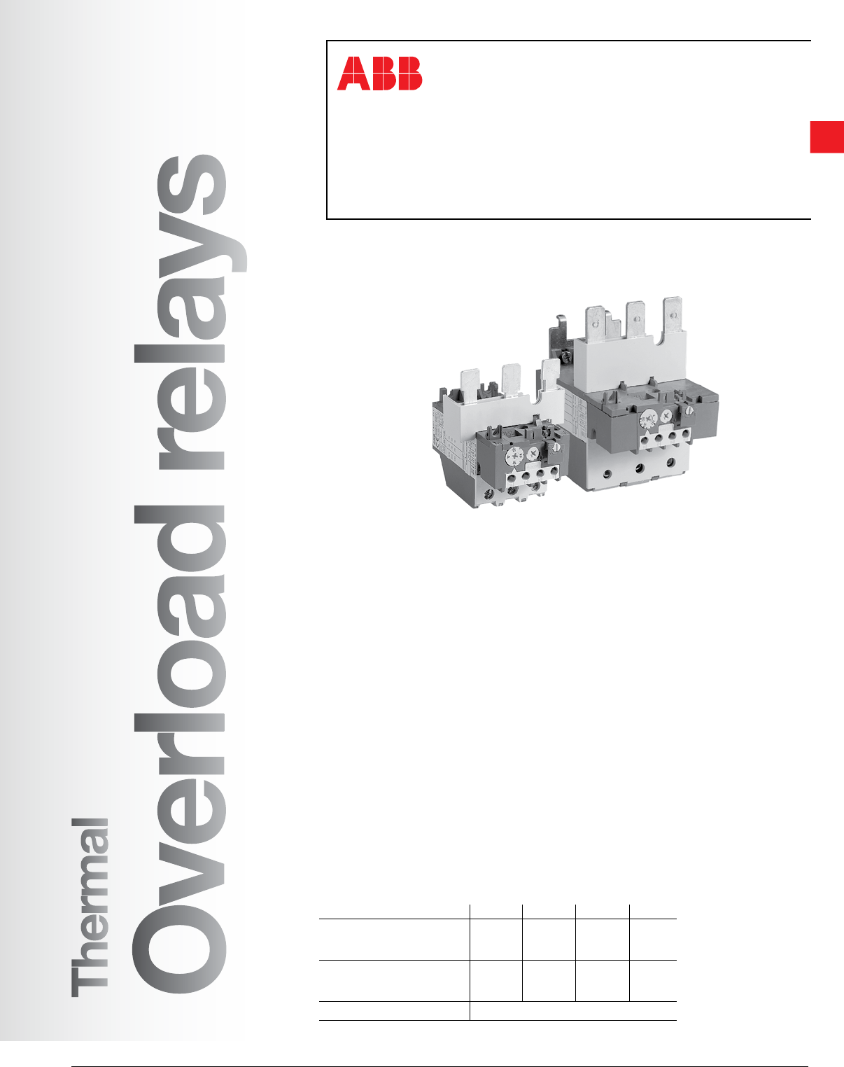
Thermal
Overload
relays
Low Voltage Products & Systems 2.1
ABB Inc. • 888-385-1221 • www.abb.us/lowvoltage 1SXU000023C0202
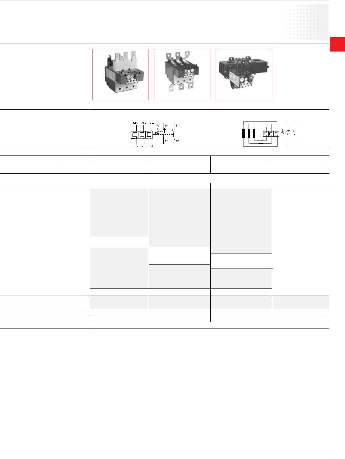
Thermal overload relays
Type TA
Class 10
Class 20
Description
• Available for starter construction with
A Line contactors and separate panel
mounting
• Designed for close couple mounting
• Separate base mounting available for all
overload relays
• Class 10 adjustable overload relays are
standard with all ABB Line starters
• Reset can also be adjusted to function as a
stop button
• Screwdriver guide holes
• All terminal screws are available from the
front
• UL File No: E48139
• CSA File No: LR98336
• Trip indication
• Remote trip and reset option available
• Single phase and phase unbalance protection
• Isolated alarm circuit (N.O.) contact
• Ambient compensation:
-25°C to +55°C (-13oF to +131oF)
• Manual test
• Manual or automatic reset
• Factory calibrated and tested
• Wide adjustment range
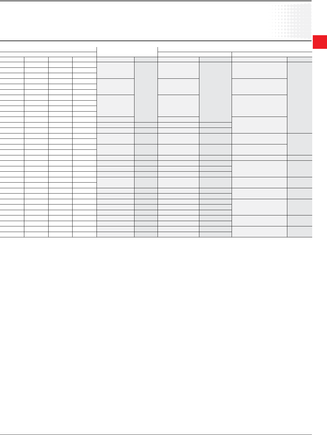
Tripping classes of the thermal overload relays
Standard classes in IEC 947-4-1 are classes: 10 A, 10, 20, 30. The tripping class indicates
according to IEC 947-4-1 the maximum tripping time in seconds under specied conditions of
test at 7.2 times the setting current and species tripping and non tripping times for 1.5 and 7.2
times the setting current. Mostly used class is 10 A.
Abstract from IEC 947-4-1
Tripping class 10 A 10 20 30
Max. tripping time
at 1.5 x setting current (s) 120 240 480 720
(warm state)
Tripping time at
7.2 x setting current (s) 2 – 10 4 – 10 6 – 20 9 – 30
(cold state)
At 1.05 x setting current no tripping
Thermal
Overload relays
2
Thermal
Overload
relays
2.2 Low Voltage Products & Systems
1SXU000023C0202 ABB Inc. • 888-385-1221 • www.abb.us/lowvoltage
Description
TA thermal overload relays are used with A Line contactors for the protection of
motors having a nominal voltage of up to 600VAC max per UL/CSA (690VAC and
800VDC per IEC).
Product range
• Standardrelays:
Types: TA25DU, TA42DU, TA75DU, TA80DU, TA110DU, TA200DU and TA450DU
– TA25 to TA110 and TA200 are directly connected in the motor circuit.
– TA450DU relays are fed through a linear type transformer
• Specialconstruction
Thermal overload relays with different certications and approvals.
Relays for protection EEx e motors.
Construction and function
• General
Thermal O/L relays and their accessories meet UL, CSA and most other important
international standards (IEC), European standards (EN) and the most important
national standards (DIN-VDE, NFC-UTE, BS, etc.). They meet the certication
and approval directives required throughout the world.
Thermal overload relays are 3 pole. The motor current ows through their bimetals
(1 per phase) which are indirectly heated. Under the effect of the heating, the
bimetals bend, cause the relay to trip and the position of the auxiliary contacts to
change.
The relay setting range is graduated in amps. In compliance with international and
national standards, the setting current is the motor nominal current and not the
tripping current (no tripping at 1.05 x setting current, tripping at 1.2 times setting
current).
The tripping curves (cold or warm starting, 3 phases and 2 phases) are shown on
page 2.14.
The relays are built to be self protecting in the event of an overload until the short
circuit protection device is activated.
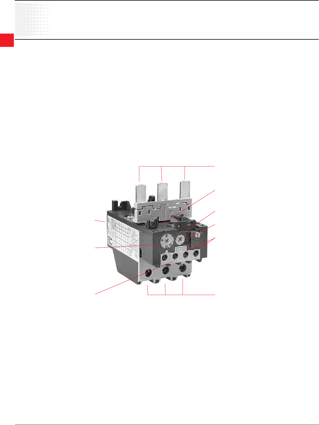
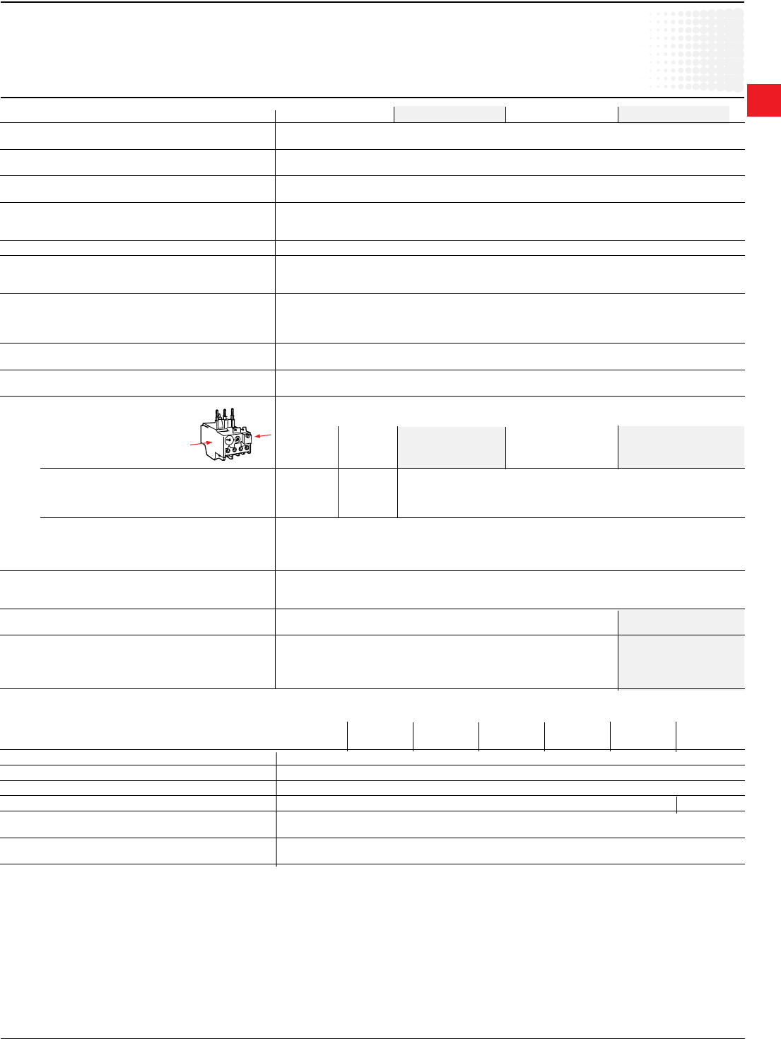
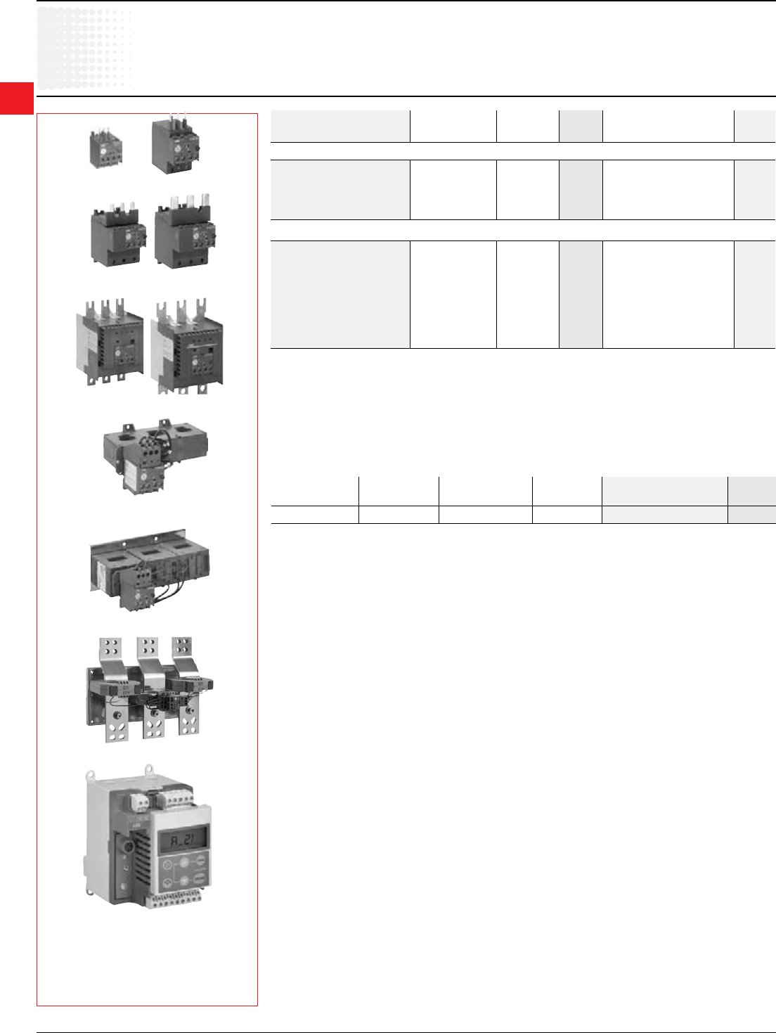
Frame size
TA....DU
Amp setting range
Signaling contact, (97, 98) Terminals T1, T2, T3
Manual test
Manual or automatic reset
Trip indication light
Tripping contact (95, 96)
Terminals L1, L3, L5
2
Thermal
Overload
relays
Low Voltage Products & Systems 2.3
ABB Inc. • 888-385-1221 • www.abb.us/lowvoltage 1SXU000023C0202
{
Description
Application
Technical data
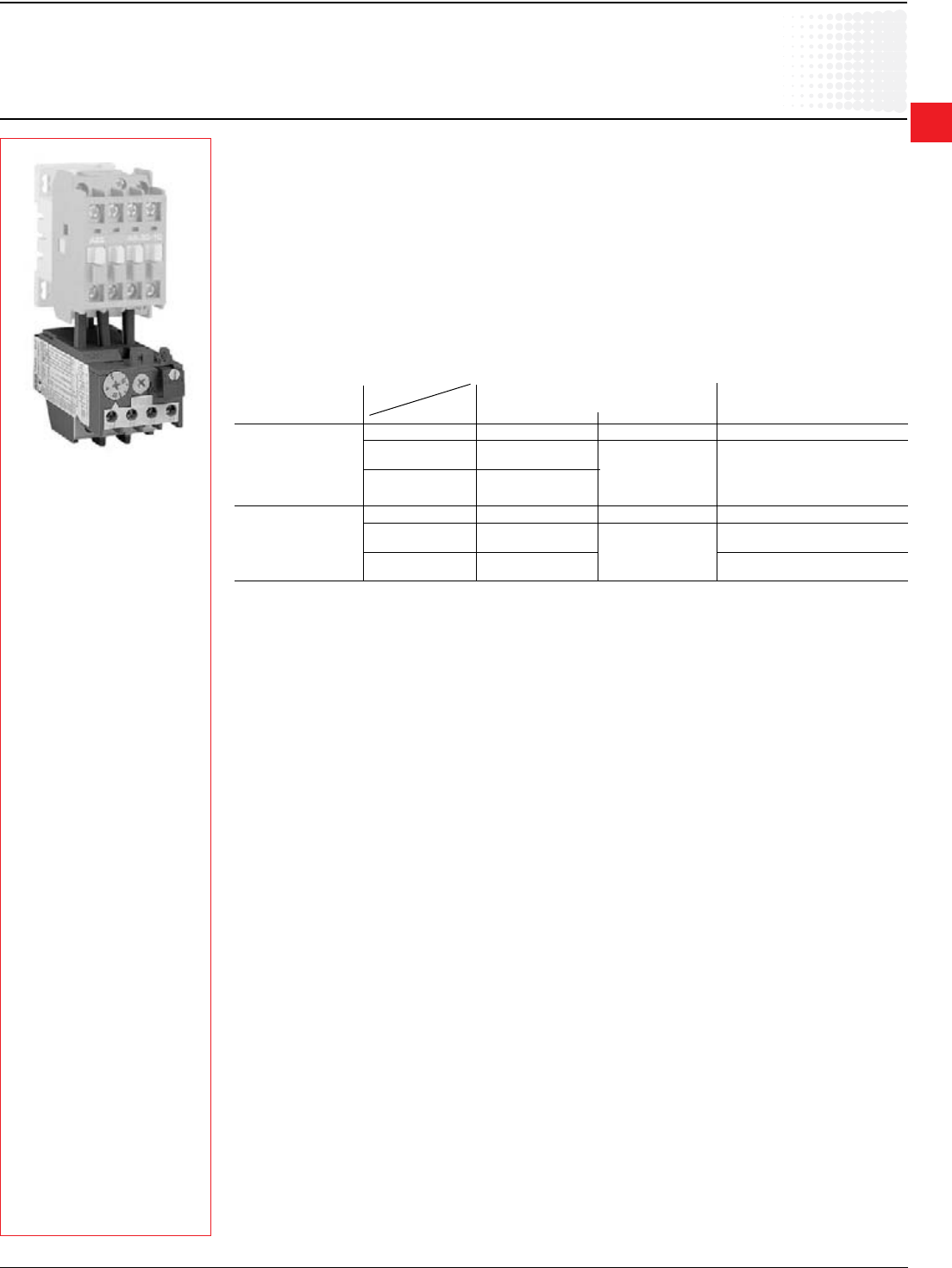
•Alltherelayshave:
– Free tripping: the resetting button, even if held in, does not prevent tripping of the thermal overload relay in the
event of a fault.
– Temperature compensation
– Phase failure protection according to IEC 947-4-1: Within the limits of the setting range, a reduced tripping time, and
thus improved motor protection, is obrtained in case of a phase failure.
– Tripping class: 10A, for TA relays
– Test functions and resetting: see table below.
• Auxiliarycontacts
The relays have two built in auxiliary contacts: NC marked 95-96; NO marked 97-98. Both contacts are physically separate
and can thus be used for 2 different circuits (control circuit and indication circuit).
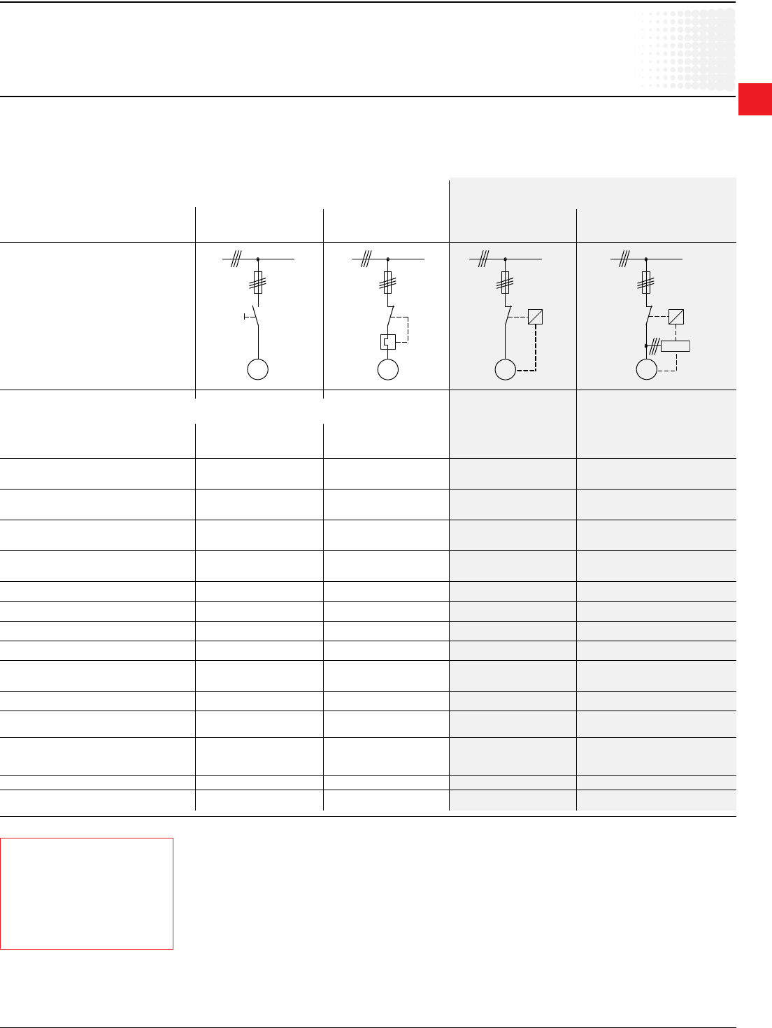
Function of TA25DU – TA450DU thermal O/L relays
Resetting Relay tripped 95-96 Open Relay not tripped 95-96 Closed
97-98 Closed 97-98 Open
Contacts Manual Automatic Both manual and automatic
Effect of blue Resetting Yes No No
button indexed 95-96 Closed when the
on R button is pressed No effect No effect
(RESET ONLY)
97-98 Open when the
button is pressed
Effect of blue Resetting Yes No No
button indexed 95-96 Closed when the Open when the button is pressed
on R/O button is released Closed when the button is released
(RESET/OFF) 97-98 Open when the No effect
button is pressed
No effect
{
TA25DU
2
Thermal
Overload
relays
2.4 Low Voltage Products & Systems
1SXU000023C0202 ABB Inc. • 888-385-1221 • www.abb.us/lowvoltage
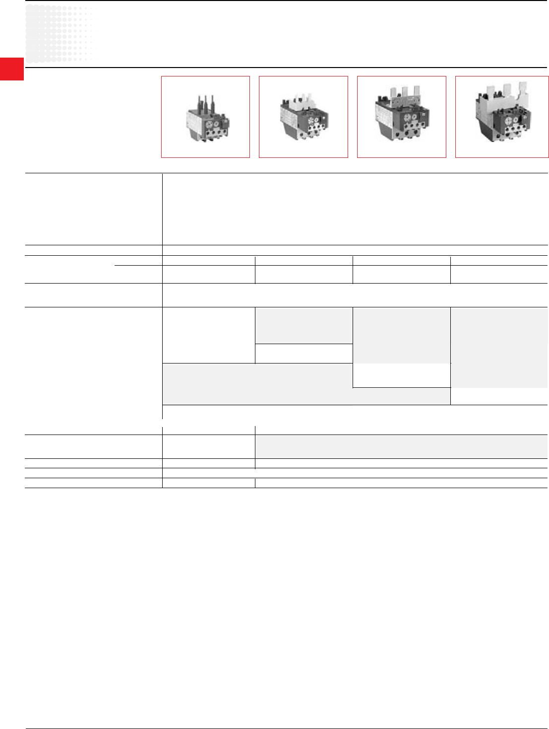
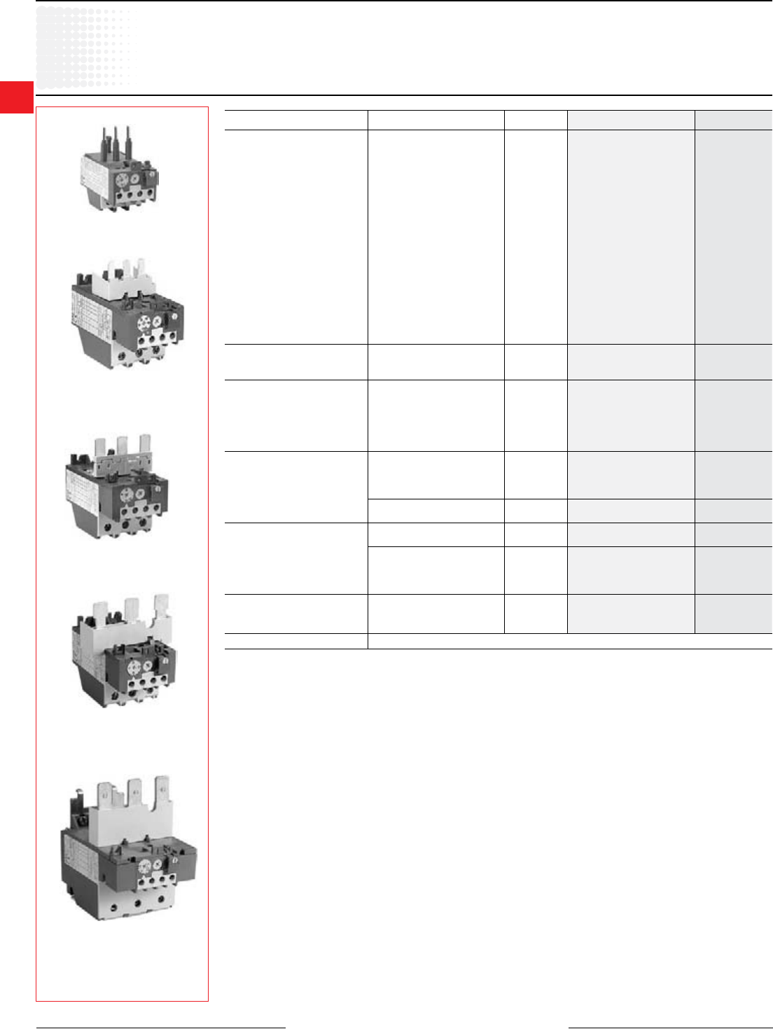
Selectionguide
TA25DU – TA80DU
Types TA25DU TA42DU TA75DU TA80DU
Main characteristics
Construction 3 pole with ambient temperature variation compensation.
Protection against single phase operation. Built in auxiliary contacts: 1N.O. + 1N.C.
Resetting Convertible: Manual to Automatic
Settingranges Number 18 3 6 4
from 0.1 – 0.16A 18 – 25A 18 – 25A 29 – 42A
to 24 – 32A 29 – 42A 60 – 80A 60 – 80A
Mounted with contactors
Mounting kit No kit is required for mounting thermal O/L relays below contactors
Types of contactors A/AE/AL9
for combined mounting A/AE/AL12
A/AE/AL16
A/AE/AL26
A/AE/AL30 A/AE30
A/AE/AL40 A/AE40
A/AE/AF50
A/AE/AF63
A/AE/AF75
A/AE/AF95
A/AE/AF110
Mounted separately (i.e. separate from contactor)
Separate mounting kit DB25 DB80
Accessories
Tripping coil DS25-A
Resetting coil DR25-A
Terminal shroud Terminals protected against direct contact (without the addition of terminal shrouds)
Function markers BA5-50
2
Thermal
Overload
relays
Low Voltage Products & Systems 2.5
ABB Inc. • 888-385-1221 • www.abb.us/lowvoltage 1SXU000023C0202
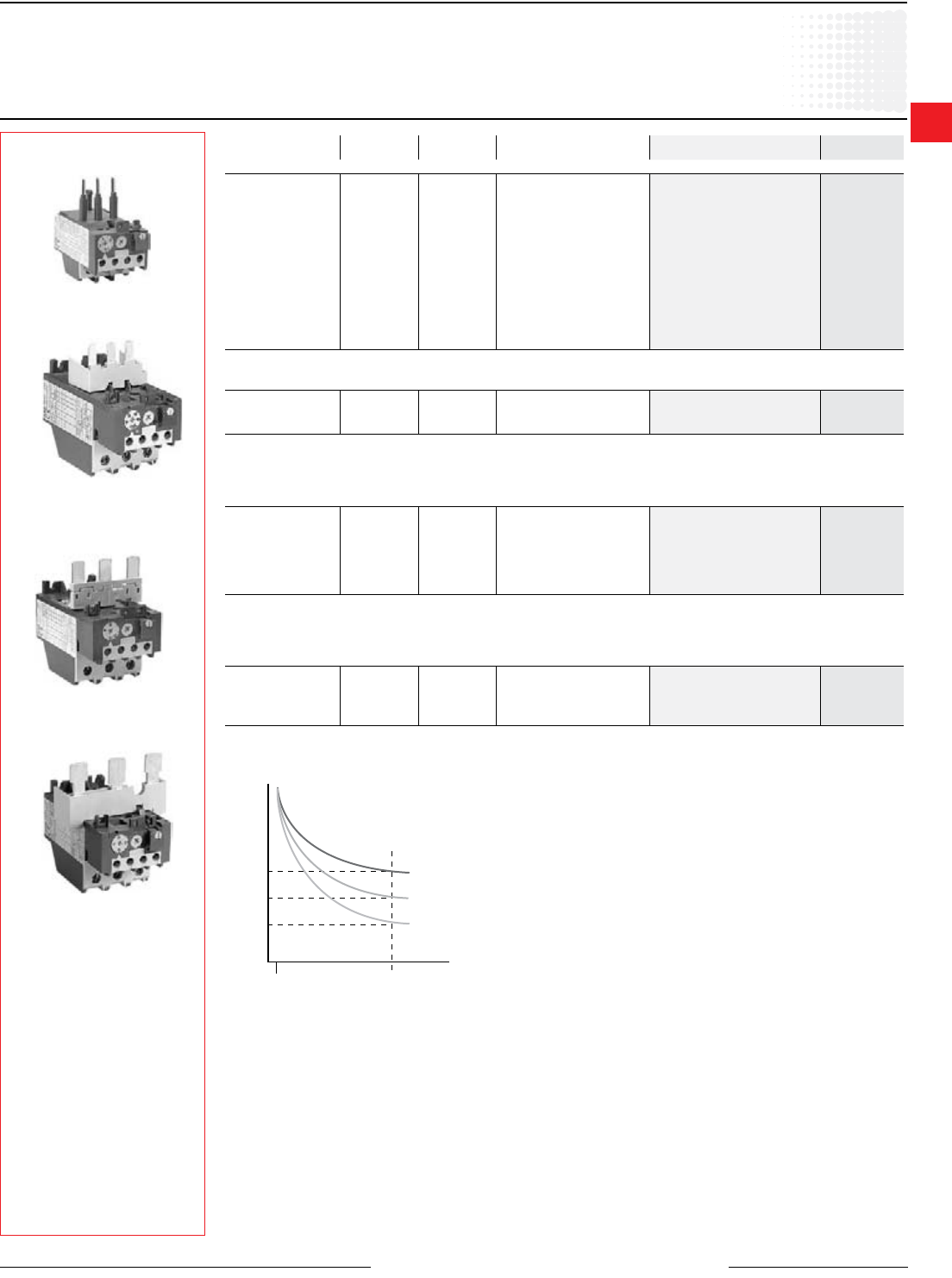
Selectionguide
TA110DU – TA450DU
Types TA110DU TA200DU TA450DU
Main characteristics
1 Terminals protected against direct contact (without the addition of terminal shrouds)
13 5 R
24 6
95 97
96 98
Construction 3 pole with ambient temperature variation compensation.
Protection against single phase operation. Built in auxiliary contacts: 1N.O. + 1N.C.
Resetting Convertible: manual to automatic
Settingranges Number 2 6 3
from A 65 – 90 65 – 90 130 – 185
to A 80 – 110 150 – 200 220 – 310
Mounted with contactors
Mounting kit No kit is required for mounting thermal O/L relays See page 2.7.
Types of contactors
for combined mounting
A/AE/AF95
A/AE/AF110
A/AF145
A/AF185 A/AF210 + DT450/A300
A/AF260 + DT450/A300
A/AF300 + DT450/A300
Mounted separately (i.e. separate from contactor)
Separate mounting kit DB200 No kit required for separate mounting of thermal O/L relays
Accessories
Tripping coil
Resetting coil
Terminal shroud 1 LT200 – LT450 –
Function markers BA5-50
2
Thermal
Overload
relays
2.6 Low Voltage Products & Systems
1SXU000023C0202 ABB Inc. • 888-385-1221 • www.abb.us/lowvoltage
TA42DU
TA75DU
TA80DU
TA110DU
TA25 - TA450
Class 10
for Contactors A9 – A/AF300
Discount schedule TAA [OW] — TA25
Discount schedule TBA [OX] — TA42, TA75
Discount schedule TCA [OY] — TA80, TA110, TA200, TA450
TA25DU
1 TA450 overloads require mounting kits for installation.
For
Contactor
Setting Range
A
Sufx
Code
Catalog
Number
List
Price
A/AE/AL9 – A/AE/AL40
0.1 - 0.16 ATA25DU0.16
$ 63
0.16 - 0.25 BTA25DU0.25
0.25 - 0.4 C TA25DU0.4
0.4 - 0.63 D TA25DU0.63
0.63 - 1.0 E TA25DU1.0
1.0 - 1.4 F TA25DU1.4
1.3 - 1.8 GTA25DU1.8
1.7 - 2.4 HTA25DU2.4
2.2 - 3.1 JTA25DU3.1
2.8 - 4.0 KTA25DU4.0
3.5 - 5.0 LTA25DU5.0
4.5 - 6.5 M TA25DU6.5
6.0 - 8.5 N TA25DU8.5
7.5 - 11 PTA25DU11
10 - 14 QTA25DU14
13 - 19 R TA25DU19
18 - 25 STA25DU25
24 - 32 TTA25DU32
A/AE30 - A/AE/40
18 - 25 ATA42DU25
7822 - 32 BTA42DU32
29 - 42 C TA42DU42
A/AE/AF50 - A/AE/AF75
18 - 25 ATA75DU25
102
22 - 32 BTA75DU32
29 - 42 C TA75DU42
36 - 52 D TA75DU52
45 - 63 E TA75DU63
60 - 80 F TA75DU80
A/AE/AF95 - A/AE/AF110
29 -42 C TA80DU42
135
36 - 52 D TA80DU52
45 - 63 E TA80DU63
60 - 80 F TA80DU80
65 - 90 ATA110DU90 165
80 - 110 BTA110DU110
A/AF145 - A/AF185
65 - 90 ATA200DU90 165
80 - 110 BTA200DU110
100 - 135 C TA200DU135
225
110 - 150 D TA200DU150
130 - 175 E TA200DU175
150 - 200 F TA200DU200
A/AF210 - A/AF300
130 - 185 ATA450DU185 1
488
165 - 235 BTA450DU235
220 - 310 C TA450DU310
AF400 - AF750 See electronic overloads, pages 2.21
2
Thermal
Overload
relays
Low Voltage Products & Systems 2.7
ABB Inc. • 888-385-1221 • www.abb.us/lowvoltage 1SXU000023C0202
T
ime
Ie (adjusted current)
No Tripping at 1.05 Ie
Tripping at 1.2 Ie within 2 hours
Class 10 4 - 10 sec
1.2 Ie 7.2 Ie
Class 20 6 - 20 sec
Class 30 9 - 30 sec
Setting range
A ... A Sufx Packing
unit piece Reference code Catalog number List
price
TA25DU trip class 20 for contactors A9 … A40 and (T) AL9 … (T) AL30
1.3 … 1.8 GZ 1 1SAZ211401R1025 TA25DU1.8-20
$ 63
1.7 … 2.4 HZ 1 1SAZ211401R1028 TA25DU2.4-20
2.2 … 3.1 JZ 1 1SAZ211401R1031 TA25DU3.1-20
2.8 … 4.0 KZ 1 1SAZ211401R1033 TA25DU4.0-20
3.5 … 5.0 LZ 1 1SAZ211401R1035 TA25DU5.0-20
4.5 … 6.5 MZ 11SAZ211401R1038 TA25DU6.5-20
6.0 … 8.5 NZ 11SAZ211401R1040 TA25DU8.5-20
7.5 … 11 PZ 1 1SAZ211401R1043 TA25DU11-20
10 … 14 QZ 1 1SAZ211401R1045 TA25DU14-20
13 … 19 RZ 11SAZ211401R1047 TA25DU19-20
18 … 25 SZ 1 1SAZ211401R1051 TA25DU25-20
24 … 32 (1) TZ 1 1SAZ211401R1053 TA25DU32-20 (1)
(1) with terminal block DX25: 1x16mm2
TA42DU trip class 20 for contactors A30, A40 and (T) AL30, (T) AL40
18 … 25 AZ 1 1SAZ311401R1001 TA42DU25-20
$ 7822 …32 BZ 1 1SAZ311401R1002 TA42DU32-20
29 … 42 CZ 11SAZ311401R1003 TA42DU42-20
TA75DU trip class 20 for contactors A50 … A75 and AE50 … AE75
18 … 25 AZ 1 1SAZ321401R1001 TA75DU25-20
$ 102
22 … 32 BZ 1 1SAZ321401R1002 TA75DU32-20
29 … 42 CZ 11SAZ321401R1003 TA75DU42-20
36 … 52 DZ 11SAZ321401R1004 TA75DU52-20
45 … 63 EZ 11SAZ321401R1005 TA75DU63-20
60 … 80 FZ 11SAZ321401R1006 TA75DU80-20
TA80DU trip class 20 for contactors A95, A110, AE 95 and AE110
29 … 42 AZ 1 1SAZ331401R1003 TA80DU42-20
$ 135
36 … 52 BZ 1 1SAZ331401R1004 TA80DU52-20
45 … 63 CZ 11SAZ331401R1005 TA80DU63-20
60 … 80 DZ 11SAZ331401R1006 TA80DU80-20
TA25 - TA80
Class 20
for Contactors A9 - A80
TA42DU
TA75DU
TA80DU
TA25DU
Discount schedule TAA [OW] — TA25
Discount schedule TBA [OX] — TA42, TA75
Discount schedule TCA [OY] — TA80, TA110, TA200, TA450
2
Thermal
Overload
relays
2.8 Low Voltage Products & Systems
1SXU000023C0202 ABB Inc. • 888-385-1221 • www.abb.us/lowvoltage
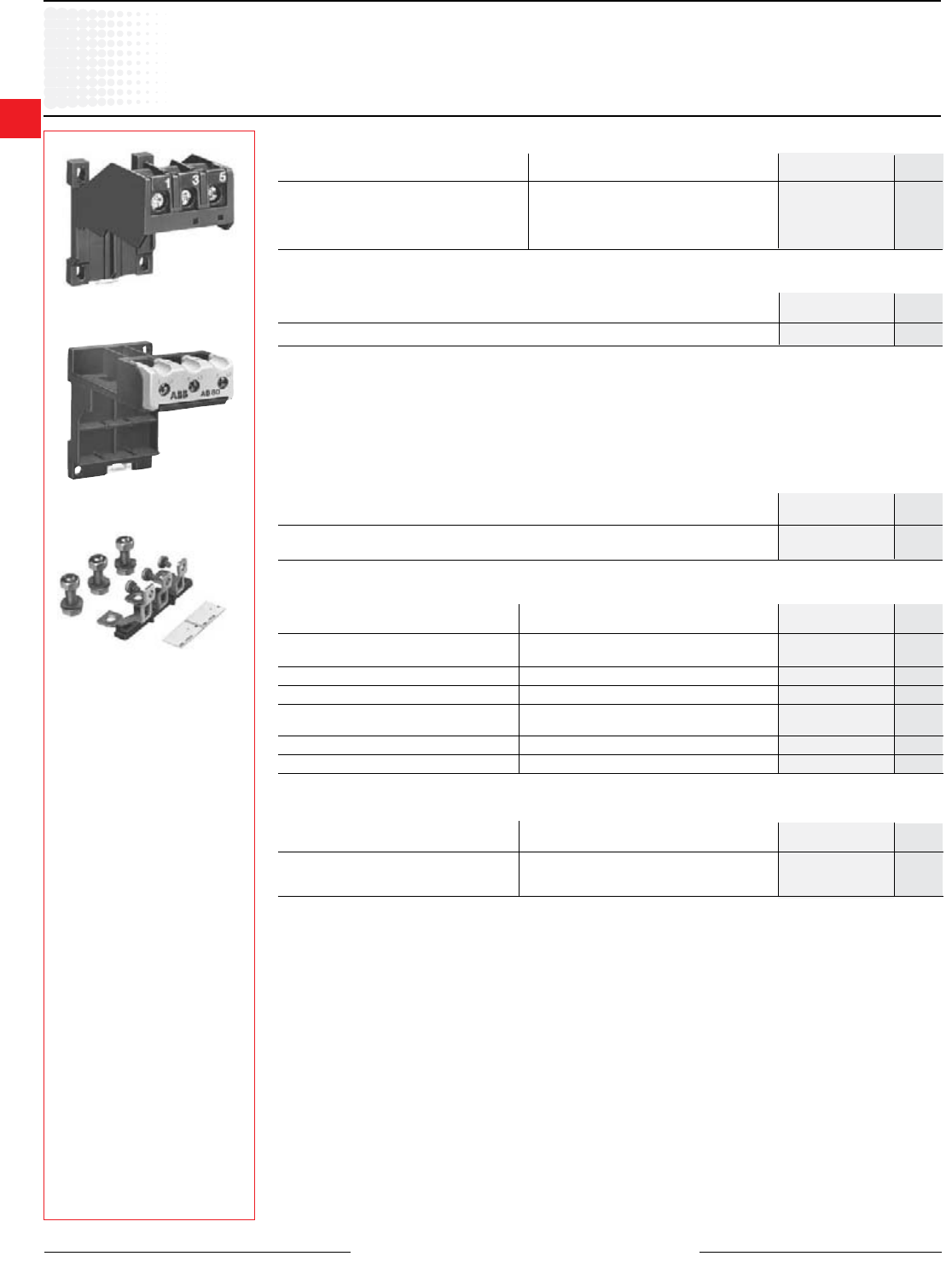
Accessories
DB25/25A
DB80
DB200
Separatemountingkits
Terminal block — AWG #8 cable
Mounting kit – for TA450 overload relay
A145 – A185 DT450/A185 $ 225
A210 – A300 DT450/A300
Catalog List
For contactor number price
LC terminal blocks can be used to convert standard connections into Faston connections: 2 x 6.3mm or 4 x 2.8mm per pole.
The connections are protected against accidental contact.
The LC30-T has a terminal block for the 3 power terminals and a second for the 4 auxiliary terminals of a TA25DU thermal
O/L relay.
The LC26-B1 has two identical terminal blocks each for 3 power terminals. This block allows the power terminals to be
mounted with two DB25 kits or a TA25DU thermal O/L relay and DB25 kit assembly.
NOTE: According to DIN 46429 part 1 and NFC 20-120 the max. capacity of a Faston connection is 25 A.
Terminal shrouds – for contactors and overload relays
Overload Catalog List
Contactor relay number price
A9 – A16 TA25DU Included —
A26 – A40
A30 – A40 TA42DU Included —
A50 – A75 TA75DU Included —
A95 – A110 TA80DU Included —
TA110DU
A145 – A185 TA200DU LT185-AY $ 10
A145 – A185 Load side of TA200DU LT200A185 50
Terminal lug kits
Wire For Catalog List
range overloads number price
6 – 250MCM TA110DU, TA200DU EHTK210 $ 45
4 – 400MCM TA450DU185 ATK300HK 78
(2) 4 – 500MCM TA450DU310 ATK300/2HK 120
Discount schedule ABA [OF] — A-contactor accessories
Discount schedule TAA [OW] — TA25
Discount schedule TBA [OX] — TA42, TA75
Discount schedule TCA [OY] — TA80, TA110, TA200, TA450
For O/L Amps Catalog List
relays number price
TA25DU 0.1 – 25 DB25/25A $ 30
TA25DU 24 – 32 DB25/32A 38
TA42DU, TA75DU, TA80DU 18 – 80 DB80 45
TA110DU, TA200DU 100 – 200 DB200 60
Catalog List
Mounting on: number price
TA25DU (25A or less) or DB25/25A DX25 $ 15
2
Thermal
Overload
relays
Low Voltage Products & Systems 2.9
ABB Inc. • 888-385-1221 • www.abb.us/lowvoltage 1SXU000023C0202
1 Cannot be used with TA42, TA75, or TA200 overload relays.
DS25A
DR25A
Application
• The DS25-A coil is used for remote electrical tripping of the TA25 DU thermal O/L relay and is connected to the relay's
normally closed 95-96 auxiliary contact.
• The DR 25-A coil is used for remote electrical resetting of the TA25DU thermal O/L relay which is
adjusted for “Manual resetting;” it is connected to the relay’s normally open 97-98 auxiliary contact.
Thecoilsarenotdesignedforcontinuousduty.Impulseduration:0.2to0.35s.
Set the button to “Man” (Manual resetting).
Mounting: clipped on to TA25DU thermal O/L relay.
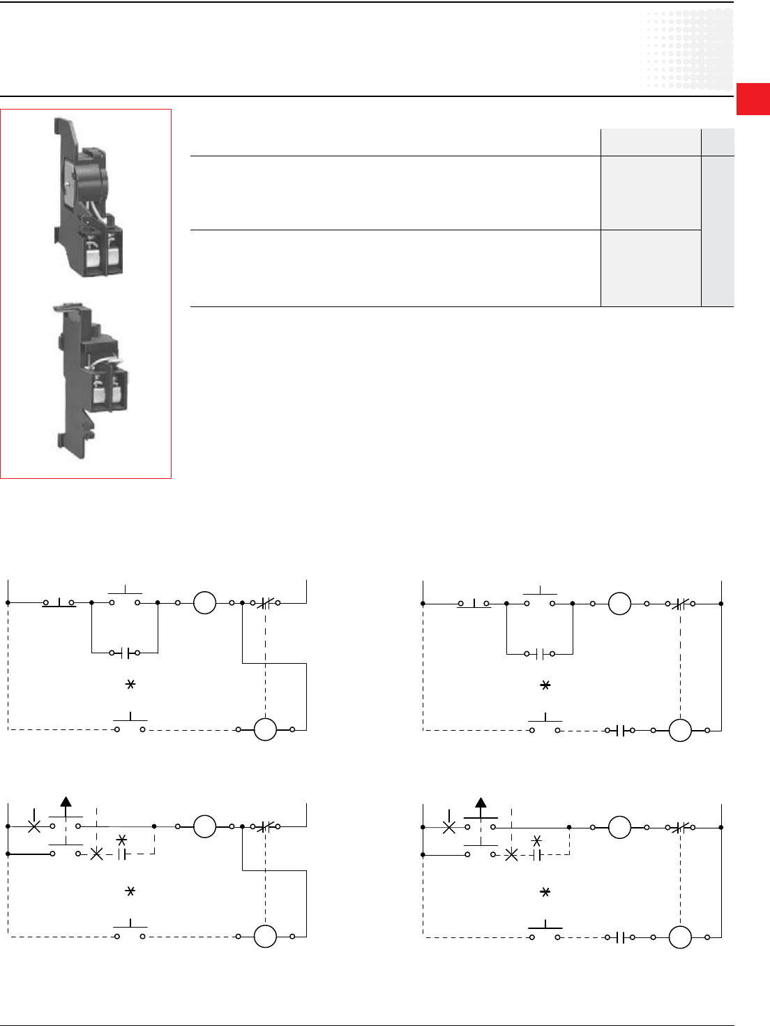
Installation diagrams
ForconnectionofDS25-AtoTA25DUrelay ForconnectionofDR25-AtoTA25DUrelay
Remote tripping coils
Discount schedule TAA [OW] — TA25
Accessories
23 24
13 14
HAND
OFF
AUTO
M
13 14
A1 A2
M
95 96
O L
21 22
STOP
START
13 14
E1 E2
OL
TRIPPING
COIL
OVERLOAD
TRIP
L1 L2/N
A1 A2
M
96
O L
E1 E2
OL
TRIPPING
COIL
OVERLOAD
TRIP
L1 L2/N
95
23 24
13 14
HAND
OFF
AUTO
M
13 14
A1 A2
M
95 96
O L
21 22
STOP
START
13 14
E1 E2
OL
RESETTING
COIL
OVERLOAD
RESET
L1 L2/N
A1 A2
M
96
O L
E1 E2
OL
RESETTING
COIL
OVERLOAD
RESET
L1 L2/N
95
97 98
O L
97 98
O L
U voltage at 50/60 Hz Catalog List
number 1 price
DS25-A remote tripping coil
24V DS25-A-24
48V DS25-A-48
110V DS25-A-110
220/380V DS25-A-220/380
500V DS25-A-500 $ 60
DS25-A remote resetting coil
24V DR25-A-24
48V DR25-A-48
110V DR25-A-110
220/380V DR25-A-220/380
500V DR25-A-500
2
Thermal
Overload
relays
2.10 Low Voltage Products & Systems
1SXU000023C0202 ABB Inc. • 888-385-1221 • www.abb.us/lowvoltage
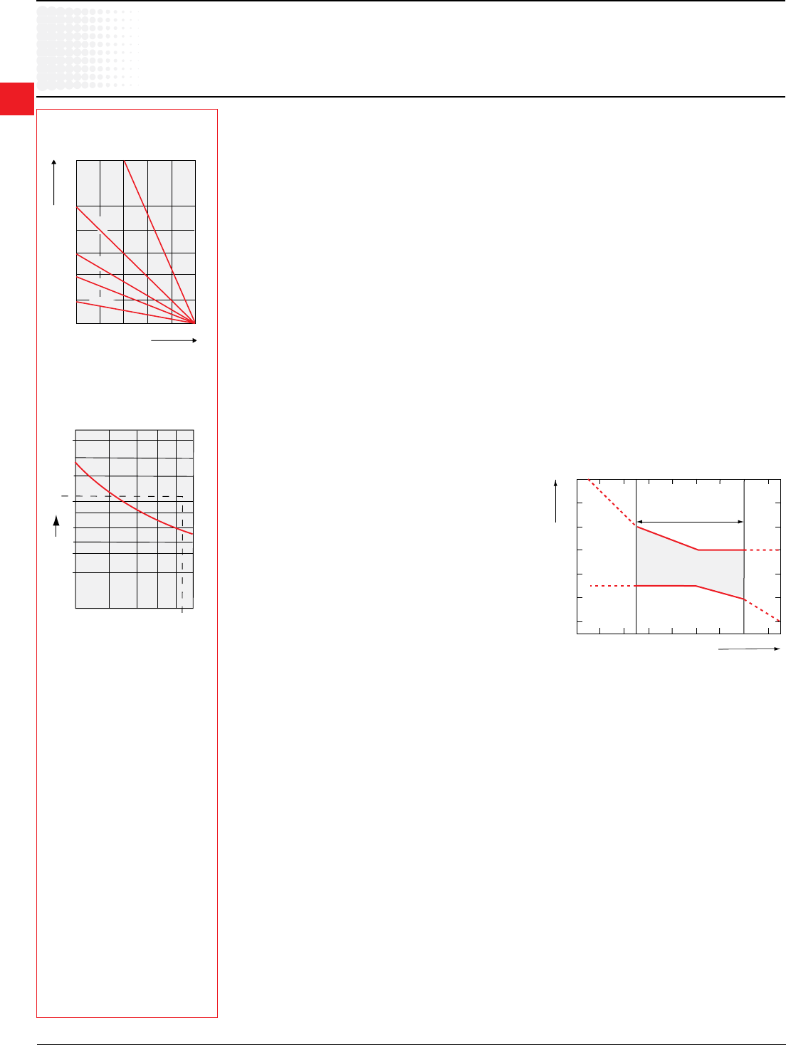
Ambient temperature compensation
Thermal O/L relays are compensated against ambient temperature
variations by a compensation bimetal which is sensitive to the
ambient temperature.
Thermal O/L relays are designed to operate between –5 °C and
+40 °C in compliance with standard IEC 947-4-1. For a wider range
of –25° C to +55 °C consult the graph opposite.
Example:tripping at – 25 °C. Tripping takes place before 1.5 times
the setting current.
Resetting:TA25DU – TA450 DU thermal O/L relays have convertible
manual/automatic resetting.
Delivery:in manual resetting mode.
Switching frequency
in relation to load factor.
ta:
motor starting time.
TA thermal O/L relay cold-state
tripping characteristics
Technical data
TA25DU – TA450DU
Switchingfrequency:
To avoid untimely tripping, TA and T thermal O/L relays have been designed to withstand roughly 15 switching operations
per hour with an approximately equal distribution between working and rest cycles.
In these conditions, the motor starting time must not exceed 1 second and the starting current must be lower than or equal
to 6 times the motor In.
For intermittent operations, the diagram opposite species relay operating limits.
Example: Motor starting time: 1 sec.
Load factor: 40 %
Switching frequency: 60 ops./h according to diagram
For a higher number of operations and for load variations (e.g. frequent starting and braking), it is advisable to use
CUSTORAPID® protection.
For motors subject to particularly severe operating conditions (e.g. locked rotor) it is advisable to use protection combined
with a thermal O/L relay and the CUSTORAPID® system.
Protection of motors with long starting time
See electronic overload relay section, pages 2.21 - 2.32.
Mounting position
On a support at an angle of ± 30° in relation to the vertical plane (standard position).
Other mounting positions possible, except mounting on a horizontal plane (in this case the tripping
mechanism would be located above the bimetals).
SpecialversionforEExemotors
Consult factory.
Tripping limits at ambient temperatures varying by + 20°C
020406080100(%)
Closing time
0
20
40
60
80
100
120
140
Switching frequency
(ops/h)
ta = 0.5s
ta = 1s
ta = 1.5s
ta = 3s
ta = 3.5s
Intermittent duty
Ambient temperature
compensation limits
according to IEC 947-4-1
No tripping
Multiple of the setting current
Tripping
Ambient temperature
-20 -10 0 10 20 30 40 50
0.9
1.0
1.1
1.2
1.3
1.4
1.5
40
20
1110
6
4
3
2
1
3 4 5 6 7
7.4
8
[s]
Multiple of the setting current
Tripping time
2
Thermal
Overload
relays
Low Voltage Products & Systems 2.11
ABB Inc. • 888-385-1221 • www.abb.us/lowvoltage 1SXU000023C0202
Technical data
TA25DU – TA80DU
A1 A2
Types TA25DU TA42DU TA75DU TA80DU
Standards: IEC 947-4-1, EN 60947-4-1
(international, European)
Rated insulation voltage Ui V 690
according to IEC 947-4-1
Rated impulse withstand voltage Uimp kV 6
according to IEC 947-4-1
Permissible ambient temperature
– for storage °C –40 to +70
– for operation °C –25 to +55 with temperature compensation (maximum values: see page 2.9)
Climatic withstand DIN 50017 Humidity in alternate climate KFW, 30 cycles
Mounting positions On a support at an angle of ±30° in relation to the vertical plane (standard position). Other positions
possible except mounting on a horizontal plane (in this case the tripping mechanism
would be located above the bimetals).
Shock withstand shock duration ms 15
at nominal Ie
Critical direction
of shocks A1, A2 multiples of g 12
Resistance to vibrations
(±1 mm, 50 Hz) multiples of g 8
Mounting – on contactor Latching below the contactor, screw xing on main terminals
– separate with DB - kit Using screws: 2 x M4 or 35 mm EN 50022
Terminals and cross-sectional areas TA25DU setting ranges:
for main conductors (motor side) from 0.1-0.16A 24-32 A
• screw terminal to 18-25A
– with cable clamp M4 –
– via tunnel connector – M5 M6 M6 M6
– at type for lug or bar – – – – –
• conductor cross-sectional area
– rigid solid or rigid stranded mm2 2 x 1.5 - 6 1 x 10 1 x 2.5 - 35 or 2 x 2.5 x 16
– exible with cable end mm2 2 x 1.5 - 4 2 x 0.75- 6 1 x 2.5 - 25 or 2 x 2.5 x 10
– recommended bars mm – – – – –
Terminals and cross-sectional area
for auxiliary conductors
• screw terminal (screw size)
– with cable clamp M 3.5
• conductor cross-sectional area
– rigid solid or rigid stranded 2 x mm2 0.75 - 4
– exible with cable end 2 x mm2 0.75 - 2.5
Degree of protection All the terminals are protected against direct contact according to All the terminals are
VDE 0106/Part. 100. (without additional terminal shrouds) protected against direct
direct contact according to
VDE0106/part 100 (with
additional terminal shrouds
for the main terminals
Pole Technical Characteristics
Types TA25 TA42 TA75 TA80 TA10 TA200 TA450
DU DU DU DU DU DU DU
Number of poles 3
Setting ranges see page 2.6
Tripping class according to IEC 947-4-1, EN 60947-1 10 A
Rated operational frequencies Hz 0 - 400 50/60
Max. switching frequency Up to 15 starts/h or 60 starts/h with 40 % on-load factor when neither
without untimely tripping the starting current of 6 x In nor the starting time 1 s are exceeded.
Resistance per phase in mΩ
and heat dissipation in W see page 2.13
2
Thermal
Overload
relays
2.12 Low Voltage Products & Systems
1SXU000023C0202 ABB Inc. • 888-385-1221 • www.abb.us/lowvoltage
Technical data
TA110DU – TA450DU
A1 A2
Types TA110DU TA200DU TA450DU
Standards: IEC 947-4-1, EN 60947-4-1
(international, European)
Rated insulation voltage Ui V 690 1000
according to IEC 947-4-1
Rated impulse withstand voltage Uimp kV 6 8
according to IEC 947-4-1
Permissible ambient temperature
– for storage °C –40 to +70
– for operation °C –25 to +55 with temperature compensation (maximum values: see page 2.9)
Climatic withstand DIN 50017 Humidity in alternate climate KFW, 30 cycles
Mounting positions On a support at an angle of ±30° in relation to the vertical plane (standard position). Other positions
possible except mounting on a horizontal plane (in this case the tripping mechanism would
be located above the bimetals).
Shock withstand shock duration ms 15
at nominal Ie
Critical direction
of shocks A1, A2 multiples of g 12
Resistance to vibrations
(±1 mm, 50 Hz) multiples of g 8
Mounting – on contactor 4 x M5 screws
– separate with DB - kit
Terminals and cross-sectional areas
for main conductors (motor side)
• screw terminal
– with cable clamp – – –
– via tunnel connector HC, M8 – –
– at type for lug or bar – M10 M10
• conductor cross-sectional area
– rigid solid or rigid stranded mm2 16 – 35 25 – 120 2 x 240
– exible with cable end mm2 16 – 35 25 – 95 2 x 240
– recommended bars mm 12 x 3 20 x 4 20 x 4...5
Terminals and cross-sectional area
for auxiliary conductors
• screw terminal (screw size)
– with cable clamp M 3.5
• conductor cross-sectional area
– rigid solid or rigid stranded 2 x mm2 0.75 - 4
– exible with cable end 2 x mm2 0.75 - 2.5
Degree of protection All the terminals are protected against direct contact according to
VDE 0106/Part. 100. (with additional terminal shrouds)
TechnicalcharacteristicsofauxiliarycontactsforthermalO/Lrelays:TA25DU to TA450DU
Auxiliary contacts normally closed N.C. normally open N.O.
Terminal marking 95-96 97-98
Rated operational voltage Ue VAC 500 500
Conventional thermal current (in free air) Ith A 10 6
Rated operational current Ie, AC-15
up to 240 V A 3.0 1.5
up to 440 V A 1.9 0.95
up to 500 V A 1.0 0.75
Rated operational current Ie DC-13
up to 250 V A 0.12 0.04
Protection against short circuits
gG (gl) fuses (according to IEC 269) A 10 6
S 271/S 281circuit-breaker A k3 k1
Maximum potential difference VAC 500 500
between N.C. and N.O. auxiliary contacts VDC 440 440
2
Thermal
Overload
relays
Low Voltage Products & Systems 2.13
ABB Inc. • 888-385-1221 • www.abb.us/lowvoltage 1SXU000023C0202
Technical data
Motor protection; Choice of protective device
Note:Fuses
Fuses do not protect motors against overloads. They are only used to protect installations and lines against short circuits.
To ensure efcient protection of a motor against short circuits, it is advisable to use aM type fuses in association with thermal
OLR relays.
For the selection of fuses or circuit-breakers, refer to the indications given in this catalogue concerning contactors on the one
hand and thermal O/L relays on the other.
In general, fuse protection for direct-on-line starting must be sized as follows:
– aM fuses: choose the fuse rating immediately above the full load value of the motor current.
– gG (gI) fuses: determine the fuse rating immediately above the motor current value and choose the next highest fuse rating.
Protectionefciency:
❑ unsuitable
■ very average efciency
● perfectly efcient
M
3~
M
3~
M
3~
M
3~
SPEM
Motor Protection — general
It is very important to choose an adequate protective device for the safety of the motor during operation and for its durability.
The efciency of protection methods varies according to the application. The overview below will help you to choose.
There is no general rule and we are available to advise you for special applications and especially in the case of difcult starting.
Protective devices and efficiency
Protectioninrelationtocurrent: Protectioninrelationtotemperature:
Fuses Protective relay with Motor protection Motor protection
phase fault protection via CUSTORAPID® via SPEM electronic
thermistor relay
Causes of dangerous overloads for the motor windings
1 Overload with current ❑●●●
1.2 times the nominal current
2 S1-S8 nominal duties ❑ ■ ● ●
according to IEC 34-I
3 Operation with starting, ❑ ■ ● ●
braking, reversal in operating direction
4 Operation with starting ❑ ■ ● ●
rate at > 15 cycles/hour
5 Locked rotor ■ ● ■ for motors with ●
special rotor
6 Overloads due to phase failure ❑ ● ● ●
7 Network undervoltage or overvoltage ❑ ● ● ●
8 Fluctuation of network frequency ❑ ● ●❑
9 Ambient temperature too high ❑ ● ●❑
10 Overheating due to external ❑ ❑ ●❑
cause (i.e. overheating of bearings)
11 Motor cooling disturbed ❑ ❑ ●❑
12 Undercurrent protection
on drop in load
13 Protection of asymmetry:
wrong phase direction
rotation or asymmetrical load
14 Earth fault protection
15 Automatic disconnection for
auxiliary load fault
2
Thermal
Overload
relays
2.14 Low Voltage Products & Systems
1SXU000023C0202 ABB Inc. • 888-385-1221 • www.abb.us/lowvoltage
Technical data
Resistance and Joule losses per phase
Short circuit protection
Resistance and Joule losses per phase, short circuit protection
Joule losses
Setting range Resistance per phase at
current per phase max. setting
from – to
A A mΩ W
TA25DU
0.1 – 0.16 85850 2.2
0.16 – 0.25 85150 2.2
0.25 – 0.4 13750 2.2
0.4 – 0.63 5370 2.2
0.63 – 1.0 2190 2.2
1.0 – 1.4 1120 2.2
1.3 – 1.8 670 2.2
1.7 – 2.4 383 2.2
2.2 – 3.1 229 2.2
2.8 – 4.0 137 2.2
3.5 – 5.0 87.5 2.2
4.5 – 6.5 61 2.2
6.0 – 8.5 30.4 2.2
7.5 – 11 18.2 2.2
10 – 14 11.2 2.2
13 – 19 6.3 2.3
18 – 25 4.7 2.9
24 – 32 3.2 3.3
TA42DU
18 – 25 5.5 3.43
22 – 32 2.89 2.91
29 – 42 1.84 3.24
TA75DU
18 – 25 5.5 3.43
22 – 32 2.89 2.91
29 – 42 1.84 3.24
36 – 52 1.3 3.51
45 – 63 0.936 3.72
60 – 80 0.615 3.94
TA80DU
29 – 42 1.84 3.24
36 – 52 1.3 3.51
45 – 63 0.936 3.72
60 – 80 0.615 3.94
Joule losses
Setting range Resistance per phase at
current per phase max. setting
from – to
A A mΩ W
TA110DU
80 – 110 0.378 3.78
TA200DU
100 – 135 0.318 5.79
110 – 150 0.255 5.74
130 – 175 0.214 6.55
150 – 200 0.182 7.28
TA450DU
130 – 185 — 2.5
165 – 235 — 2.5
220 – 310 — 2.5
2
Thermal
Overload
relays
Low Voltage Products & Systems 2.15
ABB Inc. • 888-385-1221 • www.abb.us/lowvoltage 1SXU000023C0202
Tripping time
Minutes
Tripping current
in multiples of the setting current
Seconds
120
100
80
60
40
40
20
20
10
10
8
8
6
8
6
4
4
2
2
1
1
0.8 1 2 3 4 5 6 7 8 9 101.2 1.5
from warm state
from cold state
3 Phases
3 Phases
2 Phases
2 Phases
Tripping time
Minutes
Tripping current
in multiples of the setting current
Seconds
120
100
80
60
40
40
20
20
10
10
8
8
6
8
6
4
4
2
2
1
1
0.8 1 2 3 4 5 6 7 8 9 101.2 1.5
from warm state
from cold state
3 Phases
3 Phases
2 Phases
2 Phases
Tripping time
Minutes
Tripping current
in multiples of the setting current
Seconds
120
100
80
60
40
40
20
20
10
10
8
8
6
8
6
4
4
2
2
1
1
0.8 1 2 3 4 5 6 7 8 9 101.2 1.5
from warm state
from cold state
3 Phases
3 Phases
2 Phases
2 Phases
6
8
0.8 1 1.2 1.5 2 3 4 5 6 7 8 9 10
1
2
4
8
10
20
40
1
2
4
6
10
20
40
60
80
100
120
from warm state
from cold state
3 Phases
3 Phases
2 Phases
2 Phases
Tripping time
Minutes
Tripping current
in multiples of the setting current
Seconds
6
8
0.8 1 1.2 1.5 2 3 4 5 6 7 8 9 10
Tripping current
as multiple of setting current
1
2
4
8
10
20
40
1
2
4
6
10
20
40
60
80
100
120
Triping time
minutes
seconds
from warm state
from cold state
2 Phase
3 Phase
2 Phase
3 Phase
TA200DU TA450DU
(tripping class 10A) (tripping class 10A)
Technical data
Tripping curves
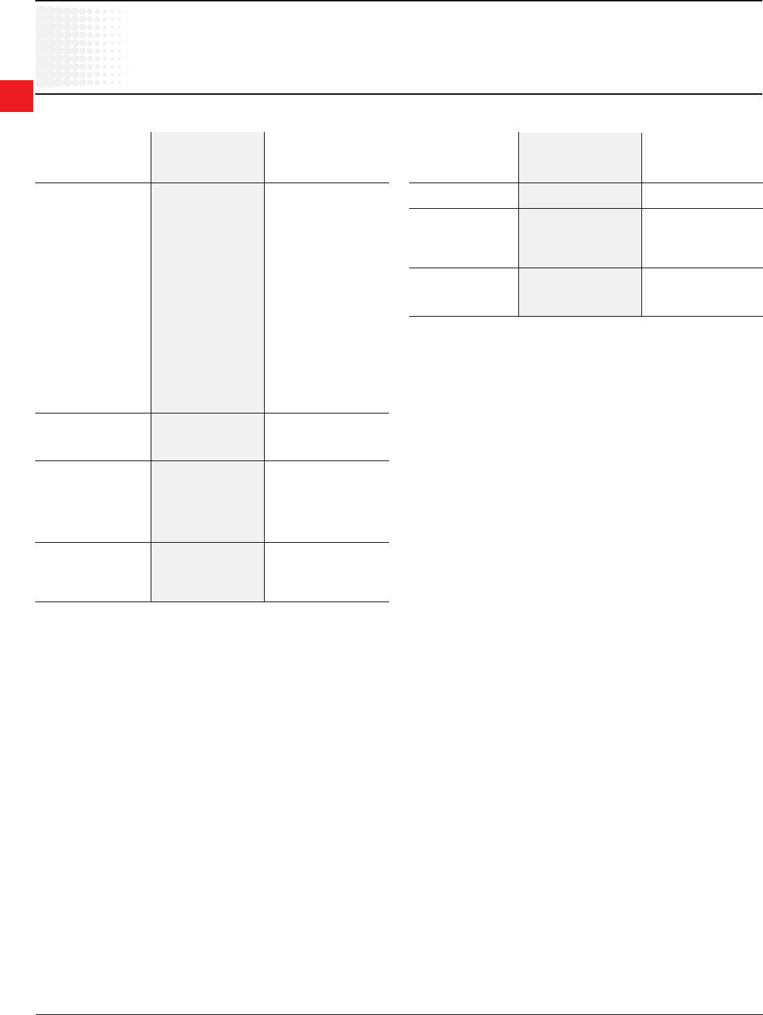
TA25DU TA75DU TA110DU/SU TA450DU
Thermal O/L relay tripping curves
TA25DU TA42DU, TA75DU and TA80DU TA110DU
(tripping class 10A) (tripping class 10A) (tripping class 10A)
TA-DU thermal O/L relays are 3-pole with manual or automatic resetting mode selection.
The resetting button can also be used for stopping.
Built-in auxiliary contacts are physically separate and, consequently, can be used in different circuits (control circuit/indication circuit).
Each relay is temperature compensated and ensures phase failure protection.
Protective relays up to size TA75DU are protected against direct contact via the front face. Terminal shrouds are available for TA200DU to TA450DU size relays.
The connecting terminals are delivered in open position with (+,-) pozidriv screws and screwdriver guidance. It is advisable to tighten unused terminal screws.

2
Thermal
Overload
relays
2.16 Low Voltage Products & Systems
1SXU000023C0202 ABB Inc. • 888-385-1221 • www.abb.us/lowvoltage
Type 1 co-ordination according to IEC 60947-4-1: Under short-circuit conditions, the starter shall cause no danger to persons or
installation and may not be suitable for further service without repair and replacement of parts.
Type 2 co-ordination according to IEC 60947-4-1: Under short-circuit conditions, the contactor or starter shall cause no danger
to persons or installation and shall be suitable for further use. The risk of contact welding is recognized, in which case the manu-
facturer shall indicate the measures to be taken as regards the maintenance of the equipment.
Standardtechnicaldata,operatingdataanddimensionsseeTA...RelayMainCatalog
Setting Range Short-circuit protection (fuses) UL UL Resistance
per phase
Power Loss
per phase
Type "2"
co-ordination
Type "1"
co-ordination
from ... to
A A
gL/gG
A
gL/gG
A
Fuse/600V
K5
A
600V
CB
A
mOhm
at upper
current setting
W
Thermal overload relay TA25DU trip class 20
1.3 … 1.8 10 25 6 - 670.3 2.2
1.7 … 2.4 16 25 10 - 381 2.2
2.2 … 3.1 16 25 10 - 235.3 2.3
2.8 … 4.0 20 25 15 - 140.7 2.3
3.5 … 5.0 25 25 20 - 91.2 2.3
4.5 … 6.5 25 25 25 - 54.5 2.3
6.0 … 8.5 32 32 35 - 32.1 2.3
7.5 … 11 40 40 45 - 15.5 1.9
10 … 14 50 50 60 - 12 2.4
13 … 19 63 63 60 - 6.3 2.3
18 … 25 80 80 70 - 4.7 3.0
24 … 32 100 100 100 - 3.2 3.3
Thermal overload relay TA42DU trip class 20
18 … 25 100 160 80 80 5.5 3.43
22 … 32 125 160 100 80 2.89 2.91
29 … 42 160 160 150 80 1.84 3.24
Thermal overload relay TA75DU trip class 20
18 …25 100 160 80 80 5.5 3.43
22 … 32 125 160 100 80 2.89 2.91
29 …42 160 160 150 80 1.84 3.24
36 … 52 200 200 175 125 1.3 3.51
45 … 63 200 250 200 125 0.936 3.72
60 … 80 250 250 250 125 0.615 3.94
Thermal overload relay TA80DU trip class 20
29 … 42 160 160 150 80 1.84 3.24
36 … 52 200 200 175 125 1.3 3.51
45 … 63 200 250 200 125 0.936 3.72
60 … 80 250 250 250 150 0.615 3.94
Technical data, Class 20 OLR
Resistance and Joule losses per phase
Short circuit protection

2
Thermal
Overload
relays
Low Voltage Products & Systems 2.17
ABB Inc. • 888-385-1221 • www.abb.us/lowvoltage 1SXU000023C0202
Technical data, Class 20 OLR
Short-circuit ratings
Setting Range Catalog number Voltage 5 kA 10 kA 18 kA
A ... A 480V Fuse K5 CB Fuse K5 CB Fuse K5 CB
1.3 … 1.8 TA25DU-1.8-20
TA25DU
6 -6 -6 -
1.7 … 2.4 TA25DU-2.4-20 10 - 10 - 10 -
2.2 … 3.1 TA25DU-3.1-20 10 - 10 - 10 -
2.8 … 4.0 TA25DU-4.0-20 15 - 15 - 15 -
3.5 … 5.0 TA25DU-5.0-20 20 - 20 - 20 -
4.5 … 6.5 TA25DU-6.5-20 25 - 25 - 25 -
6.0 … 8.5 TA25DU-8.5-20 35 - 35 - 35 -
7.5 … 11 TA25DU-11-20 45 - 45 - 45 -
10 … 14 TA25DU-14-20 60 - 60 - 60 -
13 … 19 TA25DU-19-20 60 - 60 - 60 -
18 … 25 TA25DU-25-20 70 - 70 - 70 -
24 … 32 TA25DU-32-20 100 - 100 - 100 -
18 … 25 TA42DU-25-20
TA42DU
80 80 80 - 150 -
22 …32 TA42DU-32-20 100 80 100 - 150 -
29 … 42 TA42DU-42-20 150 80 150 - 200 -
18 … 25 TA75DU-25-20
TA75DU
80 80 80 - 150 -
22 … 32 TA75DU-32-20 100 80 100 - 150 -
29 … 42 TA75DU-42-20 150 80 150 - 200 -
36 … 52 TA75DU-52-20 175 125 175 - 250 -
45 … 63 TA75DU-63-20 200 125 200 - 250 -
60 … 80 TA75DU-80-20 250 125 250 - 250 -
29 … 42 TA80DU-42-20
TA80DU
150 80 150 - 150 -
36 … 52 TA80DU-52-20 175 125 175 - 175 -
45 … 63 TA80DU-63-20 200 125 200 - 250 -
60 … 80 TA80DU-80-20 250 150 250 - 250 -
Setting Range Catalog number Voltage 5 kA 10 kA 18 kA
A ... A 600V Fuse K5 CB Fuse K5 CB Fuse K5 CB
1.3 … 1.8 TA25DU-1.8-20
TA25DU
6 -6 -6 -
1.7 … 2.4 TA25DU-2.4-20 10 - 10 - 10 -
2.2 … 3.1 TA25DU-3.1-20 10 - 10 - 10 -
2.8 … 4.0 TA25DU-4.0-20 15 - 15 - 15 -
3.5 … 5.0 TA25DU-5.0-20 20 - 20 - 20 -
4.5 … 6.5 TA25DU-6.5-20 25 - 25 - 25 -
6.0 … 8.5 TA25DU-8.5-20 35 - 35 - 35 -
7.5 … 11 TA25DU-11-20 45 - 45 - 45 -
10 … 14 TA25DU-14-20 60 - 60 - 60 -
13 … 19 TA25DU-19-20 60 - 60 - 60 -
18 … 25 TA25DU-25-20 70 - 70 - 70 -
24 … 32 TA25DU-32-20 100 - 100 - 100 -
18 … 25 TA42DU-25-20
TA42DU
80 80 80 - 150 -
22 …32 TA42DU-32-20 100 80 100 - 150 -
29 … 42 TA42DU-42-20 150 80 150 - 200 -
18 … 25 TA75DU-25-20
TA75DU
80 80 80 - 150 -
22 … 32 TA75DU-32-20 100 80 100 - 150 -
29 … 42 TA75DU-42-20 150 80 150 - 150 -
36 … 52 TA75DU-52-20 175 125 175 - 175 -
45 … 63 TA75DU-63-20 200 125 200 - 250 -
60 … 80 TA75DU-80-20 250 125 250 - 250 -
29 … 42 TA80DU-42-20
TA80DU
150 80 150 - 150 -
36 … 52 TA80DU-52-20 175 125 175 - 175 -
45 … 63 TA80DU-63-20 200 125 200 - 250 -
60 … 80 TA80DU-80-20 250 150 250 - 250 -

2
Thermal
Overload
relays
2.18 Low Voltage Products & Systems
1SXU000023C0202 ABB Inc. • 888-385-1221 • www.abb.us/lowvoltage
Tripping times of thermal overload relays as a function of a multiple of the setting current from cold state
(tolerance +/- 20% of the tripping time).
Technical data, Class 20 OLR
Table for tripping time
Setting Range Tripping times of thermal overload relays:
at multiple of setting current
3 4 5 6 7.2 8
from ... to
A A Tripping times in seconds
Thermal overload relays TA25DU trip class 20
1.3 … 1.8 47.1 27 20.3 15.8 12.7 11.5
1.7 … 2.4 43.3 25 18.9 14.4 11.9 10.4
2.2 … 3.1 47.5 28 20.8 16 13.1 11.8
2.8 … 4.0 45.6 27 19.8 15.3 12.5 11
3.5 … 5.0 47.8 29 21.2 16 13.2 11.8
4.5 … 6.5 47.4 28 20.3 15.5 12.5 11
6.0 … 8.5 46.1 27 20 15 11.7 10
7.5 … 11 42.3 25 17.8 14.1 10.9 10.5
10 … 14 39.4 25 16.8 13 9.9 8.5
13 … 19 38.1 21 13.6 10 7.4 6.2
18 … 25 44.4 25 16.1 11 9 8
24 … 32 44.4 27 17.7 13 9.8 8.5
Thermal overload relays TA42DU, TA75DU, TA80DU trip class 20
18 … 25 51.6 29 20.3 15 11.7 10
22 … 32 67.9 38 26.9 20 14.8 12.5
29 … 42 58.8 33 22.5 16 12.2 10.3
36 ... 52 59.9 34 22.7 16 12.3 10.5
45 ... 63 65.8 34 22.4 16 12.4 10.5
60 ... 80 71.9 35 23.4 17 13.9 12
2
Thermal
Overload
relays
Low Voltage Products & Systems 2.19
ABB Inc. • 888-385-1221 • www.abb.us/lowvoltage 1SXU000023C0202
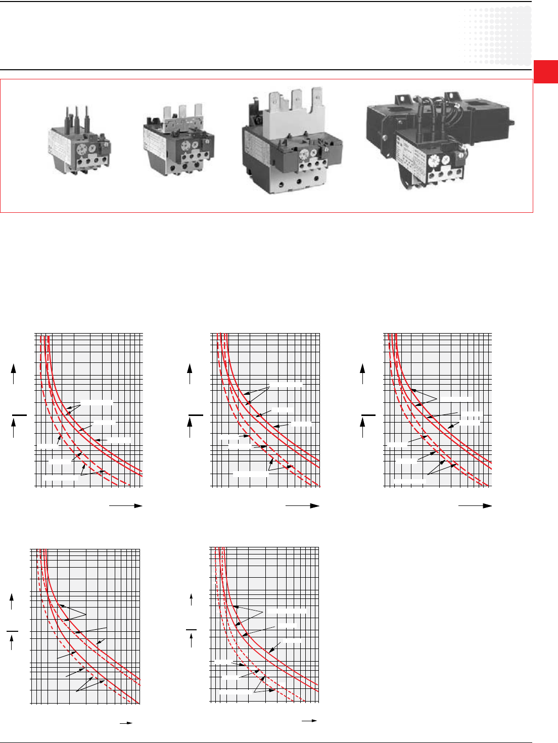
Approximatedimensions
T25DU – TA42DU
TA25DU
TA42DU
TA25DU & DB25
TA25DU & DB25/32
TA42DU / TA75DU & DB80
00.00
00.00
Inches
[Millimeters]
TA25/32A
0.24
3.70
94
0.51
13
3.15
80
1.73
44
3.70
94
6
TA25DU32
only
TA42
3.54
90
0.24
6
4.35
110.5
2.13
54
0.51
13
TA25+AB25
3.31
84
1.73
44
0.35
6
4.25
108
0.24
6
0.51
13
1.38
35
1.88
48
4.2
0.17
TA25/32A+AB32
1.38
35
1.88
48
4.2
0.17
0.35
6
4.25
108
0.24
6
0.51
13
1.73
44
4.41
112
TA75+AB80A
0.51
13
3.86
98
2.36
60
5.03
127.7
0.24
6
4.2
1.97
50
2.95
75
0.17
2
Thermal
Overload
relays
2.20 Low Voltage Products & Systems
1SXU000023C0202 ABB Inc. • 888-385-1221 • www.abb.us/lowvoltage
TA75
3.99
93
2.13
54
0.24
6
4.35
110.5
0.51
13
TA110 OVERLOAD RELAY
6 - 0.21 HOLES
2.52
64.0
0.24
6.0
.61
15.5
1.98
50.2
1.48
37.5
3.14
80.0
5.44
138.1
TOUCH SAFE COVER
4.73
120.1
0.24
6.0
0.07
1.7
1.18
2 - M4 Mtg. Slots
30.0
0.47
12.0
0.47
12.0
3.77
2.85
54.0
95.7
72.3
TA80 OVERLOAD RELAY
4.37
0.50
12.5
111.0
TOUCH SAFE COVER
2.12
TA200DU
00.00
00.00
Inches
[Millimeters]
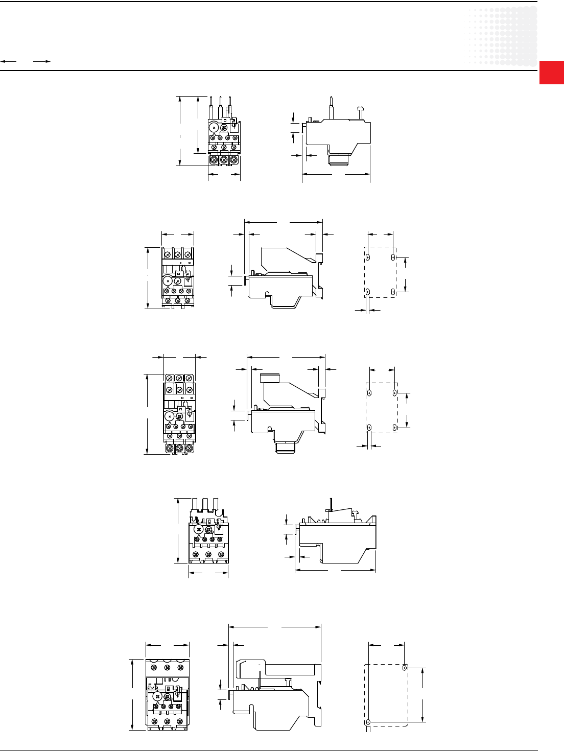
Approximatedimensions
TA75DU – TA200DU
TA75DU
TA80DU
TA110DU
2
Thermal
Overload
relays
Low Voltage Products & Systems 2.21
ABB Inc. • 888-385-1221 • www.abb.us/lowvoltage 1SXU000023C0202
Approximatedimensions
TA450DU
TA450DU
T450DU/SU
168.0
4.5
58.0 58.0
21.0
28.3
0.18
6.62
2.28
2.28
1.11
0.82
6.0 76.0
24.5
55.0
193.0
2.17
0.96
7.60
0.24 2.99
5.0 DIA.
0.2 DIA.
642
00.00
00.00
Inches
[Millimeters]

2
Thermal
Overload
relays
2.22 Low Voltage Products & Systems
1SXU000023C0202 ABB Inc. • 888-385-1221 • www.abb.us/lowvoltage
Notes
2
Electronic
Overload
relays
Low Voltage Products & Systems 2.23
ABB Inc. • 888-385-1221 • www.abb.us/lowvoltage 1SXU000023C0202
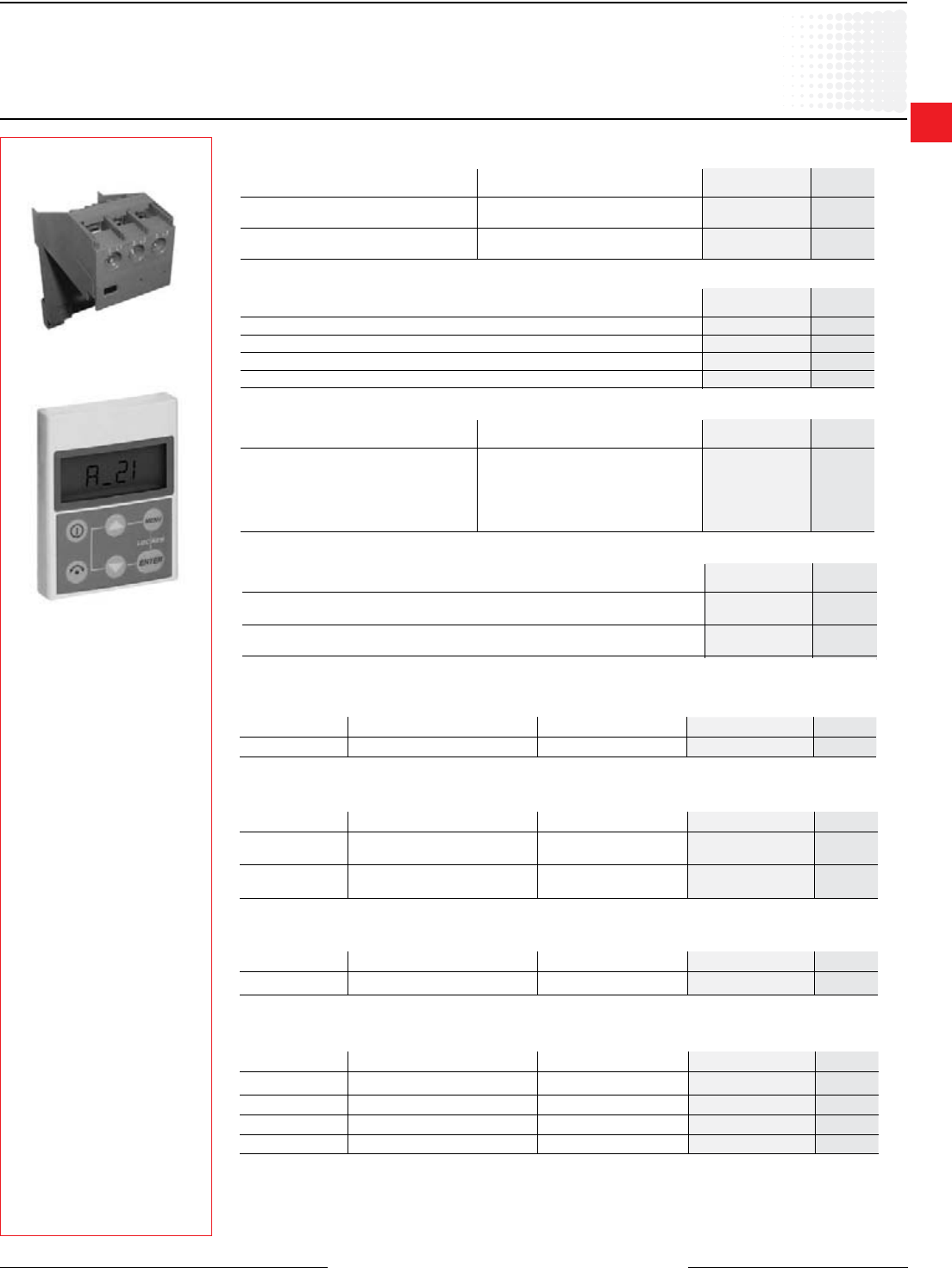
Electronic overload relays
E16DU – E1250DU
Description
• Available for starter construction with
A Line contactors and separate panel
mounting
• Designed for close couple mounting
• Separate base mounting available for
all overload relays
• E16DU Class 10, 20, & 30, eld
selectable
• E200DU – E800DU Class 10, 20 & 30,
eld selectable
• Stop button
• Screwdriver guide holes
• All terminal screws are available from the
front
• Single phase and phase unbalance
protection
• Isolated alarm circuit (N.O.) contact
• Ambient compensation:
-25°C to +70°C (-13oF to +158oF)
• Manual test
• Manual or automatic reset
• Factory calibrated and tested
• Wide adjustment range
• UL File No: E48139
• CSA File No: LR98336
Tripping classes of the thermal overload relays
Standard classes in IEC 947-4-1 are classes: 10 A, 10, 20, 30. The
tripping class indicates according to IEC 947-4-1 the maximum tripping
time in seconds under specied conditions of test at 7.2 times the
setting current and species tripping and non tripping times for 1.5 and
7.2 times the setting current. Mostly used class is 10 A.
Electronic
Overload relays
Abstract from IEC 947-4-1
Tripping class 10 A 10 20 30
Max. tripping time
at 1.5 x setting current (s) 120 240 480 720
(warm state)
Tripping time at
7.2 x setting current (s) 2 – 10 4 – 10 6 – 20 9 – 30
(cold state)
At 1.05 x setting current no tripping
2
Electronic
Overload
relays
2.24 Low Voltage Products & Systems
1SXU000023C0202 ABB Inc. • 888-385-1221 • www.abb.us/lowvoltage
Catalog number explanation
Frame size
E16DU
E200DU
E320DU
E500DU
E800DU Amp rating
1.0
200
320
500
800
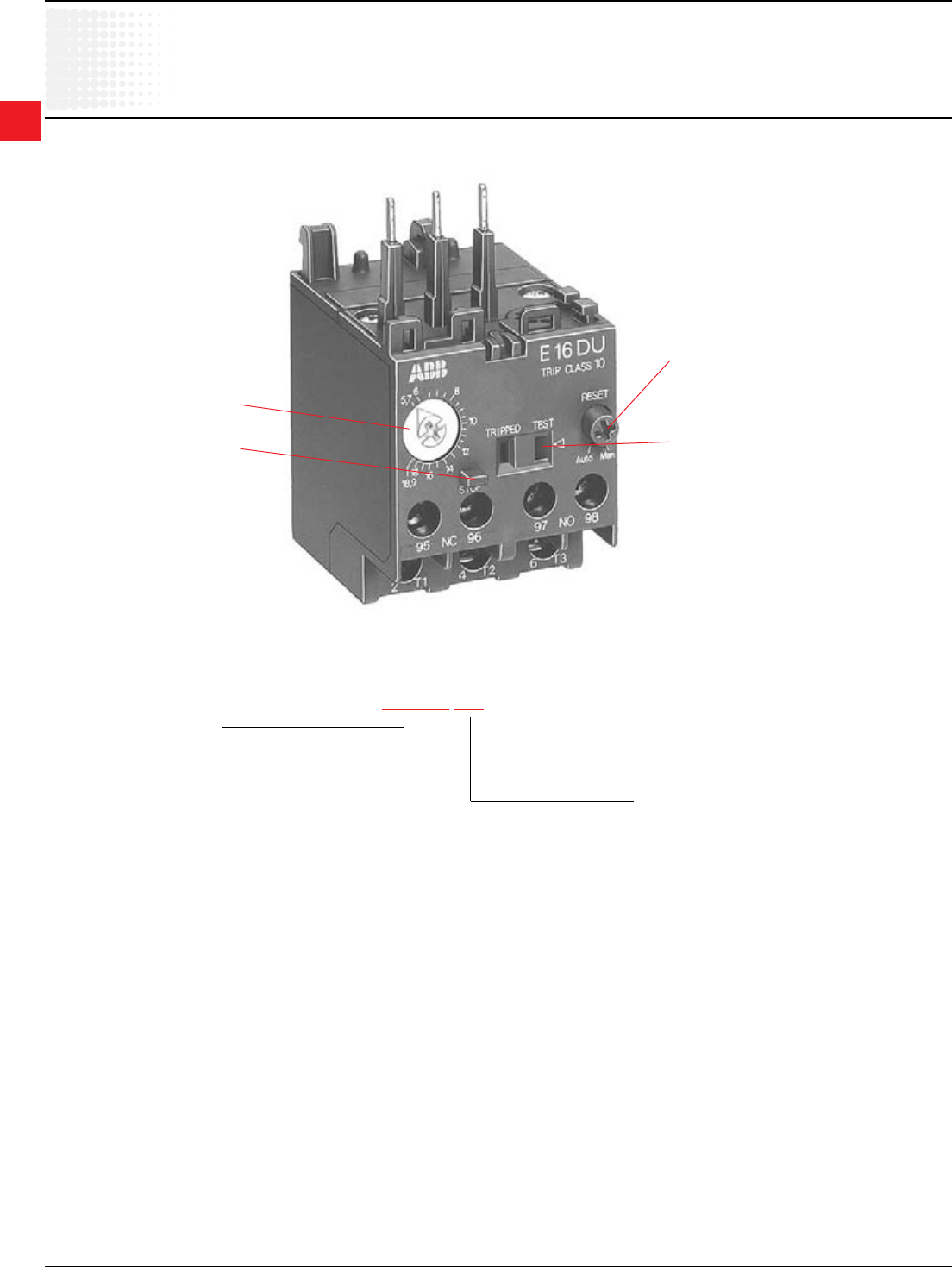
Catalog number explanation
E16DU 1.0
Nominal current setting
Stop button
Reset, manual or automatic
Trip indicator test function
2
Electronic
Overload
relays
Low Voltage Products & Systems 2.25
ABB Inc. • 888-385-1221 • www.abb.us/lowvoltage 1SXU000023C0202
Motor horsepower Open
Complete starter
Starter components
3 Phase, 1800 RPM Contactor Overload relay
200V 230V 460V 575V Catalog number List Price Catalog number List Price Catalog number List Price
——— 1/4
11-2B1
$ 198
A9-30-10-84
$ 78
E16DU1.0 (0.3 - 1.0)
$ 96
— — 1/4,1/3 1/3
——— 1/2
— — 1/2 3/4
11-2C1 A9-30-10-84 E16DU2.7 (0.9-2.7)— — 3/4 —
— 1/2 1 1 1/2
1/2 —1 1/2 2
11-2D1 A9-30-10-84 E16DU6.3 (2.0-6.3)
3/4 3/4 2 —
— 1 — 3
1 1 1/2 3 5
2 2 5 7 1/2 11-2E1 A9-30-10-84
E16DU18.9 (5.7-18.9) 3 3 7 1/2 10 21-2E1 204 A12-30-10-84 84
5 5 10 15 31-2E1 233 A16-30-10-84 102
—7 1/2 15 20 41-2E1 336 A26-30-10-84 183 E45DU30 (9-30)
105
7 1/2 10 20 25
10 10 — — 51-2E2 414 A30-30-10-84 252 E45DU45 (15-45)
— — 25 30
10 15 30 40 61-2E2 472 A40-30-10-84 297 E45DU45 (15-45) 112
15 20 40 50 71-2E1 544 A50-30-11-84 330
E80DU80 (27-80) 18820 —50 60 81-2E1 608 A63-30-11-84 372
25 30 60 75 91-2E1 649 A75-30-11-84 413
30 ———A1-2E1 861 A110-30-11-84 480 E140DU140 (50-140) 261
—40 75 100
40 50 100 125 B1-2E2 1,415 A145-30-11-84 825 E200DU200 (60-200) 325
50 60 125 150 C1-2E2 1,830 A185-30-11-84 1,290
60 75 150 200 D1-2E3 2,422 A210-30-11-84 1,635
E320DU320 (100-320) 77575 100 200 250 E1-2E3 3,027 A260-30-11-84 1,815
100 —250 300 F1-2E3 3,177 A300-30-11-84 1,875
125 5/6 350 400 G1-70E5 4,125 AF400-30-11-70 3,120 E500DU500 (150-500) 865
150 200 400 500 H1-70E5 5,700 AF460-30-11-70 4,425
200 250 500 600 T1-70E8 8,346 AF580-30-11-70 6,900 E800DU800 (250-800) 950
250 300 600 700 U1-70E8 8,646 AF750-30-11-70 7,200
Selection by motor horsepower
UL/CSA Starters with electronic overload
Discount schedule TS [OZ]
2
Electronic
Overload
relays
2.26 Low Voltage Products & Systems
1SXU000023C0202 ABBInc.•888-385-1221•www.abb.us/lowvoltage
E16DU – E1250DU
for contactors and mini contactors
Discount schedule TS [OZ]
E16DU E45DU
E80DU E140DU
E200DU E320DU
E500DU
E800DU
E1250DU
UniversalMotorController,UMC22-FBP.0
Catalog
number
Setting
range
Trip
class
List
price Contactor Sufx
code
TripClass,Selectable10,20,30
E16DU0.32 0.1-0.32A 10,20,30
$ 96
B...6-B...7/A...9...A...16... A1
E16DU1.0 0.3-1.0A 10,20,30 B...6-B...7/A...9...A...16... B1
E16DU2.7 0.9-2.7A 10,20,30 B...6-B...7/A...9...A...16... C1
E16DU6.3 2.0-6.3A 10,20,30 B...6-B...7/A...9...A...16... D1
E16DU18.9 5.7-18.9A 10,20,30 B...6-B...7/A...9...A...16... E1
TripClassselectable,10,20,30
E45DU30 9-30A 10,20,30 105 A...26 ... A...40 E1
E45DU45 15-45A 10,20,30 112 A...26 ... A...40 E2
E80DU80 27-80A 10,20,30 188 A...50...A...75 E1
E140DU140 50-140A 10,20,30 261 A...95...A...110 E1
E200DU200 65-200A 10,20,30 325 A...145...A...185 E2
E320DU320 105-320A 10,20,30 775 A...210 ... A...300 E3
E500DU500 170-500A 10,20,30 865 AF...400...AF...460 E5
E800DU800 270-800A 10,20,30 950 AF...580...AF...750 E8
E1250DU1250 375-1250A 10,20,30 2,970 AF...1350...AF...1650 E12
NOTE:Electronicoverloadrelaysarenotsuitableforsingle-phaseandDCmotors.
Universalmotorcontroller
Universalmotorcontrollerwiththermaloverloadprotection0.24-63Ainasingledevicetype.Bushing-type
transformer,cablecrosssection25mm2(max.diameterincludinginsulation-11mm). Integrated motor control
functions:Directstarting,reversestarting,star-deltastarting,servo-drivefunctions.Diagnosticfunctions:
Overloadphasefailure,tripcategories,5,10,20,30.Integratedstorageofparametersandmotordata.6digital
inputs,3relayoutputs.Fieldbus-independentinterfaceforconnectiontoFBPeldbusconnectors,interfaceto
operatingpanelACS100-PAN.
Description Contactor Setting range Trip class Catalognumber List price
UMC22-FBP.0 A9-AF1650 0.63-63A 5,10,20,30 1SAJ510000R0600 $ 603
2
Electronic
Overload
relays
Low Voltage Products & Systems 2.27
ABB Inc. • 888-385-1221 • www.abb.us/lowvoltage 1SXU000023C0202
Accessories
Discount schedule ABA [OF] – All products except DB16E
Discount schedule TS [OZ] – DB16E
Mounting kits
for direct mounting on contactors AF400 – AF750
E500DU AF400 – AF460 DT500/AF460S $ 395
AF400 – AF460 w/reversing kits DT500/AF460L
E800DU AF580 – AF750 DT800/AF750S 415
AF580 – AF750 w/reversing kits DT800/AF750L
For On Catalog List
overload relays contactor number price
Separate mounting kits
E16DU DB16E $ 15
E45DU DB45E 39
E80DU DB80E 48
E140DU DB140E 70
For Catalog List
overload relays number price
Lug kits
6 – 250 MCM E200DU200 ATK185 $ 45
4 – 400 MCM E320DU320 ATK300 68
(2) 4 – 500 MCM E320DU320 ATK300/2 110
(2) 2/0 – 500 MCM E500DU500 ATK580/2HK 160
(3) 2/0 – 500 MCM E800DU800 ATK750/3HK 235
(4) 1/0 – 750 MCM E12150DU1250 ATK1350/4 235
Wire Electronic Catalog List
range overload number price
DB16E
Terminal shrouds
E200DU LT200E $ 41
E320DU LT320E
E500DU LT500E 52
E800DU LT800-E 60
For Catalog List
overload relays number price
Operating panel, ACS100-PAN
Accessories for universal motor controller UMC22-FBP
Operating, diagnostics and parameter setting panel for Universal Motor Controller UMC22-FBP.
Setting of motor and bus parameters.
Type Designation Usage with Catalog number List price
ACS100-PAN Operating panel UMC22-FBP 1SAJ510001R0002 $ 114
Accessories for operating panel ACS100-PAN
Extension cable 3 m and door mounting set IP65 (front side) for ACS100-PAN operating panel.
Type Designation Usage with Catalog number List price
ACS100-CAB.300 Extension cable 3m with door
mounting set ACS100-PAN 1SAJ510002R0001 $ 98
ACS100-CAB.070 Extension cable 3m with front
mounting set ACS100-PAN 1SAJ510003R0001 67
Current transformers for use with the universal motor controller UMC22-FBP
Secondary-linear transformer, 3-phase with terminal block, intended for conductors Cu 2.5mm2.
Type Designation Current range recommended Catalog number List price
KORC 4L 185 R/4 Current transformer 60 - 185 A KORC-4L-185R/4 $ 600
Connection kit for use with the KORC-current transformers
Connection kit for applications with KORC-current transformers with A-series contactors
Type Designation Appropriate for contactor type Catalog number List price
DT 450 / A185 Connection kit AF145 - AF185 DT450/A185 $ 225
DT 450 / A300 Connection kit AF260 - AF300 DT450/A300 225
DT 500 / AF460L Connection kit 1AF400 - AF460 DT500/AF460L 395
DT 800 / AF750L Connection kit 1AF580 - AF750 DT800/AF750L 415
1 Connection kit for Star-Delta-Starter
2
Electronic
Overload
relays
2.28 Low Voltage Products & Systems
1SXU000023C0202 ABB Inc. • 888-385-1221 • www.abb.us/lowvoltage
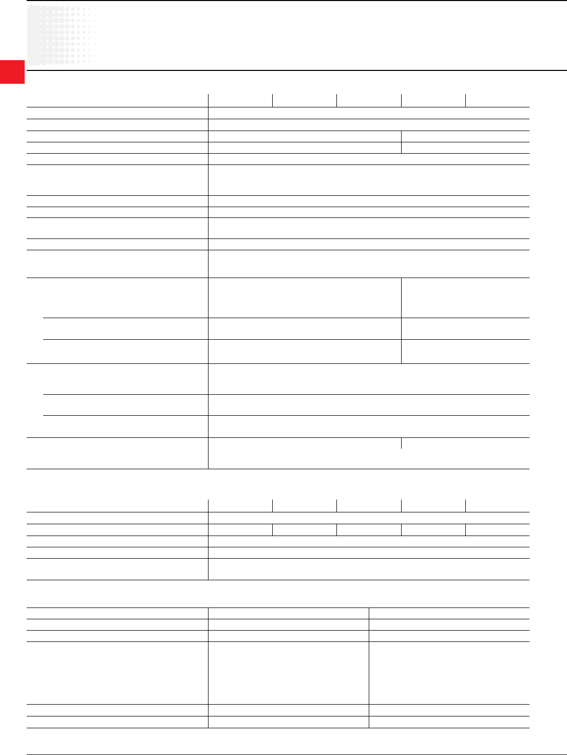
Technical data of the conducting paths
Type E16DU E45DU30 E45DU45 E80DU80 E140DU140
Number of conducting paths 3
Setting ranges A ... A 0,1 ... 18,9 9 … 30 15 ... 45 27 ... 80 50 ... 140
Tripping classes to IEC/EN 60 947-4-1 10 or selectable 10, 20, 30
Frequency range Hz 50 and 60 (only for a.c. operating 3 phase)
Switching frequency
without early tripping
80 ops./h with 40% if the making current does not
exceed 6 x in and starting time does not exceed 1s.
Technical data
E16/E45/E80/E140DU
Load rating of auxiliary contacts
Contact NC (95-96) NO (97-98)
Rated operating voltage Ue V600 600
Rated thermal continuous current A6 6
Rated operating current Ie at AC-15 230 V A
at AC-15 400 V A
at AC-15 500 V A
at DC-13 24 V A
at DC-13 60 V A
at DC-13 110 V A
at DC-13 220 V A
3
1,1
0,7
1,5
0,5
0,4
0,2
3
1,1
0,7
1,5
0,5
0,4
0,2
Short-circuit protection fuse gG A6 6
STOTZ safety circuit-breaker: S271, S281 (2) (2)
General technical data
Type E16DU E45DU30 E45DU45 E80DU80 E140DU140
Standards: IEC/EN 60 947-4-1 / IEC/EN 60 947-5-1
Approvals and certificates UL, CSA
Rated insulation voltage Ui V600 600
Rated operating voltage Ue V600 600
Impulse withstand voltage Uimp kV 6
Permissible ambient temperature
– Storage °C
– Operation °C
– 25 to + 70
– 25 to + 70
Climatic resistance according to on request
Mounting position
Resistance to shock Shock duration ms
multiple of g on request (1)
Resistance to vibrations to EN 61373 on request
Mounting – by screws:
– onto contactor:
separate mounting with Kit for single set up by screws 4xM5
or direct mounting onto contactor - no kit necessary
Connection terminals and attachment type
Main contactors (load side)
• Screw terminal
– with self-disengaging clamping piece M5/2,3 ... 2,6 Nm M8/6 ... 6,5 Nm
• Connection cross-sections
– single-core or stranded mm2
1 x 2,5 ... 16
2 x 2,5 ... 16
1 x 10 ... 95
2 x 6 ... 35
– exible with wire end ferrule mm21 x 2,5 ... 10
2 x 2,5 ... 10
1 x 10 ... 70
2 x 6 ... 35
Connection to aux.-contacts terminals
• Screw terminal
– with self-disengaging clamping piece
M3,5/0,8 ... 1,0 Nm
• Connection cross-sections
– single-core or stranded mm2
1 x 1 ... 4
2 x 1 ... 4
– exible with wire end ferrule mm21 x 0,75 ... 2,5
2 x 0,75 ... 2,5
Protection degree to IEC/EN 60 947-1 IP 20 IP 10
All terminals are safe from nger-touch and safe from touch
by the back of the hand to EN 50274
(1) on request
2
Electronic
Overload
relays
Low Voltage Products & Systems 2.29
ABB Inc. • 888-385-1221 • www.abb.us/lowvoltage 1SXU000023C0202
Technical data
E200/ 320/500/ 800/1250DU
Technical data of the conducting paths
Type E200DU E320DU E500DU E800DU E1250DU
Number of conducting paths 3
Setting ranges A ... A 60 ... 200 100 ... 320 150 ... 500 250 ... 800 375 ... 1250
Tripping classes to IEC/EN 60 947-4-1 10, 20, 30 selectable
Frequency range Hz 50 and 60 (only for a.c.operating 3 phase)
Switching frequency
without early tripping
80 ops./h with 40% if the making current does not
exceed 6 x in and starting time does not exceed 1s.
Load rating of auxiliary contacts
Type E200DU, E320DU, E500DU, E800DU, E1250DU
Contact NC (95-96) NO (97-98)
Rated operating voltage Ue V600 600
Rated thermal continuous current A6 6
Rated operating current Ie at AC-15 230 V A
at AC-15 400 V A
at AC-15 500 V A
at DC-13 24 V A
at DC-13 60 V A
at DC-13 110 V A
at DC-13 220 V A
3
1,1
0,7
1,5
0,5
0,4
0,2
3
1,1
0,7
1,5
0,5
0,4
0,2
Short-circuit protection fuse gG A6 6
STOTZ safety circuit-breaker: S271, S281 (1) (1)
General technical data
Type E200DU E320DU E500DU E800DU E1250DU
Standards: IEC/EN 60 947-4-1 / IEC/EN 60 947-5-1
Approvals and certificates UL, CSA
Rated insulation voltage Ui V600
Rated operating voltage Ue V600
Impulse withstand voltage Uimp kV 6
Permissible ambient temperature
– Storage °C
– Operation °C
– 25 to + 70
– 25 to + 70
Climatic resistance according to IEC 68-2-1, IEC 68-2-2
IEC 68-2-14, IEC 68-2-30
IEC 68-2-1, IEC 68-2-2,
IEC 68-2-30
Mounting position any
Resistance to shock Shock duration ms
multiple of g
30
5
Resistance to vibrations to EN 61373 category 1 class B
Mounting – by screws:
– onto contactor:
by screws
4 x M5
by screws
4 x M5
by screws
4 x M5
with DT ...
mounting kit
by screws
4 x M6
with DT ...
mounting kit
by screws
4 x M6
with DT ...
mounting kit
Connection terminals and attachment type
Main contuctors (load side)
• Screw terminals
– with busbar or cable lugs
M8 M10 M10
(rail order
separately)
M12
(rail order
separately)
M12
Connection terminals and attachment type
Auxiliary contacts
• Screw terminal
– with self-disengaging clamping piece
– tigtening torque Nm
M3,5
1,0
• Connection cross-sections
– single-core or stranded mm2
– exible with wire end ferrule mm22 x 0,75 ... 4
2 x 0,75 ... 2,5
Protection degree to IEC/EN 60 947-1 All terminals are safe from nger-touch and safe from touch
by the back of the hand to EN 50274
IP 00
2
Electronic
Overload
relays
2.30 Low Voltage Products & Systems
1SXU000023C0202 ABB Inc. • 888-385-1221 • www.abb.us/lowvoltage
Technical data
Universal motor controller
UMC22-FBP
Conductor holes through the current transformers max. 25 mm2
(max. diameter incl. insulation 11 mm)
3
1
4
5
2
6
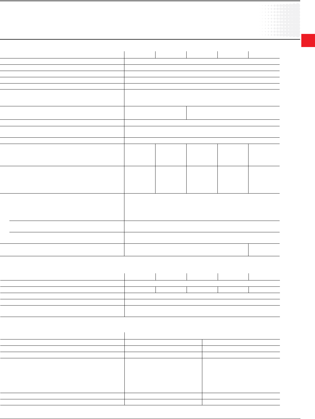
General technical data
Type UMC22-FBP
Rated operating voltage Ue (three-phase system) V AC/Hz max. 690/50
Rated operating current range A 0.24 ... 63
Trip classes 5, 10, 20, 30
Short-circuit-protection separate fuses on power line side
Supply voltage V DC 19.2 ... 31.2, including ripple
Supply current mA max. 130 (at 18 ... 30 V DC)
Total device power dissipation W max. 3.1 (at 24 V DC)
LEDs on front LED 1, green: device ready for operation
LED 2, yellow: motor current > 33 % of Is
LED 3, red: fault (trip, device fault, etc.)
Digital inputs
Number of digital inputs 6 (DI0 ... DI5)
Power supply for digital inputs 18 … 30V, 70 mA
1-Signal (range including ripple) +13 V ... +31,2 V
0-Signal (range including ripple) -31,2 V ... +13 V
Input current per channel (24 V DC) typ. 6.0 mA
Input resistor to 0 V 3.9 kOhm
Line length unshielded max. 600 m
Line length shielded max. 1000 m
Mechanical relay contact lifetime 500 000 switching cycles
Electrical lifetime 250 V AC / 0.5 A 100 000 switching cycles
250 V AC / 1.5 A 50 000 switching cycles
Terminal conductor cross section mm2 max. 2.5, max. 2 x 1.5
Current transformer bushing holes 11 mm Ø (25 mm“)
Internal clearance and creepage distances mm > 5.5 (safety insulation up to 250 V AC)
Mounting on DIN rail (EN 50022-35) or wall mounting with 4 screws M4
Dimensions (W x H x D) mm 70 x 105 x 110 (incl. FieldBusPlug and Control Panel)
Net weight kg 0.39 (current transf. + control unit)
Degree of protection IP 20
Storage temperature range °C -25...+70
Operating temperature range °C 0...+55
Technical description Order Code 2CDC 135 004 D02xx
FieldBusPlug connection see FBP catalogue
Digital outputs
Number of digital relay outputs 3 (DO0...DO2)
Grouping of contacts 3 contacts with 1 com-
mon
Switching capacity per relay contact
AC15: 120 V AC,
max. 3 A 240 V AC,
max. 1.5 A
DC13: 24 V DC, max. 0.1 A
125 V DC, max. 0.22 A
250 V DC, max. 0.11 A
max. load for all contacts 4 A (terminal 5 or 6)
min load for switching signals 12 V, 1 W or 1 VA
PTC Input - direct connection of PTC sensors from the motor
Parameter Options:
1 = Control function
2 = check back via aux.-contact
3 = Fault output, e.g. to lamp
4 = PTC Input
5 = digital inputs for control signals
6 = Connections for earth fault monitor

2
Electronic
Overload
relays
Low Voltage Products & Systems 2.31
ABB Inc. • 888-385-1221 • www.abb.us/lowvoltage 1SXU000023C0202
Technical data
Terms and technical denitions
Altitude
Characterizes the place of use. It is expressed in meters above sea
level.
Circuits
• Auxiliary circuit – all the conductive parts of a contactor designed
to be inserted in a different circuit from the main circuit and the
contactor control circuits.
• Control circuit – all the conductive parts of a contactor (other
than the main circuit and the auxiliary circuit) used to control the
contactor’s closing operation or opening operation or both.
• Main circuit – all the conductive parts of a contactor designed to
be inserted in the circuit that it controls.
Insulation Class according to NFC 20 040 and VDE 0110
Characterizes adaptation of the devices to ambient temperature and
operating conditions. For given clearances and creepage distances,
a device will have different insulating voltages depending on
insulation classes A, B, C & D. Class C corresponds to most industrial
applications. The devices in this catalog belong to Class C.
Coordination of equipment protections during a short circuit
This is the addition upstream of the contactor and thermal overload
relay of a short circuit (SCPD) protection device such as a circuit
breaker, a fuse with a high breaking capacity or other fuses.
IEC publication 947-4-1 denes coordination Types 1 & 2:
• Type 1 – Coordination requires that, in the event of a short circuit,
the contactor or starter does not endanger persons or installations
and will not be able to operate without being repaired or parts being
replaced.
• Type 2 – Coordination requires that, in short circuit conditions, the
contactor or starter does not endanger persons or installations and
will be able to operate afterwards. The risk of contacts being welded
is acceptable. In this case, the manufacturer must stipulate the
measures to be taken with respect to maintenance of the equipment.
Rated operational current Ie
Current rated by the manufacturer. It is mainly based on the rated
operational voltage Ue, the rated frequency, the utilization category,
the rated duty and the type of protective enclosure, if necessary.
Conventional free air thermal current Ith
Current that the contactor can withstand in free air for a duty time of 8
hours without the temperature rise of its various parts exceeding the
maximum values given by the standard.
Cycle time
Cycle time is the sum of the current ow time and the no-current time
for given cycle.
Electrical durability
Number of on-load operations that the contactor is able to carry out; it
depends on the utilization category.
Mechanical durability
Number of no-current operations that a contactor is able to carry out.
Load factor
Ratio of the on-load operating time to the total cycle time x 100.
Switching frequency
Number of switching cycles per hour.
2
Electronic
Overload
relays
2.32 Low Voltage Products & Systems
1SXU000023C0202 ABB Inc. • 888-385-1221 • www.abb.us/lowvoltage
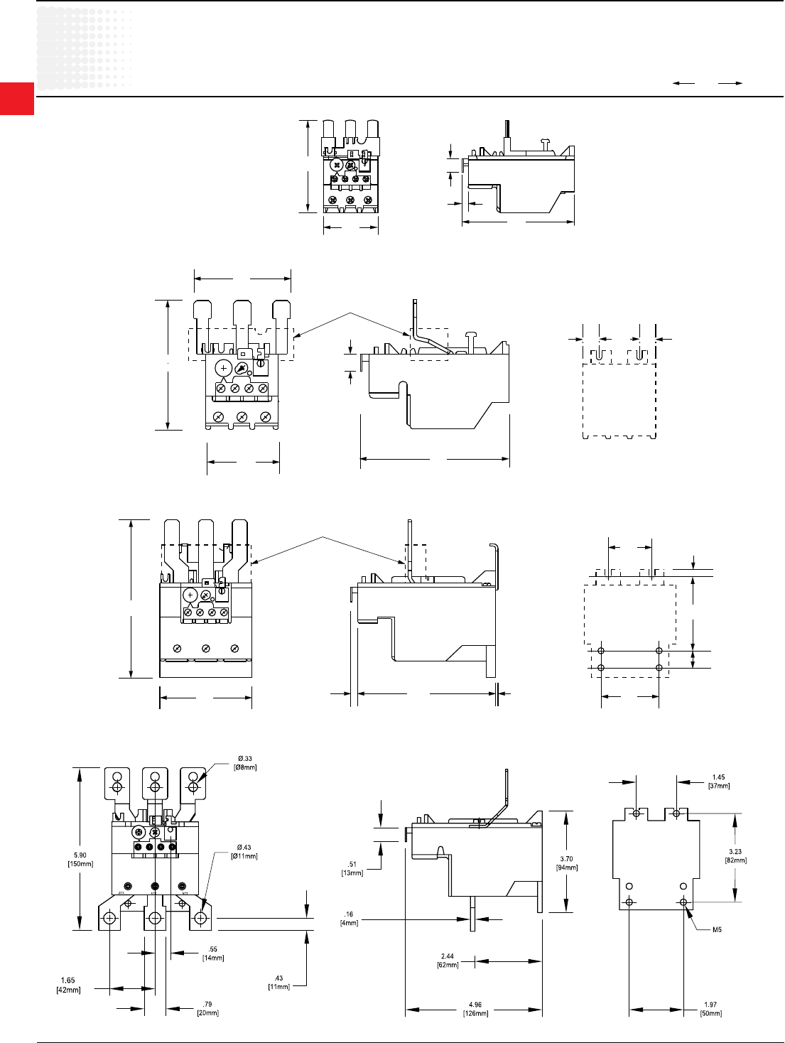
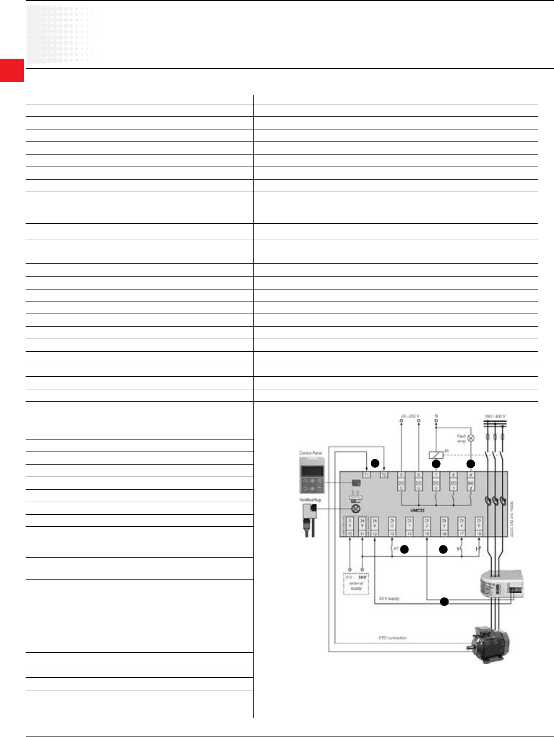
Approximate dimensions
E16DU – E140DU
E16DU E16DU + DB16E
E2326D
9.3
2.4
1.2
9.3
44.4
74.6
148.2 5.65
10.3
36.3
37.5
53
57
E2327D
4.4
14.8
44.6 68.5
35.7
41.7
5.5
14 14
69.5
65.2
64.5
50
82.7
91.1
E45DU E80DU
E140DU

2
Electronic
Overload
relays
Low Voltage Products & Systems 2.33
ABB Inc. • 888-385-1221 • www.abb.us/lowvoltage 1SXU000023C0202
E200DU
E320DU
Approximate dimensions
E200DU – E320DU
2
Electronic
Overload
relays
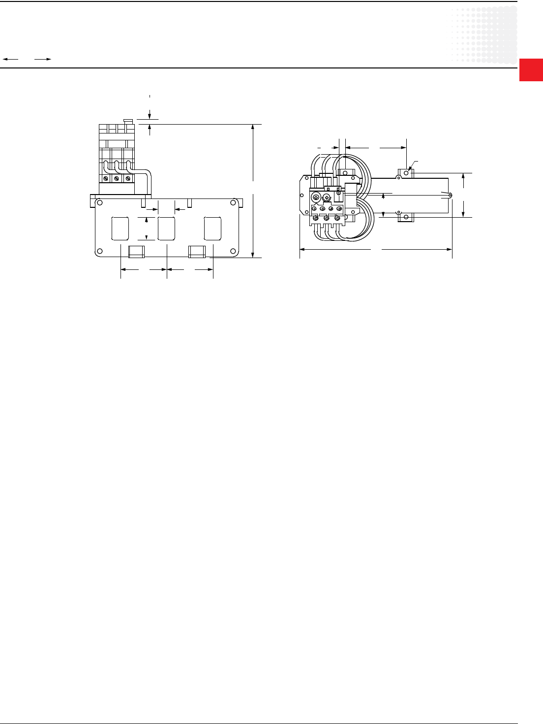
2.34 Low Voltage Products & Systems
1SXU000023C0202 ABB Inc. • 888-385-1221 • www.abb.us/lowvoltage
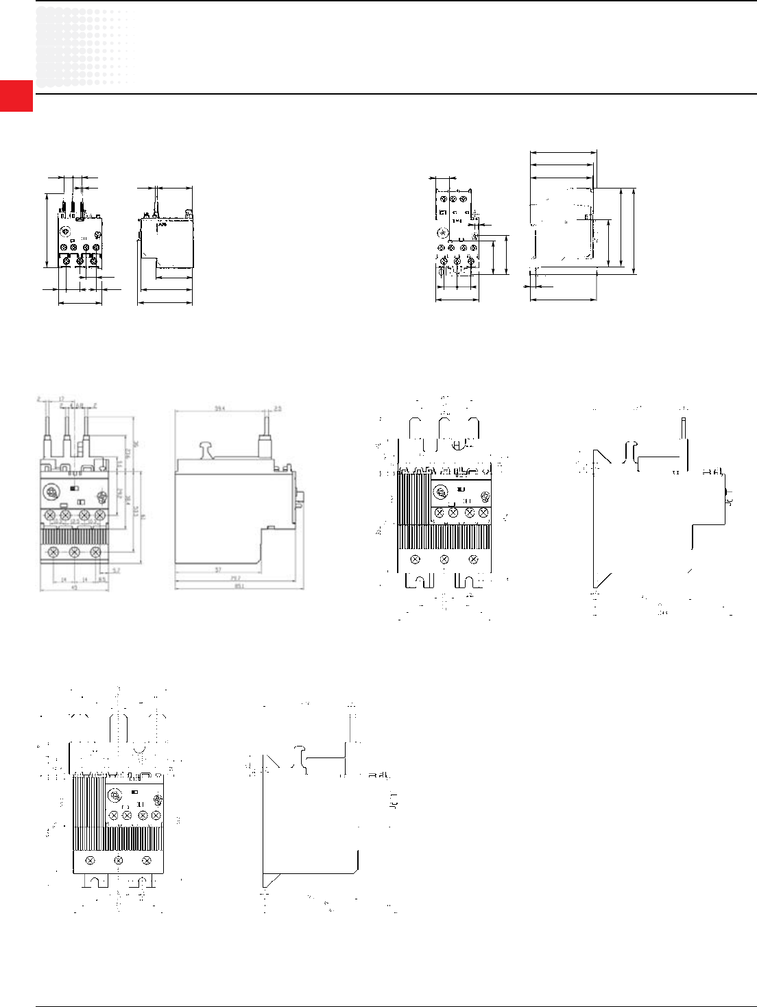
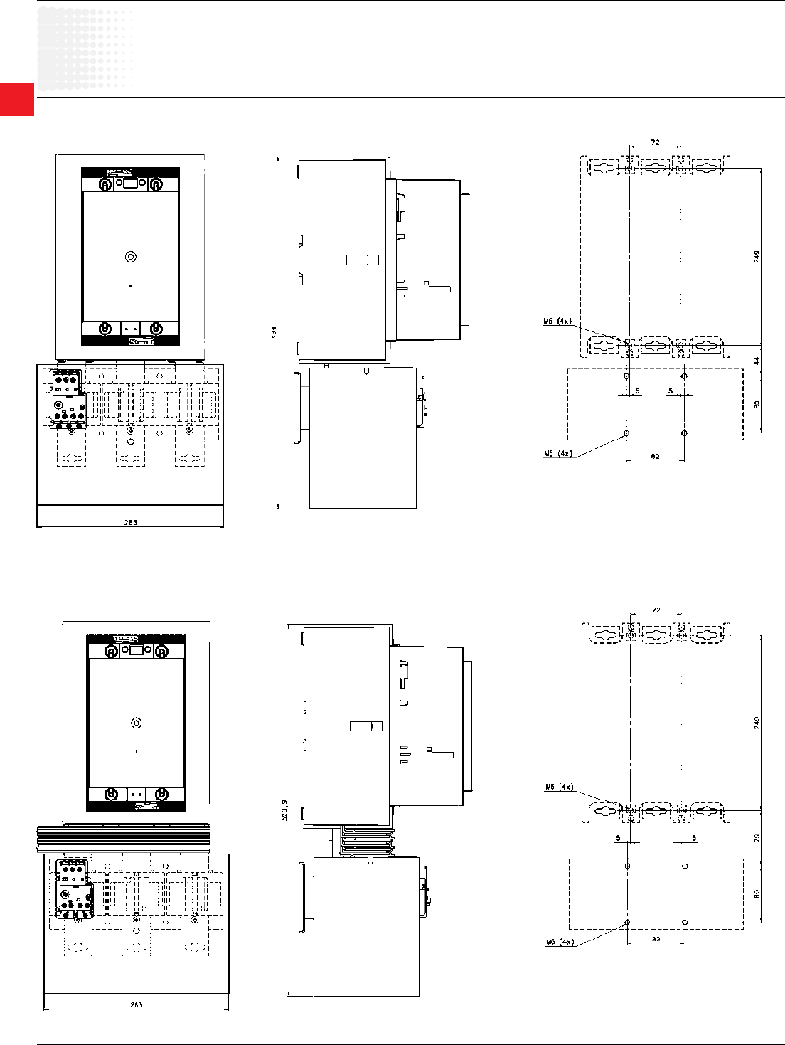
Approximate dimensions
E500DU – E800DU
E1250DU + AF1350 / AF1650
E500DU E800DU
(dimensions in mm)
AF1350 / AF1650 + E1250DU Drilling plan

2
Electronic
Overload
relays
Low Voltage Products & Systems 2.35
ABB Inc. • 888-385-1221 • www.abb.us/lowvoltage 1SXU000023C0202
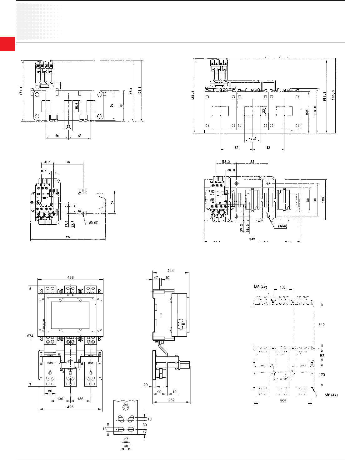
Approximate dimensions
Starter combination with contactor and terminal shroud
AF400 / AF460 + E500DU + DT500 / AF460S + LT500 Drilling plan
AF400 / AF460 + E500DU + DT500 / AF460L Drilling plan
(dimensions in mm)
2
Electronic
Overload
relays
2.36 Low Voltage Products & Systems
1SXU000023C0202 ABB Inc. • 888-385-1221 • www.abb.us/lowvoltage
Approximate dimensions
Starter combination with contactor and terminal shroud
AF580 / AF750 + E800DU + DT800 / AF750S + LT800 Drilling plan
AF580 / AF750 + E800DU + DT800 / AF750L Drilling plan
(dimensions in mm)
