Tnb09_gm102_F_00_01 113108 Catalog
100052-Brochure 100052-Brochure 100052-Brochure B2 unilog cesco-content
1000475926-Brochure 1000475926-Brochure 1000475926-Brochure B4 unilog cesco-content
143639-Catalog 143639-Catalog 143639-Catalog B4 unilog cesco-content
155210-Catalog 155210-Catalog 155210-Catalog B4 unilog cesco-content
1000387413-Catalog 1000387413-Catalog 1000387413-Catalog B5 unilog cesco-content
2016-07-04
: Pdf 113108-Catalog 113108-Catalog B1 unilog
Open the PDF directly: View PDF ![]() .
.
Page Count: 92
- Table of Contents
- Overview
- Thinwall Conduit Fittings (EMT)
- Rigid/Intermediate Grade Conduit Fittings
- Flexible Cord and Power Cable Connectors
- Liquidtight Flexible Metal Conduit and Connectors
- Non-Metallic Sheathed Cable Fittings
- Armored Cable/Flexible Metallic Conduit Fittings
- Service Caps
- Cable Caps, Protector, Straps and Clips; Threaded Rod and Coupling
- Beam Clamps
- Ground Clamps, Pipe Hangers
- PVC Conduit Repair System
- Schedule 40 & 80 Elbows
- Schedule 40 & 80 Fittings & Accessories
- Conduit Bodies & Accessories
- Junction Boxes
- Switch Boxes
- Support Straps
- Conduit Clamps
- Schedule 40 & 80 Tech Specs
- Utility Conduit
- P&C Duct
- Telephone Duct
- Split Duct
- Accessories
- Spacers
- P&C Flex™

and
Fittings & Non-Metallic Rigid Conduit Fittings and Accessories
In This Section…
Steel City®Fittings
Overview .........................................................................F-2–F-3
Thinwall Conduit Fittings (EMT)........................................F-4–F-9
Rigid/Intermediate Grade Conduit Fittings .......................F-10–17
Flexible Cord and Power Cable Connectors ...........................F-18
Liquidtight Flexible Metal Conduit and Connectors.......F-19–F-23
Non-Metallic Sheathed Cable Fittings ..........................F-24–F-25
Armored Cable/Flexible Metallic Conduit Fittings..........F-26–F-31
Service Caps.........................................................................F-31
Cable Caps, Protector, Straps and Clips;
Threaded Rod and Coupling ..................................................F-32
Beam Clamps........................................................................F-33
Ground Clamps, Pipe Hangers...............................................F-34
Carlon®Non-Metallic Rigid Conduit Fittings
and Accessories
PVC Conduit Repair System .........................................F-35–F-36
Schedule 40 & 80 Elbows............................................F-37–F-42
Schedule 40 & 80 Fittings & Accessories.....................F-43–F-46
Conduit Bodies & Accessories......................................F-47–F-48
Junction Boxes ............................................................F-49–F-50
Switch Boxes...............................................................F-51–F-53
Support Straps ......................................................................F-54
Conduit Clamps ...........................................................F-55–F-56
Schedule 40 & 80 Tech Specs...............................................F-57
Utility Conduit ..............................................................F-58–F-59
P&C Duct.....................................................................F-60–F-68
Telephone Duct............................................................F-69–F-71
Split Duct ..............................................................................F-72
Accessories
PVC Cements and Sealers.......................................F-73–F-77
PVC Conduit Cutters .........................................................F-78
EZ Bend™.........................................................................F-79
Rope & Tape.....................................................................F-80
Spacers .......................................................................F-81–F-86
P&C Flex™....................................................................F-87–F-92
F-1
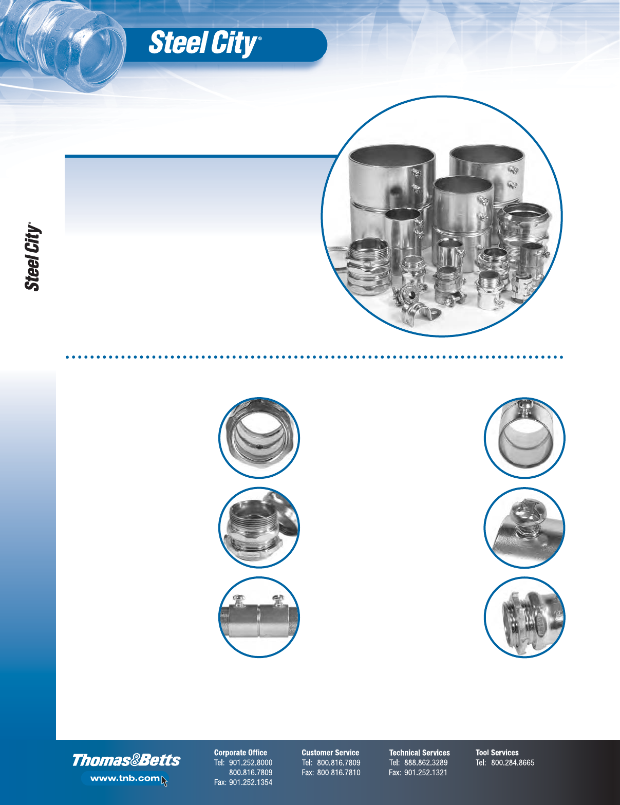
Overview
Fittings
Couplings and Connectors
Superior Quality and Design
•Strict tolerances throughout fitting
ensures a straight conduit run with
no sagging over extreme lengths
•Chamfered entry provides lead-in
for conduit insertion
Dependable Pipe Stop
•360° groove traveling the circumference
ensures that conduit forcefully inserted
won’t break through to the opposite side
of the fitting. Also, it does not exceed
thickness of EMT and prevents interference
with pulling conductors
Extra-Large Head Tri-Drive Set Screw
•Accommodates Phillips, slotted
and square drives
Enhanced Locknut Construction
•Heavy-duty turned sharp teeth,
double-threaded
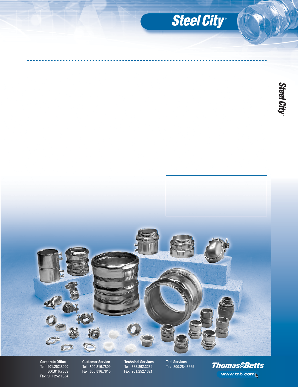
Advantages of Steel City®Commercial Conduit Fittings
Steel City®Conduit Fittings provide long-lasting service in commercial,
industrial and residential construction. Our fittings are manufactured
within strict tolerances to maintain consistent performance. Installers
can be assured that every fitting with the Steel City®name will work
every time. So when you select Steel City®Conduit Fittings, that means
fewer headaches and call-backs.
Steel City®products symbolize the highest quality standards in
manufacturing and innovative design, with one of the most complete
offerings available. Contact a T&B distributor nearest you to select
the right Steel City®product for your requirements.
Steel City®Fittings
Compression Fittings
Dependable Pipe Stop
• Strong, thick protrusion that does not
exceed thickness of EMT. Keeps forcefully
inserted conduit from breaking through
the opposite side of the coupling, while
not interfering with the pulling of
conductors
Heavy-Duty Thick Steel Body/Glands
with Continuous Threading
•True hexagonal shape. The non-circular
design has actual flats for gripping power
using hand or tool force
Extra-Thick Electro-Plated Zinc Finish
•Ensures corrosion resistance while the
clear chromate coating gives the fittings
their quality shine and luster
F-2
Overview
Here’s How the Steel City®Part Number System Works
B G – Bushings, Grounding
BI – Bushings, Insulated
BL – Blanks
BR – Rigid Spacer
BS – Box Spacer
BT – Thinwall Spacer
BU – Bushings
CB – Clamp Back
CP – Cable Protector
EK – 3-Piece Coupling
FA – Fire Alarm
GA – Ground Clamp (Armored Ground Wire)
GC – Ground Clamp
H– Hub
HA – Heavywall Adapter
HC – Heavywall Connector
HK – Heavywall Coupling
HL – Heavywall Elbow
HO – Heavywall Offset
HS – Heavywall Strap
LG – Locknut, Grounding
LN – Locknut
LT – Liquidtight
NC – Non-Metallic Sheathed Cable Connector
NS – Non-Metallic Sheathed Cable Strap
RB – Reducing Bushings
RT – Raintight
SH – Service Entrance Fitting
SL – Service Ells
SR – Sealing Rings
SS – Stainless Steel
LS – Locknut, Sealing
TC – Thinwall Connectors
TK – Thinwall Couplings
TL – Thinwall Elbow
TO – Thinwall Offset
TS – Thinwall Strap
TX – Thinwall to Flexible Metallic Conduit Fitting
UC – Utility Connector
USA – Made in USA
WA – Washer
XC – Armored Cable or Flexible Metallic Conduit Connector
XK – Armored Cable or Flexible Metallic Conduit Coupling
1st Digit — Material
1= Steel
2= Die Cast
3= Combination Steel and Die Cast
4= Malleable
5= Plastic
6= Aluminum
7= Steel Insulated
8= Die Cast Insulated
9= Malleable Insulated
2nd Digit — Method
1= Compression
2= Set Screw
3= Other
3rd/4th Digit — Size
0= 3⁄8"
1= 1⁄2"
2= 3⁄4"
3= 1"
4= 11⁄4"
5= 11⁄2"
6= 2"
7= 21⁄2"
8= 3"
9= 31⁄2"
10 = 4"
11 = 5"
12 = 6"
Easy-to-identify alphabetical prefixes:
A few examples of the three-digit identification
system for thinwall fittings are:
TK-111A: 1⁄2" steel, compression-type coupling
TC-714A: 11⁄4" steel insulated compression-type connector
TC-822SC: 3⁄4" die cast, insulated, set-screw type connector
Fittings
F-3
Thinwall Conduit Fittings (EMT)
F-4
Fittings
Insulated
CONDUIT INNER OUTER
“A” CAT NO.
SIZE (IN.) PACK PACK
TC-721A 1⁄250 500
TC722A 3⁄450 250
TC-723A 1 25 100
TC724A 11⁄4—25
TC725A 11⁄2—25
TC726A 2—25
TC727A 21⁄2—10
TC728A 3—5
TC729A 31⁄2—5
TC7210A 4—5
TC721A-FA 1⁄250 500
TC722A-FA 3⁄450 250
TC723A-FA 1 25 100
CONDUIT INNER OUTER
“A” CAT NO.
SIZE (IN.) PACK PACK
TK121A 1⁄250 500
TK122A 3⁄450 250
TK123A 1 25 100
TK124A 11⁄4—25
TK125A 11⁄2—25
TK126A 2—25
TK127A 21⁄2—10
•Concrete tight when taped
•Zinc plated
•Fire Alarm
(FA) painted
red for
fire alarm
identification
Non-Insulated
CONDUIT INNER OUTER
“A” CAT NO.
SIZE (IN.) PACK PACK
TC111A 1⁄250 500
TC112A 3⁄450 250
TC113A 1 25 100
TC114A* 11⁄4—25
TC115A* 11⁄2—25
TC116A* 2—25
TC117A 21⁄2—10
TC118A 3—5
TC119A 31⁄2—5
TC1110A 4—5
TC111A-RT 1⁄250 500
TC112A-RT 3⁄450 250
TC113A-RT 1 25 100
TC114A-RT* 11⁄4—25
TC115A-RT* 11⁄2—25
TC116A-RT* 2—25
TC117ART 21⁄2—10
TC118ART 3—5
TC119ART 31⁄2—5
TC1110ART 4—5
Insulated
CONDUIT INNER OUTER
“A” CAT NO.
SIZE (IN.) PACK PACK
TC711A 1⁄250 500
TC712A 3⁄450 250
TC713A 1 25 100
TC714A 11⁄4—25
TC715A 11⁄2—25
TC716A 2—25
TC717A 21⁄2—10
TC718A 3—5
TC719A 31⁄2—5
TC7110A 4—5
TC711A-RT 1⁄250 500
TC712A-RT 3⁄450 250
TC713A-RT 1 25 100
TC714A-RT* 11⁄4—25
TC715A-RT* 11⁄2—25
TC716A-RT* 2—25
TC717ART 21⁄2—10
TC718ART 3—5
TC719ART 31⁄2—5
TC7110ART 4—5
•1⁄2"–4"
concrete tight
•Zinc plated
•RT — Raintight
UL File No. E-16592.
*O-rings are supplied.
UL File No. E-16592.
Non-Insulated
CONDUIT INNER OUTER
“A” CAT NO.
SIZE (IN.) PACK PACK
TC121A 1⁄250 500
TC122A 3⁄450 250
TC123A 1 25 100
TC124A 11⁄4—25
TC125A 11⁄2—25
TC126A 2—25
TC127A 21⁄2—10
TC128A 3—5
TC129A 31⁄2—5
TC1210A 4—5
TC121A-FA 1⁄250 500
TC122A-FA 3⁄450 250
TC123A-FA 1 25 100
UL File No. E-16592.
UL File No. E-16592.
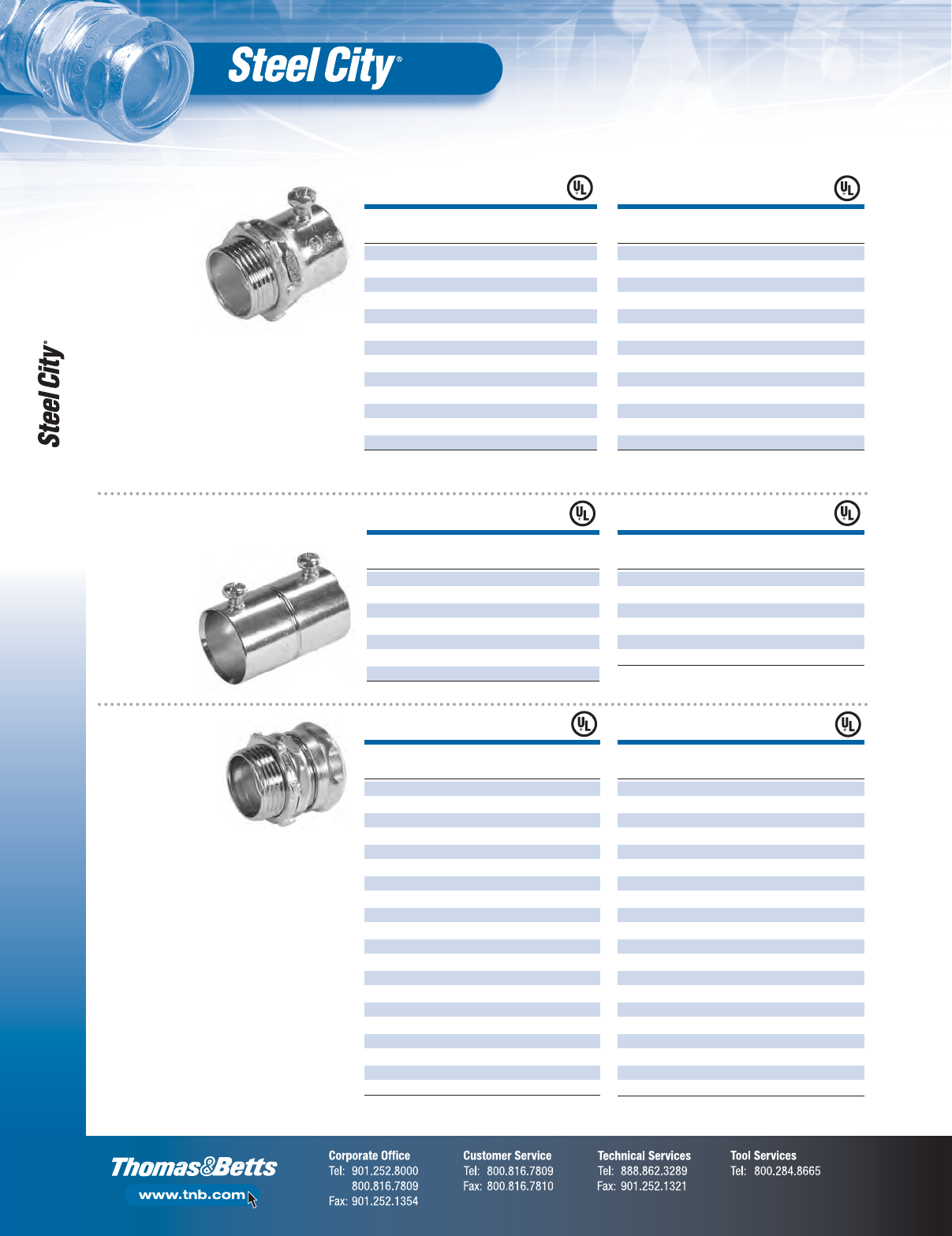
Set Screw
Connectors —
Steel
CONDUIT INNER OUTER
“A” CAT NO.
SIZE (IN.) PACK PACK
TK128A 3—5
TK129A 31⁄2—5
TK1210A 4—5
TK121A-FA 1⁄250 500
TK122A-FA 3⁄450 250
TK123A-FA 1 25 100
Set Screw Couplings — Steel
Steel City®Raintight EMT Compression Fittings
feature a distinctive design and a vibrant gold
gland nut, enabling inspectors to visually inspect
conformance from a distance. There’s no close-
up inspection required!
•Concrete
tight when
taped
•Zinc plated
UL File No. E-16592.
FA — Fire Alarm.
UL File No. E-16592.
FA — Fire Alarm.
Compression
Connectors —
Steel
NOTE: A sealing ring is required when fitting is used outside
on the tops and side of enclosure.

Thinwall Conduit Fittings (EMT)
F-5
Fittings
CONDUIT INNER OUTER
“A” CAT NO.
SIZE (IN.) PACK PACK
TK111A 1⁄250 250
TK112A 3⁄450 250
TK113A 1 25 100
TK114A 11⁄4—25
TK115A 11⁄2—25
TK116A 2—25
TK117A 21⁄2—10
TK118A 3—5
TK119A 31⁄2—5
TK1110A 4—5
Steel City®Raintight EMT Compression Fittings
feature a distinctive design and a vibrant gold
gland nut, enabling inspectors to visually inspect
conformance from a distance. There’s no close-
up inspection required!
CAT. NO.
DESCRIPTION STD. CTN.
TC101-SC 1⁄2" Uninsulated 500
TC-102-SC 3⁄4" Uninsulated 250
TC-701-SC 1⁄2" Insulated 500
TC-702-SC 3⁄4" Insulated 250
UL Listing No. E16592, CSA Listing No. LR-12798.
Installation using either slotted or Phillips screwdriver head,
35-in-lb of torque onto the EMT.
NOTE: Excessive torque could damage EMT or housing.
•Simple, one-piece installation with no locknuts
•Available in insulated or non-insulated throat
•Screw designed for exceptional pullout resistance
•Captive screw ensures that the screw is intact for installation
and resists backing out after installation
•Corrosion-resistant, zinc-chromatic plating
•Positive grounding
•Vibration-resistant screw design
•UL listed and CSA certified
CONDUIT DIMENSIONS (IN.) STD.
CAT. NO.
SIZE (IN.) A B C CTN.
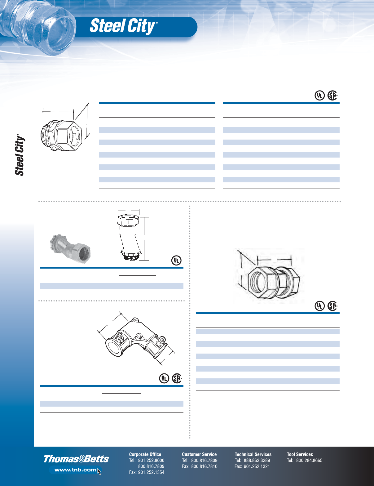
LTT 111 1⁄2EMT to 1⁄2Liquidtight
13⁄415⁄16 11⁄8
100
LTT-112 3⁄4EMT to 3⁄4Liquidtight
13⁄4111⁄64 13⁄8
50
LTT-113 1 EMT to 1 Liquidtight
115⁄16 11⁄213⁄4
25
CONDUIT DIMENSIONS (IN.) STD.
CAT. NO.
SIZE (IN.) A B C CTN.
LTH 111 1⁄2Rigid to 1⁄2Liquidtight 17⁄811⁄811⁄8100
A
C
Corner
B
Corner
A
C
Corner
B
Corner
•Steel
•Raintight
•Zinc plated
UL File No. E-16592.
CONDUIT INNER OUTER
“A” CAT NO.
SIZE (IN.) PACK PACK
TK111A-RT 1⁄250 250
TK112A-RT 3⁄450 250
TK113A-RT 1 25 100
TK114A-RT 11⁄4—25
TK115A-RT 11⁄2—25
TK116A-RT 2—25
TK117A-RT 21⁄2—10
TK118A-RT 3—5
TK119A-RT 31⁄2—5
TK1110A-RT 4—5
UL File No. E-16592.
Compression
Couplings —
Steel
•Steel
•Raintight
•Zinc plated
EMT LOK Conduit Connector — Steel
Combination Compression Couplings — Heavywall to Liquidtight Flexible Metal Conduit — Steel
Combination Compression Couplings — Thinwall to Liquidtight Flexible Metal Conduit — Steel
•1⁄2"–4"
concrete
tight
•Zinc plated
•RT — Raintight
Thinwall Conduit Fittings (EMT)
F-6
Fittings
A
B
CONDUIT DIMENSIONS (IN.) STD.
CAT NO.
SIZE (IN.) A B CTN.
Non-Insulated
TC-211-SC 1⁄211⁄41 500
TC-212-SC 3⁄4111⁄32 15⁄32 250
TC-213-SC 11
29⁄64 115⁄32 200
TC-214-SC 11⁄4113⁄16 127⁄32 100
TC-215-SC 11⁄217⁄821⁄16 40
TC-216-SC 22
5⁄32 217⁄32 20
TC-217-SC 21⁄2245⁄64 31⁄412
TC-218-SC 32
7⁄8315⁄16 12
TC-219-SC 31⁄2247⁄64 47⁄16 10
TC-2110-SC 42
13⁄16 415⁄16 6
CONDUIT DIMENSIONS (IN.) STD.
CAT NO.
SIZE (IN.) A B CTN.
Insulated
TC-811-SC 1⁄2123⁄64 63⁄64 500
TC-812-SC 3⁄4115⁄32 15⁄16 250
TC-813-SC 11
35⁄64 115⁄32 200
TC-814-SC 11⁄4129⁄32 127⁄32 100
TC-815-SC 11⁄2131⁄32 21⁄16 40
TC-816-SC 22
1⁄4217⁄32 20
TC-817-SC 21⁄2225⁄32 31⁄412
TC-818-SC 32
31⁄32 315⁄16 12
TC-819-SC 31⁄2227⁄32 47⁄16 10
TC-8110-SC 42
29⁄32 415⁄16 6
•1⁄2"–4" concrete tight
OFFSET CONDUIT DIMENSIONS (IN.) STD.
CAT NO.
(IN.) SIZE (IN.) A B CTN.
TO-211SC 3⁄81⁄2213⁄64 1 200
UL File No. E-16592.
A
B
A
B
CONDUIT DIMENSIONS (IN.) STD.
CAT NO.
SIZE (IN.) A B CTN.
TL-291 1⁄21.81 1.00 100
TL-292 3⁄42.00 1.25 50
UL File No. E-16592.
CSA File No. LR-12798.
•Concrete tight
when taped
A
B
CONDUIT DIMENSIONS (IN.) STD.
CAT NO.
SIZE (IN.) A B CTN.
TK-211-SC 1⁄211⁄213⁄32 500
TK-212-SC 3⁄415⁄815⁄16 250
TK-213-SC 11
7⁄8145⁄64 200
TK-214-SC 11⁄4113⁄16 23⁄32 100
TK-215-SC 11⁄229⁄32 221⁄64 40
TK-216-SC 22
11⁄32 229⁄32 20
TK-217-SC 21⁄2313⁄64 311⁄64 12
TK-218-SC 33
7⁄32 41⁄212
TK-219-SC 31⁄239⁄64 51⁄16 10
TK-2110-SC 43
3⁄16 541⁄64 6
UL File No. E-16592 —
1
⁄
2
"–4".
CSA File No. LR-12798 —
1
⁄
2
"–1
1
⁄
4
", 2
1
⁄
2
"–4".
•1⁄2"–4" concrete tight
UL File No. E-16592 —
1
⁄
2
"–4". CSA File No. LR-12798 —
1
⁄
2
"–2".
Capped Corner
Couplings —
Die Cast Zinc
Compression Couplings —
Die Cast Zinc
Compression Connectors — Die Cast Zinc
Offset Compression
Connectors —
Die Cast Zinc

Thinwall Conduit Fittings (EMT)
F-7
Fittings
CONDUIT A (IN.) B STD.
CAT NO.
SIZE (IN.) TC-221 SERIES TC-821 SERIES (IN.) CTN.
Non-Insulated
TC-221-SC 1⁄215⁄32 117⁄64 15⁄16 500
TC-222-SC 3⁄4113⁄32 133⁄64 15⁄32 250
TC-223-SC 11
9⁄16 121⁄32 127⁄64 200
TC-224-SC 11⁄4115⁄16 21⁄32 113⁄16 100
TC-225-SC 11⁄229⁄32 23⁄823⁄64 40
TC-226-SC 22
33⁄64 239⁄64 217⁄32 20
TC-227-SC 21⁄233⁄16 39⁄32 319⁄64 12
TC-228-SC 33
25⁄64 331⁄64 41⁄16 12
TC-229-SC 31⁄2331⁄64 319⁄32 417⁄32 10
TC-2210-SC 43
47⁄64 353⁄64 51⁄16 6
CONDUIT A (IN.) B STD.
CAT. NO.
SIZE (IN.) TC-221 SERIES TC-821 SERIES (IN.) CTN.
Insulated
TC-821-SC 1⁄215⁄32 117⁄64 15⁄16 500
TC-822-SC 3⁄4113⁄32 133⁄64 15⁄32 250
TC-823-SC 11
9⁄16 121⁄32 127⁄64 200
TC-824-SC 11⁄4115⁄16 21⁄32 113⁄16 100
TC-825-SC 11⁄229⁄32 23⁄823⁄64 40
TC-826-SC 22
33⁄64 239⁄64 217⁄32 20
TC-827-SC 21⁄233⁄16 39⁄32 319⁄64 12
TC-828-SC 33
25⁄64 331⁄64 41⁄16 12
TC-829-SC 31⁄2331⁄64 319⁄32 417⁄32 10
TC-8210-SC 43
47⁄64 353⁄64 51⁄16 6
•Concrete tight
when taped
CONDUIT DIMENSIONS (IN.) STD.
CAT NO.
OFFSET (IN.) SIZE (IN.) A B C CTN.
TO 221 3⁄81⁄22.00 .90 .37 100
TO 222 3⁄43⁄42.98 1.16 .25 100
TO-223 3⁄41 3.15 1.42 .75 100
UL File No. E-16592.
CSA File No. LR-18130M57.
A
B
C
A
B
•Concrete tight
when taped
CONDUIT DIMENSIONS (IN.) STD.
CAT NO.
SIZE (IN.) A B CTN.
TK-221 1⁄2133⁄64 59⁄64 500
TK-222 3⁄4129⁄32 15⁄32 250
TK-223 12 1
7⁄16 200
TK-224 11⁄4233⁄64 127⁄32 100
TK-225 11⁄2227⁄32 21⁄16 40
CONDUIT DIMENSIONS (IN.) STD.
CAT. NO.
SIZE (IN.) A B CTN.
TK-226A 23
13⁄32 21⁄220
TK-227 21⁄247⁄32 319⁄64 12
TK-228 34
11⁄16 43⁄64 12
TK-229 31⁄2427⁄32 417⁄32 10
TK-2210 45
15⁄32 49⁄16 6
A
B
•Concrete tight
when taped
UL File No. E-16592 —
1
⁄
2
"–2".
UL File No. E-23018 — 2
1
⁄
2
"–4".
CSA File No. LR-12798 —
1
⁄
2
"–1", 2
1
⁄
2
"–4".
UL File No. E-16592 —
1
⁄
2
"–2".
UL File No. E-23018 — 2
1
⁄
2
"–4".
CSA File No. LR 12798 —
1
⁄
2
"–2".
UL File No. E-16592 —
1
⁄
2
"–2".
UL File No. E-23018 — 2
1
⁄
2
"–4".
CSA File No. LR-12798 —
1
⁄
2
"–1
1
⁄
4
", 2
1
⁄
2
"–4".
UL File No. E-16592 —
1
⁄
2
"–2".
UL File No. E-23018 — 2
1
⁄
2
"–4".
CSA File No. LR-12798 —
1
⁄
2
"–1
1
⁄
4
", 2
1
⁄
2
"–4".
Set Screw Connectors —
Die Cast Zinc, Offset
Set Screw
Couplings —
Die Cast Zinc
Set Screw Connectors — Die Cast Zinc
CONDUIT DIMENSIONS (IN.) STD.
CAT. NO.
SIZE (IN.) A B CTN.
HT 221 1⁄2EMT to 1⁄2Rigid 1.67 1.07 500
HT-222 3⁄4EMT to 3⁄4Rigid 1.98 1.29 250
HT-223 1 EMT to 1 Rigid 2.15 1.58 100
UL File No. E-23018.
A
B
•Concrete tight
when taped
Combination Set Screw Couplings Thinwall to Heavywall — Die Cast Zinc
Thinwall Conduit Fittings (EMT)
F-8
Fittings
TRADE DIMENSIONS (IN.) STD.
CAT. NO.
SIZE (IN.) A B CTN.
EMT to Flex Compression to Screw-In Type — Die Cast Zinc
TX201 1⁄20.84 1.10 500
TX-202 3⁄40.95 1.30 250
TRADE DIMENSIONS (IN.) STD.
CAT. NO.
FIG. SIZE (IN.) A (MIN.) A (MAX.) B CTN.
EMT to Flex Set Screw Type — Die Cast Zinc
TX210 11⁄2–3⁄80.15 0.61 1.16 250
TX211 21⁄2–1⁄20.60 1.00 1.71 250
TX-212 2 3⁄4–3⁄40.78 1.20 1.93 200
Fig. 1
1
⁄
2
"–
3
⁄
8
"
Fig. 2
1
⁄
2
"–
1
⁄
2
"
3
⁄
4
"–
3
⁄
4
"
B
A Max
A Min
A
B
CONDUIT DIMENSIONS (IN.) STD.
CAT. NO.
SIZE (IN.) A B CTN.
TL-211 1⁄21.31 .93 100
TL-212 3⁄41.47 1.22 50
UL File No. E-23018.
CONDUIT DIMENSIONS (IN.) STD.
CAT. NO.
SIZE (IN.) A B CTN.
TL 201 1⁄21.31 1.10 100
TL-202-SC 3⁄41.60 1.24 50
TL-203 1 1.94 1.59 25
TL-204 11⁄42.26 1.97 25
UL File No. E-23018.
A
B
A
B
A
B
CONDUIT DIMENSIONS (IN.) STD.
CAT. NO.
SIZE (IN.) A B CTN.
Die Cast Zinc Flexible Metal Conduit to EMT
TX-220 3⁄8Flex to 1⁄2EMT 15⁄81⁄2500
TX-221 1⁄2Flex to 1⁄2EMT 113⁄16 15⁄32 250
TX-222 3⁄4Flex to 3⁄4EMT 131⁄32 111⁄32 150
TX-223 1 Flex to NMT 27⁄64 15⁄8150
UL File No. E-23018.
• Concrete tight when taped
Combination Set Screw Couplings
Combination Couplings
EMT to Box Set Screw Type —
Die Cast Zinc
EMT to EMT Set Screw Type —
Die Cast Zinc
Thinwall Conduit Fittings (EMT)
F-9
Fittings
A
B
TRADE DIMENSIONS (IN.) STD.
CAT. NO.
SIZE (IN.) A B CTN.
TC-201-SC 1⁄20.68 1.05 1,000
UL File No. E16592.
EMT Connector
A
B
CONDUIT DIMENSIONS (IN.) STD.
CAT. NO.
SIZE (IN.) A B CTN.
BT-501 1⁄2215⁄32 133⁄64 100
BT-502 3⁄4215⁄32 147⁄64 100
BT-503 12
15⁄32 131⁄32 100
BT-504 11⁄4215⁄32 231⁄64 100
BT-505 11⁄2215⁄32 31⁄32 100
A
B
Space Cap
CONDUIT DIMENSIONS (IN.) STAINLESS STEEL REGULAR
CAT. NO.
SIZE (IN.) A B STD. CTN. STD. CTN.
TS 101 1⁄20.57 1.79 25 100
TS-102 3⁄40.62 1.96 25 50
TS-103 1 0.75 2.25 25 50
TS-104 11⁄40.88 2.85 10 25
TS-105 11⁄20.99 3.16 5 20
TS-106 2 1.10 3.93 5 10
HS-107 21⁄21.28 5.00 5 25
HS-108 3 1.28 5.55 5 25
HS-109 31⁄21.28 6.37 5 10
HS-110 4 1.28 6.87 5 10
*Add SS suffix to part number for Stainless Steel.
• Steel
• Zinc plated
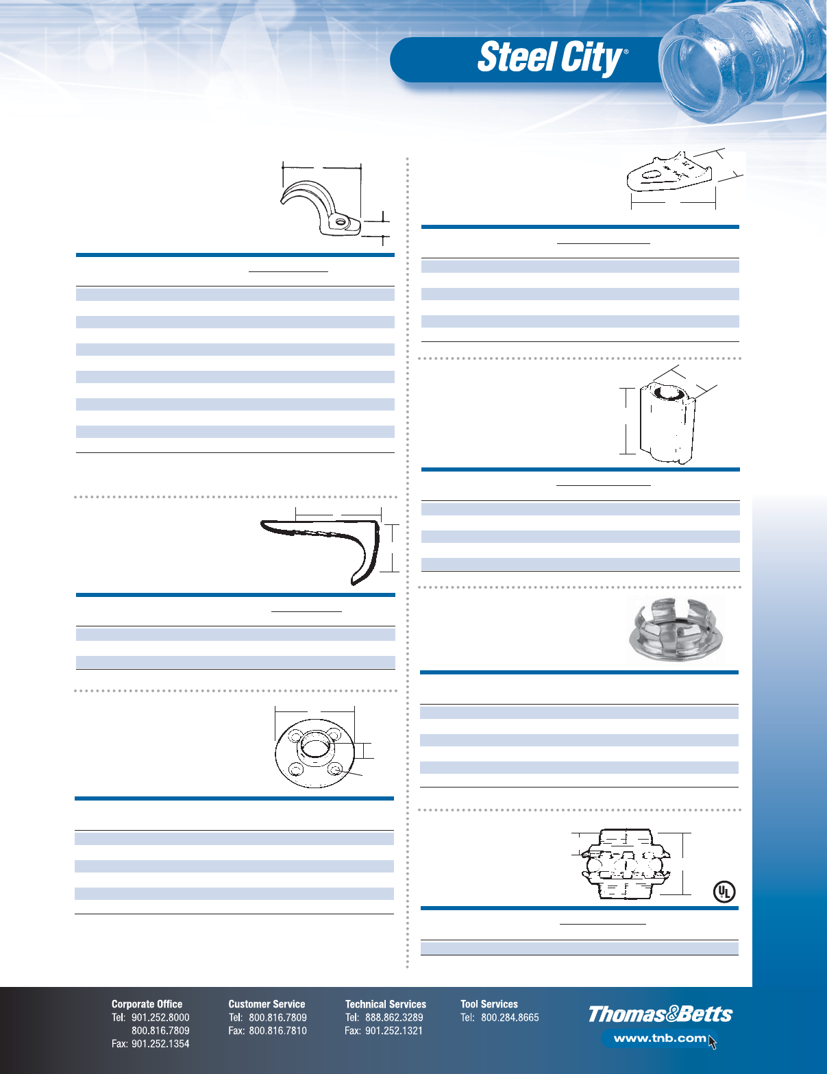
TRADE DIMENSIONS (IN.) STD.
CAT. NO.
TYPE SIZE (IN.) A B C CTN.
TC921 Set Screw Type 1⁄21.27 1.15 .45 200
TC-911-SC Compression Type 1⁄21.37 1.15 .45 200
TC-912-SC Compression Type 3⁄41.86 .95 .52 200
Set Screw Type Compression Type
AA
BB
CC
CONDUIT DIMENSIONS (IN.) STAINLESS STEEL REGULAR
CAT. NO.
SIZE (IN.) A B STD. CTN. STD. CTN.
TS-901 1⁄20.56 2.20 25 250
TS-902 3⁄40.62 2.67 25 200
TS-903 1 0.68 2.97 25 100
TS-904 11⁄40.75 3.67 10 50
TS-905 11⁄20.88 4.22 5 5
TS-906 2 1.00 4.91 5 25
*Add SS suffix to part number for Stainless Steel.
• Steel
• Zinc plated
RIGID/MC EMT FLEX DIMENSIONS (IN.) STD.
CAT. NO.
SIZE (IN.) SIZE (IN.) SIZE (IN.) A B CTN.
N-101-SC —1⁄23⁄8115⁄16 15⁄64 1,000
N-102-SC 1⁄23⁄41⁄223⁄16 117⁄32 1,000
N-103-SC 3⁄41—2
3⁄8115⁄32 1,000
• Stamped steel
• Zinc plated
B
A
A
B
One-Hole Snap Straps — Steel
Nail Straps — SteelSpace Caps — Plastic
Two-Hole EMT Straps —
Steel — Malleable Insulated
EMT Connectors — Die Cast Zinc
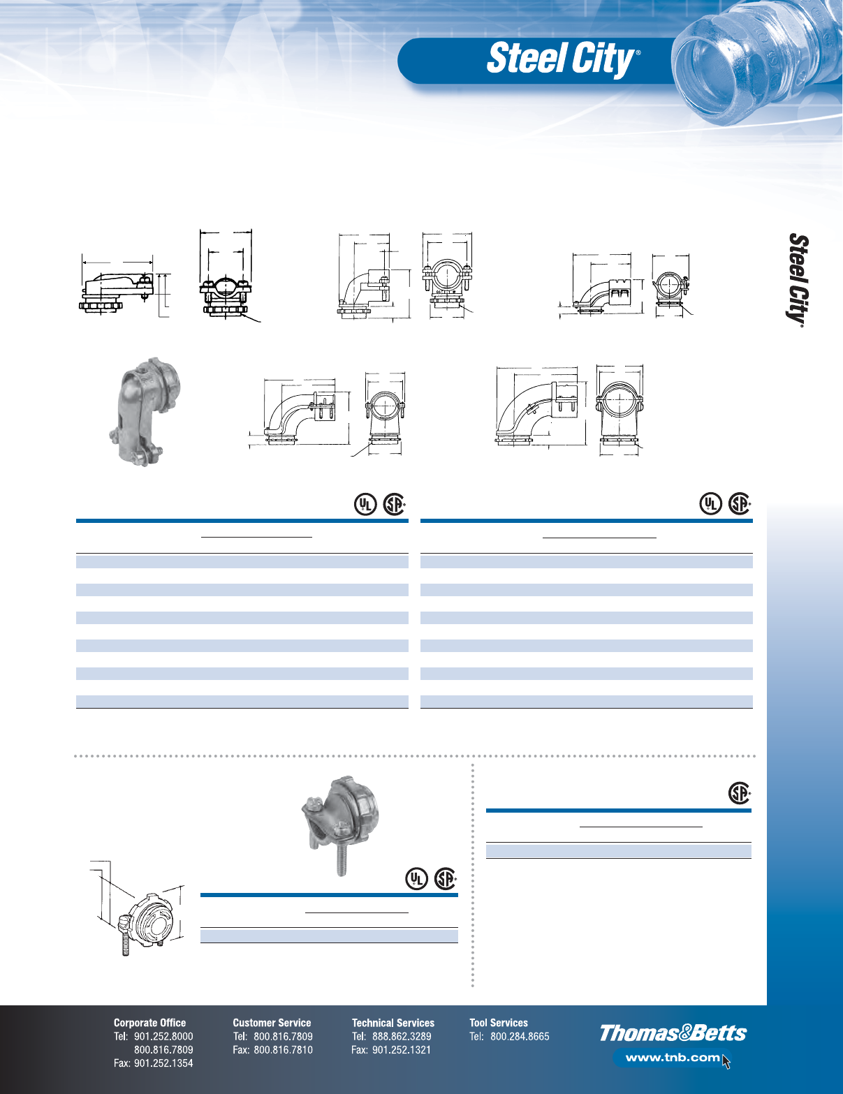
Two-Piece Type 90° Angle

Rigid/Intermediate Grade Conduit Fittings
F-10
Fittings
CONDUIT DIMENSIONS (IN.) STD.
CAT. NO.
SIZE (IN.) A B CTN.
HK-101 1⁄211⁄8213⁄32 100
HK-102 3⁄413⁄8217⁄32 50
HK-103 11
5⁄8211⁄16 25
HK-104 11⁄422
25⁄32 25
HK-105 11⁄221⁄4311⁄64 25
Two set screws starting at 2".
UL File No. E-23018.
•Malleable iron/zinc plated
•Malleable iron/zinc plated
A
B
•Steel concrete tight when taped
•Zinc plated
A
B
•Steel (concrete tight) when taped
•Zinc plated
Rigid Connectors — Set Screw Type —
Die Cast Zinc
TRADE DIMENSIONS (IN.) STD.
CAT. NO.
SIZE (IN.) A B CTN.
HC-203 1 1.54 0.49 100
HC-802 3⁄41.44 0.45 250
HC-803 1 1.54 0.49 100
A
B
Rigid Couplings — Set Screw Type —
Die Cast Zinc
TRADE DIMENSIONS (IN.) STD.
CAT. NO.
SIZE (IN.) A B CTN.
HK 201 1⁄21.77 1.09 250
HK-203 1 2.29 1.61 100
A
B
STD.
CAT. NO.
CONDUIT (IN.) CTN.
HC 401 1⁄2300
HC-402 3⁄4150
HC-403 190
HC-404 11⁄460
HC-405 11⁄230
HC-406 212
HC-407 21⁄212
HC-408 36
HC-409 31⁄26
HC-410 46
Suggested use — rigid conduit only.
UL File No. E-23018
1
⁄
2
"–1
1
⁄
4
".
Threadless Compression
Connectors
Set Screw Couplings
CONDUIT DIMENSIONS (IN.) STD.
CAT. NO.
SIZE (IN.) A B CTN.
HK-106 22
3⁄4313⁄32 20
HK-107 21⁄237⁄16 329⁄32 10
HK-108 34
1⁄16 45⁄32 5
HK-109 31⁄249⁄16 47⁄85
HK-110 45
1⁄16 53⁄85
Two set screws starting at 2".
UL File No. E-23018.
Threadless Compression
Couplings
STD.
CAT. NO
CONDUIT (IN.) CTN.
HK 401 1⁄2300
HK 402 3⁄4150
HK 403 190
HK 404 11⁄460
HK 405 11⁄230
HK 406 26
HK 407 21⁄26
HK 408 34
HK 409 31⁄24
HK 410 44
Suggested use — rigid conduit only.
UL File No. E-23018
1
⁄
2
"–1
1
⁄
4
".
Set Screw Connectors
CONDUIT DIMENSIONS (IN.) STD.
CAT. NO.
SIZE (IN.) A B CTN.
HC 101 1⁄211⁄811⁄8100
HC-102 3⁄413⁄811⁄250
HC-103 15⁄8113⁄16 50
HC-104 11⁄42225
HC-105 11⁄221⁄223⁄825
HC-106 22
3⁄423⁄820
HC-107 21⁄2313⁄32 35⁄16 10
HC-108 34
1⁄32 37⁄16 5
HC-109 31⁄249⁄16 313⁄16 5
HC-110 45
3⁄32 43⁄32 5
One set screw or two. Two set screws starting at 2" trade size.
Suggested use — rigid conduit only.
UL File No. E-23018
1
⁄
2
" –1
1
⁄
4
".
Insulated
CONDUIT DIMENSIONS (IN.) STD.
CAT. NO.
SIZE (IN.) A B CTN.
HC 701 1⁄211⁄811⁄8100
HC-702 3⁄413⁄811⁄250
HC-703 15⁄8113⁄16 25
HC-704 11⁄42225
HC-705 11⁄221⁄223⁄825
HC-706 22
3⁄423⁄820
HC-707 21⁄2313⁄32 35⁄16 10
HC-708 34
1⁄32 37⁄16 5
HC-709 31⁄241⁄447⁄85
HC-710 44
3⁄445⁄16 5
One set screw or two. Two set screws starting at 2" trade size.
Suggested use — rigid conduit only.
UL File No. E-23018
1
⁄
2
" –1
1
⁄
4
".
Rigid/Intermediate Grade Conduit Fittings
F-11
Fittings
TRADE DIMENSIONS (IN.) STD.
CAT. NO.
SIZE (IN.) A (ASSEMBLED) B CTN.
EK 201 1⁄21.39 1.31 100
EK-202 3⁄41.53 1.58 50
A
B
CONDUIT DIMENSIONS (IN.) STD.
CAT. NO.
SIZE (IN.) A (ASSEMBLED) B CTN.
EK 401 1⁄211⁄16 11⁄8100
EK 402 3⁄411⁄8111⁄32 50
EK 403 11
3⁄815⁄825
EK 404 11⁄4121⁄32 25⁄32 25
EK 405 11⁄217⁄8223⁄32 25
EK 406 22 3
33⁄64 20
EK 407 21⁄221⁄2329⁄64 10
EK 408 33
3⁄8423⁄32 6
EK 409 31⁄235⁄855⁄32 5
EK 410 43
29⁄32 529⁄32 5
EK 411 54
5⁄16 71
UL File No. E-23018
1
⁄
2
"–4".
•1⁄2"–21⁄2" — Steel
•21⁄2"–6" — Malleable iron
•Zinc plated
A
B
CONDUIT DIMENSIONS (IN.) STD.
CAT. NO.
SIZE (IN.) A B CTN.
HL-611 1⁄21.31 1.09 100
HL-612 3⁄41.47 1.29 50
UL File No. E-23018.
CONDUIT DIMENSIONS (IN.) STD.
CAT. NO.
SIZE (IN.) A B CTN.
HL-601 1⁄21.31 1.10 100
HL-602 3⁄41.60 1.24 50
HL-603 1 1.95 1.59 25
HL-604 11⁄42.26 1.97 30
UL File No. E-23018.
SIZE DIMENSIONS (IN.) SHF. CTF./
CAT. NO.
(IN.) A B SHIP QTY.
HL-202-SC 3⁄41.17 1.04 25/250
USE: To join rigid or IMC conduit at right angles where lack of room prevents using
a standard sweep elbow, or to terminate a run of rigid or IMC conduit at a box.
UL Listing E37148.
A
B
A
B
A
B
HUB STD.
CAT. NO.
SIZE (IN.) CTN.
H050-SC 1⁄2100
H075-SC 3⁄4100
H100-SC 125
H125-SC 11⁄425
H150-SC 11⁄210
H200-SC 25
H250-SC 21⁄25
H300-SC 32
H350-SC 31⁄22
H400-SC 41
H500-SC 51
H600-SC 61
*Available in nickel-chrome plating or with
PVC coating.
Consult customer service for price and delivery.
UL File No. E-23018.
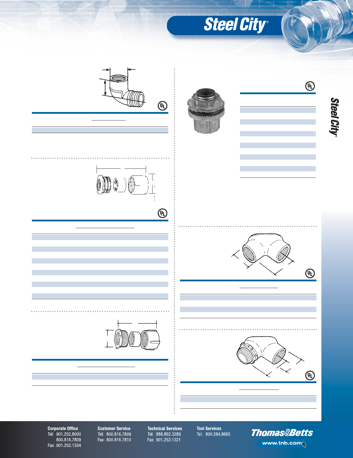
•The T&B Hub with sealing
ring that will not fall out
•Provides superior sealing
for exceptional watertight
performance
•Color blue is a registered
trademark of Thomas &
Betts Corporation
H050-SC Series Hub
90° Short Radius
Elbows —
Die Cast Zinc
Three-Piece
Couplings
Rigid Couplings —
Three Piece Type —
Die Cast Zinc
Pull Corner
Elbows —
Die Cast Zinc
Rigid to Box
with Gasket —
Die Cast Zinc
The T&B Hub — Zinc Die Cast
with Insulated Throat *
Rigid/Intermediate Grade Conduit Fittings
F-12
Fittings
B
A
CONDUIT DIMENSIONS (IN.) STD.
CAT. NO.
SIZE (IN.) A B CTN.
841-TB 3⁄89⁄16 11⁄16 500
HA-401 1⁄233⁄64 15⁄16 500
HA-402 3⁄443⁄64 13⁄16 200
HA-403 17⁄817⁄16 100
HA-404 11⁄411⁄813⁄4100
HA-405 11⁄211⁄821⁄16 50
HA-406 21
7⁄16 29⁄16 50
HA-407 21⁄211⁄4320
HA-408 31
1⁄237⁄810
HA-409 31⁄213⁄443⁄85
HA-410 4— —5
UL File No. E-23018
3
⁄
8
"–3
1
⁄
2
".
B
A
CONDUIT DIMENSIONS (IN.) STD.
CAT. NO.
SIZE (IN.) A B CTN.
HA-901 1⁄243⁄64 113⁄16 500
HA-902 3⁄413⁄16 17⁄32 200
HA-903 17⁄817⁄16 100
HA-904 11⁄411⁄813⁄4100
HA-905 11⁄211⁄821⁄16 50
HA-906 21
7⁄16 29⁄16 50
UL File No. E-23018
3
⁄
8
"–3
1
⁄
2
".
CONDUIT DIMENSIONS (IN.) STD.
CAT. NO.
SIZE (IN.) A B CTN.
HA-201 1⁄20.98 0.59 1,000
HA-202 3⁄41.18 0.70 500
HA-203 1 1.50 0.80 250
HA-204 11⁄41.75 1.06 250
HA-205 11⁄22.11 1.01 100
HA-206 2 2.61 1.20 40
HA-207 21⁄23.13 1.49 40
HA-208 3 3.90 1.65 40
HA-209 31⁄24.20 1.68 40
HA-210 4 4.79 1.73 20
UL File No. E-23018
1
⁄
2
"–2".
CONDUIT DIMENSIONS (IN.) STD.
CAT. NO.
SIZE (IN.) A B CTN.
HA-801 1⁄20.98 0.59 1,000
HA-802 3⁄41.18 0.70 500
HA-803 1 1.50 0.80 250
HA-804 11⁄41.75 1.06 250
HA-805 11⁄22.11 1.01 100
HA-806 2 2.61 1.20 40
HA-807 21⁄23.13 1.49 25
HA-808 3 3.90 1.65 10
HA-809 31⁄24.20 1.68 10
HA-810 4 4.79 1.73 10
UL File No. E-23018
1
⁄
2
"&
3
⁄
4
" only.
A
B
B
A
A
B
3⁄4"
CONDUIT DIMENSIONS (IN.) STD.
CAT. NO.
SIZE (IN.) A B CTN.
HO 221 1⁄22.60 1.00 100
HO-222 3⁄42.62 1.32 100
HO-223 1 2.68 1.51 100
HO-224 11⁄42.85 1.85 50
HO-225 11⁄22.88 2.08 50
HO-226 2 3.19 2.71 20
3
⁄
4
" offset.
UL File No. E-23018.
CONDUIT DIMENSIONS (IN.) STD.
CAT. NO.
SIZE (IN.) A B CTN.
HA-211 1⁄2115⁄16 1,000
HA-212 3⁄4113⁄16 500
HA-213 1117⁄16 250
UL File No. E-23018
1
⁄
2
" &
3
⁄
4
" only.
Offset Nipples
Die Cast Zinc
Conduit Nipples
Die Cast Zinc —
Insulated
Conduit Nipples
Iron/Zinc Plated —
Insulated
Conduit Nipples
Iron/Zinc Plated
Conduit Nipples
Die Cast Zinc —
1" Long
Conduit Nipples
Die Cast Zinc —
Non-Insulated
A
B
Rigid/Intermediate Grade Conduit Fittings
F-13
Fittings
A
B
A
B
CONDUIT DIMENSIONS (IN.) STD.
CAT. NO.
SIZE (IN.) A (MIN.) B (MAX.) CTN.
LN-100-SC 3⁄8— — 1,000
LN-101-SC 1⁄20.125 1.140 1,000
LN-102 3⁄40.140 1.420 1,000
LN-103 1 0.170 1.770 500
LN-104 11⁄40.170 2.281 200
LN-105 11⁄20.170 2.598 100
LN-106 2 0.187 3.175 50
LN-107 21⁄20.375 3.562 30
LN-108 3 0.375 4.250 25
LN-109 31⁄20.438 4.803 25
LN-110 4 0.438 5.402 25
LN-111 5 0.500 6.674 10
LN-112 6 0.561 7.934 10
UL File No. E-23018.
A
B
CONDUIT UNIT STD.
CAT. NO.
SIZE (IN.) QTY. CTN.
SPLN-107 21⁄230 30
SPLN-108 32525
SPLN-109 31⁄225 25
SPLN-110 42525
Not UL Listed.
CONDUIT DIMENSIONS (IN.) STD.
CAT. NO.
SIZE (IN.) A (MIN.) B (MAX.) CTN.
LS 101 1⁄20.26 1.12 1,000
LS-102 3⁄40.27 1.37 1,000
LS-103 1 0.28 1.75 500
LS-104 11⁄40.32 2.06 200
LS-105 11⁄20.32 2.37 100
LS-106 2 0.32 2.87 50
LS-107 21⁄20.32 3.43 50
LS-108 3 0.32 4.12 50
LS-109 31⁄20.32 4.62 50
LS-110 4 0.32 5.18 25
UL File No. E-23018.
A
B
CONDUIT DIMENSIONS (IN.) STD.
CAT. NO.
SIZE (IN.) A (MIN.) B (MAX.) CTN.
LN-201 1⁄20.125 1.140 2,000
LN-202 3⁄40.140 1.420 1,000
LN-203 1 0.170 1.770 1,000
LN-204 11⁄40.170 2.281 500
LN-205 11⁄20.170 2.598 500
LN-206 2 0.187 3.175 200
LN-207 21⁄20.375 3.562 100
LN-208 3 0.375 4.250 100
LN-209 31⁄20.438 4.803 40
LN-210 4 0.438 5.402 40
CSA File No. LR-12798.
UL File No. E-23018.
CONDUIT DIMENSIONS (IN.) STD.
CAT. NO.
SIZE (IN.) A (MIN.) B (MAX.) CTN.
LG-401 1⁄20.125 1.140 100
LG-402 3⁄40.140 1.420 100
LG-403 1 0.170 1.770 50
LG-404 11⁄40.170 2.281 50
LG-405 11⁄20.170 2.598 50
LG-406 2 0.187 3.175 25
LG-407 21⁄20.375 3.562 10
LG-408 3 0.375 4.250 10
LG-409 31⁄20.438 4.803 50
LG 410 4 0.438 5.402 5
UL File No. E-23018.
TRADE A DIA. B THD. STD.
CAT. NO.
SIZE (IN.) (IN.) (IN.) CTN.
LN-501 1⁄21.3 1⁄2–14 100
LN-502 3⁄41.4 3⁄4–14 100
LN-503 1 1.7 1–111⁄250
Material: Nylon 6/6.
Color: Gray.
.200"
A
B Thd.
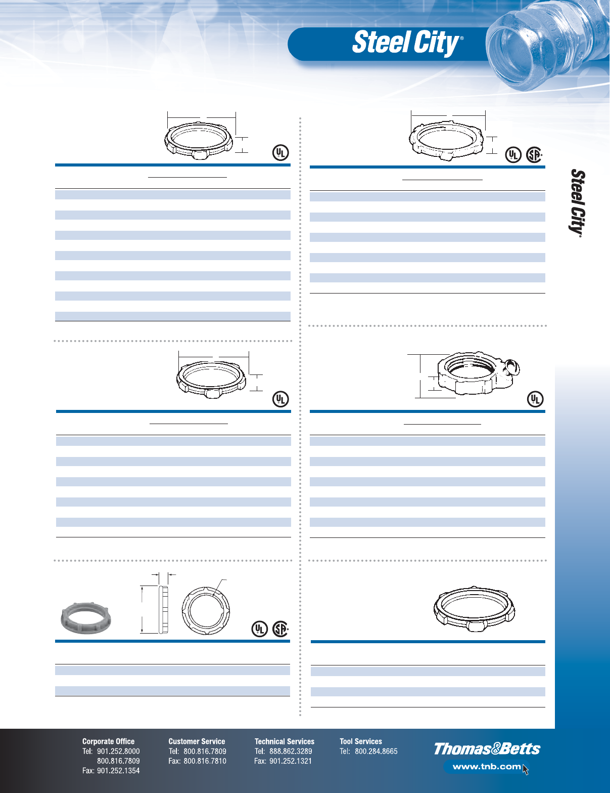
Locknuts
Steel/Zinc Plated
Locknuts
Die Cast Zinc
Sealing Locknuts
Steel/Zinc Plated
Grounding Locknuts
Malleable —
Iron/Zinc Plated
Locknuts
Non-Metallic
Thin Construction
Locknuts —
Steel/Zinc Plated
Rigid/Intermediate Grade Conduit Fittings
F-14
Fittings
CONDUIT DIMENSIONS (IN.) STD.
CAT. NO.
SIZE (IN.) A B CTN.
BU-401 1⁄211⁄32 7⁄16 1,000
BU-402 3⁄411⁄47⁄16 1,000
BU-403 11
9⁄16 1⁄2500
BU-404 11⁄4115⁄16 17⁄32 200
BU-405 11⁄2213⁄64 9⁄16 100
BU-406 22
45⁄64 9⁄16 50
UL File No. E-23018.
TRADE GROUNDING LUG WIRE SIZE STD.
CAT. NO.
SIZE (IN.) MIN. MAX. CTN.
BG201 1⁄214 4 500
BG-202 3⁄414 4 500
BG-203 1 14 4 250
BG-204A 11⁄414 4 200
BG-204 11⁄48 1/0 200
BG-205A 11⁄211 4 100
BG-205 11⁄281/0 50
BG-206A 1 14 4 100
BG-206 2 8 1/0 50
UL File No. E-3060.
•105° C thermoplastic liners
•Heavy reinforced ribs
CONDUIT DIMENSIONS (IN.) STD.
CAT. NO.
SIZE (IN.) A B CTN.
BU-801 1⁄21.06 0.43 1,000
BU-802 3⁄41.31 0.43 1,000
BU-803 1 1.59 0.48 500
BU-804 11⁄41.96 0.56 250
BU-805 11⁄22.18 0.60 250
UL File No. E-23018.
CONDUIT DIMENSIONS (IN.) STD.
CAT. NO.
SIZE (IN.) A (MIN.) B (MAX.) CTN.
BU201 1⁄21.05 0.37 1,000
BU-202 3⁄41.32 0.37 1,000
BU-203 1 1.58 0.47 500
BU-204 11⁄41.94 0.50 250
BU-205 11⁄22.20 0.52 250
UL File No. E-23018.
A
B
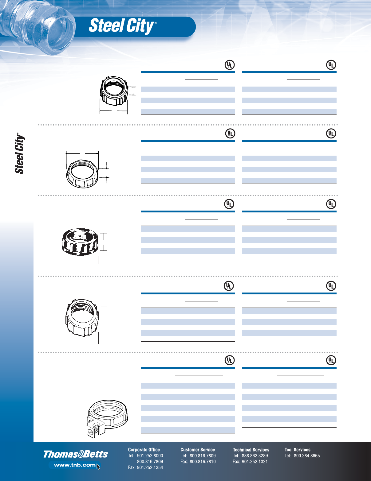
Conduit Bushings Die Cast
Zinc — Heavy Reinforced Ribs
Grounding Bushings
Die Cast Zinc — Insulated
Metallic With Aluminum
Lay-in Type Lug
A
B
A
B
CONDUIT DIMENSIONS (IN.) STD.
CAT. NO.
SIZE (IN.) A B CTN.
BU-501 1⁄213⁄32 11⁄16 400
BU-502 3⁄413⁄32 119⁄64 400
BU-503 19⁄16 19⁄16 200
BU-504 11⁄49⁄16 129⁄32 100
BU-505 11⁄29⁄16 23⁄16 100
BU-506 25⁄8211⁄16 60
UL File No. E-23018
1
⁄
2
"–4" only.
Rated 105° C.
Insulated Bushings —
Thermoplastic
Bushings — Iron/Zinc Plated
CONDUIT DIMENSIONS (IN.) STD.
CAT. NO.
SIZE (IN.) A B CTN.
BU-806 2 2.68 0.56 250
BU-807 21⁄23.25 0.90 50
BU-808 3 3.87 0.85 25
BU-809 31⁄24.37 0.93 25
BU-810 4 5.00 0.93 10
UL File No. E-23018.
CONDUIT DIMENSIONS (IN.) STD.
CAT. NO.
SIZE (IN.) A (MIN.) B (MAX.) CTN.
BU-206 2 2.69 0.52 250
BU-207 21⁄23.23 0.85 50
BU-208 3 3.84 0.85 25
BU-209 31⁄24.35 0.85 25
BU-210 4 5.02 0.85 10
UL File No. E-23018.
CONDUIT DIMENSIONS (IN.) STD.
CAT. NO.
SIZE (IN.) A B CTN.
BU-507 21⁄223⁄32 33⁄16 20
BU-508 39⁄16 327⁄32 20
BU-509 31⁄23⁄4423⁄64 5
BU-510 425⁄32 427⁄32 5
BU-511 516
5⁄16 5
BU-512 617
7⁄16 5
UL File No. E-23018
1
⁄
2
"–4" only.
Rated 105° C.
CONDUIT DIMENSIONS (IN.) STD.
CAT. NO.
SIZE (IN.) A B CTN.
BU-407 21⁄233⁄16 11⁄32 30
BU-408 33
5⁄825⁄32 25
BU-409 31⁄241⁄16 27⁄32 25
BU-410 44
21⁄32 15⁄16 25
BU-411 54
21⁄32 15⁄16 10
UL File No. E-23018.
TRADE GROUNDING LUG WIRE SIZE STD.
CAT. NO.
SIZE (IN.) MIN. MAX. CTN.
BG-207 21⁄281/0 50
BG-207A 21⁄26 250 kcmil 50
BG-208 3 8 1/0 50
BG-208A 3 6 250 kcmil 50
BG-209 31⁄281/0 10
BG-209A 31⁄26 250 kcmil 10
BG-210 4 8 1/0 10
BG-210A 4 6 250 kcmil 10
UL File No. E-3060.
A
B
•105°C thermoplastic
liners
•Heavy reinforced ribs
Conduit Bushings
Die Cast Zinc —
Insulated Metallic
Rigid/Intermediate Grade Conduit Fittings
F-15
Fittings
A
B
CONDUIT DIMENSIONS (IN.) STD.
CAT. NO.
SIZE (IN.) A B CTN.
BI-906 22
45⁄64 5⁄850
BI-907 21⁄237⁄32 9⁄16 30
BI-908 33
27⁄32 9⁄16 25
BI-909 31⁄247⁄16 7⁄825
BI910 44
31⁄32 29⁄32 25
UL File No. E-23018.
CONDUIT GROUNDING DIMENSIONS
SIZE LUG WIRE (IN.) STD.
CAT. NO.
(IN.) CAPACITY A B CTN.
BG-801 1⁄2—1
1⁄32 1⁄2500
BG-802 3⁄4#14– #4 CU 11⁄41⁄2500
BG-803 1or1
9⁄16 9⁄16 250
BG-804 11⁄4#12–#4 AL 115⁄16 19⁄32 150
BG-805 11⁄2—2
13⁄64 5⁄8150
UL File No. E-3060.
1
⁄
2
"–2" Iron, 2
1
⁄
4
"–4" Die Cast Zinc.
TRADE GROUNDING LUG WIRE SIZE STD.
CAT. NO.
SIZE (IN.) MIN. MAX. CTN.
BG801A 1⁄214 6 500
BG-802A 3⁄414 6 500
BG-803A 1 14 6 250
BG-804A 11⁄414 2 200
BG- 805A 11⁄214 2 100
BG-806A 2 14 2 100
UL File No. E-3060.
CONDUIT DIMENSIONS (IN.) STD.
CAT. NO.
SIZE (IN.) A B CTN.
RB 121 3⁄4–1⁄29⁄16 7⁄8100
RB-131 1–1⁄25⁄811⁄850
RB-132 1–3⁄45⁄811⁄850
RB-141 11⁄4–1⁄211⁄16 17⁄16 50
RB 142 11⁄4–3⁄411⁄16 17⁄16 50
RB-143 11⁄4–1 11⁄16 17⁄16 50
RB-151 11⁄2–1⁄223⁄32 111⁄16 50
RB-152 11⁄2–3⁄423⁄32 111⁄16 50
RB-153 11⁄2–1 23⁄32 111⁄16 50
RB-154 11⁄2–11⁄423⁄32 111⁄16 50
UL File No. E-23018.
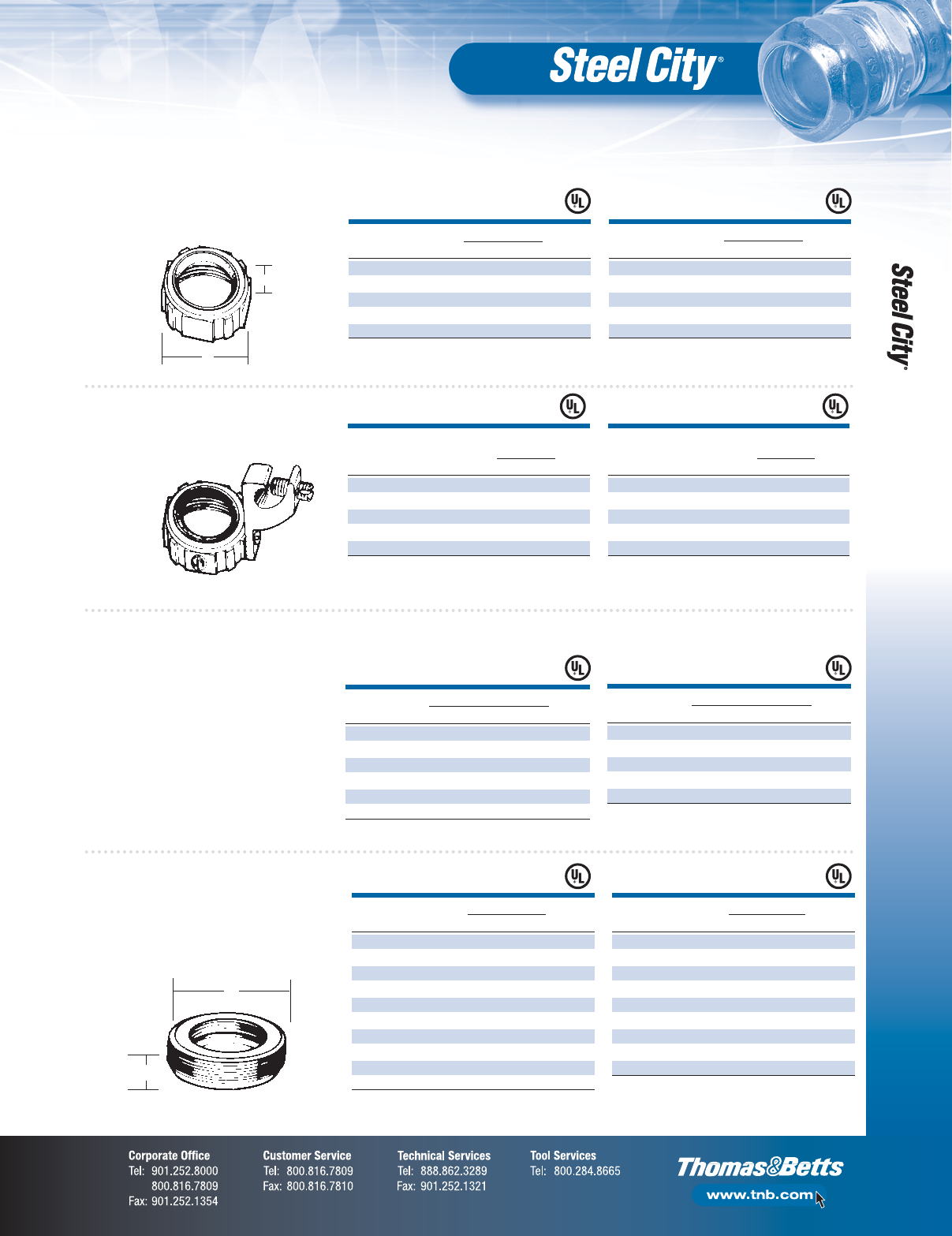
Insulated Bushings —
Iron/Zinc Plated
Insulated Grounding
Bushings — Malleable
Iron/Zinc Plated
Reducing Bushings
•RB-121 thru RB-165 — Steel
•RB-175 thru RB-187 — Malleable iron
(concrete tight), zinc plated
Grounding Bushings
Malleable Iron/Zinc Plated —
Insulated With Aluminum Lug
•For copper or aluminum
bare ground wire
•105°C thermoplastic liners
•Heavy reinforced ribs
CONDUIT DIMENSIONS (IN.) STD.
CAT. NO.
SIZE (IN.) A B CTN.
BI 901 1⁄211⁄32 1⁄21,000
BI-902 3⁄411⁄41⁄21,000
BI-903 11
9⁄16 9⁄16 500
BI-904 11⁄4115⁄16 19⁄32 200
BI-905 11⁄2213⁄64 5⁄8100
UL File No. E-23018.
CONDUIT GROUNDING DIMENSIONS
SIZE LUG WIRE (IN.) STD.
CAT. NO.
(IN.) CAPACITY A B CTN.
BG-806 2—2
45⁄64 5⁄8100
BG-807 21⁄2#14–1/0 CU 33⁄16 9⁄16 60
BG-808 3 or #12–1/0 AL 35⁄89⁄16 30
BG-809 31⁄2#6–250 kcmil 41⁄16 7⁄830
BG-810 4 CU or AL 421⁄32 29⁄32 30
UL File No. E-3060.
1
⁄
2
"–2" Iron, 2
1
⁄
4
"–4" Die Cast Zinc.
CONDUIT DIMENSIONS (IN.) STD.
CAT. NO.
SIZE (IN.) A B CTN.
RB-161 2–1⁄227⁄32 23⁄32 25
RB-162 2–3⁄427⁄32 23⁄32 25
RB-163 2–1 27⁄32 23⁄32 25
RB-164 2–11⁄427⁄32 23⁄32 25
RB-165 2–11⁄227⁄32 23⁄32 25
RB-175 21⁄2–11⁄27⁄8213⁄16 25
RB-176 21⁄2–2 7⁄8213⁄16 25
RB-186 3–2 29⁄32 27⁄16 25
RB-187 3–21⁄229⁄32 27⁄16 25
UL File No. E-23018.
TRADE GROUNDING LUG WIRE SIZE STD.
CAT. NO.
SIZE (IN.) MIN. MAX. CTN.
BG-807A 21⁄214 2/0 50
BG-808A 3 14 2/0 50
BG-809A 31⁄214 2/0 10
BG-810A 4 14 2/0 10
BG-810B 4 6 250 kcmil 10
UL File No. E-3060.
B
A
Rigid/Intermediate Grade Conduit Fittings
F-16
Fittings
B
A
CONDUIT DIMENSIONS (IN.) STD.
CAT. NO.
SIZE (IN.) A B CTN.
RB 421 3⁄4–1⁄25⁄813⁄16 100
RB-432 1⁄2–3⁄411
3⁄16 100
RB-443 1–3⁄411⁄16 13⁄16 50
UL File No. E-23018.
SCREW CONDUIT DIMENSIONS (IN.) STD.
CAT. NO.
SIZE SIZE (IN.) A B CTN.
HS-100-SC 10 3⁄83⁄4147⁄64 1,000
HS-101 1⁄41⁄211
15⁄16 500
HS-102 1⁄43⁄412
5⁄64 500
HS-103 1⁄4112
13⁄32 250
HS-104 5⁄16 11⁄413
3⁄32 100
HS-105 3⁄811⁄213⁄16 313⁄32 100
HS-106 3⁄821
3⁄16 327⁄32 100
HS-107 7⁄16 21⁄211⁄451⁄16 25
HS-108 1⁄231
3⁄857⁄825
HS-109 1⁄231⁄213⁄861⁄410
HS-110 1⁄241
3⁄867⁄810
Available in one-hole and two-hole in stainless steel.
Add SS suffix to part number for Stainless Steel.
A
B
SCREW CONDUIT DIMENSIONS (IN.) STD.
CAT. NO.
SIZE SIZE (IN.) A B C CTN.
HS-901 81⁄23⁄427⁄16 3⁄16 1,200
HS-902 10 3⁄43⁄4211⁄16 3⁄16 900
HS-903 1⁄413⁄437⁄16 3⁄16 600
HS-904 1⁄411⁄43⁄4327⁄32 3⁄16 450
HS-905 1⁄411⁄23⁄441⁄16 3⁄16 50
HS-906 1⁄423⁄447⁄16 3⁄16 150
HS-907 1⁄421⁄215
1⁄81⁄4150
HS-908 1⁄2316
3⁄16 1⁄460
HS-909 1⁄431⁄217
3⁄16 1⁄460
HS-910 1⁄4418
11⁄16 1⁄460
CSA Certified.
Add SS suffix to part number for Stainless Steel.
A
B
C
Reducers —
Malleable Iron/
Zinc Plated
CONDUIT DIAMETER (IN.) STD.
CAT. NO.
SIZE (IN.) A B C CTN.
WA 110 1⁄2–3⁄813⁄16 11⁄16 27⁄32 500
WA-121 3⁄4–1⁄211⁄27⁄811⁄16 500
WA-131 1–1⁄213⁄47⁄815⁄16 500
WA-132 1–3⁄413⁄413⁄32 15⁄16 500
WA-141 11⁄4–1⁄223⁄16 7⁄8111⁄16 200
WA-142 11⁄4–3⁄423⁄16 13⁄32 111⁄16 200
WA-143 11⁄4–1 23⁄16 123⁄64 111⁄16 200
WA-151 11⁄2–1⁄225⁄87⁄817⁄8200
WA-152 11⁄2–3⁄425⁄813⁄32 17⁄8200
WA-153 11⁄2–1 25⁄8123⁄64 17⁄8200
WA-154 11⁄2–11⁄425⁄8123⁄32 17⁄8200
WA-161 2–1⁄231⁄47⁄823⁄8100
WA-162 2–3⁄4"3
1⁄413⁄32 23⁄8100
WA-163 2–1 31⁄4123⁄64 23⁄8100
WA-164 2–11⁄431⁄4123⁄32 23⁄8100
WA-165 2–11⁄231⁄4131⁄32 23⁄8100
WA-171 21⁄2–1⁄231⁄47⁄827⁄8100
WA-172 21⁄2–3⁄431⁄413⁄32 27⁄8100
WA-173 21⁄2–1 31⁄4123⁄64 27⁄8100
WA-174 21⁄2–11⁄431⁄4123⁄32 27⁄8100
WA-175 21⁄2–11⁄231⁄4131⁄32 27⁄8100
WA-176 21⁄2–2 31⁄427⁄16 27⁄8100
WA-181 3–1⁄241⁄27⁄831⁄2100
WA-182 3–3⁄441⁄2123⁄32 31⁄2100
WA-183 3–1 41⁄2123⁄64 31⁄2100
WA-184 3–11⁄441⁄2123⁄32 31⁄2100
WA-185 3–11⁄241⁄2131⁄32 31⁄2100
WA-186 3–2 41⁄227⁄16 31⁄2100
WA-187 3–21⁄241⁄225⁄16 31⁄2100
WA-121 thru WA-165 CSA Listed.
A
B
C
Reducing Washers —
Steel/Zinc Plated
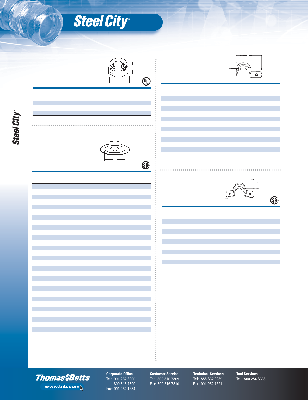
One-Hole Straps —
Steel/Zinc Plated
Two-Hole Straps —
Steel/Zinc Plated
Rigid/Intermediate Grade Conduit Fittings
F-17
Fittings
A
B
SCREW CONDUIT DIMENSIONS (IN.) STD.
CAT. NO.
SIZE SIZE (IN.) A B CTN.
HS-400 10 3⁄8111⁄16 17⁄32 500
HS-401 1⁄41⁄221⁄64 5⁄8500
HS-402 1⁄43⁄427⁄16 13⁄16 500
HS-403 1⁄412
7⁄815⁄16 100
HS-404-SC 5⁄16 11⁄435⁄16 11⁄32 100
HS-405 3⁄811⁄233⁄411⁄850
HS-406 1⁄224
19⁄32 15⁄16 25
HS-407 5⁄821⁄2511⁄16 15⁄825
HS-408 5⁄836
7⁄817⁄825
HS-409 5⁄831⁄2723⁄32 21⁄810
HS-410 5⁄848
9⁄16 23⁄810
HS-411 5⁄8510
9⁄32 25⁄85
Available in one-hole and two-hole in Stainless Steel.
Add SS suffix to part number for Stainless Steel.
Pipe Straps —
Malleable Iron/
Zinc Plated
RIGID/MC EMT FLEX DIMENSIONS (IN.) STD.
CAT. NO.
SIZE (IN.) SIZE (IN.) SIZE (IN.) A B CTN.
N-101-SC —1⁄23⁄825⁄32 15⁄64 1,000
N-102-SC 1⁄23⁄41⁄225⁄16 17⁄32 1,000
N-103-SC 3⁄41—2
3⁄8115⁄32 1,000
B
A
CONDUIT DIA. DEPTH STD.
CAT. NO.
SIZE (IN.) A (IN.) B (IN.) CTN.
FP 401 1⁄23 .625 50
FP-402 3⁄433⁄8.656 50
FP-403 13
5⁄8.765 50
FP-404 11⁄44 .875 25
FP-405 11⁄243⁄8.937 25
FP-406 24
7⁄8.843 25
B
5⁄16"
Bolt Hole
A
CONDUIT DIMENSIONS (IN.) STD.
CAT. NO.
SIZE (IN.) A B CTN.
CB-201 1⁄22 1 1,000
CB-202 3⁄423⁄811⁄16 500
CB-203 12
3⁄415⁄16 500
CB-204 11⁄433⁄811⁄2250
CB-205 11⁄2313⁄16 15⁄8100
CB-206 24
1⁄2250
A
B
CONDUIT DIMENSIONS (IN.) STD.
CAT. NO.
SIZE (IN.) A B CTN.
BR-501 1⁄2215⁄32 121⁄32 100
BR-502 3⁄4215⁄32 155⁄64 100
BR-503 12
15⁄32 21⁄8100
BR-504 11⁄4215⁄32 261⁄64 100
BR-505 11⁄2215⁄32 313⁄64 100
A
B
•Steel
•Zinc plated
CONDUIT STD.
CAT. NO.
SIZE (IN.) DIAMETER (IN.) CTN.
BL-111 1⁄215⁄64 1,000
BL-112 3⁄411⁄41,000
BL-113 11
1⁄21,000
BL-114 11⁄4113⁄16 500
BL-115 11⁄227⁄32 500
BL-116 22
11⁄16 250
A
B
CONDUIT DIMENSIONS (IN.) STD.
CAT. NO.
SIZE (IN.) A B CTN.
BS 201 1⁄211⁄813⁄32 500
UL File No. E-23018.
Nail Strap —
Stamped Steel/
Zinc Plated
Rigid/Intermediate
Space Caps — Plastic
Flange Plates —
Malleable Iron/Zinc Plated
Snap-in Blanks
Pipe Spacers
for Rigid/Intermediate
or Thinwall — Die Cast Zinc
Box Spacer —
Die Cast Zinc
(1⁄4" Space)
Flexible Cord & Power Cable Connectors
F-18
Fittings
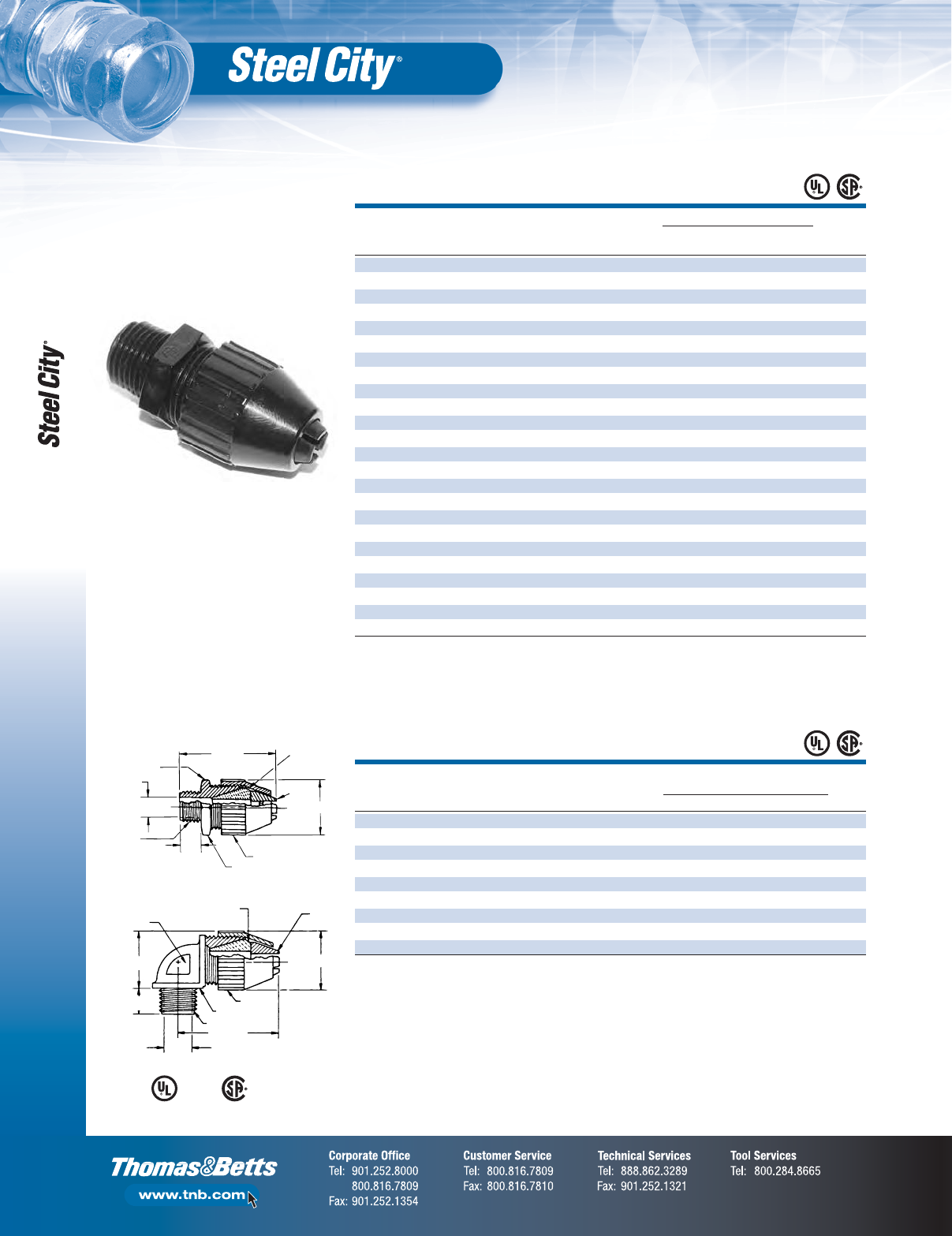
BLACK BEAUTY®
Non-Metallic
Liquidtight Strain
Relief Connectors
A Max.
Hex Flat
Throat Size
Hub N.P.T.
THD C
Body
Gland
B
Chuck
Neoprene
Bushing
Seal
LR 52391
E 13938
LR 52391
E 13938
Neoprene Bushing Seal Chuck
B
D
C
Throat Size
Wrench Flat
A (Max.)
Hub N.P.T. Thd
90º Elbow
Gland
Straight
TRADE THROAT HEX DIMENSIONS (IN.)
OR HUB CORD SIZE FLAT A B C STD.
CAT. NO.
SIZE (IN.) RANGE ± .03 ± .06 MAX. ± .06 ± .06 CTN.
2671†3⁄8.125–.275 0.33 .78 2.0 .90 .46 250
2690†1⁄2.125–.275 0.33 1.00 2.3 .90 .60 100
2672 1⁄2.250–.400 0.55 1.08 2.6 1.27 .60 100
2673*1⁄2.400–.560 0.55 1.08 2.6 1.27 .60 100
2691*1⁄2.560–.690 0.54 1.32 3.0 1.57 .60 100
2692*1⁄2.660–.780 0.54 1.32 3.0 1.57 .60 100
2693 3⁄4.250–.400 0.55 1.22 2.7 1.27 .62 100
2694*3⁄4.400–.560 0.55 1.22 2.7 1.27 .62 100
2674 3⁄4.560–.690 0.79 1.34 3.0 1.57 .62 100
2675 3⁄4.660-.780 0.79 1.34 3.0 1.57 .62 100
2696*3⁄4.770–.895 0.76 1.64 3.2 1.89 .62 100
2676 1 .660–.780 0.98 1.60 3.3 1.89 .77 100
2677 1 .770–.895 0.98 1.60 3.3 1.89 .77 100
2678 1 .870–1.020 0.98 1.60 3.3 1.89 .77 50
2699 1 .890–1.090 0.98 2.25 4.2 2.58 .77 10
2702 11⁄4.890–1.090 1.25 2.25 4.2 2.58 .80 10
2703*1
1⁄41.080–1.280 1.25 2.25 4.0 2.58 .80 10
2704*1
1⁄41.270-1.470 1.25 2.25 4.0 2.58 .80 10
2705-TB 11⁄4.890-1.150 1.47 2.65 4.2 2.95 .82 10
2706 11⁄41.140-1.400 1.47 2.65 4.3 2.95 .82 10
2707*1
1⁄41.390–1.650 1.47 2.65 4.3 2.95 .82 10
2708 2 1.190–1.530 1.89 3.13 5.1 3.50 .84 5
2709 2 1.520–1.860 1.89 3.13 4.9 3.50 .84 5
2710* 2 1.850–2.190 1.89 3.13 4.9 3.50 .84 5
*Remove sufficient outer covering of cable to permit conductors to pass through connector body.
†CSA certified for factory installation.
Material: Weather-stabilized nylon, rated at – 34°C to 105°C.
For 90° style see AS-72555.
90º Angle
TRADE
OR HUB CORD THROAT HEX DIMENSIONS (IN.) STD.
CAT. NO.
SIZE (IN.) RANGE SIZE FLAT A B C D CTN.
2680 †3⁄8.125–.275 .33 .62 1.8 .90 .46 1.00 100
2681 1⁄2.250–.400 .55 .83 2.5 1.27 .60 1.35 50
2682*1⁄2.400–.560 .55 .83 2.5 1.27 .60 1.35 50
2683 3⁄4.560-.690 .78 1.06 2.8 1.57 .62 1.60 50
2684 3⁄4.660–.780 .78 1.06 2.8 1.57 .62 1.60 50
2688 1 .560–.690 1.00 1.280 3.0 1.89 .77 1.90 25
2685 1 .660–.780 1.00 1.280 3.0 1.89 .77 1.90 25
2686 1 .770–.895 100 1.280 3.0 1.89 .77 1.90 25
2687 * 1 .870–1.020 1.00 1.280 3.0 1.89 .77 1.90 25
* Remove sufficient outer covering of cable to permit conductors to pass through connector body.
† CSA certified for factory installation.
•Installs on cord by hand
•Achieves maximum pullout strength
without installation tools
•Each hub size takes a range
of cord diameters
•Non-metallic construction provides
corrosion resistance
•Weather-stabilized nylon rated
at –34°C to 105°C
Liquidtight Flexible Metal Conduit and Connectors
F-19
Fittings
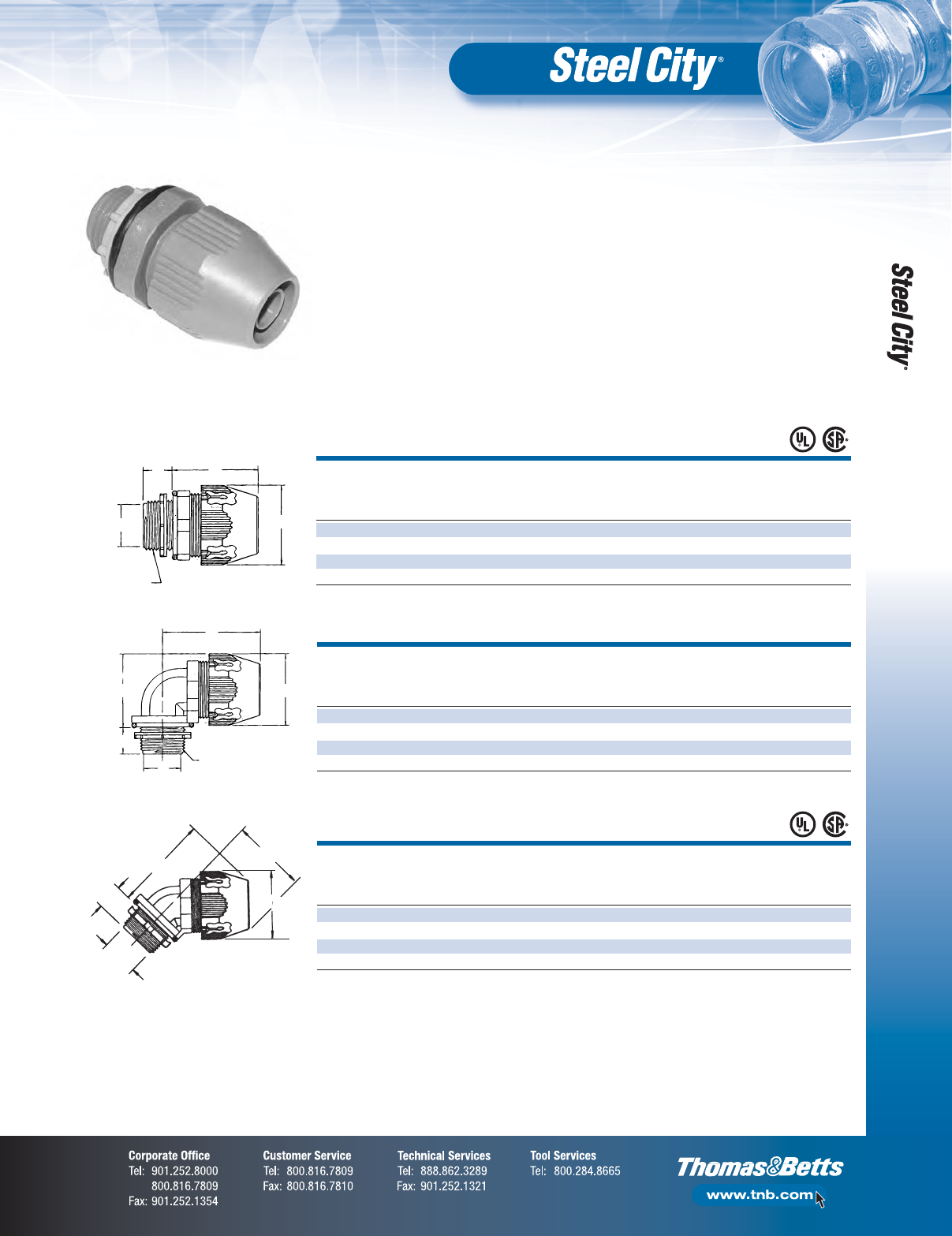
Straight
C 5.015 (0.40) MIN.
A5 .015 B 5.35 ACROSS THROAT E F
TRADE (0.40) IN. (0.90) IN. CORNERS DIA. D. THREAD INCH (MM) STD.
CAT. NO.
SIZE (IN.) (MM) (MM) IN. (MM) IN. (MM) NPT. APPROX. CTN.
LT-500 3⁄8.570 1.595 (40.51) 1.354 .417 1⁄2–14 1.880 (47.75) 100
LT-501 1⁄2.570 1.636 (41.55) 1.448 .550 1⁄2–14 1.986 (50.44) 100
LT-502 3⁄4.582 1.757 (44.63) 1.740 .740 3⁄4–14 2.212 (56.18) 50
LT-503 1 .726 1.923 (48.84) 2.068 .940 111⁄12 2.508 (63.70) 50
A
D
B
C
E Thread
90° Angle
C 5.015 (0.40) MIN.
A5 .015 B 5.35 ACROSS THROAT E F
TRADE (0.40) IN. (0.90) IN. CORNERS DIA. D. THREAD INCH (MM) STD.
CAT. NO.
SIZE (IN.) (MM) (MM) IN. (MM) IN. (MM) NPT. APPROX. CTN.
LT-590 3⁄8(14.48) 1.380 (35.05) (34.39) (10.59) 1⁄2–14 1.880 (47.75) 50
LT-591 1⁄2(14.48) 1.489 (37.82) (36.78) (13.97) 1⁄2–14 1.986 (50.44) 50
LT-592 3⁄4(14.78) 1.790 (45.47) (44.20) (18.80) 3⁄4–14 2.212 (56.18) 50
LT-593 1 (18.44) 2.104 (53.44) (52.53) (23.88) 111⁄12 2.508 (63.70) 25
E Thread
A
D
B
F
C
Standard Material/Finish:
•Body/Gland — Nylon-Gray
•O-Ring — Nitrate (Black)
•Locknut — Nylon
•Temp. Rating — 80°C
•Material Flammability Rating: UL94-V2
45° Angle
C 5.015 (0.40) MIN.
A5 .015 B 5.35 ACROSS THROAT E F
TRADE (0.40) IN. (0.90) IN. CORNERS DIA. D. THREAD IN. (MM) STD.
CAT. NO.
SIZE (IN.) (MM) (MM) IN. (MM) IN. (MM) NPT. APPROX. CTN.
LT-540 3⁄8(14.48) 2.012 (51.10) (34.39) (10.59) 1⁄2–14 1.534 (38.95) 50
LT-541 1⁄2(14.48) 2.092 (53.14) (36.78) (13.97) 1⁄2–14 1.590 (40.39) 50
LT-542 3⁄4(14.78) 2.452 (62.28) (44.20) (18.80) 3⁄4–14 1.821 (46.25) 50
LT-543 1 (18.44) 2.684 (68.17) (52.53) (23.88) 111⁄12 2.034 (51.66) 25
D
A
B
F
C
Liquidtight Flex for Type B
Non-Metallic Conduit
Listed/Certified by:
•UL Listed (File # E23018)
•CSA Certified (File # LR52391)
•Conforms to watertight
requirements for Type 4

Liquidtight Flexible Metal Conduit and Connectors
F-20
Fittings
CAT. NO.
TRADE I.D. (IN.) O.D. (IN.) STD.
SERIES
SIZE (IN.) MIN. MAX. MIN. MAX. CTN.
LTC038GY 3⁄8.484 .504 .690 .710 100
LTC050GY 1⁄2.622 .642 .820 .840 100
LTC075GY 3⁄4.820 .840 1.030 1.050 100
LTC100GY 1 1.041 1.066 1.290 1.315 100
LTC125GY 11⁄41.380 1.410 1.630 1.660 100
LTC150GY 11⁄21.575 1.600 1.865 1.900 50
LTC200GY 2 2.020 2.045 2.340 2.375 50
UL Listed: File E95745.
For use with Thomas & Betts LT38P, LT38M, LT500 series
and Liquidtight Flexible Metal Conduit Fittings.
For Non-Metallic Flexible Conduit
CAT. NO.
DESCRIPTION
XF-CUT For Cutting Non-Metallic Flexible Conduit up to 1"
XF-BLADE Replacement Blade for XF-CUT
O.D. I.D.
. . . . . . . . Specifications . . . . . . . . . .
•Color: Gray
•Length: 100 ft. for LTC038GY thru LTC125GY
50 ft. for LTC150GY and LTC200GY
•UL Temperature Rating:
80° C dry, 60° C wet
70° C oil. res. sunlight resistant,
outdoor, direct burial
•CSA Certified: File LR 80349-2
•CSA Temperature Rating: -18°C to 75°C
•Material: PVC Helix reinforcement surrounded
with flexible PVC
•Voltage Rating: 600V
CONDUIT WIRE STD.
CAT. NO.
SIZE (IN.) LENGTH (FT.) GAUGE CTN.
LTWHIP 12-6-10 1⁄26 #10 6
LTWHIP 12-4-10 1⁄24 #10 6
LTWHIP 34-6-8 3⁄46#8 6
LTWHIP 34-4-8 3⁄44#8 6
Whip with Metallic Fittings — One Straight, One 90°
LTWM 12-6-10 1⁄26 #10 6
LTWM 12-4-10 1⁄24 #10 6
LTWM 34-6-8 3⁄46#8 6
LTWM 34-4-8 3⁄44#8 6
Liquidtight Whip Assembly
Conduit Cutter
Outdoor XTRA FLEX®
Raceway System (Type B)

Liquidtight Flexible Metal Conduit and Connectors
F-21
Fittings
A
C
TRADE STD.
CAT. NO.
SIZE (IN.) A (IN.) B C (IN.) CTN.
5341GR 3⁄819⁄16 14-4 11⁄16 50
5342GR 1⁄217⁄814-4 13⁄850
5343GR 3⁄421⁄814-4 13⁄16 50
5344GR 12
1⁄414-4 13⁄425
5241GR 3⁄819⁄16 14-4 11⁄16 50
5242GR 1⁄217⁄814-4 13⁄850
5243GR 3⁄421⁄814-4 13⁄16 50
5244GR 12
1⁄414-4 13⁄425
A
C
B Lug Range
TRADE STD.
CAT. NO.
SIZE (IN.) A (IN.) B CTN.
5271GR 3⁄815⁄32 14-4 50
5272GR 1⁄213⁄814-4 50
5273GR 3⁄4121⁄32 14-4 50
5274GR 11
7⁄814-4 25
A
A
B Lug Range
Liquidtight Fittings — 45° Type
Liquidtight to Rigid External Ground Adapter
GROUNDING
DEVICE TRADE
(LUG ONLY) SIZE STD.
CAT. NO. CAT. NO.
(IN.) A (IN.) B CTN.
5331GR 38GR-TB 3⁄811⁄214-4 100
5332GR 12GR-TB 1⁄219⁄16 14-4 100
5333GR 34GR-TB 3⁄415⁄814-4 25
5334GR 1GR-TB 12
1⁄16 14-4 50
5231GR 38GR-TB 3⁄811⁄214-4 100
5232GR 12GR-TB 1⁄219⁄16 14-4 100
B Lug Range
A
GROUNDING DEVICE
(LUG ONLY) TRADE STD.
CAT. NO. CAT. NO.
SIZE (IN.) A (IN.) B (IN.) C CTN.
5351GR 38GR-TB 3⁄813⁄811⁄414-4 50
5352GR 12GR-TB 1⁄219⁄16 17⁄16 14-4 50
5353GR 34GR-TB 3⁄413⁄413⁄16 14-4 50
5354GR 1GR-TB 12
3⁄16 21⁄16 14-4 25
5251GR 38GR-TB 3⁄813⁄811⁄414-4 50
5252GR 12GR-TB 1⁄219⁄16 17⁄16 14-4 50
5253GR 34GR-TB 3⁄413⁄4113⁄16 14-4 50
5254GR 1GR-TB 12
3⁄16 21⁄16 14-4 25
5251ALGR 38GR-TB 3⁄813⁄811⁄414-4 50
5252ALGR 12GR-TB 1⁄219⁄16 17⁄16 14-4 50
5253ALGR 13GR-TB 3⁄413⁄4113⁄16 14-4 50
5254ALGR 1GR-TB 12
3⁄16 21⁄16 14-4 25
C Lug Range A
B
Liquidtight Fittings
Liquidtight Fittings — 90° Type
GROUNDING
DEVICE TRADE
(LUG ONLY) SIZE STD.
CAT. NO. CAT. NO.
(IN.) A (IN.) B CTN.
5233GR 34GR-TB 3⁄415⁄814-4 25
5234GR 1GR-TB 12
1⁄16 14-4 50
5231ALGR 38GR-TB 3⁄811⁄214-4 100
5232ALGR 12GR-TB 1⁄219⁄16 14-4 100
5233ALGR 13GR-TB 3⁄415⁄814-4 50
5234ALGR 1GR-TB 12
1⁄16 14-4 50

Liquidtight Flexible Metal Conduit and Connectors
F-22
Fittings
•3⁄8"–1", steel
•11⁄4"–4", malleable iron/zinc plated •3⁄8"–1", steel
•11⁄4"–4", malleable iron/zinc
plated (with insulated throat)
CONDUIT DIMENSIONS (IN.) STD.
CAT. NO.
SIZE (IN.) A B C CTN.
LT 100 3⁄811⁄16 1⁄2113⁄16 100
LT-101 1⁄213⁄16 39⁄64 17⁄8100
LT-102 3⁄417⁄16 9⁄16 21⁄32 50
LT-103 11
3⁄45⁄829⁄32 50
LT-104 11⁄427⁄16 11⁄16 219⁄32 25
LT-105 11⁄223⁄425⁄32 225⁄32 10
LT-106 23
17⁄32 25⁄32 35
CSA File No. LR-12798.
UL File No. E-23018 —
1
⁄
4
"–4".
CONDUIT DIMENSIONS (IN.) STD.
CAT. NO.
SIZE (IN.) E F G I CTN.
LT-950 3⁄81.140 .500 1.150 1.480 50
LT-951 1⁄21.250 .500 1.280 1.510 50
LT-952 3⁄41.280 .520 1.550 1.540 50
LT-953 1 1.430 .650 1.800 1.810 25
LT-954 11⁄41.500 .660 2.250 2.160 25
LT-955 11⁄21.610 .730 2.440 2.430 10
LT-956 2 1.760 .750 2.970 2.820 5
LT-959 31⁄22.610 1.180 5.250 5.930 1
CONDUIT DIMENSIONS (IN.) STD.
CAT. NO.
SIZE (IN.) E F G H CTN.
LT-450 3⁄81.140 .500 1.150 1.480 50
LT-451 1⁄21.250 .500 1.280 1.510 50
LT-452 3⁄41.280 .520 1.550 1.540 50
LT-453 1 1.430 .650 1.800 1.810 25
LT-454 11⁄41.500 .660 2.250 2.160 25
LT-455 11⁄21.610 .730 2.440 2.430 10
LT-456 2 1.760 .750 2.970 2.820 5
LT-459 31⁄22.610 1.180 5.250 5.930 1
CSA File No. LR-12798.
UL File No. E-23018.
A
B
CA
B
C
D
G
E
F
HI
45º
CONDUIT DIMENSIONS (IN.) STD.
CAT. NO.
SIZE (IN.) J K L M CTN.
LT-490 3⁄811⁄16 1⁄217⁄813⁄850
LT-491 1⁄213⁄16 1⁄221
13⁄32 50
LT-492 3⁄417⁄16 9⁄16 23⁄16 121⁄32 50
LT-493 11
3⁄45⁄829⁄16 17⁄825
25CSA File No. LR-12798.
UL File No. E-23018.
CONDUIT DIMENSIONS (IN.) STD.
CAT. NO.
SIZE (IN.) J K L N CTN.
LT-990 3⁄811⁄16 1⁄217⁄8115⁄32 50
LT-991 1⁄213⁄16 1⁄221
1⁄250
LT-992 3⁄417⁄16 9⁄16 23⁄16 13⁄450
LT-993 11
3⁄45⁄823⁄16 131⁄32 50
J
L
K
MN
Straight Connectors
CONDUIT DIMENSIONS (IN.) STD.
CAT. NO.
SIZE (IN.) A B C CTN.
LT-700 3⁄811⁄16 1⁄2129⁄32 100
LT-701 1⁄213⁄16 39⁄64 131⁄32 100
LT-702 3⁄417⁄16 9⁄16 21⁄850
LT-703 11
3⁄45⁄823⁄850
LT-704 11⁄427⁄16 11⁄16 211⁄16 25
LT-705 11⁄223⁄425⁄32 27⁄810
LT-706 23
17⁄32 25⁄32 35⁄16 5
LT-707 21⁄223⁄16 141
LT-708 32
1⁄215⁄32 43⁄16 1
CSA File No. LR-12798.
UL File No. E-23018 —
1
⁄
4
"–4".
Straight Connectors
(with Insulated Throat)
45° Connectors —
Malleable Iron/Zinc Plated
45° Connectors —
Malleable Iron/Zinc Plated
(with Insulated Throat)
90° Connectors —
Malleable Iron/Zinc Plated
90° Connectors —
Malleable Iron/Zinc Plated
(with Insulated Throat)
Liquidtight Flexible Metal Conduit and Connectors
F-23
Fittings
CONDUIT DIMENSIONS (IN.) STD.
CAT. NO.
SIZE (IN.) A B C CTN.
LT-200 3⁄81.81 0.50 1.06 100
LT-201 1⁄21.88 0.61 1.19 100
LT-202 3⁄42.03 0.56 1.44 100
LT-203 1 2.28 0.63 1.75 50
LT-204 11⁄42.59 0.69 2.44 40
LT-205 11⁄22.78 0.78 2.75 20
LT-206 2 3.22 0.78 3.53 20
LT-207 21⁄23.53 0.84 4.28 1
LT-208 3 3.91 0.88 4.72 1
LT-209 31⁄24.04 0.91 5.42 1
LT-210 4 4.16 0.94 5.91 1
UL File No. E-23018.
A
B
C
A
B
C
CONDUIT DIMENSIONS (IN.) STD.
CAT. NO.
SIZE (IN.) A B C CTN.
LT-290 3⁄81.88 1.38 0.50 100
LT-291 1⁄22.00 1.41 0.50 100
LT-292 3⁄42.19 1.66 0.56 100
LT-293 1 2.56 1.88 0.63 50
LT-294 11⁄43.00 2.00 0.69 40
LT-295 11⁄23.38 2.56 0.78 20
LT-296 2 4.06 3.00 0.78 10
LT-297 21⁄25.03 3.72 0.84 1
LT-298 3 5.63 4.66 0.88 1
LT-299 31⁄26.10 4.82 0.91 1
LT-2910 4 6.56 4.97 0.94 1
UL File No. E-23018.
A
B
C
CONDUIT DIMENSIONS (IN.) STD.
CAT. NO.
SIZE (IN.) A B C CTN.
LT-890 3⁄81.88 1.38 0.50 100
LT-891 1⁄22.00 1.41 0.50 100
LT-892 3⁄42.19 1.66 0.56 100
LT-893 1 2.56 1.88 0.63 50
LT-894 11⁄43.00 2.00 0.69 20
LT-896 2 4.06 3.00 0.78 10
LT-897 21⁄25.03 3.72 0.84 1
A
B
C
CONDUIT STD.
CAT. NO.
SIZE (IN.) CTN.
SR 101 1⁄2500
SR-102 3⁄4500
SR-103 1 500
SR-104 11⁄4250
SR-105 11⁄2250
SR-106 2 250
Material: Neoprene
Straight Connectors —
Die Cast Zinc
CONDUIT DIMENSIONS (IN.) STD.
CAT. NO.
SIZE (IN.) A B C CTN.
LT-800 3⁄81.81 0.50 1.06 100
LT-801 1⁄21.88 0.61 1.19 100
LT-802 3⁄42.03 0.56 1.44 100
LT-803 1 2.28 0.63 1.75 50
LT-804 11⁄42.59 0.69 2.44 40
LT-805 11⁄22.78 0.78 2.75 20
LT-806 2 3.22 0.78 3.53 20
LT-807 21⁄23.53 0.84 4.28 1
LT-808 3 3.91 0.88 4.72 1
LT-809 31⁄24.04 0.91 5.42 1
LT-810 4 4.16 0.94 5.91 1
CSA File No. LR-12798.
Straight Connectors —
Die Cast Zinc
(with Insulated Throat)
90° Connectors —
Die Cast Zinc
90° Connectors —
Die Cast Zinc
(with Insulated Throat)
Sealing O-Rings
Non-Metallic Sheathed Cable Fittings
F-24
Fittings
Fig. 1
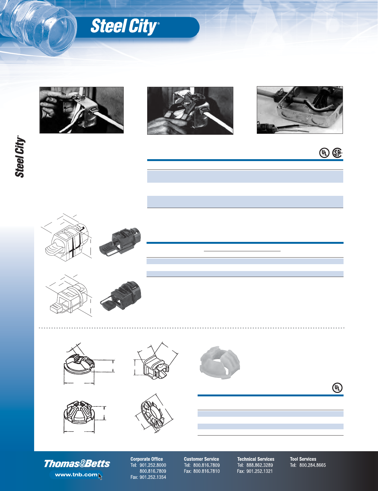
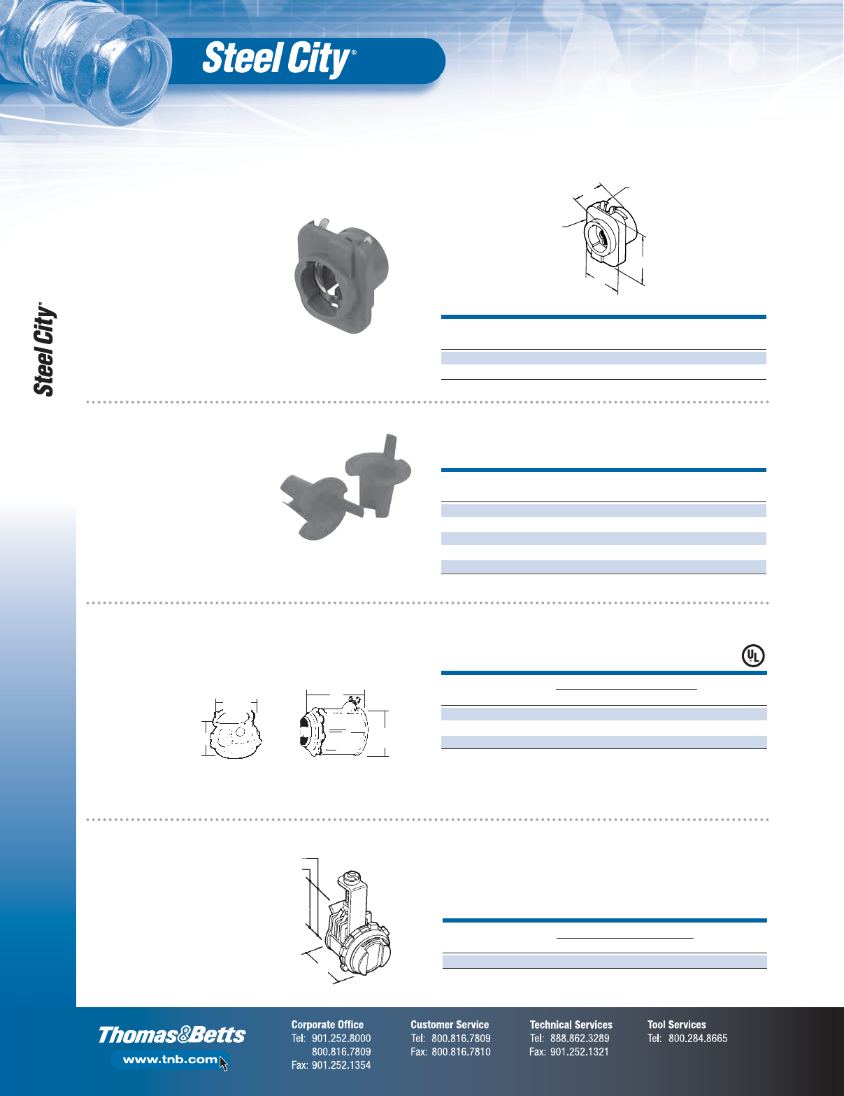
•High-impact thermoplastic: UL 94-V1
•Features push-in design
•Captive locking wedge secures cable
with single squeeze of standard
electrician’s pliers
•Provides excellent insulation, strain-
relief and high pull-out value
Snap captive locking wedge into
connector’s cavity.
Press locking wedge into cavity that
locks onto cable.
Cat. No. 3201 is ideal for multiple flexible
cords and cable.
STD.
CAT. NO.
DESCRIPTION CTN.
NC-501SC 1⁄2" Hit Lock®Connector 500
NC-501DBL-SC 1⁄2" Double Hit Lock®Connector 500
NC-502SC 3⁄4" Hit Lock®Connector 100
SB1216-SC Twist It Bushing For Metal Studs 50
UL File No. E-17583.
.400"
.580"
1.030"
1.250"
1.000"
1.120"
1.300"
.580"
2.485"
1.315"
.115"
NC-501-SC
NC-501-SC
NC-501DBL-SC
NC-502-SC SB1216-SC
Hit Lock®Connectors
All Plastic Connector for NM Cable and Flexible Cord
H
Hole
Size
H
Hole
Size
Fig. 2
Size Range
CAT. NO.
DESCRIPTION
3300 For use with 10-2, 12-2 and 14-2 NM cables; 18-2 and 18-3 SJ and SJO cords and
18-2 SV, SVO, SJT and SJTO cords, single or multiple; cord capacity .125–.300" diameter
3201-TB For use with 10-3, 12-3, 14-3, 10-2, 12-2, 4-2 NM cables; multiple (2) 12-2 and
14-2 NM cables; single and multiple flexible cords in wire range .300–.600"
3202 For use with 8-3 and 6-3 NM cables; (2) 14-3, 14-2, 12-2 and 10-2 NM cables;
single and multiple flexible cords in wire range .500–.850"
Temperature Rating: 105° C.
CSA File Nos. 584 and 2884.
UL File No. E-17583.
DIMENSIONS (IN.) MAX THK. STD.
CAT. NO.
KO SIZE (IN.) FIG. A B C D E ENCLOSURE H (IN.) CTN.
3300 1⁄221
1⁄32 15⁄16 3⁄8.880 .795 .080 5⁄16 x 9⁄16 500
3201-TB 1⁄211
11⁄32 17⁄16 .880 .795 .080 21⁄32 dia. 500
3202 3⁄411
1⁄215⁄16 7⁄16 1.100 1.005 .090 7⁄8dia. 250
Temperature Rating: 105° C.
CSA File Nos. 584 and 2884.
UL File No. E-17583.
A
AC
B
B
C
Non-Metallic Sheathed Cable Fittings
F-25
Fittings
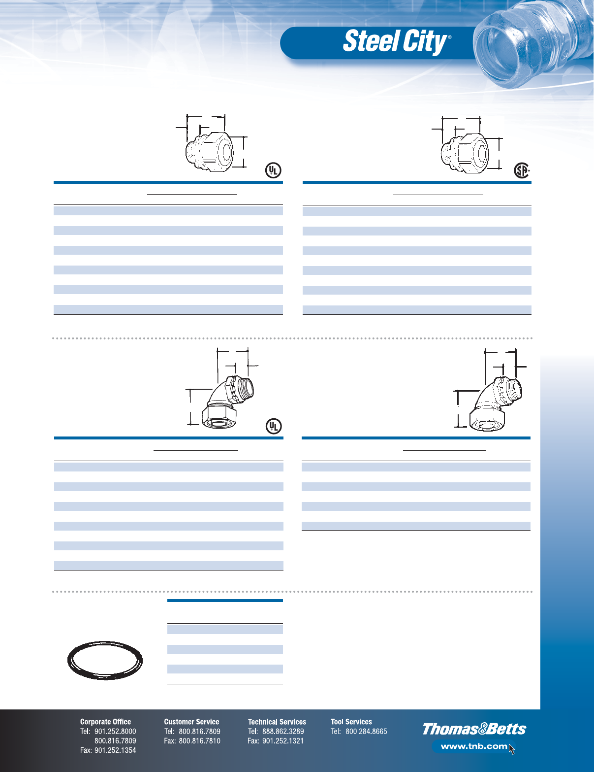
CONDUIT DIMENSIONS (IN.) STD.
CAT. NO.
SIZE (IN.) A B C D E CTN.
NC-850 1⁄2.050 .950 1.312 .650 8–32 x 3⁄41,000
NC-851 3⁄4–1 .050 1.250 1.750 .760 8–32 x 1 500
NC-852 1–1⁄4.062 1.625 2.125 .760 10–32 x 1 250
NC-853 1–1⁄2.062 1.970 2.500 .785 10–32 x 12 100
A
BD
C
E
A Max.
A Min.
DIMENSIONS (IN.) STD.
CAT. NO.
SIZE (IN.) A (MIN.) A (MAX.) B CTN.
XC-2200-C 3⁄80.12 0.63 0.98 500
B
CONDUIT DIMENSIONS (IN.) STD.
CAT. NO.
SIZE (IN.) A (MIN.) A (MAX.) B CTN.
NC-201 1⁄20.40 0.95 1.87 250
NC-202 3⁄40.50 1.10 1.84 200
NC-203 1 0.62 1.14 2.00 100
NC-204 11⁄40.50 1.38 2.28 100
NC-205 13⁄80.75 1.61 2.49 50
NC-206 2 0.90 2.04 3.35 50
CSA File No. LR-12798.
UL File No. E-17583.
CONDUIT DIMENSIONS (IN.) STD.
CAT. NO.
SIZE (IN.) A (MIN.) A (MAX.) B CTN.
NC041 11⁄40.27 0.75 2.02 100
NC-051 11⁄20.54 0.95 2.50 50
NC-061 2 0.75 1.12 3.41 40
UL File No. E-15170 — 1
1
⁄
4
"–1
1
⁄
2
".
UL File No. E-17583 — 2".
1–11⁄16"
CONDUIT DIMENSIONS (IN.) STD.
CAT. NO.
SIZE (IN.) A (MIN.) A (MAX.) B CTN.
XC-210 3⁄8(1⁄2KO) 0.13 0.65 1.56 250
XC-211-SC 3⁄80.24 0.63 1.59 200
XC-222-SC 3⁄80.24 0.63 1.59 200
CONDUIT/CABLE FMC (IN.) AC MCC MCI
Max. Size 3⁄810/2 .565 .565
Min. Size 3⁄814/2 .425 .425
CSA File No. LR-12798.
UL File No. E1383.
B
A Max.
A Min.
•For use with
aluminum, smooth,
extruded metal–clad
cable. (min. dia. .410
— max. dia. .500).
NM Clamp Type
Connector —
Die Cast Zinc B
A Max.
A Min.
B
A Max.
A Min.
CONDUIT DIMENSIONS (IN.) STD.
CAT. NO.
SIZE (IN.) A (MIN.) A (MAX.) B CTN.
NC301 3⁄8(1⁄2KO) 0.18 0.64 1.16 1,000
NC-302 3⁄40.41 0.82 1.87 500
NC-303 1 0.34 0.94 2.01 250
CSA File No. LR-12798.
UL File No. E-17583.
Connectors Clamp Type
Non-Watertight —
Die Cast Zinc
Duplex Clamp
Type Connector —
Die Cast Zinc
NM Flex Connectors
Saddle Type —
Die Cast Zinc
Tilt-In Connector
Metallic Steel —
Electro-Galvanized
Clamp Type
Connector —
Die Cast Zinc

Armored Cable/Flexible Metallic Conduit Fittings
F-26
Fittings
CONDUIT UNIT STD.
CAT. NO.
SIZE (IN.) QTY. CTN.
XC-400 3⁄8(1⁄2KO) 50 100
XC-401 1⁄225 100
XC-402 3⁄425 100
XC-403 1 25 100
XC-404 11⁄4510
XC-405 11⁄210 10
XC-406 21010
XC-407 21⁄255
XC-408 355
UL File No. E-1383
1
⁄
2
"–
3
⁄
4
".
UL File No. E-23018 1"–3".
3
⁄
8
"–
3
⁄
4
" — Steel.
CONDUIT UNIT STD.
CAT. NO.
SIZE (IN.) QTY. CTN.
XC-901 1⁄225 100
XC-902 3⁄425 100
XC-903 1 25 100
XC-904 11⁄4510
XC-905 11⁄210 10
XC-906 21010
XC-907 21⁄255
XC-908 355
1
⁄
2
"–
3
⁄
4
"— Steel.
CONDUIT UNIT STD.
CAT. NO.
SIZE (IN.) QTY. CTN.
XC-490 3⁄8(1⁄2KO) 50 100
XC-491 1⁄225 100
XC-492 3⁄425 50
XC-493 12525
XC-494 11⁄410 10
XC-495 11⁄210 10
XC-496 255
XC-497 21⁄211
XC-498 311
UL File No. E-1383
3
⁄
8
" &
3
⁄
4
".
UL File No. E-23018 1"–3".
3
⁄
8
"–
3
⁄
4
" — Steel.
NOTE: For die cast armored
cable/flexible metallic conduit
fittings and combination fittings,
refer to the Steel City
®
Die Cast
Conduit Fittings section.
XC-490
Straight Squeeze-Type Connectors —
Malleable Iron or Stamped Steel/Zinc Plated
Straight Squeeze-Type Connectors — Insulated
Malleable Iron or Stamped Steel/Zinc Plated
Clamp Straight Set,
90° and Duplex Connectors
Straight Squeeze
Type Connectors —
Die Cast Zinc
90° Angle Squeeze-Type Connectors —
Steel or Malleable Iron/Zinc Plated
DIMENSIONS (IN.) STD.
CAT. NO.
FIG. SIZE (IN.) A (MIN.) A (MAX.) B CTN.
XC-269 13⁄8(1⁄2KO) 0.45 0.60 0.96 500
XC-270 11⁄20.74 0.92 1.43 250
XC-272 13⁄40.88 1.10 1.59 250
XC-273 2 1 1.10 1.35 1.60 100
XC-274 21
1⁄41.48 1.65 1.91 100
XC-275 21
1⁄21.68 2.00 2.12 50
XC-276 3 2 2.12 2.47 2.54 40
XC-277 32
1⁄22.71 3.08 2.88 10
XC-278 3 3 3.15 3.60 3.88 5
XC-278A 33
1⁄23.20 4.03 5.04 1
XC-2710 3 4 3.15 4.25 5.04
Armored Cable/Flexible Metallic Conduit Fittings
F-27
Fittings
DIMENSIONS (IN.) STD.
CAT. NO.
FIG. SIZE (IN.) A (MIN.) A (MAX.) B CTN.
XC-870 11⁄20.74 0.92 1.43 250
XC-872 13⁄40.88 1.10 1.59 250
XC-873 2 1 1.10 1.35 1.60 100
XC-874 21
1⁄41.48 1.65 1.91 50
XC-875 21
1⁄21.68 2.00 2.12 50
XC-876 3 2 2.12 2.47 2.54 10
XC-877 32
1⁄22.71 3.08 2.88 10
XC-878 3 3 3.15 3.60 3.88 5
XC-879 33
1⁄23.20 4.03 5.04 1
XC-8710 3 4 3.15 4.25 5.04 1
UL File No. E-17909 —
1
⁄
2
"–
3
⁄
4
".
UL File No. E-23018 — 1
1
⁄
4
".
CSA File No. LR-12798.
Fig. 2 Fig. 3
A Min.
A Max.
A Min.
A Max.
BB
N2
N2
N1 N1
N3 N3
TRADE DIMENSIONS (IN.) F G
CAT. NO.
SIZE (IN.) A B C D E THREADS SIZE RANGE
XC-201 1⁄2125⁄64 17⁄64 13⁄32 155⁄64 13⁄81⁄2–14NPS 10–24 x 7⁄8.40–.95
XC-202 3⁄411⁄211⁄41⁄2153⁄64 13⁄83⁄4–14NPS 10–24 x 7⁄8.50–1.10
XC-203 11
3⁄4123⁄32 9⁄16 29⁄32 17⁄81–11 1⁄2NPS 10–24 x 7⁄8.62–1.14
XC-204 11⁄417⁄8157⁄64 9⁄16 247⁄64 27⁄32 11⁄4–11 1⁄2NPS 10–24 x 7⁄8.50–1.38
All dimensions are approximated to the nearest
1
⁄
64
".
A
B
C
D
E
G Size
F Threads
Straight Squeeze-Type Connectors —
Insulated — Die Cast Zinc
Fig. 1
B
C
F Thread
A Min.
A Max.
D
E
Squeeze Type — BX Flex Connectors
Armored Cable/Flexible Metallic Conduit Fittings
F-28
Fittings
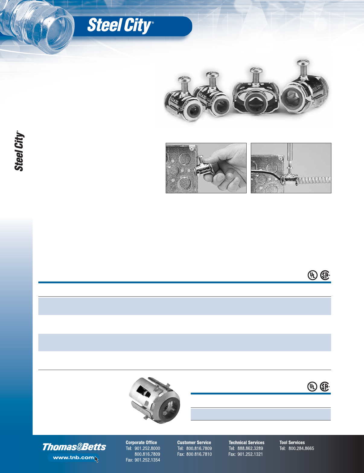
1. Simply snap into place. No locknuts required! 2. Insert cord and twist set screw. Connector
tightens as screw is set.
Simple, fast steps to install the Steel City®Cable Lok®.
•Simple, one-piece installation with no locknuts
•Screw designed for exceptional pullout resistance
•Captive screw ensures that the screw is intact for
installation and resists backing out after installation
•Corrosion-resistant, zinc-chromatic plating
•Positive grounding
•Vibration-resistant screw design
•UL Listed and CSA Certified
Material: Body: Steel (spring steel);
Finish: Zinc;
Insulator: Nylon;
Temp.: 105°C
Listing: UL, CSA Listed
Snap-In Fitting for MC Cable — Steel
STD.
CAT. NO.
DESCRIPTION CTN.
XC-130 Steel Snap-In Fitting for MC cable 500
(14-2+G to 10-3+G)
Steel City®Cable Lok®
SIZE AC AC ALUMINUM MC (I) MC (I) FLEX STD.
CAT. NO.
RANGE (IN.) STEEL INTERLOCKED STEEL ALUMINUM RW CTN.
14/2 14/3 14/4 14/2 14/3 14/4 14/2 14/3 14/4 14/2 14/3 14/4 3⁄8Steel 50
XC-730 .450/.610 12/2 12/3 12/4 12/2 12/3 12/4 12/2 12/3 12/4 12/2 12/3 12/4 & AL
1⁄2KO 10/2 10/2 10/3 1⁄2" KO 10/2 10/3
14/2 14/3 14/4 14/2 14/3 14/4 14/2 14/3 14/4 14/2 14/3 14/4 50
XC-731 .450/.610 12/2 12/3 12/4 12/2 12/3 12/4 12/2 12/3 12/4 12/2 12/3 12/4 —
1⁄2KO 10/2 10/2 10/3 1⁄2" KO 10/2 10/3
10/3 10/4 10/5 10/4 10/5 3⁄8Steel 25
XC-732 .610/.875 8/3 8/4 — 8/3 8/4 — & AL
3⁄4KO 6/2 6/2 3⁄4"KO
14/2 14/3 14/4 14/2 14/3 14/4 14/2 14/3 14/4 14/2 14/3 14/4 25
XC-7300 .450/.610 12/2 12/3 12/4 12/2 12/3 12/4 12/2 12/3 12/4 12/2 12/3 12/4 —
1⁄2KO 10/2 10/2 10/3 1⁄2" KO 10/2 10/3
UL File No. E-1383.
CSA File No. LR-12798.
Steel City®Cable Lok®
•O.D. for over armor 0.400"–0.510"
•No set screws, locknuts or tools are required
to attach MC cable to a box or enclosure
•One-piece spring-steel construction
•Accommodates the widest range of MC cable
sizes in the industry — 14-2 to 10-3
•Compact, low-profile design saves space
in the box or enclosure
•Fittings can be used in adjacent knockouts
in the corner of the box
•Removable and reusable
•Ideal for commercial construction or prefabricated
electrical wiring assemblies
Armored Cable/Flexible Metallic Conduit Fittings
F-29
Fittings
Fig. 2 Fig. 3
Fig. 4 Fig. 5
Fig. 1
DIMENSIONS (IN.) STD.
CAT. NO.
FIG. SIZE (IN.) A (MIN.) A (MAX.) B CTN.
XC-290 13⁄8(1⁄2KO) 0.40 0.63 1.80 500
XC-291 11⁄20.65 1.00 2.08 250
XC-292 13⁄40.83 1.25 2.27 100
XC-293 2 1 1.27 1.50 2.60 50
XC-294 21
1⁄41.49 1.85 3.10 30
XC-295 31
1⁄21.51 2.47 6.05 5
XC-296 3 2 1.51 2.47 6.05 5
XC-297 42
1⁄22.45 3.50 7.75 2
XC298 5 3 3.07 4.02 8.88 1
XC-299 43
1⁄23.63 4.34 12.75 1
XC-2910 4 4 3.68 5.17 12.75 1
UL File No. E-1383.
CSA File No. LR-18130M57.
Insulated Die Cast Zinc
DIMENSIONS (IN.) STD.
CAT. NO.
FIG. SIZE (IN.) A (MIN.) A (MAX.) B CTN.
XC-890 13⁄80.40 0.63 1.81 500
XC-891 11⁄20.65 0.97 2.18 250
XC-892 13⁄40.77 1.12 2.38 100
XC-893 2 1 1.06 1.40 2.87 50
XC-894 21
1⁄41.34 1.65 3.93 30
XC-895 31
1⁄21.51 2.47 6.05 5
XC-896 3 2 1.51 2.47 6.05 5
XC-897 42
1⁄22.45 3.50 7.75 2
XC-898 5 3 3.07 4.02 8.88 1
XC-899 43
1⁄23.63 4.34 12.75 1
XC-8910 4 4 3.68 5.17 12.75 1
UL File No. E-1383.
CSA File No. LR-12798.
B
A Min.
B Max.
G
H
Threads
A
BC
D
E
F
G
HThreads Threads
Threads Threads
A
B
D
E
F
C
AB
D
E
F
G
C
AB
C
D
E
F
G
For use with Metal Clad Cable
A Max.
A Min.
CONDUIT DIMENSIONS (IN.) STD.
CAT. NO.
SIZE (IN.) A (MIN.) A (MAX.) B CTN.
XC-280 3⁄8(1⁄2KO) 0.18 0.64 1.16 1,000
UL File No. E-1383.
CSA File No. LR-18130M57.
CONDUIT DIMENSIONS (IN.) STD.
CAT. NO.
SIZE (IN.) A (MIN.) A (MAX.) B CTN.
XC-210 3⁄8(1⁄2KO) 0.13 0.65 1.56 250
CSA File No. LR-18130M57.
B
90° Clamp Type Connectors —
Die Cast Zinc
Clamp Type Connector —
Die Cast Zinc
Duplex Clamp Type Connector —
Die Cast Zinc
XC-290
Armored Cable/Flexible Metallic Conduit Fittings
F-30
Fittings
KO UNIT STD.
CAT. NO.
CONDUIT SIZE (IN.) SIZE (IN.) QTY. CTN.
100-TB 3⁄81⁄250 500
100BP 3⁄81⁄2250 1,000
•Packed in polybags
•Available bulk packed —
10,000 per carton
•Plastic
4 Metal
Grounding Tabs
Plastic
Body
A
B
C
•No locknut required
•No special tools required
•High-impact thermoplastic
with steel insert
NOTE: For die cast armored cable/flexible metallic
conduit fittings and combination fittings, refer to the
Steel City
®
Die Cast Conduit Fittings section.
DIMENSIONS (IN.) STD.
CAT. NO.
SIZE (IN.) A (MIN.) A (MAX.) B CTN.
XC-220SC 3⁄8(1⁄2KO) 0.38 0.63 0.84 1,000
XC-221 1⁄20.74 0.94 1.46 250
XC-821 1⁄20.74 0.94 1.46 250
XC-220 and XC-221: UL File No. E-1383
3
⁄
8
".
UL File No. E-23018
1
⁄
2
".
XC-821: UL File No. E-1275
1
⁄
2
".
A Max.
A Min.
BA Max.
A Min.
B
XC-221
XC-821
A Max.
A Min.
DIMENSIONS (IN.) STD.
CAT. NO.
SIZE (IN.) A (MIN.) A (MAX.) B CTN.
XC-2200-C 3⁄80.12 0.63 0.98 500
B
FITS STANDARD UNIT STD.
CAT. NO.
CABLE RANGE SIZE QTY. CTN.
IT 100 SC 14/2–14/3–12/2 0 100 100
IT-101 14/4–12/3–6/1–4/1 1 100 35
IT-102 12/4–10/2–10/3–2/1 2 50 50
IT-103 10/4–8/2–8/3–1/1 3 50 50
IT-104 8/4–6/2–6/3–4/2–4/3–6/4 4 50 50
Ordered by Bags.
Snap-In Connector for Flexible Metal
Conduit — 105° C Rated
BX Flex Bushings — Anti-Short
Straight Set Screw Connectors
Die Cast Zinc — Non-Insulated
BX Flex Connectors
Saddle Type —
Die Cast Zinc
XC-220
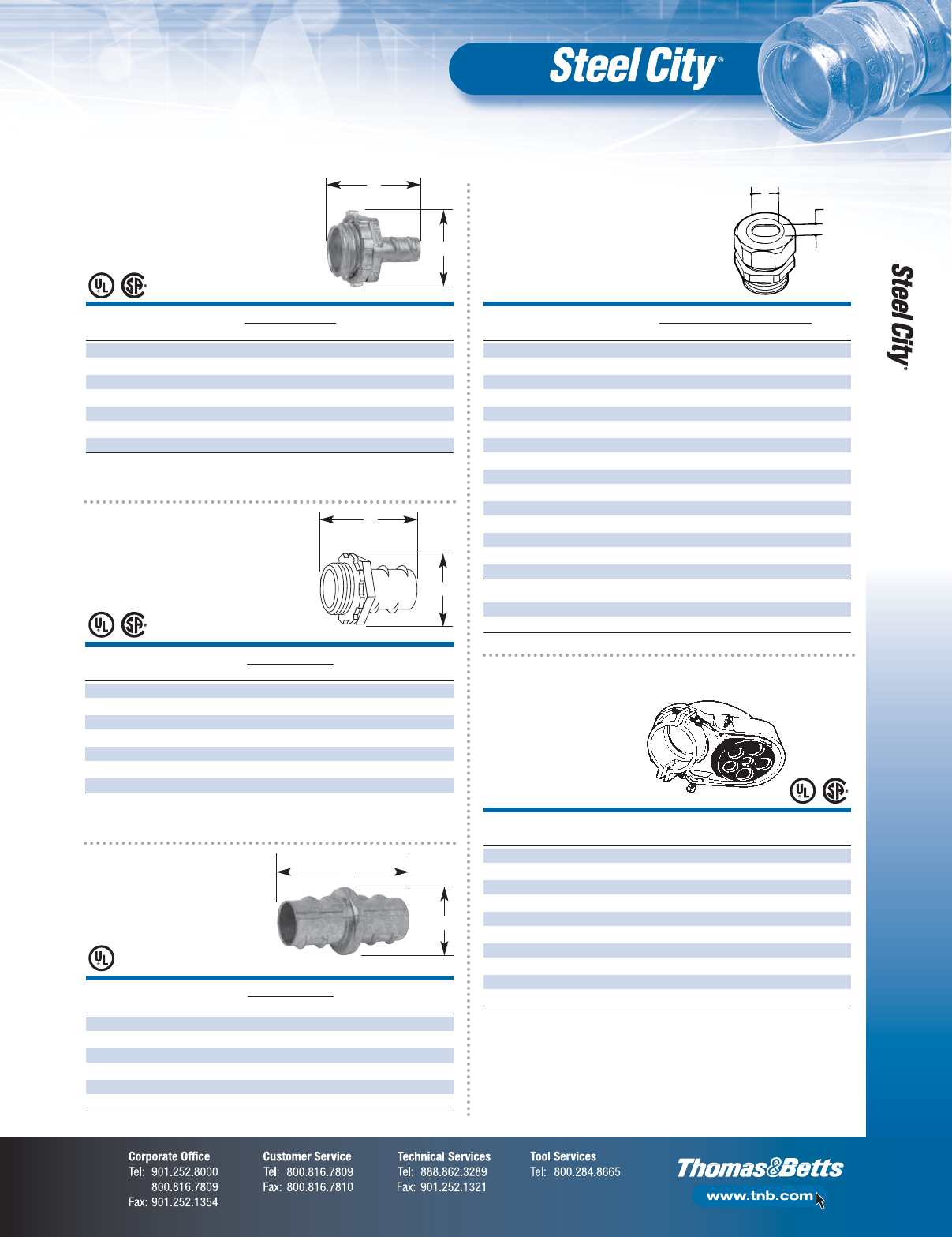
Armored Cable/Flexible Metallic Conduit Fittings, Service Caps
F-31
Fittings
DIMENSIONS (IN.) STD.
CAT. NO.
SIZE (IN.) A B CTN.
XC-240 3⁄8(1⁄2KO) 1.31 0.92 500
XC-241 1⁄21.38 0.92 500
XC-242 3⁄81.62 1.12 125
XC-243 1 1.94 1.37 125
XC-244 11⁄42.12 1.75 50
XC-245 11⁄22.31 2.13 50
XC-246 2 2.58 2.67 50
UL File No. E-23018.
CSA File No. LR-18130M57
3
⁄
8
"–
1
⁄
2
".
A
B
DIMENSIONS (IN.) STD.
CAT. NO.
SIZE (IN.) A B CTN.
XK 241 1⁄21.81 0.92 250
XK-242 3⁄42.09 1.12 250
XK-243 1 2.41 1.37 125
XK-244 11⁄42.75 1.81 50
XK-245 11⁄23.05 2.12 50
XK-246 2 3.28 2.67 50
UL File No. E-23018.
A
B
A
B
DIMENSIONS (IN.) STD.
CAT. NO.
SIZE (IN.) A B CTN.
XC-840 3⁄8(1⁄2KO) 1.31 0.92 500
XC-841 1⁄21.38 0.92 500
XC-842 3⁄41.62 1.12 125
XC-843 1 1.94 1.37 125
XC-844 11⁄42.12 1.75 50
XC-845 11⁄22.31 2.13 50
XC-846 2 2.58 2.67 50
UL File No. E-23018.
CSA File No. LR-18130M57
3
⁄
8
"–
1
⁄
2
".
A
B
Screw-In Connectors
Die Cast Zinc —
Non-Insulated
Screw-In Connectors
Die Cast Zinc —
Insulated
Screw-In Couplings
Die Cast Zinc
CONDUIT STD.
CAT. NO.
SIZE (IN.) NO. HOLES SIZE CTN.
SH-101 1⁄244
19⁄64"50
SH-102 3⁄452 (
3⁄8") 3 (13⁄32") 50
SH-103 152 (
7⁄16") 3 (1⁄2") 10
SH-104 11⁄452 (
19⁄32") 3 (5⁄8") 10
SH-105 11⁄262 (
19⁄32") 1 (7⁄16") 3 (3⁄4") 5
SH-106 2 6 2 (3⁄4") 3 (1") 1 (17⁄32") 5
SH-107 21⁄273 (
7⁄8") 1 (1") 3 (15⁄16") 1
SH-108 3 7 4 (11⁄8") 3 (13⁄4") 1
SH-109 31⁄244 (1
3⁄4") 2 (1⁄8") 1
SH-110 4 4 4 (13⁄4") 2 (11⁄8") 1
CSA File No. LR-12798.
UL File No. E-13938.
Aluminum Service Caps —
Clamp Type for
Rigid/Intermediate
or Thinwall
TRADE RUBBER GROMMET OPENING (IN.) STD.
CAT. NO.
SIZE (IN.) FITS CABLE A B CTN.
WT203A 1 3#8 .500 .750 100
WT-203B 1 3#6 .563 .844 100
WT-203C 1 3#4 .625 .938 100
WT-204A 11⁄43#3 .625 1.000 50
WT-204B 11⁄43#2 .580 .960 50
WT-204C 11⁄43#1 .660 1.090 50
WT-204D 11⁄43#1/0 .750 1.125 50
WT-205A 11⁄23#1/0 & 3#2/0 .735 1.240 20
WT-205B 11⁄23#2/0 & 3#3/0 .875 1.375 20
WT-205C 11⁄23#2/0 & 3#3/0 .938 1.438 20
WT-206A 2 3#1/0 & 3#2/0 .735 1.240 20
WT-206B 2 3#2/0 & 3#3/0 .875 1.375 20
WT-206C 2 3#2/0 & 3#3/0 .938 1.438 20
WT-206D 2 3#4/0 .890 1.550 20
WT-206E 2 3#4/0 1.063 1.688 20
For Underground Feeder Cable
UF201 1⁄22#14 .210 .440 250
UF-202 3⁄43#14 .220 .660 250
•For type SE, style U, flat;
2 insulating conductors, 1 bare
A
B
Water-Tight Connectors
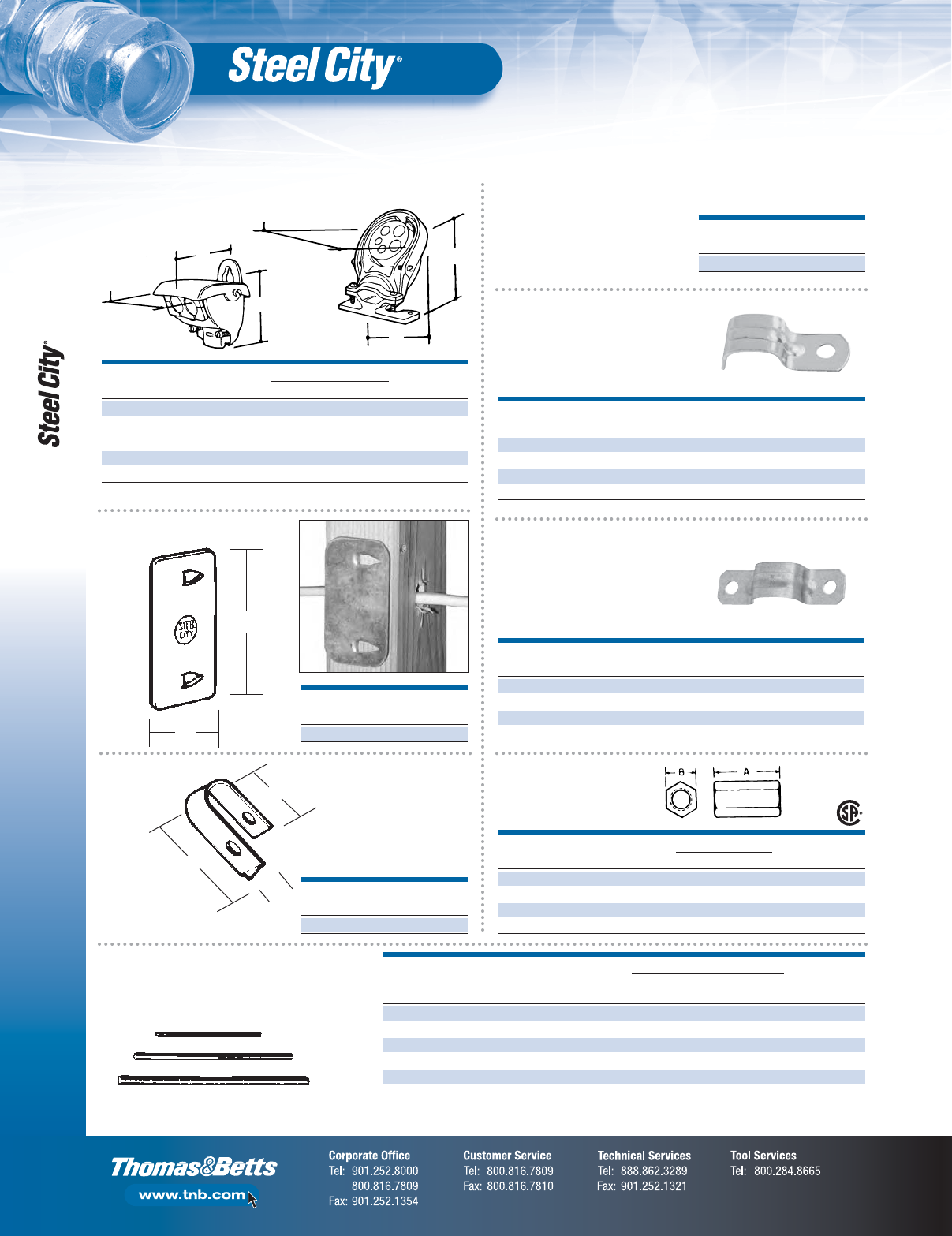
Cable Caps, Protector, Straps and Clips; Threaded Rod and Coupling
F-32
Fittings
STD.
CAT. NO.
DESCRIPTION CTN.
CP-1 Steel 100
Cable Protector
13⁄8"
19⁄16"
FITS DIMENSIONS (IN.) STD.
CAT. NO.
CABLE A B C CTN.
50130 To 2/0–3 5.00 3.31 4.75 10
50130A To 4/0–3 6.75 4.62 6.00 5
With Split Insulator
SC1000 3#3–2 2.37 2.12 2.25 25
SC2001 3#3/0–4/0 4.93 3.12 3.75 10
Extra large body for additional wiring space.
Service Cable Caps — Oval
A
B
C
A
C
B
1"
11⁄8"
3⁄8"STD.
CAT. NO.
DESCRIPTION CTN.
NS 100 Steel 1,000
Cable Clip
FITS SHELF SHIP STD.
CAT. NO.
CABLE CTN. CASE CTN.
SE-100 3#8, 3#6, 3#4 100 1,000 1,000
SE101 3#3, 3#2 100 1,000 1,000
SE102 3#1, 3#0, 3#1/0, 3#2/0 25 250 250
SE103 3#3/0, 3#4/0 25 250 250
FITS SHELF SHIP STD.
CAT. NO.
CABLE CTN. CASE CTN.
SE-900 3#8, 3#6, 3#4 100 1,000 1,000
SE901 3#3, 3#2 100 1,000 1,000
SE902 3#1, 3#0, 3#1/0, 3#2/0 25 250 250
SE903 3#3/0, 3#4/0 25 250 250
Service Cable Straps —
Two-Hole
Service Cable Straps —
One-Hole
DIMENSIONS (IN.) STD.
CAT. NO.
ROD SIZE (IN.) A B CTN.
H-195-1/4 1⁄43⁄43⁄81,000
H-195-3/8 3⁄811⁄2500
H-195-1/2 1⁄215⁄8500
H-195-5/8 5⁄811⁄23⁄450
DATA FOR PR ESSURE PIPING
ROD ULTIMATE‡ ROOT AREA NOMINAL MAX. SAFE STD.
CAT. NO.
SIZE (IN.) LOAD IN LBS. THREAD PIPE SIZE (IN.) LOAD AT 450° CTN.
R628-6 FT. 1⁄4–20 900 .027 — — 300
R638-6 FT. 3⁄8–16 1,900 .068 3⁄4–2 610 150
R648-6 FT. 1⁄2–13 3,500 .126 21⁄2–31⁄21,130 60
R1028-10 FT. 1⁄4–20 900 .027 — — 500
R1038-10 FT. 3⁄8–16 1,900 .068 3⁄4–2 610 250
R1048-10 FT. 1⁄2–13 3,500 .126 21⁄2–31⁄21,130 100
‡ Load Ratings based on safely factor of three.
R-Series Continuous Thread
Rod — Galvanized
H-195 Steel
Rod Coupling
STD. WT./100
CAT. NO.
CTN. (LBS.)
FS100-SC 250 1.70
One-Hole Strap for 3⁄8"
Armored Cable and
Flexible Metal Conduit
Beam Clamps
F-33
Fittings
DIMENSIONS (IN.)
CAT. NO.
O.D. OF CONDUIT NOM. CONDUIT OR STD.
& SIZE
OR PIPE PIPE SIZE CTN.
RCS Clamp — Steel
RCS-1/2 .840 1⁄250
RCS-3/4 1.050 3⁄450
RCS-1 1.315 1 50
RCS-1-1/4 1.660 11⁄450
RCS-1-1/2 1.900 11⁄250
RCS-2 2.375 2 50
RC Clamp — Malleable Iron
RC-3/8 .675 3⁄850
RC-1/2 .840 1⁄250
RC-3/4 1.050 3⁄450
RC-1 1.315 1 50
RC-1-1/4 1.660 11⁄450
RC-1-1/2 1.900 11⁄250
RC-2-SC 2.375 2 50
RC-2-1/2 2.875 21⁄225
RC-3 3.500 3 25
RC-3-1/2 4.000 31⁄225
RC-4-SC 4.500 4 20
•For mounting pipe or conduit
at right angles to the beam
•Add a SS316 suffix for stainless steel
•Add a HDG suffix for hot-dip galvanized
RCS Series
DIMENSIONS (IN.)
CAT. NO.
O.D. OF CONDUIT NOM. CONDUIT OR STD.
& SIZE
OR PIPE PIPE SIZE CTN.
PC Clamp — Malleable Iron
PC-3/8 .675 3⁄850
PC 1/2 .840
1⁄250
PC-3/4 1.050 3⁄450
PC-1 1.315 1 50
PC-1-1/4 1.660 11⁄425
PC-1-1/2 1.900 11⁄225
PC-2 2.375 2 25
PC-2-1/2
2.875 21⁄225
PC-3 3.500 3 10
PC-3-1/2
4.000 31⁄210
PC-4 4.500 4 10
DIMENSIONS (IN.)
CAT. NO.
O.D. OF CONDUIT NOM. CONDUIT OR STD.
& SIZE
OR PIPE PIPE SIZE CTN.
EC Clamp — Malleable Iron
EC 1/2 .840 1⁄250
EC-3/4 1.050 3⁄450
EC-1 1.315 1 25
EC-1-1/4 1.660 11⁄425
EC-1-1/2 1.900 11⁄225
EC-2 2.375 2 25
EC-2-1/2 2.875 21⁄210
EC Series
•For mounting pipe or conduit
vertically across the beam
•Add a HDG suffix for
hot-dip galvanized
PC Series
•For mounting pipe or conduit
parallel to the beam
•Add a HDG suffix for
hot-dip galvanized
EC Series
PC Series
Conduit/Pipe to Beam Clamps
Conduit/Pipe to Beam Clamps
BASE SIZE JAW
(IN.) OPENING TAPPING OF BASE LOAD STD.
CAT. NO.
A B INCHES AND BACK HOLES RATING‡ CTN.
510 27⁄32 11⁄85⁄81⁄4–20 400 100
511-SC 27⁄32 11⁄85⁄810–24 400 100
500-SC 11
1⁄415⁄16 1⁄4–20 450 50
509 11
1⁄415⁄16 10–24 375 100
501 11⁄215⁄87⁄85⁄16–18 800 50
502 221 3⁄8–16 1,300 50
503-SC 25⁄821⁄211⁄2–13 1,300 20
507 21⁄223⁄813⁄81⁄2–13 1,700 20
508 21⁄223⁄821⁄81⁄2–13 1,700 10
‡Safety Factor of 3.
Loan Ratings based on bottom hole of Beam Clamp.
CSA File No. LR-52208.
Beam Clamps — Malleable Iron,
Electroplated Finish
Beam Clamps
3⁄8"
Min
D
A
SIZE DIMENSIONS (IN.) STD.
CAT. NO.
(IN.) TAPPED A B C D CTN.
BC1-TB 11⁄4–20 111⁄16 13⁄85⁄813⁄16 250
BC2-TB 215⁄16 3⁄8–16 21⁄821⁄16 3⁄4111⁄16 25
Material: Steel
Finish: Zinc Plated
C B
Cup Point
5/16-18 x 1
3
⁄
8
" hex head, cup point,
hardened steel, cap screw note
1

Ground Clamps, Pipe Hangers
F-34
Fittings
For hanging conduit (rigid or EMT) and pipe.
The 6H series hangers are fast, easy and economical
to use. May be fastened directly to a #500 beam
clamp through a hole in the base of the hanger by
means of a 1⁄4-20 stove bolt or suspended on 1⁄4"
hanger rod.
All Steel City 6H Hanger Bolts include
a combination Slot-Phillips Head.
-
6H Without bolt. 6H-B With bolt
and hex nut.
6H-T Threaded
without bolt.
6H-TB Threaded
with bolt.
D Dia.
6H Series Conduit and Pipe Hangers — With Bolt
RIGID CONDUIT
OR PIPE EMT DIMENSIONS (IN.) LOAD STD.
CAT. NO.
SIZE (IN.) SIZE (IN.) A B C D (DIA.) RATING CTN.
6H0 B 3⁄8–1⁄21⁄23⁄4.045 121
⁄32 9⁄32 500 100
6H0 TB 3⁄8–1⁄21⁄23⁄4 .045 127
⁄32 9⁄32 500 100
6H1-B 3⁄43⁄47⁄8.045 131
⁄32 9⁄32 500 100
6H1-TB 3⁄4 3⁄47⁄8 .045 2 9⁄32 9⁄32 500 100
6H2-B 117⁄8 .045 2 3⁄89⁄32 500 100
6H2-B 11
1⁄47⁄8 .045 2 23⁄32 9⁄32 500 100
6H3-B 11⁄411⁄27⁄8 .045 2 7⁄89⁄32 500 100
6H4-B 11⁄2— 1 .071 3 3⁄811⁄32 500 100
6H5-B 221
1⁄4.071 3 29⁄32 11⁄32 500 50
6H6-B 21⁄2—1
1⁄4.071 4 9⁄32 11⁄32 500 50
6H7-B 3—1
1⁄4.071 5 3⁄16 11⁄32 500 25
6H8-B 31⁄2—1
1⁄4.071 5 7⁄16 11⁄32 500 25
6H9-B 441
1⁄4.071 5 7⁄811⁄32 500 10
UL File No. E-160899.
Add SS suffix to part number for Stainless Steel.
Load rating is 500 lbs. with a safety factor of 3.
Available with or without closure bolt.
Standard finishes: Electro-Galvanized. (Add SS suffix for Type 302 Stainless Steel)
6H Series Conduit and Pipe Hangers — Without Bolt
RIGID CONDUIT
OR PIPE EMT DIMENSIONS (IN.) LOAD STD.
CAT. NO.
SIZE (IN.) SIZE (IN.) A B C D (DIA.) RATING CTN.
6H0 3⁄8–1⁄21⁄23⁄4.045 121
⁄32 9⁄32 500 100
6H0 T 3⁄8–1⁄2 1⁄23⁄4.045 127
⁄32 9⁄32 500 100
6H1 3⁄43⁄47⁄8.045 131
⁄32 9⁄32 500 100
6H1-T 3⁄43⁄4 7⁄8.045 29⁄32 9⁄32 500 100
6H2 117⁄8.045 23⁄89⁄32 500 100
6H2 1/2 — 11⁄47⁄8.045 223⁄32 9⁄32 500 100
6H3-SC 11⁄411⁄27⁄8 .045 27⁄89⁄32 500 100
6H4 11⁄2— 1 .071 33⁄811⁄32 500 100
6H5 221
1⁄4.071 329⁄32 11⁄32 500 50
6H6 21⁄2—1
1⁄4.071 49⁄32 11⁄32 500 50
6H7 3—1
1⁄4.071 53⁄16 11⁄32 500 25
6H8 31⁄2—1
1⁄4.071 57⁄16 11⁄32 500 25
6H9 441
1⁄4.071 57⁄811⁄32 500 10
UL File No. E-160899.
Add SS suffix to part number for Stainless Steel.
Load rating is 500 lbs. with a safety factor of 3. Available with or without closure bolt.
Standard finishes: Electro-Galvanized. (Add SS suffix for Type 302 Stainless Steel)
Without Bolt
CONDUIT STD.
CAT. NO.
SIZE (IN.) CTN.
GC-203-B 1⁄2; 1 200
Ground Clamps — Die Cast
Zinc, Brass Colored
•Two-screw ground connection
for armored ground wire
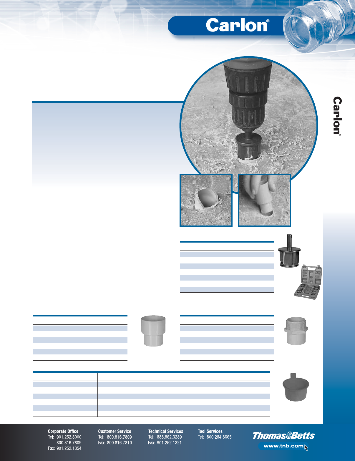
F-35
Non-Metallic Rigid Conduit, Fittings and Accessories
The new, revolutionary Carlon®PVC Conduit Repair System significantly
reduces the time and money associated with repairing broken PVC
conduits, a.k.a. “stub-ups”, in concrete slabs.
The system includes a line of couplings, adapters, reamers and plugs
designed to enable contractors to quickly and easily repair broken PVC
conduits without having to chip away and repour concrete, while still
maintaining the inside diameter of the conduit. Simply cut off the broken
conduit, ream the I.D. of the conduit and insert a coupling or adapter.
It’s that easy. A job that normally takes 20 minutes can now be done in
2 minutes or less!
Features:
•cUL–US Listed
•PVC repair fittings are listed in accordance with the NEC®and
Section 352.6
•Non-metallic couplings, adapters and plugs won’t rust or corrode
•Available in sizes 1⁄2" through 2"
Benefits:
•Saves time and money
•Maintains inside diameter of conduit
•Metallic reamers for extra strength, durability and longer life
•Quickly and easily repair broken PVC conduits
A job that normally takes 20 minutes —
DONE in 2 minutes or less!
Carlon®PVC Conduit Repair System
Male Threaded Adapter
Reamer
Coupling
Reamer Kit
Couplings
CAT. NO.
TRADE SIZE (IN.) STD. CTN.
E910D 1⁄225
E910E 3⁄425
E910F 115
E910G 11⁄410
E910H 11⁄210
E910J 210
Plug
Schedule 40 Plugs
CAT. NO.
SIZE (IN.) COLOR
CAT. NO.
SIZE (IN.) COLOR
CAT. NO.
SIZE (IN.) COLOR STD. CTN.
HL-6XR 1⁄2Red HL-6XB 1⁄2Blue HL-6XY 1⁄2Yellow 1 Bag of 50
HL-10R 3⁄4Red HL-10B 3⁄4Blue HL-10Y 3⁄4Yellow 1 Bag of 50
HL-13AR 1Red HL-13AB 1Blue HL-13AY 1 Yellow 1 Bag of 50
HL-16R 11⁄4Red HL-16B 11⁄4Blue HL-16Y 11⁄4Yellow 1 Bag of 50
HL-18R 11⁄2Red HL-18B 11⁄2Blue HL-18Y 11⁄2Yellow 1 Bag of 50
HL-21R 2Red HL-21B 2Blue HL-21Y 2 Yellow 1 Bag of 50
Male Threaded Adapters
CAT. NO.
TRADE SIZE (IN.) STD. CTN.
E920D 1⁄225
E920E 3⁄425
E920F 115
E920G 11⁄410
E920H 11⁄210
E920J 210
Reamers
CAT. NO.
TRADE SIZE (IN.) STD. CTN.
E910REAMD 1⁄212
E910REAME 3⁄412
E910REAMF 110
E910REAMG 11⁄410
E910REAMH 11⁄210
E910REAMJ 210
E910REAMKIT All sizes 5
Rigid Non-Metallic Conduit
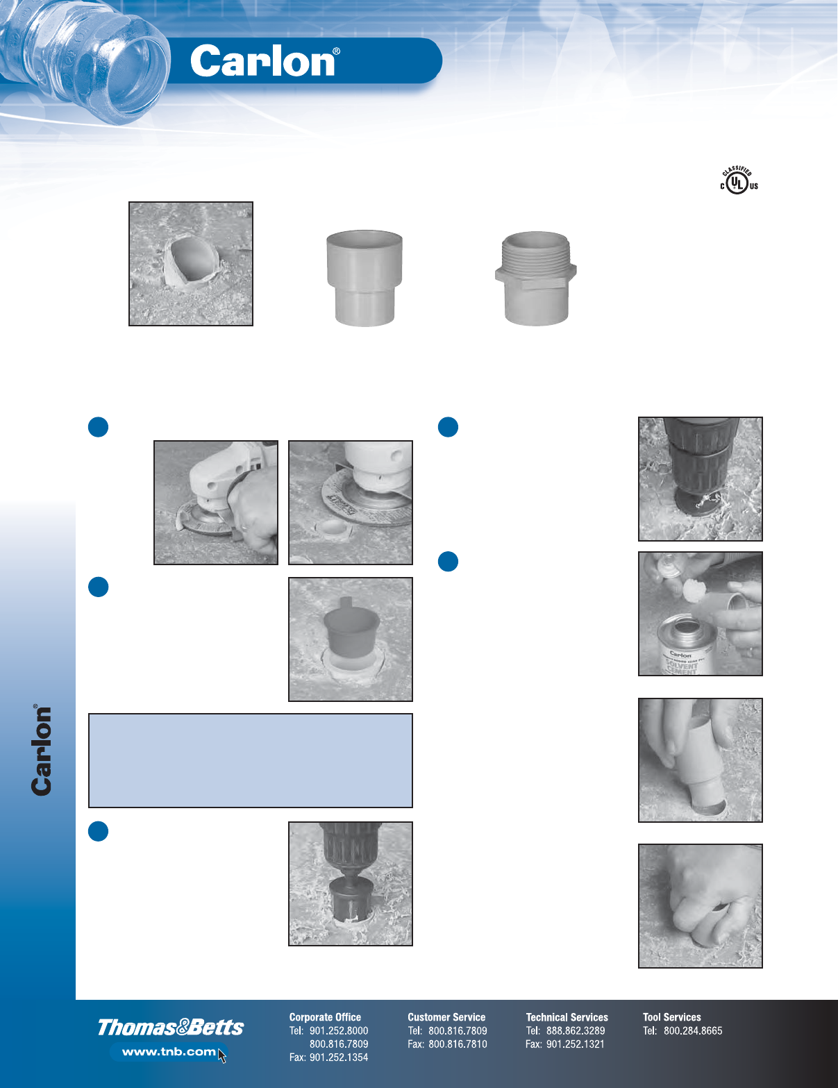
Rigid Non-Metallic Conduit
F-36
Non-Metallic Rigid Conduit, Fittings and Accessories
Coupling
E910_
Male Threaded Adapter
E920_
PVC Conduit Repair Fittings
E2969
Apply a uniform coat of cement.
Insert fitting.
Rotate 1/4 turn.
Instructions:
Broken conduit on jobsite
Cut broken conduit off flush.
1
Insert plug to keep conduit clean/dry
through balance of rough-in. Once
rough-in is complete, remove plug
and continue with Step 3.
2
With reamer tool and standard
1⁄2" drill, ream I.D. of conduit. It is
recommended to use a variable
speed drill. Use slower speed to
avoid overheating the conduit.
3
The guide will direct the cutter; the
stop will touch when completed.
4
Insert the coupling and cement
into place using the cement
manufacturer’s instructions.
Cementing Instructions:
A. Clean socket I.D. and spigot O.D.
of dirt and moisture.
B. Apply a uniform coat of cement to
spigot end and push onto socket
bottom, rotating 1/4 turn.
C. Allow time to set before disturbing.
This will depend upon temperature.
5
Alternative to Conduit Repairs:
Prior to concrete pour, measure and saw cut all conduit stub-ups to the
thickness of the concrete pour. Insert plugs. Pour concrete flush to the
conduit. When pour is complete, remove plugs and proceed with Step 3.
This alternative method saves time/money by eliminating the need for
transitions or use of metal elbows.
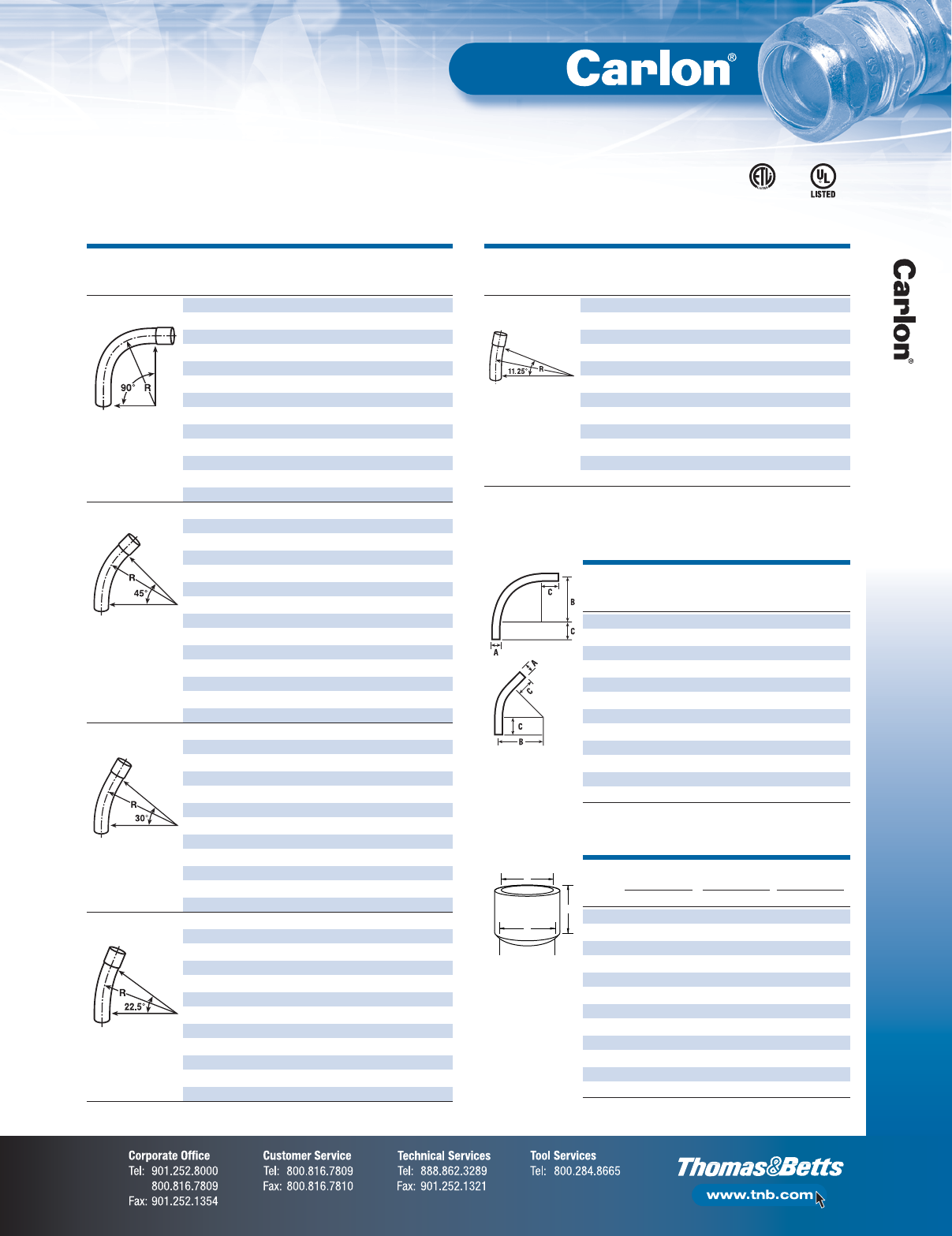
F-37
Non-Metallic Rigid Conduit, Fittings and Accessories
Rigid Non-Metallic Conduit
Standard Radius
Standard Radius Elbow Dimensions
Schedule 40 Elbows
90°
Elbow
45°
Elbow
PLAIN BELLED
PLAIN BELLED
END END
SIZE END END
ITEM CAT. NO. CAT. NO.
(IN.) STD. CTN. STD. CTN.
90° ELBOW UA9AD UA9ADB 1⁄250 50
UA9ADR-CAR UA9ADB 1⁄225 50
UA9AE UA9AEB 3⁄425 25
UA9AFR-CTN UA9AFB-CTN 125 25
UA9AG UA9AGB 11⁄420 20
UA9AH UA9AHB 11⁄225 25
UA9AJ UA9AJB 220 20
UA9AK-CAR UA9AKB-CAR 21⁄210 10
UA9AL UA9ALB 31 5
UA9AM UA9AMB 31⁄2120
UA9AN UA9ANB 41 1
UA9AP UA9APB 51 1
UA9AR UA9ARB 61 1
45° ELBOW UA7AD UA7ADB 1⁄250 50
UA7AE UA7AEB 3⁄425 25
UA7AF UA7AFB 120 20
UA7AF-CAR UA7AFB 115 20
UA7AG UA7AGB 11⁄420 20
UA7AH UA7AHB 11⁄220 20
UA7AJ UA7AJB 220 20
UA7AJ-CAR — 24 4
UA7AK UA7AKB 21⁄220 20
UA7AL UA7ALB 35 25
UA7AM UA7AMB 31⁄2120
UA7AN UA7ANB 41 20
UA7AP UA7APB 51 1
UA7AR UA7ARB 61 1
30° ELBOW UA6AD UA6ADB 1⁄250 50
UA6AE UA6AEB 3⁄425 25
UA6AF UA6AFB 125 1
UA6AG UA6AGB 11⁄420 20
UA6AH UA6AHB 11⁄225 1
UA6AJ UA6AJB 220 20
UA6AK UA6AKB 21⁄210 20
UA6AL UA6ALB 31 1
UA6AM UA6AMB 31⁄211
UA6AN UA6ANB 41 1
UA6AP UA6APB 51 1
UA6AR UA6ARB 61 1
221⁄2° ELBOW UA5AD — 1⁄21—
UA5AE — 3⁄41—
UA5AF — 11 —
UA5AG — 11⁄41—
UA5AH — 11⁄21—
UA5AJ UA5AJB 225 1
UA5AK — 21⁄220 —
UA5AL UA5ALB 35 1
UA5AM — 31⁄21—
UA5AN UA5ANB 41 1
UA5AP UA5APB 51 1
UA5AR UA5ARB 61 1
B MIN. C
SIZE A (RADIUS) MIN.
(IN.) (IN.) (IN.) (IN.)
1⁄2.840 4 11⁄2
3⁄41.050 41⁄211⁄2
1 1.315 53⁄417⁄8
11⁄41.660 71⁄42
11⁄21.900 81⁄42
2 2.375 91⁄22
21⁄22.875 101⁄23
3 3.500 13 31⁄8
31⁄24.000 15 31⁄4
4 4.500 16 33⁄8
5 5.563 24 35⁄8
6 6.625 30 33⁄4
Integral Belled End Dimensions
A
C
B
TRADE A (IN.) B (IN.) C (IN.)
SIZE AT ENTRANCE AT BOTTOM SOCKET DEPTH
(IN.) MAX. MIN. MAX. MIN. MAX. MIN.
1⁄2.860 0.844 0.844 0.828 1.500 0.652
3⁄41.074 1.054 1.056 1.036 1.500 0.719
1 1.340 1.320 1.320 1.300 1.875 0.875
11⁄41.689 1.665 1.667 1.643 2.000 0.938
11⁄21.930 1.906 1.906 1.882 2.000 1.062
2 2.405 2.381 2.381 2.357 2.000 1.125
21⁄22.905 2.875 2.883 2.853 3.000 1.469
3 3.530 3.500 3.507 3.477 3.125 1.594
31⁄24.065 3.965 4.007 3.977 3.250 1.687
4 4.565 4.465 4.506 4.476 3.375 1.750
5 5.643 5.543 5.583 5.523 3.625 1.937
6 6.708 6.608 6.644 6.584 3.750 2.125
PLAIN BELLED
PLAIN BELLED
END END
SIZE END END
ITEM CAT. NO. CAT. NO.
(IN.) STD. CTN. STD. CTN.
111⁄4° ELBOW UA3AD — 1⁄21—
UA3AE — 3⁄41—
UA3AF — 11 —
UA3AG — 11⁄41—
UA3AH — 11⁄21—
UA3AJ — 21 —
UA3AK — 21⁄21—
UA3AL — 31 —
UA3AM — 31⁄21—
UA3AN UA3ANB 41 1
UA3AP — 51 —
UA3AR — 61 —
Available in plain and integral belled end for use with non-metallic solvent weld fittings.
E23018
ETL Listed
to UL 651 in
compliance
to the NEC®
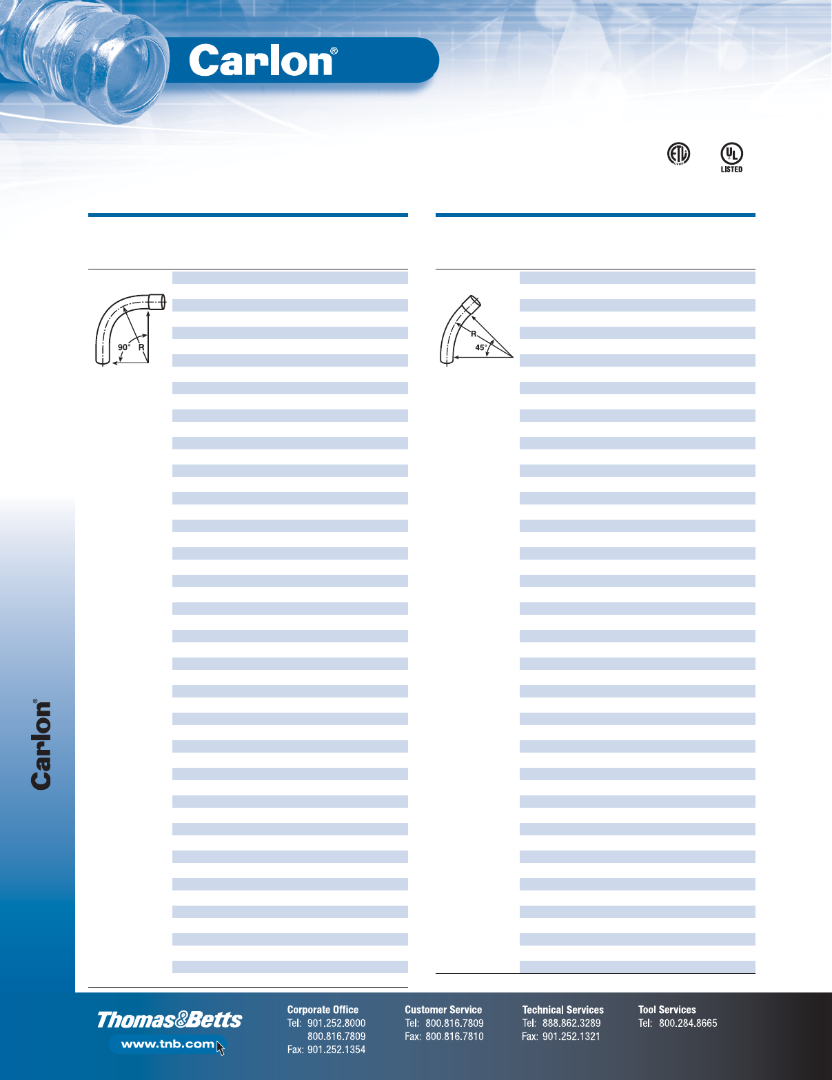
Rigid Non-Metallic Conduit
F-38
Non-Metallic Rigid Conduit, Fittings and Accessories
Special Radius
*Consult factory for additional sizes/configurations
Schedule 40 Elbows
PLAIN BELLED
PLAIN BELLED
NOM. END END
END END
DIAM. RADIUS STD. STD.
SEGMENT CAT. NO. CAT. NO.
(IN.) (IN.) CTN. CTN.
90° ELBOW UA9CF UA9CFB 1181 1
UA9DF UA9DFB 1241 1
UA9EF UA9EFB 1301 1
UA9FF — 1361 —
UA9HF — 1481 —
UA9CG UA9CGB 11⁄418 1 1
UA9DG UA9DGB 11⁄424 1 1
UA9EG UA9EGB 11⁄430 1 1
UA9FG UA9FGB 11⁄436 1 1
UA9HG — 11⁄448 1 —
UA9CH UA9CHB 11⁄218 1 1
UA9DH UA9DHB 11⁄224 1 1
UA9EH UA9EHB 11⁄230 1 1
UA9FH UA9FHB 11⁄236 1 1
UA9HH — 11⁄248 1 —
UA9CJ UA9CJB 2181 1
UA9DJ UA9DJB-UPC 2241 1
UA9EJ UA9EJB 2301 1
UA9FJ-UPC UA9FJB 2361 1
UA9HJ UA9HJB 2481 1
UA9JJ — 2721 —
UA9CK UA9CKB 21⁄218 1 1
UA9DK UA9DKB-UPC 21⁄224 1 1
UA9EK UA9EKB 21⁄230 1 1
UA9FK-UPC UA9FKB 21⁄236 1 1
UA9HK UA9HKB 21⁄248 1 1
UA9CL UA9CLB 3181 1
UA9DL UA9DLB-UPC 3241 1
UA9EL UA9ELB 3301 1
UA9FL UA9FLB 3361 1
UA9HL UA9HLB 3481 1
UA9IL — 3601 —
UA9DM UA9DMB 31⁄224 1 1
UA9EM UA9EMB 31⁄230 1 1
UA9FM UA9FMB 31⁄236 1 1
UA9HM UA9HMB 31⁄248 1 1
— UA9CNB 418— 1
UA9DN UA9DNB 4241 1
UA9EN UA9ENB 4301 1
UA9FN UA9FNB 4361 1
UA9HN UA9HNB 4481 1
UA9IN UA9INB 4601 1
UA9JN — 4721 1
UA9EP UA9EPB 5301 1
UA9FP UA9FPB 5361 1
UA9HP UA9HPB 5481 1
UA9IP UA9IPB 5601 1
UA9FR UA9FRB 6361 1
UA9HR UA9HRB 6481 1
UA9IR UA9IRB 6601 1
— UA9TRB 6 180 — 1
UA9HT — 8481 1
PLAIN BELLED
PLAIN BELLED
NOM. END END
END END
DIAM. RADIUS STD. STD.
SEGMENT CAT. NO. CAT. NO.
(IN.) (IN.) CTN. CTN.
45° ELBOW UA7CF — 1181 —
UA7DF — 1241 —
UA7EF — 1301 —
UA7FF — 1361 —
UA7HF — 1481 —
UA7CG — 11⁄418 1 —
UA7DG — 11⁄424 1 —
UA7EG — 11⁄430 1 —
UA7FG — 11⁄436 1 —
UA7HG — 11⁄448 1 —
UA7CH — 11⁄218 1 —
UA7DH — 11⁄224 1 —
UA7EH — 11⁄230 1 —
UA7FH UA7FHB 11⁄236 1 1
UA7HH — 11⁄248 1 —
— UA7BJB 212— 1
UA7CJ UA7CJB 2181 1
UA7DJ UA7DJB 2241 1
UA7EJ UA7EJB 2301 1
UA7FJ UA7FJB 2361 1
UA7HJ UA7HJB 2481 1
UA7SJ — 2 150 1 —
UA7CK — 21⁄218 1 —
UA7DK UA7DKB 21⁄224 1 1
UA7EK — 21⁄230 1 —
UA7FK UA7FKB 21⁄236 1 1
UA7HK — 21⁄248 1 —
UA7CL UA7CLB 3181 1
UA7DL UA7DLB 3241 1
UA7EL UA7ELB 3301 1
UA7FL UA7FLB 3361 1
UA7HL UA7HLB 3481 1
UA7DM — 31⁄224 1 —
UA7EM — 31⁄230 1 —
UA7FM — 31⁄236 1 —
UA7DN UA7DNB 4241 1
UA7EN UA7ENB 4301 1
UA7FN UA7FNB 4361 1
UA7HN UA7HNB 4481 1
— UA7NNB 4 120 — 1
UA7SN UA7SNB 4 150 1 —
UA7EP UA7EPB 5301 1
UA7FP UA7FPB 5361 1
UA7HP UA7HPB 5481 1
— UA7IPB 560— 1
— UA7NPB 5 120 — 1
— UA7SPB 5 150 — 1
UA7FR UA7FRB 6361 1
UA7HR UA7HRB 6481 1
UA7FT — 8361 —
UA7HT — 8481 —
NOTE: Elbows 72" and larger may be shipped in segments. Consult factory for specifics.
E23018
ETL Listed
to UL 651 in
compliance
to the NEC®
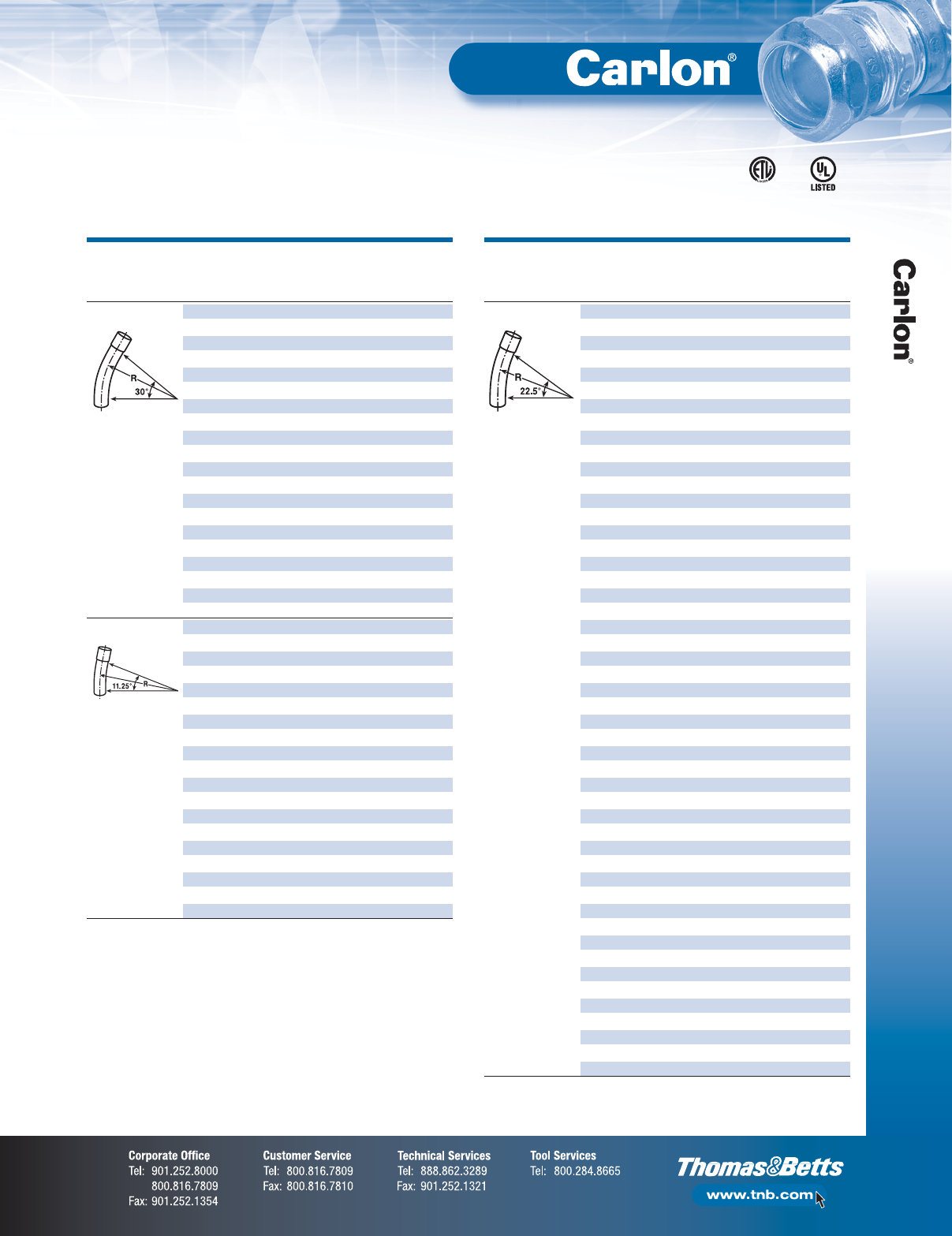
F-39
Non-Metallic Rigid Conduit, Fittings and Accessories
Rigid Non-Metallic Conduit
Special Radius
*Consult factory for additional sizes/configurations
Schedule 40 Elbows
PLAIN BELLED
PLAIN BELLED
NOM. END END
END END
DIAM. RADIUS STD. STD.
SEGMENT CAT. NO. CAT. NO.
(IN.) (IN.) CTN. CTN.
30° ELBOW UA6CJ — 2181 —
UA6DJ UA6DJB 2241 1
UA6FJ UA6FJB 2361 1
UA6HJ UA6HJB 2481 1
UA6CK — 21⁄218 1 —
UA6DK — 21⁄224 1 —
UA6CL — 3181 —
UA6DL UA6DLB 3241 1
UA6FL UA6FLB 3361 1
UA6HL UA6HLB 3481 1
UA6DM — 31⁄224 1 —
UA6FM — 31⁄236 1 —
UA6HM — 31⁄248 1 —
UA6DN — 4241 —
UA6FN UA6FNB 4361 1
UA6HN UA6HNB 4481 1
UA6FP UA6FPB 5361 1
UA6HP UA6HPB 5481 1
UA6FR UA6FRB 6361 1
UA6HR UA6HRB 6481 1
111⁄4° ELBOW UA3DJ UA3DJB 2241 25
UA3FJ UA3FJB 2361 1
UA3HJ — 2481 —
UA3HK — 21⁄248 1 —
UA3DL UA3DLB 3241 1
UA3FL UA3FLB 3361 1
UA3HL — 3481 —
UA3DM — 31⁄224 1 —
UA3HM — 31⁄248 1 —
UA3DN UA3DNB 4241 1
UA3FN UA3FNB 4361 1
— UA3SNB 4 150 — 1
UA3HN UA3HNB 4481 1
UA3FP UA3FPB 5361 1
UA3HP — 5481 —
— UA3UPB 5 240 — 1
UA3FR UA3FRB 6361 1
UA3HR — 6481 —
UA3FT — 8361 —
PLAIN BELLED
PLAIN BELLED
NOM. END END
END END
DIAM. RADIUS STD. STD.
SEGMENT CAT. NO. CAT. NO.
(IN.) (IN.) CTN. CTN.
221⁄2° ELBOW UA5FF — 1361 —
UA5FG — 11⁄436 1 —
UA5FH UA5FHB 11⁄236 1 1
UA5CJ UA5CJB 2181 1
UA5DJ UA5DJB 2241 25
UA5EJ UA5EJB 2301 1
UA5FJ UA5FJB 2361 1
UA5HJ — 2481 —
UA5VJ — 2 300 1 —
UA5CK — 21⁄218 1 —
UA5DK — 21⁄224 1 —
UA5EK — 21⁄230 1 —
UA5FK — 21⁄236 1 —
UA5HK — 21⁄248 1 —
— UA5CLB 3181 1
UA5DL UA5DLB 3241 1
UA5EL UA5ELB 3301 1
UA5FL UA5FLB 3361 1
UA5HL — 3481 —
UA5VL — 3 300 1 —
UA5DM — 31⁄224 1 —
UA5EM — 31⁄230 1 —
UA5FM — 31⁄236 1 —
UA5HM — 31⁄248 1 —
UA5DN UA5DNB 4241 1
UA5EN UA5ENB 4301 1
UA5FN UA5FNB 4361 1
UA5HN UA5HNB 4481
UA5IN — 4601 —
UA5JN — 4721 —
UA5SN UA5SNB 4 150 1
— UA5UNB 4 240 — 1
— UA5VNB 4 300 — 1
— UA5DPB 5241 1
UA5EP UA5EPB 5301 1
UA5FP UA5FPB 5361 1
UA5HP UA5HPB 5481 1
UA5IP — 5601 —
UA5SP — 5 150 1 —
— UA5UPB 5 240 — 1
— UA5VPB 5 300 — 1
UA5FR UA5FRB 6361 1
UA5HR UA5HRB 6481 1
UA5IR — 6601 —
UA5RR — 6 144 1 —
UA5SR — 6 150 1 —
UA5VR — 6 300 1 —
UA5FT — 8361 —
UA5HT — 8481 —
NOTE: Elbows 72" and larger may be shipped in segments. Consult factory for specifics.
E23018
ETL Listed
to UL 651 in
compliance
to the NEC®
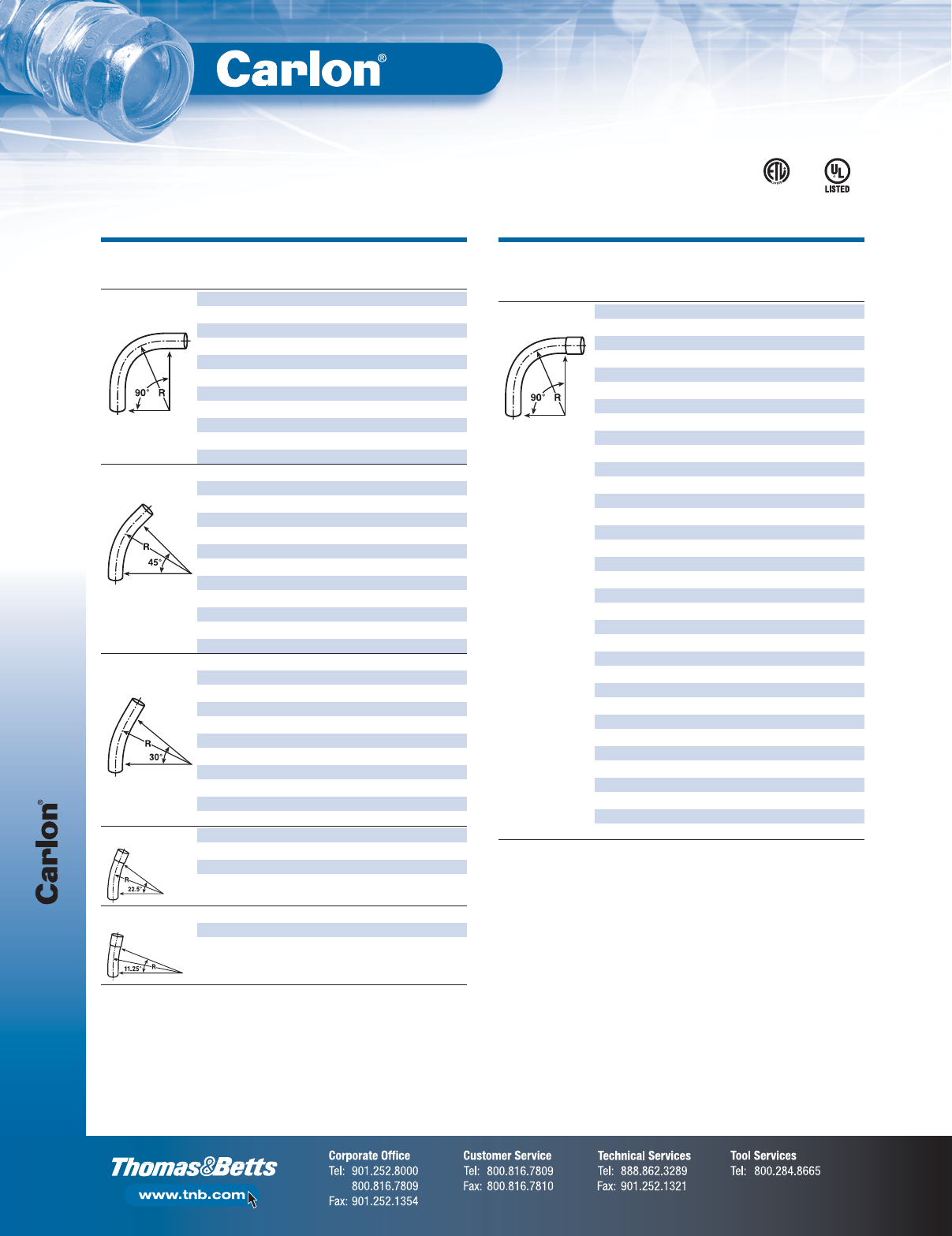
Rigid Non-Metallic Conduit
F-40
Non-Metallic Rigid Conduit, Fittings and Accessories
Standard Radius
For use with non-metallic solvent weld fittings.
Special Radius
Schedule 80 Elbows
PLAIN BELLED
PLAIN BELLED
END END
SIZE END END
ITEM CAT. NO. CAT. NO.
(IN.) STD. CTN. STD. CTN.
90° ELBOW UB9AD — 1⁄250 —
UB9AE — 3⁄425 —
UB9AF — 125 —
UB9AG — 11⁄420 —
UB9AH — 11⁄225 —
UB9AJ — 220 —
UB9AK — 21⁄210 —
UB9AL — 35 —
UB9AN — 41 —
UB9AP UB9APB 51 1
UB9AR — 61 —
45° ELBOW UB7AD — 1⁄250 —
UB7AE-UPC — 3⁄425 —
UB7AF-UPC — 120 —
UB7AG — 11⁄420 —
UB7AH — 11⁄220 —
UB7AH-CAR — 11⁄25—
UB7AJ-UPC — 220 —
UB7AK — 21⁄220 —
UB7AL — 31 —
UB7AN — 41 —
UB7AP UB7APB 51 1
UB7AR — 61 —
30° ELBOW UB6AD — 1⁄250 —
UB6AE — 3⁄425 —
UB6AF — 125 —
UB6AG — 11⁄45—
UB6AH — 11⁄225 —
UB6AJ — 220 —
UB6AK — 21⁄21—
UB6AL — 31 —
UB6AN — 41 —
UB6AP — 51 —
UB6AR — 61 —
221⁄2° ELBOW UB5AL — 35 —
UB5AN — 41 —
UB5AP UB5APB 51 1
111⁄4° ELBOW UB3AL — 31 —
UB3AR — 61 —
PLAIN BELLED
PLAIN BELLED
NOM. END END
END END
DIAM. RADIUS STD. STD.
SEGMENT CAT. NO. CAT. NO.
(IN.) (IN.) CTN. CTN.
90° ELBOW UB9CF — 1181 —
UB9DF — 1241 —
UB9FF — 1361 —
UB9HF — 1481 —
UB9CG — 11⁄418 1 —
UB9DG — 11⁄424 1 —
UB9FG — 11⁄436 1 —
UB9HG — 11⁄448 1 —
UB9CH — 11⁄218 1 —
UB9DH-UPC UB9DHB 11⁄224 1 1
UB9FH — 11⁄236 1 —
UB9HH — 11⁄248 1 —
UB9CJ — 2181 —
UB9DJ-UPC UB9DJB 2241 1
UB9FJ UB9FJB 2361 1
UB9HJ — 2481 —
UB9CK — 21⁄218 1 —
UB9DK-UPC UB9DKB 21⁄224 1 1
UB9FK UB9FKB 21⁄236 1 1
UB9HK — 21⁄248 1 —
UB9CL — 3181 —
UB9DL UB9DLB 3241 1
UB9FL UB9FLB 3361 1
UB9HL — 3481 —
UB9DN UB9DNB 4241 1
UB9FN UB9FNB 4361 1
UB9HN UB9HNB 4481 1
UB9NN — 4 120 1 —
UB9FP — 5361 —
UB9HP — 5481 —
UB9IP — 5601 —
UB9FR — 6361 —
UB9HR — 6481 —
UB9IR — 6601 —
NOTE: Elbows 72" and larger may be shipped in segments. Consult factory for specifics.
Continued on next page
E23018
ETL Listed
to UL 651 in
compliance
to the NEC®
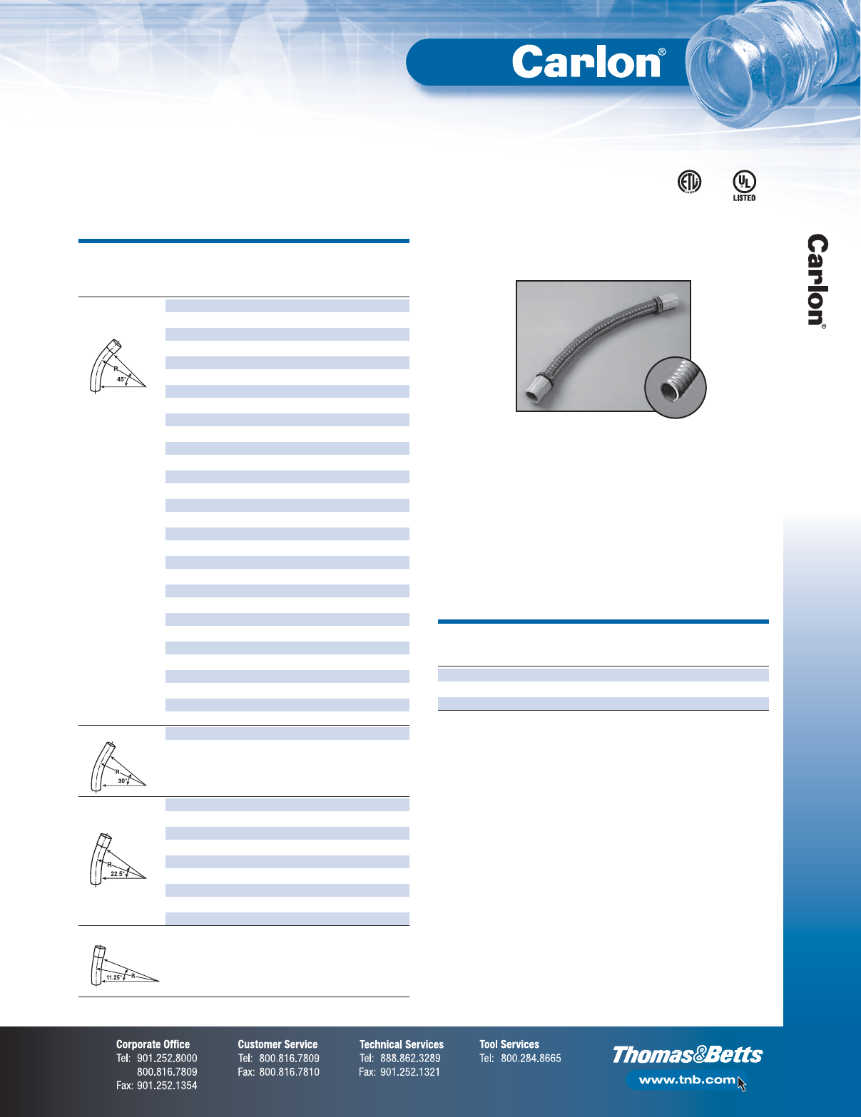
F-41
Non-Metallic Rigid Conduit, Fittings and Accessories
Rigid Non-Metallic Conduit
Schedule 80 Elbows
Special Radius
PLAIN BELLED
PLAIN BELLED
NOM. END END
END END
DIAM. RADIUS STD. STD.
SEGMENT CAT. NO. CAT. NO.
(IN.) (IN.) CTN. CTN.
45° ELBOW UB7CF — 1181 —
UB7DF — 1241 —
UB7FF — 1361 —
UB7HF — 1481 —
UB7DG — 11⁄424 1 —
UB7FG — 11⁄436 1 —
UB7HG — 11⁄448 1 —
UB7CH — 11⁄218 1 —
UB7DH UB7DHB 11⁄224 1 1
UB7FH — 11⁄236 1 —
UB7HH — 11⁄248 1 —
UB7CJ — 2181 —
UB7DJ UB7DJB 2241 1
UB7FJ UB7FJB 2361 1
UB7HJ — 2481 —
UB7DK UB7DKB 21⁄224 1 1
UB7FK — 21⁄236 1 —
UB7HK — 21⁄248 1 —
UB7CL — 3181 —
UB7DL UB7DLB 3241 1
UB7FL UB7FLB 3361 1
UB7HL — 3481 —
UB7DN UB7DNB 4241 1
UB7FN UB7FNB 4361 1
UB7HN — 4481 —
UB7FP — 5361 —
UB7HP — 5481 —
UB7FR — 6361 —
UB7HR — 6481 —
UB7IR — 6601 —
30° ELBOW UB6FN — 4361 —
UB6FR — 6361 —
221⁄2° ELBOW — UB5DHB 11⁄224 — 20
— UB5DJB 224— 20
— UB5FJB 236— 25
— UB5DKB 21⁄224 — 15
UB5DL UB5DLB 3241 10
— UB5FLB 336— 1
UB5DN UB5DNB 4241 5
— UB5FNB 436— 1
UB5FP — 5361 —
111⁄4° ELBOW UB3FP — 5361 —
NOTE: Elbows 72" and larger may be shipped in segments. Consult factory for specifics.
•UL Listed for exposed and direct burial applications
in accordance with Article 356 of the NEC®
•0°–90° bending and offset applications
•O-ring seal for moisture-tight connections
•Maintains round shape throughout bend
•Sunlight resistant
•Non-corrosive — all PVC and Neoprene material
•Fully assembled and ready to use
Flexible PVC Elbows
LENGTH
SIZE STD. STD. WT. FULLY
CAT. NO.
(IN.) CTN. (LBS.) ASSEMBLED (IN.)
UAFAD 1⁄28 1.6 8.5
UAFAE 3⁄46 1.9 9.6
UAFAF 1 6 2.4 11.9
Continued from previous page
E23018
ETL Listed
to UL 651 in
compliance
to the NEC®
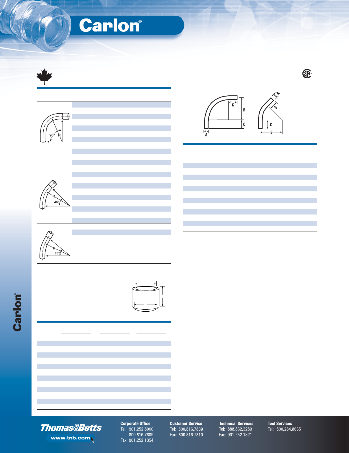
Canadian Rigid Non-Metallic Conduit
F-42
Non-Metallic Rigid Conduit, Fittings and Accessories
Standard Radius
Canadian Schedule 40 Elbows
BELLED END
BELLED END
ITEM CAT. NO.
SIZE (IN.) STD. CTN.
90° ELBOW UA9ADCB-CTN 1⁄240
UA9AECB-CTN 3⁄425
UA9AFCB-CTN 125
UA9AGCB-UPC 11⁄420
UA9AHCB-UPC 11⁄225
UA9AJCB-UPC 220
UA9AKCB-CTN 21⁄210
UA9ALCB-UPC 325
UA9AMCB 31⁄21
UA9ANCB 41
UA9APCB 51
UA9ARCB 61
45° ELBOW UA7AGCB 11⁄41
UA7AHCB 11⁄220
UA7AJCB 220
UA7AKCB 21⁄21
UA7ALCB 35
UA7AMCB 31⁄21
UA7ANCB 41
UA7APCB 51
UA7ARCB 61
30° ELBOW UA6AJCB 220
UA6ANCB 41
UA6ARCB 61
Available in plain and integral belled end for use with non-metallic solvent weld fittings.
Integral Belled End
Dimensions
ABC
TRADE AT ENTRANCE AT BOTTOM SOCKET DEPTH
SIZE (IN.) MAX. MIN. MAX. MIN. MAX. MIN.
1⁄2.860 0.844 0.844 0.828 1.500 0.652
3⁄41.074 1.054 1.056 1.036 1.500 0.719
1 1.340 1.320 1.320 1.300 1.875 0.875
11⁄41.689 1.665 1.667 1.643 2.000 0.938
11⁄21.930 1.906 1.906 1.882 2.000 1.062
2 2.405 2.381 2.381 2.357 2.000 1.125
21⁄22.905 2.875 2.883 2.853 3.000 1.469
3 3.530 3.500 3.507 3.477 3.125 1.594
31⁄24.065 3.965 4.007 3.977 3.250 1.687
4 4.565 4.465 4.506 4.476 3.375 1.750
5 5.643 5.543 5.583 5.523 3.625 1.937
6 6.708 6.608 6.644 6.584 3.750 2.125
A
C
B
Standard Radius
Elbow Dimensions
B MIN. C
SIZE A (RADIUS) MIN.
(IN.) (IN.) (IN.) (IN.)
1⁄2.840 4 11⁄2
3⁄41.050 41⁄211⁄2
1 1.315 53⁄417⁄8
11⁄41.660 71⁄42
11⁄21.900 81⁄42
2 2.375 91⁄22
21⁄22.875 101⁄23
3 3.500 13 31⁄8
31⁄24.000 15 31⁄4
4 4.500 16 33⁄8
5 5.563 24 35⁄8
6 6.625 30 33⁄4
90°
Elbow 45°
Elbow
LR90813
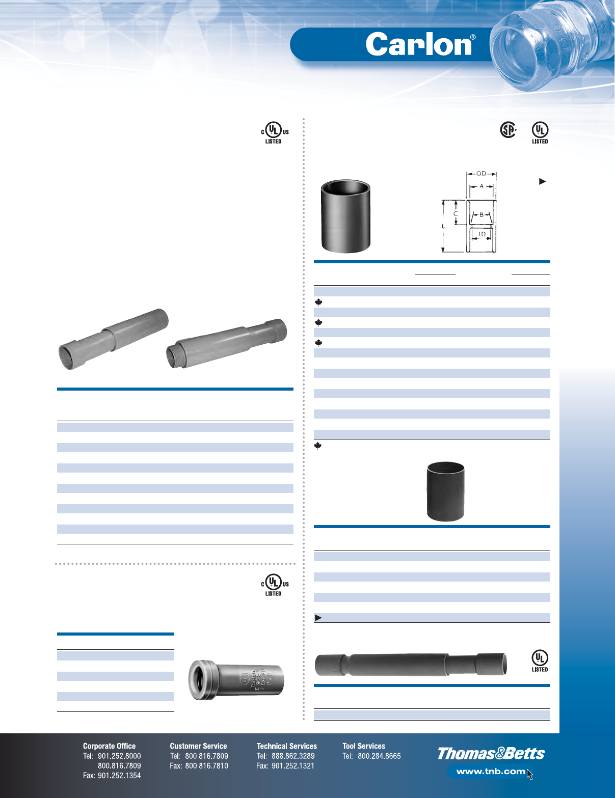
F-43
Non-Metallic Rigid Conduit, Fittings and Accessories
Rigid Non-Metallic Conduit Fittings
(for use with Schedule 40 & 80 Conduit)
Standard Couplings
All socket fittings should be attached
using Carlon®solvent cement.
Couplings
SIZE STD. TYPICAL (IN.) I.D. O.D. TYPICAL (IN.)
CAT. NO.
(IN.) CTN. A B (IN.) (IN.) C L
E940D 1⁄2150 .852 .836 .728 17⁄64 11⁄16 11⁄2
CE940DR-CTN 1⁄275 .852 .836 .728 17⁄64 11⁄16 11⁄2
E940E 3⁄4100 1.064 1.046 .840 15⁄16 3⁄415⁄8
CE940ER-CTN 3⁄445 1.064 1.046 .840 15⁄16 3⁄415⁄8
E940F 1 50 1.330 1.310 1.210 15⁄815⁄16 2
CE940F-UPC 1 50 1.330 1.310 1.210 15⁄815⁄16 2
E940G 11⁄430 1.677 1.655 1.535 163⁄64 12
1⁄8
E940H 11⁄225 1.918 1.894 1.755 215⁄64 11⁄823⁄8
E940J 2 30 2.393 2.369 2.190 247⁄64 13⁄16 21⁄2
E940K 21⁄220 2.890 2.868 2.688 35⁄16 133⁄64 33⁄16
E940L 3 25 3.515 3.492 3.375 331⁄32 13⁄4313⁄32
E940M 31⁄220 4.015 3.992 3.780 49⁄16 13⁄435⁄8
E940N 4 15 4.515 4.491 4.265 53⁄32 125⁄32 33⁄4
E940P 5 8 5.593 5.553 5.097 61⁄415⁄16 41⁄16
E940R 6 5 6.658 6.614 6.115 71⁄223⁄16 45⁄8
SIZE STD. STD. WT. LENGTH
CAT. NO.
(IN.) CTN. (LBS.) (IN.)
E941H 11⁄240 9 3.19
E941J 2 25 8 3.59
E941K 21⁄215 8 4.29
E941L 3 15 14 6.44
E941N 4 10 15 6.96
E941PF 5 4 12 9.63
E941RF 6 5 21 11.75
Expansion Fittings
COUPLING MALE TERMINAL
TRAVEL
END ADAPTER END
SIZE STD. LENGTH
CAT. NO. CAT. NO.
(IN.) CTN. (IN.)
E945D E945DX 1⁄220 4
E945E E945EX 3⁄415 4
E945F E945FX 1104
E945G E945GX 11⁄454
E945H E945HX 11⁄254
E945J E945JX 2158
E945K E945KX 21⁄210 8
E945L E945LX 3108
E945M E945MX 31⁄258
E945N E945NX 458
E945P E945PX 518
E945R E945RX 618
CAT. NO.
SIZE (IN.) STD. CTN.
E955D 1⁄240
E955E 3⁄440
E955F 125
E955G 11⁄415
E955H 11⁄210
E955J 26
Special
Long Line
Couplings
Long Line
Couplings
Socket type for
joining non-metallic
conduit.
E945 series expansion fittings are designed to compensate
for length changes due to temperature variations in exposed
conduit runs.
Short Expansion Couplings
Expand to a maximum of 2".
Male terminal
adapter end
Coupling end
Fabricated Expansion Couplings
•Exclusive molded-in mid-point indicator on the piston
•Exclusive 2" expansion fitting with an 8" travel distance
•Two-piece molded design with lubricated seals for easier
movement for the life of the product
•Ridges on the fitting for easier installation (sizes 2"–6" only)
•Male terminal adapter end design (1⁄2"–2" NPT Threads,
and 21⁄2"–6" NPSC threads)
•Two O-rings to prevent leakage
•Can be installed vertically or horizontally
Canada only
SIZE STD. TRAVEL LENGTH
CAT. NO.
(IN.) CTN. (IN.)
E945KXL 21⁄210 12
E23018
E23018
E23018
LR33856 E23018
Except
where
noted
by
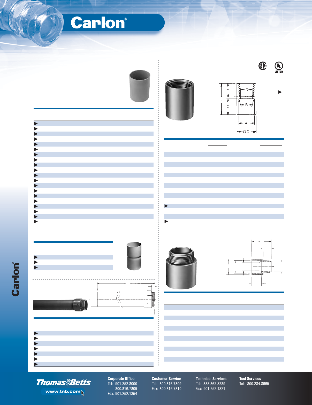
Rigid Non-Metallic Conduit Fittings
(for use with Schedule 40 & 80 Conduit)
F-44
Non-Metallic Rigid Conduit, Fittings and Accessories
Special Long Line Couplings —
Sleeve Couplings
Couplings
Female Adapters
Adapters
Schedule 40
Risers
SIZE STD. STD. WT. LENGTH
CAT. NO.
(IN.) CTN. (LBS.) (IN.)
E948H 11⁄225 6 4
E948J 22553
E948K 21⁄225 16 6
E948L 325134
E948N 4 10 8 6.5
E948P 514337
E948R 6 6 16 6
E948JR 21586
E948JS 2 (Sch. 40 Split Duct) 25 6 —
E948KS7 21⁄2(Sch. 40 Split Duct) 25 19 7
E948L12 31112
E948L6 315156
E948LS 3 (Sch. 40 Split Duct) 25 17 —
E948N12 4 102812
E948N7 415257
E948NS 4 (Sch. 40 Split Duct) 10 15 —
E948PS 5 (Sch. 40 Split Duct) 1 2 —
E948R10 6 6 25 10
E948R12 6 6 25 12
E948RS 6 (Sch. 40 Split Duct) 1 2 —
Sleeve Coupling
(For Repair Work)
No Internal Stop
Male Terminal Adapters
For adapting non-
metallic conduits
to boxes, threaded
fittings, metallic
systems. Male
threads on one
end, socket end
on other.
For adapting non-metallic conduits to threaded
fittings, metallic systems. Female threads
on one end, socket end on other.
Special Schedule 40 Swedge Couplings
SIZE A (IN.) C THREAD STD. STD.
CAT. NO.
(IN.) (LENGTH) B (IN.) (IN.) SIZE (IN.) CTN. WT. (LBS.)
E954HX 11⁄280.00 1.567 .950 11⁄2NPT 1 3.8
E954J 2 60.00 2.024 .825 2 NPT 1 3.7
E954JX 2 80.00 2.024 .825 2 NPT 1 5.0
E954K 21⁄260.00 2.418 .812 21⁄2NPSC 1 6.0
E954KX 21⁄280.00 2.418 .812 21⁄2NPSC 1 8.4
E954L 3 60.00 3.012 .798 3 NPSC 1 8.7
E954LX 3 80.00 3.012 .798 3 NPSC 1 11.0
SIZE STD. TYPICAL (IN.) MIN. MAX. TYPICAL (IN.)
CAT. NO.
(IN.) CTN. A B D (IN.) OD (IN.) C S L
E943D 1⁄2150 .852 .836 .594 1.042 .652 .545 1.310
E943E 3⁄4125 1.064 1.046 .793 1.290 .809 .553 1.470
E943F 1 50 1.330 1.310 1.025 1.580 .965 .812 1.902
E943G 11⁄450 1.677 1.655 1.345 1.973 1.208 .816 1.986
E943H 11⁄225 1.918 1.894 1.574 2.188 1.155 .802 2.105
E943J 2 50 2.393 2.369 1.998 2.713 1.145 .825 2.093
E943K 21⁄225 2.890 2.868 2.400 3.290 1.490 .812 2.480
E943L 3 45 3.515 3.492 2.989 3.965 1.643 .797 2.660
E943M 31⁄230 4.015 3.992 3.405 4.515 1.720 .802 2.740
E943N 4 20 4.515 4.491 3.895 5.065 1.788 .733 2.830
E943P 5 5 5.593 5.553 4.900 6.104 1.935 .990 3.200
E943R 6 10 6.658 6.614 5.900 7.288 2.128 985 3.410
SIZE STD. STD. WT.
CAT. NO.
(IN.) CTN. (LBS.)
E442K 21⁄220 13
E442R 66 27
E442T 82 17
*Consult factory for additional sizes
SIZE STD. TYPICAL (IN.) MIN. MAX. TYPICAL (IN.)
CAT. NO.
(IN.) CTN. A B D (IN.) OD (IN.) C T L
E942D 1⁄2150 .852 .836 .620 17⁄64 11⁄16 3⁄419⁄16
E942E 3⁄4100 1.064 1.046 .822 15⁄16 13⁄16 3⁄415⁄8
E942F 1 50 1.330 1.310 1.046 15⁄815⁄16 7⁄8115⁄16
E942G 11⁄430 1.677 1.655 1.377 163⁄64 17⁄82
E942H 11⁄225 1.918 1.894 1.607 25⁄32 11⁄87⁄827⁄32
E942J 2 30 2.393 2.369 2.064 247⁄64 13⁄16 12
5⁄16
E942K 21⁄220 2.890 2.868 2.450 311⁄32 15⁄811⁄8215⁄16
E942L 3 25 3.515 3.492 3.000 331⁄32 13⁄411⁄831⁄16
E942M 31⁄220 4.015 3.992 3.500 41⁄217⁄811⁄831⁄4
E942N 4 15 4.515 4.491 4.000 51⁄64 13⁄411⁄16 313⁄64
E942NX9* 4 15 (Call for information)
E942P 5 8 5.593 5.553 5.047 61⁄4115⁄16 11⁄16 33⁄16
E942R 6 6 6.658 6.614 6.055 71⁄421⁄811⁄16 33⁄8
E942RX* 6 6 (Call for information)
* Long Line Adapter
B
L
C
C
THREAD
SIZE
A
OD AD
S
C
REF
B (I.D.)
LR31146 E23018
Except
where
noted
by

F-45
Non-Metallic Rigid Conduit, Fittings and Accessories
Rigid Non-Metallic Conduit Fittings
(for use with Schedule 40 & 80 Conduit)
Reducer Bushings
Reducers
SIZE STD. L (IN.) A (IN.) C (IN.)
CAT. NO.
(IN.) CTN. TYPICAL TYPICAL TYPICAL
E950ED 3⁄4x 1⁄2100 15⁄32 13⁄64 11⁄32
E950FD-CAR 1 x 1⁄225 111⁄32 3⁄16 57⁄64
E950FE 1 x 3⁄4100 111⁄32 3⁄16 11⁄64
E950GE-CAR 11⁄4x 3⁄410 115⁄32 3⁄16 11⁄64
E950GF 11⁄4x 1 50 115⁄32 3⁄16 19⁄64
E950HF-CAR 11⁄2x 1 10 119⁄32 3⁄16 19⁄64
E950HG-CAR 11⁄2x 11⁄410 119⁄32 3⁄16 117⁄64
E950JG-CAR 2 x 11⁄410 13⁄47⁄32 117⁄64
E950JH-CAR 2 x 11⁄210 13⁄47⁄32 125⁄64
E950KJ-CAR 21⁄2x 2 10 25⁄32 3⁄8127⁄64
E950LJ-CAR 3 x 2 10 21⁄81⁄417⁄8
E950LK 3 x 21⁄225 115⁄16 1⁄4111⁄16
E950NL 4 x 3 25 23⁄45⁄16 115⁄16
Box Adapters for Enclosures
Adapters
SIZE STD. MIN OD (IN.) MAX CM (IN.) L (IN.)
CAT. NO.
(IN.) CTN. D (IN.) TYPICAL X (IN.) TYPICAL TYPICAL
E996D 1⁄2100 .662 .840 17⁄64 23⁄32 27⁄32
E996E 3⁄4100 .824 1.050 121⁄64 25⁄32 29⁄32
E996F 1 100 1.049 1.315 15⁄861⁄64 13⁄32
E996G 11⁄450 1.380 1.660 131⁄32 11⁄16 11⁄4
E996H 11⁄250 1.610 1.900 213⁄64 13⁄16 13⁄8
E996J 2 25 2.067 2.375 229⁄32 11⁄417⁄16
E996K 21⁄215 2.469 2.875 37⁄16 17⁄8115⁄16
E996L 3 20 3.068 3.500 41⁄822
1⁄16
E996N 4 10 4.026 4.500 51⁄821⁄221⁄4
Threaded Adapters
SIZE STD.
CAT. NO.
(IN.) CTN.
E9842D 11⁄225
E9842E 23⁄425
1
Fits
3
⁄
4
" sockets
2
Fits 1" sockets
SIZE STD. STD. WT.
CAT. NO.
(IN.) CTN. (LBS.)
E971C 3⁄4x 1⁄2100 2
E971D 1 x 3⁄4100 3
Adapts non-metallic
conduit to all electrical
enclosures by inserting
adapter through knockout
and cementing into Carlon
couplings.
For connecting
different sizes
of conduit.
Bell x Spigot.
Fabricated Reducers
SIZE STD. STD. WT.
CAT. NO.
(IN.) CTN. (LBS.)
Male x Male
E952JH 11⁄2x 2 48 20
E952KJ 21⁄2x 2 48 26
E952LJ 3 x 2 36 21
E952LK 3 x 21⁄236 32
E952NL 4 x 3 15 21
E952NM 4 x 31⁄215 25
E952PN 5 x 4 12 27
E952RP 6 x 5 10 31
Male x Female
E952NJF 4 x 2 15 16
E952RNF 6 x 4 10 28
Reducer Plugs
Plugs
SIZE STD. STD. WT.
CAT. NO.
(IN.) CTN. (LBS.)
P258H 11⁄250 2
P258K 21⁄225 1.5
Plugs (Polyethylene)
SIZE STD. STD. WT.
CAT. NO.
(IN.) CTN. (LBS.)
P258JT 2603
P258LT 3303
P258NT 4488
P258PT 5306
P258RT 6309
Plugs with Pull Tabs (Polyethylene)
LR31146 E23018
Except
where
noted
by

Rigid Non-Metallic Conduit Fittings
(for use with Schedule 40 & 80 Conduit)
F-46
Non-Metallic Rigid Conduit, Fittings and Accessories
Meter Offset
Offsets
Service Entrance
Caps
Caps
End Bells
End Bells
SIZE STD. DIMENSIONS (IN.)
CAT. NO.
(IN.) CTN. E F G H
E998D 1⁄25 1.76 .45 .45 —
E998E 3⁄420 1.76 .45 .45 —
E998E-CAR 3⁄45 1.76 .45 .45 —
E998F 1 15 2.26 .59 .58 —
E998F-CAR 1 5 2.26 .59 .58 —
E998G-CAR 11⁄45 3.52 .74 .71 .50
E998H-CAR 11⁄25 3.52 .74 .71 .50
E998J-CAR 2 5 4.26 .83 .78 .56
E998K-UPC 21⁄22 7.47 1.70 1.31 1.00
E998L 3 2 7.47 1.70 1.31 1.00
E998N 4 2 10.45 2.25 1.88 1.31
A
SIZE STD. STD. WT.
CAT. NO.
(IN.) CTN. (LBS.)
E949J5 2 x 5 50 10
E949J6 2 x 6 25 12
E949JN 2 x 4 25 7
E949JX 2 x 8 12 7
E949LR 3 x 6 20 21
E949N5 4 x 5 20 2
E949NR 4 x 6 15 21
E949R5 6 x 5 12 27
E949RX 6 x 8 6 17
Fabricated End Bells
(Schedule 40)
SIZE STD. STD. WT.
CAT. NO.
(IN.) CTN. (LBS.)
E958D 1⁄2100 3
E958E 3⁄4100 4
E958F 1755
E958G 11⁄440 4
E958H 11⁄230 4
E958J 2255
E958K 21⁄210 4
E958L 3105
E958N 4517
E958P 5511
E958R 6513
End Caps
SIZE STD. STD. WT.
CAT. NO.
(IN.) CTN. (LBS.)
E935J 2253
E935L 3255
E935N 4257
E935P 52535
E935R 6107
PVC Riser Caps
SIZE OFFSET STD. STD. WT.
CAT. NO.
(IN.) (IN.) CTN. (LBS.)
E994D 1⁄2.250 25 3
E994E 3⁄4.250 25 3
E994F 1 .500 50 12
Offset
SIZE STD. OFFSET A
CAT. NO.
(IN.) CTN. (IN.) (IN.)
E995G 11⁄415 0.758 4.230
E995J 2 8 0.684 4.270
SIZE STD. STD. WT.
CAT. NO.
(IN.) CTN. (LBS.)
E997F 1 50 2.6
E997G 11⁄435 2.5
E997H 11⁄230 2.5
E997J 2 40 5.0
E997K 21⁄230 2
E997L 35010
E997M 31⁄240 11
E997N 43016
E997P 5158
E997R 6107
E997T 8315
E13938 LR31146 E23018
Except
where
noted
by

F-47
Non-Metallic Rigid Conduit, Fittings and Accessories
Rigid Non-Metallic Conduit Accessories, Conduit Bodies
Flat Sealing Washer
Washers
PVC Lock Nut
Lock Nuts
Access Pull Elbows
Pull Elbows
STD. A (IN.) B (IN.) C (IN.) D (IN.)
CAT. NO.
SIZE (IN.) CTN. TYPICAL TYPICAL TYPICAL TYPICAL
E990D 1⁄275 .852 .836 2.187 .718
E990E 3⁄450 1.064 1.046 2.531 .781
Gasket included.
†
†
CAT. NO.
SIZE (IN.) STD. CTN.
E943DW 1⁄2125
E943EW 3⁄4125
E943FW 1 100
E943GW 11⁄450
E943HW 11⁄250
E943JW 225
CAT. NO.
SIZE (IN.) STD. CTN.
LT9LD 1⁄21200
LT9LE 3⁄4700
LT9LF 1 600
Where a waterproof termination is required into any enclosure (metallic or
non-metallic), install the neoprene washer over the threads of a terminal
adapter before inserting into the enclosure. Use a standard locknut or
threaded bushing to secure the assembly.
HOLFORM™Concrete Sleeves
Sleeves
MIN. O.D. STD. STD. WT.
CAT. NO.
A (IN.) B (IN.) CTN. (LBS.)
E92CSH 11⁄213⁄420 3
E92CSJ 22
13⁄32 25 6
E92CSL 33
13⁄32 25 8
E92CSN 44
13⁄32 18 8
E92CSP 55
13⁄32 15 8
E92CSR 66
13⁄32 12 8
HOLFORM™non-metallic concrete sleeve forms
are the easy way to form holes in concrete.
They install in seconds with nails, screws
or staples and are easily removed. Concrete
will not adhere to them. HOLFORMs are
adjustable to any slab thickness.
Type X with Cover
Conduit Bodies
SIZE VOL. STD.
CAT. NO.
(IN.) CU. IN. CTN.
E970CD 1⁄215.16 15
E970CE 3⁄415.16 15
Supplied with 4 stainless steel cover screws. Diameter 4
1
⁄
8
", Thickness
1
⁄
4
".
*Not designed for use with wiring devices or light fixtures.
Four knock-out type socket openings,
90° spacing. Available with 1⁄2" or 3⁄4"
socket outlets. Includes cover
and gasket.
†
†
†
†
†
†
GASKET
COVER
PORTS
1⁄2"–E970CD
3⁄4"–E970CE
4.625
(117.48)
2.420
(61.47)
LR31146 E23018
Except
where
noted
by
Except
where
noted
by
†
83⁄4"
A
B
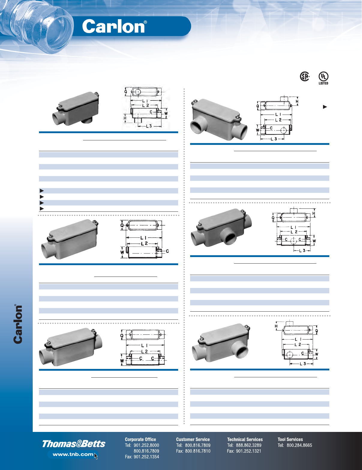
Conduit Bodies
F-48
Non-Metallic Rigid Conduit, Fittings and Accessories
Type LB
Type E
VOL.
SIZE STD. DIMENSIONS (IN.) CU.
CAT. NO.
(IN.) CTN. C L1 L2 Q W IN.
E988D 1⁄225 11⁄16 45⁄16 31⁄2111⁄32 11⁄24.0
E988E 3⁄420 29⁄32 611⁄32 59⁄32 13⁄421⁄32 12.0
E988F 110
29⁄32 611⁄32 59⁄32 13⁄421⁄32 12.0
E988G 11⁄410 13⁄32 86
13⁄32 21⁄223⁄432.0
E988H 11⁄210 13⁄32 86
13⁄32 21⁄223⁄432.0
E988J 251
5⁄32 915⁄32 813⁄32 35⁄32 315⁄32 63.0
Type LR
DIMENSIONS (IN.) VOL.
SIZE STD. TYPICAL MAX. TYPICAL MAX. MAX. MAX. CU.
CAT. NO.
(IN.) CTN. C L1 L2 L3 H Q W IN.
E985D-CAR 1⁄210 11⁄16 45⁄16 37⁄32 31⁄16 15⁄16 111⁄32 11⁄24.0
E985E-CAR 3⁄410 29⁄32 69⁄32 59⁄32 425⁄32 125⁄32 13⁄421⁄32 12.0
E985F 110 29⁄32 69⁄32 59⁄32 425⁄32 125⁄32 13⁄421⁄32 12.0
E985G 11⁄410 13⁄32 731⁄32 613⁄32 62
5⁄16 21⁄223⁄432.0
E985H-CAR 11⁄251
3⁄32 731⁄32 613⁄32 62
5⁄16 21⁄223⁄432.0
E985J 2101
5⁄32 99⁄32 813⁄32 71⁄429⁄16 35⁄32 315⁄32 63.0
Type T
DIMENSIONS (IN.) VOL.
SIZE STD. TYPICAL MAX. TYPICAL MAX. MAX. MAX. CU.
CAT. NO.
(IN.) CTN. C L1 L2 L3 H Q W IN.
E983D-CAR 1⁄210 11⁄16 411⁄16 37⁄32 211⁄32 15⁄16 111⁄32 11⁄24.0
E983E 3⁄415 29⁄32 67⁄859⁄32 47⁄16 125⁄32 13⁄421⁄32 12.0
E983F 120 29⁄32 67⁄859⁄32 37⁄16 125⁄32 13⁄421⁄32 12.0
E983G 11⁄410 13⁄32 821⁄32 613⁄32 421⁄64 25⁄16 21⁄223⁄432.0
E983H 11⁄210 13⁄32 821⁄32 613⁄32 421⁄64 25⁄16 21⁄223⁄432.0
E983J 2101
5⁄32 105⁄16 813⁄32 55⁄32 29⁄16 35⁄32 315⁄16 63.0
Type C
DIMENSIONS (IN.) VOL.
SIZE STD. TYPICAL MAX. TYPICAL MAX. MAX. CU.
CAT. NO.
(IN.) CTN. C L1 L2 Q W IN.
E987D 1⁄225 11⁄16 411⁄16 31⁄2111⁄32 11⁄24.0
E987E-CAR 3⁄410 29⁄32 67⁄8532⁄64 13⁄421⁄32 12.0
E987F-CAR 110
29⁄32 67⁄859⁄32 13⁄421⁄32 12.0
E987G 11⁄410 13⁄32 821⁄32 613⁄32 21⁄223⁄432.0
E987H 11⁄210 13⁄32 821⁄32 613⁄32 21⁄223⁄432.0
E987J 2151
5⁄32 105⁄16 813⁄32 35⁄32 315⁄32 63.0
Feature unthreaded hubs and textured lids with foam-in-place gaskets.
Conduit Bodies
Type LL
DIMENSIONS (IN.) VOL.
SIZE STD. TYPICAL MAX. TYPICAL MAX. MAX. MAX. CU.
CAT. NO.
(IN.) CTN. C L1 L2 L3 H Q W IN.
E984D-CAR 1⁄210 11⁄16 45⁄16 37⁄32 31⁄16 15⁄16 111⁄32 11⁄24.0
E984E 3⁄420 29⁄32 69⁄32 59⁄32 425⁄32 125⁄32 13⁄421⁄32 12.0
E984F-CAR 110 29⁄32 69⁄32 59⁄32 425⁄32 125⁄32 13⁄421⁄32 12.0
E984G-CAR 11⁄451
3⁄32 731⁄32 613⁄32 62
5⁄16 21⁄223⁄432.0
E984H 11⁄210 13⁄32 731⁄32 613⁄32 62
5⁄16 21⁄223⁄432.0
E984J 2101
5⁄32 99⁄32 813⁄32 71⁄429⁄16 35⁄32 315⁄32 63.0
DIMENSIONS (IN.) VOL.
SIZE STD. TYPICAL MAX. TYPICAL MAX. MAX. MAX. CU.
CAT. NO.
(IN.) CTN. C L1 L2 L3 H Q W IN.
E986D 1⁄225 11⁄16 45⁄16 37⁄32 31⁄16 15⁄16 111⁄32 11⁄24.0
E986E 3⁄415 29⁄32 69⁄32 59⁄32 425⁄32 125⁄32 13⁄421⁄32 12.0
E986F 110
29⁄32 69⁄32 59⁄32 425⁄32 125⁄32 13⁄421⁄32 12.0
E986G 11⁄410 13⁄32 731⁄32 613⁄32 62
5⁄16 21⁄223⁄432.0
E986H 11⁄210 13⁄32 731⁄32 613⁄32 62
5⁄16 21⁄223⁄432.0
E986J 2101
5⁄32 931⁄32 813⁄32 71⁄429⁄16 35⁄32 315⁄32 63.0
E986K 21⁄241
5⁄8147⁄8131⁄41131⁄32 33⁄4411⁄32 45⁄8210.
E986L 341
5⁄8147⁄8131⁄41131⁄32 33⁄4411⁄32 45⁄8210.
E986M 31⁄241
25⁄32 1723⁄32 157⁄81417⁄64 47⁄16 511⁄32 521⁄32 390.
E986N 441
25⁄32 1723⁄32 157⁄81417⁄64 47⁄16 511⁄32 521⁄32 390.
LR31146 E11461
Except
where
noted
by
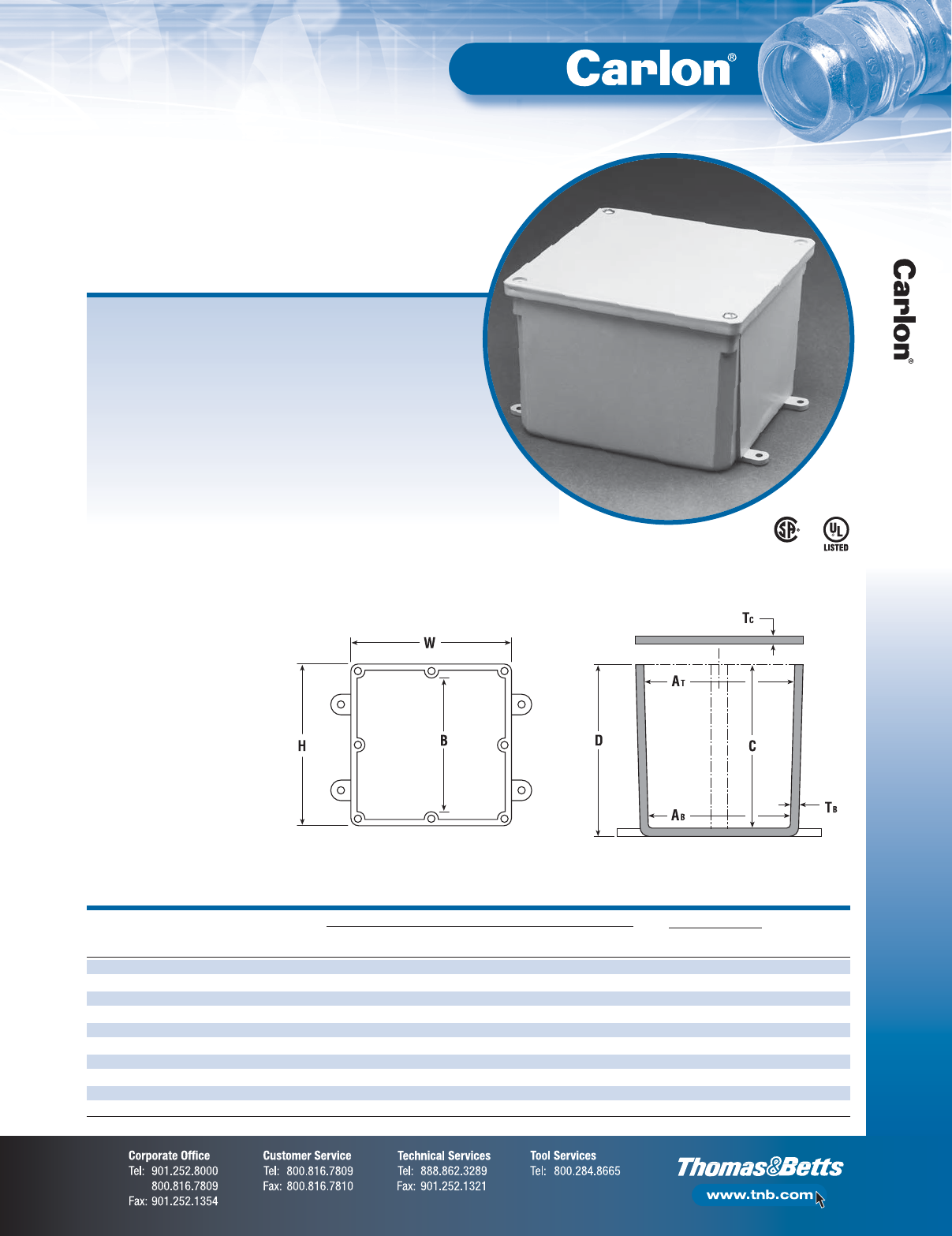
F-49
Non-Metallic Rigid Conduit, Fittings and Accessories
Junction Boxes
SIZE DIMENSIONS (IN.) MATERIAL STD.
(IN.) STD. MIN. MIN. MIN. MIN. THERMO- WT.
CAT. NO.
H X W X D CTN. ATABBCT
BTCPVC PLASTIC (LBS.)
E989NNJ* 4 x 4 x 2 10 311⁄16 35⁄8N/A 2 .160 .155 X 3
E987N* 4 x 4 x 4 10 311⁄16 31⁄2N/A 4 .160 .155 X 4
E989NNR* 4 x 4 x 6 10 311⁄16 33⁄8N/A 6 .160 .200 X 5
E989PPJ* 5 x 5 x 2 10 411⁄16 41⁄2N/A 2 .110 .150 X 3
E987R-CAR* 6 x 6 x 4 2 6 55⁄8N/A 4 .190 .190 X 3
E989RRR-UPC* 6 x 6 x 6 8 55⁄853⁄8N/A 6 .160 .150 X 14
E989N-CAR 8 x 8 x 4 1 8 8 N/A 4 .185 .190 X 2
E989SSX-UPC 8 x 8 x 7 2 721⁄32 75⁄16 N/A 7 .160 .150 X 6
E989UUN 12 x 12 x 4 3 115⁄8111⁄2111⁄84 .160 .150 X 12
E989R-UPC 12 x 12 x 6 2 1115⁄16 117⁄8117⁄16 6 .265 .185 X 10
Non-metallic junction boxes are UL Listed with a NEMA 6P rating per
Section 314.29, Exception of the National Electrical Code®and CSA
Certified per Section 12 of the Canadian Electrical Code. Manufactured
from PVC or PPO thermoplastic molding compound and featuring foam-
in-place gasketed lids attached with stainless steel screws, these rugged
enclosures offer all the corrosion resistance and physical properties
you need for direct burial applications.
Type 6P enclosures are intended for indoor or outdoor use, primarily to
provide a degree of protection against contact with enclosed equipment,
falling dirt, hose-directed water, entry of water during prolonged
submersion at a limited depth and external ice formation.
•All Carlon®Junction Boxes are UL Listed/CSA Certified
and maintain a minimum of a NEMA Type 4/4x Rating
•Part numbers with an asterisk (*) are UL Listed and
maintain a NEMA Type 6P Rating and Type 4/4X Rating
Molded Non-Metallic Junction
Boxes — 6P Rated
†
E11461
Except
where
noted
by
†
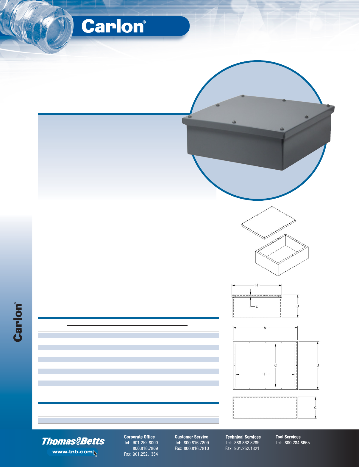
Junction Boxes
F-50
Non-Metallic Rigid Conduit, Fittings and Accessories
DIMENSIONS (IN.) STD. WT.
CAT. NO.
A B C D E F G H (LBS.)
EP12128 12 12 8 8.25 1.00 10.5 10.5 12.75 11
EP181812 18 18 12 12.25 1.00 16 16 18.75 21
EP201808 20 18 8 8.25 1.00 18 16 18.75 20
EP202008 20 20 8 8.25 1.00 18 18 20.75 22
EP241808 24 18 8 8.25 1.00 22 16 18.75 24
EP242008 24 20 8 8.25 1.00 21.5 17.5 20.75 25
EP242408 24 24 8 8.25 1.00 21.5 21.5 24.75 29
EP302408 30 24 8 8.25 1.00 27.5 21.5 24.75 34
EP362408 36 24 8 8.25 1.00 33.5 21.5 24.75 39
Large PVC Junction Boxes are fabricated from Type II PVC sheet.
Reduce the use of steel boxes and keep your wiring connections clean,
safe and dry using these high-quality, fully gasketed junction boxes.
Features and Benefits:
•PVC Type II material with “Uni-Body” construction
and penetration welding providing a very strong,
durable enclosure
•UL-94V-0 flame rating
•Suitable for exposure of up to 90°C
•PVC material enables the use of standard solvent
cements for fitting attachment
•Junction boxes are available with or without
mounting flanges
•Individual mounting feet are available and provided
in kits of four
•Custom features such as windows or panel mounts
are available
•Custom sizes are also available upon request
•Made in the USA
Large PVC Junction Boxes/
NEMA 4X
STD. WT.
CAT. NO.
DESCRIPTION (LBS.)
ESMFK-1 “CleverMount” Mounting Feet (4 Feet and Fasteners) 5
Accessories
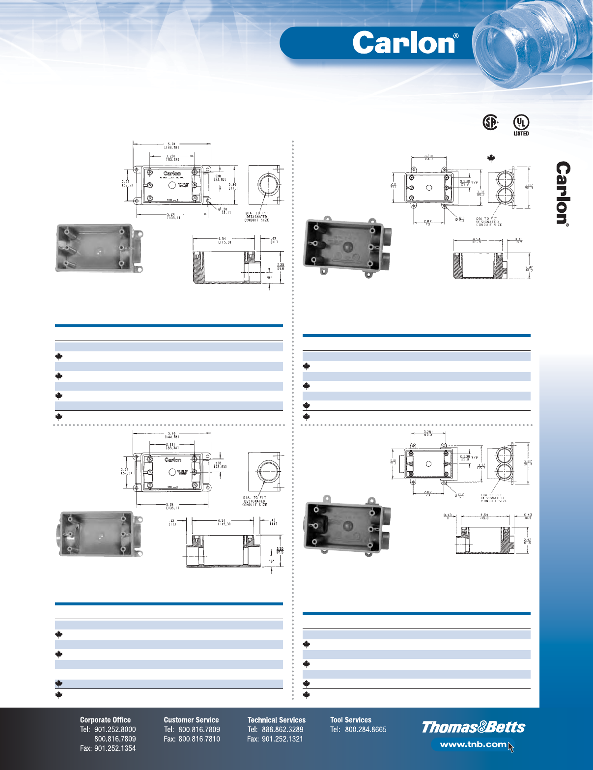
F-51
Non-Metallic Rigid Conduit, Fittings and Accessories
Switch Boxes
CAT. NO.
SIZE (IN.) VOL. CU. IN. STD. CTN.
E980DFN 1⁄219 10
C980DFN-CTN 1⁄218 12
E980EFN 3⁄419 10
C980EFN-CTN 3⁄418 12
E980FFN 11918
C980FFN-CTN 1188
E980FFN-CAR 11910
Canada Only
Type FSE
•For dead-end terminations
•All sizes take standard covers and accessories or devices
•Integral mounting feet provide easy mounting
Single-Gang FS Boxes
CAT. NO.
SIZE (IN.) VOL. CU. IN. STD. CTN.
E981DFN 1⁄219 15
C981DFN-CTN 1⁄218 12
E981EFN 3⁄419 15
C981EFN-CTN 3⁄418 12
E981FFN 11918
E981FFN-CAR 11910
C981FFN-CTN 1188
Canada Only
Type FSC
•For through terminations
•All sizes take standard covers and accessories or devices
•Detachable mounting feet provide easy mounting
CAT. NO.
SIZE (IN.) VOL. CU. IN. STD. CTN.
E982DFN 1⁄219 10
C982DFN-CTN 1⁄218 12
E982EFN 3⁄419 10
C982EFN-CTN 3⁄418 12
E982FFN 11910
C982FFN-CTN 1188
Canada Only
Type FSS
•For multiple dead-end circuit terminations or where additional
support is required in stub-up applications
•All sizes take standard covers and accessories or devices
•Detachable mounting feet provide easy mounting
CAT. NO.
SIZE (IN.) VOL. CU. IN. STD. CTN.
E979DFN-CAR 1⁄219 10
C979DFN 1⁄218 15
E979EFN-CAR 3⁄419 10
C979EFN 3⁄418 15
E979FFN 11915
C979FFN 11815
Canada Only
Type FSCC
•For multiple through-circuit terminations or where additional
support is required in stub-up applications
•All sizes take standard covers and accessories or devices
•Detachable mounting feet provide easy mounting
LR31146 E11461
Where
noted
by
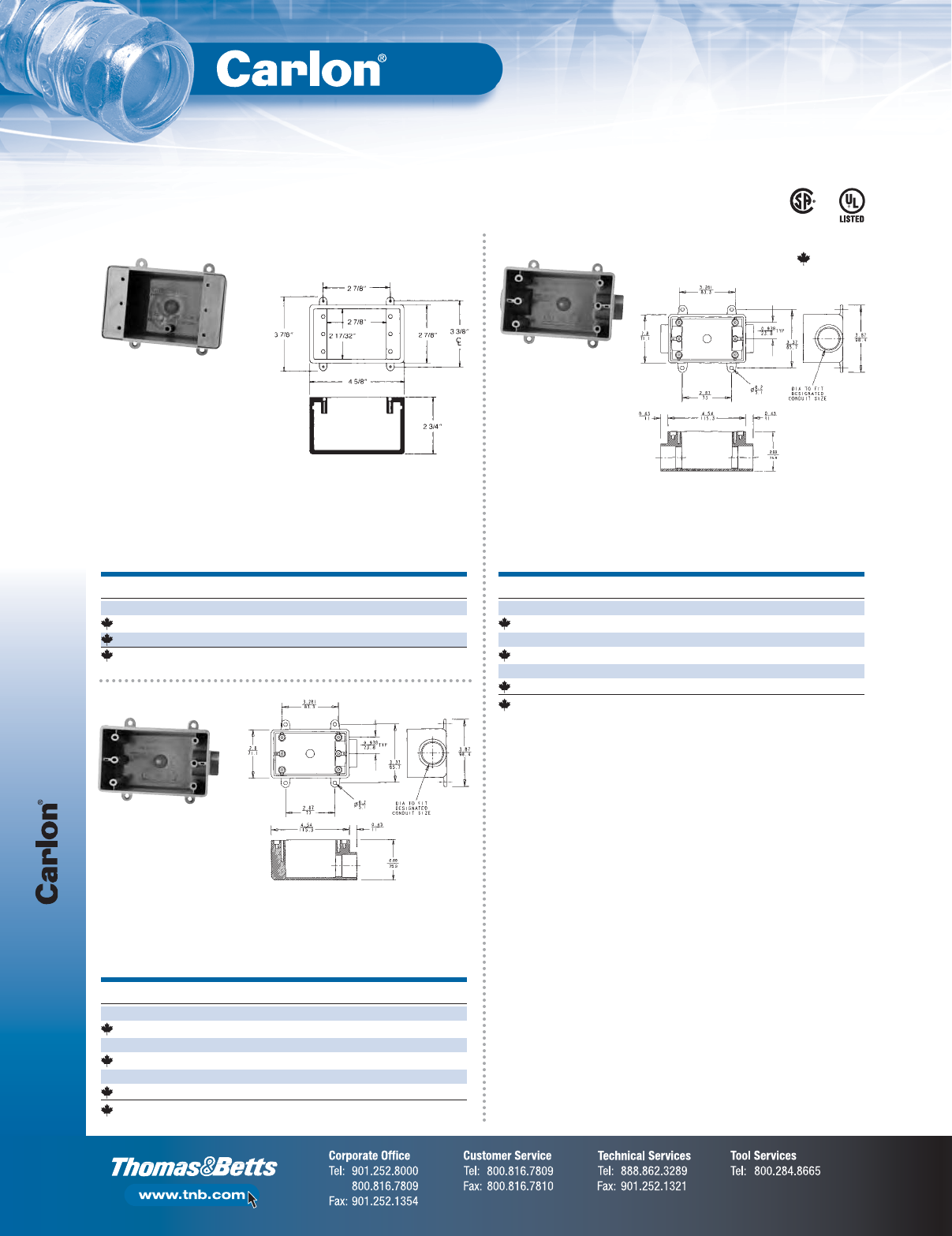
Switch Boxes
F-52
Non-Metallic Rigid Conduit, Fittings and Accessories
Single-Gang FD Deep Device Boxes
CAT. NO.
SIZE (IN.) VOL. CU. IN. STD. CTN.
E9801 N/A 25 10
CE9801-CTN N/A 25 10
C9801-347 N/A 25 10
Canada Only
•For terminations where hub requirements vary according to
application — hubs easily made with flared wood bit or hole saw
•All sizes take standard covers and accessories or devices
•Integral mounting feet provide easy mounting
CAT. NO.
SIZE (IN.) VOL. CU. IN. STD. CTN.
E9811DN 1⁄225 10
C9811DN 1⁄225 10
E9811EN 3⁄425 10
C9811EN 3⁄425 10
E9811FN 12510
C9811FN 12510
Canada Only
•For through terminations where large devices or additional
wiring capacity is required
•All sizes take standard covers and accessories or devices
•Integral mounting feet provide easy mounting
CAT. NO.
SIZE (IN.) VOL. CU. IN. STD. CTN.
E9801DN 1⁄225 10
C9801DN 1⁄225 10
E9801EN 3⁄425 10
C9801EN 3⁄425 10
E9801FN 12510
C9801FN 12510
Canada Only
•For dead-end terminations where large devices or additional
wiring capacity is required
•All sizes take standard covers and accessories or devices
•Integral mounting feet provide easy mounting
Type FD
Type FDE
Type FDC
LR31146 E11461
Where
noted
by
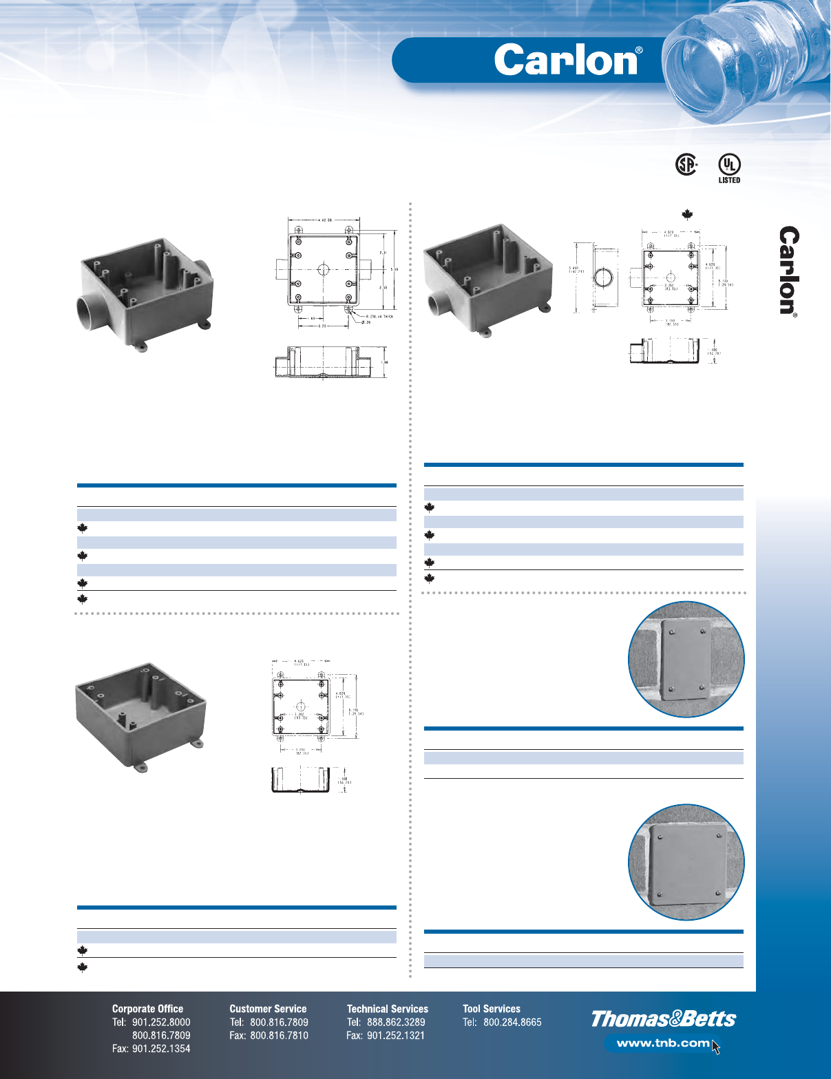
F-53
Non-Metallic Rigid Conduit, Fittings and Accessories
Switch Boxes
Two-Gang FS Boxes
CAT. NO.
SIZE (IN.) VOL. CU. IN. STD. CTN.
E9812D 1⁄232 10
CE9812D-CTN 1⁄232 10
E9812E 3⁄432 10
CE9812E-CTN 3⁄432 10
E9812F 13210
C9812F 13210
Canada Only
•For through terminations where two devices or additional
wiring capacity is required
•All sizes take standard covers and accessories or devices
•Integral mounting feet provide easy mounting
CAT. NO.
SIZE (IN.) VOL. CU. IN. STD. CTN.
E9802 N/A 32 10
CE9802 N/A 32 10
Canada Only
•For terminations where hub requirements vary according to
application — hubs easily made with flared wood bit or hole saw
•All sizes take standard covers and accessories or devices
•Integral mounting feet provide easy mounting
CAT. NO.
COLOR STD. CTN. STD. WT. (LBS.)
E980CN-CAR Gray 12 1.60
E980CM-CAR White 12 1.60
•Fits Carlon®single-gang
FS boxes
•Supplied with stainless steel
mounting screws and gasket
CAT. NO.
COLOR STD. CTN. STD. WT. (LBS.)
E9802CN-CAR Gray 10 2.17
•Fits Carlon®two-gang FS boxes,
other non-metallic and metallic
FS boxes
•Supplied with stainless steel
mounting screws and gasket
CAT. NO.
SIZE (IN.) VOL. CU. IN. STD. CTN.
E9802D 1⁄232 10
CE9802D-CTN 1⁄232 10
E9802E 3⁄432 10
CE9802E-CTN 3⁄432 10
E9802F 13210
C9802F 1321
Canada Only
•For dead-end terminations where two devices or additional
wiring capacity is required
•All sizes take standard covers and accessories or devices
•Integral mounting feet provide easy mounting
Type 2FSC
Type FS
Type 2FSE
Blank Covers
Single-Gang
Two-Gang
LR31146 E11461
Where
noted
by
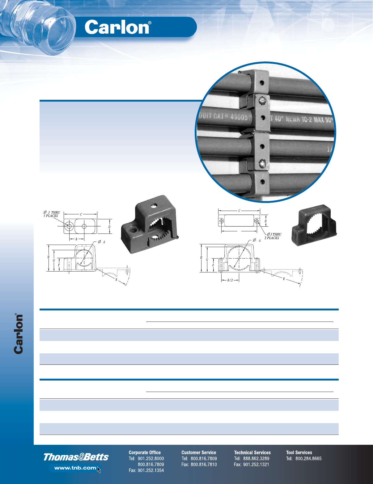
Support Straps
F-54
Non-Metallic Rigid Conduit, Fittings and Accessories
Carlon’s Snap Strap™offers a unique support strap designed especially
for the installation of PVC conduit. Also usable for installations of rigid
steel. This high-strength, non-metallic clamp enables conduit to expand
and contract freely, eliminating the bowing commonly seen from the
expansion and contraction of conduit caused by varying temperature
changes. Finished installations have a neat, attractive appearance
on exposed applications.
To be used in accordance with conduit spacing requirements per the
NEC®, Section 352.30 and 12-1114 of the CEC. This part is not
supplied with screws.
•UV inhibited for use in direct sunlight
Snap Strap™Conduit
Support Straps
Single Mount
SIZE
IN. STD. STD. WT. DIMENSIONS IN. (MM)
CAT. NO.
(MM) CTN. (LBS.) A B C D F G H J R
E978DC-CAR 1⁄240 1 0.80 .75 1.63 0.75 .68 1.08 1.36 .21 1.67
(16) (20.3) (1.90) (41.4) (19.1) (14.9) (25.1) (34.5) (5.33) (42.4)
E978EC-CAR 3⁄440 3 1.00 .88 1.92 0.75 .79 1.29 1.58 .21 1.96
(21) (25.4) (22.4) (48.7) (19.1) (17.8) (30.4) (39.9) (5.33) (49.8)
E978FC-CAR 1 30 4 1.20 1.02 2.17 0.75 .92 1.54 1.84 .21 2.22
(27) (30.5) (25.9) (55.1) (19.1) (21.1) (36.3) (46.7) (5.33) (56.3)
Double Mount
SIZE
IN. STD. STD. WT. DIMENSIONS IN. (MM)
CAT. NO.
(MM) CTN. (LBS.) A B C D F G H J R
E978GC-CAR 11⁄415 4 1.66 2.75 3.23 1.00 1.07 1.90 2.15 .218 3.28
(35) (42.16) (69.9) (82.0) (25.4) (24.1) (45.2) (54.61) (5.54) (83.3)
E978HC-CAR 11⁄215 5 1.92 3.05 3.53 1.00 1.20 2.16 2.40 .218 3.58
(41) (48.77) (77.5) (89.7) (25.4) (27.4) (51.8) (60.96) (5.54) (90.9)
E978JC-CAR 2 10 5 2.34 3.50 4.00 1.00 1.43 2.59 2.86 .218 4.06
(53) (59.44) (88.9) (101.6) (25.4) (33.3) (63.0) (72.64) (5.54) (103.1)
Single Mount Double Mount
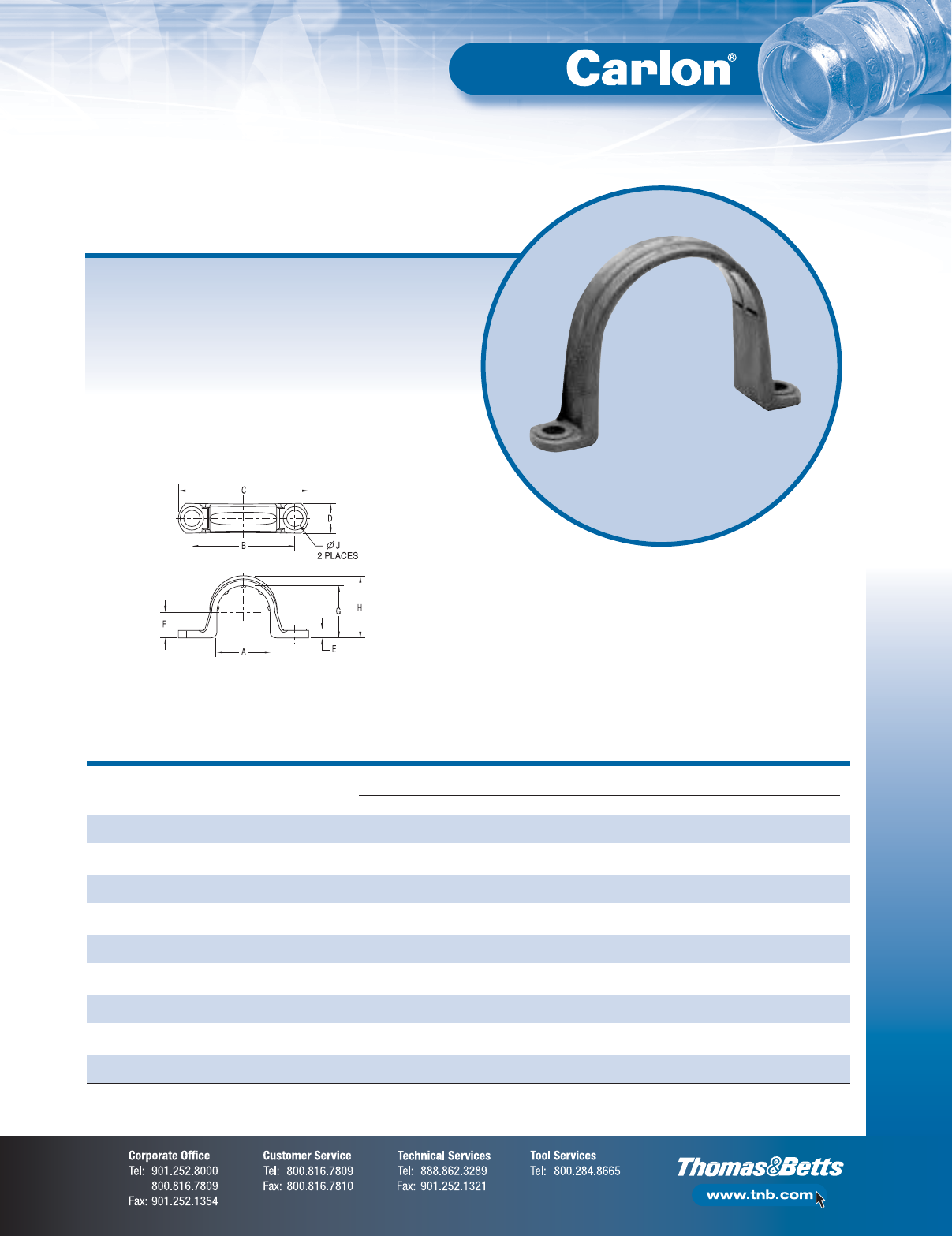
F-55
Non-Metallic Rigid Conduit, Fittings and Accessories
Clamps
Non-metallic clamps offer the same chemical resistance as Carlon®
non-metallic conduits for a complete, corrosion-resistant system.
To be used in accordance with conduit spacing requirements
per the NEC®, Section 352.30 and 12-1114 of the CEC.
•UV inhibited for use in direct sunlight
Non-Metallic Clamps
Conduit Clamps
SIZE
IN. STD. STD. WT. DIMENSIONS IN. (MM)
CAT. NO.
(MM) CTN. (LBS.) A B C D E F G H J
E977DC 1⁄2100 1.2 0.892 1.71 2.16 0.50 .14 .42 .866 1.04 .260
(16) (22.6) (43.4) (54.8) (12.7) (3.5) (10.6) (21.9) (26.4) (6.6)
E977EC 3⁄4100 1.4 1.102 1.97 2.40 0.50 .14 .525 1.076 1.255 .260
(21) (27.9) (50.0) (60.9) (12.7) (3.5) (13.3) (27.3) (31.8) (6.6)
E977FC 1 100 2 1.39 2.25 2.81 0.594 .14 .658 1.342 1.574 .260
(27) (35.3) (57.1) (71.3) (15.0) (3.5) (16.7) (34.0) (39.9) (6.6)
E977GC 11⁄450 5 1.714 2.68 3.28 .64 .15 .83 1.687 1.89 .320
(35) (43.5) (68.0) (83.3) (16.2) (3.8) (21.0) (42.8) (48.0) (8.1)
E977HC 11⁄250 6 1.92 2.82 3.44 .70 .15 .97 1.93 2.12 .312
(41) (48.7) (71.6) (87.3) (17.7) (3.8) (24.6) (49.0) (53.8) (7.9)
E977JC 2 25 4.5 2.54 3.54 4.18 .76 .16 1.05 2.29 2.49 .315
(53) (64.5) (89.9) (106.1) (19.3) (4.0) (26.6) (58.1) (63.2) (8.0)
E977KC-CAR 21⁄225 1.4 2.86 4.50 5.46 1.00 .20 1.43 2.86 3.12 .36
(63) (72.6) (114.3) (138.7) (25.4) (5.08) (36.3) (72.6) (79.2) (9.14)
E977LC-CAR 3 20 1.4 3.47 5.00 6.00 1.00 .20 1.74 3.48 3.70 .36
(78) (88.2) (127.0) (152.4) (25.4) (5.08) (44.3) (88.4) (94.0) (9.14)
E977NC-CAR 4 15 12.2 4.366 6.15 7.20 1.00 .20 2.32 4.50 4.70 .36
(103) (110.9) (156.2) (182.9) (25.4) (5.08) (58.8) (114.3) (119.4) (9.14)
*NOTE: Some clamp applications require 2 screws, 2 nuts and 2 washers.
Conduit Clamp
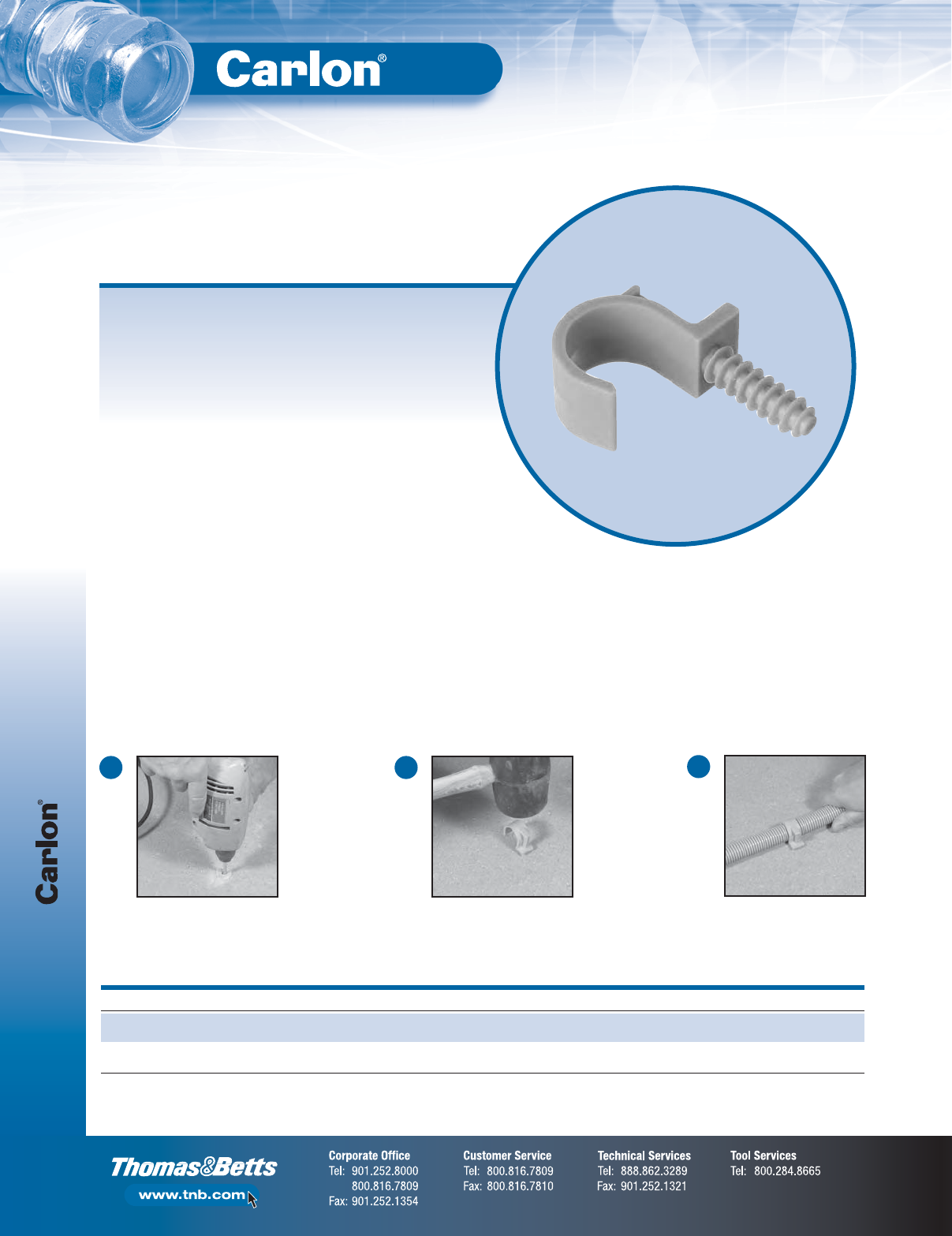
Clamps
F-56
Non-Metallic Rigid Conduit, Fittings and Accessories
Carlon®Masonry Pipe Clamps make installations faster and easier by
eliminating the use of bolts and anchors. The one-piece design features
an anchoring projection designed to push into a 5⁄16" drill hole.
The clamps are used to securely support pipe/conduit and electrical
cables on concrete and masonry block, and unlike metallic clamps
Carlon®Masonry Clamps won’t rust or corrode.
Carlon®Masonry Pipe Clamps are available in sizes 1⁄2" and 3⁄4" and are
ideal for commercial applications such as schools, hospitals, airports,
condominiums, hotels, airports, office buildings and casinos.
Features
•One-piece design
•Material: Nylon PA6
•Color: Gray
•Flame resistance: V2
•Anchor length: 1.2" threaded
•Drill hole: 5⁄16"
Carlon®Masonry Pipe Clamps
Installation:
CAT. NO.
SIZE (IN.) STD. CTN. STD. WT. (LBS.)
E977NDC-CTN 1⁄212 1.2
(Equals 12 bags of 5 Clamps)
E977NEC-CTN 3⁄412 1.3
(Equals 12 bags of 5 Clamps)
Using a 5⁄16" masonry drill bit,
drill a hole into the concrete.
1
Tap clamp with hammer until
fully inserted.
2
Hang desired conduit onto
the clamp.
3

F-57
Non-Metallic Rigid Conduit, Fittings and Accessories
Technical Specifications
Corrosion Resistance of Carlon®Schedule 40
and Schedule 80 Fittings
Carlon Schedule 40 and Schedule 80 Fittings are generally acceptable for
use in environments containing the chemicals below. These environmental-
resistance ratings are based upon tests where the specimens were placed in
complete submergence in the reagent listed. Schedule 40 and Schedule 80
Fittings can be used in many process areas where chemicals not on this list
are manufactured or used because worker safety requirements
dictate that any air presence or splashing be at a very low level.
If there are any questions about specific suitability in a given
environment, prototype samples should be tested under
actual conditions.
Acetic Acid O-20%
Acetic Acid 20-30%
Acetic Acid 3O-60%
Acetic Acid 80%
Acetic Acid – Glacial
Acetic Acid Vapors
Acetylene
Adipic Acid
Alum
Aluminum Chloride
Aluminum Fluoride
Aluminum Hydroxide
Aluminum Oxychloride
Aluminum Nitrate
Aluminum Sulfate
Ammonia-Dry Gas
Ammonium Bifluoride
Ammonium Carbonate
Ammonium Chloride
Ammonium Hydroxide 28%
Ammonium Metaphosphate
Ammonium Nitrate
Ammonium Persulfate
Ammonium Phosphate –
Neutral
Ammonium Sulfate
Ammonium Sulfide
Ammonium Thiocyanate
Amyl Alcohol
Anthraquinone
Anthraquinonesulfonic Acid
Antimony Trichloride
Aqua Regia
Arsenic Acid 80%
Arylsulfonic Acid
Barium Carbonate
Barium Chloride
Barium Hydroxide
Barium Sulfate
Barium Sulfide
Beet – Sugar Liquor
Benzine Sulfonic Acid 10%
Benzoic Acid
Bismuth Carbonate
Black Liquor (Paper Industry)
Bleach – 12.5% Active CL2
Borax
Boric Acid
Brine
Breeder Pellets – Dane. Fish
Bromic Acid
Bromine – Water
Butane
Butadiene
Butyl Alcohol
Butyl Phenol
Butylene
Butyric Acid
Calcium Bisulfite
Calcium Carbonate
Calcium Chlorate
Calcium Chloride
Calcium Hydroxide
Calcium Hypochlorite
Calcium Nitrate
Calcium Sulfate
Carbonic Acid
Carbon Dioxide Gas – Wet
Carbon Dioxide – Aqueous
Solution
Carbon Monoxide
Caustic Potash
Caustic Soda
Chloracatic Acid
Chloral Hydrate
Chlorine Gas (Dry)
Chlorine Gas (Moist)
Chlorine Water
Chlorosulfonic Acid
Chrome Alum
Chromic Acid 10%
Chromic Acid 30%
Chromic Acid 40%
Chromic Acid 50%
Citric Acid
Copper Chloride
Copper Cyanide
Copper Fluoride
Copper Nitrate
Copper Sulfate
Cottonseed Oil
Cresylic Acid 50%
Crude Oil – Sour
Crude Oil – Sweet
Demineralized Water
Dextrin
Dextrose
Diglycolic Acid
Disodium Phosphate
Ethyl Alcohol
Ethylene Glycol
Fatty Acids
Ferric Chloride
Ferric Nitrate
Ferric Sulfate
Ferrous Chloride
Ferrous Sulfate
Fluorine Gas – Wet
Fluorine Gas – Dry
Fluoroboric Acid
Fluorosilicic Acid
Formaldehyde
Formic Acid
Fructose
Gallic Acid
Gas – Coke Oven
Gas – Natural (Dry)
Gas – Natural (Wet)
Gasoline – Sour
Gasoline – Refined
Glucose
Glycerine (Glycerol)
Glycol
Glycolic Acid
Green Liquor (Paper Industry)
Heptane
Hexanol, Tertiary
Hydrobromic Acid 20%
Hydrochloric Acid 0% - 25%
Hydrochloric Acid 25% -
40%
Hydrocyanic Acid or
Hydrogen Cyanide
Hydrofluoric Acid 10%
Hydrofluorosilicic Acid
Hydrogen Phosphide
Hydrogen Sulfide – Dry
Hydrogen Sulfide –
Aqueous Solution
Hydroquinone
Hydroxylamine Sulfate
Iodine
Kerosene
Lactic Acid 28%
Lauric Acid
Lauryl Chloride
Lauryl Sulfate
Lead Acetate
Lime Sulfur
Linoleic Acid
Linseed Oil
Lubricating Oils
Magnesium Carbonate
Magnesium Chloride
Magnesium Hydroxide
Magnesium Nitrate
Magnesium Sulfate
Maleic Acid
Malic Acid
Mercuric Chloride
Mercuric Cyanide
Mercurous Nitrate
Mercury
Methyl Sulfate
Methylene Chloride
Mineral Oils
Naphthalene
Nickel Chloride
Nickel Nitrate
Nitric Acid, Anydrous
Nitric Acid 20%
Nitric Acid 40%
Nitric Acid 60%
Nitrobenzene
Nitrous Oxide
Oils and Fats
Oils – Petroleum – (See
Type)
Oleic Acid
Oxalic Acid
Palmitic Acid 10%
Perchloric Acid 10%
Phenylhydrazine
Hydrochloride
Phosgene, Gas
Phosphoric Acid – 0-25%
Phosphoric Acid – 25-50%
Phosphoric Acid – 50-85%
Photographic Chemicals
Plating Solutions
Potassium Bicarbonate
Potassium Bichromate
Potassium Borate
Potassium Bromide
Potassium Carbonate
Potassium Chloride
Potassium Chromate
Potassium Cyanide
Potassium Dichromate
Potassium Ferricyanide
Potassium Ferrocyanide
Potassium Fluoride
Potassium Hydroxide
Potassium Nitrate
Potassium Perborate
Potassium Perchlorite
Potassium Permanganate
10%
Potassium Persulfate
Potassium Sulfate
Propane
Propyl Alcohol
Silicic Acid
Silver Cyanide
Silver Nitrate
Silver Plating Solutions
Sodium Acetate
Sodium Arsenite
Sodium Benzoate
Sodium Bicarbonate
Sodium Bisulfate
Sodium Bisulfite
Sodium Bromide
Sodium Chlorate
Sodium Chloride
Sodium Cyanide
Sodium Dichromate
Sodium Ferricyanide
Sodium Ferrocyanide
Sodium Fluoride
Sodium Hydroxide
Sodium Hypochlorite
Sodium Nitrate
Sodium Nitrite
Sodium Sulfate
Sodium Sulfide
Sodium Sulfite
Sodium Thiosulfate (Hypo)
Stannic Chloride
Stannous Chloride
Stearic Acid
Sulfur
Sulfur Dioxide – Gas Dry
Sulfur Trioxide
Sulfuric Acid – 0-10%
Sulfuric Acid – 10-75%
Sulfuric Acid – 75-90%
Sulfurous Acid
Tannic Acid
Tanning Liquors
Tartaric Acid
Titanium Tetrachloride
Triethanolamine
Trimethyl Propane
Trisodium Phosphate
Turpentine
Urea
Vinegar
Whiskey
White Liquor (Paper Industry)
Wines
Zinc Chloride
Zinc Chromate
Zinc Cyanide
Zinc Nitrate
Zinc Sulfate
CHEMICAL ENVIRONMENT
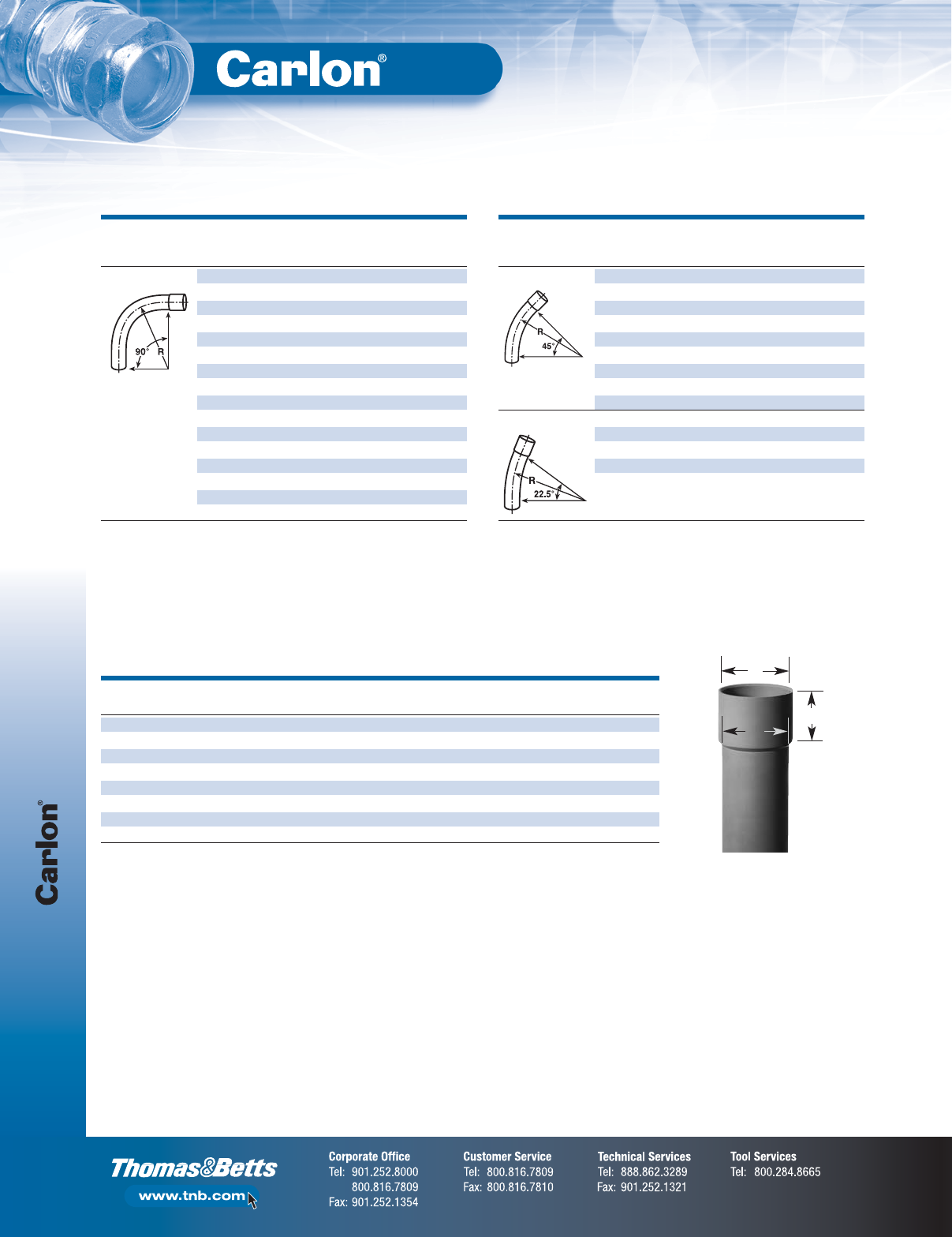
Rigid Non-Metallic Utility Conduit
F-58
Non-Metallic Rigid Conduit, Fittings and Accessories
Deep-Socket Schedule 40 Utility Elbows with Integral Belled Ends
NOM. STD.
DIA. RADIUS STD. WT.
SEGMENT CAT. NO.
(IN.) (IN.) CTN. (LBS.)
90° SWEEP UC9BHB 11⁄212 20 25.00
UC9DHB 11⁄224 1 2.13
UC9FHB 11⁄236 1 3.05
UC9BJB 2 12 1 1.44
UC9DJB 2 24 1 2.82
UC9FJB 2 36 1 4.14
UC9HJB 2 48 1 5.15
UC9DKB 21⁄224 1 5.00
UC9FKB 21⁄236 1 7.15
UC9DLB 3 24 1 6.57
UC9FLB 3 36 1 9.15
UC9DNB 4 24 1 10.59
UC9FNB 4 36 1 13.64
UC9HNB 4 48 1 17.72
UC9FRB 6 36 1 25.80
UC9HRB 6 48 1 32.24
NOM. STD.
DIA. RADIUS STD. WT.
SEGMENT CAT. NO.
(IN.) (IN.) CTN. (LBS.)
45° ELBOW UC7FHB 11⁄236 1 1.74
UC7FJB 2 36 1 2.07
UC7CKB 21⁄218 1 2.27
UC7FKB 21⁄236 1 4.12
UC7FLB 3 36 1 5.00
UC7FNB 4 36 1 8.15
UC7HNB 4 48 1 9.36
UC7HRB 6 48 1 17.19
UC7ITB 8 60 1 33.00
221⁄2° ELBOW UC5CKB 21⁄218 1 1.45
UC5FKB 21⁄236 1 2.49
UC5FNB 4 36 1 5.18
UC5FRB 6 36 1 11.82
UC5HNB 4 48 1 5.57
TRADE A B C
SIZE AT ENTRANCE AT BOTTOM NOMINAL BELL
11⁄21.921 ± .005 1.894 ± .006 25⁄8± 1⁄8
2 2.400 ± .005 2.369 ± .012 23⁄4± 1⁄8
21⁄22.906 ± .005 2.868 ± .007 3 ± 1⁄8
3 3.538± .005 3.492 ± .008 3 ± 1⁄8
4 4.544 ± .005 4.491 ± .009 35⁄8± 1⁄8
5 5.614 ± .005 5.553 ± .010 41⁄8± 1⁄8
6 6.687 ± .005 6.614 ± .011 51⁄8± 1⁄8
8 8.687 ± .005 8.636 ± .005 61⁄8± 1⁄8
Utility Elbow Bells (Dimensions in Inches)
A
B
C
Non-UL Listed
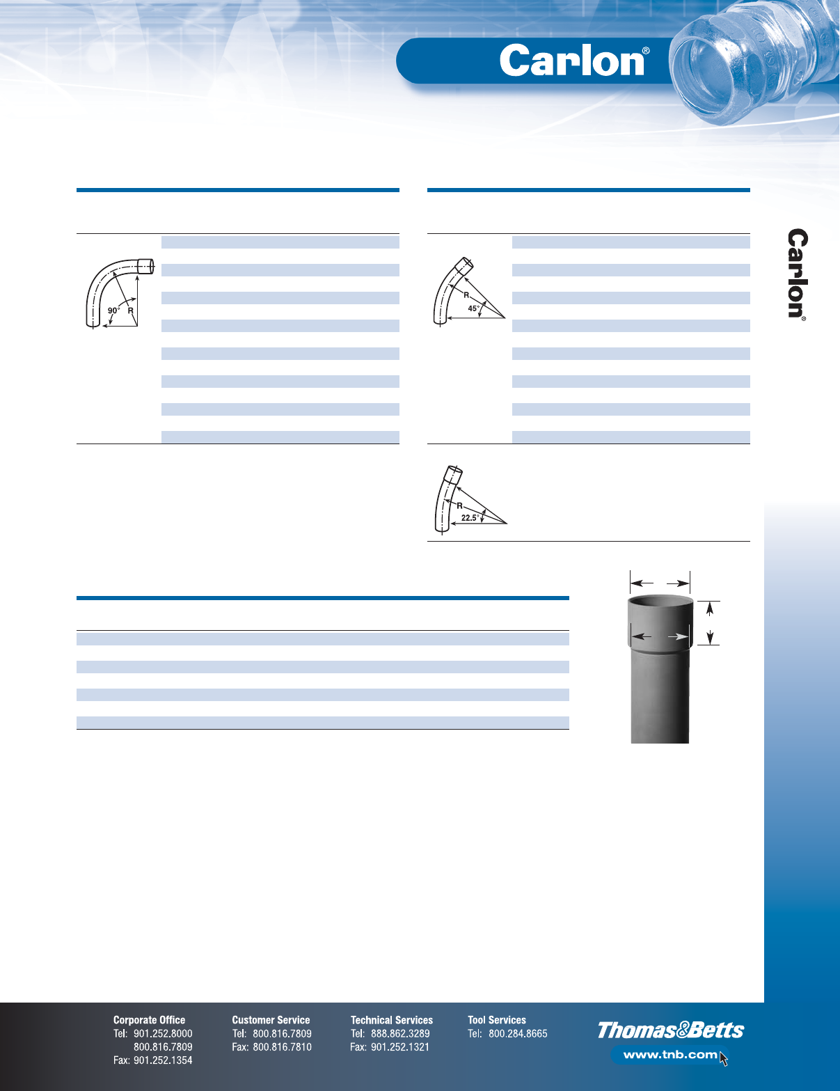
F-59
Non-Metallic Rigid Conduit, Fittings and Accessories
Rigid Non-Metallic Long Belled Utility Conduit
NOM. STD.
DIA. RADIUS STD. WT.
SEGMENT CAT. NO.
(IN.) (IN.) CTN. (LBS.)
45° ELBOW UC7CJBLB 2 18 1 1.3
UC7DJBLB 2 24 1 1.4
UC7DLBLB 3 24 1 5.0
UC7DNBLB 4 24 1 5.8
UC7DPBLB 5 24 1 8.5
UC7FJBLB 2 36 1 2.2
UC7FLBLB 3 36 1 5.2
UC7FNBLB 4 36 1 7.8
UC7FPBLB 5 36 1 11.1
UC7FRBLB 6 36 1 9.6
UC7HJBLB 2 48 1 2.8
UC7HLBLB 3 48 1 6.6
UC7HNBLB 4 48 1 9.7
UC7HPBLB 5 48 1 13.7
UC7HRBLB 6 48 1 18.1
221⁄2° ELBOW UC5FRBLB 6 36 1 9.6
NOM. STD.
DIA. RADIUS STD. WT.
SEGMENT CAT. NO.
(IN.) (IN.) CTN. (LBS.)
90° ELBOW UC9CJBLB 2 18 1 1.3
UC9DJBLB 2 24 1 1.4
UC9DLBLB 3 24 1 5.0
UC9DNBLB 4 24 1 5.8
UC9DPBLB 5 24 1 8.5
UC9FJBLB 2 36 1 2.2
UC9FLBLB 3 36 1 5.2
UC9FNBLB 4 36 1 7.8
UC9FPBLB 5 36 1 11.1
UC9FRBLB 6 36 1 9.6
UC9HJBLB 2 48 1 2.8
UC9HLBLB 3 48 1 12.0
UC9HNBLB 4 48 1 9.7
UC9HPBLB 5 48 1 13.7
UC9HRBLB 6 48 1 18.1
TRADE A B C
SIZE AT ENTRANCE AT BOTTOM NOMINAL BELL
11⁄21.918 ± .006 1.894 ± .006 23⁄4± 1⁄8
2 2.393 ± .006 2.369 ± .012 31⁄4± 1⁄8
21⁄22.890 ± .007 2.868 ± .007 31⁄4± 1⁄8
3 3.515 ± .008 3.492 ± .008 4 ± 1⁄8
4 4.515 ± .009 4.491 ± .009 43⁄4± 1⁄8
5 5.593 ± .010 5.553 ± .010 53⁄4± 1⁄8
6 6.658 ± .011 6.614 ± .011 61⁄4± 1⁄8
Long Belled Utility Elbow Bells (Dimensions in Inches)
A
B
C
Non-UL Listed
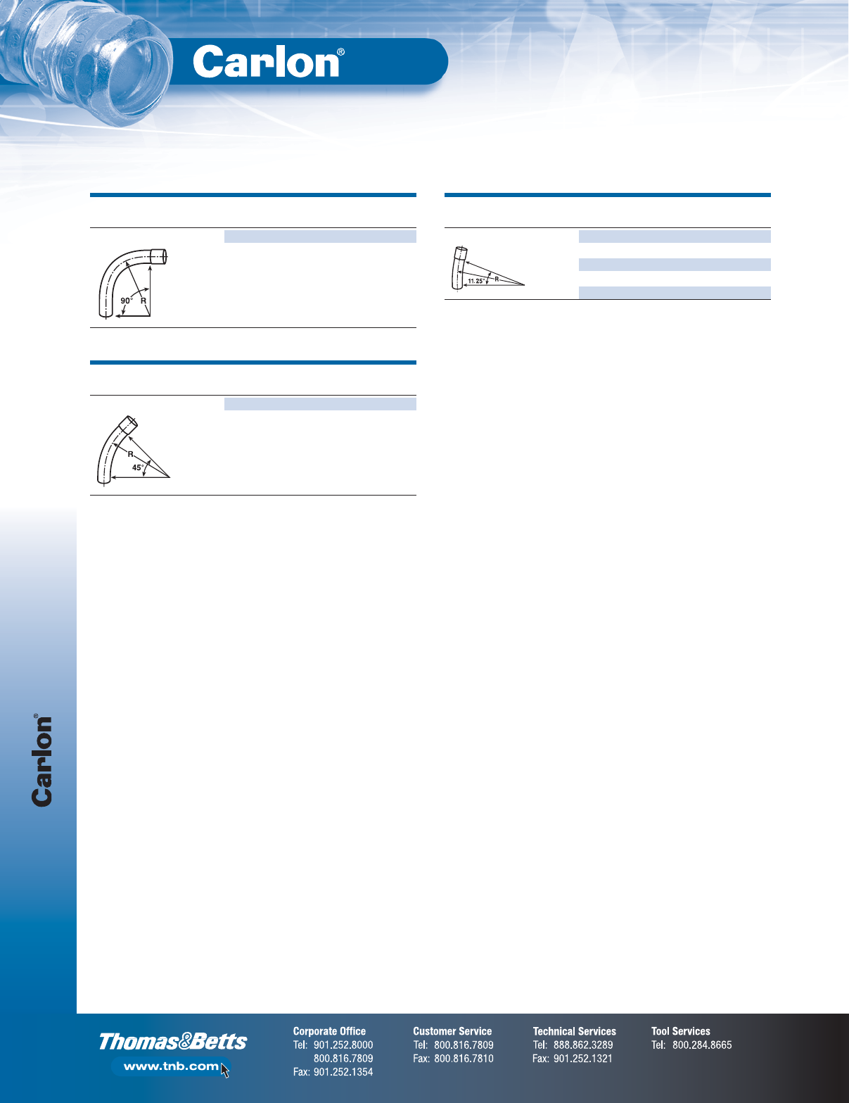
P&C Duct
F-60
Non-Metallic Rigid Conduit, Fittings and Accessories
Special California Type DB-100 Sweeps — Belled
SIZE STD.
CAT. NO.
(IN.) CTN.
90° SWEEP — 48" RADIUS PE9HN 41
PE9HP 51
SIZE STD.
CAT. NO.
(IN.) CTN.
45° SWEEP — 150" RADIUS PE7SP 51
SIZE STD.
CAT. NO.
(IN.) CTN.
111⁄4° SWEEP — 150" RADIUS PE3SP 51
SEGMENTED SWEEPS
PE3SNS 41
PE3SPS 51
PE3SRS 61
*Consult your Thomas & Betts
Sales Team for additional sizes
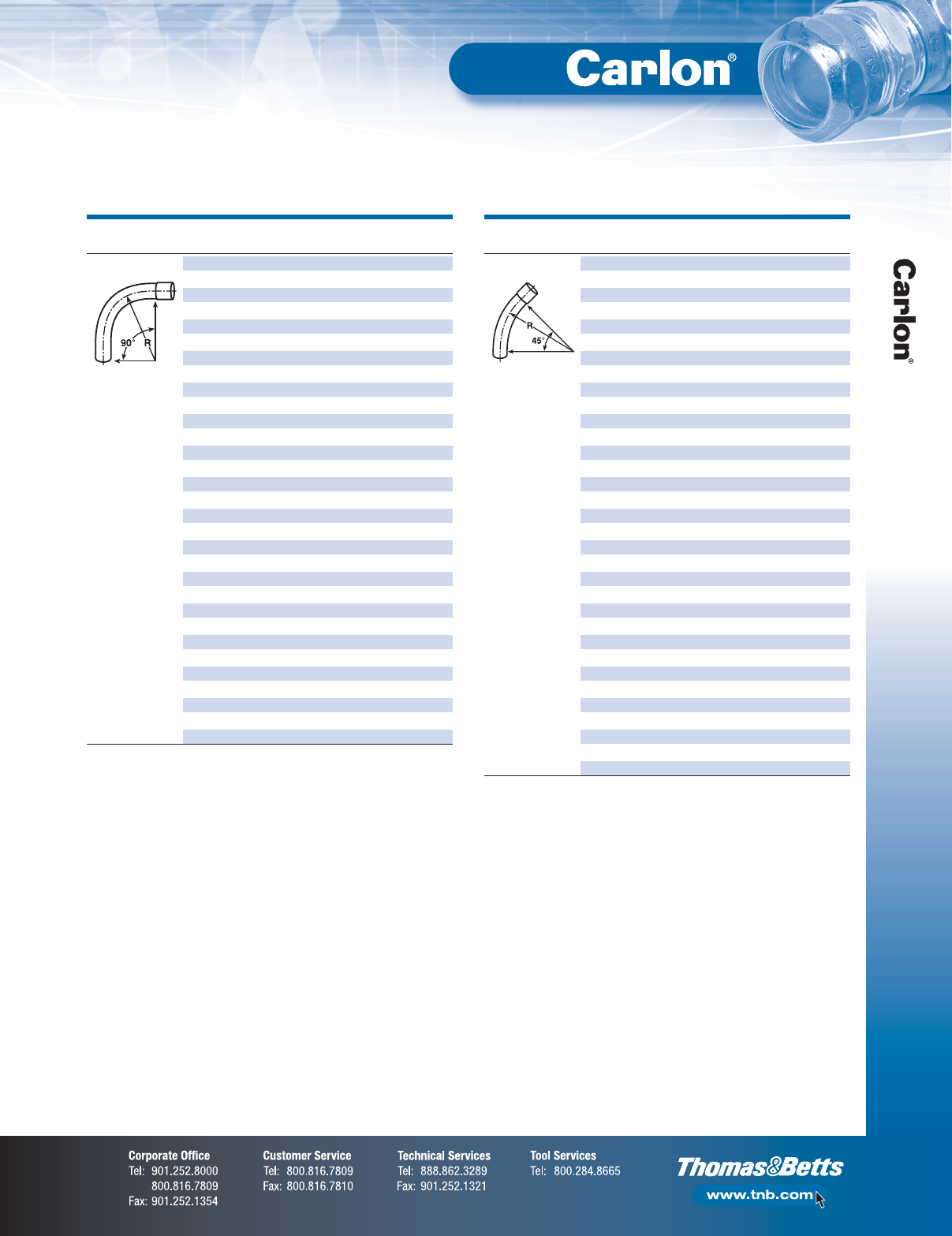
F-61
Non-Metallic Rigid Conduit, Fittings and Accessories
P&C Duct
DB-60 Sweeps
SIZE RADIUS STD.
SEGMENT CAT. NO.
(IN.) (IN.) CTN.
90° SWEEP PF9CH 11⁄218 1
PF9CJ 2181
PF9CL 3181
PF9CN 4181
PF9DF 1241
PF9DH 11⁄224 1
PF9DJ 2241
PF9DL 3241
PF9DN 4241
PF9DP 5241
PF9FF 1361
PF9FJ 2361
PF9FL 3361
PF9FN 4361
PF9FP 5361
PF9FR 6361
PF9HL 3481
PF9HN 4481
PF9HP 5481
PF9HR 6481
PF9IL 3601
PF9IN 4601
PF9IP 5601
PF9IR 6601
PF9SH 11⁄2150 1
PF9SJ 2 150 1
PF9SL 3 150 1
PF9SR 6 150 1
PF9VL 3 300 1
PF9VN 4 300 1
PF9VP 5 300 1
NOTE: Elbows 72" and larger may be shipped in segments. Consult factory for specifics.
SIZE RADIUS STD.
SEGMENT CAT. NO.
(IN.) (IN.) CTN.
45° SWEEP PF7CF 1181
PF7CH 11⁄218 1
PF7CJ 2181
PF7CL 3181
PF7DF 1241
PF7DH 11⁄224 1
PF7DJ 2241
PF7DL 3241
PF7DN 4241
PF7FF 1361
PF7FH 11⁄236 1
PF7FJ 2361
PF7FL 3361
PF7FN 4361
PF7FP 5361
PF7FR 6361
PF7HJ 2481
PF7HL 3481
PF7HN 4481
PF7HP 5481
PF7HR 6481
PF7IL 3601
PF7IP 5601
PF7NN 4 120 1
PF7SH 11⁄2150 1
PF7SJ 2 150 1
PF7SL 3 150 1
PF7SN 4 150 1
PF7SP 5 150 1
PF7SR 6 150 1
PF7VN 4 300 1
PF7VP 5 300 1
PF7VR 6 300 1
NOTE: Elbows 72" and larger may be shipped in segments. Consult factory for specifics.
*Consult your Thomas & Betts
Sales Team for additional sizes
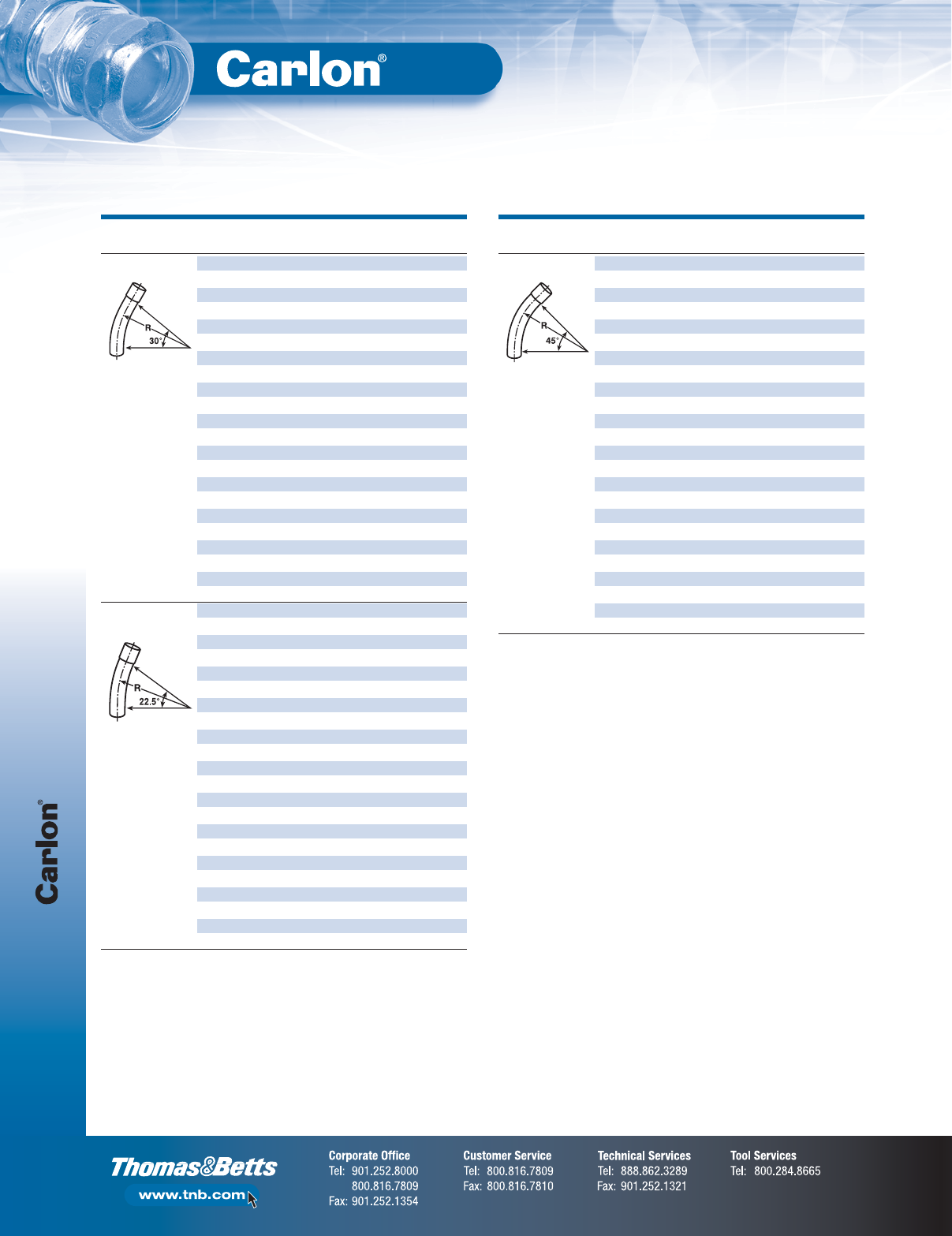
P&C Duct
F-62
Non-Metallic Rigid Conduit, Fittings and Accessories
DB-60 Sweeps
SIZE RADIUS STD.
SEGMENT CAT. NO.
(IN.) (IN.) CTN.
30° SWEEP PF6CJ 2181
PF6CL 3181
PF6DL 3241
PF6DN 4241
PF6DP 5241
PF6CH 11⁄230 1
PF6FJ 2361
PF6FL 3361
PF6FN 4361
PF6FR 6361
PF6HJ 2481
PF6HN 4481
PF6HP 5481
PF6HR 6481
PF6IN 4 60 1
PF6IP 5 60 1
PF6SJ 2 150 1
PF6SN 4 150 1
PF6SP 5 150 1
PF6VJ 2 300 1
PF6VN 4 300 1
PF6VR 6 300 1
221⁄2° SWEEP PH5DL 3241
PF5DN 4241
PF5DP 5241
PF5FF 1361
PF5FL 3361
PF5FN 4361
PF5FP 5361
PF5FR 6361
PF5HL 3481
PF5HN 4481
PF5HR 6481
PF5IJ 2601
PF5IL 3601
PF5IP 5601
PF5IR 6601
PF5SL 3 150 1
PF5SN 4 150 1
PF5SP 5 150 1
PF5SR 6 150 1
PF5VN 4 300 1
PF5VP 5 300 1
PF5VR 6 300 1
NOTE: Elbows 72" and larger may be shipped in segments. Consult factory for specifics.
SIZE RADIUS STD.
SEGMENT CAT. NO.
(IN.) (IN.) CTN.
111⁄4° SWEEP PF3CJ 2181
PF3CL 3181
PF3DF 1241
PF3DH 11⁄224 1
PF3DP 5241
PF3FJ 2361
PF3FL 3361
PF3FN 4361
PF3FP 5361
PF3FR 6361
PF3HL 3481
PF3HN 4481
PF3HP 5481
PF3HR 6481
PF3IJ 2601
PF3IR 6601
PF3SJ 2 150 1
PF3SN 4 150 1
PF3SP 5 150 1
PF3SR 6 150 1
PF3VJ 2 300 1
PF3VL 3 300 1
PF3VN 4 300 1
PF3VP 5 300 1
NOTE: Elbows 72" and larger may be shipped in segments. Consult factory for specifics.
*Consult your Thomas & Betts
Sales Team for additional sizes
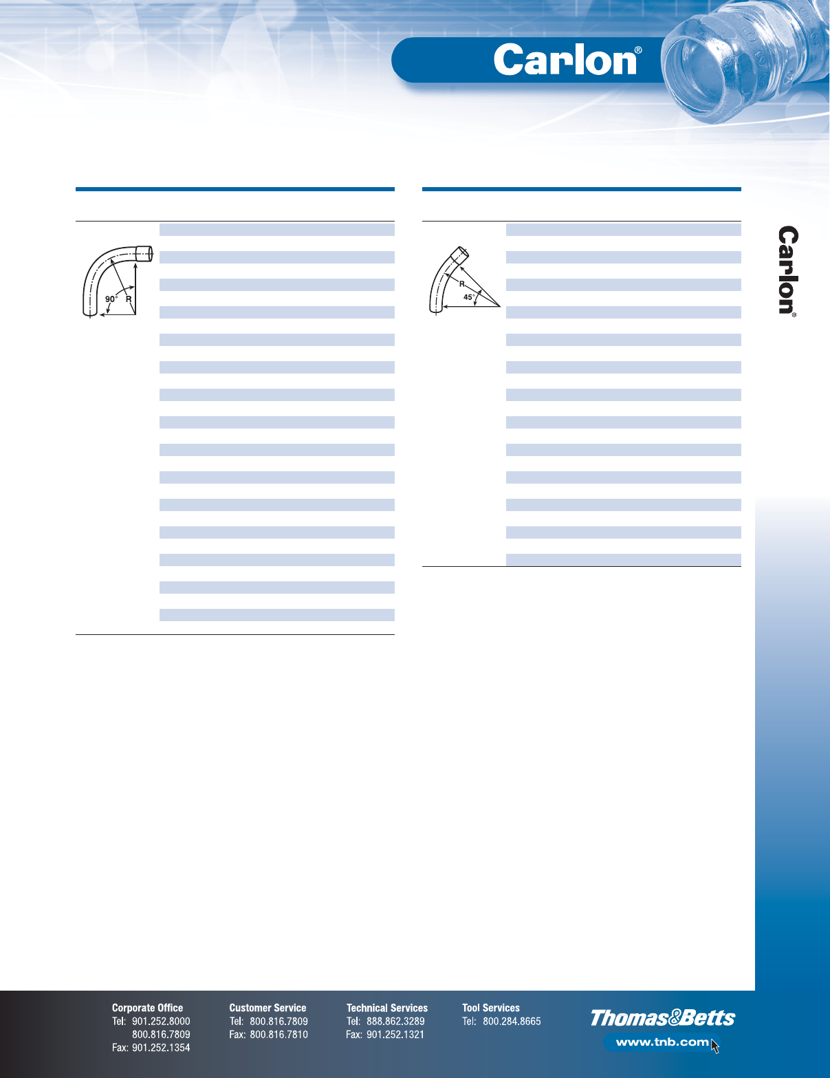
F-63
Non-Metallic Rigid Conduit, Fittings and Accessories
P&C Duct
DB-120 Sweeps
SIZE RADIUS STD.
SEGMENT CAT. NO.
(IN.) (IN.) CTN.
90° SWEEP PH9CJ 2181
PH9CL 3181
PH9CN 4181
PH9DJ 2241
PH9DL 3241
PH9DN 4241
PH9DP 5241
PH9FJ 2361
PH9FL 3361
PH9FN 4361
PH9FP 5361
PH9FR 6361
PH9HJ 2481
PH9HL 3481
PH9HN 4481
PH9HP 5481
PH9HR 6481
PH9IJ 2601
PH9IL 3601
PH9IN 4601
PH9IR 6601
PH9OJ 2661
PH9SJ 2 150 1
PH9SL 3 150 1
PH9SN 4 150 1
PH9SP 5 150 1
PH9SR 6 150 1
PH9VN 4 300 1
PH9VP 5 300 1
PH9VR 6 300 1
NOTE: Elbows 72" and larger may be shipped in segments. Consult factory for specifics.
SIZE RADIUS STD.
SEGMENT CAT. NO.
(IN.) (IN.) CTN.
45° SWEEP PH7CJ 2181
PH7CL 3181
PH7CN 4181
PH7DJ 2241
PH7DL 3241
PH7DN 4241
PH7DP 5241
PH7FJ 2361
PH7FL 3361
PH7FN 4361
PH7FP 5361
PH7FR 6361
PH7HJ 2481
PH7HL 3481
PH7HN 4481
PH7HP 5481
PH7HR 6481
PH7IJ 2601
PH7IL 3601
PH7IP 5601
PH7IR 6601
PH7SJ 2 150 1
PH7SN 4 150 1
PH7SP 5 150 1
PH7SR 6 150 1
NOTE: Elbows 72" and larger may be shipped in segments. Consult factory for specifics.
*Consult your Thomas & Betts
Sales Team for additional sizes
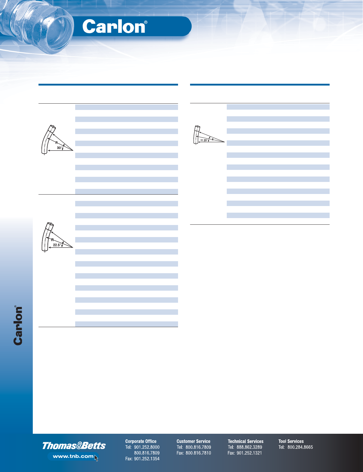
P&C Duct
F-64
Non-Metallic Rigid Conduit, Fittings and Accessories
DB-120 Sweeps
SIZE RADIUS STD.
SEGMENT CAT. NO.
(IN.) (IN.) CTN.
30° SWEEP PH6CJ 2181
PH6CL 3181
PH6CN 4181
PH6DJ 2241
PH6DN 4241
PH6DP 5241
PH6FJ 2361
PH6FL 3361
PH6FN 4361
PH6FP 5361
PH6FR 6361
PH6HN 4481
PH6HR 6481
PH6IN 4601
PH6SL 3 150 1
221⁄2° SWEEP PH5CJ 2181
PH5CL 3181
PH5CN 4181
PH5DJ 2241
PH5DL 3241
PH5DP 5241
PH5FJ 2361
PH5FL 3361
PH5FN 4361
PH5FP 5361
PH5HL 3481
PH5HN 4481
PH5HP 5481
PH5HR 6481
PH5IJ 2601
PH5IL 3601
PH5IR 6601
PH5SN 4 150 1
PH5SP 5 150 1
PH5SR 6 150 1
PH5VJ 2 300 1
PH5VN 4 300 1
NOTE: For nominal diameter of 1", use 1" DB-60 Sweeps.
For nominal diameter of 1
1
⁄
2
", use 1
1
⁄
2
" DB-60 Sweeps.
NOTE: Elbows 72" and larger may be shipped in segments. Consult factory for specifics.
SIZE RADIUS STD.
SEGMENT CAT. NO.
(IN.) (IN.) CTN.
111⁄4° SWEEP PH3CJ 2181
PH3CN 4181
PH3DJ 2241
PH3DN 4241
PH3DP 5241
PH3FJ 2361
PH3FL 3361
PH3FN 4361
PH3FP 5361
PH3FR 6361
PH3HN 4481
PH3IN 4601
PH3IP 5601
PH3IR 6601
PH3SJ 2 150 1
PH3SL 3 150 1
PH3SN 4 150 1
PH3SP 5 150 1
PH3SR 6 150 1
PH3VR 6 300 1
NOTE: For nominal diameter of 1", use 1" DB-60 Sweeps.
For nominal diameter of 1
1
⁄
2
", use 1
1
⁄
2
" DB-60 Sweeps.
NOTE: Elbows 72" and larger may be shipped in segments. Consult factory for specifics.
*Consult your Thomas & Betts
Sales Team for additional sizes
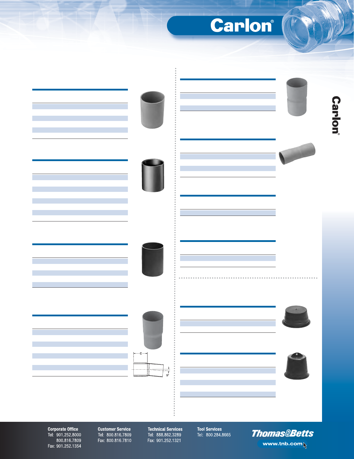
F-65
Non-Metallic Rigid Conduit, Fittings and Accessories
P&C Duct
(for use with all types of EB and DB Duct)
Couplings
SIZE STD.
CAT. NO.
(IN.) CTN.
E200J 230
E200L 325
E200M 31⁄220
E200N 415
E200P 58
E200R 65
SIZE STD.
CAT. NO.
(IN.) CTN.
E940F 150
E940H 11⁄225
E940J 230
E940K 21⁄220
E240L 330
E240N 415
E240P 520
E240RF 65
Coupling
Sleeve Coupling (for repair work)
5° Angle Coupling BxB (Bell x Bell)
SIZE STD.
CAT. NO.
(IN.) CTN.
E2440NF 415
E2440PF 510
E2440RF 65
5° Angle Coupling B x B (Swedged)
SIZE STD.
CAT. NO.
(IN.) CTN.
E245J 220
E245N 410
E245P 510
E245R 65
No internal stop
Plugs
SIZE STD.
CAT. NO.
(IN.) CTN.
P258H 11⁄250
P258K 21⁄250
Plug
SIZE STD.
CAT. NO.
(IN.) CTN.
P258JT 260
P258LT 330
P258NT 448
P258PT 530
P258RT 630
Plug with Pull Tab
SIZE STD.
CAT. NO.
(IN.) CTN.
E242J 248
Swedge Coupling
SIZE STD.
CAT. NO.
(IN.) CTN.
E2440N5 415
E2440P5 520
5° Angle Coupling S x S
SIZE STD.
CAT. NO.
(IN.) CTN.
E941H 11⁄240
E941J 225
E941K 21⁄215
E241L 315
E241N 410
Long Line Coupling
SIZE C STD.
CAT. NO.
(IN.) (IN.) CTN.
E244J 2 2.13 15
E244L 3 3.25 5
E244NF 4 3.50 15
E244NF5 (SHORT) 4 1.87 25
E244PF 5 4.13 10
E244PF5 (SHORT) 5 2.00 20
E244RF 6 5.13 5
E244RF5 (SHORT) 6 2.25 10
5° Angle Coupling B x S
(Bell x Spigot)
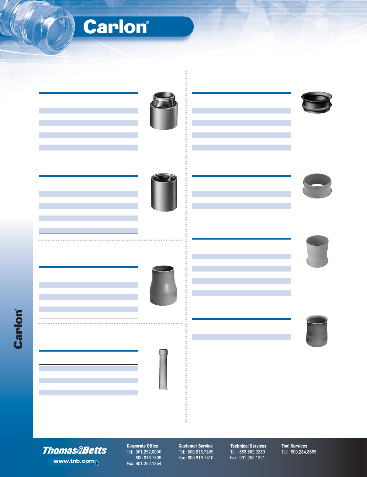
P&C Duct
F-66
Non-Metallic Rigid Conduit, Fittings and Accessories
Adapters
SIZE STD.
CAT. NO.
(IN.) CTN.
E943F 150
E943H 11⁄225
E943J 250
E943L 350
E943N 420
E943P 55
E943R 610
SIZE STD.
CAT. NO.
(IN.) CTN.
E942F 150
E942H 11⁄225
E942J 230
E942L 325
E942N 415
E942P 58
E942R 66
Female Adapter
Male Adapter
Reducers
SIZE STD.
CAT. NO.
(IN.) CTN.
E252LJ 3 x 2 50
E252NJS 4 x 2 25
E252NL 4 x 3 25
E252PN 5 x 4 20
E252RNS 6 x 4 6
E252RP 6 x 5 10
Swedge Reducer (Male x Male)
End Bells
SIZE STD.
CAT. NO.
(IN.) CTN.
E997F 150
E997H 11⁄230
E997J 240
E997L 350
E997N 430
E997P 515
E997R 610
End Bell
SIZE STD.
CAT. NO.
(IN.) CTN.
E297J 240
E297L 350
E297N 430
E297P 515
Molded End Bell
SIZE STD.
CAT. NO.
(IN.) CTN.
E297JN 2 x 4 25
E297LR 3 x 6 20
E297NT 4 x 10 15
E297PS 5 x 8 10
E297PT 5 x 10 10
E297RF 6 x 5 10
E297RT 6 x 10 6
Fabricated End Bell
SIZE STD.
CAT. NO.
(IN.) CTN.
E297RR 6 (6 long) 10
Long-Length End Bell P&C Duct
Markers
SIZE STD.
CAT. NO.
(IN.) CTN.
E299JM 2 x 42 1
E299JP 2 x 56 1
E299JR 2 x 78 1
E299LF 3 x 36 1
E299LR 3 x 60 1
E299NX7 4 x 84 1
Cable Marker
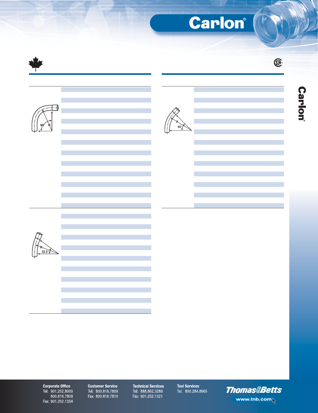
F-67
Non-Metallic Rigid Conduit, Fittings and Accessories
P&C Duct
SIZE RADIUS STD.
SEGMENT CAT. NO.
(IN.) (IN.) CTN.
90° SWEEP CPF9DJ 2241
CPF9DL 3241
CPF9DM*3
1⁄224 1
CPF9DN 4241
CPF9DP* 5241
CPF9FJ 2361
CPF9FL 3361
CPF9FM* 31⁄236 1
CPF9FN 4361
CPF9FP* 5361
CPF9FR* 6361
CPF9GJ* 2421
CPF9GL* 3421
CPF9GM* 31⁄242 1
CPF9GN* 4421
CPF9GP 5421
CPF9GR* 6 42 1
CPF9IJ 2601
CPF9IL 3601
CPF9IM*3
1⁄260 1
CPF9IN 4601
CPF9IP 5601
CPF9IR 6601
221⁄2° SWEEP CPF5DJ* 2241
CPF5DL* 3241
CPF5DM* 31⁄224 1
CPF5DN* 4241
CPF5DP* 5241
CPF5FJ* 2361
CPF5FL* 3361
CPF5FM* 31⁄236 1
CPF5FN 4361
CPF5FP* 5361
CPF5GJ* 2421
CPF5GL* 3421
CPF5GM* 31⁄242 1
CPF5GN* 4421
CPF5GP 5421
CPF5IJ* 2601
CPF5IL* 3601
CPF5IM* 31⁄260 1
CPF5IN* 4601
CPF5IP* 5601
*Non-stock special radius sweeps are available on request — Quote only.
NOTE: Elbows 72" and larger may be shipped in segments. Consult factory for specifics.
SIZE RADIUS STD.
SEGMENT CAT. NO.
(IN.) (IN.) CTN.
45° SWEEP CPF7DJ 2241
CPF7DL 3241
CPF7DM* 31⁄224 1
CPF7DN 4241
CPF7DP* 5241
CPF7FJ 2361
CPF7FL 3361
CPF7FM* 31⁄236 1
CPF7FN 4361
CPF7FP* 5361
CPF7FR* 6361
CPF7GJ* 2421
CPF7GL* 3421
CPF7GM* 31⁄242 1
CPF7GN* 4421
CPF7GP 5421
CPF7GR* 6421
CPF7IJ* 2601
CPF7IL* 3601
CPF7IM* 31⁄260 1
CPF7IN 4601
CPF7IP* 5601
CPF7IR 6601
*Non-stock special radius sweeps are available on request — Quote only.
NOTE: Elbows 72" and larger may be shipped in segments. Consult factory for specifics.
Canadian DB/2 Sweeps LR90813
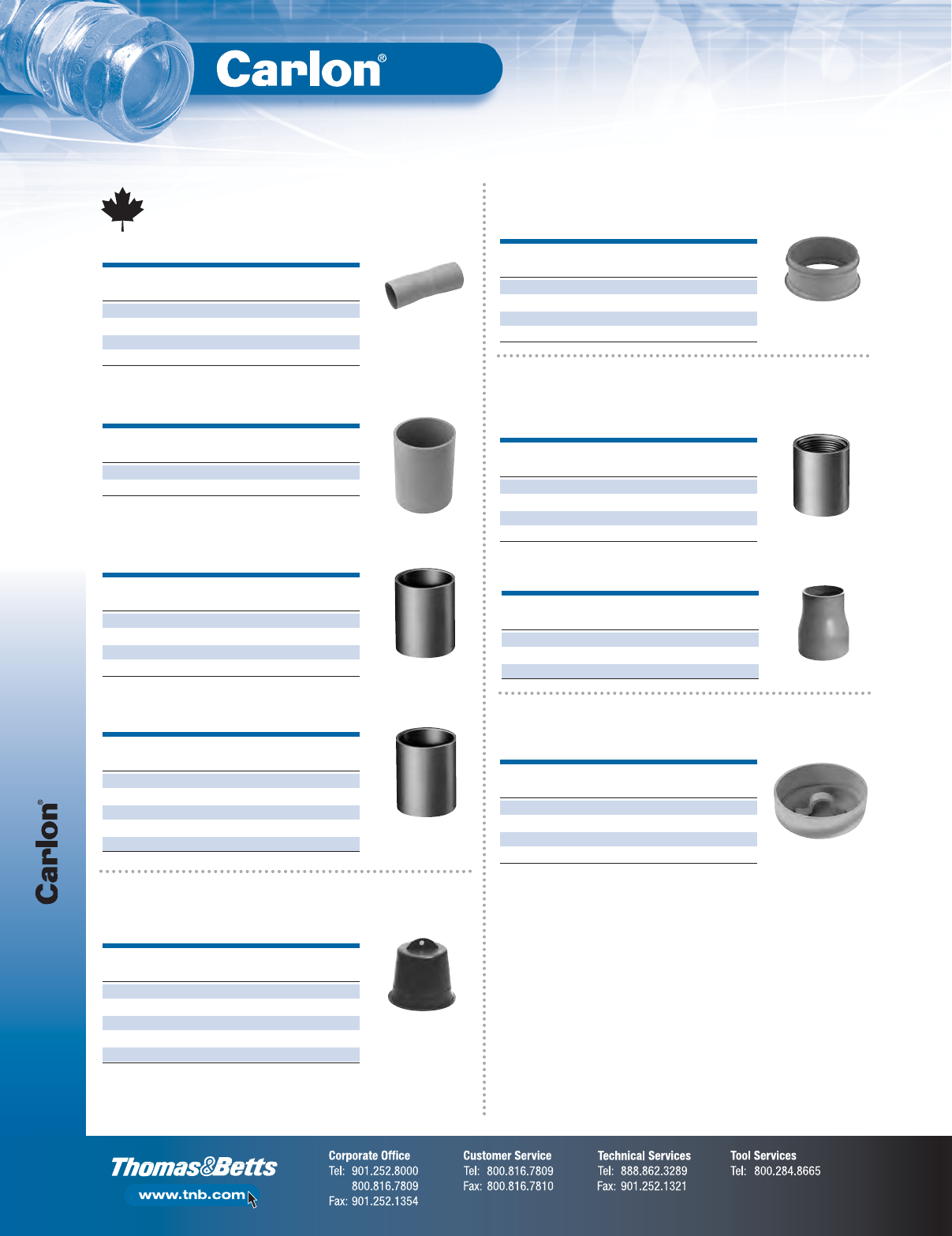
P&C Duct
F-68
Non-Metallic Rigid Conduit, Fittings and Accessories
SIZE STD.
CAT. NO.
(IN.) CTN.
CE245J 230
CE245L 315
CE245N 410
CE245P 520
SIZE STD.
CAT. NO.
(IN.) CTN.
CE2440L 3 100
CE2440N 490
PE 5° Coupling — Push Fit
End Bells
SIZE STD.
CAT. NO.
(IN.) CTN.
CE297J 240
CE297L 350
CE297N 430
CE297P 515
End Bell (For use with DB/2 Duct only)
SIZE STD.
CAT. NO.
(IN.) CTN.
CE242J 2 213
CE242L 3 100
CE242N 4 100
CE242P 512
PE Coupling — Push Fit
SIZE STD.
CAT. NO.
(IN.) CTN.
CE240J 230
CE240L 330
CE240N 415
CE240P 520
CE240R 61
PVC Coupling — Solvent Weld
Plugs
SIZE STD.
CAT. NO.
(IN.) CTN.
P258JT 260
P258LT 330
P258NT 448
P258PT 530
P258RT 630
Plug with Pull Tab
Adapters
SIZE STD.
CAT. NO.
(IN.) CTN.
CE942DJ 225
CE942DL 330
CE942DN 450
CE942DP 515
PVC Female Adapter —
I.P.S. Solvent Weld Duct
Caps
SIZE STD.
CAT. NO.
(IN.) CTN.
CE935J 225
CE935L 325
CE935N 450
CE935P 525
Cap — Solvent Weld
SIZE STD.
CAT. NO.
(IN.) CTN.
CE942RJ 224
CE942RL 31
CE942RN 41
PVC Conduit to DB/2 Duct Adapter
PVC 5° Coupling B x B — Solvent Weld
Canadian DB/2 Duct Fittings
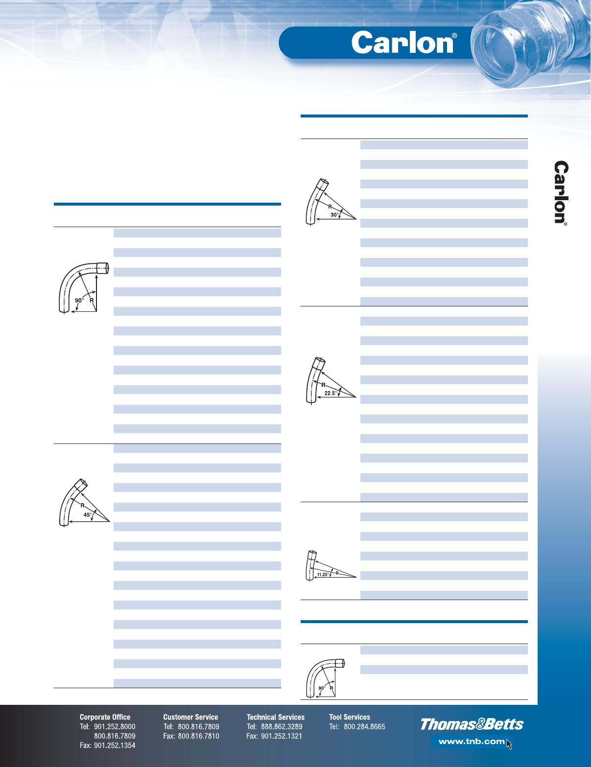
F-69
Non-Metallic Rigid Conduit, Fittings and Accessories
Telephone Duct
Telephone Duct Sweeps
Manufactured from Heavy Wall “C” Duct
•Size: 4"
•Each sweep is furnished with a belled end
•Straight-end length 3"
BEND STD.
SEGMENT CAT. NO.
RADIUS CTN.
90° SWEEP GRAY
TP9CN 1'6" 1
TP9DN 2' 1
TP9FN 3' 1
TP9HN 4' 1
TP9IN 5' 1
TP9JN 6' 1
TP9MN 9' 1
TP9NN 10' 1
TP9SN 12'6" 1
TP9TN 15' 1
TP9UN 20' 1
WHITE
TW9DN 2' 1
TW9FN 3' 1
TW9HN 4' 1
TW9IN 5' 1
TW9JN 6' 1
TW9MN 9' 1
TW9NN 10' 1
TW9SN 12'6" 1
TW9TN 15' 1
45° SWEEP GRAY
TP7DN 2' 1
TP7FN 3' 1
TP7HN 4' 1
TP7ON 4'6" 1
TP7IN 5' 1
TP7JN 6' 1
TP7MN 9' 1
TP7NN 10' 1
TP7RN 12' 1
TP7SN 12'6" 1
TP7TN 15' 1
TP7UN 20' 1
WHITE
TW7DN 2' 1
TW7FN 3' 1
TW7HN 4' 1
TW7ON 4'6" 1
TW7IN 5' 1
TW7JN 6' 1
TW7MN 9' 1
TW7NN 10' 1
TW7RN 12' 1
TW7SN 12'6" 1
TW7TN 15' 1
BEND STD.
SEGMENT CAT. NO.
RADIUS CTN.
90° SWEEP TA9ENT (BELLED END) 2' 6" 1
TA9FN (PLAIN END) 3' 1
TA9FNT (BELLED END) 3' 1
TA9FNTL (BELLED END-LONG) 3' 1
*Gray only
BEND STD.
SEGMENT CAT. NO.
RADIUS CTN.
30° SWEEP GRAY
TP6FN 3' 1
TP6HN 4' 1
TP6JN 6' 1
TP6NN 10' 1
TP6RN 12' 1
TP6SN 12'6" 1
TP6TN 15' 1
WHITE
TW6FN 3' 1
TW6HN 4' 1
TW6JN 6' 1
TW6MN 9' 1
TW6NN 10' 1
TW6RN 12' 1
TW6SN 12'6" 1
TW6TN 15' 1
221⁄2° SWEEP GRAY
TP5DN 2' 1
TP5FN 3' 1
TP5HN 4' 1
TP5IN 5' 1
TP5JN 6' 1
TP5MN 9' 1
TP5RN 12' 1
TP5SN 12'6" 1
TP5TN 15' 1
TP5UN 20' 1
TP5VN 25' 1
WHITE
TW5DN 2' 1
TW5FN 3' 1
TW5HN 4' 1
TW5JN 6' 1
TW5MN 9' 1
TW5SN 12'6" 1
TP3DN 2' 1
111⁄4° SWEEP GRAY
TP3FN 3' 1
TP3HN 4' 1
TP3IN 5' 1
TP3JN 6' 1
TP3SN 12'6" 1
WHITE
TW3DN 2' 1
TW3FN 3' 1
TW3HN 4' 1
E-Bends — Riser Ells
RUS Accepted
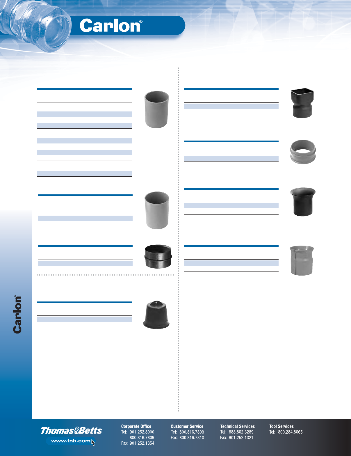
Telephone Duct
F-70
Non-Metallic Rigid Conduit, Fittings and Accessories
Couplings
SIZE STD.
CAT. NO.
(IN.) CTN.
For Repair Work
E900N 4 x 6 25
E900NU 4 x 12 10
E900NW (WHITE) 4 x 6 25
Split Sleeve Couplings
E900NS 425
E900NS8 (WHITE) 4 x 8 15
E900NSW (WHITE) 425
E900PS 515
For Type D Duct Applications Only
E900DN (WHITE) 425
SIZE STD.
CAT. NO.
(IN.) CTN.
Internal Stop
E908N 425
SIZE STD.
CAT. NO.
(IN.) CTN.
E914N 415
Molded Coupling
Sleeve Coupling
5° Angle Coupling
End Bells
SIZE STD.
CAT. NO.
(IN.) CTN.
E903N 4 (Sq.) 4
Square to Round
Plugs
SIZE STD.
CAT. NO.
(IN.) CTN..
P258NTB 450
Plug with Pull Tab
SIZE STD.
CAT. NO.
(IN.) CTN.
E907N 4 (5 long, 5.5 flare) 10
E907NY 4 (9 long, 5.75 flare) 1
Flare and Straight End Bell
SIZE STD.
CAT. NO.
(IN.) CTN.
E971N 410
Molded End Bell
SIZE STD.
CAT. NO.
(IN.) CTN.
E9098NS 41
E9098PS 51
Split End Bell (PVC)
No internal stop
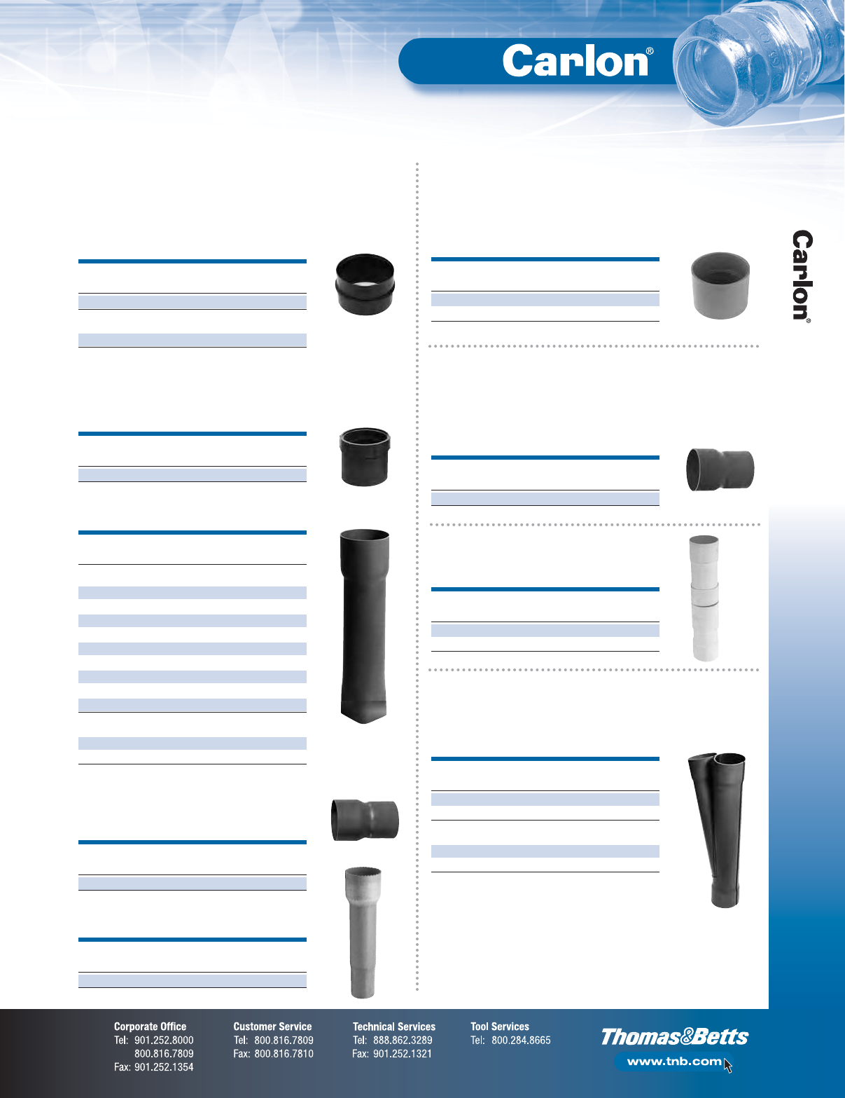
F-71
Non-Metallic Rigid Conduit, Fittings and Accessories
Telephone Duct
Adapters
SIZE STD.
CAT. NO.
(IN.) CTN.
E901N 424
Split
E901NS 424
Internal Adapter
SIZE STD.
CAT. NO.
(IN.) CTN.
E902N 410
Female Adapter
SIZE STD.
CAT. NO.
(IN.) CTN.
E906N 41
Cast Iron Adapter
SIZE STD.
CAT. NO.
(IN.) CTN.
E913N 415
E913NF 415
P&C Duct Adapter
SIZE STD.
CAT. NO.
(IN.) CTN.
E923NM 4–31⁄410
Round Clay Tile Adapter
SIZE STD.
CAT. NO.
(IN.) CTN.
Adapts Clay to Telephone Duct
E904M 31⁄4–4 x 18 10
E904M12 31⁄4–4 x 12 10
E904M8 31⁄4–4 x 81⁄212
E904MM 31⁄2–31⁄2x 18 12
E904MX 3–4 x 18 10
E904N 31⁄2–4 x 18 10
E904N12 31⁄2–4 x 12 12
E904N24 31⁄2–4 x 24 10
E904N8 31⁄2–4 x 8 10
Split Square Adapter
E904MS 31⁄4x 4 10
E904NS 31⁄2–4 x 18 10
Square Clay Tile Adapter
Adapts Telephone Duct to P&C Duct
and Rigid Non-Metallic Conduit
Adapts Telephone Duct
to Cast Iron Bends
Adapts Threaded Metal Pipe
to Telephone Duct
Adapts Telephone Duct
to Fiber Transite MCD
Reducers
SIZE STD.
CAT. NO.
(IN.) CTN.
E908NM 4–31⁄215
P&C Duct Adapter
Adapts Telephone Duct to P&C Duct
and Rigid Non-Metallic Conduit
Wyes
SIZE STD.
CAT. NO.
(IN.) CTN.
E916N 41
E916NW (WHITE) 41
Split
E916NS 41
E916NSW (WHITE) 45
P&C Duct Adapter
For starting lateral runs
Expansion Fittings
SIZE STD.
CAT. NO.
(IN.) CTN.
E905N 45
E905NL (LONG) 41
Expansion Fitting — Type D
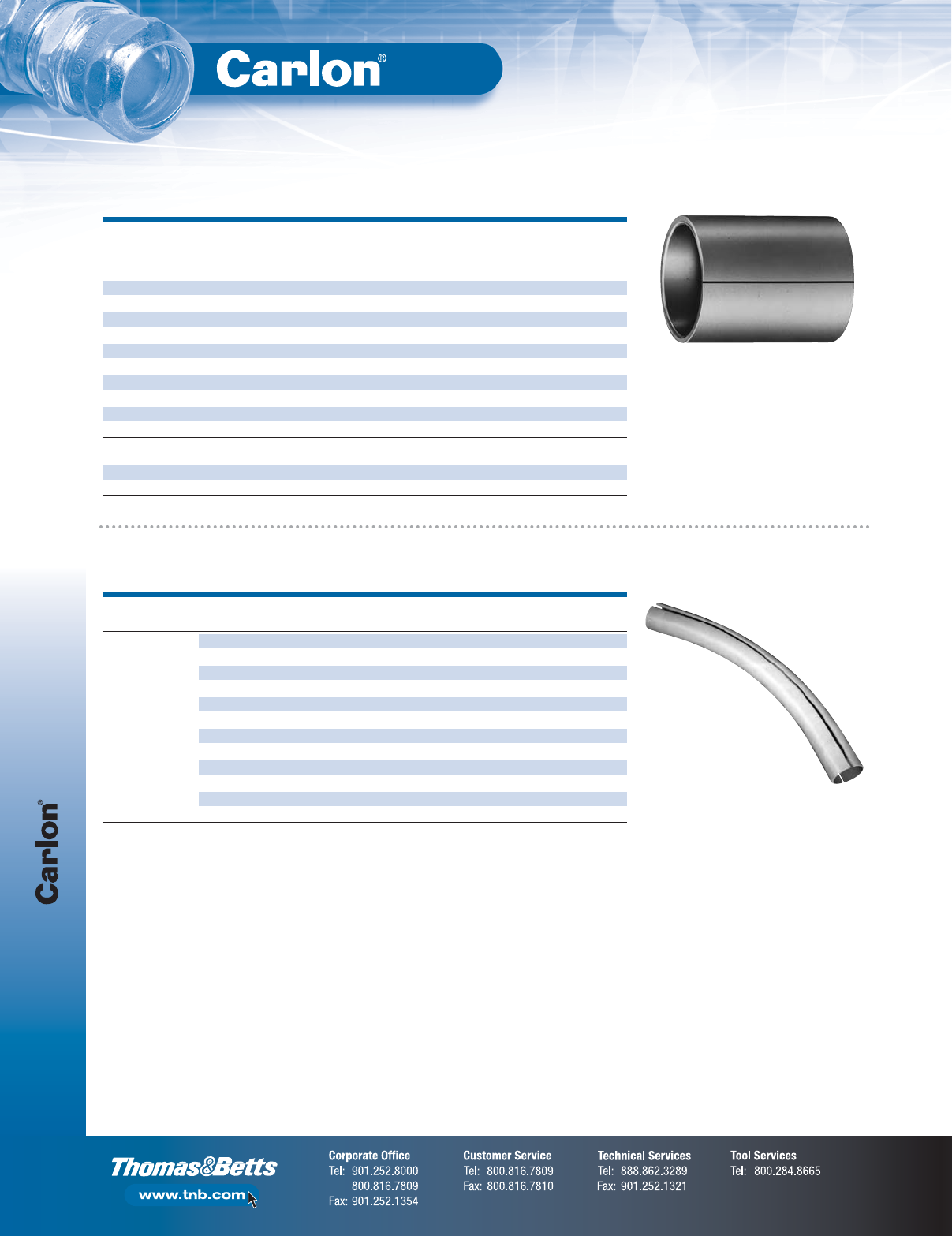
Split Duct
F-72
Non-Metallic Rigid Conduit, Fittings and Accessories
Split Sleeve Coupling
SIZE LENGTH STD. STD. WT.
CAT. NO.
(IN.) DESCRIPTION (IN.) SPLIT CTN. (LBS.)
Schedule 40 and 80
E200JS6 2 Split Coupling 6 1 25 6.1
E200KS7 21⁄2Split Coupling 7 1 25 21
E200LS7 3 Split Coupling 7 1 25 15.5
*E200LSS 3 Split Coupling 6.5 1 25 10
E200MS8 31⁄2Split Coupling 8 1 25 41.2
E200NS8 4 Split Coupling 8 1 15 16
*E200NSS 4 Split Coupling 6 2 25 17
E200PS8 5 Split Coupling 8 1 15 25
E200PS9 5 Split Coupling 9 1 8 16.4
E200RS1 6 Split Coupling 10 1 6 24.2
C Duct
E900NS8 (WHITE) 4 C Duct Split Coupling 8 1 15 19
E900NSW (WHITE) 4 C Duct Split Coupling 6 1 25 22
*Two Piece Design
Split Sleeve Coupling
For joining Split Duct to existing duct.
Split Sleeve Sweeps
NOM. RADIUS STD. STD. WT.
SEGMENT CAT. NO.
SIZE (IN.) (IN.) CTN. (LBS.)
45° SWEEP UA7DJSD 2 24 1 1.4
UA7FJSD 2 36 1 2.1
UA7FLSD 3 36 1 4.7
UA7HJSD 2 48 1 2.7
UA7HLSD 3 48 1 6.1
UA7IJSD 2 60 1 3.2
UA7ILSD 3 60 1 7.2
UA7INSD 4 60 1 10.2
221⁄2° SWEEP UA5INSD 4 60 1 6.1
111⁄4° SWEEP UA3IJSD 2601 1
UA3ILSD 3 60 1 3.6
UA3INSD 4 60 1 5.1
Two 45° Elbows may be segmented for 90°.
Split Duct Sweeps
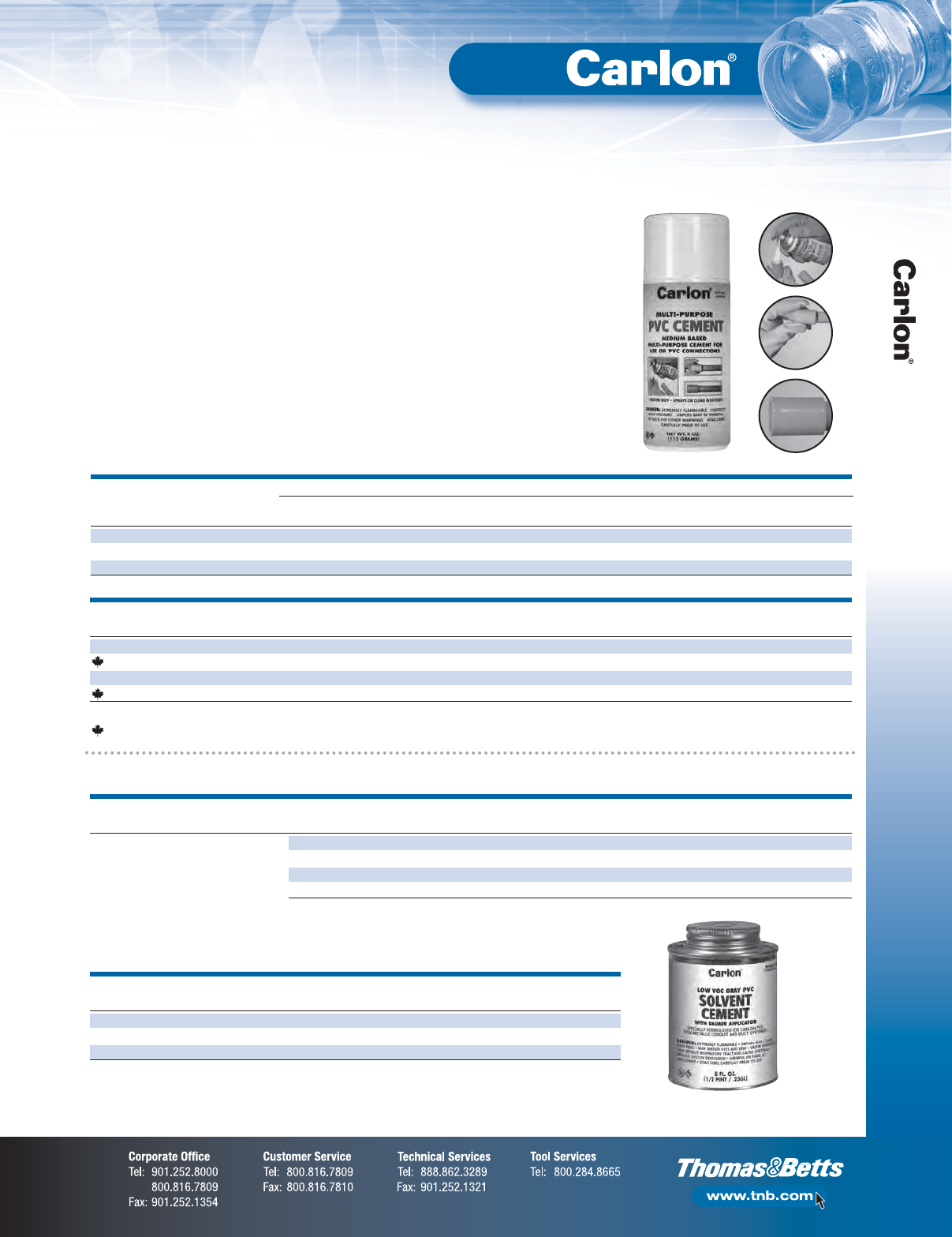
F-73
Non-Metallic Rigid Conduit, Fittings and Accessories
Accessories — PVC Cements
No waste • Sprays on in seconds • Fast setting
Multi-Purpose Spray-On PVC Cement
•Equivalent to a medium-bodied low-VOC,
quick-setting clear cement
•No more spills
•Reuse can until empty
•Installation: 50° to 80°F; Storage: 35° to 120°F
•Meets ASTM D-2564
•3-year shelf life
•One 4 oz. can is equivalent to 4 oz. of non-aerosol PVC cement*
*Equivalence is subject to usage and will vary.
•For use up to 4" diameter
Schedule 40 or 80 PVC
electrical conduit
•For use with PVC Raceways
only. Not recommended for
use on water, sewer, natural
gas, compressed gas or
air connections
Applications:
STD. STD. WT.
CAT. NO.
SIZE DESCRIPTION CTN. (LBS.)
VC9AC5 4 oz. PVC Spray-On Medium Clear 12 5.6
VC9AC5C 4 oz. PVC Spray-On Medium Clear 12 5.6
VC9AC16 11 oz. PVC Spray-On Medium Clear 12 12.3
VC9AC16C 11 oz. PVC Spray-On Medium Clear 12 12.3
Recommended set time may vary depending on humidity.
Canada only
RECOMMENDED SET TIME
TEMPERATURE PIPE SIZES PIPE SIZES PIPE SIZES
RANGE 1⁄2" TO 11⁄4"1
1⁄2" TO 2" 21⁄2" TO 4"
60°–100°F 2 min. 5 min. 30 min.
40°–60°F 5 min. 10 min. 2 hrs.
0°–40°F 10 min. 15 min. 12 hrs.
Low VOC — Gray
RECOMMENDED PIPE SET-UP TIME RECOMMENDED LAP SHEAR VISCOSITY AT 75˚
APPLICATION AND SIZES (EVAPORATION RATE) INSTALLATION TEMP. @ 73˚F AS MANUFACTURED
10˚–30˚F Not recommended 40˚ to 100˚F 2 hrs. 350 psi 500–900 cps
30˚–50˚F 5–6 minutes 16 hrs. 800 psi
50˚–70˚F 3–4 minutes 72 hrs. 1,500 psi
70˚–90˚F 1–2 minutes
STD. STD. WT.
CAT. NO.
SIZE APPLICATOR DESCRIPTION CTN. (LBS.)
VC9LV4-24 1⁄2Pint Dauber Low VOC Gray 24 15.5
VC9LV3 Pint Dauber Low VOC Gray 24 27.0
VC9LV2 Quart Dauber Low VOC Gray 12 26.0
Recommended for all grades and
types of Carlon®wireway and fittings,
except Flex-Plus®Blue™ENT
(Electrical Non-Metallic Tubing).
Up through 6" diameter.
VOC emission of 490 grams/liter per
the Bay and South Coast test method.
Meets ASTM D-2564
Accessories — PVC Cements
F-74
Non-Metallic Rigid Conduit, Fittings and Accessories
RECOMMENDED PIPE SET-UP TIME RECOMMENDED LAP SHEAR VISCOSITY AT 75˚
APPLICATION AND SIZES (EVAPORATION RATE) INSTALLATION TEMP. @ 73˚F AS MANUFACTURED
10˚–30˚F Not recommended 40˚ to 100˚F 2 hrs. 350 psi 500–900 cps
30˚–50˚F 5–6 minutes 16 hrs. 800 psi
50˚–70˚F 3–4 minutes 72 hrs. 1,500 psi
70˚–90˚F 1–2 minutes
STD. STD. WT.
CAT. NO.
SIZE APPLICATOR DESCRIPTION CTN. (LBS.)
VC9963 Pint Dauber PVC Medium Clear 24 29.0
VC9962 Quart Dauber PVC Medium Clear 12 27.5
VC9961P Gallon — PVC Medium Clear 6 53.5
Meets ASTM D-2564.
Recommended for all grades and
types of Carlon®wireway and fittings,
except Flex-Plus®Blue™ENT
(Electrical Non-Metallic Tubing).
Up through 6" diameter.
Medium — Clear
STD. STD. WT.
CAT. NO.
SIZE APPLICATOR DESCRIPTION CTN. (LBS.)
VC9923 Pint Dauber PVC Medium Gray 24 29.0
VC9922 Quart Dauber PVC Medium Gray 12 27.5
VC9941P Gallon — PVC Medium Gray 6 53.5
Meets ASTM D-2564.
Medium — Gray
Regular — Clear
STD. STD. WT.
CAT. NO.
SIZE APPLICATOR DESCRIPTION CTN. (LBS.)
VC9964 1⁄2Pint Dauber PVC Regular Clear 10 29.06.5
Meets ASTM D-2564.
Regular — Gray
STD. STD. WT.
CAT. NO.
SIZE APPLICATOR DESCRIPTION CTN. (LBS.)
VC9924-24 1⁄2Pint Dauber PVC Regular Gray 24 15.0
Meets ASTM D-2564.
RECOMMENDED PIPE RECOMMENDED
APPLICATION AND SIZES INSTALLATION TEMPERATURE
Recommended for use with Carlon®cement 5˚ to 100˚F
STD. STD. WT.
CAT. NO.
SIZE APPLICATOR CTN. (LBS.)
VC9903 Pint Dauber 24 27.0
VC9902 Quart Dauber 12 25.0
Meets ASTM F-686.
Clear Primer
RECOMMENDED PIPE RECOMMENDED
APPLICATION AND SIZES INSTALLATION TEMPERATURE
Recommended for use with Carlon®cement 5˚ to 100˚F
STD. STD. WT.
CAT. NO.
SIZE APPLICATOR CTN. (LBS.)
VC9932 Quart Dauber 12 25.0
Meets ASTM F-686.
Purple Primer
F-75
Non-Metallic Rigid Conduit, Fittings and Accessories
Accessories — PVC Cements
RECOMMENDED PIPE SET-UP TIME RECOMMENDED LAP SHEAR VISCOSITY AT 75˚
APPLICATION AND SIZES (EVAPORATION RATE) INSTALLATION TEMP. @ 73˚F AS MANUFACTURED
-5˚–10˚F 6–8 minutes -5˚ to 100˚F 2 hrs. 350 psi 400–700 cps
10˚–30˚F 4–5 minutes 16 hrs. 800 psi
30˚–50˚F 3–4 minutes 72 hrs. 1,500 psi
50˚–70˚F 1–2 minutes
70˚–90˚F 1⁄2–11⁄2minutes
STD. STD. WT.
CAT. NO.
SIZE APPLICATOR DESCRIPTION CTN. (LBS.)
VC9984 1/2 Pint Dauber All Weather “Quick-Set” Cement 10 7.0
VC9983 Pint Dauber All Weather “Quick-Set” Cement 24 30.0
VC9982 Quart Dauber All Weather “Quick-Set” Cement 12 29.0
VC9981P Gallon — All Weather “Quick-Set” Cement 6 54.0
Meets ASTM D-2564.
Recommended for all grades and
types of Carlon®wireway and fittings,
except Flex-Plus®Blue™ENT
(Electrical Non-Metallic Tubing).
Up through 6" diameter.
All Weather — Clear
RECOMMENDED PIPE SET-UP TIME RECOMMENDED LAP SHEAR VISCOSITY AT 75˚
APPLICATION AND SIZES (EVAPORATION RATE) INSTALLATION TEMP. @ 73˚F AS MANUFACTURED
-5˚–10˚F 6–8 minutes -5˚ to 100˚F 2 hrs. 350 psi 400–700 cps
10˚–30˚F 4–5 minutes 16 hrs. 800 psi
30˚–50˚F 3–4 minutes 72 hrs. 1,500 psi
50˚–70˚F 1–2 minutes
70˚–90˚F 1⁄2–11⁄2minutes
STD. STD. WT.
CAT. NO.
SIZE APPLICATOR DESCRIPTION CTN. (LBS.)
VC9992 Quart Dauber All Weather “Quick-Set” Blue 12 29.0
Meets ASTM D-2564.
Required for use with Flex-Plus®Blue™
ENT (Electrical Non-Metallic Tubing),
Riser-Gard®, P&C Flex™and Carlon
®
PVC fittings.
Up through 6" diameter.
All Weather — ENT Blue
RECOMMENDED PIPE SET-UP TIME RECOMMENDED LAP SHEAR VISCOSITY AT 75˚
APPLICATION AND SIZES (EVAPORATION RATE) INSTALLATION TEMP. @ 73˚F AS MANUFACTURED
10˚–30˚F 4–5 minutes 40˚ to 100˚F 2 hrs. 350 psi 500–900 cps
30˚–50˚F 3–4 minutes 16 hrs. 800 psi
50˚–70˚F 1–2 minutes 72 hrs. 1,500 psi
70˚–90˚F 1⁄2–11⁄2minutes
For use with Resi-Gard®, Riser-Gard®,
P&C Flex™and Carlon
®
PVC fittings.
Up through 6" diameter.
Resi-Gard®— Clear
STD. STD. WT.
CAT. NO.
SIZE APPLICATOR DESCRIPTION CTN. (LBS.)
VC9963SC Pint Brush Resi-Gard®Solvent Cement Clear 24 28.0
Meets ASTM D-2564.
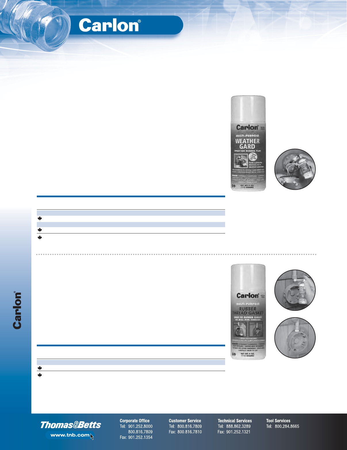
Accessories — Sealers
F-76
Non-Metallic Rigid Conduit, Fittings and Accessories
Sealers
No waste • Sprays on in seconds • Fast setting
Multi-Purpose Weather Gard Spray-On Rubber Film
•Weatherproof
•Forms a protective weatherproof seal
on electrical connections
•Dries in minutes to crystal clear rubber film
•Prevents corrosion on electrical
connections
•Recommended installation temperatures:
50° to 80°F
•Can be used on wood and plastic
•2-year shelf life
Applications:
•Electrical connections
•Outdoor lighting
•Panel boxes
•Pool motors and timers
•Water valves and connections
•Sprinkler connections and control box
•Marine applications
STD. STD. WT.
CAT. NO.
SIZE DESCRIPTION CTN. (LBS.)
VC9WG5 4 oz. Multi-Purpose Weather-Gard Spray-On Rubber Film 12 5.6
VC9WG5C 4 oz. Multi-Purpose Weather-Gard Spray-On Rubber Film 12 5.6
VC9WG16 11 oz. Multi-Purpose Weather-Gard Spray-On Rubber Film 12 12.3
VC9WG16C 11 oz. Multi-Purpose Weather-Gard Spray-On Rubber Film 12 12.3
Canada only
Multi-Purpose Spray-On Rubber Thread Gasket
•Dries to rubber gasket to seal
pipe threads
•Seals out leaks
•Protects against rust and corrosion
•UV resistant
•Weatherproof
•2-year shelf life
Applications:
•PVC
•Copper
•Iron
•Brass
STD. STD. WT.
CAT. NO.
SIZE DESCRIPTION CTN. (LBS.)
VC9TS5 4 oz. Multi-Purpose Rubber Thread Sealer 12 5.6
VC9TS5C 4 oz. Multi-Purpose Rubber Thread Sealer 12 5.6
Canada only
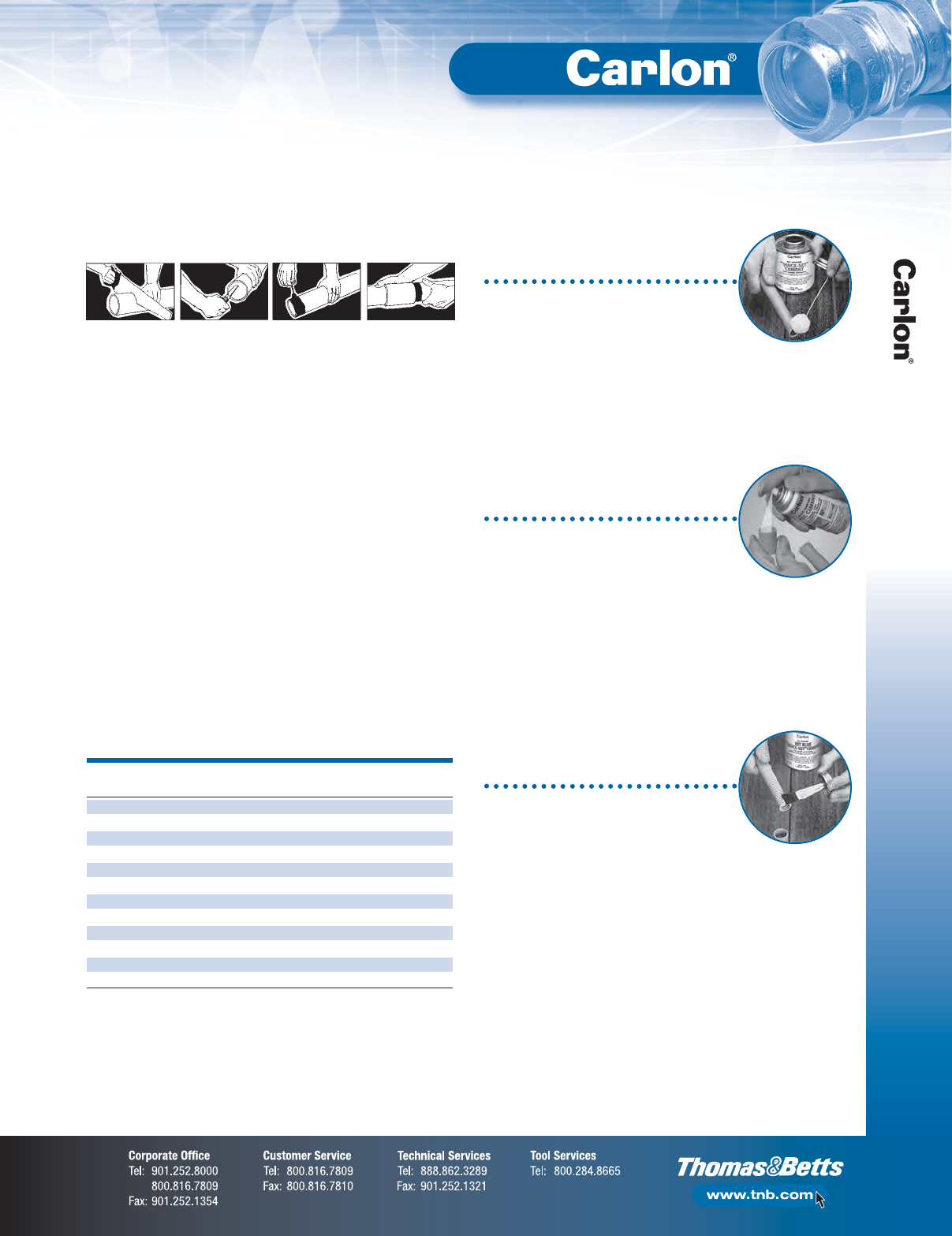
F-77
Non-Metallic Rigid Conduit, Fittings and Accessories
Accessories — Cement
Cement Joints
Installation Instructions
Carlon®non-metallic products are joined by means of solvent cement joints.
Sizes 1⁄2" through 11⁄2" should be cut square (using a fine tooth handsaw)
and deburred. For sizes 2" through 6", a miter box or similar saw guide
should be utilized to keep the material steady. After cutting and deburring,
wipe ends clean of dust, dirt and shavings.
Joining process as follows:
– Be sure that conduit end is clean and dry.
– Apply coat of Carlon®Solvent Cement (use dauber) to end of conduit
for the length of the socket to be attached.
– Push conduit firmly into fitting while rotating conduit slightly, about
one-quarter turn to spread cement evenly.
– Allow joint to set approximately 10 minutes.
Carlon
®
recommends the use of Carlon
®
cement for proper solvent
cement joints. Because this cement is prepared particularly for our
product compounds and tolerances, we cannot guarantee joints assembled
with cement materials supplied by other manufacturers. Regular-grade gray
solvent cement will accommodate most application situations being of a
general-purpose nature. In situations requiring an extremely fast-setting
joint (low temperature or difficult installation conditions), Carlon
®
All Weather
Quick-Set Cement is recommended. Standard-grade clear cement is
recommended for non-critical utility applications where gap filling
and leak testing are not required.
TRADE 1⁄2PINT PINT QUART GALLON SPRAY SPRAY
SIZE (IN.) 8 OZ. 16 OZ. 32 OZ. 128 OZ. 4 OZ. 16 OZ.
1⁄2140 275 550 2,200 70 275
3⁄490 180 360 1,440 45 180
1 70 140 280 1,120 35 140
11⁄450 100 200 800 25 100
11⁄237 75 150 600 18.5 75
2 20 40 80 320 10 40
21⁄217 35 70 280 8.5 35
3 15 30 60 240 7.5 30
31⁄213 27 54 216 6.5 27
4 12 25 50 200 6 25
5 9 19 38 150 N/A N/A
6 6 12 24 95 N/A N/A
CAN: Average shelf-life of all Carlon
®
cement is 24 months
(unopened cans stored below 80˚F).
SPRAY: Average shelf-life of all Carlon
®
Spray PVC Cement is 3 years.
All Carlon
®
cements are specially formulated to be used with Carlon
®
PVC products,
and do not require primers when parts are clean of dirt and moisture.
MSDS available at www.carlon.com.
Average Number of Joints per Can
Cementing PVC Conduit:
1. Make square saw cut with fine tooth saw.
2. Deburr and round inside edge of the cut end.
3. Clean socket I.D. and spigot O.D. of
dirt and moisture.
4. Apply a uniform coat of cement to spigot end
and push onto socket bottom, rotating 1/4 turn.
5. Allow time to set before disturbing. Setting time
will depend upon temperature.
Cementing PVC Conduit for Submerged
Areas Requiring Air or Water Tightness:
1. Follow the procedure above for
cementing conduit.
2. Test workmanship by conducting a low-pressure
air (3.0–5.0 psi) test after system is installed and
cemented joints are set.
3. Plug and block ends to prevent movement prior
to pressurization.
4. Check for leaks with soap solution.
5. Even low-pressure air can cause high-thrust
loads and caution must be observed.
Cementing ENT for Concrete-Tight
Applications:
1. Use Carlon®Socket tight fittings or couplings.
2. Do not use chemical primer or cleaner.
3. Apply a light uniform coat of cement
labeled for use with ENT.
4. Use a brush to apply the cement.
5. Brush excess cement out of ENT grooves.
6. Promptly insert ENT into fitting while cement
is wet until the fitting stop is reached
and give 1/4 turn.
7. Do not disturb until the joint is set.
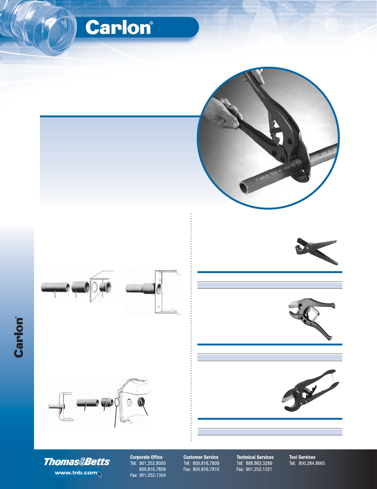
Accessories — Conduit Termination,
Cutting and Joining
F-78
Non-Metallic Rigid Conduit, Fittings and Accessories
PVC Conduit Cutters
PVC
Conduit
E940
Coupling
E996
Box Adapter
PVC
Conduit
E943
Terminal
Adapter
E943_W
Flat Washer
or O-Ring
Locknut
or Bushing
Apply solvent cement to shoulder and shank of box adapter and insert
through knockout from inside the enclosure. Push coupling over the shank
of the box adapter, tight against the enclosure wall. Rotate the coupling
about one-half turn while installing, and hold in position for a few seconds
to permit setting of solvent cement. The coupling is now ready for the
conduit to be installed. Only the shoulder of the box adapter extends
inside the enclosure.
Method 1. Permanent Termination
If a “wet location” as defined in Article 100 of the NEC®construction is
required, place a flat washer or O-ring over the threads of the terminal
adapter, securely against the shoulder. Insert the adapter threads through
knockout and secure using either a standard locknut or threaded bushing.
If watertight construction is not required, eliminate flat washer.
Method 2. Separable Termination
For fast, smooth field cuts of 1⁄2"
through 1" Non-Metallic Rigid Conduit,
Flex-Plus®Blue™ENT and Carflex®
liquidtight flexible non-metallic conduit.
Hand-held cutter makes fast, square,
smooth field cuts on Non-Metallic Rigid
Conduit from 1⁄2" through 11⁄4". Produces
burr-free cut with no shavings. Fits into
pocket or pouch.
For clean cuts of conduit
1⁄2" through 2".
CAT. NO.
SIZE (IN.) STD. CTN.
CC120B 810
CAT. NO.
SIZE (IN.) STD. CTN.
CC125 912
CAT
.
NO.
SIZE (IN.) STD. CTN.
CC122 171⁄21
Medium Cutter
Small Cutter
Large Cutter
Terminating Non-Metallic Rigid Conduit is quick and easy utilizing
either of the methods indicated below. Terminations may be made
in any electrical box or enclosure using standard size knockouts
or drilled holes.
Fittings and Adapters for Terminating
Non-Metallic Rigid Conduit
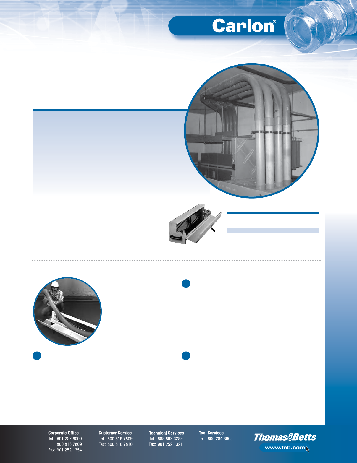
F-79
Non-Metallic Rigid Conduit, Fittings and Accessories
Accessories — EZ BEND™Conduit-Bending Equipment
EZ BEND™Conduit Bender, Jr.
A practical, convenient portable conduit bender for 1⁄2" through 2"
diameter non-metallic conduit enables bends up to 14" radius and
to 90° elbows. The EZ BEND™Conduit Bender, Jr. is a timesaving,
easy-to-carry unit featuring a bracket to store the power cord,
a carrying handle and a clasped cover. The unit operates on
a standard 20 Amp, 120V circuit.
STD. STD. WT.
CAT NO.
CTN. (LBS.)
G280J 114
Dimensions: 7
1
⁄
2
" x 8
1
⁄
2
" x 31"
Operating Temperature: 180°–200°F
Minimum practice is
required to master the
three steps in bending
non-metallic conduits
and ducts.
For field bending of small and large diameter non-metallic conduit,
the easy answer is EZ BEND™conduit-bending equipment.
•Lightweight
•Portable
•Fast, simple and safe
•Less expensive than factory bends
•Includes complete instructions and a convenient bending chart
EZ BEND™Conduit-Bending Equipment is designed with the electrical
contractor in mind. The completely portable and fully encased EZ BEND™
benders and plug kits can be transported from job to job without damage
or harm to the equipment. Additionally, the heavy-duty construction and
integrity of EZ BEND™Conduit-Bending Equipment ensures that it will
last for years to come.
EZ BEND™Conduit-
Bending Equipment
Field-Bending Rigid Non-Metallic Conduit
Heating
Conduit section to be bent must be heated evenly over the entire
length of the curve. Carlon®offers EZ BEND™electric heaters
designed specifically for this purpose, in sizes to accommodate all
conduit diameters. These devices employ infrared heat energy, which
is most quickly absorbed by the conduit. Small sizes are ready to
bend after a few seconds, while larger diameters require two or three
minutes or more, depending on conditions. The use of torches or
other flame-type devices is not recommended. PVC conduit exposed
to excessively high temperatures may take on a brownish color.
Sections showing evidence of such scorching should be discarded.
1
Forming the Bend
1⁄2" thru 11⁄2" Diameters — When properly heated, the conduit is very
flexible and can be shaped to almost any configuration. The conduit is
then cooled by sponging with water and the bend is ready to install.
2" and Larger Diameters — Larger sizes of conduit and ducts
require internal support to prevent “crimping” or deforming during
the bending process. Bending plugs are inserted in each end of
the conduit section before heating. The plugs expand to provide
an airtight seal.
NOTE: Carlon
®
does not offer bending plugs.
2
Cooling
As the conduit is heated, the retained air expands and the increased
internal pressure enables the conduit to be bent without deforming.
The conduit must be cooled before the plugs are removed. For an
immediate cool and set, sponge with cold water.
3
Special Bends
For “blind” bends or for compound turns in a conduit run, the heated
conduit may be solvent-cemented in place while still flexible.
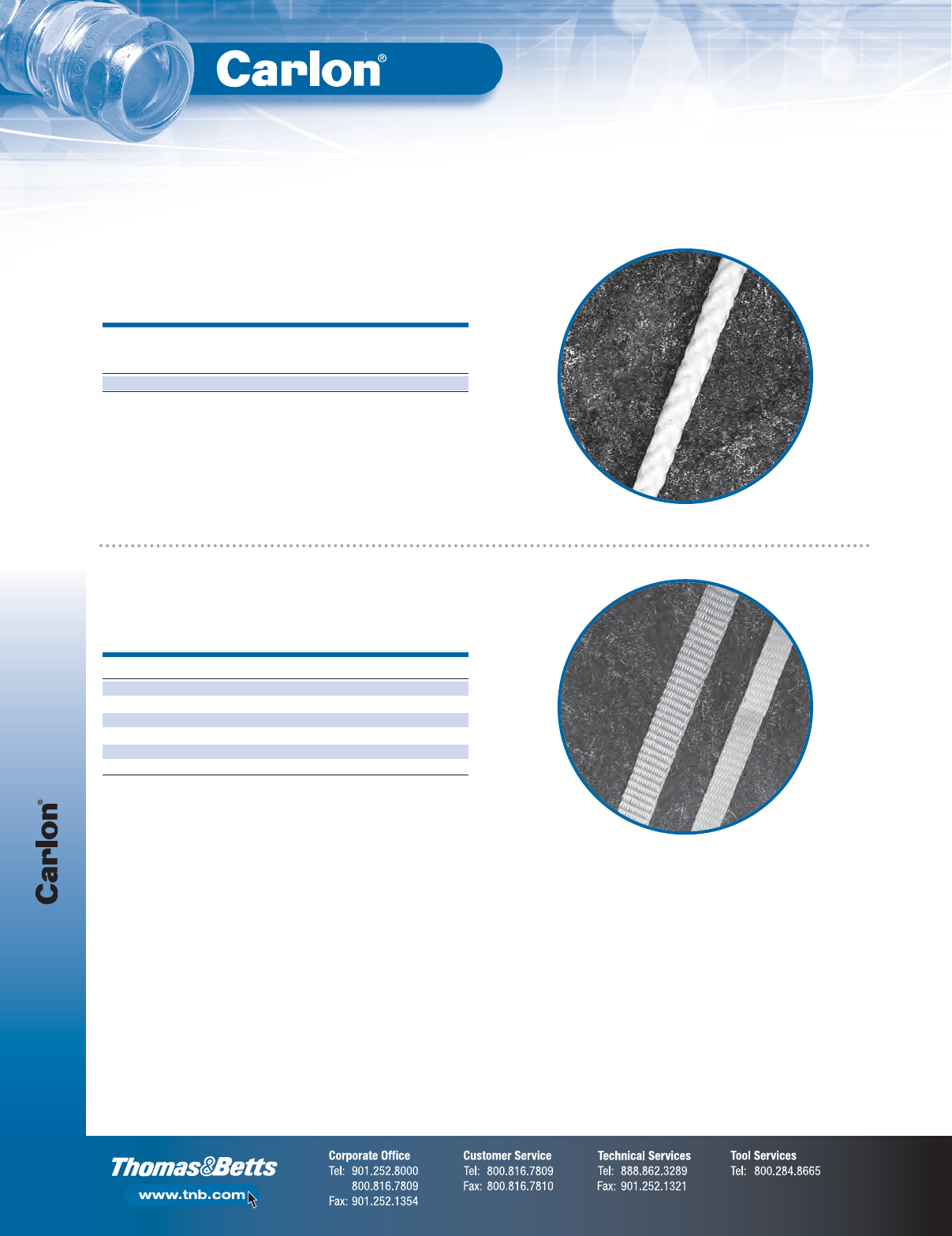
Accessories — Rope and Tape
F-80
Non-Metallic Rigid Conduit, Fittings and Accessories
White Diamond Braid Rope
CAT. NO. SIZE (IN.) TENSILE STRENGTH (LBS.) REEL LENGTHS (FT.)
TL14203 1⁄21130 3,000
TL14505 1⁄21250 5,000
TL14510 1⁄21250 10,000
TL38203 5⁄81800 3,000
TL38265 5⁄81800 6,500
TL38210 5⁄81800 10,000
REEL RECOMMENDED APPROXIMATE
LENGTHS DIAMETER WORKING LOAD AVG. TENSILE STD. WT.
CAT. NO.
(FT.) (IN.) (LBS.) (LBS.) (LBS.)
SB14105 5,000 1⁄4260 1700 1000
Rope (Conduit Pulling Lines for Conductors or Fiber Optics)
This rope is constructed of polyethylene over polyester, designed specifically
for fiber optic pulling. The polyethylene jacket gives the “slippery” feel that
gives less drag in pulling through conduit.
Tape
Pre-lubricated, woven polyester tape made from low-friction, high abrasion-
resistant yarns, providing a low coefficient of friction. Tape is printed with
sequential footage markings for accurate measurements.
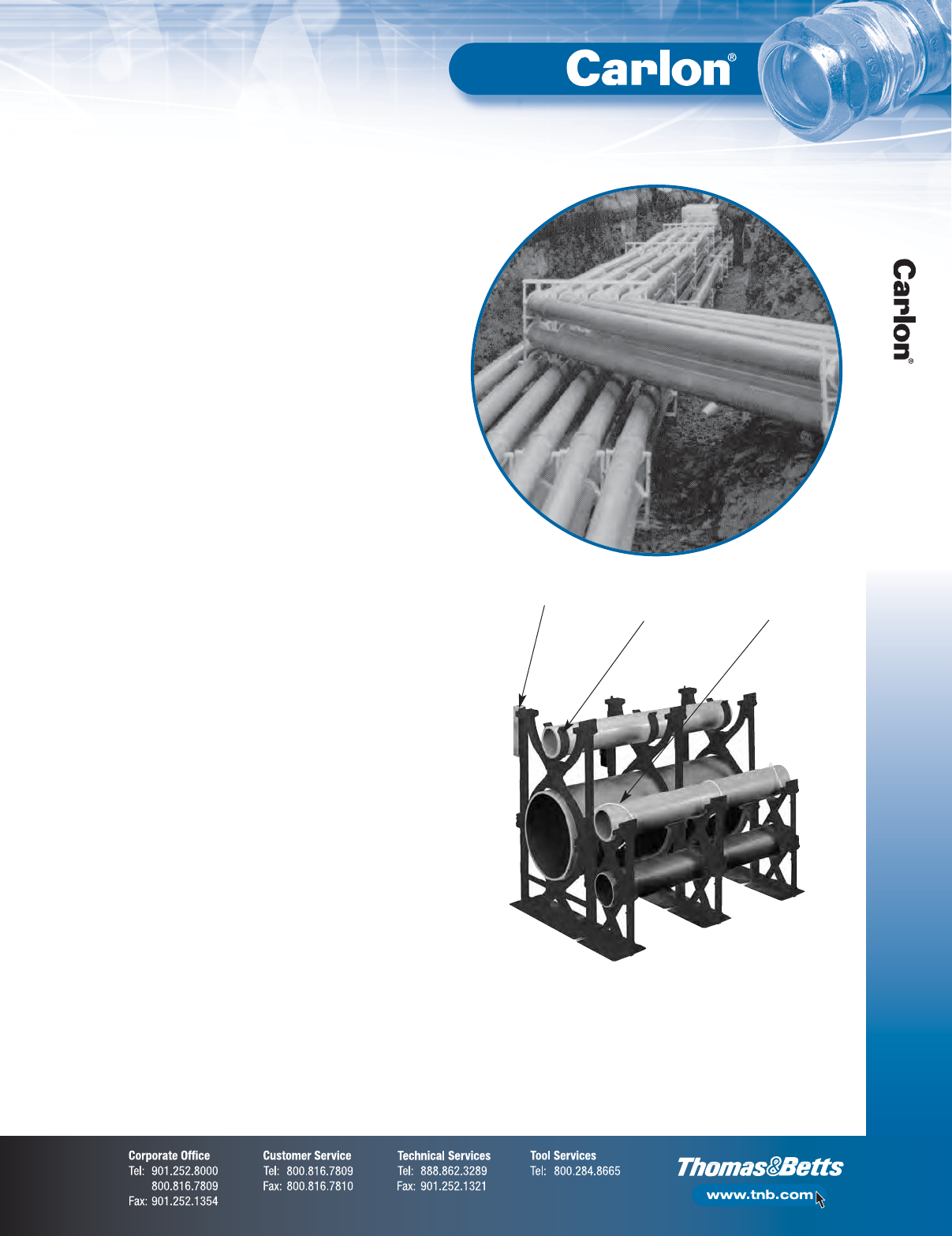
F-81
Non-Metallic Rigid Conduit, Fittings and Accessories
Spacers
Carlon®Snap-Loc®Duct Spacers provide stability, consistent separation
and relieve direct stress for duct materials encased in concrete
and direct-bury applications.
Carlon®Snap-Loc®Spacers provide:
•A side dovetail rail-and-groove design enabling
side-by-side interchangeability of conduit spacer
sizes while maintaining horizontal stability
•Locking keyways incorporated into intermediate
spacers eliminate the need for costly top spacers in
each size. The locking keyways provide for the use of
a beaded strap that secures the top section of conduit
•1" and 2" Snap-Loc
®
Reducers enable fixturing of 1"
or 2" conduit inside larger spacers
•The Snap-Loc
®
Rebar Holder provides stabilization
on large banks of spacers
Non-metallic Snap-Loc®Spacers are designed specifically for use with
non-metallic duct, with maximum O.D. dimensions as specified in NEMA
TC-2, TC-6 & 8, and ASTM F512. The innovative vertical and horizontal
interlocking Snap-Loc®design has tapered joining slots with maximum
tolerances for easy jobsite assembly.
Important:
The use of duct spacers for direct burial may result in excessive point
deflections unless proper design engineering is applied, such as the proper
compaction of the appropriate backfill material.
Carlon®Snap-Loc®Spacers
Rebar Holder
Snap-Loc
®
Reducer
Beaded Strap &
Locking Key Way
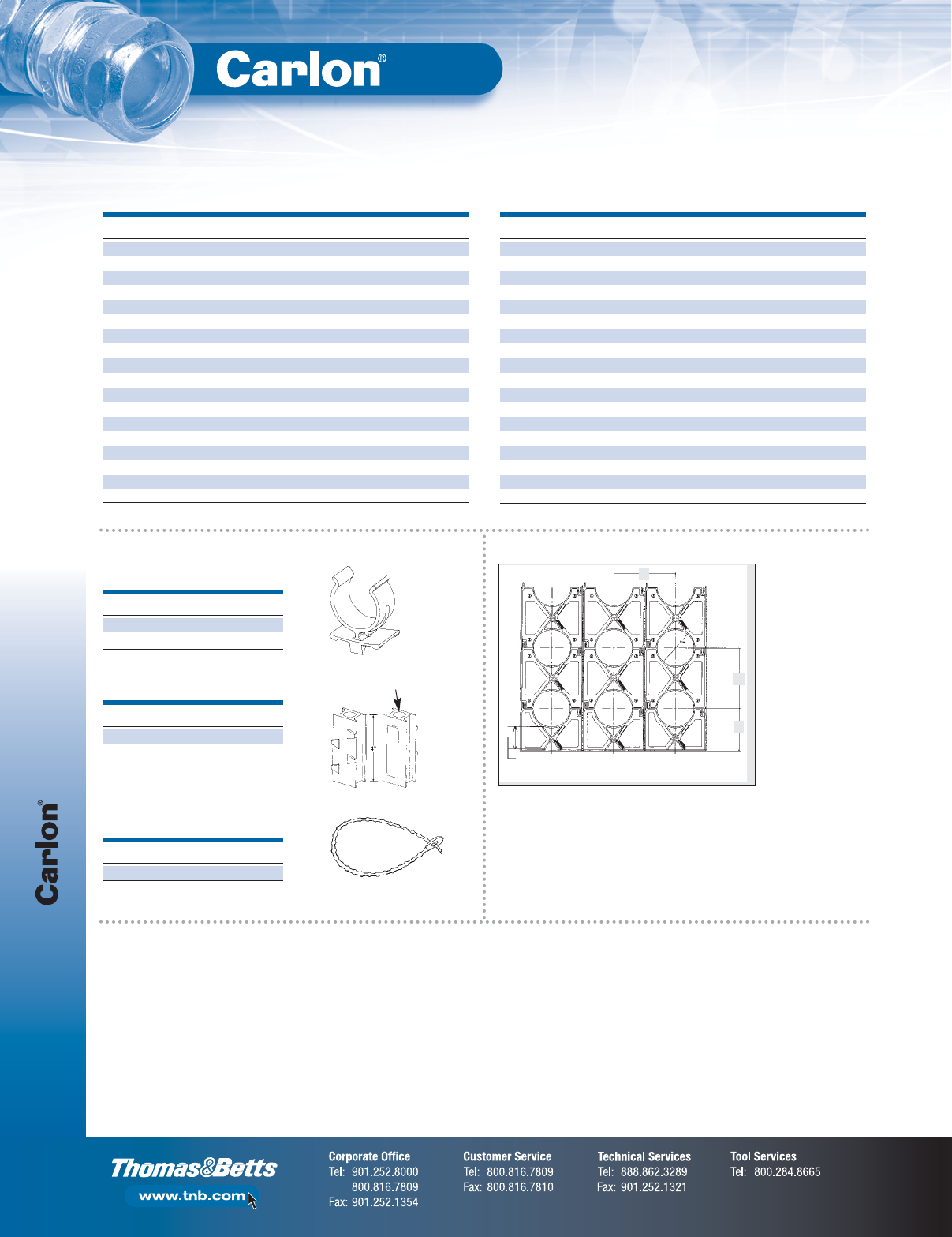
Spacers
F-82
Non-Metallic Rigid Conduit, Fittings and Accessories
Dimensions — Base Spacers
Carlon®Snap-Loc®Spacers
(continued)
CAT. NO. SIZE (IN.) A (IN.) C (IN.) D (DIA.) (IN.) STD. CTN.
S288JHN 2 x 11⁄24.25 4.12 2.50 100
S288JJN 2 x 2 4.25 4.62 2.50 100
S288JLN 2 x 3 4.25 5.62 2.50 100
S288LHN 3 x 11⁄24.81 5.25 3.63 90
S288LJN 3 x 2 4.81 5.75 3.63 80
S288LLN 3 x 3 4.81 6.75 3.63 60
S288NFN 4 x 1 4.50 5.75 4.63 70
S288NHN 4 x 11⁄25.31 6.25 4.63 50
S288NJN 4 x 2 5.31 6.75 4.63 50
S288NLN 4 x 3 5.31 7.75 4.63 60
S288PHN 5 x 11⁄25.84 7.31 5.69 50
S288PJN 5 x 2 5.84 7.81 5.69 60
S288PLN 5 x 3 5.84 8.81 5.69 50
S288RHN 6 x 11⁄26.38 8.38 6.75 50
S288RJN 6 x 2 6.38 8.88 6.75 50
S288RLN 6 x 3 6.38 9.88 6.75 40
S288SHN 8 x 11⁄27.38 10.30 8.75 30
S288SJN 8 x 2 7.38 10.76 8.75 30
Accessories
Dimensions — Intermediate Spacers
CAT. NO. SIZE (IN.) A (IN.) C (IN.) D (DIA.) (IN.) STD. CTN.
S289JHN 2 x 11⁄23.88 4.12 2.50 120
S289JJN 2 x 2 4.38 4.62 2.50 100
S289JLN 2 x 3 5.38 5.62 2.50 80
S289LHN 3 x 11⁄25.01 5.25 3.63 100
S289LJN 3 x 2 5.51 5.75 3.63 80
S289LLN 3 x 3 6.51 6.75 3.63 60
S289NFN 4 x 1 5.51 5.73 4.63 70
S289NHN 4 x 11⁄26.01 6.25 4.63 60
S289NJN 4 x 2 6.51 6.75 4.63 60
S289NLN 4 x 3 7.51 7.75 4.63 50
S289PHN 5 x 11⁄27.07 7.31 5.69 50
S289PJN 5 x 2 7.57 7.81 5.69 50
S289PLN 5 x 3 8.57 8.81 5.69 30
S289RHN 6 x 11⁄28.14 8.38 6.75 50
S289RJN 6 x 2 8.64 8.88 6.75 40
S289RLN 6 x 3 9.64 9.88 6.75 30
S289SHN 8 x 11⁄210.14 10.30 8.75 30
S289SJN 8 x 2 10.64 10.76 8.75 30
*First number indicates trade size of duct, second number indicates separation between conduits or ducts.
CAT. NO. SIZE (IN.) STD. CTN.
S287F 1 100
S287J 2 100
Snap-Loc®Reducer
CAT. NO. STD. CTN.
S258RH 100
Rebar Holder
CAT. NO. STD. CTN.
S28612 1 Bag of 250
Beaded Strap
15" in length
Specifications
B
C
A
3" Standard for all Base Spacers
(with the exception of the 4X1-S288NFN)
The Spacers and Rebar Holder are designed with a dovetail
tongue-and-groove feature for easy installation.
If required to permanently fix the position of a group of Spacers
and/or Rebar Holder, the following are recommended procedures:
1. Use Carlon®Quick-Set Cement glue during assembly or spot glue
after assembly to secure.
2. During assembly, deform the edge of the tongue or groove portion
of the dovetail slide with a pair of pliers or similar tool. This deformation
will create an interference, restricting movement.
3. An assembled system may be wired together for additional support.
Installation Note
Important:
The use of duct spacers for direct burial may result in excessive
point deflections unless proper design engineering is applied, such
as the proper compaction of the appropriate backfill material.
Suggested Specification:
(Duct) (Conduit) bank shall be encased in concrete with at least three inches
of concrete at the top and bottom and two inches on each side. A horizontal
and vertical separation between the ducts of ____* inches shall be
maintained by installing Carlon®high-impact spacers with horizontal
and vertical locking intervals of ____** feet.
*Standard Separations of 1", 11⁄2", 2" and 3" are available.
**Preferred interval between spacer assemblies is 8 to 10 feet.
Hole Dia. = .688 min.
.750 max.
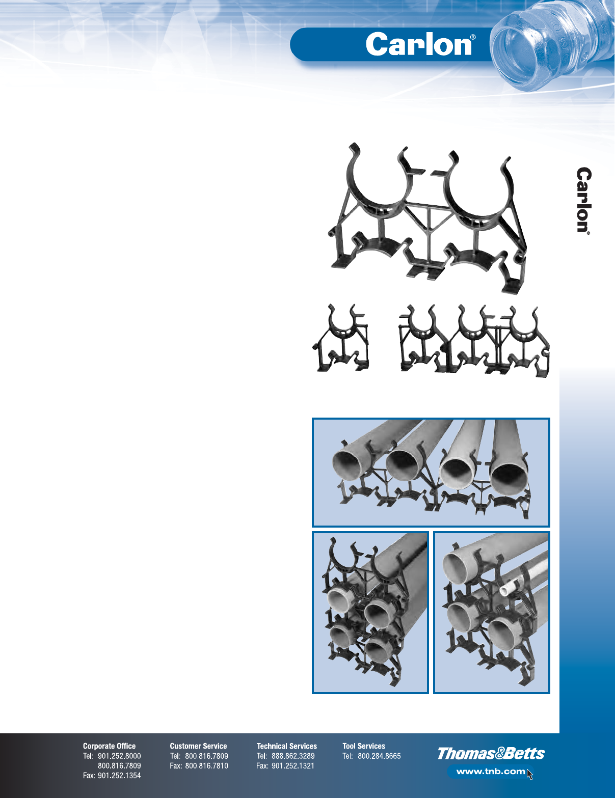
F-83
Non-Metallic Rigid Conduit, Fittings and Accessories
Spacers
Carlon®Snap-N-Stac™Combo Spacers
One-way Three-way
Installations
Vertical Interlocking With Reducer
Horizontal Locking
Carlon®Snap-N-Stac™Combo Duct Spacers are specifically designed to
replace the two-piece base and intermediate spacer system, by combining
the conventional base and intermediate spacer into a single unit!
Manufactured out of highly engineered thermoplastic material, Snap-N-Stac™
Spacers are strong, durable and able to withstand the rigors of concrete
construction. They feature an innovative horizontal and EXCLUSIVE vertical
locking system, and can be used as either a base or intermediate spacer.
Snap-N-Stac™Spacers are available in one-way, two-way and three-way
configurations (one-way and three-way only available in sizes 2" and 4").
They accept 2", 3", 4", 5" and 6" pipe and can be installed horizontally,
vertically or turned upright for unique duct bank configurations.
This NEW one-piece design makes underground duct bank installations
faster and easier than the conventional two-piece system — saving material
and labor costs.
Carlon®Snap-N-Stac™Combo Spacers…The IDEAL solution for underground
duct bank installations.
Features:
•Conventional base and intermediate spacer in a single unit
•Less inventory required
•EXCLUSIVE vertical locking system
•Horizontal locking system
•Installs horizontally or turned upright
•Molded-in rebar holder on two-way and three-way
•One-, two- and three-way configurations (one-way
and three-way only available in sizes 2" and 4")
•5 sizes: 2", 3", 4", 5" and 6"
•Reducer to accommodate smaller duct sizes
•Can be used as either an intermediate or base spacer
•Spacers interlock horizontally regardless of size
•Non-metallic, non-corrosive, non-conductive
•Strong and durable
•Easy to handle
•Fast installation
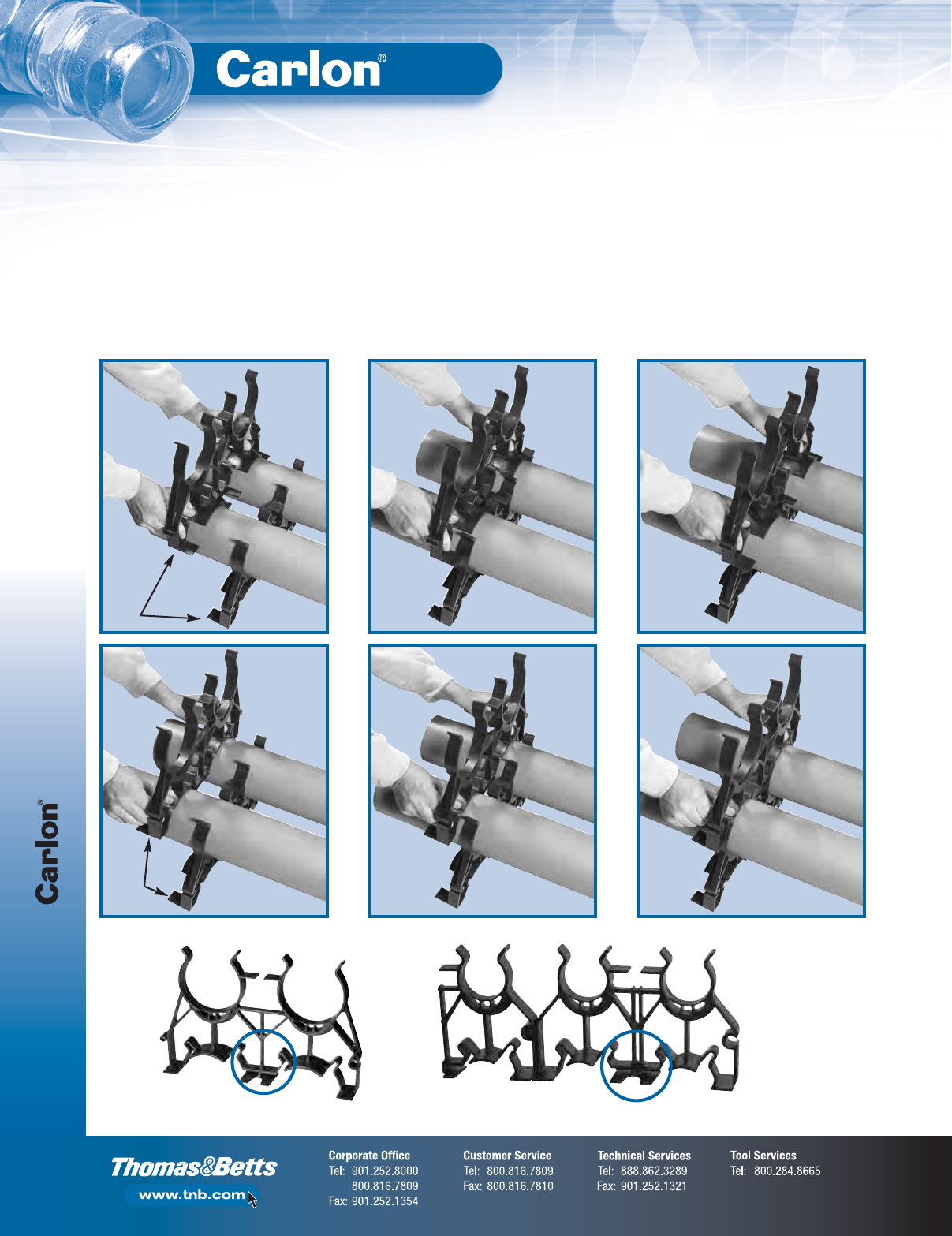
Spacers
F-84
Non-Metallic Rigid Conduit, Fittings and Accessories
IMPORTANT:
1. Snap-N-Stac™Spacers are recommended for concrete-encased applications only.
2. The use of duct spacers for direct burial may result in excessive point deflections unless proper
design engineering is applied, such as the proper compaction of the appropriate backfill material.
Installation Instructions
Vertical Interlocking
Slide spacers together “Feet Facing Feet.”
Feet
Facing
Feet
Opposite
Molded-In Rebar Holder
Carlon®Snap-N-Stac™Combo Spacers
(continued)
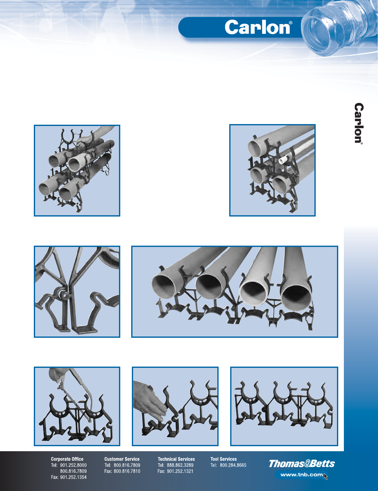
F-85
Non-Metallic Rigid Conduit, Fittings and Accessories
Spacers
Vertical Free Standing
If spacers are installed using free-standing method, it is recommended
to install the spacer on the upper row mid-way between the two spacers
on the bottom row.
Reducer
1" and 2" Snap-Loc Reducers enable fixturing
of 1" and 2" conduit inside of larger spacers.
Transition to Various Duct Sizes
Install spacers side-by-side by inserting the male adapter into the female adapter.
NOTE: All Snap-N-Stac™spacers are designed to interlock horizontally, regardless of size.
Odd Number of Ducts
Two-way spacers, size 2" and 4" only, can easily be cut apart to produce two one-way spacers. Create three-way and five-way
spacers using the one-way spacer. Install spacers side-by-side by inserting the male adapter into the female adapter.
Installation Instructions
Carlon®Snap-N-Stac™Combo Spacers
(continued)
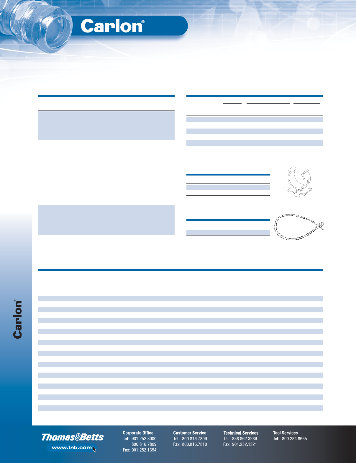
Spacers
F-86
Non-Metallic Rigid Conduit, Fittings and Accessories
DUCT-TO-DUCT CENTER-TO-CENTER
DUCT SPACING SPACING BOTTOM OF BOTTOM OF
SIZE DUCT HORIZONTAL VERTICAL HORIZONTAL VERTICAL HORIZONTAL TRENCH TO TRENCH TO CENTER OVERALL
CAT. NO. (IN.) O.D. DUCT POSITIONS (IN.) (IN.) (IN.) (IN.) BOTTOM OF DUCT OF BOTTOM OF DUCT LENGTH
SP2W20-1 2 2.375 1 2 2 2.19 2.19 3.13 4.25 4.38
SP2W30-1 2 2.375 1 3 3 2.69 2.69 4.13 5.25 5.38
SP4W15-1 4 4.500 1 1.5 1.5 3.00 3.00 3.38 5.56 6.00
SP4W20-1 4 4.500 1 2 2 3.25 3.25 3.88 6.06 6.50
SP4W30-1 4 4.500 1 3 3 3.75 3.75 4.88 7.06 7.50
SP2W20-2 2 2.375 2 2 2 4.38 4.38 3.13 4.25 8.75
SP2W30-2 2 2.375 2 3 3 5.38 5.38 4.13 5.25 10.75
SP3W20-2 3 3.500 2 2 2 5.50 5.50 3.63 5.38 11.00
SP3W30-2 3 3.500 2 3 3 6.50 6.50 4.63 6.38 13.00
SP4W15-2 4 4.500 2 1.5 1.5 6.00 6.00 3.38 5.56 12.00
SP4W20-2 4 4.500 2 2 2 6.50 6.50 3.88 6.06 13.00
SP4W30-2 4 4.500 2 3 3 7.50 7.50 4.88 7.06 15.00
SP5W20-2 5 5.500 2 2 2 7.56 7.56 4.38 7.25 15.12
SP5W30-2 5 5.500 2 3 3 8.56 8.56 5.38 8.25 17.14
SP6W20-2 6 6.625 2 2 2 8.62 8.62 4.13 7.38 17.25
SP6W30-2 6 6.625 2 3 3 9.62 9.62 5.13 8.38 19.25
SP2W20-3 2 2.375 3 2 2 4.38 4.38 3.13 4.25 13.13
SP2W30-3 2 2.375 3 3 3 5.38 5.38 4.13 5.25 16.13
SP4W15-3 4 4.500 3 1.5 1.5 6.00 6.00 3.38 5.56 18.00
SP4W20-3 4 4.500 3 2 2 6.50 6.50 3.88 6.06 19.50
SP4W30-3 4 4.500 3 3 3 7.50 7.50 4.88 7.06 22.50
How to Interpret the Part Number:
POSITION 1 POSITION 2 POSITION 3 POSITION 4
PRODUCT TYPE DUCT SIZE DUCT-TO-DUCT SPACING — HORIZONTAL
HORIZONTAL AND VERTICAL DUCT POSITIONS
SP = Spacer 2W = 2" Width 15 = 11⁄2" -1 = One-Way
3W = 3" Width 20 = 2" -2 = Two-Way
4W = 4" Width 30 = 3" -3 = Three-Way
5W = 5" Width
6W = 6" Width
Technical Information
CAT. NO. SIZE (IN.) STD. CTN.
S287F 1 100
S287J 2 100
Snap-Loc®Reducer
CAT. NO. STD. CTN.
S28612 100
Beaded Strap
15" in length
SIZE SEPARATION STD. WT.
CAT. NO. DESCRIPTION (IN.) (IN.) STD. CTN. (LBS.)
SP2W20-1 2 2 56 15.0
SP2W30-1 2 3 40 13.0
SP4W15-1 1-Way Spacers 4 11⁄226 9.6
SP4W20-1 4 2 20 10.0
SP4W30-1 4 3 20 9.4
SP2W20-2* 2 2 56 28.5
SP2W30-2* 2 3 40 23.8
SP3W20-2 3 2 40 24.0
SP3W30-2 3 3 24 17.9
SP4W15-2* 41
1⁄226 18.3
SP4W20-2* 2-Way Spacers 4 2 24 18.8
SP4W30-2* 4 3 20 17.6
SP5W20-2 5 2 20 17.2
SP5W30-2 5 3 14 15.5
SP6W20-2 6 2 12 12.8
SP6W30-2 6 3 12 14.1
SP2W20-3 2 2 36 28.5
SP2W30-3 2 3 18 17.8
SP4W15-3 3-Way Spacers 4 11⁄218 19.4
SP4W20-3 4 2 16 19.3
SP4W30-3 4 3 14 19.1
*Can be cut apart to make (2) one-way spacers.
Accessories
Carlon®Snap-N-Stac™Combo Spacers
(continued)
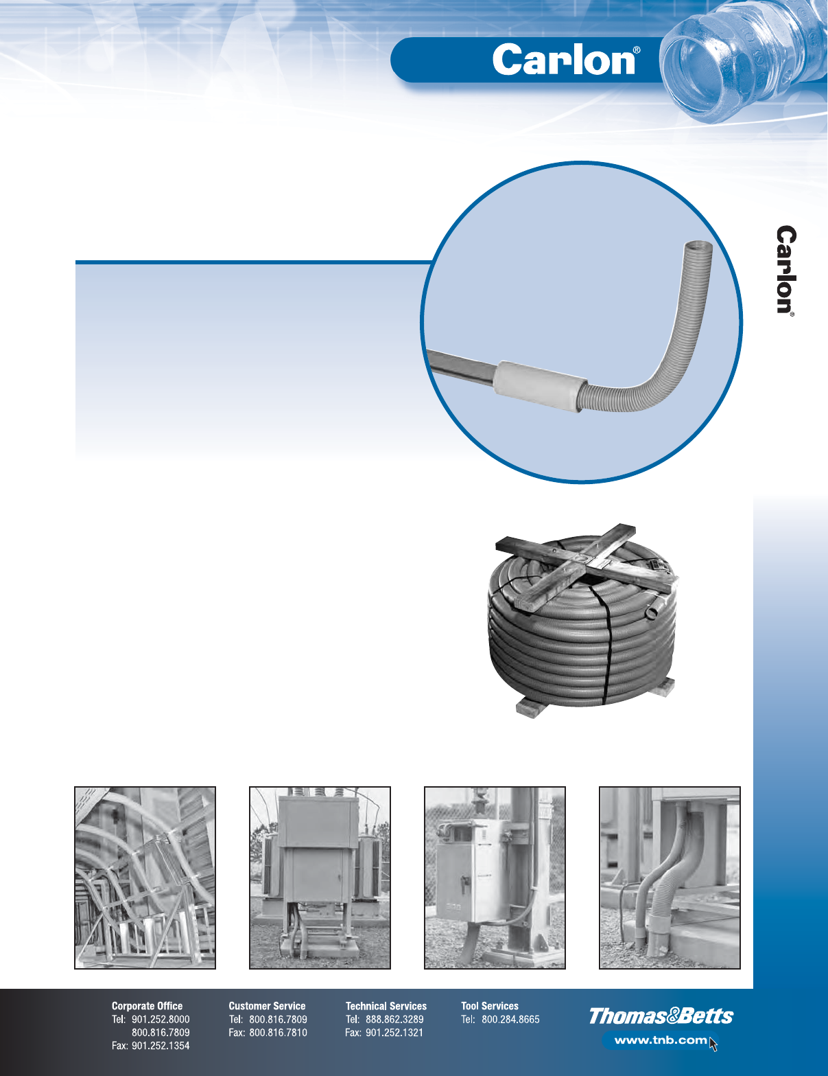
F-87
Non-Metallic Rigid Conduit, Fittings and Accessories
P&C Flex™
Applications
Carlon®P&C Flex™Non-Metallic Corrugated Conduit makes power and
communication installations faster and easier by providing maximum
installation flexibility. The corrugated design is flexible enough to
accommodate any degree of bend requirement. Unlike rigid conduit, it
has a tight bend radius, making this product ideal for shallow trenches.
P&C Flex™is manufactured to IPS dimensions and can be used with any
existing conduit system using standard fittings. It is UV resistant and
suitable for a variety of applications, including direct burial, under
bridges, service entrance/FTTx terminations, manhole terminations,
pedestal/enclosure terminations and running up utility poles or outside
of buildings.
P&C Flex™is available in sizes 3⁄4" though 4", with or without pull tape
(1" through 4" only) and comes in a variety of convenient standard put-ups.
Features:
•Accommodates any degree of bend — ideal for shallow trenches
– For use with HDPE — Use ELA_ Series Fittings
– For use with PVC — Use E940_ Series Fittings
•Easily handles offsets
•Manufactured to IPS dimensions — can be used
with standard IPS coupling/fittings
•UV resistant
•Can be used as a flexible sweep or raceway —
one SKU can do multiple bends
•Available in sizes 3⁄4" though 4"
•Small put-ups for easy handling
NOTE: Not UL Listed.
Carlon®P&C Flex™
Corrugated Flexible Conduit
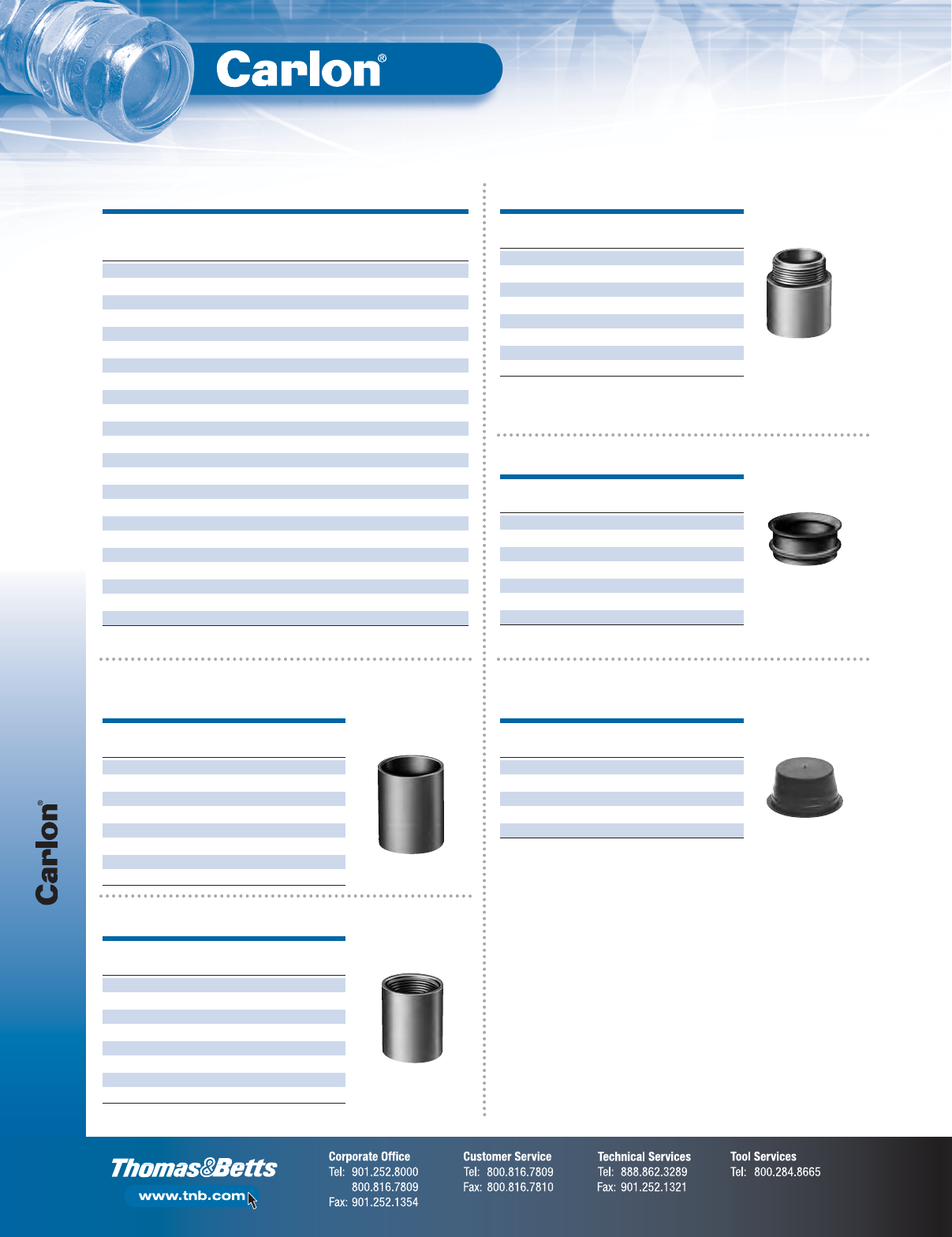
P&C Flex™
F-88
Non-Metallic Rigid Conduit, Fittings and Accessories
P&C Flex Conduit
STD. STD.
SIZE I.D. O.D. PULL REEL/ CTN. WT.
CAT. NO.
(IN.) (IN.) (IN.) TAPE COIL (FT.) (LBS.)
11807-350 3⁄4.83 1.040 Empty Coil 350 39.9
1808-250C 1 1.000 1.315 Empty Coil 250 36.3
11808-5200 1 1.000 1.315 Empty Reel 5200 1019.0
11809-900 11⁄41.340 1.660 Empty Reel 900 243.0
11809-4500 11⁄41.340 1.660 Empty Reel 4500 972.0
11810-250 11⁄21.570 1.900 Empty Reel 250 75.8
11810-4500 11⁄21.570 1.900 Empty Reel 4500 1080.0
11810T-2300 11⁄21.570 1.900 1250 lb. Reel 2300 720.0
11810T-250 11⁄21.570 1.900 1250 lb. Reel 250 78.0
11811-1100 2 2.045 2.375 Empty Reel 1100 521.4
11811-250 2 2.045 2.375 Empty Reel 250 87.0
11811-2500 2 2.045 2.375 Empty Reel 2500 815.0
11811-500 2 2.045 2.375 Empty Reel 500 201.6
11811-700 2 2.045 2.375 Empty Reel 700 269.0
11811T-250 2 2.045 2.375 1250 lb Reel 250 89.0
11812-250 21⁄22.469 2.875 Empty Reel 250 121.0
11812AG-001 21⁄22.469 2.875 Empty Reel 1300 516.1
11813-1200 3 3.068 3.500 Empty Reel 1200 850.8
11813-250 3 3.068 3.500 Empty Reel 250 192.0
11813-500 3 3.068 3.500 Empty Reel 500 523.0
11813-750 3 3.068 3.500 Empty Reel 750 554.3
11815-250 4 4.026 4.500 Empty Reel 250 324.0
11815-800 4 4.026 4.500 Empty Reel 800 778.4
P&C Flex Fittings
SIZE STD. STD. WT.
CAT. NO.
(IN.) CTN. (LBS.)
E940E 3⁄4100 4.6
E940F 1 50 3.5
E940G 11⁄430 3.2
E940H 11⁄225 3.4
E940J 2 30 5.3
E940K 21⁄220 7.5
E940L 3 25 14.7
E940N 4 15 12.5
SIZE STD. STD. WT.
CAT. NO.
(IN.) CTN. (LBS.)
E943E 3⁄4125 4.2
E943F 1 50 3.0
E943G 11⁄425 4.1
E943H 11⁄225 2.7
E943J 2 5 6.9
E943K 21⁄220 6.3
E943L 3 45 16.6
E943N 4 15 11.7
SIZE STD. STD. WT.
CAT. NO.
(IN.) CTN. (LBS.)
E997F 1 50 2.6
E997G 11⁄435 2.5
E997H 11⁄230 2.5
E997J 2 10 4.8
E997K 21⁄210 2.0
E997L 3 10 10.0
E997N 4 30 16.0
SIZE STD. STD. WT.
CAT. NO.
(IN.) CTN. (LBS.)
P258H 11⁄250 1.7
P258JT 2 60 3.1
P258K 21⁄225 1.5
P258LT 3 30 3.4
P258NT 4 48 8.3
SIZE STD. STD. WT.
CAT. NO.
(IN.) CTN. (LBS.)
E942E 3⁄4100 4.3
E942F 1 50 3.7
E942G 11⁄430 3.3
E942H 11⁄225 3.3
E942J 2 30 5.4
E942K 21⁄220 6.6
E942L 3 25 11.8
E942N 4 15 10.8
Terminal Adapters
Bell Ends (Schedule 40)
Plugs
Couplings
Female Adapters
F-89
Non-Metallic Rigid Conduit, Fittings and Accessories
P&C Flex™
PERFORMANCE PROPERTIES 3⁄4"1"1
1⁄4"1
1⁄2"2"2
1⁄2"3" 4"
Stiffness F/ y at 5% deflection 200 200 200 200 200 130 130 90
Impact Strength (ft./lbs.) 72° 35 40 40 50 50 70 120 140
Impact Strength (ft./lbs.) 32° 5 8 8 15 25 35 60 60
Minimum Bending Radius (inches) 6 6 6 7 8 12 15 18
Conduit Tensile Strength 200 300 400 500 700 1000 1500 2000
Storage: -4° to 158°F
Handling: -4° to 104°F
Technical Information
RADIUS
18" REQUIRED 24" REQUIRED 36" REQUIRED 48" REQUIRED 60" REQUIRED
(IN.)
LENGTH OF P&C LENGTH OF P&C LENGTH OF P&C LENGTH OF P&C LENGTH OF P&C
NOM. DIA.
SEGMENT FLEX (IN.) FLEX (IN.) FLEX (IN.) FLEX (IN.) FLEX (IN.)
90º 33 42 61 80 99
45º 19 23 33 42 52
11⁄230º 14 17 23 30 36
221⁄2º12 14 19 23 28
90º 32 42 61 79 98
45º 18 23 32 42 51
230º 14 17 23 29 35
221⁄2º11 12 18 23 28
90º 34 44 63 81 100
45º 20 25 33 44 53
21⁄230º 16 19 24 31 37
221⁄2º13 15 20 25 30
90º 35 44 63 82 101
45º 20 25 34 44 53
330º 16 19 24 32 38
221⁄2º13 16 20 25 30
90º 37 46 65 84 103
45º 22 27 37 46 55
430º 18 21 27 34 40
221⁄2º15 18 22 27 32
For other radius sweeps use this formula: .0175 x Radius (inches) x Angle° = Required length of P&C flex in inches
Sweep and Elbow Conversion Chart
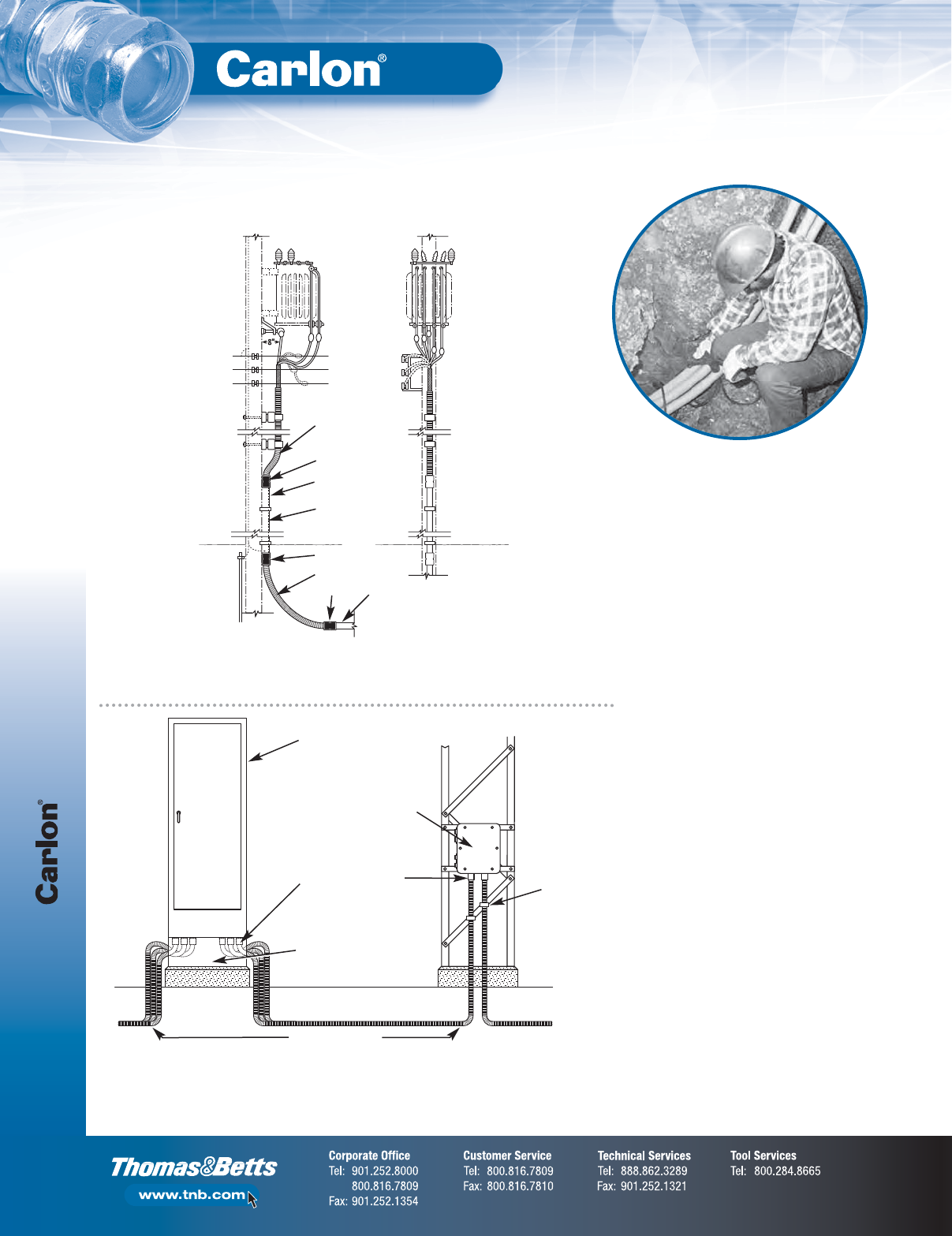
F-90
Non-Metallic Rigid Conduit, Fittings and Accessories
P&C Flex™
Technical Information
P&C Flex™conduit is flexible. Carlon
®
P&C Flex™Non-Metallic Corrugated Conduit is used
to transition from Carlon
®
P&C Duct Type DB. Despite equipment being mounted away
from the pole, P&C Flex™conduit remains flush to the pole.
When soil conditions do not permit direct burial
of cable, use Carlon®P&C Flex™Non-Metallic
Corrugated Conduit to protect the cable. A lower
coefficient of friction provides easy wire pulls on
location. Flexibility eliminates the need for elbows.
Flex conduit
Flex conduit
Coupling
Coupling
Coupling
Rigid
Non-Metallic
Conduit
Customer
conduit
Guard
Substation SCADA
RTU cabinet
Steel channels to support
RTU and provide space under
cabinet for conduit
Carlon
®
Terminal
Adapters cemented
to ends of P&C Flex
™
Circuit Safe JIC Enclosure
with transducers and
interposing relays
mounted to steel
structure or equipment
Conduit clamps
Control Cables run in
1" or 1
1
⁄
2
" P&C Flex
™
conduit
Carlon
®
P&C Flex™Non-Metallic Corrugated Conduit protects control cables in supervisory control
and data acquisition equipment (SCADA) in distribution substations. Flexibility provides maximum
utilization of equipment.
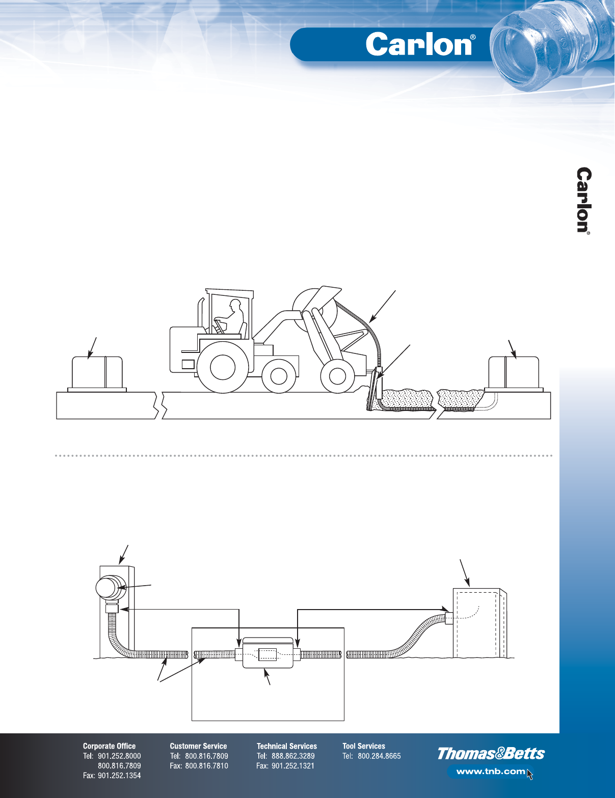
F-91
Non-Metallic Rigid Conduit, Fittings and Accessories
P&C Flex®
Suggested Applications
•Carlon®P&C Flex™Non-Metallic Corrugated Conduit
is the most versatile system available for power
and communications applications
•P&C Flex™combines high crush strength with flexibility.
Longer coil lengths reduce installation time
In single-phase underground primary systems, lower the cost of direct
buried and standard conduit systems by installing P&C Flex™Non-Metallic
Corrugated Conduit with a vibratory plow.
Pad Mount
Transformer
Pad Mount
Transformer
2" Carlon P&C Flex
™
Non-Metallic Corrugated
Conduit
Vibratory
Plow
Digging up faulty cable in frozen ground can be expensive and time
consuming. Use Carlon
®
P&C Flex™from the customer service raceway
to the temporary service pedestal to restore power on an interim basis.
When the service length is more than 250 feet, use a splice box and
an additional length of P&C Flex™Non-Metallic Corrugated Conduit.
Customer Service
Raceway
Service cable
inserted into
2" Carlon
®
P&C Flex
™
Corrugated Conduit
Temporary pedestal installed
over existing pedestal
and service
wires connected
Meter
Adapter Carlon
®
Terminal
Adapters
cemented to
P&C Flex
™
Circuit Safe JIC enclosure used as
splice box where service length
is more than 125 feet
Here are a few application ideas that illustrate how P&C Flex®can be effectively used:
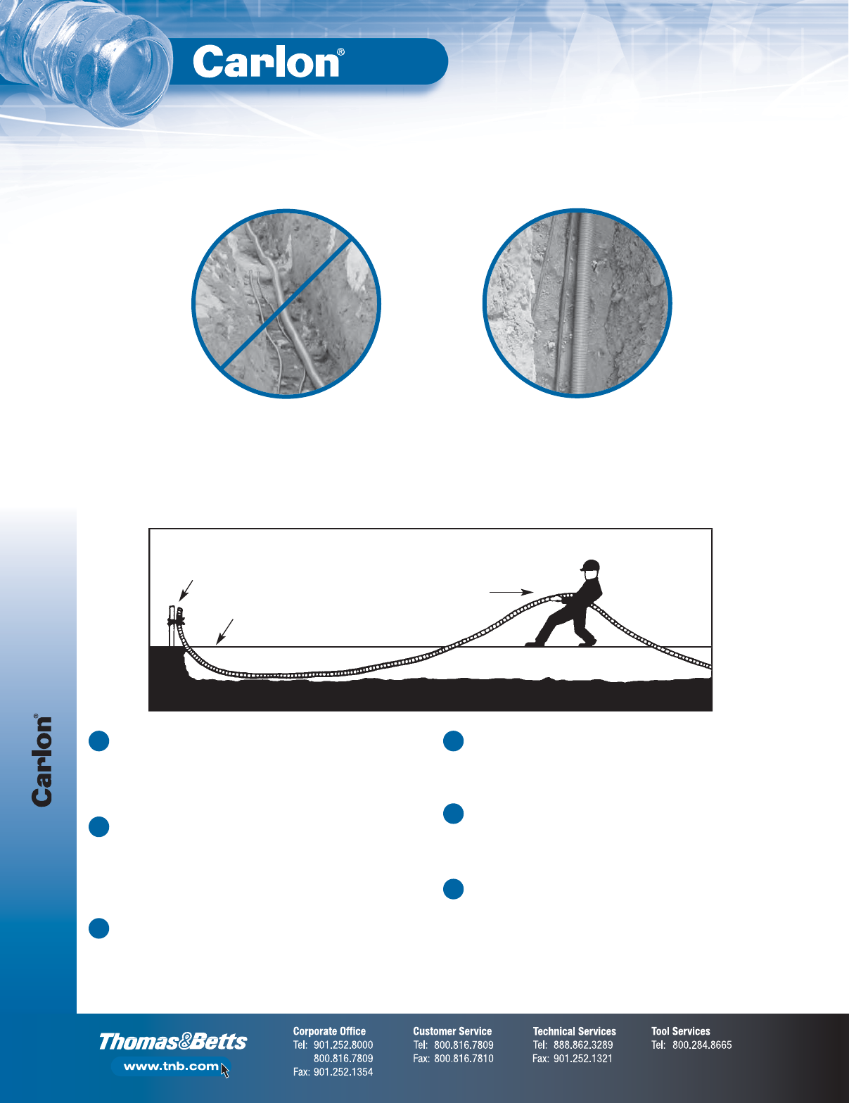
P&C Flex™
F-92
Non-Metallic Rigid Conduit, Fittings and Accessories
Installation
Lay conduit in the trench as straight as
possible. Avoid undulations up and down
and side to side.
Incorrect Method Correct Method
Stretch duct in one direction
away from secured end
Spot backfill
Keep bends as gradual as possible
Secure end
Trenching
Trenching
Trench should be graded true and free from stones or soft spots.
Backfill should also be free of stones and be firmly tamped around
the sides of the conduit to develop maximum supporting strength.
Tamping on top of the conduit is not recommended.
Backfill
In rocky soil where it is impossible to have an even trench bottom,
a selected backfill should be put in before laying the conduit.
Selected backfill (not tamped) at least 6" over the top of the conduit
is recommended. After final backfill is placed, tamping may be used
to finish the grade.
Duct Placement
Duct may be unreeled directly into trench or along side trench
and subsequently placed in trench. After placing in trench, secure
one end and stretch it by hand to take up the slack. Spot backfill
to hold in position. Do not use mechanical stretching equipment.
1
2
3
Changes in Direction
Avoid unnecessary turns, dips or changes in direction. Keep
bends as gradual as possible to ensure ease of cable pull-in
after duct installation.
Pneumatic Rodding
All commonly used vacuum or pressure rodding equipment can be
used to rod P&C Flex™. The line carrier (mouse, puck, rocket) should
be soft, flexible material designed to fit snugly into duct without
interference.
Mechanical Rodding
All commonly used mechanical rodding equipment can be used
to rod P&C Flex™. The tip should have a ball-type arrangement
to keep rod from catching in the convolutions on the inside of duct.
4
5
6
