Adalet Catalog Increased Safety VH4X VC4X
2014-11-11
: Pdf 115058-Attachment 115058-Attachment 781063 Batch12 unilog
Open the PDF directly: View PDF ![]() .
.
Page Count: 145 [warning: Documents this large are best viewed by clicking the View PDF Link!]

SEND ORDERS TO ORDERS@ADALET.COM
T: 216.267.9000 | F:216.267.1681 | info@adalet.com ©Adalet
1
Increased Safety Enclosures
Explosionproof / Dust-Ignition Proof Enclosures
Explosionproof Auxiliary Devices
Explosionproof Motor Control
Explosionproof / Dust-Ignition Proof Panelboards
Explosionproof Instrument Housings
Explosionproof Meter Housings
Explosionproof Fittings & Accessories
PLM - Cable Systems
Technical Data
Numerical Index
4
94
128
146
162
204
228
258
280
290
296

ADALET.COM
ADALET ENCLOSURE SYSTEMS | 4801 WEST 150TH | CLEVELAND, OHIO 44135©Adalet
2
Increased Safety Enclosures
Quarter Turn Latch Terminal Enclosures 6
VH4X Series 8
VC4X Series 10
Screw Cover Terminal Enclosures (TSC Series) 14
Clamped Door Terminal Enclosures (TN Series) 34
Control Enclosures (CN Series) 76
Increased Safety Controls 82
Pushbutton Station Enclosures 85
High Voltage Junction Boxes (HV Series) 87
Principles, Markings & Design Guidelines 90
Explosionproof / Dust-Ignition
Proof Enclosures
XCE, XCEX, XCESX & XJF Series 96
XHVX Series 112
XCPX Series 115
ATEX Control Panel Certification 116
XIF Series 117
Control / Pendant Stations 121
Dust-Ignition Proof 126
Control Station for Panel Mounting 127
Explosionproof Auxiliary Devices
Push Buttons 130
Selector Switches 133
Pilot Lights 135
ATEX Pilot Lights 137
Reset Buttons 138
Accessories 139
Contact Blocks 141
Miniature Operators 142
Flame Arrestors 144
Breather / Drains 145
Motor Control
Explosionproof Circuit Breaker Enclosures 148
Explosionproof Combination Motor Starters 152
Enclosure Only 153
Full Voltage Non-Reversing 154
Full Voltage Reversing 155
Options & Ordering Information 156
Explosionproof Motor Starter / Protector 158
Switchrack Assemblies 160
Explosionproof / Dust-Ignition
Proof Panelboards
Stainless Steel Panelboards 164
N4XPBH Series 166
N4XPB Series 168
Factory Sealed Panelboards 170
Lighting Panel Main Lug Only 172
Vertical Main Breaker 176
Back Fed Main Breaker 180
Power Panel Main Lug Only 184
Division 1 Explosionproof Panelboards 188
Lighting Panel Main Lug Only 190
Vertical Main Breaker 192
Back Fed Main Breaker 194
Power Panel Main Lug Only 196
Lighting Panelboards 200
Power Distribution Panelboards 202

SEND ORDERS TO ORDERS@ADALET.COM
T: 216.267.9000 | F:216.267.1681 | info@adalet.com ©Adalet
3
Instrument Housings
XDHI Series (Mini) - 2 ⁄” ID 206
XIH Series - 3 ⁄” ID 208
XIH 3-Lug Series - 3 ⁄” ID 210
XDH Series - 3 ⁄” ID 212
XIHM Series - 3 ⁄” ID 214
XDHM Series - 3 ⁄” ID 216
XIHL Series - 4” ID 218
XDHL Series - 4” ID 220
XIHN Series - 4 ⁄” ID 222
XIHNS Series - 4 ⁄” ID 224
XIHS Series - 2 ⁄” 226
Explosionproof Meter Housing
Screw Cover 232
Window Screw Cover 240
Dome Cover 248
Drilling & Tapping Guidelines 257
Explosionproof / Dust-Ignition
Proof Fittings & Accessories
Multi-Hub Junction Boxes 262
Sealing Fittings 264
Close-Up Plugs 270
Pull Elbows 271
Explosionproof Flexible Couplings 272
Conduit Unions 273
Jacket Over Armor 274
Ventilators 278
Bus-Drop Cable Clamps - Sky-Tie™ 281
PLM - Cable Systems
PLM Cable Coupler Selection Guide 282
415 / 515 Series Cable Couplers 284
Conversion Kits 287
Connection Options 288
Accessories 289
Quick Guide
ATEX CERTIFIED PRODUCTS
Increased Safety Terminal Enclosures Ex e II
ATEX Conformity & Component Enclosures Available
Instrument Housings Exd IIC
(except XDHLX is Exd IIB+H2)
XIHMK series
XIHX / XDHX series
XIHMX / XDHMX series
XIHLX / XDHLX series
XCEX Exd IIB or IIB +H2
Includes Push Buttons, Pilot Lights, Selector Switches,
Potentiometers & Close Up Plugs When Installed In
Adalet Enclosures.
XCPX Enclosure Series
ATEX Enclosure Certification
XIFCX Control Enclosures
Pilot Lights
XJ_X Screw Cover Series Exd IIB+H2
XJLBX Multi-Hub General Purpose Junction Box

ADALET.COM
ADALET ENCLOSURE SYSTEMS | 4801 WEST 150TH | CLEVELAND, OHIO 44135©Adalet
4
Increased Safety Enclosures
Adalet offers a variety of enclosures which are rated to the increased safety (Exe) method of protection. These
enclosures provide an alternative to ameproof enclosures and are intended to house electrical components
which will not generate an arc or spark during normal operation. Additional design measures are taken to
prevent the possibility of excessive heat, the ingress of water or dust, and the resistance to impact, thus
preventing any explosions from occurring. From simple terminal enclosures to high voltage and control
enclosures, Adalet’s line of increased safety enclosures offers the exibility to meet your custom requirements.
INCREASED SAFETY ENCLOSURES
PRINCIPLE
Intended for product in which arcs and sparks do not
occur in normal service or under fault conditions and
in which surface temperatures are controlled below
incendive values. Increased Safety is achieved by
enhancing insulation values and creepage and clearance
distances above those required for normal service, thus
providing a safety factor against accidental breakdown.
Increased Safety must not be confused with Intrinsically
Safe; they are two completely different approaches.
Intrinsic Safety requires that the electrical components
within an enclosure have very low levels of electrical
energy, either stored or circulating. Typically, allowable
currents will be in the tens of milliamperes and voltage
will be less than 100 volts, so they will be insufcient to
ignite a surrounding explosive atmostphere even under
fault conditions.
KEY DESIGN FEATURES
• Enclosure: must be constructed to withstand mechanical
impact and provide a specied degree of ingress protection
(IP rating). A minimum IP54 rating is required for Increased
Safety enclosures.
• Terminals for external connections: must be generously
dimensioned for the intended connection and ensure that
conductors are securely fastened.
• Internal connections: must not be subject to undue
mechanical stress and shall be made using specied
methods.
• Clearances: between bare conductive parts must not be less
than the values specied according to the rated voltage.
• Creepage distances: must not be less than the values
specied according to the rated voltage and the Comparative
Tracking Index (CTI) of the insultationg material.
• Temperatures: of parts of equipment must be limited so as
not to exceed values which would affect the thermal stability
of the material and the T-Class relating to the ignition of
explosive atmospheres.
Designed to protect in areas where flammable gases, vapors, liquids and dusts can exist.
SEND ORDERS TO ORDERS@ADALET.COM
T: 216.267.9000 | F:216.267.1681 | info@adalet.com ©Adalet
5
Increased Safety Enclosures
Increased Safety Enclosures
Quarter Turn Latch Terminal Enclosures 6
VH4X Series 8
VC4X Series 10
Screw Cover Terminal Enclosures (TSC Series) 14
Clamped Door Terminal Enclosures (TN Series) 34
Control Enclosures (CN Series) 76
Increased Safety Controls 82
Pushbutton Station Enclosures 85
High Voltage Junction Boxes (HV Series) 87
Principles, Markings & Design Guidelines 90
Contents
INCREASED SAFETY
TERMINAL ENCLOSURES
INCREASED SAFETY
ENCLOSURES
ADALET.COM
ADALET ENCLOSURE SYSTEMS | 4801 WEST 150TH | CLEVELAND, OHIO 44135©Adalet
6
• 37 standard sizes available
• Stainless steel quarter turn latch with 3mm double bit insert (includes key)
• Continuous one-piece water tight silicone gasket
• Lift off door hinges
• Painted steel mounting panel
• Ground stud on box and cover
• External earth stud
• Wall mounting feet (vertical or horizontal)
• Gland plates (6” deep or greater) can be supplied pre-drilled
or blank for eld drilling
• Drilled entries and cut-outs
• Breather / drain
• Stopping plugs
• Terminal block assemblies
• Stainless steel mounting panels
• Cable glands and conduit ttings
• Internal earth bar
• Custom sizes
STANDARD FEATURES
DESIGN FEATURES
Quarter Turn Latch Terminal Enclosures
MATERIAL
• Type 304 or 316L Stainless Steel
• Enclosure and cover constructed from 14 gauge (.075) stainless steel with #3/4 brush nish
• Gland plates constructed from 12 gauge (.1054) stainless steel with a #3/4 brush nish
• Silicone gasket constructed from ¼” Bisco silicone with acrylic PSA
• Gland plate gasket constructed from 1/8” Bisco silicone with acrylic PSA
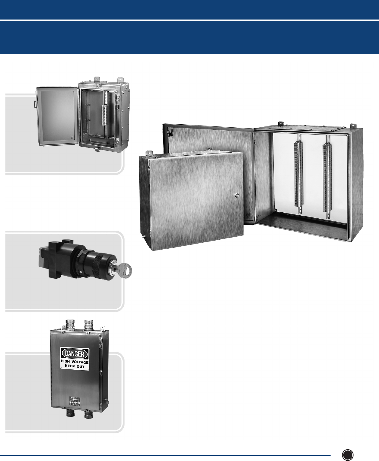
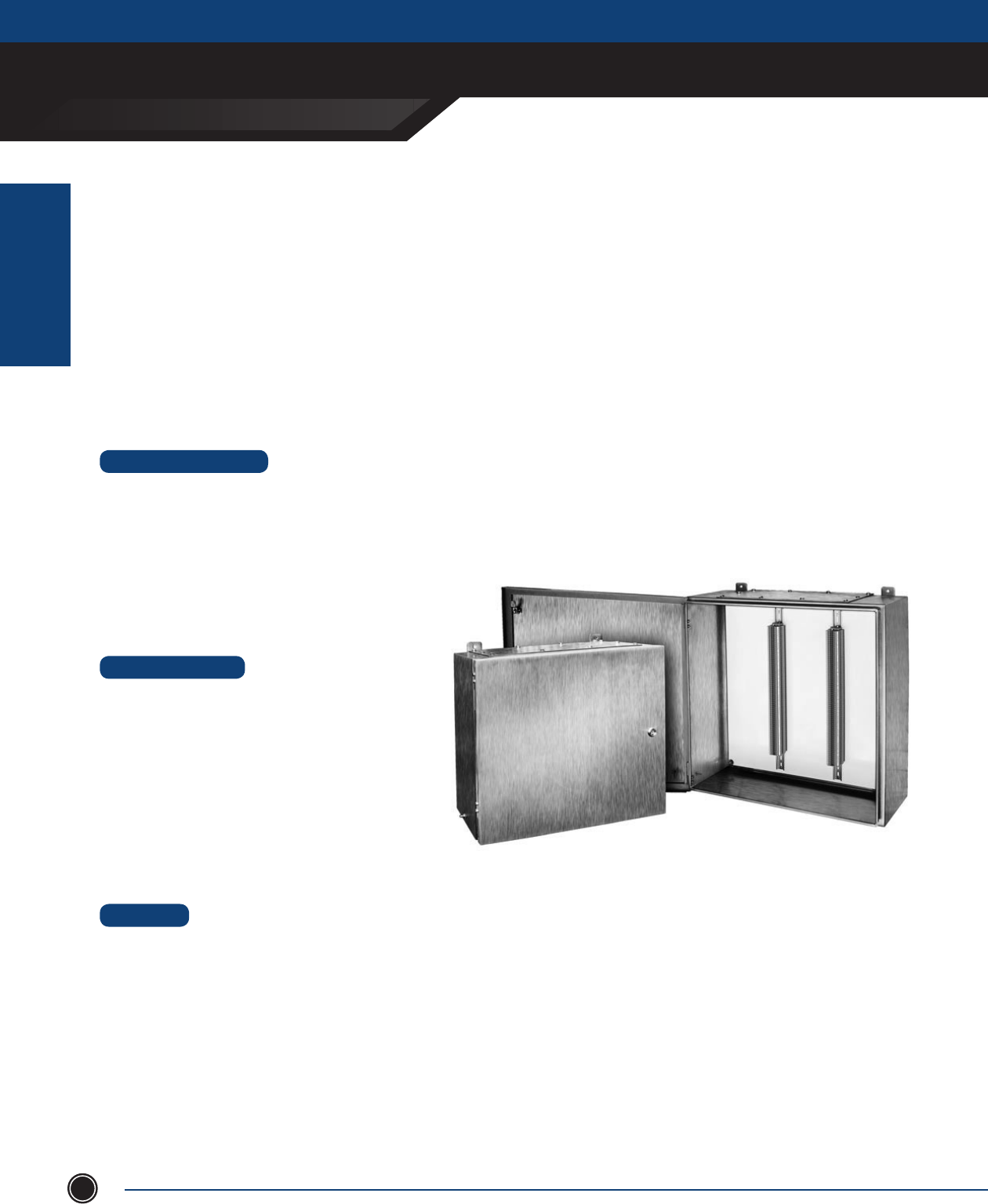
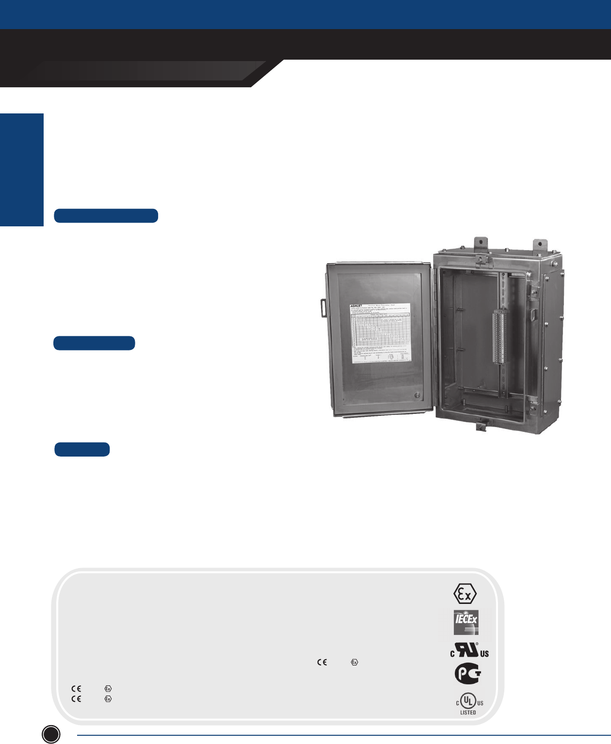
The VC4X6 & VH4X6 increased safety enclosures are cULus, ATEX, GOST, and IECEx certied to house terminal block assemblies
in Exe rated Zone 1 & 2 hazardous locations. The completed enclosure line includes 13 standard VH sizes and 24 VC standard
sizes. Adalet also offers the option for custom sizes to meet most specications.
The enclosures feature a continuous one piece silicone gasket which provides an IP66 ingress rating for dust-tight and water-
tight locations. Standard lift-off door hinges are included for easy removal of the cover. The quarter turn door latches are
designed with security in mind and include a double bit insert. Mounting feet can be oriented in either horizontal or vertical
directions and an internal / external earth stud is included as standard. The enclosures are equipped with a painted steel
mounting panel for mounting DIN rail and terminal block assemblies.
INCREASED SAFETY
TERMINAL ENCLOSURES
INCREASED SAFETY
ENCLOSURES
SEND ORDERS TO ORDERS@ADALET.COM
T: 216.267.9000 | F:216.267.1681 | info@adalet.com ©Adalet
7
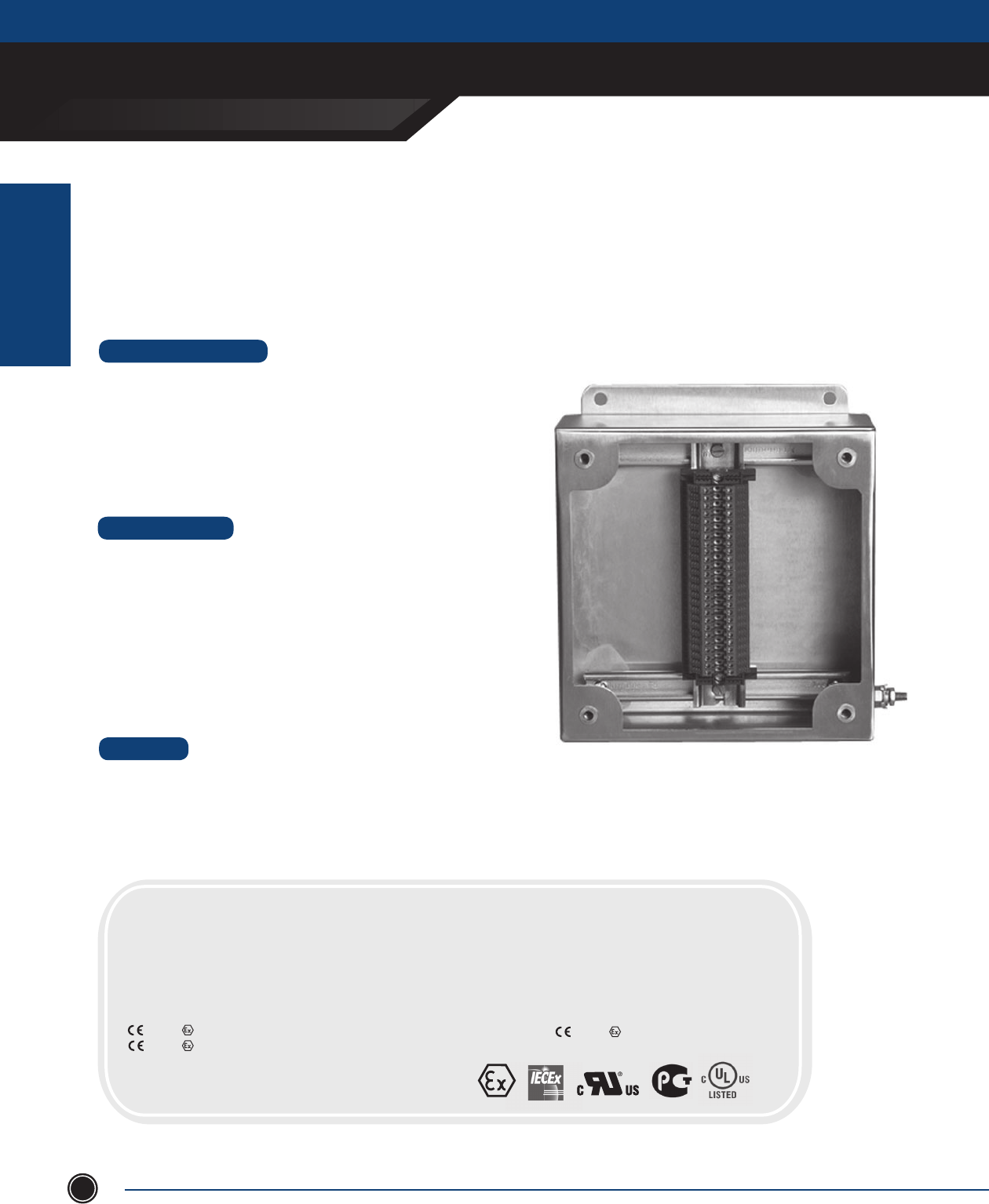
CERTIFICATIONS
POPULATED ENCLOSURE
Class I, Division 2, Groups A, B, C, D
Class II, Division 2, Groups F, G
Class I, Zone 1, AEx e II T6 (T5 Tamb +55°C)
Ex e II T6 (T5 Tamb +55°C)
NEMA Type 4X, 12, 13
0539 II 2 GD
IECEx UL 08.0012X
IECEx Ex e II T6 (T5 Tamb +55°C)
IECEx Ex tD A21 IP66 T200°C
Ex e II T6 (T5 Tamb +55°C)
Ex tD A21 IP66 T200°C
DEMKO 09 ATEX 0803119X
EMPTY ENCLOSURE
Class II, Division 2
Class I, Zone 1, AEX e II
Ex e II (Canada)
NEMA Type 4
DEMKO 01 ATEX 0112700U
0539 II 2 GD
Ex e II
Ex tD A21 IP66
IECEx UL 10.0021U
Ex e II
Ex tD A21 IP66
VH4X Series
MATERIAL
• Enclosure & cover constructed of 14 ga. (.075) 316L
stainless steel with #3/4 brush nish
• Optional gland plate constructed of 12 ga. (.1054) 316L
stainless steel with #3/4 brush nish
• Cover gasket: ¼ ” thick Bisco silicone with acrylic PSA, Part #HT805A
• Gland plate gasket: 1/8” thick Bisco silicone with acrylic PSA, Part #HT805A
OPTIONS
• Optional pressure sensitive adhesive gasket
material, Part #HT8055
• Optional Quarter Turn Inserts:
- Slot
- 8MM Hex Socket
- 7MM Triangle
- 8MM Triangle
- 7MM Square
- 8MM Square
- 5mm Double Bit
- Bellcore 216
- Railway standard
VC4X Series
MATERIAL
• Enclosure & cover constructed of 14 ga. (.075) 316L
stainless steel with #3/4 brush nish
• Optional gland plate constructed of 12 ga. (.1046) 316L
stainless steel with #3/4 brush nish
• Cover gasket : ¼ ” thick Bisco silicone with acrylic PSA, Part #HT805A
• Gland plate gasket : 1/8” thick Bisco silicone with acrylic PSA, Part #HT805A
OPTIONS
• Optional pressure sensitive adhesive
gasket material, Part #HT8055
• Optional Quarter Turn Inserts:
- Slot
- 8MM Hex Socket
- 7MM Triangle
- 8MM Triangle
- 7MM Square
- 8MM Square
- 5mm Double Bit
- Bellcore 216
- Railway standard
Mounting feet on left and right of enclosure. Mounting feet can be on left and right OR top and bottom of enclosure.

INCREASED SAFETY
TERMINAL ENCLOSURES
INCREASED SAFETY
ENCLOSURES
ADALET.COM
ADALET ENCLOSURE SYSTEMS | 4801 WEST 150TH | CLEVELAND, OHIO 44135©Adalet
8
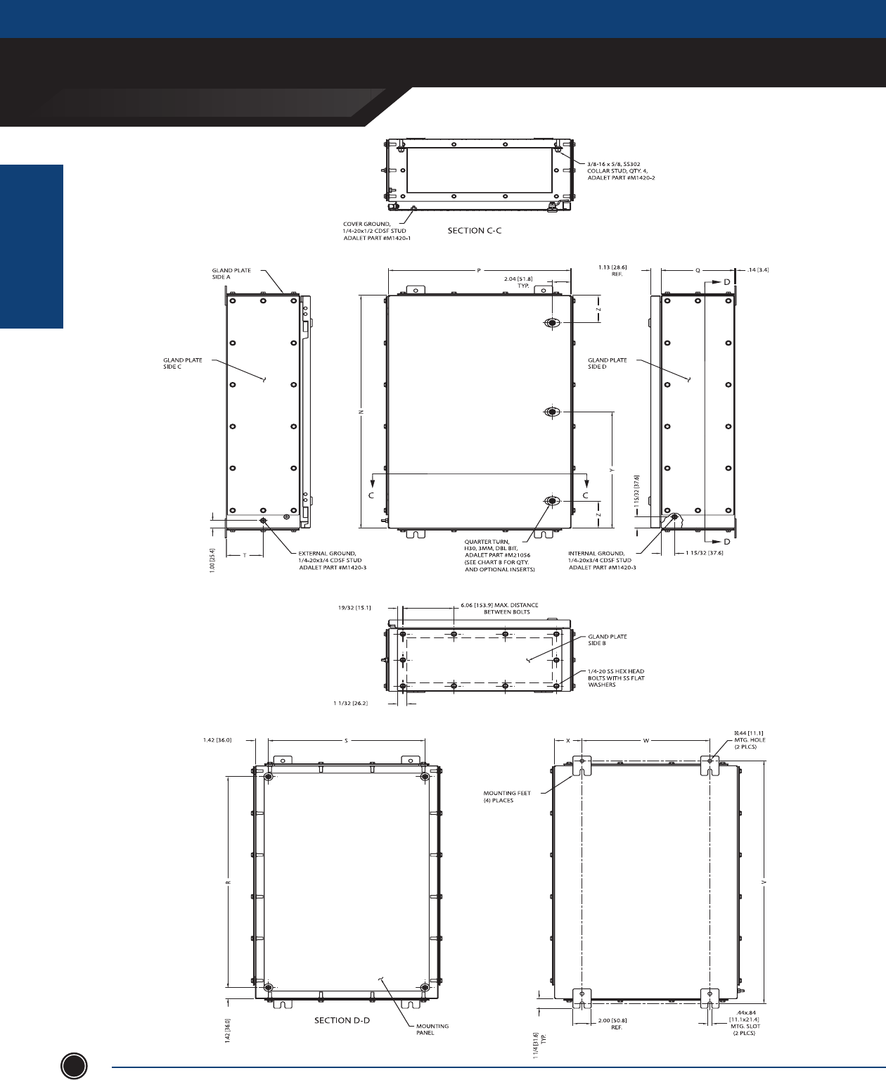
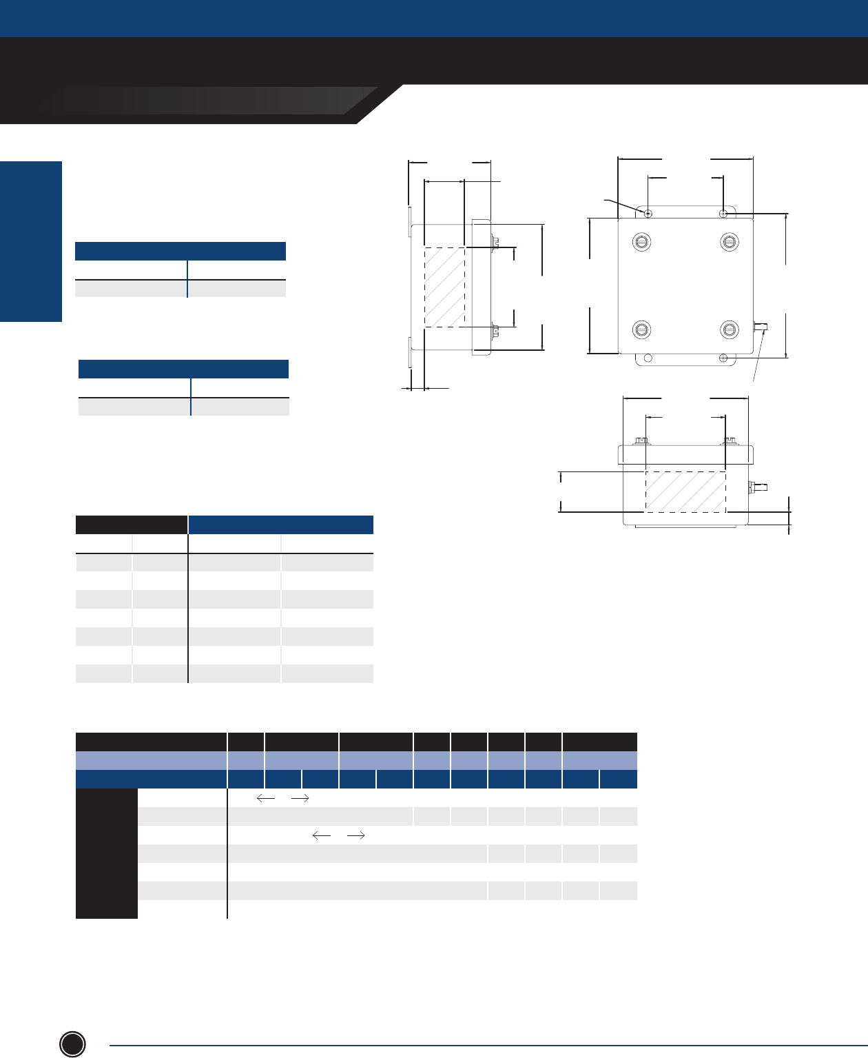
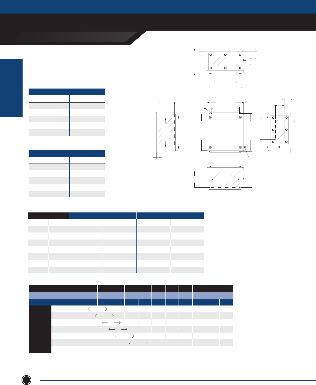
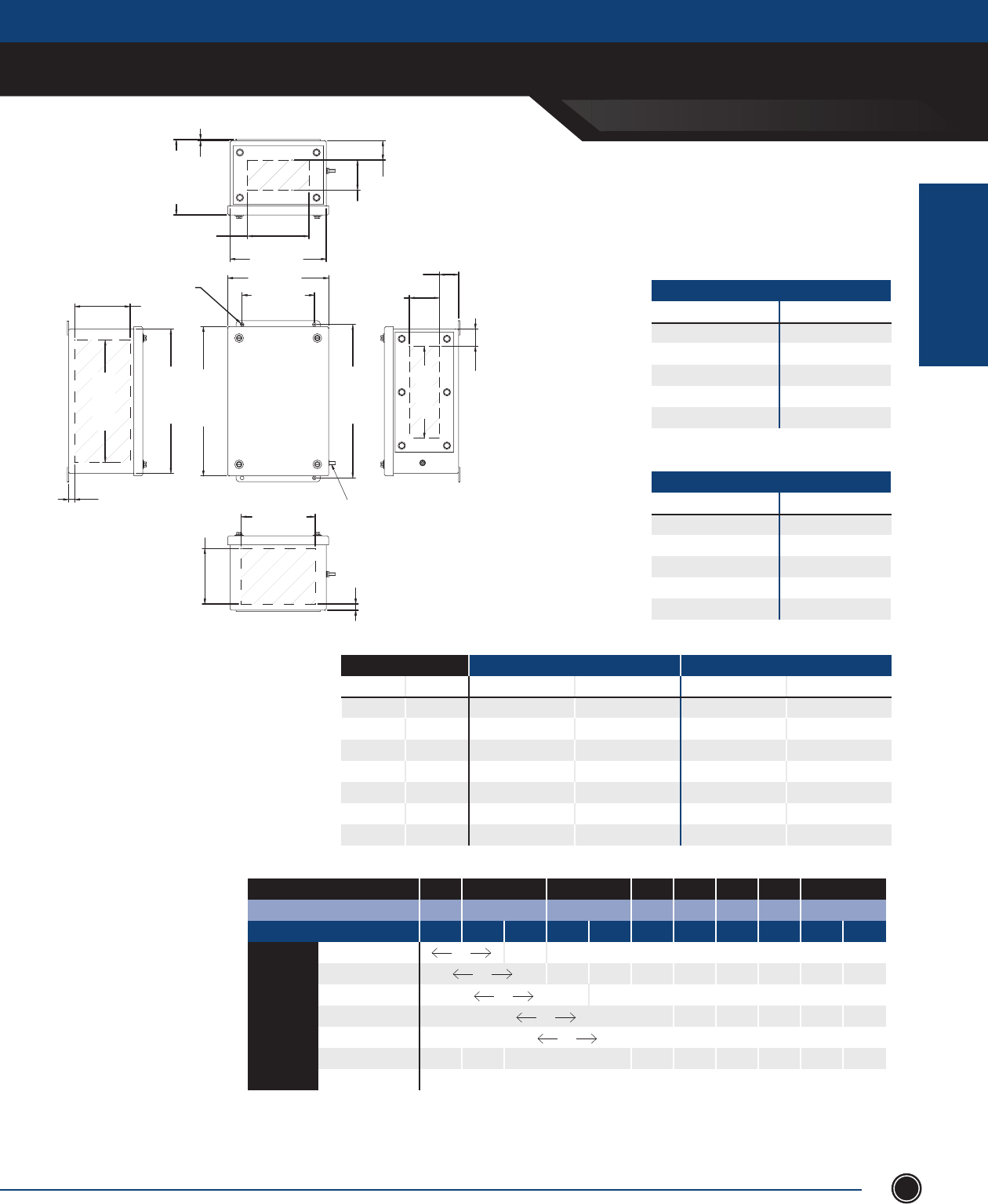
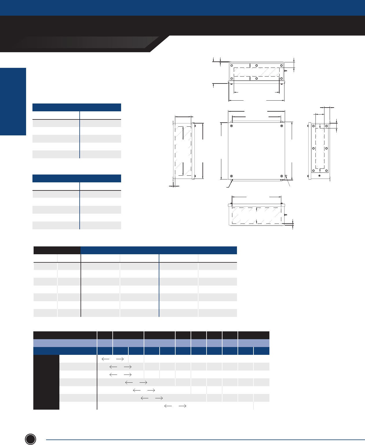
VH4X6 Series
Mounting feet on left and right of enclosure.
INCREASED SAFETY
TERMINAL ENCLOSURES
INCREASED SAFETY
ENCLOSURES
SEND ORDERS TO ORDERS@ADALET.COM
T: 216.267.9000 | F:216.267.1681 | info@adalet.com ©Adalet
9
INCHES
STAINLESS STEEL 316L
Optional Gland Plate Sufxes:
-A: Gland Plate On Top Side
-B: Gland Plate On Bottom Side
-C: Gland Plate On Left Side
-D: Gland Plate On Right Side
*Omit dashes when multiple gland plates are installed.
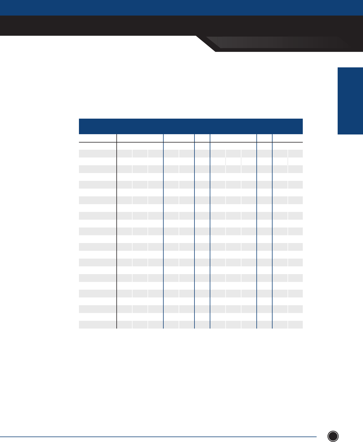
NOTES
Collar Stud Grd. Stud Mounting # Qtr. Quarter Turn
Catalog Number Enclosure Dimensions Spacing Locations Feet Spacing Turns Locations
ENCLOSURE A B C D E F G H L K
VH4X6-101006 10.24 10.24 6.30 7.40 7.40 3.15 6.24 11.74 1 5.12 -
VH4X6-101008 10.24 10.24 8.07 7.40 7.40 4.04 6.24 11.74 1 5.12 -
VH4X6-121206 12.05 12.05 6.30 9.22 9.22 3.15 8.05 13.55 1 6.03 -
VH4X6-121208 12.05 12.05 8.07 9.22 9.22 4.04 8.05 13.55 1 6.03 -
VH4X6-151006 14.96 10.24 6.30 12.13 7.40 3.15 10.96 11.74 1 7.48 -
VH4X6-151008 14.96 10.24 8.07 12.13 7.40 4.04 10.96 11.74 1 7.48 -
VH4X6-181506 18.03 15.04 6.30 15.20 12.21 3.15 14.03 16.54 1 9.02 -
VH4X6-191908 18.90 18.90 8.07 16.07 16.07 4.04 14.90 20.40 1 9.45 -
VH4X6-201406 19.68 13.78 6.30 16.85 10.95 3.15 15.68 15.28 1 9.84 -
VH4X6-201408 19.68 13.78 8.07 16.85 10.95 4.04 15.68 15.28 1 9.84 -
VH4X6-241808 24.41 17.72 8.07 21.58 14.89 4.04 20.41 19.22 2 - 3.53
VH4X6-292208 29.13 21.65 8.07 26.30 18.82 4.04 25.13 23.15 2 - 3.53
VH4X6-302008 30.00 20.00 8.07 27.17 17.17 4.04 26.00 21.50 2- 3.53
INCREASED SAFETY
TERMINAL ENCLOSURES
INCREASED SAFETY
ENCLOSURES
ADALET.COM
ADALET ENCLOSURE SYSTEMS | 4801 WEST 150TH | CLEVELAND, OHIO 44135©Adalet
10
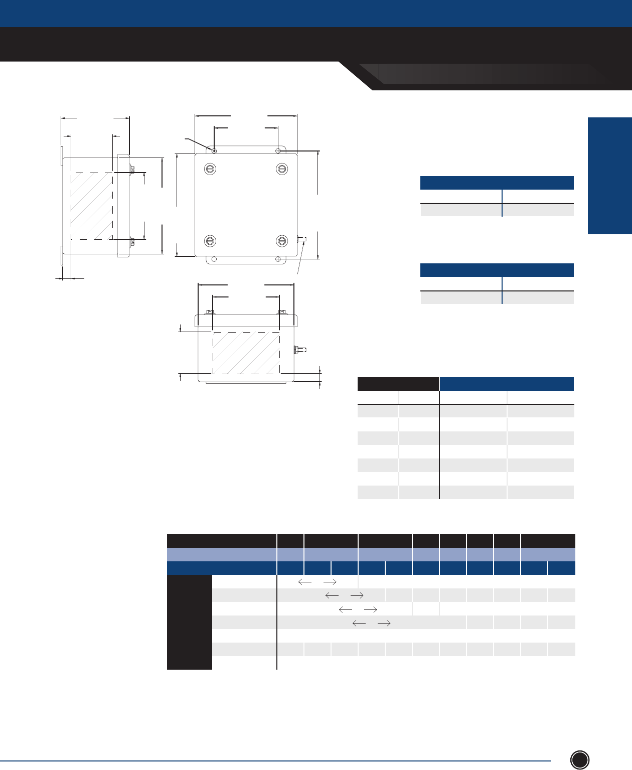
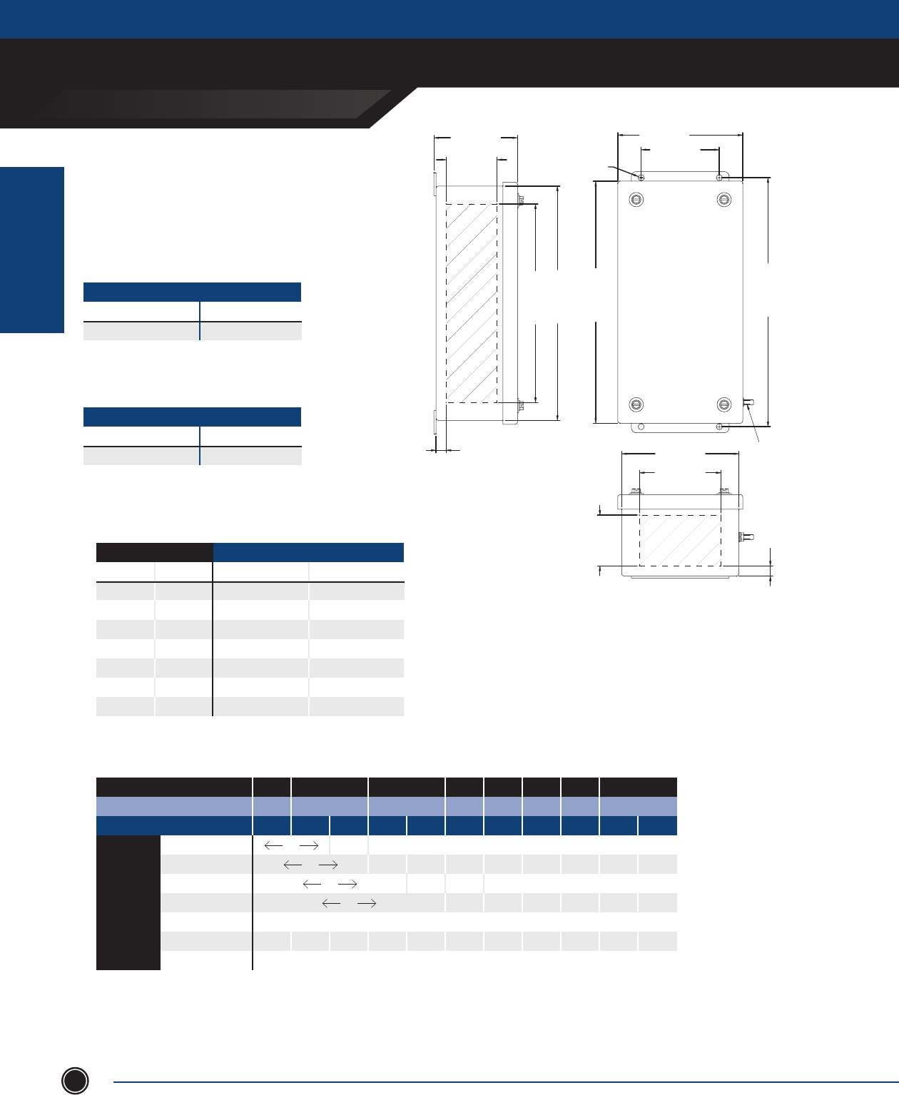
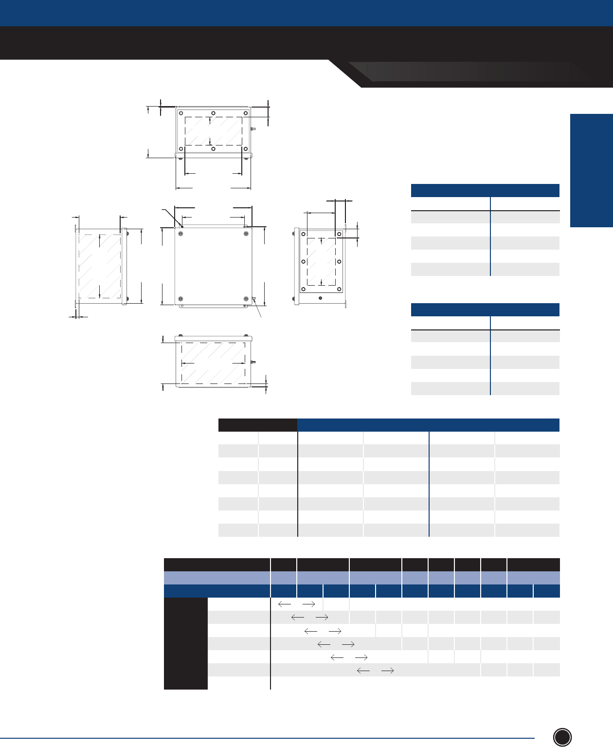
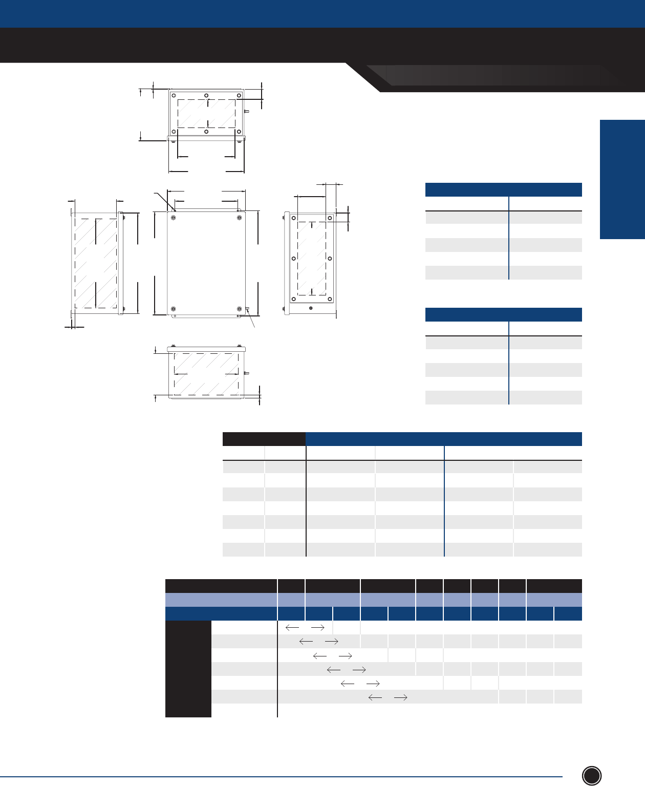
VC4X6 Series
Vertical Mount
Mounting feet can be on left and right OR
top and bottom of enclosure.
INCREASED SAFETY
TERMINAL ENCLOSURES
INCREASED SAFETY
ENCLOSURES
SEND ORDERS TO ORDERS@ADALET.COM
T: 216.267.9000 | F:216.267.1681 | info@adalet.com ©Adalet
11
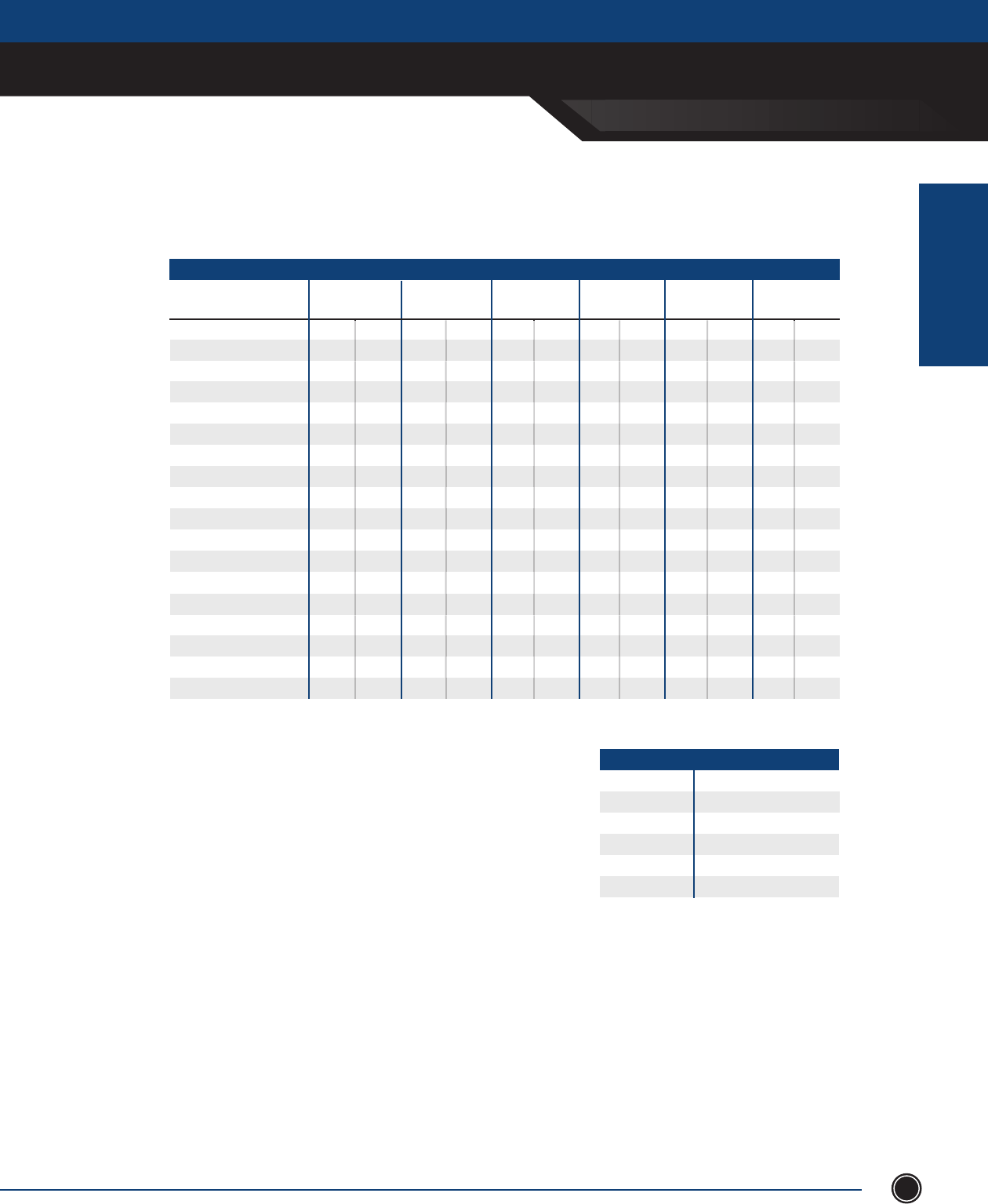
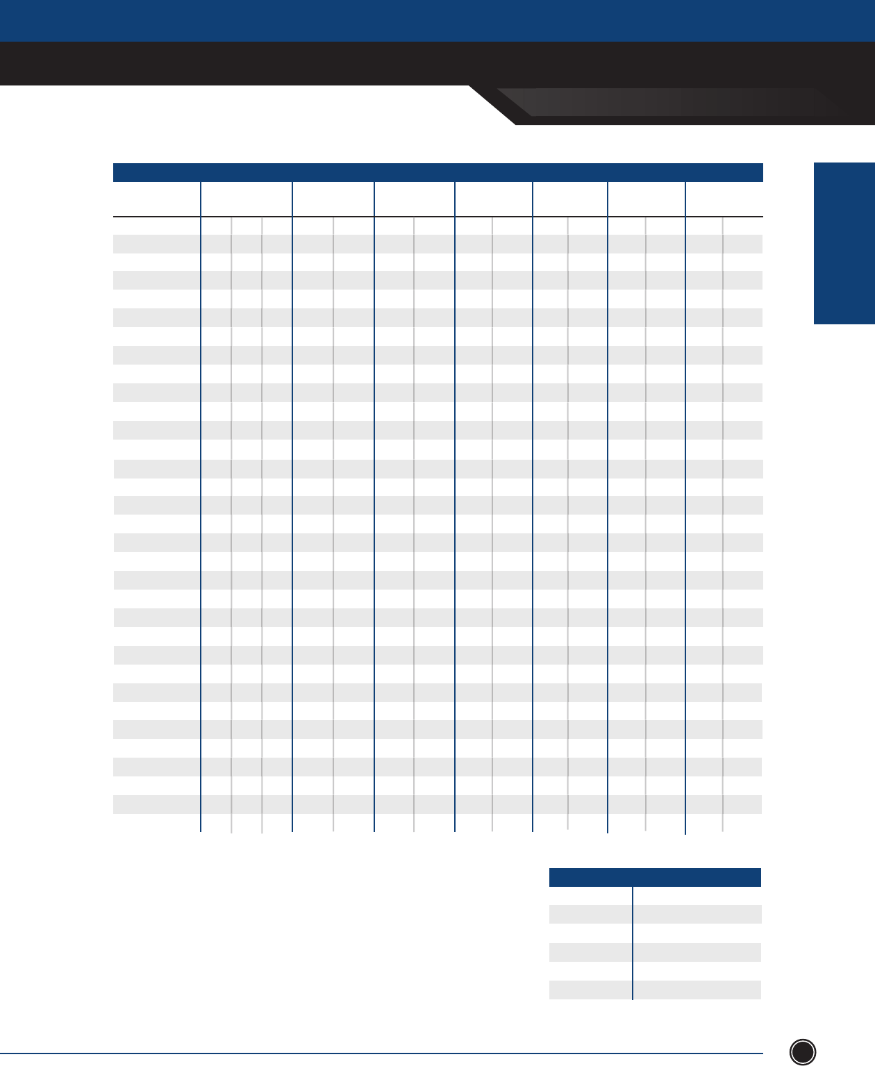
INCHES
Collar Stud Grd. Stud Mounting # Qtr. Quarter Turn
Catalog Number Enclosure Dimensions Spacing Locations Feet Spacing Turns Locations
ENCLOSURE N P Q R S T V W X Y Z
VC4X6-090605V 9.00 6.00 5.00 6.17 3.17 2.50 10.24 3.50 1.25 1 4.50 -
VC4X6-120806V 12.00 8.00 6.30 9.17 5.17 3.15 13.24 5.50 1.25 1 6.00 -
VC4X6-121206V 12.05 12.05 6.3 9.22 9.22 3.15 13.24 9.50 1.28 1 6.03 -
VC4X6-161206V 16.00 12.00 8.00 13.17 9.17 3.15 17.24 9.50 1.25 1 8.00 -
VC4X6-161208V 16.00 12.00 8.00 13.17 9.17 4.00 17.24 9.50 1.25 1 8.00 -
VC4X6-161606V 16.00 16.00 6.30 13.17 13.17 3.15 17.24 10.00 3.00 1 8.00 -
VC4X6-161608V 16.00 16.00 8.00 13.17 13.17 4.00 17.24 10.00 3.00 1 8.00 -
VC4X6-162006V 16.00 20.00 6.30 13.17 17.17 3.15 17.24 14.00 3.00 1 8.00 -
VC4X6-162008V 16.00 20.00 8.00 13.17 17.17 4.00 17.24 14.00 3.00 1 10.00 -
VC4X6-201606V 20.00 16.00 6.30 17.17 13.17 3.15 21.24 10.00 3.00 1 10.00 -
VC4X6-201608V 20.00 16.00 8.00 17.17 13.17 4.00 21.24 10.00 3.00 1 10.00 -
VC4X6-202006V 20.00 20.00 6.30 17.17 13.17 3.15 21.24 14.00 3.00 1 10.00 -
VC4X6-202008V 20.00 20.00 8.00 17.17 17.17 4.00 21.24 14.00 3.00 1 10.00 -
VC4X6-202408V 20.00 24.00 8.00 17.17 21.17 4.00 21.24 18.00 3.00 1 10.00 -
VC4X6-241606V 24.00 16.00 6.30 21.17 13.17 3.15 25.24 10.00 3.00 2 - 3.53
VC4X6-241608V 24.00 16.00 8.00 21.17 13.17 4.00 25.24 10.00 3.00 2 - 3.53
VC4X6-242006V 24.00 20.00 6.30 21.17 17.17 3.15 25.24 10.00 3.00 2 - 3.53
VC4X6-242008V 24.00 20.00 6.30 21.17 17.17 4.00 25.24 14.00 3.00 2 - 3.53
VC4X6-242406V 24.00 24.00 6.30 21.17 21.17 3.15 25.24 18.00 3.00 2 - 3.53
VC4X6-242408V 24.00 24.00 8.00 21.17 21.17 4.00 25.24 18.00 3.00 2 - 3.53
VC4X6-243008V 24.00 30.00 8.00 21.17 27.17 4.00 25.24 24.00 3.00 2 - 3.53
VC4X6-302008V 30.00 20.00 8.07 27.17 17.17 4.04 31.24 14.00 3.00 2 - 3.53
VC4X6-302408V 30.00 24.00 8.00 27.17 21.17 4.00 31.24 18.00 3.00 2 - 3.53
VC4X6-303008V 30.00 30.00 8.00 27.17 27.17 4.00 31.24 24.00 3.00 2 - 3.53
STAINLESS STEEL 316L
Optional Gland Plate Sufxes:
-A: Gland Plate On Top Side
-B: Gland Plate On Bottom Side
-C: Gland Plate On Left Side
-D: Gland Plate On Right Side
*Omit dashes when multiple gland plates are installed.
NOTES

INCREASED SAFETY
TERMINAL ENCLOSURES
INCREASED SAFETY
ENCLOSURES
ADALET.COM
ADALET ENCLOSURE SYSTEMS | 4801 WEST 150TH | CLEVELAND, OHIO 44135©Adalet
12
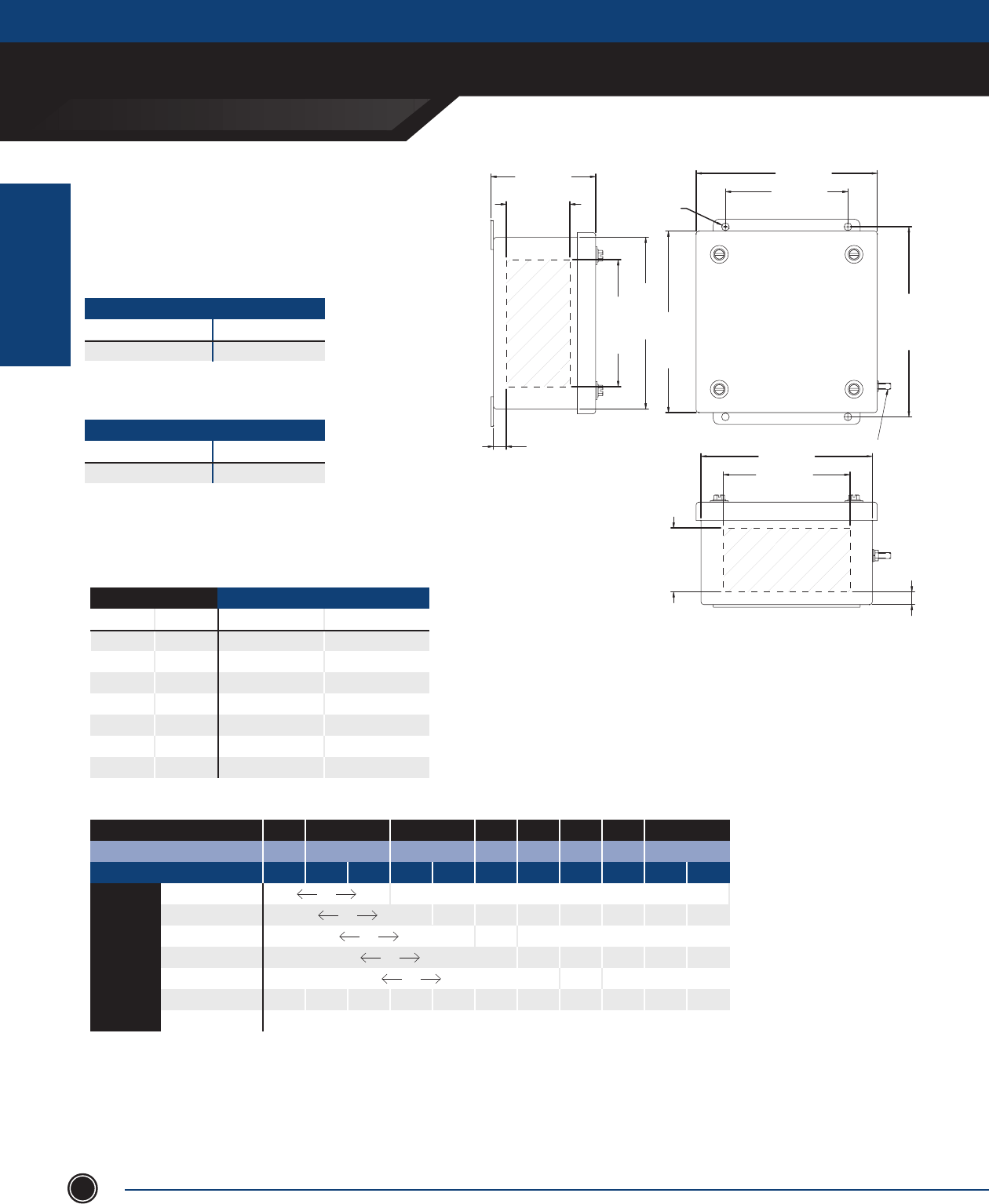
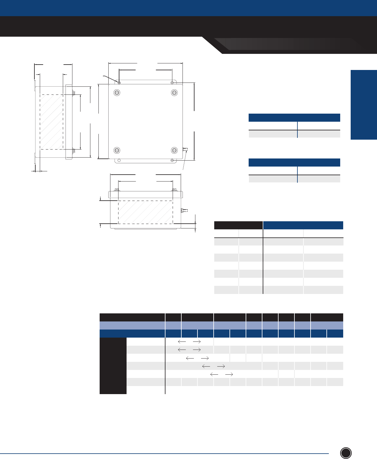
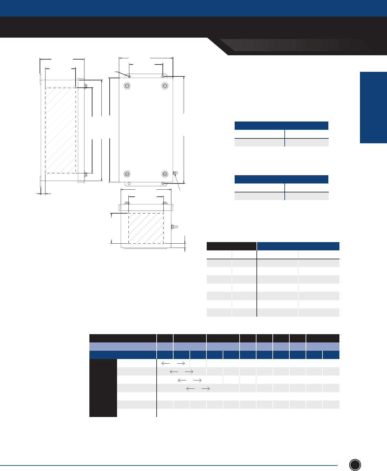
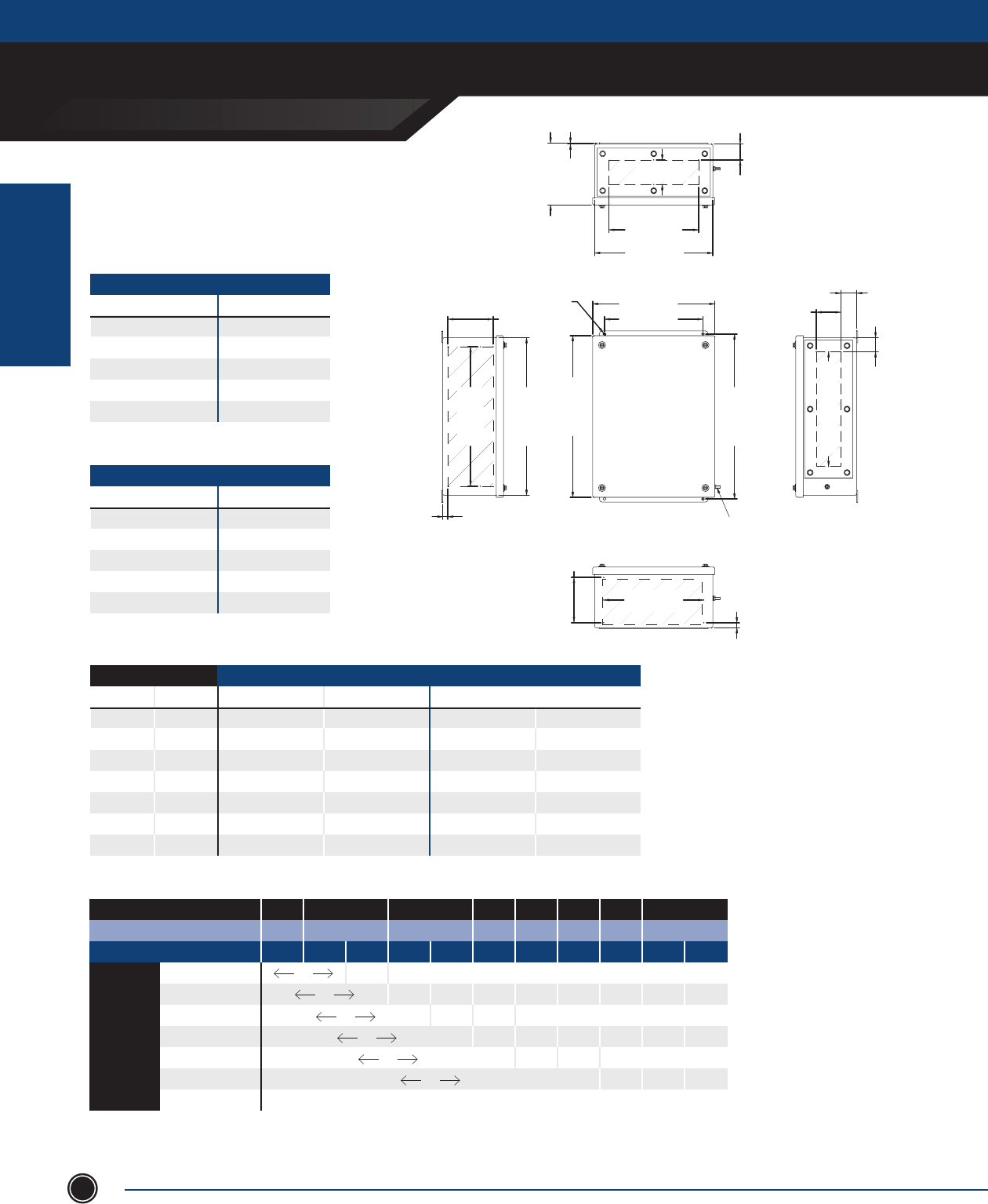
VC4X6 Series
Horizonal Mount
Mounting feet can be on left and right OR
top and bottom of enclosure.

INCREASED SAFETY
TERMINAL ENCLOSURES
INCREASED SAFETY
ENCLOSURES
SEND ORDERS TO ORDERS@ADALET.COM
T: 216.267.9000 | F:216.267.1681 | info@adalet.com ©Adalet
13
INCHES
Collar Stud Grd. Stud Mounting # Qtr. Quarter Turn
Catalog Number Enclosure Dimensions Spacing Locations Feet Spacing Turns Locations
ENCLOSURE A B C D E F H K G L M
VC4X6-090605H 9.00 6.00 5.00 6.17 3.17 2.50 1.51 5.98 8.19 1 4.50 -
VC4X6-120806H 12.00 8.00 6.30 9.17 5.17 3.15 2.01 7.99 10.20 1 6.00 -
VC4X6-121206H 12.05 12.05 6.3 9.22 9.22 3.15 2.03 7.99 14.21 1 6.03 -
VC4X6-161206H 16.00 12.00 8.00 13.17 9.17 3.15 2.74 10.51 14.21 1 8.00 -
VC4X6-161208H 16.00 12.00 8.00 13.17 9.17 4.00 2.74 10.51 14.21 1 8.00 -
VC4X6-161606H 16.00 16.00 6.30 13.17 13.17 3.15 2.74 10.51 18.19 1 8.00 -
VC4X6-161608H 16.00 16.00 8.00 13.17 13.17 4.00 2.74 10.51 18.19 1 8.00 -
VC4X6-162006H 16.00 20.00 6.30 13.17 17.17 3.15 2.74 10.51 22.20 1 8.00 -
VC4X6-162008H 16.00 20.00 8.00 13.17 17.17 4.00 2.74 10.51 22.20 1 10.00 -
VC4X6-201606H 20.00 16.00 6.30 17.17 13.17 3.15 3.03 13.94 18.19 1 10.00 -
VC4X6-201608H 20.00 16.00 8.00 17.17 13.17 4.00 3.03 13.94 18.19 1 10.00 -
VC4X6-202006H 20.00 20.00 6.30 17.17 13.17 3.15 3.03 13.94 22.20 1 10.00 -
VC4X6-202008H 20.00 20.00 8.00 17.17 17.17 4.00 3.03 13.94 22.20 1 10.00 -
VC4X6-202408H 20.00 24.00 8.00 17.17 21.17 4.00 3.03 13.94 26.22 1 10.00 -
VC4X6-241606H 24.00 16.00 6.30 21.17 13.17 3.15 3.24 17.52 18.19 2 - 3.53
VC4X6-241608H 24.00 16.00 8.00 21.17 13.17 4.00 3.24 17.52 18.19 2 - 3.53
VC4X6-242006H 24.00 20.00 6.30 21.17 17.17 3.15 3.24 17.52 22.20 2 - 3.53
VC4X6-242008H 24.00 20.00 6.30 21.17 17.17 4.00 3.24 17.52 22.20 2 - 3.53
VC4X6-242406H 24.00 24.00 6.30 21.17 21.17 3.15 3.24 17.52 26.22 2 - 3.53
VC4X6-242408H 24.00 24.00 8.00 21.17 21.17 4.00 3.24 17.52 26.22 2 - 3.53
VC4X6-243008H 24.00 30.00 8.00 21.17 27.17 4.00 3.24 17.52 32.20 2 - 3.53
VC4X6-302008H 30.00 20.00 8.07 27.17 17.17 4.04 5.00 20.00 22.20 2 - 3.53
VC4X6-302408H 30.00 24.00 8.00 27.17 21.17 4.00 5.00 20.00 26.22 2 - 3.53
VC4X6-303008H 30.00 30.00 8.00 27.17 27.17 4.00 5.00 20.00 32.20 2 - 3.53
STAINLESS STEEL 316L
Optional Gland Plate Sufxes:
-A: Gland Plate On Top Side
-B: Gland Plate On Bottom Side
-C: Gland Plate On Left Side
-D: Gland Plate On Right Side
*Omit dashes when multiple gland plates are installed.
NOTES
INCREASED SAFETY
TERMINAL ENCLOSURES
INCREASED SAFETY
ENCLOSURES
ADALET.COM
ADALET ENCLOSURE SYSTEMS | 4801 WEST 150TH | CLEVELAND, OHIO 44135©Adalet
14
Adalet’s Screw Cover Terminal Enclosures are available in stainless Steel 304 & 316L. Silicone gasket, slotted captive
cover bolts, box and cover ground studs including an external earthing stud, and universal rail mounting system are
included as standard (except 050503, mtg pan used).
• 18 standard sizes available
• Stainless steel captive hex head, slotted cover screws
• Continuous one-piece water tight silicone gasket
• Internal rail mounting system (except 050503)
• Ground stud on box and cover
• External ground stud
• Wall mounting fl ange with .31” clearance holes
• Gland plates (6” deep or greater) can be supplied pre-drilled
or blank for fi eld drilling
• Drilled entries and cut-outs
• Hinged cover
• Breather / drain, stopping plugs, cable glands and conduit fi ttings
• Terminal block assemblies
• Stainless steel or painted steel mounting panels
• Internal earth bar
• Custom sizes
• Cable glands
• Type 304 or 316L Stainless Steel
• Enclosure and cover constructed from 14 gauge (.075) stainless steel with #3/4 brush fi nish
• Gland plates constructed from 10 gauge (.1345) stainless steel with a #3/4 brush fi nish
• Silicone gasket constructed from ¼ ” Bisco silicone with acrylic PSA
• Gland plate gasket constructed from ⁄” Bisco silicone with acrylic PSA
STANDARD FEATURES
DESIGN OPTIONS
MATERIAL
TSC Series
Screw Cover Terminal Enclosure
CERTIFICATIONS
POPULATED ENCLOSURE
Class I, Division 2, Groups A, B, C, D
Class II, Division 2, Groups F, G
Class I, Zone 1, AEx e II (T5: Ta < +55°C) (T4: Ta < +70°C)
Ex e II T6 (T5: Ta < +55°C) (T4: Ta < +70°C)
NEMA Type 4X, 12, 13
0539 II 2 G Ex e II T6 (T5: Ta<+55°C) (T4: Ta<+70°C)
0539 II 2 D Ex tD A21 IP66 T200°C
IECEx UL 09.0017X
Ex e II T6(T5: Ta < +55°C) (T4: Ta < +70°C)
Ex tD A21 IP66 T200°C
EMPTY ENCLOSURE
Class II, Division 2
Class I, Zone 1, AEx e II
Ex e II
NEMA Type 4X, 12, 13
DEMKO 01 ATEX 0113363U
0539 II 2 GD
Ex tD A21 IP66
INCREASED SAFETY
TERMINAL ENCLOSURES
INCREASED SAFETY
ENCLOSURES
SEND ORDERS TO ORDERS@ADALET.COM
T: 216.267.9000 | F:216.267.1681 | info@adalet.com ©Adalet
15
TSC4X6-050503
TSC4X6-060604
TSC4X6-070704
TSC4X6-080804
TSC4X6-101006
TSC4X6-101008
TSC4X6-120604
TSC4X6-120605
TSC4X6-120805
TSC4X6-120806
TSC4X6-121206
TSC4X6-121208
TSC4X6-151506
TSC4X6-151508
TSC4X6-161206
TSC4X6-161208
TSC4X6-161606
TSC4X6-161608
MAXIMUM TERMINAL BLOCK CONTENT
CAT. NUMBER 2.5mm
# ROWS QTY.
6
13
18
23
66
66
43
43
43
43
86
86
177
177
128
128
192
192
1
1
1
1
2
2
1
1
1
1
2
2
3
3
2
2
3
3
4mm
# ROWS QTY.
1
1
1
1
2
2
1
1
1
1
2
2
3
3
2
2
3
3
6mm
# ROWS QTY.
5
8
11
14
42
42
27
27
27
27
54
54
111
111
80
80
120
120
1
1
1
1
2
2
1
1
1
1
2
2
3
3
2
2
3
3
10mm
# ROWS QTY.
0
0
9
11
17
17
0
0
22
22
44
44
58
58
64
64
96
96
0
0
1
1
1
1
0
0
1
1
2
2
2
2
2
2
3
3
16mm
# ROWS QTY.
0
0
0
0
14
14
0
0
0
0
18
18
48
48
266
26
52
52
0
0
0
0
1
1
0
0
0
0
1
1
2
2
1
1
2
2
35mm
# ROWS QTY.
0
0
0
0
0
0
0
0
0
0
0
0
18
18
0
0
20
20
0
0
0
0
0
0
0
0
0
0
0
0
1
1
0
0
1
1
6
13
18
23
66
66
43
43
43
43
86
86
177
177
128
128
192
192
1. The TSC4 Series is available either in SS316L (TSC4X6) or SS304 (TSC4X).
2. Refer to enclosure catalog page for dimensional information.
3. The maximum terminal block content is based on the following
maximum permitted continuous current and minimum conductor size
(See chart right).
4. For higher ampacities refer to enclosure catalog page.
5. The maximum terminal block content is based on vertical
rail installation. For horizontal installations, consult factory.
6. For applications requiring multiple terminal block confi gurations and
ampacities, consult factory.
7. For applications requiring larger terminal blocks or custom enclosure sizes,
consult factory.
MAX CURRENT MIN CONDUCTOR SIZE
10 AMPS 1.5mm2 (16 AWG)
16 AMPS 2.5 mm2 (14 AWG)
20 AMPS 4 mm2 (12 AWG)
25 AMPS 6 mm2 (10 AWG)
35 AMPS 10 mm2 (8 AWG)
63 AMPS 16 mm2 (6 AWG)
NOTES
INCREASED SAFETY
TERMINAL ENCLOSURES
INCREASED SAFETY
ENCLOSURES
ADALET.COM
ADALET ENCLOSURE SYSTEMS | 4801 WEST 150TH | CLEVELAND, OHIO 44135©Adalet
16
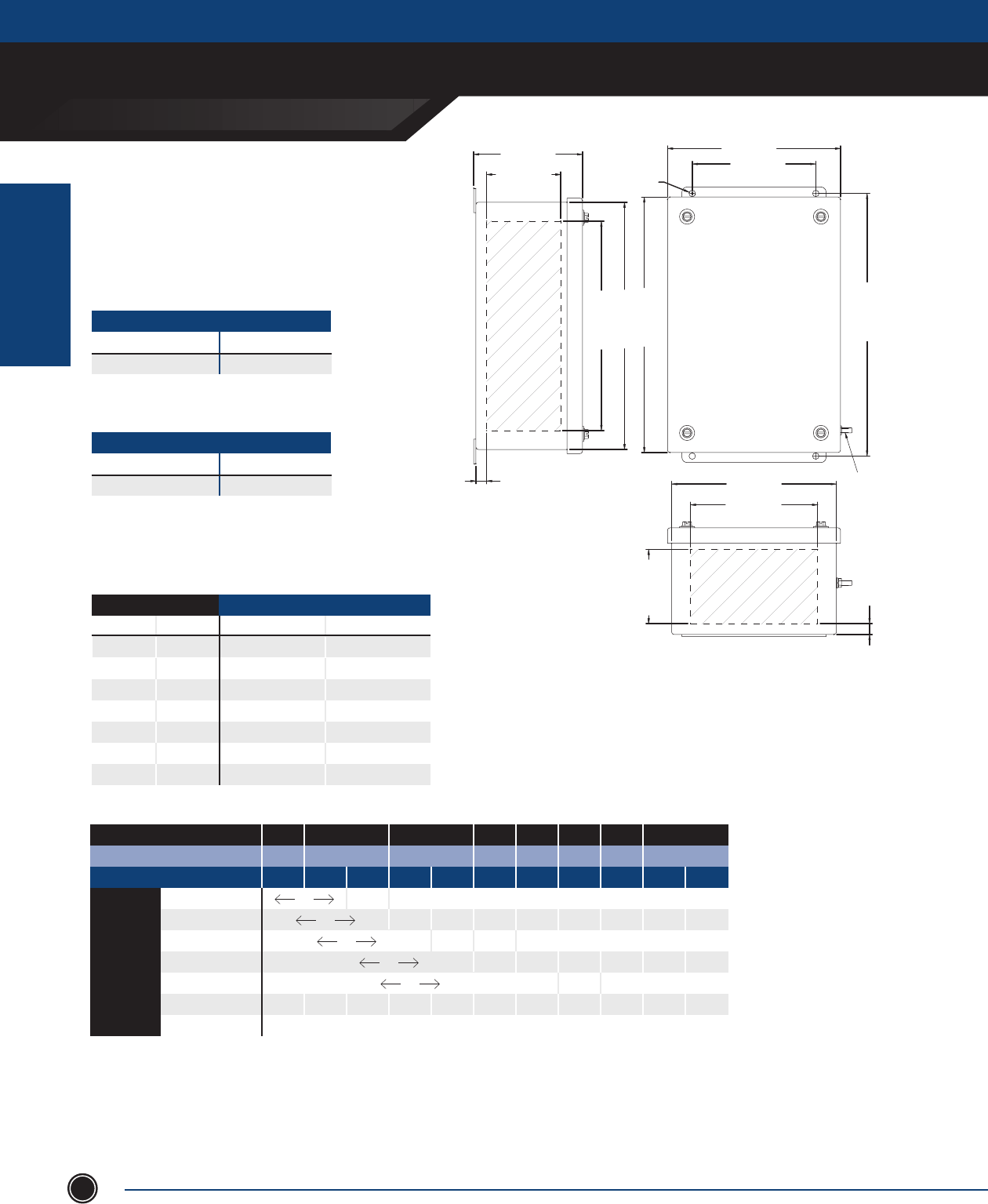
TSC Series
5” x 5” x 3” Enclosure
5.40 [137mm]
5.40 [137mm]
1.60 [41mm]
GLAND AREA 3.00 [76mm]
5.75 [146mm]
5.00 [127mm]
3.17 [80mm]
GLAND AREA
.52 [13mm]
3.17 [80mm]
GLAND AREA
.52 [13mm]
.31 [8mm]
EARTH STUD
3.28 [83mm]
5.00 [127mm]
1.60 [41mm]
G.P. OPENING
STAINLESS STEEL 304ENCLO
STAINLESS STEEL 316LENCLO
ENCLOSURE WITH TERMINALS
CAT. NUMBER
TSC4X-050503
GLAND PLATE
None
CAT. NUMBER
TSC4X6-050503
GLAND PLATE
None
ENCLOSURE WITH TERMINALS
Terminal Block Size
MAXIMUM TERMINAL BLOCK CONTENT
MIN CONDUCTOR SIZE .5mm 1.5mm 2.5mm 4mm 6mm 10mm 16mm 35mm
MIN CONDUCTOR SIZE AWG 22 16 14 12 10 8 6 2
MAXIMUM AMPERAGE 3 8 10 16 20 25 35 50 63 80 100
1.5mm2 6 x x x x x x x x
2.5mm2 6 x x x x x x
4mm2 6 x x x x x
6mm2 5 x x x x
10mm2 x x x x x x x x x x x
16mm2 x x x x x x x x x x x
35mm2 x x x x x x x x x x x
SIZE WITHOUT GLAND PLATES
NPT Metric Sides A & B Sides C & D
½ M16 2 2
¾ M20 2 2
1 M25 1 1
1
¼ M32 - -
1
½ M40 - -
2 M50 - -
2
½ M63 - -
MAXIMUM NUMBER OF CABLE/CONDUIT ENTRIES
1. The maximum terminal block content is based on vertical rail installation. For horizontal installations, consult factory.
2. For applications requiring multiple terminal block congurations and ampacities, consult factory.
3. For applications requiring larger terminal blocks or custom enclosure sizes, consult factory.
4. For conduit/cable spacings, wire bending and wire conversion guidelines, refer to the inside back cover of this catalog.
NOTES
INCREASED SAFETY
TERMINAL ENCLOSURES
INCREASED SAFETY
ENCLOSURES
SEND ORDERS TO ORDERS@ADALET.COM
T: 216.267.9000 | F:216.267.1681 | info@adalet.com ©Adalet
17
6.40 [163mm]
6.40 [163mm]
2.60 [66mm]
GLAND AREA
4.00 [102mm]
6.75 [171mm]
6.00 [152mm]
4.17 [106mm]
GLAND AREA
.52 [13mm]
4.17 [106mm]
GLAND AREA
.52 [13mm]
.31 [8mm]
EARTH STUD
2.60 [66mm]
GLAND AREA
4.28 [109mm]
6.00 [152mm]
TSC Series
6” x 6” x 4” Enclosure
STAINLESS STEEL 304
STAINLESS STEEL 316LENCLO
ENCLOSURE WITH TERMINALS
CAT. NUMBER
TSC4X-060604
GLAND PLATE
None
CAT. NUMBER
TSC4X6-060604
GLAND PLATE
None
ENCLOSURE WITH TERMINALS
Terminal Block Size
MAXIMUM TERMINAL BLOCK CONTENT
MIN CONDUCTOR SIZE .5mm 1.5mm 2.5mm 4mm 6mm 10mm 16mm 35mm
MIN CONDUCTOR SIZE AWG 22 16 14 12 10 8 6 2
MAXIMUM AMPERAGE 3 8 10 16 20 25 35 50 63 80 100
1.5mm2 13 x x x x x x x x
2.5mm2 13 9 x x x x x x
4mm2 13 10 x x x x x
6mm2 8 x x x x
10mm2 x x x x x x x x x x x
16mm2 x x x x x x x x x x x
35mm2 x x x x x x x x x x x
SIZE WITHOUT GLAND PLATES
NPT Metric Sides A & B Sides C & D
½ M16 6 6
¾ M20 3 3
1 M25 2 2
1
¼ M32 2 2
1
½ M40 1 1
2 M50 - -
2
½ M63 - -
MAXIMUM NUMBER OF CABLE/CONDUIT ENTRIES
1. The maximum terminal block content is based on vertical rail installation. For horizontal installations, consult factory.
2. For applications requiring multiple terminal block congurations and ampacities, consult factory.
3. For applications requiring larger terminal blocks or custom enclosure sizes, consult factory.
4. For conduit/cable spacings, wire bending and wire conversion guidelines, refer to the inside back cover of this catalog.
NOTES
INCREASED SAFETY
TERMINAL ENCLOSURES
INCREASED SAFETY
ENCLOSURES
ADALET.COM
ADALET ENCLOSURE SYSTEMS | 4801 WEST 150TH | CLEVELAND, OHIO 44135©Adalet
18
TSC Series
7” x 7” x 4” Enclosure
STAINLESS STEEL 304
7.40 [188mm]
7.40 [188mm]
2.60 [66mm]
GLAND AREA
5.00 [127mm]
7.75 [197mm]
7.00 [178mm]
5.17 [131mm]
GLAND AREA
.52 [13mm]
5.17 [131mm]
GLAND AREA
.52 [13mm]
.31 [8mm]
EARTH STUD
2.60 [66mm]
GLAND AREA
4.28 [109mm]
7.00 [178mm]
STAINLESS STEEL 316LLO
ENCLOSURE WITH TERMINALS
CAT. NUMBER
TSC4X-070704
GLAND PLATE
None
CAT. NUMBER
TSC4X6-070704
GLAND PLATE
None
ENCLOSURE WITH TERMINALS
Terminal Block Size
MAXIMUM TERMINAL BLOCK CONTENT
MIN CONDUCTOR SIZE .5mm 1.5mm 2.5mm 4mm 6mm 10mm 16mm 35mm
MIN CONDUCTOR SIZE AWG 22 16 14 12 10 8 6 2
MAXIMUM AMPERAGE 3 8 10 16 20 25 35 50 63 80 100
1.5mm2 18 x x x x x x x x
2.5mm2 18 10 x x x x x x
4mm2 18 11 x x x x x
6mm2 11 8 x x x x
10mm2 9 7 x x x
16mm2 x x x x x x x x x x x
35mm2 x x x x x x x x x x x
SIZE WITHOUT GLAND PLATES
NPT Metric Sides A & B Sides C & D
½ M16 8 8
¾ M20 3 3
1 M25 3 3
1
¼ M32 2 2
1
½ M40 2 2
2 M50 - -
2
½ M63 - -
MAXIMUM NUMBER OF CABLE/CONDUIT ENTRIES
1. The maximum terminal block content is based on vertical rail installation. For horizontal installations, consult factory.
2. For applications requiring multiple terminal block congurations and ampacities, consult factory.
3. For applications requiring larger terminal blocks or custom enclosure sizes, consult factory.
4. For conduit/cable spacings, wire bending and wire conversion guidelines, refer to the inside back cover of this catalog.
NOTES
INCREASED SAFETY
TERMINAL ENCLOSURES
INCREASED SAFETY
ENCLOSURES
SEND ORDERS TO ORDERS@ADALET.COM
T: 216.267.9000 | F:216.267.1681 | info@adalet.com ©Adalet
19
TSC Series
8” x 8” x 4” Enclosure
8.40 [213mm]
8.40 [213mm]
2.60 [66mm]
GLAND AREA
6.00 [152mm]
8.75 [222mm]
8.00 [203mm]
6.17 [157mm]
GLAND AREA
.52 [13mm]
6.17 [157mm]
GLAND AREA
.52 [13mm]
.31 [8mm]
EARTH STUD
2.60 [66mm]
GLAND AREA
4.28 [109mm]
8.00 [203mm]
STAINLESS STEEL 304
ENCLOSURE WITH TERMINALS
CAT. NUMBER
TSC4X-080804
GLAND PLATE
None
STAINLESS STEEL 316L
CAT. NUMBER
TSC4X6-080804
ENCLOSURE WITH TERMINALS
GLAND PLATE
None
SIZE WITHOUT GLAND PLATES
NPT Metric Sides A & B Sides C & D
½ M16 10 10
¾ M20 4 4
1 M25 3 3
1
¼ M32 2 2
1
½ M40 2 2
2 M50 - -
2
½ M63 - -
MAXIMUM NUMBER OF CABLE/CONDUIT ENTRIES
Terminal Block Size
MAXIMUM TERMINAL BLOCK CONTENT
MIN CONDUCTOR SIZE .5mm 1.5mm 2.5mm 4mm 6mm 10mm 16mm 35mm
MIN CONDUCTOR SIZE AWG 22 16 14 12 10 8 6 2
MAXIMUM AMPERAGE 3 8 10 16 20 25 35 50 63 80 100
1.5mm2 23 x x x x x x x x
2.5mm2 23 19 11 x x x x x x
4mm2 23 21 12 x x x x x
6mm2 14 9 x x x x
10mm2 11 7 x x x
16mm2 x x x x x x x x x x x
35mm2 x x x x x x x x x x x
1. The maximum terminal block content is based on vertical rail installation. For horizontal installations, consult factory.
2. For applications requiring multiple terminal block congurations and ampacities, consult factory.
3. For applications requiring larger terminal blocks or custom enclosure sizes, consult factory.
4. For conduit/cable spacings, wire bending and wire conversion guidelines, refer to the inside back cover of this catalog.
NOTES
INCREASED SAFETY
TERMINAL ENCLOSURES
INCREASED SAFETY
ENCLOSURES
ADALET.COM
ADALET ENCLOSURE SYSTEMS | 4801 WEST 150TH | CLEVELAND, OHIO 44135©Adalet
20
TSC Series
10” x 10” x 6” Enclosure
STAINLESS STEEL 304
ENCLOSURES WITH TERMINALS
Catalog Number Gland Plate
TSC4X-101006 None
TSC4X-101006-B Side B
TSC4X-101006-AB Sides A & B
TSC4X-101006-BCD Sides B, C & D
TSC4X-101006-ABCD Sides A, B, C & D
STAINLESS STEEL 316L
ENCLOSURES WITH TERMINALS
Catalog Number Gland Plate
TSC4X6-101006 None
TSC4X6-101006-B Side B
TSC4X6-101006-AB Sides A & B
TSC4X6-101006-BCD Sides B, C & D
TSC4X6-101006-ABCD Sides A, B, C & D
10.40 [264mm]
10.40 [264mm]
4.60 [117mm]
GLAND AREA
G. P. SIDE B
G. P. SIDE C
G.P. SIDE D
1.60 [41mm]
7.12 [181mm]
G.P. OPENING
8.00 [203mm]
10.75 [273mm]
10.00 [254mm]
.10 [3mm]
6.28 [160mm]
10.00 [254mm]
1.81 [44mm]
G.P. SIDE A
1.60 [41mm]
.52 [13mm]
.52 [13mm]
5.63 [143mm]
G.P OPENING
2.50 [64mm]
G.P. OPENING
.31 [8mm]
EARTH STUD
2.50 [64mm]
G.P. OPENING
4.60 [117mm]
G.P. OPENING
8.17 [207mm]
GLAND AREA
8.17 [207mm]
GLAND AREA
Terminal Block Size
MAXIMUM TERMINAL BLOCK CONTENT
MIN CONDUCTOR SIZE .5mm 1.5mm 2.5mm 4mm 6mm 10mm 16mm 35mm
MIN CONDUCTOR SIZE AWG 22 16 14 12 10 8 6 2
MAXIMUM AMPERAGE 3 8 10 16 20 25 35 50 63 80 100
1.5mm2 66 39 x x x x x x x x
2.5mm2 66 26 15 x x x x x x
4mm2 66 29 16 x x x x x
6mm2 42 32 12 x x x x
10mm2 17 16 10 x x x
16mm2 14 12 x x
35mm2 x x x x x x x x x x x
MAXIMUM NUMBER OF CABLE/CONDUIT ENTRIES
SIZE WITHOUT GLAND PLATES WITH GLAND PLATES
NPT Metric Sides A & B Sides C & D Sides A & B Sides C & D
½ M16 18 18 10 8
¾ M20 15 15 5 4
1 M25 8 8 4 3
1
¼ M32 6 6 3 2
1
½ M40 4 4 2 2
2 M50 2 2 2 1
2
½ M63 2 2 - -
1. The maximum terminal block content is based on vertical rail installation. For horizontal installations, consult factory.
2. For applications requiring multiple terminal block congurations and ampacities, consult factory.
3. For applications requiring larger terminal blocks or custom enclosure sizes, consult factory.
4. For conduit/cable spacings, wire bending and wire conversion guidelines, refer to the inside back cover of this catalog.
NOTES

INCREASED SAFETY
TERMINAL ENCLOSURES
INCREASED SAFETY
ENCLOSURES
SEND ORDERS TO ORDERS@ADALET.COM
T: 216.267.9000 | F:216.267.1681 | info@adalet.com ©Adalet
21
TSC Series
10” x 10” x 8” Enclosure
STAINLESS STEEL 304
ENCLOSURES WITH TERMINALS
Catalog Number Gland Plate
TSC4X-101008 None
TSC4X-101008-B Side B
TSC4X-101008-AB Sides A & B
TSC4X-101008-BCD Sides B, C & D
TSC4X-101008-ABCD Sides A, B, C & D
STAINLESS STEEL 316L
ENCLOSURES WITH TERMINALS
Catalog Number Gland Plate
TSC4X6-101008 None
TSC4X6-101008-B Side B
TSC4X6-101008-AB Sides A & B
TSC4X6-101008-BCD Sides B, C & D
TSC4X6-101008-ABCD Sides A, B, C & D
10.40 [264mm]
10.40 [264mm]
6.60 [168mm]
GLAND AREA
6.60 [168mm]
GLAND AREA
G. P. SIDE B
G. P. SIDE C
G.P. SIDE D
1.60 [41mm]
7.12 [181mm]
G.P. OPENING
8.00 [203mm]
10.75 [273mm]
10.00 [254mm]
.10 [3mm]
8.28 [210mm]
10.00 [254mm]
1.81 [44mm]
G.P. SIDE A
1.60 [41mm]
.52 [13mm]
.52 [13mm]
5.63 [143mm]
G.P OPENING
4.50 [114mm]
G.P. OPENING
.31 [8mm]
EARTH STUD
4.50 [114mm]
G.P. OPENING
8.17 [207mm]
GLAND AREA
8.17 [207mm]
GLAND AREA
Terminal Block Size
MAXIMUM TERMINAL BLOCK CONTENT
MIN CONDUCTOR SIZE .5mm 1.5mm 2.5mm 4mm 6mm 10mm 16mm 35mm
MIN CONDUCTOR SIZE AWG 22 16 14 12 10 8 6 2
MAXIMUM AMPERAGE 3 8 10 16 20 25 35 50 63 80 100
1.5mm2 66 47 x x x x x x x x
2.5mm2 66 31 18 x x x x x x
4mm2 66 35 20 x x x x x
6mm2 42 38 15 x x x x
10mm2 17 12 x x x
16mm2 14 x x
35mm2 x x x x x x x x x x x
MAXIMUM NUMBER OF CABLE/CONDUIT ENTRIES
SIZE WITHOUT GLAND PLATES WITH GLAND PLATES
NPT Metric Sides A & B Sides C & D Sides A & B Sides C & D
½ M16 30 30 15 12
¾ M20 20 20 15 12
1 M25 12 12 8 6
1
¼ M32 6 6 6 4
1
½ M40 6 6 2 2
2 M50 4 4 2 1
2
½ M63 2 2 2 1
1. The maximum terminal block content is based on vertical rail installation. For horizontal installations, consult factory.
2. For applications requiring multiple terminal block congurations and ampacities, consult factory.
3. For applications requiring larger terminal blocks or custom enclosure sizes, consult factory.
4. For conduit/cable spacings, wire bending and wire conversion guidelines, refer to the inside back cover of this catalog.
NOTES
INCREASED SAFETY
TERMINAL ENCLOSURES
INCREASED SAFETY
ENCLOSURES
ADALET.COM
ADALET ENCLOSURE SYSTEMS | 4801 WEST 150TH | CLEVELAND, OHIO 44135©Adalet
22
TSC Series
12” x 6” x 4” Enclosure
6.40 [163mm]
12.40 [315mm]
2.60 [66mm]
GLAND AREA
4.00 [102mm]
12.75 [324mm]
12.00 [305mm]
10.17 [258mm]
GLAND AREA
.52 [13mm]
4.17 [106mm]
GLAND AREA
.52 [13mm]
.31 [8mm]
EARTH STUD
2.60 [66mm]
GLAND AREA
4.28 [109mm]
6.00 [152mm]
STAINLESS STEEL 304
STAINLESS STEEL 316LENCLO
ENCLOSURE WITH TERMINALS
CAT. NUMBER
TSC4X-120604
GLAND PLATE
None
CAT. NUMBER
TSC4X6-120604
GLAND PLATE
None
ENCLOSURE WITH TERMINALS
Terminal Block Size
MAXIMUM TERMINAL BLOCK CONTENT
MIN CONDUCTOR SIZE .5mm 1.5mm 2.5mm 4mm 6mm 10mm 16mm 35mm
MIN CONDUCTOR SIZE AWG 22 16 14 12 10 8 6 2
MAXIMUM AMPERAGE 3 8 10 16 20 25 35 50 63 80 100
1.5mm2 43 27 x x x x x x x x
2.5mm2 43 18 10 x x x x x x
4mm2 43 20 11 x x x x x
6mm2 27 22 8 x x x x
10mm2 x x x x x x x x x x x
16mm2 x x x x x x x x x x x
35mm2 x x x x x x x x x x x
SIZE WITHOUT GLAND PLATES
NPT Metric Sides A & B Sides C & D
½ M16 6 16
¾ M20 3 7
1 M25 2 5
1
¼ M32 2 4
1
½ M40 1 4
2 M50 - -
2
½ M63 - -
MAXIMUM NUMBER OF CABLE/CONDUIT ENTRIES
1. The maximum terminal block content is based on vertical rail installation. For horizontal installations, consult factory.
2. For applications requiring multiple terminal block congurations and ampacities, consult factory.
3. For applications requiring larger terminal blocks or custom enclosure sizes, consult factory.
4. For conduit/cable spacings, wire bending and wire conversion guidelines, refer to the inside back cover of this catalog.
NOTES
INCREASED SAFETY
TERMINAL ENCLOSURES
INCREASED SAFETY
ENCLOSURES
SEND ORDERS TO ORDERS@ADALET.COM
T: 216.267.9000 | F:216.267.1681 | info@adalet.com ©Adalet
23
TSC Series
12” x 6” x 5” Enclosure
6.40 [163mm]
12.40 [315mm]
3.60 [91mm]
GLAND AREA
4.00 [102mm]
12.75 [324mm]
12.00 [305mm]
10.17 [258mm]
GLAND AREA
.52 [13mm] 4.17 [106mm]
GLAND AREA
.52 [13mm]
.31 [8mm]
EARTH STUD
3.60 [91mm]
GLAND AREA
5.28 [134mm]
6.00 [152mm]
STAINLESS STEEL 304ENCLO
STAINLESS STEEL 316LENCLO
ENCLOSURE WITH TERMINALS
CAT. NUMBER
TSC4X-120605
GLAND PLATE
None
CAT. NUMBER
TSC4X6-120605
GLAND PLATE
None
ENCLOSURE WITH TERMINALS
Terminal Block Size
MAXIMUM TERMINAL BLOCK CONTENT
MIN CONDUCTOR SIZE .5mm 1.5mm 2.5mm 4mm 6mm 10mm 16mm 35mm
MIN CONDUCTOR SIZE AWG 22 16 14 12 10 8 6 2
MAXIMUM AMPERAGE 3 8 10 16 20 25 35 50 63 80 100
1.5mm2 43 30 x x x x x x x x
2.5mm2 43 20 12 x x x x x x
4mm2 43 23 13 x x x x x
6mm2 27 25 9 x x x x
10mm2 x x x x x x x x x x x
16mm2 x x x x x x x x x x x
35mm2 x x x x x x x x x x x
SIZE WITHOUT GLAND PLATES
NPT Metric Sides A & B Sides C & D
½ M16 6 16
¾ M20 6 14
1 M25 4 10
1
¼ M32 2 4
1
½ M40 1 4
2 M50 1 3
2
½ M63 1 2
MAXIMUM NUMBER OF CABLE/CONDUIT ENTRIES
1. The maximum terminal block content is based on vertical rail installation. For horizontal installations, consult factory.
2. For applications requiring multiple terminal block congurations and ampacities, consult factory.
3. For applications requiring larger terminal blocks or custom enclosure sizes, consult factory.
4. For conduit/cable spacings, wire bending and wire conversion guidelines, refer to the inside back cover of this catalog.
NOTES
INCREASED SAFETY
TERMINAL ENCLOSURES
INCREASED SAFETY
ENCLOSURES
ADALET.COM
ADALET ENCLOSURE SYSTEMS | 4801 WEST 150TH | CLEVELAND, OHIO 44135©Adalet
24
TSC Series
12” x 8” x 5” Enclosure
8.40 [213mm]
12.40 [315mm]
3.60 [91mm]
GLAND AREA
6.00 [152mm]
12.75 [324mm]
12.00 [305mm]
10.17 [258mm]
GLAND AREA
.52 [13mm]
6.17 [157mm]
GLAND AREA
.52 [13mm]
.31 [8mm]
EARTH STUD
3.60 [91mm]
GLAND AREA
5.28 [134mm]
8.00 [203mm]
STAINLESS STEEL 304ENCLO
STAINLESS STEEL 316L
ENCLOSURE WITH TERMINALS
CAT. NUMBER
TSC4X-120805
GLAND PLATE
None
CAT. NUMBER
TSC4X6-120805
GLAND PLATE
None
ENCLOSURE WITH TERMINALS
Terminal Block Size
MAXIMUM TERMINAL BLOCK CONTENT
MIN CONDUCTOR SIZE .5mm 1.5mm 2.5mm 4mm 6mm 10mm 16mm 35mm
MIN CONDUCTOR SIZE AWG 22 16 14 12 10 8 6 2
MAXIMUM AMPERAGE 3 8 10 16 20 25 35 50 63 80 100
1.5mm2 43 30 x x x x x x x x
2.5mm2 43 20 12 x x x x x x
4mm2 43 23 13 x x x x x
6mm2 27 25 9 x x x x
10mm2 22 8 x x x
16mm2 x x x x x x x x x x x
35mm2 x x x x x x x x x x x
SIZE WITHOUT GLAND PLATES
NPT Metric Sides A & B Sides C & D
½ M16 10 16
¾ M20 8 14
1 M25 6 10
1
¼ M32 2 4
1
½ M40 2 4
2 M50 2 3
2
½ M63 1 2
MAXIMUM NUMBER OF CABLE/CONDUIT ENTRIES
1. The maximum terminal block content is based on vertical rail installation. For horizontal installations, consult factory.
2. For applications requiring multiple terminal block congurations and ampacities, consult factory.
3. For applications requiring larger terminal blocks or custom enclosure sizes, consult factory.
4. For conduit/cable spacings, wire bending and wire conversion guidelines, refer to the inside back cover of this catalog.
NOTES
INCREASED SAFETY
TERMINAL ENCLOSURES
INCREASED SAFETY
ENCLOSURES
SEND ORDERS TO ORDERS@ADALET.COM
T: 216.267.9000 | F:216.267.1681 | info@adalet.com ©Adalet
25
TSC Series
12” x 8” x 6” Enclosure
8.40 [213mm]
12.40 [315mm]
4.60 [117mm]
GLAND AREA
4.60 [117mm]
GLAND AREA
G. P. SIDE B
G. P. SIDE C
G.P. SIDE D
1.60 [41mm]
5.12 [130mm]
G.P. OPENING
6.00 [152mm]
12.75 [324mm]
8.00 [203mm]
.10 [3mm]
6.28 [159mm]
12.00 [305mm]
1.81 [44mm]
G.P. SIDE A
1.60 [41mm]
.52 [13mm]
6.17 [157mm]
GLAND AREA
.52 [13mm]
7.62 [194mm]
G.P OPENING
2.50 [63mm]
G.P. OPENING
.31 [8mm]
EARTH STUD
2.50 [63mm]
G.P. OPENING
10.17 [258mm]
GLAND AREA
MAXIMUM NUMBER OF CABLE/CONDUIT ENTRIES
SIZE WITHOUT GLAND PLATES WITH GLAND PLATES
NPT Metric Sides A & B Sides C & D Sides A & B Sides C & D
½ M16 15 24 8 12
¾ M20 12 21 3 5
1 M25 6 10 3 4
1
¼ M32 4 8 2 3
1
½ M40 2 4 2 3
2 M50 2 3 1 2
2
½ M63 1 2 - -
Terminal Block Size
MAXIMUM TERMINAL BLOCK CONTENT
MIN CONDUCTOR SIZE .5mm 1.5mm 2.5mm 4mm 6mm 10mm 16mm 35mm
MIN CONDUCTOR SIZE AWG 22 16 14 12 10 8 6 2
MAXIMUM AMPERAGE 3 8 10 16 20 25 35 50 63 80 100
1.5mm2 43 34 x x x x x x x x
2.5mm2 43 22 13 x x x x x x
4mm2 43 25 14 x x x x x
6mm2 27 11 x x x x
10mm2 22 8 x x x
16mm2 x x x x x x x x x x x
35mm2 x x x x x x x x x x x
1. The maximum terminal block content is based on vertical rail installation. For horizontal installations, consult factory.
2. For applications requiring multiple terminal block congurations and ampacities, consult factory.
3. For applications requiring larger terminal blocks or custom enclosure sizes, consult factory.
4. For conduit/cable spacings, wire bending and wire conversion guidelines, refer to the inside back cover of this catalog.
NOTES
ENCLOSURES WITH TERMINALS
Catalog Number Gland Plate
TSC4X-120806 None
TSC4X-120806-B Side B
TSC4X-120806-AB Sides A & B
TSC4X-120806-BCD Sides B, C & D
TSC4X-120806-ABCD Sides A, B, C & D
ENCLOSURES WITH TERMINALS
Catalog Number Gland Plate
TSC4X6-120806 None
TSC4X6-120806-B Side B
TSC4X6-120806-AB Sides A & B
TSC4X6-120806-BCD Sides B, C & D
TSC4X6-120806-ABCD Sides A, B, C & D
STAINLESS STEEL 304
STAINLESS STEEL 316L

INCREASED SAFETY
TERMINAL ENCLOSURES
INCREASED SAFETY
ENCLOSURES
ADALET.COM
ADALET ENCLOSURE SYSTEMS | 4801 WEST 150TH | CLEVELAND, OHIO 44135©Adalet
26
TSC Series
12” x 12” x 6” Enclosure
12.40 [315mm]
12.40 [315mm]
4.60 [117mm]
GLAND AREA
4.60 [117mm]
GLAND AREA
G. P. SIDE B
G. P. SIDE C
G.P. SIDE D
1.60 [41mm]
9.12 [232mm]
G.P. OPENING
10.00 [254mm]
12.75 [324mm]
12.00 [305mm]
.10 [3mm]
6.28 [160mm]
12.00 [305mm]
1.81 [44mm]
G.P. SIDE A
1.60 [41mm]
.52 [13mm]
.52 [13mm]
7.63 [194mm]
G.P OPENING
2.50 [64mm]
G.P. OPENING
.31 [8mm]
EARTH STUD
2.50 [64mm]
G.P. OPENING
10.17 [258mm]
GLAND AREA
10.17 [258mm]
GLAND AREA
STAINLESS STEEL 304
ENCLOSURES WITH TERMINALS
Catalog Number Gland Plate
TSC4X-121206 None
TSC4X-121206-B Side B
TSC4X-121206-AB Sides A & B
TSC4X-121206-BCD Sides B, C & D
TSC4X-121206-ABCD Sides A, B, C & D
STAINLESS STEEL 316L
ENCLOSURES WITH TERMINALS
Catalog Number Gland Plate
TSC4X6-121206 None
TSC4X6-121206-B Side B
TSC4X6-121206-AB Sides A & B
TSC4X6-121206-BCD Sides B, C & D
TSC4X6-121206-ABCD Sides A, B, C & D
Terminal Block Size
MAXIMUM TERMINAL BLOCK CONTENT
MIN CONDUCTOR SIZE .5mm 1.5mm 2.5mm 4mm 6mm 10mm 16mm 35mm
MIN CONDUCTOR SIZE AWG 22 16 14 12 10 8 6 2
MAXIMUM AMPERAGE 3 8 10 16 20 25 35 50 63 80 100
1.5mm2 86 43 x x x x x x x x
2.5mm2 86 28 16 x x x x x x
4mm2 86 32 18 x x x x x
6mm2 54 35 13 x x x x
10mm2 44 34 11 x x x
16mm2 18 13 x x
35mm2 x x x x x x x x x x x
MAXIMUM NUMBER OF CABLE/CONDUIT ENTRIES
SIZE WITHOUT GLAND PLATES WITH GLAND PLATES
NPT Metric Sides A & B Sides C & D Sides A & B Sides C & D
½ M16 24 24 14 12
¾ M20 21 21 6 5
1 M25 10 10 5 4
1
¼ M32 8 8 4 3
1
½ M40 4 4 3 3
2 M50 3 3 3 2
2
½ M63 2 2 - -
1. The maximum terminal block content is based on vertical rail installation. For horizontal installations, consult factory.
2. For applications requiring multiple terminal block congurations and ampacities, consult factory.
3. For applications requiring larger terminal blocks or custom enclosure sizes, consult factory.
4. For conduit/cable spacings, wire bending and wire conversion guidelines, refer to the inside back cover of this catalog.
NOTES
INCREASED SAFETY
TERMINAL ENCLOSURES
INCREASED SAFETY
ENCLOSURES
SEND ORDERS TO ORDERS@ADALET.COM
T: 216.267.9000 | F:216.267.1681 | info@adalet.com ©Adalet
27
TSC Series
12” x 12” x 8” Enclosure
12.40 [315mm]
12.40 [315mm]
6.60 [168mm]
GLAND AREA
6.60 [168mm]
GLAND AREA
G. P. SIDE B
G. P. SIDE C
G.P. SIDE D
1.60 [41mm]
9.12 [232mm]
G.P. OPENING
10.00 [254mm]
12.75 [324mm]
12.00 [305mm]
.10 [3mm]
8.28 [210mm]
12.00 [305mm]
1.81 [44mm]
G.P. SIDE A
1.60 [41mm]
.52 [13mm]
.52 [13mm]
7.63 [194mm]
G.P OPENING
4.50 [114mm]
G.P. OPENING
.31 [8mm]
EARTH STUD
4.50 [114mm]
G.P. OPENING
10.17 [258mm]
GLAND AREA
10.17 [258mm]
GLAND AREA
STAINLESS STEEL 304
ENCLOSURES WITH TERMINALS
Catalog Number Gland Plate
TSC4X-121208 None
TSC4X-121208-B Side B
TSC4X-121208-AB Sides A & B
TSC4X-121208-BCD Sides B, C & D
TSC4X-121208-ABCD Sides A, B, C & D
STAINLESS STEEL 316L
ENCLOSURES WITH TERMINALS
Catalog Number Gland Plate
TSC4X6-121208 None
TSC4X6-121208-B Side B
TSC4X6-121208-AB Sides A & B
TSC4X6-121208-BCD Sides B, C & D
TSC4X6-121208-ABCD Sides A, B, C & D
MAXIMUM NUMBER OF CABLE/CONDUIT ENTRIES
SIZE WITHOUT GLAND PLATES WITH GLAND PLATES
NPT Metric Sides A & B Sides C & D Sides A & B Sides C & D
½ M16 40 40 21 18
¾ M20 28 28 18 15
1 M25 15 15 10 8
1
¼ M32 8 8 8 6
1
½ M40 8 8 3 3
2 M50 6 6 3 2
2
½ M63 2 2 2 2
Terminal Block Size
MAXIMUM TERMINAL BLOCK CONTENT
MIN CONDUCTOR SIZE .5mm 1.5mm 2.5mm 4mm 6mm 10mm 16mm 35mm
MIN CONDUCTOR SIZE AWG 22 16 14 12 10 8 6 2
MAXIMUM AMPERAGE 3 8 10 16 20 25 35 50 63 80 100
1.5mm2 86 50 x x x x x x x x
2.5mm2 86 33 19 x x x x x x
4mm2 86 38 21 x x x x x
6mm2 54 41 16 x x x x
10mm2 44 40 13 x x x
16mm2 18 15 x x
35mm2 x x x x x x x x x x x
1. The maximum terminal block content is based on vertical rail installation. For horizontal installations, consult factory.
2. For applications requiring multiple terminal block congurations and ampacities, consult factory.
3. For applications requiring larger terminal blocks or custom enclosure sizes, consult factory.
4. For conduit/cable spacings, wire bending and wire conversion guidelines, refer to the inside back cover of this catalog.
NOTES

INCREASED SAFETY
TERMINAL ENCLOSURES
INCREASED SAFETY
ENCLOSURES
ADALET.COM
ADALET ENCLOSURE SYSTEMS | 4801 WEST 150TH | CLEVELAND, OHIO 44135©Adalet
28
TSC Series
15” x 15” x 6” Enclosure
15.40 [391mm]
15.40 [391mm]
4.60 [117mm]
GLAND AREA
4.60 [117mm]
GLAND AREA
GLAND PLATE SIDE B
GLAND PLATE SIDE C
GLAND PLATE SIDE D
1.60 [41mm]
12.12 [308mm]
G.P. OPENING
13.00 [330mm]
15.75 [400mm]
15.00 [381mm]
.10 [3mm]
6.28 [160mm]
15.00 [381mm]
1.81 [44mm]
GLAND PLATE SIDE A
2.50 [64mm]
G.P. OPENING
1.60 [41mm]
.52 [13mm]
.52 [13mm]
10.63 [270mm]
G.P. OPENING
2.50 [64mm]
G.P. OPENING
.31 [8mm]
EARTH STUD
13.17 [334mm]
GLAND AREA
13.17 [334mm]
GLAND AREA
STAINLESS STEEL 304
ENCLOSURES WITH TERMINALS
Catalog Number Gland Plate
TSC4X-151506 None
TSC4X-151506-B Side B
TSC4X-151506-AB Sides A & B
TSC4X-151506-BCD Sides B, C & D
TSC4X-151506-ABCD Sides A, B, C & D
STAINLESS STEEL 316L
ENCLOSURES WITH TERMINALS
Catalog Number Gland Plate
TSC4X6-151506 None
TSC4X6-151506-B Side B
TSC4X6-151506-AB Sides A & B
TSC4X6-151506-BCD Sides B, C & D
TSC4X6-151506-ABCD Sides A, B, C & D
Terminal Block Size
MAXIMUM TERMINAL BLOCK CONTENT
MIN CONDUCTOR SIZE .5mm 1.5mm 2.5mm 4mm 6mm 10mm 16mm 35mm
MIN CONDUCTOR SIZE AWG 22 16 14 12 10 8 6 2
MAXIMUM AMPERAGE 3 8 10 16 20 25 35 50 63 80 100
1.5mm2 100 48 x x x x x x x x
2.5mm2 177 32 19 x x x x x x
4mm2 177 126 36 20 x x x x x
6mm2 111 40 15 x x x x
10mm2 58 38 12 x x x
16mm2 48 32 15 x x
35mm2 18 15
MAXIMUM NUMBER OF CABLE/CONDUIT ENTRIES
SIZE WITHOUT GLAND PLATES WITH GLAND PLATES
NPT Metric Sides A & B Sides C & D Sides A & B Sides C & D
½ M16 30 30 18 16
¾ M20 27 27 8 7
1 M25 14 14 6 5
1
¼ M32 10 10 5 4
1
½ M40 5 5 4 4
2 M50 4 4 3 3
2
½ M63 3 3 - -
1. The maximum terminal block content is based on vertical rail installation. For horizontal installations, consult factory.
2. For applications requiring multiple terminal block congurations and ampacities, consult factory.
3. For applications requiring larger terminal blocks or custom enclosure sizes, consult factory.
4. For conduit/cable spacings, wire bending and wire conversion guidelines, refer to the inside back cover of this catalog.
NOTES

INCREASED SAFETY
TERMINAL ENCLOSURES
INCREASED SAFETY
ENCLOSURES
SEND ORDERS TO ORDERS@ADALET.COM
T: 216.267.9000 | F:216.267.1681 | info@adalet.com ©Adalet
29
TSC Series
15” x 15” x 8” Enclosure
15.40 [391mm]
15.40 [391mm]
6.60 [168mm]
GLAND AREA
6.60 [168mm]
GLAND AREA
GLAND PLATE SIDE B
GLAND PLATE SIDE C
GLAND PLATE SIDE D
1.60 [41mm]
12.12 [308mm]
GLAND PLATE OPENING
13.00 [330mm]
15.75 [400mm]
15.00 [381mm]
.10 [3mm]
8.28 [210mm]
15.00 [381mm]
1.81 [44mm]
GLAND PLATE SIDE A
4.50 [114mm]
GLAND PLATE OPENING
1.60 [41mm]
.52 [13mm]
.52 [13mm]
10.63 [270mm]
GLAND PLATE OPENING
4.50 [114mm]
G.P. OPENING
.31 [8mm]
EARTH STUD
13.17 [334mm]
GLAND AREA
13.17 [334mm]
GLAND AREA
STAINLESS STEEL 304
ENCLOSURES WITH TERMINALS
Catalog Number Gland Plate
TSC4X-151508 None
TSC4X-151508-B Side B
TSC4X-151508-AB Sides A & B
TSC4X-151508-BCD Sides B, C & D
TSC4X-151508-ABCD Sides A, B, C & D
STAINLESS STEEL 316L
ENCLOSURES WITH TERMINALS
Catalog Number Gland Plate
TSC4X6-151508 None
TSC4X6-151508-B Side B
TSC4X6-151508-AB Sides A & B
TSC4X6-151508-BCD Sides B, C & D
TSC4X6-151508-ABCD Sides A, B, C & D
Terminal Block Size
MAXIMUM TERMINAL BLOCK CONTENT
MIN CONDUCTOR SIZE .5mm 1.5mm 2.5mm 4mm 6mm 10mm 16mm 35mm
MIN CONDUCTOR SIZE AWG 22 16 14 12 10 8 6 2
MAXIMUM AMPERAGE 3 8 10 16 20 25 35 50 63 80 100
1.5mm2 115 56 x x x x x x x x
2.5mm2 177 37 21 x x x x x x
4mm2 177 144 42 23 x x x x x
6mm2 111 45 18 x x x x
10mm2 58 44 14 x x x
16mm2 48 37 17 x x
35mm2 18
MAXIMUM NUMBER OF CABLE/CONDUIT ENTRIES
SIZE WITHOUT GLAND PLATES WITH GLAND PLATES
NPT Metric Sides A & B Sides C & D Sides A & B Sides C & D
½ M16 50 50 27 24
¾ M20 36 36 24 21
1 M25 21 21 12 10
1
¼ M32 10 10 10 8
1
½ M40 10 10 4 4
2 M50 8 8 3 3
2
½ M63 3 3 3 3
1. The maximum terminal block content is based on vertical rail installation. For horizontal installations, consult factory.
2. For applications requiring multiple terminal block congurations and ampacities, consult factory.
3. For applications requiring larger terminal blocks or custom enclosure sizes, consult factory.
4. For conduit/cable spacings, wire bending and wire conversion guidelines, refer to the inside back cover of this catalog.
NOTES
INCREASED SAFETY
TERMINAL ENCLOSURES
INCREASED SAFETY
ENCLOSURES
ADALET.COM
ADALET ENCLOSURE SYSTEMS | 4801 WEST 150TH | CLEVELAND, OHIO 44135©Adalet
30
Terminal Block Size
TSC Series
16” x 12” x 6” Enclosure
12.40 [315mm]
16.40 [417mm]
4.60 [117mm]
GLAND AREA
4.60 [117mm]
GLAND AREA
GLAND PLATE SIDE B
GLAND PLATE SIDE C
GLAND PLATE SIDE D
1.60 [41mm]
9.12 [232mm]
G.P. OPENING
10.00 [254mm]
16.75 [425mm]
12.00 [305mm]
.10 [3mm]
6.28 [160mm]
16.00 [406mm]
1.81 [44mm]
GLAND PLATE SIDE A
1.60 [41mm]
.52 [13mm]
.52 [13mm]
11.63 [295mm]
GLAND PLATE OPENING
2.50 [64mm]
G.P. OPENING
.31 [8mm]
EARTH STUD
2.50 [64mm]
G.P. OPENING
14.17 [360mm]
GLAND AREA
10.17 [258mm]
GLAND AREA
STAINLESS STEEL 304
ENCLOSURES WITH TERMINALS
Catalog Number Gland Plate
TSC4X-161206 None
TSC4X-161206-B Side B
TSC4X-161206-AB Sides A & B
TSC4X-161206-BCD Sides B, C & D
TSC4X-161206-ABCD Sides A, B, C & D
STAINLESS STEEL 316L
ENCLOSURES WITH TERMINALS
Catalog Number Gland Plate
TSC4X6-161206 None
TSC4X6-161206-B Side B
TSC4X6-161206-AB Sides A & B
TSC4X6-161206-BCD Sides B, C & D
TSC4X6-161206-ABCD Sides A, B, C & D
MAXIMUM TERMINAL BLOCK CONTENT
MIN CONDUCTOR SIZE .5mm 1.5mm 2.5mm 4mm 6mm 10mm 16mm 35mm
MIN CONDUCTOR SIZE AWG 22 16 14 12 10 8 6 2
MAXIMUM AMPERAGE 3 8 10 16 20 25 35 50 63 80 100
1.5mm2 94 46 x x x x x x x x
2.5mm2 128 30 17 x x x x x x
4mm2 128 118 34 19 x x x x x
6mm2 80 37 14 x x x x
10mm2 64 36 12 x x x
16mm2 26 14 x x
35mm2 x x x x x x x x x x x
MAXIMUM NUMBER OF CABLE/CONDUIT ENTRIES
SIZE WITHOUT GLAND PLATES WITH GLAND PLATES
NPT Metric Sides A & B Sides C & D Sides A & B Sides C & D
½ M16 24 33 14 18
¾ M20 21 27 6 8
1 M25 10 14 5 6
1
¼ M32 8 12 4 5
1
½ M40 4 5 3 4
2 M50 3 4 3 3
2
½ M63 2 3 - -
1. The maximum terminal block content is based on vertical rail installation. For horizontal installations, consult factory.
2. For applications requiring multiple terminal block congurations and ampacities, consult factory.
3. For applications requiring larger terminal blocks or custom enclosure sizes, consult factory.
4. For conduit/cable spacings, wire bending and wire conversion guidelines, refer to the inside back cover of this catalog.
NOTES
INCREASED SAFETY
TERMINAL ENCLOSURES
INCREASED SAFETY
ENCLOSURES
SEND ORDERS TO ORDERS@ADALET.COM
T: 216.267.9000 | F:216.267.1681 | info@adalet.com ©Adalet
31
TSC Series
16” x 12” x 8” Enclosure
12.40 [315mm]
16.40 [417mm]
6.60 [168mm]
GLAND AREA
6.60 [168mm]
GLAND AREA
GLAND PLATE SIDE B
GLAND PLATE SIDE C
GLAND PLATE SIDE D
1.60 [41mm]
9.12 [232mm]
G.P. OPENING
10.00 [254mm]
16.75 [425mm]
12.00 [305mm]
.10 [3mm]
8.28 [210mm]
16.00 [406mm]
1.81 [44mm]
GLAND PLATE SIDE A
1.60 [41mm]
.52 [13mm]
.52 [13mm]
11.63 [295mm]
GLAND PLATE OPENING
4.50 [114mm]
G.P. OPENING
.31 [8mm]
EARTH STUD
4.50 [114mm]
G.P. OPENING
14.17 [360mm]
GLAND AREA
10.17 [258mm]
GLAND AREA
STAINLESS STEEL 304
ENCLOSURES WITH TERMINALS
Catalog Number Gland Plate
TSC4X-161208 None
TSC4X-161208-B Side B
TSC4X-161208-AB Sides A & B
TSC4X-161208-BCD Sides B, C & D
TSC4X-161208-ABCD Sides A, B, C & D
STAINLESS STEEL 316L
ENCLOSURES WITH TERMINALS
Catalog Number Gland Plate
TSC4X6-161208 None
TSC4X6-161208-B Side B
TSC4X6-161208-AB Sides A & B
TSC4X6-161208-BCD Sides B, C & D
TSC4X6-161208-ABCD Sides A, B, C & D
Terminal Block Size
MAXIMUM TERMINAL BLOCK CONTENT
MIN CONDUCTOR SIZE .5mm 1.5mm 2.5mm 4mm 6mm 10mm 16mm 35mm
MIN CONDUCTOR SIZE AWG 22 16 14 12 10 8 6 2
MAXIMUM AMPERAGE 3 8 10 16 20 25 35 50 63 80 100
1.5mm2 109 53 x x x x x x x x
2.5mm2 128 35 20 x x x x x x
4mm2 128 40 27 x x x x x
6mm2 80 43 17 x x x x
10mm2 64 42 13 x x x
16mm2 26 18 x x
35mm2 x x x x x x x x x x x
MAXIMUM NUMBER OF CABLE/CONDUIT ENTRIES
SIZE WITHOUT GLAND PLATES WITH GLAND PLATES
NPT Metric Sides A & B Sides C & D Sides A & B Sides C & D
½ M16 40 55 21 27
¾ M20 28 36 18 24
1 M25 15 21 10 12
1
¼ M32 8 12 8 10
1
½ M40 8 10 3 4
2 M50 6 8 3 3
2
½ M63 2 3 2 3
1. The maximum terminal block content is based on vertical rail installation. For horizontal installations, consult factory.
2. For applications requiring multiple terminal block congurations and ampacities, consult factory.
3. For applications requiring larger terminal blocks or custom enclosure sizes, consult factory.
4. For conduit/cable spacings, wire bending and wire conversion guidelines, refer to the inside back cover of this catalog.
NOTES
INCREASED SAFETY
TERMINAL ENCLOSURES
INCREASED SAFETY
ENCLOSURES
ADALET.COM
ADALET ENCLOSURE SYSTEMS | 4801 WEST 150TH | CLEVELAND, OHIO 44135©Adalet
32
TSC Series
16” x 16” x 6” Enclosure
16.40 [417mm]
16.40 [417mm]
4.60 [117mm]
GLAND AREA
GLAND PLATE SIDE B
GLAND PLATE SIDE C
GLAND PLATE SIDE D
1.60 [41mm]
13.12 [333mm]
GLAND PLATE OPENING
14.00 [356mm]
16.75 [425mm]
16.00 [406mm]
.10 [3mm]
6.28 [159mm]
16.00 [406mm]
1.81 [44mm]
GLAND PLATE SIDE A
1.60 [41mm]
.52 [13mm]
14.17 [360mm]
GLAND AREA
.52 [13mm]
11.63 [295mm]
GLAND PLATE OPENING
2.50 [63mm]
G.P. OPENING
EARTH STUD
.31 [8mm]
2.50 [63mm]
G.P. OPENING
14.17 [360mm]
GLAND AREA
4.60 [117mm]
GLAND PLATE OPENING
STAINLESS STEEL 304
ENCLOSURES WITH TERMINALS
Catalog Number Gland Plate
TSC4X-161606 None
TSC4X-161606-B Side B
TSC4X-161606-AB Sides A & B
TSC4X-161606-BCD Sides B, C & D
TSC4X-161606-ABCD Sides A, B, C & D
STAINLESS STEEL 316L
ENCLOSURES WITH TERMINALS
Catalog Number Gland Plate
TSC4X6-161606 None
TSC4X6-161606-B Side B
TSC4X6-161606-AB Sides A & B
TSC4X6-161606-BCD Sides B, C & D
TSC4X6-161606-ABCD Sides A, B, C & D
MAXIMUM NUMBER OF CABLE/CONDUIT ENTRIES
SIZE WITHOUT GLAND PLATES WITH GLAND PLATES
NPT Metric Sides A & B Sides C & D Sides A & B Sides C & D
½ M16 33 33 20 18
¾ M20 27 27 9 8
1 M25 14 14 7 6
1
¼ M32 12 12 5 5
1
½ M40 5 5 5 4
2 M50 4 4 4 3
2
½ M63 3 3 - -
Terminal Block Size
MAXIMUM TERMINAL BLOCK CONTENT
MIN CONDUCTOR SIZE .5mm 1.5mm 2.5mm 4mm 6mm 10mm 16mm 35mm
MIN CONDUCTOR SIZE AWG 22 16 14 12 10 8 6 2
MAXIMUM AMPERAGE 3 8 10 16 20 25 35 50 63 80 100
1.5mm2 104 50 x x x x x x x x
2.5mm2 192 33 19 x x x x x x
4mm2 192 130 38 21 x x x x x
6mm2 120 41 16 x x x x
10mm2 96 40 13 x x x
16mm2 52 33 15 x x
35mm2 20 16
1. The maximum terminal block content is based on vertical rail installation. For horizontal installations, consult factory.
2. For applications requiring multiple terminal block congurations and ampacities, consult factory.
3. For applications requiring larger terminal blocks or custom enclosure sizes, consult factory.
4. For conduit/cable spacings, wire bending and wire conversion guidelines, refer to the inside back cover of this catalog.
NOTES

INCREASED SAFETY
TERMINAL ENCLOSURES
INCREASED SAFETY
ENCLOSURES
SEND ORDERS TO ORDERS@ADALET.COM
T: 216.267.9000 | F:216.267.1681 | info@adalet.com ©Adalet
33
TSC Series
16” x 16” x 8” Enclosure
16.40 [417mm]
16.40 [417mm]
6.60 [168mm]
GLAND AREA
6.60 [168mm]
GLAND AREA
GLAND PLATE SIDE B
GLAND PLATE SIDE C
GLAND PLATE SIDE D
1.60 [41mm]
13.12 [333mm]
GLAND PLATE OPENING
14.00 [356mm]
16.75 [425mm]
16.00 [406mm]
.10 [3mm]
8.28 [210mm]
16.00 [406mm]
1.81 [44mm]
GLAND PLATE SIDE A
4.50 [114mm]
GLAND PLATE OPENING
1.60 [41mm]
.52 [13mm]
.52 [13mm]
11.63 [295mm]
GLAND PLATE OPENING
4.50 [114mm]
G.P. OPENING
.31 [8mm]
EARTH STUD
14.17 [360mm]
GLAND AREA
14.17 [360mm]
GLAND AREA
STAINLESS STEEL 304
ENCLOSURES WITH TERMINALS
Catalog Number Gland Plate
TSC4X-161608 None
TSC4X-161608-B Side B
TSC4X-161608-AB Sides A & B
TSC4X-161608-BCD Sides B, C & D
TSC4X-161608-ABCD Sides A, B, C & D
STAINLESS STEEL 316L
ENCLOSURES WITH TERMINALS
Catalog Number Gland Plate
TSC4X6-161608 None
TSC4X6-161608-B Side B
TSC4X6-161608-AB Sides A & B
TSC4X6-161608-BCD Sides B, C & D
TSC4X6-161608-ABCD Sides A, B, C & D
Terminal Block Size
MAXIMUM TERMINAL BLOCK CONTENT
MIN CONDUCTOR SIZE .5mm 1.5mm 2.5mm 4mm 6mm 10mm 16mm 35mm
MIN CONDUCTOR SIZE AWG 22 16 14 12 10 8 6 2
MAXIMUM AMPERAGE 3 8 10 16 20 25 35 50 63 80 100
1.5mm2 119 58 x x x x x x x x
2.5mm2 192 38 22 x x x x x x
4mm2 192 149 43 24 x x x x x
6mm2 120 47 18 x x x x
10mm2 96 46 15 x x x
16mm2 52 38 17 x x
35mm2 20 18
MAXIMUM NUMBER OF CABLE/CONDUIT ENTRIES
SIZE WITHOUT GLAND PLATES WITH GLAND PLATES
NPT Metric Sides A & B Sides C & D Sides A & B Sides C & D
½ M16 55 55 30 27
¾ M20 36 36 27 24
1 M25 21 21 14 12
1
¼ M32 12 12 10 10
1
½ M40 10 10 5 4
2 M50 8 8 4 3
2
½ M63 3 3 3 3
1. The maximum terminal block content is based on vertical rail installation. For horizontal installations, consult factory.
2. For applications requiring multiple terminal block congurations and ampacities, consult factory.
3. For applications requiring larger terminal blocks or custom enclosure sizes, consult factory.
4. For conduit/cable spacings, wire bending and wire conversion guidelines, refer to the inside back cover of this catalog.
NOTES
INCREASED SAFETY
TERMINAL ENCLOSURES
INCREASED SAFETY
ENCLOSURES
ADALET.COM
ADALET ENCLOSURE SYSTEMS | 4801 WEST 150TH | CLEVELAND, OHIO 44135©Adalet
34
Adalet’s TN4X(6) series terminal enclosures are available in stainless steel 304 or 316L. Adalet can also supply custom size
enclosures, operators, and components to suit your increased safety application. Silicone gaskets, removable hinge pin, box
and cover ground studs including an external earthing stud and universal rail mounting system are included as standard.
STANDARD FEATURES
DESIGN OPTIONS
MATERIAL
TN Series
Clamped Door Terminal Enclosure
CERTIFICATIONS
POPULATED ENCLOSURE
Class I, Division 2, Groups A, B, C, D
Class II, Division 2, Groups F, G
Class I, Zone 1, AEx e II T6 (T5: Ta < +55°C) (T4: Ta < 70°C)
NEMA Type 4X, 12, 13
Ex e II T6 (T5: Ta < +55°C) (T4: Ta < 70°C)
Ex tD A21 IP66 T200°C
IECEx UL 09.0016X
DEMKO 01 ATEX 130437X
0539 II 2 G Ex e II T6 (T5: Ta < +55°C) (T4: Ta < +70°C)
0539 II 2 D Ex tD A21 IP66 T200°C
EMPTY ENCLOSURE
Class II, Division 2
Class I, Zone 1, AEx e II
Ex e II
NEMA Type 4X, 12, 13
DEMKO 01 ATEX 0113363U
0539 II 2 GD
Ex tD A21 IP66
ENCLOSURE TN4X Series
TN4X6 Series
TN4X Gland Plates
TN4X6 Gland Plates
GASKET Cover
Gland Plates
ENCLOSURE MOUNTING
#14 ga Stainless Steel 304 - Brushed Finish
#14 ga Stainless Steel 316L - Brushed Finish
#10 ga Stainless Steel 304 - Brushed Finish
#10 ga Stainless Steel 316L - Brushed Finish
Silicone Sponge
Silicone Sponge
Four (4) external lugs with .44” clearance holes / slots
Continuous piano SS304
Continuous piano SS316L
Stainless Steel 304
Stainless Steel 316L
1/4-20 stud with 300 Series SS hardware
LID FIXING TN4X Hinge
TN4X6 Hinge
TN4X Door Clamps
TN4X6 Door Clamps
GROUNDING Box & Cover
•64standardenclosuresizes,availableinSS316LorSS304.
•Stainlesssteelcoverclampsandscrews
•Foldedliparounddooropeningforcompleteandmaximumgasketcontact
•Continuouslyweldedseamsandgroundsmooth
•Siliconecovergasket&internalrailmountsystem
•Continuouspianohinge,withremovablestainlesssteelpin
•Groundstuds-ondoorandbox,includinganexternalgroundstud
•Weldedonexternalmountingfeet
•Padlockhaspforpadlocking
•Glandplatespre-drilledorsolidforelddrilling
•Cableglands,stoppingplugs,reducers,adaptors
•Terminalrailassemblies
•Breather/drain
•Custompolyesterpowdercoatingandpainting
•Mountingpans
•Customsizeenclosuresandglandplates
INCREASED SAFETY
TERMINAL ENCLOSURES
INCREASED SAFETY
ENCLOSURES
SEND ORDERS TO ORDERS@ADALET.COM
T: 216.267.9000 | F:216.267.1681 | info@adalet.com ©Adalet
35
06
06
06
06
06
-
06
06
06
06
06
06
06
-
-
06
06
-
06
-
-
06
-
06
-
-
-
-
-
-
-
-
-
TN4X6-1224
TN4X6-1612
TN4X6-1616
TN4X6-1620
TN4X6-2012
TN4X6-201407
TN4X6-2016
TN4X6-2020
TN4X6-2024
TN4X6-2412
TN4X6-2416
TN4X6-2420
TN4X6-2424
TN4X6-2430
TN4X6-251807
TN4X6-3016
TN4X6-3020
TN4X6-302007
TN4X6-3024
TN4X6-3030
TN4X6-3036
TN4X6-362406
TN4X6-362507
TN4X6-3630
TN4X6-3636
TN4X6-392907
TN4X6-4224
TN4X6-4230
TN4X6-4236
TN4X6-4824
TN4X6-4830
TN4X6-4836
TN4X6-6036
MAXIMUM TERMINAL BLOCK CONTENT
CAT. NUMBER DEPTH SIZES
-
10
-
-
-
-
10
10
-
10
-
10
10
-
-
-
10
-
10
-
-
-
-
10
-
-
-
10
10
-
10
10
10
08
08
08
08
08
-
08
08
08
08
08
08
08
08
-
-
08
-
08
08
08
08
-
08
08
-
08
08
08
08
08
08
08
2.5mm
# ROWS QTY.
170
108
165
216
148
222
222
296
370
190
285
380
475
665
400
375
500
625
625
875
1000
780
936
1092
1248
1197
930
1302
1488
1085
1519
1736
2224
5
2
3
4
2
3
3
4
5
2
3
4
5
7
4
3
4
5
5
7
8
5
6
7
8
7
5
7
8
5
7
8
8
4mm
# ROWS QTY.
170
108
165
216
148
222
222
296
370
190
285
380
475
665
400
375
500
625
625
875
1000
780
936
1092
1248
1197
930
1302
1488
1085
1519
1736
2224
5
2
3
4
2
3
3
4
5
2
3
4
5
7
4
3
4
5
5
7
8
5
6
7
8
7
5
7
8
5
7
8
8
6mm
# ROWS QTY.
105
68
102
136
94
141
141
188
235
120
180
240
300
420
252
237
316
395
395
553
632
495
594
693
797
756
590
826
944
685
959
1096
1408
5
2
3
4
2
3
3
4
5
2
3
4
5
7
4
3
4
5
5
7
8
5
6
7
8
7
5
7
8
5
7
8
8
10mm
# ROWS QTY.
85
54
81
108
74
74
111
148
185
96
144
192
240
288
150
189
252
252
315
378
441
390
390
468
546
516
470
564
658
545
654
763
980
5
2
3
4
2
2
3
4
5
2
3
4
5
6
3
3
4
4
5
6
7
5
5
6
7
6
5
6
7
8
5
7
8
16mm
# ROWS QTY.
42
22
44
66
31
62
62
93
93
39
78
117
117
195
84
104
156
156
156
260
312
195
260
325
390
284
234
390
468
273
455
546
696
3
1
2
3
1
2
2
3
3
1
2
3
3
5
2
2
3
3
3
5
6
3
4
5
6
4
3
5
6
3
5
6
6
35mm
# ROWS QTY.
20
-
17
17
-
23
23
23
46
-
29
29
58
87
31
39
39
78
78
117
117
96
96
144
144
106
116
174
174
134
201
201
258
2
-
1
1
-
1
1
1
2
-
1
1
2
3
1
1
1
2
2
3
3
2
2
3
3
2
2
3
3
2
3
3
3
1. TheTN4SeriesisavailableeitherinSS316L(TN4X6)orSS304(TN4X).
2. Refertoenclosurecatalogpagefordimensionalinformation.
3. Themaximumterminalblockcontentisbasedonthefollowingmaximumpermitted
continuouscurrentandminimumconductorsize.(Seechartright)
4. Forhigherampacitiesrefertoenclosurecatalogpage.
5. Themaximumterminalblockcontentisbasedon
verticalrailinstallation.Forhorizontalinstallations,consultfactory.
6. Forapplicationsrequiringmultipleterminalblockcongurationsand
ampacities,consultfactory.
7. Forapplicationsrequiringlargerterminalblocksorcustomenclosuresizes,
consultfactory.
NOTES MAX CURRENT MIN CONDUCTOR SIZE
10 AMPS 2.5mm2 (14 AWG)
10 AMPS 4mm2 (12 AWG)
20 AMPS 6mm2 (10 AWG)
25 AMPS 10mm2 (8 AWG)
35 AMPS 16mm2 (6 AWG)
63 AMPS 35mm2 (2 AWG)
Measurements in inchesInformation is subject to change without notice
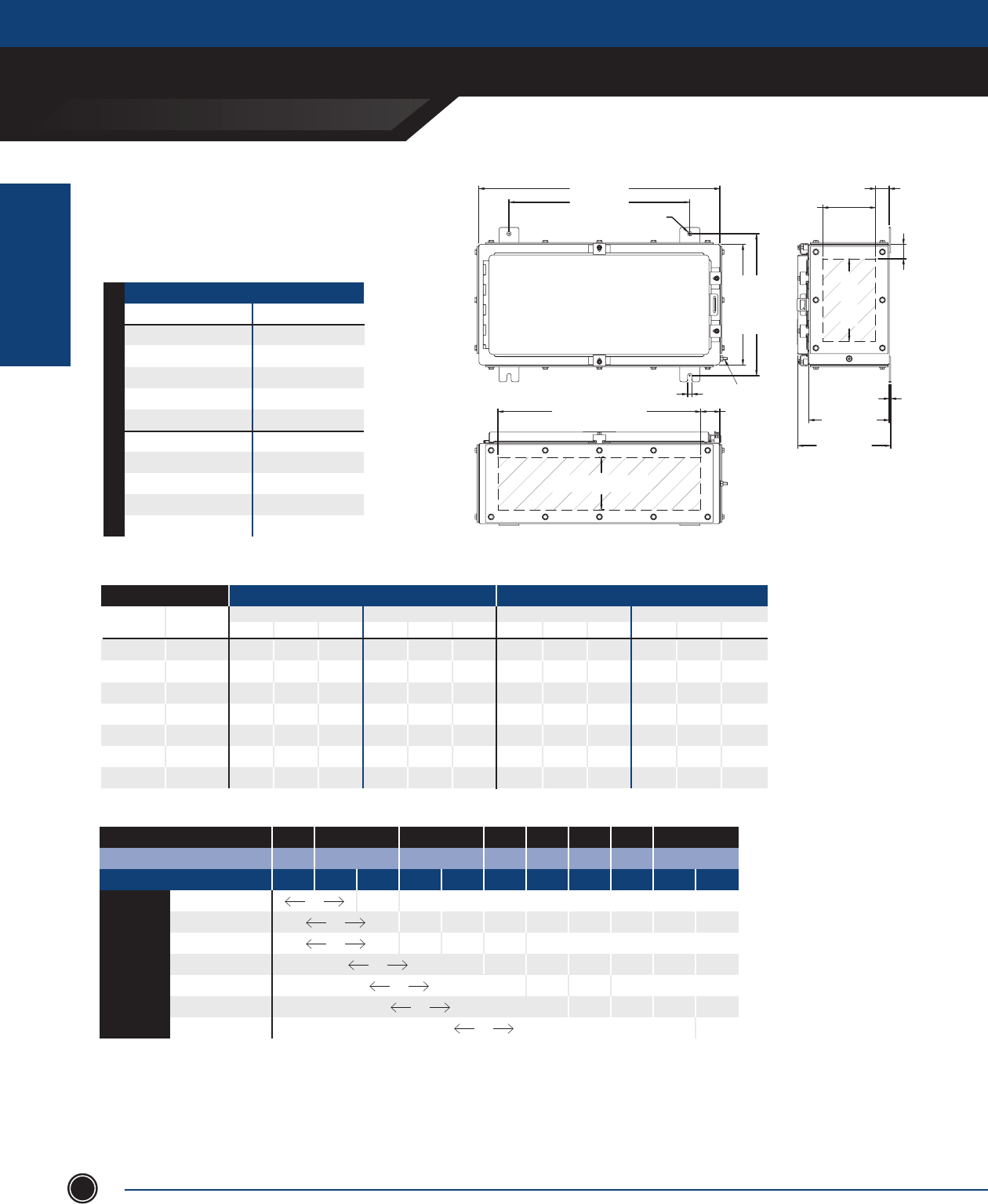
INCREASED SAFETY
TERMINAL ENCLOSURES
INCREASED SAFETY
ENCLOSURES
ADALET.COM
ADALET ENCLOSURE SYSTEMS | 4801 WEST 150TH | CLEVELAND, OHIO 44135©Adalet
36
TN Series
12” x 24” Clamped Door
24.00 [610mm]
18.00 [457mm]
.44 [11mm]
3.25 [83mm]
5.25 [133mm]
G.P. OPENING
1.38 [35mm]
1.44 [37mm]
8.19 [208mm]
G.P. OPENING
6.00 [152mm]
8.00 [203mm]
7.26 [184mm]
9.26 [235mm]
.14 [3mm]
14.13 [359mm]
12.00 [305mm]
.44 [11mm]
EARTH STUD
3.25 [83mm] / 5.25 [133mm]
GLAND PLATE OPENING
20.19 [513mm]
GLAND PLATE OPENING 1.91 [48mm]
GLAND PLATE SIDE B
GLAND PLATE SIDE A
GLAND PLATE SIDE C
GLAND PLATE SIDE D
ENCLOSURES WITH TERMINALS
CATALOG NUMBER GLAND PLATE
TN4X6-122406 None
TN4X6-122406-B Side B
TN4X6-122406-AB Sides A & B
TN4X6-122406-BCD Sides B, C & D
TN4X6-122406-ABCD Sides A, B, C & D
TN4X6-122408 None
TN4X6-122408-B Side B
TN4X6-122408-AB Sides A & B
TN4X6-122408-BCD Sides B, C & D
TN4X6-122408-ABCD Sides A, B, C & D
8” [203.2mm] Depth 6” [152.4mm] Depth
STAINLESS STEEL 316L
MAXIMUM NUMBER OF CABLE/CONDUIT ENTRIES
SIZE WITHOUT GLAND PLATES WITH GLAND PLATES
Sides A & B Sides C & D Sides A & B Sides C & D
NPT Metric 06 08 10 06 08 10 06 08 10 06 08 10
½ M16 95 114 - 45 54 - 32 64 - 12 24 -
¾ M20 64 80 - 32 40 - 26 39 - 10 15 -
1 M25 39 52 - 18 24 - 22 33 - 4 12 -
1
¼ M32 20 30 - 10 15 - 8 16 - 3 6 -
1
½ M40 18 27 - 8 12 - 7 14 - 3 6 -
2 M50 14 14 - 6 6 - 6 6 - 2 2 -
2
½ M63 6 12 - 3 6 - 5 5 - 2 2 -
Terminal Block Size
MAXIMUM TERMINAL BLOCK CONTENT
MIN CONDUCTOR SIZE .5mm 1.5mm 2.5mm 4mm 6mm 10mm 16mm 35mm
MIN CONDUCTOR SIZE AWG 22 16 14 12 10 8 6 2
MAXIMUM AMPERAGE 3 8 10 16 20 25 35 50 63 80 100
1.5mm2 99 48 x x x x x x x x
2.5mm2 170 32 18 x x x x x x
4mm2 170 124 36 20 x x x x x
6mm2 105 39 15 x x x x
10mm2 85 38 12 x x x
16mm2 42 31 14 x x
35mm2 20 15
1. For stainless steel 304 construction, substitute TN4X6 prex with TN4X.
2. The maximum terminal block content is based on vertical rail installation. For horizontal installations, consult factory.
3. For applications requiring multiple terminal block congurations and ampacities, consult factory.
4. For applications requiring larger terminal blocks or custom enclosure sizes, consult factory.
5. For conduit/cable spacings, wire bending and wire conversion guidelines, refer to the inside back cover of this catalog.
NOTES
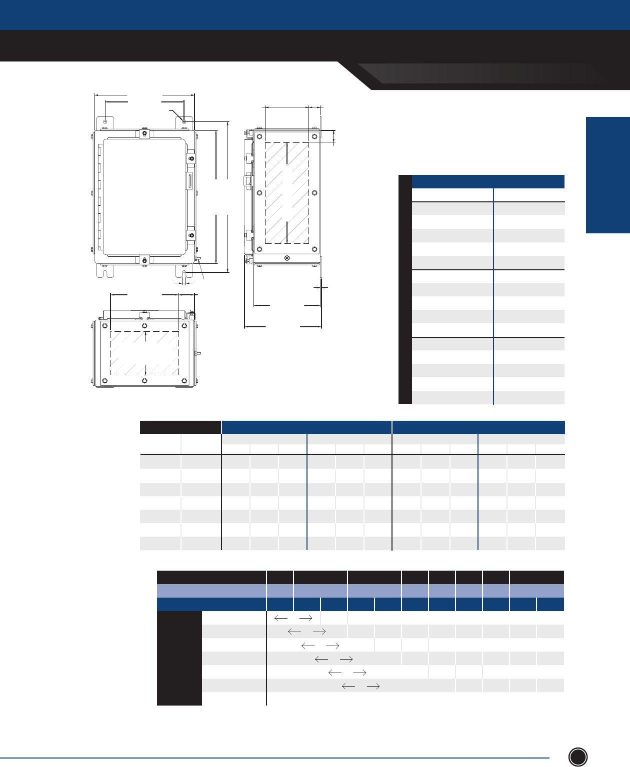
INCREASED SAFETY
TERMINAL ENCLOSURES
INCREASED SAFETY
ENCLOSURES
SEND ORDERS TO ORDERS@ADALET.COM
T: 216.267.9000 | F:216.267.1681 | info@adalet.com ©Adalet
37
TN Series
16” x 12” Clamped Door
12.00 [305mm]
9.50 [241mm]
.44 [11mm]
3.25 [83mm]
5.25 [133mm]
7.25 [184mm]
GLAND PLATE OPENING 1.38 [35mm]
12.19 [310mm]
GLAND PLATE OPENING
1.44 [37mm]
6.00 [152mm]
8.00 [203mm]
10.00 [254mm]
7.26 [184mm]
9.26 [235mm]
11.26 [286mm]
.14 [3mm]
8.19 [208mm]
G.P. OPENING 1.91 [48mm]
3.25 [83mm]
5.25 [133mm]
7.25 [184mm]
GLAND PLATE OPENING
.44 [11mm]
18.13 [460mm]
16.00 [406mm]
EARTH STUD
GLAND PLATE SIDE B
GLAND PLATE SIDE A
GLAND PLATE SIDE C
GLAND PLATE SIDE D
MAXIMUM NUMBER OF CABLE/CONDUIT ENTRIES
SIZE WITHOUT GLAND PLATES WITH GLAND PLATES
Sides A & B Sides C & D Sides A & B Sides C & D
NPT Metric 06 08 10 06 08 10 06 08 10 06 08 10
½ M16 45 54 72 60 72 96 12 24 36 18 36 54
¾ M20 32 40 48 40 50 60 10 15 25 16 24 40
1 M25 18 24 30 24 32 40 4 12 16 6 18 24
1
¼ M32 10 15 20 12 18 24 3 6 9 5 10 15
1
½ M40 8 12 16 10 15 20 3 6 6 4 8 8
2 M50 6 6 9 8 8 12 2 2 4 3 3 6
2
½ M63 3 6 6 4 8 8 2 2 4 3 3 6
Terminal Block Size
MAXIMUM TERMINAL BLOCK CONTENT
MIN CONDUCTOR SIZE .5mm 1.5mm 2.5mm 4mm 6mm 10mm 16mm 35mm
MIN CONDUCTOR SIZE AWG 22 16 14 12 10 8 6 2
MAXIMUM AMPERAGE 3 8 10 16 20 25 35 50 63 80 100
1.5mm2 94 46 x x x x x x x x
2.5mm2 108 30 17 x x x x x x
4mm2 108 34 19 x x x x x
6mm2 68 37 14 x x x x
10mm2 54 36 12 x x x
16mm2 22 30 14 x x
35mm2 x x x x x x x x x x x
1. For stainless steel 304 construction, substitute TN4X6 prex with TN4X.
2. The maximum terminal block content is based on vertical rail installation. For horizontal installations, consult factory.
3. For applications requiring multiple terminal block congurations and ampacities, consult factory.
4. For applications requiring larger terminal blocks or custom enclosure sizes, consult factory.
5. For conduit/cable spacings, wire bending and wire conversion guidelines, refer to the inside back cover of this catalog.
NOTES
ENCLOSURES WITH TERMINALS
CAT NUMBER GLAND PLATE
TN4X6-161206 None
TN4X6-161206-B Side B
TN4X6-161206-AB Sides A & B
TN4X6-161206-BCD Sides B, C & D
TN4X6-161206-ABCD Sides A, B, C & D
TN4X6-161208 None
TN4X6-161208-B Side B
TN4X6-161208-AB Sides A & B
TN4X6-161208-BCD Sides B, C & D
TN4X6-161208-ABCD Sides A, B, C & D
TN4X6-161210 None
TN4X6-161210-B Side B
TN4X6-161210-AB Sides A & B
TN4X6-161210-BCD Sides B, C & D
TN4X6-161210-ABCD Sides A, B, C & D
10” [254.0mm] Depth 8” [203.2mm] Depth 6” [152.4mm] Depth
STAINLESS STEEL 316L
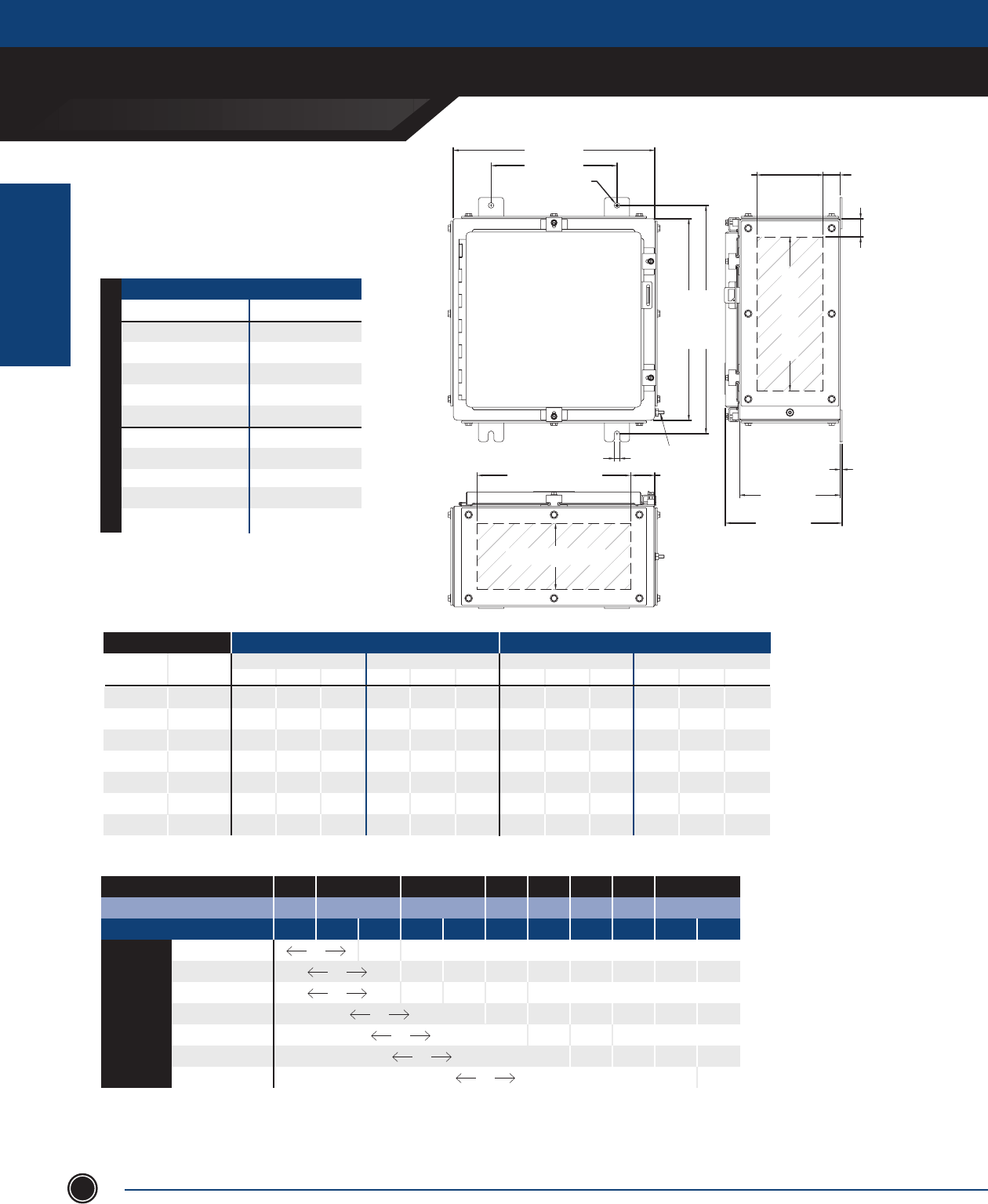
INCREASED SAFETY
TERMINAL ENCLOSURES
INCREASED SAFETY
ENCLOSURES
ADALET.COM
ADALET ENCLOSURE SYSTEMS | 4801 WEST 150TH | CLEVELAND, OHIO 44135©Adalet
38
TN Series
16” x 16” Clamped Door
16.00 [406mm]
10.00 [254mm]
.44 [11mm]
3.25 [83mm]
5.25 [133mm]
GLAND PLATE OPENING 1.38 [35mm]
12.19 [310mm]
GLAND PLATE OPENING
1.44 [37mm]
6.00 [ 152mm]
8.00 [203mm]
7.26 [184mm]
9.26 [235mm]
.14 [3mm]
18.13 [460mm]
16.00 [406mm]
.44 [11mm]
EARTH STUD
12.19 [310mm]
GLAND PLATE OPENING 1.91 [48mm]
3.25 [83mm] / 5.25 [133mm]
GLAND PLATE OPENING
GLAND PLATE SIDE B
GLAND PLATE SIDE A
GLAND PLATE SIDE C
GLAND PLATE SIDE D
MAXIMUM NUMBER OF CABLE/CONDUIT ENTRIES
SIZE WITHOUT GLAND PLATES WITH GLAND PLATES
Sides A & B Sides C & D Sides A & B Sides C & D
NPT Metric 06 08 10 06 08 10 06 08 10 06 08 10
½ M16 65 78 - 60 72 - 18 36 - 18 36 -
¾ M20 40 50 - 40 50 - 16 24 - 16 24 -
1 M25 24 32 - 24 32 - 6 18 - 6 18 -
1
¼ M32 12 18 - 12 18 - 5 10 - 5 10 -
1
½ M40 12 18 - 10 15 - 4 8 - 4 8 -
2 M50 10 10 - 8 8 - 3 3 - 3 3 -
2
½ M63 4 8 - 4 8 - 3 3 - 3 3 -
Terminal Block Size
MAXIMUM TERMINAL BLOCK CONTENT
MIN CONDUCTOR SIZE .5mm 1.5mm 2.5mm 4mm 6mm 10mm 16mm 35mm
MIN CONDUCTOR SIZE AWG 22 16 14 12 10 8 6 2
MAXIMUM AMPERAGE 3 8 10 16 20 25 35 50 63 80 100
1.5mm2 104 50 x x x x x x x x
2.5mm2 162 33 19 x x x x x x
4mm2 162 130 38 21 x x x x x
6mm2 102 41 16 x x x x
10mm2 81 40 13 x x x
16mm2 44 33 15 x x
35mm2 17 7
ENCLOSURES WITH TERMINALS
CATALOG NUMBER GLAND PLATE
TN4X6-161606 None
TN4X6-161606-B Side B
TN4X6-161606-AB Sides A & B
TN4X6-161606-BCD Sides B, C & D
TN4X6-161606-ABCD Sides A, B, C & D
TN4X6-161608 None
TN4X6-161608-B Side B
TN4X6-161608-AB Sides A & B
TN4X6-161608-BCD Sides B, C & D
TN4X6-161608-ABCD Sides A, B, C & D
8” [203.2mm] Depth 6” [152.4mm] Depth
STAINLESS STEEL 316L
1. For stainless steel 304 construction, substitute TN4X6 prex with TN4X.
2. The maximum terminal block content is based on vertical rail installation. For horizontal installations, consult factory.
3. For applications requiring multiple terminal block congurations and ampacities, consult factory.
4. For applications requiring larger terminal blocks or custom enclosure sizes, consult factory.
5. For conduit/cable spacings, wire bending and wire conversion guidelines, refer to the inside back cover of this catalog.
NOTES

INCREASED SAFETY
TERMINAL ENCLOSURES
INCREASED SAFETY
ENCLOSURES
SEND ORDERS TO ORDERS@ADALET.COM
T: 216.267.9000 | F:216.267.1681 | info@adalet.com ©Adalet
39
TN Series
16” x 20” Clamped Door
20.00 [508mm]
14.00 [356mm]
.44 [11mm]
3.25 [83mm]
5.25 [133mm]
GLAND PLATE OPENING 1.38 [35mm]
12.19 [310mm]
GLAND PLATE OPENING
1.44 [37mm]
6.00 [152mm]
8.00 [203mm]
7.26 [184mm]
9.26 [235mm]
.14 [3mm]
3.25 [83mm] / 5.25 [133mm]
GLAND PLATE OPENING
16.19 [411mm]
GLAND PLATE OPENING 1.91 [48mm]
.44 [11mm]
18.13 [460mm]
16.00 [406mm]
EARTH STUD
GLAND PLATE SIDE B
GLAND PLATE SIDE A
GLAND PLATE SIDE C
GLAND PLATE SIDE D
8” [203.2mm] Depth 6” [152.4mm] Depth
ENCLOSURES WITH TERMINALS
CATALOG NUMBER GLAND PLATE
TN4X6-162006 None
TN4X6-162006-B Side B
TN4X6-162006-AB Sides A & B
TN4X6-162006-BCD Sides B, C & D
TN4X6-162006-ABCD Sides A, B, C & D
TN4X6-162008 None
TN4X6-162008-B Side B
TN4X6-162008-AB Sides A & B
TN4X6-162008-BCD Sides B, C & D
TN4X6-162008-ABCD Sides A, B, C & D
STAINLESS STEEL 316L
MAXIMUM NUMBER OF CABLE/CONDUIT ENTRIES
SIZE WITHOUT GLAND PLATES WITH GLAND PLATES
Sides A & B Sides C & D Sides A & B Sides C & D
NPT Metric 06 08 10 06 08 10 06 08 10 06 08 10
½ M16 80 96 - 60 72 - 26 52 - 18 36 -
¾ M20 52 65 - 40 50 - 22 33 - 16 24 -
1 M25 30 40 - 24 32 - 8 24 - 6 18 -
1
¼ M32 16 24 - 12 18 - 7 14 - 5 10 -
1
½ M40 14 21 - 10 15 - 6 12 - 4 8 -
2 M50 12 12 - 8 8 - 5 5 - 3 3 -
2
½ M63 5 10 - 4 8 - 4 4 - 3 3 -
Terminal Block Size
MAXIMUM TERMINAL BLOCK CONTENT
MIN CONDUCTOR SIZE .5mm 1.5mm 2.5mm 4mm 6mm 10mm 16mm 35mm
MIN CONDUCTOR SIZE AWG 22 16 14 12 10 8 6 2
MAXIMUM AMPERAGE 3 8 10 16 20 25 35 50 63 80 100
1.5mm2 110 53 x x x x x x x x
2.5mm2 216 35 20 x x x x x x
4mm2 216 138 40 22 x x x x x
6mm2 136 43 17 x x x x
10mm2 108 42 13 x x x
16mm2 66 35 16 x x
35mm2 17
1. For stainless steel 304 construction, substitute TN4X6 prex with TN4X.
2. The maximum terminal block content is based on vertical rail installation. For horizontal installations, consult factory.
3. For applications requiring multiple terminal block congurations and ampacities, consult factory.
4. For applications requiring larger terminal blocks or custom enclosure sizes, consult factory.
5. For conduit/cable spacings, wire bending and wire conversion guidelines, refer to the inside back cover of this catalog.
NOTES
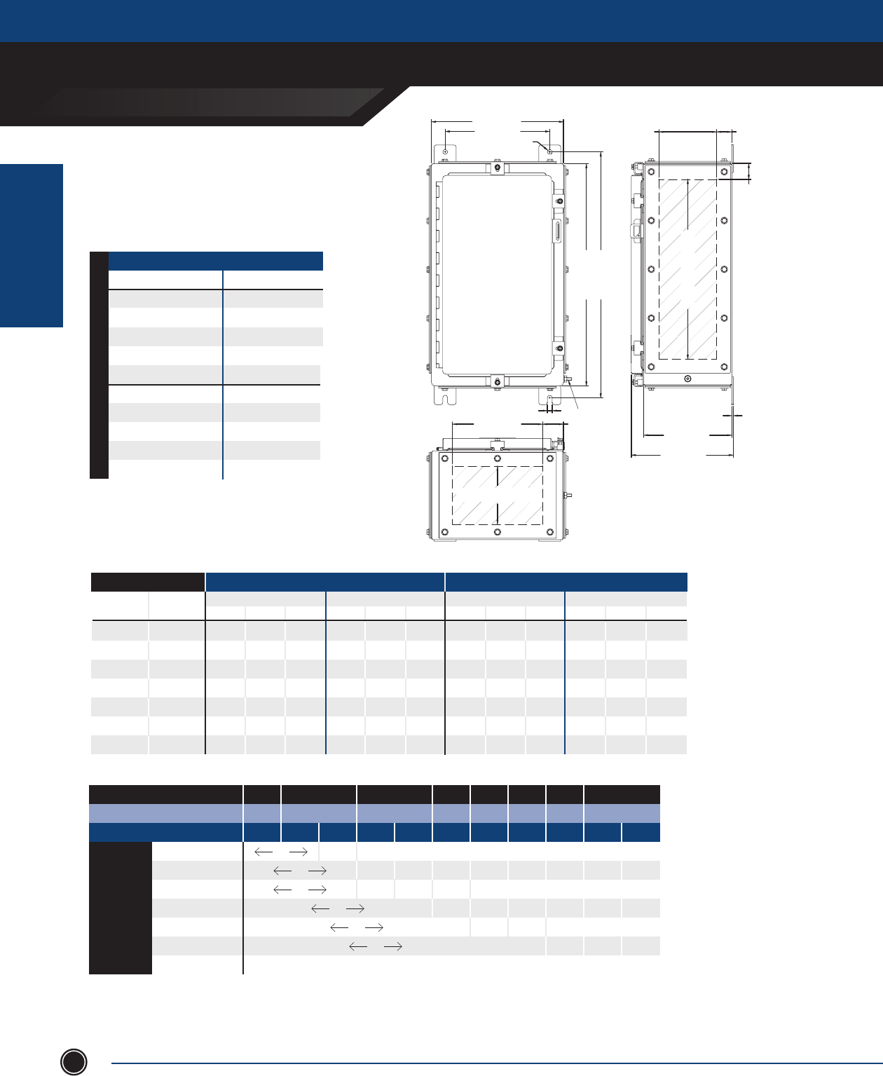
INCREASED SAFETY
TERMINAL ENCLOSURES
INCREASED SAFETY
ENCLOSURES
ADALET.COM
ADALET ENCLOSURE SYSTEMS | 4801 WEST 150TH | CLEVELAND, OHIO 44135©Adalet
40
TN Series
20” x 12” Clamped Door
12.00 [305mm]
9.50 [241mm]
.44 [11mm]
22.13 [562mm]
20.00 [508mm]
.44 [11mm] EARTH STUD
3.25 [83mm]
5.25 [133mm]
GLAND PLATE OPENING
1.38 [35mm]
16.19 [411mm]
GLAND PLATE OPENING
1.44 [37mm]
6.00 [152mm]
8.00 [203mm]
7.26 [184mm]
9.26 [235mm]
.14 [3mm]
3.25 [83mm] / 5.25 [133mm]
GLAND PLATE OPENING
8.19 [208mm]
G.P. OPENING 1.91 [48mm]
GLAND PLATE SIDE B
GLAND PLATE SIDE A
GLAND PLATE SIDE C
GLAND PLATE SIDE D
ENCLOSURES WITH TERMINALS
CATALOG NUMBER GLAND PLATE
TN4X6-201206 None
TN4X6-201206-B Side B
TN4X6-201206-AB Sides A & B
TN4X6-201206-BCD Sides B, C & D
TN4X6-201206-ABCD Sides A, B, C & D
TN4X6-201208 None
TN4X6-201208-B Side B
TN4X6-201208-AB Sides A & B
TN4X6-201208-BCD Sides B, C & D
TN4X6-201208-ABCD Sides A, B, C & D
8” [203.2mm] Depth 6” [152.4mm] Depth
STAINLESS STEEL 316L
MAXIMUM NUMBER OF CABLE/CONDUIT ENTRIES
SIZE WITHOUT GLAND PLATES WITH GLAND PLATES
Sides A & B Sides C & D Sides A & B Sides C & D
NPT Metric 06 08 10 06 08 10 06 08 10 06 08 10
½ M16 40 48 - 75 80 - 12 24 - 26 52 -
¾ M20 28 35 - 48 60 - 10 15 - 22 33 -
1 M25 18 24 - 30 40 - 4 12 - 8 24 -
1
¼ M32 8 12 - 16 24 - 3 6 - 7 14 -
1
½ M40 8 12 - 14 21 - 3 6 - 6 12 -
2 M50 6 6 - 10 10 - 2 2 - 5 5 -
2
½ M63 3 6 - 5 10 - 2 2 - 4 4 -
Terminal Block Size
MAXIMUM TERMINAL BLOCK CONTENT
MIN CONDUCTOR SIZE .5mm 1.5mm 2.5mm 4mm 6mm 10mm 16mm 35mm
MIN CONDUCTOR SIZE AWG 22 16 14 12 10 8 6 2
MAXIMUM AMPERAGE 3 8 10 16 20 25 35 50 63 80 100
1.5mm2 97 47 x x x x x x x x
2.5mm2 148 31 18 x x x x x x
4mm2 148 122 35 20 x x x x x
6mm2 94 36 15 x x x x
10mm2 74 37 12 x x x
16mm2 31 14 x x
35mm2 x x x x x x x x x x x
1. For stainless steel 304 construction, substitute TN4X6 prex with TN4X.
2. The maximum terminal block content is based on vertical rail installation. For horizontal installations, consult factory.
3. For applications requiring multiple terminal block congurations and ampacities, consult factory.
4. For applications requiring larger terminal blocks or custom enclosure sizes, consult factory.
5. For conduit/cable spacings, wire bending and wire conversion guidelines, refer to the inside back cover of this catalog.
NOTES
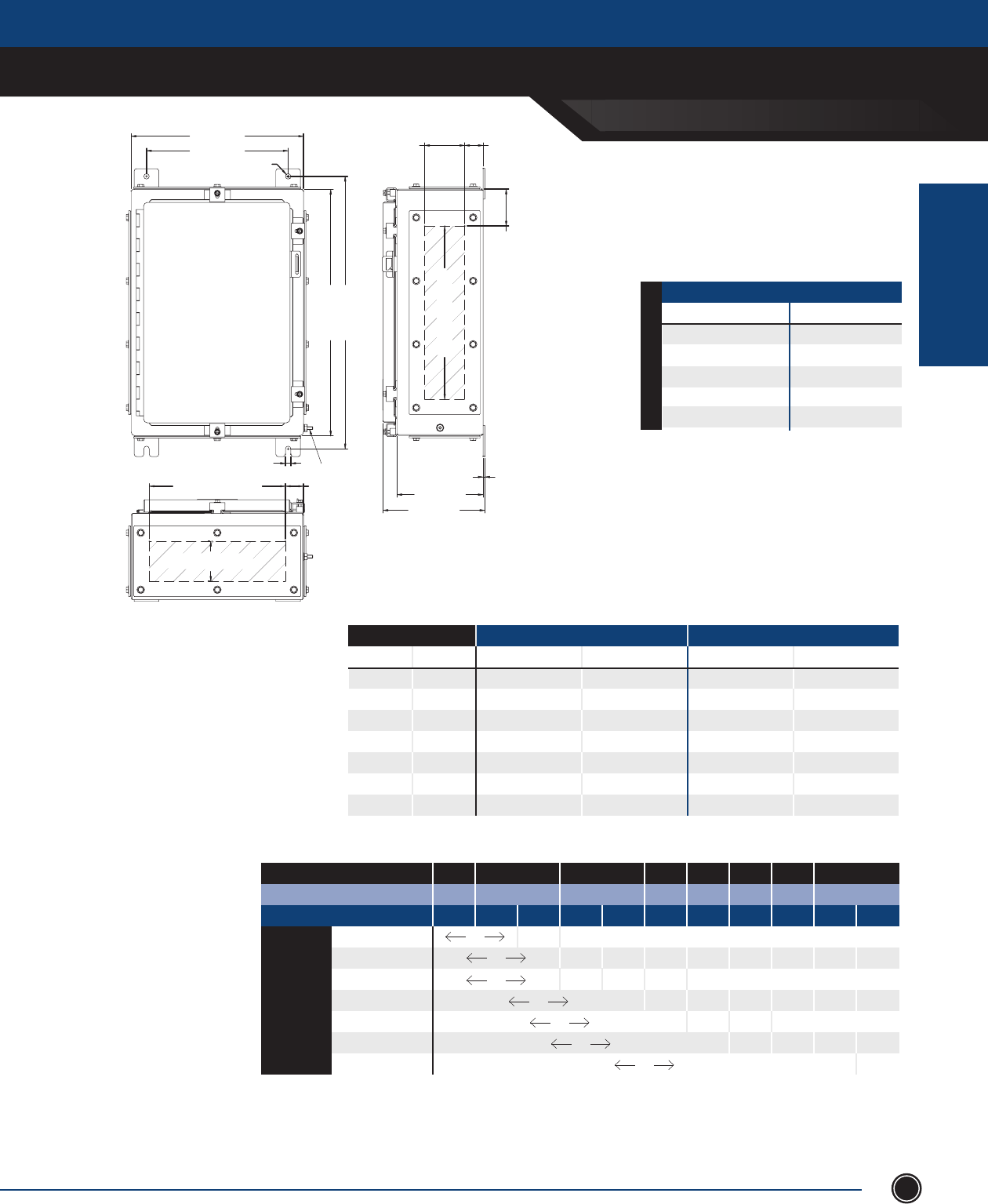
INCREASED SAFETY
TERMINAL ENCLOSURES
INCREASED SAFETY
ENCLOSURES
SEND ORDERS TO ORDERS@ADALET.COM
T: 216.267.9000 | F:216.267.1681 | info@adalet.com ©Adalet
41
TN Series
20” x 14” x 7” Clamped Door
14.00 [356mm]
11.50 [292mm]
.44 [11mm]
3.25 [83mm] 1.50 [38mm]
3.00 [76mm]
14.06 [357mm]
GLAND PLATE OPENING
7.00 [178mm]
8.26 [210mm]
.14 [3mm]
22.13 [562mm]
20.00 [508mm]
.44 [11mm] EARTH STUD
11.06 [281mm]
GLAND PLATE OPENING
3.25 [83mm]
GLAND PLATE OPENING
1.47 [37mm]
GLAND PLATE SIDE B
GLAND PLATE SIDE A
GLAND PLATE SIDE C
GLAND PLATE SIDE D
MAXIMUM NUMBER OF CABLE/CONDUIT ENTRIES
SIZE WITHOUT GLAND PLATES WITH GLAND PLATES
NPT Metric Sides A & B Sides C & D Sides A & B Sides C & D
½ M16 55 75 18 22
¾ M20 36 48 14 18
1 M25 21 30 6 7
1
¼ M32 12 16 4 6
1
½ M40 10 14 4 5
2 M50 8 10 3 4
2
½ M63 3 5 3 3
Terminal Block Size
MAXIMUM TERMINAL BLOCK CONTENT
MIN CONDUCTOR SIZE .5mm 1.5mm 2.5mm 4mm 6mm 10mm 16mm 35mm
MIN CONDUCTOR SIZE AWG 22 16 14 12 10 8 6 2
MAXIMUM AMPERAGE 3 8 10 16 20 25 35 50 63 80 100
1.5mm2 104 50 x x x x x x x x
2.5mm2 222 33 19 x x x x x x
4mm2 222 131 38 21 x x x x x
6mm2 141 41 16 x x x x
10mm2 74 40 13 x x x
16mm2 62 33 15 x x
35mm2 23 16
ENCLOSURES WITH TERMINALS
CATALOG NUMBER GLAND PLATE
TN4X6-201407 None
TN4X6-201407-B Side B
TN4X6-201407-AB Sides A & B
TN4X6-201407-BCD Sides B, C & D
TN4X6-201407-ABCD Sides A, B, C & D
7” [177.8mm] Depth
STAINLESS STEEL 316L
1. For stainless steel 304 construction, substitute TN4X6 prex with TN4X.
2. The maximum terminal block content is based on vertical rail installation. For horizontal installations, consult factory.
3. For applications requiring multiple terminal block congurations and ampacities, consult factory.
4. For applications requiring larger terminal blocks or custom enclosure sizes, consult factory.
5. For conduit/cable spacings, wire bending and wire conversion guidelines, refer to the inside back cover of this catalog.
NOTES

INCREASED SAFETY
TERMINAL ENCLOSURES
INCREASED SAFETY
ENCLOSURES
ADALET.COM
ADALET ENCLOSURE SYSTEMS | 4801 WEST 150TH | CLEVELAND, OHIO 44135©Adalet
42
TN Series
20” x 16” Clamped Door
16.00 [406mm]
10.00 [254mm]
.44 [11mm]
22.13 [562mm]
20.00 [508mm]
.44 [11mm]
3.25 [83mm]
5.25 [133mm]
7.25 [184mm]
GLAND PLATE OPENING 1.38 [35mm]
1.44 [37mm]
16.19 [411mm]
GLAND PLATE OPENING
6.00 [152mm]
8.00 [203mm]
10.00 [254mm]
.14 [3mm]
7.26 [184mm]
9.26 [235mm]
11.26 [286mm]
3.25 [83mm]
5.25 [133mm]
7.25 [184mm]
GLAND PLATE OPENING
12.19 [310mm]
GLAND PLATE OPENING 1.91 [48mm]
EARTH STUD
GLAND PLATE SIDE B
GLAND PLATE SIDE A
GLAND PLATE SIDE C
GLAND PLATE SIDE D
ENCLOSURES WITH TERMINALS
CATALOG NUMBER GLAND PLATE
TN4X6-201606 None
TN4X6-201606-B Side B
TN4X6-201606-AB Sides A & B
TN4X6-201606-BCD Sides B, C & D
TN4X6-201606-ABCD Sides A, B, C & D
TN4X6-201608 None
TN4X6-201608-B Side B
TN4X6-201608-AB Sides A & B
TN4X6-201608-BCD Sides B, C & D
TN4X6-201608-ABCD Sides A, B, C & D
TN4X6-201610 None
TN4X6-201610-B Side B
TN4X6-201610-AB Sides A & B
TN4X6-201610-BCD Sides B, C & D
TN4X6-201610-ABCD Sides A, B, C & D
10” [254.0mm] Depth 8” [203.2mm] Depth 6” [152.4mm] Depth
MAXIMUM NUMBER OF CABLE/CONDUIT ENTRIES
SIZE WITHOUT GLAND PLATES WITH GLAND PLATES
Sides A & B Sides C & D Sides A & B Sides C & D
NPT Metric 06 08 10 06 08 10 06 08 10 06 08 10
½ M16 65 78 104 75 90 120 18 36 54 26 52 78
¾ M20 40 50 60 48 60 72 16 24 40 22 33 55
1 M25 24 32 40 30 40 50 6 18 24 8 24 32
1
¼ M32 12 18 24 16 24 32 5 10 15 7 14 21
1
½ M40 12 18 24 14 21 28 4 8 8 6 12 12
2 M50 10 10 15 10 10 15 3 3 6 5 5 10
2
½ M63 4 8 8 5 10 10 3 3 6 4 4 8
Terminal Block Size
MAXIMUM TERMINAL BLOCK CONTENT
MIN CONDUCTOR SIZE .5mm 1.5mm 2.5mm 4mm 6mm 10mm 16mm 35mm
MIN CONDUCTOR SIZE AWG 22 16 14 12 10 8 6 2
MAXIMUM AMPERAGE 3 8 10 16 20 25 35 50 63 80 100
1.5mm2 110 53 x x x x x x x x
2.5mm2 222 35 20 x x x x x x
4mm2 222 138 40 22 x x x x x
6mm2 141 43 17 x x x x
10mm2 111 42 13 x x x
16mm2 62 35 16 x x
35mm2 23 17
STAINLESS STEEL 316L
1. For stainless steel 304 construction, substitute TN4X6 prex with TN4X.
2. The maximum terminal block content is based on vertical rail installation. For horizontal installations, consult factory.
3. For applications requiring multiple terminal block congurations and ampacities, consult factory.
4. For applications requiring larger terminal blocks or custom enclosure sizes, consult factory.
5. For conduit/cable spacings, wire bending and wire conversion guidelines, refer to the inside back cover of this catalog.
NOTES

INCREASED SAFETY
TERMINAL ENCLOSURES
INCREASED SAFETY
ENCLOSURES
SEND ORDERS TO ORDERS@ADALET.COM
T: 216.267.9000 | F:216.267.1681 | info@adalet.com ©Adalet
43
TN Series
20” x 20” Clamped Door
20.00 [508mm]
14.00 [356mm]
.44 [11mm]
3.25 [83mm]
5.25 [133mm]
7.25 [184mm]
GLAND PLATE OPENING 1.38 [35mm]
16.19 [411mm]
GLAND PLATE OPENING
1.44 [37mm]
6.00 [152mm]
8.00 [203mm]
10.00 [254mm]
7.26 [184mm]
9.26 [235mm]
11.26 [286mm]
.14 [3mm]
3.25 [83mm] / 5.25 [133mm] / 7.25 [184mm]
GLAND PLATE OPENING
16.19 [411mm]
GLAND PLATE OPENING 1.91 [48mm]
.44 [11mm]
22.13 [562mm]
20.00 [508mm]
EARTH STUD
GLAND PLATE SIDE B
GLAND PLATE SIDE A
GLAND PLATE SIDE C
GLAND PLATE SIDE D
ENCLOSURES WITH TERMINALS
CATALOG NUMBER GLAND PLATE
TN4X6-202006 None
TN4X6-202006-B Side B
TN4X6-202006-AB Sides A & B
TN4X6-202006-BCD Sides B, C & D
TN4X6-202006-ABCD Sides A, B, C & D
TN4X6-202008 None
TN4X6-202008-B Side B
TN4X6-202008-AB Sides A & B
TN4X6-202008-BCD Sides B, C & D
TN4X6-202008-ABCD Sides A, B, C & D
TN4X6-202010 None
TN4X6-202010-B Side B
TN4X6-202010-AB Sides A & B
TN4X6-202010-BCD Sides B, C & D
TN4X6-202010-ABCD Sides A, B, C & D
10” [254.0mm] Depth 8” [203.2mm] Depth 6” [152.4mm] Depth
STAINLESS STEEL 316L
MAXIMUM NUMBER OF CABLE/CONDUIT ENTRIES
SIZE WITHOUT GLAND PLATES WITH GLAND PLATES
Sides A & B Sides C & D Sides A & B Sides C & D
NPT Metric 06 08 10 06 08 10 06 08 10 06 08 10
½ M16 80 96 128 75 90 120 26 52 78 26 52 78
¾ M20 52 65 78 48 60 72 22 33 55 22 33 55
1 M25 30 40 50 30 40 50 8 24 32 8 24 32
1
¼ M32 16 24 32 16 24 32 7 14 21 7 14 21
1
½ M40 14 21 28 14 21 28 6 12 12 6 12 12
2 M50 12 12 18 10 10 15 5 5 12 5 5 10
2
½ M63 5 10 10 5 10 10 4 4 8 4 4 8
Terminal Block Size
MAXIMUM TERMINAL BLOCK CONTENT
MIN CONDUCTOR SIZE .5mm 1.5mm 2.5mm 4mm 6mm 10mm 16mm 35mm
MIN CONDUCTOR SIZE AWG 22 16 14 12 10 8 6 2
MAXIMUM AMPERAGE 3 8 10 16 20 25 35 50 63 80 100
1.5mm2 119 58 x x x x x x x x
2.5mm2 296 38 22 x x x x x x
4mm2 296 149 43 24 x x x x x
6mm2 188 47 18 x x x x
10mm2 148 46 15 x x x
16mm2 93 38 17 x x
35mm2 23 18
1. For stainless steel 304 construction, substitute TN4X6 prex with TN4X.
2. The maximum terminal block content is based on vertical rail installation. For horizontal installations, consult factory.
3. For applications requiring multiple terminal block congurations and ampacities, consult factory.
4. For applications requiring larger terminal blocks or custom enclosure sizes, consult factory.
5. For conduit/cable spacings, wire bending and wire conversion guidelines, refer to the inside back cover of this catalog.
NOTES
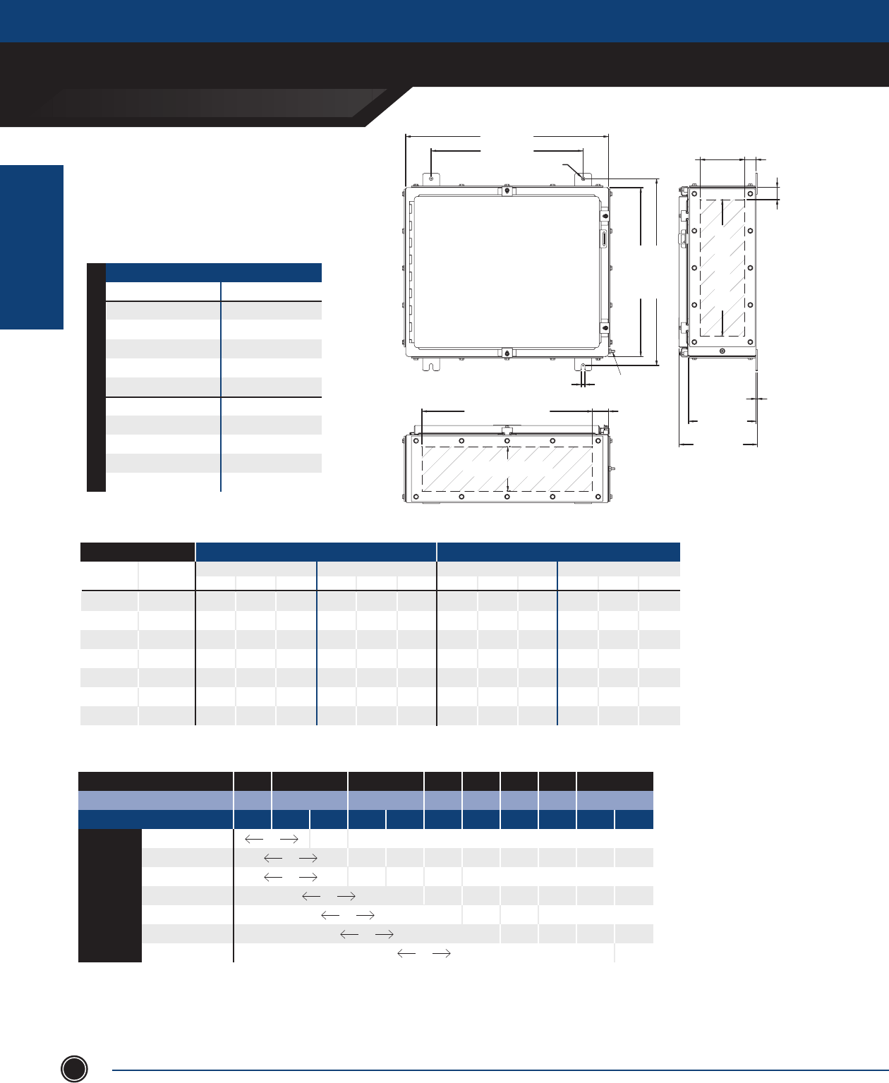
INCREASED SAFETY
TERMINAL ENCLOSURES
INCREASED SAFETY
ENCLOSURES
ADALET.COM
ADALET ENCLOSURE SYSTEMS | 4801 WEST 150TH | CLEVELAND, OHIO 44135©Adalet
44
TN Series
20” x 24” Clamped Door
24.00 [610mm]
18.00 [457mm]
.44 [11mm]
3.25 [83mm]
5.25 [133mm]
GLAND PLATE OPENING 1.37 [35mm]
1.44 [37mm]
16.19 [411mm]
GLAND PLATE OPENING
7.26 [184mm]
9.26 [235mm]
6.00 [152mm]
8.00 [203mm]
.13 [3mm]
20.19 [513mm]
GLAND PLATE OPENING 1.91 [48mm]
.44 [11mm]
22.13 [562mm]
20.00 [508mm]
3.25 [83mm] / 5.25 [133mm]
GLAND PLATE OPENING
EARTH STUD
GLAND PLATE SIDE B
GLAND PLATE SIDE A
GLAND PLATE SIDE C
GLAND PLATE SIDE D
ENCLOSURES WITH TERMINALS
CATALOG NUMBER GLAND PLATE
TN4X6-202406 None
TN4X6-202406-B Side B
TN4X6-202406-AB Sides A & B
TN4X6-202406-BCD Sides B, C & D
TN4X6-202406-ABCD Sides A, B, C & D
TN4X6-202408 None
TN4X6-202408-B Side B
TN4X6-202408-AB Sides A & B
TN4X6-202408-BCD Sides B, C & D
TN4X6-202408-ABCD Sides A, B, C & D
8” [203.2mm] Depth 6” [152.4mm] Depth
STAINLESS STEEL 316L
MAXIMUM NUMBER OF CABLE/CONDUIT ENTRIES
SIZE WITHOUT GLAND PLATES WITH GLAND PLATES
Sides A & B Sides C & D Sides A & B Sides C & D
NPT Metric 06 08 10 06 08 10 06 08 10 06 08 10
½ M16 80 96 - 90 108 - 32 64 - 26 52 -
¾ M20 52 65 - 60 75 - 26 39 - 22 33 -
1 M25 30 40 - 36 48 - 11 33 - 8 24 -
1
¼ M32 16 24 - 18 27 - 8 16 - 7 14 -
1
½ M40 14 21 - 16 24 - 7 14 - 6 12 -
2 M50 12 12 - 14 14 - 6 6 - 5 5 -
2
½ M63 5 10 - 6 12 - 5 5 - 4 4 -
Terminal Block Size
MAXIMUM TERMINAL BLOCK CONTENT
MIN CONDUCTOR SIZE .5mm 1.5mm 2.5mm 4mm 6mm 10mm 16mm 35mm
MIN CONDUCTOR SIZE AWG 22 16 14 12 10 8 6 2
MAXIMUM AMPERAGE 3 8 10 16 20 25 35 50 63 80 100
1.5mm2 125 61 x x x x x x x x
2.5mm2 370 40 23 x x x x x x
4mm2 370 157 45 25 x x x x x
6mm2 235 49 19 x x x x
10mm2 185 48 15 x x x
16mm2 93 40 18 x x
35mm2 46 19
1. For stainless steel 304 construction, substitute TN4X6 prex with TN4X.
2. The maximum terminal block content is based on vertical rail installation. For horizontal installations, consult factory.
3. For applications requiring multiple terminal block congurations and ampacities, consult factory.
4. For applications requiring larger terminal blocks or custom enclosure sizes, consult factory.
5. For conduit/cable spacings, wire bending and wire conversion guidelines, refer to the inside back cover of this catalog.
NOTES

INCREASED SAFETY
TERMINAL ENCLOSURES
INCREASED SAFETY
ENCLOSURES
SEND ORDERS TO ORDERS@ADALET.COM
T: 216.267.9000 | F:216.267.1681 | info@adalet.com ©Adalet
45
TN Series
24” x 12” Clamped Door
9.50 [241mm]
12.00 [305mm]
.44 [11mm]
3.25 [83mm]
5.25 [133mm]
7.25 [184mm]
GLAND PLATE OPENING 1.38 [35mm]
1.44 [37mm]
20.19 [513mm]
GLAND PLATE OPENING
6.00 [152mm]
8.00 [203mm]
10.00 [254mm]
7.26 [184mm]
9.26 [235mm]
11.26 [286mm]
.14 [3mm]
8.19 [208mm]
G.P. OPENING 1.91 [48mm]
3.25 [83mm]
5.25 [133mm]
7.25 [184mm]
G.P. OPENING
.44 [11mm]
26.13 [664mm]
24.00 [610mm]
EARTH STUD
GLAND PLATE SIDE B
GLAND PLATE SIDE A
GLAND PLATE SIDE C
GLAND PLATE SIDE D
ENCLOSURES WITH TERMINALS
CATALOG NUMBER GLAND PLATE
TN4X6-241206 None
TN4X6-241206-B Side B
TN4X6-241206-AB Sides A & B
TN4X6-241206-BCD Sides B, C & D
TN4X6-241206-ABCD Sides A, B, C & D
TN4X6-241208 None
TN4X6-241208-B Side B
TN4X6-241208-AB Sides A & B
TN4X6-241208-BCD Sides B, C & D
TN4X6-241208-ABCD Sides A, B, C & D
TN4X6-241210 None
TN4X6-241210-B Side B
TN4X6-241210-AB Sides A & B
TN4X6-241210-BCD Sides B, C & D
TN4X6-241210-ABCD Sides A, B, C & D
10” [254.0mm] Depth 8” [203.2mm] Depth 6” [152.4mm] Depth
STAINLESS STEEL 316L
MAXIMUM NUMBER OF CABLE/CONDUIT ENTRIES
SIZE WITHOUT GLAND PLATES WITH GLAND PLATES
Sides A & B Sides C & D Sides A & B Sides C & D
NPT Metric 06 08 10 06 08 10 06 08 10 06 08 10
½ M16 45 54 72 90 108 144 12 24 36 32 64 96
¾ M20 32 40 48 60 75 90 10 15 25 26 39 65
1 M25 18 24 30 36 48 60 4 12 16 11 33 44
1
¼ M32 10 15 20 18 27 36 3 6 9 8 16 24
1
½ M40 8 12 16 16 24 32 3 6 6 7 14 14
2 M50 6 6 9 14 14 21 2 2 4 6 6 12
2
½ M63 3 6 6 6 12 12 2 2 4 5 5 10
Terminal Block Size
MAXIMUM TERMINAL BLOCK CONTENT
MIN CONDUCTOR SIZE .5mm 1.5mm 2.5mm 4mm 6mm 10mm 16mm 35mm
MIN CONDUCTOR SIZE AWG 22 16 14 12 10 8 6 2
MAXIMUM AMPERAGE 3 8 10 16 20 25 35 50 63 80 100
1.5mm2 99 48 x x x x x x x x
2.5mm2 190 32 18 x x x x x x
4mm2 190 124 36 20 x x x x x
6mm2 120 39 15 x x x x
10mm2 96 38 12 x x x
16mm2 39 31 14 x x
35mm2 x x x x x x x x x x x
1. For stainless steel 304 construction, substitute TN4X6 prex with TN4X.
2. The maximum terminal block content is based on vertical rail installation. For horizontal installations, consult factory.
3. For applications requiring multiple terminal block congurations and ampacities, consult factory.
4. For applications requiring larger terminal blocks or custom enclosure sizes, consult factory.
5. For conduit/cable spacings, wire bending and wire conversion guidelines, refer to the inside back cover of this catalog.
NOTES
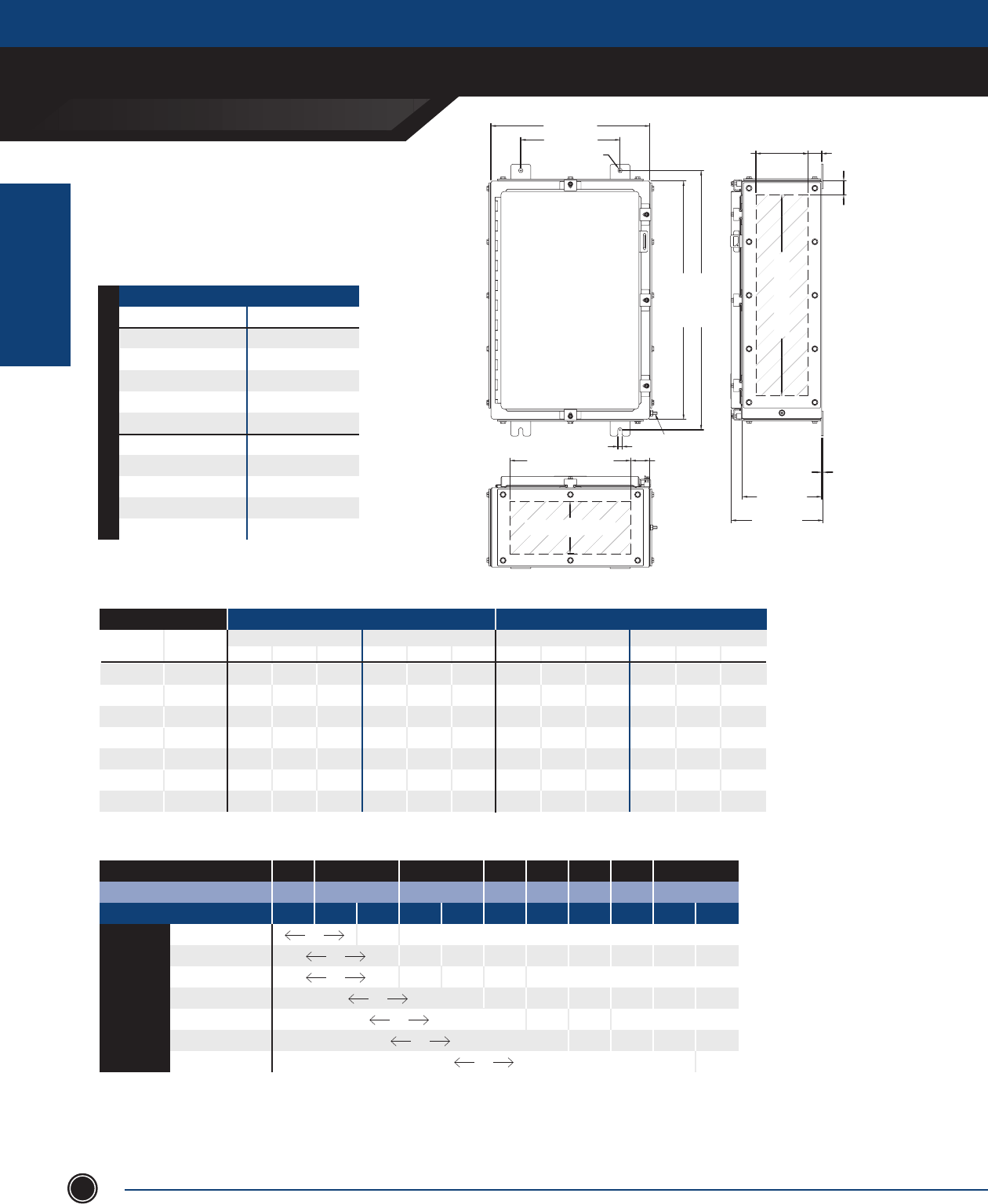
INCREASED SAFETY
TERMINAL ENCLOSURES
INCREASED SAFETY
ENCLOSURES
ADALET.COM
ADALET ENCLOSURE SYSTEMS | 4801 WEST 150TH | CLEVELAND, OHIO 44135©Adalet
46
TN Series
24” x 16” Clamped Door
16.00 [406mm]
10.00 [254mm]
.44 [11mm]
3.25 [83mm]
5.25 [133mm]
GLAND PLATE OPENING 1.38 [35mm]
20.19 [513mm]
GLAND PLATE OPENING
1.44 [37mm]
26.13 [664mm]
24.00 [610mm]
.44 [11mm]
12.19 [310mm]
GLAND PLATE OPENING 1.91 [48mm]
3.25 [83mm] / 5.25 [133mm]
GLAND PLATE OPENING
6.00 [152mm]
8.00 [203mm]
7.26 [184mm]
9.26 [235mm]
.14 [3mm]
GLAND PLATE SIDE B
GLAND PLATE SIDE A
GLAND PLATE SIDE C
GLAND PLATE SIDE D
EARTH STUD
ENCLOSURES WITH TERMINALS
CATALOG NUMBER GLAND PLATE
TN4X6-241606 None
TN4X6-241606-B Side B
TN4X6-241606-AB Sides A & B
TN4X6-241606-BCD Sides B, C & D
TN4X6-241606-ABCD Sides A, B, C & D
TN4X6-241608 None
TN4X6-241608-B Side B
TN4X6-241608-AB Sides A & B
TN4X6-241608-BCD Sides B, C & D
TN4X6-241608-ABCD Sides A, B, C & D
8” [203.2mm] Depth 6” [152.4mm] Depth
STAINLESS STEEL 316L
MAXIMUM NUMBER OF CABLE/CONDUIT ENTRIES
SIZE WITHOUT GLAND PLATES WITH GLAND PLATES
Sides A & B Sides C & D Sides A & B Sides C & D
NPT Metric 06 08 10 06 08 10 06 08 10 06 08 10
½ M16 65 78 - 95 114 - 18 36 - 32 64 --
¾ M20 40 50 - 64 80 - 16 24 - 26 39 -
1 M25 24 32 - 39 52 - 6 18 - 11 33 -
1
¼ M32 12 18 - 20 30 - 5 10 - 8 16 -
1
½ M40 12 18 - 18 27 - 4 8 - 7 14 -
2 M50 10 8 - 14 14 - 3 3 - 6 6 -
2
½ M63 4 8 - 6 12 - 3 3 - 5 5 -
Terminal Block Size
MAXIMUM TERMINAL BLOCK CONTENT
MIN CONDUCTOR SIZE .5mm 1.5mm 2.5mm 4mm 6mm 10mm 16mm 35mm
MIN CONDUCTOR SIZE AWG 22 16 14 12 10 8 6 2
MAXIMUM AMPERAGE 3 8 10 16 20 25 35 50 63 80 100
1.5mm2 114 55 x x x x x x x x
2.5mm2 285 36 21 x x x x x x
4mm2 285 142 41 23 x x x x x
6mm2 180 45 17 x x x x
10mm2 144 44 14 x x x
16mm2 78 36 17 x x
35mm2 29 17
1. For stainless steel 304 construction, substitute TN4X6 prex with TN4X.
2. The maximum terminal block content is based on vertical rail installation. For horizontal installations, consult factory.
3. For applications requiring multiple terminal block congurations and ampacities, consult factory.
4. For applications requiring larger terminal blocks or custom enclosure sizes, consult factory.
5. For conduit/cable spacings, wire bending and wire conversion guidelines, refer to the inside back cover of this catalog.
NOTES

INCREASED SAFETY
TERMINAL ENCLOSURES
INCREASED SAFETY
ENCLOSURES
SEND ORDERS TO ORDERS@ADALET.COM
T: 216.267.9000 | F:216.267.1681 | info@adalet.com ©Adalet
47
TN Series
24” x 20” Clamped Door
20.00 [508mm]
14.00 [356mm]
.44 [11mm]
3.25 [83mm]
5.25 [133mm]
7.25 [184mm]
GLAND PLATE OPENING 1.37 [35mm]
1.44 [37mm]
20.19 [513mm]
GLAND PLATE OPENING
26.13 [664mm]
24.00 [610mm]
.44 [11mm]
16.19 [411mm]
GLAND PLATE OPENING
3.25 [83mm] / 5.25 [133mm] / 7.25 [184mm]
GLAND PLATE OPENING
7.26 [184mm]
9.26 [235mm]
11.26 [286mm]
1.91 [48mm]
6.00 [152mm]
8.00 [203mm]
10.00 [254mm]
.13 [3mm]
GLAND PLATE SIDE B
GLAND PLATE SIDE A
GLAND PLATE SIDE C
GLAND PLATE SIDE D
EARTH STUD
MAXIMUM NUMBER OF CABLE/CONDUIT ENTRIES
SIZE WITHOUT GLAND PLATES WITH GLAND PLATES
Sides A & B Sides C & D Sides A & B Sides C & D
NPT Metric 06 08 10 06 08 10 06 08 10 06 08 10
½ M16 80 96 128 90 108 144 26 52 78 32 64 96
¾ M20 52 65 78 60 75 90 22 33 55 26 39 65
1 M25 30 40 50 36 48 60 8 24 32 11 33 44
1
¼ M32 16 24 32 18 27 36 7 14 21 8 16 24
1
½ M40 14 21 28 16 24 32 6 12 12 7 14 14
2 M50 12 12 18 14 14 21 5 5 10 6 6 12
2
½ M63 5 10 10 6 12 12 4 4 8 5 5 10
Terminal Block Size
MAXIMUM TERMINAL BLOCK CONTENT
MIN CONDUCTOR SIZE .5mm 1.5mm 2.5mm 4mm 6mm 10mm 16mm 35mm
MIN CONDUCTOR SIZE AWG 22 16 14 12 10 8 6 2
MAXIMUM AMPERAGE 3 8 10 16 20 25 35 50 63 80 100
1.5mm2 125 61 x x x x x x x x
2.5mm2 380 40 23 x x x x x x
4mm2 380 157 45 25 x x x x x
6mm2 240 49 19 x x x x
10mm2 192 48 15 x x x
16mm2 117 40 18 x x
35mm2 29 19
ENCLOSURES WITH TERMINALS
CATALOG NUMBER GLAND PLATE
TN4X6-242006 None
TN4X6-242006-B Side B
TN4X6-242006-AB Sides A & B
TN4X6-242006-BCD Sides B, C & D
TN4X6-242006-ABCD Sides A, B, C & D
TN4X6-242008 None
TN4X6-242008-B Side B
TN4X6-242008-AB Sides A & B
TN4X6-242008-BCD Sides B, C & D
TN4X6-242008-ABCD Sides A, B, C & D
TN4X6-242010 None
TN4X6-242010-B Side B
TN4X6-242010-AB Sides A & B
TN4X6-242010-BCD Sides B, C & D
TN4X6-242010-ABCD Sides A, B, C & D
10” [254.0mm] Depth 8” [203.2mm] Depth 6” [152.4mm] Depth
STAINLESS STEEL 316L
1. For stainless steel 304 construction, substitute TN4X6 prex with TN4X.
2. The maximum terminal block content is based on vertical rail installation. For horizontal installations, consult factory.
3. For applications requiring multiple terminal block congurations and ampacities, consult factory.
4. For applications requiring larger terminal blocks or custom enclosure sizes, consult factory.
5. For conduit/cable spacings, wire bending and wire conversion guidelines, refer to the inside back cover of this catalog.
NOTES
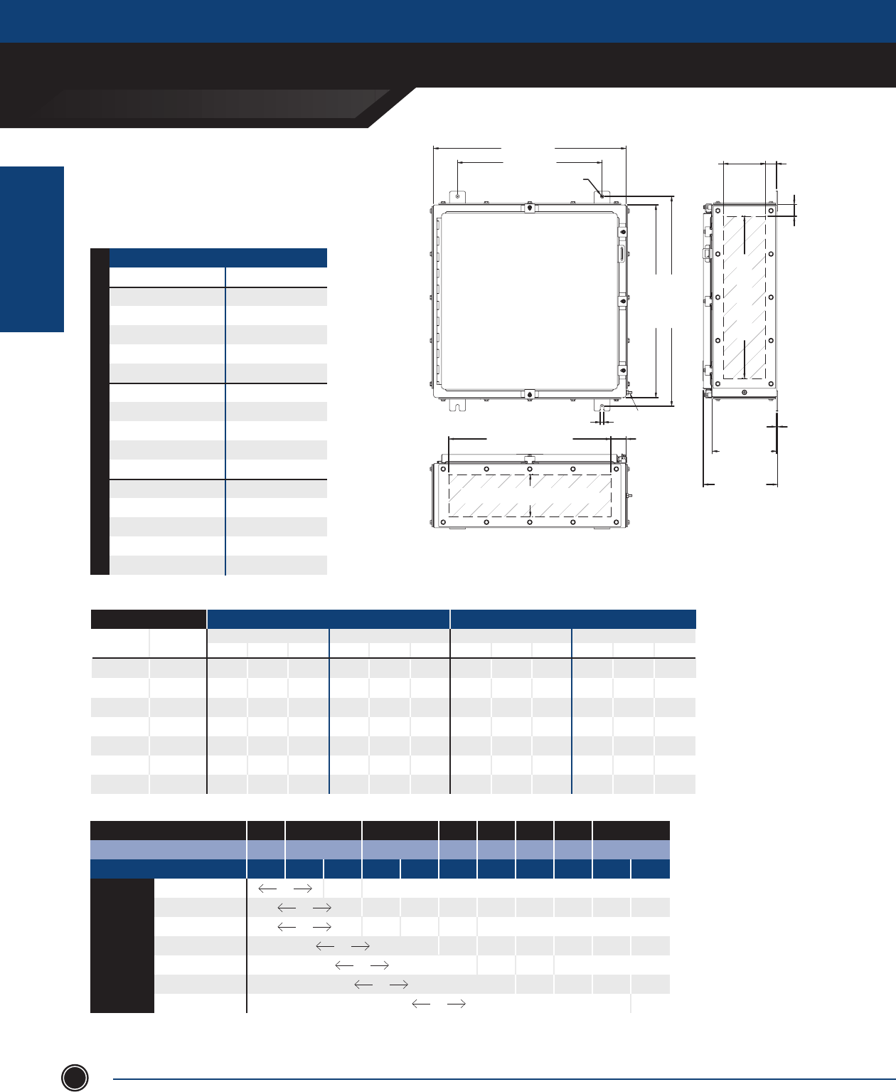
INCREASED SAFETY
TERMINAL ENCLOSURES
INCREASED SAFETY
ENCLOSURES
ADALET.COM
ADALET ENCLOSURE SYSTEMS | 4801 WEST 150TH | CLEVELAND, OHIO 44135©Adalet
48
TN Series
24” x 24” Clamped Door
24.00 [610mm]
18.00 [457mm]
.44 [11mm]
1.37 [35mm]
3.25 [83mm]
5.25 [133mm]
7.25 [ 184mm]
GLAND PLATE OPENING
26.13 [664mm]
24.00 [610mm]
20.19 [513mm]
GLAND PLATE OPENING
1.44 [37mm]
.44 [11mm]
20.19 [513mm]
GLAND PLATE OPENING 1.91 [48mm]
3.25 [83mm] / 5.25 [133mm] / 7.25 [184mm]
GLAND PLATE OPENING
7.26 [184mm]
9.26 [235mm]
11.26 [286mm]
6.00 [152mm]
8.00 [203mm]
10.00 [254mm]
.13 [3mm]
GLAND PLATE SIDE B
GLAND PLATE SIDE A
GLAND PLATE SIDE C
GLAND PLATE SIDE D
EARTH STUD
ENCLOSURES WITH TERMINALS
CATALOG NUMBER GLAND PLATE
TN4X6-242406 None
TN4X6-242406-B Side B
TN4X6-242406-AB Sides A & B
TN4X6-242406-BCD Sides B, C & D
TN4X6-242406-ABCD Sides A, B, C & D
TN4X6-242408 None
TN4X6-242408-B Side B
TN4X6-242408-AB Sides A & B
TN4X6-242408-BCD Sides B, C & D
TN4X6-242408-ABCD Sides A, B, C & D
TN4X6-242410 None
TN4X6-242410-B Side B
TN4X6-242410-AB Sides A & B
TN4X6-242410-BCD Sides B, C & D
TN4X6-242410-ABCD Sides A, B, C & D
10” [254.0mm] Depth 8” [203.2mm] Depth 6” [152.4mm] Depth
STAINLESS STEEL 316L
MAXIMUM NUMBER OF CABLE/CONDUIT ENTRIES
SIZE WITHOUT GLAND PLATES WITH GLAND PLATES
Sides A & B Sides C & D Sides A & B Sides C & D
NPT Metric 06 08 10 06 08 10 06 08 10 06 08 10
½ M16 95 114 152 90 108 144 32 64 96 32 64 96
¾ M20 64 80 96 60 75 90 26 39 65 26 39 65
1 M25 39 52 65 36 48 60 11 33 44 11 33 44
1
¼ M32 20 30 40 18 27 36 8 16 24 8 16 24
1
½ M40 18 27 36 16 24 32 7 14 14 7 14 14
2 M50 14 14 21 14 14 21 6 6 12 6 6 12
2
½ M63 6 12 12 6 12 12 5 5 10 5 5 10
Terminal Block Size
MAXIMUM TERMINAL BLOCK CONTENT
MIN CONDUCTOR SIZE .5mm 1.5mm 2.5mm 4mm 6mm 10mm 16mm 35mm
MIN CONDUCTOR SIZE AWG 22 16 14 12 10 8 6 2
MAXIMUM AMPERAGE 3 8 10 16 20 25 35 50 63 80 100
1.5mm2 134 65 x x x x x x x x
2.5mm2 475 43 25 x x x x x x
4mm2 475 168 48 27 x x x x x
6mm2 300 53 20 x x x x
10mm2 240 51 17 x x x
16mm2 117 42 20 x x
35mm2 58 20
1. For stainless steel 304 construction, substitute TN4X6 prex with TN4X.
2. The maximum terminal block content is based on vertical rail installation. For horizontal installations, consult factory.
3. For applications requiring multiple terminal block congurations and ampacities, consult factory.
4. For applications requiring larger terminal blocks or custom enclosure sizes, consult factory.
5. For conduit/cable spacings, wire bending and wire conversion guidelines, refer to the inside back cover of this catalog.
NOTES

INCREASED SAFETY
TERMINAL ENCLOSURES
INCREASED SAFETY
ENCLOSURES
SEND ORDERS TO ORDERS@ADALET.COM
T: 216.267.9000 | F:216.267.1681 | info@adalet.com ©Adalet
49
TN Series
24” x 30” Clamped Door
24.00 [610mm]
30.00 [762mm]
.44 [11mm]
1.44 [37mm]
5.25 [133mm]
G.P. OPENING 1.38 [35mm]
26.13 [664mm]
24.00 [610mm]
20.19 [513mm]
GLAND PLATE OPENING
9.26 [235mm]
8.00 [203mm]
.14 [3mm]
EARTH STUD
.44 [11mm]
26.19 [665mm]
GLAND PLATE OPENING 1.91 [48mm]
5.25 [133mm]
GLAND PLATE OPENING
GLAND PLATE SIDE B
GLAND PLATE SIDE A
GLAND PLATE SIDE C
GLAND PLATE SIDE D
ENCLOSURES WITH TERMINALS
CATALOG NUMBER GLAND PLATE
TN4X6-243008 None
TN4X6-243008-B Side B
TN4X6-243008-AB Sides A & B
TN4X6-243008-BCD Sides B, C & D
TN4X6-243008-ABCD Sides A, B, C & D
8” [203.2mm] Depth
STAINLESS STEEL 316L
MAXIMUM NUMBER OF CABLE/CONDUIT ENTRIES
SIZE WITHOUT GLAND PLATES WITH GLAND PLATES
Sides A & B Sides C & D Sides A & B Sides C & D
NPT Metric 06 08 10 06 08 10 06 08 10 06 08 10
½ M16 - 84 - - 64 - - 144 - - 108 -
¾ M20 - 51 - - 39 - - 100 - - 75 -
1 M25 - 42 - - 33 - - 64 - - 48 -
1
¼ M32 - 22 - - 16 - - 36 - - 27 -
1
½ M40 - 20 - - 14 - - 33 - - 24 -
2 M50 - 8 - - 6 - - 18 - - 14 -
2
½ M63 - 7 - - 5 - - 14 - - 12 -
Terminal Block Size
MAXIMUM TERMINAL BLOCK CONTENT
MIN CONDUCTOR SIZE .5mm 1.5mm 2.5mm 4mm 6mm 10mm 16mm 35mm
MIN CONDUCTOR SIZE AWG 22 16 14 12 10 8 6 2
MAXIMUM AMPERAGE 3 8 10 16 20 25 35 50 63 80 100
1.5mm2 143 69 x x x x x x x x
2.5mm2 665 46 27 x x x x x x
4mm2 665 179 52 29 x x x x x
6mm2 420 56 22 x x x x
10mm2 288 55 18 x x x
16mm2 195 45 21 x x
35mm2 87 84 22
1. For stainless steel 304 construction, substitute TN4X6 prex with TN4X.
2. The maximum terminal block content is based on vertical rail installation. For horizontal installations, consult factory.
3. For applications requiring multiple terminal block congurations and ampacities, consult factory.
4. For applications requiring larger terminal blocks or custom enclosure sizes, consult factory.
5. For conduit/cable spacings, wire bending and wire conversion guidelines, refer to the inside back cover of this catalog.
NOTES
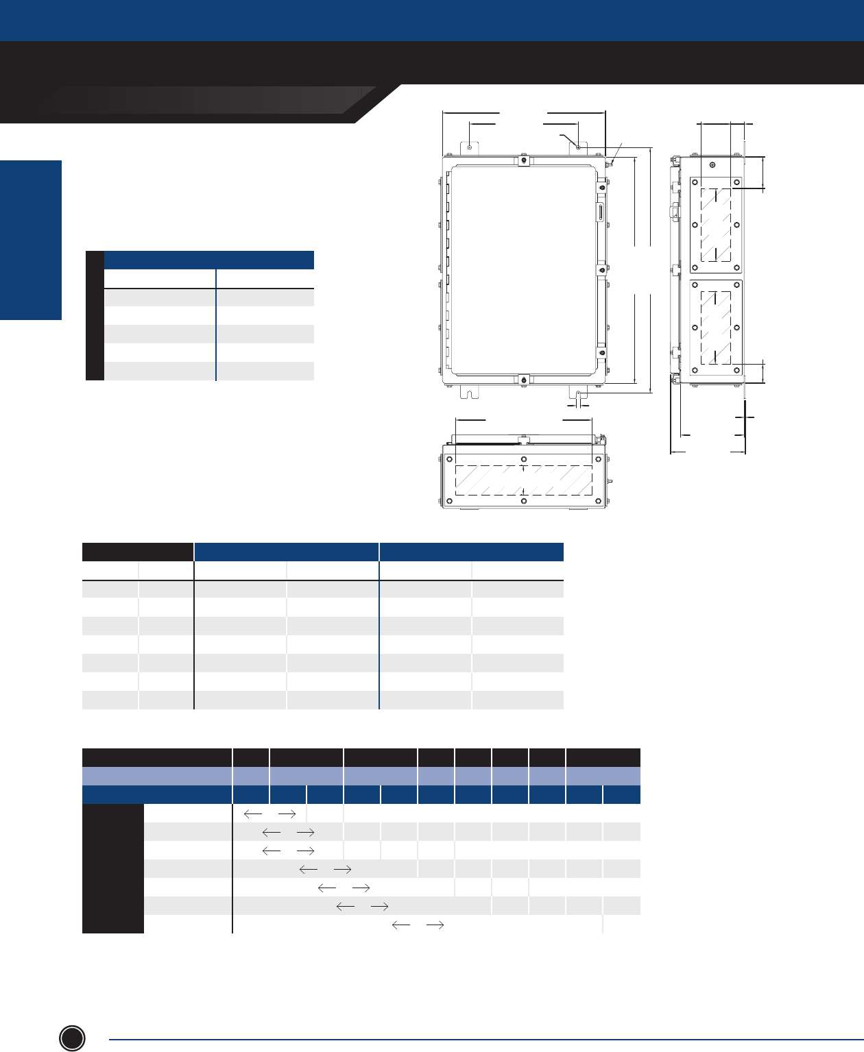
INCREASED SAFETY
TERMINAL ENCLOSURES
INCREASED SAFETY
ENCLOSURES
ADALET.COM
ADALET ENCLOSURE SYSTEMS | 4801 WEST 150TH | CLEVELAND, OHIO 44135©Adalet
50
TN Series
25” x 18” x 7” Clamped Door
12.00 [305mm]
18.00 [457mm]
.44 [11mm]
25.00 [635mm]
27.13 [689mm]
3.25 [83mm]
GLAND PLATE OPENING 1.50 [38mm]
3.49 [89mm]2.11 [54mm]
8.06 [205mm]
G.P. OPENING
8.06 [205mm]
G.P. OPENING
7.00 [178mm]
8.26 [210mm]
.13 [3mm]
.44 [11mm]
15.06 [383mm]
GLAND PLATE OPENING
3.25 [83mm]
GLAND PLATE OPENING
GLAND PLATE SIDE A
GLAND PLATE SIDE B
GLAND PLATE SIDE D
GLAND PLATE SIDE C
EARTH STUD
ENCLOSURES WITH TERMINALS
CATALOG NUMBER GLAND PLATE
TN4X6-251807 None
TN4X6-251807-B Side B
TN4X6-251807-AB Sides A & B
TN4X6-251807-BCD Sides B, C & D
TN4X6-251807-ABCD Sides A, B, C & D
7” [177.8mm] Depth
STAINLESS STEEL 316L
Terminal Block Size
MAXIMUM TERMINAL BLOCK CONTENT
MIN CONDUCTOR SIZE .5mm 1.5mm 2.5mm 4mm 6mm 10mm 16mm 35mm
MIN CONDUCTOR SIZE AWG 22 16 14 12 10 8 6 2
MAXIMUM AMPERAGE 3 8 10 16 20 25 35 50 63 80 100
1.5mm 121 58 x x x x x x x x
2.5mm2 400 39 22 x x x x x x
4mm2 400 151 44 25 x x x x x
6mm2 252 48 18 x x x x
10mm2 150 46 15 x x x
16mm2 84 38 18 x x
35mm2 31 18
MAXIMUM NUMBER OF CABLE/CONDUIT ENTRIES
SIZE WITHOUT GLAND PLATES WITH GLAND PLATES
NPT Metric Sides A & B Sides C & D Sides A & B Sides C & D
½ M16 70 95 24 12
¾ M20 48 64 20 10
1 M25 27 36 8 4
1
¼ M32 14 20 6 3
1
½ M40 14 18 5 3
2 M50 10 14 4 2
2
½ M63 4 6 4 2
1. Forstainlesssteel304construction,substituteTN4X6prexwithTN4X.
2. Themaximumterminalblockcontentisbasedonverticalrailinstallation.Forhorizontalinstallations,consultfactory.
3. Forapplicationsrequiringmultipleterminalblockcongurationsandampacities,consultfactory.
4. Forapplicationsrequiringlargerterminalblocksorcustomenclosuresizes,consultfactory.
5. Forconduit/cablespacings,wirebendingandwireconversionguidelines,refertotheinsidebackcoverofthiscatalog.
NOTES

INCREASED SAFETY
TERMINAL ENCLOSURES
INCREASED SAFETY
ENCLOSURES
SEND ORDERS TO ORDERS@ADALET.COM
T: 216.267.9000 | F:216.267.1681 | info@adalet.com ©Adalet
51
TN Series
30” x 16” Clamped Door
16.00 [406mm]
10.00 [254mm]
.44 [11mm]
32.13 [816mm]
30.00 [762mm]
3.25 [83mm]
GLAND PLATE OPENING 1.38 [35mm]
1.44 [37mm]
26.19 [665mm]
GLAND PLATE OPENING
6.00 [152mm]
7.26 [184mm]
.14 [3mm]
.44 [11mm]
12.19 [310mm]
GLAND PLATE OPENING
3.25 [83mm]
GLAND PLATE OPENING
1.91 [48mm]
EARTH STUD
GLAND PLATE SIDE B
GLAND PLATE SIDE A
GLAND PLATE SIDE C
GLAND PLATE SIDE D
MAXIMUM NUMBER OF CABLE/CONDUIT ENTRIES
SIZE WITHOUT GLAND PLATES WITH GLAND PLATES
Sides A & B Sides C & D Sides A & B Sides C & D
NPT Metric 06 08 10 06 08 10 06 08 10 06 08 10
½ M16 65 - - 120 - - 18 - - 42 - -
¾ M20 40 - - 80 - - 16 - - 34 - -
1 M25 24 - - 48 - - 6 - - 14 - -
1
¼ M32 12 - - 24 - - 5 - - 11 - -
1
½ M40 12 - - 22 - - 4 - - 10 - -
2 M50 10 - - 18 - - 3 - - 8 - -
2
½ M63 4 - - 7 - - 3 - - 7 - -
Terminal Block Size
MAXIMUM TERMINAL BLOCK CONTENT
MIN CONDUCTOR SIZE .5mm 1.5mm 2.5mm 4mm 6mm 10mm 16mm 35mm
MIN CONDUCTOR SIZE AWG 22 16 14 12 10 8 6 2
MAXIMUM AMPERAGE 3 8 10 16 20 25 35 50 63 80 100
1.5mm2 117 56 x x x x x x x x
2.5mm2 375 37 22 x x x x x x
4mm2 375 146 42 24 x x x x x
6mm2 237 46 18 x x x x
10mm2 189 45 14 x x x
16mm2 104 37 17 x x
35mm2 39 18
1. Forstainlesssteel304construction,substituteTN4X6prexwithTN4X.
2. Themaximumterminalblockcontentisbasedonverticalrailinstallation.Forhorizontalinstallations,consultfactory.
3. Forapplicationsrequiringmultipleterminalblockcongurationsandampacities,consultfactory.
4. Forapplicationsrequiringlargerterminalblocksorcustomenclosuresizes,consultfactory.
5. Forconduit/cablespacings,wirebendingandwireconversionguidelines,refertotheinsidebackcoverofthiscatalog.
NOTES
ENCLOSURES WITH TERMINALS
CATALOG NUMBER GLAND PLATE
TN4X6-301606 None
TN4X6-301606-B Side B
TN4X6-301606-AB Sides A & B
TN4X6-301606-BCD Sides B, C & D
TN4X6-301606-ABCD Sides A, B, C & D
6” [152.4mm] Depth
STAINLESS STEEL 316L

INCREASED SAFETY
TERMINAL ENCLOSURES
INCREASED SAFETY
ENCLOSURES
ADALET.COM
ADALET ENCLOSURE SYSTEMS | 4801 WEST 150TH | CLEVELAND, OHIO 44135©Adalet
52
TN Series
30” x 20” Clamped Door
20.00 [508mm]
3.25 [83mm]
5.25 [133mm]
7.25 [184mm]
GLAND PLATE OPENING 1.38 [35mm]
1.44 [37mm]
26.19 [665mm]
GLAND PLATE OPENING
7.26 [184mm]
9.26 [235mm]
11.26 [286mm]
6.00 [152mm]
8.00 [203mm]
10.00 [254mm]
.14 [3mm]
14.00 [356mm]
.44 [11mm]
32.13 [816mm]
30.00 [762mm]
16.19 [411mm]
GLAND PLATE OPENING
3.25 [83mm] / 5.25 [133mm] / 7.25 [184mm]
GLAND PLATE OPENING
1.91 [48mm]
EARTH STUD
GLAND PLATE SIDE B
GLAND PLATE SIDE A
GLAND PLATE SIDE D
GLAND PLATE SIDE C
.44 [11mm]
ENCLOSURES WITH TERMINALS
Catalog Number Gland Plate
TN4X6-302006 None
TN4X6-302006-B Side B
TN4X6-302006-AB Sides A & B
TN4X6-302006-BCD Sides B, C & D
TN4X6-302006-ABCD Sides A, B, C & D
TN4X6-302008 None
TN4X6-302008-B Side B
TN4X6-302008-AB Sides A & B
TN4X6-302008-BCD Sides B, C & D
TN4X6-302008-ABCD Sides A, B, C & D
TN4X6-302010 None
TN4X6-302010-B Side B
TN4X6-302010-AB Sides A & B
TN4X6-302010-BCD Sides B, C & D
TN4X6-302010-ABCD Sides A, B, C & D
10” [254.0mm] Depth 8” [203.2mm] Depth 6” [152.4mm] Depth
STAINLESS STEEL 316L
MAXIMUM NUMBER OF CABLE/CONDUIT ENTRIES
SIZE WITHOUT GLAND PLATES WITH GLAND PLATES
Sides A & B Sides C & D Sides A & B Sides C & D
NPT Metric 06 08 10 06 08 10 06 08 10 06 08 10
½ M16 80 96 128 120 144 192 26 52 78 42 84 126
¾ M20 52 65 78 80 100 120 22 33 55 34 51 85
1 M25 30 40 50 48 64 80 8 24 32 14 42 56
1
¼ M32 16 24 32 24 36 48 7 14 21 14 22 33
1
½ M40 14 21 28 22 33 44 6 12 12 10 20 30
2 M50 12 12 18 18 18 27 5 5 10 8 8 16
2
½ M63 5 10 10 7 14 14 4 4 8 7 7 14
Terminal Block Size
MAXIMUM TERMINAL BLOCK CONTENT
MIN CONDUCTOR SIZE .5mm 1.5mm 2.5mm 4mm 6mm 10mm 16mm 35mm
MIN CONDUCTOR SIZE AWG 22 16 14 12 10 8 6 2
MAXIMUM AMPERAGE 3 8 10 16 20 25 35 50 63 80 100
1.5mm 131 64 x x x x x x x x
2.5mm2 500 42 24 x x x x x x
4mm2 500 165 47 27 x x x x x
6mm2 316 52 20 x x x x
10mm2 252 50 16 x x x
16mm2 156 42 19 x x
35mm2 39 20
1. For stainless steel 304 construction, substitute TN4X6 prex with TN4X.
2. The maximum terminal block content is based on vertical rail installation.
For horizontal installations, consult factory.
3. For applications requiring multiple terminal block congurations and
ampacities, consult factory.
4. For applications requiring larger terminal blocks or custom
enclosure sizes, consult factory.
5. For conduit/cable spacings, wire bending and wire conversion
guidelines, refer to the inside back cover of this catalog.
NOTES
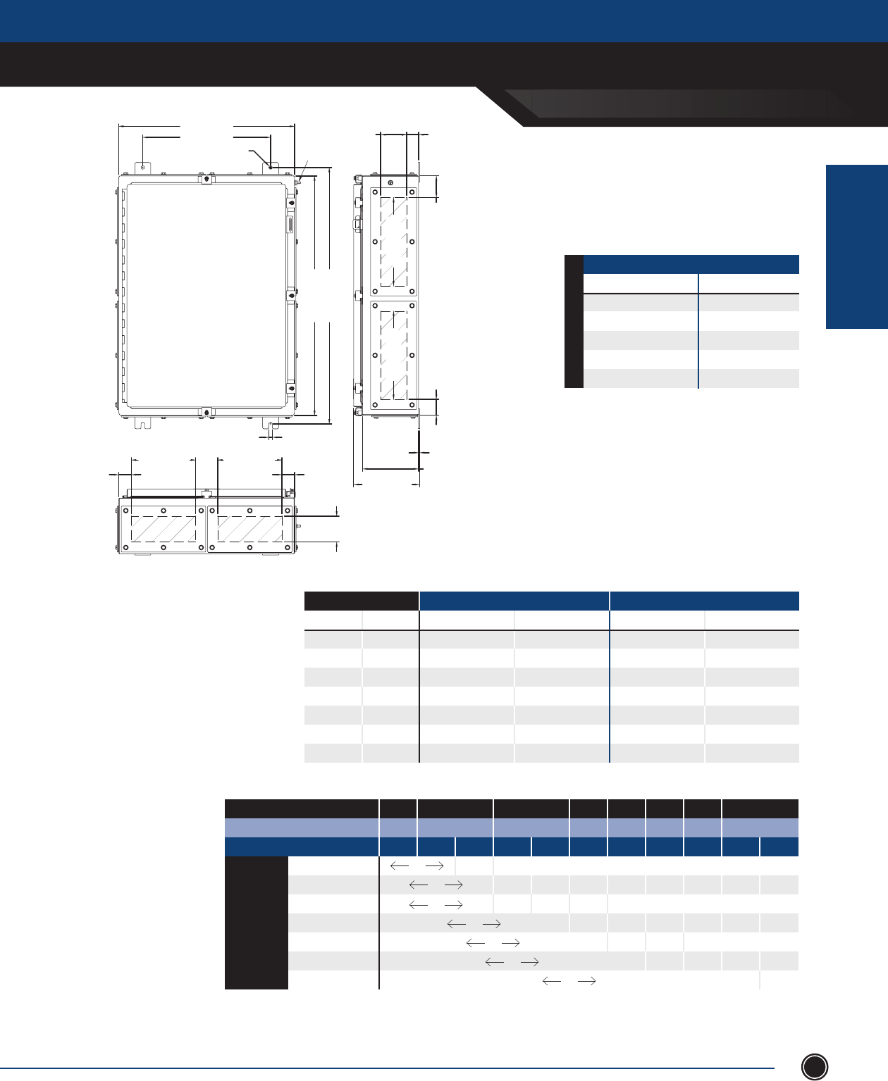
INCREASED SAFETY
TERMINAL ENCLOSURES
INCREASED SAFETY
ENCLOSURES
SEND ORDERS TO ORDERS@ADALET.COM
T: 216.267.9000 | F:216.267.1681 | info@adalet.com ©Adalet
53
TN Series
30” x 22” x 7” Clamped Door
22.00 [559mm] 3.25 [83mm]
G.P. OPENING 1.50 [38mm]
1.57 [40mm]
16.00 [406mm]
.44 [11mm]
2.74 [70mm]1.97 [50mm]
11.06 [281mm]
G.P. OPENING
11.06 [281mm]
G.P. OPENING
7.00 [178mm]
8.26 [210mm]
.13 [3mm]
.44 [11mm]
32.12 [816mm]
30.00 [762mm]
3.25 [83mm]
G.P. OPENING
8.06 [205mm]
G.P. OPENING
1.57 [40mm]
8.06 [205mm]
G.P. OPENING
GLAND PLATE SIDE A
GLAND PLATE SIDE B
GLAND PLATE SIDE C
GLAND PLATE SIDE D
EARTH STUD
ENCLOSURES WITH TERMINALS
CATALOG NUMBER GLAND PLATE
TN4X6-302207 None
TN4X6-302207-B Side B
TN4X6-302207-AB Sides A & B
TN4X6-302207-BCD Sides B, C & D
TN4X6-302207-ABCD Sides A, B, C & D
7” [177.8mm] Depth
STAINLESS STEEL 316L
MAXIMUM NUMBER OF CABLE/CONDUIT ENTRIES
SIZE WITHOUT GLAND PLATES WITH GLAND PLATES
NPT Metric Sides A & B Sides C & D Sides A & B Sides C & D
½ M16 85 115 12 18
¾ M20 56 76 10 14
1 M25 48 60 4 6
1
¼ M32 33 45 3 4
1
½ M40 18 24 3 4
2 M50 12 16 2 3
2
½ M63 5 7 2 3
Terminal Block Size
MAXIMUM TERMINAL BLOCK CONTENT
MIN CONDUCTOR SIZE .5mm 1.5mm 2.5mm 4mm 6mm 10mm 16mm 35mm
MIN CONDUCTOR SIZE AWG 22 16 14 12 10 8 6 2
MAXIMUM AMPERAGE 3 8 10 16 20 25 35 50 63 80 100
1.5mm2 137 67 x x x x x x x x
2.5mm2 625 44 26 x x x x x x
4mm2 625 172 50 28 x x x x x
6mm2 395 54 21 x x x x
10mm2 252 53 17 x x x
16mm2 156 44 20 x x
35mm2 78 21
1. For stainless steel 304 construction, substitute TN4X6 prex with TN4X.
2. The maximum terminal block content is based on vertical rail installation. For horizontal installations, consult factory.
3. For applications requiring multiple terminal block congurations and ampacities, consult factory.
4. For applications requiring larger terminal blocks or custom enclosure sizes, consult factory.
5. For conduit/cable spacings, wire bending and wire conversion guidelines, refer to the inside back cover of this catalog.
NOTES

INCREASED SAFETY
TERMINAL ENCLOSURES
INCREASED SAFETY
ENCLOSURES
ADALET.COM
ADALET ENCLOSURE SYSTEMS | 4801 WEST 150TH | CLEVELAND, OHIO 44135©Adalet
54
TN Series
30” x 24” Clamped Door
24.00 [610mm]
18.00 [457mm]
.44 [11mm]
3.25 [83mm]
5.25 [133mm]
7.25 [184mm]
GLAND PLATE OPENING 1.37 [35mm]
1.44 [37mm]2.37 [60mm]
26.19 [665mm]
GLAND PLATE OPENING
7.26 [184mm]
9.26 [235mm]
11.26 [286mm]
6.00 [152mm]
8.00 [203mm]
10.00 [254mm]
.13 [3mm]
20.19 [513mm]
GLAND PLATE OPENING
3.25 [83mm] / 5.25 [133mm] / 7.25 [184mm]
GLAND PLATE OPENING
1.91 [48mm]
.44 [11mm]
30.00 [762mm]
32.13 [816mm]
GLAND PLATE SIDE B
GLAND PLATE SIDE A
GLAND PLATE SIDE C
GLAND PLATE SIDE D
EARTH STUD
ENCLOSURES WITH TERMINALS
CATALOG NUMBER GLAND PLATE
TN4X6-302406 None
TN4X6-302406-B Side B
TN4X6-302406-AB Sides A & B
TN4X6-302406-BCD Sides B, C & D
TN4X6-302406-ABCD Sides A, B, C & D
TN4X6-302408 None
TN4X6-302408-B Side B
TN4X6-302408-AB Sides A & B
TN4X6-302408-BCD Sides B, C & D
TN4X6-302408-ABCD Sides A, B, C & D
TN4X6-302410 None
TN4X6-302410-B Side B
TN4X6-302410-AB Sides A & B
TN4X6-302410-BCD Sides B, C & D
TN4X6-302410-ABCD Sides A, B, C & D
10” [254.0mm] Depth 8” [203.2mm] Depth 6” [152.4mm] Depth
STAINLESS STEEL 316L
MAXIMUM NUMBER OF CABLE/CONDUIT ENTRIES
SIZE WITHOUT GLAND PLATES WITH GLAND PLATES
Sides A & B Sides C & D Sides A & B Sides C & D
NPT Metric 06 08 10 06 08 10 06 08 10 06 08 10
½ M16 95 114 152 115 138 184 32 64 96 42 84 126
¾ M20 64 80 96 76 95 114 26 39 65 34 51 85
1 M25 39 52 65 45 60 75 11 33 44 14 42 56
1
¼ M32 20 30 40 24 36 48 8 16 24 11 22 33
1
½ M40 18 27 36 22 33 44 7 14 21 10 20 20
2 M50 14 14 21 16 16 24 6 6 12 8 8 16
2
½ M63 6 12 12 7 14 14 5 5 10 7 7 14
Terminal Block Size
MAXIMUM TERMINAL BLOCK CONTENT
MIN CONDUCTOR SIZE .5mm 1.5mm 2.5mm 4mm 6mm 10mm 16mm 35mm
MIN CONDUCTOR SIZE AWG 22 16 14 12 10 8 6 2
MAXIMUM AMPERAGE 3 8 10 16 20 25 35 50 63 80 100
1.5mm 143 69 x x x x x x x x
2.5mm2 625 46 27 x x x x x x
4mm2 625 179 52 29 x x x x x
6mm2 395 56 22 x x x x
10mm2 315 55 18 x x x
16mm2 156 45 21 x x
35mm2 78 22
1. For stainless steel 304 construction, substitute TN4X6 prex with TN4X.
2. The maximum terminal block content is based on vertical rail installation. For horizontal installations, consult factory.
3. For applications requiring multiple terminal block congurations and ampacities, consult factory.
4. For applications requiring larger terminal blocks or custom enclosure sizes, consult factory.
5. For conduit/cable spacings, wire bending and wire conversion guidelines, refer to the inside back cover of this catalog.
NOTES

INCREASED SAFETY
TERMINAL ENCLOSURES
INCREASED SAFETY
ENCLOSURES
SEND ORDERS TO ORDERS@ADALET.COM
T: 216.267.9000 | F:216.267.1681 | info@adalet.com ©Adalet
55
TN Series
30” x 30” Clamped Door
30.00 [762mm]
24.00 [610mm]
.44 [11mm]
5.25 [133mm]
GLAND PLATE OPENING
1.37 [35mm]
1.44 [37mm]
2.37 [60mm]
26.19 [665mm]
GLAND PLATE OPENING
9.26 [235mm]
8.00 [203mm]
.13 [3mm]
32.13 [816mm]
30.00 [762mm]
26.19 [665mm] 1.91 [48mm]
.44 [11mm]
5.25 [133mm]
GLAND PLATE OPENING
GLAND PLATE SIDE B
GLAND PLATE SIDE A
GLAND PLATE SIDE C
GLAND PLATE SIDE D
EARTH STUD
ENCLOSURES WITH TERMINALS
CATALOG NUMBER GLAND PLATE
TN4X6-303008 None
TN4X6-303008-B Side B
TN4X6-303008-AB Sides A & B
TN4X6-303008-BCD Sides B, C & D
TN4X6-303008-ABCD Sides A, B, C & D
8” [203.2mm] Depth
STAINLESS STEEL 316L
MAXIMUM NUMBER OF CABLE/CONDUIT ENTRIES
SIZE WITHOUT GLAND PLATES WITH GLAND PLATES
Sides A & B Sides C & D Sides A & B Sides C & D
NPT Metric 06 08 10 06 08 10 06 08 10 06 08 10
½ M16 - 144 - - 138 - - 84 - - 84 -
¾ M20 - 100 - - 95 - - 51 - - 51 -
1 M25 - 64 - - 60 - - 42 - - 42 -
1
¼ M32 - 36 - - 36 - - 22 - - 22 -
1
½ M40 - 33 - - 33 - - 20 - - 20 -
2 M50 - 18 - - 16 - - 8 - - 8 -
2
½ M63 - 14 - - 14 - - 7 - - 7 -
Terminal Block Size
MAXIMUM TERMINAL BLOCK CONTENT
MIN CONDUCTOR SIZE .5mm 1.5mm 2.5mm 4mm 6mm 10mm 16mm 35mm
MIN CONDUCTOR SIZE AWG 22 16 14 12 10 8 6 2
MAXIMUM AMPERAGE 3 8 10 16 20 25 35 50 63 80 100
1.5mm2 156 76 x x x x x x x x
2.5mm2 875 50 29 x x x x x x
4mm2 875 196 57 32 x x x x x
6mm2 553 62 24 x x x x
10mm2 378 60 19 x x x
16mm2 260 50 23 x x
35mm2 117 92 24
1. For stainless steel 304 construction, substitute TN4X6 prex with TN4X.
2. The maximum terminal block content is based on vertical rail installation. For horizontal installations, consult factory.
3. For applications requiring multiple terminal block congurations and ampacities, consult factory.
4. For applications requiring larger terminal blocks or custom enclosure sizes, consult factory.
5. For conduit/cable spacings, wire bending and wire conversion guidelines, refer to the inside back cover of this catalog.
NOTES
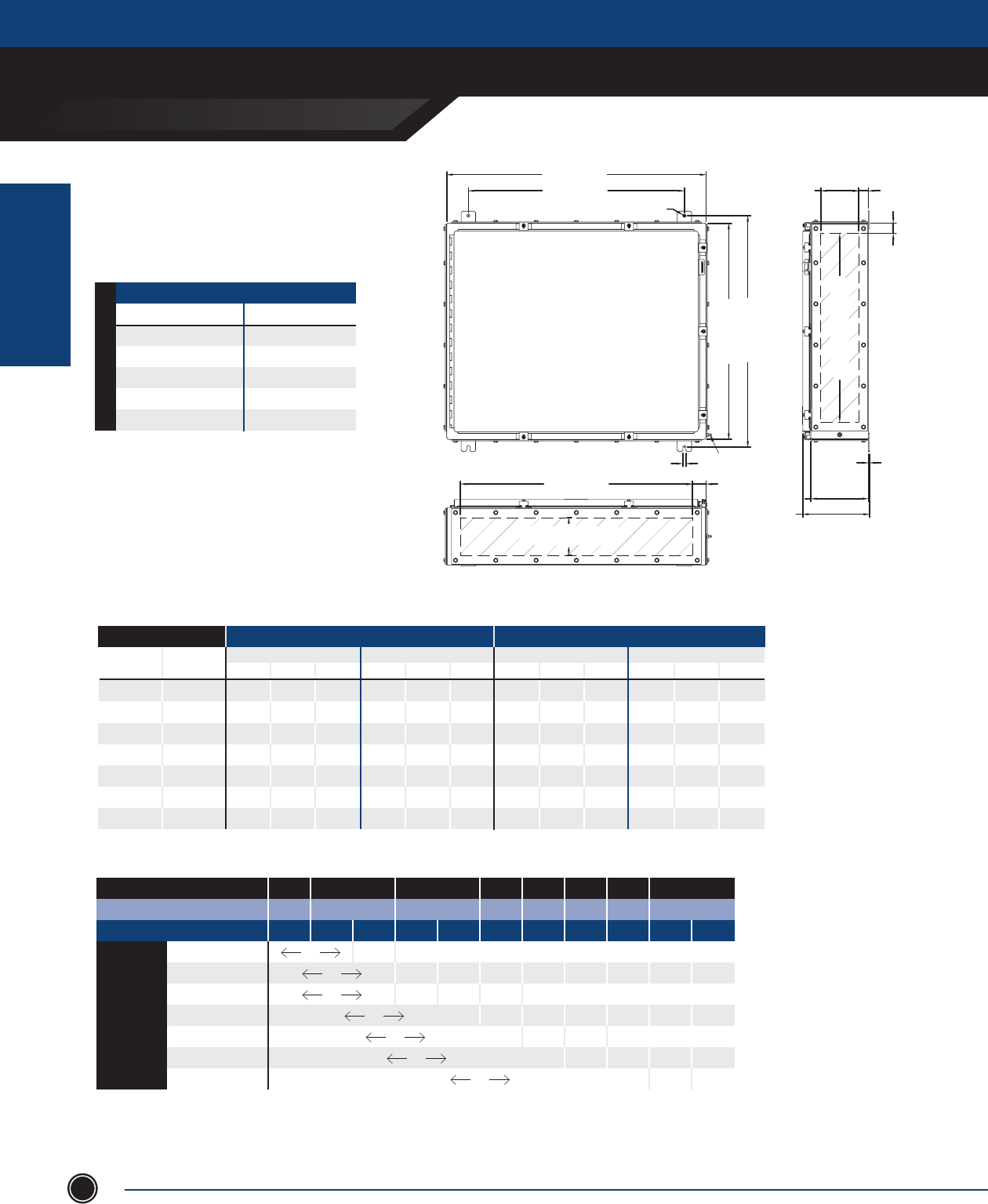
INCREASED SAFETY
TERMINAL ENCLOSURES
INCREASED SAFETY
ENCLOSURES
ADALET.COM
ADALET ENCLOSURE SYSTEMS | 4801 WEST 150TH | CLEVELAND, OHIO 44135©Adalet
56
TN Series
30” x 36” Clamped Door
36.00 [914mm]
30.00 [762mm]
5.25 [133mm]
GLAND PLATE OPENING 1.37 [35mm]
.44 [11mm]
1.44 [37mm]
26.19 [665mm]
GLAND PLATE OPENING
8.00 [203mm]
9.26 [235mm]
.13 [3mm]
5.25 [133mm]
GLAND PLATE OPENING
32.19 [818mm]
.44 [11mm]
1.91 [48mm]
32.13 [816mm]
30.00 [762mm]
GLAND PLATE SIDE B
GLAND PLATE SIDE A
GLAND PLATE SIDE C
GLAND PLATE SIDE D
EARTH STUD
MAXIMUM NUMBER OF CABLE/CONDUIT ENTRIES
SIZE WITHOUT GLAND PLATES WITH GLAND PLATES
Sides A & B Sides C & D Sides A & B Sides C & D
NPT Metric 06 08 10 06 08 10 06 08 10 06 08 10
½ M16 - 174 - - 168 - - 100 - - 84 -
¾ M20 - 120 - - 115 - - 63 - - 51 -
1 M25 - 76 - - 72 - - 51 - - 42 -
1
¼ M32 - 45 - - 42 - - 26 - - 22 -
1
½ M40 - 39 - - 39 - - 24 - - 20 -
2 M50 - 20 - - 20 - - 9 - - 8 -
2
½ M63 - 18 - - 18 - - 8 - - 7 -
Terminal Block Size
MAXIMUM TERMINAL BLOCK CONTENT
MIN CONDUCTOR SIZE .5mm 1.5mm 2.5mm 4mm 6mm 10mm 16mm 35mm
MIN CONDUCTOR SIZE AWG 22 16 14 12 10 8 6 2
MAXIMUM AMPERAGE 3 8 10 16 20 25 35 50 63 80 100
1.5mm2 161 80 x x x x x x x x
2.5mm2 1000 53 31 x x x x x x
4mm2 1000 208 60 34 x x x x x
6mm2 632 66 25 x x x x
10mm2 441 64 21 x x x
16mm2 312 53 24 x x
35mm2 117 97 25
ENCLOSURES WITH TERMINALS
CATALOG NUMBER GLAND PLATE
TN4X6-303608 None
TN4X6-303608-B Side B
TN4X6-303608-AB Sides A & B
TN4X6-303608-BCD Sides B, C & D
TN4X6-303608-ABCD Sides A, B, C & D
8” [203.2mm] Depth
STAINLESS STEEL 316L
1. For stainless steel 304 construction, substitute TN4X6 prex with TN4X.
2. The maximum terminal block content is based on vertical rail installation. For horizontal installations, consult factory.
3. For applications requiring multiple terminal block congurations and ampacities, consult factory.
4. For applications requiring larger terminal blocks or custom enclosure sizes, consult factory.
5. For conduit/cable spacings, wire bending and wire conversion guidelines, refer to the inside back cover of this catalog.
NOTES
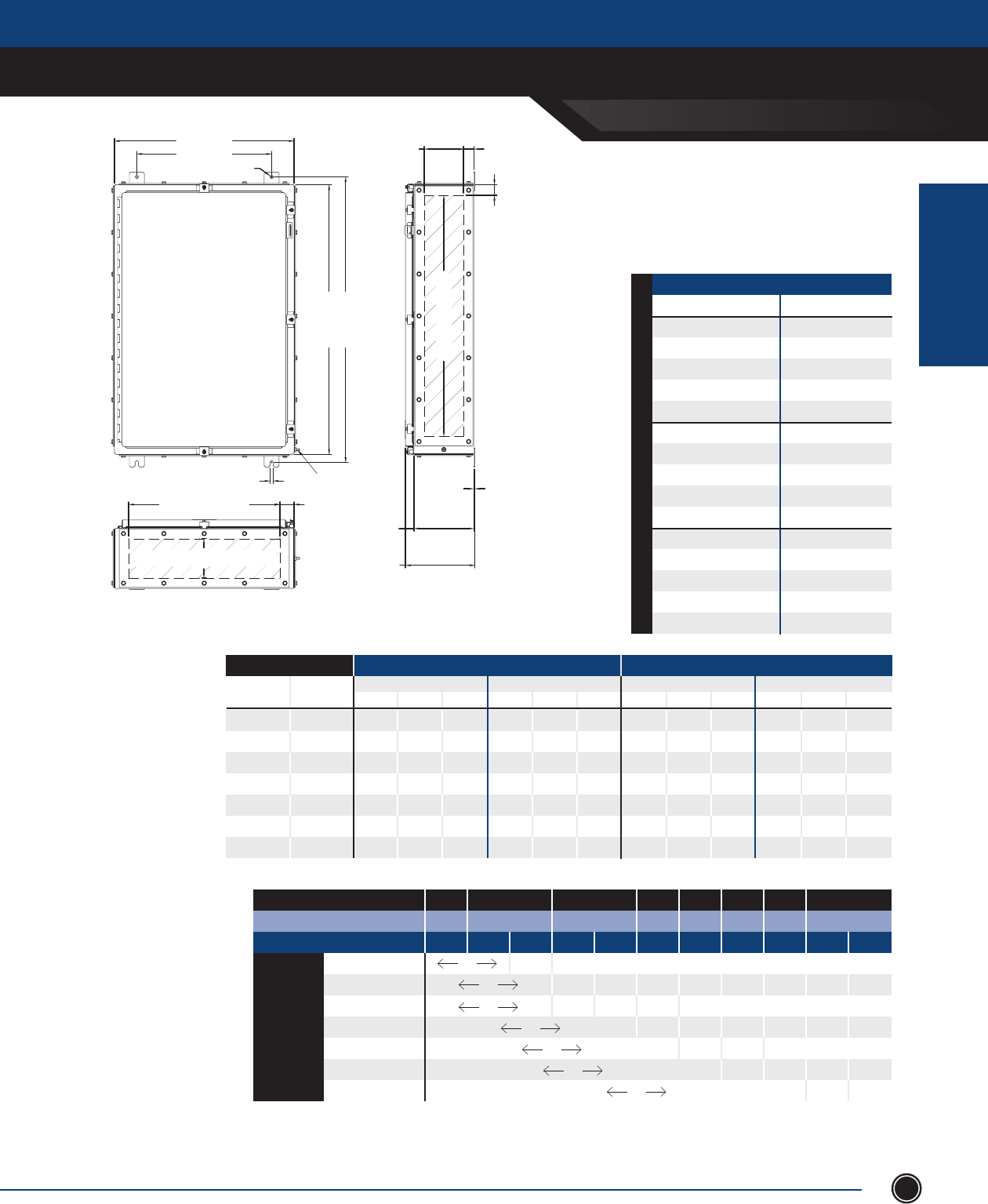
INCREASED SAFETY
TERMINAL ENCLOSURES
INCREASED SAFETY
ENCLOSURES
SEND ORDERS TO ORDERS@ADALET.COM
T: 216.267.9000 | F:216.267.1681 | info@adalet.com ©Adalet
57
TN Series
36” x 24” Clamped Door
24.00 [610mm]
18.00 [457mm]
.44 [11mm]
38.12 [968mm]
36.00 [914mm]
EARTH STUD
.44 [11mm]
3.25 [83mm]
5.25 [133mm]
7.25 [184mm]
GLAND PLATE OPENING 1.37 [35mm]
1.44 [37mm]
32.19 [818mm]
GLAND PLATE OPENING
6.00 [152mm]
8.00 [203mm]
10.00 [254mm]
7.26 [184mm]
9.26 [235mm]
11.26 [286mm]
.13 [3mm]
3.25 [83mm] / 5.25 [133mm] / 7.25 [184mm]
GLAND PLATE OPENING
20.19 [513mm]
GLAND PLATE OPENING 1.91 [48mm]
GLAND PLATE SIDE B
GLAND PLATE SIDE A
GLAND PLATE SIDE C
GLAND PLATE SIDE D
MAXIMUM NUMBER OF CABLE/CONDUIT ENTRIES
SIZE WITHOUT GLAND PLATES WITH GLAND PLATES
Sides A & B Sides C & D Sides A & B Sides C & D
NPT Metric 06 08 10 06 08 10 06 08 10 06 08 10
½ M16 95 114 152 140 168 204 32 64 96 50 100 150
¾ M20 64 80 96 92 115 138 26 39 65 42 63 105
1 M25 35 52 65 54 72 90 11 33 44 17 51 68
1
¼ M32 20 30 40 28 42 56 8 16 24 13 26 39
1
½ M40 18 27 36 26 39 52 7 14 14 12 24 24
2 M50 14 14 21 20 20 30 6 6 12 9 9 18
2
½ M63 6 12 12 9 18 18 5 5 10 8 8 16
Terminal Block Size
MAXIMUM TERMINAL BLOCK CONTENT
MIN CONDUCTOR SIZE .5mm 1.5mm 2.5mm 4mm 6mm 10mm 16mm 35mm
MIN CONDUCTOR SIZE AWG 22 16 14 12 10 8 6 2
MAXIMUM AMPERAGE 3 8 10 16 20 25 35 50 63 80 100
1.5mm2 149 72 x x x x x x x x
2.5mm2 780 48 28 x x x x x x
4mm2 780 187 54 30 x x x x x
6mm2 495 59 23 x x x x
10mm2 300 57 18 x x x
16mm2 195 47 22 x x
35mm2 96 88 23
ENCLOSURES WITH TERMINALS
Catalog Number Gland Plate
TN4X6-362406 None
TN4X6-362406-B Side B
TN4X6-362406-AB Sides A & B
TN4X6-362406-BCD Sides B, C & D
TN4X6-362406-ABCD Sides A, B, C & D
TN4X6-362408 None
TN4X6-362408-B Side B
TN4X6-362408-AB Sides A & B
TN4X6-362408-BCD Sides B, C & D
TN4X6-362408-ABCD Sides A, B, C & D
TN4X6-362410 None
TN4X6-362410-B Side B
TN4X6-362410-AB Sides A & B
TN4X6-362410-BCD Sides B, C & D
TN4X6-362410-ABCD Sides A, B, C & D
10” [254.0mm] Depth 8” [203.2mm] Depth 6” [152.4mm] Depth
1. For stainless steel 304 construction, substitute TN4X6 prex with TN4X.
2. The maximum terminal block content is based on vertical rail installation.
For horizontal installations, consult factory.
3. For applications requiring multiple terminal block congurations and
ampacities, consult factory.
4. For applications requiring larger terminal blocks or custom
enclosure sizes, consult factory.
5. For conduit/cable spacings, wire bending and wire conversion
guidelines, refer to the inside back cover of this catalog.
NOTES
STAINLESS STEEL 316L
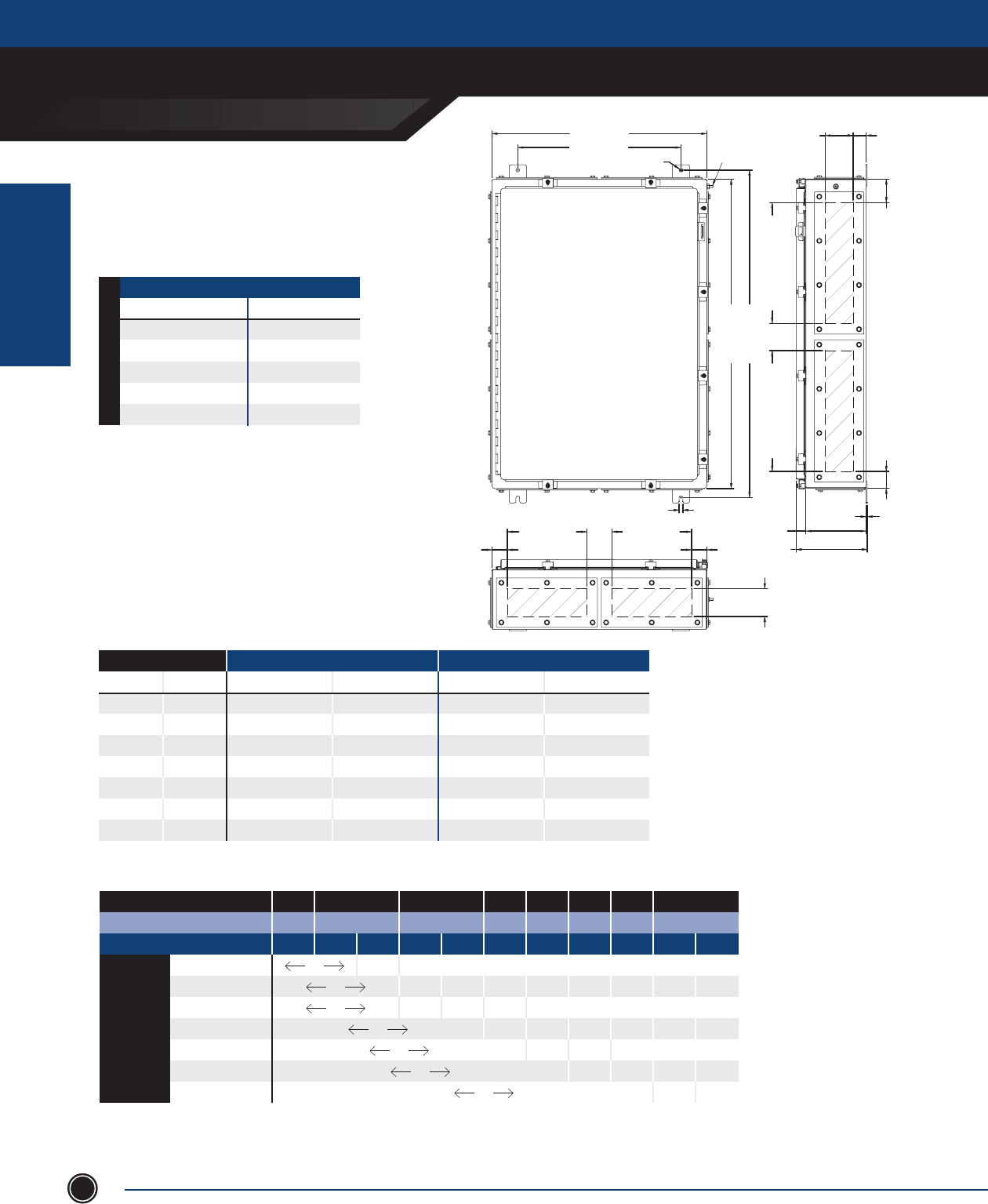
INCREASED SAFETY
TERMINAL ENCLOSURES
INCREASED SAFETY
ENCLOSURES
ADALET.COM
ADALET ENCLOSURE SYSTEMS | 4801 WEST 150TH | CLEVELAND, OHIO 44135©Adalet
58
ENCLOSURES WITH TERMINALS
CATALOG NUMBER GLAND PLATE
TN4X6-362507 None
TN4X6-362507-B Side B
TN4X6-362507-AB Sides A & B
TN4X6-362507-BCD Sides B, C & D
TN4X6-362507-ABCD Sides A, B, C & D
STAINLESS STEEL 316L
TN Series
36” x 25” x 7” Clamped Door
25.00 [635mm]
19.00 [483mm]
.44 [11mm]
3.25 [83mm]
GLAND PLATE OPENING 1.50 [38mm]
2.74 [70mm]
14.06 [357mm]
GLAND PLATE OPENING
14.06 [357mm]
GLAND PLATE OPENING
1.97 [50mm]
7.00 [178mm]
8.26 [210mm]
.14 [3mm]
1.78 [45mm]
9.25 [235mm]
G.P. OPENING
1.78 [45mm]
9.25 [235mm]
G.P. OPENING
3.25 [83mm]
GLAND PLATE OPENING
.44 [11mm]
38.13 [968mm]
36.00 [914mm]
EARTH STUD
7” [177.8mm] Depth
Terminal Block Size
MAXIMUM TERMINAL BLOCK CONTENT
MIN CONDUCTOR SIZE .5mm 1.5mm 2.5mm 4mm 6mm 10mm 16mm 35mm
MIN CONDUCTOR SIZE AWG 22 16 14 12 10 8 6 2
MAXIMUM AMPERAGE 3 8 10 16 20 25 35 50 63 80 100
1.5mm2 152 74 x x x x x x x x
2.5mm2 936 49 28 x x x x x x
4mm2 936 190 55 31 x x x x x
6mm2 594 60 28 x x x x
10mm2 390 58 19 x x x
16mm2 260 48 27 x x
35mm2 96 89 23
MAXIMUM NUMBER OF CABLE/CONDUIT ENTRIES
SIZE WITHOUT GLAND PLATES WITH GLAND PLATES
NPT Metric Sides A & B Sides C & D Sides A & B Sides C & D
½ M16 100 140 14 22
¾ M20 64 92 12 18
1 M25 39 54 5 7
1
¼ M32 20 28 4 6
1
½ M40 18 26 3 5
2 M50 14 20 3 4
2
½ M63 6 9 2 3
1. For stainless steel 304 construction, substitute TN4X6 prex with TN4X.
2. The maximum terminal block content is based on vertical rail installation. For horizontal installations, consult factory.
3. For applications requiring multiple terminal block congurations and ampacities, consult factory.
4. For applications requiring larger terminal blocks or custom enclosure sizes, consult factory.
5. For conduit/cable spacings, wire bending and wire conversion guidelines, refer to the inside back cover of this catalog.
NOTES

INCREASED SAFETY
TERMINAL ENCLOSURES
INCREASED SAFETY
ENCLOSURES
SEND ORDERS TO ORDERS@ADALET.COM
T: 216.267.9000 | F:216.267.1681 | info@adalet.com ©Adalet
59
TN Series
36” x 30” Clamped Door
30.00 [762mm]
24.00 [610mm]
.44 [11mm]
3.25 [83mm]
5.25 [133mm]
7.25 [184mm]
GLAND PLATE OPENING 1.37 [35mm]
1.44 [37mm]
32.19 [818mm]
GLAND PLATE OPENING
6.00 [152mm]
8.00 [203mm]
10.00 [254mm]
.13 [3mm]
7.26 [184mm]
9.26 [235mm]
11.26 [286mm]
.44 [11mm]
26.19 [665mm]
GLAND PLATE OPENING 1.91 [48mm]
3.25 [83mm] / 5.25 [133mm] / 7.25 [184mm]
GLAND PLATE OPENING
38.12 [968mm]
36.00 [914mm]
GLAND PLATE SIDE B
GLAND PLATE SIDE A
GLAND PLATE SIDE C
GLAND PLATE SIDE D
EARTH STUD
ENCLOSURES WITH TERMINALS
CATALOG NUMBER GLAND PLATE
TN4X6-363006 None
TN4X6-363006-B Side B
TN4X6-363006-AB Sides A & B
TN4X6-363006-BCD Sides B, C & D
TN4X6-363006-ABCD Sides A, B, C & D
TN4X6-363008 None
TN4X6-363008-B Side B
TN4X6-363008-AB Sides A & B
TN4X6-363008-BCD Sides B, C & D
TN4X6-363008-ABCD Sides A, B, C & D
TN4X6-363010 None
TN4X6-363010-B Side B
TN4X6-363010-AB Sides A & B
TN4X6-363010-BCD Sides B, C & D
TN4X6-363010-ABCD Sides A, B, C & D
10” [254.0mm] Depth 8” [203.2mm] Depth 6” [152.4mm] Depth
STAINLESS STEEL 316L
MAXIMUM NUMBER OF CABLE/CONDUIT ENTRIES
SIZE WITHOUT GLAND PLATES WITH GLAND PLATES
Sides A & B Sides C & D Sides A & B Sides C & D
NPT Metric 06 08 10 06 08 10 06 08 10 06 08 10
½ M16 120 144 192 140 168 224 42 84 126 50 100 150
¾ M20 80 100 120 92 115 138 34 51 85 42 63 105
1 M25 48 64 80 54 72 90 14 42 56 17 51 68
1
¼ M32 24 36 48 28 42 56 11 22 33 13 26 39
1
½ M40 22 33 44 26 39 52 10 20 20 12 24 24
2 M50 18 18 27 20 20 30 8 8 16 9 9 18
2
½ M63 7 14 14 9 18 18 7 7 14 8 8 16
Terminal Block Size
MAXIMUM TERMINAL BLOCK CONTENT
MIN CONDUCTOR SIZE .5mm 1.5mm 2.5mm 4mm 6mm 10mm 16mm 35mm
MIN CONDUCTOR SIZE AWG 22 16 14 12 10 8 6 2
MAXIMUM AMPERAGE 3 8 10 16 20 25 35 50 63 80 100
1.5mm2 161 80 x x x x x x x x
2.5mm2 1092 53 31 x x x x x x
4mm2 1092 208 60 34 x x x x x
6mm2 693 66 25 x x x x
10mm2 468 64 21 x x x
16mm2 325 53 24 x x
35mm2 144 97 25
1. For stainless steel 304 construction, substitute TN4X6 prex with TN4X.
2. The maximum terminal block content is based on vertical rail installation. For horizontal installations, consult factory.
3. For applications requiring multiple terminal block congurations and ampacities, consult factory.
4. For applications requiring larger terminal blocks or custom enclosure sizes, consult factory.
5. For conduit/cable spacings, wire bending and wire conversion guidelines, refer to the inside back cover of this catalog.
NOTES
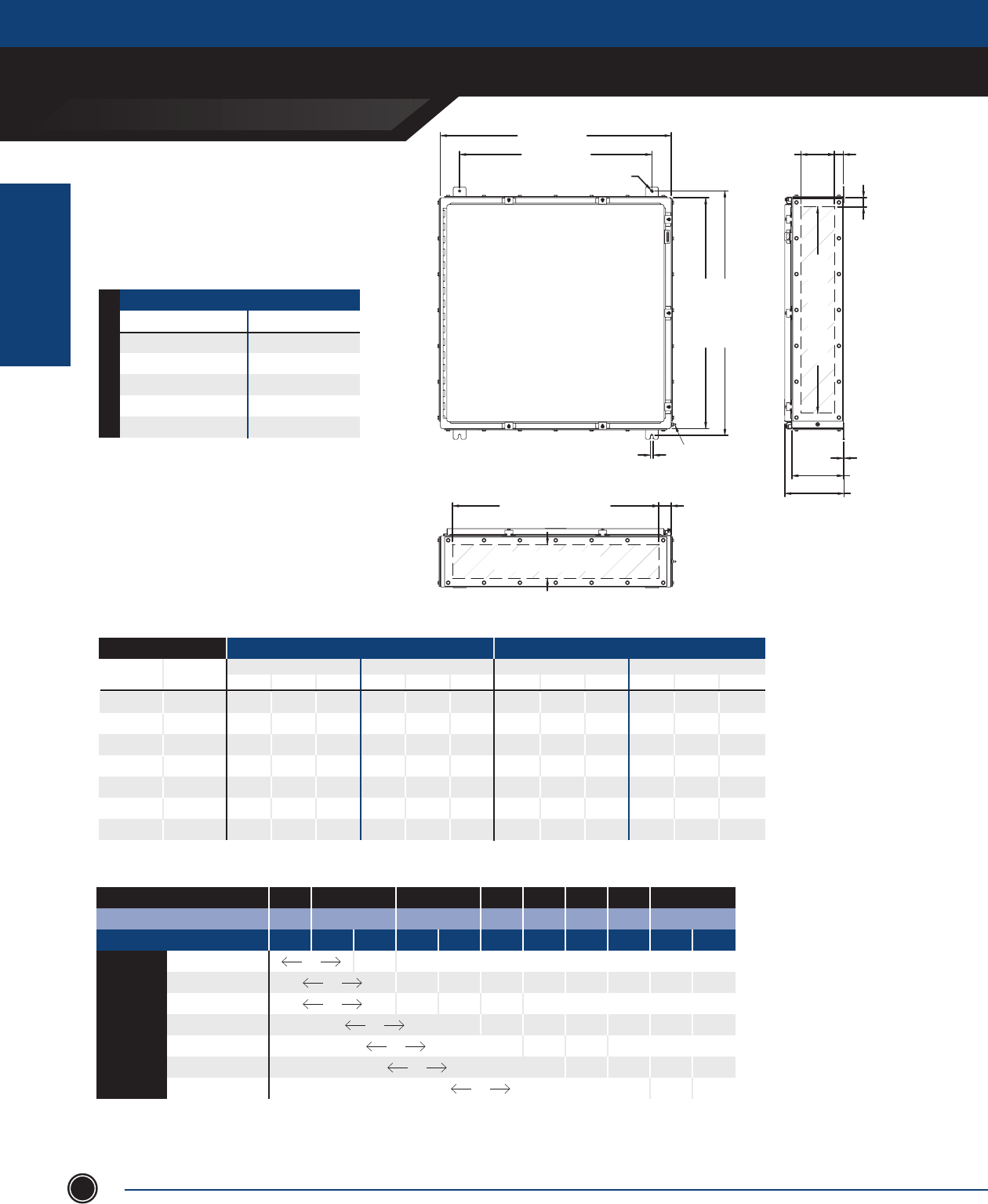
INCREASED SAFETY
TERMINAL ENCLOSURES
INCREASED SAFETY
ENCLOSURES
ADALET.COM
ADALET ENCLOSURE SYSTEMS | 4801 WEST 150TH | CLEVELAND, OHIO 44135©Adalet
60
TN Series
36” x 36” Clamped Door
36.00 [914mm]
30.00 [762mm]
.44 [11mm]
5.25 [133mm]
GLAND PLATE OPENING 1.37 [35mm]
1.44 [37mm]
32.19 [818mm]
GLAND PLATE OPENING
8.00 [203mm]
9.26 [235mm]
.13 [3mm]
32.19 [818mm]
GLAND PLATE OPENING
5.25 [133mm]
GLAND PLATE OPENING
1.91 [48mm]
.44 [11mm]
38.13 [968mm]
36.00 [914mm]
GLAND PLATE SIDE B
GLAND PLATE SIDE A
GLAND PLATE SIDE C
GLAND PLATE SIDE D
EARTH STUD
ENCLOSURES WITH TERMINALS
CATALOG NUMBER GLAND PLATE
TN4X6-363608 None
TN4X6-363608-B Side B
TN4X6-363608-AB Sides A & B
TN4X6-363608-BCD Sides B, C & D
TN4X6-363608-ABCD Sides A, B, C & D
8” [203.2mm] Depth
STAINLESS STEEL 316L
MAXIMUM NUMBER OF CABLE/CONDUIT ENTRIES
SIZE WITHOUT GLAND PLATES WITH GLAND PLATES
Sides A & B Sides C & D Sides A & B Sides C & D
NPT Metric 06 08 10 06 08 10 06 08 10 06 08 10
½ M16 - 174 - - 168 - - 100 - - 100 -
¾ M20 - 120 - - 115 - - 63 - - 63 -
1 M25 - 76 - - 72 - - 51 - - 51 -
1
¼ M32 - 45 - - 42 - - 26 - - 26 -
1
½ M40 - 39 - - 39 - - 24 - - 24 -
2 M50 - 20 - - 20 - - 9 - - 9 -
2
½ M63 - 18 - - 18 - - 8 - - 8 -
Terminal Block Size
MAXIMUM TERMINAL BLOCK CONTENT
MIN CONDUCTOR SIZE .5mm 1.5mm 2.5mm 4mm 6mm 10mm 16mm 35mm
MIN CONDUCTOR SIZE AWG 22 16 14 12 10 8 6 2
MAXIMUM AMPERAGE 3 8 10 16 20 25 35 50 63 80 100
1.5mm2 179 87 x x x x x x x x
2.5mm2 1248 57 33 x x x x x x
4mm2 1248 224 65 37 x x x x x
6mm2 792 71 27 x x x x
10mm2 546 69 22 x x x
16mm2 390 57 26 x x
35mm2 144 105 27
1. For stainless steel 304 construction, substitute TN4X6 prex with TN4X.
2. The maximum terminal block content is based on vertical rail installation. For horizontal installations, consult factory.
3. For applications requiring multiple terminal block congurations and ampacities, consult factory.
4. For applications requiring larger terminal blocks or custom enclosure sizes, consult factory.
5. For conduit/cable spacings, wire bending and wire conversion guidelines, refer to the inside back cover of this catalog.
NOTES
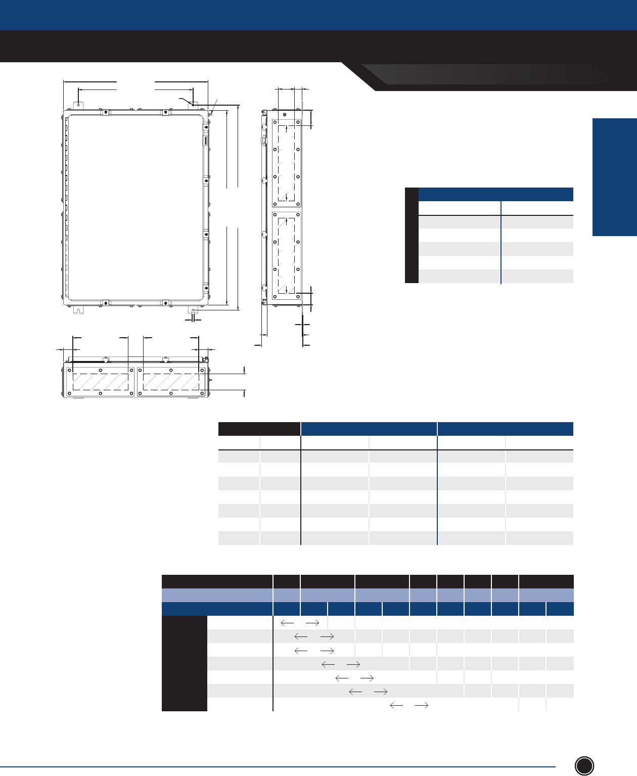
INCREASED SAFETY
TERMINAL ENCLOSURES
INCREASED SAFETY
ENCLOSURES
SEND ORDERS TO ORDERS@ADALET.COM
T: 216.267.9000 | F:216.267.1681 | info@adalet.com ©Adalet
61
TN Series
39” x 29” x 7” Clamped Door
29.00 [737mm]
23.00 [584mm]
.44 [11mm]
41.13 [1045mm]
39.00 [991mm]
.44 [11mm]
EARTH STUD
11.06 [281mm]
G.P. OPENING
1.90 [48mm]
3.07 [78mm]
2.32 [59mm]
15.06 [383mm]
GLAND PLATE OPENING
15.06 [383mm]
GLAND PLATE OPENING
3.25 [83mm]
GLAND PLATE OPENING 1.50 [38mm]
7.00 [178mm]
8.26 [210mm]
.14 [3mm]
3.25 [83mm]
GLAND PLATE OPENING
11.06 [281mm]
G.P. OPENING
1.90 [48mm]
GLAND PLATE SIDE A
GLAND PLATE SIDE B
GLAND PLATE SIDE C
GLAND PLATE SIDE D
Terminal Block Size
MAXIMUM TERMINAL BLOCK CONTENT
MIN CONDUCTOR SIZE .5mm 1.5mm 2.5mm 4mm 6mm 10mm 16mm 35mm
MIN CONDUCTOR SIZE AWG 22 16 14 12 10 8 6 2
MAXIMUM AMPERAGE 3 8 10 16 20 25 35 50 63 80 100
1.5mm2 167 81 x x x x x x x x
2.5mm2 1197 54 31 x x x x x x
4mm2 1197 209 60 34 x x x x x
6mm2 756 66 26 x x x x
10mm2 516 64 21 x x x
16mm2 284 53 24 x x
35mm2 106 98 26
MAXIMUM NUMBER OF CABLE/CONDUIT ENTRIES
SIZE WITHOUT GLAND PLATES WITH GLAND PLATES
NPT Metric Sides A & B Sides C & D Sides A & B Sides C & D
½ M16 115 150 18 24
¾ M20 76 100 14 20
1 M25 45 60 6 8
1
¼ M32 24 32 4 6
1
½ M40 22 28 4 5
2 M50 16 22 3 4
2
½ M63 7 10 3 4
ENCLOSURES WITH TERMINALS
CATALOG NUMBER GLAND PLATE
TN4X6-392907 None
TN4X6-392907-B Side B
TN4X6-392907-AB Sides A & B
TN4X6-392907-BCD Sides B, C & D
TN4X6-392907-ABCD Sides A, B, C & D
7” [177.8mm] Depth
STAINLESS STEEL 316L
1. For stainless steel 304 construction, substitute TN4X6 prex with TN4X.
2. The maximum terminal block content is based on vertical rail installation. For horizontal installations, consult factory.
3. For applications requiring multiple terminal block congurations and ampacities, consult factory.
4. For applications requiring larger terminal blocks or custom enclosure sizes, consult factory.
5. For conduit/cable spacings, wire bending and wire conversion guidelines, refer to the inside back cover of this catalog.
NOTES
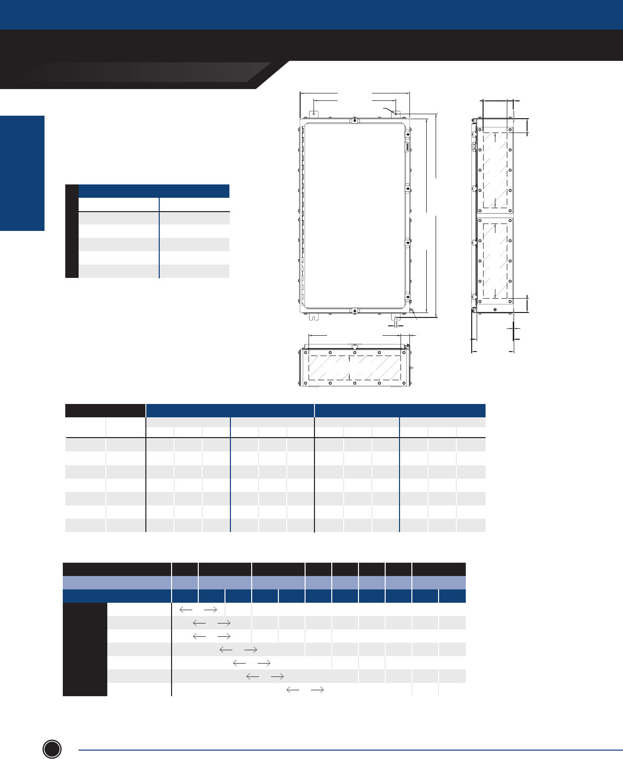
INCREASED SAFETY
TERMINAL ENCLOSURES
INCREASED SAFETY
ENCLOSURES
ADALET.COM
ADALET ENCLOSURE SYSTEMS | 4801 WEST 150TH | CLEVELAND, OHIO 44135©Adalet
62
TN Series
42” x 24” Clamped Door
24.00 [610mm]
18.00 [457mm]
.44 [11mm]
5.25 [133mm]
GLAND PLATE OPENING 1.38 [35mm]
3.06 [78mm]
16.19 [411mm]
GLAND PLATE OPENING
16.19 [411mm]
GLAND PLATE OPENING
3.06 [78mm]
8.00 [203mm]
9.26 [235mm]
.14 [3mm]
44.13 [1121mm]
42.00 [1067mm]
.44 [11mm]
20.19 [513mm]
GLAND PLATE OPENING
5.25 [133mm]
GLAND PLATE OPENING
1.91 [48mm]
GLAND PLATE SIDE B
GLAND PLATE SIDE A
GLAND PLATE SIDE C
GLAND PLATE SIDE D
EARTH STUD
MAXIMUM NUMBER OF CABLE/CONDUIT ENTRIES
SIZE WITHOUT GLAND PLATES WITH GLAND PLATES
Sides A & B Sides C & D Sides A & B Sides C & D
NPT Metric 06 08 10 06 08 10 06 08 10 06 08 10
½ M16 - 114 - - 192 - - 64 - - 52 -
¾ M20 - 80 - - 135 - - 39 - - 33 -
1 M25 - 52 - - 88 - - 33 - - 24 -
1
¼ M32 - 30 - - 51 - - 16 - - 14 -
1
½ M40 - 27 - - 45 - - 14 - - 12 -
2 M50 - 14 - - 24 - - 6 - - 5 -
2
½ M63 - 12 - - 20 - - 5 - - 4 -
Terminal Block Size
MAXIMUM TERMINAL BLOCK CONTENT
MIN CONDUCTOR SIZE .5mm 1.5mm 2.5mm 4mm 6mm 10mm 16mm 35mm
MIN CONDUCTOR SIZE AWG 22 16 14 12 10 8 6 2
MAXIMUM AMPERAGE 3 8 10 16 20 25 35 50 63 80 100
1.5mm2 153 74 x x x x x x x x
2.5mm2 930 49 29 x x x x x x
4mm2 930 191 55 31 x x x x x
6mm2 590 60 28 x x x x
10mm2 470 59 19 x x x
16mm2 234 49 22 x x
35mm2 116 90 x
ENCLOSURES WITH TERMINALS
CATALOG NUMBER GLAND PLATE
TN4X6-422408 None
TN4X6-422408-B Side B
TN4X6-422408-AB Sides A & B
TN4X6-422408-BCD Sides B, C & D
TN4X6-422408-ABCD Sides A, B, C & D
8” [203.2mm] Depth
STAINLESS STEEL 316L
1. For stainless steel 304 construction, substitute TN4X6 prex with TN4X.
2. The maximum terminal block content is based on vertical rail installation. For horizontal installations, consult factory.
3. For applications requiring multiple terminal block congurations and ampacities, consult factory.
4. For applications requiring larger terminal blocks or custom enclosure sizes, consult factory.
5. For conduit/cable spacings, wire bending and wire conversion guidelines, refer to the inside back cover of this catalog.
NOTES

INCREASED SAFETY
TERMINAL ENCLOSURES
INCREASED SAFETY
ENCLOSURES
SEND ORDERS TO ORDERS@ADALET.COM
T: 216.267.9000 | F:216.267.1681 | info@adalet.com ©Adalet
63
TN Series
42” x 30” Clamped Door
30.00 [762mm]
24.00 [610mm]
.44 [11mm]
1.38 [35mm]
5.25 [133mm]
7.25 [184mm]
GLAND PLATE OPENING
44.13 [1121mm]
42.00 [1067mm]
.44 [11mm]
26.19 [665mm]
GLAND PLATE OPENING
5.25 [133mm] / 7.25 [184mm]
GLAND PLATE OPENING
1.91 [48mm]
9.26 [235mm]
11.26 [286mm]
8.00 [203mm]
10.00 [254mm]
.14 [3mm]
3.06 [78mm] 3.06 [78mm]
16.19 [411mm]
GLAND PLATE OPENING
16.19 [411mm]
GLAND PLATE OPENING
GLAND PLATE SIDE B
GLAND PLATE SIDE A
GLAND PLATE SIDE C
GLAND PLATE SIDE D
EARTH STUD
ENCLOSURES WITH TERMINALS
CATALOG NUMBER GLAND PLATE
TN4X6-423008 None
TN4X6-423008-B Side B
TN4X6-423008-AB Sides A & B
TN4X6-423008-BCD Sides B, C & D
TN4X6-423008-ABCD Sides A, B, C & D
TN4X6-423010 None
TN4X6-423010-B Side B
TN4X6-423010-AB Sides A & B
TN4X6-423010-BCD Sides B, C & D
TN4X6-423010-ABCD Sides A, B, C & D
10” [254.0mm] Depth 8” [203.2mm] Depth
STAINLESS STEEL 316L
MAXIMUM NUMBER OF CABLE/CONDUIT ENTRIES
SIZE WITHOUT GLAND PLATES WITH GLAND PLATES
Sides A & B Sides C & D Sides A & B Sides C & D
NPT Metric 06 08 10 06 08 10 06 08 10 06 08 10
½ M16 - 144 192 - 192 256 - 84 126 - 52 78
¾ M20 - 100 120 - 135 162 - 51 85 - 33 55
1 M25 - 64 80 - 88 110 - 42 56 - 24 32
1
¼ M32 - 36 48 - 51 68 - 22 33 - 14 21
1
½ M40 - 33 44 - 45 60 - 20 20 - 12 12
2 M50 - 18 27 - 24 36 - 8 20 - 5 10
2
½ M63 - 14 14 - 20 20 - 7 14 - 4 8
Terminal Block Size
MAXIMUM TERMINAL BLOCK CONTENT
MIN CONDUCTOR SIZE .5mm 1.5mm 2.5mm 4mm 6mm 10mm 16mm 35mm
MIN CONDUCTOR SIZE AWG 22 16 14 12 10 8 6 2
MAXIMUM AMPERAGE 3 8 10 16 20 25 35 50 63 80 100
1.5mm2 172 84 x x x x x x x x
2.5mm2 1302 55 32 x x x x x x
4mm2 1302 216 63 35 x x x x x
6mm2 826 68 27 x x x x
10mm2 564 66 21 x x x
16mm2 390 55 25 x x
35mm2 174 101 27
1. For stainless steel 304 construction, substitute TN4X6 prex with TN4X.
2. The maximum terminal block content is based on vertical rail installation. For horizontal installations, consult factory.
3. For applications requiring multiple terminal block congurations and ampacities, consult factory.
4. For applications requiring larger terminal blocks or custom enclosure sizes, consult factory.
5. For conduit/cable spacings, wire bending and wire conversion guidelines, refer to the inside back cover of this catalog.
NOTES
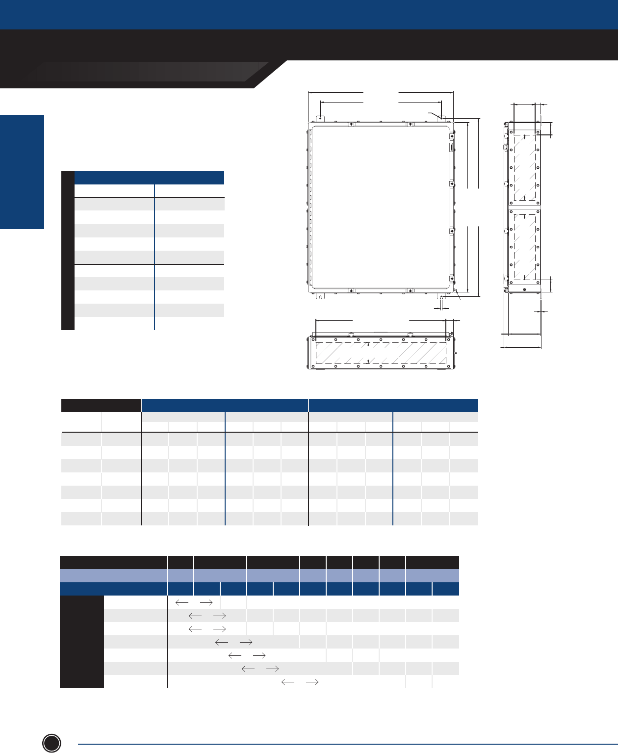
INCREASED SAFETY
TERMINAL ENCLOSURES
INCREASED SAFETY
ENCLOSURES
ADALET.COM
ADALET ENCLOSURE SYSTEMS | 4801 WEST 150TH | CLEVELAND, OHIO 44135©Adalet
64
TN Series
42” x 36” Clamped Door
36.00 [914mm]
30.00 [762mm]
.44 [11mm]
42.00 [1067mm]
44.12 [1121mm]
.44 [11mm]
32.19 [818mm]
GLAND PLATE OPENING
5.25 [133mm] / 7.25 [184mm]
GLAND PLATE OPENING
5.25 [133mm]
7.25 [184mm]
GLAND PLATE OPENING
1.37 [35mm]
3.06 [78mm]3.06 [78mm]
16.19 [411mm]
GLAND PLATE OPENING
16.19 [411mm]
GLAND PLATE OPENING
9.26 [235mm]
11.26 [286mm]
1.91 [48mm]
8.00 [203mm]
10.00 [254mm]
.13 [3mm]
GLAND PLATE SIDE B
GLAND PLATE SIDE A
GLAND PLATE SIDE C
GLAND PLATE SIDE D
EARTH STUD
MAXIMUM NUMBER OF CABLE/CONDUIT ENTRIES
SIZE WITHOUT GLAND PLATES WITH GLAND PLATES
Sides A & B Sides C & D Sides A & B Sides C & D
NPT Metric 06 08 10 06 08 10 06 08 10 06 08 10
½ M16 - 174 232 - 192 256 - 100 150 - 52 78
¾ M20 - 120 144 - 135 162 - 63 105 - 33 55
1 M25 - 76 95 - 88 110 - 51 68 - 24 32
1
¼ M32 - 45 60 - 51 68 - 26 39 - 14 21
1
½ M40 - 39 52 - 45 60 - 24 24 - 12 12
2 M50 - 20 30 - 24 36 - 9 18 - 5 10
2
½ M63 - 18 18 - 20 20 - 8 16 - 4 8
Terminal Block Size
MAXIMUM TERMINAL BLOCK CONTENT
MIN CONDUCTOR SIZE .5mm 1.5mm 2.5mm 4mm 6mm 10mm 16mm 35mm
MIN CONDUCTOR SIZE AWG 22 16 14 12 10 8 6 2
MAXIMUM AMPERAGE 3 8 10 16 20 25 35 50 63 80 100
1.5mm2 188 91 x x x x x x x x
2.5mm2 1488 61 35 x x x x x x
4mm2 1488 236 68 39 x x x x x
6mm2 944 75 28 x x x x
10mm2 658 72 23 x x x
16mm2 468 60 28 x x
35mm2 174 111 29
1. For stainless steel 304 construction, substitute TN4X6 prex with TN4X.
2. The maximum terminal block content is based on vertical rail installation. For horizontal installations, consult factory.
3. For applications requiring multiple terminal block congurations and ampacities, consult factory.
4. For applications requiring larger terminal blocks or custom enclosure sizes, consult factory.
5. For conduit/cable spacings, wire bending and wire conversion guidelines, refer to the inside back cover of this catalog.
NOTES
ENCLOSURES WITH TERMINALS
CATALOG NUMBER GLAND PLATE
TN4X6-423608 None
TN4X6-423608-B Side B
TN4X6-423608-AB Sides A & B
TN4X6-423608-BCD Sides B, C & D
TN4X6-423608-ABCD Sides A, B, C & D
TN4X6-423610 None
TN4X6-423610-B Side B
TN4X6-423610-AB Sides A & B
TN4X6-423610-BCD Sides B, C & D
TN4X6-423610-ABCD Sides A, B, C & D
10” [254.0mm] Depth 8” [203.2mm] Depth
STAINLESS STEEL 316L
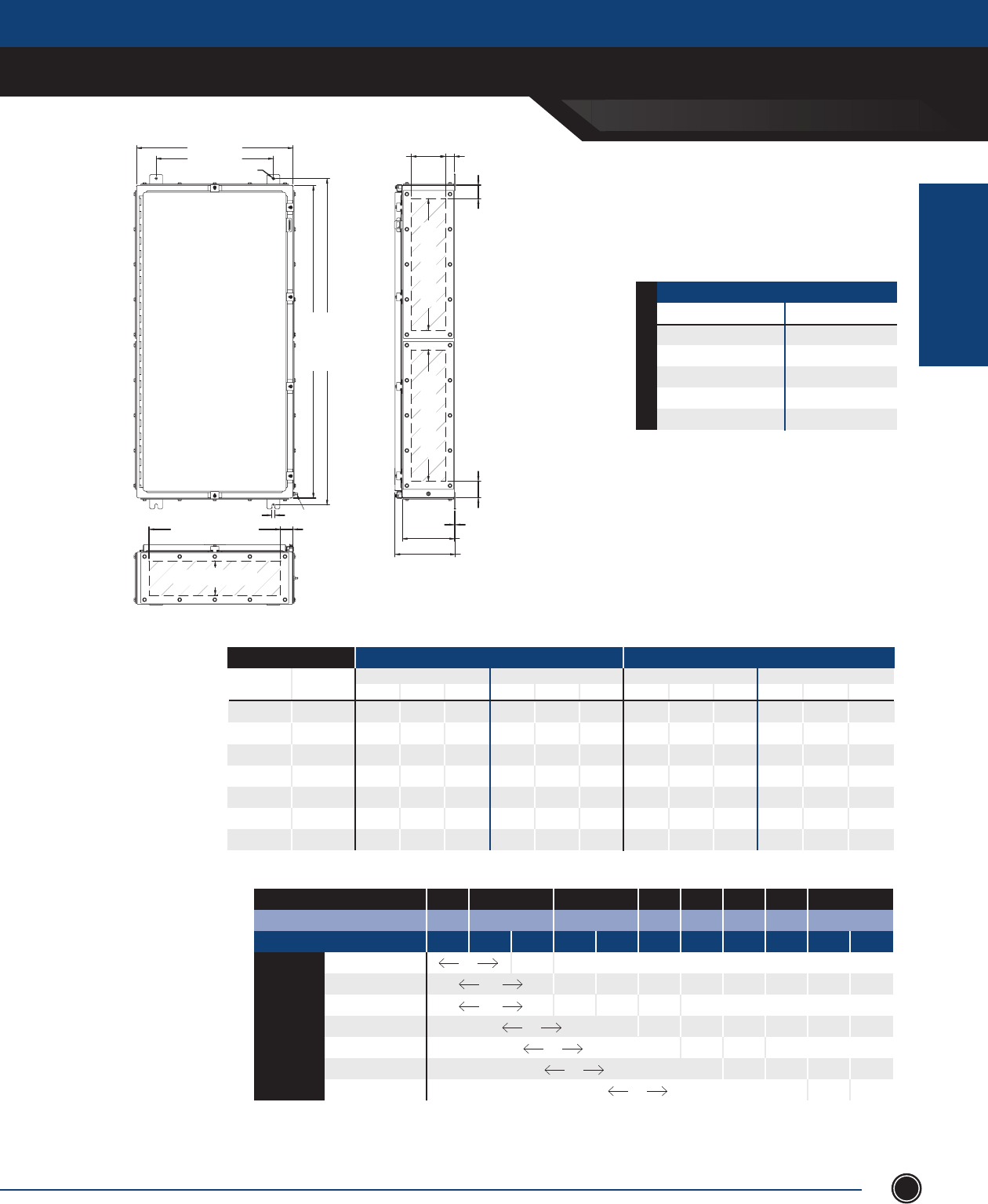
INCREASED SAFETY
TERMINAL ENCLOSURES
INCREASED SAFETY
ENCLOSURES
SEND ORDERS TO ORDERS@ADALET.COM
T: 216.267.9000 | F:216.267.1681 | info@adalet.com ©Adalet
65
24.00 [610mm]
18.00 [457mm]
.44 [11mm]
48.00 [1219mm]
50.12 [1273mm]
.44 [11mm]
20.19 [513mm]
GLAND PLATE OPENING
5.25 [133mm]
GLAND PLATE OPENING
8.00 [203mm]
9.26 [235mm]
.13 [3mm]
2.56 [65mm] 2.06 [52mm]
20.19 [513mm]
GLAND PLATE OPENING
20.19 [513mm]
GLAND PLATE OPENING
5.25 [133mm]
GLAND PLATE OPENING 1.37 [35mm]
1.91 [48mm]
GLAND PLATE SIDE B
GLAND PLATE SIDE A
GLAND PLATE SIDE C
GLAND PLATE SIDE D
EARTH STUD
TN Series
48” x 24” Clamped Door
MAXIMUM NUMBER OF CABLE/CONDUIT ENTRIES
SIZE WITHOUT GLAND PLATES WITH GLAND PLATES
Sides A & B Sides C & D Sides A & B Sides C & D
NPT Metric 06 08 10 06 08 10 06 08 10 06 08 10
½ M16 - 114 - - 222 - - 64 - - 64 -
¾ M20 - 80 - - 155 - - 39 - - 39 -
1 M25 - 52 - - 100 - - 33 - - 33 -
1
¼ M32 - 30 - - 57 - - 16 - - 16 -
1
½ M40 - 27 - - 54 - - 14 - - 14 -
2 M50 - 14 - - 28 - - 6 - - 6 -
2
½ M63 - 12 - - 24 - - 5 - - 5 -
Terminal Block Size
MAXIMUM TERMINAL BLOCK CONTENT
MIN CONDUCTOR SIZE .5mm 1.5mm 2.5mm 4mm 6mm 10mm 16mm 35mm
MIN CONDUCTOR SIZE AWG 22 16 14 12 10 8 6 2
MAXIMUM AMPERAGE 3 8 10 16 20 25 35 50 63 80 100
1.5mm2 155 75 x x x x x x x x
2.5mm2 1085 50 29 x x x x x x
4mm2 1085 195 56 32 x x x x x
6mm2 685 61 24 x x x x
10mm2 545 60 19 x x x
16mm2 273 49 23 x x
35mm2 134 91 24
ENCLOSURES WITH TERMINALS
CATALOG NUMBER GLAND PLATE
TN4X6-482408 None
TN4X6-482408-B Side B
TN4X6-482408-AB Sides A & B
TN4X6-482408-BCD Sides B, C & D
TN4X6-482408-ABCD Sides A, B, C & D
8” [203.2mm] Depth
STAINLESS STEEL 316L
1. For stainless steel 304 construction, substitute TN4X6 prex with TN4X.
2. The maximum terminal block content is based on vertical rail installation. For horizontal installations, consult factory.
3. For applications requiring multiple terminal block congurations and ampacities, consult factory.
4. For applications requiring larger terminal blocks or custom enclosure sizes, consult factory.
5. For conduit/cable spacings, wire bending and wire conversion guidelines, refer to the inside back cover of this catalog.
NOTES

INCREASED SAFETY
TERMINAL ENCLOSURES
INCREASED SAFETY
ENCLOSURES
ADALET.COM
ADALET ENCLOSURE SYSTEMS | 4801 WEST 150TH | CLEVELAND, OHIO 44135©Adalet
66
TN Series
48” x 30” Clamped Door
30.00 [762mm]
24.00 [610mm]
.44 [11mm]
48.00 [1219mm]
50.12 [1273mm]
.44 [11mm]
26.19 [665mm]
GLAND PLATE OPENING 1.91 [48mm]
5.25 [133mm] / 7.25 [184mm]
GLAND PLATE OPENING
8.00 [203mm]
10.00 [254mm]
9.26 [235mm]
11.26 [286mm]
.13 [3mm]
2.56 [65mm] 2.06 [52mm]
5.25 [133mm]
7.25 [184mm]
GLAND PLATE OPENING 1.37 [35mm]
20.19 [513mm]
GLAND PLATE OPENING
20.19 [513mm]
GLAND PLATE OPENING
GLAND PLATE SIDE B
GLAND PLATE SIDE A
GLAND PLATE SIDE C
GLAND PLATE SIDE D
EARTH STUD
MAXIMUM NUMBER OF CABLE/CONDUIT ENTRIES
SIZE WITHOUT GLAND PLATES WITH GLAND PLATES
Sides A & B Sides C & D Sides A & B Sides C & D
NPT Metric 06 08 10 06 08 10 06 08 10 06 08 10
½ M16 - 144 192 - 222 296 - 84 126 - 64 96
¾ M20 - 100 120 - 155 186 - 51 85 - 39 65
1 M25 - 64 80 - 100 125 - 42 56 - 33 44
1
¼ M32 - 36 48 - 57 76 - 22 33 - 16 24
1
½ M40 - 33 44 - 54 72 - 20 20 - 14 14
2 M50 - 18 27 - 28 42 - 8 16 - 6 12
2
½ M63 - 14 14 - 24 24 - 7 14 - 5 10
Terminal Block Size
MAXIMUM TERMINAL BLOCK CONTENT
MIN CONDUCTOR SIZE .5mm 1.5mm 2.5mm 4mm 6mm 10mm 16mm 35mm
MIN CONDUCTOR SIZE AWG 22 16 14 12 10 8 6 2
MAXIMUM AMPERAGE 3 8 10 16 20 25 35 50 63 80 100
1.5mm2 177 86 x x x x x x x x
2.5mm2 1519 57 33 x x x x x x
4mm2 1519 222 64 36 x x x x x
6mm2 959 70 27 x x x x
10mm2 654 68 22 x x x
16mm2 455 56 26 x x
35mm2 201 104 27
ENCLOSURES WITH TERMINALS
CATALOG NUMBER GLAND PLATE
TN4X6-483008 None
TN4X6-483008-B Side B
TN4X6-483008-AB Sides A & B
TN4X6-483008-BCD Sides B, C & D
TN4X6-483008-ABCD Sides A, B, C & D
TN4X6-483010 None
TN4X6-483010-B Side B
TN4X6-483010-AB Sides A & B
TN4X6-483010-BCD Sides B, C & D
TN4X6-483010-ABCD Sides A, B, C & D
10” [254.0mm] Depth 8” [203.2mm] Depth
STAINLESS STEEL 316L
1. For stainless steel 304 construction, substitute TN4X6 prex with TN4X.
2. The maximum terminal block content is based on vertical rail installation. For horizontal installations, consult factory.
3. For applications requiring multiple terminal block congurations and ampacities, consult factory.
4. For applications requiring larger terminal blocks or custom enclosure sizes, consult factory.
5. For conduit/cable spacings, wire bending and wire conversion guidelines, refer to the inside back cover of this catalog.
NOTES
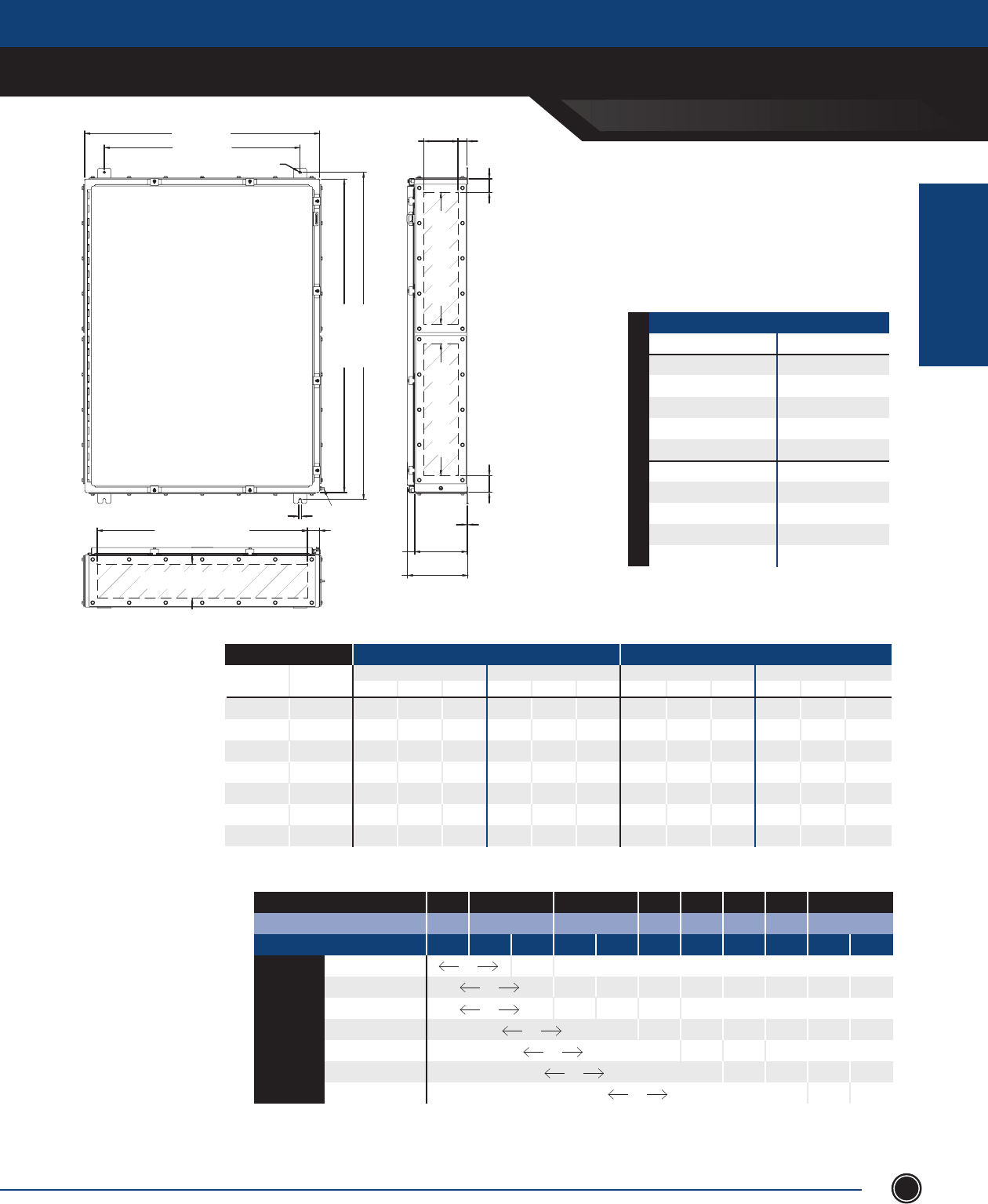
INCREASED SAFETY
TERMINAL ENCLOSURES
INCREASED SAFETY
ENCLOSURES
SEND ORDERS TO ORDERS@ADALET.COM
T: 216.267.9000 | F:216.267.1681 | info@adalet.com ©Adalet
67
TN Series
48” x 36” Clamped Door
36.00 [914mm]
30.00 [762mm]
.44 [11mm]
.44 [11mm]
48.00 [1219mm]
50.13 [1273mm]
32.19 [818mm]
GLAND PLATE OPENING
5.25 [133mm] / 7.25 [184mm]
GLAND PLATE OPENING
1.91 [48mm]
8.00 [203mm]
10.00 [254mm]
9.26 [235mm]
11.26 [286mm]
.14 [3mm]
2.56 [65mm]
20.19 [513mm]
GLAND PLATE OPENING
20.19 [513mm]
GLAND PLATE OPENING
2.06 [52mm]
5.25 [133mm]
7.25 [184mm]
GLAND PLATE OPENING 1.38 [35mm]
GLAND PLATE SIDE B
GLAND PLATE SIDE A
GLAND PLATE SIDE C
GLAND PLATE SIDE D
EARTH STUD
MAXIMUM NUMBER OF CABLE/CONDUIT ENTRIES
SIZE WITHOUT GLAND PLATES WITH GLAND PLATES
Sides A & B Sides C & D Sides A & B Sides C & D
NPT Metric 06 08 10 06 08 10 06 08 10 06 08 10
½ M16 - 174 232 - 222 296 - 100 150 - 64 96
¾ M20 - 120 144 - 155 186 - 63 105 - 39 65
1 M25 - 76 95 - 100 125 - 51 68 - 33 44
1
¼ M32 - 45 60 - 57 76 - 26 39 - 16 24
1
½ M40 - 39 52 - 54 72 - 24 24 - 14 14
2 M50 - 20 30 - 28 42 - 9 18 - 6 12
2
½ M63 - 18 18 - 24 24 - 8 16 - 5 10
Terminal Block Size
MAXIMUM TERMINAL BLOCK CONTENT
MIN CONDUCTOR SIZE .5mm 1.5mm 2.5mm 4mm 6mm 10mm 16mm 35mm
MIN CONDUCTOR SIZE AWG 22 16 14 12 10 8 6 2
MAXIMUM AMPERAGE 3 8 10 16 20 25 35 50 63 80 100
1.5mm2
196 95 x x x x x x x x
2.5mm2 1736 63 37 x x x x x x
4mm2 1736 245 71 40 x x x x x
6mm2 1096 77 30 x x x x
10mm2 763 75 24 x x x
16mm2 546 62 29 x x
35mm2 201 115 30
ENCLOSURES WITH TERMINALS
CATALOG NUMBER GLAND PLATE
TN4X6-483608 None
TN4X6-483608-B Side B
TN4X6-483608-AB Sides A & B
TN4X6-483608-BCD Sides B, C & D
TN4X6-483608-ABCD Sides A, B, C & D
TN4X6-483610 None
TN4X6-483610-B Side B
TN4X6-483610-AB Sides A & B
TN4X6-483610-BCD Sides B, C & D
TN4X6-483610-ABCD Sides A, B, C & D
10” [254.0mm] Depth 8” [203.2mm] Depth
STAINLESS STEEL 316L
1. For stainless steel 304 construction, substitute TN4X6 prex with TN4X.
2. The maximum terminal block content is based on vertical rail installation. For horizontal installations, consult factory.
3. For applications requiring multiple terminal block congurations and ampacities, consult factory.
4. For applications requiring larger terminal blocks or custom enclosure sizes, consult factory.
5. For conduit/cable spacings, wire bending and wire conversion guidelines, refer to the inside back cover of this catalog.
NOTES
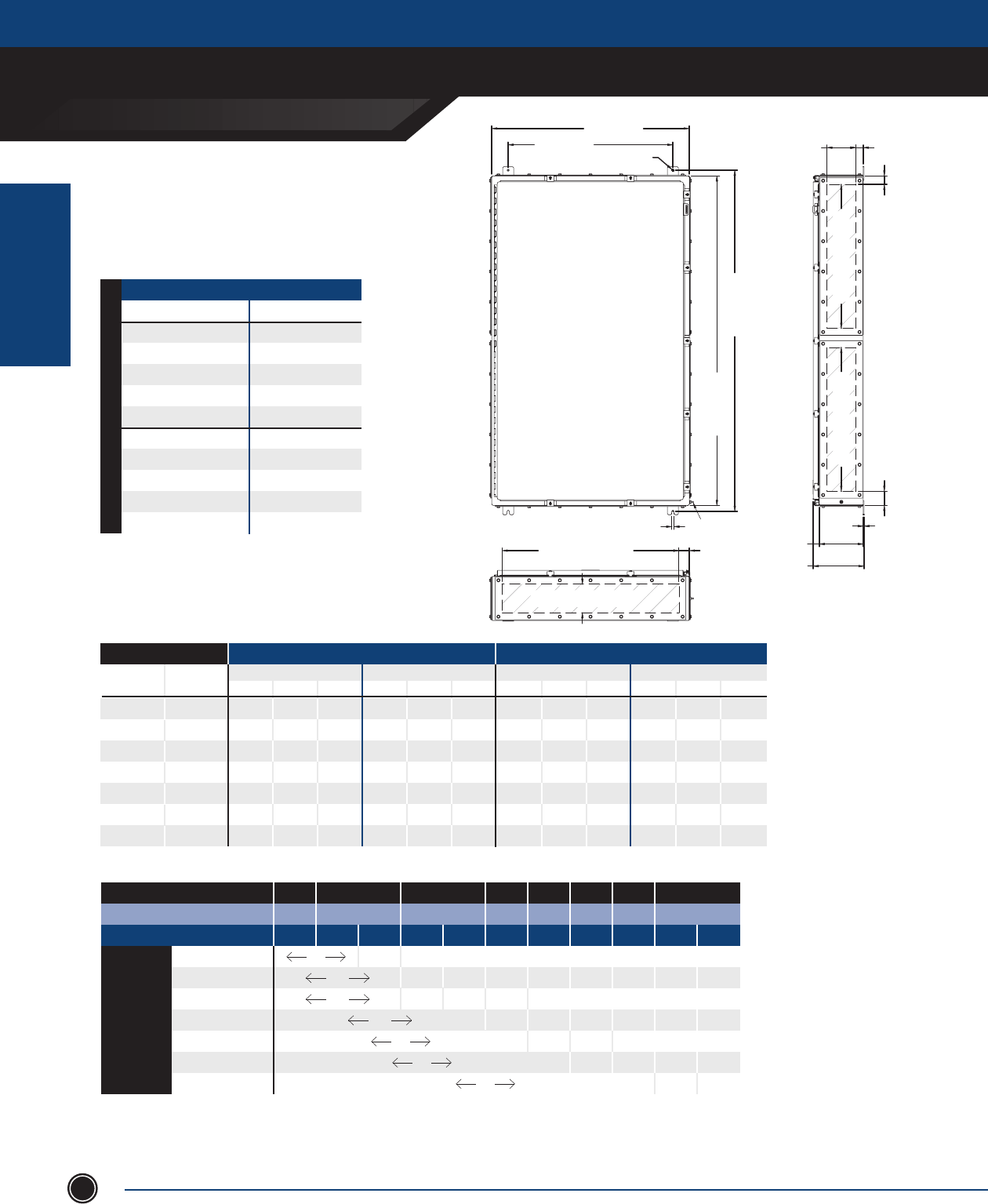
INCREASED SAFETY
TERMINAL ENCLOSURES
INCREASED SAFETY
ENCLOSURES
ADALET.COM
ADALET ENCLOSURE SYSTEMS | 4801 WEST 150TH | CLEVELAND, OHIO 44135©Adalet
68
Terminal Block Size
MAXIMUM TERMINAL BLOCK CONTENT
MIN CONDUCTOR SIZE .5mm 1.5mm 2.5mm 4mm 6mm 10mm 16mm 35mm
MIN CONDUCTOR SIZE AWG 22 16 14 12 10 8 6 2
MAXIMUM AMPERAGE 3 8 10 16 20 25 35 50 63 80 100
1.5mm2 206 100 x x x x x x x x
2.5mm2 2224 66 39 x x x x x x
4mm2 2224 258 75 47 x x x x x
6mm2 1408 81 32 x x x x
10mm2 980 79 26 x x x
16mm2 696 68 30 x x
35mm2 258 121 32
TN Series
60” x 36” Clamped Door
ENCLOSURES WITH TERMINALS
Catalog Number Gland Plate
TN4X6-603608 None
TN4X6-603608-B Side B
TN4X6-603608-AB Sides A & B
TN4X6-603608-BCD Sides B, C & D
TN4X6-603608-ABCD Sides A, B, C & D
TN4X6-603610 None
TN4X6-603610-B Side B
TN4X6-603610-AB Sides A & B
TN4X6-603610-BCD Sides B, C & D
TN4X6-603610-ABCD Sides A, B, C & D
MAXIMUM NUMBER OF CABLE/CONDUIT ENTRIES
SIZE WITHOUT GLAND PLATES WITH GLAND PLATES
Sides A & B Sides C & D Sides A & B Sides C & D
NPT Metric 06 08 10 06 08 10 06 08 10 06 08 10
½ M16 - 174 232 - 282 376 - 100 150 - 84 126
¾ M20 - 120 144 - 195 234 - 63 105 - 51 85
1 M25 - 76 95 - 124 155 - 51 68 - 42 56
1
¼ M32 - 45 60 - 72 96 - 26 39 - 22 33
1
½ M40 - 39 52 - 66 88 - 24 24 - 20 30
2 M50 - 20 30 - 34 51 - 9 18 - 8 16
2
½ M63 - 18 18 - 14 30 - 8 16 - 7 14
1. For stainless steel 304 construction, substitute TN4X6 prex with TN4X.
2. The maximum terminal block content is based on vertical rail installation.
For horizontal installations, consult factory.
3. For applications requiring multiple terminal block congurations and
ampacities, consult factory.
4. For applications requiring larger terminal blocks or custom
enclosure sizes, consult factory.
5. For conduit/cable spacings, wire bending and wire conversion
guidelines, refer to the inside back cover of this catalog.
6. There are (2) gland plates on each side, quantity shown is for (1) plate.
NOTES
36.00 [914mm]
.44 [11mm]
30.00 [762mm]
60.00 [1524mm]
62.13 [1578mm]
.44 [11mm]
32.19 [818mm]
GLAND PLATE OPENING
5.25 [133mm] / 7.25 [184mm]
GLAND PLATE OPENING
26.19 [665mm]
GLAND PLATE OPENING
2.56 [65mm] 1.56 [40mm]
8.00 [203mm]
10.00 [254mm]
9.26 [235mm]
11.26 [286mm]
.13 [3mm]
5.25 [133mm]
7.25 [184mm]
GLAND PLATE OPENING
1.91 [48mm]
1.37 [35mm]
26.19 [665mm]
GLAND PLATE OPENING
GLAND PLATE SIDE A
GLAND PLATE SIDE B
GLAND PLATE SIDE C
GLAND PLATE SIDE D
EARTH STUD
10” [254.0mm] Depth 8” [203.2mm] Depth
GROUND STUD
STAINLESS STEEL 316L
INCREASED SAFETY
TERMINAL ENCLOSURES
INCREASED SAFETY
ENCLOSURES
SEND ORDERS TO ORDERS@ADALET.COM
T: 216.267.9000 | F:216.267.1681 | info@adalet.com ©Adalet
69
TN Series Enclosures - Empty
Adalet’s Empty Single Door Clamped Enclosures are available in Stainless Steel 316L & 304. Adalet can also supply custom
size enclosures, operators, and components to suit your Increased Safety Application. Silicone gaskets, removable hinge
pin, box & cover ground studs including an external earthing stud and internal standoffs for mounting panels are standard.
• 68 standard enclosure sizes, available in SS316L or SS304.
• Folded lip around door opening for complete and maximum gasket contact
• Continuously welded seams and ground smooth
• Silicone cover gasket
• Hinge - continuous piano type, with removable stainless steel pin
• Ground studs - on door and box, including an external ground stud
• Welded on external mounting feet
• Padlock hasp for padlocking
• Gland plates, pre-drilled or blank for fi eld drilling
• Cable glands, stopping plugs, reducers, adaptors installation
• Terminal rail assemblies - any Exe terminal block
• Breather/drain
• Custom polyester powder coating and painting
• Mounting pans
• Custom size enclosures and gland plates
STANDARD FEATURES
DESIGN OPTIONS
MATERIAL
CERTIFICATIONS
Class II, Division 2
Class I, Zone 1, AEX e II
Ex e II (Canada)
NEMA Type 4
DEMKO 01 ATEX 0112700U
0539 II 2 GD
Ex e II
Ex tD A21 IP66
IECEx UL 10.0021U
Ex e II
Ex tD A21 IP66
ENCLOSURE TN4X Series
TN4X6 Series
TN4X Gland Plates
TN4X6 Gland Plates
GASKET Cover
Gland Plates
ENCLOSURE MOUNTING
GLAND PLATE HARDWARE
#14 ga Stainless Steel 304 - Brushed Finish
#14 ga Stainless Steel 316L - Brushed Finish
#10 ga Stainless Steel 304 - Brushed Finish
#10 ga Stainless Steel 316L - Brushed Finish
Silicone Sponge
Silicone Sponge
Four (4) external lugs with .44” clearance holes / slots
300 Series Stainless Steel
Continuous piano SS304
Continuous piano SS316L
Stainless Steel 304
Stainless Steel 316L
1/4-20 stud with 300 Series SS hardware
LID FIXING TN4X Hinge
TN4X6 Hinge
TN4X Door Clamps
TN4X6 Door Clamps
GROUNDING Box & Cover
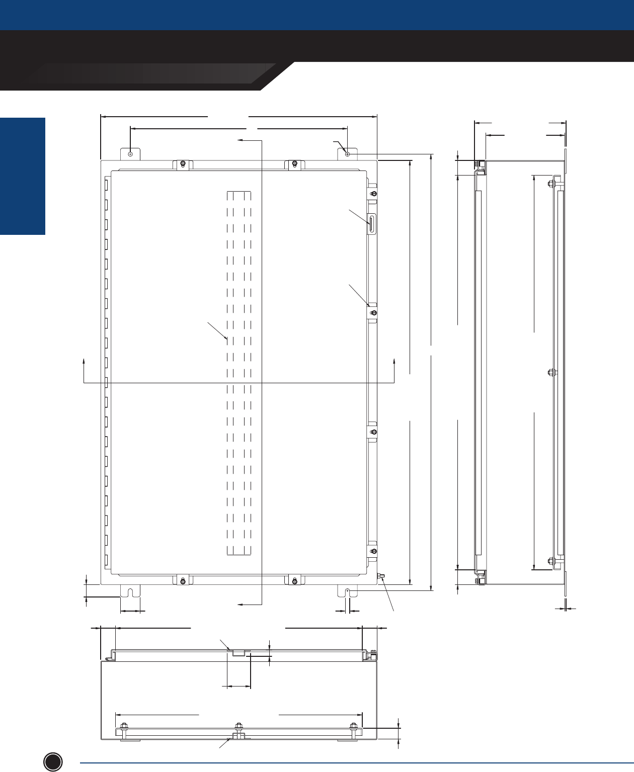
INCREASED SAFETY
TERMINAL ENCLOSURES
INCREASED SAFETY
ENCLOSURES
ADALET.COM
AdAlet enclosure systems | 4801 West 150th | cleVelAnd, ohIo 44135©Adalet
70
G
B (WIDTH)
.44 [11mm]
A (LENGTH)
F
.44 [11mm]2.00 [51mm]
1.25 [32mm]
EARTH STUD
BOX/COVER STIFFENER
(SEE TABLE, IF REQ'D)
DOOR CLAMP
(REF TABLE FOR QTY.)
PADLOCK
HASP & STAPLE
1.50 [38mm] B - 3.00 [76mm] (OPENING) 1.50 [38mm]
COVER STIFFENER
2.37 [60mm]
.62 [16mm]
Y (MOUNTING PANEL)
BOX STIFFENER
1.50 [38mm]
A - 3.00 [76mm] (OPENING)
1.50 [38mm]
1.10 [28mm]
C (DEPTH)
C + 1.30 [33mm]
X (MOUNTING PANEL)
.13 [3mm]

INCREASED SAFETY
TERMINAL ENCLOSURES
INCREASED SAFETY
ENCLOSURES
SEND ORDERS TO ORDERS@ADALET.COM
T: 216.267.9000 | F:216.267.1681 | info@adalet.com ©Adalet
71
TN4X6-161206U
TN4X6-161606U
TN4X6-162006U
TN4X6-201606U
TN4X6-202006U
TN4X6-202406U
TN4X6-241206U
TN4X6-241606U
TN4X6-242006U
TN4X6-242406U
TN4X6-302006U
TN4X6-302406U
TN4X6-362406U
TN4X6-363006U
TN4X6-161208U
TN4X6-161608U
TN4X6-162008U
TN4X6-201608U
TN4X6-202008U
TN4X6-202408U
TN4X6-241608U
TN4X6-242008U
TN4X6-242408U
TN4X6-243008U
TN4X6-302008U
TN4X6-302408U
TN4X6-303008U
TN4X6-362408U
TN4X6-363008U
TN4X6-363608U
TN4X6-423008U
TN4X6-423608U
TN4X6-483608U
TN4X6-201610U
TN Series - Empty Enclosure 316L Stainless Steel
ENCLOSURE GAUGE
BOX DOOR
OUTSIDE DIM.
A B C CLAMPS
#
MOUNTING
CENTER
PANEL
PART NO.
PANEL DIM.
X Y
16
16
16
20
20
20
24
24
24
24
30
30
36
36
16
16
16
20
20
20
24
24
24
24
30
30
30
36
36
36
42
42
48
20
14
14
14
14
14
14
14
14
14
14
14
14
14
14
14
14
14
14
14
14
14
14
14
14
14
14
14
14
14
14
14
14
14
14
-
-
-
-
-
-
-
-
-
-
-
-
-
REQ’D
-
-
-
-
-
-
-
-
-
-
-
-
REQ’D
-
REQ’D
REQ’D
REQ’D
REQ’D
REQ’D
-
4
4
4
4
4
4
5
5
5
5
5
5
5
7
4
4
4
4
4
4
5
5
5
7
5
5
7
5
7
7
8
8
8
4
18.13
18.13
18.13
22.13
22.13
22.13
26.13
26.13
26.13
26.13
32.13
32.13
38.13
38.13
18.13
18.13
18.13
22.13
22.13
22.13
26.13
26.13
26.13
26.13
32.13
32.13
32.13
38.13
38.13
38.13
44.13
44.13
50.13
22.13
V1612
V1616
V2016
V2016
V2020
V2420
V2412
V2416
V2420
V2424
V3020
V3024
V3624
V3630
V1612
V1616
V1620
V2016
V2020
V2024
V2416
V2420
V2424
V2430
V3020
V3024
V3030
V3624
V3630
V3636
V4230
V4236
V4836
V2016
14
14
14
14
14
14
14
14
14
14
14
14
14
14
14
14
14
14
14
14
14
14
14
14
14
14
14
14
14
14
14
14
14
14
12
16
20
16
20
24
12
16
20
24
20
24
24
30
12
16
20
16
20
24
16
20
24
30
20
24
30
24
30
36
30
36
36
16
6
6
6
6
6
6
6
6
6
6
6
6
6
6
8
8
8
8
8
8
8
8
8
8
8
8
8
8
8
8
8
8
8
10
STIFFENERS
BOX DOOR
-
-
-
-
-
-
-
-
-
-
-
-
-
-
-
-
-
-
-
-
-
-
-
-
-
-
-
-
-
REQ’D
REQ’D
REQ’D
REQ’D
-
13
13
13
17
17
17
21
21
21
21
27
27
33
33
13
13
13
17
17
17
21
21
21
21
27
27
27
33
33
33
39
39
45
17
9
13
17
13
17
21
9
13
17
21
17
21
21
27
9
13
17
13
17
21
13
17
21
27
17
21
27
21
27
33
27
33
33
13
Measurements in inches
Information is subject to change without notice
9.5
10
14
10
14
18
9.5
10
14
18
14
18
18
24
9.5
10
14
10
14
18
10
14
18
24
14
18
24
18
24
30
24
30
30
10
1. The stainless steel 304 constructions substitute TN4X6 (SS316L Pre x)
with TN4X (SS304 Pre x)
2. Gland plates options area available on enclosure depths < 12 inches deep,
consult factory for gland plates on enclosures > 10 inches deep
NOTES Add the following su xes for gland plates:
A: Gland plate installed on TOP side of box
B: Gland plate installed on BOTTOM side of box
C: Gland plate installed on LEFT side of box
D: Gland plate installed on RIGHT side of box
For multiple gland plates omit dashes. (i.e. TN4X6-161608-ABCD

INCREASED SAFETY
TERMINAL ENCLOSURES
INCREASED SAFETY
ENCLOSURES
ADALET.COM
ADALET ENCLOSURE SYSTEMS | 4801 WEST 150TH | CLEVELAND, OHIO 44135©Adalet
72
TN4X6-202010U
TN4X6-242010U
TN4X6-242410U
TN4X6-302410U
TN4X6-362410U
TN4X6-363010U
TN4X6-423010U
TN4X6-423610U
TN4X6-483610U
TN4X6-603610U
TN4X6-201612U
TN4X6-242012U
TN4X6-242412U
TN4X6-302412U
TN4X6-303012U
TN4X6-362412U
TN4X6-363012U
TN4X6-363612U
TN4X6-423012U
TN4X6-423612U
TN4X6-483612U
TN4X6-603612U
TN4X6-242016U
TN4X6-242416U
TN4X6-302416U
TN4X6-363016U
TN4X6-423616U
TN4X6-483616U
TN4X6-603616U
TN4X6-302420U
TN4X6-363020U
TN4X6-483620U
TN4X6-603620U
TN4X6-302424U
ENCLOSURE GAUGE
BOX DOOR
OUTSIDE DIM.
A B C CLAMPS
#MOUNTING
CENTER
PANEL
PART NO. PANEL DIM.
X Y
20
24
24
30
36
36
42
42
48
60
20
24
24
30
30
36
36
36
42
42
48
60
24
24
30
36
42
48
60
30
36
48
60
30
14
14
14
14
14
14
14
14
14
14
14
14
14
14
14
14
14
14
14
14
14
14
14
14
14
14
14
14
14
14
14
14
14
14
-
-
-
-
-
REQ’D
REQ’D
REQ’D
REQ’D
REQ’D
-
-
-
-
REQ’D
-
REQ’D
REQ’D
REQ’D
REQ’D
REQ’D
REQ’D
-
-
-
REQ’D
REQ’D
REQ’D
REQ’D
-
REQ’D
REQ’D
REQ’D
-
4
5
5
5
5
7
8
8
8
9
4
5
5
5
7
5
7
7
8
8
8
9
5
5
5
7
8
8
9
5
7
8
9
5
22.13
26.13
26.13
32.13
38.13
38.13
44.13
44.13
50.13
62.13
22.13
26.13
26.13
32.13
32.13
38.13
38.13
38.13
44.13
44.13
50.13
62.13
26.13
26.13
32.13
38.13
44.13
50.13
62.13
32.13
38.13
50.13
62.13
32.13
V2020
V2420
V2424
V3024
V3624
V3630
V4230
V4236
V4836
V6036
V2016
V2420
V2424
V3024
V3030
V3624
V3630
V3636
V4230
V4236
V4836
V6036
V2420
V2424
V3024
V3630
V4236
V4836
V6036
V3024
V3630
V4836
V6036
V3024
14
14
14
14
14
14
14
14
14
14
14
14
14
14
14
14
14
14
14
14
14
14
14
14
14
14
14
14
14
14
14
14
14
14
20
20
24
24
24
30
30
36
36
36
16
20
24
24
30
24
30
36
30
36
36
36
20
24
24
30
36
36
36
24
30
36
36
24
10
10
10
10
10
10
10
10
10
10
12
12
12
12
12
12
12
12
12
12
12
12
16
16
16
16
16
16
16
20
20
20
20
24
STIFFENERS
BOX DOOR
-
-
-
-
-
-
REQ’D
REQ’D
REQ’D
REQ’D
-
-
-
-
-
-
-
REQ’D
REQ’D
REQ’D
REQ’D
REQ’D
-
-
-
-
REQ’D
REQ’D
REQ’D
-
-
REQ’D
REQ’D
-
17
21
21
27
33
33
39
39
45
57
17
21
21
27
27
33
33
33
39
39
45
57
21
21
27
33
39
45
57
27
33
45
57
27
17
17
21
21
21
27
27
33
33
33
13
17
21
21
27
21
27
33
27
33
33
33
17
21
21
27
33
33
33
21
27
33
33
21
Measurements in inchesInformation is subject to change without notice
TN Series - Empty Enclosure 316L Stainless Steel
14
14
18
18
18
24
24
30
30
30
10
14
18
18
24
18
24
30
24
30
30
30
14
18
18
24
30
30
30
18
24
30
30
18
1. The stainless steel 304 constructions substitute TN4X6 (SS316L Pre x)
with TN4X (SS304 Pre x)
2. Gland plates options area available on enclosure depths < 12 inches deep,
consult factory for gland plates on enclosures > 10 inches deep
NOTES Add the following su xes for gland plates:
A: Gland plate installed on TOP side of box
B: Gland plate installed on BOTTOM side of box
C: Gland plate installed on LEFT side of box
D: Gland plate installed on RIGHT side of box
For multiple gland plates omit dashes. (i.e. TN4X6-161608-ABCD
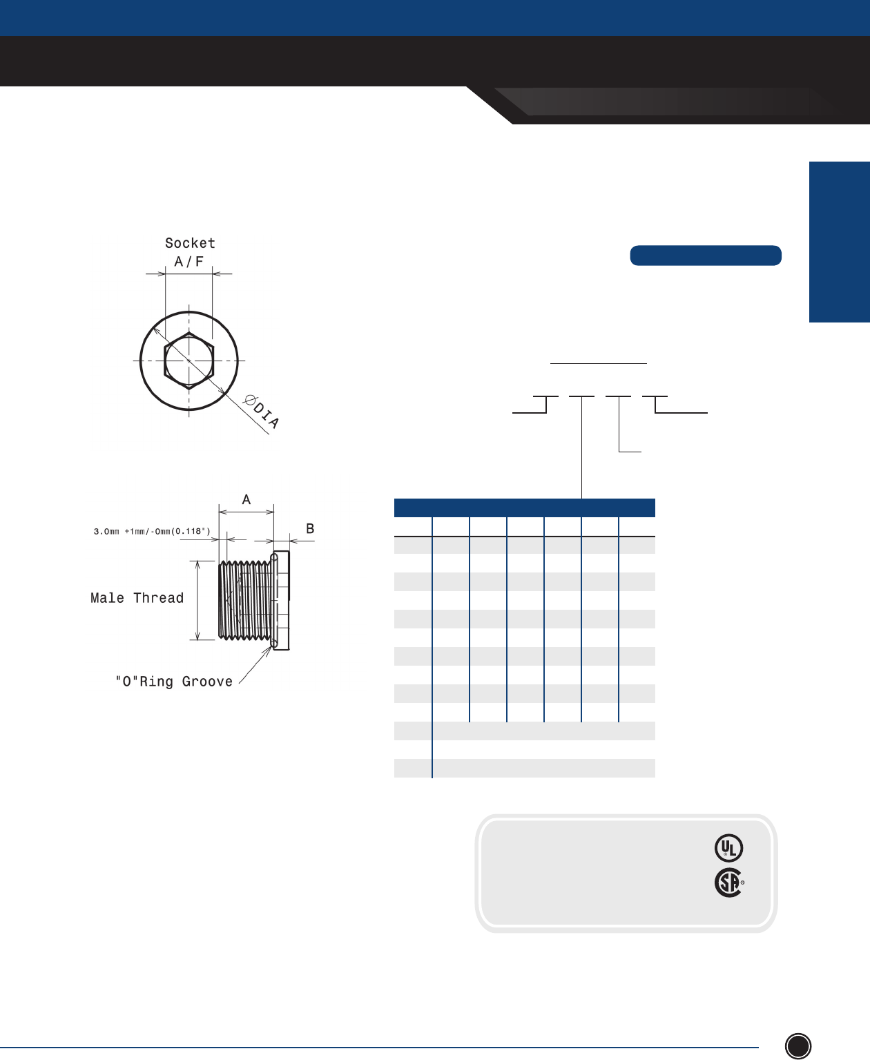
INCREASED SAFETY
ACCESSORIES
INCREASED SAFETY
ENCLOSURES
SEND ORDERS TO ORDERS@ADALET.COM
T: 216.267.9000 | F:216.267.1681 | info@adalet.com ©Adalet
73
•UsedtosealunusedcableglandorconduitentriesinExeapproved
enclosures,maintainingthehazardouslocationcerticationandthe
overallintegrityoftheinstallation.
STANDARD FEATURES
Type ‘U’
Close-Up Plugs
BASE CATALOG NUMBER
PART NUMBER BUILD
U5 20 S NT
O-RING
Nitrile(std.)-NT
Silicone - SC
MATERIAL
NickelPlatedBrass - N
316StainlessSteel - SC
THREAD DESIGNATION
METRIC NPT NPS ISO ISO ET PG
16 ½ ½S ½P ½T ½E 7
20 ¾ ¾S ¾P ¾T ¾E 9
25 1 1S 1P 1T 1E 11
32 1¼ 1¼S 1¼P 1¼T 1¼E 13
40 1½ 1½S 1½P 1½T 1½E 16P
50 2 2S 2P 2T 2E 21
63 2½ 2½S 2½P 2½T 2½E 29
75 3 2S 3P 3T 3E 36
80 3½ 3½S 3½P 3½T 42
85 4 4S 4P 4T 48
90 Note: Metric sizes M80 and larger are 2.0mm
95 pitch is Standard, for 1.5mm pitch add *
100
ClassI,Div1,GroupsA,B,C&D
AExdIIC/AExeIIClassI,Zone1
II2GDExdIIC/ExeIIcategory2&3
CSAStandardC22.2No.30
CERTIFICATIONS
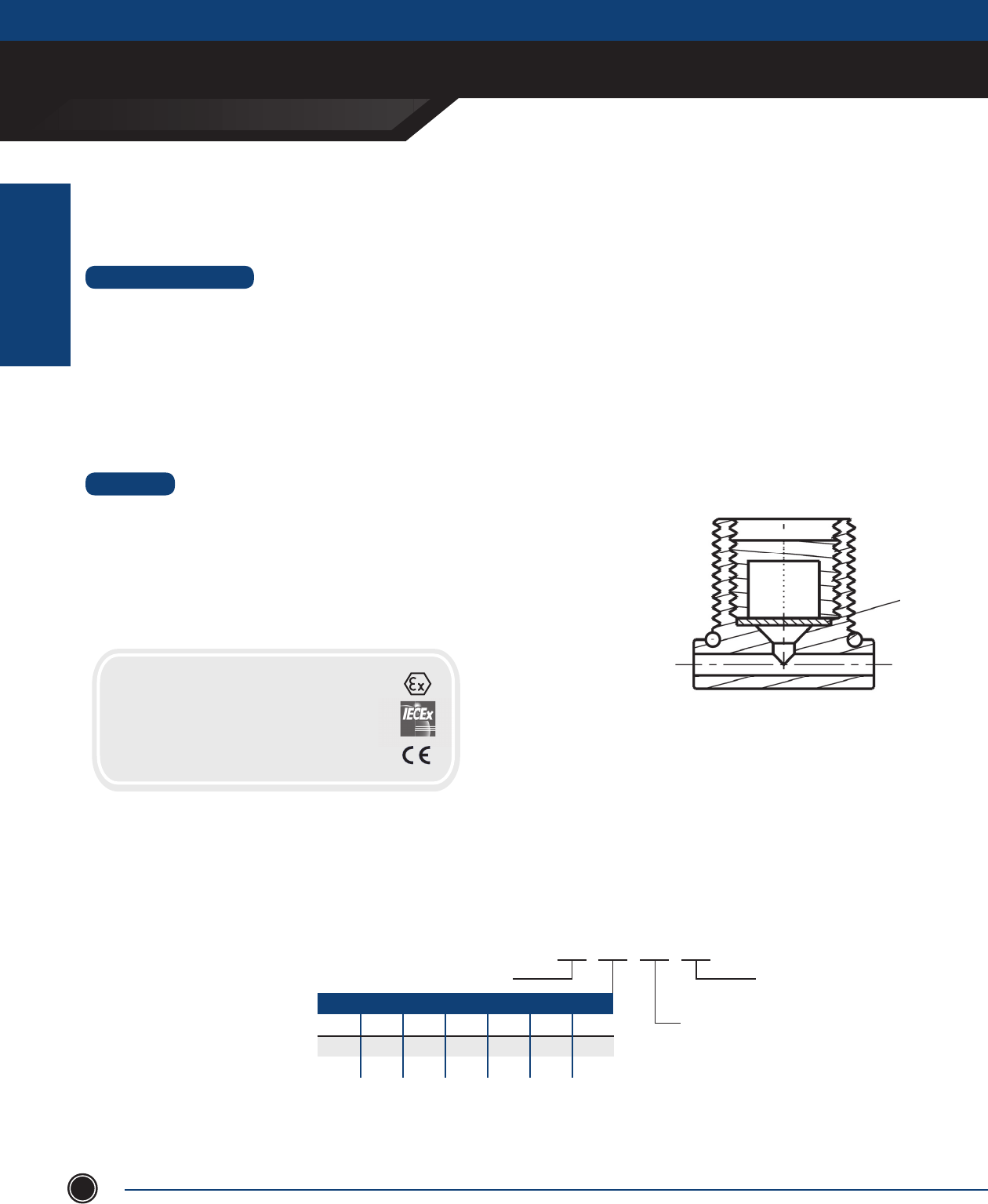
INCREASED SAFETY
ACCESSORIES
INCREASED SAFETY
ENCLOSURES
ADALET.COM
ADALET ENCLOSURE SYSTEMS | 4801 WEST 150TH | CLEVELAND, OHIO 440135©Adalet
74
Be Series
Combination Breather / Drains
STANDARD FEATURES
• Allows the air inside an Ex e Flameproof or Class I, Div 1 enclosure to breathe with the surrounding atmosphere
• Allows any moisture that enters the enclosure to drain while maintaing the overall integrity of the installation
• 7Nm impact resistance
• Thread Gauging - Other thread forms available on applications
Metric: 1.5mm Pitch - Medium Fit 6g
NPT: Male L1 + / - Turn
• Certifi ed for Exe clearance hole applications where the castellated nut is used to secure the installation
MATERIAL
• Nickel Plated Brass “N” (-50° to +80° C)
• 316 Stainless Steel “S” (-50° to +80° C)
• O Ring Options - Nitrile (-30° to +80° C)
Silicone (-50° to 80° C)
• Nitrile O Ring supplied as a standard on versions with parallel male threads
BASE CATALOG NUMBER
PART NUMBER BUILD Be 20 N NT
O-RING
Nitrile (std.) - NT
Silicone - SC
MATERIAL
Nickel Plated Brass - N
316 Stainless Steel - S
THREAD DESIGNATION
METRIC NPT NPS ISO ISO ET PG
20 ½ ½S ½P ½T ¾E 13
25 ¾ ¾S ¾P ¾T 1E 16P
Part Number Structure
Example - Be.20.N.NT
• Type Be Breather Drain
• M20 Male Thread
• Nickel Plated Brass
• Nitrile O Ring
CERTIFICATIONS
IECEx
Ex e II
Ex tD A21 IP66
ATEX II 2 G D
Ex tb IIIC Db IP66
Canada
DIP A21
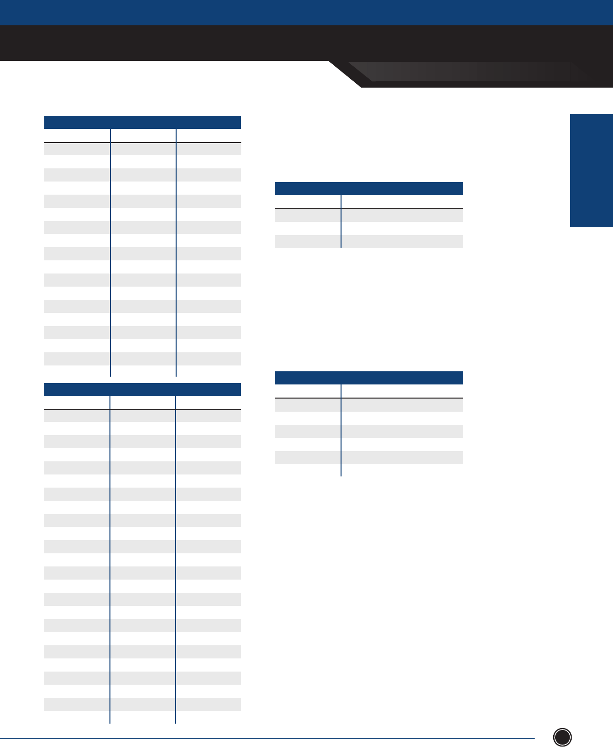
INCREASED SAFETY
ACCESSORIES
INCREASED SAFETY
ENCLOSURES
SEND ORDERS TO ORDERS@ADALET.COM
T: 216.267.9000 | F:216.267.1681 | info@adalet.com ©Adalet
75
Data Pockets
Data pockets are used inside of the enclosure to provide space to store
wiring diagrams, operation manuals and other pertinent data.
Molded from polystyrene and mounted with double sided tape (provided).
DATA POCKETS
CATAlOg NumbEr DESCriPTiON
M1657 6” x 6” x 1”
M3547 10” x 10” x 1”
M3534 12” x 12” x 2.75”
Drip Shield
Drip shields protect door hardware from dripping water and settling dust.
Factory installed only. For use with TN & CN Series Enclosures only.
DriP SHiElDS
CATAlOg NumbEr DESCriPTiON
DS12 for 12” wide enclosures
DS16 for 16” wide enclosures
DS20 for 20” wide enclosures
DS24 for 24” wide enclosures
DS30 for 30” wide enclosures
DS36 for 36” wide enclosures
Labels / Legend Plates
Labels and legend plates are used to identify enclosures and/or
operating devices. Available in 3-ply laminated plastic or anodized aluminum.
Labels and legend plates are laser engraved for permanent and quality
appearance.
Custom engraving available for sheet sizes up to 12” x 24” sheets.
To order: Specify size and text engraving instructions. For laminated plastic,
please specify face color and letter color. For custom artwork engineering,
consult factory.
TSC SERIES - 14 Ga. (.075) Steel, White Polyester Powder Coat Finish
CATAlOg NumbEr FOr ENClOSurE PANEl SizE (H x W)
05P05 5 x 5 3 ⁄ x 3 ⁄
06P04 6 x 4 4 ⁄ x 2 ⁄
06P06 6 x 6 4 ⁄ x 4 ⁄
07P07 7 x 7 5 ⁄ x 5 ⁄
08P06 8 x 6 6 ⁄ x 4 ⁄
08P08 8 x 8 6 ⁄ x 6 ⁄
10P08 10 x 8 8 ⁄ x 6 ⁄
10P10 10 x 10 8 ⁄ x 8 ⁄
12P06 12 x 6 10 ⁄ x 4 ⁄
12P08 12 X 8 10 ⁄ x 6 ⁄
12P10 12 x 10 10 ⁄ x 8 ⁄
12P12 12 x 12 10 ⁄ x 10 ⁄
14P08 14 x 8 12 ⁄ x 6 ⁄
14P12 14 x 12 12 ⁄ x 10 ⁄
15P15 15 x 15 13 ⁄ x 13 ⁄
16P12 16 x 12 14 ⁄ x 10 ⁄
16P14 16 x 14 14 ⁄ x 12 ⁄
16P16 16 x 16 14 ⁄ x 14 ⁄
Inner Panels
1. For stainless steel 316L mounting panels add sux -SS6 to catalog number.
2. Custom sizes and panels fabricated from stainless steel, painted carbon steel
and aluminum are available. Consult factory.
iNNEr PANEl NOTES
TN & CN SERIES -12 Ga. (.1054) Steel, White Polyester Powder Coat Finish
CATAlOg NumbEr FOr ENClOSurE PANEl SizE (H x W)
V-1212 12 x 12 9 x 9
V-1612 16 x 12 13 x 9
V-1616 16 x 16 13 x 13
V-2012 20 x 12 17 x 19
V-2016 20 x 16 (16 x 20) 17 x 13
V-2020 20 x 20 17 x 17
V-2412 24 x 12 (12 x 24) 21 x 9
V-2416 24 x 16 21 x 13
V-2420 24 x 20 (20 x 24) 21 x 17
V-2424 24 x 24 21 x 21
V-3016 30 x 16 27 x 13
V-3020 30 x 20 27 x 17
V-3024 30 x 24 (24 x 30) 27 x 21
V-3030 30 x 30 27 x 27
V-3624 36 x 24 33 x 21
V-3630 36 x 30 (30 x 36) 33 x 27
V-3636 36 x 36 33 x 33
V-4224 42 x 24 35 x 21
V-4230 42 x 30 39 x 27
V-4236 42 x 36 39 x 33
V-4824 48 x 24 45 x 21
V-4830 48 x 30 42 x 27
V-4836 48 x 36 45 x 33
V-6036 60 x 36 57 x 33
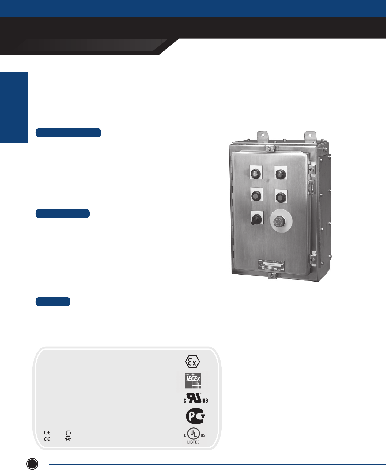
INCREASED SAFETY
CONTROL ENCLOSURES
INCREASED SAFETY
ENCLOSURES
ADALET.COM
ADALET ENCLOSURE SYSTEMS | 4801 WEST 150TH | CLEVELAND, OHIO 44135©Adalet
76
Adalet’s Single Door Clamped Control Enclosures are available in stainless steel 316L & 304. Adalet can also supply custom
size enclosures, operators, and wiring of devices to rail mounted terminal blocks to suit your Increased Safety application.
Silicone gaskets, removeable hinge pin, box & cover ground studs including an external earthing stud, along with internal
standoffs for mounting pans are included as standard.
• Gland plates (6” deep or greater) can be supplied pre-drilled or blank for fi eld drilling
• Mounting panels
• Drilled entries and cut-outs
• Adalet EH series Exe operators
• Legend plates and lamacoid or stainless steel name plates
• Breather / drain & stopping plugs
• Terminal block assemblies
• Stainless steel mounting panels
• Cable glands and conduit fi ttings
• Internal earth bar
STANDARD FEATURES
DESIGN OPTIONS
MATERIAL
Control Enclosures
• Type 304 or 316L Stainless Steel
• Enclosure and cover constructed from 14 gauage (.060) stainless steel with #3/4 brush fi nish
• Gland plates constructed from 10 gauge (.1046) stainless steel with a #3/4 brush fi nish
• Silicone gasket constructed from ¼ ” Bisco silicone with acrylic PSA
• Gland plate gasket constructed from 1⁄8” Bisco silicone with acrylic PSA
• 68 standard sizes available
• Stainless steel quarter turn latch with 3mm double bit insert
(includes key)
• Continuous one-piece water tight silicone gasket
• Continuous piano hinge with removable stainless steel pin
• Ground stud on box and cover
• External earth stud
• Wall mounting feet (vertical or horizontal)
CERTIFICATIONS
POPULATED ENCLOSURE
Class I, Division 2, Groups A, B, C, D
Class II, Division 2, Groups F, G
Class I, Zone 1, AEx d e mb IIC T6 (T5:Ta<+55°C)
NEMA Type 4X, 12, 13
Ex d e mb IIC T6X (T5:Ta<+55°C)
Ex d e mb IIC T6(T5:Ta<+55°C)
Ex tD A21 IP66 T200°C
IECEx UL 09.0020X
DEMKO 01 ATEX 130437X
0539 II 2 G Ex d e mb IIC T6 (T5:Ta<+55°C)
0539 II 2 D Ex tD A21 IP66 T200°C
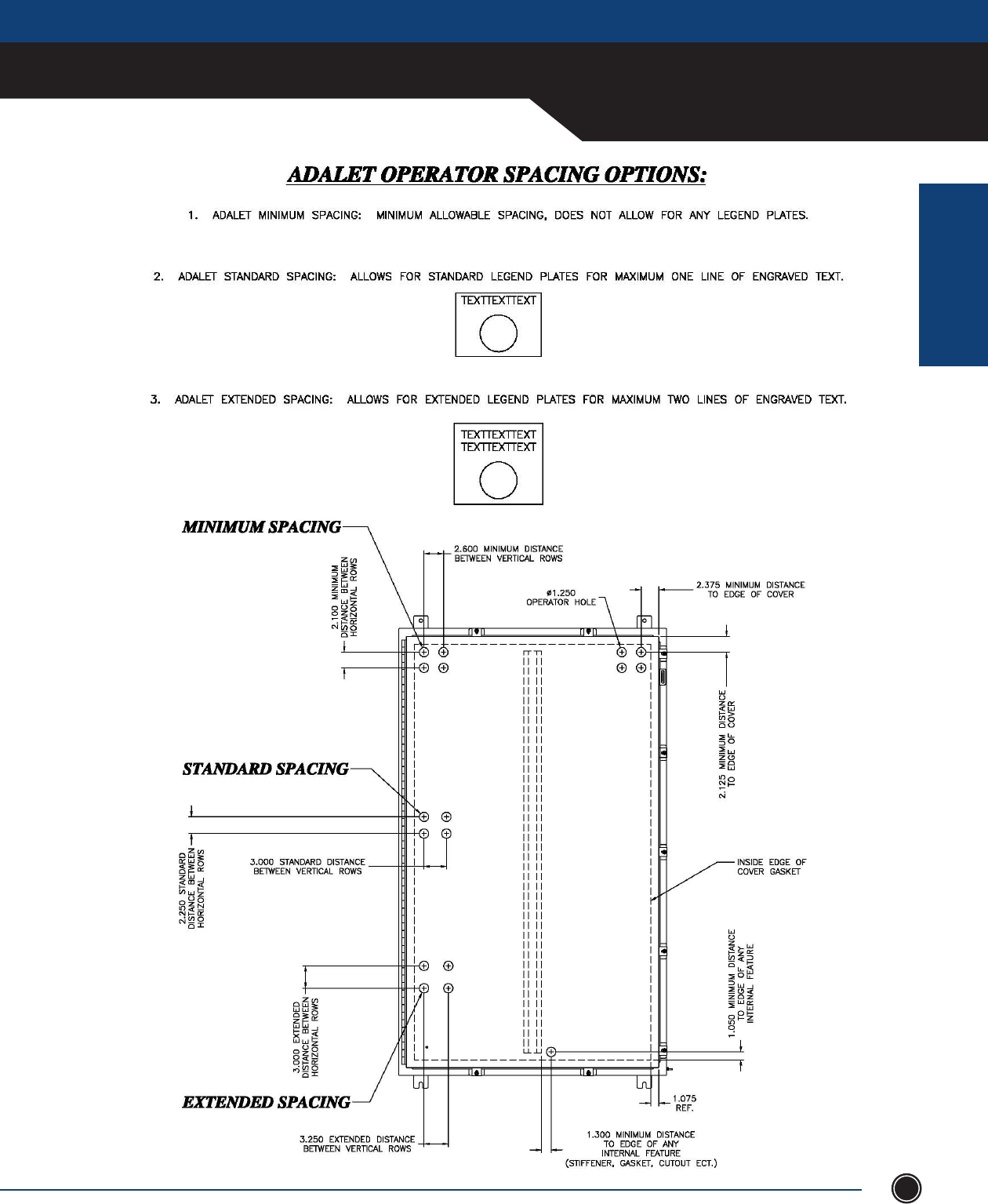
INCREASED SAFETY
CONTROL ENCLOSURES
INCREASED SAFETY
ENCLOSURES
SEND ORDERS TO ORDERS@ADALET.COM
T: 216.267.9000 | F:216.267.1681 | info@adalet.com ©Adalet
77
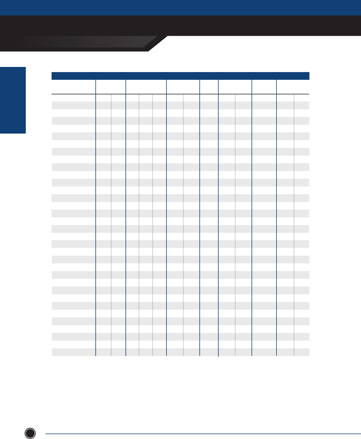
INCREASED SAFETY
CONTROL ENCLOSURES
INCREASED SAFETY
ENCLOSURES
ADALET.COM
ADALET ENCLOSURE SYSTEMS | 4801 WEST 150TH | CLEVELAND, OHIO 44135©Adalet
78
CN4X6-161206
CN4X6-161606
CN4X6-162006
CN4X6-201606
CN4X6-202006
CN4X6-202406
CN4X6-241206
CN4X6-241606
CN4X6-242006
CN4X6-242406
CN4X6-302006
CN4X6-302406
CN4X6-362406
CN4X6-363006
CN4X6-161208
CN4X6-161608
CN4X6-162008
CN4X6-201608
CN4X6-202008
CN4X6-202408
CN4X6-241608
CN4X6-242008
CN4X6-242408
CN4X6-243008
CN4X6-302008
CN4X6-302408
CN4X6-303008
CN4X6-362408
CN4X6-363008
CN4X6-363608
CN4X6-423008
CN4X6-423608
CN4X6-483608
CN4X6-201610
CN Series - Control Enclosure 316L Stainless Steel
ENCLOSURE GAUGE
BOX DOOR
OUTSIDE DIM.
A B C CLAMPS
#
MOUNTING
CENTER
PANEL
PART NO. PANEL DIM.
X Y
16
16
16
20
20
20
24
24
24
24
30
30
36
36
16
16
16
20
20
20
24
24
24
24
30
30
30
36
36
36
42
42
48
20
14
14
14
14
14
14
14
14
14
14
14
14
14
14
14
14
14
14
14
14
14
14
14
14
14
14
14
14
14
14
14
14
14
14
-
-
-
-
-
-
-
-
-
-
-
-
-
REQ’D
-
-
-
-
-
-
-
-
-
-
-
-
REQ’D
-
REQ’D
REQ’D
REQ’D
REQ’D
REQ’D
4
4
4
4
4
4
5
5
5
5
5
5
5
7
4
4
4
4
4
4
5
5
5
7
5
5
7
5
7
7
8
8
8
4
17.25
17.25
17.25
21.25
21.25
21.25
25.25
25.25
25.25
25.25
31.25
31.25
37.25
37.25
17.25
17.25
17.25
21.25
21.25
21.25
25.25
25.25
25.25
25.25
31.25
31.25
31.25
37.25
37.25
37.25
43.25
43.25
49.25
21.25
V1612
V1616
V2016
V2016
V2020
V2420
V2412
V2416
V2420
V2424
V3020
V3024
V3624
V3630
V1612
V1616
V1620
V2016
V2020
V2024
V2416
V2420
V2424
V3024
V3020
V3024
V3030
V3624
V3630
V3636
V4230
V4236
V4836
V2016
16
16
16
16
16
16
16
16
16
16
14
14
14
14
16
16
16
16
16
16
16
16
16
14
14
14
14
14
14
14
14
14
14
16
12
16
20
16
20
24
12
16
20
24
20
24
24
30
12
16
20
16
20
24
16
20
24
30
20
24
30
24
30
36
30
36
36
16
6
6
6
6
6
6
6
6
6
6
6
6
6
6
8
8
8
8
8
8
8
8
8
8
8
8
8
8
8
8
8
8
8
10
STIFFENERS
BOX DOOR
-
-
-
-
-
-
-
-
-
-
-
-
-
-
-
-
-
-
-
-
-
-
-
-
-
-
-
-
-
REQ’D
REQ’D
REQ’D
REQ’D
-
13
13
13
17
17
17
21
21
21
21
27
27
33
33
13
13
13
17
17
17
21
21
21
27
27
27
27
33
33
33
39
39
45
17
9
13
17
13
17
21
9
13
17
21
17
21
21
27
9
13
17
13
17
21
13
17
21
21
17
21
27
21
27
33
27
33
33
13
Measurements in inches
Information is subject to change without notice
9.5
10
14
10
14
18
9.5
10
14
18
14
18
18
24
9.5
10
14
10
14
18
10
14
18
24
14
18
24
18
24
30
24
30
30
10
1. For stainless steel 304 constructions, substitute CN4X6
(SS316L Pre x) with CN4X (SS304 Pre x).
2. Gland plate options area available on enclosure < 12 inches deep,
consult factory for gland plates on enclosures > 10 inches deep.
Add the following su xes for gland plates:
- A: Gland plate installed on TOP side of box
- B: Gland plate installed on BOTTOM side of box
- C: Gland plate installed on LEFT side of box
- D: Gland plate installed on RIGHT side of box
For multiple gland plates omit dashes. (i.e. CN4X6-161608-ABCD)
NOTES
INCHES
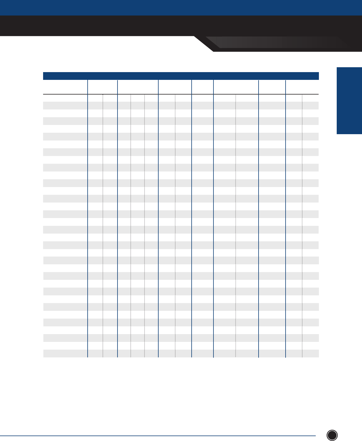
INCREASED SAFETY
CONTROL ENCLOSURES
INCREASED SAFETY
ENCLOSURES
SEND ORDERS TO ORDERS@ADALET.COM
T: 216.267.9000 | F:216.267.1681 | info@adalet.com ©Adalet
79
INCHES
CN4X6-202010
CN4X6-242010
CN4X6-242410
CN4X6-302410
CN4X6-362410
CN4X6-363010
CN4X6-423010
CN4X6-423610
CN4X6-483610
CN4X6-603610
CN4X6-201612
CN4X6-242012
CN4X6-242412
CN4X6-302412
CN4X6-303012
CN4X6-362412
CN4X6-363012
CN4X6-363612
CN4X6-423012
CN4X6-423612
CN4X6-483612
CN4X6-603612
CN4X6-242016
CN4X6-242416
CN4X6-302416
CN4X6-363016
CN4X6-423616
CN4X6-483616
CN4X6-603616
CN4X6-302420
CN4X6-363020
CN4X6-483620
CN4X6-603620
CN4X6-302424
ENCLOSURE GAUGE
BOX DOOR
OUTSIDE DIM.
A B C CLAMPS
#MOUNTING
CENTER
PANEL
PART NO. PANEL DIM.
X Y
20
24
24
30
36
36
42
42
48
60
20
24
24
30
30
36
36
36
42
42
48
60
24
24
30
36
42
48
60
30
36
48
60
30
14
14
14
14
14
14
14
14
14
14
14
14
14
14
14
14
14
14
14
14
14
14
14
14
14
14
14
14
14
14
14
14
14
14
-
-
-
-
-
REQ’D
REQ’D
REQ’D
REQ’D
REQ’D
-
-
-
-
REQ’D
-
REQ’D
REQ’D
REQ’D
REQ’D
REQ’D
REQ’D
-
-
-
REQ’D
REQ’D
REQ’D
REQ’D
-
REQ’D
REQ’D
REQ’D
-
4
5
5
5
5
7
8
8
8
9
4
5
5
5
7
5
7
7
8
8
8
9
5
5
5
7
8
8
9
5
7
8
9
5
22.13
26.13
26.13
32.13
38.13
38.13
44.13
44.13
50.13
62.13
22.13
26.13
26.13
32.13
32.13
38.13
38.13
38.13
44.13
44.13
50.13
62.13
26.13
26.13
32.13
38.13
44.13
50.13
62.13
32.13
38.13
50.13
62.13
32.13
V2020
V2420
V2424
V3024
V3624
V3630
V4230
V4236
V4836
V6036
V2016
V2420
V2424
V3024
V3030
V3624
V3630
V3636
V4230
V4236
V4836
V6036
V2420
V2424
V3024
V3630
V4236
V4836
V6036
V3024
V3630
V4836
V6036
V3024
14
14
14
14
14
14
14
14
14
14
14
14
14
14
14
14
14
14
14
14
14
14
14
14
14
14
14
14
14
14
14
14
14
14
20
20
24
24
24
30
30
36
36
36
16
20
24
24
30
24
30
36
30
36
36
36
20
24
24
30
36
36
36
24
30
36
36
24
10
10
10
10
10
10
10
10
10
10
12
12
12
12
12
12
12
12
12
12
12
12
16
16
16
16
16
16
16
20
20
20
20
24
STIFFENERS
BOX DOOR
-
-
-
-
-
-
REQ’D
REQ’D
REQ’D
REQ’D
-
-
-
-
-
-
-
REQ’D
REQ’D
REQ’D
REQ’D
REQ’D
-
-
-
-
REQ’D
REQ’D
REQ’D
-
-
REQ’D
REQ’D
-
17
21
21
27
33
33
39
39
45
57
17
21
21
27
27
33
33
33
39
39
45
57
21
21
27
33
39
45
57
27
33
45
57
27
17
17
21
21
21
27
27
33
33
33
13
17
21
21
27
21
27
33
27
33
33
33
17
21
21
27
33
33
33
21
27
33
33
21
Measurements in inchesInformation is subject to change without notice
14
14
18
18
18
24
24
30
30
30
10
14
18
18
24
18
24
30
24
30
30
30
14
18
18
24
30
30
30
18
24
30
30
18
1. For stainless steel 304 constructions, substitute CN4X6
(SS316L Pre x) with CN4X (SS304 Pre x).
2. Gland plate options area available on enclosure < 12 inches deep,
consult factory for gland plates on enclosures > 10 inches deep.
Add the following su xes for gland plates:
- A: Gland plate installed on TOP side of box
- B: Gland plate installed on BOTTOM side of box
- C: Gland plate installed on LEFT side of box
- D: Gland plate installed on RIGHT side of box
For multiple gland plates omit dashes. (i.e. CN4X6-161608-ABCD)
NOTES
CN Series - Control Enclosure 316L Stainless Steel

INCREASED SAFETY
CONTROL ENCLOSURES
INCREASED SAFETY
ENCLOSURES
ADALET.COM
ADALET ENCLOSURE SYSTEMS | 4801 WEST 150TH | CLEVELAND, OHIO 44135©Adalet
80
CN4X6-161206
CN4X6-161606
CN4X6-162006
CN4X6-201606
CN4X6-202006
CN4X6-202406
CN4X6-241206
CN4X6-241606
CN4X6-242006
CN4X6-242406
CN4X6-302006
CN4X6-302406
CN4X6-362406
CN4X6-363006
CN4X6-161208
CN4X6-161608
CN4X6-162008
CN4X6-201608
CN4X6-202008
CN4X6-202408
CN4X6-241608
CN4X6-242008
CN4X6-242408
CN4X6-243008
CN4X6-302008
CN4X6-302408
CN4X6-303008
CN4X6-362408
CN4X6-363008
CN4X6-363608
CN4X6-423008
CN4X6-423608
CN4X6-483608
CN4X6-201610
CN Series - Control Enclosure 316L Stainless Steel
ENCLOSURE GAUGE
BOX DOOR
OUTSIDE DIM.
A B C CLAMPS
# MTG CENTER
F G
PANEL
PART NO. PANEL DIM.
X Y
406.4
406.4
406.4
508.0
508.0
508.0
609.6
609.6
609.6
609.6
762.0
762.0
914.4
914.4
406.4
406.4
406.4
508.0
508.0
508.0
609.6
609.6
609.6
609.6
762.0
762.0
762.0
914.4
914.4
914.4
1066.8
1066.8
1219.2
508.0
14
14
14
14
14
14
14
14
14
14
14
14
14
14
14
14
14
14
14
14
14
14
14
14
14
14
14
14
14
14
14
14
14
14
-
-
-
-
-
-
-
-
-
-
-
-
-
REQ’D
-
-
-
-
-
-
-
-
-
-
-
-
REQ’D
-
REQ’D
REQ’D
REQ’D
REQ’D
REQ’D
4
4
4
4
4
4
5
5
5
5
5
5
5
7
4
4
4
4
4
4
5
5
5
7
5
5
7
5
7
7
8
8
8
4
18.13
18.13
18.13
22.13
22.13
22.13
26.13
26.13
26.13
26.13
32.13
32.13
38.13
38.13
18.13
18.13
18.13
22.13
22.13
22.13
26.13
26.13
26.13
26.13
32.13
32.13
32.13
38.13
38.13
38.13
44.13
44.13
50.13
22.13
V1612
V1616
V2016
V2016
V2020
V2420
V2412
V2416
V2420
V2424
V3020
V3024
V3624
V3630
V1612
V1616
V1620
V2016
V2020
V2024
V2416
V2420
V2424
V3024
V3020
V3024
V3030
V3624
V3630
V3636
V4230
V4236
V4836
V2016
16
16
16
16
16
16
16
16
16
16
14
14
14
14
16
16
16
16
16
16
16
16
16
14
14
14
14
14
14
14
14
14
14
16
304.8
406.4
508.0
406.4
508.0
609.6
304.8
406.4
508.0
609.6
508.0
609.6
609.6
762.0
304.8
406.4
508.0
406.4
508.0
609.6
406.4
508.0
609.6
762.0
508.0
609.6
762.0
609.6
762.0
914.4
762.0
914.4
914.4
406.4
152.4
152.4
152.4
152.4
152.4
152.4
152.4
152.4
152.4
152.4
152.4
152.4
152.4
203.2
203.2
203.2
203.2
203.2
203.2
203.2
203.2
203.2
203.2
203.2
203.2
203.2
203.2
203.2
203.2
203.2
203.2
203.2
203.2
254.0
STIFFENERS
BOX DOOR
-
-
-
-
-
-
-
-
-
-
-
-
-
-
-
-
-
-
-
-
-
-
-
-
-
-
-
-
-
REQ’D
REQ’D
REQ’D
REQ’D
-
330.2
330.2
330.2
431.8
431.8
431.8
533.4
533.4
533.4
533.4
685.8
685.8
838.2
838.2
330.2
330.2
330.2
431.8
431.8
431.8
533.4
533.4
533.4
533.4
685.8
685.8
685.8
838.2
838.2
838.2
990.6
990.6
1143.0
431.8
228.6
330.2
431.8
330.2
431.8
533.4
228.6
330.2
431.8
533.4
431.8
533.4
533.4
685.8
228.6
330.2
431.8
330.2
431.8
533.4
330.2
431.8
533.4
685.8
431.8
533.4
685.8
533.4
685.8
838.2
685.8
838.2
838.2
330.2
Measurements in inches
Information is subject to change without notice
241.3
254.0
355.6
254.0
355.6
457.2
241.3
254.0
355.6
457.2
355.6
457.2
457.2
609.6
241.3
254.0
355.6
254.0
355.6
457.2
254.2
355.6
457.2
609.6
355.6
457.2
609.6
457.2
609.6
762.0
609.6
762.0
762.0
254.0
METRIC1
1. For stainless steel 304 constructions, substitute CN4X6
(SS316L Pre x) with CN4X (SS304 Pre x).
2. Gland plate options area available on enclosure < 12 inches deep,
consult factory for gland plates on enclosures > 10 inches deep.
Add the following su xes for gland plates:
- A: Gland plate installed on TOP side of box
- B: Gland plate installed on BOTTOM side of box
- C: Gland plate installed on LEFT side of box
- D: Gland plate installed on RIGHT side of box
For multiple gland plates omit dashes. (i.e. CN4X6-161608-ABCD)
NOTES
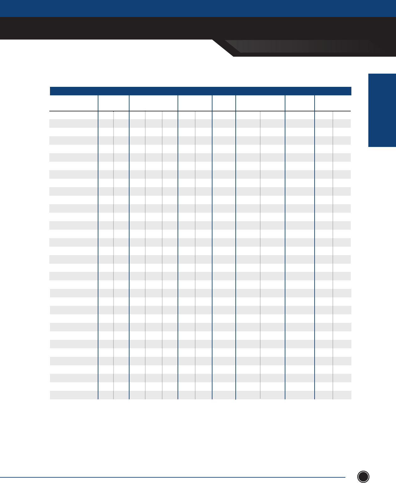
INCREASED SAFETY
CONTROL ENCLOSURES
INCREASED SAFETY
ENCLOSURES
SEND ORDERS TO ORDERS@ADALET.COM
T: 216.267.9000 | F:216.267.1681 | info@adalet.com ©Adalet
81
METRIC1
CN4X6-202010
CN4X6-242010
CN4X6-242410
CN4X6-302410
CN4X6-362410
CN4X6-363010
CN4X6-423010
CN4X6-423610
CN4X6-483610
CN4X6-603610
CN4X6-201612
CN4X6-242012
CN4X6-242412
CN4X6-302412
CN4X6-303012
CN4X6-362412
CN4X6-363012
CN4X6-363612
CN4X6-423012
CN4X6-423612
CN4X6-483612
CN4X6-603612
CN4X6-242016
CN4X6-242416
CN4X6-302416
CN4X6-363016
CN4X6-423616
CN4X6-483616
CN4X6-603616
CN4X6-302420
CN4X6-363020
CN4X6-483620
CN4X6-603620
CN4X6-302424
ENCLOSURE GAUGE
BOX DOOR
OUTSIDE DIM.
A B C CLAMPS
#MOUNTING
CENTER
PANEL
PART NO. PANEL DIM.
X Y
508.0
609.6
609.6
762.0
914.4
914.4
1066.8
1066.8
1219.2
1524.0
508.0
609.6
609.6
762.0
762.0
914.4
914.4
914.4
1066.8
1066.8
1219.2
1524.0
609.6
609.6
762.0
914.4
1066.8
1219.2
1524.0
762.0
914.4
1219.2
1524.0
762.0
14
14
14
14
14
14
14
14
14
14
14
14
14
14
14
14
14
14
14
14
14
14
14
14
14
14
14
14
14
14
14
14
14
14
-
-
-
-
-
REQ’D
REQ’D
REQ’D
REQ’D
REQ’D
-
-
-
-
REQ’D
-
REQ’D
REQ’D
REQ’D
REQ’D
REQ’D
REQ’D
-
-
-
REQ’D
REQ’D
REQ’D
REQ’D
-
REQ’D
REQ’D
REQ’D
-
4
5
5
5
5
7
8
8
8
9
4
5
5
5
7
5
7
7
8
8
8
9
5
5
5
7
8
8
9
5
7
8
9
5
22.13
26.13
26.13
32.13
38.13
38.13
44.13
44.13
50.13
62.13
22.13
26.13
26.13
32.13
32.13
38.13
38.13
38.13
44.13
44.13
50.13
62.13
26.13
26.13
32.13
38.13
44.13
50.13
62.13
32.13
38.13
50.13
62.13
32.13
V2020
V2420
V2424
V3024
V3624
V3630
V4230
V4236
V4836
V6036
V2016
V2420
V2424
V3024
V3030
V3624
V3630
V3636
V4230
V4236
V4836
V6036
V2420
V2424
V3024
V3630
V4236
V4836
V6036
V3024
V3630
V4836
V6036
V3024
14
14
14
14
14
14
14
14
14
14
14
14
14
14
14
14
14
14
14
14
14
14
14
14
14
14
14
14
14
14
14
14
14
14
508.0
508.0
609.6
609.6
609.6
762.0
762.0
914.4
914.4
914.4
406.4
508.0
609.6
609.6
762.0
609.6
762.0
914.4
762.0
914.4
914.4
914.4
508.0
609.6
609.6
762.0
914.4
914.4
914.4
609.6
762.0
914.4
914.4
609.6
254.0
254.0
254.0
254.0
254.0
254.0
254.0
254.0
254.0
254.0
304.8
304.8
304.8
304.8
304.8
304.8
304.8
304.8
304.8
304.8
304.8
304.8
406.4
406.4
406.4
406.4
406.4
406.4
406.4
508.0
508.0
508.0
508.0
508.0
STIFFENERS
BOX DOOR
-
-
-
-
-
-
REQ’D
REQ’D
REQ’D
REQ’D
-
-
-
-
-
-
-
REQ’D
REQ’D
REQ’D
REQ’D
REQ’D
-
-
-
-
REQ’D
REQ’D
REQ’D
-
-
REQ’D
REQ’D
-
431.8
533.4
533.4
685.8
838.2
838.2
990.6
990.6
1143.0
1447.8
431.8
533.4
533.4
685.8
685.8
838.2
838.2
838.2
990.6
990.6
1143.0
1447.8
533.4
533.4
685.8
838.2
990.6
1143.0
1447.8
685.8
838.2
1143.0
1447.8
685.8
431.8
431.8
533.4
533.4
533.4
685.8
685.8
838.2
838.2
838.2
330.2
431.8
533.4
533.4
685.8
533.4
685.8
838.2
685.8
838.2
838.2
838.2
431.8
533.4
533.4
685.8
838.2
838.2
838.2
533.4
685.8
838.2
838.2
533.4
Measurements in inches
Information is subject to change without notice
CN Series - Control Enclosure 316L Stainless Steel
355.6
355.6
457.2
457.2
457.2
609.6
609.6
762.0
762.0
762.0
254.0
355.6
457.2
457.2
609.6
457.2
609.6
762.0
609.6
762.0
762.0
762.0
355.6
457.2
457.2
609.6
762.0
762.0
762.0
457.2
609.6
762.0
762.0
457.2
1. For stainless steel 304 constructions, substitute CN4X6
(SS316L Pre x) with CN4X (SS304 Pre x).
2. Gland plate options area available on enclosure < 12 inches deep,
consult factory for gland plates on enclosures > 10 inches deep.
Add the following su xes for gland plates:
- A: Gland plate installed on TOP side of box
- B: Gland plate installed on BOTTOM side of box
- C: Gland plate installed on LEFT side of box
- D: Gland plate installed on RIGHT side of box
For multiple gland plates omit dashes. (i.e. CN4X6-161608-ABCD)
NOTES
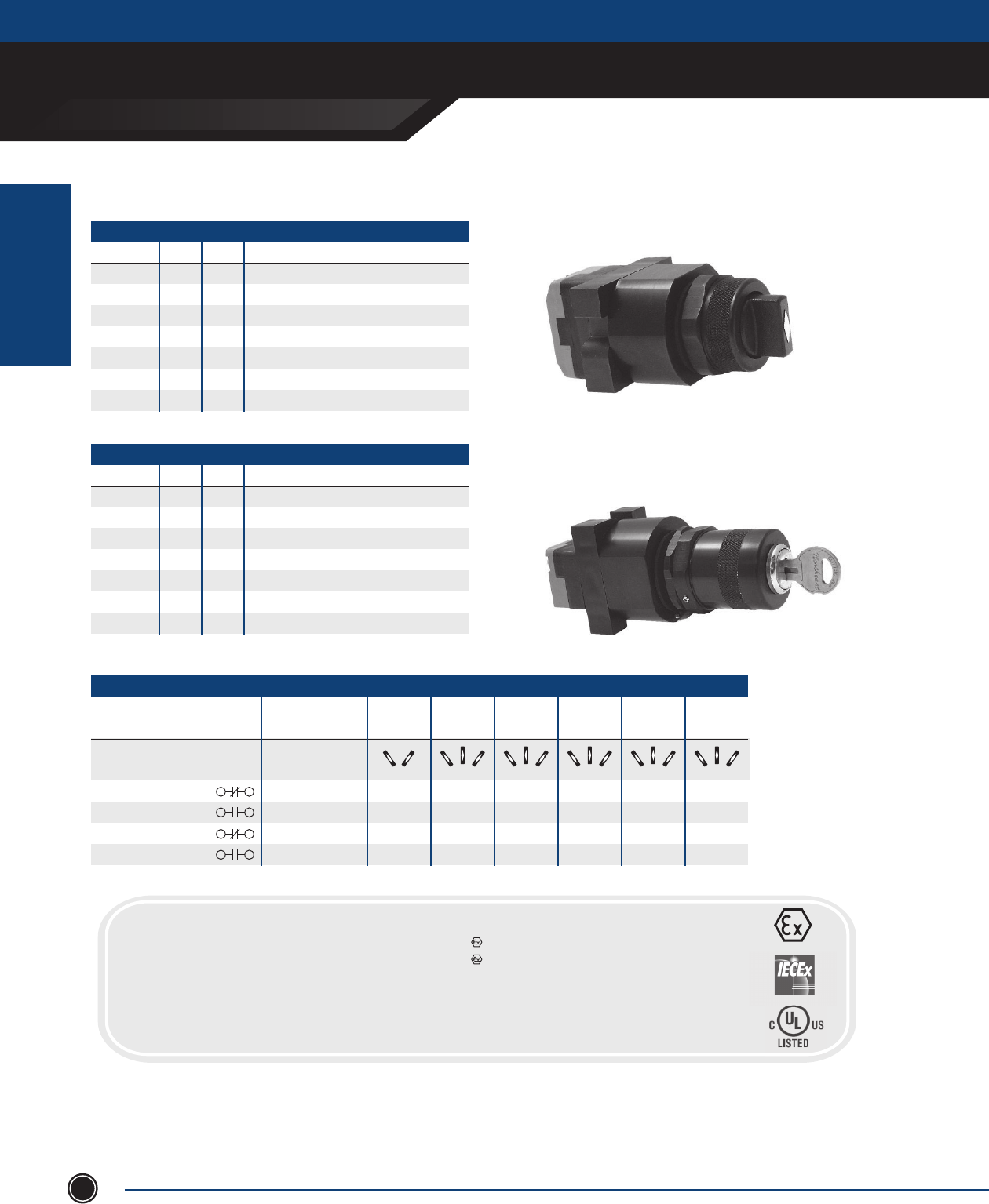
INCREASED SAFETY
CONTROLS
INCREASED SAFETY
ENCLOSURES
ADALET.COM
ADALET ENCLOSURE SYSTEMS | 4801 WEST 150TH | CLEVELAND, OHIO 44135©Adalet
82
SELECTOR SWITCH
CAT # CAM # POS. TYPE
EHSS 1 2 2 POSITION - Maintained
EHSS 2-6 3 3 POSITION - Maintained
EHSC 2-6 3 Spring return center from right and left
EHSR2 1 2 Spring return to left from right
EHSR 2-6 3 Spring return center from right, maintain left
EHSL2 1 2 Spring return to right from left
EHSL 2-6 3 Spring return center from left, maintain right
KEYED SELECTOR SWITCH
CAT # CAM # POS. TYPE
EHKSS 1 2 2 POSITION - Maintained
EHKSS 2-6 3 3 POSITION - Maintained
EHKSC 2-6 3 Spring return center from right and left
EHKSR2 1 2 Spring return to left from right
EHKSR 2-6 3 Spring return center from right, maintain left
EHKSL2 1 2 Spring return to right from left
EHKSL 2-6 3 Spring return center from left, maintain right
CONTACT SEQUENCE CHART
Cam 1 Cam 2 Cam 3 Cam 4 Cam 5 Cam 6
Contact Contact Contact Contact Contact Contact
Circuit of Contact Block Mounting Position Sequence Sequence Sequence Sequence Sequence Sequence
Normally Closed (NC) A X O X X O X X O X O X O O X O O X
Normally Open (NO) A O X O O X O O X O X O X X O O X O
Normally Closed (NC) B X O O X O O X X X O O O X X X O O
Normally Open (NO) B O X X O X X O O O X X X O O O O X
CONTACT SEQUENCE CHART
O = Contact Open
X = Contact Closed
Selector Switches
CERTIFICATIONS
Class I, Division 2, Groups A, B, C, D
Class II, Groups E, F, G (Canada Only)
Class I, Zone 1, AEx de IIC T6 -55°C < Ta < +60°C
Ex de IIC T6 X -55°C < Ta < +60°C
IECEx Ex de IIC Gb -55°C < Ta < +60°C
IECEx UL.09.0002U
0539 II 2 G Ex e II T6 (T5: Ta < +55°C) (T4: Ta < +70°C)
0539 II 2 D Ex tD A21 IP66 T200°C
IECEx Ex tb IIIC Db IP66
DIP
DIP A21 TAT6
1. Adalet EBT contact blocks are 1NO / 1NC Standard
2. A max of 2 blocks per operator
3. One EBT contact block is standard
NOTE
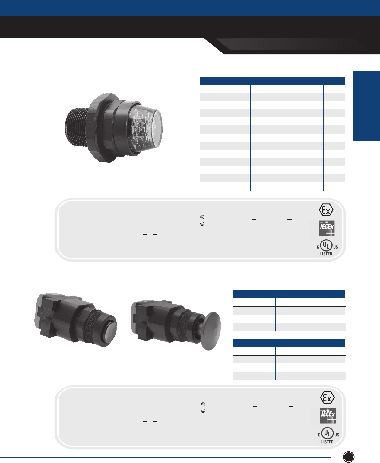
INCREASED SAFETY
CONTROLS
INCREASED SAFETY
ENCLOSURES
SEND ORDERS TO ORDERS@ADALET.COM
T: 216.267.9000 | F:216.267.1681 | info@adalet.com ©Adalet
83
Pilot Lights
PILOT LIGHTS
8” FLEXIBLE LEADS CAT # TERMINAL BLOCK CAT # COLOR VOLTAGE
ELA120 ELAT120 AMBER 120
ELG120 ELGT120 GREEN 120
ELR120 ELRT120 RED 120
ELW120 ELWT120 WHITE 120
ELA12 ELAT12 AMBER 12
ELG12 ELGT12 GREEN 12
ELR12 ELRT12 RED 12
ELW12 ELWT12 WHITE 12
ELA24 ELAT24 AMBER 24
ELG24 ELGT24 GREEN 24
ELR24 ELRT24 RED 24
ELW24 ELWT24 WHITE 24
Pushbuttons
PUSHBUTTON
CAT # CAP COLOR BUTTON COLOR
EHPB-B BLACK BLACK
EHPB-G BLACK GREEN
EHPB-R BLACK RED
MUSHROOM HEAD PUSHBUTTON
CAT # CAP COLOR STYLE
EHPBM-R RED MOMENTARY
EHPBM-B BLACK MOMENTARY
EHPPM RED PUSH/PULL
CERTIFICATIONS
ClassI,Division2,GroupsA,B,C,D
ClassII,GroupsE,F,G(CanadaOnly)
ClassI,Zone1,AExdeIICT6-55°C<Ta<+60°C
ExdeIICT6X-55°C<Ta<+60°C
IECExExdeIICGb-55°C<Ta<+60°C
IECExUL.09.0002U
0539 II2GExeIIT6(T5:Ta<+55°C)(T4:Ta<+70°C)
0539 II2DExtDA21IP66T200°C
IECExExtbIIICDbIP66
DIP
DIPA21TAT6
CERTIFICATIONS
ClassI,Division2,GroupsA,B,C,D
ClassII,GroupsE,F,G(CanadaOnly)
ClassI,Zone1,AExdeIICT6-55°C<Ta<+60°C
ExdeIICT6X-55°C<Ta<+60°C
IECExExdeIICGb-55°C<Ta<+60°C
IECExUL.09.0002U
0539 II2GExeIIT6(T5:Ta<+55°C)(T4:Ta<+70°C)
0539 II2DExtDA21IP66T200°C
IECExExtbIIICDbIP66
DIP
DIPA21TAT6
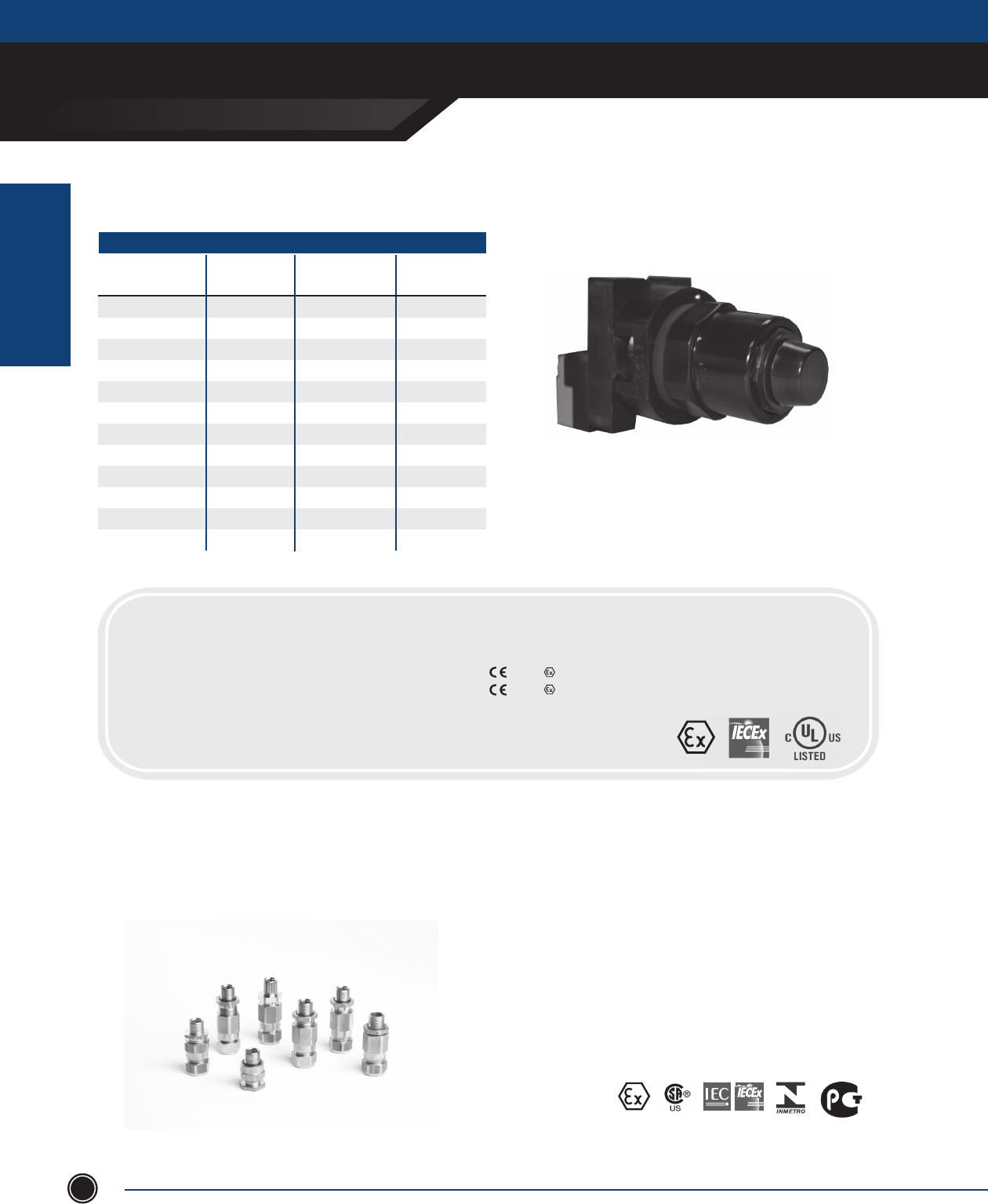
INCREASED SAFETY
INCREASED SAFETY
ENCLOSURES
ADALET.COM
ADALET ENCLOSURE SYSTEMS | 4801 WEST 150TH | CLEVELAND, OHIO 44135©Adalet
84
Illuminated Pushbutton
ILLUMINATED PUSH BUTTON OPERATORS WITH CONTACT BLOCK
CAT. NUMBER COLOR VOLTAGE
AC/DC WATTS
ELPA120
ELPG120
ELPR120
ELPW120
ELPA12
ELPG12
ELPR12
ELPW12
ELPA24
ELPG24
ELPR24
ELPW24
AMBER
GREEN
RED
WHITE
AMBER
GREEN
RED
WHITE
AMBER
GREEN
RED
WHITE
120
120
120
120
12
12
12
12
24
24
24
24
1.50
1.50
1.50
1.50
.30
.30
.30
.30
.60
.60
.60
.60
CERTIFICATIONS
Class I, Division 2, Groups A, B, C, D
Class II, Groups E, F, G (Canada Only)
NEMA Type 4, 4X, 12, 13
Class I, Zone 1, AEx d e mb IIC T6 -55°C < Tamb < +60°C
Ex d e mb IIC -55°C < Tamb < +60°C (Canada)
IECEx Ex d e mb IIC -55°C < Tamb < +60°C
IECEx UL 11.0013U
IECEx Ex tD A21 IP66
DEMKO 11 ATEX 1005210U
0539 II 2 G Ex e II T6 (T5: Ta < +55°C) (T4: Ta < +70°C)
0539 II 2 D Ex tD A21 IP66 T200°C
DIP
DIP A21 TAT6 X
CONTROLS
Adalet offers a variety of cable glands and fi ttings used in hazardous location applications. Available in brass, nickel plated brass,
or stainless steel, the cable glands are for use in hazardous areas within the oil & gas, petrochemical, and marine applications.
These fi ttings carry global certifi cations and are available in various gland sizes for metric and NPT threads. Available for both Exd
and Exe applications, the cable glands can be equipped with various options such as special threads, seals, and plating.
CABLE GLANDS
ATEX
*Consult factory for details
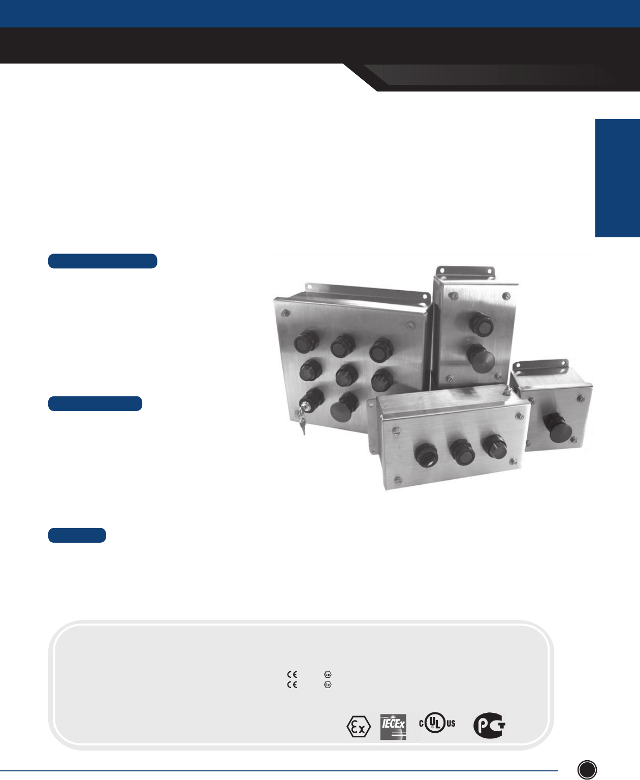
INCREASED SAFETY
INCREASED SAFETY
ENCLOSURES
SEND ORDERS TO ORDERS@ADALET.COM
T: 216.267.9000 | F:216.267.1681 | info@adalet.com ©Adalet
85
•10standardsizeswith4”or6”depth
•Holecongurationsfrom1to16holes
•Verticalin-linecongurationsfrom1to4holes
•Watertightgasketprovidesingressprotectionagainst
wateranddust
•Weldedonexternalmountingbrackets
•Captivehexhead/slottedcoverbolts
•Drilledcoverentriesfor30.5mmoperators
•Internal/externalearthstud
•Boxandcovergroundstud
•Mountingpanelsoruniversalrailmountsystem
•Drilledentriesandcut-outs
•Stoppingplugs
•Glandplateson6”deepenclosures
•AdaletIncreasedSafetyoperators
•Terminalblockassemblies
•Legendplates
•Breatherordrain
•Internalearthbar
STANDARD FEATURES
DESIGN OPTIONS
MATERIAL
CSC4X6 Series
Pushbutton Station Enclosures
•Type316Lor304stainlesssteel
•Enclosureandcoverconstructedfrom14gauge(.075)stainlesssteelwith#3/4brushnish
•Glandplatesconstructedfrom10gauge(.1345)stainlesssteelwith#3/4brushnish
•Siliconegasketconstructedfrom¼ ”BiscosiliconewithacrylicPSA
•Glandplategasketconstructedfrom⁄”BiscosiliconewihtacrylicPSA
CERTIFICATIONS
ClassI,Division2,GroupsA,B,C,D
ClassII,Division2,GroupsF,G
ClassI,Zone1,AExdembIICT6(T5:Ta<+55°C)
NEMAType4X
ExdembIICT6X(T5:Ta<+55°C)
ExdembIICT6(T5:Ta<+55°C)
ExtDA21IP66T200°C
IECExUL09.0024X
DEMKO01ATEX130438X
0539II2GExdembIICT6(T5:Ta<+55°C)
0539II2DExtDA21IP66T200°C
LISTED 30RL
OPERATOR ENCLOSURES
Ten standard designs make up the CSC4X(6) line of stainless steel 316L or 304 control station enclosures ranging from 1 hole to
16 holes. Design confi gurations include in-line options for 1 to 4 holes as well as larger enclosures for 2 x 2 up to 4 x 4 designs.
Custom sizes and hole confi gurations are available up to 24” x 24”. The enclosures feature a continuous one piece silicone gasket
which provides an IP66 ingress rating for dust-tight and water-tight locations. Cover hole cut-outs are 30.5mm openings and are
designed to house Adalet’s standard line of increased safety pushbuttons, pilot lights, and selector switches.
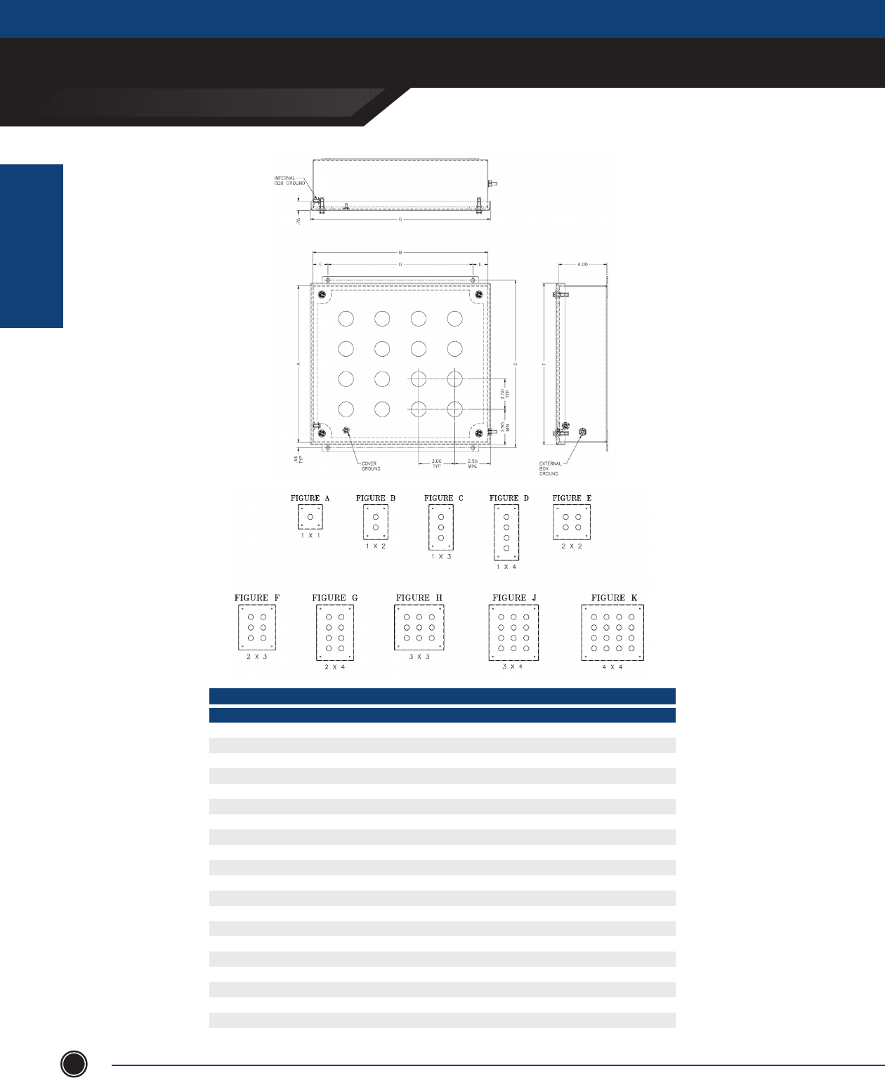
INCREASED SAFETY
INCREASED SAFETY
ENCLOSURES
ADALET.COM
ADALET ENCLOSURE SYSTEMS | 4801 WEST 150TH | CLEVELAND, OHIO 44135©Adalet
86
CSC4X6-050504 (1x1) 1 A 5.50 5.50 6.25 4.00 0.75 5.90 5.90
CSC4X6-050506 (1x1 w/ Terminal Blocks) 1 A 5.50 5.50 6.25 4.00 0.75 5.90 5.90
CSC4X6-080504 (1x2) 2 B 8.00 5.50 8.75 4.00 0.75 8.40 5.90
CSC4X6-080506 (1x2 w/ Terminal Blocks) 2 B 8.00 5.50 8.75 4.00 0.75 8.40 5.90
CSC4X6-100504 (1x3) 3 C 10.50 5.50 11.25 4.00 0.75 10.90 5.90
CSC4X6-100506 (1x3 w/ Terminal Blocks) 3 C 10.50 5.50 11.25 4.00 0.75 10.90 5.90
CSC4X6-130504 (1x4) 4 D 13.00 5.50 13.75 4.00 0.75 13.40 5.90
CSC4X6-130506 (1x4 w/ Terminal Blocks) 4 D 13.00 5.50 13.75 4.00 0.75 13.40 5.90
CSC4X6-080804 (2x2) 4 E 8.00 8.50 8.75 6.00 1.25 8.40 8.90
CSC4X6-080806 (2x2 w/ Terminal Blocks) 4 E 8.00 8.50 8.75 6.00 1.25 8.40 8.90
CSC4X6-100804 (2x3) 6 F 10.50 8.50 11.25 6.00 1.25 10.90 8.90
CSC4X6-100806 (2x3 w/ Terminal Blocks) 6 F 10.50 8.50 11.25 6.00 1.25 10.90 8.90
CSC4X6-130804 (2x4) 8 G 13.00 11.50 13.75 6.00 1.25 13.40 8.90
CSC4X6-130806 (2x4 w/ Terminal Blocks) 8 G 13.00 11.50 13.75 6.00 1.25 13.40 8.90
CSC4X6-101104 (3x3) 9 H 10.50 11.50 11.25 10.00 0.75 10.90 11.90
CSC4X6-101106 (3x3 w/ Terminal Blocks) 9 H 10.50 11.50 11.25 10.00 0.75 10.90 11.90
CSC4X6-131104 (3x4) 12 J 13.00 11.50 13.75 10.00 0.75 13.40 11.90
CSC4X6-131106 (3x4 w/ Terminal Blocks) 12 J 13.00 11.50 13.75 10.00 0.75 13.40 11.90
CSC4X6-131404 (4x4) 16 K 13.00 14.50 13.75 12.00 1.25 13.40 14.90
CSC4X6-131406 (4x4 w/ Terminal Blocks) 16 K 13.00 14.50 13.75 12.00 1.25 13.40 14.90
A B C D E F GFIG.HOLESENCLOSURE CATALOG NUMBER
ENCLOSURE DIMENSIONS
OPERATOR ENCLOSURES
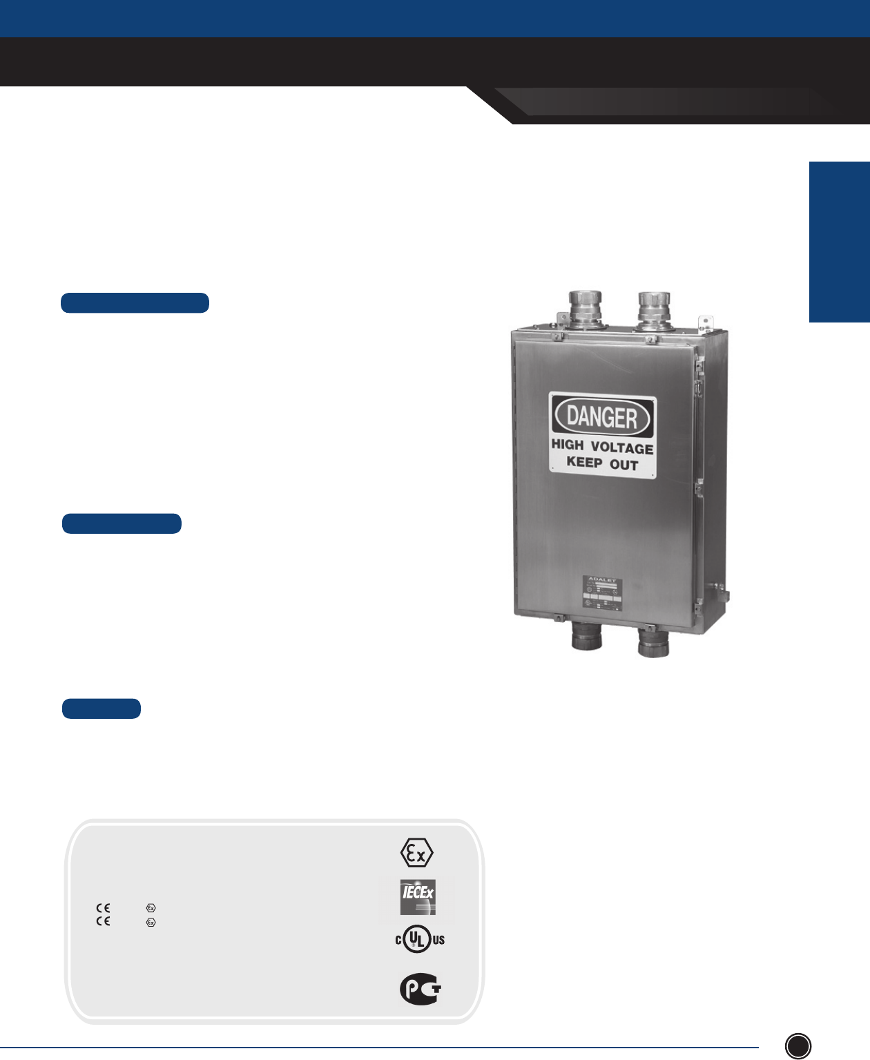
INCREASED SAFETY
INCREASED SAFETY
ENCLOSURES
SEND ORDERS TO ORDERS@ADALET.COM
T: 216.267.9000 | F:216.267.1681 | info@adalet.com ©Adalet
87
HV Series
Clamped Cover High Voltage Enclosures
Available in Stainless Steel
304 or 316L
•Type304or316Lstainlesssteel
•Enclosureandcoverconstructedfrom14gauge(.075stainlesssteelwith#3/4brushnish
•Glandplatesconstructedfrom10gauge(.1345)stainlesssteelwith#3/4brushnish
•Siliconegasketconstructedfrom¼ ”BiscosiliconewithacrylicPSA
•Glandplategasketconstructedfrom⁄”BiscosiliconewithacrylicPSA
Adalet’s Single Door Clamped High Voltage Junction Boxes are available in stainless steel 316L and 304. Silicone gaskets,
removable hinge pin, box and cover ground studs including an internal / external earthing stud, and a universal rail mounting
system are included as standard.
•31standardsizesavailablein1x1or2x2connectionoptions
•Stainlesssteelcoverclampsandscrews
•Continuouspianohingewithremovablesteelpin
•Watertightsiliconegasket
•Setofthreeporcelaininsulators(1x1)ormechanicalconnections(2x2)
•Adjustablemountingplate(1x1and2x2)
•Adjustableclamprails(1x1and2x2)
•Padlockhaspandstaple
•Internalrailmountingsystem
•Groundstudonboxandcover
•Internal/externalgroundlug#6-350MCMAI/Cu
•Wallmountingfeet
•Glandplates(6”orgreater)canbesuppliedpre-drilledorblankforelddrilling
•Mountingpanels
•Drilledentriesandcut-outs
•UHWM-PEcableclamps(1x1connectiononly)
•Breather/drain
•Stoppingplugs
•Terminalblockassemblies
•Stainlesssteelmountingpanels
•Cableglandsandconduitttings
•Internalearthbar
STANDARD FEATURES
DESIGN OPTIONS
MATERIAL
CERTIFICATIONS
ClassI,Division2,GroupsA,B,C,D
ClassII,Division2,GroupsF,G
ClassI,Zone1,AExIIT6Tamb-20°C<Ta<+55°C
0539II2GExeIIT6-20°C<Ta<+55°C
0539II2DExtDA21IP66T200°C
DEMKO01ATEX130437X
IECExUL09.0021X
ExeIIT6-20°C<Ta<+55°C
ExtDA21IP66T200°C
NEMAType4,4X,12&13
LISTED 437S
HIGH VOLTAGE ENCLOSURES
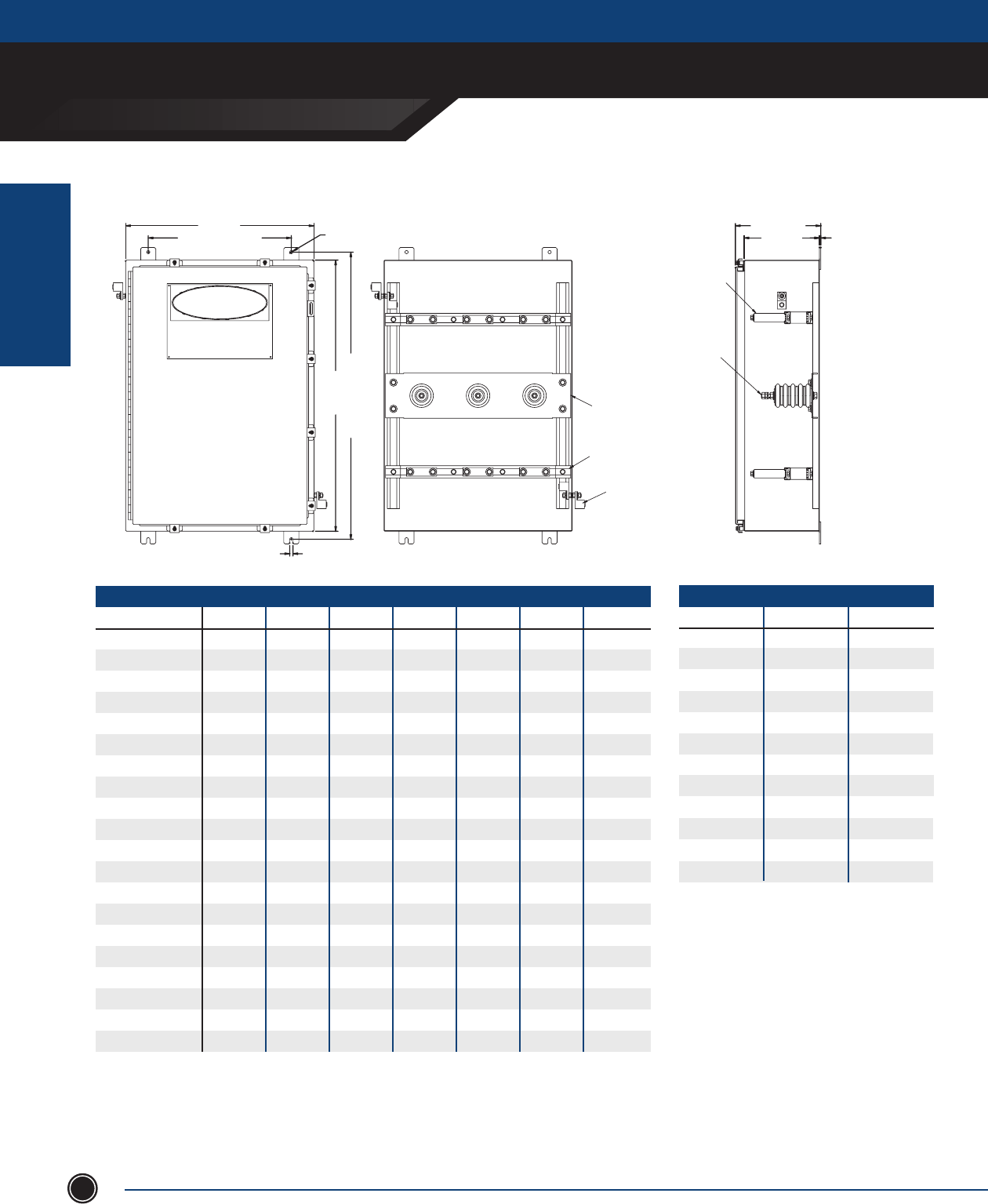
INCREASED SAFETY
INCREASED SAFETY
ENCLOSURES
ADALET.COM
ADALET ENCLOSURE SYSTEMS | 4801 WEST 150TH | CLEVELAND, OHIO 44135©Adalet
88
DANGER
HIGH VOLTAGE
KEEP OUT
W (WIDTH)
N (MOUNTING CENTER)
.44 [11mm]
.44 [11mm]
H (HEIGHT)
M (MOUNTING CENTER)
D (DEPTH)
D + 1.31 [33mm]
.13 [3mm]
OPTIONAL (UHMW-PE) CABLE CLAMPS
(FURNISHED SOLID STANDARD, SPECIFY
DIAMETER FOR FACTORY DRILLED)
PORCELAIN INSULATOR
3/8" DIAMETER STUD: 1.5 ~ 2.5kV ASSY'S
1/2" DIAMETER STUD: 6.6 ~ 8kV ASSY'S
#6 ~ 350MCM (Al/Cu)
INTERNAL/EXTERNAL
GROUNDING LUG
ADJUSTABLE PORCELAIN INSULATOR
MOUNTING PLATE
ADJUSTABLE CABLE CLAMP RAIL
OPTIONAL GLAND PLATE SIDE B
OPTIONAL GLAND PLATE SIDE A
MIN CONDUCTOR SIZE AMPERAGE
mm AWG/MCM MAX
10 8 50
16 6 63
25 4 80
35 2 100
50 1/0 125
70 2/0 160
95 3/0 200
120 410 225
150 250 250
185 350 315
240 400 400
300 500 500
VOLTAGE AMPERAGE
ENCLOSURE H W D M N MAX MAX
HV4X6-241206 24.00 12.00 6.00 25.25 9.50 1.5kV 315
HV4X6-242006 24.00 20.00 6.00 25.25 14.00 1.5kV 315
HV4X6-201206 20.00 12.00 6.00 21.25 9.50 2.5kV 250
HV4X6-161606 16.00 16.00 6.00 17.25 10.00 2.5kV 200
HV4X6-241606 24.00 16.00 6.00 25.25 10.00 2.5kV 315
HV4X6-301606 30.00 16.00 6.00 31.25 10.00 2.5kV 400
HV4X6-202006 20.00 20.00 6.00 21.25 14.00 2.5kV 250
HV4X6-201407 20.00 14.00 7.00 21.25 8.00 2.5kV 250
HV4X6-251807 25.00 18.00 7.00 26.25 12.00 2.5kV 315
HV4X6-302207 30.00 22.00 7.00 31.25 16.00 2.5kV 400
HV4X6-362507 36.00 25.00 7.00 37.25 19.00 2.5kV 400
HV4X6-201610 20.00 16.00 10.00 21.25 10.00 6.6kV 250
HV4X6-302010 30.00 20.00 10.00 31.25 14.00 8kV 400
HV4X6-242010 24.00 20.00 10.00 25.25 14.00 8kV 315
HV4X6-302410 30.00 24.00 10.00 31.25 18.00 8kV 400
HV4X6-242410 24.00 24.00 10.00 25.25 18.00 8kV 315
HV4X6-362410 36.00 24.00 10.00 37.25 18.00 8kV 400
HV4X6-362510 36.00 25.00 10.00 37.25 19.00 8kV 400
HV4X6-603610 60.00 36.00 10.00 61.25 30.00 8kV 400
HV4X6-603616 60.00 36.00 16.00 61.25 30.00 8kV 400
1. Forstainlesssteel304assembliessubstitute
HV4X6-prexwithHV4X-prex.
2. Pleasespecifyworkingvoltage,
amperageandconductorsizewhen
requestingquote.
3.Forconduit/cableentryspacing,wire
bendingandwireconversionguidelines,
refertoinsidebackcoverofthiscatalog.
4. Glandplateoptionsareavailableonthe
topandbottomsidesofthebox.
Addthefollowingsufxesforglandplates:
-A: GlandplateinstalledonTOPside
ofbox
-B: GlandplateinstalledonBOTTOM
sideofbox
Formultipleglandplatesomitdashes.
(i.e.HV4X6-161608-ABCD)
NOTES
1 x 1 Connection Series
HIGH VOLTAGE ENCLOSURES
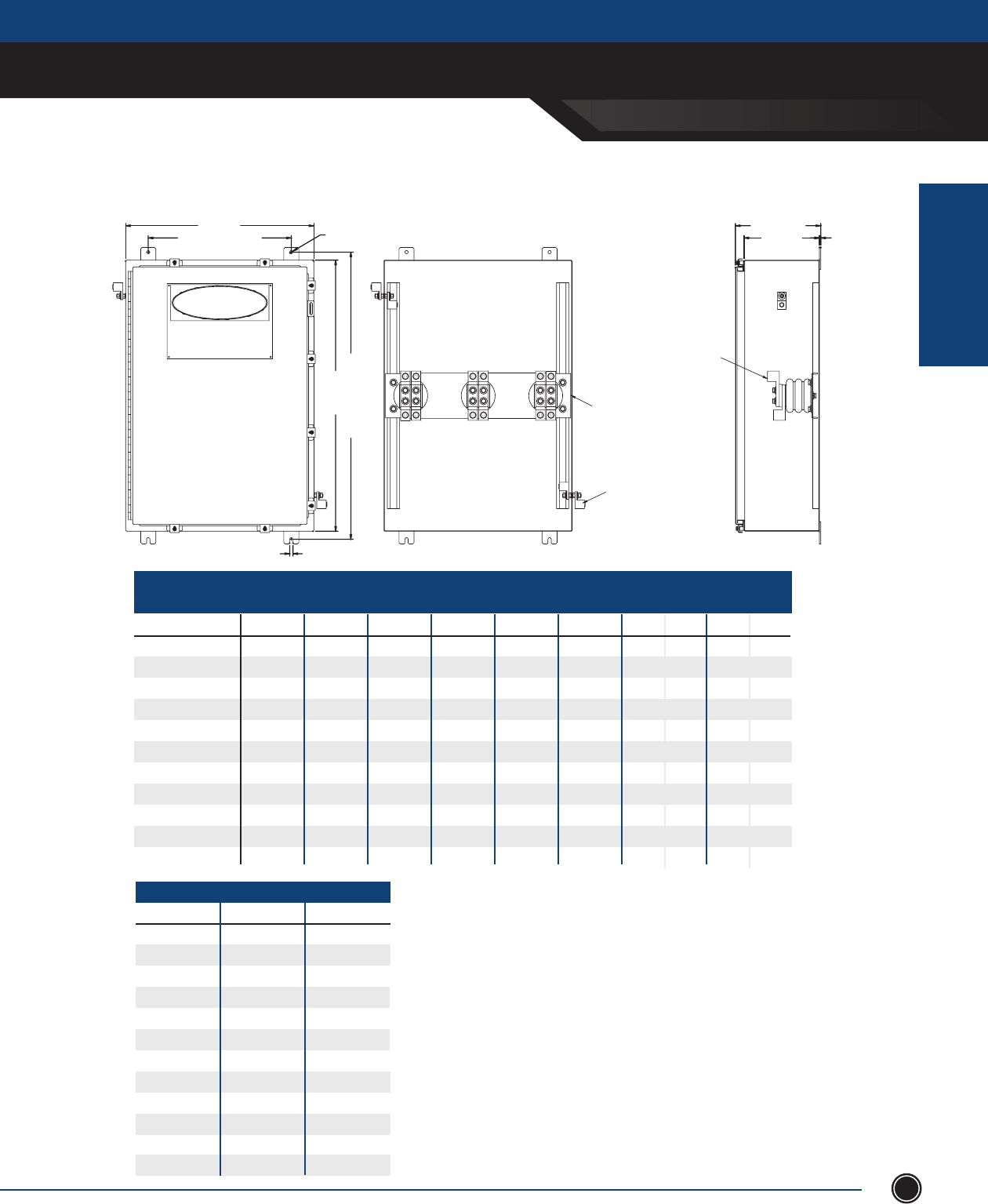
INCREASED SAFETY
INCREASED SAFETY
ENCLOSURES
SEND ORDERS TO ORDERS@ADALET.COM
T: 216.267.9000 | F:216.267.1681 | info@adalet.com ©Adalet
89
2 x 2 Connection Series
VOLTAGE MAX AMP. MAX AMP.
T6 RATING T5 RATING
ENCLOSURE H W D M N MAX Phase Conductor Phase Conductor
HV4X6-202008 20.00 20.00 8.00 21.25 14.00 1.1kV 500 250 500 250
HV4X6-242008 24.00 20.00 8.00 25.25 14.00 1.1kV 630 315 630 315
HV4X6-242408 24.00 24.00 8.00 25.25 18.00 1.1kV 630 315 630 315
HV4X6-202010 20.00 20.00 10.00 21.25 14.00 1.1kV 500 250 500 250
HV4X6-242010 24.00 20.00 10.00 25.25 14.00 1.1kV 630 315 630 315
HV4X6-302010 30.00 20.00 10.00 31.25 14.00 1.1kV 650 325 800 400
HV4X6-242410 24.00 24.00 10.00 25.25 18.00 1.1kV 630 315 630 315
HV4X6-302410 30.00 24.00 10.00 31.25 18.00 1.1kV 650 325 800 400
HV4X6-362410 36.00 24.00 10.00 37.25 18.00 1.1kV 650 325 800 400
HV4X6-362510 36.00 25.00 10.00 37.25 19.00 1.1kV 650 325 1000 500
HV4X6-603610 60.00 36.00 10.00 61.25 30.00 1.1kV 650 325 1000 500
Ea. Ea.
MIN CONDUCTOR SIZE AMPERAGE
mm AWG/MCM MAX
10 8 50
16 6 63
25 4 80
35 2 100
50 1/0 125
70 2/0 160
95 3/0 200
120 410 225
150 250 250
185 350 315
240 400 400
300 500 500
1. For stainless steel 304 assemblies substitute HV4X6-
prex with HV4X-prex.
2. Please specify working voltage, amperage and conduc
tor size when requesting quote.
3. For conduit/cable entry spacing, wire bending and
wire conversion guidelines, refer to inside back cover
of this catalog.
4. Gland plate options are available on the top and bot
tom sides of the box.
Add the following suxes for gland
plates:
- A: Gland plate installed on TOP side of box
- B: Gland plate installed on BOTTOM side of box
For multiple gland plates omit dashes.
(i.e. HV4X6-161608-ABCD)
NOTES
HIGH VOLTAGE ENCLOSURES
DANGER
HIGH VOLTAGE
KEEP OUT
W (WIDTH)
N (MOUNTING CENTER)
.44 [11mm]
.44 [11mm]
H (HEIGHT)
M (MOUNTING CENTER)
D (DEPTH)
D + 1.31 [33mm]
.13 [3mm]
600MCM ~ 2 AWG
MECHANICAL CONNECTOR
#6 ~ 350MCM (Al/Cu)
INTERNAL/EXTERNAL
GROUNDING LUG
ADJUSTABLE PORCELAIN INSULATOR
MOUNTING PLATE
OPTIONAL GLAND PLATE SIDE B
OPTIONAL GLAND PLATE SIDE A
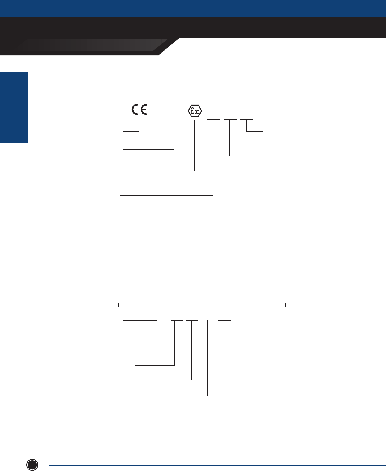
INCREASED SAFETY
TECHNICAL DATA
INCREASED SAFETY
ENCLOSURES
ADALET.COM
ADALET ENCLOSURE SYSTEMS | 4801 WEST 150TH | CLEVELAND, OHIO 44135©Adalet
90
Area Classication
Class I, Zone 1, AEx ed IIC T5 Tamb -40°C to +70°C
AEx - Compliance to ANSI/UL60079 Standards
Ex - Compliance to IEC 60079 Standards and
CSA E60079 Standards
Ambient Temperature Range in Service
(Required when other than –20°C to +40°C)
Zone 0 Continuous Hazard
Zone 1 Intermittent Hazard
Zone 2 Hazard Under
Abnormal Conditions
TEMPERATURE CLASSIFICATION
T class Max Surface Temp
T1 ≤ 450°C
T2 ≤ 300°C
T3 ≤ 200°C
T4 ≤ 135°C
T5 ≤ 100°C
T6 ≤ 85°C
GAS GROUPING
I Methane (redamp) (Mining Only)
IIA Propane
IIB Ethylene
IIC Acetylene/Hydrogen
IIB+H2 Ethylene & Hydrogen
II All Gases
PROTECTION METHOD
m Encapsulation (Zone 1)
d Flameproof (Zone 1)
e Increased Safety (Zone 1)
i* Intrinsically Safe (Zone 0/1)
o Oil Immersion (Zone 1)
p Pressurized (Zone 1)
q Powder Filling (Zone 1)
n* Non-Sparking (Zone 2)
*denotes additional sub-categories
NOTE: Main protection concept appears rst
For use in Explosive Atmosphere
Equipment Marking
ATEX Directive
0539 II 2 G
CE CONFORMITY MARKING TYPE OF EXPLOSIVE ATMOSPHERE
G Gas/Vapor/Mist (Zone 0, 2, 2)
D Dust (Zone 20, 21, 22)
EXPLOSIVE PROTECTION
SYMBOL
IDENTIFICATION NUMBER OF THE
NOTIFIED BODY (I.E. DEMKO) EQUIPMENT CATEGORY
(Mining)
M1 Energized
M2 De-energized
(Non-Mining)
1 Very High Protection (Zone 0 & 20)
2 High Protection (Zone 1 & 21)
3 Normal Protection (Zone 2 & 22)
EQUIPMENT GROUP
I Mining
II Non-Mining
NEC 505, CEC Sec.18, IEC, CENELEC
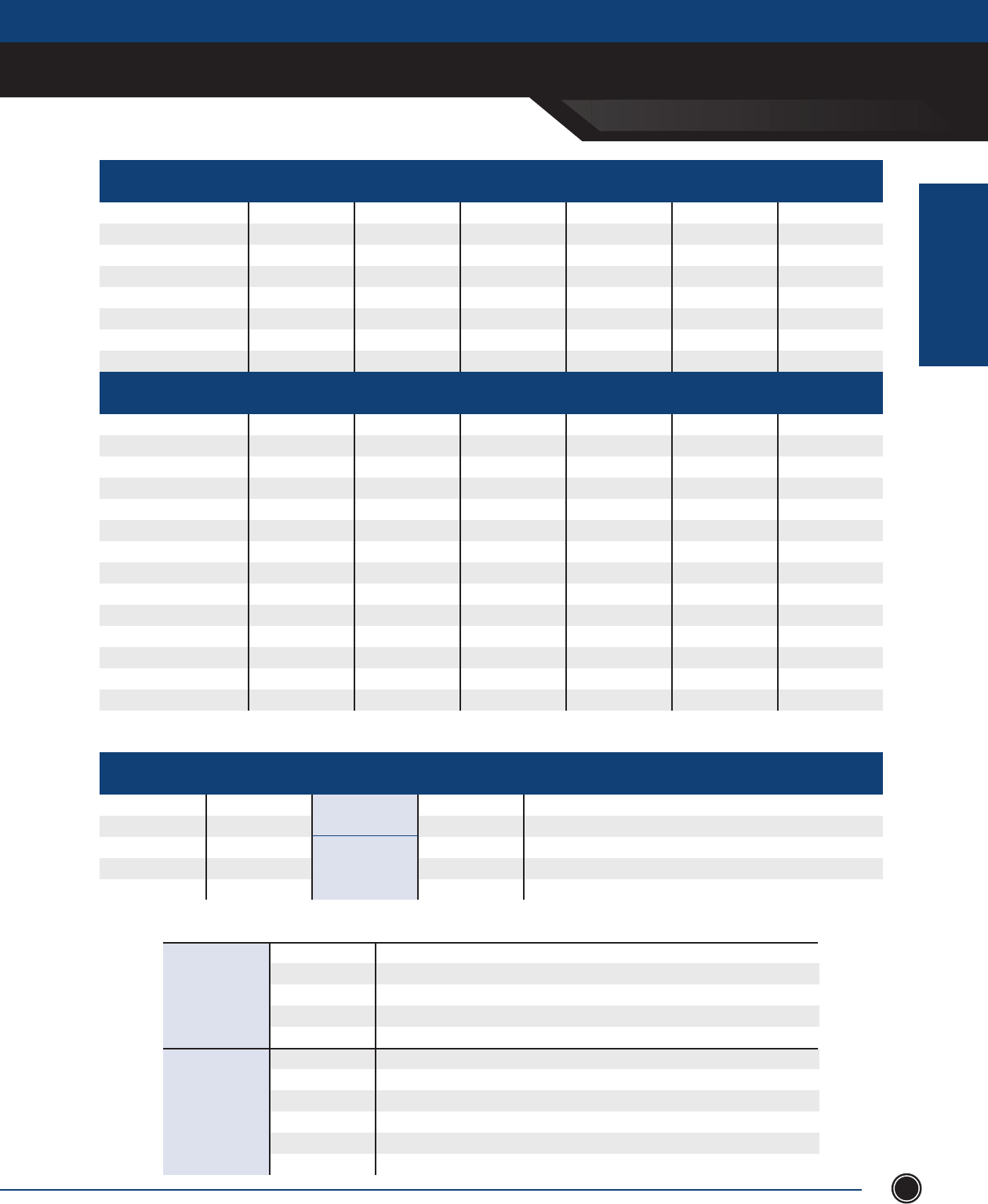
INCREASED SAFETY
TECHNICAL DATA
INCREASED SAFETY
ENCLOSURES
SEND ORDERS TO ORDERS@ADALET.COM
T: 216.267.9000 | F:216.267.1681 | info@adalet.com ©Adalet
91
METHODS OF PROTECTION
Protection Method Permitted Use ATEX Equipment Certication Documents
Category UL CSA CENELEC IEC
Explosionproof Division 1 -- ANSI/UL 1203 CSA-30 -- --
Intrinsically Safe (2 Fault) Division 1 -- ANSI/UL 913 CSA-157 -- --
Purge/Pressurized
(Type X or Y) Division 1 -- ANSI/NFPA 496 ANSI/NFPA 496 -- --
Nonincendive Division 2 -- UL 1604 CSA-213 -- --
Non-sparking device Division 2 -- UL 1604 CSA-213 -- --
Purge/Pressurized (Type Z) Division 2 -- ANSI/NFPA 496 ANSI/NFPA 496 -- --
Hermetically sealed Division 2 -- UL 1604 CSA-213 -- --
Any Class I, Division 1 Method Division 2 -- -- -- -- --
Protection Method Permitted Use ATEX Equipment Certication Documents
Category UL (AEx) CSA (Ex) CENELEC (EEx) IEC (Ex)
Intrinsically Safe ‘ia’ (2 Fault) Zone 0 M1 & 1 ANSI/UL 60079-11 CAN/CSA-E60079-11 EN 60079-11 & -25 IEC 60 079-11
Flameproof ‘d’ Zone 1 M2 & 2 ANSI/UL 60079-1 CAN/CSA-E60079-1 EN 60079-1 IEC 60 079-1
Increased Safety ‘e’ Zone 1 M2 & 2 ANSI/UL 60079-7 CAN/CSA-E60079-7 EN 60079-7 IEC 60 079-7
Intrinsically Safe ‘ib’ (1 Fault) Zone 1 M2 & 2 ANSI/UL 60079-11 CAN/CSA-E60079-11 EN 60079-11 & -25 IEC 60 079-11
Encapsulation ‘m’ Zone 1 2 ANSI/UL 60079-18 CAN/CSA-E79-18 EN 60079-18 IEC 60 079-18
Oil Immersion ‘o’ Zone 1 2 ANSI/UL 60079-6 CAN/CSA-E60079-6 EN 60079-6 IEC 60 079-6
Purged/Pressurized ‘p’ Zone 1 2 ANSI/NFPA 496 CAN/CSA-E60079-2 EN 60079-2 IEC 60 079-2
Powder lling ‘q’ Zone 1 2 ANSI/UL 60079-5 CAN/CSA-E60079-5 EN 60079-5 IEC 60 079-5
Any Zone 0 Method Zone 1 -- -- -- -- --
Non-sparking ‘nA’ Zone 2 3 ANSI/UL 60079-15 CAN/CSA-E60079-15 EN 60079-15 IEC 60 079-15
Hermetically sealed ‘nC’ Zone 2 3 ANSI/UL 60079-15 CAN/CSA-E60079-15 EN 60079-15 IEC 60 079-15
Nonincendive ‘nC’ Zone 2 3 ANSI/UL 60079-15 CAN/CSA-E60079-15 EN 60079-15 IEC 60 079-15
Restricted breathing ‘nR’ Zone 2 3 ANSI/UL 60079-15 CAN/CSA-E60079-15 EN 60079-15 IEC 60 079-15
Any Zone 0 or 1 Method Zone 2 -- -- -- -- --
Methane & Dust
Gas, Vapors,
Mist & Dust
NEC 500
NEC 505,
IEC, Europe
ATEX EQUIPMENT CLASSIFICATIONS
Equipment Group Equipment Category Atmosphere Level of Protection Required Protection
I M1 Very High Two faults, remain energized and functioning
I M2 High Severe normal operations, de-energize in explosive atmosphere
II 1 Very High Two faults, remain energized and functioning
II 2 High One fault
II 3 Low Normal operation
AREA CLASSIFICATIONS First Digit Protec
Class I Potentially explosive gas or vapor
Class II Potentially explosive dust
Class III Potentially explosive ber
Division 1 Potentially explosive substance present under normal operating conditions
Division 2 Potentially explosive substance present under abnormal operating conditions
Zone 0 Explosive gas present continuously
Zone 1 Explosive gas present occasionally under normal operating conditions
Zone 2 Explosive gas present for short period
Zone 20 Explosive dust present continuously
Zone 21 Explosive dust present occasionally under normal operating conditions
Zone 22 Explosive dust present for short period
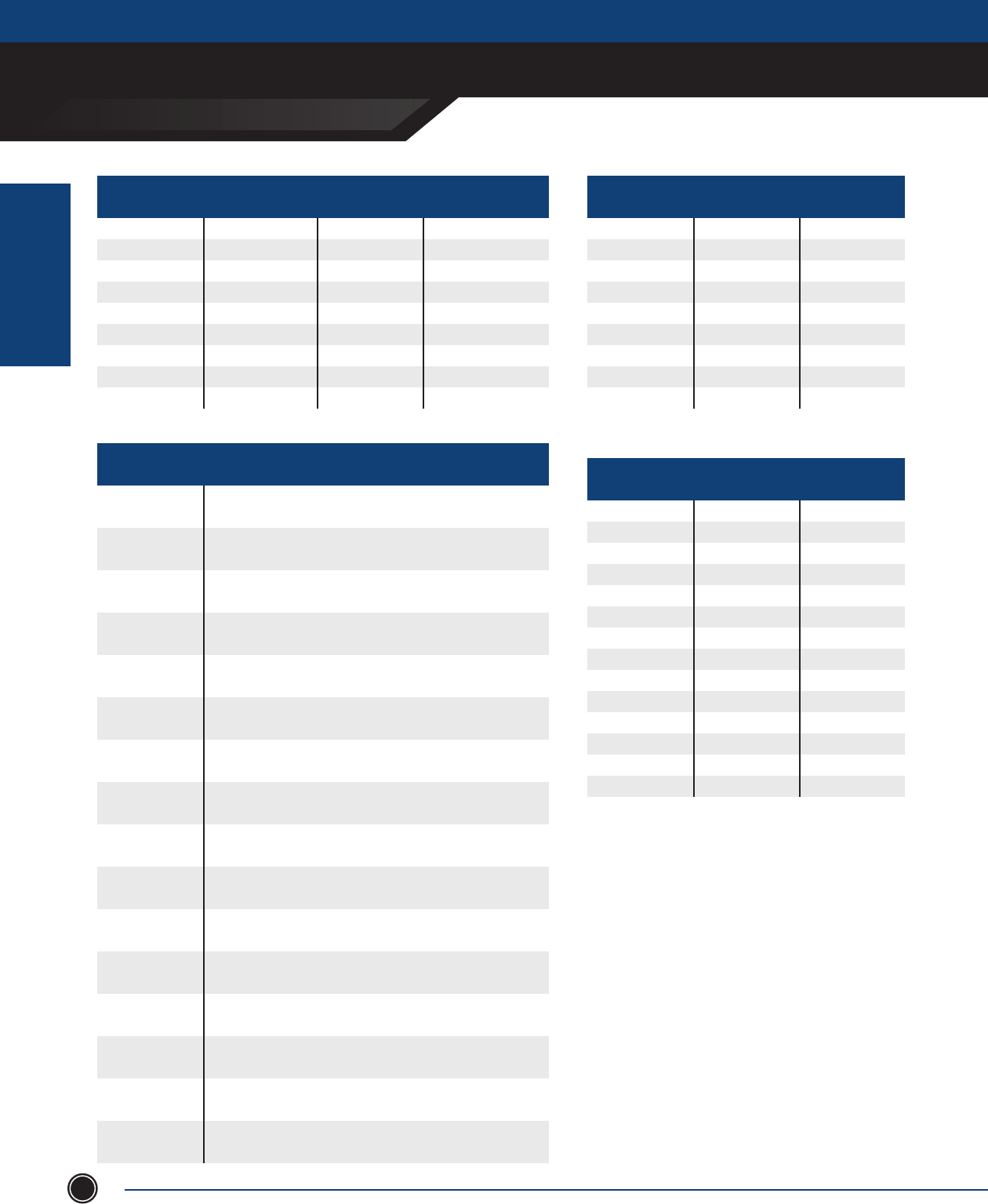
INCREASED SAFETY
TECHNICAL DATA
INCREASED SAFETY
ENCLOSURES
ADALET.COM
ADALET ENCLOSURE SYSTEMS | 4801 WEST 150TH | CLEVELAND, OHIO 44135©Adalet
92
INGRESS PROTECTION (IP XX) CODES - IEC60529
First Digit Protection Against Second Digit Protection Against
Solid Bodies Liquids
0 No protection 0 No protection
1 Objects > 50mm 1 Vertically dripping water
2 Objects > 12mm 2 75-90 Deg. dripping water
3 Objects > 2.5mm 3 Sprayed water
4 Object > 1mm 4 Splashed water
5 Dust Protected 5 Water jets
6 Dust-tight 6 Heavy seas
7 -- 7 Eects of immersion
8 -- 8 Indenite immersion
NEMA TYPE DESIGNATIONS
Enclosure Type Intended Use and Description
1 Indoor use primarily to provide a degree of protection against limited
amounts of falling dirt.
2 Indoor use primarily to provide a degree of protection against
limited amounts of falling water and dirt.
3 Outdoor use primarily to provide a degree of protection against
rain, sleet, wind blown dust and damage from external ice formation.
3R Outdoor use primarily to provide a degree of protection against rain,
sleet, and damage from external ice formation.
3S
Outdoor use primarily to provide a degree of protection against rain,
sleet, windblown dust and to provide for operation of external
mechanisms when ice laden.
4 Indoor or outdoor use primarily to provide a degree of protection
against windblown dust and rain, splashing water, hose-directed water
and damage from external ice formation.
4X Indoor or outdoor use primarily to provide a degree of protection
against corrosion, windblown dust and rain, splashing water, hose-
directed water, and damage from external ice formation.
5 Indoor use primarily to provide a degree of protection against settling
airborne dust, falling dirt, and dripping noncorrosive liquids.
6 Indoor or outdoor use primarily to provide a degree of protection against
hose-directed water, and the entry of water during occasional temporary
submersion at limited depth and damage from external ice formation.
6P Indoor or outdoor use primarily to provide a degree of protection against
hose-directed water, the entry of water during prolonged submersion at a
limited depth and damage from external ice formation.
7 Indoor use in locations classied as Class I, Division 1, Groups A, B, C or D
hazardous locations as dened in the National Electric Code (NFPA 70)
(Commonly referred to as explosion-proof).
8 Indoor or outdoor use in locations classied as Class I, Division 2, Groups
A, B, C or D hazardous locations as dened in the National Electric Code
(NFPA 70) (commonly referred to as oil immersed).
9 Indoor use in locations classied as Class II, Division 1, Groups E, F and G
hazardous locations as dened in the National Electric Code (NFPA 70)
(commonly referred to as dust-ignition proof).
10 Intended to meet the applicable requirements of the Mine Safety and
Health Administration (MSHA).
12 and 12K Indoor use primarily to provide a degree of protection against circulating
dust, falling dirt, and dripping noncorrosive liquids.
13 Indoor use primarily to provide a degree of protection against dust,
spraying of water, oil, and noncorrosive coolant
ATMOSPHERE GROUPS
Gas, Dust, Fiber NEC 505, IEC, Europe NEC 500
Acetylene Group IIC Group A
Hydrogen Group IIC (IIB+H2) Group B
Ethylene Group IIB Group C
Propane Group IIA Group D
Methane Group I (redamp) Group D
Metal Dust None Group E
Coal Dust None Group F
Grain Dust None Group G
Fibers None None
TEMPERATURE CLASSES
Maximum Surface NEC 505, IEC, Europe NEC 500
Temperature
450° C T1 T1
300° C T2 T2
280° C --- T2A
260° C --- T2B
230° C --- T2C
215° C --- T2D
200° C T3 T3
180° C --- T3A
165° C --- T3B
160° C --- T3C
135° C T4 T4
120° C --- T4A
100° C T5 T5
85° C T6 T6
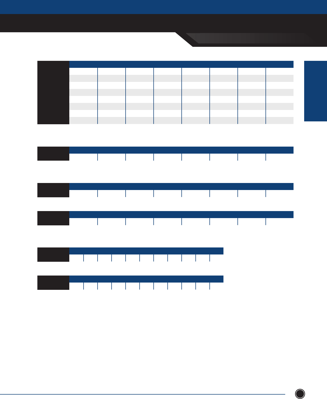
INCREASED SAFETY
TECHNICAL DATA
INCREASED SAFETY
ENCLOSURES
SEND ORDERS TO ORDERS@ADALET.COM
T: 216.267.9000 | F:216.267.1681 | info@adalet.com ©Adalet
93
ATMOSPHERE GROUPS
Gas, Dust, Fiber NEC 505, IEC, Europe NEC 500
Acetylene Group IIC Group A
Hydrogen Group IIC (IIB+H2) Group B
Ethylene Group IIB Group C
Propane Group IIA Group D
Methane Group I (redamp) Group D
Metal Dust None Group E
Coal Dust None Group F
Grain Dust None Group G
Fibers None None
MINIMUM SPACING BETWEEN CENTERS OF CONDUIT OR CABLE ENTRIES
NPT [metric] 3 [M75] 2-1/2 [M63] 2 [M50] 1-1/2 [M40] 1-1/4 [M32] 1 [M25] 3/4 [M20] 1/2 [M16]
1/2 [M16] 3 [77mm] 2-5/8 [68mm] 2-3/8 [61mm] 2 [51mm] 1-7/8 [48mm] 1-5/8 [42mm] 1-3/8 [35mm] 1-1/4 [32mm]
3/4 [M20] 3-1/8 [80mm] 2-3/4 [70mm] 2-1/2 [64mm] 2-1/8 [54mm] 2 [51mm] 1-3/4 [45mm] 1-1/2 [38mm] 1-3/8 [35mm]
1 [M25] 3-1/4 [83mm] 2-7/8 [74mm] 2-3/4 [70mm] 2-1/4 [58mm] 2-1/8 [54mm] 1-7/8 [48mm] 1-3/4 [45mm] 1-5/8 [42mm]
1-1/4 [M32] 3-1/2 [89mm] 3-1/8 [80mm] 2-7/8 [74mm] 2-1/2 [64mm] 2-3/8 [61mm] 2-1/8 [54mm] 2 [51mm] 1-7/8 [48mm]
1-1/2 [M40] 3-5/8 [92mm] 3-1/4 [83mm] 3 [77mm] 2-5/8 [68mm] 2-1/2 [64mm] 2-1/4 [58mm] 2-1/8 [54mm] 2 [51mm]
2 [M50] 3-5/8 [92mm] 3-5/8 [92mm] 3-3/8 [86mm] 3 [77mm] 2-7/8 [74mm] 2-3/4 [70mm] 2-1/2 [64mm] 2-3/8 [61mm]
2-1/2 [M63] 3-5/8 [92mm] 3-7/8 [99mm] 3-5/8 [92mm] 3-1/4 [83mm] 3-1/8 [80mm] 2-7/8 [74mm] 2-3/4 [70mm] 2-5/8 [68mm]
3 [M75] 4-5/8 [118mm] 3-5/8 [92mm] 3-5/8 [92mm] 3-5/8 [92mm] 3-1/2 [89mm] 3-1/4 [83mm] 3-1/8 [80mm] 3 [77mm]
MINIMUM DISTANCE FROM CONDUIT/CABLE CENTER TO EDGE OF BOX/ OPENING
NPT [metric] 3 [M75] 2-1/2 [M63] 2 [M50] 1-1/2 [M40] 1-1/4 [M32] 1 [M25] 3/4 [M20] 1/2 [M16]
Min. Distance 1-3/4 [45mm] 1-7/16 [37mm] 1-3/16 [31mm] 1 [26mm] 7/8 [23mm] 11/16 [18mm] 9/16 [14mm] 1/2 [13mm]
MINIMUM WIRE BENDING REQUIREMENTS
16 (1.5) 14 (2.5) 12 (4) 10 (6) 8 (10) 6 (16) 4 (25) 2 (35)
Min. Distance 1-1/2 [38mm] 1-1/2 [38mm] 1-1/2 [38mm] 1-1/2 [38mm] 2 [51mm] 3 [77mm] 3-1/2 [89mm] 5-1/2 [140mm]
1/0 (50) 2/0 (70) 3/0 (95) 4/0 (120) 250 (150) 350 (185) 400 (240) 500 (300)
Min. Distance 6 [152mm] 6-1/2 [165mm] 7 [178mm] 8-1/2 [216mm] 10[254mm] 12 [305mm] 13 [330mm] 14 [356mm]
ELECTRICAL WIRE CONVERSION
AWG/MCM 22 20 18 16 14 12 10 8 6 4 2
Metric (mm) 0.50 0.75 1.0 1.5 2.5 4 6 10 16 25 35
AWG/MCM 1/0 2/0 3/0 4/0 250 350 400 500 750 1000 1500
Metric (mm) 50 70 95 120 150 185 240 300 400 625 800
NOTES:
1. Theminimumspacinganddistancetablesprovidedforconduit/cablettingsandentriesarebasedonmaintainingaminimumwallsection.They
donottakeintoconsiderationwrenchclearancesandlocknutturningradius.Consultconduit/cablettingmanufacturerforsuggestedwrench
clearancesorspacing.
Thisinformationiscompiledfromdatawhichwebelieveisreliableandisgiveningoodfaith.Sincethemethodsofapplicationandconditionunder
whichourproductsareusedarebeyondourcontrol,wearenotabletoguaranteetheapplicationand/oruseofsame.Theuserassumesallrisksand
liabilityinconnectionwiththeapplicationanduseofourproducts.
AWG/MCM (mm)
AWG/MCM (mm)
AWG/MCM (mm)

EXPLOSIONPROOF ENCLOSURES
XCE SERIES & XJF
ADALET.COM
AdAlet enclosure systems | 4801 West 150th | cleVelAnd, ohIo 44135
©Adalet
EXPLOSIONPRROOF
ENCLOSURES
94
Adalet offers a line of explosionproof and dust-ignition proof enclosures that provide reliable protection
and allows electrical instrumentation and control devices to remain safe from the danger of an explosion.
Adalet explosionproof enclosures are typically used in the packaging of electrical/electronic components
for control, measurement or monitoring applications in hazardous environments. With help from our
engineering department, Adalet explosionproof enclosures can be modied for installation with a variety of our
explosionproof operator devices, viewing windows and accessories.
Explosionproof & dust-iGnition proof ENCLOSURES
Explosionproof / Dust-Ignition Proof Enclosures
• Enclosure: most sizes in industry with over 75 standard sizes.
Stainless steel versions available in select sizes.
• Fully customizable: All enclosures can be built to spec with
conduit/operator drilling & tapping, round or square/rectangular
viewing windows, watertight gaskets for washdown applications,
hinge kits, mounting panels, breaker handles, breather / drains, etc.
• Operator / pendant stations available in 1-18 vertical operator
congurations
• Approvals: Extensive approvals including UL, cUL, ATEX, IEC, IECEx
• Over 75 custom paint colors to match OEM or end user color
schemes
• Largest selection of design options provides exibility to meet your
application needs
• Junction Boxes
• Control Enclosures
• High Voltage Enclosures
• ATEX Control Panels
• Internal Flanged Enclosures
• Pendant Stations
• Operator Stations
• Dust-Ignition Proof Enclosures
AVAILABLE MODELS STANDARD FEATURES
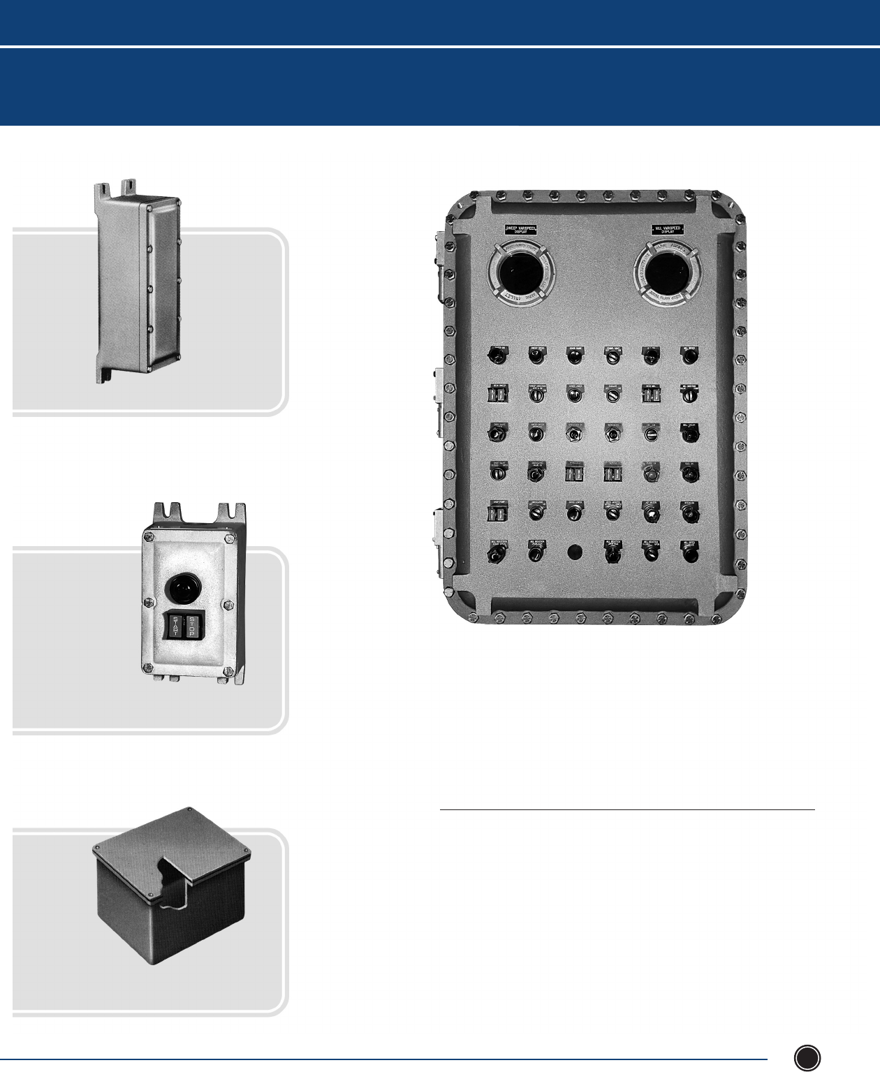
XCE SERIES & XJF
SEND ORDERS TO ORDERS@ADALET.COM
T: 216.267.9000 | F:216.267.1681 | info@adalet.com ©Adalet
EXPLOSIONPRROOF
ENCLOSURES
EXPLOSIONPROOF ENCLOSURES
95
Explosionproof / Dust-Ignition Proof
Enclosures
XCE, XCEX, XCESX & XJF Series 96
XHVX Series 112
XCPX Series 115
ATEX Control Panel Certification 116
XIF Series 117
Control / Pendant Stations 121
Dust-Ignition Proof 126
Control Station for Panel Mounting 127
Contents
Explosionproof / Dust-Ignition Proof Enclosures
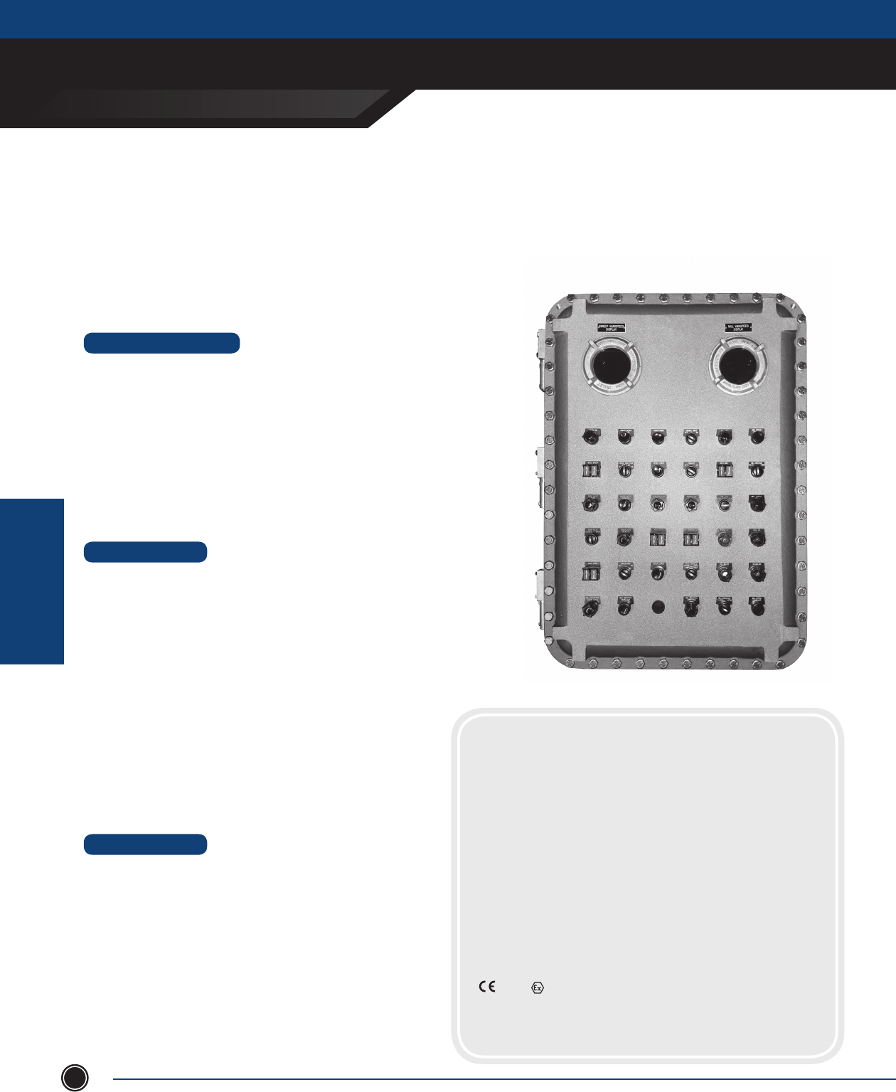
EXPLOSIONPROOF ENCLOSURES
xCE sEriEs & xJf
ADALET.COM
ADALET ENCLOSURE SYSTEMS | 4801 WEST 150TH | CLEVELAND, OHIO 44135
©Adalet
EXPLOSIONPRROOF
ENCLOSURES
96
XCE: Explosionproof Control Enclosures
XCEX: Flameproof Control Enclosures
XCEQ: Explosionproof Quad-Lead Control Enclosures
XJF: Explosionproof Junction Boxes
Explosionproof Quad-Lead Control Enclosures Explosionproof Quad-Lead Control Enclosures
STANDARD FEATURES
• 75 standard sizes available
• Corrosion resistant, copper free aluminum (⁄ of 1%)
• Pre-drilled hinge holes (hinge optional)
• Pre-drilled mounting panel bosses (mounting panel optional)
• NEMA 4 watertight gasket
• Premium, high strength steel cover bolts (zinc plated and coated)
• Internal / external grounding screws
• Removable lifting eye bolts (18x24 and larger)
• Lid-lifter cover alignment device (18x24 and larger)
• Cast-on mounting lugs / feet
• Tumblast, natural aluminum nish
• Stainless steel cover bolts for NEMA 4X corrosion protection
• Mounting panels - Available in galvanized steel (XSM) or aluminum (XSA)
• Aluminum hinge kits with stainless steel hardware
• Conduit (NPT & metric) and device (NPSM) drilling & tapping
• Operators and auxiliary devices such as breather / drains and
fl ame arrestors
• Quad lead, quick thread cover bolts (designate XCEQ when
ordering, not available on XCEX)
• Window kits - Round (up to 8” viewing diameter or
square/rectangular (up to 13” x 13”))
• Custom machining - Milling, counter-boring, spot-facing, blind
drilled entries, chamfers
• Panel assembly / population
• Custom cast-on logos
• Powder and epoxy coating for additional corrosion resistance
• Special mounting provisions
• Captive bolt retainer plate
DESIGN OPTIONS
CERTIFICATIONS
XCE Series:
Class I, Division 1, Gas Groups BCD UL 1203
Class II, Division 1, Gas Groups EFG CSA C22.2 No. 30
Class III UL 50
NEMA Type 4, 7, 9
NEMA Type 4X (w/ SS cover bolts)
XCEX Series:
Class I, Division 1, Gas Groups BCD UL 1203
Class II, Division 1, Gas Groups EFG CSA C22.2 No. 30
Class III UL 50
NEMA Type 4, 7, 9
NEMA Type 4X (w/ SS cover bolts)
Class I, Zone 1, AExd IIB UL 60079-0 / UL 60079-1
Exd IIB CSA 60079-0 / CSA 60079-1
0539 Ex II 2GD (Optional) EN 60079-0 / EN 60079-1
IP66 IEC 60529
NEMA Type 4X (w/ N4X suf x)
MATERIAL
• Enclosure - Copper free aluminum (⁄ of 1%)
• Cover Bolts - Steel, zinc plated and coated
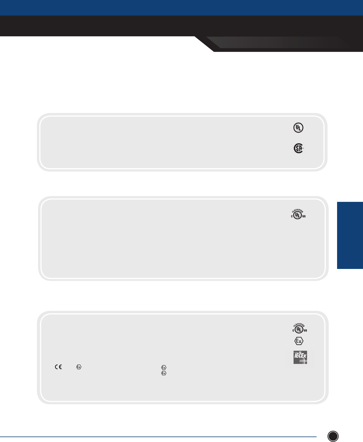
xCE sEriEs & xJf
SEND ORDERS TO ORDERS@ADALET.COM
T: 216.267.9000 | F:216.267.1681 | info@adalet.com ©Adalet
EXPLOSIONPRROOF
ENCLOSURES
EXPLOSIONPROOF ENCLOSURES
97
Certi cations
Class I, Division 1, Gas Groups B*,C, D
Class II, Division 1, Gas Groups E, F, G
NEMA Type 4 (with N4 suf x)
*N4 suf x may affect Group B approval, consult factory
XJF: Explosionproof Junction Boxes
CERTIFICATIONS
Class I, Division 1, Gas Groups B*,C, D
Class II, Division 1, Gas Groups E, F, G
Class III
NEMA Type 4 (with N4 suf x)
NEMA Type 4X (w/SS cover bolts)
*Specify Group B if required w/N4 suf x
XCE/XCEQ: Explosionproof / Quad-Lead Enclosures
CERTIFICATIONS
Class I, Division 1, Gas Groups B*,C, D
Class II, Division 1, Gas Groups E, F, G
Class III
Class I, Zone 1, AEx d IIB
Ex d IIB
Epsilon 07 ATEX 2251U
0539 II 2GD Ex d II B
Ex d IIB+H2 (Optional)*
Ex tD A21: IP 66
* Specify ATEX / IECEx if required
NEMA Type 4 (with N4 suf x)
NEMA Type 4X (w/SS cover bolts)
IECEx UL 10.0046U
Exd IIB Gb
Extd A21 / IP66
DEMKO 01 ATEX 01294724
II 2 G Exd IIB Gb
II 2 D Extd A21
IP66
XCEX: Flameproof Enclosures
NOTE: Where reference is made to Class I and Class II hazardous locations, the equipment is suitable for both Div. 1 and Div. 2 locations.
CERTIFICATIONS
LISTED 437S
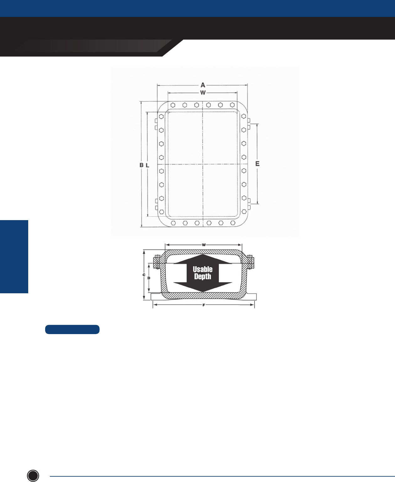
EXPLOSIONPROOF ENCLOSURES
xCE sEriEs & xJf
ADALET.COM
ADALET ENCLOSURE SYSTEMS | 4801 WEST 150TH | CLEVELAND, OHIO 44135
©Adalet
EXPLOSIONPRROOF
ENCLOSURES
98
DESIGN OPTIONS
Mounting Panels
• Steel: (XSM) Galvanized 12 gauge steel plate. The catalog
number includes the steel mounting pan complete with 1/4”
high spacers and stainless steel mounting screws.
• Aluminum: (XSA) consult factory for availablility.
Hinge Kits
Made of extruded aluminum alloy consisting of two sections,
female and male (with stainless steel pin) and four stainless
steel hex head bolts. Designed to allow right or left hand
removable or non-removable installation.
Unless specifed, left hand removable hinge installation will
be furnished by factory when hinged enclosures are ordered.
1. No installation charge when customer speci es factory installation
of mounting pan.
2. Enclosures are pre-drilled for mounting panel unless otherwise
speci ed.
NOTE
1. Catalog number represents complete hinge sets necessary
for enclosure assembly.
2. Enclosures are pre-drilled for hinge kits unless otherwise
speci ed.
3. Hinges are left side removable standard
NOTE
xCE sEriEs & xJf
SEND ORDERS TO ORDERS@ADALET.COM
T: 216.267.9000 | F:216.267.1681 | info@adalet.com ©Adalet
EXPLOSIONPRROOF
ENCLOSURES
EXPLOSIONPROOF ENCLOSURES
99
1. Catalog number represents complete hinge sets necessary
for enclosure assembly.
2. Enclosures are pre-drilled for hinge kits unless otherwise
speci ed.
3. Hinges are left side removable standard
-041604
-060804
-060805
-060806
-061105
-061204
-061206
-061305
-071004
-071006
-071805
-080804
-080806
-080808
-081004
-081006
-081008
-081204
-081206
-081208
-091105
-101004
-101006
-101008
-101206
-101404
-101406
-101408
-101410
-121204
-121206
-121208
-121804
-121806
-121808
-122005
-122404
-122406
-122408
-122410
XCE Series
CAT. NUMBER
XCE or XJF MTG BOLT
SIZE
INSIDE NOM. DIM. MTG LUG
E F
USABLE
DEPTH
PANEL
PART NO.
SHIPPING
WT. (LBS)
PANEL DIM.
X Y
4
6
6
6
6
6
6
6
7
7
7
8
8
8
8
8
8
8
8
8
9
10
10
10
10
10
10
10
10
12
12
12
12
12
12
12
12
12
12
12
⁄
⁄
⁄
⁄
⁄
⁄
⁄
⁄
⁄
⁄
⁄
⁄
⁄
⁄
⁄
⁄
⁄
⁄
⁄
⁄
⁄
⁄
⁄
⁄
⁄
⁄
⁄
⁄
⁄
½
½
½
½
½
½
½
½
½
½
½
12 ⁄
4 ½
4 ½
4 ½
7 ½
8 ½
8 ½
9 ½
6 ½
6 ½
14 ½
4 ¼
4 ¼
4 ¼
6 ½
6 ½
6 ½
8 ½
8 ½
8 ½
7 ½
6 ½
6 ½
6 ½
8 ½
10 ⁄
10 ⁄
10 ⁄
10 ⁄
8 ⁄
8 ⁄
8 ⁄
14 ⁄
14 ⁄
14 ⁄
14 ⁄
18 ⁄
18 ⁄
18 ⁄
18 ⁄
16
8
8
8
11
12
12
13
10
10
18
8
8
8
10
10
10
12
12
12
11
10
10
10
12
14
14
14
14
12
12
12
18
18
18
20
24
24
24
24
4
4
5
6
5
4
6
5
4
6 ⁄
5
4
6
8
4
6
8
4
6
8
5
4
6
8
6 ¼
4
6
8
10
4
6
8
4
6
8
5
4
6
8
10
3 ¼
5 ⁄
5 ⁄
5 ⁄
5 ⁄
5 ⁄
5 ⁄
5 ⁄
6 ⁄
6 ⁄
6 ⁄
7
7
7
7
7
7
6 ⁄
6 ⁄
6 ⁄
8
8 ⁄
8 ⁄
8 ⁄
10 ⁄
8 ⁄
8 ⁄
8 ⁄
8 ⁄
10 ⁄
10 ⁄
10 ⁄
10 ½
10 ½
10 ½
11
11
11
11
11
15 ¼
7 ⁄
7 ⁄
7 ⁄
10 ⁄
11 ⁄
11 ⁄
12 ⁄
9 ⁄
9 ⁄
17 ⁄
7
7
7
9 ⁄
9 ⁄
9 ⁄
10 ⁄
10 ⁄
10 ⁄
10
8 ⁄
8 ⁄
8 ⁄
8 ⁄
12 ⁄
12 ⁄
12 ⁄
12 ⁄
10 ⁄
10 ⁄
10 ⁄
16 ½
16 ½
16 ½
19
23
23
23
23
OVERALL DIM.
7 ¼
9 ¼
9 ¼
9 ¼
9 ¼
9 ¼
9 ¼
9 ¼
10 ⁄
10 ⁄
10 ⁄
11 ⁄
11 ⁄
11 ⁄
11 ⁄
11 ⁄
11 ⁄
11 ⁄
11 ⁄
11 ⁄
12 ⁄
13 ⁄
13 ⁄
13 ⁄
13 ⁄
13 ⁄
13 ⁄
13 ⁄
13
16 ¼
16 ¼
16 ¼
16 ¼
16 ¼
16 ¼
16 ¼
16 ¼
16 ¼
16 ¼
16 ¼
19 ¼
11¼
11 ¼
11 ¼
14 ¼
15 ¼
15 ¼
16 ¼
13 ⁄
13 ⁄
21 ⁄
11 ⁄
11 ⁄
11 ⁄
13 ⁄
13 ⁄
13 ⁄
15 ⁄
15 ⁄
15 ⁄
14 ⁄
13 ⁄
13 ⁄
13 ⁄
15 ⁄
17 ⁄
17 ⁄
17 ⁄
17 ⁄
16 ¼
16 ¼
16 ¼
22 ¼
22 ¼
22 ¼
24 ¼
24 ¼
28 ¼
28 ¼
28 ¼
6
5 ⁄
6 ⁄
7 ⁄
7 ⁄
6 ⁄
8 ⁄
7 ⁄
6 ⁄
8 ⁄
7 ⁄
6 ⁄
8 ⁄
10 ⁄
6 ¼
8 ¼
10 ¼
6 ¼
8 ¼
10 ¼
7 ⁄
6 ⁄
8 ⁄
10 ⁄
8 ⁄
6 ⁄
8 ⁄
10 ½
12 ½
6 ⁄
8 ⁄
10 ⁄
6 ¾
8 ¾
10 ¾
8 ⁄
7 ¼
9 ¼
11 ¼
13 ¼
XSM0416
XSM0608
XSM0608
XSM0608
XSM0611
XSM0612
XSM0612
XSM0613
XSM0710
XSM0710
XSM0718
XSM0808
XSM0808
XSM0808
XSM0810
XSM0810
XSM0810
XSM0812
XSM0812
XSM0812
XSM0911
XSM1010
XSM1010
XSM1010
XSM1012
XSM1014
XSM1014
XSM1014
XSM1014
XSM1212
XSM1212
XSM1212
XSM1218
XSM1218
XSM1218
XSM1220
XSM1224
XSM1224
XSM1224
XSM1224
XSA0416
XSA0608
XSA0608
XSA0608
XSA0611
XSA0612
XSA0612
XSA0613
XSA0710
XSA0710
XSA0718
XSA0808
XSA0808
XSA0808
XSA0810
XSA0810
XSA0810
XSA0812
XSA0812
XSA0812
XSA0911
XSA1010
XSA1010
XSA1010
XSA1012
XSA1014
XSA1014
XSA1014
XSA1014
XSA1212
XSA1212
XSA1212
XSA1218
XSA1218
XSA1218
XSA1220
XSA1224
XSA1224
XSA1224
XSA1224
4 ¾
4 ⁄
5 ⁄
6 ⁄
5 ⁄
4 ¾
6 ¾
5 ⁄
4 ¾
6 ¾
5 ¾
4 ⁄
6 ⁄
8 ⁄
4 ¾
6 ¾
8 ¾
4 ¾
6 ¾
8 ¾
5 ¾
4 ¾
6 ¾
8 ¾
7 ¼
4 ¾
6 ¾
8 ¾
10 ¾
5
7
9
4 ¾
6 ¾
8 ¾
5 ¾
4 ⁄
6 ⁄
8 ⁄
10 ⁄
25
21
23
25
24
24
29
26
27
31
55
24
28
35
30
34
39
34
42
48
41
34
44
50
46
42
49
57
62
60
68
80
85
93
101
104
115
127
142
154
6 ¾
9 ⁄
9 ⁄
9 ⁄
9 ⁄
9 ⁄
9 ⁄
9 ⁄
9 ¾
9 ¾
9 ¾
11
11
11
10 ¾
10 ¾
10 ¾
10 ¾
10 ¾
10 ¾
12
13
13
13
13
13
13
13
13
16
16
16
16
16
16
16
16
16
16
16
HINGE
CAT#
XHB-2
XHB-2
XHB-2
XHB-2
XHB-2
XHB-2
XHB-2
XHB-2
XHB-2
XHB-2
XHB-2
XHB-2
XHB-2
XHB-2
XHB-2
XHB-2
XHB-2
XHB-2
XHB-2
XHB-2
XHB-2
XHB-2
XHB-2
XHB-2
XHB-2
XHB-2
XHB-2
XHB-2
XHB-2
XHC-2
XHC-2
XHC-2
XHC-2
XHC-2
XHC-2
XHC-2
XHC-2
XHC-2
XHC-2
XHC-2
1. To indicate Quad-Lead bolt option, add suf x “Q” after XCE. (Not available on XCEX models.)
2. Operators, windows and hinges are ordered separately.
3. Ex d approval optional on XCEX series only.
4. To indicate Type 4 / IP66 option, add suf x “N4” after size (catalog number)
5. Where reference is made to Class I and Class II hazardous locations, the equipment is suitable for
both Div. 1 and Div. 2 locations.
6. Enclosures are pre-drilled for mounting panel and hinge kit unless otherwise speci ed.
NOTES
Measurements in inchesInformation is subject to change without notice
EXPLOSIONPROOF ENCLOSURES
xCE sEriEs & xJf
ADALET.COM
ADALET ENCLOSURE SYSTEMS | 4801 WEST 150TH | CLEVELAND, OHIO 44135
©Adalet
EXPLOSIONPRROOF
ENCLOSURES
100
-123006
-123604
-123606
-123608
-124608
-141404
-141406
-141408
-142210
-142213
-142806
-161604
-161606
-161608
-162406
-162408
-162410
-162806
-163406
-164610
-181804
-181806
-181808
-182406
-182408
-182410
-183008
-183608
-183610
-242408
-242410
-243008
-243608
-243610
-323612***
XCE Series
CAT. NUMBER
XCE or XJF MTG BOLT
SIZE
INSIDE NOM. DIM. MTG LUG
E F
USABLE
DEPTH SHIPPING
WT. (LBS)
PANEL DIM.
X Y
12
12
12
12
12
14
14
14
14
14
14
16
16
16
16
16
16
16
16
16
18
18
18
18
18
18
18
18
18
24
24
24
24
24
32
½
½
½
½
⁄
½
½
½
½
½
½
⁄
⁄
⁄
⁄
⁄
⁄
⁄
⁄
⁄
⁄
⁄
⁄
⁄
⁄
⁄
⁄
⁄
⁄
⁄
⁄
⁄
⁄
⁄
⁄
23
29
29
29
39
9 ¾
9 ¾
9 ¾
16 ½
16 ½
22 ½
11
11
11
18 ⁄
18 ⁄
18 ⁄
22 ½
27
39
13
13
13
18 ⁄
18 ⁄
18 ⁄
23
29
29
18 ⁄
18 ⁄
23
29
29
29
30
36
36
36
46
14
14
14
22
22
28
16
16
16
24
24
24
28
34
46
18
18
18
24
24
24
30
36
36
24
24
30
36
36
36
6
4
6
8
8
4
6
8
10
13
6
4
6
8
6
8
10
6
6
10
4
6
8
6
8
10
8
8
10
8
10
8
8
10
12
10 ¾
10 ¾
10 ¾
10 ¾
10 ¾
12 ⁄
12 ⁄
12 ⁄
12 ⁄
12 ⁄
12 ⁄
14 ¾
14 ¾
14 ¾
14 ½
14 ½
14 ½
26 ½
14 ½
14 ½
16 ¾
16 ¾
16 ¾
16 ½
16 ½
16 ½
16 ½
16 ½
16 ½
22
22
22
34
34
29
28 ¾
34 ¾
34 ¾
34 ¾
44 ¾
12 ⁄
12 ⁄
12 ⁄
20 ⁄
20 ⁄
26 ⁄
14 ¾
14 ¾
14 ¾
22 ½
22 ½
22 ½
14 ½
28 ½
44 ½
16 ¾
16 ¾
16 ¾
22 ½
22 ½
22 ½
28 ½
34 ½
34 ½
22
22
28
22
22
33
OVERALL DIM.
16 ¾
16 ¼
16 ¼
16 ¼
16 ¼
18 ¼
18 ¼
18 ¼
18 ¼
18 ¼
18 ¼
20 ⁄
20 ⁄
20 ⁄
20 ⁄
20 ⁄
20 ⁄
20 ½
20 ½
20 ⁄
22 ⁄
22 ⁄
22 ⁄
22 ⁄
22 ⁄
22 ⁄
22 ⁄
22 ⁄
22 ⁄
28 ⁄
28 ⁄
28 ⁄
28 ⁄
28 ⁄
37 ¾
34 ¼
40 ¼
40 ¼
40 ¼
50 ¼
18 ¼
18 ¼
18 ¼
26 ¼
26 ¼
32 ¼
20 ⁄
20 ⁄
20 ⁄
28 ⁄
28 ⁄
28 ⁄
32 ⁄
38 ½
50 ⁄
22 ⁄
22 ⁄
22 ⁄
28 ⁄
28 ⁄
28 ⁄
34 ⁄
40 ⁄
40 ⁄
28 ⁄
28 ⁄
34 ⁄
40 ⁄
40 ⁄
41 ¾
9 ⁄
7 ⁄
9 ⁄
11 ⁄
11 ⁄
7 ⁄
9 ¼
11 ⁄
13 ⁄
15 ⁄
9 ⁄
7 ⁄
9 ⁄
11 ⁄
10 ⁄
12 ⁄
14 ⁄
9 ½
9 ½
14 ⁄
8 ½
10 ½
12 ½
10 ⁄
12 ⁄
14 ⁄
12 ⁄
12 ⁄
14 ⁄
12 ⁄
14 ⁄
12 ⁄
12 ⁄
14 ⁄
15 ½
XSM1230
XSM1236
XSM1236
XSM1236
XSM1246
XSM1414
XSM1414
XSM1414
XSM1422
XSM1422
XSM1428
XSM1616
XSM1616
XSM1616
XSM1624
XSM1624
XSM1624
XSM1628
XSM1634
XSM1646
XSM1818
XSM1818
XSM1818
XSM1824
XSM1824
XSM1824
XSM1830
XSM1836
XSM1836
XSM2424
XSM2424
XSM2430
XSM2436
XSM2436
XSM3236
6 ⁄
4 ⁄
6 ⁄
8 ⁄
8 ⁄
5
7
9
11 ¼
13
7 ⁄
5 ⁄
7 ⁄
9 ⁄
7 ⁄
9 ⁄
11 ⁄
6 ⁄
6 ⁄
11 ⁄
5 ⁄
7 ⁄
9 ⁄
7 ⁄
9 ⁄
11 ⁄
9 ⁄
9 ⁄
11 ⁄
9 ⁄
11 ⁄
9 ¼
9 ¼
11 ¼
12
180
200
212
232
280
91
97
103
181
235
120
123
135
156
109
209
225
220
277
390
154
177
200
226
239
260
293
318
340
302
330
356
408
433
691
16
16
16
16
16
17 ¾
17 ¾
17 ¾
17 ¾
17 ¾
17 ¾
19 ¾
19 ¾
19 ¾
19 ¾
19 ¾
19 ¾
19 ¾
19 ¾
19 ¾
21 ¾
21 ¾
21 ¾
21 ¾
21 ¾
21 ¾
21 ¾
21 ¾
21 ¾
28
28
28
28
28
36 ⁄
HINGE
CAT#
XHC-2
XHC-3
XHD-3
XHD-3
XHD-4
XHC-2
XHC-2
XHC-2
XHD-2
XHD-2
XHF-2
XHD-2
XHD-2
XHD-2
XHF-2
XHF-2
XHF-2
XHF-2
XHF-2
XHF-4
XHF-2
XHF-2
XHF-2
XHF-2
XHF-2
XHF-2
XHF-2
XHF-3
XHF-3
XHF-2
XHF-2
XHF-2
XHF-3
XHF-3
XHF-3
XSA1230
XSA1236
XSA1236
XSA1236
XSA1246
XSA1414
XSA1414
XSA1414
XSA1422
XSA1422
XSA1428
XSA1616
XSA1616
XSA1616
XSA1624
XSA1624
XSA1624
XSA1628
XSA1634
XSA1646
XSA1818
XSA1818
XSA1818
XSA1824
XSA1824
XSA1824
XSA1830
XSA1836
XSA1836
XSA2424
XSA2424
XSA2430
XSA2436
XSA2436
XSA3236
1. To indicate Quad-Lead bolt option, add su x “Q” after XCE. (Not available on XCEX models.)
2. Operators, windows and hinges are ordered separately.
3. Ex d approval optional on XCEX series only.
4. To indicate Type 4 / IP66 option, add su x “N4” after size (catalog number)
5. Where reference is made to Class I and Class II hazardous locations, the equipment is suitable for both Div. 1 and Div. 2 locations.
6. Enclosures are pre-drilled for mounting panel and hinge kit unless otherwise speci ed.
7. Lid Lifter Cover Assist standard on all XCE enclosures 18 x 24 and higher
***This unit has limited approval dependent on number of entries
Some XJF Series enclosures do not have UL approval - consult factory
NOTES
PANEL
PART NO.
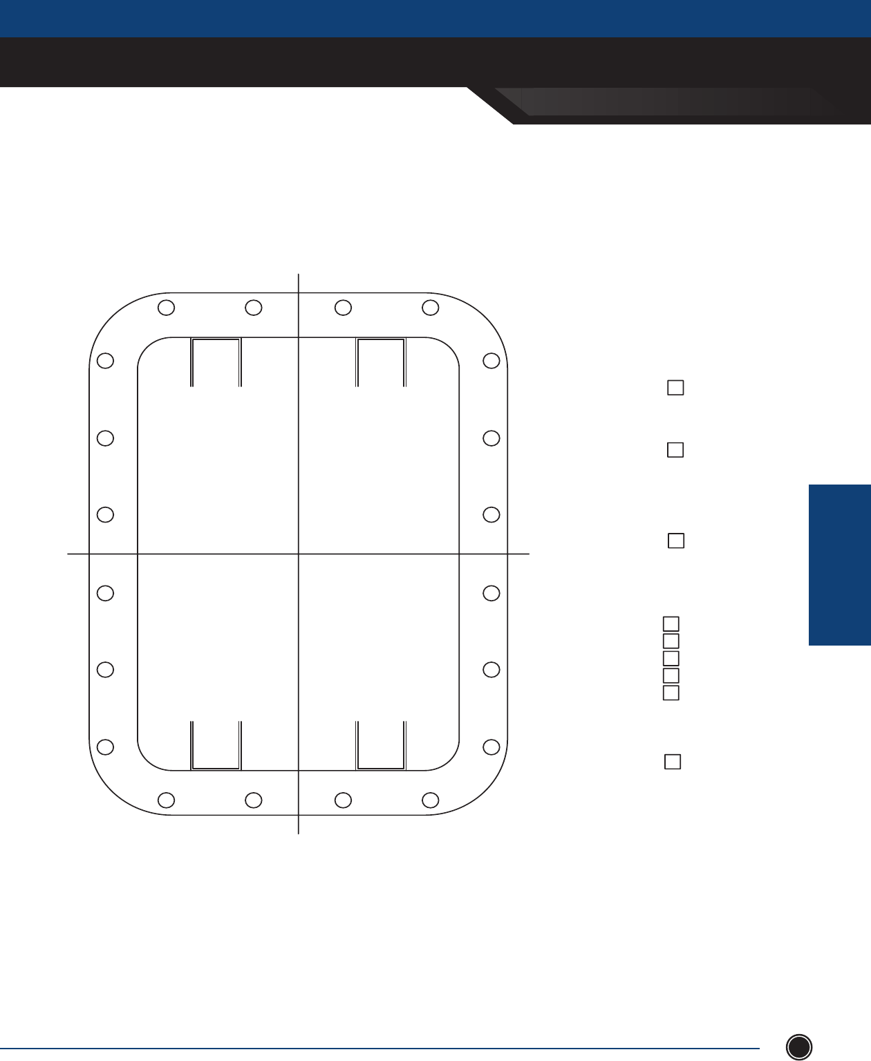
XCE SERIES & XJF
SEND ORDERS TO ORDERS@ADALET.COM
T: 216.267.9000 | F:216.267.1681 | info@adalet.com ©Adalet
EXPLOSIONPRROOF
ENCLOSURES
EXPLOSIONPROOF ENCLOSURES
101
Customer Design Sheets
Cover Layout
REF. DS361 & B301
UL APPROVED
N4 GROOVE
RIGHT HAND
SHORT SIDE
NON REMOVABLE
NEMA 4/ IP66
LEFT HAND
LONG SIDE
HINGES
REF. DS327 & B301
CSA APPROVED
UL
CSA
DIMENSION ALL MODIFICATIONS
FROM CENTER LINES OF COVER
DEMKO U Cert.
ATEX / IECEx
CAT #: X _ _ _ _ _ _ _ _
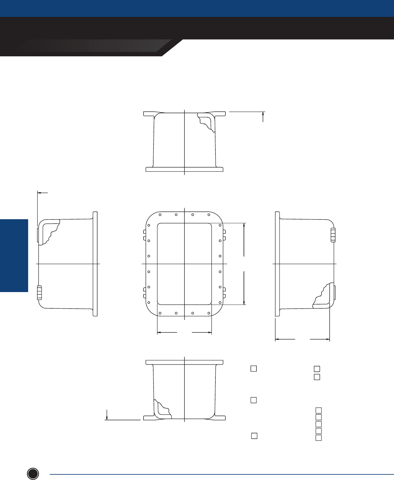
EXPLOSIONPROOF ENCLOSURES
XCE SERIES & XJF
ADALET.COM
ADALET ENCLOSURE SYSTEMS | 4801 WEST 150TH | CLEVELAND, OHIO 44135
©Adalet
EXPLOSIONPRROOF
ENCLOSURES
102
Customer Design Sheets
Box Layout
LEFT HAND
RIGHT HAND
HINGES
LONG SIDE
NON REMOVABLE
SHORT SIDE
UL APPROVED
UL
DIMENSION ALL MODIFICATIONS FROM
CENTER LINES AND BOTTOM OF MOUNTING
LUGS WHENEVER POSSIBLE.
REF. DS248 & B301
CSA APPROVED
REF. B301
CSA
MTG. PANS
XSA PAN
XSM PAN
ATEX / IECEx
DEMKO U Cert.
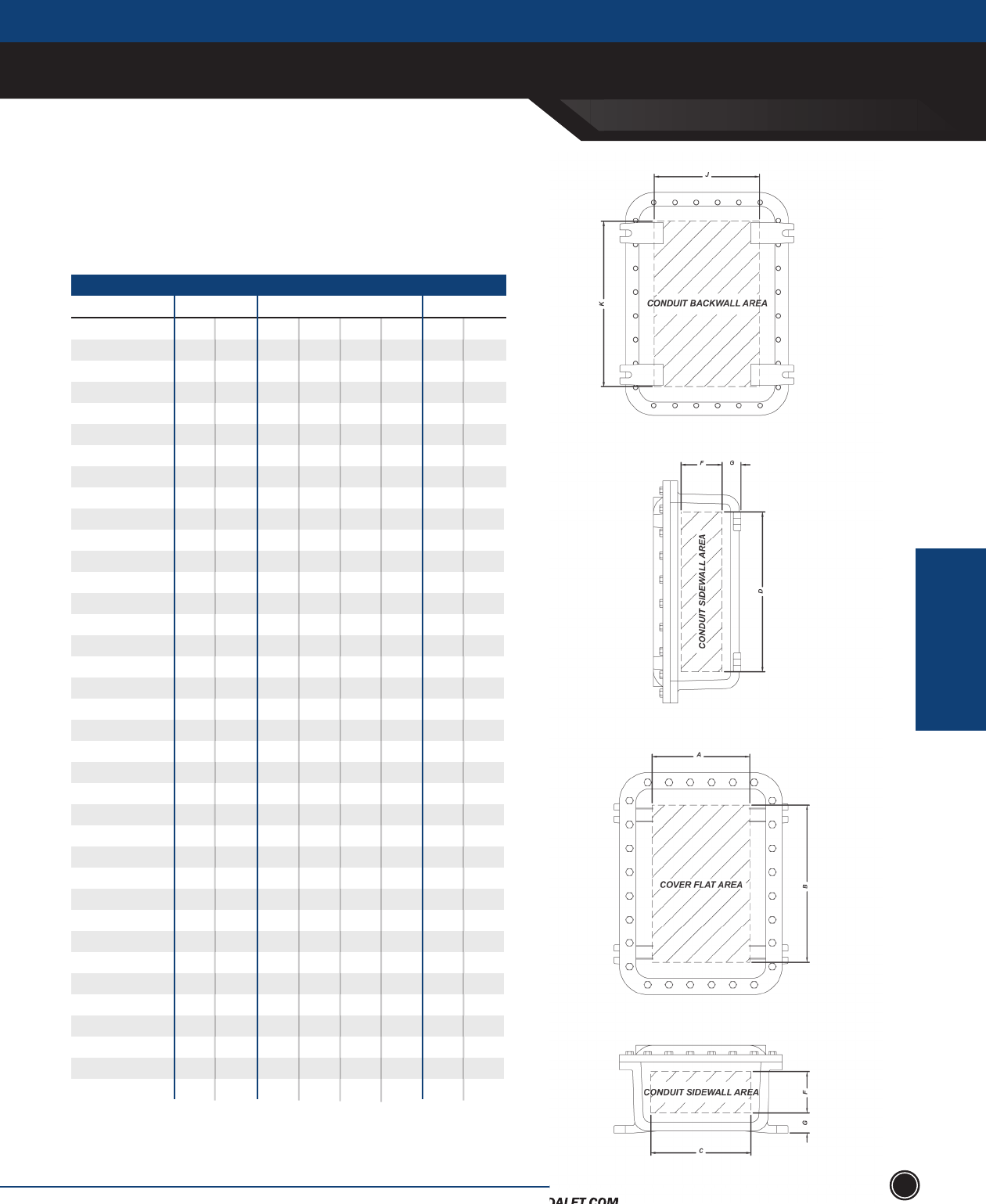
xCE sEriEs & xJf
SEND ORDERS TO ORDERS@ADALET.COM
T: 216.267.9000 | F:216.267.1681 | info@adalet.com ©Adalet
EXPLOSIONPRROOF
ENCLOSURES
EXPLOSIONPROOF ENCLOSURES
103
Cover & Sidewall Area
Enclosure Series
-041604
-060804
-060805
-060806
-061105
-061204
-061206
-061305
-071004
-071006
-071805
-080804
-080806
-080808
-081004
-081006
-081008
-081204
-081206
-081208
-091105
-101004
-101006
-101008
-101206
-101404
-101406
-101408
-121204
-121206
-121208
-121804
-121806
-121808
-122005
-122404
-122406
COVER FLAT
A B
2 ⁄
3 ⁄
3 ⁄
3 ⁄
3 ⁄
3 ⁄
3 ⁄
3 ⁄
4 ⁄
4 ⁄
5
5 ⁄
5 ⁄
5 ⁄
5 ⁄
5 ⁄
5 ⁄
5 ⁄
5 ⁄
5 ⁄
6 ⁄
7 ⁄
7 ⁄
7 ⁄
7 ¾
7 ⁄
7 ⁄
7 ⁄
9 ¾
9 ¾
9 ¾
9 ¾
9 ¾
9 ¾
9 ¾
9 ⁄
9 ⁄
14 ⁄
5 ⁄
5 ⁄
5 ⁄
8 ⁄
9 ⁄
9 ⁄
10 ⁄
7 ⁄
7 ⁄
16 ¼
5 ⁄
5 ⁄
5 ⁄
7 ⁄
7 ⁄
7 ⁄
9 ⁄
9 ⁄
9 ⁄
8 ⁄
7 ⁄
7 ⁄
7 ⁄
9 ¾
11 ⁄
11 ⁄
11 ⁄
9 ¾
9 ¾
9 ¾
15 ¾
15 ¾
15 ¾
17 ¾
21 ¾
21 ⁄
CONDUIT - SIDEWALL
2 ⁄
4 ⁄
4 ⁄
4 ⁄
4 ⁄
4 ⁄
4 ⁄
4 ⁄
5 ⁄
5 ⁄
5 ⁄
6 ⁄
6 ⁄
6 ⁄
6 ⁄
6 ⁄
6 ⁄
6 ⁄
6 ⁄
6 ⁄
7 ⁄
8 ⁄
8 ⁄
8 ⁄
8 ¼
8 ⁄
8 ⁄
8 ⁄
10
9 ⁄
9 ⁄
10 ⁄
9 ⁄
9 ⁄
10 ⁄
10 ⁄
10 ⁄
14 ⁄
6 ⁄
6 ⁄
6 ⁄
9 ⁄
10 ⁄
10 ⁄
11 ⁄
8 ⁄
8 ⁄
16 ⁄
6 ⁄
6 ⁄
6 ⁄
8 ⁄
8 ⁄
8 ⁄
10 ⁄
10 ⁄
10 ⁄
9 ⁄
8 ⁄
8 ⁄
8 ⁄
10 ¼
12 ⁄
12 ⁄
12 ⁄
10
9 ⁄
9 ⁄
16 ⁄
15 ⁄
15 ⁄
18 ⁄
22 ⁄
22 ⁄
2 ⁄
2 ⁄
3 ⁄
4 ⁄
3 ⁄
2 ⁄
4 ⁄
3 ⁄
2 ½
4 ⁄
3 ½
2 ⁄
4 ⁄
6 ⁄
2 ½
4 ½
6 ½
2 ½
4 ½
6 ½
3 ⁄
2 ⁄
4 ⁄
6 ⁄
4 ⁄
2 ⁄
4 ⁄
6 ¼
2 ⁄
4 ⁄
6 ⁄
2 ⁄
4 ⁄
6 ⁄
3 ⁄
2 ⁄
4 ⁄
1
1
1
1
1
1
1 ⁄
1
1 ⁄
1 ⁄
1 ⁄
1 ⁄
1 ⁄
1 ⁄
1 ⁄
1 ⁄
1 ⁄
1 ⁄
1 ⁄
1 ⁄
1 ⁄
1 ⁄
1 ⁄
1 ⁄
1 ⁄
1 ⁄
1 ⁄
1 ¾
1 ⁄
1 ⁄
1 ⁄
1 ⁄
1 ⁄
1 ⁄
2
2
2
F GC D J K
3 ⁄
5 ⁄
5 ⁄
4 ⁄
5 ⁄
5 ⁄
4 ⁄
5 ⁄
5 ⁄
5 ⁄
5 ⁄
7 ⁄
7 ⁄
6 ⁄
6 ⁄
6 ⁄
6 ⁄
6 ⁄
6 ⁄
6 ⁄
7 ⁄
8 ⁄
8 ⁄
8 ⁄
8 ¼
8 ⁄
8 ⁄
7 ⁄
10
9 ⁄
9 ⁄
10 ⁄
9 ⁄
9 ⁄
10 ⁄
10 ⁄
10 ⁄
15 ⁄
7 ⁄
7 ⁄
6 ⁄
10 ⁄
11 ⁄
10 ⁄
12 ⁄
8 ⁄
8 ⁄
16 ⁄
7 ⁄
7 ⁄
6 ⁄
8 ⁄
8 ⁄
8 ⁄
10 ⁄
10 ⁄
10 ⁄
9 ⁄
8 ⁄
8 ⁄
8 ⁄
10 ¼
12 ⁄
12 ⁄
11 ⁄
10
9 ⁄
9 ⁄
16 ⁄
15 ⁄
15 ⁄
18 ⁄
22 ⁄
22 ⁄
BACK WALL
SEND ORDERS TO ORDERS@ADALET.COM
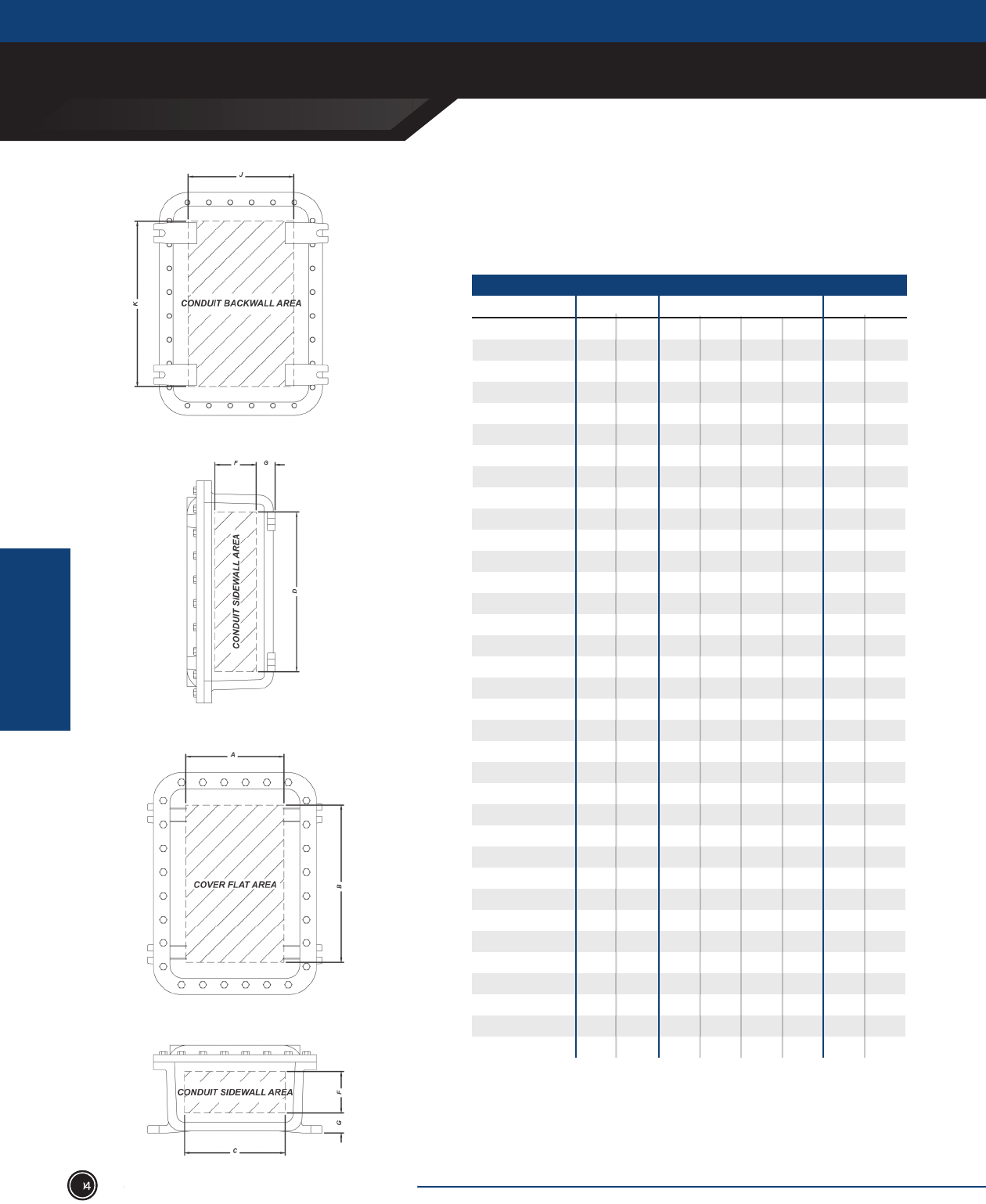
EXPLOSIONPROOF ENCLOSURES
xCE sEriEs & xJf
ADALET.COM
ADALET ENCLOSURE SYSTEMS | 4801 WEST 150TH | CLEVELAND, OHIO 44135
©Adalet
EXPLOSIONPRROOF
ENCLOSURES
104
Cover & Sidewall Area
Enclosure Series
COVER FLAT
A B
9 ⁄
9 ⁄
9 ⁄
9 ⁄
9 ⁄
9 ⁄
9 ⁄
11
11
11
11
12 ½
12 ½
12 ½
12 ½
12 ½
12 ½
13 ¼
13 ⁄
12 ½
14 ¼
14 ¼
14 ¼
14 ¼
14 ¼
14 ¼
14 ¼
14 ¼
14 ¼
20 ¼
20 ¼
20 ¼
20 ¼
20 ¼
28 ¾
21 ⁄
21 ⁄
27 ⁄
33 ⁄
33 ⁄
33 ⁄
42 ¼
11
11
11
25
12 ½
12 ½
12 ½
20 ½
20 ½
20 ½
25 ¼
31 ⁄
42 ¼
14 ¼
14 ¼
14 ¼
20 ¼
20 ¼
20 ¼
26 ¼
32 ¼
32 ¼
20 ¼
20 ¼
26 ¼
32 ¼
32 ¼
32 ¾
CONDUIT - SIDEWALL
9 ⁄
9 ⁄
10 ⁄
10 ⁄
10 ⁄
9 ⁄
9 ⁄
12 ⁄
12 ⁄
11 ⁄
11 ⁄
14 ⁄
14 ⁄
13 ⁄
13 ½
13 ⁄
13 ¼
14 ⁄
14 ⁄
13 ⁄
16 ⁄
16 ⁄
15 ⁄
15 ⁄
15 ⁄
15 ¼
15 ⁄
15 ⁄
15 ¼
20 ⁄
20 ¾
20 ⁄
21 ⁄
21 ⁄
30
21 ⁄
21 ⁄
28 ⁄
34 ⁄
34 ⁄
33 ⁄
43 ⁄
12 ⁄
12 ⁄
11 ⁄
25 ⁄
14 ⁄
14 ⁄
13 ⁄
21 ½
21 ⁄
21 ¼
26 ⁄
32 ⁄
43 ⁄
16 ⁄
16 ⁄
15 ⁄
21 ⁄
21 ⁄
21 ¼
27 ⁄
33 ⁄
33 ¼
20 ⁄
20 ¾
26 ⁄
33 ⁄
33 ⁄
34
6 ⁄
8 ⁄
4
2
4
6
5 ⁄
1 ¾
3 ¾
5 ¾
4
2
4
6
3 ⁄
5 ⁄
7 ⁄
3 ⁄
3 ⁄
7 ⁄
1 ⁄
3 ⁄
5 ⁄
3 ⁄
5 ⁄
7 ⁄
5 ⁄
5 ⁄
7 ⁄
5 ⁄
7 ⁄
5 ⁄
5 ⁄
7 ⁄
3 ⁄
2
2
2 ⁄
2 ⁄
2 ⁄
2 ⁄
2 ⁄
2 ⁄
2 ⁄
2 ⁄
2
2 ⁄
2 ⁄
2 ⁄
2 ⁄
2 ⁄
2 ⁄
2 ⁄
2 ⁄
2 ⁄
2 ⁄
2 ⁄
2 ⁄
2 ½
2 ½
2 ½
2 ½
2 ½
2 ½
2 ⁄
2 ⁄
2 ⁄
2 ½
2 ¾
2 ¾
F GC D J K
BACK WALL
-122408
-122410
-123006
-123604
-123606
-123608
-124608
-141404
-141406
-141408
-142806
-161604
-161606
-161608
-162406
-162408
-162410
-162806
-163406
-164610
-181804
-181806
-181808
-182406
-182408
-182410
-183008
-183608
-183610
-242408
-242410
-243008
-243608
-243610
-323612
9 ⁄
9 ⁄
10 ⁄
10 ⁄
10 ⁄
9 ⁄
9 ⁄
11 ⁄
11 ⁄
11 ⁄
11 ⁄
14 ⁄
14 ⁄
13 ⁄
13 ½
13 ⁄
13 ¼
14 ⁄
14 ⁄
13 ⁄
16 ⁄
16 ⁄
15 ⁄
15 ⁄
15 ⁄
15 ¼
15 ⁄
15 ⁄
15 ¼
20 ⁄
20 ¾
21 ⁄
21 ⁄
20 ⁄
28 ⁄
21 ⁄
21 ⁄
28 ⁄
34 ⁄
34 ⁄
33 ⁄
43 ⁄
11 ⁄
11 ⁄
11 ⁄
25 ⁄
14 ⁄
14 ⁄
13 ⁄
21 ½
21 ⁄
21 ¼
26 ⁄
32 ⁄
43 ⁄
16 ⁄
16 ⁄
15 ⁄
21 ⁄
21 ⁄
21 ¼
27 ⁄
33 ⁄
33 ¼
20 ⁄
20 ¾
27 ⁄
33 ⁄
32 ⁄
32 ⁄
104
xCE sEriEs & xJf
SEND ORDERS TO ORDERS@ADALET.COM
T: 216.267.9000 | F:216.267.1681 | info@adalet.com ©Adalet
EXPLOSIONPRROOF
ENCLOSURES
EXPLOSIONPROOF ENCLOSURES
105
Minimum Spacing for Operators in Covers
Enclosure Series
XCE041604
XCE060804
XCE060805
XCE060806
XCE061105
XCE061204
XCE061206
XCE061305
XCE071004
XCE071006
XCE071805
XCE080804
XCE080806
XCE080808
XCE081004
XCE081006
XCE081008
XCE081204
XCE081206
XCE081208
XCE091105
XCE101004
XCE101006
XCE101008
XCE101206
XCE101404
XCE101406
XCE101408
XCE101410
XCE121204
XCE121206
XCE121208
XCE121804
XCE121806
XCE121808
XCE122005
XCE122404
STANDARD OPERATORS
Max. Rows
5
2
2
2
3
4
4
4
6
6
12
4
4
4
6
6
6
8
8
8
6
9
9
9
12
12
12
12
12
9
9
9
15
15
15
18
21
MINIATURE OPERATORS
Max. # Max. Per Row
5
2
2
2
3
4
4
4
3
3
6
2
2
2
3
3
3
4
4
4
3
3
3
3
4
4
4
4
4
3
3
3
5
5
5
6
7
Spacing
CL to CL Max. Rows
13
8
8
8
14
16
16
18
18
18
45
16
16
16
24
24
24
32
32
32
35
36
36
36
48
60
60
60
60
64
64
64
92
92
92
128
150
Max. # Max. Per Row
13
4
4
4
7
8
8
9
6
6
15
4
4
4
6
6
6
8
8
8
7
6
6
6
8
10
10
10
10
8
8
8
14
14
14
16
20
Spacing
CL to CL
COVER WALL
Thickness
1
1
1
1
1
1
1
1
2
2
2
2
2
2
2
2
2
2
2
2
2
3
3
3
3
3
3
3
3
3
3
3
3
3
3
3
3
2 ½
2 ½
2 ½
2 ½
2 ½
2 ½
2 ½
2 ½
2 ½
2 ½
2 ½
2 ½
2 ½
2 ½
2 ½
2 ½
2 ½
2 ½
2 ½
2 ½
2 ½
2 ½
2 ½
2 ½
2 ½
2 ½
2 ½
2 ½
2 ½
3
3
3
3
3
3
3
3
1
2
2
2
2
2
2
2
3
3
3
4
4
4
4
4
4
4
4
4
5
6
6
6
6
6
6
6
6
8
8
8
8
8
8
8
8
1
1
1
1
1
1
1
1
1
1
1
1
1
1
1
1
1
1
1
1
1
1
1
1
1
1
1
1
1
1
1
1
1
1
1
1
1
½
½
½
½
½
⁄
⁄
½
⁄
⁄
⁄
⁄
⁄
⁄
⁄
⁄
⁄
⁄
⁄
⁄
⁄
⁄
⁄
⁄
¾
¾
¾
¾
¾
⁄
⁄
⁄
⁄
⁄
⁄
1 ⁄
1 ⁄
For closer spacing consult factory for details. Hydro test may be necessary for closer hole spacing.NOTE
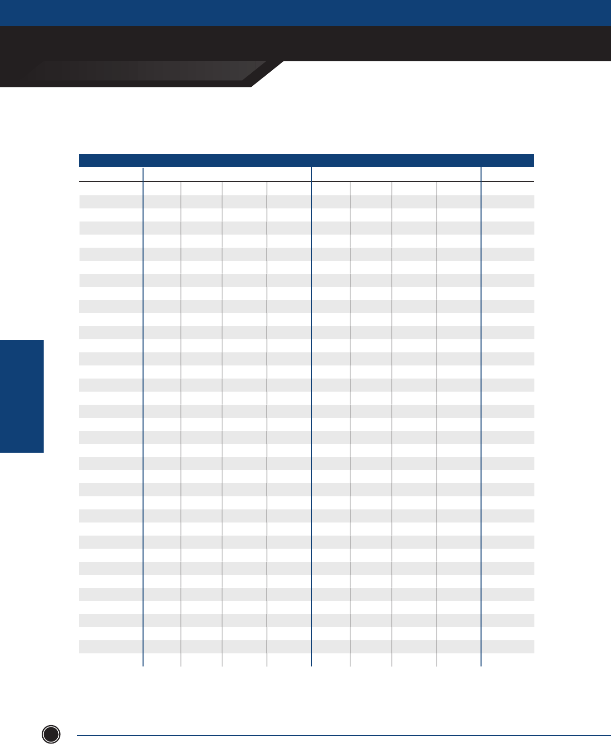
EXPLOSIONPROOF ENCLOSURES
XCE SERIES & XJF
ADALET.COM
ADALET ENCLOSURE SYSTEMS | 4801 WEST 150TH | CLEVELAND, OHIO 44135
©Adalet
EXPLOSIONPRROOF
ENCLOSURES
106
Minimum Spacing for Operators in Covers
Enclosure Series
STANDARD OPERATORS
Max. Rows
21
21
27
33
33
33
42
16
16
16
24
24
32
16
16
16
24
24
24
28
32
48
36
36
36
24
24
24
32
36
36
36
36
42
54
54
72
MINIATURE OPERATORS
Max. # Max. Per Row
7
7
9
11
11
11
14
4
4
4
6
6
8
4
4
4
6
6
6
7
8
12
6
6
6
6
6
6
8
9
9
6
6
7
9
9
9
Spacing
CL to CL Max. Rows
150
150
150
150
150
150
150
100
100
100
100
100
150
121
121
121
150
150
150
150
150
150
150
150
150
150
150
150
150
150
150
150
150
150
150
150
50
Max. # Max. Per Row
20
20
26
32
32
32
41
10
10
10
18
18
24
11
11
11
19
19
19
24
30
41
13
13
13
19
19
19
25
31
31
19
19
25
31
31
31
Spacing
CL to CL
COVER WALL
Thickness
3
3
3
3
3
3
3
3
4
4
4
4
4
4
4
4
4
4
4
4
4
4
6
6
6
4
4
4
4
4
4
6
6
6
6
6
8
3
3
3
3
3
3
3
3
3
3
3
3
3
3 ½
3 ½
3 ½
3 ½
3 ½
3 ½
3 ½
3 ½
3 ½
2 ½
2 ½
2 ½
3 ½
3 ½
3 ½
3 ½
3 ½
3 ½
3 ½
3 ½
3 ½
3 ½
3 ½
3 ½
8
8
8
8
8
8
8
10
10
10
10
10
10
11
11
1
11
11
11
11
11
11
13
13
13
13
13
13
13
13
13
19
19
19
19
19
27
1
1
1
1
1
1
1
1
1
1
1
1
1
1
1
1
1
1
1
1
1
1
1
1
1
1
1
1
1
1
1
1
1
1
1
1
1
1 ⁄
1 ⁄
1 ⁄
1 ⁄
1 ⁄
1 ⁄
1 ¼
⁄
⁄
⁄
1 ⁄
1 ⁄
1 ⁄
⁄
⁄
⁄
⁄
⁄
⁄
1 ¼
1 ¼
1
1
1
1
1 ½
1 ½
1 ½
1 ½
1 ⁄
1 ⁄
1 ½
1 ½
1 ⁄
1 ⁄
1 ⁄
1 ⁄
XCE122408
XCE122410
XCE123006
XCE123604
XCE123606
XCE123608
XCE124608
XCE141404
XCE141406
XCE141408
XCE142210
XCE142213
XCE142806
XCE161604
XCE161606
XCE161608
XCE162406
XCE162408
XCE162410
XCE162806
XCE163406
XCE164610
XCE181804
XCE181806
XCE181808
XCE182406
XCE182408
XCE182410
XCE183008
XCE183608
XCE183610
XCE242408
XCE242410
XCE243008
XCE243608
XCE243610
XCE323612***
For closer spacing consult factory for details. Hydro test may be necessary for closer hole spacing.
NOTE
***This unit has limited approval dependent on number of entries
Some XJF Series enclosures do not have UL approval - consult factory
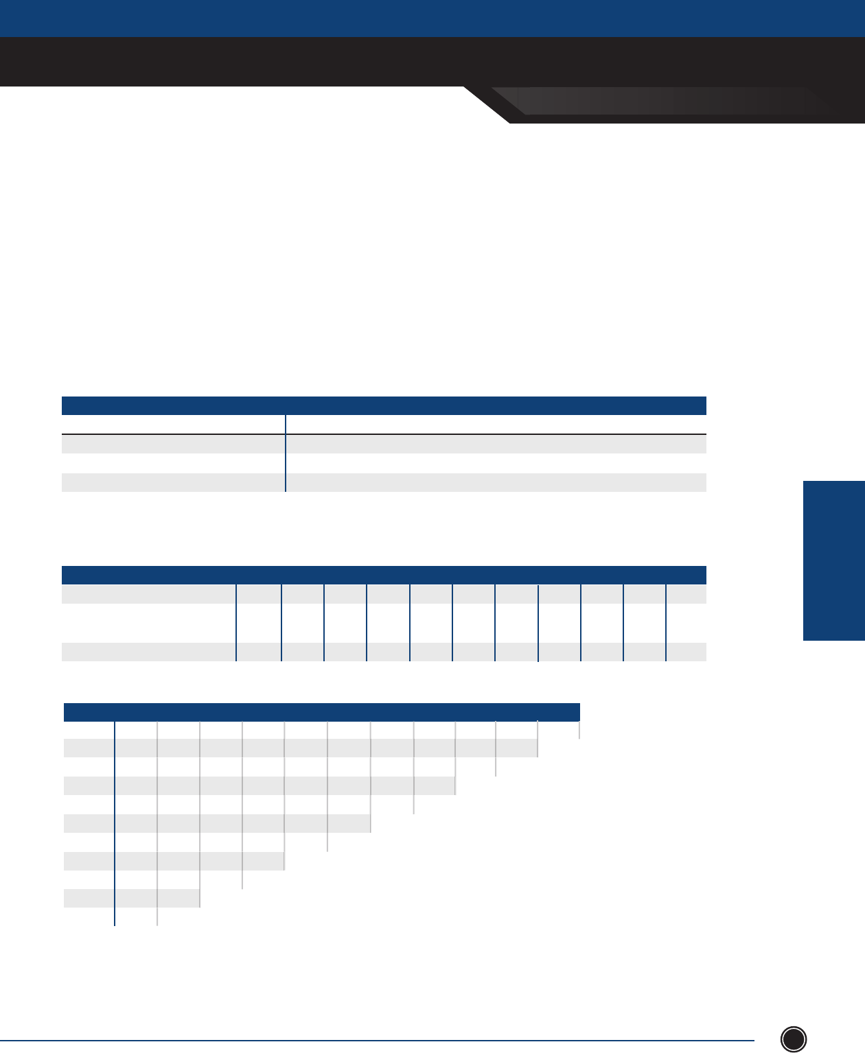
xCE sEriEs & xJf
SEND ORDERS TO ORDERS@ADALET.COM
T: 216.267.9000 | F:216.267.1681 | info@adalet.com ©Adalet
EXPLOSIONPRROOF
ENCLOSURES
EXPLOSIONPROOF ENCLOSURES
107
Conduit Drilling and Tapping Guidelines
When drilling and tapping enclosures for conduit, proper installation requires compliance with the following:
1. Must be tapped with at least 5 full NPT threads in enclosure back or sides only; min. 1/2” conduit size
for XJF and XCE series.
2. Depth of NPT holes must be plus 1/2 turn min. to plus 2 turns max. past standard NPT plug gauge notch.
3. Inner end of conduit openings shall be smooth and well-rounded.
THREAD SIZE OF CONDUIT MINIMUM WALL THICKNESS AT CONDUIT ENTRANCE EXCLUDING XCEX
Inches (NPT)
½ ¾
2 ½ 5
1 - 2
Explosionproof
¾ inch
⁄ inch
⁄ inch
THREAD SIZE OF CONDUIT MINIMUM WALL THICKNESS AT CONDUIT ENTRANCE EXCLUDING XCEX
Conduit size, inches (NPT) / metric
Minumum Distance from conduit CL
to inside corner or back of box
Approximate diameter of union
1 ⁄ 1 ⁄
1 ⁄ 1 ⁄ 2 ⁄ 2 ⁄
1 ⁄ 1 ¾ 1 ⁄ 2 ⁄
3 ¼ 3 ⁄ 4 ⁄ 5 ½ 66 ½ 7 ½
2 ⁄ 2 ⁄ 2 ⁄ 3 ¼ 3 ⁄
½ /m16 ¾ /m20 1 / m25 1 ¼ /m32 1
½ /
m40 2 / m50 2 ½ /m63 3 /m75 3 ½ 45
SIZE 5 4
4 ½
4 ¾
4 ⁄
5 ⁄
5 ½
5 ¾
6
6 ¼
6 ½
6 ¾
7 ¼
3 ⁄
3 ¾
4
4 ⁄
4 ¼
4 ⁄
4 ⁄
5 ⁄
5 ⁄
5 ⁄
3 ½ 32 ½
3 ⁄
3 ½
3 ⁄
3 ⁄
4
4 ¼
4 ⁄
5
5 ¼
3
3 ⁄
3 ¼
3 ½
3 ⁄
3 ⁄
4 ¼
4 ⁄
2 ⁄
2 ¾
3
3 ⁄
3 ¼
3 ⁄
3 ⁄
2 ⁄
2 ½
2 ⁄
2 ⁄
3
3 ¼
2
2
2 ⁄
2 ⁄
2 ½
2 ⁄
1 ½
1 ⁄
2
2 ¼
2 ⁄
1 ¼
1 ¾
1 ⁄
2
1
1 ⁄
1 ¾
¾ ½
1 ½
½ /m16
¾ /m20
1 / m25
1 ¼ /m32
1
½ /
m46
2 / m56
2 ½ /m63
3 /m75
3 ½
4
5
1. This information is compiled from data which we believe is reliable and is given in good faith. Since the methods of applications and conditions under which our products are used are
beyond our control, we are not able to guarantee the application and/or use of same. The user assumes all risks and liability in connection with the application and use of our product.
2. Dimensions are in inches
3. Metric threads available from factory for most applications - consult factory.
4. Consult factory for special spacing arrangements. Hydro test may be required.
NOTE
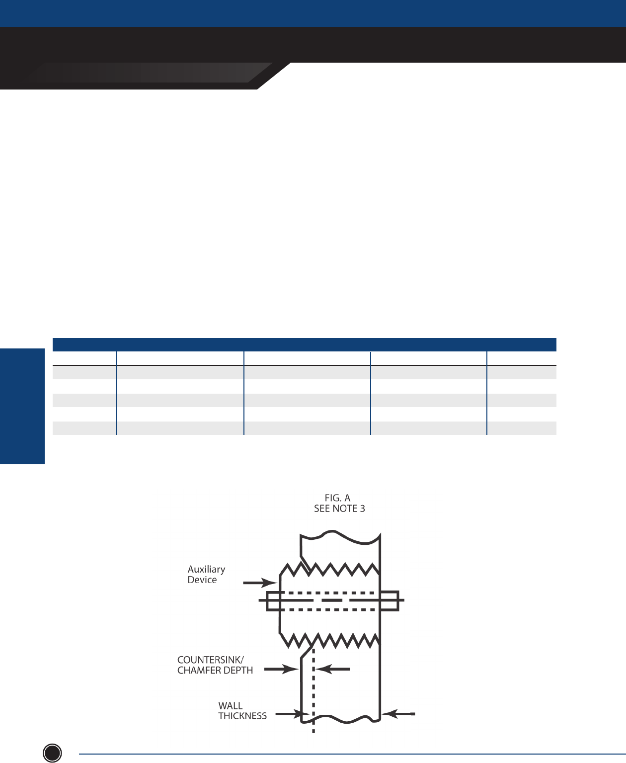
EXPLOSIONPROOF ENCLOSURES
xCE sEriEs & xJf
ADALET.COM
ADALET ENCLOSURE SYSTEMS | 4801 WEST 150TH | CLEVELAND, OHIO 44135
©Adalet
EXPLOSIONPRROOF
ENCLOSURES
108
Auxiliary Device Drilling and Tapping Guidelines
When using an auxiliary device in the box wall of an enclosure used in hazardous locations, proper installation requires
compliance with the following:
1. A minimum of (5) thread engagement, class 2 t, required for group C & D applications.
A minimum of (7) thread engagement, class 2 t, required for group B applications.
2. The table below shows minimum box wall thickness for auxiliary devices threads.
REQUIRED MINIMUM BOX WALL THICKNESS
Thread Size (in.)
½ - 14 NPSM
¾ - 14 NPSM
1-11 ½ NPSM
⁄- 18 NPSM
⁄- 16 UNC
Group C & D min. (5) thread engagement
⁄ inch
⁄ inch
⁄ inch
⁄ inch
⁄ inch
Group B min. (7) thread engagement
½ inch
½ inch
⁄ inch
⁄ inch
⁄ inch
Typical Auxlilary Device Drill Dia.
XBO, XHPB, XHSS, Standard Operators
XBO, XHPB, XHSS, Standard Operators
XCBH Large Handle Assembly
XCBH Small Handle Assembly
XMOB, XMOSS, Mini Operators
.747 / .759
.958 / .970
1.201 / 1.211
.603 / .612
⁄
3. If auxiliary device contains undercut in engaging threaded section, the minimum wall thickness shown in Table I
must increase to maintain the minimum required thread engagement. (Fig. A)
(continued on next page)
Spacing for auxiliary devices installed in box walls of control panel enclosures used in
hazardous locations
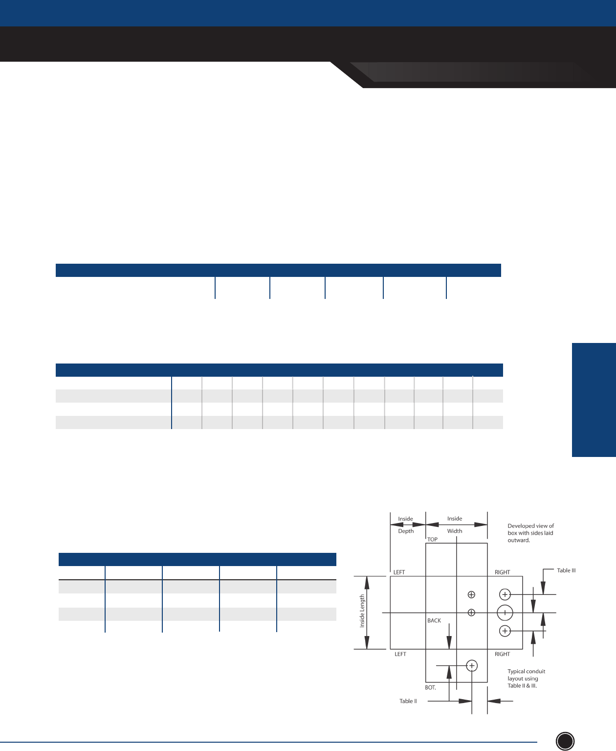
xCE sEriEs & xJf
SEND ORDERS TO ORDERS@ADALET.COM
T: 216.267.9000 | F:216.267.1681 | info@adalet.com ©Adalet
EXPLOSIONPRROOF
ENCLOSURES
EXPLOSIONPROOF ENCLOSURES
109
Auxiliary Device Drilling and Tapping Guidelines (cont.)
When using an auxiliary device in the box wall of an enclosure used in hazardous locations, proper installation requires
compliance with the following:
4. Table II provides the minimum distance an auxiliary device center can be placed from inside corner or back of box.
TITLE? ⁄ - 16 UNC
Minimum distance from auxiliary device CL to
corner or back of box
⁄ - NPSM ½ - NPSM ¾ - NPSM 1 - NPSM
1 ½ 1 ⁄ 1 ¾ 1 ⁄ 2
AUXILIARY DEVICE THREAD (in) 5 4 3 ½ 32 ½
3 ⁄
3 ½
3 ⁄
3 ⁄
3
3 ⁄
3 ¼
3 ½
2 ⁄
2 ¾
2 ⁄
3
2 ⁄
2 ½
2 ⁄
2 ¾
2
2
2 ¼
2 ⁄
2 ½
1 ½
1 ⁄
2 ⁄
2 ¼
2 ⁄
1 ¼
1 ¾
2
2 ⁄
2 ¼
1
1 ⁄
1 ⁄
2
2 ⁄
¾ ½
1 ½
1 ¾
1 ⁄
2
⁄
½
¾
1
4 ½
4 ⁄
4 ¾
5
3 ⁄
3 ¾
4
4 ¼
5. Table III shows minimum spacing between conduit and auxiliary device entrances.
MIN. SPACING BETWEEN AUX. DEVICE OF VARYING THREAD SIZES (INCHES)
⁄
½
¾
1
1 ½
1 ½
1 ½
2 ½
1 ½
2
2
2 ½
⁄ ½ ¾
1 ½
2
2
3
2 ½
2 ½
3
3 ½
1
6. Table IV shows minimum spacing between auxiliary device entrances.
NOTE: Increase distance between devices as required to maintain
minimum through air spacing of contacts required by electrical codes.
7. Double all distances in Table III and IV holes located in back wall.
TABLE II
TABLE III
TABLE IV
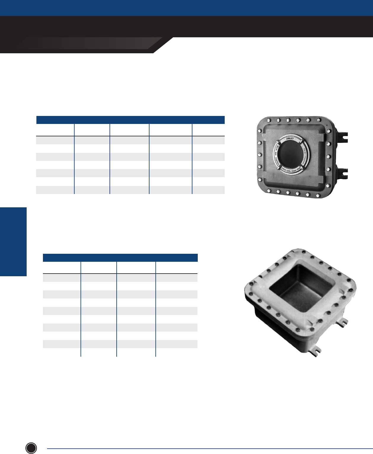
EXPLOSIONPROOF ENCLOSURES
XCE SERIES & XJF
ADALET.COM
ADALET ENCLOSURE SYSTEMS | 4801 WEST 150TH | CLEVELAND, OHIO 44135
©Adalet
EXPLOSIONPRROOF
ENCLOSURES
110
Glass Windows
CIRCULAR WINDOW
1 ⁄
1 ⁄
3
4
5 ¼
6 ⁄
8
3
4 ⁄
5 ⁄
6 ⁄
7 ⁄
10 ⁄
12 ⁄
8
9
9
9
10
16
18
2 ½ - 16
3 ⁄- 12
4 ¾- 12
5 ½- 12
7 ⁄- 12
9 ⁄- 12
10 ⁄- 8
Circular
Window Window Viewing
Area Diameter Overall Window
Cover Diameter Min. Enclosure Inside
Width / Length Thread
XGC 10
XGC 20
XGC 30
XGC 40
XGC 52
XGC66
XGC 80
1. All dimensions are in inches.
2. Glass window catalog number includes XCE cover machining and installation
3. For TYPE 4/IP66 option add sux “N4”.
4. To order glass windows for eld installations, add sux SLF to XGC catalog no.
5. Consult factory for closer spacing requirements, multiple windows or combinations of operators and windows.
NOTE
STANDARD RECTANGLE WINDOW
3 x 3
3 x 5
3 x 7
5 x 5
5 x 9
7 x 7
7 x 13
9 x 9
11 x 11
13 x 13
8
8
8
10
10
12
12
14
16
18
8
10
12
10
14
12
18
14
16
18
Rectangular
Window Window Viewing
Area Diameter Min. Enclosure
Inside Width Min. Enclosure Inside
Length
XGW 0303
XGW 0305
XGW 0307
XGW 0505
XGW 0509
XGW 0707
XGW 0713
XGW 0909
XGW 1111
XGW 1313
1. All dimensions are in inches.
2. Glass window catalog number includes installation and pattern modications
3. For TYPE 4 option add sux “N4”.
4. Consult factory for special viewing area requirements, closer spacing and to combine windows with other
window sizes or operators.
5. Windows can be ordered in sizes between 3” and 13” - consult factory.
6. XGW window kits are not sold for eld installation
NOTE
Photo shown is example only
Photo shown is example only
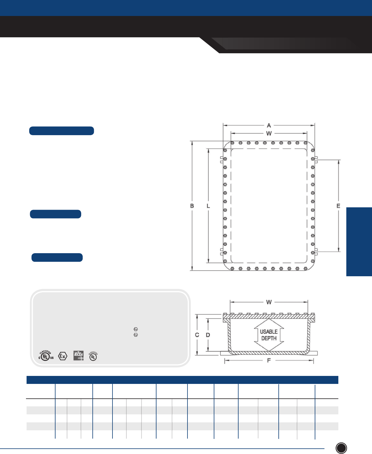
XCE SERIES & XJF
SEND ORDERS TO ORDERS@ADALET.COM
T: 216.267.9000 | F:216.267.1681 | info@adalet.com ©Adalet
EXPLOSIONPRROOF
ENCLOSURES
EXPLOSIONPROOF ENCLOSURES
111
Stainless Steel Explosionproof & Flameproof Control Enclosures
STANDARD FEATURES
• 5 standard sizes available
• Flat plate cover design
• Corrosion resistant, cast stainless steel 316
• Stainless steel cover bolts for Type 4X additional corrosion protection
• Stainless steel hinge kit
• Pre-drilled for mounting panel (mounting panel optional)
• Type 4X watertight Nitrile gasket
• Internal / external grounding screws
• Removable lifting eye bolts
• Lid-lifter cover alignment device on covers > 100 lbs
• Cast-on mounting lugs / feet
• Conduit (NPT & metric) and device (NPSM) drilling & tapping
• Auxiliary devices: breather / drains, fl ame arrestors, and operators
• Custom machining - milling, counter-boring, spot-facing, blind drilled
holes, entries, chamfers
DESIGN OPTIONS
MATERIAL
• Enclosure - Stainless steel 316
• Cover bolts - Stainless steel 316
• Hinge kits - Stainless steel 316
CERTIFICATIONS
-101408
-121208
-122410
-242410
-243610
XCESX Series
XCESX
CAT. NUMBER MTG BOLT
SIZE
INSIDE NOM. DIM.
W L D MTG LUG
E F
USABLE
DEPTH PANEL
PART NO.
SHIPPING
WT. (LBS)
PANEL DIM.
W H
10
12
12
24
24
⁄
⁄
⁄
¾
¾
10 ⁄
8 ⁄
18 ⁄
18 ⁄
29
14
12
24
24
36
8
8
10
10
10
8 ⁄
10 ⁄
11
22
34
12 ⁄
10 ⁄
23
22
22
OVERALL DIM.
A B C
13 ⁄
16 ¼
16 ¼
28 ⁄
28 ⁄
17 ⁄
16 ¼
28 ¼
28 ⁄
40 ⁄
9 ⁄
9 ⁄
11 ¾
12 ⁄
12 ⁄
XSM1014
XSM1212
XSM1224
XSM2424
XSM2436
XSA1014
XSA1212
XSA1224
XSA2424
XSA2436
8
8
10
10
10
195
210
380
735
985
13
15 ¾
15 ¾
28
28
HINGE
CAT#
XHBK-2
XHCK-2
XHCK-2
XHFK-2
XHFK-3
IECEx UL 10.0046U
IECEx Ex d IIB Gb
IECEx Ex DA21 IP66
0539 II 2 G Ex d IIB
0539 II 2 D ExtD A21
IP66
DEMKO 01 ATEX 01294724
Class I, Division 1, Groups B, C, & D
Class II, Groups E, F & G
Class III
Class I, Zone 1, AEx d IIB
NEMA Type 4X, 7, 9
ExtD A21 / IP66
Designed for use in highly corrosive areas, the cast stainless steel explosionproof enclosures provide the perfect construction material for offshore,
petrochem, or volatile industrial areas where environmental conditions require additional corrosion protection. The XCESX series of cast stainless
steel explosionproof enclosures provide an alternative to traditional cast aluminum explosionproof enclosures which may become compromised or
could break down over time in highly corrosive areas. Rated for Class I, Division 1 / Zone 1 hazardous locations, the XCESX enclosure series carries
UL, cUL, ATEX, and IECEx approvals for global applications
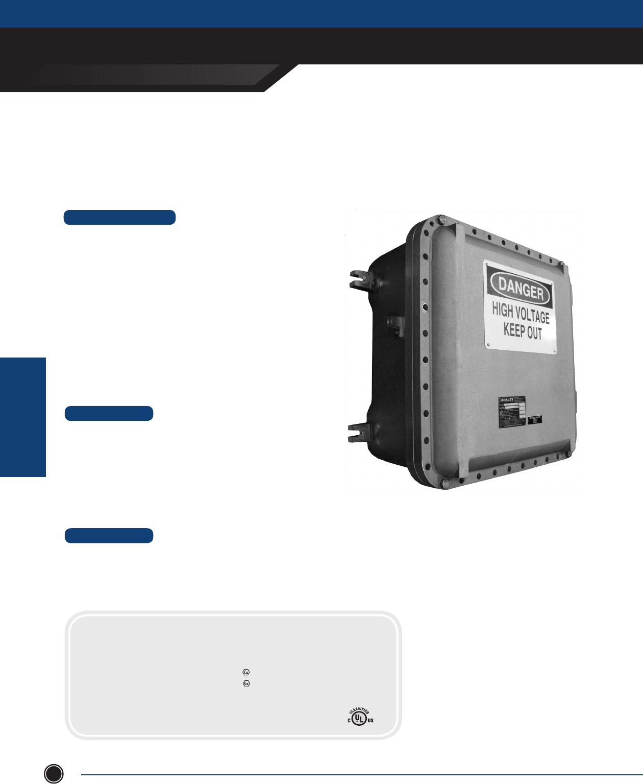
XHVX SERIES
ADALET.COM
AdAlet enclosure systems | 4801 West 150th | cleVelAnd, ohIo 44135
©Adalet
EXPLOSIONPRROOF
ENCLOSURES
EXPLOSIONPROOF ENCLOSURES
112
Flameproof High Voltage Enclosures
STANDARD FEATURES
• 16 (1 x 1) and 10 (2 x 2) sizes available
• Corrosion resistant, copper free aluminum
• Hinged cover
• Type 4 watertight gasket
• Custom steel mounting panel
• Set of three porcelain standoffs and hardware (1 x 1 connection only)
• Set of three porcelain bus supports insulators and hardware (2 x 2
connection only)
• High Voltage cover sign
• High strength steel cover bolts (zinc plated and coated)
• Internal and external ground lugs
• Removable lifting eye bolts (18 x 24 and larger)
• Lid-lifter cover alignment device (18 x 24 and larger)
• Cast-on mounting lugs / feet
• Tumblast, natural aluminum nish
• Stainless steel cover bolts for Type 4X additional corrosion protection
• Conduit (NPT & metric) and device (NPSM) drilling & tapping
• Auxiliary devices such as breather / drains
• Custom machining - milling, counter-boring, spot-facing, blind drilled holes,
entries, chamfers
• Custom cast-on logos
• Powder and epoxy coating for additional corrosion resistance
• Special mounting provisions
DESIGN OPTIONS
MATERIAL
• Enclosure - copper free aluminum (⁄ of 1%)
• Cover bolts - steel, zinc plated and coated
• Hinge kits - copper free aluminum with stainless steel 316L hardware
• Mounting panel - galvanized steel
CERTIFICATIONS
Class I, Division 1, Groups B, C, D
Class II, Division 1, Groups E, F, & G
Class III
Class I, Zone 1, AEx d IIB
T6 or T5: -20°C < Ta <55 °C
IECEx UL 09.0031X
Ex d IIB T6: -20°C < Ta <+55°C
Ex tb IIIC T73C Db / IP66
DEMKO 12 ATEX 1104713X
Ex d IIB T6: -20 < Ta < 55°C
0539 II 2 G Ex d IIB Gb T6 -20 < Ta < 55°C
0539 II 2 D Extb IIIC T73C Db / IP66
Adalet XHVX series ameproof high voltage junction boxes are available in 26 sizes up to 8kV and 1000 amps. Utilizing Adalet’s
XCEX ATEX certied ameproof enclosures, the XHVX high voltage enclosures include a set of three porcelain insulators for high
voltage applications.
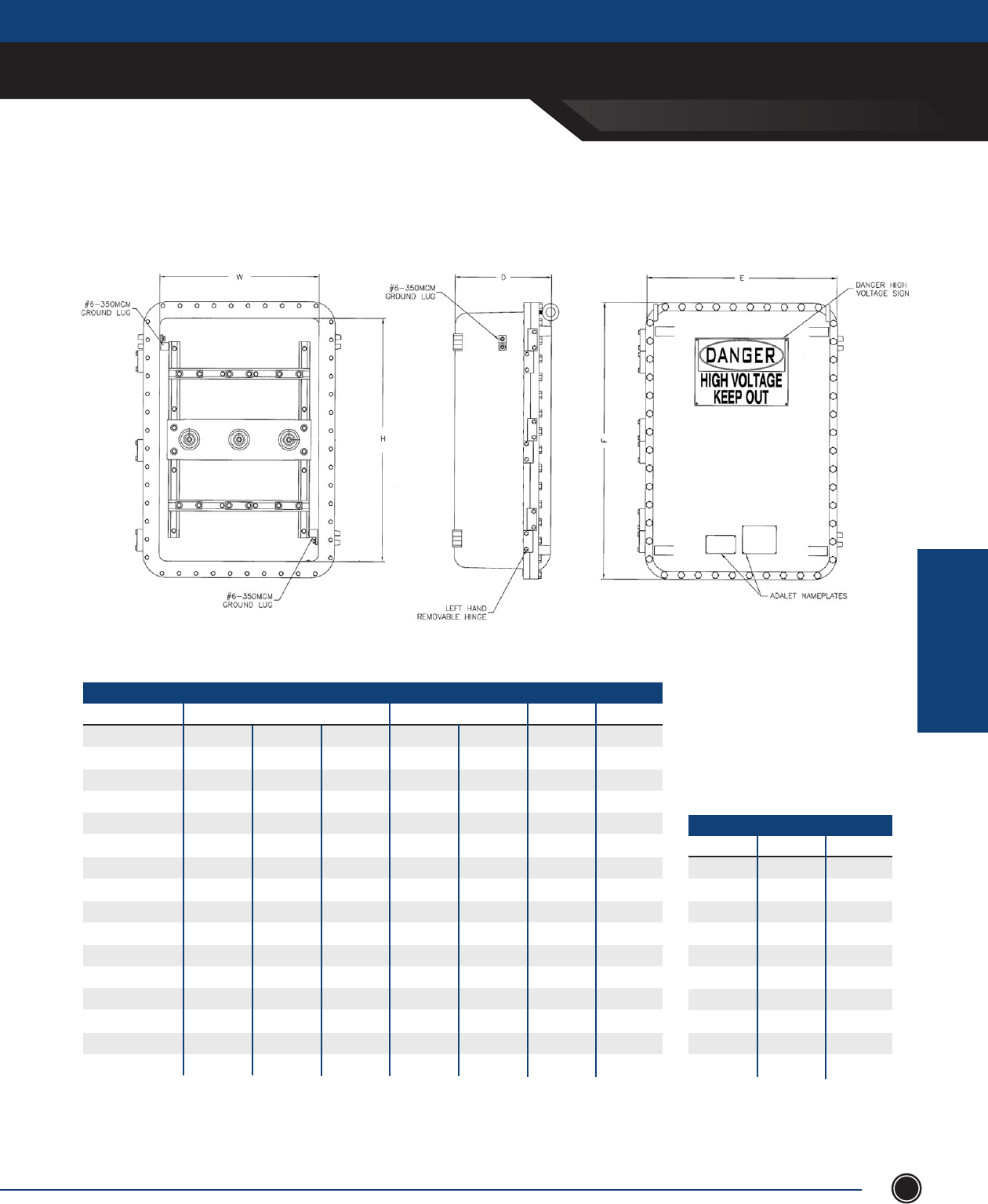
xHVx sEriEs
SEND ORDERS TO ORDERS@ADALET.COM
T: 216.267.9000 | F:216.267.1681 | info@adalet.com ©Adalet
EXPLOSIONPRROOF
ENCLOSURES
EXPLOSIONPROOF ENCLOSURES
113
1 x 1 Connection Series
XHVX-121208
XHVX-161608
XHVX-162408
XHVX-181808
XHVX-182408
XHVX-183008
XHVX-183608
XHVX-242408
XHVX-243008
XHVX-243608
XHVX-162410
XHVX-164610
XHVX-182410
XHVX-183610
XHVX-242410
XHVX-243610
12.00
16.00
16.00
18.00
18.00
18.00
18.00
24.00
24.00
24.00
16.00
16.00
18.00
18.00
24.00
24.00
ENCLOSURE
12.00
16.00
24.00
18.00
24.00
30.00
36.00
24.00
30.00
36.00
24.00
46.00
24.00
36.00
24.00
36.00
8.00
8.00
8.00
8.00
8.00
8.00
8.00
8.00
8.00
8.00
10.00
10.00
10.00
10.00
10.00
10.00
2/10
3/10
350
4/10
350
350
350
350
350
350
350
350
350
350
350
400
70
95
185
120
185
185
185
185
185
185
185
185
185
185
185
240
2.5kV
6.6kV
6.6kV
6.6kV
6.6kV
6.6kV
6.6kV
6.6kV
6.6kV
6.6kV
6.6kV
6.6kV
6.6kV
6.6kV
8kV
8kV
160
200
315
225
315
315
315
315
315
315
315
315
315
315
315
400
MAXMAXmm2
AWG / MCMH W D
CONDUCTOR SIZE VOLTAGE AMPERAGE
10
16
25
35
50
70
95
150
185
240
8
6
4
2
1/0
2/0
3/0
250
350
400
50
80
100
125
160
200
225
250
315
400
MAXmm2AWG / MCM
AMPERAGEMIN CONDUCTOR SIZE
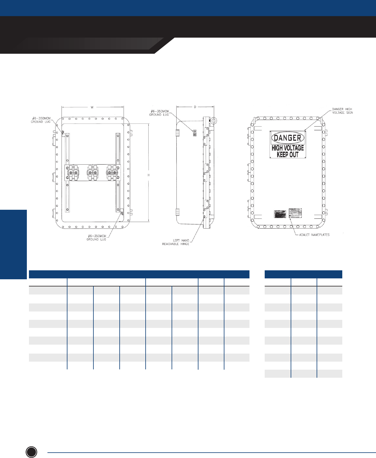
ADALET.COM
ADALET ENCLOSURE SYSTEMS | 4801 WEST 150TH | CLEVELAND, OHIO 44135
©Adalet
EXPLOSIONPRROOF
ENCLOSURES
EXPLOSIONPROOF ENCLOSURES
114
2 x 2 Connection Series
10
16
25
35
50
70
95
150
185
240
300
8
6
4
2
1/0
2/0
3/0
250
350
400
500
50
80
100
125
160
200
225
250
315
400
500
MAXmm2AWG / MCM
AMPERAGEMIN CONDUCTOR SIZE
XHVX-182408
XHVX-183008
XHVX-183608
XHVX-182410
XHVX-183610
XHVX-242408
XHVX-243008
XHVX-243608
XHVX-242410
XHVX-243610
18.00
18.00
18.00
18.00
18.00
24.00
24.00
24.00
24.00
24.00
ENCLOSURE
24.00
30.00
36.00
24.00
36.00
24.00
30.00
36.00
24.00
36.00
8.00
8.00
8.00
10.00
10.00
8.00
8.00
8.00
10.00
10.00
350
400
400
350
400
350
400
400
350
500
185
240
240
185
240
185
240
240
185
300
630
800
800
630
800
630
800
800
630
1000
315
400
400
315
400
315
400
400
315
500
CONDUCTOR
PHASEmm2
MCMH W D
AMPERAGE
xHVx sEriEs
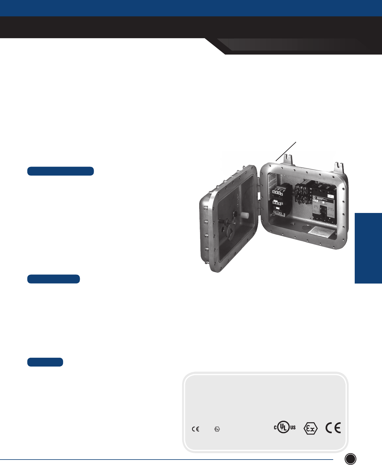
SEND ORDERS TO ORDERS@ADALET.COM
T: 216.267.9000 | F:216.267.1681 | info@adalet.com ©Adalet
EXPLOSIONPRROOF
ENCLOSURES
EXPLOSIONPROOF ENCLOSURES
115
XCPX Enclosure Series
The Adalet XCPX series ATEX Certi ed Control Panels are designed to provide a complete ATEX equipment certi cate to nal
assemblies direct from ADALET without additional third party testing & approvals. Utilizing our ATEX Certi ed empty XCEX series
of ameproof control enclosures, Adalet can fully populate our control enclosures with any CE approved device and provide the
engineering services required to certify your nal assembly as an ATEX control panel with a complete ATEX Equipment Certi cate.
STANDARD FEATURES
• 75 standard sizes available
• Corrosion resistant, copper free aluminum
• Turnkey engineering and panel population / assembly
• Drilled and tapped conduit entries per customer design speci cations
• Pre-drilled hinge holes (hinge optional) and mounting panel bosses
(mounting panel optional)
• Type 4 watertight gasket
• High strength steel cover bolts (zinc plated and coated)
• Internal / external grounding screws
• Removable lifting eye bolts (18 x 24 and larger)
• Lid-lifter cover alignment device (18 x 24 and larger)
• Cast-on mounting lugs / feet
• Tumblast, natural aluminum nish
• Stainless steel cover bolts for Type 4X additional corrosion protection
• Mounting panels - available in galvanized steel (XSM), aluminum (XSA) or phenolic (XSB)
• Aluminum hinge kits with stainless steel hardware
• Operators and auxiliary devices such as breather / drains and fl ame arrestors
• Window kits - round (up to 8” viewing diamater) or square / rectangle (up to 13” x 13”)
• Custom machining - milling, counter-boring, spot-facing, blind drilled holes, entries, chamfers
• Custom cast-on logos
• Powder and epoxy coating for additional corrosion resistance
• Special mounting provisions
DESIGN OPTIONS
MATERIAL
• Enclosure - Copper free aluminum (⁄ of 1%)
• Cover Bolts - Steel, zinc plated and coated
• Hinge Kits - Copper free aluminum with stainless steel hardware
• Mounting panel - Galvanized steel, aluminum or phenolic
Copper-free aluminum
construction with a corrosion-
resistant tumblast nish
CERTIFICATIONS
Class I, Division 1, Groups B*, C*, D
Class II, Division 1, Groups E, F, & G
Class III
Class I, Zone 1, AEx d IIB
Ex d IIB
NEMA Type 4, 7, 9
0539 II 2 GD
Ex d IIB+H2 T6
Ex d IIB+H2 T5 (Tamb +60°C)
Ex tD A21 IP66 T100 C
*Limitations on internal electrical components, consult factory
xCpx sEriEs
LISTED 437S
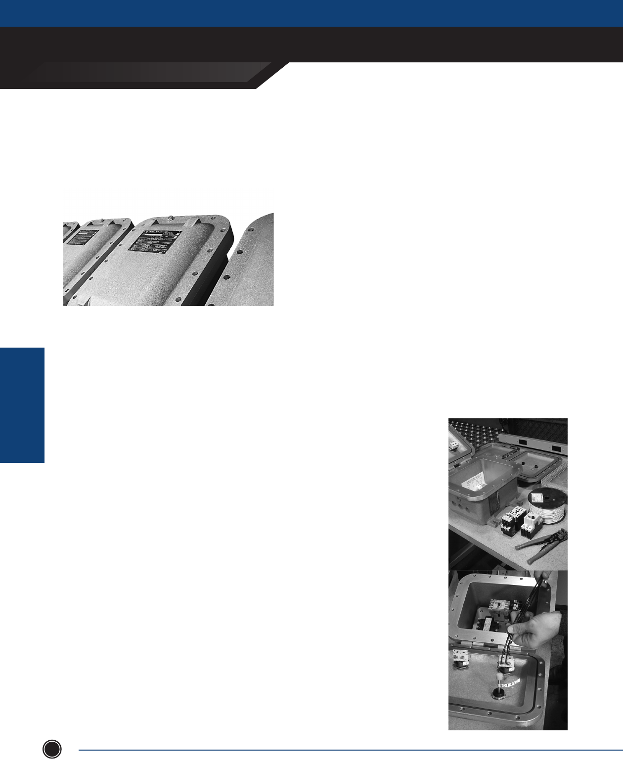
ADALET.COM
ADALET ENCLOSURE SYSTEMS | 4801 WEST 150TH | CLEVELAND, OHIO 44135
©Adalet
EXPLOSIONPRROOF
ENCLOSURES
EXPLOSIONPROOF ENCLOSURES
116
ATEX Flameproof Control Panel
Equipment Certication
Utilizing our ATEX equipment certication, Adalet can now fully populate
empty ATEX certied XCEX enclosures and provide CE certication to
any and all applicable CE marking directives. This ATEX control panel
certication allows Adalet to eliminate the requirement to re-submit
enclosure assemblies to third party testing laboratories for nal ATEX
equipment certication saving customers considerable time and
money.
The Adalet ATEX Control Panel Assembly certicate allows for the installation of control operators, motor control
components, and all other CE marked components inside Adalet’s complete line of ATEX certied empty XCEX IIB+H2
enclosures. Adalet also provides services for installation and wiring of all control components as well as complete
engineering design and review certication, and documentation requirements. Added charges are included for such items
as ATEX inspection, hydro testing, component thermal review, declarations and documentation retention to name a few.
Adalet will accept the customers existing specications or offer our engineering services to assist with design details.
ATEX Certication & Documentation
As part of the nal ATEX control panel assembly, Adalet will provide all necessary
certication and documentation required for your nal ATEX equipment certication.
Engineering Review, Design &
Consultation Services
Adalet engineering services are available for those projects which are candidates for
ATEX control panel certication. Using customer supplied specications or Adalet design
and engineering services, we will carefully review your requirements making certain your
assembly meets or exceeds the minimum specications for ATEX equipment certication.
IIB+H2 Certication
Adalet XCEX empty enclosures are now certied for IIB+H2 for ATEX applications.
Turnkey Solutions for Adalet ATEX
Control Panel Assemblies
Adalet can provide a complete turnkey ATEX control panel package based on your design
specications. Our engineering team has the experience necessary to provide you with a
complete ATEX control panel from start to nish.
ATEX CERTIFICATION
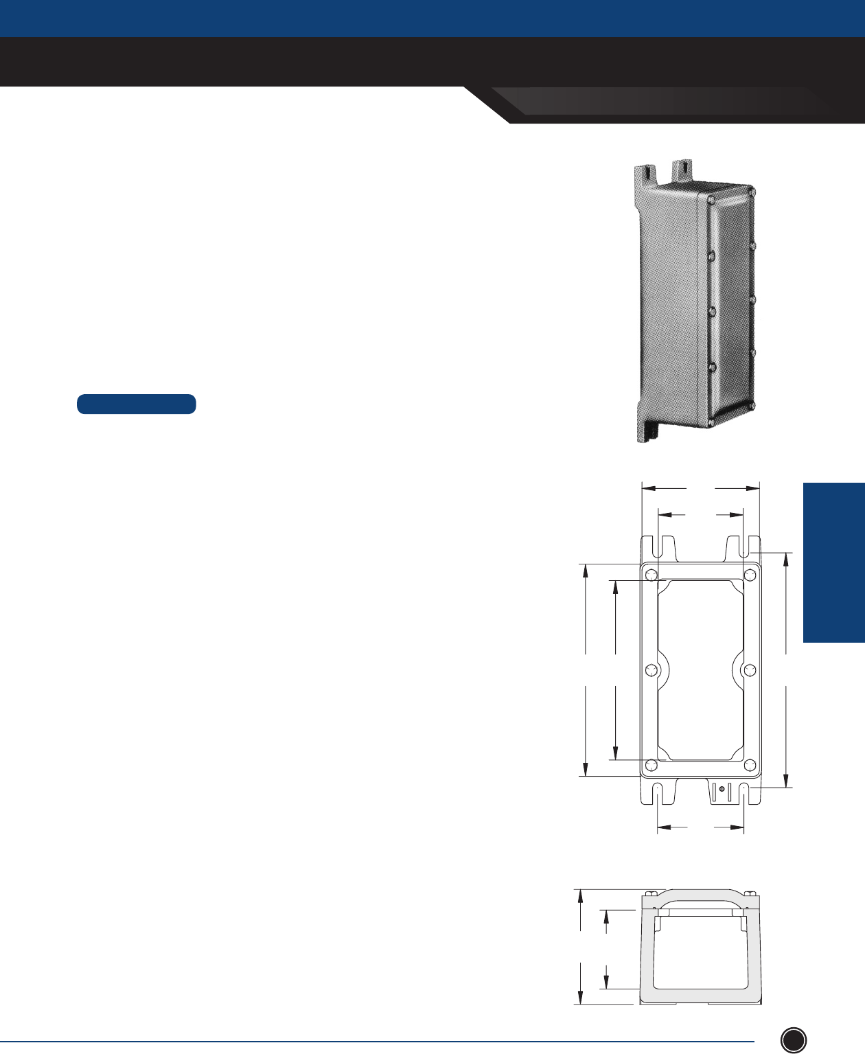
SEND ORDERS TO ORDERS@ADALET.COM
T: 216.267.9000 | F:216.267.1681 | info@adalet.com ©Adalet
EXPLOSIONPRROOF
ENCLOSURES
EXPLOSIONPROOF ENCLOSURES
117
XIF: Explosionproof Junction Boxes
XIFX: Flameproof Junction Boxes
XIFC: Explosionproof Control Enclosures
XIFCX: Flameproof Control Enclosures
DESIGN OPTIONS
Mounting Panels
• Steel: (XSM) Galvanized 12 gauge steel plate. The catalog
number includes the steel mounting pan complete with 1/4”
high spacers and stainless steel mounting screws.
• Aluminum: (XSA) consult factory for availability.
Auxiliary Operator Installations
Available in XIFC and XIFCX covers
External Earthing Device
Supplied on XIFX and XIFCX
Gasket for Type 4 applications available for XIF and XIFC
NOTE: Where reference is made to Class I and Class II hazardous locations, the
equipment is suitable for both Div. 1 and Div. 2 locations.
xif sEriEs
E
F
W
A
B L
CD
XIF SERIES
ADALET.COM
ADALET ENCLOSURE SYSTEMS | 4801 WEST 150TH | CLEVELAND, OHIO 44135
©Adalet
EXPLOSIONPRROOF
ENCLOSURES
EXPLOSIONPROOF ENCLOSURES
118
Certifi cations
CERTIFICATIONS
Class I, Division 1, Groups C & D
Class II, Groups E, F, G
NEMA Type 4, 7, 9
XIF: Junction Boxes
CERTIFICATIONS
Class I, Division 1, Groups C & D Ex d IIB
Class II, Groups E, F, G
Class III
Class I, Zone 1, Aex d IIB
Ex d IIB
IECEx Ex d IIB
XIFX: Flameproof Junction Boxes
CERTIFICATIONS
Class I, Division 1, Groups C & D
Class II, Groups E, F, G
Class III
Class I, Zone 1, AEx d IIB
Ex d IIB T6 (T5 Tamb +55°C)
IECEx Ex d IIB T6 (T5 Tamb +55°C)
IECEx UL 08.0023X
IP 40
Ex d IIB T5 +55°C
0539 II 2 G
DEMKO 09 ATEX 0816570X
XIFC: Explosionproof Control Enclosures
IEC60529: IP 40
IECEX UL.08.0011U
Ex d II
0539 II 2 G
DEMKO 07 ATEX 0603868U
CERTIFICATIONS
Class I, Division 1, Groups C & D
Class II, Groups E, F, G
NEMA Type 4, 7, 9
XIFCX: Flameproof Control Enclosures
LISTED 437S
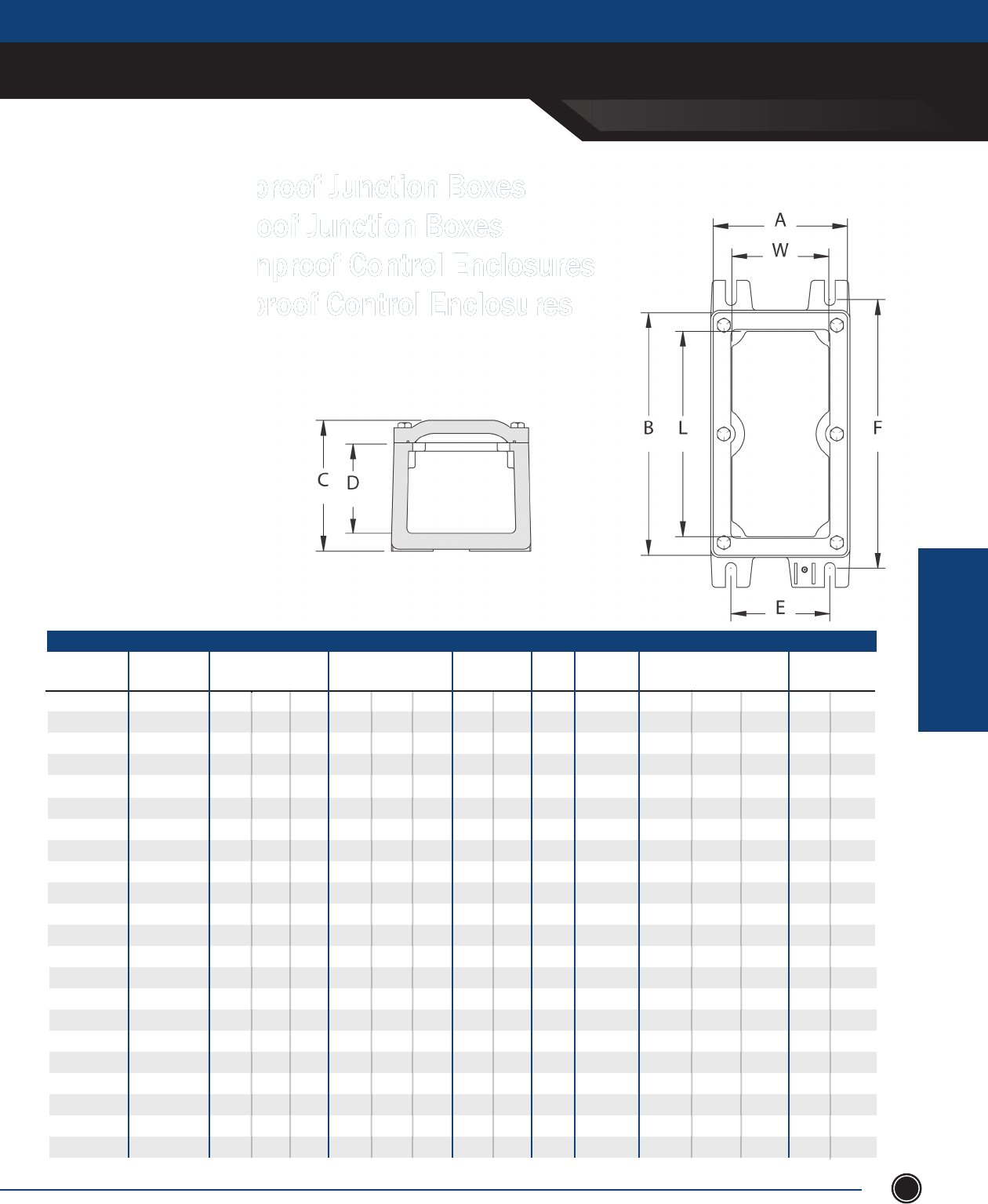
xif sEriEs
SEND ORDERS TO ORDERS@ADALET.COM
T: 216.267.9000 | F:216.267.1681 | info@adalet.com ©Adalet
EXPLOSIONPRROOF
ENCLOSURES
EXPLOSIONPROOF ENCLOSURES
119
XIFC/X030303
XIFC/X030603
XIFC/X030703
XIFC/X030903
XIFC/X031103
XIFC/X031303
XIFC/X031503
XIFC/X031803
XIFC/X032403
XIFC/X033003
XIFC/X033603
XIFC/X040604
XIFC/X041204
XIFC/X060606
XIFC/X060608
XIFC/X061206
-
-
-
XIFC/X070704
-
-
XIF Series
XIFC / XIFCX
CAT. NUMBER
MTG
BOLT
SIZE
MTG LUG
E F
PANEL
PART NO.
SHIPPING
WT. (LBS)
PANEL DIM.
W L
⁄
⁄
⁄
⁄
⁄
⁄
⁄
⁄
⁄
⁄
⁄
⁄
⁄
⁄
⁄
⁄
⁄
⁄
⁄
⁄
⁄
⁄
3 ¼
3 ¼
3 ⁄
3 ¼
3 ¼
3 ¼
3 ¼
3 ¼
3 ¼
3 ¼
3 ¼
4 ⁄
4 ⁄
5 ½
5 ½
5 ½
5 ½
5 ½
5 ½
6 ⁄
6 ½
7 ½
XSB0303
XSB0306
XSB0307
XSB0309
XSB0311
XSB0313
XSB0315
XSB0318
XSB0324
XSB0330
XSB0336
XSB0406
XSB0412
XSB0606
XSB0606
XSB0612
XSB0618
XSB0624
XSB0636
XSB0707
XSB0716
XSB0832
3
3
3
3
3
3
3
3
3
3
3
3 ⁄
3 ⁄
5 ½
5 ½
5 ½
5 ⁄
5 ⁄
5 ⁄
6 ½
6 ½
7 ½
3
5 ½
6 ½
8 ½
10 ½
12 ½
14 ½
17 ½
23 ½
29
35
5 ½
11 ½
5 ½
5 ½
11 ½
16 ⁄
22 ⁄
34 ⁄
6 ½
15 ½
31 ½
XSM0303
XSM0306
XSM0307
XSM0309
XSM0311
XSM0313
XSM0315
XSM0318
XSM0324
XSM0330
XSM0336
XSM0406
XSM0412
XSM0606
XSM0606
XSM0612
XSM0618
XSM0624
XSM0636
XSM0707
XSM0716
XSM0832
XSA0303
XSA0306
XSA0307
XSA0309
XSA0311
XSA0313
XSA0315
XSA0318
XSA0324
XSA0330
XSA0336
XSA0406
XSA0412
XSA0606
XSA0606
XSA0612
XSA0618
XSA0624
XSA0636
XSA0707
XSA0716
XSA0832
5
6 ½
7 ½
9 ½
11
11 ½
13
16
21
28
33
8 ½
15 ½
14
17 ½
28
33
59
84
13
36
87
5 ½
8
9
11
13
15
17
20
26
32 ½
38 ⁄
8 ¼
14 ¼
8 ½
8 ½
15
21 ⁄
27
39
9 ⁄
18 ⁄
35
XIF: Explosionproof Junction Boxes
XIFX: Flameproof Junction Boxes
XIFC: Explosionproof Control Enclosures
XIFCX: Flameproof Control Enclosures
XIF / XIFX
CAT. NUMBER
XIF/X030303
XIF/X030603
XIF/X030703
XIF/X030903
XIF/X031103
XIF/X031303
XIF/X031503
XIF/X031803
XIF/X032403
XIF/X033003
XIF/X033603
XIF/X040604
XIF/X041204
XIF/X060606
XIF/X060608
XIF/X061206
XIF/X061806*
XIF/X062406*
XIF/X063606*
XIF/X070704
XIF/X071603*
XIF/X083206*
3 ⁄
3 ¼
3 ¼
3 ⁄
3 ¼
3 ¼
3 ¼
3 ¼
3 ¼
3 ¼
3 ¼
4 ⁄
4 ¼
5 ½
5 ¼
5 ¼
6
6
6
6 ⁄
7
8
3 ⁄
5 ¾
6 ⁄
8 ⁄
10 ⁄
12 ⁄
14 ¾
17 ¾
23 ⁄
29 ½
35 ⁄
5 ⁄
11 ⁄
5 ½
5 ½
11 ⁄
18
24
36
6 ⁄
16
32
3 ⁄
3
3
3
3
3
3 ⁄
3
3
3
3
4
4
6
8
6
6
6
6
4
3 ½
5 ⁄
4 ½
4 ½
4 ½
4 ½
4 ½
4 ½
4 ½
4 ½
4 ½
4 ⁄
4 ½
5 ⁄
5 ½
7
7
7 ¼
7 ½
7 ½
7 ½
7 ⁄
8 ½
9 ½
4 ½
7 ⁄
8 ⁄
10 ⁄
12
14 ⁄
16
19
25 ⁄
31 ⁄
37 ¼
7
13 ⁄
7
7
13 ½
19 ½
25 ½
37 ½
7 ⁄
17 ½
33 ½
4 ⁄
4 ¼
4 ⁄
4 ⁄
4 ⁄
4 ⁄
4 ⁄
4 ¼
4 ⁄
4 ⁄
4 ⁄
5 ⁄
5 ⁄
7 ⁄
9 ⁄
7 ⁄
7 ⁄
7 ¾
7 ⁄
5 ⁄
5 ⁄
7 ⁄
Explosionproof Junction Boxes Explosionproof Junction Boxes
Flameproof Junction Boxes Flameproof Junction Boxes
Explosionproof Control Enclosures Explosionproof Control Enclosures
Flameproof Control Enclosures Flameproof Control Enclosures
* Limited Approvals
INSIDE NOM. DIM.
W L D OVERALL DIM.
A B C
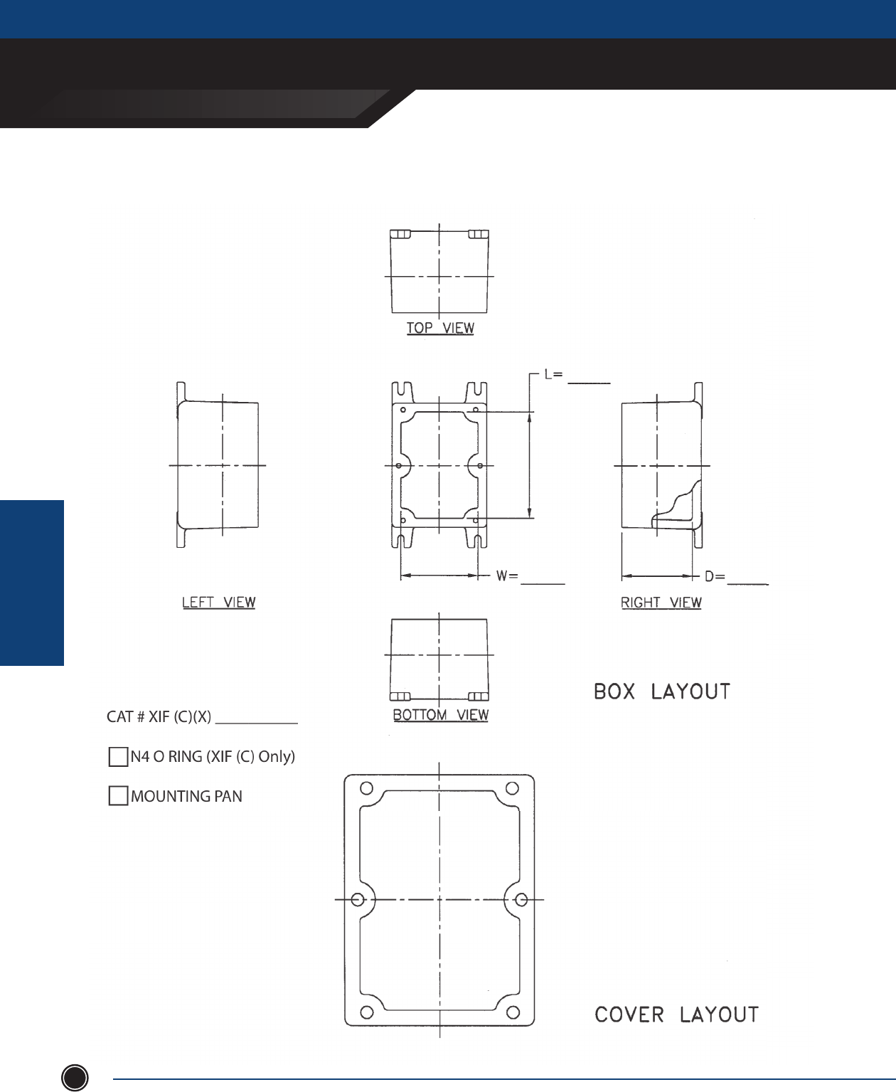
ADALET.COM
ADALET ENCLOSURE SYSTEMS | 4801 WEST 150TH | CLEVELAND, OHIO 44135
©Adalet
EXPLOSIONPRROOF
ENCLOSURES
EXPLOSIONPROOF ENCLOSURES
120
Customer Design Sheets
xif sEriEs
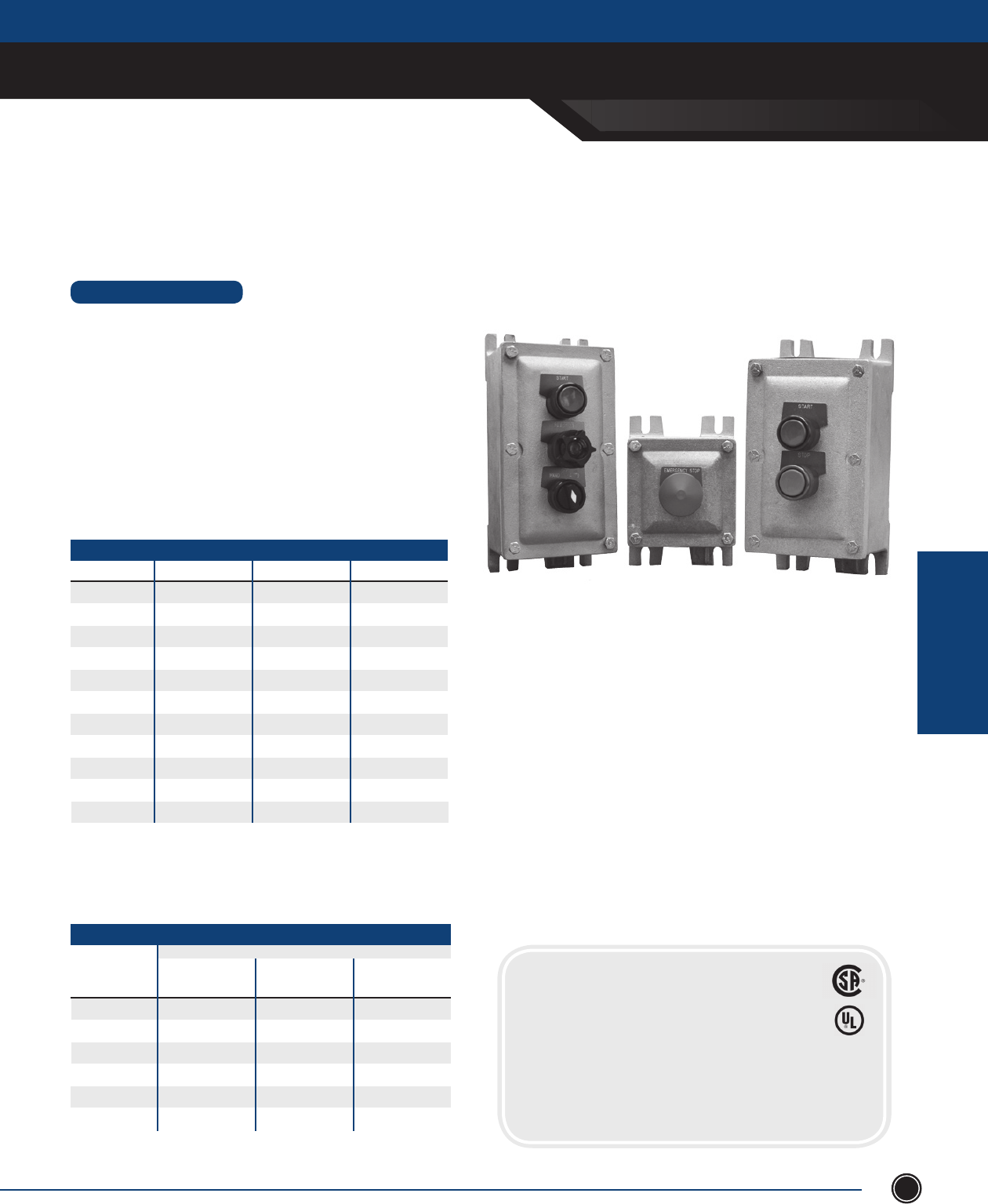
SEND ORDERS TO ORDERS@ADALET.COM
T: 216.267.9000 | F:216.267.1681 | info@adalet.com ©Adalet
EXPLOSIONPRROOF
ENCLOSURES
EXPLOSIONPROOF ENCLOSURES
121
Explosionproof Control Station
STANDARD FEATURES
• Lightweight, corrosion-resistant, copper-free aluminum alloy (0.3% max
copper content)
• All operating shafts are stainless steel for corrosion resistance
• Durable cast on lugs cannot get lost
• Ground screw is highly visible and accessible
• Uniform wall thickness (not ribbed) for versatility of conduit openings
assuring 5 full threads engagement and maximum available area for
conduit drilling and tapping.
• Operators may be mounted through back wall for panel mounting
• Box depth provides for the stacking of 2 contact blocks
• Annodized aluminum operators install easily in the eld
1
2
3
4
5
6
7
8
12
15
18
# of Operators Surface Mount* Panel Mount* Std. Cond. Size (in)
X1
X2
X3
X4
X5
X6
X7
X8
X12
X15
X18
X1P
X2P
X3P
X4P
X5P
X6P
X7P
X8P
X12P
X15P
X18P
¾
¾
¾
1
1 ¼
1 ¼
1 ¼
1 ¼
1 ½
1 ½
1 ½
Table A2 - CONTROL STATION BOXES
* Panel Mount: Operators mounted in back, add P to operator suf x
* Surface Mount: Operators mounted in cover
NOTE: All operators holes are 3/4” - 14 NPSM
Amber
Blue
Clear
Green
Red
White
Lens Color
Guarded
Candelabra
Base XL
Lighted
Pushbutton**
Unguarded XLP
337
338
339
340
341
342
343
344
345
346
347
348
30
35
40
45
50
55
Table B2 - PILOT LIGHTS & LIGHTED PUSHBUTTON (SURFACE MOUNT)
SUFFIX NOS. FOR 120V PILOT LIGHTS
Guarded Slide
Base XLS CERTIFICATIONS
Class I, Division 1, Groups C & D
Class II, Groups E, F, G
For Type 4 or special machining options - see XIFC Series.
Listed enclosures must use Adalet auxiliary devices only
**CSA certi ed products require guarded pilot devices
CONTROL STATION
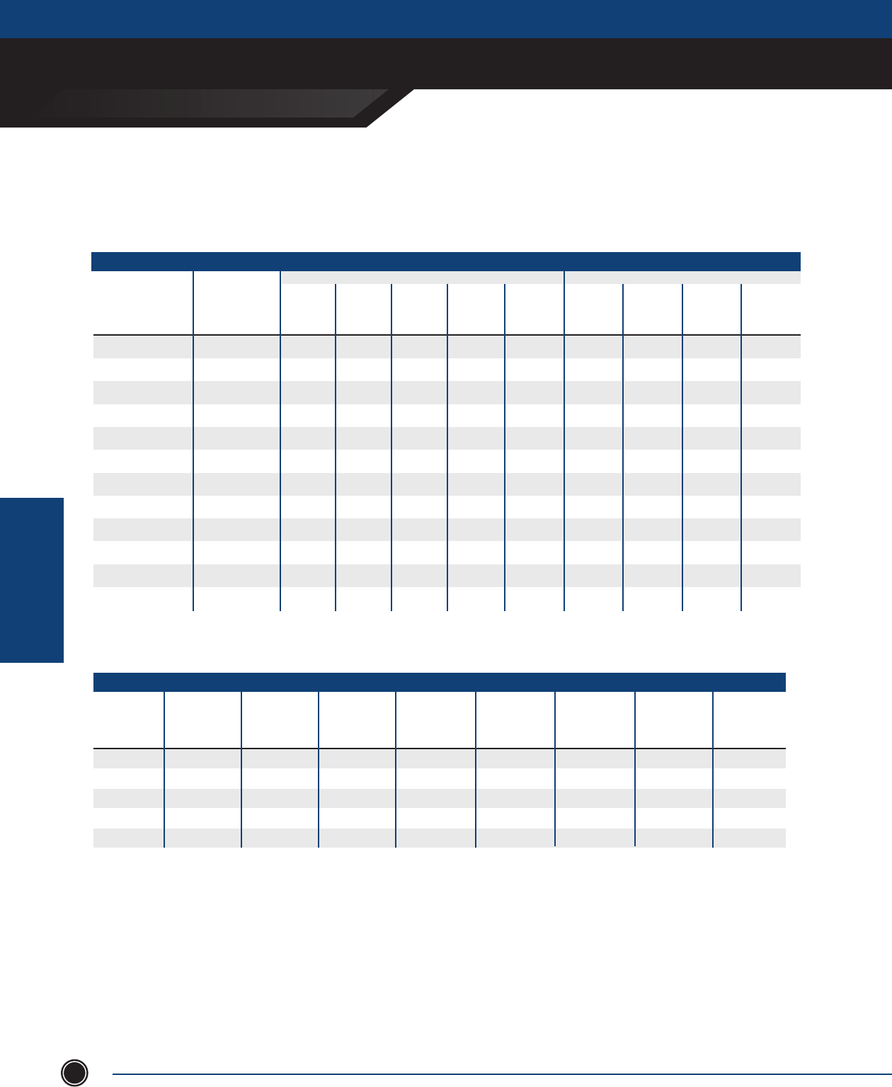
ADALET.COM
ADALET ENCLOSURE SYSTEMS | 4801 WEST 150TH | CLEVELAND, OHIO 44135
©Adalet
EXPLOSIONPRROOF
ENCLOSURES
EXPLOSIONPROOF ENCLOSURES
122
Contact Block / Cam
Standard
Selector
Switch
XHSS
6
7
8
9
10
11
12
13
14
15
16
17
-
-
-
-
111
112
113
114
115
116
117
118
Table C2 - PILOT LIGHTS & LIGHTED PUSHBUTTON (SURFACE MOUNT)
SUFFIX NOS. FOR 120V PILOT LIGHTS
Selector
Switch
w/ Padlock
XHSSPL
Spring Ret.
Center
from R & L
XHSSC
Spring Ret.
Center
from R
XHSSR
Spring Ret.
Center
from L
XHSSL
KEY SWITCH SUFFIX NUMBERS
Standard
Key
Switch
XHKSS
Spring Ret.
Center
from R & L
XHKSSC
283
284
285
286
293
288
289
290
294
287
291
292
-
-
-
-
135
136
137
138
139
140
141
142
-
-
-
-
159
160
161
162
163
164
165
166
82
83
84
85
86
87
88
89
90
91
92
93
-
-
-
-
229
224
225
226
230
223
227
228
-
-
-
-
249
244
245
246
250
243
247
248
-
-
-
-
269
264
265
266
270
263
267
268
Spring Ret.
Center
from R
XHKSSR
Spring Ret.
Center
from L
XHKSSL
BT1A
BT2
BT3
BT4
BT5
Contact Style
Momentary
Pushbutton
XHPBS
307
308
309
310
311
1
2
3
4
5
Table D2 - CONTROL STATION BOXES
Momentary
Pushbutton
w/Padlock
XHPBS
1NO/1NC
2NO
2NC
1NO
1NC
106
107
108
109
110
Mushroom Head
Momentary1
XHPBMS
Dual
Pushbutton1
Momentary
XHDPBS
Dual
Pushbutton1
w/Lockout
XHDPBSPL
Dual
Pushbutton2
Maint
XHDMCS
Dual
Pushbutton2
Maint w/Lock
XHDMCSPL
72
73
74
-
-
322
323
324
-
-
77
78
79
-
-
327
328
329
-
-
Box & Sufx Numbers
1 Standard knob is red. Black and green available.
2 Standard with one green knob labeled “start” and one red knob labeled “stop”. Unlabeled black knobs available.
Pushbuttons furnished with black collars and knobs as standard. Optional knobs: green, red. Optional colors: blue, green, gold or red.
Maintained, push-pull operator available, but requires special spacing. Consult factory.
Other pilot devices available - consult factory
BTIA/1
BTIB/1
BT2/1
BT3/1
BT2/3
BT1B/2
BT2/2
BT3/2
BT3/3
BT1A/2
BT1A/3
BT1B/3
NO
NC
NC
NO
NO
NO
NC
NC
NO
NO
NC
NO
NO
NO
NC
NC
NC
NC
NO
NC
NO
NC
NC
NO
XO
OX
OX
XO
OX
OX
XO
XO
XOO
OOX
XOX
XXO
XOX
OOX
OXO
XXO
OXX
XXO
OXO
OOX
OXX
OOX
XOO
XXO
Contact Block
CONTROL STATION
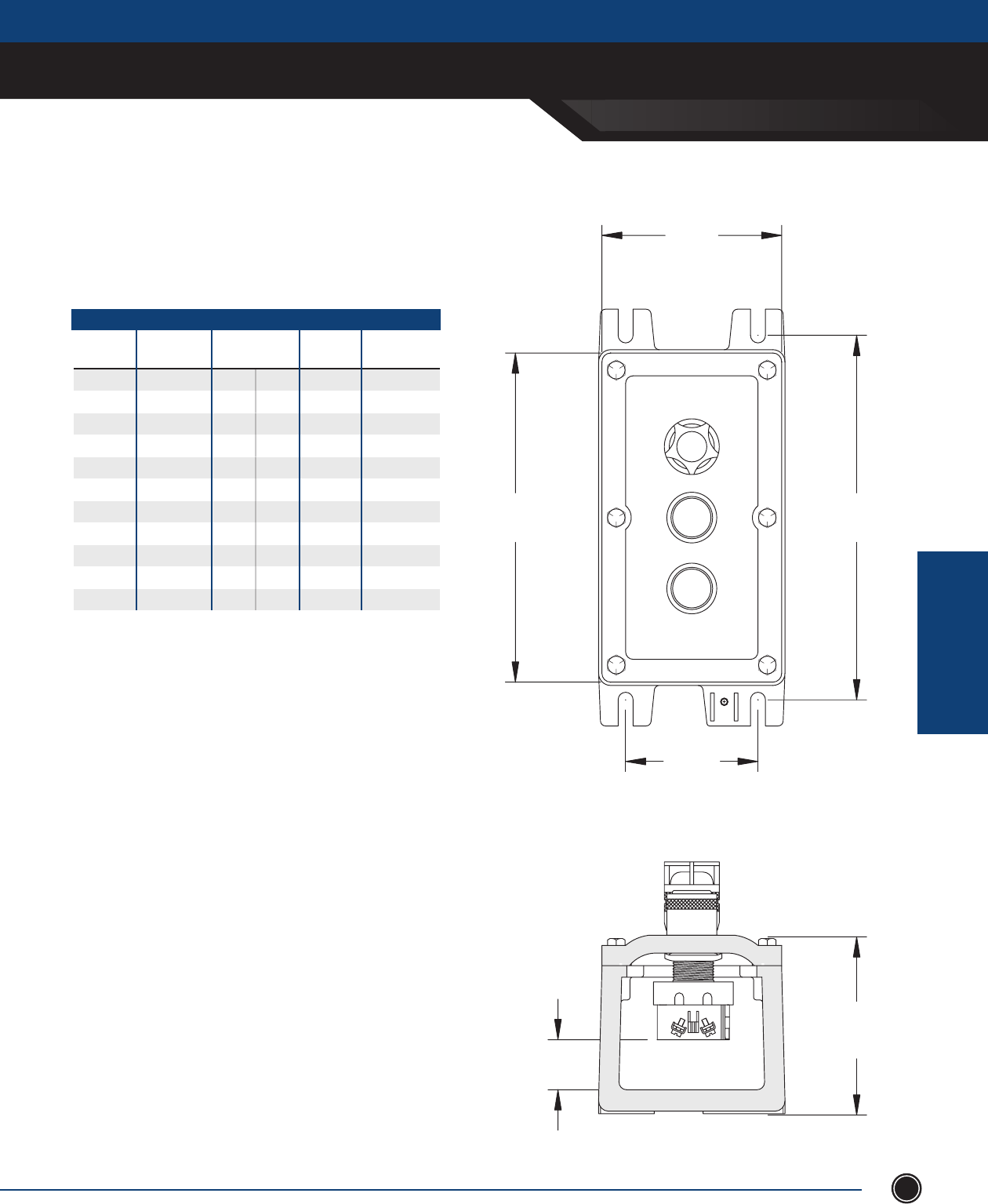
SEND ORDERS TO ORDERS@ADALET.COM
T: 216.267.9000 | F:216.267.1681 | info@adalet.com ©Adalet
EXPLOSIONPRROOF
ENCLOSURES
EXPLOSIONPROOF ENCLOSURES
123
3
1/4
"
B
4
1/2
"
A
1"
4
7/16
"
Control Station
X1
X2
X3
X4
X5
X6
X7
X8
X12
X15
X18
Enclosure Nom. Inside
Dimensions
030303
030603
030703
030903
031103
031303
031503
031803
032403
033003
033603
4 ½
7 ⁄
8 ⁄
10 ⁄
12 ⁄
14 ⁄
16
19
25 ⁄
31 ⁄
37 ¼
¾
¾
¾
1
1 ¼
1 ¼
1 ¼
1 ¼
1 ½
1 ½
1 ½
DIMENSIONS
Dimensions
A B
5 ½
8
9
11
13
15
17
20
26
32 ⁄
38 ⁄
Est. Weight
(lbs)
5
7
8
10
11
12
13
16
21
28
33
Std. Conduit*
Size (in.)
Control stations have conduit openings centered on top and bottom.
*Consult factory for other conduit sizes
CONTROL STATION
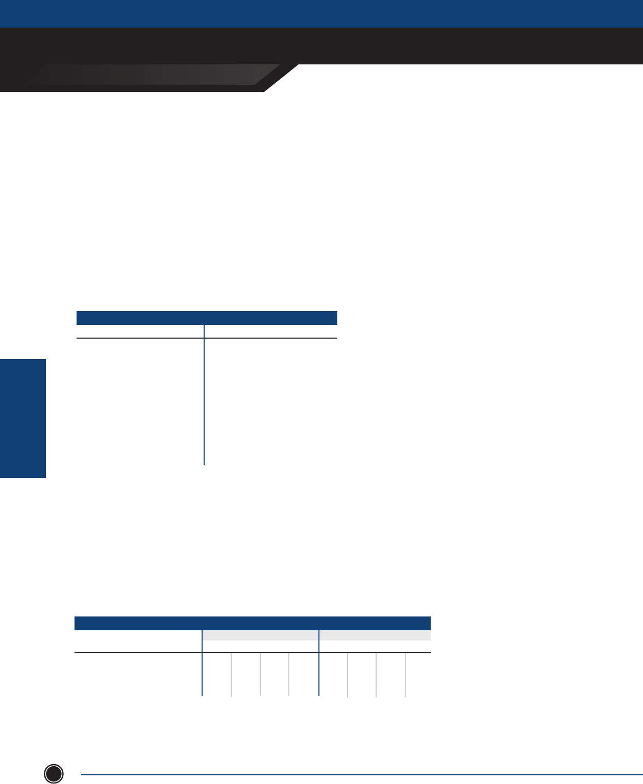
ADALET.COM
ADALET ENCLOSURE SYSTEMS | 4801 WEST 150TH | CLEVELAND, OHIO 44135
©Adalet
EXPLOSIONPRROOF
ENCLOSURES
EXPLOSIONPROOF ENCLOSURES
124
PENDANT STATION
Control Station
Ordering Information
To order control stations, determine the number of operators required. Select the control station box by operator
quantity and mounting type from Table A2. Order operators by suf x numbers from Tables B2, C2 and D2. Add
suf x numbers to box number and separate by dashes. All operator holes must be lled. Use suf x “0” for plugs to
ll unused space. Installation of operators will be made from top to bottom in sequence as listed. Select optional
legend plates from Table F2 below.
PUSHBUTTON / PILOT LIGHTS
Blank
Start
Inch
Stop
Run
Forward
Reverse
Fast
Table F2 - STANDARD MARKING
SELECTOR SWITCHES
Slow
Open
Close
Up
Jog
On
O
Back
Reset
In
Out
Left
Right
Low
High
Down
E-Stop
Run-Jog
Hand-Auto
Forward - Reverse
Fast-Slow
Open-Close
Up-Down
O - O n
Open-O -Close
Fast-O -Slow
Run-Auto-Jog
Hand-O -Auto
Forward-O -Reverse
1-O -2
Up-O -Down
Legend plates are anodized aluminum with engraved letters on black background
Stop has red and start has green background
Special engraved legend plates can be supplied
Contact Ratings
VOLTS
Make & Energy Interrupting Capacity A
Normal Load Break
Continuous Current
MAX RATING: TYPE BT CONTACT BLOCKS
DCAC
A
A
110 220 440 550 24/28 120 240 600
60
6
10
30
3
10
15
1.5
10
12
1.2
10
5.7
5.7
5.
1.1
1.1
10.
0.5
0.5
10.
0.2
0,2
10.5
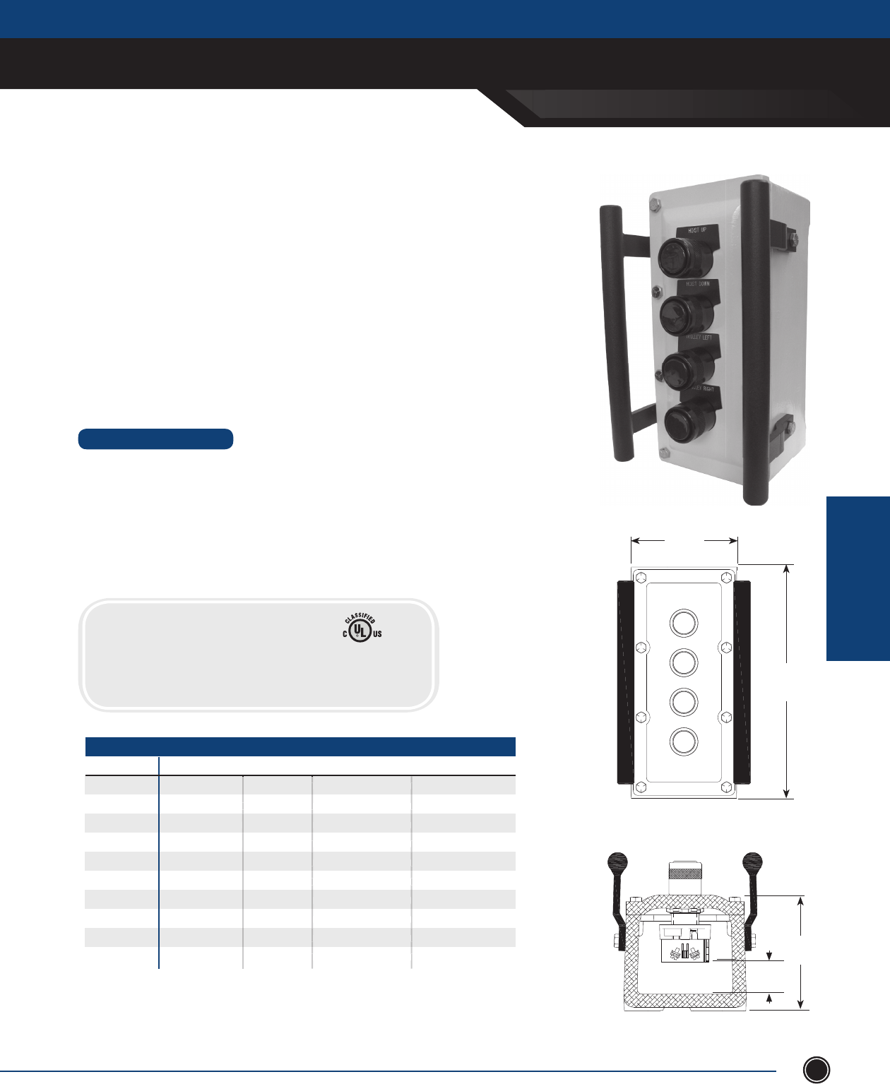
SEND ORDERS TO ORDERS@ADALET.COM
T: 216.267.9000 | F:216.267.1681 | info@adalet.com ©Adalet
EXPLOSIONPRROOF
ENCLOSURES
EXPLOSIONPROOF ENCLOSURES
125
Pendant / Operator Station
STANDARD FEATURES
• 11 standard sizes
• Standard feed through conduit entries
• Enclosures rated NEMA Type 4X, 7, 9
• Populated with Adalet pushbuttons, pilot lights, selector switches
or emergency stops
• ATEX and IECEx versions available, consult factory
• Side handles
• Safety yellow coating for high visibility
CONTROL STATION
CERTIFICATIONS
Class I, Division 1, Groups C & D
Class II, Groups E, F, G
CSA Certi ed products require guarded pilot devices
Adalet offers a complete line of explosionproof pendant stations for pushbutton control
& operation in rugged or hazardous locations. Designed for use in Class I, Division 1 & 2
or Zone 1 & 2 locations, the cast aluminum enclosure and heavy duty operators provide a
rugged solution for operating overhead cranes, hoists, lifts, and other remote controlled
equipment. Available in various hole con gurations, the enclosures can be assembled
with Adalet's line of explosionproof pushbuttons, emergency stop pushbuttons, pilot
lights, and selector switches. Optional hanging brackets, and strain relief provide the
necessary accessories for safe hanging and operation. Safety yellow paint provides high
visibility in high traf c, industrial applications.
4 1/2”
A
1 ”
4 7/16”
PENDANT / OPERATOR STATION
ENCLOSURE NOM. INSIDE DIM. DIMENSION A EST. WEIGHT (LBS.) STD. CONDUIT SIZE (IN.)
X2CP 030603 7 1/16 7 3/4
X3CP 030703 8
1/8 8 3/4
X4CP 030903 10
1/16 10 1
X5CP 031103 12
1/16 11 1 1/4
X6CP 031303 14
1/16 12 1 1/4
X7CP 031503 16 13 1 1/4
X8CP 031803 19 16 1 1/4
X12CP 032403 25
1/16 21 1 1/2
X15CP 033003 31 1/8 28 1 1/2
X18CP 033603 37
1/4 33 1 1/2
X3CP 030703 8
X4CP 030903 10
X5CP 031103 12
X6CP 031303 14
X7CP 031503 16 13 1
X8CP 031803 19 16 1
X12CP 032403 25
X15CP 033003 31
X18CP 033603 37
7
8
10 1
11 1
12 1
X7CP 031503 16 13 1
X8CP 031803 19 16 1
21 1
28 1
33 1
7
8
10 1
11 1
12 1
X7CP 031503 16 13 1
X8CP 031803 19 16 1
21 1
28 1
33 1
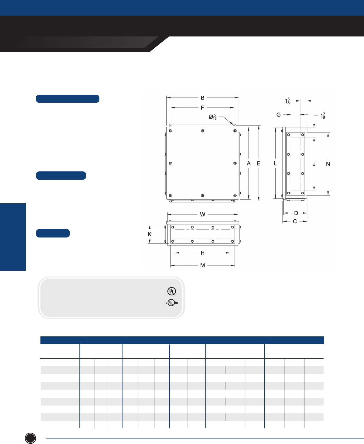
ADALET.COM
ADALET ENCLOSURE SYSTEMS | 4801 WEST 150TH | CLEVELAND, OHIO 44135
©Adalet
EXPLOSIONPRROOF
ENCLOSURES
EXPLOSIONPROOF ENCLOSURES
126
Dust-Ignition Proof Enclosures
STANDARD FEATURES
• 9 standard sizes available
• Wall mounting feet
• Watertight silicone gasket
• Stainless steel hardware
• Four #10-32 weld nuts for optional mounting panel
(mounting panel sold separately)
• Grounding studs on inside of box and cover
• Gland plates for drilled and tapped entries (specify
sides A,B,C,D)
• Mounting panels - available in stainless steel or painted steel
• Aluminum gland plates
• Conduit drilling & tapping from ½ ” NPT to 3” NPT
• Custom sizes
DESIGN OPTIONS
MATERIAL
• Enclosure - 14 gauge / Type 316L stainless steel
• Cover Bolts - Stainless Steel 316L
• Gland Plates - copper-free aluminum (⁄ of 1%)
D9SC-161206
D9SC-161608
D9SC-201608
D9SC-202008
D9SC-241608
D9SC-242410
D9SC-302410
D9SC-362410
D9SC-363010
Dust-Ignition Proof Series
CAT. NUMBER MOUNTING FEET
E F
16
16
20
20
24
24
30
36
36
12
16
16
20
16
24
24
24
30
6
8
8
8
8
10
10
10
10
16 ½
16 ½
20 ½
20 ½
24 ½
24 ½
30 ½
36 ½
36 ½
12 ½
16 ½
16 ½
20 ½
16 ½
24 ½
24 ½
24 ½
30 ½
10
14
14
18
14
22
22
22
28
6 ¼
8 ¼
8 ¼
8 ¼
8 ¼
10 ¼
10 ¼
10 ¼
10 ¼
17 ½
17 ½
21 ½
21 ½
25 ½
25 ½
31 ½
37 ½
37 ½
GLAND PLATE OPENING
G H J
2 ½
4 ½
4 ½
4 ½
4 ½
6 ½
6 ½
6 ½
6 ½
10 ⁄
14 ⁄
14 ⁄
18 ⁄
14 ⁄
22 ⁄
22 ⁄
22 ⁄
28 ⁄
11 ⁄
11 ⁄
15 ⁄
15 ⁄
19 ⁄
19 ⁄
25 ⁄
31 ⁄
31 ⁄
GLAND PLATE AREA
K M N
4 ⁄
6 ⁄
6 ⁄
6 ⁄
6 ⁄
8 ⁄
8 ⁄
8 ⁄
8 ⁄
11 ⁄
15 ⁄
15 ⁄
19 ⁄
15 ⁄
23 ⁄
23 ⁄
23 ⁄
29 ⁄
CERTIFICATIONS
Class II, Division I, Groups E, F, G
Class III
UL 1203
CSA C22.2 No. 25
NEMA Type 4X, 9
UL 50
14 ⁄
14 ⁄
18 ⁄
18 ⁄
22 ⁄
22 ⁄
28 ⁄
34 ⁄
34 ⁄
DUST-IGNITION PROOF
INSIDE NOM. DIM.
L W D OVERALL DIM.
A B C
LISTED
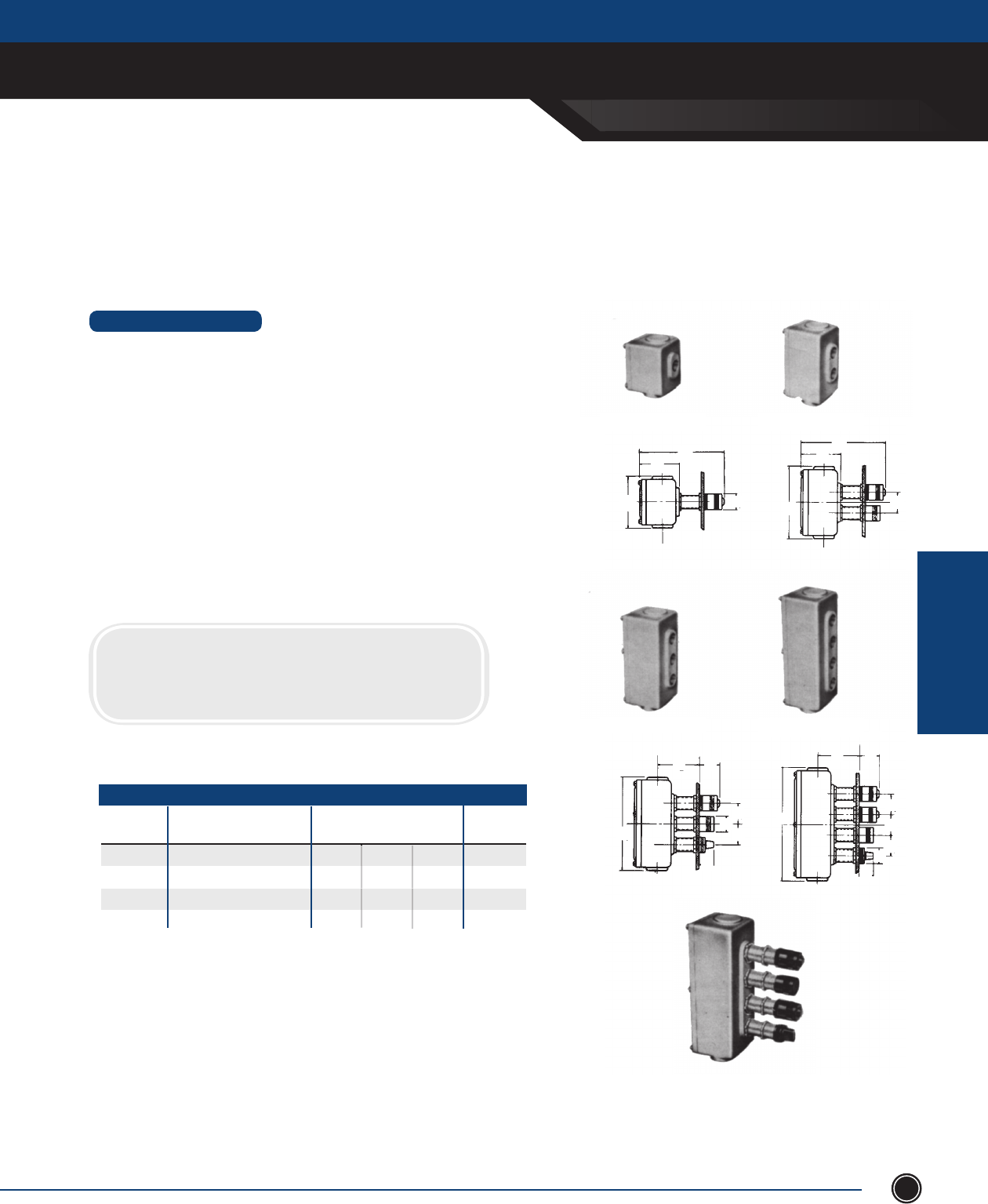
SEND ORDERS TO ORDERS@ADALET.COM
T: 216.267.9000 | F:216.267.1681 | info@adalet.com ©Adalet
EXPLOSIONPRROOF
ENCLOSURES
EXPLOSIONPROOF ENCLOSURES
127
1¾
1¾
1¾
3½
1¼
1¼
9½
1¾
1¾
1¾
1¾
1¼
1¼
3½
7⁄
1¾
1¼
7⁄
3⁄
6
7⁄
3⁄
4⁄
4⁄
6¾
2⁄
3⁄ 1¼
1¾
3⁄
XB3
XB1
XB4
XB2
EXPLOSIONPROOF
Enclosures
Explosionproof & Dust-Tight Control
Station Box for Panel Mounting
STANDARD FEATURES
• Designed for mounting on panel boards so that pilot lights, pushbuttons and switch
handles are fl ush with panel fronts and the bodies or housings are in back of the panel.
• Threaded necks are provided with locknuts to clamp ttings in place on panels when used
with long operators. The parts extending beyond the face of the panel have a black
anodized nish.
• Style XB is suitable for combinations of pilot lights, pushbuttons and selector switches for
600 volt maximum use and are large enough to include pilot light transformers. XB bodies
have fl at machined joint covers fastened with machine screws. Covers give maximum
accessibility to interiors.
• All station boxes are drilled and tapped with 3/4” NPSM thread for operator, or pilot lights.
Unused openings must be plugged with XPP plugs, XB style boxes are suitably padded for
two conduit openings on one end and one on opposite end. 1” maximum conduit size.
CERTIFICATIONS
NEC Class I, Groups C & D
Class II, Groups E, F, G
XB 1
XB 2
XB 3
XB 4
CAT # DESCRIPTION
1 station box - specify hubs
2 station box - specify hubs
3 station box - specify hubs
4 station box - specify hubs
3 ½
3 ½
3 ½
3 ½
1 ¾
2
2 ¾
3 ¼
DIMENSIONS
OUTSIDE DIMENSIONS IN.
W L D
4 ⁄
6 ⁄
8 ⁄
9 ⁄
3 ⁄
3 ⁄
3 ⁄
3 ⁄
WEIGHT
EA. LBS
CONTROL STATION BOX

EXPLOSIONPROOF AUXILIARY DEVICES
ADALET.COM
ADALET ENCLOSURE SYSTEMS | 4801 WEST 150TH | CLEVELAND, OHIO 44135 ©Adalet
EXPLOSIONPRROOF
AUXILIARY DEVICES
128
Explosionproof Auxiliary Devices
Adalet Explosionproof Operators are for use in control circuits functioning in environments containing hazardous
gases, vapors or dusts. These heavy duty pilot lights, pushbuttons and selector switches are suitable for use in Class
I, groups C & D hazardous gas; Class II, Groups E, F & G dust atmospheres.
ATEX FLAMEPROOF AUXILIARY
EXPLOSIONPROOF AUXILIARY
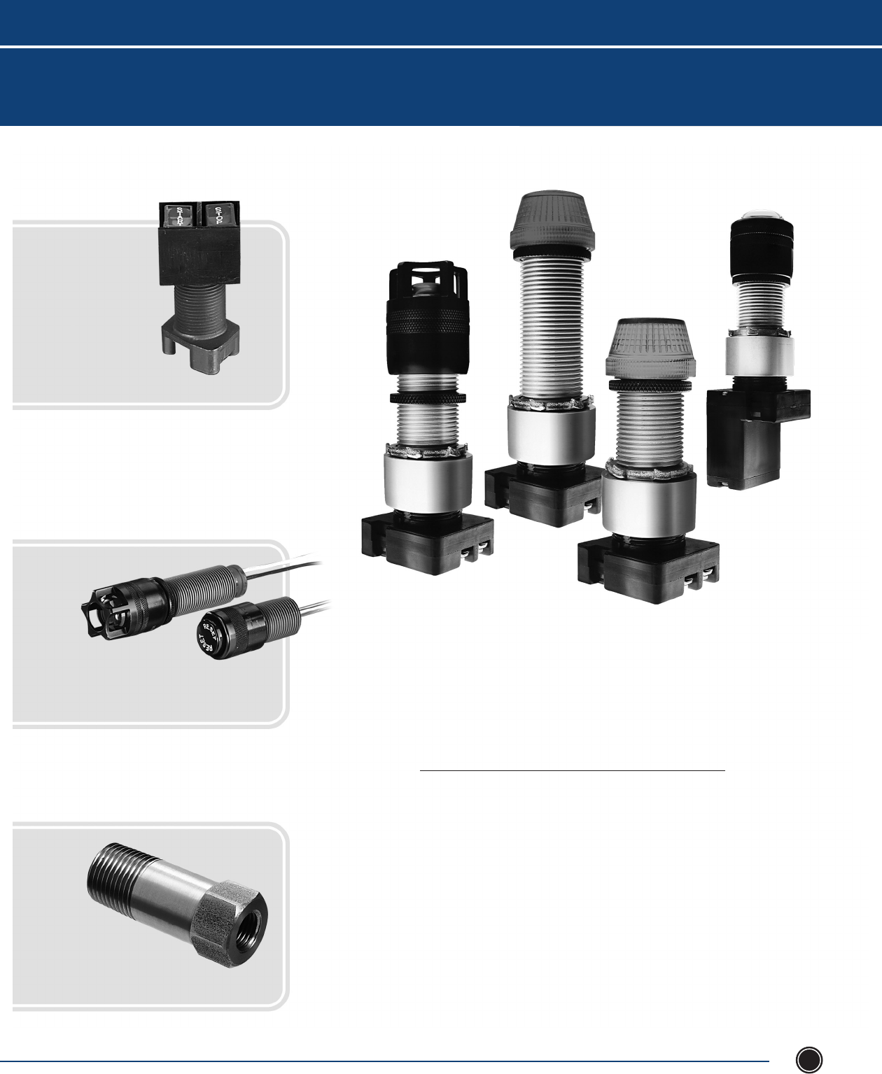
EXPLOSIONPROOF AUXILIARY DEVICES
SEND ORDERS TO ORDERS@ADALET.COM
T: 216.267.9000 | F:216.267.1681 | info@adalet.com ©Adalet
EXPLOSIONPRROOF
AUXILIARY DEVICES
129
Contents
Explosionproof Auxiliary Devices
Push Buttons 130
Selector Switches 133
Pilot Lights 135
ATEX Pilot Lights 137
Reset Buttons 138
Accessories 139
Contact Blocks 141
Miniature Operators 142
Flame Arrestors 144
Breather / Drains 145
Explosionproof Auxiliary Devices
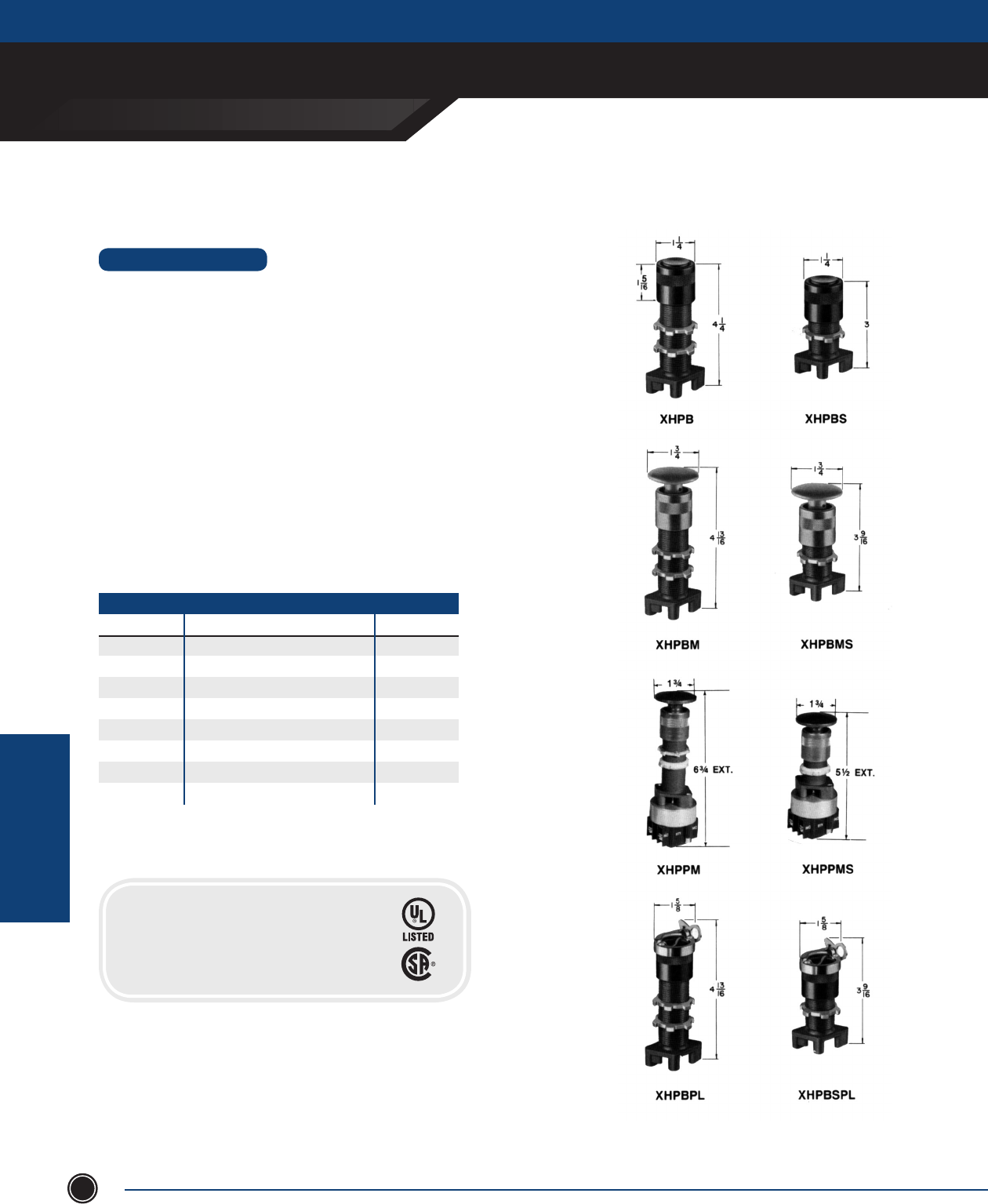
EXPLOSIONPROOF AUXILIARY DEVICES
ADALET.COM
ADALET ENCLOSURE SYSTEMS | 4801 WEST 150TH | CLEVELAND, OHIO 44135 ©Adalet
EXPLOSIONPRROOF
AUXILIARY DEVICES
130
PUSHBUTTONS
Explosionproof & Dust-Tight Push Buttons
STANDARD FEATURES
•All operators are die cast aluminum alloy. The barrels are all ¾” NPSM
thread. Maximum installation thickness 1 ¾” long barrel, ¾” short barrel.
•Blackmoldednylonbuttons.Theexposedmetalpartsareblackanodized
aluminum. For color coding we will furnish at no additional cost the
following color combinations: Red buttons with red metal caps and green
buttons with green metal caps. Metal caps are also available in blue, gold
or clear with black buttons. Specify colors required.
•RedMushroomheadbuttonsare1¾”diameteranodizedaluminum.Also
available in black or green.
•XHPBPLhaspadlockattachmentontopofcapallowingoperatortobe
locked with the push button depressed.
•ForusewithBTcontactblocks.Contactblockscanbestackedfor
multiple circuits. Contact blocks are not included with the operators.
•XHPPM/XHPPMSrequire2"minimumspacing.
•XHPBpushbuttonsaremomentary.
•XHPPpushbuttonsaremaintained.
FOR USE WITH SERIES BT CONTACT BLOCKS
CAT. NUMBER OPERATOR DESCRIPTION WEIGHT LBS.
XHPB Long Barrel ½
XHPBS Short Barrel ½
XHPBM Red Mushroom Head, Long Barrel ½
XHPBMS Red Mushroom Head, Short Barrel ½
XHPBPL W/Padlock devices, Long Barrel ¾
XHPBSPL W/Padlock devices, Short Barrel ¾
XHPPM* Push/Pull switches, Long Barrel ¾
XHPPMS* Push/Pull switches, Short Barrel ¾
*Type BT1 contact blocks are included
CERTIFICATIONS
Class I, Division 1, Groups B, C & D
Class II, Groups E, F & G
NEMA Type 3, 4, 7 & 9
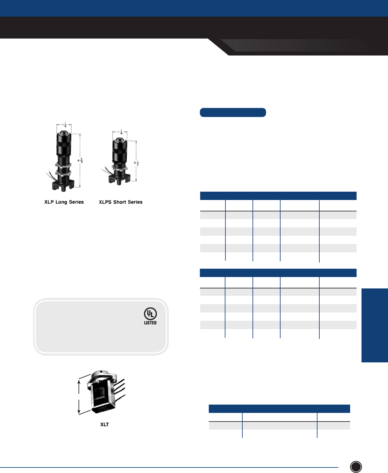
EXPLOSIONPROOF AUXILIARY DEVICES
SEND ORDERS TO ORDERS@ADALET.COM
T: 216.267.9000 | F:216.267.1681 | info@adalet.com ©Adalet
EXPLOSIONPRROOF
AUXILIARY DEVICES
131
PUSHBUTTONS
Illuminated Push Button /
Push-To-Test Operators
(Long Barrel) (Short Barrel)
• Die cast aluminum alloy. The barrels are all ¾” NPSM thread.
Maximum installation thickness 1 ⁄” Long Barrel, ¾” short barrel.
• Furnished standard with 120 volt slide base lamp. Also available
for 6, 12, 24, 28, 48 and 60 volts. Specify when ordering.
• For use with BT contact blocks. Contact blocks can be stacked
for multiple circuits. Contact blocks are not included with the
operators. For NEMA 4 application, add boot and special legend
plate. (See accessories at end of section)
STANDARD FEATURES
SHORT BARREL
PILOT LIGHT TRANSFORMERS
CATALOG # DESCRIPTION WEIGHT (LBS.)
XLT 240 240 to 120 Volt 1
XLT480 480 to 120 Volt 1
Pilot Light Transformers
One transformer required for each pilot light. Adapter furnished for
mounting on threaded pilot light stem, or can be mounted to housing
as space requires.
2 ⁄
CERTIFICATIONS
Class I, Groups C & D
Class II, Groups E, F & G
NEMA Type 7 & 9
*Consult factory for ATEX certications
CATALOG #
(STANDARD)
Amber Lens
Blue Lens
Clear Lens
Green Lens
Red Lens
White Lens
XLPAS
XLPBS
XLPCS
XLPGS
XLPRS
XLPWS
XLPAS-G
XLPBS-G
XLPCS-G
XLPGS-G
XLPRS-G
XLPWS-G
DESCRIPTION WEIGHT (LBS.)
½
½
½
½
½
½
CATALOG #
(GUARDED)
LONG BARREL
CATALOG #
(STANDARD)
Amber Lens
Blue Lens
Clear Lens
Green Lens
Red Lens
White Lens
XLPA
XLPB
XLPC
XLPG
XLPR
XLPW
XLPA-G
XLPB-G
XLPC-G
XLPG-G
XLPR-G
XLPW-G
DESCRIPTION WEIGHT (LBS.)
¾
¾
¾
¾
¾
¾
CATALOG #
(GUARDED)
XLPAX
XLPBX
XLPCX
XLPGX
XLPRX
XLPWX
CATALOG #
(ATEX*)
XLPASX
XLPBSX
XLPCSX
XLPGSX
XLPRSX
XLPWSX
CATALOG #
(ATEX*)
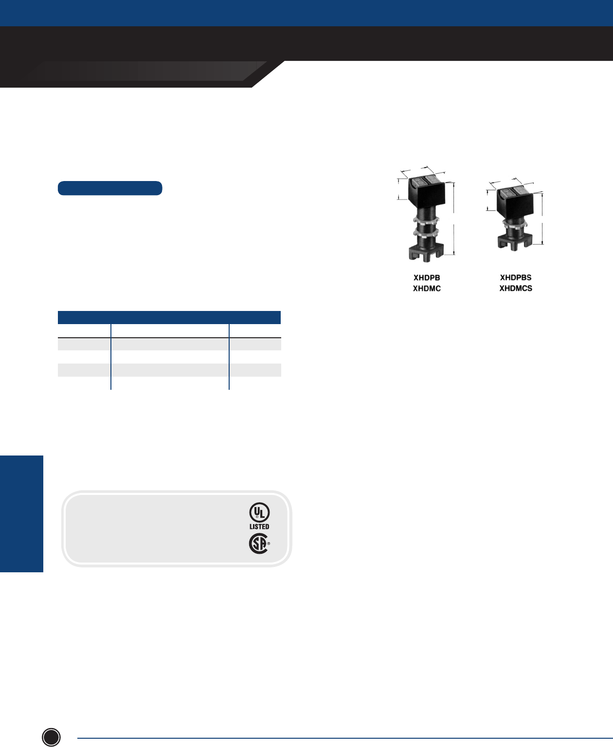
EXPLOSIONPROOF AUXILIARY DEVICES
ADALET.COM
ADALET ENCLOSURE SYSTEMS | 4801 WEST 150TH | CLEVELAND, OHIO 44135 ©Adalet
EXPLOSIONPRROOF
AUXILIARY DEVICES
132
Dual Push Button Operator or
Maintained Contact Unit
STANDARD FEATURES
•Diecastaluminumalloy.Thebarrelsareall¾” NPSM thread. Maximum
installation thickness 1 ⁄” Long Barrel, ¾” Short Barrel.
•ForusewithBTcontactblocks.Contactblockscanbestackedformultiple
circuits.ContactblocksarenotincludedwithXHDoperators.(Seeaccessories
at end of section)
•Redandgreenorblackpushbuttonsavailable,pleasespecify
PUSHBUTTONS
FOR USE WITH SERIES BT CONTACT BLOCKS
CATALOG # OPERATOR DESCRIPTION WEIGHT LBS.
XHDPB Long Barrel - momentary* ½
XHDPBS Short Barrel - momentary* ½
XHDMC Maintained Contact, Long Barrel ½
XHDMCS Maintained Contact, Short Barrel ½
*Two contacts in the BT contact block are actuated independently
LEGEND PLATES AT END OF SECTION
11
—
4
43
—
16
15
—
8
11
—
411
—
4
3
15
—
8
11
—
4
CERTIFICATIONS
Class I, Division 1, Groups B, C & D
Class II, Groups E, F & G
NEMA Type 3, 4, 7 & 9
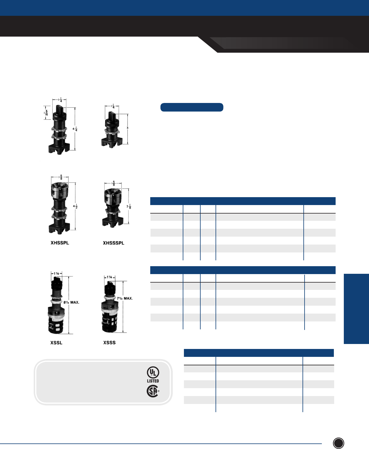
EXPLOSIONPROOF AUXILIARY DEVICES
SEND ORDERS TO ORDERS@ADALET.COM
T: 216.267.9000 | F:216.267.1681 | info@adalet.com ©Adalet
EXPLOSIONPRROOF
AUXILIARY DEVICES
133
Selector Switch Operators
SELECTOR SWITCHES
•Diecastaluminumalloy.Thebarrelsareall¾” NPSM thread. Maximum
installation thickness: 1 ⁄” Long Barrel, ¾” Short Barrel.
•Specify2positionor3position.For3-position,ordermustspecifycam(see
contact block page for contact sequence chart).
•Alloperatorshaveblackmoldednylonknobs.Theexposedmetalpartsareblack
anodizedaluminum.
•ContactblocksarenotincludedwithXHSSoperators.Selectcontactblock
and sequence operating cam from contact block page. (See accessories at
end of section)
STANDARD FEATURES
XHSS Series XHSSS Series
XHSSS
XHSSC*
XHSSR2
XHSSR
XHSSL2
XHSSL
2
4
2/3
3
2
3
2
3
CATALOG # CAM
Short Barrel
Spring Return to Center from Right & Left
Spring Return to Left from Right
Spring Return to Center from Right, Maintain Left
Spring Return to Right from Left
Spring Return to Center from Left, Maintain Right
# POS. OPERATOR DESCRIPTION WEIGHT LBS.
½
½
½
½
½
½
SHORT BARREL
XHSS
XHSC*
XHSR2
XHSR
XHSL2
XHSL
2
4
2/3
3
2
3
2
3
CATALOG # CAM
Long Barrel
Spring Return to Center from Right & Left
Spring Return to Left from Right
Spring Return to Center from Right, Maintain Left
Spring Return to Right from Left
Spring Return to Center from Left, Maintain Right
# POS. OPERATOR DESCRIPTION WEIGHT LBS.
½
½
½
½
½
½
LONG BARREL
SELECTOR SWITCH
CATALOG # OPERATOR DESCRIPTION WEIGHT LBS.
XHSSPL w/padlock device Long Barrel ¾
XHSSSPL w/padlock device Short Barrel ¾
XSSL-4P Long Barrel, Four Position ¾
XSSL-5P Long Barrel, Five Position ¾
XSSS-4P Short Barrel, Four Position ¾
XSSS-5P Short Barrel, Five Position ¾
*3 Position Only
Forextremelywet-dirtylocationapplications,useprotectiveboots.
EXCLUDES PADLOCK DEVICES.
NOTE
CERTIFICATIONS
Class I, Division 1, Groups B, C & D
Class II, Groups E, F & G
NEMA Type 3, 4, 7 & 9
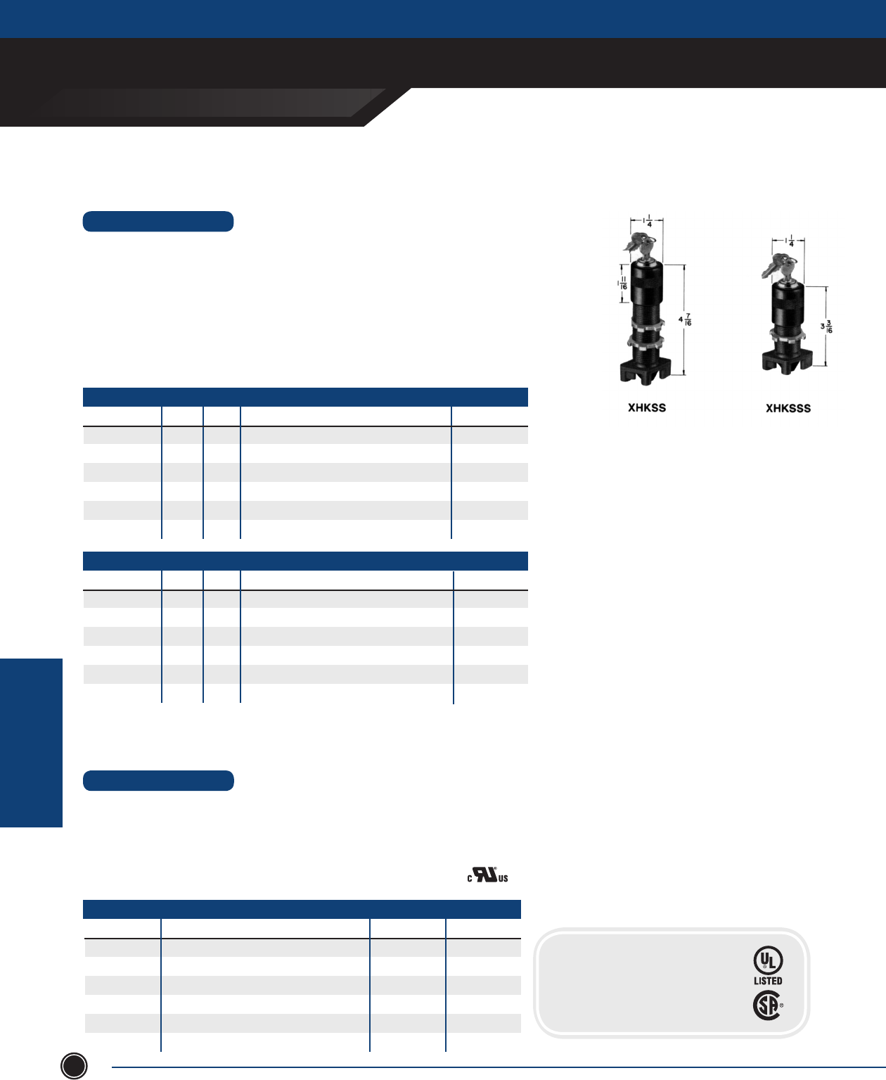
EXPLOSIONPROOF AUXILIARY DEVICES
ADALET.COM
ADALET ENCLOSURE SYSTEMS | 4801 WEST 150TH | CLEVELAND, OHIO 44135 ©Adalet
EXPLOSIONPRROOF
AUXILIARY DEVICES
134
Keylock Selector Switch Operators
Potentiometer & Switch Operators
•Thebarrelsareall¾” NPSM thread. Max. installation thickness: 1 ⁄” Long Barrel,
¾” Short Barrel.
•Selectorswitchoperatorscanbeusedas2positionor3positionbyremovalofknoband
rotating knob 180°.
•Theactuatorcamwhichoperatestheplungersonthecontactblockscanbereadilychanged
for various contact sequences. FOR 3 POSITION, ORDERS MUST STATE CAM NUMBER.
•Theexposedmetalpartsareblackanodizedaluminum.
•Contactblocksarenotincludedwithoperators.Selectcontactblockandsequenceoperating
cam from contact block page.
STANDARD FEATURES
SELECTOR SWITCHES
XHKSS
XHKSC*
XHKSR2
XHKSR
XHKSL2
XHKSL
2
4
2/3
3
2
3
2
3
CATALOG # CAM
Long Barrel
Spring Return to Center from Right & Left
Spring Return to Left from Right
Spring Return to Center from Right, Maintain Left
Spring Return to Right from Left
Spring Return to Center from Left, Maintain Right
# POS. OPERATOR DESCRIPTION WEIGHT LBS.
½
½
½
½
½
½
LONG BARREL
XHKSSS
XHKSSC*
XHKSSR2
XHKSSR
XHKSSL2
XHKSSL
2
4
2/3
3
2
3
2
3
CATALOG # CAM
Short Barrel
Spring Return to Center from Right & Left
Spring Return to Left from Right
Spring Return to Center from Right, Maintain Left
Spring Return to Right from Left
Spring Return to Center from Left, Maintain Right
# POS. OPERATOR DESCRIPTION WEIGHT LBS.
½
½
½
½
½
½
SHORT BARREL
•Diecastaluminumalloy.Thebarrelsareall¾” NPSM thread. ¼” diameter shafts.
Maximum installation thickness: 1 ⁄” long barrel, 3/4” short barrel.
•XPO-XPOShaveknobanddialmarked1to100.Twodialsizesareavailable.
•XPOC-XPOCShave15turncountingdial.
•Operatorsinclude3pc.couplinganddevicemountingbracket.
•Potentiometersnotfurnished,consultfactory.
STANDARD FEATURES
CATALOG # OPERATOR DESCRIPTION MOUNTING WEIGHT LBS.
XPO Plain Dial Long Barrel ½
XPOL Plain Dial, Large Size Long Barrel ½
XPOC Counting Dial Long Barrel ¾
XPOS Plain Dial Short Barrel ½
XPOSL Plain Dial, Large Size Short Barrel ½
XPOCS Counting Dial Short Barrel ½
* 3 position only
CERTIFICATIONS
Class I, Division 1, Groups B, C & D
Class II, Groups E, F & G
NEMA Type 3, 4, 7 & 9
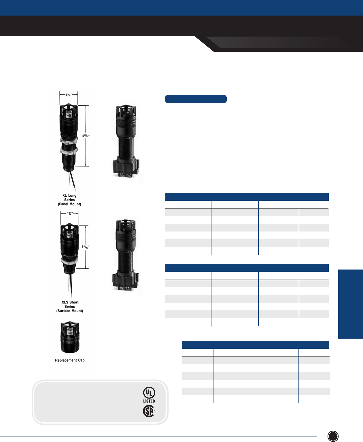
EXPLOSIONPROOF AUXILIARY DEVICES
SEND ORDERS TO ORDERS@ADALET.COM
T: 216.267.9000 | F:216.267.1681 | info@adalet.com ©Adalet
EXPLOSIONPRROOF
AUXILIARY DEVICES
135
Guarded Pilot Lights
for Group B Applications
PILOT LIGHTS
STANDARD FEATURES
• Explosionproofpilotlightsaresuitableforlongbarrelorshortbarrelapplications.
• Sealedconstructionandcanberelampedfromthefrontbyremovaloflenscap.
• Madefor¾” NPSM threads.
• 8”exibleleads,otherlengthsonspecialorder,orscrewterminal(sufxT).
• Alllenscapsareblackanodizedaluminumnish.
• Maximum installation thickness: 1 ⁄” on Long Series, ⁄” on Short Series.
• Standard Series-Equippedwithcandelabrabasereceptaclesand6watt120
volt 6S6 Clear 1500 hr. avg. lamps. Also available with 6, 12, 24, 30, 50, 75 and
135 volt lamps. Specify voltage desired.
• Slide Base Series -Equippedwithslidebasereceptaclesand120volt5000hr.avg.
lamps with slide base. Also available with 6, 12, 24, 48 and 60 volt lamps. Specify
voltage desired.
STANDARD SERIES
LONG BARREL CAT # SHORT BARREL CAT # DESCRIPTION WEIGHT LBS.
XLA-GH XLSA-GH Amber Lens ½
XLB-GH XLSB-GH Blue Lens ½
XLC-GH XLSC-GH Clear Lens ½
XLG-GH XLSG-GH Green Lens ½
XLR-GH XLSR-GH Red Lens ½
XLW-GH XLSW-GH White Lens ½
SLIDE BASE SERIES
LONG BARREL CAT # SHORT BARREL CAT # DESCRIPTION WEIGHT LBS.
XLAS-GH XLSAS-GH Amber Lens ½
XLBS-GH XLSBS-GH Blue Lens ½
XLCS-GH XLSCS-GH Clear Lens ½
XLGS-GH XLSGS-GH Green Lens ½
XLRS-GH XLSRS-GH Red Lens ½
XLWS-GH XLSWS-GH White Lens ½
CATALOG # DESCRIPTION WEIGHT LBS.
XLA-GCH Amber Lens ⁄
XLB-GCH Blue Lens ⁄
XLC-GCH Clear Lens ⁄
XLG-GCH Green Lens ⁄
XLR-GCH Red Lens ⁄
XLW-GCH White Lens ⁄
REPLACEMENT CAP
*AddsufxTtoP/Nforscrewterminal(Example:XLAST-GH)
CERTIFICATIONS
Class I, Division 1, Groups B, C & D
Class II, Groups E, F & G
NEMA Type 3, 4, 7 & 9
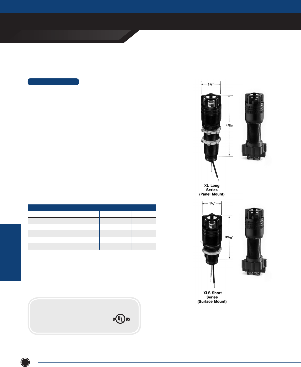
EXPLOSIONPROOF AUXILIARY DEVICES
ADALET.COM
ADALET ENCLOSURE SYSTEMS | 4801 WEST 150TH | CLEVELAND, OHIO 44135 ©Adalet
EXPLOSIONPRROOF
AUXILIARY DEVICES
136
Guarded LED Pilot Lights
for Group B Applications
Congure terminals to
suit your application
•Suitableforlongbarrelorshortbarrelapplications.AllcandelabrabaseLED
lights can be relamped from the front by removal of the lens cap.
•Madewith¾” NPSM threads.
•AllLEDpilotlightshave8”exibleleads,otherlengthsonspecialorder,or
screw terminal.
•AddsufxTtoP/Nforscrewterminal.
•Alllenscapsareblackanodizedaluminumnishwithcoloredglasslens.
•Maximuminstallationthickness:1⁄” on long barrel, ⁄” on
short barrel.
STANDARD FEATURES
LED Advantages:
•10Year/100,000hourservicelifeundernormalambientconditions.
•Upto4xmoreenergyefcient.
•Improvedresistancetoshockandvibration.
•LEDsoperatesignicantlycoolerthantraditionallamps.
•UltrabrightclusterLED’s.
STANDARD SERIES
LONG BARREL CAT # SHORT BARREL CAT # DESCRIPTION WEIGHT LBS.
XLRL-GH XLSRL-GH Red ½
XLAL-GH XLSAL-GH Amber ½
XLGL-GH XLSGL-GH Green ½
XLWL-GH XLSWL-GH White ½
XLBL-GH XLSBL-GH Blue ½
120V dual polarity supplied as standard. 5, 12, 24, 48, 60 volts optional, consult factory.
*AddsufxTtoP/Nforscrewterminal(Example:XLRLT-GH)
PILOT LIGHTS
CERTIFICATIONS
Class I, Division 1, Groups B, C & D
Class II, Groups E, F & G
NEMA Type 3, 4, 7 & 9 LISTED 437S
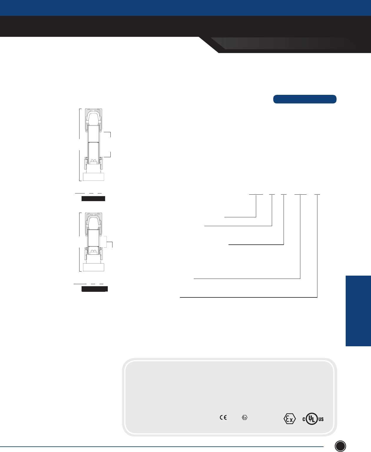
EXPLOSIONPROOF AUXILIARY DEVICES
SEND ORDERS TO ORDERS@ADALET.COM
T: 216.267.9000 | F:216.267.1681 | info@adalet.com ©Adalet
EXPLOSIONPRROOF
AUXILIARY DEVICES
137
ATEX Certied LED Pilot Lights
5.91[150.2]
(REF)
2.05[52.2]
MAX.JOIN
(NOTES3&4)
XLX - G
LONGBODY
CLASSIC GUARDED CAP
4.79[121.6]
(REF)
.93[23.6
MAX.JOIN
(NOTES3&4)
XLXS - G
SHORTBODY
CLASSIC GUARDED CAP
LONG BODY
CLASSIC GUARDED CAP
SHORT BODY
CLASSIC GUARDED CAP
5.91
[150.2]
(REF)
2.05 [52.2]
MAX. JOINT
(NOTES 3 & 4)
4.79
[121.6]
(REF)
.93 [23.6]
MAX. JOINT
(NOTES 3 & 4)
STANDARD FEATURES
•Explosionproofpilotlightsaresuitableforpanelorsurfacemount
applications. Superior Safety Lamps located inside enclosure (not
underlenscap)forworry-freeoperation.
•Congurable:Yourchoiceofcolor,shortorlonglengthsand120or
240 Volt lamps.
• 240VoltPowerOptionUseoptionalresistortypebasefor240Volt
applications.
• LowMaintenance10year/100,000servicelifeundernormal
ambient conditions.
• Efcient4xmoreefcientthanstandardincandescentbulbs.
• ImprovedVisibilityUtilizesultra-brightclusterLED’s.
XLX S R 120 - G
BASE CATALOG NUMBER
BODY LENGTH3
- NONE=Long - S=Short
COLOR OF LENS & LAMP2
- R=Red - B=Blue
- A=Amber(Yellow) - W=White
- G=Green
VOLTAGE1
- 120,240(optional voltages available, consult factory.)
CAP
- G=GuardedClassicCap
1 240 Volt lamp requires optional resistor type base (P/N 31216–1). Maximum lamp Voltage is 120.
2 Color of lamp and lens are normally the same. White lamp uses clear lens cap.
3 Minimumlengthofthreadedjoint=seventhreads(GroupB),=vethreads(GroupC).
4 Maximum installation thickness shown for classic guarded models may be increased .15” by
discardingknurledlockring.Minimumlengthofthreadedjointmustbesatised.
CERTIFICATIONS
ATEX Directive 94/9/EC
UL60079-0/UL60079-1
IEC60079-0/IEC60079-1
UL 698 / UL 1203 / CSA C22.2, No.30
UL 50
IEC 60529
DEMKOCerticate:05ATEX0530154U
ExdIIB+H2T6Tamb-20°Cto+55°C
ClassI,Zone1,AExdIIB+H2T6Tamb-20°Cto+55°C
ExdIIB+H2T6Tamb-20°Cto+55°C
Class I, Groups B, C & D; Class II, Groups E, F & G
IP66
NEMA Type 4, 4X, 7 & 9
0539 II 2 GD
LISTED 437S
PILOT LIGHTS
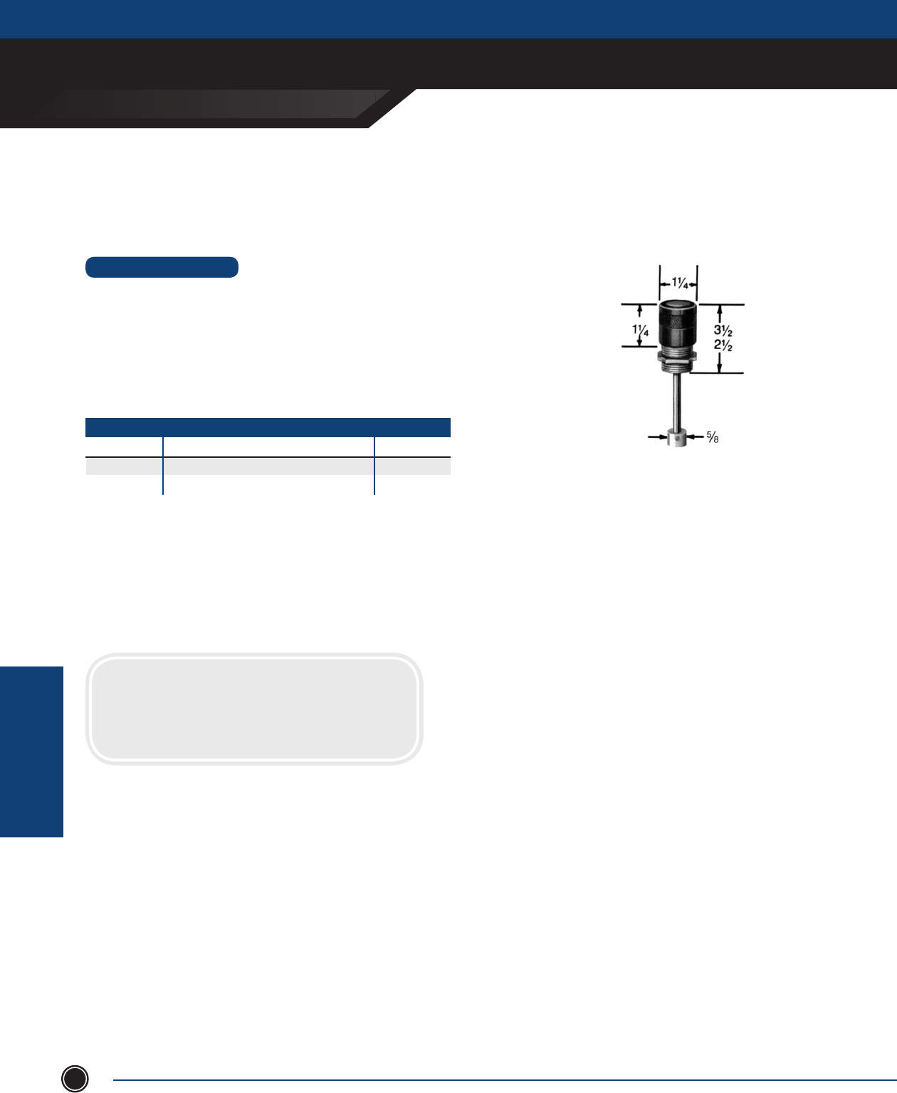
EXPLOSIONPROOF AUXILIARY DEVICES
ADALET.COM
AdAlet enclosure systems | 4801 West 150th | cleVelAnd, ohIo 44135 ©Adalet
EXPLOSIONPRROOF
AUXILIARY DEVICES
138
Reset Button Operators
SPECIAL OPERATORS
• Used for resetting contactors, relays, etc. in explosionproof and weather-proof
enclosures. Made with ¾” NPSM threaded stem.
• Standard operating shaft length 6” can be cut to length. Special lengths are
also available. Use XRBL for wall thickness greater than ¾”.
STANDARD FEATURES
XRB / XRBL
RESET BUTTON
CaTalOg # OpERaTOR DESCRipTiON WEighT (lBS.)
XRB Reset Button - Short ½
XRBL Reset Button - Long ½
CERTIFICATIONS
Class I, Division 1, Groups B, C & D
Class II, Groups E, F & G
NEMA Type 3, 4, 7 & 9
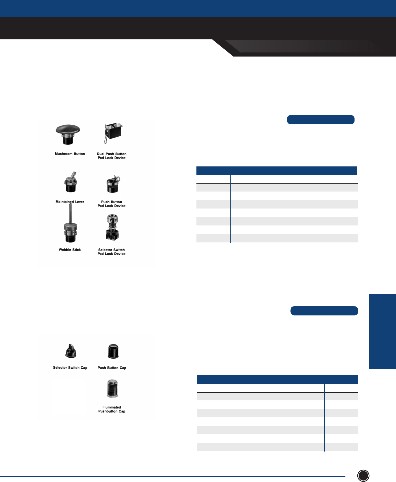
EXPLOSIONPROOF AUXILIARY DEVICES
SEND ORDERS TO ORDERS@ADALET.COM
T: 216.267.9000 | F:216.267.1681 | info@adalet.com ©Adalet
EXPLOSIONPRROOF
AUXILIARY DEVICES
139
XMB XHDPL
XHPL
XHSPL
XMT
XMC
• Moldedsiliconerubber,protectivebootsforusewithexplosionproofoperators
inextremelywet-dirtylocations.MakesoperatorssuitableforNEMAType3,4,
4X, 5, 7, 9, 12, 13 application.
• Bootandmetalcollarareanintegralassemblyavailableasafactoryadderora
eldreplacement.
• Simpleinstallationrequiresremovalofexistingcapandthreadingonthe
replacement.
Operator Protective Boots
PUSHBUTTON & SELECTOR SWITCH
CATALOG # DESCRIPTION WEIGHT LBS.
XBB Black Push Button Cap 1 oz.
XBG Green Push Button Cap 1 oz.
XBR Red Push Button Cap 1 oz.
XBSB Black Selector Switch Cap 1 oz.
XBSG Green Selector Switch Cap 1 oz.
XBSR Red Selector Switch Cap 1 oz.
XBPC Clear Pilot Light Push Button Cap 1 oz.
Toorderascompleteoperator,addpart#assufx
NOTE
•Operatorlockingcapsandactuatordevicescanbeadaptedtoexisting
explosion proof operators.
•Simpleinstallationrequiresremovaloftopcapandthreadingonthe
replacement unit.
PUSHBUTTON & SELECTOR SWITCH
CATALOG # DESCRIPTION WEIGHT LBS.
XHDPL Padlock Device for Dual Push Button ¼
XHPL Padlock Device to activate Push Button ¼
XHSPL Padlock Device for Selector Switch ¼
XMB Red Mushroom Head 2 ¼” Button ¼
XMC Maintained Contact Lever for Push Buttons ¼
XMT Wobble Stick 2 ½” Long for NC Push Button ¼
XHPLG Padlockable Push Button Cover (Not Shown) ¼
Mushroom button and wobble stick recommended only for
operators with normally closed contact blocks.
NOTE
Push Button & Selector Switch Components
XBSB XBB
XBPC
STANDARD FEATURES
STANDARD FEATURES
ACCESSORIES
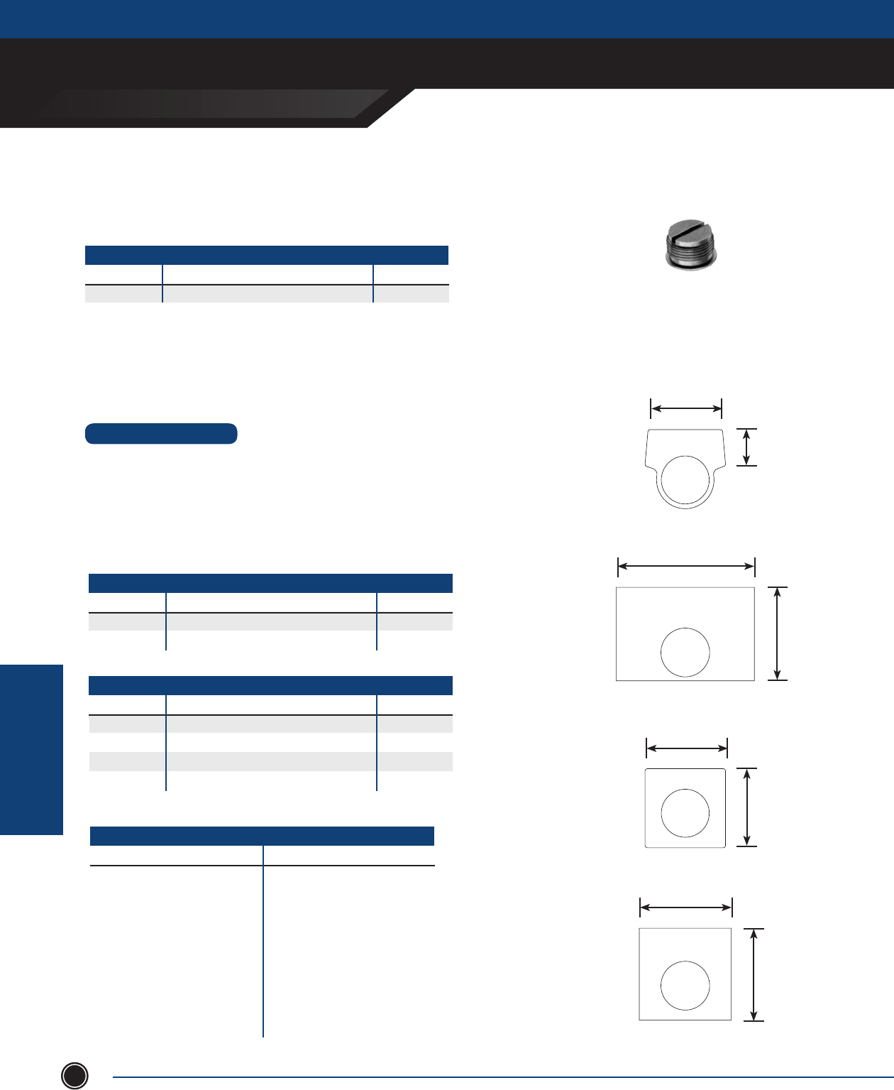
EXPLOSIONPROOF AUXILIARY DEVICES
ADALET.COM
ADALET ENCLOSURE SYSTEMS | 4801 WEST 150TH | CLEVELAND, OHIO 44135 ©Adalet
EXPLOSIONPRROOF
AUXILIARY DEVICES
140
XPPH3-N4
BLACK ANODIzED
CLOSE UP PLUGS
CATALOG # OPERATOR DESCRIPTION WEIGHT
XPPH3-N4 ¾” NPSM Type 4 ¾ oz.
LEGEND PLATES
CATALOG # OPERATOR DESCRIPTION WEIGHT OZ.
XNPWB Black Blank Legend Plate 1
XNPWG Green Blank Legend Plate 1
XNPWR Red Blank Legend Plate 1
XNPW XL Specify Legend 1
STANDARD MARKING
FOR PUSH BUTTON FOR SELECTOR SWITCHES
(BLANK) SLOW RESET RUN-JOG OPEN-OFF-CLOSE
START OPEN IN HAND-AUTO FAST-OFF-SLOW
INCH CLOSE OUT FWD-REV RUN-AUTO-JOG
STOP UP LEFT FAST-SLOW HAND-OFF-AUTO
RUN JOG RIGHT OPEN-CLOSE FWD-OFF-REV
FORWARD ON LOW UP-DOWN 1-OFF-2
REVERSE OFF HIGH OFF-ON U P-OFF-DOWN
FAST BACK DOWN
EMERGENCY STOP
• Legendplatesareanodizedaluminumwithengravedlettersonblackbackground(XNP).
• Stophasredandstarthasgreenbackground.
• Specialengravedlegendplatescanbesupplied.
• Legendplatehasfoamgasketbackingforusewithprotectivebootsforsealing.
EngravingonelineonlyseePriceList(XNPW).
SPECIFY LEGEND PLATE
CATALOG # OPERATOR DESCRIPTION WEIGHT OZ.
XNP Specify Legend 1
XNPL Specify Legend 1
Close Up Plugs
for Unused Operator Openings
Legend Plates
XNP
XNPL
XNPW_
XNPW X-L
1 ⁄
3
1 ¾1 ¾
2
⁄
2 ⁄
1 ⁄
2
ACCESSORIES
STANDARD FEATURES
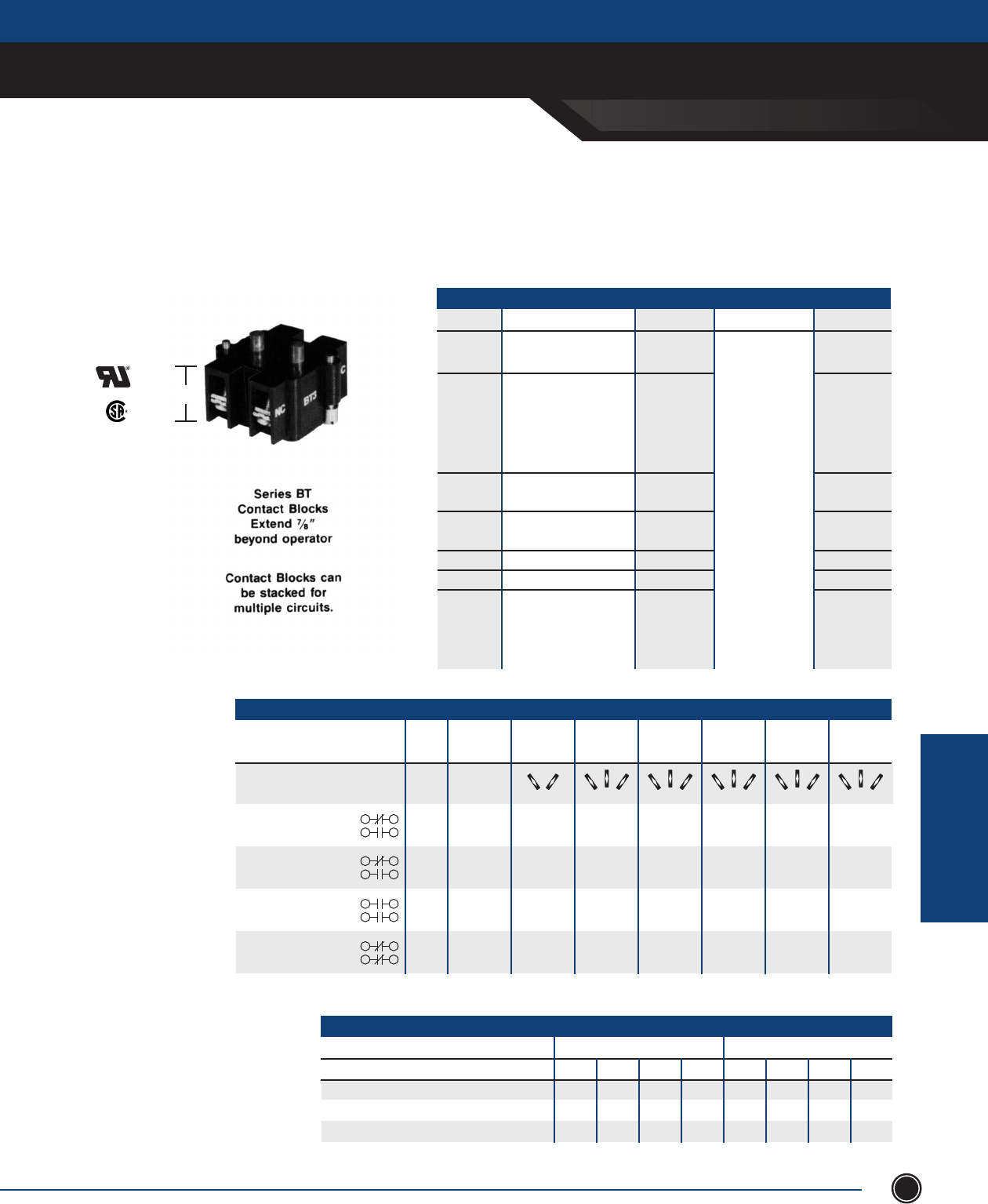
EXPLOSIONPROOF AUXILIARY DEVICES
SEND ORDERS TO ORDERS@ADALET.COM
T: 216.267.9000 | F:216.267.1681 | info@adalet.com ©Adalet
EXPLOSIONPRROOF
AUXILIARY DEVICES
141
(max. four)
⁄
MAX RATING: TYPE BT CONTACT BLOCKS
AC DC
VOLTS 110 220 440 550 24/28 120 240 600
Make & Emergency Interrupting Capacity A 60. 30. 15. 12. 5.7 1.1 0.5 0.2
Normal Load Break A 6. 3. 1.5 1.2 5.7 1.1 0.5 0.2
Continuous Current A 10. 10. 10. 10. 5. 10. 10. 10.5
Congure terminals to
suit your application
SERIES BT
CATALOG # CONTACT BLOCK PUSH BUTTON SELECTOR SWITCH WEIGHT LBS.
BT1A One Open and 1 N.O. 1/10
One Closed 1 N.C.
BT1B One Closed and One Open
(this is BT1A block 1 N.C. See
rotated 180 degrees 1 N.O. Chart 1/10
when assembled to
operator)
BT2 Two open 1 N.O. 1/10
1 N.O.
BT3 Two closed 1 N.C. 1/10
1 N.C. Specify Cam
BT4 One open 1 N.O. and 1/10
BT5 One closed 1 N.C. Contact 1/10
BT44 Two open 1 N.C. Block 1/10
1 N.O.
Two closed 1 N.O.
1 N.C.
CONTACT SEQUENCE CHART
Contact Cam 1 Cam 2 Cam 3 Cam 4 Cam 5 Cam 6
Block Contact Contact Contact Contact Contact Contact
Circuit of Contact Block Number Sequence Sequence Sequence Sequence Sequence Sequence
Normally Closed (NC) BT1A Circuit A X O O X O O X X X O O O X X X O O
Normally Open (NO) Circuit B O X O O X O O X O X O X X O O X O
Normally Closed (NC) BT1B* Circuit B X O X X O X X O X O X O O X O O X
Normally Open (NO) Circuit A O X X O X X O O O X X X O O O O X
Normally Open(NO) BT2 Circuit A O X X O X X O O O X X X O O O O X
Normally Open (NO) Circuit B O X O O X O O X O X O X X O O X O
Normally Closed (NC) BT3 Circuit A X O O X O O X X X O O O X X X O O
Normally Closed (NC) Circuit B X O X X O X X O X O X O O X O O X
O = Contact Open
X = Contact Closed
* This contact block is same as BT1A one N.C. and one N.O. except rotated 180° when assembled to operator.
600 Volts AC Maximum Contact Blocks
for Push Buttons & Selector Switches
CONTACT BLOCKS
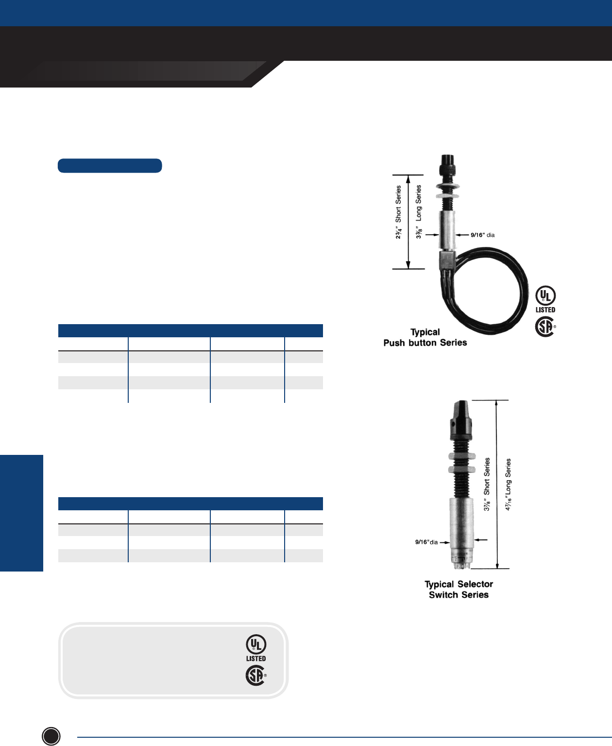
EXPLOSIONPROOF AUXILIARY DEVICES
ADALET.COM
ADALET ENCLOSURE SYSTEMS | 4801 WEST 150TH | CLEVELAND, OHIO 44135 ©Adalet
EXPLOSIONPRROOF
AUXILIARY DEVICES
142
• Reducesizeofcontrolenclosurerequirementsinhazardousenvironments.
• Mounton1”centersvs.standardoperatorsrequiring2½” centers.
• Nospecialenclosuresrequired;canbeinstalledinmostAdaletstandard
explosionproof enclosures.
• ⁄”-16UNCthreadsizebody.
• Blackanodizedbody,cap,buttonorknob
• Twolengthsavailable:LongSeriesAccommodatesupto1⁄”
enclosure wall thickness. Short Series Accommodates up to ⁄”
enclosure wall thickness
• Stainlesssteelactuatorshaft.
• Optionalredorgreenbutton(PushbuttonOperatoronly)
PUSH BUTTONS
CAT # LONG BARREL CAT # SHORT BARREL CONTACT CONFIGS. WEIGHT
XMOB-1 XMOBS-1 SPDT maintained 1 oz.
XMOB-2 XMOBS-2 SPDT momentary 1 oz.
XMOB-3* XMOBS-3* DPDT maintained 1 oz.
XMOB-4 XMOBS-4 DPDT momentary 1 oz.
* Not UL or CSA Approved
•Solidsilvercontactsrated5ampsat125VAC,3ampsat250VAC.
•Insulationresistance1000megohmminimum.
•Furnishedwithcontactblockhaving8”wireleads,otherlengthsavailable.
•Optionalredorgreenbutton(PushbuttonOperatoronly)
XMOB
XMOS
Miniature Operators
STANDARD FEATURES
•Selectorswitchesprovidedwithinternaladjustablestop.
•Silvercontactsrated150m.a.at30VAC,NECCL2circuit.
•Insulationresistance10,000megohmsminimum.
•Furnishedwithcontactblockhavingsoldertypewireconnectors.
PUSH BUTTONS
CAT # LONG BARREL CAT # SHORT BARREL CONTACT CONFIGS. WEIGHT
XMOS-1 XMOSS-1 Single Pole, 12 position 1 oz.
XMOS-2 XMOSS-2 Double Pole, 5 position 1 oz.
XMOS-3 XMOSS-3 Three Pole, 3 position 1 oz.
MINIATURE OPERATORS
CERTIFICATIONS
Class I, Division 1, Groups B, C & D
Class II, Groups E, F & G
NEMA Type 4, 7 & 9
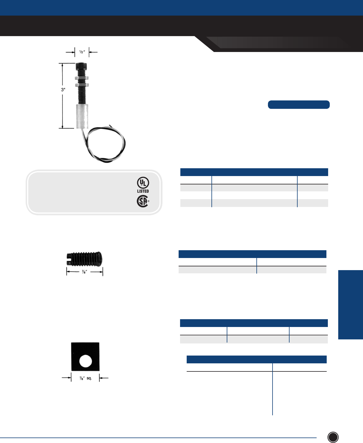
EXPLOSIONPROOF AUXILIARY DEVICES
SEND ORDERS TO ORDERS@ADALET.COM
T: 216.267.9000 | F:216.267.1681 | info@adalet.com ©Adalet
EXPLOSIONPRROOF
AUXILIARY DEVICES
143
CLOSE UP PLUGS
CATALOG # WEIGHT
XMPP ½ oz.
Legend Plates Standard Marking
STANDARD MARKING
FOR PUSH BUTTON FOR SELECTOR SWITCHES
(BLANK) SLOW RESET START RUN-JOG
OPEN IN INCH CLOSE HAND-AUTO
OUT STOP UP LEFT FWD-REV
RUN JOG RIGHT FORWARD FAST-SLOW
ON LOW REVERSE OFF OFF-ON
HIGH FAST BACK OPEN-CLOSE
UP-DOWN
Close Up Plugs
For Unused Operator Openings
LEDGEND PLATES
CATALOG # DESCRIPTION WEIGHT
XMNP Specify legend ½ oz.
ACCESSORIES
•Upto100,000hourslamplife.
•Standard12VDCfurnished.Optional24VDC,or12,24,120VAC
available.
•Blackanodizedbodyandlenscap.
•⁄”-16UNCthreadsizebody.
•Onelength-accommodatesupto1⁄” enclosure wall thickness.
•Furnishedwith8”exiblewireleads,otherlengthsavailable.
SURFACE MOUNTING
Catalog # Operator Description Weight (lbs.)
XMOLR Red Indicator Light 1 oz.
XMOLA Amber Indicator Light 1 oz.
XMOLG Green Indicator Light 1 oz.
Indicator LED Light
STANDARD FEATURES
CERTIFICATIONS
Class I, Division 1, Groups B, C & D
Class II, Groups E, F & G
NEMA Type 4, 7 & 9
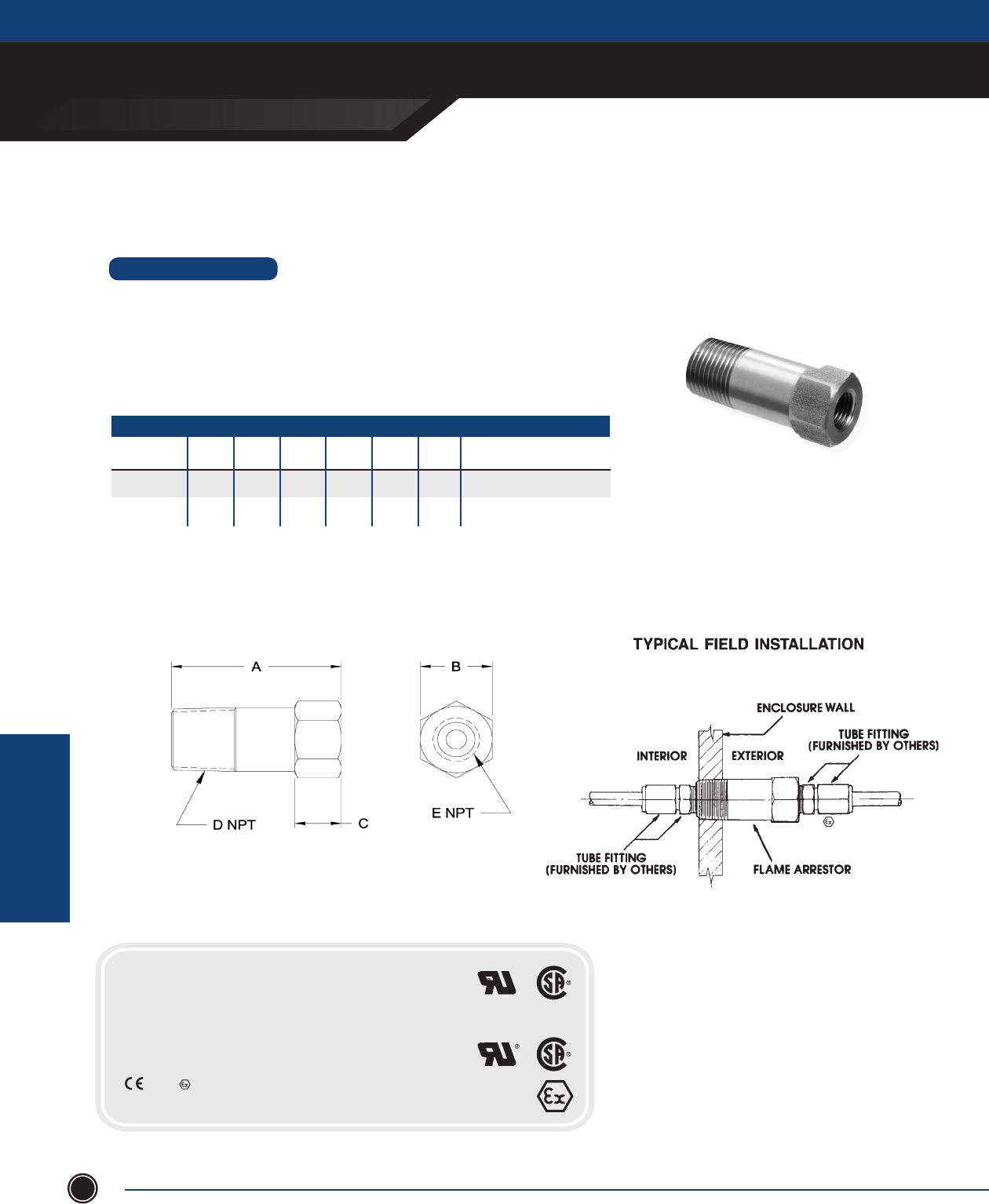
EXPLOSIONPROOF AUXILIARY DEVICES
ADALET.COM
ADALET ENCLOSURE SYSTEMS | 4801 WEST 150TH | CLEVELAND, OHIO 44135 ©Adalet
EXPLOSIONPRROOF
AUXILIARY DEVICES
144
CERTIFICATIONS
XFA2
Class I, Division 1, Groups B, C & D
XFAX2*
Class I, Division 1, Groups B, C & D
NEMA Type 7
0539 II 2 G
EEx d IIB
UL 1203
CSA C22.2 No. 30
UL 1203
CSA C22.2 No. 30
ATEX DIRECTIVE 94/9/EC
Exterior enclosure wall counter boring may be required to maintain
1/2”enclosurewallthicknessforeaseofeldconnections.
Flame Arrestor Fitting
XFAX2
*ATEX Application note: Maximum Enclosure Volume 41000 cm3 (2500 in3)
•Providesthru-wallconnectionsoftubingsystemsforelectro/pneumatic
andgasanalysisdevicesinstalledwithinAdalet’sexplosionproofenclosures.
•Theamearrestorttingisdesignedtopreventamepropagationthru
tubingsystemswithminimumowrestrictionsofcontrolpressures.
•Manufacturedfrom316Lstainlesssteel.
STANDARD FEATURES
CATALOG
NUMBER
XFA2
XFAX2
A
2 ⁄
2 ⁄
B
⁄
⁄
C
⁄
⁄
D NPT
½-14
½-14
E NPT
¼-18
¼-18
WT.
oz.
4
4
CONTROL
RESTRICTIONS
0.5 PSI drop at 20 CFH airflow
1.3 PSI drop at 34 CFH airflow
1 PSI drop at 18 CFH airflow
5 PSI drop at 53 CFH airflow
ACCESSORIES
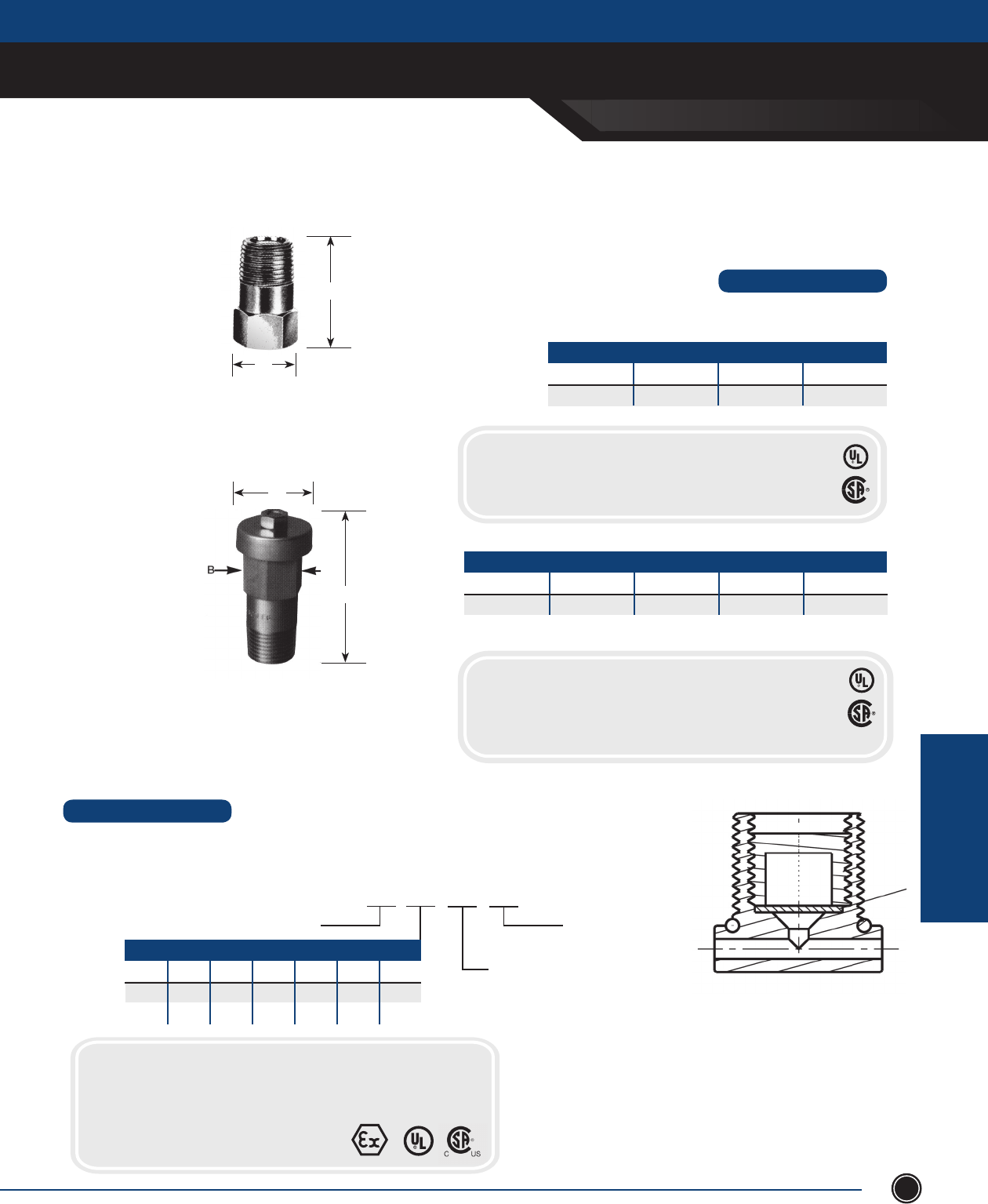
EXPLOSIONPROOF AUXILIARY DEVICES
SEND ORDERS TO ORDERS@ADALET.COM
T: 216.267.9000 | F:216.267.1681 | info@adalet.com ©Adalet
EXPLOSIONPRROOF
AUXILIARY DEVICES
145
Combination Breather/Drains
XDB Series
A
C
NOMINAL DIMENSIONS [inches)
CATALOG # THREAD A B C
XDBH2 ½ NPT ½ NPT ⁄ HEX 1 ¼
*ATEX APPLICATION NOTE: Maximum Enclosure Volume 41000 cm3 (2500 in3)
• Stainless steel combination breather drain. Install in top of enclosure
as breather. Install in bottom of enclosure as drain.
NOMINAL DIMENSIONS [inches)
CATALOG # THREAD A B
XDB2 ½ NPT 1 ⁄ ⁄
XDB2
A
B
Type Bd Series
• Allows the air inside an ‘Ex d’ Flameproof or Class I, Div 1 enclosure to breathe with the surrounding atmosphere.
• Allows any moisture that enters the enclosure to drain while maintaining the overall integrity of the installation.
Bd Series
PART NUMBER BUILD Bd 20 N NT
O-RING
Nitrile (std.) - NT
Silicone - SC
MATERIAL
Nickel Plated Brass - N
316 Stainless Steel - S
THREAD DESIGNATION
Metric NPT NPS ISO ISO ET PG
20 ½ ½S ½P ½T ¾E 13
25 ¾ ¾S ¾P ¾T 1E 16P
CERTIFICATIONS
Class I, Groups C & D
Class II, Groups E, F & G
Class III
UL Standard 1203
CSA Standard C22.2 No. 30
CERTIFICATIONS
Class I, Groups A, B, C & D
Class II, Groups E, F & G
Class III
UL Standard 1203
CSA Standard C22.2 No. 30
ATEX EExd IIB DEMKO 00E.004127U
(when installed in XCEX & XJ_X enclosures)
STANDARD FEATURES
CERTIFICATIONS
Class I, Div 1 Groups A, B, C & D
AExd IIC / AExe II Class I, zone 1
Class III
II 2 GD Exd IIC/Exe II Category 2 & 3
CSA Standard C22.2 No. 30
461203
STANDARD FEATURES
ACCESSORIES
XDBH2
