Catalog HIMEL
2014-09-05
: Pdf 115695-Attachment 115695-Attachment 785901 Batch7 unilog
Open the PDF directly: View PDF ![]() .
.
Page Count: 186 [warning: Documents this large are best viewed by clicking the View PDF Link!]

900001 B06
general catalogue
general catalogue 47G.1e
We reserve the right to further developments and
technical modifications of our products. Such
modifications, along with errors and printing errata,
shall not constitute grounds for compensation.
We refer customers to our Terms of Sale and delivery.
HISPANO MECANO ELÉCTRICA, S.A.
Llobregat, 9 - Pol. Ind. El Pla
08750 Molins de Rei (Barcelona) SPAIN
Tel.: + 34 93 484 33 33
Fax: + 34 93 484 34 89
E-mail: customerservice@himel.es
www.himelenclosures.com
Dep. legal: B. 8.045-2006
SUMMARY
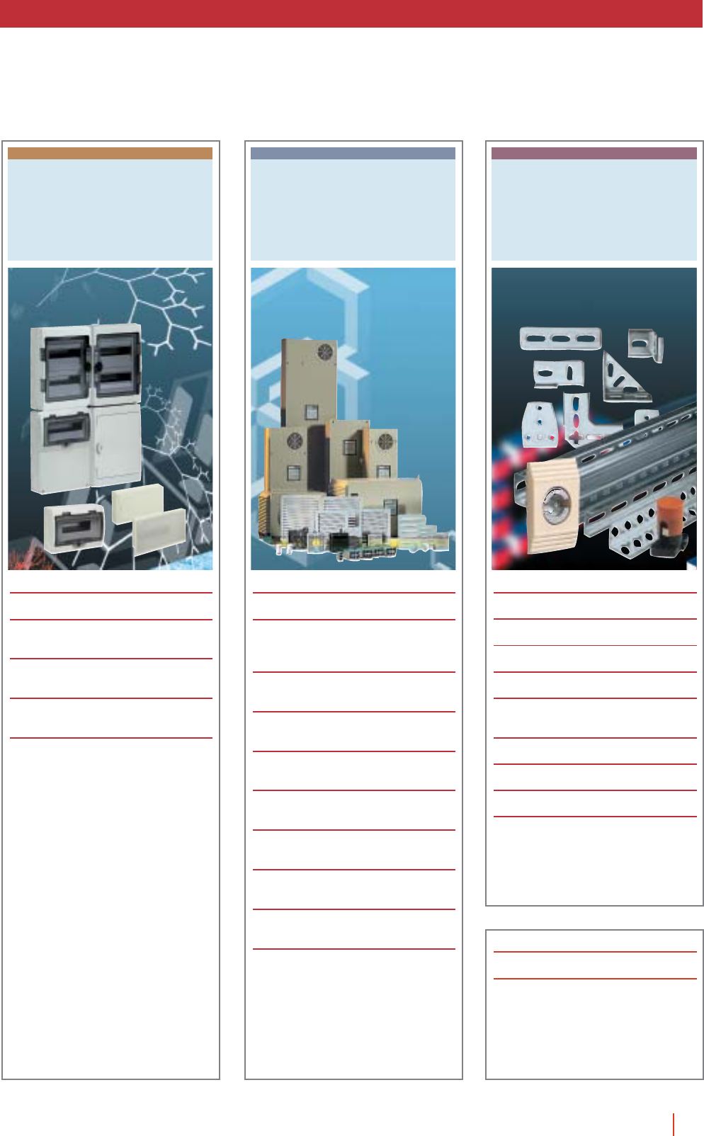
WALL FIXING AND
FLOOR STANDING
METAL ENCLOSURES
BOXES AND ENCLOSURES
IN POLYESTER
METAL AND INSULATING
BOXES AND ENCLOSURES
BOXES FOR MODULAR
DISTRIBUTION
THERMAL CONTROL FOR
ELECTRICAL SWITCHBOARDS
ACCESSORIES
3summary HIMEL
ANNEX TECHNICAL
REFERENCE LIST

COMPANY
47G.1e
4 HIMEL company
Our Company
Since 1958, Himel has always been anxious to remain very close to its
customers. The constant innovation in our designs, improvements in our
logistics process and the continuous expansion of our world distribution
network demonstrate this fact.
We are specialists in the design, production and marketing of enclosure
systems which ease the implementation of your installations and protect
them under any environmental conditions.
Our products adapt perfectly to each and every one of the necessities of
the industrial, tertiary and domestic sectors.
Our values
Over the years, Himel has developed the values that bring it closer to its
customers:
cWide range of enclosures available near you.
cEasily adaptable, flexible universal solutions.
cEnclosures designed to simplify and carry out your installations.
cReactivity and maximum cooperation.

5company HIMEL
Himel “Always close to you”
Himel’s extensive catalogue offers technical solutions for enclosures in steel,
stainless steel, thermoplastic and polyester, including the elements for ther-
mal control in the interior of the enclosure and a very wide range of acces-
sories to facilitate the construction of your equipment.
In this way, we can always be close to your applications, whether they are
for electrical distribution, industrial control and automatism or voice and data
networks, in the industrial, infrastructure, tertiary or residential markets.
The communication link with our customers is established by means of our
extensive sales network, which offers you highly-qualified, professional per-
sonal treatment, satisfying all your needs and keeping you constantly infor-
med of our products and services.

6 HIMEL company
During the last 25 years, Himel has been implanting an intense stra-
tegy of internationalisation. This has made it possible for our enclo-
sures today to be protecting thousands of installations in the five
continents, with a total guarantee of quality.
Thanks to a wide, professionalized distribution network, we have
succeeded in locating our range of enclosures always close to where
you are, available for rapid, sure delivery in most of the countries in
the world.
A will of iron to achieve quality, service and reactivity to our customers’
demands, has allowed us to consolidate a position of leadership in
the enclosures market, which permits us to continue developing
advanced solutions for protecting your future installations, wherever
they may be.
Himel in the world

7company HIMEL
One of the reasons for our success is the importance we attach to
logistics. Our commitment to serving our customers, in an increa-
singly efficient manner all over the world, impels us to make efforts in
logistical innovations that are applied to all processes of storage,
transport, distribution and marketing.
We apply new database, automatic identification, and packaging
technologies which ensure that waiting times are minimal, that errors
are not produced, that the products are well transported and that
handling and storage are simple.
Logistics thus become a competitive advantage, which permits deli-
very periods to be shortened and, most important of all, allows us to
provide customers with an excellent service.
Logistics are the key
11user’s guide HIMEL
Ranking coding:
1. Product lines section
1.1. Sub-index.
1.2. Introduction.
1.3. Tables of description by selection type.
1.4. Tables of selection by type.
1.5. Main points.
1.6. Models, measurements, references, diagrams.
2. Systems section
2.1. Selection tables.
2.2. Product description, tables, diagrams.
3. Accessories section
3.1. Selection tables.
3.2. Product description, tables, diagrams.
WALL FIXING AND FLOOR
STANDING METAL ENCLOSURES
BOXES AN
D
IN POLYES
T
WALL FIXING AND FLOOR
STANDING METAL ENCLOSURES
Detail colour code for indexes Detail colour code for title pages
Ranking and classification
of the products and their
different components
Each product line is composed of different sections: title page, introduction, pano-
rama, explanations, selection table, product and description, panel of models and
references, dimensions and diagrams, basic components, installation systems,
accessories and complements.
These sections are coded as follows:
Ranking coding:
Colour
corresponding
to product
line
Classification of the
enclosures in the chapters
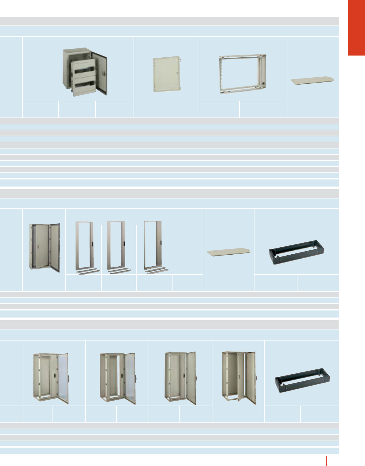
CRN
WALL MOUNTING STEEL ENCLOSURES
IP66 (EN 60529)
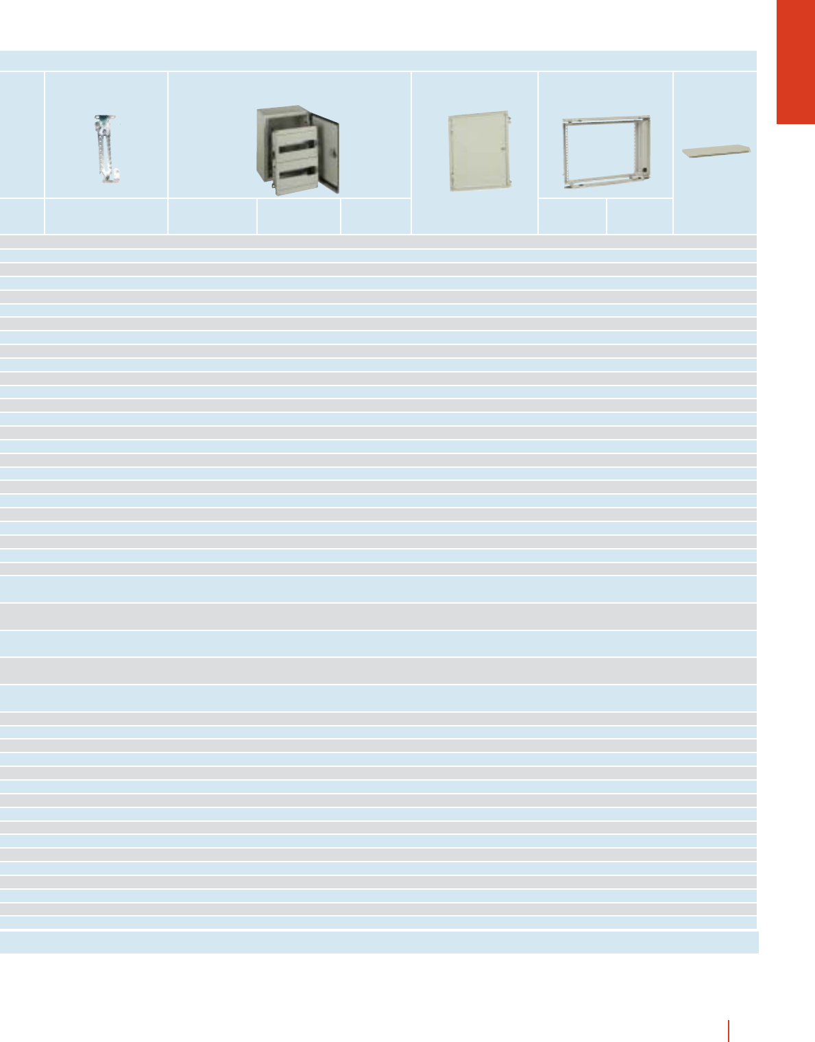
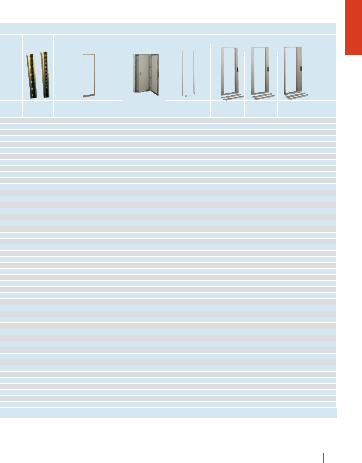
ENCLOSURES, DIMENSIONS AND REFERENCES
* Weight of enclosures with plain door. ** Enclosures with three point locking system.
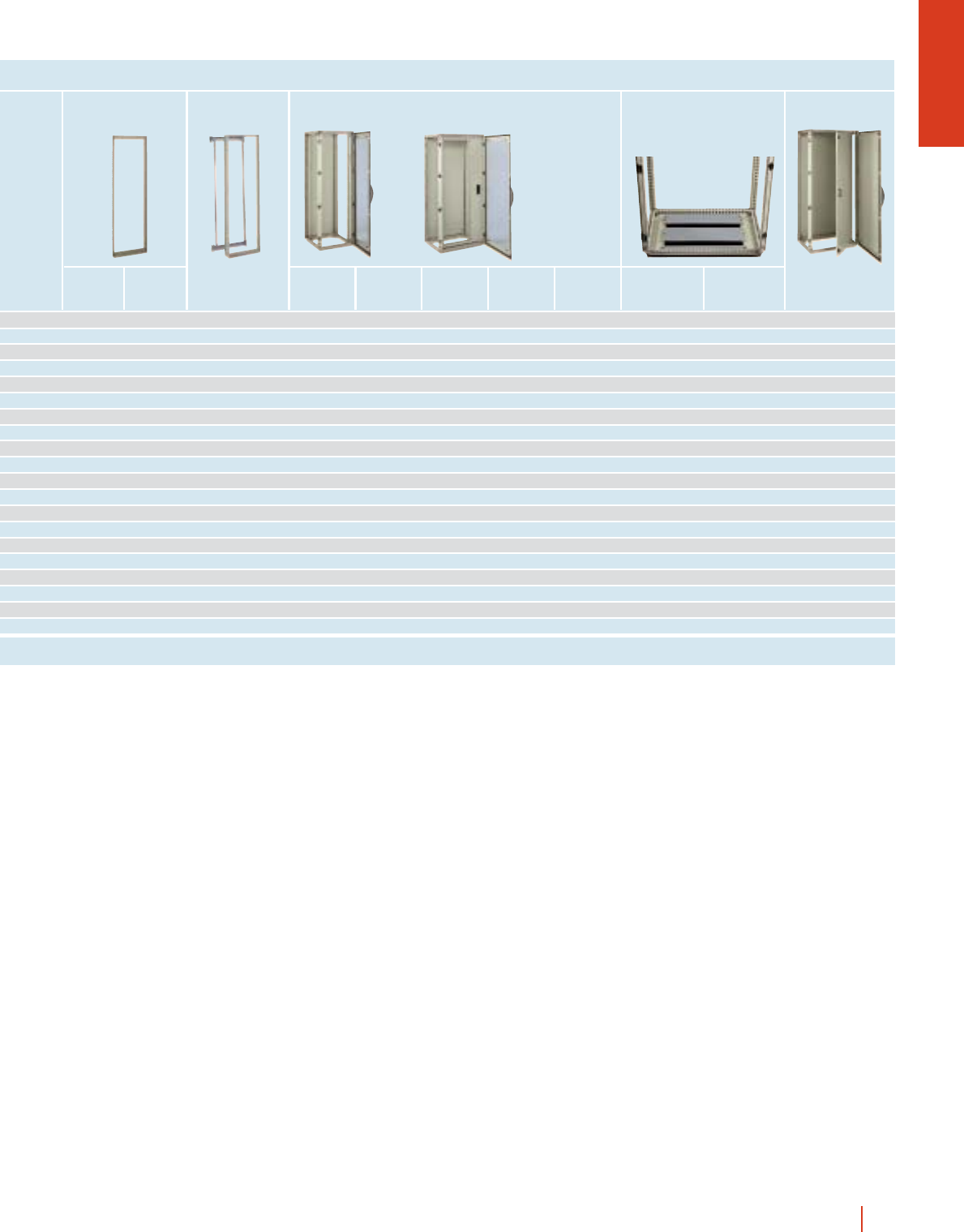
Enclosures Mounting plates
Mounting
plate
adjustable
supports
Metallic
chasis
DLM
Fixed and
swing
19" racks
Internal
door
External
dimensions (mm)
Height
(A)
Width
(B)
Depth
(C)
Reference Reference with
glazed door Fig.
Flange
opening
type
Weight*
Kg
250 200 150 CRN-2520/150 - 103.2
ppp
300 250 150 CRN-3025/150 CRN-3025/150 KT 1A4.2pppp
300 250 200 CRN-3025/200 CRN-3025/200 KT 1A4.9ppppp
300 300 150 CRN-33/150 CRN-33/150 KT 1B5pppp
300 300 200 CRN-33/200 CRN-33/200 KT 1B6ppppp
300 400 200 CRN-34/200 CRN-34/200 KT 1C6.4ppppp
400 300 150 CRN-43/150 CRN-43/150 KT 1B6pppp p
400 300 200 CRN-43/200 CRN-43/200 KT 1B6.8pppppp p
400 400 200 CRN-44/200 CRN-44/200 KT 1C8ppppp
400 600 250 CRN-46/250 CRN-46/250 KT 1D10ppppp p
400 600 300 CRN-46/300 CRN-46/300 KT 1 D 11.2 ppppp p
500 400 150 CRN-54/150 CRN-54/150 KT 2B8.7pppp p p
500 400 200 CRN-54/200 CRN-54/200 KT 2C9.8pppppp p
500 400 250 CRN-54/250 CRN-54/250 KT 2C11pppppp p
500 500 250 CRN-55/250 CRN-55/250 KT 2 D 12.8 ppppp
600 400 150 CRN-64/150 CRN-64/150 KT 2B9.3pppp p p
600 400 200 CRN-64/200 CRN-64/200 KT 2 C 10.8 pppppp p
600 400 250 CRN-64/250 CRN-64/250 KT 2 C 12.3 pppppp p
600 500 150 CRN-65/150 CRN-65/150 KT 2 B 11.3 pppp
600 500 200 CRN-65/200 CRN-65/200 KT 2 D 14.3 ppppp
600 500 250 CRN-65/250 CRN-65/250 KT 2 D 16.3 ppppp
600 600 200 CRN-66/200 CRN-66/200 KT 2D- ppppppp
600 600 250 CRN-66/250 CRN-66/250 KT 2 D 18.2 ppppppp
600 600 300 CRN-66/300 CRN-66/300 KT 2 D 19.8 ppppppp
600 800 300 CRN-68/300 CRN-68/300 KT 2E26ppppp
700 500 200 CRN-75/200 CRN-75/200 KT 2 D 17.3 pppppp p
700 500 250 CRN-75/250 CRN-75/250 KT 2 D 19.3 pppppp p
800 600 200 CRN-86/200 CRN-86/200 KT 2 D 21.8 pppppp p
800 600 250 CRN-86/250 CRN-86/250 KT 2 D 24.8 pppppppp
800 600 300 CRN-86/300 CRN-86/300 KT 2 D 26.3 pppppppp
800 600 400 CRN-86/400 CRN-86/400 KT 2D- pppppppp
800 800 200 CRN-88/200 CRN-88/200 KT 2 E 29.5 ppppp
800 800 300 CRN-88/300 CRN-88/300 KT 2 E 32.5 ppppp
800 1,000 300 CRN-810/300** - 4E37ppppp
1,000 600 250 CRN-106/250 CRN-106/250 KT 2 D 28.4 pppppppp
1,000 600 300 CRN-106/300 CRN-106/300 KT 2 D 30.6 pppppppp
1,000 800 250 CRN-108/250 CRN-108/250 KT 2 E 34.5 pppppppp
1,000 800 300 CRN-108/300 CRN-108/300 KT 2 E 37.4 pppppppp
1,000 800 400 CRN-108/400 CRN-108/400 KT 2E- pppppppp
1,000 1,000 300 CRN-1010/300** CRN-1010/300 KT** 4 (KT:3) E 46.7 ppppp
1,000 1,200 300 CRN-1012/300** - 4E41ppppp
1,200 800 300 CRN-128/300** CRN-128/300 KT** 3E- ppppp pp
1,200 800 400 CRN-128/400** CRN-128/400 KT** 3E- ppppp pp
1,200 1,000 300 CRN-1210/300** - 4 E 53.4 ppppp
1,200 1,000 400 CRN-1210/400** CRN-1210/400 KT** 4 (KT:3) E - ppppp
Metal Insul. Perf. Universal
In the selection tables, you will find, duly indicated,
the product’s degree of protection, plus a small
summary of the page where this enclosure is located,
for your complete information.
Colour
corresponding
to systems
Colour
corresponding
to accessories

8 HIMEL company
At Himel, we are committed to our planet. Therefore, we have a
company culture that is absolutely respectful of the environment.
We integrate into our strategic decisions the development manu-
facturing products and processes that optimise energy consump-
tion and permit recycling.
All our factories have obtained the ISO 14001 Certificate of Environ-
mental Management, the maximum institutional recognition for
Himel’s efforts towards the development and application of clean
technologies in production processes, which reduce environmental
impact and contribute to the conservation of the environment.
Himel and the environment

9company HIMEL
At Himel, quality is not improvised
GL
CUL
®
LISTED
US
Quality at Himel is an indispensable requirement to guarantee that our customer’s needs are met.
It is the result of integral management, which encompasses both the staff of the company and our suppliers in this
philosophy. The Company Registration Certificates ER-008/1/91 and ER-009/1/91 according to UNE-EN-ISO-
9001 granted by AENOR, reaffirm the validity of the management systems for ensuring the quality of our products.
Products which have been tested and certified by the most prestigious international organisms.
USER’S GUIDE
47G.1e
10 HIMEL user’s guide
User’s guide
In this section, which we call the “User’s Guide”, we define the visual codes necessary to better understand and use this cata-
logue.
Inside, the graphic elements are explained that define the composition, structure, colour and other components of the different
chapters, so as to facilitate a rapid and efficient search for anything that may be of immediate interest.
2005 General Catalogue
Sectional chapters
Colour coding
This Catalogue, in addition to the different general information sections, consists
of 6 chapters, each of which corresponds to a range of our products. You will find
these chapters duly paginated in the general table of contents and in the parti-
cular sub-indexes.
An identifying colour has been established for each of the sections making up the
catalogue and this indicates in which section it is located throughout the catalo-
gue. You will also find this colour coding on the side of the catalogue to help you
to look for the different product ranges.
Both the list of contents and the entries to the different chapters include this
coding, so that you can always know which section of the catalogue you are
reading.
1 - WALL FIXING AND FLOOR STANDING METAL ENCLOSURES
2 - BOXES AND ENCLOSURES IN POLYESTER
3 - METAL AND INSULATING BOXES AND ENCLOSURE
4 - BOXES FOR MODULAR DISTRIBUTION
5 - THERMAL CONTROL FOR ELECTRICAL SWITCHBOARDS
6 - ACCESSORIES
Example of use of colour identifier at (explanatory)
chapter beginnings
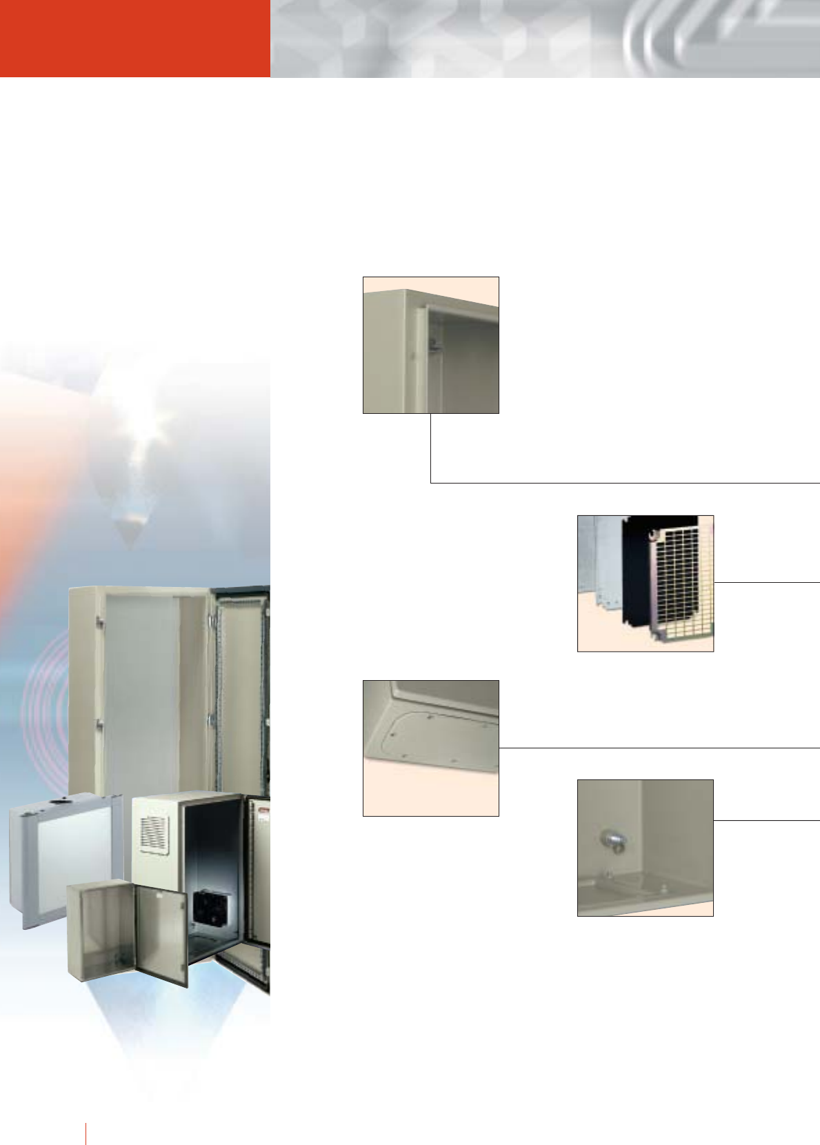
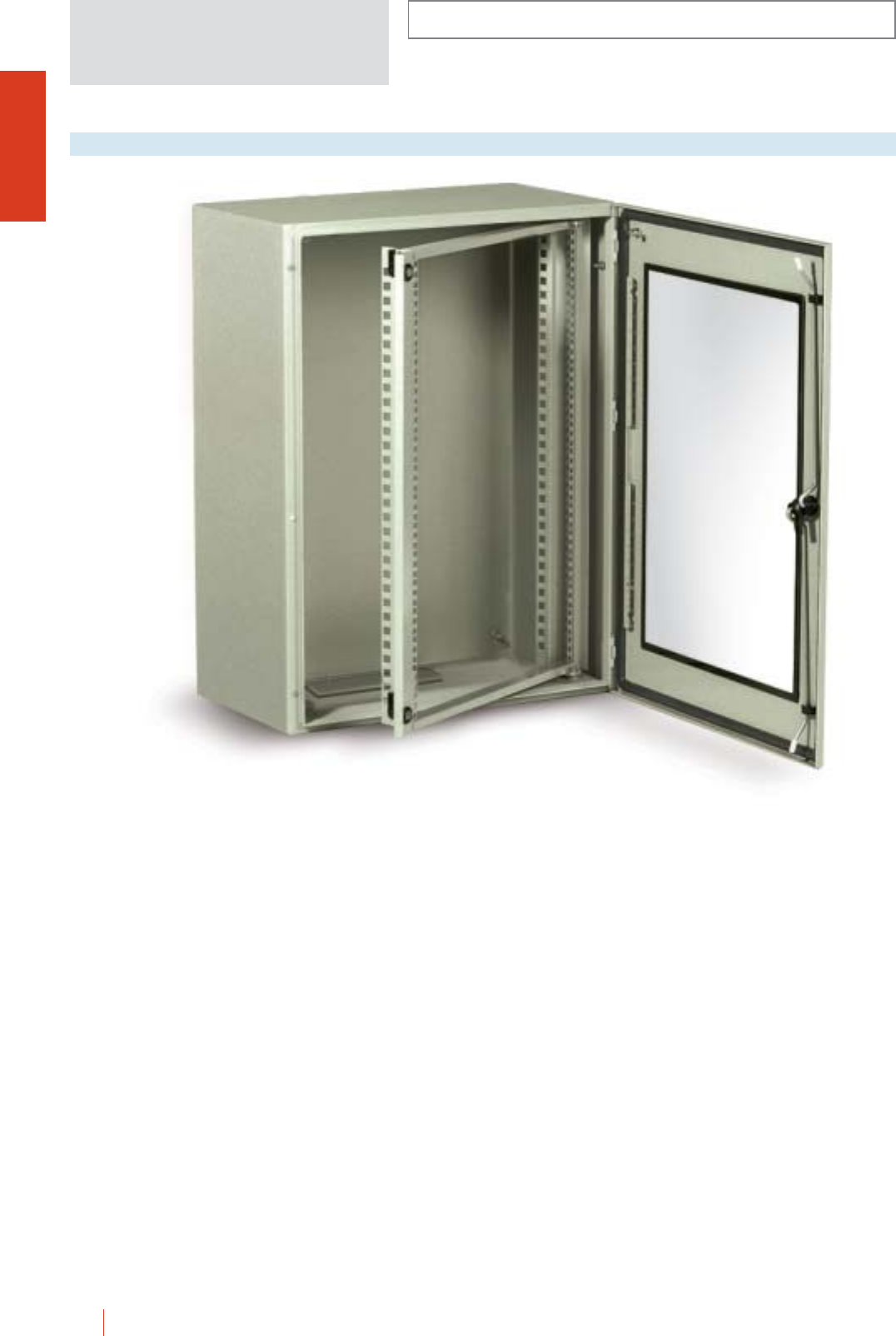
Transparent tempered
glass door and fully
watertight, maintaining
IP66 protection.
CRN wall mounting steel enclo sures suitable for all applications
A complete range of
mounting plates
suitable for most types
of installations.
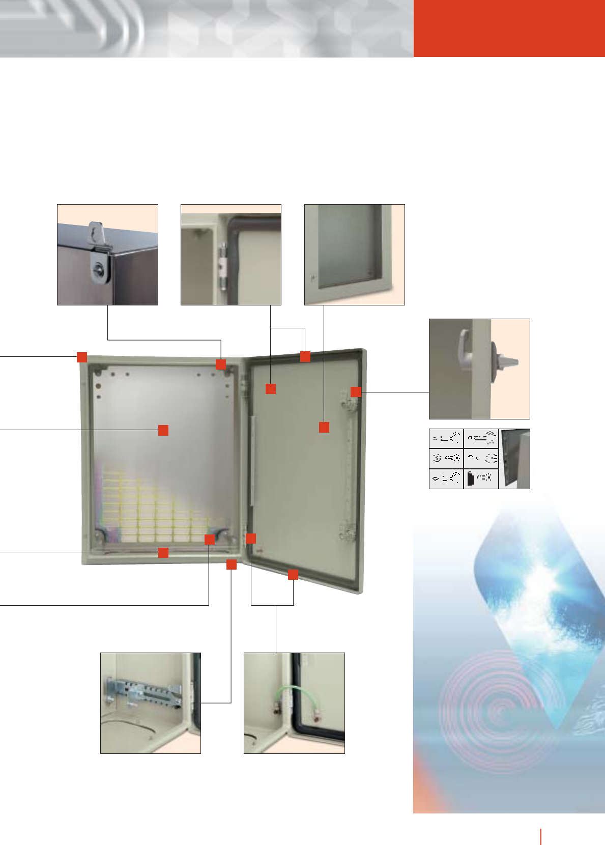
Built in standard double
bar lociking system and
three points locking for
two doors enclosures and
1,200 mm high
enclosures. Different lock
transformations available.
Foamed-in polyurethane
gasket guarantees
watertightness for years.
Perforated door reinforcement
profiles allowing fixing of
equipment in up to 400 mm
high enclosures.
Wall fixing brackets fixed
from the outside and can
be placed both horizontally
or vertically. Not included
as standard supply.
Depth adjustable support
with positions every
12.5 mm.
Embedded cable gland
plate and entrance, leveled
with the base, with a
neoprene seal.
Insulated cable gland
plates with pre-punched
holes for easy cable entry
available as accessory.
Two M6 15 welded earth
studs on the back an one
M6 15 stud on the door.
Easily reversible door, fitted
with two or three invisible
hinges allowing 120º opening.
Front rain gutter avoids the entry of
water, oil or liquids which ensures IP66
protection and protects the inside
surface when opening the door.
Back of enclosure with four
M8 15 welded studs with
built-in spacers for fixing of
mounting plate and
adjustable support.
Wall fixing holes sealed with
plastic plugs to assure the
protection degree.
1/22 H IMEL CRN wall mounting steel enclosures 1/23CRN wall mounting steel enclosures HIMEL
GENERAL INDEX
47G.1e
12 HIMEL general index
WALL FIXING AND FLOOR
STANDING METAL ENCLOSURES
Presentation 1/2
Selection guide 1/4
CRN
Wall mounting steel enclosures 1/22
CM
Control boxes system 1/44
CMO
Floor standing industrial enclosures 1/56
OLN
Industrial cubicle system 1/70
PK, PKP, PKP.../F
Metal control deks 1/152
INOX
Stainless steel enclosures 1/166
CEM
Metal enclosures for
electromagnetic protection 1/180
BOXES AND ENCLOSURES
IN POLYESTER
Presentation 2/2
Selection guide 2/4
SYSTEM 27
Polyester modular boxes 2/14
POLYMEL PLM
Polyester enclosures monobloc 2/28
PLA
Polyester cabinets 2/46
PLD
DIN polyester enclosures and plinths 2/84
METAL AND INSULATING
BOXES AND ENCLOSURES
Presentation 3/2
Selection guide 3/4
D/DX
Pressed steel enclosures 3/8
DPC
Insulated junction and industrial boxes 3/12
IBS/IBP
Industrial boxes 3/16
13general index HIMEL
Presentation 5/2
Selection guide 5/4
VF
Forced and natural ventilation
devices 5/8
ICL/AI
Exchangers air/air 5/24
ICT/ICL/AG
Exchangers air/water 5/30
CLL/CLT
Cooling units 5/34
CLLMP/CLTMP
Cooling units 5/48
RC
Resistance heaters 5/56
TS
Heat control devices 5/60
Thermal control for
electrical switchboards 5/64
BOXES FOR MODULAR
DISTRIBUTION
Presentation 4/2
Selection guide 4/4
DSU/DSUN
Distribution boards 4/8
DTU
Enclosures for DIN rail equipment 4/18
DHS
Weatherproof enclosures IP65 4/22
ACCESSORIES
ACCESSORIES
Metal rails and fixing nuts 6/4
Metal brackets 6/7
Spacers 6/10
Terminals 6/11
Accessories for electrical
cabling 6/13
Adjustable membrane glands 6/16
Enclosure lighting 6/19
Complements 6/20
THERMAL CONTROL FOR
ELECTRICAL SWITCHBOARDS
ANNEX TECHNICAL 7/0
REFERENCE LIST 8/1


WALL FIXING AND FLOOR
STANDING METAL ENCLOSURES
Presentation 1/2
Selection guide 1/4
CRN
Wall mounting steel enclosures 1/22
CM
Control boxes system 1/44
CMO
Floor standing industrial enclosures 1/56
OLN
Industrial cubicle system 1/70
PK & PKP.../F
Metal control desks 1/152
INOX
Stainless steel enclosures 1/166
CEM
Metal enclosures for
electromagnetic protection 1/180
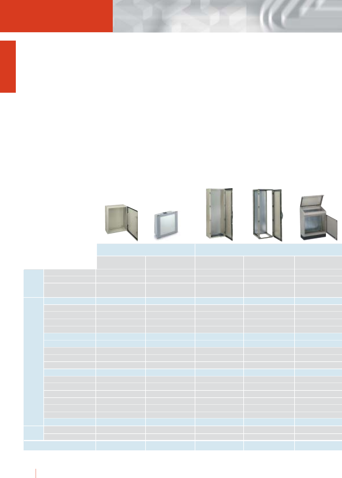
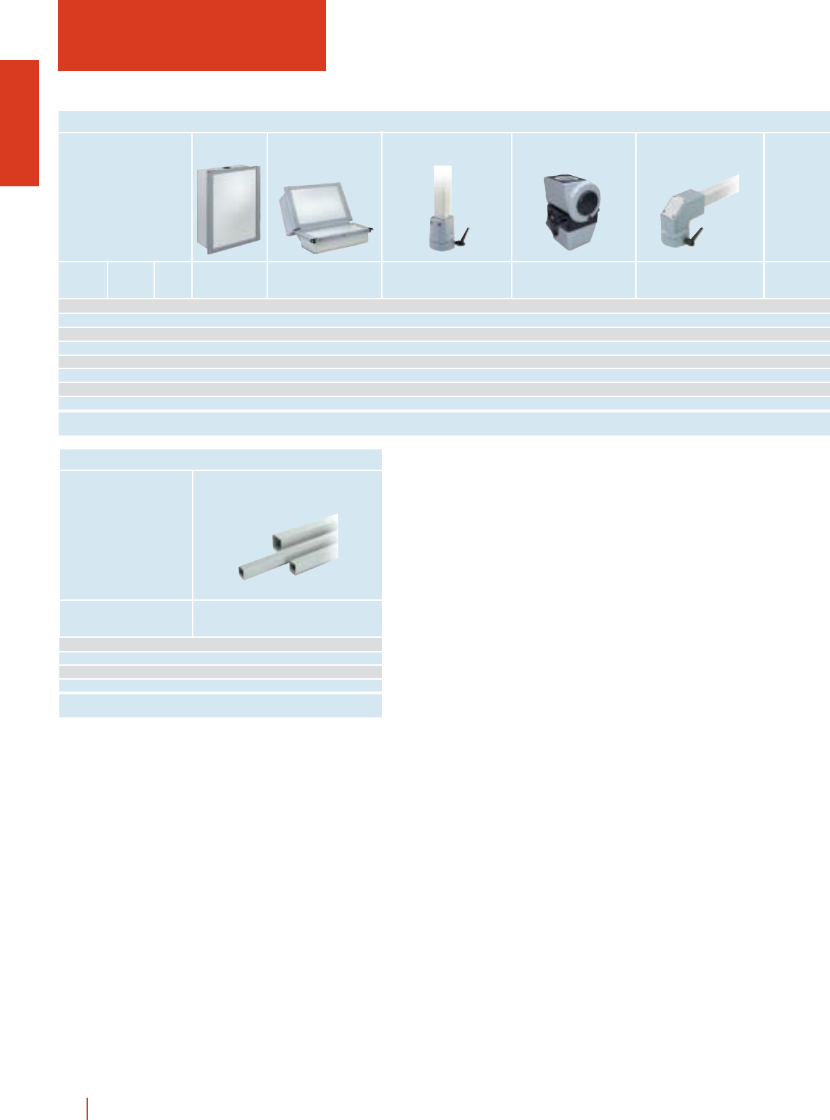
Wall fixing and floor stan
natural toughne
1/2 HIMEL wall fixing and floor standing metal enclosures
Acces- Installation Enclosure
sories systems features
WALL FIXING
PKOLNCMOCMCRN
Protection degree IP66 IP66 IP55 IP55
No. of sizes/models 45/86 8/8 48/122 59/277 4/4
Dimensions (mm) 250 200 150 to 300 300 200 1000 1000 300 to 1200 600 400 to
1200 1000 400 800 600 300 2000 1600 600 2200 1200 800
Mounting plates
Metal ■■■■
Insulating ■
Universal ■ ■
Perforated ■
Universal chassis ■■
Distribution chassis
18 mm modules up to 236 up to 352 up to 432
Metal cover plates ■■■
Insulating cover plates ■ ■
19’’ racks”
No. of units U 5 to 25 6 to 47 6 to 47
Fixed ■■■
Swing ■
Centred full rack ■■
Full off-centre rack ■■
Partial ■■
Internal doors ■■■
Canopies ■■■
Plinths ■■■
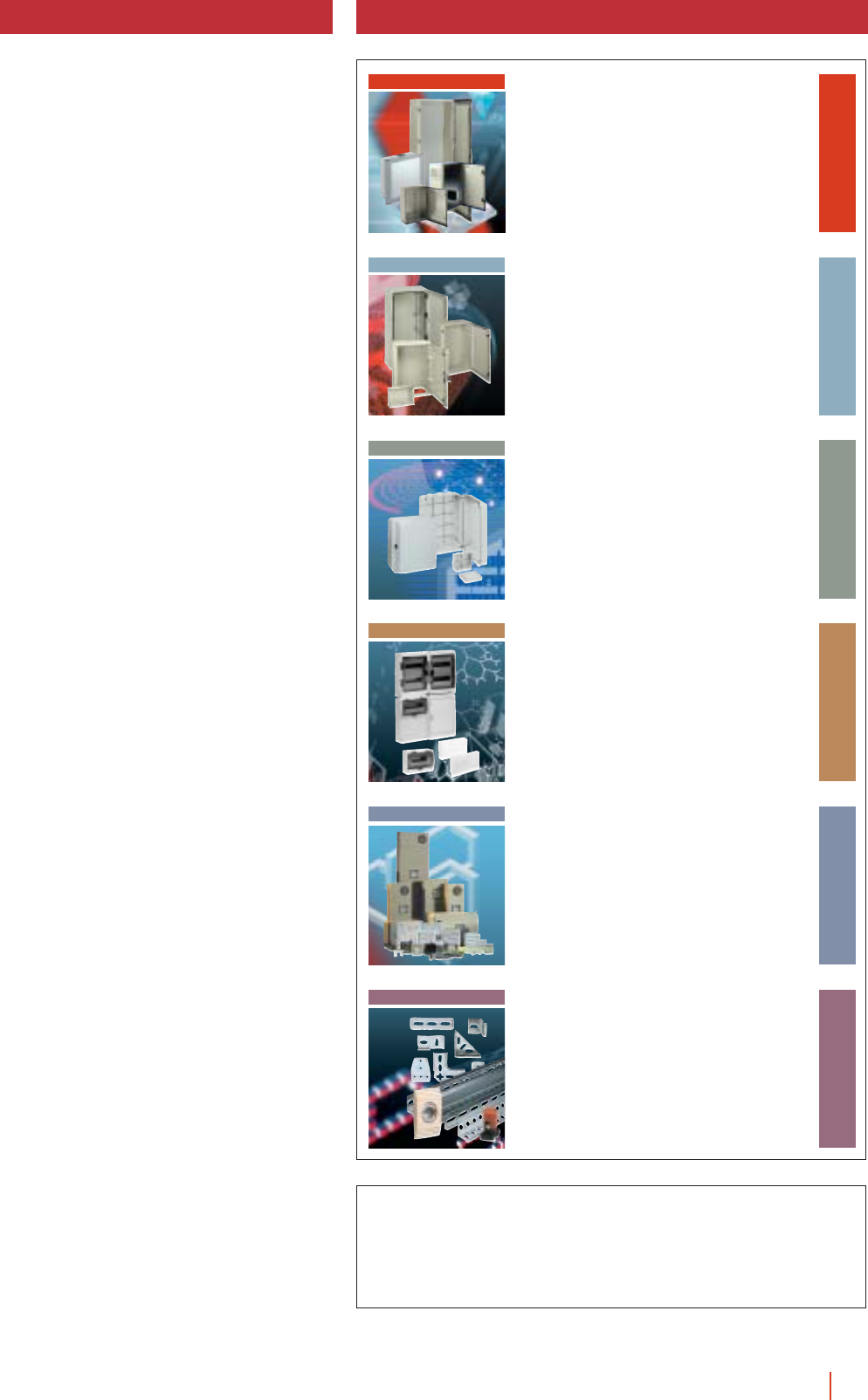
cWall mounting steel enclosures
CRN: Made from a continuous length
of sheet steel.
cControl boxes system CM: Designed
to fit human-machine dialogue
elements.
cFloor industrial enclosures CMO:
Monobloc construction and door
reinforcement 11 ×13 mm drilling with
a 25 mm pitch for mounting of
accessories.
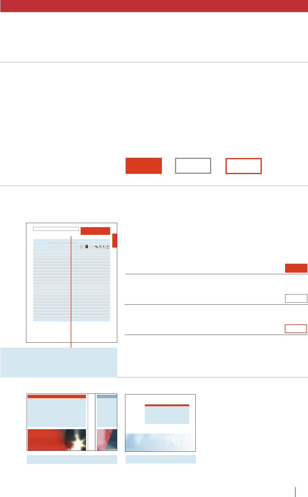
cIndustrial cubicle system OLN:
Triangular closed profile structure with
welded top and base and vertical
bolted on profiles for maximum
versatility.
cMonobloc control desks PK:
Excellent internal accessibility together
with a wide range of applications and
installations.
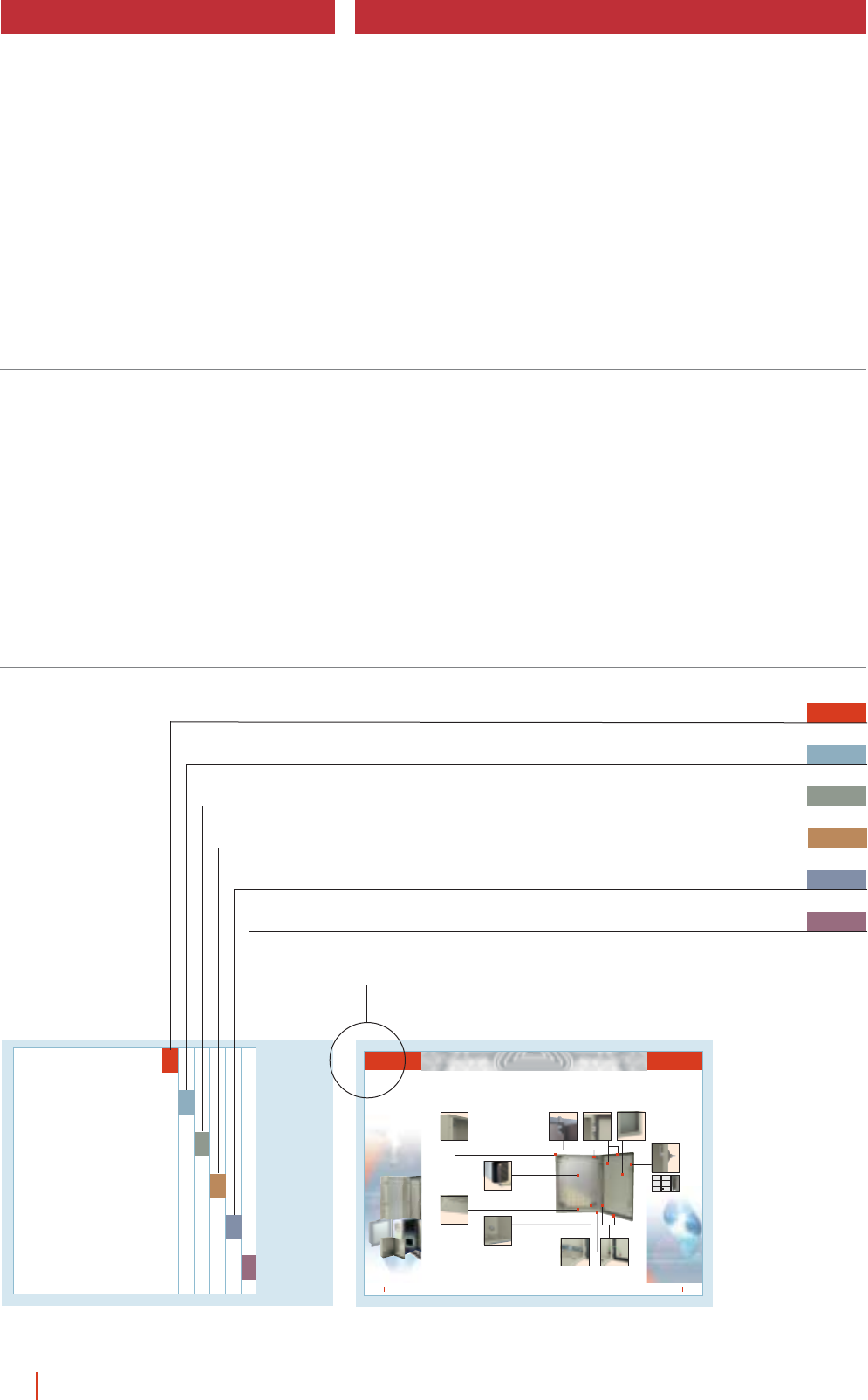
cStainless steel enclosures
CRSX-CMOX: Made from AISI 304
quality stainless steel with a
mechanical polish for an excellent
surface quality.
cMetal enclosures for
electromagnetic protection EMC:
Made from especial ALU-ZINC 150
sheet metal, wich gives good
reflection of electromagnetic waves.
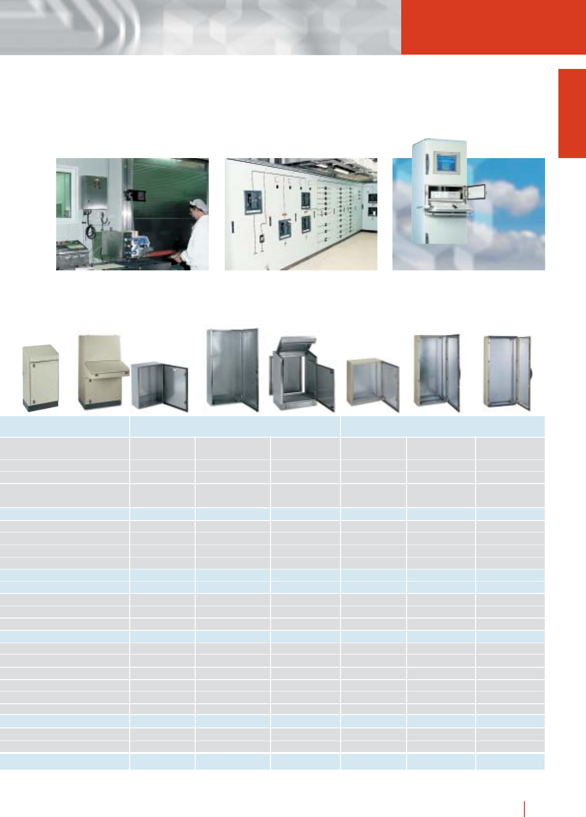
FLOOR STANDING
Page 1/22 1/44 1/56 1/70 1/154
ding metal enclosures
ss and strenght
1/3wall fixing and floor standing metal enclosures HIMEL
CRSX stainless enclosures are particularly
suitable for corrosive environments where a high
degree of cleanliness is required: food,
pharmaceutical, petrochemical industries…, etc.
The main feature of OLN cubicles is that they
can be joined together to form large bay
switchboards and their full accessibility.
Amongst the various OLN installation systems
the PC application is paramount.
STAINLESS STEEL ELECTROMAGNETIC PROTECTION
PKP/FPKP CRSX CMOX PKPX
IP55 IP66 IP55 IP55 IP66 IP66 IP66
4/4 8/8 14/14 9/9 4/4 9/9 3/3 4/4
1024 600 466 to 300 200 150 to 1200 1000 300 to 1024 600 597 to 400 300 200 to 1600 800 400 to 1800 800 400 to
1400 1600 1045 1200 800 300 2000 1600 600 1024 1200 597 1200 800 300 2000 800 400 2000 800 600
■■ ■ ■ ■ ■ ■ ■
■
■■ ■ ■
■■
■
up to 236
■
■
■
■■■ ■
■■ ■■■
■■
CRAF COAF OLAF
1/156 1/160 1/166 1/167 1/176 1/180 1/180 1/180
selection guide
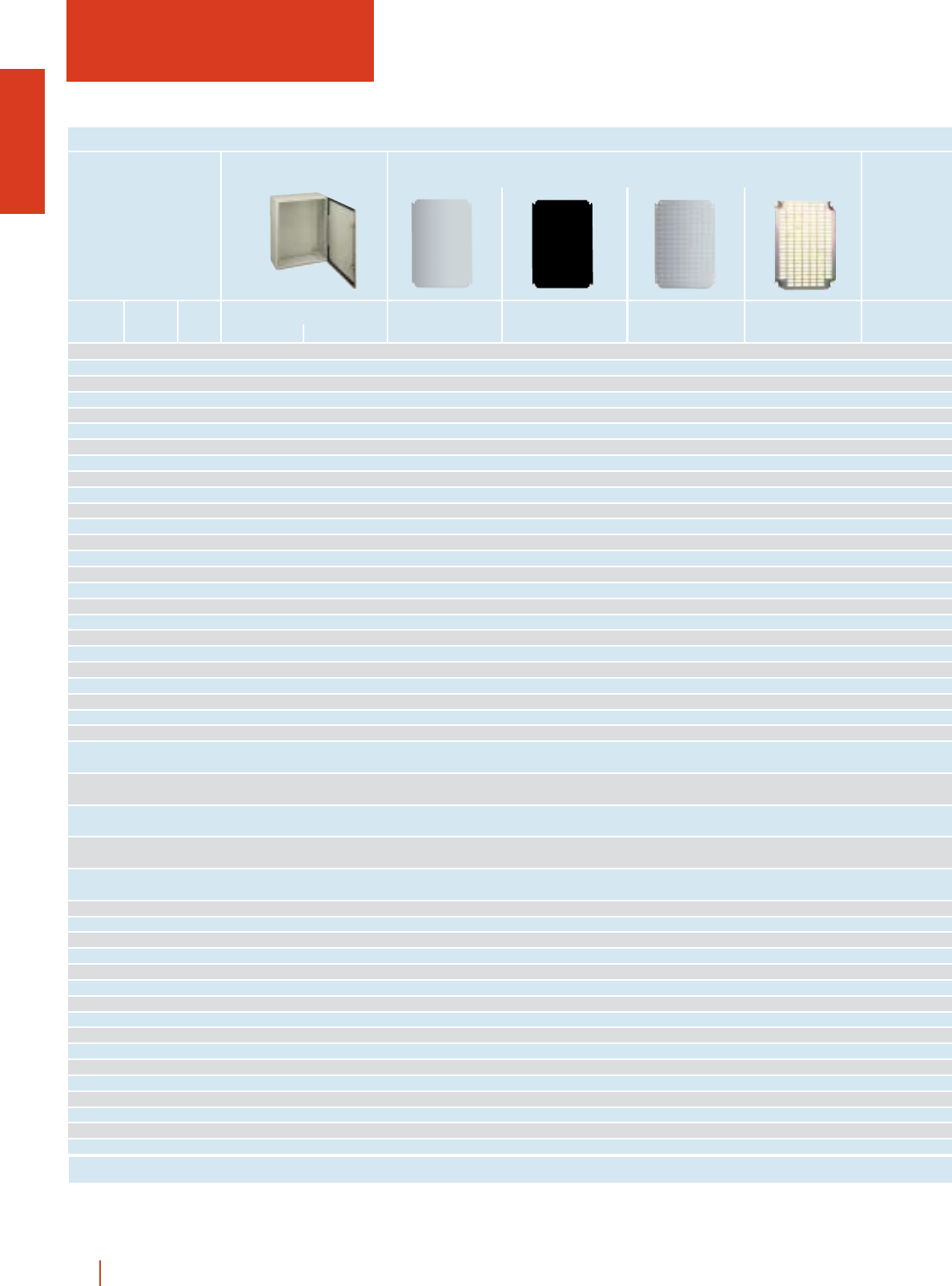
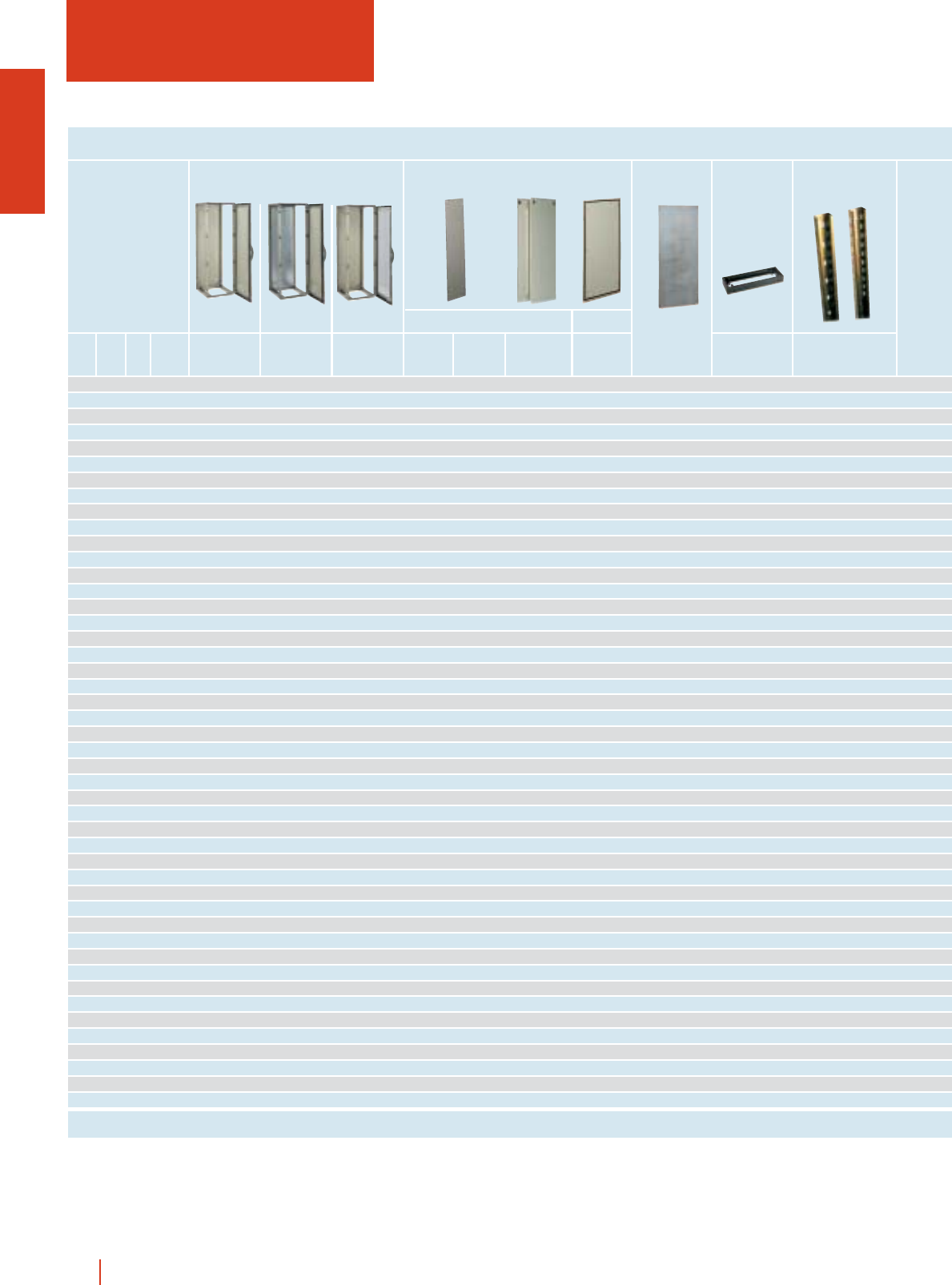
WALL MOUNTING STEEL
ENCLOSURES CRN
250 200 150 CRN-2520/150 - MM-2520 MB-2520 MF-2520 -
300 250 150 CRN-3025/150 ...KT MM-3025 MB-3025 MF-3025 MR-3025
300 250 200 CRN-3025/200 ...KT MM-3025 MB-3025 MF-3025 MR-3025
300 300 150 CRN-33/150 ...KT MM-33 MB-33 MF-33 MR-33
300 300 200 CRN-33/200 ...KT MM-33 MB-33 MF-33 MR-33
300 400 200 CRN-34/200 ...KT MM-34 MB-34 MF-34 MR-34
400 300 150 CRN-43/150 ...KT MM-43 MB-43 MF-43 MR-43
400 300 200 CRN-43/200 ...KT MM-43 MB-43 MF-43 MR-43
400 400 200 CRN-44/200 ...KT MM-44 MB-44 MF-44 MR-44
400 600 250 CRN-46/250 ...KT MM-46 MB-46 MF-46 MR-46
400 600 300 CRN-46/300 ...KT MM-46 MB-46 MF-46 MR-46
500 400 150 CRN-54/150 ...KT MM-54 MB-54 MF-54 MR-54
500 400 200 CRN-54/200 ...KT MM-54 MB-54 MF-54 MR-54
500 400 250 CRN-54/250 ...KT MM-54 MB-54 MF-54 MR-54
500 500 250 CRN-55/250 ...KT MM-55 MB-55 MF-55 MR-55
600 400 150 CRN-64/150 ...KT MM-64 MB-64 MF-64 MR-64
600 400 200 CRN-64/200 ...KT MM-64 MB-64 MF-64 MR-64
600 400 250 CRN-64/250 ...KT MM-64 MB-64 MF-64 MR-64
600 500 150 CRN-65/150 ...KT MM-65 MB-65 MF-65 MR-65
600 500 200 CRN-65/200 ...KT MM-65 MB-65 MF-65 MR-65
600 500 250 CRN-65/250 ...KT MM-65 MB-65 MF-65 MR-65
600 600 200 CRN-66/200 ...KT MM-66 MB-66 MF-66 MR-66
600 600 250 CRN-66/250 ...KT MM-66 MB-66 MF-66 MR-66
600 600 300 CRN-66/300 ...KT MM-66 MB-66 MF-66 MR-66
600 800 300 CRN-68/300 ...KT MM-68 MB-68 MF-68 MR-68
700 500 200 CRN-75/200 ...KT MM-75 MB-75 MF-75 MR-75
700 500 250 CRN-75/250 ...KT MM-75 MB-75 MF-75 MR-75
800 600 200 CRN-86/200 ...KT MM-86 MB-86 MF-86 MR-86
800 600 250 CRN-86/250 ...KT MM-86 MB-86 MF-86 MR-86
800 600 300 CRN-86/300 ...KT MM-86 MB-86 MF-86 MR-86
800 600 400 CRN-86/400 ...KT MM-86 MB-86 MF-86 MR-86
800 800 200 CRN-88/200 ...KT MM-88 MB-88 MF-88 MR-88
800 800 300 CRN-88/300 ...KT MM-88 MB-88 MF-88 MR-88
800 1000 300 CRN-810/300 ...KT MM-810 MB-810 MF-810 MR-810
1000 600 250 CRN-106/250 ...KT MM-106 MB-106 MF-106 MR-106
1000 600 300 CRN-106/300 ...KT MM-106 MB-106 MF-106 MR-106
1000 800 200 - - MM-108 MB-108 MF-108 MR-108
1000 800 250 CRN-108/250 ...KT MM-108 MB-108 MF-108 MR-108
1000 800 300 CRN-108/300 ...KT MM-108 MB-108 MF-108 MR-108
1000 800 400 CRN-108/400 ...KT MM-108 MB-108 MF-108 MR-108
1000 1000 300 CRN-1010/300 ...KT MM-1010 MB-1010 MF-1010 MR-1010
1000 1200 300 CRN-1012/300 - MM-1012 MB-1012 MF-1012 MR-1012
1200 800 300 CRN-128/300 ...KT MM-128 MB-128 MF-128 MR-128
1200 800 400 CRN-128/400 ...KT MM-128 MB-128 MF-128 MR-128
1200 1000 300 CRN-1210/300 - MM-1210 MB-1210 MF-1210 MR-1210
1200 1000 400 CRN-1210/400 ...KT MM-1210 MB-1210 MF-1210 MR-1210
External dimensions (mm)
Reference
Plain Glazed
IP66 Mounting plates
Metal Insulating Drilling Universal
1/4 HIMEL wall fixing and floor standing metal enclosures
Height Width Depth
ENCLOSURES, DIMENSIONS AND REFERENCES
Page 1/25 1/27 1/27 1/27 1/27
---- - - - TJ-2015
---- - - - TJ-2515
SDCR-200 - -- - - - TJ-2520
---- - - - TJ-3015
SDCR-200 - -- - - - TJ-3020
SDCR-200 - -- - - - TJ-4020
- DLM-24 24 2/- PIN 43 - - TJ-3015
SDCR-200 DLM-24 24 2/- PIN 43 - - TJ-3020
SDCR-200 - -- - - - TJ-4020
SDCR-250 - -- - BR…/CRN 7/8 TJ-6025
SDCR-300 - -- - BR…/CRN 7/8 TJ-6030
DLM-48 48 3/- - - - TJ-4015
SDCR-200 DLM-48 48 3/- PIN 54 - - TJ-4020
SDCR-250 DLM-48 48 3/- - - - TJ-4025
SDCR-250 - -- - - - TJ-5025
- DLM-48P 48 3/- PIN 64 - TJ-4015
SDCR-200 DLM-48P 48 3/- PIN 64 - - TJ-4020
SDCR-250 DLM-48P 48 3/- PIN 64 - - TJ-4025
---- - - - TJ-5015
SDCR-200 - -- - - - TJ-5020
SDCR-200 DLM-84P 84 3/- - - - TJ-6025
SDCR-200 DLM-84P 84 3/- - BR…/CRN 11/12 TJ-6020
SDCR-250 DLM-84P 84 3/- - BR…/CRN 11/12 TJ-6025
SDCR-300 DLM-84P 84 3/- - BR…/CRN 11/12 TJ-6030
SDCR-300 - -- - - - TJ-8030
SDCR-200 DLM-66 66 3/1 PIN 75 - - TJ-5020
DLM-88 88 4/-
SDCR-250 DLM-66 66 3/1 PIN 75 - - TJ-5025
DLM-88 88 4/-
SDCR-200 DLM-84 84 3/1 PIN 86 - - TJ-6020
DLM-112 112 4/-
SDCR-250 DLM-84 84 3/1 PIN 86 BR…/CRN 16/17 TJ-6025
DLM-112 112 4/-
SDCR-300 DLM-84 84 3/1 PIN 86 BR…/CRN 16/17 TJ-6030
DLM-112 112 4/-
SDCR-400 DLM-84…112 84/112 3/1 4/- PIN 86 BR…/CRN 16/17 TJ-6040
SDCR-200 - -- - - - TJ-8020
SDCR-300 - -- - - - TJ-8030
SDCR-360 - -- - - - TJ-10030
SDCR-250 - - - PIN 106 BR…/CRN 20/21 TJ-6025
SDCR-300 DLM-168 168 6/- PIN 106 BR…/CRN 20/21 TJ-6030
SDCR-200 DLM-240 234 6/- PIN 108 BR20/CRN 800 20 TJ-8020
SDCR-250 DLM-240 234 6/- PIN 108 BR20/CRN 800 20 TJ-8025
SDCR-300 DLM-240 234 6/- PIN 108 BR20/CRN 800 20 TJ-8030
SDCR-400 DLM-240 234 6/- PIN 108 BR20/CRN 800 20 TJ-8040
SDCR-300 - -- - - - TJ-10030
SDCR-300 - -- ----
SDCR-300 - -- PIN 128 BR25/CRN 800 25 TJ-8030
SDCR-400 - -- PIN 128 BR25/CRN 800 25 TJ-8040
SDCR-300 - -- - - - TJ-10030
SDCR-400 - -- - - - TJ-10040
Depth adjustable supports Dinimel DLM Internal doors Fixed and
swing 19” rack
Canopies
Reference No. of units
No. of 18 mm No. of rows/
Reference modules plates
1/5wall fixing and floor standing metal enclosures HIMEL
1/40 1/28 1/36 1/29 1/41
selection guide
CONTROL BOXES CM
1/6 HIMEL wall fixing and floor standing metal enclosures
300 300 200 HHH CM3030/200 - HHH CM/UCR50 - HHH CM/UCP50 - HHH CM/UCC50 -
300 400 200 HHH CM3040/200 - HHH CM/UCR50 - HHH CM/UCP50 - HHH CM/UCC50 -
400 400 200 HHH CM4040/200 - HHH CM/UCR50 - HHH CM/UCP50 - HHH CM/UCC50 -
400 600 250 HHH CM4060/250 HHH CMT2560/110 HHH CM/UCR50 - HHH CM/UCP50 - HHH CM/UCC50 -
500 500 250 HHH CM5050/250 - HHH CM/UCR50 - HHH CM/UCP50 - HHH CM/UCC50 -
600 600 200 HHH CM6060/200 HHH CMT2560/110 HHH CM/UCR50 - HHH CM/UCP50 - HHH CM/UCC50 -
600 800 300 HHH CM6080/300 HHH CMT2560/110 - HHH CM/UCR80 - HHH CM/UCP80 - HHH CM/UCC80
800 600 300 HHH CM8060/300 HHH CMT2560/110 - HHH CM/UCR80 - HHH CM/UCP80 - HHH CM/UCC80
External dimensions (mm)
Height Width Depth 50 80 50 80 50 80
ENCLOSURES, DIMENSIONS AND REFERENCES
0.5 HHH CMT5005 HHH CMT8005
1.00 HHH CMT5010 HHH CMT8010
1.50 HHH CMT5015 HHH CMT8015
2.00 HHH CMT5020 HHH CMT8020
Length (m) v50 v80
ENCLOSURES, DIMENSIONS AND REFERENCES
Page 1/49 1/55 1/50 1/50 1/51 1/51 1/51 1/51
Page 1/50 1/50
1/7wall fixing and floor standing metal enclosures HIMEL
HHH CM/UMR50 - HHH CM/UTC50 - HHH CM/UMC50 - HHH CM/UMA50 - HHH CM/UIA50 - HHH CM/ACS50 -
HHH CM/UMR50 - HHH CM/UTC50 - HHH CM/UMC50 - HHH CM/UMA50 - HHH CM/UIA50 - HHH CM/ACS50 -
HHH CM/UMR50 - HHH CM/UTC50 - HHH CM/UMC50 - HHH CM/UMA50 - HHH CM/UIA50 - HHH CM/ACS50 -
HHH CM/UMR50 - HHH CM/UTC50 - HHH CM/UMC50 - HHH CM/UMA50 - HHH CM/UIA50 - HHH CM/ACS50 -
HHH CM/UMR50 - HHH CM/UTC50 - HHH CM/UMC50 - HHH CM/UMA50 - HHH CM/UIA50 - HHH CM/ACS50 -
HHH CM/UMR50 - HHH CM/UTC50 - HHH CM/UMC50 - HHH CM/UMA50 - HHH CM/UIA50 - HHH CM/ACS50 -
- HHH CM/UMR80 - HHH CM/UTC80 - HHH CM/UMC80 - HHH CM/UMA80 - HHH CM/UIA80 - HHH CM/ACS80
- HHH CM/UMR80 - HHH CM/UTC80 - HHH CM/UMC80 - HHH CM/UMA80 - HHH CM/UIA80 - HHH CM/ACS80
50 80 50 80 50 80 50 80 50 80 50 80
1/53 1/53 1/53 1/53 1/52 1/52 1/52 1/52 1/54 1/54 1/54 1/54
External dimensions (mm)
Height Width Depth No. of
doors
ENCLOSURES, DIMENSIONS AND REFERENCES
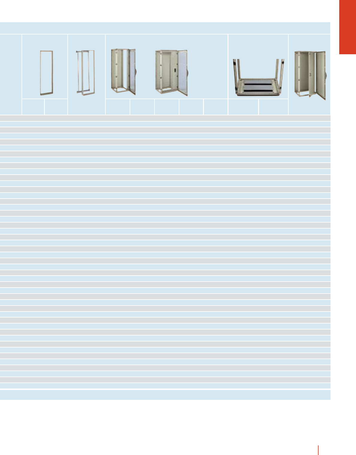
selection guide
FLOOR STANDING INDUSTRIAL
ENCLOSURES CMO
1000 1000 300 2 CMO 1010/30 PM CMO 1010/30 - PMOL 1010 ZUN 103/100
1200 800 300 1 CMO 128/30 PM CMO 128/30 CMO 128/30 KT PMOL 128 ZUN 83/100
1200 1000 300 2 CMO 1210/30 PM CMO 1210/30 - PMOL 1210 ZUN 103/100
1200 1200 400 2 CMO 1212/40 PM CMO 1212/40 - PMOL 1212 ZUN 124/100
1400 600 300 1 CMO 146/30 PM CMO 146/30 CMO 146/30 KT PMOL 146 ZUN 63/100
1400 600 400 1 CMO 146/40 PM CMO 146/40 CMO 146/40 KT PMOL 146 ZUN 64/100
1400 800 300 1 CMO 148/30 PM CMO 148/30 CMO 148/30 KT PMOL 148 ZUN 83/100
1400 800 400 1 CMO 148/40 PM CMO 148/40 CMO 148/40 KT PMOL 148 ZUN 84/100
1400 1000 400 2 CMO 1410/40 PM CMO 1410/40 - PMOL 1410 ZUN 104/100
1400 1200 400 2 CMO 1412/40 PM CMO 1412/40 - PMOL 1412 ZUN 124/100
1600 600 300 1 CMO 166/30 PM CMO 166/30 CMO 166/30 KT PMOL 166 ZUN 63/100
1600 600 400 1 CMO 166/40 PM CMO 166/40 CMO 166/40 KT PMOL 166 ZUN 64/100
1600 800 300 1 CMO 168/30 PM CMO 168/30 CMO 168/30 KT PMOL 168 ZUN 83/100
1600 800 400 1 CMO 168/40 PM CMO 168/40 CMO 168/40 KT PMOL 168 ZUN 84/100
1600 1000 300 2 CMO 1610/30 PM CMO 1610/30 - PMOL 1610 ZUN 103/100
1600 1000 400 2 CMO 1610/40 PM CMO 1610/40 - PMOL 1610 ZUN 104/100
1600 1200 300 2 CMO 1612/30 PM CMO 1612/30 - PMOL 1612 ZUN 123/100
1600 1200 400 2 CMO 1612/40 PM CMO 1612/40 - PMOL 1612 ZUN 124/100
1800 600 300 1 CMO 186/30 PM CMO 186/30 CMO 186/30 KT PMOL 186 ZUN 63/100
1800 600 400 1 CMO 186/40 PM CMO 186/40 CMO 186/40 KT PMOL 186 ZUN 64/100
1800 600 500 1 - - CMO 186/50 KT PMOL 186 ZUN 65/100
1800 600 600 1 - - CMO 186/60 KT PMOL 186 ZUN 66/100
1800 800 300 1 CMO 188/30 PM CMO 188/30 CMO 188/30 KT PMOL 188 ZUN 83/100
1800 800 400 1 CMO 188/40 PM CMO 188/40 CMO 188/40 KT PMOL 188 ZUN 84/100
1800 800 500 1 CMO 188/50 PM CMO 188/50 CMO 188/50 KT PMOL 188 ZUN 85/100
1800 800 600 1 CMO 188/60 PM CMO 188/60 CMO 188/60 KT PMOL 188 ZUN 86/100
1800 1000 400 2 CMO 1810/40 PM CMO 1810/40 - PMOL 1810 ZUN 104/100
1800 1000 500 2 CMO 1810/50 PM CMO 1810/50 - PMOL 1810 ZUN 105/100
1800 1200 400 2 CMO 1812/40 PM CMO 1812/40 - PMOL 1812 ZUN 124/100
1800 1200 500 2 CMO 1812/50 PM CMO 1812/50 - PMOL 1812 ZUN 125/100
1800 1600 400 2 CMO 1816/40 PM CMO 1816/40 - PMOL 1816 ZUN 164/100
1800 1600 500 2 CMO 1816/50 PM CMO 1816/50 - PMOL 1816 ZUN 165/100
2000 600 300 1 CMO 206/30 PM CMO 206/30 CMO 206/30 KT PMOL 206 ZUN 63/100
2000 600 400 1 CMO 206/40 PM CMO 206/40 CMO 206/40 KT PMOL 206 ZUN 64/100
2000 600 500 1 - - CMO 206/50 KT PMOL 206 ZUN 65/100
2000 600 600 1 - - CMO 206/60 KT PMOL 206 ZUN 66/100
2000 800 300 1 CMO 208/30 PM CMO 208/30 CMO 208/30 KT PMOL 208 ZUN 83/100
2000 800 400 1 CMO 208/40 PM CMO 208/40 CMO 208/40 KT PMOL 208 ZUN 84/100
2000 800 500 1 CMO 208/50 PM CMO 208/50 CMO 208/50 KT PMOL 208 ZUN 85/100
2000 800 600 1 CMO 208/60 PM CMO 208/60 CMO 208/60 KT PMOL 208 ZUN 86/100
2000 1000 400 2 CMO 2010/40 PM CMO 2010/40 - PMOL 2010 ZUN 104/100
2000 1000 500 2 CMO 2010/50 PM CMO 2010/50 - PMOL 2010 ZUN 105/100
2000 1200 400 2 CMO 2012/40 PM CMO 2012/40 - PMOL 2012 ZUN 124/100
2000 1200 500 2 CMO 2012/50 PM CMO 2012/50 - PMOL 2012 ZUN 125/100
2000 1200 600 2 CMO 2012/60 PM CMO 2012/60 - PMOL 2012 ZUN 126/100
2000 1600 400 2 CMO 2016/40 PM CMO 2016/40 - PMOL 2016 ZUN 164/100
2000 1600 500 2 CMO 2016/50 PM CMO 2016/50 - PMOL 2016 ZUN 165/100
2000 1600 600 2 CMO 2016/60 PM CMO 2016/60 - PMOL 2016 ZUN 166/100
1/8 HIMEL wall fixing and floor standing metal enclosures
Enclosures
with mounting plate
*For plinths height 200, ask reference ZUN.../200.
Enclosures
without mounting plate
Enclosures
with glazed door
Height 100 mm*
Mounting plate Plinths
Page 1/59 1/59 1/60 1/66 1/66
1/9wall fixing and floor standing metal enclosures HIMEL
MOL 100 - - - - -----
MOL 120 AF/COL 128 - - - -----
MOL 120 - - - - -----
MOL 120 - - - - -----
MOL 140 AF/COL 146 - - BRF 29/OL 29 ----
MOL 140 AF/COL 146 - - BRF 29/OL 29 ----
MOL 140 AF/COL 148 - - - -BRP 27/OL BRPC 27/OL BRP 27/OL 180 27
MOL 140 AF/COL 148 - - - -BRP 27/OL BRPC 27/OL BRP 27/OL 180 27
MOL 140 AF/COL 1464 - - - -----
MOL 140 AF/COL 1484 AF/COL 1466 + DCOL 40 - - -----
MOL 160 AF/COL 166 - PIL 166 BRF 33/OL 33 ----
MOL 160 AF/COL 166 - PIL 166 BRF 33/OL 33 ----
MOL 160 AF/COL 168 - PIL 168 - -BRP 31/OL BRPC 31/OL BRP 31/OL 180 31
MOL 160 AF/COL 168 - PIL 168 - -BRP 31/OL BRPC 31/OL BRP 31/OL 180 31
MOL 160 AF/COL 1664 - - - -----
MOL 160 AF/COL 1664 - - - -----
MOL 160 AF/COL 1684 AF/COL 1666 + DCOL 30 - - -----
MOL 160 AF/COL 1684 AF/COL 1666 + DCOL 40 - - -----
MOL 180 AF/COL 186 - PIL 186 BRF 38/OL 38 ----
MOL 180 AF/COL 186 - PIL 186 BRF 38/OL 38 ----
MOL 180 AF/COL 186 - PIL 186 BRF 38/OL 38 ----
MOL 180 AF/COL 186 - PIL 186 BRF 38/OL 38 ----
MOL 180 AF/COL 188 - PIL 188 - -BRP 36/OL BRPC 36/OL BRP 36/OL 180 36
MOL 180 AF/COL 188 - PIL 188 - -BRP 36/OL BRPC 36/OL BRP 36/OL 180 36
MOL 180 AF/COL 188 - PIL 188 - -BRP 36/OL BRPC 36/OL BRP 36/OL 180 36
MOL 180 AF/COL 188 - PIL 188 - -BRP 36/OL BRPC 36/OL BRP 36/OL 180 36
MOL 180 AF/COL 1864 - PIL 1810 - -----
MOL 180 AF/COL 1864 - PIL 1810 - -----
MOL 180 AF/COL 1884 AF/COL 1866 + DCOL 40 - - -----
MOL 180 AF/COL 1884 AF/COL 1866 + DCOL 50 - - -----
MOL 180 AF/COL 1888 - - - -----
MOL 180 AF/COL 1888 - - - -----
MOL 200 AF/COL 206 - PIL 206 BRF 42/OL 42 ----
MOL 200 AF/COL 206 - PIL 206 BRF 42/OL 42 ----
MOL 200 AF/COL 206 - PIL 206 BRF 42/OL 42 ----
MOL 200 AF/COL 206 - PIL 206 BRF 42/OL 42 ----
MOL 200 AF/COL 208 - PIL 208 - -BRP 40/OL BRPC 40/OL BRP 40/OL 180 40
MOL 200 AF/COL 208 - PIL 208 - -BRP 40/OL BRPC 40/OL BRP 40/OL 180 40
MOL 200 AF/COL 208 - PIL 208 - -BRP 40/OL BRPC 40/OL BRP 40/OL 180 40
MOL 200 AF/COL 208 - PIL 208 - -BRP 40/OL BRPC 40/OL BRP 40/OL 180 40
MOL 200 AF/COL 2064 - PIL 2010 - -----
MOL 200 AF/COL 2064 - PIL 2010 - -----
MOL 200 AF/COL 2084 AF/COL 2066 + DCOL 40 - - -----
MOL 200 AF/COL 2084 AF/COL 2066 + DCOL 50 - - -----
MOL 200 AF/COL 2084 AF/COL 2066 + DCOL 60 - - -----
MOL 200 AF/COL 2088 - - - -----
MOL 200 AF/COL 2088 - - - -----
MOL 200 AF/COL 2088 - - - -----
Set of
2 uprights Reference Reference
Universal chassis UNIDIS coupling assembly Internal door
Reference No. of units
1 U = 44.45 mm
No. of units
1 U = 44.45 mm
19” Rack
Swing
rack
Centred
swing rack
180°
swing rack
1/111 1/113 1/140 1/119 1/119 1/120 1/120
Fixed rack
1/10 HIMEL wall fixing and floor standing metal enclosures
External dimensions (mm)
Height
Without
mounting plate
With
mounting plate
With
glazed door
Width
Depth
No. of
doors
ENCLOSURES, DIMENSIONS AND REFERENCES
selection guide
INDUSTRIAL CUBICLE SYSTEM OLN
1200 600 400 1 OLN 126/40 OLN 126/40 PM OLN 126/40 KT 2 PLOL 124 2 PLIOL 124 - PPION 126 PMOL 126 ZUN 64/100 -
1200 600 600 1 OLN 126/60 OLN 126/60 PM OLN 126/60 KT 2 PLOL 126 2 PLIOL 126 2 PLROL 126 PPION 126 PMOL 126 ZUN 66/100 -
1200 600 800 1 OLN 126/80 OLN 126/80 PM OLN 126/80 KT 2 PLOL 128 2 PLIOL 128 2 PLROL 128 PPION 126 PMOL 126 ZUN 68/100 -
1200 800 400 1 OLN 128/40 OLN 128/40 PM OLN 128/40 KT 2 PLOL 124 2 PLIOL 124 - PPION 128 PMOL 128 ZUN 84/100 -
1200 800 600 1 OLN 128/60 OLN 128/60 PM OLN 128/60 KT 2 PLOL 126 2 PLIOL 126 2 PLROL 126 PPION 128 PMOL 128 ZUN 86/100 -
1200 800 800 1 OLN 128/80 OLN 128/80 PM OLN 128/80 KT 2 PLOL 128 2 PLIOL 128 2 PLROL 128 PPION 128 PMOL 128 ZUN 88/100 -
1400 600 400 1 OLN 146/40 OLN 146/40 PM OLN 146/40 KT 2 PLOL 144 2 PLIOL 144 - PPION 146 PMOL 146 ZUN 64/100 -
1400 600 600 1 OLN 146/60 OLN 146/60 PM OLN 146/60 KT 2 PLOL 146 2 PLIOL 146 2 PLROL 146 PPION 146 PMOL 146 ZUN 66/100 -
1400 600 800 1 OLN 146/80 OLN 146/80 PM OLN 146/80 KT 2 PLOL 148 2 PLIOL 148 2 PLROL 148 PPION 146 PMOL 146 ZUN 68/100 -
1400 800 400 1 OLN 148/40 OLN 148/40 PM OLN 148/40 KT 2 PLOL 144 2 PLIOL 144 - PPION 148 PMOL 148 ZUN 84/100 -
1400 800 600 1 OLN 148/60 OLN 148/60 PM OLN 148/60 KT 2 PLOL 146 2 PLIOL 146 2 PLROL 146 PPION 148 PMOL 148 ZUN 86/100 -
1400 800 800 1 OLN 148/80 OLN 148/80 PM OLN 148/80 KT 2 PLOL 148 2 PLIOL 148 2 PLROL 148 PPION 148 PMOL 148 ZUN 88/100 -
1600 600 600 1 OLN 166/60 OLN 166/60 PM OLN 166/60 KT 2 PLOL 166 2 PLIOL 166 2 PLROL 166 PPION 166 PMOL 166 ZUN 66/100 MOL 160
1600 600 800 1 OLN 166/80 OLN 166/80 PM OLN 166/80 KT 2 PLOL 168 2 PLIOL 168 2 PLROL 168 PPION 166 PMOL 166 ZUN 68/100 MOL 160
1600 800 600 1 OLN 168/60 OLN 168/60 PM OLN 168/60 KT 2 PLOL 166 2 PLIOL 166 2 PLROL 166 PPION 168 PMOL 168 ZUN 86/100 MOL 160
1600 800 800 1 OLN 168/80 OLN 168/80 PM OLN 168/80 KT 2 PLOL 168 2 PLIOL 168 2 PLROL 168 PPION 168 PMOL 168 ZUN 88/100 MOL 160
1800 600 400 1 OLN 186/40 OLN 186/40 PM OLN 186/40 KT 2 PLOL 184 2 PLIOL 184 - PPION 186 PMOL 186 ZUN 64/100 MOL 180
1800 600 500 1 OLN 186/50 OLN 186/50 PM OLN 186/50 KT 2 PLOL 185 2 PLIOL 185 - PPION 186 PMOL 186 ZUN 65/100 MOL 180
1800 600 600 1 OLN 186/60 OLN 186/60 PM OLN 186/60 KT 2 PLOL 186 2 PLIOL 186 2 PLROL 186 PPION 186 PMOL 186 ZUN 66/100 MOL 180
1800 600 800 1 OLN 186/80 OLN 186/80 PM OLN 186/80 KT 2 PLOL 188 2 PLIOL 188 2 PLROL 188 PPION 186 PMOL 186 ZUN 68/100 MOL 180
1800 800 400 1 OLN 188/40 OLN 188/40 PM OLN 188/40 KT 2 PLOL 184 2 PLIOL 184 - PPION 188 PMOL 188 ZUN 84/100 MOL 180
1800 800 500 1 OLN 188/50 OLN 188/50 PM OLN 188/50 KT 2 PLOL 185 2 PLIOL 185 - PPION 188 PMOL 188 ZUN 85/100 MOL 180
1800 800 600 1 OLN 188/60 OLN 188/60 PM OLN 188/60 KT 2 PLOL 186 2 PLIOL 186 2 PLROL 186 PPION 188 PMOL 188 ZUN 86/100 MOL 180
1800 1000 400 1 OLN 1810/40 OLN 1810/40 PM OLN 1810/40 KT 2 PLOL 184 2 PLIOL 184 - PPION 1810 PMOL 1810 ZUN 104/100 MOL 180
1800 1000 400 2 OLN 1810/40/2P OLN 1810/40/2P PM - 2 PLOL 184 2 PLIOL 184 - PPION 1810 PMOL 1810 ZUN 104/100 MOL 180
1800 1000 500 1 OLN 1810/50 OLN 1810/50 PM OLN 1810/50 KT 2 PLOL 185 2 PLIOL 185 - PPION 1810 PMOL 1810 ZUN 105/100 MOL 180
1800 1000 500 2 OLN 1810/50/2P OLN 1810/50/2P PM - 2 PLOL 185 2 PLIOL 185 - PPION 1810 PMOL 1810 ZUN 105/100 MOL 180
1800 1000 600 1 OLN 1810/60 OLN 1810/60 PM OLN 1810/60 KT 2 PLOL 186 2 PLIOL 186 2 PLROL 186 PPION 1810 PMOL 1810 ZUN 106/100 MOL 180
1800 1000 600 2 OLN 1810/60/2P OLN 1810/60/2P PM - 2 PLOL 186 2 PLIOL 186 2 PLROL 186 PPION 1810 PMOL 1810 ZUN 106/100 MOL 180
1800 1200 400 2 OLN 1812/40/2P OLN 1812/40/2P PM - 2 PLOL 184 2 PLIOL 184 - PPION 1812 PMOL 1812 ZUN 124/100 MOL 180
1800 1200 500 2 OLN 1812/50/2P OLN 1812/50/2P PM - 2 PLOL 185 2 PLIOL 185 - PPION 1812 PMOL 1812 ZUN 125/100 MOL 180
1800 1200 600 2 OLN 1812/60/2P OLN 1812/60/2P PM - 2 PLOL 186 2 PLIOL 186 2 PLROL 186 PPION 1812 PMOL 1812 ZUN 126/100 MOL 180
2000 300 500 1 - OLN 203/50 PM - 2 PLOL 205 2 PLIOL 205 - - - ZUN 35/100 -
2000 300 600 1 - OLN 203/60 PM - 2 PLOL 206 2 PLIOL 206 2 PLROL 206 - - ZUN 36/100 -
2000 300 800 1 - OLN 203/80 PM - 2 PLOL 208 2 PLIOL 208 2 PLROL 208 - - ZUN 38/100 -
2000 400 500 1 - OLN 204/50 PM - 2 PLOL 205 2 PLIOL 205 - PPION 204 PMOL 204 ZUN 45/100 -
2000 400 600 1 - OLN 204/60 PM - 2 PLOL 206 2 PLIOL 206 2 PLROL 206 PPION 204 PMOL 204 ZUN 46/100 -
2000 600 400 1 OLN 206/40 OLN 206/40 PM OLN 206/40 KT 2 PLOL 204 2 PLIOL 204 - PPION 206 PMOL 206 ZUN 64/100 MOL 200
2000 600 500 1 OLN 206/50 OLN 206/50 PM OLN 206/50 KT 2 PLOL 205 2 PLIOL 205 - PPION 206 PMOL 206 ZUN 65/100 MOL 200
2000 600 600 1 OLN 206/60 OLN 206/60 PM OLN 206/60 KT 2 PLOL 206 2 PLIOL 206 2 PLROL 206 PPION 206 PMOL 206 ZUN 66/100 MOL 200
2000 600 800 1 OLN 206/80 OLN 206/80 PM OLN 206/80 KT 2 PLOL 208 2 PLIOL 208 2 PLROL 208 PPION 206 PMOL 206 ZUN 68/100 MOL 200
2000 800 400 1 OLN 208/40 OLN 208/40 PM OLN 208/40 KT 2 PLOL 204 2 PLIOL 204 - PPION 208 PMOL 208 ZUN 84/100 MOL 200
2000 800 500 1 OLN 208/50 OLN 208/50 PM OLN 208/50 KT 2 PLOL 205 2 PLIOL 205 - PPION 208 PMOL 208 ZUN 85/100 MOL 200
2000 800 600 1 OLN 208/60 OLN 208/60 PM OLN 208/60 KT 2 PLOL 206 2 PLIOL 206 2 PLROL 206 PPION 208 PMOL 208 ZUN 86/100 MOL 200
2000 800 800 1 OLN 208/80 OLN 208/80 PM OLN 208/80 KT 2 PLOL 208 2 PLIOL 208 2 PLROL 208 PPION 208 PMOL 208 ZUN 88/100V MOL 200
2000 1000 400 1 OLN 2010/40 OLN 2010/40 PM OLN 2010/40 KT 2 PLOL 204 2 PLIOL 204 - PPION 2010 PMOL 2010 ZUN 104/100 MOL 200
External
fixing
Side panels Back panels
Internal
fixing
Quick external
fixing
Internal
fixing
Height
100 mm*
*For plinths height 200, ask reference ZUN.../200.
Set of
2 uprights
Mounting plate Plinths Universal chassis
Panels
Page 1/77 1/77 1/79 1/88 1/88 1/88 1/89 1/86 1/89 1/111
1/11wall fixing and floor standing metal enclosures HIMEL
AF/COL 126 - -
AF/COL 126 - -
AF/COL 126 - -
AF/COL 128 - -
AF/COL 128 - -
AF/COL 128 - -
AF/COL 146 - -
AF/COL 146 - -
AF/COL 146 - -
AF/COL 148 - -
AF/COL 148 - -
AF/COL 148 - -
AF/COL 166 - DM/OL 166
AF/COL 166 - DM/OL 166
AF/COL 168 - -
AF/COL 168 - -
AF/COL 186 - DM/OL 186
AF/COL 186 - DM/OL 186
AF/COL 186 - DM/OL 186
AF/COL 186 - DM/OL 186
AF/COL 188 - -
AF/COL 188 - -
AF/COL 188 - -
AF/COL 1864 - DM/OL 1810
AF/COL 1864 - DM/OL 1810
AF/COL 1864 - DM/OL 1810
AF/COL 1864 - DM/OL 1810
AF/COL 1864 - DM/OL 1810
AF/COL 1864 - DM/OL 1810
AF/COL 1884 AF/COL 1866 -
AF/COL 1884 AF/COL 1866 -
AF/COL 1884 AF/COL 1866 -
-- -
-- -
-- -
-- -
-- -
- - DM/OL 206
AF/COL 206 - DM/OL 206
AF/COL 206 - DM/OL 206
AF/COL 206 - DM/OL 206
AF/COL 208 - -
AF/COL 208 - -
AF/COL 208 - -
AF/COL 208 - -
AF/COL 2064 - DM/OL 2010
Reference Reference
UNIDIS coupling assembly Dinimel 2000
coupling assembly
No. of units
1 U = 44.45 mm One entry Two entry
19” Rack Cable gland plates Internal door
Swing
rack
Fixed
rack
Centred
swing
rack
180°
swing
rack
BRF 24/OL - - - 24 ECON 64/1 - -
BRF 24/OL - - - 24 ECON 66/1 ECON 66/2 -
BRF 24/OL - - - 24 ECON 68/1 ECON 68/2 -
-- ---ECON 84/1 - -
-- ---ECON 86/1 ECON 86/2 -
-- ---ECON 88/1 ECON 88/2 -
BRF 29/OL - - - 29 ECON 64/1 - -
BRF 29/OL - - - 29 ECON 66/1 ECON 66/2 -
BRF 29/OL - - - 29 ECON 68/1 ECON 68/2 -
- BRP 27/OL BRPC 27/OL BRP 27/OL 180 27 ECON 84/1 - -
- BRP 27/OL BRPC 27/OL BRP 27/OL 180 27 ECON 86/1 ECON 86/2 -
- BRP 27/OL BRPC 27/OL BRP 27/OL 180 27 ECON 88/1 ECON 88/2 -
BRF 33/OL - - - 33 ECON 66/1 ECON 66/2 PIL 166
BRF 33/OL - - - 33 ECON 68/1 ECON 68/2 PIL 166
- BRP 31/OL BRPC 31/OL BRP 31/OL 180 31 ECON 86/1 ECON 86/2 PIL 168
- BRP 31/OL BRPC 31/OL BRP 31/OL 180 31 ECON 88/1 ECON 88/2 PIL 168
BRF 38/OL - - - 38 ECON 64/1 - PIL 186
BRF 38/OL - - - 38 ECON 65/1 - PIL 186
BRF 38/OL - - - 38 ECON 66/1 ECON 66/2 PIL 186
BRF 38/OL - - - 38 ECON 68/1 ECON 68/2 PIL 186
BRP 36/OL BRPC 36/OL BRP 36/OL 180 36 ECON 84/1 - PIL 188
- BRP 36/OL BRPC 36/OL BRP 36/OL 180 36 ECON 85/1 - PIL 188
- BRP 36/OL BRPC 36/OL BRP 36/OL 180 36 ECON 86/1 ECON 86/2 PIL 188
-- ---ECON 104/1 - PIL 1810
-- ---ECON 104/1 - PIL 1810 2P
-- ---ECON 105/1 - PIL 1810
-- ---ECON 105/1 - PIL 1810 2P
-- ---ECON 106/1 ECON 106/2 PIL 1810
-- ---ECON 106/1 ECON 106/2 PIL 1810 2P
-- ---ECON 124/1 - -
-- ---ECON 125/1 - -
-- ---ECON 126/1 ECON 126/2 -
-- -----
-- -----
-- -----
-- ---ECON 45/1 - -
-- ---ECON 46/1 ECON 46/2 -
BRF 42/OL - - - 42 ECON 46/1 - PIL 206
BRF 42/OL - - - 42 ECON 65/1 - PIL 206
BRF 42/OL - - - 42 ECON 66/1 ECON 66/2 PIL 206
BRF 42/OL - - - 42 ECON 68/1 ECON 68/2 PIL 206
- BRP 40/OL BRPC 40/OL BRP 40/OL 180 40 ECON 84/1 - PIL 208
- BRP 40/OL BRPC 40/OL BRP 40/OL 180 40 ECON 85/1 - PIL 208
- BRP 40/OL BRPC 40/OL BRP 40/OL 180 40 ECON 86/1 ECON 88/2 PIL 208
- BRP 40/OL BRPC 40/OL BRP 40/OL 180 40 ECON 88/1 ECON 88/2 PIL 208
-- ---ECON 104/1 - PIL 2010
1/113 1/105 1/105 1/119 1/119 1/120 1/120 1/87 1/87 1/140
selection guide
INDUSTRIAL CUBICLE SYSTEM OLN
1/12 HIMEL wall fixing and floor standing metal enclosures
2000 1000 400 2 OLN 2010/40/2P OLN 2010/40/2P PM - 2 PLOL 204 2 PLIOL 204 - PPION 2010 ZUN 104/100
2000 1000 500 1 OLN 2010/50 OLN 2010/50 PM OLN 2010/50 KT 2 PLOL 205 2 PLIOL 205 - PPION 2010 ZUN 105/100
2000 1000 500 2 OLN 2010/50/2P OLN 2010/50/2P PM - 2 PLOL 205 2 PLIOL 205 - PPION 2010 ZUN 105/100
2000 1000 600 1 OLN 2010/60 OLN 2010/60 PM OLN 2010/60 KT 2 PLOL 206 2 PLIOL 206 2 PLROL 206 PPION 2010 ZUN 106/100
2000 1000 600 2 OLN 2010/60/2P OLN 2010/60/2P PM - 2 PLOL 206 2 PLIOL 206 2 PLROL 206 PPION 2010 ZUN 106/100
2000 1000 800 1 OLN 2010/80 OLN 2010/80 PM OLN 2010/80 KT 2 PLOL 208 2 PLIOL 208 2 PLROL 208 PPION 2010 ZUN 108/100
2000 1000 800 2 OLN 2010/80/2P OLN 2010/80/2P PM - 2 PLOL 208 2 PLIOL 208 2 PLROL 208 PPION 2010 ZUN 108/100
2000 1200 400 2 OLN 2012/40/2P OLN 2012/40/2P PM - 2 PLOL 204 2 PLIOL 204 - PPION 2012 ZUN 124/100
2000 1200 500 2 OLN 2012/50/2P OLN 2012/50/2P PM - 2 PLOL 205 2 PLIOL 205 - PPION 2012 ZUN 125/100
2000 1200 600 2 OLN 2012/60/2P OLN 2012/60/2P PM - 2 PLOL 206 2 PLIOL 206 2 PLROL 206 PPION 2012 ZUN 126/100
2000 1200 800 2 OLN 2012/80/2P OLN 2012/80/2P PM - 2 PLOL 208 2 PLIOL 208 2 PLROL 208 PPION 2012 ZUN 128/100
2200 600 600 1 OLN 226/60 OLN 226/60 PM - 2 PLOL 226 2 PLIOL 226 2 PLROL 226 PPION 226 ZUN 66/100
2200 600 800 1 OLN 226/80 OLN 226/80 PM - 2 PLOL 228 2 PLIOL 228 2 PLROL 228 PPION 226 ZUN 68/100
2200 800 600 1 OLN 228/60 OLN 228/60 PM OLN 228/60 KT 2 PLOL 226 2 PLIOL 226 2 PLROL 226 PPION 228 ZUN 86/100
2200 800 800 1 OLN 228/80 OLN 228/80 PM OLN 228/80 KT 2 PLOL 228 2 PLIOL 228 2 PLROL 228 PPION 228 ZUN 88/100
2200 1000 600 1 OLN 2210/60 OLN 2210/60 PM OLN 2210/60 KT 2 PLOL 226 2 PLIOL 226 2 PLROL 226 PPION 2210 ZUN 106/100
2200 1000 800 1 OLN 2210/80 OLN 2210/80 PM OLN 2210/80 KT 2 PLOL 228 2 PLIOL 228 2 PLROL 228 PPION 2210 ZUN 108/100
2200 1000 800 2 OLN 2210/80/2P OLN 2210/80/2P PM - 2 PLOL 228 2 PLIOL 228 2 PLROL 228 PPION 2210 ZUN 108/100
2200 1200 600 2 OLN 2212/60/2P OLN 2212/60/2P PM - 2 PLOL 226 2 PLIOL 226 2 PLROL 226 PPION 2212 ZUN 126/100
2200 1200 800 2 OLN 2212/80/2P OLN 2212/80/2P PM - 2 PLOL 228 2 PLIOL 228 2 PLROL 228 PPION 2212 ZUN 128/100
*For plinths height 200, ask reference ZUN.../200.
External dimensions (mm)
Height
Without
mounting plate
With
mounting plate
With
glazed door
Width Depth No. of
doors
ENCLOSURES, DIMENSIONS AND REFERENCES
External
fixing
Side panels Back panels
Internal
fixing
Quick external
fixing
Internal
fixing
Height
100 mm*
Set of
2 uprights
Mounting platePlinths Universal chassis
Cubicle reference application Panels
PMOL 2010 MOL 200
PMOL 2010 MOL 200
PMOL 2010 MOL 200
PMOL 2010 MOL 200
PMOL 2010 MOL 200
PMOL 2010 MOL 200
PMOL 2010 MOL 200
PMOL 2012 MOL 200
PMOL 2012 MOL 200
PMOL 2012 MOL 200
PMOL 2012 MOL 200
PMOL 226 MOL 220
PMOL 226 MOL 220
PMOL 228 MOL 220
PMOL 228 MOL 220
PMOL 2210 MOL 220
PMOL 2210 MOL 220
PMOL 2210 MOL 220
PMOL 2212 MOL 220
PMOL 2212 MOL 220
Page 1/77 1/77 1/79 1/88 1/88 1/88 1/89 1/89 1/86 1/111
1/13wall fixing and floor standing metal enclosures HIMEL
Reference Reference
UNIDIS coupling assembly Dinimel 2000
coupling assembly
No. of units
1 U = 44.45 mm One entry Two entry
19” Rack Cable gland plates Internal door
Swing
rack
Fixed
rack
Centred
swing
rack
180°
swing
rack
AF/COL 2064 - DM/OL 2010 - - - - -ECON 104/1 - PIL 2010 2P
AF/COL 2064 - DM/OL 2010 - - - - -ECON 105/1 - PIL 2010
AF/COL 2064 - DM/OL 2010 - - - - -ECON 105/1 - PIL 2010 2P
AF/COL 2064 - DM/OL 2010 - - - - -ECON 106/1 ECON 106/2 PIL 2010
AF/COL 2064 - DM/OL 2010 - - - - -ECON 106/1 ECON 106/2 PIL 2010 2P
AF/COL 2064 - DM/OL 2010 - - - - -ECON 108/1 ECON 108/2 PIL 2010
AF/COL 2064 - DM/OL 2010 - - - - -ECON 108/1 ECON 108/2 PIL 2010 2P
AF/COL 2084 AF/COL 2066 - - - - - -ECON 124/1 - -
AF/COL 2084 AF/COL 2066 - - - - - -ECON 125/1 - -
AF/COL 2084 AF/COL 2066 - - - - - -ECON 126/1 ECON 126/2 -
AF/COL 2084 AF/COL 2066 - - - - - -ECON 128/1 ECON 128/2 -
- - - BRF 47/OL - - - 47 ECON 66/1 ECON 66/2 PIL 226
- - - BRF 47/OL - - - 47 ECON 68/1 ECON 68/2 PIL 226
- - - - BRP 45/OL BRPC 45/OL BRP 45/OL 180 45 ECON 86/1 ECON 86/2 PIL 228
- - - - BRP 45/OL BRPC 45/OL BRP 45/OL 180 45 ECON 88/1 ECON 88/2 PIL 228
-- - - - - - -ECON 106/1 ECON 106/2 PIL 2210
-- - - - - - -ECON 108/1 ECON 108/2 PIL 2210
-- - - - - - -ECON 108/1 ECON 108/2 PIL 2210 2P
-- - - - - - -ECON 126/1 ECON 126/2 -
-- - - - - - -ECON 128/1 ECON 128/2 -
1/113 1/113 1/105 1/119 1/119 1/120 1/120 1/87 1/87 1/140
1/14 HIMEL wall fixing and floor standing metal enclosures
External dimensions (mm)
Height Width Depth
ENCLOSURES, DIMENSIONS AND REFERENCES
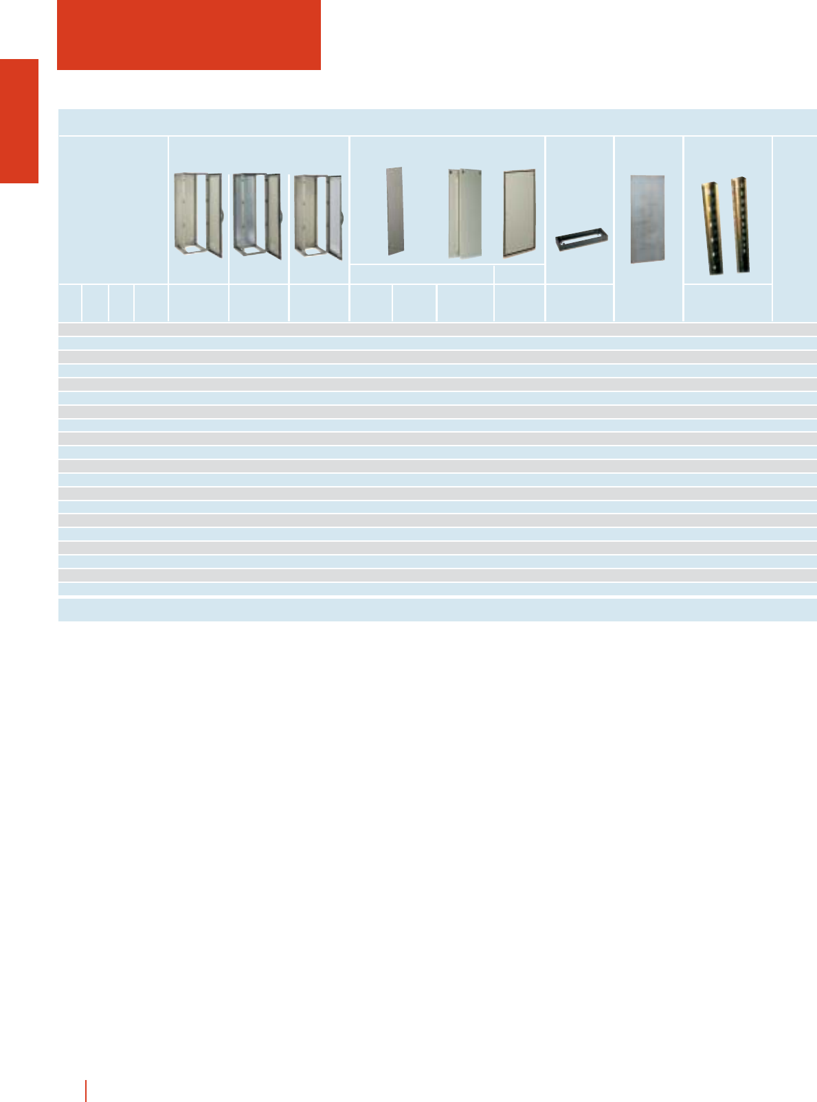
selection guide
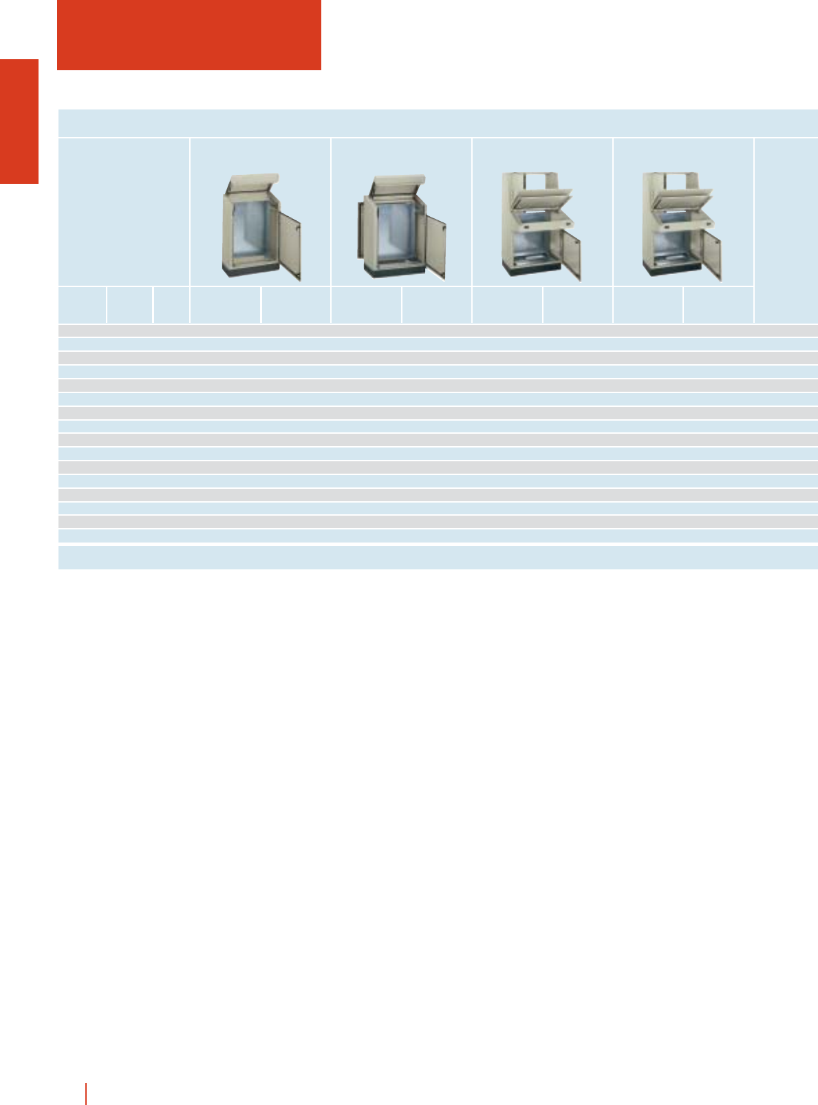
METAL CONTROL DESKS
1024 600 466 PK 60 PK 60 PM - - - - - -
1024 800 466 PK 80 PK 80 PM - - - - - -
1024 1000 466 PK 100 PK 100 PM - - - - - -
1024 1200 466 PK 120 PK 120 PM - - - - - -
1024 600 597 - - PKP 60 PKP 60 PM - - - -
1024 800 597 - - PKP 80 PKP 80 PM - - - -
1024 1000 597 - - PKP 100 PKP 100 PM - - - -
1024 1200 597 - - PKP 120 PKP 120 PM - - - -
1400 800 814 - - - - PKP 80 / F30 PKP 80 / F30 PM - -
1400 1000 814 - - - - PKP 100 / F30 PKP 100 / F30 PM - -
1400 1200 814 - - - - PKP 120 / F30 PKP 120 / F30 PM - -
1400 1600 814 - - - - PKP 160 / F30 PKP 160 / F30 PM - -
1400 800 1014 - - - - - - PKP 80 / F50 PKP 80 / F50 PM
1400 1000 1014 - - - - - - PKP 100 / F50 PKP 100 / F50 PM
1400 1200 1014 - - - - - - PKP 120 / F50 PKP 120 / F50 PM
1400 1600 1014 - - - - - - PKP 160 / F50 PKP 160 / F50 PM
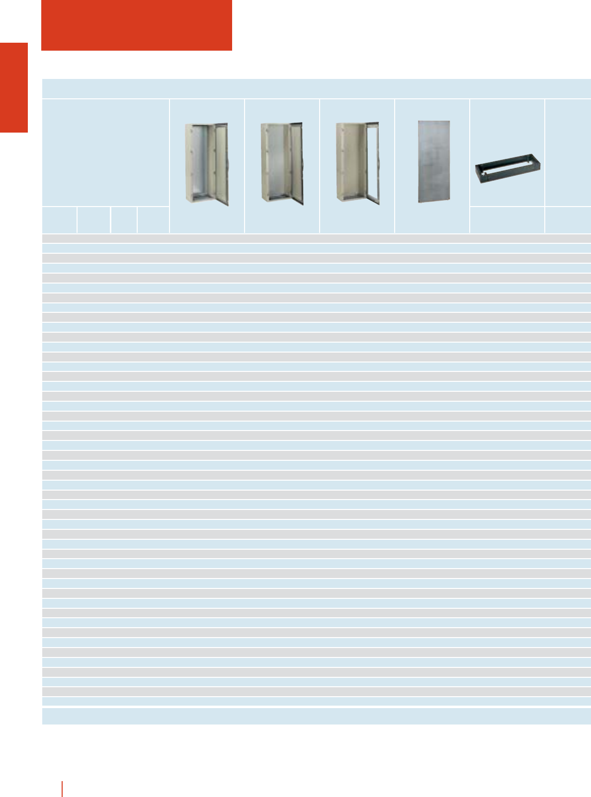
PK metal monobloc control desks
with fix rear panel
PKP metal monobloc control desks
with detachable rear panel
PKP.../30 metal monobloc control desks
with front panel and rear door
PKP.../50 metal monobloc control desks
with front panel and rear door
Without
mounting plate
With
mounting plate
Without
mounting plate
With
mounting plate
Without
mounting plate
With
mounting plate
Without
mounting plate
With
mounting plate
*For plinths height 200, ask reference ZUN.../200.
Page 1/155 1/155 1/157 1/157 1/161 1/161 1/161 1/161
1/15wall fixing and floor standing metal enclosures HIMEL
PMPK-8560 PMR-6760 - - - - ZUN 64/100
PMPK-8580 PMR-6780 - - - - ZUN 84/100
PMPK-85100 PMR-67100 - - - - ZUN 104/100
PMPK-85120 PMR-67120 - - - - ZUN 124/100
PMPK-8560 PMR-6760 - - - - ZUN 65/100
PMPK-8580 PMR-6780 - - - - ZUN 85/100
PMPK-85100 PMR-67100 - - - - ZUN 105/100
PMPK-85120 PMR-67120 - - - - ZUN 125/100
PMP-7080 PMR-6780 PMP-4580 PMR-4280 PMOL-148 PMP-4080 ZUN 84/100
PMP-70100 PMR-67100 PMP-45100 PMR-42100 PMOL-1410 PMP-40100 ZUN 104/100
PMP-70120 PMR-67120 PMP-45120 PMR-42120 PMOL-1412 PMP-40120 ZUN 124/100
PMP-70160 - PMP-45160 - - PMP-40160 ZUN 164/100
PMP-7080 PMR-6780 PMP-4580 PMR-4280 PMOL-148 PMP-4080 ZUN 86/100
PMP-70100 PMR-67100 PMP-45100 PMR-42100 PMOL-1410 PMP-40100 ZUN 106/100
PMP-70120 PMR-67120 PMP-45120 PMR-42120 PMOL-1412 PMP-40120 ZUN 126/100
PMP-70160 - PMP-45160 - - PMP-40160 ZUN 166/100
Metal Universal
Mounting plates
Lower Upper
Plinths
Metal Universal Full mounting
plates Console Height
100 mm*
1/157 1/157 1/162 1/162 1/162 1/162 1/89
1/16 HIMEL wall fixing and floor standing metal enclosures
External dimensions (mm)
Height Width Depth
ENCLOSURES, DIMENSIONS AND REFERENCES
300 200 150 CRSX 32/150 MM-32 MB-32 MF-32 MR-32
300 250 150 CRSX 3025/150 MM-3025 MB-3025 MF-3025 MR-3025
300 300 150 CRSX 33/150 MM-33 MB-33 MF-33 MR-33
400 300 150 CRSX 43/150 MM-43 MB-43 MF-43 MR-43
-----
400 300 200 CRSX 43/200 MM-43 MB-43 MF-43 MR-43
-----
400 400 200 CRSX 44/200 MM-44 MB-44 MF-44 MR-44
500 400 200 CRSX 54/200 MM-54 MB-54 MF-54 MR-54
600 400 200 CRSX 64/200 MM-64 MB-64 MF-64 MR-64
600 600 250 CRSX 66/200 MM-66 MB-66 MF-66 MR-66
700 500 250 CRSX 75/250 MM-75 MB-75 MF-75 MR-75
-----
800 600 250 CRSX 86/250 MM-86 MB-86 MF-86 MR-86
-----
800 800 300 CRSX 88/300 MM-88 MB-88 MF-88 MR-88
1000 800 300 CRSX 108/300 MM-108 MB-108 MF-108 MR-108
1200 800 300 CRSX 128/300 MM-128 MB-128 MF-128 MR-128
Mounting plates
Metal Insulating Drilling Universal
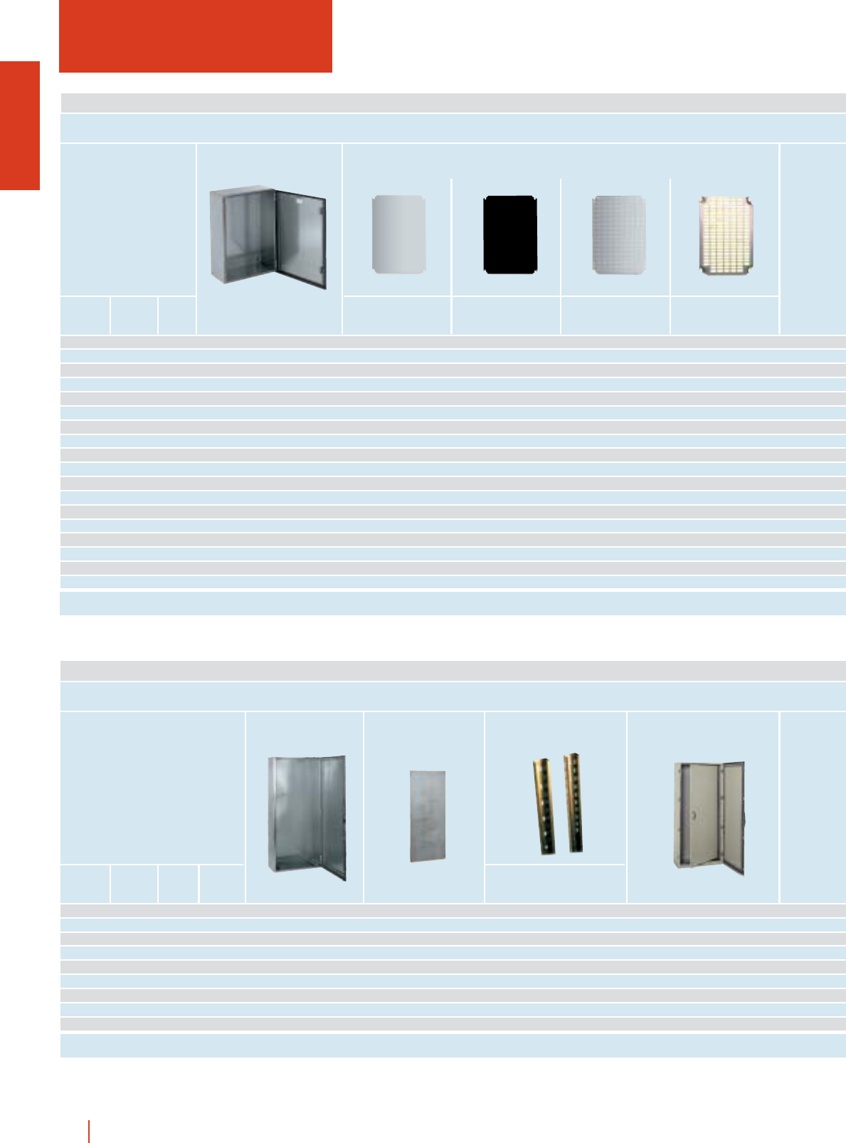
selection guide
STAINLESS STEEL ENCLOSURES
External dimensions (mm)
Height Width Depth No. of
doors
ENCLOSURES, DIMENSIONS AND REFERENCES
1200 1000 300 2 CMOX 1210/30 PMOL 1210 MOL 120 -
1600 800 400 1 CMOX 168/40 PMOL 168 MOL 160 PIL 168
1800 800 400 1 CMOX 188/40 PMOL 188 MOL 180 PIL 188
1800 1200 400 2 CMOX 1812/40 PMOL 1812 MOL 180 -
1800 1600 400 2 CMOX 1816/40 PMOL 1816 MOL 180 -
2000 800 400 1 CMOX 208/40 PMOL 208 MOL 200 PIL 208
2000 1000 400 2 CMOX 2010/40 PMOL 2010 MOL 200 PIL 2010 2P
2000 1200 500 2 CMOX 2012/50 PMOL 2012 MOL 200 -
2000 1600 500 2 CMOX 2016/50 PMOL 2016 MOL 200 -
Mounting plate Universal chassis Internal doors
Set of 2 uprights
*For plinths height 200, ask reference ZUN.../200.
CRSX
CMOX
Page 1/169 1/172 1/172 1/172 1/172
Page 1/171 1/86 1/111 1/140
1/17wall fixing and floor standing metal enclosures HIMEL
------ - TX 2015
------ - TX 2515
------ - TX 3015
- DLM-24 24 2 2 - - TX 3015
------ --
SDCR-200 DLM-24 24 2 2 - PIN-43/200 TX 3020
------ --
SDCR-200 - ---- - TX 4020
SDCR-200 DLM-48 48 3 3 - PIN-54/200 TX 4020
SDCR-200 DLM-48 P 48 3 3 - PIN-64/200 TX 4020
SDCR-250 - ---- - TX 6025
SDCR-250 DLM-66 66 4 3 1 PIN-75/250 TX 5025
- DLM-88 88 4 4 - --
SDCR-250 DLM-84 84 4 3 1 PIN-86/250 TX 6025
DLM-112 112 4 4 - --
SDCR-300 - ---- - TX 8030
SDCR-300 DLM-240 234 6 6 - PIN-108/300 TX 8030
SDCR-300 - ---- - TX 8030
Depth adjustable supports Dinimel DLM
Reference No. of 18 mm
modules
No. of
rows
No. of
rails
No. of
plates
Canopies
Internal doors
----TJX 10030 CMOX ZUX 103/100
BRP 31/OL BRPC 31/OL BRP 31/OL 180 31 TJX 8040 CMOX ZUX 84/100
BRP 36/OL BRPC 36/OL BRP 36/OL 180 36 TJX 8040 CMOX ZUX 84/100
----TJX 12040 CMOX ZUX 124/100
----TJX 16040 CMOX ZUX 164/100
BRP 40/OL BRPC 40/OL BRP 40/OL 180 40 TJX 8040 CMOX ZUX 84/100
----TJX 10040 CMOX ZUX 104/100
----TJX 12050 CMOX ZUX 125/100
----TJX 16040 CMOX ZUX 164/100
No. units
1 unit = 44.45 mm
180° swing rack Height
100 mm*
Centred swing rackSwing rack
Plinths
Canopies19” Rack
1/20 1/21 1/21 1/174
1/119 1/121 1/120 1/175 1/175
1/18 HIMEL wall fixing and floor standing metal enclosures
External dimensions (mm)
Height Width Depth Control desk without
mounting plate
Control desk with
mounting plate
ENCLOSURES, DIMENSIONS AND REFERENCES
1024 600 597 PKPX 60 PKPX 60-PM PMPK 8560 ZUX 65/100
-- - -
1024 800 597 PKPX 80 PKPX 80-PM PMPK 8580 ZUX 85/100
-- - -
-- - -
1024 1000 597 PKPX 100 PKPX 100-PM PMPK 85100 ZUX 105/100
-- - -
-- - -
-- - -
1024 1200 597 PKPX 120 PKPX 120-PM PMPK 85120 ZUX 125/100
-- - -
-- - -
-- - -
-- - -
Metal monobloc control desks Mounting plates Plinths
Height 100 mm
selection guide
STAINLESS STEEL METAL
CONTROL DESKS
Page 1/177 1/177 1/177 1/177
1/19wall fixing and floor standing metal enclosures HIMEL
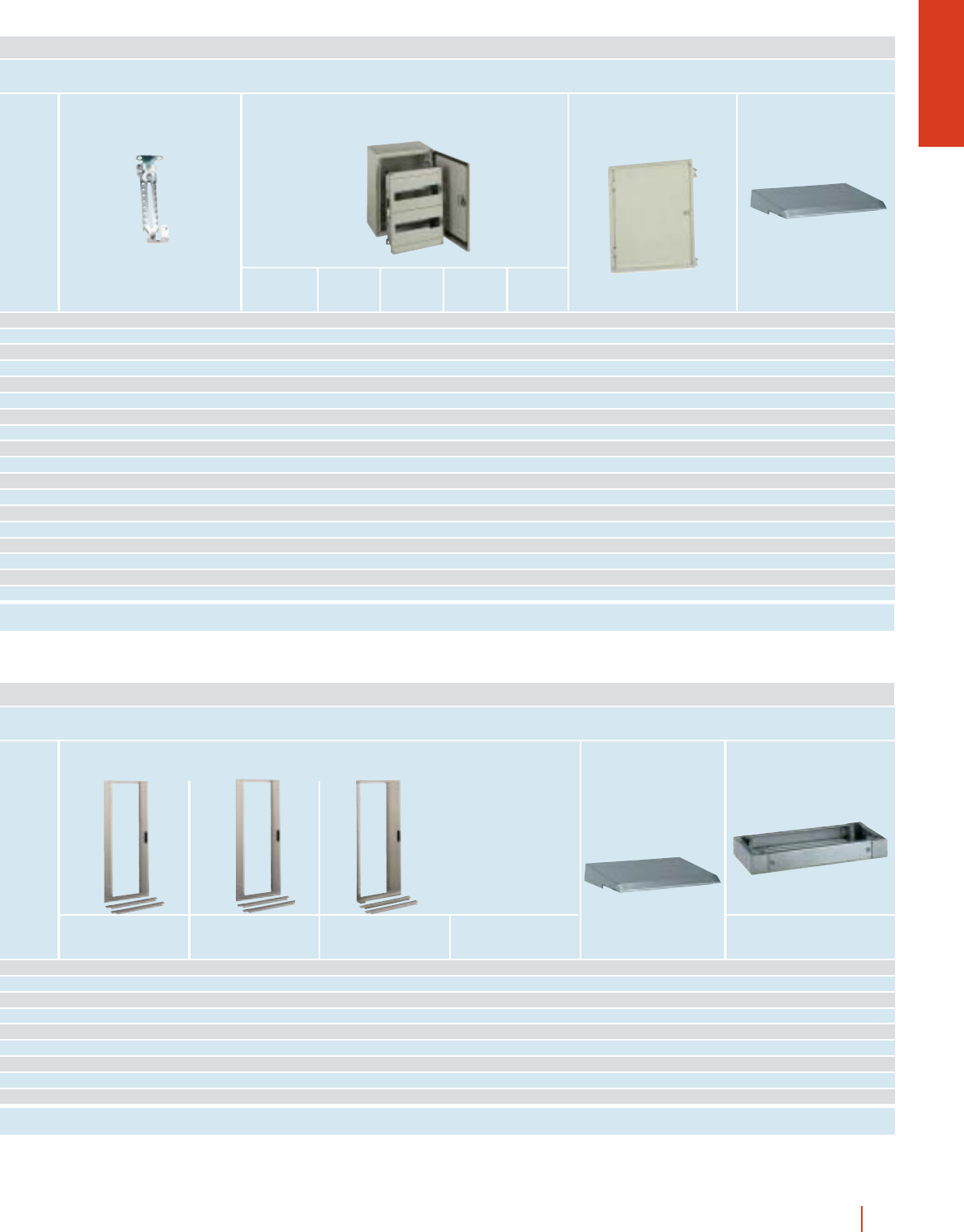
400 FEX 42 FEX 43 TAX 20 200 MM-44 MF-44 MR-44
600 FEX 62 FEX 63 - -MM-64 MF-64 MR-64
400 FEX 42 FEX 43 TAX 40 400 MM-44 MF-44 MR-44
400 2×FEX 42 2 ×FEX 43 - -MM-44 MF-44 MR-44
600 FEX 62 FEX 63 TAX 20 200 MM-64 MF-64 MR-64
400 FEX 42 FEX 43 TAX 60 600 MM-44 MF-44 MR-44
600 FEX 62 FEX 63 TAX 40 400 MM-64 MF-64 MR-64
600 FEX 42 FEX 43 2 ×TAX 20 200 MM-64 MF-64 MR-64
400 + 600 FEX 42+FEX 63 FEX 43+FEX 63 - -MM-44+MM-64 MF-44+MF-64 MR-44+MR-64
400 FEX 42 FEX 43 TAX 80 800 MM-44 MF-44 MR-44
400 + 600 FEX 42+FEX 62 FEX 43+FEX 63 TAX 20 200 MM-44+MM-64 MF-44+MF-64 MR-44+MR-64
600 FEX 62 FEX 63 TAX 60 600 MM-64 MF-64 MR-64
600 FEX 62 FEX 63 TAX 20+TAX 40 200 + 400 MM-64 MF-64 MR-64
600 2×FEX 62 2 ×FEX 63 - - MM-64 MF-64 MR-64
Front Covers
Width
Depth
200 mm 300 mm Width Metal Drilling UniversalReference
Front opening mounting plates
1/178 1/178 1/178 1/178 1/178 1/178
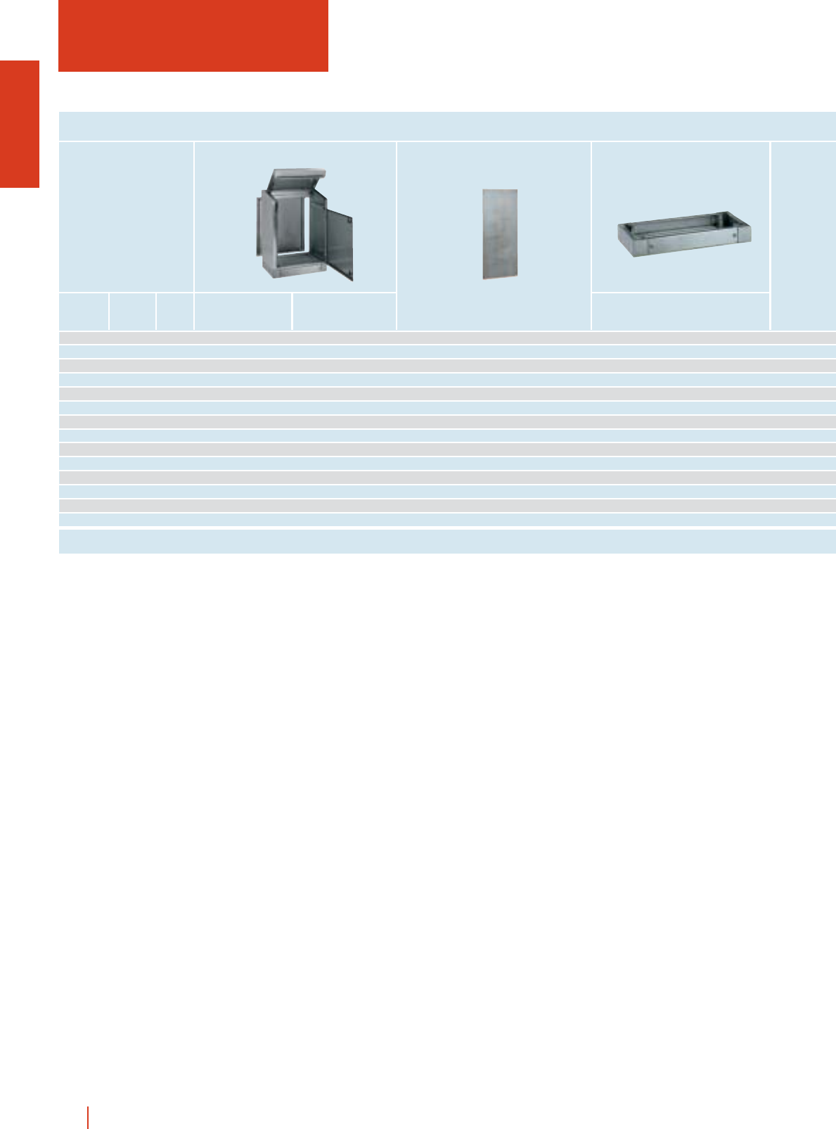
1/20 HIMEL wall fixing and floor standing metal enclosures
External dimensions (mm)
Height Width Depth
ENCLOSURES, DIMENSIONS AND REFERENCES
CRN-CEM
selection guide
METAL ENCLOSURES FOR
ELECTROMAGNETIC PROTECTION
400 300 200 CRAF 43/200 PM MM-43 MF-43 SDCR-200
500 400 200 CRAF 54/200 PM MM-54 MF-54 SDCR-200
600 400 200 CRAF 64/200 PM MM-64 MF-64 SDCR-200
600 600 200 CRAF 66/250 PM MM-66 MF-66 SDCR-200
700 500 250 CRAF 75/250 PM MM-75 MF-75 SDCR-200
-- - -
800 600 300 CRAF 86/300 PM MM-86 MF-86 SDCR-300
-- - -
1000 800 300 CRAF 108/300 PM MM-108 MF-108 SDCR-300
1200 800 300 CRAF 128/300 PM MM-128 MF-128 SDCR-300
Metal Drilling
Mounting plates Depth adjustable supports
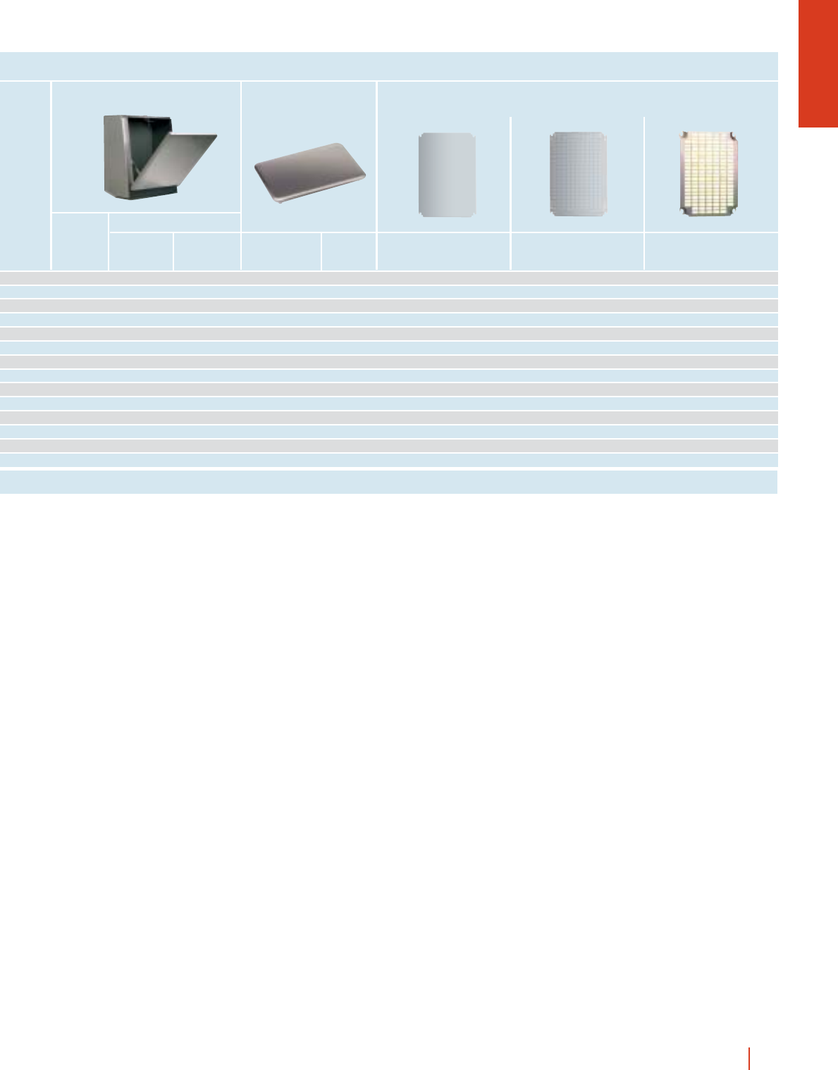
CMO-CEM
External dimensions (mm)
Height Width Depth No. of
doors
ENCLOSURES, DIMENSIONS AND REFERENCES
1600 800 400 1 COAF 168/40 PM PMOL 168 MOL 160 800 AF/COL 168
1800 800 400 1 COAF 188/40 PM PMOL 188 MOL 180 800 AF/COL 188
2000 800 400 1 COAF 208/40 PM PMOL 208 MOL 200 800 AF/COL 208
ReferenceColumn width
Mounting plates Universal chassis UNIDIS coupling assembly
OLN-CEM
External dimensions (mm)
Height Width Depth No. of
doors
ENCLOSURES, DIMENSIONS AND REFERENCES
1800 800 400 1 OLAF 188/40 PM 2 PLAF 184 PMOL 188 MOL 180 800 AF/COL 188
1800 800 600 1 OLAF 188/60 PM 2 PLAF 186 PMOL 188 MOL 180 800 AF/COL 188
2000 800 500 1 OLAF 208/50 PM 2 PLAF 205 PMOL 208 MOL 200 800 AF/COL 208
2000 800 600 1 OLAF 208/60 PM 2 PLAF 206 PMOL 208 MOL 200 800 AF/COL 208
ReferenceColumn width
Mounting plates
Side panels Universal chassis UNIDIS coupling assembly
Page 1/183 1/188 1/27 1/40
Page 1/185 1/188 1/111 1/113
Page 1/187 1/187 1/188 1/111 1/113
1/21wall fixing and floor standing metal enclosures HIMEL
DLM-24 24 2/- PIN-43/200 - -TJ-3020
DLM-48 48 3/- PIN-54/200 - -TJ-4020
DLM-48P 48 3/- PIN-64/200 - -TJ-4020
--- ---TJ-6025
DLM-66 66 3/1 ---TJ-5025
DLM-88 88 4/- ----
DLM-84 84 3/1 - BR.../CRN 16 TJ-6030
DLM-112 112 4/- ----
DLM-240 234 6/- ---TJ-8030
--- ---TJ-8030
Reference No. of 18 mm
modules
No. of
rows/plates
Dinimel DLM Internal doors Fixed and swing 19” rack Canopies
Reference No. of units
PIL 168 BRP 31/OL BRPC 31/OL BRP 31/OL 180 31 TJ 8040 CMO ZUN 84/100 ZUN 84/200
PIL 188 BRP 36/OL BRPC 36/OL BRP 36/OL 180 36 TJ 8040 CMO ZUN 84/100 ZUN 84/200
PIL 208 BRP 40/OL BRPC 40/OL BRP 40/OL 180 40 TJ 8040 CMO ZUN 84/100 ZUN 84/200
Height 100 mm Height 200 mm
No. units
1 U = 44.45 mm
19” RackInternal doors PlinthsCanopies
Swing
rack
Centred swing
rack
180°
swing rack
BRP 36/OL 36 BRPC 36/OL 36 BRP 36/OL 180 36 PIL 188 ZUN 84/100 ZUN 84/200
BRP 36/OL 36 BRPC 36/OL 36 BRP 36/OL 180 36 PIL 188 ZUN 86/100 ZUN 86/200
BRP 40/OL 40 BRPC 40/OL 40 BRP 40/OL 180 40 PIL 208 ZUN 85/100 ZUN 85/200
BRP 40/OL 40 BRPC 40/OL 40 BRP 40/OL 180 40 PIL 208 ZUN 86/100 ZUN 86/200
Swing
rack Height 100 mm Height 200 mm
19” Rack PlinthsInternal door
No. units
1 U = 44.45 mm
Centred swing
rack
No. units
1 U = 44.45 mm
180°
swing rack
No. units
1 U = 44.45 mm
1/28 1/36 1/29 1/41
1/140 1/119 1/120 1/120 1/67 1/66 1/66
1/119 1/120 1/120 1/140 1/89 1/89
CRN wall mounting steel enclo
A complete range of
mounting plates
suitable for most types
of installations.
Embedded cable gland
plate and entrance, leveled
with the base, with a
neoprene seal.
Insulated cable gland
plates with pre-punched
holes for easy cable entry
available as accessory.
Front rain gutter avoids the entry of
water, oil or liquids which ensures IP66
protection and protects the inside
surface when opening the door.
Back of enclosure with four
M8 15 welded studs with
built-in spacers for fixing of
mounting plate and
adjustable supports.
Wall fixing holes sealed with
plastic plugs to assure the
protection degree.
1/22 HIMEL CRN wall mounting steel enclosures
Transparent tempered
glass door and fully
watertight, maintaining
IP66 protection.
sures suitable for all applications
Built in standard double
bar locking system and
three points locking for
two doors enclosures and
1200 mm high enclosures.
Different lock
combinations available.
Foamed-in polyurethane
gasket guarantees
watertightness for years.
Perforated door reinforcement
profiles allowing fixing of
equipment in up to 400 mm
high enclosures.
Wall fixing brackets fixed
from the outside and can
be placed both horizontally
or vertically. Not included
as standard supply.
Depth adjustable support
with positions every
12.5 mm.
Two M6 15 welded earth
studs on the back and one
M6 15 stud on the door.
Easily reversible door, fitted
with two or three invisible
hinges allowing 120º opening.
1/23CRN wall mounting steel enclosures HIMEL
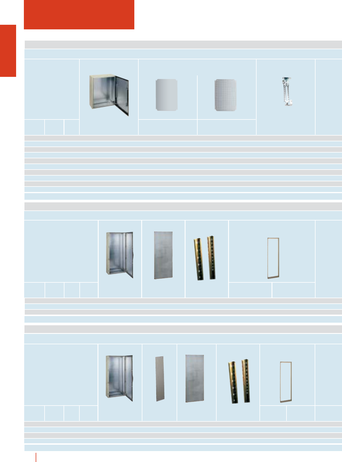
CRN WALL MOUNTING STEEL ENCLOSURES
IP66 (EN 60529)
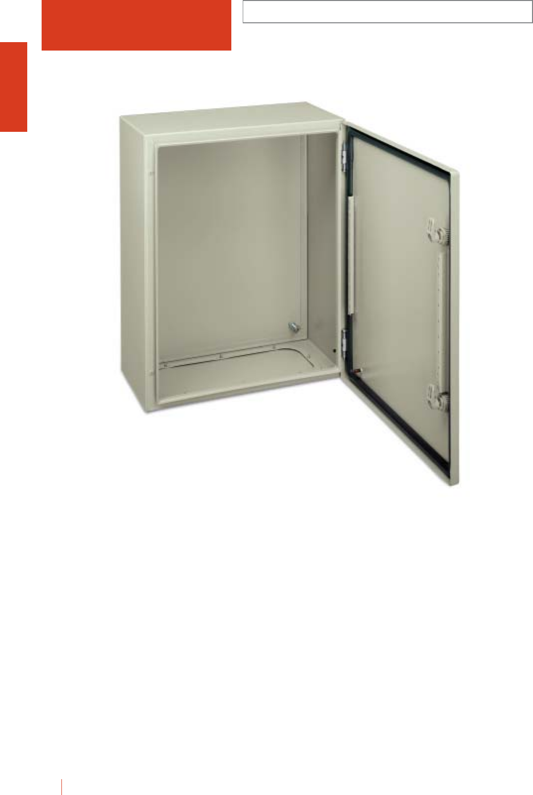
1/24 HIMEL CRN wall mounting steel enclosures
CRN 54/200
Metal enclosures made from a continuous length of
sheet steel double folded at the front, with back
welded to the frame. Both externally and internally
protected with polyester epoxy resin grey paint to
RAL-7032 texturized.
cNew series CRN...KT with transparent security glass door.
cDepth adjustable mounting plate supports.
cPerforated door reinforcement profiles allowing fixing of
equipment on models up to CRN-54/150.
cConcealed and easily removable hinges allowing over 120º
door opening.
cSingle plinth ZUN, 100 mm and 200 mm high, available for
models 600, 800 and 1000 mm width and 300 mm depth.
cIP66 for one door enclosures.
cIP55 for two doors enclosures.

CRN
WALL MOUNTING STEEL ENCLOSURES
IP66 (EN 60529)
1/25CRN wall mounting steel enclosures HIMEL
ENCLOSURES, DIMENSIONS AND REFERENCES
* Weight of enclosures with plain door. ** Enclosures with three point locking system.
Enclosures Mounting plates
Mounting
plate
adjustable
supports
Metallic
chasis
DLM
Fixed and
swing
19" racks
Internal
door
External
dimensions (mm)
Height
(A)
Width
(B)
Depth
(C)
Reference Reference with
glazed door Fig.
Flange
opening
type
Weight*
kg
250 200 150 CRN-2520/150 - 103.2
ppp
300 250 150 CRN-3025/150 CRN-3025/150 KT 1A4.2pppp
300 250 200 CRN-3025/200 CRN-3025/200 KT 1A4.9ppppp
300 300 150 CRN-33/150 CRN-33/150 KT 1B5pppp
300 300 200 CRN-33/200 CRN-33/200 KT 1B6ppppp
300 400 200 CRN-34/200 CRN-34/200 KT 1C6.4ppppp
400 300 150 CRN-43/150 CRN-43/150 KT 1B6pppp p
400 300 200 CRN-43/200 CRN-43/200 KT 1B6.8pppppp p
400 400 200 CRN-44/200 CRN-44/200 KT 1C8ppppp
400 600 250 CRN-46/250 CRN-46/250 KT 1D10ppppp p
400 600 300 CRN-46/300 CRN-46/300 KT 1 D 11.2 ppppp p
500 400 150 CRN-54/150 CRN-54/150 KT 2B8.7pppp p p
500 400 200 CRN-54/200 CRN-54/200 KT 2C9.8pppppp p
500 400 250 CRN-54/250 CRN-54/250 KT 2C11pppppp p
500 500 250 CRN-55/250 CRN-55/250 KT 2 D 12.8 ppppp
600 400 150 CRN-64/150 CRN-64/150 KT 2B9.3pppp p p
600 400 200 CRN-64/200 CRN-64/200 KT 2 C 10.8 pppppp p
600 400 250 CRN-64/250 CRN-64/250 KT 2 C 12.3 pppppp p
600 500 150 CRN-65/150 CRN-65/150 KT 2 B 11.3 pppp
600 500 200 CRN-65/200 CRN-65/200 KT 2 D 14.3 ppppp
600 500 250 CRN-65/250 CRN-65/250 KT 2 D 16.3 ppppp
600 600 200 CRN-66/200 CRN-66/200 KT 2D- ppppppp
600 600 250 CRN-66/250 CRN-66/250 KT 2 D 18.2 ppppppp
600 600 300 CRN-66/300 CRN-66/300 KT 2 D 19.8 ppppppp
600 800 300 CRN-68/300 CRN-68/300 KT 2E26ppppp
700 500 200 CRN-75/200 CRN-75/200 KT 2 D 17.3 pppppp p
700 500 250 CRN-75/250 CRN-75/250 KT 2 D 19.3 pppppp p
800 600 200 CRN-86/200 CRN-86/200 KT 2 D 21.8 pppppp p
800 600 250 CRN-86/250 CRN-86/250 KT 2 D 24.8 pppppppp
800 600 300 CRN-86/300 CRN-86/300 KT 2 D 26.3 pppppppp
800 600 400 CRN-86/400 CRN-86/400 KT 2D- pppppppp
800 800 200 CRN-88/200 CRN-88/200 KT 2 E 29.5 ppppp
800 800 300 CRN-88/300 CRN-88/300 KT 2 E 32.5 ppppp
800 1000 300 CRN-810/300** - 4E37ppppp
1000 600 250 CRN-106/250 CRN-106/250 KT 2 D 28.4 pppppppp
1000 600 300 CRN-106/300 CRN-106/300 KT 2 D 30.6 pppppppp
1000 800 250 CRN-108/250 CRN-108/250 KT 2 E 34.5 pppppppp
1000 800 300 CRN-108/300 CRN-108/300 KT 2 E 37.4 pppppppp
1000 800 400 CRN-108/400 CRN-108/400 KT 2E- pppppppp
1000 1000 300 CRN-1010/300** CRN-1010/300 KT** 4 (KT:3) E 46.7 ppppp
1000 1200 300 CRN-1012/300** - 4E41ppppp
1200 800 300 CRN-128/300** CRN-128/300 KT** 3E- ppppp pp
1200 800 400 CRN-128/400** CRN-128/400 KT** 3E- ppppp pp
1200 1000 300 CRN-1210/300** - 4 E 53.4 ppppp
1200 1000 400 CRN-1210/400** CRN-1210/400 KT** 4 (KT:3) E - ppppp
Metal Insul. Perf. Universal
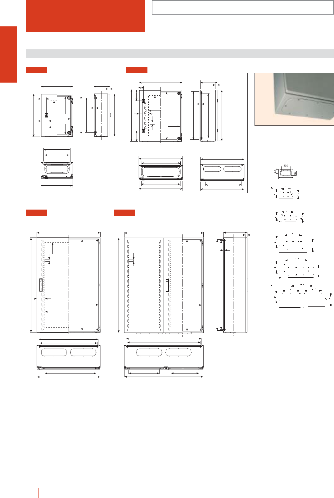
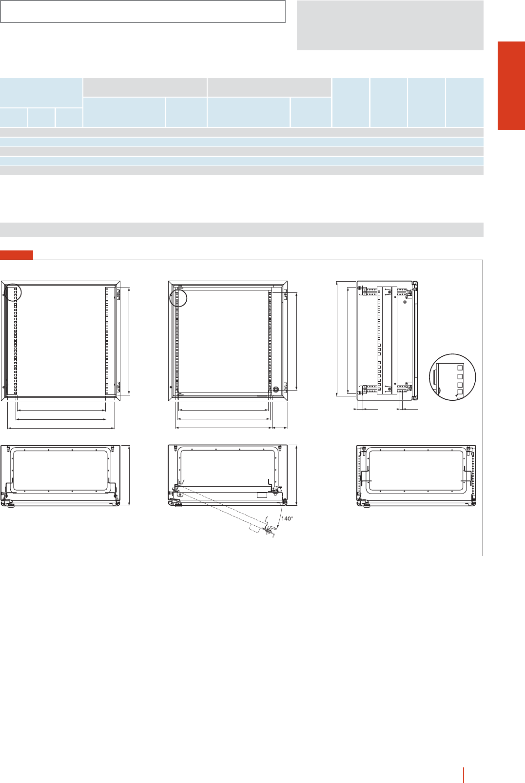
FIG. 1
CRN WALL MOUNTING STEEL ENCLOSURES
IP66 (EN 60529)
1/26 HIMEL CRN wall mounting steel enclosures
B
A
40
83 B-44
A-44
A-125
A-50
A-75
C21
10
B-5
B-75
B-50
B-133
A-5
* All glazed door enclosures
type KT are without door
reinforcement profiles.
** For 1200 mm width.
FIG. 3
A-125
B
A-44
A
B-44
B-75
B-50
B-5
25
B-145
B-154*
83
FIG. 4
C22
A-50
A-75
A-44
B-44
B-5
B-75
B-50
A
B
25
389/489** 346/546**
10
FIG. 2
B
40
A
83
A-125
B-145
25*
A-44
B-44
C21
A-50
10
A-75
A-5
114 114
800
B-5
B - 76.4*
B - 50
B - 75
B - 5
B - 76.4*
Dimensions (mm)
Detail of recessed cable gland plate
ensuring a flat surface (except 400 mm
depth and type E models).
0
CRN
BASIC COMPONENTS
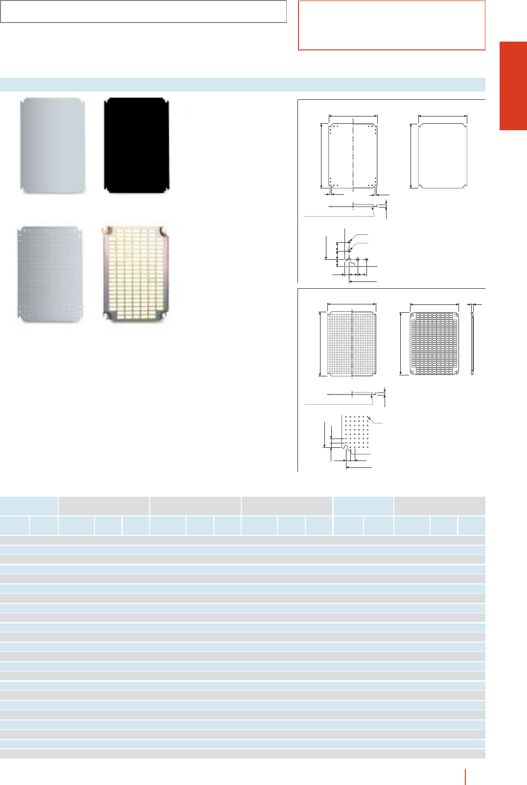
1/27CRN wall mounting steel enclosures HIMEL
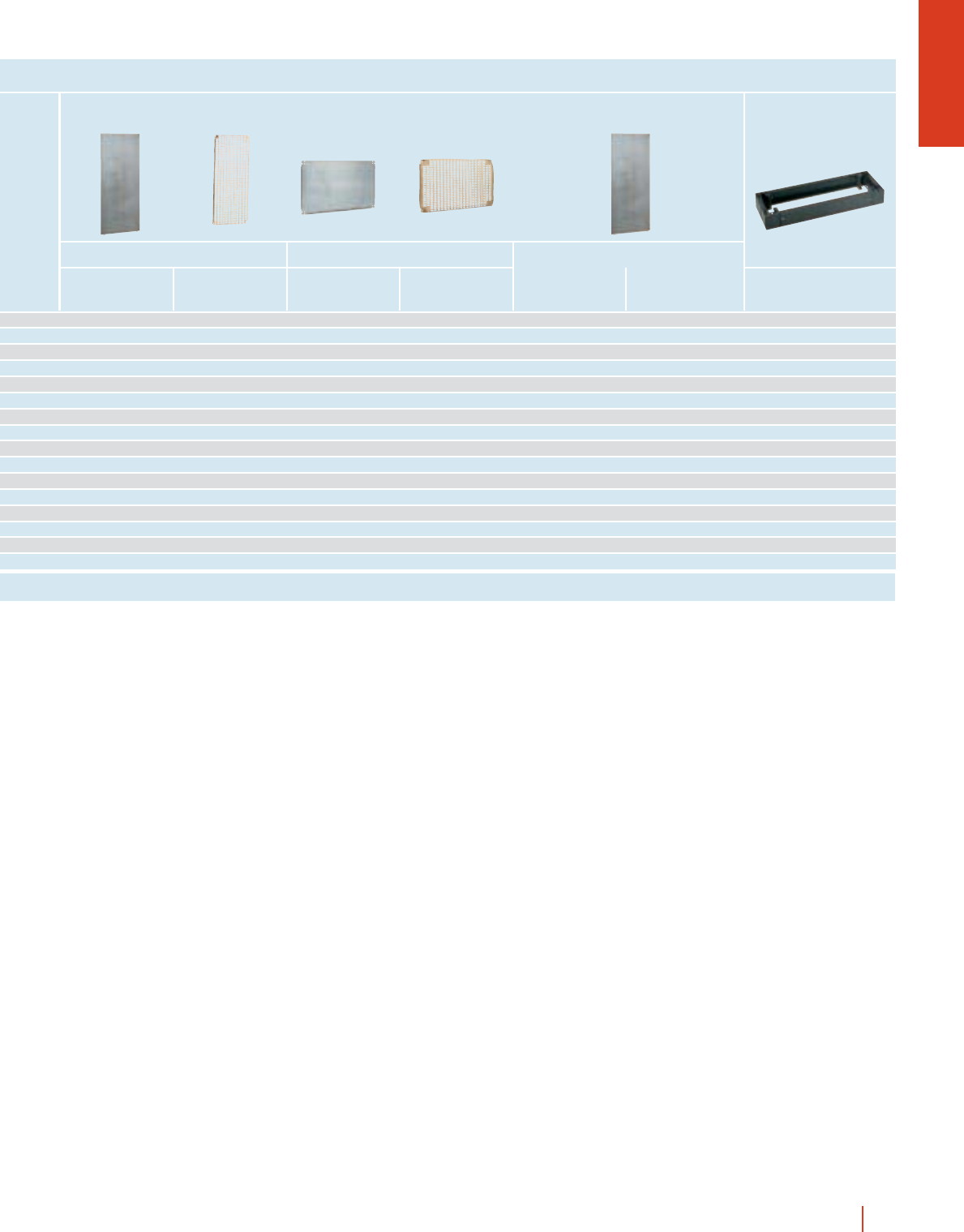
Metal
Reference
A comprehensive range
of mounting plates
consisting of 3 models
suitable for most types
of installations.
cBichromated zinc-
coated metal plates with
holes for fixing of
accessories and earthing
strip.
cInsulating bakelite
plates.
cGalvanized steel
mounting plates with
3.6 ∅drillings (12.5 mm
thread) for fixing of
equipment through
self-tapping 4.2 ∅mm
bolts and M4 trilobular
bolts.
cPerforated plates for
quick fixing of
equipment made of
bichromated zinc-coated
steel. The perforated
plate with fixing nuts
ensures that equipment
can be fixed in any
position.
Mounting plates
12.5
P
S
10.5 10.5
12.5 25 25
25 25
20
B-75
A-75
ø6.5
ø8.5
P
S
MM-1010, MM-1012, MM-128 and MM-1210
E
D
15
12.5
P
S
B-75
A-75
12.5
12.5
12.5
12.5
ø3.6
MF-1010, MF-1012, MF-128 and MF-1210
To be fitted
to enclosures
Height
(A)
Width
(B)
Thickness
mm
Weight
kg
Insulating
Reference Thickness
mm
Weight
kg
250 200 MM-2520 20.4MB-2520 40.13MF-2520 2 0.3 215 150 - - -
300 250 MM-3025 20.6MB-3025 40.2MF-3025 2 0.5 265 200 MR-3025 253 228
300 300 MM-33 21.2MB-33 40.3MF-33 2 1.1 265 250 MR-33 255 251
300 400 MM-34 21.6MB-34 40.5MF-34 2 1.5 265 350 MR-34 255 351
400 300 MM-43 21.6MB-43 40.5MF-43 2 1.5 365 250 MR-43 348 251
400 400 MM-44 22.2MB-44 40.7MF-44 2 2.1 365 350 MR-44 345 351
400 600 MM-46 23.1MB-46 41.1MF-46 2 3 365 550 MR-46 345 551
500 400 MM-54 22.5MB-54 40.9MF-54 2 2.4 465 350 MR-54 450 351
500 500 MM-55 23.7MB-55 41.2MF-55 2 3.5 465 450 MR-55 450 451
600 400 MM-64 23.1MB-64 41.1MF-64 2 3 565 350 MR-64 555 351
600 500 MM-65 24MB-65 41.4MF-65 2 3.8 565 450 MR-65 555 451
600 600 MM-66 25.5MB-66 41.7MF-66 2 5.2 565 550 MR-66 555 551
600 800 MM-68 2.5 9.9 MB-68 42.3MF-68 2.5 9.3 565 750 MR-68 555 751
700 500 MM-75 24.6MB-75 41.7MF-75 2 4.3 665 450 MR-75 645 451
800 600 MM-86 2.5 9.9 MB-86 42.3MF-86 2.5 9 765 550 MR-86 750 551
800 800 MM-88 2.5 13.6 MB-88 54.5MF-88 2.5 12 765 750 MR-88 750 751
800 1000 MM-810 2.5 16.9 MB-810 55.7MF-810 2.5 16 765 950 MR-810 750 951
1000 600 MM-106 2.5 12.6 MB-106 54.2MF-106 2.5 12 965 550 MR-106 945 551
1000 800 MM-108 2.5 16.9 MB-108 55.7MF-108 2.5 16 965 750 MR-108 945 751
1000 1000 MM-1010 2.5 18.6 MB-1010 57.1MF-1010 2.5 17 950 950 MR-1010 945 951
1000 1200 MM-1012 2.5 21.7 MB-1012 58.3MF-1012 2.5 20 950 1150 MR-1012 945 1151
1200 800 MM-128 2.5 17.8 MB-128 56.8MF-128 2.5 17 1150 750 MR-128 1145 751
1200 1000 MM-1210 2.5 21.7 MB-1210 58.3MF-1210 2.5 20 1150 950 MR-1210 1145 951
Perforated
Reference Thickness
mm
Weight
kg PS
Universal
Reference D E
Metal
Metal Insulating
Insulating
Perforated Universal
Perforated Universal
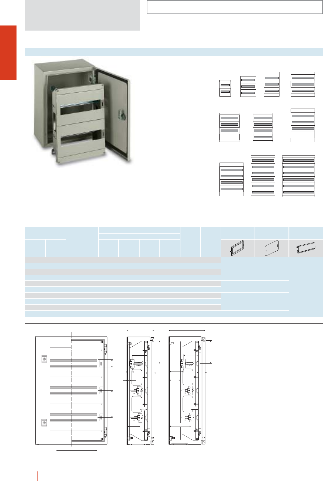
INSTALLATION SYSTEMS
CRN
1/28 HIMEL CRN wall mounting steel enclosures
Row lay-out
Breaker rails
Distribution chassis
assembly for mudular
equipment, ref.: DLM-…
with adjustable distance
between the 35 mm
symmetrical profile and
cover plate from 40 up
to 85 mm.
cChassis made of
galvanized steel.
cBlanck cover plate and
metal frame painted to
RAL-7032. Quick fixing
without screws.
cIdentifying circuits
system included in the
standard supply.
cTerminal blocks for
earth and neutral wiring
ref.: RBLZ/21656
supplied as standard.
Dinimel DLM distribution chassis
To fit to enclosures
CRN-CRS
Reference
Plain
door
Transparent
door
No. of
rows
CRN 43/150 + DLM-24P
DLM-84P
(600)
(600)
DLM-48P
(400)
(600)
DLM-48
(400)
(500)
DLM-24
(300)
(400)
DLM-66
(500)
(700)
DLM-88
(500)
(700)
DLM-84
(600)
(800)
DLM-240
(800)
(1000)
DLM-168
(600)
(1000)
DLM-112
(600)
(800)
Quant.
No. of
18 mm
mod.
No. of
plates DE
Blind cover
plate
Mounting
plate
Blanking
plate
…-43 …-43/KT DLM-24 2 2 24 - 216 103 CTL300DLM PMP300DLM
…-54 …-54/KT DLM-48 3 3 48 - 288 78 CTL400DLM PMP400DLM
…-64 …-64/KT DLM-48P 3 3 48 - 288 128
…-66 …-66/KT DLM-84P 3 3 84 - 504 128 CTL600DLM PMP600DLM
…-75 …-75/KT DLM-66 4 3 66 1 395 103 CTL500DLM PMP500DLM
…-75 …-75/KT DLM-88 4 4 88 - 395 103
…-86 …-86/KT DLM-84 4 3 84 1 504 153
…-86 …-86/KT DLM-112 4 4 112 - 504 153 CTL600DLM PMP600DLM
…-106 …-106/KT DLM-168 6 6 168 - 504 103
…-108 …-108/KT DLM-240 6 6 234 - 704 103 CTL800DLM PMP800DLM
ATP/72G
(72 mm)
4 modules
ATP/UND
(1100 mm)
D
150 46
C>150
E
36*
85
40
C-124
C-79
C=150
E
36*
85
40
26
71
C-140
10
* For enclosures with KT door remove 4 mm.
Note: On 150 mm deep enclosures, the DLM chassis
can be fixed to the front or the back of the enclosure.
For deeper enclosures, a MM, MB, MF... mounting
plate can be fixed to the back. In this case, the
chassis can be adjusted in depth through the SDCR
supports sold separately.
CRN
INSTALLATION SYSTEMS
1/29CRN wall mounting steel enclosures HIMEL
Racks to fit directly to 600 and 800
width CRN enclosures.
cPerforated 19” rack system with
v8.5 drillings every 44.45 mm.
cDouble bar locking mechanism and
reversible door.
cFixed rack made in galvanised sheet
steel and swing rack textured epoxy-
polyester paint finish colour grey
RAL-7032.
cFixed rack depth adjustable by SDCR
adjustable supports.
Fixed and swing 19” racks
Depth
(C)
To be fitted to enclosures
Height
(A)
Width
(B)
300 600 400 BRF5/CRN - - 188/238 61 5
400 600 250/300 BRF8/CRN - 359 188/238 61 8
500 600 400 BRF10/CRN - - 188/238 61 10
600 600 250/300 BRF12/CRN - 537 188/238 61 12
700 600 400 BRF14/CRN - - 188/238 61 14
800 600 250/300/400 BRF17/CRN - 759 188/238/338 61 17
1000 600 250/300 BRF21/CRN - 937 188/238 61 21
400 600 250/300 BRP7/CRN 342 311 188/238 59 7
600 600 250/300 BRP11/CRN 542 489 188/238 59 11
800 600 250/300/400 BRP16/CRN 742 711 188/238/338 59 16
1000 600 250/300 BRP20/CRN 942 889 188/238 59 20
1000 800 250/300/400 BRP20/CRN 800 942 889 188/238 59 20
1200 800 300/400 BRP25/CRN 800 - - 188/238 59 25
Reference
fixed rack
Reference
swing rack
No. of units
(1 U = 44.45 mm)
G
140°
B = 600
465
451
E
F
G(1)
A
A
C
465
453
485
B = 600
E
D
C
F
55
31.75
12.7
44.45
44.45
8.5 8.5
(1)
Fixed
rack
Fig. 1
Swing
rack
Fig. 2
NOTE: F and G can be modified when fixing BRF racks to the SDCR supports.
Enclosures with aluminium PACRN door G is 15 mm more. Enclosures with glazed KT door G is 4 mm less.
CRN 46/300 KT + BRP 7/CRN
D E FG
CRN
1/30 HIMEL CRN wall mounting steel enclosures
One body enclosures
INSTALLATION SYSTEMS
IP66 (EN 60529)
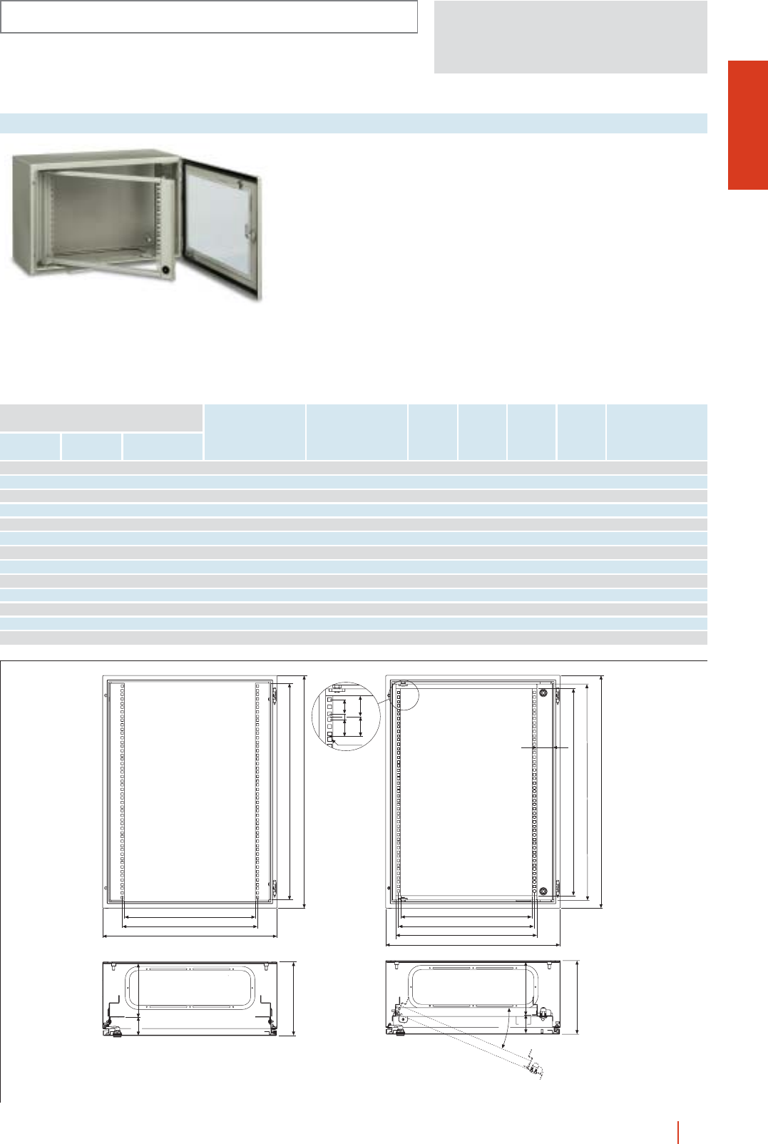
CRN 86/400 EP KT
19” metal enclosures for electronic applications with
back and transparent KT, door that can fit fixed or
swing 19” Racks with v8.5 mm drillings every
44.45 mm.
c5 heights: 4, 7, 9, 13 and 16 units for swing racks and
5, 8, 10, 14 and 17 units for fixed racks.
cDepth 400 mm.
cMade of sheet steel painted to RAL-7032.
cKT transparent templated glass reversible door.
c3 points lock from 700 mm height.
cFixed rack depth adjustable on 25 mm pitch with
adjustable supports (to be ordered separately).
cCable gland plates.
cEarth welded stud.
CRN
1/31CRN wall mounting steel enclosures HIMEL
INSTALLATION SYSTEMS
IP66 (EN 60529)
With 19’’ swing chassis With 19’’ fixed chassis
DEFG
Dimensions
enclosures (mm)
Height
(A)
Width
(B)
Depth
(C)
Reference Reference
No. of
units
No. of
units
300 600 400 CRN-36/400EP KT 4CRN-36/400EF KT 5 258 200 275 225
400 600 400 CRN-46/400EP KT 7CRN-46/400EF KT 8 358 300 375 325
500 600 400 CRN-56/400EP KT 9CRN-56/400EF KT 10 458 400 475 425
700 600 400 CRN-76/400EP KT 13 CRN-76/400EF KT 14 658 600 675 625
800 600 400 CRN-86/400EP KT 16 CRN-86/400EF KT 17 758 700 775 725
FIG. 1
453
467
543
D
403
X
Detail X
453
467
485 80
E403
X
F
G
30.7 12.5 8.58.5
Dimensions (mm)
Fixed chassis Swing chassis
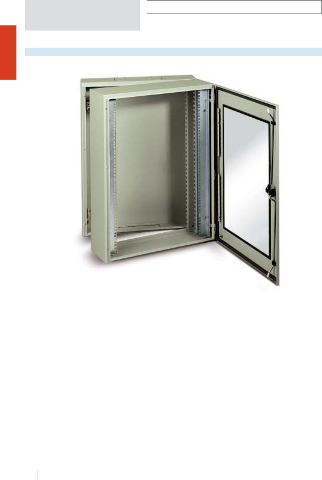
CRN
1/32 HIMEL CRN wall mounting steel enclosures
CRN 86/500E 17U KT
Swing frame metal enclosures for electronic
applications with three parts: back, frame and KT door,
19” fixed rack with v8.5 holes every 44.45 mm.
c5 heighs: 5, 8, 10, 14 and 17 U.
c2 depths: 400 and 500 mm.
cMade of sheet steel painted to RAL-7032.
REAR PANEL
cDepth 150 mm.
cInternal attachment point for fixing of various supports.
cHinges and closure system with body.
cTop and bottom cable gland plates.
BODY
cUsable depth 200 or 300 mm.
cTwo 19” uprights in treated steel, set back 100 mm from
front face.
cIntermediate body mounted on rear panel with 180° hinges.
DOOR
cKT transparent templated glass.
c120° opening with 2 or 3 hinges.
c3 points lock from 700 mm height.
INSTALLATION SYSTEMS
IP66 (EN 60529)
Two bodies enclosures
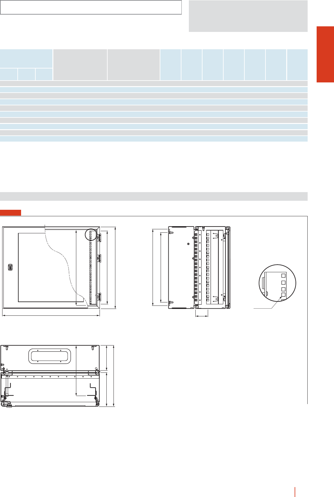
CRN
1/33CRN wall mounting steel enclosures HIMEL
Reference No. of units
(1 U = 44.45 mm)
DEFLGHJ
Dimensions (mm)
Height
(A)
Width
(B)
Depth
(C)
300 600 400 CRN-36/400E 5U KT 5 210 306 259 258 225 275 71
400 600 400 CRN-46/400E 8U KT 8 210 306 359 358 325 375 71
500 600 400 CRN-56/400E 10U KT 10 210 306 459 458 425 475 71
700 600 400 CRN-76/400E 14U KT 14 210 306 659 658 625 675 71
800 600 400 CRN-86/400E 17U KT 17 210 306 759 758 725 775 71
300 600 500 CRN-36/500E 5U KT 5 310 406 259 258 225 275 171
400 600 500 CRN-46/500E 8U KT 8 310 406 359 358 325 375 171
500 600 500 CRN-56/500E 10U KT 10 310 406 459 458 425 475 171
700 600 500 CRN-76/500E 14U KT 14 310 406 659 658 625 675 171
800 600 500 CRN-86/500E 17U KT 17 - 406 759 758 725 775 171
FIG. 1
X
600
A
D157
C
L
F
E
H
G
J
8.58.5
Detail X
Dimensions (mm)
INSTALLATION SYSTEMS
IP66 (EN 60529)
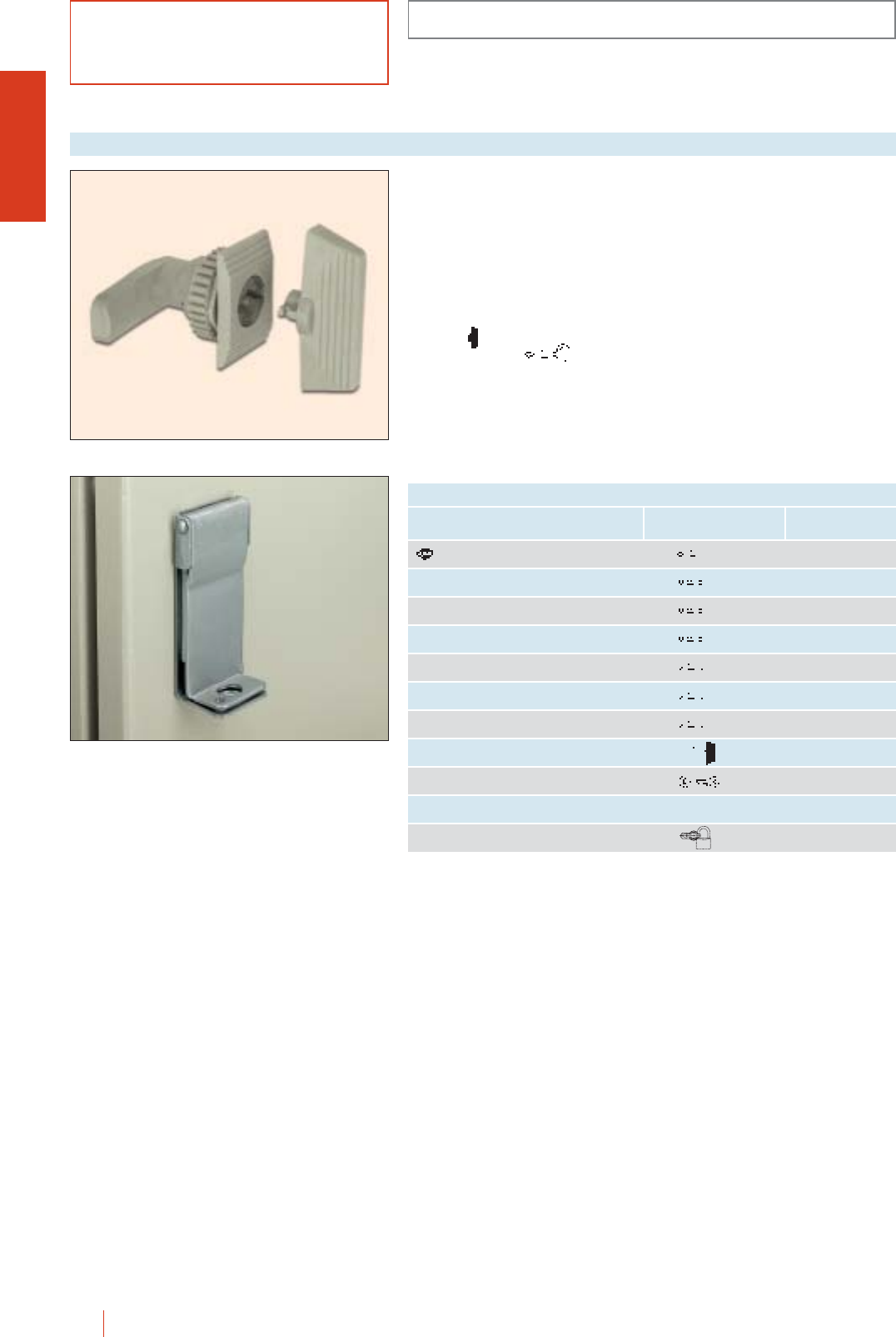
1/34 HIMEL CRN wall mounting steel enclosures
ACCESSORIES AND COMPLEMENTS
CRN
Locks
Key type/
reference
Type Reference
3 mm double bar key lock LDB 5 TDB/CRN
6 mm square key lock LC-7 TC 6/CRN
7 mm square key lock LC-7 TC 7/CRN
8 mm square key lock LC-8 TC 8/CRN
6.5 mm triangular key lock LT-6,5 TT 6/CRN
7 mm triangular key lock LT-8 TT 7/CRN
8 mm triangular key lock LT-8 TT 8/CRN
Safety cylinder lock
insert with wing key 405 CL/CRN
Full metal lock with keylock 405 CLL/CR-CRS-CRN
Stainless steel padlock KPLM
Lock with padlock bar for CRN CBC/CRN
Standard double bar
lock ref. CDB/CRN.
When wing DBP is
affited to lock, the
double bar lock is
transformed into normal
wing lock.
cOperated by:
vWing shaped handle
ref.: DBP (standard).
vKey wing LDB 5
DIN 43668
(optional supply).
OPTIONAL LOCK INSERTS TO TRANSFORM STANDARD LOCK
KPLM
CDB/CRN
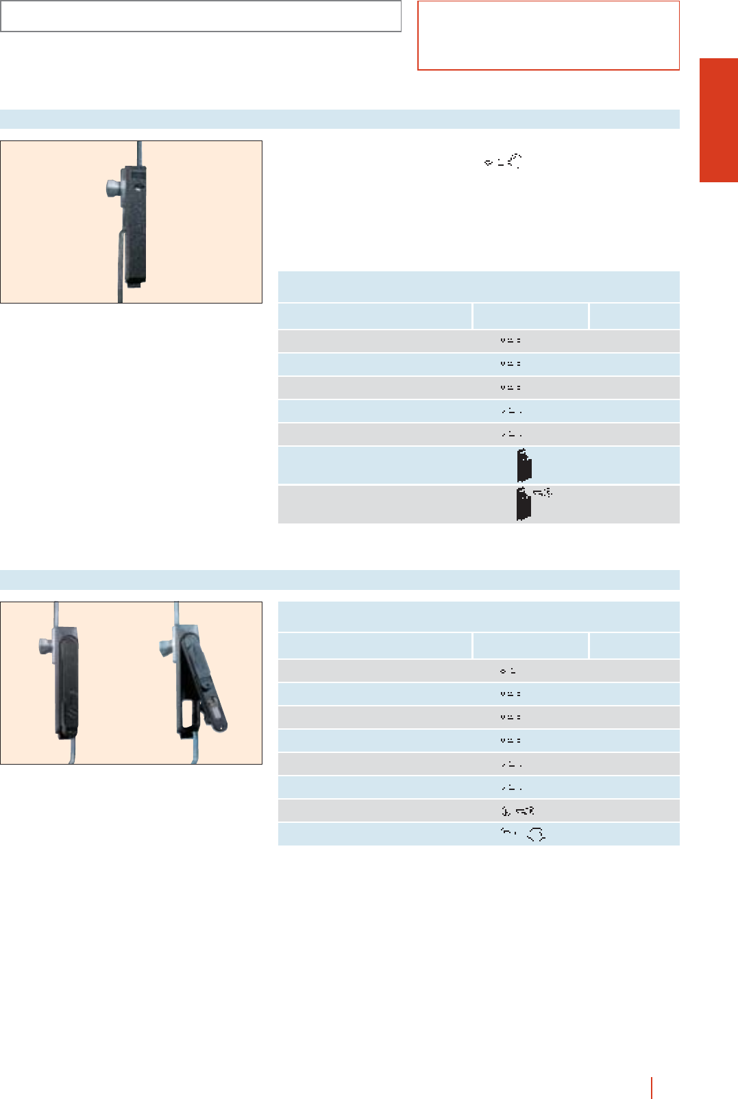
CRN
ACCESSORIES AND COMPLEMENTS
1/35CRN wall mounting steel enclosures HIMEL
Three-point lock for CRN enclosures
Key type/
reference
Type Reference
6 mm square lock LC-7 TC 6/ML
7 mm square lock LC-7 TC 7/ML
8 mm square lock LC-8 TC 8/ML
7 mm triangular lock LT-8 TT 7/ML
8 mm triangular lock LT-8 TT 8/ML
Handle lock TS/ML
Handle lock with key TL/ML
Double bar standard
lock for CRN-1010/300,
CRN 128/300 and CRN
1210/300 models in their
plain and transparent KT
door versions.
Three-point lock for CRN enclosures
Key type/
reference
Type Reference
Double bar lock LDB 5 TEDB/ML
6 mm square lock LC-7 TEC 6/ML
7 mm square lock LC-7 TEC 7/ML
8 mm square lock LC-8 TEC 8/ML
7 mm triangular lock LT-8 TET 7/ML
8 mm triangular lock LT-8 TET 8/ML
Key lock type 405 TEL/ML
Safety cylinder lock TER/ML
cOperation through:
vLDB 5 key
(according DIN 43668).
OPTIONAL LOCK INSERTS TO TRANSFORM THE STANDARD THREE-POINT
LOCKING ENCLOSURES
OPTIONAL HANDLE LOCKS TO TRANSFORM STANDARD
THREE-POINT LOCK
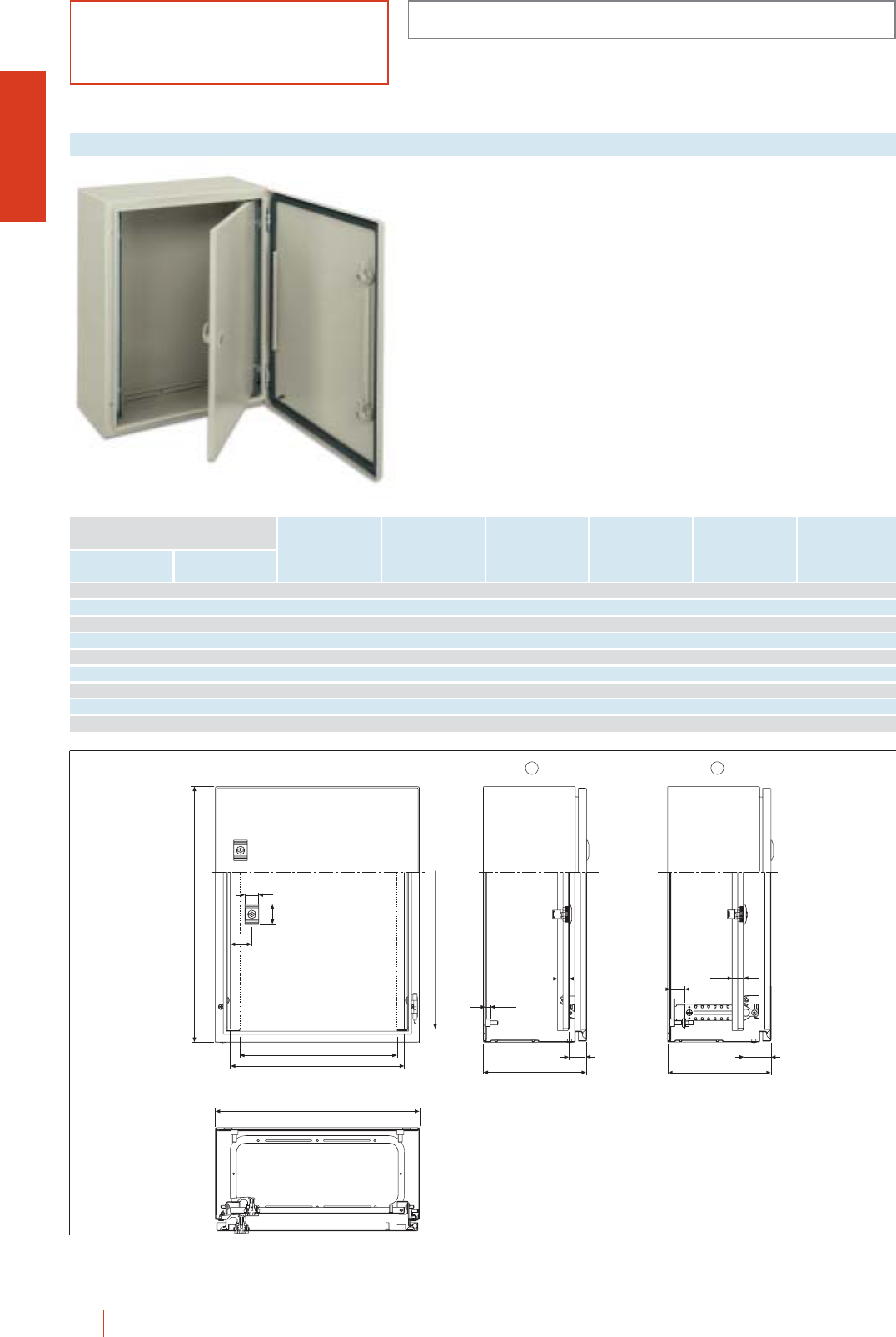
ACCESSORIES AND COMPLEMENTS
CRN
1/36 HIMEL CRN wall mounting steel enclosures
Internal door set for
fixing to the front of the
enclosure. The internal
door can also be
adjusted in depth
through SDCR supports.
Enables positioning of
the mounting plate by
making it depth
adjustable.
Made of sheet steel
protected with polyester
epoxy grey paint to
RAL-7032.
Vertical reinforcing
profiles are included on
up to 800 mm high
doors.
Internal doors
G
E
D
HI
23 23
min = 30
10
C
C
A
B
40
27
32
12
Reference
To fit to enclosures
Height
(A)
Width
(B)
400 300 PIN 43 349 241 208 32 51
500 400 PIN 54 449 341 308 32 51
600 400 PIN 64 549 341 308 32 51
700 500 PIN 75 649 441 408 32 51
800 600 PIN 86 749 541 508 32 51
1000 600 PIN 106 949 541 508 32 51
1000 800 PIN 108 949 741 708 32 51
1200 800 PIN 128 1149 741 708 32 52
For glazed door enclosures, H is 4 mm less.
D E G H I
min.
CRN 54/200 + PIN 54
cDirected fixing of PIN internal door to the front of the enclosure.
dFixing of PIN internal door through SDCR depth adjustable supports.
In this case, both the door and a mounting plate can be adjusted.
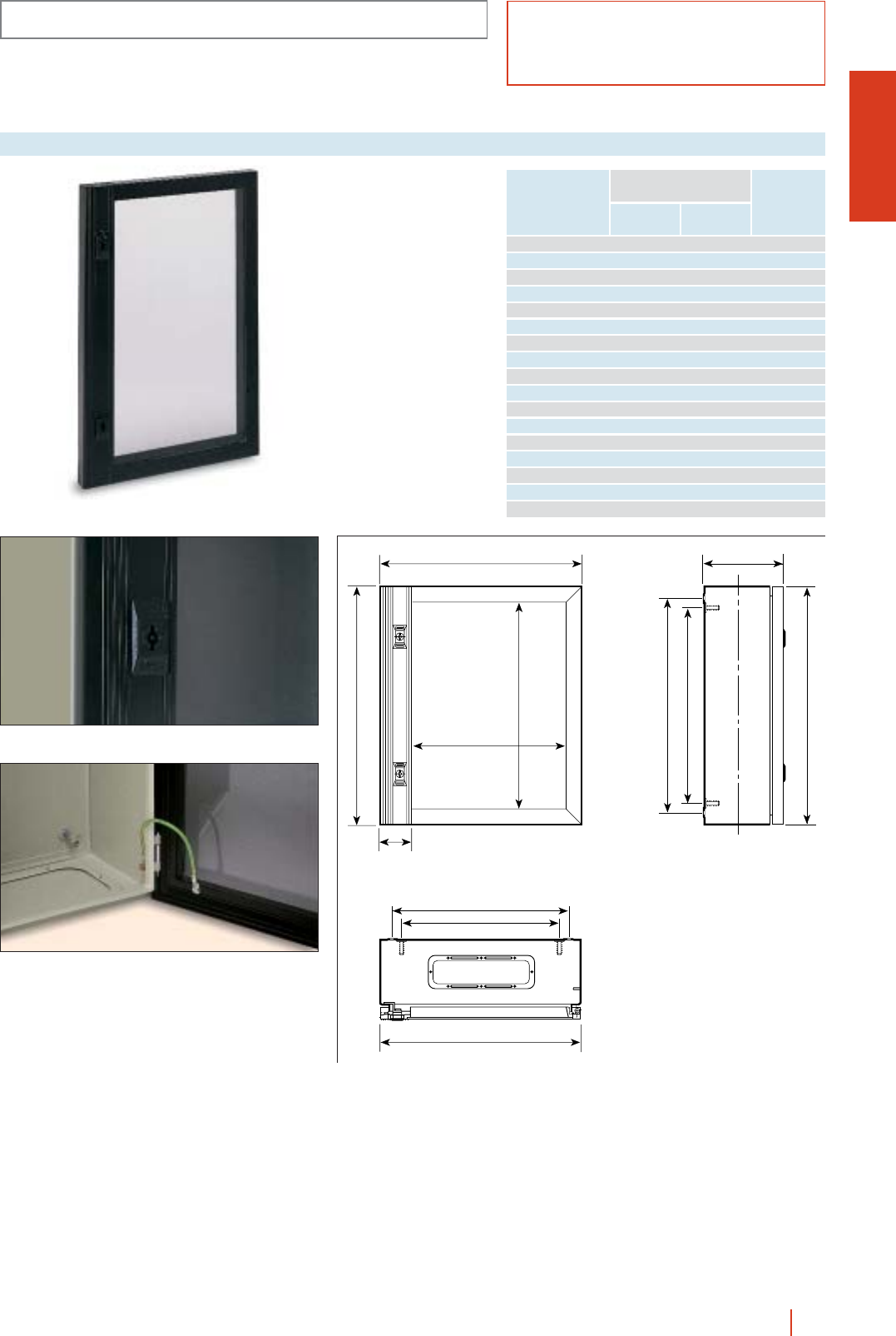
CRN
ACCESSORIES AND COMPLEMENTS
1/37CRN wall mounting steel enclosures HIMEL
Aluminium glazed door
Reference
PACRN-3025 300 250 0.8
PACRN-33 300 300 1
PACRN-43 400 300 1.2
PACRN-44 400 400 1.6
PACRN-46 400 600 2.3
PACRN-54 500 400 2
PACRN-55 500 500 2.4
PACRN-64 600 400 2.3
PACRN-65 600 500 2.8
PACRN-66 600 600 3.2
PACRN-75 700 500 3.1
PACRN-86 800 600 4.1
PACRN-88 800 800 5.4
PACRN-106 1000 600 5
PACRN-108 1000 800 6.3
PACRN-1010 1000 1000 7.6
PACRN-128 1200 800 7.4
To be fitted to enclosures
Height
(A)
Width
(B)
Weight
kg
Polycarbonate
transparent doors with
anodized aluminium
frame of great resistance
and lightness. Black
paint to RAL-9005.
cMaximum viewing
area.
cExcellent finish.
c120º opening.
cIP40.
B_50
B_75
B_5
* C +17
A_50
A_75
A_5
B
A
B_102
A_70
65
* C measurement as per general table on
page 1/11.
Detail of standard double bar lock fitted right on the profile
for an excellent finish.
Detail of earthing between body and door frame.
PACRN-75
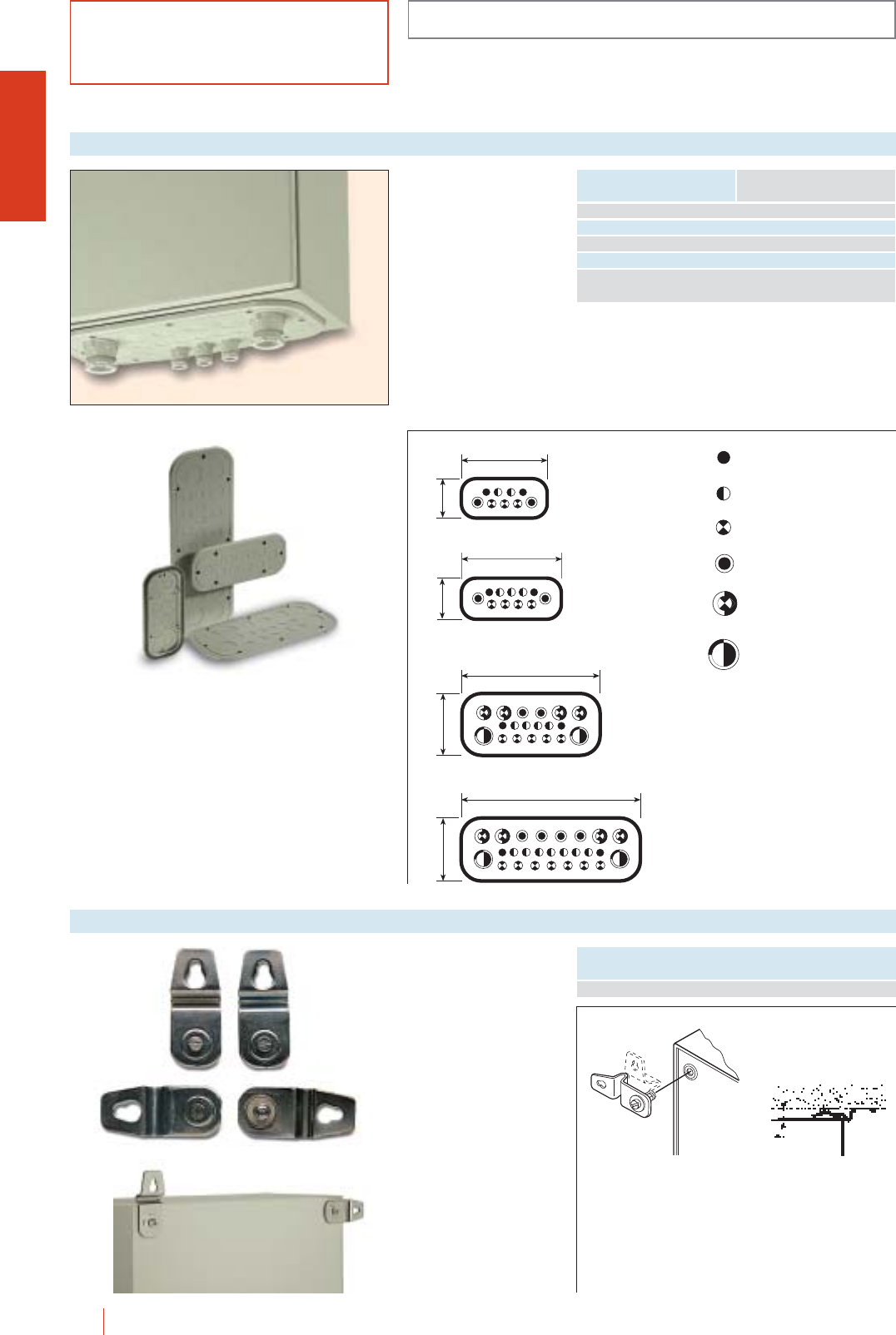
ACCESSORIES AND COMPLEMENTS
CRN
1/38 HIMEL CRN wall mounting steel enclosures
Made of ABS
autoexinguible with fibre
glass (30% contents).
Colour RAL-7035.
cWith pre-punched Pg
holes.
cPolyurethane foam
gasket.
cExcellent resistance to
heat.
Insulated cable gland plates
Reference Flange openings*
223
105
105
259
163
460
360
163
2 Pg 11
2 Pg 13.5
3 Pg 16
1 Pg 21 / 11
Pg 11 (18.6 mm)
Pg 13.5 (20.4 mm)
Pg 16 (22.5 mm)
Pg 21 / 11 (28.3 / 18.6 mm)
Pg 29 / 16 (37 / 22.5 mm)
Pg 36 / 29 (47 / 37 mm)
2 Pg 11
2 Pg 13.5
4 Pg 16
2 Pg 21 / 11
2 Pg 11
4 Pg 13.5
6 Pg 16
3 Pg 21 / 11
4 Pg 29 / 16
2 Pg 36 / 29
2 Pg 11
3 Pg 13.5
9 Pg 16
6 Pg 21 / 11
4 Pg 29 / 16
2 Pg 36 / 29
TSA-CRN/A A
TSA-CRN/B B
TSA-CRN/C C, E**
TSA-CRN/D D
* See drawings of flange openings on page 1/12.
** For flange openings type E, two TSA-CRN/C are required.
Passivated zinc-coated
steel PFCR. They are
fixed from the outside
and can be placed
horizontally or vertically.
Not included in the
standard supply.
Wall fixing brackets
Reference
PFCR
PFCR
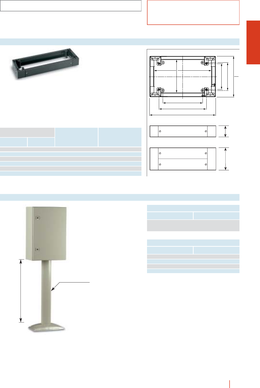
CRN
ACCESSORIES AND COMPLEMENTS
1/39CRN wall mounting steel enclosures HIMEL
B - 164
B - 2
C - 145
C - 164
C - 34
B - 228
B - 62
C - 106
100
200
To fit directly to the
enclosures using the
drillings for ground
fixing.
c100 and 200 mm high.
cFront and rear access.
cPolyester epoxy resin
paint to RAL-7022.
Single plinths
Plinth height = 100 mm
Reference
Enclosure dimensions
Width
(B)
Depth
(C)
Plinth height = 200 mm
Reference
600 300 ZUN 63/100 ZUN 63/200
600 400 ZUN 64/100 ZUN 64/200
800 300 ZUN 83/100 ZUN 83/200
800 400 ZUN 84/100 ZUN 84/200
1000 300 ZUN 103/100 ZUN 103/200
1200 300 ZUN 123/100 ZUN 123/200
Directly fitted to the
flange openings by
means of CHCO
coupling plates.
Made of extruded
aluminium and painted
with polyester epoxi
resin to light gray
RAL-7032 texturized.
Supporting pole
Reference To be fitted to flange opening*
CHCO/A A
CHCO/B B
CHCO/C C-E*
CHCO/D D
* 2 coupling plates and 2 supporting poles are required.
Reference Description
Suitable for all
COCN-80 models except
CRN-2520/150
800 mm
U10265 mm
SUPPORTING POLE
COUPLING PLATES
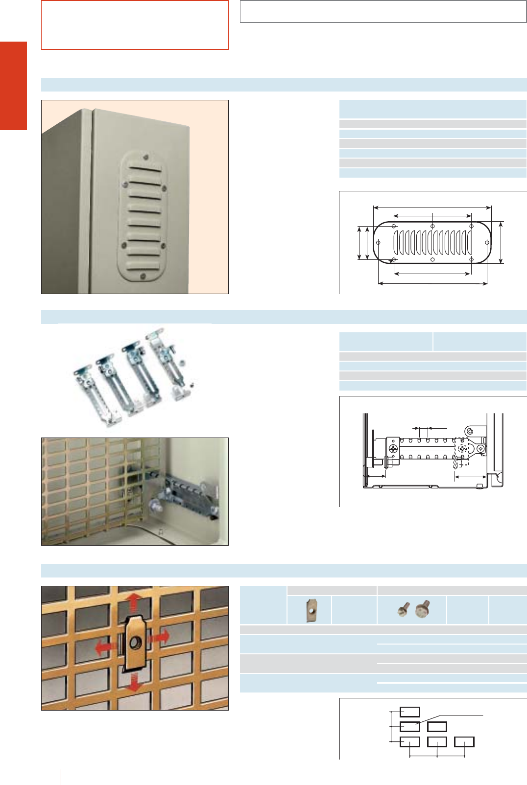
ACCESSORIES AND COMPLEMENTS
CRN
1/40 HIMEL CRN wall mounting steel enclosures
A
FF
D
E
B
==
Ø 5.3
C
To be fitted on any
surface of the enclosure
for internal ventilation.
Colour RAL-7032
texturized.
Louvre plates
Ref. A B C D E F
TR-1 144 62 36 110 - -
TR-2 208 90 72 94 190 -
TR-3 244 90 72 130 226 -
TR-4 345 118 100 231 237 115.5
TR-5 345 148 130 231 327 115.5
TR-6 445 148 130 297 427 148.5
For 200, 250, 300 and
400 mm depth
enclosures. The different
positions allow the
adjusting of mounting
plates and accessories
every 12.5 mm.
Depth adjustable supports
12.5
30 44
1126 mm
30 30
1515
Fixing accessories for universal plates
Reference To be fitted in enclosures
depth (mm)
SDCR 200 200
SDCR 250 250
SDCR 300 300
SDCR 400 400
Lenght
(mm)
Fixing nut Fixing screw and washer
Metric
sice Pack
qty.
Pack
qty.
M3 TFP 3 100 ---
M4 TFP 4 100 TOR 10/4 A 10 100
TOR 16/4 A 16 100
M5 TFP 5 100 TOR 12/5 A 12 100
TOR 18/5 A 18 100
M6 TFP 6 100 TOR 12/6 A 12 100
TOR 18/6 A 18 100
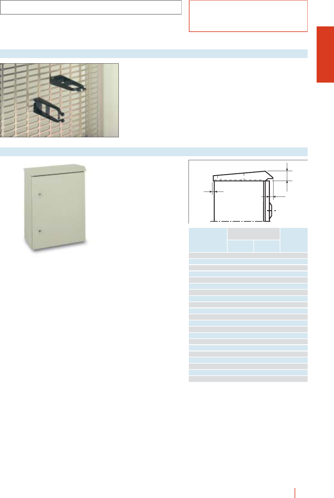
CRN
ACCESSORIES AND COMPLEMENTS
1/41CRN wall mounting steel enclosures HIMEL
Snap-on clamps
designed to be installed
directly on 19” racks,
and MR mounting
plates.
Ref.: GCR.
Clamps GCR
Metal canopies
protectec externally and
internally with polyester-
epoxy resin to light grey
RAL-7032 texturized.
Canopies
Reference
TJ-2015 200 150 36
TJ-2515 250 150 36
TJ-2520 250 200 36
TJ-3015 300 150 36
TJ-3020 300 200 36
TJ-4015 400 150 36
TJ-4020 400 200 36
TJ-4025 400 250 42
TJ-5015 500 150 36
TJ-5020 500 200 36
TJ-5025 500 250 42
TJ-6020 600 200 36
TJ-6025 600 250 42
TJ-6030 600 300 42
TJ-6040 600 400 42
TJ-8020 800 200 36
TJ-8025 800 250 42
TJ-8030 800 300 42
TJ-8040 800 400 42
TJ-10030 1000 300 42
TJ-10040 1000 400 42
To be fitted
to enclosures
Width
(B)
Depth
(C)
F
3
12
F
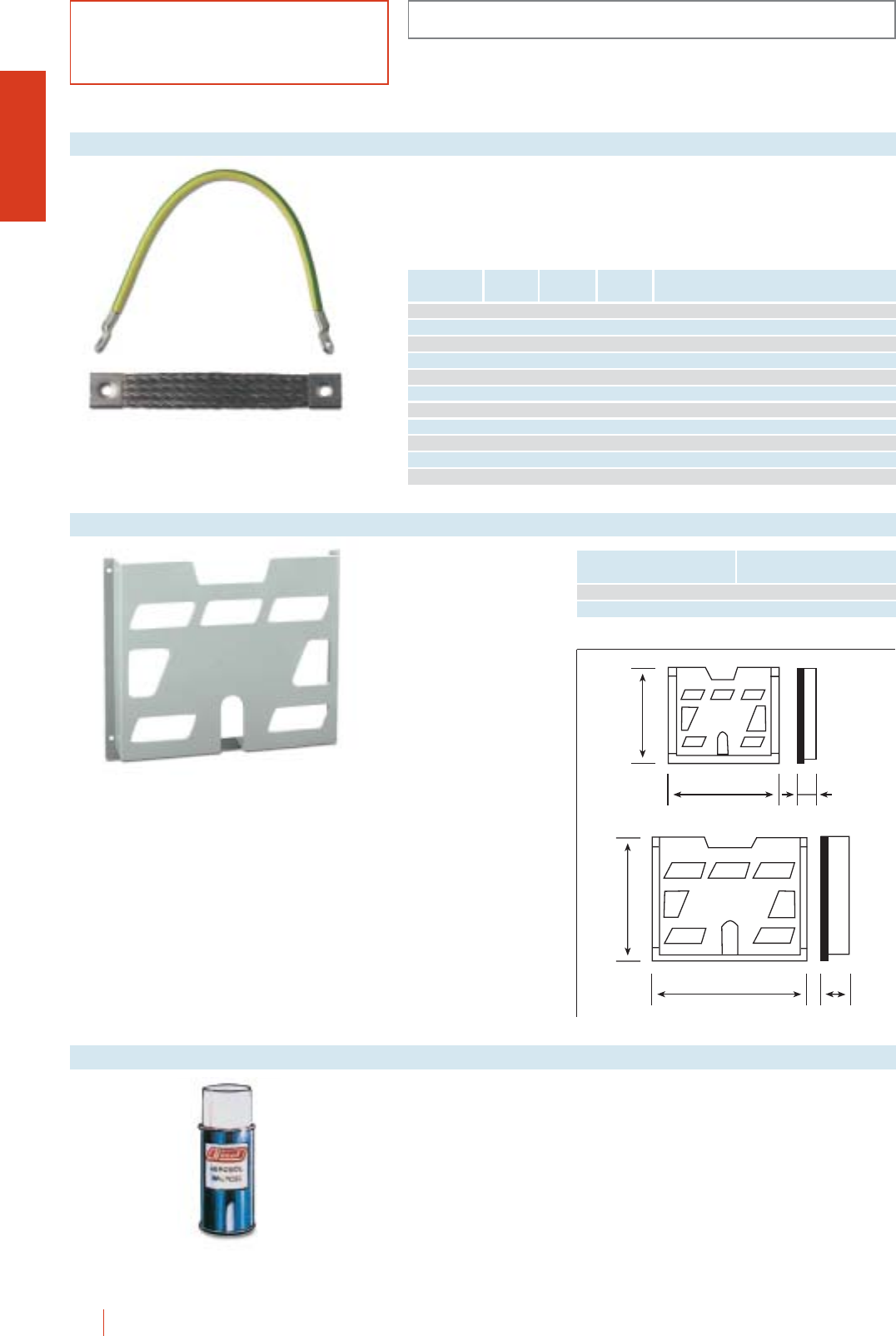
ACCESSORIES AND COMPLEMENTS
CRN
1/42 HIMEL CRN wall mounting steel enclosures
Earthing braids
PP-A models made of
PVC to grey RAL-7035.
cAdhesive fixing or by
means of screws.
For DIN A4 or A5 sized
documents.
Diagram pockets
174
188 22
278 40
234
Width
mm
Cross section
mm2
Reference Lenght
mm Material
CTI 17/6 170 6 Copper/brass
CTI 17/10 170 10 Copper/brass
CTI 22/6 220 6 Copper/brass
CTI 22/10 220 10 Copper/brass
CTI 22/25 220 25 Copper/brass
CTI 41/10 410 10 Copper/brass
CTI 41/25 410 25 Copper/brass
CTAF 15/16 155 20 16 Tinned copper
CTAF 20/25 200 21 25 Tinned copper
CTAF 25/25 200 26 25 Tinned copper
CTAF 20/25 200 40 50 Tinned copper
Size Reference
A4 PP-A4
A5 PP-A5
Touch-up paint. Air
drying. RAL-7032 colour.
150 g.
Ref.: BPA-7032.
RAL-7032 aerosol
Ref.: PP-A5
Ref.: PP-A4
Normally used for the earthing between enclosure door and body and between
enclosure body and mounting plate. They include the screws necessary for their
use. Ref. CTAF..., Earthing braids provide an earthing connection suitable for
high frequencies since they prevent disturbing unwanted electrical currents that
occur at these frequencies.
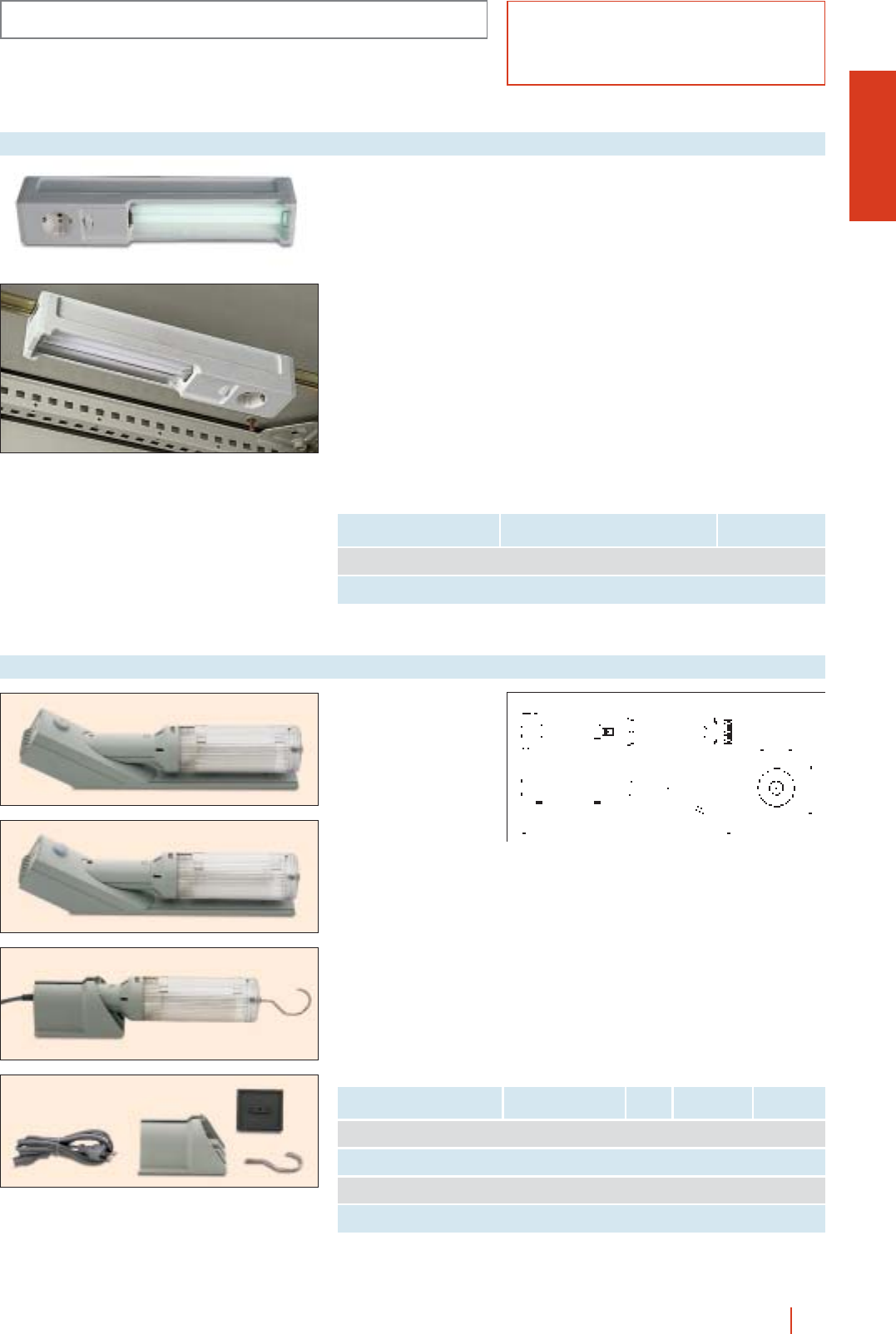
CRN
ACCESSORIES AND COMPLEMENTS
1/43CRN wall mounting steel enclosures HIMEL
Compact neon lamps,
specially designed for
their use in enclosures.
Possibility to fix them
with magnet.
cElectronic low
consumption lamp
220 V/50 Hz or
120 V/60 Hz.
cConsumption 11 W.
cPower on/off switch.
cWith switch and
220 V/16 A or
120 V/15 A earthed
socket.
cMax. ambient
temperature 60 oC.
cLighting performance
+ 75 W bulb.
Enclosure lighting
Characteristics Reference Switch Voltage
Lamp with magnet or 35 mm LAM-75 220 V/16 A 220 V/50 Hz
symmetrical DIN rail fixing LAM-75/120 120 V/15 A 120 V/60 Hz
Lamp with 35 mm LAC-75 220 V/16 A 220 V/50 Hz
symmetrical DIN rail fixing LAC-75/120 120 V/15 A 120 V/60 Hz
Lighting specially designed
for use in electrical
enclosures with various
types of fixing and
switching.
cElectronic low
consumption lamp E27,
20 W, 220-240 V/50-60 Hz
or 120 V/60 Hz.
cOutput equivalent to
a 100 W.
cConnection through
terminal block on fixed
models or cord on portable
models.
cIP20 rating.
cType II insulation.
cAccording to standards
EN55014 and EN50082-1.
Enclosure lighting
1
2
3
4
Description Fixing Fig. Reference Voltage
Proximity switch Magnetic, screws LAMDP 220 V/50 Hz
operated and or DIN 35 rail (1) 1LAMDP 120 120 V/60 Hz
ON/OFF switch with Magnetic, screws LAMIN 220 V/50 Hz
optional door switch and or DIN 35 rail(1) 2LAMIN 120 120 V/60 Hz
Portable lamp, Adhesive or LAMPO 220 V/50 Hz
cord connection screws 3LAMPO 120 120 V/60 Hz
Lamp support for LAMDP, Adhesive or screws
LAMIN,LAMPO (1) DIN rail not included 4SOLAM
(1) DIN rail not supplied as standard.
396
67
100
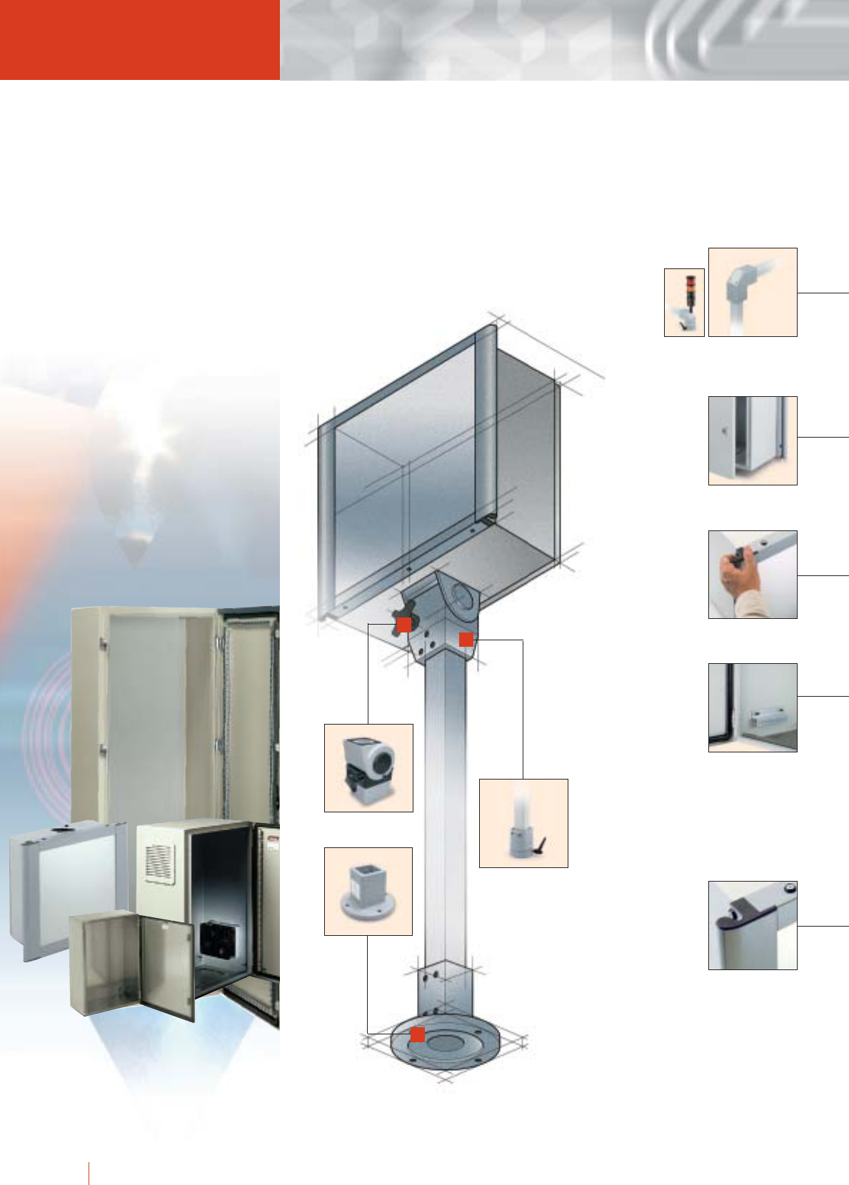
1/44 HIMEL control boxes system CM
Rear door
enabling access
to the inside of
the control box.
Double bar lock.
Ergonomic frame
trim for the
manipulation of
the box.
Plastic trim cover
to protect the
aluminium section.
Set of profiles to
fit elements
inside.
CM control bo
to fit human-machine
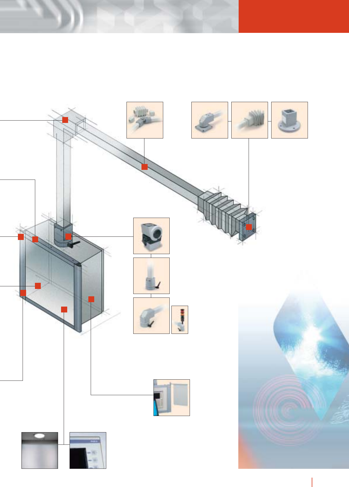
1/45control boxes system CM HIMEL
Reinforcement
designed to avoid
deformation of the
box when
suspended.
Aluminium front plate,
for fitting the dialogue
elements.
Easy to fit
accessories on
the aluminium
profile with bolts.
xes designed
dialogue elements
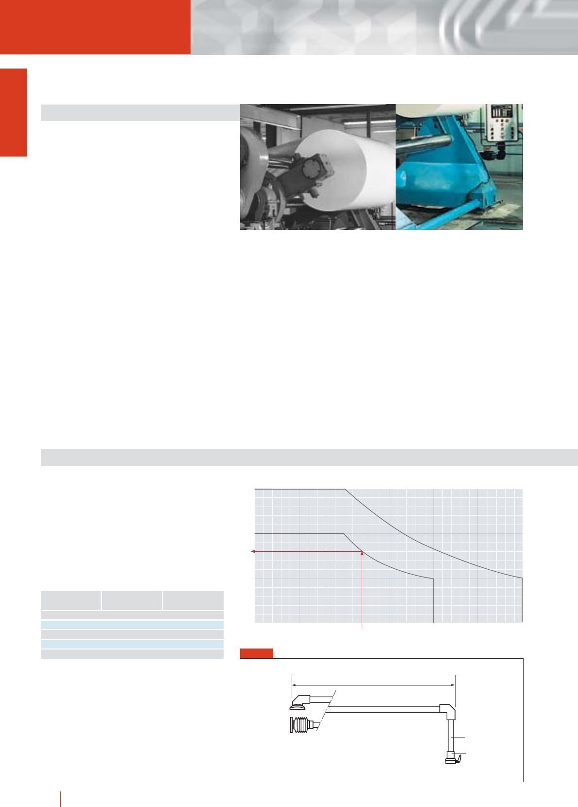
1/46 HIMEL control boxes system CM
GENERAL DESCRIPTION
WIDE RANGE
Seven sizes of control boxes plus one box for the
keyboard.
CONTROL BOX BASED ON THE
STANDARD BOX
The new control box is based on our CRN box.
REAR DOOR
The rear door opening 120° allows an easy access
to the inside of the box.
INTERIOR PROFILES
Two profiles can be fitted inside, using the bolts
welded to the sides.
TRIM FRAME
The ergonomic design of the trim frame makes it
very easy to handle.
The trim frame is ready for fitting accessories either
when installing or later.
It is not necessary to foresee them from the
beginning.
ACCESSORIES
A wide range of easy to fit accessories, lamp,
diagram support, keyboard holder tray and PC tray.
RESISTANCE TABLES
SUSPENSION SYSTEM WITHOUT
INTERMEDIATE ARTICULATED COUPLING
cThe load (a + b + control box + elements installed)
must be below the maximum load.
cEx.: If a 50 mm cross section suspension system
is used, without an articulated intermediate
coupling, wiht a lever arm of 1200 mm, the
maximum load it will support is 80 kg.
150
100
50
1 (mm) 1000 2000 3000
1200
80
Cross Section 80
Cross Section 50
Maximum
load
kg
(L)
L
a
b
FIG. 1
500 100 150
1000 100 150
1500 60 110
2000 50 80
2500 - 60
Cross section 50
Maximum load kg
Length mm Cross section 80
Maximum load kg
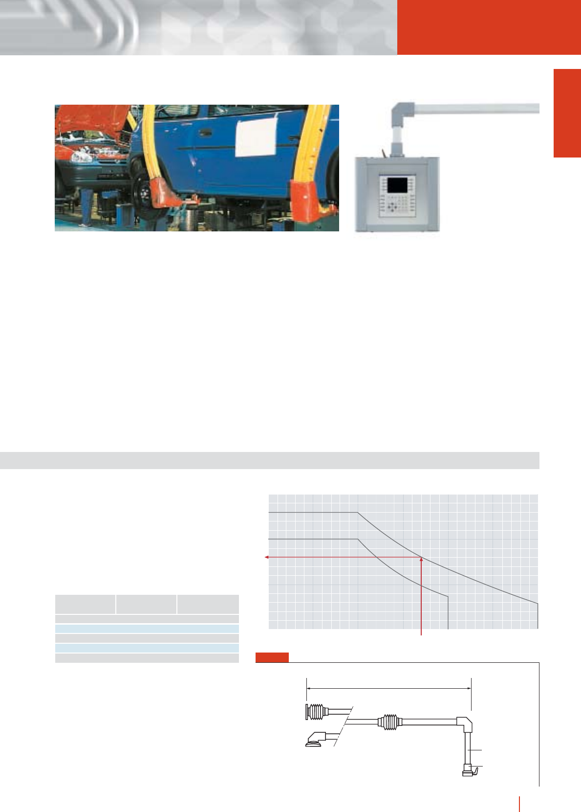
1/47control boxes system CM HIMEL
FIG. 1
SUSPENSION SYSTEM WITH AN INTERMEDIATE
ARTICULATED COUPLING
cThe load (a + b + control box + elements installed)
must be below the maximum load.
cEx.: If a 80 mm cross section suspension system
is used, with an intermediate articulated coupling,
with a lever arm of 1700 mm, the maximum load
it will support is 80 kg.
150
100
50
1 (mm) 1000 2000 3000
1700
80
kg
(L)
Maximum
load
Cross Section 80
Cross Section 50
500 100 130
1000 100 130
1500 55 90
2000 35 60
2500 - 40
Cross section 50
Maximum load kg
Length mm Cross section 80
Maximum load kg
L
a
b
SUSPENSION SYSTEM
A wide range of accessories to assemble the
suspension system, available in two sizes, covering
a large number of applications.
DESIGN
The neutral design of the control boxes allows
them to be used in a large number of applications.
ADAPTABILITY
The boxes can be painted in other colours on
request. The aluminium front plate can be
machined to facilitate the fitting of dialogue
elements.
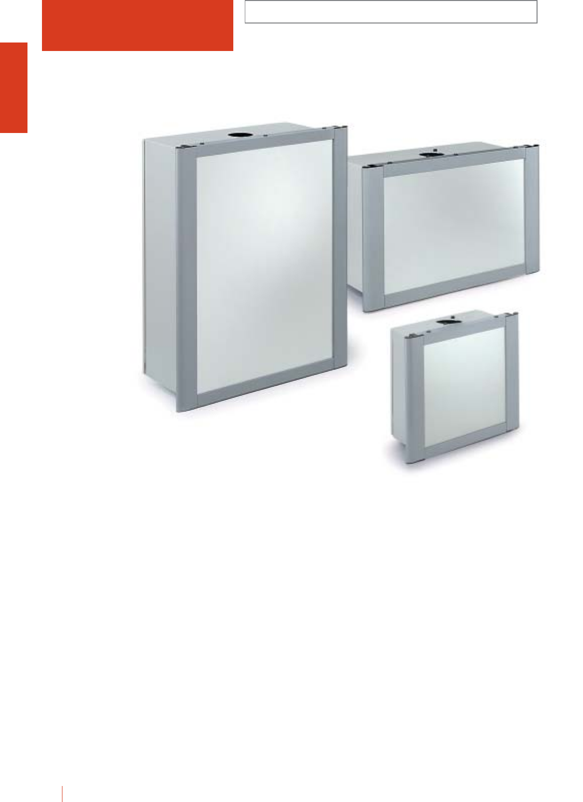
CM CONTROL BOXES
IP66 (EN 60529)
1/48 HIMEL control boxes system CM
Control box system designed to fit man-machine
dialogue elements, reinforced at the top and drilled to
fit articulations.
Boxes 600 mm wide are prepared for fitting a
keyboard.
cAnodised aluminium front plate for fitting man-machine
dialogue elements.
cErgonomic extruded aluminium trim frame to facilitate the
manipulation of the box.
c4 bolts M515 welded on each side of the box to enable
the fitting of profiles for the assembly of elements.
cRear door opening 120°.
cIP55.
cBox painted in epoxy polyester resin colour RAL-7035 fine
texture. Trim frame for securing the front panel in plain
RAL-7040 colour.
cFor lock changes see CRN catalogue.
Basic composition:
cSteel box.
cSteel reinforcement.
cAluminium trim.
cAluminium front plate.
c2 profiles to fit the interior elements.
cDouble bar lock.
CM 8060/300
CM 6080/300
CM 4040/200
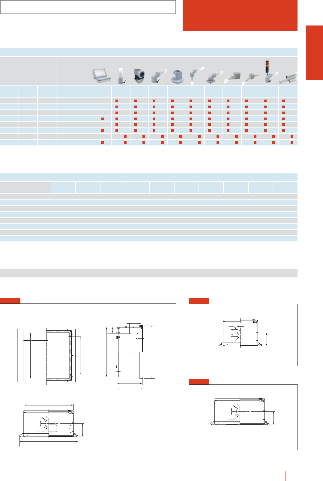
CM
CONTROL BOXES
IP66 (EN 60529)
1/49control boxes system CM HIMEL
REFERENCES AND DETAILS OF BOXES
ABCDFGHJFig.Weight kg
Reference
HHHCM3030/200 300 300 180 162 260 260 100 45 2 8.6
HHHCM3040/200 300 400 180 162 360 260 100 45 2 9.5
HHHCM4040/200 400 400 180 262 360 360 100 45 2 11.4
HHHCM4060/250 400 600 250 262 560 360 125 100 1 17.9
HHHCM5050/250 500 500 250 362 560 460 125 100 2 20.2
HHHCM6060/200 600 600 200 462 560 560 150 100 1 26.5
HHHCM6080/300 600 800 280 462 760 560 150 100 3 34.9
HHHCM8060/300 800 600 280 662 560 760 150 100 1 33.6
G
F
D
H
58
Ø7
Ø54
58
H
87
Ø9
Ø87
87
u50
u80 + keyboard u80
FIG. 1
Dimensions (mm)
FIG. 2
FIG. 3
C
J
A
75
102.5
A + 36
C + 15
H
87
Ø9
Ø87
87
B
B + 97
BOXES DIMENSIONS
Height Width Depth Reference
Dimensions in mm
300 300 200 HHHCM3030/200
300 400 200 HHHCM3040/200
400 400 200 HHHCM4040/200
400 600 250 HHHCM4060/250
500 500 250 HHHCM5050/250
600 600 200 HHHCM6060/200
600 800 300 HHHCM6080/300
800 600 300 HHHCM8060/300
50 80 50 80 50 80 50 80 50 80 50 80 50 80 50 80 50 80 50 80
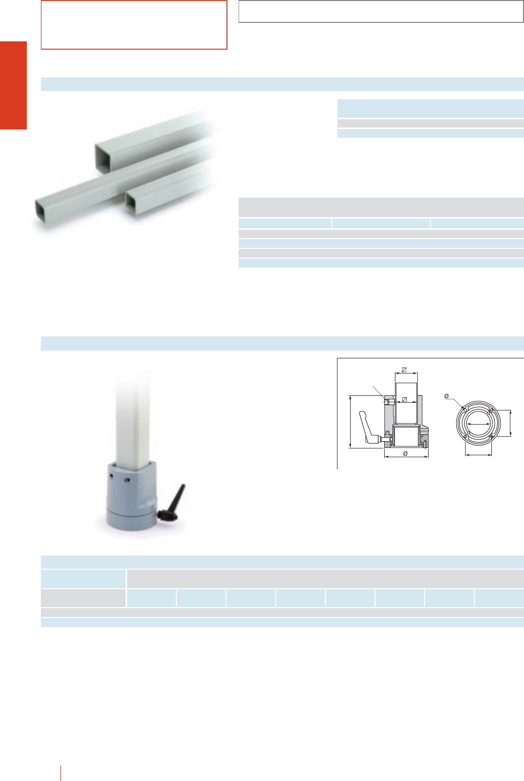
Reference
ACCESSORIES AND COMPLEMENTS
CM
1/50 HIMEL control boxes system CM
cTo join the box to a
tube vertically.
cBox suspended.
cTurning angle limited
mechanically to about
310º.
cMaterial: Aluminium.
cColour: RAL-7040.
Straight coupling
C
D
A
B
2ⴛM12
DIN916
M
F
F
E
REFERENCES AND DETAILS
A B C D E F M Weight kg
Dimensions in mm
HHHCM/UCR50 50 42 115 96 52.3 58 M6 1.25
HHHCM/UCR80 80 72 145 139 85 87 M8 3.10
cFor the assembly of
suspension systems.
cClosed profile to
increase the rigidity of
the system.
cMaterial: Iron.
cColour: RAL-7035.
Tubes
Weight
50×50 6.5 kg/m
80×80 10.5 kg/m
Cross section 50
Reference
Cross section 80 Lenght in m
HHHCM T5005 HHHCM T8005 0.50
HHHCM T5010 HHHCM T8010 1.00
HHHCM T5015 HHHCM T8015 1.50
HHHCM T5020 HHHCM T8020 2.00
IP54 (EN 60529)
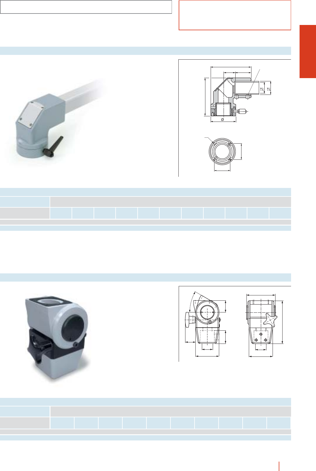
CM
ACCESSORIES AND COMPLEMENTS
1/51control boxes system CM HIMEL
cTo fix the box to a
tube horizontally.
cBox suspended.
cTurning angle limited
mechanically to about
310º.
cMaterial: Aluminium.
cColour: RAL-7040.
cColour of inspection
cover: RAL-7035.
“L” coupling for box
REFERENCES AND DETAILS
A B C D E F G H I M Weight kg
Reference
Dimensions in mm
HHHCM/UCC50 154 46 60 147 96 42 50 42 58 M6 2.00
HHHCM/UCC80 208.5 56 83 190 139 72 80 70 87 M8 6.55
B
A
C
D
E
G
F
4ⴛM12
DIN916
M
H
I
cTo join the box to a
tube vertically.
cBox suspended or
supported.
cRotation angle 30º.
cMaterial: Cast iron.
cColour: RAL-7040.
Rotating coupling
REFERENCES AND DETAILS
A B C D d E F G H Weight kg
Reference
Dimensions in mm
HHHCM/UCP50 50 55 100 44 50 121 182 50 100 2.98
HHHCM/UCP80 50 55 100 44 80 121 182 50 100 3.10
E
F
G
H
D
d
C
BA
0 - 30º
IP54 (EN 60529)
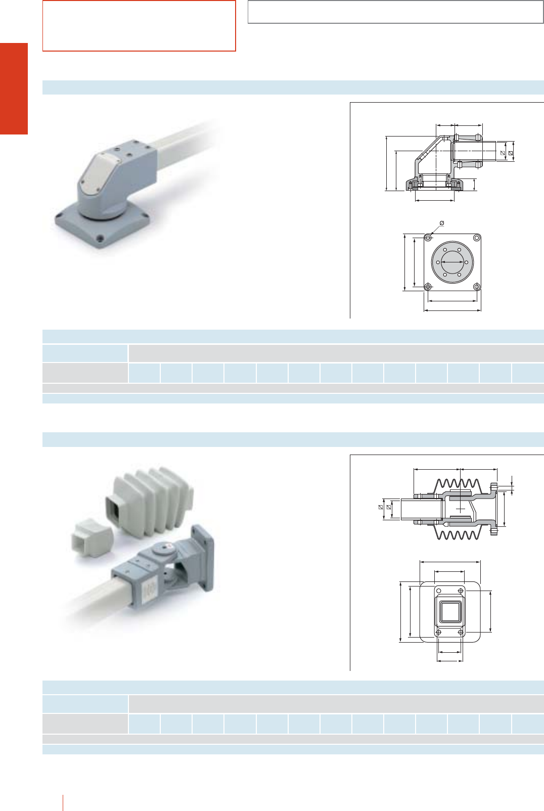
ACCESSORIES AND COMPLEMENTS
CM
1/52 HIMEL control boxes system CM
cTo fix the suspension
system to a horizontal
surface.
cTurning angle limited
mechanically to about
295º.
cMaterial: Cast iron.
cColour: RAL-7040.
cColour of the
inspection cover:
RAL-7035.
Fixing of suspension system to a horizontal surface
REFERENCES AND DETAILS
A B C D E F G H I J K L Weight kg
Reference
Dimensions in mm
HHHCM/UMC50 68 50 50 42 30 96 96 134 140 120 9 55 5.40
HHHCM/UMC80 98 74 80 72 45 144 141.5 195.5 210 180 13 84 15.70
F
G
H
BA
E
D
C
J
I
J
I
K
L
cFor the articulated
fixing of the
suspension system to
a vertical surface.
cArticulation protected
by a rubber bellows.
cApproximate
maximum opening
angle 170º.
cMaterial: Cast iron.
cColour: RAL-7040.
cColour of bellows:
RAL-7035.
Articulated fixing of suspension system to a vertical surface
REFERENCES AND DETAILS
A B C D E F G H I J K L Weight kg
Reference
Dimensions in mm
HHHCM/UMA50 118 92 50 42 85 11 148 80 130 55 68 105 4.35
HHHCM/UMA80 160 115 80 72 130 11 190 115 175 90 103 150 9.45
AB
C
D
E
F
G
G
J
H
I
L
K
IP54 (EN 60529)
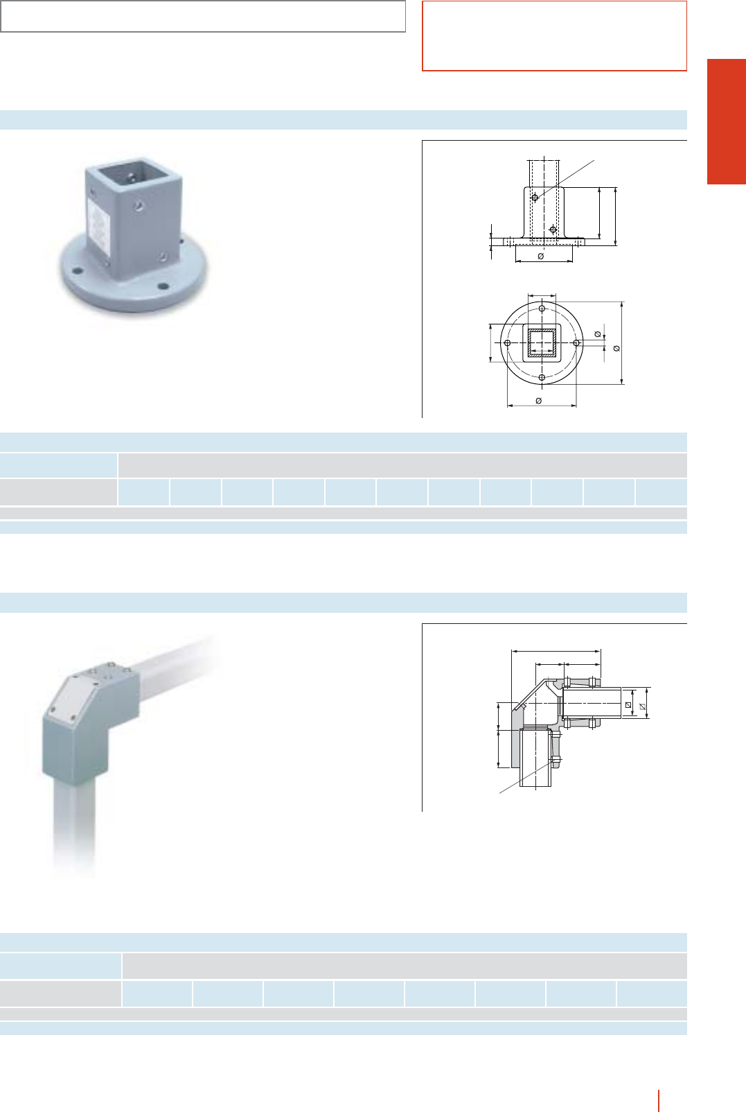
CM
ACCESSORIES AND COMPLEMENTS
1/53control boxes system CM HIMEL
cTo fix the suspension
system to a vertical or
horizontal surface.
cMaterial: Cast iron.
cColour: RAL-7040.
Pedestal
l
L
S
C
8ⴛM12
DIN916
D
a
b
F
d
h
REFERENCES AND DETAILS
a b c d D F h I L S Weight kg
Reference
Dimensions in mm
HHHCM/UMR50 50 42 105 11 125 152 72 97 110 15 3.25
HHHCM/UMR80 80 72 134 11 173 201 111 126 140 16 7.00
cTo join two tubes
at 90º.
cMaterial: Aluminium.
cColour: RAL-7040.
cColour of inspection
cover: RAL-7035.
“L” coupling for tube
BC
A
DE
F
G
12ⴛM12
DIN916
REFERENCES AND DETAILS
A B C D E F G Weight kgReference
Dimensions in mm
HHHCM/UTC50 144 46 60 60 46 42 50 1.35
HHHCM/UTC80 193 56 83 83 56 70 80 2.40
IP54 (EN 60529)
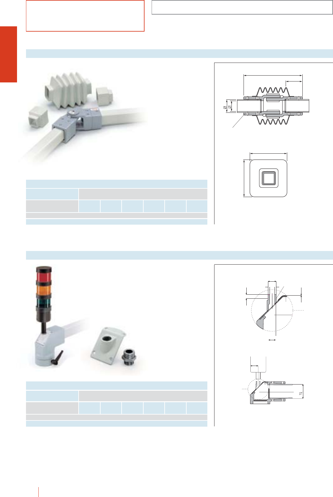
ACCESSORIES AND COMPLEMENTS
CM
1/54 HIMEL control boxes system CM
cFor an articulated
horizontal coupling
between tubes.
cArticulation protected
by a rubber bellows.
cApproximate
maximum opening
angle 170º.
cMaterial: Cast iron.
cColour: RAL-7040.
cColour of bellows:
RAL-7035.
Intermediate articulated coupling
REFERENCES AND DETAILS
A B C D E Weight kg
Reference
Dimensions in mm
HHHCM/UIA50 50 42 236 67 148 4.25
HHHCM/UIA80 80 72 320 94 190 10.00
D
C
B
A
12ⴛM12 DIN916
E
E
cFor fitting the
signalling column.
cMaterial: Aluminium.
cColour: RAL-7035.
Control lamp adaptor
REFERENCES AND DETAILS
A B C D E Weight kg
Reference
Dimensions in mm
HHHCM/ACS50 14 11 8.7 31.5 50 0.025
HHHCM/ACS80 14 11 2.5 43 80 0.080
M23ⴛ2
A
C
M20ⴛ1.5
B
SW24
D
E
IP54 (EN 60529)
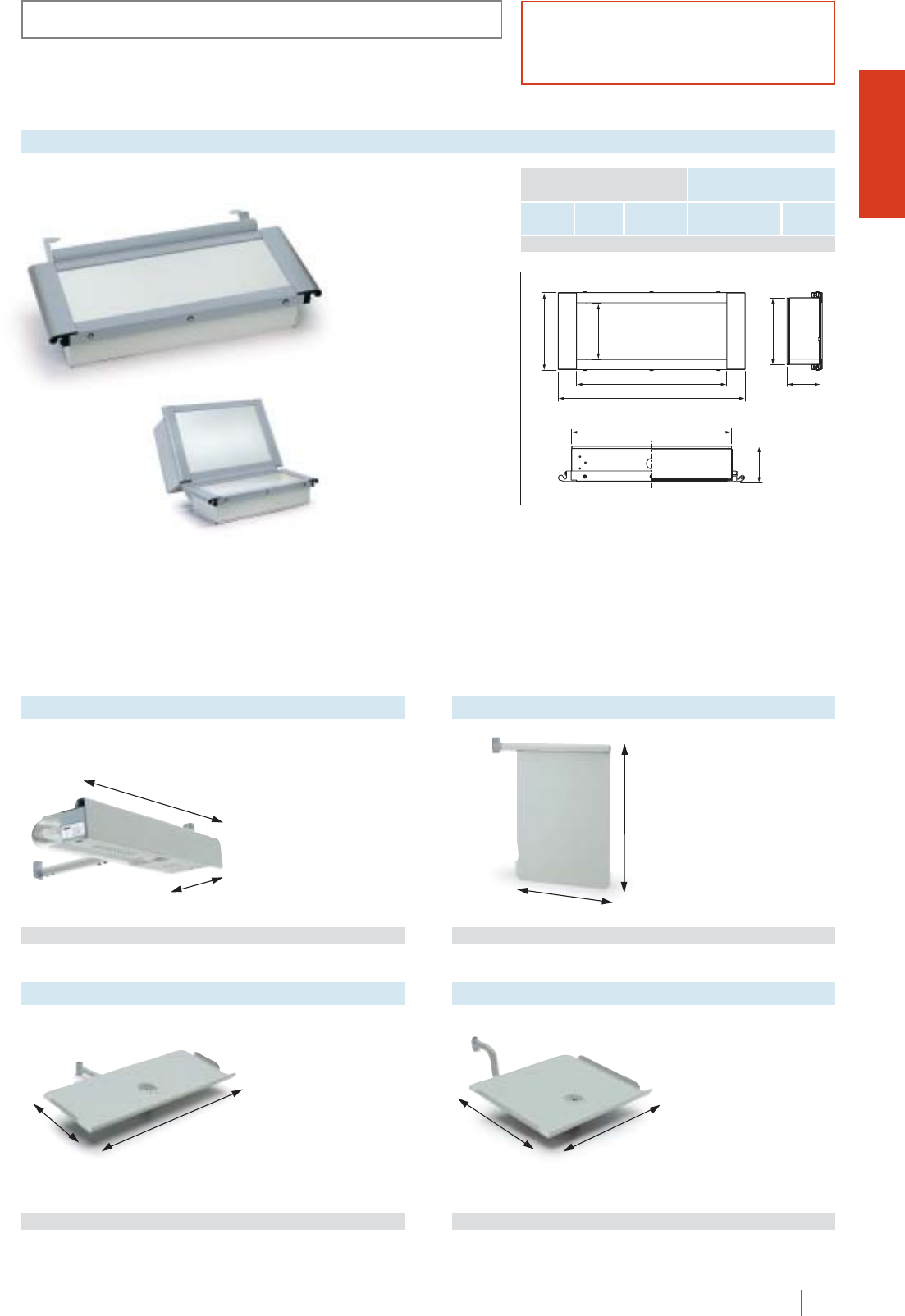
500
200
315
230
CM
ACCESSORIES AND COMPLEMENTS
1/55control boxes system CM HIMEL
cProvides lighting and a
16 A power socket
over the workplace.
cBracket colour to
RAL-7035.
cArticulation colour to
RAL-7040.
Low consumption lamp (11 W)
385
102
Reference HHHCM/LAG 1.5 kg
cHolds diagrams or
other documents
conveniently.
cColour: RAL-7035.
cArticulation colour:
RAL-7040.
Diagram support
Reference HHHCM/SPP 1.15 kg
cTray to hold a PC
keyboard.
cColour: RAL-7035.
cColour of articulations:
RAL-7040.
Keyboard support tray
Reference HHHCM/BPT 2.16 kg
cTray to hold a laptop
computer.
cColour: RAL-7035.
cArticulation colour:
RAL-7040.
Tray to hold a PC
Reference HHHCM/BPC 2.04 kg
350
310
Keyboard prepared for
fitting to the control
boxes, 600 mm wide.
The 120º joint is made
by 2 metal brackets and
aluminium trim.
cAnodised aluminium
front plate to fit the
keyboard.
Side orifice for cables.
cRear cover, screwed
on, totally removable,
to facilitate access to
the inside.
cErgonomic extruded
aluminium trim frame.
cIP55.
cBox painted in epoxy
polyester resin colour
RAL-7035 fine texture.
Trim frame to secure
the plate and
aluminium profile in
plain RAL-7040 colour.
Keyboard for control boxes
Basic composition:
cSteel box.
cAluminium trim.
cAluminium front plate.
c2 brackets to join to the control box.
cTrim profile for the joint between the keyboard and
the control box.
cCable conduit.
560 110
697
286
210
250
125
600
Depth ReferenceHeight
Keyboard
Dimensions in mm
Width Weight kg
250 600 110 HHHCMT 2560/110 8
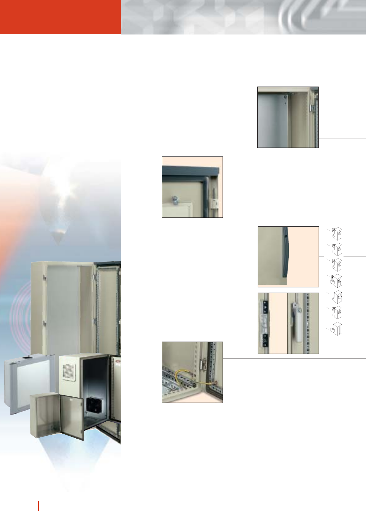
1/56 HIMEL floor standing industrial enclosures CMO
Floor standing indus
A complete range of full
or partial mounting plates
suitable for most types
of installations.
Detail of the tempered glass fixing.
A complete system to earth
the enclosure and
components.
Standard flat lock placed outside
the gasketed area. Handle lock
and various lock combinations
available.
Double door enclosures with an
internal locking system to ensure
the IP degree.

1/57floor standing industrial enclosures CMO HIMEL
trial enclosures CMO
Lifting eyebolts bolted
directly to the cubicle
structure.
Inside view of the 2 mm thick
door with detail of 15 ×20 mm
cross section reinforcement
frame with Ø 5 and 10 mm
drilling every 25 mm.
Detail of front perforated
profile with 25 mm pitch for
fixing of accessories, modular
distribution chassis,
19” racks, etc.
Detail of profiles with 25 mm
pitch for depth adjustment of
equipment.
Door recentering
wedge.
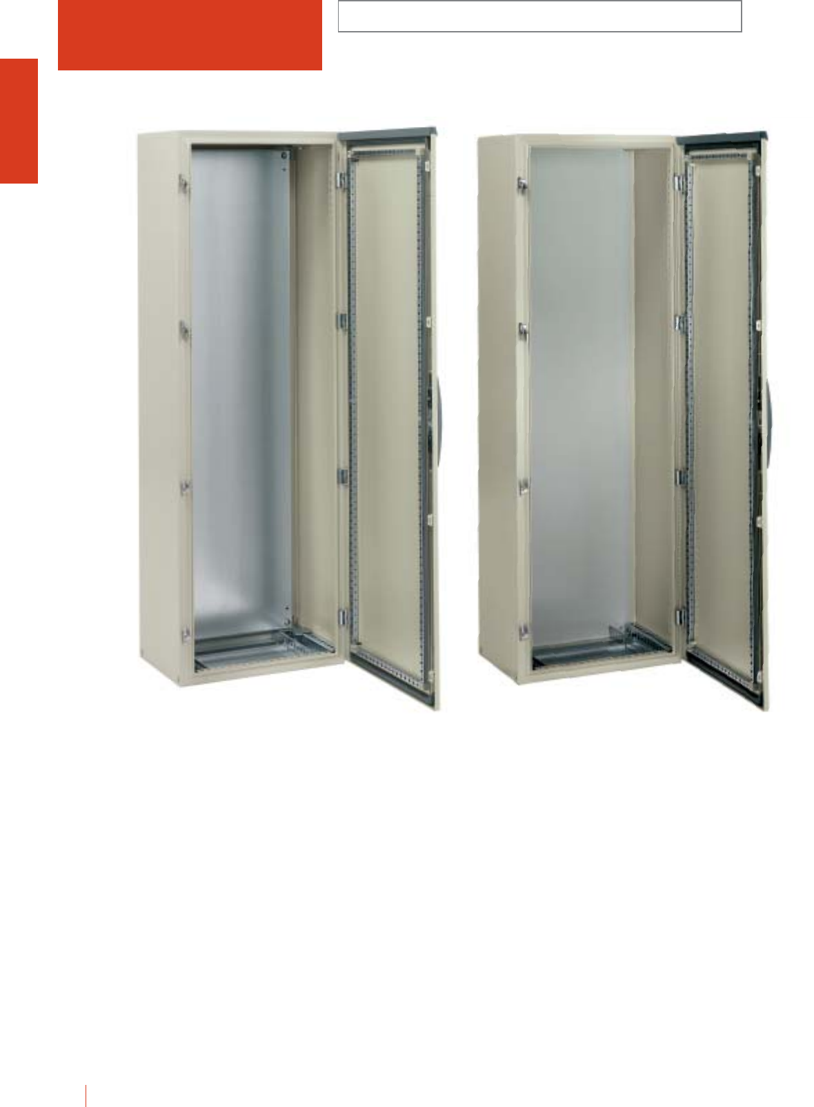
CMO MONOBLOC FLOOR STANDING ENCLOSURES
WITH OR WITHOUT MOUNTING PLATE
IP55 (EN 60529)
1/58 HIMEL floor standing industrial enclosures CMO
Monobloc floor standing enclosure made from a
continuous length of sheet steel triple folded. Front
with perforated profile. Back welded onto a flanged
rear profile for higher protection. Painted internally and
externally with polyester epoxy powder paint to light
grey RAL-7032 and texturized finish.
Easy installation:
■Front frame with u11×13 mm drillings and 25 mm pitch
for fixing of accessories, modular distribution chassis,
19” racks, etc.
■Perforated profiles with 25 mm pitch for depth adjusting
of mounting plate and other accessories.
■Front door, 120º opening to right or left with reinforcing
profile which can be used for mounting of equipment.
Rigidity and watertightness:
■Double folding of front profile and reinforced fixing of the
back.
■Self-centreing of door through specially designed lock
catches.
■Locking system outside gasketed area.
■Internal handle on left door for 2 doors up to 1400 mm
high enclosures.
■4 point locking on heights 1600 to 2000 mm.
■2 point locking on heights 1000 to 1400 mm.
■Foamed polyurethane gasket.
Configuration:
■CMO...PM version includes mounting plate.
■4 mounting plate supports.
■Plain front door with reinforcing frame.
■5 mm double bar locking system.
■2 parts cable gland plate supplied with a gasket.
CMO 186/40 PM CMO 186/40

CMO
MONOBLOC FLOOR STANDING ENCLOSURES
WITH OR WITHOUT MOUNTING PLATE
IP55 (EN 60529)
1/59floor standing industrial enclosures CMO HIMEL
ENCLOSURES, DIMENSIONS AND REFERENCES
No. of
doors
Height
(A)
External dimensions
(mm)
Width
(B)
Enclosure with
mounting plate
Enclosure without
mounting plate
1000 1000 300 2 CMO 1010/30 PM CMO 1010/30
1200 800 300 1 CMO 128/30 PM CMO 128/30
1200 1000 300 2 CMO 1210/30 PM CMO 1210/30
1200 1200 400 2 CMO 1212/40 PM CMO 1212/40
1400 600 300 1 CMO 146/30 PM CMO 146/30
1400 600 400 1 CMO 146/40 PM CMO 146/40
1400 800 300 1 CMO 148/30 PM CMO 148/30
1400 800 400 1 CMO 148/40 PM CMO 148/40
1400 1000 400 2 CMO 1410/40 PM CMO 1410/40
1400 1200 400 2 CMO 1412/40 PM CMO 1412/40
1600 600 300 1 CMO 166/30 PM CMO 166/30
1600 600 400 1 CMO 166/40 PM CMO 166/40
1600 800 300 1 CMO 168/30 PM CMO 168/30
1600 800 400 1 CMO 168/40 PM CMO 168/40
1600 1000 300 2 CMO 1610/30 PM CMO 1610/30
1600 1000 400 2 CMO 1610/40 PM CMO 1610/40
1600 1000 400 2 CMO 1610/40 PM SB* -
1600 1200 300 2 CMO 1612/30 PM CMO 1612/30
1600 1200 400 2 CMO 1612/40 PM CMO 1612/40
1800 600 300 1 CMO 186/30 PM CMO 186/30
1800 600 400 1 CMO 186/40 PM CMO 186/40
1800 800 300 1 CMO 188/30 PM CMO 188/30
1800 800 400 1 CMO 188/40 PM CMO 188/40
1800 800 500 1 CMO 188/50 PM CMO 188/50
1800 800 600 1 CMO 188/60 PM CMO 188/60
1800 1000 400 2 CMO 1810/40 PM CMO 1810/40
1800 1000 500 2 CMO 1810/50 PM CMO 1810/50
1800 1200 400 2 CMO 1812/40 PM CMO 1812/40
1800 1200 400 2 CMO 1812/40 PM SB* -
1800 1200 500 2 CMO 1812/50 PM CMO 1812/50
1800 1600 400 2 CMO 1816/40 PM CMO 1816/40
1800 1600 500 2 CMO 1816/50 PM CMO 1816/50
2000 600 300 1 CMO 206/30 PM CMO 206/30
2000 600 400 1 CMO 206/40 PM CMO 206/40
2000 800 300 1 CMO 208/30 PM CMO 208/30
2000 800 400 1 CMO 208/40 PM CMO 208/40
2000 800 500 1 CMO 208/50 PM CMO 208/50
2000 800 600 1 CMO 208/60 PM CMO 208/60
2000 1000 400 2 CMO 2010/40 PM CMO 2010/40
2000 1000 500 2 CMO 2010/50 PM CMO 2010/50
2000 1200 400 2 CMO 2012/40 PM CMO 2012/40
2000 1200 500 2 CMO 2012/50 PM CMO 2012/50
2000 1200 600 2 CMO 2012/60 PM CMO 2012/60
2000 1600 400 2 CMO 2016/40 PM CMO 2016/40
2000 1600 500 2 CMO 2016/50 PM CMO 2016/50
2000 1600 600 2 CMO 2016/60 PM CMO 2016/60
Depth
(C)
Reference
* SB: CMO with roof panel.
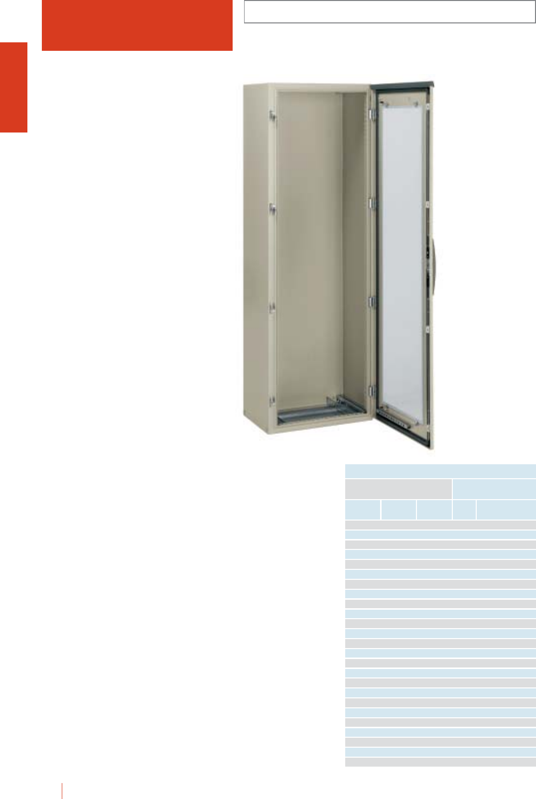
1/60 HIMEL floor standing industrial enclosures CMO
CMO MONOBLOC FLOOR STANDING ENCLOSURES
WITH GLAZED DOOR
IP55 (EN 60529)
Monobloc floor standing enclosure made from a
continuous length of sheet steel triple folded.
■Front door, 120° opening to right or left with reinforcing
profile which can be used for mounting of equipment.
■Rest of characteristics like those of the CMO standard
enclosure.
Configuration:
■Glazed door.
■5 mm double bar locking system.
■4 mounting plate supports.
■2-part cable gland plate with gasket.
CMO 186/40 KT
ENCLOSURES, DIMENSIONS AND REFERENCES
Depth
(C)
No. of
doors
Height
(A)
External dimensions
(mm)
Width
(B) Reference
1200 800 300 1 CMO 128/30 KT
1400 600 300 1 CMO 146/30 KT
1400 600 400 1 CMO 146/40 KT
1400 800 300 1 CMO 148/30 KT
1400 800 400 1 CMO 148/40 KT
1600 600 300 1 CMO 166/30 KT
1600 600 400 1 CMO 166/40 KT
1600 800 300 1 CMO 168/30 KT
1600 800 400 1 CMO 168/40 KT
1800 600 300 1 CMO 186/30 KT
1800 600 400 1 CMO 186/40 KT
1800 600 500 1 CMO 186/50 KT
1800 600 600 1 CMO 186/60 KT
1800 800 300 1 CMO 188/30 KT
1800 800 400 1 CMO 188/40 KT
1800 800 500 1 CMO 188/50 KT
1800 800 600 1 CMO 188/60 KT
2000 600 300 1 CMO 206/30 KT
2000 600 400 1 CMO 206/40 KT
2000 600 500 1 CMO 206/50 KT
2000 600 600 1 CMO 206/60 KT
2000 800 300 1 CMO 208/30 KT
2000 800 400 1 CMO 208/40 KT
2000 800 500 1 CMO 208/50 KT
2000 800 600 1 CMO 208/60 KT
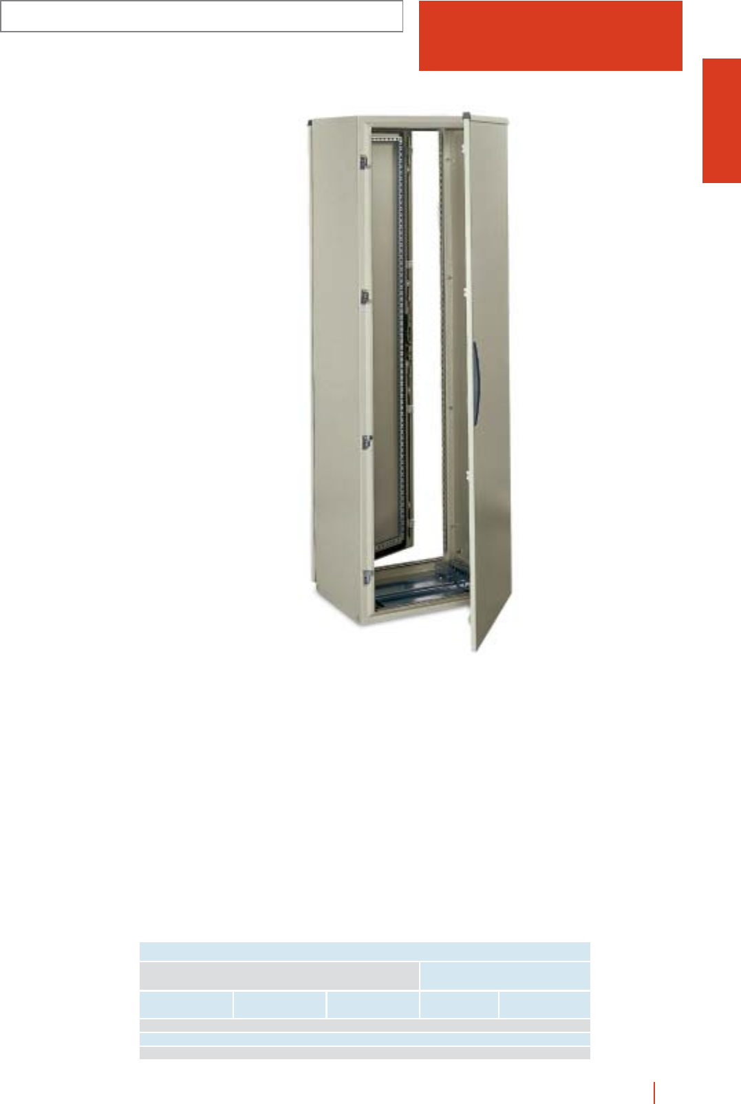
1/61floor standing industrial enclosures CMO HIMEL
CMO
MONOBLOC FLOOR STANDING ENCLOSURES
WITH FRONT AND REAR DOOR
IP55 (EN 60529)
Monobloc floor standing enclosure made from a
continuous length of sheet steel triple folded.
Front and back with perforated profile. Back welded
onto a flanged rear profile for higher protection.
■Front and rear door, 120º opening to right or left with
reinforcing profile which can be used for mounting of
equipment.
■Rest of characteristics like those of the CMO standard
enclosure.
Configuration:
■Plain front door with reinforcing profile and back door
without.
■5 mm double bar locking system.
■4 mounting plate supports.
■2-part cable gland plate with gasket.
■Internal handle on left door for 2 doors enclosure.
CMO 188/60 PUP
ENCLOSURES, DIMENSIONS AND REFERENCES
Depth
(C)
No. of
doors
Height
(A)
External dimensions
(mm)
Width
(B) Reference
1800 800 600 1 + 1 CMO 188/60 PUP
2000 800 600 1 + 1 CMO 208/60 PUP
2000 1200 600 2 + 2 CMO 2012/60 PUP
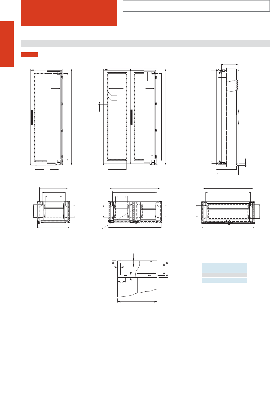
CMO MONOBLOC FLOOR STANDING ENCLOSURES
IP55 (EN 60529)
1/62 HIMEL floor standing industrial enclosures CMO
FIG. 1
Dimensions (mm)
25
A-
A - 90
B - 90
B - 150
B - 150
A - 150
A
12.5
A - 90
B - 90 18 x 18
Ø10
Ø5
B/2 - 150
B -150
A - 150
A
24
Min. 105
Max. C - 45
25
A - 62
C - 24
C + 6.5
B - 280
B - 164*
B - 120
C - 164*
600/800
C - 130
B/2 - 280
C - 164*
B - 164*
B - 120
1200/1600
C - 130
1200 width models without central adjustement rails.
C - 164*
1000
C - 130
B - 164*
B - 120
Width - 90
1000/1200
1600/1800
45
14
50
200
D - 68
D
Reference enclosures D
CMO 1610/40SB PM 400
CMO 1812/40SB PM 400
* Ground or plinth fixing dimensions.
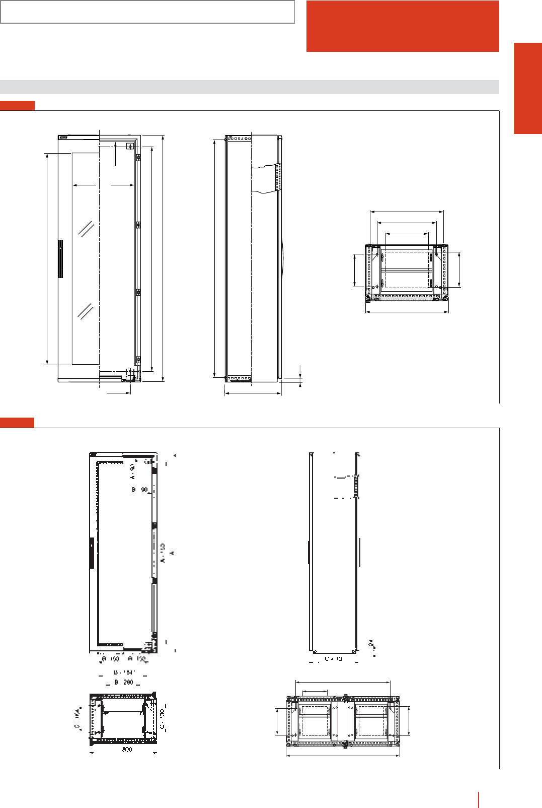
B/2 - 280
C - 164*
B - 164*
1200
C - 130
FIG. 3
* Ground or plinth fixing dimensions.
CMO...PUP enclosures
CMO
MONOBLOC FLOOR STANDING ENCLOSURES
IP55 (EN 60529)
1/63floor standing industrial enclosures CMO HIMEL
B - 280
B - 164*
B - 120
C - 164*
B
C - 130
Dimensions (mm)
24
C + 6.5
A - 66
25
A-
A - 262
A - 90
B - 205 B - 90
B - 150
A - 150
A
FIG. 2
* Ground or plinth fixing dimensions.
CMO...KT enclosures
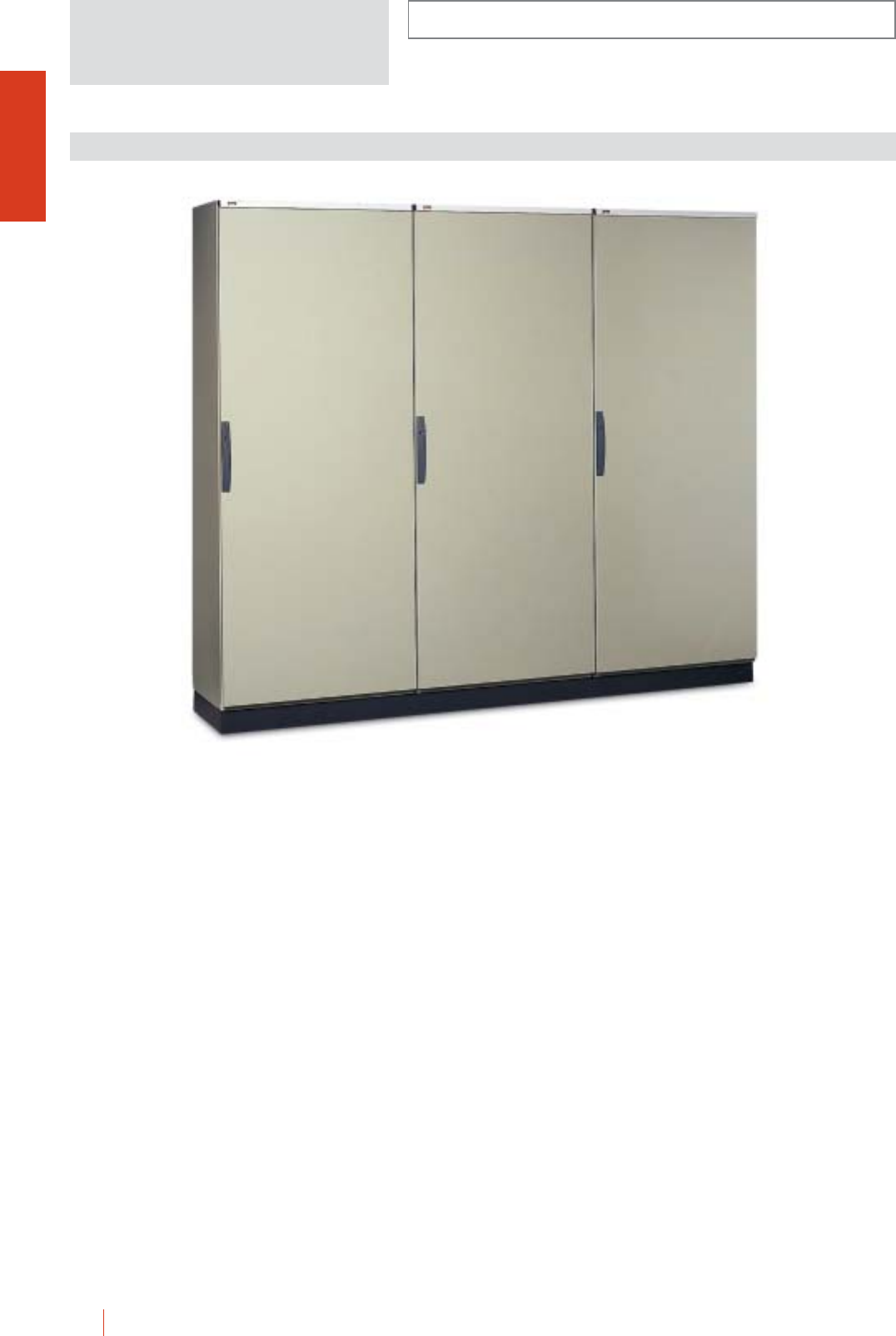
1/64 HIMEL floor standing industrial enclosures CMO
INSTALLATION SYSTEMS
Enclosure assembly of standard CMO 2000 mm high
enclosures mounted on a 200 mm high plinth. Opening
on adjoining sides leaving 45 mm to the edge around
their perimeter.
■Plain doors with reinforcement frame.
■4 mounting plate supports per enclosure.
■2-part cable gland plate with gasket per enclosure.
■5 mm double bar locking system.
■Optional intermediate mounting plates.
CMO 20 888/50
ENCLOSURE ASSEMBLY
CMO
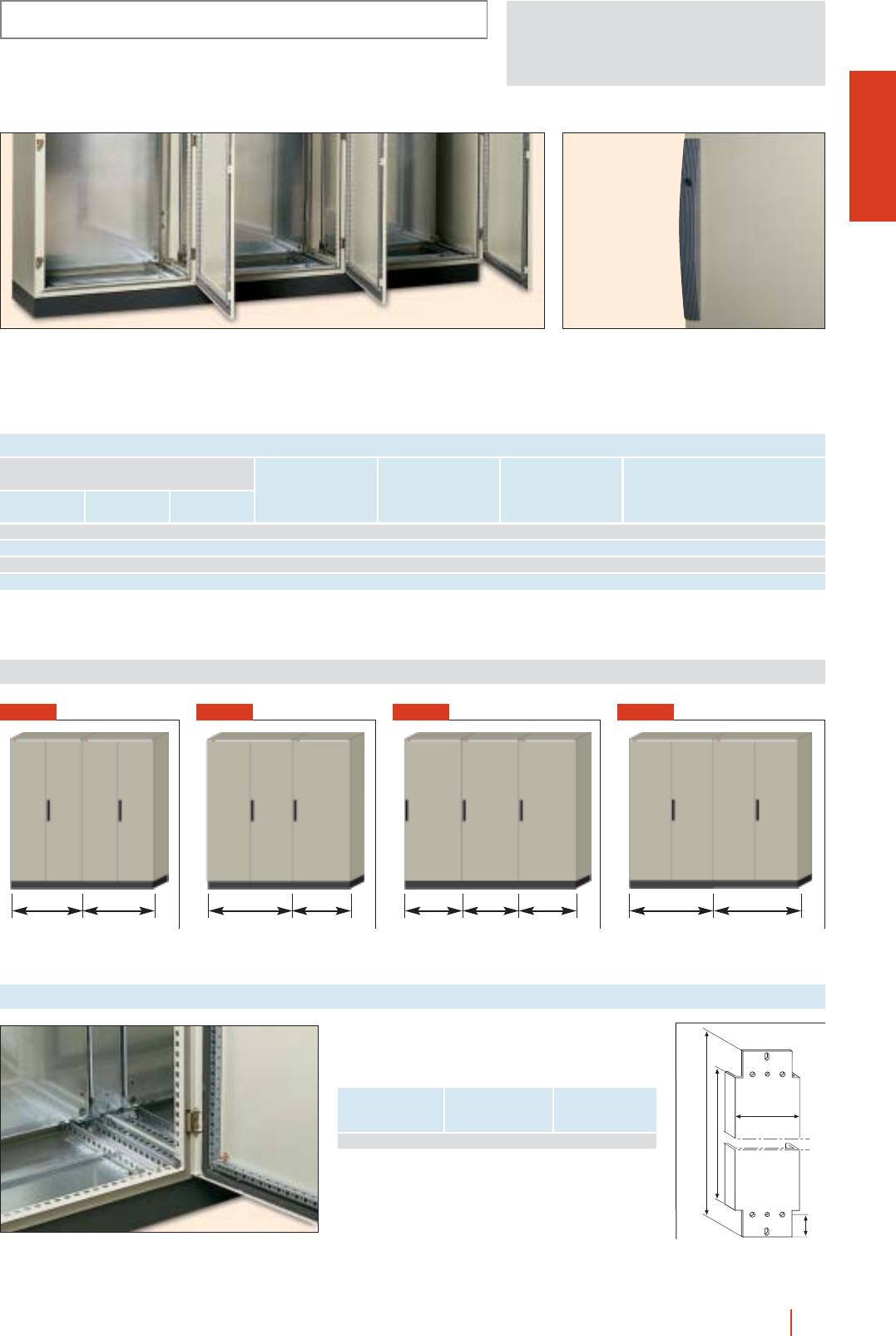
1/65floor standing industrial enclosures CMO HIMEL
INSTALLATION SYSTEMS
Detail of inside of enclosure assembly with mounting plates fitted. Standard flat lock outside the gasketed area.
Various lock transformations are available.
Dimensions (mm)
FIG. 1
1000 1000
FIG. 2
1200 800
FIG. 3
800 800 800
FIG. 4
1200 1200
Intermediate mounting plate
To ensure a continuous mounting surface when
enclosures are joined together.
Enclosure dimensions
Height
(A)
H Reference
2000 1884 PMI 20
107
42
H
H - 96
CMO
ENCLOSURES, DIMENSIONS AND REFERENCES
Height (1)
(A)
Dimensions
2000 2000 500 4 1 2 1000 CMO 201010/50
2000 2000 500 3 2 1200 + 800 CMO 20128/50
2000 2400 500 3 3 3 800 CMO 20888/50
2000 2400 500 4 4 2 1200 CMO 201212/50
(1) Total height including plinth 2100 mm.
Fig.
Assembly
made
up of
No. of
doors
Depth
(C)
Width
(B)
Reference
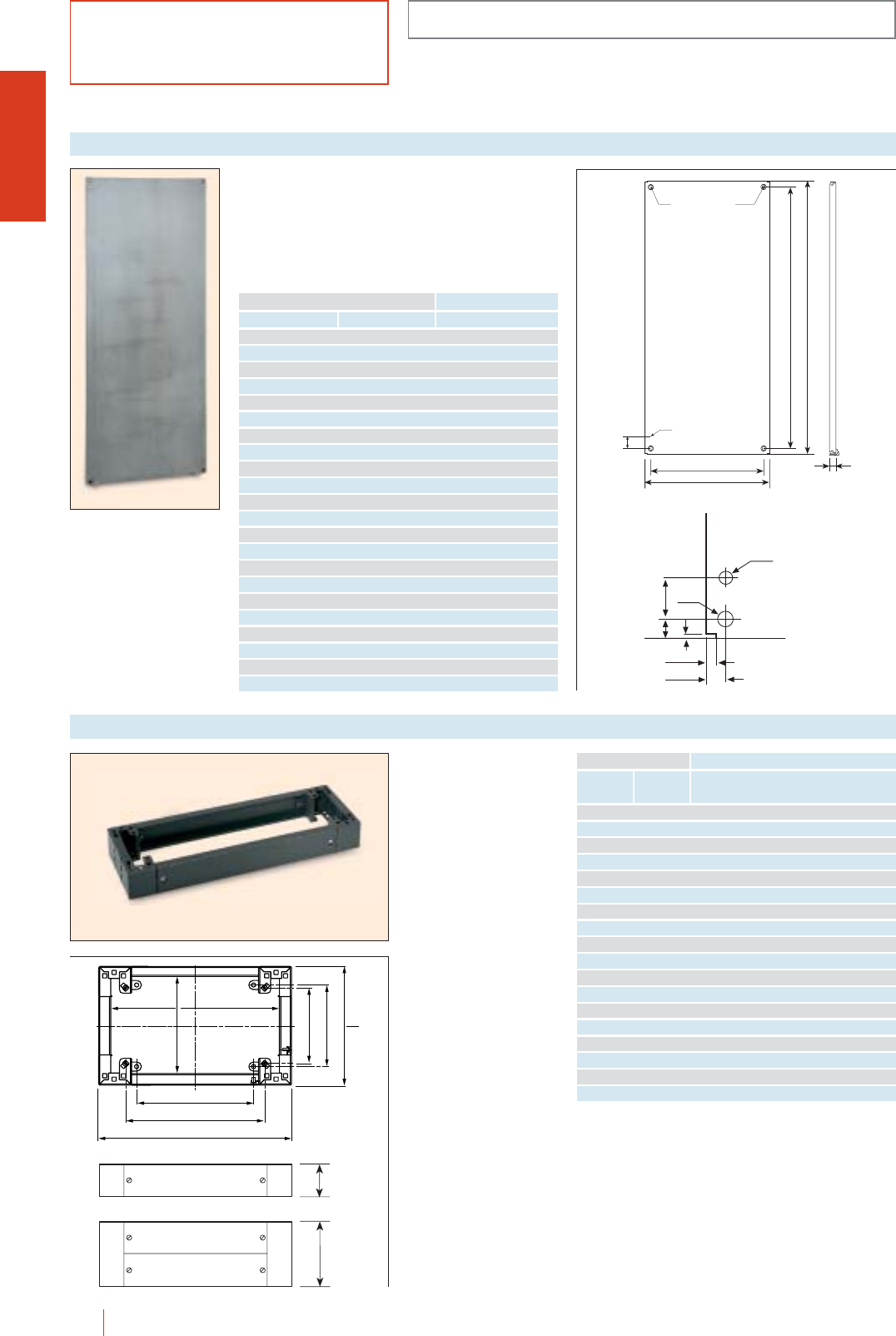
B-150
B-103
ø9
ø22 10x18
50
25
A-150
A-102
1/66 HIMEL floor standing industrial enclosures CMO
To fit directly to the
enclosures using the
drillings for ground fixing.
c100 and 200 mm high.
cFront and rear access.
cPolyester epoxy resin
paint to RAL-7022.
Single plinths
Width
(B)
Enclosure dimensions
Depth
(C)
Plinth height Plinth height
= 100 mm = 200 mm
Reference Reference
600 300 ZUN 63/100 ZUN 63/200
600 400 ZUN 64/100 ZUN 64/200
600 500 ZUN 65/100 ZUN 65/200
600 600 ZUN 66/100 ZUN 66/200
800 300 ZUN 83/100 ZUN 83/200
800 400 ZUN 84/100 ZUN 84/200
800 500 ZUN 85/100 ZUN 85/200
800 600 ZUN 86/100 ZUN 86/200
1000 300 ZUN 103/100 ZUN 103/200
1000 400 ZUN 104/100 ZUN 104/200
1000 500 ZUN 105/100 ZUN 105/200
1200 300 ZUN 123/100 ZUN 123/200
1200 400 ZUN 124/100 ZUN 124/200
1200 500 ZUN 125/100 ZUN 125/200
1200 600 ZUN 126/100 ZUN 126/200
1600 400 ZUN 164/100 ZUN 164/200
1600 500 ZUN 165/100 ZUN 165/200
1600 600 ZUN 166/100 ZUN 166/200
B - 164
B - 2
C - 145
C - 164
C - 34
B - 228
B - 62
C - 106
100
200
Made of galvanized steel with reinforced edges. Vertical
ones are double folded for extra rigidity. Depth adjustable
every 25 mm.
To ensure a continuous mounting surface when
enclosures are joined together, use PMI intermediate
mounting plate.
Mounting plates
Height (A)
Enclosures dimensions
Width (B) Reference
1000 1000 PMOL 1010
1200 800 PMOL 128
1200 1000 PMOL 1210
1200 1200 PMOL 1212
1400 600 PMOL 146
1400 800 PMOL 148
1400 1000 PMOL 1410
1400 1200 PMOL 1412
1600 600 PMOL 166
1600 800 PMOL 168
1600 1000 PMOL 1610
1600 1200 PMOL 1612
1800 600 PMOL 186
1800 800 PMOL 188
1800 1000 PMOL 1810
1800 1200 PMOL 1812
1800 1600 PMOL 1816
2000 600 PMOL 206
2000 800 PMOL 208
2000 1000 PMOL 2010
2000 1200 PMOL 2012
2000 1600 PMOL 2016
BASIC COMPONENTS
CMO
Ø9
Ø22
11.5
23.5
5
50
23
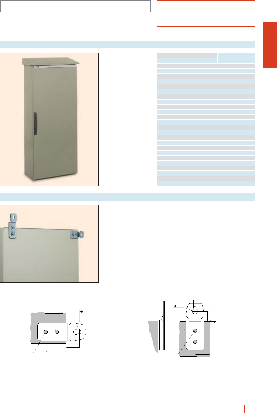
1/67floor standing industrial enclosures CMO HIMEL
13.5
29
60
24.5
32.5
9
31
Fixing hole
To fit directly to the
enclosures using the
same fixing holes as
those for the eyebolts.
Protected internally and
externally with polyester
epoxy resin paint to
RAL-7032 texturized.
Canopies
Width (B)
Enclosure dimensions
Depth (C) Reference
600 300 TJ 6030 CMO
600 400 TJ 6040 CMO
600 500 TJ 6050 CMO
600 600 TJ 6060 CMO
800 300 TJ 8030 CMO
800 400 TJ 8040 CMO
800 500 TJ 8050 CMO
800 600 TJ 8060 CMO
1000 300 TJ 10030 CMO
1000 400 TJ 10040 CMO
1000 500 TJ 10050 CMO
1200 300 TJ 12030 CMO
1200 400 TJ 12040 CMO
1200 500 TJ 12050 CMO
1200 600 TJ 12060 CMO
1600 400 TJ 16040 CMO
1600 500 TJ 16050 CMO
1600 600 TJ 16060 CMO
1800 500 TJ 18050 CMO
1800 600 TJ 18060 CMO
2000 500 TJ 20050 CMO
2000 600 TJ 20060 CMO
2400 500 TJ 24050 CMO
2400 600 TJ 24060 CMO
13.5
29
31
24.5
32.5
9
60
Fixing hole
Set of 2 wall fixing
brackets supplied with
fixings to mount by the
enclosure back.
Ref.: FMCO.
Wall fixing brackets
Horizontal assembly Vertical assembly
ACCESSORIES AND COMPLEMENTS CMO
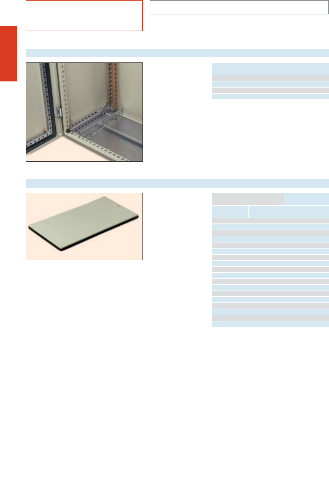
CMO
1/68 HIMEL floor standing industrial enclosures CMO
ACCESSORIES AND COMPLEMENTS
Folded and welded sheet
steel, galvanized.
cEnables central
positioning and fixing
of vertical rails in
1200 mm wide
enclosures.
cScrew fixing to upper
and lower parts of
enclosure. Fixing
included.
cPack of 4 parts.
Top and bottom adjustment rails
Enclosure dimensions
Depth Reference
300 DCOL 30
400 DCOL 40
500 DCOL 50
600 DCOL 60
Supplied with all the
screws and elements
needed for direct fixing
to top or bottom of
enclosure.
Made of sheet steel,
epoxy polyester powder
paint finish, color grey
RAL-7032.
Plain cable gland plate
Width
(A)
Enclosure dimensions (mm)
Depth
(B) Reference
600 300 ECMO 63/0
600 400 ECMO 64/0
600 500 ECMO 65/0
600 600 ECMO 66/0
800 300 ECMO 83/0
800 400 ECMO 84/0
800 500 ECMO 85/0
800 600 ECMO 86/0
1000 300 ECMO 103/0
1000 400 ECMO 104/0
1000 500 ECMO 105/0
1200 300 ECMO 123/0
1200 400 ECMO 124/0
1200 500 ECMO 125/0
1200 600 ECMO 126/0
1600 400 ECMO 164/0
1600 500 ECMO 165/0
1600 600 ECMO 166/0
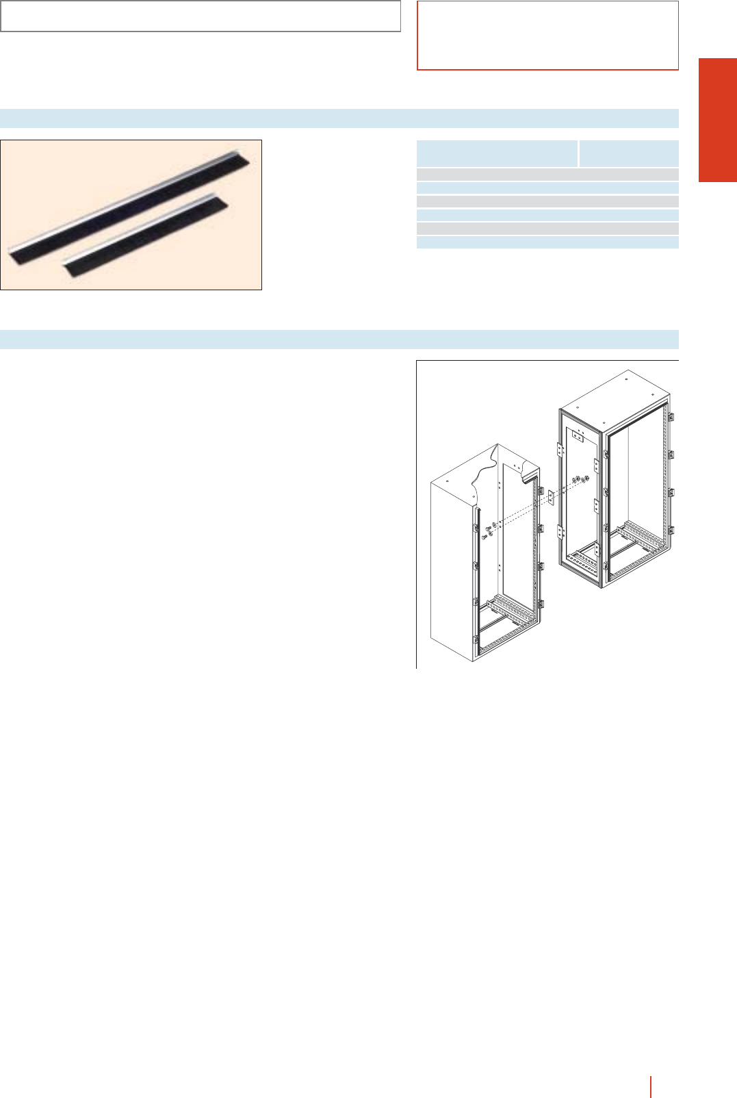
CMO
ACCESSORIES AND COMPLEMENTS
1/69floor standing industrial enclosures CMO HIMEL
(1) 2 sets should be used in cubicles with a width of B = 1200/1600.
Width
cubicle/desk Reference
600 JPCM 6
800 JPCM 8
1000 JPCM 10
1200 JPCM 6 (1)
1600 JPCM 8 (1)
For control desks B = 1200 JPCM 12
Set of 2 “brush type”
cable entry gaskets for
installation in cut-out
cable gland plates in
CMO enclosures and PK
control desks.
cAluminium mounting.
cClip-attached.
c34 mm-wide black
plastic fibre “brush”.
“Brush-type” cable entry gasket
Coupling kit for coupling
2 enclosures
side-by-side. Kit
comprises a sealing
gasket and fixings.
Ref.: CUCMO.
Enclosures assembly
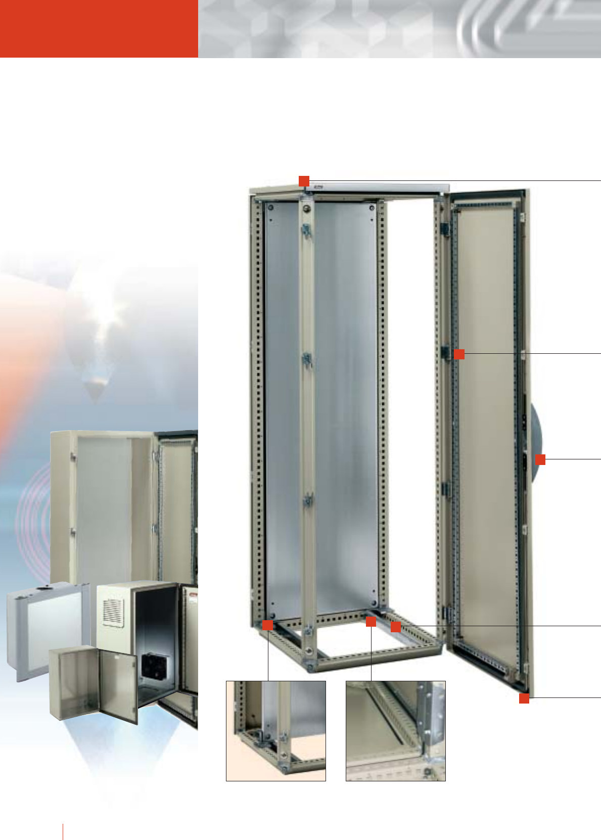
1/70 HIMEL OLN industrial cubicle system
OLN industrial
Displacement of the
mounting plate through
sliding guide.
Cubicle suit joining
set.
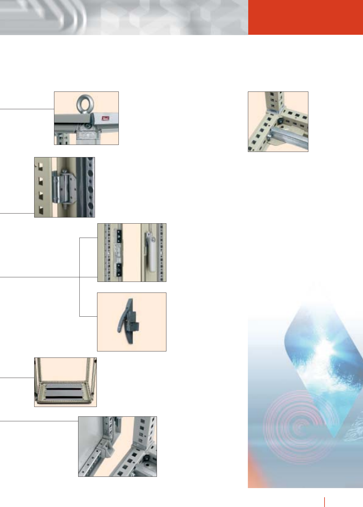
1/71OLN industrial cubicle system HIMEL
cubicle system
Lifting eyebolts bolted
directly to the cubicle
structure.
Standard handle lock
system for OLN
enclosures. Different
lock combinations
available.
Closing mechanism
outside of the sealed
zone.
Steel hinge designed for
easy door reversing.
4 points locking system to
maintain IP degree.
Polyurethane gasket.
120° door opening.
Cable gland plates for cable
entry through the cubicle
bottom, with neoprene gasket
ensuring good sealing.
Available with one or two
entries.
Door recentering
wedge.
2 doors enclosures with an
internal locking system to
ensure the thightening.
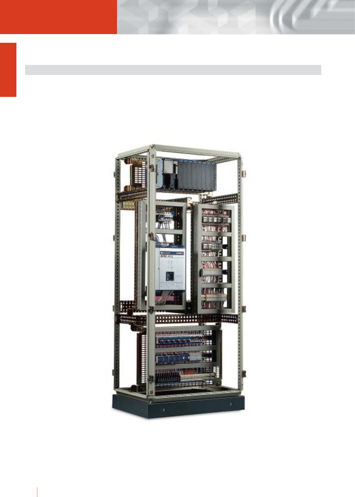
1/72 HIMEL OLN industrial cubicle system
cGreat strength, reliability and rigidity.
cErgonomic design, easy installation.
cNew standard versions available.
cWide accessories ranges.
cFlexible flat pack kit delivery.
INSTALLATIONS SYSTEM FOR INDUSTRIAL APPLICATIONS
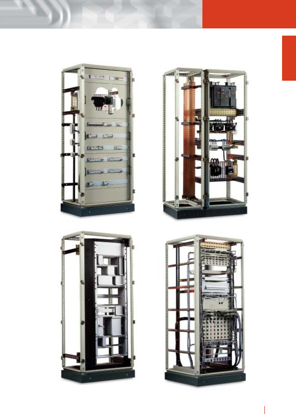
1/73OLN industrial cubicle system HIMEL
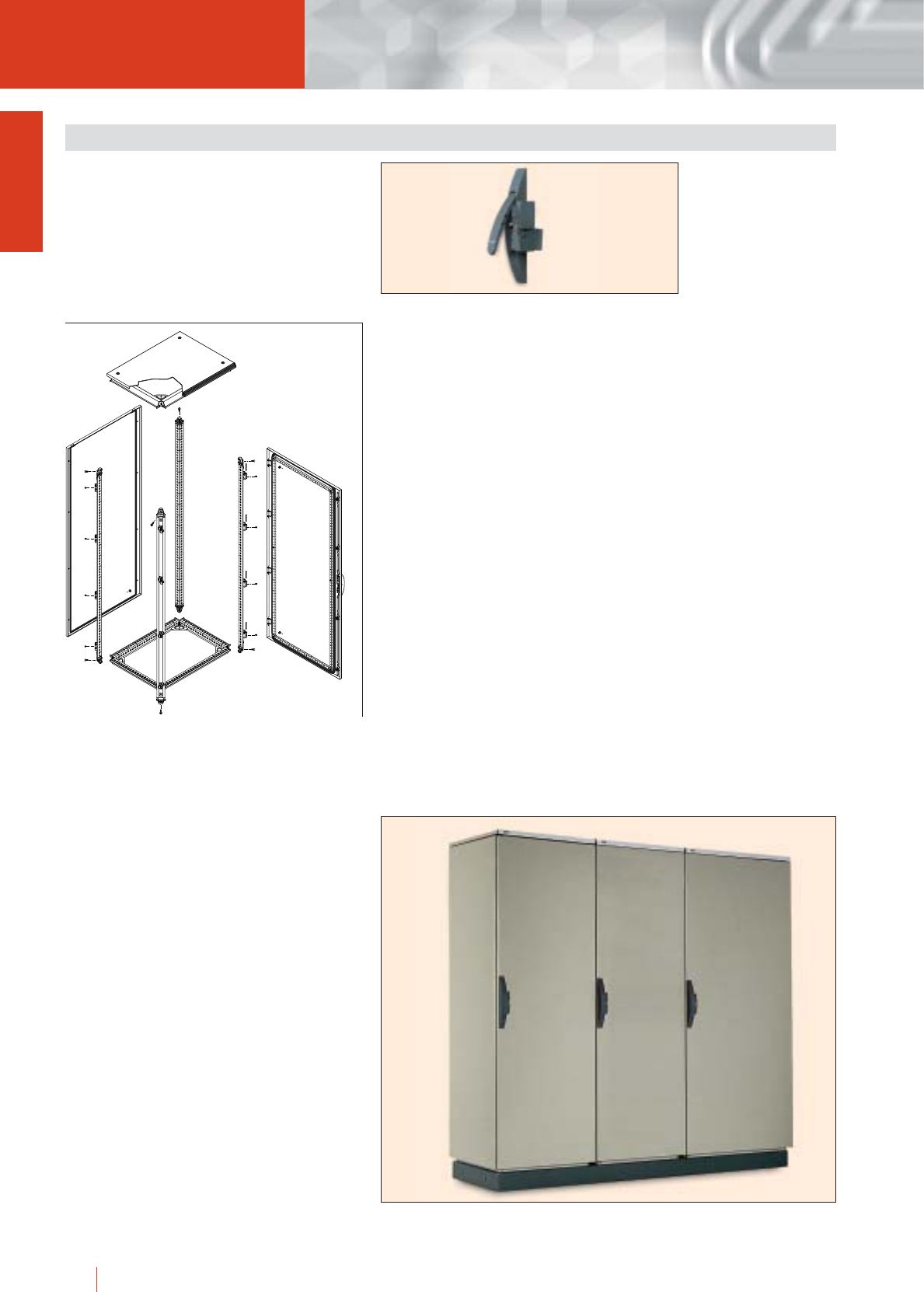
1/74 HIMEL OLN industrial cubicle system
System of Modular metal cubicles, consisting of a
structure of triangular closed profiles with welded top
frame and base and vertical removable bolted
profiles, giving the assembly and optimum stability
and versatility, 1.5 mm thick back and side metal
panels, 2 and a wide range of accessories.
The joining of the various parts is done in a simple
easy way through the accessories specifically
designed to simplify the operations.
GENERAL FEATURES
The basic cubicle has the following elements:
c4 vertical triangular profiles onto which the hinges
are fitted. They include a reference drilling every
100 mm which is meant to help the installer to
position the equipment.
cWelded top and base to which the vertical profiles
are bolted.
cPlain or glazed front door, except for
OLNE.../...SP.
cHandle double bar locking system with double
cylinder delivered disassembled inside the cubicle.
cTop panel with personalized strip, HIMEL tag and
clear cover.
cBack panel (two OLNE versions).
cMounting plate fixing supports except for OLNP,
OLNM, OLNE versions.
cSlidins fixing guide for mounting plates except for
OLNP, OLNM, OLNE.
Rigidity:
The rigidity of the cubicle is ensured by the welded
top and base. The hinges are made of steel for more
rigidity and less chances to break.
Universal locking system with many distinct
possibilities including double dylinder locking and
even magnetic card in the near future.
Easy access to the inside of the cubicle through
removable uprights (even with the unit already
assembled) which ensure a great level of
accessibility and make working inside the cubicle
easier.
Treatment and finish:
The treatment applied before the final finish ensures
a perfect adherence of the paint, which provides a
greater protection in harsh environments and
whenever drillings are done.
Treatment description:
The steps are as follows: degreasing, phosphating,
passivating, drying, powder epoxy resin painting and
polymerization.
Final finish:
cMounting plates (PMOL, PMP, PMI) to RAL-2000.
cPlinths (ZUN, ZUN/T, ZUN/C) to dark grey
RAL-7002.
cRest of cubicle and components: texturized
RAL-7032.
cOther parts such as hinges, locking rods, mounting
plate supports, etc., are zinc coated bichromated.
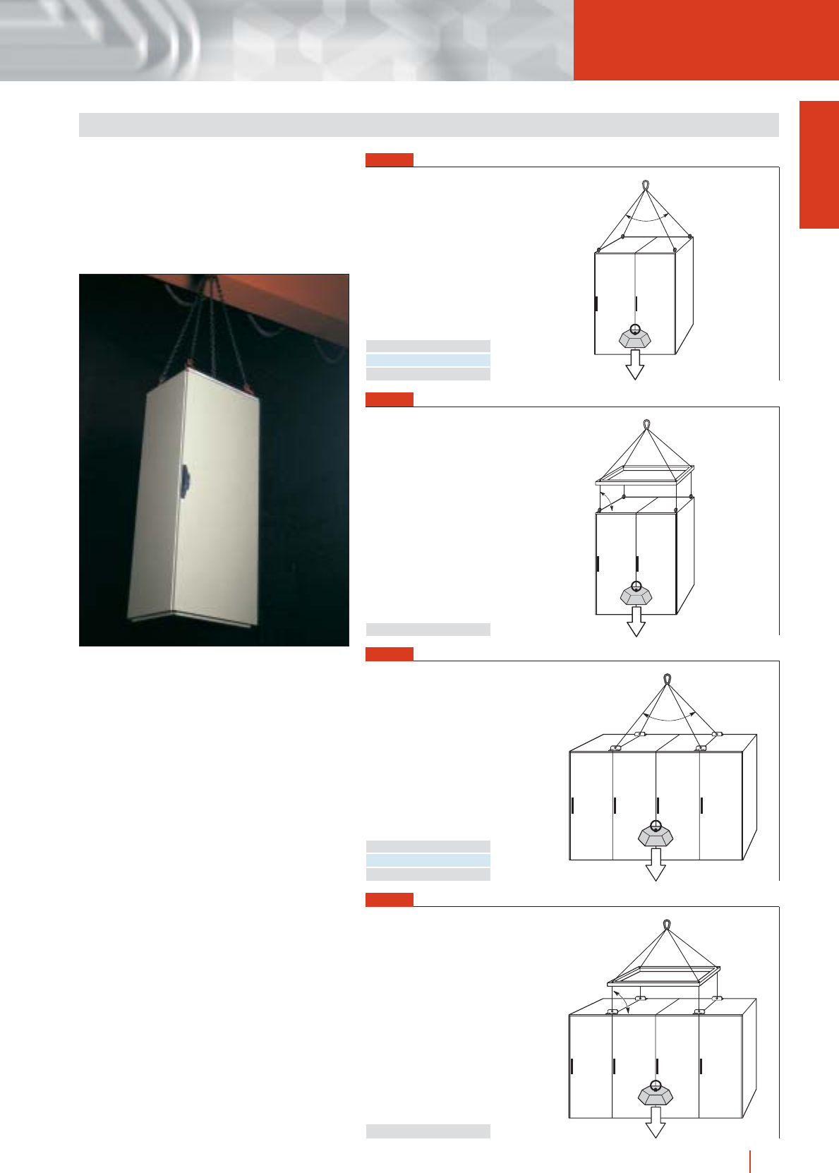
1/75OLN industrial cubicle system HIMEL
Whenever forming cubicle suites, the CPUT joining
set, TLN/12 eyebolts and joining pieces PUN must
be used.
Maximum loads are shown on the right. For further
information see instructions leaflet provided with
each cubicle.
FIG. 1
Directly to TLN/12 eyebolts
FIG. 2
a = 45° P < 1160 kg
a = 60° P < 830 kg
a = 90° P < 480 kg
a = 45° P < 2800 kg
a = 60° P < 2000 kg
a = 90° P < 1100 kg
a = 90° P < 1360 kg
a = 90° P < 3000 kg
P
a
P
a
P
a
P
a
By means of an intermediate lifting frame and TLN/12
eyebolts
FIG. 3
FIG. 4
Through PUN joining pieces
By means of an intermediate lifting frame and PUN
joining pieces
LIFTING AND TRANSPORT
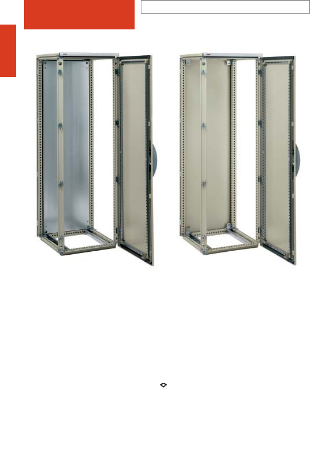
OLN INDUSTRIAL CUBICLES WITH OR WITHOUT
MOUNTING PLATE
1/76 HIMEL OLN industrial cubicle system
OLN 186/60
Metal cubicle consisting of a structure of triangular
closed profiles with welded top and base and vertical
removable bolted profiles, giving the assembly and
optimum stability and versatility. Painted internally and
externally with polyester-epoxy resin to texturized
RAL-7032.
Mounting plate in galvanized steel (for models
OLN...PM).
cGreat accessibility.
cMaximum versatility for all kind of installations.
c120° door opening.
c4 point locking system outside the gasketed area. Several
transformation and locking possibilities.
Basic cubicle:
cWelded top.
cWelded base.
cVerticals uprights.
cRemovable roof.
cRemovable back panel.
cPlain front door with lock.
cMounting plate supports.
cMounting plate supplied with OLN...PM models.
cMounting plate sliding guide.
cDoor recentering wedge in up to 1400 mm high
enclosures.
cTwo doors enclosures with internal fixing system for left
door.
OLN 186/60 PM
IP55 (EN 60529)

OLN
1/77OLN industrial cubicle system HIMEL
INDUSTRIAL CUBICLES WITH OR WITHOUT
MOUNTING PLATE
ENCLOSURES, DIMENSIONS AND REFERENCES
No. of
doors
Height
(A)
External dimensions
(mm)
Width
(B)
Enclosure with
mounting plate
Reference
Enclosure without
mounting plate
Depth
(C)
1200 600 400 1 OLN 126/40 PM OLN 126/40
1200 600 600 1 OLN 126/60 PM OLN 126/60
1200 600 800 1 OLN 126/80 PM OLN 126/80
1200 800 400 1 OLN 128/40 PM OLN 128/40
1200 800 600 1 OLN 128/60 PM OLN 128/60
1200 800 800 1 OLN 128/80 PM OLN 128/80
1400 600 400 1 OLN 146/40 PM OLN 146/40
1400 600 600 1 OLN 146/60 PM OLN 146/60
1400 600 800 1 OLN 146/80 PM OLN 146/80
1400 800 400 1 OLN 148/40 PM OLN 148/40
1400 800 600 1 OLN 148/60 PM OLN 148/60
1400 800 800 1 OLN 148/80 PM OLN 148/80
1600 600 600 1 OLN 166/60 PM OLN 166/60
1600 600 800 1 OLN 166/80 PM OLN 166/80
1600 800 600 1 OLN 168/60 PM OLN 168/60
1600 800 800 1 OLN 168/80 PM OLN 168/80
1800 600 400 1 OLN 186/40 PM OLN 186/40
1800 600 500 1 OLN 186/50 PM OLN 186/50
1800 600 600 1 OLN 186/60 PM OLN 186/60
1800 600 800 1 OLN 186/80 PM OLN 186/80
1800 800 400 1 OLN 188/40 PM OLN 188/40
1800 800 500 1 OLN 188/50 PM OLN 188/50
1800 800 600 1 OLN 188/60 PM OLN 188/60
1800 1000 400 1 OLN 1810/40 PM OLN 1810/40
1800 1000 400 2 OLN 1810/40/2P-PM OLN 1810/40/2P
1800 1000 500 1 OLN 1810/50 PM OLN 1810/50
1800 1000 500 2 OLN 1810/50/2P-PM OLN 1810/50/2P
1800 1000 600 1 OLN 1810/60 PM OLN 1810/60
1800 1000 600 2 OLN 1810/60/2P-PM OLN 1810/60/2P
1800 1200 400 2 OLN 1812/40/2P-PM OLN 1812/40/2P
1800 1200 500 2 OLN 1812/50/2P-PM OLN 1812/50/2P
1800 1200 600 2 OLN 1812/60/2P-PM OLN 1812/60/2P
2000 300 500 1 - OLN 203/50* (1)
2000 300 600 1 - OLN 203/60*
2000 300 800 1 - OLN 203/80*
2000 400 500 1 - OLN 204/50*
2000 400 600 1 - OLN 204/60*
2000 600 400 1 OLN 206/40 PM OLN 206/40
2000 600 500 1 OLN 206/50 PM OLN 206/50
2000 600 600 1 OLN 206/60 PM OLN 206/60
2000 600 800 1 OLN 206/80 PM OLN 206/80
2000 800 400 1 OLN 208/40 PM OLN 208/40
2000 800 500 1 OLN 208/50 PM OLN 208/50
2000 800 600 1 OLN 208/60 PM OLN 208/60
2000 800 800 1 OLN 208/80 PM OLN 208/80
2000 1000 400 1 OLN 2010/40 PM OLN 2010/40
2000 1000 400 2 OLN 2010/40/2P-PM OLN 2010/40/2P
2000 1000 500 1 OLN 2010/50 PM OLN 2010/50
2000 1000 500 2 OLN 2010/50/2P-PM OLN 2010/50/2P
2000 1000 600 1 OLN 2010/60 PM OLN 2010/60
2000 1000 600 2 OLN 2010/60/2P-PM OLN 2010/60/2P
2000 1000 800 1 OLN 2010/80 PM OLN 2010/80
2000 1000 800 2 OLN 2010/80/2P-PM OLN 2010/80/2P
2000 1200 400 2 OLN 2012/40/2P-PM OLN 2012/40/2P
2000 1200 500 2 OLN 2012/50/2P-PM OLN 2012/50/2P
2000 1200 600 2 OLN 2012/60/2P-PM OLN 2012/60/2P
2000 1200 800 2 OLN 2012/80/2P-PM OLN 2012/80/2P
2200 600 600 1 OLN 226/60 PM OLN 226/60
2200 600 800 1 OLN 226/80 PM OLN 226/80
2200 800 600 1 OLN 228/60 PM OLN 228/60
2200 800 800 1 OLN 228/80 PM OLN 228/80
2200 1000 600 1 OLN 2210/60 PM OLN 2210/60
2200 1000 800 1 OLN 2210/80 PM OLN 2210/80
2200 1000 800 2 OLN 2210/80/2P-PM OLN 2210/80/2P
2200 1200 600 2 OLN 2212/60/2P-PM OLN 2212/60/2P
2200 1200 800 2 OLN 2212/80/2P-PM OLN 2212/80/2P
* Side busbar chambers.
(1) CE busbar chamber + SEP busbar supports can not be mounted.
IP55 (EN 60529)
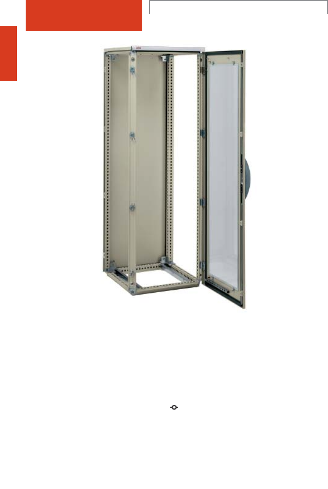
1/78 HIMEL OLN industrial cubicle system
OLN.../... KT INDUSTRIAL CUBICLES
WITH GLAZED DOOR
Metal cubicle consisting of a structure of triangular
closed profiles with welded top and base and vertical
removable bolted profiles, giving the assembly and
optimum stability and versatility. Painted internally and
externally with polyester-epoxy resin to texturized
RAL-7032.
cGreat accessibility.
cMaximum versatility for all kind of installations.
c120° door opening.
c4 point locking system outside the gasketed area. Several
transformation and locking possibilities.
cTemplated glass glazed front door.
Basic cubicle:
cWelded top.
cWelded base.
cVertical uprights.
cRemovable roof.
cRemovable back panel.
cFront glazed door with lock.
cMounting plate supports.
cMounting plate sliding guide.
OLN 186/60 KT
IP55 (EN 60529)

1/79OLN industrial cubicle system HIMEL
OLN.../... KT
INDUSTRIAL CUBICLES
WITH GLAZED DOOR
ENCLOSURES, DIMENSIONS AND REFERENCES
No. of
doors
Height
(A)
External dimensions
(mm)
Width
(B) Enclosure with glazed door
1200 600 400 1 OLN 126/40 KT
1200 600 600 1 OLN 126/60 KT
1200 600 800 1 OLN 126/80 KT
1200 800 400 1 OLN 128/40 KT
1200 800 600 1 OLN 128/60 KT
1200 800 800 1 OLN 128/80 KT
1400 600 400 1 OLN 146/40 KT
1400 600 600 1 OLN 146/60 KT
1400 600 800 1 OLN 146/80 KT
1400 800 400 1 OLN 148/40 KT
1400 800 600 1 OLN 148/60 KT
1400 800 800 1 OLN 148/80 KT
1600 600 600 1 OLN 166/60 KT
1600 600 800 1 OLN 166/80 KT
1600 800 600 1 OLN 168/60 KT
1600 800 800 1 OLN 168/80 KT
1800 600 400 1 OLN 186/40 KT
1800 600 500 1 OLN 186/50 KT
1800 600 600 1 OLN 186/60 KT
1800 600 800 1 OLN 186/80 KT
1800 800 400 1 OLN 188/40 KT
1800 800 500 1 OLN 188/50 KT
1800 800 600 1 OLN 188/60 KT
1800 1000 400 1 OLN 1810/40 KT
1800 1000 500 1 OLN 1810/50 KT
1800 1000 600 1 OLN 1810/60 KT
2000 600 400 1 OLN 206/40 KT
2000 600 500 1 OLN 206/50 KT
2000 600 600 1 OLN 206/60 KT
2000 600 800 1 OLN 206/80 KT
2000 800 400 1 OLN 208/40 KT
2000 800 500 1 OLN 208/50 KT
2000 800 600 1 OLN 208/60 KT
2000 800 800 1 OLN 208/80 KT
2000 1000 400 1 OLN 2010/40 KT
2000 1000 500 1 OLN 2010/50 KT
2000 1000 600 1 OLN 2010/60 KT
2000 1000 800 1 OLN 2010/80 KT
2200 600 600 1 OLN 226/60 KT
2200 600 800 1 OLN 226/80 KT
2200 800 600 1 OLN 228/60 KT
2200 800 800 1 OLN 228/80 KT
2200 1000 600 1 OLN 2210/60 KT
2200 1000 800 1 OLN 2210/80 KT
Depth
(C)
IP55 (EN 60529)
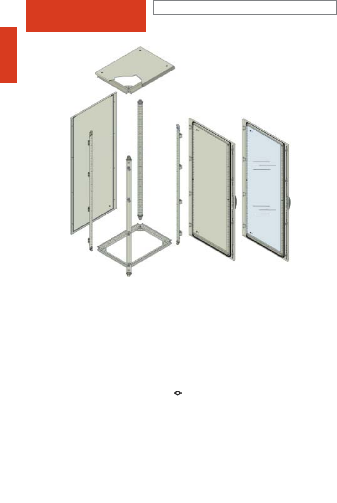
1/80 HIMEL OLN industrial cubicle system
OLN FLAT PACK INDUSTRIAL
CUBICLE SYSTEM
Metal cubicle consisting of a structure of triangular
closed profiles with welded top and base and vertical
removable bolted profiles, giving the assembly and
optimum stability and versatility. Painted internally and
externally with polyester-epoxy resin to texturized
RAL-7032.
cGreat accessibility.
cMaximum versatility for all kind of installations.
c120° door opening.
c4 point locking system outside the gasketed area. Several
transformation and locking possibilities.
cTwo doors enclosures with internal fixing system
for left door.
cThe flat pack kit version includes all the necessary
elements to form the basic cubicle. These elements can
be obtained through independent references.
cThe flat pack kit is supplied partly assembled, which
reduces greatly the mounting time. It also saves volume
substantially, making storage and transport cheaper.
Basic cubicle:
OLMV:
cVertical uprights including hinges, locking elements and
side fixing blocks already fitted.
OLSI:
cWelded top with roof.
cWelded base.
cMounting plate sliding guide.
cMounting plate fixing supports.
OLPP:
cPlain door with lock.
cPlain back panel.
OLPU:
cPlain door with lock and internal handle for two doors
models.
OLPUKT:
cGlazed door with lock.
OLPO:
cPlain back panel.
ADPUPOL:
cBack door adaptor.
AD2PUPOL:
cTwo back door adaptor.
EMBT:
cRoof panel.
IP55 (EN 60529)
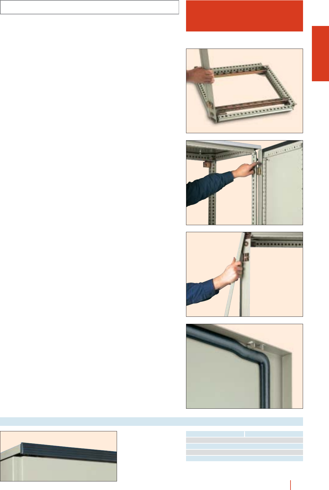
1/81OLN industrial cubicle system HIMEL
OLN
FLAT PACK INDUSTRIAL
CUBICLE SYSTEM
Placing and fixing of the 4 vertical uprights to
the top and base corner pieces.
Door mounting by inserting pins in
to hinges.
Placing of back panel throught self-centreing
hanger provided and screwing.
Detail of self-centering hanger.
cTo be used for lining an
enclosure with rear
door.
cRAL-7022.
cSupplied with
mounting clips.
Roof panel
Reference Width enclosure (mm)
EMBT40 400
EMBT60 600
EMBT80 800
EMBT100 1000
IP55 (EN 60529)

1/82 HIMEL OLN industrial cubicle system
ENCLOSURES, DIMENSIONS AND REFERENCES
No. of
doors
Height
(A)
External dimensions
(mm)
Width
(B)
1200 600 400 1 OLMV 12 OLSI 64
1200 600 600 1 OLMV 12 OLSI 66
1200 600 800 1 OLMV 12 OLSI 68
1200 800 400 1 OLMV 12 OLSI 84
1200 800 600 1 OLMV 12 OLSI 86
1200 800 800 1 OLMV 12 OLSI 88
1400 600 400 1 OLMV 14 OLSI 64
1400 600 600 1 OLMV 14 OLSI 66
1400 600 800 1 OLMV 14 OLSI 68
1400 800 400 1 OLMV 14 OLSI 84
1400 800 600 1 OLMV 14 OLSI 86
1400 800 800 1 OLMV 14 OLSI 88
1600 600 600 1 OLMV 16 OLSI 66
1600 600 800 1 OLMV 16 OLSI 68
1600 800 600 1 OLMV 16 OLSI 86
1600 800 800 1 OLMV 16 OLSI 88
1800 600 400 1 OLMV 18 OLSI 64
1800 600 500 1 OLMV 18 OLSI 65
1800 600 600 1 OLMV 18 OLSI 66
1800 600 800 1 OLMV 18 OLSI 68
1800 800 400 1 OLMV 18 OLSI 84
1800 800 500 1 OLMV 18 OLSI 85
1800 800 600 1 OLMV 18 OLSI 86
1800 1000 400 2 OLMV 18 OLSI 104
1800 1000 400 1 OLMV 18/2P OLSI 104
1800 1000 500 2 OLMV 18 OLSI 105
1800 1000 500 1 OLMV 18/2P OLSI 105
1800 1000 600 2 OLMV 18 OLSI 106
1800 1000 600 2 OLMV 18/2P OLSI 106
1800 1200 400 2 OLMV 18/2P OLSI 124
1800 1200 500 2 OLMV 18/2P OLSI 125
1800 1200 600 1 OLMV 18/2P OLSI 126
2000 400 500 1 OLMV 20 OLSI 45
2000 400 600 1 OLMV 20 OLSI 46
2000 600 400 1 OLMV 20 OLSI 64
2000 600 500 1 OLMV 20 OLSI 65
2000 600 600 1 OLMV 20 OLSI 66
2000 600 800 1 OLMV 20 OLSI 68
2000 800 400 1 OLMV 20 OLSI 84
2000 800 500 1 OLMV 20 OLSI 85
2000 800 600 1 OLMV 20 OLSI 86
2000 800 800 1 OLMV 20 OLSI 88
2000 1000 400 1 OLMV 20 OLSI 104
2000 1000 400 2 OLMV 20/2P OLSI 104
2000 1000 500 1 OLMV 20 OLSI 105
2000 1000 500 2 OLMV 20/2P OLSI 105
2000 1000 600 1 OLMV 20 OLSI 106
2000 1000 600 2 OLMV 20/2P OLSI 106
2000 1000 800 1 OLMV 20 OLSI 108
2000 1000 800 2 OLMV 20/2P OLSI 108
2000 1200 400 2 OLMV 20/2P OLSI 124
2000 1200 500 2 OLMV 20/2P OLSI 125
2000 1200 600 2 OLMV 20/2P OLSI 126
2000 1200 800 2 OLMV 20/2P OLSI 128
2200 600 600 1 OLMV 22 OLSI 66
2200 600 800 1 OLMV 22 OLSI 68
2200 800 600 1 OLMV 22 OLSI 86
2200 800 800 1 OLMV 22 OLSI 88
2200 1000 600 1 OLMV 22 OLSI 106
2200 1000 800 1 OLMV 22 OLSI 108
2200 1000 800 2 OLMV 22/2P OLSI 108
2200 1200 600 2 OLMV 22/2P OLSI 126
2200 1200 800 2 OLMV 22/2P OLSI 128
Depth
(C)
OLN FLAT PACK INDUSTRIAL
CUBICLE SYSTEM
Top and baseVertical uprights
IP55 (EN 60529)
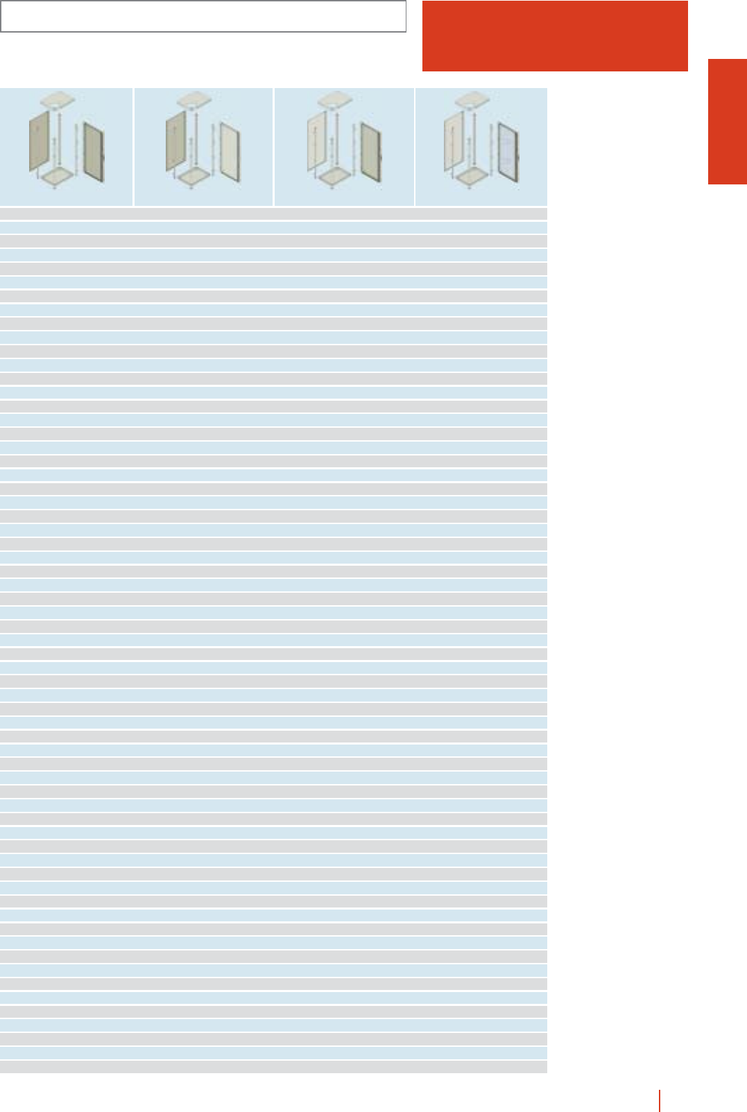
1/83OLN industrial cubicle system HIMEL
OLPP 126 OLPO 126 OLPU 126 OLPU 126KT
OLPP 126 OLPO 126 OLPU 126 OLPU 126KT
OLPP 126 OLPO 126 OLPU 126 OLPU 126KT
OLPP 128 OLPO 128 OLPU 128 OLPU 128KT
OLPP 128 OLPO 128 OLPU 128 OLPU 128KT
OLPP 128 OLPO 128 OLPU 128 OLPU 128KT
OLPP 146 OLPO 146 OLPU 146 OLPU 146KT
OLPP 146 OLPO 146 OLPU 146 OLPU 146KT
OLPP 146 OLPO 146 OLPU 146 OLPU 146KT
OLPP 148 OLPO 148 OLPU 148 OLPU 148KT
OLPP 148 OLPO 148 OLPU 148 OLPU 148KT
OLPP 148 OLPO 148 OLPU 148 OLPU 148KT
OLPP 166 OLPO 166 OLPU 166 OLPU 166KT
OLPP 166 OLPO 166 OLPU 166 OLPU 166KT
OLPP 168 OLPO 168 OLPU 168 OLPU 168KT
OLPP 168 OLPO 168 OLPU 168 OLPU 168KT
OLPP 186 OLPO 186 OLPU 186 OLPU 186KT
OLPP 186 OLPO 186 OLPU 186 OLPU 186KT
OLPP 186 OLPO 186 OLPU 186 OLPU 186KT
OLPP 186 OLPO 186 OLPU 186 OLPU 186KT
OLPP 188 OLPO 188 OLPU 188 OLPU 188KT
OLPP 188 OLPO 188 OLPU 188 OLPU 188KT
OLPP 188 OLPO 188 OLPU 188 OLPU 188KT
OLPP 1810 OLPO 1810 OLPU 1810 OLPU 1810KT
OLPP 1810/2P OLPO 1810 OLPU 1810/2 -
OLPP 1810 OLPO 1810 OLPU 1810 OLPU 1810KT
OLPP 1810/2P OLPO 1810 OLPU 1810/2 -
OLPP 1810 OLPO 1810 OLPU 1810 OLPU 1810KT
OLPP 1810/2P OLPO 1810 OLPU 1810/2 -
OLPP 1812/2P OLPO 1812 OLPU 1812/2 -
OLPP 1812/2P OLPO 1812 OLPU 1812/2 -
OLPP 1812/2P OLPO 1812 OLPU 1812/2 -
OLPP 204 OLPO 204 OLPU 204 OLPU 204KT
OLPP 204 OLPO 204 OLPU 204 OLPU 204KT
OLPP 206 OLPO 206 OLPU 206 OLPU 206KT
OLPP 206 OLPO 206 OLPU 206 OLPU 206KT
OLPP 206 OLPO 206 OLPU 206 OLPU 206KT
OLPP 206 OLPO 206 OLPU 206 OLPU 206KT
OLPP 208 OLPO 208 OLPU 208 OLPU 208KT
OLPP 208 OLPO 208 OLPU 208 OLPU 208KT
OLPP 208 OLPO 208 OLPU 208 OLPU 208KT
OLPP 208 OLPO 208 OLPU 208 OLPU 208KT
OLPP 2010 OLPO 2010 OLPU 2010 OLPU 2010KT
OLPP 2010/2P OLPO 2010 OLPU 2010/2 -
OLPP 2010 OLPO 2010 OLPU 2010 OLPU 2010KT
OLPP 2010/2P OLPO 2010 OLPU 2010/2 -
OLPP 2010 OLPO 2010 OLPU 2010 OLPU 2010KT
OLPP 2010/2P OLPO 2010 OLPU 2010/2 -
OLPP 2010 OLPO 2010 OLPU 2010 OLPU 2010KT
OLPP 2010/2P OLPO 2010 OLPU 2010/2 -
OLPP 2012/2P OLPO 2012 OLPU 2012/2 -
OLPP 2012/2P OLPO 2012 OLPU 2012/2 -
OLPP 2012/2P OLPO 2012 OLPU 2012/2 -
OLPP 2012/2P OLPO 2012 OLPU 2012/2 -
OLPP 226 OLPO 226 OLPU 226 OLPU 226KT
OLPP 226 OLPO 226 OLPU 226 OLPU 226KT
OLPP 228 OLPO 228 OLPU 228 OLPU 228KT
OLPP 228 OLPO 228 OLPU 228 OLPU 228KT
OLPP 2210 OLPO 2210 OLPU 2210 OLPU 2210KT
OLPP 2210 OLPO 2210 OLPU 2210 OLPU 2210KT
OLPP 2210/2P OLPO 2210 OLPU 2210/2 -
OLPP 2212/2P OLPO 2212 OLPU 2212/2 -
OLPP 2212/2P OLPO 2212 OLPU 2212/2 -
OLN
FLAT PACK INDUSTRIAL
CUBICLE SYSTEM
Back panel and door Plain doorBack panel Glazed door
IP55 (EN 60529)
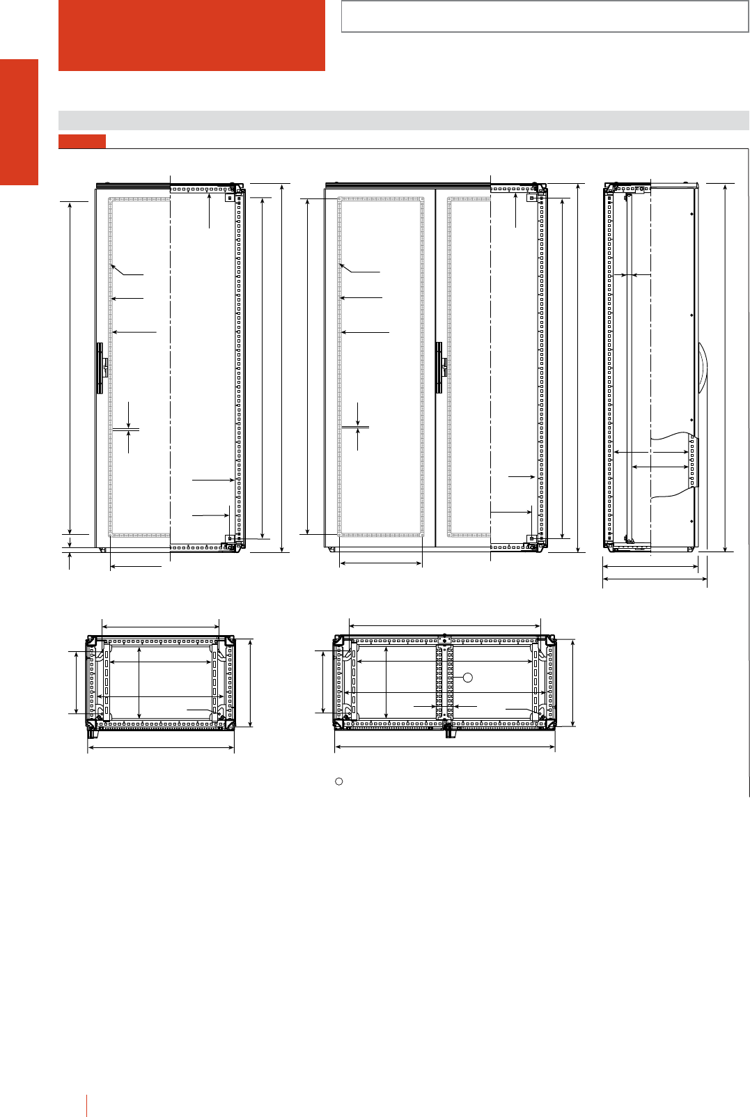
OLN INDUSTRIAL CUBICLE SYSTEM
1/84 HIMEL OLN industrial cubicle system
C + 16
C + 60
A + 11
C-90
min. 80
max. C-90
25
A-150
B-150
B-90
B/2-150
∅ 10
∅ 5
■
18 x 18
12.5
A-90
A-150
A
B-150
A-150
A
B-150
B-90
■
18 x 18
A-150
12.5
24
∅ 10
∅ 5
A-90
B
-169
*
B
C-164*
C
∅12.5
B-110
B-247*
C-110
B-169*
B
C-164*
C
∅12.5
B-110
C-110
B-247
90
1
Dimensions (mm)
* Ground or plinth fixing dimensions. 1Central crossbar for the 1200 width enclosure.
FIG. 1
IP55 (EN 60529)
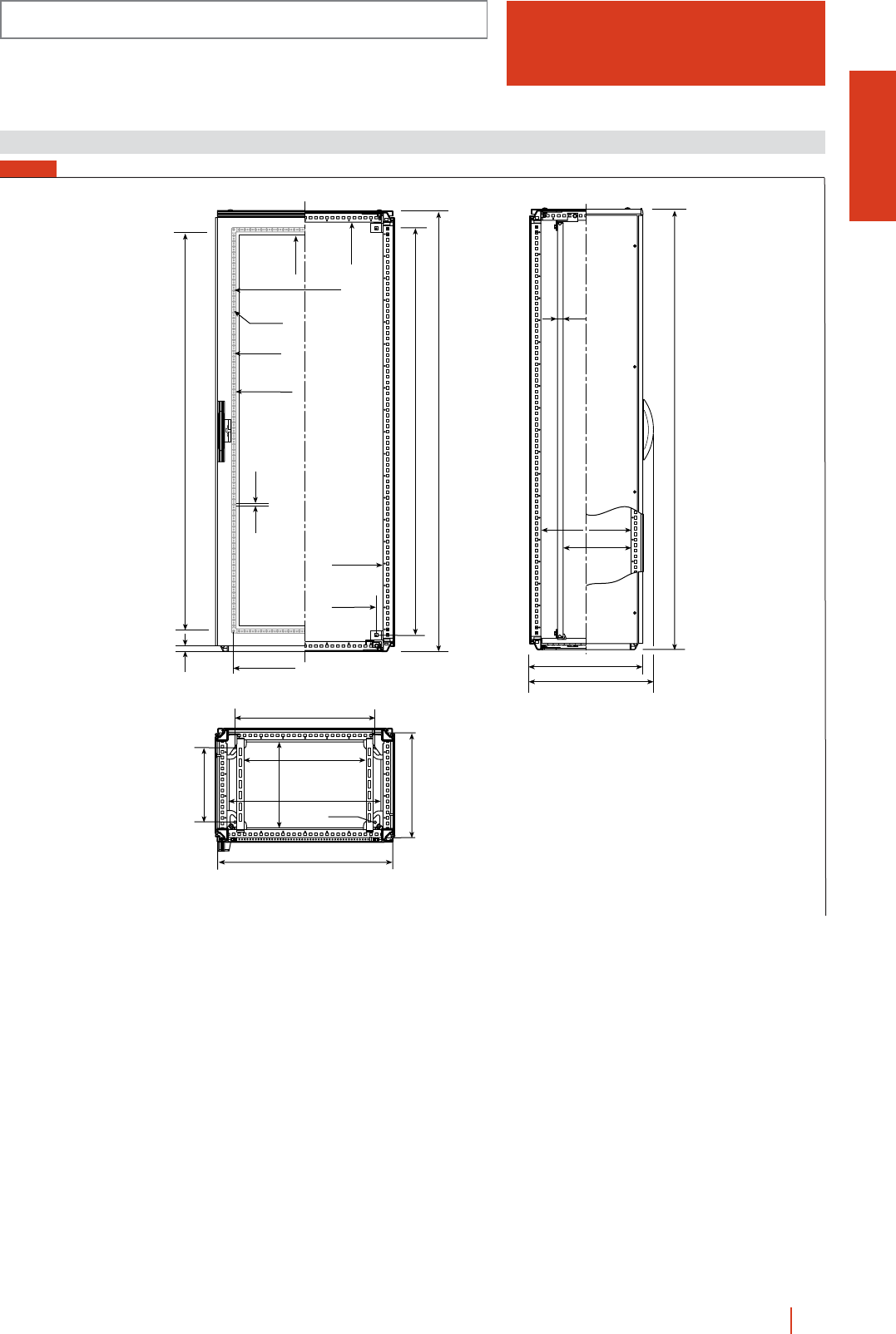
1/85OLN industrial cubicle system HIMEL
OLN.../... KT
INDUSTRIAL CUBICLE SYSTEM
WITH GLAZED DOOR
B-169*
B
C-164*
C
∅ 12.5
B-110
B-247*
C-110
B-150
A-150
A
B-150
B-90
■
18 x 18
A-150
12.5
24
∅ 10
∅ 5
A-90
A-262
B-205
C + 16
C + 60
A + 11
C-90
min. 80
max. C-90
25
Dimensions (mm)
* Ground or plinth fixing dimensions.
FIG. 1
IP55 (EN 60529)
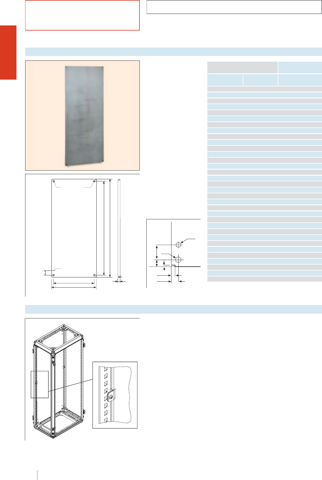
BASIC COMPONENTS
1/86 HIMEL OLN industrial cubicle system
OLN
Made of sheet steel with
reinforced edges. Vertical
ones are double folded
for extra rigidity. Painted
to orange RAL-2000.
Depth adjustable every
25 mm. Easy mounting
by sliding it through the
bottom guides.
Whenever mounting
plates for suites of two or
more cubicles are
required, a continuous
mounting surface can be
obtained by means of
intermediate mounting
plates.
cMax. load 600 kg (with
plate right at the back)
and 500 kg if placed in
the middle.
Mounting plates
Height
(A)
Cubicle dimensions
Width
(B) Reference
1000 1000 PMOL 1010
1200 500 PMOL 125*
1200 600 PMOL 126
1200 800 PMOL 128
1200 1000 PMOL 1210
1200 1200 PMOL 1212
1400 500 PMOL 145*
1400 600 PMOL 146
1400 800 PMOL 148
1400 1000 PMOL 1410
1400 1200 PMOL 1412
1600 500 PMOL 165*
1600 600 PMOL 166
1600 800 PMOL 168
1600 1000 PMOL 1610
1600 1200 PMOL 1612
1800 500 PMOL 185*
1800 600 PMOL 186
1800 800 PMOL 188
1800 1000 PMOL 1810
1800 1200 PMOL 1812
1800 1600 PMOL 1816
2000 500 PMOL 205*
2000 600 PMOL 206
2000 800 PMOL 208
2000 1000 PMOL 2010
2000 1200 PMOL 2012
2000 1600 PMOL 2016
2200 500 PMOL 225*
2200 600 PMOL 226
2200 800 PMOL 228
2200 1000 PMOL 2210
2200 1200 PMOL 2212
* Plates designed to be joined depth-wise in the enclosure.
Ø9
Ø22
11.5
23.5
5
50
23
B-150
B-103
ø9
ø22 10x18
50
25
A-150
A-102
Set of 10 fixings.
Intermediate fixings for
mounting plate
assembled at the back
enclosure.
Ref.: FIPMOL.
Intermediate mounting plate fixing
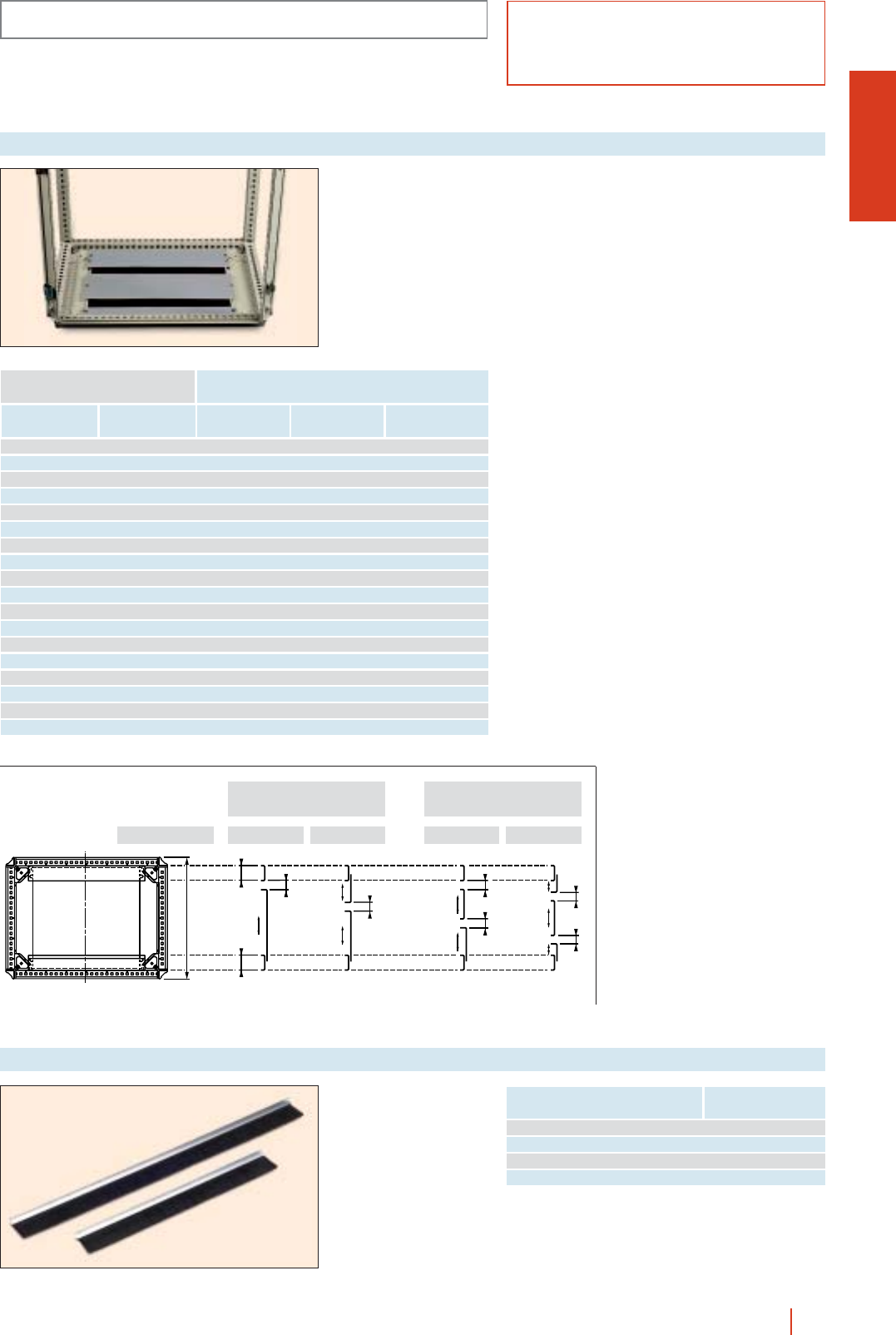
1/87OLN industrial cubicle system HIMEL
BASIC COMPONENTS OLN
Cable gland plates for
cable entry through the
cubicle bottom, with
neoprene gasket
ensuring good sealing.
Available with one or
two entries.
Cable gland plate
Width
(B)
Size enclosures
Depth
(C) With one entry With two entries
400 500 ECON 45/0 ECON 45/1
400 600 ECON 46/0 ECON 46/1 ECON 46/2
600 400 ECON 64/0 ECON 64/1
600 500 ECON 65/0 ECON 65/1
600 600 ECON 66/0 ECON 66/1 ECON 66/2
600 800 ECON 68/0 ECON 68/1 ECON 68/2
800 400 ECON 84/0 ECON 84/1
800 500 ECON 85/0 ECON 85/1
800 600 ECON 86/0 ECON 86/1 ECON 86/2
800 800 ECON 88/0 ECON 88/1 ECON 88/2
1000 400 ECON 104/0 ECON 104/1
1000 500 ECON 105/0 ECON 105/1
1000 600 ECON 106/0 ECON 106/1 ECON 106/2
1000 800 ECON 108/0 ECON 108/1 ECON 108/2
1200 400 ECON 124/0 ECON 124/1
1200 500 ECON 125/0 ECON 125/1
1200 600 ECON 126/0 ECON 126/1 ECON 126/2
1200 800 ECON 128/0 ECON 128/1 ECON 128/2
Plain
8080
a
a
a
a a
a
C
Adjustment possibilities
of cable gland plates 2 part cable gland
plate
a: 25 to 50 mm
600 800800400-500-600Depth (C)
3 part cable gland
plate
*For 1200 width enclosures, use 2 references.
Width
cubicle/desk Reference
400 JPON 4
600/1200* JPON 6
800 JPON 8
1000 JPON 10
Set of 2 “brush type”
cable entry gaskets for
installation in cut-out
cable gland plates in
ECON.
cClip-attached.
cBlack plastic fibre
“brush”.
“Brush-type” cable entry gasket
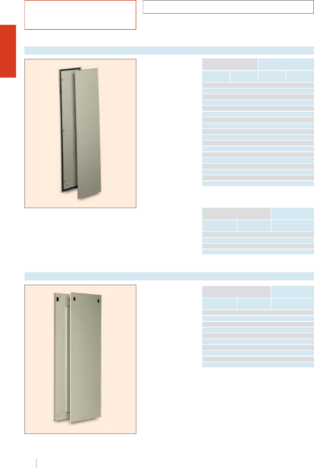
OLN
1/88 HIMEL OLN industrial cubicle system
BASIC COMPONENTS
Set of 2 side panels for
fitting inside or outside
the enclosure.
Manufactured in steel
sheet and painted with
textured grey RAL-7032
polyester epoxy resin
paint.
cFully gasketed,
includes a all the
necessary screw
fittings.
Cut-out side panels
for air-conditioning
installations
(see page 5/54)
Internal or external fixing side panel
Height
Enclosure dimensions (mm)
Depth Reference
1800 600 2 PLOL 186 CLM
1800 800 2 PLOL 188 CLM
2000 600 2 PLOL 206 CLM
2000 800 2 PLOL 208 CLM
Height
Enclosure dimensions (mm) Reference
Depth Internal
fitting
1200 400 2 PLOL 124 2 PLIOL 124
1200 600 2 PLOL 126 2 PLIOL 126
1200 800 2 PLOL 128 2 PLIOL 128
1400 400 2 PLOL 144 2 PLIOL 144
1400 600 2 PLOL 146 2 PLIOL 146
1400 800 2 PLOL 148 2 PLIOL 148
1600 600 2 PLOL 166 2 PLIOL 166
1600 800 2 PLOL 168 2 PLIOL 168
1800 400 2 PLOL 184 2 PLIOL 184
1800 500 2 PLOL 185 2 PLIOL 185
1800 600 2 PLOL 186 2 PLIOL 186
1800 800 2 PLOL 188 2 PLIOL 188
2000 400 2 PLOL 204 2 PLIOL 204
2000 500 2 PLOL 205 2 PLIOL 205
2000 600 2 PLOL 206 2 PLIOL 206
2000 800 2 PLOL 208 2 PLIOL 208
2200 600 2 PLOL 226 2 PLIOL 226
2200 800 2 PLOL 228 2 PLIOL 228
External
fitting
Set of two side panels for
fitting to the outside of
the enclosure by double
bar locks. Manufactured
in sheet steel and
painted with textured
grey RAL-7032 polyester
epoxy resin paint.
cWithout sealing
gasket.
Quick fitting side panel
Height
Enclosure dimensions (mm)
Depth Reference
1200 600 2 PLROL 126
1200 800 2 PLROL 128
1400 600 2 PLROL 146
1400 800 2 PLROL 148
1600 600 2 PLROL 166
1600 800 2 PLROL 168
1800 600 2 PLROL 186
1800 800 2 PLROL 188
2000 600 2 PLROL 206
2000 800 2 PLROL 208
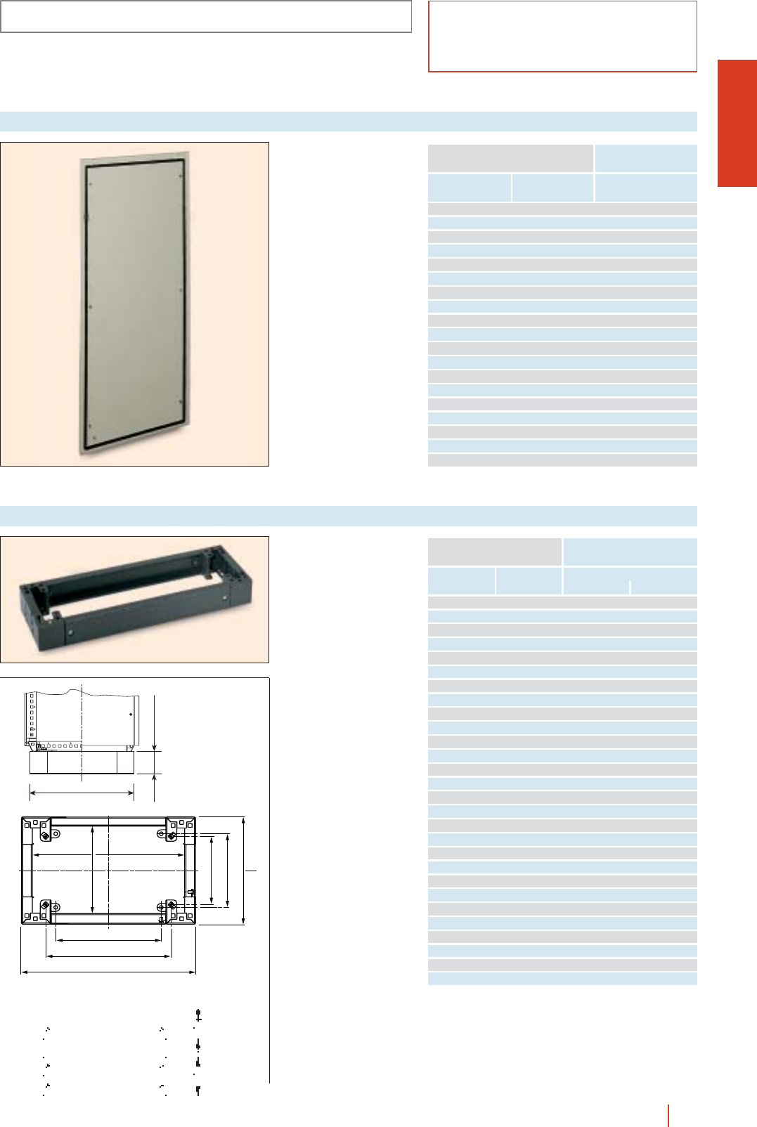
OLN
1/89OLN industrial cubicle system HIMEL
Back panel fixed to the
cubicle from the inside.
Made of sheet steel and
painted with polyester-
epoxy resin to texturized
RAL-7032.
cSupplied with foamed
gasket and fixing
accessories.
Internal fixing back panel
Height
Cubicle dimensions (mm)
Width Reference
1200 600 PPION 126
1200 800 PPION 128
1400 600 PPION 146
1400 800 PPION 148
1600 600 PPION 166
1600 800 PPION 168
1800 600 PPION 186
1800 800 PPION 188
1800 1000 PPION 1810
1800 1200 PPION 1812
2000 400 PPION 204
2000 600 PPION 206
2000 800 PPION 208
2000 1000 PPION 2010
2000 1200 PPION 2012
2200 600 PPION 226
2200 800 PPION 228
2200 1000 PPION 2210
2200 1200 PPION 2212
BASIC COMPONENTS
To fit directly to the
cubicles using the
drillings for ground fixing.
c100 and 200 mm high.
cFront and rear access.
cCan be joined side to
side in cubicle suites.
cDark grey to RAL-7022.
Single plinths
Width
(B)
Cubicle dimensions (mm)
Depth
(C)
300 500 ZUN 35/100 ZUN 35/200
300 600 ZUN 36/100 ZUN 36/200
300 800 ZUN 38/100 ZUN 38/200
400 500 ZUN 45/100 ZUN 45/200
400 600 ZUN 46/100 ZUN 46/200
600 300 ZUN 63/100 ZUN 63/200
600 400 ZUN 64/100 ZUN 64/200
600 500 ZUN 65/100 ZUN 65/200
600 600 ZUN 66/100 ZUN 66/200
600 800 ZUN 68/100 ZUN 68/200
800 300 ZUN 83/100 ZUN 83/200
800 400 ZUN 84/100 ZUN 84/200
800 500 ZUN 85/100 ZUN 85/200
800 600 ZUN 86/100 ZUN 86/200
800 800 ZUN 88/100 ZUN 88/200
1000 300 ZUN 103/100 ZUN 103/200
1000 400 ZUN 104/100 ZUN 104/200
1000 500 ZUN 105/100 ZUN 105/200
1000 600 ZUN 106/100 ZUN 106/200
1000 800 ZUN 108/100 ZUN 108/200
1200 300 ZUN 123/100 ZUN 123/200
1200 400 ZUN 124/100 ZUN 124/200
1200 500 ZUN 125/100 ZUN 125/200
1200 600 ZUN 126/100 ZUN 126/200
1200 800 ZUN 128/100 ZUN 128/200
1600 400 ZUN 164/100 ZUN 164/200
1600 500 ZUN 165/100 ZUN 165/200
1600 600 ZUN 166/100 ZUN 166/200
100 mm 200 mm
Height
B - 164
B - 2
C - 145
C - 164
C - 34
B - 228
B - 62
C - 106
100/200
C-34
*Floor fixings.
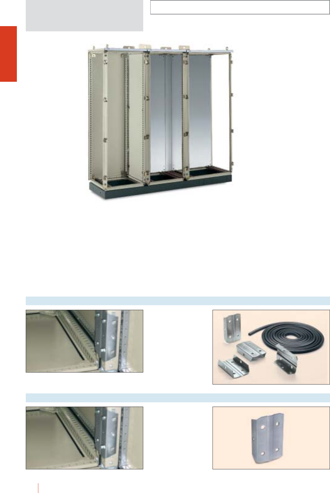
OLN
1/90 HIMEL OLN industrial cubicle system
INSTALLATION SYSTEMS
Any enclosure model can
be joined by forming
suites with the cubicle
joining set.
Reference: CPUT.
Cubicle suite joining set
For reinforcing the join
vetween cubicles.
Reference: PUT.
Reinforced joining part
CUBICLE SUITES
The constructive design of the OLN cubicles is
particularly meant to form suites. The quick easy
joining, both in width and depth and the specific
elements for making assemblies and transport them
allow for the most suitable solution to every electrical
installation.
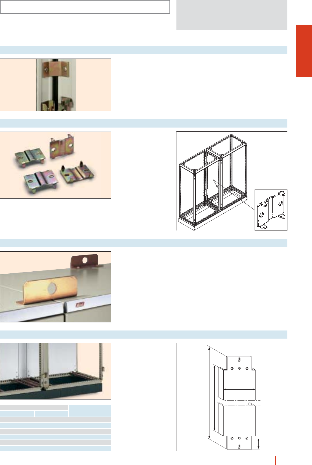
OLN
1/91OLN industrial cubicle system HIMEL
INSTALLATION SYSTEMS
Used to attach cubicles
from the outside
(if internal joining
is impossible).
Reference: CUNE.
Outside cubicle suite joining set
Galvanised sheet steel
intermediate plate to
provide a continuous
mounting plate surface
when joining cubicles.
If the PMOL mounting
plates are located in the
bottom of the cubicles,
the vertical profiles of the
actual cubicle structure
are flush with the plates,
acting as an intermediate
plate. In this case it
would not be possible (or
necessary) to install the
intermediate plate.
Intermediate mounting plate
Height (A)
Cubicle measurements
HReference
1200 1084 PMI 12
1400 1284 PMI 14
1600 1484 PMI 16
1800 1684 PMI 18
2000 1884 PMI 20
2200 2084 PMI 22
107
42
H
H - 96
Set of 4 brackets to join
OLN enclosures as a
CPUT complement when
the angles of the
enclosure are fitted with
accessories (as 19"
swing rack or UNIDIS
chassis) or as other
joining system
reinforcement.
Ref.: CSUT.
Inside cubicle suite joining set
Set of 2 lifting brackets.
Attaches across two
adjacent enclosures,
giving extra rigidity for
lifting, using the same
holes as for the lifting
eyes. Guarantee rigidity
of the assembly on lifting.
For details of enclosure
slinging see page 1/75.
Reference: PUN.
Lifting brackets
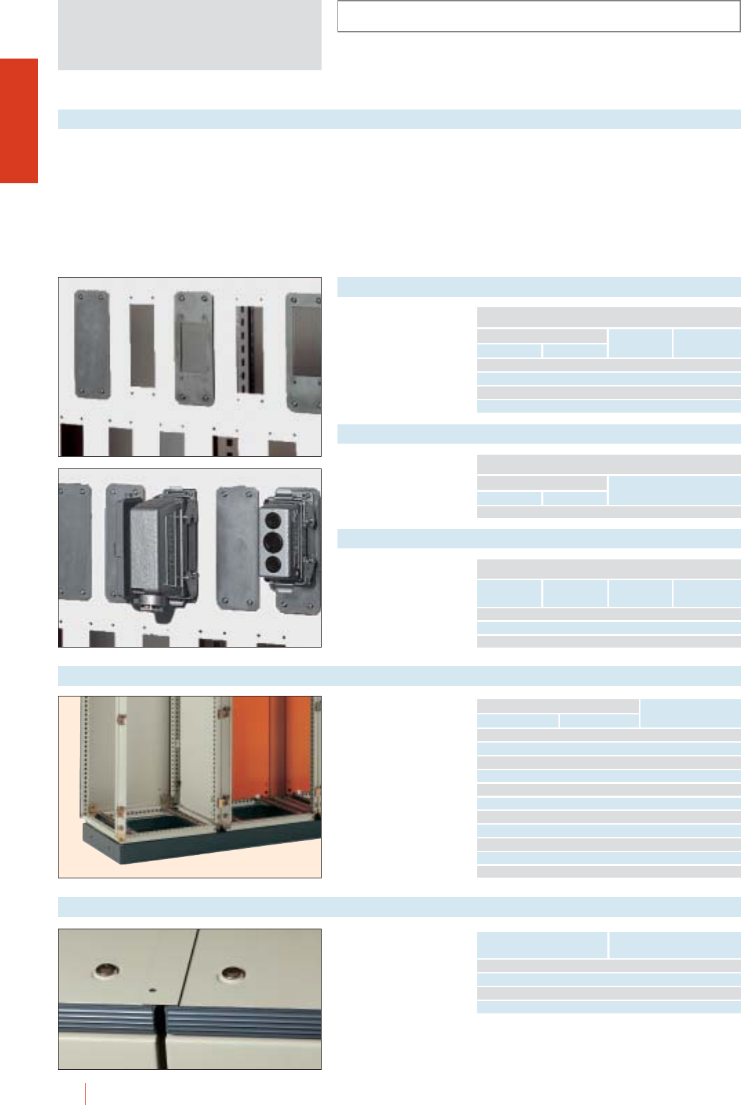
OLN
1/92 HIMEL OLN industrial cubicle system
INSTALLATION SYSTEMS
Connections for machines, robot outputs, interconnections between cubicles... they all need a partition that makes it possible to assemble
with Harting-type industrial plug sockets.
cThis new partition is adapted to OLN enclosures by being attached to the frame structure.
cThe sheets available in different dimensions are fitted with a watertight gasket, and feature numerous drillings.
cUnused drill holes can be covered by blankers.
cThere are 3 reducer models available for adaptation to the different types of connectors.
cEasy-to-fit sockets.
cFully watertight.
cGalvanised sheet steel.
cSheets wupplied with
gaskets and fixing
screws.
Connector separation sheets
CONNECTOR SEPARATION SHEETS
Height
Enclosure dimensions (mm)
Depth
Plates
reference
No. of
drillings
1800 500 CHSC185 36
1800 600 CHSC186 45
2000 500 CHSC205 40
2000 600 CHSC206 50
cFully gasketed
galvanised sheet steel
15/10 mm sheet steel.
Blank plates
BLANK PLATES
Height
External dimensions (mm)
Width
Ref. branker
150 55 OBTC24
cFully gasketed
galvanised sheet steel
15/10 mm sheet steel.
Reducers
REDUCERS
Accessories for joining cubicles
Model Reference
reducer
External
dimensions (mm)
Opening
socket
24/6 REDC24/6 150 55 52 36
24/10 REDC24/10 150 55 64 36
24/16 REDC24/16 150 55 86 36
To obtain separate
compartments in cubicle
joining suites. Made of
textured grey sheet steel
painted to RAL-7032.
Cubicle separation sheet
Height (A)
Cubicle measurements
Depth (C) Reference
1600 600 CHS 166
1600 800 CHS 168
1800 400 CHS 184
1800 500 CHS 185
1800 600 CHS 186
2000 400 CHS 204
2000 500 CHS 205
2000 600 CHS 206
2000 800 CHS 208
2200 600 CHS 226
2200 800 CHS 228
cColour RAL-7032.
cWhere joining cubicles.
Top dust protector
Enclosure
depth (mm) Reference
400 GPON40
500 GPON50
600 GPON60
800 GPON80
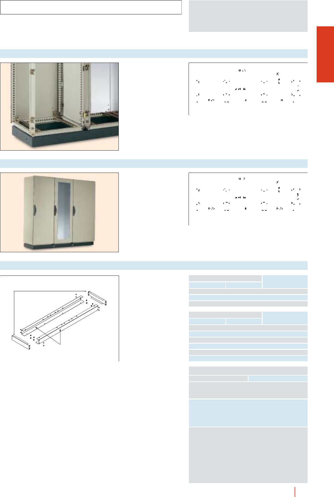
OLN
1/93OLN industrial cubicle system HIMEL
INSTALLATION SYSTEMS
Made of 3 mm thick “U”
profiles for cubicle suites
up to 3 m wide. Grey
colour to RAL-7022.
cPossibility of side
joining for wider suites.
c100 y 200 mm heights.
Reference: ZUN/C.
Suite plinths
Made of 3 mm thick “U”
profile (100 mm high).
Supplied with or without
painting (to RAL-7022).
cHoles for lifting bars
provided
Reference: ZUN/T.
See “Lifting and
transport” on page 1/75.
Transport plinths
Medidas armario
1600 100 ZUN/CD100 FP16
1800 100 ZUN/CD100 FP18
2400 100 ZUN/CD100 FP24
1600 200 ZUN/CD200 FP16
1800 200 ZUN/CD200 FP18
2400 200 ZUN/CD200 FP24
Total width Plinth height Reference
1600 100 ZUN/CD100 FP16
1800 100 ZUN/CD100 FP18
2400 100 ZUN/CD100 FP24
1600 200 ZUN/CD200 FP16
1800 200 ZUN/CD200 FP18
2400 200 ZUN/CD200 FP24
Total depth
Enclosure dimensions
Plinth height* Reference
500 100/200 ZUN/CD100/2L5
600 100/200 ZUN/CD100/2L6
800 100/200 ZUN/CD100/2L8
Set of two “U” profiles
and one or two sets of
“U” side profiles (for
100 or 200 mm high),
1.5 mm thick. Painted
RAL-7022.
* For 200 mm high plinths
2 sets must be ordered.
Modular plinth for joining cubicles
POSSIBLE COMBINATIONS
Total plinth width Enclosures width
1600 600 + 100
800 + 800
1000 + 600
1800 600 + 600 + 600
600 + 1200
800 + 1000
1000 + 800
1200 + 600
2400 600 + 600 + 600 + 600
600 + 600 + 1200
600 + 800 + 1000
600 + 1200 + 600
800 + 600 + 1000
800 + 800 + 800
800 + 1000 + 600
1000 + 600 + 800
1200 + 600 + 600
1200 + 1200
ZUN/CD100/2L...
ZUN/CD...FP...
B and C = cubicle nominal dimensions
B and C = cubicle nominal dimensions
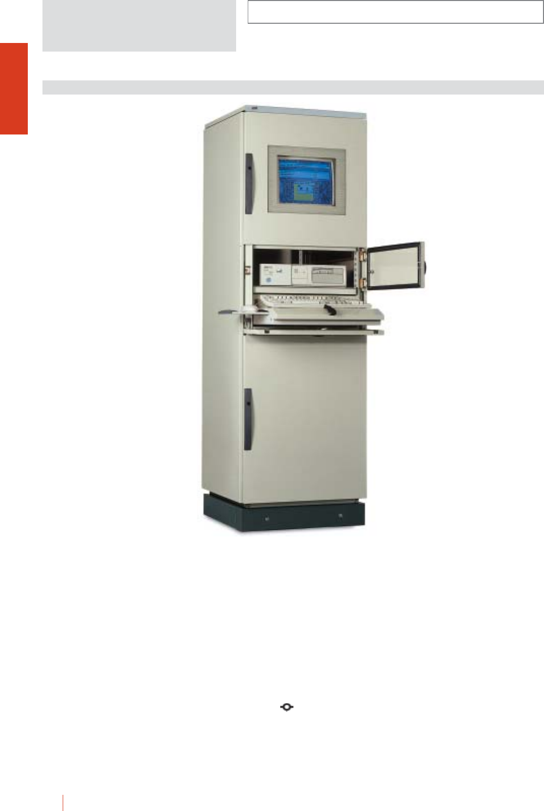
1/94 HIMEL OLN industrial cubicle system
OLNP INSTALLATION SYSTEMS
Metal cubicle consisting of a structure of triangular
closed profiles with welded top and base and vertical
removable bolted profiles, giving the assembly and
optimum stability and versatility. Painted internally and
externally with polyester-epoxy resin to texturized
RAL-7032.
cGreat accessibility.
cMaximum versatility for all kind of installations.
c120° door opening.
c4 point locking system outside the gasketed area. Several
transformation and locking possibilities.
cGlazed templated glass door with sliding guides.
Basic cubicle:
cWelded top.
cWelded base.
cVertical uprights.
cRemovable roof.
cRemovable side panels.
cTop front glazed door.
cKeyboard panel.
cPlain bottom door.
cMonitor supporting tray.
cKeyboard sliding tray.
cBack door without door reinforcement frame.
c2 part cable gland plate.
OLNP 186/60 + ZUN 66/100
PC APPLICATION
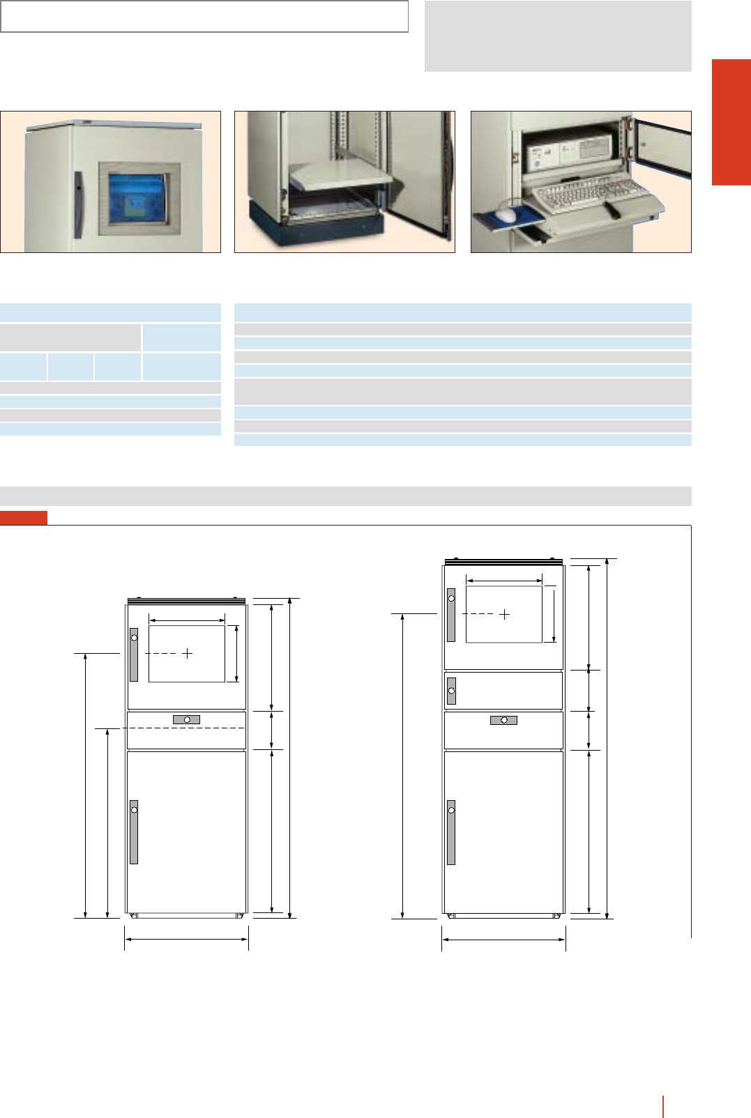
1/95OLN industrial cubicle system HIMEL
OLNP
INSTALLATION SYSTEMS
Detail of glazed door for 14” or 17” monitor. Optional printer tray support. Compartment with adjustable tray for
keyboard and mouse.
REFERENCES AND DIMENSIONS
Height
(A)
External dimensions
(mm)
Width
(B) Reference
1600 600 600 OLNP 166/60
1600 600 800 OLNP 166/80
1800 600 600 OLNP 186/60
1800 600 800 OLNP 186/80
Depth
(C)
ACCESSORIES AND COMPLEMENTS
Fixed tray 510 390 mm BFOL64
Adjustable tray 510 390 mm BDOL64
Tray fixing crossbeams for 600 mm deep cubicles TML40/60
Tray fixing crossbeams for 800 mm deep cubicles TML40/80
A4 printer tray
For 800 mm depth enclosures you should use 2 TML 40/80 cross rails SIMPA 4
A3 printer tray SIMPA 3
Line protection switch socket block ZDBE6P
Switch socket block ZDBE6I
Dimensions (mm)
(B) 600
900
590195747
1603.5
1300
(B) 600
590195 195747
1803.5
1500
375
285
375
285
FIG. 1
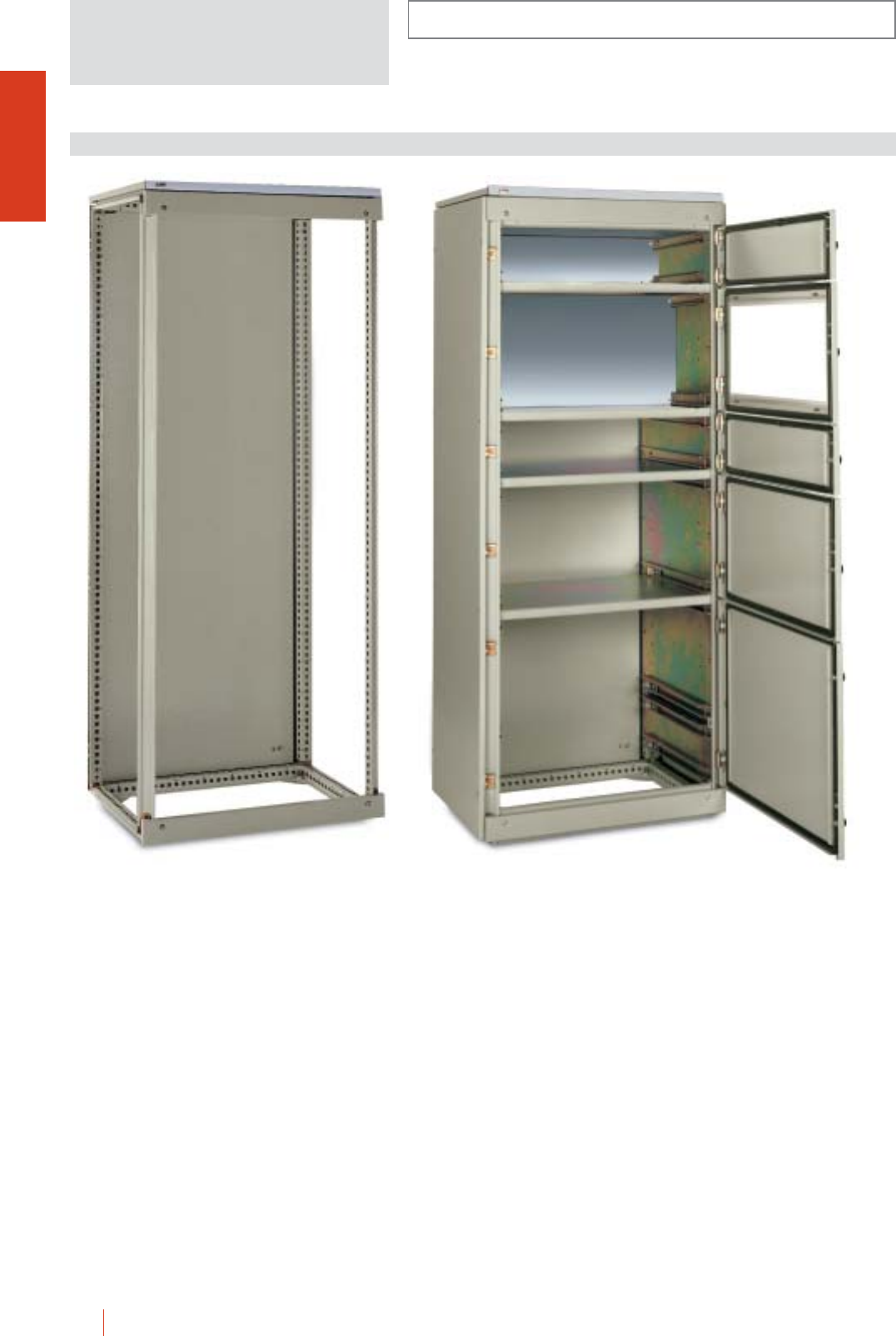
1/96 HIMEL OLN industrial cubicle system
Metal cubicle consisting of a structure of triangular
closed profiles with welded top and base and vertical
removable bolted profiles, giving the assembly and
optimum stability and versatility. Painted internally and
externally with polyester-epoxy resin to texturized
RAL-7032.
The OLNM system allows to combine partial doors
from 200 mm in height up to 1000 mm (multiples of
200 mm) at the front. Also, 19” racks, depth adjustable
mounting plates, back locks and front and rear side
covers. Electrical feeding can be done through the top,
the base or sides by means of the busbar
compartments. This system offers a quick personalized
installation.
cGreat accessibility.
cMaximum versatility for all kind off installations.
Basic cubicle:
cWelded top.
cWelded base.
cVertical uprights.
cRemovable roof.
cRemovable back panel.
cModular top and bottom front panels.
OLNM 208/60
OLNM INSTALLATION SYSTEMS
INDUSTRIAL CUBICLE SYSTEM FOR MOTOR CONTROL CENTRE
OLNM 206/60 + PPMC 2060 N + PPMC 4060 N KT +
PPMC 2060 N + PPMC 4060 N + PPMC 6060 N
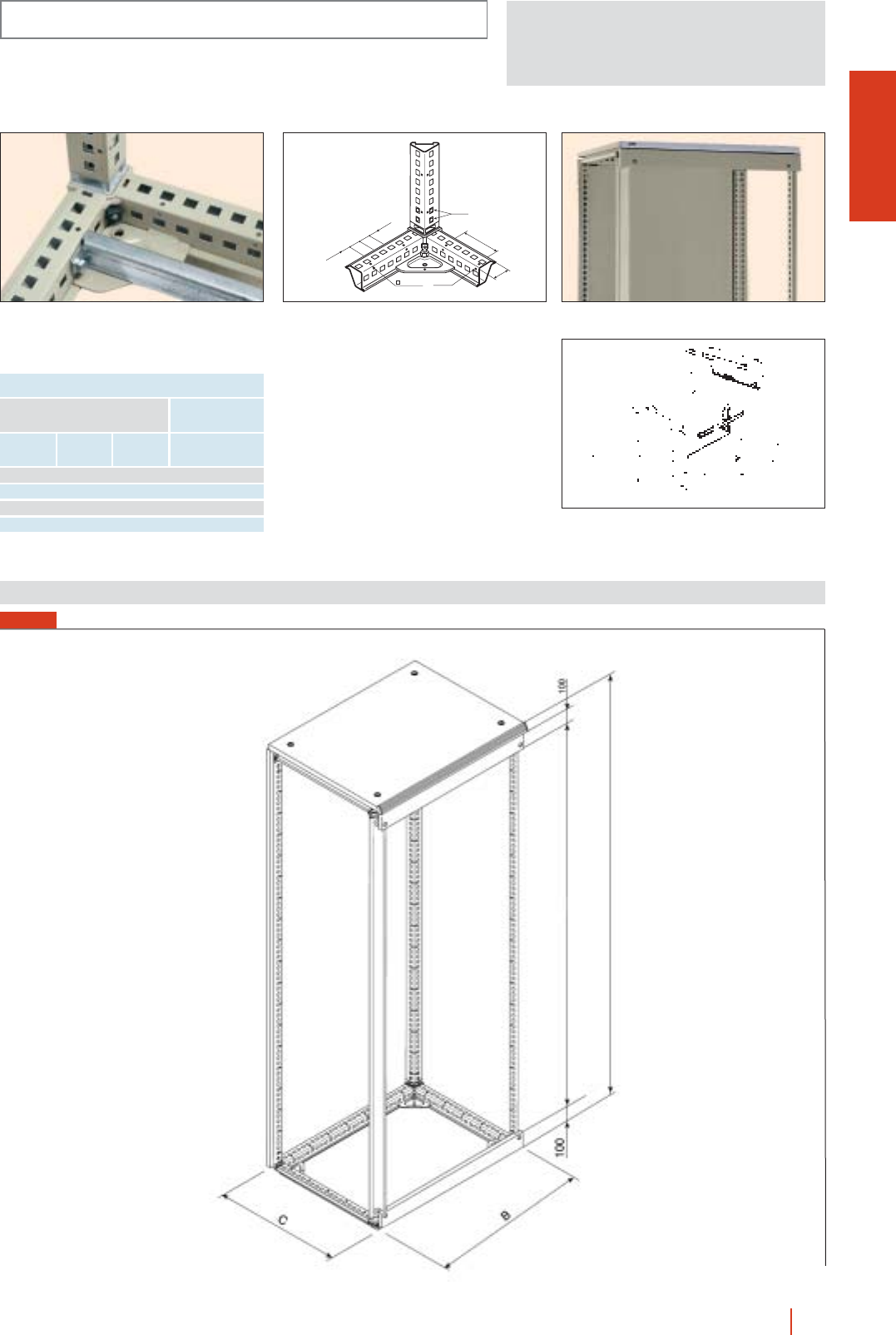
1/97OLN industrial cubicle system HIMEL
25
M.8
100
∅5
11 x 13
252525
45
Profile structure with triangular profile drilled
1113 with 25 mm centres and reference Ø 5 mm
hole every 100 mm.
Detail of modular top front panel.
Detail of compartments and partial doors of
OLNM system.
ENCLOSURES, DIMENSIONS AND REFERENCES
Height
(A)
External dimensions
(mm)
Width
(B) Reference
2000 600 600 OLNM 206/60
2000 600 800 OLNM 206/80
2000 800 600 OLNM 208/60
2000 800 800 OLNM 208/80
Depth
(C)
Dimensions (mm)
OLNM
INSTALLATION SYSTEMS
FIG. 1
1800
A=2000
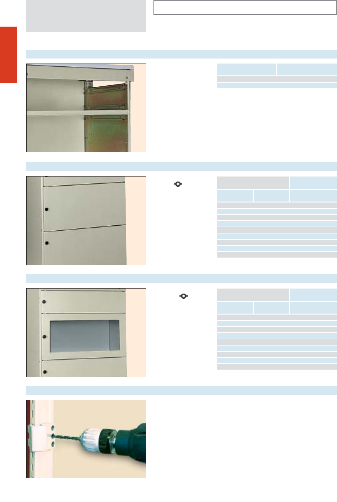
INSTALLATION SYSTEMS
OLN
1/98 HIMEL OLN industrial cubicle system
Intermediate crossbar
Plain door with double
bar lock . Various
locking possibilities
available.
Painted to RAL-7032.
Partial doors
Width
Nominal dimensions
(mm)
ReferenceHeight
600 200 PPMC 2060 N
400 PPMC 4060 N
600 PPMC 6060 N
800 PPMC 8060 N
1000 PPMC 10060 N
800 400 PPMC 4080 N
600 PPMC 6080 N
800 PPMC 8080 N
1000 PPMC 10080 N
Transparent templated
glass door .
Various locking
possibilities available.
Painted to RAL-7032.
KT glazed partial doors
Width
Nominal dimensions
(mm)
ReferenceHeight
600 200 PPMC 2060 N KT
400 PPMC 4060 N KT
600 PPMC 6060 N KT
800 PPMC 8060 N KT
1000 PPMC 10060 N KT
800 400 PPMC 4080 N KT
600 PPMC 6080 N KT
800 PPMC 8080 N KT
1000 PPMC 10080 N KT
Drilling template
For partial door fixing to
enclosure front.
Reference: PLTON.
Fitting between partial
doors or between doors
and control desks.
Painted to RAL-7032.
Width Reference
600 TIMC 60 N
800 TIMC 80 N
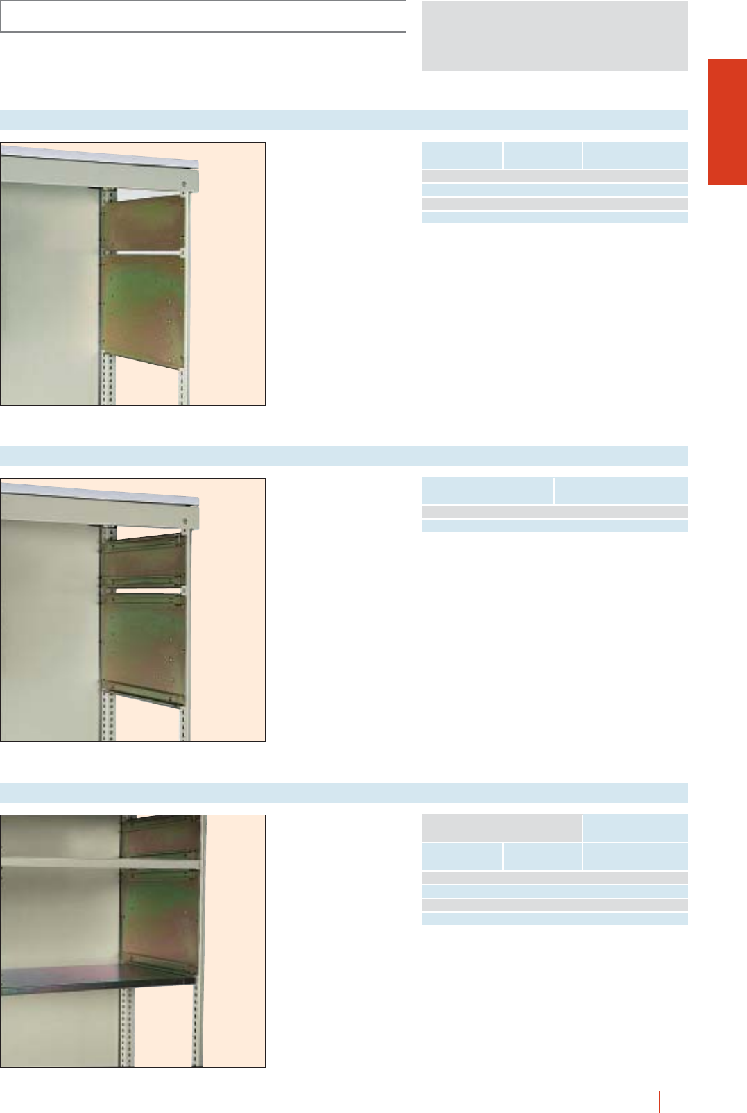
OLN
INSTALLATION SYSTEMS
1/99OLN industrial cubicle system HIMEL
For adjustment of
mounting plate.
Rail guides
Nominal dimensions
(mm) Reference
600 4DPMC 60
800 4DPMC 80
Separation between
doors.
Compartmental tray
Height
Nominal dimensions
(mm)
ReferenceDepth
600 400 BSMC 6040
600 500 BSMC 6050
800 400 BSMC 8040
800 500 BSMC 8050
Closing side covers to
form compartments.
Side covers
Height ReferenceDepth
200 600 2TLMC 2060
200 800 2TLMC 2080
400 600 2TLMC 4060
400 800 2TLMC 4080
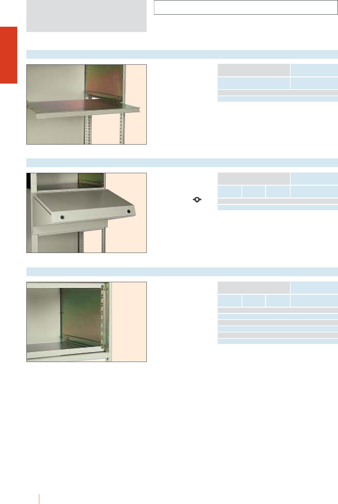
INSTALLATION SYSTEMS
OLN
1/100 HIMEL OLN industrial cubicle system
To fit between partial
doors separated by
BSMC tray.
Painted to RAL-7032.
Tray crossbar
Width
Nominal dimensions
(mm)
Reference
600 TBMC 60
800 TBMC 80
Can be located (as
partial doors) anywhere
on the cubicle. Painted
to RAL-7032. Folding
panel with locks .
Control desks
Height Width Depth
Nominal dimensions
(mm)
Reference
400 600 500 PKMC 60
400 800 500 PKMC 80
Fixing of 19"
equipment.
19" RACK
Height No. units Width
Nominal dimensions
(mm)
Reference
200 3 600 BRF 3 MC
400 7 600 BRF 7 MC
600 12 600 BRF 12 MC
800 16 600 BRF 16 MC
1000 21 600 BRF 21 MC
1200 25 600 BRF 25 MC
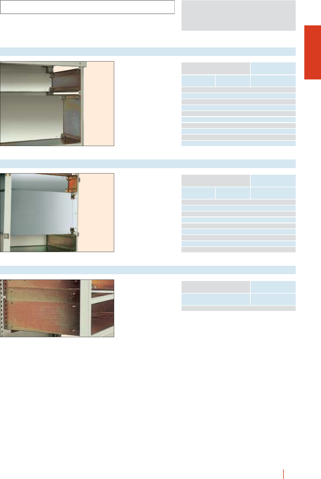
OLN
INSTALLATION SYSTEMS
1/101OLN industrial cubicle system HIMEL
For fixing or equipment.
Painted to RAL-2000.
Mounting plates
Width Height
Nominal dimensions
(mm)
Reference
600 200 PMMC 2060 N
400 PMMC 4060 N
600 PMMC 6060 N
800 PMMC 8060 N
1000 PMMC 10060 N
800 200 PMMC 2080 N
400 PMMC 4080 N
600 PMMC 6080 N
800 PMMC 8080 N
1000 PMMC 10080 N
To fit between TLMC
side covers.
Side closing
Depth
Nominal dimensions
(mm)
Reference
600 CLCM 60
Closing back covers to
form compartments.
Back covers
Height Width
Nominal dimensions
(mm)
Reference
600 200 TPMC 2060
400 TPMC 4060
600 TPMC 6060
800 TPMC 8060
1000 TPMC 10060
800 400 TPMC 4080
600 TPMC 6080
800 TPMC 8080
1000 TPMC 10080
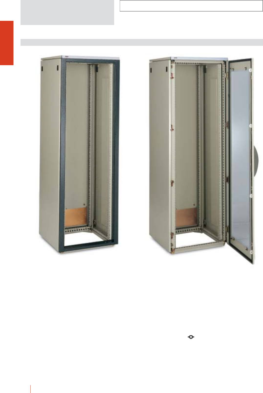
1/102 HIMEL OLN industrial cubicle system
OLNE.../... SP
Metal cubicle consisting of a structure of triangular
closed profiles with welded top and base and vertical
removable bolted profiles, giving the assembly and
optimum stability and versatility.
Painted internally and externally with polyester-epoxy
resin to texturized RAL-7032.
Basic cubicle:
OLNE.../...SP cubicle
cWelded top.
cWelded base.
cVertical uprights.
cRemovable roof.
cQuick fixing side panels.
c2 removable back panels.
cFront frame.
cFront and rear 19” profiles.
OLNE.../...KT cubicle
cWelded top.
cWelded base.
cVertical uprights.
cRemovable roof.
cQuick fixing side panels.
c2 removable back panels.
cFront and back 19” profiles.
cFront glazed door with lock.
c120° door opening.
c4 point locking system outside the gasketed area.
Standard 5 mm double bar handle lock.
Several transformation and locking possibilities.
OLNE 186/60 SP OLNE 186/60 KT
INSTALLATION SYSTEMS
INDUSTRIAL CUBICLE SYSTEM FOR ELECTRONICS
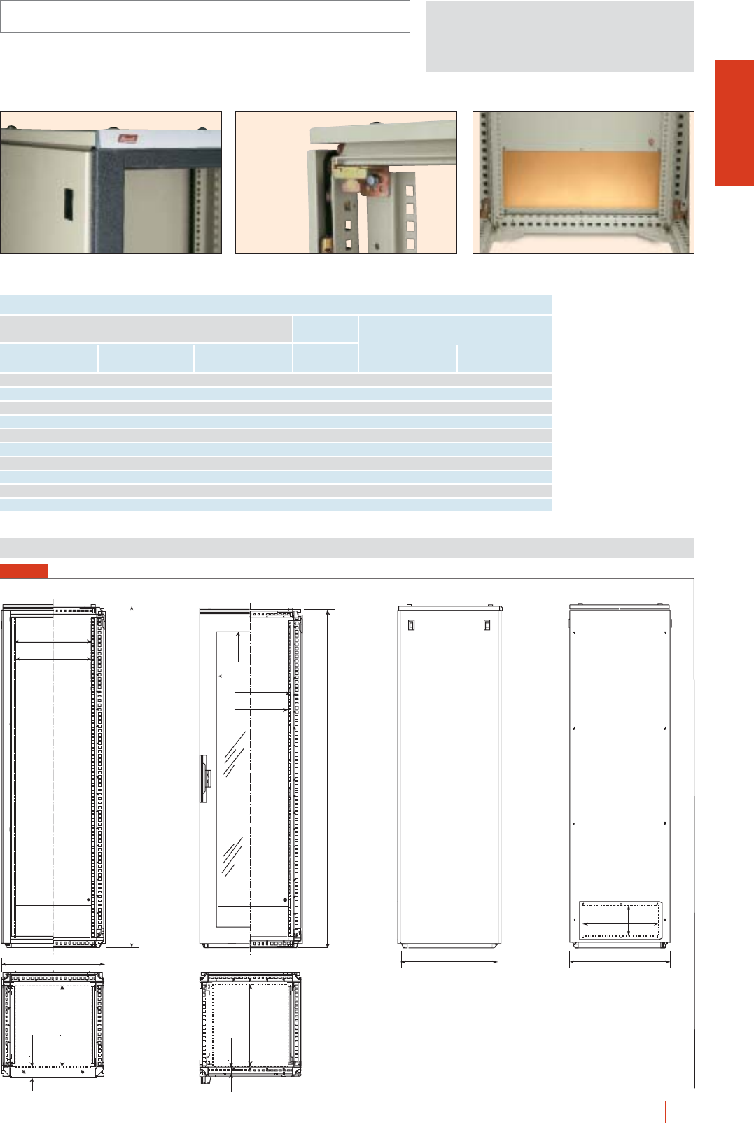
1/103OLN industrial cubicle system HIMEL
OLNE.../... SP
Detail of front frame and lock on removable quick
fixing side panel.
Detail of BRF profile fixing. Bottom view of back panel.
465
450
B = 600
A
min. 60
max. c-107
C = 800
B = 600
466
178
Dimensions (mm)
REFERENCES AND DIMENSIONS
No. of
units
Height
(A)
External dimensions
(mm)
Width
(B) Without door
Reference
With glazed door
1200 600 600 24 OLNE 126/60 SP OLNE 126/60 KT
1200 600 800 24 OLNE 126/80 SP OLNE 126/80 KT
1400 600 600 29 OLNE 146/60 SP OLNE 146/60 KT
1400 600 800 29 OLNE 146/80 SP OLNE 146/80 KT
1600 600 600 31 OLNE 166/60 SP OLNE 166/60 KT
1600 600 800 31 OLNE 166/80 SP OLNE 166/80 KT
1800 600 600 36 OLNE 186/60 SP OLNE 186/60 KT
1800 600 800 36 OLNE 186/80 SP OLNE 186/80 KT
2000 600 600 42 OLNE 206/60 SP OLNE 206/60 KT
2000 600 800 42 OLNE 206/80 SP OLNE 206/80 KT
Depth
(C)
INSTALLATION SYSTEMS
B-205
465
450
A
min. 60
max. C-107
A-262
FIG. 1
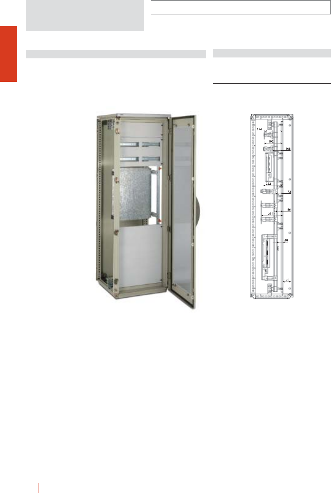
1/104 HIMEL OLN industrial cubicle system
INSTALLATION SYSTEMS
OLN
DINIMEL 2000 CHASSIS DISTRIBUTION SYSTEM
Coupling DINIMEL 2000 chassis set for OLN cubicles
prepared to fit all the necessary components for high
capacity distribution boards.
cDimensional modularity: 150 250 mm to DIN 43870.
cAdjustable distance between equipment and cover plate.
cHeavy-duty special supports for fixing of heavy or bulky
equipment.
cEasy wiring inside the cubicle thanks to the excellent
accessibility of the OLN cubicle.
Dimensions (mm)
OLN 186/60 KT + DM/OL 186 + CTLM 1550/0 +
CTLM 3050/4C + PMCD 6050 + CTLM 6050/0
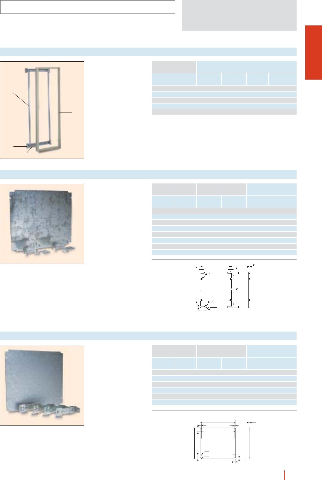
1/105OLN industrial cubicle system HIMEL
OLN
INSTALLATION SYSTEMS
Set consisting of 2 or 4
MCM ➀, uprights 2
crossbars ➁, adapters ➂
cover plate adjustment
set ➃.
DINIMEL 2000 chassis coupling set
Height
(A)
Cubicle dimensions
Width
(B)
Maximum
no. of 18 mm
modules
No. of
150
rows
➞
No. of
250 mm
columns
➞Reference
1600 600 240 10 2 DM/OL 166
1800 600 264 11 2 DM/OL 186
1800 1000 396 11 3 DM/OL 1810
2000 600 288 12 2 DM/OL 206
2000 1000 432 12 3 DM/OL 2010
Standard mounting plates
with SDCD supports
included.
DINIMEL 2000 standard mounting plate
150 mm
Height
To fit modular
sizes (mm)
Plate
dimensions
250 mm
Width ➞
Height
(A)
Width
(B) Reference
150 250 100 220 PMCD 1525
150 500 100 470 PMCD 1550
300 250 250 220 PMCD 3025
300 500 250 470 PMCD 3050
450 250 400 220 PMCD 4525
450 500 400 470 PMCD 4550
600 250 550 220 PMCD 6025
600 500 550 470 PMCD 6050
➞
Reinforced mounting
plates with adjustable
SDCM supports included.
Reinforced DINIMEL 2000 mounting plates
150 mm
Height
To fit to modular
sizes (mm)
Plate
dimensions
250 mm
Width ➞
Height
(A)
Width
(B) Reference
300 500 250 444 PMCM 3050
300 750 250 694 PMCM 3075
450 500 400 444 PMCM 4550
450 750 400 694 PMCM 4575
600 500 550 444 PMCM 6050
600 750 550 694 PMCM 6075
A
R=7
50
ø 9
50
10
B
11
21
10
2.5
➞
B
➀
➂
➁
➃
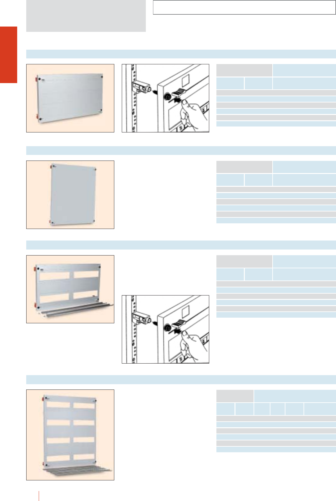
INSTALLATION SYSTEMS
OLN
1/106 HIMEL OLN industrial cubicle system
DINIMEL 2000 insulating blank cover plates
150 mm
Height
To fit to modular
sizes (mm)
250 mm
Width ➞Reference
150 250 CTL 1525/0
150 500 CTL 1550/0
300 250 CTL 3025/0
300 500 CTL 3050/0
600 250 CTL 6025/0
600 500 CTL 6050/0
➞
DINIMEL 2000 insulating cut-out cover plates
150 mm
Height
To fit to modular
sizes (mm)
250 mm
Width ➞Reference
150 250 CTL 1525/1C
150 500 CTL 1550/2C
300 250 CTL 3025/2C
300 500 CTL 3050/4C
600 250 CTL 6025/4C
600 500 CTL 6050/8C
➞
Cut-out covers for CO35D/... rails
(included) for switchgear.
On 500 mm wide covers, 2 extra units
per row can be mounted by cutting out
the separation between openings.
DINIMEL 2000 metal cut-out cover plates
150 mm
Height
To fit to modular
sizes (mm)
250 mm
Width ➞
No. of
openings
No. of
rows
No. of
18 mm
units
Reference
150 250 1 1 12 CTLM 1525/1C
150 500 2 1 24 CTLM 1550/2C
300 250 2 2 24 CTLM 3025/2C
300 500 4 2 48 CTLM 3050/4C
600 250 4 4 48 CTLM 6025/4C
600 500 8 4 96 CTLM 6050/8C
➞
DINIMEL 2000 metal blank cover plates
150 mm
Height
To fit to modular
sizes (mm)
250 mm
Width ➞Reference
150 250 CTLM 1525/0
150 500 CTLM 1550/0
300 250 CTLM 3025/0
300 500 CTLM 3050/0
600 250 CTLM 6025/0
600 500 CTLM 6050/0
➞
Cut-out covers for CO35D/... rails
(included) for switchgear.
On 500 mm wide covers, 2 extra units
per row can be mounted by cutting out
the separation between openings.
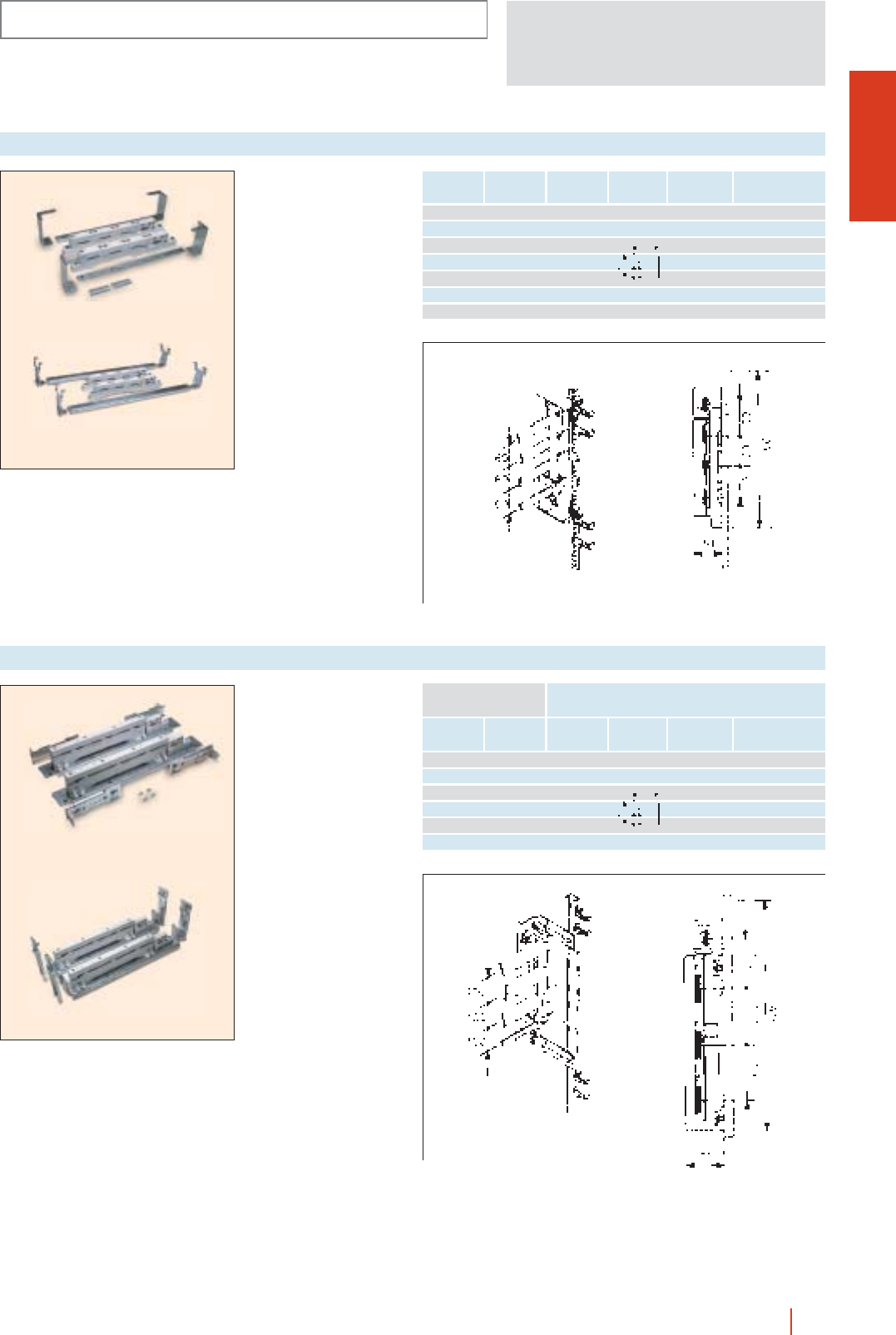
OLN
INSTALLATION SYSTEMS
1/107OLN industrial cubicle system HIMEL
EMH 630 A horizontal
busbar to fit to 300 mm
modules.
EMV 630 A vertical
busbar to fit to chassis
500 mm wide or two
250 mm wide.
EMH 630 A
DINIMEL 2000 630 A busbar
Phase busbar
(mm)
Rated
current (A)
Neutral
bar (mm)
Earth
bar (mm) Reference
12 5 200 12 5-10 6 3EMH 630 A
15 5 250 12 5-10 10 3 (horizontal)
20 5 320 20 5-10 10 6
25 5 390 25 5
30 5 440 30 5
20 10 500 EMV 630 A
30 10 630 (vertical)
EMH 1250 A horizontal
busbar to fit to 600 mm
high modules.
EMV 1250 A vertical
busbar to fit to chassis
500 mm wide or two
250 mm wide.
EMH 1250 A
DINIMEL 2000 1250 busbar
Phase busbar
(mm)
To fit to modular
sizes
Rated
current (A)
Neutral
bar (mm)
Earth
bar (mm) Reference
30 10 630 12 5-10 EMH 1250 A
40 10 850 15 5-10 6 3 (horizontal)
50 10 1000 20 5-10 10 3
60 10 1250 25 5 10 6
30 5EMV 1250 A
(vertical)
EMV 630 A
EMV 1250 A
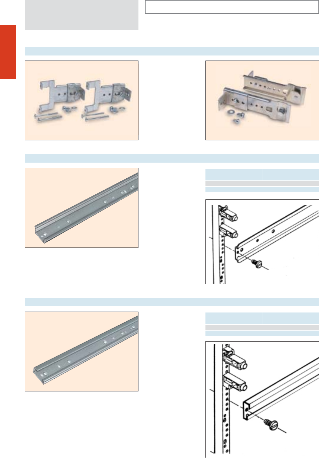
INSTALLATION SYSTEMS
OLN
1/108 HIMEL OLN industrial cubicle system
Set of two supports to fix
directly to the vertical
uprights. Distance
between equipment fitting
surface and inside of
cover marked in mm.
Standard adjustable
supports
Reference: SDCD.
Reinforced adjustable
supports
Reference: SDCM.
DINIMEL 2000 supports
SDCD SDCM
Loose rails to fix directly or
by means of SDCD
adjustable supports to the
vertical uprights.
DINIMEL 2000 DIN-35 reinforced rail
Modular lenght
(mm) Reference
250 CO 3515D/25
500 CO 3515D/50
Loose rails to fix directly
or by means of SDCD
adjustable supports to the
vertical uprights.
DINIMEL 2000 asymmetric rail
Modular length
(mm) Reference
250 CA 32D/25
500 CA 32D/50
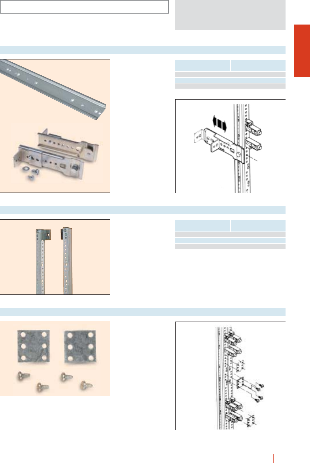
OLN
INSTALLATION SYSTEMS
1/109OLN industrial cubicle system HIMEL
Reinforced rail fixed by
means of SDCM
supports (included).
DINIMEL 2000 reinforced rail with SCDM support
Modular lenght
(mm) Reference
250 CO 3515M/25
500 CO 3515M/50
750 CO 3515M/75
Set of two vertical
uprights.
DINIMEL 2000 uprights
Cubicle dimensions
Height (A) Reference
1600 MCM 1570
1800 MCM 1720
2000 MCM 1870
To reinforce the joining of
uprights.
Reference: UMD.
DINIMEL 2000 coupling units
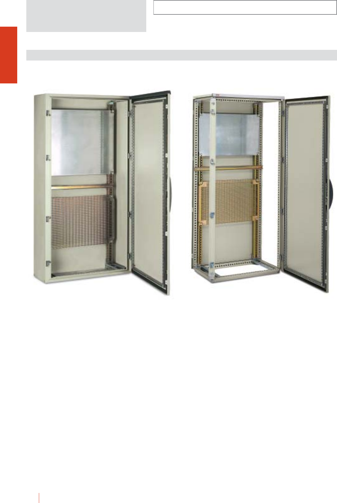
CMO-OLN
1/110 HIMEL OLN industrial cubicle system
INSTALLATION SYSTEMS
UNIVERSAL CHASSIS SYSTEM
Universal chassis prepared to be fitted directly to CMO
and OLN enclosures. Depth adjustable every 25 mm.
Allow for mounting of all kind of equipment on
mounting plate and or DIN rail.
cVertical uprights set.
cPlain, partial and perforated mounting plates and rails.
CMO 168/30 + MOL 160 + PMP 6080
+ PMR 6080 + CDP 80
OLN 166/60 + MOL 160 + PMP 4060
+ PMR 4560 + CDP 60
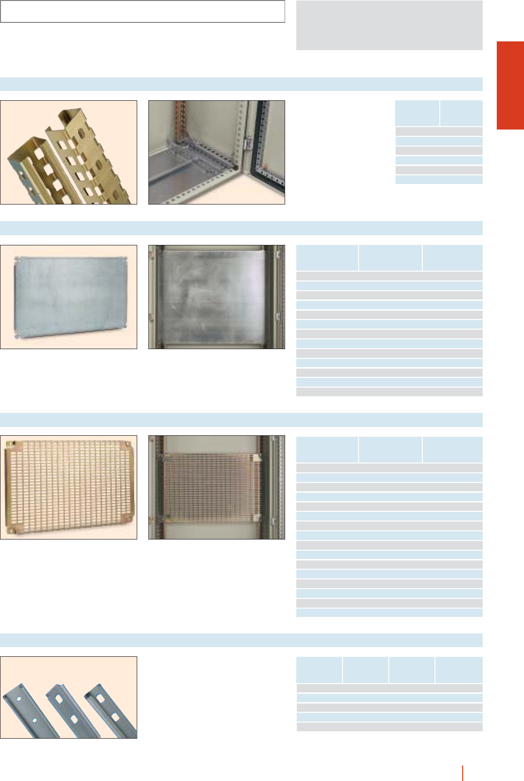
CMO-OLN
INSTALLATION SYSTEMS
1/111OLN industrial cubicle system HIMEL
Set of vertical uprights for
fixing of mounting plates
and rails.
Set of uprights for universal chassis
Enclosure
dimensions
Height (A)
Reference
1000 MOL 100
1200 MOL 120
1400 MOL 140
1600 MOL 160
1800 MOL 180
2000 MOL 200
Partial plain mounting plate for universal chassis
Enclosure dimensions
Width
(B)
Plate height Reference
600 247 PMP 2560
397 PMP 4060
597 PMP 6060
800 247 PMP 2580
397 PMP 4080
597 PMP 6080
1000 247 PMP 25100
397 PMP 40100
597 PMP 60100
1200 247 PMP 25120
397 PMP 40120
597 PMP 60120
1600 397 PMP 40160
Note: in order to fix the mounting plate on
the chassis, the TDM 8 nuts and the
TOR 16/8A screws should be ordered
separatelly.
Enclosure dimensions
Width
(B)
Plate height Reference
600 225 PMR 2260
450 PMR 4560
600 PMR 6060
825 PMR 8260
800 225 PMR 2280
450 PMR 4580
600 PMR 6080
825 PMR 8280
1000 225 PMR 22100
450 PMR 45100
600 PMR 60100
825 PMR 82100
1200 225 PMR 22120
450 PMR 45120
600 PMR 60120
825 PMR 82120
Partial perforated mounting plate for universal chassis
Rails for fixing of equipment.
Rails for universal chasis
Enclosure
dimensions
Width (B)
Reference
double profile
Reference
symmetric rail
Reference
assymmetric rail
600 CDP 60 CSON 60 CAON 60
800 CDP 80 CSON 80 CAON 80
1000 CDP 100 CSON 100 CAON 100
1200 CDP 120 CSON 120 CAON 120
2000 CDP 200 - -
Note: for nuts and screws to adapt to all the rails see page 1/150.
CSON... CDP... CAON...
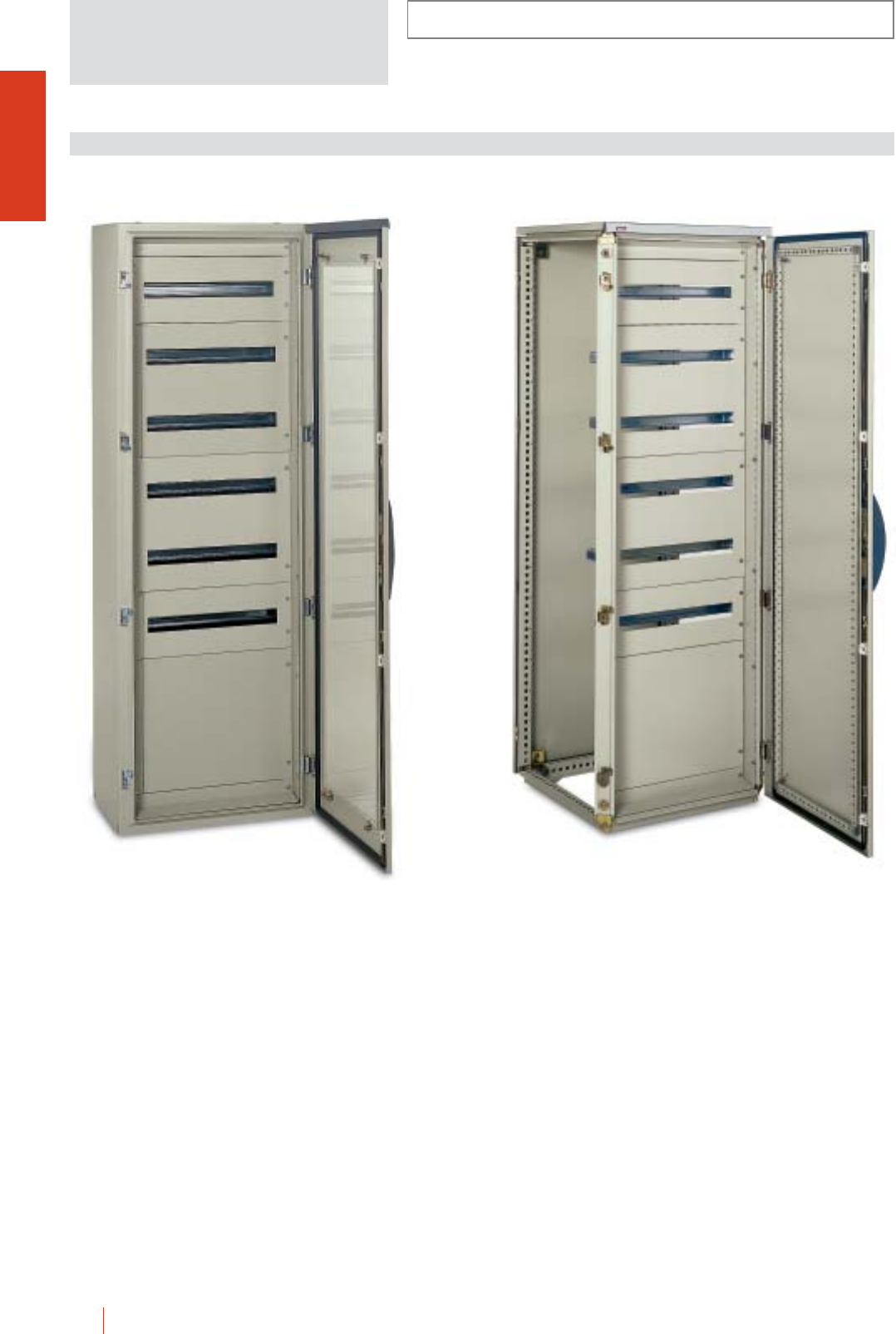
INSTALLATION SYSTEMS
CMO-OLN
1/112 HIMEL OLN industrial cubicle system
Coupling set for modular chassis prepared to fit all the
necessary elements to build large capacity distribution
panels.
Coupling front frame allowing for mounting of:
■600 or 800 mm wide covers (plain or cut-out) with fixed
and hinged types, and height up to 600 mm (150 or
200 mm modularity).
■Fixed and depth adjustable support rails for plain or
perforated mounting plates.
■Sets for double modular chassis or busbar systems.
■Double chassis are mounted on enclosures 1200 to
1600 mm wide.
■Vertical busbar covers are mounted on enclosures 1000
or 1200 mm wide.
■All accessories, covers, rails and supports are combined
in these kits as in the single chassis.
UNIDIS DISTRIBUTION SYSTEM
CMO 186/40 KT + AFCOL 186 + CP 2060/1 +
CPH 4060/2 + CP 4060/2 + CPH 2060/1 + CPH 4060/0
OLN 186/60 + AFCOL 186 + CP 2060/1 +
CHP 4060/2 + CP 4060/2 + CPH 2060/1 + CPH 4060/0
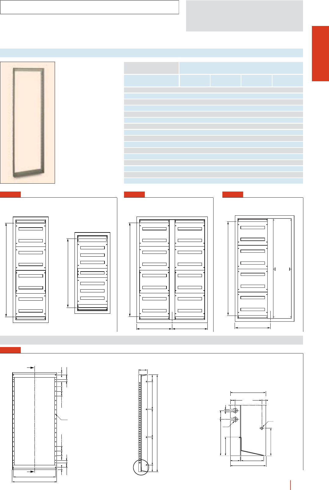
CMO-OLN
INSTALLATION SYSTEMS
1/113OLN industrial cubicle system HIMEL
FIG. 4
Set of uprights and
crossbars for fixing of covers
and supports.
Coupling set for modular chassis
Height
(A)
Enclosure dimensions
Width
(B)
Maximum
no. of 18 mm
units
Set of
columns Reference Fig. no.
1200 600 126 600 AF/COL 126 1
1200 800 192 800 AF/COL 128 1
1400 600 168 600 AF/COL 146 1
1400 800 256 800 AF/COL 148 1
1600 600 183 600 AF/COL 166 1
1600 800 288 800 AF/COL 168 1
1800 600 210 600 AF/COL 186 1
1800 800 320 800 AF/COL 188 1
1800 1000 210 600+400 AF/COL 1864 3
1800 1200 320 800+400 AF/COL 1884 3
1800 1200 420 600+600 AF/COL 1866 2
2000 600 252 600 AF/COL 206 1
2000 800 384 800 AF/COL 208 1
2000 1000 252 600+400 AF/COL 2064 3
2000 1200 384 800+400 AF/COL 2084 3
2000 1200 504 600+600 AF/COL 2066 2
A- 200
B - 122
B - 98
Ø 4.8
26
51.425
50505026
51.4 25
50 50 50
100
77.577.5 300300
A - 95
300
13.5
Ø 13
Ø 7
6428
11.5
100
7
25102.5
52.3
77.5
A- 200
A- 200
B/2 B/2
A- 200
B-400
FIG. 1
Dimensions (mm)
FIG. 2 FIG. 3
Modular chassis
Modular chassis
Modular chassis with
finishing blanking plates
With vertical busbars front plate
and modular chassis set
With double modular
chassis set
Distance of inside cover
transparent part: 80 mm
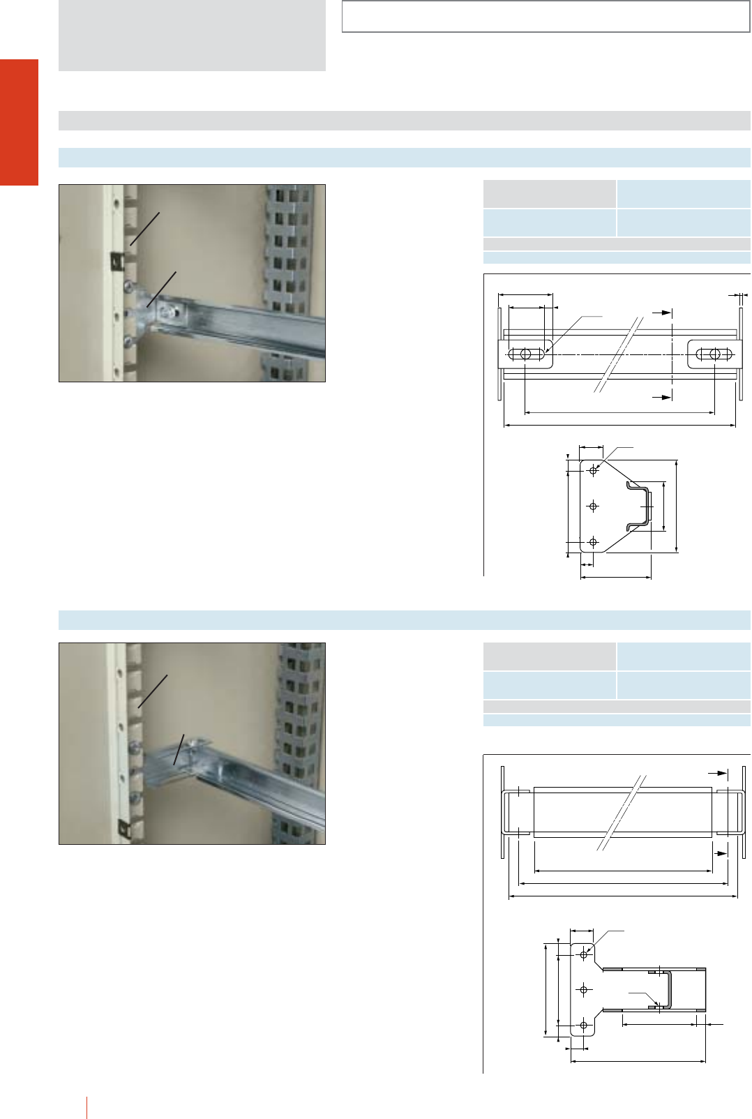
INSTALLATION SYSTEMS
CMO-OLN
1/114 HIMEL OLN industrial cubicle system
38.4
25 6
2
Ø 6.5
B - 146
B - 116
65
35
507.5 7.5
Ø 5
9
50
17
Symmetric 3515 mm
cross rail, galvanized,
with fixed supports.
cBolted on uprights of
modular chassis.
cEnables fixing of
modular or non
modular clip-on
equipment.
cFixed supports without
rail reference CSF.
Fixed supports with cross rail
UNIDIS DISTRIBUTION SYSTEM
Width
(B)
Enclosure dimensions
Reference
600 CSCF 60
800 CSCF 80
AF/COL
CSF
Symmetric 3515 mm,
cross rail, galvanized, with
adjustable supports.
cBolted on uprights of
modular chassis.
cEnables fixing of modular
or non modular clip-on
equipment, as well as
depth adjustment of
cross rail.
cFixed supports without
rail reference CSA.
Adjustable supports with cross rail
Width
(B)
Enclosure dimensions
Reference
600 CSCA 60
800 CSCA 80
AF/COL
CSCA
52 6.6
ØM6
9
95
50
7.5 7.5
65
Ø5
17
B - 146
B - 125
B - 111
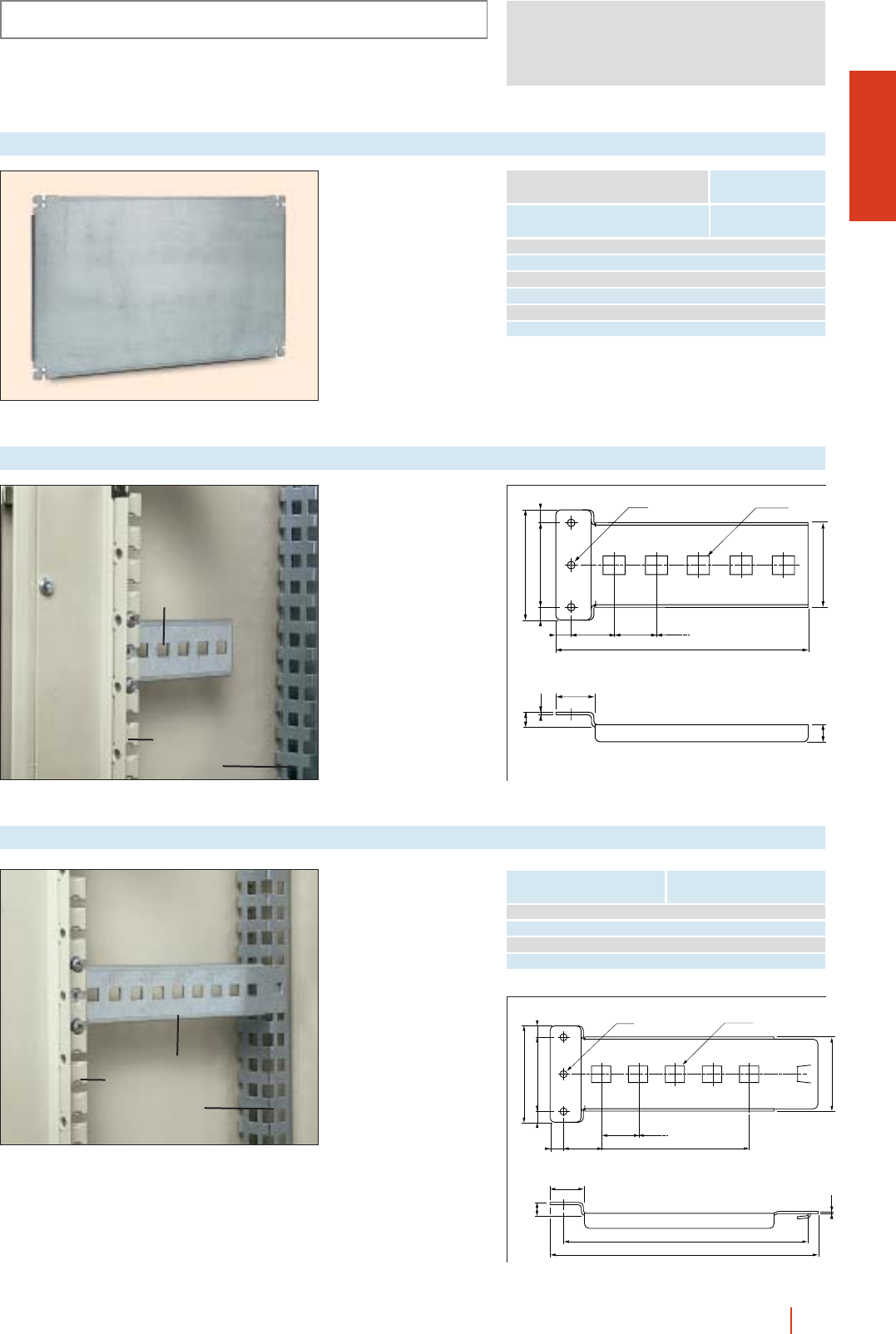
CMO-OLN
INSTALLATION SYSTEMS
1/115OLN industrial cubicle system HIMEL
925
22.4
25
149
50
7.5 7.5
50
1.5
9
10
65
Ø 4.5 13 x 11
cAllows fixing of.
cMaterial: folded and
welded sheet steel,
galvanized.
cBolted on uprights of
modular chassis.
Ref.: CSP.
Set of 2 short plate supports
AF/COL
TML
CSP
22.4
1.5
9
C - 130.5
C - 115
50
50
7.5 7.5
65
Ø 4.5 13 x 11
925
25
C - 200
cAllows fixing of.
cFront and rear face
coupling on 1 row
mounting profile,
mounted vertically.
cMaterial: folded and
welded sheet steel,
galvanized.
Set of 2 reinforced plate supports
AF/COL
TML
CSR
Enclosure
depth (C) Reference
300 CSR 30
400 CSR 40
500 CSR 50
600 CSR 60
For non-modular
equipment.
Partial plain mounting plate
Height
plate
Width
(B)
Enclosure dimensions
Reference
247 600 PMP 2560
397 600 PMP 4060
597 600 PMP 6060
247 800 PMP 2580
397 800 PMP 4080
597 800 PMP 6080
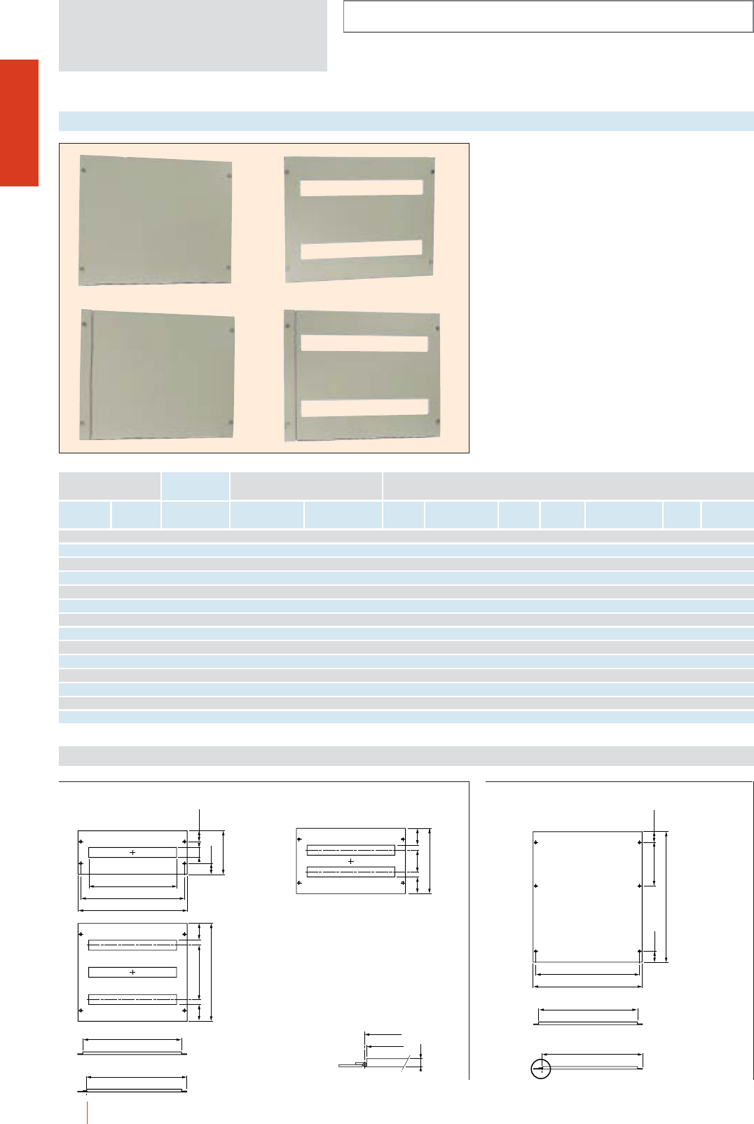
INSTALLATION SYSTEMS
CMO-OLN
1/116 HIMEL OLN industrial cubicle system
cPlain and cut-out types, fixed or hinged.
cMade of sheet steel and painted with polyester
epoxy to RAL-7032.
c150 and 200 mm modularity.
cOn plain covers, cut-outs made by user for
protection of control or protection components.
cCut-out covers for modular equipment
ref.: ATP UND.
cHinged covers.
cEnd covers to fill up the chassis depending on the
combination of covers.
Metal covers
Hinged
type
No. of
18 mm
unids
Cover
Height (A)
Dimensions Plain cover plates Cut-out cover plates
Fixed
type
End
covers
Enclosure
Width (B)
Hinged
type
Fixed
type (E)(D)(E)(D)
50 600 CSC 560 - - - -
50 800 CSC 580 - - - -
150 600 - CP 1560/0 CPH 1560/0 21 CP 1560/1 --CPH 1560/1 --
150 800 - CP 1580/0 CPH 1580/0 32 CP 1580/1 --CPH 1580/1 --
200 600 - CP 2060/0 CPH 2060/0 21 CP 2060/1 --CPH 2060/1 --
200 800 - CP 2080/0 CPH 2080/0 32 CP 2080/1 --CPH 2080/1 --
300 600 - CP 3060/0 CPH 3060/0 42 CP 3060/2 52 150 CPH 3060/2 52 150
300 800 - CP 3080/0 CPH 3080/0 64 CP 3080/2 52 150 CPH 3080/2 52 150
400 600 - CP 4060/0 CPH 4060/0 42 CP 4060/2 77 200 CPH 4060/2 77 200
400 800 - CP 4080/0 CPH 4080/0 64 CP 4080/2 77 200 CPH 4080/2 77 200
450 600 - CP 4560/0 CPH 4560/0 63 CP 4560/3 52 300 CPH 4560/3 52 300
450 800 - CP 4580/0 CPH 4580/0 96 CP 4580/3 52 300 CPH 4580/3 52 300
600 600 - CP 6060/0 CPH 6060/0 63 CP 6060/3 77 400 CPH 6060/3 77 400
600 800 - CP 6080/0 CPH 6080/0 96 CP 6080/3 77 400 CPH 6080/3 77 400
Dimensions (mm)
B - 122
B - 98
49.75200 (1)
A - 0.5
49.75
B - 135
B - 146
B - 122
B - 196
B - 98
49.7546
49.75
A - 0.5
B - 146
B - 135
ED
D
A - 0.5
D
D
A - 0.5
E
B - 135
B - 137
12
Cut-out fixed and hinged typesPlain fixed and hinged covers
A = 300 and 400 mm
A = 150 and 200 mm
A = 450 and 600 mm
Fixed cover
Hinged cover Hinged cover
Fixed cover
(1) For B = 600 mm
Detail view
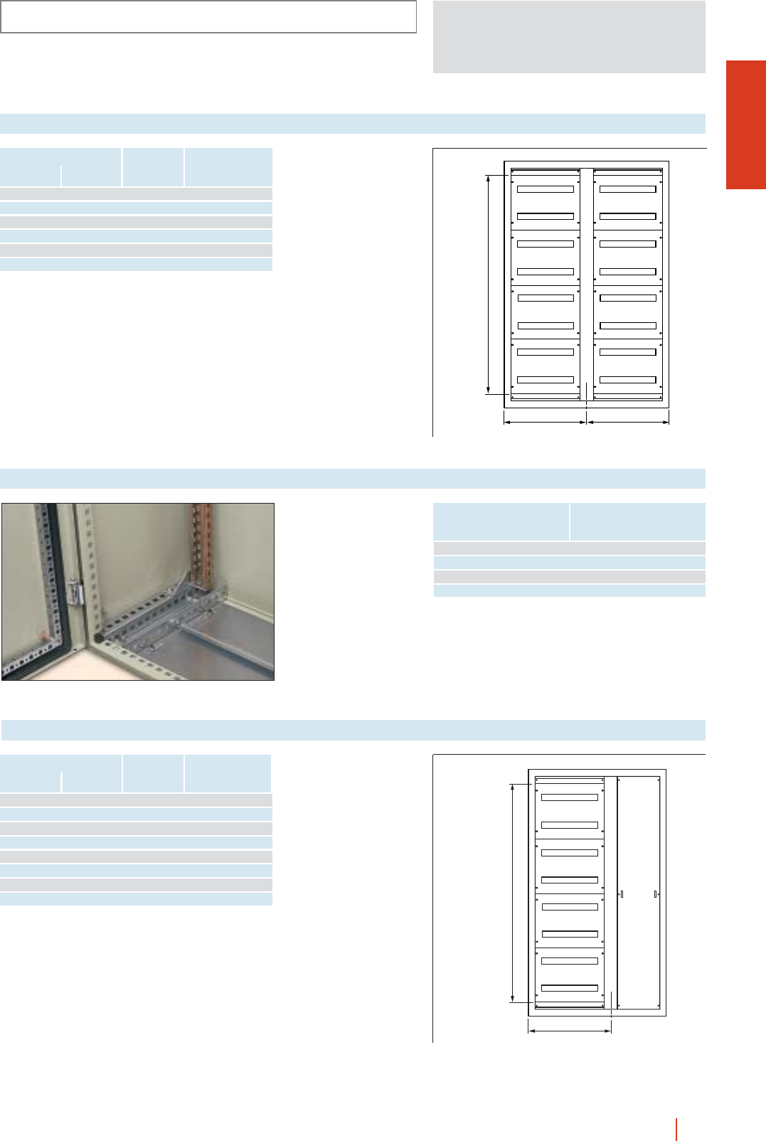
CMO-OLN
INSTALLATION SYSTEMS
1/117OLN industrial cubicle system HIMEL
Double chassis coupling set
Height
(A)
Enclosure dimensions
Width
(B)
Maximum
no. of
18 mm units
Reference
1400 1200 336 AF/COL 1466*
1600 1200 378 AF/COL 1666*
1800 1200 420 AF/COL 1866*
2000 1200 504 AF/COL 2066*
1800 1600 640 AF/COL 1888
2000 1600 768 AF/COL 2088
For enclosure width
1200 and 1600 mm.
Set consisting of:
c2 modular chassis.
cCentral upright.
cAll necessary fixings
and supports for
mounting.
* For CMO enclosures, order separately top and bottom
DCOL... adjusting rails depending on depth of enclosure.
B/2 B/2
A - 200
Top and bottom adjustment rails
Folded and welded
sheet steel, galvanized.
cEnables central
positioning and fixing
of vertical rails in
1200 mm wide
enclosures.
cScrew fixing to upper
and lower parts of
enclosure. Fixing
included.
cPack of 4 parts.
Enclosure dimensions
Depth Reference
300 DCOL 30
400 DCOL 40
500 DCOL 50
600 DCOL 60
Vertical busbars front plate and modular chassis set
Height
(A)
Enclosure dimensions
Width
(B)
D Reference
1400 1000 600 AF/COL 1464
1600 1000 600 AF/COL 1664
1800 1000 600 AF/COL 1864
2000 1000 600 AF/COL 2064
1400 1200 800 AF/COL 1484
1600 1200 800 AF/COL 1684
1800 1200 800 AF/COL 1884
2000 1200 800 AF/COL 2084
For enclosure width
1000 and 1200 mm.
Set consisting of:
c1 modular chassis.
c1 central,
compensating upright.
c1 blanking plate for
busbars (width
300 mm).
cAll necessary fixings
and supports for
mounting.
D
A - 200
BUSBARS
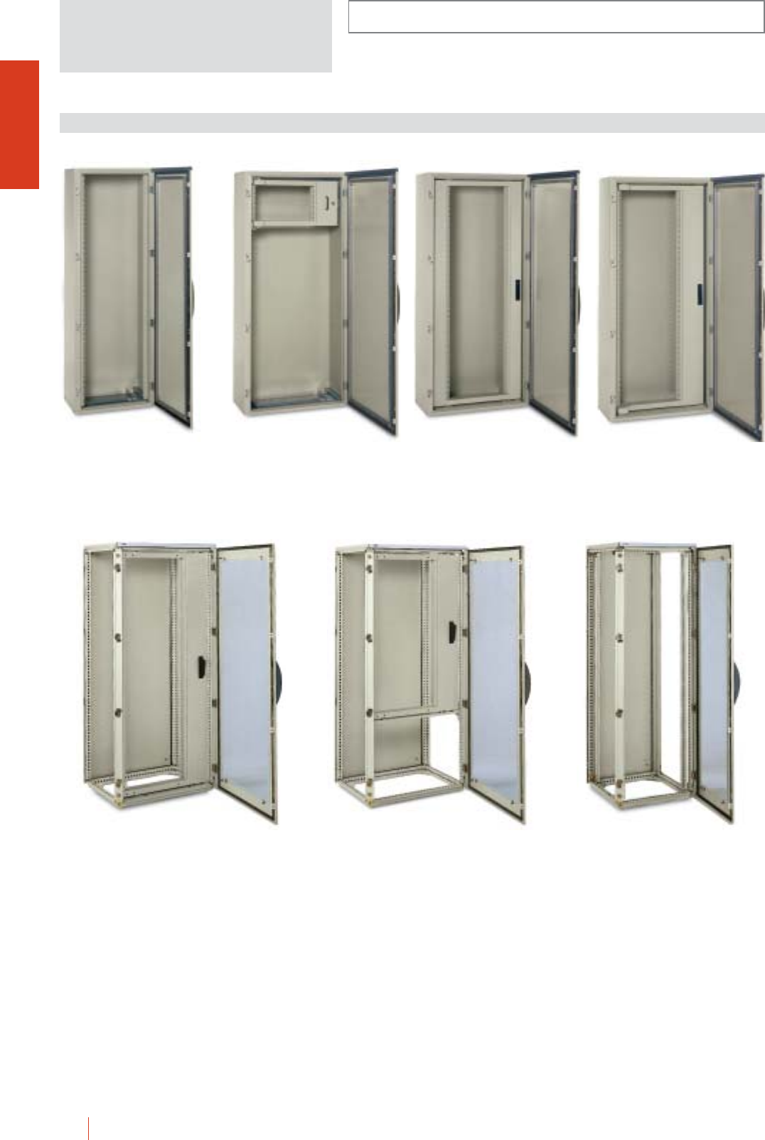
CMO-OLN
1/118 HIMEL OLN industrial cubicle system
INSTALLATION SYSTEMS
19” SWING CHASSIS
Rack 19” system prepared to be fitted directly to
CMO and OLN enclosures: fixed and swing types.
■Fixed racks, polyester epoxy resin paint to RAL-7032,
consisting of 2 uprights with fixing hardware.
■Swing racks, polyester epoxy resin paint to RAL-7032,
125° and 180° opening, double bar lock, maximum load
140 kg.
■Partial swing racks, polyester epoxy resin paint to
RAL-7032, double bar lock, for enclosures wider than
800 mm.
■Centred swing racks, polyester epoxy resin paint to
RAL-7032, double bar lock.
CMO 186/40 +
BRF 38/OL
CMO 188/40 +
BRP 9/OL
CMO 188/40 +
BRPC 36/OL
CMO 188/40 +
BRP 18/OL
OLN 168/600 KT +
BRP 31/OL
OLN 168/60 KT +
BRP 21/OL
OLN 166/60 KT +
BRF 33/OL
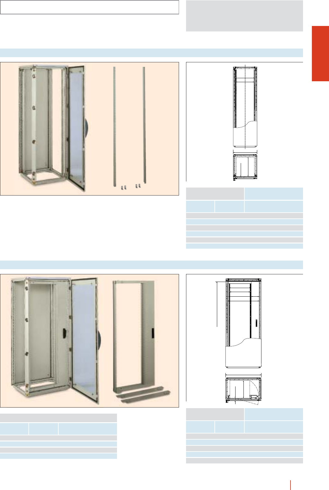
CMO-OLN
INSTALLATION SYSTEMS
1/119OLN industrial cubicle system HIMEL
PARTIAL SWING 19” RACK
465
450
B = 600
min. 55
max. C-107
To fit to 600 mm wide
CMO and OLN
enclosures. Allows for
direct fixing of any 19”
modular chassis to the
standard drillings.
Painted to RAL-7032.
Set of 2 fixed 19” racks
Height
(A)
Enclosure dimensions
Width
(B) Reference
No. of
units
1200 600 24 BRF 24/OL
1400 600 29 BRF 29/OL
1600 600 33 BRF 33/OL
1800 600 38 BRF 38/OL
2000 600 42 BRF 42/OL
2200 600 47 BRF 47/OL
465
450
510
700
175
max. 140
o
min. 55
max. 450
D
B = 800
Allows for direct fixing of
any 19” modular chassis
to the standard drillings.
To fit to 800 mm wide
CMO and OLN
enclosures.
Painted to RAL-7032.
Swing 19” rack
Height
(A)
Enclosure dimensions
Width
(B) Reference
No. of
units
1400 800 27 BRP 27/OL
1600 800 31 BRP 31/OL
1800 800 36 BRP 36/OL
2000 800 40 BRP 40/OL
2200 800 45 BRP 45/OL
Rack height
(D)
Width enclosure
(B) Reference
No. of
units
354 800 6 BRP 6/OL
621 800 12 BRP 12/OL
887 800 18 BRP 18/OL
1021 800 21 BRP 21/OL
C = nominal cubicle depth.
C = nominal cubicle depth.
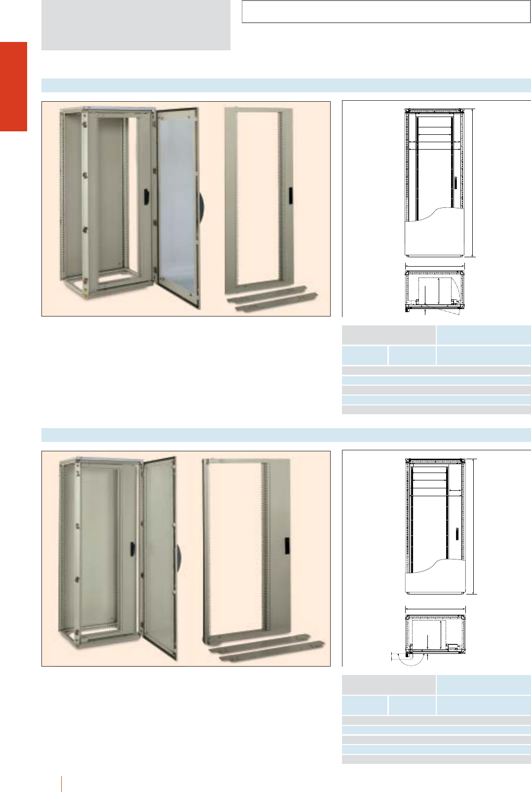
INSTALLATION SYSTEMS
CMO-OLN
1/120 HIMEL OLN industrial cubicle system
465
450
510
700
92
98
A
B = 800
max.140°
min. 55
max. 365
Allows for direct fixing of any 19” modular chassis to
the standard drillings.
To fit to 800 mm wide CMO and OLN enclosures.
Rack centred in the middle.
Colour RAL-7032.
Centred swings 19” rack
Height
(A)
Enclosure dimensions
Width
(B) Reference
No. of
units
1400 800 27 BRPC 27/OL
1600 800 31 BRPC 31/OL
1800 800 36 BRPC 36/OL
2000 800 40 BRPC 40/OL
2200 800 45 BRPC 45/OL
465
450
510
700
175
B = 800
180°
A
min. 70
max. 395
Allows for direct fixing of any 19” modular chassis to
the standard drillings.
To fit to 800 mm wide CMO and OLN enclosures.
180° opening.
Colour RAL-7032.
180° swing 19” rack
Height
(A)
Enclosure dimensions
Width
(B) Reference
No. of
units
1400 800 27 BRP 27/OL 180
1600 800 31 BRP 31/OL 180
1800 800 36 BRP 36/OL 180
2000 800 40 BRP 40/OL 180
2200 800 45 BRP 45/OL 180
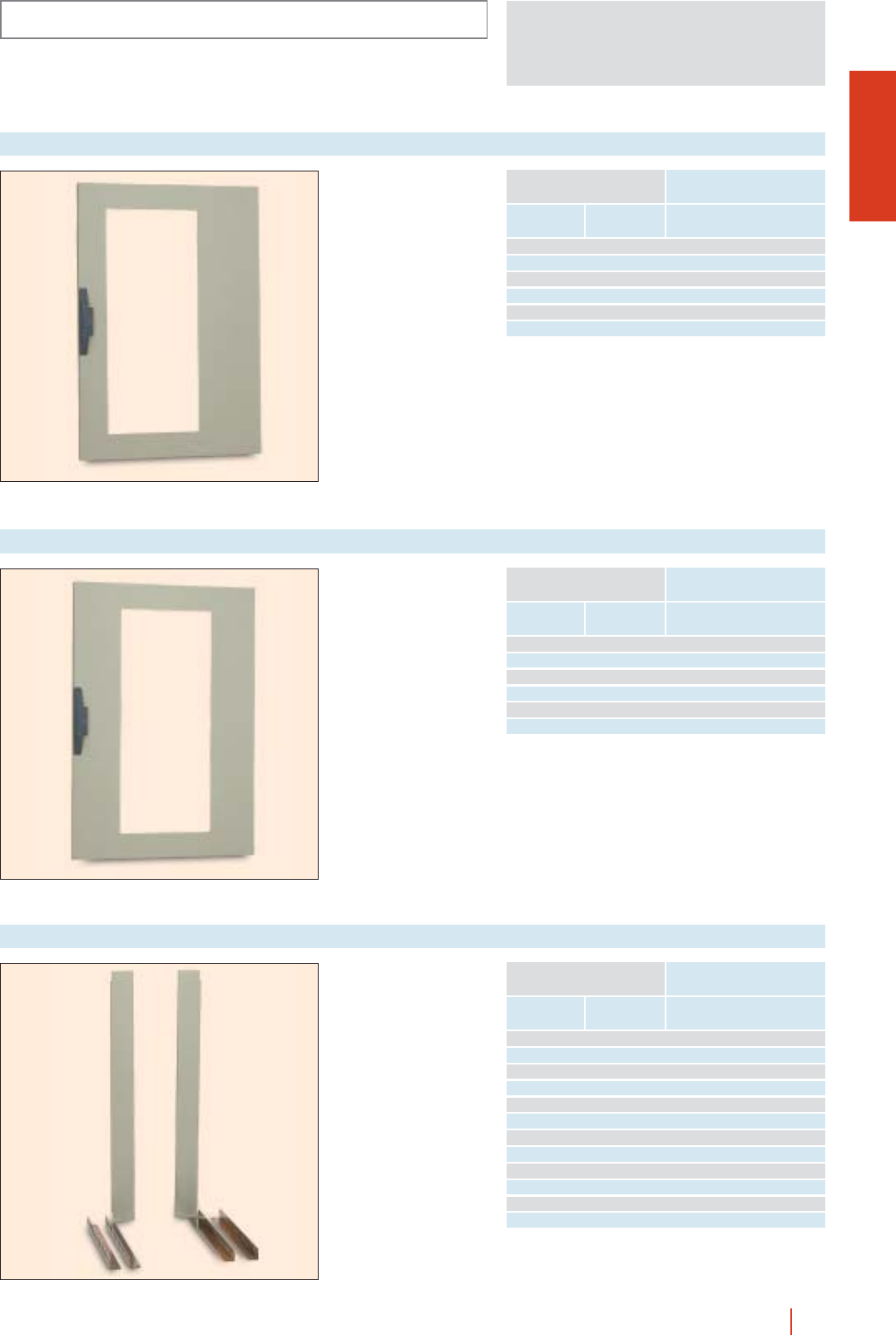
CMO-OLN
INSTALLATION SYSTEMS
1/121OLN industrial cubicle system HIMEL
Transparent KT doors
with window centred on
the rack BRP…/OL and
BRP…/OL 180.
Transparent KT doors with window centred on the rack
Height
(A)
Enclosure dimensions
Width
(B) Reference
1200 800 PPKT 128 BRP
1400 800 PPKT 148 BRP
1600 800 PPKT 168 BRP
1800 800 PPKT 188 BRP
2000 800 PPKT 208 BRP
2200 800 PPKT 228 BRP
Transparent KT doors
with window centred on
the rack BRPC…/OL and
BRF…/OL.
Transparent KT doors with window centred on the rack
Height
(A)
Enclosure dimensions
Width
(B) Reference
1200 800 PPKT 128 BRPC
1400 800 PPKT 148 BRPC
1600 800 PPKT 168 BRPC
1800 800 PPKT 188 BRPC
2000 800 PPKT 208 BRPC
2200 800 PPKT 228 BRPC
Suite of 2 side lids to
adapt racks BRF…/OL
to 800 mm wide
enclosures.
Suite of 2 side lids centred fixed rack
Height
(A)
Enclosure dimensions
Width
(B) Reference
1200 800 600 TBRF 24/OL 60
1400 800 600 TBRF 29/OL 60
1600 800 600 TBRF 33/OL 60
1800 800 600 TBRF 38/OL 60
2000 800 600 TBRF 42/OL 60
2200 800 600 TBRF 47/OL 60
1200 800 800 TBRF 24/OL 80
1400 800 800 TBRF 29/OL 80
1600 800 800 TBRF 33/OL 80
1800 800 800 TBRF 38/OL 80
2000 800 800 TBRF 42/OL 80
2200 800 800 TBRF 47/OL 80
Depth
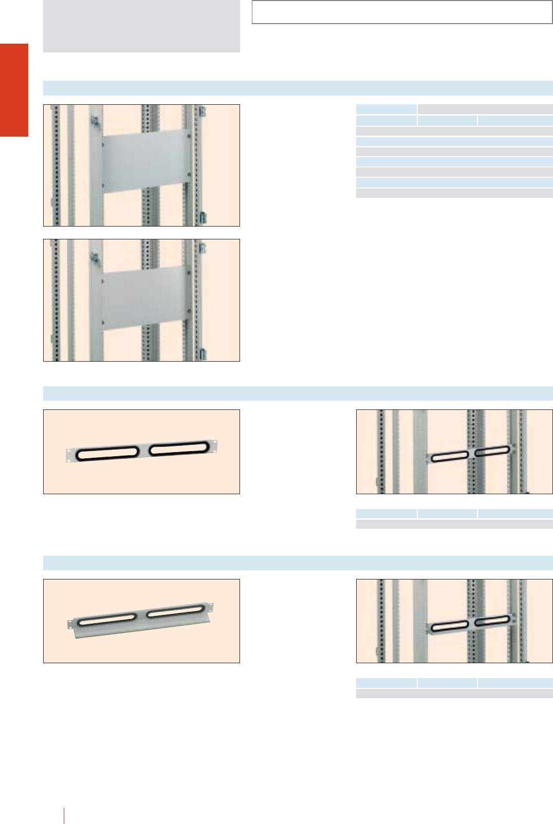
1/122 HIMEL OLN industrial cubicle system
INSTALLATION SYSTEMS
CMO-OLN
Fixed directly to the 19”
rack with GFR ref.
screws.
Made of 1.5 mm-thick
sheet steel painted in
fine texturised grey
RAL-7035 or in 3 mm-
thick aluminium.
Cover plates
Steel Aluminium
1CRTM 1U CRTA 1U
2CRTM 2U CRTA 2U
3CRTM 3U CRTA 3U
6CRTM 6U CRTA 6U
9CRTM 9U CRTA 9U
10 CRTM 10U CRTA 10U
12 CRTM 12U CRTA 12U
Fixed directly to the 19”
rack with GFR ref.
screws.
Made of 1.5 mm-thick
sheet steel painted fine
texturised RAL-7035,
protected cable entry
holes.
Cut-out cover plates for cables
No. of units Reference
No. of units No. of holes Reference
12CRTM 1U2
Fixed directly to the 19”
rack with GFR ref.
screws. Made of
1.5 mm-thick sheet
steel, painted fine
texturised grey
RAL-7035, protected
cable entry holes and
supporting fold.
Cut-out cover plates for cables with housing
No. of units No. of holes Reference
12CRTM 1UA2
CRTM 6U
CRTA 6U
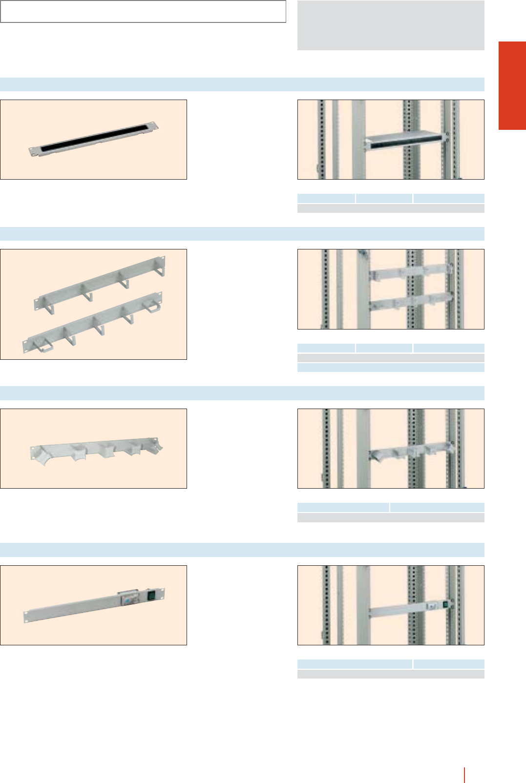
CMO-OLN
INSTALLATION SYSTEMS
1/123OLN industrial cubicle system HIMEL
Fixed directly to the 19”
rack with GFR ref.
screws.
Made of 1.5 mm-thick
sheet steel, painted fine
texturised grey
RAL-7035, with a cale
entry hole and anti-dust
protection.
Cable gland plate with brush
No. of units No. of holes Reference
11CRTM 1U1P
Fixed directly to the 19”
rack with GFR ref.
screws.
Made of 1.5 mm-thick
sheet steel, painted in
fine texturised grey
RAL-7035, with welded
cable ties.
Cover plates with steel cable ties
Fixed directly to the 19”
rack with GFR ref.
screws.
Made of 1.5 mm-thick
sheet steel, painted to
fine texturised grey
RAL-7035, with 5 GCA
46 insulating cable ties
with 4 different positions
(vertical, horizontal,
45° and 135°).
Cover plates with insulating cable ties
Fixed directly to the 19”
rack with GFR ref.
screws.
Made of 1 mm-thick
sheet steel fitted with an
illuminated switch
TS-141 thermostat to
operate and adjust the
fans.
Cover plates for protection and ventilation control
No. of units No. of ties/position Reference
1 4 vert. CRTM 1U40B
1 3 vert./2 hor. CRTM 1U32B
No. of units Reference
1CRTM 1U5GCA
No. of units Reference
1CRTM 1UVT
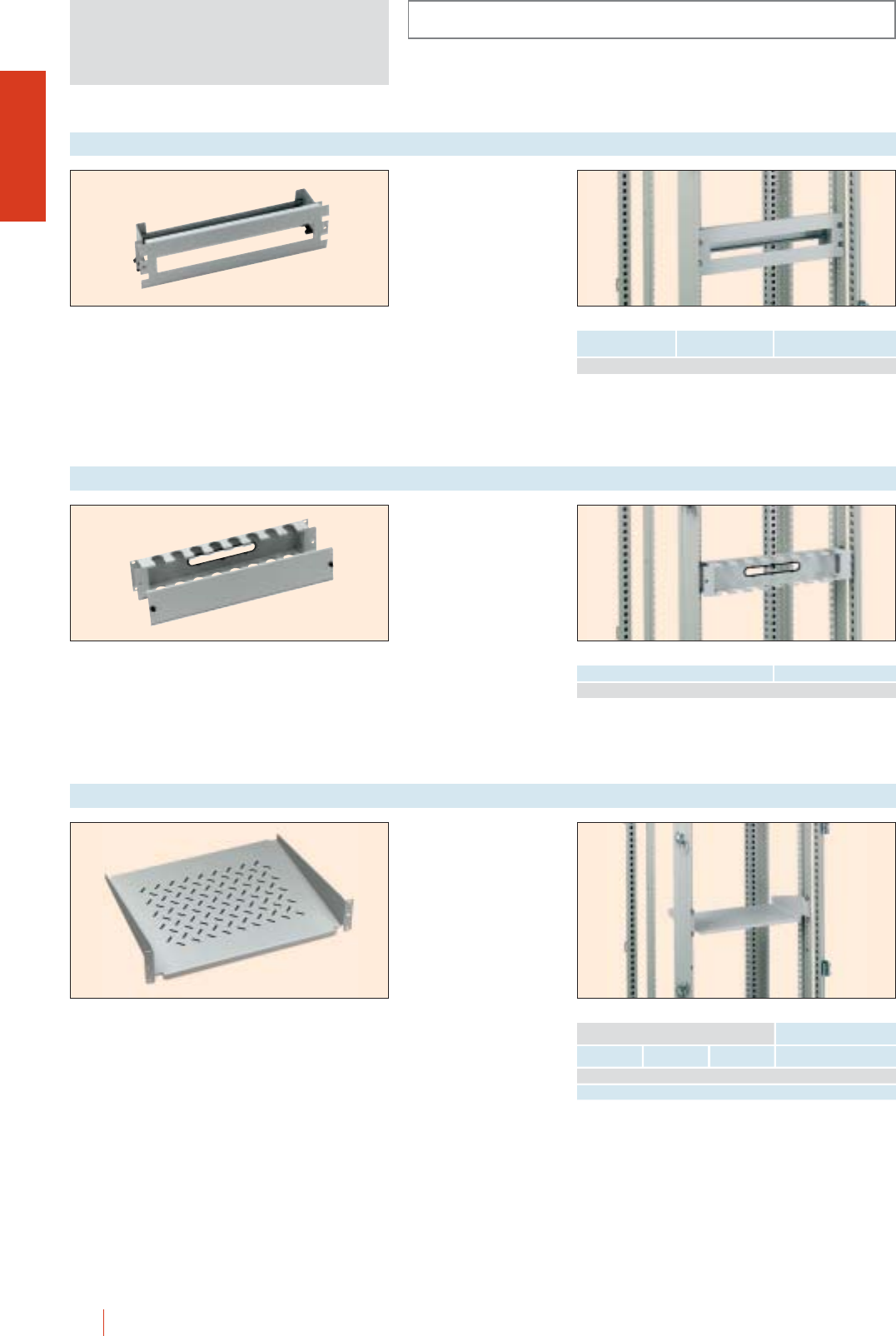
INSTALLATION SYSTEMS
CMO-OLN
1/124 HIMEL OLN industrial cubicle system
Fixed directly to the 19”
rack with GFR ref.
screws.
Made of 1 mm-thick
sheet steel, DIN rail
module cover plate
taking up to 22 modules,
with detachable front,
painted in fine texturised
grey RAL-7035.
DIN rail cover plates
Fixed directly to the 19”
rack with GFR ref.
screws.
Made of 1 mm-thick
sheet steel, cable guide
front cover with quick-
detachable front for
concealing cables,
painted in fine texturised
grey RAL-7035.
Cable guide cover plates
No. of units No. of modules
(18 mm)
Reference
322CRTM 3UD
No. of units Reference
2CRTM 2UC
Fixed directly to the 19”
front rack with GFR ref.
screws.
Made of 1.5 mm-thick
perforated sheet steel,
painted in fine texturised
RAL-7035. Maximum
load 20 kg.
2 U perforated fixed tray
Height
Tray dimensions
Width Reference
2 U 450 250 BF 2U25P
2 U 450 380 BF 2U40P
Depth
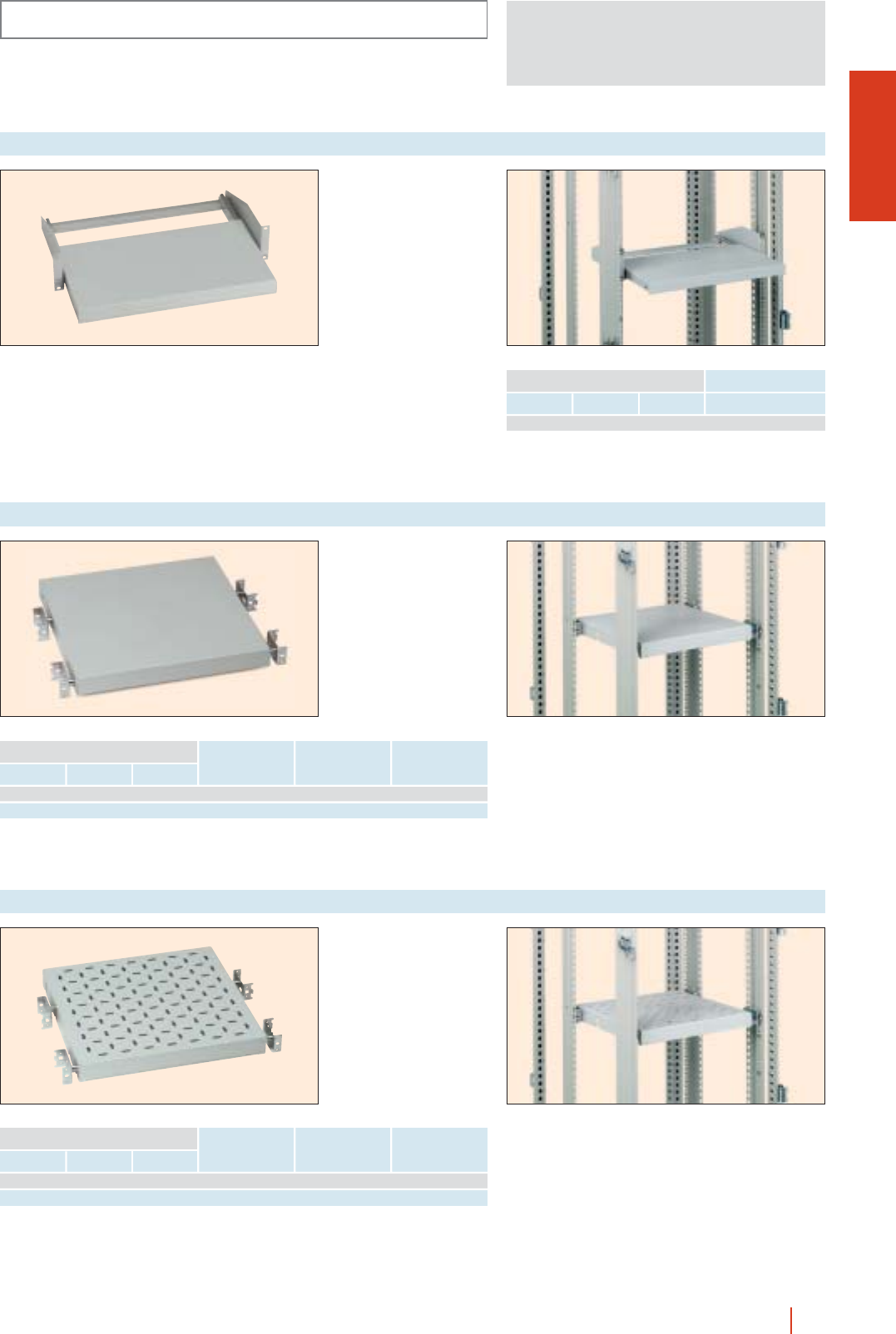
CMO-OLN
INSTALLATION SYSTEMS
1/125OLN industrial cubicle system HIMEL
Fixed directly to the front
19” rack with GFR ref.
screws.
Made of 1.5 mm-thick
sheet steel, painted in
fine texturised
RAL-7035 colour, fitted
with telescopic guides
and securing device.
Maximum load 5 kg.
2 U telescopic tray
Height
Tray dimensions
Width Reference
2 U 450 250 BT 2U25
Depth
Fixed directly to the front
and rear of the 19” rack
(not included) (2 sets of
fixed 19” racks must be
ordered). Made of
1.5 mm-thick sheet
steel, painted in fine
texturised RAL-7035
colour.
Maximum load 25 kg.
1 U fixed tray
Height
Tray dimensions
Width Referencie
1 U 450 400 600/800 258 BBF 1U40
1 U 450 600 800 458 BBF 1U60
Depth
For enclosures
depth
Distance frame
front-back
Fixed directly to the front
and rear of the 19” rack
(not included) (2 sets of
fixed 19” racks must be
ordered).
Made of 1.5 mm-thick
sheet steel, painted to
fine texturised RAL-7035
colour. Maximum load
25 kg.
1 U perforated fixed tray
Height
Tray dimensions
Width Reference
1 U 450 400 600/800 258 BBF 1U40P
1 U 450 600 800 458 BBF 1U60P
Depth
For enclosures
depth
Distance frame
front-back
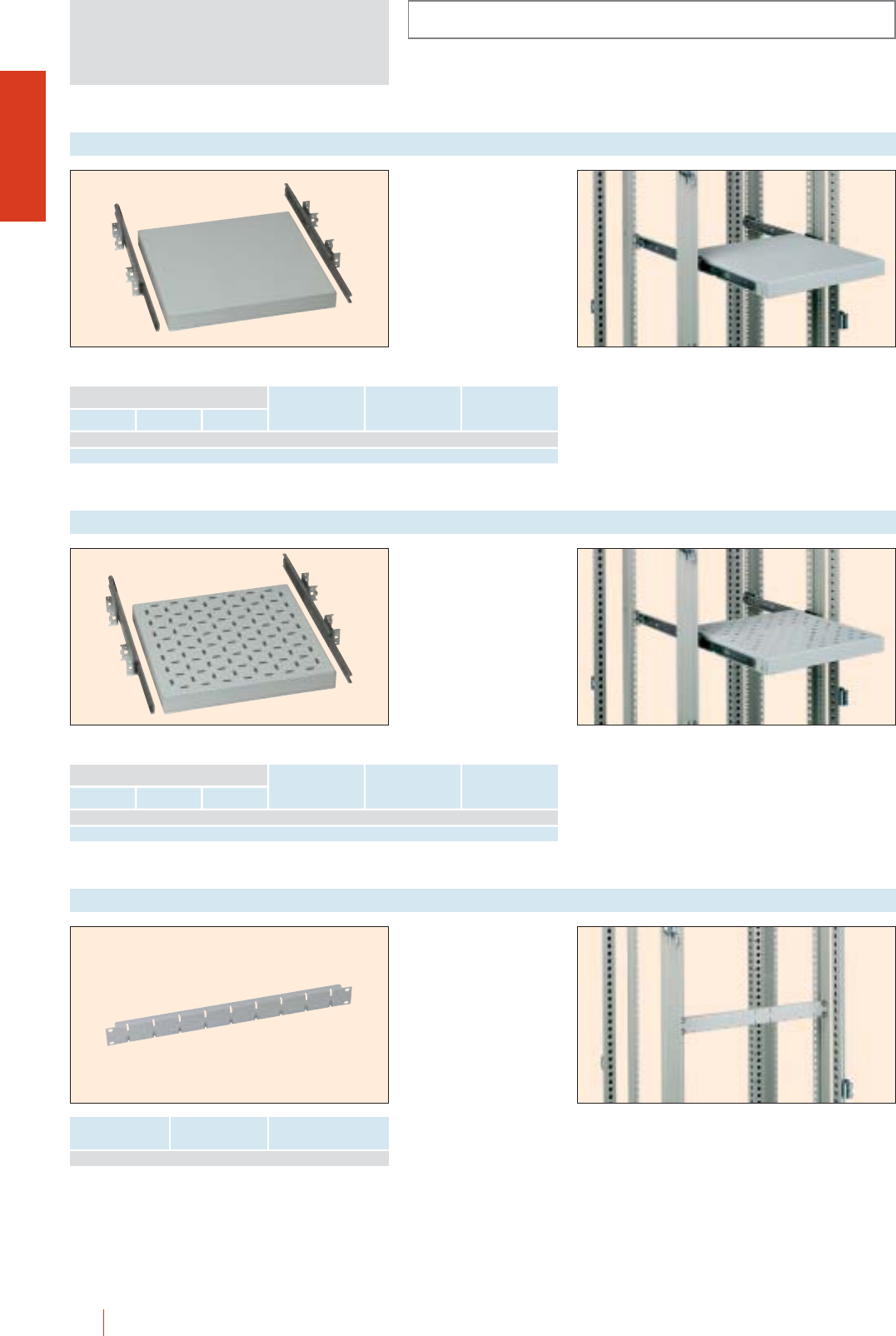
INSTALLATION SYSTEMS
CMO-OLN
1/126 HIMEL OLN industrial cubicle system
Fixed directly to the 19”
front and rear rack (not
included) (2 sets of fixed
19” racks must be
ordered).
Made of 1.5 mm-thick
sheet steel, painted in
fine texturised RAL-7035
colour, fitted with
telescopic guides with a
securing device.
Maximum load 25 kg.
1 U adjustable tray
Heigth
Tray dimensions
Width Reference
1 U 450 400 600/800 258 BBT 1U40
1 U 450 600 800 458 BBT 1U60
Depth
For enclosures
depth
Distance frame
front-back
Fixed directly to the front
and rear of the 19” rack
(not included) (2 sets of
fixed 19” racks must be
ordered).
Made of 1.5 mm-thick
sheet steel, painted in fine
texturised RAL-7035
colour, fitted with
telescopic guides and a
securing device.
Maximum load 25 kg.
1 U telescopic perforated tray
Height
Tray dimensions
Width Reference
1 U 450 400 600/800 258 BBT 1U40P
1 U 450 600 800 458 BBT 1U60P
Depth
For enclosures
depth
Distance frame
front-back
For cable support with
adjustable cable ties
(LZ).
Made of 1.5 mm-thick
zinc coated sheet steel.
For fitting in depth
between the front and
back of rack (not
included), with GFR ref.
screws.
Horizontal cable support crossbeam
No. of units ReferenceNo. of lodgings
19 TVA
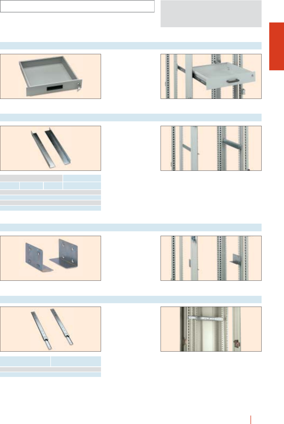
CMO-OLN
INSTALLATION SYSTEMS
1/127OLN industrial cubicle system HIMEL
To fixed enclosures. Fitted
on telescopic guides
ref. GT... (not included in
the standard unit).
RAL-7035.
Reference: CS2U400.
19” drawer
Set of 2 guides for fitting
directly to the 19” racks
and front and back
frames (not included).
Made of 2 mm-thick zinc
coated sheet steel.
19” fixed guides
Set of 2 guides for fitting
directly to the front of
rack.
Made of 2 mm-thick zinc
coated sheet steel.
Reference: GB/140.
19” guides
Set of 2 guides for fitting
directly to the front and
rear of fixed racks (not
supplied).
Telescopic 19” guides
Enclosure dimensions
Depth (C) Reference
600 GT 40
800 GT 60
Length
(mm)
Enclosure dimensions
Distance frame
front-back Reference
256 250 400 GF 256
356 350 500 GF 356
456 450 600 GF 456
556 550 800 GF 556
Depth
(C)
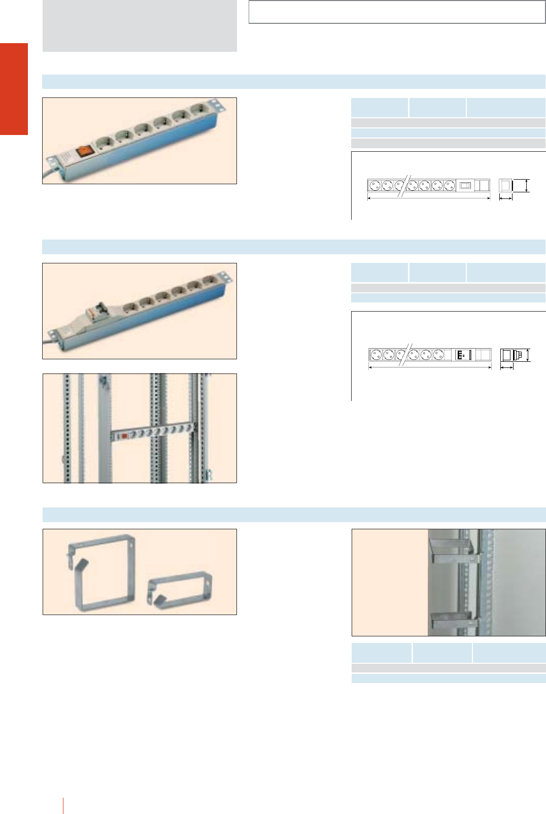
INSTALLATION SYSTEMS
CMO-OLN
1/128 HIMEL OLN industrial cubicle system
Double pole distribution
socket block with 16 A
switch. Rated voltage
250 V-2 metre cable
(3 1.5 mm2) with 2F+T
10/16 A 250 V plug. 2 flat
mounting supports and
fasteners included.
1 U Schucko line protection switched socket block
Horizontal and vertical position
45
L
44
Double pole distribution
socket block with line
protection. Rated voltage
250 V 2-metre cable
(3 1,5 mm2) with a
2F+T 10/16 A 250 V plug.
2 flat mounting supports
and fasteners included.
1 U Schucko line protection socket block
No. of bases Length
(L) mm Reference
6 440 (19”) ZDBE 6P
12 704 ZDBE 12P
No. of bases Length
(L) mm Reference
6 440 (19”) ZDBE 6I
8 440 (19”) ZDBE 8IN
12 704 ZDBE 12I
L44
45
Vertical cable guides for
fitting to 19” racks. Made
of 2 mm-thick stainless
steel sheet, RAL-7035
colour.
Metal cable guides
Dimensions
(mm) Reference
To fit to
enclosures width
40 100 600/800 GC 4
100 100 800 GC 10
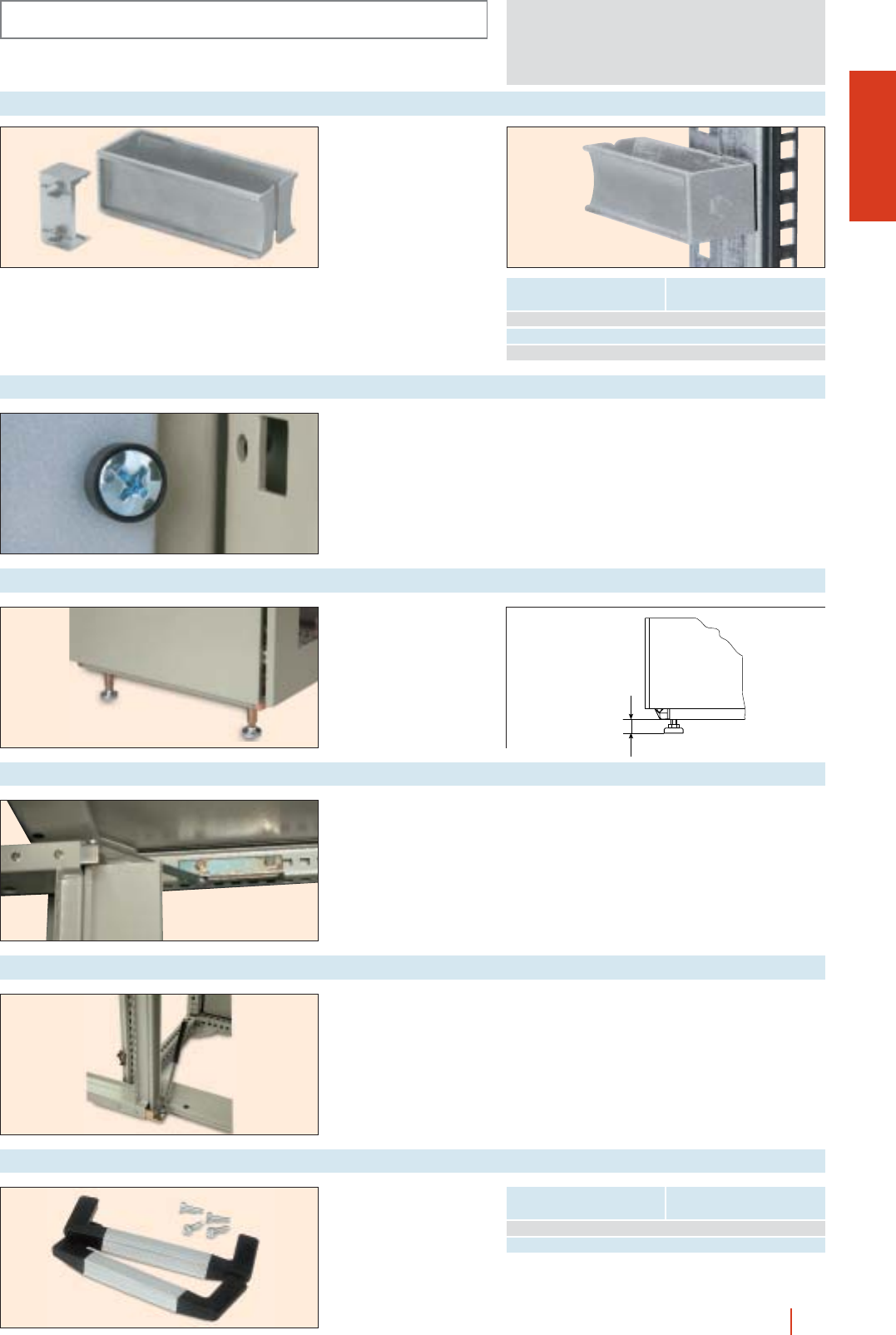
INSTALLATION SYSTEMS
1/129OLN industrial cubicle system HIMEL
Insulating cable guide, for
fixing to the 8.5 mm
rectangular perforations
(19” racks).
Adaptor for fixing the
cable guides to the
6 5.4 mm holes.
Reference: AD/GCA.
AD/GCA GCA...
Insulating cable guide
Dimensions
(mm) Reference
40 60 GCA 46
40 100 GCA 410
100 100 GCA 1010
Set composet of:
1 screw.
1 washer.
1 nut.
Reference: GFR.
Hardware set
Set of four stands.
Reference: PRON.
Adjustable stands
min. 55
max. 80
To fix to BRP…/OL
19” rack.
120° opening.
Reference: RET/BON.
19” door retainer
CMO-OLN
For fixing to front cover
plates.
19” front cover handles
Heigth Reference
99 ASR 3U
156 ASR 6U
To fix to BRP.../OL 180
rack.
Reference: RETN/BON
180.
180° 19” door retainer
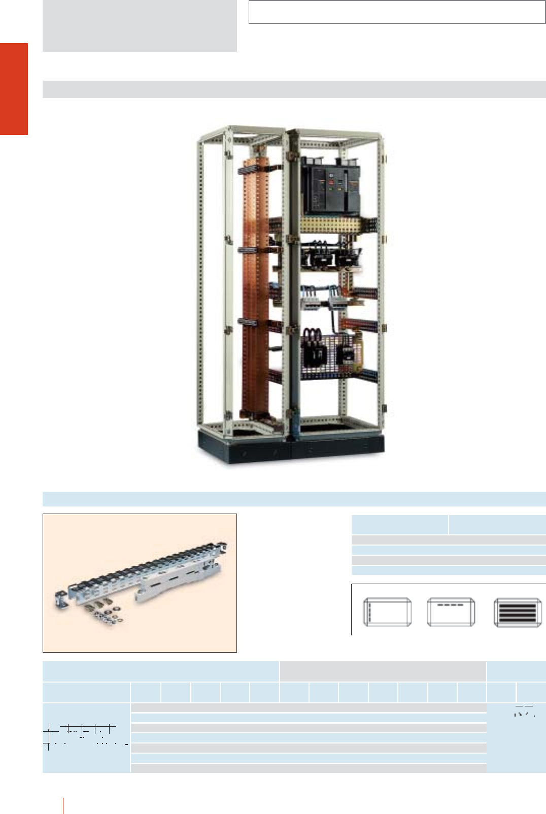
INSTALLATION SYSTEMS
OLN
1/130 HIMEL OLN industrial cubicle system
To fit directly to the
uprights of any OLN
cubicle.
cMaximum current
intensity 630 A.
cWork out according to
the table below the bar
cross section and the
distance between
supports depending on
current intensity and
short circuit value
respectively.
630 A busbar supports
To fit to cubicle nominal
Width (B) or Depth (C) Reference
400 SEM/OL 400
500 SEM/OL 500
600 SEM/OL 600
800 SEM/OL 800
Rated
current
IP55 In (A)
No. of
bars per
phase (mm)
Cross
section
(mm2)
Icc
(kA.):1223303952 6669
Neutral
(mm)
Earth
(mm)
Max. distance depending on
short circuit value
200 1 12 5 60 mm: 525 525 525 400 250 - -
250 1 12 5 75 mm: 575 575 575 450 325 - -
320 1 20 5 100 mm: 600 600 600 475 350 150 - 12 5-10
390 1 25 5 125 mm: 600 600 600 475 350 150 - 15 5-10 6 3
440 1 30 5 150 mm: 650 650 650 650 525 400 350 20 5-10 10 3
500 1 20 10 200 mm: 675 675 675 525 350 150 - 25 5-10 10 6
600 1 30 10 300 mm: 675 675 675 600 475 325 275 30 5-10 10 6
60 60 60
51
BUSBAR SYSTEMS
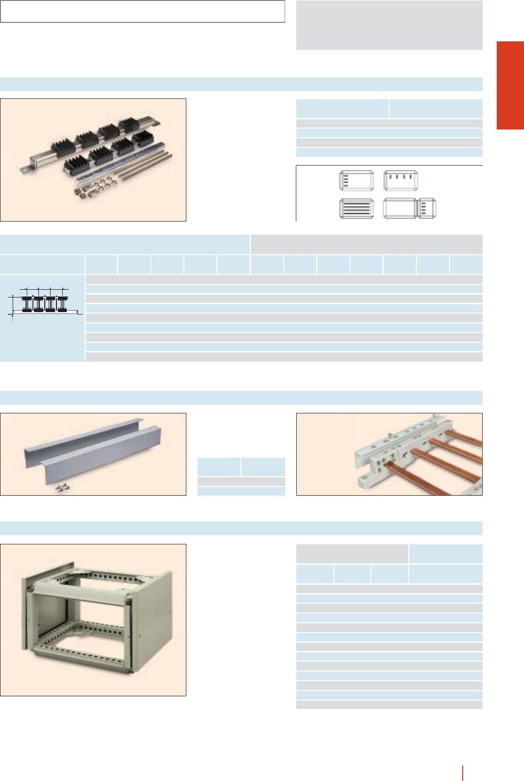
OLN
INSTALLATION SYSTEMS
1/131OLN industrial cubicle system HIMEL
To fit directly to the
uprights of any OLN
cubicle.
cMaximum current
intensity 1600 A.
cWork out according to
the table below the bar
cross section and the
distance between
supports depending on
current intensity and
short circuit value
respectively.
1,600 A busbar supports
To fit to cubicle nominal
Width (B) or Depth (C) Reference
400 SEP/OL 400
500 SEP/OL 500
600 SEP/OL 600
800 SEP/OL 800
Rated
current
IP55 In (A)
Numer of
bars per
phase (mm)
Cross
section
(mm2)
Icc
(kA.): 12 23 30 39 52 66 69
Max. distance depending on
short circuit value
600 1 50 5 250 mm: 475 250 200 150 100 75 75
700 1 60 5 300 mm: 550 275 225 150 125 100 75
900 1 80 5 400 mm: 625 325 250 175 125 100 100
1000 2 50 5 500 mm: 1000 725 575 425 275 125 150
1050 1 100 5 500 mm: 725 375 275 225 150 125 125
1150 2 60 5 600 mm: 1000 850 675 500 275 175 150
1200 1 125 5 625 mm: 850 425 325 250 175 150 125
1450 2 80 5 800 mm: 1000 975 775 525 300 175 175
1600 2 100 5 1000 mm: 1000 1000 875 575 300 200 175
75 75 75
S+150
S = bar height.
Busbar end protection
with direct fixing to
insulating blocks.
Busbar end cover
To fit
to busbar Reference
630 A TFE 630
1250 A TFE 1250
cConceived to protect and
support the sets of
horizontal bars.
cThe busbar chambers
allow the new power
points per terminal and
insulate the sets of bars
from the rest of the
equipment.
cFor assembly inside the
enclosure, top or bottom.
cThe busbar chambers are
supplied without side
panels.
Top/bottom busbar chambers
Height Width Depth
External dimensions mm
Reference
300 300 500 CE 3050 N
300 300 600 CE 3060 N
300 300 800 CE 3080 N
300 400 500 CE 4050 N
300 400 600 CE 4060 N
300 600 500 CE 6050 N
300 600 600 CE 6060 N
300 600 800 CE 6080 N
300 800 500 CE 8050 N
300 800 600 CE 8060 N
300 800 800 CE 8080 N
300 1200 500 CE 12050 N
300 1200 600 CE 12060 N
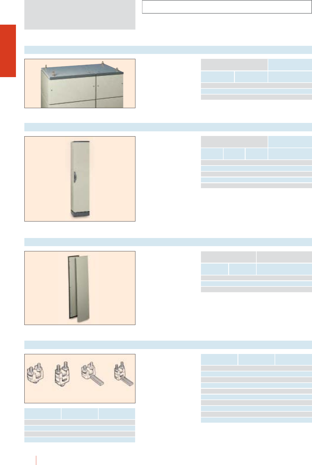
INSTALLATION SYSTEMS
OLN
1/132 HIMEL OLN industrial cubicle system
Terminals specially
designed for the
diversion of cables and
connection of busbars.
BBH terminals are made
of a copper alloy. Hot
stamped and tin-plated,
suitable to connect a
copper or aluminium
conductor (bimetallic).
BBH bimetal terminals
BBH-29 BBH-29 D BBH-29P BBH-29 DP
Reference Main cross
section mm2
Diversion cross
section mm2
BBH-29 6-50 -
BBH-29 C* 6-50 -
BBH-30 10-95 -
BBH-31 16-150 -
BBH-32 50-240 -
BBH-29 D 6-50 6-50
BBH-29 DC* 6-50 6-50
BBH-30 D 10-95 10-95
BBH-31 D 25-150 16-150
BBH-32 D 95-240 5-240
Reference Main cross
section mm2
Diversion cable cross
section mm2
BBH-29P 6-50 -
BBH-29 PC* 6-50 -
BBH-29 DP 6-50 6-50
BBH-29 DPC* 6-50 6-50
* Terminal cover CBBH-29 included.
Side busbar chambers
Height Depth Outside
fixing
Measurements enclosure (mm) Reference
Inside
fixing
2000 500 2PLOL205 2PLIOL205
2000 600 2PLOL206 2PLIOL206
2000 800 2PLOL208 2PLIOL206
Set of 2 side panels to be
fited externally or internally
to the enclosure. Made of
sheet steel, painted with
textured polyester-epoxy
resin to RAL-7032.
cFully gasketed and
supplied with screws
required for fixing.
Bolted externally or internally side panel
Note: for busbar supports, see previous page.
Note: for busbar supports, see previous page.
Set of 2 side panels to be
fitted to top and bottom
busbar chambers.
Busbar chamber + sides +
eye-bolts.
Top/bottom busbar chamber panels
Height Width
External dimensions mm
Side panels reference
300 500 2LCE50
300 600 2LCE60
300 800 2LCE80
cConceived to protect
and support the sets of
vertical bars.
cThe busbar chambers
allow the new power
points per terminal and
insulate the sets of bars
from the rest of the
equipment.
cFor assembly on any
side of the enclosure.
Height No. of units Width
Measurements enclosure in mm
Reference
2000 300 500 OLN 203/50
2000 300 600 OLN 203/60
2000 300 800 OLN 203/80
2000 400 500 OLN 204/50
2000 400 600 OLN 204/60
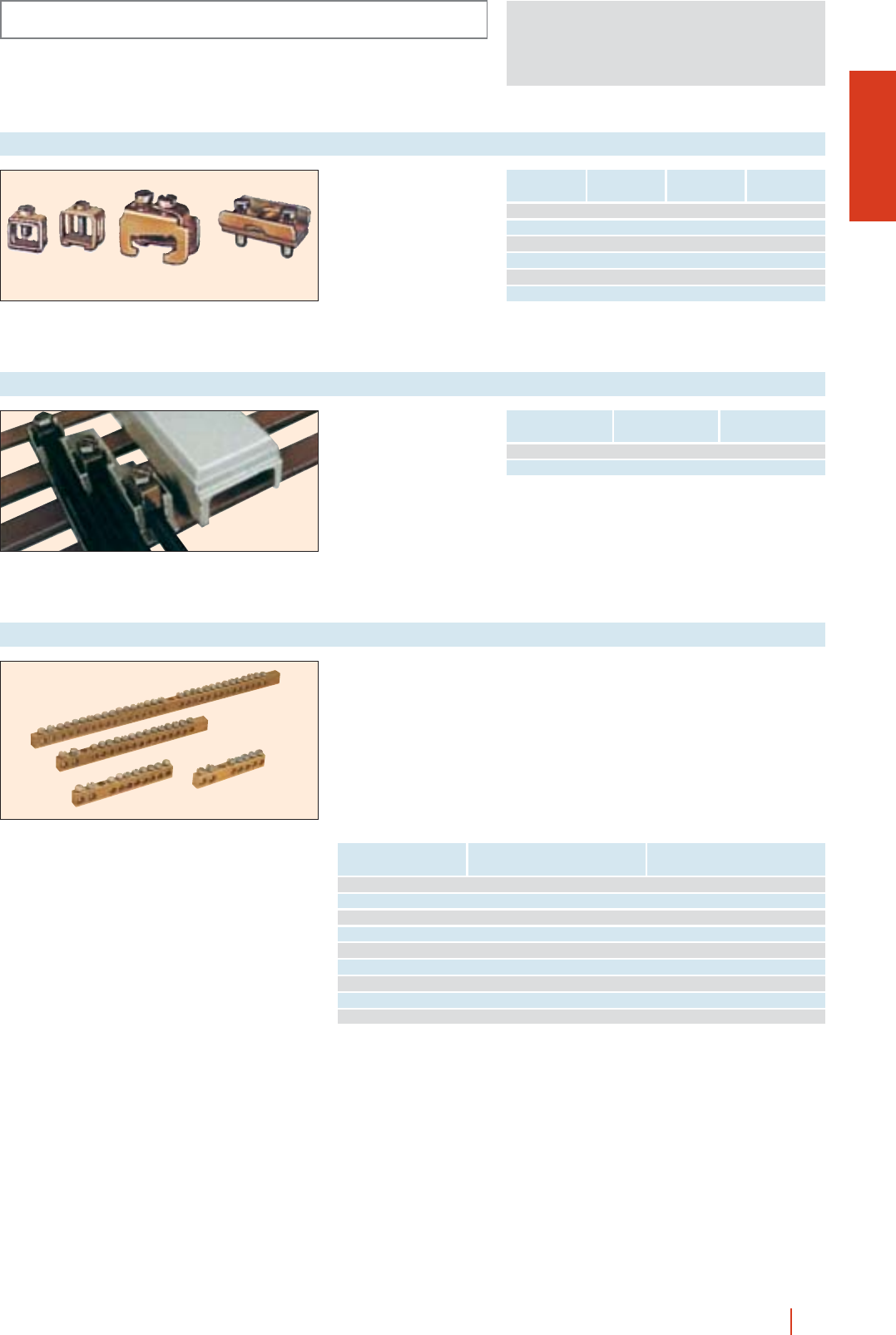
RBL/21656 M 216 mm2+ 5 6 mm2COMBINORM - DSU - DTU
RBL/21686 M 216 mm2+ 8 6 mm2COMBINORM - DSU - DTU
RBL/216146 M 216 mm2+ 14 6 mm2COMBINORM - DSU - DTU
RBL/216296 M 216 mm2+ 29 6 mm2COMBINORM - DSU - DTU
RBLZ/21656 216 mm2+ 5 6 mm2DSU - DTM - CRD/CMD
RBLZ/21686 216 mm2+ 8 6 mm2DSU - DTM - CRD/CMD
RBLZ/216146 216 mm2+ 14 6 mm2DSU - DTM - CRD/CMD
RBLZ/216296 216 mm2+ 29 6 mm2DSU - DTM - CRD/CMD
RBLZ/416286 K 216 mm2+ 14 6 mm2DSU
OLN
INSTALLATION SYSTEMS
1/133OLN industrial cubicle system HIMEL
For the diversion of neutrals and earth wires.
cRBL models to fit to COMBINORM - DSU - DTU, insulating bottom cases, in the
holes prepared for their fixing.
cRBLZ models with insulating base to fit onto a 12 2 mm profile in the
DSU - DTM - CRD/CMD, models, already prepared for fixing of these terminal
blocks.
cRBL/416286 K model made up of two RBL/216146 M terminals mounted on a
bakelite bar, which makes it possible to place the standard supply terminal,
RBL/21656 M, on the centre. This allows a total of 6 16 mm2terminals and
33 6 mm2terminals to fit to DSU 15 and 30 modules insulating bottom cases.
Terminal blocks
Reference Quantity of terminals
cross section mm2
To fit to
boxes / enclosures
Entry through plate and
cable, plate or terminal
diversion.
Plate/cable diversion terminals
12 3 4
Reference Entry plate
thickness mm
Diversion cable
cross section mm2Fig. no.
BTN 25 15 16 1
BDA 25 15 16 2
BPC 1550 15 50 3
BPC 2050 20 50 3
BPC 3050 30 50 3
BCT 15/20 15/20 95 4
Reference Entry plate
thickness mm
Diversion cable
cross section mm2
BTE 630 12 30 35 120
TBT 630 BTE 630 terminal cover
Plate entry and cable
diversion (for EMH-630
and EMV-630 busbars).
Three pole diversion terminals
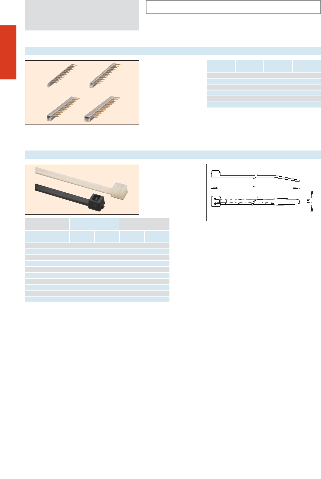
INSTALLATION SYSTEMS
OLN
1/134 HIMEL OLN industrial cubicle system
Made of 6.6 nylon in
natural colour or in black
for inclemency.
Adjustable cable ties
∅
min.
To use for
∅
max. L M White Black
1.6 22 100 2.5 LZ25100 LN25100
1.6 49 200 2.5 LZ25200 LN25200
1.6 35 150 3.5 LZ35150 LN35150
1.6 49 200 3.5 LZ35200 LN35200
1.6 75 300 3.5 LZ35300 LN35300
1.6 36 150 4.6 LZ46150 LN46150
1.6 49 200 4.6 LZ46200 LN46200
1.6 73 270 4.8 LZ48270 LN48270
1.6 109 390 4.6 LZ46390 LN46390
4.7 108 390 7.6 LZ76390 LN76390
Reference
For the distribution in the
same row of a total of
12 automatic modules.
Distribution terminals
Reference No. of bars No. of poles
per bar Fig. no.
BDS 1/12 112 1
BDS 2/6 26 2
BDS 3/4 34 3
BDS 4/3 43 4
BAP 25 25 mm2cross section 5
BAH 25 25 mm2cross section 6
1
3
2
4

OLN
INSTALLATION SYSTEMS
1/135OLN industrial cubicle system HIMEL
It allows the insertion of
1 cable tie from 4 points
in a 90° angle. Cable ties
trom series LZ25100 to
LZ46390 can be
coupled. Material
6.6 nylon.
Cable tie base
Ties width A B C D E Reference
2.5÷3.5 19.1 19.1 4.8 3.2 13.2 MB3A
2.5÷4.8 28.5 28.5 5.5 4 20.2 MB4A
adhesive support
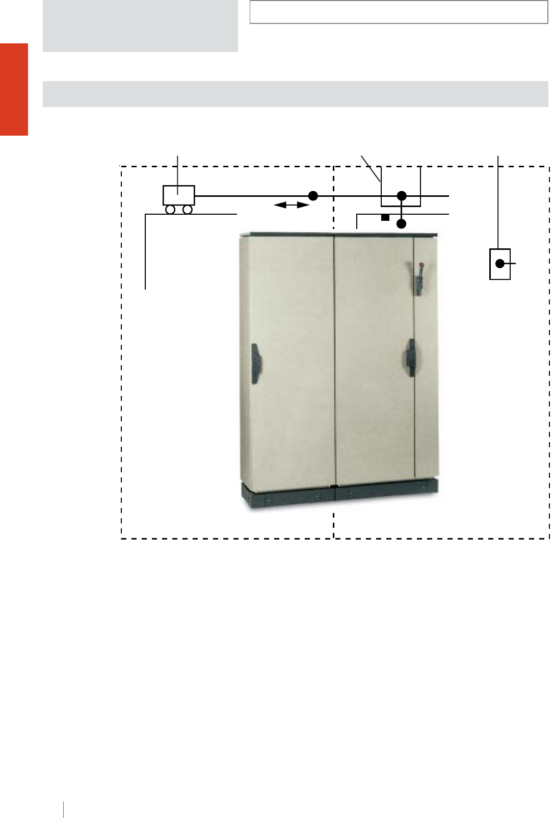
INSTALLATION SYSTEMS
OLN
1/136 HIMEL OLN industrial cubicle system
Made to be associated to same breakers or switches:
– Allen Bradley (1494 VH11),
– Square D (9422 A1),
– Siemens (FH0H),
– Telemecanique.
The integrate safety locking system for “incoming” and
“outgoing” enclosure doors makes it possible to adapt
the OLN… enclosures to American standards
(automobiles).
cHow they work: the “incoming” enclosure doors is locked
by means of the breaker control or main switch. A built-in
locking system with sliding rods forces the opening of the
doors of the “outgoing” enclosures. Access is only
possible when the incoming organ is at the “ON” position,
the incoming door open, and the remaining rods are
manually unlocked and access given.
ACCESSOIRES AND COMPLEMENTS LOCKING SYSTEM
BUILT INTO THE DOORS OF JOINED ENCLOSURES
Ref. ENBAR60
ENBAR80
ENBAR100 Ref. ENPUS Ref. ENCIN
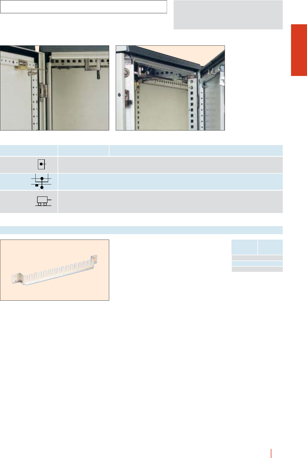
OLN
INSTALLATION SYSTEMS
1/137OLN industrial cubicle system HIMEL
Height
(A)
Depth
(C)
ENCIN Locking kit lock main enclosure
ENPUS Locking kit lock secondary doors
ENBAR60 Locking kit lock joining enclosures 600 mm-wide
ENBAR80 Locking kit lock joining enclosures 800 mm-wide
ENBAR100 Locking kit lock joining enclosures 1000 mm-wide
Set of 6 cross rails for fixing and adjusting of Lütze
chassis. Made in galvanised sheet steel, thickness
2.5 mm. Fixings for assembly included. To fix them
at the back enclosure, use SFLTZ supports.
Cross rails Lütze chassis
Measurements
enclosure
Depth (mm)
Reference
400 SDLTZ40
500 SDLTZ50
600 SDLTZ60
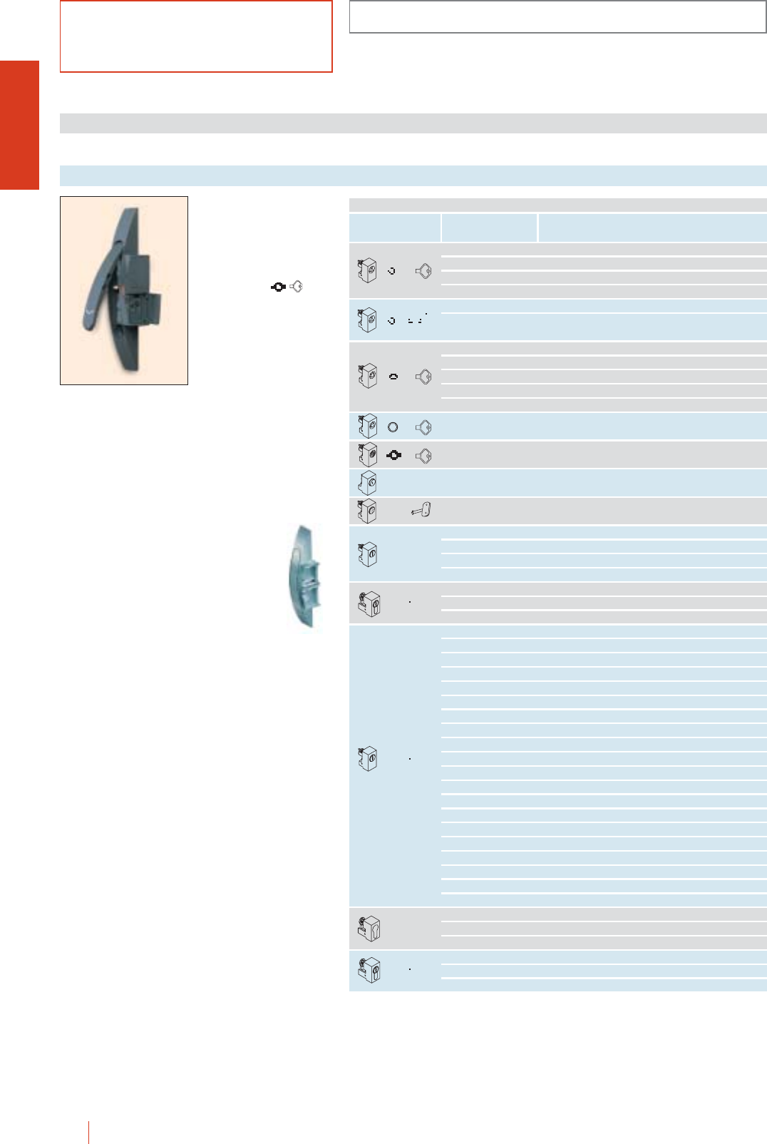
ACCESSORIES AND COMPLEMENTS
CMO-OLN
1/138 HIMEL OLN industrial cubicle system
LOCKS FOR FLOOR STANDING ENCLOSURES
OLN standard closing
mechanism option for
CMO.
Double bar (supplied as
standard).
cOperated by
LDB/OLN
(in accordance with
DIN 43668).
Locks
OPTIONAL LOCK INSERTS TO TRANSFORM THE STANDARD LOCK
Reference
Type of mechanism
using key reference Characteristics
TT 7/OLN 7 mm triangular key
TT 8/OLN 8 mm triangular key
TT 9/OLN 9 mm triangular key
TT 10/OLN 10 mm triangular key
TCNOMO/OLN CNOMO closing mechanism
TCNOMO/OLN-2P Two-door enclosure CNOMO
closing mechanism
TC 6/OLN 6 mm square key
TC 7/OLN 7 mm square key
TC 8/OLN 8 mm square key
TC 6H/OLN 6 strand square key
TC 8H/OLN 8 strand square key
TDB3/OLN 3 mm two bar
TEX10/OLN 10 mm hexagonal key
TS/OLN Pushbutton closing mechanism
TFI/OLN FIAT closing mechanism
TM24/OLN 2×4 coin
TCOR/OLN Crown (tubo)
TAUSA/OLN Channelled
TBENZ/OLN Daimler Benz
TLR/OLN Locking catch with reinforced key
TJIS/OLN JIS
TFAC/OLN Lockable type FAC
TL/OLN 405 key lock
TLB/OLN Locking top part with 405 key
TLE1/OLN E1 closing mechanism
TL421E/OLN Lockable 421 E
TL455/OLN Lockable 455
TL1242E/OLN Lockable 1242 E
TL1332E/OLN Lockable 1332 E
TL2131A/OLN Lockable 2131 A
TL2132A/OLN Lockable 2132 A
TL2331A/OLN Lockable 2331 A
TL2433A/OLN Lockable 2433 A
TL2452E/OLN Lockable 2452 E
TL3113A/OLN Lockable 3113 A
TL3122E/OLN Lockable 3122 E
TL3123A/OLN Lockable 3123 A
TL3133A/OLN Lockable 3133 A
TL3422E/OLN Lockable 3422 E
TL3432E/OLN Lockable 3432 E
TL1300/OLN Lockable EDF 1300
TL1400/OLN Lockable EDF 1400
ABDIN/OLN Adapted DIN barrel lock
ABKABA/OLN Adapted KABA barrel lock
ABASSA/OLN Adapted ASSA barrel lock
MCS/MICH8376 MICHELIN-type handle-operated closing mechanism
MCS/MICH8079 MICHELIN-type handle-operated closing mechanism
MCS/MICH8133 MICHELIN-type handle-operated closing mechanism

CMO-OLN
ACCESSORIES AND COMPLEMENTS
1/139OLN industrial cubicle system HIMEL
EMP/OLN
Optional CMO standard closing mechanism for OLN.
Standard two bar mechanism
(supplied as standard).
cOperated by:
vLDB 5 key
(in accordance with DIN 43668).
cFor conversion to closing mechanisms for internal doors PIL see enclosure
closing mechanisms section CRN.
cFor conversion of closing mechanisms of enclosures for PC applications or
motor control centres see panel closing mechanism section PK.
Optional flat lock
OPTIONAL LOCK INSERTS TO TRANSFORM THE STANDARD LOCK
CharacteristicsReference
TPDT7/OLN 7 mm triangular key
TPDT8/OLN 8 mm triangular key
TPDC6/OLN 6 mm square key
TPDC7/OLN 7 mm square key
TPC8/OLN 8 mm square key
TPDB/OLN 5 mm two bar
TPDES/OLN Screwdriver slot
Type of mechanism using key reference
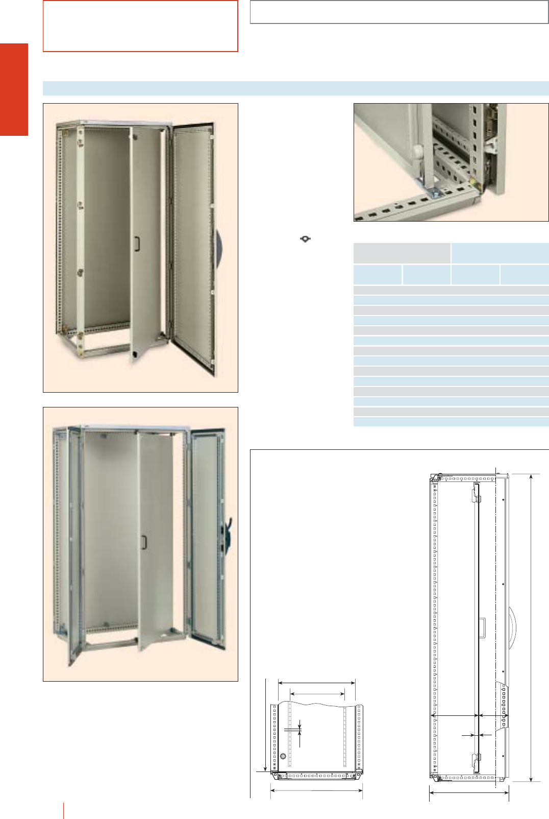
ACCESSORIES AND COMPLEMENTS
CMO-OLN
1/140 HIMEL OLN industrial cubicle system
To fit directly into OLN
cubicles. Made of sheet
steel and painted with
poliester-epoxy resin to
texturized RAL-7032.
cDepth adjustable every
25 mm.
cReversible door.
cReinforcement profiles
on the back, punched
every 25 mm for
mounting of
equipment.
cDouble bar
standard lock. By fixing
the wing to the locks,
this is transformed into
handle lock. Easily
change to triangle,
square or safety locks.
See CRN locks.
Internal doors
Height
(A)
Dimensions enclosure (mm)
Depth
(B) Reference
1600 600 350 PIL 166
1600 800 550 PIL 168
1800 600 350 PIL 186
1800 800 550 PIL 188
1800 1000 700 PIL 1810
1800 1000 700 PIL 18102P*
2000 600 350 PIL 206
2000 800 550 PIL 208
2000 1000 700 PIL 2010
2000 1000 700 PIL 20102P*
2200 600 350 PIL 226
2200 800 550 PIL 228
2200 1000 700 PIL 2210
2200 1000 700 PIL 22102P*
D
C
A
20
C-65
min.
70
B - 100
D
B
A - 100
25
Side view of internal door installed, with detail of lock.
C = cubicle nominal depth
* For 2 door enclosures.
OLN 186/60 + PIL 186
OLN 1810602P + PIL 18102P
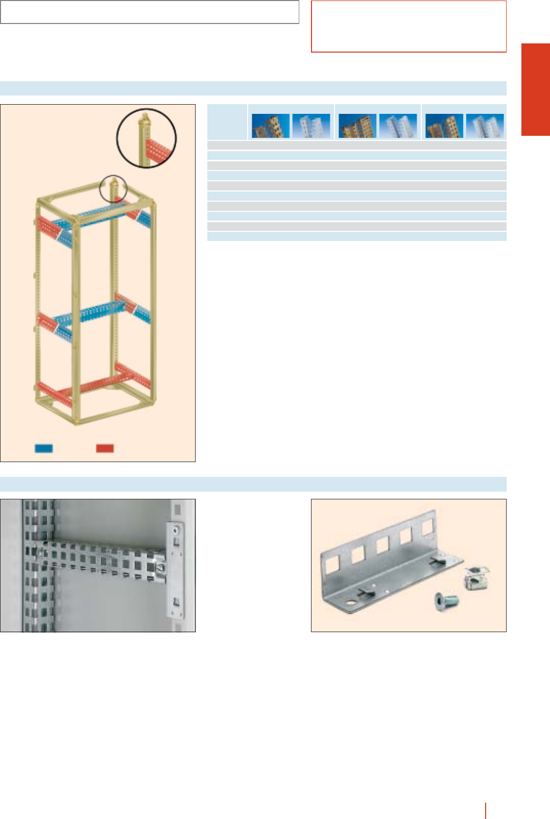
CMO-OLN
ACCESSORIES AND COMPLEMENTS
1/141OLN industrial cubicle system HIMEL
cFor mounting profiles
in depth.
cDirectly fixed to the
front of CMO
enclosure.
cMade of galvanized
steel.
Ref.: STCMO.
Cross rail brackets
Two ranges available, 40 mm width (1 row), 65 mm width (2 rows) and 90 mm
width (3 rows). Enable depth adjustment of equipment supports, 19" rack, etc.
Can be combined to form partial supports or horizontal supports for mounting
deep equipment.
cTMR: access to 4 fixing nuts from outside.
cTML: for all kind of assembly.
Direct attachment to framework with STCMO brackets.
Delivered in pairs with supports and fixings.
Mounting profiles
Enclosure
width or
depth
Detail of upper
and lower
mounting limits
90 mm wide profile65 mm wide profile40 mm wide profile
400 TML 40/40 TMR 40/40 TML 65/40 TMR 65/40 TML 90/40 TMR 90/40
500 TML 40/50 TMR 40/50 TML 65/50 TMR 65/50 TML 90/50 TMR 90/50
600 TML 40/60 TMR 40/60 TML 65/60 TMR 65/60 TML 90/60 TMR 90/60
800 TML 40/80 TMR 40/80 TML 65/80 TMR 65/80 TML 90/80 TMR 90/80
100 TML 40/100 TMR 40/100 TML 65/100 TMR 65/100 TML 90/100 TMR 90/100
1200 TML 40/120 TMR 40/120 TML 65/120 TMR 65/120 TML 90/120 TMR 90/120
1400 TML 40/140 – TML 65/140 – TML 90/140 –
1600 TML 40/160 – TML 65/160 – TML 90/160 –
1800 TML 40/180 – TML 65/180 – TML 90/180 –
2000 TML 40/200 – TML 65/200 – TML 90/200 –
3 rows
2 rows
1 row
TML TMR
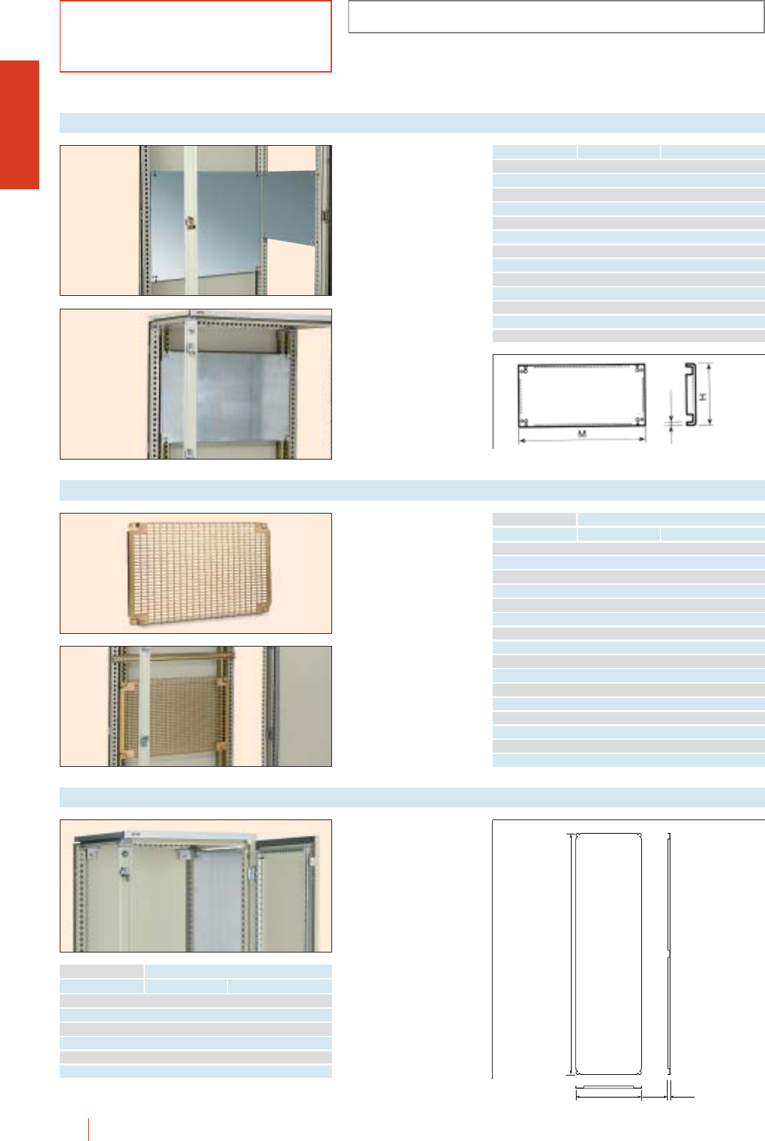
ACCESSORIES AND COMPLEMENTS
CMO-OLN
1/142 HIMEL OLN industrial cubicle system
Made of galvanized steel
with all edges reinforced.
Fixed directly to the
enclosure up rights,
both at the sides and the
back. Depth adjustable
by means of TML
mounting profiles.
Partial mounting plate
Width enclosure (M) Plate height (H) Reference
600 247 PMP 2560
397 PMP 4060
597 PMP 6060
800 247 PMP 2580
397 PMP 4080
597 PMP 6080
1000 247 PMP 25100
397 PMP 40100
597 PMP 60100
1200 247 PMP 25120
397 PMP 40120
597 PMP 60120
1600 397 PMP 40160
Partial perforated mounting plate
Width (B)
Enclosure dimensions
Plate height Reference
600 225 PMR 2260
450 PMR 4560
600 PMR 6060
825 PMR 8260
800 225 PMR 2280
450 PMR 4580
600 PMR 6080
825 PMR 8280
1000 225 PMR 22100
450 PMR 45100
600 PMR 60100
825 PMR 82100
1200 225 PMR 22120
450 PMR 45120
600 PMR 60120
825 PMR 82120
Made of galvanized
sheet steel with
reinforced edges.
Prepared to be mounted
at the enclosure sides.
Side mounting plate
Height (A)
Enclosure dimensions
Depth (C) Reference
1800 600 PMLOL186
1800 800 PMLOL188
2000 600 PMLOL206
2000 800 PMLOL208
2200 600 PMLOL226
2200 800 PMLOL228
C
A
16
2.5
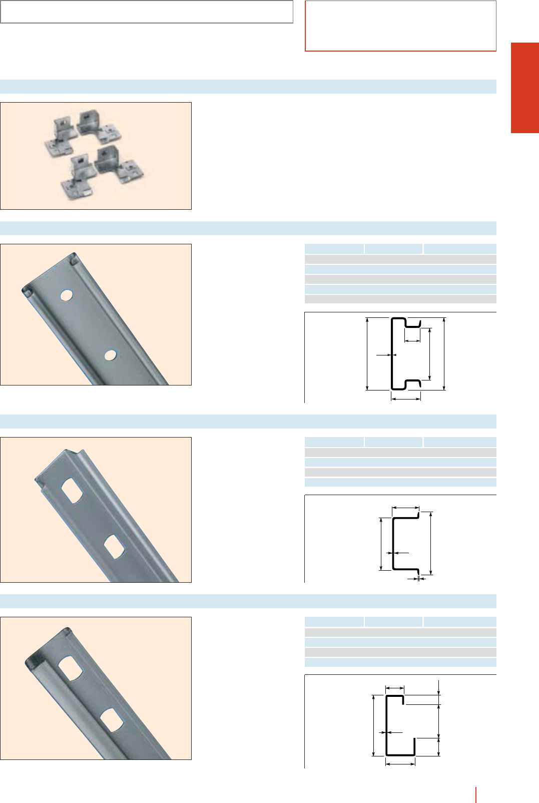
9
15
1.5
32
16
10.5 5.5
15
1
1.5
27
35
15
1.5
8.5
37
25
35
CMO-OLN
ACCESSORIES AND COMPLEMENTS
1/143OLN industrial cubicle system HIMEL
Set of 4 fixing brackets
to be directly mounted to
the enclosure frame
work for fixing the
mounting plate.
Reference: EDCOL.
Fixing brackets
cCombines advantages
of symmetric and
asymmetric DIN rails.
cDirect fixing to the
structure.
cLevel continuity
guaranteed in case of
juxtaposition of
enclosures.
cGalvanized sheet steel.
cSheet thickness:
1.5 mm.
Double rail profile
Reference Width enclosure (mm) Units pack.
CDP60 600 10
CDP80 800 10
CDP100 1000 10
CDP120 1200 10
CDP200 2000 10
cDirect fixing to the
structure.
cLevel continuity
guaranteed in case of
juxtaposition of
enclosures.
cGalvanized sheet steel.
cSheet thickness:
1.5 mm.
Symmetric DIN rail
Reference guide Width enclosure (mm) Units pack.
CSON60 600 10
CSON80 800 10
CSON100 1000 10
CSON120 1200 10
cDirect fixing to the
structure.
cLevel continuity
guaranteed in case of
juxtaposition of
enclosures.
cGalvanized sheet steel.
cSheet thickness:
1.5 mm.
Asymmetric DIN rail
Reference guide Width enclosure (mm) Units pack.
CAON60 600 10
CAON80 800 10
CAON100 1000 10
CAON120 1200 10
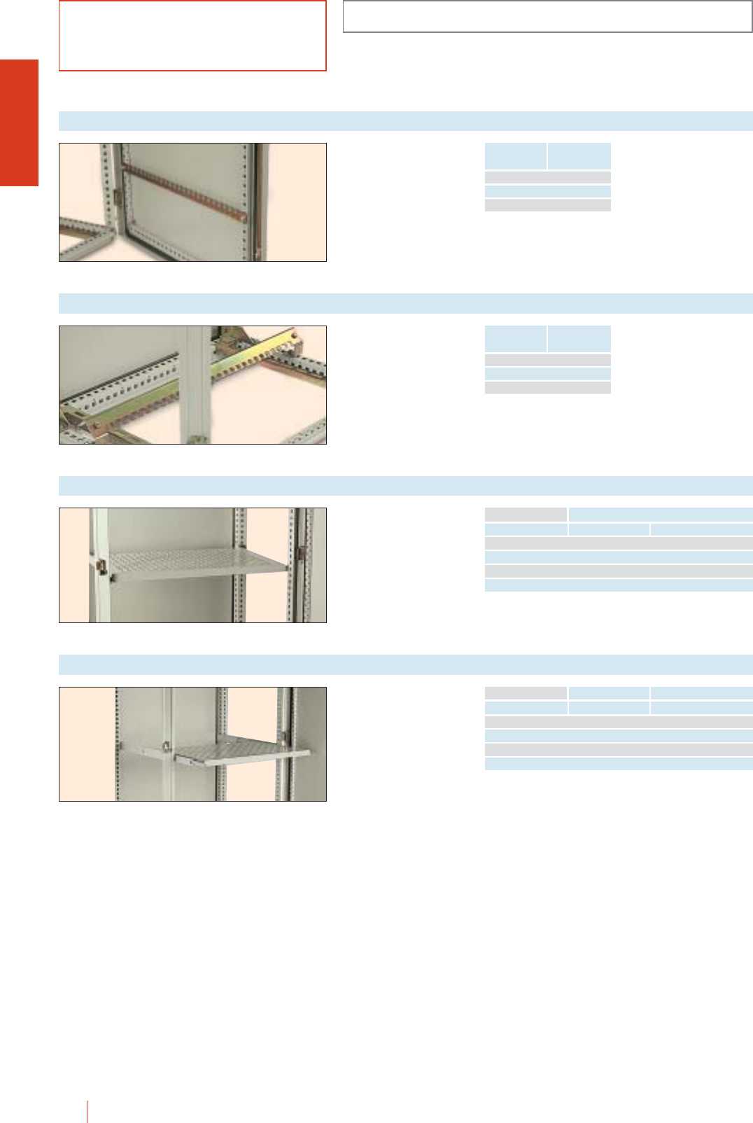
CMO-OLN
1/144 HIMEL OLN industrial cubicle system
Drilled to improve air
circulation inside the
cubicle.
Painted to RAL-7032.
Fixed tray
Width (B)
Cubicle dimensions
Depth1(C) Reference
600 400 BFOL 64
600 600 BFOL 66
800 400 BFOL 84
800 600 BFOL 86
Max. load 25 kg.
(1) Can be fitted in more depth enclosures by means of
TML 40/... cross rails (to be ordered separately).
Drilled to improve air
circulation inside the
cubicle. Painted to
RAL-7032.
Adjustable tray
Width (B)
Cubicle dimensions
Depth1(C) Reference
600 400 BDOL 64
600 600 BDOL 66
800 400 BDOL 84
800 600 BDOL 86
Max. load 20 kg.
(1) Can be fitted in more depth enclosures by means of
TML 40/... cross rails (to be ordered separately).
ACCESSORIES AND COMPLEMENTS
To fix cables on the
inside of the door. Profile
bolted to door
reinforcement frame and
height adjustable every
25 mm.
Door cable fixing profile
Cubicle
dimensions
Width (B)
Reference
600 TFP/OL 6
800 TFP/OL 8
1000 TFP/OL 10
Quick fixing of
incoming/outgoing
cables. Depth adjustable
25 mm.
Cable fixing profile
Cubicle
dimensions
Width (B)
Reference
600 TFC/OL 6
800 TFC/OL 8
1000 TFC/OL 10
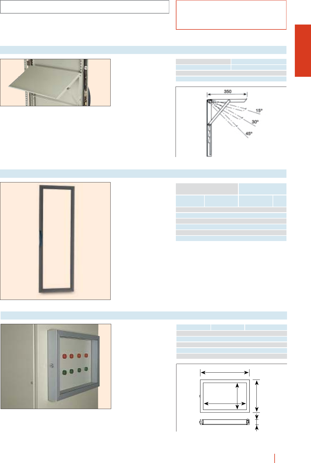
CMO-OLN
ACCESSORIES AND COMPLEMENTS
1/145OLN industrial cubicle system HIMEL
Made of sheet steel.
Painted to grey
RAL-7032. Direct fixing
to door reinforcement
frame and adjustable in
height every 25 mm.
4 different positions.
Folding plan tray
Width (B)
Cubicle dimensions
Reference
600 BSP/OL 6
800 BSP/OL 8
Made of anodized
aluminium. Neoprene
gasket. Hinges for direct
fixing to door and key
lock supplied.
Protection frames for controls
Height (H) Width (M) Reference
400 400 MA-44
400 500 MA-45
400 600 MA-46
500 500 MA-55
600 600 MA-66
M-68
M
H61
H-68
Transparent doors with
polycarbonate visor
made of a
highly-resistant special
anodized aluminium
profile. Colour RAL-7013.
cMaximum inside
visibility.
cHigh-quality finishing.
c120° opening.
cStandard OLN double-
bar lock.
Aluminium doors
Height
(A)
To fit to enclosures
Width
(B) Reference Weight
kg
1800 600 PAOL 186 11
1800 800 PAOL 188 13
1800 600 PAOL 1810 15
2000 800 PAOL 206 13
2000 1000 PAOL 208 14
2000 1000 PAOL 2010 16
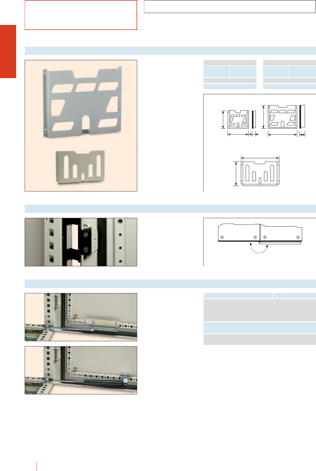
180º
ACCESSORIES AND COMPLEMENTS
CMO-OLN
1/146 HIMEL OLN industrial cubicle system
Made of anodized
aluminium in black. Ready
to fit to both standard and
glazed doors.
Reference: OLN: BEN 180
CMO: BEM 180
180° opening hinges
PP-A models of PS to
grey RAL-7035.
cAdhesive fixing or by
means of screws.
For DIN A3, A4 or A5
sized documents.
PPM-A models made of
sheet steel and painted
to light grey RAL-7032.
cFixing to door
reinforcement frame by
means of screws.
Diagram pockets
Document size Reference
A4 PP-A4
A5 PP-A5
INSULATING
Cubicle
dimensions
Width (B)
Reference
600 PPM-A3/6N
800 PPM-AE/8N
METAL
174
188 22 278 40
234
B-150
281
Ref.: PP-A5 Ref.: PP-A4
Ref.: PPM-A3/...N
Mechanical and
pneumatic door and 19”
rack retainers to fit
directly to the cubicle
structure.
cEasy mounting.
c90° up to 120° opening
depending on models.
cFor 19" Rack retainers
see page 1/129.
Door retainer
Features Reference
Mechanical retainer with
2 posiciones (90° and 120°) RET/OL
for standar door
(hinges on the right)
Same as above with
hinges on the left RET I/OL
Pneumatic retainer with
90°/120° opening RETN/OL
PP-A
PPM-A
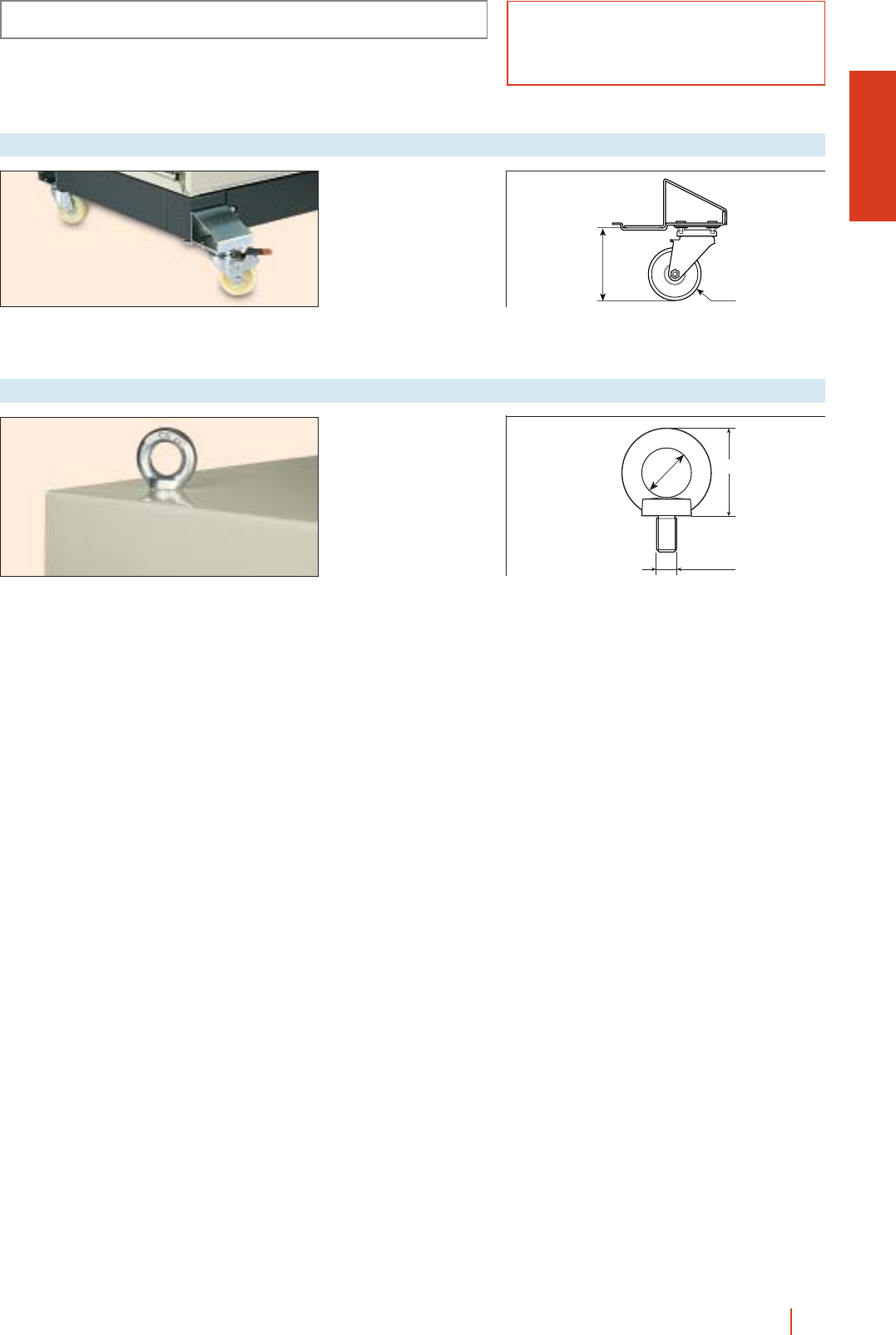
CMO-OLN
1/147OLN industrial cubicle system HIMEL
ACCESSORIES AND COMPLEMENTS
M12 lifting eyebolts bolted
directly to the cubicle
structure.
Reference: OLN: TLN/12
CMO: TMO/12
Set of 2 eyebolts.
Eyebolts
Ø 29
M.12
55
Set of 4 castors, two of
them with brakes. Easy
quick fixing.
Reference: RUT/ZUN.
Max. load:
75 kg per castor.
Castors
110
Ø 80
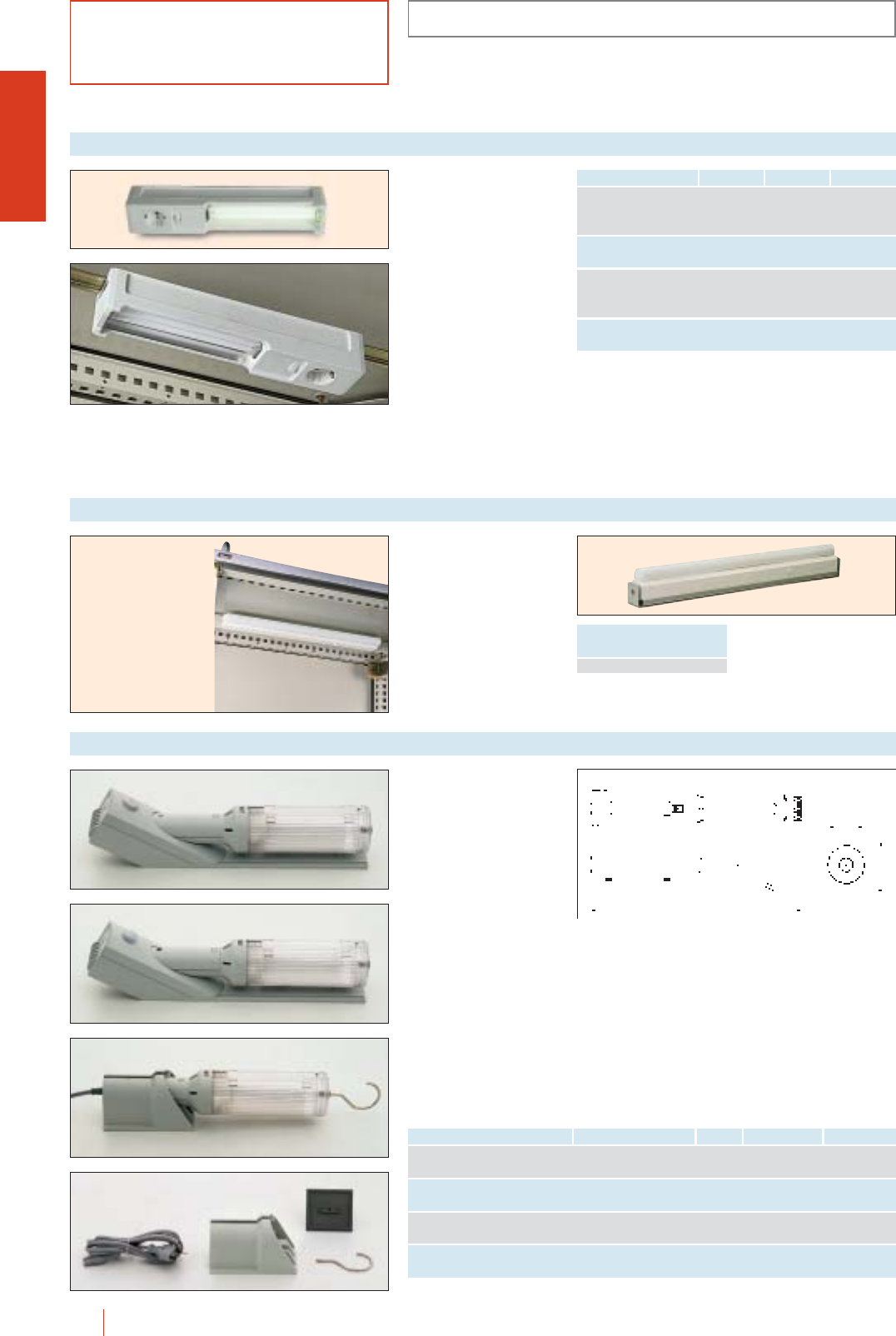
ACCESSORIES AND COMPLEMENTS
CMO-OLN
1/148 HIMEL OLN industrial cubicle system
Enclosure lighting
Characteristics VoltagePlugReference
Lamp with magnet or
35 mm symmetrical LAM-75 220 V/16 A 220 V/50 Hz
DIN rail fixing
Lamp with 35 mm
symmetrical DIN rail fixing LAC-75 220 V/16 A 220 V/50 Hz
Lamp with magnet or
35 mm symmetrical LAM-75/120 120 V/15 A 120 V/60 Hz
DIN rail fixing
Lamp with 35 mm
symmetrical DIN rail fixing LAC-75/120 120 V/15 A 120 V/60 Hz
Compact fluorescent
lamps, specially
designed for their use in
enclosures. Possibility to
fix them with magnet.
cVoltage 220 V/50 Hz.
cConsumption 11 W.
cPower on/off switch.
cEarthed
200 V/16 A plug.
cMax. ambient
temperature: 60 °C.
cLighting performance +
75 W bulb.
Enclosure lighting
1
2
3
4
Description Fixing Figure Reference Voltage
Proximity switch operated Magnetic, screws LAMDP 220 V/56 Hz
and or DIN 35 rail (1) 1LAMDP 120 120 V/60 Hz
ON/OFF switch with optional Magnetic, screws LAMIN 220 V/50 Hz
door switch and or DIN 35 rail (1) 2LAMIN 120 120 V/60 H
Portable lamp, cord Adhesive or LAMPO 220 V/50 Hz
connection screws 3LAMPO 120 120 V/60 Hz
Lamp support for LAMDP, Adhesive or screws
LAMIN,LAMPO (1) DIN rail not included 4SOLAM
(1) DIN rail not supplied as standard.
396
67
100
Lighting specially
designed for use in
electrical enclosures
with various types of
fixing and switching.
cElectronic low
consumption lamp
E27, 20 W, 220 -
240 V/50-60 Hz or
120 V/60 Hz.
cOutput equivalent to a
100 W bulb.
cDelivered with power
supply cable with
either plug and socket
(portable inspection
lamp), or 2.5 mm2
screw terminal block.
Incandescent lamp
specially designed to be
used in electric
enclosures.
cConnection current:
220 V/50-60 Hz.
cConsumption: 60 W.
cPower on/off switch.
cEntry connection
terminal.
Enclosure lighting
Reference
LAI/OL 68
cIP20 rating.
cType II insulation.
cAccording to
standards EN 55014
and EN 50082-1.
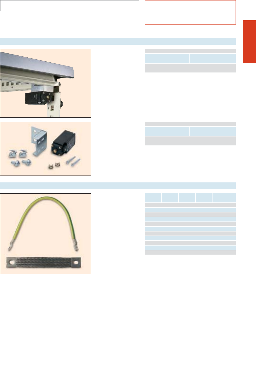
CMO-OLN
ACCESSORIES AND COMPLEMENTS
1/149OLN industrial cubicle system HIMEL
INL: Supplied with
support and screws for
direct fixing to the cubicle
structure.
cCan be connected to
lamp, thermal controls...
INL/BRP: Supplied with
support and screws for
direct fixing to the cubicle
structure.
cCan be connected to
swing 19” rack
(120° or 180°).
Door switch
Features Reference
Door In = 10 A
switch INL
DOOR SWITCH
Features Reference
Door In = 10 A
switch INL/BRP
19” RACK SWITCH
Earthing braids
Reference
Lenght
mm
Width
mm
Cross section
mm2
Eyelet hole ∅
mm
170 - 6 6.4 CTI 17/6
170 - 10 6.4 CTI 17/10
220 - 6 6.4 CTI 22/6
220 - 10 6.4 CTI 22/10
220 - 25 8.3 CTI 22/25
410 - 10 8.3 CTI 41/10
410 - 25 8.3 CTI 41/25
155 20 16 8.5 CTAF 15/16
200 21 25 8.5 CTAF 20/25
200 26 25 8.5 CTAF 25/25
200 40 50 8.5 CTAF 20/50
CTI earthing leads made
in copper/brass and
yellow/green PVC
insulation.
CTAF earthing braids
made in tinned copper.
Ensure adequate
connections to earth for
high frequencies, since it
is at these frequencies
that electrical interference
is likely.
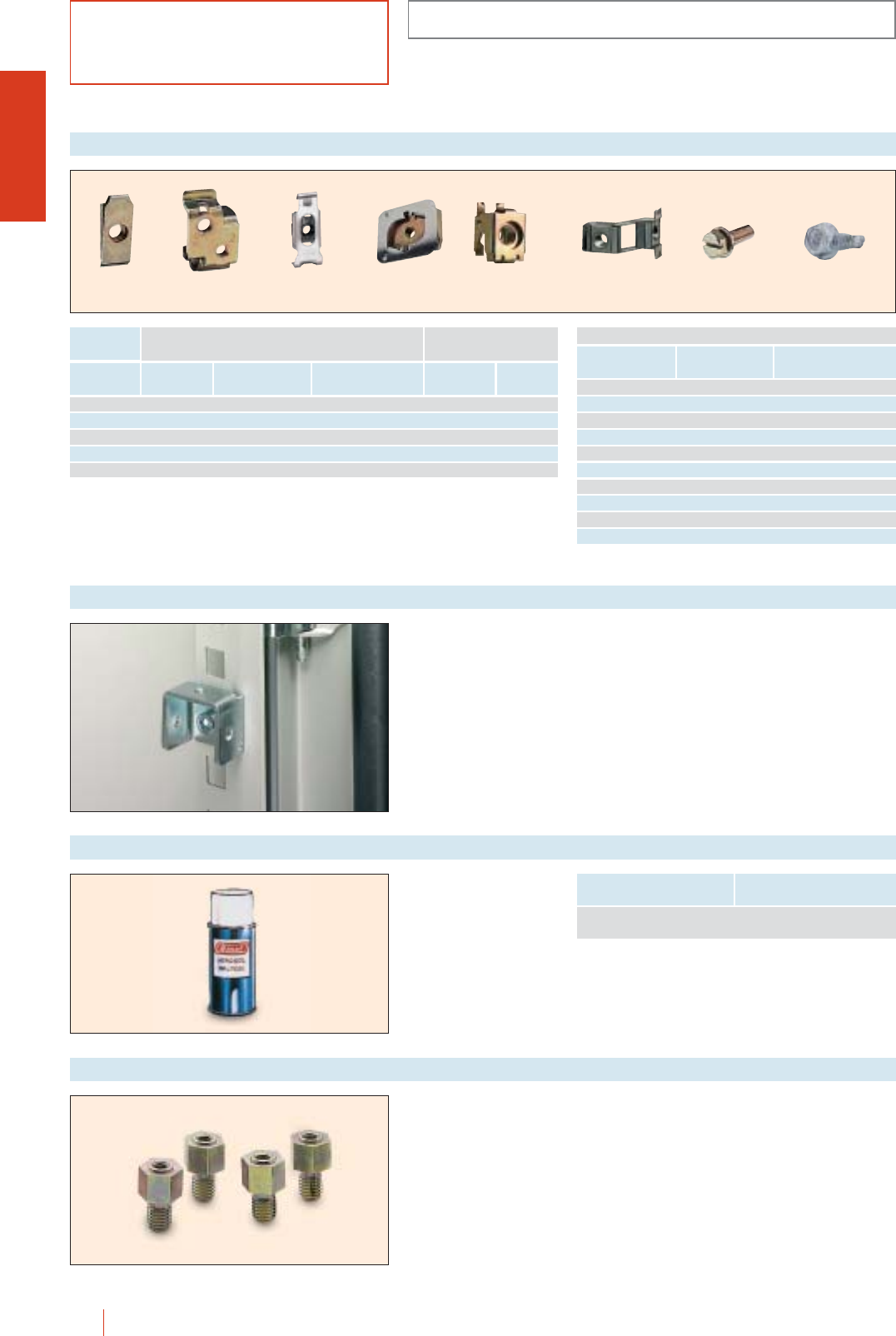
CMO-OLN
1/150 HIMEL OLN industrial cubicle system
ACCESSORIES AND COMPLEMENTS
Nuts and screws
Thread
FIXING SCREW AND WASHER
Lenght (mm) Reference
M4 10 TOR 10/4 A
M4 16 TOR 16/4 A
M5 12 TOR 12/5 A
M5 18 TOR 18/5 A
M6 12 TOR 12/6 A
M6 16 TOR 16/6A
M6 18 TOR 18/6 A
M8 16 TOR 16/8 A
M8 20 TOR 20/8 A
Self-tapping 16 TOR 16/5 AT*
TFP TDC TDE TDM TNS TLD TOR TOR 16/5 AT
* Self-tapping metal screw with washer.
Thread
Nuts for fixing of equipment Nuts for mounting
on cubicle structure
PMR mounting
plates and MOL
profiles
CDP
Double rails
MOL
Profiles Single nut Double nut
M3 TFP 3 TDC 34 - - -
M4 TFP 4 TDC 34 TDE 4 - - -
M5 TFP 5 TDC 56 TDE 5 - - -
M6 TFP 6 TDC 56 TDE 6 TDM 6 TNS 6 TLD 6
M8 - - - TDM 8 TNS 8 TLD 8
Support to fit directly to
the 1113 mm drillings
of cubicle uprights and
TML.
Reference: STON.
Fixing accessories
Spray paint
Features Reference
Colour RAL-7032
contents 150 g BPA-7032
Set of 4 top ventilation
liftings, references.
cRoof height:
14 mm.
Reference: VET 12.
Top ventilation liftings
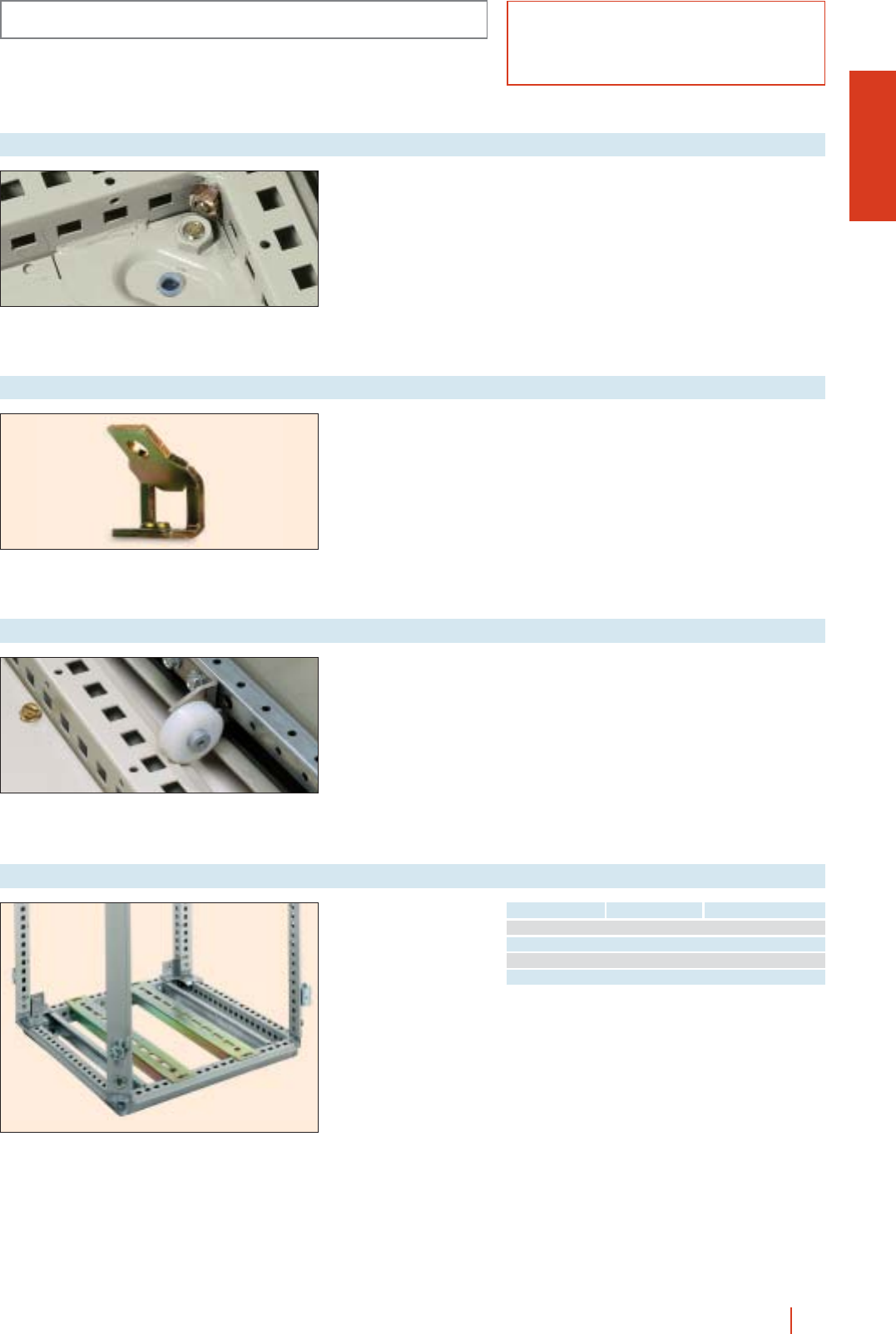
OLN
1/151OLN industrial cubicle system HIMEL
ACCESSORIES AND COMPLEMENTS
cMakes the base of the
plinth-mounted or floor
standing enclosure fully
watertight.
Reference: TPOB.
Blanking cap base
cFor mounting side
panels on enclosures
joined at the back or if
there are no rear
panels.
cSupplied with screws.
Reference: SPON.
Single support for side panel
For recentering door as it
closes.
Max. load: 60 kg
per door.
Reference: CP/CMOL.
Door recentering castor
Set of 2 cross rails for
use with loads
distributed across both
rails. Attachment
possible with cable gland
plate and mounting plate
fitted.
Heavy duty cross rails
Reference Width enclosure (mm) Load (kg)
TMP40 400 250
TMP50 600 200
TMP60 800 175
TMP80 1000 150
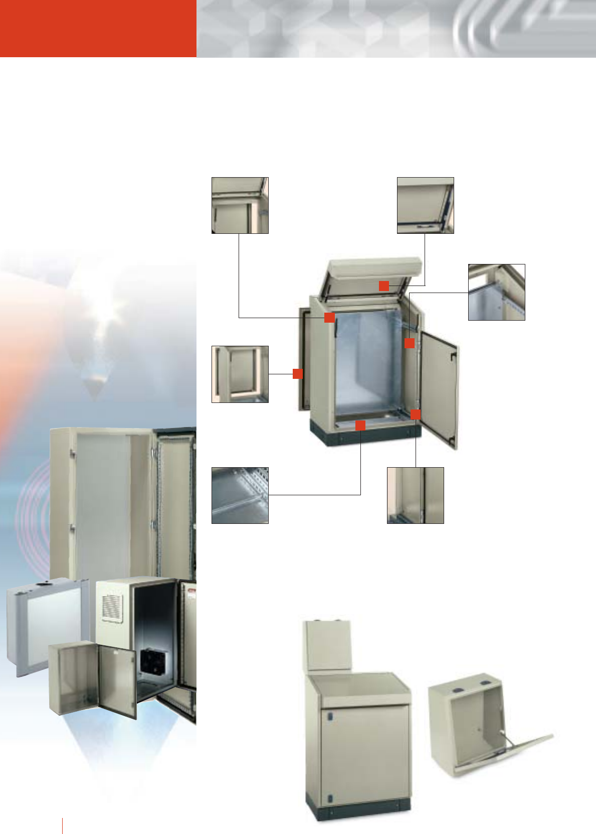
1/152 HIMEL monobloc control desks
The removal of the front
upright allows for a
complete access to the
inside of the control desks.
A pneumatic retaining stay
facilitates opening of the
top of the control desk and
prevents it dropping down
unexpectedly.
These control desks are
equipped with side
cross-rails providing
support, depth adjustment
and fixing for the different
equipment mounting
accessories through the
use of perforations at
25 mm pitch.
Installation of two chassis
back-to-back is very easy
and provides space for
maximum of equipment.
The cable entry gland plates
at the bottom of the control
desk are in two sliding parts
to optimise cabling. An
adhesive gasket can be
added to these plates to
ensure dust and damp
protection.
Changing the direction
of opening of the doors
is fast and does not
require special tools
through the use of
screw-fixed hinges.
Modular console for PKP control desk.
Monobloc control desks
PK & PKP
PK: back panel.
PKP: removal back
panel.
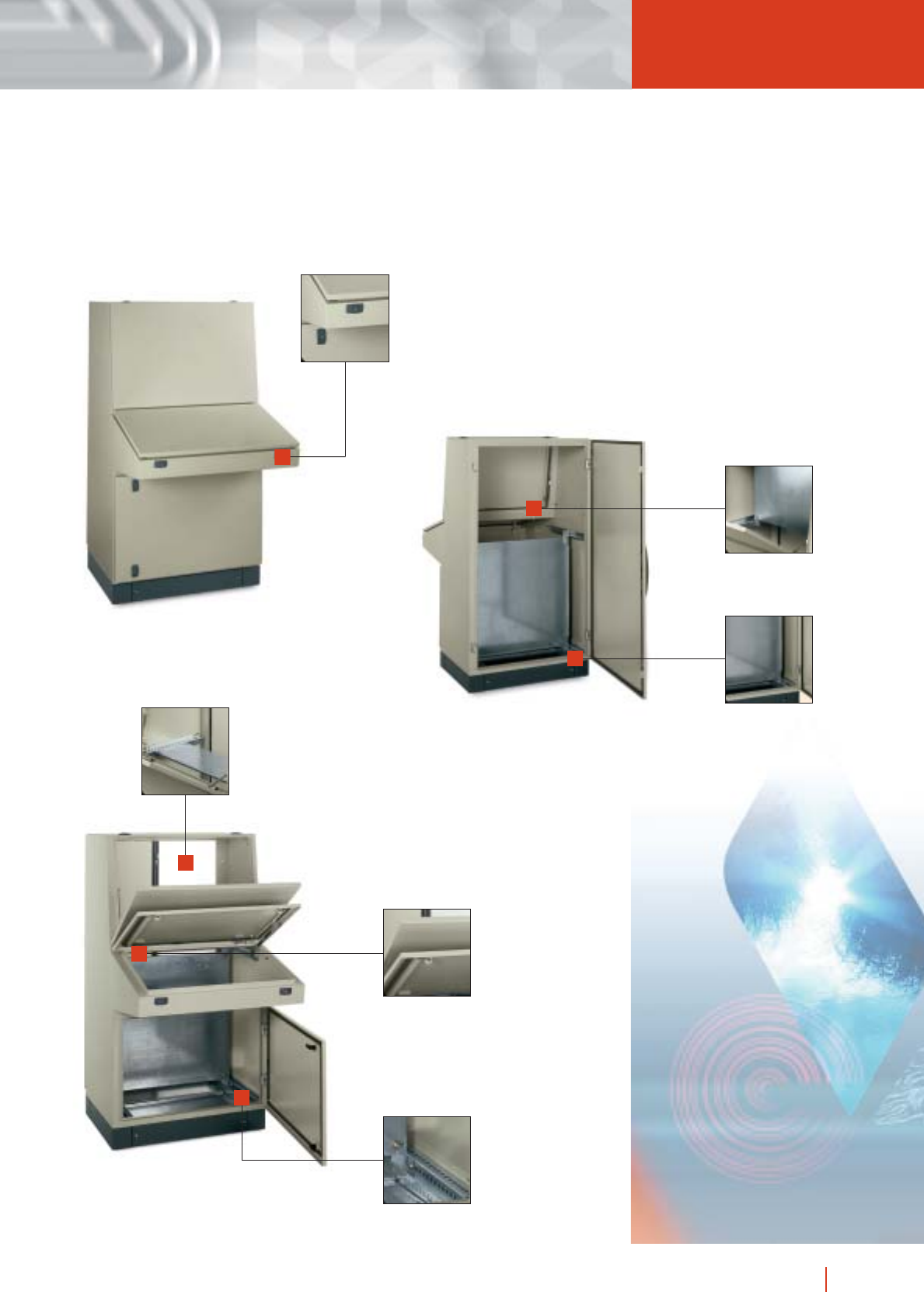
1/153monobloc control desks HIMEL
for customised solutions
The closing system uses
a 5 mm double bar. A wide
range of lock combinations
is available in the form of
accessories.
And accessory is
available to support
the screen.
The operator panels of the
main part of the control desk
and the console are equipped
with vertical rails for mounting
equipment or securing the
cables.
Cross rails can be used to
accommodate the same
component mounting
accessories as those used
for our standard enclosure
ranges.
PKP... /F
Upper mounting plate.
Bottom mounting plate.
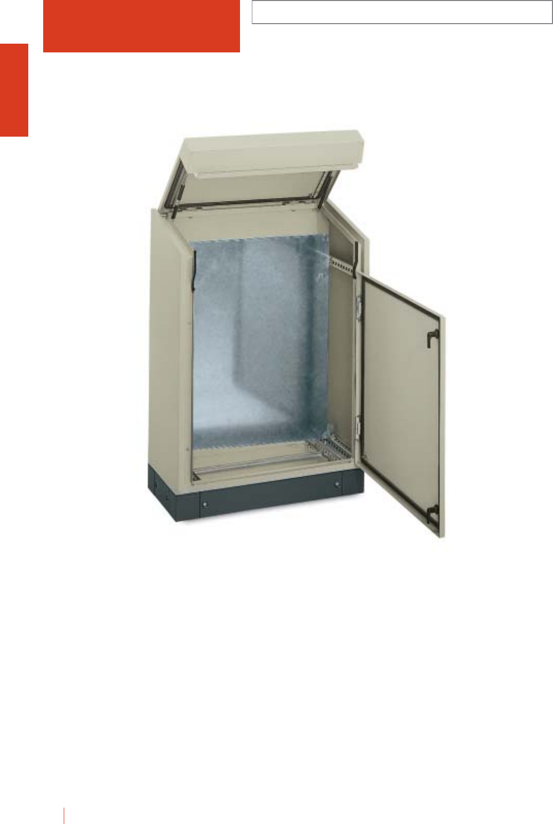
PK MONOBLOC METAL CONTROL DESKS WITH
FIXED REAR PANEL
IP55 (EN 60529)
1/154 HIMEL monobloc control desks
Monobloc sheet steel control desks. Single-piece back
and sides. Total accessibility thanks to intermediate
crossbeam-free design. Protected on outside and
inside with textured grey polyester-epoxy to RAL-7032.
cMechanical retention support top front and pneumatic on
console making opening easier, and preventing abrupt
openings leading to falls.
cDouble-bar locks on doors.
Can easily be changed to triangular, square or key lock.
cAngular reinforcement on panel to facilitate the fixing
of gear, with drillings every 25 mm, with drill holes of
Ø 4.25 mm.
cEarthing on door, body and mounting plate.
c100 mm or 200-mm high U plinth in anthracite grey
RAL-7022.
cCable gland plate with maximum cable access.
cGalvanised steel mounting plate, adjustable at 25 mm.
Basic configuration:
cPlain front door.
c3 mm double bar locking system.
c4 plate support brackets.
cMounting plate (only PK...PM references).
cCable gland plate.
PK 80-PM + ZUN 84/100
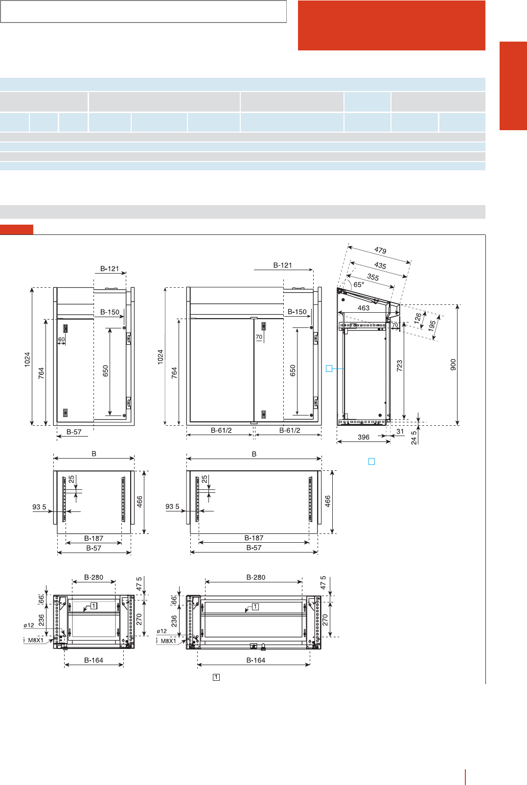
PK
MONOBLOC METAL CONTROL DESKS WITH
FIXED REAR PANEL
IP55 (EN 60529)
1/155monobloc control desks HIMEL
A
A
Maximum opening 56 mm
Mounting plate
.
..
.
.
Height
(A)
Width
(B)
Depth
(C)
External
dimensions (mm) Control desks Metal mounting plates Plinths
Without
mounting plate
Universal
mounting
plates
Heights
100 (mm)
Heights
200 (mm)
1024 600 466 PK 60 PK 60-PM 1PMPK-8560 PMR-6760 ZUN 64/100 ZUN 64/200
1024 800 466 PK 80 PK 80-PM 1PMPK-8580 PMR-6780 ZUN 84/100 ZUN 84/200
1024 1000 466 PK 100 PK 100-PM 2PMPK-85100 PMR-67100 ZUN 104/100 ZUN 104/200
1024 1200 466 PK 120 PK 120-PM 2PMPK-85120 PMR-67120 ZUN 124/100 ZUN 124/200
With
mounting plate
No. of
doors Reference
MODELS, SIZES AND REFERENCES
Dimensions (mm)
PK control desks
FIG. 1
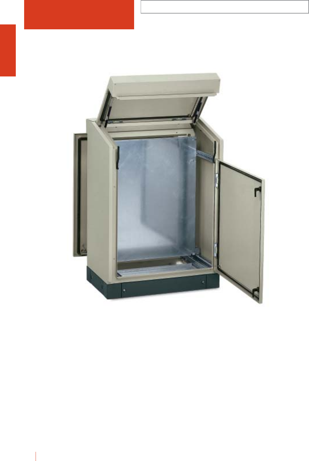
1/156 HIMEL monobloc control desks
MONOBLOC METAL CONTROL DESKS WITH
REMOVABLE REAR PANEL
IP55 (EN 60529)
PKP
Monobloc sheet steel control desks. Total accessibility
thanks to intermediate crossbeam-free design.
Protected on outside and inside with textured light grey
polyester-epoxy to RAL-7032.
cMechanical retention support top front and pneumatic on
console making opening easier, and preventing abrupt
openings leading to falls.
cDouble-bar locks on doors can easily be changed to
triangular, square or key lock.
cRear panel with screw fixing, with positioners for easy and
quick assembly.
cAngular reinforcement on panel to facilitate the fixing
of gear, with drillings evvery 25 mm, with drill holes of
Ø 4.25 mm.
cEarthing door, body, mounting plate and rear panel.
c100 mm or 200-mm high U plinth in anthracite grey
RAL-7022.
cCable gland plate with maximum cable access.
cGalvanised steel mounting plate, adjustable at 25 mm.
Basic configuration:
cPaint front door.
cRemovable rear panel.
cDouble-bar locking system.
c4 plate support brackets.
cMounting plate (only with PKP...PM).
cCable gland plate.
PKP 80-PM + ZUN 85/100
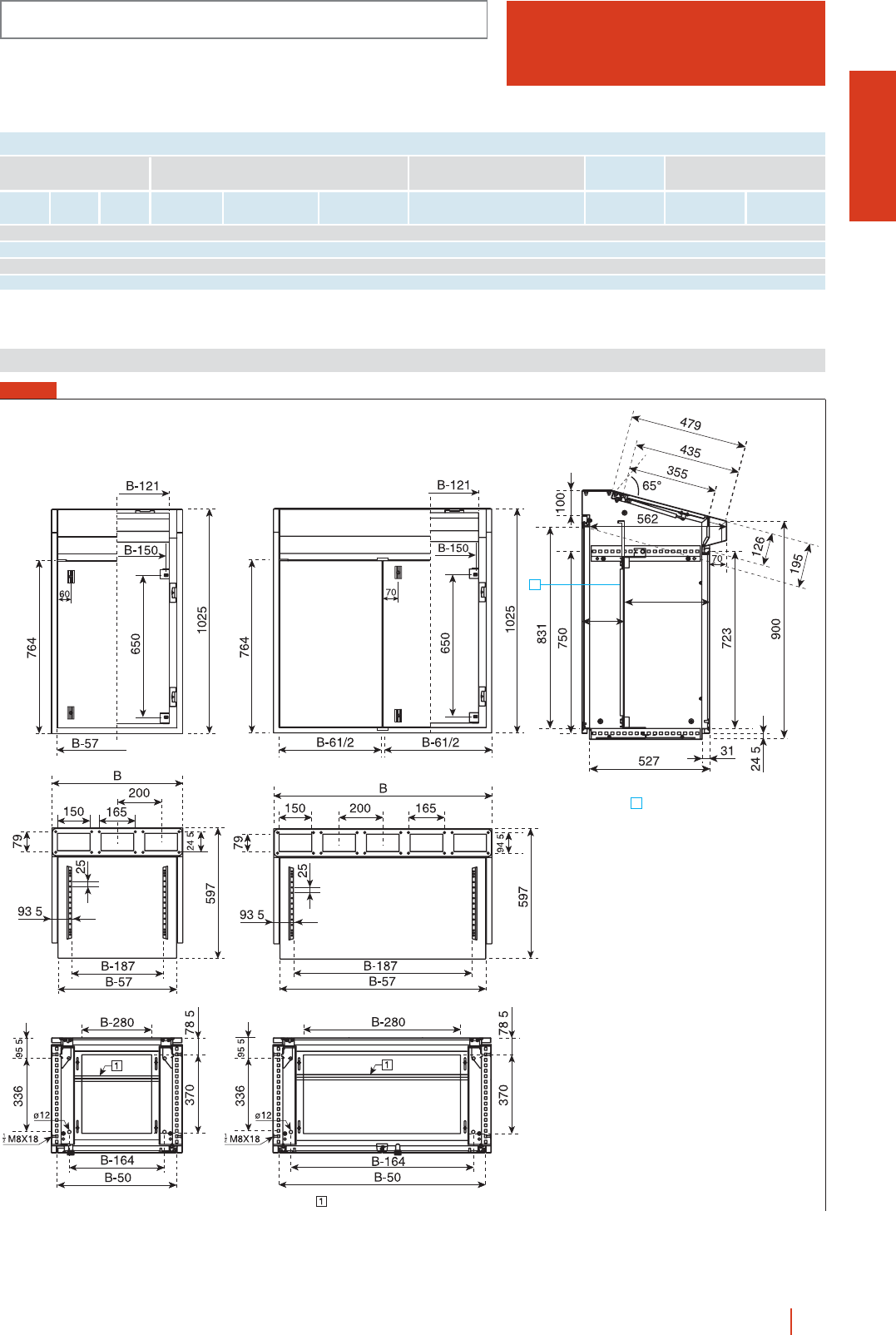
1/157monobloc control desks HIMEL
PKP
MONOBLOC METAL CONTROL DESKS WITH
REMOVABLE REAR PANEL
IP55 (EN 60529)
Height
(A)
Width
(B)
Depth
(C)
External
dimensions (mm) Control desks Metal mounting plates Plinths
Without
mounting plate
Universal
mounting
plates
Heights
100 (mm)
Heights
200 (mm)
1024 600 597 PKP 60 PKP 60-PM 1PMPK-8560 PMR 6760 ZUN 65/100 ZUN 65/200
1024 800 597 PKP 80 PKP 80-PM 1PMPK-8580 PMR 6780 ZUN 85/100 ZUN 85/200
1024 1000 597 PKP 100 PKP 100-PM 2PMPK-85100 PMR 67100 ZUN 105/100 ZUN 105/200
1024 1200 597 PKP 120 PKP 120-PM 2PMPK-85120 PMR 67120 ZUN 125/100 ZUN 125/200
With
mounting plate
No. of
doors Reference
MODELS, SIZES AND REFERENCES
min. 45
max. 395
min. 126
max. 476
A
AMounting plate
Maximum opening 56 mm
.
.
.
.
.
.
.
.
.
Dimensions (mm)
PKP control desks
FIG. 1
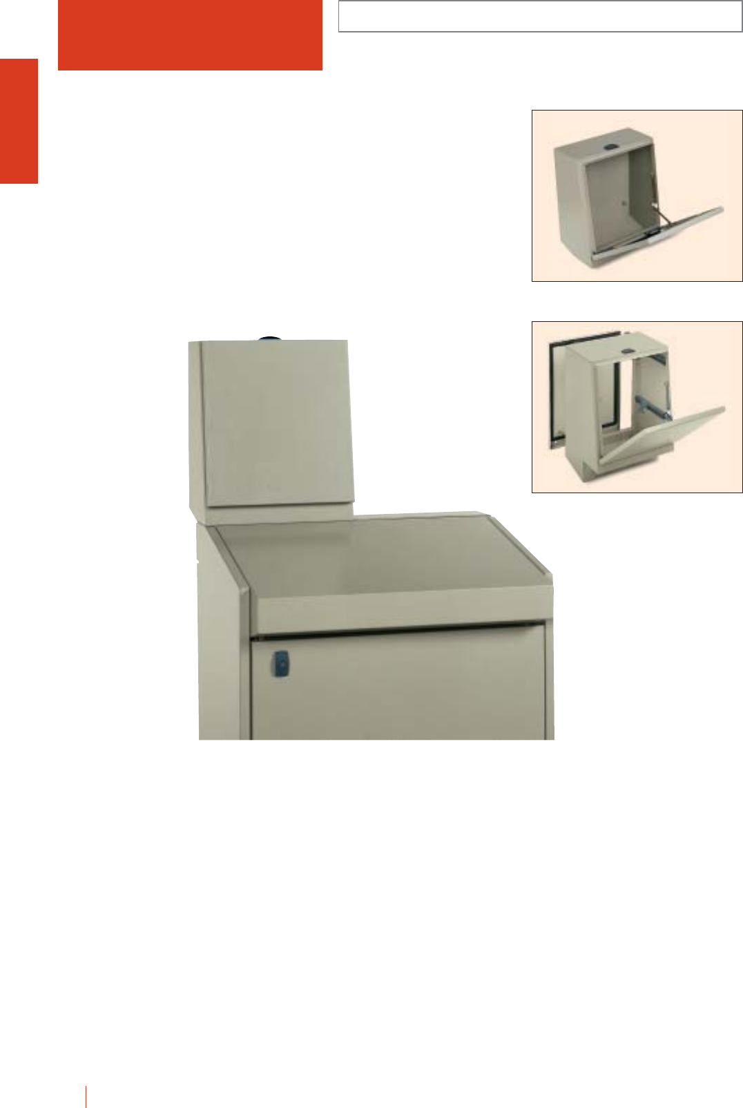
1/158 HIMEL monobloc control desks
BASIC COMPONENTS
IP55 (EN 60529)
FE
Modular top fronts for PKP control desks with
removable rear panel made of sheet steel, protected
on the inside and outside with light grey textured
polyester-epoxy RAL-7032 paint.
cTwo widths, 400 and 600 mm, and two depths, 200 and
300 mm, the latter fitted with a depth-adjustable mounting
plate and a detachable rear panel with screws, providing
easy access to the inside of the front.
cLocks on the top of the front, providing optimal usable
door surface area, double bar lock which can be easily
changed to triangular, square or key lock.
cFeatures door retainer support.
cBlanking lids in different widths, 200, 400, 600 and
800 mm.
cUniversal and metal mounting plates, either attached to
the bottom of the front or adjustable in the 300 mm-deep
models.
PKP 80 + FE 42 + TA 40
200 mm console: fix back panel.
300 mm console: removable back panel.
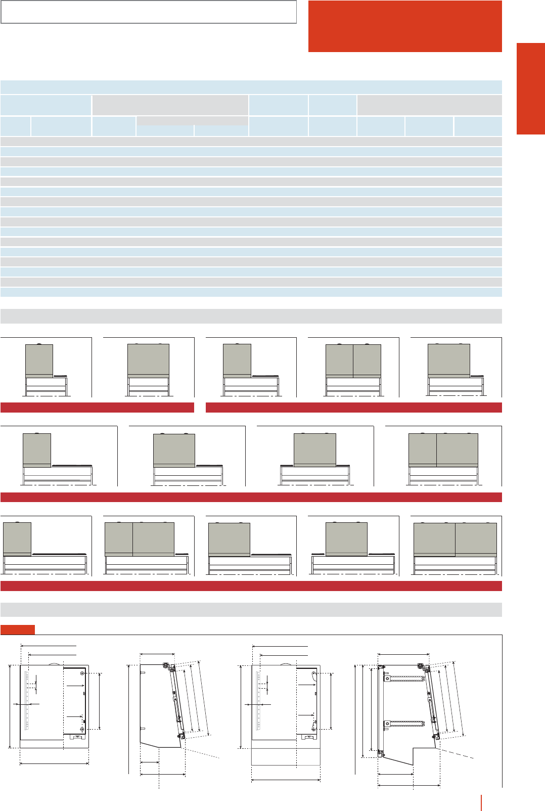
1/159monobloc control desks HIMEL
FE
BASIC COMPONENTS
IP55 (EN 60529)
Width
desk
Reference
desk
Front references
Depth
Mounting plates
Width Fig. no. Perforated UniversalMetal
600 PKP 60 400 FE 42 FE 43 TA 20 1MM 44 MF 44 MR 44
600 FE 62 FE 63 - 2MM 64 MF 64 MR 64
800 PKP 80 400 FE 42 FE 43 TA 40 3MM 44 MF 44 MR 44
400 2FE 42 2 FE 43 - 42MM 44 2 MF 44 2 MR 44
600 FE 62 FE 63 TA 20 5MM 64 MF 64 MR 64
1000 PKP 100 400 FE 42 FE 43 TA 60 6MM 44 MF 44 MR 44
600 FE 62 FE 63 TA 40 7MM 64 MF 64 MR 64
600 FE 62 FE 63 2 TA 20 8MM 64 MF 64 MR 64
400+600 FE 42 + FE 62 FE 43 + FE 63 - 9MM 44 MF 44 MR 44
MM 64 MF 64 MR 64
1200 PKP 120 400 FE 42 FE 43 TA 80 10 MM 44 MF 44 MR 44
400+600 FE 42 + FE 62 FE 43 + FE 63 TA 20 11 MM 44 MF 44 MR 44
MM 64 MF 64 MR 64
600 FE 62 FE 63 TA 60 12 MM 64 MF 64 MR 64
600 FE 62 FE 63 TA 20 + TA 40 13 MM 64 MF 64 MR 64
600 2FE 62 2 FE 63 - 14 2MM 64 2 MF 64 2 MR 64
200 (mm) 300 (mm) Blanking lids
MODELS, SIZES AND REFERENCES
Mounting possibilities
FIG. 1
Desk dimensions (width): 600 mm Desk dimensions (width): 800 mm
FIG. 2 FIG. 3 FIG. 4 FIG. 5
FIG. 10
Desk dimensions (width): 1200 mm
FIG. 11 FIG. 12 FIG. 13 FIG. 14
FIG. 6
Desk dimensions (width): 1000 mm
FIG. 7 FIG. 8 FIG. 9
Dimensions (mm)
B
B-8
53
25
B-106
325
483
B-75
B-40
200
350
387
435
107
262
1508
300
350
387
435
206
361
1508
477
536
53
25
325
B-75
B-40
B-8
B-106
483
B
FIG. 1
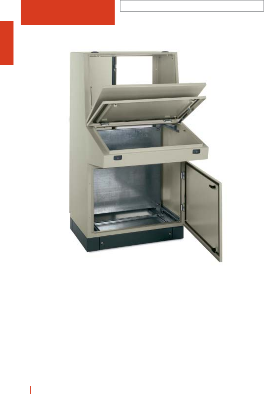
1/160 HIMEL monobloc control desks
COMPACT METAL CONTROL DESKS WITH FRONT
PANEL AND REAR DOOR
IP55 (EN 60529)
PKP.../F
Compact control desks with top front made of steel
sheet. Top part can be accessed via a three-point lock
door. Painted on the inside and outside with light grey
polyester-epoxy to textured RAL-7032.
cMechanical retention support top front and pneumatic on
console making opening easier, and preventing abrupt
openings leading to falls.
cDouble bar locking on doors. Can easily be changed to
triangular, squared or key lock.
cAngular reinforcement on panels perforated every 25 mm
with 4.25 mm Ø crill holes.
cGalvanised mounting plate to be fitted in control console,
in top front and in bottom desk or total mounting plate
adjustable at 25 mm.
cEarthing on door, body and mounting plate.
c100 or 200 mm U-profile plinth in anthracite grey to
RAL-7022.
cFully gasketed cable gland plate. Maximum capacity for
cable access.
Basic configuration:
cTop front panel.
cPlain front door.
cPlain rear door.
c3 mm double bar system lock.
c4 support brackets for bottom plate.
cBottom mounting plate, removable plate and upper
brackets (only with PKP.../F...PM).
c2 parts cable gland plate.
PKP 80/F30-PM
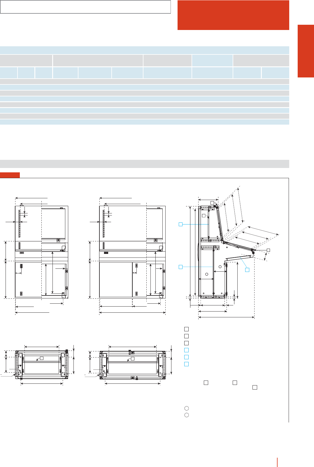
1/161monobloc control desks HIMEL
PKP.../F
COMPACT METAL CONTROL DESKS WITH FRONT
PANEL AND REAR DOOR
IP55 (EN 60529)
Height
(A)
Width
(B)
Depth
(C)
External
dimensions (mm) Control desks Metal mounting plates Plinths
Without
mounting plate
Bottom* Universal
mounting plates
Height
100 (mm)
Height
200 (mm)
With
mounting plate
No. door
front and rear Reference
MODELS, SIZES AND REFERENCES
1400 800 845 PKP80/F30 PKP80/F30-PM 1PMP7080 PMR 6760 ZUN 84/100 ZUN 84/200
1400 1000 845 PKP100/F30 PKP100/F30-PM 2PMP70100 PMR 6780 ZUN 104/100 ZUN 104/200
1400 1200 845 PKP120/F30 PKP120/F30-PM 2PMP70120 PMR 67100 ZUN 124/100 ZUN 124/200
1400 1600 845 PKP160/F30 PKP160/F30-PM 2PMP70160 PMR 67120 ZUN 164/100 ZUN 164/200
1400 800 1045 PKP80/F50 PKP80/F50-PM 1PMP7080 - ZUN 86/100 ZUN 86/200
1400 1000 1045 PKP100/F50 PKP100/F50-PM 2PMP70100 - ZUN 106/100 ZUN 106/200
1400 1200 1045 PKP120/F50 PKP120/F50-PM 2PMP70120 - ZUN 126/100 ZUN 126/200
1400 1600 1045 PKP160/F50 PKP160/F50-PM 2PMP70160 - ZUN 166/100 ZUN 166/200
236/436
273/473 78
ø12
1
B-280
B-164
M8X18
1
2
95.5
236/436
ø12
M8X18
1
2
B-280
B-164
273/473 78
1
95.5
B
CE
89
25
78
B-93
B-150
477
650
566 299
B-8
B-8
B
B-156
25
78
B-93
B-150
477
650
566
B
299
B-8
B-16/2 B-16/2
B-156
60
Cable entry: max. opening 66 mm.
Comanding panel: max. opening 75º.
Sinoptic panel: max. opening 65º.
Upper mounting plate.
Bottom mounting plate.
Control console mounting plate.
2 cable entries on 1600 mm wide desks.
Upper and bottom mounting platesBC
can be substituted by a complete
mounting plate.
D
For 2 door control desks:
+25 mm
-25 mm
1
2
3
B
C
E
Notes:
a
b
1310
1372
24.5
427/627
845/1045
365/565 31
21
297/497
526
539
480
447
min. 53
max. 278/478
a
min. 143
max.
368/568
b
3
2
4
132
482
407
390
39
Dimensions (mm)
FIG. 1
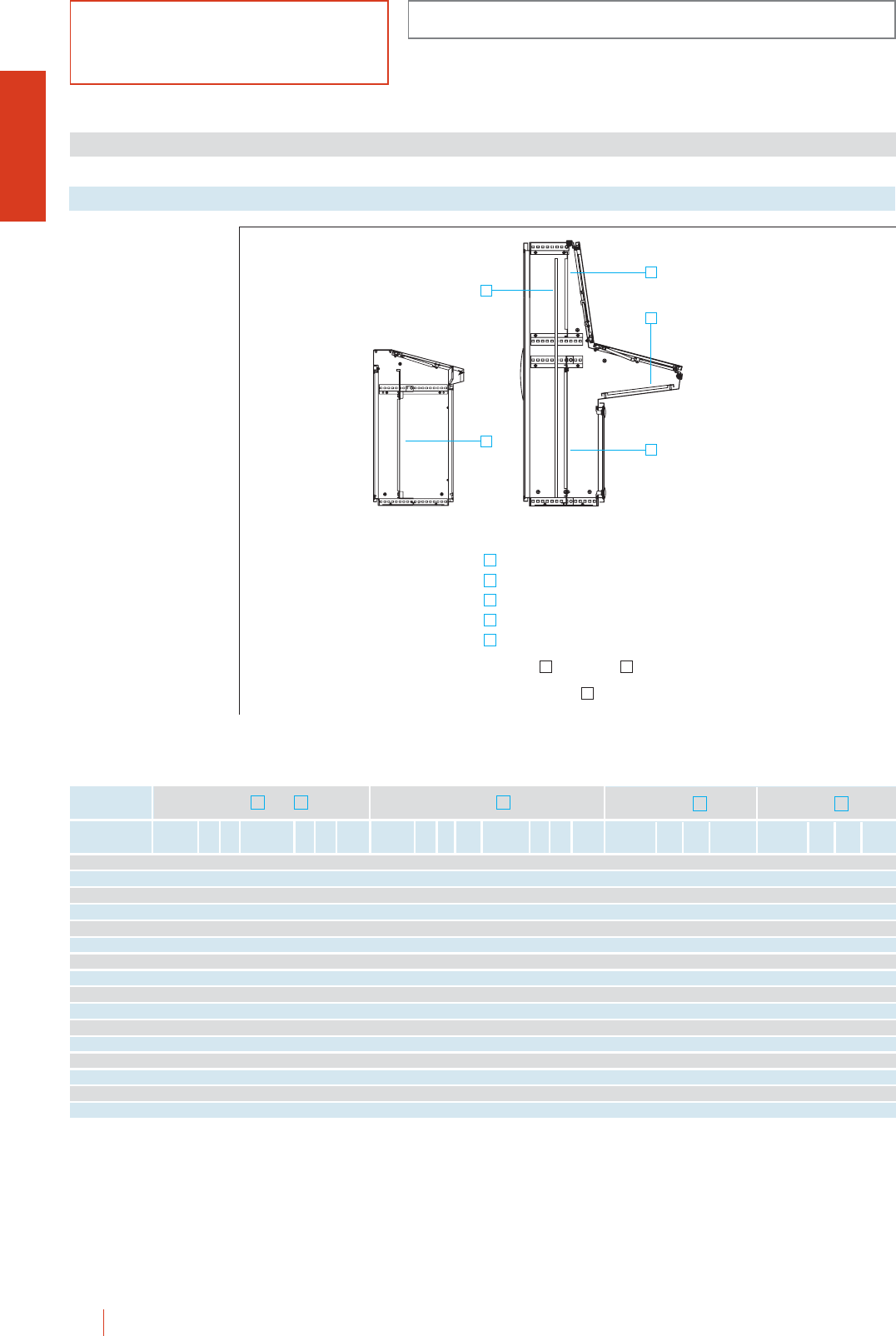
Metal
Console
E
PS Pos. Metal
Total*
D
PSPos.
FUNDAMENTAL COMPONENTS
PK-PKP
IP55 (EN 60529)
1/162 HIMEL monobloc control desks
Mounting plates
Made of galvanised
sheet steel for the
bottom, total, front and
console models, and in
zinc steel for bichrome
universal plates.
Accessories for metal control desks
To couple to control
desk reference Metal
Bottom and
CA
PS PS
PK 60 PMPK-8560 847 505 PMR 6760 675 508 A
PK 80 PMPK-8580 847 705 PMR 6780 675 708 A
PK 100 PMPK-85100 847 905 PMR 67100 675 908 A
PK 120 PMPK-85120 847 1105 PMR 67120 675 1108 A
PKP 60 PMPK-8560 847 505 PMR 6760 675 508 A
PKP 80 PMPK-8580 847 705 PMR 6780 675 708 A
PKP 100 PMPK-85100 847 905 PMR 67100 675 908 A
PKP 120 PMPK-85120 847 1105 PMR 67120 675 1108 A
PKP 80/F30 PMP-7080 697 705 PMR 6780 675 708 C PMP 4580 447 705 B PMR 4280 425 708 B PMP 4080 397 705 E PMOL 148 1298 697 D
PKP 100/F30 PMP-70100 697 905 PMR 67100 675 908 C PMP 45100 447 905 B PMR 42100 425 908 B PMP 40100 397 905 E PMOL 1410 1298 897 D
PKP 120/F30 PMP-70120 697 1105 PMR 67120 675 1108 C PMP 45120 447 1105 B PMR 42120 425 1108 B PMP 40120 397 1105 E PMOL 1412 1298 1097 D
PKP 160/F30 PMP-70160 697 1505 --- CPMP 45160 447 1505 B - - - - PMP 40160 397 1505 E - - - -
PKP 80/F50 PMP-7080 697 705 PMR 6780 675 708 C PMP 4580 447 705 B PMR 4280 425 708 B PMP 4080 397 705 E PMOL 148 1298 697 D
PKP 100/F50 PMP-70100 697 905 PMR 67100 675 908 C PMP 45100 447 905 B
P
MR 42100 425 908 B PMP 40100 397 905 E PMOL 1410 1298 897 D.
PKP 120/F50 PMP-70120 697 1105 PMR 67120 675 1108 C PMP 45120 447 1105 B PMR 42120 425 1108 B PMP 40120 397 1105 E PMOL 1412 1298 1097 D
PKP 160/F50 PMP-70160 697 1505 - - - C PMP 45160 447 1505 B - - - - PMP 40160 397 1505 E - - - -
* The DFPK plate fixing suite is required to fix front or total mounting plates.
Universal Pos. Metal
Front*
B
P S Pos. P S
Universal
Pos.
C
B
A
E
D
Bottom mounting plate.
Upper mounting plate.
Bottom mounting plate.
Control console mounting plate.
Complete mounting plate.
Upper and bottomBC
mounting plates can be substituted
D
A
B
C
E
D
Notes:
PK and PKP PKP... /F
by a complete mounting plate
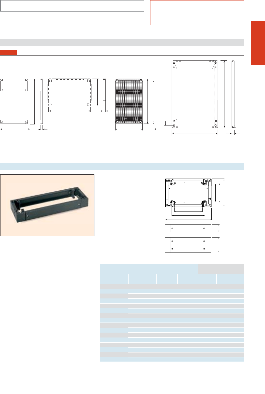
PK-PKP
FUNDAMENTAL COMPONENTS
IP55 (EN 60529)
1/163monobloc control desks HIMEL
Dimensions (mm)
S
P
16
S
ø10
ø2
2
1018
50
25
P
15S
P
S
P
16
PMPK... PMP... PMR... PMOL...
Plinths
For direct coupling to
the control desks using
floor-fixing screw holes.
cHeights of 100 and
200 mm.
cAccessible from front
and rear side.
cPainted in anthracite
grey polyester paint to
RAL-7022.
100200
B - 164
B - 2
C - 145
C - 164
C - 34
B - 228
B - 62
C - 106
To couple to
control desk
Plinth height
100 mm 200 mm
Without front PK60 600 400 ZUN 64/100 ZUN 64/200
rear panel PK80 800 400 ZUN 84/100 ZUN 84/200
fixed PK100 1000 400 ZUN 104/100 ZUN 104/200
PK120 1200 400 ZUN 124/100 ZUN 124/200
Without front PKP60 600 500 ZUN 65/100 ZUN 65/200
rear panel PKP80 800 500 ZUN 85/100 ZUN 85/200
fixed PKP100 1000 500 ZUN 105/100 ZUN 105/200
PKP120 1200 500 ZUN 125/100 ZUN 125/200
With front PKP80/F30 800 400 ZUN 84/100 ZUN 84/200
model PKP100/F30 1000 400 ZUN 104/100 ZUN 104/200
F30 PKP120/F30 1200 400 ZUN 124/100 ZUN 124/200
PKP160/F30 1600 400 ZUN 164/100 ZUN 164/200
With front PKP80/F50 800 600 ZUN 86/100 ZUN 86/200
model PKP100/F50 1000 600 ZUN 106/100 ZUN 106/200
F50 PKP120/F50 1200 600 ZUN 126/100 ZUN 124/200
PKP160/F50 1600 600 ZUN 166/100 ZUN 164/200
Reference Width
(B)
Depth
(C)
FIG. 1
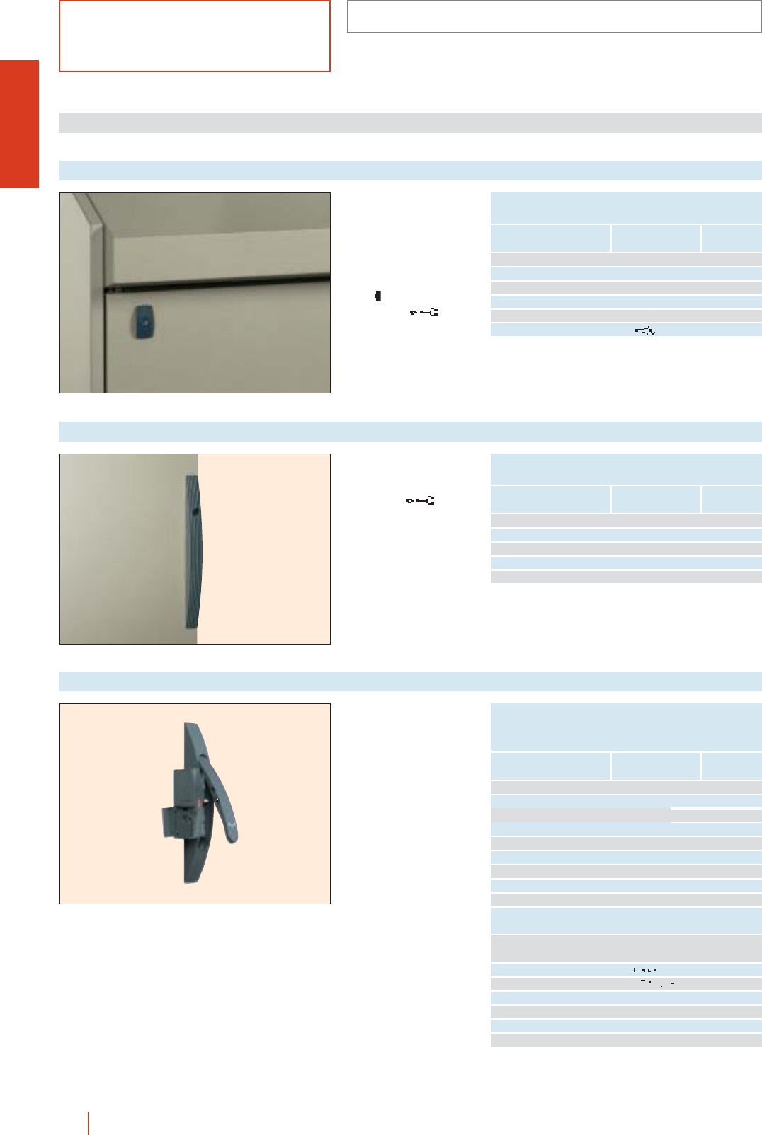
1/164 HIMEL monobloc control desks
ACCESSORIES AND COMPLEMENTS
PK-PKP
IP55 (EN 60529)
Standard double bar
lock, fixing wing-type
lock if changing from
double bar to standard
manual lock.
Operated by
wing-shaped handle
PDB .
LDB 5 key
(to DIN 43668).
Door and front panel locks
Characteristics Reference
v6 mm square lock LC-7 TC 6/CRN
v7 mm square lock LC-7 TC 7/CRN
v8 mm square lock LC-8 TC 8/CRN
∆7 mm triangular lock LT-8 TT 7/CRN
∆8 mm triangular lock LT-8 TT 8/CRN
405 full key lock TCL/PK
Key type
OPTIONAL LOCK INSERTS TO TRANSFORM
THE STANDARD LOCK
Locks for metal control desks
Standard double bar
lock (normal supply).
Operated by
LDB 5 key
(to DIN 43668).
Locks for rear doors
Characteristics Reference
∆7 mm triangular lock LT-7 TPT 7/OLN
∆8 mm triangular lock LT-8 TPT 8/OLN
v6 mm square lock LC-7 TPC 6/OLN
v7 mm square lock LC-7 TPC 7/OLN
v8 mm square lock LC-8 TPC 8/OLN
Key type
OPTIONAL LOCK INSERTS TO TRANSFORM
THE FLAT LOCK
Ergonomic locking
syhstem with pivoting
handle.
(1) To form the new lock
order the panel with handle
ref.: MCS/OLN plus the
operating/locking variant
chosen.
Optional handle lock
Characteristics Reference
Handle lock panel MCS/OLN
MCS/MICH 8079
Handle lock with MICHELIN type mechanism MCS/MICH 8133
MCS/MICH 8376
v6 mm square lock LC-7 TC 6/OLN
v7 mm square lock LC-7 TC 7/OLN
v8 mm square lock LC-8 TC 8/OLN
∆7 mm triangular lock LT-8 TT 7/OLN
∆8 mm triangular lock LT-8 TT 8/OLN
∆6.5 mm CNOMO
triangular lock LT-6,5 TCNOMO/OLN
∆6.5 mm CNOMO triangular lock
for double door enclosures TCNOMO/OLN-2P
Key lock type 405 TL/OLN
Safety cylinder lock TLR/OLN
Pushbutton lock opening TS/OLN
FIAT lock TFI/OLN
E1 lock TLE1/OLN
Padlock BC/OLN
Key type
OPTIONAL LOCK INSERTS
TO TRANSFORM
THE HANDLE LOCK (1)
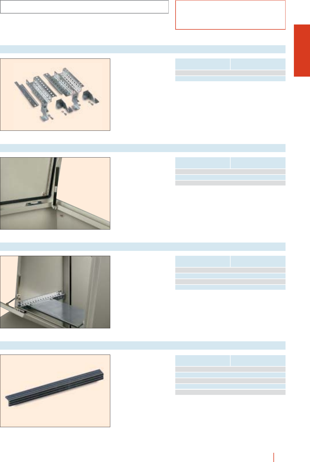
1/165monobloc control desks HIMEL
Plate support suites
DFPK suite... needed to
fix front or total plates to
PKP…/F control desks.
cAre depth-adjustable.
cFor double plates
(back-to-back) the 4
loose bracket suite
should be ordered.
Ref.: EDF/PK.
PK-PKP
ACCESSORIES AND COMPLEMENTS
IP55 (EN 60529)
Pneumatic retainers
Quick-to-mount
pneumatic retainers
make it easy to open the
console while stopping it
from dropping abruptly.
PC monitor support
Monitor support suite to
join to the front of the
PKF…F control desks,
consisting of guides and
horizontal tray.
Diagram rest
Profile for fixing to the
edge of the top tilted
panel. Stops diagrams
or material from falling.
cMade of PVC to
RAL-7011.
Maximum load
per retainer Reference
21 kg RETN 21/PK
24 kg RETN 24/PK
29 kg RETN 30/PK
To couple to control desk Reference
PKP800/F... SPC8
PKP1000/F... SPC10
PKP1200/F... SPC12
PKP1600/F... SPC16
To couple to width control desk Reference
600 REP 6
800 REP 8
1000 REP 10
1200 REP 12
1600 REP 16
To couple to front
of control desk Reference
PKP.../F30 DFPK-2030
PKP.../F50 DFPK-4050

1/166 HIMEL stainless steel enclosures
Stainless steel enclosures
Stainless steel hinge bolted to
the body of the enclosure for a
reversible door and easy
machining. Opening angle over
120°.
Back with 4 welded studs for
fixing of mounting plate and
depth adjustable supports.
4 drillings for direct wall fixing or
through brackets.
Vertical door profiles (up from
600 mm high enclosures)
for fixing of equipment.
Earthing between body and door
through welded studs. Total
safety of use. Available as
accessory.
Door reinforcement frame on
CRSX 108 and 128 models.
Polyurethane foamed gasket
ensuring full watertightness
(IP66).
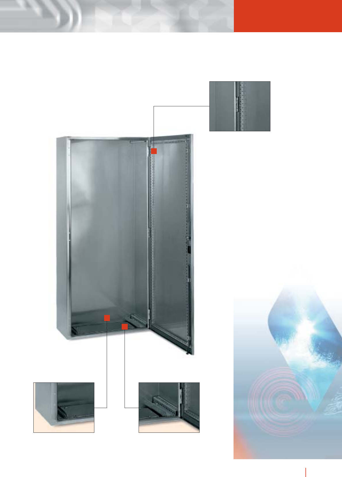
1/167stainless steel enclosures HIMEL
for permanent protection
Stainless steel inside guide
and reinforcement frame with
section 18×18 mm, reinforced
at 25 mm intervals with Ø 5
and 10 mm drill holes.
Guide with drill holes every
25 mm to facilitate
depth-adjustment of the plate.
Inside view of cable gland plate
in stainless steel.
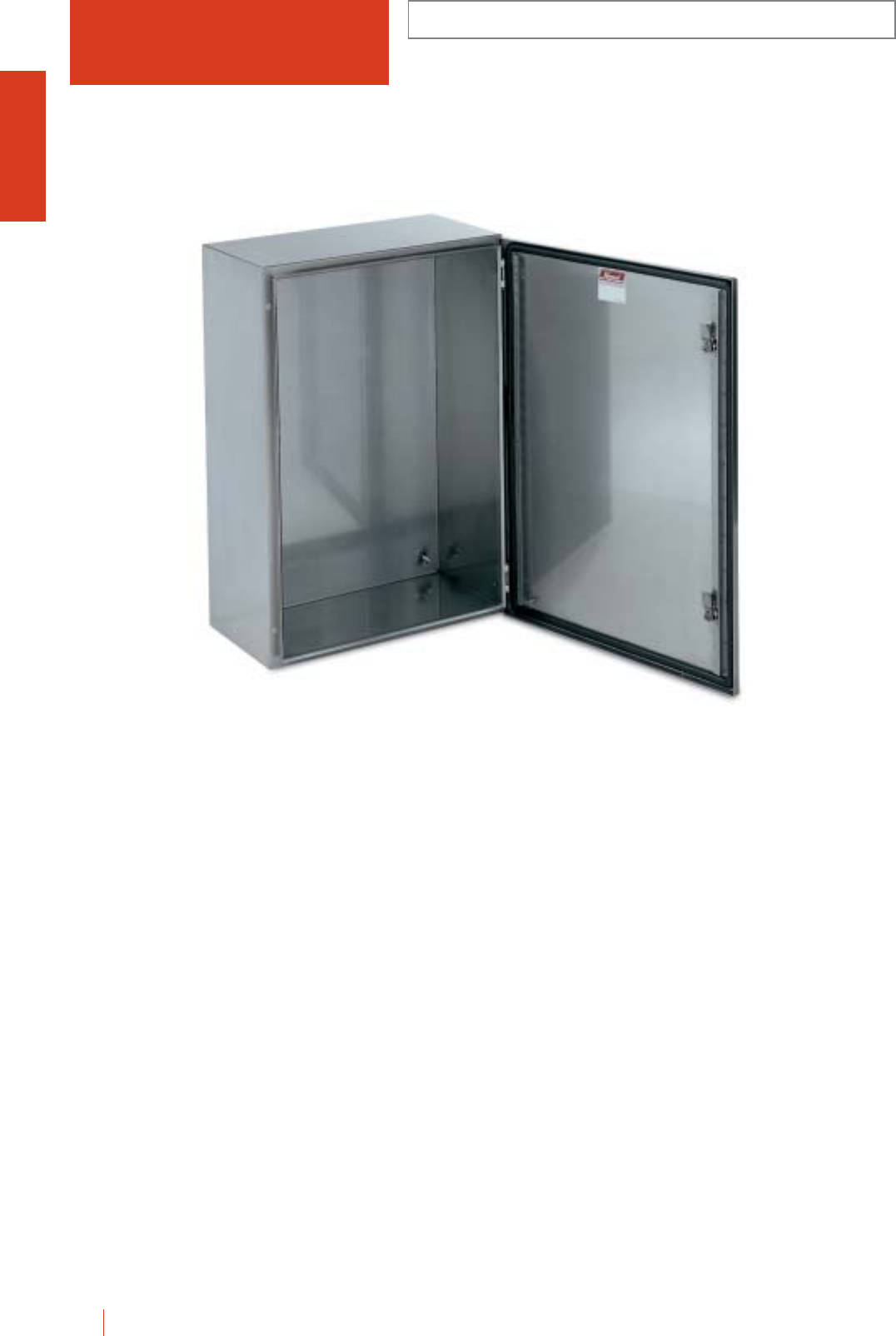
CRSX
IP66 (EN 60529)
1/168 HIMEL stainless steel enclosures
The stainless steel Himel enclosures are specially
suitable for corrosive environments and installations
where hygiene is essential. Also in chemical and food
industries, etc.
■Monobloc watertight AISI 304 stainless steel enclosures.
Types AISI 304L (resistant against corrosive organic
agents) and AISI 316 (resistant to concentrated acids and
halogen based agents) also available on request.
■Scotch brite (AST) type mechanical polish for an excellent
surface quality and improved protection against
corrosion. Electrical polish on request.
■14 dimensions. Wide range of accessories compatible
with the CRN enclosures.
■CMOX range in stainless steel also available, dimensions
up to 2000 high 1600 wide 600 deep (mm).
CRSX 54/200
STAINLESS STEEL ENCLOSURES
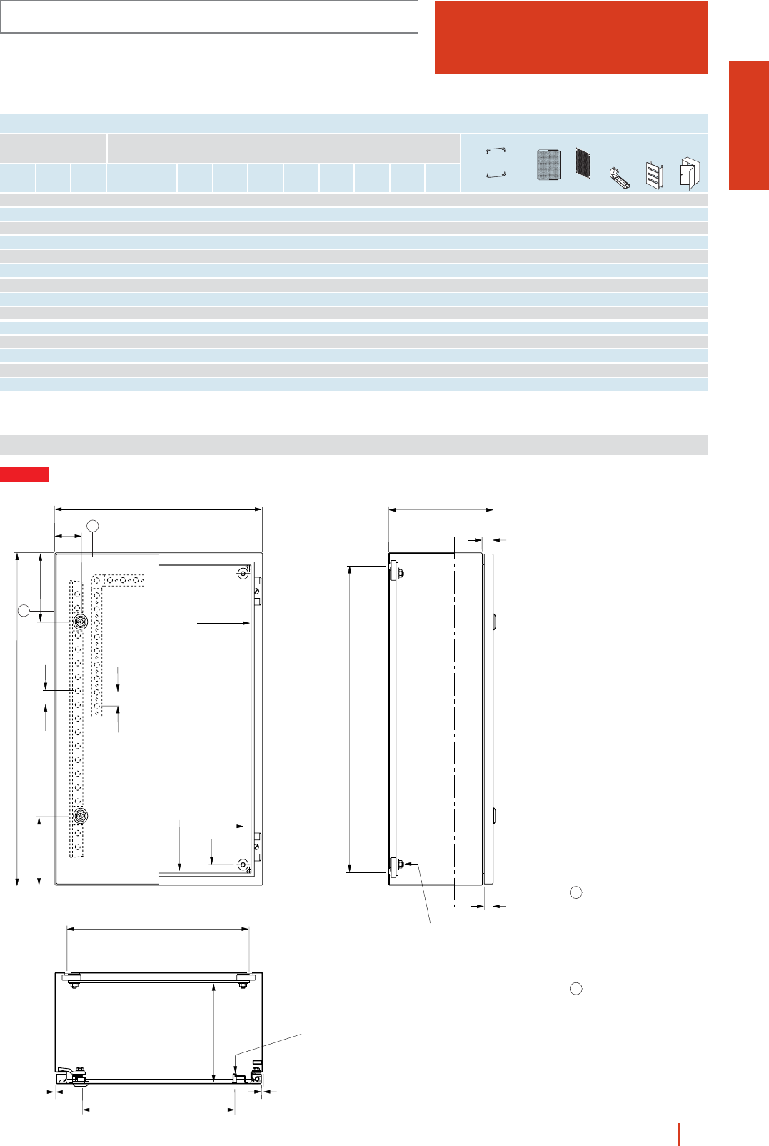
FIG. 1
CRSX
IP66 (EN 60529)
1/169stainless steel enclosures HIMEL
STAINLESS STEEL ENCLOSURES
Dimensions (mm)
MODELS, SIZE AND REFERENCES
Height
(A)
Width
(B)
Depth
(C) Reference No. of
locks
No. of
hinges DFGMT
Weight
(Kg) metal insulating perf. universal
External
dimensions (mm) Enclosures
300 200 150 CRSX 32/150 1 2 150 257 157 134 - 3.9 pppp
300 250 150 CRSX 3025/150 1 2 150 257 207 134 - 4.8 pppp
300 300 150 CRSX 33/150 1 2 150 257 257 134 - 5 pppp
400 300 150 CRSX 43/150 2 2 200 347 257 134 165 5.7 pppp p
400 300 200 CRSX 43/200 2 2 200 347 257 184 165 6.7 ppppp pp
400 400 200 CRSX 44/200 2 2 200 347 357 184 265 7 ppppp
500 400 200 CRSX 54/200 2 2 125 457 357 184 265 9.2 ppppp pp
600 400 200 CRSX 64/200 2 2 125 557 357 184 317 10.7 ppppp pp
600 600 250 CRSX 66/250 2 2 125 557 557 234 517 14 ppppp
700 500 250 CRSX 75/250 2 2 125 657 457 234 417 18.5 ppppp pp
800 600 250 CRSX 86/250 2 2 125 757 557 234 517 23.5 ppppp pp
800 800 300 CRSX 88/300 2 2 125 757 757 284 717 31 ppppp
1000 800 300 CRSX 108/300 2 3 125 957 757 284 650 38.5 ppppp pp
1200 800 300 CRSX 128/300 2 3 125 1157 757 284 650 44 ppppp p
(1) See characteristics and references in CRN.
Mounting plates (1)
Depth adjust.
m. plate
support
(1)
DINIMEL
chassis
(1)
Internal
door
(1)
A
BC
D
F
G
B
-
50
A-50
A-75
B-75
D
50
16.5
20
25
M8
×
25
25
2.5
2.5
M
T
B-50
M6
×
15
1 2 mm thick door
reinforcement frame in
CRSX 108/300
and 128/300 models.
v20 ×15 mm cross section
with Ø 5 and 10 mm
drillings every 25 mm.
2 Two vertical door
reinforcement profiles
(models from 600 mm high)
with 4,25 mm Ø drillings
every 25 mm.
1
2
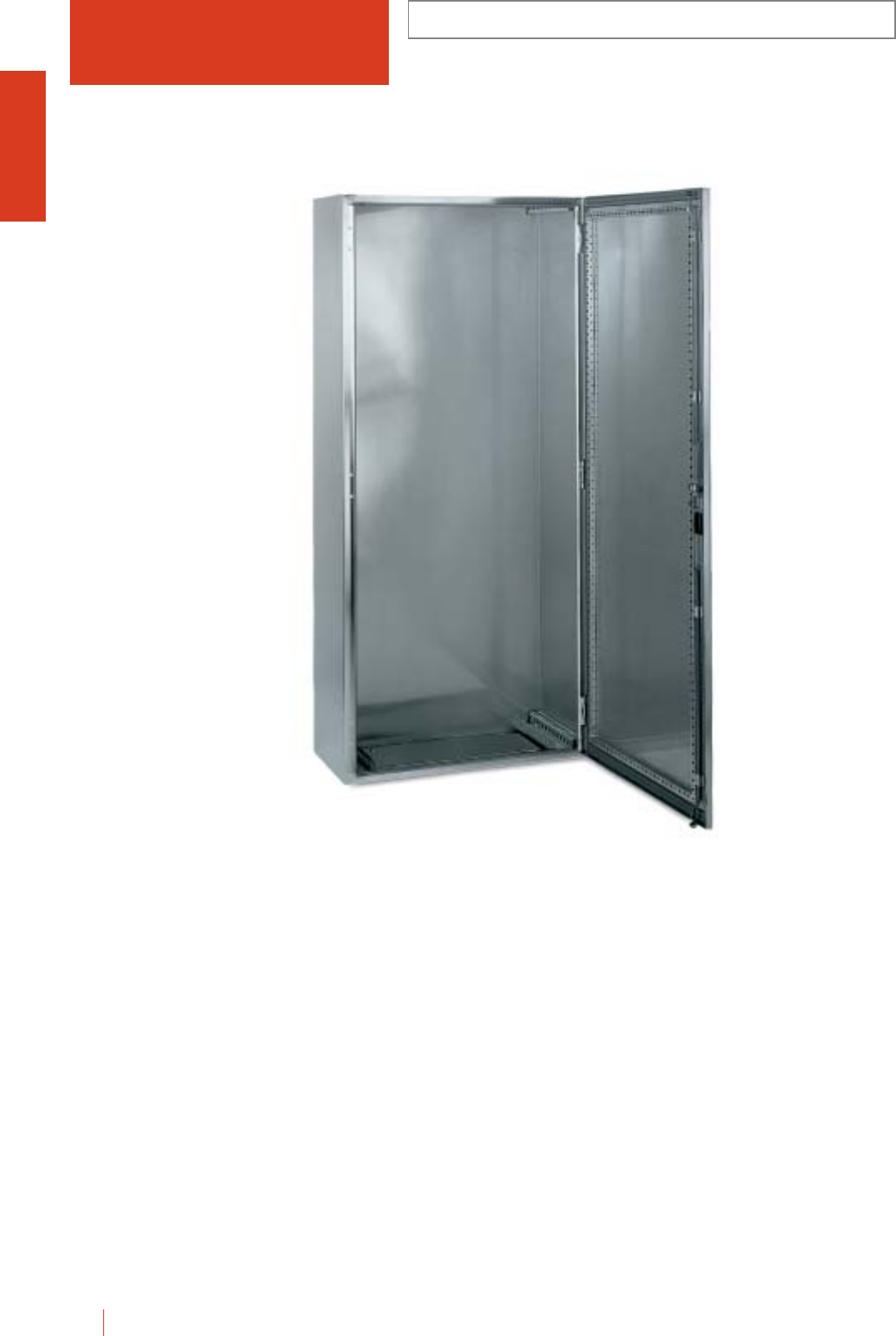
CMOX
IP55 (EN 60529)
1/170 HIMEL stainless steel enclosures
Floor standing enclosures made of AISI 304 stainless
steel. Polished finish.
■Door in folded and welded 304 stainless sheet steel.
■Door opening 120º, to right or left. Reinforcing frame on
door, with 4 stainless steel hinges.
Maximum load 50 kg.
3 locking points. Handle with key 405.
■4 support brackets included for mounting plate PMOL.
■Stainless steel cable gland plate.
■Optional 100 and 200 mm high plinths.
■Optional stainless steel canopies.
■Lifting eyebolts TMO/12 available.
MONOBLOC STAINLESS STEEL ENCLOSURES
CMOX 188/40
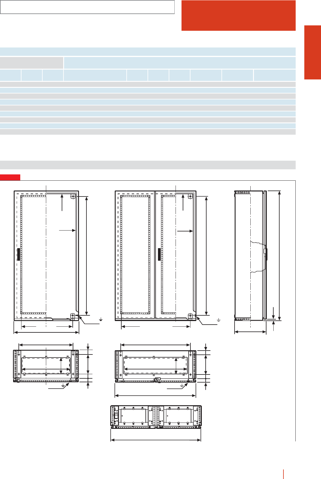
CMOX
IP55 (EN 60529)
1/171stainless steel enclosures HIMEL
MONOBLOC STAINLESS STEEL ENCLOSURES
Height
(A)
Width
(B)
Depth
(C) Reference No. of
doors EF
MOL universal
chassis
PIL
internal doors
Reference
mounting plate
External dimensions
(mm)
1200 1000 300 CMOX 1210/30 2 720 170 pPMOL 1210
1600 800 400 CMOX 168/40 1 520 270 ppPMOL 168
1800 800 400 CMOX 188/40 1 520 270 ppPMOL 188
1800 1200 400 CMOX 1812/40 2 920 270 pPMOL 1812
1800 1600 400 CMOX 1816/40 2 520 270 pPMOL 1816
2000 800 400 CMOX 208/40 1 520 270 ppPMOL 208
2000 1000 400 CMOX 2010/40 2 720 270 ppPMOL 2010
2000 1200 500 CMOX 2012/50 2 920 370 ppPMOL 2012
2000 1600 600 CMOX 2016/60 2 1,320 470 pPMOL 2016
MODELS, SIZES AND REFERENCES
Dimensions (mm)
FIG. 1
M8 × 18
E
F
B-164 *
30 C-164*
67
E
67
236*
67
M8 × 18
F
30
636*
800
650 650
A - 150
M8 × 18
A-70
730
B/2 - 150
A - 150
M8 × 18
A-70
B -70
B - 150
20
A
C
67
1600
1000/1200
* Dimensions for fixing plinth to floor.
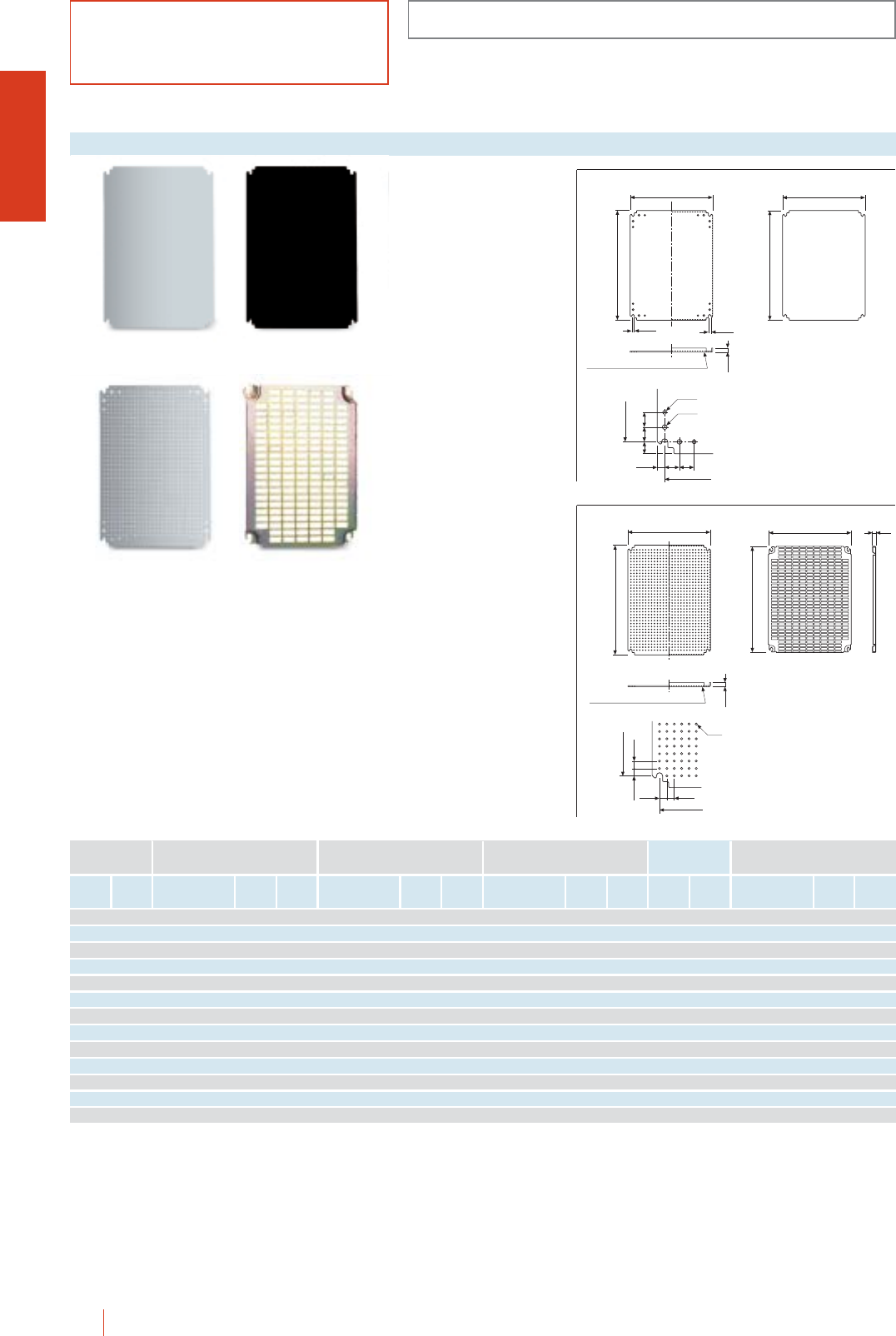
FUNDAMENTAL COMPONENTS
CRSX-CMOX
1/172 HIMEL stainless steel enclosures
IP66/IP55 (EN 60529)
A comprehensive range
of plates in three
versions solves most
installation requirements.
cMounting plates in
zinc bichromated steel
with holes for accessory
fixing and earth
connection.
cInsulating plates in
bakelite.
cPerforated plates in
galvanized steel, drilled
with 3.6 mm Ø holes,
12.5 mm apart.
cPerforated plates for
quick equipment fixing,
in zinc bichromated
steel. The distribution of
them, together with the
position of the nuts,
cover all the fixing
points.
Mounting plates
12.5
P
S
10.5 10.5
12.5 25 25
25 25
20
B-75
A-75
ø6.5
ø8.5
P
S
MM-1010, MM-1012, MM-128 and MM-1210
E
D
15
12.5
P
S
B-75
A-75
12.5
12.5
12.5
12.5
ø3.6
MF-1010, MF-1012, MF-128 and MF-1210
Metallic Insulating
Perforated Universal
Height
(A)
Width
(B)
Thickness
(mm)
Weight
(Kg)
Thickness
(mm)
Weight
(Kg)
Thickness
(mm)
Weight
(Kg) PS DEReference Reference Reference Reference
To fit into CRSX
enclosures Metallic
300 200 MM-32 20.5 MB-32 40.2 MF-32 2 0.5 265 150 MR-32 255 154
300 250 MM-3025 20.6 MB-3025 40.3 MF-3025 2 0.6 265 200 MR-3025 253 228
300 300 MM-33 21.2 MB-33 40.5 MF-33 2 1.1 265 250 MR-33 255 251
400 300 MM-43 21.6 MB-43 40.5 MF-43 2 1.5 365 250 MR-43 348 251
400 400 MM-44 22.2 MB-44 40.7 MF-44 2 2.1 365 350 MR-44 345 351
500 400 MM-54 22.5 MB-54 40.9 MF-54 2 2.4 465 350 MR-54 450 351
600 400 MM-64 23.1 MB-64 41.1 MF-64 2 3.1 565 350 MR-64 555 351
600 600 MM-66 25.5 MB-66 41.7 MF-66 2 5.5 565 550 MR-66 555 551
700 500 MM-75 24.6 MB-75 41.7 MF-75 2 4.3 665 450 MR-75 645 451
800 600 MM-86 39.9 MB-86 42.3 MF-86 3 9 765 550 MR-86 750 551
800 800 MM-88 3 13.6 MB-88 54.5 MF-88 3 12 765 750 MR-88 750 751
1000 800 MM-108 3 16.9 MB-108 55.7 MF-108 3 16 965 750 MR-108 945 751
1200 800 MM-128 2.5 17.8 MB-128 56.8 MF-128 2.5 17 1150 750 MR-128 1145 751
Insulating Perforated Universal
Metallic Insulating
Perforated Universal
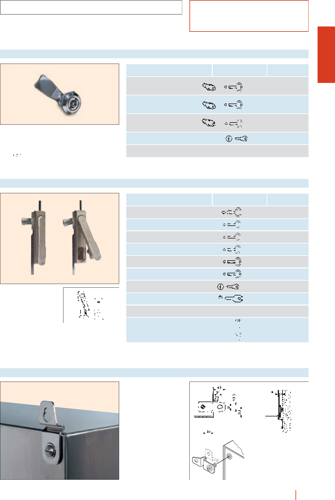
1/173stainless steel enclosures HIMEL
CRSX-CMOX
IP66/IP55 (EN 60529)
ACCESSORIES AND COMPLEMENTS
Double bar standard
lock, with stainless steel
latch and fixing screw.
Operation through LDB3
key (according
Locks for CRSX enclosures
Type Reference
Stainless steel v6 mm
square lock LC-7 TC 6/CSX
Stainless steel v7 mm
square lock LC-7 TC 7/CSX
Stainless steel ∆8 mm
triangular lock LT-8 TT 8/CSX
Key lock type 405 CL/CSX
Full stainless catch CC6/CSX
Key type /
reference
STD/CSX
Directly operated
standard closing
mechanism retractable
handle with key 405.
Locks for CMSX enclosures
Type Reference
Double bar lock LDB 5 TE DB/ML
∆7 mm triangular lock LT-8 TE T7/ML
∆8 mm triangular lock LT-8 TE T8/ML
v6 mm square lock LC-8 TE C6/ML
v7 mm square lock LC-8 TE C7/ML
v8 mm square lock LC-8 TE C8/ML
Key lock type 405 TE L/ML
Safety cylinder lock TE R/ML
Manual lock TEM/PLD
Padlock fastening BCME/PL
Key type /
reference
Set of 4 stainless steel
brackets fixed from the
outside vertically or
horizontally. Not included in
standard supply.
Reference: CRSX: PFCX.
CMOX: FCMX.
Wall fixing brackets
to DIN 43668) (supplied
as standard).
Reference STD/CSX.
FCMX
PFCX
