118163 Catalog
2014-09-27
: Pdf 118163-Catalog 118163-Catalog 785901 Batch8 unilog
Open the PDF directly: View PDF ![]() .
.
Page Count: 124 [warning: Documents this large are best viewed by clicking the View PDF Link!]
- Pumping machine control solutions for Industry & Infrastructure
- introduction
- General content
- 1-Pumping Control Solutions overview
- How can you reduce the time-tomarketof your booster?
- Application solutions
- Application Function Blocks
- Boost the energy efficiency ofyour pumping machines
- How can you develop your business?
- Service and support
- Gain a competitive advantage in each stage of your machine
- A complete pumping setup to validate your Pumping application
- World-class monitoring service for you and your customers
- Easy and hassle-free remote monitoring solution
- Your one-stop shop from simple control systems to global automation solutions
- 2_SoMachine software suite
- 3_Hardware control platforms
- General selection guide
- Altivar IMC drive controller card type S solutions with Application function Blocks
- HMI Controllers
- Modicon M238 logic controller for Solutions with Application function Blocks
- Modicon M258 logic controller for Solutions with Application function Blocks
- I/O expansion modules for Hardware control platform
- 4_Communication
- 5_Associated offers
- Altivar 212 and Altivar 61 variable speed drives
- Altistart 01, Altistart 22 and Altistart 48 softstarters for asynchronous motors
- Selecting motor starting mode
- Selecting devices
- Control starter functions
- D.O.L. starter
- D.O.L. Softstarter VSD
- TeSys Contactors
- TeSys protection components: Thermal-magnetic motor circuit-breakers
- Protection relays and controllers
- Feeder protection and circuit disconnection
- Branch circuit and control circuit protection
- Power & Energy - Monitoring & Control
- Spacial enclosures
- Thalassa enclosures
- Control and signalling units
- Control stations and enclosures
- Power supplies Phaseo
- Magelis™ Operator dialogue terminals
- OsiSense™ for pumping applications
- Measurement & control relays - Zelio Control
- Product reference index

Catalogue
2012
Pumping machine control solutions
for Industry & Infrastructure

1
Improve your pumping system
& business performance
Water & wastewater, commercial buildings, industry or irrigation - Whatever your
focus. In order to increase customer satisfaction you must supply machines which
are more safe, energy efcient, reliable, at a reduced cost and shorter lead-time.
Your choice of Control Solutions is now, more than ever, a determining factor in
distinguishing yourself at each stage, from the design and development to
implementation and maintenance of the machine
Your Pumping solutions must be:
>Reliable
>Energy efcient
>Innovative and adaptable
>Open
>Environment compliant
The requirements of a competitive market:
>Quicker time to market
>Optimized machines
>Reduce maintenance cost
>Compliance with worldwide standards
>Worldwide services and support
To meet this demand, Schneider Electric offers MachineStruxure™, automation
solutions, which help Machine Builders to quickly design pumping machines that
are optimized regarding costs and energy efciency, whilst maximising their
performance throughout the service life of the machine. MachineStruxure™
solutions for pumping applications allow you to:
>Reduce your machine’s time-to-market with predened “Tested, Validated, and
Documented Architectures” and comprehensive pumping library
>Improve machine performance with innovative automation technology and expert
pumping application functions, supplemented by advanced drive technology, in order to
increase energy efciency while reducing maintenance and improving reliability
>Gain a competitive advantage and optimize the global cost of your machine: from design
to maintenance, we are ready to help you wherever you are through our worldwide
network of training, solution design and delivery centres, after-sales services, and
pumping control experts

2
General contents

3
Contents Pumping Control Solutions
Solution Overview .........................
SoMachine software &
Application Function Blocks library . . . . . . . .
Hardware control platform . . . . . . . . . . . . . . . . .
Communication ...........................
Associated offers ..........................
2
1
3
4
5
6

chapter 1
Pumping Control
Solutions
Solution overview
b

1/1
Contents
Solution Overview
b
v
................................................................................................. 1/2
v
.......................... 1/3
v
..................................................................... 1/3
v
.................................................................................. 1/3
b
v ......................................................................................... 1/4
v ....................................................................................... 1/5
b
v .............................................................................. 1/6
v ................................................................................... 1/7
v ................................................................................................ 1/8
v ...................................................................................... 1/9
v ................................................................................................... 1/10
v ....................................................................................................................1/11
b
v
.................................................... 1/12
v
............................................................................ 1/13
b
v................................. 1/14
v ................. 1/15
v .......... 1/15
v ................. 1/16
v .................................... 1/17
v
........................................................................................................ 1/18
1/2
Presentation
Solution Overview
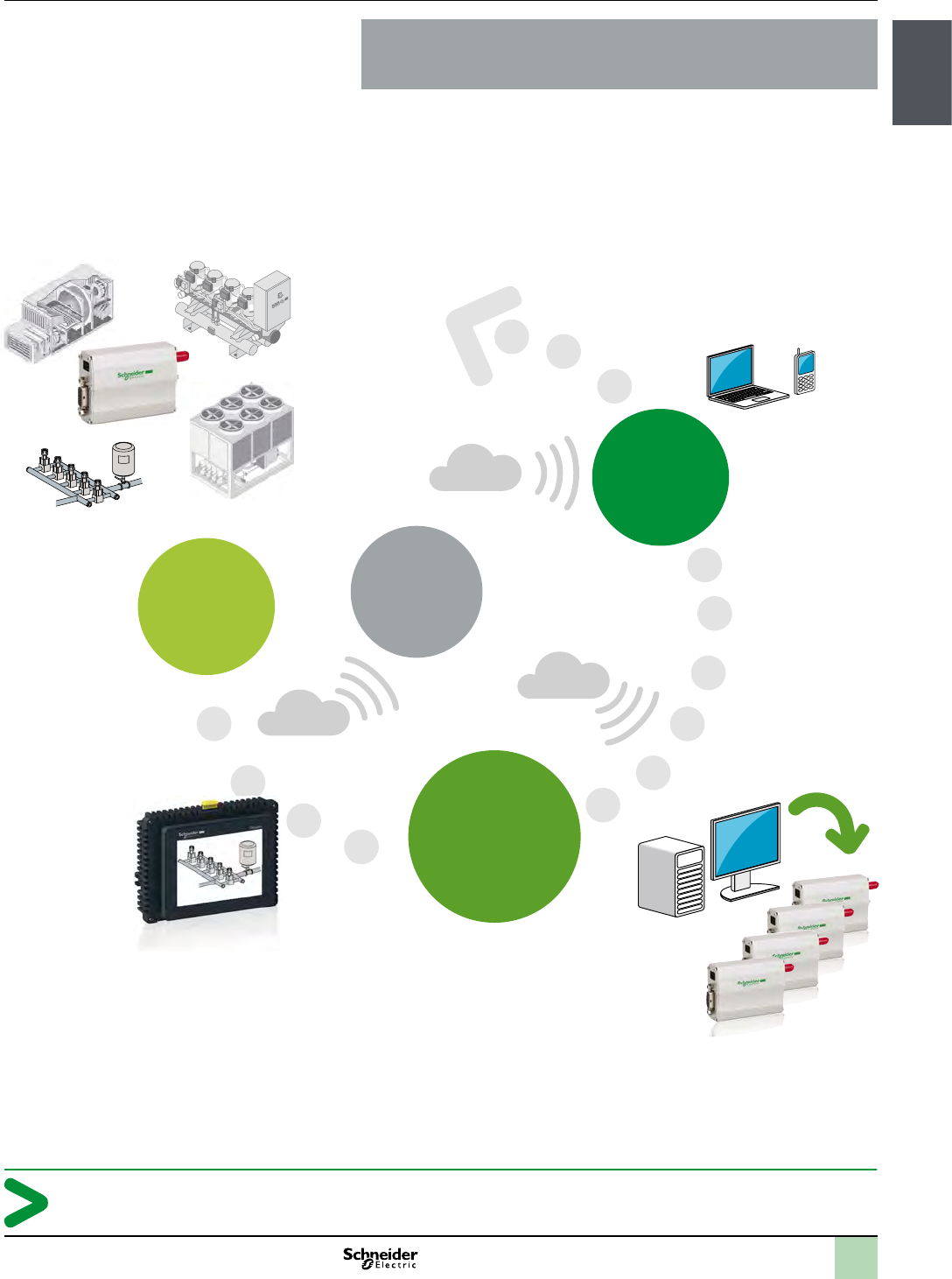
Reduce your Pumping application’s time-to-market
Pumping equipment today needs to be ever more efcient and reliable. To enjoy a
much more smart control, traditional relays and electronic boards solutions with
traditional controllers are being replaced with smart control systems with
integrated and functionalities for pumping and energy efciency. As a consequence
the mix in development costs have changed, demanding an even greater emphasis
on design efciency. Flexibility is the key in providing a control solution that meets
perfectly your requirements whilst reducing your costs.
That’s why MachineStruxure™ solution incorporates a Flexible Machine Control
Platform system that focuses on embedded intelligence in its products and a
unique software platform that provides a single, easy to use environment for
developing, programming and commissioning the machines.
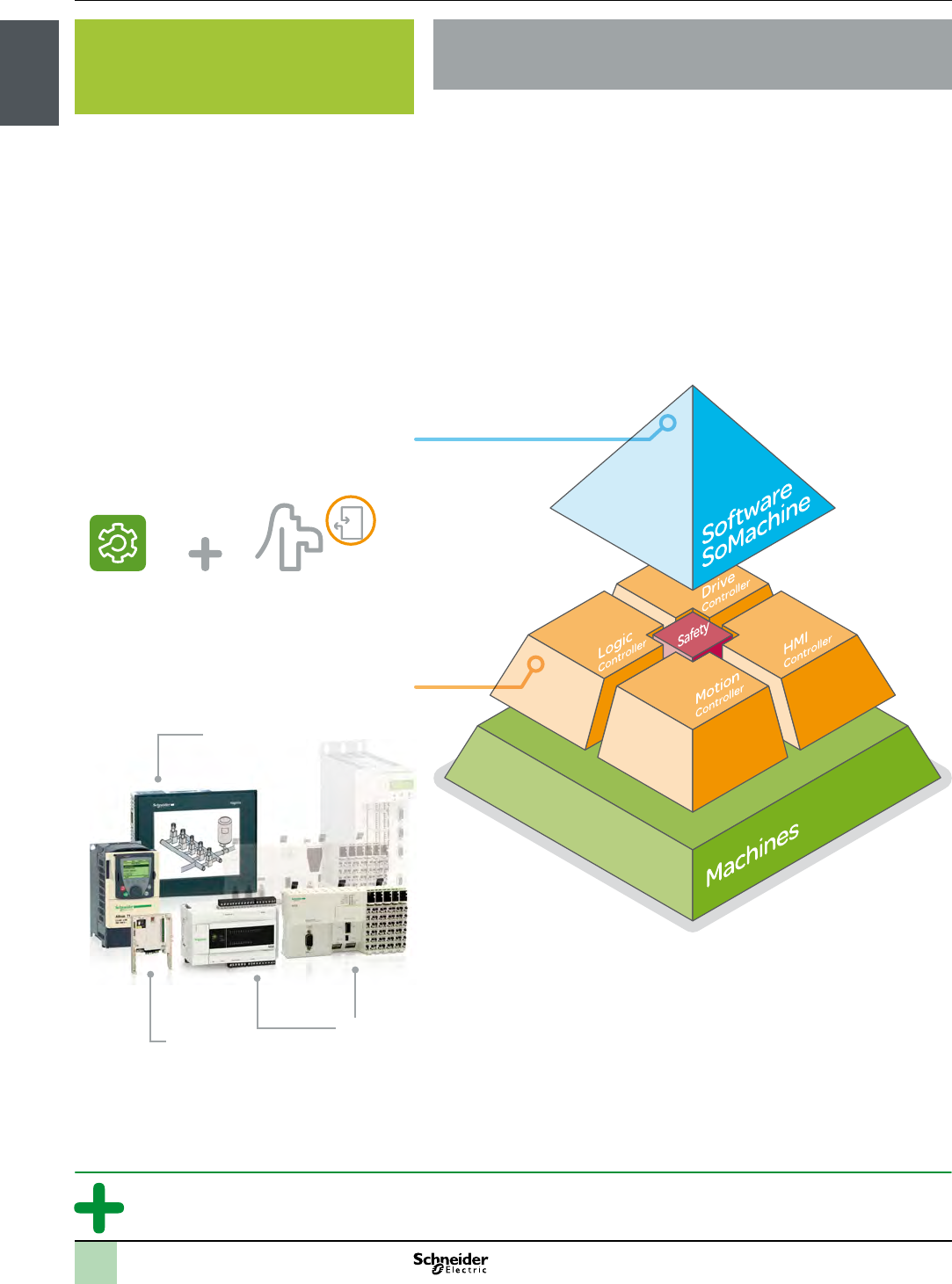
With MachineStruxureTM achieve 100% flexibility and optimization
of your machines
>
with SoMachine suite
> where it is needed
Library
>Efcient
>Flexibility
>Compact
1/3
Presentation
Solution Overview
Reduce your Pumping application’s time-to-market
Based upon exible and scalable hardware platforms and a comprehensive single
software suite, MachineStruxureTM proposes Tested, Validated and Documented
Architectures (TVDA) with pumping application function block (AFB) libraries.
>Programming and template libraries
>Graphical objects
>Alarm management
>Application Function Blocks (AFB) library
>Application examples
>With our existing function blocks you can simply modify, reuse or create your
own
>Easily integrate your own systems into our architectures utilizing FDT/DTM
technology
>SoMachine and the control platforms support the 6 programming languages
(FBD, ST, SFC, LD, IL, CFC) and is compliant with IEC 61131-3
>Integrated open and standard networks in devices
>SoMachine software combined with our control platforms allow you simply
upgrade your architectures
>Ethernet connection allows remote connection between the pump and the
ground with Wi-Fi
>Bluetooth connection available as well on Controller port
>Suggested equipment lists
>: to ensure that they function in each
possible conguration
>: full functional compatibility of devices
>: a complete System User Guide
MachineStruxureTM solutions use open standards through IEC
languages, open networks and transparency through FDT/
DTM technology, providing you time savings.
Our pre-programmed function blocks offer speed in
development for your applications. they can be congured with
a simple copy and paste.
They can be quickly implemented in the machine programs,
reducing the effort required to create an application and
reducing the risk of errors.
Save up 50% of design and implementation time
Pumping solutions examples
Wi-Fi- Bluetooth
2
1
3
4
5
6
7
8
9
10
1/4
Presentation Pumping Control Solutions
Solution Overview
Application solutions
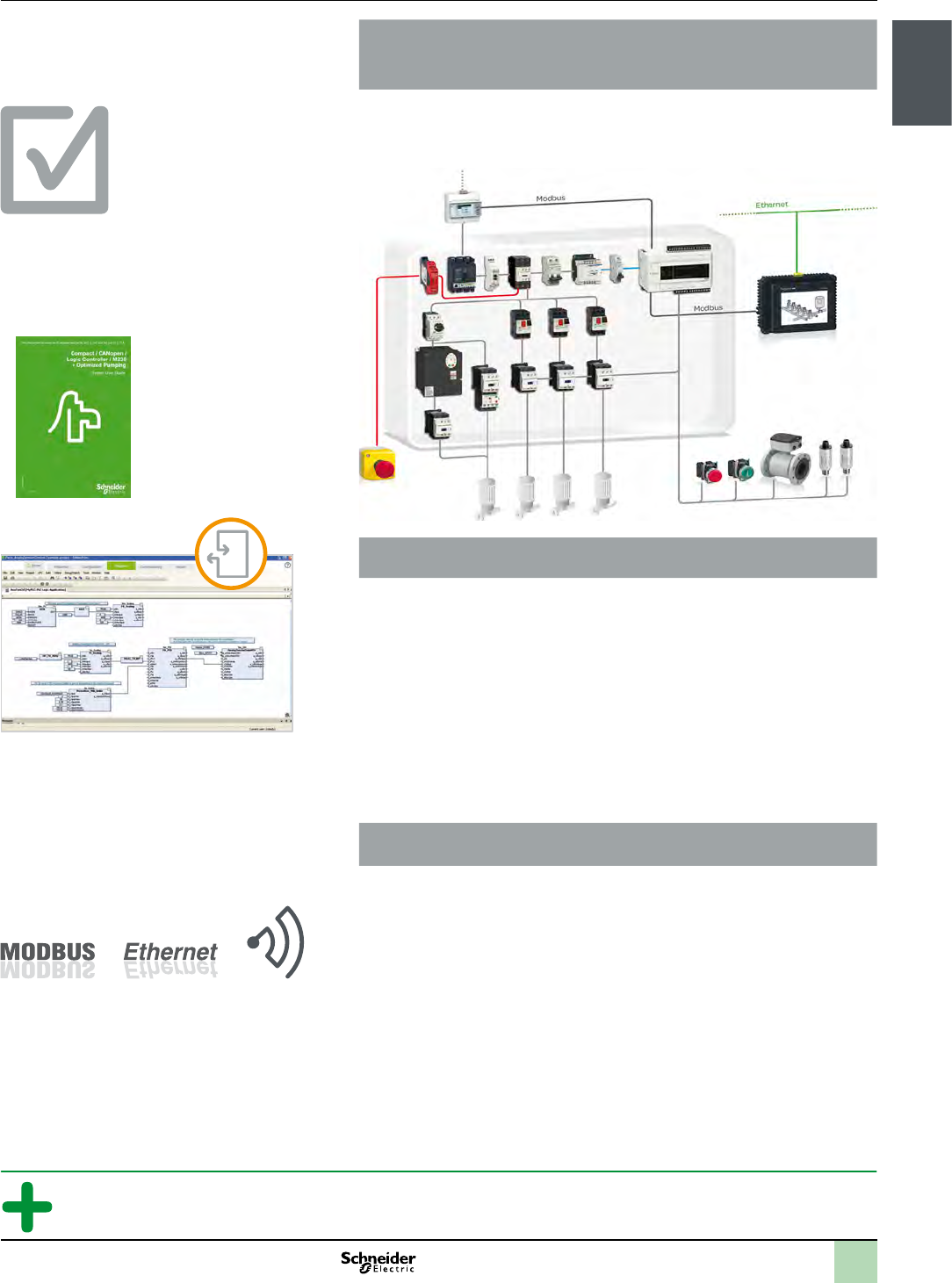
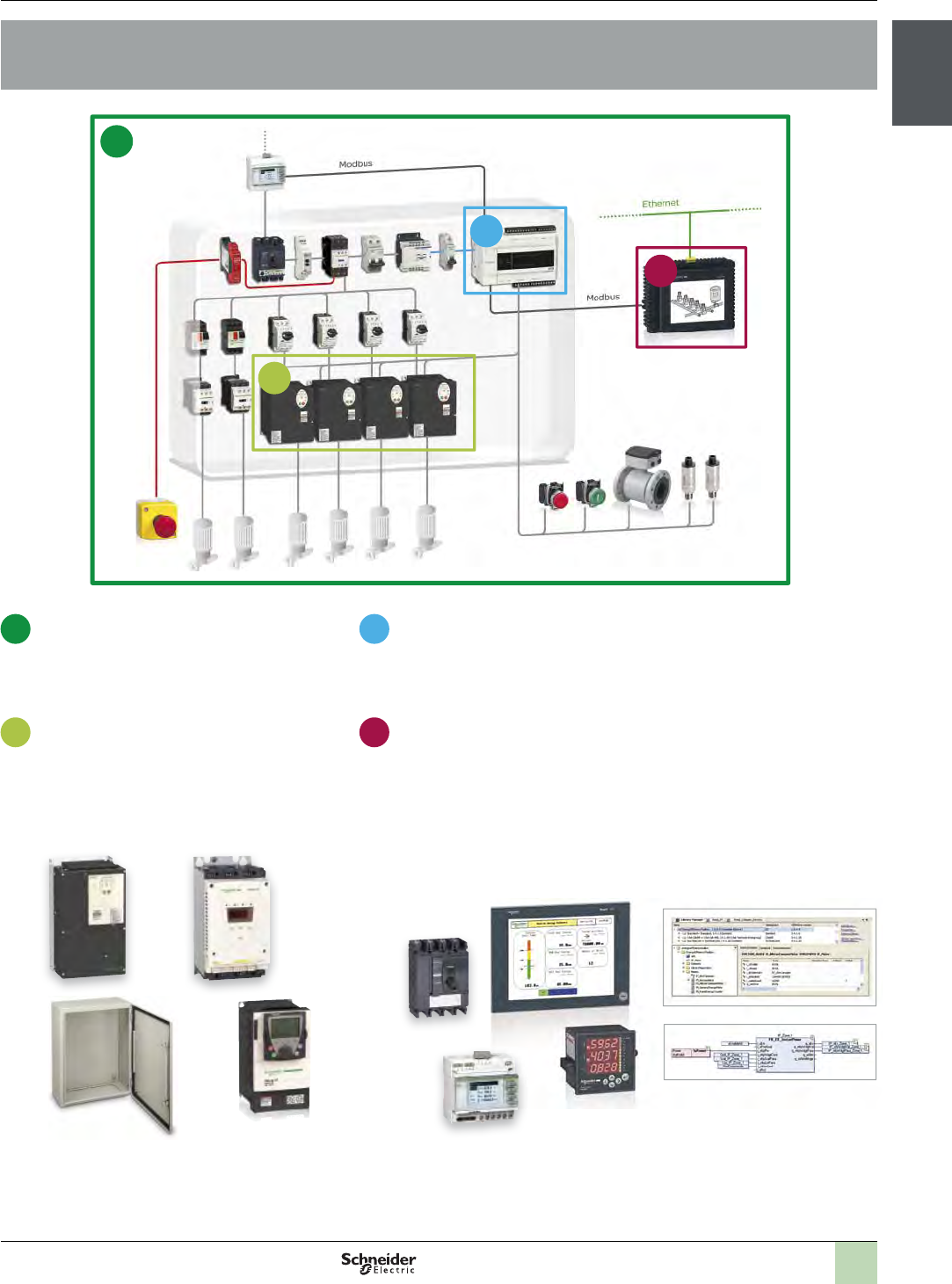
Application solutions
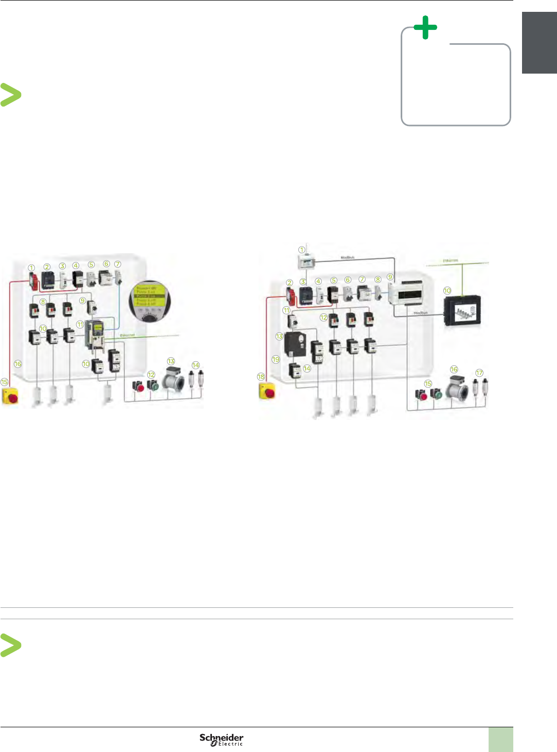
Booster Multi-drive
>Simplifi ed cabling
>Phase control functionality integrated in the drive
>Monitor Energy Effi ciency through a large range of Power Meter and easy-to-use Application function blocks
>Best Effi ciency with the drive technology additional up to 20% Energy saving
>Advanced pumps protection performed by the drive
>All information available on HMI screen with ready to use pages matching application example
>Supports fi xed speed pumps in addition to variable speed pumps
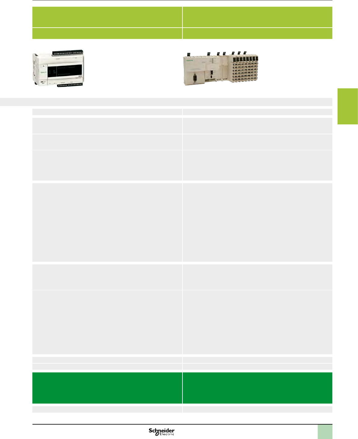
With logic controller Modicon M238
Powerful solution for machines requiring maximum fl exibility
and scalability plus higher level of functionality
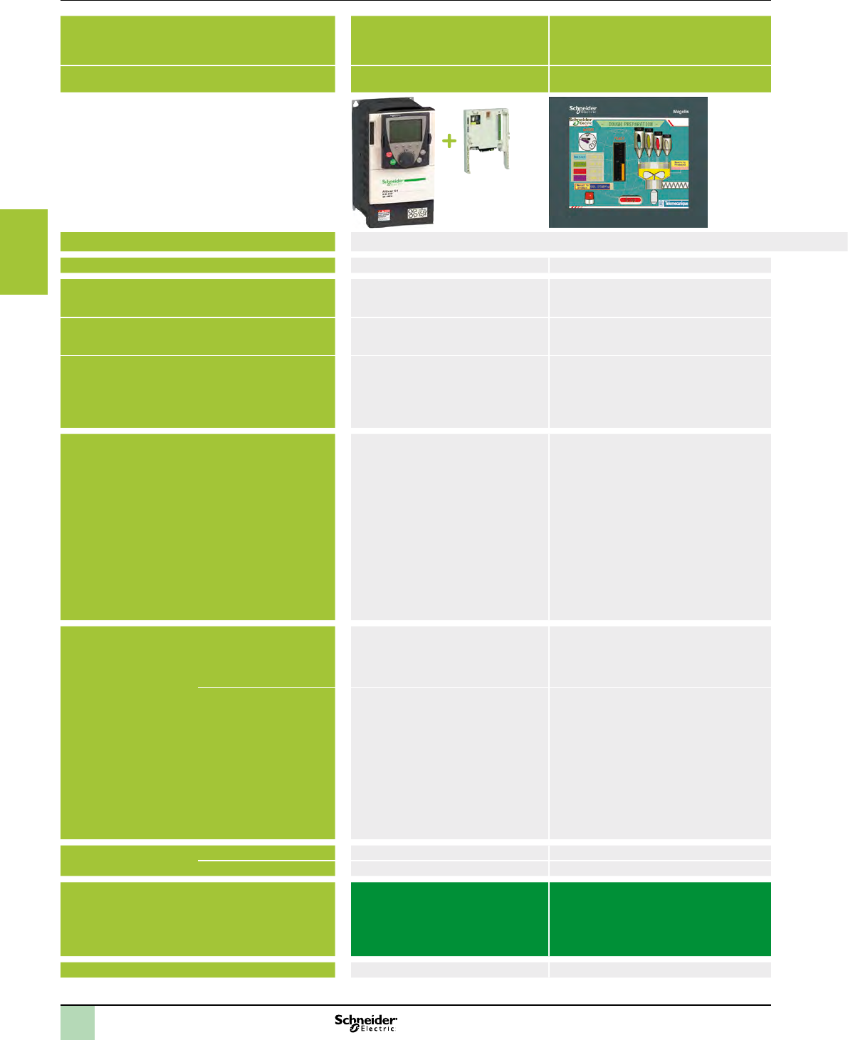
With HMI controller Magelis SCU
Higher level of functionality with an cost effective controller
with built-in HMI for scalable systems
Solution breakdown
1 Safety module Preventa XPS (1)
2 Circuit breaker Compact NSX (1)
3 Phase sequence relay Zelio control (1)
4 Contactor TeSys D (1)
5 Modular Circuit breaker C60L-MA (1)
6 Switch mode power supply Phaseo (1)
7 DC Circuit breaker C60L-DC (1)
8 Logic controller Modicon M238 (See chapter 3)
9 Display Magelis HMI STU (1)
10 Circuit breaker TeSys GV2M (1)
11 Magnetic Circuit breaker TeSys GV2L (1)
12 Contactor TeSys D (1)
13 Variable speed drive Altivar 212 (1)
14 Control & Signalling units Harmony XB4/XB5 (1)
15 Flow meter (Third-party product)
16 Pressure sensor OsiSense XMLP (1)
17 Emergency stop push button Harmony XALK (1)
18 Enclosure Spacial 3D ACM & AP (1)
Solution breakdown
1 Safety module Preventa XPS (1)
2 Circuit breaker Compact NSX (1)
3 Phase sequence relay Zelio control (1)
4 Contactor TeSys D (1)
5 Modular Circuit breaker C60L-MA (1)
6 Switch mode power supply Phaseo (1)
7 DC Circuit breaker C60L-DC (1)
8 HMI controller Magelis SCU (1)
9 Circuit breaker TeSys GV2M (1)
10 Magnetic Circuit breaker TeSys GV2L (1)
11 Contactor TeSys D (1)
12 Variable speed drive Altivar 212 (1)
13 Control & Signalling units Harmony XB4/XB5 (1)
14 Flow meter (Third-party product)
15 Pressure sensor OsiSense XMLP (1)
16 Emergency stop push button Harmony XALK (1)
17 Enclosure Spacial 3D ACM & AP (1)
(1) Please consult the chapter 5 - Associated offers, or our web site: www.schneider-electric.com
2
1
3
4
5
6
7
8
9
10
1/5
Presentation Pumping Control Solutions
Solution Overview
Application solutions
Booster Single drive
>Drive connected to the same pump
>Cost effective & simple solution for small booster
With drive controller Altivar IMC
An open and 30% less costly system than a PLC - based
solution: without any compromise on functionalities
With logic controller Modicon M238
Simple solution for machines requiring a minimum fl exibility
and scalability with a good level of functionality
Solution breakdown
1 Safety module Preventa XPS (1)
2 Circuit breaker Compact NSX (1)
3 Phase sequence relay Zelio control (1)
4 Contactor TeSys D (1)
5 Modular Circuit breaker C60L-MA (1)
6 Switch mode power supply Phaseo (1)
7 DC Circuit breaker C60L-DC (1)
8 Circuit breaker TeSys GV2M (1)
9 Magnetic Circuit breaker TeSys GV2L (1)
10 Contactor TeSys D (1)
11 Drive controller Altivar IMC + Altivar 61 (See chapter 3)
12 Control & Signalling units Harmony XB4/XB5 (1)
13 Flow meter (Third-party product)
14 Pressure sensor OsiSense XMLP (1)
15 Emergency stop push button Harmony XALK (1)
16 Enclosure Spacial 3D ACM & AP (1)
Solution breakdown
1 PowerMeter (1)
2 Safety module Preventa XPS (1)
3 Circuit breaker Compact NSX (1)
4 Phase sequence relay Zelio control (1)
5 Contactor TeSys D (1)
6 Modular Circuit breaker C60L-MA (1)
7 Switch mode power supply Phaseo (1)
8 DC Circuit breaker C60L-DC (1)
9 Logic controller Modicon M238 (See chapter 3)
10 Display Magelis HMI STU (1)
11 Magnetic Circuit breaker TeSys GV2L (1)
12 Circuit breaker TeSys GV2M (1)
13 Variable speed drive Altivar 212 (1)
14 Contactor TeSys D (1)
15 Control & Signalling units Harmony XB4/XB5 (1)
16 Flow meter (Third-party product)
17 Pressure sensor OsiSense XMLP (1)
18 Emergency stop push button Harmony XALK (1)
19 Enclosure Spacial 3D ACM & AP (1)
(1) See chapter 5 - Associated offers. Or please consult on our web site: www.schneider-electric.com
Other possibility for Single drive, multi lead
>Energy effi cient solution, fl exible
>Drive is used to start successively all pumps
>Save 50% in design and
installation time
>Modularity and fl exibility
>Energy effi ciency
>Openness Plug & play
connectivity
1/6
Presentation
Solution Overview
Application Function Blocks
>Maintains the required pressure by performing switching between the pumps
available in the system.
>Making the system energy efcient by making the operational combination of
pumps in such a way that the pumps operated by drives are given priority.
>To ensure a smooth operation, checking the availability of the pumps and in case
of a faulted pump detected, change over to next available pump.
The main objective of the function is to perform switching of the multiple pumps to
maintain a pre-dened pressure in the booster system. The ow and pressure are
measured through sensors while the setpoints are entered from the HMI.
Using intelligent algorithms, the function is managing the switching by dening
priorities to the pumps by detecting availability and principle of energy optimization.
>Capable of maintaining required pressure in the booster system using an energy
efcient algorithm selecting the optimized state of pumps operation.
>Switching of pumps is based upon the principle to assign higher priority to
variable speed pumps and pumps with less number of operating hours.
>With an intelligent algorithm, the function switches next available pump in
operation, in case of detection of a faulty pump.
>Booster pumping system consisting of multiple pumps
>Optimized Pumping compact / Hardwired / Drive controller / Altivar IMC
>Optimized Pumping compact / Modbus or Hardwired / Logic controller / Modicon
M238 and Magelis HMI
>Optimized Pumping compact / Modbus or Hardwired / HMI controller / Magelis
SCU
ON ON OFF
1/7
Presentation
Solution Overview
Application Function Blocks
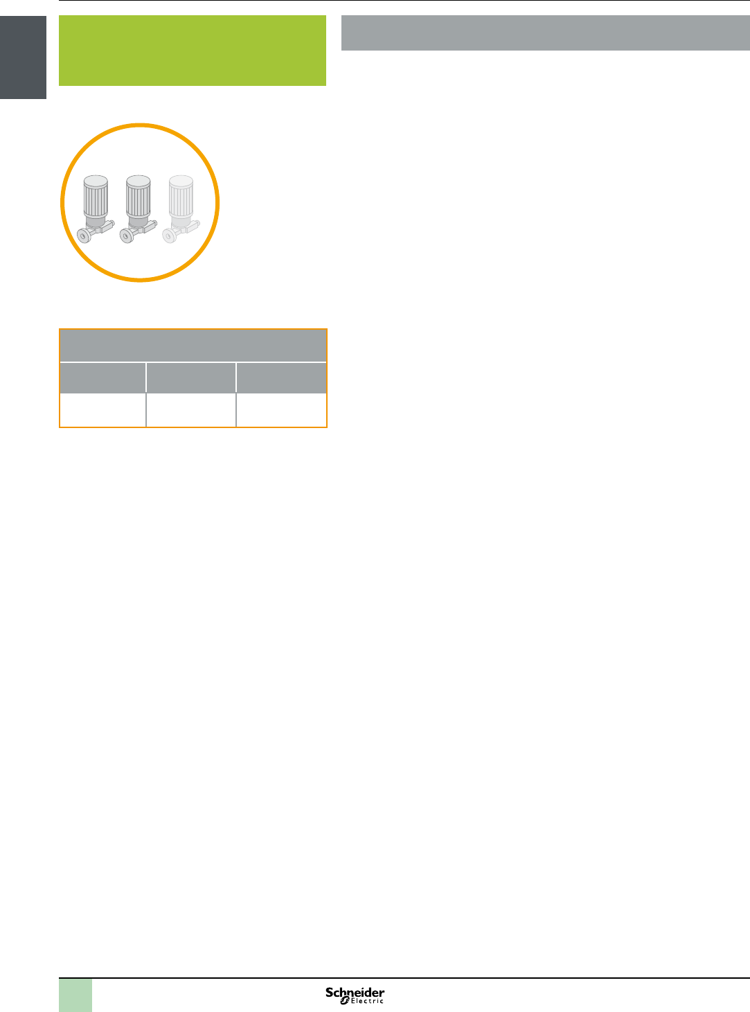
””
>Denition: In this mode, each pump in the system is connected to an individual
drive.
>Main advantages: This type of arrangement provides the best energy efcient
systems along with higher level of pump protection. Easy to maintain systems.
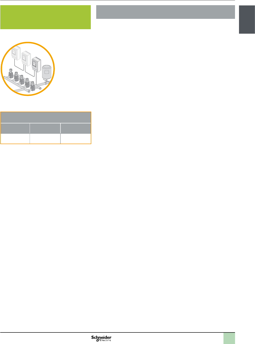
>Denition: In this mode, a single drive is used to start the rst pump in the
system. The selection of pump is based upon operating hours /fault status of the
pump or the user-dened priority.
>Main advantages: These types of arrangements are cost effective and more
energy efcient.
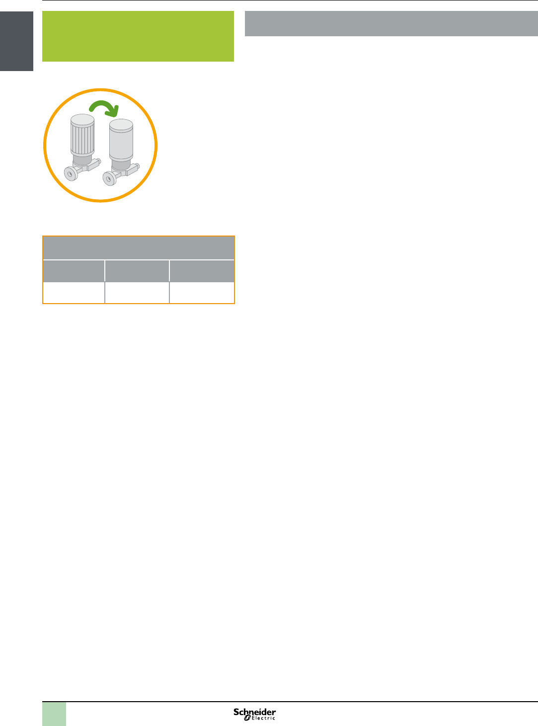
>Denition: In this mode, a single drive is used to start the only one pump in the
system and there is no switching of drives to other pump.
>Main advantages: These types of arrangements are cost effective.
The main task of this function is to enable the pump packager to select the best
working mode for the booster system. By selecting multi lead systems, multiple
pumps, connected to drives or contactors, can be controlled to perform the
switching different pumps to operate them in most optimized manner. Switching is
based upon pressure, operating hours and available pumps in the system.
>The single-drive, multi lead systems can select the pump to be connected and
started with the single drive present in the system. Subjected to the pressure
requirements, the other xed speed pumps are started accordingly. In case of
fault and the stoppage of the system, the drive will be connected to the rst
available pump based upon operating hours / fault status of the pump or the
user-dened priority.
>In single-drive, single lead systems the single drive in the system is connected to
only one pump and there is no switching of the drive to other pumps in the
system. Subjected to the pressure requirements, the other xed speed pumps
are started by DOL.
>Switching of the pumps is performed to operate the pumps in most optimized and
energy efcient operating way.
>The function detects the next available pump on the basis of operating hour, fault
condition and pressure requirement.
>The function is capable of bypassing the drives in case of fault.
>Switching value can be set from the HMI.
>Booster pumping system consisting of multiple pumps
>Optimized Pumping compact / Hardwired / Drive controller / Altivar IMC
>Optimized Pumping compact / Modbus or Hardwired / Logic controller / Modicon
M238 and Magelis HMI
>Optimized Pumping compact / Modbus or Hardwired / HMI controller / Magelis
SCU
1/8
Presentation
Solution Overview
Application Function Blocks
>Detect condition where an auxiliary pump needs to be operated.
>Ensure optimized pump efciency by switching auxiliary pumps to maintain
pressure in the system.
>Increase the energy efciency of the system by operating smaller pumps to
maintain lower ow.
The main task of this function is to maintain the pressure during low ow situations,
like in the night (sleep-mode), in a water distribution system. The sleep mode is
detected by the PID-stage/de-stage function. By detecting a low pressure, the
system sends command to start the auxiliary pump. Similarly, the sleep modes
ends by detecting pressure dropping below the required limit.
>With the setpoints and actual pressure values, the function activates the
auxiliary pump.
>The function detects the end of the sleep mode with the help of the ow value or
the pressure value and limit set-points. If the ow overruns the limit, the function
resets the sleep mode state.
>The function is capable of displaying the operating hour value.
>Booster pumping system consisting of multiple pumps
>Optimized Pumping compact / Hardwired / Drive controller / Altivar IMC
>Optimized Pumping compact / Modbus or Hardwired / Logic controller / Modicon
M238 and Magelis HMI
>Optimized Pumping compact / Modbus or Hardwired / HMI controller / Magelis
SCU
AUX
1/9
Presentation
Solution Overview
Application Function Blocks
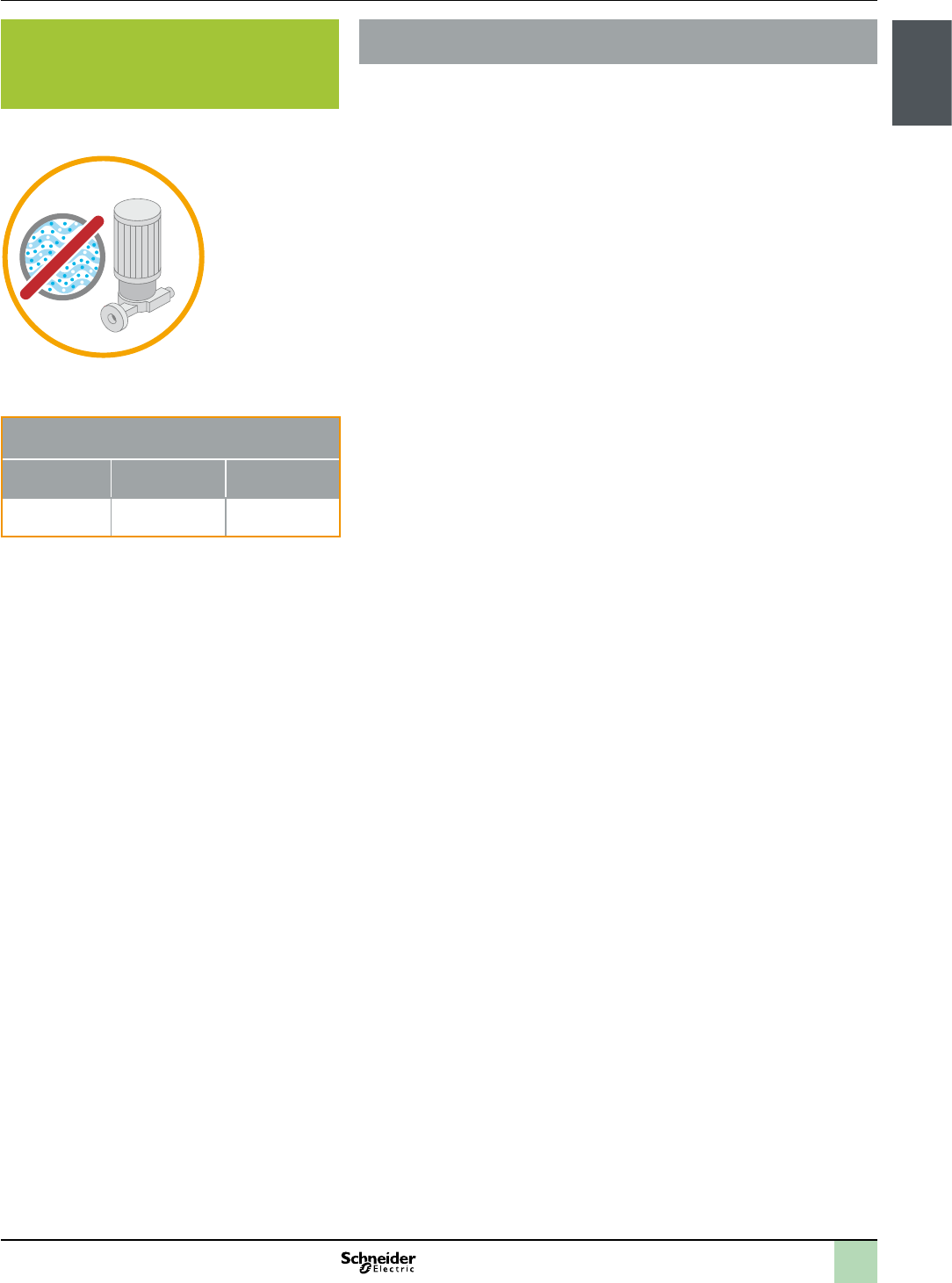
>Ensures a longer operating life of the pump by ensuring that the pump is not
operating in cavitation.
>Generates alarms in case of detection of the cavitation in the system.
>With the adaption of the setpoints, this function ensures that the pumps are
operating in optimized state.
The main task of this function is to avoid the operation of the pumps in a cavitation
situation. By detecting of a cavitation situation, the function immediately stops the
pumps. The function is accomplished by reducing the pressure set-point /ow of
the system. The function, after completing the cavitation task and resetting the
alarm, checks the suction pressure. If the suction pressure is within the permissible
limits than the function starts the operation of pump in normal mode.
>Detection of abnormality in pressure using the actual suction feedback pressure
value.
>Activating algorithms to adjust setpoints to avoid a cavitation situation.
>Using a limit switch function, the function avoids toggling of the cavitation mode.
>Capable of generating alarms by detecting of a cavitation situation.
>Booster Pumping system consisting of single or multiple pumps
>Optimized Pumping compact / Hardwired / Drive controller / Altivar IMC
>Optimized Pumping compact / Modbus or Hardwired / Logic controller / Modicon
M238 and Magelis HMI
>Optimized Pumping compact / Modbus or Hardwired / HMI controller / Magelis
SCU
1/10
Presentation
Solution Overview
Application Function Blocks
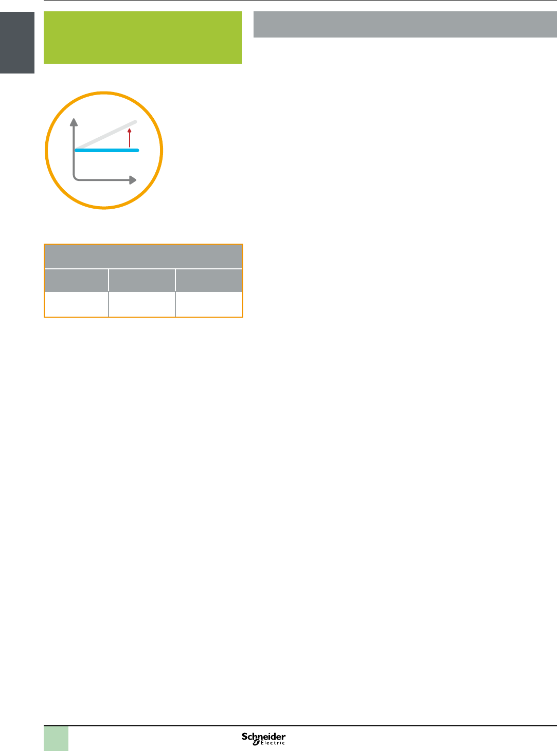
>Ensures a longer operating life of the pump by ensuring a linear pressure in the
system.
>Generates alarms in case of detection of the abnormality in suction pressure
curve.
>With the adaption of the pressure setpoints, this function ensures that the pumps
are operating in optimized state.
>Ideal pressure can be maintained either on the basis of ow or setpoints of each
pump in the system. For ow, the function adapts the set-point to the system
curve with the help of the actual ow value using actual ow value and setpoint.
Both absolute and percentage values can be used. The minimal setting (two
points) to use this function are:
>The raised value in percent (% to increase the standard set-point) or the
absolute value of the set-point to reach the set-point value on the highest and
farthest point of the system in case of minimal ow. The standard value of this
point is zero (relative) or equal to the set-point (absolute).
>The raised value in percent (% to increase the standard set-point) or
absolute value of the set-point to reach the set-point value on the highest and
farthest point of the system in case of maximal ow. The value of this point is
higher than zero (relative) or greater than the set-point (absolute.).
>The results of this measurement are minimum two correction values in percent
or absolute values and its corresponding ow values.
In case of adaptation of the setpoints of the pumps, the function adapts the
set-point depending on the number of used pumps and the moment of the stage
change.
>Detection of abnormality in pressure in the system.
>Execution of algorithms to maintain the pressure using ow or setpoints
management of the pumps.
>Capable of generating alarms by detecting abnormality in pressure in the system.
>Booster Pumping system consisting of single or multiple Pumps
>Optimized Pumping compact / Hardwired / Drive controller / Altivar IMC
>Optimized Pumping compact / Modbus or Hardwired / Logic controller / Modicon
M238 and Magelis HMI
>Optimized Pumping compact / Modbus or Hardwired / HMI controller / Magelis
SCU
1/11
Presentation
Solution Overview
Application Function Blocks
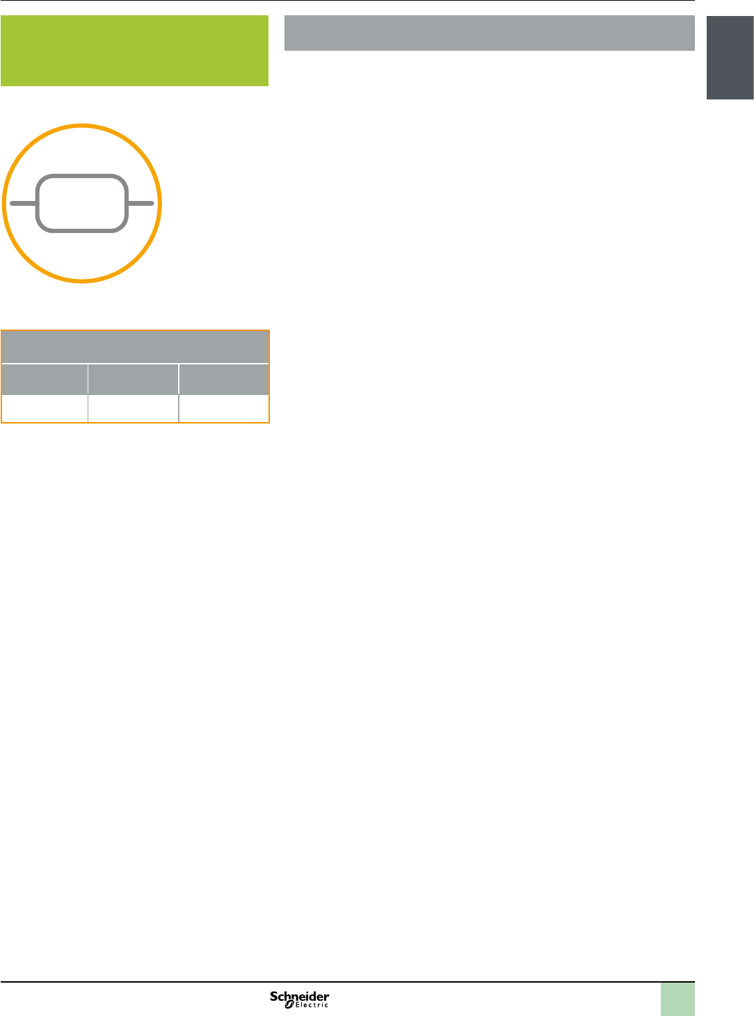
>Maintains the required pressure by adjusting the setpoint.
>Generates alarms in case of deviation of limits.
>To ensure a smooth operation, by maintaining the setpoints curve by avoiding
damping.
The main objective of this function is to generate the set-point for the VSD in the
booster system. The ow and pressure are measured through sensors while the
setpoints are entered from the HMI. Using intelligent algorithms, the function
manages the setpoint using ow and pressure values as input and generating the
outputs values in percentage. Alarms are generated in case of deviation of values
with reference of dened limits.
>Capable of calculating the cycle time.
>Capable of limiting different attributes with corresponding set of values like error
value for the I-part calculation, the control value.
>Detection and display of alarms in HMI.
>Booster Pumping system consisting of single or multiple Pumps
>Optimized Pumping compact / Hardwired / Drive controller / Altivar IMC
>Optimized Pumping compact / Modbus or Hardwired / Logic controller / Modicon
M238 and Magelis HMI
>Optimized Pumping compact / Modbus or Hardwired / HMI controller / Magelis
SCU
PID
1/12
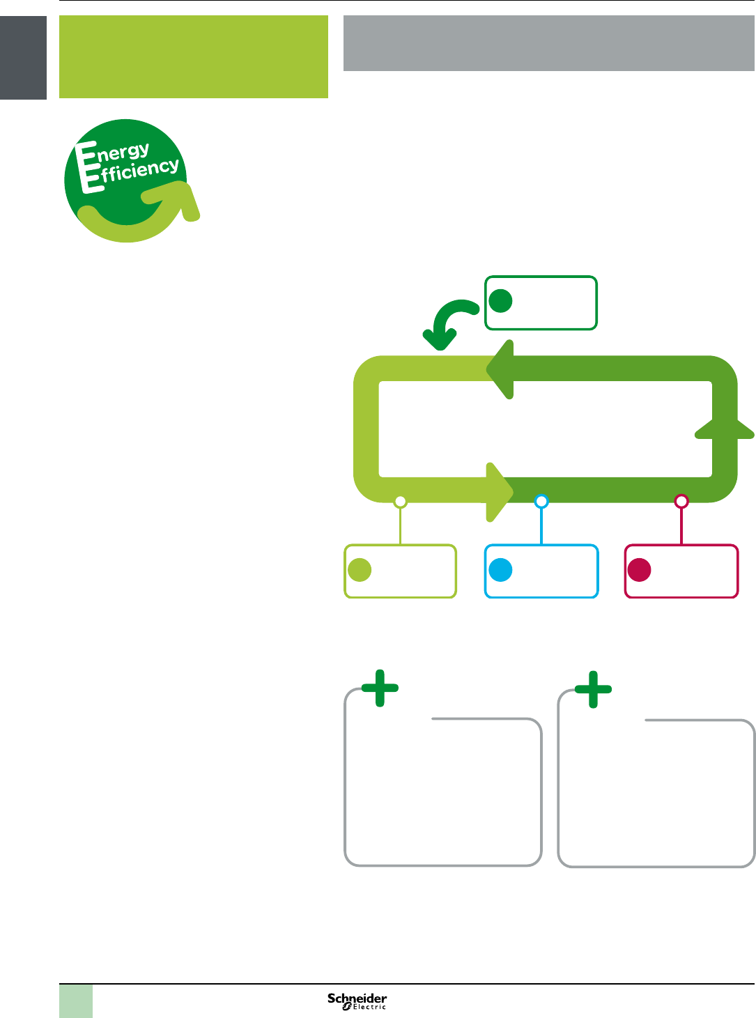
Model complies with EN16001 & ISO50001
energy efciency
OptimizeFix the basics
Monitor,
maintain,
improve
Audit
& Measure
energy efciency
Presentation
Solution Overview
Energy Efciency
>Improve the visibility of your
machines’ energy consumption
>Detection of the “over-sized”
equipments as these consumes
more energy
>Possible marketing argument to
your customers with a real
evidence of Energy savings
>Signicant reductions in energy
bills
>Improved preventive
maintenance for machines
>Increased lifespan for motors
and electronic equipment
2
1
3
4
5
6
7
8
9
10
1/13
Presentation Pumping Control Solutions
Solution Overview
Energy Effi ciency
Increase performance whilst reducing energy consumption of your pumping machine
1 Audit & Measure energy consumption with a
Schneider Electric expert. They will identify
devices with high energy consumption (pumps,
motors, compressors etc.) and recommend
potential savings.
3 Optimize machines by using the energy effi ciency function block libraries
available in the SoMachine software suite, specifi cally designed for the
various applications. Example: pumps, packaging, conveyors, etc
2Fix the basics by selecting the appropriate
motor,using servo-drives, improved cabinet
thermal management etc.
4 Monitor, maintain, improve. The SoMachine software suite contains
function blocks dedicated to collecting energy information from metering
units and electronic equipment (variable speed drive, servomotor etc.).
The information provided allows the dedicated function blocks to create
indicators that are used to monitor the relevant information by correlating
energy readings (active power, power, current etc.) with the machine’s
operational modes and production data. All of the indicators produced can
be manipulated on-screen via predefi ned graphic objects supplied with
SoMachine and Vijeo Designer.
1
2
3
4
1/14
Presentation
Solution Overview
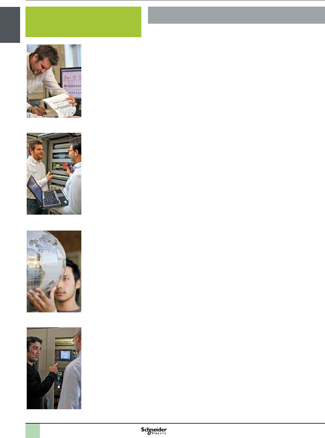
How can you develop your business?
>Based on your needs, our Solution Application Experts and Application Design
Experts (SAE/ADE) work out innovative technical solutions including
>co-engineering
>tests
>validation
>Consulting
>Our solution design and delivery centers (Flex-Centres) are committed to quality
and results and provide:
>Project and program management
>Software and hardware engineering
>Tests, validation, and commissioning
> In class training and on site training
>Availability of components through a large worldwide network of distributors
>Collaboration, management, and delivery through local partners
>With Schneider Electric as your turnkey solution partner we include in our solutions:
>Project management and responsibility
>Engineered systems
>Third-party components management
>Secondment of qualied personnel to deliver on-site engineering and technical
services
>Service and commissioning training
>Maintenance contracts
>Spares parts
>Repairs
>Normal and express deliveries
>Return of goods
>Service expertise:
>Error diagnosis and repair
>Environmental measurements ( EMC, eld bus, thermography, power quality
analyses, etc.)
>Customer International Support (CIS) as a single point of contact:
>A network of 190 dedicated local country experts
>A web-based collaborative platform for efcient communication
>In-class customer training and on-site training
>Customer service and commissioning training
>Consulting
>Audits
>Services Expertises:
>Consultancy
>Retrotting
>Migration and upgrade
>Training
1/15
Presentation
Solution Overview
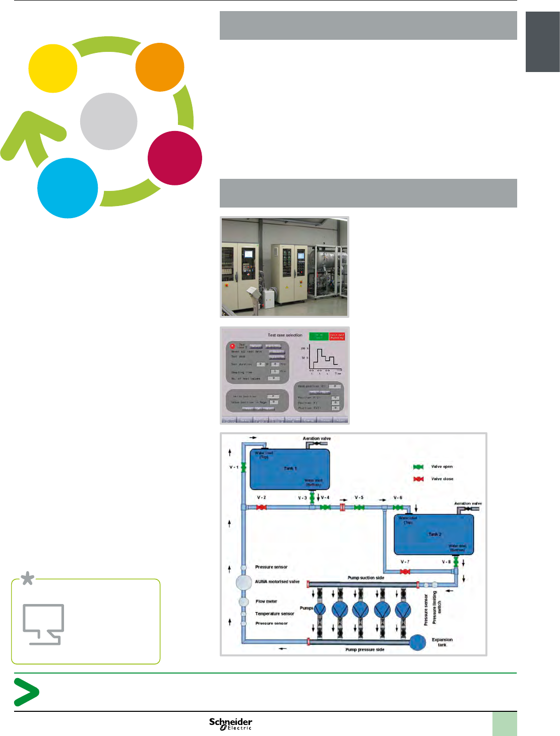
How can you develop your business?
From design to commissioning to maintenance, we’re ready to help you wherever
you are with our worldwide network of training, solution design centres, distribution,
and after-sales services.
>Select the architecture you want
>DOL, Single drive, Multidrive
>I/O control, Field-bus control
>Controllers & HMI
>Drives: Altivar 212 / Altivar 61
>Select Hydraulic circuit
>Apply to hydraulic system for test case
>Run complete test and Monitor
>Energy consumption
>Pressure, Flow, etc
Increase your efficiency and competitiveness
Connect with the experts
www.schneider-electric.com/pumping
Build
Operate
Improve
Design
Your
machine
1/16
Presentation
Solution Overview
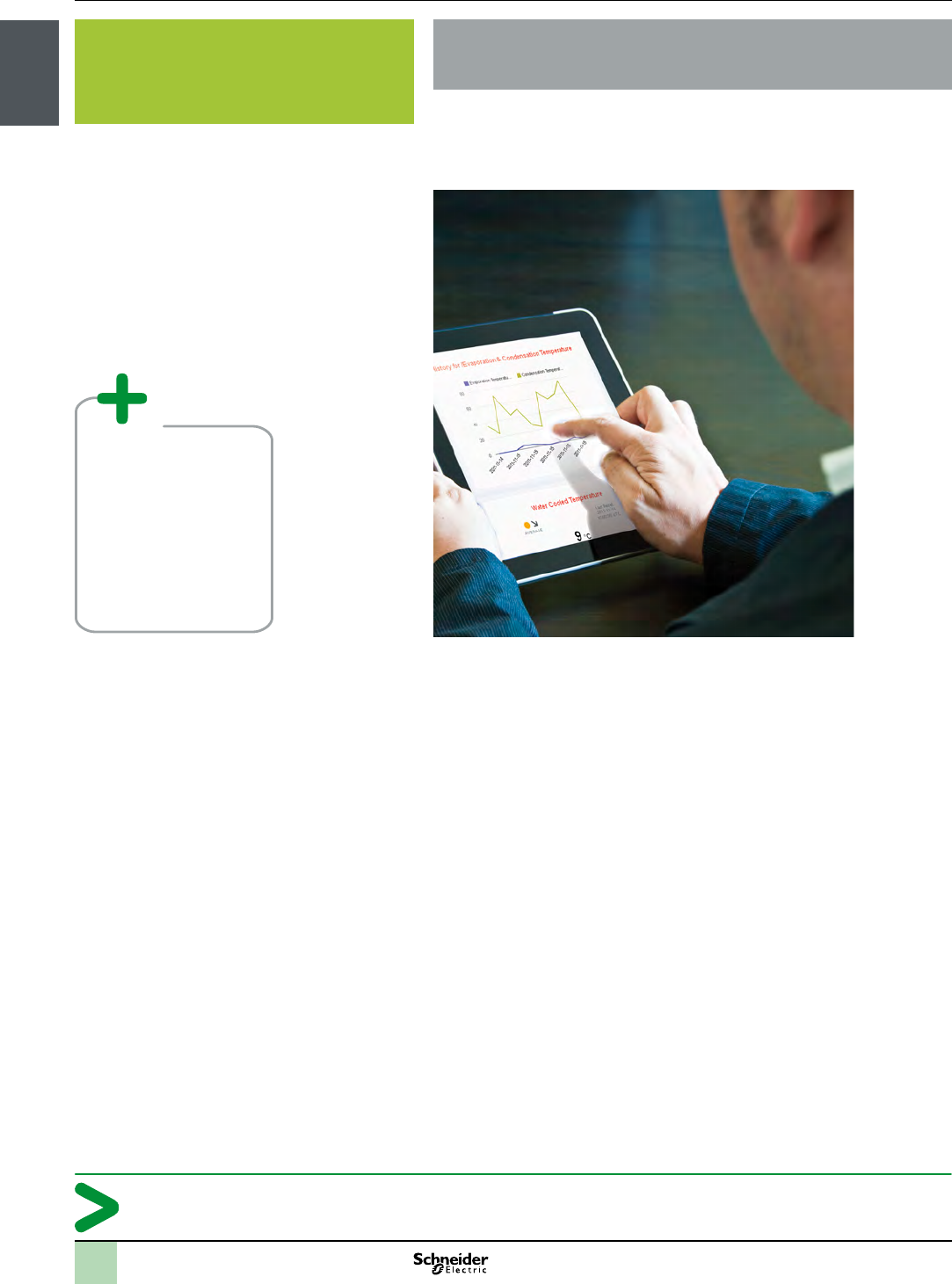
How can you develop your business?
>With OptiM2M, a web-based machine-to-machine monitoring application, you
can remotely view and analyse incoming machine data. At any time, from
anywhere in the world, using only your smart phone, laptop or another web-
connected device with a browser.
>OptiM2M users can harvest detailed, real-time equipment usage statistics, such
as energy consumption of Pumping machines or usage statistics data access
can be congured according to user type (equipment manager/owner/user, etc)
>Grow your business and prots
>Develop sales with new customers and reach new markets
>Generate additional business with existing customers
>Develop your portfolio of smart services
>Build your service provider image and customer satisfaction
>Maximise machine uptime and minimise after-sales intervention costs on site
>Achieve higher energy efciency in true operating conditions
>Add value to your product with quality machine lifecycle support
Unirivalled machine services for you and your customers
>Improved control of
remote equipment
>Enhanced reaction time
and productivity: detailed
reports on equipment use
(usage statistics, machine
energy consumption, etc.)
>New services for your
established customers
1/17
Presentation
Solution Overview
How can you develop your business?
Improve pumping machine management through remote control
Install Server
Operate
Configure
and deploy
1/18
Presentation
Solution Overview
How can you develop your business?
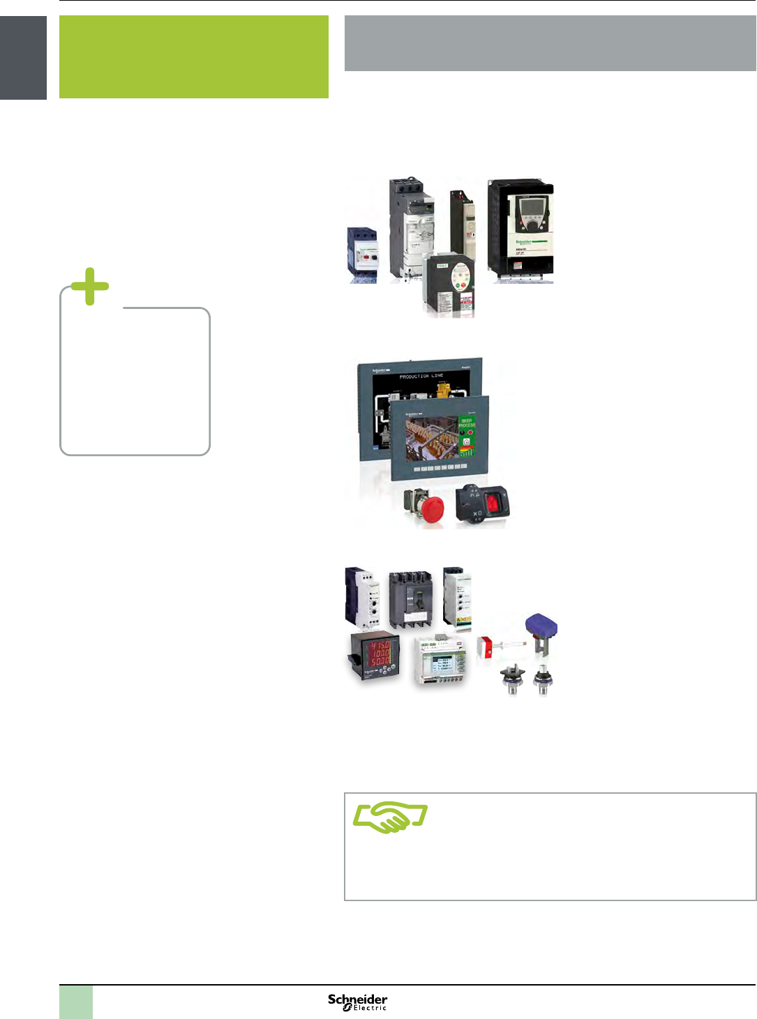
>Maximum productivity and
efciency
>Intuitive and ergonomic design
>Assembly and supply systems,
protection and control of LV power
circuits, power meters, HVAC & R
sensors, valves and actuators
Building on our open automation platforms and strategies, we work with strategic
partners who compliment our capabilities in order to provide you with solutions
that fully meet your business objectives. Within this collaboration partnership that
can deliver the most complete and effective solution for your applications.
>wide range
>simple to use
>network opening
>worldwide availability
>enclosure size
>wiring time
>installation time
1/19
Presentation
Solution Overview
How can you develop your business?
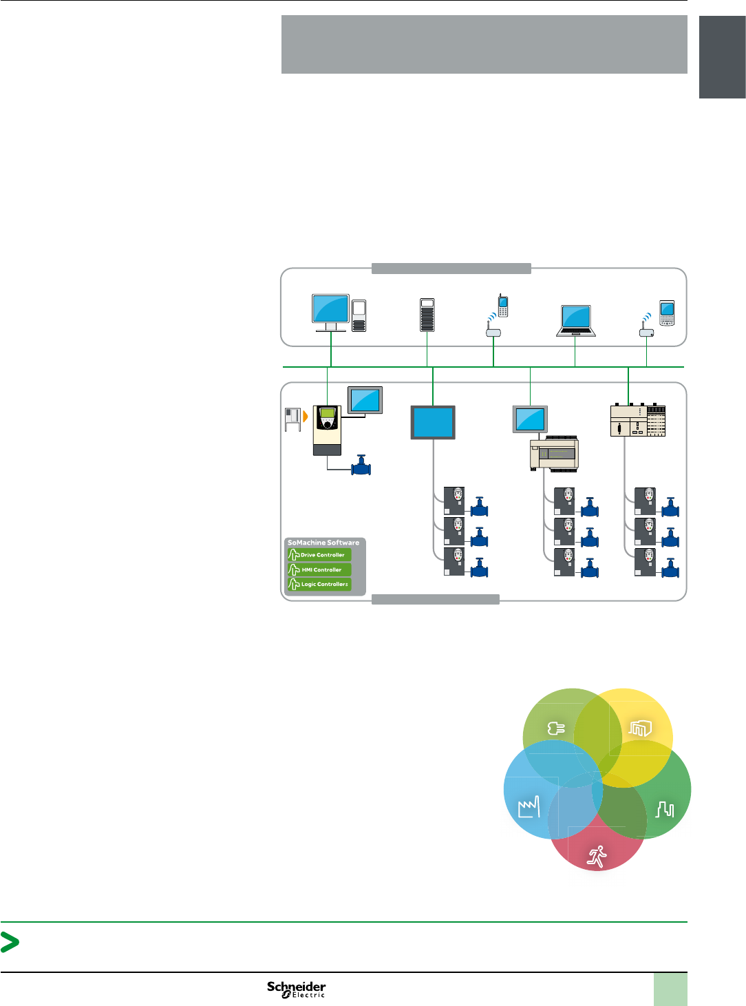
Because both architectures are based on open standards and designed to be
fully compatible, your machines can easily be integrated into your customers’
factory processes. In addition, open standards allow your machines to evolve
with your customers’ changing requirements.h
Pumping machine control
Ethernet TCP/IP
Process & machine managment
Modbus
Modbus
Modbus
Drive
controller
HMI
controller
Logic
controller
Logic
controller
EcoStruxureTM system architecture enables
the convergence of ve key domains of our
expertise: management of Power,
Processes and Machines, the IT Room,
Buildings, and Security.
EcoStruxureTM architecture takes multiple,
siloed systems and adapts them to an
integrated solution, reducing redundancy in
equipment, software, and personnel.
Power
Management
Process &
Machine
Management
White Space
Management
Building Comfort
Management
Security
Management
From machine to plant, Schneider Electric provides a single, fully coherent
system

chapter 2
SoMachine
software suite
All technical information about products listed in this chapter
are available on www.schneider-electric.com

2
1
3
4
5
6
7
8
9
10
2/1
bSoMachine software suite
vVisual graphic user interface ....................................2/2
vLearning centre ...............................................2/2
vProjects management ..........................................2/2
vProject properties .............................................2/3
vConguration .................................................2/3
vProgramming and debug ........................................2/3
vCommissioning ...............................................2/3
vDocumentation ................................................2/3
vTransparency .................................................2/3
vDedicated OEM application libraries (AFB libraries) . . . . . . . . . . . . . . . . . 2/3
vTested Validated Documented Architectures (TVDA) . . . . . . . . . . . . . . . . 2/3
bSoMachine characteristics . . . . . . . . . . . . . . . . . . . . . . . . . .
2/4
bReferences .......................................
2/5
Contents SoMachine software suite
2
1
3
4
5
6
7
8
9
10
2/2
Presentation SoMachine software suite
Simplify machine programming and
commissioning
Presentation
SoMachine is the Machine Builder solution software for developing, conguring and
commissioning the entire machine in a single software environment, including logic,
motion control, HMI and related network automation functions.
SoMachine allows you to program and commission all the elements in
Schneider Electric’s Flexible and Scalable Control platform, the comprehensive
solution-oriented offer for Machine Builders, which helps you achieve optimized
control solution for each machine’s requirements.
Flexible and Scalable Control platforms include:
Controllers:
bHMI controllers: XBT GC, XBT GT/GK CANopen,
bLogic controllers for Solutions with AFB: Modicon M238S, Modicon M258S,
bDrive Controller: Altivar IMC for Solutions with AFB,
bI/Os range: Modicon TM2, Modicon TM5 and Modicon TM7 offers
HMI:
bSmall Panels MagelisTM STO/STU
bAdvanced Panels MagelisTM GH/GK/GT
bOptimum Advanced Panels MagelisTM GTO
SoMachine is a professional, efcient, and open software solution integrating
Vijeo-Designer.
It integrates also the conguring and commissioning tool for motion control devices.
It features the IEC 61131-3 languages, integrated eld bus congurators, expert
diagnostics and debugging, as well as outstanding capabilities for maintenance and
visualisation.
SoMachine integrates tested, validated, documented and supported expert
application libraries dedicated to applications in Pumping, Packaging, Hoisting and
Conveying.
SoMachine provides you:
bOne software package
bOne project le
bOne cable connection
bOne download operation
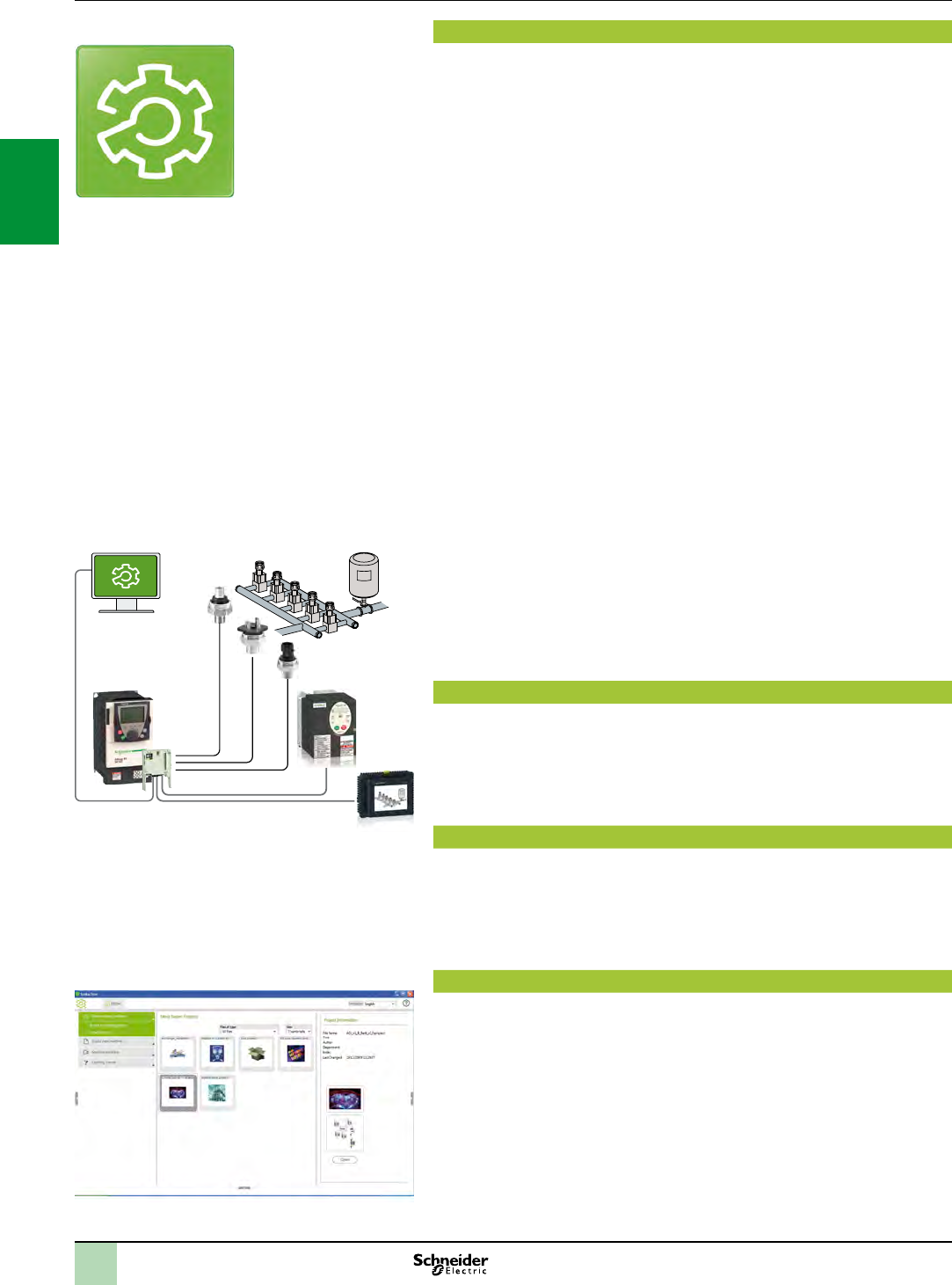
Visual graphic user interface
Navigation within SoMachine is intuitive and highly visual. Presentation is optimized
in such a way that selecting the development stage of the desired project makes the
appropriate tools available. The user interface ensures nothing is overlooked, and
suggests the tasks to be performed throughout the project development cycle. The
workspace has been streamlined, so that only that which is necessary and relevant
to the current task is featured, without any superuous information.
Learning centre
From the home menu, the learning centre provides several tools to get started with
SoMachine. An animated le explains briey the SoMachine interface and concept.
An e-learning allows to run a self-training about SoMachine. A third section gives
access to several documented examples of simple coding with SoMachine.
An intuitive and efcient online help is also available, guiding you to get the
appropriate answer.
Projects management
The implemented project management principle allows to browse quickly through
the existing projects getting the relevant information without the need to open
them before selection.
The user can create a new project, starting from several means: using Tested
Validated and Documented Architectures, using the provided examples, using an
existing project or start with an empty project. There is quick access to the most
recently-used projects.
There is as well a way to start a project from standard project taking advantages of
a pre-congured program (task, library, ....)
Project management
SoMachine software platform
HMI
PC + SoMachine
software
Variable
speed
drive
Drive
Controller
Sensors
Software solution
Modbus
2
1
3
4
5
6
7
8
9
10
2/3
Presentation (continued) SoMachine software suite
Simplify machine programming and
commissioning
Project properties
For each project, the user has the option to dene additional information, through
simple forms. It’s also possible to attach documents, a customer picture and
a conguration picture.
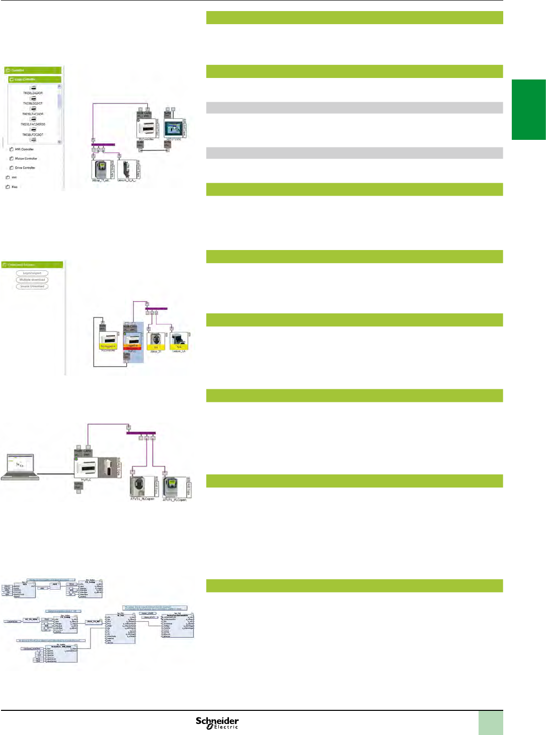
Conguration
From the graphic user interface, the user can easily build his architecture and
congure the devices of the architecture.
Description of the architecture
A graphic editor can be used to assemble the various elements easily by a simple
drag & drop. A devices catalogue is displayed on the left of the screen. It is split into
several sections: controllers, HMI, Miscellaneous and search.
Conguration of the device
Directly from the topologic view of the user interface, a simple click drives the user to
the conguration screen of the selected device.
Programming and debug
Programming is an essential step, and the user has to carefully design it to be as
efcient as possible. Advanced control and HMI functions cover all the needs of an
engineer in terms of creating the control and visualisation system.
Powerful tools allow debug and functional tests such as simulation, step by step
execution, break points and trace.
Commissioning
For an easy and fast diagnostic, the menu commissioning allows the user to check
the online state of his architecture.Through the topologic view of the conguration,
the devices display if you are logged in or not, as well as if they are in run or stop
mode.
Documentation
Because a printed le of the project is an important element, it is possible to build
and customize the project report:
- select the items to be included in the report,
- organize the sections,
- dene the page layout
- and then launch the printing.
Transparency
SoMachine supports Device Type manager (DTM) because it is a eld device tool
(FDT) container.
With DTM’s representing eld device in SoMachine, direct communications are
possible to every single device via SoMachine, the controller and the eld bus
(Modbus for all devices and CANopen for the I/O’s).
From the SoMachine unique environment, the remote devices can be set-up off-line
and tuned on-line.
Dedicated application libraries (AFB libraries)
SoMachine can be extended through its solution extension DVD. It integrates tested,
validated, documented and supported expert application libraries dedicated to many
Machine Builder applications. Their simple conguration speeds up design,
commissioning, installation and troubleshooting.
These libraries cover the following applications:
bPackaging,
bHoisting,
bConveying
bPumping
Tested Validated Documented Architectures (TVDA)
SoMachine provides a variety of preset projects with ready-to-use architectures you
can adapt to individual requirements. Some of them are generic TVDA, they are
based on controllers conguration. The solution extension DVD brings specic
application solutions oriented TVDA’s to SoMachine.
Commissioning
Transparency
Application Function Blocks
Conguration

2
1
3
4
5
6
7
8
9
10
2/4
Characteristics SoMachine software suite
Simplify machine programming and
commissioning
SoMachine characteristics
Overview
IEC 61131-3 programming languages bIL (Instruction List)
bLD (Ladder Diagram)
bSFC (Sequential Function Chart)
bST (Structured Text)
bFBD (Function Block Diagram)
b+ CFC (Continous Function Chart)
Controller programming services bMulti-tasking: Mast, Fast, Event
bFunctions (Func) and Function Blocks (FBs)
bData Unit Type (DUTs)
bOn-line changes
bWatch windows
bGraphical monitoring of variables (trace)
bBreakpoints, step-by-step execution
bSimulation
bVisualization for application and machine set-up
HMI-based services bGraphics libraries containing more than 4000 2D and 3D objects.
bSimple drawing objects (points, line, rectangles, ellipses, etc …)
bPrecongured objects (button, switch, bar graph, etc …)
bRecipes (32 groups of 256 recipes with max. 1024 ingredients)
bAction tables
bAlarms
bPrinting
bJava scripts
bMultimedia le support: wav, png, jpg, emf, bmp
bVariable trending
Motion services bEmbeded devices conguration and commissioning
bCAM prole editor
bSample application trace
bMotion and drive function blocks libraries for inverters, servos and steppers
bVisualization screens
bLogical encoder
Global services bUser access and prole
bProject documentation printing
bProject comparison (control)
bVariable sharing based on publish/subscribe mechanism
bLibrary version management
bEnergy efciency machine monitoring
Integrated eldbus congurators bControl network:
vModbus Serial Line
vModbus TCP
bField bus:
vCANopen
vCANmotion
bConnectivity:
vProbus-DP
vEthernet IP
Expert and solutions libraries bPLCopen function blocks for Motion control
vExample: MC_MoveAbsolute, MC_CamIn, ServoDrive, ...
bPackaging function blocks
vExample: Analog lm tension control, rotary knife, lateral lm position control, ...
bConveying function blocks
vExample: tracking, turntable, conveyor , ...
bHoisting functions
vHoisting function blocks: anti-sway, anti-crab, hoisting position
synchronisation, ...
vApplication template for industrial crane
bPumping application
vPumping function blocks
vApplication template for booster
bEnergy Efciency library

2
1
3
4
5
6
7
8
9
10
2/5
References SoMachine software suite
Simplify machine programming and
commissioning
Product offer
SoMachine software is delivered on a DVD, it is a product oriented version that includes all SoMachine features
related to generic hardware (M238, M258, LMC058, XBT GC, Altivar IMC), as well as generic TVDA.
The solution features are added to SoMachine by installing its solution extension DVD. It includes all SoMachine
solutions hardware, plus all the dedicated application libraries and TVDA.
References
bSoMachine is available in 6 languages:
vEnglish
vFrench
vGerman
vItalian
vSpanish
vSimplied Chinese.
bSystem Requirements:
vProcessor: Pentium 4 - 1,8 GHz or higher , Pentium M 1.0 GHz or equivalent
vRAM Memory: 2 GByte; recommended: 3 GByte
vHard Disk: 3.5 GB, recommended: 5 GB
vOS: Windows XP Professional, Windows 7 Professional 32/64 bytes
vDrive: DVD reader
vDisplay: 1024 × 768 pixel resolution or higher
vPeripherals: a Mouse or compatible pointing device
vPeripherals: USB interface
vWeb Access: Web registration requires Internet access
bThe documentation is supplied in electronic format: complete on-line help plus complementary documentation
in pdf version.
SoMachine solution extension for Solution controllers (1)
Added
controllers
Added TVDA Added
libraries
Reference (2)
DVDs and Licence / number & type
bM238S
bM258S
bLMC058S
bXBT GC with CANopen
module type S
bXBT GT/GK with control
function type S
bAltivar IMC with control
function type S
- Optimized CANopen Altivar
IMC
- Performance CANmotion
LMC058
- Hoisting Optimized
CANopen M238
- Conveying Performance
CANmotion LMC058
Hoisting
Conveying
Packaging
Pumping
MSDCHLLMUV31S0 / 1 (Single)
MSDCHLLMTV31S0 / 10 (Team)
MSDCHLLMFV31S0 /100 (Facility)
SoMachine software compatibility and hardware control platforms
Product type Version
Logic controller Modicon M238 ≥ V1.0
HMI controller XBT GC
Logic controller Modicon M238S ≥ V2.0
Logic controller Modicon M258
Logic controller Modicon M258S
Motion controller Modicon LMC058 ≥ V3.0
Motion controller Modicon LMC058S ≥ V2.0
HMI controller XBT GT/GK with control function type S, XBT GC with CANopen module type S
Altivar IMC integrated controller card ≥ V3.1
Altivar IMC integrated controller card with control function type S ≥ V2.0
TM5 CANopen Interface ≥ V3.0
TM7 CANopen Interface block
Altivar IMC integrated controller card (with patch)
(1) For this offer, please contact your Customer Care Centre.
(2) Each reference for SoMachine solution software contains: one generic trail DVD, one solution extension V3.1 DVD and one
licence.

chapter 3
Hardware control
platforms
All technical information about products listed in this chapter
are available on www.schneider-electric.com

2
1
3
4
5
6
7
8
9
10
3/1
bDrive controller for Solutions with AFB, HMI controllers,
Logic controllers compact base for Solutions with AFB
General selection guide ............................................................................... 3/2
bDrive controller for Solutions with AFB
vAltivar IMC drive controller card type S solutions with AFB for Altivar 61
variable speed drive
Presentation ................................................................................................ 3/4
Functions .................................................................................................... 3/6
Description, References .............................................................................. 3/7
bHMI controllers
vMagelisTM XBT GC HMI Controllers
Selection guide ............................................................................................ 3/8
Presentation .............................................................................................. 3/10
Functions ................................................................................................... 3/12
Description ................................................................................................ 3/13
References ................................................................................................ 3/14
Combination .............................................................................................. 3/15
bLogic compact bases for Solutions with AFB
vModicon M238 logic controller compact base for Solutions with AFB
Selection guide .......................................................................................... 3/16
Presentation .............................................................................................. 3/18
Description ................................................................................................ 3/20
References ................................................................................................ 3/21
Memory structure....................................................................................... 3/23
vModicon M258 logic controller compact base for Solutions with AFB
Selection guide .......................................................................................... 3/24
Presentation .............................................................................................. 3/26
Description ................................................................................................ 3/31
References ................................................................................................ 3/32
bI/O expansion modules for Hardware platform control
vLocal and remote I/O expansion modules
Selection guide .......................................................................................... 3/34
vDistributed I/O expansion modules
Selection guide .......................................................................................... 3/34
Contents Hardware control platforms
2
1
3
4
5
6
7
8
9
10
3/23/2
General selection guide Hardware control platforms
Drive controller type S Solutions with AFB,
HMI controllers,
Logic controllers for Solutions with AFB
Applications Control by integration of automation
functions on Altivar 61 variable speed
drive
Data control and parameter-setting
IEC 1131-2 control function
Display of text messages, graphic objects and
mimics
High speed counter control and simple position control Speed control, high speed counter control and motion control
Machines Textile, hoisting, pumping, woodworking,
etc.
All machine types, pumping Packaging, conveying, hoisting, pumping, ... Packaging, conveying, hoisting, pumping, ...
Conguration software SoMachine
Power supply 24 V c24 V c24 V c and 100/240 V a24 V c
Embedded inputs
(depending on model)
v10 digital inputs including 4 available for 2
HSC inputs or 2 incremental encoders
v2 analog inputs
12 to 16 digital outputs v14 digital inputs, 8 of which can be congured as fast inputs v26 to 38 digital inputs including 8 counter inputs (200 kHz)
v4 analog inputs
Embedded outputs
(depending on model)
v6 transistor outputs
v2 analog outputs
v6 to 16 transistor outputs v4 transistor outputs + 6 relay outputs or 10 transistor outputs, 4 of which can
be congured as fast outputs
v16 to 28 transistor outputs including 4 reex outputs
vUp to 12 relay outputs
I/O expansion With expansion card VW3A320p:
vDigital, analog, relay, frequency control
and probe I/O (see page 3/4)
With Modicon TM2 expansion modules:
vDigital I/O (see page 3/34)
vAnalog I/O (see page 3/34)
With Modicon TM2 modules:
vDigital I/O (see page 3/34)
vAnalog I/O (see page 3/34)
With Modicon TM5 compact blocks:
vDigital and analog I/O (see page 3/34)
With Modicon TM5 modules:
vDigital (see page 3/34)
vDigital/Analog (see page 3/34)
vAnalog (see page 3/34)
Integrated functions vHSC
vAnalog
vPosition control
vDisplay of animated mimics and current date
and time
vControl and modication of numeric or
alphanumeric variables
vReal-time and trending curves with log
vMultiwindow management
vPage calls initiated by the operator
vMultilingual application management
vRecipe management
vData processing via Java script
vApplication support and external memory logs
vManagement of printers and barcode readers
vExecution of programmed logic sequences
vCANopen eldbus device management
vManagement of digital/analog I/O on
expansion modules
vHSC
vPTO
vPWM
vPID control
vEvent processing
vHSC
vAnalog
vPosition control
vPWM
Communication Embedded vProtocols: Ethernet Modbus TCP, UDP,
TCP, SNMP
vWeb/FTP servers
vCANopen master
vEthernet
vSerial links: RS 232C/RS 422/485
vProtocols: Uni-TE, Modbus, Modbus TCP/IP
vEthernet
vParallel printer
vMaster/slave type isolated serial link
vProtocols: Modbus master/slave RTU/ASCII, ASCII
vCANopen master
vSerial links: RS232/RS485
vWeb/FTP servers
vProtocols: , Modbus master/slave RTU/ASCII, ASCII
vCANopen master
vEthernet
Option vModbusPlus
vUni-Telway
vInterBus-S
vProbus DP
vDeviceNet
vEthernet Modbus/TCP
vFipio
vEtherNet IP
vCC-Link
vLonworks
vMETASYS N2
vAPOGEE FLN
vBACnet
vCANopen master vEthernet
vProbus
vDeviceNet
vModbus RS232 serial link
vModbus RS485 serial link
vProbus DP (slave)
User memory RAM 2 MB 512 KB (SRAM) 500 or 1000 KB (depending on model) 64 MB (program + data)
Flash 2 MB 16 to 32 MB (Flash EEPROM) 2 MB 128 MB
Controller ATV IMC drive controller card
type S solutions with AFB
Control by integration of
automation functions on Altivar 61
variable speed drives
XBTGC controllers M238 logic controller type S,
compact base for solutions with AFB
M258 logic controllertype S,
compact base for solutions with AFB
Pages 3/4 3/8 3/16 3/24
2
1
3
4
5
6
7
8
9
10
3/33/3
Applications Control by integration of automation
functions on Altivar 61 variable speed
drive
Data control and parameter-setting
IEC 1131-2 control function
Display of text messages, graphic objects and
mimics
High speed counter control and simple position control Speed control, high speed counter control and motion control
Machines Textile, hoisting, pumping, woodworking,
etc.
All machine types, pumping Packaging, conveying, hoisting, pumping, ... Packaging, conveying, hoisting, pumping, ...
Conguration software SoMachine
Power supply 24 V c24 V c24 V c and 100/240 V a24 V c
Embedded inputs
(depending on model)
v10 digital inputs including 4 available for 2
HSC inputs or 2 incremental encoders
v2 analog inputs
12 to 16 digital outputs v14 digital inputs, 8 of which can be congured as fast inputs v26 to 38 digital inputs including 8 counter inputs (200 kHz)
v4 analog inputs
Embedded outputs
(depending on model)
v6 transistor outputs
v2 analog outputs
v6 to 16 transistor outputs v4 transistor outputs + 6 relay outputs or 10 transistor outputs, 4 of which can
be congured as fast outputs
v16 to 28 transistor outputs including 4 reex outputs
vUp to 12 relay outputs
I/O expansion With expansion card VW3A320p:
vDigital, analog, relay, frequency control
and probe I/O (see page 3/4)
With Modicon TM2 expansion modules:
vDigital I/O (see page 3/34)
vAnalog I/O (see page 3/34)
With Modicon TM2 modules:
vDigital I/O (see page 3/34)
vAnalog I/O (see page 3/34)
With Modicon TM5 compact blocks:
vDigital and analog I/O (see page 3/34)
With Modicon TM5 modules:
vDigital (see page 3/34)
vDigital/Analog (see page 3/34)
vAnalog (see page 3/34)
Integrated functions vHSC
vAnalog
vPosition control
vDisplay of animated mimics and current date
and time
vControl and modication of numeric or
alphanumeric variables
vReal-time and trending curves with log
vMultiwindow management
vPage calls initiated by the operator
vMultilingual application management
vRecipe management
vData processing via Java script
vApplication support and external memory logs
vManagement of printers and barcode readers
vExecution of programmed logic sequences
vCANopen eldbus device management
vManagement of digital/analog I/O on
expansion modules
vHSC
vPTO
vPWM
vPID control
vEvent processing
vHSC
vAnalog
vPosition control
vPWM
Communication Embedded vProtocols: Ethernet Modbus TCP, UDP,
TCP, SNMP
vWeb/FTP servers
vCANopen master
vEthernet
vSerial links: RS 232C/RS 422/485
vProtocols: Uni-TE, Modbus, Modbus TCP/IP
vEthernet
vParallel printer
vMaster/slave type isolated serial link
vProtocols: Modbus master/slave RTU/ASCII, ASCII
vCANopen master
vSerial links: RS232/RS485
vWeb/FTP servers
vProtocols: , Modbus master/slave RTU/ASCII, ASCII
vCANopen master
vEthernet
Option vModbusPlus
vUni-Telway
vInterBus-S
vProbus DP
vDeviceNet
vEthernet Modbus/TCP
vFipio
vEtherNet IP
vCC-Link
vLonworks
vMETASYS N2
vAPOGEE FLN
vBACnet
vCANopen master vEthernet
vProbus
vDeviceNet
vModbus RS232 serial link
vModbus RS485 serial link
vProbus DP (slave)
User memory RAM 2 MB 512 KB (SRAM) 500 or 1000 KB (depending on model) 64 MB (program + data)
Flash 2 MB 16 to 32 MB (Flash EEPROM) 2 MB 128 MB
Controller ATV IMC drive controller card
type S solutions with AFB
Control by integration of
automation functions on Altivar 61
variable speed drives
XBTGC controllers M238 logic controller type S,
compact base for solutions with AFB
M258 logic controllertype S,
compact base for solutions with AFB
Pages 3/4 3/8 3/16 3/24
2
1
3
4
5
6
7
8
9
10
3/4
Presentation Hardware control platforms
Drive controller
Altivar IMC drive controller card type S solutions with
AFB, for Altivar 61 variable speed drive
Presentation
The Altivar IMC drive controller card type S Solutions with AFB forms a part of
Flexible Machine Control approach, a key component of MachineStruxureTM, which
brings you maximum exibility and ensures the most optimised control solution.
The Altivar IMC drive controller card type S Solutions with AFB VW3 A3521S0 is a
compact optimised solution developed for Altivar 71 variable speed drives. When
equipped with the ATV IMC card type S Solutions with AFB, Altivar 61 drives become
controllers capable of meeting the needs of machine manufacturers in applications
such as textiles, hoisting, pumping or woodworking, etc.
The Altivar IMC drive controller card type S Solutions with AFB VW3 A3521S0 is
congured and programmed using SoMachine software (see page 2/2).
The Altivar IMC card type S Solutions with AFB boosts the expansion capability of
machines and allows us to meet the Machine Builder market’s requirements in terms
of performance, simplicity of use and openness.
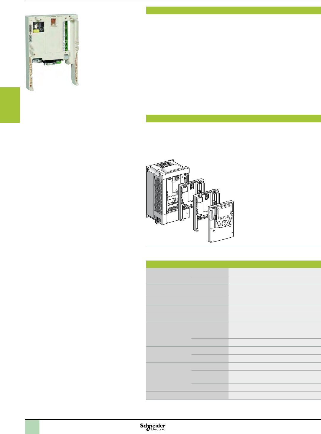
Installation
The Altivar IMC card type S Solutions with AFB is designed for integration on Altivar
61 variable speed drives in conjunction with other Altivar 61-specic cards, such as
I/O expansion cards and communication cards.
1
1
2
3
1 Altivar 61 drive and graphic display
terminal
2 Altivar IMC card VW3 A3521S0
3 I/O expansion card VW3A32pp or
communication card VW3A33pp
Note: Only one I/O expansion card or communication card can be mounted simultaneously with
the Altivar IMC card type S Solutions with AFB on anAltivar 61 drive.
Special features
User memory RAM 2 MB
Flash 2 MB
Data storage memory FRAM
(Ferroelectric RAM)
64 KB
Typical time (for 1000 Boolean instructions) 942 µs
User program size 1 MB
Power supply 24 V c
Inputs Digital 10 x 24 V c inputs, 4 of which can be used for
2 high-speed counter inputs (100 kHz) or
2 incremental encoders (A/B) (100 kHz)
Analog 2 x 0…20 mA inputs
Outputs Digital 6 transistor outputs (2 A) - source
Analog 2 x 0…20 mA outputs
Built-in
communication
ports
RJ45 port Ethernet Modbus TCP, Web/FTP Server
SUB-D connector
(male 9-way)
Master CANopen bus (16 slaves)
USB Mini-B port SoMachine software programming
Real-time clock Integrated
Altivar IMC integrated controller card

2
1
3
4
5
6
7
8
9
10
3/5
Presentation Hardware control platforms
Drive controller
Altivar IMC drive controller card type S solutions with
AFB, for Altivar 61 variable speed drive
SoMachine software platform
Performance
Reduce the time it takes to develop your machines
bThe use of a single SoMachine programming software environment offers a number
of advantages:
vA single project le
vA single software program
vA single download for the whole application
bThe ease of use of PLCopen function blocks signicantly reduces the time needed
to program motion control and independent axis control on machines.
A more powerful machine
The Altivar IMC drive controller card type S Solutions with AFB has 8 tasks to suit
different machine requirements (cyclic, event-triggered, free).
A task can be synchronized with the task of the drive in which it is embedded. This
task manages the speed reference, the torque reference, the speed feedback, the
torque feedback, the number of encoder pulses feedback in order to increase
machine performance.
A more intelligent drive
vPerforms more complex operations (2 MB memory)
vReduces program loading time (Mini-B USB connectors)
vCommunication with all the other system devices (built-in Ethernet and CANopen
connection ports)
Transparency of your machines
Access to all the other devices in the system architecture via CANopen is totally
transparent due to FDT/DTM technology.
Development and technology
The Altivar IMC drive controller card type S Solutions with AFB has been developed
with two criteria in mind: low cost and practicality.
bLow cost because the standard equipment for the Altivar IMC card type S Solutions
with AFB comprises:
vSixteen discrete I/O
vA built-in Ethernet port
vTwo analog inputs
vTwo analog outputs
vAnd a CANopen master
bPracticality because the Altivar IMC card type S Solutions with AFB is ideal for
integration in Altivar 61 drives, and can therefore use:
vTheir inputs/outputs
vTheir communication cards
vTheir parameters: speed, current, torque, etc.
vTheir remote graphic display terminal
vAnd also the inputs/outputs in their I/O expansion cards
vPlus the speed feedback counter in the encoder interface cards
Software conguration
Conguration and programming of the Altivar IMC drive controller card type S
Solutions with AFB and equipment in Schneider Electric’s “Flexible Machine Control”
concept are both designed to cut costs and optimize your machine performance.
Schneider Electric’s SoMachine software platform can be used to program Altivar
IMC drive controller card type S Solutions with AFB using:
bIEC 61131-3 programming languages: Instruction List (IL), Ladder Diagram (LD),
Function Block Diagram (FBD), Sequential Function Chart/Grafcet (SFC) and
Structured Text (ST)
bCFC (Continuous Function Chart) language.
PLCopen function blocks are used for managing motion control and axis control on
your machines.
See page 2/2.
Integration in the Schneider Electric product offer
Combined with other dedicated products in the Schneider Electric offer, such as
Altivar variable speed drives, Lexium servo drives, Magelis HMI terminals, TeSys
motor starters and contactors, the Altivar IMC drive controller card type S Solutions
with AFB can be integrated transparently in a number of architectures.
2
1
3
4
5
6
7
8
9
10
3/6
Functions Hardware control platforms
Drive controller
Altivar IMC drive controller card type S solutions with
AFB, for Altivar 61 variable speed drive
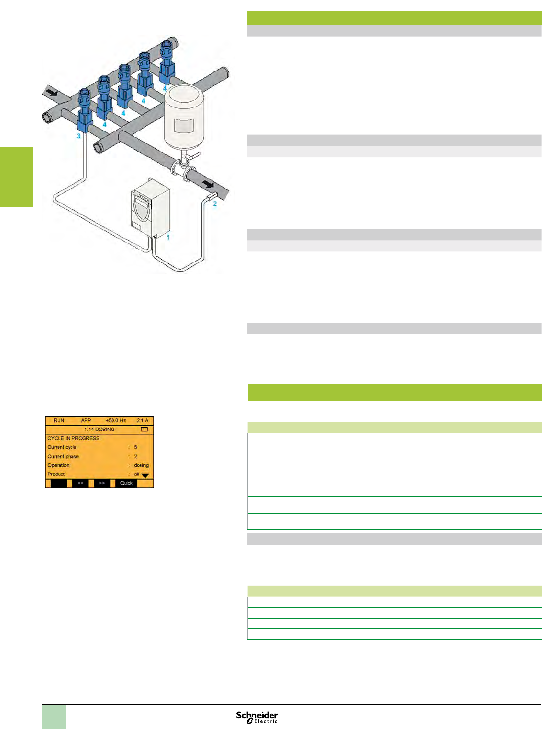
Analog functions
Functions
Analog functions
For machines that require functions to process data issued by analog sensors/
actuators (voltage or current), temperature sensors, pressure or PID control
sensors, the Altivar IMC drive controller card type S Solutions with AFB has, as
standard, 2 analog inputs (voltage or current) with 10-bit resolution and 2 analog
outputs (current) with 10-bit resolution.
1 Altivar IMC drive controller card type S Solutions with AFB installed on Altivar 61
2 Pressure sensor
3 Variable speed pump
4 Fixed speed pumps
Communication function
Ethernet
The Altivar IMC drive controller card type S Solutions with AFB has a built-in RJ45
Ethernet port (10/100 Mbps, MDI/MDIX) with Ethernet TCP Modbus, SoMachine on
Ethernet, UDP, TCP and SNMP protocols.
In addition, the Altivar IMC card type S Solutions with AFB has an embedded Web
Server and FTP Server.
As well as the default address based on the MAC address, it is possible to assign a
controller IP address via a DHCP server or via a BOOTP server.
Customization function on the graphic display terminal
Menu 1.14
The remote graphic display terminal on Altivar 61 drive includes a menu dedicated to
the Altivar IMC drive controller card type S Solutions with AFB.
The user is offered a graphic display of 8 lines of 24 characters.
This menu can be customized simply and directly using the SoMachine software.
The user can dene the language, name, unit, decimal point, and the type of
parameter he wishes to customize for his own application. The user can also dene
alarms and error messages for his application.
Clock function
A time and date-stamping function combined with a clock backed up by a lithium
battery makes it possible to keep a log of events that have occurred. When the
Altivar IMC drive controller card type S Solutions with AFB is installed in the drive,
drive faults are automatically time and date-stamped without the need for any special
programming.
Communication
The Altivar IMC drive controller card type S Solutions with AFB has the following
built-in communication ports:
Communication ports Use
1 x RJ45 (MDI/MDIX port) vFTP server
vWeb server
vModbus TCP server
vModbus TCP client
vManager SoMachine
vSNMP
vModbus device
1 x mini-USB Programming port (480 Mbps)
1 x 9-way male SUB-D Master CANopen connection
Embedded Ethernet
The Altivar IMC drive controller card type S Solutions with AFB has an embedded
Ethernet link via a direct connection to its RJ45 port.
bSpeed: “10 BaseT” and “100 BaseTX” with auto-negotiation
bRJ45 port (MDI/MDIX): automatic adaptation to a straight or crossed cable
Protocols Number of connections
Modbus server 8
Modbus device 2
FTP server 4
Web server 10
Menu 1.14
2
1
3
4
5
6
7
8
9
10
3/7
Description,
references
Hardware control platforms
Drive controller
Altivar IMC integrated controller card for Altivar 61
variable speed drive
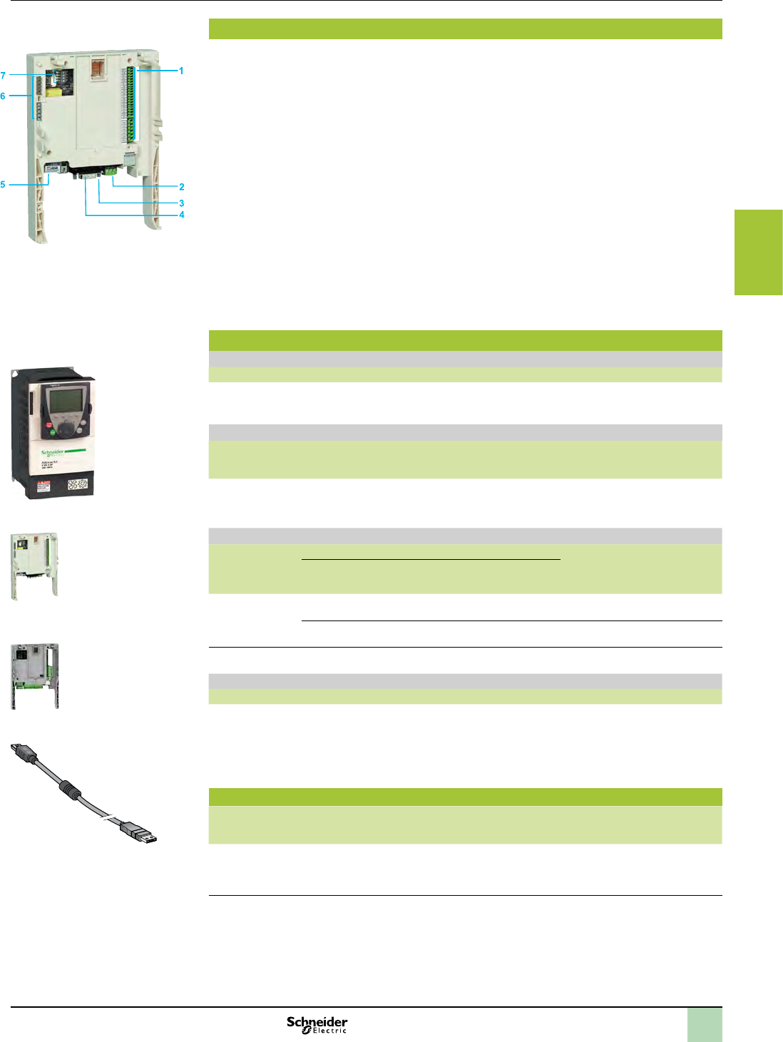
Description
The Altivar IMC drive controller card type S Solutions with AFB comprises:
1 Three spring connectors for:
v10 digital inputs
v6 digital outputs
v2 analog inputs
v2 analog outputs
v2 commons
2 A connector with removable screw terminals, 3 contacts at intervals of 3.81 for the 24 V c power
supply
3 A mini USB-B connector for programming using SoMachine software
4 A 9-way SUB-D connector for connection to the CANopen machine bus
5 An RJ45 connector for connection of the SoMachine software workshop and/or connection to an
Ethernet Modbus TCP network
6 Five LEDs:
v1 green/yellow ETH LED for Ethernet activity
v1 green/red NS (Network status) LED
v1 green/red MS (Module status) LED
v1 green/red CAN (CANopen activity) LED
v1 green/red LED programmable by the user
7 Four conguration selector switches
References
Variable speed drives
Designation Reference
Altivar 61 variable speed drives Refer to the “Altivar 61 variable speed
drives” catalogue or visit our website
www.schneider-electric.com
Altivar IMC drive controller card type S Solutions with AFB for Altivar 61
Designation Voltage Reference Weight
kg
lb
Altivar IMC drive
controller card
type S Solutions
with AFB
24 V c VW3A3521S0 0.185 kg
0.408 lb
I/O expansion cards for Altivar 61(1)
Designation Type of I/O Reference Weight
kg
lb
Logic
input
Logic
output
Analog
input
Analog
output
PTC
probe
input (2)
Frequency
control
input
I/O expansion
cards (2)
4 3 – – 1 – VW3A3201 0.300
0.661
4 3 2 2 1 1 VW3A3202 0.300
0.661
For more information about digital I/O cards, visit our website www.schneider-electric.com.
Communication cards
Designation Protocols available (depending on model) Reference
VW3A3 3pp
communication
cards
vModbus Plus
vUni-Telway
vInterBus-S
vProbus DP
vDeviceNet
vEthernet Modbus TCP
vFipio
vEtherNet IP
vCC-Link
vLonworks
vMETASYS N2
vAPOGEE FLN
vBACnet
Refer to “Altivar 61 variable speed
drives” catalogue, or visit our website
www.schneider-electric.com
Connection cable
Designation Use Length Reference Weight
kg
lb
Programming
cable
From the mini USB-B port on the Altivar IMC
drive controller card type S to the type A USB
port on the PC terminal for programming and
updating rmware
3 m
9.843 ft
TCSXCNAMUM3P 0.065
0.143
(1) Altivar 61 variable speed drive can only take one I/O expansion card with the same reference.
(2) This PTC probe input must never be used to protect an ATEX motor in applications in explosive atmospheres.
Please refer to the ATEX guide which is available on our website “www.schneider-electric.com”.
VW3A3 202
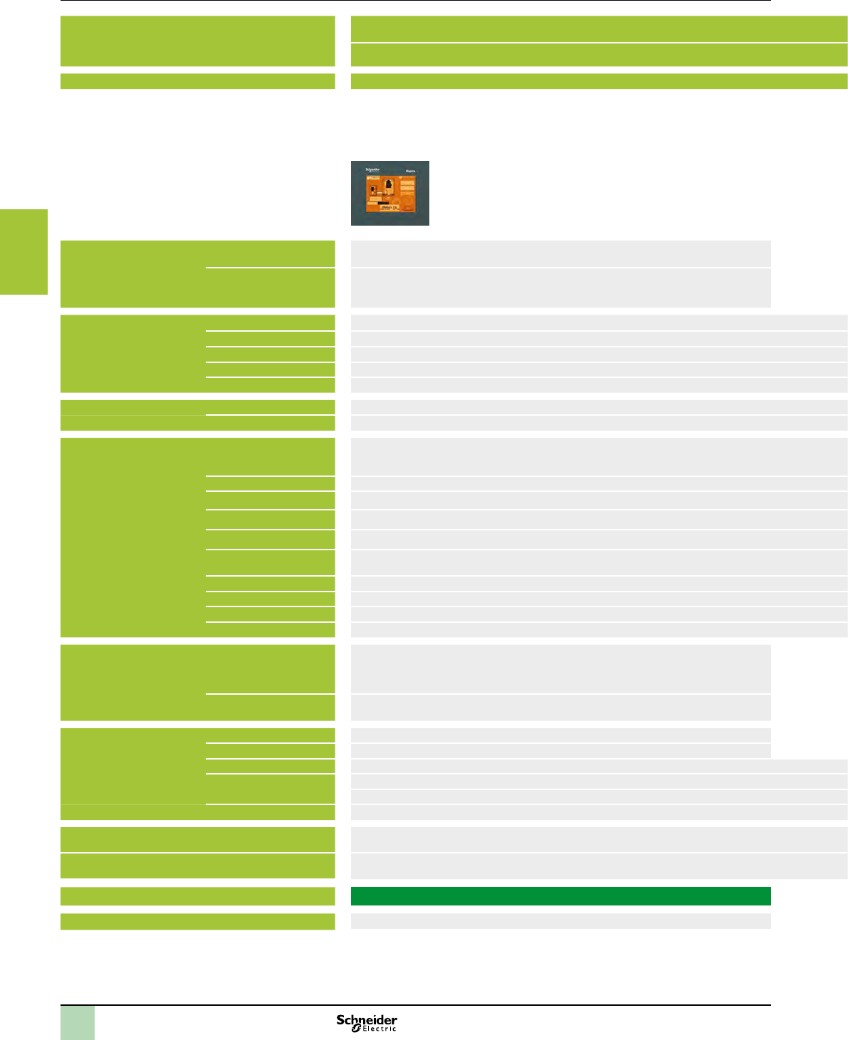
VW3A3521S0
Altivar 61 variable speed drives
TCSXCNAMUM3P
2
1
3
4
5
6
7
8
9
10
3/8
Selection guide Hardware control platforms
HMI Controllers
MagelisTM XBTGC HMI Controllers
Applications Display of text messages, graphic objects and mimics
Control and conguration of data
IEC 1131-2 control function
Terminal type HMI Controllers
Display Type Back-lit monochrome (amber or red mode) STN LCD
(320 x 240 pixels)
Backlit monochrome STN LCD (320 x 240 pixels) Colour STN LCD (320 x 240 pixels)
Capacity 3.8” (monochrome) 5.7” (monochrome) 5.7” (colour)
Data entry Via touch screen
Static function keys –
Dynamic function keys –
Service keys –
Alphanumeric keys –
Memory capacity Application 16 MB EPROM Flash
Extension –
Functions Maximum number of pages
and maximum number of
instructions
Limited by internal Flash EPROM memory capacity
Variables per page Unlimited (8000 variables max.)
Programmed logic 5 languages according to IEC 1131-2 (LD, ST, FBD, SFC, IL)
Counting/positioning 4 x 100 kHz fast counter inputs/4 x 65 kHz pulse train outputs
Control (PID) Yes
Representation of variables Alphanumeric, bitmap, bargraph, gauge, tank, tank level indicator, curves, polygon, button, indicator
Recipes 32 groups of 64 recipes comprising 1024 ingredients max.
Curves Yes, with log
Alarm logs Yes
Real-time clock Built-in
I/O Integrated 12 x 24 V c digital inputs
6 sink or source
transistor outputs (1)
16 x 24 V c digital inputs
16 sink or source
transistor outputs (1)
I/O modular extensions Two M238 I/O modules max. Three M238 I/O modules max.
Communication Downloadable protocols – Uni-TE, Modbus, Modbus TCP/IP (1) and for PLC brands: Mitsubishi, Omron, Allen-Bradley and Siemens
Asynchronous serial link – RS 232C/RS 422/485 (COM1)
USB ports 1
Buses and networks 1 CANopen master with optional module (XBTZGC CAN)
–Ethernet TCP/IP (10BASE-T/100 BASE-TX)
Printer link USB port for parallel printer
Design software SoMachine with Windows XP Professional and Windows 7 Professional 32/64-bit, see page 2/5
Operating system Magelis
(131 MHz RISC CPU)
Terminal type XBTGC1100 T/U XBTGC2120 T/U XBTGC2230 T/U
Pages 3/14 3/14 3/14
(1) Depending on model
2
1
3
4
5
6
7
8
9
10
3/9
Applications Display of text messages, graphic objects and mimics
Control and conguration of data
IEC 1131-2 control function
Terminal type HMI Controllers
Display Type Back-lit monochrome (amber or red mode) STN LCD
(320 x 240 pixels)
Backlit monochrome STN LCD (320 x 240 pixels) Colour STN LCD (320 x 240 pixels)
Capacity 3.8” (monochrome) 5.7” (monochrome) 5.7” (colour)
Data entry Via touch screen
Static function keys –
Dynamic function keys –
Service keys –
Alphanumeric keys –
Memory capacity Application 16 MB EPROM Flash
Extension –
Functions Maximum number of pages
and maximum number of
instructions
Limited by internal Flash EPROM memory capacity
Variables per page Unlimited (8000 variables max.)
Programmed logic 5 languages according to IEC 1131-2 (LD, ST, FBD, SFC, IL)
Counting/positioning 4 x 100 kHz fast counter inputs/4 x 65 kHz pulse train outputs
Control (PID) Yes
Representation of variables Alphanumeric, bitmap, bargraph, gauge, tank, tank level indicator, curves, polygon, button, indicator
Recipes 32 groups of 64 recipes comprising 1024 ingredients max.
Curves Yes, with log
Alarm logs Yes
Real-time clock Built-in
I/O Integrated 12 x 24 V c digital inputs
6 sink or source
transistor outputs (1)
16 x 24 V c digital inputs
16 sink or source
transistor outputs (1)
I/O modular extensions Two M238 I/O modules max. Three M238 I/O modules max.
Communication Downloadable protocols – Uni-TE, Modbus, Modbus TCP/IP (1) and for PLC brands: Mitsubishi, Omron, Allen-Bradley and Siemens
Asynchronous serial link – RS 232C/RS 422/485 (COM1)
USB ports 1
Buses and networks 1 CANopen master with optional module (XBTZGC CAN)
–Ethernet TCP/IP (10BASE-T/100 BASE-TX)
Printer link USB port for parallel printer
Design software SoMachine with Windows XP Professional and Windows 7 Professional 32/64-bit, see page 2/5
Operating system Magelis
(131 MHz RISC CPU)
Terminal type XBTGC1100 T/U XBTGC2120 T/U XBTGC2230 T/U
Pages 3/14 3/14 3/14
(1) Depending on model
2
1
3
4
5
6
7
8
9
10
3/10
Presentation Hardware control platforms
HMI Controllers
MagelisTM XBTGC HMI Controllers
Presentation
Magelis HMI Controllers are part of Schneider's Flexible Machine Control concept, a
key element in MachineStruxureTM.
The Magelis HMI Controller offer brings together Human Machine Interface and
control functions within in a single product. This reduces the amount of equipment
required and the associated costs throughout the life cycle of the machine.
Magelis XBTGC HMI Controllers
The compact design of Magelis XBTGC HMI Controllers optimizes setup.
This range comprises six touch screen terminals, with the following, depending on
the model:
b3.8” monochrome screen, 12 integrated inputs/6 integrated outputs (sink or source)
b5.7” monochrome or colour screen, 16 integrated inputs/16 integrated outputs (sink
or source)
bA wide choice of communication interfaces (USB, serial link, CANopen and
Ethernet)
In order to adapt easily to different congurations, it is possible to add digital or
analog I/O expansion modules at the rear of the Controller.
Operation
With their fast, multitasking processors, the HMI Controllers combine HMI and
control functions and share the same screen and communication features and
dimensions.
The internal memory can be freely used by both the HMI function and the control
function.
Processing is split 75% on the HMI part and 25% on the control part. The processing
can be congured for 3 tasks, including 1 master task.
XBTGC HMI Controllers also share the same I/O modules, the same Telefast
pre-wired system and the same peripherals on the CANopen bus as the M238 logic
controller.
Magelis XBTGC HMI Controllers
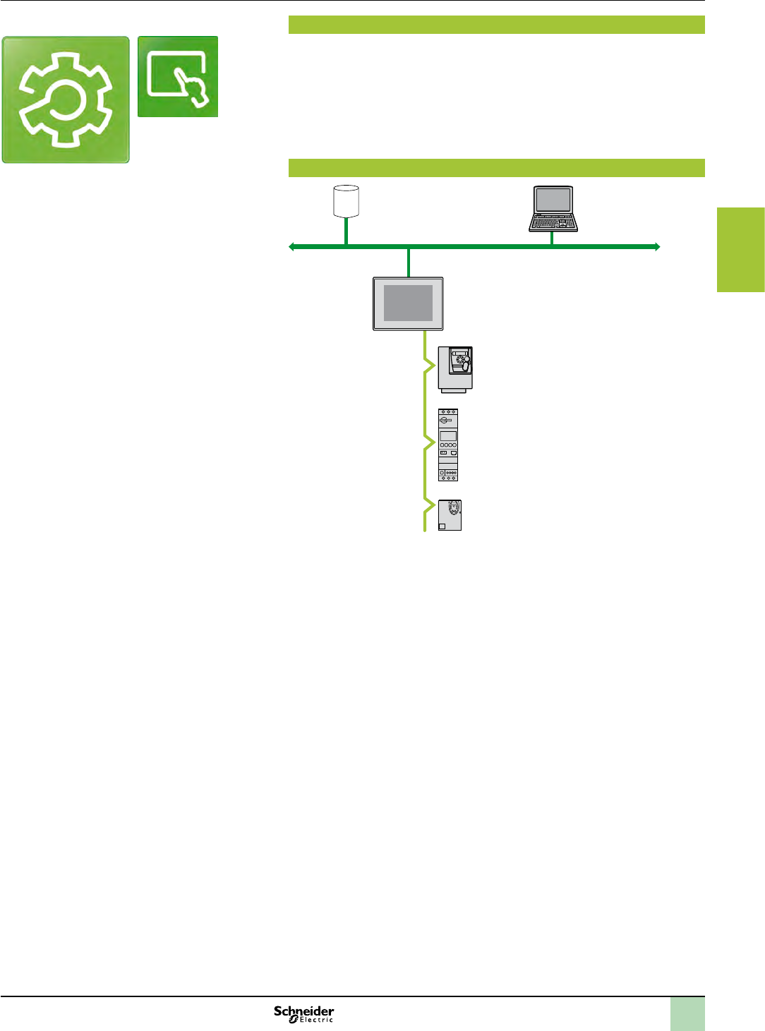
2
1
3
4
5
6
7
8
9
10
3/11
Presentation (continued) Hardware control platforms
HMI Controllers
MagelisTM XBTGC HMI Controllers
Conguration
Magelis XBT GC HMI Controllers are congured using Schneider Electric's unique
machine automation software, SoMachine.
This software, combining both HMI and control functions, is based on Vijeo Designer
software in the Windows XP Professional and Windows 7 Professional 32/64-bit
environment.
SoMachine software boasts an advanced user interface with many congurable
windows, enabling unique projects to be developed quickly and easily.
See page 2/5.
Communication
SoMachine:
WebGate function
Ethernet
TeSys U
ATV212
ATV312
Modbus
XBT GC
Examples of communication architectures
Depending on the model:
bMagelis HMI Controllers communicate with automation devices via 1 or 2 integrated
serial links using the following communication protocol: Schneider Electric (Uni-TE,
Modbus)
bMagelis HMI Controllers can be connected to Ethernet TCP/IP networks with the
Modbus TCP protocol or a third-party protocol. They also can be used as the CANopen
master to control the peripherals which can be connected on this bus.
SoMachine
Vijeo Designer
(included in SoMachine)
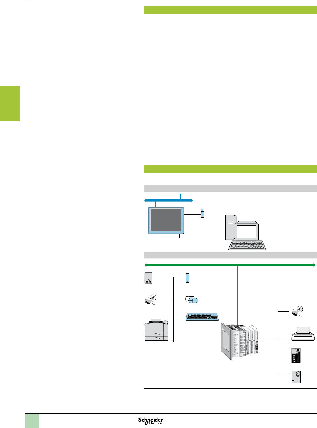
2
1
3
4
5
6
7
8
9
10
3/12
Functions Hardware control platforms
HMI Controllers
MagelisTM XBTGC HMI Controllers
Functions
Magelis HMI Controllers are part of Schneider's Flexible Machine Control concept, a
key element in MachineStruxureTM.
Magelis XBTGC HMI Controllers offer the following HMI functions:
bDisplay of animated mimics with 8 types of animation (pressing the touch panel,
colour changes, lling, movement, rotation, size, visibility and value display)
bControl, modication of numeric and alphanumeric values
bDisplay of current date and time
bReal-time curves and trend curves with log
bAlarm display, alarm log and management of alarm groups
bMulti-window management
bPage calls initiated by the operator
bMultilingual application management (10 languages simultaneously)
bRecipe management
bData processing via Java script
bApplication support and USB key external memory logs
bManagement of serial printers and barcode readers
Magelis XBTGC HMI Controllers (1) have been designed for Transparent Ready
architectures and equipment (combination of Web and Ethernet TCP/IP
technologies). With the WebGate function, it is possible to control or carry out
maintenance remotely.
Magelis XBTGC HMI Controllers offer the following functions for control:
bExecution of programmed logic sequences with the ve IEC 1131-2 languages (LD,
ST, FBD, SFC, IL)
bManagement of equipment on the CANopen eldbus
In addition to these functions, Magelis XBT GC HMI Controllers manage:
bIntegrated and remote I/O on expansion modules
bRemote analog I/O on expansion modules
Operating modes for the terminals
The illustrations below show which equipment can be connected to XBT terminals
based on their two operating modes.
Edit mode
USB key
Connection cable
XBTZG935
PC with software
SoMachine
Ethernet network (1)
XBTGC
Run mode
Barcode
reader (4)
Parallel printer
(5)
USB port
duplicator
Ethernet network (2)
Barcode
reader (4)
Keyboard
Mouse
Modicon OTB
ATV 212
COM2
COM1
XBTGC
+ 3 I/O modules (3)
(1) Depending on model
(2) With XBTGC 2230T/U
(3) With XBTGCppppT/U, maximum 2/3 I/O modules according to model
(4) Should be a DataLogic Gryphon barcode reader
(5) Should be a Hewlett Packard printer via a USB/PIO converter
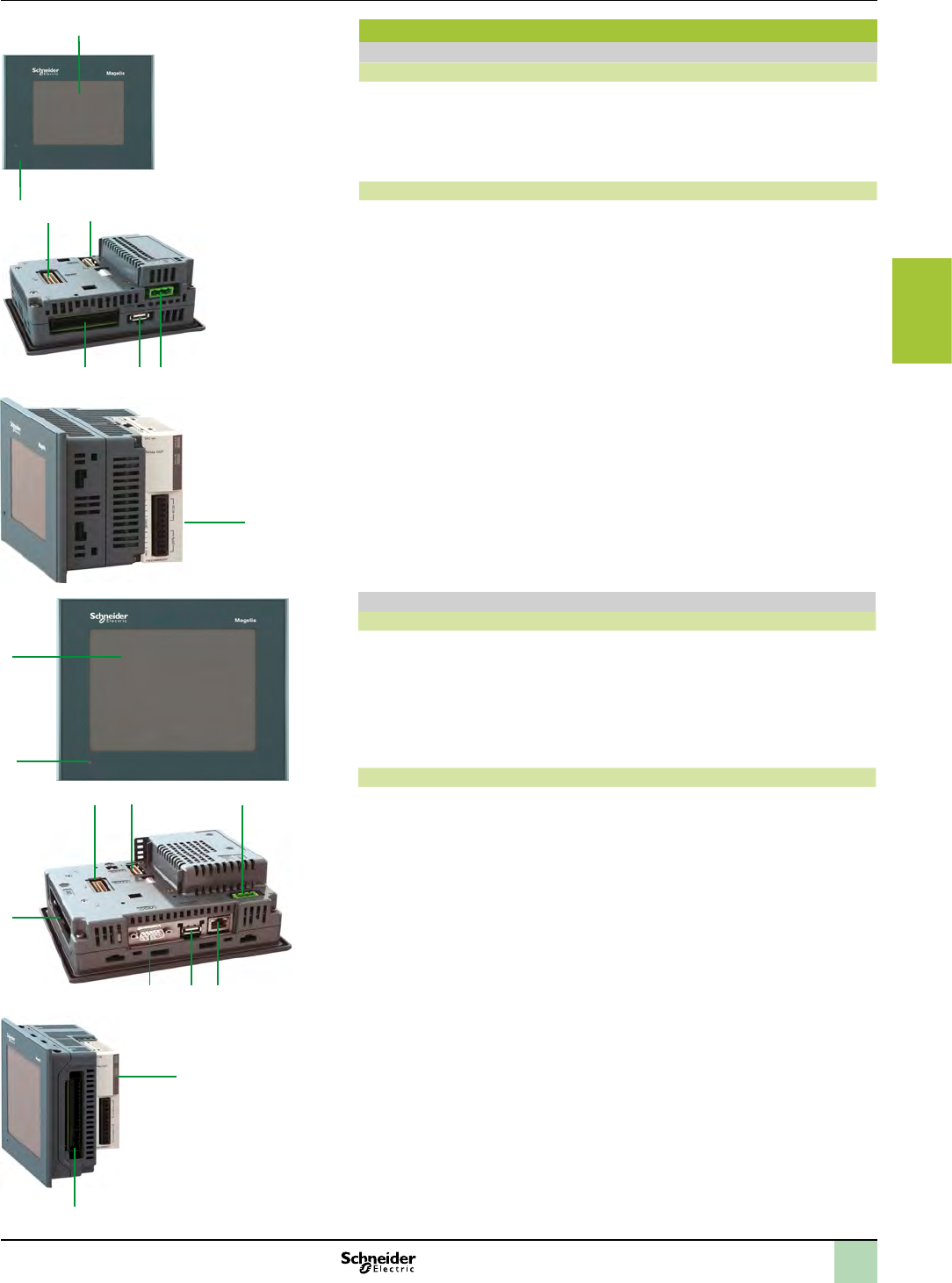
2
1
3
4
5
6
7
8
9
10
3/13
Description Hardware control platforms
HMI Controllers
MagelisTM XBTGC HMI Controllers with 3.8” screen,
MagelisTM XBTGC HMI Controllers with 5.7” screen
1
2
Description
Magelis XBTGC1100T and XBTGC1100U HMI Controllers
The front panel comprises:
1 A touch screen for displaying mimics (3.8” amber or red mode monochrome)
2 A control indicator showing the terminal's operating mode
The rear panel comprises:
5 4
123
1 A removable screw terminal block for 24 V c power supply
2 A type A USB master connector for peripheral connection and application transfer
3 A removable terminal block for 12 digital inputs and 6 digital outputs
4 An interface for connecting M238 logic controller I/O expansion modules
5 An interface for connecting the CANopen bus master module
6 Digital (TM2Dpp) or analog (TM2App) I/O expansion module (to be ordered
separately, see page 3/34)
It is possible to combine a maximum of two I/O expansion modules, depending
on the module type (see page 3/34).
2
1
Magelis XBTGC2p20 and XBTGC2p30 HMI Controllers
The front panel comprises:
1 A touch screen for displaying mimics (5.7” monochrome or colour)
2 A multicolour indicator (green, orange and red) showing the terminal's operating
mode
The rear panel comprises:
3
45
2
1
6
8
1 A removable screw terminal block for 24 V c power supply
2 A type A USB master connector for peripheral connection and application transfer
3 A 9-way male SUB-D connector for RS 232C or RS 422/485 serial link to PLCs
(COM1)
4 An interface for connecting the M238 logic controller I/O expansion module
5 An interface for connecting the CANopen bus master module.
6 A removable terminal block for 16 digital inputs and 16 digital outputs
7 Digital (TM2Dpp) or analog (TM2App) I/O expansion module (to be ordered
separately, see page 3/34)
It is possible to combine a maximum of three I/O expansion modules, depending
on the module type (see page 3/34).
For XBTGC2230 only:
8 An RJ45 connector for Ethernet TCP/IP 10BASE-T/100BASE-TX link
6
6
7
2
1
3
4
5
6
7
8
9
10
3/14
References Hardware control platforms
HMI Controllers
MagelisTM XBTGC HMI Controllers
XBTGC1100
XBTGC1100p
XBTGC2pppp
XBTZGUSB
Magelis XBTGC HMI Controllers (1)
Type of screen No. of
ports
Application
memory
capacity
Compact
Flash
memory
Integrated I/O No. of
Ethernet
ports
Reference Weight
kg
lb
3.8’’ screen
STN
amber or red
1 USB 16 MB No 12 I/6 O source - XBTGC1100T 0.400
0.882
12 I/6 O sink - XBTGC1100U 0.400
0.882
5.7’’ screen
STN
black and white
mode
1 COM 1 16 MB No 16 I/16 O source - XBTGC2120T 1.000
2.205
1 USB 16 I/16 O sink - XBTGC2120U 1.000
2.205
5.7’’ screen
STN
colour
1 COM 1 16 MB No 16 I/16 O source 1 XBTGC2230T 1.000
2.205
1 USB 16 I/16 O sink 1 XBTGC2230U 1.000
2.205
Separate parts
Designation Compatibility Size Reference Weight
kg
lb
Protective sheets
(5 peel-off sheets)
XBTGC 1100 – XBTZG60 0.200
0.441
XBTGC2pp0 – XBTZG62 0.200
0.441
Designation Description Length Reference Weight
kg
Remote USB port location
for type A XBT terminal
Enables the USB port to be located remotely on
the rear of the XBT terminal on a panel or cabinet
door (Ø 21 mm / 826.772 in. mounting device)
1 m
3.281 ft
XBTZGUSB –
Remote USB port location
for mini type B XBT terminal
-XBTZGUSBB –
XBTGC connection to
CANopen master eldbus
Connection via card on bus extension - XBTZGCCAN –
Cable for transferring
application to PC
USB TTL connector 2 m
6.562 ft
XBTZG935 –
Replacement parts
Designation Used for Reference Weight
kg
lb
Joints d’étanchéité XBTGC1100 XBTZG51 0.030
0.066
XBTGT21p0XBTZG52 0.030
0.066
Attache USB XBTGC 1100 XBTZGCLP2 –
XBTGC 2pp0XBTZGCLP4 –
Mounting kit 4 clips and screws (max. tightening torque: 0,5 Nm),
included with XBTGC terminals
XBTZGFIX 0.100
0.220
Spring clip for expansion
modules on XBTGC
XBTGC2pp0 terminals XBTZGCHOK 0.030
0.066
Power supply connector XBTGC1ppp / GC2ppp XBTZGPWS1 0.030
0.066
Dierct I/O connector XBTGC1000 XBTZGDIO1 –
XBTGC2000 XBTZGDIO2 –
(1) Terminals supplied with mounting kit (screw clips), locking device for USB connectors, spring clip for expansion modules
(except XBTGC1100) and instruction sheet. The setup documentation for XBTGC terminals is supplied in electronic format with
SoMachine software (see page 2/5).
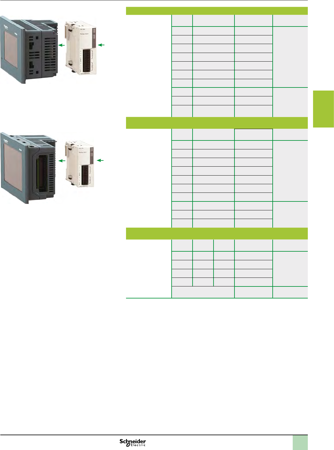
2
1
3
4
5
6
7
8
9
10
3/15
Combinations Hardware control platforms
HMI Controllers
MagelisTM XBTGC HMI Controllers
I/O expansion modules
XBTGC1ppp Combinations of two expansion modules
Combinations of
2 I/O expansion
modules with
XBTGC1ppp
Type (1) Type (1) Total thickness
mm (in.)
A A 35.2 (1.280) Permitted
combinations
A B 41.1 (1.618)
B B 47.0 (1.850)
A C 47.3 (1.862)
B C 53.2 (2.094)
A D 56.7 (2.232)
C C 59.4 (2.239)
B D 62.6 (2.465) Prohibited
combinations
C D 68.8 (2.709)
D D 78.2 (3.079)
XBTGC2ppp Combinations of two expansion modules
Combinations of
2 I/O expansion
modules with
XBTGC2ppp
Type (1) Type (1) Total thickness
mm (in.)
A A 35.2 (1.280) Permitted
combinations
A B 41.1 (1.618)
B B 47.0 (1.850)
A C 47.3 (1.862)
B C 53.2 (2.094)
A D 56.7 (2.232)
C C 59.4 (2.239)
B D 62.6 (2.465) Prohibited
combinations
C D 68.8 (2.709)
D D 78.2 (3.079)
XBTGC2ppp Combinations of three expansion modules
Combinations of
3 I/O expansion
modules with
XBTGC2ppp
Type (1) Type (1) Type (1) Total thickness
mm (in.)
A A A 52.8 (2.079) Permitted
combinations
with hook
(2)
A A B 58.7 (2.311)
A B B 64.6 (2.543)
B B B 70.5 (2.776)
All other combinations – (-) Prohibited
(1) For digital (TM2Dpp) and analog (TM2App) I/O expansion module types, see page 3/34:
- Type A: thickness 17.6 mm (0.693 in.)
- Type B: thickness 23.5 mm (1.169 in.)
- Type C: thickness 29.7 mm (0.693 in.)
- Type D: thickness 39.1 mm (1.539 in.)
(2) Hook included with product
XBTGC1ppp
TM2Dpp
TM2App
XBTGC2ppp
TM2Dpp
TM2App
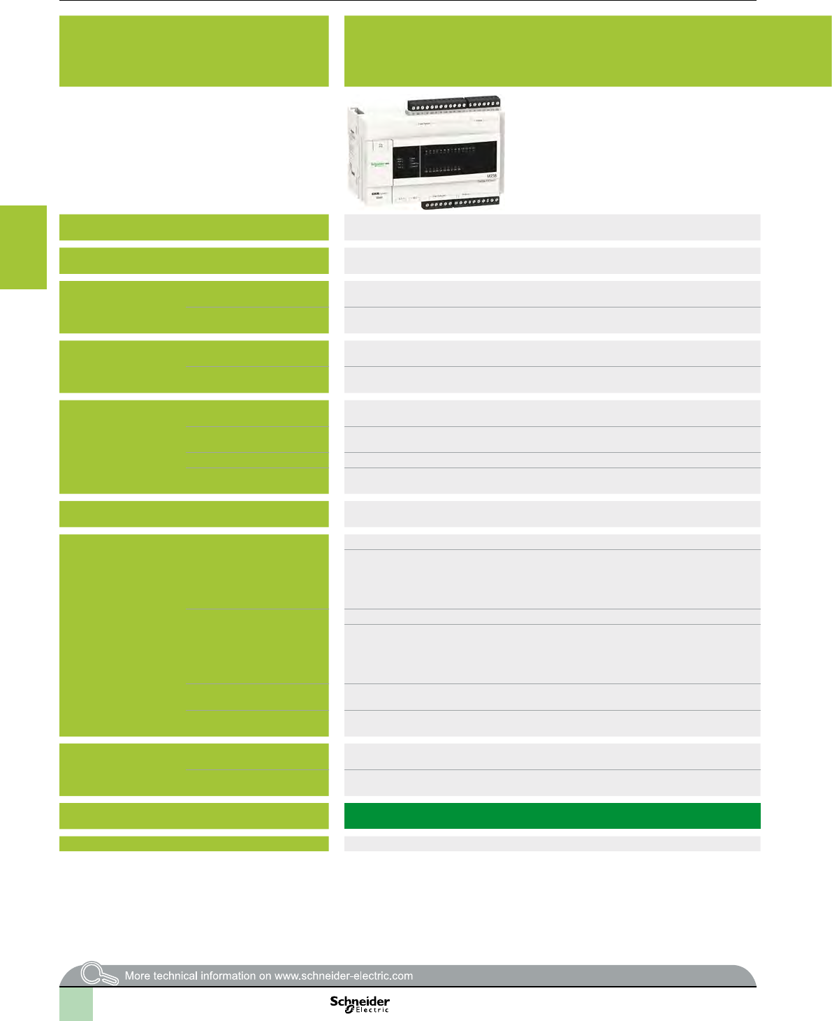
2
1
3
4
5
6
7
8
9
10
3/16
Selection guide Hardware control platforms
Modicon M238 logic controller,
Compact base for Solutions with Application function
Blocks (AFB)
Application General control solutions for
vHoisting
vPackaging
vConveying
vPumping
v...
Voltage 24 c (- 15% / + 20 %) 100-240 V a (+ 10% / - 15 %)
Certications e, UL, CSA, ACA (C-Tick), GOST (pending) e, UL, CSA, ACA (C-Tick), GOST (pending), CSA (Class 1, Division 2, Groups A, B, C, D)
Digital I/ONo. of 24 V c inputs 14, 8 of which can be congured as fast inputs 14, 8 of which can be congured as fast inputs
No. of outputs 10 transistor,
4 of which can be congured as fast outputs
4 transistor
+ 6 relay
I/O expansion Max. number of modules 7: digital, analog, high-speed counter, (3 high-speed counter TM200HSC060pp) 7: digital, analog, high-speed counter, (3 high-speed counter TM200HSC060pp)
Max. number of digital I/O 136/192/248 (1) 136/192/248 (1)
Embedded function HSC 8 x 100 kHz simple channels, 4 x 100 kHz simple channels and 1 x 100 kHz advanced channel
(2) or 2 x 100 kHz advanced channels (2)
8 x 100 kHz simple channels, 4 x 100 kHz simple channels and 1 x 100 kHz advanced channel (2) or 2 x 100 kHz advanced channels (2)
Motion or Reex functions 4 channels,
frequency: 100 Hz
4 channels,
frequency: 100 Hz
PID regulation Yes Yes
Event processing Yes, up to 4 event tasks can be activated by the fast inputs or by the integrated counter channels
(on threshold)
Yes, up to 4 event tasks that can be activated by the base's fast inputs or by the integrated counter channels (threshold attained)
Connection via 4 removable screw terminal blocks (supplied as standard)
4 removable spring terminal blocks with optional unit TM238 RSSPT (ordered separately)
4 removable screw terminal blocks (supplied as standard)
4 removable spring terminal blocks with optional unit TM238 RSSPT (ordered separately)
Embedded
communication
RS 485/RS 232 serial port Master/slave type isolated serial link Master/slave type isolated serial link
RJ45 port, marking on front panel SL1 :
1 channel
Protocols:
vDefault : Modbus slave,
vModbus master/slave RTU/ASCII, ASCII
RJ45 Port, marking on front panel SL1 : 1 channel
Protocols:
vDefault : Modbus slave,
vModbus master/slave RTU/ASCII, ASCII
RS 485 serial port Master/slave type isolated serial link Master/slave type isolated serial link
RJ45 port, marking on front panel SL2 :
1 channel
Protocols:
vDefault : Modbus slave,
vModbus master/slave RTU/ASCII, ASCII
RJ45 port, marking on front panel SL2 : 1 channel
Protocols:
vDefault : Modbus slave,
vModbus master/slave RTU/ASCII, ASCII
Terminal port “Prg. Port” 1 USB 2.0 (Mini B USB connector): Programming port for SoMachine software 1 USB 2.0 (Connecteur type USB mini-B): Programming port for SoMachine software
CANopen Conformity class M10, limited to 16 slaves for 1 master Conformity class M10, limited to 16 slaves for 1 master
User zone in internal RAM Capacity 1000 KB 1000 KB
No. of instructions 25 K instructions depending on the language and type of instruction used 25 K instructions depending on the language and type of instruction used
Type of compact base TM238 LFDC24DTS0 TM238 LFAC24DRS0
Page 3/21 3/21
(1) The 1st value corresponds to the maximum number of I/O (base and expansions) with expansion modules with screw terminals, the 2 nd to expansion modules with
spring terminals and the 3 rd to expansion modules with HE 10 connectors..
(2) Advanced channel with two-phase signal inputs for encoder, threshold detection function and reex function.
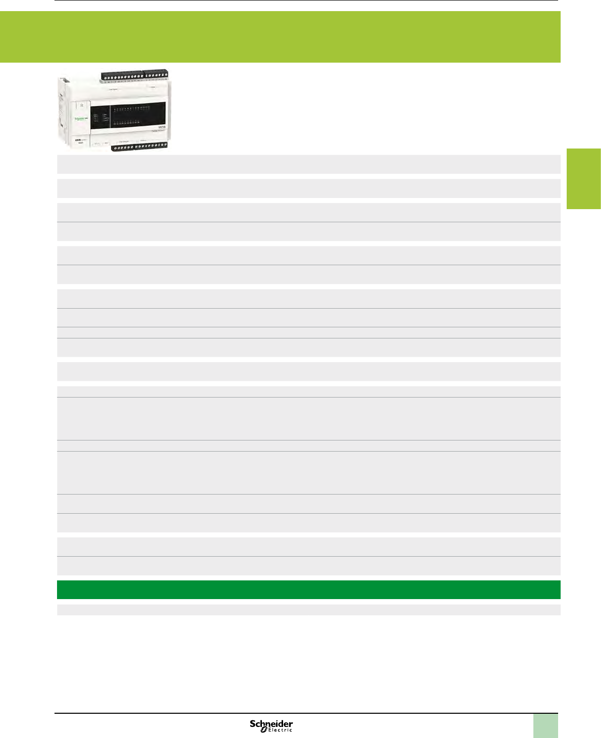
2
1
3
4
5
6
7
8
9
10
3/17
Application General control solutions for
vHoisting
vPackaging
vConveying
vPumping
v...
Voltage 24 c (- 15% / + 20 %) 100-240 V a (+ 10% / - 15 %)
Certications e, UL, CSA, ACA (C-Tick), GOST (pending) e, UL, CSA, ACA (C-Tick), GOST (pending), CSA (Class 1, Division 2, Groups A, B, C, D)
Digital I/ONo. of 24 V c inputs 14, 8 of which can be congured as fast inputs 14, 8 of which can be congured as fast inputs
No. of outputs 10 transistor,
4 of which can be congured as fast outputs
4 transistor
+ 6 relay
I/O expansion Max. number of modules 7: digital, analog, high-speed counter, (3 high-speed counter TM200HSC060pp) 7: digital, analog, high-speed counter, (3 high-speed counter TM200HSC060pp)
Max. number of digital I/O 136/192/248 (1) 136/192/248 (1)
Embedded function HSC 8 x 100 kHz simple channels, 4 x 100 kHz simple channels and 1 x 100 kHz advanced channel
(2) or 2 x 100 kHz advanced channels (2)
8 x 100 kHz simple channels, 4 x 100 kHz simple channels and 1 x 100 kHz advanced channel (2) or 2 x 100 kHz advanced channels (2)
Motion or Reex functions 4 channels,
frequency: 100 Hz
4 channels,
frequency: 100 Hz
PID regulation Yes Yes
Event processing Yes, up to 4 event tasks can be activated by the fast inputs or by the integrated counter channels
(on threshold)
Yes, up to 4 event tasks that can be activated by the base's fast inputs or by the integrated counter channels (threshold attained)
Connection via 4 removable screw terminal blocks (supplied as standard)
4 removable spring terminal blocks with optional unit TM238 RSSPT (ordered separately)
4 removable screw terminal blocks (supplied as standard)
4 removable spring terminal blocks with optional unit TM238 RSSPT (ordered separately)
Embedded
communication
RS 485/RS 232 serial port Master/slave type isolated serial link Master/slave type isolated serial link
RJ45 port, marking on front panel SL1 :
1 channel
Protocols:
vDefault : Modbus slave,
vModbus master/slave RTU/ASCII, ASCII
RJ45 Port, marking on front panel SL1 : 1 channel
Protocols:
vDefault : Modbus slave,
vModbus master/slave RTU/ASCII, ASCII
RS 485 serial port Master/slave type isolated serial link Master/slave type isolated serial link
RJ45 port, marking on front panel SL2 :
1 channel
Protocols:
vDefault : Modbus slave,
vModbus master/slave RTU/ASCII, ASCII
RJ45 port, marking on front panel SL2 : 1 channel
Protocols:
vDefault : Modbus slave,
vModbus master/slave RTU/ASCII, ASCII
Terminal port “Prg. Port” 1 USB 2.0 (Mini B USB connector): Programming port for SoMachine software 1 USB 2.0 (Connecteur type USB mini-B): Programming port for SoMachine software
CANopen Conformity class M10, limited to 16 slaves for 1 master Conformity class M10, limited to 16 slaves for 1 master
User zone in internal RAM Capacity 1000 KB 1000 KB
No. of instructions 25 K instructions depending on the language and type of instruction used 25 K instructions depending on the language and type of instruction used
Type of compact base TM238 LFDC24DTS0 TM238 LFAC24DRS0
Page 3/21 3/21
(1) The 1st value corresponds to the maximum number of I/O (base and expansions) with expansion modules with screw terminals, the 2 nd to expansion modules with
spring terminals and the 3 rd to expansion modules with HE 10 connectors..
(2) Advanced channel with two-phase signal inputs for encoder, threshold detection function and reex function.
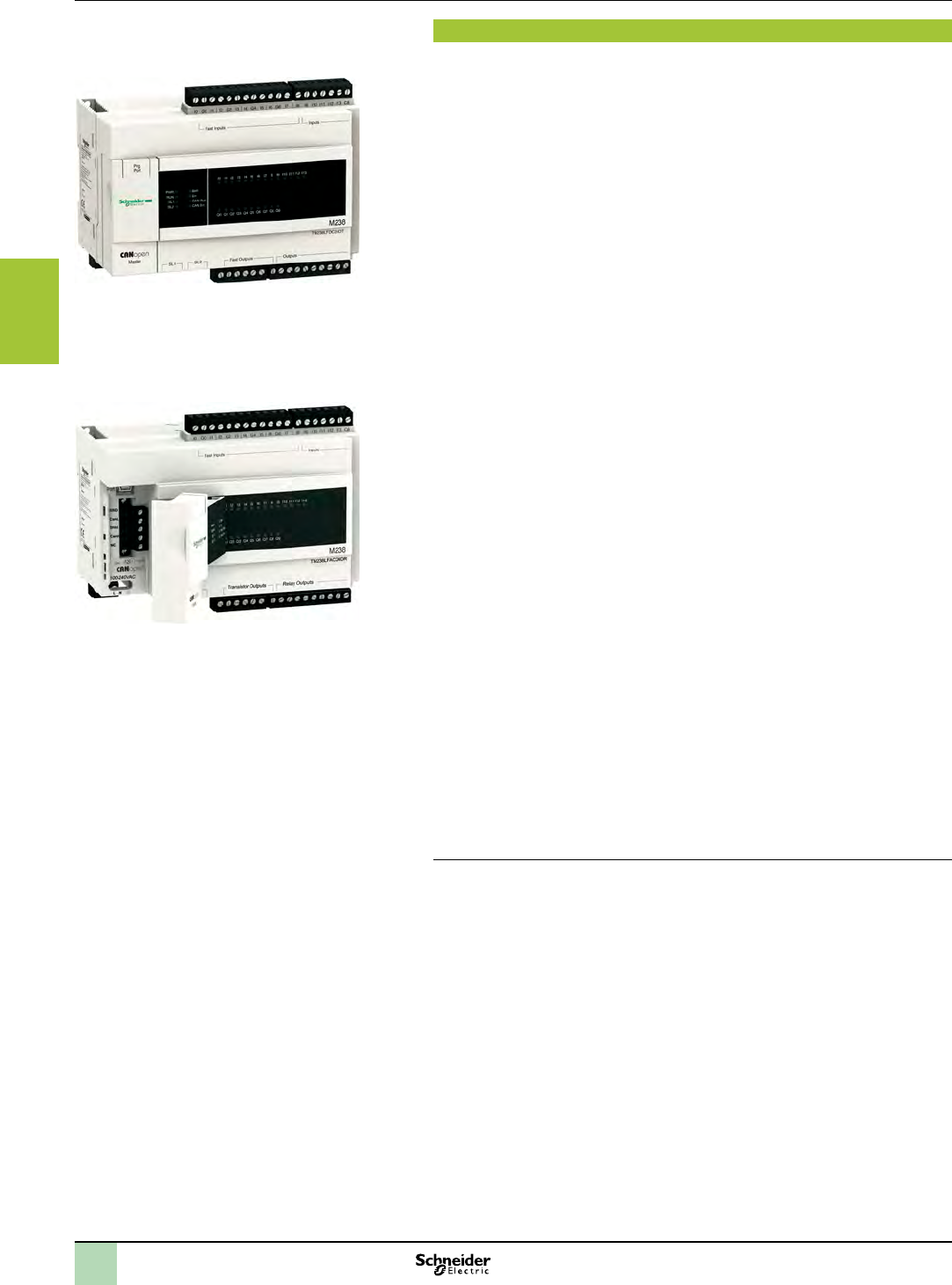
2
1
3
4
5
6
7
8
9
10
3/18
Presentation Hardware control platforms
Modicon M238 logic controller
Compact base for Solutions with Application function
Blocks (AFB)
Presentation
The Modicon M238 logic controller is the compact base for solutions with AFB,
high-performance and fully expandable PLC. It forms a part of Flexible Machine
Control approach, a key component of MachineStruxureTM, which brings you
maximum exibility and ensures the most optimised control solution.
Modicon M238 compact logic controllers offer an “all-in-one” solution in a compact
unit (157 x 118 x 86 mm excluding expansion modules).
Two models are available, with different embedded communications and supply
voltages.
bModel TM238LFDC24DTS0, powered with 24 V c offers:
v14 x 24 V c inputs, including 8 fast inputs, dedicated to special functions such as
high-speed counting (HSC)
v10 x 24 V c solid state outputs, including 4 fast outputs, dedicated to special
functions such as PWM and PTO.
vAn RS 232/RS 485 serial link (SoMachine-Network, Modbus, ASCII protocols)
vA CANopen bus master link
vA second RS 485 serial link (SoMachine-Network, Modbus, ASCII protocols)
bModel TM238LFAC24DRS0, powered with 100-240 V a offers:
v14 x 24 V c inputs, including 8 fast inputs, dedicated to special functions such as
high-speed counting (HSC)
v4 x 24 V c solid state outputs, dedicated to HSC reex functions, and 6 relay outputs
(PMW and PTO functions not supported on these models)
vAn RS 232/RS 485 serial link (SoMachine-Network, Modbus, ASCII protocols)
vA CANopen bus master link
vA second RS 485 serial link (SoMachine-Network, Modbus, ASCII protocols).
vThe number of I/O can be expanded on all four models by adding up to
7 expansion modules (1) of the following type on the right-hand side of the base unit:
- Digital TM2DDI/DDO/DMM/DRA
- Analog TM2AMI/ALM/ARI/AMO/AVO/AMM
- up to 3 High-speed counter TM200HSC206DT/DF
Modems or communication gateways can be connected to the serial links in order to
expand the connectivity capability to include
vEthernet Modbus/TCP,
vProbus DP,
vDeviceNet,
vetc.
Note: A serial link on each controller delivers a 5 V c voltage dedicated primarily to powering a
Magelis display unit or Small panel terminal XBTNp00/R400/RT500 or the Ethernet gateway
499TWD01100.
The compact controller solution also has great exibility in terms of wiring. With
digital I/O expansion modules, several connection options are available, including
removable screw terminals, spring terminals and HE 10 connectors, providing
simple, quick, safe wiring. The Modicon Telefast ABE 7 prewiring system can be
used for easy connection of expansion modules with HE 10 connectors.
(1) The addition of 7 expansion modules allows a maximum number per conguration of
136/192/248 I/O (depending on whether expansion modules with screw terminals, spring
terminals or HE 10 connectors are being used).
TM238LFAC24DRS0
TM238LFDC24DTS0
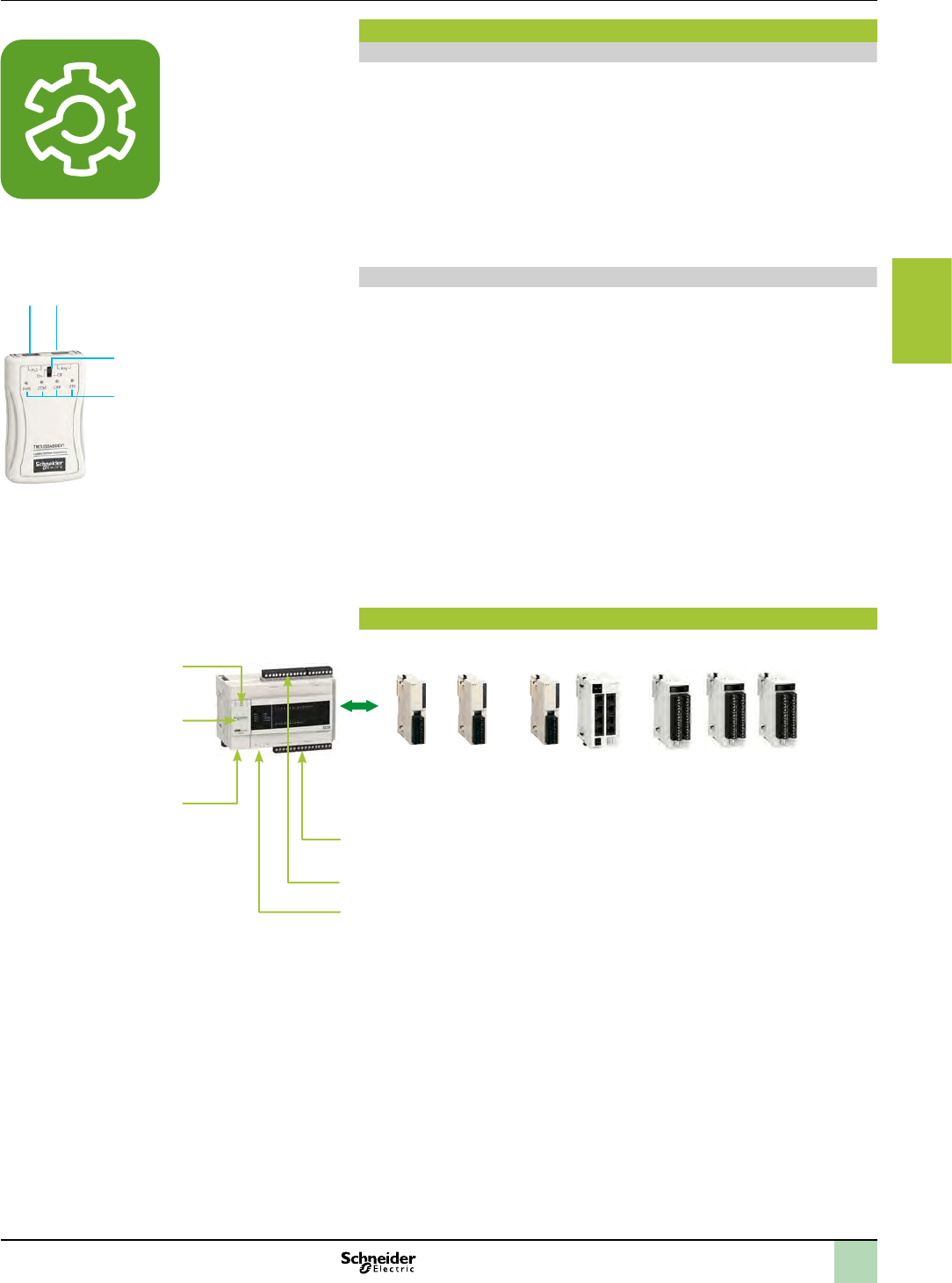
2
1
3
4
5
6
7
8
9
10
3/19
Presentation (continued) Hardware control platforms
Modicon M238 logic controller
Compact base for Solutions with Application function
Blocks (AFB)
SoMachine software platform
Presentation
Design and installation of Modicon M238 applications
Schneider Electric’s SoMachine software platform is used to program
Modicon M238 logic controllers for Solutions with AFB using:
bIEC 61131-3 programming languages: Instruction List (IL), Ladder Diagram (LD),
Function Block Diagram (FBD), Sequential Function Chart/Grafcet (SFC) and
Structured Text (ST)
bCFC (Continuous Function Chart) language.
Access to the hoisting libraries including all the specialized AFB, see page 2/2..
Program loader
1
4
3
2The TM2USBABDEV1 program loader is an accessory which is designed to simplify
updating or duplication of applications on Modicon M238 logic controllers without the
need for a programming terminal.
bFor updating: an application generated by SoMachine, stored on a USB memory
stick, will be transferred by the program loader to an M238 controller.
bFor duplication: an application is transferred from an M238 controller to the program
loader. The application is stored on a USB memory stick, then transferred from the
program loader to another M238 controller.
The front panel of the TM2USBABDEV1 program loader features:
1. A USB port (marked PLC) for the connection cable to the mini-B USB port
(marked Prg. Port) on the Modicon M238 logic controller.
2. A USB port (marked key) for the USB memory stick (holding the application).
3. An On/Off button to start the transfer.
4. Four operation LED indicators (PWR, COM, ERR, STS).
Compact base conguration
+
10 transistor outputs (including 4 PWM/PTO outputs) with TM238LFDC24DTS0
4 transistor outputs + 6 relay outputs with TM238LFAC24DRS0
14 digital inputs (including 8 fast inputs)
- 1 RS 485/RS 232 serial link, SoMachine-Network/Modbus/ASCII protocols
- 1 RS 485 serial link, SoMachine-Network/Modbus protocols
mini B USB port dedicated to
the programming terminal /
program loader
CANopen integrated link
24 V c power supply:
TM238LFDC24DTS0
100-240 V a power supply:
TM238LFAC24DRS0
TM238LFpC24DpS0 ------------------------- I/O expansion modules (Up to 7) ------------------------------
Digital I/O
TM2DpI
TM2DpO
Analog I/O
TM2AMI/ARI/ApO
TM2ApM
Counter with 2 x 60 kHz channels
TM200HSC206Dp
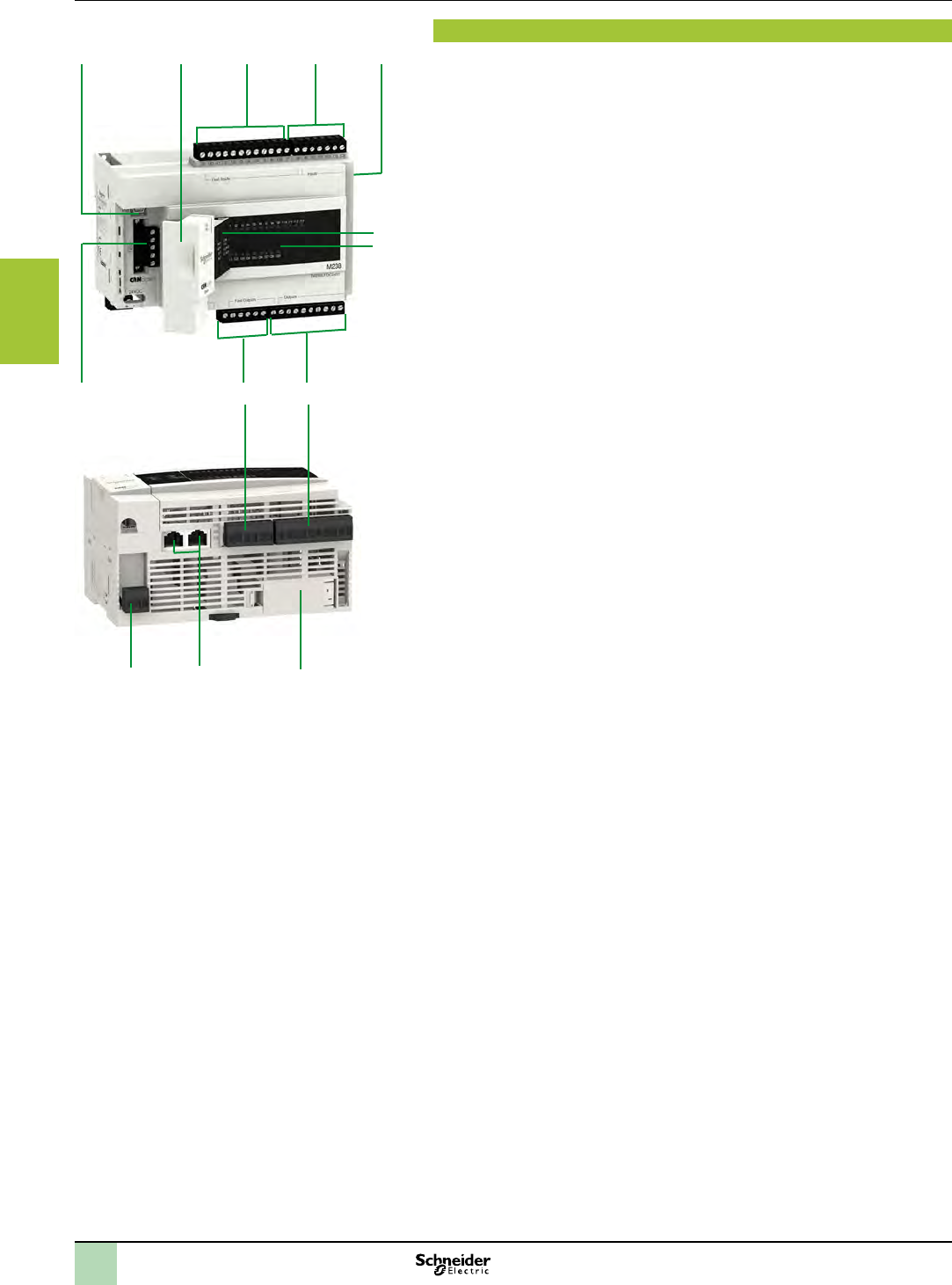
2
1
3
4
5
6
7
8
9
10
3/20
Description Hardware control platforms
Modicon M238 logic controller
Compact base for Solutions with Application function
Blocks (AFB)
Description
The Modicon M238 logic controller base for Solutions with AFB TM238LFDC24DTS0
and TM238LFAC24DRS0 comprise:
1 A mini B USB connector, marked Prg. Port, for connecting a programming
terminal
2 A hinged access cover with 2 cable glands (1 removable for the terminal cordset
and 1 for the CANopen cable)
3 A removable screw terminal block (12 terminals) for connecting the sensors (24 V
c fast inputs)
4 A removable screw terminal block (7 terminals) for connecting the sensors (24 V
c inputs)
5 A connector for up to 7 digital TM2Dpp, analog TM2App and up to 3 counter
TM200HSC206Dp I/O expansion modules
6 A display unit showing:
- The controller status by means of 4 LEDs (PWR, RUN, Batt and Err)
- The integrated communication port status by means of 4 LEDs (SL1, SL2,
CAN Run and CAN Err)
7 A display unit showing the I/O states (I0…I13 and Q0…Q9)
8 A removable screw terminal block (10 terminals) for connecting 6 preactuators
9 A removable screw terminal block (6 terminals) for connecting 4 preactuators
10 A removable screw terminal block (5 terminals marked CANopen) for connection
to the CANopen bus.
Accessible from the underside of the controller:
11 A removable screw terminal block (3 terminals):
v+, -, t marked 24 VDC for connecting the 24 V c power supply
vL, N, t marked 100-240 VAC for connecting the 100-240 V a power supply
12 2 RJ45 connectors marked SL1 and SL2 for connecting the serial links
13 A hinged cover for accessing the RAM backup battery (optional) and the internal
real-time clock
The compact bases are mounted as standard on a symmetrical 5 rail or on a metal
plate (two Ø 4.3 holes).
1 2 3 4 5
6
7
10 9 8
11 12 13
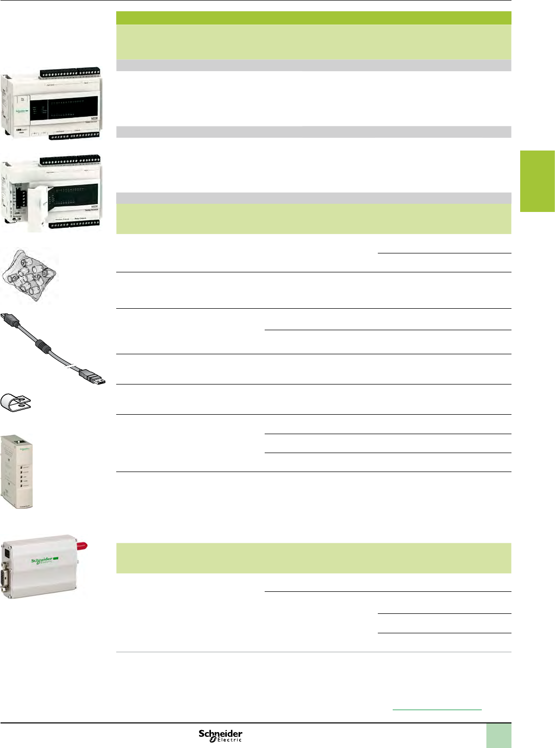
2
1
3
4
5
6
7
8
9
10
3/21
References Hardware control platforms
Modicon M238 logic controller
Compact base for Solutions with Application function
Blocks (AFB)
References
Number
of I/O
Inputs Outputs No. of I/O
expansion
modules
Integrated
serial port
Integrated
master
CANopen
port
Reference Weight
kg
lb
Compact base for solutions with AFB, 24 V c power supply
24 I/O
(removable
battery
to be ordered
separately)
6 x 24 V c
inputs (sink/
source)
8 x 24 V
c fast inputs
(sink)
10 transistor
outputs
(source)
including 4 fast
7 modules
max.
1 RS 232/485 (marked
SL1)
1 RS 485 (1)
(marked SL2)
1TM238LFDC24DTS0 0.595
1.312
Compact base for solutions with AFB, 100-240 V a power supply
24 I/O
(removable
battery
to be ordered
separately)
6 x 24 V c
inputs (sink/
source)
8 x 24 V
c fast inputs
(sink)
4 transistor
outputs
(source) and
6 relay outputs
7 modules
max.
1 RS 232/485 (marked
SL1)
1 RS 485 (1)
(marked SL2)
1TM238LFAC24DRS0 0.595
1.312
Separate parts
Designation Use Length
Sold
Reference Weight
kg
lb
Removable backup
batteries
Lithium thionyl chloride type for Modicon M238
compact bases
Individual TSXPLP01 0.012
0.026
Pack of 10 TSXPLP101 0.189
0.417
Programming cable From the mini B USB port on the Modicon M238
compact bases to the type A USB port on the PC
terminal for programming and updating rmware
3 m TCSXCNAMUM3P 0.065
0.143
RS 232 serial link cordsets
for DTE/DCE
terminal device
1 RJ45 connector
and one 9-way
SUB-D
connector
For DTE terminal (printer) 3 m TCSMCN3M4F3C2 0.150
0.331
For DCE terminal (modem,
converter)
3 m TCSMCN3M4M3S2 0.150
0.331
Removable spring
connectors for digital I/O
Set of 5 removable spring connectors.
Replaces the 5 screw connectors supplied with
Modicon M238 compact bases
–TM238RSSPT 0.048
0.106
Shielding connection
clamps
Attachment and earthing of the cable shielding
Pack of 25 clamps including 20 clamps for Ø 4.8 mm
cable and 5 for Ø 7.9 mm cable
Pack of 25 TM200RSRCEMC –
Modbus communication
gateways
Connection of
Modicon M238
compact bases
to network/bus
Ethernet Modbus/TCP (2) 499TWD01100 0.200
0.441
Probus DP (3) LUFP7 0.245
0540
DeviceNet (3) LUFP9 0.245
0.540
GSM/GPRS modem
(DCE terminal)
4-band 900/1800 MHz (Europe) and 850/1900 MHz
(United States)
IP 31 casing supplied with:
v1.5 m power cable
vSMA-M magnetic GSM 4-band aerial with 2.5 m
cable
vFixed on panel or 5
5.5…24 V c supply voltage
–SR2MOD03 0.335
0.739
Designation Use
From To
Length Reference Weight
kg
lb
Modbus cables
equipped with
2 RJ45 connectors
Serial port
marked
SL1/SL2
Ethernet gateway 499 TWD 01100 2.5 m XBTZ9980 –
Probus DP LUF P7 or DeviceNet
LUF P9, TSX CUSB 485 converter
1 m VW3A8306R10 0.050
0.110
3 m VW3A8306R30 0.150
0.331
0.3 m VW3A8306R03 0.030
0.066
(1) RS 485 link delivering a 5 V c/200 mA power supply.
(2) Connection to serial port SL1 on controller TM238LDA24DRS0 or to serial port SL2 on controller TM238LFAC24DRS0 via
Modbus cable XBTZ9980 (to be ordered separately).
(3) Connection to serial port SL1 on controller controller TM238LDA24DRS0, to serial port SL1 or SL2 on controllers
TM238LFAC24DRS0 via Modbus cable VW3A8306 Rpp (to be ordered separately). Requires a 24 V c external power
supply.
Gateway congurable via the ABC Cong Tool software, downloadable from our website www.schneider-electric.com
TSXPLP101
TM200RSRCEMC
499TWD01100
SR2MOD03
TM238LFAC24DR
TM238LFDC24DT
TCSXCNAMUM3P
2
1
3
4
5
6
7
8
9
10
3/22
References (continued) Hardware control platforms
Modicon M238 logic controller
Compact base for Solutions with Application function
Blocks (AFB)
References
Accessories
Designation Description Length Reference Weight
kg
lb
Remote location of the
USB port for M238
controllers and
XBTGT2pp0…GT7340,
GT1pp5, GKppp, GTWppp
terminals
Used to locate the USB
port of M238 controllers
(front) and XBTG
terminals (rear) remotely
on panel or enclosure
door (Ø 21 mm (3.281 in.)
mounting device)
1 m
3.281 ft
HMIZSUSBB 0.100
0.220
Program loader
Kit consisting of the
program loader, a cable
(USB/mini-B USB), and
2 batteries (type AA/LR6)
Used to update and
duplicate applications
Requires the use of a
USB memory stick (not
supplied)
3 m
9.843 ft
(cable)
TM2USBABDEV1 0.250
0.551
Connection elements for RS 485 OS download port for M238 version V1.0 (1)
Designation Use Length Reference Weight
kg
lb
USB/RS 485 converter Used to connect the
RS 485 port (SL1) to the
USB port on the PC to
update the controller
operating system.
Requires Modbus cable
VW3 A8 306 Rpp for the
connection at the
controller end
0.4 m
1.312 ft
(integrated
cable at
PC end)
TSXCUSB485 0.144
0.317
Replacement parts
Designation Use Reference Weight
kg
lb
Removable screw
connectors, supplied with
Modicon M238 bases
Set of 5 removable screw
connectors for digital I/O
TM238RSSCT 0.055
0.121
One 5-way connector with line
terminator for CANopen link
TM238CNTLSCT 0.010
0.022
(1) For later versions, use the USB port and cable.
TSXCUSB485
HMIZSUSBB
TM2USBABDEV1
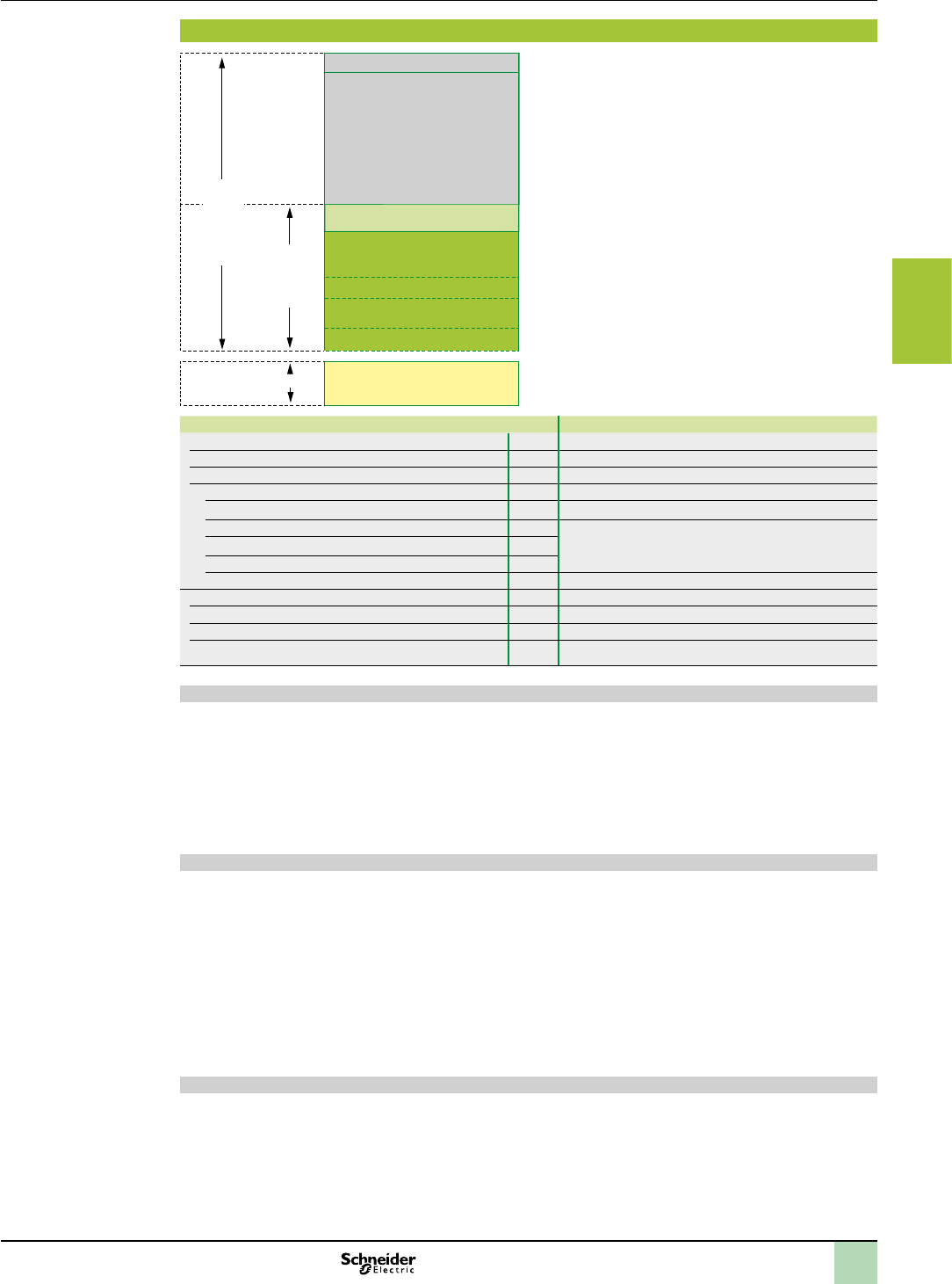
2
1
3
4
5
6
7
8
9
10
3/23
Memory structure Hardware control platforms
Modicon M238 logic controller
Compact base for Solutions with Application function
Blocks (AFB)
Memory structure
1
5
4
8
2
3
6
7
%MW located variables
System + system variables +
relocation table
Symbols
(55 KB + 0.13 KB/symbols)
Program
(eg. 41 bytes per ST instruction)
Unlocated variables
Libraries
CANopen variables
“Retain” and “Retain
Persistent” remanent variables
Internal RAM
User zone
Protected internal
RAM and rst 1000
%MW words
10 KB
Modicon M238 controllers offer great exibility in
memory management. Depending on the model used,
they have a user memory zone of 1024 KB with
TM238LFDC24DTS0 and TM238LFAC24DRS0
bases.
This user memory zone is divided according to the
application program requirements and the volume
needed by the symbols, unlocated variables and
libraries required by the application.
The memory structure of Modicon M238 controllers is
shown opposite.
The table below lists the maximum memory capacities
depending on the model (values are given for
information only).
TM238LFDC24DTS0, TM238LFAC24DRS0
Internal RAM KB 2048
1 Located variables KB 120 (60,000 %MW)
2 System + system variables + relocation table KB 900
User zone KB 1000
3 Symbols KB 200 (max. 1000 symbols)
4 Program (including online program modication) As required by the application, within the limits of the size
of the user zone
5 Unlocated variables
6 Libraries
7 CANopen variables KB 115 + 10 per slave
Protected internal RAM KB 10
8 “Retain” variables Bytes 8168
8 “Retain Persistent” variables Bytes 400
8 First 1000 %MW words Bytes 2000
Storing variables
Remanent variables can be one of two types depending on their declaration in the application:
v“Retain” variables, 8168 bytes maximum
v“Retain Persistent” variables, 400 bytes maximum.
The rst 1000 located variables 1 (rst 1000 %MW words) and all the unlocated variables 5 congured as “Retain”
and “Retain Persistent” type are backed up by the internal battery or by the optional external battery. They are
maintained when the power returns if the startup context allows this (see “Restart context” below).
In addition, “Retain Persistent” type variables are maintained on a change of application if the startup context
allows this (see “Restart context” below).
Restart context
The state of the remanent memory before disconnection is restored on the next power-up when the internal
battery and/or the optional external battery is/are capable of protecting the internal RAM (no memory checksum
error).
If the internal battery or optional external battery does not have enough charge to back up the internal RAM, the
values of the “Retain” and “Retain Persistent” remanent variables are reset to 0.
In SoMachine V3, a new option accessible by conguration allows the choice of 3 modes to restart after powering
off the controller; run / stop / original state when powered off. In this third case, the optional battery is required in
case of powering off more than three days (autonomy of the battery after an initial charge of 22 hours ). If there is
no optional battery, the controller will start in the stop mode after a three-day power off.
The external battery can be monitored by the GetBatteryLevel software function, and its charging status is visible
from the status of the Batt LED on the front of the controller.
Storing the program
Regardless of the context and status of the internal battery and/or optional external battery, the program is backed
up in the Flash RAM during the “boot application” creation procedure (SoMachine software procedure).
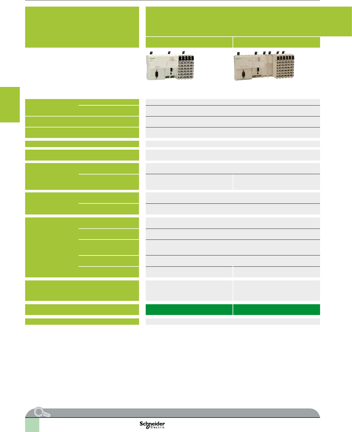
2
1
3
4
5
6
7
8
9
10
3/24
Selection guide Hardware control platforms
Modicon M258 logic controller
Compact base for Solutions with Application function
Blocks (AFB)
Applications Control solutions for
vPackaging
vConveying
vHoisting
vPumping
v...
42 digital I/O 42 digital I/O
+ 4 analog inputs
42 digital I/O 66 digital I/O
+ 4 analog inputs
User memory RAM 64 MB (program + data) 64 MB (program + data)
Flash 128 Mbytes 128 Mbytes
Typical Boolean instruction time 22 ns 22 ns
User program size 128 program K instructions 128 program K instructions
Power supply 24 V c24 V c
Channel connection With removable spring terminal blocks (supplied) With removable spring terminal blocks (supplied)
Inputs Digital 26 x 24 V c inputs including 8 counter inputs (100 kHz) 26 x 24 V c inputs including 8 counter inputs (100 kHz) 38 x 24 V c inputs including 8 counter inputs (100 kHz)
Analog – 4 inputs
+ 10 V/- 10 V, 4-20 mA/0-20 mA,
12-bit resolution
– 4 inputs
+ 10 V/- 10 V, 4-20 mA/0-20 mA,
12-bit resolution
Digital outputs Transistor 16 outputs (0.5 A) including 4 reex outputs 4 reex outputs (0.5 A) 28 outputs (0.5 A) including 4 reex outputs
Relay – 12 –
Built-in communication
ports
USB-B mini-port Programming port for SoMachine software Programming port for SoMachine software
USB-A port Connection of a USB memory stick for transferring programs, data les, rmware updates Connection of a USB memory stick for transferring programs, data les, rmware updates
RJ45 port (MBS)
RS232 serial link,
RS485 serial link (supplies 250 mA, 5 V for HMI power supply)
Protocols: Master/Slave Modbus ASCII/RTU, ASCII (character string)
RS232 serial link,
RS485 serial link (supplies 250 mA, 5 V for HMI power supply)
Protocols: Master/Slave Modbus ASCII/RTU, ASCII (character string)
SUB-D connector (male 9-way)
(CAN0)
Master CANopen bus (63 slaves) Master CANopen bus (63 slaves)
RJ45 port (Ethernet) Ethernet TCP IP, Web Server, FTP, Ethernet
Modbus TCP
Ethernet TCP IP Modbus slave, Web Server,
FTP
Ethernet TCP IP Modbus slave, Web Server, FTP
Optional communication ports – 2 PCI slots available on controller for optional
communication modules TM5 PCppp (1):
vModbus or ASCII serial link
vconnection to Probus DP bus (slave)
2 PCI slots available on controller for optional communication modules TM5 PCppp (1):
vModbus or ASCII serial link
vconnection to Probus DP bus (slave)
Logic controller type TM258 LF42DTS0 TM258 LF42DT4LS0 TM258 LF42DRS0 TM258 LF66DT4LS0
Page 3/32 3/32
(1) To be ordered separately, see page 4/8.
More technical information on www.schneider-electric.com
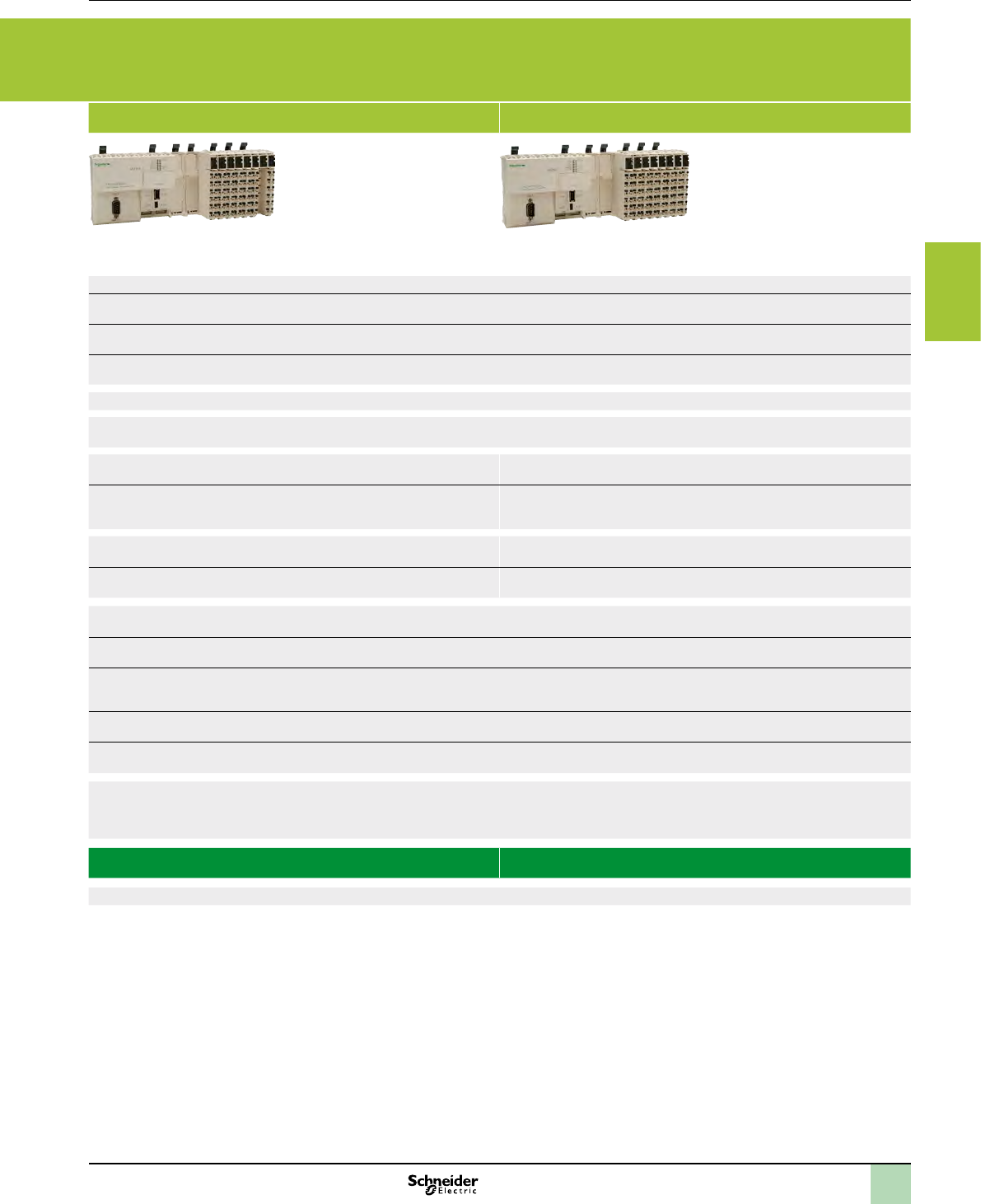
2
1
3
4
5
6
7
8
9
10
3/25
Applications Control solutions for
vPackaging
vConveying
vHoisting
vPumping
v...
42 digital I/O 42 digital I/O
+ 4 analog inputs
42 digital I/O 66 digital I/O
+ 4 analog inputs
User memory RAM 64 MB (program + data) 64 MB (program + data)
Flash 128 Mbytes 128 Mbytes
Typical Boolean instruction time 22 ns 22 ns
User program size 128 program K instructions 128 program K instructions
Power supply 24 V c24 V c
Channel connection With removable spring terminal blocks (supplied) With removable spring terminal blocks (supplied)
Inputs Digital 26 x 24 V c inputs including 8 counter inputs (100 kHz) 26 x 24 V c inputs including 8 counter inputs (100 kHz) 38 x 24 V c inputs including 8 counter inputs (100 kHz)
Analog – 4 inputs
+ 10 V/- 10 V, 4-20 mA/0-20 mA,
12-bit resolution
– 4 inputs
+ 10 V/- 10 V, 4-20 mA/0-20 mA,
12-bit resolution
Digital outputs Transistor 16 outputs (0.5 A) including 4 reex outputs 4 reex outputs (0.5 A) 28 outputs (0.5 A) including 4 reex outputs
Relay – 12 –
Built-in communication
ports
USB-B mini-port Programming port for SoMachine software Programming port for SoMachine software
USB-A port Connection of a USB memory stick for transferring programs, data les, rmware updates Connection of a USB memory stick for transferring programs, data les, rmware updates
RJ45 port (MBS)
RS232 serial link,
RS485 serial link (supplies 250 mA, 5 V for HMI power supply)
Protocols: Master/Slave Modbus ASCII/RTU, ASCII (character string)
RS232 serial link,
RS485 serial link (supplies 250 mA, 5 V for HMI power supply)
Protocols: Master/Slave Modbus ASCII/RTU, ASCII (character string)
SUB-D connector (male 9-way)
(CAN0)
Master CANopen bus (63 slaves) Master CANopen bus (63 slaves)
RJ45 port (Ethernet) Ethernet TCP IP, Web Server, FTP, Ethernet
Modbus TCP
Ethernet TCP IP Modbus slave, Web Server,
FTP
Ethernet TCP IP Modbus slave, Web Server, FTP
Optional communication ports – 2 PCI slots available on controller for optional
communication modules TM5 PCppp (1):
vModbus or ASCII serial link
vconnection to Probus DP bus (slave)
2 PCI slots available on controller for optional communication modules TM5 PCppp (1):
vModbus or ASCII serial link
vconnection to Probus DP bus (slave)
Logic controller type TM258 LF42DTS0 TM258 LF42DT4LS0 TM258 LF42DRS0 TM258 LF66DT4LS0
Page 3/32 3/32
(1) To be ordered separately, see page 4/8.
2
1
3
4
5
6
7
8
9
10
3/26
Presentation Hardware control platforms
Modicon M258 logic controller
Compact base for Solutions with Application function
Blocks (AFB)
The Modicon M258 logic controller is the compact base for Solutions with AFB using
pre-dened AFB libraries, high-performance and fully expandable PLC. It forms a part
of Flexible Machine Control approach, a key component of MachineStruxureTM, which
brings you maximum exibility and ensures the most optimised control solution.
This PLC is designed for machine manufacturers focusing on applications such as
packaging, conveying and storage, textiles and woodworking, hoisting, etc. It offers
high-performance solutions for speed control, counting, axis control and
communication functions.
Performance
In terms of performance, the Modicon M258 logic controller has a Dual-Core
processor:
bCore 1 is dedicated exclusively to managing program tasks and offers the maximum
resources for real-time execution of the application code.
bCore 2 is dedicated to executing communication tasks, which then have no further
impact on the application execution performance.
With an execution speed of 22 ns for a Boolean instruction i.e. more than 45,000
Boolean instructions per ms, the capacity to manage up to 2400 I/O, a 64 MByte
RAM memory that can store data and programs as well as a 128 MByte Flash
memory for application and data backup, the Modicon M258 logic controller
eliminates any doubts about the machine’s limits.
In developing the Modicon M258 logic controller, the cost aspect was taken into
account, the CPUs are equipped as standard with:
b42 or 66 digital I/O
bEmbedded serial link and Ethernet port
b4 analog inputs (TM258pppp4L references)
Development and technology
In all its characteristics, the Modicon M258 logic controller has been developed to
minimize the costs of assembly, cabling, commissioning and maintenance.
To this end:
bAll the modules have removable terminals.
bAll the electrical connections are made on spring terminals, speeding up the wiring
process and also avoiding the need for periodic retightening. In addition, each terminal
has a test point for a voltage sensing device.
bThe embedded serial link and Ethernet port on the Modicon M258 logic controller
have an RJ45 connection at 45° for quick visible connection of your communication
channels.
bThe modularity of the various bases and expansion modules has been optimized in
order to reduce signicantly the number of references to be ordered and assembled,
while ensuring the minimum investment in your conguration is necessary, thanks to a
capacity of 2 to 42 channels per expansion module.
bMechanical assembly of the various parts has been designed to save a
considerable amount of time during assembly.
Software conguration
Conguration and programming of all M258 logic controllers for Solutions with AFB
and equipment in Schneider Electric’s “Flexible Machine Control” concept are both
designed to cut costs and optimize machine performance.
Schneider Electric’s SoMachine software platform can be used to program M258
logic controllers for Solutions with AFB using:
bIEC 61131-3 programming languages: Instruction List (IL), Ladder Diagram (LD),
Function Block Diagram (FBD), Sequential Function Chart/Grafcet (SFC) and
Structured Text (ST)
bCFC (Continuous Function Chart) language.
PLCopen function blocks are used for managing motion control and axis control on
your machines.
Access to the hoisting libraries including all the specialised AFB, see page 2/2.
Integration in the Schneider Electric product offer
Combined with other products dedicated to machine manufacturers in the Schneider
Electric offer, such as ATV variable speed drives, Lexium servo drives, Magelis HMI
terminals, TeSys motor starters and contactors, the Modicon M258 logic controller is
now a must-have element in machine architectures, with hitherto unrivalled ease and
speed of installation.
Modicon M258 logic controller for Solutions with AFB
SoMachine software platform
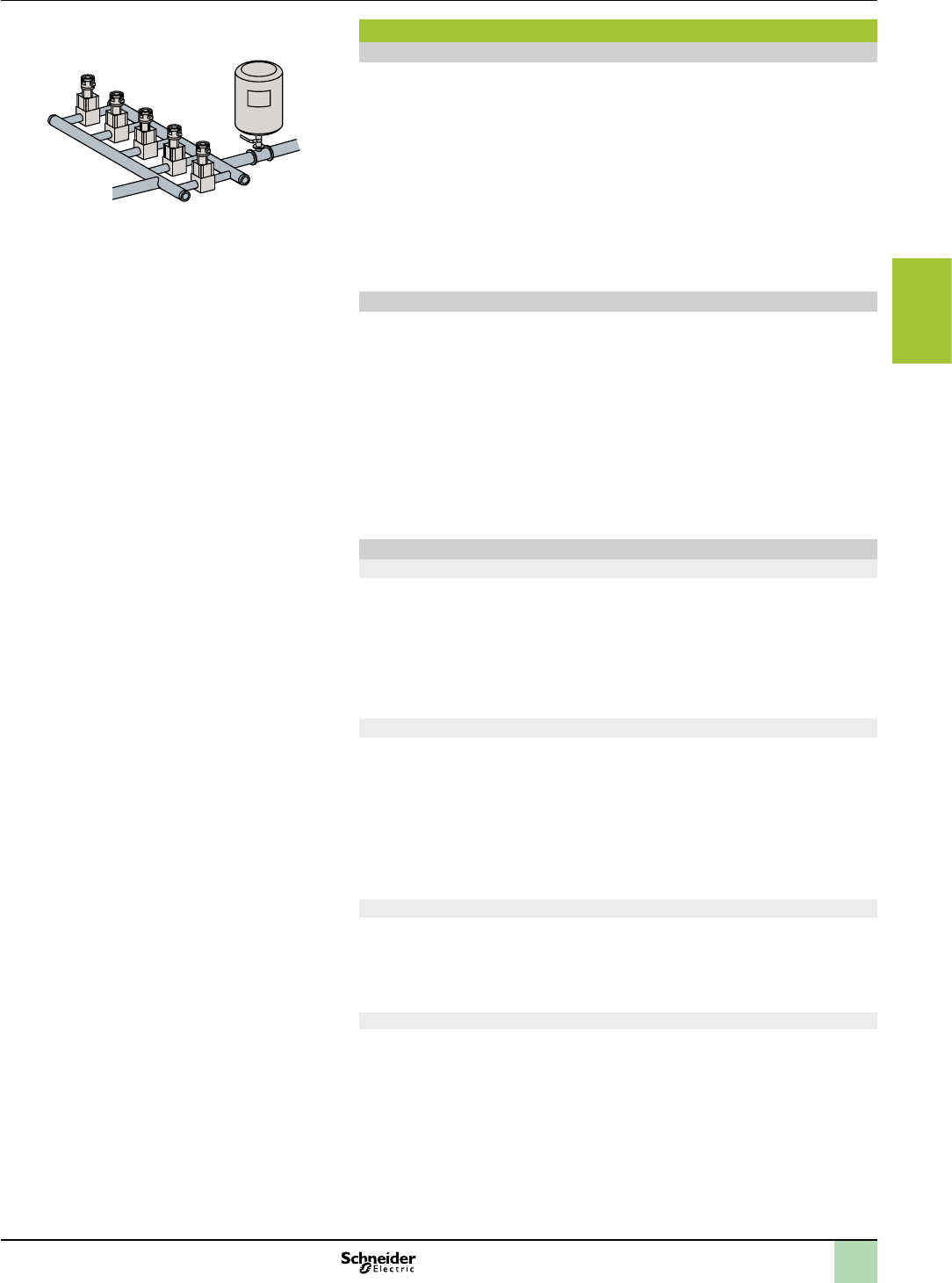
2
1
3
4
5
6
7
8
9
10
3/27
Presentation Hardware control platforms
Modicon M258 logic controller
Compact base for Solutions with Application function
Blocks (AFB)
Analog functions
Pressure ow control >
Functions
Analog functions
For machines that require functions to process data issued by analog sensors/
actuators (voltage or current), temperature sensors or PID control sensors, a
complete range of expansion modules as well as advanced programming functions
are included in the Modicon M258 logic controller for Solutions with AFB offer.
In order to minimize the number of product references of your machines, optimize
assembly time and cut costs, all M258 logic controllers for Solutions with AFB with
the reference TM258LFppp4LS0 include as standard 4 voltage or current analog
inputs with 12-bit resolution.
The different expansion modules are available in 2, 4, 6 or 8-channel versions and
with either 12 or 16-bit resolution.
The powerful performance of the M258 logic controller for Solutions with AFB enables
up to 200 analog I/O and/or temperature modules to be connected, thus extending the
limits of machine requirements.
High-speed counter function (HSC)
In order to meet requirements for machine productivity, the Modicon M258 logic
controller for Solutions with AFB has 8 embedded high-speed counters with a
counting frequency of 100 kHz for each channel as well as 4 reex outputs. The
availability of these embedded counters and also the presence of the Master
CANopen link in TM258LFppppS0 logic controllers for Solutions with AFB makes it
quick and easy to create low-cost, high-performance multi-axis functions that suit the
machines’ limitations.
With the availability of “PLCopen” function blocks specic to the motion control
functions in the SoMachine software, you can be sure that developing your
applications will be quick and reliable.
Moreover, a complete range of high-speed counter modules is available so you can
adapt your conguration to your machine’s specic requirements.
Communication functions
Ethernet
All M258 logic controller for Solutions with AFB references have an embedded RJ45
Ethernet port (10/100 Mbps, MDI/MDIX) with Ethernet TCP Modbus, Ethernet IP
Device, SoMachine on Ethernet, UDP, TCP and SNMP protocols.
In addition, all the M258 logic controllers for Solutions with AFB have an embedded
Web Server and FTP Server.
As well as the default address based on the MAC address, it is possible to assign a
controller IP address via a DHCP server or via a BOOTP server.
CANopen
Depending on the reference, M258 logic controllers for Solutions with AFB have an
embedded CANopen master.
The link can be congured between 125 Kbps and 1 Mbps and supports up to 63
slaves.
Architectures based on CANopen can be used to distribute I/O modules as close to
the sensors and actuators as possible, thus reducing wiring costs and times, and to
communicate with different devices such as variable speed drives, servo drives, etc.
The CANopen congurator is integrated in the SoMachine software and can also be
used to import standard description les in EDS format.
Modbus serial link
All M258 logic controllers for Solutions with AFB have as standard a serial link that
can be congured as either RS232/RS485 and incorporates the two most commonly
used protocols on the market:
vMaster or Slave Modbus ASCII/RTU
vCharacter string (ASCII)
Probus DP (Decentralized Peripherals)
The Modicon TM258LF42DT4LS0, TM258LF42DRS0 and TM258LF66DT4LS0 logic
controllers equipped with the TM5PCDPS communication module can be connected
to Probus bus: for controlling decentralized sensors, actuators or PLCs via a central
master controller
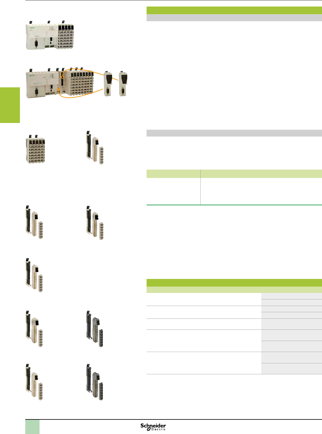
2
1
3
4
5
6
7
8
9
10
3/28
Presentation Hardware control platforms
Modicon M258 logic controller
Compact base for Solutions with Application function
Blocks (AFB)
TM258LF42DTS0 logic controller
for Solutions with AFB
TM5C compact blocks TM5SD digital modules
TM5SA and TM5SEAISG
analog modules
TM5SE Expert modules
TM5SPD Common
Distribution modules
TM5SPS Power Distribution
modules
TM5SBET1 transmitter
module
TM5SBER2 receiver module
TM258LD42DT4LS0 logic controller
for Solutions with AFB
TM5PCpp
communication
modules
Presentation
Range
The M258 logic controller for Solutions with AFB range is divided into two controller
sizes:
vTM258LF42DTS0 is 175 mm wide.
vTM258LF42DTS0, TM258LF42DT4LS0, TM258LF42DRS0 and
TM258LF66DT4LS0 are at least 237.5 mm wide as they have two free PCI slots for
optional Modicon TM5 communication modules (Modbus or ASCII serial link, and
connection to Probus DP bus).
The M258 logic controller for Solutions with AFB range is completed by an expansion
module offer:
vModicon TM5 Compact blocks
vModicon TM5 Digital modules
vModicon TM5 Digital/Analog module
vModicon TM5 Analog modules
vModicon TM5 Expert modules
vModicon TM5 Common Distribution modules
vModicon TM5 Power Distribution modules
vModicon TM5 Transmitter and receiver modules
Functions
The main component in a system is the controller: 4 M258 logic controller for
Solutions with AFB models are offered to cover different control requirements
(pressure, temperature, counting, speed, position control, motion, etc.).
M258 logic controller for Solutions with AFB and I/O modules are programmed with
the SoMachine software.
Reference Embedded functions
TM258LF42DTS0,
TM258LF42DT4LS0,
TM258LF42DRS0,
TM258LF66DT4LS0
b42 or 66 digital I/O including 8 high-speed counters (100 kHz)
bDepending on the reference, 4 voltage/current analog inputs
can be added
bUp to 16 independent axes
bCANopen master
All M258 logic controllers for Solutions with AFB have two groups of high-speed I/O
with, for each group:
vFour sink type high-speed inputs (up to 100 KHz), 2 standard inputs and 2 source
type high-speed outputs (up to 100 KHz) dedicated to HSC or PWM functions
vA high-speed input which can be used as an “Encoder capture input”
vTwo commons for the inputs
vOne common for the outputs
vA power supply (24 V c) consisting of 3 units:
- One for the CPU
- One for the high-speed I/O modules
- One for other modules (internal I/O Bus)
Conformity to standards
Type Performance
Surge immunity 24 VDC circuit EN/IEC 61000-4-5 1 kV in common mode
0.5 kV in differential mode
Surge immunity 230 VAC circuit EN/IEC 61000-4-5 2 kV in common mode
1 kV in differential mode
Induced electromagnetic eld EN/IEC 61000-4-6 10 Veff (0.15...80 MHz)
Conducted emission EN 55011 (IEC/CISPR11) 150...500 kHz,
quasi peak 79 dBμV
500 kHz...30 MHz,
quasi peak 73 dBμV
Radiated emission EN 55011 (IEC/CISPR11) 30...230 MHz,
10 m @ 40 dBμV/m
230 MHz...1 GHz,
10 m @ 47 dBμV/m
TM5SMM6D2L digital/Analog
module
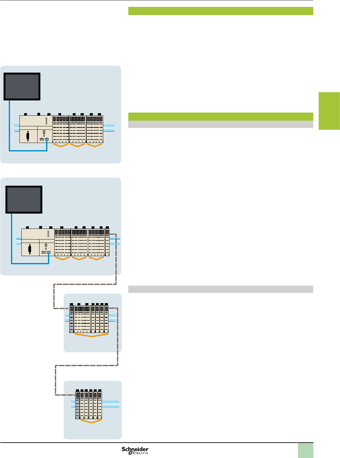
2
1
3
4
5
6
7
8
9
10
3/29
Presentation Hardware control platforms
Modicon M258 logic controller
Compact base for Solutions with Application function
Blocks (AFB)
2 3 3
1
Local I/O
Ethernet Modbus/TCP
I/O
expansion
Embedded
I/O
I/O
expansion
Assembly and mounting
The components of this system have been designed for simple interlocking
mechanical assembly.
An 8-way expansion bus connection (2 for the power supply, 2 for the bus and 4 for
the data) is used to distribute data and the power supply when assembling the
components: the M258 controller with compact blocks and modules (digital, digital/
analog, analog, Expert, common distribution, power distribution, expansion bus).
All the elements which make up the system are mounted and dismounted on a
symmetrical rail using the locking levers located on top of each device.
Wiring and maintenance of devices is simplied since they are tted with removable
spring terminals. The spring terminals are undone by pressing a locking tab.
The system is integrated into communication networks: all the connectors (RJ45,
USB, mini-USB and SUB-D type depending on the model) are accessible, as they
are located on the controller front panels.
Local or remote architecture
Local I/O
A PLC conguration can be local or remote. It consists of an M258 controller with its
embedded input and output channels, used in conjunction with compact blocks and/
or modules which are used to increase the number of channels and/or “Application-
specic” functions.
bCompact blocks represent a way of adding a large number of I/O with a single
reference. This possibility reduces both the cost per channel, and also assembly times.
These compact blocks are available in 4 references offering a high level of exibility in
congurations.
bI/O modules (a combination of a bus base, an electronic module and a terminal
block) complete this conguration and, being modular with between 2 and 12 channels,
make it possible to adjust the number of channels to exactly that required. Addition of
digital or analog modules, temperature or high-speed modules increases the
processing capabilities of applications.
Conguration of local I/O
1 XBTGT supervision graphic touch screen terminal
2 M258 controller for Solutions with AFB
3 Compact blocks or I/O modules
Remote I/O
Because of its backplane bus management, the TM5 system can be used to control
I/O remotely.
The same modules can be used in either a local and/or remote conguration, linked
together with expansion bus cables.
The total maximum distance between 2 remote islands is 100 m and the maximum
number of islands is 25, i.e. a total distance of up to 2500 m.
This function ensures a high level of exibility, while retaining synchronization of all
data acquisition, since all the expansion modules are on the same backplane bus.
Conguration of remote I/O
1 XBTGT supervision graphic touch screen terminal
2 M258 controller for Solutions with AFB
3 Compact blocks or I/O modules
4 Transmitter modules
5 Receiver modules
6 TM5 expansion bus cables
7 Common distribution modules
24
5
6
6
1
3 7 3 4
533 7 3 7
3 3
3
Ethernet Modbus/TCP
I/O
expansion
Embedded
I/O
Remote I/O
expansion
Remote I/O
expansion
I/O
expansion
Remote I/O
Remote I/O
2
1
3
4
5
6
7
8
9
10
3/30
Presentation Hardware control platforms
Modicon M258 logic controller
Compact base for Solutions with Application function
Blocks (AFB)
Communication
M258 logic controllers for Solutions with AFB have the following built-in
communication ports:
References Communication ports Use
TM258LF42DTS0,
TM258LF42DT4LS0,
TM258LF42DRS0,
TM258LF66DT4LS0
1 x RJ45
Congurable as RS232 or RS485
ASCII or RTU exchange with
Modbus communication protocol
1 x RJ45 (MDI/MDIX port) vFTP server
vWeb server
vModbus TCP server
vModbus TCP client
vManager SoMachine
vSNMP
vEthernet IP device
vModbus device
1 x USB-A Connection of a USB memory stick
for transferring (uploading/
downloading) programs, data and/
or rmware
1 x mini-USB Programming port (480 Mbps)
1 x 9-way male SUB-D Master CANopen connection
2 PCI slots for communication
modules = 2 x 9-way male SUB-D
Addition of optional communication
modules for a serial link and a
connection on the bus Probus DP
(1)
Embedded Ethernet
M258 logic controllers for Solutions with AFB have an embedded Ethernet link via a
direct connection to their RJ45 port.
vSpeed: “10 BaseT” and “100 BaseTX” with auto-negotiation
vRJ45 port (MDI/MDIX): automatic adaptation to a straight or crossed cable
References Protocols Number of connections
TM258LF42DTS0,
TM258LF42DT4LS0,
TM258LF42DRS0,
TM258LF66DT4LS0
Modbus server 8
Modbus device 2
SoMachine 3 (2)
Ethernet IP device 16
FTP server 4
Web server 10
(1) Only on TM258LF42DT4LS0, TM258LF42DRS0 and TM258LF66DT4LS0.
(2) The Oscilloscope function uses one connection
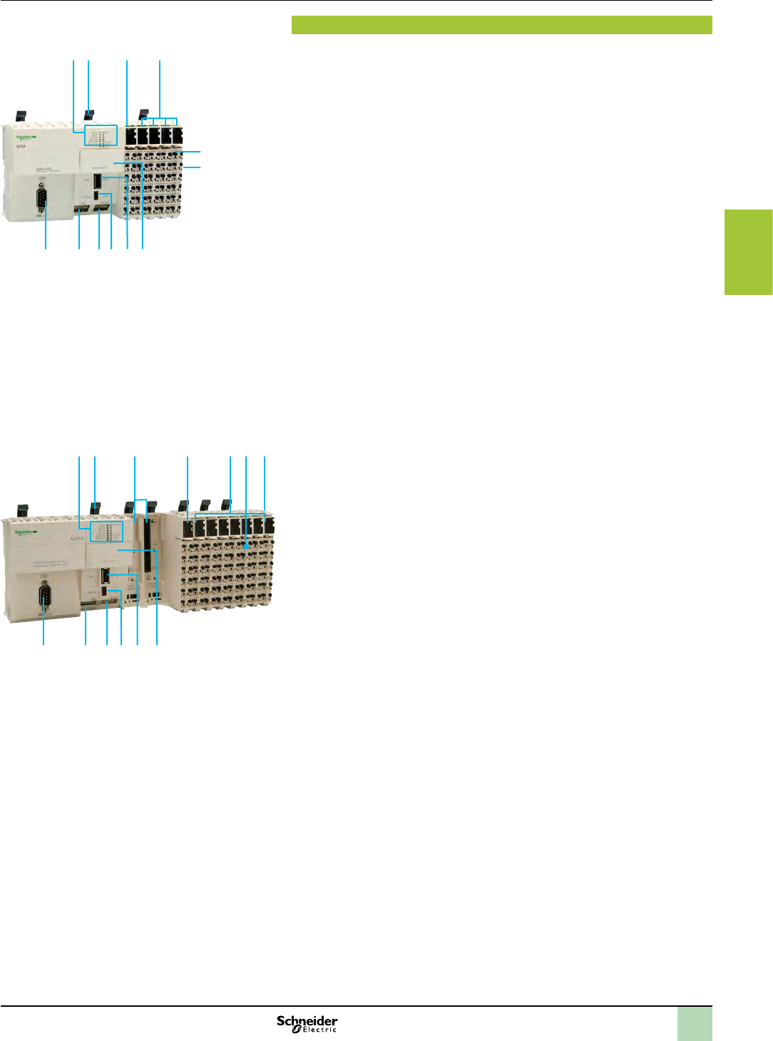
2
1
3
4
5
6
7
8
9
10
3/31
Description Hardware control platforms
Modicon M258 logic controller
Compact base for Solutions with Application function
Blocks (AFB)
1 2 3
7891011
4
6
12
5
1 2
9111213
54 6 7
8
10
3
Description
The TM258LF42DTS0 logic controller for Solution comprises:
1 A display block with:
- 4 controller status LEDs (RUN/MS, BATTERY, APP0 and APP1)
- 6 built-in communication port status LEDs (Eth LA, Eth ST, Eth NS, USB Host,
MBS COM, CAN 0 STS)
2 Locking lever for mounting/dismounting on 5 symmetrical rail.
3 A 24 V c power supply module with removable terminal block and locking lever,
display block and slot for a label.
4 I/O modules, each one with: a removable terminal block with locking lever, a
display block showing the I/O states and a slot for a label-holder.
5 Removable terminal block with locking lever for locking/unlocking.
6 On the side, an expansion bus connection for the link with the next module.
7 A slot for the RTC (Real Time Clock) battery.
8 A USB-A connector (marked Host) for connection of a USB memory stick for
transferring programs, data or rmware updates.
9 A USB-B mini-connector (marked Pgr Port) for connection to the programming
PC
10 An RJ45 connector (marked Ethernet) for connection to the Ethernet network
and/or connection to the Magelis XBTGT graphic terminal.
11 An RJ45 connector (marked MBS) for the RS232 or RS485 serial link.
12 A 9-way male SUB-D connector, marked CAN 0, for connection to the CANopen
bus.
The TM258LF42DT4LS0 / LF42DRS0 / LF66DT4LS0 logic controllers for
Solutions with AFB comprise:
1 A display block with:
- 4 controller status LEDs (RUN/MS, BATTERY, APP0 and APP1)
- 6 built-in communication port status LEDs (Eth LA, Eth ST, Eth NS, USB Host,
MBS COM, CAN 0 STS)
2 Locking lever for mounting/dismounting on 5 symmetrical rail.
3 Two free PCI slots for the communication module.
4 A 24 V c power supply module with removable terminal block and locking lever,
display block and slot for a label.
5 I/O modules, each one with: a removable terminal block with locking lever, a
display block showing the I/O states and a slot for a label-holder.
6 Removable terminal block with locking lever for locking/unlocking.
7 On the side, an expansion bus connection for the link with the next module.
8 A slot for the RTC (Real Time Clock) battery.
9 A USB-A connector (marked Host) for connection of a USB memory stick for
transferring programs, data or rmware updates.
10 A USB-B mini-connector (marked Pgr Port) for connection to the programming
PC.
11 An RJ45 connector (marked Ethernet) for connection to the Ethernet network
and/or connection to the Magelis XBTGT graphic terminal.
12 An RJ45 connector (marked MBS) for the RS232 or RS485 serial link.
13 A 9-way male SUB-D connector, marked CAN 0, for connection to the CANopen
bus.
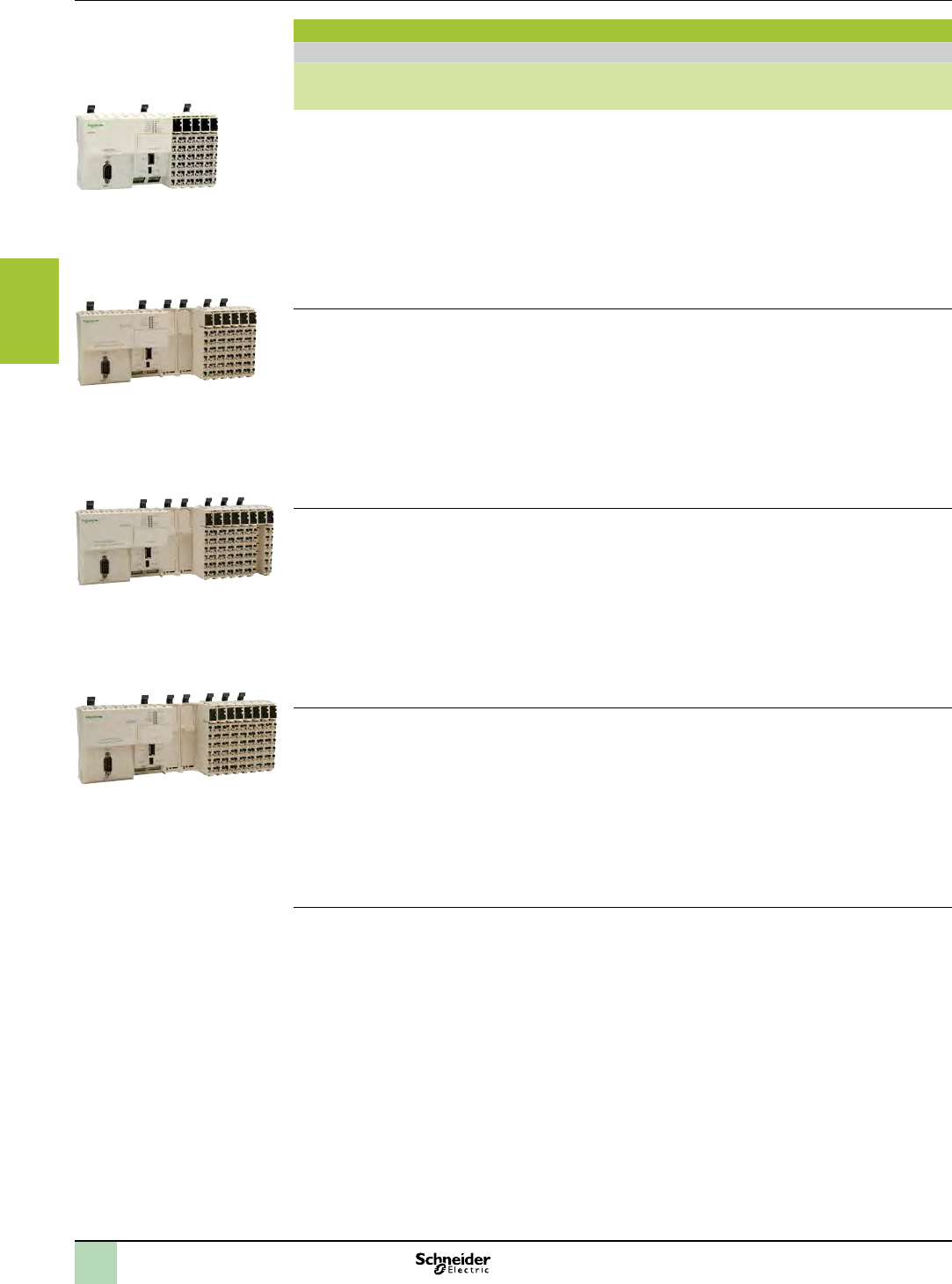
2
1
3
4
5
6
7
8
9
10
3/32
References Hardware control platforms
Modicon M258 logic controller
Compact base for Solutions with Application function
Blocks (AFB)
TM258LF42DTS0
TM258LF42DT4LS0
TM258LF42DRS0
TM258LF66DT4LS0
References
Logic controllers, Compact base for solutions with AFB, 24 V c power supply (1)
Nbr.
of I/O
Inputs Outputs Built-in communication ports Reference Weight
kg
lb
42 I/O b26 x 24 V c
digital inputs
including 8 counter
inputs (100 kHz)
b16 transistor
digital outputs
(0.5 A)
including 4 reex
outputs
v1 RJ45 port: Ethernet
v1 SUB-D port (9-way male):
CANopen master
v1 USB-A port: program transfer
v1 USB-B mini-port: software
programming
v1 RJ45 port: RS232/RS485 serial
link
TM258LF42DTS0 0.550
1.213
42 + 4
I/O
b26 x 24 V c
digital inputs
including 8 counter
inputs (100 kHz)
b4 analog inputs
10 V/- 10 V,
4-20 mA/0-20 mA,
12-bit resolution
b16 digital
transistor outputs
(0.5 A)
including 4 reex
outputs
v1 RJ45 port: Ethernet
v1 SUB-D port (9-way male):
CANopen master
v1 USB-A port: program transfer
v1 USB-B mini-port: software
programming
v1 RJ45 port: RS232/RS485 serial
link
v+ 2 free PCI slots for optional
communication modules (2): RS232/
RS485 serial link and Probus DP bus
TM258LF42DT4LS0 0.770
1.698
42 I/O b26 x 24 V c
digital inputs
including 8 counter
inputs (100 kHz)
b4 digital
transistor (reex)
outputs (0.5 A)
b12 relay outputs
v1 RJ45 port: Ethernet
v1 SUB-D port (9-way male):
CANopen master
v1 USB-A port: program transfer
v1 USB-B mini-port: software
programming
v1 RJ45 port: RS232/RS485 serial
link
v+ 2 free PCI slots for optional
communication modules (2): RS232/
RS485 serial link and Probus DP bus
TM258LF42DRS0 0.800
1.764
66 + 4
I/O
b38 x 24 V c
digital inputs
including 8 counter
inputs (100 kHz)
b4 analog inputs
+ 10 V/- 10 V,
4-20 mA/0-20 mA,
12-bit resolution
b28 digital
transistor outputs
(0.5 A)
including 4 reex
outputs
v1 RJ45 port: Ethernet
v1 SUB-D port (9-way male):
CANopen master
v1 USB-A port: program transfer
v1 USB-B mini-port: software
programming
v1 RJ45 port: RS232/RS485 serial
link
v+ 2 free PCI slots for optional
communication modules (2): RS232/
RS485 serial link and Probus DP bus
TM258LF66DT4LS0 0.800
1.764
(1) The Modicon M258 logic controllers type S Solutions with AFB require a power supply with a nominal voltage of 24 V c.
The 24 V c power supply must be rated Separated Extra Low Voltage (SELV-rated) according to IEC 61140.
The SELV-rating means that SELV isolation is provided between the electrical input and output of the power supply.
(2) To be ordered separately see page 4/8.
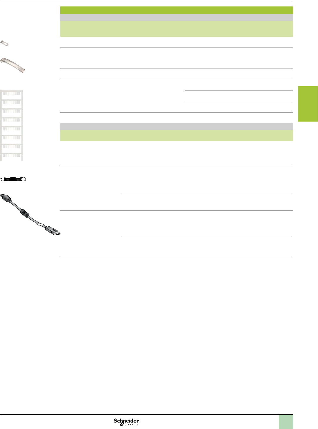
2
1
3
4
5
6
7
8
9
10
3/33
References (continued) Hardware control platforms
Modicon M258 logic controller
Compact base for Solutions with Application function
Blocks (AFB)
TM5ACTCH100
TM5ACTLC100
TM5ACLITW1
TM5ACLT1
References
Accessories
Type Used for Colour Sold in
lots of
Unit
reference
Weight
kg
lb
Plain text cover holder
(label-holder)
Marking the terminal blocks on the
I/O channels
Transparent 100 TM5ACTCH100 0.002
0.004
Plain text cover holder locking
clip
(Order with plain text cover
holder TM5ACTCH100)
Locking plain text cover holder
TM5 ACTCH100
Transparent 100 TM5ACTLC100 0.001
0.002
Precut legend strips of paper Plain text cover holder
TM5ACTCH100
White 100 TM5ACTLS100 0.001
0.002
Coloured plastic
identiers
Labelling 16 connection channel
terminals
White 1TM5ACLITW1 0.015
0.033
Red 1TM5ACLITR1 0.015
0.033
Blue 1TM5ACLITB1 0.015
0.033
Metal tool Inserting/removing TM5 ACLITp1
identiers
Black 1TM5ACLT1 0.030
0.066
Connection cables
Description Use from
to
Length Reference Weight
kg
Software programming cable
Baud rate: 480 Mbps max.
Protocol: Modbus, HTTP, FTP,
Codesys or virtual, non-isolated
PC USB port USB mini-port on M258
controllers
3 m
9.843 in.
TCSXCNAMUM3P 0.065
0.143
RS485 serial link cables
Modbus protocol
SUB-D port (25-way) on
Small Panel compact
display units: XBTN401,
XBTN410, XBTR410,
XBTR411, XBTGT2...
GT7
RJ45 port on M258
controllers
1.8 m
5.906 in.
XBTZ938 0.230
0.507
RJ45 port on XBTGT
graphic touch screen
terminals
RJ45 port on M258
controllers
2.5 m
8.220 in.
XBT9980 0.230
0.507
RS232 serial link cables
Character mode
SUB-D port (9-way
female) on DTE
equipment (1): printer,
hand-held bar code
reader, etc.
RJ45 port on M258
controllers
3 m
9.843 in.
TCSMCN3M4F3C2 0.150
0.331
SUB-D port (9-way
female) on DCE
equipment (2): GSM
modem
RJ45 port on M258
controllers
3 m
9.843 in.
TCSMCN3M4M3S2 0.150
0.331
(1) DTE: Data Terminal Equipment.
(2) DCE: Data Communication Equipment.
TCSXCNAMUM3P

2
1
3
4
5
6
7
8
9
10
3/34
Selection guide Hardware control platforms
I/O expansion modules for Hardware platform
control
Local and remote I/O expansion modules
Distributed I/O expansion modules
Local and remote I/O expansion modules
Applications Local I/O (IP 20) Local and/or remote I/O (IP 20) Remote I/O expansion bus (IP 67)
Compatibility bModicon M238 logic controller type S Solutions with AFB
bXBTGC HMI controllers
bModicon OTB
bModicon M258 logic controller type S Solutions with AFB bModicon M258 logic controller type S Solutions with AFBs
I/O type Digital Analog Digital Analog Digital/analog Digital Analog
Remote I/O conguration Hardware – –
Bus type – –
Inputs Number (depending on
model)
4 to 32 inputs 2 to 8 inputs 2 to 12 inputs 2 to 6 inputs Digital: 12 to 14 inputs
Analog: 4 inputs
8 to 16 inputs 2 to 4 inputs
Type (depending on model) 24 V c
120 V aVoltage,
Current,
Temperature
24 V c
100/120 V a,
100/240 V a
Voltage,
Current,
Temperature
Digital: 24 V c
Analog: Voltage,
Current
24 V cVoltage,
Current,
Temperature
Resistance
Outputs Number (depending on
model)
8 to 32 outputs 1 to 2 outputs 2 to 12 outputs 2 to 4 outputs Digital: 6 to 18 outputs
Analog: 2 outputs
8 to 16 outputs 2 to 4 outputs
Type (depending on model) 24 V c transistor,
Relay
0…10 V,
± 10 V,
4…20 mA
24 V c
30/230 V a,
100/240 V a
- 10…+ 10 V,
0…20 mA
Digital: 24 V c
Analog: Voltage/Current
24 V c
Transistor/Source
- 10…+ 10 V,
0…20 mA
Type of expansion module Modicon TM2 digital module Modicon TM2 analog module Modicon TM5 digital module Modicon TM5 analog module Modicon TM5 compact block Modicon TM7 digital block Modicon TM7 analog block
More information Please consult on our web site www.schneider-electric.com Please consult on our web site www.schneider-electric.com
(1) Modicon TM5 transmitter/receiver modules, please consult our web site www.schneider-electric.com
Distributed I/O expansion modules
Applications Optimum distributed I/O (IP 20)
Compatibility bModicon M238 logic controller type S Solutions with AFBs
bXBTGC HMI controller
bAltivar IMC drive controller card type S solutions with AFB
Available buses and networks bEthernet Modbus TCP/IP
bCANopen bus
bModbus serial link (RS 485)
Conguration with
I/O expansion modules
Module type Modicon TM2:
vDigital I/O modules
vAnalog I/O modules
vCommon distribution modules
Capacity For 1 Modicon OTB interface module: 7 Modicon TM2 modules max. including:
vDigital I/O modules:
- 132 I/O max. with modules with screw terminals
- 188 I/O max. with modules with spring terminals
- 244 I/O max. with modules with HE10 connector
vAnalog I/O modules with screw terminals: up to 7 x 8 inputs, or 7 x 2 outputs, or 7 x (4I/2O)
vCommon distribution module
Integrated I/O Number and type
(depending on model)
12 x 24 V c digital inputs
2 x 24 V c solid state outputs
6 x 30 V c/240 V a relay outputs
2 channels: 5 kHz/20 kHz
2 PWM function channels
Type of distributed I/O expansion module Modicon OTB interface modules
More information Please consult on our web site www.schneider-electric.com
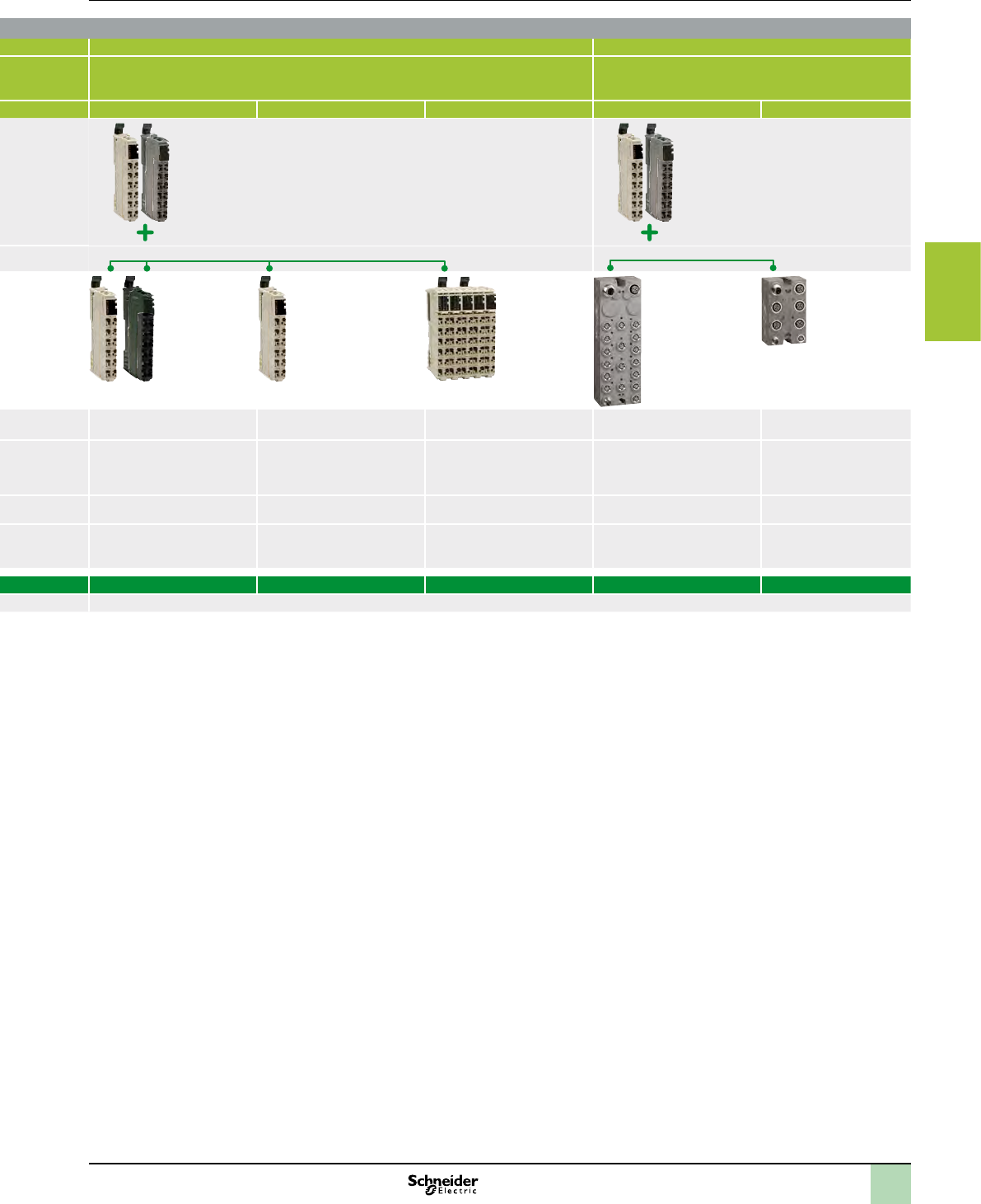
2
1
3
4
5
6
7
8
9
10
3/35
Local and remote I/O expansion modules
Applications Local I/O (IP 20) Local and/or remote I/O (IP 20) Remote I/O expansion bus (IP 67)
Compatibility bModicon M238 logic controller type S Solutions with AFB
bXBTGC HMI controllers
bModicon OTB
bModicon M258 logic controller type S Solutions with AFB bModicon M258 logic controller type S Solutions with AFBs
I/O type Digital Analog Digital Analog Digital/analog Digital Analog
Remote I/O conguration Hardware – –
Modicon TM5 transmitter/receiver:
For use with remote I/O (1)
Modicon TM5 transmitter/receiver:
Required (1)
Bus type – – TM5 expansion bus TM7 expansion bus
Inputs Number (depending on
model)
4 to 32 inputs 2 to 8 inputs 2 to 12 inputs 2 to 6 inputs Digital: 12 to 14 inputs
Analog: 4 inputs
8 to 16 inputs 2 to 4 inputs
Type (depending on model) 24 V c
120 V aVoltage,
Current,
Temperature
24 V c
100/120 V a,
100/240 V a
Voltage,
Current,
Temperature
Digital: 24 V c
Analog: Voltage,
Current
24 V cVoltage,
Current,
Temperature
Resistance
Outputs Number (depending on
model)
8 to 32 outputs 1 to 2 outputs 2 to 12 outputs 2 to 4 outputs Digital: 6 to 18 outputs
Analog: 2 outputs
8 to 16 outputs 2 to 4 outputs
Type (depending on model) 24 V c transistor,
Relay
0…10 V,
± 10 V,
4…20 mA
24 V c
30/230 V a,
100/240 V a
- 10…+ 10 V,
0…20 mA
Digital: 24 V c
Analog: Voltage/Current
24 V c
Transistor/Source
- 10…+ 10 V,
0…20 mA
Type of expansion module Modicon TM2 digital module Modicon TM2 analog module Modicon TM5 digital module Modicon TM5 analog module Modicon TM5 compact block Modicon TM7 digital block Modicon TM7 analog block
More information Please consult on our web site www.schneider-electric.com Please consult on our web site www.schneider-electric.com
(1) Modicon TM5 transmitter/receiver modules, please consult our web site www.schneider-electric.com
Distributed I/O expansion modules
Applications Optimum distributed I/O (IP 20)
Compatibility bModicon M238 logic controller type S Solutions with AFBs
bXBTGC HMI controller
bAltivar IMC drive controller card type S solutions with AFB
Available buses and networks bEthernet Modbus TCP/IP
bCANopen bus
bModbus serial link (RS 485)
Conguration with
I/O expansion modules
Module type Modicon TM2:
vDigital I/O modules
vAnalog I/O modules
vCommon distribution modules
Capacity For 1 Modicon OTB interface module: 7 Modicon TM2 modules max. including:
vDigital I/O modules:
- 132 I/O max. with modules with screw terminals
- 188 I/O max. with modules with spring terminals
- 244 I/O max. with modules with HE10 connector
vAnalog I/O modules with screw terminals: up to 7 x 8 inputs, or 7 x 2 outputs, or 7 x (4I/2O)
vCommon distribution module
Integrated I/O Number and type
(depending on model)
12 x 24 V c digital inputs
2 x 24 V c solid state outputs
6 x 30 V c/240 V a relay outputs
2 channels: 5 kHz/20 kHz
2 PWM function channels
Type of distributed I/O expansion module Modicon OTB interface modules
More information Please consult on our web site www.schneider-electric.com

chapter 4
Communication
All technical information about products listed in this chapter
are available on www.schneider-electric.com

2
1
3
4
5
6
7
8
9
10
Contents Communication
bModbus and Character mode serial link
vModicon TM5 communication modules for Modbus serial link dedicated to
Modicon M258 logic controller, compact base for Solutions with AFB
vCabling system for Modicon M238 & M258 logic controllers,
compact bases for Solutions with AFB
bEthernet Modbus/TCP network
vCabling system for Hardware platform controllers
vTwidoPort interface module for Modicon M238 logic controller, compact
base for Solutions with AFB
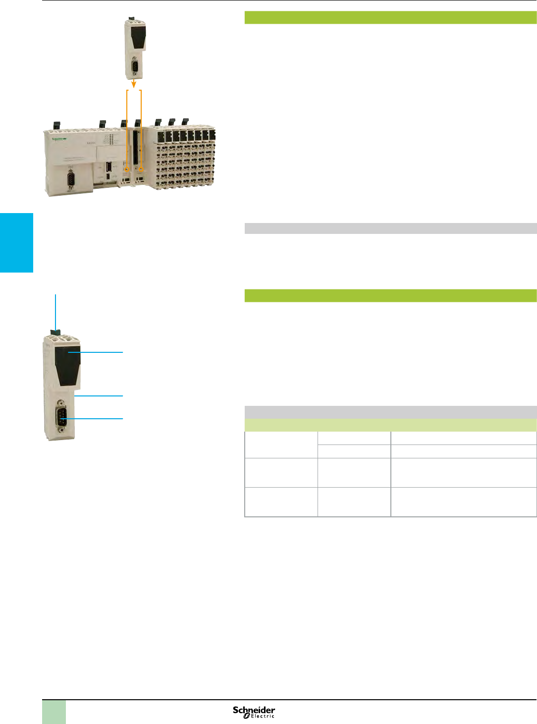
2
1
3
4
5
6
7
8
9
10
Presentation,
description
Communication
Presentation
TM5 PCRSp
TM5 PCppp
Nota: the maximum number of communication modules is 2.
Modbus and Character mode serial links
Description
TM5 PCRSp
1
2
3
4
Serial link
LED Colour Status: on
v
v
v
v
TM5 PCRSp communication module: for mounting the two free
PCI slots in the M258 logic controller
1
2
3
4
or
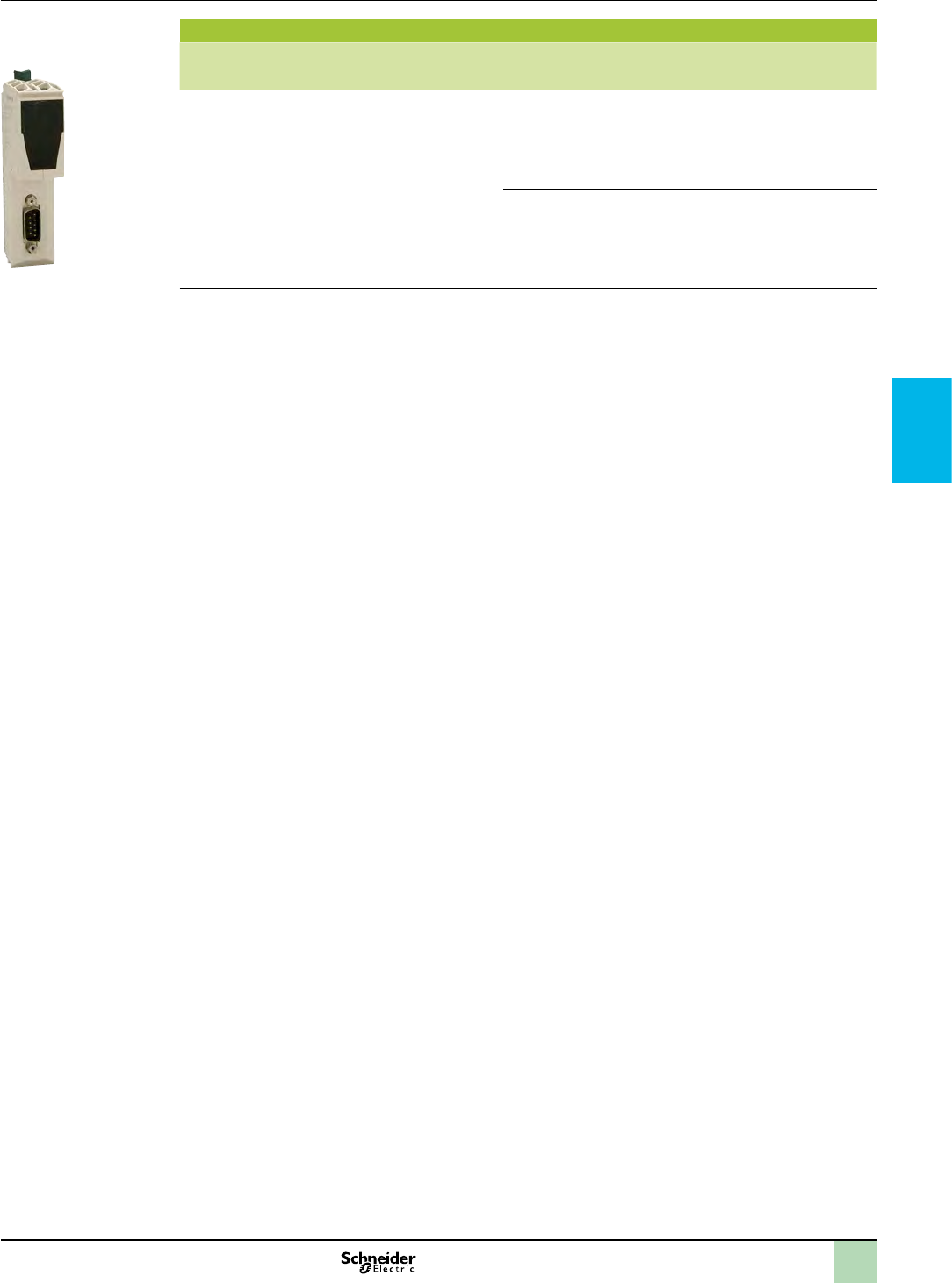
2
1
3
4
5
6
7
8
9
10
References Communication
References
Description Used for Physical
layer/
protocols
Built-in port Reference Weight
kg
lb
Modbus serial link
communication modules
v
v
v
v
TM5PCRS2
0.141
TM5PCRS4
0.141
TM5 PCRSp
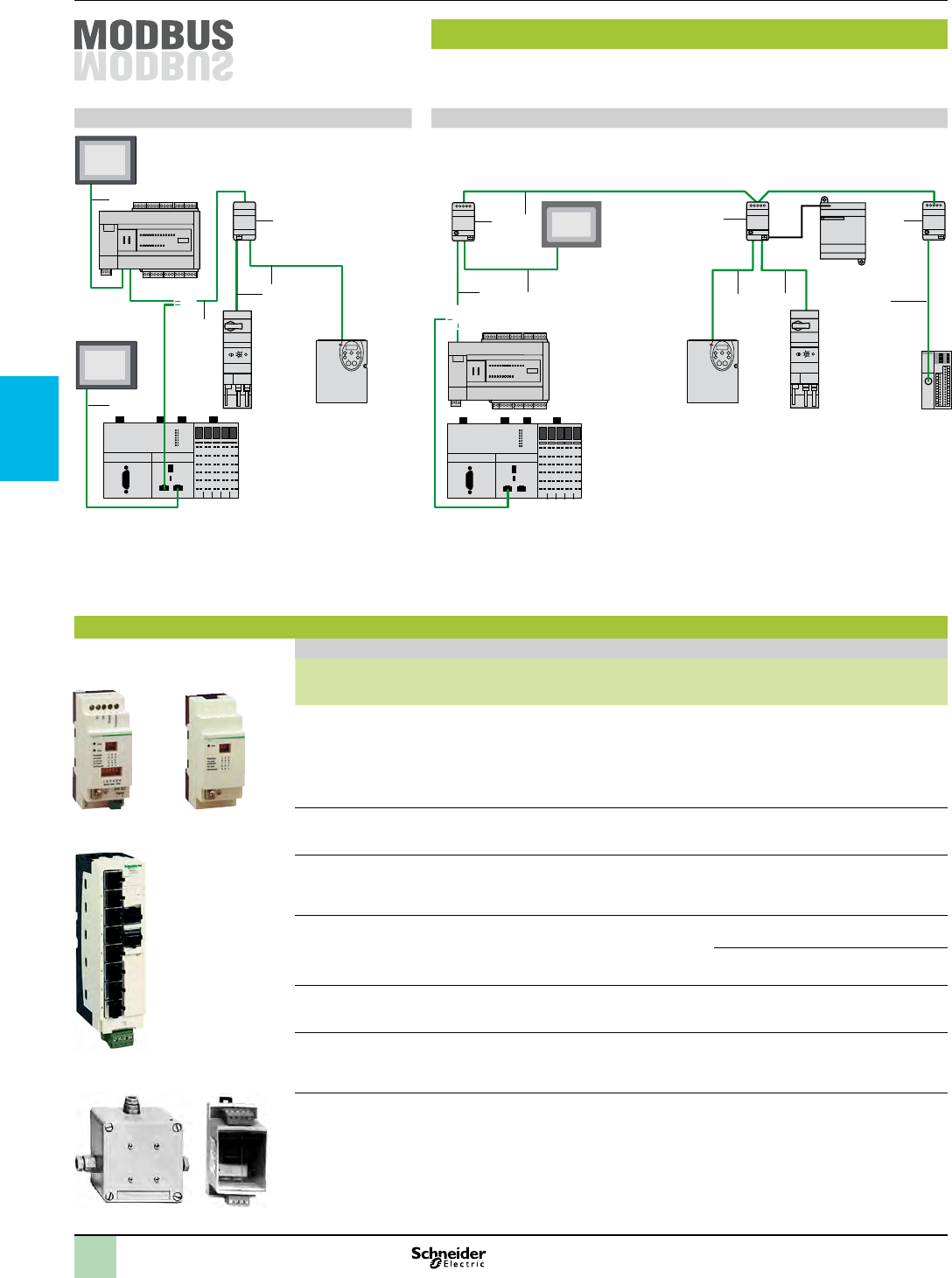
2
1
3
4
5
6
7
8
9
10
Communication
Connections,
references
Modbus cabling system
Non isolated link Isolated link
7
11
4
4
1
6
3
2
5
4
4
c 24 V
4
7
Length of cables between Modicon M238S/M258S and Altivar 212:
y 30 m max. (98.425 ft max.)
g Line polarization active
b Line termination
Total length of cables between isolation boxes 1: y 1000 m (3280.840 ft)
Length of tap cables 4, 5 or 6: y 10 m (32.808 ft)
bg b b
or
or
References
Tap-off and adapter components for RS 485 serial link
Description Application Item Length Reference Weight
kg
lb
Tap isolation box
(1)
Ω
Ω
c
c
5
1TWDXCAISO
0.220
Tap junction box
Ω
Ω
5
2TWDXCAT3RJ
0.176
Modbus hub
5
–LU9GC3
1.102
T-junction boxes
–
VW3A8306TF03
VW3A8306TF10
Passive tap
junction box
–TSXSCA50
1.146
RS 232C/RS 485
line converter
c
5
–XGSZ24
0.220
(1) Line isolation recommended for distances > 10 m (32.808 ft)
TWD XCA ISO TWD XCA T3RJ
LU9 GC3
TSX SCA 50 XGS Z24

2
1
3
4
5
6
7
8
9
10
References (continued) Communication
References
Connection cables for RS 485 serial link
Description Application Item Length Unit reference Weight
kg
lb
Main cables
double shielded
twisted pair
RS 485
3
TSXCSA100
12.522
TSXCSA200
24.074
TSXCSA500
66.139
Modbus cordsets
RS 485
4
VW3A8306R03
0.066
VW3A8306R10
0.110
VW3A8306R30
0.331
–
TWDXCAFJ010
0.132
VW3A8306D30
0.331
–
TWDXCARJ003
0.088
TWDXCARJ010
0.198
TWDXCARJ030
0.353
(1) (2)
5
TWDXCARJP03
0.060
(2) (3)
–
TWDXCARJP03P
0.060
–
TWDXCAFD010
0.137
TSXCX100
1.140
Modicon M238
cordsetsto
Magelis HMI terminal
7
XBTZ9980
0.331
6, 7
XBTZ938
0.463
7
XBTZ9008
0.331
Cordsets for Magelis
STU
7
VW3A8306R30
0.331
Line end adapter
Ω
–
VW3A8306RC
0.441
Connection cables for RS 232 serial link
Description Application Length Reference Weight
kg
lb
Cordset for
DTE terminal
(4)
TCSMCN3M4F3C2
0.331
Cordset for
DCE terminal
TCSMCN3M4M3S2
0.331
(1) Forcing the conguration of RS 485 integrated port with TwidoSuite programming protocol parameters.
(2) Carries c 5 V voltage (supplied by RS 485 integrated port of Twido controller ) for TWD XCA ISO tap isolation box (not
using the c 5 V external power supply).
(3) Allows the using of RS 485 integrated port with the parameters dened in conguration.
(4) If the terminal is equipped with a 25-way SUB-D connector, Please order a SUB-D 25-way female/9-way male adapter
TSX CTC 07 as well.
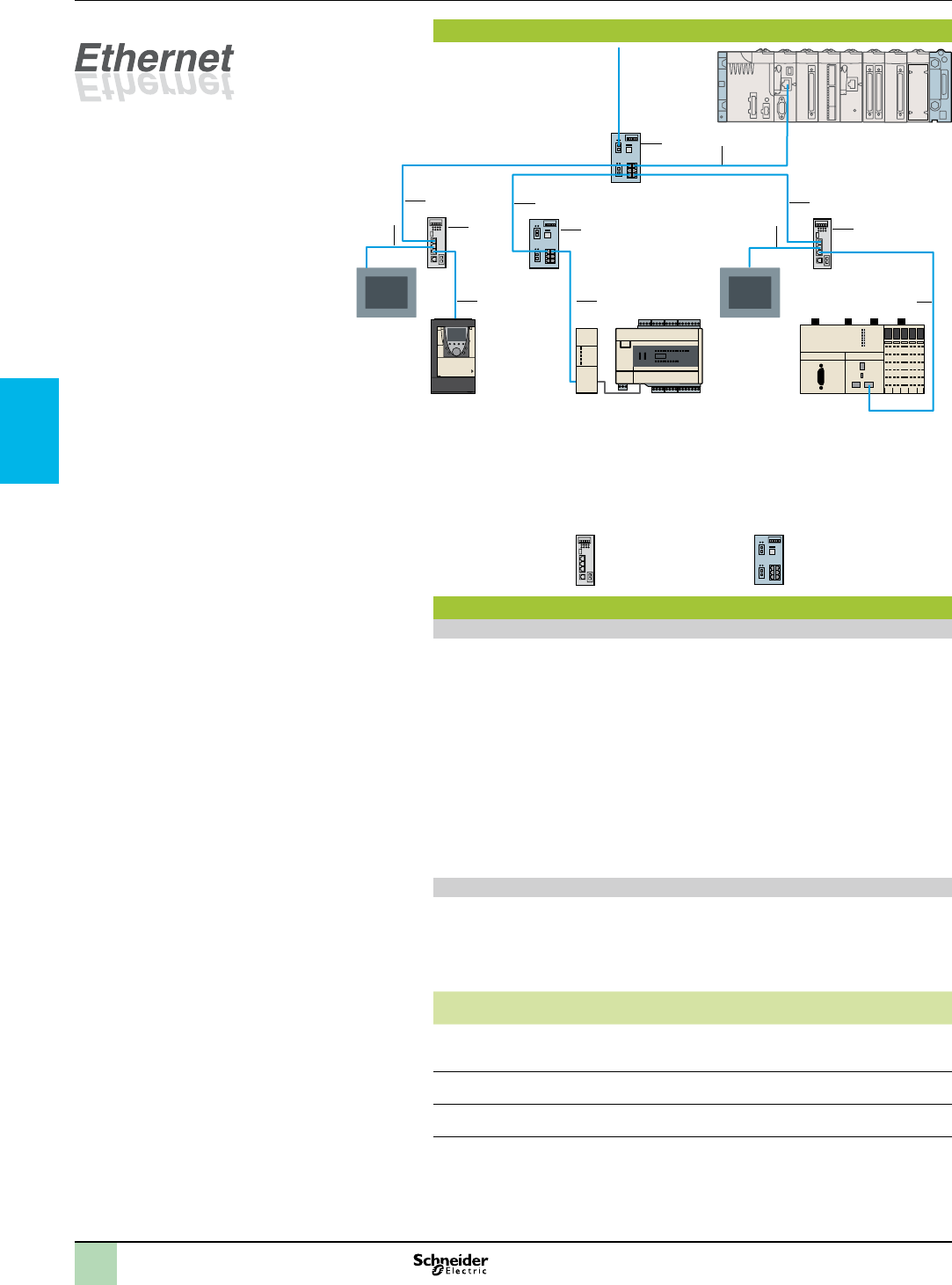
2
1
3
4
5
6
7
8
9
10
Connections,
references
Communication
Ethernet Modbus/TCP or Ethernet IP network architecture
1
2
1
4
3
4
4
1
1
2
3
1
2
1
3
M238STwidoPort
Interface
M258S
XBT GCXBT GC
Altivar IMC drive
controller for
Solutions with
AFB
+ Altivar 61
M340
Optical fibre
References (1)
Shielded copper connection cables
bShielded twisted pair copper cables to standard EIA/TIA 568
v
v
v
v
v
bShielded twisted pair copper cables, UL and CSA 22.1 approved
v
“Do It Yourself” cable and connectors
Description Characteristics Length Reference Weight
kg
Ethernet copper cable
TCSECN300R2
RJ 45 connector
TCSEK3MDS
M12 connector
TCSEK1MDRS
(1) For other versions (optical bre, switches,…), please consult our site www.schneider-electric.com
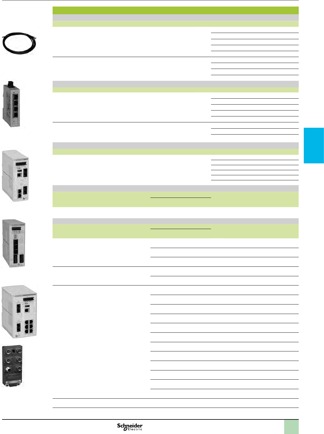
2
1
3
4
5
6
7
8
9
10
References (continued) Communication
References
Shielded twisted pair cables to standard EIA/TIA568
Description Pre-formed at both ends Item Length Reference Weight
Straight cables
1 490NTW00002
490NTW00005
490NTW00012
490NTW00040
490NTW00080
Crossover cables
2 490NTC00005
490NTC00015
490NTC00040
490NTC00080
Shielded twisted pair cables, UL and CSA 22.1 approved
Description Pre-formed at both endsItem Length Reference Weight
Straight cables
1 490NTW00002U
490NTW00005U
490NTW00012U
490NTW00040U
490NTW00080U
Crossover cables
2 490NTC00005U
490NTC00040U
490NTC00080U
Shielded twisted pair cable for IP 67 switch
Description Pre-formed at both endsItem Length Reference Weight
Straight cables
– TCSECL1M3M1S2
TCSECL1M3M3S2
TCSECL1M3M5S2
TCSECL1M3M10S2
TCSECL1M3M25S2
TCSECL1M3M40S2
ConneXium hub
Description Number of ports Item Reference Weight
kg
lb
Copper cable Fibre optic
Twisted pair hub
3499NEH10410
1.168
ConneXium switches
Description Number of ports Item Manag
-eable
Reference Weight
kg
lb
Copper cable Fibre optic
Optimized twisted pair switch:
3 TCSESU033FN0
0.249
3 TCSESU043FN0
0.265
3 TCSESU053FN0
0.249
Twisted pair switches:
3 499NES18100
0.507
4 TCSESM083F23F0
0.904
Twisted pair and bre optic switches
4 TCSESM043F1CU0
0.882
4 TCSESM043F2CU0
0.882
4 TCSESM043F1CS0
0.882
4 TCSESM043F2CS0
0.882
3 499NMS25101
0.728
3 499NMS25102
0.739
3 499NSS25101
0.728
3 499NSS25102
0.739
4 TCSESM083F1CU0
0.904
4 TCSESM083F2CU0
0.904
4 TCSESM083F1CS0
0.904
4 TCSESM083F2CS0
0.904
IP 67 twisted pair switch (1)
– TCSESU051F0
0.463
(1) Require special cables with M12 connectors for their c 24 V supply: XZCP1p64Lp.
490 NTp 000 pp
TCS ESU 043F1N0
TCS ESM 043F2Cp0
499 NMS/NSS 251 02
TCS ESM 083F2Cp0
TCS ESU 051 F0
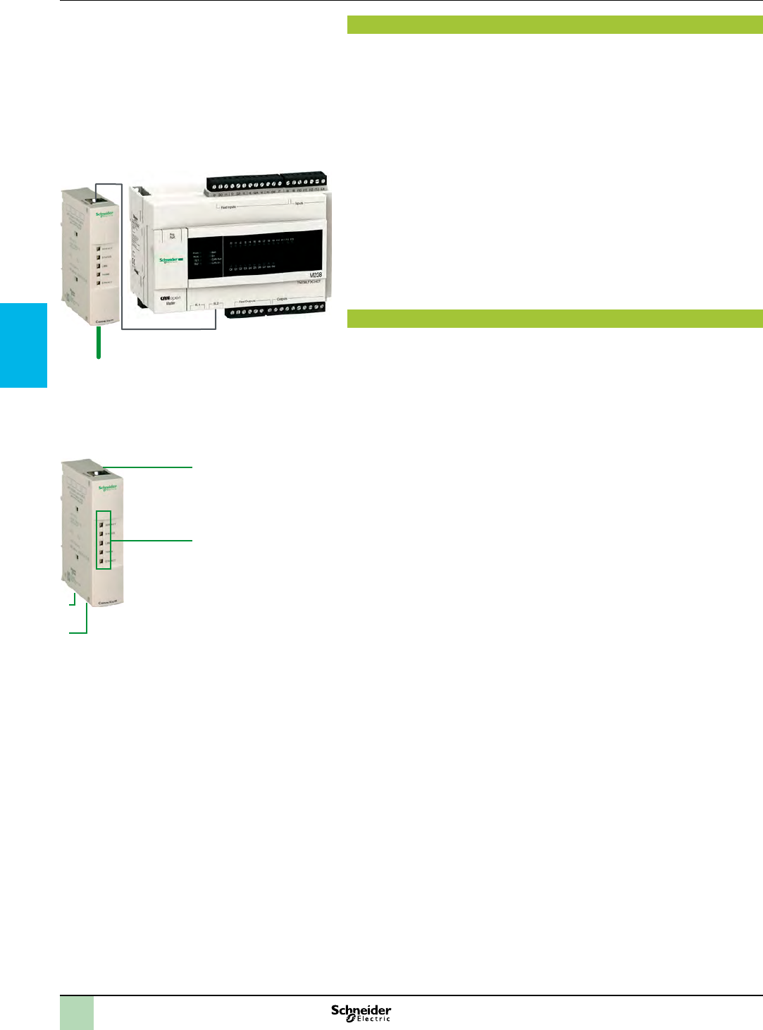
2
1
3
4
5
6
7
8
9
10
Presentation,
description
Communication
2
1
3
4
Ethernet Modbus/TCP
network
Modbus
Modicon M238 base for Solutions with AFB
pppppp
Presentation
499TWD01100
b
b
v
v
b
Description
499TWD01100
1
2
TWDXCARJP03P
3
4
5
TWDXMT5
To order separately
XBTZ9980
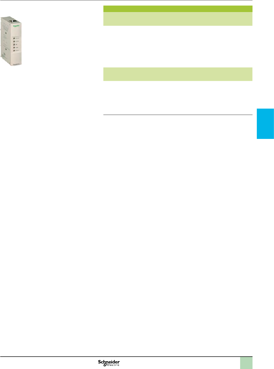
2
1
3
4
5
6
7
8
9
10
References Communication
References
Description Controller bases Function Reference Weight
kg
lb
TwidoPort
interface
module
499TWD01100
0.441
Description Use Length Reference Weight
kg
lb
Modbus
RS 485
cordsets
XBTZ9980
0.220
499 TWD 01100

chapter 5
Associated offers
All technical information about products listed in this chapter
are available on www.schneider-electric.com

2
1
3
4
bAltivar 212 and Altivar 61 variable speed drives
v
v
bAltistart 01, Altistart 22 and Altistart 48 soft starters for
asynchronous motors
v
bProtection components
v
v
v
v
v
v
v
bEnclosures
v
v
bControl and signalling units
v
v
bPower supplies Phaseo
v
bMagelis Operator dialogue terminals
v
v
v
v
v
v
bOsiSense XM pressure sensors
v
bMeasurement & control relays - Zelio Control
v
bProduct reference index
v
Contents Associated offers
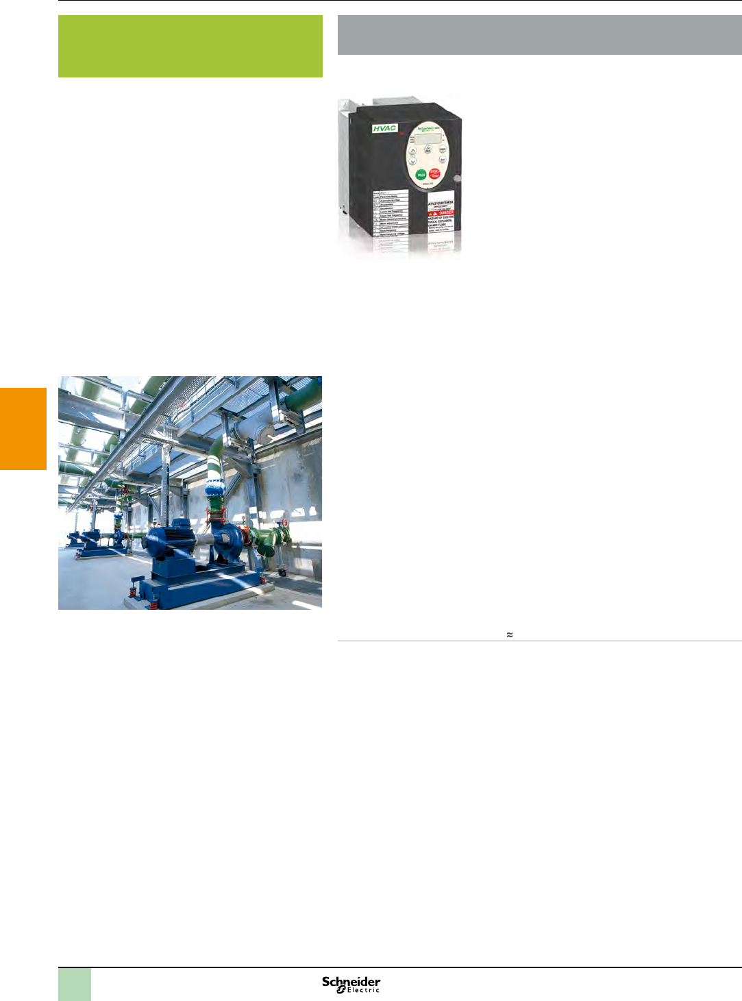
2
1
3
4
5
6
7
8
9
10
Presentation Associated offers
Orientated towards performance, intelligence and building
protection
The Altivar 212 is focused on Pumping machine as a dedicated variable speed
drive for pumps and compressors.
Drives
>
>
>
Orientated towards performance, intelligence and pumping protection
>
>
>
>
Focused on user-friendliness
>
>
Focused on cost savings
>
>
Focused on protection & efciency
>
>
>
>
Selection guide: see page 5/4
Altivar 212 variable speed drives
Pumping application
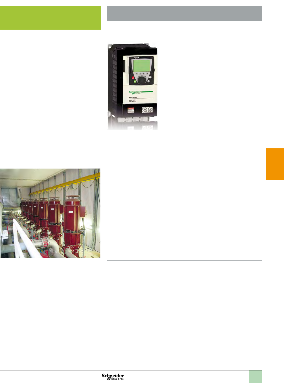
2
1
3
4
5
6
7
8
9
10
Presentation Associated offers
Energy savings and performance for your pumps
The Altivar 61 is a variable speed drive with variable torque and is designed
for exceptional versatility from the smallest application to the highest power
rating.
Drives
>
>
>
Communication
>
>
Flexibility
>
Powerful
>
>
>
>
>
Rugged in harsh environments
>
>
>
>
Selection guide: see page 5/5
Altivar 61 variable speed drives
Multi-pump solution
2
1
3
4
5
6
7
8
9
10
Selection guide Associated offers
Applications b
b
b
b
b
Types of control Variable speed drives for asynchronous motors Variable speed drives for asynchronous motors
Standards and certications
e
e
Drive
a a
Functions
Number of preset speeds
Speed range
No. of I/O
Reduction in harmonic currents
Communication
onorks Interusonorks
Cards (2)
Dialogue tools
Conguration tools
Supply voltage Three-phase 200…240 V Three-phase 380…480 V Single-phase 200…240 VThree-phase 200…240 V (1)
Motor power for 50...60 Hz line supply 0.75…75 kW (1…10 hp) 0.75…75 kW (1…10 hp) 0.37…630 kW (0.50…845 hp) (2) 0.37…630 kW (0.50…845 hp) (2) 0.37…630 kW (0.50…845 hp) (2)
kWHP
References (without EMC lter) References with integrated EMC lter,
categories C1, C2 or C3
References with integrated EMC lter, categories C1,
C2 or C3
References with integrated EMC lter
(up to 7.5 W), category C2
References (without EMC lter)
0.5 – – ATV 61H075M3 – –
1 – – ATV 61HU15M3 – –
2 – – ATV 61HU22M3 – –
3 – – ATV 61HU30M3 – –
– – ATV 61HU40M3 – –
5 – – ATV 61HU55M3 – –
7.5 – – ATV 61HU75M3 – –
13.3/6.1 ATV 212H075M3X ATV 212H075N4 – ATV 61H075M3 –
2 ATV 212HU15M3X ATV 212HU15N4 – ATV 61HU15M3 –
3 ATV 212HU22M3X ATV 212HU22N4 – ATV 61HU22M3 –
ATV 212HU30M3X ATV 212HU30N4 – ATV 61HU30M3 –
5 ATV 212HU40M3X ATV 212HU40N4 – ATV 61HU40M3 –
7.5 ATV 212HU55M3X ATV 212HU55N4 – ATV 61HU55M3 –
10 ATV 212HU75M3X ATV 212HU75N4 – ATV 61HU75M3 –
15 ATV 212HD11M3X ATV 212HD11N4 – – ATV 61HD11M3X
20 ATV 212HD15M3X ATV 212HD15N4 – – ATV 61HD15M3X
25 ATV 212HD18M3X ATV 212HD18N4 – – ATV 61HD18M3X
30 ATV 212HD22M3X ATV 212HD22N4 – – ATV 61HD22M3X
40 ATV 212HD30M3X ATV 212HD30N4 – – ATV 61HD30M3X
50 – ATV 212HD37N4 – – ATV 61HD37M3X
60 – ATV 212HD45N4 – – ATV 61HD45M3X
75 – ATV 212HD55N4 – – ATV 61HD55M3X
100 – ATV 212HD75N4 – – ATV 61HD75M3X
125 – – – – ATV 61HD90M3X
(1) Other voltages available (Three-phase 380…480 V or three-phase 500…690 V), please consult our “Altivar 61 variable speed drives” catalogue or our website
www.schneider-electric.com
(2) For motors with a higher rating than 90 kW (120 hp), please consult our “Altivar 61 variable speed drivescatalogue or our website www.schneider-electric.com

2
1
3
4
5
6
7
8
9
10
Applications b
b
b
b
b
Types of control Variable speed drives for asynchronous motors Variable speed drives for asynchronous motors
Standards and certications
e
e
Drive
a a
Functions
Number of preset speeds
Speed range
No. of I/O
Reduction in harmonic currents
Communication
onorks Interusonorks
Cards (2)
Dialogue tools
Conguration tools
Supply voltage Three-phase 200…240 V Three-phase 380…480 V Single-phase 200…240 VThree-phase 200…240 V (1)
Motor power for 50...60 Hz line supply 0.75…75 kW (1…10 hp) 0.75…75 kW (1…10 hp) 0.37…630 kW (0.50…845 hp) (2) 0.37…630 kW (0.50…845 hp) (2) 0.37…630 kW (0.50…845 hp) (2)
kWHP
References (without EMC lter) References with integrated EMC lter,
categories C1, C2 or C3
References with integrated EMC lter, categories C1,
C2 or C3
References with integrated EMC lter
(up to 7.5 W), category C2
References (without EMC lter)
0.5 – – ATV 61H075M3 – –
1 – – ATV 61HU15M3 – –
2 – – ATV 61HU22M3 – –
3 – – ATV 61HU30M3 – –
– – ATV 61HU40M3 – –
5 – – ATV 61HU55M3 – –
7.5 – – ATV 61HU75M3 – –
13.3/6.1 ATV 212H075M3X ATV 212H075N4 – ATV 61H075M3 –
2 ATV 212HU15M3X ATV 212HU15N4 – ATV 61HU15M3 –
3 ATV 212HU22M3X ATV 212HU22N4 – ATV 61HU22M3 –
ATV 212HU30M3X ATV 212HU30N4 – ATV 61HU30M3 –
5 ATV 212HU40M3X ATV 212HU40N4 – ATV 61HU40M3 –
7.5 ATV 212HU55M3X ATV 212HU55N4 – ATV 61HU55M3 –
10 ATV 212HU75M3X ATV 212HU75N4 – ATV 61HU75M3 –
15 ATV 212HD11M3X ATV 212HD11N4 – – ATV 61HD11M3X
20 ATV 212HD15M3X ATV 212HD15N4 – – ATV 61HD15M3X
25 ATV 212HD18M3X ATV 212HD18N4 – – ATV 61HD18M3X
30 ATV 212HD22M3X ATV 212HD22N4 – – ATV 61HD22M3X
40 ATV 212HD30M3X ATV 212HD30N4 – – ATV 61HD30M3X
50 – ATV 212HD37N4 – – ATV 61HD37M3X
60 – ATV 212HD45N4 – – ATV 61HD45M3X
75 – ATV 212HD55N4 – – ATV 61HD55M3X
100 – ATV 212HD75N4 – – ATV 61HD75M3X
125 – – – – ATV 61HD90M3X
(1) Other voltages available (Three-phase 380…480 V or three-phase 500…690 V), please consult our “Altivar 61 variable speed drives” catalogue or our website
www.schneider-electric.com
(2) For motors with a higher rating than 90 kW (120 hp), please consult our “Altivar 61 variable speed drivescatalogue or our website www.schneider-electric.com
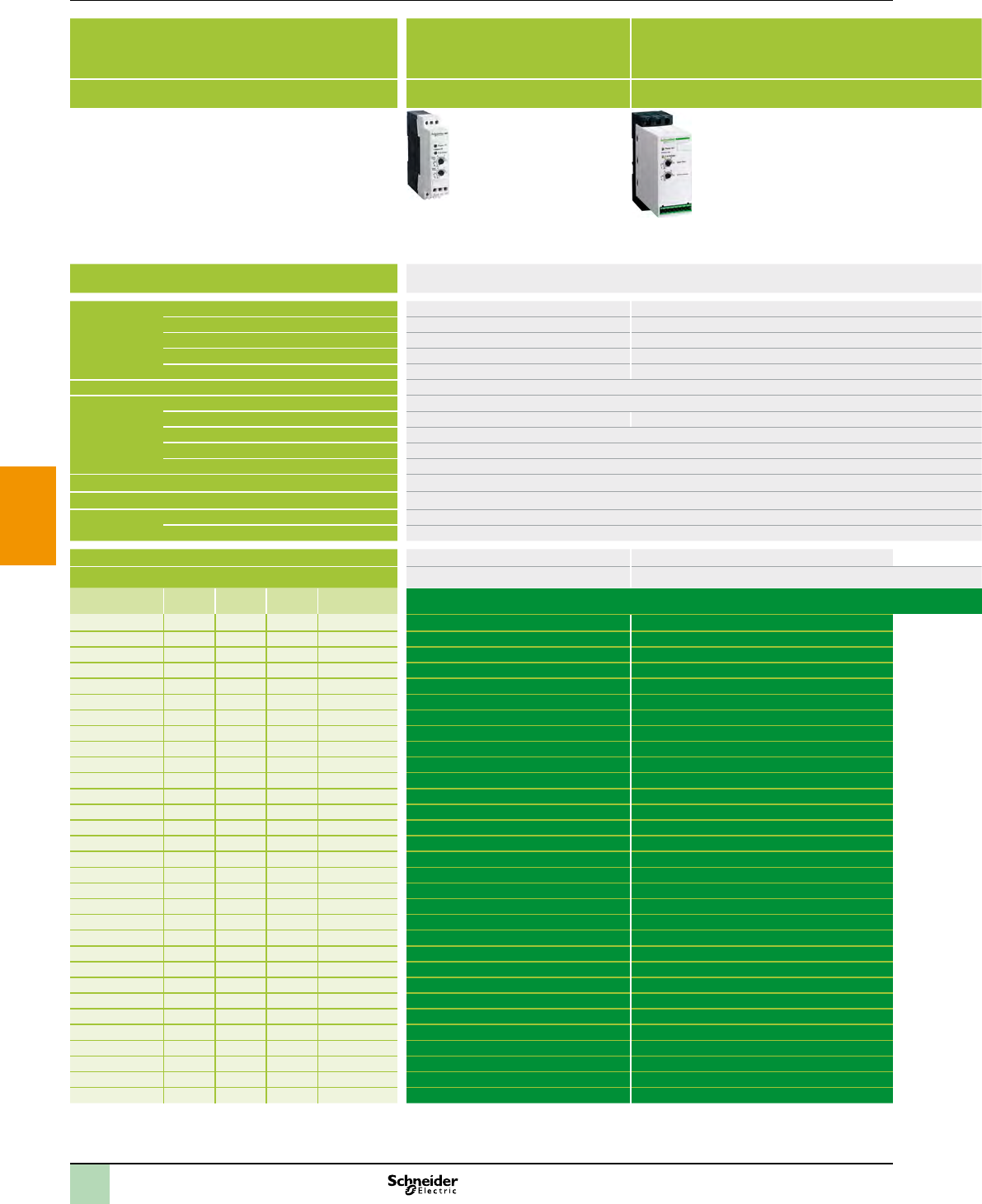
2
1
3
4
5
6
7
8
9
10
Selection guide Associated offers
Applications b
b
b(1)
b
b
b
Type of control Controlled starting of simple machines Controlled starting and deceleration of simple
machines
Controlled starting and deceleration of simple and complex machines
Standards and certications e e
e
Drive
Functions
Number
of I/O
Dialogue tools
Conguration tools
Communication
Supply voltage Single-phase 110…230 V Three-phase 200…240 V Three-phase 380…415 V Three-phase 440…480 V Three-phase 230…440 V (2) Three-phase 230…415 V (2)
Motor power for 50...60 Hz line supply kW-HP0.37…2.2 kW (0.50…3 hp) (3) 0.75…15 kW (0.50…20 hp) (3) 0.75…15 kW (0.50…20 hp) 0.75…15 kW (0.50…20 hp) 4…355 kW (5.4…476 hp) (3) 3…630 kW (4…845 hp) (3)
References
ATS01N103FT – – – – –
ATS01N106FT – – – – –
ATS01N109FT – – – – –
ATS01N112FT – – – – –
ATS01N125FT – – – – –
1/1.5 2/3 – ATS01N206LU ATS01N206QN ATS01N206RT – –
25– ATS01N209LU ATS01N209QN ATS01N209RT – –
3/55 7.5 – ATS01N212LU ATS01N212QN ATS01N212RT – –
5/7.5 10/15 – ATS01N222LU ATS01N222QN ATS01N222RT – –
10 20 – ATS01N232LU ATS01N232QN ATS01N232RT – –
– – – – ATS22D17Q ATS48D17Q
– – – – – ATS48D22Q
– – – – ATS22D32Q ATS48D32Q
– – – – – ATS48D38Q
– – – – ATS22D47Q ATS48D47Q
– – – – ATS22D62Q ATS48D62Q
– – – – ATS22D75Q ATS48D75Q
– – – – ATS22D88Q ATS48D88Q
– – – – ATS22C11Q ATS48C11Q
– – – – ATS22C14Q ATS48C14Q
– – – – ATS22C17Q ATS48C17Q
– – – – ATS22C21Q ATS48C21Q
– – – – ATS22C25Q ATS48C25Q
– – – – ATS22C32Q ATS48C32Q
– – – – ATS22C41Q ATS48C41Q
– – – – ATS22C48Q ATS48C48Q
– – – – ATS22C59Q ATS48C59Q
– – – – – ATS48C66Q
– – – – – ATS48C79Q
– – – – – ATS48M10Q
– – – – – ATS48M12Q
(1) For optimum fan control, use of a variable speed drive is recommended.
(2) Other voltages available: Three-phase 208…600 V, please consult our website www.schneider-electric.com
(3) For other motor ratings, please consult our website www.schneider-electric.com
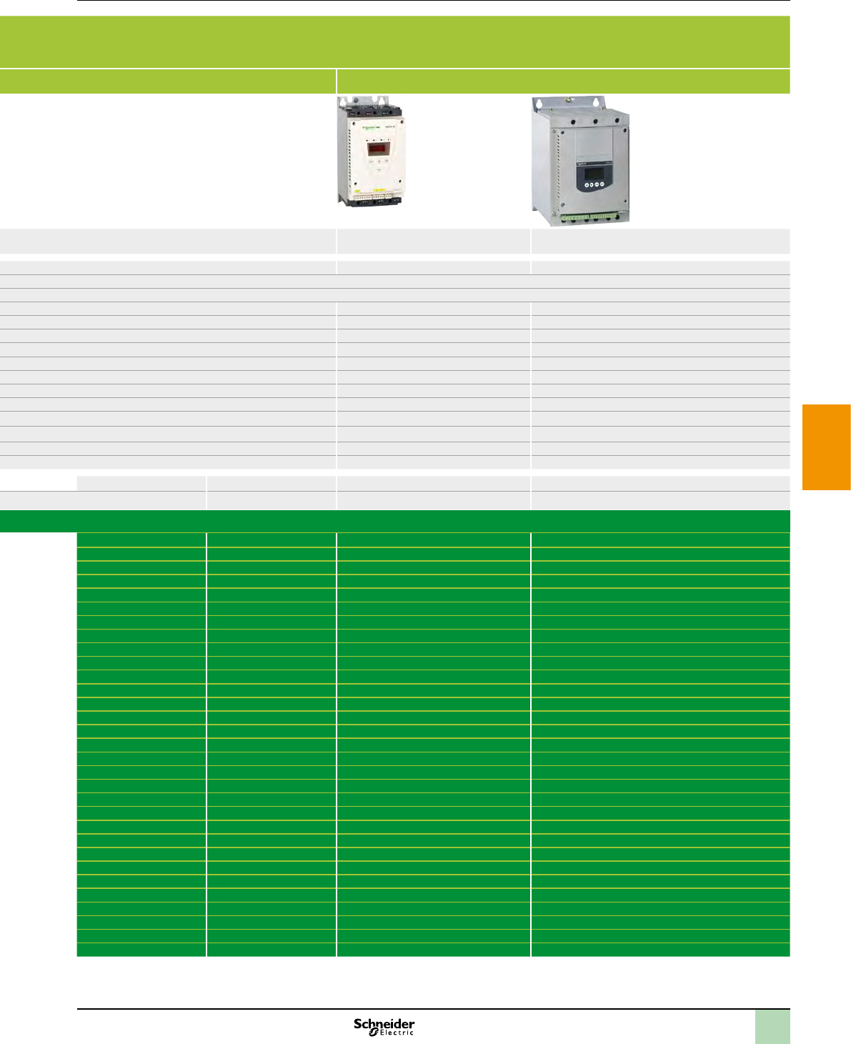
2
1
3
4
5
6
7
8
9
10
Presentation Associated offers
Selecting motor starting mode Selecting devices
The starter mode is closely linked to the load carried by the motor. The table
below presents several typical applications in process control, part of which
are used in processes such as water treatment or cement production.
The examples illustrate how the selection is made.
Type of actuator Description/ comment Power range Torque Direct On
Line (D.O.L.)
Soft starter Speed Drive
Centrifugal
Pump
>
>
b b b
b b
Dosing pump >
b b
Screw pump >
>
>
b b
Mixer >
>
>
b b
Moving devices >
b b
Air blower and
fan
>
>
b b
Mill and
crusher
>
>
b b

2
1
3
4
5
6
7
8
9
10
Presentation Associated offers
Selecting motor starting mode Control starter functions
Depending on needs, it is necessary to control some or all functions of a starter.
The principal function groups are:
Motor control performance
>
Motor protection
>
>
>
>
>
>
Motor metering and monitoring functions
>
>
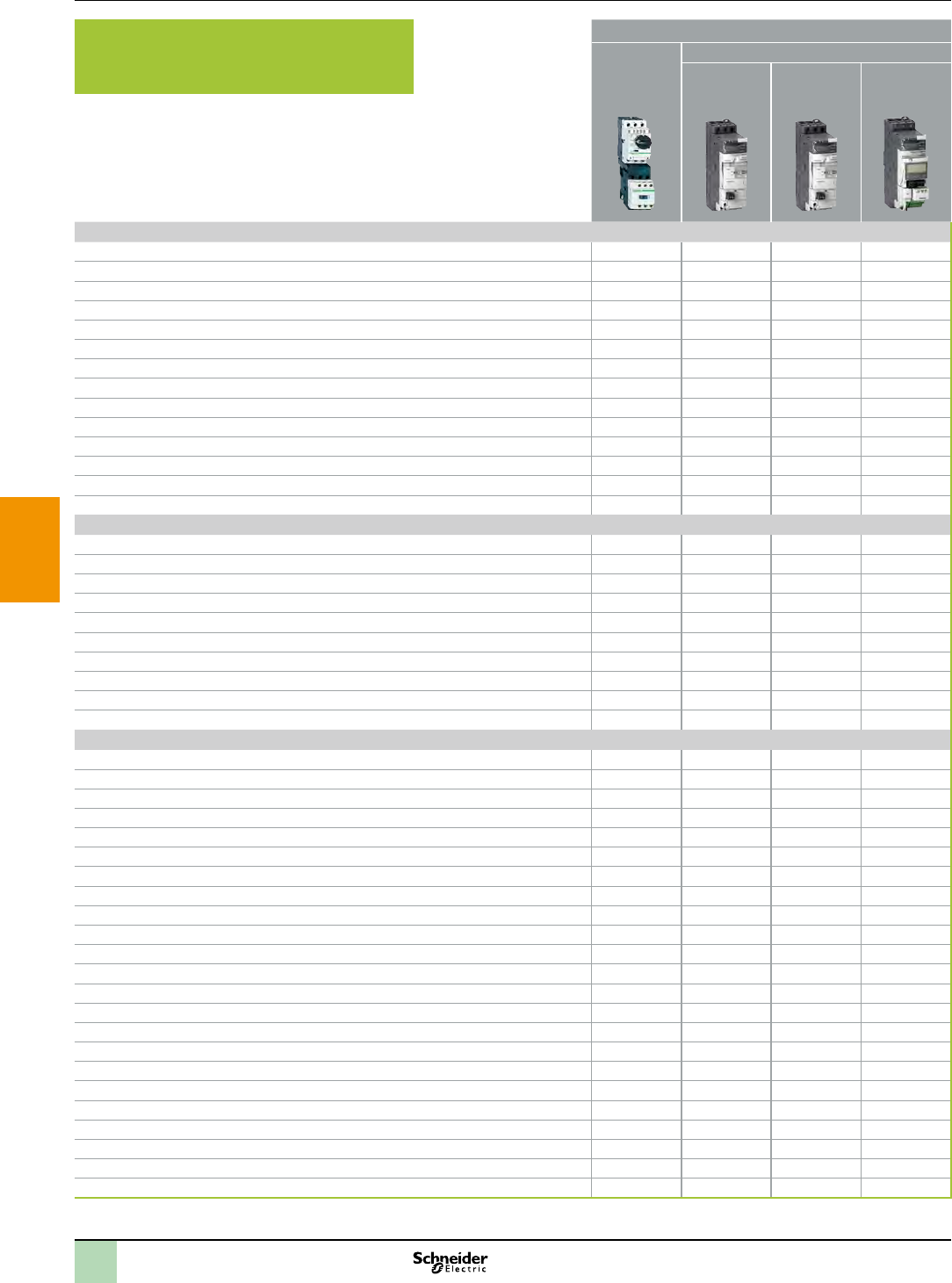
2
1
3
4
5
6
7
8
9
10
Presentation Associated offers
(continued)
Selecting motor starting mode D.O.L. starter
p
Motor protection functions
> b b b b
> b b b b
> b b b b
> b b
> b b
> b b b b
>
>
>
>
> b b b b
>
>
>
Metering functions
> b b
> b
> b
>
>
>
>
>
>
>
Monitoring functions
> b b
> b b
> b
> b
>
>
>
>
>
>
>
>
>
>
>
>
>
>
>
> b
>
> b
>
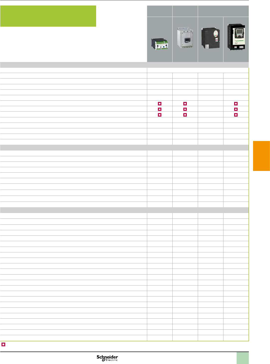
2
1
3
4
5
6
7
8
9
10
Presentation Associated offers
D.O.L. Soft
starter VSD
Motor protection functions
> by upstream CB
> b b b b
> b b b b
> b b b b
> b b b
> b b b b
> b b b
> b b b
> b b b
> b b
> b b b b
> b b b b
> b b b
> b b b
Metering functions
> b b b b
> b b
> b b b
> b b b b
> b b
> b
> b
> b b b
> b b
> b b
Monitoring functions
> b b b b
> b b b b
> b b b b
> b b b b
> b b b
> b b
> b
> b b b
> b b
> b
> b b
> b b
> b b
> b b
> b
> b
> b
> b
> b b
> b
> b b b
> b b b
> b b b
b
Selecting motor starting mode
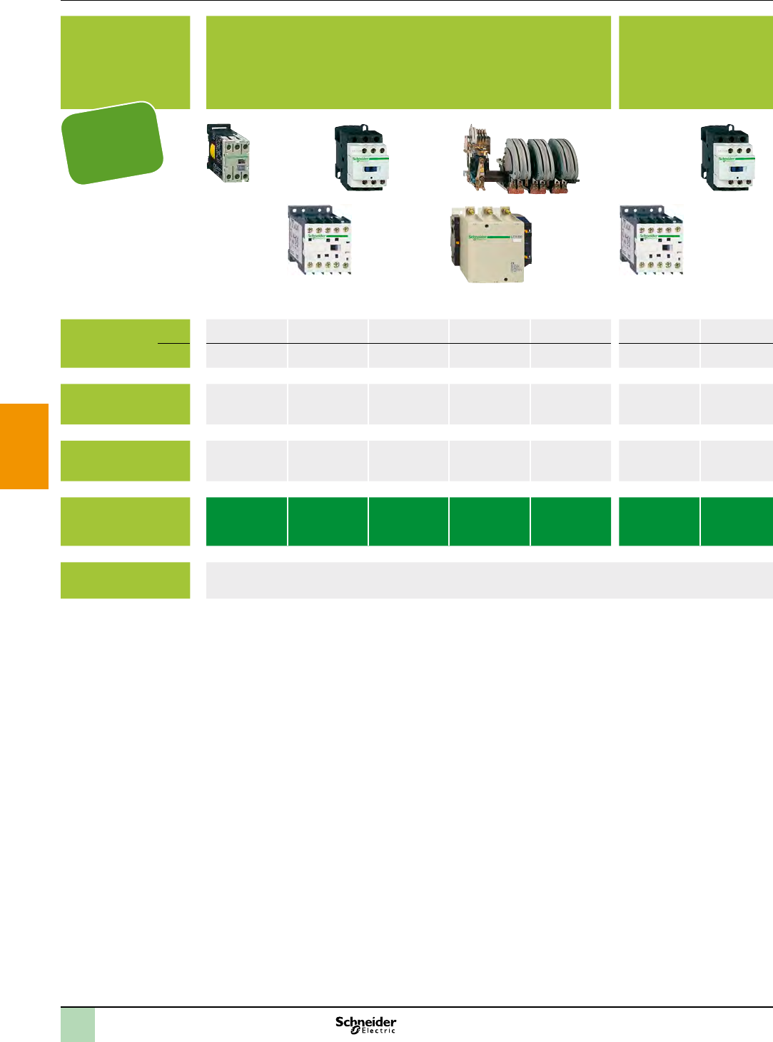
2
1
3
4
5
6
7
8
9
10
Selection guide Associated offers
Applications Equipment based on standard contactors Equipment requiring low
consumption contactors
which can be switched
directly from solid state
outputs
Rated
operational
current
Rated operational
voltage
Number of poles
Contactor type
references LC1 SK
LP1 SK
LC1 K
LC7 K
LP1 K
LC1 D LC1 F LC1 B LP4 K LC1 D
More information
Protection
according to
IEC60947-2 and
UL508

2
1
3
4
5
6
7
8
9
10
Selection guide
Applications Protection of motors against short-circuits and overloads
Tripping threshold on
short-circuit
Standard motor power
ratings in AC-3, 415 V
Operational current at
415 V
Breaking capacity at
415 V (Icu) to IEC 60947-2
Door interlock mechanism
Circuit-breaker type GV2 ME GV2 P GV3 P GV3 ME80 GV7 RE
More information
Associated offers
Protection
according to
IEC60947-2 and
UL508
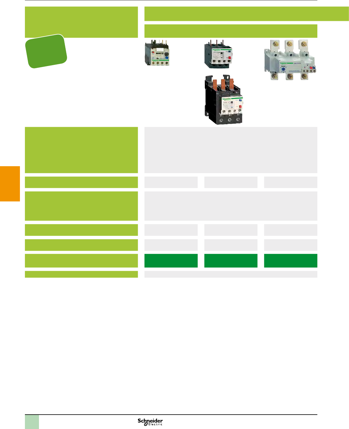
2
1
3
4
5
6
7
8
9
10
Selection guide TeSys protection components
Applications Motor protection Machine protection Motor and machine protection
Thermal motor protection Protection of resistors,
bearings, capacitors
Specic motor protection Protection and control
Protection
Tripping class
Communication
Used with contactor type
Motor current
Relay or controller type LR2 K LRD, LR2 D and
LR9 D
LR9 F LT3 S LR97D LT47 LUTM p0BL LTM R
More information
Protection
according to
IEC60947-2 and
UL508
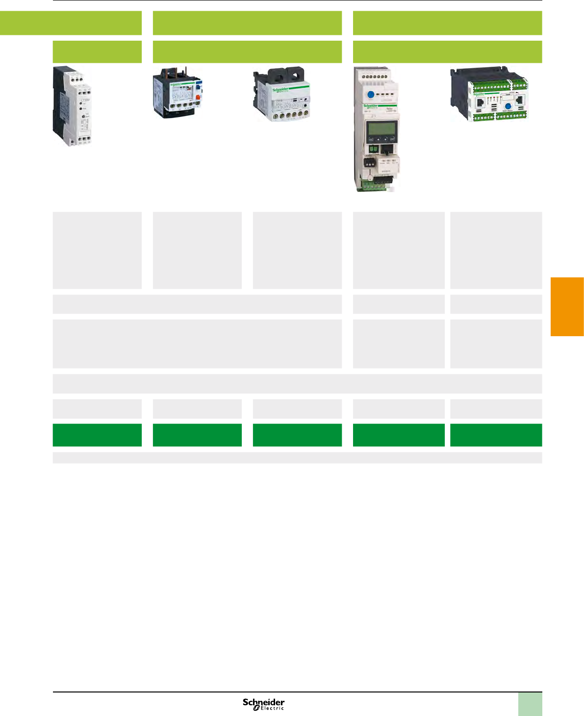
2
1
3
4
5
6
7
8
9
10
Applications Motor protection Machine protection Motor and machine protection
Thermal motor protection Protection of resistors,
bearings, capacitors
Specic motor protection Protection and control
Protection
Tripping class
Communication
Used with contactor type
Motor current
Relay or controller type LR2 K LRD, LR2 D and
LR9 D
LR9 F LT3 S LR97D LT47 LUTM p0BL LTM R
More information
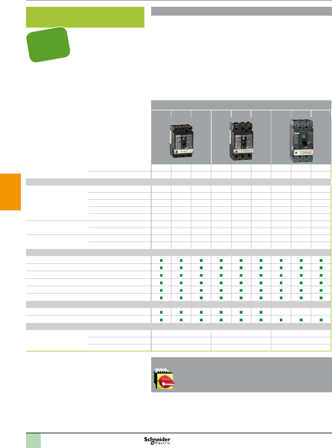
2
1
3
4
5
6
7
8
9
10
Presentation Associated offers
Powerpact
HD HG HJ JD JG JJ LD LG LJ
Number of poles
Current range
Interrupting ratings
UL/CSA/NOM rating
(kA RMS) (50/60 Hz AC)
DC ratings
IEC 60947-2 kA RMS
(50/60 Hz AC) Icu/Ics
Accessories
Shunt Trip
Undervoltage Trip
Auxiliary Switches
Handle Operators
Mechanical Interlocks
Handle Padlock Attachment
Trip system type
Thermal magnetic
Electronic
Enclosure
Dimensions
PowerPact multistandard molded case circuit breakers
Proven performance
>
Flexible
>
Simple
>
Direct access to energy efciency
>
Feeder protection and circuit
disconnection
TeSys Vario load break switch according to IEC947-3 / UL508
>
>
Protection
according to
IEC60947-2
and UL489
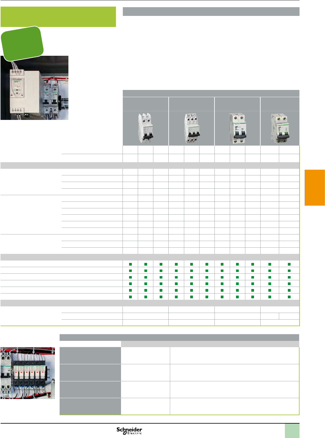
2
1
3
4
5
6
7
8
9
10
Presentation Associated offers
Breaker type
UL489 C60
(120/240 V)
UL489 C60
(480Y 277 Vac)
UL 1077 C60N UL 1077
C60H-DC
Number of poles 1 2 3 1 2 3 1 2 3.4 1 2
Current range
Interrupting ratings
UL/CSA rating
(kA RMS) (50/60 Hz AC)
DC ratings
IEC 60947-2
(50/60 Hz AC)
Accessories
Shunt Trip
Undervoltage Trip
Auxiliary Switches
Handle Operators
Handle Padlock Attachment
GF Protection (GFP)
Enclosure
Dimensions
Multi 9TM miniature circuit breakers
>
>
>
Branch circuit
and control circuit protection
TeSys DF fuse holders according to IEC947- 3 / UL248
UL512
TeSys DF10 IEC
UL (UL recognized)
>
>
>
TeSys DFCC IEC
UL (UL listed) >
>
>
TeSys DF14 IEC
UL (UL recognized) >
>
>
TeSys DF22 IEC
UL (UL recognized) >
>
>
Protection
according to
IEC60947-2,
UL489 and
UL1077
2
1
3
4
5
6
7
8
9
10
Panorama Associated offers
Basic Monitoring Advanced Monitoring Power & Energy Monitoring Energy Management & Control Monitoring
software
Power Logic System
Name
Function
Panel instrumentation
Integrated in Compact NSX circuit
breaker
Name
Function
Panel instrumentation
Remote Monitoring
Common accessories
Name
Function
2
1
3
4
5
6
7
8
9
10
Presentation Associated offers
Steel enclosures
Description
Dimensions
Ingress protection rating
Mechanical protection rating
Options
Why should I choose it?
Durable, with high UV resistance, coated hinges, aluminium hinge pins and folded gutters that avoids
the entry of water, oil and other liquids .
Wall-mountingFloor-standing
Description
Dimensions
Ingress protection rating
Mechanical protection rating
Options
Why should I choose it?
High level of modularity and flexibility. Save up 25 % of time in assembly.
CV-CA
CE
CU
Thermal
management
ClimaSys
Accessories
Project & Services
Configured
Specific
The
2
1
3
4
5
6
7
8
9
10
Presentation Associated offers
Insulating material enclosures
Description
Dimensions
Ingress protection rating
Mechanical protection rating
Options:
Description
Dimensions
Ingress protection rating
Mechanical protection rating
Options
Details and technical datasheets available on
www.schneider-electric.com
Why should I choose it?
Thalassa PLM are suitable for indoor or outdoor use and ensure
a long-life lasting without maintenance.
Why should I choose it?
Thalassa PLA protect large and heavy control equipment
in harsh and corrosive environments for indoors and outdoors.
CR
CC
ProClima
Thermal
calculation
software
Spare Parts
Cable Doors Door Fixing Roof
Offline
software
Graphic
configurator
Enclosures selector
Services
configurator
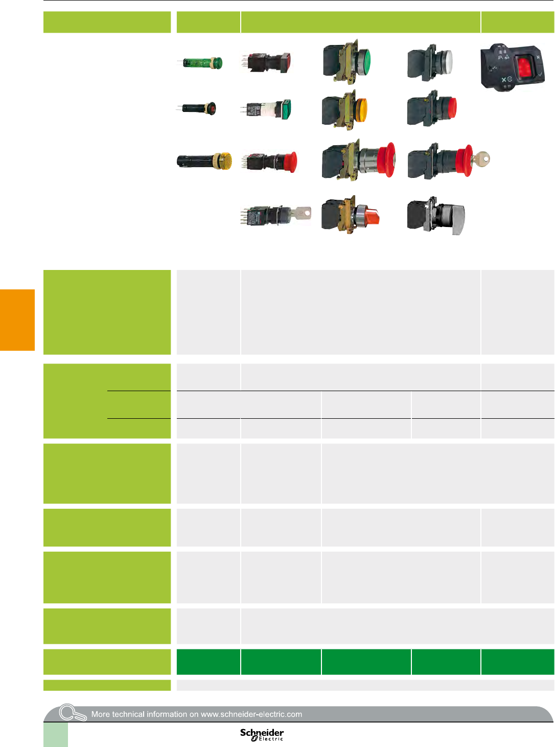
2
1
3
4
5
6
7
8
9
10
Applications Pilot lights Pushbuttons, selector switches and pilot lights
Biometric switches
Wireless and batteryless
pushbuttons
Pushbuttons, selector
switches and pilot lights
Joystick controllers Pushbuttons, selector
switches and pilot lights
Cam switches
Description of range b b
b
b
b
b
b
b
c
c
a c
b
b
b
b
b
b
b
b
b
b
b
b
b
b
b
b
b
b
b
b
b
Features
(1)
Drilling or cut-out for mounting
series
K10
series K1/K2
Degree of
protection
Cabling
Mounting
Type references XVLA XB6 XB4 XB5 XB5S XB5R, XB4R XB7 XD4PA XD2GA XD5PA 9001K,9001SK K10, K1, K2, K30, K50,
K63, K115, K150
Pages
(1) Wireless and batteryless pushbutton and receiver ready-paired at the factory.
Associated offers
Selection guide
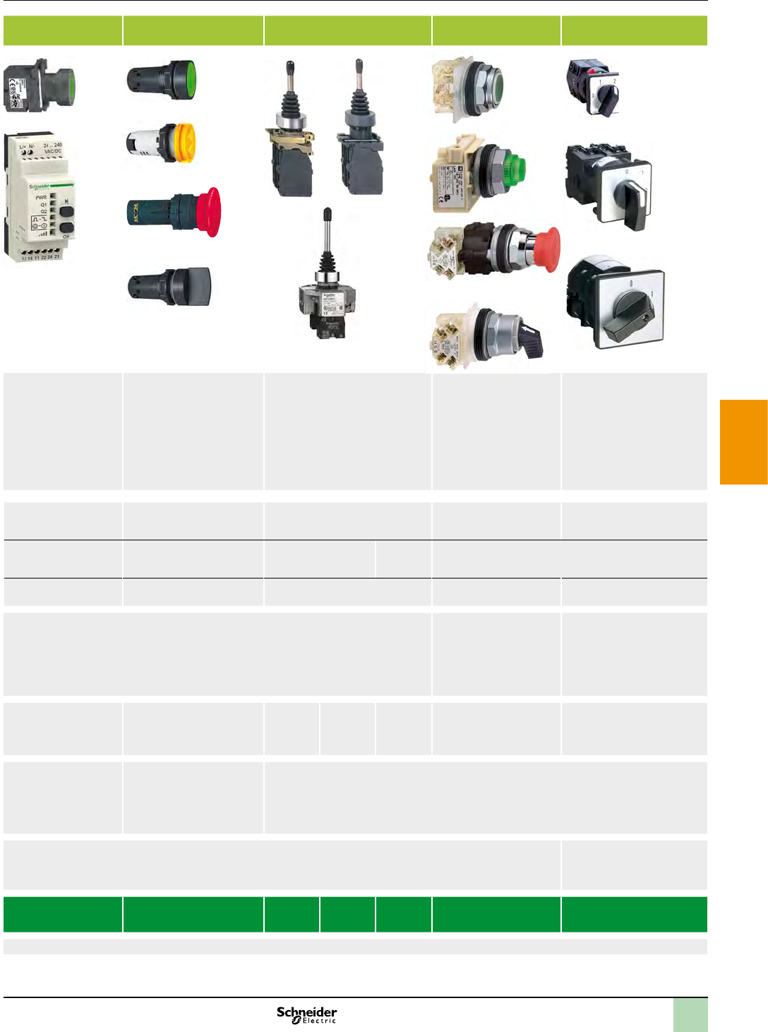
2
1
3
4
5
6
7
8
9
10
Applications Pilot lights Pushbuttons, selector switches and pilot lights
Biometric switches
Wireless and batteryless
pushbuttons
Pushbuttons, selector
switches and pilot lights
Joystick controllers Pushbuttons, selector
switches and pilot lights
Cam switches
Description of range b b
b
b
b
b
b
b
c
c
a c
b
b
b
b
b
b
b
b
b
b
b
b
b
b
b
b
b
b
b
b
b
Features
(1)
Drilling or cut-out for mounting
series
K10
series K1/K2
Degree of
protection
Cabling
Mounting
Type references XVLA XB6 XB4 XB5 XB5S XB5R, XB4R XB7 XD4PA XD2GA XD5PA 9001K,9001SK K10, K1, K2, K30, K50,
K63, K115, K150
Pages
(1) Wireless and batteryless pushbutton and receiver ready-paired at the factory.
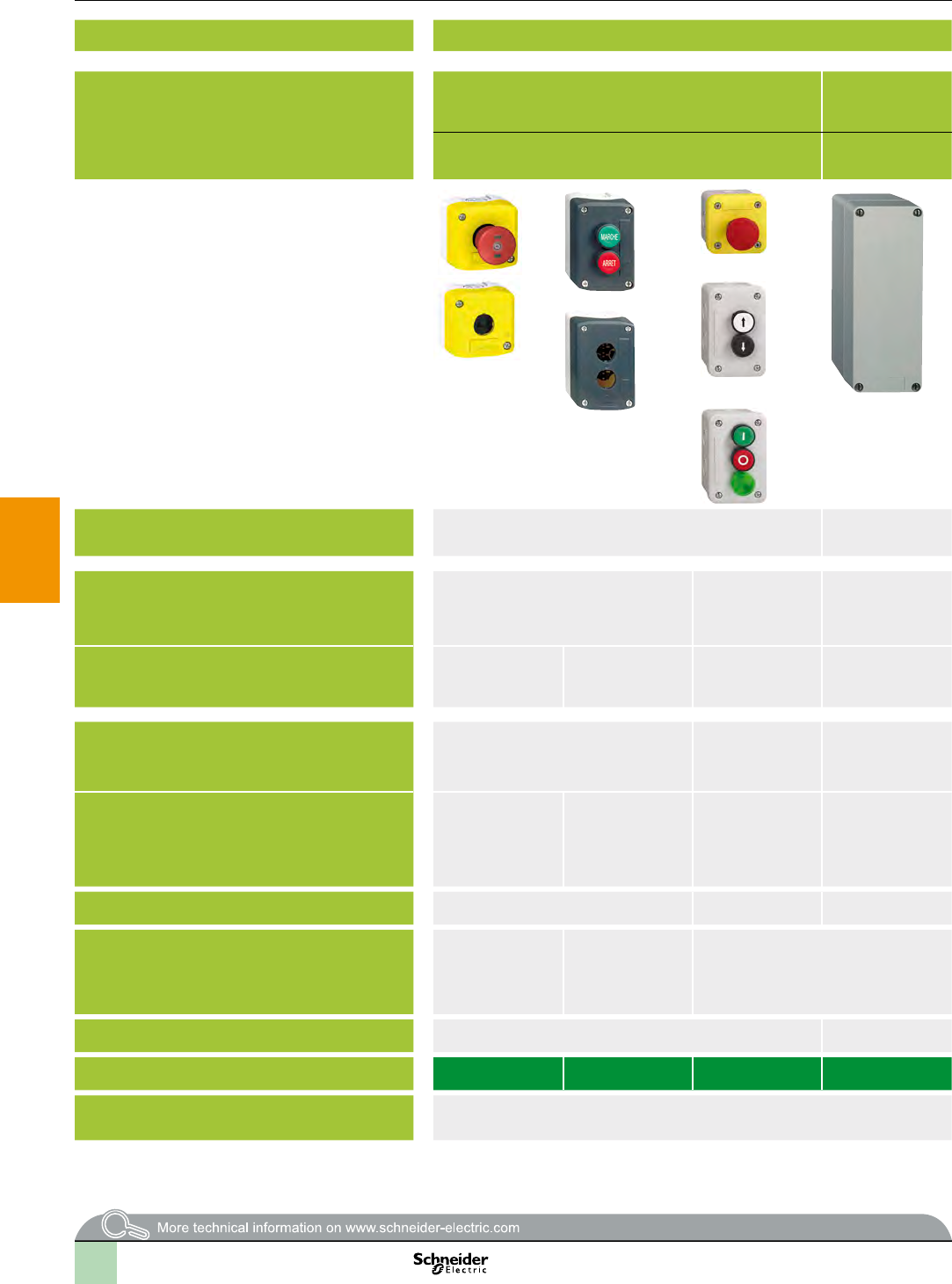
2
1
3
4
5
6
7
8
9
10
Type of applications All applications Specic applications
Enclosures Plastic Glass-reinforced
polyester
Metal Metal front plate,
insulated protective
rear cover
Plastic Metal
Complete stations and separate components for customer
assembly
Empty insulated
enclosures
Empty enclosures Empty, ush mounting
enclosures: front plate
+ rear cover
Control stations for
severe environments
Lift inspection stations Key operated
control stations
Main feature
Associated control and signalling units
Number of cut-outs for Ø 22 mm (Ø 0.866 in.) control and
signalling units
Material
Colour
XAP M
XAP J:
Degree of protection
Function
v
v
v
v
v
v
v
v
Cable entries
Type references XAL K XAL D XAL E XAP A XB2 SL XAP M, XAP J XAP E XAL G XAL F XAP S
Page(s)
Selection guide Associated offers
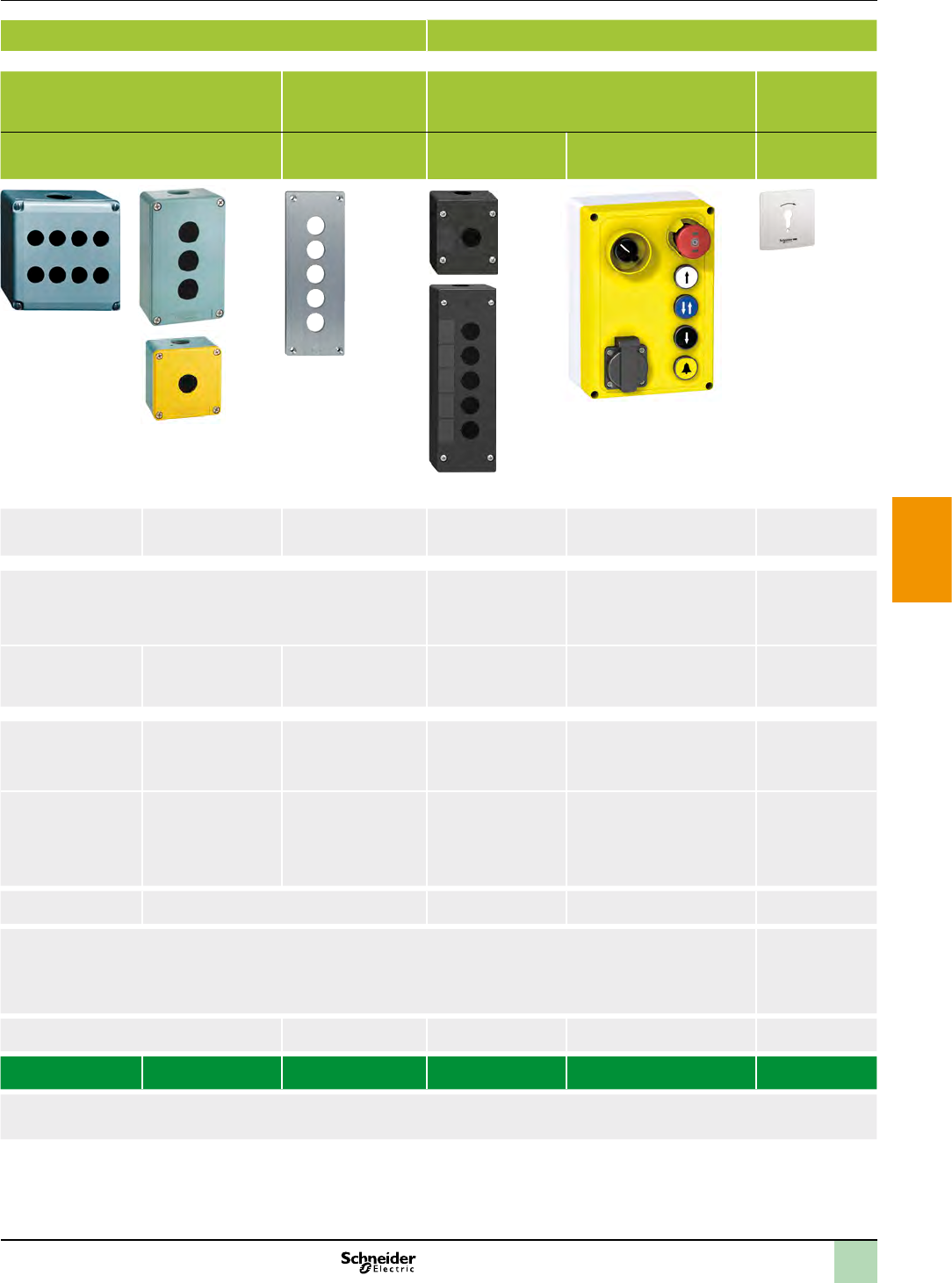
2
1
3
4
5
6
7
8
9
10
Type of applications All applications Specic applications
Enclosures Plastic Glass-reinforced
polyester
Metal Metal front plate,
insulated protective
rear cover
Plastic Metal
Complete stations and separate components for customer
assembly
Empty insulated
enclosures
Empty enclosures Empty, ush mounting
enclosures: front plate
+ rear cover
Control stations for
severe environments
Lift inspection stations Key operated
control stations
Main feature
Associated control and signalling units
Number of cut-outs for Ø 22 mm (Ø 0.866 in.) control and
signalling units
Material
Colour
XAP M
XAP J:
Degree of protection
Function
v
v
v
v
v
v
v
v
Cable entries
Type references XAL K XAL D XAL E XAP A XB2 SL XAP M, XAP J XAP E XAL G XAL F XAP S
Page(s)
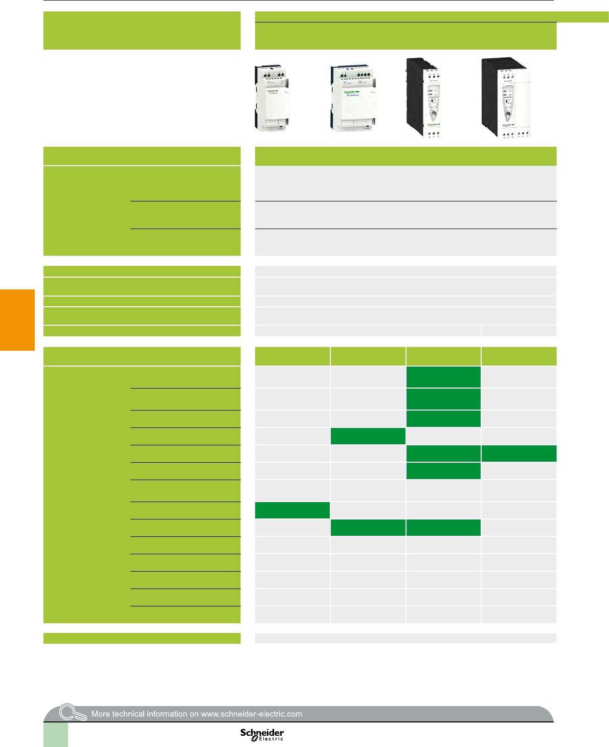
2
1
3
4
5
6
7
8
9
10
Selection guide Associated offers
Power supplies Regulated switch mode power supplies
ABL 8MEM, ABL 7RM: 7 to 60 W - Rail mounting
ABL 8REM, ABL 7RP: 60 to 144 W - Rail mounting
ABL4: 85 to 960 W - Compact - Rail mounting Function modules ABL 8DCC: converters c/c
Nominal input voltage a
c
a aa a c
Connection to
worldwide line
supplies
Undervoltage control
Protection against overloads and short-circuits
Diagnostics relay
Compatibility with function modules
Power reserve (Boost)
Output voltage c c c c c c c
Output current ABL8MEM24003
ABL8MEM24006
ABL8MEM24012
ABL8MEM12020 ABL8DCC12020 (1)
ABL7RM24025 ABL7RP4803
ABL8REM24030
ABL4RSM24035
ABL8MEM05040
ABL7RP1205 ABL8REM24050 ABL4RSM24050
ABL8DCC05060 (1)
ABL4RSM24100
ABL4RSM24200 ABL4WSR24200
ABL4WSR24300
ABL4WSR24400
Pages (2)
(1) Converter module c/c, must be used with a Phaseo power supply.
(2) Certain offers can not be marketed in certain countries, please consult your “Customer Care Centre”.
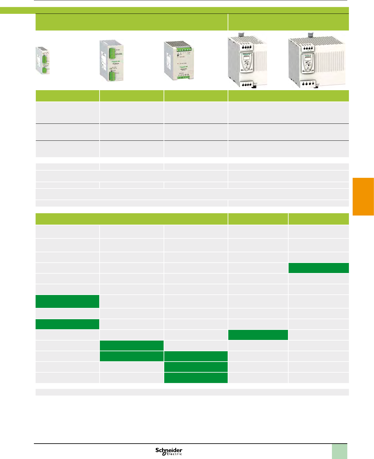
2
1
3
4
5
6
7
8
9
10
Power supplies Regulated switch mode power supplies
ABL 8MEM, ABL 7RM: 7 to 60 W - Rail mounting
ABL 8REM, ABL 7RP: 60 to 144 W - Rail mounting
ABL4: 85 to 960 W - Compact - Rail mounting Function modules ABL 8DCC: converters c/c
Nominal input voltage a
c
a aa a c
Connection to
worldwide line
supplies
Undervoltage control
Protection against overloads and short-circuits
Diagnostics relay
Compatibility with function modules
Power reserve (Boost)
Output voltage c c c c c c c
Output current ABL8MEM24003
ABL8MEM24006
ABL8MEM24012
ABL8MEM12020 ABL8DCC12020 (1)
ABL7RM24025 ABL7RP4803
ABL8REM24030
ABL4RSM24035
ABL8MEM05040
ABL7RP1205 ABL8REM24050 ABL4RSM24050
ABL8DCC05060 (1)
ABL4RSM24100
ABL4RSM24200 ABL4WSR24200
ABL4WSR24300
ABL4WSR24400
Pages (2)
(1) Converter module c/c, must be used with a Phaseo power supply.
(2) Certain offers can not be marketed in certain countries, please consult your “Customer Care Centre”.
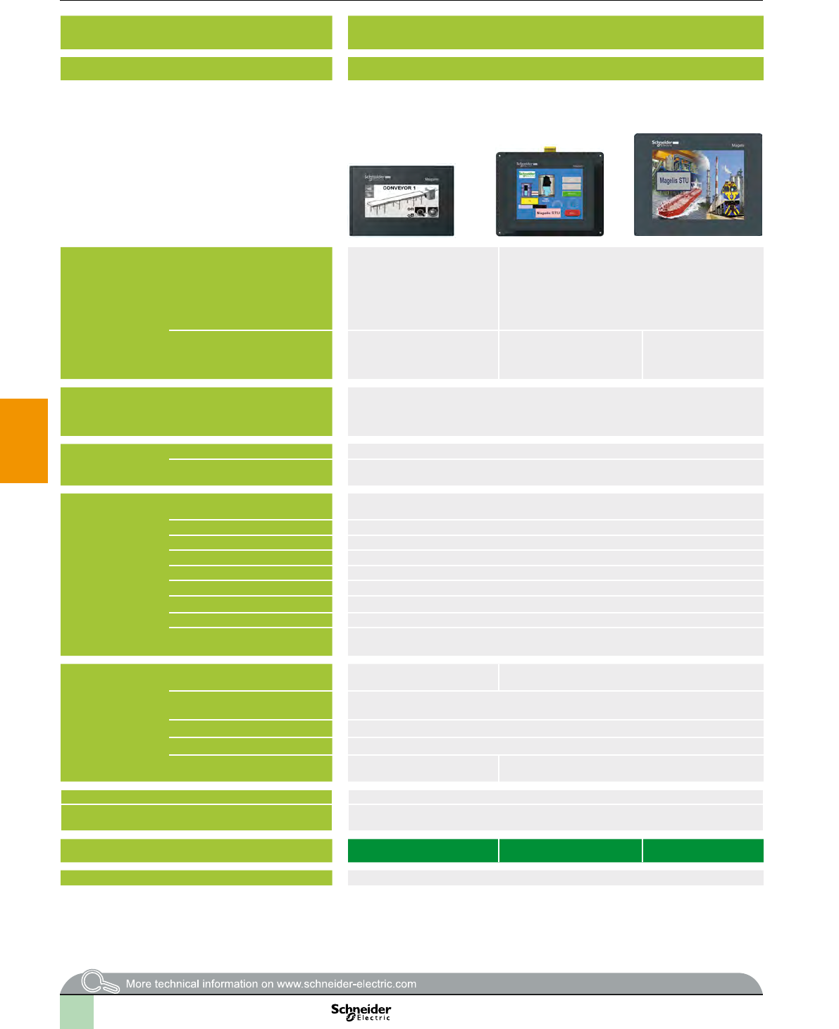
2
1
3
4
5
6
7
8
9
10
Selection guide Associated offers
Applications Display of graphic pages Display of text messages and/or semi-graphic
pages
Display of text messages and/or semi-graphic pages
Control and conguration of data
Type of terminal Small Panels with touch screen Small Panels with keypad Small Panels with keypad Small Panels with touch screen and keypad
Display
Data entry
b
b
b
b
b
b
Memory
capacity
Functions
(5)
(4)
Communication (1)
(2)
(5)
(3)
Development software
Operating system
References HMI STO 5pp HMI STU 655 HMI STU 855 XBT N pppp XBT R ppp XBT RT ppp
Page
(1) Only HMI STO 511/512.
(2) Only HMI STO 501.
(3) Only HMI STO 531/532.
(4) Only XBT RT511.
(5) Depending on model.
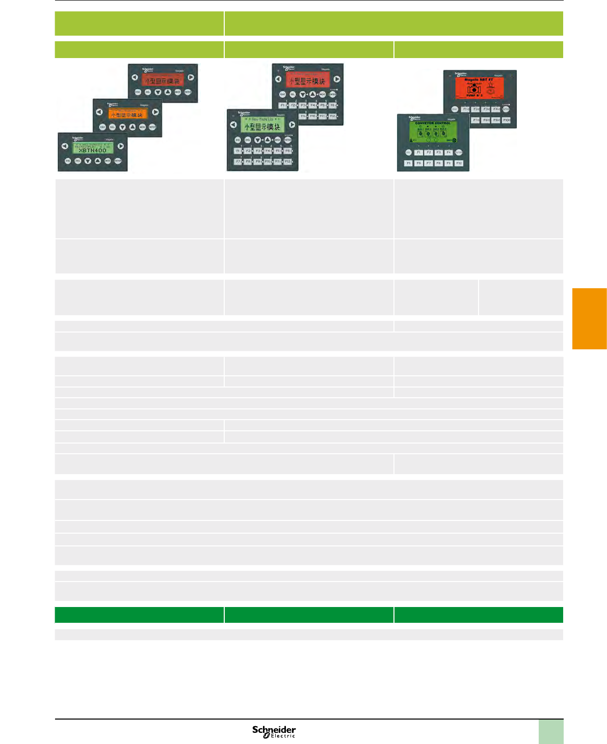
2
1
3
4
5
6
7
8
9
10
Applications Display of graphic pages Display of text messages and/or semi-graphic
pages
Display of text messages and/or semi-graphic pages
Control and conguration of data
Type of terminal Small Panels with touch screen Small Panels with keypad Small Panels with keypad Small Panels with touch screen and keypad
Display
Data entry
b
b
b
b
b
b
Memory
capacity
Functions
(5)
(4)
Communication (1)
(2)
(5)
(3)
Development software
Operating system
References HMI STO 5pp HMI STU 655 HMI STU 855 XBT N pppp XBT R ppp XBT RT ppp
Page
(1) Only HMI STO 511/512.
(2) Only HMI STO 501.
(3) Only HMI STO 531/532.
(4) Only XBT RT511.
(5) Depending on model.
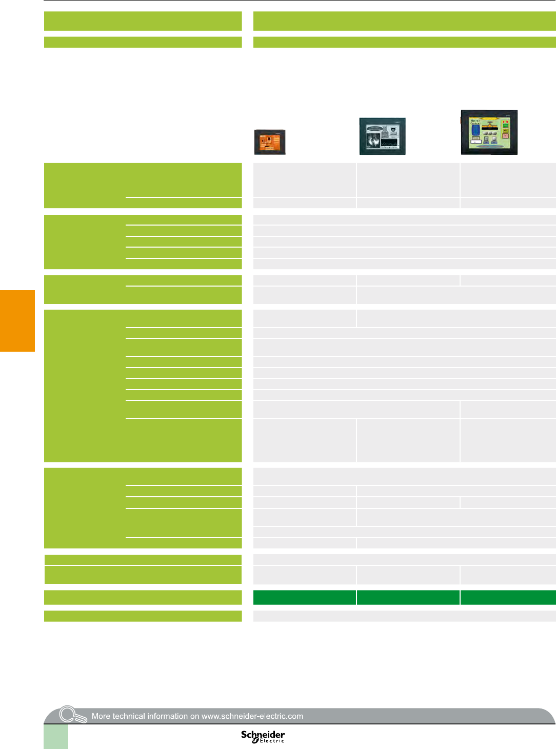
2
1
3
4
5
6
7
8
9
10
Selection guide Associated offers
Applications Display of text messages, graphic objects and synoptic views
Control and conguration of data
Display of text messages, graphic objects and synoptic views
Control and conguration of data
Type of terminal Touch screen Advanced Panels Touch screen Advanced Panels
Display
(3)
(4)
Data entry
Memory capacity (3)
Functions
(3)
(1)
(1)
Communication (2)(1)
(2)(1)
(3) 2
(1)
Development software
Operating system
(3)
Type of terminal XBT GT11/13
XBT GT21/22/23/24/29
XBT GT42/43 XBT GT52/53/54 XBT GT63 XBT GT73
Page
(1) Depending on model.
(2) Uni-TE version V2 for Twido controller and TSX Micro/Premium platform.
(3) For XBTGT 2430, 32 MB Flash EPROM, 1 sound output, 2 USB ports, 266 MHz RISC CPU.
(4) For XBT GT 5430.

2
1
3
4
5
6
7
8
9
10
Applications Display of text messages, graphic objects and synoptic views
Control and conguration of data
Display of text messages, graphic objects and synoptic views
Control and conguration of data
Type of terminal Touch screen Advanced Panels Touch screen Advanced Panels
Display
(3)
(4)
Data entry
Memory capacity (3)
Functions
(3)
(1)
(1)
Communication (2)(1)
(2)(1)
(3) 2
(1)
Development software
Operating system
(3)
Type of terminal XBT GT11/13
XBT GT21/22/23/24/29
XBT GT42/43 XBT GT52/53/54 XBT GT63 XBT GT73
Page
(1) Depending on model.
(2) Uni-TE version V2 for Twido controller and TSX Micro/Premium platform.
(3) For XBTGT 2430, 32 MB Flash EPROM, 1 sound output, 2 USB ports, 266 MHz RISC CPU.
(4) For XBT GT 5430.
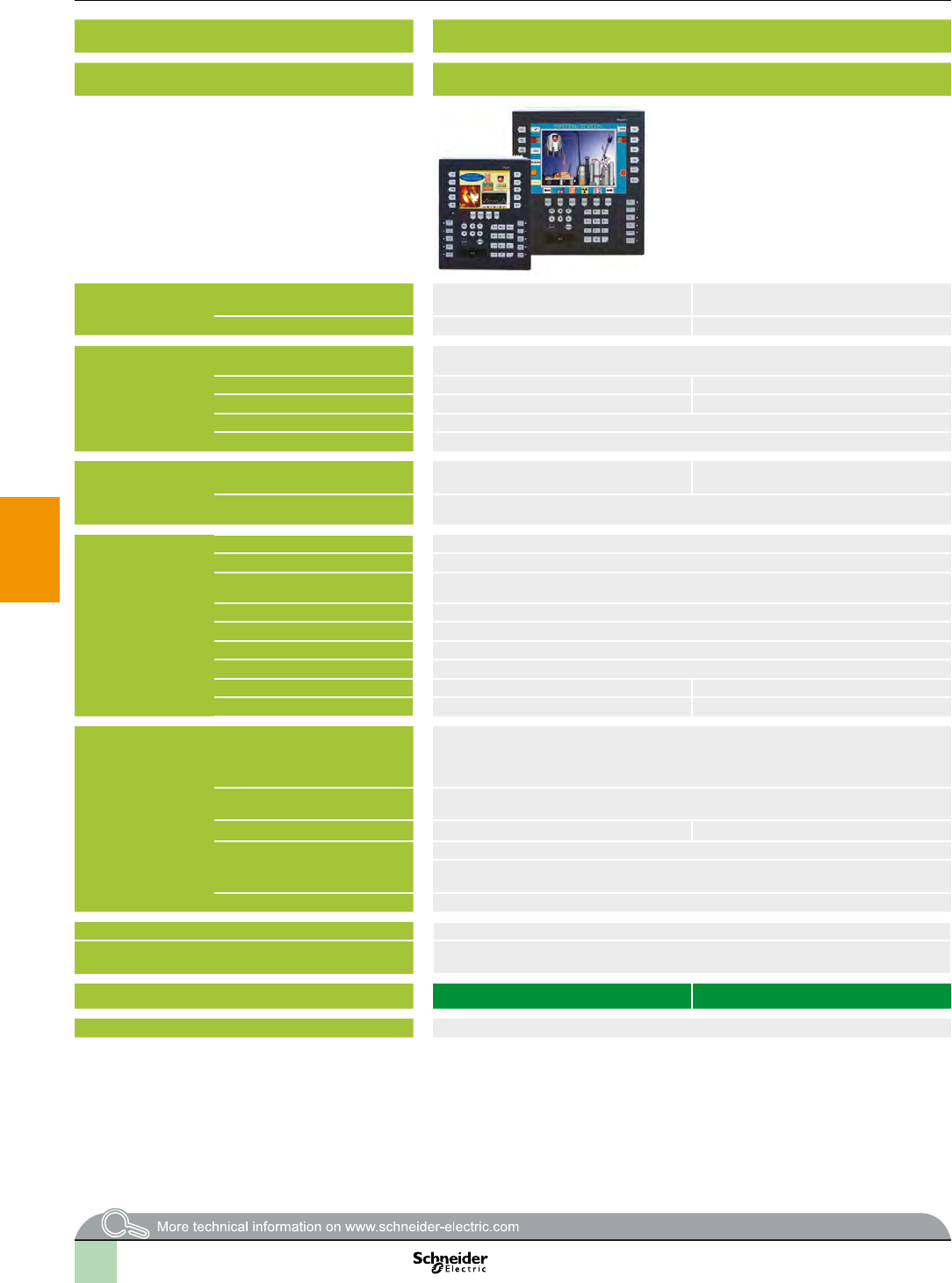
2
1
3
4
5
6
7
8
9
10
Selection guide (continued) Associated offers
Applications Display of text messages, graphic objects and synoptic views
Control and conguration of data
Display of text messages, graphic objects and synoptic views
Control and conguration of data
Type of terminal Advanced Panels with keypad Portable Advanced Panels Open touch screen Advanced Panels
Display
Data entry
Memory capacity
Functions
–
Communication (2)(1)
(2)(1)
2
Development software
Operating system
Type of terminal XBT GK 21/23 XBT GK 53 XBT GH 2460 XBT GTW 450 XBT GTW 652 HMI GTW 7353
Page
(1) Depending on model.
(2) Uni-TE version V2 for Twido controller and TSX Micro/Premium platform.
(1) Depending on model.
(2) Uni-TE version V2 for Twido controller and TSX Micro/Premium platform.
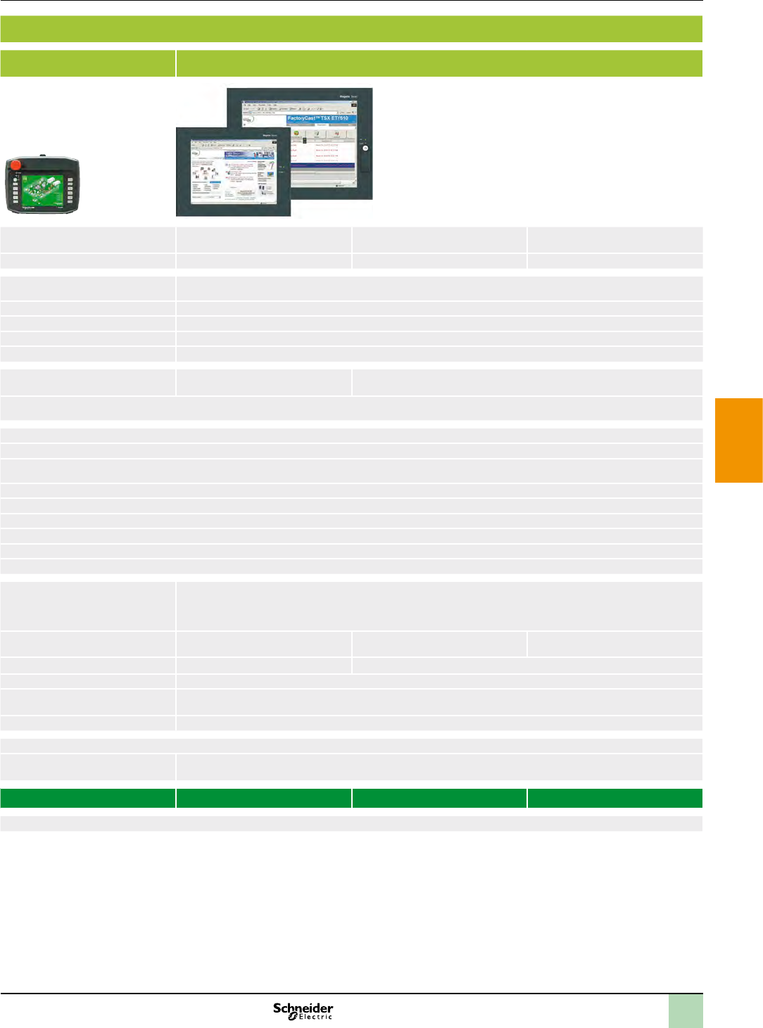
2
1
3
4
5
6
7
8
9
10
Applications Display of text messages, graphic objects and synoptic views
Control and conguration of data
Display of text messages, graphic objects and synoptic views
Control and conguration of data
Type of terminal Advanced Panels with keypad Portable Advanced Panels Open touch screen Advanced Panels
Display
Data entry
Memory capacity
Functions
–
Communication (2)(1)
(2)(1)
2
Development software
Operating system
Type of terminal XBT GK 21/23 XBT GK 53 XBT GH 2460 XBT GTW 450 XBT GTW 652 HMI GTW 7353
Page
(1) Depending on model.
(2) Uni-TE version V2 for Twido controller and TSX Micro/Premium platform.
(1) Depending on model.
(2) Uni-TE version V2 for Twido controller and TSX Micro/Premium platform.
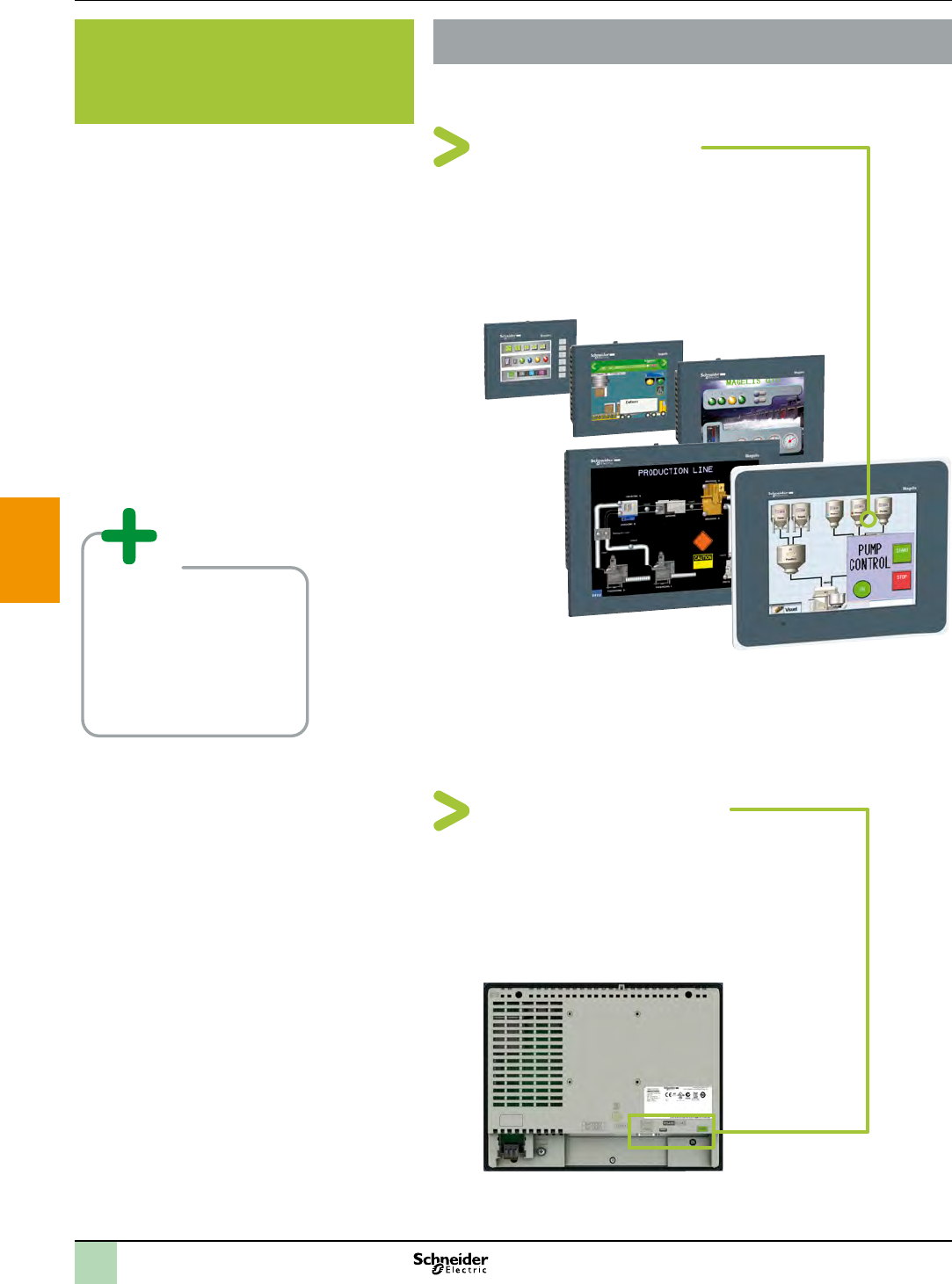
2
1
3
4
5
6
7
8
9
10
The new operator terminal standard for Machine Builders
State of the art display
>
>
Presentation Associated offers
MagelisTM GTO Optimum Advanced
Panels
>
>
Optimized communication
>
>
2
1
3
4
5
6
7
8
9
10
Presentation Associated offers
Easy to install and sustainable offer
With Magelis GTO, you can rely on a long term investment
>
>
The installation is made easy with:
>
>
>
Magelis GTO is part of Machine solution
>
Selection guide: see page 5/42
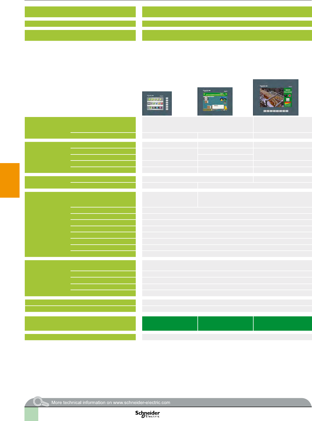
2
1
3
4
5
6
7
8
9
10
Selection guide Associated offers
Applications Display of text messages, graphic objects and synoptic views
Control and conguration of data
Display of text messages, graphic objects and synoptic views
Control and conguration of data
Type of terminal Optimum Advanced Panels, touch screen Optimum Advanced Panels, touch screen Optimum Advanced Panels, touch screen, “Stainless Steel” version
Degree of protection (according to IEC 60529) IP 65 (IP 67 with addition of a cover) IP 65 (IP 67 with addition of a cover) IP 66K (Front panel with stainless steel frame) for food & beverage
environment
Display
Data entry
Memory capacity (1)
Functions
Communication (2)(1)
(2)(1)
(3)
(4)
Development software
Operating system
Type of terminal HMI GTO1300
HMI GTO1310
HMI GTO2300
HMI GTO2310
HMI GTO3510 HMI GTO4310 HMI GTO5310 HMI GTO6310 HMI GTO2315 HMI GTO5315 HMI GTO6315
Page
(1) Depending on model.
(2) Uni-TE version V2 for Twido controller and TSX Micro/Premium platform.
(3) Except HMI GTO1300 and GTO2300 (Modbus Plus and Fipway via USB gateway only).
(4) Except HMI GTO1310 (USB port for parallel printer only).
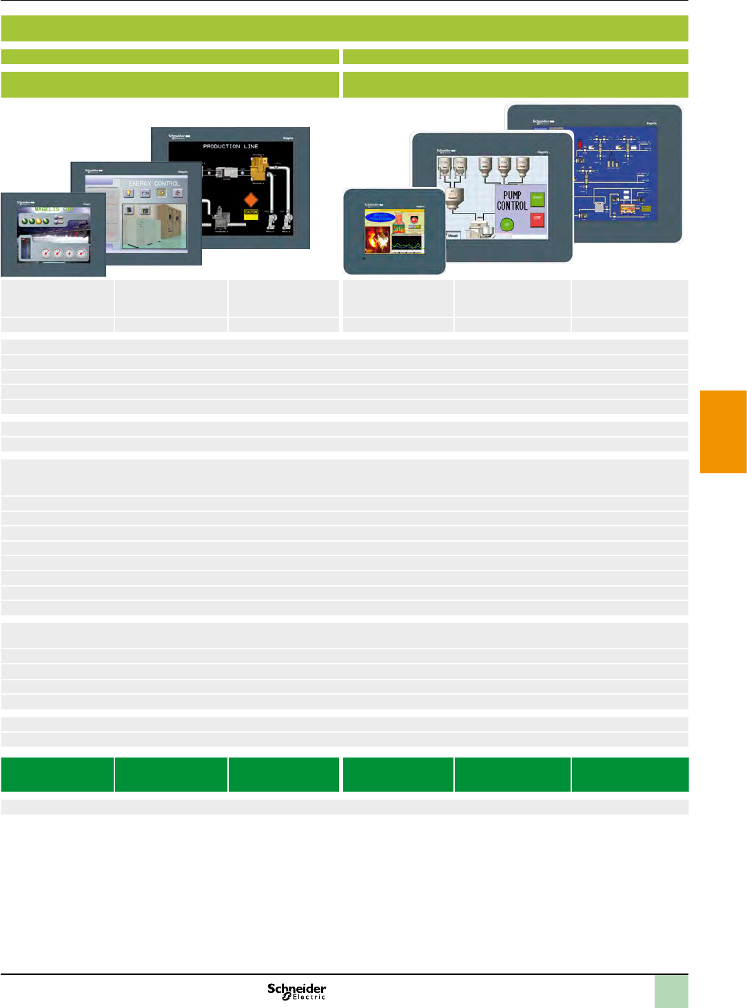
2
1
3
4
5
6
7
8
9
10
Applications Display of text messages, graphic objects and synoptic views
Control and conguration of data
Display of text messages, graphic objects and synoptic views
Control and conguration of data
Type of terminal Optimum Advanced Panels, touch screen Optimum Advanced Panels, touch screen Optimum Advanced Panels, touch screen, “Stainless Steel” version
Degree of protection (according to IEC 60529) IP 65 (IP 67 with addition of a cover) IP 65 (IP 67 with addition of a cover) IP 66K (Front panel with stainless steel frame) for food & beverage
environment
Display
Data entry
Memory capacity (1)
Functions
Communication (2)(1)
(2)(1)
(3)
(4)
Development software
Operating system
Type of terminal HMI GTO1300
HMI GTO1310
HMI GTO2300
HMI GTO2310
HMI GTO3510 HMI GTO4310 HMI GTO5310 HMI GTO6310 HMI GTO2315 HMI GTO5315 HMI GTO6315
Page
(1) Depending on model.
(2) Uni-TE version V2 for Twido controller and TSX Micro/Premium platform.
(3) Except HMI GTO1300 and GTO2300 (Modbus Plus and Fipway via USB gateway only).
(4) Except HMI GTO1310 (USB port for parallel printer only).
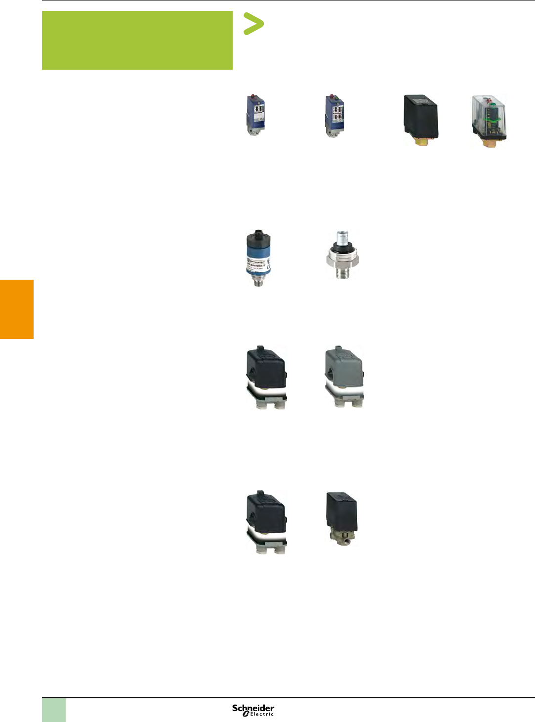
2
1
3
4
5
6
7
8
9
10
Presentation Associated offers
Select OsiSense XM sensor in terms of pumping
applications
OsiSense XM pressure sensors
> Medium duty from 0 to 25 bar
Electronic pressure
transmitters
type XMLA, with
xed differential:
detection of a single
threshold
Electronic pressure
transmitters
type XMLB with
adjustable differential:
regulation between 2
thresholds
Electromechanical
pressure switches
type XMX
Electromechanical
pressure switches
type XMA
> Over 25 bar & high end
Electronic pressure
transmitters
type XMLK
Electronic pressure
transmitters
type XMLP
> Light duty from 0 to 8 bar: Small pumps up to 3 HP
Electromechanical
pressure switches
type FTG
with xed differential:
detection of a single
threshold
Electromechanical
pressure switches
type FSG
with adjustable
differential: regulation
between 2 thresholds
> Medium duty from 0 to 25 bar : Mid-power pumps up to 4 HP
Electromechanical
pressure switches
type FYG
with adjustable
differential: regulation
between 2 thresholds,
2 contacts
Electromechanical
pressure switches
type XMP
with adjustable
differential: regulation
between 2 thresholds,
2 or 3 contacts
2
1
3
4
5
6
7
8
9
10
Presentation Associated offers
Connect with the experts
>
>
How to choose a pressure sensor in 4 steps?
1Choose a product line according to application
>
>
>
2Choose a product according to the pressure
>
3Choose the uid connection according habits (geographical use)
>
4Choose the electrical connection according habits
>
OsiSense XMLK optimum pressure transmitter for
pumps
>
>
>
>
>
>
>
>
>
OsiSense XMLP optimum pressure transmitter for
Hydraulics & HVAC
>
>
>
>
>
>
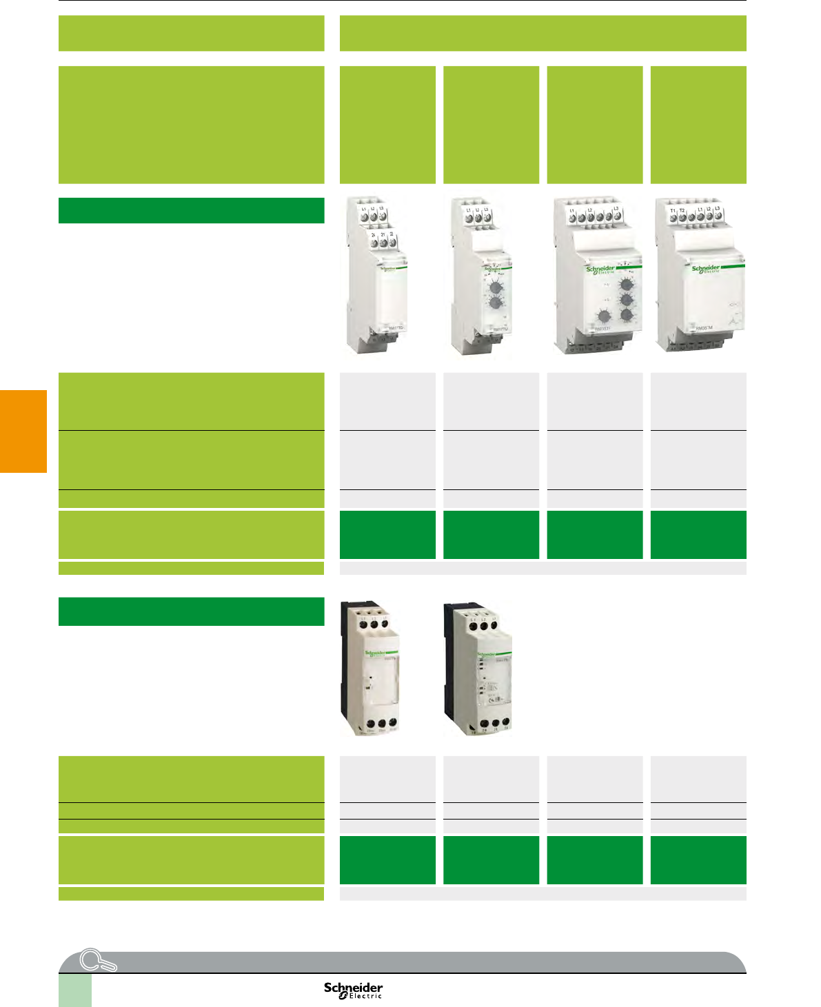
2
1
3
4
5
6
7
8
9
10
Selection guide Associated offers
Application Control of 3-phase supplies Voltage control Current control
Functions
3-phase
Single-phase and d.c. Integrated current
transformer
Modular type
Values controlled a
a
a a
a
a a
a
a
c
ac
ac
ac
ac
ac
ac
ac
Output
Size
Modular relay type p
p
ppp
ppp p
More information
Industrial type
Values controlled a
a
a
a
a
a
ac
ac
Output
Size
Industrial relay type
pp
pp
pp
pp
p
p
More information
More technical information on www.schneider-electric.com . . . please consult the end pages of this catalogue
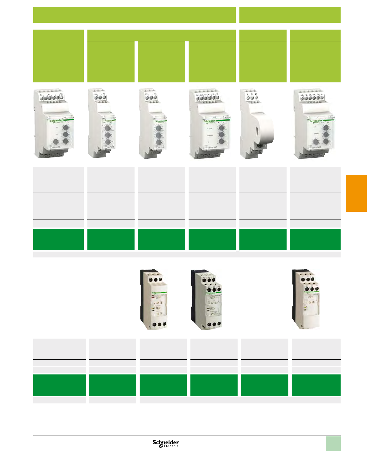
2
1
3
4
5
6
7
8
9
10
Application Control of 3-phase supplies Voltage control Current control
Functions
3-phase
Single-phase and d.c. Integrated current
transformer
Modular type
Values controlled a
a
a a
a
a a
a
a
c
ac
ac
ac
ac
ac
ac
ac
Output
Size
Modular relay type p
p
ppp
ppp p
More information
Industrial type
Values controlled a
a
a
a
a
a
ac
ac
Output
Size
Industrial relay type
pp
pp
pp
pp
p
p
More information
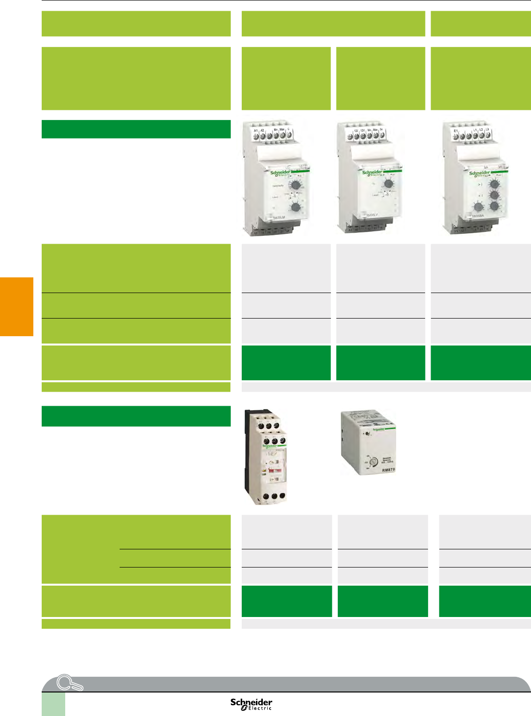
2
1
3
4
5
6
7
8
9
10
Selection guide Associated offers
Application Level control Pump control Frequency control Speed control Temperature control for elevator machine rooms and 3-phase supplies
Functions By resistive probes By discrete sensor 3-phase and single-phase
Modular type
Values controlled W
W
W
a
a
a
Output
Size
Modular relay type
More information
Industrial type
Industrial type Values controlled W
W
W
W
Output
Size
Industrial relay type
More information
More technical information on www.schneider-electric.com . . . please consult the end pages of this catalogue
2
1
3
4
5
6
7
8
9
10
Application Level control Pump control Frequency control Speed control Temperature control for elevator machine rooms and 3-phase supplies
Functions By resistive probes By discrete sensor 3-phase and single-phase
Modular type
Values controlled W
W
W
a
a
a
Output
Size
Modular relay type
More information
Industrial type
Industrial type Values controlled W
W
W
W
Output
Size
Industrial relay type
More information
2
1
3
4
5
6
7
8
9
10
490
490NTC00005
4/7
490NTC00005U
4/7
490NTC00015
4/7
490NTC00040
4/7
490NTC00040U
4/7
490NTC00080
4/7
490NTC00080U
4/7
490NTW00002
4/7
490NTW00002U
4/7
490NTW00005
4/7
490NTW00005U
4/7
490NTW00012
4/7
490NTW00012U
4/7
490NTW00040
4/7
490NTW00040U
4/7
490NTW00080
4/7
490NTW00080U
4/7
499
499NEH10410
4/7
499NES18100
4/7
499NMS25101
4/7
499NMS25102
4/7
499NSS25101
4/7
499NSS25102
4/7
499TWD01100
4/9
9001
9001K, 9001SK
5/23
A
ABL4RSM24035
5/27
ABL4RSM24050
5/27
ABL4RSM24100
5/27
ABL4RSM24200
5/27
ABL4WSR24200
5/27
ABL4WSR24300
5/27
ABL4WSR24400
5/27
ABL7RM24025
5/26
ABL7RP1205
5/26
ABL7RP4803
5/26
ABL8DCC05060
5/27
ABL8DCC12020
5/27
ABL8MEM05040
5/26
ABL8MEM12020
5/26
ABL8MEM24003
5/26
ABL8MEM24006
5/26
ABL8MEM24012
5/26
ABL8REM24030
5/26
ABL8REM24050
5/26
AMP
5/18
ATS01N103FT
5/5
ATS01N106FT
5/5
ATS01N109FT
5/5
ATS01N112FT
5/5
ATS01N125FT
5/5
ATS01N206LU
5/5
ATS01N206QN
5/6
ATS01N206RT
5/6
ATS01N209LU
5/6
ATS01N209QN
5/6
ATS01N209RT
5/6
ATS01N212LU
5/5
ATS01N212QN
5/6
ATS01N212RT
5/6
ATS01N222LU
5/5
ATS01N222QN
5/6
ATS01N222RT
5/6
ATS01N232LU
5/5
ATS01N232QN
5/6
ATS01N232RT
5/7
ATS22C11Q
5/7
ATS22C14Q
5/7
ATS22C17Q
5/7
ATS22C21Q
5/7
ATS22C25Q
5/7
ATS22C32Q
5/7
ATS22C41Q
5/7
ATS22C48Q
5/7
ATS22C59Q
5/7
ATS22D17Q
5/7
ATS22D32Q
5/7
ATS22D47Q
5/7
ATS22D62Q
5/7
ATS22D75Q
5/7
ATS22D88Q
5/7
ATS48C11Q
5/7
ATS48C14Q
5/7
ATS48C17Q
5/7
ATS48C21Q
5/7
ATS48C25Q
5/7
ATS48C32Q
5/7
ATS48C41Q
5/7
ATS48C48Q
5/7
ATS48C59Q
5/7
ATS48C66Q
5/7
ATS48C79Q
5/7
ATS48D17Q
5/7
ATS48D22Q
5/7
ATS48D32Q
5/7
ATS48D38Q
5/7
ATS48D47Q
5/7
ATS48D62Q
5/7
ATS48D75Q
5/7
ATS48D88Q
5/7
ATS48M10Q
5/7
ATS48M12Q
5/7
ATV212H075M3X
5/4
ATV212H075N4
5/4
ATV212HD11M3X
5/4
ATV212HD11N4
5/4
ATV212HD15M3X
5/4
ATV212HD15N4
5/4
ATV212HD18M3X
5/4
ATV212HD18N4
5/4
ATV212HD22M3X
5/4
ATV212HD22N4
5/4
ATV212HD30M3X
5/4
ATV212HD30N4
5/4
ATV212HD37N4
5/4
ATV212HD45N4
5/4
ATV212HD55N4
5/4
ATV212HD75N4
5/4
ATV212HU15M3X
5/4
ATV212HU15N4
5/4
ATV212HU22M3X
5/4
ATV212HU22N4
5/4
ATV212HU30M3X
5/4
ATV212HU30N4
5/4
ATV212HU40M3X
5/4
ATV212HU40N4
5/4
ATV212HU55M3X
5/4
ATV212HU55N4
5/4
ATV212HU75M3X
5/4
ATV212HU75N4
5/4
ATV61H075M3
5/5
ATV61H075M3
5/5
ATV61HD11M3X
5/5
ATV61HD15M3X
5/5
ATV61HD18M3X
5/5
ATV61HD22M3X
5/5
ATV61HD30M3X
5/5
ATV61HD37M3X
5/5
ATV61HD45M3X
5/5
ATV61HD55M3X
5/5
ATV61HD75M3X
5/5
ATV61HD90M3X
5/5
ATV61HU15M3
5/5
ATV61HU15M3
5/5
ATV61HU22M3
5/5
ATV61HU22M3
5/5
ATV61HU30M3
5/5
ATV61HU30M3
5/5
ATV61HU40M3
5/5
ATV61HU40M3
5/5
ATV61HU55M3
5/5
ATV61HU55M3
5/5
ATV61HU75M3
5/5
ATV61HU75M3
5/5
D
DM6000
5/18
DM6200
5/18
G
GV2ME
5/13
GV2P
5/13
GV3ME80
5/13
GV3P
5/13
GV7RE
5/13
H
HMIGTO1300
5/36
HMIGTO1310
5/36
HMIGTO2300
5/36
HMIGTO2310
5/36
HMIGTO2315
5/36
HMIGTO3510
5/36
HMIGTO4310
5/37
HMIGTO5310
5/37
HMIGTO5315
5/37
HMIGTO6310
5/37
HMIGTO6315
5/37
HMIGTW7353
5/33
HMISTO5pp
5/28
HMISTU655
5/28
HMISTU855
5/28
HMIZSUSBB
3/22
I
IEM3110
5/19
K
K1, K2, K10, K30, K50,
K63, K115, K150
5/23
L
LC1B
5/12
LC1D
5/12
LC1F
5/12
LC1K
5/12
LC1SK
5/12
LC7K
5/12
LP1K
5/12
LP1SK
5/12
LP4K
5/12
LR2K
5/14
LR9F
5/14
LR97D
5/14
LRD, LR2D, LR9D
5/14
LT3S
5/15
LT47
5/15
LTMR
5/15
LU9GC3
4/4
LUFP7
3/21
LUFP9
3/21
LUTMp0BL
5/15
M
Micrologic A trip unit
5/18
Micrologic E trip unit
5/18
Modicon OTB
interface modules
3/34
Modicon TM2 analog
module
3/34
Modicon TM2 digital
module
3/34
Modicon TM5 analog
module
3/35
Modicon TM5
compact block
3/35
Modicon TM5 digital
module
3/35
Modicon TM7 analog
block
3/35
Modicon TM7 digital
block
3/35
MSDCHLLMUV31S0
2/5
MSDCHLLMTV31S0
2/5
MSDCHLLMFV31S0
2/5
P
PM1200
5/19
PM3210
5/19
PM700
5/19
PM750
5/19
PM820
5/19
PM9
5/19
PM1000
5/19
PowerView
5/19
R
RM17JC00MW
5/41
RM17TA00
5/40
RM17TE00
5/40
RM17TT00
5/40
RM17TU00
5/40
RM17UAS1p
5/41
RM17UB310
5/41
RM17UBE1p
5/41
RM35ATL0MW
5/43
RM35ATR5MW
5/43
RM35ATW5MW
5/43
RM35BA10
5/42
RM35HZ21FM
5/43
RM35JA3pMW
5/41
RM35LM33MW
5/42
RM35LV14MW
5/42
RM35S0MW
5/43
RM35TF30
5/40
RM35TMp50MW
5/40
RM35UA1pMW
5/41
RM35UB3ppp
5/41
RM4JA01
5/41
RM4JA3p
5/41
RM4L
5/42
RM4TApp
5/40
RM4TG20
5/40
RM4TRpp
5/40
RM4TUpp
5/40
RM4UA1p
5/41
RM4UA3p
5/41
RM4UB3p
5/41
RM84
5/42
S
SR2MOD03
3/21
T
TCSECL1M3M10S2
4/7
TCSECL1M3M1S2
4/7
TCSECL1M3M25S2
4/7
TCSECL1M3M3S2
4/7
TCSECL1M3M40S2
4/7
TCSECL1M3M5S2
4/7
TCSECN300R2
4/6
TCSEK1MDRS
4/6
TCSEK3MDS
4/6
TCSESM043F1CS0
4/7
TCSESM043F1CU0
4/7
TCSESM043F2CS0
4/7
TCSESM043F2CU0
4/7
TCSESM083F1CS0
4/7
TCSESM083F1CU0
4/7
TCSESM083F23F0
4/7
TCSESM083F2CS0
4/7
TCSESM083F2CU0
4/7
TCSESU033FN0
4/7
TCSESU043FN0
4/7
TCSESU051F0
4/7
TCSESU053FN0
4/7
TCSMCN3M4F3C2
3/21
TCSMCN3M4F3C2
3/33
TCSMCN3M4F3C2
4/5
TCSMCN3M4M3S2
3/21
TCSMCN3M4M3S2
3/33
TCSMCN3M4M3S2
4/5
TCSXCNAMUM3P
3/21
TCSXCNAMUM3P
3/33
TCSXCNAMUM3P
3/7
TGp0
5/40
TM200RSRCEMC
3/21
TM238CNTLSCT
3/22
TM238LFAC24DRS0
3/21
TM238LFDC24DTS0
3/21
TM238RSSCT
3/22
TM238RSSPT
3/21
TM258LF42DTS0
3/32
TM258LF42DT4LS0
3/32
TM258LF42DRS0
3/32
TM258LF66DT4LS0
3/32
TM2USBABDEV1
3/22
TM5ACLITB1
3/33
TM5ACLITR1
3/33
TM5ACLITW1
3/33
TM5ACLT1
3/33
TM5ACTCH100
3/33
TM5ACTLC100
3/33
TM5ACTLS100
3/33
TM5PCRS2
4/3
TM5PCRS4
4/3
TSXCSA100
4/5
TSXCSA200
4/5
TSXCSA500
4/5
TSXCX100
4/5
TSXPLP01
3/21
TSXPLP101
3/21
TSXSCA50
4/4
TWDXCARJ003
4/5
TWDXCARJ010
4/5
TWDXCARJ030
4/5
TWDXCARJP03
4/5
TWDXCARJP03P
4/5
Index Appendices
2
1
3
4
5
6
7
8
9
10
TWDXCAFD010
4/5
TWDXCAFJ010
4/5
TWDXCAISO
4/4
TWDXCAT3RJ
4/4
V
VLT
5/18
VW3A8306D30
4/5
VW3A8306R03
4/5
VW3A8306R10
4/5
VW3A8306R30
4/5
VW3A8306RC
4/5
VW3A3521S0
3/7
VW3A3201
3/7
VW3A3202
3/7
VW3A8306TF03
4/4
VW3A8306TF10
4/4
VW3A8306R03
3/21
VW3A8306R10
3/21
VW3A8306R30
3/21
X
XALE
5/24
XALF
5/25
XALG
5/25
XALD
5/24
XALK
5/24
XAPA
5/25
XAPE
5/25
XAPJ
5/25
XAPM
5/25
XAPS
5/25
XB2SL
5/25
XB4
5/22
XB5R,XB4R
5/22
XB5S
5/22
XB5
5/22
XB6
5/22
XB7
5/23
XBTZ9008
4/5
XBTZ938
4/5
XBTZ9980
4/5
XBTZG60
3/14
XBT9980
3/33
XBTGC1100T
3/14
XBTGC1100U
3/14
XBTGC2120T
3/14
XBTGC2120U
3/14
XBTGC2230T
3/14
XBTGC2230U
3/14
XBTGH2460
5/33
XBTGK21/23
5/32
XBTGK53
5/32
XBTGT11/13
5/30
XBTGT21/22/23/24/29
5/30
XBTGT42/43
5/30
XBTGT52/53/54
5/31
XBTGT63
5/31
XBTGT73
5/31
XBTGTW450
5/32
XBTGTW652
5/32
XBTNpppp
5/29
XBTRppp
5/29
XBTRTppp
5/29
XBTZ938
3/33
XBTZ9980
4/9
XBTZ9980
3/21
XBTZG51
3/14
XBTZG52
3/14
XBTZG62
3/14
XBTZG935
3/14
XBTZGCCAN
3/14
XBTZGCHOK
3/14
XBTZGCLP2
3/14
XBTZGCLP4
3/14
XBTZGDIO1
3/14
XBTZGDIO2
3/14
XBTZGFIX
3/14
XBTZGPWS1
3/14
XBTZGUSB
3/14
XBTZGUSBB
3/14
XD2GA
5/23
XD4PA
5/23
XD5PA
5/23
XGSZ24
4/4
XVLA
5/22
Index Appendices

The information provided in this documentation contains general descriptions and/or technical
characteristics of the performance of the products contained herein. This documentation is not
intended as a substitute for and is not to be used for determining suitability or reliability of these
products for specic user applications. It is the duty of any such user or integrator to perform the
appropriate and complete risk analysis, evaluation and testing of the products with respect to the
relevant specic application or use thereof. Neither Schneider Electric nor any of its afliates or
subsidiaries shall be responsible or liable for misuse of the information contained herein.
Design: Schneider Electric
Photos: Schneider Electric
Printed by:
Head Ofce
35, rue Joseph Monier
F-92500 Rueil-Malmaison
France
Schneider Electric Industries SAS www.schneider-electric.com/pumping
ART. 057170 November 2012
MKTED2121001EN
