8502CT0401 118248 Catalog
2014-09-05
: Pdf 118248-Catalog 118248-Catalog 785901 Batch7 unilog
Open the PDF directly: View PDF ![]() .
.
Page Count: 120 [warning: Documents this large are best viewed by clicking the View PDF Link!]
Heavy industrial power
applications
Motor contactors and starters
Catalog
January
2006

General contents
0
Heavy Industrial Power Applications
Motor Contactors and Starters
1 – Contactors and Starters, Type S, NEMA Style
2 – Combination Starters, Type S, NEMA Style
3 – Solid-State Overload Relays
4 – Definite Purpose Contactors
5 – Lighting Contactors
6 – Manual Starters and Switches
7 – Accessories
8 – Services

1/0

1/1
Contents
1
1 - Heavy Industrial Contactors and
Starters, Type S, NEMA Style
Selection guide . . . . . . . . . . . . . . . . . . . . . . . . . . . . . . . . . . . . . . . . . . . . . page 1/2
bContactors and starters
vGeneral, characteristics . . . . . . . . . . . . . . . . . . . . . . . . . . . . . . . . . . . . page 1/4
bContactors, Class 8502
vReferences . . . . . . . . . . . . . . . . . . . . . . . . . . . . . . . . . . . . . . . . . . . . . page 1/6
bReversing contactors, Class 8702
vReferences . . . . . . . . . . . . . . . . . . . . . . . . . . . . . . . . . . . . . . . . . . . . . page 1/7
bStarters, Class 8536
vReferences . . . . . . . . . . . . . . . . . . . . . . . . . . . . . . . . . . . . . . . . . . . . . page 1/8
bReversing starters, Class 8736
vReferences . . . . . . . . . . . . . . . . . . . . . . . . . . . . . . . . . . . . . . . . . . . . . page 1/9
bContactors and starters
vVariants – Motor Logic®. . . . . . . . . . . . . . . . . . . . . . . . . . . . . . . . . . . page 1/10
vVariants – Motor Logic® Plus . . . . . . . . . . . . . . . . . . . . . . . . . . . . . . . page 1/11
vVariants . . . . . . . . . . . . . . . . . . . . . . . . . . . . . . . . . . . . . . . . . . . . . . . page 1/12
vDimensions . . . . . . . . . . . . . . . . . . . . . . . . . . . . . . . . . . . . . . . . . . . . page 1/14
1/2
1
Selection guide
0
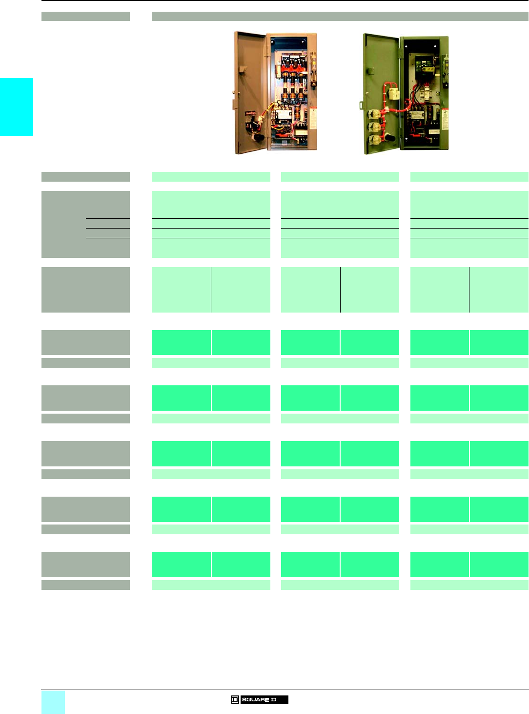
Contactors and Starters 0
Type S, NEMA-style
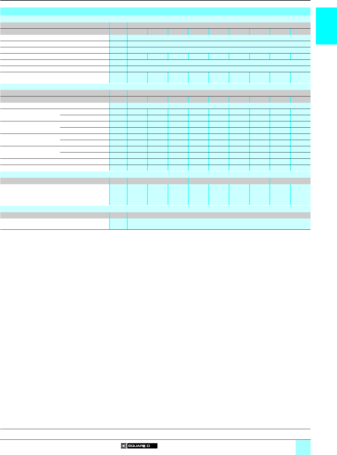
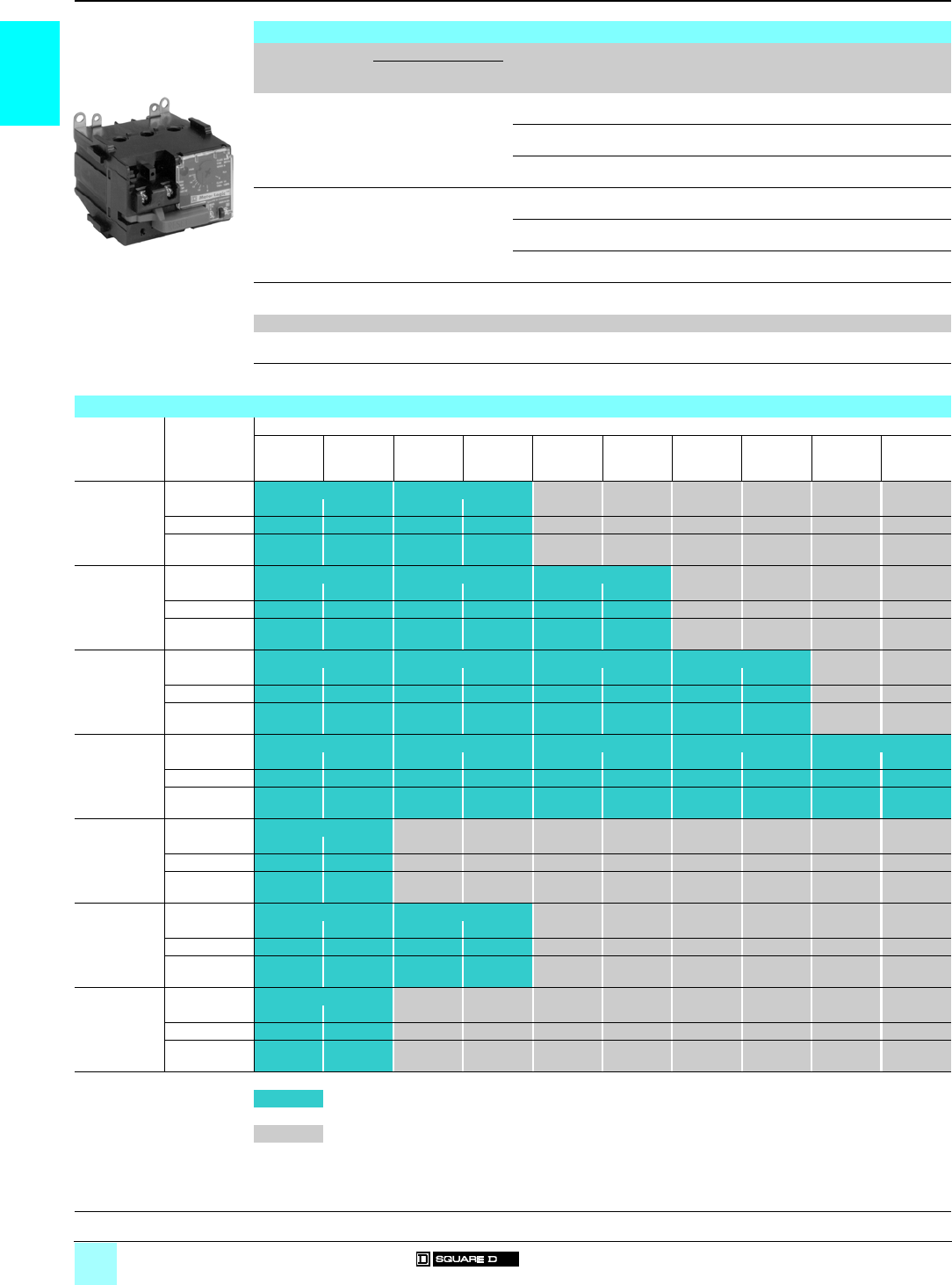
Contactors and starters
Applications Type S NEMA Contactors and Starters
NEMA Size 00 012
Continuous current
ratings
9 A 18 A 27 A 45 A
Motor
200 V 1.5 hp/1.1 kW 3 hp/2.2 kW 7.5 hp/5.5 kW 10 hp/7.5 kW
230 V 1.5 hp/1.1 kW 3 hp/2.2 kW 7.5 hp/5.5 kW 15 hp/11 kW
460 V 2 hp/1.5 kW 5 hp/3.7 kW 10 hp/7.5 kW 25 hp/18.5 kW
575 V 2 hp/1.5 kW 5 hp/3.7 kW 10 hp/7.5 kW 25 hp/18.5 kW
Enclosures Open NEMA
1
NEMA
12
Open NEMA
1
NEMA
12
Open NEMA
1
NEMA
12
Open NEMA
1
NEMA
12
- NEMA 1: General purpose
- NEMA 12: Dust-tight and
drip-tight for industrial use
Contactors 8502
SAO
8502
SAG
8502
SBA
8502
SBO
8502
SBG
8502
SBA
8502
SCO
8502
SCG
8502
SCA
8502
SDO
8502
SDG
8502
SDA
Pages 1/6 1/6 1/6 1/6
Reversing contactors 8702
SAO
8702
SAG
8702
SBA
8702
SBO
8702
SBG
8702
SBA
8702
SCO
8702
SCG
8702
SCA
8702
SDO
8702
SDG
8702
SDA
Pages 1/7 1/7 1/7 1/7
Starters 8536
SAO
8536
SAG
8536
SBA
8536
SBO
8536
SBG
8536
SBA
8536
SCO
8536
SCG
8536
SCA
8536
SDO
8536
SDG
8536
SDA
Pages 1/8 1/8 1/8 1/8
Reversing starters 8736
SAO
8736
SAG
8736
SBA
8736
SBO
8736
SBG
8736
SBA
8736
SCO
8736
SCG
8736
SCA
8736
SDO
8736
SDG
8736
SDA
Pages 1/9 1/9 1/9 1/9
531259
531260
531261
531262
1/3
1
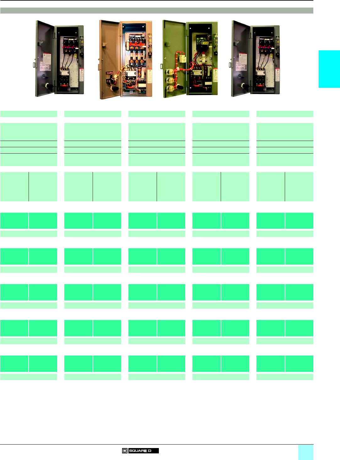
0
Type S NEMA Contactors and Starters
34567
90 A 135 A 270 A 540 A 810 A
25 hp/18.5 kW 40 hp/30 kW 75 hp/55 kW 150 hp/110 kW –
30 hp/22 kW 50 hp/37 kW 100 hp/75 kW 200 hp/150 kW 300 hp/220 kW
50 hp/37 kW 100 hp/75 kW 200 hp/150 kW 400 hp/300 kW 600 hp/450 kW
50 hp/37 kW 100 hp/75 kW 200 hp/150 kW 400 hp/300 kW 600 hp/450 kW
Open NEMA
1
NEMA
12
Open NEMA
1
NEMA
12
Open NEMA
1
NEMA
12
Open NEMA
1
NEMA
12
Open NEMA
1
NEMA
12
8502
SEO
8502
SEG
8502
SEA
8502
SFO
8502
SFG
8502
SFA
8502
SGO
8502
SGG
8502
SGA
8502
SHO
8502
SHG
8502
SHA
8502
SJO
8502
SJG
8502
SJA
1/6 1/6 1/6 1/6 1/6
8702
SEO
8702
SEG
8702
SEA
8702
SFO
8702
SFG
8702
SFA
8702
SGO
8702
SGG
8702
SGA
8702
SHO
8702
SHG
8702
SHA
8702
SJO
8702
SJG
8702
SJA
1/7 1/7 1/7 1/7 1/7
8536
SEO
8536
SEG
8536
SEA
8536
SFO
8536
SFG
8536
SFA
8536
SGO
8536
SGG
8536
SGA
8536
SHO
8536
SHG
8536
SHA
8536
SJO
8536
SJG
8536
SJA
1/8 1/8 1/8 1/8 1/8
8736
SEO
8736
SEG
8736
SEA
8736
SFO
8736
SFG
8736
SFA
8736
SGO
8736
SGG
8736
SGA
8736
SHO
8736
SHG
8736
SHA
8736
SJO
8736
SJG
8736
SJA
1/9 1/9 1/9 1/9 1/9
531263
531264
531265
531266
531266
1/4
1
General,
characteristics
0
Contactors and Starters 0
Type S, NEMA-style
Contactors and starters
General
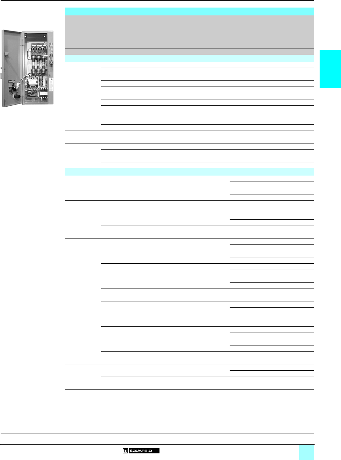
Full-voltage contactors
Class 8502 Type S magnetic contactors are used to switch heating loads,
capacitors, transformers and electric motors where overload protection is provided
separately. Class 8502 contactors are available in NEMA Sizes 00 to 7. Type S
contactors are designed for operation up to a 600 V, 50 to 60 Hz.
Full-voltage starters
Class 8536 Type S magnetic starters are used for full-voltage starting and stopping
of a.c. squirrel-cage motors. Motor overload protection is provided via solid-state
overload relays. Type S starters are available in NEMA Sizes 00 to 7 and are
designed for operation up to a 600 V, 50 to 60 Hz.
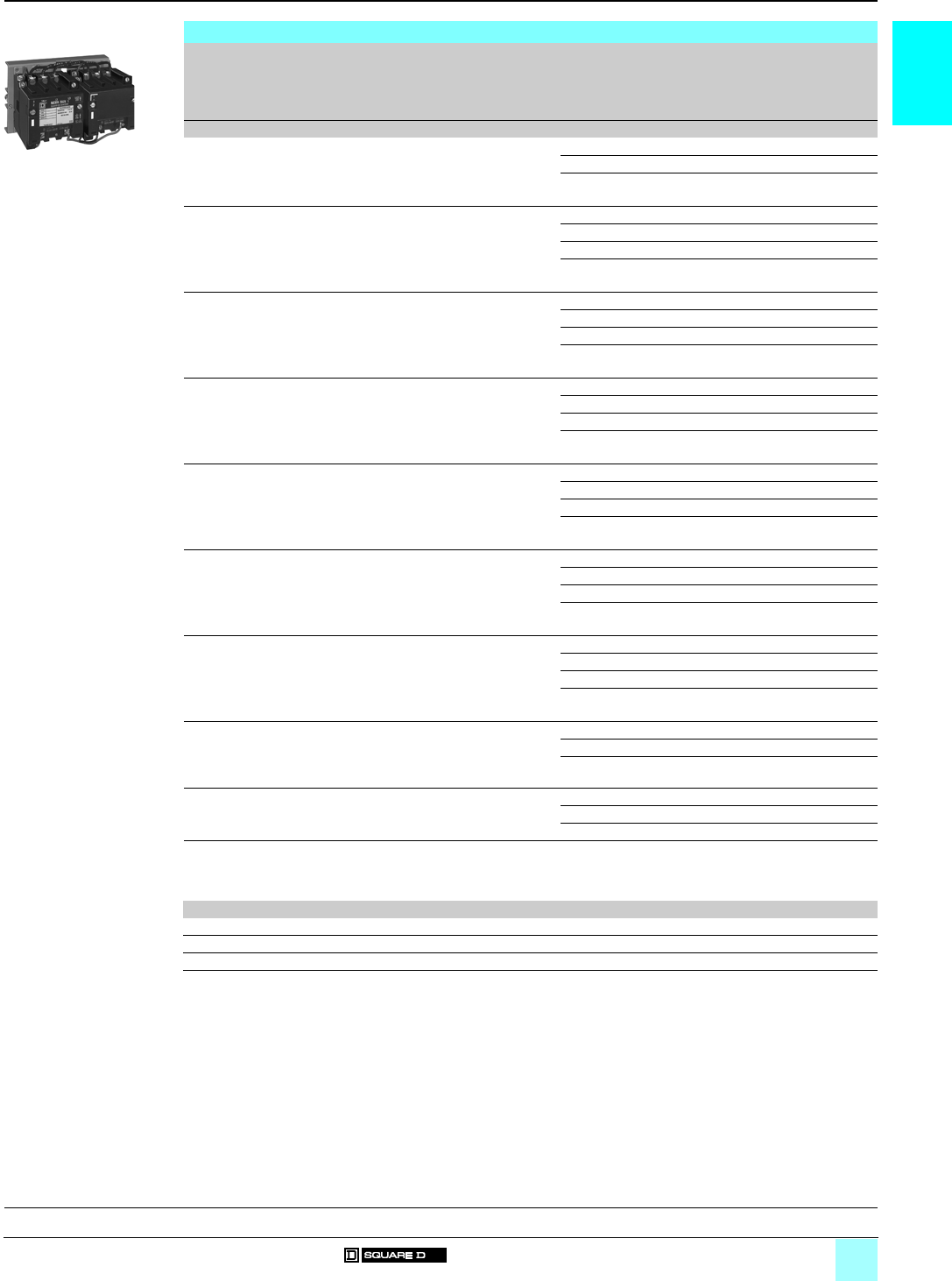
Full-voltage reversing contactors
Class 8702 Type S reversing magnetic contactors are used for starting, stopping and
reversing a.c. motors where overload protection is provided separately. Class 8702
reversing contactors consist of two Class 8502 contactors mechanically and
electrically interlocked. Open-type devices, Sizes 0 to 5, are available in either
horizontal or vertical arrangements. Sizes 00, 6 and 7 are available as horizontal
only. Enclosed devices Size 00 to 7 use horizontally arranged components. Type S
reversing contactors are designed for operation up to a 600 V, 50 to 60 Hz.
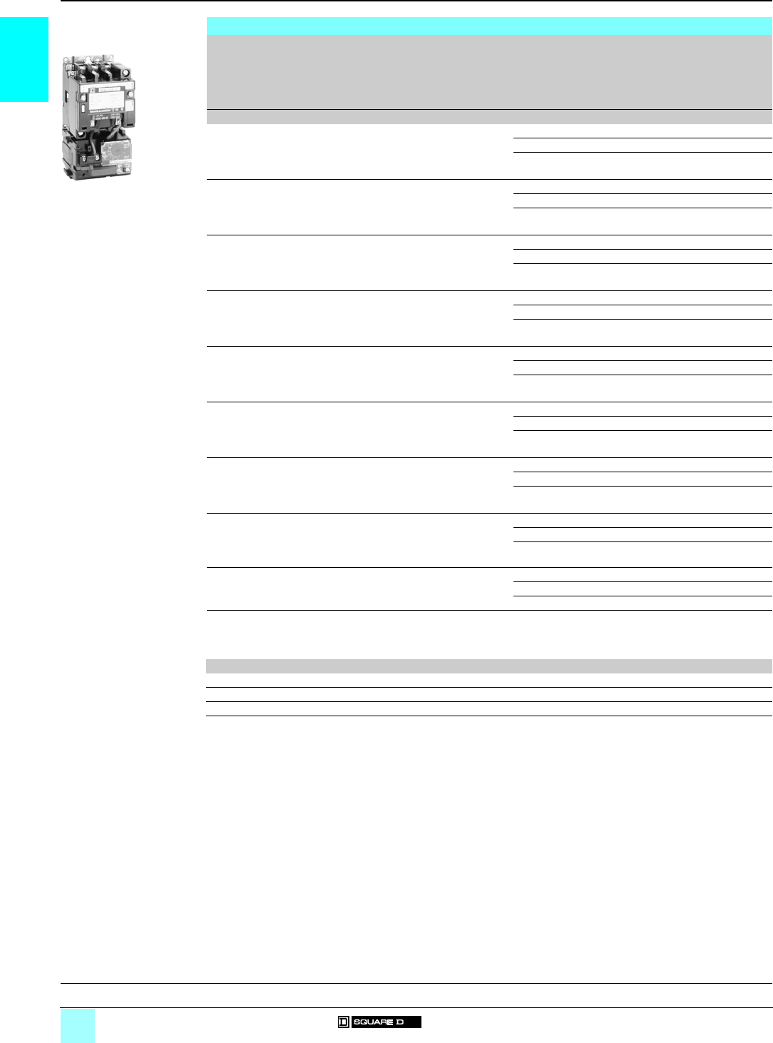
Full-voltage reversing starters
Class 8736 Type S reversing magnetic starters are used for full-voltage starting,
stopping and reversing of a.c. squirrel-cage motors. Class 8736 starters consist of
one Class 8502 contactor and one Class 8536 starter mechanically and electrically
interlocked. Open-type devices, Sizes 0 to 5, are available in either horizontal or
vertical arrangements. Sizes 00, 6 and 7 are available as horizontal only. Enclosed
devices use horizontally arranged components. Type S starters are designed for
operation up to a 600 V, 50 to 60 Hz.
Characteristics
Environment
Class 8502, 8536, 8702, 8736
Size 00 01234567
Rated insulation voltage
Conforming to UL, CSA V600
Rated impulse withstand voltage kV 510 18
Conforming to standards NEMA ICS-1, ICS-2, UL 508
Product certifications
Type S
magnetic contactors
and starters
UL Yes
CSA Yes
eYes No
Ambient air temperature
around the device
Storage °C 0…40
Operation °C 0…40
Maximum operating altitude Without derating m1300
Operating position (1) Without derating ± 90° Vertical
(1) ± 90° degrees possible in relation to normal vertical mounting plane.
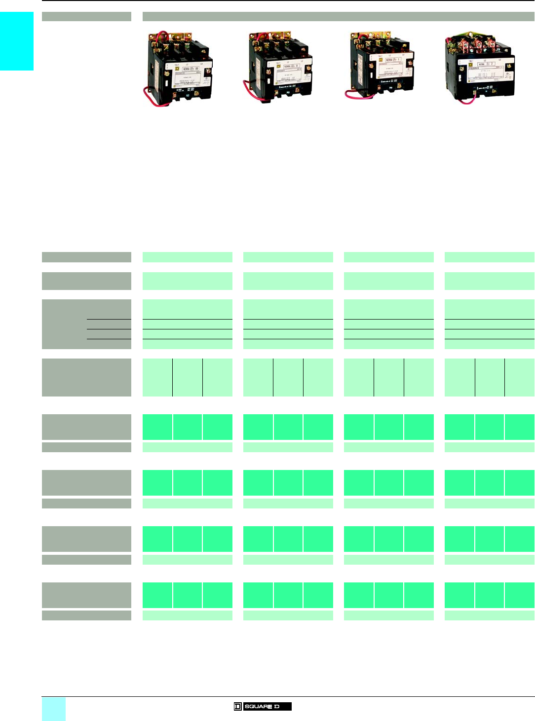
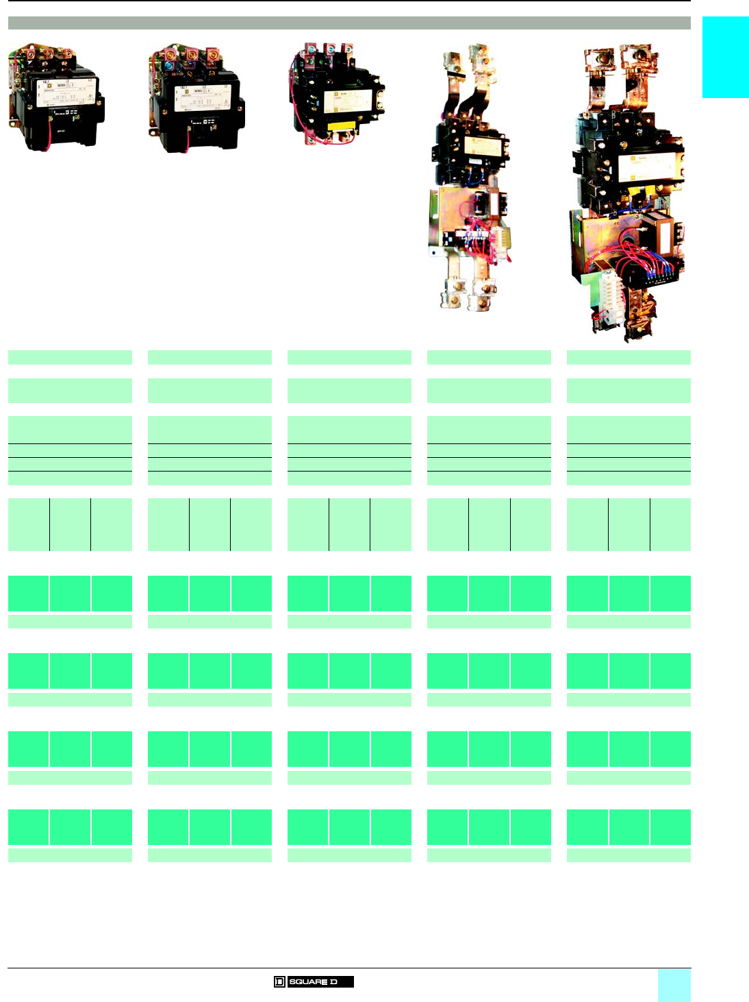
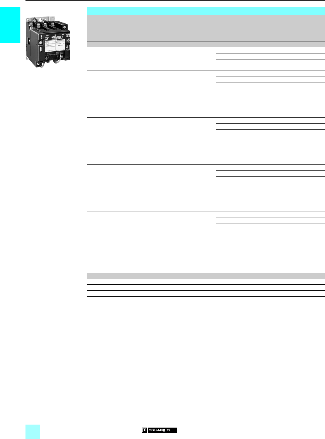
Type SCO 2
Size 1, 3-pole contactor
531007
Starter with
Motor Logic
solid-state overload relay
531008
Size 00, 0, 1
reversing contactor
(horizontal type)
531010
Reversing starter with
Motor Logic
solid-state overload relay
(vertical type)
531011
References:
pages 1/6 to 1/13
Dimensions:
pages 1/14 to 1/17
1/5
1
Characteristics (continued)
0
Contactors and Starters 0
Type S, NEMA-style
Contactors and starters
Characteristics (continued)
Pole characteristics
Class 8502, 8536, 8702, 8736
Size 00 01234567
Number of poles 3-pole devices 3
Rated operational voltage Up to V600
Frequency limits Of the operational current Hz 50/60
Conventional rated thermal current A918 27 45 90 135 270 540 810
Rated making capacity At 600 V 10 x rated current
Rated breaking capacity At 600 V 10 x rated current
Permissible short time
rating
Service limit current A11 21 32 52 104 156 311 621 932
a.c. control circuit characteristics
Class 8502, 8536, 8702, 8736
Size 00 01234567
Rated control circuit voltage V600
Average consumption 50 Hz Inrush VA N/A 232 232 296 676 1260 1300 1495 (1) –
Sealed VA N/A 26 26 36 47 89 14 56 (1) –
Average consumption 60 Hz Inrush VA 165 245 245 311 700 1185 1300 1780 (1) 1960 (1)
Sealed VA 33 27 27 37 46 85 14 48 (1) 59 (1)
Heat dissipation 50/60Hz 50 Hz WN/A 7.7 7.7 12 15 23.4 13 27 –
60 Hz W67.8 7.8 14 14 22 13 32 36
Operating time (2) Closing "C" ms 9.1 - 23.2 8.4 - 20.1 8.4 - 20.1 14.6 - 27.6 17.3 - 32.3 13.0- 43.9 40 - 60 57.0- 74.0 43.8
Opening "O" ms 5.29 - 15.9 2.4 - 15.9 2.4 - 15.9 16.3 - 22.8 9.6 - 18.7 11.2 -21.7 50 - 75 28.3 - 31.8 54.3
Mechanical life In millions of op. cycles 610 10 10 5321.5 0.5
Maximum operating rate (3) In op. cycles per hour 9000 9000 9000 5400 4500 4500 180 180 180
Power circuit connections (connection via lug)
Type of lug Screw clamp terminal Box lug Parallel groove
Wire sizes (Min./max.) Solid or stranded copper
wire (AWG)
#14–#8 #14–#8 #14–#8 #14–#4 #14–
#1/0
#8–
250kcmil
#4–
500kcmil
1 or 2,
250–
500kcmil
per phase
1 to 4,
250–
500kcmil
per phase
Control circuit connections (connection via lug)
Type of lug Screw clamp terminal
Wire sizes (Min./max.) Solid or stranded copper
wire (AWG)
#16–#12
(1) Size 6 and 7 have a d.c. coil. The values shown are for the a.c. input to the d.c. power supply that provides power to the coil.
(2) The closing time "C" is measured from the moment that the coil supply is switched on to the initial contact of the main poles. The opening time "O" is measured
from the moment that the coil supply is switched off to the moment that the main poles separate.
(3) Operating cycles are without a load (mechanical life).
References:
pages 1/6 to 1/13
Dimensions:
pages 1/14 to 1/17
1/6
1
References
0
Contactors and Starters 0
Type S, NEMA-style
Contactors Class 8502
3-pole contactors
NEMA
Size
Standard power ratings of 3-phase
motors 50/60 Hz
Motor volts
Contin-
uous
current
ratings
Enclosure
type (1)
Basic reference
Add code indicating
control circuit voltage
(2) and optional
variants (3)
Weight
200 V 230 V 460 V 575 V
hp kW hp kW hp kW hp kW Akg (lb)
00 1.5 1.1 1.5 1.1 21.5 21.5 9 Open 8502 SAO 12 ppp 2 (4)
NEMA 1 8502 SAG 12 ppp 3 (7.5)
NEMA 12 8502 SBA 2 ppp 7 (15)
032.2 32.2 53.7 53.7 18 Open 8502 SBO 2 ppp 2 (4)
NEMA 1 8502 SBG 2 ppp 3 (7.5)
NEMA 12 8502 SBA 2 ppp 7 (15)
17.5 5.5 7.5 5.5 10 7.5 10 7.5 27 Open 8502 SCO 2 ppp 2 (4)
NEMA 1 8502 SCG 2 ppp 3 (7.5)
NEMA 12 8502 SCA 2 ppp 7 (15)
210 7.5 15 11 25 18.5 25 18.5 45 Open 8502 SDO 2 ppp 3 (6.75)
NEMA 1 8502 SDG 2 ppp 7 (14.5)
NEMA 12 8502 SDA 2 ppp 10 (22)
325 18.5 30 22 50 37 50 37 90 Open 8502 SEO 2 ppp 6 (14)
NEMA 1 8502 SEG 2 ppp 15 (34)
NEMA 12 8502 SEA 2 ppp 29 (65)
440 30 50 37 100 75 100 75 135 Open 8502 SFO 2 ppp 8 (18)
NEMA 1 8502 SFG 2 ppp 24 (52)
NEMA 12 8502 SFA 2 ppp 31 (69)
575 55 100 75 200 150 200 150 270 Open 8502 SGO 2 ppp 20 (45)
NEMA 1 8502 SGG 2 ppp 65 (143)
NEMA 12 8502 SGA 2 ppp 72 (160)
6150 110 200 150 400 300 400 300 540 Open 8502 SHO 2 ppp 32 (80)
NEMA 1 8502 SHG 2 ppp 103 (226)
NEMA 12 8502 SHA 2 ppp 103 (228)
7– – 300 220 600 450 600 450 810 Open 8502 SJO 2 ppp 61 (135)
NEMA 1 8502 SJG 2 ppp 154 (340)
NEMA 12 8502 SJA 2 ppp 196 (433)
(1) Open: no enclosure (“O”).
NEMA 1: General purpose enclosure (“G”).
NEMA 12: Dust-tight and drip-tight industrial-use enclosure (“A”).
(2) Standard control circuit voltage:
Volts 24 110 120 208 220 240 380 440 480 550 600
50 Hz – V02 – – V03 – V05 V06 – V07 –
60 Hz V01 – V02 V08 – V03 – – V06 – V07
24 V and 120 V coils require the addition of form "S" for separate control. Example: 8502 SAO 12 V01S.
(3) For optional variants, see pages 1/10 to 1/13.
8502 SCO 2
ppp
531007
General, characteristics:
pages 1/4 and 1/5
Dimensions:
pages 1/14 to 1/17
1/7
1
References
0
Contactors and Starters 0
Type S, NEMA-style
Reversing contactors Class 8702
3-pole reversing contactors
NEMA
Size
Standard power ratings of 3-phase
motors 50/60 Hz
Motor volts
Contin-
uous
current
ratings
Enclosure
type (1)
Basic reference
Add code indicating
control circuit voltage
(2) and optional
variants (3)
Weight
200 V 230 V 460 V 575 V
hp kW hp kW hp kW hp kW Akg (lb)
00 1.5 1.1 1.5 1.1 21.5 21.5 9 Open/Horizontal Type 8702 SAO 4 ppp 5 (12)
NEMA 1 8702 SAG 4 ppp 7 (16)
NEMA 12 8702 SBA 4 ppp 10 (23)
032.2 32.2 53.7 53.7 18 Open/Vertical Type 8702 SBO 12 ppp 5 (12)
Open/Horizontal Type 8702 SBO 4 ppp 5 (12)
NEMA 1 8702 SBG 4 ppp 7 (16)
NEMA 12 8702 SBA 4 ppp 10 (23)
17.5 5.5 7.5 5.5 10 7.5 10 7.5 27 Open/Vertical Type 8702 SCO 7 ppp 5 (12)
Open/Horizontal Type 8702 SCO 8 ppp 5 (12)
NEMA 1 8702 SCG 8 ppp 7 (16)
NEMA 12 8702 SCA 4 ppp 10 (23)
210 7.5 15 11 25 18.5 25 18.5 45 Open/Vertical Type 8702 SDO 1 ppp 7 (16)
Open/Horizontal Type 8702 SDO 2 ppp 7 (16)
NEMA 1 8702 SDG 2 ppp 11 (24)
NEMA 12 8702 SDA 1 ppp 14 (31)
325 18.5 30 22 50 37 50 37 90 Open/Vertical Type 8702 SEO 1 ppp 15 (35)
Open/Horizontal Type 8702 SEO 2 ppp 15 (35)
NEMA 1 8702 SEG 2 ppp 43 (95)
NEMA 12 8702 SEA 1 ppp 44 (96)
440 30 50 37 100 75 100 75 135 Open/Vertical Type 8702 SFO 1 ppp 20 (45)
Open/Horizontal Type 8702 SFO 3 ppp 20 (45)
NEMA 1 8702 SFG 3 ppp 43 (95)
NEMA 12 8702 SFA 1 ppp 44 (96)
575 55 100 75 200 150 200 150 270 Open/Vertical Type 8702 SGO 1 ppp 44 (98)
Open/Horizontal Type 8702 SGO 3 ppp 44 (98)
NEMA 1 8702 SGG 3 ppp 135 (298)
NEMA 12 8702 SGA 1 ppp 137 (302)
6150 110 200 150 400 300 400 300 540 Open/Horizontal Type 8702 SHO 1 ppp 88 (195)
NEMA 1 8702 SHG 1 ppp 181 (400)
NEMA 12 8702 SHA 1 ppp 222 (490)
7– – 300 220 600 450 600 450 810 Open/Horizontal Type 8702 SJO 1 ppp 141 (310)
NEMA 1 8702 SJG 1 ppp 233 (514)
NEMA 12 8702 SJA 1 ppp 275 (607)
(1) Open: no enclosure (“O”).
NEMA 1: General purpose enclosure (“G”).
NEMA 12: Dust-tight and drip-tight industrial-use enclosure (“A”).
(2) Standard control circuit voltage:
Volts 24 110 120 208 220 240 380 440 480 550 600
50 Hz – V02 – – V03 – V05 V06 – V07 –
60 Hz V01 – V02 V08 – V03 – – V06 – V07
24 V and 120 V coils require the addition of form "S" for separate control. Example: 8702 SAO 4 V01S.
(3) For optional variants, see pages 1/10 to 1/13.
8702 SAO 4
ppp
(horizontal type)
531010
General, characteristics:
pages 1/4 and 1/5
Dimensions:
pages 1/14 to 1/17
1/8
1
References
0
Contactors and Starters 0
Type S, NEMA-style
Starters Class 8536
3-pole starters
NEMA
Size
Standard power ratings of 3-phase
motors 50/60 Hz
Motor volts
Contin-
uous
current
ratings
Enclosure
type (1)
Basic reference
Add code indicating
control circuit voltage
(2) and optional
variants (3) and “H”
code (4)
Weight
200 V 230 V 460 V 575 V
hp kW hp kW hp kW hp kW Akg (lb)
00 1.5 1.1 1.5 1.1 21.5 21.5 9 Open 8536 SAO 12 (2) (3) (4) 2 (4)
NEMA 1 8536 SAG 12 (2) (3) (4) 3 (8)
NEMA 12 8536 SBA 2 (2) (3) (4) 7 (16)
032.2 32.2 53.7 53.7 18 Open 8536 SBO 2 (2) (3) (4) 2 (4)
NEMA 1 8536 SBG 2 (2) (3) (4) 4 (8)
NEMA 12 8536 SBA 2 (2) (3) (4) 7 (16)
17.5 5.5 7.5 5.5 10 7.5 10 7.5 27 Open 8536 SCO 3 (2) (3) (4) 2 (4)
NEMA 1 8536 SCG 3 (2) (3) (4) 3 (8)
NEMA 12 8536 SCA 3 (2) (3) (4) 7 (16)
210 7.5 15 11 25 18.5 25 18.5 45 Open 8536 SDO 1 (2) (3) (4) 3 (6.75)
NEMA 1 8536 SDG 1 (2) (3) (4) 7 15.5)
NEMA 12 8536 SDA 1 (2) (3) (4) 10 (23)
325 18.5 30 22 50 37 50 37 90 Open 8536 SEO 1 (2) (3) (4) 6 (14)
NEMA 1 8536 SEG 1 (2) (3) (4) 17 (37)
NEMA 12 8536 SEA 1 (2) (3) (4) 31 (68)
440 30 50 37 100 75 100 75 135 Open 8536 SFO 1 (2) (3) (4) 8 (18)
NEMA 1 8536 SFG 1 (2) (3) (4) 25 (56)
NEMA 12 8536 SFA 1 (2) (3) (4) 33 (73)
575 55 100 75 200 150 200 150 270 Open 8536 SGO 1 (2) (3) (4) 20 (45)
NEMA 1 8536 SGG 1 (2) (3) (4) 73 (160)
NEMA 12 8536 SGA 1 (2) (3) (4) 80 (177)
6150 110 200 150 400 300 400 300 540 Open 8536 SHO 2 (2) (3) (4) 32 (80)
NEMA 1 8536 SHG 2 (2) (3) (4) 105 (231)
NEMA 12 8536 SHA 2 (2) (3) (4) 106 (233)
7– – 300 220 600 450 600 450 810 Open 8536 SJO 2 (2) (3) (4) 61 (135)
NEMA 1 8536 SJG 2 (2) (3) (4) 130 (287)
NEMA 12 8536 SJA 2 (2) (3) (4) 140 (309)
(1) Open: no enclosure (“O”).
NEMA 1: General purpose enclosure (“G”).
NEMA 12: Dust-tight and drip-tight industrial-use enclosure (“A”).
(2) Standard control circuit voltage:
Volts 24 110 120 208 220 240 380 440 480 550 600
50 Hz – V02 – – V03 – V05 V06 – V07 –
60 Hz V01 – V02 V08 – V03 – – V06 – V07
24 V and 120 V coils require the addition of form "S" for separate control. Example: 8536 SAO 12 V01 H10S.
(3) For optional variants, see pages 1/10 to 1/13.
(4) To complete the "H" code for solid-state overload relays, see page 1/10.
8536 SAO 12 V02 H20
531008
General, characteristics:
pages 1/4 and 1/5
Dimensions:
pages 1/14 to 1/17

1/9
1
References
0
Contactors and Starters 0
Type S, NEMA-style
Reversing starters Class 8736
3-pole reversing starters
NEMA
Size
Standard power ratings of 3-phase
motors 50/60 Hz
Motor volts
Contin-
uous
current
ratings
Enclosure
type (1)
Basic reference
Add code indicating
control circuit voltage
(2) and optional
variants (3) and “H”
code (4)
Weight
200 V 230 V 460 V 575 V
hp kW hp kW hp kW hp kW Akg (lb)
00 1.5 1.1 1.5 1.1 21.5 21.5 9 Open/Horizontal Type 8736 SAO 16 (2) (3) (4) 6 (13)
NEMA 1 8736 SAG 16 (2) (3) (4) 8 (17)
NEMA 12 8736 SBA 4 (2) (3) (4) 11 (24)
032.2 32.2 53.7 53.7 18 Open/Vertical Type 8736 SBO 10 (2) (3) (4) 6 (13)
Open/Horizontal Type 8736 SBO 4 (2) (3) (4) 6 (13)
NEMA 1 8736 SBG 4 (2) (3) (4) 8 (17)
NEMA 12 8736 SBA 4 (2) (3) (4) 11 (24)
17.5 5.5 7.5 5.5 10 7.5 10 7.5 27 Open/Vertical Type 8736 SCO 7 (2) (3) (4) 6 (13)
Open/Horizontal Type 8736 SCO 8 (2) (3) (4) 6 (13)
NEMA 1 8736 SCG 8 (2) (3) (4) 8 (17)
NEMA 12 8736 SCA 4 (2) (3) (4) 11 (24)
210 7.5 15 11 25 18.5 25 18.5 45 Open/Vertical Type 8736 SDO 1 (2) (3) (4) 8 (18)
Open/Horizontal Type 8736 SDO 2 (2) (3) (4) 8 (18)
NEMA 1 8736 SDG 2 (2) (3) (4) 11 (25)
NEMA 12 8736 SDA 1 (2) (3) (4) 15 (32)
325 18.5 30 22 50 37 50 37 90 Open/Vertical Type 8736 SEO 1 (2) (3) (4) 17 (38)
Open/Horizontal Type 8736 SEO 2 (2) (3) (4) 17 (38)
NEMA 1 8736 SEG 2 (2) (3) (4) 44 (98)
NEMA 12 8736 SEA 1 (2) (3) (4) 45 (99)
440 30 50 37 100 75 100 75 135 Open/Vertical Type 8736 SFO 1 (2) (3) (4) 22 (48)
Open/Horizontal Type 8736 SFO 3 (2) (3) (4) 22 (48)
NEMA 1 8736 SFG 3 (2) (3) (4) 44 (98)
NEMA 12 8736 SFA 1 (2) (3) (4) 45 (99)
575 55 100 75 200 150 200 150 270 Open/Vertical Type 8736 SGO 1 (2) (3) (4) 52 (115)
Open/Horizontal Type 8736 SGO 3 (2) (3) (4) 52 (115)
NEMA 1 8736 SGG 3 (2) (3) (4) 143 (315)
NEMA 12 8736 SGA 1 (2) (3) (4) 145 (319)
6150 110 200 150 400 300 400 300 540 Open/Horizontal Type 8736 SHO 1 (2) (3) (4) 91 (200)
NEMA 1 8736 SHG 1 (2) (3) (4) 184 (405)
NEMA 12 8736 SHA 1 (2) (3) (4) 225 (495)
7– – 300 220 600 450 600 450 810 Open/Horizontal Type 8736 SJO 1 (2) (3) (4) 143 (315)
NEMA 1 8736 SJG 1 (2) (3) (4) 236 (521)
NEMA 12 8736 SJA 1 (2) (3) (4) 280 (618)
(1) Open: no enclosure (“O”).
NEMA 1: General purpose enclosure (“G”).
NEMA 12: Dust-tight and drip-tight industrial-use enclosure (“A”).
(2) Standard control circuit voltage:
Volts 24 110 120 208 220 240 380 440 480 550 600
50 Hz –V02––V03–V05V06–V07–
60 Hz V01 – V02 V08 – V03 – – V06 – V07
24 V and 120 V coils require the addition of form "S" for separate control. Example: 8736 SAO 16 V01 H10S.
(3) For optional variants, see pages 1/10 to 1/13.
(4) To complete the "H" code for solid-state overload relays, see page 1/10.
8736 SAO 16 V02 H20
(vertical type)
531011
General, characteristics:
pages 1/4 and 1/5
Dimensions:
pages 1/14 to 1/17
1/10
1
References,
associations
0
Contactors and Starters 0
Type S, NEMA-style
Variants – Motor Logic® Overload Relay
Variants – Motor Logic solid-state overload relays
Type For use on Description Overload relay
range
Suffix to the
starter reference
(1)
Weight
Class Enclosure
Type
kg (lb)
Motor Logic
solid state
overload relays
(no additional
auxiliary contact)
8536,
8736
Open,
NEMA 1,
NEMA 12
Base unit, trip class 10 (2) H10 –
Base unit, trip class 20 (2) H20 –
Feature unit (2) H30 –
Motor Logic
solid state
overload relays
(with additional
auxiliary contact)
8536,
8736
Open,
NEMA 1,
NEMA 12
Base unit, trip class 10 (2) H11 –
Base unit, trip class 20 (2) H21 –
Feature unit (2) H31 –
(1) Example: 8536 SAO 12 V01 H10.
(2) Standard current ranges, depending on contactor size:
Size 00 0 1234567
Current ranges A 3…9 6…18 9…27 15…45 30…90 40…135 90…270 180…540
(3)
270…810
(4)
(3) Only available with feature unit.
(4) Only available with feature unit with auxiliary contact.
Associations
Contactor
Size
Trip type Motor Logic solid-state overload relays
No
auxiliary
contact
With
auxiliary
contact
No
auxiliary
contact
With
auxiliary
contact
No
auxiliary
contact
With
auxiliary
contact
No
auxiliary
contact
With
auxiliary
contact
No
auxiliary
contact
With
auxiliary
contact
Size 00C (3–9 A) Size 00B (1.5–4.5 A)
00 Class 10 H10 H11 H108 H118
Class 20 H20 H21 H208 H218
Class 10/20
(selectable)
H30 H31 H308 H318
Size 0 (6–18 A) Size 00C (3–9 A) Size 00B (1.5–4.5 A)
0 Class 10 H10 H11 H109 H119 H108 H118
Class 20 H20 H21 H209 H219 H208 H218
Class 10/20
(selectable)
H30 H31 H309 H319 H308 H318
Size 1 (9–27 A) Size 0 (6–18 A) Size 00C (3–9 A) Size 00B (1.5–4.5 A)
1 Class 10 H10 H11 H100 H110 H109 H119 H108 H118
Class 20 H20 H21 H200 H210 H209 H219 H208 H218
Class 10/20
(selectable)
H30 H31 H300 H310 H309 H319 H308 H318
Size 2 (15–45 A) Size 1 (9–27 A) Size 0 (6–18 A) Size 00C (3–9 A) Size 00B (1.5–4.5 A)
2 Class 10 H10 H11 H101 H111 H100 H110 H109 H119 – –
Class 20 H20 H21 H201 H211 H200 H210 H209 H219 – –
Class 10/20
(selectable)
H30 H31 H301 H311 H300 H310 H309 H319 H308 H318
Size 3 (30–90 A)
3 Class 10 H10 H11
Class 20 H20 H21
Class 10/20
(selectable)
H30 H31
Size 4 (45–135 A) Size 3 (30–90 A)
4 Class 10 H10 H11 H103 H113
Class 20 H20 H21 H203 H213
Class 10/20
(selectable)
H30 H31 H303 H313
Size 5 (90–270 A)
5 Class 10 H10 H11
Class 20 H20 H21
Class 10/20
(selectable)
H30 H31
Available codes
Not available
H10
531123
General, characteristics:
pages 1/4 and 1/5
Dimensions:
pages 1/14 to 1/17
1/11
1
References (continued)
0
Contactors and Starters 0
Type S, NEMA-style
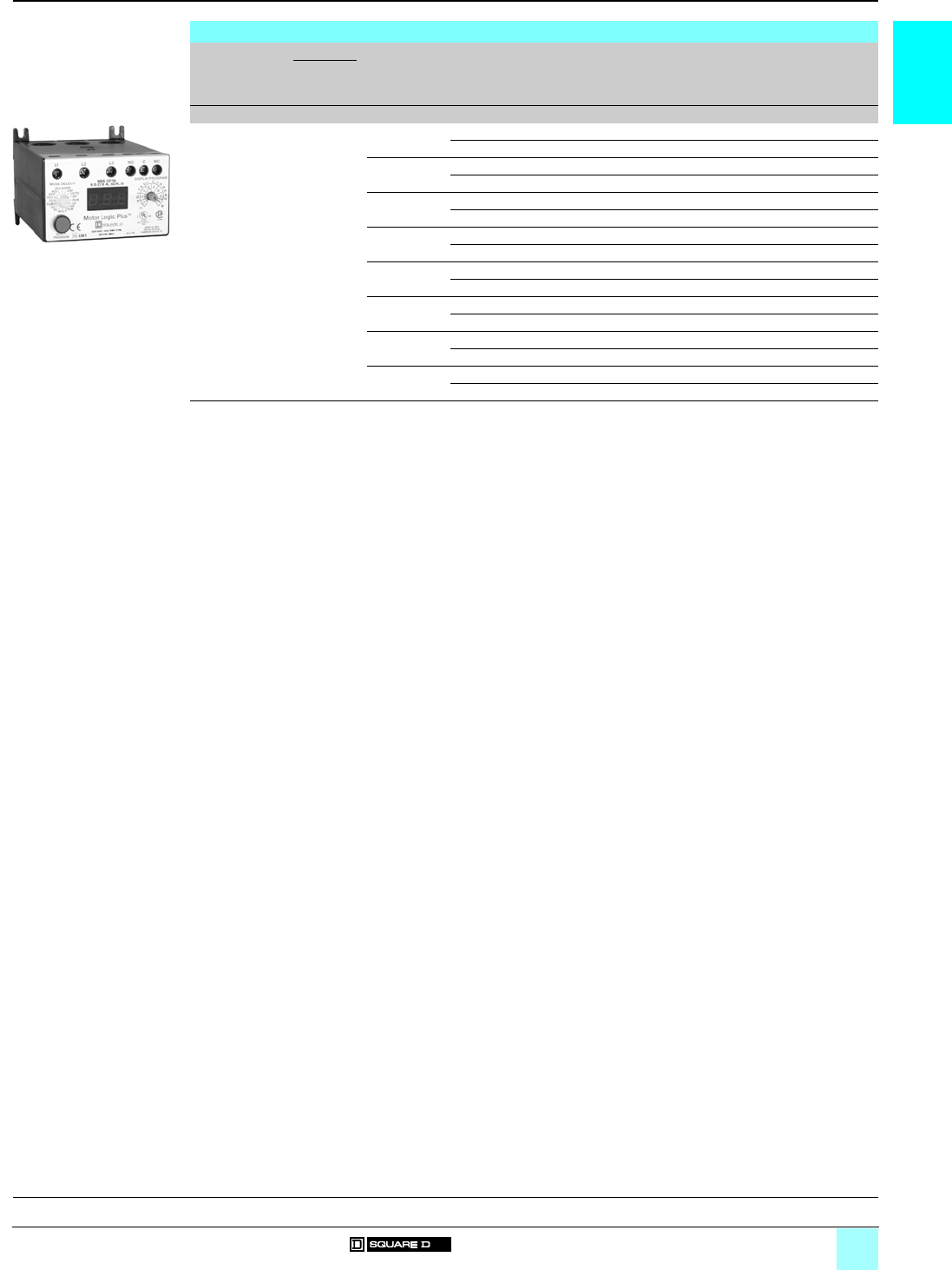
Variants – Motor Logic® Plus overload relay
(1) Example: 8536 SAO 12 V01 B20S.
Variants – Motor Logic Plus solid-state overload relays
Description For use on Motor Logic
Plus current
ranges
Factory modification Suffix to the
starter reference
(1)
Weight
Class/
Enclosure
type
Akg (lb)
Motor Logic
Plus
solid-state
overload relays
8536, 8736
Open type
0.5…2.3 No modification for 200–480 V B20 –
No modification for 600 V B24 –
2…9 No modification for 200–480 V B30 –
No modification for 600 V B34 –
6…27 No modification for 200–480 V B40 –
No modification for 600 V B44 –
10…45 No modification for 200–480 V B50 –
No modification for 600 V B54 –
20…90 No modification for 200–480 V B60 –
No modification for 600 V B64 –
60…135 No modification for 200–480 V B70 –
No modification for 600 V B74 –
120…270 No modification for 200–480 V B80 –
No modification for 600 V B84 –
240…540 No modification for 200–480 V B90 –
No modification for 600 V B94 –
B20
531202
General, characteristics:
pages 1/4 and 1/5
Dimensions:
pages 1/14 to 1/17
1/12
1
References
0
Contactors and Starters 0
Type S, NEMA-style
Variants
Variants – Operators
Description For use on Colour/Marking Suffix to the
contactor or
starter reference
(1)
Weight
Class Enclosure
type
kg (lb)
Push buttons 8502, 8536 NEMA 1, 12 "Start-Stop" A–
8702, 8736 NEMA 1, 12 "Forward-Reverse-Stop" A1 –
"High-Low-Stop" A2 –
Pilot lights
without operating interlock
(2)
8502, 8536,
8702, 8736
NEMA 1 Red P1 –
Green P2 –
Amber P3 –
Clear P4 –
Push-to-test pilot lights
without operating interlock
(2)
8502, 8536,
8702, 8736
NEMA 12 Red P21 –
Green P22 –
Amber P23 –
Clear P24 –
Yellow P25 –
LED pilot lights 8502, 8536,
8702, 8736
NEMA 1 Red P51 –
Green P52 –
Yellow P55 –
Special wiring 8502, 8536,
8702, 8736
NEMA 1 Red/"Off" P71 –
Green/"On" P72 –
Selector switches 8502, 8536,
8702, 8736
NEMA 1,
NEMA 12
"Hand-Off-Auto" C–
8702, 8736 NEMA 1,
NEMA 12
"On-Off" C6 –
"Forward-Off-Reverse" C14 –
"Forward-Reverse" C20 –
Variants – Transformers
Description For use on Functions Suffix to the
contactor or
starter reference
(1)
Weight
Class Enclosure
type
kg (lb)
Separate control circuit 8502, 8536,
8702, 8736
NEMA 1, 12 Specify voltage and frequency S–
Fused control circuit
without transformer
8502, 8536,
8702, 8736
NEMA 1, 12 One fuse F–
Two fuses F4 –
Control circuit transformers
standard capacity (50/60 Hz)
(3)
8502, 8536,
8702, 8736
NEMA 1, 12 Fuses: 2 (primary), 0 (secondary) F4T (4) –
Fuses: 2 (primary), 1 (secondary) FF4T –
Fuses: 1 (primary), 2 (secondary) (5) F1F10T –
Fuses: 2 (primary), 2 (secondary) F4F10T –
Additional capacity
(50/60 Hz) Two fuses in primary
(3)
8502, 8536,
8702, 8736
NEMA 1, 12 100 VA additional capacity F4T11 (6) –
200 VA additional capacity F4T12 (6) –
Additional capacity
(50/60 Hz) Two fuses in primary
and one fuse in secondary (3)
8502, 8536,
8702, 8736
NEMA 1, 12 100 VA additional capacity FF4T11 –
(1) Example: 8536 SAG 12 V01 A P1 P2. All suffixes are listed in alphanumeric order after the voltage code.
(2) Unless otherwise requested, the standard practice is to wire the red pilot light to indicate that the device is energized. No
additional auxiliary contact is required. Also, standard practice is to wire the green pilot light to indicate that the device is de-
energized. An additional normally closed auxiliary contact is required; please consult your regional sales office.
(3) Control circuit transformer selection table:
Primary-secondary 120-24 (7) 208-120 240-24 (7) 240-120 277-120 480-24 (7) 480-120 480-240 600-120
60 Hz V89 V84 V82 V80 V85 V83 V81 V87 V86
Example: 8536 SAG 12 V81 F4T A P1 P2.
(4) Not available with 24 V secondary on Size 3. Select appropriate transformer with secondary fuse protection. See transformer
selection table.
(5) Single phase with one leg earthed, or earthed 3-phase applications only.
(6) Not available with 24 V secondary. Select appropriate transformer with secondary fuse protection. See transformer selection
table for 24 V secondary restrictions.
(7) 24 V coils are not available on Sizes 4–7.
General, characteristics:
pages 1/4 and 1/5
Dimensions:
pages 1/14 to 1/17
1/13
1
References (continued)
0
Contactors and Starters 0
Type S, NEMA-style
Variants
Variants – Auxiliary contacts
Description For use on Number of contacts Suffix to the
contactor or
starter reference
Weight
kg (lb)
Class Enclosure
type
Forward
contactor
Reverse
contactor
N/O N/C N/O N/C
Auxiliary contacts
for non-reversing contactors and
non-reversing starters
(1)
8502, 8536 NEMA 1,
NEMA 12
–1 X01 –
2X02 –
3X03 –
4X04 –
1– X10 –
1X11 –
2X12 –
3X13 –
2– X20 –
1X21 –
2X22 –
3– X30 –
1X31 –
4– X40 –
Auxiliary contacts standard
no additional auxiliary
contacts
for reversing contactors and
reversing starters
8702, 8736 NEMA 1,
NEMA 12
1– –– X1000 –
–1 –– X0100 –
2– –– X2000 –
11 –– X1100 –
–2 –– X0200 –
–– 1– X0010 –
1– 1– X1010 –
–1 1– X0110 –
2– 1– X2010 –
11 1– X1110 –
–2 1– X0210 –
–– –1 X0001 –
1– –1 X1001 –
–1 –1 X0101 –
2– –1 X2001 –
11 –1 X1101 –
–2 –1 X0201 –
–– 2– X0020 –
1– 2– X1020 –
–1 2– X0120 –
2– 2– X2020 –
11 2– X1120 –
–2 2– X0220 –
–– 11 X0011 –
1– 11 X1011 –
–1 11 X0111 –
2– 11 X2011 –
11 11 X1111 –
–2 11 X0211 –
–– –2 X0002 –
1– –2 X1002 –
–1 –2 X0102 –
2– –2 X2002 –
11 –2 X1102 –
–2 –2 X0202 –
(1) Maximum number of external auxiliary units (in addition to holding circuit contact):
Class 8502/8536/8702/8736 Maximum number
pppp SA 4 N/O or N/C, if second internal auxiliary contact is not used
pppp SB/SC/SD 4 N/O or N/C
2 N/O or N/C plus 1 power-pole adder (single- or 2-pole, N/O or N/C)
1 attached timer plus 1 power-pole adder (single- or 2-pole, N/O or N/C) plus 1 auxiliary contact
pppp SE/SF/SG
(Size 3 and Size 4)
4 N/O or N/C
pppp SE/SF/SG
(Size 5)
2 N/O or N/C plus 1 NEMA Size 0–1 or Size 2 power-pole adder (single- or 2-pole, N/O or N/C)
pppp SH/SJ 4 N/O or N/C
2 N/O or N/C plus 1 NEMA Size 0–1 or Size 2 power-pole adder (single- or 2-pole, N/O or N/C)
General, characteristics:
pages 1/4 and 1/5
Dimensions:
pages 1/14 to 1/17
1/14
1
Dimensions
0
Contactors and Starters 0
Type S, NEMA-style
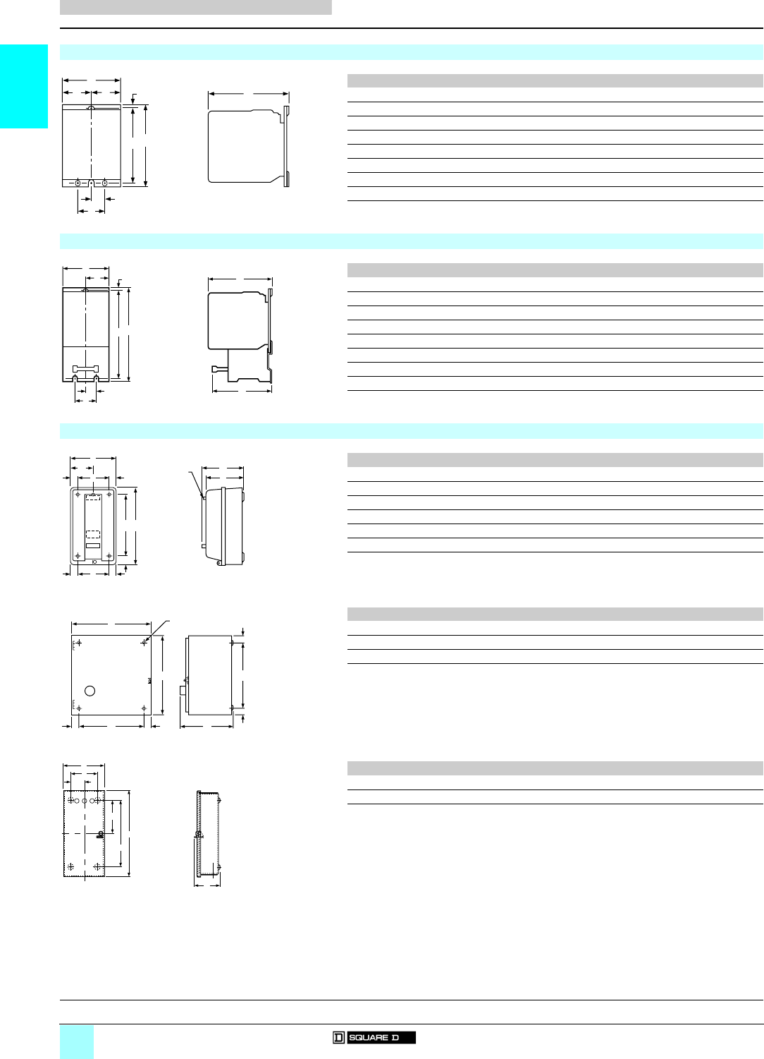
Contactors and starters
Dimensions in mm (25.4 mm = 1 inch)
Contactors 8502 SpO (Open)
ABCD E F G H I
8502 SAO 81.5 110.2 106.9 41.3 41.3 5.3 99.8 – –
8502 SBO 81.5 110.2 106.9 41.3 41.3 5.3 99.8 – –
8502 SCO 81.5 110.2 106.9 41.3 41.3 5.3 99.8 – –
8502 SDO 125.2 130.2 125.2 54.6 54.6 5.3 116.6 13.5 26.9
8502 SEO 138.7 180.1 165.1 47.6 89.7 7.9 153.2 82.6 120.7
8502 SFO 152.4 207.8 165.1 52.3 99.8 7.9 177.8 91.2 134.9
8502 SGO 220.0 312.7 222.3 82.6 147.6 15.9 282.6 120.7 184.2
8502 SHO 267.7 712.7 228.6 89.7 185.7 128.5 471.4 120.7 184.2
8502 SJO 267.7 946.2 276.1 89.7 185.7 183.1 568.3 120.7 184.2
Starters 8536 SpO (Open)
ABCD E F G H I
8536 SAO 81.5 168.3 106.9 12.7 25.4 37.3 5.1 158.8 100.6
8536 SBO 81.5 168.3 106.9 12.7 25.4 37.3 5.1 158.8 100.6
8536 SCO 81.5 168.3 106.9 12.7 25.4 37.3 5.1 158.8 100.6
8536 SDO 109.5 198.4 125.2 12.7 25.4 52.3 5.2 186.4 103.1
8536 SEO 138.7 281.7 165.1 22.2 44.5 91.2 7.9 258.6 196.9
8536 SFO 152.4 327.0 165.1 46.0 44.5 99.8 7.9 284.0 146.1
8536 SGO 217.4 446.0 222.3 120.7 184.2 136.5 15.9 415.9 152.4
8536 SHO 313.4 712.7 228.6 120.7 184.2 146.8 128.5 471.4 220.5
8536 SJO 313.4 946.2 276.2 120.7 184.2 146.8 183.1 568.3 228.6
Contactors and starters 8502/8536 SpG (NEMA 1 General purpose enclosure)
A B C C D E F G H I JK L
8502 8536
8502/8536 SAG 152.4 254.0 134.1 141.2 76.2 22.2 206.4 25.4 23.6 104.8 127.0 ––
8502/8536 SBG 152.4 254.0 134.1 141.2 76.2 22.2 206.4 25.4 23.6 104.8 127.0 ––
8502/8536 SCG 152.4 254.0 134.1 141.2 76.2 22.2 206.4 25.4 23.6 104.8 127.0 ––
8502/8536 SDG 198.4 322.1 153.2 160.3 – 32.5 266.7 27.7 27.7 142.9 146.1 27.7 142.9
8502/8536 SEG 290.3 554.0 203.2 212.7 – 38.9 476.3 38.9 38.9 212.7 196.9 38.9 212.7
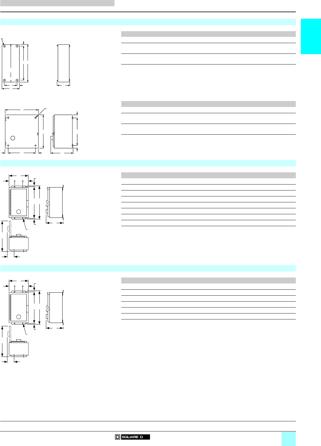
ABCCD E F G H I
8502 8536
8502/8536 SFG 285.8 639 228.6 228.6 218.2 31.8 31.8 566.7 36.3 11
8502/8536 SGG 437.1 1122.9 325.4 328.4 330.2 54.0 54.0 1016.0 54.0 14
ABCD E F G H
8502/8536 SHG 1670.1 513.3 333.4 – 279.4 1638.3 60.3 139.7
8502/8536 SJG 2362.2 876.3 596.9 –––––
A
B
C
I
H
EF
G
D
A
B
C
E
D
FG
H
I
RESET
RESET
H
F
G
E
K
D
KL
I
H
B
C
J
A
Pilot
Light
RESET
A
B
H
H
C
F
D
E
G
I Dia.
Mounting Holes
H
B
E
G
A
F
C
General, characteristics:
pages 1/4 and 1/5
References:
pages 1/6 to 1/13
1/15
1
Dimensions (continued)
0
Contactors and Starters 0
Type S, NEMA-style
Contactors and starters
Dimensions in mm (25.4 mm = 1 inch)
Contactors and starters 8502/8536 SpG F4T (NEMA 1 General purpose enclosure with suffix F4T)
(1) ABCCD E F G H
8502 8536
8502/8536
SBG ppp F4T
161.0 403.2 127.0 141.2 118.1 21.3 365.1 19.1 7.1
8502/8536
SCG ppp F4T
161.0 403.2 127.0 141.2 118.1 21.3 365.1 19.1 7.1
(1) ABCCD E F G H I
8502 8536
8502/8536
SDG ppp F4T
377.8 358.8 192 194.3 323.9 26.9 26.9 304.8 26.9 7.9
8502/8536
SFG ppp F4T
461.0 740.4 235.0 235.0 393.7 35.1 35.1 673.1 33.5 10.9
(1) For other products with form F4T:
8502/8536 SEG
ppp
F4T uses 9070 GO transformer (see dimensions page 1/14).
8502/8536 SHG
ppp
F4T and 8502/8536 SJG
ppp
F4T are supplied as standard.
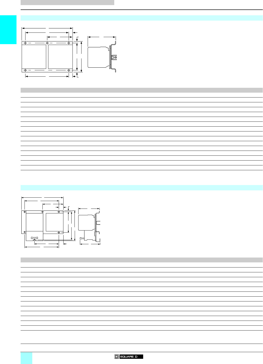
Contactors and starters 8502/8536 SpA (NEMA 12 Dust-tight enclosure)
A B C D E F G H IJ
8502/8536 SBA 161.9 216.7 323.9 39.6 82.6 304.8 9.5 90.4 311.2 7.9
8502/8536 SCA 161.9 216.7 323.9 39.6 82.6 304.8 9.5 90.4 311.2 7.9
8502/8536 SDA 206.4 235.7 406.4 39.6 127.0 381.0 12.7 90.4 390.5 7.9
8502/8536 SEA 461.0 242.8 800.1 78.0 304.8 774.7 12.7 114.3 678.4 10.9
8502/8536 SFA 461.0 242.8 800.1 78.0 304.8 774.7 12.7 114.3 678.4 10.9
8502/8536 SGA 437.1 341.1 1193.8 104.8 228.6 1168.4 12.7 137.2 719.1 14.2
8502/8536 SHA 513.3 330.2 1651.0 104.8 304.8 1625.6 12.7 163.3 784.2 17.3
8502/8536 SJA 876.3 596.9 2362.2 ––– ––––
Contactors and starters 8502/8536 SpA F4T (NEMA 12 Dust-tight enclosure with suffix F4T)
(1) A B C D E F G H IJ
8502/8536 SBA ppp F4T 301.6 203.2 342.9 71.4 171.5 323.9 9.5 99.1 466.7 7.9
8502/8536 SCA ppp F4T 301.6 203.2 342.9 71.4 171.5 323.9 9.5 99.1 466.7 7.9
8502/8536 SDA ppp F4T 377.8 206.4 406.4 65.0 247.7 381.0 9.5 92.7 546.1 7.9
8502/8536 SEA ppp F4T 461.0 242.8 800.1 78.0 304.8 774.7 12.7 114.3 678.4 10.9
8502/8536 SFA ppp F4T 461.0 242.8 800.1 78.0 304.8 774.7 12.7 114.3 678.4 10.9
8502/8536 SGA ppp F4T 437.1 341.1 1193.8 104.8 228.6 1168.4 12.7 137.2 719.1 14.2
(1) 8502/8536 SHA
ppp
F4T and 8502/8536 SJA
ppp
F4T are supplied as standard.
F
G
B
E
DC
A
H Dia.
Mounting Holes
RESET
A
B
H
H
C
F
D
E
G
I Dia.
Mounting Holes
F
G
G
DDE
C
B
A
I
H
J Dia.
Mounting Holes
F
G
G
DDE
C
B
A
I
H
J Dia.
Mounting Holes
General, characteristics:
pages 1/4 and 1/5
References:
pages 1/6 to 1/13
1/16
1
Dimensions
0
Contactors and Starters 0
Type S, NEMA-style
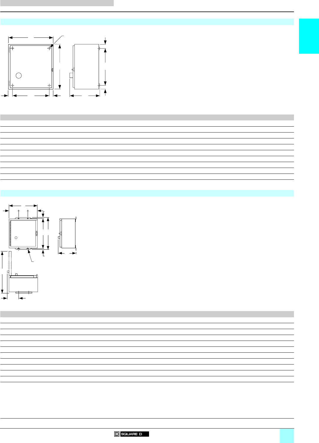
Reversing contactors and reversing starters
Dimensions in mm (25.4 mm = 1 inch)
Reversing contactors and reversing starters 8702 SpO/8736 SJO (Open)
Reference/Mounting (1) ABCD E F G H I J K
8702 SAO/Horizontal 181.0 127.0 134.9 – – 86.4 11.7 110.2 4.6 139.7 22.9
8702 SBO/Horizontal 181.0 127.0 134.9 – – 86.4 11.7 110.2 4.6 139.7 22.9
8702 SBO/Vertical 138.7 233.9 134.9 127.8 5.3 – 15.5 203.2 15.5 127.8 5.3
8702 SCO/Horizontal 181.0 127.0 134.9 – – 86.4 11.7 110.2 4.6 139.7 22.9
8702 SCO/Vertical 138.7 233.9 134.9 127.8 5.3 – 15.5 203.2 15.5 127.8 5.3
8702 SDO/Horizontal 228.6 174.6 153.2 – – 114.3 9.5 142.9 6.4 152.4 38.1
8702 SDO/Vertical 171.5 288.9 153.2 158.8 6.4 – 12.7 263.5 12.7 158.8 6.4
8702 SEO/Horizontal 322.8 202.2 177.8 298.5 12.2 – 12.2 177.8 12.2 298.5 12.2
8702 SEO/Vertical 182.9 482.6 177.8 158.8 12.2 – 25.7 431.8 24.9 158.8 12.2
8702 SFO/Horizontal 362.0 296.7 177.8 336.6 12.7 – 12.7 203.2 46.7 336.6 12.7
8702 SFO/Vertical 202.2 607.1 177.8 177.8 12.2 – 46.0 514.4 30.0 177.8 12.2
8702 SGO/Horizontal 490.5 411.0 238.1 457.2 16.5 – 26.2 355.6 29.2 457.2 16.5
8702 SGO/Vertical 273.1 864.6 238.1 241.3 15.9 – 31.8 812.8 29.2 241.3 15.9
8702 SHO/Horizontal 568.3 712.2 241.6 457.2 15.9 – 97.2 538.0 77.0 457.2 19.4
8702 SJO/Horizontal 616.0 946.2 350.8 501.738.4––762.0–––
8736 SJO/Horizontal 616.0 946.2 350.8 501.738.4––762.0–––
(1) Vertical type design differs from that shown on the corresponding NEMA size horizontal type figure, but dimensions listed apply to that figure.
Reversing contactors and reversing starters 8736 SpO (Open)
Reference/Mounting (1) A B C D E F G H I J KL M
8736 SAO/Horizontal 181.0 175.3 134.9 – – 86.4 11.9 110.2 157.7 115.1 128.5 16.7 –
8736 SBO/Horizontal 181.0 175.3 134.9 – – 86.4 11.9 110.2 157.7 115.1 128.5 16.7 –
8736 SBO/Vertical 138.9 292.4 134.9 127.8 5.3 – 15.5 203.2 271.8 63.8 128.5 5.3 127.8
8736 SCO/Horizontal 181.0 175.3 134.9 – – 86.4 11.9 110.2 157.7 115.1 128.5 16.7 –
8736 SCO/Vertical 138.9 292.4 134.9 127.8 5.3 – 15.5 203.2 271.8 63.8 128.5 5.3 127.8
8736 SDO/Horizontal 228.6 215.9 153.2 – – 114.3 9.5 142.9 190.5 127.0 131.0 38.1 –
8736 SDO/Vertical 171.5 342.4 153.2 158.8 6.4 – 19.8 263.5 329.2 79.4 131.0 6.4 152.4
8736 SEO/Horizontal 322.8 297.4 177.8 298.5 12.2 12.2 273.1 273.1 298.5 158.8 12.2 298.5
8736 SEO/Vertical 185.7 565.2 177.8 158.8 12.2 – 25.7 527.1 – 158.8 158.8 12.2 158.8
8736 SFO/Horizontal 362.0 370.6 177.8 336.6 12.7 – 46.7 311.2 311.2 336.6 158.8 12.7 336.6
8736 SFO/Vertical 202.2 662.4 177.8 177.8 12.2 46.7 622.3 – 102.6 158.8 12.2 177.8
8736 SGO/Horizontal 490.5 530.9 238.1 457.2 16.5 32.5 482.6 482.6 457.2 168.3 15.9 457.2
8736 SGO/Vertical 273.1 994.4 238.1 241.3 16.5 – 32.5 946.2 946.2 241.3 168.3 15.9 241.3
8736 SHO/Horizontal 568.3 712.2 241.6 457.2 17.3 – 97.2 538.0 77.0 457.2 19.4 ––
(1) Vertical type design differs from that shown on the corresponding NEMA size horizontal type figure, but dimensions listed apply to that figure.
A
G
I
HB
JK
DE
F C
A
H
F
C
LK
M
J
D
EG
RESET
I
B
General, characteristics:
pages 1/4 and 1/5
References:
pages 1/6 to 1/13
1/17
1
Dimensions (continued)
0
Contactors and Starters 0
Type S, NEMA-style
Reversing contactors and reversing starters
Dimensions in mm (25.4 mm = 1 inch)
Reversing contactors and reversing starters 8702/8736 SpG (NEMA 1 General purpose enclosure)
ABCCD E F G H I
8702 8736
8702/8736 SAG 301.6 301.6 188.0 191.3 247.7 26.9 26.9 247.7 26.9 7.9
8702/8736 SBG 301.6 301.6 188.0 191.3 247.7 26.9 26.9 247.7 26.9 7.9
8702/8736 SCG 301.6 301.6 188.0 191.3 247.7 26.9 26.9 247.7 26.9 7.9
8702/8736 SDG 377.8 358.8 192.0 194.3 323.9 26.9 26.9 304.8 26.9 7.9
8702/8736 SEG 461.0 740.6 235.0 235.0 393.7 33.7 33.7 673.1 33.7 11.1
8702/8736 SFG 461.0 740.6 235.0 235.0 393.7 33.7 33.7 673.1 33.7 11.1
8702/8736 SGG 894.3 1173.7 325.4 328.4 787.4 53.3 53.3 1066.8 53.3 14.2
8702/8736 SHG 919.7 1582.7 494.3 494.3 ––––––
8702/8736 SJG 876.3 2362.2 596.9 596.9 ––––––
Reversing contactors and reversing starters 8702/8736 SpA (NEMA 12 Dust-tight enclosure)
(1) ABCD E F G H IJ
8702/8736 SBA 301.6 196.9 349.3 65.0 171.5 323.9 12.7 92.7 460.4 7.9
8702/8736 SCA 301.6 196.9 349.3 65.0 171.5 323.9 12.7 92.7 460.4 7.9
8702/8736 SDA 377.8 200.0 406.4 65.0 247.7 381.0 12.7 92.7 539.8 7.9
8702 SEA 461.2 235.0 800.1 78.0 304.8 774.7 12.7 93.5 678.4 10.9
8736 SEA 461.0 242.8 800.1 78.0 304.8 774.7 12.7 114.3 678.4 10.9
8702 SFA 461.2 235.0 800.1 78.0 304.8 774.7 12.7 93.5 678.4 10.9
8736 SFA 461.0 242.8 800.1 78.0 304.8 774.7 12.7 114.3 678.4 10.9
8702 SGA 889.5 333.4 1244.6 104.8 685.8 1219.2 12.7 134.9 1165.2 14.2
8736 SGA 889.5 353.8 1244.6 104.8 685.8 1219.2 12.7 155.6 1165.2 14.2
8702/8736 SHA 919.7 494.3 1580.1 –––––––
8702/8736 SJA 876.3 596.9 2362.2 –––––––
(1) Standard enclosure has space for a fused control transformer, suffix F4T, on 8702/8736 SBA, 8702/8736 SCA, 8702/8736 SDA.
RESET
A
B
H
H
C
F
D
E
G
I Dia.
Mounting Holes
F
G
G
DDE
C
B
A
I
H
J Dia.
Mounting Holes
General, characteristics:
pages 1/4 and 1/5
References:
pages 1/6 to 1/13

2/0

2/1
Contents
2
2 - Heavy Industrial Combination
Starters, Type S, NEMA-Style
Selection guide . . . . . . . . . . . . . . . . . . . . . . . . . . . . . . . . . . . . . . . . . . . . . page 2/2
bStarters with disconnect switch or circuit breaker
vGeneral, characteristics . . . . . . . . . . . . . . . . . . . . . . . . . . . . . . . . . . . . page 2/4
bStarters with fusible disconnect switch, Class 8538
with Class H fuse clips and solid-state overload relay
vReferences . . . . . . . . . . . . . . . . . . . . . . . . . . . . . . . . . . . . . . . . . . . . . page 2/6
bStarters with fusible disconnect switch, Class 8538
with Class R fuse clips
vReferences . . . . . . . . . . . . . . . . . . . . . . . . . . . . . . . . . . . . . . . . . . . . . page 2/7
bStarters with Mag-Gard® circuit breaker, Class 8539
vReferences . . . . . . . . . . . . . . . . . . . . . . . . . . . . . . . . . . . . . . . . . . . . . page 2/8
bStarters with thermal-magnetic circuit breaker, Class 8539
vReferences . . . . . . . . . . . . . . . . . . . . . . . . . . . . . . . . . . . . . . . . . . . . page 2/10
bStarters with non-fusible disconnect switch, Class 8538
vReferences . . . . . . . . . . . . . . . . . . . . . . . . . . . . . . . . . . . . . . . . . . . . page 2/12
bStarters with fusible disconnect switch and Class H fuse clips
Class 8538
vReferences . . . . . . . . . . . . . . . . . . . . . . . . . . . . . . . . . . . . . . . . . . . . page 2/13
bStarters with fusible disconnect switch (Class R fuse clips)
and solid-state overload relay, Class 8538
vAssociations. . . . . . . . . . . . . . . . . . . . . . . . . . . . . . . . . . . . . . . . . . . . page 2/14
bStarters with fusible disconnect switch and solid-state overload relay,
Class 8538
vAssociations. . . . . . . . . . . . . . . . . . . . . . . . . . . . . . . . . . . . . . . . . . . . page 2/15
bStarters with Mag-Gard® circuit breaker, Class 8539
and solid-state overload relay
vAssociations. . . . . . . . . . . . . . . . . . . . . . . . . . . . . . . . . . . . . . . . . . . . page 2/16
bStarters with thermal-magnetic circuit breaker
and solid-state overload relay
vAssociations. . . . . . . . . . . . . . . . . . . . . . . . . . . . . . . . . . . . . . . . . . . . page 2/18
bAccessories
vCharacteristics . . . . . . . . . . . . . . . . . . . . . . . . . . . . . . . . . . . . . . . . . . page 2/20
vReferences . . . . . . . . . . . . . . . . . . . . . . . . . . . . . . . . . . . . . . . . . . . . page 2/21
bStarters with disconnect switch or circuit breaker
vDimensions . . . . . . . . . . . . . . . . . . . . . . . . . . . . . . . . . . . . . . . . . . . . page 2/22
2/2
2
Selection guide
0
Combination Starters 0
Type S, NEMA-style starters with
Disconnect switch or circuit breaker
Applications Type S NEMA combination starters
NEMA Size 012
Standard motor power
ratings 50/60 Hz
(1) 200 V (208 V) 3 hp/2.2 kW 7.5 hp/5.5 kW 10 hp/7.5 kW
230 V (240 V) 3 hp/2.2 kW 7.5 hp/5.5 kW 15 hp/11 kW
460 V (480 V) 5 hp/3.75 kW 10 hp/7.5 kW 25 hp/18.5 kW
575 V (500 V) 5 hp/3.75 kW 10 hp/7.5 kW 25 hp/18.5 kW
Motor voltage (starter voltage)
Enclosures NEMA 1 NEMA 12 NEMA 1 NEMA 12 NEMA 1 NEMA 12
- NEMA 1: General purpose
- NEMA 12: Dust-tight for
industrial use
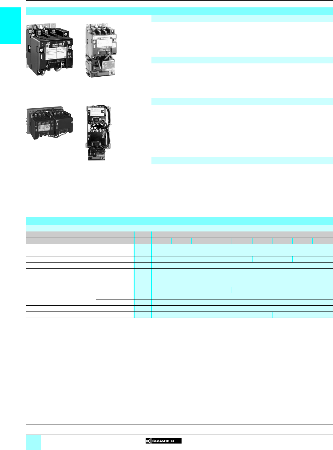
Fusible disconnect-
switch starters
Class H fuse clips
8538
SBG 1p
8538
SBA pp
8538
SCG 1p
8538
SCA pp
8538
SDG 1p
8538
SDA pp
Pages 2/6 2/6 2/6
Fusible disconnect-
switch starters
Class R fuse clips
8538
SBG 3 p
8538
SBA pp
8538
SCG 3 p
8538
SCA pp
8538
SDG 3 p
8538
SDA pp
Pages 2/7 2/7 2/7
Non-fusible disconnect-
switch starters 8538
SBG 11
8538
SBA p1
8538
SCG 11
8538
SCA p1
8538
SDG 11
8538
SDA p1
Pages 2/12 2/12 2/12
Circuit-breaker starters 8539
SBG 4p
8539
SBA pp
8539
SCG 4p
8539
SCA pp
8539
SDG 4p
8539
SDA pp
Pages 2/8 and 2/9 2/8 and 2/9 2/8 and 2/9
Thermal-magnetic circuit-
breaker starters 8539
SBG p
8539
SBA pp
8539
SCG p
8539
SCA pp
8539
SDG p
8539
SDA pp
Pages 2/10 and 2/11 2/10 and 2/11 2/10 and 2/11
(1) For circuit-breaker starters and thermal-magnetic circuit-breaker starters, see pages 2/8 to 2/11.
531120
531119
2/3
2
0
Type S NEMA combination starters
34567
25 hp/18.5 kW 40 hp/30 kW 75 hp/55 kW 150 hp/110 kW –
30 hp/22 kW 50 hp/37 kW 100 hp/75 kW 200 hp/150 kW 300 hp/220 kW
50 hp/37 kW 100 hp/75 kW 200 hp/150 kW 400 hp/300 kW 600 hp/450 kW
50 hp/37 kW 100 hp/75 kW 200 hp/150 kW 400 hp/300 kW 600 hp/450 kW
NEMA 1 NEMA 12 NEMA 1 NEMA 12 NEMA 1 NEMA 12 NEMA 1 NEMA 12 NEMA 1 NEMA 12
8538
SEG 1p
8538
SEA pp
8538
SFG 1p
8538
SFA pp
8538
SGG 1p
8538
SGA pp
8538
SHG 1p
8538
SHA pp
– –
2/6 2/6 2/6 2/6 –
8538
SEG 3 p
8538
SEA pp
8538
SFG 3 p
8538
SFA pp
8538
SGG 3 p
8538
SGA pp
8538
SHG 3 p
8538
SHA pp
– –
2/7 2/7 2/7 2/7 –
8538
SEG 11
8538
SEA p1
8538
SFG 11
8538
SFA p1
8538
SGG 11
8538
SGA p1
8538
SHG 11
8538
SHA p1
– –
2/12 2/12 2/12 2/12 –
8539
SEG 4p
8539
SEA pp
8539
SFG 4p
8539
SFA pp
8539
SGG 4p
8539
SGA pp
8539
SHG 4p
8539
SHA pp
8539
SJG 4p
8539
SJA 5p
2/8 and 2/9 2/8 and 2/9 2/8 and 2/9 2/8 and 2/9 2/8 and 2/9
8539
SEG p
8539
SEA pp
8539
SFG p
8539
SFA pp
8539
SGG p
8539
SGA pp
8539
SHG p
8539
SHA pp
8539
SJG p
8539
SJA pp
2/10 and 2/11 2/10 and 2/11 2/10 and 2/11 2/10 and 2/11 2/10 and 2/11
531269
531120
531119
531269

2/4
2
General,
characteristics
0
Combination Starters 0
Type S, NEMA-style starters with
Disconnect switch or circuit breaker
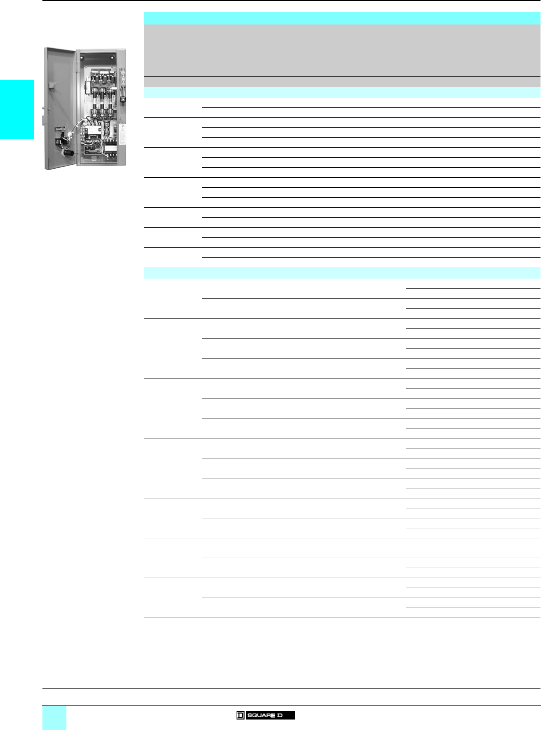
General
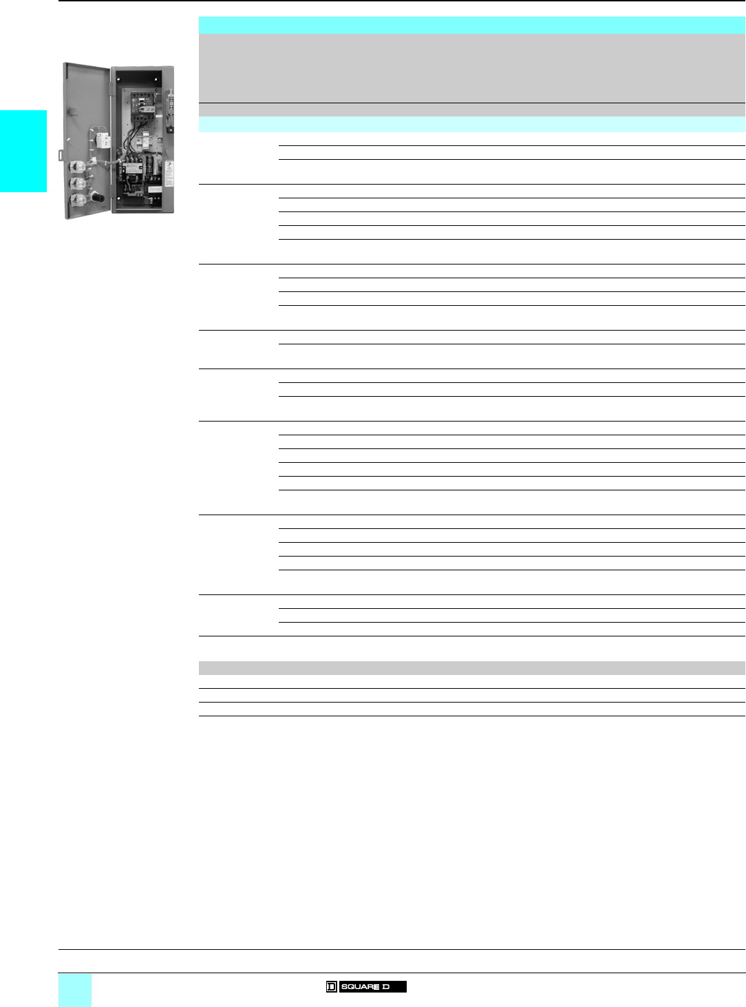
Class 8538 and 8539 Type S combination starters combine the requirements of
motor overload and short-circuit protection into one package. These starters are
manufactured in accordance with NEMA standards and are UL listed. They are
designed to operate up to a 600 V maximum, 50 to 60 Hz, and are available with
solid-state overload relays.
Square D is one of the leaders in North America and Europe in providing starters that
are verified by UL to comply with IEC 947-4-1 and Type 2 coordination. This means
that the components of a motor branch circuit protective device (fuses and circuit-
breaker), contactor and overload relay will be suitable for further use following a
short-circuit fault allowing for replacement of components during normal scheduled
maintenance. Class 8538 Type S combination starters, Sizes 0–5, with fusible
disconnect switches, meet Type 2 performance criteria.
Disconnect-switch starters
Features:
bInterchangeable fuse clips, straight through wiring, solid earth/ground bar, space
for a fused control transformer, provisions for adding disconnect switch electrical
interlock, handle mechanism/door closing mechanism.
Switch-type combination starters are available with fusible or non-fusible disconnect
switches in NEMA Sizes 0–6. The switch itself is constructed of a moulded, insulated
material that delivers arc-quenching performance similar to that of high voltage
switch-gear. The visible blade construction allows you to confirm the blade position
at a glance. Many industries have standardized on this feature.
Sizes 0–2, non-fusible assemblies can be field converted to fusible designs easily
and quickly. Factory-built fusible units accept the industry-standard Class H or R
fuses. The various units have specific UL-listed short-circuit withstand ratings that
range from 5000 to 100 000 A. Specific ratings are influenced by many components
including the size of the disconnect switch and the type of fuses used with the switch.
Circuit-breaker starters
Features:
bHandle mechanism, door closing mechanism.
Options:
bFactory-installed auxiliary switch (provides remote indication of an open or tripped
breaker), factory-supplied alarm switch (actuates bell alarms or warning light when
breaker is tripped).
Square D provides both a thermal-magnetic circuit-breaker and a motor circuit
protector in NEMA Sizes 0–7 for applications requiring a breaker-type combination
starter. The most widely used over-current protection devices are thermal-magnetic
circuit-breakers. Mag-Gard® motor circuit protectors are similar in construction, but
provide only short-circuit protection. When Mag-Gard devices are used with motor
starters, the adjustable instantaneous trip provides maximum motor protection based
on specific amperage and application.
Type S combination starters using thermal-magnetic breakers carry a UL-listed
short-circuit withstand rating from 5000 to 30 000 A. If a Mag-Gard Type GJL breaker
is used, withstand ratings increase to 100 000 A. Specific ratings and listings may
vary depending on the specific combination of components used in the assembly.
Characteristics
Environment
Class 8538 8539
Size 0 1 2 3 4 5 6 0 1 2 3 4 5 6 7
Rated insulation voltage
Conforming to UL, CSA V600 600
Rated impulse withstand voltage
Class H or Class K fuses kV 510 18 –
Class R fuses kV 100 –
ITE circuit-breaker (FAL, KAL, LAL, MAL) kV –10
ITE circuit-breaker (GJL) kV –65 –
INST circuit-breaker (FAL, KAL, LAL, MAL) kV –22 (1) 22 30 (3)
INST circuit-breaker (GJL) kV –100 (2) –
Product certifications UL, CSA
(1) 22 kV rating for 0–480 V. 10 kV rating for 600 V.
(2) 100 kV rating for 0–480 V. 10 kV rating for 600 V.
(3) 30 kV rating for 0–480 V. 22 kV rating for 600 V.
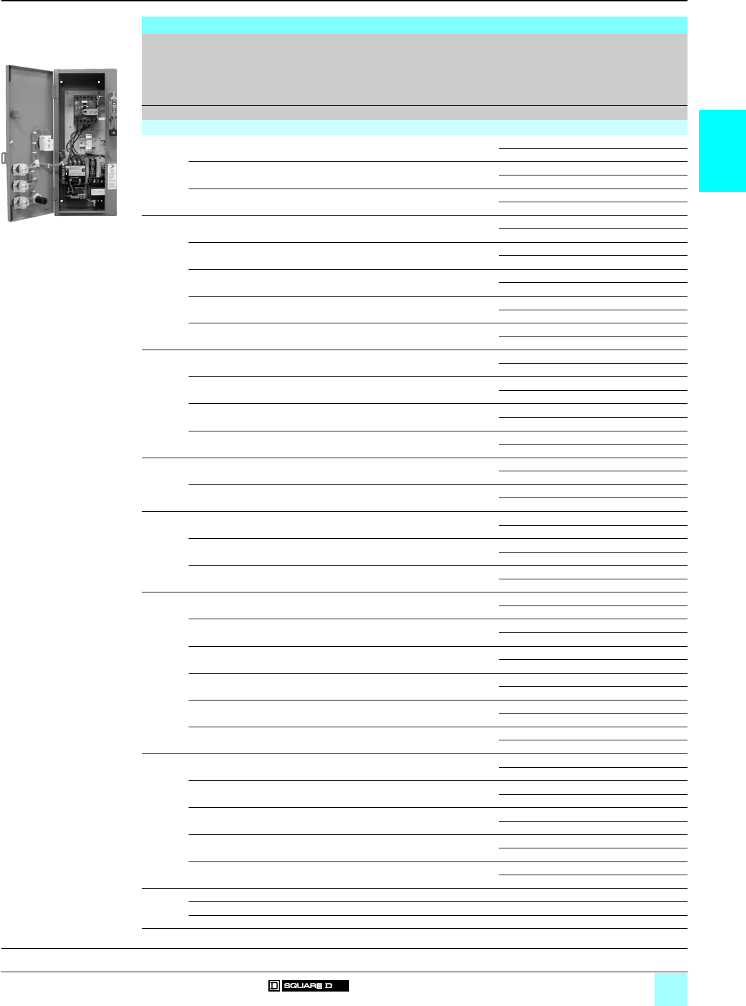
Fusible disconnect-switch combination starter
531043
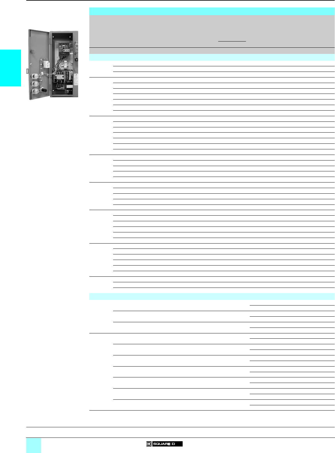
Circuit-breaker combination starter
531042
References:
pages 2/6 to 2/21
Dimensions:
pages 2/22 and 2/23
2/5
2
Characteristics (continued)
0
Combination Starters 0
Type S, NEMA-style starters with
Disconnect switch or circuit breaker
Electrical characteristics
UL-listed short-circuit ratings
Size 0 1 2 3 4 5 6 7
Disconnect-switch starters 8538 SpG 1p/SpA
NEMA fuse class Class H
Enclosure (1) Standard –
Available Ampere RMS symmetrical A5000 10 000 18 000 –
Disconnect-switch starters 8538 SpG 3p/SpA
NEMA fuse class Class R
Enclosure (1) Standard –
Available Ampere RMS symmetrical A100 000 –
Circuit-breaker starters 8539 SpG 4p/SpA
Enclosure (1) Standard
Available Ampere RMS symmetrical AWith GJL
circuit-breaker:
100 000
(voltage 0–480 V)
10 000
(voltage 481–600 V)
With GJL
circuit-breaker:
100 000
(voltage 0–480 V)
10 000
(voltage 481–600 V)
22 000
(8539 SGG 4p S8
and
8539 SDA pp S8)
22 000 30 000
(voltage 0–480 V)
22 000
(voltage 481–600 V)
Thermal-magnetic circuit-breaker starters 8538 SpG p/SpA
Enclosure (1) Standard
Available Ampere RMS symmetrical A5000 10 000 18 000 30 000
(voltage 0–480 V)
22 000
(voltage 481–600 V)
Mag-Gard trip range
Circuit-breaker GJL/FAL/KAL/LAL/MAL ppppp Mpp
Suffix number/trip range AM01 = 9–33 25M = 625–1250 35M = 1750–3500
M02 = 21–77 26M = 750–1500 36M = 2000–4000
M03 = 45–165 29M = 875–1750 40M = 2500–5000
M04 = 90–330 30M = 1000–2000 42M = 3000–6000
M05 = 150–550 31M = 1125–2250 44M = 3500–7000
M06 = 225–825 32M = 1250–2500
18M = 300–1100 33M = 1500–3000
Terminals
Size 0 1 2 3 4 5 6 7
Type Line terminals on disconnect switch
Type of lug Box lug
Wire
size
min.–
max.
Switch #14–#1/0 Cu/Al #6–300 MCM Cu/Al One #4–500 MCM Cu – –
Circuit-
breaker
#14–#4 Cu (2)
#12–#4 Al or
#14–#1/0 Cu
#12–#1/0 Al
#14–#1 Cu/#8–#1/0
Al (GJL Breaker)
#14–#1/0 Cu or
#12–#1/0 Al
#14–#1 Cu/#8–1/0 Al
(GJL Breaker)
#14–#2 Cu
#10–#2 Al (FA Brkr)
#4–300 MCM Cu/Al
(KA Breaker)
#14–#1 Cu/#8–#1/0
Al (GJL Breaker)
#14–#1/0 Cu
#12–#1/0 Al (LA Brkr)
#4–300 MCM Cu/Al
(KA Breaker)
#4–300 MCM Cu/Al
(KA Breaker)
x1 #1–600 MCM or
x2 #1–250 MCM
Cu/Al (LA Breaker)
x1 #1–600 MCM or
x2 #1–250 MCM
Cu/Al (LA Breaker) or
x3 #3/0–500 MCM
Cu/Al (MA Breaker)
x3 #3/0–500 MCM
Cu/Al
Type Power terminals on magnetic starter
Type of lug Screw
clamp
terminal
Box lug Parallel groove
Wire Size
min.–
max.
#14–#8 Cu #14–#4 Cu #14–#0 Cu #8–250 MCM Cu #4–500 MCM Cu 250–500 MCM Cu
(3)
250–500 MCM Cu
Per
terminal
1 or 2 11 or 2 1–4
Type Control terminals on magnetic starter
Type of lug Screw clamp terminal
Wire Size
min.-
max.
#16–#12 Cu #16–#12 Cu (4) #16–#12 Cu
Per
terminal
2
(1) Standard enclosure includes non-oversize NEMA 1 and 12.
(2) Use on FAL circuit-breakers rated 25 A or less.
(3) Order Class 9999 Type SAL-16 parts kit to convert power terminals to accept wire sizes 1/0–300 MCM.
(4) Terminal block range limited to #16–#14.
References:
pages 2/6 to 2/21
Dimensions:
pages 2/22 and 2/23
2/6
2
References
0
Combination Starters 0
Type S, NEMA-style starters with
Fusible disconnect switch, Class 8538
with Class H fuse clips and solid-state overload relay
3-pole fusible full-voltage starters, non-reversing (Class H fuse clips)
NEMA Size Standard power ratings of 3-phase motors 50/60 Hz
Motor volts (1)
Fuse
clip
size
External
reset
Basic reference
Add code indicating
control circuit voltage
(2), optional variants (3)
and H code (4)
Weight
200 V (208 V) 230 V (240 V) 460 V (480 V) 575 V (600 V)
hp kW hp kW hp kW hp kW Akg (lb)
NEMA 1 general purpose enclosure
032.2 32.2 ––––30– 8538 SBG 12 (2) (3) (4) 17 (38)
––––53.75 53.75 30 – 8538 SBG 13 (2) (3) (4) 17 (38)
153.75 53.75 ––––30– 8538 SCG 12 (2) (3) (4) 17 (38)
––––10 7.5 10 7.5 30 – 8538 SCG 14 (2) (3) (4) 17 (38)
7.5 5.5 7.5 5.5 ––––60– 8538 SCG 13 (2) (3) (4) 17 (38)
210 7.5 15 11 ––––60– 8538 SDG 12 (2) (3) (4) 25 (54)
––––15 11 15 11 30 – 8538 SDG 16 (2) (3) (4) 25 (54)
––––25 18.5 25 18.5 60 – 8538 SDG 14 (2) (3) (4) 25 (54)
320 15 25 18.5 ––––100– 8538 SEG 15 (2) (3) (4) 46 (102)
––––50 37 50 37 100 – 8538 SEG 13 (2) (3) (4) 46 (102)
25 18.5 30 22 ––––200– 8538 SEG 12 (2) (3) (4) 46 (102)
440 30 50 37 ––––200– 8538 SFG 15 (2) (3) (4) 74 (163)
––––100 75 100 75 200 – 8538 SFG 13 (2) (3) (4) 74 (163)
575 55 100 75 ––––400– 8538 SGG 15 (2) (3) (4) 204 (450)
––––200 150 200 150 400 – 8538 SGG 13 (2) (3) (4) 204 (450)
6150 110 200 150 ––––600– 8538 SHG 13 (2) (3) (4) 240 (530)
––––400 300 400 300 600 – 8538 SHG 12 (2) (3) (4) 240 (530)
NEMA 12 dust-tight industrial-use enclosure
032.2 32.2 ––––30With8538 SBA 22 (2) (3) (4) 18 (40)
Without 8538 SBA 12 (2) (3) (4) 18 (40)
––––53.75 53.75 30 With 8538 SBA 23 (2) (3) (4) 18 (40)
Without 8538 SBA 13 (2) (3) (4) 18 (40)
153.75 53.75 ––––30With8538 SCA 22 (2) (3) (4) 18 (40)
Without 8538 SCA 12 (2) (3) (4) 18 (40)
––––10 7.5 10 7.5 30 With 8538 SCA 24 (2) (3) (4) 18 (40)
Without 8538 SCA 14 (2) (3) (4) 18 (40)
7.5 5.5 7.5 5.5 ––––60With8538 SCA 23 (2) (3) (4) 18 (40)
Without 8538 SCA 13 (2) (3) (4) 18 (40)
210 7.5 15 11 ––––60With8538 SDA 22 (2) (3) (4) 25 (55)
Without 8538 SDA 12 (2) (3) (4) 25 (55)
––––15 11 15 11 30 With 8538 SDA 26 (2) (3) (4) 25 (55)
Without 8538 SDA 16 (2) (3) (4) 25 (55)
––––25 18.5 25 18.5 60 With 8538 SDA 24 (2) (3) (4) 25 (55)
Without 8538 SDA 14 (2) (3) (4) 25 (55)
320 15 25 18.5 –––– 100 With 8538 SEA 25 (2) (3) (4) 50 (111)
Without 8538 SEA 15 (2) (3) (4) 50 (111)
––––50 37 50 37 100 With 8538 SEA 23 (2) (3) (4) 50 (111)
Without 8538 SEA 13 (2) (3) (4) 50 (111)
25 18.5 30 22 –––– 200 With 8538 SEA 22 (2) (3) (4) 50 (111)
Without 8538 SEA 12 (2) (3) (4) 50 (111)
440 30 50 37 –––– 200 With 8538 SFA 25 (2) (3) (4) 77 (170)
Without 8538 SFA 15 (2) (3) (4) 77 (170)
––––100 75 100 75 200 With 8538 SFA 23 (2) (3) (4) 77 (170)
Without 8538 SFA 13 (2) (3) (4) 77 (170)
575 55 100 75 –––– 400 With 8538 SGA 25 (2) (3) (4) 207 (457)
Without 8538 SGA 15 (2) (3) (4) 207 (457)
––––200 150 200 150 400 With 8538 SGA 23 (2) (3) (4) 207 (457)
Without 8538 SGA 13 (2) (3) (4) 207 (457)
6150 110 200 150 –––– 600 With 8538 SHA 23 (2) (3) (4) 250 (552)
Without 8538 SHA 13 (2) (3) (4) 250 (552)
––––400 300 400 300 600 With 8538 SHA 22 (2) (3) (4) 250 (552)
Without 8538 SHA 12 (2) (3) (4) 250 (552)
(1) (2) (3) (4) See page 2/8.
8538 SBG 12
ppp
531043
General, characteristics:
pages 2/4 and 2/5
Dimensions:
pages 2/22 and 2/23
2/7
2
References
0
Combination Starters 0
Type S, NEMA-style starters with
Fusible disconnect switch, Class 8538
with Class R fuse clips
3-pole fusible full-voltage starters, non-reversing (Class R fuse clips)
NEMA Size Standard power ratings of 3-phase motors 50/60 Hz
Motor volts (1)
Fuse
clip
size
External
reset
Basic reference
Add code indicating
control circuit voltage
(2), optional variants (3)
and H code (4)
Weight
200 V (208 V) 230 V (240 V) 460 V (480 V) 575 V (600 V)
hp kW hp kW hp kW hp kW Akg (lb)
NEMA 1 general purpose enclosure
032.2 32.2 ––––30– 8538 SBG 32 (2) (3) (4) 17 (38)
––––53.75 53.75 30 – 8538 SBG 33 (2) (3) (4) 17 (38)
153.75 53.75 ––––30– 8538 SCG 32 (2) (3) (4) 17 (38)
––––10 7.5 10 7.5 30 – 8538 SCG 34 (2) (3) (4) 17 (38)
7.5 5.5 7.5 5.5 ––––60– 8538 SCG 33 (2) (3) (4) 17 (38)
210 7.5 15 11 ––––60– 8538 SDG 32 (2) (3) (4) 25 (54)
––––15 11 15 11 30 – 8538 SDG 36 (2) (3) (4) 25 (54)
––––25 18.5 25 18.5 60 – 8538 SDG 34 (2) (3) (4) 25 (54)
320 15 25 18.5 ––––100– 8538 SEG 35 (2) (3) (4) 46 (102)
––––50 37 50 37 100 – 8538 SEG 33 (2) (3) (4) 46 (102)
25 18.5 30 22 ––––200– 8538 SEG 32 (2) (3) (4) 46 (102)
440 30 50 37 ––––200– 8538 SFG 35 (2) (3) (4) 74 (163)
––––100 75 100 75 200 – 8538 SFG 33 (2) (3) (4) 74 (163)
575 55 100 75 ––––400– 8538 SGG 35 (2) (3) (4) 204 (450)
––––200 150 200 150 400 – 8538 SGG 33 (2) (3) (4) 204 (450)
6150 110 200 150 ––––600– 8538 SHG 33 (2) (3) (4) 240 (530)
––––400 300 400 300 600 – 8538 SHG 32 (2) (3) (4) 240 (530)
NEMA 12 dust-tight industrial-use enclosure
032.2 32.2 ––––30With8538 SBA 42 (2) (3) (4) 18 (40)
Without 8538 SBA 32 (2) (3) (4) 18 (40)
––––53.75 53.75 30 With 8538 SBA 43 (2) (3) (4) 18 (40)
Without 8538 SBA 33 (2) (3) (4) 18 (40)
153.75 53.75 ––––30With8538 SCA 42 (2) (3) (4) 18 (40)
Without 8538 SCA 32 (2) (3) (4) 18 (40)
––––10 7.5 10 7.5 30 With 8538 SCA 44 (2) (3) (4) 18 (40)
Without 8538 SCA 34 (2) (3) (4) 18 (40)
7.5 5.5 7.5 5.5 ––––60With8538 SCA 43 (2) (3) (4) 18 (40)
Without 8538 SCA 33 (2) (3) (4) 18 (40)
210 7.5 15 11 ––––60With8538 SDA 42 (2) (3) (4) 25 (55)
Without 8538 SDA 32 (2) (3) (4) 25 (55)
––––15 11 15 11 30 With 8538 SDA 46 (2) (3) (4) 25 (55)
Without 8538 SDA 36 (2) (3) (4) 25 (55)
––––25 18.5 25 18.5 60 With 8538 SDA 44 (2) (3) (4) 25 (55)
Without 8538 SDA 34 (2) (3) (4) 25 (55)
320 15 25 18.5 ––––100With8538 SEA 45 (2) (3) (4) 50 (111)
Without 8538 SEA 35 (2) (3) (4) 50 (111)
––––50 37 50 37 100 With 8538 SEA 43 (2) (3) (4) 50 (111)
Without 8538 SEA 33 (2) (3) (4) 50 (111)
25 18.5 30 22 ––––200With8538 SEA 42 (2) (3) (4) 50 (111)
Without 8538 SEA 32 (2) (3) (4) 50 (111)
440 30 50 37 ––––200With8538 SFA 45 (2) (3) (4) 77 (170)
Without 8538 SFA 35 (2) (3) (4) 77 (170)
––––100 75 100 75 200 With 8538 SFA 43 (2) (3) (4) 77 (170)
Without 8538 SFA 33 (2) (3) (4) 77 (170)
575 55 100 75 ––––400With8538 SGA 45 (2) (3) (4) 207 (457)
Without 8538 SGA 35 (2) (3) (4) 207 (457)
––––200 150 200 150 400 With 8538 SGA 43 (2) (3) (4) 207 (457)
Without 8538 SGA 33 (2) (3) (4) 207 (457)
6150 110 200 150 ––––600With8538 SHA 43 (2) (3) (4) 250 (552)
Without 8538 SHA 33 (2) (3) (4) 250 (552)
––––400 300 400 300 600 With 8538 SHA 42 (2) (3) (4) 250 (552)
Without 8538 SHA 32 (2) (3) (4) 250 (552)
(1) (2) (3) (4) See page 2/8.
8538 SBG 32
ppp
531043
General, characteristics:
pages 2/4 and 2/5
Dimensions:
pages 2/22 and 2/23
2/8
2
References
0
Combination Starters 0
Type S, NEMA-style starters with
Mag-Gard® circuit-breaker, Class 8539
3-pole circuit-breaker starters, non-reversing
NEMA Size Standard power ratings of 3-phase motors 50/60 Hz
Motor volts (1)
Circuit-breaker Basic reference
Add code indicating
control circuit voltage
(2),
optional variants (3)
and “H” code (4)
Weight
200 V (208 V) 230 V (240 V) 460 V (480 V) 575 V (600 V)
hp kW hp kW hp kW hp kW kg (lb)
NEMA 1 general purpose enclosure
00.3 0.2 0.3 0.2 10.75 10.75 GJL 36003 MO1 8539 SBG 41 (2) (3) (4) 17 (38)
10.75 10.75 32.2 32.2 GJL 36007 MO2 8539 SBG 42 (2) (3) (4) 17 (38)
32.2 32.2 53.7 53.7 GJL 36015 MO3 8539 SBG 43 (2) (3) (4) 17 (38)
10.3 0.2 0.3 0.2 10.75 10.75 GJL 36003 MO1 8539 SCG 41 (2) (3) (4) 17 (38)
10.75 10.75 32.2 32.2 GJL 36007 MO2 8539 SCG 42 (2) (3) (4) 17 (38)
32.2 32.2 7.5 5.5 10 7.5 GJL 36015 MO3 8539 SCG 43 (2) (3) (4) 17 (38)
53.7 7.5 5.5 10 7.5 –– GJL 36030 MO4 8539 SCG 44 (2) (3) (4) 17 (38)
7.5 5.5 –––––– GJL 36050 MO5 8539 SCG 45 (2) (3) (4) 17 (38)
232.2 32.2 7.5 5.5 10 7.5 GJL 36015 MO3 8539 SDG 41 (2) (3) (4) 25 (54)
53.7 7.5 5.5 15 11 20 15 GJL 36030 MO4 8539 SDG 42 (2) (3) (4) 25 (54)
10 7.5 10 7.5 25 18.5 25 18.5 GJL 36050 MO5 8539 SDG 43 (2) (3) (4) 25 (54)
––15 11 –––– GJL 36075 MO6 8539 SDG 44 (2) (3) (4) 25 (54)
3––––25 18.5 30 22 GJL 36050 MO5 8539 SEG 41 (2) (3) (4) 46 (102)
25 18.5 30 22 30 22 50 37 FAL 36100 18M 8539 SEG 42 (2) (3) (4) 46 (102)
430 22 ––75 55 100 75 KAL 36250 25M 8539 SFG 42 (2) (3) (4) 74 (163)
––40 30 –––– KAL 36250 26M 8539 SFG 43 (2) (3) (4) 74 (163)
––50 37 100 75 –– KAL 36250 29M 8539 SFG 44 (2) (3) (4) 74 (163)
5––––––125 90 KAL 36250 29M 8539 SGG 41 (2) (3) (4) 191 (420)
50 37 ––––150 110 KAL 36250 30M 8539 SGG 42 (2) (3) (4) 191 (420)
––60 45 125 90 –– KAL 36250 31M 8539 SGG 43 (2) (3) (4) 191 (420)
60 45 75 55 150 110 200 150 LAL 36400 32M 8539 SGG 44 (2) (3) (4) 191 (420)
75 55 –––––– LAL 36400 33M 8539 SGG 45 (2) (3) (4) 191 (420)
––100 75 200 150 –– LAL 36400 35M 8539 SGG 46 (2) (3) (4) 191 (420)
6––––––250 185 LAL 36400 35M 8539 SHG 42 (2) (3) (4) 200 (441)
100 75 ––250 185 300 220 LAL 36400 36M 8539 SHG 43 (2) (3) (4) 200 (441)
125 90 150 110 300 220 400 300 MAL 36600 40M 8539 SHG 44 (2) (3) (4) 200 (441)
150 110 ––350 250 –– MAL 36600 42M 8539 SHG 45 (2) (3) (4) 200 (441)
––200 150 400 300 –– MAL 36600 44M 8539 SHG 46 (2) (3) (4) 200 (441)
7––––––500 370 MAL 36800 44M 8539 SJG 41 (2) (3) (4) 318 (702)
––250 185 500 370 600 450 MAL 36800 45M 8539 SJG 42 (2) (3) (4) 318 (702)
––300 220 600 450 –– MAL 361000 47M 8539 SJG 43 (2) (3) (4) 318 (702)
(1) Motor voltage (starter voltage).
(2) Standard control circuit voltage:
Volts 24 110 120 208 220 240 380 440 480 550 600
50 Hz – V02 – – V03 – V05 V06 – V07 –
60 Hz V01 (5) (6) –V02 (5) V08 – V03 – – V06 – V07
24 V and 120 V coils require the addition of form “S” for separate control. Example: 8559 SCG 41 V02 H10S.
(3) For optional variants, see page 2/21.
(4) To complete “H” code for Motor Logic solid-state overload relays, see pages 2/13 to 2/19. Motor Logic Plus units are not
available on combination starters.
(5) 24 V coils are not available on Sizes 4–6. On Sizes 0–3, where 24 V coils are available, suffix “S” (separate control) must be
specified.
(6) These voltage codes must include suffix “S” (supplied at no charge). When specifying suffix “S”, please supply motor voltage
when ordering.
8539 SBG 41
ppp
531042
General, characteristics:
pages 2/4 and 2/5
Dimensions:
pages 2/22 and 2/23
2/9
2
References (continued)
0
Combination Starters 0
Type S, NEMA-style starters with
Mag-Gard® circuit breaker, Class 8539
3-pole circuit-breaker starters, non-reversing (continued)
NEMA
Size
Standard power ratings of 3-phase motors 50/60 Hz
Motor volts (1)
Circuit-
breaker
External
reset
Basic reference
Add code indicating
control circuit voltage
(2), optional variants (3),
and “H” code (4)
Weight
200 V (208 V) 230 V (240 V) 460 V (480 V) 575 V (600 V)
hp kW hp kW hp kW hp kW kg (lb)
NEMA 12 dust-tight industrial-use enclosure
00.3 0.2 0.3 0.2 10.75 10.75 GJL 36003 MO1 With 8539 SBA 51 (2) (3) (4) 18 (40)
Without 8539 SBA 41 (2) (3) (4) 18 (40)
10.75 10.75 32.2 32.2 GJL 36007 MO2 With 8539 SBA 52 (2) (3) (4) 18 (40)
Without 8539 SBA 42 (2) (3) (4) 18 (40)
32.2 32.2 53.7 53.7 GJL 36015 MO3 With 8539 SBA 53 (2) (3) (4) 18 (40)
Without 8539 SBA 43 (2) (3) (4) 18 (40)
10.3 0.2 0.3 0.2 10.75 10.75 GJL 36003 MO1 With 8539 SCA 51 (2) (3) (4) 18 (40)
Without 8539 SCA 41 (2) (3) (4) 18 (40)
10.75 10.75 32.2 32.2 GJL 36007 MO2 With 8539 SCA 52 (2) (3) (4) 18 (40)
Without 8539 SCA 42 (2) (3) (4) 18 (40)
32.2 32.2 7.5 5.5 10 7.5 GJL 36015 MO3 With 8539 SCA 53 (2) (3) (4) 18 (40)
Without 8539 SCA 43 (2) (3) (4) 18 (40)
53.7 7.5 5.5 10 7.5 –– GJL 36030 MO4 With 8539 SCA 54 (2) (3) (4) 18 (40)
Without 8539 SCA 44 (2) (3) (4) 18 (40)
7.5 5.5 –––––– GJL 36050 MO5 With 8539 SCA 55 (2) (3) (4) 18 (40)
Without 8539 SCA 45 (2) (3) (4) 18 (40)
232.2 32.2 7.5 5.5 10 7.5 GJL 36015 MO3 With 8539 SDA 51 (2) (3) (4) 25 (55)
Without 8539 SDA 41 (2) (3) (4) 25 (55)
53.7 7.5 5.5 15 11 20 15 GJL 36030 MO4 With 8539 SDA 52 (2) (3) (4) 25 (55)
Without 8539 SDA 42 (2) (3) (4) 25 (55)
10 7.5 10 7.5 25 18.5 25 18.5 GJL 36050 MO5 With 8539 SDA 53 (2) (3) (4) 25 (55)
Without 8539 SDA 43 (2) (3) (4) 25 (55)
––15 11 –––– GJL 36075 MO6 With 8539 SDA 54 (2) (3) (4) 25 (55)
Without 8539 SDA 44 (2) (3) (4) 25 (55)
3––––25 18.5 30 22 GJL 36050 MO5 With 8539 SEA 51 (2) (3) (4) 50 (111)
Without 8539 SEA 41 (2) (3) (4) 50 (111)
25 18.5 30 22 30 22 50 37 FAL 36100 18M With 8539 SEA 52 (2) (3) (4) 50 (111)
Without 8539 SEA 42 (2) (3) (4) 50 (111)
430 22 ––75 55 100 75 KAL 36250 25M With 8539 SFA 52 (2) (3) (4) 77 (170)
Without 8539 SFA 42 (2) (3) (4) 77 (170)
––40 30 –––– KAL 36250 26M With 8539 SFA 53 (2) (3) (4) 77 (170)
Without 8539 SFA 43 (2) (3) (4) 77 (170)
––50 37 100 75 –– KAL 36250 29M With 8539 SFA 54 (2) (3) (4) 77 (170)
Without 8539 SFA 44 (2) (3) (4) 77 (170)
5––––––125 90 KAL 36250 29M With 8539 SGA 51 (2) (3) (4) 200 (440)
Without 8539 SGA 41 (2) (3) (4) 200 (440)
50 37 ––––150 110 KAL 36250 30M With 8539 SGA 52 (2) (3) (4) 200 (440)
Without 8539 SGA 42 (2) (3) (4) 200 (440)
––60 45 125 90 –– KAL 36250 31M With 8539 SGA 53 (2) (3) (4) 200 (440)
Without 8539 SGA 43 (2) (3) (4) 200 (440)
60 45 75 55 150 110 200 150 LAL 36400 32M With 8539 SGA 54 (2) (3) (4) 200 (440)
Without 8539 SGA 44 (2) (3) (4) 200 (440)
75 55 –––––– LAL 36400 33M With 8539 SGA 55 (2) (3) (4) 200 (440)
Without 8539 SGA 45 (2) (3) (4) 200 (440)
––100 75 200 150 –– LAL 36400 35M With 8539 SGA 56 (2) (3) (4) 200 (440)
Without 8539 SGA 46 (2) (3) (4) 200 (440)
6––––––250 185 LAL 36400 35M With 8539 SHA 52 (2) (3) (4) 200 (441)
Without 8539 SHA 42 (2) (3) (4) 200 (441)
100 75 ––250 185 300 220 LAL 36400 36M With 8539 SHA 53 (2) (3) (4) 200 (441)
Without 8539 SHA 43 (2) (3) (4) 200 (441)
125 90 150 110 300 220 400 300 MAL 36600 40M With 8539 SHA 54 (2) (3) (4) 200 (441)
Without 8539 SHA 44 (2) (3) (4) 200 (441)
150 110 ––350 250 –– MAL 36600 42M With 8539 SHA 55 (2) (3) (4) 200 (441)
Without 8539 SHA 45 (2) (3) (4) 200 (441)
––200 150 400 300 –– MAL 36600 44M With 8539 SHA 56 (2) (3) (4) 200 (441)
Without 8539 SHA 46 (2) (3) (4) 200 (441)
7––––––500 370 MAL 36800 44M With 8539 SJA 51 (2) (3) (4) 318 (702)
––250 185 500 370 600 450 MAL 36800 45M With 8539 SJA 52 (2) (3) (4) 318 (702)
––300 220 600 450 –– MAL 361000 47M With 8539 SJA 53 (2) (3) (4) 318 (702)
(1) (2) (3) (4) See page 2/8.
8539 SBA 51
ppp
531042
General, characteristics:
pages 2/4 and 2/5
Dimensions:
pages 2/22 and 2/23
2/10
2
References
0
Combination Starters 0
Type S, NEMA-style starters with
Thermal-magnetic circuit breaker, Class 8539
3-pole thermal-magnetic circuit-breaker starters, non-reversing
NEMA
Size
Standard power ratings of 3-phase motors 50/60 Hz
Motor volts (1)
3Circuit-
breaker
External
reset
Basic reference
Add code indicating
control circuit voltage
(2), optional variants (3)
and “H” code (4)
Weight
200 V (208 V) 230 V (240 V) 460 V (480 V) 575 V (600 V) Type Rating
hp kW hp kW hp kW hp kW Akg (lb)
NEMA 1 general purpose enclosure
021.5 21.5 ––––FAL15– 8539 SBG 1 (2) (3) (4) 17 (38)
––––53.7 53.7 FAL 15 – 8539 SBG 2 (2) (3) (4) 17 (38)
32.2 32.2 ––––FAL20– 8539 SBG 3 (2) (3) (4) 17 (38)
153.7 ––––––FAL35– 8539 SCG 5 (2) (3) (4) 17 (38)
7.5 5.5 ––––––FAL50– 8539 SCG 2 (2) (3) (4) 17 (38)
––53.7 ––––FAL30– 8539 SCG 1 (2) (3) (4) 17 (38)
––7.5 5.5 ––––FAL45– 8539 SCG 6 (2) (3) (4) 17 (38)
––––7.5 5.5 10 7.5 FAL 20 – 8539 SCG 3 (2) (3) (4) 17 (38)
––––10 7.5 ––FAL25– 8539 SCG 7 (2) (3) (4) 17 (38)
––––––7.5 5.5 FAL 15 – 8539 SCG 8 (2) (3) (4) 17 (38)
210 7.5 10 7.5 ––––FAL60– 8539 SDG 1 (2) (3) (4) 25 (54)
––15 11 ––––FAL80– 8539 SDG 7 (2) (3) (4) 25 (54)
––––7.5 5.5 ––FAL20– 8539 SDG 3 (2) (3) (4) 25 (54)
––––20 15 25 18.5 FAL 60 – 8539 SDG 4 (2) (3) (4) 25 (54)
––––25 18.5 ––FAL70– 8539 SDG 5 (2) (3) (4) 25 (54)
––––––15 11 FAL 35 – 8539 SDG 8 (2) (3) (4) 25 (54)
––––––20 15 FAL 45 – 8539 SDG 9 (2) (3) (4) 25 (54)
315 11 20 15 40 30 50 37 FAL 90 – 8539 SEG 3 (2) (3) (4) 46 (102)
20 15 25 18.5 50 37 ––FAL100– 8539 SEG 1 (2) (3) (4) 46 (102)
25 18.5 30 22 ––––KAL110– 8539 SEG 5 (2) (3) (4) 46 (102)
––––30 22 40 30 FAL 80 – 8539 SEG 6 (2) (3) (4) 46 (102)
––––––30 22 FAL 60 – 8539 SEG 4 (2) (3) (4) 46 (102)
430 22 ––75 55 ––KAL125– 8539 SFG 3 (2) (3) (4) 74 (163)
40 30 50 37 100 75 ––KAL200– 8539 SFG 4 (2) (3) (4) 74 (163)
––40 30 ––100 75 KAL 150 – 8539 SFG 1 (2) (3) (4) 74 (163)
––––60 45 75 55 KAL 110 – 8539 SFG 5 (2) (3) (4) 74 (163)
––––––60 45 FAL 100 – 8539 SFG 6 (2) (3) (4) 74 (163)
550 37 ––––150 110 LAL 200 – 8539 SGG 6 (2) (3) (4) 191 (420)
60 45 75 55 150 110 200 150 LAL 250 – 8539 SGG 1 (2) (3) (4) 191 (420)
75 55 ––––––LAL300– 8539 SGG 4 (2) (3) (4) 191 (420)
––60 45 125 90 ––LAL225– 8539 SGG 3 (2) (3) (4) 191 (420)
––100 75 200 150 ––LAL350– 8539 SGG 2 (2) (3) (4) 191 (420)
––––––125 90 KAL 200 – 8539 SGG 7 (2) (3) (4) 191 (420)
6100 75 125 90 250 185 300 220 MAL 450 – 8539 SHG 4 (2) (3) (4) 220 (486)
125 90 150 110 300 220 400 300 MAL 600 – 8539 SHG 3 (2) (3) (4) 220 (486)
150 110 ––350 250 ––MAL600– 8539 SHG 5 (2) (3) (4) 220 (486)
––200 150 400 300 ––MAL800– 8539 SHG 7 (2) (3) (4) 220 (486)
––––––250 185 MAL 250 – 8539 SHG 6 (2) (3) (4) 220 (486)
––––––350 250 MAL 500 – 8539 SHG 2 (2) (3) (4) 220 (486)
7––250 185 500 370 600 450 MAL 900 – 8539 SJG 2 (2) (3) (4) 320 (706)
––300 220 600 450 –– MAL 1000 – 8539 SJG 3 (2) (3) (4) 320 (706)
––––––500 370 MAL 800 – 8539 SJG 1 (2) (3) (4) 320 (706)
NEMA 12 dust-tight industrial-use enclosure
021.5 21.5 –––– FAL 15 With 8539 SBA 11 (2) (3) (4) 18 (40)
Without 8539 SBA 1 (2) (3) (4) 18 (40)
––––53.7 53.7 FAL 15 With 8539 SBA 12 (2) (3) (4) 18 (40)
Without 8539 SBA 2 (2) (3) (4) 18 (40)
32.2 32.2 –––– FAL 20 With 8539 SBA 13 (2) (3) (4) 18 (40)
Without 8539 SBA 13 (2) (3) (4) 18 (40)
153.7 –––––– FAL 35 With 8539 SCA 15 (2) (3) (4) 18 (40)
Without 8539 SCA 5 (2) (3) (4) 18 (40)
7.5 5.5 –––––– FAL 50 With 8539 SCA 12 (2) (3) (4) 18 (40)
Without 8539 SCA 2 (2) (3) (4) 18 (40)
––53.7 –––– FAL 30 With 8539 SCA 11 (2) (3) (4) 18 (40)
Without 8539 SCA 1 (2) (3) (4) 18 (40)
––7.5 5.5 –––– FAL 45 With 8539 SCA 16 (2) (3) (4) 18 (40)
Without 8539 SCA 6 (2) (3) (4) 18 (40)
––––7.5 5.5 10 7.5 FAL 20 With 8539 SCA 13 (2) (3) (4) 18 (40)
Without 8539 SCA 3 (2) (3) (4) 18 (40)
––––10 7.5 –– FAL 25 With 8539 SCA 17 (2) (3) (4) 18 (40)
Without 8539 SCA 7 (2) (3) (4) 18 (40)
––––––7.5 5.5 FAL 15 With 8539 SCA 18 (2) (3) (4) 18 (40)
Without 8539 SCA 8 (2) (3) (4) 18 (40)
(1) (2) (3) (4) See page 2/8.
8539 SBG 1
ppp
531042
General, characteristics:
pages 2/4 and 2/5
Dimensions:
pages 2/22 and 2/23
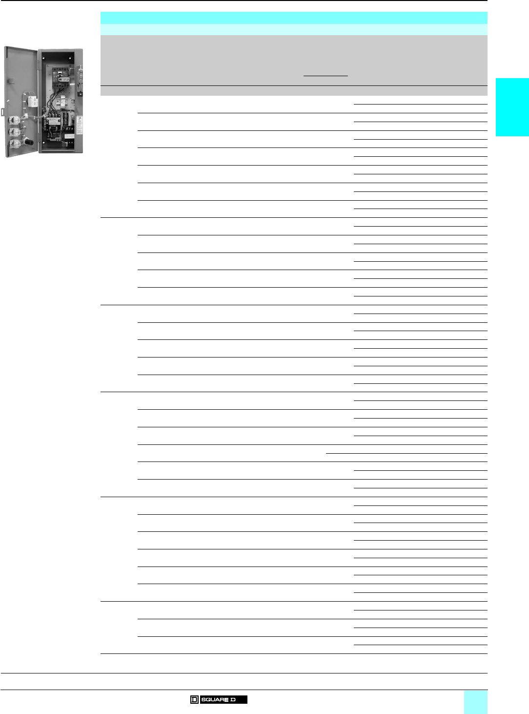
2/11
2
References (continued)
0
Combination Starters 0
Type S, NEMA-style starters with
Thermal-magnetic circuit-breaker, Class 8539
3-pole thermal-magnetic circuit-breaker starters, non-reversing
NEMA 12 dust-tight industrial-use enclosure (continued)
NEMA
Size
Standard power ratings of 3-phase motors 50/60 Hz
Motor volts (1)
Circuit-
breaker
External
reset
Basic reference
Add code indicating
control circuit voltage
(2), optional variants (3)
and “H” code (4)
Weight
200 V (208 V) 230 V (240 V) 460 V (480 V) 575 V (600 V) Type Rating
hp kW hp kW hp kW hp kW Akg (lb)
210 7.5 10 7.5 –––– FAL 60 With 8539 SDA 11 (2) (3) (4) 25 (55)
Without 8539 SDA 1 (2) (3) (4) 25 (55)
––15 11 –––– FAL 80 With 8539 SDA 17 (2) (3) (4) 25 (55)
Without 8539 SDA 7 (2) (3) (4) 25 (55)
––––7.5 5.5 –– FAL 20 With 8539 SDA 13 (2) (3) (4) 25 (55)
Without 8539 SDA 3 (2) (3) (4) 25 (55)
––––20 15 25 18.5 FAL 60 With 8539 SDA 14 (2) (3) (4) 25 (55)
Without 8539 SDA 4 (2) (3) (4) 25 (55)
––––25 18.5 –– FAL 70 With 8539 SDA 15 (2) (3) (4) 25 (55)
Without 8539 SDA 5 (2) (3) (4) 25 (55)
––––––15 11 FAL 35 With 8539 SDA 18 (2) (3) (4) 25 (55)
Without 8539 SDA 8 (2) (3) (4) 25 (55)
––––––20 15 FAL 45 With 8539 SDA 19 (2) (3) (4) 25 (55)
Without 8539 SDA 9 (2) (3) (4) 25 (55)
315 11 20 15 40 30 50 37 FAL 90 With 8539 SEA 13 (2) (3) (4) 50 (111)
Without 8539 SEA 3 (2) (3) (4) 50 (111)
20 15 25 18.5 50 37 ––FAL100With8539 SEA 11 (2) (3) (4) 50 (111)
Without 8539 SEA 1 (2) (3) (4) 50 (111)
25 18.5 30 22 ––––KAL110With8539 SEA 15 (2) (3) (4) 50 (111)
Without 8539 SEA 5 (2) (3) (4) 50 (111)
––––30 22 40 30 FAL 80 With 8539 SEA 16 (2) (3) (4) 50 (111)
Without 8539 SEA 6 (2) (3) (4) 50 (111)
––––––30 22 FAL 60 With 8539 SEA 14 (2) (3) (4) 50 (111)
Without 8539 SEA 4 (2) (3) (4) 50 (111)
430 22 ––75 55 ––KAL125With8539 SFA 13 (2) (3) (4) 77 (170)
Without 8539 SFA 3 (2) (3) (4) 77 (170)
40 30 50 37 100 75 ––KAL200With8539 SFA 14 (2) (3) (4) 77 (170)
Without 8539 SFA 4 (2) (3) (4) 77 (170)
––40 30 ––100 75 KAL 150 With 8539 SFA 11 (2) (3) (4) 77 (170)
Without 8539 SFA 1 (2) (3) (4) 77 (170)
––––60 45 75 55 KAL 110 With 8539 SFA 15 (2) (3) (4) 77 (170)
Without 8539 SFA 5 (2) (3) (4) 77 (170)
––––––60 45 FAL 100 With 8539 SFA 16 (2) (3) (4) 77 (170)
Without 8539 SFA 6 (2) (3) (4) 77 (170)
550 37 ––––150 110 LAL 200 With 8539 SGA 16 (2) (3) (4) 200 (440)
Without 8539 SGA 6 (2) (3) (4) 200 (440)
60 45 75 55 150 110 200 150 LAL 250 With 8539 SGA 11 (2) (3) (4) 200 (440)
Without 8539 SGA 1 (2) (3) (4) 200 (440)
75 55 ––––––LAL300With8539 SGA 14 (2) (3) (4) 200 (440)
Without 8539 SGA 4 (2) (3) (4) 200 (440)
––60 45 125 90 ––LAL225With8539 SGA 13 (2) (3) (4) 200 (440)
Without 8539 SGA 3 (2) (3) (4) 200 (440)
––100 75 200 150 ––LAL350With8539 SGA 12 (2) (3) (4) 200 (440)
Without 8539 SGA 2 (2) (3) (4) 200 (440)
––––––125 90 KAL 200 With 8539 SGA 17 (2) (3) (4) 200 (440)
Without 8539 SGA 7 (2) (3) (4) 200 (440)
6100 75 125 90 250 185 300 220 MAL 450 With 8539 SHA 14 (2) (3) (4) 220 (486)
Without 8539 SHA 4 (2) (3) (4) 220 (486)
125 90 150 110 300 220 400 300 MAL 600 With 8539 SHA 13 (2) (3) (4) 220 (486)
Without 8539 SHA 3 (2) (3) (4) 220 (486)
150 110 ––350 250 ––MAL600With8539 SHA 15 (2) (3) (4) 220 (486)
Without 8539 SHA 5 (2) (3) (4) 220 (486)
––200 150 400 300 ––MAL800With8539 SHA 17 (2) (3) (4) 220 (486)
Without 8539 SHA 7 (2) (3) (4) 220 (486)
––––––250 185 MAL 250 With 8539 SHA 16 (2) (3) (4) 220 (486)
Without 8539 SHA 6 (2) (3) (4) 220 (486)
––––––350 250 MAL 500 With 8539 SHA 12 (2) (3) (4) 220 (486)
Without 8539 SHA 2 (2) (3) (4) 220 (486)
7––250 185 500 370 600 450 MAL 900 With 8539 SJA 12 (2) (3) (4) 320 (706)
Without 8539 SJA 2 (2) (3) (4) 320 (706)
––300 220 600 450 –– MAL 1000 With 8539 SJA 13 (2) (3) (4) 320 (706)
Without 8539 SJA 3 (2) (3) (4) 320 (706)
––––––500 370 MAL 800 With 8539 SJA 11 (2) (3) (4) 320 (706)
Without 8539 SJA 1 (2) (3) (4) 320 (706)
(1) (2) (3) (4) (5) See page 2/8.
8539 SDA 11
ppp
531042
General, characteristics:
pages 2/4 and 2/5
Dimensions:
pages 2/22 and 2/23
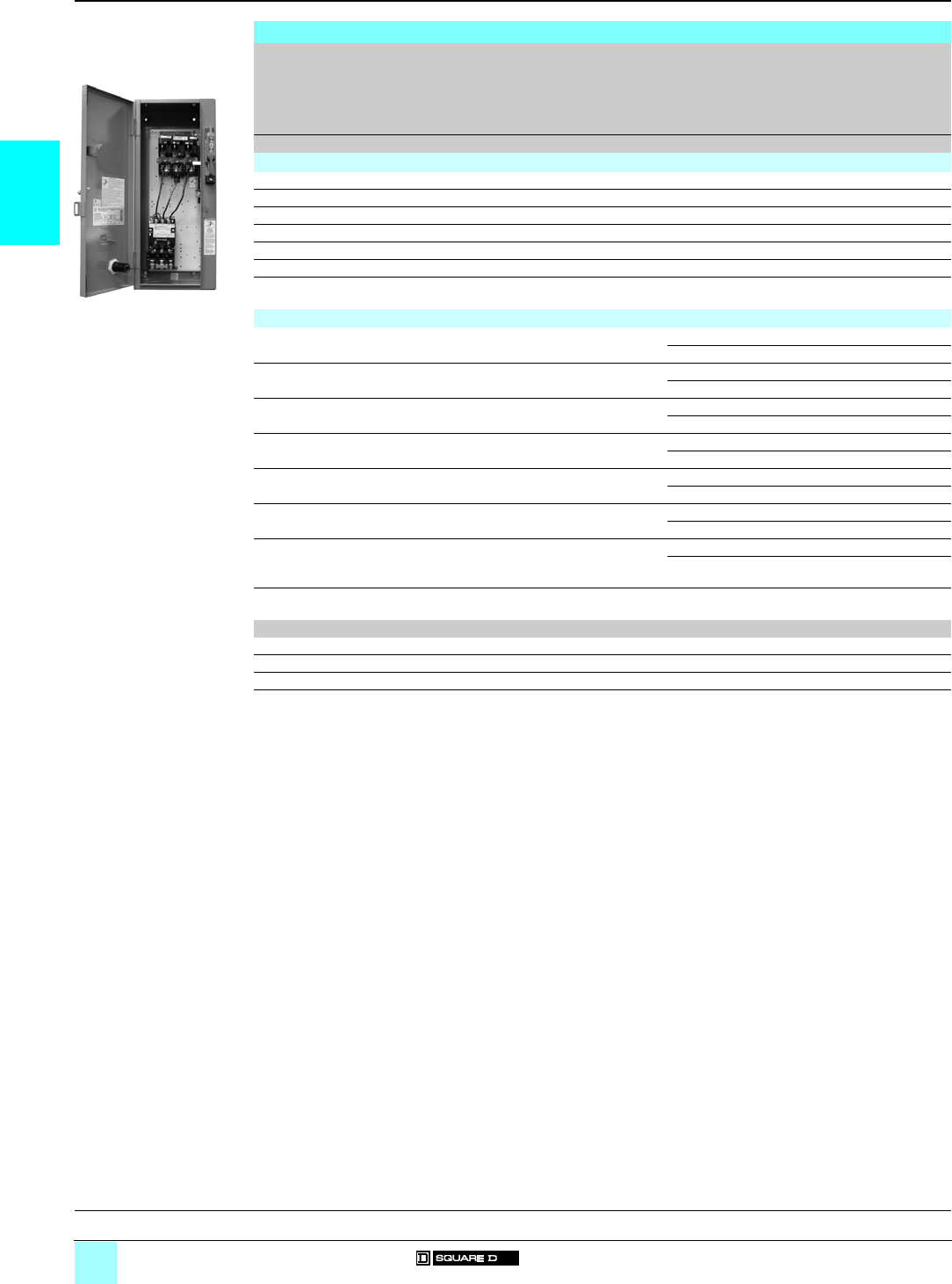
2/12
2
References
0
Combination Starters 0
Type S, NEMA-style starters with
Non-fusible disconnect-switch, Class 8538
3-pole non-fusible full-voltage starters, non-reversing
NEMA Size Standard power ratings of 3-phase motors 50/60 Hz
Motor volts (1)
External reset Basic reference
Add code indicating
control circuit voltage
(2), optional variants (3)
and “H” code (4)
Weight
200 V (208 V) 230 V (240 V) 460 V (480 V) 575 V (600 V)
hp kW hp kW hp kW hp kW kg (lb)
NEMA 1 general purpose enclosure
032.2 32.2 53.75 53.75 – 8538 SBG 11 (2) (3) (4) 17 (38)
17.5 5.5 7.5 5.5 10 7.5 10 7.5 – 8538 SCG 11 (2) (3) (4) 17 (38)
210 7.5 15 11 25 18.5 25 18.5 – 8538 SDG 11 (2) (3) (4) 25 (54)
325 18.5 30 22 50 37 50 37 – 8538 SEG 11 (2) (3) (4) 46 (102)
440 30 50 37 100 75 100 75 – 8538 SFG 11 (2) (3) (4) 74 (163)
575 55 100 75 200 150 200 150 – 8538 SGG 11 (2) (3) (4) 204 (450)
6150 110 200 150 400 300 400 300 – 8538 SHG 11 (2) (3) (4) –
NEMA 12 dust-tight industrial-use enclosure
032.2 32.2 53.75 53.75 With 8538 SBA 21 (2) (3) (4) 18 (40)
Without 8538 SBA 11 (2) (3) (4) 18 (40)
17.5 5.5 7.5 5.5 10 7.5 10 7.5 With 8538 SCA 21 (2) (3) (4) 18 (40)
Without 8538 SCA 11 (2) (3) (4) 18 (40)
210 7.5 15 11 25 18.5 25 18.5 With 8538 SDA 21 (2) (3) (4) 25 (55)
Without 8538 SDA 11 (2) (3) (4) 25 (55)
325 18.5 30 22 50 37 50 37 With 8538 SEA 21 (2) (3) (4) 50 (111)
Without 8538 SEA 11 (2) (3) (4) 50 (111)
440 30 50 37 100 75 100 75 With 8538 SFA 21 (2) (3) (4) 77 (170)
Without 8538 SFA 11 (2) (3) (4) 77 (170)
575 55 100 75 200 150 200 150 With 8538 SGA 21 (2) (3) (4) 200 (441)
Without 8538 SGA 11 (2) (3) (4) 200 (441)
6150 110 200 150 400 300 400 300 With 8538 SHA 21 (2) (3) (4) 200 (441)
Without 8538 SHA 11 (2) (3) (4) 200 (441)
(1) Motor voltage (starter voltage).
(2) Standard control circuit voltage:
Volts 24 110 120 208 220 240 380 440 480 550 600
50 Hz – V02 – – V03 – V05 V06 – V07 –
60 Hz V01 (5) (6) –V02 (5) V08 – V03 – – V06 – V07
24 V and 120 V coils require the addition of form “S” for separate control. Example: 8538 SCA 21 V03 H10S.
(3) For optional variants, see page 2/21.
(4) To complete “H” code for Motor Logic solid-state overload relays, see pages 2/13 to 2/19. Motor Logic Plus units are not
available on combination starters.
(5) 24 V coils are not available on Sizes 4–6. On Sizes 0–3, where 24 V coils are available, suffix “S” (separate control) must be specified.
(6) These voltage codes must include suffix “S” (supplied at no charge). When specifying suffix “S”, please supply motor voltage when ordering.
8538 SBG 11
ppp
531268
General, characteristics:
pages 2/4 and 2/5
Dimensions:
pages 2/22 and 2/23
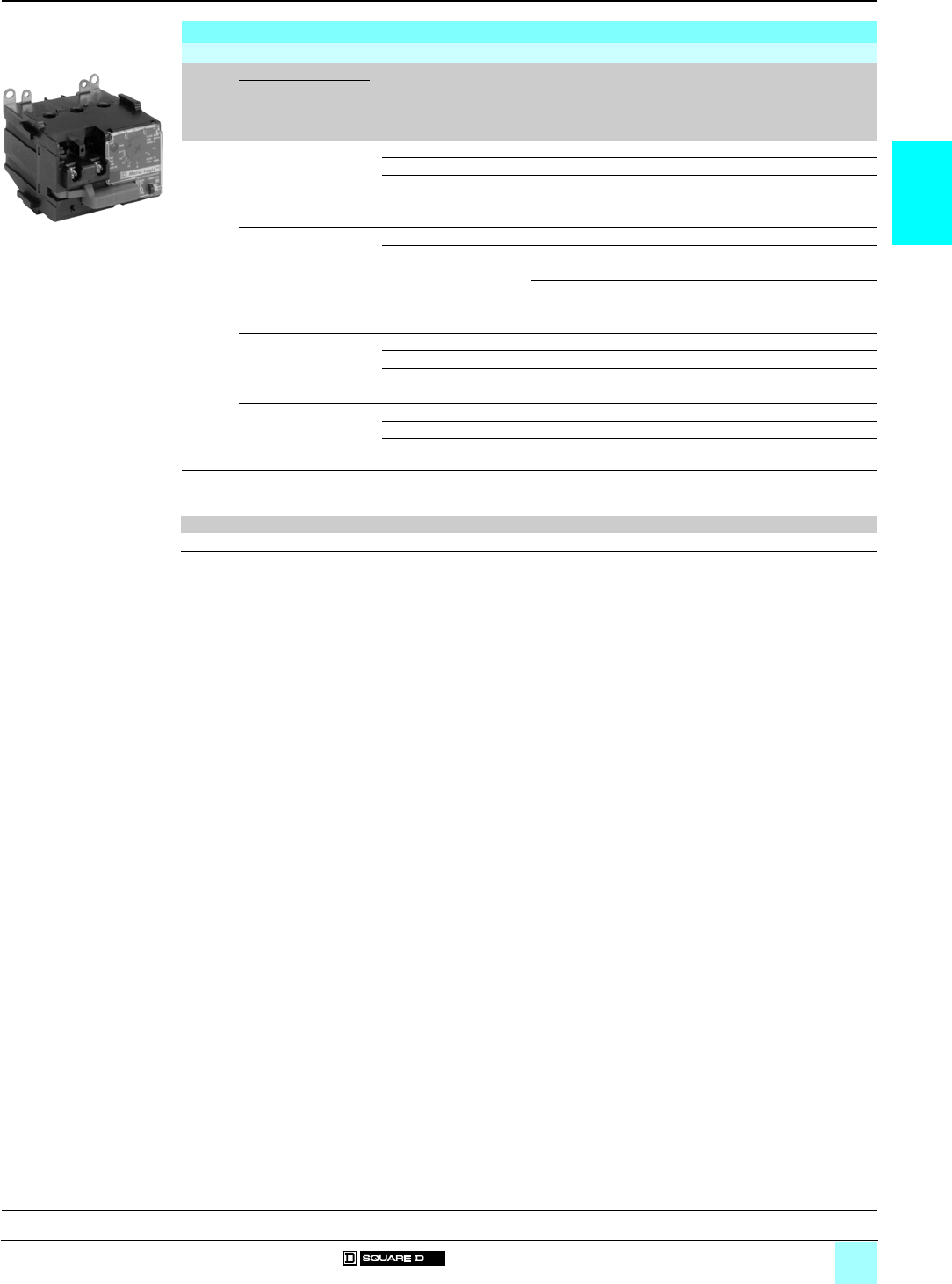
2/13
2
References
0
Combination Starters 0
Type S, NEMA-style starters with
Fusible disconnect switch, Class 8538 with
Class H fuse clips
Variants for fusible disconnect-switch starters only (Class H fuse clips)
Motor Logic solid-state overload relays (1)
Type For use on Description Overload relay range Suffix to the
starter reference
(2)
Weight
Fusible disconnect-
switch starters
Class 8538 with
Class H fuse clips
kg (lb)
Motor
Logic
solid-
state
overload
relays
8538 SpG 1p,
8538 SpA 1p,
8538 SpA 2p,
(except 8538 SDG 16,
8538 SDA 16/SDA 26)
Base unit, trip class 10 (3) H10 –
Base unit, trip class 20 (3) H20 –
Feature unit (3) H30 –
8538 SBG 12/13,
8538 SBA 12/22/13/23,
8538 SCG 12/14,
8538 SCA 12/22/14/24,
8538 SDG 16,
8538 SDA 16/26
Base unit, trip class 10 With 3…9 A overload relay H109 –
Base unit, trip class 20 With 3…9 A overload relay H209 –
Feature unit With 1.5…4.5 A overload relay H308 –
With 3…9 A overload relay H309 –
8538 SCG 12/14
8538 SCA 12/22/14/24,
8538 SDG 16
8538 SDA 16/26
Base unit, trip class 10 With 6…18 A overload relay H100 –
Base unit, trip class 20 With 6…18 A overload relay H200 –
Feature unit With 6…18 A overload relay H300 –
8538 SDG 16,
8538 SDA 16/26
Base unit, trip class 10 With 9…27 A overload relay H101 –
Base unit, trip class 20 With 9…27 A overload relay H201 –
Feature unit With 9…27 A overload relay H301 –
(1) For Motor Logic solid-state overload relays, see pages 3/2 to 3/7.
(2) Example: 8538 SBG 12 V02 H10 S.
(3) Standard current ranges, depending on contactor size:
Size 00 0123456 7
Current ranges A 3…9 6…18 9…27 15…45 30…90 45…135 90…270 180…540 (4) 270…810 (5)
(4) Only available with feature unit.
(5) Only available with feature unit with auxiliary contact.
H10
531123
General, characteristics:
pages 2/4 and 2/5
Dimensions:
pages 2/22 and 2/23
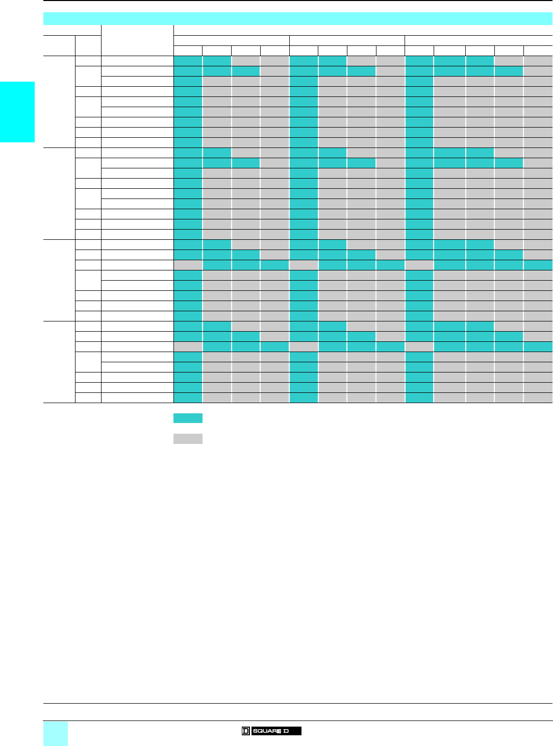
2/14
2
Associations
0
Combination Starters 0
Type S, NEMA-style starters with
Fusible disconnect switch, Class 8538
(Class R fuse clips) with solid-state overload relay
Associations
Ratings For use on Motor Logic solid-state overload relays
Motor
voltage
NEMA
Size
Class 10 Class 20 Class 10/20 (selectable)
8538 – 3–9 A 6–18 A 9–27 A – 3–9 A 6–18 A 9–27 A – 1.5–4.5 A 3–9 A 6–18 A 9–27 A
200 V 0 SBG 32, SBA 42/32 H10 H109 H20 H209 H30 H308 H309
1 SCG 32, SCA 42/32 H10 H109 H100 H20 H209 H200 H30 H308 H309 H300
SCG 33, SCA 43/33 H10 H20 H30
2 SDG 32, SDA 42/32 H10 H20 H30
3 SEG 35, SEA 45/35 H10 H20 H30
SEG 32, SEA 42/32 H10 H20 H30
4 SFG 35, SFA 45/35 H10 H20 H30
5 SGG 35, SGA 45/35 H10 H20 H30
6 SHG 33, SHA 43/33 H10 H20 H30
230 V 0 SBG 32, SBA 42/32 H10 H109 H20 H209 H30 H308 H309
1 SCG 32, SCA 42/32 H10 H109 H100 H20 H209 H200 H30 H308 H309 H300
SCG 33, SCA 43/33 H10 H20 H30
2 SDG 32, SDA 42/32 H10 H20 H30
3 SEG 35, SEA 45/35 H10 H20 H30
SEG 32, SEA 42/32 H10 H20 H30
4 SFG 35, SFA 45/35 H10 H20 H30
5 SGG 35, SGA 45/35 H10 H20 H30
6 SHG 33, SHA 43/33 H10 H20 H30
460 V 0 SBG 33, SBA 43/33 H10 H109 H20 H209 H30 H308 H309
1 SCG 34, SCA 44/34 H10 H109 H100 H20 H209 H200 H30 H308 H309 H300
2 SDG 36, SDA 46/36 H109 H100 H101 H209 H200 H201 H308 H309 H300 H301
3 SDG 34, SDA 44/34 H10 H20 H30
SEG 33, SEA 43/33 H10 H20 H30
4 SFG 33, SFA 43/33 H10 H20 H30
5 SGG 33, SGA 43/33 H10 H20 H30
6 SHG 32, SHA 42/32 H10 H20 H30
575 V 0 SBG 33, SBA 43/33 H10 H109 H20 H209 H30 H308 H309
1 SCG 34, SCA 44/34 H10 H109 H100 H20 H209 H200 H30 H308 H309 H300
2 SDG 36, SDA 46/36 H109 H100 H101 H209 H200 H201 H308 H309 H300 H301
3 SDG 34, SDA 44/34 H10 H20 H30
SEG 33, SEA 43/33 H10 H20 H30
4 SFG 33, SFA 43/33 H10 H20 H30
5 SGG 33, SGA 43/33 H10 H20 H30
6 SHG 32, SHA 42/32 H10 H20 H30
Available codes
Not available
General, characteristics:
pages 2/4 and 2/5
Dimensions:
pages 2/22 and 2/23
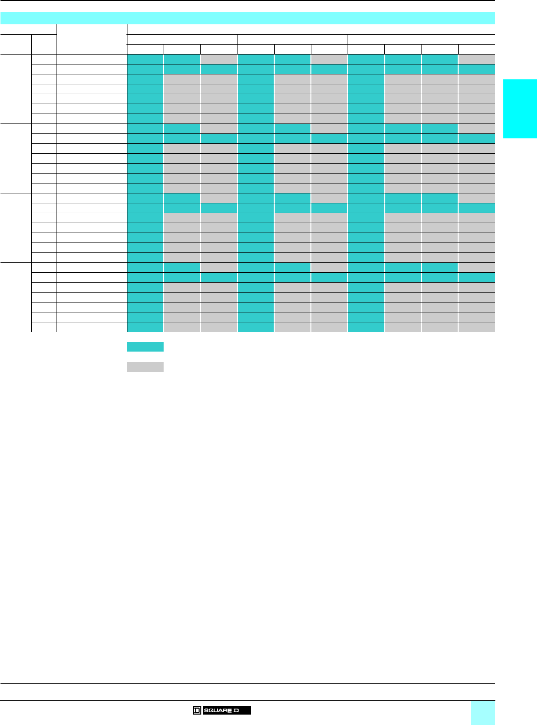
2/15
2
Associations
0
Combination Starters 0
Type S, NEMA-style starters with
Non-fusible disconnect switch, Class 8538 with
solid-state overload relays
Associations
Ratings For use on Motor Logic solid-state overload relays
Motor
voltage
NEMA
Size
Class 10 Class 20 Class 10/20 (selectable)
8538 – 3–9 A 6–18 A – 3–9 A 6–18 A – 1.5–4.5 A 3–9 A 6–18 A
200 V 0 SBG 11, SBA 21/11 H10 H109 H20 H209 H30 H308 H309
1 SCG 11, SCA 21/11 H10 H109 H100 H20 H209 H200 H30 H308 H309 H300
2 SDG 11, SDA 21/11 H10 H20 H30
3 SEG 11, SEA 21/11 H10 H20 H30
4 SFG 11, SFA 21/11 H10 H20 H30
5 SGG 11, SGA 21/11 H10 H20 H30
6 SHG 11, SHA 21/11 H10 H20 H30
230 V 0 SBG 11, SBA 21/11 H10 H109 H20 H209 H30 H308 H309
1 SCG 11, SCA 21/11 H10 H109 H100 H20 H209 H200 H30 H308 H309 H300
2 SDG 11, SDA 21/11 H10 H20 H30
3 SEG 11, SEA 21/11 H10 H20 H30
4 SFG 11, SFA 21/11 H10 H20 H30
5 SGG 11, SGA 21/11 H10 H20 H30
6 SHG 11, SHA 21/11 H10 H20 H30
460 V 0 SBG 11, SBA 21/11 H10 H109 H20 H209 H30 H308 H309
1 SCG 11, SCA 21/11 H10 H109 H100 H20 H209 H200 H30 H308 H309 H300
2 SDG 11, SDA 21/11 H10 H20 H30
3 SEG 11, SEA 21/11 H10 H20 H30
4 SFG 11, SFA 21/11 H10 H20 H30
5 SGG 11, SGA 21/11 H10 H20 H30
6 SHG 11, SHA 21/11 H10 H20 H30
575 V 0 SBG 11, SBA 21/11 H10 H109 H20 H209 H30 H308 H309
1 SCG 11, SCA 21/11 H10 H109 H100 H20 H209 H200 H30 H308 H309 H300
2 SDG 11, SDA 21/11 H10 H20 H30
3 SEG 11, SEA 21/11 H10 H20 H30
4 SFG 11, SFA 21/11 H10 H20 H30
5 SGG 11, SGA 21/11 H10 H20 H30
6 SHG 11, SHA 21/11 H10 H20 H30
Available codes
Not available
General, characteristics:
pages 2/4 and 2/5
Dimensions:
pages 2/22 and 2/23
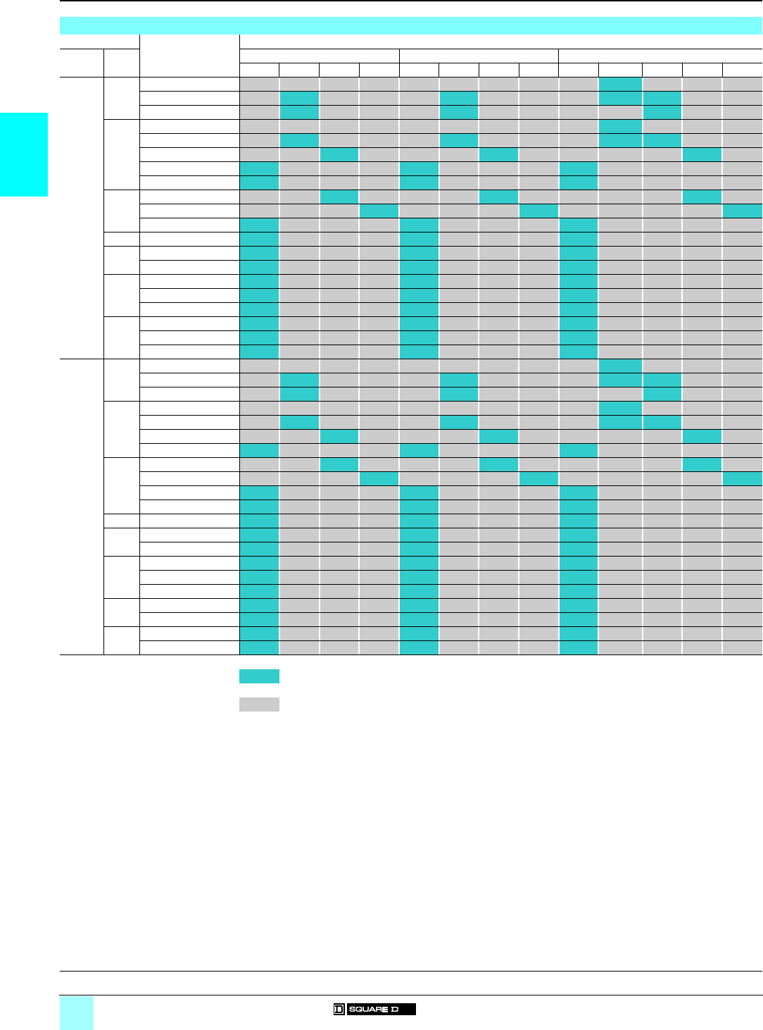
2/16
2
Associations
0
Combination Starters 0
Type S, NEMA-style starters with
Mag-Gard® circuit breaker, Class 8539 with
solid-state overload relays
Associations
Ratings For use on Motor Logic solid-state overload relays
Motor
voltage
NEMA
Size
Class 10 Class 20 Class 10/20 (selectable)
8539 – 3–9 A 6–18 A 9–27 A – 3–9 A 6–18 A 9–27 A – 1.5–4.5 A 3–9 A 6–18 A 9–27 A
200 V 0 SBG 41, SBA 51/41 H308
SBG 42, SBA 52/42 H109 H209 H308 H309
SBG 43, SBA 53/43 H109 H209 H309
1 SCG 41, SCA 51/41 H308
SCG 42, SCA 52/42 H109 H209 H308 H309
SCG 43, SCA 53/43 H100 H200 H300
SCG 44, SCA 54/44 H10 H20 H30
SCG 45, SCA 55/45 H10 H20 H30
2 SDG 41, SDA 51/41 H100 H200 H300
SDG 42, SDA 52/42 H101 H201 H301
SDG 43, SDA 53/43 H10 H20 H30
3 SEG 42, SEA 52/42 H10 H20 H30
4 SFG 42, SFA 52/42 H10 H20 H30
SFG 43, SFA 53/43 H10 H20 H30
5 SGG 42, SGA 52/42 H10 H20 H30
SGG 44, SGA 54/44 H10 H20 H30
SGG 45, SGA 55/45 H10 H20 H30
6 SHG 43, SHA 53/43 H10 H20 H30
SHG 44, SHA 54/44 H10 H20 H30
SHG 45, SHA 55/45 H10 H20 H30
230 V 0 SBG 41, SBA 51/41 H308
SBG 42, SBA 52/42 H109 H209 H308 H309
SBG 43, SBA 53/43 H109 H209 H309
1 SCG 41, SCA 51/41 H308
SCG 42, SCA 52/42 H109 H209 H308 H309
SCG 43, SCA 53/43 H100 H200 H300
SCG 44, SCA 54/44 H10 H20 H30
2 SDG 41, SDA 51/41 H100 H200 H300
SDG 42, SDA 52/42 H101 H201 H301
SDG 43, SDA 53/43 H10 H20 H30
SDG 44, SDA 54/44 H10 H20 H30
3 SEG 42, SEA 52/42 H10 H20 H30
4 SFG 43, SFA 53/43 H10 H20 H30
SFG 44, SFA 54/44 H10 H20 H30
5 SGG 43, SGA 53/43 H10 H20 H30
SGG 44, SGA 54/44 H10 H20 H30
SGG 46, SGA 56/46 H10 H20 H30
6 SHG 44, SHA 54/44 H10 H20 H30
SHG 46, SHA 56/46 H10 H20 H30
7SJG42, SJA52H10 H20 H30
SJG 43, SJA 53 H10 H20 H30
Available codes
Not available
General, characteristics:
pages 2/4 and 2/5
Dimensions:
pages 2/22 and 2/23
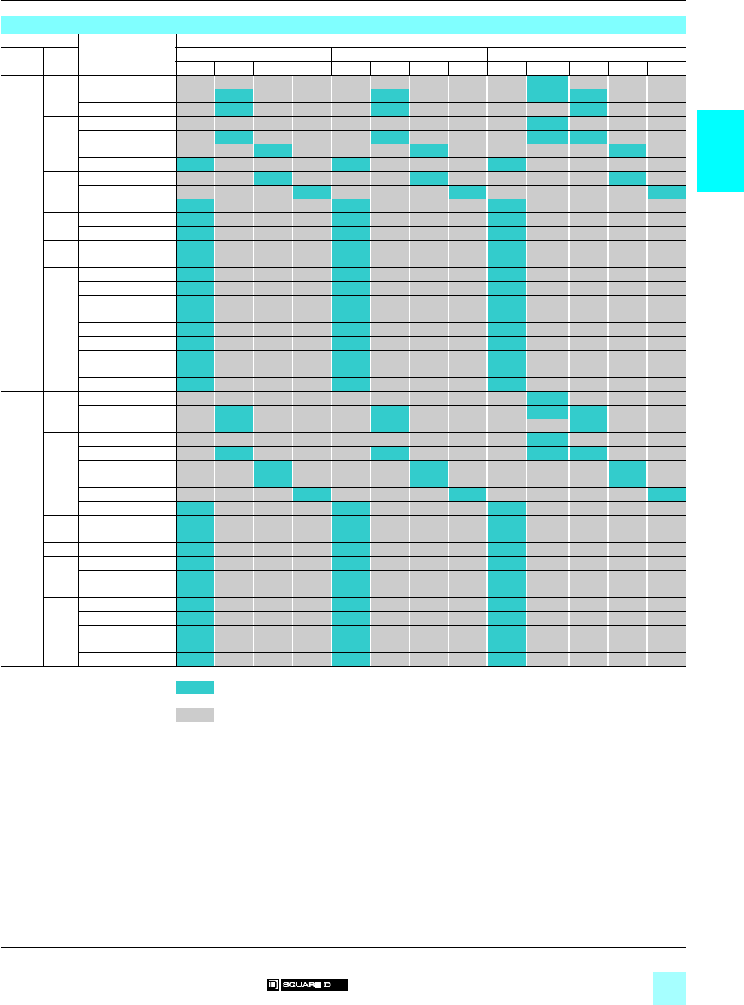
2/17
2
Associations (continued)
0
Combination Starters 0
Type S, NEMA-style starters with
Mag-Gard® circuit breaker, Class 8539 with
solid-state overload relays
Associations (continued)
Ratings For use on Motor Logic solid-state overload relays
Motor
voltage
NEMA
Size
Class 10 Class 20 Class 10/20 (selectable)
8539 – 3–9 A 6–18 A 9–27 A – 3–9 A 6–18 A 9–27 A – 1.5–4.5 A 3–9 A 6–18 A 9–27 A
460 V 0 SBG 41, SBA 51/41 H308
SBG 42, SBA 52/42 H109 H209 H308 H309
SBG 43, SBA 53/43 H109 H209 H309
1 SCG 41, SCA 51/41 H308
SCG 42, SCA 52/42 H109 H209 H308 H309
SCG 43, SCA 53/43 H100 H200 H300
SCG 44, SCA 54/44 H10 H20 H30
2 SDG 41, SDA 51/41 H100 H200 H300
SDG 42, SDA 52/42 H101 H201 H301
SDG 43, SDA 53/43 H10 H20 H30
3 SEG 41, SEA 51/41 H10 H20 H30
SEG 42, SEA 52/42 H10 H20 H30
4 SFG 42, SFA 52/42 H10 H20 H30
SFG 44, SFA 54/44 H10 H20 H30
5 SGG 43, SGA 53/43 H10 H20 H30
SGG 44, SGA 54/44 H10 H20 H30
SGG 46, SGA 56/46 H10 H20 H30
6 SHG 43, SHA 53/43 H10 H20 H30
SHG 44, SHA 54/44 H10 H20 H30
SHG 45, SHA 55/45 H10 H20 H30
SHG 46, SHA 56/46 H10 H20 H30
7SJG42, SJA52H10 H20 H30
SJG 43, SJA 53 H10 H20 H30
575 V 0 SBG 41, SBA 51/41 H308
SBG 42, SBA 52/42 H109 H209 H308 H309
SBG 43, SBA 53/43 H109 H209 H309
1 SCG 41, SCA 51/41 H308
SCG 42, SCA 52/42 H109 H209 H308 H309
SCG 43, SCA 53/43 H100 H200 H300
2 SDG 41, SDA 51/41 H100 H200 H300
SDG 42, SDA 52/42 H101 H201 H301
SDG 43, SDA 53/43 H10 H20 H30
3 SEG 41, SEA 51/41 H10 H20 H30
SEG 42, SEA 52/42 H10 H20 H30
4 SFG 42, SFA 52/42 H10 H20 H30
5 SGG 41, SGA 51/41 H10 H20 H30
SGG 42, SGA 52/42 H10 H20 H30
SGG 44, SGA 54/44 H10 H20 H30
6 SHG 42, SHA 52/42 H10 H20 H30
SHG 43, SHA 53/43 H10 H20 H30
SHG 44, SHA 54/44 H10 H20 H30
7SJG41, SJA51H10 H20 H30
SJG 42, SJA 52 H10 H20 H30
Available codes
Not available
General, characteristics:
pages 2/4 and 2/5
Dimensions:
pages 2/22 and 2/23
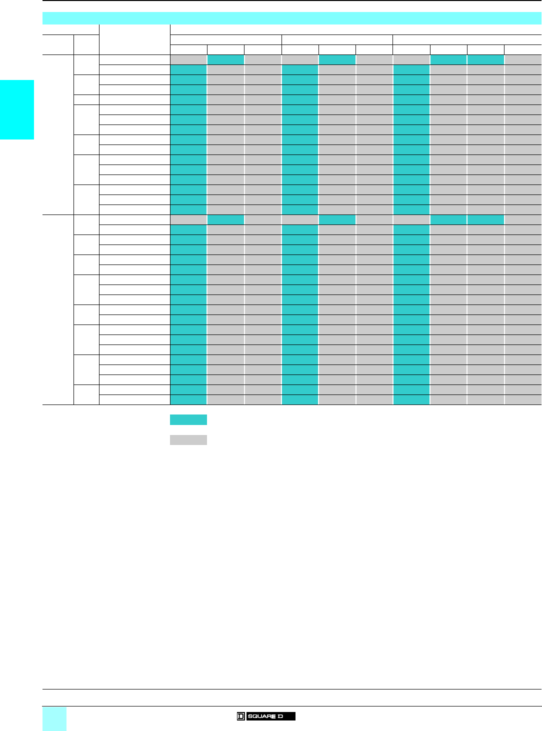
2/18
2
Associations
0
Combination Starters 0
Type S, NEMA-style starters with
Thermal-magnetic circuit breaker
and solid-state overload relay
Associations
Ratings For use on Motor Logic solid-state overload relays
Motor
voltage
NEMA
Size
Class 10 Class 20 Class 10/20 (selectable)
8539 – 3–9 A 6–18 A – 3–9 A 6–18 A – 1.5–4.5 A 3–9 A 6–18 A
200 V 0 SBG 1, SBA 11/1 H109 H209 H308 H309
SBG 3, SBA 13/3 H10 H20 H30
1SCG5, SCA15/5H10 H20 H30
SCG 2, SCA 12/2 H10 H20 H30
2SDG1, SDA11/1H10 H20 H30
3 SEG 3, SEA 13/3 H10 H20 H30
SEG 1, SEA 11/1 H10 H20 H30
SEG 5, SEA 15/5 H10 H20 H30
4SFG3, SFA13/3H10 H20 H30
SFG 4, SFA 14/4 H10 H20 H30
5SGG6, SGA16/6H10 H20 H30
SGG 1, SGA 11/1 H10 H20 H30
SGG 4, SGA 14/4 H10 H20 H30
6SHG4, SHA14/4H10 H20 H30
SHG 3, SHA 13/3 H10 H20 H30
SHG 5, SHA 15/5 H10 H20 H30
230 V 0 SBG 1, SBA 11/1 H109 H209 H308 H309
SBG 3, SBA 13/3 H10 H20 H30
1SCG1, SCA11/1H10 H20 H30
SCG 6, SCA 16/6 H10 H20 H30
2SDG1, SDA11/1H10 H20 H30
SDG 7, SDA 17/7 H10 H20 H30
3 SEG 3, SEA 13/3 H10 H20 H30
SEG 1, SEA 11/1 H10 H20 H30
SEG 5, SEA 15/5 H10 H20 H30
4SFG1, SFA11/1H10 H20 H30
SFG 4, SFA 14/4 H10 H20 H30
5SGG3, SGA13/3H10 H20 H30
SGG 1, SGA 11/1 H10 H20 H30
SGG 2, SGA 12/2 H10 H20 H30
6SHG4, SHA14/4H10 H20 H30
SHG 3, SHA 13/3 H10 H20 H30
SHG 7, SHA 17/7 H10 H20 H30
7SJG2, SJA12 H10 H20 H30
SJG 3, SJA 13 H10 H20 H30
Available codes
Not available
General, characteristics:
pages 2/4 and 2/5
Dimensions:
pages 2/22 and 2/23
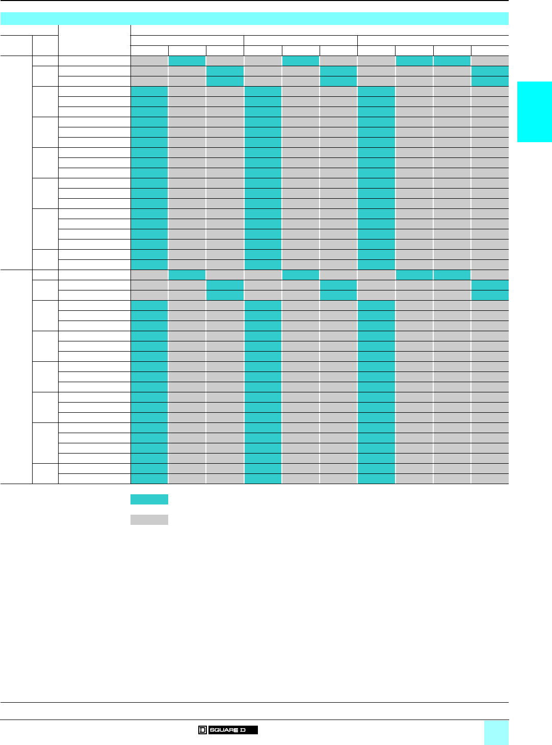
2/19
2
Associations (continued)
0
Combination Starters 0
Type S, NEMA-style starters with
Thermal magnetic circuit breaker
with solid-state overload relays
Associations (continued)
Ratings For use on Motor Logic solid-state overload relays
Motor
voltage
NEMA
Size
Class 10 Class 20 Class 10/20 (selectable)
8539 – 3–9 A 6–18 A – 3–9 A 6–18 A – 1.5–4.5 A 3–9 A 6–18 A
460 V 0 SBG 2, SBA 12/2 H109 H209 H308 H309
1SCG3, SCA13/3 H100 H200 H300
SCG 7, SCA 17/7 H100 H200 H300
2SDG3, SDA13/3
H10 H20 H30
SDG 4, SDA 14/4 H10 H20 H30
SDG 5, SDA 15/5 H10 H20 H30
3SEG6, SEA16/6H10 H20 H30
SEG 3, SEA 13/3 H10 H20 H30
SEG 1, SEA 11/1 H10 H20 H30
4SFG5, SFA15/5H10 H20 H30
SFG 3, SFA 13/3 H10 H20 H30
SFG 4, SFA 14/4 H10 H20 H30
5SGG3, SGA13/3H10 H20 H30
SGG 1, SGA 11/1 H10 H20 H30
SGG 2, SGA 12/2 H10 H20 H30
6SHG4, SHA14/4H10 H20 H30
SHG 3, SHA 13/3 H10 H20 H30
SHG 5, SHA 15/5 H10 H20 H30
SHG 7, SHA 17/7 H10 H20 H30
7SJG2, SJA12 H10 H20 H30
SJG 3, SJA 13 H10 H20 H30
575 V 0 SBG 2, SBA 12/2 H109 H209 H308 H309
1SCG8, SCA18/8 H100 H200 H300
SCG 3, SCA 13/3 H100 H200 H300
2SDG8, SDA18/8
H10 H20 H30
SDG 9, SDA 19/9 H10 H20 H30
SDG 4, SDA 14/4 H10 H20 H30
3SEG4, SEA14/4H10 H20 H30
SEG 6, SEA 16/6 H10 H20 H30
SEG 3, SEA 13/3 H10 H20 H30
4SFG6, SFA16/6H10 H20 H30
SFG 5, SFA 15/5 H10 H20 H30
SFG 1, SFA 11/1 H10 H20 H30
5SGG7, SGA17/7H10 H20 H30
SGG 6, SGA 16/6 H10 H20 H30
SGG 1, SGA 11/1 H10 H20 H30
6SHG6, SHA16/6H10 H20 H30
SHG 4, SHA 14/4 H10 H20 H30
SHG 2, SHA 12/2 H10 H20 H30
SHG 3, SHA 13/3 H10 H20 H20
7SJG1, SJA11 H10 H20 H30
SJG 2, SJA 12 H10 H20 H30
Available codes
Not available
General, characteristics:
pages 2/4 and 2/5
Dimensions:
pages 2/22 and 2/23

2/20
2
Characteristics
0
Combination Starters 0
Type S, NEMA-style
Accessories
Characteristics
Class 9999
Type Single-pole electrical interlocks
Electrical ratings
Maximum current
Make Break Continuous carrying
current
50/60 Hz a 120 V A40 15 15
a 240 V A20 10 15
a 480 V A10 815
a 600 V A8 6 15
Class 9999
Type 2-pole electrical interlocks
Electrical ratings
Maximum current
Make Break Continuous carrying
current
50/60 Hz a 120 V A30 310
VA 3450 345 –
a 240 V A15 1.5 10
VA 3450 345 –
a 480 V A7.5 0.75 10
VA 3450 345 –
a 600 V A60.6 10
VA 3450 345 –
General, characteristics:
pages 2/4 and 2/5
Dimensions:
pages 2/22 and 2/23
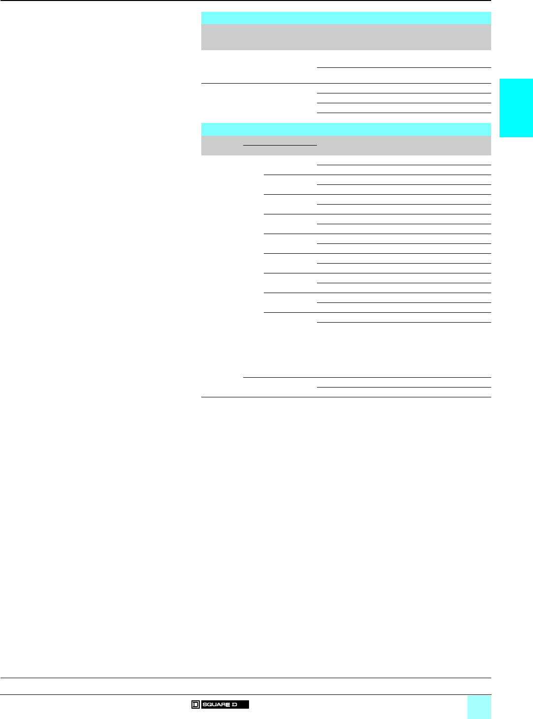
2/21
2
References
0
Combination Starters 0
Type S, NEMA-style
Accessories
Variants
Type For use on Description Suffix to the
starter reference
(1)
Weight
kg (lb)
Interlocks Disconnect-switch
starters 8538 Spp or
circuit-breaker starters
8539 Spp
Single-pole Y74 –
2-pole Y75 –
Control
transformers
Disconnect-switch
starters 8538 Spp or
circuit-breaker starters
8539 Spp
Standard capacity F4T –
50 VA additional capacity F4T10 –
100 VA additional capacity F4T11 –
200 VA additional capacity F4T12 –
Interlocks
Type For use on Description Reference Weight
kg (lb)
Class Type (2)
Interlocks 8538 SB, SC, SD
(Series B) (3)
Single-pole 9999 R6 –
2-pole 9999 R7 –
SD
(Series C)
Single-pole 9999 R43 –
2-pole 9999 R44 –
SB, SC
(Series C)
Single-pole 9999 R45 –
2-pole 9999 R46 –
SE, SF
(Series A)
Single-pole 9999 R8 –
2-pole 9999 R9 –
SE
(Series B and C)
Single-pole 9999 R41 –
2-pole 9999 R42 –
SF
(Series B and C)
Single-pole 9999 R39 –
2-pole 9999 R40 –
SG Single-pole 9999 R35 –
2-pole 9999 R36 –
SBA, SCA, SBG,
SCG (Series D)
Single-pole 9999 TC11 –
2-pole 9999 TC21 –
SBAS8, SCAS8,
SBGS8, SCGS8
(Series D),
SDA, SDA (3),
SDG, SDG (3)
(Series D),
SEA, SEG
(Series D)
Single-pole 9999 TC10 –
2-pole 9999 TC20 –
8539 SB, SC, SD, SE,
SF, SG (4)
Single-pole 9999 R26 –
2-pole 9999 R27 –
(1) Example: 8538 SBG 12 V01 Y74.
(2) Series A, B, C and D are product versions.
(3) Class 8538 type numbers ending in suffix "S8".
(4) No interlocks available when used with the GJL circuit-breaker.
General, characteristics:
pages 2/4 and 2/5
Dimensions:
pages 2/22 and 2/23
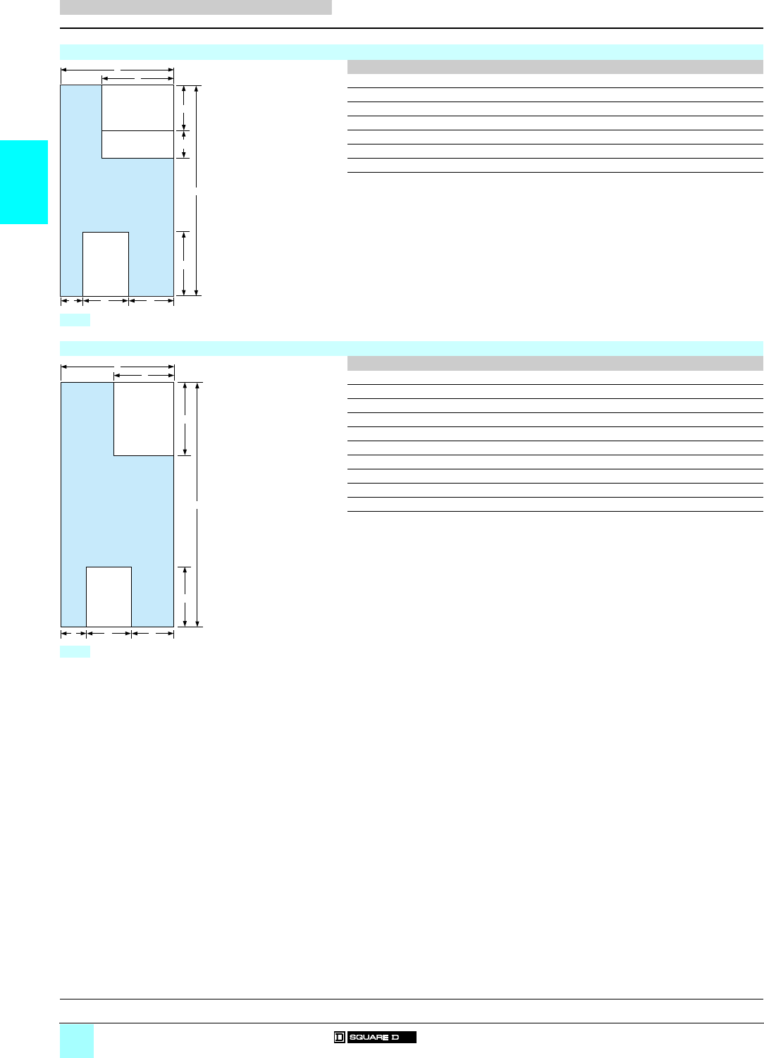
2/22
2
Dimensions
0
Combination Starters 0
Type S, NEMA-style starters with
Disconnect switch or
Circuit breaker
Dimensions in mm (25.4 mm = 1 inch)
Combination starters 8538 SpG
A B C D E F G H I
8538 SBG 175.3 469.9 175.3 165.1 0 88.9 86.4 175.3 101.6
8538 SCG 175.3 469.9 175.3 165.1 0 88.9 86.4 175.3 101.6
8538 SDG 200.7 558.8 190.5 177.8 78.7 121.9 0 195.6 152.4
8538 SEG 304.8 749.3 228.6 195.6 0 142.2 162.6 327.7 134.6
8538 SFG 330.2 990.6 279.4 292.1 0 177.8 152.4 330.2 228.6
8538 SGG (1) 439.4 1498.6 342.9 635.0 0 274.3 165.1 520.7 –
8538 SHG 812.8 2082.8 812.8 1016.0 0 330.2 482.6 889.0 –
(1) Combination starter does not contain a full-size panel. No usable panel space is available.
Available space for field requirements
Combination starters 8539 SpG
A B C D E F G H
8539 SBG 175.3 469.9 165.1 200.7 0 88.9 86.4 175.3
8539 SCG 175.3 469.9 165.1 200.7 0 88.9 86.4 175.3
8539 SDG 200.7 558.8 165.1 162.6 78.7 121.9 0 195.6
8539 SEG + FAL (1) 304.8 749.3 165.1 215.9 0 142.2 162.6 327.7
8539 SEG + KAL (1) 304.8 749.3 172.7 266.7 0 142.2 162.6 327.7
8539 SFG 330.2 990.6 172.7 317.5 0 177.8 152.4 330.2
8539 SGG + KAL (1) (2) 439.4 1498.6 172.7 584.2 0 274.3 165.1 520.7
8539 SGG + LAL (1) (2) 439.4 1498.6 228.6 622.3 0 274.3 165.1 520.7
8539 SHG + LAL (1) 812.8 2082.8 228.6 647.7 0 330.2 482.6 889.0
8539 SHG + MAL (1) 812.8 2082.8 317.5 1028.7 0 330.2 482.6 889.0
(1) Circuit-breaker.
(2) Combination starter does not contain a full-size panel. No usable panel space is available.
Available space for field requirements
C
GFE
A
H
D
B
I
Disconnect
Switch
Fuse
Base
Starter
C
GFE
A
H
D
B
Starter
Breaker
General, characteristics:
pages 2/4 and 2/5
References:
pages 2/6 to 2/21

2/23
2
Dimensions (continued)
0
Combination Starters 0
Type S, NEMA-style starters with
Disconnect switch or
Circuit breaker
Dimensions in mm (25.4 mm = 1 inch)
Combination starters 8538/8539 SBG to SDG (NEMA 1 enclosure)
ABCD E FG H I J
8538/8539 SBG 241.3 571.5 211.8 161.9 520.7 372.1 46.0 42.7 76.2 58.7
8538/8539 SCG 241.3 571.5 211.8 161.9 520.7 372.1 46.0 42.7 76.2 58.7
8538/8539 SDG 266.7 660.4 243.6 187.3 609.6 429.3 54.0 50.8 101.6 25.4
KLM N O W X Y
8538/8539 SBG 26.9 82.6 55.4 31.8 22.2 12.7–19.1 12.7–19.1 12.7
8538/8539 SCG 26.9 82.6 55.4 31.8 22.2 12.7–19.1 12.7–19.1 12.7
8538/8539 SDG 26.9 82.6 55.4 31.8 22.2 25.4–31.8 12.7–19.2 12.7
Combination starters 8538/8539 SEG to SJG (NEMA 1 enclosure)
ABCD E FG H J K
8538 SEG 387.4 1066.8 269.0 235.0 76.2 576.8 1041.4 12.7 71.6 89.7
8539 SEG 387.4 1066.8 269.0 235.0 76.2 576.8 1041.4 12.7 71.6 89.7
8538/8539 SFG 406.4 1333.5 267.5 254.0 76.2 600.7 1308.1 12.7 71.6 89.7
8538 SGG 508.0 1981.2 393.7 304.8 101.6 746.8 1955.8 12.7 89.2 114.6
8539 SGG 508.0 1676.4 348.2 304.8 101.6 746.8 1651.0 12.7 89.2 114.6
8538/8539 SHG 914.4 2286.0 534.2 ––1050.9 ––––
8539 SJG 863.6 533.4 2286.0 ––1257.3 ––––
LM N O W X Y
8538 SEG 127.0 68.1 136.5 32.5 25.4–31.8 12.7–19.2 12.7
8539 SEG 127.0 68.1 136.5 32.5 50.8–63.5 12.7–19.3 12.7
8538/8539 SFG 127.0 68.1 136.5 32.5 63.5 12.7–19.4 12.7
8538 SGG 235.0 80.8 – – 12.7–19.1 76.2 –
8539 SGG 127.0 80.8 – – 12.7–19.2 76.2 –
8538/8539 SHG 127.0 –––– – –
8539 SJG 127.0 –––– – –
Combination starters 8538/8539 SpA (NEMA 12 enclosure)
A B C D E F G H I J
8538/8539 SBA 241.3 211.8 609.6 82.6 63.5 114.3 596.9 15.0 112.5 363.5
8538/8539 SCA 241.3 211.8 609.6 82.6 63.5 114.3 596.9 15.0 112.5 363.5
8538/8539 SDA 266.7 243.6 704.9 82.6 63.5 139.7 685.8 9.5 104.8 420.6
8538/8539 SEA 387.4 269.0 1066.8 127.0 76.2 235.0 1041.4 12.7 128.5 566.7
8538 SFA 406.4 267.5 1333.5 127.0 76.2 254.0 1308.1 12.7 106.2 583.2
8539 SFA 406.4 267.5 1333.5 127.0 76.2 254.0 1308.1 12.7 131.6 583.2
8538 SGA 508.0 348.2 1981.2 235.0 101.6 304.8 1955.8 12.7 197.6 746.8
8539 SGA 508.0 348.2 1676.4 127.0 101.6 304.8 1651.0 12.7 197.6 696.0
8538/8539 SHA 914.4 431.8 2286.0 127.0 –––––1203.3
8539 SJA 863.6 533.4 2286.0 127.0 –––––1257.3
Combination starters 8538/8539 SpGpp S8 and 8538/8539 SpApp S8 (NEMA 12 enclosure)
A B C D E L
8538/8539 SpGpp S8 381.0 730.3 243.6 295.3 666.8 82.6
8538/8539 SpApp S8 381.0 787.4 278.4 228.6 768.4 82.6
(2) 0.31 in. (8 mm) dia. mounting holes.
(1) 0.31 in. (8 mm) dia. mounting holes for Sizes 0, 1, and 2, 0.44 in. (11 mm) dia. mounting holes for Sizes 3 and 4 , 0.56 in. (14 mm) dia. mounting holes located on
14 external flanges for Size 5.
YO
N
C
EB
K
M
D
A
Y
(1)
F
WXW
G
J
H
I
L
Cover Open 90°
D
A
EH
LC
P
O
Y
B
G
Y
J
N
M
K
WX
W
F
(1)
Cover Open 90°
B
C
F
A
(1)
J
I
D
E
G
H
C
EB
D
A
(2)
L
General, characteristics:
pages 2/4 and 2/5
References:
pages 2/6 to 2/21

3/0
3 -

3/1
Contents
3
3 - Solid-State Overload Relays
bMotor Logic® base unit
vGeneral, description. . . . . . . . . . . . . . . . . . . . . . . . . . . . . . . . . . . . . . . page 3/2
vCharacteristics . . . . . . . . . . . . . . . . . . . . . . . . . . . . . . . . . . . . . . . . . . . page 3/3
vReferences . . . . . . . . . . . . . . . . . . . . . . . . . . . . . . . . . . . . . . . . . . . . . page 3/6
vDimensions . . . . . . . . . . . . . . . . . . . . . . . . . . . . . . . . . . . . . . . . . . . . . page 3/8
bMotor Logic® feature unit
vGeneral, description. . . . . . . . . . . . . . . . . . . . . . . . . . . . . . . . . . . . . . . page 3/2
vCharacteristics . . . . . . . . . . . . . . . . . . . . . . . . . . . . . . . . . . . . . . . . . . . page 3/3
vReferences . . . . . . . . . . . . . . . . . . . . . . . . . . . . . . . . . . . . . . . . . . . . . page 3/6
vDimensions . . . . . . . . . . . . . . . . . . . . . . . . . . . . . . . . . . . . . . . . . . . . . page 3/8
bMotor Logic® Plus programmable unit
vGeneral, description. . . . . . . . . . . . . . . . . . . . . . . . . . . . . . . . . . . . . . . page 3/2
vCharacteristics . . . . . . . . . . . . . . . . . . . . . . . . . . . . . . . . . . . . . . . . . . . page 3/3
vReferences . . . . . . . . . . . . . . . . . . . . . . . . . . . . . . . . . . . . . . . . . . . . . page 3/7
vDimensions . . . . . . . . . . . . . . . . . . . . . . . . . . . . . . . . . . . . . . . . . . . . . page 3/9
bMotor Logic® Plus II programmable unit
vGeneral, description. . . . . . . . . . . . . . . . . . . . . . . . . . . . . . . . . . . . . . . page 3/4
vCharacteristics . . . . . . . . . . . . . . . . . . . . . . . . . . . . . . . . . . . . . . . . . . . page 3/5
vReferences . . . . . . . . . . . . . . . . . . . . . . . . . . . . . . . . . . . . . . . . . . . . . page 3/7
vDimensions . . . . . . . . . . . . . . . . . . . . . . . . . . . . . . . . . . . . . . . . . . . . . page 3/9
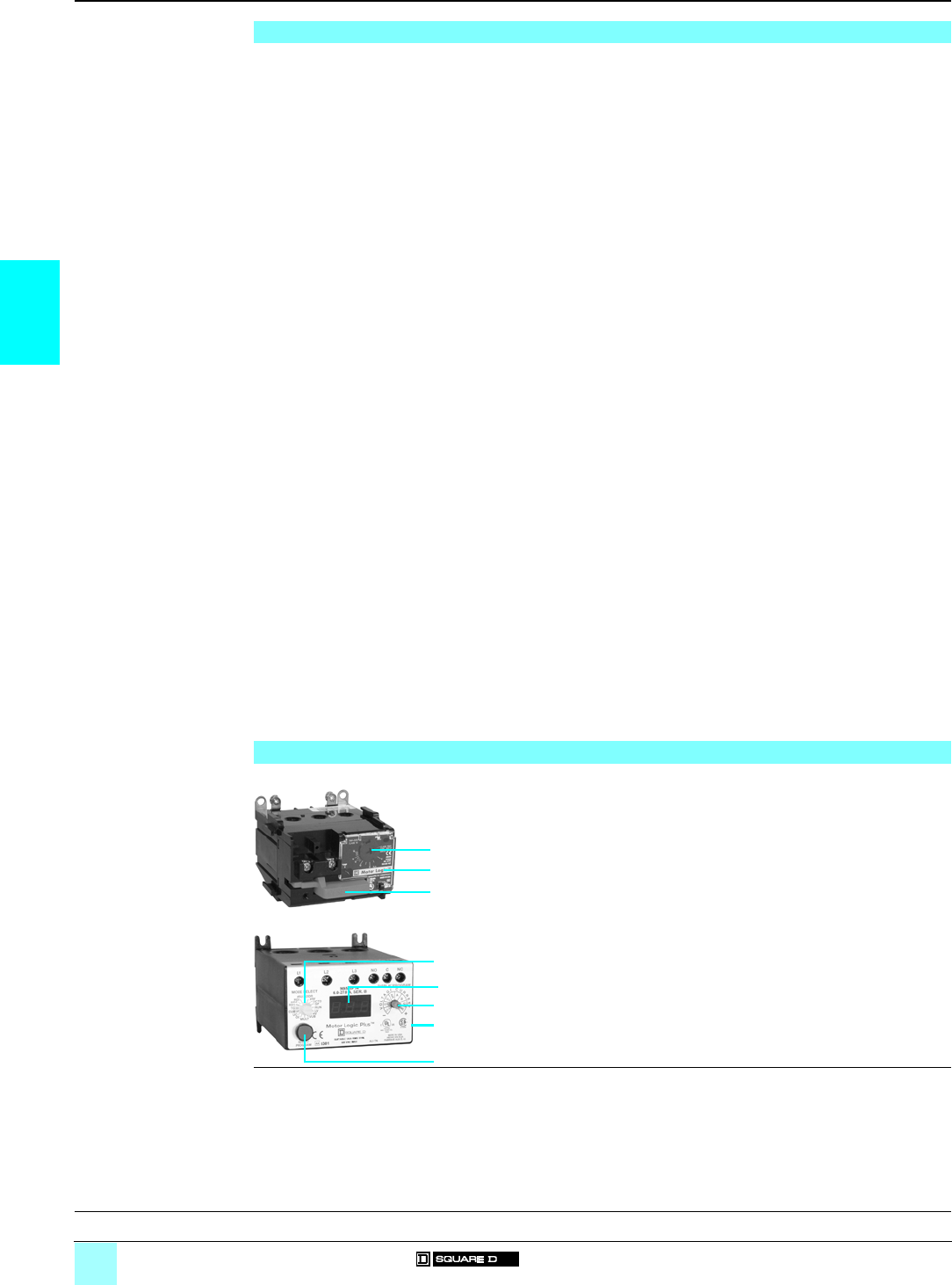
3/2
3
General,
description
0
Solid-State Overload Relays 0
Motor Logic® base unit
Motor Logic® feature unit
Motor Logic® Plus programmable unit
General
Overload relays are intended to protect motors, controllers and branch-circuit conductors against excessive
heating due to prolonged motor overcurrents up to and including locked rotor currents. Protection of the motor and
the other branch-circuit components from higher currents, due to short-circuits or earth faults, is a function of the
branch-circuit fuses, circuit-breakers or motor short-circuit protectors.
Electric motors make up a large percentage of power system loads. Market demands for reduced downtime and
increased productivity have compelled the motor control industry to continuously evaluate motor protection technology.
Technology advancements now allow the motor control industry to offer several options for motor protection.
This briefly reviews traditional motor protection technologies and discusses the new, electronic motor protection
options. Important factors to consider in determining the appropriate overload protection include:
bApplication requirements.
bCost per feature of a given technology.
bWillingness and ability of all parts of the user's organization to embrace and implement the new technology.
Motor failure may be the result of electrical or mechanical factors. A study commissioned by the Electrical
Research Associates (ERA) of the United Kingdom indicated that the most common causes of motor failure are:
1 Overcurrent
2 Contamination
3 Single phasing
4 Bearing failure
5 Aging (natural wear)
6 Rotor fault
7 Miscellaneous
30 %
18 %
15 %
12 %
10 %
5 %
7 %
Failure modes 1, 3 and 7 are attributable to electrical issues. Modes 2, 4, 5 and 6 are the result of mechanical (and
some manufacturing) issues.
Historically, motor protection provided with the controller was only able to address the electrical causes of motor
failure. These electrical issues account for at least 45% of the most common causes of motor failure. Motor branch
circuits are protected against short circuits (instantaneous overload currents) and steady-state or low-level
sustained overloads. In the U.S., this protection is provided by the short-circuit protective device (SCPD) and the
motor overload relay, when they are applied according to the National Electrical Code (NEC).
Motor Logic solid-state overload relay base unit
As the market leader in motor control products, Square D offers the Motor Logic solid-state overload relay base
unit. It provides the most complete electronic overload protection available to date for the price.
Motor Logic solid-state overload relay feature unit
The Motor Logic solid-state overload relay feature unit offers the same features as the base unit, along with the
following:
bClass II earth fault detection to protect motors from hard-to-find earth fault conditions.
bSwitch-selectable trip class (Class 10 or Class 20) for application flexibility in a single unit.
Motor Logic Plus programmable solid-state overload relay
The Motor Logic Plus programmable solid-state overload relay is a fully programmable overload relay designed to
monitor three-phase a.c. motor systems. It has 16 programming parameters of which eight can be viewed from
the 3-digit alphanumeric LED display screen on the face of the overload relay. Additionally, these parameters can
be viewed through the use of a personal computer for remote access to motor performance and adjustments.
Description
Motor Logic solid-state overload relays 9065 Sp include:
1Adjustment dial
2Tamper-proof cover
3Reset button
Motor Logic Plus programmable solid-state overload relays 9065 SP include:
1Mode select switch (1)
23-digit alphanumeric LED display screen
3Display/Program switch
4Communication port (on side)
5Reset/Program button
(1) Low voltage set point, High voltage set point, Voltage unbalance set point, Overcurrent trip point, Undercurrent trip point,
Current unbalance trip point, Trip class (5, 10, 15, 20, 30), Rapid cycle timer (RD1), Overload restart delay (RD2), Underload
restart delay (RD3), Number of restarts after an overload, Unbalance, Single phasing (manual or automatic), RS-485 address,
Number of restarts after an underload fault, Underload trip delay and Earth fault trip point, Individual line voltages, Current
levels, as well as Average voltage and Average current.
1
2
3
1
2
3
4
5
Characteristics:
page 3/3
References:
pages 3/6 and 3/7
Dimensions:
page 3/8
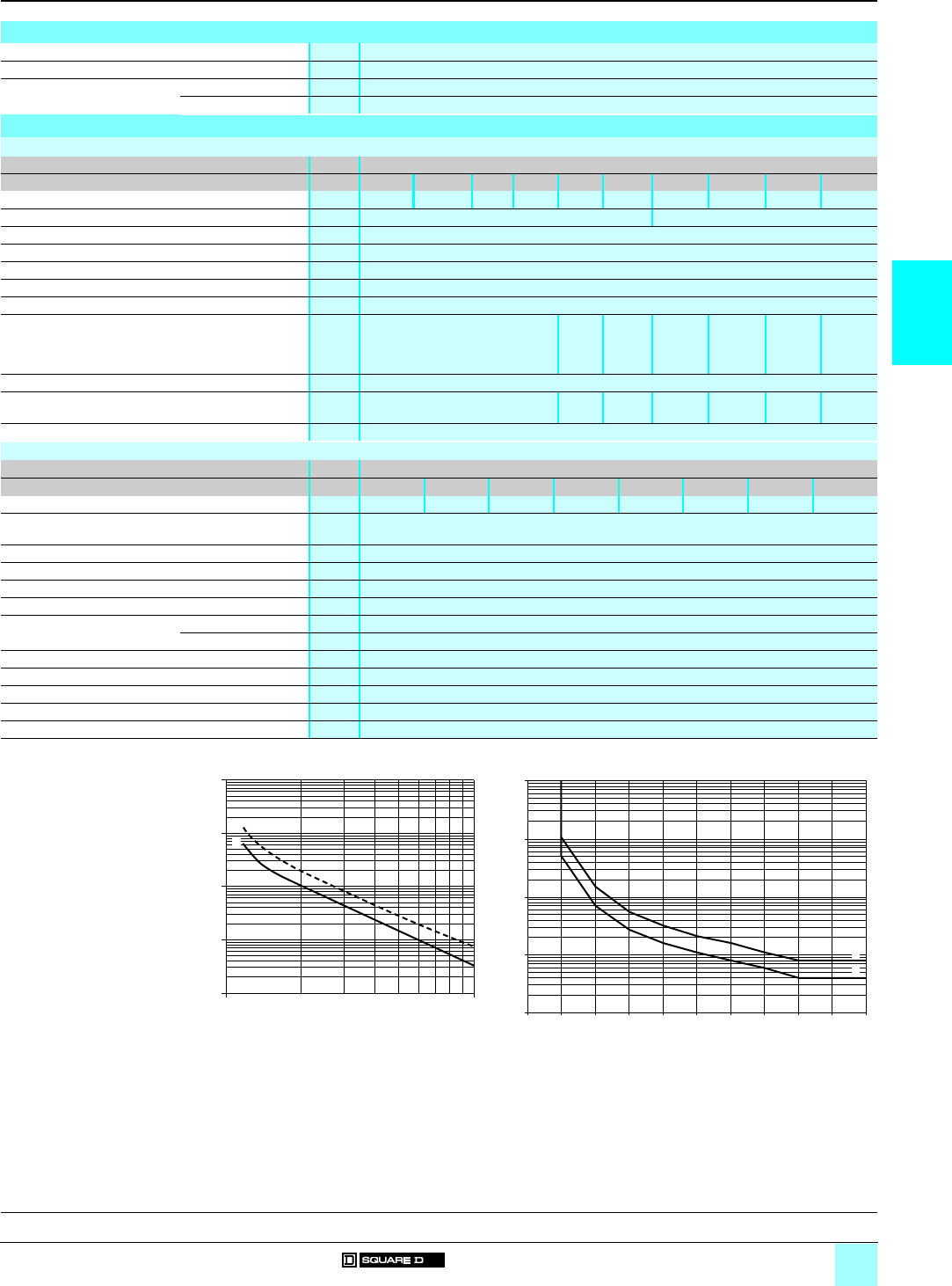
3/3
3
Characteristics
0
Solid-State Overload Relays 0
Motor Logic® base unit
Motor Logic® feature unit
Motor Logic® Plus programmable unit
Tripping curves
Average operating time
related to multiples of the
current setting
Environment
Conforming to standards UL 508, NEMA ICS-2, IEC 60947-4-1
Product certifications UL Listed, CSA certified, e marked
Ambient air temperature
around the device
Storage °C - 40...+ 80
Operation °C - 25…+ 70
Electrical characteristics
Motor Logic solid-state overload relays
Class 9065
Type SpB SpC Sp 0 Sp 1 Sp 2 Sp 3 Sp 4 Sp 5 ST 620 ST 720
Current ranges A1.5…4.5 3…9 6…18 9…27 15…45 30…90 45…135 90…270 180…540 270…810
Withstand rating (stand alone) A5000 RMS symmetrical, 600 V 10 000 RMS symmetrical, 600 V
Rated insulation voltage a V 600
Control voltage Self-powered
Frequency limits Hz 48…62
Trip contact ratings A600/P300
Repeat trip time accuracy ± 2 %
Power wire connection Through hole device # 14–4
AWG
# 14–1/0
AWG
# 8–250
MCM
# 4–500
MCM
250–500
MCM
(1 or 2 per
phase)
250–500
MCM
(1 to 4 per
phase)
Control wire # 16–12 AWG (two per terminal)
Lug kit power wire # 14–8 AWG # 14–4
AWG
# 14–1/0
AWG
# 8–250
MCM
N/A N/A N/A
DIN adapter 35 mm DIN rail, 7.5 mm track depth
Motor Logic Plus programmable solid-state overload relays
Class 9065
Type SPBpSPCpSP 1pSP 2pSP 3pSP 4pSP 5pSP 6p
Current ranges A0.5…2.3 2…9 6…27 10…45 20…90 60…135 120…270 240…540
Withstand rating (stand alone) A100 000 (RMS symmetrical, 600 V) UL
100 000 (RMS symmetrical, 600 V) CSA
Rated insulation voltage a V 600
Control voltage 3-phase, 50/60 Hz a V 200 to 480, 500 to 600
Frequency limits Hz 48...66
Trip contact ratings B300
Repeat trip time accuracy Voltage ± 0.5 % of nominal voltage
Current ± 1 % (50 % min to 120 % max overcurrent)
Screen 3-digit alphanumeric LED display screen
Programming parameters 16
Power wire connection Through-hole device
Control wire # 12–22 AWG (two per terminal)
Lug kit power wire # 1/0–14 AWG
10000.0
1000.0
100.0
10.0
1.0
1.0 10.0
2
1
1
10
100
1000
10000
0 100 200 300 400 500 600 700 800 900 1000
1
2
Ti
me
(
s
)
x current setting
1Class 10
2Class 20
Ti
me
(
s
)
1Class 10
2Class 20
Motor Logic devices Motor Logic Plus devices
% of OC setting
General, description:
page 3/2
References:
pages 3/6 and 3/7
Dimensions:
page 3/8
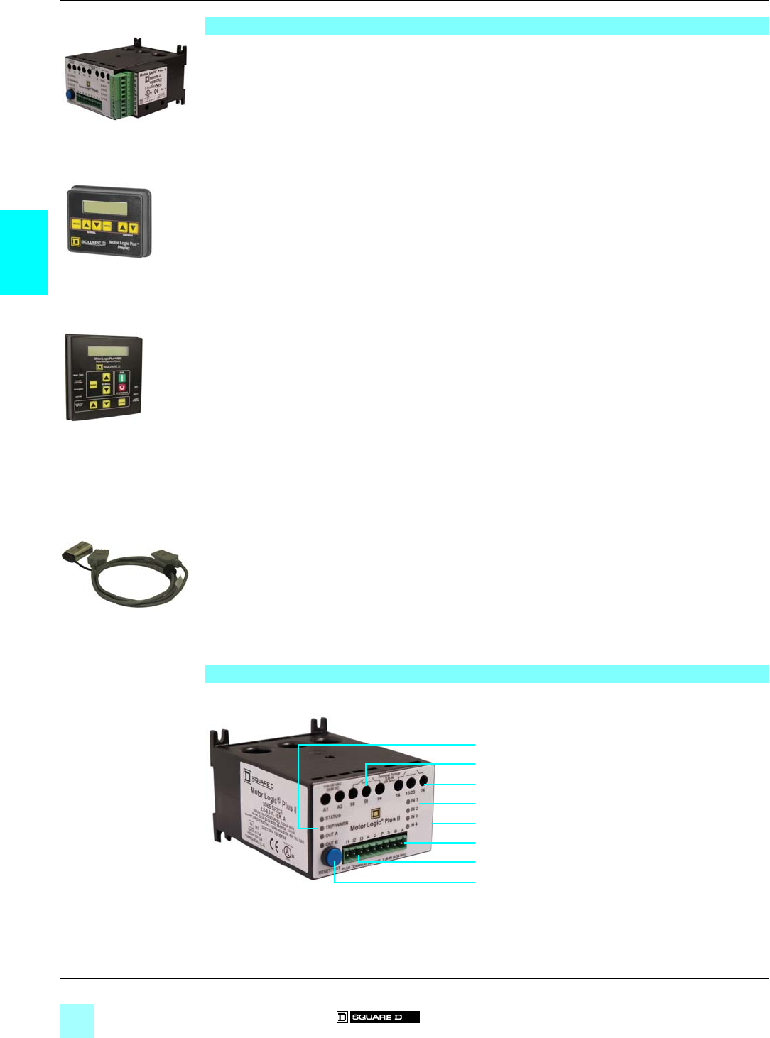
3/4
3
General,
description
0
Solid-State Overload Relays 0
Motor Logic® Plus II programmable unit
General
The Motor Logic Plus II programmable solid-state overload relay is separately powered from a 110/120 Vac,
50/60 Hz source. It has three internal current transformers for measuring phase currents from 0.5–90 A, and one
internal zero-sequence current transformer for measuring earth ground faults up to 10 A. Current measurements
from 90–540 A require the use of external CTs and result in a residual ground fault detection system.
LED indicators on the front face of the overload relay display the product status and the states of the fault relay,
the inputs, and the outputs. A reset button is located on the face for manual reset.
Four digital inputs are available via field wiring terminals. All digital inputs are internally pulled down to the board
reference. One power terminal (P) is used to source the inputs to +24 Vdc. Inputs 1 and 4 can be used as standard
digital inputs, or they can be independently configured through programming as PTC (positive temperature
coefficient) and Reset inputs, respectively. When Input 1 is configured as a PTC input, the return reference is to
the G terminal.
Three relay outputs are available via field wiring terminals: one Form C relay (single-pole, double-throw) for fault;
and two Form A relays (single-pole, single-throw) for contactor control. A Form C relay has one normally open
(N.O.) and one normally closed (N.C.) set of contacts that share a common terminal; when energized, both sets
of contacts change state. The Form A relays are normally open and wired to share a common terminal; however,
their operation is independent.
Two-wire Modbus® communication is internal to the overload relay and allows for direct connection to a
Motor Logic Plus display (9999 MLPD)(1) or motor management system (9999 MMS) via the terminal blocks
located on the front face. The DeviceNet communication module (9999 DN2) connects to the Sub-D connector on
the right side of the product.
The Motor Logic Plus II programmable overload relay provides the following protection features for 3-phase
(default) and single-phase motors:
bThermal Overload
bUndercurrent
Programmable trip delay from 2 to 60 seconds
bJam
bCurrent Unbalance (3-phase only)
Programmable from 2 to 25%
bPhase Loss (3-phase only)
bGround Fault (enabled/disabled)
Zero sequence transformer core
Programmable from 1 to 10 A
Ground fault inhibit programmable from 1 to 255 seconds
bReverse Phase (3-phase only)
bSingle Phase (3-phase only)
bPTC Thermistor
Other features include:
bProgrammable overload trip class: 5, 10, 15, 20, or 30
Manual and automatic reset option
Warning of impending faults
Motor thermal capacity
bRestart delay timers
Rapid cycle: programmable from 0 to 500 seconds
Motor cool down: programmable from 2 to 500 minutes
Dry well recovery: programmable from 2 to 500 minutes
Description
Motor Logic Plus II programmable solid-state overload relay 9065 SP2
1Status, Trip/Warn, and output LEDs
23 fault relay outputs
33 outputs
44 input LEDs
5Sub-D connector for DeviceNet module (on side)
63 network terminals
74 digital inputs
8Reset/Test Trip button
(1) The Motor Logic Plus display is powered using the cable configuration kit (9999CCKIT) and a 9 V battery (not included).
9999DN2 installed.tif
9065 SP2 with 9999 DN2
MLPD reverse color.tif
9999 MLPD
9999MMS-2003-01.tif
9999 MMS
cable.tif
9999CCKIT
(battery not included)
1
2
3
4
8
5
7
6
Characteristics:
page 3/5
References:
page 3/7
Dimensions:
page 3/9
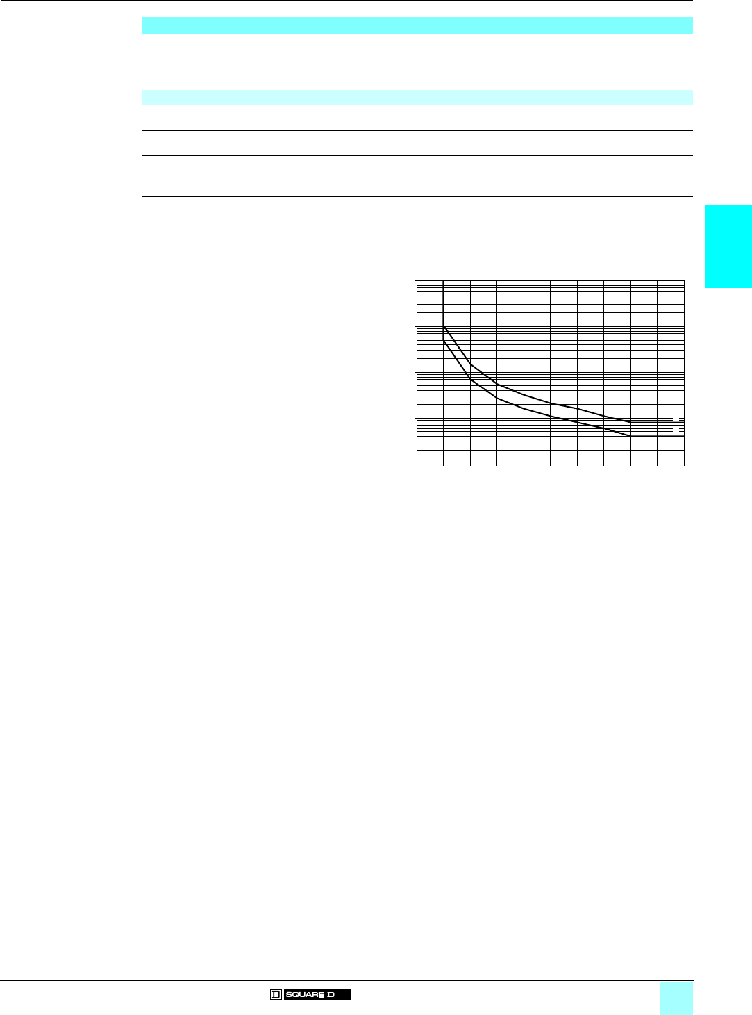
3/5
3
Characteristics
0
Solid-State Overload Relays 0
Motor Logic® Plus II programmable unit
Trip Class (TC)
The trip class for overload protection, described in the following table, defines the trip delay upon detection of a
thermal overload. (Refer to the tripping curves.) The motor and application determine the trip class. Consult the
motor manufacturer for the proper setting.
Note: Class 20 is the default setting for all Motor Logic Plus units.
Trip Class Application Description
5Small, fractional-horsepower motors where acceleration time is almost instantaneous or where
extremely quick trip times are required
10 (Fast Trip) Hermetic refrigerant motors, compressors, submersible pumps, and general-purpose motors that
reach rated speed in less than 4 seconds
15 Certain specialized applications
20 (Standard Trip) Most NEMA general-purpose motors are protected by this setting
30 (Slow Trip) Motors with long acceleration times (>10 seconds) or high-inertia loads
J Prefix Programming any trip class with the J prefix enables jam protection. This additional protection is
enabled 1 minute after the motor starts and provides a 2 second trip time for motors exceeding 400%
of the overcurrent setting, regardless of trip class.
Tripping curves
Average operating time
related to multiples of the
current setting
1
10
100
1000
10000
0 100 200 300 400 500 600 700 800 900 1000
1
2
Time (s)
1Class 10
2Class 20
Motor Logic Plus II devices
% of OC setting
General, description:
page 3/4
References:
page 3/7
Dimensions:
page 3/9
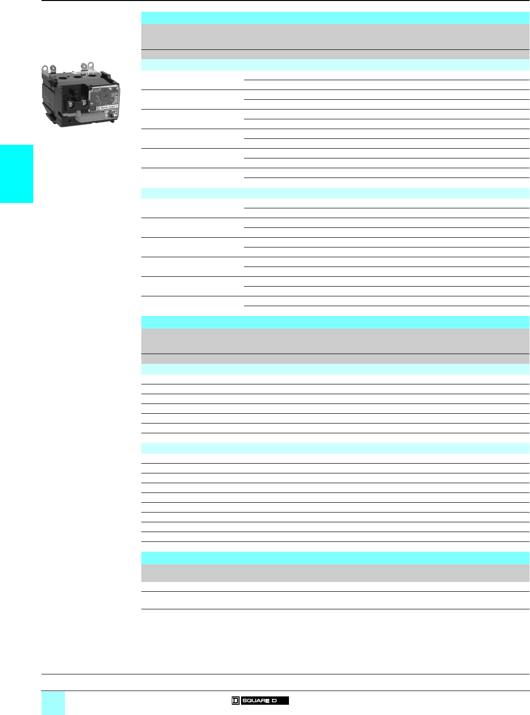
3/6
3
References
0
Solid-State Overload Relays 0
Motor Logic® base unit
Motor Logic® feature unit
Motor Logic solid-state overload relays base unit
NEMA Size
3-phase
Full-load
current
range
Open type Reference Weight
Akg (lb)
Motor Logic base unit for separate mounting
00C (1) 3…9 Trip Class 10 9065 SSC 10 0.5 (1)
Trip Class 20 9065 SSC 20 0.5 (1)
0 (1) 6…18 Trip Class 10 9065 SS 010 0.5 (1.2)
Trip Class 20 9065 SS 020 0.5 (1.2)
1 (1) 9…27 Trip Class 10 9065 SS 110 0.5 (1.2)
Trip Class 20 9065 SS 120 0.5 (1.2)
215…45 Trip Class 10 9065 SS 210 0.7 (1.5)
Trip Class 20 9065 SS 220 0.7 (1.5)
330…90 Trip Class 10 9065 SS 310 1.3 (2.9)
Trip Class 20 9065 SS 320 1.3 (2.9)
445…135 Trip Class 10 9065 SS 410 1.6 (3.6)
Trip Class 20 9065 SS 420 1.6 (3.6)
Motor Logic base unit for retrofitting existing Type S starters (2)
00C (1) 3…9 Trip Class 10 9065 SSC 10 0.5 (1)
Trip Class 20 9065 SSC 20 0.5 (1)
0 (1) 6…18 Trip Class 10 9065 SS 010 0.5 (1.2)
Trip Class 20 9065 SS 020 0.5 (1.2)
1 (1) 9…27 Trip Class 10 9065 SS 110 0.5 (1.2)
Trip Class 20 9065 SS 120 0.5 (1.2)
215…45 Trip Class 10 9065 SR 210 0.7 (1.5)
Trip Class 20 9065 SR 220 0.7 (1.5)
330…90 Trip Class 10 9065 SR 310 1.3 (2.9)
Trip Class 20 9065 SR 320 1.3 (2.9)
445…135 Trip Class 10 9065 SR 410 1.6 (3.6)
Trip Class 20 9065 SR 420 1.6 (3.6)
Motor Logic solid-state overload relays feature unit
NEMA Size
1/3-pole
Full-load
current
range
Open type Reference Weight
Akg (lb)
Motor Logic feature unit for separate mounting
00B (1) 1.5…4.5 Trip Class 10/20 9065 SFB 20 0.5 (1)
00C (1) 3…9 Trip Class 10/20 9065 SFC 20 0.5 (1)
0 (1) 6…18 Trip Class 10/20 9065 SF 020 0.5 (1.2)
1 (1) 9…27 Trip Class 10/20 9065 SF 120 0.5 (1.2)
215…45 Trip Class 10/20 9065 SF 220 0.7 (1.5)
330…90 Trip Class 10/20 9065 SF 320 1.3 (2.9)
445…135 Trip Class 10/20 9065 SF 420 1.6 (3.6)
Motor Logic feature unit for retrofitting existing Type S starters (2)
00B (1) 1.5…4.5 Trip Class 10/20 9065 SFB 20 0.5 (1)
00C (1) 3…9 Trip Class 10/20 9065 SFC 20 0.5 (1)
0 (1) 6…18 Trip Class 10/20 9065 SF 020 0.5 (1.2)
1 (1) 9…27 Trip Class 10/20 9065 SF 120 0.5 (1.2)
215…45 Trip Class 10/20 9065 ST 220 0.7 (1.5)
330…90 Trip Class 10/20 9065 ST 320 1.3 (2.9)
445…135 Trip Class 10/20 9065 ST 420 1.6 (3.6)
5 (3) 90…270 Trip Class 10/20 9065 ST 520 0.5 (1.2)
6 (3) 180…540 Trip Class 10/20 9065 ST 620 0.5 (1.2)
7 (3) 270…810 Trip Class 10/20 9065 ST 720 0.5 (1.2)
Kits
Type Kit description For use on Reference Weight
kg (lb)
Lug-lug kit For separate mounting 9065 Sp (Sizes 00C/0/1 only) 9999 LLO –
Lug-extender kit For retrofitting existing
Type S starters
9065 Sp (Sizes 00C/0/1 only) 9999 LBO –
(1) Size supplied without lugs.
(2) For Type S starter references, see pages 1/6 to 1/13.
(3) Replacement for Type S starters with an existing Motor Logic solid-state overload relay. Does not include primary current
transformer or additional components.
531203
9065 SSC 10
General, description:
page 3/2
Characteristics:
page 3/3
Dimensions:
page 3/6
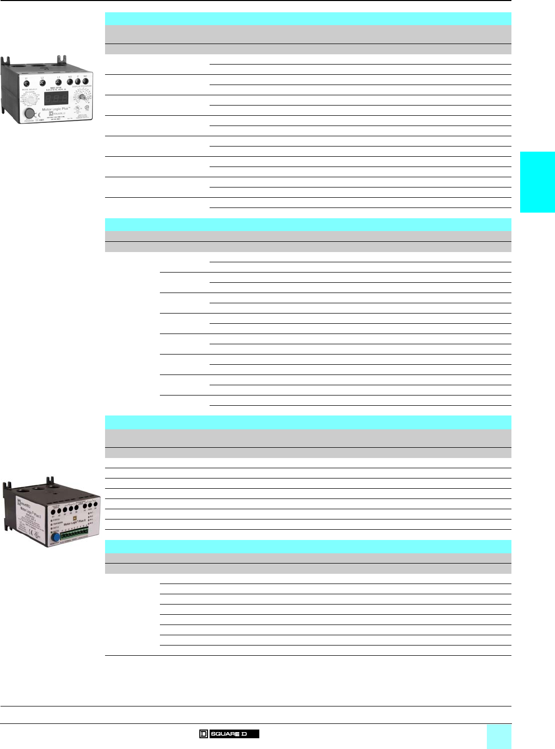
3/7
3
References
0
Solid-State Overload Relays 0
Motor Logic® Plus programmable unit
Motor Logic® Plus II programmable unit
Motor Logic Plus programmable solid-state overload relays
NEMA Size
3-phase
Product
current range
Voltage Reference Weight
A V kg (lb)
00 0.5…2.3 200…480 9065 SPB 4 1 (3)
600 9065 SPB 6 1 (3)
02…9 200…480 9065 SPC 4 1 (3)
600 9065 SPC 6 1 (3)
16…27 200…480 9065 SP 14 1 (3)
600 9065 SP 16 1 (3)
210…45 200…480 9065 SP 24 1 (3)
600 9065 SP 26 1 (3)
320…90 200…480 9065 SP 34 1 (3)
600 9065 SP 36 1 (3)
4 (1) 60…135 200…480 9065 SP 44 1 (3)
600 9065 SP 46 1 (3)
5 (2) 120…270 200…480 9065 SP 54 1 (3)
600 9065 SP 56 1 (3)
6 (3) 240…540 200…480 9065 SP 64 1 (3)
600 9065 SP 66 1 (3)
Variants of Type S starters
Description Current range Factory modification Reference Suffix Weight
Akg (lb)
Motor Logic
Plus
programmable
solid-state
overload relays
(add to the
starter
reference)
(4)
0.5…2.3 No modification for 200…480 V B20 –
No modification for 600 V B24 –
2…9 No modification for 200…480 V B30 –
No modification for 600 V B34 –
6…27 No modification for 200…480 V B40 –
No modification for 600 V B44 –
10…45 No modification for 200…480 V B50 –
No modification for 600 V B54 –
20…90 No modification for 200…480 V B60 –
No modification for 600 V B64 –
60…135 No modification for 200…480 V B70 –
No modification for 600 V B74 –
120…270 No modification for 200…480 V B80 –
No modification for 600 V B84 –
240…540 No modification for 200…480 V B90 –
No modification for 600 V B94 –
Motor Logic Plus II programmable solid-state overload relays
NEMA Size
3-phase
Product
current range
Voltage Reference Weight
A V kg (lb)
00 0.5…2.3 600 9065 SP2 B6 1 (3)
02…9 600 9065 SP2 C6 1 (3)
16…27 600 9065 SP2 16 1 (3)
210…45 600 9065 SP2 26 1 (3)
320…90 600 9065 SP2 36 1 (3)
4 (1) 60…135 600 9065 SP2 46 1 (3)
5 (2) 120…270 600 9065 SP2 56 1 (3)
6 (3) 240…540 600 9065 SP2 66 1 (3)
Variants of Type S starters
Description Current range Factory modification Reference Suffix Weight
Akg (lb)
Motor Logic
Plus
programmable
solid-state
overload relays
(add to the
starter
reference)
(4)
0.5…2.3 No modification for 600 V H50 –
2…9 No modification for 600 V H51 –
6…27 No modification for 600 V H52 –
10…45 No modification for 600 V H53 –
20…90 No modification for 600 V H54 –
60…135 No modification for 600 V H55 –
120…270 No modification for 600 V H56 –
240…540 No modification for 600 V H57 –
(1) Size 4 requires the use of external current transformer. Ratio of 150: 5 recommended.
(2) Size 5 requires the use of external current transformer. Ratio of 300: 5 recommended.
(3) Size 6 requires the use of external current transformer. Ratio of 600: 5 recommended.
(4) For Type S Open style starter references, see pages 1/6 to 1/13.
531202
9065 SPB 4
SSOLR MLPII.tif
9065 SP2
General, description:
pages 3/2 and 3/4
Characteristics:
pages 3/3 and 3/5
Dimensions:
page 3/9
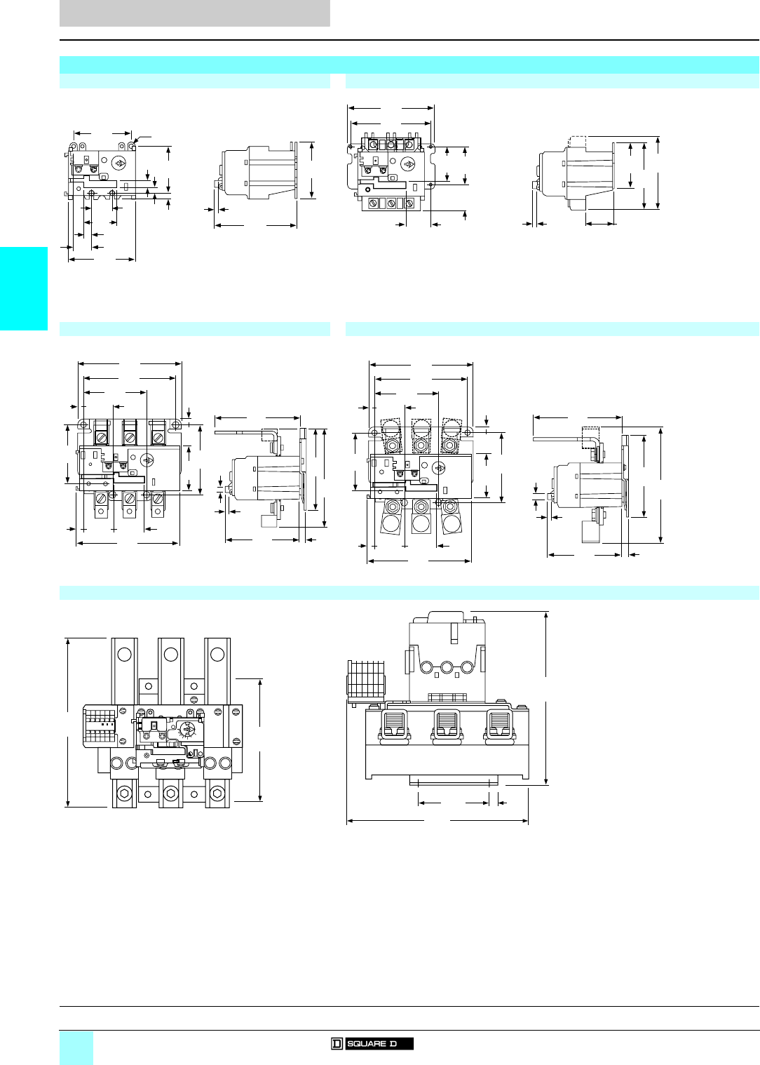
3/8
3
Dimensions
0
Solid-State Overload Relays 0
Motor Logic® base unit
Motor Logic® feature unit
Dimensions are inch
mm
------------
Motor Logic solid-state overload relays
9065 Spp10 / Spp20 9065 SS 2p0 / SR 2p0 / SF 220 / ST 220
(1) 2 holes. 2 slots for 8-32 mounting screws.
9065 SS 3p0 / SR 3p0 / SF 320 / ST 320 9065 SS 4p0 / SR 4p0 / SF 420 / ST 420
9065 ST 520
RESET
Reset
Travel
.24
6
3.90
99
2.23
57
.31
8
.27
7.28
7
1.00
25
1.59
40
3.26
83
.36
9
.89
23
2.69
68
2.81
71
(1)
RESET
4.28
109
3.91
99
Reset
Travel
.24
6
0.00
00
2.19
56
3.51
89
3.24
82
1.70
43 1.84
47
1.24
31
1.24
31
RESET
.30
8
1.08
27
1.50
38
3.25
83
4.74
120
5.32
135
.29
74.45
113
4.16
106
5.02
128
3.80
97
5.33
135
.38
10 1.57
40
2.96
75 3.56
90
2.26
57
1.57
40 .32
8
Reset
Travel
.24
6
.31
8
RESET
Reset
Travel
1.50
38
3.25
83
4.74
120
5.32
135
.29
7.30
8
1.08
27
5.33
135
.38
10
1.57
40
2.96
75 3.56
90
2.26
57
1.57
40
4.53
115
4.16
106 5.92
150
3.80
97
.32
8
.24
6
.31
8
C
O
M
C
O
M
C
O
M123
RESET
8
6
8
6
MeterLogic®
200
160 120
80
220
270
2.25
57
7.38
187
7.75
197
5.88
149
8
.25
210
1.18
30
General, description:
page 3/2
Characteristics:
page 3/3
References:
page 3/6
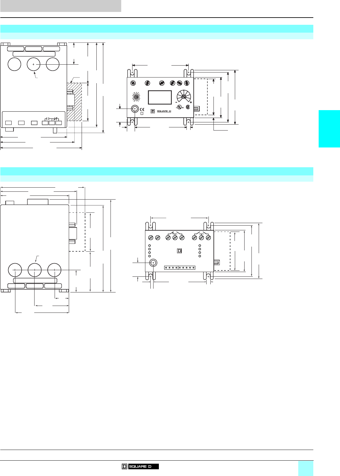
3/9
3
Dimensions (continued)
0
Solid-State Overload Relays 0
Motor Logic® Plus programmable unit
Motor Logic® Plus II programmable unit
Dimensions are inch
mm
------------
Motor Logic Plus programmable solid-state overload relays
9065 SPB / SPC / SP
Motor Logic Plus II programmable solid-state overload relays
9065 SP2 p6
(1) Optional communication module.
2.20
(55,9)
2.14
(54,4)
200–480 V~
50/60 Hz
CONTACT RATING
NEMA B300
5.05
(128)
3.85 (97,8)
4.37 (111)
3.60 (91,4)
ø 0.65 (16,5) 4.70
(119)
1.20
(30,5)
(1)
7 lb-in (0,8 N m) 96 95 98
™®
5
5)
TC RUN
RESET/
PROGRAM
#RU/ADDR
RD2
RD1
CUB
UC
OC MULT VUB
HV
LV
GF
UCTD
#RF
RD3
Motor Logic Plus
3.0
(77,
2.65
(67,3)
2.03
(51,6)
0.70
(17,8)
0.25
(6,35) 0.34
(8,64)
2.28
(57,9)
0.20
(5,08)
3.10 (78,7)
L1 L2 L3NO NCC
DISPLAY / PROGRAM9065 SPC4
2.0-9.0 A, SER. B
MODE SELECT
LISTED
IND. CONT. EQ.
786X
MADE IN USA
HECHO EN EUA
FABRIQUE AUX E.U.
L1–L2
L2–L3
L3–L1
AVG
AVG
A
B
C
V
O
L
T
A
G
E
C
U
R
R
E
N
T
AA 0149 SUITABLE 5 kA RMS
600 VAC MAX
*
3.85 (97,8)
3.60 (91,4)
4.37 (111)
<5.51
(140)
4.70
(119)
1.20
(30,5)
2.14
(54,4)
2.20
(55,9)
Ø 0.65 (16,5)
0.67
(17,0)
1.80
(45,7)
2.93
(74,4)
3.05
(77,5)
2.65
(67,3)
0.70
(17,8)
0.25
(6,35)
2.28
(57,9)
0.20
(5,08)
3.10 (78,7)
2.03
(51,6)
*
A1
I1
A2 98
I3
I2 G
I4
95 96 13/23
S
PA
B
14 24
RESET/TEST
110/120 Vac
50/60 Hz
STATU S
TRIP/WARN
OUT A
OUT B
IN 1
IN 2
IN 3
IN 4
Motor Logic® Plus II
General, description:
pages 3/2 and 3/4
Characteristics:
pages 3/3 and 3/5
References:
page 3/7

4/0
4 -

4/1
Contents
0
4
4 - Definite Purpose Contactors
bTypes DP and DPA Class 8910
vGeneral . . . . . . . . . . . . . . . . . . . . . . . . . . . . . . . . . . . . . . . . . . . . . . . . page 4/2
vCharacteristics . . . . . . . . . . . . . . . . . . . . . . . . . . . . . . . . . . . . . . . . . . . page 4/3
vReferences . . . . . . . . . . . . . . . . . . . . . . . . . . . . . . . . . . . . . . . . . . . . . page 4/4
vAccessories . . . . . . . . . . . . . . . . . . . . . . . . . . . . . . . . . . . . . . . . . . . . . page 4/6
vDimensions . . . . . . . . . . . . . . . . . . . . . . . . . . . . . . . . . . . . . . . . . . . . . page 4/8
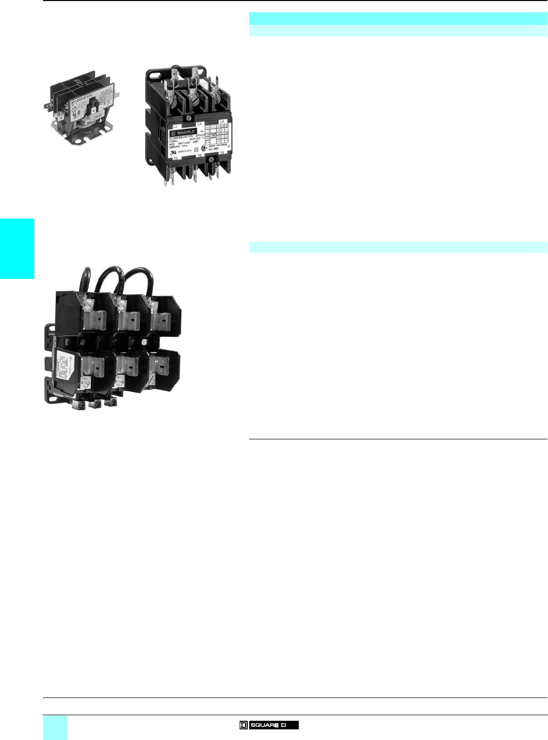
4/2
4
General
0
Definite Purpose Contactors 0
Types DP and DPA Class 8910
(1) Dimensions in mm (25.4 mm = 1 inch).
General
Definite purpose contactors
Definite purpose contactors are ideal for heating, air conditioning, refrigeration, data
processing and food service equipment. New compact single- and 2-pole contactors
are available, as well as full-size 2-, 3- and 4-pole devices.
bFeatures:
v compact design,
v industry standard mounting,
v double break contacts,
v low coil VA,
v straight-through wiring,
v low cost,
v open contact constructions for easier contact inspection,
v optional cover over contacts.
They feature quick-connect terminals and binding head screws for easy wiring. Box
lugs are standard on 40 A contactors and larger.
An exclusive DIN track mounting option may reduce installation costs.
Coils can be changed on the Type DPA contactors quickly without a tool.
Auxiliary contact modules snap on either side of the Type DPA contactors.
Contactors with fuse blocks
The DPA fused-type contactor provides an integrally mounted fuse block with fuse
clips electrically connected to the contactor. This factory assembled unit not only
provides space savings but reduces installation cost as well, with only six field
connections for a 3-pole unit and featuring one unit for two functions, i.e., short-circuit
protection for branch circuits and remote or manual power circuit interruption. The
fused contactor thus meets the provisions of the National Electric Code (NEC) Article
424 for overcurrent protection as well as limit controls for fixed electric space heating.
By a unique fuse clip arrangement, these devices can accommodate a variety of
fuses for other electrical or electronic applications. This fused cover accommodates
the Type SC 300 volt fuse, which is UL listed under Type G, as well as the standard
10 mm x 38 mm fuses (1).
Only UL-listed, Class G, K, H or J fuses meet branch circuit requirements when
applied in accordance with NEC Article 240. Supplementary fuses shown may be
used for additional equipment protection as defined in NEC 240-30.
Consult the manufacturer of the selected fuse for proper application.
8910 DPA 33 V02
3-pole contactor
531125
8910 DP 31 V02
Single-pole contactor
531124
8910 DPA 23 V02 DFM1
Contactor with fuse block
531257
Characteristics:
page 4/3
References:
pages 4/4 to 4/7
Dimensions:
pages 4/8 and 4/9
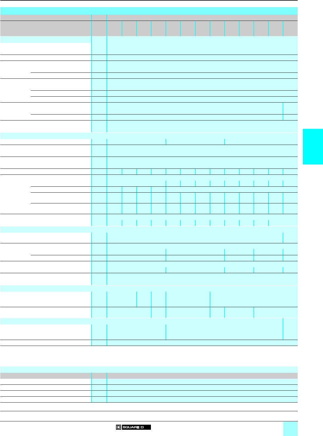
4/3
4
Characteristics
0
Definite Purpose Contactors 0
Types DP and DPA Class 8910
Characteristics
Class 8910
Type DP
11/12
DP
21/22
DP
31/32
DP
41/42
DPA
12/13/
14
DPA
22/23/
24
DPA
32/33/
34
DPA
42/43/
44
DPA
52/53
DPA
62/63
DPA
72/73
DPA
92/93
DPA
122/
123
Environment
Rated insulation voltage
Conforming to UL, CSA V600
Rated impulse withstand voltage kV 5
Conforming to standards
NEMA ICS-1, ICS-2 Yes
UL 508 Yes
Product certifications
UL Yes
CSA Yes
eYes
Ambient air temperature around the device - 30…
Storage °C 0…65 + 65
Operation °C 0…65 0…40
Operating position
Without derating Vertical
Pole characteristics
Number of poles (P) 1, 2 2, 3, 4 2, 3
Rated operational voltage
Up to V600
Frequency limits
Of the operational current Hz 50/60
Conventional thermal current (FLA) A20 25 30 40 20 25 30 40 50 60 70 90 120
Rated making capacity (LRA)
At 240 V A–120 150 180 240 300 360 450 540 720
At 277 V A100 125 150 200 –
At 480 V A100 125 150 150/
200
100 125 150 200 250 300 375 450 600
At 600 V A80 100 120 150/
160
80 100 120 160 200 240 300 360 480
Resistive rating
At 600 V A30/30 30/35 40/40 50/50 25 35 40 50 62 75 94 120
a.c. control circuit characteristics
Rated control circuit voltage V600 24/
600
Average consumption 60Hz
Inrush VA 30 56 (1) 109 214 700
Sealed VA 66 (1) 10 19 46
Heat dissipation 60 Hz
Sealed W2.5 2.7 (2) 3.3 7.5 14
Mechanical durability (3)
In thousands of operating cycles 500
Power circuit connections
Type of termination Binding head
screw
Screw
clamp
terminal
Box
lug
Binding head screw Box lug
Wire sizes (Min./max.) (4) #14 - #8 #14 -
#6
#14 - #8 #14 -
#6
#14 - #2 #14 - #1/0
Control circuit connections
Type of termination .250" Quick connect .250" Quick connect/binding head screw Screw
clamp
terminal
Wire sizes (Min./max.) (4) #16 - #12
(1) 4-pole has 109 VA inrush, 10 VA sealed.
(2) 4-pole Watts are 3.3.
(3) Operating cycles are without a load (mechanical durability).
(4) Solid or stranded copper wire (AWG).
External auxiliary contacts
Type 9999 D10/D01/D11/D20/SX6/SX7/SX8/SX9/SX10
Voltage a V 120 or less
Making current a A 60 (35% power factor)
Breaking current a A 6 (35% power factor)
Continuous current A10
General:
page 4/2
References:
pages 4/4 to 4/7
Dimensions:
pages 4/8 and 4/9
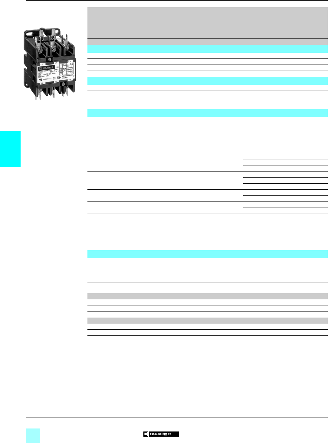
4/4
4
References
0
Definite Purpose Contactors 0
Types DP and DPA Class 8910
Full-load
Amperes
Locked rotor
Amperes
Resistive
load
Amperes
Motor power ratings N/O
poles
N/C
poles
(1)
Basic reference
Add code indicating
control circuit
voltage (2)
Weight
115V
single-
phase
230V
single-
phase
230V
3-phase
460/575V
3-phase
277V 480V 575V
A A A A A hp kW hp kW hp kW hp kW kg (lb)
Compact single-pole contactors
20 100 100 80 25 11.1 21.5 ––––1– 8910 DP 11 (2) 0.2 (0.5)
25 125 125 100 30 21.5 32.2 ––––1–8910 DP 21 (2) 0.2 (0.5)
30 150 150 120 40 21.5 32.2 ––––1–8910 DP 31 (2) 0.2 (0.5)
40 240 200 160 50 (3) 2 1.5 53.7 ––––1–8910 DP 41 (2) 0.2 (0.5)
Compact 2-pole contactors (4)
20 100 100 80 30 11.1 21.5 ––––2–8910 DP 12 (2) 0.2 (0.5)
25 125 125 100 35 21.5 32.2 ––––2–8910 DP 22 (2) 0.2 (0.5)
30 150 150 120 40 21.5 53.7 ––––2–8910 DP 32 (2) 0.2 (0.5)
40 240 200 160 50 21.5 53.7 ––––28910 DP 42 (2) 0.2 (0.5)
2-, 3- and 4-pole contactors (4)
20 120 100 80 25 11.1 21.5 53.7 7.5 5.5 2 –8910 DPA 12 (2) 0.5 (1)
3–8910 DPA 13 (2) 0.5 (1)
4–8910 DPA 14 (2) 0.6 (1.3)
25 150 125 100 35 21.5 32.2 7.5 5.5 10 7.5 2 –8910 DPA 22 (2) 0.5 (1)
3–8910 DPA 23 (2) 0.5 (1)
4–8910 DPA 24 (2) 0.6 (1.3)
30 180 150 120 40 21.5 53.7 10 7.5 15 11 2 –8910 DPA 32 (2) 0.5 (1)
3–8910 DPA 33 (2) 0.5 (1)
4–8910 DPA 34 (2) 0.6 (1.3)
40 240 200 160 50 32.2 7.5 5.5 10 7.5 20 15 2 –8910 DPA 42 (2) 0.5 (1)
3–8910 DPA 43 (2) 0.5 (1)
4–8910 DPA 44 (2) 0.7 (1.5)
50 300 250 200 62 32.2 10 7.5 15 11 30 22 2 –8910 DPA 52 (2) 0.7 (1.5)
3–8910 DPA 53 (2) 0.7 (1.5)
60 360 300 240 75 53.7 10 7.5 25 18.5 30 22 2 –8910 DPA 62 (2) 0.7 (1.5)
3–8910 DPA 63 (2) 0.7 (1.5)
75 450 375 300 94 53.7 15 11 25 18.5 40 30 2 –8910 DPA 72 (2) 1.6 (3.5)
3–8910 DPA 73 (2) 1.7 (3.7)
90 540 450 360 120 7.5 5.5 20 15 30 22 50 37 2 –8910 DPA 92 (2) 1.4 (3)
3–8910 DPA 93 (2) 1.7 (3.7)
120 720 600 480 120 10 7.5 25 18.5 40 30 75 55 2 –8910 DPA 122 (2) 2 (4.4)
3–8910 DPA 123 (2) 5.9 (13)
4-pole contactors (4)
20 120 100 80 25 11.1 21.5 53.7 7.5 5.5 2 2 8910 DPA 14 (2) Y392 0.6 (1.3)
25 150 125 100 35 21.5 32.2 7.5 5.5 10 7.5 2 2 8910 DPA 24 (2) Y392 0.6 (1.3)
30 180 150 120 40 21.5 53.7 10 7.5 15 11 2 2 8910 DPA 34 (2) Y392 0.6 (1.3)
40 240 200 160 50 32.2 7.5 5.5 10 7.5 20 15 2 2 8910 DPA 44 (2) Y392 0.7 (1.5)
(1) N/C poles on outside. N/C poles open before N/O poles close.
(2) Standard control circuit voltage for 8910 DP/DPA:
Volts 24 110 120 208–240 220 277 440 480 550 600
50 Hz V14V02– – V09– V06 (5) – V07 (6) –
60 Hz V14 – V02 V09 – V04 – V06 (5) –V07 (6)
Standard control circuit voltage for 8910 DPA 122/DPA 123:
Volts 24 110 120 208 220 230–240 440 480 550 600
50 Hz V12V02– – V03– V06– V07–
60 Hz V01 (7) – V02 V08 – V03 – V06 – V07
(3) 50 A resistive limited to 277V. All others rated 40 A resistive (above 277V).
(4) Above 240V, all lines must be switched.
(5) Not available for Type 8910 DP 11 to 8910 DP 31 single-pole devices.
(6) Not available for Type 8910 DP single- and 2-pole devices.
(7) Only available on Types 8910 DPA 122/DPA 123.
8910 DPA 33
531125
General:
page 4/2
Characteristics:
page 4/3
Dimensions:
pages 4/8 and 4/9
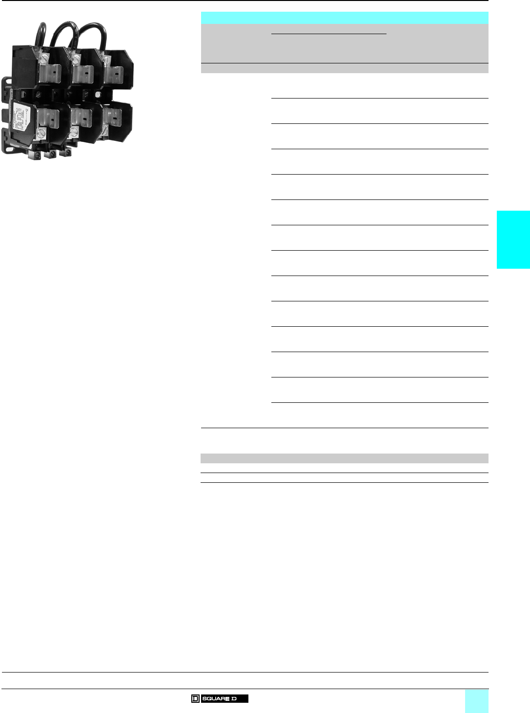
4/5
4
References
0
Definite Purpose Contactors 0
Types DP and DPA Class 8910
Contactors with fuse blocks (1)
Contactors Fuse Suffix to the
contactor reference
(3)
Weight
Rating Maximum
rating
voltage
Dimen-
sions
(2)
Class
A V mm kg (lb)
8910 DPA 13/23/33/43 3 600 10 x 38 CC (3) DFC1 0.35 (0.8)
60 480 10 x 57 G (3) DFG1 0.35 (0.8)
30 480 10 x 41 G (3) DFG2 0.35 (0.8)
30 250 14 x 51 H or K (3) DFH1 0.35 (0.8)
60 250 20 x 76 H or K (3) DFH2 0.35 (0.8)
30 600 20 x 57 J (3) DFJ1 0.40 (0.9)
60 600 26 x 60 J (3) DFJ2 0.40 (0.9)
30 600 10 x 38 M (3) DFM1 0.40 (0.9)
30 250 14 x 51 R (3) DFR1 0.35 (0.8)
60 250 20 x 76 R (3) DFR2 0.35 (0.8)
30 300 14 x 22 T (3) DFT1 0.35 (0.8)
60 300 14 x 22 T (3) DFT2 0.35 (0.8)
30 600 14 x 22 T (3) DFT3 0.40 (0.9)
60 600 25 x 39 T (3) DFT4 0.40 (0.9)
(1) For dimensions, see page 4/9.
(2) Dimensions in mm (25.4 mm = 1 inch).
(3) 8910 DPA 13 or 23 or 33 or 43 plus standard control circuit voltage:
Volts 24 110 120 208–240 220 277 440 480 550 600
50 Hz V14 V02 – – V09 – V06 – V07 –
60 Hz V14 – V02 V09 – V04 – V06 – V07
Example: 8910 DPA 33 V02 DFG1.
8910 DPA 23 V02 DFM1
531257
General:
page 4/2
Characteristics:
page 4/3
Dimensions:
pages 4/8 and 4/9
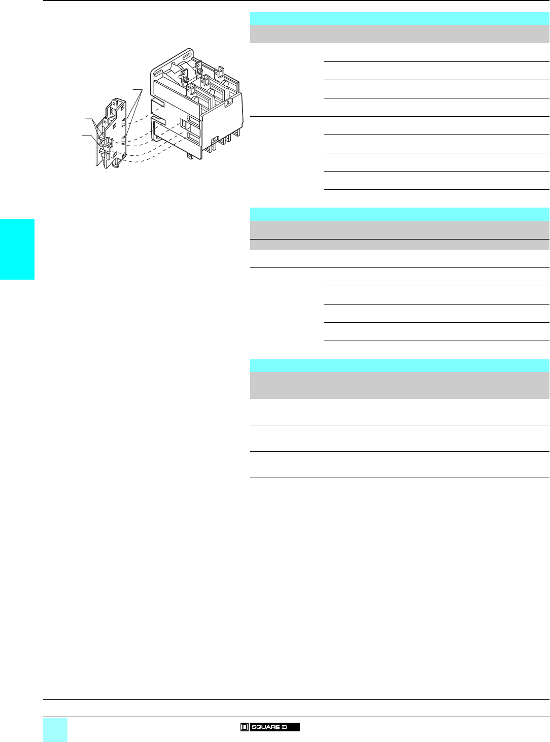
4/6
4
References
0
Definite Purpose Contactors 0
Types DP and DPA Class 8910
Accessories
External auxiliary contacts
For use with Description Reference Weight
kg (lb)
8910 DPA 1 N/O contact 9999 D10 0.03
(0.07)
1 N/C contact 9999 D01 0.03
(0.07)
1 N/O and 1 N/C contacts 9999 D11 0.04
(0.09)
2 N/O contacts 9999 D20 0.04
(0.09)
8910 DPA 122/123 1 N/O contact 9999 SX6 0.03
(0.07)
1 N/C contact 9999 SX7 0.03
(0.07)
1 N/O and 1 N/C isolated contacts 9999 SX8 0.04
(0.09)
1 N/O make before break contact 9999 SX9 0.03
(0.07)
1 N/C make before break contact 9999 SX10 0.03
(0.07)
NEMA 1 general purpose enclosures
For use with Full-load
Amperes
Poles Reference Weight
Akg (lb)
8910 DP (1) 20…40 1 and 2 9991 DPG1 1.1 (2.5)
8910 DPA 20…40 2 and 3 9991 DPG1 1.1 (2.5)
50 2 and 3 9991 DPG2 1.8 (4)
20…40 4 9991 DPG2 1.8 (4)
60…75 2 and 3 9991 DPG3 3 (7)
90…120 2 and 3 9991 DPG4 4 (9)
Variants
Type For use on Suffix to the
contactor reference
(2)
Weight
kg (lb)
Screw clamp
terminal connectors
8910 DPA 1p/2p/3pY122 –
Box lugs 8910 DPA 1p/2p/3pY124 –
DIN mounting
bracket attachment
(35 mm wide)
8910 DPA 1p/2p/3p/4p/5p/6pY135 –
(1) Optional contact cover 9999 DRC1, only available for 8910 DP compact single-pole or 2-pole
contactors.
(2) Example: 8910 DPA 12 V02 Y122.
Auxiliary contact
531258
Bottom Tabs
Top Hooks
Operating Tab
Contactor
General:
page 4/2
Characteristics:
page 4/3
Dimensions:
pages 4/8 and 4/9
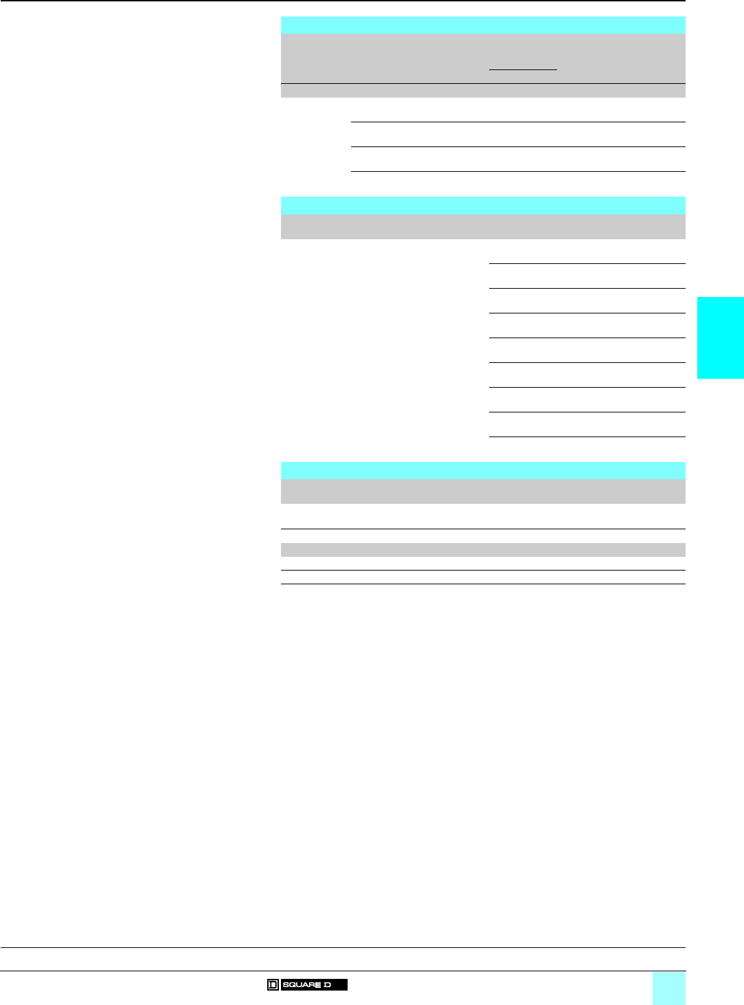
4/7
4
References (continued)
0
Definite Purpose Contactors 0
Types DP and DPA Class 8910
Accessories
Replacement coils
Type For use on Poles Average
consumption
(60 Hz)
Basic reference
Add code
indicating control
circuit voltage (1)
Weight
Inrush Sealed
VA VA kg (lb)
Replacement
coils
8910 DPA 1p/2p/3p/4p2 and 3 56 6 9998 DA1 ppp –
8910 DPA p44109109998 DA2 ppp –
8910 DPA 5p/6p2 and 3 109 10 9998 DA2 ppp –
8910 DPA 7p/9p2 and 3 214 19 9998 DA3 ppp –
Replacement parts kits
Type Kit description For use on Reference Weight
kg (lb)
Replacement
parts kits
Contains the necessary
movable and stationary
contacts, contact springs and
additional hardware for one pole
8910 DPA 1p9998 DRC1 –
8910 DPA 2p9998 DRC2 –
8910 DPA 3p9998 DRC3 –
8910 DPA 4p9998 DRC4 –
8910 DPA 5p9998 DRC5 –
8910 DPA 6p9998 DRC6 –
8910 DPA 7p9998 DRC7 –
8910 DPA 9p9998 DRC9 –
8910 DPA 12p9998 DRC12 –
Miscellaneous parts
Type For use on Reference Weight
kg (lb)
DIN mounting
adaptor plate
8910 DPA 9999 DMB1 –
(1) Standard control circuit voltage:
Volts 24 110 120 208–240 220 277 440 480 550 600
50 Hz V14 V02 – – V09 – V06 – V07 –
60 Hz V14 – V02 V09 – V04 – V06 – V07
Example: 9998 DA1 V02.
General:
page 4/2
Characteristics:
page 4/3
Dimensions:
pages 4/8 and 4/9
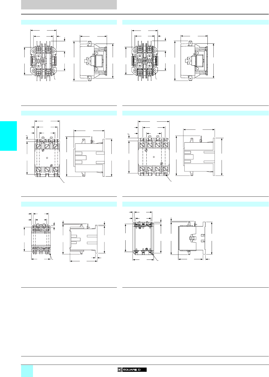
4/8
4
Dimensions
0
Definite Purpose Contactors 0
Types DP and DPA Class 8910
Dimensions are inch
mm
------------
8910 DP 11/21/31/41 (single-pole) 8910 DP 12/22/32/42 (2-pole)
(1) Provisions for #10 or M5 mounting screws. (1) Provisions for #10 or M5 mounting screws.
8910 DPA 12/13/22/23/32/33/42/43 (2 and 3-pole/20–40 A) 8910 DPA 14/24/34/44 (4-pole/20–40 A)
(1) Provisions for #10 or M5 mounting screws. (1) Provisions for #10 or M5 mounting screws.
8910 DPA 5p/6p (2 and 3-pole/50–60 A) 8910 DPA 7p/9p (2 and 3-pole/75–90 A)
(1) Provisions for #10 or M5 mounting screws. (1) Provisions for #10 or M5 mounting screws.
2.87
73
3.29
84
1.63
42
2.31
59
.83
21
.27
7
2.16
55
1.63
42 2.22
57
(1)
2.87
73
3.29
84
1.63
42
2.31
59
.83
21
.27
7
2.16
55
1.63
42 2.22
57
(1)
2.50
64
2.00
51
1.50
38
.50
13
(1)
3.12
79
.25
6
.25
6
3.25
83
4.00
102 3.75
95
3.17
81
2.25
57
.46
12
.81
21
3.25
83
.25
6
1.55
39
(1)
3.11
79
4.00
102 3.75
95
.24
6
2.11
54
1.54
39
4.06
103
3.27
83
2.56
85
.23
6
.23
6
.51
13
(1)
.07
2
.09
2
3.72
94
3.67
93
2.87
73
2.50
64
(1)
3.39
86
4.44
113
4.37
111 .39
10
4.63
118 5.20
132
.06
2
5.12
130
.44
11
.26
7.26
7
General:
page 4/2
Characteristics:
page 4/3
References:
pages 4/4 to 4/7
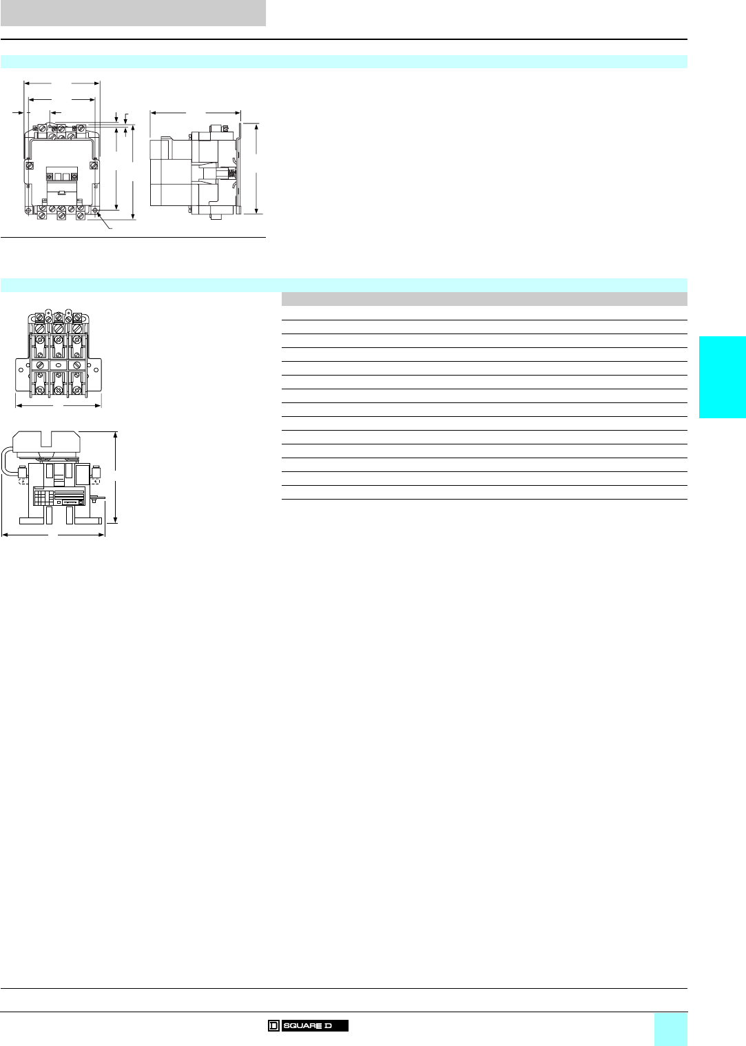
4/9
4
Dimensions
0
Definite Purpose Contactors 0
Types DP and DPA Class 8910
Dimensions are inch
mm
------------
8910 DPA 122/123 (120 A)
(1) Provision for 1/4" mounting screw.
Contactors with fuse blocks
(2) A B C
8910 DPA p3 ppp DFC1 91 150 117
8910 DPA p3 ppp DFG1 91 155 119
8910 DPA p3 ppp DFG2 91 150 114
8910 DPA p3 ppp DFH1 91 150 119
8910 DPA p3 ppp DFH2 107 168 135
8910 DPA p3 ppp DFJ1 91 150 132
8910 DPA p3 ppp DFJ2 119 152 135
8910 DPA p3 ppp DFM1 91 150 117
8910 DPA p3 ppp DFR1 91 152 119
8910 DPA p3 ppp DFR2 107 168 136
8910 DPA p3 ppp DFT1 91 150 114
8910 DPA p3 ppp DFT2 91 150 114
8910 DPA p3 ppp DFT3 119 155 114
8910 DPA p3 ppp DFT4 119 150 114
(2) Dimensions in mm (25.4 mm = 1 inch)
.31
8.12
3
(1)
5.38
137
6.50
165
6.63
168
4.75
121
6.03
153 6.86
174
1.50
38
.31
8
A
B
C
T
op
Vi
ew
Side View
General:
page 4/2
Characteristics:
page 4/3
References:
pages 4/4 to 4/7

5/0

5/1
Contents
5
5 - Lighting Contactors
bMultipole lighting contactors, Types L, LX and S Class 8903
vGeneral, characteristics . . . . . . . . . . . . . . . . . . . . . . . . . . . . . . . . . . . . page 5/2
bMultipole lighting contactors, Types L and LX Class 8903
vReferences . . . . . . . . . . . . . . . . . . . . . . . . . . . . . . . . . . . . . . . . . . . . . page 5/4
bMultipole lighting contactors, Type S Class 8903
vReferences . . . . . . . . . . . . . . . . . . . . . . . . . . . . . . . . . . . . . . . . . . . . . page 5/5
bMultipole lighting contactors, Types L, LX and S Class 8903
vAccessories . . . . . . . . . . . . . . . . . . . . . . . . . . . . . . . . . . . . . . . . . . . . . page 5/7
vVariants . . . . . . . . . . . . . . . . . . . . . . . . . . . . . . . . . . . . . . . . . . . . . . . . page 5/8
vDimensions . . . . . . . . . . . . . . . . . . . . . . . . . . . . . . . . . . . . . . . . . . . . page 5/10
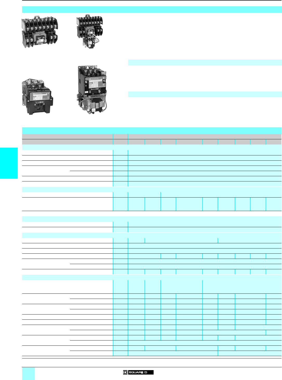
5/2
5
General,
characteristics
0
Lighting Contactors 0
Multipole lighting contactors
Types L, LX and S Class 8903
General
Lighting contactors have evolved from the need for more
than just simple on-off manual control of lights. Today's
requirements call for the development of new and varied
types of control. Often the application will call for remote
control of lighting from some distant location. This control
may not be in addition to a master control station at a
central location. Certain applications include the use of
automatic control by time clocks or photoelectric cells.
Whatever the need may be, applications are increasing and
lighting contactors are designed to meet the ever-changing
requirements.
Typical installations include:
bParking lots.
bIndustrial plants.
bOffice buildings.
bTheatres and auditoriums.
bHospitals and institutions.
bShopping centres.
bStadiums.
bAirports.
Multipole lighting contactors, Types L and LX Class 8903
Features:
b30 A fluorescent lighting rating.
b20 A tungsten lighting rating.
bElectrically and mechanically held.
b2 to 12-pole versions.
bField-convertible contacts with N/O and N/C indicators (8 N/C contacts maximum).
Multipole lighting contactors, Type S Class 8903
Features:
b30…800 A lighting ratings.
bElectrically and mechanically held.
b2- to 5-pole versions (5-pole to 200 A).
bUL-listed short-circuit rating up to 100 000 A.
bMixed load ratings (lighting and motor).
bFactory-wired controls and clearly marked termination points.
Characteristics
Class 8903
Type Lp/LXpSMpSPpSQpSVpSXpSYpSZpSJp
Environment
Rated insulation voltage Conforming to UL, CSA… aV600
Conforming to standards NEMA ICS-1, ICS-2, UL 508, CSA 22-2 n° 14
Product certifications UL, CSA
Ambient air temperature
around the device
Storage °C - 30…+ 65
Operation °C 0…+ 40
Max. operating altitude Without derating m2000
Operating position Without derating Vertical
Power circuit connections
Type of termination
Screw clamp terminal
Box lug
Wire sizes (Min./max.)
(AWG)
Solid or stranded copper
wire
#14–#10 #14–#8 #14–#2
(1)
#14–#2/0 (1) #6–350
MCM (1)
#4–600
MCM (1)
(2)
#6–350
MCM (1)
(3)
#4–600
MCM (1)
(3)
#30/0–
750MCM
(1) (4)
(1) Solid or stranded aluminium wire. (2) Two wires #4–250 MCM. (3) Two holes. (4) Four holes.
Control circuit connections
Type of termination Screw clamp terminal
Wire sizes (Min./max.) Solid or stranded copper wire (AWG) #16–#12
Pole characteristics
Number of poles (P) 2–12 2–5 2–3
Rated operating voltage Up to aV600
Frequency limits Of the operating current Hz 50/60
Conventional thermal current (FLA) A30 60 100 200 300 400 600 800
Rated making capacity Tungsten A10 x rated current
Ballast A3 x rated current
Resistance heating rating At 600V A20 30 60 100 200 300 400 600 800
a.c. control circuit characteristics
Rated control circuit voltage aV24–600
(2–6P)
(8–12P)
24–600 24–600 (2–3P)
110–600 (4–5P)
110–600
Average consumption 60Hz
Electrically held
Inrush VA 150/180 245 311/438 700/1185 1185 1300 1780 1960
Sealed VA 30/35 27 37/38 41/89 89 14 48 59
Average consumption 50Hz
Electrically held
Inrush VA 140/170 232 296/429 678/1260 1260 1300 1495 –
Sealed VA 30/35 26 36/37 47/89 89 14 56 –
Heat dissipation 60Hz Electrically held - Sealed W6.5/9.5 7.8 14/14 14/22 22 13 32 36
Heat dissipation 50Hz Electrically held - Sealed W–7.7 12/12 15/23 23 –27 –
Inrush 60 Hz
Mechanically held
Latch coil VA 150/180 245 311/438 700/973 973 2970 1530
Unlatch coil VA 25/25 140 140/140 550/550 550 2100
Inrush 50 Hz
Mechanically held
Latch coil VA 140/170 232 296/429 678/– –2970 1250
Unlatch coil VA –
Mechanical durability Electrically held 4000 10,000 3000 2000 1500 500
In x 103 of operating cycles Mechanically held 1000 500
531221
8903 L
p
Electrically held
531222
8903 LX
p
Mechanically held
531223
8903 S
pp p
Electrically held
531224
8903 S
pp pp
Mechanically held
References:
pages 5/4 to 5/9
Dimensions:
pages 5/10 and 5/11
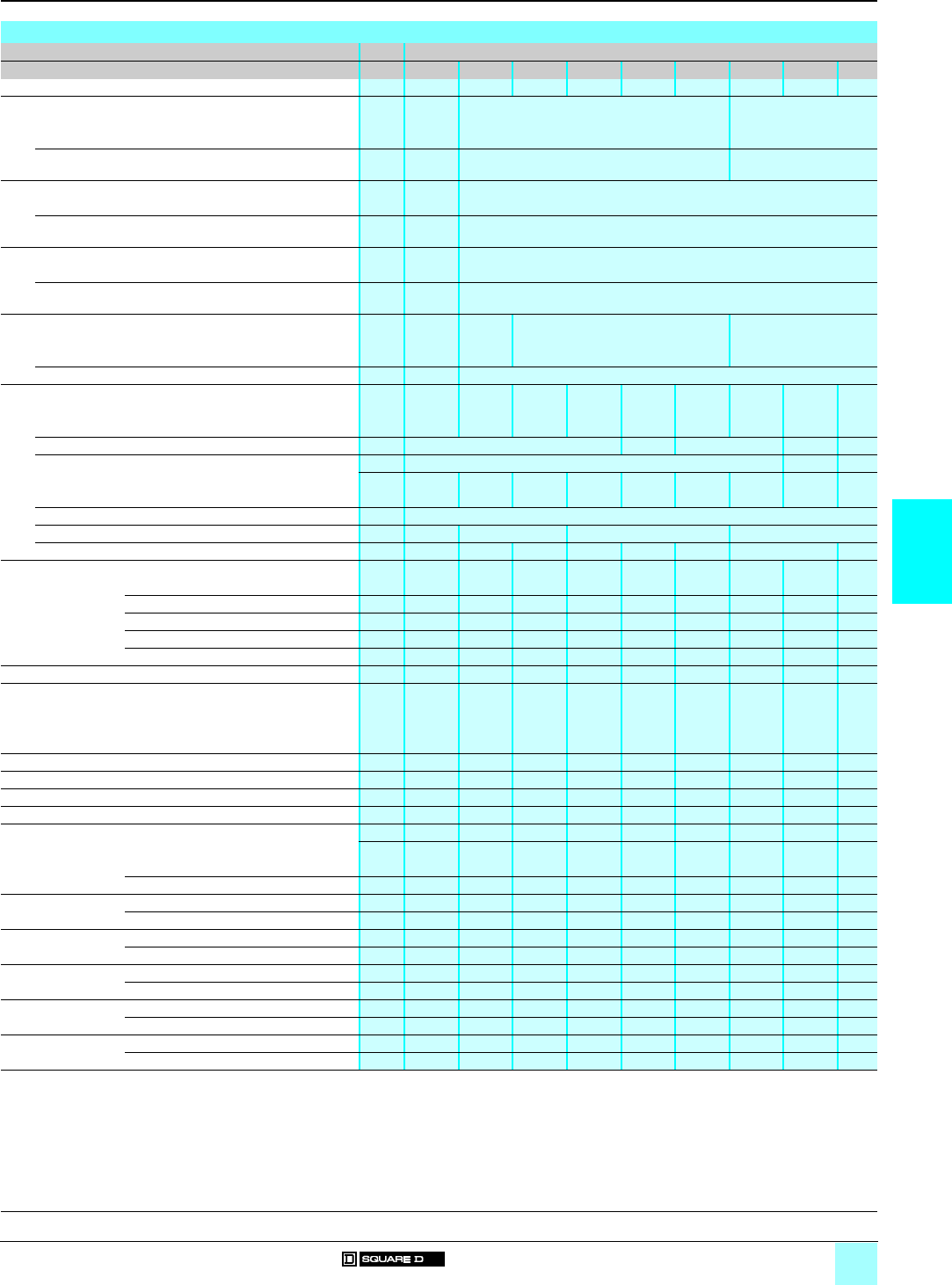
5/3
5
Characteristics (continued)
0
Lighting Contactors 0
Multipole lighting contactors
Types L, LX and S Class 8903
Electrical characteristics (continued)
Class 8903
Type Lp/LXpSMpSPpSQpSVpSXpSYpSZpSJp
Contactor continuous rating A30 30 60 100 200 300 400 600 (1) 800
a Voltage ratings
Tungsten lamp loads
Single-pole to load a V 20 A/277 277 –
2-pole to load on single-phase and 3-pole to load on
3-phase
a V 20 A/480 480 –
Ballast loads
Single-pole to load a V 277 (2) 347
2-pole to load on single-phase and 3-pole to load on
3-phase
a V 480 (2) 600
Resistive loads
a VSingle-pole to load 20 A/600 600
2-pole to load on single-phase and 3-pole to load on
3-phase
a V 20 A/600 600
c Voltage ratings
Tungsten lamp or resistance loads
2-pole in series c V 125 250 –
3-pole in series c V 20 A/250 250
UL-listed short-circuit rating
Contactors protected by fused disconnect switches
Maximum Class RK5 fuse rating A30 30 60 100 200 400 400 – –
Maximum voltage V600 480 600 – –
Available Amperes (RMS sym) kA 100 –30 (5)
Contactors protected by circuit breakers
Maximum circuit breaker rating A25 40 80/90 125 250/225 400 800 800 1200
Recommended circuit breaker type Thermal-magnetic
Maximum voltage V240/480 480/600/480 600/480 600
Available Amperes (RMS sym) kA 22/14 10/5/100 18/14/100 10/100 14/100 22/100 22 30
Kilowatt ratings (3)
Voltage kW 6.9 10.3 20.7 34.6 69.2 103.9 138.5 207.8 277.1a 200 V
a 230 V kW 7.9 11.9 23.9 39.8 79.6 119.5 159.3 239 318.7
a 380 V kW 13.1 19.7 39.4 65.8 131.6 197.4 263.2 394.9 526.5
a 460 V kW 15.9 23.9 47.8 79.8 159.3 239 318.6 478 637.4
a 575 V kW 19.9 30 60 99 199 299 398.4 597.6 796.7
Motor power ratings equivalent to NEMA Size contactor –Size 1 Size 2 Size 3 Size 4 Size 5 Size 6 Size 6 Size 7
Mixed load ratings
Percent lighting (and/or resistive) load: 0%
Motor voltage and phases (4)
200 V / 3-phase Max. motor hp –7.5 10 25 40 75 125 150 250
230 V / 3-phase Max. motor hp –7.5 15 30 50 100 150 200 300
380 V / 3-phase Max. motor hp –10 25 50 75 150 250 300 400
460…575 V / 3-phase Max. motor hp –10 25 50 100 200 300 400 600
115 V / single-phase Max. motor hp –237.5 – – – – –
230 V / single-phase Max. motor hp –37.5 15 – – – – –
Percent lighting (and/or resistive) load: 75%
200 V / 3-phase Max. non-motor A–22.5 45 75 150 225 300 450 600
Max. motor hp –1.5 3515 20 30 50 60
230 V / 3-phase Max. non-motor A–22.5 45 75 150 225 300 450 600
Max. motor hp –237.5 15 25 30 50 75
380 V / 3-phase Max. non-motor A–22.5 45 75 150 225 300 450 600
Max. motor hp –37.5 10 30 40 60 75 125
460…575 V / 3-phase Max. non-motor A–22.5 45 75 150 225 300 450 600
Max. motor hp –310 15 30 50 75 100 150
115 V / single-phase Max. non-motor A–22.5 45 75 – – – – –
Max. motor hp –0.33 0.75 2 – – – – –
230 V / single-phase Max. non-motor A–22.5 45 75 – – – – –
Max. motor hp –0.75 2 3 – – – – –
(1) 600 A devices are derated to 540 A for resistance heating loads when aluminium wire is used.
(2) Types L and LX contactors also have a ballast lamp rating of 15 A/
a
347 V when connected single-pole to load and a 600 V when connected 2-pole to load on
single-phase and 3-pole to load on 3-phase.
(3) Resistance heating only (3-phase system).
(4) Select lighting contactor on basis of rated motor voltage, whether non-motor load is connected line-to-line or line-to-neutral.
(5) 30 kA also applies for Class J and Class K5, time-delay, 600 A maximum fuses. Additionally, 30 kA ratings apply to Class T, 1200 A maximum and Class L,
1600 A maximum fuses.
References:
pages 5/4 to 5/9
Dimensions:
pages 5/10 and 5/11
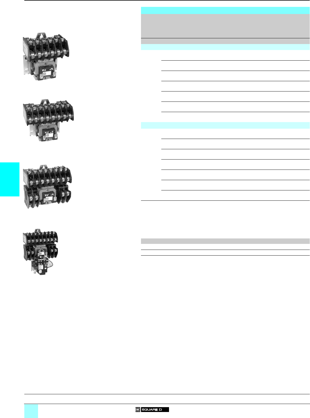
5/4
5
References
0
Lighting Contactors 0
Multipole lighting contactors
Types L and LX Class 8903
Multipole lighting contactors, Types L and LX (4)
Contact
Ampere
ratings
Number
of
poles
Enclosure type (1) Basic reference (2)
Add code
indicating control
circuit voltage (3) and
enclosure type (5)
Weight
Akg (lb)
Electrically held
30 2 Open (“O”), NEMA 1 (“G”),
NEMA 1+ (“F”), NEMA 12 (“A”)
8903 L (2) 20 (3) 1.3 (2.8)
3 Open (“O”), NEMA 1 (“G”),
NEMA 1+ (“F”), NEMA 12 (“A”)
8903 L (2) 30 (3) 1.3 (2.8)
4 Open (“O”), NEMA 1 (“G”),
NEMA 1+ (“F”), NEMA 12 (“A”)
8903 L (2) 40 (3) 1.3 (2.8)
6 Open (“O”), NEMA 1 (“G”),
NEMA 1+ (“F”), NEMA 12 (“A”)
8903 L (2) 60 (3) 1.5 (3.2)
8 Open (“O”), NEMA 1 (“G”),
NEMA 1+ (“F”), NEMA 12 (“A”)
8903 L (2) 80 (3) 1.7 (3.7)
10 Open (“O”), NEMA 1 (“G”),
NEMA 1+ (“F”), NEMA 12 (“A”)
8903 L (2) 1000 (3) 1.9 (4.1)
12 Open (“O”), NEMA 1 (“G”),
NEMA 1+ (“F”), NEMA 12 (“A”)
8903 L (2) 1200 (3) 2 (4.4)
Mechanically held
30 2 Open (“O”), NEMA 1 (“G”),
NEMA 1+ (“F”), NEMA 12 (“A”)
8903 LX (2) 20 (3) 2 (4.4)
3 Open (“O”), NEMA 1 (“G”),
NEMA 1+ (“F”), NEMA 12 (“A”)
8903 LX (2) 30 (3) 2.1 (4.6)
4 Open (“O”), NEMA 1 (“G”),
NEMA 1+ (“F”), NEMA 12 (“A”)
8903 LX (2) 40 (3) 2.1 (4.6)
6 Open (“O”), NEMA 1 (“G”),
NEMA 1+ (“F”), NEMA 12 (“A”)
8903 LX (2) 60 (3) 2.3 (5)
8 Open (“O”), NEMA 1 (“G”),
NEMA 1+ (“F”), NEMA 12 (“A”)
8903 LX (2) 80 (3) 2.4 (5.4)
10 Open (“O”), NEMA 1 (“G”),
NEMA 1+ (“F”), NEMA 12 (“A”)
8903 LX (2) 1000 (3) 2.6 (5.8)
12 Open (“O”), NEMA 1 (“G”),
NEMA 1+ (“F”), NEMA 12 (“A”)
8903 LX (2) 1200 (3) 2.8 (6)
(1) Open: separate enclosures are available for these devices. Delivery time might be improved
by ordering an open-type contactor and a separate Class 9991 enclosure; please consult your
regional sales office.
NEMA 1: general purpose enclosure.
NEMA 1+: flush-mounting, general-purpose enclosure with plaster adjustment.
NEMA 12: dust-tight and drip-tight industrial-use enclosure.
(2) Insert "O" for Open , "G" for NEMA 1, "F" for NEMA 1+, "A" for NEMA 12. Example: 8903 LO 20 V02.
(3) Standard control circuit voltage:
Volts 24 110 120 208 220 240 277 440 480
50 Hz –V02––V03––V06–
60 Hz V01 – V02 V08 – V03 V04 – V06
(4) All lighting contactors are provided with separate control as standard.
(5) Factory conversion of N/O contacts to N/C, order following the example below.
Example: for 2 N/O + 2 N/C (NEMA 1 enclosure) the reference is 8903 LG 22.
There is a maximum of eight N/C poles for Type 8903 L contactors and a maximum of six
N/C poles for Type 8903 LX contactors (field conversion only). Versions are available with up
to 12 N/C poles (factory only).
531217
8903 LO 60
ppp
531218
8903 LO 80
ppp
531220
8903 LO 1200
ppp
531219
8903 LXO 1200
ppp
General, characteristics:
pages 5/2 and 5/3
Dimensions:
pages 5/10 and 5/11
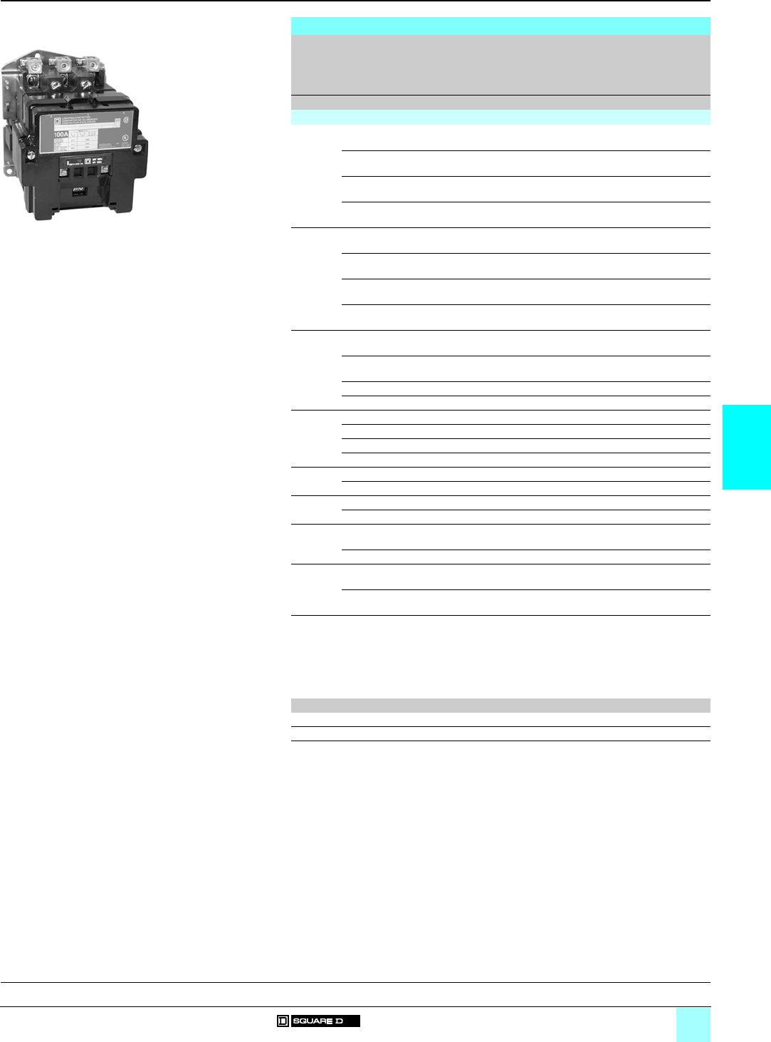
5/5
5
References
0
Lighting Contactors 0
Multipole lighting contactors
Type S Class 8903
Multipole lighting contactors, Type S (4)
Contact
Ampere
ratings
Number
of
poles
Enclosure type (1) Basic reference (2)
Add code
indicating control
circuit voltage (3)
and enclosure type
Weight
Akg (lb)
Electrically held
30 2 Open (“O”), NEMA 1 (“G”),
NEMA 1+ (“F”), NEMA 12 (“A”)
8903 SM (2) 1 (3) 1.4 (3.1)
3 Open (“O”), NEMA 1 (“G”),
NEMA 1+ (“F”), NEMA 12 (“A”)
8903 SM (2) 2 (3) 1.4 (3.1)
4 Open (“O”), NEMA 1 (“G”),
NEMA 1+ (“F”), NEMA 12 (“A”)
8903 SM (2) 3 (3) 1.7 (3.7)
5 Open (“O”), NEMA 1 (“G”),
NEMA 1+ (“F”), NEMA 12 (“A”)
8903 SM (2) 4 (3) 1.7 (3.7)
60 2 Open (“O”), NEMA 1 (“G”),
NEMA 1+ (“F”), NEMA 12 (“A”)
8903 SP (2) 1 (3) 2.4 (5.3)
3 Open (“O”), NEMA 1 (“G”),
NEMA 1+ (“F”), NEMA 12 (“A”)
8903 SP (2) 2 (3) 2.5 (5.5)
4 Open (“O”), NEMA 1 (“G”),
NEMA 1+ (“F”), NEMA 12 (“A”)
8903 SP (2) 3 (3) 3.1 (6.9)
5 Open (“O”), NEMA 1 (“G”),
NEMA 1+ (“F”), NEMA 12 (“A”)
8903 SP (2) 4 (3) 3.3 (7.2)
100 2 Open (“O”), NEMA 1 (“G”),
NEMA 1+ (“F”), NEMA 12 (“A”)
8903 SQ (2) 1 (3) 9.9 (22)
3 Open (“O”), NEMA 1 (“G”),
NEMA 1+ (“F”), NEMA 12 (“A”)
8903 SQ (2) 2 (3) 9.9 (22)
4 Open (“O”), NEMA 1 (“G”), NEMA 12 (“A”) 8903 SQ (2) 3 (3) 15.5 (34)
5 Open (“O”), NEMA 1 (“G”), NEMA 12 (“A”) 8903 SQ (2) 4 (3) 28.4 (63)
200 2 Open (“O”), NEMA 1 (“G”), NEMA 12 (“A”) 8903 SV (2) 1 (3) 14.5 (32)
3 Open (“O”), NEMA 1 (“G”), NEMA 12 (“A”) 8903 SV (2) 2 (3) 14.5 (32)
4 Open (“O”), NEMA 1 (“G”), NEMA 12 (“A”) 8903 SV (2) 3 (3) 29.4 (65)
5 Open (“O”), NEMA 1 (“G”), NEMA 12 (“A”) 8903 SV (2) 4 (3) 29.4 (65)
300 2 Open (“O”), NEMA 1 (“G”), NEMA 12 (“A”) 8903 SX (2) 1 (3) 23.6 (52)
3 Open (“O”), NEMA 1 (“G”), NEMA 12 (“A”) 8903 SX (2) 2 (3) 31.3 (69)
400 2 Open (“O”), NEMA 1 (“G”), NEMA 12 (“A”) 8903 SY (2) 1 (3) 43.5 (96)
3 Open (“O”), NEMA 1 (“G”), NEMA 12 (“A”) 8903 SY (2) 2 (3) 45 (99)
600 2 Open (“O”), NEMA 1 (“G”), NEMA 12 (“A”) 8903 SZ (2) 1 (3) 61.2
(135)
3 Open (“O”), NEMA 1 (“G”), NEMA 12 (“A”) 8903 SZ (2) 2 (3) 63 (139)
800 2 Open (“O”), NEMA 1 (“G”), NEMA 12 (“A”) 8903 SJ (2) 1 (3) 85.2
(188)
3 Open (“O”), NEMA 1 (“G”), NEMA 12 (“A”) 8903 SJ (2) 2 (3) 87.9
(193)
(1) Open: separate enclosures are available for 30, 60 and 100 A devices.
NEMA 1: general purpose enclosure.
NEMA 1+: flush-mounting, general-purpose enclosure with plaster adjustment.
NEMA 12: dust-tight and drip-tight industrial-use enclosure.
(2) Insert "O" for Open , "G" for NEMA 1, "F" for NEMA 1+, "A" for NEMA 12.
Example: 8903 SMO 1 V02.
(3) Standard control circuit voltage:
Volts 24 110 120 208 220 240 277 440 480
50 Hz – V02 – – V03 – – V06 –
60 Hz V01 – V02 V08 – V03 V04 – V06
(4) All lighting contactors are provided with separate control as standard, except electrically held
400, 600 and 800 A devices. Electrically held 400, 600 and 800 A devices are provided with
common control.
531223_1
8903 SQO
1
ppp
General, characteristics:
pages 5/2 and 5/3
Dimensions:
pages 5/10 and 5/11
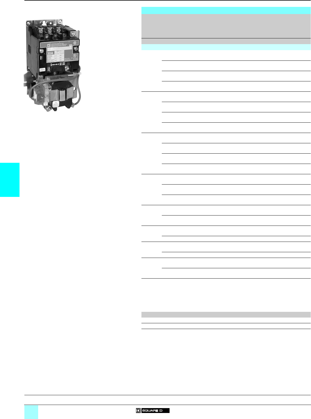
5/6
5
References (continued)
0
Lighting Contactors 0
Multipole lighting contactors
Type S, Class 8903
Multipole lighting contactors, Type S (continued) (4)
Contact
Ampere
ratings
Number
of
poles
Enclosure type (1) Basic reference (2)
Add code
indicating control
circuit voltage (3)
and enclosure type
Weight
Akg (lb)
Mechanically held
30 2 Open (“O”), NEMA 1 (“G”),
NEMA 1+ (“F”), NEMA 12 (“A”)
8903 SM (2) 10 (3) 2.9 (6.5)
3 Open (“O”), NEMA 1 (“G”),
NEMA 1+ (“F”), NEMA 12 (“A”)
8903 SM (2) 11 (3) 2.7 (5.9)
4 Open (“O”), NEMA 1 (“G”),
NEMA 1+ (“F”), NEMA 12 (“A”)
8903 SM (2) 12 (3) 3 (6.8)
5 Open (“O”), NEMA 1 (“G”),
NEMA 1+ (“F”), NEMA 12 (“A”)
8903 SM (2) 13 (3) 3.8 (8.3)
60 2 Open (“O”), NEMA 1 (“G”),
NEMA 1+ (“F”), NEMA 12 (“A”)
8903 SP (2) 10 (3) 3.9 (8.6)
3 Open (“O”), NEMA 1 (“G”),
NEMA 1+ (“F”), NEMA 12 (“A”)
8903 SP (2) 11 (3) 4 (8.8)
4 Open (“O”), NEMA 1 (“G”),
NEMA 1+ (“F”), NEMA 12 (“A”)
8903 SP (2) 12 (3) 5.3
(11.7)
5 Open (“O”), NEMA 1 (“G”),
NEMA 1+ (“F”), NEMA 12 (“A”)
8903 SP (2) 13 (3) 5.3
(11.7)
100 2 Open (“O”), NEMA 1 (“G”),
NEMA 1+ (“F”), NEMA 12 (“A”)
8903 SQ (2) 10 (3) 8 (18)
3 Open (“O”), NEMA 1 (“G”),
NEMA 1+ (“F”), NEMA 12 (“A”)
8903 SQ (2) 11 (3) 8.4
(18.6)
4 Open (“O”), NEMA 1 (“G”), NEMA 12 (“A”) 8903 SQ (2) 12 (3) 9.6
(21.1)
5 Open (“O”), NEMA 1 (“G”), NEMA 12 (“A”) 8903 SQ (2) 13 (3) 9.6
(21.1)
200 2 Open (“O”), NEMA 1 (“G”), NEMA 12 (“A”) 8903 SV (2) 10 (3) 19,9
(43,8)
3 Open (“O”), NEMA 1 (“G”), NEMA 12 (“A”) 8903 SV (2) 11 (3) 20.5
(45.4)
4 Open (“O”), NEMA 1 (“G”), NEMA 12 (“A”) 8903 SV (2) 12 (3) 28.5
(62.9)
300 2 Open (“O”), NEMA 1 (“G”), NEMA 12 (“A”) 8903 SX (2) 13 (3) 31.2
(68.9)
3 Open (“O”), NEMA 1 (“G”), NEMA 12 (“A”) 8903 SX (2) 14 (3) 31.2
(68.9)
400 2 Open (“O”), NEMA 1 (“G”), NEMA 12 (“A”) 8903 SY (2) 16 (3) 38.7
(85.4)
3 Open (“O”), NEMA 1 (“G”), NEMA 12 (“A”) 8903 SY (2) 17 (3) 39 (86.2)
600 2 Open (“O”), NEMA 1 (“G”), NEMA 12 (“A”) 8903 SZ (2) 18 (3) 61.2
(135)
3 Open (“O”), NEMA 1 (“G”), NEMA 12 (“A”) 8903 SZ (2) 19 (3) 63 (139)
800 2 Open (“O”), NEMA 1 (“G”), NEMA 12 (“A”) 8903 SJ (2) 10 (3) 85
(187.6)
3 Open (“O”), NEMA 1 (“G”), NEMA 12 (“A”) 8903 SJ (2) 11 (3) 87.9
(194)
(1) Open: separate enclosures are available for 30, 60 and 100 A devices.
NEMA 1: general purpose enclosure.
NEMA 1+: flush-mounting, general-purpose enclosure with plaster adjustment.
NEMA 12: dust-tight and drip-tight industrial-use enclosure.
(2) Insert: "O" for Open , "G" for NEMA 1, "F" for NEMA 1+, "A" for NEMA 12.
Example: 8903 SMO 10 V02.
(3) Standard control circuit voltage:
Volts 24 110 120 208 220 240 277 440 480
50 Hz – V02 – – V03 – – V06 –
60 Hz V01 – V02 V08 – V03 V04 – V06
(4) All lighting contactors are provided with separate control as standard, except electrically held
400, 600 and 800 A devices. Electrically held 400, 600 and 800 A devices are provided with
common control.
531224_1
8903 SMO 10
ppp
General, characteristics:
pages 5/2 and 5/3
Dimensions:
pages 5/10 and 5/11
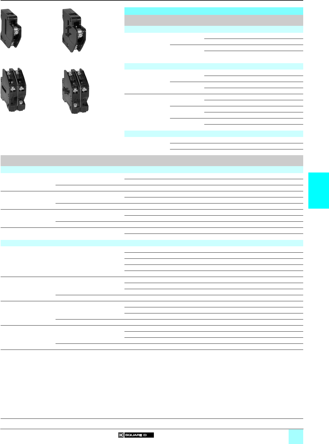
5/7
5
References
0
Lighting Contactors 0
Multipole lighting contactors
Types L, LX and S Class 8903
Accessories
Kits
Type Kit description For use on Reference Weight
kg (lb)
Power-pole adder kits
Power-pole adder kits
(used to add 30 A
power poles to existing
contactors when
additional circuits are
required)
Single pole 8903 LO 60/80 8903 L1L –
8903 LXO 60/80 8903 L1R –
Double pole 8903 LO 80/1000 (1) 8903 L3L –
8903 LXO 80/1000 (1) 8903 L3R –
Single-pole and double-pole kits
Single-pole kits
(2)
1 N/O 8903 SMp9999 SB6 –
8903 SPp (3) 9999 SB21 –
1 N/C 8903 SMp9999 SB7 –
8903 SPp (3) 9999 SB22 –
Double-pole kits
(2)
1 N/O and 1 N/C 8903 SMp9999 SB8 –
8903 SPp (3) 9999 SB23 –
2 N/O 8903 SMp9999 SB9 –
8903 SPp (3) 9999 SB24 –
2 N/C 8903 SMp9999 SB10 –
8903 SPp (3) 9999 SB25 –
8903 L1L
531225
8903 L1R
531226
8903 L3L
531227
8903 L3R
531228
Solid neutral terminal block kits
Solid neutral terminal
block kits
30/60/100 A 8903 L/LX/SM/SP/SQ 9999 SN1 –
200/300 A 8903 SV/SX 9999 SN2 –
400/600/800 A 8903 SY/SZ/SJ 9999 SN3 –
Type Kit description For use on Reference Weight
kg (lb)
Mechanically held
Push button (On-Off) NEMA 1 enclosure 8903 Lp/LXp9999 BLX + 9999 LXPB –
8903 SPp/SQp/SVp/SXp/SYp/SZp/SJp9001 KA2 + 9999 SA3 (4) –
NEMA 12 enclosure 8903 Lp/LXp/SMp/SPp/SQp/SVp/SXp/SYp/SZp/SJp9001 KA2 + 9999 SA3 (4) –
Selector switch
(2-position)
NEMA 1 enclosure 8903 Lp/LXp9999 BLX + 9999 LXS –
8903 SMp/SPp/SQp/SVp/SXp/SYp/SZp/SJp9001 KN244 + 9001 KS11BH1 –
NEMA 12 enclosure 8903 Lp/LXp/SMp/SPp/SQp/SVp/SXp/SYp/SZp/SJp9001 KN244 + 9001 KS11BH1 –
Selector switch
(3-position)
NEMA 1 enclosure
(must include two-wire control relay)
8903 Lp/LXp9999 BLX + 9999 SC2 –
8903 SMp/SPp/SQp/SVp/SXp/SYp/SZp/SJp9001 KN260 + 9001 KS46BH2 –
NEMA 12 enclosure 8903 Lp/LXp/SMp/SPp/SQp/SVp/SXp/SYp/SZp/SJp9001 KN260 + 9001 KS46BH2 –
Two-wire control relay
Suffix R6 (5)
– 8903 Lp/LXp9999 RLX + CA2SK11 –
8903 SMp/SPp/SQp/SVp/SXp/SYp/SZp/SJp8501 X011 –
Electrically held
Pilot lights (red) NEMA 1 and NEMA 12 enclosures 8903 Lp/LXp9999 SP28R –
8903 SMp9999 SP2R + 9999 SP28R –
8903 SPp9999 SP3R + 9999 SP28R –
8903 SQp9999 SP14R + 9999 SP28R (6) –
8903 SVp/SXp/SYp/SZp/SJp9999 SP28R + 9999 SP28R (7) –
Push buttons (8) NEMA 1 enclosure 8903 Lp/LXp9999 BLX + 9999 SA10 –
8903 SMp/SPp9999 SA10 –
8903 SQp/SVp/SXp/SYp/SZp/SJp9999 SA3 –
NEMA 12 enclosure 8903 Lp/LXp/SMp/SPp/SQp/SVp/SXp/SYp/SZp/SJp9999 SA3 –
Selector switch
(2-position)
NEMA 1 enclosure 8903 Lp/LXp9999 BLX + 9999 SC22 –
8903 SMp/SPp/SQp9999 SC22 –
8903 SVp/SXp/SYp/SZp/SJp9001 KN244 + 9001 KS11BH1 –
NEMA 12 enclosure 8903 Lp/LXp/SMp/SPp/SQp/SVp/SXp/SYp/SZp/SJp9001 KN244 + 9001 KS11BH1 –
Selector switch
(3-position)
NEMA 1 enclosure 8903 Lp/LXp9999 BLX + 9999 SC2 –
8903 SMp/SPp/SQp9999 SC2 –
8903 SVp/SXp/SYp/SZp/SJp9999 SC8 –
NEMA 12 enclosure 8903 Lp/LXp/SMp/SPp/SQp/SVp/SXp/SYp/SZp/SJp9999 SC8 –
(1) Single-pole power pole must be removed before double-pole power pole can be installed.
(2) A single-pole or double-pole kit can be added to any 2- or 3-pole, 30 or 60 A Type S lighting contactor to make a 4- or 5-pole device. Factory assembled 4- and
5-pole contactors use the basic 3-pole device with a single- or double-pole kit installed. Only one power pole can be added per contactor. Sufficient room is
provided in all enclosure styles for the addition of the power pole kit.
(3) When power pole is added to a 60 A contactor (8903 SP
p
), a 4-pole coil is also required. 60 A power poles are suitable for use with copper or aluminium wire.
(4) Mechanically held contactors need two distinct signals to operate. It is necessary to add a N/O contact block to the Class 9999 Type SA3 push button kit.
(5) Form R6 available for 24 V, 120 V, 240 V and 277 V only.
(6) Choice for 2- or 3-pole only; for 4- or 5-pole, use Class 9999 SP15R.
(7) The coil voltage must be the same as the pilot light rating. Kit contains one Class 9001 KP1R6 (120 V / 60 Hz) red pilot light control unit. For other voltages, refer
to the Class 9001 KP control section of the Digest.
(8) Requires holding circuit interlock or additional power pole on Type L devices.
General, characteristics:
pages 5/2 and 5/3
Dimensions:
pages 5/10 and 5/11
5/8
5
References
0
Lighting Contactors 0
Multipole lighting contactors
Types L, LX and S Class 8903
Variants
Variants
Type Enclosure
type
For use on Description Suffix to the lighting
contactor reference (1)
Weight
kg (lb)
"ON-OFF" push button NEMA 1, Mechanically held Pulsed contact A3 –
NEMA 12
"ON-OFF" push button Any Electrically held With holding circuit interlock A12 –
"HAND-OFF-AUTO" selector switch NEMA 1, Electrically held, (2) C–
NEMA 12 Mechanically held
"ON-OFF" selector switch NEMA 1, Electrically held, (2) C6 –
NEMA 12 Mechanically held
Control circuit fuses Any Electrically held, 1 fuse F–
Mechanically held 2 fuses F4 –
Control circuit transformers
standard capacity (50/60 Hz) (3)
NEMA 1, Electrically held, Fuses: 2 (primary), 0 (secondary) F4T –
NEMA 12 Mechanically held Fuses: 2 (primary), 1 (secondary) FF4T –
Additional capacity
(50/60 Hz) Two fuses in primary and
one fuse in secondary (3)
NEMA 1, Electrically held, 100 VA additional capacity FF4T11 –
NEMA 12 Mechanically held 200 VA additional capacity FF4T12 –
300 VA additional capacity FF4T13 –
Noise-reduced enclosure and shock-
mounted panel
Any Electrically held – G4 –
Addition of photoelectric receptacle NEMA 1, Electrically held – G10 –
NEMA 12 With photo-cell installed G101 –
Mechanically held And relay R6 (4) G10R6 –
With photo-cell installed (4) G101R6 –
Addition of terminal blocks
(other than standard) (5)
Any Electrically held, Wired G56pp –
Mechanically held Unwired G50pp –
Bracketing for internally mounted pilot
device
Any Electrically held, – G53 –
Mechanically held
Addition of time clock NEMA 1, Electrically held, 24 hour (120–127 V only) K14 –
NEMA 12 Mechanically held 24 hour w/day omission (120–127 V only) K141 –
7 day (120–127 V only) K142 –
Addition of solid neutral terminal block NEMA 1, Electrically held, – N–
NEMA 12 Mechanically held
(1) Example: 8903 LXG 20 V02 A3.
(2) To substitute a key operated selector switch, use suffix "C33" and specify positions, legend marking and key removal. This suffix must be used with another
selector switch suffix.
(3) Control circuit transformer selection table:
Primary-secondary 120-24 208-120 240-24 240-120 277-120 480-24 480-120 480-240 600-120
60 Hz V89 V84 V82 V80 V85 V83 V81 V87 V86
(4) Available for 24 V, 120 V, 240 V and 277 V applications only.
(5) At the end of suffix,
pp
represents the number of terminals needed.
General, characteristics:
pages 5/2 and 5/3
Dimensions:
pages 5/10 and 5/11
5/9
5
References (continued)
0
Lighting Contactors 0
Multipole lighting contactors
Types L, LX and S Class 8903
Variants
Variants (continued)
Type Enclosure
type
For use on Description Suffix to the lighting
contactor reference (1)
Weight
kg (lb)
Red pilot light Any Electrically held, – P1 –
Mechanically held
Two or more lights (each) (2) Any Electrically held, – P–
Mechanically held
Red push-to-test pilot light Any Electrically held, – P21 –
Mechanically held
Interlock Any Electrically held, Necessary for pilot light, one needed for (3) –
Mechanically held each additional pilot light
Two-wire interfaces Any Mechanically held (4) R6 –
Addition of under- and overvoltage relay Any Electrically held, – R44 –
Mechanically held
Three-wire control for long distance
applications
Any Mechanically held (4) R62 –
Auxiliary contacts (5) Any Electrically held, 0 N/O + 1 N/C X01 –
Mechanically held 0 N/O + 2 N/C X02 –
0 N/O + 3 N/C X03 –
0 N/O + 4 N/C X04 –
1 N/O + 0 N/C X10 –
1 N/O + 1 N/C X11 –
1 N/O + 2 N/C X12 –
1 N/O + 3 N/C X13 –
2 N/O + 0 N/C X20 –
2 N/O + 1 N/C X21 –
2 N/O + 2 N/C X22 –
3 N/O + 0 N/C X30 –
3 N/O + 1 N/C X31 –
4 N/O + 0 N/C X40 –
Addition of DC coil to Type L
(7 poles maximum)
Any Electrically held – Y48 –
Coil transient suppressor
(a 120 V only)
Any Electrically held, – Y145 –
Mechanically held
Addition of lightning arrestor Any Electrically held, – Y1532 –
Mechanically held
Substitute copper only lugs for standard Any Electrically held, – Y157 –
Mechanically held
Substitute Anderson VC crimp style lugs
for standard (per lug adder), specify lug
Any Electrically held, – Y1574 –
Mechanically held
(1) Example: 8903 LXG 20 V02 P1.
(2) For electrically held enclosed devices, the first pilot light is wired in parallel with the coil. Operating interlocks are required for all additional pilot lights.
Mechanically held devices require operating interlocks for all pilot lights.
(3) Do not use suffix "X" for any interlock which is wired in series with pilot light, but do specify how pilot light and interlock are to be wired into the circuit.
(4) Available for 24 V, 120 V, 240 V and 277 V applications only.
(5) Electrically held (Type L) multipole contactors cannot add interlocks. Additional poles can be used for the same function, however. Mechanically held (Type LX)
contactors provide one double-throw auxiliary (or status) contact as standard.
Maximum number of external auxiliary units:
Contactor Maximum number
8903 SM/SP 4 N/O or 4 N/C
3 N/O or N/C plus 1 attached timer (on- or off-delay)
2 N/O or N/C plus 1 power-pole adder (single- or 2-pole, N/O or N/C)
1 attached timer plus 1 power-pole adder (single- or 2-pole, N/O or N/C) plus auxiliary contact
8903 SQ/SV/SY 4 N/O or N/C
(Size 3 and Size 4) 2 N/O or N/C plus 1 attached timer (on- or off-delay)
8903 SQ/SV/SY 3 N/O or N/C plus 1 attached timer (on- or off-delay)
(Size 5) 2 N/O or N/C plus 1 NEMA Size 0–1 or Size 2 power-pole adder (single- or 2-pole, N/O or N/C)
8903 SZ/SJ 4 N/O or N/C
3 N/O or N/C plus 1 attached timer (on- or off-delay)
2 N/O or N/C plus 1 NEMA Size 0–1 or Size 2 power-pole adder (single- or 2-pole, N/O or N/C)
General, characteristics:
pages 5/2 and 5/3
Dimensions:
pages 5/10 and 5/11
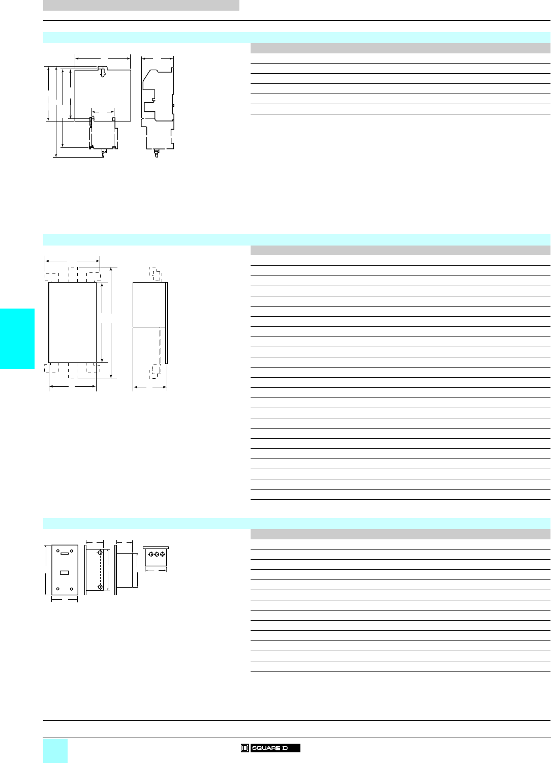
5/10
5
Dimensions
0
Lighting Contactors 0
Multipole lighting contactors
Types L, LX and S Class 8903
Dimensions in mm (25.4 mm = 1 inch)
8903 LO/LXO
ABCDEF
8903 LO 20/30/40 73 127 117 – 79 –
8903 LO 60 108 127 117 – 79 –
8903 LO 80/1000/1200 143 127 117 – 79 –
8903 LXO 20/30/40 73 – – 224 83 196
8903 LXO 60 108 – – 224 83 196
8903 LXO 80/1000/1200 143 – – 224 83 196
8903 SpO
ABCDE
8903 SMO 1/2 110 82 107 – –
8903 SMO 3/4 110 108 107 – –
8903 SPO 1/2 135 110 125 – –
8903 SPO 3/4 158 143 125 – –
8903 SQO 1/2 180 139 165 – –
8903 SQO 3/4 199 248 165 – –
8903 SVO 1/2 232 152 165 – –
8903 SVO 3/4 232 248 165 – –
8903 SXO 1/2 313 220 222 – –
8903 SYO 1/2 – 313 229 – 706
8903 SZO 1/2 – 313 229 – 706
8903 SJO 1/2 – 313 303 – 1085
8903 SMO 10/11 182 96 119 – –
8903 SMO 12/13 182 116 119 – –
8903 SPO 10/11 210 117 133 – –
8903 SPO 12/13 221 150 133 – –
8903 SQO 10/11 257 151 171 – –
8903 SQO 12/13 268 248 171 – –
8903 SVO 10/11 293 152 171 – –
8903 SVO 12 293 248 171 – –
8903 SXO 13/14 313 220 267 – –
8903 SYO 16/17 – 220 267 – 533
8903 SZO 18/19 – 220 267 – 533
8903 SJO 10/11 – 220 303 – 898
8903 LF/LXF/SpF
Class/Type Variants ABCDEF G
8903 LF F/R6/Y48 386 227 194 327 138 278 130
8903 LXF F/R6/Y48 386 227 194 327 138 278 130
8903 LF A3/A12/C/C6/P 610 445 381 489 181 – –
8903 LXF A3/A12/C/C6/P 610 445 381 489 181 – –
8903 SMF A12/C/C6/P/X 341 183 149 283 121 233 114
8903 SMF 1 X 341 183 149 283 121 233 114
8903 SMF 1/2/3/4 N 610 445 381 489 146 – –
8903 SMF 1 A3/C/C6/N/P/R6 610 445 381 489 146 – –
8903 SPF 1/2/3/4 A12/C/C6/P/X 386 227 194 327 138 278 130
8903 SPF 1 X 386 227 194 327 138 278 130
8903 SPF 1/2/3/4 N 610 445 381 489 146 – –
8903 SPF 1 A3/C/C6/N/P/R6 610 445 381 489 146 – –
8903 SQF – 787 425 362 667 203 – –
E
A
D
F
C
2.25
57
B
Mtg
Mtg
Mtg
D
C
B
AE
A
B
EG
DFC
Enclosure Saddle
General, characteristics:
pages 5/2 and 5/3
References:
pages 5/4 to 5/9
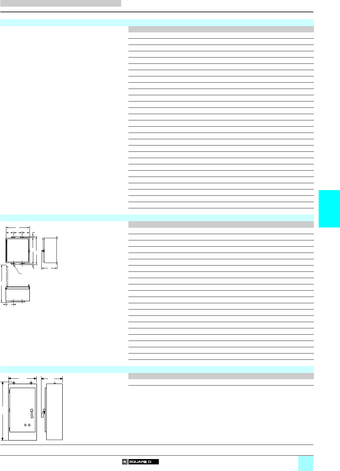
5/11
5
Dimensions (continued)
0
Lighting Contactors 0
Multipole lighting contactors
Types L, LX and S Class 8903
Dimensions in mm (25.4 mm = 1 inch)
8903 LG/LXG/SpG
Class/Type Variants Width Height Depth
8903 LG A3/A12/C/C6/F/R6/Y48 198 322 153
8903 LXG A3/A12/C/C6/F/R6/Y48 198 322 153
8903 LG P 302 302 189
8903 LXG P 302 302 189
8903 LG K14/K141/K142 406 559 181
8903 LXG K14/K141/K142 406 559 181
8903 SMG 1/2/3/4 A12/C/C6/P/X 152 254 134
8903 SMG 1 X 152 254 134
8903 SMG 1/2/3/4 N 378 359 192
8903 SMG 1 N/R6 378 359 192
8903 SMG 1 A3/C/C6/P 206 359 247
8903 SPG 1/2/3/4 A12/C/C6/P/X 198 322 153
8903 SPG N/R6 378 359 192
8903 SPG 1 A3/C/C6/P/X 206 359 247
8903 SQG 1/2 A12/C/C6/F/P/X 286 639 288
8903 SQG 10/11 F/X 286 639 288
8903 SQG 1/2 N/R6/Kppp 461 740 234
8903 SQG 10/11 A3/C/C6/N/R6/Kppp 461 740 234
8903 SQG 3/4 A12/C/C6/F/P/X 286 639 288
8903 SQG 12/13 F/X 286 639 288
8903 SQG 3/4 Kppp 461 740 234
8903 SQG 12/13 A3/C/C6 461 740 234
8903 SQG 3/4 N/R6 563 994 260
8903 SQG 12/13 N/R6 563 994 260
8903 SVG – 563 994 260
8903 SXG – 437 1123 325
8903 SYG – 513 1670 333
8903 SZG – 513 1670 333
8903 SJG – 876 2362 597
8903 LA/LXA/SpA
Class/Type Variants A B C D E F G H I J
8903 LA F/R6/Y48 206 216 400 40 127 381 8 54 375 8
8903 LXA F/R6/Y48 206 216 400 40 127 381 8 54 375 8
8903 LA A3/A12/C/C6/P 302 197 343 97 108 324 10 125 460 8
8903 LXA A3/A12/C/C6/P 302 197 343 97 108 324 10 125 460 8
8903 SMA 1/2/3/4 A12/C/C6/P/X 162 217 324 40 83 305 10 90 318 8
8903 SMA 1 F/P/X 162 217 324 40 83 305 10 90 318 8
8903 SMA 1/2/3/4 N/R6 378 200 406 65 248 381 13 93 540 8
8903 SMA 1 A3/C/C6/N/P/R6 378 200 406 65 248 381 13 93 540 8
8903 SPA 1/2/3/4 A12/C/C6/P/X 206 236 406 40 127 381 13 93 391 8
8903 SPA 1 A3/C/C6/P/X 206 236 406 40 127 381 13 93 391 8
8903 SPA 1/2/3/4 N/R6 378 200 400 65 248 381 10 93 540 8
8903 SPA 1 A3/C/C6/N/P/R6 378 200 400 65 248 381 10 93 540 8
8903 SQA 1/2 A12/C/C6/F/N/R6/P/X 461 234 800 78 305 775 13 93 678 11
8903 SQA 10/11 A3/C/C6/F/N/P/R6/X 461 234 800 78 305 775 13 93 678 11
8903 SQA 3/4 A12/C/C6/F/N/P/Kppp 461 234 800 78 305 775 13 93 678 11
8903 SQA 12/13 A3/C/C6/P/Kppp 461 234 800 78 305 775 13 93 678 11
8903 SQA 3/4 N/R6/Kppp 563 260 1054 78 406 1029 13 93 805 11
8903 SQA 12/13 N/R6/Kppp 563 260 1054 78 406 1029 13 93 805 11
8903 SVA – 563 260 1054 78 406 1029 15 93 805 11
8903 SXA – 437 339 1193 104 229 1168 13 117 719 14
8903 SYA – 513 330 1651 104 305 1625 13 135 784 18
8903 SZA – 513 330 1651 104 305 1625 13 135 784 18
8903 SJA
A B C
8903 SJA 2362 876 597
A
DE D G
FC
G
I
H
B
J
(1)
(
1) 4 diameter mounting holes
BC
A
General, characteristics:
pages 5/2 and 5/3
References:
pages 5/4 to 5/9

6/0

6/1
Contents
6
6 - Manual Starters and Switches
bManual starters and switches
vGeneral . . . . . . . . . . . . . . . . . . . . . . . . . . . . . . . . . . . . . . . . . . . . . . . . page 6/2
vCharacteristics . . . . . . . . . . . . . . . . . . . . . . . . . . . . . . . . . . . . . . . . . . . page 6/3
bSingle units Type F
vReferences . . . . . . . . . . . . . . . . . . . . . . . . . . . . . . . . . . . . . . . . . . . . . page 6/4
bDuplex units Type F
vReferences . . . . . . . . . . . . . . . . . . . . . . . . . . . . . . . . . . . . . . . . . . . . . page 6/5
bNon-reversing Type K
vReferences . . . . . . . . . . . . . . . . . . . . . . . . . . . . . . . . . . . . . . . . . . . . . page 6/6
bIntegral motor power non-reversing Types T and M
vReferences . . . . . . . . . . . . . . . . . . . . . . . . . . . . . . . . . . . . . . . . . . . . . page 6/8
bReversing drum switches
vReferences . . . . . . . . . . . . . . . . . . . . . . . . . . . . . . . . . . . . . . . . . . . . . page 6/9
bManual starters and switches
vAccessories . . . . . . . . . . . . . . . . . . . . . . . . . . . . . . . . . . . . . . . . . . . . . page 6/9
vDimensions . . . . . . . . . . . . . . . . . . . . . . . . . . . . . . . . . . . . . . . . . . . . page 6/10
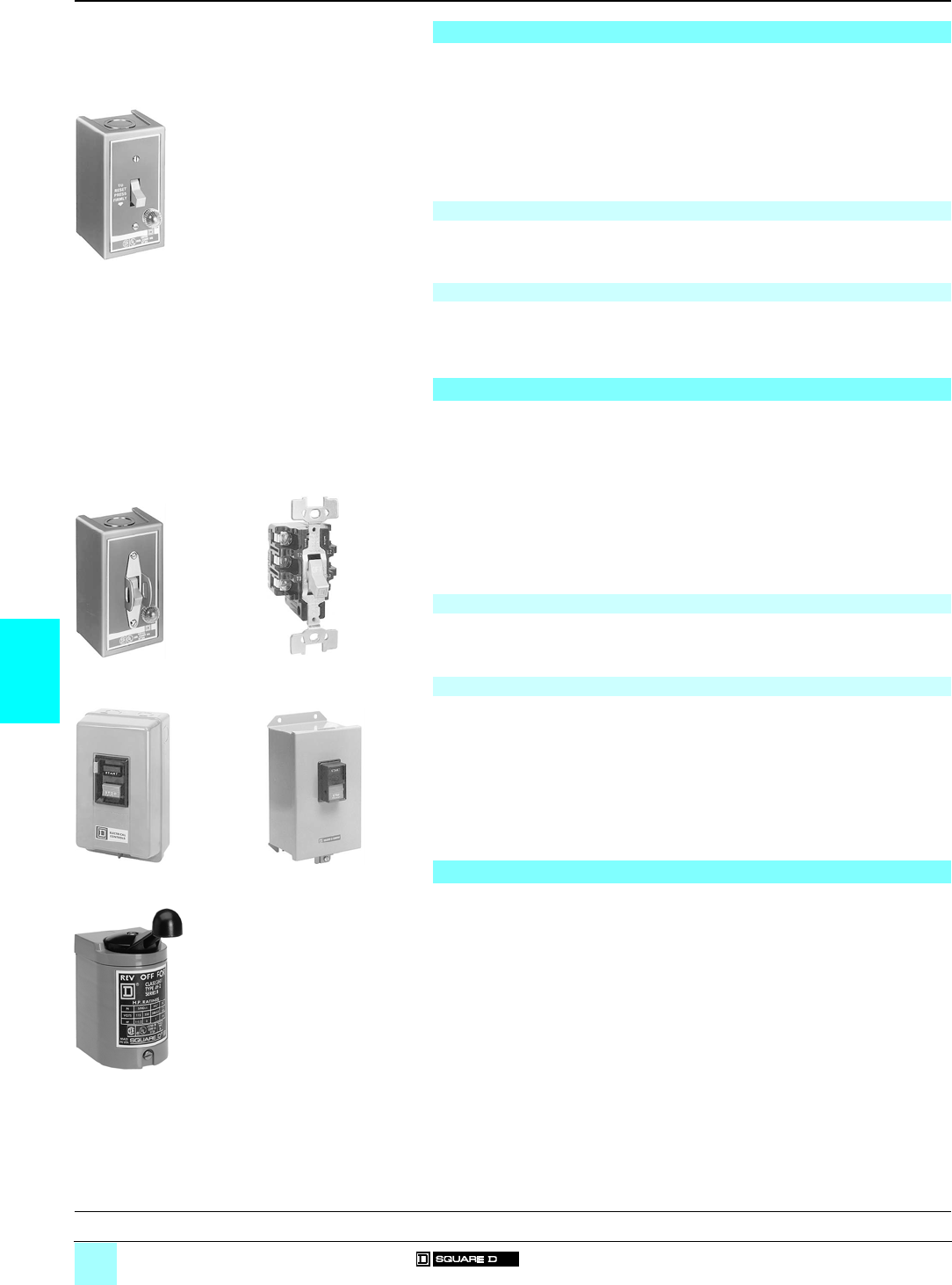
6/2
6
General
0
Manual Starters and Switches 0
Manual starters Class 2510
Manual switches Class 2510
Reversing drum switches Class 2601
Type F fractional motor power starters provide overload protection as well as manual
"On-Off" control for small motors in a variety of industrial and commercial installations.
Typical applications include fans, conveyors, pumps and small machine tools.
They are available in single- or 2-pole versions. Both single- and 2-pole versions are
suitable for use with single-phase a motors rated up to 1 hp. 2-pole starters may
also be used with c motors rated up to 0.75 hp.
Note: Manual starters include motor overload protection. After tripping, the overload
relay must be reset before the motor can restart.
bBasic starters.
bStarters with handle guard/lock-off.
bOne starter in duplex enclosure.
bTwo starters in one enclosure.
bStarters and "AUTO-OFF-HAND" selector switch.
Type K motor-starting switches provide manual "On-Off" control of single- or 3-phase
a motors, where overload protection is not required or is provided separately. These
devices are suitable for use with 3-phase a motors rated up to 20 hp. Compact
construction and a 600 V rating make these switches suitable for a wide range of
industrial and commercial uses. Typical applications include small machine tools,
pumps, fans, conveyors and many other types of electrical machinery. They may
also be used on non-motor loads such as resistance heaters.
Note: Manual switches do not include motor overload or low-voltage protection.
Should the power fail, the contacts will remain closed, and upon re-energization, the
motor will restart immediately.
bWith toggle operator.
bWith removable key.
Types T and M integral motor power manual starters provide convenient "On-Off"
operation of small single-phase, 3-phase or c motors. Typical applications include
small machine tools, pumps, fans and conveyors. They feature toggle or push button
operators and reliable overload protection. Pilot lights and auxiliary contacts are
available.
bToggle (T) or push button (M) operators.
bReliable overload protection.
bPilot light and auxiliary contact available.
Reversing drum switches are designed to start and reverse motors by connecting
them directly across-the-line. The devices may be used with squirrel-cage motors;
single-phase a motors designed for reversing service; and series, shunt and
compound c motors. The applications should be such that across-the-line starting
of the motors is not objectionable, unless other means is provided for limiting starting
current and torque. Class 2601 drum switches are field convertible from maintained
to pulsed operation.
The reversing drum switches are suited to manual reversing control applications,
such as machine tools, woodworking machines and similar types of equipment.
Examples include lathes, milling machines, planers, grinders, shapers and boring mills.
Other possible applications include door operators, small hoists and conveyor belts.
Note: Reversing drum switches do not include motor overload or low-voltage
protection. Should the power fail, the contacts will remain closed, and upon re-
energization, the motor will restart immediately; however, if the drum switch is
assembled for pulsed operation, the handle will stay in the selected position, and the
handle position will determine the motor state.
Manual starters Class 2510
Single units Type F
Duplex units Type F
Manual switches Class 2510
Non-reversing Type K
Integral Horsepower non-reversing Types T and M
Reversing drum switches Class 2601
531176
2510 FG 2P
531177
2510 KG 1A
531178
2510 KO 2
531179
2510 TBG 1
531180
2510 MBA 1
531181
2601 AG2
References:
pages 6/4 to 6/9
Dimensions:
pages 6/10 and 6/11
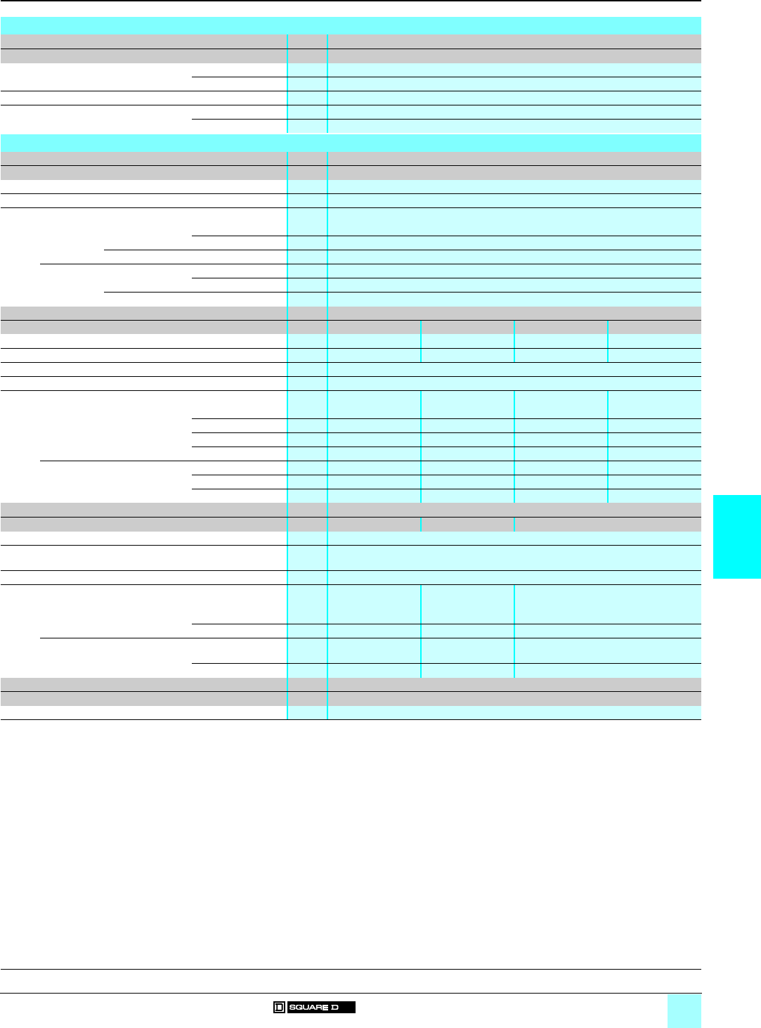
6/3
6
Characteristics
0
Manual Starters and Switches 0
Manual starters Class 2510
Manual switches Class 2510
Reversing drum switches Class 2601
Environment
Class 2510/2601
Type F/K/T/M
Conforming to standards Enclosed unit UL
Open unit UL
Product certifications CSA
Ambient air temperature around the
device
Storage °C 0…+ 40
Operation °C 0…+ 40
Electrical characteristics
Class 2510
Type F
Voltage rating Va 277 maximum (single- or 2-pole); c 230 maximum (2-pole only)
Continuous current rating A16
Maximum Horsepower
115–230 V a Single-phase Single-pole hp/kW 1/0.75
2-pole hp/kW 1/0.75
c2-pole only hp/kW 0.75/0.55
277 V a Single-phase Single-pole hp/kW 1/0.75
2-pole hp/kW 1/0.75
c2-pole only hp/kW –
Class 2510
Type Kpp1/Kpp3 Kpp2/Kpp4 Kpp5 Kpp6
Number of poles 2 3 2 3
Number of phases Single phase Three phase Single phase Three phase
Voltage rating Va 600 maximum; c 230 maximum
Continuous current rating A30 at 600 V maximum
Maximum motor power
a rating 115 V hp/kW 2/1.5 2/1.5 2/1.5 2/1.5
230 V hp/kW 2/1.5 7.5/5.6 3/2.2 7.5/5.6
460 V hp/kW 3/2.2 10/7.5 7.5/5.6 15/11.2
575 V hp/kW 3/2.2 10/7.5 10/7.5 20/14.9
c rating 90 V hp/kW 1/0.75 1/0.75 1/0.75 1/0.75
115 V hp/kW 2/1.5 2/1.5 2/1.5 2/1.5
230 V hp/kW 1.5/1.1 1.5/1.1 1.5/1.1 1.5/1.1
Class 2510
Type TBp p/MBp pTCp p/MCp pMCp 2
Size Available in NEMA Sizes M-0, M-1 and M-1P
Number of poles a : 2-pole single-phase; 3-pole 3-phase
c : 2-pole (without low voltage protection only)
Voltage rating Va 600 maximum; c 250 maximum
Terminals
Power terminals Type of lug Screw clamp
terminal
Screw clamp
terminal
Box lug
Wire Size (min.-max.) #14–#8 #14–#8 #14–#6
Auxiliary interlock terminals Type of lug Screw clamp
terminal
Screw clamp
terminal
Screw clamp terminal
Wire Size (min.-max.) #16–#12 #16–#12 #16–#12
Class 2601
Type AG2/AG2 S2/BG1/BG1 S4
Voltage rating Va 600 maximum; c 250 maximum
References:
pages 6/4 to 6/9
Dimensions:
pages 6/10 and 6/11
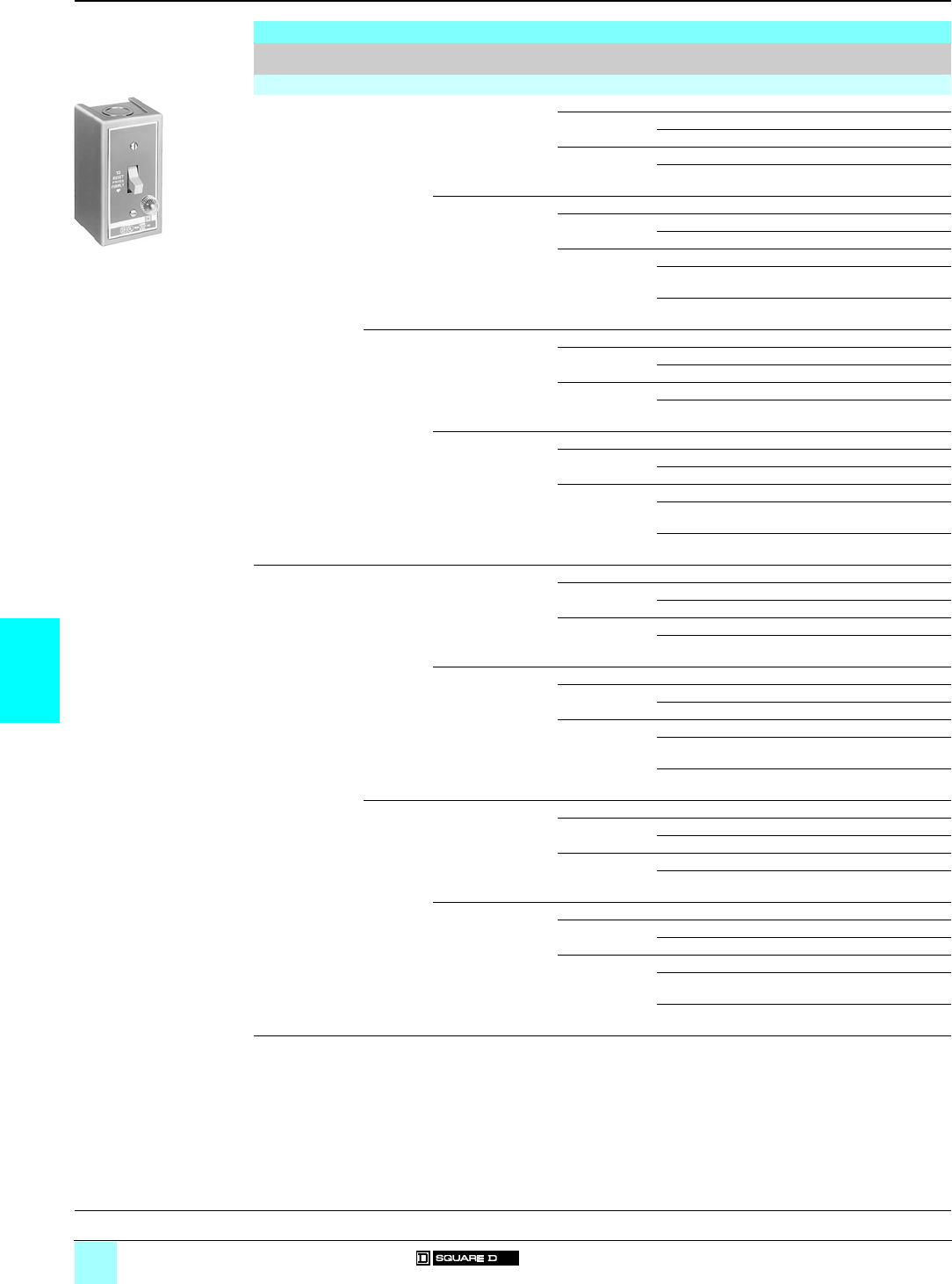
6/4
6
References
0
Manual Starters and Switches 0
Manual starters Class 2510
Single units Type F
Type
of operator
Number
of poles
Features Enclosure type
(2)
Specification Reference Weight
kg (lb)
Basic starters
Toggle operator
(1)
1 Standard Open – 2510 FO 1 0.14 (0.32)
NEMA 1 Standard 2510 FG 1 0.35 (0.72)
Oversized 2510 FGJ 1 0.49 (1.08)
General purpose
flush mounting
(without pull box)
Grey flush plate 2510 FF 1 0.19 (0.42)
Standard stainless
steel flush plate
2510 FS 1 0.20 (0.44)
With red pilot light Open – 2510 FO 1P 0.15 (0.33)
NEMA 1 Standard 2510 FG 1P 0.36 (0.80)
Oversized 2510 FGJ 1P 0.50 (1.12)
General purpose
flush mounting
(without pull box)
Grey flush plate 2510 FF 1P 0.20 (0.46)
Standard stainless
steel flush plate
2510 FS 1P 0.20 (0.46)
Jumbo stainless
steel flush plate
2510 FSJ 1P 0.36 (0.80)
2 Standard Open – 2510 FO 2 0.15 (0.33)
NEMA 1 Standard 2510 FG 2 0.36 (0.80)
Oversized 2510 FGJ 2 0.50 (1.11)
General purpose
flush mounting
(without pull box)
Grey flush plate 2510 FF 2 0.20 (0.46)
Standard stainless
steel flush plate
2510 FS 2 0.20 (0.46)
With red pilot light Open Type – 2510 FO 2P 0.16 (0.35)
NEMA 1 Standard 2510 FG 2P 0.35 (0.78)
Oversized 2510 FGJ 2P 0.52 (1.15)
General purpose
flush mounting
(without pull box)
Grey flush plate 2510 FF 2P 0.22 (0.50)
Standard stainless
steel flush plate
2510 FS 2P 0.20 (0.45)
Jumbo stainless
steel flush plate
2510 FSJ 2P 0.20 (0.45)
Removable key
(1)
1 Standard Open – 2510 FO 3 0.15 (0.33)
NEMA 1 Standard 2510 FG 3 0.35 (0.79)
Oversized 2510 FGJ 3 0.36 (0.80)
General purpose
flush mounting
(without pull box)
Grey flush plate 2510 FF 3 0.22 (0.50)
Standard stainless
steel flush plate
2510 FS 3 0.20 (0.45)
With red pilot light Open – 2510 FO 3P 0.18 (0.40)
NEMA 1 Standard 2510 FG 3P 0.38 (0.84)
Oversized 2510 FGJ 3P 0.36 (0.80)
General purpose
flush mounting
(without pull box)
Grey flush plate 2510 FF 3P 0.20 (0.46)
Standard stainless
steel flush plate
2510 FS 3P 0.21 (0.48)
Jumbo stainless
steel flush plate
2510 FSJ 3P 0.20 (0.45)
2 Standard Open – 2510 FO 4 0.18 (0.40)
NEMA 1 Standard 2510 FG 4 0.36 (0.80)
Oversized 2510 FGJ 4 0.36 (0.80)
General purpose
flush mounting
(without pull box)
Grey flush plate 2510 FF 4 0.22 (0.50)
Standard stainless
steel flush plate
2510 FS 4 0.20 (0.45)
With red pilot light Open – 2510 FO 4P 0.36 (0.80)
NEMA 1 Standard 2510 FG 4P 0.36 (0.80)
Oversized 2510 FGJ 4P 0.36 (0.80)
General purpose
flush mounting
(without pull box)
Grey flush plate 2510 FF 4P 0.22 (0.50)
Standard stainless
steel flush plate
2510 FS 4P 0.20 (0.45)
Jumbo stainless
steel flush plate
2510 FSJ 4P 0.20 (0.45)
(1) One thermal unit required.
(2) Open: no enclosure,
NEMA 1: general purpose enclosure surface mounting.
2510 FG 2P
531176
General, characteristics:
pages 6/2 and 6/3
Dimensions:
pages 6/10 and 6/11

6/5
6
References (continued)
0
Manual Starters and Switches 0
Manual starters Class 2510
Single units Type F (continued)
Type
of operator
Number
of poles
Features Enclosure type
(2)
Specification Reference Weight
kg (lb)
Starters with handle guard/lock-off
Toggle operator
(1)
1 Standard NEMA 1 (3) Standard 2510 FG 5 0.36 (0.80)
Oversized 2510 FGJ 5 0.50 (1.11)
With red pilot light NEMA 1 (3) Standard 2510 FG 5P 0.37 (0.82)
Oversized 2510 FGJ 5P 0.52 (1.15)
2 Standard NEMA 1 (3) Standard 2510 FG 6 0.37 (0.82)
Oversized 2510 FGJ 6 0.51 (1.13)
With red pilot light NEMA 1 (3) Standard 2510 FG 6P 0.38 (0.84)
Oversized 2510 FGJ 6P 0.53 (1.17)
Duplex units Type F
One starter in duplex enclosure
Toggle operator
(1)
2 Standard NEMA 1 Standard 2510 FG 02 0.50 (1.10)
With red pilot light NEMA 1 Standard 2510 FG 02P 0.51 (1.12)
Removable key
(1)
2 With red pilot light NEMA 1 Standard 2510 FG 04P 0.51 (1.12)
Two starters in one enclosure
Toggle operator
(1)
2 for each
starter
Standard NEMA 1 Standard 2510 FG 22 0.70 (1.54)
General purpose
flush mounting
(without pull box)
Grey flush plate 2510 FF 22 0.70 (1.54)
With red pilot light on
each starter
NEMA 1 Standard 2510 FG 22P 0.70 (1.54)
General purpose
flush mounting
(without pull box)
Grey flush plate 2510 FF 22P 0.70 (1.54)
Standard stainless
steel flush plate
2510 FS 22P 0.70 (1.54)
Removable key
(4)
2 for each
starter
With red pilot light on
each starter
NEMA 1 Standard 2510 FG 44P 0.70 (1.54)
General purpose
flush mounting
(without pull box)
Grey flush plate 2510 FF 44P 0.70 (1.54)
Standard stainless
steel flush plate
2510 FS 44P 0.70 (1.54)
Starters and "AUTO-OFF-HAND" selector switch (a only)
Toggle operator
(1)
1 Standard NEMA 1 Standard 2510 FG 71 0.81 (1.79)
General purpose
flush mounting
(without pull box)
Grey flush plate 2510 FF 71 0.73 (1.61)
With red pilot light NEMA 1 Standard 2510 FG 71P 0.72 (1.59)
General purpose
flush mounting
(without pull box)
Grey flush plate 2510 FF 71P 0.80 (1.76)
Standard stainless
steel flush plate
2510 FS 71P 0.80 (1.76)
2 Standard NEMA 1 Standard 2510 FG 72 0.80 (1.76)
General purpose
flush mounting
(without pull box)
Grey flush plate 2510 FF 72 0.80 (1.76)
With red pilot light NEMA 1 Standard 2510 FG 72P 0.80 (1.76)
General purpose
flush mounting
(without pull box)
Grey flush plate 2510 FF 72P 0.80 (1.76)
Standard stainless
steel flush plate
2510 FS 72P 0.80 (1.76)
Removable key
(1)
2 With red pilot light NEMA 1 Standard 2510 FG 74P 0.80 (1.76)
General purpose
flush mounting
(without pull box)
Grey flush plate 2510 FF 74P 0.80 (1.76)
Standard stainless
steel flush plate
2510 FS 74P 0.80 (1.76)
(1) One thermal unit required.
(2) NEMA 1: general purpose enclosure surface mounting.
(3) For general purpose flush mounting enclosure (without pull box), order basic starter plus separate handle guard kit, reference
is 2510 FL1.
(4) Two thermal units required.
General, characteristics:
pages 6/2 and 6/3
Dimensions:
pages 6/10 and 6/11

6/6
6
References
0
Manual Starters and Switches 0
Manual starters Class 2510
Non-reversing Type K (1)
Type
of operator
Number
of poles
Features Enclosure type
(2)
Specification Reference Weight
kg (lb)
Toggle operator 2 Standard Open – 2510 KO 1 0.15 (0.35)
NEMA 1 Standard 2510 KG 1 0.38 (0.85)
General purpose
flush mounting
(without pull box)
Grey flush plate 2510 KF 1 0.22 (0.50)
Standard stainless
steel flush plate
2510 KS 1 0.20 (0.46)
With red pilot light
a115 V
Open – 2510 KO 1A (3) 0.16 (0.37)
NEMA 1 Standard 2510 KG 1A 0.38 (0.84)
General purpose
flush mounting
(without pull box)
Grey flush plate 2510 KF 1A 0.30 (0.66)
Standard stainless
steel flush plate
2510 KS 1A 0.23 (0.52)
Jumbo stainless
steel flush plate
2510 KSJ 1A 0.30 (0.66)
With red pilot light
a230 V
Open – 2510 KO 1B (3) 0.18 (0.39)
NEMA 1 Standard 2510 KG 1B 0.38 (0.84)
General purpose
flush mounting
(without pull box)
Grey flush plate 2510 KF 1B 0.30 (0.66)
Standard stainless
steel flush plate
2510 KS 1B 0.30 (0.66)
Jumbo stainless
steel flush plate
2510 KSJ 1B 0.30 (0.66)
3 Standard Open – 2510 KO 2 0.18 (0.39)
NEMA 1 Standard 2510 KG 2 0.30 (0.66)
General purpose
flush mounting
(without pull box)
Grey flush plate 2510 KF 2 0.30 (0.66)
Standard stainless
steel flush plate
2510 KS 2 0.30 (0.66)
With red pilot light
a208…277 V
Open – 2510 KO 2B (3) 0.20 (0.44)
NEMA 1 Standard 2510 KG 2B 0.39 (0.86)
General purpose
flush mounting
(without pull box)
Grey flush plate 2510 KF 2B 0.30 (0.66)
Standard stainless
steel flush plate
2510 KS 2B 0.30 (0.66)
Jumbo stainless
steel flush plate
2510 KSJ 2B 0.30 (0.66)
With red pilot light
a440…600 V
Open – 2510 KO 2C (3) 0.18 (0.40)
NEMA 1 Standard 2510 KG 2C 0.40 (0.88)
General purpose
flush mounting
(without pull box)
Grey flush plate 2510 KF 2C 0.30 (0.66)
Standard stainless
steel flush plate
2510 KS 2C 0.30 (0.66)
Jumbo stainless
steel flush plate
2510 KSJ 2C 0.30 (0.66)
2 Standard Open – 2510 KO 5 0.17 (0.38)
NEMA 1 Standard 2510 KG 5 0.34 (0.75)
With red pilot light
a115 V
Open – 2510 KO 5A 0.30 (0.66)
NEMA 1 Standard 2510 KG 5A 0.30 (0.66)
With red pilot light
a230 V
Open – 2510 KO 5B 0.30 (0.66)
NEMA 1 Standard 2510 KG 5B 0.30 (0.66)
3 Standard Open – 2510 KO 6 0.17 (0.39)
NEMA 1 Standard 2510 KG 6 0.39 (0.87)
With red pilot light
a115 V
Open – 2510 KO 6B 0.20 (0.44)
NEMA 1 Standard 2510 KG 6B 0.30 (0.66)
With red pilot light
a230 V
Open – 2510 KO 6C 0.30 (0.66)
NEMA 1 Standard 2510 KG 6C 0.40 (0.88)
(1) See motor power ratings table page 6/3.
(2) Open: no enclosure,
NEMA 1: general purpose enclosure surface mounting.
(3) Do not use as replacement parts for devices. For replacement unit, order Type 2510 KO 1 or 2510 KO 2 and separate pilot light
kit, see page 6/9.
2510 KG 1A
531177
2510 KO 2
531178
General, characteristics:
pages 6/2 and 6/3
Dimensions:
pages 6/10 and 6/11
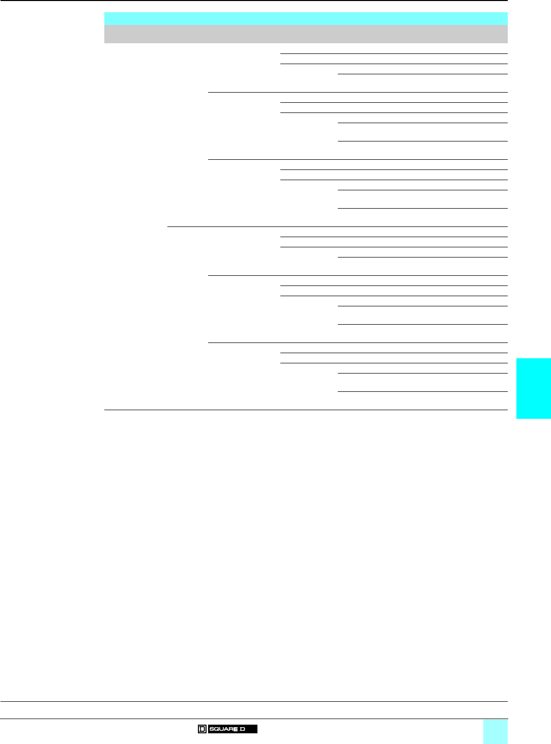
6/7
6
References (continued)
0
Manual Starters and Switches 0
Manual starters Class 2510
Non-reversing Type K (continued) (1)
Type
of operator
Number
of poles
Features Enclosure type
(2)
Specification Reference Weight
kg (lb)
Removable key 2 Standard Open – 2510 KO 3 0.16 (0.35)
NEMA 1 Standard 2510 KG 3 0.40 (0.88)
General purpose
flush mounting
(without pull box)
Grey flush plate 2510 KF 3 0.30 (0.66)
Standard stainless
steel flush plate
2510 KS 3 0.30 (0.66)
With red pilot light
a115 V
Open – 2510 KO 3A 0.17 (0.37)
NEMA 1 Standard 2510 KG 3A 0.40 (0.88)
General purpose
flush mounting
(without pull box)
Grey flush plate 2510 KF 3A 0.30 (0.66)
Standard stainless
steel flush plate
2510 KS 3A 0.30 (0.66)
Jumbo stainless
steel flush plate
2510 KSJ 3A 0.30 (0.66)
With red pilot light
a230 V
Open – 2510 KO 3B 0.16 (0.35)
NEMA 1 Standard 2510 KG 3B 0.40 (0.88)
General purpose
flush mounting
(without pull box)
Grey flush plate 2510 KF 3B 0.30 (0.66)
Standard stainless
steel flush plate
2510 KS 3B 0.30 (0.66)
Jumbo stainless
steel flush plate
2510 KSJ 3B 0.30 (0.66)
3 Standard Open – 2510 KO 4 0.18 (0.39)
NEMA 1 Standard 2510 KG 4 0.39 (0.87)
General purpose
flush mounting
(without pull box)
Grey flush plate 2510 KF 4 0.22 (0.50)
Standard stainless
steel flush plate
2510 KS 4 0.25 (0.55)
With red pilot light
a208…277 V
Open – 2510 KO 4B 0.18 (0.39)
NEMA 1 Standard 2510 KG 4B 0.40 (0.88)
General purpose
flush mounting
(without pull box)
Grey flush plate 2510 KF 4B 0.30 (0.66)
Standard stainless
steel flush plate
2510 KS 4B 0.30 (0.66)
Jumbo stainless
steel flush plate
2510 KSJ 4B 0.30 (0.66)
With red pilot light
a440…600 V
Open – 2510 KO 4C 0.20 (0.44)
NEMA 1 Standard 2510 KG 4C 0.40 (0.88)
General purpose
flush mounting
(without pull box)
Grey flush plate 2510 KF 4C 0.30 (0.66)
Standard stainless
steel flush plate
2510 KS 4C 0.30 (0.66)
Jumbo stainless
steel flush plate
2510 KSJ 4C 0.30 (0.66)
(1) See motor power ratings table page 6/3.
(2) Open: no enclosure,
NEMA 1: general purpose enclosure surface mounting.
General, characteristics:
pages 6/2 and 6/3
Dimensions:
pages 6/10 and 6/11
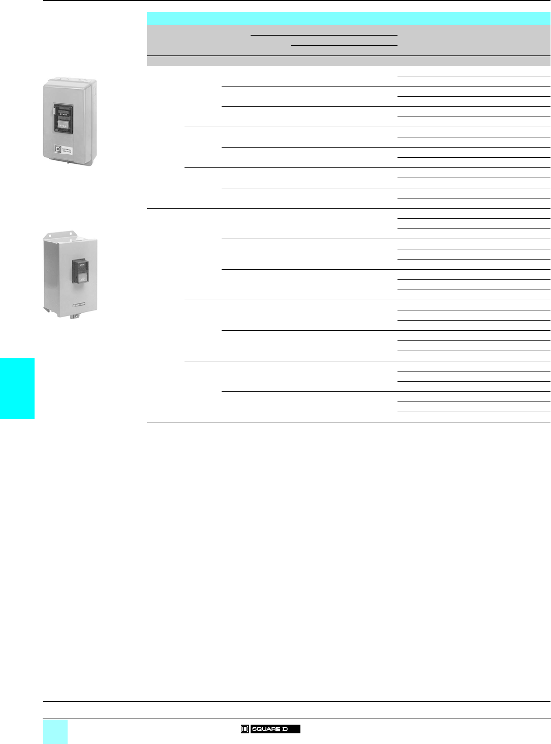
6/8
6
References
0
Manual Starters and Switches 0
Manual starters Class 2510
Integral Horsepower non-reversing Types T and M
Type
of
operator
Number
of
poles
NEMA
Size
Ratings Enclosure
type (1)
Reference Weight
Motor
voltage
Max. power
3-phase Single-phase
Vhp/kW hp/kW kg (lb)
Toggle
operator
a 2 M-0 115
230
–1/0.75
2/1.5
Open 2510 TBO 1 1 (3)
NEMA 1 2510 TBG 1 (2) 2 (5)
M-1 115
230
–2/1.5
3/2.2
Open 2510 TCO 1 1 (3)
NEMA 1 2510 TCG 1 2 (5)
M-1P 115
230
–3/2.2
5/3.7
Open 2510 TCO 2 1 (3)
NEMA 1 2510 TCG 2 2 (5)
a 3 M-0 200…230,
380…575
3/2.2 (230 V),
5/3.7 (575 V)
– Open 2510 TBO 2 1 (3)
NEMA 1 2510 TBG 2 (2) 2 (5)
M-1 200…230,
380…575
7.5/5.5 (230 V),
10/7.5 (575 V)
– Open 2510 TCO 3 1 (3)
NEMA 1 2510 TCG 3 2 (5)
c 2 M-0 115
230
1/0.75
1.5/1.1
1/0.75
1.5/1.1
Open 2510 TBO 4 1 (3)
NEMA 1 2510 TBG 4 2 (5)
M-1 115
230
1.5/1.1
2/1.5
1.5/1.1
2/1.5
Open 2510 TCO 5 1 (3)
NEMA 1 2510 TCG 5 2 (5)
Push-
button
a 2 M-0 115
230
–1/0.75
2/1.5
Open 2510 MBO 1 1 (3)
NEMA 1 2510 MBG 1 (2) 2 (5)
NEMA 12 2510 MBA 1 (3) 4 (9)
M-1 115
230
–2/1.5
3/2.2
Open 2510 MCO 1 1 (3)
NEMA 1 2510 MCG 1 2 (5)
NEMA 12 2510 MCA 1 4 (9)
M-1P 115
230
–3/2.2
5/3.7
Open 2510 MCO 2 1 (3)
NEMA 1 2510 MCG 2 2 (5)
NEMA 12 2510 MCA 2 4 (9)
a 3 M-0 200…230,
380…575
3/2.2 (230 V),
5/3.7 (575 V)
– Open 2510 MBO 2 1 (3)
NEMA 1 2510 MBG 2 (2) 2 (5)
NEMA 12 2510 MBA 2 (3) 4 (9)
M-1 200…230,
380…575
7.5/5.5 (230 V),
10/7.5 (575 V)
– Open 2510 MCO 3 1 (3)
NEMA 1 2510 MCG 3 2 (5)
NEMA 12 2510 MCA 3 4 (9)
c 2 M-0 115
230
1/0.75
1.5/1.1
1/0.75
1.5/1.1
Open 2510 MBO 4 1 (3)
NEMA 1 2510 MBG 4 2 (5)
NEMA 12 2510 MBA 4 4 (9)
M-1 115
230
1.5/1.1
2/1.5
1.5/1.1
2/1.5
Open 2510 MCO 5 1 (3)
NEMA 1 2510 MCG 5 2 (5)
NEMA 12 2510 MCA 5 4 (9)
(1) Open: no enclosure.
NEMA 1: general purpose enclosure surface mounting.
NEMA 12: dust-tight and drip-tight industrial-use enclosure.
(2) For a NEMA 1 enclosed starter approved for group motor installations, order a loom switch: 2-pole 2510 TBL 1, 3-pole 2510 TBL 2.
Loom switch w/LVP: 2-pole 2510 TBL 21, 3-pole 2510 TBL 22.
(3) Approved for group motor installations per NEC 430-53(c).
2510 TBG 1
531179
2510 MBA 1
531180
General, characteristics:
pages 6/2 and 6/3
Dimensions:
pages 6/10 and 6/11
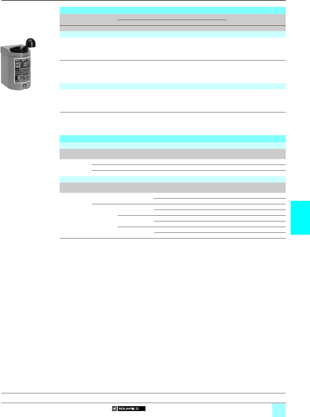
6/9
6
References
0
Manual Starters and Switches 0
Reversing drum switches Class 2601
Accessories for manual starters Class 2510
Reversing drum switches
Voltage Standard power ratings Reference Weight
a single-phase a 3-phase c
Vhp kW hp kW hp kW kg (lb)
NEMA 1 general purpose enclosure
115 1.5 1.1 ––0.25 0.185 2601 AG2 0.6 (1.32)
200/230 ––21.5 ––
230 21.5 ––0.25 0.185
460/575 ––21.5 ––
115 1.5 1.1 ––21.5 2601 BG1 1.1 (2.38)
200/230 ––53.7 ––
230 32.2 ––21.5
460/575 53.7 7.5 5.5 ––
NEMA 1 maintained and pulsed (1)
115 1.5 1.1 ––0.25 0.185 2601 AG2 S2 0.6 (1.32)
200/230 ––21.5 ––
230 21.5 ––0.25 0.185
460/575 ––21.5 ––
115 1.5 1.1 ––21.5 2601 BG1 S4 1.1 (2.38)
200/230 ––53.7 ––
230 32.2 ––21.5
460/575 53.7 7.5 5.5 ––
Kits
Replacement contact kits (for manual starters, Types T and M Class 2510)
Type NEMA
Size
Series Number of poles Service bulletin Reference Weight
kg (lb)
Replacement
contact kits
M-0 A or B 2 or 3 312AS 9998 ML1 –
M-1 A or B 2 or 3 312AS 9998 ML2 –
M-1P A or B 2 312AS 9998 ML2 –
Pilot light kits (for manual starters, Types F and K Class 2510)
Type For use on Voltage Pilot light Reference Weight
kg (lb)
Pilot light kits 2510 FF/FG a/c 115–240 V Red 9998 PL10 –
Green 9998 PL10G –
2510 KF/KG
(2)
a 110–120 V Red 9998 PL11 –
Green 9998 PL11G –
a 208–227 V Red 9998 PL12 –
Green 9998 PL12G –
a 440–600 V Red 9998 PL13 –
Green 9998 PL13G –
(1) Maintained-"Forward". Pulsed-"Reverse". Not field convertible.
(2) Lens cannot be replaced.
2601 AG2
531181
General, characteristics:
pages 6/2 and 6/3
Dimensions:
pages 6/10 and 6/11
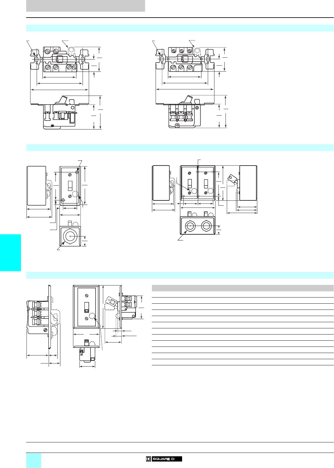
6/10
6
Dimensions
0
Manual Starters and Switches 0
Manual starters Class 2510
Manual switches Class 2510
Dimensions are inch
mm
------------
2510 FO 1/1P/2 (Open) 2510 KO 1/1A/2/2B/2C, 2510 KO 5/5A/5B/6/6B/6C (Open)
(1) 2 mounting holes for #6-32 screws.
(2) Pilot light.
(1) 2 mounting holes for #6-32 screws.
(2) Pilot light.
2510 FG/KG (NEMA 1 Surface mounting) 2510 FG 0pp/2pp/44P/7pp (NEMA 1)
(1) 2 x 0.25" diameter mounting holes 25/6.
(2) Pilot light.
(3) 1/2 -3/4" conduit knockout, both ends.
(1) 4 x 0.25" diameter mounting holes.
(2) Pilot light.
(3) 1/2 -3/4" conduit knockout, both ends.
2510 FF/FS/FSJ/KF/KS/KSJ (NEMA 1 Flush mounting)
(1) Pilot light.
(2) ABC
2510 FF 1/1P/2/2P 36.5 69.9 114.3
2510 FS 1/1P/2/2P 36.5 69.9 114.3
2510 FSJ 1P/2P 36.5 88.9 133.4
2510 FF 3/4/4P 36.5 69.9 114.3
2510 FS 3/3P/4/4P 36.5 69.9 114.3
2510 FSJ 3P/4P 36.5 88.9 133.4
2510 KF 1/1A/1B/2/2B/2C 44.5 69.9 114.3
2510 KS 1/1A/1B/2/2B/2C 44.5 69.9 114.3
2510 KSJ 1A/1B/2B/2C 44.5 88.9 133.4
2510 KF 3/3A/3B/4/4B/4C 44.5 69.9 114.3
2510 KS 3/3A/3B/4/4B/4C 44.5 69.9 114.3
2510 KSJ 3A/4B/4C 44.5 88.9 133.4
(2) Dimensions in mm (25.4 mm = 1 inch).
(1) (2)
1.69
43
.84
21
2.22
56
1.59
40
2.38
60
3.28
83 4.13
105
(1) (2)
1.69
43
.84
21
2.34
60
1.70
43
2.38
60
3.28
83 4.13
105
1.06
27
4.25
108
3.00
76
2.75
70
2.88
73 0.56
14
0.41
10
1.63
41
2.44
62
OFF
(1)
(2)
(3)
1.06
27
4.25
108
3.00
76
2.75
70
2.88
73
1.88
48 4.50
114
OFF
(1)
OFF
1.88
48
38
10 56
14 2.56
65 2.63
67
3.81
97
(2)
(3)
.50
13
2.56
65
.66
17
1.78
45
1.69
43
B
(1)
C
OFF
0.91
23
0.75
19
A
General, characteristics:
pages 6/2 and 6/3
References:
pages 6/4 to 6/9
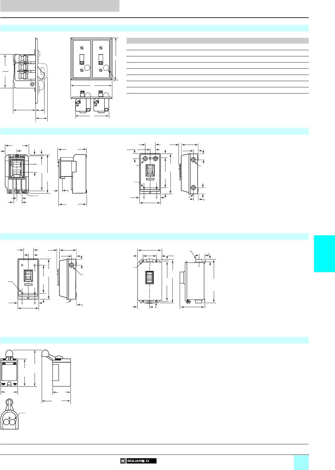
6/11
6
Dimensions (continued)
0
Manual Starters and Switches 0
Manual starters Class 2510
Manual switches Class 2510
Reversing drum switches Class 2601
Dimensions are inch
mm
------------
2510 FF 22/44/7p, 2510 FS 22/44/7p (General purpose flush mounting plate)
(1) Pilot light.
(2) A B C D
2510 FF 22/22P 133.4 95.3 133.4 36.5
2510 FS 22P 4.6 88.9 114.3 36.5
2510 FF 44P 133.4 95.3 133.4 36.5
2510 FS 44P 4.6 88.9 114.3 36.5
2510 FF 71/71P/72/72P 133.4 19.1 133.4 50.8
2510 FS 71P/72P 4.6 88.9 114.3 50.8
2510 FF 74P 133.4 95.3 133.4 50.8
2510 FS 74P 4.6 88.9 114.3 50.8
(2) Dimensions in mm (25.4 mm = 1 inch).
2510 TpO p/MpO p (Open) 2510 TCG 2/MCG 2 (NEMA 1)
Sizes M-0, M-1 and M-1P
(1) 3 prov. for #10 mounting screws.
(2) Travel to reset.
Size M-1P
(1) 3 x 0.22 diameter mounting holes.
(2) 6 x 0.50 - 0.75 knockouts
(3) 1 x 0.50 - 0.75 knockouts
(4) 2 x 0.75 - 1.00 knockouts Top and bottom.
2510 TBG p/TCG p/MBG p/MCG p (NEMA 1) 2510 MpA p (NEMA 12)
Sizes M-0 and M-1
(1) 4 x 0.22 diameter mounting holes.
(2) 0.50 - 0.75 knockouts Each side.
(3) 1 x 0.50 - 0.75 knockouts and 2 x 0.75 - 1.00 knockouts
Sizes M-0, M-1 and M-1P
(1) 2 x 0.31 diameter mounting holes.
(2) 0.75 conduit hub top and bottom.
(3) 2 x 0.31 wide slots.
(4) NEMA 4 only.
2601 AG2/AG2 S2/BG1/BG1 S4 (NEMA 1)
(1) 2 x 0.50" knockouts
0.91
23
0.75
19
D
2.56
65
A
(1
)
C
B
OFF OFF
4.03
102
3.50
89
1.75
44
.69
18 1.13
29
.44
11
3.97
101
5.72
145
5.13
130
1.25
32
1.13
29
.28
7
(2)
(1)
3.38
86
5.00
127
1.08
27
1.00
25
1.00
25
1.08
27
10.00
264
8.13
207
1.00
25
.94
24
.88
22
.94
24
4.13
105
6.00
152
1.69
43
.22
8
(1) (1)
(2)
(3)
(4)
2.13
54
3.91
1.02
26
1.14
29
1.02
26
8.63
219
5.75
148
1.44
37
1.00
25
3.00
76
5.00
127
.22
8
(1)
(2
)
1.06
27
22
(3)
1.27
32
.47
12
1.31
33
.38
10
10.92
277
10.75
273
10.00
254
5.76
148
2.89
73
5.78
147
3.25
83
(1)
(2)
(3)(4)
(4)
(4)
(4)
2.68
68
4.00
102
5.38
137
2.91
74
4.61
117
(1)
General, characteristics:
pages 6/2 and 6/3
References:
pages 6/4 to 6/9

7/0

7/1
Contents
7
7 - Accessories
bSeparate enclosures
vReferences . . . . . . . . . . . . . . . . . . . . . . . . . . . . . . . . . . . . . . . . . . . . . page 7/2
bMagnetic coils
vReferences . . . . . . . . . . . . . . . . . . . . . . . . . . . . . . . . . . . . . . . . . . . . . page 7/8
bReplacement parts kits
vReferences . . . . . . . . . . . . . . . . . . . . . . . . . . . . . . . . . . . . . . . . . . . . page 7/12
bCover-mounted control units
vReferences . . . . . . . . . . . . . . . . . . . . . . . . . . . . . . . . . . . . . . . . . . . . page 7/14
bAuxiliary contacts
vReferences . . . . . . . . . . . . . . . . . . . . . . . . . . . . . . . . . . . . . . . . . . . . page 7/18
bPower-pole adder kits, Timer attachments, Control circuit fuse holders, Transient
suppression modules
vReferences . . . . . . . . . . . . . . . . . . . . . . . . . . . . . . . . . . . . . . . . . . . . page 7/20
bCompression lugs, Terminal blocks
vReferences . . . . . . . . . . . . . . . . . . . . . . . . . . . . . . . . . . . . . . . . . . . . page 7/21
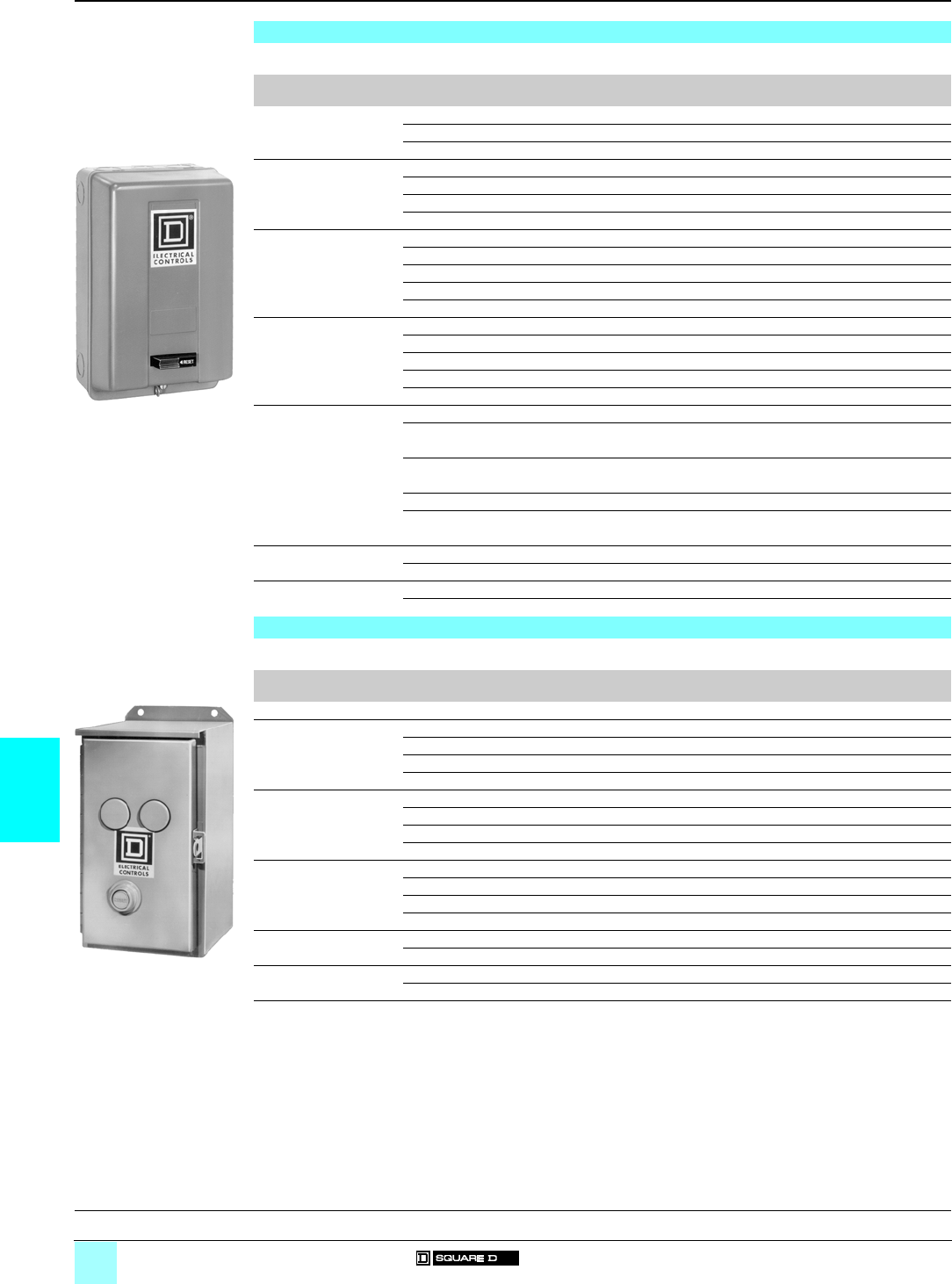
7/2
7
References Accessories for Heavy Industrial
NEMA Style Controls 0
Separate enclosures
NEMA 1 rated (general purpose) separate enclosures
The NEMA 1 rated general purpose separate enclosures listed below, when used with open style components, are equivalent to
a standard factory-assembled control device.
For use with Type Number of poles Reference Weight
kg (lb)
Manual starters 2510 F, 2510 K All 9991 EN 1 0.2 (0.5)
2510 M (Sizes M-0 and M-1) All 9991 MG 1 1.1 (2.4)
2510 M (Size M-1P) All 9991 MG 2 0.5 (1)
Contactors 8502 SAO/SBO/SCO 2…4 9991 SCG 7 1.8 (4)
8502 SDO 2…4 9991 SDG 7 3.6 (8)
8502 SEO 2…4 9991 SEG 7 10.4 (23)
8502 SFO 2…4 9991 SFG 8 15.4 (34)
Starters 8536 SAO/SBO/SCO 2…4 9991 SCG 8 1.8 (4)
8536 SDO 2…4 9991 SDG 8 3.6 (8)
8536 SEO 2…4 9991 SEG 8 (1) 10.4 (23)
8536 SFO 2…4 9991 SFG 8 (1) 15.4 (34)
8536 SGO 3 9991 SGG 8 (1) (5) 51 (112)
Lighting contactors 8903 LO, 8903 LXO All 9991 LXG 1 (6) 3.6 (8)
8903 SMO All 9991 SCG 7 (2) 1.8 (4)
8903 SPO All 9991 SDG 7 (2) 3.6 (8)
8903 SQO All 9991 SFG 8 (2) 15.4 (34)
8903 SVO All 9991 SFG 4 16.3 (36)
Definite purpose
contactors
8910 DP 1…2 9991 DPG 1 1.1 (2.5)
8910 DPA 12/13/22/23, 2…3 9991 DPG 1 1.1 (2.5)
8910 DPA 32/33/42/43
8910 DPA 14/24/34/44, 2…4 9991 DPG 2 1.8 (4)
8910 DPA 52/53
8910 DPA 62/63 2…3 9991 DPG 3 3.6 (8)
8910 DPA 72/73/92/93, 2…3 9991 DPG 4 10.4 (23)
8910 DPA 122/123
Reversing contactors 8702 SAO/SBO/SCO All 9991 SCG 9 (3) 7.3 (16)
8702 SDO All 9991 SDG 9 (3) 10.9 (24)
Reversing starters 8736 SAO/SBO/SCO All 9991 SCG 9 7.3 (16)
8736 SDO All 9991 SDG 9 10.9 (24)
NEMA 12 rated (dust-tight and drip-tight) separate enclosures
Separate enclosures can be used with open-style devices for field assembly of enclosed controls. These enclosures, plus the open
style components, are equivalent to a factory-assembled device.
For use with Type NEMA Size or
current rating
Number of
closing plates
Reference Weight
kg (lb)
Manual starters 2510 MBO, 2510 MCO M-0, M-1, M-1P – 9991 MA 1 2.3 (5)
Contactors (4) 8502 SAO/SBO/SCO 0, 1 2 9991 SCA 11 4.5 (10)
8502 SDO 2 2 9991 SDA 11 6.8 (15)
8502 SEO 3 3 9991 SEA 11 23.1 (51)
8502 SFO 4 3 9991 SFA 11 23.1 (51)
Starters 8536 SAO/SBO/SCO 0, 1 2 9991 SCA 11 4.5 (10)
8536 SDO 2 2 9991 SDA 11 6.8 (15)
8536 SEO 3 3 9991 SEA 11 (1) 23.1 (51)
8536 SFO 4 3 9991 SFA 11 (1) 23.1 (51)
Lighting contactors (4) 8903 LO, 8903 LXO 30 A 2 9991 SDA 11 6.8 (15)
8903 SMO 30 A 2 9991 SCA 11 4.5 (10)
8903 SPO 60 A 2 9991 SDA 11 6.8 (15)
8903 SQO 100 A 3 9991 SEA 11 (1) 23.1 (51)
Reversing contactors (4) 8702 SAO/SBO/SCO 0, 1 3 9991 SCA 12 9.1 (20)
8702 SDO 2 3 9991 SDA 12 11.3 (25)
Reversing starters 8736 SAO/SBO/SCO 0, 1 3 9991 SCA 12 9.1 (20)
8736 SDO 2 3 9991 SDA 12 11.3 (25)
(1) Enclosure suitable for starter with solid-state overload relays only.
(2) For electrically held contactors only.
(3) For horizontally arranged Class 8702 contactors and Class 8922 breakers, replace the reset assembly with a Class 9001
Type K51 closing plate.
(4) For contactors, replace reset assembly with an appropriate closing plate; for NEMA 12 use Class 9001 Type K51 closing plate.
(5) Series B starter enclosure.
(6) If cover-mounted control units are required, select an oversized enclosure listed on page 7/4.
9991 SCG 8
DF 531381
9991 SCA 11
DF 531382
Dimensions:
pages 7/6 and 7/7

7/3
7
References (continued) Accessories for Heavy Industrial
NEMA Style Controls 0
Separate enclosures
Flush-mounting separate enclosures
Flush-mounting, general-purpose separate enclosures for Type S Sizes 0–2 (30–60 A) are provided with knock-outs in the cover
for field assembly of one Class 9999 push button or selector switch kit and one Class 9999 pilot light kit. For Type S Size 3 (100 A),
three closing plates are provided for installation of Class 9001 Type K oil-tight control units.
For use with Type NEMA Size or
current rating
Type Reference Weight
kg (lb)
Manual starters 2510 MBO, 2510 MCO M-0, M-1, M-1P Flush plates standard 9991 MF 1 (1) 3.2 (7)
9991 MF 2 (2) 0.9 (2)
Contactors
(3)
8502 SBO, 8502 SCO 0, 1 Standard 9991 SCF 11 4.5 (10)
Stainless steel (4) 9991 SCF 12 4.5 (10)
Mounting strap 9991 SCF 2 3.6 (8)
Pull box 9991 SCF 1 3.6 (8)
8502 SDO 2 Standard 9991 SDF 11 7.7 (17)
Stainless steel (4) 9991 SDF 12 1.4 (3.1)
Mounting strap 9991 SDF 2 4.5 (10)
Pull box 9991 SDF 1 4.5 (10)
8502 SEO 3 Standard 9991 SEF 11 (5) 21.8 (48)
Starters 8536 SBO, 8536 SCO 0, 1 Standard 9991 SCF 11 4.5 (10)
Stainless steel (4) 9991 SCF 12 4.5 (10)
Mounting strap 9991 SCF 2 3.6 (8)
Pull box 9991 SCF 1 3.6 (8)
8536 SDO 2 Standard 9991 SDF 11 7.7 (17)
Stainless steel (4) 9991 SDF 12 1.4 (3.1)
Mounting strap 9991 SDF 2 4.5 (10)
Pull box 9991 SDF 1 4.5 (10)
Lighting contactors
(3)
8903 LO, 8903 LXO 30 A Standard 9991 SDF 13 7.7 (17)
Mounting strap 9991 SDF 2 4.5 (10)
Pull box 9991 SDF 1 4.5 (10)
8903 SMO 1/2/3/4 30 A Standard 9991 SCF 11 4.5 (10)
Mounting strap 9991 SCF 2 3.6 (8)
Pull box 9991 SCF 1 3.6 (8)
8903 SMO 10/11/12/13 30 A Standard 9991 SCF 13 3.6 (8)
Mounting strap 9991 SCF 2 3.6 (8)
Pull box 9991 SCF 1 3.6 (8)
8903 SPO 1/2/3/4 60 A Standard 9991 SDF 11 7.7 (17)
Mounting strap 9991 SDF 2 4.5 (10)
Pull box 9991 SDF 1 4.5 (10)
8903 SPO 10/11/12/13 60 A Standard 9991 SDF 13 7.7 (17)
Mounting strap 9991 SDF 2 4.5 (10)
Pull box 9991 SDF 1 4.5 (10)
8903 SQO 100 A Standard 9991 SEF 11 (5) 21.8 (48)
(1) With pull box and plaster adjustment.
(2) Without pull box but with mounting strap.
(3) For contactors, replace the reset assembly with an appropriate closing plate. For flush mounting, use Class 9999 Type SG2,
except for Class 9991 Type SDF 11, which requires a Class 9001 Type K51 or K11 closing plate. Class 9991 Type SEF 11 is
designed for contactors only; reset closing plates are not required.
(4) The standard cabinet has a brushed finish. For electropolished finish, specify Form G16. Example: 9991 SCF 12 G16.
(5) Enclosure complete.
9991 SCF 2
DF 531383
Dimensions:
pages 7/6 and 7/7
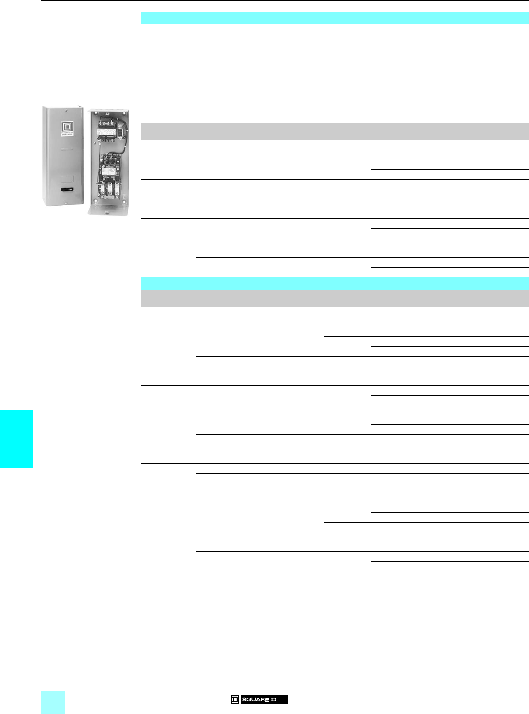
7/4
7
References Accessories for Heavy Industrial
NEMA Style Controls 0
Separate enclosures for addition of control
circuit transformer, Control circuit transformers
Separate enclosures for addition of control circuit transformer
The Class 9991 enclosures listed below accept an open-type, Class 8502 or 8536 Type S, NEMA Size 0, 1, 1P or 2 contactor or
starter, together with a fused-control circuit transformer (suffix F4T) to allow field assembly of enclosed controllers. In the cover of the
Class 9991 Type SCG 1 enclosure, knock-outs are provided for field addition of Class 9999 cover-mounted control units. All other
Class 8502 and 8536 enclosures include a panel with space and drilling for an open-type device and a fused control-circuit
transformer. In addition, three closing plates are included in each cover for easy installation of Class 9001 Type K or SK control units.
Oversized enclosures for open-type, Class 8903 Type L and LX and Type S (30 and 60 A), electrically and mechanically held
lighting contactors include a panel with space and drilling for an open-type contactor and fused control-circuit transformer (suffix
F4T) and/or an auxiliary relay for use with single-pole pilot devices (suffix R6). When an auxiliary relay is required, use a Class
8501 Type XO 11 relay. Three closing plates are provided as standard for easy installation of Class 9001 Type K or SK control
units.
Note : a Class 9991 Type SCG 1, NEMA 1 separate enclosure can also be used for Class 8903 Type SMO (30 A) electrically held
lighting contactor if suffix F4T (control transformer), with or without cover control units, is required.
For use with Type NEMA Size or
current rating
Number of
poles
Enclosure type (1) Reference Weight
kg (lb)
Contactors (2) 8502 SAO/SBO/SCO 0, 1 1…5 NEMA 1 9991 SCG 1 3.6 (8)
NEMA 12 9991 SCA 4 8.3 (18.2)
8502 SDO 2 2…5 NEMA 1 9991 SDG 4 9.5 (21)
NEMA 12 9991 SDA 4 10.4 (23)
Starters 8536 SAO/SBO/SCO 0, 1 1…5 NEMA 1 9991 SCG 1 3.6 (8)
NEMA 12 9991 SCA 4 8.3 (18.2)
8536 SDO 2 2…5 NEMA 1 9991 SDG 4 9.5 (21)
NEMA 12 9991 SDA 4 10.4 (23)
Lighting
contactors
8903 LO, 8903 LXO 30 A All NEMA 1 9991 SDG 3 6.8 (15)
NEMA 12 9991 SDA 3 9.1 (20)
8903 SMO 30 A 1…5 NEMA 1 9991 SDG 3 6.8 (15)
NEMA 12 9991 SDA 3 9.1 (20)
8903 SPO 60 A 2…5 NEMA 1 9991 SDG 3 6.8 (15)
NEMA 12 9991 SDA 3 9.1 (20)
Control circuit transformers
For use with Type NEMA Size or
current rating
Number of
poles
Transformer type Reference Weight
kg (lb)
Contactors (2) 8502 SAO/SBO/SCO 0, 1 1…3 Standard, 50 VA 9070 T50 –
Extra capacity, 100 VA 9070 T100 (3) –
Extra capacity, 150 VA 9070 T150 (3) –
4 and 5 Standard, 100 VA 9070 T100 (3) –
Extra capacity, 150 VA 9070 T150 (3) –
8502 SDO 2 2…5 Standard, 100 VA 9070 T100 –
Extra capacity, 150 VA 9070 T150 –
Extra capacity, 300 VA 9070 T300 –
Starters 8536 SAO/SBO/SCO 0, 1 1…3 Standard, 50 VA 9070 T50 –
Extra capacity, 100 VA 9070 T100 (3) –
Extra capacity, 150 VA 9070 T150 (3) –
4 and 5 Standard, 100 VA 9070 T100 (3) –
Extra capacity, 150 VA 9070 T150 (3) –
8536 SDO 2 2…5 Standard, 100 VA 9070 T100 –
Extra capacity, 150 VA 9070 T150 –
Extra capacity, 300 VA 9070 T300 –
Lighting
contactors
8903 LO 30 A All Standard, 50 VA 9070 T50 –
8903 LXO 30 A All Standard, 50 VA 9070 T50 –
Extra capacity, 100 VA 9070 T100 (3) –
Extra capacity, 150 VA 9070 T150 (3) –
8903 SMO 30 A 1…3 Standard, 100 VA 9070 T100 (3) –
Extra capacity, 150 VA 9070 T150 (3) –
4 and 5 Standard, 100 VA 9070 T100 –
Extra capacity, 150 VA 9070 T150 –
Extra capacity, 300 VA 9070 T300 –
8903 SPO 60 A 2…5 Standard, 100 VA 9070 T100 –
Extra capacity, 150 VA 9070 T150 –
Extra capacity, 300 VA 9070 T300 –
(1) NEMA 1: general purpose enclosure. NEMA 12: dust-tight and drip-tight industrial-use enclosure.
(2) For contactors (Class 8502), a separate closing plate is provided with each enclosure to replace the reset mechanism, with the
exception of Class 9991 Type SCG 1, which requires a separate reset closing plate, Class 9999 Type SG2.
(3) For mounting in a 9991 SCG 1 enclosure, a Class 9991 Type S1 adapter bracket is also required.
9991 SCG 1
DF 531389
Dimensions:
pages 7/6 and 7/7

7/5
7
References Accessories for Heavy Industrial
NEMA Style Controls 0
Fuse block, Control unit kits
Fuse block (for use with Class CC fuses)
For use with Type NEMA Size or
current rating
Reference Weight
kg (lb)
Contactors 8502 SBO/SCO/SDO 0…2 9999 SFR 4 –
Starters 8536 SBO/SCO/SDO 0…2 9999 SFR 4 –
Lighting
contactors
8903 LO/LXO/SMO/SPO 30…60 A 9999 SFR 4 –
Control unit kits
Class 9001 Type K oil-tight/water-tight control units can be easily installed in NEMA 12, separate enclosures provided with closing
plates.
When installing control units, simply remove the closing plates and install the appropriate Class 9001 Type K components.
Convenient control unit kits, complete with assembled and pre-wired operators for quick installation, are available as Class 9999
user modification kits.
Class 9001 Type SK, NEMA 4X, corrosion-resistant control units may be used as an alternative.
Kits
Control
function
Kit contents Reference Weight
kg (lb)
Description Reference Quantity
"Start-Stop" Start operator 9001 KR 1B 1 9999 SA 3 –
push button Stop operator 9001 KR 1R 1
"Start" legend plate 9001 KN 201 1
"Stop" legend plate 9001 KN 202 1
Contact block 9001 KA 1 2
"Hand-Off-Auto" Selector operator switch 9001 KS 43B 1 9999 SC 8 –
selector switch "Hand-Off-Auto" legend plate 9001 KN 260 1
Contact block 9001 KA 1 1
Pilot light
(120 V)
Red pilot light 9001 KP 1R31 1 9999 SP 28R –
Dimensions:
pages 7/6 and 7/7
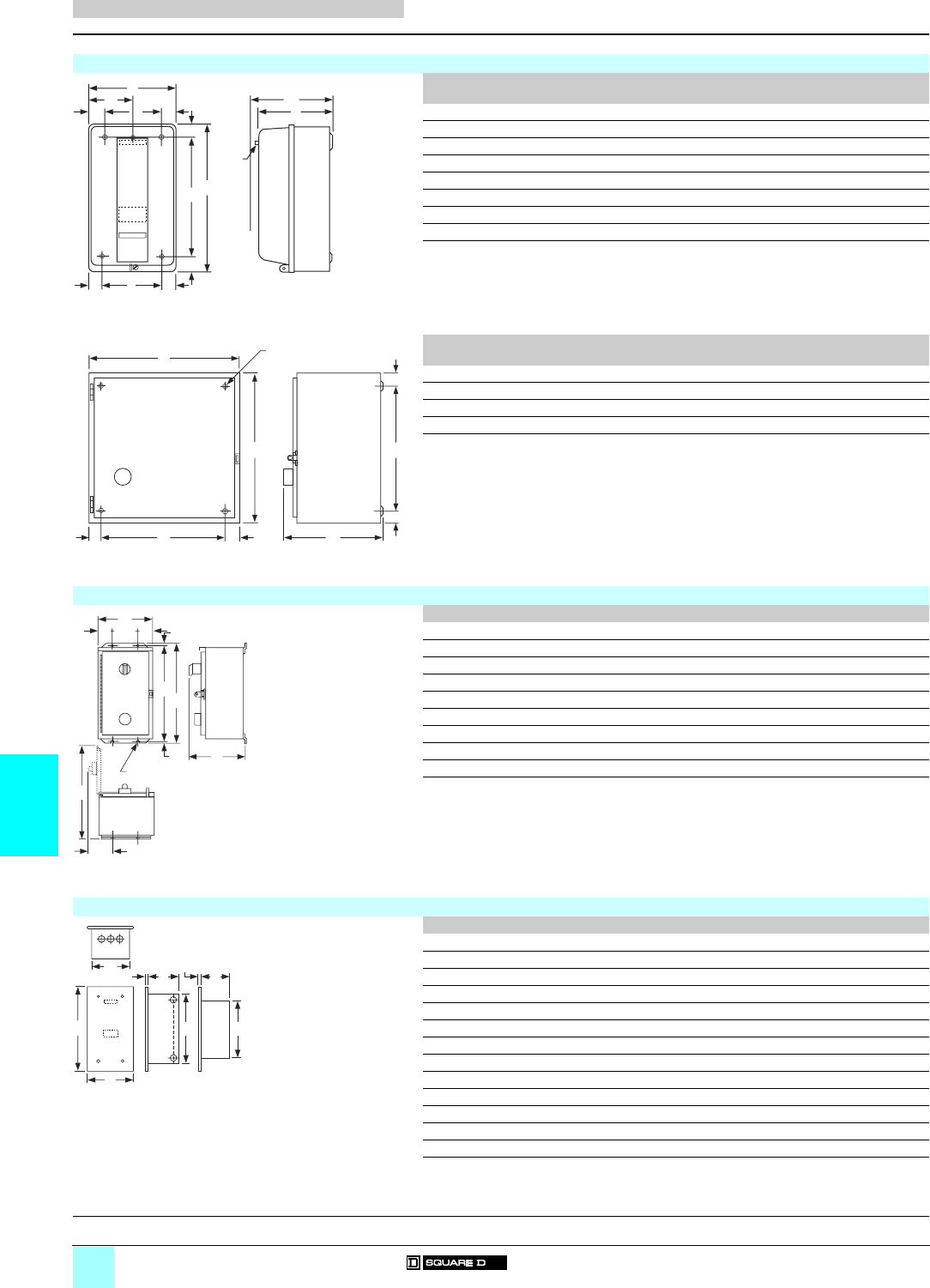
7/6
7
Dimensions
Accessories for Heavy Industrial
NEMA Style Controls 0
Separate enclosures
Dimensions in mm (25.4 mm = 1 inch)
NEMA 1 rated (general purpose) separate enclosures
Mounting
screws
A B C D E F G H I J K L
9991 SCG 7 3 x # 10 152 254 134 76 22 206 25 24 105 127 – –
9991 SDG 7 4 x 6.4 198 322 153 – 28 267 28 28 143 146 28 143
9991 SEG 7/8 4 x 9.5 286 554 203 – 39 476 39 39 213 197 39 213
9991 SCG 8/DPG 2 3 x # 10 152 254 141 76 22 206 25 24 105 127 – –
9991 SDG 8/DPG 3 4 x 6.4 198 322 160 – 28 267 28 28 143 146 28 143
9991 LXG 1 – 198 322 153 – 28 267 28 28 143 146 28 143
9991 DPG 1 – 127 216 102 – – – – – – – – –
9991 DPG 4 4 x 9.5 286 554 213 – 39 476 39 39 213 197 39 213
Mounting
screws
A B C D E F G H I J K L
9991 SFG 8 4 x 11.1 286 639 228 218 32 32 567 36 11 – – –
9991 SGG 8 – 5021129363–––––––––
9991 SCG 9 4 x 7.9 302 302 188 248 27 27 248 27 8 – – –
9991 SDG 9 4 x 7.9 378 359 192 324 27 27 305 27 8 – – –
NEMA 12 rated (dust-tight and drip-tight) separate enclosures
For use with A B C D E F G H I J
9991 MA 1 140273114–––––––
9991 SCA 11 162 217 324 40 83 305 10 90 318 8
9991 SDA 11 206 236 406 40 127 381 13 90 391 8
9991 SEA 11 461 235 800 78 305 775 13 93 678 11
9991 SEA 11 8536 SEO 461 243 800 78 305 775 13 114 678 11
9991 SFA 11 8536 SFO 461 243 800 78 305 775 13 114 678 11
9991 SFA 11 461 235 800 78 305 775 13 93 678 11
9991 SCA 12 336363225–––––––
9991 SDA 12 387413230–––––––
Flush mounting separate enclosures
A B C D E F G H
9991 MF 1 140292102–––––
9991 MF 2 14029289–––––
9991 SCF 11 341 183 149 283 121 233 114 10
9991 SCF 12 24441999–––––
9991 SCF 2 175378154–––––
9991 SCF 1 175378154–––––
9991 SDF 11 386 227 194 327 138 278 130 10
9991 SDF 12 24441999–––––
9991 SDF 2 175378154–––––
9991 SDF 1 256416152–––––
9991 SEF 11 787 425 362 667 203 – – 5
9991 SDF 13 386 227 194 327 138 278 130 10
9991 SCF 13 337178146–––––
A
D
KL
K
E
B
F
HIH
G
RESET
C
J
Pilot
Light
A
B
EDF
Reset
C
H
G
H
(4) I Dia.
Mounting Holes
A
DED G
F
C
GB
H
I
(4) J Dia. Mounting Holes
C
A
B
HE G
DF
H
References:
pages7/2 and 7/5

7/7
7
Dimensions
Accessories for Heavy Industrial
NEMA Style Controls 0
Separate enclosures
Dimensions in mm (25.4 mm = 1 inch)
Separate enclosures for addition of control circuit transformer
Mounting
screws
A B C D E F G H I
9991 SCG 1 4 x 7.1 161 403 132 118 21 365 19 7 9
For use
with
Mounting
screws
A B C D E F G H I
9991 SDG 4 8502 SDO 4 x 7.9 378 359 192 324 27 27 305 27 8
9991 SDG 4 8536 SDO 4 x 7.9 378 359 194 324 27 27 305 27 8
9991 SDG 3 4 x 7.9 378 359 192 324 27 27 305 27 8
A B C D E F G H I
9991 SCA 4 336363225––––––
9991 SDA 4 387413230––––––
9991 SDA 3 387413230––––––
H
B
G
C
D
A(4) I Dia. Mtg. Holes
E
A
B
EDF
Reset
C
H
G
H
(4) I Dia.
Mounting Holes
References:
pages 7/2 and 7/5
7/8
7
References Accessories for Heavy Industrial
NEMA Style Controls 0
Magnetic coils
Replacement a.c. magnetic coils for magnetic contactors and
starters
Equipment to be serviced Frequency Voltage Reference Weight
Device Type NEMA Size
or current
rating
Number
of
poles
Hz Vkg (lb)
Latch coils for
present-design
magnetic
contactors
and starters
Classes:
8502, 8536,
8538, 8539,
8702, 8736,
8903, 8910
L
LX
30 A
30 A
2 to 6
2 to 4
50 24 9998 L 24 –
110–115 9998 L 44 –
120 9998 L 45 –
208 9998 L 52 –
220 9998 L 53 –
240 9998 L 54 –
380 9998 L 60 –
440 9998 L 62 –
480 9998 L 63 –
550 9998 L 65 –
600 9998 L 66 –
60 24 9998 L 23 –
120 9998 L 44 –
208 9998 L 50 –
240 9998 L 53 –
277 9998 L 55 –
300 9998 L 56 –
480 9998 L 62 –
600 9998 L 65 –
L
LX
30 A
30 A
8 to 12
6 to 12
50 24 9998 LH 24 –
110–115 9998 LH 44 –
120 9998 LH 45 –
220 9998 LH 53 –
240 9998 LH 54 –
440 9998 LH 62 –
550 9998 LH 65 –
60 24 9998 LH 23 –
120 9998 LH 44 –
208 9998 LH 50 –
240 9998 LH 53 –
277 9998 LH 55 –
480 9998 LH 62 –
600 9998 LH 65 –
SA (1)
Series B
00 All 50 110–115 9998 SAC 45 –
220 9998 SAC 54 –
440 9998 SAC 62 –
550 9998 SAC 65 –
60 24 9998 SAC 23 –
120 9998 SAC 45 –
208 9998 SAC 52 –
240 9998 SAC 54 –
277 9998 SAC 55 –
380 9998 SAC 59 –
480 9998 SAC 62 –
600 9998 SAC 65 –
(1) For use on Type S Series B devices only.
7/9
7
References (continued) Accessories for Heavy Industrial
NEMA Style Controls 0
Magnetic coils
Replacement a.c. magnetic coils for magnetic contactors and
starters (continued)
Equipment to be serviced Frequency Voltage Reference Weight
Device Type NEMA Size
or current
rating
Number
of
poles
Hz Vkg (lb)
Latch coils for
present-design
magnetic
contactors
and starters
Classes:
8502, 8536,
8538, 8539,
8702, 8736,
8903
SA
(Series A),
SB, SC,
SM
00, 0,
1, 1P,
and 30 A
All 50 24 31041-400-22 –
110–115 31041-400-42 –
120 31041-400-43 –
220 31041-400-51 –
240 31041-400-53 –
380 31041-400-57 –
440 31041-400-60 –
480 31041-400-61 –
550 31041-400-62 –
600 31041-400-64 –
60 24 31041-400-20 –
120 31041-400-42 –
208 31041-400-48 –
220 31041-400-51 –
240 31041-400-51 –
277 31041-400-52 –
380 31041-400-56 –
440 31041-400-58 –
480 31041-400-60 –
550 31041-400-61 –
600 31041-400-62 –
SD, SP 2 and 60 A 2 and 3 50 24 31063-409-17 –
110–115 31063-409-38 –
120 31063-409-39 –
220 31063-409-47 –
240 31063-409-48 –
380 31063-409-54 –
440 31063-409-57 –
550 31063-409-60 –
600 31063-409-61 –
60 24 31063-409-16 –
120 31063-409-38 –
208 31063-409-44 –
220 31063-409-47 –
240 31063-409-47 –
277 31063-409-49 –
440 31063-409-57 –
480 31063-409-57 –
550 31063-409-60 –
600 31063-409-60 –
4 and 5 50 24 31063-400-17 –
110–115 31063-400-38 –
120 31063-400-39 –
220 31063-400-47 –
240 31063-400-48 –
380 31063-400-54 –
440 31063-400-57 –
550 31063-400-60 –
600 31063-400-61 –
60 24 31063-400-16 –
120 31063-400-38 –
208 31063-400-44 –
220 31063-400-47 –
240 31063-400-47 –
277 31063-400-49 –
380 31063-400-53 –
440 31063-400-57 –
480 31063-400-57 –
550 31063-400-60 –
600 31063-400-60 –
7/10
7
References (continued) Accessories for Heavy Industrial
NEMA Style Controls 0
Magnetic coils
Replacement a.c. magnetic coils for magnetic contactors and
starters (continued)
Equipment to be serviced Frequency Voltage Reference Weight
Device Type NEMA Size
or current
rating
Number
of
poles
Hz Vkg (lb)
Latch coils for
present-design
magnetic
contactors
and starters
Classes:
8502, 8536,
8538, 8539,
8702, 8736,
8903, 8910
SE, 3, 20 A 2 and 3 50 24 31074-400-17 –
SQ, and 100 A 110–115 31074-400-38 –
DPA 12 120 31074-400-39 –
220 31074-400-47 –
240 31074-400-48 –
380 31074-400-54 –
440 31074-400-57 –
550 31074-400-60 –
600 31074-400-61 –
60 24 31074-400-16 –
120 31074-400-38 –
208 31074-400-44 –
220 31074-400-47 –
240 31074-400-47 –
277 31074-400-49 –
380 31074-400-53 –
440 31074-400-57 –
480 31074-400-57 –
500 31074-400-58 –
550 31074-400-60 –
600 31074-400-60 –
4 and 5 50 110–115 31091-400-38 –
120 31091-400-39 –
220 31091-400-47 –
240 31091-400-48 –
380 31091-400-54 –
440 31091-400-57 –
480 31091-400-58 –
550 31091-400-60 –
600 31091-400-61 –
60 120 31091-400-38 –
208 31091-400-44 –
220 31091-400-47 –
240 31091-400-47 –
277 31091-400-49 –
380 31091-400-53 –
440 31091-400-57 –
480 31091-400-57 –
550 31091-400-60 –
600 31091-400-60 –
Latch coils for
present-design
magnetic
contactors and
starters
Classes:
8502, 8536,
8538, 8539,
8702, 8736, 8903
SF, SV 4 and
200 A
All 50 110–115 31091-400-38 –
120 31091-400-39 –
220 31091-400-47 –
240 31091-400-48 –
380 31091-400-54 –
440 31091-400-57 –
480 31091-400-58 –
550 31091-400-60 –
600 31091-400-61 –
60 120 31091-400-38 –
208 31091-400-44 –
240 31091-400-47 –
277 31091-400-49 –
380 31091-400-53 –
480 31091-400-57 –
600 31091-400-60 –
7/11
7
References (continued) Accessories for Heavy Industrial
NEMA Style Controls 0
Magnetic coils
Replacement a.c. magnetic coils for magnetic contactors and
starters (continued)
Equipment to be serviced Frequency Voltage Reference Weight
Device Type NEMA Size
or current
rating
Number
of
poles
Hz Vkg (lb)
Latch coils for
present-design
magnetic
contactors
and starters
Classes:
8502, 8536,
8538, 8539,
8702, 8736, 8903
SG, SX 5 and
300 A
(Series A)
All 50 110–115 31096-400-09 –
120 31096-400-10 –
220 31096-400-18 –
380 31096-400-22 –
440 31096-400-24 –
550 31096-400-29 –
600 31096-400-30 –
60 120 31096-400-09 –
208 31096-400-15 –
240 31096-400-18 –
277 31096-400-19 –
380 31096-400-21 –
480 31096-400-24 –
600 31096-400-29 –
5 and
300 A
(Series B)
All 50 110–115 31096-320-50 –
120 31096-320-50 –
220 31096-320-52 –
240 31096-320-52 –
380 31096-320-54 –
440 31096-320-55 –
480 31096-320-55 –
60 110–115 31096-320-50 –
120 31096-320-50 –
208 31096-320-51 –
220 31096-320-52 –
240 31096-320-52 –
277 31096-320-53 –
380 31096-320-54 –
440 31096-320-55 –
480 31096-320-55 –
SH, SJ 6 and 7 2 and 3 All system voltages 31104-400-50 –
SY, SZ,
SJ (1)
400, 600
and 800 A
2 and 3 All system voltages 31104-400-50 –
SY, SZ,
SJ (2)
400, 600
and 800 A
2 and 3 50 110–115 31104-418-09 –
220 31104-418-18 –
440 31104-418-24 –
550 31104-418-29 –
60 110–115 31104-418-09 –
120 31104-418-09 –
208 31104-418-15 –
220 31104-418-18 –
240 31104-418-18 –
277 31104-418-19 –
440 31104-418-24 –
480 31104-418-24 –
550 31104-418-29 –
600 31104-418-29 –
(1) Electrically held.
(2) Mechanically held.
7/12
7
References Accessories for Heavy Industrial
NEMA Style Controls 0
Replacement parts kits
Magnetic contactor and starter contact kits for present designs
Class 9998 replacement parts kits are available for servicing Square D relays, contactors and starters. Each kit contains the
necessary movable and stationary contacts, contact springs (when required; NEMA Size 3 and above do not include contact
springs, and springs are not available), and additional hardware required to service the devices listed below. When servicing
devices having more poles than contained in the corresponding kit, it may be necessary to order an additional kit.
Equipment to be serviced Reference Weight
Class Type NEMA Size or
current rating
Number of
poles in kit
kg (lb)
8502, 8536, 8538,
8539, 8702, 8736,
8903
SA (Series B) 00 3 9998 SJ 1 –
SB 0 3 9998 SL 2 –
49998 SL 12 –
SB, SC (power-
pole adder)
0 and 1 1 9998 SL 22 –
SC 1 and 1P 3 9998 SL 3 –
14 9998 SL 13 –
SD 2 3 9998 SL 4 –
49998 SL 14 –
SD (power-pole
adder)
21 9998 SL 24 –
SE 3 2 9998 SL 6 –
39998 SL 7 –
SF 4 2 9998 SL 8 –
39998 SL 9 –
SG 5 2 9998 SL 10 –
39998 SL 11 –
SH 6 2 9998 SL 25 –
39998 SL 26 –
SJ 7 2 9998 SL 30 –
39998 SL 31 –
L (Series C) and
LX (Series B)
30 A 4 9998 RA 5B –
8903 SM 30 A 3 9998 SL 3 –
49998 SL 13 –
SP 60 A 3 9998 SL 4 –
49998 SL 14 –
SQ 100 A 2 9998 SL 6 –
39998 SL 7 –
SV 200 A 2 9998 SL 8 –
39998 SL 9 –
SX 300 A 2 9998 SL 10 –
39998 SL 11 –
SY 400 A 2 9998 SL 25 –
39998 SL 26 –
SZ 600 A 2 9998 SL 32 –
39998 SL 33 –
SJ 800 A 2 9998 SL 30 –
39998 SL 31 –
Manual starter contact kits
Equipment to be serviced Reference Weight
Class Type NEMA Size Number of
poles in kit
kg (lb)
2510 M, T M-0 3 9998 ML 1 –
M-1 and M-1P 3 9998 ML 2 –
Replacement control transformers (150 VA)
Equipment to be serviced Voltage Reference Weight
Class Type NEMA Size 50 Hz 60 Hz
V V kg (lb
8502, 8536 S 6 220/440-110 240/480-120 31104-512-50 –
– 208-120 31104-512-52 –
– 277-120 31104-512-53 –
380-110 – 31104-512-54 –
550-110 600-120 31104-512-51 –
110-110 120-120 31104-512-55 –
220-110 240-120 31104-512-56 –
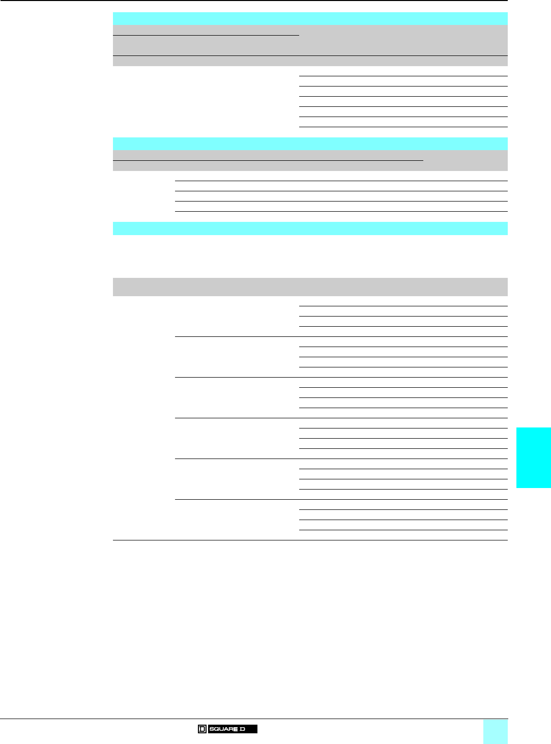
7/13
7
References (continued) Accessories for Heavy Industrial
NEMA Style Controls 0
Replacement parts kits
Universal baseplates
Replacement control transformers (200 VA)
Equipment to be serviced Voltage Reference Weight
Class Type NEMA Size 50 Hz 60 Hz
V V kg (lb)
8502, 8536 S 7 220/440-110 240/480-120 31123-501-50 –
– 208-120 31123-501-52 –
– 277-120 31123-501-53 –
380-110 – 31123-501-54 –
550-110 600-120 31123-501-51 –
110-110 120-120 31123-501-55 –
220-110 240-120 31123-501-56 –
Replacement contact kits
Equipment to be serviced Reference Weight
Class Type Current rating Number of poles kg (lb)
8910 DPA 5 50 A 1 9998 DRC 5 –
DPA 6 60 A 1 9998 DRC 6 –
DPA 7 75 A 1 9998 DRC 7 –
DPA 9 90 A 1 9998 DRC 9 –
DPA 123 120 A 1 9998 DRC 12 –
Universal baseplates
A universal baseplate may be used to retrofit a Square D Type S NEMA starter into an application which is currently using a
competitive NEMA starter. The universal baseplate is a metal plate which attaches to the panel in the location of the starter to
be replaced. The Type S starter then mounts to the baseplate. It is available for NEMA Sizes 00 to 4, and mounting screws are
provided with each plate.
The universal baseplate adapter allows the Type S starter to replace the following competitive starters:
Type Competitive
starter
NEMA Size Reference Weight
kg (lb)
Universal Allen Bradley 509 0 and 1 9998 UB 01 –
baseplates 29998 UB 02 –
39998 UB 03 –
49998 UB 04 –
Allen Bradley 709 1 9998 UB 01 –
29998 UB 02 –
39998 UB 03 –
49998 UB 04 –
Cutler Hammer
Freedom Series
00, 0, 1 9998 UB 01 –
29998 UB 02 –
39998 UB 03 –
49998 UB 04 –
Furnas ESP100 0 and 1 9998 UB 01 –
29998 UB 02 –
39998 UB 03 –
49998 UB 04 –
Furnas INNOVA 0 and 1 9998 UB 01 –
29998 UB 02 –
39998 UB 03 –
49998 UB 04 –
General Electric
CR306
00, 0, 1 9998 UB 01 –
29998 UB 02 –
39998 UB 03 –
49998 UB 04 –
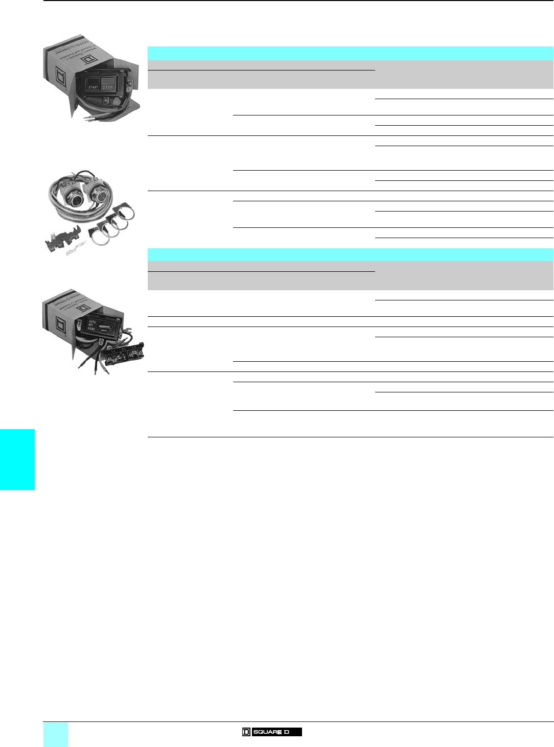
7/14
7
References Accessories for Heavy Industrial
NEMA Style Controls 0
Cover-mounted control unit kits
Class 9999 cover-mounted push button, selector switch and pilot light control unit kits can be easily field installed in a NEMA 1 or 12,
Type S contactor or starter enclosure cover. Knockouts or removable closing plates are provided with many enclosure covers for
convenient field installation of control units. Kits are supplied with leads and clearly illustrated instructions.
The Class 9999 cover-mounted control unit kits are identical to the factory-installed units.
Push button kits for NEMA 1 enclosures
For use with Description Reference Weight
Class Type NEMA Size or
current rating
Number of
poles
kg (lb)
8502 and 8536 SA, SB, SC
SD
SE
00, 0, 1 and 1P
2
3
All
All
All
Start-Stop 9999 SA2 –
On-Off 9999 SA10 –
SF to SJ 4 to 7 All Start-Stop 9999 SA3 –
On-Off 9999 SA3 –
8538, 8539, 8702, 8736 SB and SC
SD
SE
SF
0 and 1
2
3
4
All
All
All
All
Start-Stop 9999 SA2 –
On-Off 9999 SA10 –
SG to SJ 5 to 7 All Start-Stop 9999 SA3 –
On-Off 9999 SA3 –
8903 (electrically held) LX (1) 30 A All On-Off 9999 LXPB (2) –
SM
SP
SQ
30 A
60 A
100 A
All
All
All
Start-Stop 9999 SA2 (3) –
On-Off 9999 SA10 (3) –
SJ, SV, SX,
SY and SZ
200 to 800 A All Start-Stop 9999 SA3 (3) –
On-Off 9999 SA3 (3) –
Selector switch kits for NEMA 1 enclosures
For use with Description Reference Weight
Class Type NEMA Size or
current rating
Number of
poles
kg (lb)
8502 and 8536 SA, SB, SC
SD
SE
00, 0, 1 and 1P
2
3
All
All
All
Hand-Off-Auto 9999 SC2 –
On-Off 9999 SC22 –
8502 and 8536 SF to SJ 4 to 7 All Hand-Off-Auto 9999 SC8 –
8538, 8539, 8702, 8736 SB and SC
SD
SE
SF
0 and 1
2
3
4
All
All
All
All
Hand-Off-Auto 9999 SC2 –
On-Off 9999 SC22 –
SG to SJ 5 to 7 All Hand-Off-Auto 9999 SC8 –
8903 (electrically held) LX (1) 30 A All On-Off 9999 LXS (2) –
SM 30 A All Hand-Off-Auto 9999 SC2 –
SP
SQ
60 A
100 A
All
All
On-Off 9999 SC22 –
SJ, SV, SX,
SY
and SZ
200 to 800 A All Hand-Off-Auto 9999 SC8 –
(1) For Class 8903 Type LX, NEMA 12 control unit kits, refer to the Class 8903 section.
(2) To mount a control unit in a NEMA 1 enclosure, a Class 9999 Type BLX bracket is also required.
(3) Also requires N/O auxiliary contact for holding circuit contact when used on Class 8903 electrically held lighting contactors.
9999 SA2
DF
531371
9999 SA3
DF
531372
9999 SC2
DF
531373
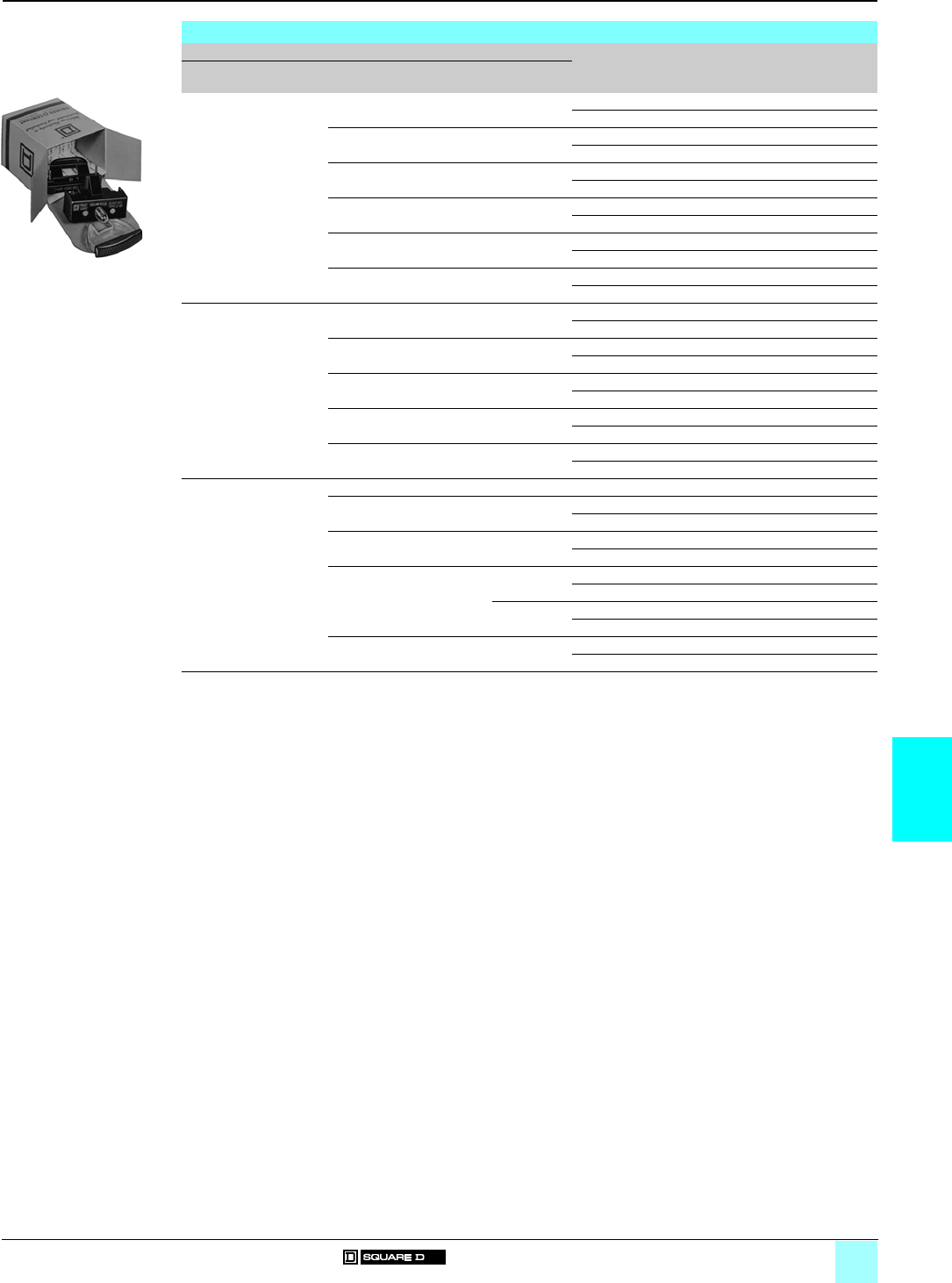
7/15
7
References (continued) Accessories for Heavy Industrial
NEMA Style Controls 0
Cover-mounted control unit kits
Red pilot light (1) kits for NEMA 1 enclosures
For use with Description Reference Weight
Class Type NEMA Size or
current rating
Number of
poles
kg (lb)
8502 and 8536 SA, SB and
SC
00, 0, 1 and 1P All With control transformer 9999 SP 28R –
Standard 9999 SP 2R –
SD 2 All With control transformer 9999 SP 28R –
Standard 9999 SP 3R –
SE 3 2 and 3 With control transformer 9999 SP 28R –
Standard 9999 SP 4R –
SE 3 4 and 5 With control transformer 9999 SP 28R (3) –
Standard 9999 SP 5R –
SF 4 All With control transformer 9999 SP 28R (3) –
Standard 9999 SP 28R –
SG to SJ 5 to 7 All With control transformer 9999 SP 28R (3) –
Standard 9999 SP 28R (3) –
8538, 8539, 8702, 8736 SB and SC 0 and 1 All With control transformer 9999 SP 12R –
Standard 9999 SP 12R –
SD 2 All With control transformer 9999 SP 13R –
Standard 9999 SP 13R –
SE 3 All With control transformer 9999 SP 14R –
Standard 9999 SP 14R –
SF 4 All With control transformer 9999 SP 15R –
Standard 9999 SP 15R –
SG to SJ 5 to 7 All With control transformer 9999 SP 28R (3) –
Standard 9999 SP 28R (3) –
8903 (electrically held) LX (2) 30 A All With control transformer 9999 SP 28R (3) –
SM 30 A All With control transformer 9999 SP 28R –
Standard 9999 SP 2R –
SP 60 A All With control transformer 9999 SP 28R –
Standard 9999 SP 3R –
SQ 100 A 2 and 3 With control transformer 9999 SP 28R (3) –
Standard 9999 SP 28R –
4 and 5 With control transformer 9999 SP 28R (3) –
Standard 9999 SP 28R –
SJ, SV, SX,
SY and SZ
200 to 800 A All With control transformer 9999 SP 28R (3) –
Standard 9999 SP 28R (3) –
(1) A green lens is included in the red pilot light kits. If you order a 9999 SP 28R kit, you will receive both a red and a green lens
with the pilot light.
(2) For Class 8903 Type LX NEMA 12 rated control unit kits, refer to the Class 8903 section.
(3) The coil voltage must be the same as the pilot light rating. The kit contains one Class 9001 Type KP1R31120V, 60 Hz red pilot
light control unit. For other voltages, refer to the Class 9001 Type KP section of the Digest..
9999 SP 2R
DF
531374

7/16
7
References (continued) Accessories for Heavy Industrial
NEMA Style Controls 0
Cover-mounted control unit kits
Push button kits for NEMA 12 enclosures
For use with Description (1) Reference Weight
Class Type NEMA Size or
current rating
Number of
poles
kg (lb)
8502, 8536
8538, 8539, 8702, 8736
8903 (electrically held)
SA, SB, SC
SD
SE
SF
SG to SJ
SB and SC
SD
SE
SF
SG to SJ
LX (2)
SM
SP
SQ
SJ, SV, SX,
SY
and SZ
00, 0, 1 and 1P
2
3
4
5 to 7
0 and 1
2
3
4
5 to 7
30 A
30 A
60 A
100 A
200 to 800 A
All
All
All
All
All
All
All
All
All
All
All
All
All
All
All
Start-Stop
or On-Off
9999 SA3 –
Selector switch kits for NEMA 12 enclosures
For use with Description (1) Reference Weight
Class Type NEMA Size or
current rating
Number of
poles
kg (lb)
8502, 8536
8538, 8539, 8702, 8736
8903 (electrically held)
SA, SB, SC
SD
SE
SF
SG to SJ
SB and SC
SD
SE
SF
SG to SJ
LX (2)
SM
SP
SQ
SJ, SV, SX,
SY and SZ
00, 0, 1 and 1P
2
3
4
5 to 7
0 and 1
2
3
4
5 to 7
30 A
30 A
60 A
100 A
200 to 800 A
All
All
All
All
All
All
All
All
All
All
All
All
All
All
All
Hand-Off-Auto 9999 SC8 –
(1) User-made openings are required in order to field install these modification kits on standard 8502, 8536 Type S Sizes 0 to 2,
and 8903 Sizes 30 to 60 A NEMA 12 enclosures
(2) For Class 8903 Type LX NEMA 12 control unit kits, refer to the Class 8903 section.
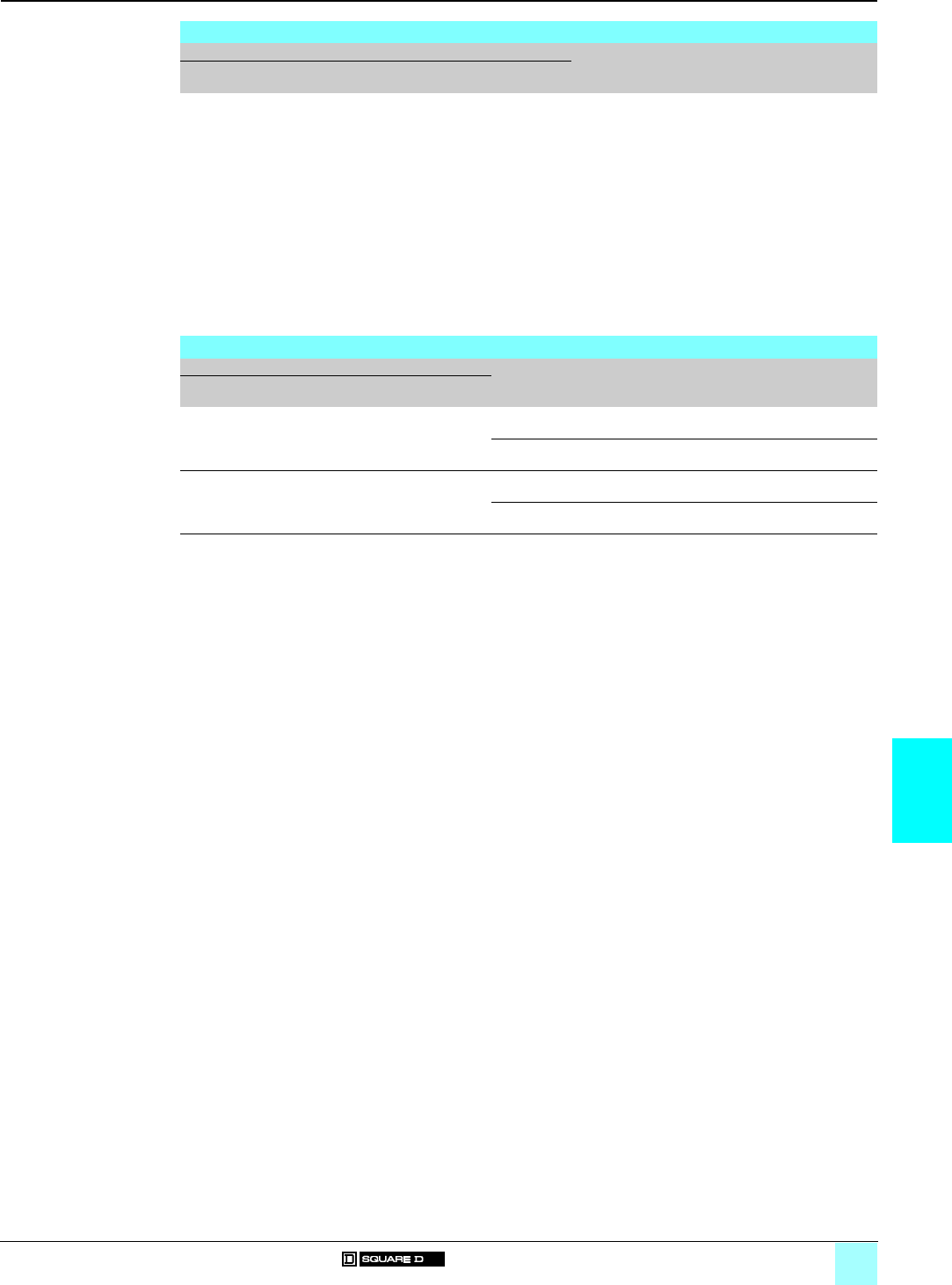
7/17
7
References (continued) Accessories for Heavy Industrial
NEMA Style Controls 0
Cover-mounted control unit kits
Red pilot light (1) kits for NEMA 12 enclosures
For use with Description (2) Reference Weight
Class Type NEMA Size or
current rating
Number of
poles
kg (lb)
8502, 8536
8538, 8539, 8702, 8736
8903 (electrically held)
SA, SB, SC
SD
SE
SF
SG to SJ
SB and SC
SD
SE
SF
SG to SJ
LX (4)
SM
SP
SQ
SJ, SV, SX,
SY
and SZ
00, 0, 1 and 1P
2
3
4
5 to 7
0 and 1
2
3
4
5 to 7
30 A
30 A
60 A
100 A
200 to 800 A
All
All
All
All
All
All
All
All
All
All
All
All
All
All
All
120 V, 60 Hz 9999 SP 28R (3) –
Closing plates for NEMA 1 enclosures
For use with Description Reference Weight
Class Type NEMA Size or
current rating
kg (lb)
8502, 8536, 8903 SA to SE or
SM to SP
00 to 3 or
30 to 60 A
For pilot light or reset
Slip-on cover, NEMA 1 enclosure
9999 SG2 –
For push button or selector switch
Slip-on cover, NEMA 1 enclosure
9999 SG3 –
8538 and 8539 SB to SF 0 to 4 For push button or selector switch
Hinged cover, NEMA 1 enclosure
9999 SG1 –
For pilot light
Hinged cover, NEMA 1 enclosure
9999 SG2 –
(1) A green lens is included in the red pilot light kits. If you order a 9999 SP 28R kit, you will receive both a red and a green lens
with the pilot light.
(2) User-made openings are required in order to field install these modification kits on standard 8502, 8536 Type S Sizes 0 to 2,
and 8903 Sizes 30 to 60 A NEMA 12 enclosures.
(3) The coil voltage must be the same as the pilot light rating. Kit contains one Class 9001 Type KP1R31120V, 60 Hz red pilot light
control unit. For other voltages, refer to the Class 9001 Type KP section of the Digest..
(4) For Class 8903 Type LX NEMA 12 control unit kits, refer to the Class 8903 section.

7/18
7
Characteristics,
references
Accessories for Heavy Industrial
NEMA Style Controls 0
Auxiliary contacts
Characteristics
Class 9999
Type SX 11/SX 12
Contact ratings
Maximum current (50/60 Hz)
Make
(35% power factor)
Break
(35% power factor)
Continuous current
a 120 V or less A30 3 3
a 120…600 V 3600 VA 360 VA 3 A
Class 9999
Type SX 6 to SX 10/SX 13 to SX 17
Contact ratings
Maximum current (50/60 Hz)
Make
(35% power factor)
Break
(35% power factor)
Continuous current
a 120 V or less A60 610
a 120…600 V 7200 VA 720 VA 10 A
References
Internal contact kits
Class 9999 Type SX 11 internal contact kit is a replacement unit for the N/O holding circuit contact supplied as standard on
Type S, Sizes 00–2, three-phase starters and contactors. The Class 9999 Type SX 12 is a replacement unit for the N/C electrical
contact supplied as standard on Type S, Sizes 00–2, mechanically interlocked devices. Internal contacts are also used on
Class 2510 Types M and T manual starters. The internal contacts can be used for other applications as long as the electrical rating
is not exceeded.
For use with Internal non-convertible
contacts
Reference Weight
Class Type NEMA Size kg (lb)
8502, 8702, 8536, 8736 SA to SD 00 to 2 1 N/O contact 9999 SX 11 (1) –
1 N/C contact 9999 SX 12 (1) –
External contact kits
Class 9999 Type SX 6 external auxiliary contact is supplied as standard for the N/O holding circuit contact on Type S Sizes 3 to
7 contactors and starters. Additional auxiliary contacts can be added to Type S contactors, starters and lighting contactors. These
contacts mount on either side of the basic contactor and are available with convertible or non-convertible contacts. The contacts
of the convertible version can be changed from N/O to N/C or vice versa in the field. The non-convertible version has fixed
contacts, either N/O or N/C.
To determine the number of auxiliary contacts that can be added to each Type S contactor or starter, refer to the contactor and
starter section.
For use with External field convertible
contacts
Reference Weight
Class Type NEMA Size kg (lb)
8502, 8702, 8536, 8736 SA to SJ 00 to 7 1 N/O contact 9999 SX 6 –
1 N/C contact 9999 SX 7 –
1 N/O and 1 N/C isolated contacts 9999 SX 8 –
1 N/O overlapping contact 9999 SX 9 (2) –
1 N/C overlapping contact 9999 SX 10 (2) –
For use with External non-convertible
contacts
Reference Weight
Class Type NEMA Size kg (lb)
8502, 8702, 8536, 8736 SA to SJ 00 to 7 1 N/O contact 9999 SX 13 –
1 N/C contact 9999 SX 14 –
1 N/O and 1 N/C isolated contacts 9999 SX 15 –
1 N/O overlapping contact 9999 SX 16 (2) –
1 N/C overlapping contact 9999 SX 17 (2) –
(1) Types SX 11 and SX 12 are not applicable on NEMA Sizes 3 or larger. Internal contacts can also be used on Class 2510 Types
M and T manual starters.
(2) Types SX 9 and SX 10 or Types SX 16 and SX 17 must be used together and mounted on the same side of the contactor. They
are suitable for applications where it is necessary for a normally open contact to overlap a normally closed contact.
9999 SX 11
DF 531376
9999 SX 6
DF 531375

7/19
7
References Accessories for Heavy Industrial
NEMA Style Controls 0
Auxiliary contacts,
Adapter, Remote reset module
Isolated auxiliary contacts for Motor Logic solid-state overload relays
Overload relay auxiliary contacts are available factory installed or in kit form for field installation on Motor Logic solid-state overload
relays.
These contacts may be used for isolated alarm contact applications.
For use with External field convertible
contact
Reference Weight
Class Type NEMA Size kg (lb)
9065 SS, SR, SF, ST 00B to 7 N/O or N/C auxiliary contact 9999 AC 04 –
Adapter
The adapter enables the Motor Logic solid-state overload relay to be mounted on a 35 mm mounting rail.
For use with Reference Weight
Class Type NEMA Size kg (lb)
9065 SS or SF 00B, 00C, 0 and 1 9999 DA 01 –
Remote reset module
The remote reset module can be easily field installed on solid-state overload relays. This module will allow the overload relay to
be reset from a remote location.
For use with Description Reference Weight
Class Type NEMA Size kg (lb)
9065 SS, SR, SF, ST 00B to 7 Remote reset module 9999 RR 04 (1) –
SS, SR, SF, ST 3 and 4 Top mounting bracket 9999 RB 34 (1) (2) –
(1)
a
120 V power required.
(2) To be used for mounting the remote reset module on the top of the solid-state overload relay.
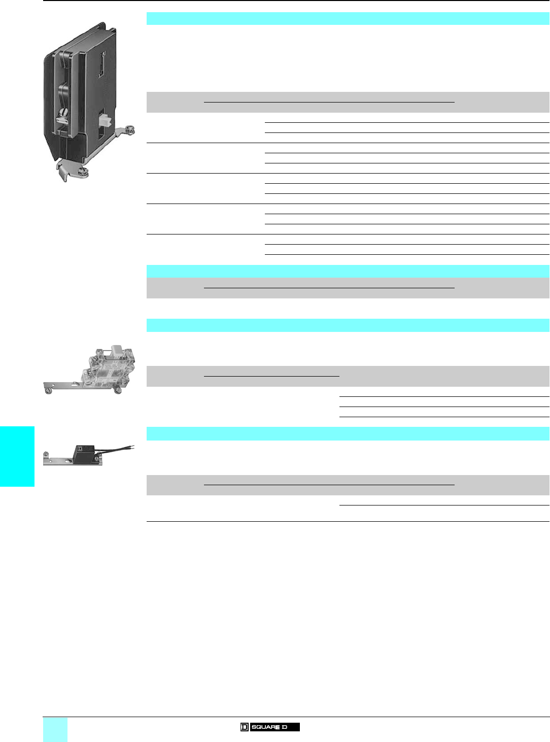
7/20
7
References Accessories for Heavy Industrial
NEMA Style Controls 0
Power-pole adder kits, Timer attachments,
Control circuit fuse holders,
Transient suppression modules
Power-pole adder kits
One single- or double-circuit power pole kit may be field added to a basic 2- or 3-pole Type S contactor or starter, Size 0–2, or a
30–60 A lighting contactor. The ratings for these power-pole adders correspond to the NEMA contact ratings found in the contactor
and starter section or lighting contactor section. A 2- or 3-pole contactor or starter will accept only one single- or double-circuit
unit. A power pole cannot be used on 4- or 5-pole devices or devices which are mechanically interlocked.
For adding a power pole to a Size 2 or 60 A device, a coil change is required. When adding Sizes 0 to 2 power pole kits to a Size 3
to 7 or 100 to 800 A device, an adapter bracket (9999 SBT 1) is required.
The Class 9999 Types SB 6 to SB 15 power pole kits are suitable for copper wire only. Types SB 21 to SB 25 are supplied with
lugs suitable for copper and aluminum wire.
Description For use with Reference Weight
kg (lb)
Class Type NEMA Size or current rating
1 N/O power-
pole adder
8502, 8702, 8536,
8736, 8903
SB, SC, SM 0, 1 and 30 A 9999 SB 6 –
SD 2 9999 SB 11 (1) –
SP 60 A 9999 SB 21 (1) –
1 N/C power
pole adder
8502, 8702, 8536,
8736, 8903
SB, SC, SM 0, 1 and 30 A 9999 SB 7 –
SD 2 9999 SB 12 (1) –
SP 60 A 9999 SB 22 (1) –
1 N/O and 1 N/C
power-pole
adder
8502, 8702, 8536,
8736, 8903
SB, SC, SM 0, 1 and 30 A 9999 SB 8 –
SD 2 9999 SB 13 (1) –
SP 60 A 9999 SB 23 (1) –
2 N/O power-
pole adders
8502, 8702, 8536,
8736, 8903
SB, SC, SM 0, 1 and 30 A 9999 SB 9 –
SD 2 9999 SB 14 (1) –
SP 60 A 9999 SB 24 (1) –
2 N/C power
pole adders
8502, 8702, 8536,
8736, 8903
SB, SC, SM 0, 1 and 30 A 9999 SB 10 –
SD 2 9999 SB 15 (1) –
SP 60 A 9999 SB 25 (1) –
Adapter bracket
Description For use with Reference Weight
kg (lb)
Class Type NEMA Size or current rating
Adapter bracket 8502, 8702, 8536,
8736, 8903
SE to SJ and
SQ to SZ
3 to 7 and
100 to 800 A
9999 SBT 1 –
Control circuit fuse holders
The control circuit fuse holder is designed to be used on Type S contactors and starters, Sizes 00 to 7, when either one or two
control circuit fuses, 600 V maximum, are required. The Type SF 3 and SF 4 fuse holders accept standard 600 V Bussmann Type
KTK or equivalent fuses (10 mm x 38 mm), 6 A maximum. Type SFR 3 and SFR 4 fuse holders accept Class CC 600 V Bussmann
Type KTK-R or equivalent fuses only.
Type For use with Description (2) Reference Weight
kg (lb)
Class NEMA Size
Control circuit
fuse holders
8502, 8702, 8536,
8736
00 to 7 Single-fuse unit 9999 SF 3 –
Single-fuse unit for Class CC fuse 9999 SFR 3 –
Two-fuse unit 9999 SF 4 –
Two-fuse unit for Class CC fuses 9999 SFR 4 –
Transient suppression modules
The transient suppression module is designed to be used where the transient voltage, generated when opening the coil circuit,
interferes with the proper operation of nearby integrated or solid-state control circuits. The module consists of a RC circuit and is
designed to suppress the coil voltage transients to approximately 200% of peak coil supply voltage. The module is wired across
the coil for Type S, Sizes 00 to 5 and is designed for coil voltages of 120 V only.
Type For use with Reference Weight
kg (lb)
Class NEMA Size
Transient
suppression
modules
8502, 8702, 8536, 8736 00 to 2 9999 ST 1 –
3 to 5 9999 ST 2 –
(1) To order a Size 2 or 60 A power pole kit complete with a new starter coil, specify suffix Y118, plus the voltage and frequency.
Example: Class 9999 Type SB11 Form Y118, 120 volts, 60 Hz.
(2) Fuses not included.
9999 SB 6
DF531377
9999 SF 4
DF531379
9999 ST 1
DF531380

7/21
7
References Accessories for Heavy Industrial
NEMA Style Controls 0
Compression lugs
Terminal block
Compression lugs
A Class 9999 Type AL hardware kit is required to install Versa-Crimp® compression lugs on Class 8903 Type S, 100 to 800 A
lighting contactors. The lugs are suitable for both copper and aluminum wire.
One VCEL lug is required for each line or load terminal. Each Class 9999 Type AL hardware kit includes mounting hardware for
3 terminals, line or load side.
Example: to install compression lugs on a 300 A 3-pole device, line and load sides, order 6 x VCEL-060-12H1 lugs and 2 x
Class 9999 Type AL 11 hardware kits.
For use with Versa-Crimp
catalogue number
Material Wire
range
(min.-max.)
Number
of poles
Reference Weight
kg (lb)
Class Type Current rating
8903 SQ 100 A VCEL-021-14S1 Al/Cu 8–1/0 – (1) –
SV 200 A VCEL-022-516H1 Al/Cu 1–2/0 2 poles 9999 AL 13 –
3 poles 9999 AL 14 –
4 poles 9999 AL 15 –
VCEL-024-516H1 Al/Cu 2/0–4/0 2 poles 9999 AL 13 –
3 poles 9999 AL 14 –
4 poles 9999 AL 15 –
VCEL-030-516H1 MCM Al/Cu 4–300 2 poles 9999 AL 13 –
3 poles 9999 AL 14 –
4 poles 9999 AL 15 –
SX 300 A VCEL-050-12H1 MCM Al/Cu 2/0–500 – 9999 AL 11 –
VCEL-060-12H1 MCM Al 400–600 – 9999 AL 11 –
MCM Cu 400–500 – 9999 AL 11 –
VCEL-075-12H1 MCM Al 500–750 – 9999 AL 11 –
MCM Cu 500 – 9999 AL 11 –
SY, SZ 400, 600 A VCEL-060-12H2 (2) MCM Al 400–600 – 9999 AL 12 –
MCM Cu 400–500 – 9999 AL 12 –
VCEL-075-12H2 (2) MCM Al 500–750 – 9999 AL 12 –
MCM Cu 500 – 9999 AL 12 –
SJ 800 A – – – – (3) –
Terminal block
The terminal block provides easy wiring of a "Hand-Off-Auto" selector switch or "Start-Stop" push buttons with separate control.
The terminal block requires no panel space. It simply snaps onto Type S, Sizes 00–4 contactors and starters by two tabs and is
secured to the left-hand coil terminal.
For use with Reference Weight
kg (lb)
Class Type NEMA Size
8502, 8702, 8536, 8736 SA to SF 00 to 4 9999 T7 –
(1) Not required.
(2) One or two lugs may be mounted on each terminal.
(3) Compression lugs for these devices are available only as a factory modification. Order: suffix Y1574. Specify the wire size, up
to 750 MCM Al or 500 MCM Cu, and the number of terminals.
Class 8903
with compression
lugs installed
DF531389
9999 T7
DF531390

8/0

8/1
Contents
8
8 - Services
Schneider Electric worldwide
bAddresses . . . . . . . . . . . . . . . . . . . . . . . . . . . . . . . . . . . . . . . . . . . . . . . . page 8/2
8/2
Schneider Electric worldwide
0
Afghanistan Contacts are assured by Schneider Electric India
Albania Contacts are assured by Schneider Electric Austria
Algeria bSchneider Electric voie A Lot C22
Zone industrielle Rouiba - Alger
Tel. : +213 21 92 97 02 à 09
Fax : +213 21 92 97 00 à 01
Andorra Contacts are assured by Schneider Electric France
Angola Contacts are assured by Schneider Electric South Africa
Anguilla Contacts are assured by Schneider Electric Dominican Rep.
Antartica Contacts are assured by Schneider Electric Brazil
Antigua & Barbuda Contacts are assured by Schneider Electric Dominican Rep.
Argentina bSchneider Argentina Viamonte 2850 - 1678 Caseros
(provincia Buenos Aires)
Tel.: +54 1 716 88 88
Fax: +54 1 716 88 33
www.schneider-electric.com.ar
Armenia Contacts are assured by Schneider Electric Russian Fed.
Aruba Contacts are assured by Schneider Electric Dominican Rep.
Australia bSchneider Electric (Australia) Pty.
Limited
2 Solent Circuit
Norwest Business Park
Baulkham Hill _ NSW 2153
Tel.: +61 298 51 28 00
Fax: +61 296 29 83 40
www.schneider.com.au
Austria bSchneider Austria Ges.m.b.H. Birostrasse 11
1239 Wien
Tel.: +431 610 540
Fax: +431 610 54 54
www.schneider-electric.at
Azerbaijan Contacts are assured by Schneider Electric Russian Fed.
Bahamas bSchneider Electric Union Village
PO Box 3901 - Nassau
Tel. : +1 242 327 42 91
Fax : +1 242 327 42 91
www.squared.com
Bahrain bSchneider Electric Floor 1 - Juma Building
Abu Horaira Avenue
PO Box 355 - 304 Manama
Tel.: +97 322 7897
Fax: +97 321 8313
Bangladesh Contacts are assured by Schneider Electric India
Barbados Contacts are assured by Schneider Electric Dominican Rep.
Belarus bSchneider Electric Industries SA Prospect Macherova 5, of. 202
220004 Minsk
Tel. : +375 172 23 75 50
Fax : +375 172 23 97 61
Belgium bSchneider Electric nv/sa Dieweg 3
B - 1180 Brussels
Tel.: +3223737711
Fax: +3223753858
www.schneider-electric.be
Belize Contacts are assured by Schneider Electric USA
Benin Contacts are assured by Schneider Electric Ivory Coast
Bermuda Contacts are assured by Schneider Electric Dominican Rep.
Bhutan Contacts are assured by Schneider Electric India
Bolivia Contacts are assured by Schneider Electric Chile
Bosnia and Herzegovina Contacts are assured by Schneider Electric Croatia
Botswana Contacts are assured by Schneider Electric South Africa
Bouvet island Contacts are assured by Schneider Electric Dominican Rep.
Brazil bSchneider Electric Brazil Ltda. Avenida Das Nações Unidas 23223
Jurubatuba - CEP 04795-907
São Paulo-SP
Tel.: +55 55 24 52 33
Fax: +55 55 22 51 34
www.schneider-electric.com.br
Brunei (Darussalam) Contacts are assured by Schneider Electric Singapore
Bulgaria bSchneider Electric Expo 2000, Boulevard Vaptzarov
1407 Sofiav
Tel.: +3592 919 42
Fax: +3592 962 44 39
www.schneiderelectric.bg
Burkina Faso Contacts are assured by Schneider Electric Ivory Coast
Burundi Contacts are assured by Schneider Electric Kenya
Cambodia Contacts are assured by Schneider Electric Viet Nam
Cameroon bSchneider Electric Cameroon 166, rue de l'Hôtel de Ville
BP12087 - Douala
Tel.: +237 343 38 84
Fax: +237 343 11 94
Canada bSchneider Canada 19, Waterman Avenue
M4 B1Y2 Toronto - Ontario
Tel.: +1 416 752 8020
Fax: +1 416 752 4203
www.schneider-electric.ca
Cape Verde Contacts are assured by Schneider Electric Senegal
Caribee Contacts are assured by Schneider Electric Dominican Rep.
Cayman islands Contacts are assured by Schneider Electric Dominican Rep.
Central African Republic Contacts are assured by Schneider Electric Cameroon
Chad Contacts are assured by Schneider Electric Cameroon
Chile bSchneider Electric Chile S.A.
Avda. Pdte Ed. Frei Montalva, 6001-31
Conchali - Santiago
Tel.: +56 2 444 3000
Fax: +56 2 423 9335
www.schneider-electric.co.cl
China bSchneider Beijing Landmark bldg-Room 1801
8 North Dong Sanhuan Rd
Chaoyang District
100004 Beijing
Tel.: +86 10 65 90 69 07
Fax: +86 10 65 90 00 13
www.schneider-electric.com.cn
Up-dated: 30-07-2003
Schneider Electric worldwide
0
Up-dated: 30-07-2003
8/3
Christmas island Contacts are assured by Schneider Electric Australia
Cocos (Keeling) islands Contacts are assured by Schneider Electric Australia
Colombia bSchneider Electric de Colombia
S.A.
Calle 45A #102-48
Bogota DC
Tel.: +57 1 426 97 00
Fax: +57 1 426 97 40
Comoros Contacts are assured by Schneider Electric la Reunion
Congo Contacts are assured by Schneider Electric Cameroon
Cook islands Contacts are assured by Schneider Electric Australia
Costa Rica bSchneider Centroamérica Ltda. 1.5 kmts oeste de la Embajada
Americana,
Pavas, San José, Costa Rica C.A.
Apartado: 4123-1000 San Jose
Tel.: +506 232-60-55
Fax: +506 232-04-26
www.schneider-ca.com
Croatia bSchneider Electric SA Fallerovo Setaliste 22
HR - 10000 Zagreb
Tel.: +385 1 367 100
Fax: +385 1 367 111
Cuba bSchneider Electric Bureau de Liaison de La Havane
Calle 36- N°306-Apto1
Entre 3ra y 5ta Avenida Miramar
Playa Habana
Tel.: +53 724 15 59
Fax: +53 724 12 17
Cyprus bSchneider Electric Cyprus 28 General Timayia Avenue
Kyriakos Building, Block #A301
Larnaca 6046
Tel.: +00357 248 12646
Fax: +00357 246 37382
Czech Republic bSchneider Electric CZ, s.r.o. Thámova 13
Praha 8 - 186 00
Tel.: +420 2 810 88 111
Fax: +420 2 24 81 08 49
www.schneider-electric.cz
Democratic Rep. of Congo Contacts are assured by Schneider Electric Cameroon
Denmark bSchneider Electric A/S Baltorpbakken 14
DK-2750 Ballerup
Tel.: +45 44 73 78 88
Fax: +45 44 68 5255
www.schneider-electric.dk
Djibouti Contacts are assured by Schneider Electric Egypt
Dominican Republic bSchneider Electric Calle Jacinto Manon
Esq. Federico Geraldino
Edificio D' Roca Plaza Suite 402,
Ens. Paraiso - Santo Domingo
Tel.: +1 809 334 66 63
Fax: +1 809 334 66 68
Ecuador bSchneider Electric Ecuador SA
Av.Republica del Salvador 1082 y Nac
Edificio Mansion Blanca-Quito
Tel. : +593 2 224 42 42
Fax : +593 2 224 42 94
Egypt bSchneider Electric Egypt sae 68, El Tayaran Street
Nasr City, 11371 - Cairo
Tel.: +20 24 01 01 19
Fax: +20 24 01 66 87
www.schneider.com.eg
El Salvador Contacts are assured by Schneider Electric USA
Equatorial Guinea Contacts are assured by Schneider Electric Cameroon
Eritrea Contacts are assured by Schneider Electric Egypt
Estonia bLexel Electric Ehitajate tee 110
EE 12618 Talinn
Tel. : +372 650 97 00
Fax : +372 650 97 22
Ethiopia Contacts are assured by Schneider Electric Egypt
Falkland islands Contacts are assured by Schneider Electric Brazil
Faroe islands Contacts are assured by Schneider Electric Australia
Fiji Contacts are assured by Schneider Electric Australia
Finland bSchneider Electric Oy Sinimäentie 14
02630 Espoo
Tel. : +358 9 527 000
Fax : +358 9 5270 0376
www.schneider-electric.fi
France bSchneider Electric SA 5, rue Nadar
92500 Rueil Malmaison
Tel.: +33 (0)1 41 29 82 00
Fax: +33 (0)1 47 51 80 20
www.schneider-electric.fr
French Polynesia Contacts are assured by Schneider Electric Australia
French West Indies Contacts are assured by Schneider Electric Dominican Rep.
Gabon Contacts are assured by Schneider Electric Cameroon
Gambia Contacts are assured by Schneider Electric Senegal
Georgia Contacts are assured by Schneider Electric Russian Fed.
Germany bSchneider Electric GmbH Gothaer Straße 29
D-40880 Ratingen
Tel.: +49210 240 40
Fax: +492 10 240 49 256
www.schneiderelectric.de
Ghana bSchneider Electric Ghana PMB Kia
3rd Floor Opeibea House
Airport Commercial Center
Liberation road - Accra
Tel. : +233 21 70 11 687
Fax : +233 21 77 96 22
Gilbraltar Contacts are assured by Schneider Electric Spain
Greece bSchneider Electric AE 14th km - RN Athens-Lamia
GR - 14564 Kifissia
Tel.: +302 106 29 52 00
Fax: +302 106 29 52 10
www.schneider-electric.com.gr
Greenland Contacts are assured by Schneider Electric United States
Grenada Contacts are assured by Schneider Electric Dominican Rep.
Guadeloupe Contacts are assured by Schneider Electric Martinique
Guam Contacts are assured by Schneider Electric Australia

Schneider Electric worldwide
0
Up-dated: 30-07-2003
8/4
Guatemala Contacts are assured by Schneider Electric United States
Guinea-Bissau Contacts are assured by Schneider Electric Sénégal
Guinea Contacts are assured by Schneider Electric Ivory Coast
Guyana Contacts are assured by Schneider Electric United States
Haiti Contacts are assured by Schneider Electric Dominican Rep.
Heard & Mac Donald isl. Contacts are assured by Schneider Electric Australia
Honduras Contacts are assured by Schneider Electric United States
Hong Kong bSchneider Electric (Hong Kong)
Ltd
Room 3108-28, 31th Floor,
Sun Hung Kai Centre,
30 Harbour Road, Wanchai
Tel.: +852 25 65 06 21
Fax: +852 28 11 10 29
Hungary bSchneider Electric Hungária
Villamossági Rt.
Fehérvári út 108 – 112
H-1116 Budapest
Tel.: +36 1 382 26-06
Fax: +36 1 206 1429
www.schneider-electric.hu
Iceland Contacts are assured by Schneider Electric Denmark
India bSchneider Electric India Max House, 1 Dr Jha Marg, Okhla
110 020 New Dehli
Tel. : +91 11 631 85 84
Tel. : +91 11 631 71 61
www.schneiderelectric-in.com
Indonesia bP.T. Schneider Indonesia Ventura Building 7th Floor
Jalan R.A. Kartini Kav.26
Cilandak - 12430 Jakarta
Tel.: +62 +21 750 44 06
Fax: +62 +21 750 44 15/ 16
www.schneider-electric.co.id
Iran (Islamic Republic of) bTelemecanique Iran 1047 Avenue VALI ASSR
P.O. Box 15875-3547
15116 Teheran
Tel.: +98 218 71 01 42
Fax: +98 218 71 81 87
Irak bSchneider Electric Industries SA 38050 Grenoble Cedex 9 Tel.: +33 04 76 60 54 27
Fax: +33 04 76 60 56 60
Ireland bSchneider Electric Ireland Maynooth Road
Cellbridge - Co. Kildare
Tel.: +353+0 1 6012200
Fax: +353+0 1 6012201
www.schneiderelectric.ie
Italy bSchneider Electric S.p.A. Centro Direzionale Colleoni
Palazzo Sirio - Viale Colleoni, 7
20041 Agrate Brianza (Mi)
Tel.: +39 39 655 8111
Fax: +39 39 605 6237
www.schneiderelectric.it
Ivory Coast bSchneider Electric Afrique de
l'Ouest
Rue Pierre et Marie Curie
18 BP 2027 Abidjan 18
Tel.: +225 21 75 00 10
Fax: +225 21 75 00 30
Jamaica bSchneider Electric Shop#5, Plaza Dunrobin
30 Dunrobin Avenue - Kingstown
Tel. : +1876 755 41 27
Tel. : +931 87 74
Japan bSchneider Electric Japan Ltd Torigoe F. Bldg
1-8-2, Torigoe
Taito-Ku - 111-0054 Tokyo
Tel.: +81 358 35 35 81
Fax: +81 358 35 35 85
www.schneider-electric.co.jp
Jordan bSchneider Electric Industr. Jordan Jordan University Street
Abu Al Haj Commercial Complex
2nd Floor - Office # 202 - Amman
Tel.: 962 65 16 78 87
Fax: 962 65 16 79 1
Kazakstan bSchneider Electric Kazakhstan
Liaison Office
Prospekt Abaia 157 off 9
480009 Almaty
Tel. : +7 327 250 93 88
Tel. : +7 327 250 63 70
Kenya bSchneider East Africa Power Technics Complex
Monbasa Road - PO Box 46345
Nairobi
Tel. : +254 2.824.156
Fax : +254 2.824.157
Kiribati Contacts are assured by Schneider Electric Australia
Korea bSchneider Electric Korea Ltd 3Floor, Cheil Bldg., 94-46, 7-Ka
Youngdeungpodong,
Youngdeungpo-ku
150-037 Seoul
Tel. : +82 2 2630 9700
Fax : +82 2 2630 9800
www.csinfo.co.kr/schneider/
Kuwait bSchneider Electric Kuwait Al Gaas Tower - Sharq 2nd Floor
PO Box 20092 - 13 061 Safat
Tel.: +965 240 75 46
Fax: +965 240 75 06
Kyrgyz Republic Contacts are assured by Schneider Electric Russian Fed.
Laos Contacts are assured by Schneider Electric Thailand
Latvia bLexel Electric 60A A.Deglava str.
LV1035 Riga
Tel. : +371 780 23 74/75
Fax : +371 754 62 80
Lebanon bSchneider Electric Liban Tabaris, Avenue Charles Malek
Immeuble Ashada, 8
P.O. Box 166223 - Beyrouth
Tel. : +961 1 20 46 20
Tel. : +961 1 20 31 19
Lesotho Contacts are assured by Schneider Electric South Africa
Liberia Contacts are assured by Schneider Electric Ghana
Libya Contacts are assured by Schneider Electric Tunisia
Liechtenstein Contacts are assured by Schneider Electric Switzerland
Lithuania bLexel Electric 44, Verkiu str.
LT-2012 Vilnius
Tel. : +370 278 59 59/61
Fax : +370 278 59 60
Loro Sae Contacts are assured by Schneider Electric Australia
Luxembourg bSchneider Electric Industrie SAS Agence de Metz
1, Rue Graham Bell - BP n° 35190
57075 Metz cedex 3 - France
Tel.: 33 03 87 39 06 03
Fax: 33 03 87 74 25 96
www.schneider-electric.fr
Macau Contacts are assured by Schneider Electric China
Schneider Electric worldwide
0
Up-dated: 30-07-2003
8/5
Macedonia Contacts are assured by Schneider Electric Bulgaria
Madagascar Contacts are assured by Schneider Electric la Reunion
Malawi Contacts are assured by Schneider Electric South Africa
Malaysia bSchneider Electric (Malaysia) Sdn
Bhd
No.11 Jalan U1/19, Seksyen U1
Hicom-Glenmarie Industrial Park
40150 Shah Alam
Selangor Darul Ehsan
Tel. : (603) 7883 6333
Fax : (603) 7883 6188
www.schneider-
electric.com.my
Maldives Contacts are assured by Schneider Electric Reunion
Mali Contacts are assured by Schneider Electric Senegal
Malta Contacts are assured by Schneider Electric Tunisia
Marshall islands Contacts are assured by Schneider Electric Australia
Martinique bSchneider Electric Schneider Electric
Immeuble Cottrell - ZI de la Lézarde
97232 Le Lamentin
Tel.: +05 96 51 06 00
Fax: +05 96 51 11 26
Mauritania Contacts are assured by Schneider Electric Senegal
Mauritius bSchneider Electric Route côtière
Calodyne - Mauritius
Tel.: 230 282 18 83
Fax: 230 282 18 84
Mayotte Contacts are assured by Schneider Electric Reunion
Mexico bGroupe Schneider Mexico Calz. Rojo Gomez N° 1121-A
Col. Guadalupe del Moral
México, D.F. - C.P. 09300
Tel.: +525 686 30 00
Fax: +525 686 24 09
www.schneider-
electric.com.mx
Micronesia Contacts are assured by Schneider Electric Australia
Moldova Contacts are assured by Schneider Electric Romania
Monaco Contacts are assured by Schneider Electric France
Mongolia Contacts are assured by Schneider Electric Russian Fed.
Montserrat Contacts are assured by Schneider Electric Dominican Rep.
Morocco bSchneider Electric Morocco 26, rue Ibnou Khalikane
Quartier Palmiers
20100 Casablanca
Tel.: +212 299 08 48 to 57
Fax: +212 299 08 67 and 69
www.schneider.co.ma
Mozambique Contacts are assured by Schneider Electric South Africa
Myanmar Contacts are assured by Schneider Electric Singapore
Namibia Contacts are assured by Schneider Electric South Africa
Nauru Contacts are assured by Schneider Electric Australia
Nepal Contacts are assured by Schneider Electric India
Netherlands bSchneider Electric BV Waarderweg 40 - Postbus 836
2003 RV Haarlem
Tel.: +31 23 512 4124
Fax: +31 23 512 4100
www.schneider-electric.nl
Netherlands Antilles Contacts are assured by Schneider Electric Dominican Rep.
New Caledonia Contacts are assured by Schneider Electric Australia
New Zealand bSchneider Electric (NZ) Ltd 14 Charann Place Avondale
P.O. Box 15355 - New Lynn
Auckland
Tel. : +64 9 829 04 90
Fax : +64 9 829 04 91
www.schneider-electric.co.nz
Nicaragua Contacts are assured by Schneider Electric United States
Niger Contacts are assured by Schneider Electric Ivory Coast
Nigeria bSchneider Electric Nigeria Limited Biro plaza - 8th Floor - Plot 634
Abeyemo Alakija Street
Victoria Islan - Lagos
Tel. : +234 1 2702973
Fax : +234 1 2702976
Niue Contacts are assured by Schneider Electric Australia
Norfolk island Contacts are assured by Schneider Electric Australia
North Korea Contacts are assured by Schneider Electric China
Northern Mariana islands Contacts are assured by Schneider Electric Australia
Norway bSchneider Electric Norge A/S Solgaard Skog 2
Postboks 128 - 1501 Moss
Tel.: +47 6924 9700
Fax: +47 6925 7871
www.schneider-electric.no
Oman bSchneider Electric CA c/o Arab Development Co
PO Box 439 - 113 Muscat
Tel.: +968 77 163 64
Fax: +968 77 104 49
Pakistan bSchneider Electric Pakistan 43-L, 2nd floor, M.M. Alam Road,
Gulberg II - Lahore
Tel.: +92 42 5754471 à 73
Fax: +92 42 5754474
Palau Contacts are assured by Schneider Electric Australia
Panama Contacts are assured by Schneider Electric United States
Papua New Guinea Contacts are assured by Schneider Electric Australia
Paraguay Contacts are assured by Schneider Electric Uruguay
Peru bSchneider Electric Peru S.A. Los Telares n°231 Urb. Vulcano, Ate
Lima 03
Tel.: +511 348 44 11
Fax: +511 348 05 23
www.schneider-electric.com.pe
Schneider Electric worldwide
0
Up-dated: 30-07-2003
8/6
Philippines bSchneider Electric Philippines, Inc 5th Floor, ALCO Building
391 Sen, Gil Puyat Avenue
Makati 1209
Tel. : +632 896 6063
Fax : +632 896 7229
Pitcairn Contacts are assured by Schneider Electric Australia
Poland bSchneider Electric Polska Sp.zo.o. ul. Lubinowa 4a
03-878 - Warszawa
Tel.: +48 22 511 8 200
Fax: +48 22 511 8 210
www.schneider-electric.pl
Portugal bSchneider Electric Portugal Av.do Forte, 3
Edificio Suécia II, Piso 3-A
CP 2028 Carnaxide
2795 Linda-A-Velha
Tel.: +351 21 416 5800
Fax: +351 21 416 5857
www.schneiderelectric.pt
Puerto Rico Contacts are assured by Schneider Electric United States
Qatar bSchneider Electric Qatar Branch c/o Khalifa BinFahred Al Thani
Trad.and Co - P.O. Box 4484
Doha
Tel.: +97 4424358
Fax: +97 4424358
Reunion bSchneider Electric Immeuble Futura,
190, rue des 2 canons
BP 646 - 97497 Sainte Clothilde
Tel.: +262 28 14 28
Fax: +262 28 39 37
Romania bSchneider Electric Bd Ficusului n°42
Apimondia, Corp.A, et.1, Sector 1
Bucuresti
Tel.: +401 203 06 50
Fax: +401 232 15 98
www.schneider-electric.ro
Russian Federation bSchneider Electric ZAO Enisseyskaya 37
129 281 Moscow
Tel.: +7095 797 40 00
Fax: +7095 797 40 03
www.schneider-electric.ru
Rwanda Contacts are assured by Schneider Electric Kenya
Samoa Contacts are assured by Schneider Electric Australia
San Marino Contacts are assured by Schneider Electric Italy
Sandwich & Georgia island Contacts are assured by Schneider Electric Australia
Sao Tome & Principe Contacts are assured by Schneider Electric Senegal
Saudi Arabia bSchneider Electric Second Industrial City
P.O. Box 89249 - 11682 Riyadh
Tel.: +966 1 265 1515
Fax: +966 1 265 1860
Senegal bSchneider Electric Sénégal BP 15952 - Dakar-Fann
Rond point N'Gor - Dakar
Tel.: +221 820 68 05
Fax: +221 820 58 50
Seychelles Contacts are assured by Schneider Electric Reunion
Sierra Leone Contacts are assured by Schneider Electric Ghana
Singapore bSchneider Electric Singapore Pte
Ltd
10 Ang Mo Kio Street 65
#02-17/20 TechPoint
Singapore 569059
Tel.: +65 484 78 77
Fax: +65 484 78 00
www.schneider-electric.com.sg
Slovak Republic bSchneider Electric Slovakia spol
s.r.o.
Borekova 10
SK-821 06 Bratislava
Tel. : +02 45 52 40 10 and 40 30
Fax : +02 45 52 40 00
www.schneider-electric.sk
Slovenia bSchneider Electric, d.o.o. Dunasjka 47
1000 Ljubljana
Tel. : +386 1 23 63 555
Fax : +386 1 23 63 559
www.schneider-electric.si
Solomon islands Contacts are assured by Schneider Electric Australia
Somalia Contacts are assured by Schneider Electric Egypt
South Africa bSchneider Electric South Africa
(PTY) Ltd
Private Bag X139
Halfway House
1685 - Midrand.
Tel.: +27 11 254 6400
Fax: +27 11 315 8830
www.schneider-electric.co.za
Spain bSchneider Electric España, S.A. Pl. Dr. Letamendi, 5-7
08007 Barcelona
Tel.: +34 93 484 3100
Fax: +34 93 484 3308
www.schneiderelectric.es
Sri Lanka bSchneider Electric Industries SA Liaison office SRI Lanka
Level 3B Valiant towers
46/7 Nawam Mawatha-Colombo 2
Tel. : +94 77 48 54 89 www.schneiderelectric-in.com
St Helena Contacts are assured by Schneider Electric Italy
St Kitts & Nevis Contacts are assured by Schneider Electric Dominican Rep.
St Lucia Contacts are assured by Schneider Electric Dominican Rep.
St Pierre et Miquelon Contacts are assured by Schneider Electric Dominican Rep.
St Vincent & Grenadines Contacts are assured by Schneider Electric Dominican Rep.
Sudan Contacts are assured by Schneider Electric Egypt
Suriname Contacts are assured by Schneider Electric United States
Svalbard & Jan Mayen isl. Contacts are assured by Schneider Electric Denmark
Swaziland Contacts are assured by Schneider Electric South Africa
Sweden bSchneider Electric AB Djupdalsvägen 17/19
19129 Sollentuna
Tel.: +46 8 623 84 00
Fax: +46 8 623 84 85
www.schneider-electric.se
Switzerland bSchneider Electric (Switzerland)
S.A.
Schermenwaldstrasse 11
CH - 3063 Ittigen
Tel.: +41 31 917 3333
Fax: +41 31 917 3355
www.schneider-electric.ch
Syrian Arab Republic bSchneider Electric Syria Elba Street - Malki
Gheibeh and Qassas bldg, 1st floor
PO Box 33876-Damascus
Tel. : +963 11 37 49 88 00
Fax : +963 11 37 17 55 9
Schneider Electric worldwide
0
Up-dated: 30-07-2003
8/7
Taiwan, Republic of China bSchneider Electric Taiwan Co Ltd 2FI., N°37, Ji-Hu Road, Nei-Hu Dist.,
Taipei 114
Tel. : +886 2 8751 6388
Fax : +886 2 8751 6389
www.schneider-electric.com.tw
Tajikistan Contacts are assured by Schneider Electric Russian Fed.
Tanzania, United Rep. of Contacts are assured by Schneider Electric Kenya
Thailand bSchneider (Thailand) Ltd 20th Floor Richmond Building
75 Sukhumvit 26 Road, Klongtoey
Bangkok 10110
Tel.: +662 204 9888
Fax: +662 204 9816
www.schneider-electric.co.th
Togo Contacts are assured by Schneider Electric Ivory Coast
Tokelau Contacts are assured by Schneider Electric Australia
Tonga Contacts are assured by Schneider Electric Australia
Trinidad & Tobago bSchneider Electric 6, 1st Street West Ext.
Beaulieu Avenue
Trincity Trinidad West Indies
Tel.: 1868 640 42 04
Fax: 1868 640 42 04
Tunisia bSchneider Electric Tunisia Rue du Lac Oubeira
1053 Les Berges du Lac - Tunis
Tel.: +216 71 960 477
Fax: +216 71 960 342
Turkey bSchneider Elektrik Sanayi Ve
Ticaret A.S.
Tütüncü Mehmet Efendi Cad. N°:110
Kat 1-2 - 81080 Göztepe – Istanbul
Tel.: +90 21 63 86 95 70
Fax: +90 21 63 86 38 75
www.schneiderelectric.com.tr
Turkmenistan bSchneider Electric Turkmenistan
Liaison Office
rue Neitralny Turkmenistan 28,
off.326/327
74 000 Achgabad
Tel. : +993 12 46 29 52
Fax : +993 12 46 29 52
Turks & Caicos islands Contacts are assured by Schneider Electric Dominican Rep.
Tuvalu Contacts are assured by Schneider Electric Australia
Uganda Contacts are assured by Schneider Electric Kenya
Ukraine bSchneider Electric Rue Krechtchalik 2
252601 Kiev
Tel.: +380 44 462 04 25
Fax: +380 44 462 04 24
www.schneider-electric.com.ua
United Arab Emirates bSchneider Electric Abu Dhabi PO Box 29580
Office Floor 2/Lulu Street
Al Marina Plaza Tower
Abu Dhabi
Tel.: +9712 6 339444
Fax: +9712 6 316606
United Kingdom bSchneider Electric Ltd Braywick House East
Windsor Road - Maidenhead
Berkshire SL6 1 DN
Tel.: +44 (0)1 628 508 500
Fax: +44 (0)1 628 508 508
www.schneider.co.uk
United States bSchneider Electric North American Division
1415 Roselle Road
Palatine - IL 60067
Tel.: +1 847 397 2600
Fax: +1 847 925 7500
www.squared.com
Uruguay bSchneider Electric Uruguay S.A. Ramon Masini 3190
Montevideo
Tel. : +59 82 707 2392
Fax : +59 82 707 2184
Uzbekistan Contacts are assured by Schneider Electric Russian Fed.
Vanuatu Contacts are assured by Schneider Electric Australia
Vatican city St./Holy See Contacts are assured by Schneider Electric Italy
Venezuela bSchneider Mg SD TE, S.A Calle 162/ Piso 2
Edificio Centro Cynamid
La Urbina, 1070 - 75319 Caracas
Tel.: +58 2 241 13 44
Fax: +58 2 243 60 09
www.schneider-electric.com.ve
Viet Nam bR.R.O. of Schneider Electric
Industries S.A.S. in Viet Nam
Unit 2.9, 2nd Floor, e-Town Building
364 Cong Hoa Street
Tan Binh District - Ho Chi Minh City
Tel.: +84 8 8103 103
Fax: +84 8 8120 477
Virgin islands Contacts are assured by Schneider Electric Dominican Rep.
Wallis & Futuna islands Contacts are assured by Schneider Electric Australia
Western Sahara Contacts are assured by Schneider Electric Morocco
Yemen Contacts are assured by Schneider Electric U.A.E.
Yugoslavia bSchneider Electric Jugoslavija
d.o.o.
Ratarski put 27d
11186 Belgrade
Tel.: +381 11 192 414
Fax: +381 11 107 125
Zambia bSchneider Zambia Zambia Office
c/o Matipi Craft Center Building
Plot 1036 - Accra Road
PO Box 22792 - Kitwe
Tel.: +260 222 22 52
Fax: +260 222 83 89
Zimbabwe bSchneider Electric Zimbabwe Liaison Office
75A Second Street
(corner Livingstone Avenue)
Harare
Tel.: +263 4 707 179/180
Fax: +263 4 707 176
Schneider Electric Industries SAS
Headquaters
89, bd Franklin Roosevelt
92506 Rueil Malmaison Cedex
France
http://www.schneider-electric.com
Due to the evolving nature regarding both the standards and
equipment, we can only be held responsible for any technical
information detailed in this catalogue, either in text or graphic
form, following confirmation by our services.
Photos : Schneider Electric Industries
© 2004–2006 Schneider Electric All Rights Reserved
8502CT0401R10/05
January 2006
