Modicon M340 With Unity Pro Analog Input/output Modules User Manual 07/2012 Brochure
2016-10-06
: Pdf 119587-Brochure 119587-Brochure B5 unilog
Open the PDF directly: View PDF ![]() .
.
Page Count: 20
35011978 07/2012 93
5
Modicon M 340 with Unity Pro
BMX AM I 0810
35011978 07/2012
BMX AMI 0810 Analog Input
Module
Subject of this Chapter
This chapter presents the BMX AMI 0810 module, its characteristics, and explains
how it is connected to the various sensors.
What Is in This Chapter?
This chapter contains the following topics:
Topic Page
Presentation 94
Characteristics 95
Functional Description 97
Wiring Precautions 104
Wiring Diagram 108
Use of the TELEFAST ABE-7CPA02/31/31E Wiring Accessory 109
BMX AMI 0810
94 35011978 07/2012
Presentation
Function
The BMX AMI 0810 is a high density input analog module with 8 isolated channels.
This module is used in conjunction with sensors or transmitters; it performs
monitoring, measurement, and continuous process control functions.
The BMX AMI 0810 module offers the following range for each input according to
the selection made during configuration:
zVoltage +/-5 V/+/-10 V/0..5 V/0..10 V/1..5 V
zCurrent +/-20 mA/0..20 mA/4..20 mA
The module operates with voltage inputs. It includes four read resistors connected
to the terminal block to perform current inputs.
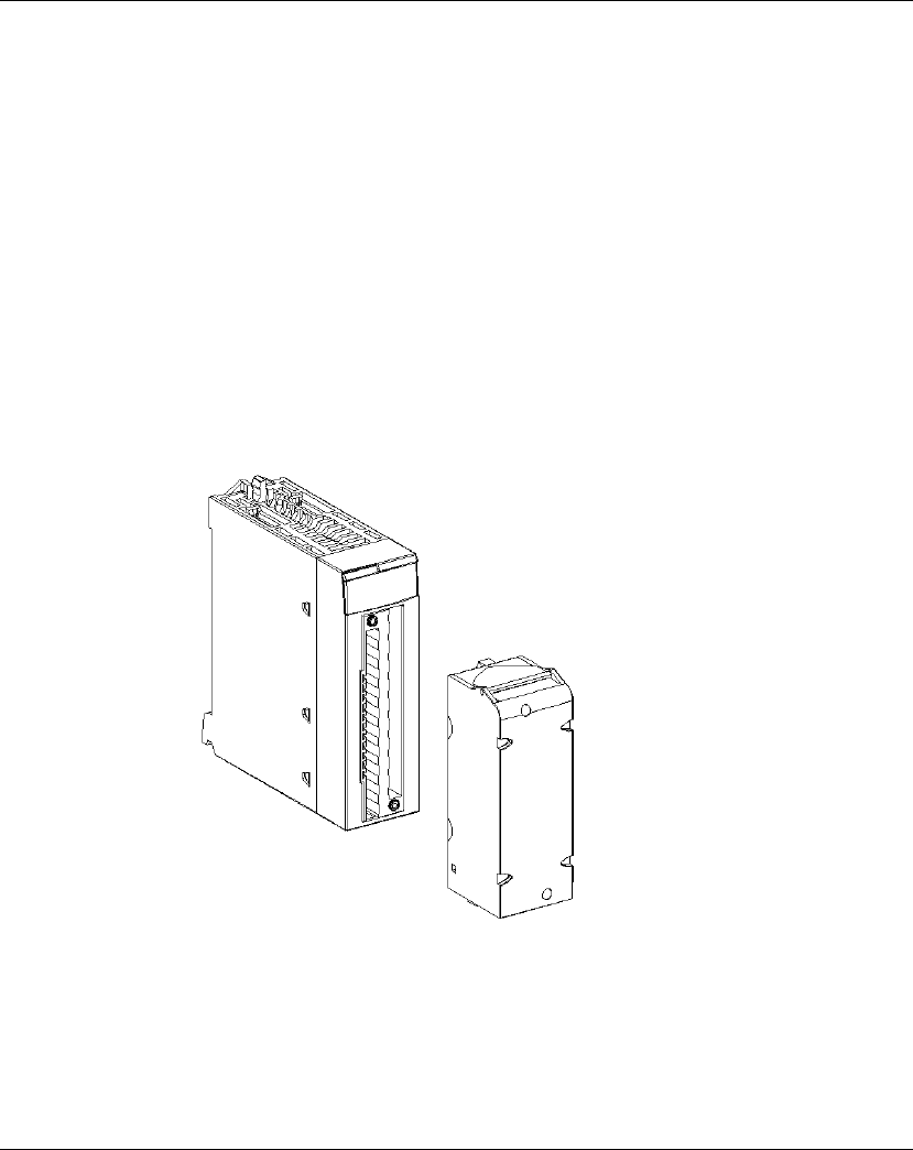
Illustration
The following graphic shows the BMX AMI 0810 analog input module:
NOTE: The terminal block is supplied separately.

BMX AMI 0810
35011978 07/2012 95
Characteristics
General Characteristics
The general characteristics for the BMX AMI 0810 and BMX AMI 0810H
(see page 45)
modules are as follows:
Type of inputs High level isolated fast inputs
Nature of inputs Voltage / Current (250 Ω internally
protected resistors)
Number of channels 8
Acquisition cycle time:
zFast (periodic acquisition for the declared
channels used)
1 ms + 1 ms x number of channels used
zDefault (periodic acquisition for all
channels)
9 ms
Display resolution 16-bit
Digital filtering 1st order
Isolation:
zBetween channels +/-300 VDC
zBetween channels and bus 1400 VDC
zBetween channels and ground 1400 VDC
Maximum overload authorized for inputs: Voltage inputs: +/- 30 VDC
Current inputs: +/- 30 mA
Protected against accidental wiring: -19.2 to
30VDC
NOTE: The Protected for accidental
wiring function is not supported when the
module works with any Telefast interface.
Power
consumption
(3.3 V)
Typical 0.32 W
Maximum 0.48 W
Power
consumption
(24 V)
Typical 0.82 W
Maximum 1.30 W

BMX AMI 0810
96 35011978 07/2012
Measurement Range
The BMX AMI 0810 and BMX AMI 0810H
(see page 45)
analog inputs have the
following measurement range characteristics:
NOTE: If nothing is connected on a BMX AMI 0810 and BMX AMI 0810H
(see page 45)
analog module and if channels are configured (range 4..20 mA or 1..5
V), there is a detected I/O error as if a wire is broken.
Measurement range +/-10 V; +/-5 V; 0..10 V; 0..5 V;
1..5 V
+/-20 mA; 0..20 mA; 4..20
mA
Maximum conversion
value
+/-11.4 V +/-30 mA
Conversion resolution 0.36 mV 1.4 μA
Input impedance 10 ΜΩ 250 Ω
Internal conversion resistor
Precision of the internal
conversion resistor
- 0.1% - 15 ppm/°C
Measurement errors for standard module:
zAt 25°C
zMaximum in the
temperature range
0...60°C (32...140°F)
0.075% of FS (1)
0.1% of FS (1)
Typically 0.15% of FS (1)(2)
0.3% of FS (1)(2)
Measurement errors for Hardened module:
zAt 25°C
zMaximum in the
temperature range -
25...70°C (-13...158°F)
0.075% of FS (1)
0.2% of FS (1)
Typically 0.15% of FS (1)(2)
0.55% of FS (1)(2)
Temperature drift 30 ppm/°C 50 ppm/°C
Monotonicity Yes Yes
Crosstalk between channels
DC and AC 50/60Hz
> 80dB > 80dB
Non-linearity 0.001% 0.001%
Repeatability @25°C of 10
min. stabilization time
0.005% of FS 0.007% of FS
Long term stability after 1000
hours
< 0.004% of FS < 0.004% of FS
Legend:
(1) FS: Full Scale
(2) With conversion resistor error
BMX AMI 0810
35011978 07/2012 97
Functional Description
Function
The BMX AMI 0810 is a high density input analog module with 8 isolated channels.
This module is used in conjunction with sensors or transmitters; it performs
monitoring, measurement, and continuous process control functions.
The BMX AMI 0810 module offers the following range for each input according to
the selection made during configuration:
z+/-10 V
z0..10 V
z0..5 V / 0..20 mA
z1..5 V / 4..20 mA
z+/-5 V / +/-20 mA
The module operates with voltage inputs. It includes eight read resistors connected
to the terminal block to perform current inputs.
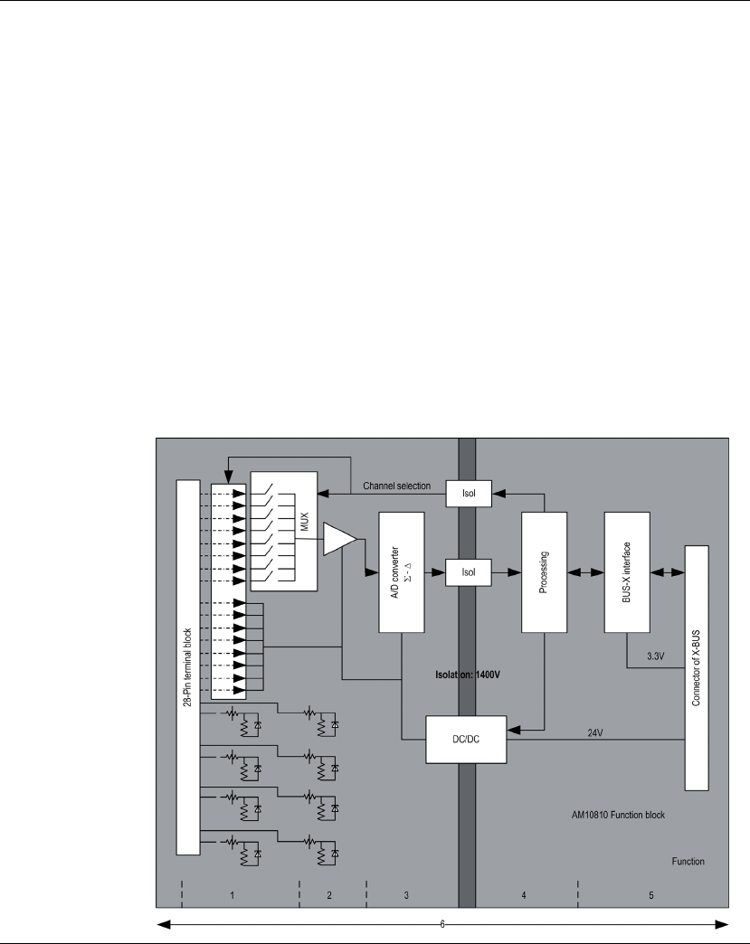
Illustration
The BMX AMI 0810 module’s illustration:

BMX AMI 0810
98 35011978 07/2012
Description:
No. Process Function
1Adapting the
Inputs and
Multiplexing
zPhysical connection to the process through a 28-pin screw
terminal block
zProtection of the module against overvoltages
zProtection of the current reading resistors using limiters and
resettable fuses
zInput signal analog filtering
zScan input channels using static multiplexing through opto-
switches, in order to provide the possibility of common mode
voltage of +/- 300 Vdc
2Amplifying Input
Signals
zGain selecting , based on characteristics of input signals, as
defined during configuration (unipolar or bipolar range, in
voltage or current)
zCompensation of drift in amplifier device
3Converting zConversion of analog Input signal into digital 24-bit signal
using a ΣΔ converter
4Transforming
incoming values
into workable
measurements
for the user.
zTakes into account recalibration and alignment coefficients to
be applied to measurements and the module’s self-
calibration coefficients
z(Numeric) filtering fo measurements, based on configuration
parameters
zScaling of measurements, based on configuration
parameters
5Communicating
with the
Application
zManages exchanges with CPU
zTopological addressing
zReceives configuration parameters from module and
channels
zSends measured values, as well as module status, to
application
6Module
monitoring and
sending error
notification back
to application.
Conversion string test
Testing for range overflow on channels
Watchdog test
BMX AMI 0810
35011978 07/2012 99
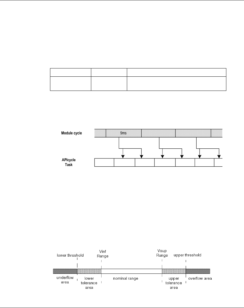
Measurement Timing
The timing of measurements is determined by the cycle selected during
configuration (Normal or Fast Cycle):
zNormal Cycle means that the scan cycle duration is fixed.
zWith the Fast Cycle, however, the system only scans the channels designated as
being In Use. The scan cycle duration is therefore proportional to the number of
channels In Use.
The cycle time values are based on the cycle selected:
NOTE: Module cycle is not synchronized with the PLC cycle. At the beginning of
each PLC cycle, each channel value is taken into account. If the MAST/FAST task
cycle time is less than the module’s cycle time, some values will not have changed.
Overflow/Underflow Control
Module BMX AMI 0810 allows the user to select between 6 voltage or current
ranges for each input.
This option for each channel have to be configured in configuration windows. Upper
and lower tolerance detection are always active regardless of overflow/underflow
control.
Depending on the range selected the module checks for overflow, it verifies that the
measurement falls between a lower and an upper threshold:
Module Normal Cycle Fast Cycle
BMX AMI 0810 9 ms 1 ms + (1 ms x N)
where N: number of channels in use.

BMX AMI 0810
100 35011978 07/2012
Description:
The values of the thresholds are configurable independently from one another. They
may assume integer values between the following limits:
Designation Description
Nominal range measurement range corresponding to the chosen
range
Upper Tolerance Area varies between the values included between the
maximum value for the range (for instance: +10 V
for the +/-10 V range) and the upper threshold
Lower Tolerance Area varies between the values included between the
minimum value for the range (for instance: -10 V for
the +/-10 V range) and the lower threshold
Overflow Area area located beyond the upper threshold
Underflow Area area located below the lower threshold
Range BMX AMI 0810 Range
Underflow Area Lower Tolerance
Area
Nominal Range Upper Tolerance
Area
Overflow Area
Unipolar
0...10 V -1,500 -1,001 -1,000 -1 0 10,000 10,001 11,000 11,001 11,400
0...5 V /
0...20 mA
-5,000 -1,001 -1,000 -1 0 10,000 10,001 11,000 11,001 15,000
1...5 V /
4...20 mA
-4,000 -801 -800 -1 0 10,000 10,001 10,800 10,801 14,000
Bipolar
+/- 10 V -11,500 -11,001 -11,000 -10,001 -10,000 10,000 10,001 11,000 11,001 11,400
+/- 5 V,
+/- 20 mA
-15,000 -11,001 -11,000 -10,001 -10,000 10,000 10,001 11,000 11,001 15,000
User
+/- 10 V -32,768 User-
defined
User-
defined
32,767
0...10 V -32,768 User-
defined
User-
defined
32,767

BMX AMI 0810
35011978 07/2012 101
Measurement Display
Measurements may be displayed using standardized display (in %, to two decimal
places):
It is also possible to define the range of values within which measurements are
expressed, by selecting:
zthe lower threshold corresponding to the minimum value for the range: 0 % (or -
100.00 %).
zthe upper threshold corresponding to the maximum value for the range (+100.00
%).
The lower and upper thresholds must be integers between -32,768 and +32,767.
For example, imagine a conditioner providing pressure data on a 4-20 mA loop, with
4 mA corresponding to 3,200 millibar and 20 mA corresponding to 9,600 millibar.
You have the option of choosing the User format, by setting the following lower and
upper thresholds:
3,200 for 3,200 millibar as the lower threshold
9,600 for 9,600 millibar as the upper threshold
Values transmitted to the program vary between 3,200 (= 4 mA) and 9,600 (=
20 mA).
Measurement Filtering
The type of filtering performed by the system is called "first order filtering". The
filtering coefficient can be modified from a programming console or via the program.
The mathematical formula used is as follows:
where:
α= efficiency of the filter
Measf(n) = measurement filtered at moment n
Measf(n-1) = measurement filtered at moment n-1
Valb(n) = gross value at moment n
Type of Range Display
Unipolar range
0...10 V, 0...5 V, 1...5 V, 0...20mA,
4...20mA
from 0 to 10,000 (0 % at +100.00 %)
Bipolar range
+/- 10 V, +/- 5 mV +/- 20 mA
from -10,000 to 10,000 (-100.00 % at +100.00 %)
() ( -1) ()
(1- )
fn fn bn
Meas Meas ValDD u u
BMX AMI 0810
102 35011978 07/2012
You may configure the filtering value from 7 possibilities (from 0 to 6). This value
may be changed even when the application is in RUN mode.
NOTE: Filtering may be accessed in Normal or Fast Cycle.
The filtering values depend on the T configuration cycle (where T = cycle time of
5 ms in standard mode):
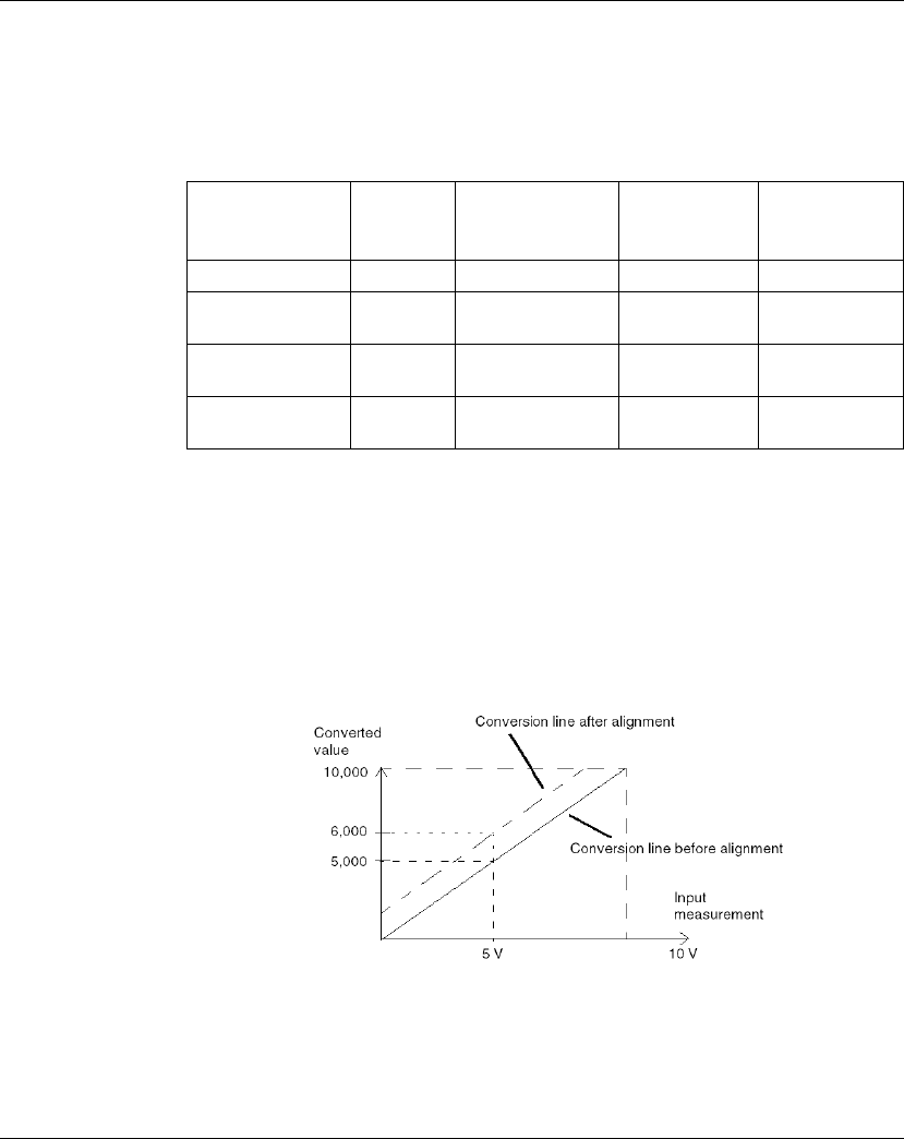
Sensor Alignment
The process of "alignment" consists in eliminating a systematic offset observed with
a given sensor, around a specific operating point. This operation compensates for
an error linked to the process. Replacing a module does not therefore require a new
alignment. However, replacing the sensor or changing the sensor’s operating point
does require a new alignment.
Conversion lines are as follows:
Desired Efficiency Required
Value
Corresponding αFilter
Response
Time at 63%
Cut-off
Frequency (in
Hz)
No filtering 0 0 0 0
Low filtering 1
2
0.750
0.875
4 x T
8 x T
0.040 / T
0.020 / T
Medium filtering 3
4
0.937
0.969
16 x T
32 x T
0.010 / T
0.005 / T
High filtering 5
6
0.984
0.992
64 x T
128 x T
0.0025 / T
0.0012 / T

BMX AMI 0810
35011978 07/2012 103
The alignment value is editable from a programming console, even if the program is
in RUN Mode. For each input channel, you can:
zview and modify the desired measurement value
zsave the alignment value
zdetermine whether the channel already has an alignment
The alignment offset may also be modified through programming.
Channel alignment is performed on the channel in standard operating mode, without
any effect on the channel’s operating modes.
The maximum offset between measured value and desired (aligned) value may not
exceed +/-1.500.
NOTE: To align several analog channels on the BMX ART/AMO/AMI/AMM
modules, we recommand proceeding channel by channel. Test each channel after
alignment before moving to the next channel in order to apply the parameters
correctly.
BMX AMI 0810
104 35011978 07/2012
Wiring Precautions
Introduction
In order to protect the signal from outside interference induced in series mode and
interference in common mode, we recommend that you take the following
precautions.
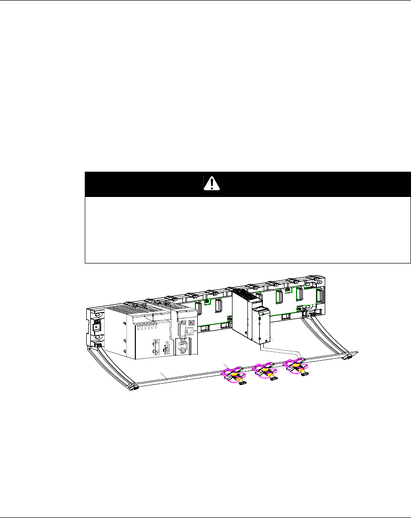
Cable Shielding
Connect the cable shielding to the grounding bar. Clamp the shielding to the
grounding bar on the module side. Use the BMX XSP 0400/0600/0800/1200
electromagnetic protection kit
(see Modicon M340 Using Unity Pro, Processors,
Racks, and Power Supply Modules, Setup Manual)
to connect the shielding.
1 BMX AMI 0810
2 Shield bar
3 Clamp
4 To sensors
DANGER
HAZARD OF ELECTRIC SHOCK, EXPLOSION, OR ARC FLASH
While mounting / removing the modules:
zmake sure that each terminal block is still connected to the shield bar and
zdisconnect voltage supplying sensors and pre-actuators.
Failure to follow these instructions will result in death or serious injury.
2
3
1
4
BMX AMI 0810
35011978 07/2012 105
Example of TELEFAST Connection
Connect the sensor cable shielding to the terminals provided and the whole
assembly to the cabinet ground.
1 Telefast ABE-7CPA02
2 The grounding of cables is facilited using the ABE-7BV10 accessory
3 Shield wiring to the ground
4 To voltage sensors
5 To current sensors
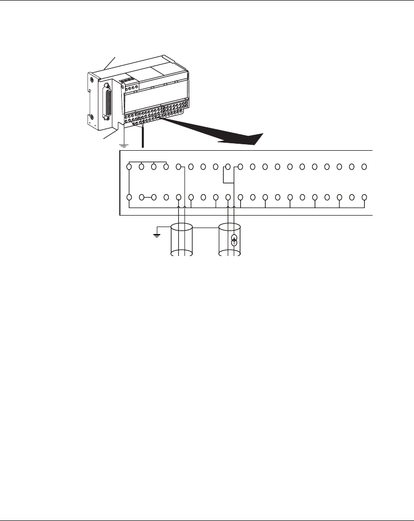
Reference of Sensors in Relation to the Ground
In order for the acquisition system to operate correctly, it is recommended to take in
account the following precautions:
zsensors must be close together (a few meters)
zall sensors must be referenced to a single point, which is connected to the PLC’s
ground
1
2
1 2 3 4 100
+IV0
101
+IC0
102 103 104 105 106 107 108 109 110 111 112 113 114 115
Supp1
STD(1)
Supp2
STD(1)
Supp3
STD(2)
Supp4 200
COM0
201 202 203 204 205 206 207 208 209 210 211 212 213 214 215
+IV1 +IC1 +IV2 +IC2 +IV3 +IC3 +IV4 +IC4 +IV5 +IC5 +IV6 +IC6 +IV7 +IC7
COM1 COM2 COM3 COM4 COM5 COM6 COM7
Ground
Ground
BMX AMI 0810
106 35011978 07/2012
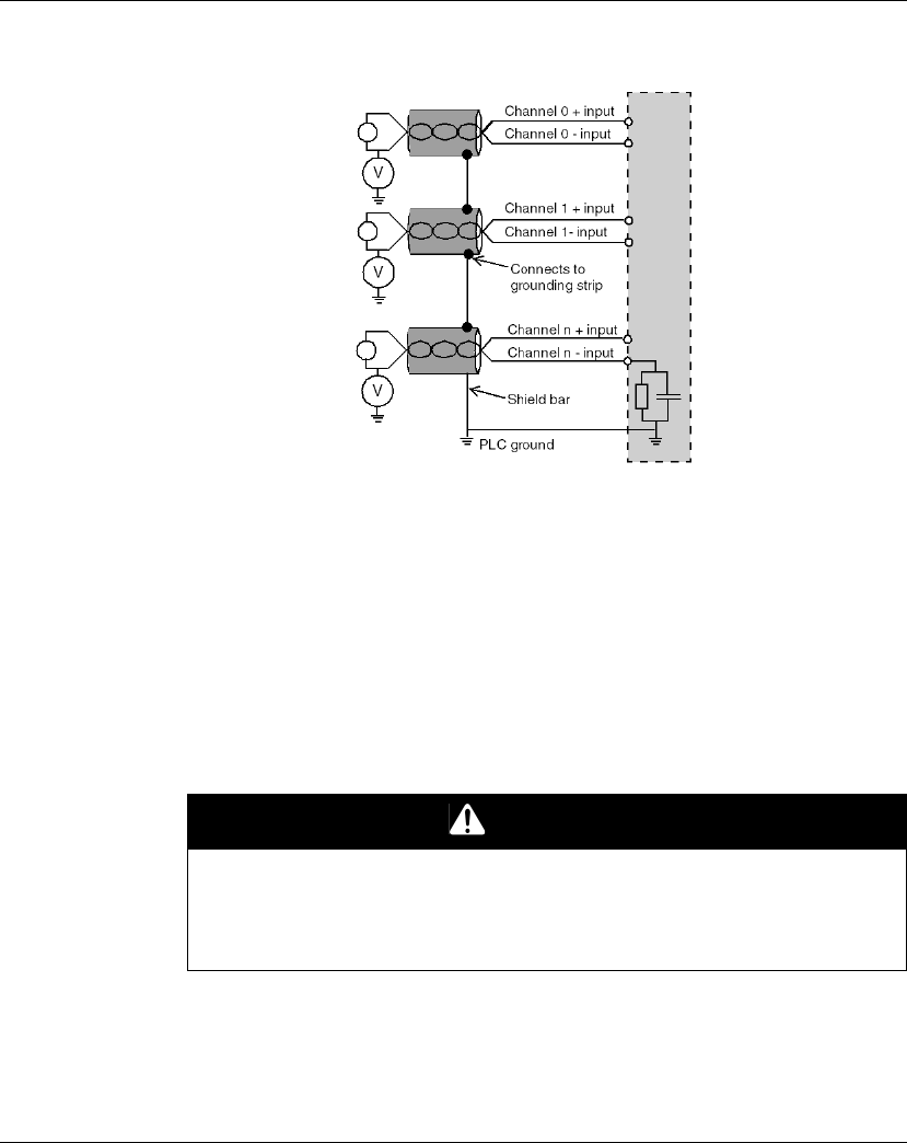
Using the Sensors Referenced in Relation to the Ground
The sensors are connected as indicated in the following diagram:
If the sensors are referenced in relation to the ground, this may in some cases return
a remote ground potential to the terminal block. It is therefore essential to follow the
following rules:
zThe potential must be less than the permitted low voltage: for example, 30 Vrms
or 42.4 VDC.
zSetting a sensor point to a reference potential generates a leakage current. You
must therefore check that all leakage currents generated do not disturb the
system.
NOTE: Sensors and other peripherals may be connected to a grounding point some
distance from the module. Such remote ground references may carry considerable
potential differences with respect to local ground. Induced currents do not affect the
measurement or integrity of the system.
DANGER
HAZARD OF ELECTRIC SHOCK
Ensure that sensors and others peripherals are not exposed through grounding
points to voltage potential greater than acceptable limits.
Failure to follow these instructions will result in death or serious injury.
BMX AMI 0810
35011978 07/2012 107
Electromagnetic Hazard Instructions
CAUTION
UNEXPECTED BEHAVIOR OF APPLICATION
Follow those instructions to reduce electromagnetic perturbations:
zuse the BMX XSP 0400/0600/0800/1200 electromagnetic protection kit
(see Modicon M340 Using Unity Pro, Processors, Racks, and Power Supply
Modules, Setup Manual)
to connect the shielding.
Electromagnetic perturbations may lead to an unexpected behavior of the
application.
Failure to follow these instructions can result in injury or equipment damage.
BMX AMI 0810
108 35011978 07/2012
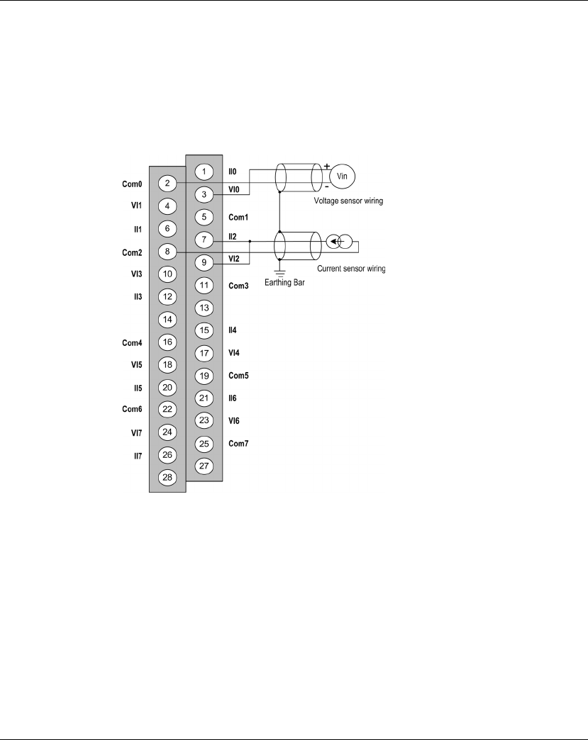
Wiring Diagram
Introduction
Module BMX AMI 0810 is connected using the 28-pin terminal block.
Illustration
The terminal block connection and the sensor wiring are as follows:
VIx + pole input for channel x
COM x - pole input for channel x
IIx current reading resistor + input
Channel 0 voltage sensor
Channel 1 2-wire current sensor
Wiring Accessories
Two cords BMXFTA150 (1.5 m (4.92 ft)) and BMXFTA300 (3 m (9.84 ft)) are
provided to connect the module with Telefast interfaces ABE-7CPA02
(see page 89)
, ABE-7CPA31
(see page 89)
or ABE-7CPA31E
(see page 89)
.
In case HART information is part of the signal to be measured, a Telefast interface
ABE-7CPA31E
(see page 89)
has to be used in order to filter this information that
would disrupt the analog value.
BMX AMI 0810
35011978 07/2012 109
Use of the TELEFAST ABE-7CPA02/31/31E Wiring Accessory
Introduction
The BMX AMI 0810 module can be connected to a TELEFAST ABE-
7CPA02/31/31E accessory.
The module is connected using one of the following cables:
zBMX FTA 150: length 1.5 m (4.92 ft)
zBMX FTA 300: length 3 m (9.84 ft)
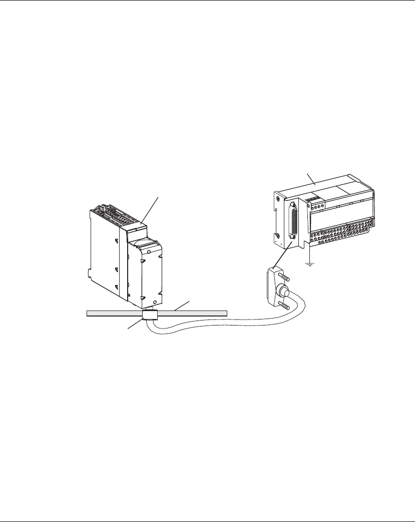
Connecting Modules
Modules can be connected to a TELEFAST ABE-7CPA02/31/31E as shown in the
diagram below:
1 BMX AMI 0810
2 Telefast ABE-7CPA02/31/31E
3 Clamp
4 Shield bar
Connecting Sensors
Sensors may be connected to the ABE-7CPA02/31/31E accessory as shown in the
illustration
(see page 87)
.
1
3
4
2

BMX AMI 0810
110 35011978 07/2012
The following table shows the distribution of analog channels on TELEFAST 2
terminal blocks with the reference ABE-7CPA02:
NOTE: The strap with the ABE7CPA02 must be removed from the terminal,
otherwise the signal ground of the channel 0 will be shorted to the earth.
For the ground connection use the additional terminal block ABE-7BV20.
TELEFAST 2
terminal block
number
25 pin SubD
connector
pin number
AMI08x0
pin out
Signal
type
TELEFAST 2
terminal block
number
25 pin SubD
connector
pin number
AMI08x0
pin out
Signal type
1 / Ground Supp 1 / Ground
2 / STD (1) Supp 2 / Ground
3 / STD (1) Supp 3 / Ground
4 / STD (2) Supp 4 / Ground
100 1 3 +IV0 200 14 2 COM0
101 2 1 +IC0 201 / Ground
102 15 4 +IV1 202 3 5 COM1
103 16 6 +IC1 203 / Ground
104 4 9 +IV2 204 17 8 COM2
105 5 7 +IC2 205 / Ground
106 18 10 +IV3 206 6 11 COM3
107 19 12 +IC3 207 / Ground
108 7 17 +IV4 208 20 16 COM4
109 8 15 +IC4 209 / Ground
110 21 18 +IV5 210 9 19 COM5
111 22 20 +IC5 211 / Ground
112 10 23 +IV6 212 23 22 COM6
113 11 21 +IC6 213 / Ground
114 24 24 +IV7 214 12 25 COM7
115 25 26 +IC7 215 / Ground
+IVx: + pole voltage input for channel x
+ICx: + pole current input for channel x
COMx: - pole voltage or current input for channel x

BMX AMI 0810
35011978 07/2012 111
The following table shows the distribution of analog channels on TELEFAST 2
terminal blocks with the reference ABE-7CPA31:
NOTE: For the ground connection use the additional terminal block ABE-7BV10.
TELEFAST 2
terminal block
number
25 pin
SubD
connector
pin
number
AMI0810
pin out
Signal type TELEFAST 2
terminal block
number
25 pin
SubD
connector
pin number
AMI0810
pin out
Signal type
1 / Ground Supp 1 / 24 V
(sensor
supply)
2 / Ground Supp 2 / 24 V
(sensor
supply)
3 / Ground Supp 3 / 0 V (sensor
supply)
4 / Ground Supp 4 / 0 V (sensor
supply)
100 / +IS0 116 / +IS4
101 1 3 +IV0 117 7 17 +IV4
102 2 1 +IC0 118 8 15 +IC4
103 14 2 0 V 119 20 16 0 V
104 / +IS1 120 / +IS5
105 15 4 +IV1 121 21 18 +IV5
106 16 6 +IC1 122 22 20 +IC5
107 3 5 0 V 123 9 19 0 V
108 / +IS2 124 / +IS6
109 4 9 +IV2 125 10 23 +IV6
110 5 7 +IC2 126 11 21 +IC6
111 17 8 0 V 127 23 22 0 V
112 / +IS3 128 / +IS7
113 18 10 +IV3 129 24 24 +IV7
114 19 12 +IC3 130 25 26 +IC7
115 6 11 0 V 131 12 25 0 V
+ISx: 24 V channel power supply
+IVx: + pole voltage input for channel x
+ICx: + pole current input for channel x
COMx: - pole voltage or current input for channel x

BMX AMI 0810
112 35011978 07/2012
The following table shows the distribution of analog channels on TELEFAST 2
terminal blocks with the reference ABE-7CPA31E:
NOTE: For the ground connection use the additional terminal block ABE-7BV10.
TELEFAST 2
terminal block
number
Terminal Signal type TELEFAST 2
terminal block
number
Terminal Signal type
1 / Ground Supp 1 / 24 V
(sensor
supply)
2 / Ground Supp 2 / 24 V
(sensor
supply)
3 / Ground Supp 3 / 0 V (sensor
supply)
4 / Ground Supp 4 / 0 V (sensor
supply)
100 / +IS0 116 / +IS4
101 / T0 117 / T4
102 / +IC0 118 / +IC4
103 / 0V0 119 / 0V4
104 / +IS1 120 / +IS5
105 / T1 121 / T5
106 / +IC1 122 / +IC5
107 / 0V1 123 / 0V5
108 / +IS2 124 / +IS6
109 / T2 125 / T6
110 / +IC2 126 / +IC6
111 / 0V2 127 / 0V6
112 / +IS3 128 / +IS7
113 / T3 129 / T7
114 / +IC3 130 / +IC7
115 / 0V3 131 / 0V7
+ISx: 24 V channel power supply
Tx: Reserved test pin for HART function, it’s internally connected with +ICx
+ICx: + pole current input for channel x
COMx: - pole voltage or current input for channel x
