Cooper Bussmann Cat Cover 119690 Catalog
2014-10-22
: Pdf 119690-Catalog 119690-Catalog Batch9 unilog
Open the PDF directly: View PDF ![]() .
.
Page Count: 384 [warning: Documents this large are best viewed by clicking the View PDF Link!]
- INTRODUCTION
- TABLE OF CONTENTS
- FUSE TECHNOLOGY
- Fuse Accessory Selection Guide
- Chip™ Fuses 0603FA Series, Fast Acting
- Chip™ Fuses 3216TD Series, Time Delay
- Chip™ Fuses 3216FF Series, Fast Acting
- Chip™ Fuses 3216LV Series, Fast Acting, Line Voltage
- Brick™ Fuses 6125TD Series, Time Delay
- Brick™ Fuses 6125FF Series, Fast Acting
- Brick™ Fuses 6125FA Series, Fast Acting
- Brick™ Fuses 1025TD Series, Time Delay
- Brick™ Fuses 1025FA Series, Fast Acting
- TCP™ Series TCP1.25A,Telecom Circuit Protector
- Subminiature Microtron® Fuses
- Printed Circuit Board Fuses
- Subminiature Fuses
- 5mm x 15mm Fuses
- 5mm x 20mm Fuses
- 1/4" x 5/8" Fuses
- 1/4" x 1-1/4" Fuses
- Blade-Type Fuses
- PC Board Fuseclips for 5mm Diameter Fuses
- PC Board Fuseclips for 1/4" Diameter Fuses
- 5mm x 20mm Fuseholders
- Fuseholders
- 1/4" x 1-1/4" Fuseholders
- HTB Panel Mount Series
- 1/4" x 7/8" to 1-1/4" Fuseholders HHB In-Line Series
- 1/4" x 1-1/4" Fuseholders HFB In-Line Waterproof Series
- 1/4" x 1-1/4" Fuseholders HFA In-Line Waterproof Series
- 1/4" x 7/8" to 1-1/4" Fuseholders HRK Universal In-Line Series
- MINI® Fuseholders HHL & HHM
- ATC® Fuseholders HHC, HHD, HHF, HHG
- MAXI® Fuseholders HHX
- 5 x 20mm Fuse Blocks HTC Series
- 1/4" x 1-1/4" Fuseblocks
- ESD Suppression Selection Guide
- MLP Series ESD Suppressor
- TR Series ESD Suppressor
- Application Notes ESD Suppression
- Power Management
- Table of Contents
- Inductor Selection Guide
- Low Profile Inductors(Surface Mount)
- FLAT-PAC™ 3 Low Profile Inductors
- FLAT-PAC™ 4 5mm Height Inductors(Surface Mount)
- FP1308 Series FLAT-PAC™High Current Power Inductors
- HCP0703 Series High Current Pressed Power Inductors
- HCP1104 Series High Current Pressed Power Inductors
- HCP1305 Series High Current Pressed Power Inductors
- HCF1305 Series Power Inductors
- HIGH CURRENT 1 Power Inductors
- HIGH CURRENT 2LP Low Profile Power Inductors
- HC3 Series HIGH CURRENT 3 Power Inductors
- HC7 Series HIGH CURRENT 7 Power Inductors
- HC8 Series HIGH CURRENT 8 Power Inductors
- HC8LP Series Power Inductors
- HC9 Series HIGH CURRENT 9 Power Inductors
- HCPT1309 Series Power Inductors
- CPL Series Multi-Phase Power Inductors
- DR1030 Series Low Profile Power Inductors
- DR1040 Series Low Profile Power Inductors
- DR1050 Series Low Profile Power Inductors
- DR Series High Power Density,High Efficiency, Shielded Inductors
- DR124 Series Low Profile Power Inductors
- DRQ Series Dual Winding, ShieldedInductors/Transformer
- LDS0705 Series Shielded Power Inductors
- SD3110 Series Low Profile Power Inductors
- SD3112 Series Low Profile Power Inductors
- SD3114 Series Low Profile Power Inductors
- SD3118 Series Low Profile Power Inductors
- SD38 Series Low Profile, Shielded Inductors
- SDH3812 Series Low Profile, High Power, Shielded Inductors
- SD Series High Power Density,Low Profile, Shielded Inductors
- SDQ Series Low Profile Dual Winding Shielded Inductor/Transformer
- SD52 Series High Power Density, Low Profile, Shielded Inductors
- SD53 Series Low Profile, Shielded Inductors
- SD6020 Series Low Profile Power Inductors
- SD6030 Series Low Profile Power Inductors
- SD7030 SeriesLow Profile Power Inductors
- SD8328 SeriesLow Profile Power Inductors
- SD8350 SeriesShielded Power Inductors
- UNI-PAC™ 2.8 Low Cost, Low Profile 2.8mmPower Inductors (Surface Mount)
- UNI-PAC™ 0.4CLow Cost, Low Profile Power Inductors (Surface Mount)
- UNI-PAC™ 2C Low Cost Power Inductors(Surface Mount)
- UNI-PAC™ Power Inductors(Surface Mount)
- LD Series Metalized Drum Core Power Inductor
- MICRO-PAC™ Low Profile Power Inductors(Surface Mount)
- ECONO-PAC™/OCTA-PAC OCTA-PAC® PLUS Power Inductors and Transformers
- VERSA-PAC® Inductors and Transformers (Surface Mount)
- Power Over Ethernet (PoE)/PD Configurable Transformer
- CCFL TRANSFORMERS Cold Cathode Fluorescent Lamp Inverter Transformers
- STANDARD GEOMETRIES Low Cost Magnetic Components
- CMS-SERIES Common Mode Inductors (Surface Mount)
- CMT-SERIES Common Mode Inductors(Through-Hole)
- CS Series Current Sense Current Sense Inductors
- LOWCOST POWER INDUCTORS Toroidal Inductors
- Application Notes Magnetics
- PowerStor
- Table of Contents
- Product Overview
- Aerogel Supercapacitors A Series
- Aerogel Supercapacitors B Series
- Aerogel Supercapacitors P Series
- Aerogel Supercapacitors KR Series
- Aerogel Supercapacitors F Series
- Custom Product Offering
- Application Guidelines
- Measurement Techniques
- Aerogel Supercapacitor Calculator
- Design Considerations In Selecting Aerogel Supercapacitors
- Aerogel Supercapacitors Provide Both High Energy and High Power Capability
- Customer / Application Information Worksheet
Circuit Protection and
Power Management Solutions
Full Line Electronics Catalog
Courtesy of Steven Engineering, Inc.-230 Ryan Way, South San Francisco, CA 94080-6370-Main Office: (650) 588-9200-Outside Local Area: (800) 258-9200-www.stevenengineering.com

I
INTRODUCTION
From overcurrent and overvoltage protection to supercapacitors and magnetics, Cooper Bussmann
provides integrated solutions that meet the evolving needs of technology-driven markets. Cooper
Bussmann is a leader and an innovator in providing cost-effective, comprehensive solutions that
utilize the high quality brand names that customers know and trust.
Circuit Protection
The Cooper Bussmann®Electronic Fuse family offers fail-safe circuit protection devices in SMD,
Thru-Hole, and traditional Ferrule Fuse packages.
The Cooper Bussmann®PolySurg™ sub-branded family offers protection for sensitive electronic
circuits from the damaging effects of electrostatic discharge (ESD).
Power Management
The Cooper Coiltronics®family of transformers and inductors offers a broad range of solutions to
meet precise specifications in a variety of applications.
The Cooper PowerStor®family of aerogel capacitors offers ultra-low resistance supercapacitors,
unique high-energy storage devices.
Cooper Bussmann continues its 90-year history of blazing new trails of innovative technologies.
Cooper Bussmann manufactures the industry’s first truly global product line. Each item is backed
by an efficient worldwide network of distribution, customer service and technical support. Cooper
Bussmann products include the most extensive circuit protection solutions approved for use in
compliance with a variety of major standards: UL, CSA, IEC within wide range of applications:
industrial motor protection, power conversion, medium voltage, power distribution, telecommunica-
tions network equipment, electronics, and automotive. Manufacturing operations in North America,
Europe, and Asia have earned ISO 9000 certification. Cooper Bussmann customers are assured
of only the utmost quality across every product line. Our team is knowledgeable, responsive and
customer focused. Bussmann continues to set the standard for circuit protection solutions around
the world.
To receive further information on Cooper Bussmann products, visit www.cooperbussmann.com
or contact customer service at 888-414-2645.
2007 Electronic Components
Courtesy of Steven Engineering, Inc.-230 Ryan Way, South San Francisco, CA 94080-6370-Main Office: (650) 588-9200-Outside Local Area: (800) 258-9200-www.stevenengineering.com
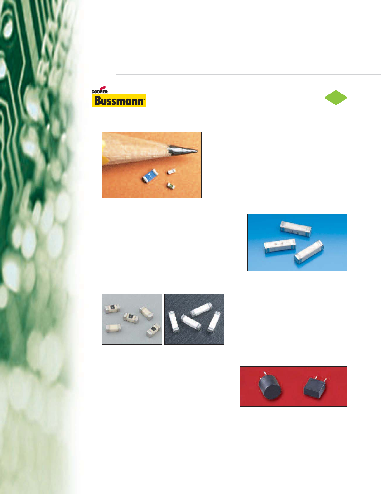
The Cooper Bussmann®Electronic Fuse family offers fail-safe circuit
protection devices in SMD, Thru-Hole, and traditional Ferrule Fuse
packages.
CHIP™ Fuses (0603FA & 3216FF Series)
Cooper Bussmann's patented Solid Matrix CHIP™ fuses
provide reliable overcurrent protection to secondary
circuits found in mobile phone handsets, battery packs,
digital still cameras, PDA's, HDD's, printers, notebook
computers, televisions, automotive instrument panels,
battery packs, and more. Its excellent cycling
characteristics, small footprint, and SMD package provide
the most effective, reliable overcurrent protection solution
for today's - and tomorrow's - technologies.
Telecom Circuit Protector (TCP Series)
Cooper Bussmann is proud to be the first to offer a surface
mount telecom circuit protector designed to protect against
power cross faults and comply with surge requirements for
the telecom industry. Today, you will find the TCP Series
fuse in central office subscriber line interface cards,
basestations, set-top box modems, and xDSL modems
among other applications.
BRICK™ Fuses (6125FA/TD & 1025FA/TD Series)
Cooper Bussmann's patented BRICK™ fuses
provide the excellent inrush withstand
capabilities in a space saving SMD package
needed in many of today's more demanding
applications such as power supplies, base
stations, televisions, computers, white goods,
and motor control circuits among others.
SR-5 & SS-5 Series Radial Leaded Fuses
Cooper Bussmann is bringing the space-saving SR-5
and SS-5 family of radial leaded fuses to the global
market to provide cost-effective primary circuit
protection in space-constrained applications such as
power adapters, televisions, handheld consumer
products, white goods, and more.
IEC & UL Electronic Fuses
In addition to SMD and Thru-Hole Device Fuses, Cooper Bussmann offers a full range of traditional
electronic fuses designed to IEC standards (5mm product line) and UL standards (1/4" product line).
Both product lines offer a cost-efficient overcurrent protection solution for a wide range of applications
including power supplies, white goods, motor control equipment, and set-top boxes. Coupled with one
of Cooper Bussmann’s extensive fuse accessories product offerings, these fuses can be conveniently
Circuit
Protection Group
II
RoHS
2002/95/EC
Courtesy of Steven Engineering, Inc.-230 Ryan Way, South San Francisco, CA 94080-6370-Main Office: (650) 588-9200-Outside Local Area: (800) 258-9200-www.stevenengineering.com
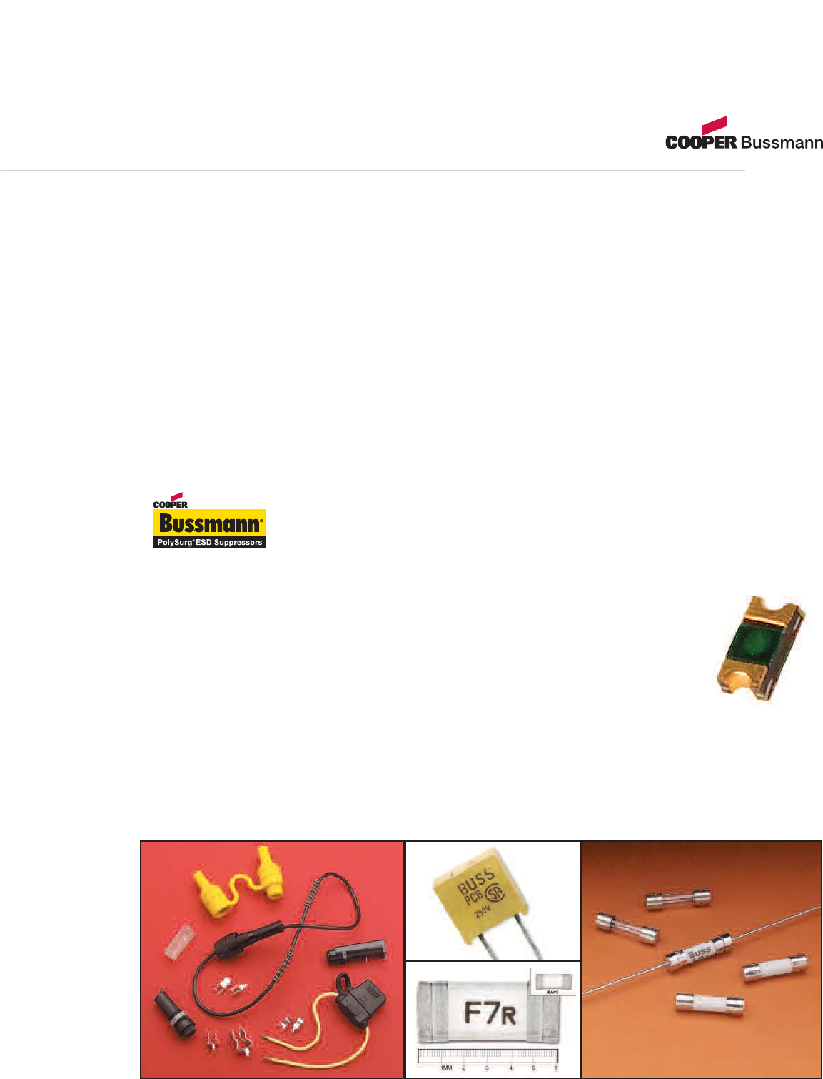
inserted into a circuit while allowing for end-user replacement if desired. And with Cooper Bussmann’s expansive global
distribution, your customers will have easy access to ensure safe, reliable, correct replacement parts available when needed.
Electrical Fuses
Cooper Bussmann®brand power fuses are the industry leader for your more demanding power applications.
From the innovative CUBEFuse™ product line – offering touch-safe, current-limiting fusible protection – to the time-honored
Fusetron®product line with class-leading time-delay performance, Cooper Bussmann®fuses set the standard for motor and
branch circuit protection. And now, with easyID™ technology available with the CUBEFuse™ and Low-Peak®product lines,
reliable permanent open fuse indication for reduced downtime and maintenance costs.
For more delicate semiconductor drive applications, Cooper Bussmann High Speed fuses provide rapid response to damaging
short circuits keeping your investment safe from damages. And look no further than the Cooper Bussmann Telpower®brand
fuses for protection of critical telecommunication infrastructure.
PolySurg™ ESD Suppression Devices
Cooper Bussmann PolySurg™ ESD Suppressors are bi-directional ESD overvoltage
protection devices that respond in less than 1ns and can protect against a threat voltage up
to 15kV per IEC standard 61000-4-2. With leakage current of less than 1nA and an ultra low capacitance less than 0.15pF,
these devices are an especially viable solution for high data rate applications. With an insertion loss
of less than -0.2dB at frequencies up to 6 GHz, the PolySurg™ ESD Suppressors are invisible to the
protected circuit, introducing no additional loading or signal distortion.
ESD Protection for High Frequency, Low Voltage Designs
PolySurg™ surface mount devices are ideally suited for ESD protection of data I/O ports, computers
and peripherals, media interfaces (DVI and HDMI), mobile communication products, hand-held test
equipment and other similar uses.
MLP Series Now Available
The MLP Series, comprised of the 0402ESDA-MLP and 0603ESDA-MLP ESD suppression devices, is now available as
discrete devices in an 0402 and 0603 footprint, respectively. This series utilizes Cooper Bussmann’s patented PolyFAMILY
design to deliver enhanced ESD protection using state of the art process and material technologies.
III
Courtesy of Steven Engineering, Inc.-230 Ryan Way, South San Francisco, CA 94080-6370-Main Office: (650) 588-9200-Outside Local Area: (800) 258-9200-www.stevenengineering.com
A leading global brand name in the power magnetics
marketplace since 1977.
Leading-Edge Technology
Cooper Coiltronics®brand magnetics specializes in standard and custom solutions offering the latest in
state-of-the-art low profile high power density magnetic components. In working closely with the
industry leaders in chipset and core development, we remain at the forefront of innovation and
new technology to deliver the optimal mix of packaging, high efficiency and unbeatable reliability.
Our designs utilize high frequency, low core loss materials, new and custom core shapes in
combination with innovative construction and packaging to provide designers with the highest
performance parts available on the market.
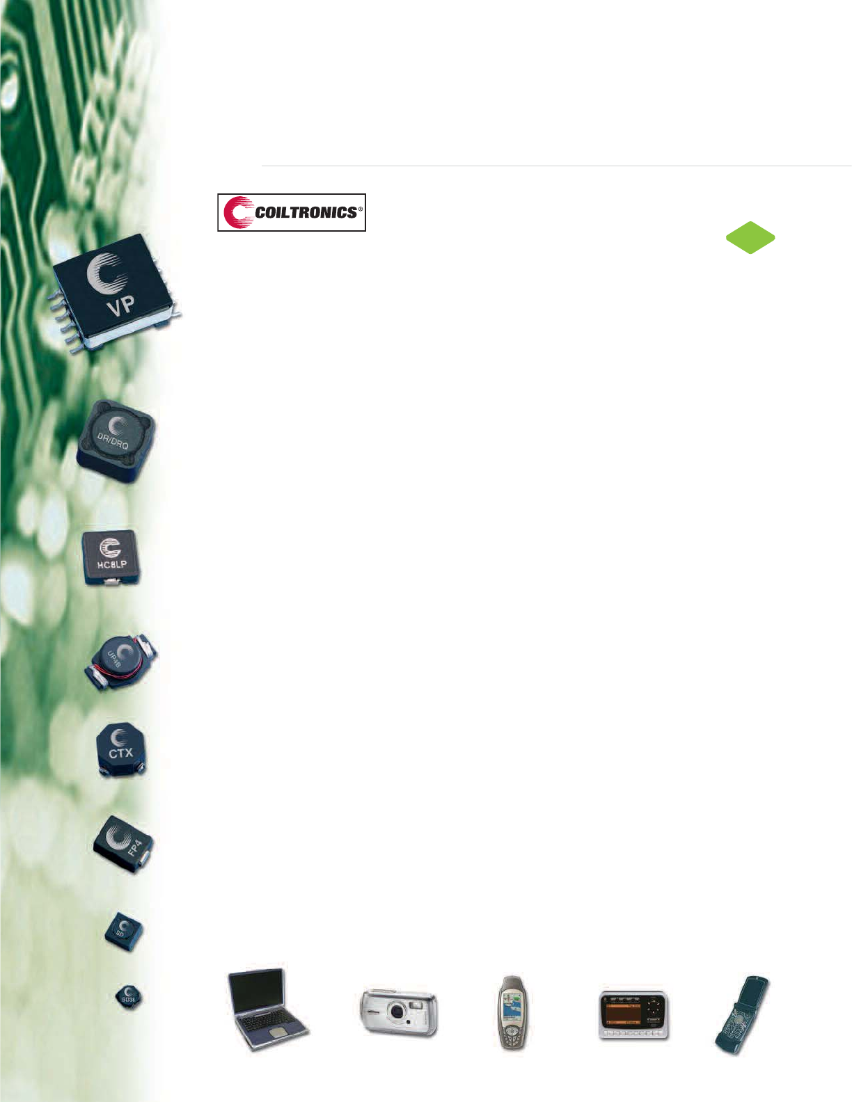
Market-Driven Products
Cooper Coiltronics brand magnetics is the first choice in power inductor and transformer solutions to
the ever-changing Digital Home, Office and Mobile electronics world. In support of this market, we
specialize in inductors and transformers for DC-DC power conversion and switch-mode applications
requiring high frequency. Our component solutions can be found in many products requiring power
conversion including cellular telephones, digital cameras, MP3 players, notebook and desktop
computers & peripherals & LCD displays across the Consumer, Communication, Computer,
Industrial and Automotive markets.
Standard Products
Cooper Coiltronics brand product line of power magnetics continually expands to satisfy shifts in
technology and related market needs. Categories of Standard Products include:
• Shielded Drum Inductors
• Low Profile Shielded Drum Inductors
• Unshielded Drum Inductors
• High Current Inductors
• Common-Mode Inductors
• Toroidal Inductors
• Transformers
• Custom Magnetics
Custom-Engineered Capabilities
• Inductors and Transformers for DC/DC Converters and Off-Line Switch Mode Power Supplies
(To 200 Watts at voltages up to 450Vac [640 Vdc] and Frequencies from 20Khz to 10Mhz)
• Custom SMT Inductors and Transformers
Cooper Coiltronics brand products can provide you with custom designs from print through manufacture.
Our design Engineers can take your designated specifications or help you determine what the specifications
should be. Either way, we’ll get you the right power magnetic solution to your design challenge.
Power
Management
Group
RoHS
2002/95/EC
IV
Courtesy of Steven Engineering, Inc.-230 Ryan Way, South San Francisco, CA 94080-6370-Main Office: (650) 588-9200-Outside Local Area: (800) 258-9200-www.stevenengineering.com
Modifications to standard products are available.
All surface mount components are available in
tape-and-reel packaging for pick-and-place utilization.
Shielded Drum Inductors and Low
Profile Shielded Drum Inductors
Cooper Coiltronics®brand magnetics put for-
ward one of the largest variety of shielded drum
core inductors that utilize a magnetic shield
reducing EMI effects and have the best power
density versus size ratio on the market.
Features:
• Large variety of shapes and sizes
• Maximum Power Density
• Ultra Low Profile (as low as 1.0mm in height)
• Dual Winding: Coupled Inductor, SEPIC,
Flyback Transformer, 1:1 Isolation Transformer
• High current
• Magnetic Shielding, Reduced EMI
• Compact Footprint
Standard Product Families:
Shielded Drum:
DR, DRQ, DR124, DR1030, DR1040,
DR1050, LDS0705.
Low Profile Shielded Drum:
SD, SDQ, SD3110, SD3112, SD3114, SD3118,
SD52, SD53, SD38, SDH3812, SD6020,
SD6030, SD7030, SD8328, SD8350.
High Current Inductors
The Cooper Coiltronics®brand high current
inductor product lines provide an optimal mix
of innovative packaging, high efficiency and
unbeatable reliability.
Features:
• Large variety of shapes and sizes
• Low profile (as low as 3mm)
• Low DCR, High Efficiency
• Designed for High Current, Low Voltage
Applications
• Foil construction adds higher reliability factor
than traditional magnet wire used for higher
frequency circuits
• Gapped Ferrite: Maximum Efficiency,
Low core loss
• High Temperature Powder Iron: 155°C
Maximum Temperature Operation, Organic
Binder Eliminates Thermal Aging
Standard Product Families:
HC1, HC2LP, HC3, HC7, HC8,
HC8LP, HC9, HCP0703, HCP1104,
HCP1305, HCPT1309, HCF1305,
FLAT-PAC™(FP2), FLAT-PAC™(FP3),
FLAT-PAC™4, (FP4), CPL.
Unshielded Drum Core Inductors
Cooper Coiltronics®brand magnetics offer a
wide variety of unshielded drum core inductors
in different shapes and sizes to fit all board
space constraints.
Features:
• Multiple sizes available
• Miniature Surface Mount Design
• Low Profile
• Small Footprint
• Ferrite Core Material
Standard Product Families:
UNI-PAC™(UP1B, 2B, 3B, 4B),
UNI-PAC™0.4C (UP0.4C),
UNI-PAC™2.8B (UP2.8B),
UNI-PAC™2C (UP2C), LD.
Toroid Inductors
The Cooper Coiltronics®brand magnetics also
offer a mixture of toroid constructed inductors
available in surface mount, through hole, and
dual winding platforms.
Features:
• Surface Mount and Through-Hole Mounting
• Maximum Power Density
• Dual Winding: Coupled Inductor, SEPIC,
Flyback Transformer, 1:1 Isolation Transformer
• Low EMI
• Variety Of Core Materials: Powder Iron, MPP,
Gapped Ferrite, Amorphous
Standard Product Families:
ECONO-PAC™, OCTA-PAC®,™, OCTA-PAC®
Plus, MICRO-PAC™, , MICRO-PAC™Plus,
Low Cost Power Inductors (LCPI), Current
Sense (CS).
Common-Mode Inductors
Cooper Coiltronics®brand magnetics also offer
a variety of surface mount and through hole
inductors specifically for common-mode
circuits.
Features:
• Variety Of Sizes
• Surface mount and through hole packages
• Wide inductance offering
• Ferrite core material
Standard Product Families:
Common Mode Inductor SMT (CMS),
Common Mode Inductor THT (CMT)
Transformers
Cooper Coiltronics®brand magnetics also offer
a variety of standard transformers that increase
versatility in design needs.
Features:
• Multi-configurable transformer/Inductors
• Variety Of Sizes
• Multi-configurable Power Over Ethernet/PD
Flyback and Forward Transformers
• Cold Cathode Fluorescent Lamp (CCFL)
Transformers
Standard Product Families:
VERSA-PAC®(VP),
VERSA-PAC®High Inductance (VPH),
Power Over Ethernet/ PD Configurable
Transformer (PoE) Flyback and Forward,
Cold Cathode Fluorescent Lamp (CCFL)
Custom Magnetics
Cooper Coiltronics®brand magnetics can be
customized to meet your application needs.
We specialize in designing product to specific
requirements and new technology, as well as
modifying our standard product platforms to
meet your requirements.
V
Courtesy of Steven Engineering, Inc.-230 Ryan Way, South San Francisco, CA 94080-6370-Main Office: (650) 588-9200-Outside Local Area: (800) 258-9200-www.stevenengineering.com
VI
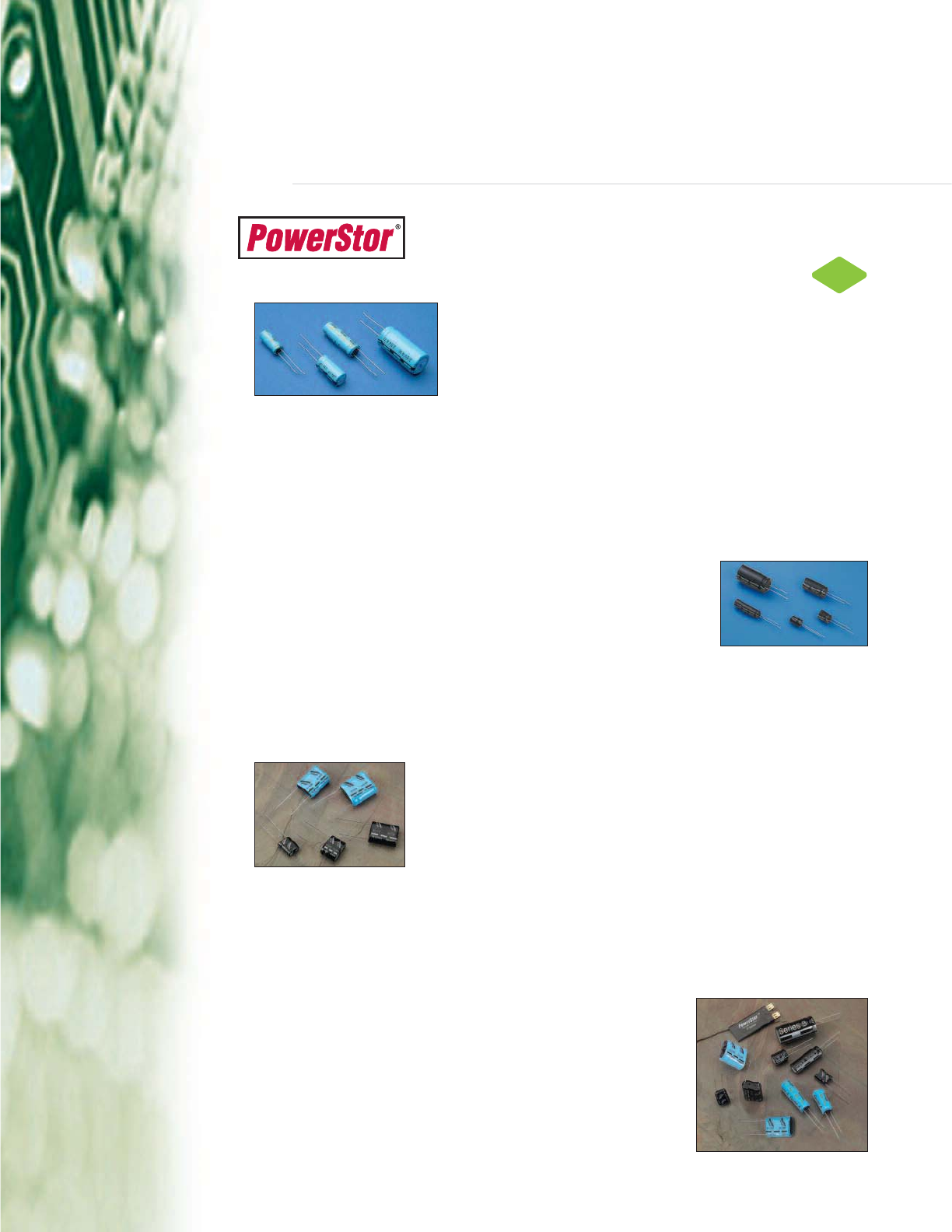
The Cooper PowerStor®family of aerogel capacitors offers ultra-low
resistance supercapacitors, unique high-energy storage devices.
Supercapacitors Extend Battery Life
The Cooper PowerStor®A series supercapacitors are available in
values from 0.47F to 4.7F, 2.5V and offer equivalent series resistance
as low as 25mΩ. In remote battery powered applications that have
pulse current loads this low ESR can be utilized to prolong battery
life.
Low cost battery solutions tend to have high ESR and as a result large amounts of stored energy can’t
be used when supplying pulse currents. By combining a supercapacitor in parallel with the battery the
overall ESR is lowered and battery life, typically, increased by 300%. For remote applications such as
utility meters, weather & river level monitoring and hotel door locks this can dramatically reduce
replacement costs.
Offering Environmentally Friendly Alternative to Ni-CD Batteries
The Cooper PowerStor®B series is available in values from 0.22F to 50F,
2.5V and is fully compliant with the EC RoHS directive. For equipment that
is only required for short term use, up to several minutes, and has a local
charger the B series offers a realistic alternative to Ni-CD batteries.
Low equivalent series resistance allows the B series parts to be rapidly charged and discharged
without damage and low leakage current means they can hold their charge for weeks. Unlike batteries
PowerStor®supercapacitors have a very long cycle life, over 500,000 cycles, so they won’t need
replacing and at end of life there are no recycling or disposal issues.
Supercapacitors Provide Last Gasp Power
The Cooper PowerStor®P series is available in values from 0.1F to 1.0F,
5V and is ideal for hold-up and bridging power applications. For telecom
products such ADSL routers a P series supercapacitor can be used to
provide power for a ‘leaving network’ signal after a mains supply failure.
Unlike batteries the P series supercapacitors have a long cycle life, over 500,000 cycles, so they won’t
need replacing. In addition to this they have ESR as low as 0.2 Ohms and small package sizes from
0.75 cm3to 4.7 cm3. All this makes the P series an ideal choice for supporting continued operation
during battery swap-out or for controlled shut down after a mains failure.
Providing Power Management Solutions
In addition to a broad range of standard products Cooper PowerStor®
also offer custom solutions for applications such as automated meter
reading, PCMCIA cards, handheld electronics, data storage systems
and toys.
These products include high integrity capacitor packs that incorporate
active voltage balancing, ultra thin ‘Flat Pack’ devices with low ESR
and optimized cylindrical components that meet specific customer
requirements.
RoHS
2002/95/EC
Power
Management
Group
Courtesy of Steven Engineering, Inc.-230 Ryan Way, South San Francisco, CA 94080-6370-Main Office: (650) 588-9200-Outside Local Area: (800) 258-9200-www.stevenengineering.com

VII
2007 Electronic Components
Courtesy of Steven Engineering, Inc.-230 Ryan Way, South San Francisco, CA 94080-6370-Main Office: (650) 588-9200-Outside Local Area: (800) 258-9200-www.stevenengineering.com

C
IRCUIT
P
ROTECTION
Courtesy of Steven Engineering, Inc.-230 Ryan Way, South San Francisco, CA 94080-6370-Main Office: (650) 588-9200-Outside Local Area: (800) 258-9200-www.stevenengineering.com

OC-1
TABLE OF CONTENTS
Overcurrent
Protection Group
Fuse Technology ..........................................................OC-3
Printed Circuit Board Fuses
Surface Mount Fuses
0603FA Chip™ Fuses . . . . . . . . . . . . . . . . . . . . . . . . . . . . . . . . . . . . . . . . . . . . . .OC-12
3216TD Chip™ Fuses . . . . . . . . . . . . . . . . . . . . . . . . . . . . . . . . . . . . . . . . . . . . . .OC-14
3216FF Chip™ Fuses . . . . . . . . . . . . . . . . . . . . . . . . . . . . . . . . . . . . . . . . . . . . . .OC-16
3216LV Chip™ Fuses . . . . . . . . . . . . . . . . . . . . . . . . . . . . . . . . . . . . . . . . . . . . . .OC-18
6125TD Brick™ Fuses . . . . . . . . . . . . . . . . . . . . . . . . . . . . . . . . . . . . . . . . . . . . . .OC-20
6125FF Brick™ Fuses . . . . . . . . . . . . . . . . . . . . . . . . . . . . . . . . . . . . . . . . . . . . . .OC-22
6125FA Brick™ Fuses . . . . . . . . . . . . . . . . . . . . . . . . . . . . . . . . . . . . . . . . . . . . . .OC-24
1025TD Brick™ Fuses . . . . . . . . . . . . . . . . . . . . . . . . . . . . . . . . . . . . . . . . . . . . . .OC-26
1025FA Brick™ Fuses . . . . . . . . . . . . . . . . . . . . . . . . . . . . . . . . . . . . . . . . . . . . . .OC-28
TCP™ Series Telecom Circuit Protector . . . . . . . . . . . . . . . . . . . . . . . . . . . . . . . .OC-30
Axial and Radial Leaded Fuses
MCRW Series Subminiature Microtron®Fuses . . . . . . . . . . . . . . . . . . . . . . . . . . .OC-34
MCRS Series Subminiature Microtron®Fuses . . . . . . . . . . . . . . . . . . . . . . . . . . . .OC-36
PC-Tron®Series PCB Fuses . . . . . . . . . . . . . . . . . . . . . . . . . . . . . . . . . . . . . . . . .OC-38
SR-5 Series Subminiature Fuses . . . . . . . . . . . . . . . . . . . . . . . . . . . . . . . . . . . . .OC-40
SS-5 Series Subminiature Fuses . . . . . . . . . . . . . . . . . . . . . . . . . . . . . . . . . . . . . .OC-42
SR-5F Series Subminiature Fuses . . . . . . . . . . . . . . . . . . . . . . . . . . . . . . . . . . . .OC-44
SS-5F Series Subminiature Fuses . . . . . . . . . . . . . . . . . . . . . . . . . . . . . . . . . . . .OC-46
SR-5H Series Subminiature Fuses . . . . . . . . . . . . . . . . . . . . . . . . . . . . . . . . . . . .OC-48
Traditional Ferrule Fuses
Ferrule Type Fuses
C515 Series 5mm x 15mm Fuses . . . . . . . . . . . . . . . . . . . . . . . . . . . . . . . . . . . . .OC-50
C517 Series 5mm x 15mm Fuses . . . . . . . . . . . . . . . . . . . . . . . . . . . . . . . . . . . . .OC-52
C518 Series 5mm x 15mm Fuses . . . . . . . . . . . . . . . . . . . . . . . . . . . . . . . . . . . . .OC-54
C519 Series 5mm x 15mm Fuses . . . . . . . . . . . . . . . . . . . . . . . . . . . . . . . . . . . . .OC-56
C520 Series 5mm x 15mm Fuses . . . . . . . . . . . . . . . . . . . . . . . . . . . . . . . . . . . . .OC-58
S500 Series 5mm x 20mm Fuses . . . . . . . . . . . . . . . . . . . . . . . . . . . . . . . . . . . . .OC-60
S501 Series 5mm x 20mm Fuses . . . . . . . . . . . . . . . . . . . . . . . . . . . . . . . . . . . . .OC-62
S505 Series 5mm x 20mm Fuses . . . . . . . . . . . . . . . . . . . . . . . . . . . . . . . . . . . . .OC-64
S506 Series 5mm x 20mm Fuses . . . . . . . . . . . . . . . . . . . . . . . . . . . . . . . . . . . . .OC-66
GMA Series 5mm x 20mm Fuses . . . . . . . . . . . . . . . . . . . . . . . . . . . . . . . . . . . . .OC-68
GMC Series 5mm x 20mm Fuses . . . . . . . . . . . . . . . . . . . . . . . . . . . . . . . . . . . . .OC-70
GMD Series 5mm x 20mm Fuses . . . . . . . . . . . . . . . . . . . . . . . . . . . . . . . . . . . . .OC-72
AGA Series 1/4" x 5/8" Fuses . . . . . . . . . . . . . . . . . . . . . . . . . . . . . . . . . . . . . . . .OC-74
AGX Series 1/4" x 1" Fuses . . . . . . . . . . . . . . . . . . . . . . . . . . . . . . . . . . . . . . . . . .OC-76
TDC Series 1/4" x 1-1/4" Fuses . . . . . . . . . . . . . . . . . . . . . . . . . . . . . . . . . . . . . . .OC-78
ABC Series 1/4" x 1-1/4" Fuses . . . . . . . . . . . . . . . . . . . . . . . . . . . . . . . . . . . . . . .OC-80
AGC Series 1/4" x 1-1/4" Fuses . . . . . . . . . . . . . . . . . . . . . . . . . . . . . . . . . . . . . .OC-82
GBB Series 1/4" x 1-1/4" Fuses . . . . . . . . . . . . . . . . . . . . . . . . . . . . . . . . . . . . . . .OC-84
Courtesy of Steven Engineering, Inc.-230 Ryan Way, South San Francisco, CA 94080-6370-Main Office: (650) 588-9200-Outside Local Area: (800) 258-9200-www.stevenengineering.com

OC-2
Ferrule Type Fuses (Cont.)
MDA Series 1/4" x 1-1/4" Fuses . . . . . . . . . . . . . . . . . . . . . . . . . . . . . . . . . . . . . .OC-86
MDL Series 1/4" x 1-1/4" Fuses . . . . . . . . . . . . . . . . . . . . . . . . . . . . . . . . . . . . . . .OC-88
MDQ Series 1/4" x 1-1/4" Fuses . . . . . . . . . . . . . . . . . . . . . . . . . . . . . . . . . . . . . .OC-90
Automotive Fuses
Blade Fuses
ATM Series Blade-Type Fuses . . . . . . . . . . . . . . . . . . . . . . . . . . . . . . . . . . . . . . . .OC-92
ATC Series Blade-Type Automotive Fuses . . . . . . . . . . . . . . . . . . . . . . . . . . . . . .OC-93
MAX Series Blade-Type Fuses . . . . . . . . . . . . . . . . . . . . . . . . . . . . . . . . . . . . . . .OC-94
Accessories
Fuseclips
5mm Diameter Fuseclips . . . . . . . . . . . . . . . . . . . . . . . . . . . . . . . . . . . . . . . . . . . .OC-95
1/4" Diameter Fuseclips . . . . . . . . . . . . . . . . . . . . . . . . . . . . . . . . . . . . . . . . . . . . .OC-96
Fuseholders
HTC PCB Series 5mm x 20mm Fuseholders . . . . . . . . . . . . . . . . . . . . . . . . . . . .OC-97
HTC PM Series 5mm x 20mm Fuseholders . . . . . . . . . . . . . . . . . . . . . . . . . . . . .OC-98
HB PCB Series 1/4" x 1-1/4" Fuseholders . . . . . . . . . . . . . . . . . . . . . . . . . . . . . . .OC-99
HKP PM Series 1/4" x 1-1/4" Fuseholders . . . . . . . . . . . . . . . . . . . . . . . . . . . . .OC-100
HTB PM Series Fuseholders . . . . . . . . . . . . . . . . . . . . . . . . . . . . . . . . . . . . . . . .OC-102
HHB In-Line Series 1/4" x 7/8" to 1-1/4" Fuseholders . . . . . . . . . . . . . . . . . . . . .OC-104
HFB In-Line Waterproof Series 1/4" x 1-1/4" Fuseholders . . . . . . . . . . . . . . . . .OC-105
HFA In-Line Waterproof Series 1/4" x 1-1/4" Fuseholders . . . . . . . . . . . . . . . . .OC-106
HRK Universal In-Line Series 1/4" x 7/8" to 1-1/4" Fuseholders . . . . . . . . . . . . .OC-107
MINI®Fuseholders (HHL & HHM) . . . . . . . . . . . . . . . . . . . . . . . . . . . . . . . . . . . .OC-108
AT C ®Fuseholders (HHC, HHD, HHF, HHG) . . . . . . . . . . . . . . . . . . . . . . . . . . . .OC-109
MAXI®Fuseholders (HHX) . . . . . . . . . . . . . . . . . . . . . . . . . . . . . . . . . . . . . . . . . .OC-110
Fuseblocks
HTC Series 5mm x 20mm Fuseblocks . . . . . . . . . . . . . . . . . . . . . . . . . . . . . . . .OC-111
S-8000 Series 1/4" x 1-1/4" Fuseblocks . . . . . . . . . . . . . . . . . . . . . . . . . . . . . . .OC-112
Overvoltage Protection
PolySurg™ ESD Suppressors
ESD Suppression Selection Guide . . . . . . . . . . . . . . . . . . . . . . . . . . . . . . . . . . .OC-114
0402ESDA-MLP, MLP Series ESD Suppressor . . . . . . . . . . . . . . . . . . . . . . . . . .OC-118
0603ESDA-MLP, MLP Series ESD Suppressor . . . . . . . . . . . . . . . . . . . . . . . . . .OC-120
0603ESDA-TR, TR Series ESD Suppressor . . . . . . . . . . . . . . . . . . . . . . . . . . . .OC-122
Application Notes, ESD Suppression
ESD Protection of Set Top Appliances with PolySurg™ ESD Suppressors
. . . . . . .OC-125
ESD Protection of High-Speed Data Lines
...............................OC-127
ESD Protection for High Speed Digital Video Solutions (DVI & HDMI)
...........OC-129
Overcurrent
Protection Group
Courtesy of Steven Engineering, Inc.-230 Ryan Way, South San Francisco, CA 94080-6370-Main Office: (650) 588-9200-Outside Local Area: (800) 258-9200-www.stevenengineering.com
FUSE TECHNOLOGY
This fuse technology guide will discuss basic fuse
operating, application, and selection criteria concepts.
The intended purpose of this section is to aid
designers with the operation and characteristics of
an overcurrent protection device and to assist in
device selection.
Overcurrent fuses serve two main purposes:
a. To protect components, equipment and
people from risk of fire and shock caused
by overcurrents.
b. To isolate sub systems from the main
system once a fault has occurred.
Overcurrents
Overcurrents exist when the normal load for a circuit is
exceeded. It can either be an overload or short circuit
condition.
An overload condition is any current flowing within the
circuit path that is higher than the circuit’s normal full
load current. An overload is typically 2 to 5 times the
magnitude of a circuit’s normal operating current.
A short circuit is an overcurrent condition that leaves
the normal current path and which greatly exceeds the
normal full load current of the circuit by a factor of tens,
hundreds, or thousands. Components and equipment
can be damaged by both types of overcurrents.
Selecting Overcurrent Protection
During normal load conditions, the fuse must carry the
normal operating current of the circuit without nuisance
openings. However, when an overcurrent occurs
the fuse must interrupt the overcurrent and withstand
the voltage across the fuse after internal arcing.
To properly select a fuse the following items must
be considered:
• Voltage rating (ac or dc voltage)
• Current rating
• Normal operating current
• Ambient temperature
• Overload conditions and opening times
• Available short circuit current
• Melting Integral (I2t)
• Pulse and In-rush characteristics
• Characteristics of equipment or components
to be protected
• Physical size and available board space
• Standards requirements
Voltage Ratings
The voltage rating of the fuse must be greater than or
equal to the maximum open circuit voltage. Because
the fuse has such low resistance, the voltage rating
becomes critical only when the fuse is trying to open.
The fuse must be able to open quickly, extinguish the
arc after the fuse element has melted and prevent the
system’s open-circuit voltage from re-striking across
the open fuse element.
Current Ratings
The current rating of a fuse identifies its current-
carrying capacity based on a controlled set of test
conditions. Each fuse is marked with its current rating.
This rating can be identified with a numeric, alpha, or
color code mark. Marking codes can be found in each
product’s data sheet.
Normal Operating Current
The normal operating current of a circuit is the level
of current drawn (in RMS or dc amperes) after it has
been energized and is operating under normal
conditions. An operating current of 80% or less of
rated current is recommended for operation at 25°C
to avoid nuisance openings. For example, a fuse with
a current rating of 1A is usually not recommended in
circuits with normal operating currents of more than
800mA. Further derating is required at elevated
ambient temperatures.
Overcurrent
Protection Group
OC-3
Fuse Technology
Courtesy of Steven Engineering, Inc.-230 Ryan Way, South San Francisco, CA 94080-6370-Main Office: (650) 588-9200-Outside Local Area: (800) 258-9200-www.stevenengineering.com
OC-4
Fuse Technology
Ambient Temperature
Ambient temperature is the temperature of the
air immediately surrounding the fuse and is not
necessarily room temperature. All electrical
characteristics of a fuse are rated and validated at an
ambient temperature of 25°C. Both higher and lower
ambient temperatures will affect the fuse’s opening
and current carrying characteristics. This effect is
demonstrated in temperature re-rating curves. Please
refer to the re-rating curves for individual product
series found in the Engineering Product Specifications
located on the Cooper Electronic Technologies web
site, or contact CET directly for technical assistance.
Overload Conditions and Opening Times
Specific attention must be given to first overload
operating points. For fuses, the first overload point is
usually between 200% to 300% of rated current. 400%
is typically the first overload point for circuit protectors.
Breaking Capacity / Interrupting Rating
A fuse must be able to open the circuit under a short
circuit condition without endangering its surroundings.
The breaking capacity or interrupting rating of a
protective device is the maximum available current, at
rated voltage, that the device can safely open without
rupturing. The breaking capacity or interrupting rating
of a fuse must be equal to or greater than the available
short circuit current of the circuit.
Melting Integral
The melting integral of a fuse, termed melting I2t, is
the thermal energy required to melt a specific fuse
element. The construction, materials, and cross
sectional area of the fuse element will determine this
value. Each fuse series and ampere rating utilize
different materials and element configurations, and
therefore it is necessary to determine the I2t value for
each fuse. Tests to determine the I2t of a fuse are
usually performed with a fault current of at least 10x
the rated current with a time constant of less than 50
microseconds in a DC test circuit. High-speed
oscilloscopes and integral programs are used to
measure very accurate I2t values.
The melting I2t of a fuse is one of the values used to
assist circuit designers when selecting and properly
sizing a fuse in a specific application. It can be
compared to the thermal energy created by transient
surge currents in a circuit.
Surge and Pulse Current Characteristics
Transient surge or pulse currents are used to describe
wave shapes that result from any startup, inrush,
surge, or transient currents in a circuit. The pulse
currents are normal for some applications. It is
therefore important to size the fuse properly to allow
these pulses to pass without nuisance openings or
degradation of the fuse element. The fuse must then
open within the limits specified by UL and CSA if the
overload condition continues. The ability to resist
surges is a function of the fuse design and/or
classification relative to the surge pulse, duration
frequency etc.
Pulse currents can produce thermal energy that may
not be large enough to open the fuse but could
possibly cause element fatigue and decrease the life
of the fuse. To properly size a fuse and determine its
surge withstand capability, the circuit’s pulse energy
should be determined and compared to the time
current curve and I2t rating of the fuse. The fuse’s
melting I2t value must be greater than or equal to the
pulse I2t multiplied by a pulse factor.
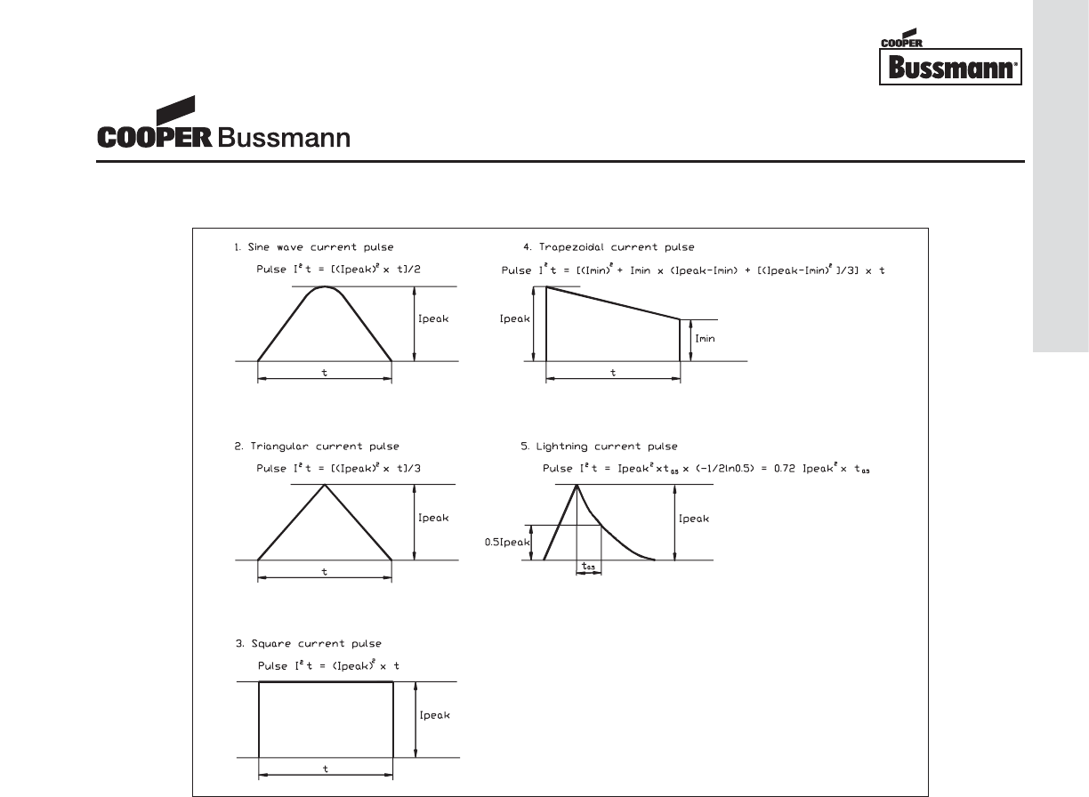
The peak current and decay time define the pulse
current characteristic or waveform. Pulses can
generate different waveform shapes, which determines
the formula used to calculate the pulse energy or I2t.
Refer to Table 1 to select the appropriate waveform
and its corresponding pulse I2t calculation.
Overcurrent
Protection Group
Courtesy of Steven Engineering, Inc.-230 Ryan Way, South San Francisco, CA 94080-6370-Main Office: (650) 588-9200-Outside Local Area: (800) 258-9200-www.stevenengineering.com
OC-5
Fuse Technology
Fuse Surge Withstand Capability
The fuse’s capability to withstand a surge pulse without
causing thermal stress to the fuse element, which may
result in nuisance openings, can be determined once
the circuit’s pulse I2t is calculated. The circuit designer
needs to properly size the fuse so that the fuse’s
melting I2t value is greater than or equal to the pulse I2t
multiplied by a pulse factor Fp(I2tfuse ≥I2tpulse xF
p).
The pulse factor is dependent on the construction
of the fuse element. A wire-in-air constructed fuse
element (ferrule fuses, 6125 and 1025 series for
example) will be affected by the number and frequency
of surge pulses the fuse is subjected to over the
lifetime of the device. This construction design utilizes
low-melting-point metals plated or deposited on the
main element material to cause an “M” effect. If the
fuse is sized improperly, low level pulse currents may
cause the low-melting-point metals to alloy to the
element without completely opening the element.
A series of pulse currents will eventually create
enough heat to shift resistance or even permanently
open the fuse. Thus it is important to take into account
the number of pulse currents to which the fuse will be
subjected.
Solid matrix fuses (for example 0603FA or 3216FF
sized surface mount fuses) do not currently use an “M”
effect for the element construction. The element will
only then be affected by the thermal energy of each
pulse, and will not normally degrade as a result of
the number or frequency of pulses. Please refer to
Table 2 to determine the pulse factor, Fp.
For example, a pulse current with an I2t of 0.0823 and
a pulse factor, Fp=1.25 would require the selection of
a fuse to have a melting I2t greater than or equal to
0.1029.
Melting I2tfuse ≥I2tpulse xF
p
Melting I2tfuse ≥0.0823 x 1.25
Melting I2tfuse ≥0.1029
Table 1. Pulse Waveshapes and I2t Calculations
Overcurrent
Protection Group
Courtesy of Steven Engineering, Inc.-230 Ryan Way, South San Francisco, CA 94080-6370-Main Office: (650) 588-9200-Outside Local Area: (800) 258-9200-www.stevenengineering.com
OC-6
Fuse Technology
It is important to note that the melting I2t values of the
fuse and pulse current that are compared must be
calculated or tested at the same test conditions, most
importantly the magnitude of the peak current must be
the same. For example, if the pulse’s peak current is
15A, then the fuse’s melting I2t must be calculated at
15A as well to fully understand its electrical
characteristics at that magnitude of current. Please
contact CET directly for technical assistance.
Table 2. Pulse Factor, Fp
Solid Matrix Construction
Wire-in-Air Construction
Time vs. Current Curves
A time current curve represents the relationship
between a fuse’s melting or clearing time and the
magnitude of RMS or dc current. The characteristics
represented on most published graphs usually indicate
a fuse’s average melting time when subjected to a
certain level of current. The curves will typically
demonstrate the ability to carry 100% of rated current,
and then also represent the fuse’s ability to open within
the maximum opening time at designated overload
points (typically 135% to 300% of the fuse rating).
Time vs. current curves are a useful design aid for
an engineer when specifying a fuse type or rating for
an application. It is however recommended that fuse
samples be tested in the actual application to verify
performance.
Fuse Resistance
In most applications, the voltage drop across the fuse
due to its internal and contact resistance is negligible.
There are, however, certain critical applications where
the fuse resistance must be considered and it is
important that the circuit designer understands the
fuse characteristics in order to select the proper fuse.
Applications that are powered by low voltage batteries,
typically 3V or less, and utilize fractional rated fuses
with high resistance may require special attention be
given to the voltage drop across the fuse.
Physical Sizes
There are numerous physical sizes of electronic fuses,
including subminiature fuses. The most common fer-
rule designs are 5x15mm, 5x20mm and 6.3x32mm
(1/4” x 1 1/4”).
Subminiature fuses are often used when board space
is limited. For applications of this type, there are
through-hole and surface mount devices available.
Standard package sizes for surface mount fuses are
0402 (1005), 0603 (1608), 1206 (3216), 6125, and
1025. These sizes are standard throughout the elec-
tronic industry. Through-hole axial and radial leaded
products allow fuses to be PCB mounted. Standard
ferrule fuses fitted with leads can also be mounted in
this way.
Physical Sizes of Traditional Ferrule Fuses
Standards
North American UL/CSA and IEC standards require
significantly different time vs. current characteristics for
overcurrent devices.
Number of
Surge Pulses Pulse Factor, Fp
100 2.1
1,000 2.6
10,000 3.4
100,000 4.5
Number of
Surge Pulses Pulse Factor, Fp
1 to 100,000 1.25
5mmx20mm 0.2" x .79"
1AG 1/4" x 5/8"
2AG (5mmx15mm) 0.2" x .59"
3AG 1/4" x 1 1/4"
4AG 9/32" x 1 1/4"
5AG 13/32" x 1 1/2"
7AG 1/4" x 7/8"
8AG 1/4" x 1"
Overcurrent
Protection Group
Courtesy of Steven Engineering, Inc.-230 Ryan Way, South San Francisco, CA 94080-6370-Main Office: (650) 588-9200-Outside Local Area: (800) 258-9200-www.stevenengineering.com

OC-7
Fuse Technology
Typically the physical dimensions and materials used
are similar; however, fuses built to different standards
are not interchangeable because their element melting
and opening times will differ when subjected to the
same magnitude of current. It is therefore important for
the circuit designer to consider that world standards
may require different fuses.
Glossary of Terms
Ampere squared seconds I2t
The melting, arcing, or clearing integral of a fuse,
termed I2t, is the thermal energy required to melt, arc,
or clear a specific current. It can be expressed as
melting I2t, arcing I2t or the sum of them, clearing I2t.
Arcing time
The amount of time from the instant the fuse link has
melted until the overcurrent is interrupted, or cleared.
Clearing time
The total time between the beginning of the overcur-
rent and the final opening of the circuit at rated voltage
by an overcurrent protective device. Clearing time is
the total of the melting time and the arcing time.
Fast acting fuse
A fuse which opens on overload and short circuits very
quickly. This type of fuse is not designed to withstand
temporary overload currents associated with some
electrical loads. UL listed or recognized fast acting
fuses would typically open within 5 seconds maximum
when subjected to 200% to 250% of its rated current.
IEC has two categories of fast acting fuses:
• F = quick acting, opens 10x rated current within
0.001 seconds to 0.01 seconds
• FF = very quick acting, opens 10x rated current in
less than 0.001 seconds
Fuse
An overcurrent protective device with a fusible link that
operates and permanently opens the circuit on an
overcurrent condition.
Overcurrent
A condition which exists in an electrical circuit when
the normal load current is exceeded. Overcurrents take
on two separate characteristics-overloads and short
circuits.
Overload
Can be classified as an overcurrent which exceeds the
normal full load current of a circuit by 2 to 5 times its
magnitude and stays within the normal current path.
Resistive load
An electrical load which is characterized by not draw-
ing any significant inrush current. When a resistive
load is energized, the current rises instantly to its
steady state value, without first rising to a higher value.
RMS Current
The R.M.S. (root mean square) value of any periodic
current is equal to the value of the direct current which,
flowing through a resistance, produces the same heat-
ing effect in the resistance as the periodic current
does.
Short circuit
An overcurrent that leaves the normal current path and
greatly exceeds the normal full load current of the cir-
cuit by a factor of tens, hundreds, or thousands times.
Time delay fuse
A fuse with a built-in time delay that allows temporary
and harmless inrush currents to pass without operat-
ing, but is so designed to open on sustained overloads
and short circuits. UL listed or recognized time delay
fuses typically open in 2 minutes maximum when sub-
jected to 200% to 250% of rated current. IEC has two
categories of time delay fuses:
• T = time lag, opens 10x rated current within 0.01
seconds to 0.1 seconds
• TT = long time lag, opens 10x rated current within
0.1 seconds to 1 second
Voltage rating
A maximum open circuit voltage in which a fuse can be
used, yet safely interrupt an overcurrent. Exceeding the
voltage rating of a fuse impairs its ability to clear an
overload or short circuit safely.
Overcurrent
Protection Group
Courtesy of Steven Engineering, Inc.-230 Ryan Way, South San Francisco, CA 94080-6370-Main Office: (650) 588-9200-Outside Local Area: (800) 258-9200-www.stevenengineering.com
OC-8
Fuse Technology
Selection Guide
The following is a quick selection guide to assist in selecting the appropriate product series for your application.
Please refer to the corresponding catalog pages for a complete listing of product specifications.
Chip Fuses
Product Voltage Amp Electrical Size Mounting 3rd Party
Series Rating Rating Characteristic Method Testing
0603FA 32 VDC 250mA - 2A Fast Acting 1.6mmx0.8mm Surface Mount UL/CSA
24 VDC 2.5A-5A (.060"x.030")
3216FF 32 VAC, 63 VDC 250mA-3A Fast Acting 3.2mmx1.6mm Surface Mount UL/CSA
32 VAC, 32 VDC 4A-7A (.120"x.060")
3216TD 63 VAC, 63 VDC 1A Time Delay 3.2mmx1.6mm Surface Mount cRUus
32 VAC, 32 VDC 1.5A-12A (.120"x.060")
3216LV 125 VAC/DC 250mA-1.5A Fast Acting 3.2mmx1.6mm Surface Mount UL/CSA
(.120"x.060")
Brick Fuses
Product Voltage Amp Electrical Size Mounting 3rd Party
Series Rating Rating Characteristic Method Testing
6125TD 125VAC, 60VDC 250mA-7A Time Delay 6.1mmx2.5mm Surface Mount UL/CSA
(0.24"x0.1")
6125FF 125VAC, 72VDC 375mA-15A Fast Acting 6.1mmx2.5mm Surface Mount cRUus
(0.24"x0.1")
125VAC, 125VDC 250mA-7A
6125FA 125VAC, 86VDC 10A-12A Fast Acting 6.1mmx2.5mm Surface Mount UL/CSA
86VDC 15A (0.24"x0.1")
1025TD 250AC, 125VDC 250mA-5A Time Delay 10.1mmx2.5mm Surface Mount UL/CSA
(0.4"x0.1")
1025FA 250VAC, 125VDC 250mA-15A Fast Acting 10.1mmx2.5mm Surface Mount UL/CSA
(0.4"x0.1")
Telecom Fuses
Product Voltage Amp Electrical Size Mounting 3rd Party
Series Rating Rating Characteristic Method Testing
TCP 250VAC 500mA-2A Time Delay for 10.1mmx2.5mm Surface Mount UL/CSA
Telecom Applications (0.4"x0.1")
Overcurrent
Protection Group
Courtesy of Steven Engineering, Inc.-230 Ryan Way, South San Francisco, CA 94080-6370-Main Office: (650) 588-9200-Outside Local Area: (800) 258-9200-www.stevenengineering.com
OC-9
Fuse Technology
Traditional Subminiature Fuses
Product Voltage Amp Electrical Size Mounting 3rd Party
Series Rating Rating Characteristic Method Testing
MCRW 125VAC, 125VDC 1/10A-15A Fast Acting, 7.1mmx3.18mm Axial UL/CSA
Wire in Air (.280"x.125") Through Hole
MCRS 125VAC, 125VDC 250MA-7A Slow Blow, 7.1mmx3.18mm Axial UL/CSA
Wire in Air (.280"x.125") Through Hole
250VAC, 450VDC 500mA-2.5A Fast Acting, 8.89mmx8.89mm Radial
PC-Tron 250VAC, 350VDC 3A Solid Matrix (.35"x.35") Through Hole UL/CSA
125VAC, 250VDC 5A
SR-5 250VAC 500mA-6.3A Time Delay 8.35mmx7.7mm Radial UL/CSA
(.33"x.3") Through Hole SEMKO/VDE
SS-5 250VAC 500mA-6.3A Time Delay 8.6mmx8.4mm Radial UL/CSA
(.34"x.33") Through Hole SEMKO/VDE
SR-5F 250VAC 800mA-5A Fast Acting 8.35mmx7.7mm Radial UL/CSA
125VAC 6.3A-10A (.33"x.3") Through Hole
SS-5F 250VAC 800mA-5A Fast Acting 8.6mmx8.4mm Radial UL/CSA
125VAC 6.3A-10A (.34"x.33") Through Hole
SR-5H 300VAC 1A-6.3A Time Delay 8.35mmx8.6mm Radial cURus
250VAC (.33"x.34") Through Hole SEMKO/VDE
1/4" Diameter Ferrule Fuses
Product Voltage Amp Electrical Size Mounting 3rd Party
Series Rating Rating Characteristic Method Testing
AGA 125VAC, 32VAC 63mA-30A Fast Acting 6.3mmx15.9mm Clips, Blocks, UL/UR
(1/4"x5/8") and Holders
AGA-V 125VAC, 32VAC 63mA-30A Fast Acting 6.3mmx15.9mm Axial UL/UR
(1/4"x5/8") Through Hole
AGX 250VAC, 125VAC, 1/500mA-30A Fast Acting 6.3mmx25.4mm Clips, Blocks, UL/UR/CSA
32VAC (1/4"x1") and Holders
AGX-V 250VAC, 125VAC, 1/500mA-30A Fast Acting 6.3mmx25.4mm Axial UL/UR/CSA
32VAC (1/4"x1") Through Hole
ABC 250VAC, 125VAC 1/4A-30A Fast Acting 6.3mmx32mm Clips, Blocks, UL/UR/CSA
(1/4"x1-1/4") and Holders
ABC-V 250VAC, 125VAC 1/4A-30A Fast Acting 6.3mmx32mm Axial UL/UR/CSA
(1/4"x1-1/4") Through Hole
AGC 250VAC, 32VAC 1/20A-30A Fast Acting 6.3mmx32mm Clips, Blocks, UL/UR/CSA
(1/4"x1-1/4") and Holders
AGC-V 250VAC, 32VAC 1/20A-30A Fast Acting 6.3mmx32mm Axial UL/UR/CSA
(1/4"x1-1/4") Through Hole
GBB 250VAC 1A-30A Very Fast Acting 6.3mmx32mm Clips, Blocks, UR/CSA
(1/4"x1-1/4") and Holders
GBB-V 250VAC 1A-30A Very Fast Acting 6.3mmx32mm Axial UR/CSA
(1/4"x1-1/4") Through Hole
MDA 250VAC 2/10A-30A Time Delay 6.3mmx32mm Clips, Blocks, UL/CSA
(1/4"x1-1/4") and Holders
MDA-V 250VAC 2/10A-30A Time Delay 6.3mmx32mm Axial UL/CSA
(1/4"x1-1/4") Through Hole
MDL 250VAC, 32VAC 1/16A-30A Time Delay 6.3mmx32mm Clips, Blocks, UL/UR/CSA
(1/4"x1-1/4") and Holders
MDL-V 250VAC, 32VAC 1/16A-30A Time Delay 6.3mmx32mm Axial UL/UR/CSA
(1/4"x1-1/4") Through Hole
MDQ 250VAC 1/100A-15A Dual Element 6.3mmx32mm Clips, Blocks, UL/UR/CSA
Time Delay (1/4"x1-1/4") and Holders
MDQ-V 250VAC 1/100A-15A Dual Element 6.3mmx32mm Axial UL/UR/CSA
Time Delay (1/4"x1-1/4") Through Hole
Overcurrent
Protection Group
Courtesy of Steven Engineering, Inc.-230 Ryan Way, South San Francisco, CA 94080-6370-Main Office: (650) 588-9200-Outside Local Area: (800) 258-9200-www.stevenengineering.com
OC-10
Fuse Technology
5x15mm Ferrule Fuses
Product Voltage Amp Electrical Size Mounting 3rd Party
Series Rating Rating Characteristic Method Testing
C515 250VAC 125mA-7A Time Delay 5.5mmx15.2mm Axial UL/UR/CSA
(0.22"x0.60") Through Hole
C517 350VAC 3A Fast Acting 5.5mmx15.2mm Axial UL/UR/CSA
(0.22"x0.60") Through Hole
C518 250VAC 100mA-5A Fast Acting 5.5mmx15.2mm Axial UL/CSA
(0.22"x0.60") Through Hole
C519250VAC 125mA-5A Time Delay 5.2mmx15mm Clips, Blocks, UL/UR/CSA
(0.20"x0.59") and Holders
C520 250VAC 100mA-5A Fast Acting 5.2mmx15mm Clips, Blocks, UL/CSA
(0.20"x0.59") and Holders
5x20mm Ferrule Fuses
Product Voltage Amp Electrical Size Mounting 3rd Party
Series Rating Rating Characteristic Method Testing
GMA 250VAC, 125VAC 63mA-15A Fast Acting 5.2mmx20mm Clips, Blocks, UL/UR/CSA/MITI
(0.20"x0.79") and Holders
GMA-V 250VAC, 125VAC 63mA-15A Fast Acting 5.5mmx21.1mm Axial UL/UR/CSA/MITI
(0.22"x0.83") Through Hole
GMC 250VAC, 125VAC 50mA-10A Medium 5.2mmx20mm Clips, Blocks, UL/UR/CSA/MITI
Time Delay (0.20"x0.79") and Holders
GMC-V 250VAC, 125VAC 50mA-10A Medium 5.5mmx21.1mm Axial UL/UR/CSA/MITI
Time Delay (0.22"x0.83") Through Hole
GMD 250VAC 125mA-4A Time Delay 5.2mmx20mm Clips, Blocks, UL/UR/CSA/MITI
(0.20"x0.79") and Holders
GMD-V 250VAC 125mA-4A Time Delay 5.5mmx21.1mm Axial UL/UR/CSA/MITI
(0.22"x0.83") Through Hole
S500 250VAC 32mA-10A Fast Acting, Low 5.2mmx20mm Clips, Blocks, UR/CSA/Semko/
Breaking Capacity (0.20"x0.79") and Holders VDE/IMQ/BSI
S500-V 250VAC 32mA-10A Fast Acting, Low 5.5mmx21.1mm Axial UR/CSA/Semko/
Breaking Capacity (0.22"x0.83") Through Hole VDE/IMQ/BSI
S501 250VAC 50mA-10A Fast Acting, High 5.2mmx20mm Clips, Blocks, UR/Semko/
Breaking Capacity (0.20"x0.79") and Holders VDE/IMQ
S501-V 250VAC 50mA-10A Fast Acting, High 5.5mmx21.1mm Axial UR/Semko/
Breaking Capacity (0.22"x0.83") Through Hole VDE/IMQ
S505 250VAC 500mA-12A Time Delay, High 5.5mmx21.1mm Clips, Blocks, UR/BSI/MITI/
Breaking Capacity (0.22"x0.83") and Holders Semko/VDE/IMQ
S505-V 250VAC 500mA-12A Time Delay, High 5.5mmx21.1mm Axial UR/BSI/MITI/
Breaking Capacity (0.22"x0.83") Through Hole Semko/VDE/IMQ
S506 250VAC 32mA-15A Time Delay, Low 5.2mmx20mm Clips, Blocks, UR/BSI/MITI/
Breaking Capacity (0.20"x0.79") and Holders Semko/VDE/IMQ
S506-V 250VAC 32mA-15A Time Delay, Low 5.5mmx21.1mm Axial UR/BSI/MITI/
Breaking Capacity (0.22"x0.83") Through Hole Semko/VDE/IMQ
Overcurrent
Protection Group
Courtesy of Steven Engineering, Inc.-230 Ryan Way, South San Francisco, CA 94080-6370-Main Office: (650) 588-9200-Outside Local Area: (800) 258-9200-www.stevenengineering.com
OC-11
Fuse Technology
ABC 1/4" x 1-1/4" 1A1907 HBH-I / HBV-I HTB / HKP HRK / HHB / HFA S-8000
AGA 1/4" x 5/8" 1A1907 - - - -
AGC 1/4" x 1-1/4" 1A1907 HBH-I / HBV-I HTB / HKP HRK / HHB / HFA S-8000
AGU 13/32" x 1-1/2" 1A3400 - HPG HEB BM6031PQ
AGW 1/4" x 7/8" 1A1907 - - HRK / HHB / HFA -
AGX 1/4" x 1" 1A1907 - HJL HRK / HHB / HFA 3828-1
ATC - 1A5600 - - HHD -
ATM - 1A5778 - - HHM -
BAF 13/32" x 1-1/2" 1A3400 - HPG HEB BM6031PQ
BAN 13/32" x 1-1/2" 1A3400 - HPG HEB BM6031PQ
BBS 13/32" x 1-3/8" 1A3400 - HPS-L HEH BM6031PQ
C519 5mm x 15mm 1A3399 - - HHT -
C520 5mm x 15mm 1A3399 - - HHT -
DCM 13/32" x 1-1/2" 1A3400 - HPG HEB BM6031PQ
FNA 13/32" x 1-1/2" 1A3400 - HPG HEB BM6031PQ
FNM 13/32" x 1-1/2" 1A3400 - HPG HEB BM6031PQ
FNQ 13/32" x 1-1/2" 1A3400 - HPG HEB BM6031PQ
FNQ-R 13/32" x 1-1/2" 1A3400 - HPG HEB BC6031PQ
FWH 1/4" x 1-1/4" 1A1907 - - - -
GBA 1/4" x 1-1/4" 1A1907 - HLD HRK / HHB / HFA S-8000
GBB 1/4" x 1-1/4" 1A1907 HBH-I / HBV-I HTB / HKP HRK / HHB / HFA S-8000
GLD 1/4" x 1-1/4" 1A1907 - HLD HRK / HHB / HFA S-8000
GMA 5mm x 20mm 1A3399 HTC-45M / -50M HTB / HTC HHT HTC-15M
GMC 5mm x 20mm 1A3399 HTC-45M / -50M HTB / HTC HHT HTC-15M
GMD 5mm x 20mm 1A3399 HTC-45M / -50M HTB / HTC HHT HTC-15M
KLM 13/32" x 1-1/2" 1A3400 - HPG HEB BM6031PQ
KTK 13/32" x 1-1/2" 1A3400 - HPG HEB BM6031PQ
KTK-R 13/32" x 1-1/2" 1A3400 - HPG HEB BC6031PQ
KTQ 13/32" x 1-3/8" 1A3400 - HPS-L HEH BM6031PQ
LP-CC 13/32" x 1-1/2" 1A3400 - HPG HEB BC6031PQ
MDA 1/4" x 1-1/4" 1A1907 HBH-I / HBV-I HTB / HKP HRK / HHB / HFA S-8000
MDL 1/4" x 1-1/4" 1A1907 HBH-I / HBV-I HTB / HKP HRK / HHB / HFA S-8000
MDQ 1/4" x 1-1/4" 1A1907 HBH-I / HBV-I HTB / HKP HRK / HHB / HFA S-8000
MIC 13/32" x 1-1/2" 1A3400 - HPG HEB BM6031PQ
MIN 13/32" x 1-1/2" 1A3400 - HPG HEB BM6031PQ
PCB - - PCS - - -
PCD - - PCS - - -
S500 / GDB 5mm x 20mm 1A3399 HTC-45M / -50M HTB / HTC HHT HTC-15M
S501 / GDA 5mm x 20mm 1A3399 HTC-45M / -50M HTB / HTC HHT HTC-15M
S505 5mm x 20mm 1A3399 HTC-45M / -50M HTB / HTC HHT HTC-15M
S506 / GDC 5mm x 20mm 1A3399 HTC-45M / -50M HTB / HTC HHT HTC-15M
SC-1 to 15 13/32" x 1.31" 1A3400 - HPS-EE HEG BG3011PQ
SC-20 13/32" x 1.41" 1A3400 - HPS-JJ HEH BG3021PQ
SC-25 to 30 13/32" x 1.63" 1A3400 - HPS-FF HEC BG3031PQ
SC-35 to 60 13/32" x 2-1/4" 1A3400 - - HEJ G30060-1CR
SR-5 - - PCS - - -
SR-5F - - PCS - - -
SS-5 - - PCS - - -
SS-5F - - PCS - - -
TDC10 1/4" x 1-1/4" 1A1907 HTC-45M / -50M HTB / HKP HRK / HHB / HFA S-8000
TDC11 1/4" x 1-1/4" 1A1907 HTC-45M / -50M HTB / HKP HRK / HHB / HFA S-8000
TDC180 1/4" x 1" 1A1907 - HJL HRK / HHB / HFA 3828-1
PC Board PC Board Mount Panel Mount In-Line Fuse
Fuse Size Fuse Clip Holder Holder Holder Fuseblock
(Qty. 2)
Fuse Accessory Selection Guide
Overcurrent
Protection Group
Courtesy of Steven Engineering, Inc.-230 Ryan Way, South San Francisco, CA 94080-6370-Main Office: (650) 588-9200-Outside Local Area: (800) 258-9200-www.stevenengineering.com
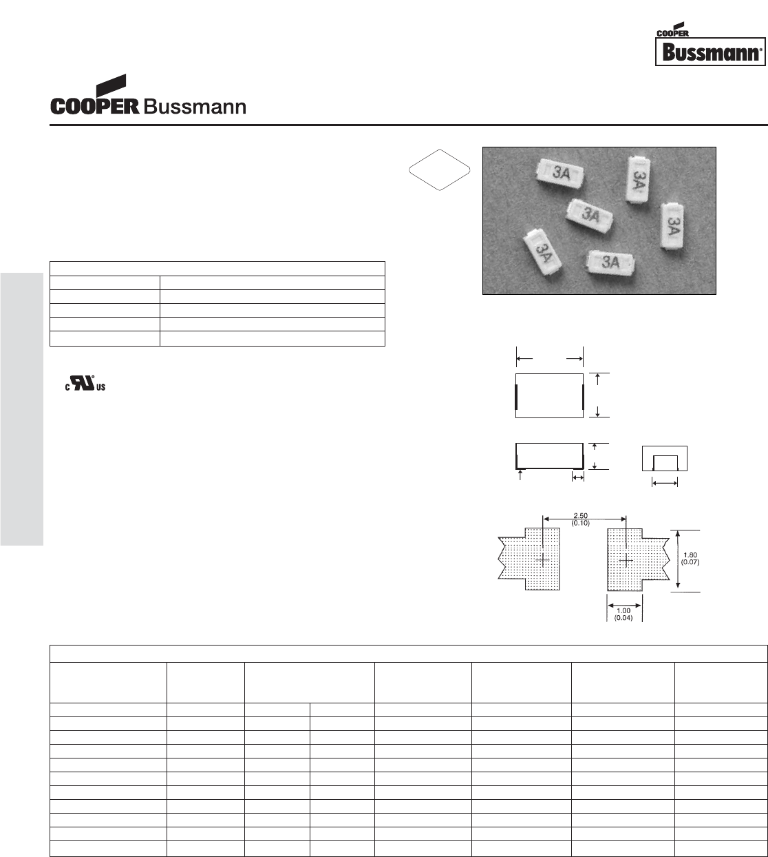
Description
• Rapid interruption of excessive current
• Compatible with reflow and wave solder
• Rugged ceramic and glass construction
• Excellent environmental integrity
• One time positive disconnect
• Compatible with lead free solders and higher
temperature profiles
Agency Information
• UL Recognition Guide & File numbers:
JDYX2 &E19180
• CSA Component Acceptance: 053787 C 000 &
Class Number: 1422 30
Environmental Data
• Life Test: MIL-STD-202, Method 108A
• Load Humidity Test: MIL-STD-202, Method 103B
• Moisture Resistance Test: MIL-STD-202, Method 106E
• Terminal Strength Test: Downward force is applied to
cause a 1mm deflection for 1 minute
• Thermal Shock Test: MIL-STD-202, Method 107D
• Solderability: ANSI/J-STD-002
• Mechanical Shock Test: MIL-STD-202, Method 213B
• High Frequency Vibration Test: MIL-STD-202,
Method 204D
• Resistance to Solvents Test: MIL-STD-202, Method 215A
Ordering
• Specify packaging and product code
(i.e., TR/0603FA250-R)
Soldering Method
• Wave Solder: 260°C, 10 sec max.
• Infrared Reflow: 260°C, 30 sec max.
1.25
(0.05)
0.50 0.90
(0.035)
(0.02)
Land Pattern
Dimensions mm⁄(inches)
Drawing Not to Scale
ELECTRICAL CHARACTERISTICS
% of Amp Rating Opening Time
100% 4 Hours Minimum
200% 60 Seconds Maximum
SPECIFICATIONS
Current Voltage Interrupting DC Cold Typical Typical Alpha
Product Code Rating Rating Rating at Resistance** (ohms) Melting Voltage Code
DC Rated Voltage* Typical I2t*** Drop† Marking‡
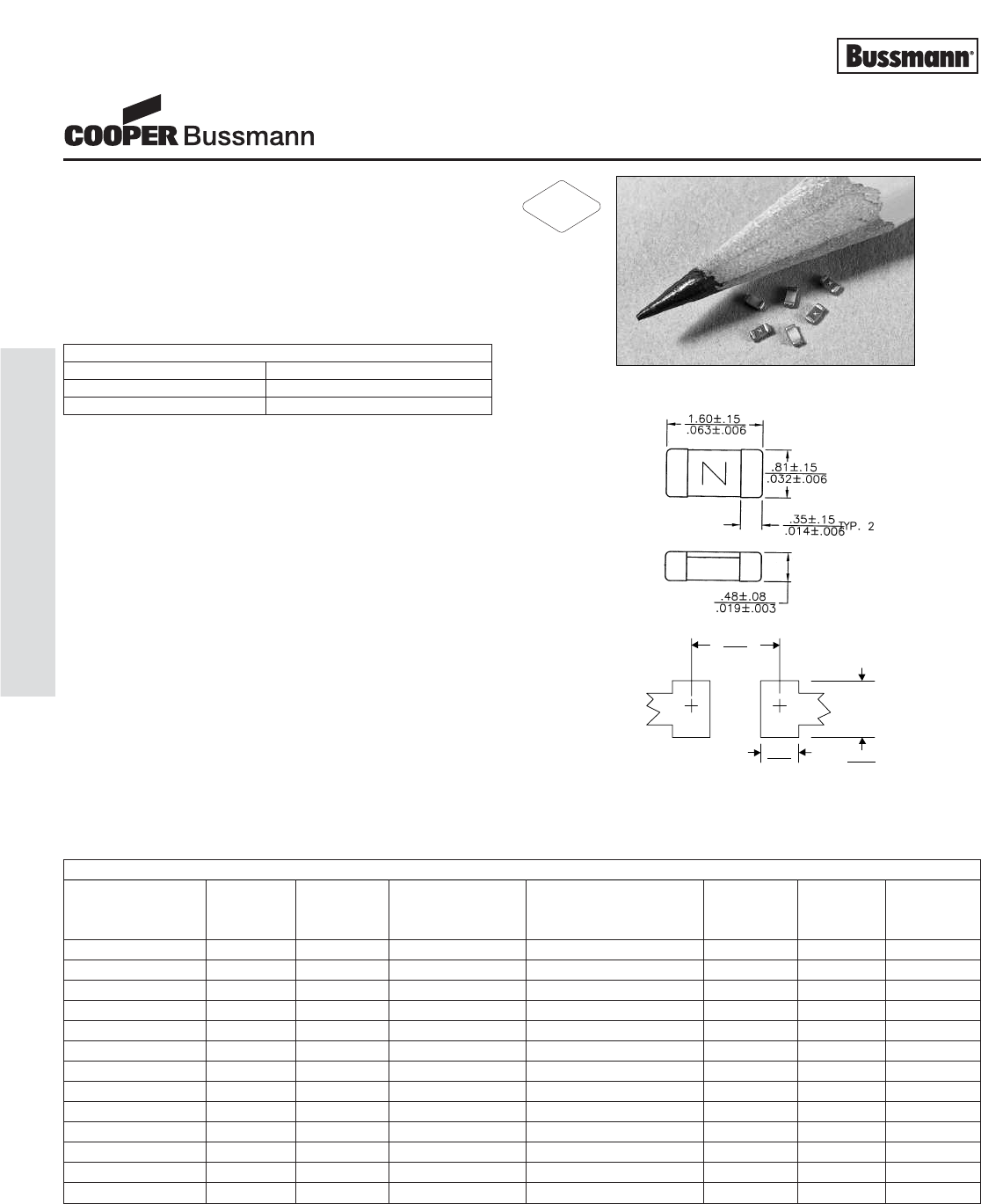
0603FA250-R 250mA 32V 50A 3.100 0.0004 0.921 D
0603FA375-R 375mA 32V 50A 1.250 0.00090.605 E
0603FA500-R 500mA 32V 50A 1.025 0.00193 0.600 F
0603FA750-R 750mA 32V 50A 0.450 0.0090 0.440 G
0603FA1-R 1A 32V 50A 0.150 0.0025 0.211 H
0603FA1.25-R 1.25A 32V 35A 0.108 0.0130 0.151 J
0603FA1.5-R 1.5A 32V 35A 0.086 0.03190.138 K
0603FA2-R 2A 32V 35A 0.051 0.0491 0.116 N
0603FA2.5-R 2.5A 24V 35A 0.037 0.0625 0.113 O
0603FA3-R 3A 24V 35A 0.028 0.0699 0.110 P
0603FA3.5-R 3.5A 24V 35A 0.022 0.1200 0.103 R
0603FA4-R 4A 24V 35A 0.017 0.2430 0.097S
0603FA5-R 5A 24V 35A 0.011 0.6950 0.090T
* DC Interrupting Rating (Measured at designated voltage, time constant of less than 50 microseconds, battery source)
** DC Cold Resistance (Measured at ≤10% of rated current)
***Typical Melting I2t (Measured with a battery bank at rated DC voltage, 10x-rated current, not to exceed IR, time constant of calibrated circuit less than 50 microsec-
onds) (0603FA4A and 5A measured at interrupting rating)
† Typical Voltage Drop (Measured at rated current after temperature stabilizes)
‡ Alpha code to be marked on the top of fuse body for all ratings
• Device designed to carry rated current for four hours minimum. An operating current of 80% or less of rated current is recommended, with
further derating required at elevated ambient temperatures.
Chip™Fuses
0603FA Series, Fast Acting
RoHS
2002/95/EC
OC-12
Printed Circuit Board Fuses - Surface Mount
Courtesy of Steven Engineering, Inc.-230 Ryan Way, South San Francisco, CA 94080-6370-Main Office: (650) 588-9200-Outside Local Area: (800) 258-9200-www.stevenengineering.com
OC-13
Printed Circuit Board Fuses - Surface Mount
PACKAGING CODE
Packaging Code Description
TR 5,000 pieces of fuses in paper tape and reeled on a 178mm (7 inch) reel per EIA Standard 481-1
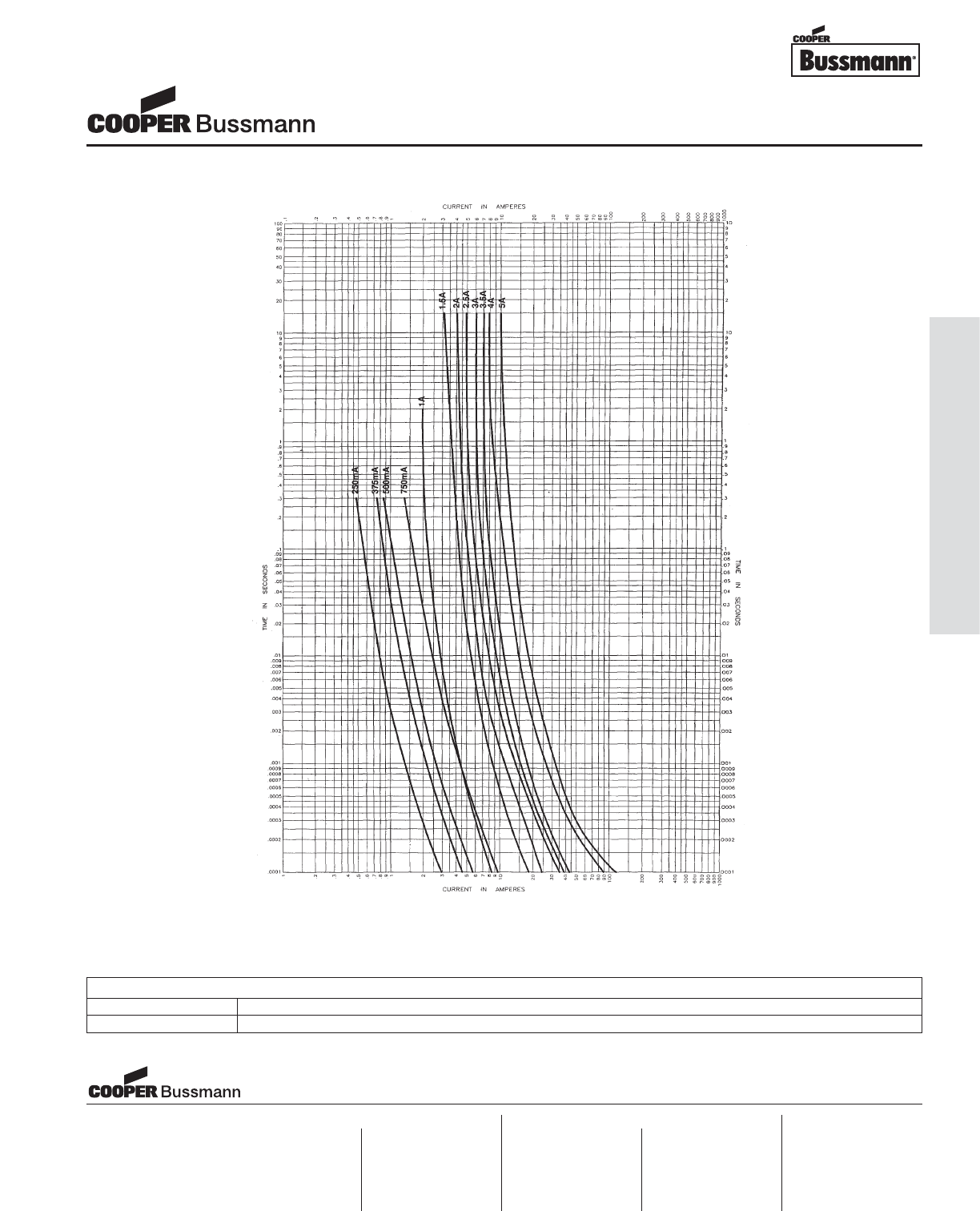
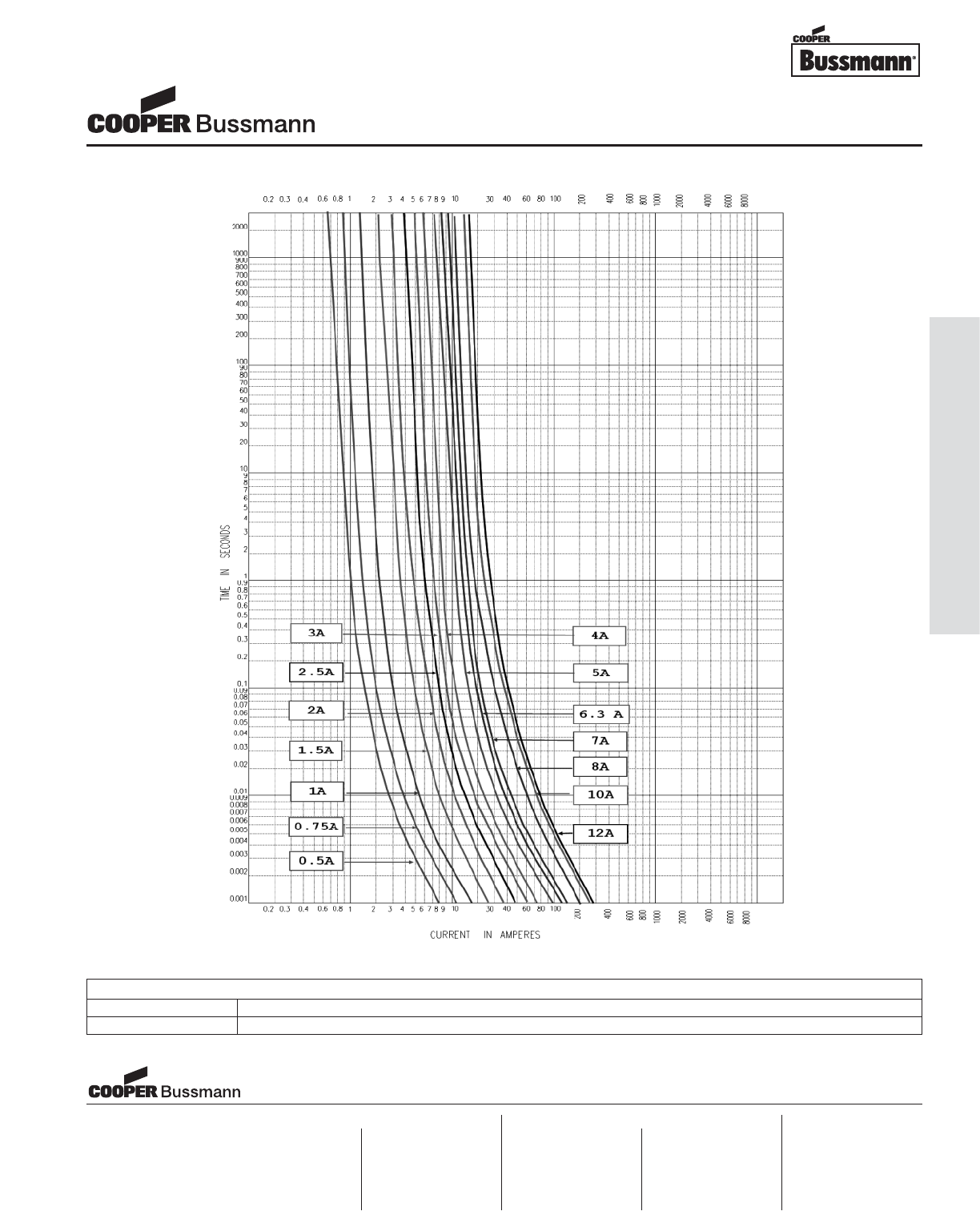
TIME CURRENT CURVE
Chip™Fuses
0603FA Series, Fast Acting
Visit us on the web at:
www.cooperbussmann.com
Cooper Electronic Technologies
1225 Broken Sound Parkway NW
Suite F
Boca Raton, FL 33487-3533
Tel: 1-561-998-4100
Fax: 1-561-241-6640
Toll Free: 1-888-414-2645
Cooper Bussmann
P.O. Box 14460
St. Louis, MO 63178-4460
Tel: 1-636-394-2877
Fax: 1-800-544-2570
Cooper Electronic Technologies
Cooper (UK) Limited
Burton-on-the-Wolds
Leicestershire • LE12 5TH UK
Tel: +44 (0) 1509 882 737
Fax: +44 (0) 1509 882 786
Cooper Electronic Technologies
Avda. Santa Eulalia, 290
08223
Terrassa, (Barcelona), Spain
Tel: +34 937 362 812
+34 937 362 813
Fax: +34 937 362 719
Asia Pacific
Cooper Electronic Technologies
1 Jalan Kilang Timor
#06-01 Pacific Tech Centre
Singapore 159303
Tel: +65 278 6151
Fax: +65 270 4160
North America Europe
Courtesy of Steven Engineering, Inc.-230 Ryan Way, South San Francisco, CA 94080-6370-Main Office: (650) 588-9200-Outside Local Area: (800) 258-9200-www.stevenengineering.com
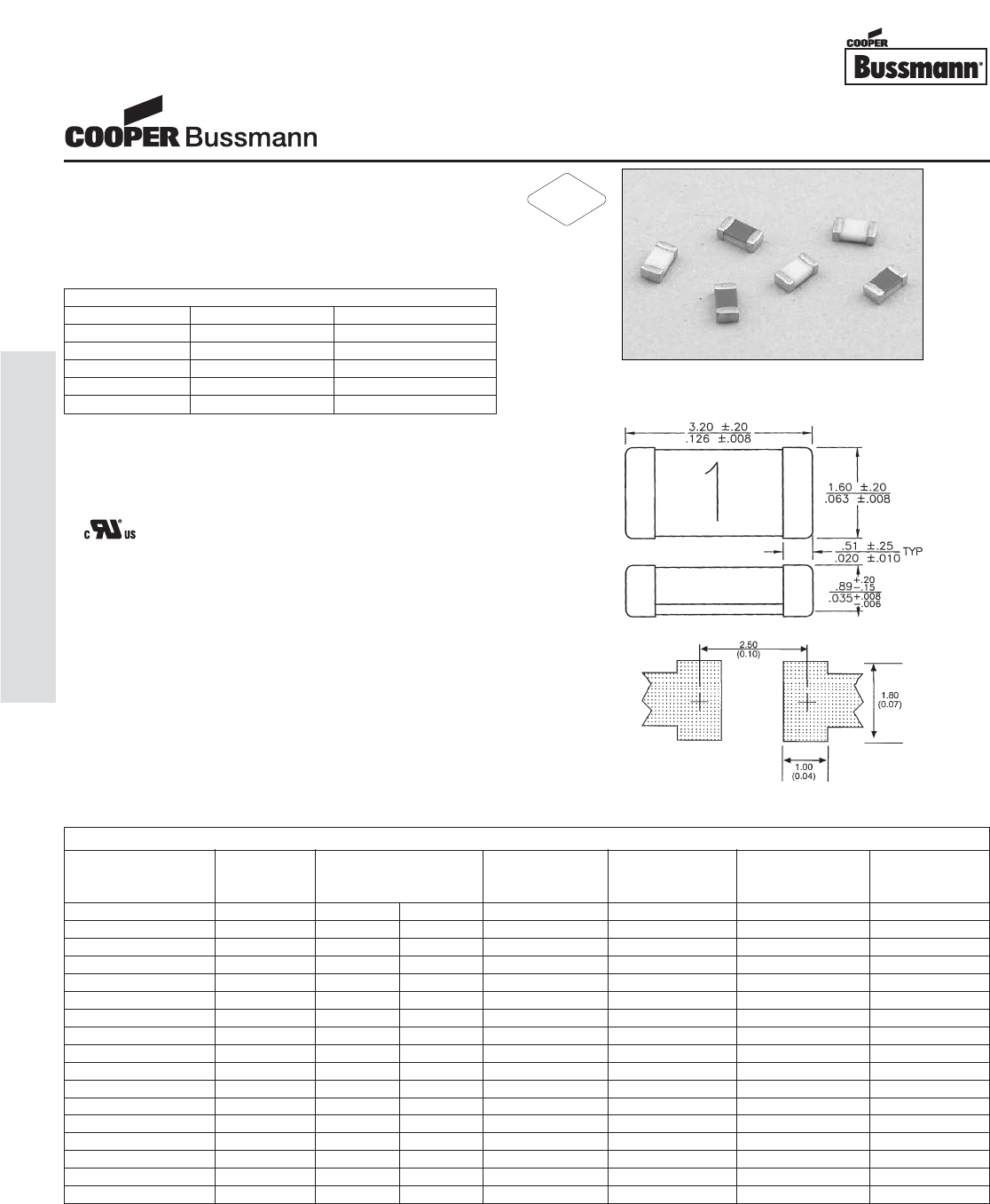
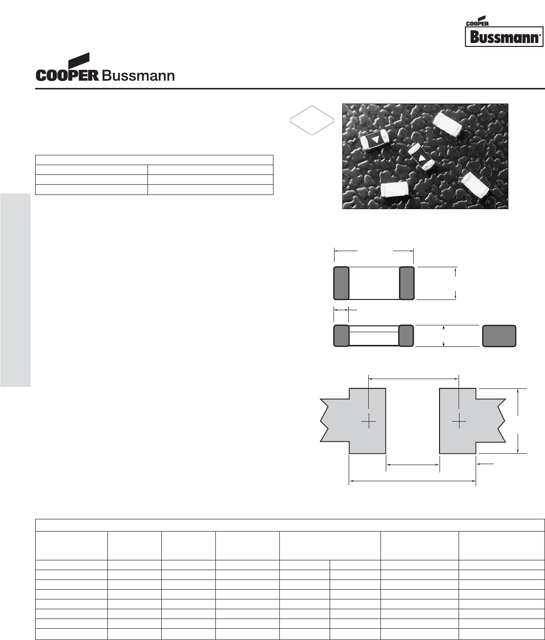
Description
• Protects against harmful overcurrents in secondary
applications
• High inrush withstand capability
• Wire-in-Air performance
• Compatible with leaded and lead-free reflow
and wave solder
Agency Information
• Recognition File number: E19180, Volume 13
Environmental Data
• Thermal Shock: Withstands 5 cycles of -55°C & 125°C
• Vibration: MIL-STD-202F, Method 201A, Method 204D
Condition D
• Solderability: ANSI/J-STD-002, Test B
Ordering
• Specify packaging and product code
(i.e. TR/3216TD1-R)
Soldering Method
• Wave Immersion: 260°C, 10 sec max.
• Infrared Reflow: 260°C, 30 sec max.
• Hand Solder: 350°C, 3 sec max.
3.2±0.1
(0.125)
1.6±0.1
(0.063)
unit: mm(inch)
5A
1.0±0.1
(0.038)
th. 0.1mm 0.4±0.1 1.0±0.05
Land Pattern
Dimensions mm⁄(inches)
Drawing Not to Scale
ELECTRICAL CHARACTERISTICS
% of Amp Rating Opening Time
100% 4 Hours Minimum
200% 1 sec. minimum, 120 sec. maximum
300% 0.05 sec. minimum, 3 sec. maximum
800% 0.002 sec. minimum, 0.05 sec. maximum
* AC Interrupting Rating (Measured at rated voltage with a unity power factor); DC Interrupting Rating (Measured at rated voltage, time constant of less than 50
microseconds, battery source)
** DC Cold Resistance (Measured at 10% of rated current)
† Typical Melting I2t (Measured with a battery bank at rated DC voltage, 10x-rated current at 1 microsecond, not to exceed IR. Above 7a uses 70 micron thickness
copper layer test board of IEC 60127-3. Others uses 35 micron thickness copper layer.
‡ Typical Voltage Drop (Measured at rated current after temperature stabilizes)
Device designed to carry rated current for four hours minimum. An operating current of 80% or less of rated current is recommended, with further derating required at
elevated ambient temperatures.
SPECIFICATIONS
Current Voltage Interrupting Resistance Typical Typical
Product Code Rating Rating Rating* (ohms)** Melt I2t† Voltage
AC DC AC/DC Typ. DC Drop (V)‡
3216TD1-R 1A 63 V 63 V 50 A 0.075 0.32 75
3216TD1.5-R 1.5A 32 V 32 V 35 A 0.050 0.62 75
3216TD2-R 2A 32 V 32 V 35 A 0.030 1.30 60
3216TD2.5-R 2.5A 32 V 32 V 35 A 0.022 2.25 55
3216TD3-R 3A 32 V 32 V 35 A 0.018 3.30 55
3216TD4-R 4A 32 V 32 V 35 A 0.0165 5.20 56
3216TD5-R 5A 32 V 32 V 35 A 0.015 8.40 66
3216TD6.3-R 6.3A 32 V 32 V 35 A 0.0120 13.8 75
3216TD7-R 7A 32 V 32 V 35 A 0.0095 16.9 67
3216TD10-R 10A 32 V 32 V 35 A 0.006 54.4 65
3216TD12-R 12A 32 V 32 V 35 A 0.005 64.0 65
Chip™Fuses
3216TD Series, Time Delay
RoHS
2002/95/EC
OC-14
Printed Circuit Board Fuses - Surface Mount
Courtesy of Steven Engineering, Inc.-230 Ryan Way, South San Francisco, CA 94080-6370-Main Office: (650) 588-9200-Outside Local Area: (800) 258-9200-www.stevenengineering.com
OC-15
Printed Circuit Board Fuses - Surface Mount
PACKAGING CODE
Packaging Code Description
TR 2,500 pieces of fuses on 12mm tape-and-reel on a 180mm reel per EIA-481-A & IEC286-3
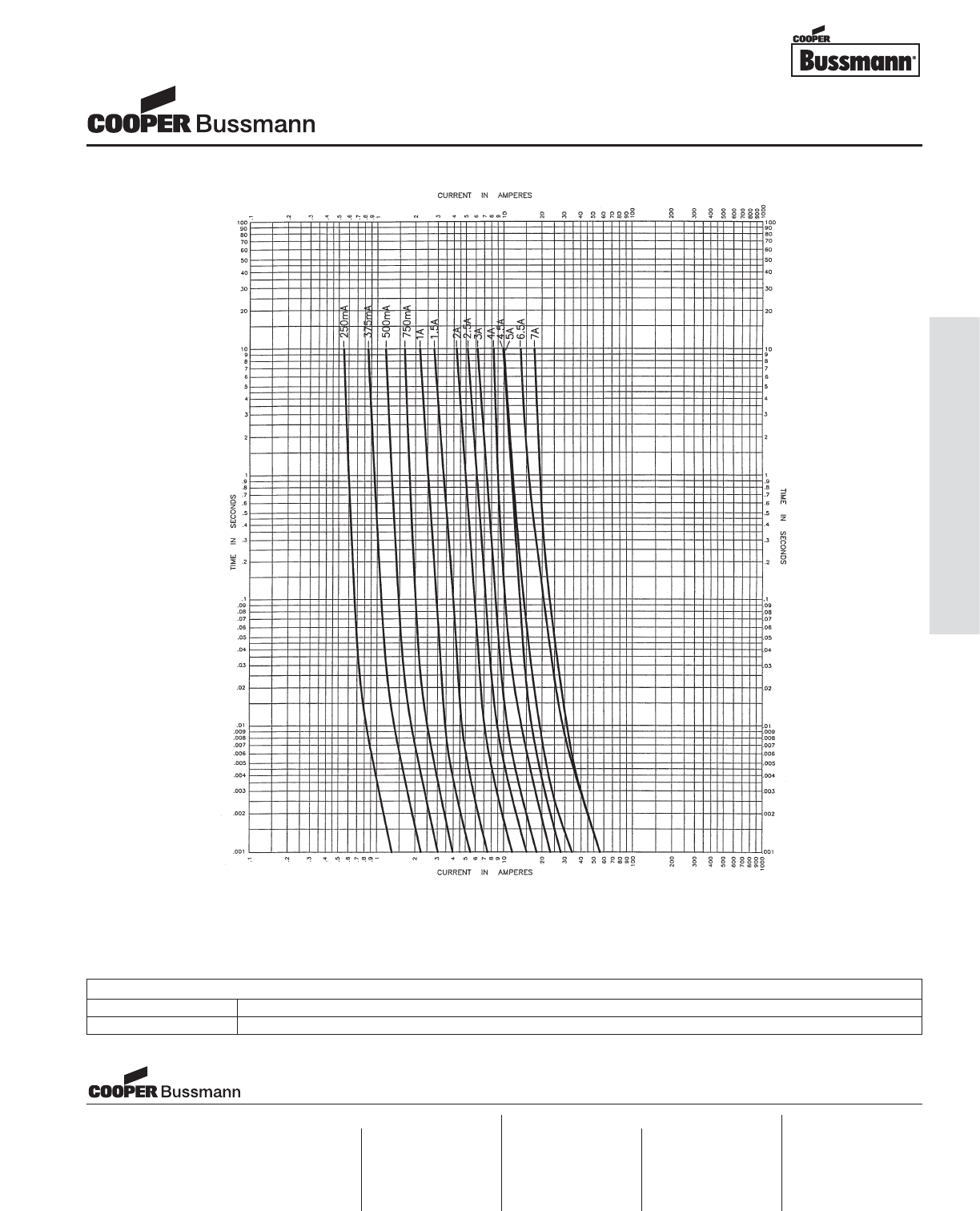
TIME CURRENT CURVE
Visit us on the web at:
www.cooperbussmann.com
Chip™Fuses
3216TD Series, Time Delay
Cooper Electronic Technologies
1225 Broken Sound Parkway NW
Suite F
Boca Raton, FL 33487-3533
Tel: 1-561-998-4100
Fax: 1-561-241-6640
Toll Free: 1-888-414-2645
Cooper Bussmann
P.O. Box 14460
St. Louis, MO 63178-4460
Tel: 1-636-394-2877
Fax: 1-800-544-2570
Cooper Electronic Technologies
Cooper (UK) Limited
Burton-on-the-Wolds
Leicestershire • LE12 5TH UK
Tel: +44 (0) 1509 882 737
Fax: +44 (0) 1509 882 786
Cooper Electronic Technologies
Avda. Santa Eulalia, 290
08223
Terrassa, (Barcelona), Spain
Tel: +34 937 362 812
+34 937 362 813
Fax: +34 937 362 719
Asia Pacific
Cooper Electronic Technologies
1 Jalan Kilang Timor
#06-01 Pacific Tech Centre
Singapore 159303
Tel: +65 278 6151
Fax: +65 270 4160
North America Europe
Courtesy of Steven Engineering, Inc.-230 Ryan Way, South San Francisco, CA 94080-6370-Main Office: (650) 588-9200-Outside Local Area: (800) 258-9200-www.stevenengineering.com
Description
• Fast acting surface mount fuse
• Ratings up to 20A
• Excellent temperature and cycling characteristics
• Compatible with reflow and wave solder
Agency Information
• UL Recognition Guide & File numbers:
JDYX2 & E19180.
• CSA Component Acceptance: 053787 C 000 &
Class No: 1422 30.
• Recognition File number: E19180 (15A - 20A)
Environmental Data
• Thermal Shock: MIL-STD-202, Method 107,
Test Condition B
• Vibration: MIL-STD-202, Method 204, Test Condition C
• Moisture Resistance: MIL-STD-202, Method 106,
10 day cycle
• Solderability: ANSI/J-STD-002, Test B
Ordering
• Specify packaging and product code
(i.e. TR/3216FF250-R)
Soldering Method
• Wave Immersion: 260°C, 10 sec max.
• Infrared Reflow: 260°C, 30 sec max.
Land Pattern
Dimensions mm⁄(inches)
Drawing Not to Scale
ELECTRICAL CHARACTERISTICS
Ampere Rating % of Amp Rating Opening Time
250mA - 7A 100% 4 Hours Minimum
1.25A - 3A 200% 60 Seconds Maximum
250mA - 3A 250% 5 Second Maximum
4A - 7A 350% 1 Second Maximum
15A - 20A 350% 5 Second Maximum
* AC Interrupting Rating (Measured at rated voltage with a unity power factor); DC Interrupting Rating (Measured at rated voltage, time constant of less than 50
microseconds, battery source)
** DC Cold Resistance (Measured at 10% of rated current)
† Typical Melting I2t (Measured with a battery bank at rated DC voltage, 10x-rated current, not to exceed IR, time constant of calibrated circuit less than 50 microsec-
onds) (6.5A & 7A measured at interrupting rating)
‡ Typical Voltage Drop (Measured at rated current after temperature stabilizes)
It is recommended that fuses be mounted with ceramic (white) side facing up.
Device designed to carry rated current for four hours minimum. An operating current of 80% or less of rated current is recommended, with further derating required at
elevated ambient temperatures.
SPECIFICATIONS
Current Voltage Interrupting Resistance Typical Typical
Product Code Rating Rating Rating* (ohms)** Melt I2t† Voltage
AC DC AC/DC Typ. DC Drop (V)‡
3216FF250-R 250mA 32 V 63 V 50 A 3.0 0.00038 1.4
3216FF375-R 375mA 32 V 63 V 50 A 1.75 0.00077 0.73
3216FF500-R 500mA 32 V 63 V 50 A 0.98 0.0019 0.66
3216FF750-R 750mA 32 V 63 V 50 A 0.50 0.0053 0.63
3216FF1-R 1A 32 V 63 V 50 A 0.24 0.030 0.20
3216FF1.25-R 1.25A 32 V 63 V 50 A 0.135 0.060 0.19
3216FF1.5-R 1.5A 32 V 63 V 50 A 0.119 0.093 0.18
3216FF2-R 2A 32 V 63 V 50 A 0.066 0.126 0.16
3216FF2.5-R 2.5A 32 V 63 V 50 A 0.046 0.260 0.14
3216FF3-R 3A 32 V 63 V 50 A 0.040 0.275 0.13
3216FF4-R 4A 32 V 32 V 50 A 0.018 0.337 0.11
3216FF4.5-R 4.5A 32 V 32 V 50 A 0.016 0.405 0.10
3216FF5-R 5A 32 V 32 V 50 A 0.014 0.534 0.09
3216FF6.5-R 6.5A 32 V 32 V 50 A 0.0082 2.294 0.076
3216FF7-R 7A 32 V 32 V 50 A 0.0078 3.623 0.078
3216FF15-R 15A 24 V 24 V 150 A 0.0031 25.5 0.065
3216FF20-R 20A 24 V 24 V 150 A 0.0018 48.6 0.058
Chip™Fuses
3216FF Series, Fast Acting
RoHS
2002/95/EC
OC-16
Printed Circuit Board Fuses - Surface Mount
Courtesy of Steven Engineering, Inc.-230 Ryan Way, South San Francisco, CA 94080-6370-Main Office: (650) 588-9200-Outside Local Area: (800) 258-9200-www.stevenengineering.com
OC-17
Printed Circuit Board Fuses - Surface Mount
PACKAGING CODE
Packaging Code Description
TR 3,000 pieces of fuses on 8mm tape-and-reel on a 7 inch (178mm) reel per EIA Standard 481
TIME CURRENT CURVE
Chip™Fuses
3216FF Series, Fast Acting
Visit us on the web at:
www.cooperbussmann.com
Cooper Electronic Technologies
1225 Broken Sound Parkway NW
Suite F
Boca Raton, FL 33487-3533
Tel: 1-561-998-4100
Fax: 1-561-241-6640
Toll Free: 1-888-414-2645
Cooper Bussmann
P.O. Box 14460
St. Louis, MO 63178-4460
Tel: 1-636-394-2877
Fax: 1-800-544-2570
Cooper Electronic Technologies
Cooper (UK) Limited
Burton-on-the-Wolds
Leicestershire • LE12 5TH UK
Tel: +44 (0) 1509 882 737
Fax: +44 (0) 1509 882 786
Cooper Electronic Technologies
Avda. Santa Eulalia, 290
08223
Terrassa, (Barcelona), Spain
Tel: +34 937 362 812
+34 937 362 813
Fax: +34 937 362 719
Asia Pacific
Cooper Electronic Technologies
1 Jalan Kilang Timor
#06-01 Pacific Tech Centre
Singapore 159303
Tel: +65 278 6151
Fax: +65 270 4160
North America Europe
Courtesy of Steven Engineering, Inc.-230 Ryan Way, South San Francisco, CA 94080-6370-Main Office: (650) 588-9200-Outside Local Area: (800) 258-9200-www.stevenengineering.com
Description
• Surface mount fuse, fast acting, 125 VAC
• Utilize thick and thin metal film technologies for
superior fusing action and enhanced reliability.
Agency Information
• UL Recognition Guide & File numbers:
JDYX2 & E19180.
• CSA Component Acceptance: 053787 C 000 &
Class No: 1422 30.
Environmental Data
• Operating Temperature Range: -65 to +125°C,
with proper derating
• Thermal Shock: MIL-STD-202, Method 107, Test
Condition B (-65 to 125°C), 1000 cycles, fuses soldered
to FR-4 glass-epoxy circuit board
• Vibration: MIL-STD-202, Method 204, Test Condition C
(55 to 2000 HZ, 10G)
• Solderability: Withstands 60 seconds above 200°C,
260°C maximum
• Moisture Resistance: MIL-STD-202, Method 106,
10 day cycle
• Solder Leach Resistance & Terminal Adhesion:
EIA-576 (30 seconds submersion in 260°C
tin-lead solder)
Ordering
• Specify packaging and product code
(i.e. TR/3216LV1-R)
2.80
1.80 to
2.00
1.60
1.20 to 1.40
4.20 to 4.40
1.60 ±0.2
(0.063 ±0.008)
3.20 ±0.2
(0.126 ±0.008)
0.50 ±0.25
(0.020 ±0.010)
.75
0.90 + 0.20, -0.15
(0.035 + 0.008, -0.006)
Land Pattern
Dimensions mm⁄(inches)
Drawing Not to Scale
Notes:
1. AC interrupting rating, melting integral and total clearing integral measured at 125V, unity power factor
2. DC interrupting rating, melting integral and total clearing integral measured at 125V with a battery source
3. Voltage drop measured at 23 ± 3°C ambient temperature with the device mounted on a suitable circuit board trace
4. It is recommended that fuses be mounted with ceramic (white) side facing up
5. Device designed to carry rated current for four hours minimum. An operating current of 80% or less of rated current is recommended,
with further derating required at elevated ambient temperatures
SPECIFICATIONS
Current Voltage Interrupting Typical Melting Typ. Resistance Typ. Voltage
Product Code Rating Rating Rating Integral @ 10X Rated @ ≤10% Rated Drop @ Rated
AC/DC 125V AC/DC Current (A2* sec) Current (Ohms) Current (Volts)
AC DC
3216LV250-R 250mA 125V 50A .00016 .000084 4.5 1.4
3216LV375-R 375mA 125V 50A .001 .0002 1.80 .73
3216LV500-R 500mA 125V 50A .0014 .0019 1.15 .66
3216LV750-R 750mA 125V 50A .0033 .00379 .75 .63
3216LV1-R 1A 125V 50A .020 .0084 .52 .63
3216LV1.25-R 1.25A 125V 50A .035 .021 .40 .62
3216LV1.5-R 1.5A 125V 50A .038 .024 .26 .49
ELECTRICAL CHARACTERISTICS
% of Amp Rating Opening Time
100% 4 hours minimum
250% 5 seconds maximum
Chip™Fuses
3216LV Series, Fast Acting, Line Voltage
RoHS
2002/95/EC
OC-18
Printed Circuit Board Fuses - Surface Mount
Courtesy of Steven Engineering, Inc.-230 Ryan Way, South San Francisco, CA 94080-6370-Main Office: (650) 588-9200-Outside Local Area: (800) 258-9200-www.stevenengineering.com
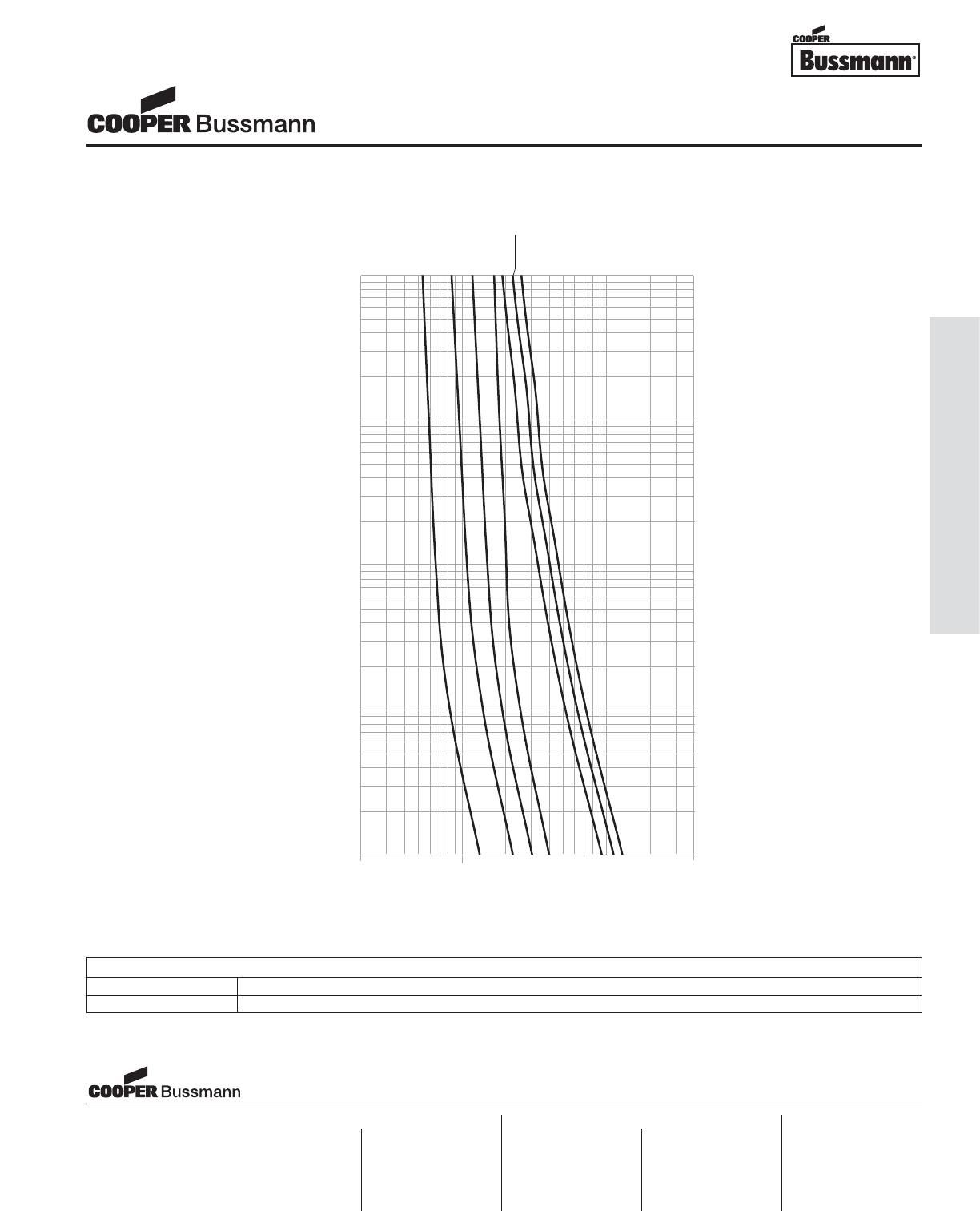
OC-19
Printed Circuit Board Fuses - Surface Mount
CURRENT IN AMPERES
10
1
.1
.01
.001
TIME IN SECONDS
10
1
40
CURRENT
RATING
.1
750mA
250mA
375mA
500mA
1A 1.25A
1.5A
TIME CURRENT CURVE
PACKAGING CODE
Packaging Code Description
TR 3,000 pieces of fuses on 8mm tape-and-reel on a 7 inch (178mm) reel per EIA Standard 481
Chip™Fuses
3216LV Series, Fast Acting, Line Voltage
Visit us on the web at:
www.cooperbussmann.com
Cooper Electronic Technologies
1225 Broken Sound Parkway NW
Suite F
Boca Raton, FL 33487-3533
Tel: 1-561-998-4100
Fax: 1-561-241-6640
Toll Free: 1-888-414-2645
Cooper Bussmann
P.O. Box 14460
St. Louis, MO 63178-4460
Tel: 1-636-394-2877
Fax: 1-800-544-2570
Cooper Electronic Technologies
Cooper (UK) Limited
Burton-on-the-Wolds
Leicestershire • LE12 5TH UK
Tel: +44 (0) 1509 882 737
Fax: +44 (0) 1509 882 786
Cooper Electronic Technologies
Avda. Santa Eulalia, 290
08223
Terrassa, (Barcelona), Spain
Tel: +34 937 362 812
+34 937 362 813
Fax: +34 937 362 719
Asia Pacific
Cooper Electronic Technologies
1 Jalan Kilang Timor
#06-01 Pacific Tech Centre
Singapore 159303
Tel: +65 278 6151
Fax: +65 270 4160
North America Europe
Courtesy of Steven Engineering, Inc.-230 Ryan Way, South San Francisco, CA 94080-6370-Main Office: (650) 588-9200-Outside Local Area: (800) 258-9200-www.stevenengineering.com
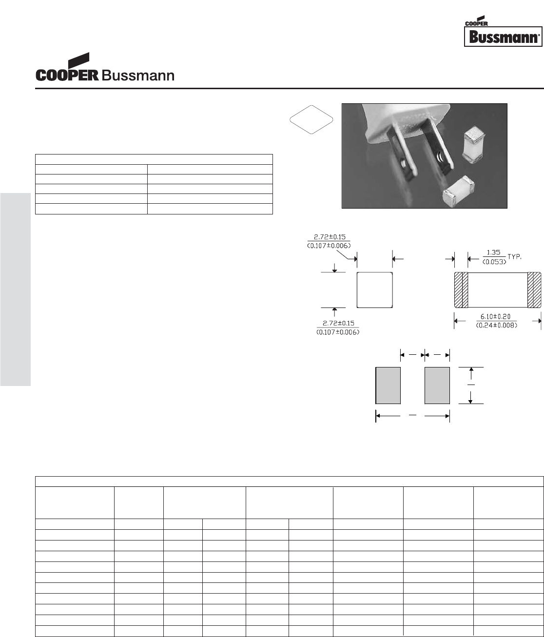
Description
• Time Delay surface mount fuse
• Complies with EIA-IS-722 Standard
• Solder Immersion Compatible
Agency Information
• UL Recognition Guide & File numbers:
JDYX2 & E19180.
• CSA Component Acceptance: 053787 C 000 &
Class No: 1422 30.
Environmental Data
• Life Test: MIL-STD-202, Method 108A, Test Condition D
• Load Humidity: MIL-STD-202, Method 103B
• Moisture Resistance: MIL-STD-202, Method 106E
• Thermal Shock: MIL-STD-202, Method 107D, air-to-air
• Case Resistance: EIA/IS-722
• Resistance to Dissolution of Metallization:
ANSI J-STD-002, Test D
• Mechanical Shock: MIL-STD-202, Method 213B, Test
Condition A
• High Frequency Vibration: MIL-STD-202, Method 204D,
Test Condition D
• Resistance to Solvents: MIL-STD-202, Method 215A
Ordering
• Specify packaging and product code
(i.e., TR1/6125TD500-R)
Soldering Method
• Wave Immersion: 260°C, 10 sec max.
• Infrared: 260°C, 30 sec max.
2.6 3.0
(0.102) (0.118)
4.0
(0.157)
8.6
(0.338)
Land Pattern
Dimensions mm⁄(inches)
ELECTRICAL CHARACTERISTICS
% of Amp Rating Opening Time
100% 4 Hours Minimum
200% 1 Second Minimum
200% 2-4 Seconds Typical
200% 60 Seconds Maximum
SPECIFICATIONS
Product Current Voltage Interrupting Resistance Typical Typical
Code Rating Rating Rating* (ohms)** Melting Voltage
AC DC 125VAC 60VDC Typ. I2t† Drop‡
6125TD500-R 500mA 125V 60V 50A 50A 0.4025 0.716 245 mV
6125TD750-R 750mA 125V 60V 50A 50A 0.2350 1.07 250 mV
6125TD1-R 1A 125V 60V 50A 50A 0.1680 2.88 256 mV
6125TD1.5-R 1.5A 125V 60V 50A 50A 0.0630 2.35 125 mV
6125TD2-R 2A 125V 60V 50A 50A 0.0480 9.45 133 mV
6125TD2.5-R 2.5A 125V 60V 50A 50A 0.0350 16.2 130 mV
6125TD3-R 3A 125V 60V 50A 50A 0.0263 15.3 97 mV
6125TD3.5-R 3.5A 125V 60V 50A 50A 0.0195 14.5 95 mV
6125TD4-R 4A 125V 60V 50A 50A 0.0185 38.8 106 mV
6125TD5-R 5A 125V 60V 50A 50A 0.0133 34.4 100 mV
6125TD7-R 7A 125V 60V 50A 50A 0.0087 90.2 99 mV
* AC Interrupting Rating (Measured at designated voltage, 100% power factor); DC Interrupting Rating (Measured at designated voltage, time constant of less than
50 microseconds, battery source)
** DC Cold Resistance (Measured at 10% of rated current)
† Typical Melting I2t (Measured with a battery bank at rated DC voltage, 10x-rated current (not to exceed IR), time constant of calibrated circuit less than 50 microseconds)
‡ Typical Voltage Drop (Measured at rated current after temperature stabilizes)
Device designed to carry rated current for four hours minimum. An operating current of 80% or less of rated current is recommended, with further derating required at elevat-
ed ambient temperatures.
Brick™Fuses
6125TD Series, Time Delay
RoHS
2002/95/EC
OC-20
Printed Circuit Board Fuses - Surface Mount
Courtesy of Steven Engineering, Inc.-230 Ryan Way, South San Francisco, CA 94080-6370-Main Office: (650) 588-9200-Outside Local Area: (800) 258-9200-www.stevenengineering.com
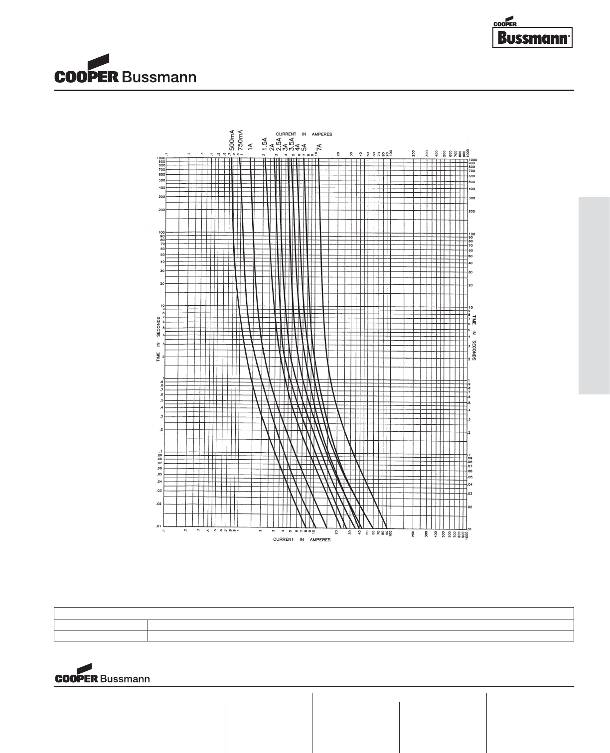
OC-21
Printed Circuit Board Fuses - Surface Mount
TIME CURRENT CURVE
PACKAGING CODE
Packaging Code Description
TR1 1,000 pieces of fuses on 12mm tape-and-reel on a 7 inch (177mm) reel per EIA Standard 481
Brick™Fuses
6125TD Series, Time Delay
Visit us on the web at:
www.cooperbussmann.com
Cooper Electronic Technologies
1225 Broken Sound Parkway NW
Suite F
Boca Raton, FL 33487-3533
Tel: 1-561-998-4100
Fax: 1-561-241-6640
Toll Free: 1-888-414-2645
Cooper Bussmann
P.O. Box 14460
St. Louis, MO 63178-4460
Tel: 1-636-394-2877
Fax: 1-800-544-2570
Cooper Electronic Technologies
Cooper (UK) Limited
Burton-on-the-Wolds
Leicestershire • LE12 5TH UK
Tel: +44 (0) 1509 882 737
Fax: +44 (0) 1509 882 786
Cooper Electronic Technologies
Avda. Santa Eulalia, 290
08223
Terrassa, (Barcelona), Spain
Tel: +34 937 362 812
+34 937 362 813
Fax: +34 937 362 719
Asia Pacific
Cooper Electronic Technologies
1 Jalan Kilang Timor
#06-01 Pacific Tech Centre
Singapore 159303
Tel: +65 278 6151
Fax: +65 270 4160
North America Europe
Courtesy of Steven Engineering, Inc.-230 Ryan Way, South San Francisco, CA 94080-6370-Main Office: (650) 588-9200-Outside Local Area: (800) 258-9200-www.stevenengineering.com
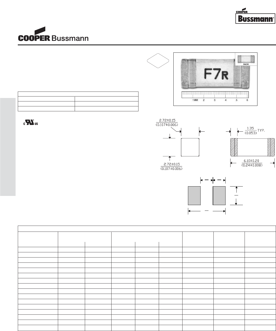
Description
• Fast Acting Surface Mount Fuse
• Overcurrent protection of systems up to
125VAC/72VDC
• High inrush withstand capability
• Solder immersion compatible
Agency Information
• Recognition File number: E19180
Environmental Data
• Operating Temperature: -55°C to 125°C
• Mechanical Shock: MIL-STD-202, Method 213
• High Frequency Vibration: MIL-STD-202, Method 204
• Load Humidity: MIL-STD-202, Method 103
• Moisture Resistance: MIL-STD-202, Method 106
• Resistance to Solvents: MIL-STD-202, Method 215
• Thermal Shock: MIL-STD-202, Method 107
Ordering
• Specify packaging and product code
(i.e., TR2/6125FF500-R)
Soldering Method
• Wave Immersion: 260°C, 10 sec max.
• Infrared: 260°C, 30 sec max.
ELECTRICAL CHARACTERISTICS
% of Amp Rating Opening Time
100% 4 Hours Minimum
200% 5 Second Maximum
Brick™Fuses
6125FF Series, Fast Acting
RoHS
2002/95/EC
2.6 3.0
(0.102) (0.118)
4.0
(0.157)
8.6
(0.338)
Land Pattern
Dimensions mm⁄(inches)
* AC Interrupting Rating (Measured at designated voltage, 100% power factor); DC Interrupting Rating (Measured at designated voltage, time constant of less than 50 microsec-
onds, battery source)
** Typical Melting I2t (Measured at 72Vdc, 10X rated current (not exceed 50A - IR @ 72Vdc)
SPECIFICATIONS
Part Voltage Interrupting DC Cold Melting Typical
Number Rating Rating Resistance I2t Voltage
AC DC 125V AC 72V DC 32V DC (milliohms) Typ. (A2sec) Drop (mV)
6125FF500-R 125V 72V 50A 50A 300A 1130 0.090 935
6125FF750-R 125V 72V 50A 50A 300A 350 0.152 433
6125FF1-R 125V 72V 50A 50A 300A 260 0.180 415
6125FF1.25-R 125V 72V 50A 50A 300A 171 0.355 410
6125FF1.5-R 125V 72V 50A 50A 300A 112 0.456 365
6125FF2-R 125V 72V 50A 50A 300A 49 1.67 160
6125FF2.5-R 125V 72V 50A 50A 300A 45 5.20 155
6125FF3-R 125V 72V 50A 50A 300A 35 8.00 153
6125FF3.5-R 125V 72V 50A 50A 300A 27 15.00 150
6125FF4-R 125V 72V 50A 50A 300A 26 15.80 145
6125FF5-R 125V 72V 50A 50A 300A 17 17.20 141
6125FF6.3-R 125V 72V 50A 50A 300A 14 22.50 135
6125FF7-R 125V 72V 50A 50A 300A 11 37.25 112
6125FF10-R 125V 72V 50A 50A 300A 7.3 67.75 110
6125FF12-R 125V 72V 50A 50A 300A 5.3 210.59 106
6125FF15-R 125V 72V 50A 50A 300A 4.2 296.10 104
OC-22
Printed Circuit Board Fuses - Surface Mount
Courtesy of Steven Engineering, Inc.-230 Ryan Way, South San Francisco, CA 94080-6370-Main Office: (650) 588-9200-Outside Local Area: (800) 258-9200-www.stevenengineering.com
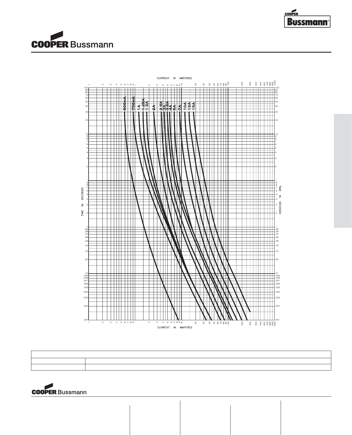
OC-23
Printed Circuit Board Fuses - Surface Mount
TIME CURRENT CURVE
PACKAGING CODE
Packaging Code Description
TR2 5,000 pieces of fuses on tape-and-reel on a 13 inch (330mm) reel
Brick™Fuses
6125FF Series, Fast Acting
Visit us on the web at:
www.cooperbussmann.com
Cooper Electronic Technologies
1225 Broken Sound Parkway NW
Suite F
Boca Raton, FL 33487-3533
Tel: 1-561-998-4100
Fax: 1-561-241-6640
Toll Free: 1-888-414-2645
Cooper Bussmann
P.O. Box 14460
St. Louis, MO 63178-4460
Tel: 1-636-394-2877
Fax: 1-800-544-2570
Cooper Electronic Technologies
Cooper (UK) Limited
Burton-on-the-Wolds
Leicestershire • LE12 5TH UK
Tel: +44 (0) 1509 882 737
Fax: +44 (0) 1509 882 786
Cooper Electronic Technologies
Avda. Santa Eulalia, 290
08223
Terrassa, (Barcelona), Spain
Tel: +34 937 362 812
+34 937 362 813
Fax: +34 937 362 719
Asia Pacific
Cooper Electronic Technologies
1 Jalan Kilang Timor
#06-01 Pacific Tech Centre
Singapore 159303
Tel: +65 278 6151
Fax: +65 270 4160
North America Europe
Courtesy of Steven Engineering, Inc.-230 Ryan Way, South San Francisco, CA 94080-6370-Main Office: (650) 588-9200-Outside Local Area: (800) 258-9200-www.stevenengineering.com
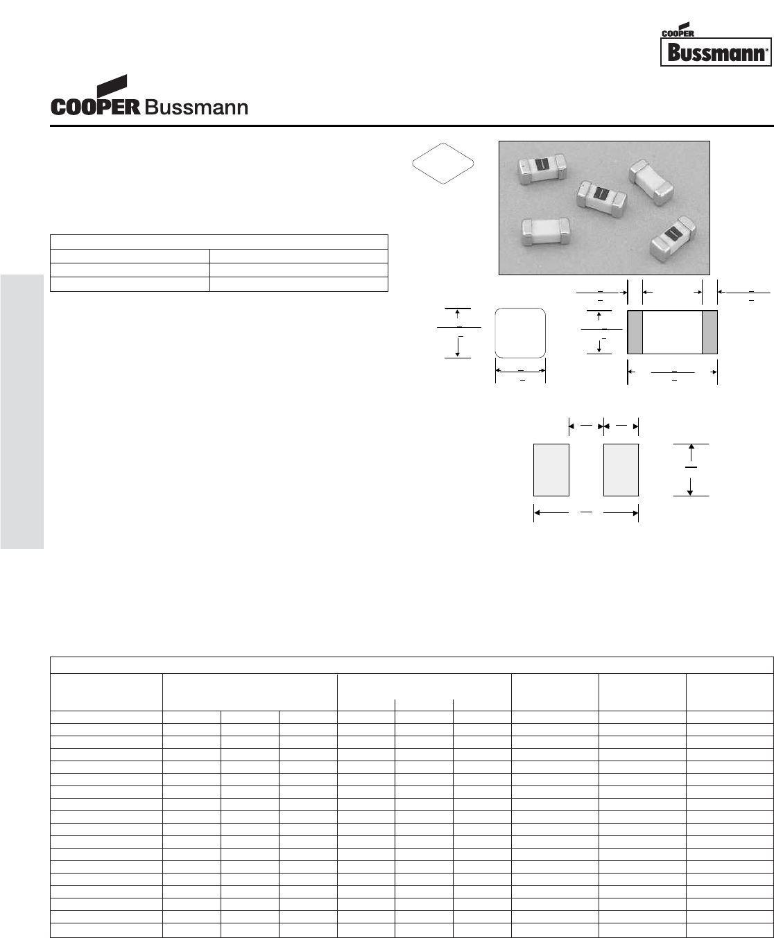
Description
• Fast Acting Surface Mount Fuse
• Complies with the EIA-IS-722 Standard
• Solder Immersion Compatible
• Overcurrent protection of systems up to 125VAC/DC
• Wire-in-air design
Agency Information
• UL Listed Guide and File Numbers (250mA-12A):
JDYX & E19180
• UL Recognized Guide and File Numbers (15A):
JDYX2 & E195337
• CSA Component Acceptance: 053787 C 000 &
Class No: 1422 30
Environmental Data
• Shock: MIL-STD-202, Method 213, Test Condition 1
(100 G’s peak for 6 milliseconds)
• Vibration: MIL-STD-202, Method 201 (10-55 Hz, 0.06
inch, total excursion)
• Salt Spray: MIL-STD-202, Method 101, Test Condition
B (48 hrs)
• Insulation Resistance: MIL-STD-202, Method 302, Test
Condition A (After Opening) 10,000 ohms minimum
• Resistance to Solder Heat: MIL-STD-202, Method 210,
Test Condition F (20 sec, at 260° C)
• Thermal Shock: MIL-STD-202, Method 107, Test
Condition B (-65° C to +125° C)
Ordering
• Specify product and packaging code
Soldering Method
• Wave Solder: 260°C, 10 sec max.
(MIL-STD-202, Method 210)
• Infrared Reflow: 260°C, 30 sec max.
2.59+.250
(0.102+.010)
2.59+.250
(0.102+.010)
2.6 3.0
(0.102) (0.118)
4.0
(0.157)
8.6
(0.339)
* AC Interrupting Rating (Measured at designated voltage, 100% power factor); DC Interrupting Rating (Measured at designated voltage, time constant of less than 50 microsec-
onds, battery source)
** DC Cold Resistance (Measured at 10% of rated current)
† Typical Melting I2t (Measured with a battery bank at rated DC voltage, 10x-rated current, time constant of calibrated circuit less than 50 microseconds)
‡ Typical Voltage Drop (Measured at rated current after temperature stabilizes)
Device designed to carry rated current for four hours minimum. An operating current of 80% or less of rated current is recommended, with further derating required at elevated
ambient temperatures.
1.35+.25 1.35+.25
(0.053+.010) (0.053+.010)
2.59+.25
(0.102+.010)
6.10+.25
(0.240+.010)
Land Pattern
Dimensions mm⁄(inches)
Drawing Not to Scale
Top View
End View
ELECTRICAL CHARACTERISTICS
% of Amp Rating Opening Time
100% 4 Hours Minimum
200% 5 Seconds Maximum
SPECIFICATIONS
Product Voltage Interrupting Resistance Typical Typical
Code Rating Rating* (ohms)** Melt Voltage
AC DC DC 125V AC 125V DC 86V DC Typ. I2t† Drop (V)‡
6125FA250mA 125V 125V 86V 50A 300A 10,000A 0.65 0.01 0.30
6125FA375mA 125V 125V 86V 50A 300A 10,000A 0.36 0.03 0.25
6125FA500mA 125V 125V 86V 50A 300A 10,000A 0.24 0.06 0.22
6125FA750mA 125V 125V 86V 50A 300A 10,000A 0.15 0.07 0.17
6125FA1A 125V 125V 86V 50A 300A 10,000A 0.11 0.14 0.17
6125FA1.25A 125V 125V 86V 50A 300A 10,000A 0.09 0.24 0.16
6125FA1.5A 125V 125V 86V 50A 300A 10,000A 0.07 0.41 0.15
6125FA2A 125V 125V 86V 50A 300A 10,000A 0.05 0.80 0.15
6125FA2.5A 125V 125V 86V 50A 300A 10,000A 0.038 1.4 0.14
6125FA3A 125V 125V 86V 50A 300A 10,000A 0.028 2.4 0.13
6125FA3.5A 125V 125V 86V 50A 300A 10,000A 0.025 3.3 0.13
6125FA4A 125V 125V 86V 50A 300A 10,000A 0.022 4.4 0.13
6125FA5A 125V 125V 86V 50A 300A 10,000A 0.016 7.8 0.12
6125FA6.3A 125V 125V 86V 50A 300A 10,000A 0.012 14.0 0.12
6125FA7A 125V 125V 86V 50A 300A 10,000A 0.011 19.0 0.114
6125FA10A 125V N/A 86V 50A N/A 10,000A 0.007 44 0.107
6125FA12A 125V N/A 86V 50A N/A 10,000A 0.006 69 0.103
6125FA15A N/A N/A 86V N/A N/A 10,000A 0.004 124 0.098
Brick™Fuses
6125FA Series, Fast Acting
RoHS
2002/95/EC
OC-24
Printed Circuit Board Fuses - Surface Mount
Courtesy of Steven Engineering, Inc.-230 Ryan Way, South San Francisco, CA 94080-6370-Main Office: (650) 588-9200-Outside Local Area: (800) 258-9200-www.stevenengineering.com
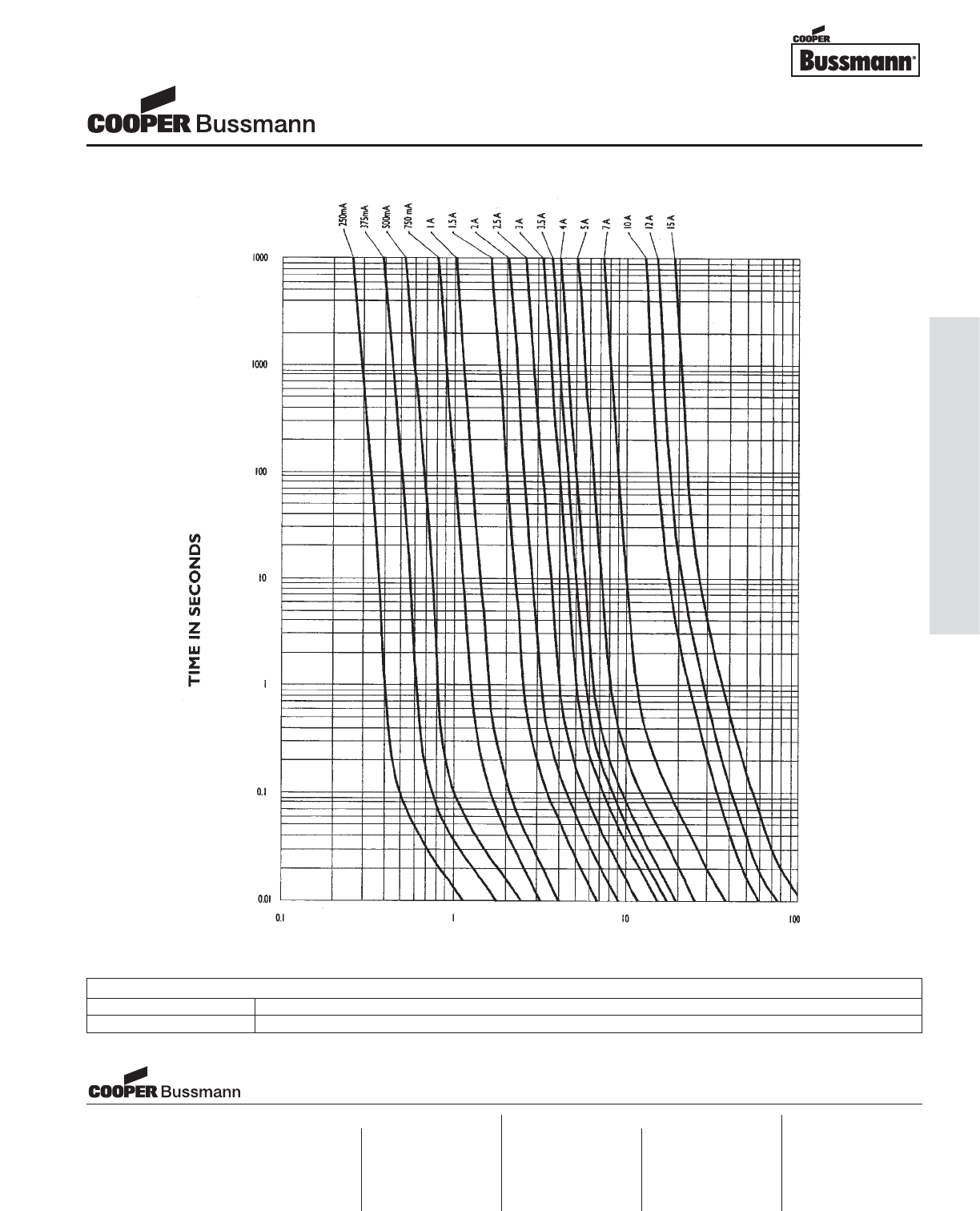
OC-25
Printed Circuit Board Fuses - Surface Mount
PACKAGING CODE
Packaging Code Description
TR2 5,000 pieces of fuses on 12mm tape-and-reel on a 13 inch (330mm) reel per EIA Standard 481
TIME CURRENT CURVE
Brick™Fuses
6125FA Series, Fast Acting
Visit us on the web at:
www.cooperbussmann.com
Cooper Electronic Technologies
1225 Broken Sound Parkway NW
Suite F
Boca Raton, FL 33487-3533
Tel: 1-561-998-4100
Fax: 1-561-241-6640
Toll Free: 1-888-414-2645
Cooper Bussmann
P.O. Box 14460
St. Louis, MO 63178-4460
Tel: 1-636-394-2877
Fax: 1-800-544-2570
Cooper Electronic Technologies
Cooper (UK) Limited
Burton-on-the-Wolds
Leicestershire • LE12 5TH UK
Tel: +44 (0) 1509 882 737
Fax: +44 (0) 1509 882 786
Cooper Electronic Technologies
Avda. Santa Eulalia, 290
08223
Terrassa, (Barcelona), Spain
Tel: +34 937 362 812
+34 937 362 813
Fax: +34 937 362 719
Asia Pacific
Cooper Electronic Technologies
1 Jalan Kilang Timor
#06-01 Pacific Tech Centre
Singapore 159303
Tel: +65 278 6151
Fax: +65 270 4160
North America Europe
Courtesy of Steven Engineering, Inc.-230 Ryan Way, South San Francisco, CA 94080-6370-Main Office: (650) 588-9200-Outside Local Area: (800) 258-9200-www.stevenengineering.com
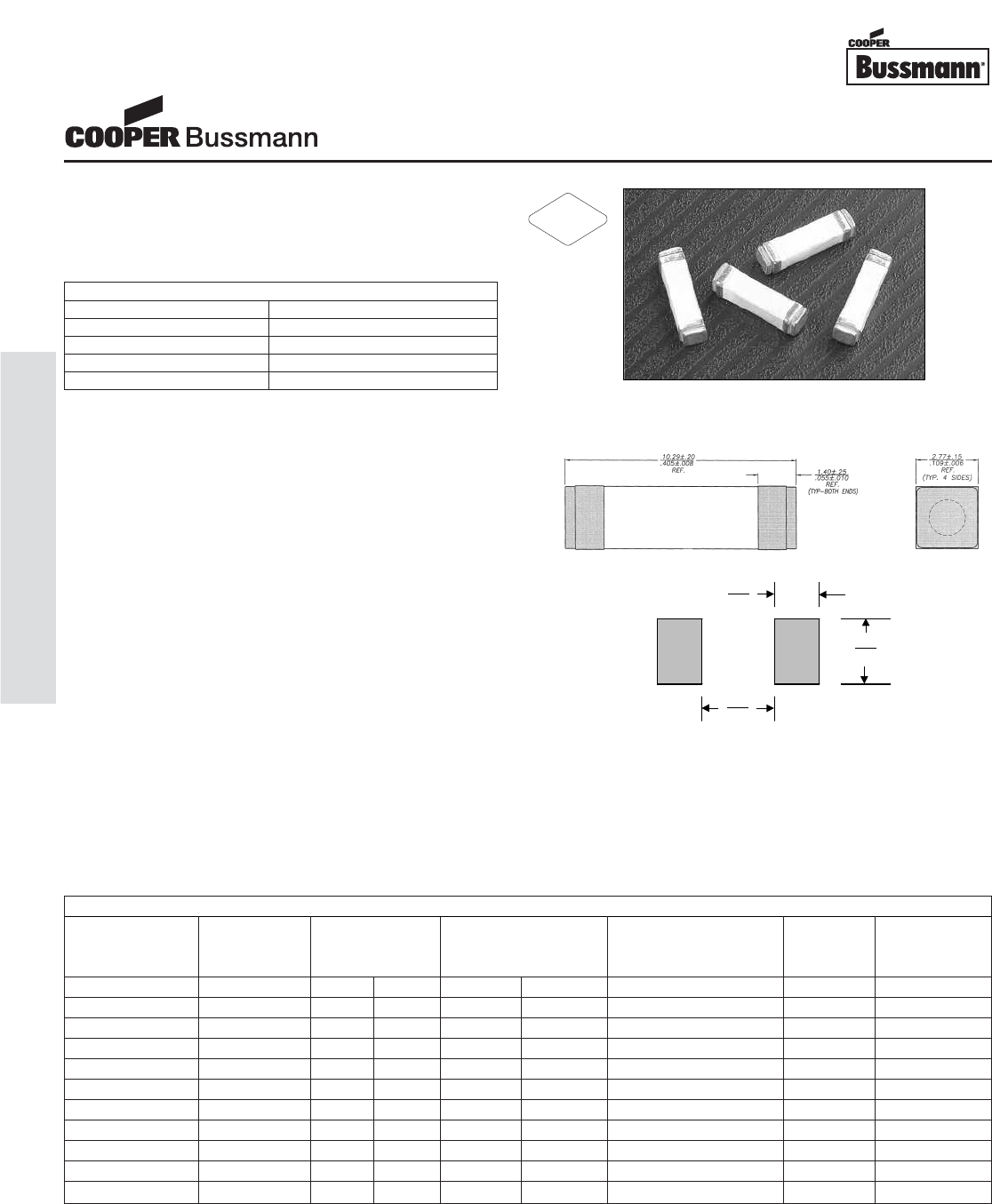
Description
• Time Delay Surface Mount Fuse
• Satisfies the EIA/IS-722 Standard
• Solder Immersion Compatible
* If fuse does not open @ 200% in 60 seconds, raise current to 250%
and the fuse must open in 10 seconds maximum.
Agency Information
• UL Recognition Guide & File numbers:
JDYX2 & E19180 (250mA - 5A)
• CSA Component Acceptance:
File # 053787 C000, Class # 1422 30
Environmental Data
• Life Test: MIL-STD-202, Method 108A, Test Condition D
• Load Humidity: MIL-STD-202, Method 103B
• Moisture Resistance: MIL-STD-202, Method 106E
• Terminal Strength: MIL-STD-202, Method 211A
• Thermal Shock: MIL-STD-202, Method 107D, air-to-air
• Case Resistance: EIA/IS-722
• Resistance to Dissolution of Metallization:
ANSI J-STD-002, Test D
• Mechanical Shock: MIL-STD-202, Method 213B with
exceptions per EIA/IS-722 Standard
• High Frequency Vibration: MIL-STD-202, Method 204D,
Test Condition D
• Resistance to Solvents: MIL-STD-202, Method 215A
Ordering
• Specify packaging and product code
(i.e., TR2/1025TD250-R)
Soldering Method
• Wave Immersion: 260°C, 10 sec max.
• Infrared: 260°C, 30 sec max.
3.30
(0.130)
4.38
(0.172)
6.79
(0.267)
Land Pattern
Dimensions mm⁄(inches)
Drawing Not to Scale
ELECTRICAL CHARACTERISTICS
% of Amp Rating Opening Time
100% 4 Hours Minimum
200% 1 Second Minimum
200% 60 Seconds Maximum
250% * 10 Seconds Maximum
SPECIFICATIONS
Current Voltage Interrupting DC Cold Typical Typical
Product Code Rating Rating Rating* Resistance** (ohms) Melting Voltage
AC DC 250VAC 125VDC Typical I2t† Drop‡
1025TD250-R 250mA 250V 125V 50A 50A 4.200 0.128 1900 mV
1025TD500-R 500mA 250V 125V 50A 50A 0.5500 1.47 455 mV
1025TD750-R 750mA 250V 125V 50A 50A 0.317 0.93 400 mV
1025TD1-R 1A 250V 125V 50A 50A 0.2030 9.91 387 mV
1025TD1.5-R 1.5A 250V 125V 50A 50A 0.1025 11.79 310 mV
1025TD2-R 2A 250V 125V 50A 50A 0.0680 17.27 250 mV
1025TD2.5-R 2.5A 250V 125V 50A 50A 0.0420 16.51 201 mV
1025TD3-R 3A 250V 125V 50A 50A 0.0330 42.74 184 mV
1025TD3.5-R 3.5A 250V 125V 50A 50A 0.0270 43.33 180 mV
1025TD4-R 4A 250V 125V 50A 50A 0.0220 66.96 152 mV
1025TD5-R 5A 250V 125V 50A 50A 0.0160 88.38 145 mV
* AC Interrupting Rating (Measured at designated voltage, 100% power factor random closing); DC Interrupting Rating (Measured at designated voltage, time con-
stant of the calibrated circuit is less than 50 microseconds, battery source)
** DC Cold Resistance (Measured at ≤10% of rated current)
† Typical Melting I2t (Measured with a battery bank at rated DC voltage, 10x-rated current, time constant of calibrated circuit less than 50 microseconds)
‡ Typical Voltage Drop (Measured at rated current after temperature stabilizes)
‡‡ Marking Code - 3rd (U = USA, T = Taiwan and S = China)
• Device designed to carry rated current for four hours minimum. An operating current of 80% or less of rated current is recommended, with further derating required at ele-
vated ambient temperatures.
Brick™Fuses
1025TD Series, Time Delay
RoHS
2002/95/EC
OC-26
Printed Circuit Board Fuses - Surface Mount
Courtesy of Steven Engineering, Inc.-230 Ryan Way, South San Francisco, CA 94080-6370-Main Office: (650) 588-9200-Outside Local Area: (800) 258-9200-www.stevenengineering.com
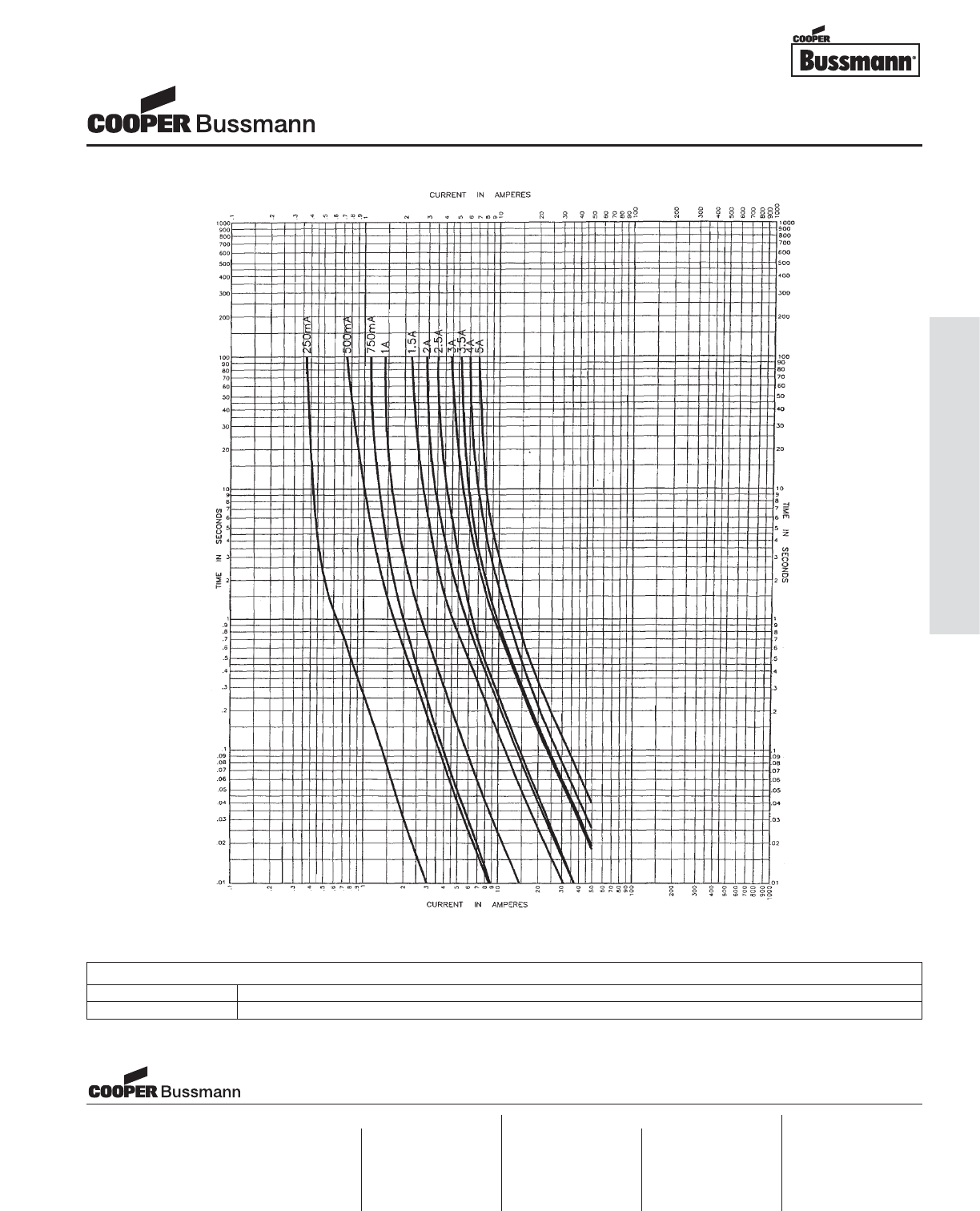
OC-27
Printed Circuit Board Fuses - Surface Mount
PACKAGING CODE
Packaging Code Description
TR2 2,500 pieces of fuses on 24mm tape-and-reel on 13 inch (330mm) reel per EIA Standard 481
TIME CURRENT CURVE
Brick™Fuses
1025TD Series, Time Delay
Visit us on the web at:
www.cooperbussmann.com
Cooper Electronic Technologies
1225 Broken Sound Parkway NW
Suite F
Boca Raton, FL 33487-3533
Tel: 1-561-998-4100
Fax: 1-561-241-6640
Toll Free: 1-888-414-2645
Cooper Bussmann
P.O. Box 14460
St. Louis, MO 63178-4460
Tel: 1-636-394-2877
Fax: 1-800-544-2570
Cooper Electronic Technologies
Cooper (UK) Limited
Burton-on-the-Wolds
Leicestershire • LE12 5TH UK
Tel: +44 (0) 1509 882 737
Fax: +44 (0) 1509 882 786
Cooper Electronic Technologies
Avda. Santa Eulalia, 290
08223
Terrassa, (Barcelona), Spain
Tel: +34 937 362 812
+34 937 362 813
Fax: +34 937 362 719
Asia Pacific
Cooper Electronic Technologies
1 Jalan Kilang Timor
#06-01 Pacific Tech Centre
Singapore 159303
Tel: +65 278 6151
Fax: +65 270 4160
North America Europe
Courtesy of Steven Engineering, Inc.-230 Ryan Way, South San Francisco, CA 94080-6370-Main Office: (650) 588-9200-Outside Local Area: (800) 258-9200-www.stevenengineering.com
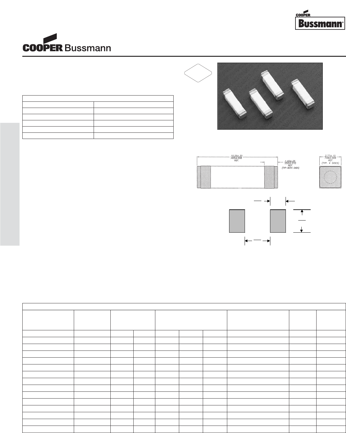
Description
• Fast Acting Surface Mount Fuse
• Satisfies the EIA/IS-722 Standard
• Solder Immersion Compatible
Note: 30vde constant current source required for 200%
overload tests on 250ma-1a.
Agency Information
• UL Recognition Guide & File numbers:
JDYX2 & E19180 (250mA - 15A)
• CSA Component Acceptance:
File # 053787 C000, Class # 1422 30
Environmental Data
• Life Test: MIL-STD-202, Method 108A, Test Condition D
• Load Humidity: MIL-STD-202, Method 103B
• Moisture Resistance: MIL-STD-202, Method 106E
• Terminal Strength: MIL-STD-202, Method 211A
• Thermal Shock: MIL-STD-202, Method 107D, air-to-air
• Case Resistance: EIA/IS-722
• Resistance to Dissolution of Metallization:
ANSI J-STD-002, Test D
• Mechanical Shock: MIL-STD-202, Method 213B with
exceptions per EIA/IS-722 Standard
• High Frequency Vibration: MIL-STD-202, Method 204D,
Test Condition D
• Resistance to Solvents: MIL-STD-202, Method 215A
Ordering
• Specify packaging and product code
(i.e., TR2/1025FA250-R)
Soldering Method
• Wave Solder: 260°C, 10 sec max.
• Infrared Reflow: 260°C, 30 sec max.
3.30
(0.130)
4.38
(0.172)
6.79
(0.267)
Land Pattern
Dimensions mm⁄(inches)
Drawing Not to Scale
ELECTRICAL CHARACTERISTICS
% of Amp Rating Opening Time
100% 4 Hours Minimum
200% (250mA-5A) 5 Seconds Maximum
250% (250mA-5A fuse) 1 Second Maximum
200% (7A-15A fuse) 20 Seconds Maximum
250% (7A-15A fuse) 4 Seconds Maximum
SPECIFICATIONS
Current Voltage Interrupting DC Cold Typical Typical
Product Code Rating Rating Rating* Resistance** (ohms) Melting Voltage
AC DC 250VAC 125VDC 60VDC Typical I2t† Drop‡
1025FA250-R 250mA 250V 125V 50A 50A - 5.0000 0.1212 2019 mV
1025FA500-R 500mA 250V 125V 50A 50A - 1.2000 0.0415 1500 mV
1025FA750-R 750mA 250V 125V 50A 50A - 0.6000 0.143 880 mV
1025FA1-R 1A 250V 125V 50A 50A - 0.3000 1.750 560 mV
1025FA1.5-R 1.5A 250V 125V 50A 50A - 0.1040 1.460 260 mV
1025FA2-R 2A 250V 125V 50A 50A - 0.0800 6.086 258 mV
1025FA2.5-R 2.5A 250V 125V 50A 50A - 0.0510 8.48 232 mV
1025FA3-R 3A 250V 125V 50A 50A - 0.0390 18.15 205 mV
1025FA3.5-R 3.5A 250V 125V 50A 50A - 0.0300 17.83 185 mV
1025FA4-R 4A 250V 125V 50A 50A - 0.0270 23.32 190 mV
1025FA5-R 5A 250V 125V 50A 50A - 0.0200 38.74 180 mV
1025FA7-R 7A 250V 60V 50A 50A - 0.0116 138 150 mV
1025FA10-R 10A 250V 60V 50A 50A - 0.0076 457 146 mV
1025FA12-R 12A 250V 60V 50A - 50A 0.0550 498 120 mV
1025FA15-R 15A 250V 60V 50A - 50A 0.0041 1451 110 mV
* AC Interrupting Rating (Measured at designated voltage, 100% power factor random closing); DC Interrupting Rating (Measured at designated voltage, time constant of
less than 50 microseconds, battery source)
** DC Cold Resistance (Measured at ≤10% of rated current)
† Typical Melting I2t (Measured with a battery bank at rated DC voltage, 10x-rated current, but not exceeding the interrupting rating. Time constant of calibrated circuit less
than 50 microseconds). Test current not to exceed interrupting rating of 50A.
‡ Typical Voltage Drop (Measured at rated current after temperature stabilizes)
• Device designed to carry rated current for four hours minimum. An operating current of 80% or less of rated current is recommended, with further derating required at
elevated ambient temperatures.
Brick™Fuses
1025FA Series, Fast Acting
RoHS
2002/95/EC
OC-28
Printed Circuit Board Fuses - Surface Mount
Courtesy of Steven Engineering, Inc.-230 Ryan Way, South San Francisco, CA 94080-6370-Main Office: (650) 588-9200-Outside Local Area: (800) 258-9200-www.stevenengineering.com
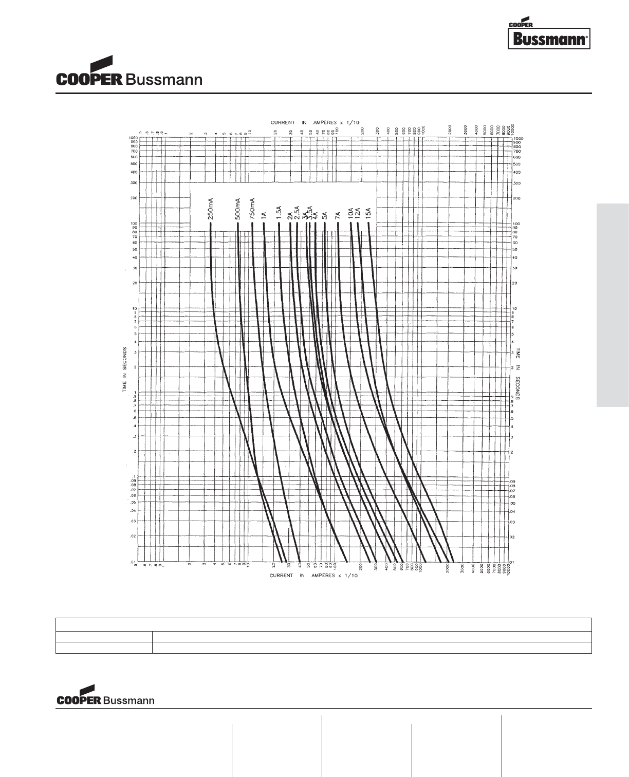
OC-29
Printed Circuit Board Fuses - Surface Mount
PACKAGING CODE
Packaging Code Description
TR2 2,500 pieces of fuses on 24mm tape-and-reel on 13 inch (330mm) reel per EIA Standard 481
TIME CURRENT CURVE
Brick™Fuses
1025FA Series, Fast Acting
Visit us on the web at:
www.cooperbussmann.com
Cooper Electronic Technologies
1225 Broken Sound Parkway NW
Suite F
Boca Raton, FL 33487-3533
Tel: 1-561-998-4100
Fax: 1-561-241-6640
Toll Free: 1-888-414-2645
Cooper Bussmann
P.O. Box 14460
St. Louis, MO 63178-4460
Tel: 1-636-394-2877
Fax: 1-800-544-2570
Cooper Electronic Technologies
Cooper (UK) Limited
Burton-on-the-Wolds
Leicestershire • LE12 5TH UK
Tel: +44 (0) 1509 882 737
Fax: +44 (0) 1509 882 786
Cooper Electronic Technologies
Avda. Santa Eulalia, 290
08223
Terrassa, (Barcelona), Spain
Tel: +34 937 362 812
+34 937 362 813
Fax: +34 937 362 719
Asia Pacific
Cooper Electronic Technologies
1 Jalan Kilang Timor
#06-01 Pacific Tech Centre
Singapore 159303
Tel: +65 278 6151
Fax: +65 270 4160
North America Europe
Courtesy of Steven Engineering, Inc.-230 Ryan Way, South San Francisco, CA 94080-6370-Main Office: (650) 588-9200-Outside Local Area: (800) 258-9200-www.stevenengineering.com
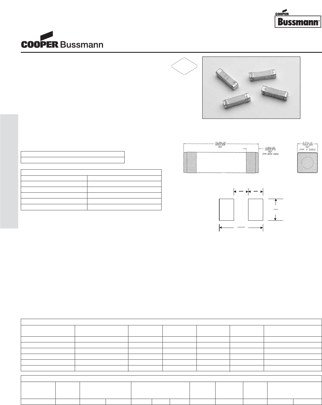
Description
• The first and most reliable surface mount telecom circuit
protector designed to protect against power cross faults
and comply with all surge requirements.
• Allows compliance with telecom regulatory standards
including Bellcore GR 1089, UL 1950/60950, and FCC
part 68. Application circuit testing is recommended.
• Eliminates the need for a current limiting resistor.
• Protects against overcurrent conditions found in telecom
Subscriber Line Interface Cards (SLICs), xDSL Modem
Applications, Set-Top Boxes, and Consumer Premises
Equipment (CPE).
• TCP1.25A tested and confirmed compatible with
STMicroelectronics Trisil™ Transient Surge Arrestor
(list of part numbers below)
* If the device does not open at 250% within 120 seconds, increase cur-
rent to 300% of amp rating. Device must open in 10 seconds max.
Environmental Data
• Life Test: MIL-STD-202, Method 108A, Test Condition D
• Load Humidity: MIL-STD-202, Method 103B
• Moisture Resistance: MIL-STD-202, Method 106E
• Thermal Shock: MIL-STD-202, Method 107D, air-to-air
• Case Resistance: EIA/IS-722
• Resistance to Dissolution of Metallization:
ANSI J-STD-002, Test D
• Mechanical Shock: MIL-STD-202, Method 213B, Test
Condition A
• High Frequency Vibration: MIL-STD-202, Method 204D,
Test Condition D
• Resistance to Solvents: MIL-STD-202, Method 215A
Agency Information
• UL Recognition Card: JDYX2/E19180
• CSA Component Certification Record and Class No.:
053787C000, 1422 30
Ordering
• Specify packaging, product and option code (refer to OC-35)
(i.e., TR2/TCP1.25-R)
Soldering Method
• Wave Immersion: 260°C, 10 sec max.
• Infrared: 260°C, 30 sec max.
5.2 3.7
(0.204) (0.145)
4.0
(0.157)
12.6
(0.496)
Land Pattern
Dimensions mm⁄(inches)
ELECTRICAL CHARACTERISTICS
% of Amp Rating Opening Time
100% 4 Hours Minimum
250% 1 Second Minimum
250% 4-10 Seconds Typical
250%* 120 Seconds Maximum
300% 10 Seconds Maximum
STMicroelectronics Trisil™ P/N’s
SMP100LC-XXX SMP100MC-XXX
ELECTRICAL AND POWER CROSS SPECIFICATIONS
Product Voltage Interrupting DC Cold Typical Maximum Typical Alpha Code
Code Rating Rating* Resistance** (ohms) Melting Total Voltage Marking
AC 250VAC 600VAC min. typ. max. I2t† Clearing Drop‡ 1st Code 2nd Code
TCP1.25A 250 V 50 A 60 A 0.070 0.090 0.110 22.2 A2s 100 A2s 150mV J R***
* AC Interrupting Rating (Measured at designated voltage, 100% power factor)
** DC Cold Resistance (Measured at 10% of rated current)
*** On RoHS Compliant Version (-R option)
† Typical Melting I2t (Measured with a battery bank at 60V DC, 10x-rated current, time constant of calibrated circuit less than 50 microseconds)
‡ Typical Voltage Drop (Measured at rated current after temperature stabilizes)
LIGHTNING SURGE SPECIFICATIONS
Surge Specification Surge Repetitions Waveform Current (A) Voltage (V) Performance
(μSec.) Requirement
FCC 47 Part 68 Longitudinal Type A 2 10x160 100 per fuse 1500 Fuse cannot open
FCC 47 Part 68 Metallic Type B 2 10x560 100 800 Fuse cannot open
Bellcore GR-1089-CORE
First Level Lightning 50 10x1000 100 1000 Fuse cannot open
Bellcore GR-1089-CORE
First Level Lightning 50 2x10 500 2500 Fuse cannot open
Surge out 1 10x160 160 N/A Fuse cannot open
Surge out 1 10x560 115 N/A Fuse cannot open
TCP™Series
TCP1.25A, Telecom Circuit Protector
RoHS
2002/95/EC
OC-30
Printed Circuit Board Fuses - Surface Mount
Courtesy of Steven Engineering, Inc.-230 Ryan Way, South San Francisco, CA 94080-6370-Main Office: (650) 588-9200-Outside Local Area: (800) 258-9200-www.stevenengineering.com
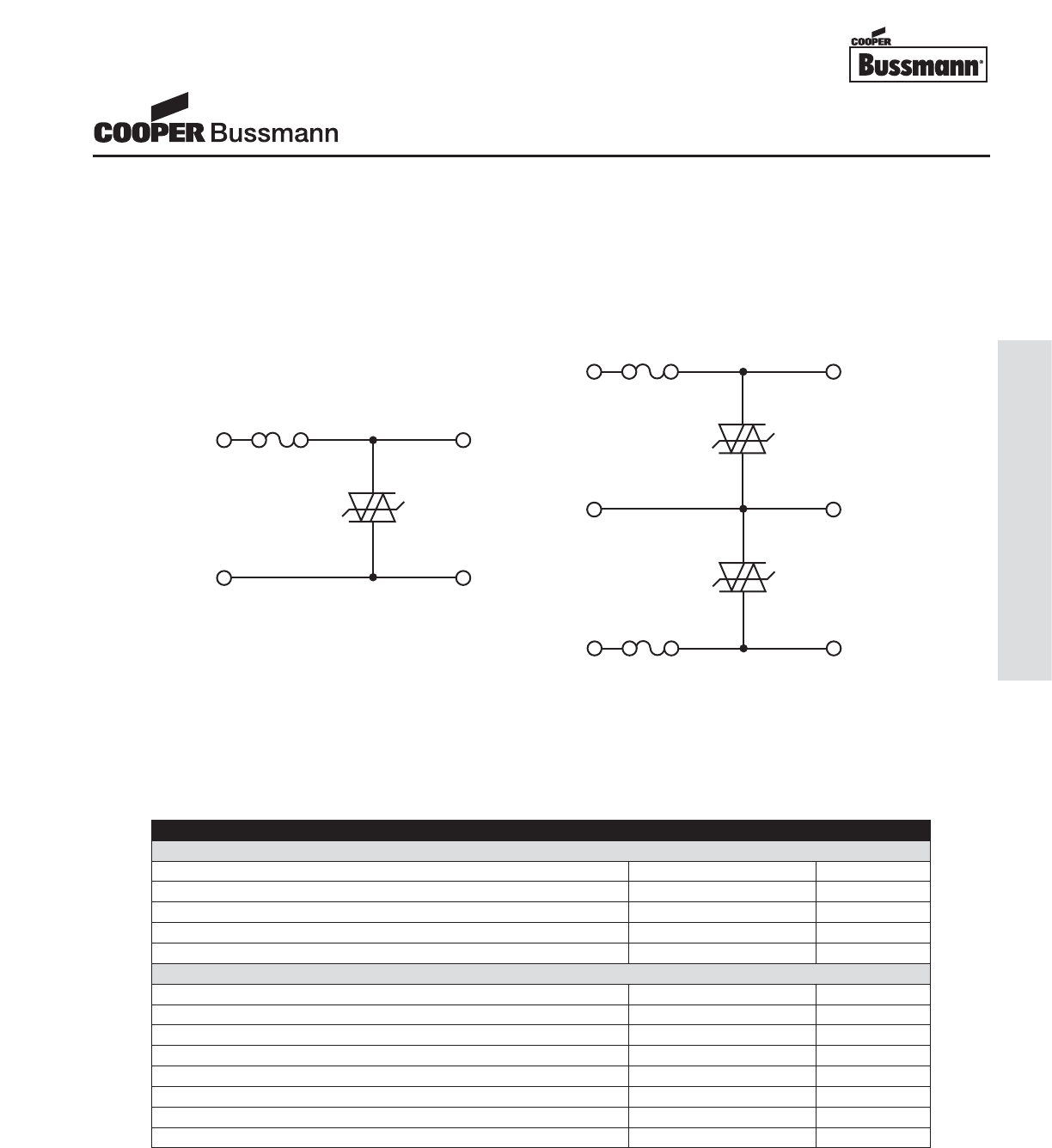
OC-31
Printed Circuit Board Fuses - Surface Mount
TCP™Series
TCP1.25A, Telecom Circuit Protector
TEST CIRCUITS
Special Investigation
The TCP1.25A is designed to provide overcurrent protection for telecom SLIC, xDSL modem, and set-top box applications regard-
less of the overvoltage device selected. To provide an easier specification experience, Cooper Bussmann and STMicroelectronics
have joined together to provide a special test report confirming the coordination between the TCP1.25A
and SMP100MC-270 devices.
* Note: or other STMicroelectronics Trisil™ part number listed in table on page 1
For additional information on STMicroelectronic’s Trisil™ Product line, please see www.st.com/protection
TEST PROGRAM
Test Standard Results
Lightning Surge Tests
10/1000μs + and –1kV 100A (25 pulses of each polarity) Bellcore GR-1089 Passed
2/10μs + and –2.5 and 5kV 500A (10 pulses of each polarity) Bellcore GR-1089 Passed
10/560μs + and –800V 100A (1 pulse of each polarity) FCC Part 68 Passed
10/160μs + and –1.5kV 200A (1 pulse of each polarity) FCC Part 68 Passed
10/700μs + and –1.5kV 37.5A (5 pulses of each polarity) K20 Passed
Electrical and Power Cross Tests
600V 3A 1.1s (first level) Bellcore GR-1089 Passed
277V 25A (second level) Bellcore GR-1089 Passed
600V 60A 5s(second level) Bellcore GR-1089 Passed
600V 40A 1.5s UL 60950 Passed
600V 2.2A 30min UL 60950 Passed
600V 1A 0.2s (A criteria) K20 Passed
230V 1.44A/0.77A/0.38A 15min (A criteria) K20 Passed
230V 23A 15min (A criteria) K20 Passed
L1
L2
Fuse TCP 1.25A
T1
T2
SMP100MC-270*
Tip L
Gnd
Fuse TCP 1.25A
Tip S
SMP100MC-270*
Gnd
SMP100MC-270*
Ring S
Ring L
Fuse TCP 1.25A
Test Circuit 1 Test Circuit 2
Courtesy of Steven Engineering, Inc.-230 Ryan Way, South San Francisco, CA 94080-6370-Main Office: (650) 588-9200-Outside Local Area: (800) 258-9200-www.stevenengineering.com
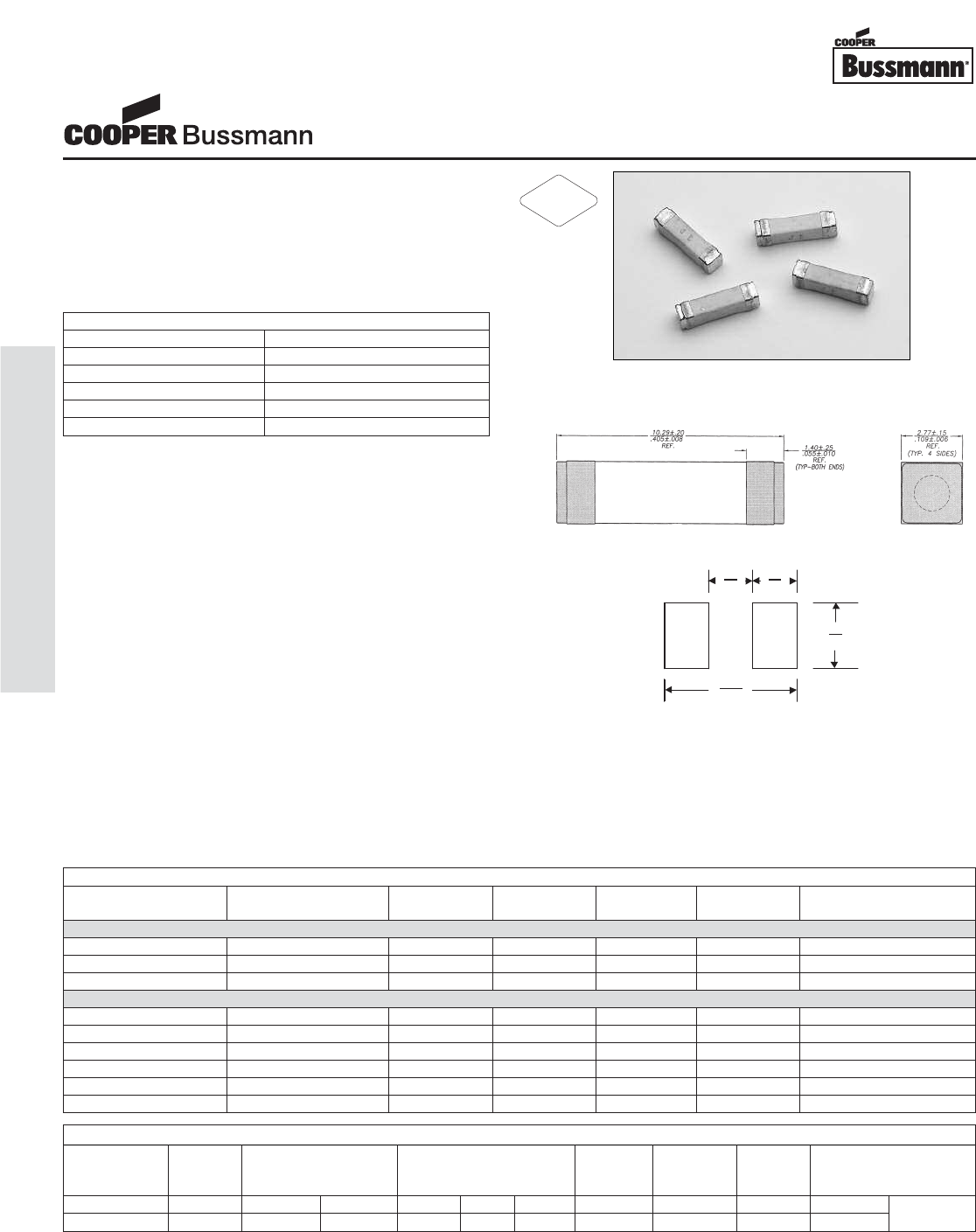
TCP™Series
TCP500MA & TCP2A, Telecom Circuit Protector
Description
• Designed to protect Consumer Premises Equipment from
harmful overcurrents.
• Allows compliance with telecom regulatory standards
including UL 1950/60950, and FCC part 68. Application
circuit testing is recommended.
• Eliminates the need for a current limiting resistor.
* If the device does not open at 250% within 120 seconds, increase
current to 300% of amp rating. Device must open in 10 seconds max.
Agency Information
• UL Recognition Card: JDYX2/E19180
• CSA Component Certification Record and Class No.:
053787C000, 1422 30
Environmental Data
• Life Test: MIL-STD-202, Method 108A, Test Condition D
• Load Humidity: MIL-STD-202, Method 103B
• Moisture Resistance: MIL-STD-202, Method 106E
• Thermal Shock: MIL-STD-202, Method 107D, air-to-air
• Case Resistance: EIA/IS-722
• Resistance to Dissolution of Metallization:
ANSI J-STD-002, Test D
• Mechanical Shock: MIL-STD-202, Method 213B, Test
Condition A
• High Frequency Vibration: MIL-STD-202, Method 204D,
Test Condition D
• Resistance to Solvents: MIL-STD-202, Method 215A
Ordering
• Specify packaging, product and option code
(i.e., TR2/TCP500-R)
Soldering Method
• Wave Immersion: 260°C, 10 sec max.
• Infrared: 260°C, 30 sec max.
5.2 3.7
(0.204) (0.145)
4.0
(0.157)
12.6
(0.496)
Land Pattern
Dimensions mm⁄(inches)
ELECTRICAL CHARACTERISTICS
% of Amp Rating Opening Time
100% 4 Hours Minimum
250% 1 Second Minimum
250% 4-10 Seconds Typical
250%* 120 Seconds Maximum
300% 10 Seconds Maximum
ELECTRICAL AND POWER CROSS SPECIFICATIONS
Product Voltage Interrupting DC Cold Typical Maximum Typical Alpha Code
Code Rating Rating* Resistance** (ohms) Melting Total Voltage Marking
AC 250VAC 600VAC min. typ. max. I2t† Clearing Drop‡ 1st Code 2nd Code
TCP500mA 250 V 50 A 40 A 0.420 0.530 0.640 1.3 A2s 100 A2s 471mV F
TCP2A 250 V 50 A 60 A 0.050 0.075 0.100 30 A2s 100 A2s 205mV N
* AC Interrupting Rating (Measured at designated voltage, 100% power factor)
** DC Cold Resistance (Measured at 10% of rated current)
*** On RoHS Compliant Version (-R option)
† Typical Melting I2t (Measured with a battery bank at 60V DC, 10x-rated current, time constant of calibrated circuit less than 50 microseconds)
‡ Typical Voltage Drop (Measured at rated current after temperature stabilizes)
R***
LIGHTNING SURGE SPECIFICATIONS
Surge Specification Surge Repetitions Waveform Current (A) Voltage (V) Performance
(μSec.) Requirement
TCP 500mA tested
FCC 47 Part 68 Longitudinal Type B 2 5x320 37.5 N/A Fuse cannot open
FCC 47 Part 68 Metallic Type A 2 10x560 100 800 Fuse must open safely
Surge out 25 10x160 65 N/A Fuse cannot open
TCP2A tested
FCC 47 Part 68 Longitudinal Type A 2 10x160 100 per fuse 1500 Fuse cannot open
FCC 47 Part 68 Metallic Type B 2 10x560 100 800 Fuse cannot open
Bellcore GR-1089-CORE
First Level Lightning 50 10x1000 100 1000 Fuse cannot open
Bellcore GR-1089-CORE
First Level Lightning 50 2x10 500 2500 Fuse cannot open
Surge out 1 10x160 160 N/A Fuse cannot open
Surge out 1 10x560 115 N/A Fuse cannot open
RoHS
2002/95/EC
OC-32
Printed Circuit Board Fuses - Surface Mount
Courtesy of Steven Engineering, Inc.-230 Ryan Way, South San Francisco, CA 94080-6370-Main Office: (650) 588-9200-Outside Local Area: (800) 258-9200-www.stevenengineering.com
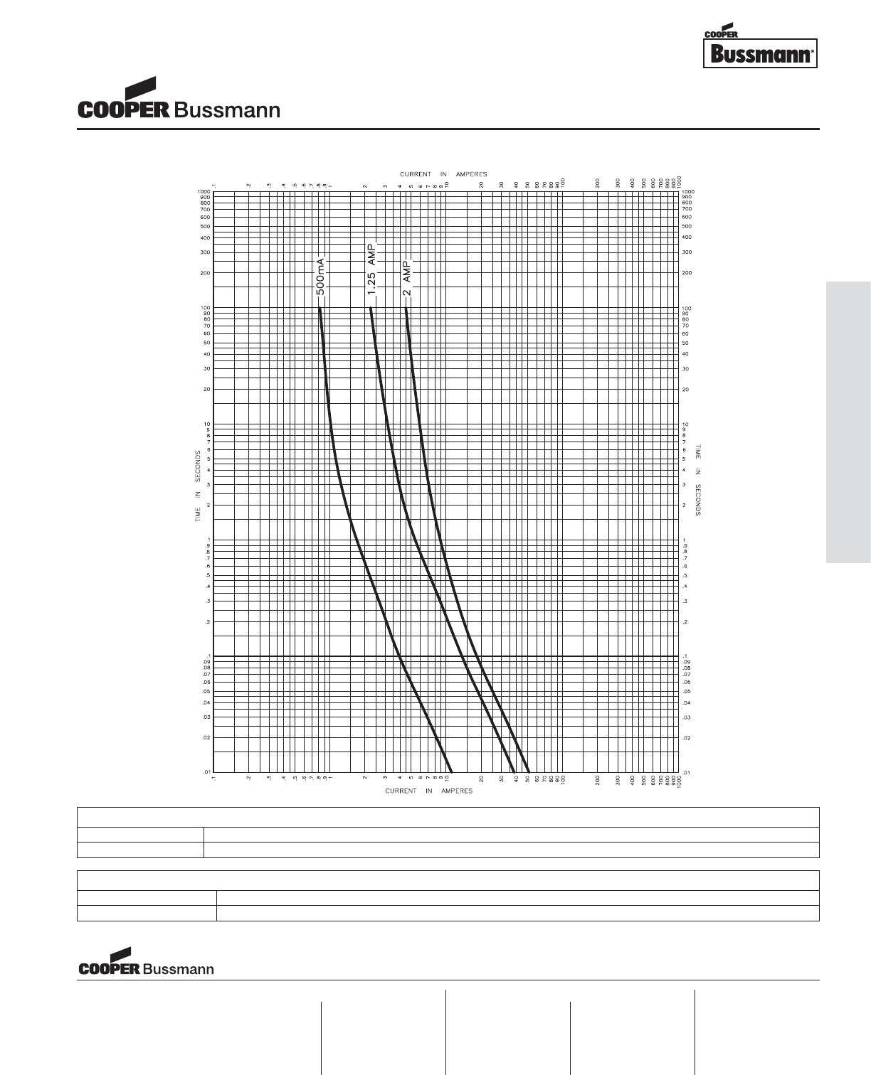
OC-33
Printed Circuit Board Fuses - Surface Mount
PACKAGING CODE
Packaging Code Description
TR2 2,500 pieces of fuses on 24mm tape-and-reel on 13 inch (330mm) reel per EIA Standard 481, 8mm pitch
OPTION CODE
Option Code Description
-R RoHS Compliant Version (Sn plating w/ Ni barrier)
TIME CURRENT CURVE
TCP™Series
TCP500MA & TCP2A, Telecom Circuit Protector
Visit us on the web at:
www.cooperbussmann.com
Cooper Electronic Technologies
1225 Broken Sound Parkway NW
Suite F
Boca Raton, FL 33487-3533
Tel: 1-561-998-4100
Fax: 1-561-241-6640
Toll Free: 1-888-414-2645
Cooper Bussmann
P.O. Box 14460
St. Louis, MO 63178-4460
Tel: 1-636-394-2877
Fax: 1-800-544-2570
Cooper Electronic Technologies
Cooper (UK) Limited
Burton-on-the-Wolds
Leicestershire • LE12 5TH UK
Tel: +44 (0) 1509 882 737
Fax: +44 (0) 1509 882 786
Cooper Electronic Technologies
Avda. Santa Eulalia, 290
08223
Terrassa, (Barcelona), Spain
Tel: +34 937 362 812
+34 937 362 813
Fax: +34 937 362 719
Asia Pacific
Cooper Electronic Technologies
1 Jalan Kilang Timor
#06-01 Pacific Tech Centre
Singapore 159303
Tel: +65 278 6151
Fax: +65 270 4160
North America Europe
Courtesy of Steven Engineering, Inc.-230 Ryan Way, South San Francisco, CA 94080-6370-Main Office: (650) 588-9200-Outside Local Area: (800) 258-9200-www.stevenengineering.com
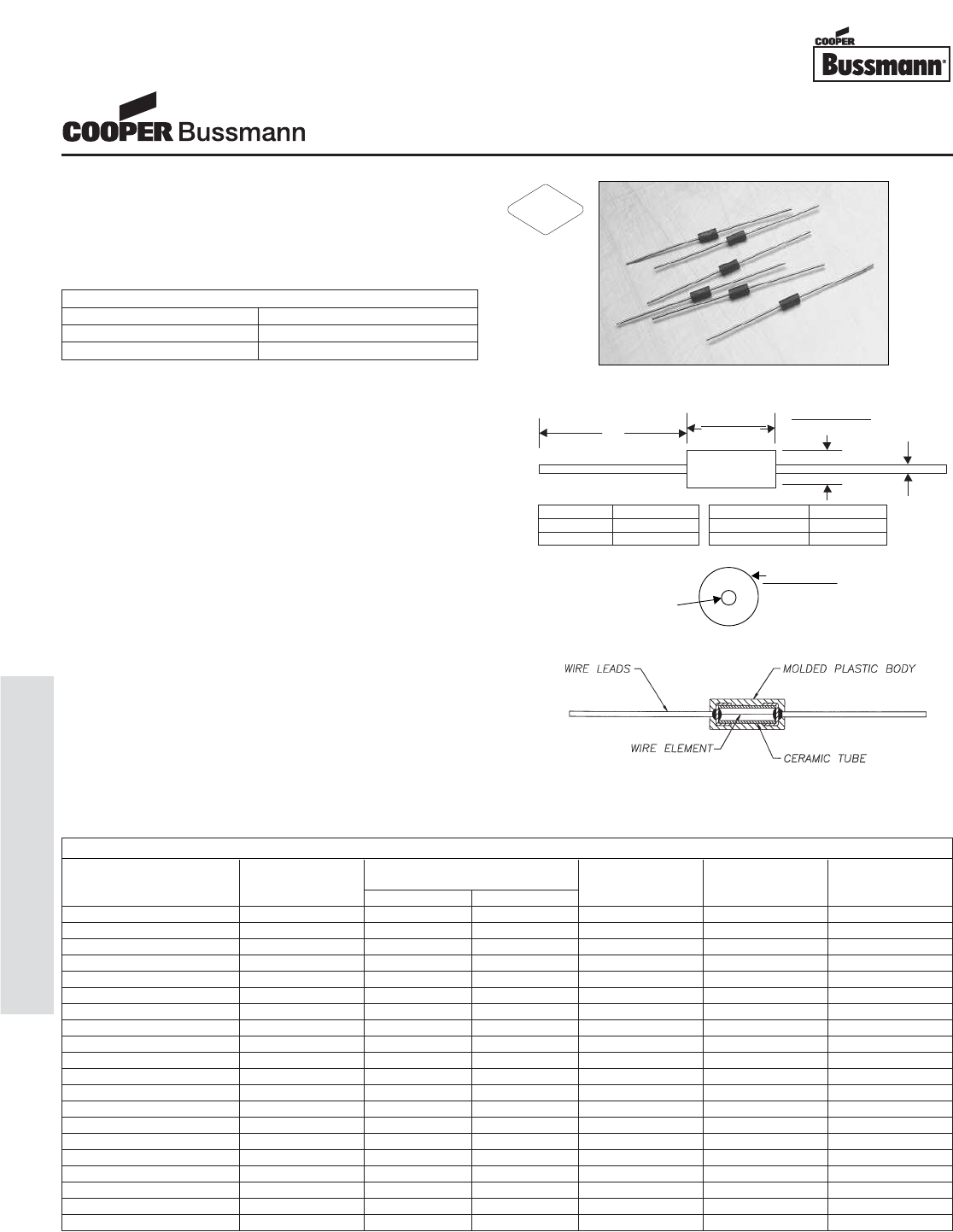
OC-34
Printed Circuit Board Fuses - Axial and Radial Leaded
Description
• Axial Leaded Fast Acting Thru-Hole Fuse
• Tin-lead Plated Copper Lead Wires
• High Temperature Epoxy Plastic Body, UL 94 VO
• Low resistance values
Agency Information
• UL Recognition Guide & File numbers: JDYX2 &
E195337.
• CSA Certification Record No: LR 701159 & Class No:
1422 30 and 1422 01.
Environmental Data
• Shock Resistance: MIL-STD-202, Method 213, Test
Condition 1 (Sawtooth)
• Vibration Resistance: MIL-STD-202, Method 201
(10-55 Hz x 3 axis/ no load)
• Moisture Resistance: MIL-STD-202F, Method 106
• Soldering Heat Resistance: 260°C, 10 seconds per
IEC 68-2-20
• Salt Spray: MIL-STD-202, Method 101, Test Condition
B (48 Hours)
Ordering
• Specify packaging and product code
(i.e., TR1/MCRW100mA)
Soldering Method
• Heat Resistance: 260°C, 10 sec per IEC 68-2-20
3.18 ±0.1___
7.1 ±0.5 (0.125 ±0.004)
(0.280 ±0.020)
“A”
“B”
3.18 ±0.1 diameter
(0.125 ±0.004)
“A” diameter
Construction
Dimensions mm⁄(inches)
End View
* AC Interrupting Rating (Measured at designated voltage, 100%) DC Interrupting Rating (Measured at designated voltage, rise time of less than 50 microseconds, battery source)
** DC Cold Resistance (Measured at 10% of rated current)
† Typical Melting I2t (Measured with a battery bank at rated DC voltage, 10x-rated current, rise time of calibrated circuit less than 50 microseconds)
‡ Typical Voltage Drop (Measured at rated current after temperature stabilizes)
ELECTRICAL CHARACTERISTICS
% of Amp Rating Opening Time
100% 4 hours minimum
200% 5 seconds maximum
Amperage “A” Diameter
100mA - 7A 0.025"
10A - 15A 0.032"
Packaging Code “B” Length
BK1 1.5"
TR1 1.13"
SPECIFICATIONS
Voltage Interrupting Resistance Typical Typical
Product Code Rating Rating* (ohms)** Melt Voltage
AC/DC AC DC Typ. I2t† Drop (V)‡
MCRW100mA 125 V 50 A 300 A 15.5 0.0006 0.68
MCRW125mA 125 V 50 A 300 A 2.2 0.0009 0.61
MCRW150mA 125 V 50 A 300 A 1.6 0.0015 0.54
MCRW200mA 125 V 50 A 300 A 1.2 0.002 0.48
MCRW250mA 125 V 50 A 300 A 0.85 0.004 0.43
MCRW300mA 125 V 50 A 300 A 0.62 0.008 0.39
MCRW375mA 125 V 50 A 300 A 0.49 0.012 0.35
MCRW500mA 125 V 50 A 300 A 0.33 0.023 0.31
MCRW750mA 125 V 50 A 300 A 0.19 0.056 0.25
MCRW1A 125 V 50 A 300 A 0.13 0.10 0.22
MCRW1.5A 125 V 50 A 300 A 0.07 0.25 0.18
MCRW2A 125 V 50 A 300 A 0.054 0.27 0.24
MCRW2.5A 125 V 50 A 300 A 0.041 0.50 0.22
MCRW3A 125 V 50 A 300 A 0.031 0.9 0.20
MCRW4A 125 V 50 A 300 A 0.023 1.6 0.19
MCRW5A 125 V 50 A 300 A 0.018 3 0.17
MCRW7A 125 V 50 A 300 A 0.012 7 0.15
MCRW10A 125 V 50 A 300 A 0.007 21 0.098
MCRW12A 125 V 50 A 300 A 0.006 35 0.093
MCRW15A 125 V 50 A 300 A 0.004 63 0.088
Subminiature Microtron®Fuses
MCRW Series, Fast Acting, Wire-in-Air
RoHS
2002/95/EC
Courtesy of Steven Engineering, Inc.-230 Ryan Way, South San Francisco, CA 94080-6370-Main Office: (650) 588-9200-Outside Local Area: (800) 258-9200-www.stevenengineering.com
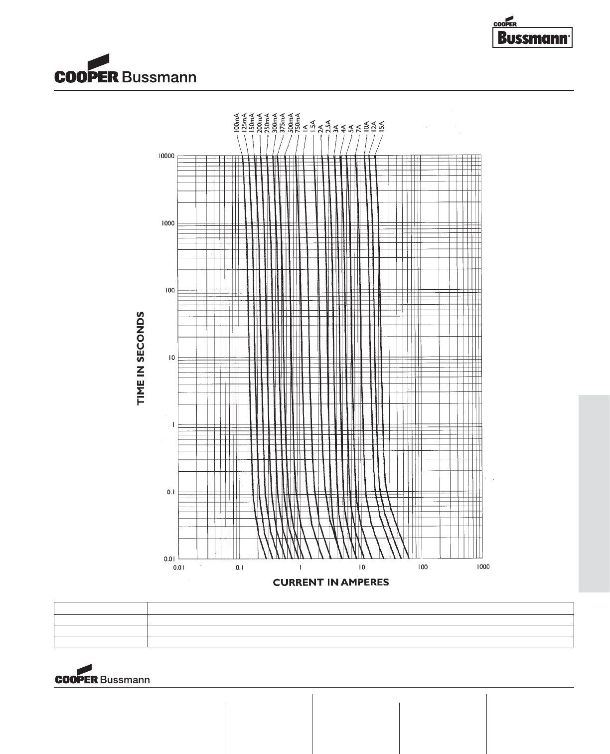
OC-35
Printed Circuit Board Fuses - Axial and Radial Leaded
PACKAGING CODE
Packaging Code Description
BK1 1,000 pieces in bulk
TR1 2,500 pieces on tape-and-reel per EIA-296-E @ 5 mm pitch and 52.4mm inside tape spacing
TIME CURRENT CURVE
Subminiature Microtron®Fuses
MCRW Series, Fast Acting, Wire-in-Air
Visit us on the web at:
www.cooperbussmann.com
Cooper Electronic Technologies
1225 Broken Sound Parkway NW
Suite F
Boca Raton, FL 33487-3533
Tel: 1-561-998-4100
Fax: 1-561-241-6640
Toll Free: 1-888-414-2645
Cooper Bussmann
P.O. Box 14460
St. Louis, MO 63178-4460
Tel: 1-636-394-2877
Fax: 1-800-544-2570
Cooper Electronic Technologies
Cooper (UK) Limited
Burton-on-the-Wolds
Leicestershire • LE12 5TH UK
Tel: +44 (0) 1509 882 737
Fax: +44 (0) 1509 882 786
Cooper Electronic Technologies
Avda. Santa Eulalia, 290
08223
Terrassa, (Barcelona), Spain
Tel: +34 937 362 812
+34 937 362 813
Fax: +34 937 362 719
Asia Pacific
Cooper Electronic Technologies
1 Jalan Kilang Timor
#06-01 Pacific Tech Centre
Singapore 159303
Tel: +65 278 6151
Fax: +65 270 4160
North America Europe
Courtesy of Steven Engineering, Inc.-230 Ryan Way, South San Francisco, CA 94080-6370-Main Office: (650) 588-9200-Outside Local Area: (800) 258-9200-www.stevenengineering.com
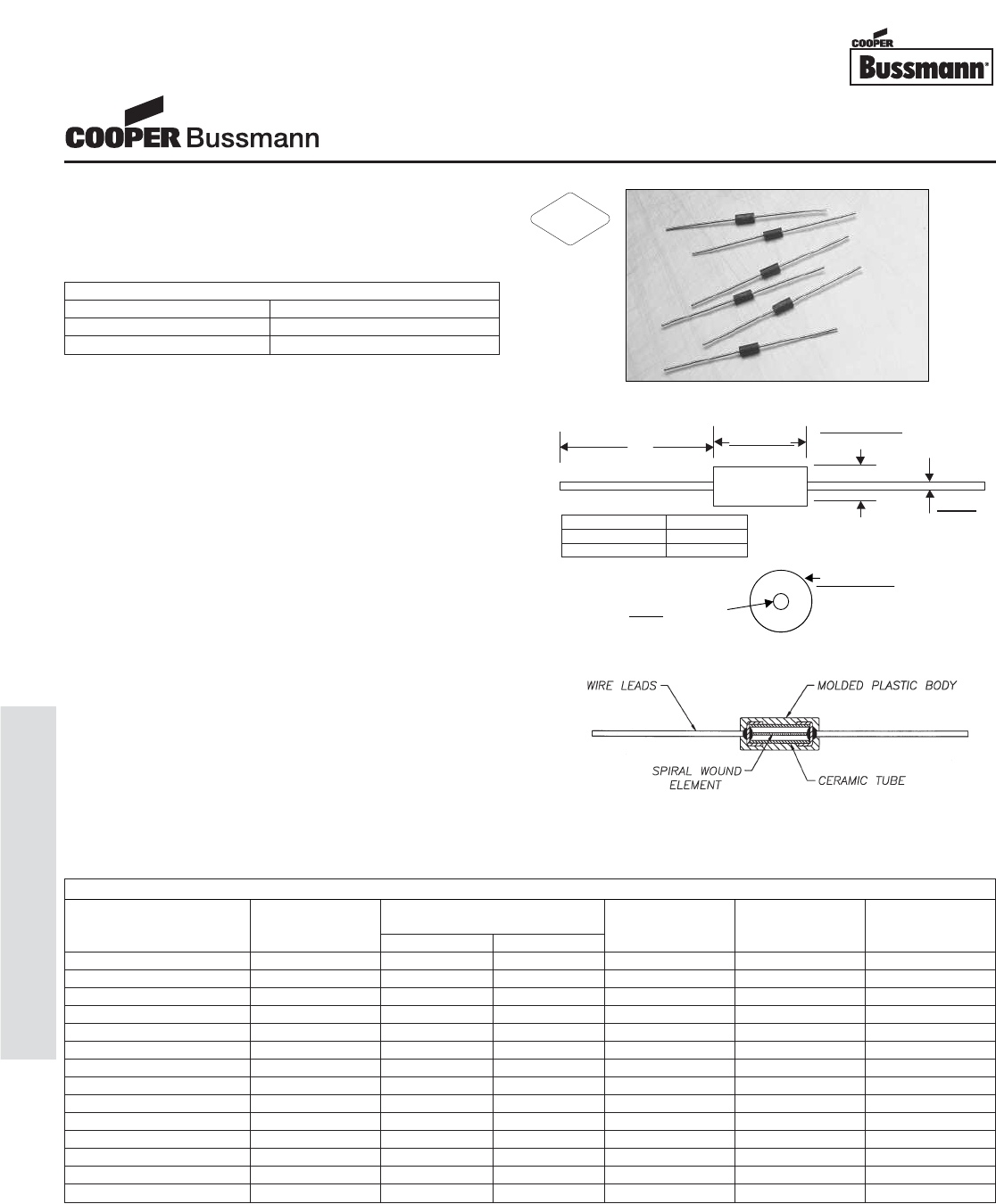
OC-36
Printed Circuit Board Fuses - Axial and Radial Leaded
Description
• Axial Leaded Slow Blow Thru-Hole Fuse
• Tin-lead Plated Copper Lead Wires
• High Temperature Epoxy Plastic Body, UL 94 VO
Agency Information
• UL Recognition Guide & File numbers: JDYX2 &
E195337.
• CSA Certification Record No: LR 701159 & Class No:
1422 30 and 1422 01.
Environmental Data
• Shock Resistance: MIL-STD-202, Method 213, Test
Condition 1 (Sawtooth)
• Vibration Resistance: MIL-STD-202, Method 201
(10-55 Hz x 3 axis/ no load)
• Moisture Resistance: MIL-STD-202F, Method 106
• Soldering Heat Resistance: 260°C, 10 seconds per
IEC 68-2-20
• Salt Spray: MIL-STD-202, Method 101, Test
Condition B (48 Hours)
Ordering
• Specify packaging and product code
(i.e., TR1/MCRS250mA)
Soldering Method
• Heat Resistance: 260°C, 10 sec per IEC 68-2-20
3.18 ±0.1__ _
7.1 ±0.5 (0.125 ±0.004)
(0.280 ±0.020)
0.81 dia.
(0.032)
"A"
3.18 ±0.1 diameter
(0.125 ±0.004)
0.81 diameter
(0.032)
Construction
Dimensions mm⁄(inches)
End View
* AC Interrupting Rating (Measured at designated voltage, 100%) DC Interrupting Rating (Measured at des-
ignated voltage, rise time of less than 50 microseconds, battery source)
** DC Cold Resistance (Measured at 10% of rated current)
† Typical Melting I2t (Measured with a battery bank at rated DC voltage, 10x-rated current, rise time of calibrat-
ed circuit less than 50 microseconds)
‡ Typical Voltage Drop (Measured at rated current after temperature stabilizes)
ELECTRICAL CHARACTERISTICS
% of Amp Rating Opening Time
100% 4 hours minimum
200% 30 seconds maximum
SPECIFICATIONS
Voltage Interrupting Resistance Typical Typical
Product Code Rating Rating* (ohms)** Melt Voltage
AC/DC AC DC Typ. I2t† Drop (V)‡
MCRS250mA 125 V 50 A 300 A 3.20 0.042 2.20
MCRS300mA 125 V 50 A 300 A 2.57 0.056 2.02
MCRS375mA 125 V 50 A 300 A 1.66 0.101 1.69
MCRS500mA 125 V 50 A 300 A 1.07 0.18 1.42
MCRS750mA 125 V 50 A 300 A 0.55 0.44 1.09
MCRS1A 125 V 50 A 300 A 0.36 0.78 0.91
MCRS1.25A 125 V 50 A 300 A 0.23 1.41 0.77
MCRS1.5A 125 V 50 A 300 A 0.18 1.9 0.7
MCRS2A 125 V 50 A 300 A 0.12 3.4 0.59
MCRS2.5A 125 V 50 A 300 A 0.08 6.1 0.5
MCRS3A 125 V 50 A 300 A 0.06 8.1 0.45
MCRS4A 125 V 50 A 300 A 0.04 15 0.38
MCRS5A 125 V 50 A 300 A 0.02 35 0.29
MCRS7A 125 V 50 A 300 A 0.01 63 0.25
Subminiature Microtron®Fuses
MCRS Series, Slow Blow, Wire-in-Air
Packaging Code “A” Length
BK1 1.5"
TR1 1.13"
RoHS
2002/95/EC
Courtesy of Steven Engineering, Inc.-230 Ryan Way, South San Francisco, CA 94080-6370-Main Office: (650) 588-9200-Outside Local Area: (800) 258-9200-www.stevenengineering.com
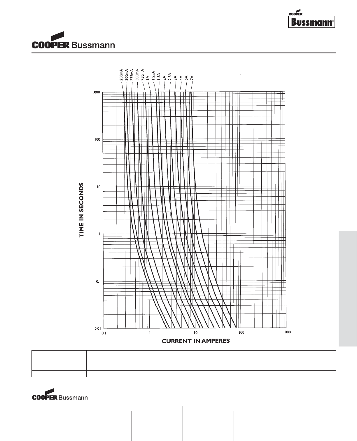
OC-37
Printed Circuit Board Fuses - Axial and Radial Leaded
TIME CURRENT CURVE
Subminiature Microtron®Fuses
MCRS Series, Slow Blow, Wire-in-Air
PACKAGING CODE
Packaging Code Description
BK1 1,000 pieces in bulk
TR1 2,500 pieces on tape-and-reel per EIA-296-E @ 5 mm pitch and 52.4mm inside tape spacing
Visit us on the web at:
www.cooperbussmann.com
Cooper Electronic Technologies
1225 Broken Sound Parkway NW
Suite F
Boca Raton, FL 33487-3533
Tel: 1-561-998-4100
Fax: 1-561-241-6640
Toll Free: 1-888-414-2645
Cooper Bussmann
P.O. Box 14460
St. Louis, MO 63178-4460
Tel: 1-636-394-2877
Fax: 1-800-544-2570
Cooper Electronic Technologies
Cooper (UK) Limited
Burton-on-the-Wolds
Leicestershire • LE12 5TH UK
Tel: +44 (0) 1509 882 737
Fax: +44 (0) 1509 882 786
Cooper Electronic Technologies
Avda. Santa Eulalia, 290
08223
Terrassa, (Barcelona), Spain
Tel: +34 937 362 812
+34 937 362 813
Fax: +34 937 362 719
Asia Pacific
Cooper Electronic Technologies
1 Jalan Kilang Timor
#06-01 Pacific Tech Centre
Singapore 159303
Tel: +65 278 6151
Fax: +65 270 4160
North America Europe
Courtesy of Steven Engineering, Inc.-230 Ryan Way, South San Francisco, CA 94080-6370-Main Office: (650) 588-9200-Outside Local Area: (800) 258-9200-www.stevenengineering.com
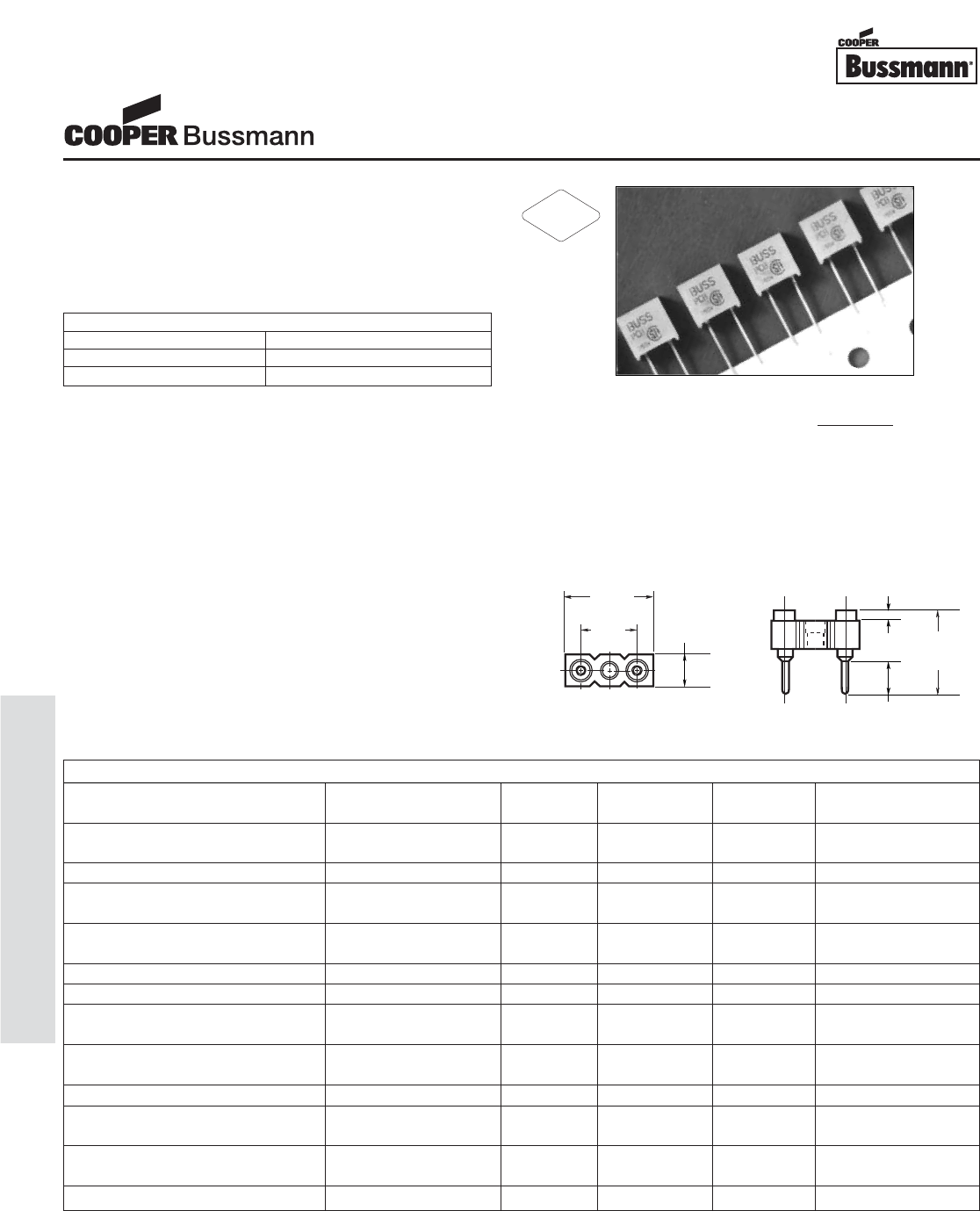
OC-38
Printed Circuit Board Fuses - Axial and Radial Leaded
Description
• Radial Leaded Fast Acting Thru-Hole Fuse
• Ideal for high voltage DC applications
• Board washable
• Optional mounting socket available (PCS)
• Available in different lead configurations
Agency Information
• UL Recognized: E19180
• CSA: 42731
Ordering
• Specify packaging, product, and option code
(i.e., BK/PCB-1/2-R)
DC Application
The PC-Tron subminiature fuse is UL Recognized for
DC supplementary overcurrent protection to provide
individual protection for components or internal circuits
in equipment. Suitability for a specific application is
dependent on time constants and capacitance values.
It is the responsibility of the customer to evaluate the
information provided for applicability to their particular
application.
Mounting Socket (RoHS compliant)
• Available as option. Specify catalog number BK/PCS
(100-in) and short fuse lead length — PCC or PCE
AC TIME-CURRENT CHARACTERISTICS
% of Amp Rating Opening Time
100% 4 hours minimum
200% 10 second maximum
SPECIFICATIONS
Product Code / Amp Rating Lead Voltage AC Voltage DC Interrupting
Length Rating AC Interrupting Rating DC Min. Max.
PCB - 1/2, 3/4, 1, 1-1/2, 2, 2-1/2 Full - 0.750" (straight) 250V 50A @ 250V 450V 300 5900A
10kA @ 125V
PCB - 3 Full - 0.750" (straight) 250V 50A @ 250V 350V 300 4400A
PCC - 1/2, 3/4, 1, 1-1/2, 2, 2-1/2 Short 0.100" (straight) 250V 50A @ 250V 450V 300 5900A
10kA @ 125V
PCC - 3 Short 0.100" (straight) 250V 50A @ 250V 350V 300 4400A
10kA @ 125V
PCD - 5 Full - 0.750" (straight) 125V 10kA @ 125V 250V 300 4200A
PCE - 5 Short 0.100" (straight) 125V 10kA @ 125V 250V 300 4200A
PCF - 1/2, 3/4, 1, 1-1/2, 2, 2-1/2 0.475" 250V 50A @ 250V 450V 300 5900A
10kA @ 125V
PCF - 3 0.475" 250V 50A @ 250V 350V 300 4400A
10kA @ 125V
PCG - 5 0.475" 125V 10kA @ 125V 250V 300 4200A
PCH - 1/2, 3/4, 1, 1-1/2, 2, 2-1/2 0.125" 250V 50A @ 250V 450V 300 5900A
10kA @ 125V
PCH - 3 0.125" 250V 50A @ 250V 350V 300 4400A
10kA @ 125V
PCI - 5 0.125" 125V 10kA @ 125V 250V 300 4200A
Device designed to carry rated current for four hours minimum. An operating current of 80% or less of rated current is recommended, with further derating required at
elevated ambient temperatures.
.030"
(2.41mm)
.12" ±.010"
(3.05mm ±0.25mm)
.290"
(7.37mm)
.200"
(5.08mm)
.300"
(7.62mm) .095"
(2.41mm)
Dimensional Data: All tolerances
Socket (PCS)
± .005"
± .13 mm
Dimensions mm⁄(inches)
Printed Circuit Board Fuses
PC-Tron®Series
RoHS
2002/95/EC
Courtesy of Steven Engineering, Inc.-230 Ryan Way, South San Francisco, CA 94080-6370-Main Office: (650) 588-9200-Outside Local Area: (800) 258-9200-www.stevenengineering.com
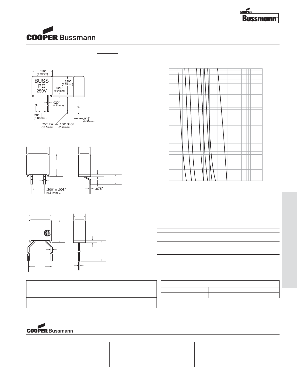
OC-39
Printed Circuit Board Fuses - Axial and Radial Leaded
B
USS
PC
_
2
50V
.
350"
(8.89mm)
(8 89
+
.127mm
)
.
0
2
0"
(
0.51mm
)
.
3
4
5"
(m)
(
8.76m
m
(m
.
0
1
5"
(
0.38mm
)
.
0
.2
5"
(
0.64mm
)
(
1.91mm
)
.1
5"
(
3.81mm
)
.1
8
4
"
(
4.67mm
)
BUSS
P
CG
12
5V
.4
00
"
REF
.
.1
8
4
"
.
350"
R
R
.
3
4
5"
0
.2
5"
.
0
2
0"
.
0
1
5"
.500"
0
0
MN.
I
Dimensional Data (PCF, PCG)
.4
1
10
100
200
CURRENT IN AMPERES
10
1
.1
.01
TIME IN SECONDS
AMPERE
RATING
5
3
2.5
2
1.5
1
0.75
0.5
Time-Current Characteristic Curves–Average Melt
Dimensional Data (PCH, PCI)
PACKAGING CODE
Packaging Code Description
Blank 5 pieces of fuses
BK 100 pieces of fuses in a carton
TR* 500 pieces of fuses on tape and Reel
* Only for PCB and PCD
Max. Total Clearing I2t (Amps2Sec.)
Amp Volts AC
Rating 125 Volts 250 Volts
50A 1,000A 10,000A 35A & 50A
1/2A 0.006 0.006 0.006 0.006
3/4A 0.016 0.016 0.016 0.016
1A 0.020 0.020 0.020 0.020
1-1/2A 0.090 0.090 0.090 0.090
2A 0.200 0.200 0.200 0.200
2-1/2A 0.300 0.300 0.300 0.300
3A 0.750 0.750 0.750 0.750
5A 5.0 5.0 5.0 —
Note—Power Factor > .90.
Dimensional Data: All tolerances
Standard Fuse (PCB, PCD)
± .005"
± .13 mm
Printed Circuit Board Fuses
PC-Tron®Series
Visit us on the web at:
www.cooperbussmann.com
Cooper Electronic Technologies
1225 Broken Sound Parkway NW
Suite F
Boca Raton, FL 33487-3533
Tel: 1-561-998-4100
Fax: 1-561-241-6640
Toll Free: 1-888-414-2645
Cooper Bussmann
P.O. Box 14460
St. Louis, MO 63178-4460
Tel: 1-636-394-2877
Fax: 1-800-544-2570
Cooper Electronic Technologies
Cooper (UK) Limited
Burton-on-the-Wolds
Leicestershire • LE12 5TH UK
Tel: +44 (0) 1509 882 737
Fax: +44 (0) 1509 882 786
Cooper Electronic Technologies
Avda. Santa Eulalia, 290
08223
Terrassa, (Barcelona), Spain
Tel: +34 937 362 812
+34 937 362 813
Fax: +34 937 362 719
Asia Pacific
Cooper Electronic Technologies
1 Jalan Kilang Timor
#06-01 Pacific Tech Centre
Singapore 159303
Tel: +65 278 6151
Fax: +65 270 4160
North America Europe
OPTION CODE
Option Code Description
-R RoHS Compliant Version
Courtesy of Steven Engineering, Inc.-230 Ryan Way, South San Francisco, CA 94080-6370-Main Office: (650) 588-9200-Outside Local Area: (800) 258-9200-www.stevenengineering.com
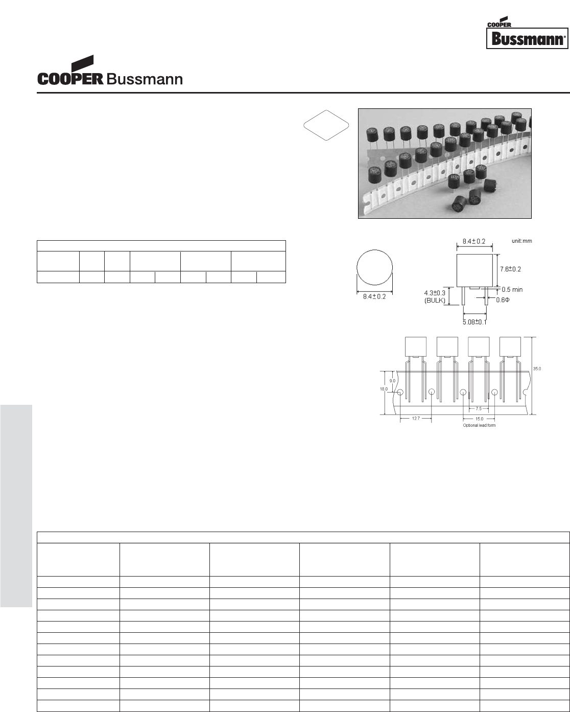
OC-40
Printed Circuit Board Fuses - Axial and Radial Leaded
Description
• Radial Leaded Time Lag Thru-Hole Fuse
• Designed to IEC 60127-3, Sheet 4
• Internationally accepted for primary and secondary
overcurrent protection
• Place directly into PCB or plug into BK/PCS holder
• High inrush withstand capability
• Compatible with leaded and lead-free reflow and wave
solder
• Base/Cap is Nylon #66, UL 94V0
• Pins are Tin Plated Copper
Agency Information
• UL Recognition: E146895 (400mA thru 6.3A)
• CSA: LR98127 (400mA thru 5A)
• VDE: 122052 (500mA thru 4A, 6.3A)
• SEMKO: 0035176 (500mA thru 4A)
• CCC 2003010207072514 (500mA thru 4A)
• METI: 32-1966 (500mA thru 5A)
• EK: KTL SA05004 (500mA thru 4A)
• Remaining 5-6.3A Approvals Pending
Specifications
• Solderability: EIA-186-9E Method 9
• High Frequency Vibration: MIL-STD-202F,
Method 201A
• Operating Temperature: -40°C to +125°C
• Soldering Heat Resistance: 260°C, 10S
(IEC 60068-2-20)
Ordering
• Specify product and packaging code
(i.e., SR-5-1A-AP)
Dimensions mm⁄(inches)
SPECIFICATIONS
Product Voltage Rating Interrupting Typical DC Cold Typical Melting Maximum Power
Code AC Rating @ Resistance I2t(A
2s) Dissipation
Rated Voltage (ohms) at 1ms (mW)
SR-5-500mA 250V 35A 0.270 2 310
SR-5-630mA 250V 35A 0.175 3.5 360
SR-5-800mA 250V 35A 0.125 6.5 430
SR-5-1A 250V 35A 0.083 9 500
SR-5-1.25A 250V 35A 0.061 13 600
SR-5-1.6A 250V 35A 0.047 24 730
SR-5-2A 250V 35A 0.031 30 870
SR-5-2.5A 250V 35A 0.028 45 1000
SR-5-3.15A 250V 35A 0.023 57 1200
SR-5-4A 250V 40A 0.015 80 1400
*SR-5-5A 250V 50A 0.011 120 1800
*SR-5-6.3A 250V 63A 0.009 140 2000
Subminiature Fuses
SR-5 Series, Time Lag
ELECTRICAL CHARACTERISTICS
Rated 1.5 In 2.1 In 2.75 In 4 In 10 In
Current min max min max min max min max
400mA-6.3A 1hr 2 min 400 ms 10 sec 150 ms 3 sec 20 ms 150 ms
* Conducting Path min. 0.2mm2
RoHS
2002/95/EC
Courtesy of Steven Engineering, Inc.-230 Ryan Way, South San Francisco, CA 94080-6370-Main Office: (650) 588-9200-Outside Local Area: (800) 258-9200-www.stevenengineering.com
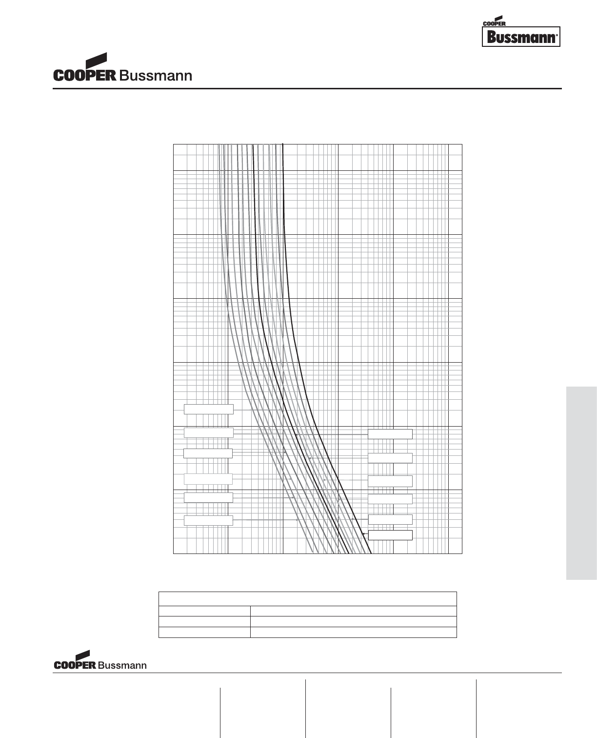
OC-41
Printed Circuit Board Fuses - Axial and Radial Leaded
03987654323.02.0
2000
1000
900
800
700
600
500
400
300
200
100
90
80
70
60
50
40
30
20
10
9
8
7
6
5
4
3
2
1
0
.
9
0.8
0.7
0.6
0.5
0.4
0.3
0.2
0.1
0
.
09
0.08
0.07
0.06
0.05
0.04
0.03
0.02
0.01
0
.009
0.008
0.007
0.006
0.005
0.004
0.003
0.002
0.001
03987654323.02.0 018.020100086.06040
60 80 100018.06.02040
TIME IN SECONDS
200
800
1000
8000
4000
6000
2000
CURRENT IN AMPERES
0.4 1
SR- 5 T2.5A
200
400
600
800
1000
8000
4000
6000
2000
0.4 1
SR- 5 T1A
SR- 5 T2A
SR- 5 T3.15A
SR- 5 T5A
SR- 5 T4A
SR- 5 T1.6A
SR- 5 T1.25A
SR- 5 T800mA
SR- 5 T500mA
SR- 5 T6.3A
400 60 0
SR- 5 T400mA
TIME CURRENT CURVE
Subminiature Fuses
SR-5 Series, Time Lag
PACKAGING CODE
Packaging Code Description
-AP Ammo-pack taped 1,000 per box
-BK In bulk 200 per bag
Visit us on the web at:
www.cooperbussmann.com
Cooper Electronic Technologies
1225 Broken Sound Parkway NW
Suite F
Boca Raton, FL 33487-3533
Tel: 1-561-998-4100
Fax: 1-561-241-6640
Toll Free: 1-888-414-2645
Cooper Bussmann
P.O. Box 14460
St. Louis, MO 63178-4460
Tel: 1-636-394-2877
Fax: 1-800-544-2570
Cooper Electronic Technologies
Cooper (UK) Limited
Burton-on-the-Wolds
Leicestershire • LE12 5TH UK
Tel: +44 (0) 1509 882 737
Fax: +44 (0) 1509 882 786
Cooper Electronic Technologies
Avda. Santa Eulalia, 290
08223
Terrassa, (Barcelona), Spain
Tel: +34 937 362 812
+34 937 362 813
Fax: +34 937 362 719
Asia Pacific
Cooper Electronic Technologies
1 Jalan Kilang Timor
#06-01 Pacific Tech Centre
Singapore 159303
Tel: +65 278 6151
Fax: +65 270 4160
North America Europe
Courtesy of Steven Engineering, Inc.-230 Ryan Way, South San Francisco, CA 94080-6370-Main Office: (650) 588-9200-Outside Local Area: (800) 258-9200-www.stevenengineering.com
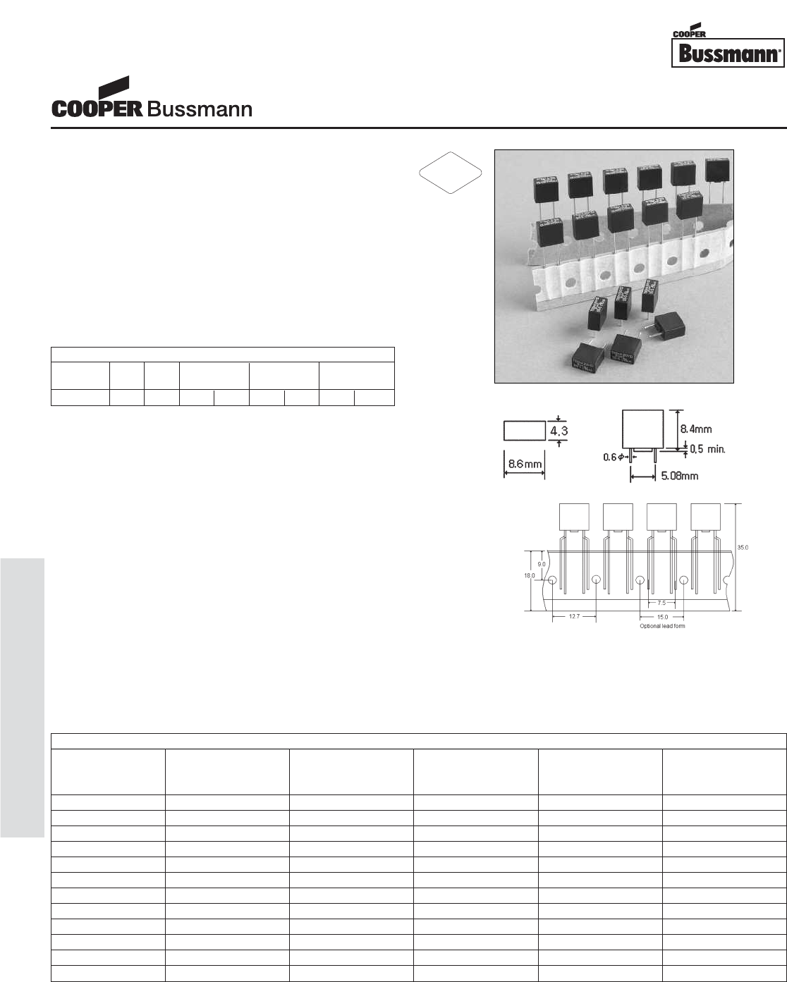
OC-42
Printed Circuit Board Fuses - Axial and Radial Leaded
Description
• Radial Leaded Time Lag Thru-Hole Fuse
• Rectangular shape with reduced foot print
• Designed to IEC 60127-3, Sheet 4
• Internationally accepted for primary and secondary
overcurrent protection
• Place directly into PCB or plug into BK/PCS holder
• High inrush withstand capability
• Compatible with leaded and lead-free reflow and wave
solder
• Base/Cap is Nylon #66, UL 94V0
• Pins are Tin Plated Copper
Agency Information
• UL Recognition: E146895 (400mA thru 6.3A)
• CSA: LR98127 (400mA thru 5A)
• VDE: 122052 (500mA thru 4A, 6.3A)
• SEMKO: 603891 (630mA thru 4A)
• CQC 05012014933 (630mA thru 4A)
• METI: 32-1966 (500mA thru 5A)
• Remaining 5-6.3A Approvals Pending
Specifications
• Solderability: EIA-186-9E Method 9
• High Frequency Vibration: MIL-STD-202F,
Method 201A
• Operating Temperature: -40°C to +125°C
• Soldering Heat Resistance: 260°C, 10S
(IEC 60068-2-20)
Ordering
• Specify product and packaging code
(i.e., SS-5-1A-AP)
Dimensions mm⁄(inches)
SPECIFICATIONS
Product Voltage Rating Interrupting Typical DC Cold Typical Melting Maximum Power
Code AC Rating @ Resistance I2t(A
2s) Dissipation
Rated Voltage (ohms) at 1ms (mW)
SS-5-500mA 250V 35A 0.270 2 310
SS-5-630mA 250V 35A 0.175 3.5 360
SS-5-800mA 250V 35A 0.125 6.5 430
SS-5-1A 250V 35A 0.083 9 500
SS-5-1.25A 250V 35A 0.061 13 600
SS-5-1.6A 250V 35A 0.047 24 730
SS-5-2A 250V 35A 0.031 30 870
SS-5-2.5A 250V 35A 0.028 45 1000
SS-5-3.15A 250V 35A 0.023 57 1200
SS-5-4A 250V 40A 0.015 80 1400
*SS-5-5A 250V 50A 0.011 120 1800
*SS-5-6.3A 250V 63A 0.009 140 2000
Subminiature Fuses
SS-5 Series, Time Lag
ELECTRICAL CHARACTERISTICS
Rated 1.5 In 2.1 In 2.75 In 4 In 10 In
Current min max min max min max min max
400mA-6.3A 1hr 2 min 400 ms 10 sec 150 ms 3 sec 20 ms 150 ms
* Conducting Path min. 0.2mm2
RoHS
2002/95/EC
Courtesy of Steven Engineering, Inc.-230 Ryan Way, South San Francisco, CA 94080-6370-Main Office: (650) 588-9200-Outside Local Area: (800) 258-9200-www.stevenengineering.com
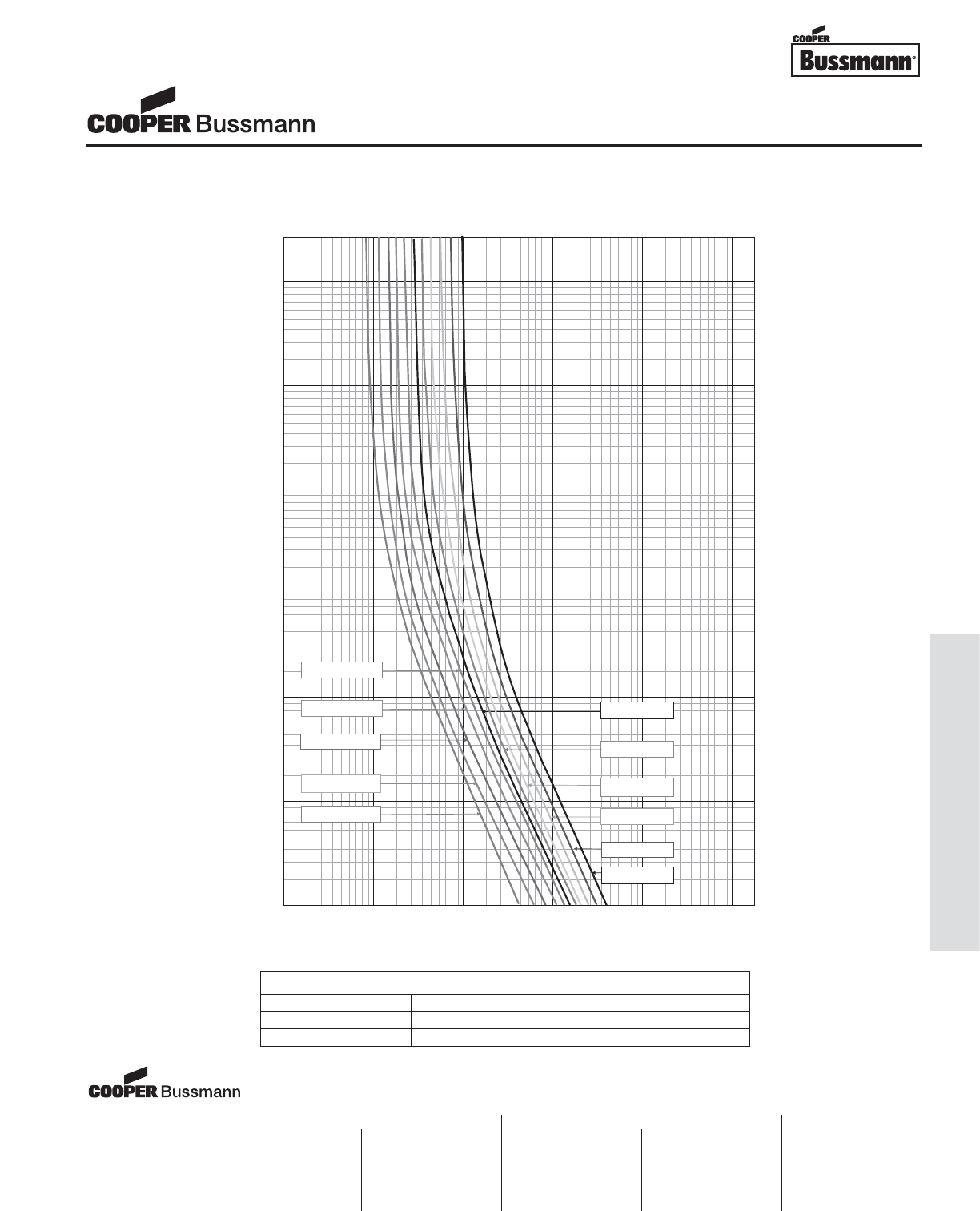
OC-43
Printed Circuit Board Fuses - Axial and Radial Leaded
03987654323.02.0
2000
1000
900
800
700
600
500
400
300
200
100
90
80
70
60
50
40
30
20
10
9
8
7
6
5
4
3
2
1
0.9
0.8
0.7
0.6
0.5
0.4
0.3
0.2
0.1
0.09
0.08
0.07
0.06
0.05
0.04
0.03
0.02
0.01
0
.009
0.008
0.007
0.006
0.005
0.004
0.003
0.002
0.001
03987654323.02.0
60 80 100 018.06.02040
018.0 20 100086.06040
TIME IN SECONDS
200
800
1000
8000
4000
6000
2000
CURRENT IN AMPERES
0.4 1
SS- 5 T2.5A
200
400
600
800
1000
8000
4000
6000
2000
0.4 1
SS- 5 T1A
SS- 5 T2A
SS- 5 T3.15A
SS- 5 T5A
SS- 5 T4A
SS- 5 T1.6A
SS- 5 T1.25A
SS- 5 T800mA
SS- 5 T500mA
SS- 5 T6.3A
400 60 0
TIME CURRENT CURVE
Subminiature Fuses
SS-5 Series, Time Lag
PACKAGING CODE
Packaging Code Description
-AP Ammo-pack taped 1,000 per box
-BK In bulk 200 per bag
Visit us on the web at:
www.cooperbussmann.com
Cooper Electronic Technologies
1225 Broken Sound Parkway NW
Suite F
Boca Raton, FL 33487-3533
Tel: 1-561-998-4100
Fax: 1-561-241-6640
Toll Free: 1-888-414-2645
Cooper Bussmann
P.O. Box 14460
St. Louis, MO 63178-4460
Tel: 1-636-394-2877
Fax: 1-800-544-2570
Cooper Electronic Technologies
Cooper (UK) Limited
Burton-on-the-Wolds
Leicestershire • LE12 5TH UK
Tel: +44 (0) 1509 882 737
Fax: +44 (0) 1509 882 786
Cooper Electronic Technologies
Avda. Santa Eulalia, 290
08223
Terrassa, (Barcelona), Spain
Tel: +34 937 362 812
+34 937 362 813
Fax: +34 937 362 719
Asia Pacific
Cooper Electronic Technologies
1 Jalan Kilang Timor
#06-01 Pacific Tech Centre
Singapore 159303
Tel: +65 278 6151
Fax: +65 270 4160
North America Europe
Courtesy of Steven Engineering, Inc.-230 Ryan Way, South San Francisco, CA 94080-6370-Main Office: (650) 588-9200-Outside Local Area: (800) 258-9200-www.stevenengineering.com
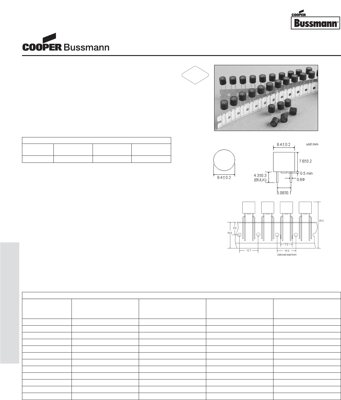
OC-44
Printed Circuit Board Fuses - Axial and Radial Leaded
Description
• Radial Leaded Fast Acting Thru-Hole Fuse
• Designed to UL 248-14
• Accepted for primary and secondary overcurrent
protection
• Place directly into PCB or plug into BK/PCS holder
• Compatible with leaded and lead-free reflow and wave
solder
• Base/Cap is Nylon #66, UL 94V0
• Pins are Tin Plated Copper
Agency Information
• UL Listed: E146895 (400mA thru 10A)
• CSA: LR98127 (400mA thru 10A)
Specifications
• Solderability: EIA-186-9E Method 9
• High Frequency Vibration: MIL-STD-202F,
Method 201A
• Operating Temperature: -40°C to +125°C
• Soldering Heat Resistance: 260°C, 10S
(IEC 60068-2-20)
Ordering
• Specify product and packaging code
(i.e., SR-5F-1A-AP)
Dimensions mm⁄(inches)
SPECIFICATIONS
Product Voltage Rating Interrupting Typical DC Cold Typical Melting
Code AC Rating @ Resistance I2t(A
2s)
Rated Voltage (ohms) at 1ms
SR-5F-800mA 250V 50A 210 2.7
SR-5F-1A 250V 50A 120 4.9
SR-5F-1.6A 250V 50A 73 8.0
SR-5F-2A 250V 50A 50 12.1
SR-5F-2.5A 250V 50A 40 16.8
SR-5F-3.15A 250V 50A 32 32.4
SR-5F-4A 250V 50A 25 48.4
*SR-5F-5A 250V 50A 17 75.0
*SR-5F-6.3A 125V 50A 14 108
*SR-5F-7A 125V 50A 11 160
*SR-5F-8A 125V 50A 9 190
*SR-5F-10A 125V 50A 7 270
Subminiature Fuses
SR-5F Series, Fast Acting
ELECTRICAL CHARACTERISTICS
Rated 1 In 1.5 In 2 In
Current min max max
400mA-10A 1hr 10 min 2 min
* Conducting Path min. 0.2mm2
RoHS
2002/95/EC
Courtesy of Steven Engineering, Inc.-230 Ryan Way, South San Francisco, CA 94080-6370-Main Office: (650) 588-9200-Outside Local Area: (800) 258-9200-www.stevenengineering.com
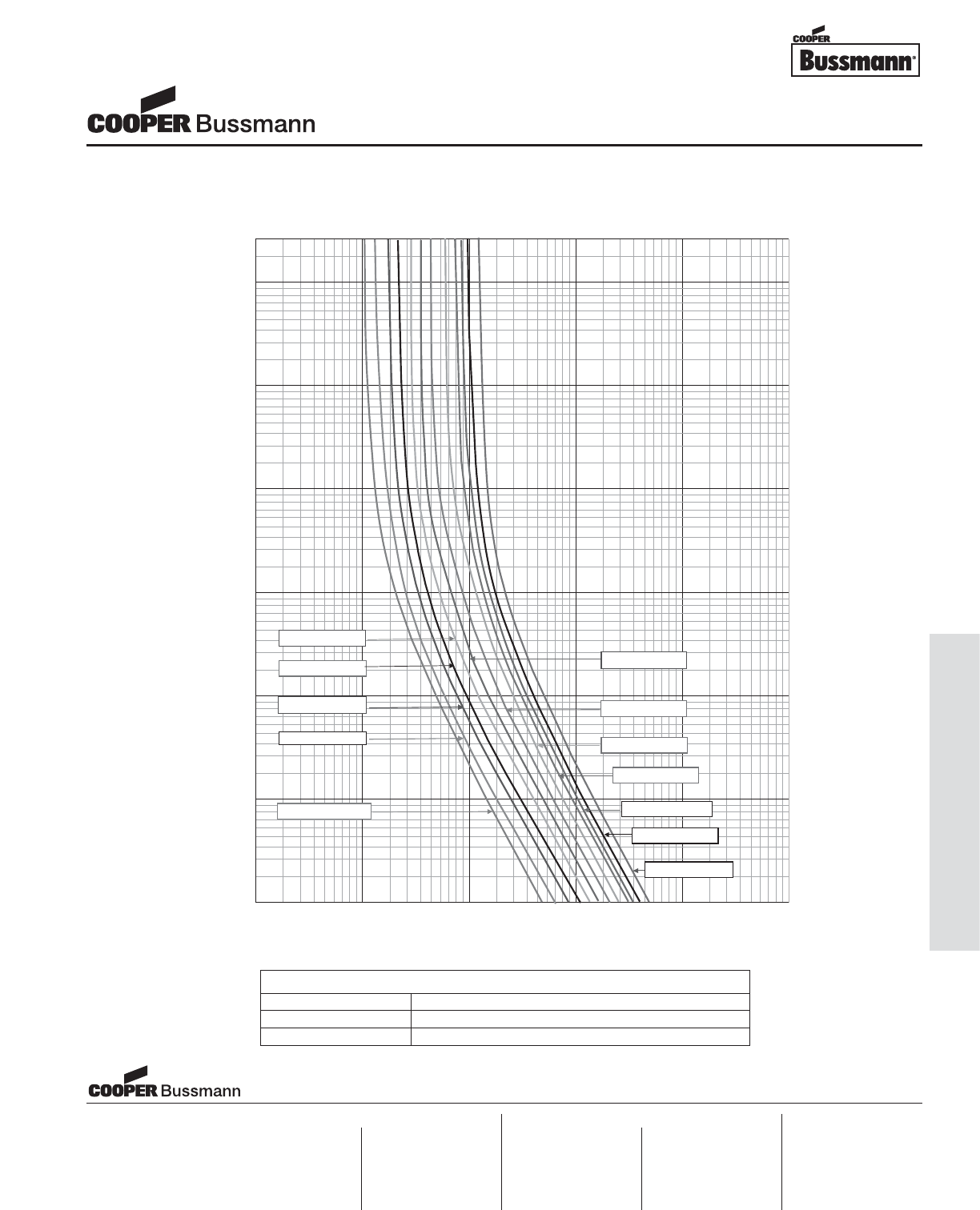
OC-45
Printed Circuit Board Fuses - Axial and Radial Leaded
03987654323.02.0
2000
1000
900
800
700
600
500
400
300
200
100
90
80
70
60
50
40
30
20
10
9
8
7
6
5
4
3
2
1
0.9
0.8
0.7
0.6
0.5
0.4
0.3
0.2
0.1
0.09
0.08
0.07
0.06
0.05
0.04
0.03
0.02
0.01
0.009
0.008
0.007
0.006
0.005
0.004
0.003
0.002
0.001
03987654323.02.0 001010.80.6 806040
60 80 10004010.86
.0
TIME IN SECONDS
200
800
1000
8000
6000
2000
CURRENT IN AMPERES
0.4 1
20
0
400
600
800
1000
8000
4000
6000
2000
0.4 1
SR-5F, 1A
SR-5F, 3.15A
SR-5F, 4A
SR-5F, 2A
SR-5F, 800mA
SR-5F 10A
400 600
SR-5F, 5A
SR-5F, 2.5A
SR-5F, 1.5A
SR-5F 6.3A
SR-5F 7A
SR-5F 8A
TIME CURRENT CURVE
Subminiature Fuses
SR-5F Series, Fast Acting
PACKAGING CODE
Packaging Code Description
-AP Ammo-pack taped 1,000 per box
-BK In bulk 200 per bag
Visit us on the web at:
www.cooperbussmann.com
Cooper Electronic Technologies
1225 Broken Sound Parkway NW
Suite F
Boca Raton, FL 33487-3533
Tel: 1-561-998-4100
Fax: 1-561-241-6640
Toll Free: 1-888-414-2645
Cooper Bussmann
P.O. Box 14460
St. Louis, MO 63178-4460
Tel: 1-636-394-2877
Fax: 1-800-544-2570
Cooper Electronic Technologies
Cooper (UK) Limited
Burton-on-the-Wolds
Leicestershire • LE12 5TH UK
Tel: +44 (0) 1509 882 737
Fax: +44 (0) 1509 882 786
Cooper Electronic Technologies
Avda. Santa Eulalia, 290
08223
Terrassa, (Barcelona), Spain
Tel: +34 937 362 812
+34 937 362 813
Fax: +34 937 362 719
Asia Pacific
Cooper Electronic Technologies
1 Jalan Kilang Timor
#06-01 Pacific Tech Centre
Singapore 159303
Tel: +65 278 6151
Fax: +65 270 4160
North America Europe
Courtesy of Steven Engineering, Inc.-230 Ryan Way, South San Francisco, CA 94080-6370-Main Office: (650) 588-9200-Outside Local Area: (800) 258-9200-www.stevenengineering.com
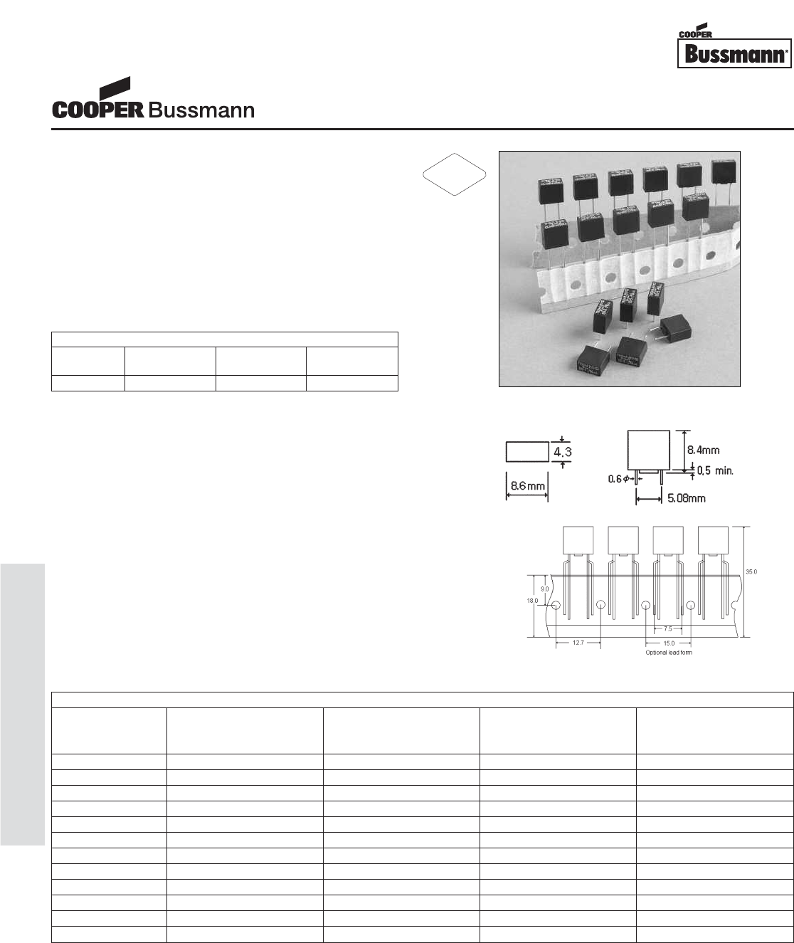
OC-46
Printed Circuit Board Fuses - Axial and Radial Leaded
Description
• Radial Leaded Fast Acting Thru-Hole Fuse
• Rectangular shape with reduced foot print
• Designed to UL 248-14
• Accepted for primary and secondary overcurrent
protection
• Place directly into PCB or plug into BK/PCS holder
• Compatible with leaded and lead-free reflow and wave
solder
• Base/Cap is Nylon #66, UL 94V0
• Pins are Tin Plated Copper
Agency Information
• UL Listed: E146895 (400mA thru 10A)
• CSA: LR98127 (400mA thru 10A)
Specifications
• Solderability: EIA-186-9E Method 9
• High Frequency Vibration: MIL-STD-202F,
Method 201A
• Operating Temperature: -40°C to +125°C
• Soldering Heat Resistance: 260°C, 10S
(IEC 60068-2-20)
Ordering
• Specify product and packaging code
(i.e., SS-5F-1A-AP)
Dimensions mm⁄(inches)
Subminiature Fuses
SS-5F Series, Fast Acting
ELECTRICAL CHARACTERISTICS
Rated 1 In 1.5 In 2 In
Current min max max
400mA-10A 1hr 10 min 2 min
SPECIFICATIONS
Product Voltage Rating Interrupting Typical DC Cold Typical Melting
Code AC Rating @ Resistance I2t(A
2s)
Rated Voltage (ohms) at 1ms
SS-5F-800mA 250V 50A 210 2.7
SS-5F-1A 250V 50A 120 4.9
SS-5F-1.6A 250V 50A 73 8.0
SS-5F-2A 250V 50A 50 12.1
SS-5F-2.5A 250V 50A 40 16.8
SS-5F-3.15A 250V 50A 32 32.4
SS-5F-4A 250V 50A 25 48.4
*SS-5F-5A 250V 50A 17 75.0
*SS-5F-6.3A 125V 50A 14 108
*SS-5F-7A 125V 50A 11 160
*SS-5F-8A 125V 50A 9 190
*SS-5F-10A 125V 50A 7 270
* Conducting Path min. 0.2mm2
RoHS
2002/95/EC
Courtesy of Steven Engineering, Inc.-230 Ryan Way, South San Francisco, CA 94080-6370-Main Office: (650) 588-9200-Outside Local Area: (800) 258-9200-www.stevenengineering.com

OC-47
Printed Circuit Board Fuses - Axial and Radial Leaded
03987654323.02.0
2000
1000
900
800
700
600
500
400
300
200
100
90
80
70
60
50
40
30
20
10
9
8
7
6
5
4
3
2
1
0.9
0.8
0.7
0.6
0.5
0.4
0.3
0.2
0.1
0.09
0.08
0.07
0.06
0.05
0.04
0.03
0.02
0.01
0.009
0.008
0.007
0.006
0.005
0.004
0.003
0.002
0.001
03987654323.02.0
60 80 10004010.86.0
001010.80.6 80
6040
TIME IN SECONDS
200
800
1000
8000
4000
6000
2000
CURRENT IN AMPERES
0.4 1
20
0
400
600
800
1000
8000
4000
6000
2000
0.4 1
SS-5F, 1A
SS-5F, 3.15A
SS-5F, 4A
SS-5F, 2A
SS-5F, 800mA
SS-5F 10A
400 600
SS-5F, 5A
SS-5F, 2.5A
SS-5F, 1.5A
SS-5F 6.3A
SS-5F 7A
SS-5F 8A
TIME CURRENT CURVE
Subminiature Fuses
SS-5F Series, Fast Acting
PACKAGING CODE
Packaging Code Description
-AP Ammo-pack taped 1,000 per box
-BK In bulk 200 per bag
Visit us on the web at:
www.cooperbussmann.com
Cooper Electronic Technologies
1225 Broken Sound Parkway NW
Suite F
Boca Raton, FL 33487-3533
Tel: 1-561-998-4100
Fax: 1-561-241-6640
Toll Free: 1-888-414-2645
Cooper Bussmann
P.O. Box 14460
St. Louis, MO 63178-4460
Tel: 1-636-394-2877
Fax: 1-800-544-2570
Cooper Electronic Technologies
Cooper (UK) Limited
Burton-on-the-Wolds
Leicestershire • LE12 5TH UK
Tel: +44 (0) 1509 882 737
Fax: +44 (0) 1509 882 786
Cooper Electronic Technologies
Avda. Santa Eulalia, 290
08223
Terrassa, (Barcelona), Spain
Tel: +34 937 362 812
+34 937 362 813
Fax: +34 937 362 719
Asia Pacific
Cooper Electronic Technologies
1 Jalan Kilang Timor
#06-01 Pacific Tech Centre
Singapore 159303
Tel: +65 278 6151
Fax: +65 270 4160
North America Europe
Courtesy of Steven Engineering, Inc.-230 Ryan Way, South San Francisco, CA 94080-6370-Main Office: (650) 588-9200-Outside Local Area: (800) 258-9200-www.stevenengineering.com
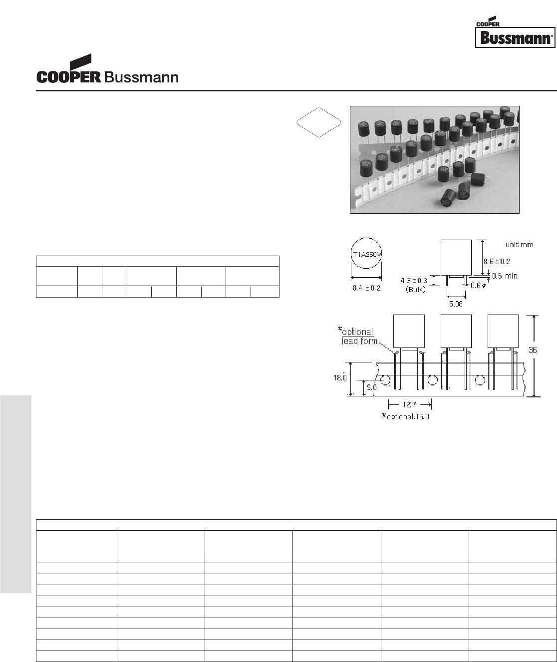
OC-48
Printed Circuit Board Fuses - Axial and Radial Leaded
Description
• Radial Leaded Time Lag Thru-Hole Fuse
• Designed to IEC 60127-3, Sheet 4
• Ideal for electronic lighting ballasts
• cURus Recognized at 300V/100A
• Internationally accepted for primary and secondary
overcurrent protection
• Place directly into PCB or plug into BK/PCS holder
• High inrush withstand capability
• Compatible with leaded and lead-free reflow and wave
solder
• Base/Cap is Nylon #66, UL 94V0
• Pins are Tin Plated Copper
Agency Information
• cURus: E146895 (1A thru 5A @ 300V/100A)
• PSE: (1A thru 6.3A @ 300V/100A)
• VDE: (1A thru 5A)
• SEMKO: (1A thru 5A) Pending
• CCC (1A thru 6.3A) Pending
• EK: KTL (1A thru 6.3A) Pending
Specifications
• Solderability: EIA-186-9E Method 9
• High Frequency Vibration: MIL-STD-202F,
Method 201A
• Operating Temperature: -40°C to +125°C
• Soldering Heat Resistance: 260°C, 10S
(IEC 60068-2-20)
Ordering
• Specify product and packaging code
(i.e., SR-5H-1A-AP)
Dimensions mm⁄(inches)
SPECIFICATIONS
Product Voltage Rating Interrupting Typical DC Cold Typical Melting Maximum Power
Code AC Rating @ Resistance I2t(A
2s) Dissipation
Rated Voltage (ohms) at 1ms (mW)
SR-5H-1A 250V 100A 0.083 9 500
SR-5H-1.25A 250V 100A 0.061 13 600
SR-5H-1.6A 250V 100A 0.047 24 730
SR-5H-2A 250V 100A 0.031 30 870
SR-5H-2.5A 250V 100A 0.028 45 1000
SR-5H-3.15A 250V 100A 0.023 57 1200
SR-5H-4A 250V 100A 0.015 80 1400
*SR-5H-5A 250V 100A 0.011 120 1800
*SR-5H-6.3A 250V 100A 0.009 140 2000
Subminiature Fuses
SR-5H Series, Time Lag
ELECTRICAL CHARACTERISTICS
Rated 1.5 In 2.1 In 2.75 In 4 In 10 In
Current min max min max min max min max
1A-6.3A 1hr 2 min 400 ms 10 sec 150 ms 3 sec 20 ms 150 ms
* Conducting Path min. 0.2mm2
RoHS
2002/95/EC
Courtesy of Steven Engineering, Inc.-230 Ryan Way, South San Francisco, CA 94080-6370-Main Office: (650) 588-9200-Outside Local Area: (800) 258-9200-www.stevenengineering.com
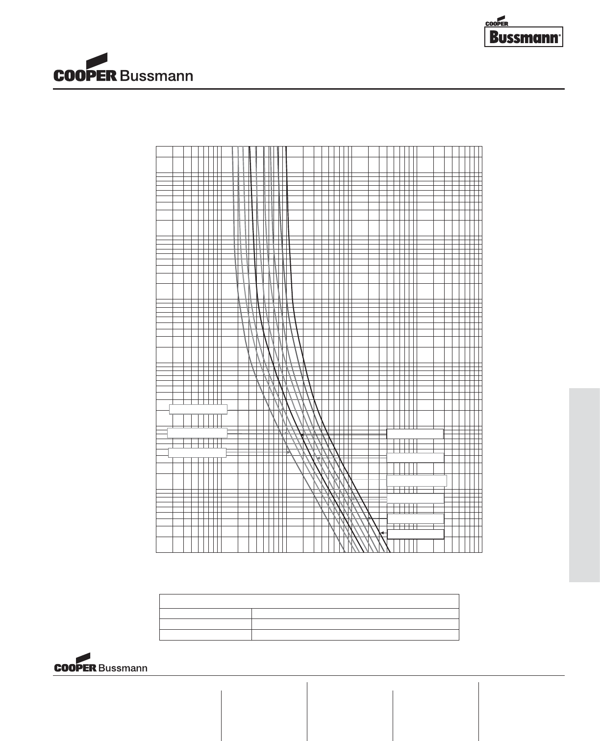
OC-49
Printed Circuit Board Fuses - Axial and Radial Leaded
03987654323.02.0
2000
1000
900
800
700
600
500
400
300
200
100
90
80
70
60
50
40
30
20
10
9
8
7
6
5
4
3
2
1
0. 9
0. 8
0.7
0.6
0.5
0.4
0.3
0.2
0.1
0. 09
0. 08
0.07
0.06
0.05
0.04
0.03
0.02
0.01
0. 009
0. 008
0.007
0.006
0.005
0.004
0.003
0.002
0.001
03987654323.02.0
60 80 10004010.86.0
00101##
0.6 806040
TIME IN SECONDS
200
800
1000
8000
4000
6000
2000
CURRENT IN AMPERES
0.4 1
SR-5H T2.5A
20
0
400
600
800
1000
8000
4000
6000
2000
0.4 1
SR-5H T1A
SR-5H T2A
SR-5H T3.15A
SR-5H T5A
SR-5H T4A
SR-5H T1.6A
SR-5H T1.25A
SR-5H T6.3A
400 600
TIME CURRENT CURVE
Subminiature Fuses
SR-5H Series, Time Lag
PACKAGING CODE
Packaging Code Description
-AP Ammo-pack taped 1,000 per box
-BK In bulk 200 per bag
Visit us on the web at:
www.cooperbussmann.com
Cooper Electronic Technologies
1225 Broken Sound Parkway NW
Suite F
Boca Raton, FL 33487-3533
Tel: 1-561-998-4100
Fax: 1-561-241-6640
Toll Free: 1-888-414-2645
Cooper Bussmann
P.O. Box 14460
St. Louis, MO 63178-4460
Tel: 1-636-394-2877
Fax: 1-800-544-2570
Cooper Electronic Technologies
Cooper (UK) Limited
Burton-on-the-Wolds
Leicestershire • LE12 5TH UK
Tel: +44 (0) 1509 882 737
Fax: +44 (0) 1509 882 786
Cooper Electronic Technologies
Avda. Santa Eulalia, 290
08223
Terrassa, (Barcelona), Spain
Tel: +34 937 362 812
+34 937 362 813
Fax: +34 937 362 719
Asia Pacific
Cooper Electronic Technologies
1 Jalan Kilang Timor
#06-01 Pacific Tech Centre
Singapore 159303
Tel: +65 278 6151
Fax: +65 270 4160
North America Europe
Courtesy of Steven Engineering, Inc.-230 Ryan Way, South San Francisco, CA 94080-6370-Main Office: (650) 588-9200-Outside Local Area: (800) 258-9200-www.stevenengineering.com
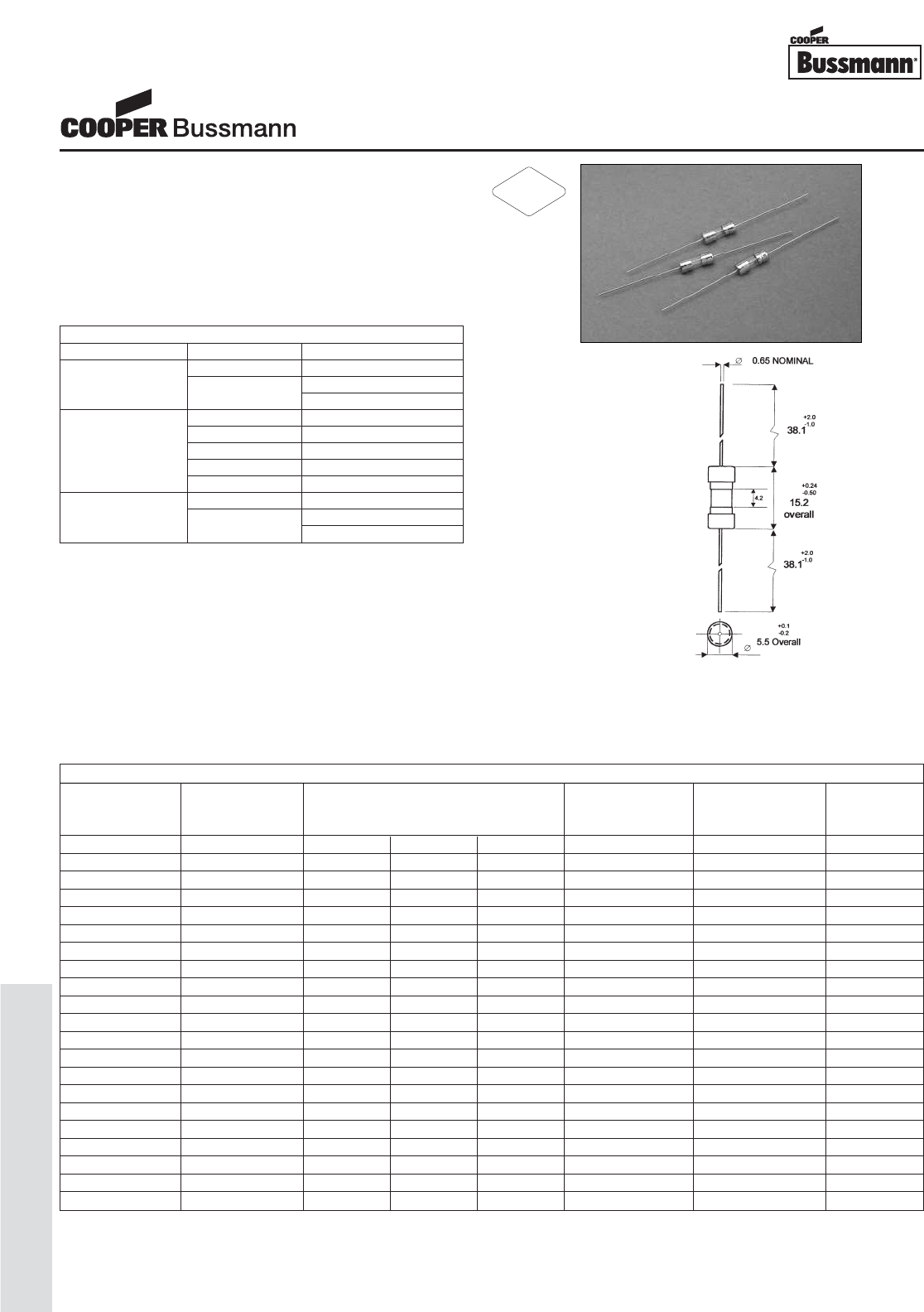
OC-50
Traditional Ferrule Fuses - Ferrule Type
Description
• Axial leaded, time delay
• 5mm x 15mm physical size
• Glass tube, nickel-plated brass endcap construction
• Leads are tin coated
• Optional sleeve is flexible flouropolymer
(U.L. flammability rating VW-1).
• UL Listed product meets standard UL 248-14
Agency Information
• UL Listed Card: C515 125mA-250mA and 375mA-3A
(Guide JDYX, File E19180)
• UL Recognized Card: C515 350mA, and 3.5A-7A
(Guide JDYX2, File E19180)
• CSA Certification Card: C515 125mA-250mA and
375mA-3A (Class 1422-01, LR65063)
Ordering
• Specify packaging, product, and option code
• For -R option, drop mA or A from product code
(i.e. C515-1-R)
• With TR2 packaging code, lead wire length is 20.3mm
Dimensions (mm)
Drawing Not to Scale
SPECIFICATIONS
Voltage AC Interrupting Typical DC Cold Typical Typical
Product Code Rating Rating Resistance* Melting I2t† Voltage
AC 600V 250V 125V (ohms) AC Drop (mV)‡
C515-125mA 250V - 35A 10000A 4.72 0.101 770
C515-250mA 250V - 35A 10000A 1.32 0.467 430
C515-350mA 250V 25A 35A 10000A 1.04 1.169 530
C515-375mA 250V - 35A 10000A 0.81 1.531 470
C515-500mA 250V - 35A 10000A 0.54 2.280 440
C515-600mA 250V - 35A 10000A 0.38 6.982 350
C515-750mA 250V - 35A 10000A 0.26 9.162 310
C515-800mA 250V - 35A 10000A 0.23 10.544 260
C515-1A 250V - 35A 10000A 0.14 14.289 230
C515-1.25A 250V - 100A 10000A 0.13 22.961 220
C515-1.5A 250V - 100A 10000A 0.100 31.989 240
C515-1.6A 250V - 100A 10000A 0.090 35.156 200
C515-2A 250V - 100A 10000A 0.059 60.256 170
C515-2.25A 250V - 100A 10000A 0.057 97.724 180
C515-2.5A 250V - 100A 10000A 0.046 78.163 190
C515-3A 250V - 100A 10000A 0.035 80.426 150
C515-3.5A 125V - - 400A 0.028 149.279 130
C515-4A 125V - - 400A 0.023 233.346 130
C515-5A 125V - - 400A 0.019 354.813 150
C515-6A 125V - - 400A 0.014 471.360 125
C515-7A 125V - - 400A 0.013 710.500 100
* DC Cold Resistance (Measured at <10% of rated current)
† Typical Melting I2t(A
2Sec) (Minimum I2t at 10 times rated current)
‡ Typical Voltage Drop (Voltage drop was measured at 25°C ambient temperature at rated current)
ELECTRICAL CHARACTERISTICS
Rated Current Amp Rating Opening Time
135% 60 minutes max.
125mA - 250mA 200% 3 seconds min.
120 seconds max.
100% 4 hours min.
470mA 30 minutes max.
350mA 600mA 90 seconds max.
2A 2 seconds max.
6A 500 milliseconds max.
135% 60 minutes max.
375mA - 7A 200% 3 seconds min.
120 seconds max.
5mm x 15mm Fuses
C515 Series, Time Delay, Glass Tube
RoHS
2002/95/EC
Courtesy of Steven Engineering, Inc.-230 Ryan Way, South San Francisco, CA 94080-6370-Main Office: (650) 588-9200-Outside Local Area: (800) 258-9200-www.stevenengineering.com
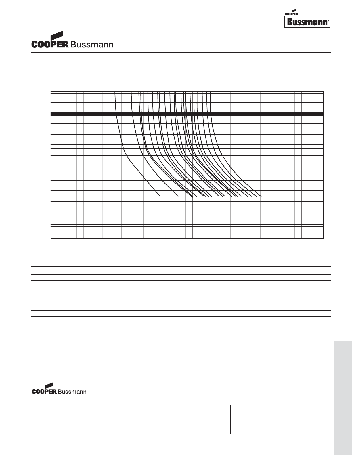
OC-51
Traditional Ferrule Fuses - Ferrule Type
Nominal Time/Current Characteristics
0.001
0.01
0.1
1
10
100
1000
10000
0.01 0.1 1 10 100 1000
Current (A)
Pre-arcing time (s)
125mA
250mA
350mA
375mA
500mA
750mA
1A
3.5A
4A
5A
7A
600mA
1.25A
1.5A
1.6A
2A
2.25A
2.5A
3A
TIME CURRENT CURVE
PACKAGING CODE
Packaging Code Description
BK 100 pieces of fuses packed into a cardboard carton
TR2 1,500 pieces of fuses packed into tape on a reel (20.3mm lead wire length)
OPTION CODE
Option Code Description
SInsulation Sleeve
-R RoHS compliant version
5mm x 15mm Fuses
C515 Series, Time Delay, Glass Tube
Visit us on the web at:
www.cooperbussmann.com
Cooper Electronic Technologies
1225 Broken Sound Parkway NW
Suite F
Boca Raton, FL 33487-3533
Tel: 1-561-998-4100
Fax: 1-561-241-6640
Toll Free: 1-888-414-2645
Cooper Bussmann
P.O. Box 14460
St. Louis, MO 63178-4460
Tel: 1-636-394-2877
Fax: 1-800-544-2570
Cooper Electronic Technologies
Cooper (UK) Limited
Burton-on-the-Wolds
Leicestershire • LE12 5TH UK
Tel: +44 (0) 1509 882 737
Fax: +44 (0) 1509 882 786
Cooper Electronic Technologies
Avda. Santa Eulalia, 290
08223
Terrassa, (Barcelona), Spain
Tel: +34 937 362 812
+34 937 362 813
Fax: +34 937 362 719
Asia Pacific
Cooper Electronic Technologies
1 Jalan Kilang Timor
#06-01 Pacific Tech Centre
Singapore 159303
Tel: +65 278 6151
Fax: +65 270 4160
North America Europe
Courtesy of Steven Engineering, Inc.-230 Ryan Way, South San Francisco, CA 94080-6370-Main Office: (650) 588-9200-Outside Local Area: (800) 258-9200-www.stevenengineering.com
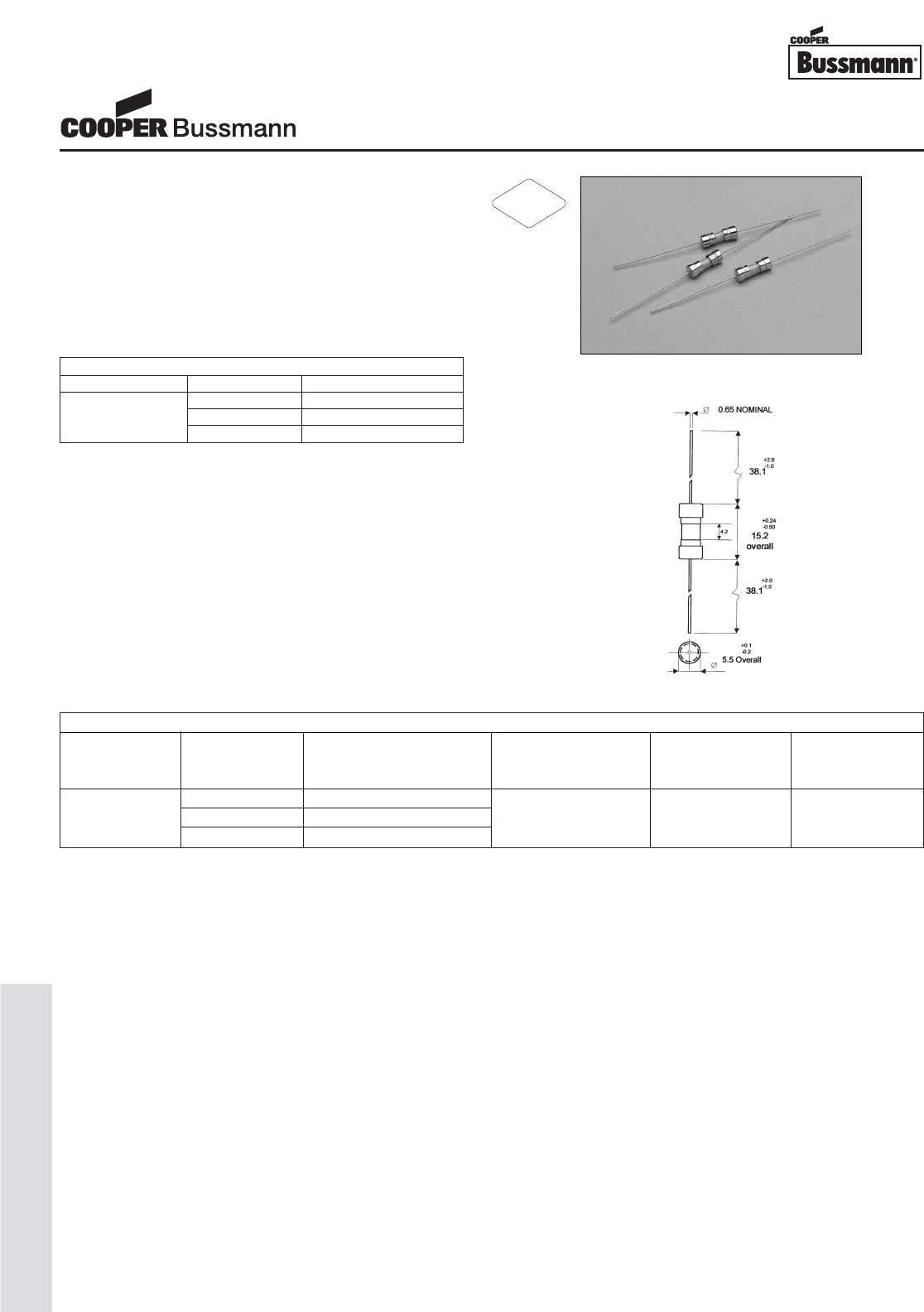
OC-52
Traditional Ferrule Fuses - Ferrule Type
Description
• Axial leaded fast acting
• 5mm x 15mm physical size
• Glass tube, nickel-plated brass endcap construction
• Leads are plated with 95% tin, 5% lead
• Optional sleeve is flexible flouropolymer
(U.L. flammability rating VW-1).
• UL Listed product meets standard UL 248-14
• High breaking capacity for lighting ballast applications
Agency Information
• UL Listed Card: C517 3A (Guide JDYX, File E75865)
• UL Recognition Card: C517 3A
(Guide JDYX2, File E75865)
• CSA Certification Card: 3A (Class 1422-01, LR65063)
Ordering
• Specify packaging, product, and option code
• For -R option, drop mA or A from product code
(i.e. C517-3-R)
• With TR2 packaging code, lead wire length is 20.3mm
Dimensions (mm)
Drawing Not to Scale
ELECTRICAL CHARACTERISTICS
Rated Current Amp Rating Opening Time
100% None
3A 135% 60 minutes max.
200% 2 seconds max.
SPECIFICATIONS
Voltage Interrupting Rating Typical DC Cold Typical Typical
Product Code Rating at Rated Voltage Resistance* Melting I2t† Voltage
AC AC (ohms) AC Drop (mV)‡
350V** 100A
C517-3A 250V 100A 0.34 5.87 141.7
125V 10,000A
* DC Cold Resistance (Measured at <10% of rated current)
†Typical Melting I2t(A
2Sec) (Minimum I2t at 10 times rated current)
‡ Typical Voltage Drop (Voltage drop was measured at 25°C ambient temperature at rated current)
** 350VAC is UL Recognized
5mm x 15mm Fuses
C517 Series, Fast Acting, Glass Tube
RoHS
2002/95/EC
Courtesy of Steven Engineering, Inc.-230 Ryan Way, South San Francisco, CA 94080-6370-Main Office: (650) 588-9200-Outside Local Area: (800) 258-9200-www.stevenengineering.com
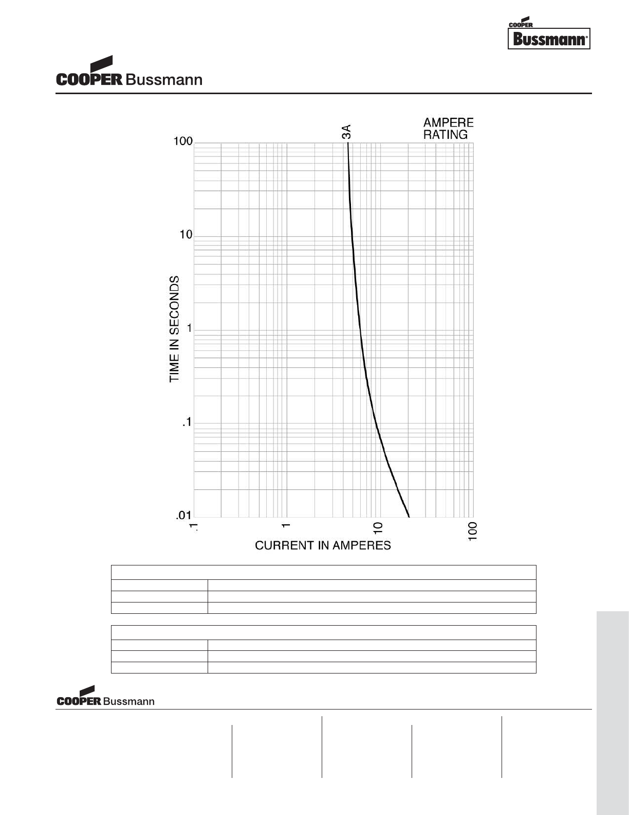
OC-53
Traditional Ferrule Fuses - Ferrule Type
TIME CURRENT CURVE
PACKAGING CODE
Packaging Code Description
BK 100 pieces of fuses packed into a cardboard carton
TR2 1,500 pieces of fuses packed into tape on a reel (20.3mm lead wire length)
OPTION CODE
Option Code Description
SInsulation Sleeve
-R RoHS compliant version
5mm x 15mm Fuses
C517 Series, Fast Acting, Glass Tube
Visit us on the web at:
www.cooperbussmann.com
Cooper Electronic Technologies
1225 Broken Sound Parkway NW
Suite F
Boca Raton, FL 33487-3533
Tel: 1-561-998-4100
Fax: 1-561-241-6640
Toll Free: 1-888-414-2645
Cooper Bussmann
P.O. Box 14460
St. Louis, MO 63178-4460
Tel: 1-636-394-2877
Fax: 1-800-544-2570
Cooper Electronic Technologies
Cooper (UK) Limited
Burton-on-the-Wolds
Leicestershire • LE12 5TH UK
Tel: +44 (0) 1509 882 737
Fax: +44 (0) 1509 882 786
Cooper Electronic Technologies
Avda. Santa Eulalia, 290
08223
Terrassa, (Barcelona), Spain
Tel: +34 937 362 812
+34 937 362 813
Fax: +34 937 362 719
Asia Pacific
Cooper Electronic Technologies
1 Jalan Kilang Timor
#06-01 Pacific Tech Centre
Singapore 159303
Tel: +65 278 6151
Fax: +65 270 4160
North America Europe
Courtesy of Steven Engineering, Inc.-230 Ryan Way, South San Francisco, CA 94080-6370-Main Office: (650) 588-9200-Outside Local Area: (800) 258-9200-www.stevenengineering.com
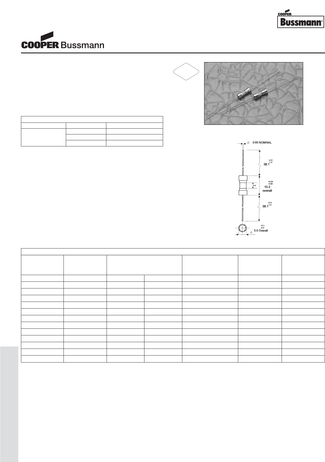
OC-54
Traditional Ferrule Fuses - Ferrule Type
Description
• Axial leaded fast acting
• 5mm x 15mm physical size
• Glass tube, nickel-plated brass endcap construction
• Leads are plated with 95% tin, 5% lead
• Optional sleeve is flexible flouropolymer
(U.L. flammability rating VW-1).
• UL Listed product meets standard UL 248-14
Agency Information
• UL Listed Card: Guide JDYX, File E19180
• CSA Certification Card: Class 1422-01, LR65063
Ordering
• Specify packaging, product, and option code
• For -R option, drop mA or A from product code
(i.e. C518-3-R)
• With TR2 packaging code, lead wire length is 20.3mm
Dimensions (mm)
Drawing Not to Scale
SPECIFICATIONS
Voltage Interrupting Rating Typical DC Cold Typical Typical
Product Code Rating at Rated Voltage Resistance* Melting I2t† Voltage
AC 250VAC 125VAC (ohms) AC Drop (mV)‡
C518-100mA 250V 35A 10,000A 22.30 0.0010 2230
C518-125mA 250V 35A 10,000A 15.20 0.0019 1930
C518-250mA 250V 35A 10,000A 5.66 0.012 1450
C518-375mA 250V 35A 10,000A 2.53 0.039 968
C518-500mA 250V 35A 10,000A 1.66 0.059 845
C518-750mA 250V 35A 10,000A 0.91 0.264 686
C518-1.5A 250V 100A 10,000A 0.900 0.800 135
C518-2A 250V 100A 10,000A 0.064 1.9 136
C518-2.5A 250V 100A 10,000A 0.046 2.9 121
C518-3A 250V 100A 10,000A 0.038 6.1 116
C518-3.5A 250V 100A 10,000A 0.032 9.7 115
C518-4A 250V 200A 10,000A 0.022 16.6 88
C518-5A 250V 200A 10,000A 0.018 22.4 91
* DC Cold Resistance (Measured at <10% of rated current)
† Typical Melting I2t(A
2Sec) (Minimum at 10 times rated current)
‡ Typical Voltage Drop (Voltage drop was measured at 20°C ambient temperature at rated current)
ELECTRICAL CHARACTERISTICS
Rated Current Amp Rating Opening Time
100% None
100mA-5A 135% 60 minutes max.
200% 2 seconds max.
5mm x 15mm Fuses
C518 Series, Fast Acting, Glass Tube
RoHS
2002/95/EC
Courtesy of Steven Engineering, Inc.-230 Ryan Way, South San Francisco, CA 94080-6370-Main Office: (650) 588-9200-Outside Local Area: (800) 258-9200-www.stevenengineering.com
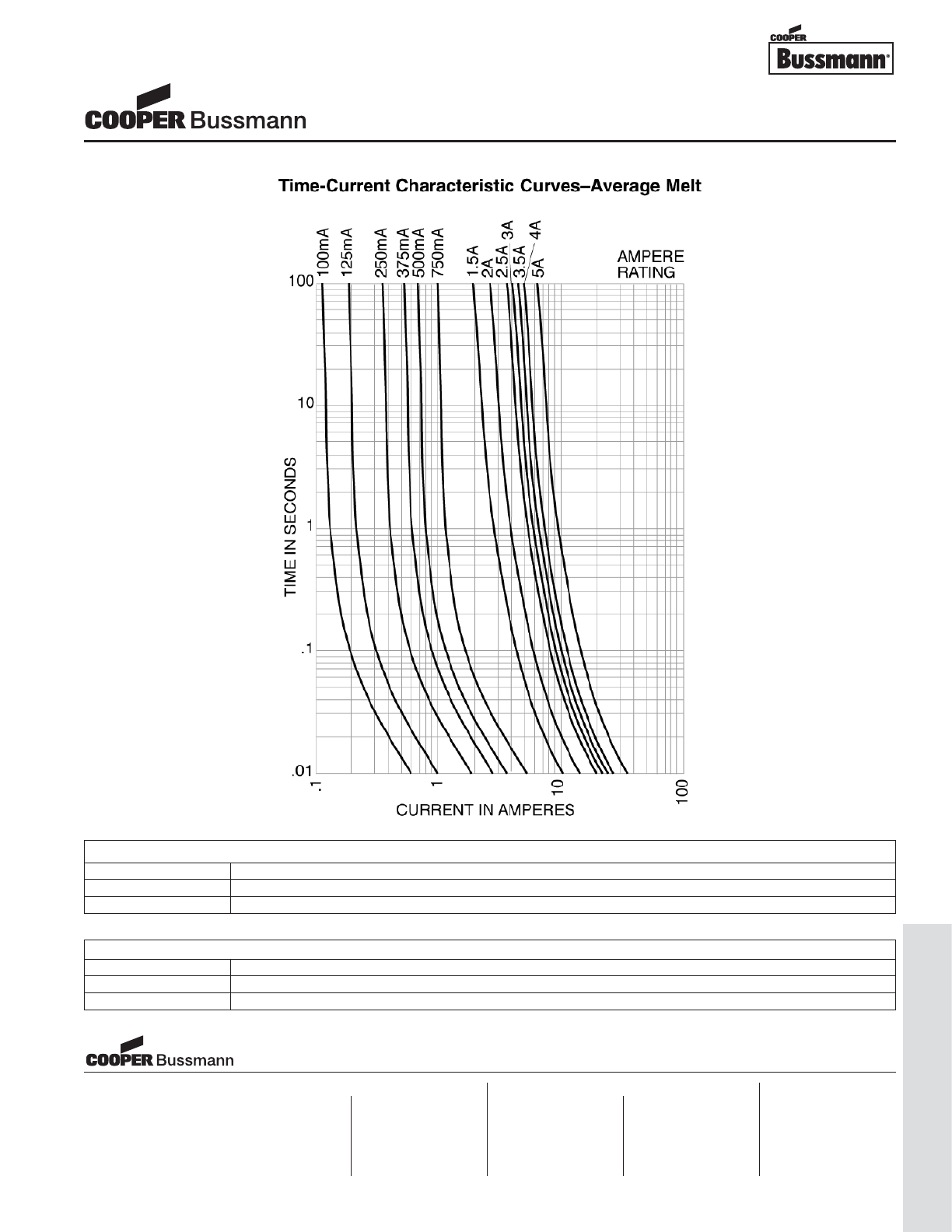
OC-55
Traditional Ferrule Fuses - Ferrule Type
TIME CURRENT CURVE
PACKAGING CODE
Packaging Code Description
BK 100 pieces of fuses packed into a cardboard carton
TR2 1,500 pieces of fuses packed into tape on a reel (20.3mm lead wire length)
OPTION CODE
Option Code Description
SInsulation Sleeve
-R RoHS compliant version
5mm x 15mm Fuses
C518 Series, Fast Acting, Glass Tube
Visit us on the web at:
www.cooperbussmann.com
Cooper Electronic Technologies
1225 Broken Sound Parkway NW
Suite F
Boca Raton, FL 33487-3533
Tel: 1-561-998-4100
Fax: 1-561-241-6640
Toll Free: 1-888-414-2645
Cooper Bussmann
P.O. Box 14460
St. Louis, MO 63178-4460
Tel: 1-636-394-2877
Fax: 1-800-544-2570
Cooper Electronic Technologies
Cooper (UK) Limited
Burton-on-the-Wolds
Leicestershire • LE12 5TH UK
Tel: +44 (0) 1509 882 737
Fax: +44 (0) 1509 882 786
Cooper Electronic Technologies
Avda. Santa Eulalia, 290
08223
Terrassa, (Barcelona), Spain
Tel: +34 937 362 812
+34 937 362 813
Fax: +34 937 362 719
Asia Pacific
Cooper Electronic Technologies
1 Jalan Kilang Timor
#06-01 Pacific Tech Centre
Singapore 159303
Tel: +65 278 6151
Fax: +65 270 4160
North America Europe
Courtesy of Steven Engineering, Inc.-230 Ryan Way, South San Francisco, CA 94080-6370-Main Office: (650) 588-9200-Outside Local Area: (800) 258-9200-www.stevenengineering.com
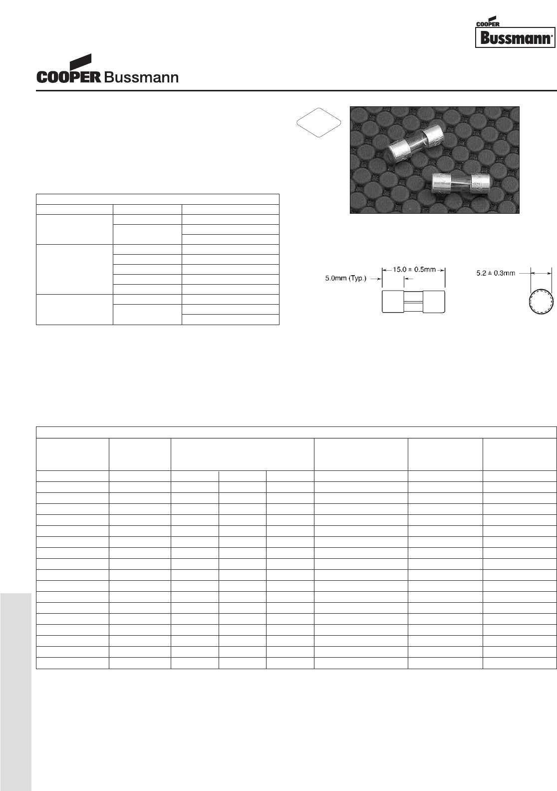
OC-56
Traditional Ferrule Fuses - Ferrule Type
Description
• Time delay
• 5mm x 15mm physical size
• Glass tube, nickel-plated brass endcap construction
• Optional sleeve is flexible flouropolymer
(U.L. flammability rating VW-1).
• UL Listed product meets standard UL 248-14
Agency Information
• UL Listed Card: C519 125mA-250mA and 375mA-3A
(Guide JDYX, File E19180)
• UL Recognized Card: C519 350mA, and 3.5A-7A
(Guide JDYX2, File E19180)
• CSA Certification Card: C519 125mA-250mA and
375mA-3A (Class 1422-01, LR65063)
Ordering
• Specify packaging, product, and option code
• For -R option, drop mA or A from product code
(i.e. C519-3-R)
Dimensions
Drawing Not to Scale
SPECIFICATIONS
Voltage Interrupting Rating Typical DC Cold Typical Typical
Product Code Rating at Rated Voltage Resistance* Melting I2t† Voltage
AC 600V 250V 125V (ohms) AC Drop (mV)‡
C519-125mA 250V - 35A 10,000A 4.72 0.101 770
C519-250mA 250V - 35A 10,000A 1.32 0.467 430
C519-350mA 250V 25A 35A 10,000A 1.04 1.169 530
C519-375mA 250V - 35A 10,000A 0.81 1.531 470
C519-500mA 250V - 35A 10,000A 0.54 2.280 440
C519-600mA 250V - 35A 10,000A 0.38 6.982 350
C519-750mA 250V - 35A 10,000A 0.26 9.162 310
C519-1A 250V - 35A 10,000A 0.14 14.289 230
C519-1.25A 250V - 100A 10,000A 0.13 22.961 220
C519-1.5A 250V - 100A 10,000A 0.10 31.989 240
C519-1.6A 250V - 100A 10,000A 0.09 31.156 200
C519-2A 250V - 100A 10,000A 0.059 60.256 170
C519-2.25A 250V - 100A 10,000A 0.057 97.724 180
C519-2.5A 250V - 100A 10,000A 0.046 78.163 190
C519-3A 250V - 100A 10,000A 0.035 80.426 150
C519-3.5A 125V - - 400A 0.028 149.279 130
C519-4A 125V - - 400A 0.023 233.346 130
C519-5A 125V - - 400A 0.019 354.813 150
* DC Cold Resistance (Measured at <10% of rated current)
† Typical Melting I2t(A
2Sec) (Typical I2t at 10 times rated current)
‡ Typical Voltage Drop (Voltage drop was measured at 25°C±3°C ambient temperature at rated current)
ELECTRICAL CHARACTERISTICS
Rated Current Amp Rating Opening Time
135% 60 minutes max.
125mA - 250mA 200% 3 seconds min.
120 seconds max.
100% 4 hours min.
470mA 30 minutes max.
350mA 600mA 90 seconds max.
2A 2 seconds max.
6A 500 milliseconds max.
135% 60 minutes max.
375mA - 5A 200% 3 seconds min.
120 seconds max.
5mm x 15mm Fuses
C519 Series, Time Delay, Glass Tube
RoHS
2002/95/EC
Courtesy of Steven Engineering, Inc.-230 Ryan Way, South San Francisco, CA 94080-6370-Main Office: (650) 588-9200-Outside Local Area: (800) 258-9200-www.stevenengineering.com
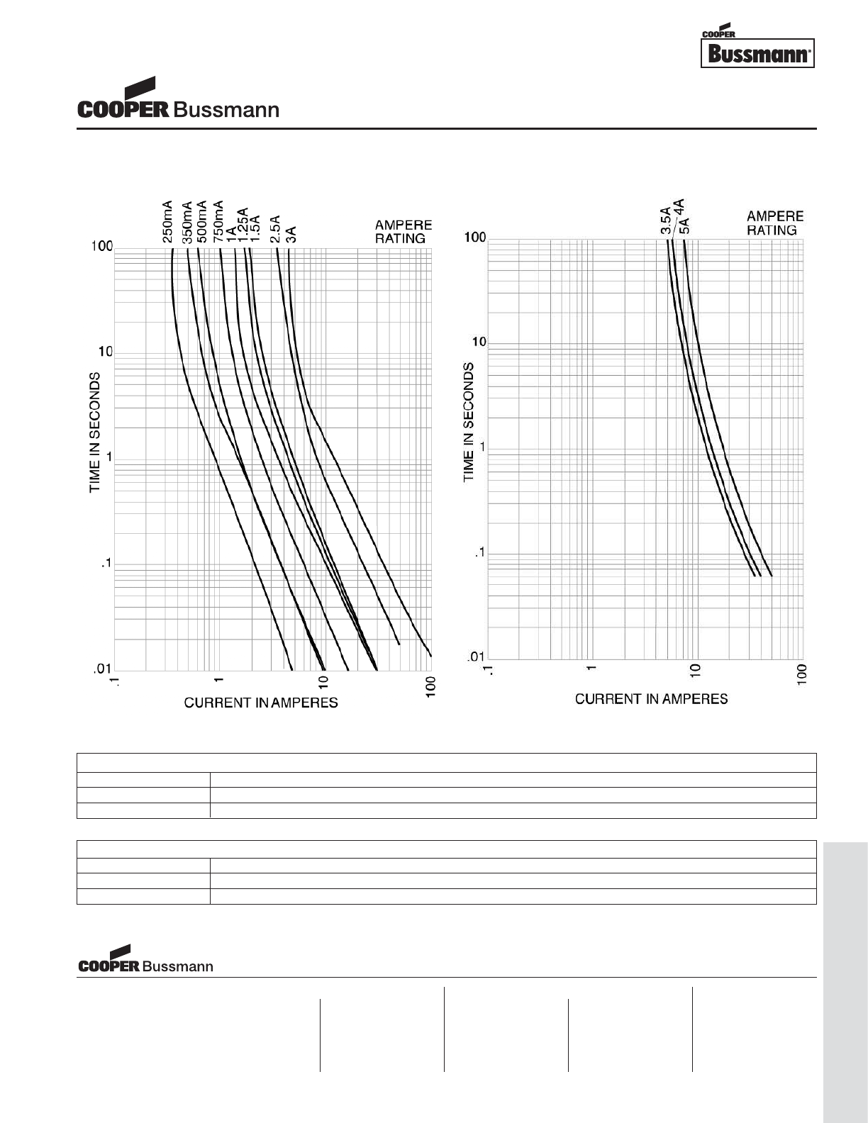
OC-57
Traditional Ferrule Fuses - Ferrule Type
TIME CURRENT CURVE
PACKAGING CODE
Packaging Code Description
BK 100 pieces of fuses packed into a cardboard carton
BK1 1,000 pieces of fuses packed into a cardboard carton
OPTION CODE
Option Code Description
SInsulation Sleeve
-R RoHS compliant version
5mm x 15mm Fuses
C519 Series, Time Delay, Glass Tube
Visit us on the web at:
www.cooperbussmann.com
Cooper Electronic Technologies
1225 Broken Sound Parkway NW
Suite F
Boca Raton, FL 33487-3533
Tel: 1-561-998-4100
Fax: 1-561-241-6640
Toll Free: 1-888-414-2645
Cooper Bussmann
P.O. Box 14460
St. Louis, MO 63178-4460
Tel: 1-636-394-2877
Fax: 1-800-544-2570
Cooper Electronic Technologies
Cooper (UK) Limited
Burton-on-the-Wolds
Leicestershire • LE12 5TH UK
Tel: +44 (0) 1509 882 737
Fax: +44 (0) 1509 882 786
Cooper Electronic Technologies
Avda. Santa Eulalia, 290
08223
Terrassa, (Barcelona), Spain
Tel: +34 937 362 812
+34 937 362 813
Fax: +34 937 362 719
Asia Pacific
Cooper Electronic Technologies
1 Jalan Kilang Timor
#06-01 Pacific Tech Centre
Singapore 159303
Tel: +65 278 6151
Fax: +65 270 4160
North America Europe
Courtesy of Steven Engineering, Inc.-230 Ryan Way, South San Francisco, CA 94080-6370-Main Office: (650) 588-9200-Outside Local Area: (800) 258-9200-www.stevenengineering.com
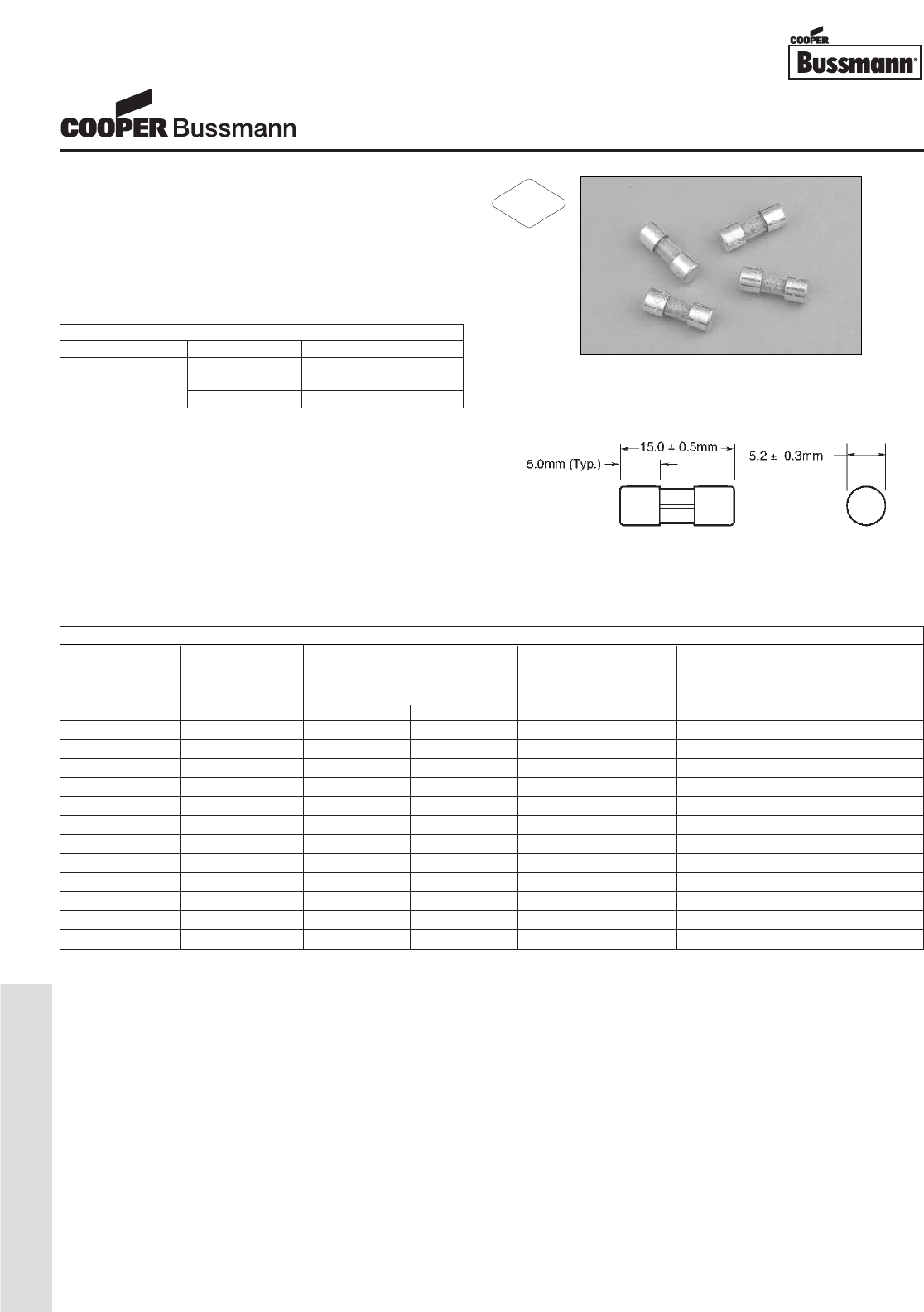
OC-58
Traditional Ferrule Fuses - Ferrule Type
Description
• Fast acting
• 5mm x 15mm physical size
• Glass tube, nickel-plated brass endcap construction
• Optional sleeve is flexible flouropolymer
(U.L. flammability rating VW-1).
• UL Listed product meets standard UL 248-14
Agency Information
• UL Listed Card: Guide JDYX, File E19180
• CSA Certification Card: Class 1422-01, LR65063
Ordering
• Specify packaging, product, and option code
• For -R option, drop mA or A from product code
(i.e. C520-3-R)
Dimensions
Drawing Not to Scale
ELECTRICAL CHARACTERISTICS
Rated Current Amp Rating Opening Time
100% None
100mA - 5A 135% 1 hours max.
200% 2 seconds max.
SPECIFICATIONS
Voltage Interrupting Rating Typical DC Cold Typical Typical
Product Code Rating at Rated Voltage Resistance* Melting I2t† Voltage
AC 250VAC 125VAC (ohms) AC Drop (mV)‡
C520-100mA 250V 35A 10,000A 22.30 0.0010 2230
C520-125mA 250V 35A 10,000A 15.20 0.0019 1930
C520-250mA 250V 35A 10,000A 5.60 0.012 1450
C520-375mA 250V 35A 10,000A 2.53 0.039 968
C520-500mA 250V 35A 10,000A 1.66 0.059 845
C520-750mA 250V 35A 10,000A 0.91 0.264 686
C520-1.5A 250V 100A 10,000A 0.900 0.800 135
C520-2A 250V 100A 10,000A 0.064 1.9 136
C520-2.5A 250V 100A 10,000A 0.046 2.9 121
C520-3A 250V 100A 10,000A 0.038 6.1 116
C520-3.5A 250V 100A 10,000A 0.032 9.7 115
C520-4A 250V 200A 10,000A 0.022 16.6 88
C520-5A 250V 200A 10,000A 0.018 22.4 91
* DC Cold Resistance (Measured at <10% of rated current)
†Typical Melting I2t (A2Sec) (maximum I2t at 10 times rated current)
‡ Typical Voltage Drop (Voltage drop was measured at 25°C±3°C ambient temperature at rated current)
5mm x 15mm Fuses
C520 Series, Fast Acting, Glass Tube
RoHS
2002/95/EC
Courtesy of Steven Engineering, Inc.-230 Ryan Way, South San Francisco, CA 94080-6370-Main Office: (650) 588-9200-Outside Local Area: (800) 258-9200-www.stevenengineering.com
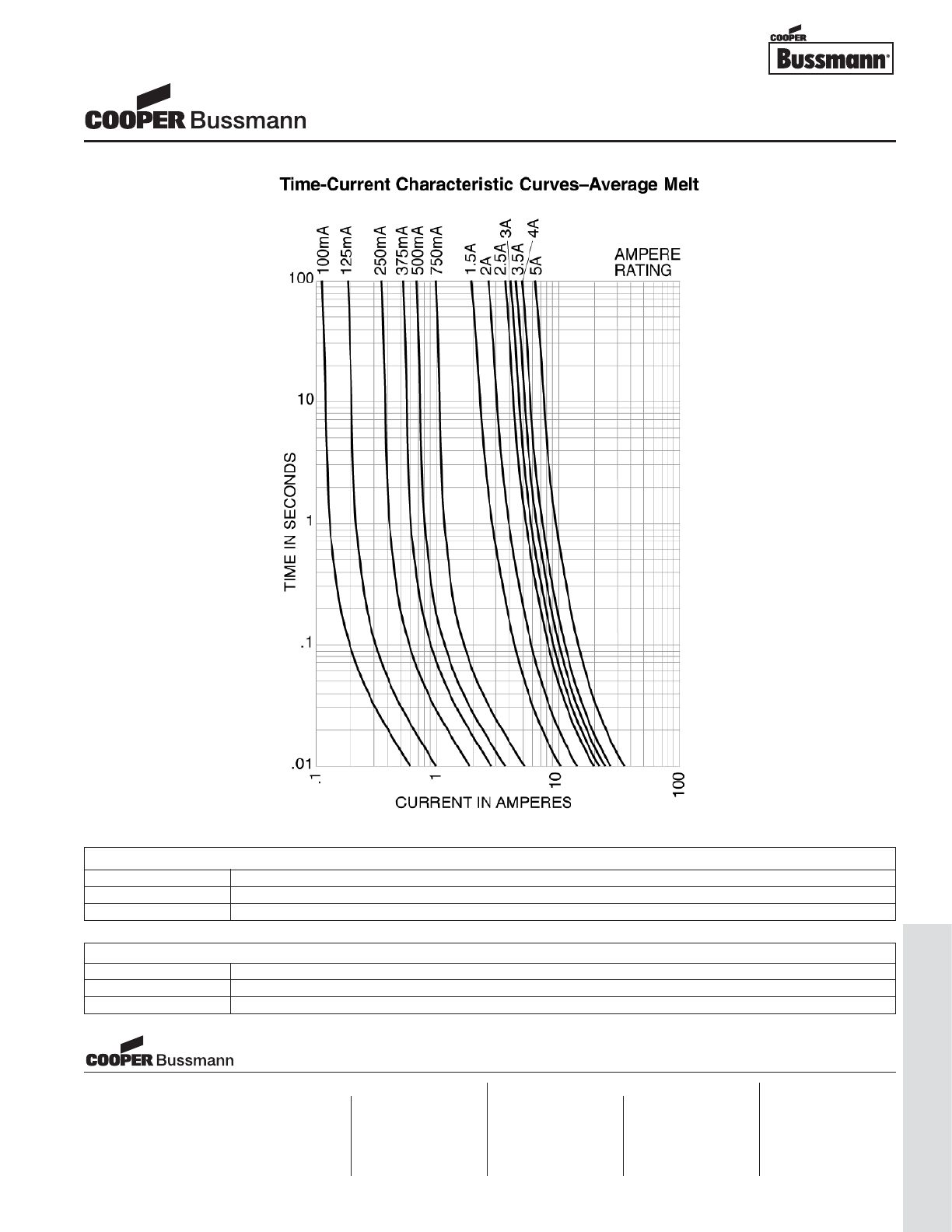
OC-59
Traditional Ferrule Fuses - Ferrule Type
TIME CURRENT CURVE
PACKAGING CODE
Packaging Code Description
BK 100 pieces of fuses packed into a cardboard carton
BK1 1,000 pieces of fuses packed into a cardboard carton
OPTION CODE
Option Code Description
SInsulation Sleeve
-R RoHS compliant version
5mm x 15mm Fuses
C520 Series, Fast Acting, Glass Tube
Visit us on the web at:
www.cooperbussmann.com
Cooper Electronic Technologies
1225 Broken Sound Parkway NW
Suite F
Boca Raton, FL 33487-3533
Tel: 1-561-998-4100
Fax: 1-561-241-6640
Toll Free: 1-888-414-2645
Cooper Bussmann
P.O. Box 14460
St. Louis, MO 63178-4460
Tel: 1-636-394-2877
Fax: 1-800-544-2570
Cooper Electronic Technologies
Cooper (UK) Limited
Burton-on-the-Wolds
Leicestershire • LE12 5TH UK
Tel: +44 (0) 1509 882 737
Fax: +44 (0) 1509 882 786
Cooper Electronic Technologies
Avda. Santa Eulalia, 290
08223
Terrassa, (Barcelona), Spain
Tel: +34 937 362 812
+34 937 362 813
Fax: +34 937 362 719
Asia Pacific
Cooper Electronic Technologies
1 Jalan Kilang Timor
#06-01 Pacific Tech Centre
Singapore 159303
Tel: +65 278 6151
Fax: +65 270 4160
North America Europe
Courtesy of Steven Engineering, Inc.-230 Ryan Way, South San Francisco, CA 94080-6370-Main Office: (650) 588-9200-Outside Local Area: (800) 258-9200-www.stevenengineering.com
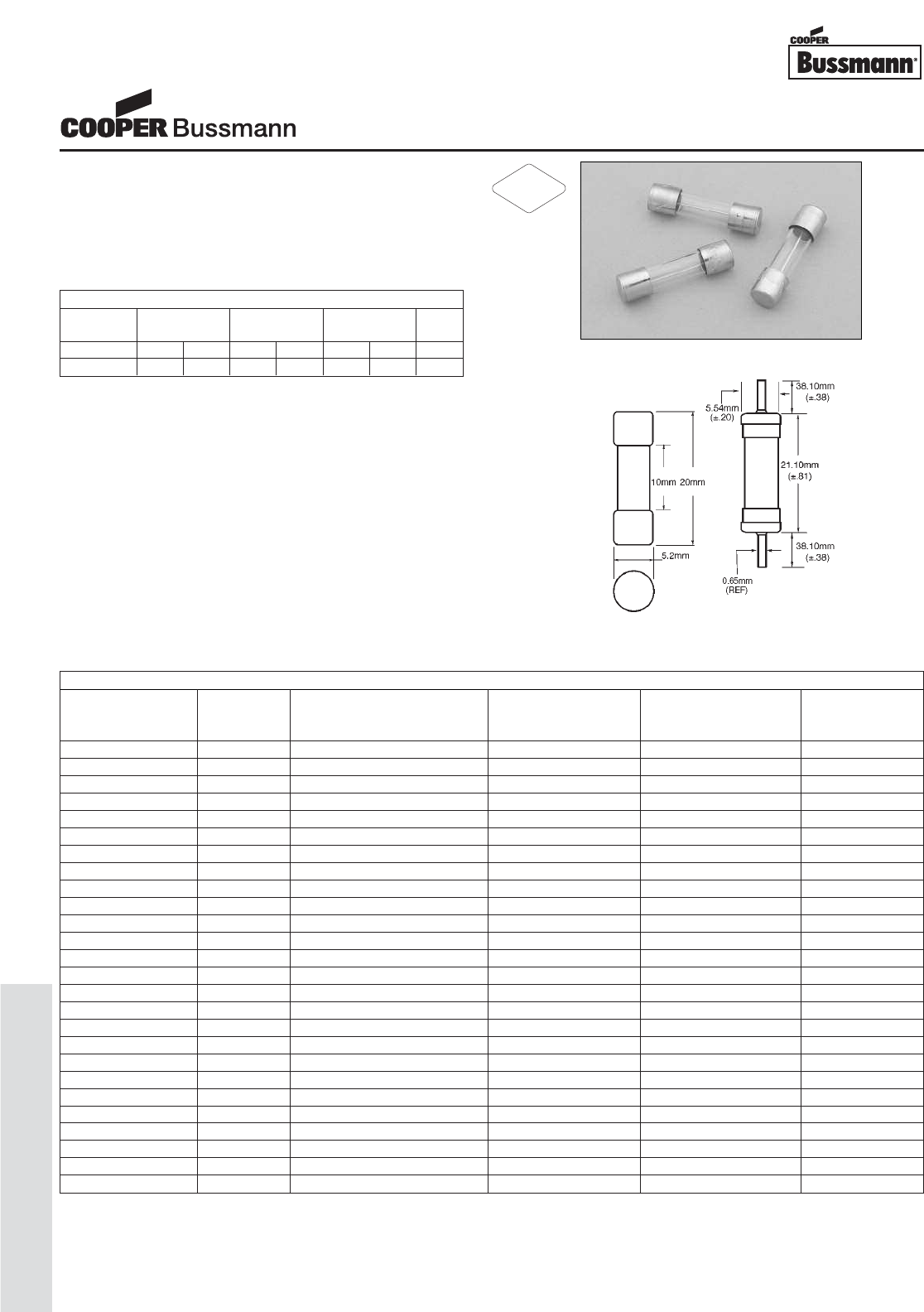
OC-60
Traditional Ferrule Fuses - Ferrule Type
Description
• Fast acting, low breaking capacity
• Optional Axial leads available
• 5mm x 20mm physical size
• Glass tube, nickel-plated brass endcap construction
• Designed to IEC 60127-2 (32mA-6.3A)
Agency Information
• UL Recognized Card: (32mA-10A) Guide JDYX2,
File E19180
• CSA Component Acceptance: File 53787
• cURus Recognition: Guide JDYX8, File E19180
• SEMKO Approval 160mA-10A
• VDE Approval 160mA-10A
• BSI Approval 160mA-10A
• IMQ Approval 160mA-10A
• CCC Approval 160mA-6.3A
Ordering
• Specify packaging, product, and option code
• For -R option, drop mA or A from product code
(i.e. S500-2-R)
• Ratings above 6.3A have a 0.8mm diameter lead
• With TR2 packaging code, lead wire length is 19.05mm
Dimensions
Drawing Not to Scale
SPECIFICATIONS
Voltage Interrupting Rating Typical DC Typical Maximum
Product Code Rating at Rated Voltage (50Hz) Cold Resistance Melting I2t (A2Sec) Voltage
AC AC (ohms)* AC† Drop (mV)‡
S500-32mA 250V 35A 41.5 0.000047 3200
S500-40mA 250V 35A 25.5 0.00011 2500
S500-50mA 250V 35A 17.5 0.00020 2400
S500-63mA 250V 35A 12.9 0.00057 2000
S500-80mA 250V 35A 5.2 0.0012 1200
S500-100mA 250V 35A 3.9 0.003 1100
S500-125mA 250V 35A 2.9 0.005 1000
S500-160mA 250V 35A 9.2 0.008 2000
S500-200mA 250V 35A 7.0 0.016 1700
S500-250mA 250V 35A 4.5 0.28 1400
S500-315mA 250V 35A 3.2 0.58 1300
S500-400mA 250V 35A 1.9 0.18 1100
S500-500mA 250V 35A 0.27 0.18 220
S500-630mA 250V 35A 0.21 0.35 220
S500-800mA 250V 35A 0.15 0.67 190
S500-1A 250V 35A 0.13 0.60 200
S500-1.25A 250V 35A 0.098 0.84 200
S500-1.6A 250V 35A 0.068 1.6 190
S500-2A 250V 35A 0.044 4.2 150
S500-2.5A 250V 35A 0.035 6.1 150
S500-3.15A 250V 35A 0.026 13 130
S500-4A 250V 40A 0.022 22 130
S500-5A 250V 50A 0.015 42 120
S500-6.3A 250V 63A 0.010 69 120
S500-8A 250V 80A N/A N/A N/A
S500-10A 250V 100A N/A N/A N/A
* DC Cold Resistance (Measured at <10% of rated current)
† Typical Melting I2t (I2t was measured at listed interrupting rating and rated voltage)
‡ Maximum Voltage Drop (Voltage drop was measured at 20°C ambient temperature at rated current)
ELECTRICAL CHARACTERISTICS
1.5 In 2.1 In 2.75 In 4 In 10 In
In min max min max min max max
32mA-100mA 60 min 30 min 10 ms 500 ms 3 ms 100 ms 20 ms
125mA-6.3A 60 min 30 min 50 ms 2 sec 10 ms 300 ms 20 ms
5mm x 20mm Fuses
S500 Series, Fast Acting, Glass Tube
RoHS
2002/95/EC
Courtesy of Steven Engineering, Inc.-230 Ryan Way, South San Francisco, CA 94080-6370-Main Office: (650) 588-9200-Outside Local Area: (800) 258-9200-www.stevenengineering.com
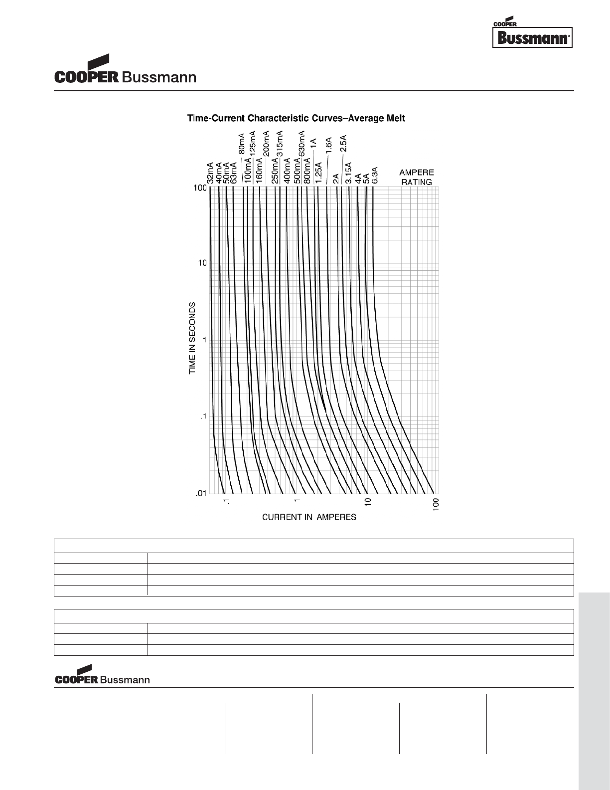
OC-61
Traditional Ferrule Fuses - Ferrule Type
TIME CURRENT CURVE
PACKAGING CODE
Packaging Code Description
BK 100 pieces of fuses packed into a cardboard carton
BK1 1,000 pieces of fuses packed into a poly bag
TR2 1,500 pieces of fuses packed into tape on a reel (19.05mm lead wire length)
OPTION CODE
Option Code Description
VAxial leads - copper tinned wire with nickel plated brass overcaps
-R RoHS compliant version
5mm x 20mm Fuses
S500 Series, Fast Acting, Glass Tube
Visit us on the web at:
www.cooperbussmann.com
Cooper Electronic Technologies
1225 Broken Sound Parkway NW
Suite F
Boca Raton, FL 33487-3533
Tel: 1-561-998-4100
Fax: 1-561-241-6640
Toll Free: 1-888-414-2645
Cooper Bussmann
P.O. Box 14460
St. Louis, MO 63178-4460
Tel: 1-636-394-2877
Fax: 1-800-544-2570
Cooper Electronic Technologies
Cooper (UK) Limited
Burton-on-the-Wolds
Leicestershire • LE12 5TH UK
Tel: +44 (0) 1509 882 737
Fax: +44 (0) 1509 882 786
Cooper Electronic Technologies
Avda. Santa Eulalia, 290
08223
Terrassa, (Barcelona), Spain
Tel: +34 937 362 812
+34 937 362 813
Fax: +34 937 362 719
Asia Pacific
Cooper Electronic Technologies
1 Jalan Kilang Timor
#06-01 Pacific Tech Centre
Singapore 159303
Tel: +65 278 6151
Fax: +65 270 4160
North America Europe
Courtesy of Steven Engineering, Inc.-230 Ryan Way, South San Francisco, CA 94080-6370-Main Office: (650) 588-9200-Outside Local Area: (800) 258-9200-www.stevenengineering.com
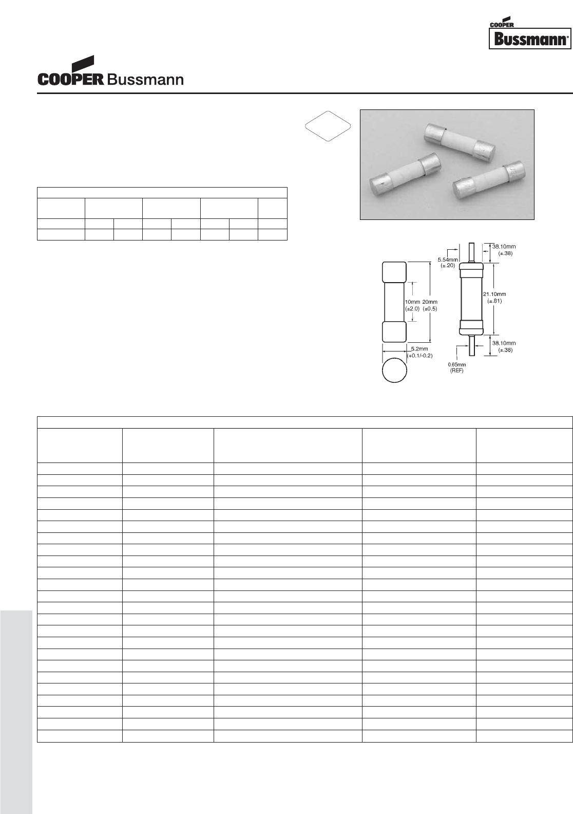
OC-62
Traditional Ferrule Fuses - Ferrule Type
Description
• Fast acting
• Optional axial leads available
• 5mm x 20mm physical size
• Ceramic tube, nickel brass endcap construction
• Designed to IEC 60127-2
Agency Information
• UL Recognized Card: (50mA-10A) Guide JDYX2,
File E19180
• CSA Component Acceptance: File 53787
• cURus Recognition: Guide JDYX8, File E19180
• SEMKO Approval 50mA, 160mA-10A
• VDE Approval 160mA-10A
• IMQ Approval 50mA-10A
• CCC Approval 160mA-10A
Ordering
• Specify packaging, product, and option code
• For -R option, drop mA or A from product code
(i.e. S501-2-R) • Ratings above 6.3A have a 0.8mm diameter lead
• With TR2 packaging code, lead wire length is 19.05mm
Dimensions
Drawing Not to Scale
SPECIFICATIONS
Voltage Interrupting Rating Typical Typical
Product Code Rating at Rated Voltage Melting I2t (A2Sec) Voltage
AC AC AC Drop (mV)‡
S501-50mA 250V 1500A 0.0017 9000
S501-63mA 250V 1500A 0.0005 3300
S501-80mA 250V 1500A 0.0011 2600
S501-100mA 250V 1500A 0.0018 2300
S501-125mA 250V 1500A 0.0037 1900
S501-160mA 250V 1500A 0.008 1600
S501-200mA 250V 1500A 0.020 1350
S501-250mA 250V 1500A 0.027 1300
S501-315mA 250V 1500A 0.010 1400
S501-400mA 250V 1500A 0.018 1200
S501-500mA 250V 1500A 0.038 1050
S501-630mA 250V 1500A 0.064 1200
S501-800mA 250V 1500A 0.097 490
S501-1A 250V 1500A 0.480 230
S501-1.25A 250V 1500A 0.9 200
S501-1.6A 250V 1500A 1.9 180
S501-2A 250V 1500A 2.0 205
S501-2.5A 250V 1500A 3.9 190
S501-3.15A 250V 1500A 8.1 160
S501-4A 250V 1500A 14 160
S501-5A 250V 1500A 25 155
S501-6.3A 250V 1500A 48 150
S501-8A 250V 1500A N/A N/A
S501-10A 250V 1500A N/A N/A
‡ Typical Voltage Drop (Voltage drop was measured at 20°C ambient temperature at rated current)
ELECTRICAL CHARACTERISTICS
1.5 In 2.1 In 2.75 In 4 In 10 In
In min max min max min max max
50mA-3.15A 60 min 30 min 10 ms 2 sec 3 ms 300 ms 20 ms
4A-10A 60 min 30 min 10 ms 3 sec 3 ms 300 ms 20 ms
5mm x 20mm Fuses
S501 Series, Fast Acting, Ceramic Tube
RoHS
2002/95/EC
Courtesy of Steven Engineering, Inc.-230 Ryan Way, South San Francisco, CA 94080-6370-Main Office: (650) 588-9200-Outside Local Area: (800) 258-9200-www.stevenengineering.com
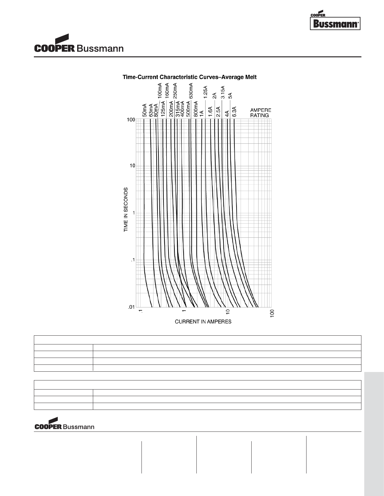
OC-63
Traditional Ferrule Fuses - Ferrule Type
TIME CURRENT CURVE
PACKAGING CODE
Packaging Code Description
BK 100 pieces of fuses packed into a cardboard carton
BK1 1,000 pieces of fuses packed into a poly bag
TR2 1,500 pieces of fuses packed into tape on a reel (19.05mm lead wire length)
OPTION CODE
Option Code Description
VAxial leads - copper tinned wire with nickel plated brass overcaps
-R RoHS compliant version
5mm x 20mm Fuses
S501 Series, Fast Acting, Ceramic Tube
Visit us on the web at:
www.cooperbussmann.com
Cooper Electronic Technologies
1225 Broken Sound Parkway NW
Suite F
Boca Raton, FL 33487-3533
Tel: 1-561-998-4100
Fax: 1-561-241-6640
Toll Free: 1-888-414-2645
Cooper Bussmann
P.O. Box 14460
St. Louis, MO 63178-4460
Tel: 1-636-394-2877
Fax: 1-800-544-2570
Cooper Electronic Technologies
Cooper (UK) Limited
Burton-on-the-Wolds
Leicestershire • LE12 5TH UK
Tel: +44 (0) 1509 882 737
Fax: +44 (0) 1509 882 786
Cooper Electronic Technologies
Avda. Santa Eulalia, 290
08223
Terrassa, (Barcelona), Spain
Tel: +34 937 362 812
+34 937 362 813
Fax: +34 937 362 719
Asia Pacific
Cooper Electronic Technologies
1 Jalan Kilang Timor
#06-01 Pacific Tech Centre
Singapore 159303
Tel: +65 278 6151
Fax: +65 270 4160
North America Europe
Courtesy of Steven Engineering, Inc.-230 Ryan Way, South San Francisco, CA 94080-6370-Main Office: (650) 588-9200-Outside Local Area: (800) 258-9200-www.stevenengineering.com
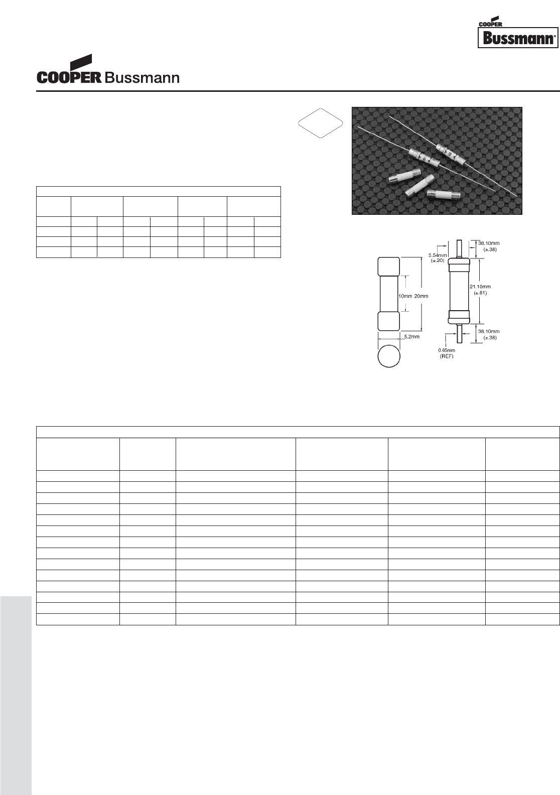
OC-64
Traditional Ferrule Fuses - Ferrule Type
Description
• Time delay, high breaking capacity
• Optional axial leads available
• 5mm x 20mm physical size
• Ceramic tube, nickel plated brass endcap construction
• Designed to IEC 60127-2 (1A-12A)
Agency Information
• UL Recognized Card: (500mA-12A) Guide JDYX2,
File E19180
• CSA Component Acceptance: File 53787, 500mA-10A
• SEMKO Approval, 500mA-10A
• VDE Approval, 500mA-10A
• BSI Approval, 500mA-10A
• IMQ Approval, 500mA-10A
• CCC Approval, 500mA-6.3A
Ordering
• Specify packaging, product, and option code
• For -R option, drop mA or A from product code
(i.e. S505-3-R)
• Ratings above 6.3A have a 0.8mm diameter lead
• With TR2 packaging code, lead wire length is 19.05mm
Dimensions
Drawing Not to Scale
SPECIFICATIONS
Voltage Interrupting Rating Typical DC Typical Typical
Product Code Rating at Rated Voltage (50Hz) Cold Resistance Melting I2t (A2Sec) Voltage
AC AC (ohms)* AC† Drop (mV)‡
S505-500mA 250V 1500A 0.507 - 295
S505-800mA 250V 1500A 0.237 - 189
S505-1A 250V 1500A 0.138 0.74 170
S505-1.25A 250V 1500A 0.089 1.6 150
S505-1.6A 250V 1500A 0.060 3.5 130
S505-2A 250V 1500A 0.041 7.6 110
S505-2.5A 250V 1500A 0.030 14 100
S505-3.15A 250V 1500A 0.021 27 90
S505-4A 250V 1500A 0.015 52 85
S505-5A 250V 1500A 0.011 98 80
S505-6.3A 250V 1500A 0.008 197 75
S505-8A 250V 1500A 0.007 311 75
S505-10A 250V 1500A 0.006 397 72
S505-12A 250V 1000A 0.005 714x77
* DC Cold Resistance (Measured at <10% of rated current)
† Typical Melting I2t (I2t was measured at listed interrupting rating and rated voltage)
‡ Typical Voltage Drop (Voltage drop was measured at 20°C ambient temperature at rated current)
x Typical Melting I2t was measured at 10 times the rated current under DC
ELECTRICAL CHARACTERISTICS
1.5 In 2.1 In 2.75 In 4 In 10 In
In min max min max min max min max
<1A 60 min 30 min 250 ms 80 sec 50 ms 5 sec 5 ms 55 ms
1A-3.15A 60 min 30 min 1 sec 80 sec 95 ms 5 sec 10 ms 100 ms
4A-10A 60 min 30 min 1 sec 80 sec 150 ms 5 sec 20 ms 100 ms
12.5A -- 30 min 1 sec 80 sec 150 ms 5 sec 20 ms 100 ms
5mm x 20mm Fuses
S505 Series, Time Delay, Ceramic Tube
RoHS
2002/95/EC
Courtesy of Steven Engineering, Inc.-230 Ryan Way, South San Francisco, CA 94080-6370-Main Office: (650) 588-9200-Outside Local Area: (800) 258-9200-www.stevenengineering.com
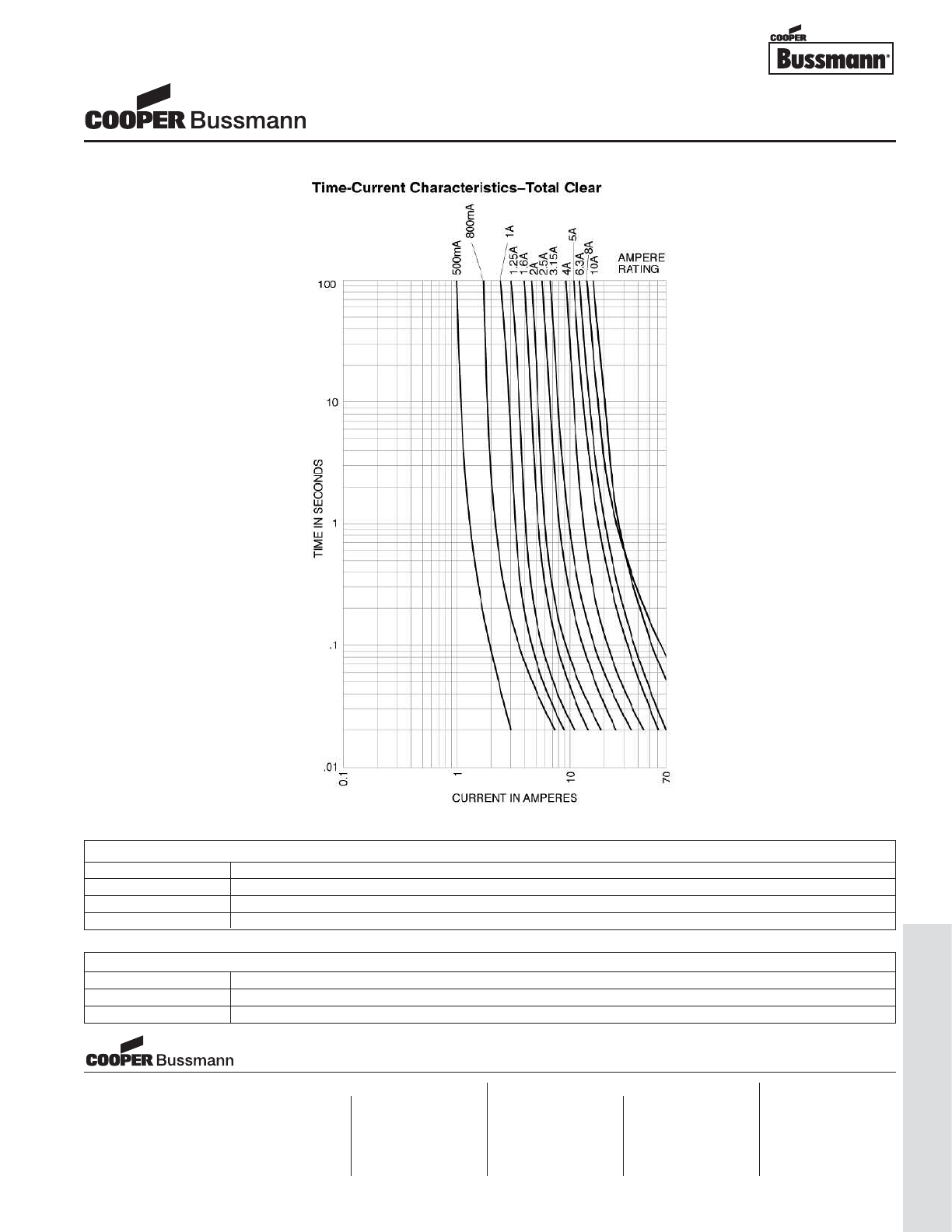
OC-65
Traditional Ferrule Fuses - Ferrule Type
TIME CURRENT CURVE
PACKAGING CODE
Packaging Code Description
BK 100 pieces of fuses packed into a cardboard carton
BK1 1,000 pieces of fuses packed into a poly bag
TR2 1,500 pieces of fuses packed into tape on a reel (19.05mm lead wire length)
OPTION CODE
Option Code Description
VAxial leads - copper tinned wire with nickel plated brass overcaps
-R RoHS compliant version
5mm x 20mm Fuses
S505 Series, Time Delay, Ceramic Tube
Visit us on the web at:
www.cooperbussmann.com
Cooper Electronic Technologies
1225 Broken Sound Parkway NW
Suite F
Boca Raton, FL 33487-3533
Tel: 1-561-998-4100
Fax: 1-561-241-6640
Toll Free: 1-888-414-2645
Cooper Bussmann
P.O. Box 14460
St. Louis, MO 63178-4460
Tel: 1-636-394-2877
Fax: 1-800-544-2570
Cooper Electronic Technologies
Cooper (UK) Limited
Burton-on-the-Wolds
Leicestershire • LE12 5TH UK
Tel: +44 (0) 1509 882 737
Fax: +44 (0) 1509 882 786
Cooper Electronic Technologies
Avda. Santa Eulalia, 290
08223
Terrassa, (Barcelona), Spain
Tel: +34 937 362 812
+34 937 362 813
Fax: +34 937 362 719
Asia Pacific
Cooper Electronic Technologies
1 Jalan Kilang Timor
#06-01 Pacific Tech Centre
Singapore 159303
Tel: +65 278 6151
Fax: +65 270 4160
North America Europe
Courtesy of Steven Engineering, Inc.-230 Ryan Way, South San Francisco, CA 94080-6370-Main Office: (650) 588-9200-Outside Local Area: (800) 258-9200-www.stevenengineering.com
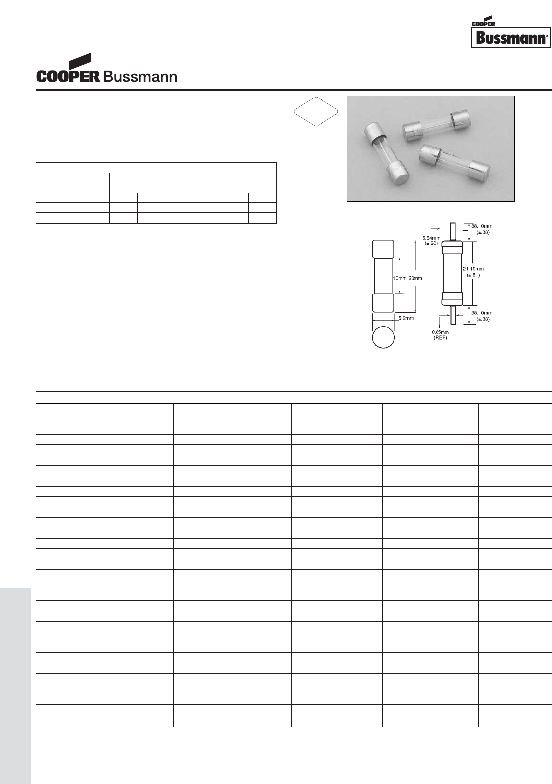
OC-66
Traditional Ferrule Fuses - Ferrule Type
Description
• Time delay, low breaking capacity
• Optional axial leads available
• 5mm x 20mm physical size
• Glass tube, nickel-plated brass endcap construction
• Designed to IEC 60127-2 (32mA-10A)
Agency Information
• UL Recognized Card: (32mA-15A) Guide JDYX2,
File E19180
• CSA Component Acceptance: File 53787
• cURus Recognition: Guide JDYX8, File E19180
• SEMKO Approval, 32mA-10A
• VDE Approval, 32mA-10A
• BSI Approval, 32mA-10A
• IMQ Approval, 32mA-10A
• MITI Approval, 32mA-6.3A
• CCC Approval, 32mA-6.3A
Ordering
• Specify packaging, product, and option code
• For -R option, drop mA or A from product code
(i.e. S506-2-R)
• Ratings above 6.3A have a 0.8mm diameter lead
• With TR2 packaging code, lead wire length is 19.05mm
Dimensions
Drawing Not to Scale
SPECIFICATIONS
Voltage Interrupting Rating Typical DC Minimum Typical
Product Code Rating at Rated Voltage (50Hz) Cold Resistance Pre-Arching I2t Voltage
AC AC (ohms)* (A2Sec) AC† Drop (mV)‡
S506-32mA 250V 35A 21.0 0.0014 1050
S506-40mA 250V 35A 13.90 0.0034 920
S506-50mA 250V 35A 9.24 0.006 800
S506-63mA 250V 35A 6.96 0.012 760
S506-80mA 250V 35A 4.42 0.015 580
S506-100mA 250V 35A 2.74 0.022 490
S506-125mA 250V 35A 1.97 0.034 390
S506-160mA 250V 35A 1.27 0.052 320
S506-200mA 250V 35A 1.00 0.078 340
S506-250mA 250V 35A 0.640 0.17 270
S506-315mA 250V 35A 0.450 0.41 250
S506-400mA 250V 35A 0.308 0.61 210
S506-500mA 250V 35A 0.183 0.67 140
S506-630mA 250V 35A 0.186 1.0 150
S506-800mA 250V 35A 0.128 2.2 75
S506-1A 250V 35A 0.062 2.7 80
S506-1.25A 250V 35A 0.045 6.7 70
S506-1.6A 250V 35A 0.038 9.7 70
S506-2A 250V 35A 0.028 15 68
S506-2.5A 250V 35A 0.023 25 68
S506-3.15A 250V 35A 0.017 51 66
S506-4A 250V 40A 0.012 88 66
S506-5A 250V 50A 0.008 150 66
S506-6.3A 250V 63A 0.008 214 60
S506-8A 250V 80A 0.006 192 55
S506-10A 250V 100A 0.004 420 54
S506-12.5A 250V 125A 0.004 812 45
S506-15A 250V 125A 0.004 1029 73
* DC Cold Resistance (Measured at <10% of rated current)
† Minimum Pre-Arching I2t (Measured at 10 In and rated voltage)
‡ Typical Voltage Drop (Voltage drop was measured at 20°C ambient temperature at rated current)
S506 ELECTRICAL CHARACTERISTICS
2.1 In 2.75 In 4 In 10 In
In max min max min max min max
32mA-100mA 2 min 200 ms 10 sec 40 ms 3 sec 10 ms 300 ms
125mA-6.3A 2 min 600 ms 10 sec 150 ms 3 sec 20 ms 300 ms
8A-15A 2 min 600 ms 10 sec 150 ms 3 sec 20 ms 300 ms
5mm x 20mm Fuses
S506 Series, Time Delay, Glass Tube
RoHS
2002/95/EC
Courtesy of Steven Engineering, Inc.-230 Ryan Way, South San Francisco, CA 94080-6370-Main Office: (650) 588-9200-Outside Local Area: (800) 258-9200-www.stevenengineering.com
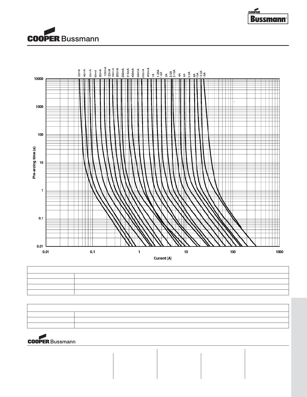
OC-67
Traditional Ferrule Fuses - Ferrule Type
TIME CURRENT CURVE
PACKAGING CODE
Packaging Code Description
BK 100 pieces of fuses packed into a cardboard carton
BK1 1,000 pieces of fuses packed into a poly bag
TR2 1,500 pieces of fuses packed into tape on a reel (19.05mm lead wire length)
5mm x 20mm Fuses
S506 Series, Time Delay, Glass Tube
OPTION CODE
Option Code Description
VAxial leads - copper tinned wire with nickel plated brass overcaps
-R RoHS compliant version
Visit us on the web at:
www.cooperbussmann.com
Cooper Electronic Technologies
1225 Broken Sound Parkway NW
Suite F
Boca Raton, FL 33487-3533
Tel: 1-561-998-4100
Fax: 1-561-241-6640
Toll Free: 1-888-414-2645
Cooper Bussmann
P.O. Box 14460
St. Louis, MO 63178-4460
Tel: 1-636-394-2877
Fax: 1-800-544-2570
Cooper Electronic Technologies
Cooper (UK) Limited
Burton-on-the-Wolds
Leicestershire • LE12 5TH UK
Tel: +44 (0) 1509 882 737
Fax: +44 (0) 1509 882 786
Cooper Electronic Technologies
Avda. Santa Eulalia, 290
08223
Terrassa, (Barcelona), Spain
Tel: +34 937 362 812
+34 937 362 813
Fax: +34 937 362 719
Asia Pacific
Cooper Electronic Technologies
1 Jalan Kilang Timor
#06-01 Pacific Tech Centre
Singapore 159303
Tel: +65 278 6151
Fax: +65 270 4160
North America Europe
Courtesy of Steven Engineering, Inc.-230 Ryan Way, South San Francisco, CA 94080-6370-Main Office: (650) 588-9200-Outside Local Area: (800) 258-9200-www.stevenengineering.com
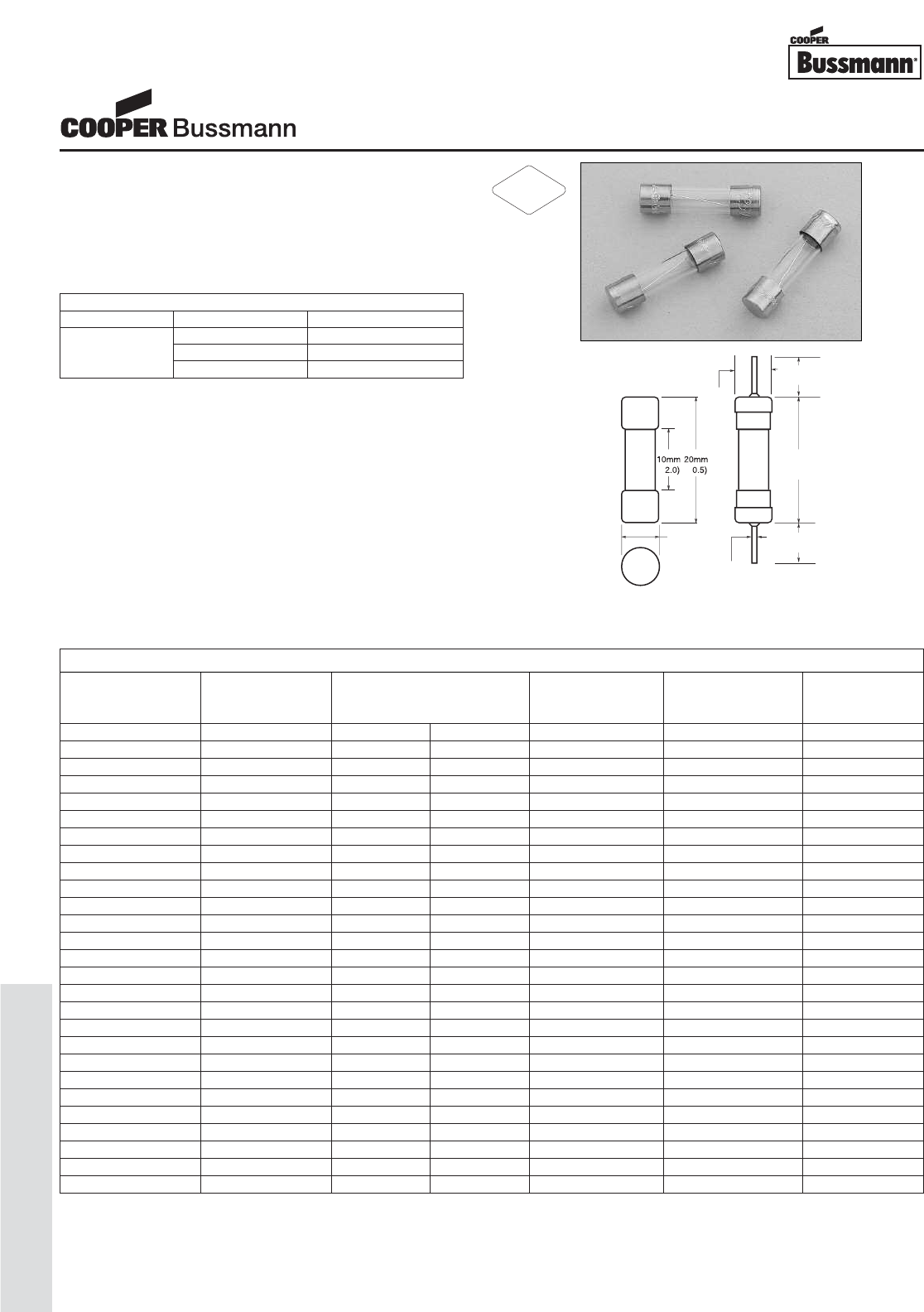
OC-68
Traditional Ferrule Fuses - Ferrule Type
Description
• Fast acting, low breaking capacity
• Optional axial leads available
• 5mm x 20mm physical size
• Glass tube, nickel-plated brass endcap construction
• Designed to UL/CSA 248-14
Agency Information
• UL Listed, Guide JDYX, File E19180, 63mA-6A
• UL Recognized Card: (7A-15A) Guide JDYX2,
File E19180
• CSA Certified, Class 1422-01, File E65063, 63mA-6A
• MITI Approval, 1A-15A
• CCC Approval, 63mA-6A
Ordering
• Specify packaging, product, and option code
• For -R option, drop mA or A from product code
(i.e. GMA-2-R) • Ratings above 6.3A have a 0.8mm diameter lead
• With TR2 packaging code, lead wire length is 19.05mm
(
±
5
.2m
m
(
+0.1/-0.2
)
38.10mm
10
(
±
±
.38)
.
3
5
.
5
4m
m
(
±
.20
)
21.10mm
0
0m
(
±
.81)
8
81
0
.
65
m
m
(
REF
)
(
±
38.10mm
0m
0m
(
±
3
8
)
.3
.3
Dimensions mm⁄(inches)
* Interrupting ratings: Interrupting ratings for 63mA - 6A were measured at 70% - 80% power factor on AC. The interrupting ratings for 7A - 15A were measured at 100% power factor on AC.
** DC Cold Resistance (Measured at <10% of rated current)
† Typical Pre-Arching I2t (I2t was measured at listed interrupting rating and rated voltage)
‡ Maximum Voltage drop (Voltage drop was measured at 20°C ambient temperature at rated current)
ELECTRICAL CHARACTERISTICS
Rated Current % of Amp Rating Opening Time
100% None
63mA - 10A 135% 60 minutes maximum
200% 2 minutes maximum
SPECIFICATIONS
Voltage AC Interrupting Typical DC Cold Typical Maximum
Product Code Rating Rating* Resistance Pre-Arc I2t Voltage
AC 250V 125V (ohms)** AC† Drop (mV)‡
GMA-63mA 250V 35A 10,000A - 0.00024 4700
GMA-100mA 250V 35A 10,000A - 0.0001 4300
GMA-125mA 250V 35A 10,000A - 0.0024 2600
GMA-200mA 250V 35A 10,000A - 0.001 3400
GMA-250mA 250V 35A 10,000A - 0.018 2200
GMA-300mA 250V 35A 10,000A - 0.019 470
GMA-315mA 250V 35A 10,000A - 0.019 450
GMA-500mA 250V 35A 10,000A 0.454 0.15 230
GMA-600mA 250V 35A 10,000A 0.256 0.32 200
GMA-750mA 250V 35A 10,000A 0.186 0.47 200
GMA-800mA 250V 35A 10,000A 0.170 0.70 180
GMA-1A 250V 35A 10,000A 0.163 0.48 300
GMA-1.25A 250V 100A 10,000A 0.122 0.84 290
GMA-1.5A 250V 100A 10,000A 0.090 1.6 270
GMA-1.6A 250V 100A 10,000A 0.080 2.0 260
GMA-2A 250V 100A 10,000A 0.066 3.1 250
GMA-2.5A 250V 100A 10,000A 0.046 4.9 240
GMA-3A 250V 100A 10,000A 0.039 8.8 215
GMA-3.15A 125V - 10,000A 0.036 9.7 210
GMA-3.5A 125V - 10,000A 0.030 13 210
GMA-4A 125V - 10,000A 0.026 19 205
GMA-5A 125V - 10,000A 0.021 29 200
GMA-6A 125V - 10,000A 0.017 45 180
GMA-7A 125V - 200A 0.012 150 110
GMA-8A 125V - 200A 0.009 280 110
GMA-10A 125V - 200A 0.006 280 110
GMA-15A 125V - 150A 0.004 950 100
5mm x 20mm Fuses
GMA Series, Fast Acting, Glass Tube
RoHS
2002/95/EC
Courtesy of Steven Engineering, Inc.-230 Ryan Way, South San Francisco, CA 94080-6370-Main Office: (650) 588-9200-Outside Local Area: (800) 258-9200-www.stevenengineering.com
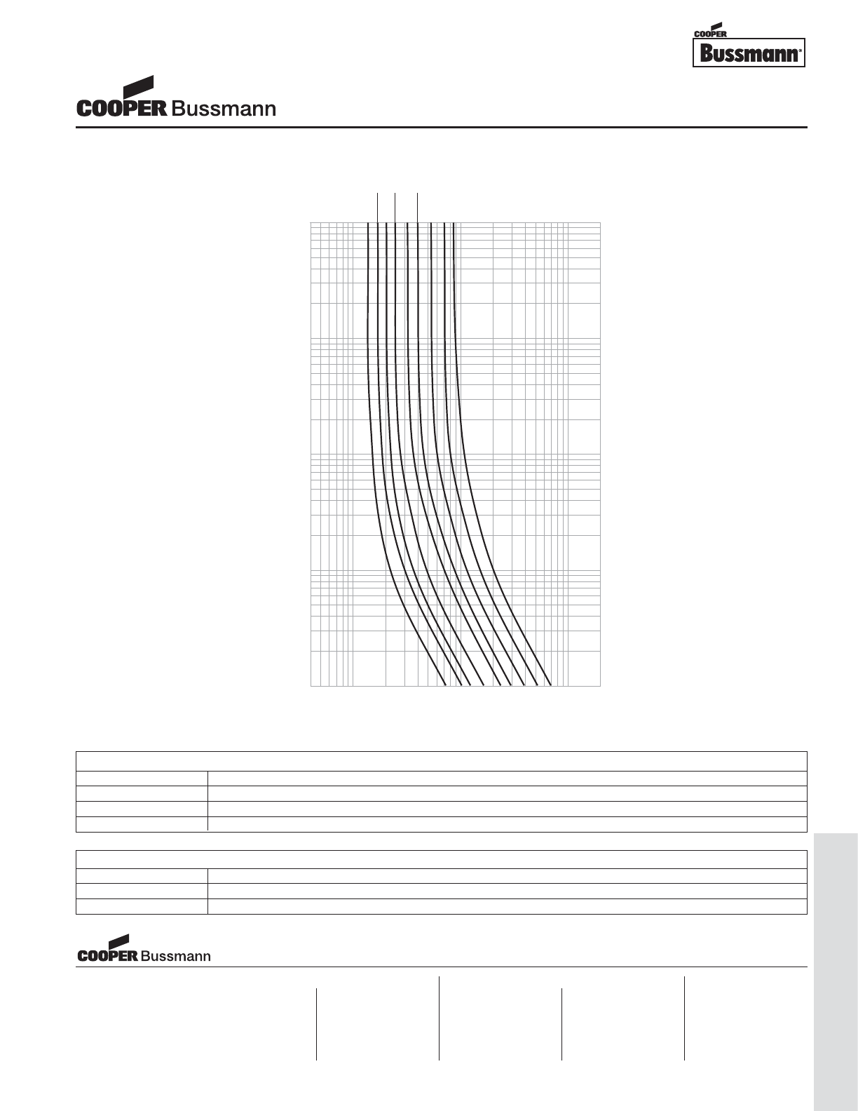
OC-69
Traditional Ferrule Fuses - Ferrule Type
.4
1
10
100
200
CURRENT IN AMPERES
100
10
1
.1
.01
TIME IN SECONDS
1A
AMPERE
RATING
1.25A
1.5A 2A
2.5A 3A
4A
5A
6A
TIME CURRENT CURVE
PACKAGING CODE
Packaging Code Description
BK 100 pieces of fuses packed into a cardboard carton
BK1 1,000 pieces of fuses packed into a poly bag
TR2 1,500 pieces of fuses packed into tape on a reel (19.05mm lead wire length)
OPTION CODE
Option Code Description
VAxial leads - copper tinned wire with nickel plated brass overcaps
-R RoHS compliant version
5mm x 20mm Fuses
GMA Series, Fast Acting, Glass Tube
Visit us on the web at:
www.cooperbussmann.com
Cooper Electronic Technologies
1225 Broken Sound Parkway NW
Suite F
Boca Raton, FL 33487-3533
Tel: 1-561-998-4100
Fax: 1-561-241-6640
Toll Free: 1-888-414-2645
Cooper Bussmann
P.O. Box 14460
St. Louis, MO 63178-4460
Tel: 1-636-394-2877
Fax: 1-800-544-2570
Cooper Electronic Technologies
Cooper (UK) Limited
Burton-on-the-Wolds
Leicestershire • LE12 5TH UK
Tel: +44 (0) 1509 882 737
Fax: +44 (0) 1509 882 786
Cooper Electronic Technologies
Avda. Santa Eulalia, 290
08223
Terrassa, (Barcelona), Spain
Tel: +34 937 362 812
+34 937 362 813
Fax: +34 937 362 719
Asia Pacific
Cooper Electronic Technologies
1 Jalan Kilang Timor
#06-01 Pacific Tech Centre
Singapore 159303
Tel: +65 278 6151
Fax: +65 270 4160
North America Europe
Courtesy of Steven Engineering, Inc.-230 Ryan Way, South San Francisco, CA 94080-6370-Main Office: (650) 588-9200-Outside Local Area: (800) 258-9200-www.stevenengineering.com
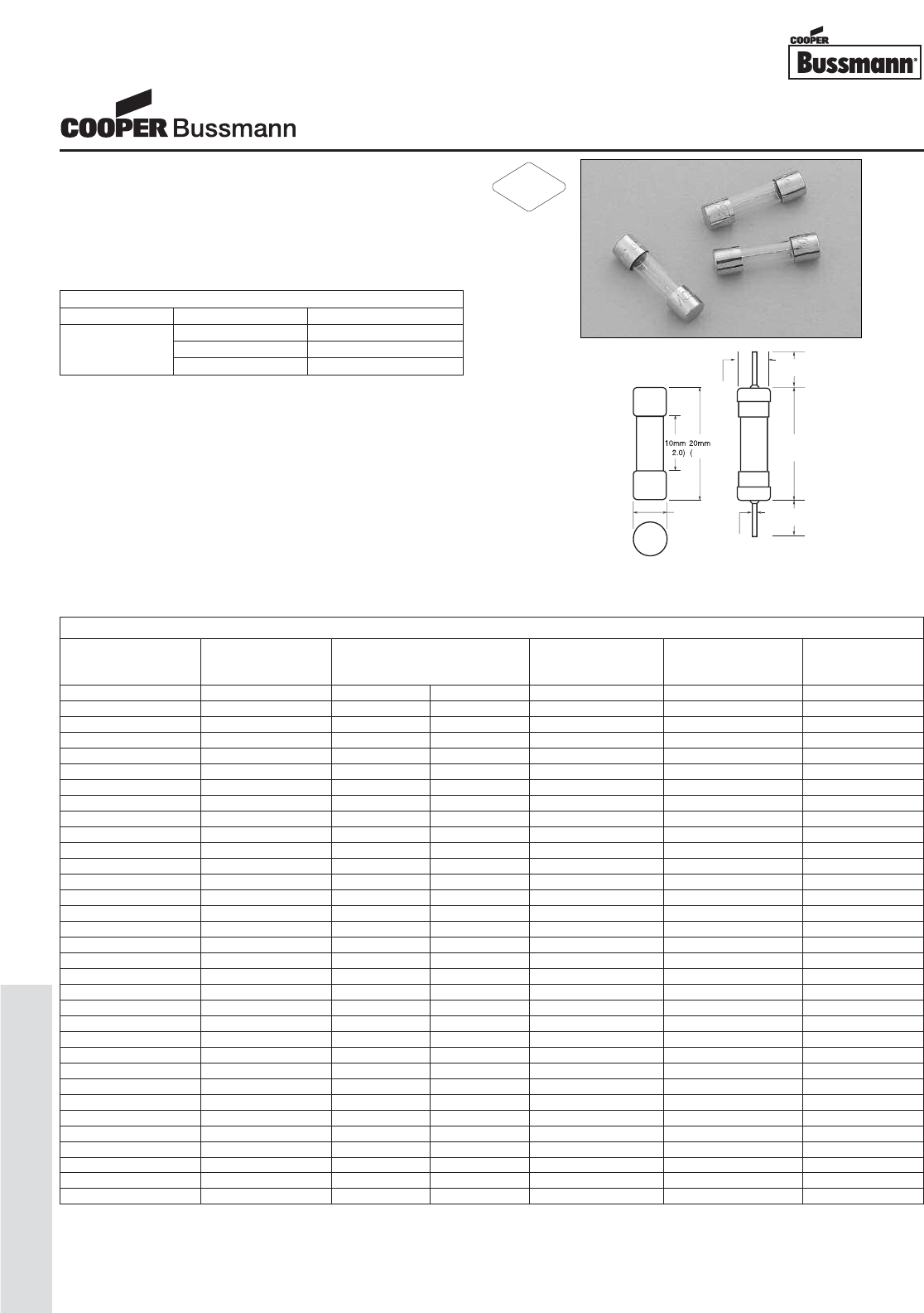
OC-70
Traditional Ferrule Fuses - Ferrule Type
Description
• Medium time delay, low breaking capacity
• Optional axial leads available
• 5mm x 20mm physical size
• Glass tube, nickel-plated brass endcap construction
• Designed to UL/CSA 248-14
Agency Information
• UL Listed, Guide JDYX, File E19180, 63mA-6.3A
• UL Recognized Card: (7A-10A) Guide JDYX2,
File E19180
• CSA Certified, Class 1422-01, File E65063, 63mA-6.3A
• MITI Approval, 1A-10A
• CCC Approval, 500mA-6.3A
Ordering
• Specify packaging, product, and option code
• For -R option, drop mA or A from product code
(i.e. GMC-2-R)
• Ratings above 6.3A have a 0.8mm diameter lead
• With TR2 packaging code, lead wire length is 19.05mm
±
5
)
0
0.
5
.
2
m
m
(
+0.1/-0.2
)
38.10mm
0m
(
±
±
.38)
.
3
5
.
5
4m
m
(
±
.20
)
21.10mm
0
0m
(
±
.81)
8
81
0
.
65
mm
(
REF
)
(
±
38.10mm
0m
0m
(
±
.38)
38
38
Dimensions mm⁄(inches)
* Interrupting ratings: Interrupting ratings for 63mA - 6.3A were measured at 70% - 80% power factor on AC. The interrupting ratings for 7A - 10A were measured at 100% power factor on AC.
** DC Cold Resistance (Measured at <10% of rated current)
† Typical Pre-Arching I
2
t (I
2
t was measured at listed interrupting rating and rated voltage)
‡ Maximum Voltage drop (Voltage drop was measured at 20°C ambient temperature at rated current)
ELECTRICAL CHARACTERISTICS
Rated Current % of Amp Rating Opening Time
100% None
63mA - 10A 135% 60 minutes maximum
200% 2 minutes maximum
SPECIFICATIONS
Voltage AC Interrupting Typical DC Cold Typical Maximum
Product Code Rating Rating* Resistance Pre-Arc I2t Voltage
AC 250V 125V (ohms)** AC† Drop (mV)‡
GMC-63mA 250V 35A 10,000A 10.350 0.0027 1400
GMC-80mA 250V 35A 10,000A - 0.0050 1400
GMC-100mA 250V 35A 10,000A 4.775 0.0094 1200
GMC-125mA 250V 35A 10,000A 3.400 0.014 1000
GMC-150mA 250V 35A 10,000A 2.555 0.022 800
GMC-160mA 250V 35A 10,000A 2.295 0.022 730
GMC-200mA 250V 35A 10,000A 1.395 0.032 650
GMC-250mA 250V 35A 10,000A 0.965 0.046 490
GMC-300mA 250V 35A 10,000A 0.838 0.081 580
GMC-315mA 250V 35A 10,000A 0.685 0.081 480
GMC-400mA 250V 35A 10,000A 0.615 0.18 510
GMC-500mA 250V 35A 10,000A 0.335 0.41 370
GMC-600mA 250V 35A 10,000A 0.282 0.60 360
GMC-630mA 250V 35A 10,000A 0.246 0.66 360
GMC-700mA 250V 35A 10,000A 0.213 0.85 340
GMC-750mA 250V 35A 10,000A 0.213 0.85 320
GMC-800mA 250V 35A 10,000A 0.180 0.85 290
GMC-1A 250V 35A 10,000A 0.156 1.8 250
GMC-1.25A 250V 100A 10,000A 0.098 3.4 200
GMC-1.5A 250V 100A 10,000A 0.076 5.4 190
GMC-1.6A 250V 100A 10,000A 0.067 5.8 160
GMC-2A 250V 100A 10,000A 0.043 8.9 130
GMC-2.5A 250V 100A 10,000A 0.035 13 130
GMC-3A 250V 100A 10,000A 0.026 19 130
GMC-3.15A 250V 100A 10,000A 0.025 23 130
GMC-3.5A 125V - 10,000A 0.022 25 130
GMC-4A 125V - 10,000A 0.019 36 120
GMC-5A 125V - 10,000A 0.014 58 120
GMC-6A 125V - 10,000A 0.013 88 120
GMC-6.3A 125V - 10,000A 0.012 110 120
GMC-7A 125V - 200A 0.012 150 120
GMC-8A 125V - 200A 0.009 200 110
GMC-10A 125V - 200A 0.007 300 110
5mm x 20mm Fuses
GMC Series Medium Time Delay, Glass Tube
RoHS
2002/95/EC
Courtesy of Steven Engineering, Inc.-230 Ryan Way, South San Francisco, CA 94080-6370-Main Office: (650) 588-9200-Outside Local Area: (800) 258-9200-www.stevenengineering.com
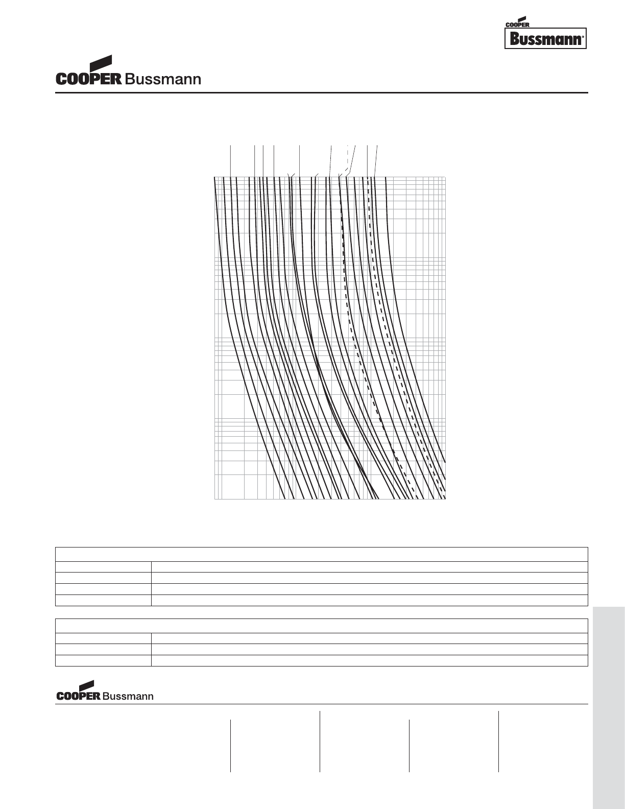
OC-71
Traditional Ferrule Fuses - Ferrule Type
.1
1
10
100
CURRENT IN AMPERES
100
10
1
.1
.01
TIME IN SECONDS
62mA
AMPERE
RATING
80mA 100mA
125mA
150mA 200mA
250mA 300mA
315mA 400mA
500mA
750mA
800mA 1A
1.5A
1.6A
2A 2.5A
3A
3.5A
4A
5A
6A 6.3A
7A 8A
10A
TIME CURRENT CURVE
PACKAGING CODE
Packaging Code Description
BK 100 pieces of fuses packed into a cardboard carton
BK1 1,000 pieces of fuses packed into a poly bag
TR2 1,500 pieces of fuses packed into tape on a reel (19.05mm lead wire length)
OPTION CODE
Option Code Description
VAxial leads - copper tinned wire with nickel plated brass overcaps
-R RoHS compliant version
5mm x 20mm Fuses
GMC Series Medium Time Delay, Glass Tube
Visit us on the web at:
www.cooperbussmann.com
Cooper Electronic Technologies
1225 Broken Sound Parkway NW
Suite F
Boca Raton, FL 33487-3533
Tel: 1-561-998-4100
Fax: 1-561-241-6640
Toll Free: 1-888-414-2645
Cooper Bussmann
P.O. Box 14460
St. Louis, MO 63178-4460
Tel: 1-636-394-2877
Fax: 1-800-544-2570
Cooper Electronic Technologies
Cooper (UK) Limited
Burton-on-the-Wolds
Leicestershire • LE12 5TH UK
Tel: +44 (0) 1509 882 737
Fax: +44 (0) 1509 882 786
Cooper Electronic Technologies
Avda. Santa Eulalia, 290
08223
Terrassa, (Barcelona), Spain
Tel: +34 937 362 812
+34 937 362 813
Fax: +34 937 362 719
Asia Pacific
Cooper Electronic Technologies
1 Jalan Kilang Timor
#06-01 Pacific Tech Centre
Singapore 159303
Tel: +65 278 6151
Fax: +65 270 4160
North America Europe
Courtesy of Steven Engineering, Inc.-230 Ryan Way, South San Francisco, CA 94080-6370-Main Office: (650) 588-9200-Outside Local Area: (800) 258-9200-www.stevenengineering.com
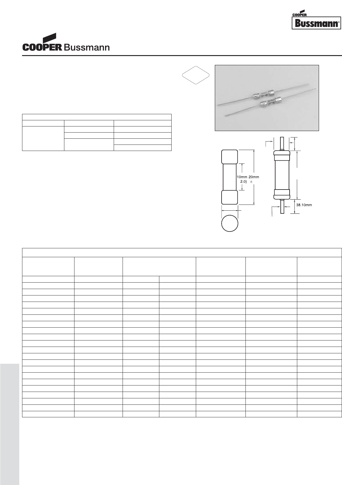
OC-72
Traditional Ferrule Fuses - Ferrule Type
Description
• Time delay, low breaking capacity
• Optional axial leads available
• 5mm x 20mm physical size
• Glass tube, nickel-plated brass endcap construction
• Designed to UL/CSA 248-14
Agency Information
• UL Listed, Guide JDYX, File E19180, 125mA-3A
• UL Recognition Card: (4A) Guide JDYX2, File E19180
• CSA Certified, Class 1422-01, File E65063
Ordering
• Specify packaging, product, and option code
• For -R option, drop mA or A from product code
(i.e. GMD-3-R)
• With TR2 packaging code, lead wire length is 19.05mm
(
5
)
0
0.
5
.2m
m
(
+0.1/-0.2
)
(
±
38
.1
0
mm
(
±
.38
)
21.10mm
(±.81)
0
.
65
m
m
(
REF
)
(
±
.38
)
5
.
5
4m
m
(
±
.20
)
Dimensions mm⁄(inches)
ELECTRICAL CHARACTERISTICS
Rated Current % of Amp Rating Opening Time
100% None
100mA - 4A 135% 60 minutes maximum
5 seconds minimum
200% 2 minutes maximum
* Interrupting ratings: Interrupting ratings for 125mA - 3A were measured at 70% - 80% power factor on AC. The interrupting ratings for 4A were measured at 100% power factor on AC.
** DC Cold Resistance (Measured at <10% of rated current)
† Typical Pre-Arching I2t (I2t was measured at listed interrupting rating and rated voltage)
‡ Maximum Voltage drop (Voltage drop was measured at 20°C ambient temperature at rated current)
SPECIFICATIONS
Voltage AC Interrupting Typical DC Cold Typical Maximum
Product Code Rating Rating* Resistance Pre-Arc I2t Voltage
AC 250V 125V (ohms)** AC† Drop (mV)‡
GMD-125mA 250V 35A 10,000A - 0.043 1600
GMD-150mA 250V 35A 10,000A - 0.046 1200
GMD-200mA 250V 35A 10,000A - 0.20 1100
GMD-250mA 250V 35A 10,000A - 0.40 950
GMD-300mA 250V 35A 10,000A - 0.65 800
GMD-315mA 250V 35A 10,000A - 0.89 750
GMD-375mA 250V 35A 10,000A - 0.89 650
GMD-400mA 250V 35A 10,000A - 1.2 600
GMD-500mA 250V 35A 10,000A - 1.4 550
GMD-600mA 250V 35A 10,000A - 3.1 450
GMD-630mA 250V 35A 10,000A - 3.1 450
GMD-750mA 250V 35A 10,000A - 4.7 410
GMD-800mA 250V 35A 10,000A - 6.6 380
GMD-1A 250V 35A 10,000A - 12 310
GMD-1.2A 250V 100A 10,000A - 16 280
GMD-1.25A 250V 100A 10,000A - 16 245
GMD-1.5A 250V 100A 10,000A - 25 240
GMD-1.6A 250V 100A 10,000A - 27 220
GMD-2A 250V 100A 10,000A - 42 200
GMD-2.5A 250V 100A 10,000A - 94 195
GMD-3A 250V 100A 10,000A - 145 190
GMD-4A 250V 200A 10,000A - 300 190
5mm x 20mm Fuses
GMD Series, Time Delay, Glass Tube
RoHS
2002/95/EC
Courtesy of Steven Engineering, Inc.-230 Ryan Way, South San Francisco, CA 94080-6370-Main Office: (650) 588-9200-Outside Local Area: (800) 258-9200-www.stevenengineering.com
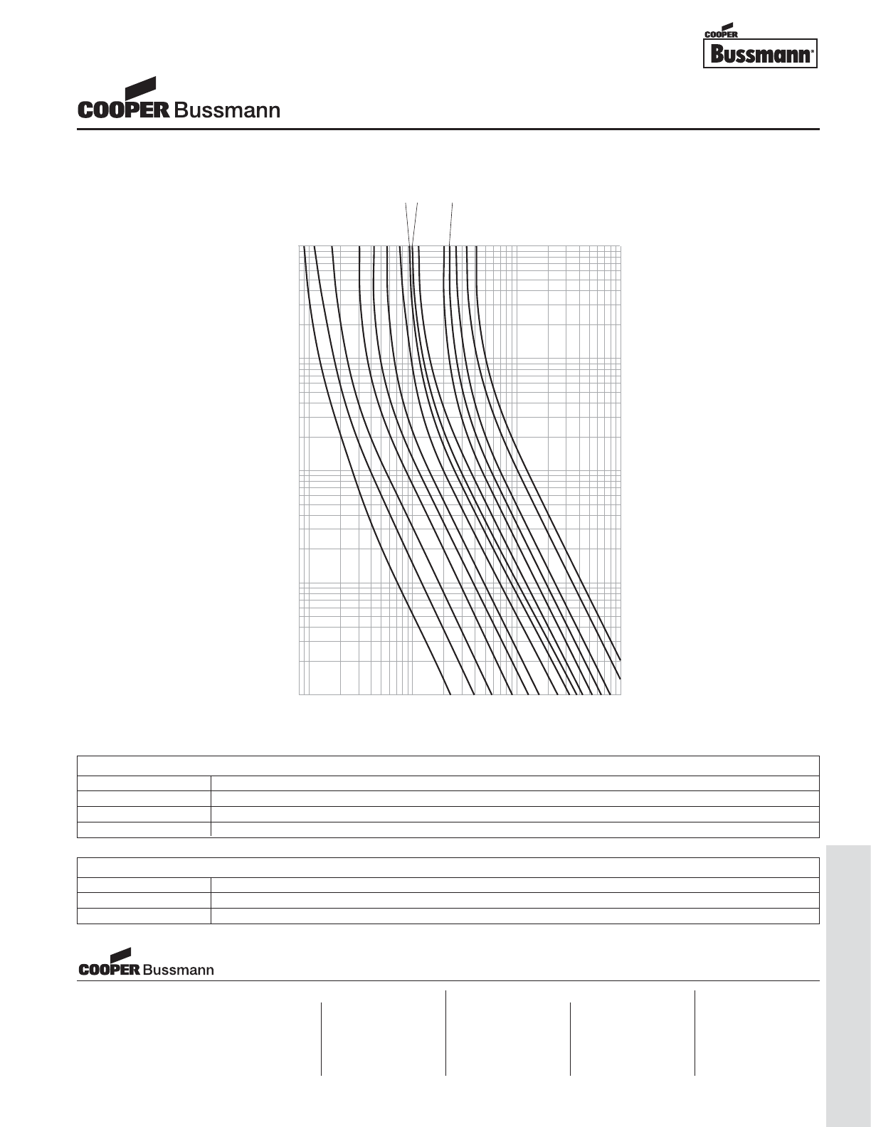
OC-73
Traditional Ferrule Fuses - Ferrule Type
.1
1
10
100
CURRENT IN AMPERES
100
10
1
.1
.01
TIME IN SECONDS
AMPERE
RATING
3A
2.5A
2A 1.6A
1.5A
1A 800mA
750mA
630mA
500mA
400mA
300mA
200mA
160mA
125mA
TIME CURRENT CURVE
PACKAGING CODE
Packaging Code Description
BK 100 pieces of fuses packed into a cardboard carton
BK1 1,000 pieces of fuses packed into a poly bag
TR2 1,500 pieces of fuses packed into tape on a reel (19.05mm lead wire length)
OPTION CODE
Option Code Description
VAxial leads - copper tinned wire with nickel plated brass overcaps
-R RoHS compliant version
5mm x 20mm Fuses
GMD Series, Time Delay, Glass Tube
Visit us on the web at:
www.cooperbussmann.com
Cooper Electronic Technologies
1225 Broken Sound Parkway NW
Suite F
Boca Raton, FL 33487-3533
Tel: 1-561-998-4100
Fax: 1-561-241-6640
Toll Free: 1-888-414-2645
Cooper Bussmann
P.O. Box 14460
St. Louis, MO 63178-4460
Tel: 1-636-394-2877
Fax: 1-800-544-2570
Cooper Electronic Technologies
Cooper (UK) Limited
Burton-on-the-Wolds
Leicestershire • LE12 5TH UK
Tel: +44 (0) 1509 882 737
Fax: +44 (0) 1509 882 786
Cooper Electronic Technologies
Avda. Santa Eulalia, 290
08223
Terrassa, (Barcelona), Spain
Tel: +34 937 362 812
+34 937 362 813
Fax: +34 937 362 719
Asia Pacific
Cooper Electronic Technologies
1 Jalan Kilang Timor
#06-01 Pacific Tech Centre
Singapore 159303
Tel: +65 278 6151
Fax: +65 270 4160
North America Europe
Courtesy of Steven Engineering, Inc.-230 Ryan Way, South San Francisco, CA 94080-6370-Main Office: (650) 588-9200-Outside Local Area: (800) 258-9200-www.stevenengineering.com
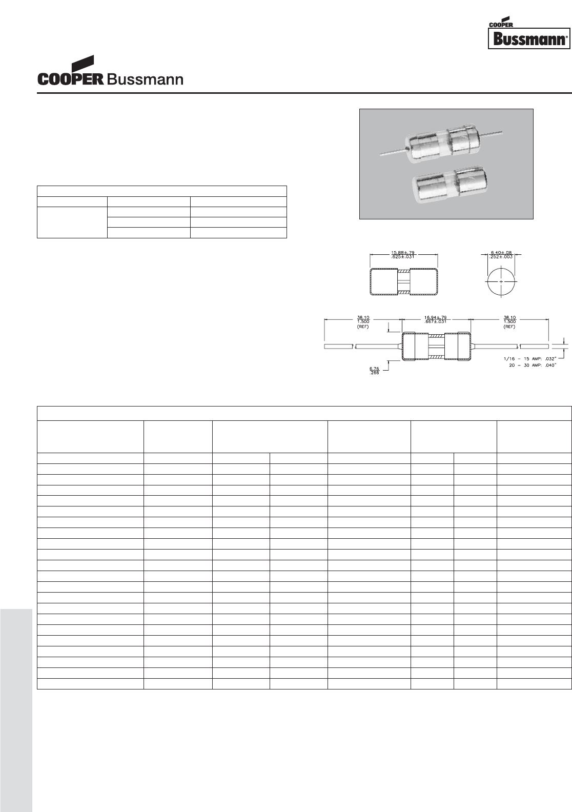
OC-74
Traditional Ferrule Fuses - Ferrule Type
Description
• Fast acting
• 1/4" x 5/8" (6.3mm x 15.9mm) physical size
• Glass tube, nickel-plated brass endcap construction
• Optional leaded version available
• UL Listed product meets standard 248-14
Agency Information
• UL Listed, Guide JDYX, File E19180 (AGA 0-1 1/2A)
• UL Listed, Guide JDYX, File E19180 (AGA-V 0-5A)
• UL Recognized, Guide JDYX2, File E19180
(AGA 2A-12A)
• UL Recognized, Guide JDYX2, File E19180
(AGA-V 6A-12A)
Ordering
• Specify packaging, product, and option code
Dimensions mm⁄(inches)
* Interrupting Rating: Interrupting ratings for 2A-5A has been measured at 70%-80% power factor. ratings for 5.1A-12A were measured at 80% power factor.
** DC Cold Resistance (Measured at <10% of rated current)
‡ Typical Voltage Drop (Measured at 25°C±3°C ambient temperature at rated current)
ELECTRICAL CHARACTERISTICS
Rated Current % of Amp Rating Opening Time
100% 4 hours minimum
1/16 - 10A 135% 60 minutes maximum
200% 120 seconds maximum
SPECIFICATIONS
Voltage AC Interrupting Typical DC Cold Typical Typical
Product Code Rating Rating* Resistance Melt Voltage
AC 125V 32V (ohms)** AC DC Drop (V)‡
AGA-1/16 125 V 10,000A - 13.250 TBD - TBD
AGA-1/10 125 V 10,000A - 6.250 TBD - TBD
AGA-1/8 125 V 10,000A - 4.000 TBD - TBD
AGA-1/4 125 V 10,000A - 1.740 TBD - TBD
AGA-3/8 125 V 10,000A - 0.925 TBD - TBD
AGA-1/2 125 V 10,000A - 0.300 TBD - TBD
AGA-6/10 125 V 10,000A - 0.250 TBD - TBD
AGA-3/4 125 V 10,000A - 0.179 TBD - TBD
AGA-1 125 V 10,000A - 0.118 TBD - TBD
AGA-1-1/2 125 V 10,000A - 0.077 TBD - TBD
AGA-2 125 V 200A - 0.054 TBD - TBD
AGA-2-1/2 125 V 200A - 0.040 TBD - TBD
AGA-3 125 V 200A - 0.031 TBD - TBD
AGA-5 125 V 200A - 0.017 TBD - TBD
AGA-6 32 V - 1,000A 0.014 TBD - TBD
AGA-7 32 V - 1,000A 0.012 TBD - TBD
AGA-7-1/2 32 V - 1,000A 0.010 TBD - TBD
AGA-10 32 V - 1,000A 0.007 TBD - TBD
AGA-15 32 V - 1,000A 0.005 TBD - TBD
AGA-20 32 V - 1,000A 0.003 TBD - TBD
AGA-25 32 V - 1,000A 0.003 TBD - TBD
AGA-30 32 V - 1,000A 0.002 TBD - TBD
1/4" x 5/8" Fuses
AGA Series, Fast Acting, Glass Tube
Courtesy of Steven Engineering, Inc.-230 Ryan Way, South San Francisco, CA 94080-6370-Main Office: (650) 588-9200-Outside Local Area: (800) 258-9200-www.stevenengineering.com
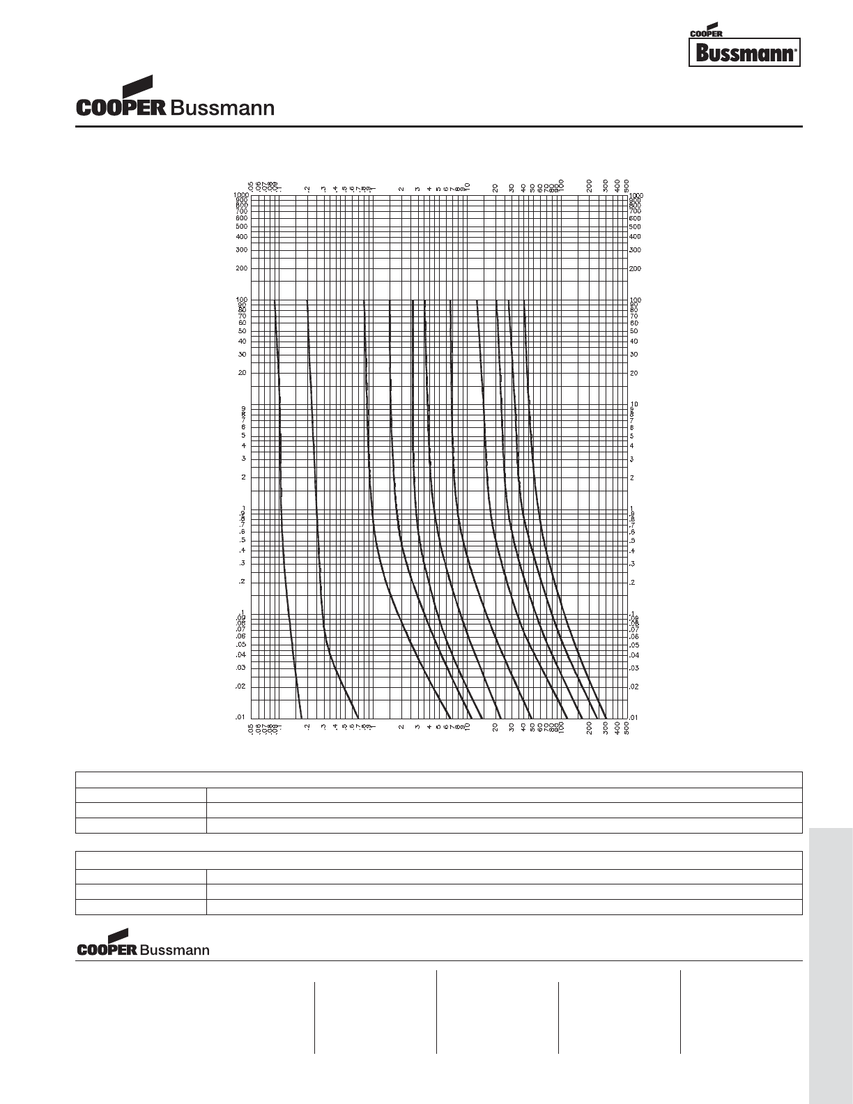
OC-75
Traditional Ferrule Fuses - Ferrule Type
PACKAGING CODE
Packaging Code Description
BK 100 pieces of fuses packed into a cardboard carton
BK8 8,000 pieces of fuses packed into a cardboard carton
TIME IN SECONDS
TIME IN SECONDS
CURRENT IN AMPERES
CURRENT IN AMPERES
1
6/10
15/100
1/16
2
3
5
10
15
20
30
TIME CURRENT CURVE
OPTION CODE
Option Code Description
BBoard Washable - Hermetically sealed to withstand aqueous cleaning
VAxial leads - copper tinned wire with nickel plated brass overcaps
1/4" x 5/8" Fuses
AGA Series, Fast Acting, Glass Tube
Visit us on the web at:
www.cooperbussmann.com
Cooper Electronic Technologies
1225 Broken Sound Parkway NW
Suite F
Boca Raton, FL 33487-3533
Tel: 1-561-998-4100
Fax: 1-561-241-6640
Toll Free: 1-888-414-2645
Cooper Bussmann
P.O. Box 14460
St. Louis, MO 63178-4460
Tel: 1-636-394-2877
Fax: 1-800-544-2570
Cooper Electronic Technologies
Cooper (UK) Limited
Burton-on-the-Wolds
Leicestershire • LE12 5TH UK
Tel: +44 (0) 1509 882 737
Fax: +44 (0) 1509 882 786
Cooper Electronic Technologies
Avda. Santa Eulalia, 290
08223
Terrassa, (Barcelona), Spain
Tel: +34 937 362 812
+34 937 362 813
Fax: +34 937 362 719
Asia Pacific
Cooper Electronic Technologies
1 Jalan Kilang Timor
#06-01 Pacific Tech Centre
Singapore 159303
Tel: +65 278 6151
Fax: +65 270 4160
North America Europe
Courtesy of Steven Engineering, Inc.-230 Ryan Way, South San Francisco, CA 94080-6370-Main Office: (650) 588-9200-Outside Local Area: (800) 258-9200-www.stevenengineering.com
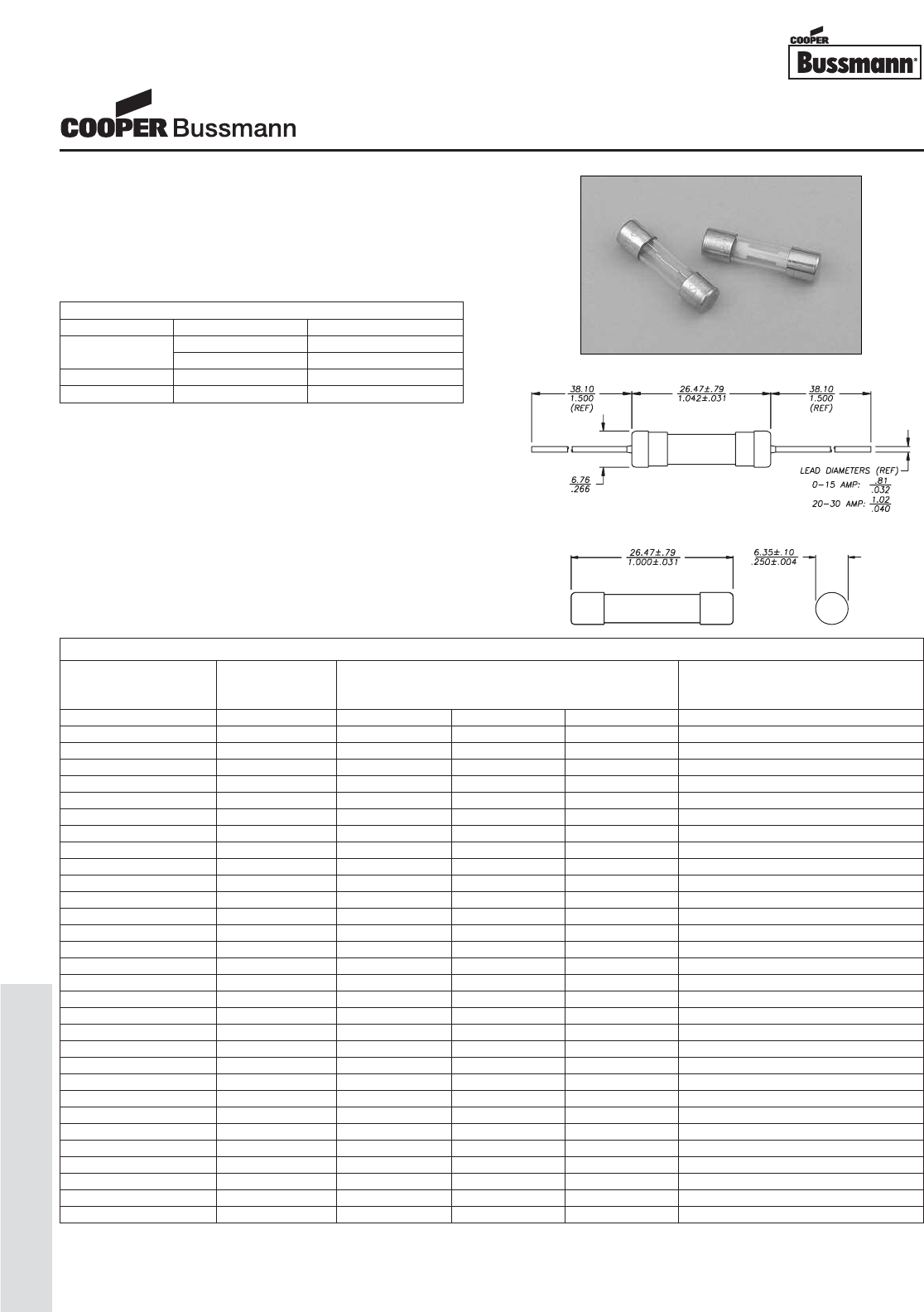
OC-76
Traditional Ferrule Fuses - Ferrule Type
Description
• Fast acting
• 1/4" x 1 (6.3mm x 25.4mm) physical size
• Glass tube, nickel-plated brass endcap construction
• For instruments, electronic and small appliance circuits
• UL Listed product meets standard 248-14
Agency Information
• UL Listed Card: AGX 0-5A (Guide JDYX, File E19180)
• UL Recognized Card: AGX 6-20A (Guide JDYX2,
File E19180)
• CSA Component Acceptance Card
(Class No. 1422-01, File 53787)
Ordering
• Specify packaging, product, and option code
Dimensions mm⁄(inches)
ELECTRICAL CHARACTERISTICS
Rated Current % of Amp Rating Opening Time
1/500 - 30A 110% 4 hours minimum
135% 60 minutes maximum
1/500 - 2A 200% 5 seconds maximum
2.5A - 30A 200% 2 minutes maximum
** DC Cold Resistance (Measured at <10% of rated current)
SPECIFICATIONS
Voltage Interrupting Typical DC Cold
Product Code Rating Rating Resistance
AC 250VAC 125VAC 32VAC (ohms)**
AGX-1/500 250V 35A 10,000A - 1750.00000
AGX-1/200 250V 35A 10,000A - 285.00000
AGX-1/100 250V 35A 10,000A - 155.00000
AGX-1/32 250V 35A 10,000A - 35.00000
AGX-1/16 250V 35A 10,000A - 22.50000
AGX-1/10 250V 35A 10,000A - 10.25000
AGX-1/8 250V 35A 10,000A - 5.41000
AGX-3/16 250V 35A 10,000A - 3.11500
AGX-2/10 250V 35A 10,000A - 2.66000
AGX-1/4 250V 35A 10,000A - 2.79000
AGX-3/10 250V 35A 10,000A - 1.42500
AGX-3/8 250V 35A 10,000A - 0.93050
AGX-4/10 250V 35A 10,000A - 0.89900
AGX-1/2 250V 35A 10,000A - 0.47850
AGX-3/4 250V 100A 10,000A - 0.26000
AGX-1 250V 100A 10,000A - 0.16250
AGX-1-1/4 250V 100A 10,000A - 0.12750
AGX-1-1/2 250V 100A 10,000A - 0.09400
AGX-2 250V 100A 10,000A - 0.06825
AGX-2-1/2 125V - 10,000A - 0.04930
AGX-3 125V - 10,000A - 0.03825
AGX-4 125V - 10,000A - 0.02700
AGX-5 125V - 10,000A - 0.02050
AGX-6 125V - 1,000A - 0.01475
AGX-7 125V - 1,000A - 0.01275
AGX-8 32V - - 1,000A 0.01100
AGX-10 32V - - 1,000A 0.00867
AGX-15 32V - - 1,000A 0.00510
AGX-20 32V - - 1,000A 0.00358
AGX-25 32V - - 1,000A 0.00275
AGX-30 32V - - 1,000A 0.00215
1/4" x 1" Fuses
AGX Series, Fast Acting, Glass Tube
Courtesy of Steven Engineering, Inc.-230 Ryan Way, South San Francisco, CA 94080-6370-Main Office: (650) 588-9200-Outside Local Area: (800) 258-9200-www.stevenengineering.com
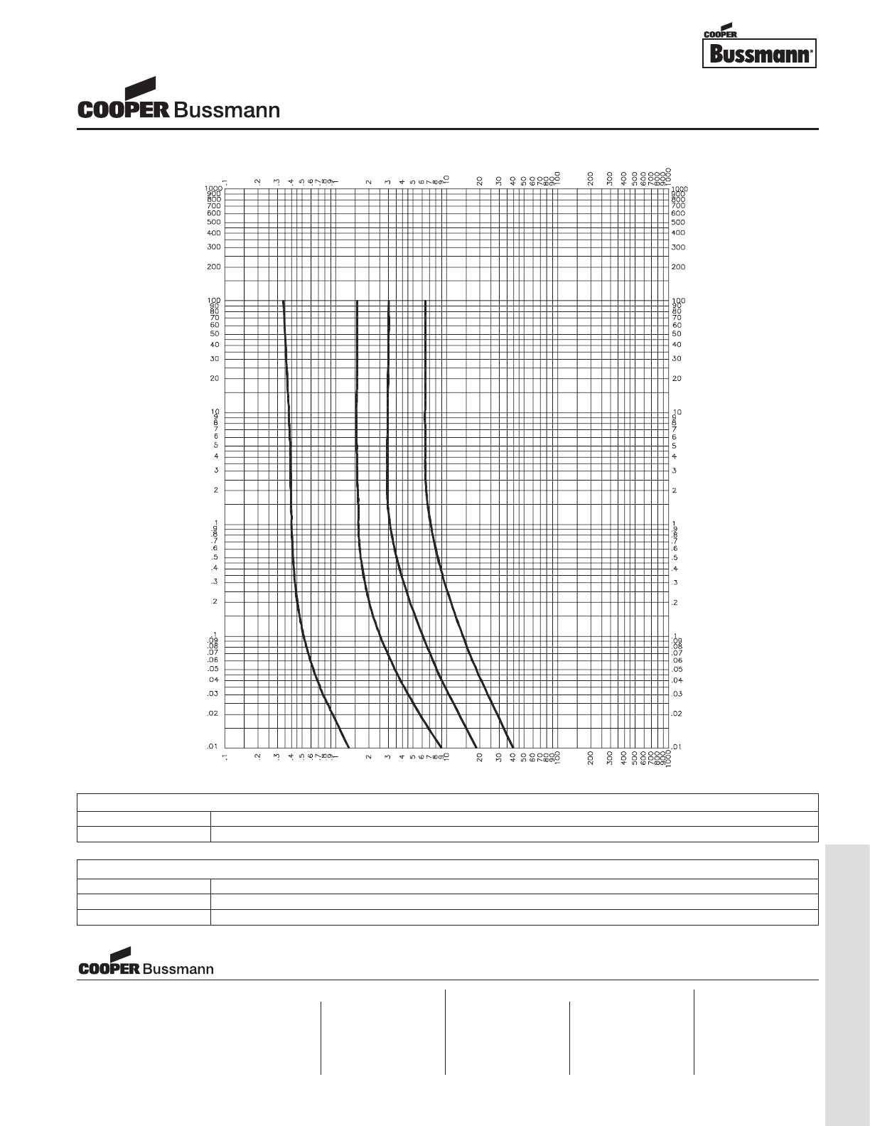
OC-77
Traditional Ferrule Fuses - Ferrule Type
TIME IN SECONDS
TIME IN SECONDS
CURRENT IN AMPERES
CURRENT IN AMPERES
1/4
1
2
5
TIME CURRENT CURVE
PACKAGING CODE
Packaging Code Description
BK 100 pieces of fuses packed into a cardboard carton
OPTION CODE
Option Code Description
BBoard Washable - Hermetically sealed to withstand aqueous cleaning
VAxial leads - copper tinned wire with nickel plated brass overcaps
1/4" x 1" Fuses
AGX Series, Fast Acting, Glass Tube
Visit us on the web at:
www.cooperbussmann.com
Cooper Electronic Technologies
1225 Broken Sound Parkway NW
Suite F
Boca Raton, FL 33487-3533
Tel: 1-561-998-4100
Fax: 1-561-241-6640
Toll Free: 1-888-414-2645
Cooper Bussmann
P.O. Box 14460
St. Louis, MO 63178-4460
Tel: 1-636-394-2877
Fax: 1-800-544-2570
Cooper Electronic Technologies
Cooper (UK) Limited
Burton-on-the-Wolds
Leicestershire • LE12 5TH UK
Tel: +44 (0) 1509 882 737
Fax: +44 (0) 1509 882 786
Cooper Electronic Technologies
Avda. Santa Eulalia, 290
08223
Terrassa, (Barcelona), Spain
Tel: +34 937 362 812
+34 937 362 813
Fax: +34 937 362 719
Asia Pacific
Cooper Electronic Technologies
1 Jalan Kilang Timor
#06-01 Pacific Tech Centre
Singapore 159303
Tel: +65 278 6151
Fax: +65 270 4160
North America Europe
Courtesy of Steven Engineering, Inc.-230 Ryan Way, South San Francisco, CA 94080-6370-Main Office: (650) 588-9200-Outside Local Area: (800) 258-9200-www.stevenengineering.com
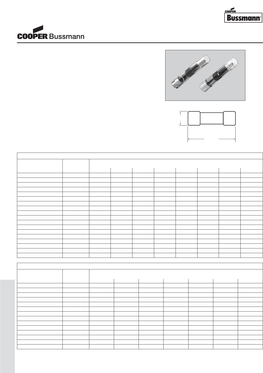
OC-78
Traditional Ferrule Fuses - Ferrule Type
Description
TDC10
• Fast Acting
• 1/4" x 1-1/4" physical size
• Glass tube, electroplated brass endcap construction
• Interrupting rating equals 10 times rated current
• Designed to British Standard BS2950A
TDC11
• Time Delay
• 1/4" x 1-1/4" physical size
• Glass tube, electroplated brass endcap construction
• Interrupting rating equals 10 times rated current
Ordering
• Specify packaging and product code
31.8mm
31.8mm
6.35mm
35m
Dimensions mm⁄(inches)
* Interrupting Rating: Interrupting rating is 10 times the rated current.
** DC Cold Resistance (Measured at <10% of rated current)
SPECIFICATIONS - TDC10
Voltage Interrupting
Product Code Rating Rating*
AC 1000V 750V 500V 350V 250V 150V 100V 32V
TDC10-50MA 1000V 500MA - - - - - - -
TDC10-60MA 1000V 600MA - - - - - - -
TDC10-100MA 1000V 1A - - - - - - -
TDC10-150MA 1000V 1.5A - - - - - - -
TDC10-250MA 1000V 2.5A - - - - - - -
TDC10-500MA 750V - 5A - - - - - -
TDC10-750MA 500V - - 7.5A - - - - -
TDC10-1A 350V - - - 10A - - - -
TDC10-1.5A 250V - - - - 15A - - -
TDC10-2A 250V - - - - 20A - - -
TDC10-3A 250V - - - - 30A - - -
TDC10-5A 250V - - - - 50A - - -
TDC10-7A 150V - - - - - 70A - -
TDC10-10A 100V - - - - - - 100A -
TDC10-12A 32V - - - - - - - 120A
TDC10-15A 32V - - - - - - - 150A
TDC10-20A 32V - - - - - - - 200A
TDC10-25A 32V - - - - - - - 250A
SPECIFICATIONS - TDC11
Voltage Interrupting
Product Code Rating Rating*
AC 1000V 750V 500V 350V 250V 150V 100V
TDC11-50MA 1000V 500MA - - - - - -
TDC11-60MA 1000V 600MA - - - - - -
TDC11-100MA 1000V 1A - - - - - -
TDC11-150MA 1000V 1.5A - - - - - -
TDC11-250MA 1000V 2.5A - - - - - -
TDC11-500MA 750V - 5A - - - - -
TDC11-750MA 500V - - 7.5A - - - -
TDC11-1A 350V - - - 10A - - -
TDC11-1.5A 250V - - - - 15A - -
TDC11-2A 250V - - - - 20A - -
TDC11-3A 250V - - - - 30A - -
TDC11-5A 250V - - - - 50A - -
TDC11-7A 150V - - - - - 70A -
TDC11-10A 100V - - - - - - 100A
1/4" x 1-1/4" Fuses
TDC Series, Glass Tube
Courtesy of Steven Engineering, Inc.-230 Ryan Way, South San Francisco, CA 94080-6370-Main Office: (650) 588-9200-Outside Local Area: (800) 258-9200-www.stevenengineering.com
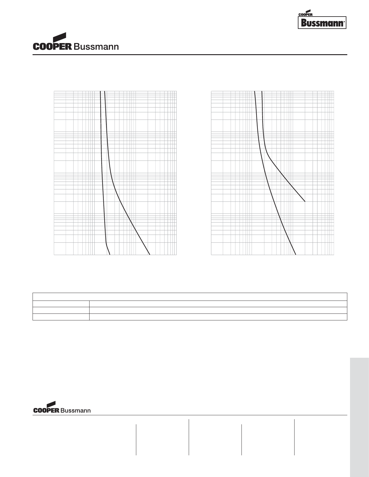
OC-79
Traditional Ferrule Fuses - Ferrule Type
TIME IN SECONDS
1
.1
.1
1
10
100
TIMES RATED CURRENT
.01
100
10
TIME IN SECONDS
1
.1
.1
1
10
100
TIMES RATED CURRENT
.01
100
10
TIME CURRENT CURVE
TDC11TDC10
PACKAGING CODE
Packaging Code Description
BK 100 pieces of fuses packed into a cardboard carton
BK1 1,000 pieces of fuses packed into a cardboard carton
1/4" x 1-1/4" Fuses
TDC Series, Glass Tube
Visit us on the web at:
www.cooperbussmann.com
Cooper Electronic Technologies
1225 Broken Sound Parkway NW
Suite F
Boca Raton, FL 33487-3533
Tel: 1-561-998-4100
Fax: 1-561-241-6640
Toll Free: 1-888-414-2645
Cooper Bussmann
P.O. Box 14460
St. Louis, MO 63178-4460
Tel: 1-636-394-2877
Fax: 1-800-544-2570
Cooper Electronic Technologies
Cooper (UK) Limited
Burton-on-the-Wolds
Leicestershire • LE12 5TH UK
Tel: +44 (0) 1509 882 737
Fax: +44 (0) 1509 882 786
Cooper Electronic Technologies
Avda. Santa Eulalia, 290
08223
Terrassa, (Barcelona), Spain
Tel: +34 937 362 812
+34 937 362 813
Fax: +34 937 362 719
Asia Pacific
Cooper Electronic Technologies
1 Jalan Kilang Timor
#06-01 Pacific Tech Centre
Singapore 159303
Tel: +65 278 6151
Fax: +65 270 4160
North America Europe
Courtesy of Steven Engineering, Inc.-230 Ryan Way, South San Francisco, CA 94080-6370-Main Office: (650) 588-9200-Outside Local Area: (800) 258-9200-www.stevenengineering.com
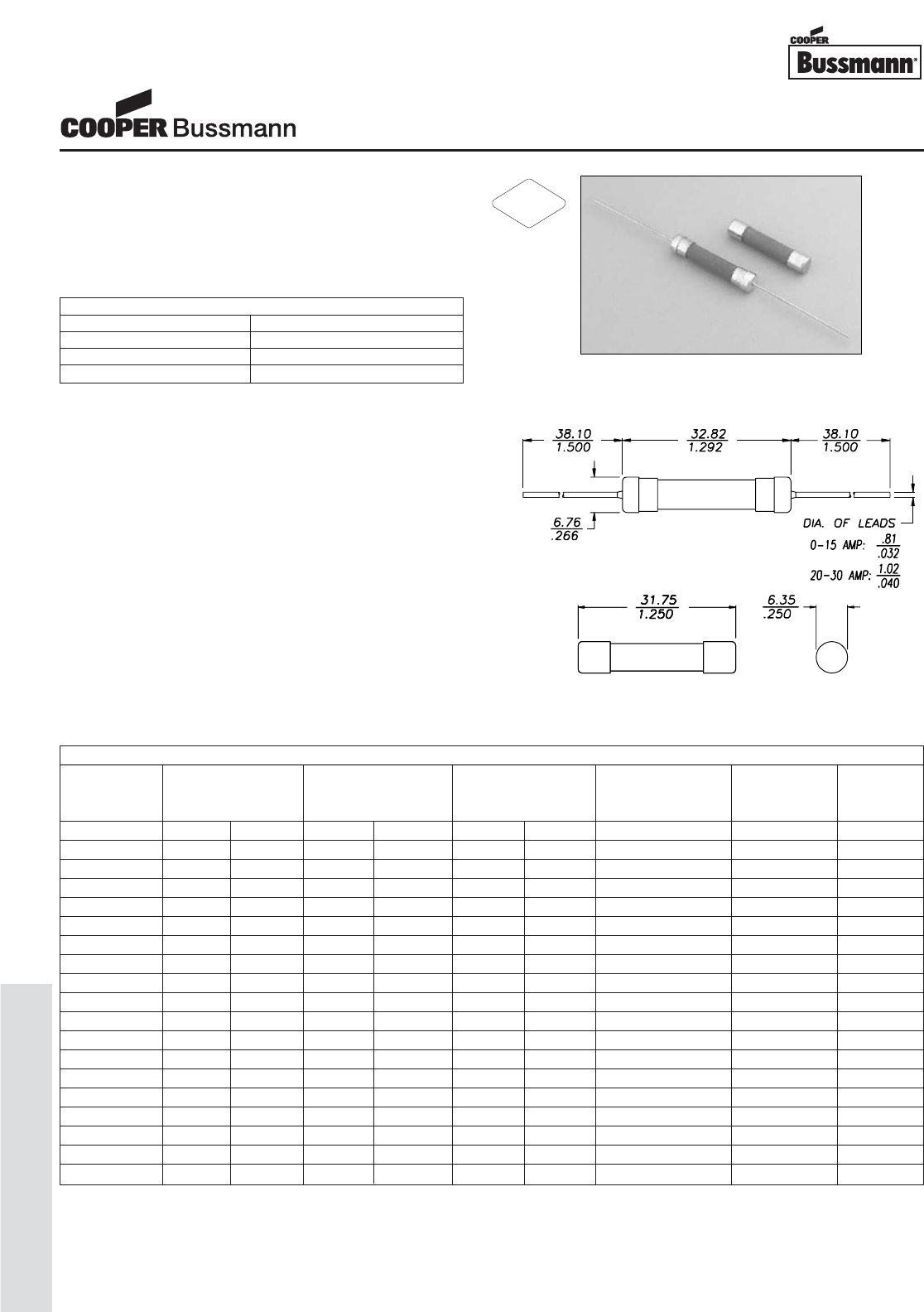
OC-80
Traditional Ferrule Fuses - Ferrule Type
Description
• Fast-acting, ceramic tube
• Optional axial leads available
• 1/4 x 1-1/4 (6.3mm x 32mm) physical size
• Ceramic tube, nickel-plated brass endcap construction
• UL Listed product meets standard 248-14
Agency Information
• UL Listed Guide & File numbers (ABC 1/4 - 15A):
JDYX & E19180.
• UL Recognition Guide & File numbers (ABC 18 - 30A):
JDYX2 & E19180.
• CSA Certification Record No: 053787 C 000 &
Class No: 1422 01 & 1422 30.
Environmental Data
• Shock: 1/4A and 1/2A – MIL-STD-202,
Method 213, Test Condition I;
1A thru 30A – MIL-STD-202, Method 207,
(HI Shock)
• Vibration: 1/4A thru 30A – MIL-STD-202,
Method 204, Test Condition C (Except 5g, 500HZ)
Ordering
• Specify packaging, product, and option code
Dimensions (mm⁄in)
Drawing Not to Scale
ELECTRICAL CHARACTERISTICS
% of Amp Rating Opening Time
100% 4 Hours Minimum
135% 60 Minutes maximum
200% 120 Seconds Maximum
SPECIFICATIONS
Product Voltage AC Interrupting DC Interrupting Typical DC Cold Typical Typical
Code Rating Rating Rating Resistance** Melting I2t† Voltage
AC DC 250V 125V 125V 75V (ohms) AC Drop‡
ABC-1/4 250V 125V 35A 10000A 10000A - 3.000 0.02 3.25
ABC-1/2 250V 125V 35A 10000A 10000A - 0.788 0.19 0.51
ABC-3/4 250V 125V 35A 10000A 10000A - 0.303 0.8 0.42
ABC-1 250V 125V 35A 10000A 10000A - 0.197 1.4 0.35
ABC-1-1/2 250V 125V 100A 10000A 10000A - 0.1175 2.9 0.35
ABC-2 250V 125V 100A 10000A 10000A - 0.0755 4.2 0.25
ABC-2-1/2 250V 125V 100A 10000A 10000A - 0.05875 8.53 0.26
ABC-3 250V 125V 100A 10000A 10000A - 0.0435 19.5 0.25
ABC-4 250V 125V 200A 10000A 10000A - 0.02975 29.1 0.25
ABC-5 250V 125V 200A 10000A 10000A - 0.0286 16.4 0.23
ABC-6 250V 125V 200A 10000A 10000A - 0.02315 31.6 0.24
ABC-7 250V 125V 200A 10000A 10000A - 0.0183 73.2 0.20
ABC-8 250V 125V 200A 10000A 10000A - 0.0146 111.9 0.17
ABC-10 250V 125V 200A 10000A 10000A - 0.01205 215.6 0.15
ABC-12 250V 125V 750A 10000A 10000A - 0.0068 129.6 0.11
ABC-15 250V 125V 750A 10000A 10000A - 0.005425 200.2 0.12
ABC-20 250V 125V 400A 1000A 10000A - 0.00366 550.8 0.13
ABC-25 125V 125V - 1000A 400A 1000A 0.00263 839.3 0.12
ABC-30 125V 125V - 1000A 400A 1000A 0.002225 1,429 0.14
** DC Cold Resistance (Measured at ≤10% of rated current)
† Typical Melting I2t (A2Sec) (I2t was measured at listed interrupting rating and rated voltage. Measured at 70% to 80% power factor on AC)
‡ Typical Voltage Drop (Voltage drop was measured at 25°C±3°C ambient temperature at rated current)
1/4" x 1-1/4" Fuses
ABC Series, Fast Acting, Ceramic Tube
RoHS
2002/95/EC
Courtesy of Steven Engineering, Inc.-230 Ryan Way, South San Francisco, CA 94080-6370-Main Office: (650) 588-9200-Outside Local Area: (800) 258-9200-www.stevenengineering.com
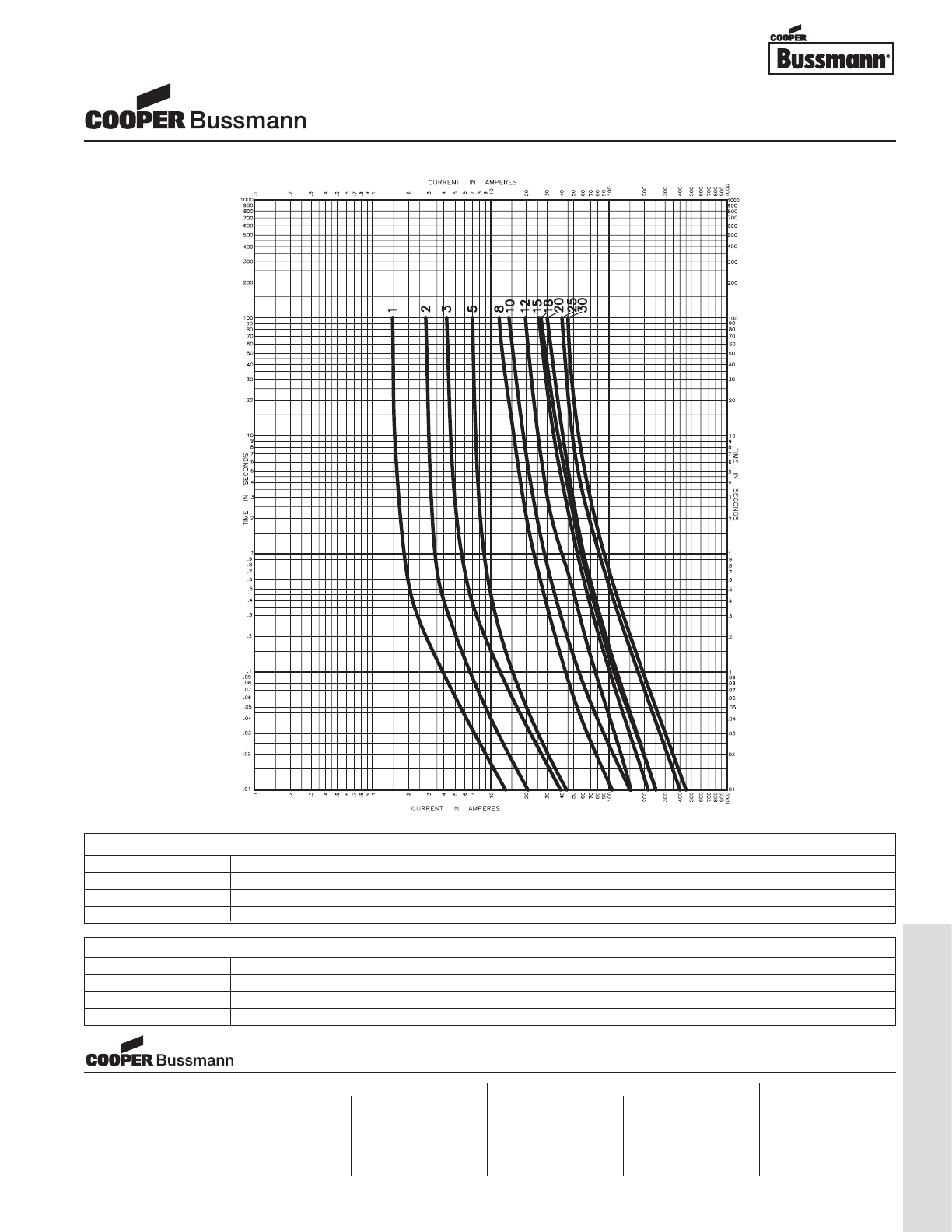
OC-81
Traditional Ferrule Fuses - Ferrule Type
TIME CURRENT CURVE
PACKAGING CODE
Packaging Code Description
BK 100 pieces of fuses packed into a cardboard carton
BK1 1,000 pieces of fuses packed into a cardboard carton
BK8 8,000 pieces of fuses packed into a cardboard carton
OPTION CODE
Option Code Description
BBoard Washable - Hermetically sealed to withstand aqueous cleaning
VAxial leads - copper tinned wire with nickel plated brass overcaps
-R RoHS compliant version
1/4" x 1-1/4" Fuses
ABC Series, Fast Acting, Ceramic Tube
Visit us on the web at:
www.cooperbussmann.com
Cooper Electronic Technologies
1225 Broken Sound Parkway NW
Suite F
Boca Raton, FL 33487-3533
Tel: 1-561-998-4100
Fax: 1-561-241-6640
Toll Free: 1-888-414-2645
Cooper Bussmann
P.O. Box 14460
St. Louis, MO 63178-4460
Tel: 1-636-394-2877
Fax: 1-800-544-2570
Cooper Electronic Technologies
Cooper (UK) Limited
Burton-on-the-Wolds
Leicestershire • LE12 5TH UK
Tel: +44 (0) 1509 882 737
Fax: +44 (0) 1509 882 786
Cooper Electronic Technologies
Avda. Santa Eulalia, 290
08223
Terrassa, (Barcelona), Spain
Tel: +34 937 362 812
+34 937 362 813
Fax: +34 937 362 719
Asia Pacific
Cooper Electronic Technologies
1 Jalan Kilang Timor
#06-01 Pacific Tech Centre
Singapore 159303
Tel: +65 278 6151
Fax: +65 270 4160
North America Europe
Courtesy of Steven Engineering, Inc.-230 Ryan Way, South San Francisco, CA 94080-6370-Main Office: (650) 588-9200-Outside Local Area: (800) 258-9200-www.stevenengineering.com
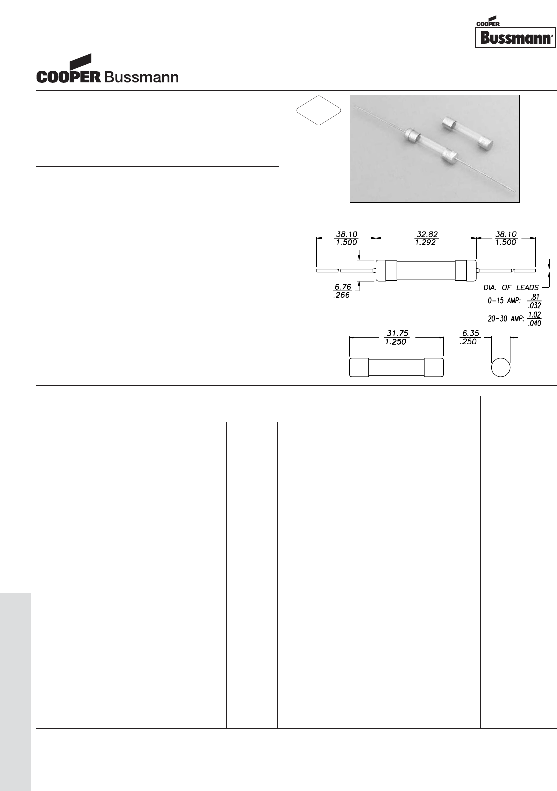
OC-82
Traditional Ferrule Fuses - Ferrule Type
Description
• Fast-acting, glass tube
• Optional axial leads available
• 1/4 x 1-1/4 (6.3mm x 32mm) physical size
• Glass tube, nickel-plated brass endcap construction
• UL Listed product meets standard 248-14
Agency Information
• UL Listed Card: AGC 1/500-10
• UL Recognition Card: AGC 11-45
• CSA Component Acceptance Card (Class No. 1422 30)
•
CSA Certification Card (Class No. 1422 01)
Environmental Data
• Shock: 1/100A thru 3/4A – MIL-STD-202,
Method 213, Test Condition I; 1A thru 30A –
MIL-STD-202, Method 207, (HI Shock)
• Vibration: 1/100A thru 30A – MIL-STD-202,
Method 204, Test Condition A (Except 5g, 500HZ)
Ordering
• Specify packaging, product, and option code
Dimensions (mm⁄in)
Drawing Not to Scale
ELECTRICAL CHARACTERISTICS
% of Amp Rating Opening Time
100% None
135% 60 Minutes Maximum
200% 120 Seconds Maximum
SPECIFICATIONS
Voltage AC Interrupting Typical DC Cold Typical Typical
Product Code Rating Rating Resistance** Melting I2t† Voltage
AC 250V 125V 32V (ohms) AC Drop‡
AGC-1/20 250V 35A 10000A - 4.500 0.00773 0.67
AGC-1/16 250V 35A 10000A - 29.000 0.000181 10.41
AGC-1/10 250V 35A 10000A - 12.565 0.000787 6.00
AGC-1/8 250V 35A 10000A - 6.800 0.00131 4.67
AGC-3/16 250V 35A 10000A - 4.900 0.00637 4.12
AGC-2/10 250V 35A 10000A - 3.360 0.00435 4.51
AGC-1/4 250V 35A 10000A - 2.300 0.0148 0.89
AGC-3/10 250V 35A 10000A - 1.670 0.0208 2.88
AGC-3/8 250V 35A 10000A - 1.203 0.0321 4.59
AGC-1/2 250V 35A 10000A - 0.615 0.269 0.59
AGC-3/4 250V 35A 10000A - 0.312 0.815 0.37
AGC-1 250V 35A 10000A - 0.190 1.615 0.31
AGC-1-1/4 250V 100A 10000A - 0.145 0.018 0.35
AGC-1-1/2 250V 100A 10000A - 0.115 0.0149 0.27
AGC-2 250V 100A 10000A - 0.078 0.00509 0.28
AGC-2-1/4 250V 100A 10000A - 0.067 0.00588 0.26
AGC-2-1/2 250V 100A 10000A - 0.057 0.00879 0.31
AGC-3 250V 100A 10000A - 0.045 0.0167 0.25
AGC-4 250V 200A 10000A - 0.030 0.0305 0.22
AGC-5 250V 200A 10000A - 0.024 0.045 0.23
AGC-6 250V 200A 10000A - 0.020 0.071 0.23
AGC-7 250V 200A 10000A - 0.017 0.105 0.23
AGC-7-1/2 250V 200A 10000A - 0.0146 - -
AGC-8 250V 200A 10000A - 0.014 0.152 0.19
AGC-9 250V 200A 10000A - 0.012 0.21 0.18
AGC-10 250V 200A 10000A - 0.008 0.492 0.20
AGC-12 32V - - 1000A 0.0070 - -
AGC-14 32V - - 1000A 0.0062 - -
AGC-15 32V - - 1000A 0.006 0.566 0.14
AGC-20 32V - - 1000A 0.004 1.438 0.12
AGC-25 32V - - 1000A 0.003 2.109 0.11
AGC-30 32V - - 1000A 0.002 3.807 0.12
AGC-35 32V - - 70A 0.0014 - -
AGC-40 32V - - 80A 0.0019 - -
** DC Cold Resistance (Measured at ≤10% of rated current)
† Typical Melting I2t (A2Sec) (I2t was measured at listed interrupting rating and rated voltage.)
‡ Typical Voltage Drop (Voltage drop was measured at 25°C ambient temperature at rated current)
1/4" x 1-1/4" Fuses
AGC Series, Fast Acting, Glass Tube
RoHS
2002/95/EC
Courtesy of Steven Engineering, Inc.-230 Ryan Way, South San Francisco, CA 94080-6370-Main Office: (650) 588-9200-Outside Local Area: (800) 258-9200-www.stevenengineering.com
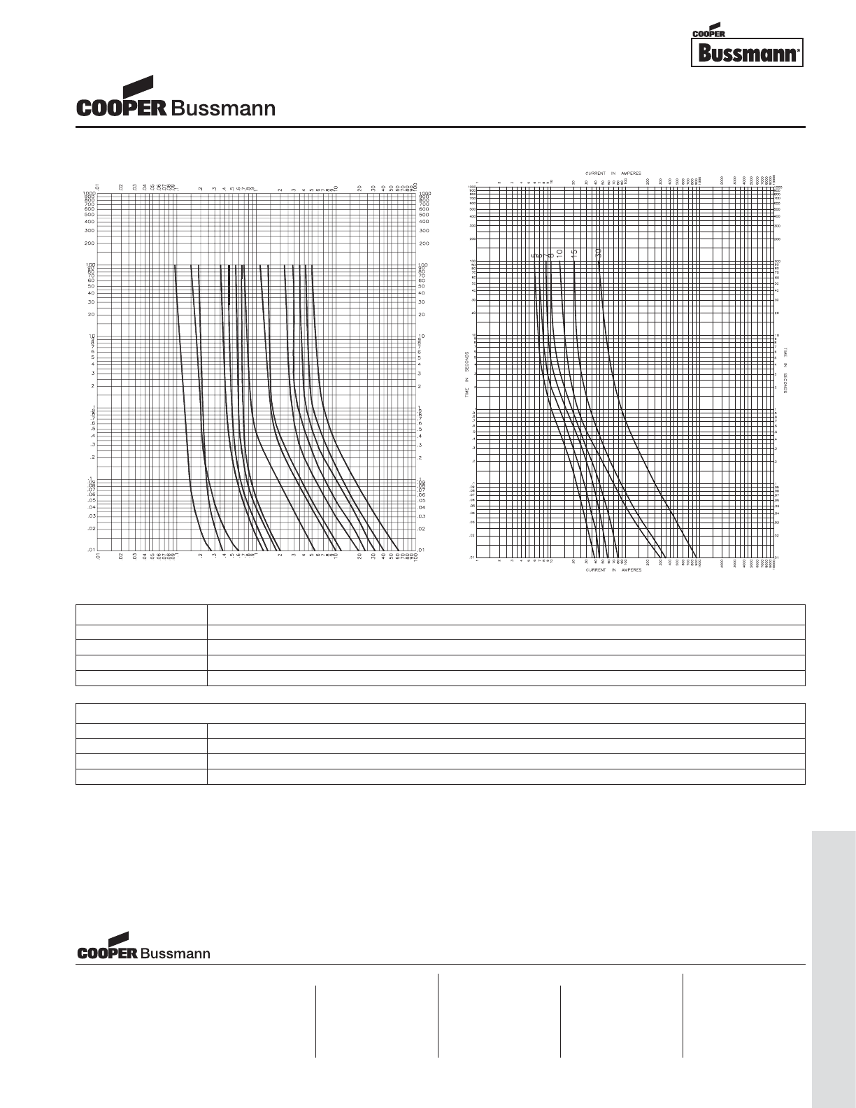
OC-83
Traditional Ferrule Fuses - Ferrule Type
CURRENT IN AMPERES
CURRENT IN AMPERES
TIME IN SECONDS
TIME IN SECONDS
1/10
1/16
3/4
1/2
1/8
2/10
1/4
3/10
3/8
1
1-1/2
2
2-1/2
3
4
TIME CURRENT CURVE
PACKAGING CODE
Packaging Code Description
BK 100 pieces of fuses packed into a cardboard carton with flaps folded
BK1 1,000 pieces of fuses packed into a cardboard carton with flaps folded
BK8 8,000 pieces of fuses packed into a cardboard carton with flaps folded
OPTION CODE
Option Code Description
BBoard Washable - Hermetically sealed to withstand aqueous cleaning
VAxial leads - copper tinned wire with nickel plated brass overcaps
-R RoHS compliant version
1/4" x 1-1/4" Fuses
AGC Series, Fast Acting, Glass Tube
Visit us on the web at:
www.cooperbussmann.com
Cooper Electronic Technologies
1225 Broken Sound Parkway NW
Suite F
Boca Raton, FL 33487-3533
Tel: 1-561-998-4100
Fax: 1-561-241-6640
Toll Free: 1-888-414-2645
Cooper Bussmann
P.O. Box 14460
St. Louis, MO 63178-4460
Tel: 1-636-394-2877
Fax: 1-800-544-2570
Cooper Electronic Technologies
Cooper (UK) Limited
Burton-on-the-Wolds
Leicestershire • LE12 5TH UK
Tel: +44 (0) 1509 882 737
Fax: +44 (0) 1509 882 786
Cooper Electronic Technologies
Avda. Santa Eulalia, 290
08223
Terrassa, (Barcelona), Spain
Tel: +34 937 362 812
+34 937 362 813
Fax: +34 937 362 719
Asia Pacific
Cooper Electronic Technologies
1 Jalan Kilang Timor
#06-01 Pacific Tech Centre
Singapore 159303
Tel: +65 278 6151
Fax: +65 270 4160
North America Europe
Courtesy of Steven Engineering, Inc.-230 Ryan Way, South San Francisco, CA 94080-6370-Main Office: (650) 588-9200-Outside Local Area: (800) 258-9200-www.stevenengineering.com
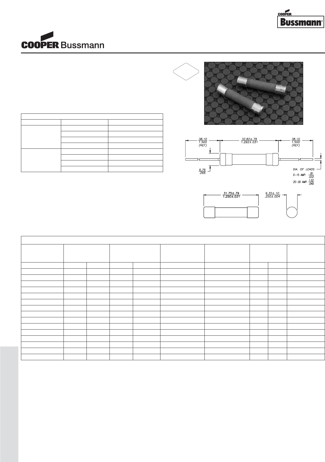
OC-84
Traditional Ferrule Fuses - Ferrule Type
Description
• Very fast-acting
• Optional axial leads available
• 1/4" x 1-1/4" (6.3mm x 32mm) physical size
• Ceramic tube, nickel-plated brass endcap construction
• 100pc-carton quantity weighs 1.0 lb (0.45 kg)
• UL recognized product meets standard 248-14
Agency Information
• UL Recognized Card: GBB 1-30A (JFHR2, E56412)
• CSA Component Certified Card
(Class 1422-01 File 53787)
Ordering
• Specify packaging, product, and option code
Dimensions mm⁄(inches)
ELECTRICAL CHARACTERISTICS
Rated Current % of Amp Rating Opening Time
100% None
1 - 20A 150% 2 minutes maximum
250% 1 seconds maximum
400% -
100% None
25, 30A 150% 2 minutes maximum
250% 6 seconds maximum
400% -
* Interrupting ratings: Interrupting ratings for 1-15A at 125Vdc was measured at 10,000A, 3.5 ms maximum, with time constant. Ratings 20-30A at 125Vdc were measured at 200A, 0.5 ms
maximum, with time constant. Ratings 1-15A at 125Vac were measured at 10,000A, and 70% - 80% power factor. The interrupting ratings for 1-30A at 250Vac were measured at 90% -
100% power factor.
** DC Cold Resistance (Measured at <10% of rated current)
† Typical Melting I2t (I2t was measured at listed interrupting rating and rated voltage) Interrupting ratings were measured at 70% to 80% power factor on AC.
‡ Typical Voltage drop (Voltage drop was measured at 25°C±3°C ambient temperature at rated current)
SPECIFICATIONS
Voltage AC Interrupting DC Interrupting Typical DC Cold Typical Typical
Product Code Rating Rating* Rating* Resistance Melt I2t † Voltage
AC DC 250V 125V 125V (ohms)** AC DC Drop (V)‡
GBB-1 250V 125V 200A 10,000A 10,000A 0.17750 - - 0.17750
GBB-1-1/4 250V 125V 200A 10,000A 10,000A 0.17900 - - 0.17900
GBB-2 250V 125V 200A 10,000A 10,000A 0.06620 - - 0.07000
GBB-3 250V 125V 200A 10,000A 10,000A 0.04475 - - 0.04475
GBB-4 250V 125V 200A 10,000A 10,000A 0.03175 - - 0.03175
GBB-5 250V 125V 200A 10,000A 10,000A 0.02125 - - 0.02125
GBB-6 250V 125V 200A 10,000A 10,000A 0.01800 - - 0.01800
GBB-7 250V 125V 200A 10,000A 10,000A 0.01550 - - 0.01550
GBB-8 250V 125V 200A 10,000A 10,000A 0.01360 - - 0.01360
GBB-9 250V 125V 200A 10,000A 10,000A 0.01070 - - 0.01070
GBB-10 250V 125V 200A 10,000A 10,000A 0.00934 - - 0.00934
GBB-12 250V 125V 200A 10,000A 10,000A 0.00620 - - 0.08620
GBB-15 250V 125V 200A 10,000A 10,000A 0.00472 - - 0.00472
GBB-20 250V 125V 200A 200A 200A 0.00330 - - 0.00365
GBB-25 250V 125V 200A 200A 200A 0.00252 - - 0.00252
GBB-30 250V 125V 200A 200A 200A 0.00206 - - 0.00206
1/4" x 1-1/4" Fuses
GBB Series Very Fast Acting, Ceramic Tube
RoHS
2002/95/EC
Courtesy of Steven Engineering, Inc.-230 Ryan Way, South San Francisco, CA 94080-6370-Main Office: (650) 588-9200-Outside Local Area: (800) 258-9200-www.stevenengineering.com
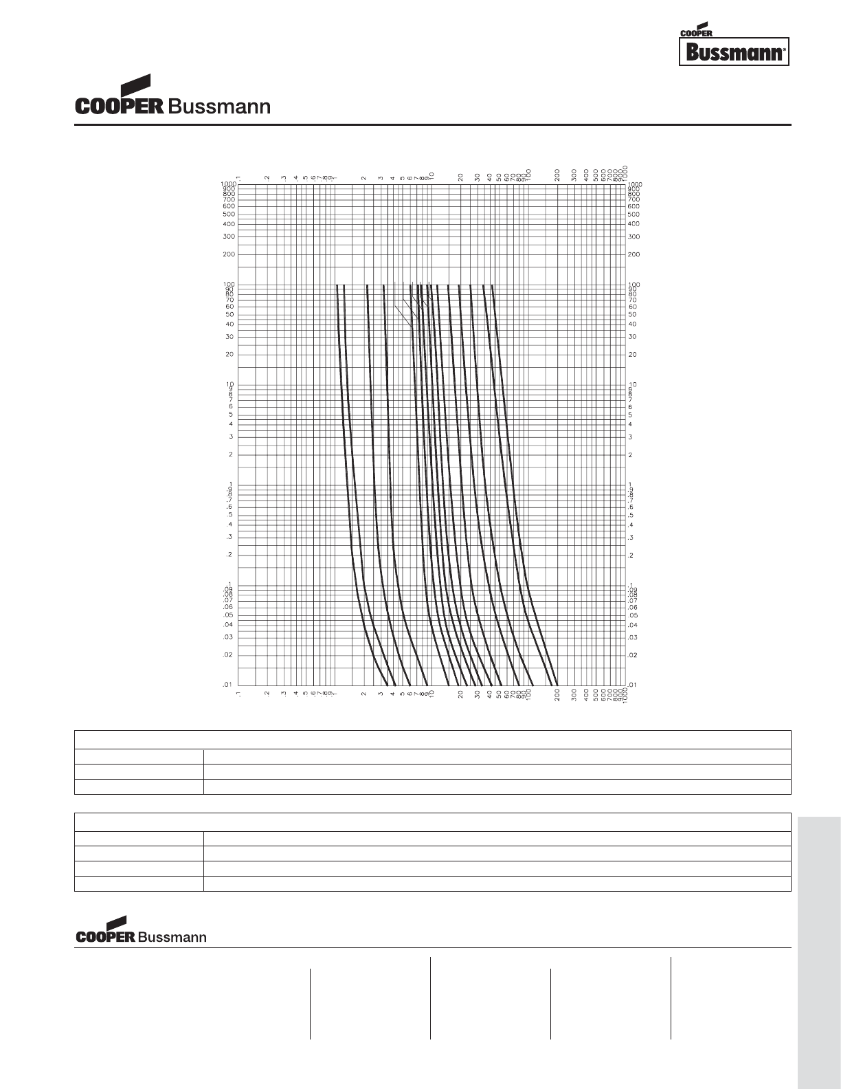
OC-85
Traditional Ferrule Fuses - Ferrule Type
TIME IN SECONDS
TIME IN SECONDS
CURRENT IN AMPERES
CURRENT IN AMPERES
1-1/4
1
2
25
9
6
3
5
7
8
15
10
12
20
30
TIME CURRENT CURVE
PACKAGING CODE
Packaging Code Description
BK 100 pieces of fuses packed into a cardboard carton
BK1 1,000 pieces of fuses packed into a cardboard carton
1/4" x 1-1/4" Fuses
GBB Series Very Fast Acting, Ceramic Tube
OPTION CODE
Option Code Description
BBoard Washable - Hermetically sealed to withstand aqueous cleaning
VAxial leads - copper tinned wire with nickel plated brass overcaps
-R RoHS compliant version
Visit us on the web at:
www.cooperbussmann.com
Cooper Electronic Technologies
1225 Broken Sound Parkway NW
Suite F
Boca Raton, FL 33487-3533
Tel: 1-561-998-4100
Fax: 1-561-241-6640
Toll Free: 1-888-414-2645
Cooper Bussmann
P.O. Box 14460
St. Louis, MO 63178-4460
Tel: 1-636-394-2877
Fax: 1-800-544-2570
Cooper Electronic Technologies
Cooper (UK) Limited
Burton-on-the-Wolds
Leicestershire • LE12 5TH UK
Tel: +44 (0) 1509 882 737
Fax: +44 (0) 1509 882 786
Cooper Electronic Technologies
Avda. Santa Eulalia, 290
08223
Terrassa, (Barcelona), Spain
Tel: +34 937 362 812
+34 937 362 813
Fax: +34 937 362 719
Asia Pacific
Cooper Electronic Technologies
1 Jalan Kilang Timor
#06-01 Pacific Tech Centre
Singapore 159303
Tel: +65 278 6151
Fax: +65 270 4160
North America Europe
Courtesy of Steven Engineering, Inc.-230 Ryan Way, South San Francisco, CA 94080-6370-Main Office: (650) 588-9200-Outside Local Area: (800) 258-9200-www.stevenengineering.com
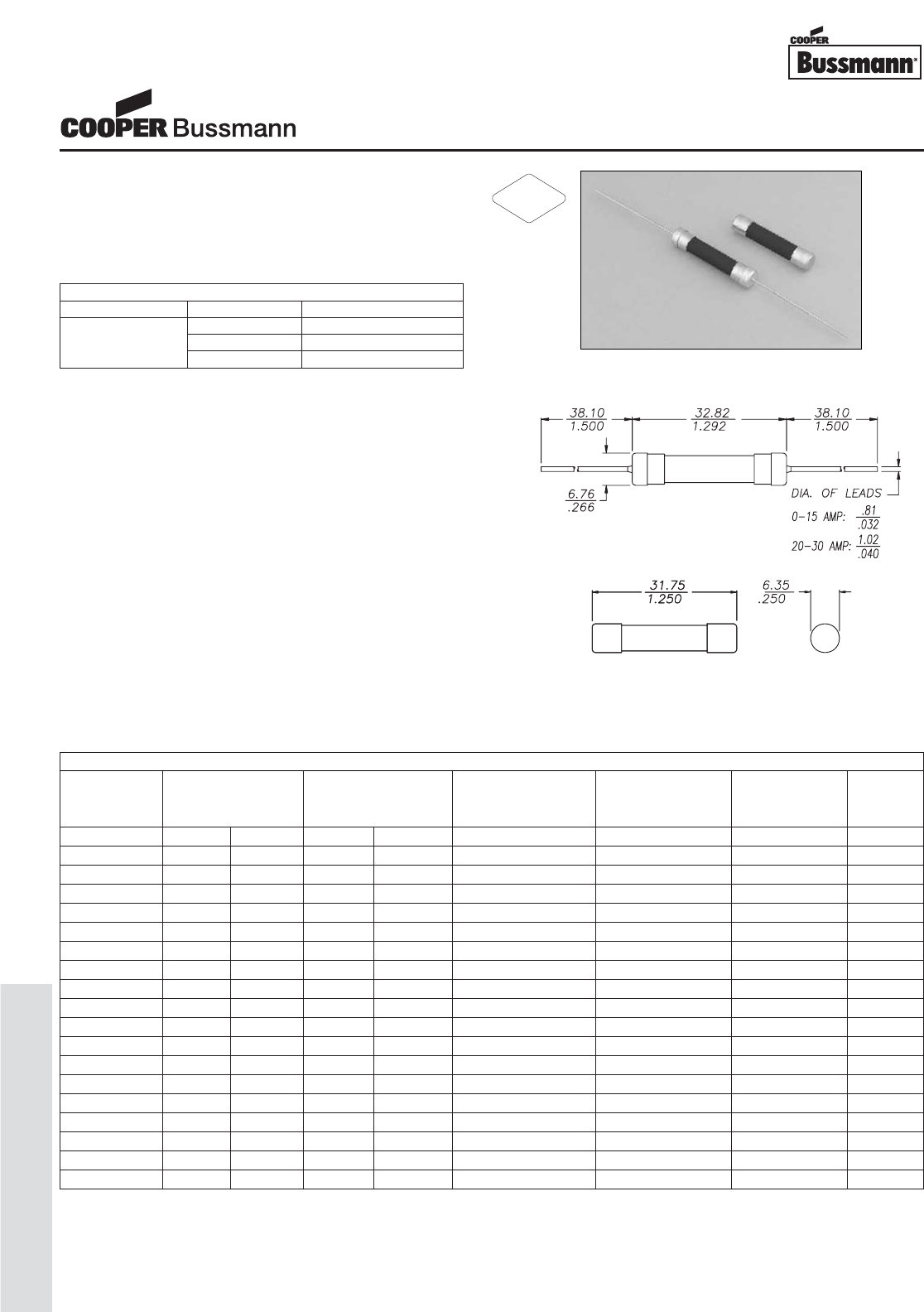
OC-86
Traditional Ferrule Fuses - Ferrule Type
Description
• Time Delay, ceramic tube
• Optional axial leads available
• 1/4 x 1-1/4 (6.3mm x 32mm) physical size
• Ceramic tube, nickel-plated brass endcap construction
• UL Listed product meets standard 248-14
Agency Information
• UL Listed Card: MDA 2/10 - 20A (Guide JDYX,
File E19180)
• UL Recognized Card: MDA 25 - 30A (Guide JDYX2,
File E19180)
• CSA Certification Card: MDA 2/10 - 20
(Class No. 1422-01)
• CSA Component Acceptance: MDA 25-30A
(Class No. 1422-30)
Environmental Data
• Shock: 1/100A and 8/10A – MIL-STD-202,
Method 213, Test Condition I;
1A thru 30A – MIL-STD-202, Method 207,
(HI Shock)
• Vibration: 1/100A and 8/10A – MIL-STD-202,
Method 201; 1/4A thru 30A – MIL-STD-202,
Method 204, Test Condition C (Except 5g, 500HZ)
Ordering
• Specify packaging, product, and option code
Dimensions (mm⁄in)
Drawing Not to Scale
SPECIFICATIONS
Product Voltage AC Interrupting DC Interrupting Typical DC Cold Typical Typical
Code Rating Rating* Rating Resistance** Melting I2t† Voltage
AC DC 250V 125V 125V (ohms) AC Drop‡
MDA-1/4 250V - 35A 10000A - 9.325 0.68 4.00
MDA-1/2 250V - 35A 10000A - 1.925 2.3 1.42
MDA-3/4 250V - 35A 10000A - 0.8555 7.8 1.31
MDA-1 250V - 35A 10000A - 0.560 11.1 1.03
MDA-1-1/2 250V - 100A 10000A - 0.2585 25.0 0.691
MDA-2 250V - 100A 10000A - 0.1645 64.0 0.623
MDA-2-1/2 250V - 200A 10000A - 0.06685 28.9 0.213
MDA-3 250V - 200A 10000A - 0.0507 40.9 0.182
MDA-4 250V - 200A 10000A - 0.0346 134.0 0.162
MDA-5 250V - 200A 10000A - 0.02355 345.9 0.145
MDA-6 250V - 200A 10000A - 0.01850 534.3 0.141
MDA-7 250V - 200A 10000A - 0.01475 580.3 0.137
MDA-8 250V - 200A 10000A - 0.01230 944.0 0.134
MDA-10 250V - 200A 10000A - 0.00858 1491.3 N/A
MDA-12 250V - 750A 10000A - 0.00725 113.8 0.114
MDA-15 250V - 750A 10000A - 0.00543 206.2 0.107
MDA-20 250V 125V 1500A 10000A 10000A 0.00358 439.5 0.095
MDA-25A 250V 125V 1500A 10000A 10000A 0.00309 667.9 0.105
MDA-30A 250V 125V 1500A 10000A 10000A 0.00243 997.0 0.110
* Interrupting Ratings (Measured at 70% - 80% power factor on AC. The interrupting ratings for 25Amp, 30Amp were measured at 90% - 100% power factor on AC)
** DC Cold Resistance (Measured at ≤10% of rated current)
† Typical Melting I2t (A2Sec) (I2t was measured at listed interrupting rating and rated voltage)
‡ Typical Voltage Drop (Voltage drop was measured at 25°C ambient temperature at rated current)
ELECTRICAL CHARACTERISTICS
Rated Current Amp Rating Opening Time
100% None
1/4 - 30A 135% 60 Minutes Max.
200% 120 Seconds Max.
1/4" x 1-1/4" Fuses
MDA Series, Time Delay, Ceramic Tube
RoHS
2002/95/EC
Courtesy of Steven Engineering, Inc.-230 Ryan Way, South San Francisco, CA 94080-6370-Main Office: (650) 588-9200-Outside Local Area: (800) 258-9200-www.stevenengineering.com
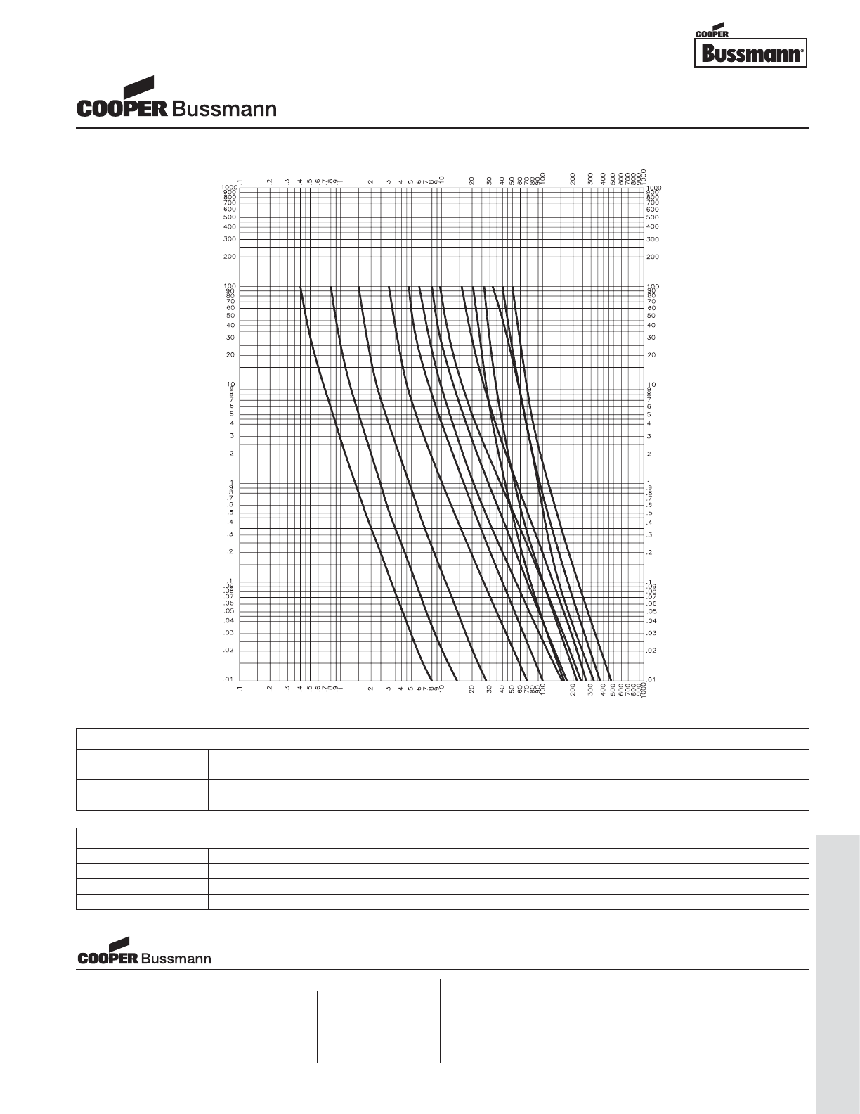
OC-87
Traditional Ferrule Fuses - Ferrule Type
TIME IN SECONDS
TIME IN SECONDS
CURRENT IN AMPERES
CURRENT IN AMPERES
1/4
1/2
1
2
3-2/10
4
5
6-1/4
10
12
15
20
25
30
TIME CURRENT CURVE
PACKAGING CODE
Packaging Code Description
BK 100 pieces of fuses packed into a cardboard carton
BK1 1,000 pieces of fuses packed into a cardboard carton
BK8 8,000 pieces of fuses packed into a cardboard carton
OPTION CODE
Option Code Description
BBoard Washable - Hermetically sealed to withstand aqueous cleaning
VAxial leads - copper tinned wire with nickel plated brass overcaps
-R RoHS compliant version
1/4" x 1-1/4" Fuses
MDA Series, Time Delay, Ceramic Tube
Visit us on the web at:
www.cooperbussmann.com
Cooper Electronic Technologies
1225 Broken Sound Parkway NW
Suite F
Boca Raton, FL 33487-3533
Tel: 1-561-998-4100
Fax: 1-561-241-6640
Toll Free: 1-888-414-2645
Cooper Bussmann
P.O. Box 14460
St. Louis, MO 63178-4460
Tel: 1-636-394-2877
Fax: 1-800-544-2570
Cooper Electronic Technologies
Cooper (UK) Limited
Burton-on-the-Wolds
Leicestershire • LE12 5TH UK
Tel: +44 (0) 1509 882 737
Fax: +44 (0) 1509 882 786
Cooper Electronic Technologies
Avda. Santa Eulalia, 290
08223
Terrassa, (Barcelona), Spain
Tel: +34 937 362 812
+34 937 362 813
Fax: +34 937 362 719
Asia Pacific
Cooper Electronic Technologies
1 Jalan Kilang Timor
#06-01 Pacific Tech Centre
Singapore 159303
Tel: +65 278 6151
Fax: +65 270 4160
North America Europe
Courtesy of Steven Engineering, Inc.-230 Ryan Way, South San Francisco, CA 94080-6370-Main Office: (650) 588-9200-Outside Local Area: (800) 258-9200-www.stevenengineering.com
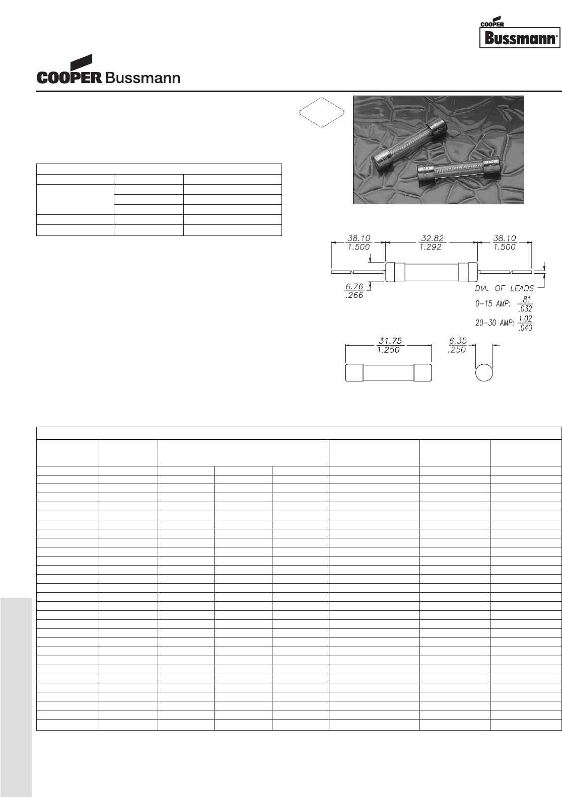
OC-88
Traditional Ferrule Fuses - Ferrule Type
Description
• Time delay, glass tube
• Optional axial leads available
• 1/4 x 1-1/4 (6.3mm x 32mm) physical size
• Glass tube, nickel-plated brass endcap construction
• UL Listed product meets standard 248-14
Agency Information
•
UL Listed Card: MDL 1/16 - 8A (Guide JDYX, File E19180)
• UL Recognized Card: MDL 9 - 30A (Guide JDYX2,
File E19180)
• CSA Certification Card: MDL 1/16 - 8A
(Class No. 1422-01)
• CSA Component Acceptance: MDL 9-30A
(Class No. 1422-30)
Environmental Data
• Shock: 1/100A and 8/10A – MIL-STD-202,
Method 213, Test Condition I; 1A thru 30A –
MIL-STD-202, Method 207, (HI Shock)
• Vibration: 1/100A and 8/10A – MIL-STD-202,
Method 201; 1/4A thru 30A – MIL-STD-202,
Method 204, Test Condition C (Except 5g, 500HZ)
Ordering
• Specify packaging, product, and option code
Dimensions (mm⁄in)
Drawing Not to Scale
SPECIFICATIONS
Voltage AC Interrupting Typical DC Cold Typical Typical
Product Code Rating Rating* Resistance** Melting I2t† Voltage
AC 250V 125V 32V (ohms) AC Drop‡
MDL-1/16 250V 35A 10000A - 38.000 0.0046 2.79
MDL-1/10 250V 35A 10000A - 15.900 0.0420 1.95
MDL-1/8 250V 35A 10000A - 9.850 0.0422 1.52
MDL-3/16 250V 35A 10000A - 4.680 0.116 1.05
MDL-2/10 250V 35A 10000A - 4.115 0.314 0.972
MDL-1/4 250V 35A 10000A - 3.200 0.447 0.965
MDL-3/10 250V 35A 10000A - 2.300 0.412 0.808
MDL-3/8 250V 35A 10000A - 2.800 0.982 1.46
MDL-1/2 250V 35A 10000A - 1.725 1.656 1.27
MDL-3/4 250V 35A 10000A - 0.822 4.343 1.01
MDL-1 250V 35A 10000A - 0.525 11.498 0.995
MDL-1-1/4 250V 100A 10000A - 0.320 86.2 0.722
MDL-1-1/2 250V 100A 10000A - 0.250 22.7 0.721
MDL-2 250V 100A 10000A - 0.173 62.3 0.644
MDL-2-1/4 250V 100A 10000A - 0.068 49.6 0.535
MDL-2-1/2 250V 100A 10000A - 0.096 63.1 0.410
MDL-3 250V 100A 10000A - 0.067 67.5 0.345
MDL-4 250V 200A 10000A - 0.035 19.3 0.187
MDL-5 250V 200A 10000A - 0.023 32.0 0.160
MDL-6 250V 200A 10000A - 0.018 37.4 0.155
MDL-6-1/4 250V 200A 10000A - 0.018 38.7 0.152
MDL-7 250V 200A 10000A - 0.018 42.7 0.140
MDL-8 250V 200A 10000A - 0.011 47.8 0.119
MDL-9 32V - - 1000A 0.009 51.5 0.124
MDL-10 32V - - 1000A 0.008 64.4 0.114
MDL-15 32V - - 1000A 0.006 354.0 0.130
MDL-20 32V - - 1000A 0.002 2914.0 0.530
MDL-25 32V - - 1000A 0.001 15221.0 0.30
MDL-30 32V - - 1000A 0.001 15581.0 0.40
* Interrupting Ratings (Interrupting ratings were measured at 70% - 80% power factor on AC)
** DC Cold Resistance (Measured at ≤10% of rated current)
† Typical Melting I2t (A2Sec) (I2t was measured at listed interrupting rating and rated voltage.)
‡ Typical Voltage Drop (Voltage drop was measured at 25°C±3°C ambient temperature at rated current)
ELECTRICAL CHARACTERISTICS
Rated Current Amp Rating Opening Time
100% None
1/16 - 30A 135% 60 minutes max.
200% 120 seconds max.
1/16 - 3A 200% 5 seconds min.
3-2/10 - 8A 200% 12 seconds min.
1/4" x 1-1/4" Fuses
MDL Series, Time Delay, Glass Tube
RoHS
2002/95/EC
Courtesy of Steven Engineering, Inc.-230 Ryan Way, South San Francisco, CA 94080-6370-Main Office: (650) 588-9200-Outside Local Area: (800) 258-9200-www.stevenengineering.com
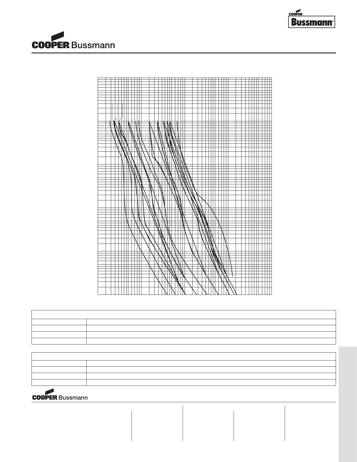
OC-89
Traditional Ferrule Fuses - Ferrule Type
90
80
70
60
50
40
30
20
10
200
100
5
.01
1
.02
.03
3
2
4
.04
.06
.05
.09
.08
.07
.1
.2
.3
.5
.4
.7
.6
.9
.8
1
2
8
6
7
9
1000
900
800
700
600
500
400
300
.01
.02
.03
.04
.06
.05
.09
.08
.07
.1
.2
.3
.5
.4
.7
.6
.9
.8
1
2
3
4
6
5
8
7
10
9
20
30
40
60
50
90
80
70
100
200
300
500
400
5
700
600
1000
900
800
1
3
2
4
8
6
7
10
9
20
30
40
50
70
60
90
80
100
200
3
4
6
5
8
7
10
9
20
30
40
60
50
90
80
70
100
200
300
500
400
700
300
400
500
600
800
1000
900
700
600
1000
900
800
10000
9000
8000
7000
6000
5000
4000
2000
3000
2000
3000
4000
5000
9000
7000
6000
8000
10000
TIME IN SECONDS
TIME IN SECONDS
CURRENT IN AMPERES
CURRENT IN AMPERES
1-1/4
3-2/10
1-1/2
1-6/10
2
5
6-1/4
10
15
20
25
30
40
TIME CURRENT CURVE
PACKAGING CODE
Packaging Code Description
BK 100 pieces of fuses packed into a cardboard carton
BK1 1,000 pieces of fuses packed into a cardboard carton
BK8 8,000 pieces of fuses packed into a cardboard carton
OPTION CODE
Option Code Description
BBoard Washable - Hermetically sealed to withstand aqueous cleaning
VAxial leads - copper tinned wire with nickel plated brass overcaps
-R RoHS compliant version
1/4" x 1-1/4" Fuses
MDL Series, Time Delay, Glass Tube
Visit us on the web at:
www.cooperbussmann.com
Cooper Electronic Technologies
1225 Broken Sound Parkway NW
Suite F
Boca Raton, FL 33487-3533
Tel: 1-561-998-4100
Fax: 1-561-241-6640
Toll Free: 1-888-414-2645
Cooper Bussmann
P.O. Box 14460
St. Louis, MO 63178-4460
Tel: 1-636-394-2877
Fax: 1-800-544-2570
Cooper Electronic Technologies
Cooper (UK) Limited
Burton-on-the-Wolds
Leicestershire • LE12 5TH UK
Tel: +44 (0) 1509 882 737
Fax: +44 (0) 1509 882 786
Cooper Electronic Technologies
Avda. Santa Eulalia, 290
08223
Terrassa, (Barcelona), Spain
Tel: +34 937 362 812
+34 937 362 813
Fax: +34 937 362 719
Asia Pacific
Cooper Electronic Technologies
1 Jalan Kilang Timor
#06-01 Pacific Tech Centre
Singapore 159303
Tel: +65 278 6151
Fax: +65 270 4160
North America Europe
Courtesy of Steven Engineering, Inc.-230 Ryan Way, South San Francisco, CA 94080-6370-Main Office: (650) 588-9200-Outside Local Area: (800) 258-9200-www.stevenengineering.com

OC-90
Traditional Ferrule Fuses - Ferrule Type
Description
• Dual element, time delay
• 1/4" x 1-1/4" (6.3mm x 32mm) physical size
• Glass tube, nickel-plated brass endcap construction
• UL Listed product meets standard 248-14
Agency Information
• UL Listed Card: MDQ-1/16 - 7A (Guide JDYX,
File E19180)
• UL Recognition Card: MDQ-7.5 - 30A
(Guide JDYX2, File E19180)
• CSA Component Acceptance Card:
MDQ-1/100 - 30 (Class 1422-01)
Ordering
• Specify packaging, product, and option code
Dimensions mm⁄(inches)
** DC Cold Resistance (Measured at <10% of rated current)
ELECTRICAL CHARACTERISTICS
Rated Current % of Amp Rating Opening Time
100% None
1/16A - 30A 135% 60 minutes maximum
200% 120 seconds maximum
SPECIFICATIONS
Voltage Interrupting Typical DC Cold
Product Code Rating Rating Resistance
AC AC (ohms)**
MDQ-1/16 250V 35A 83.30000
MDQ-1/10 250V 35A 35.00000
MDQ-1/8 250V 35A 21.50000
MDQ-3/16 250V 35A 10.00000
MDQ-2/10 250V 35A 8.65000
MDQ-1/4 250V 35A 5.77500
MDQ-3/10 250V 35A 4.20000
MDQ-3/8 250V 35A 2.35000
MDQ-1/2 250V 35A 1.40000
MDQ-3/4 250V 35A 0.39685
MDQ-1 250V 35A 0.37400
MDQ-1-1/4 250V 100A 0.36000
MDQ-1-1/2 250V 100A 0.27000
MDQ-2 250V 100A 0.13250
MDQ-2-1/4 250V 100A 0.11450
MDQ-2-1/2 250V 100A 0.10050
MDQ-3 250V 100A 0.05715
MDQ-4 250V 200A 0.03510
MDQ-5 250V 200A 0.02650
MDQ-6 250V 200A 0.01715
MDQ-6-1/4 250V 200A 0.01690
MDQ-7 250V 200A 0.01375
MDQ-8 32V 1,000A 0.01200
MDQ-9 32V 1,000A 0.00888
MDQ-10 32V 1,000A 0.00720
MDQ-15 32V 1,000A 0.00410
MDQ-20 32V 1,000A 0.00150
MDQ-25 32V 1,000A 0.00123
MDQ-30 32V 1,000A 0.00105
1/4" x 1-1/4" Fuses
MDQ Series Dual Element, Time Delay, Glass Fuse
Courtesy of Steven Engineering, Inc.-230 Ryan Way, South San Francisco, CA 94080-6370-Main Office: (650) 588-9200-Outside Local Area: (800) 258-9200-www.stevenengineering.com
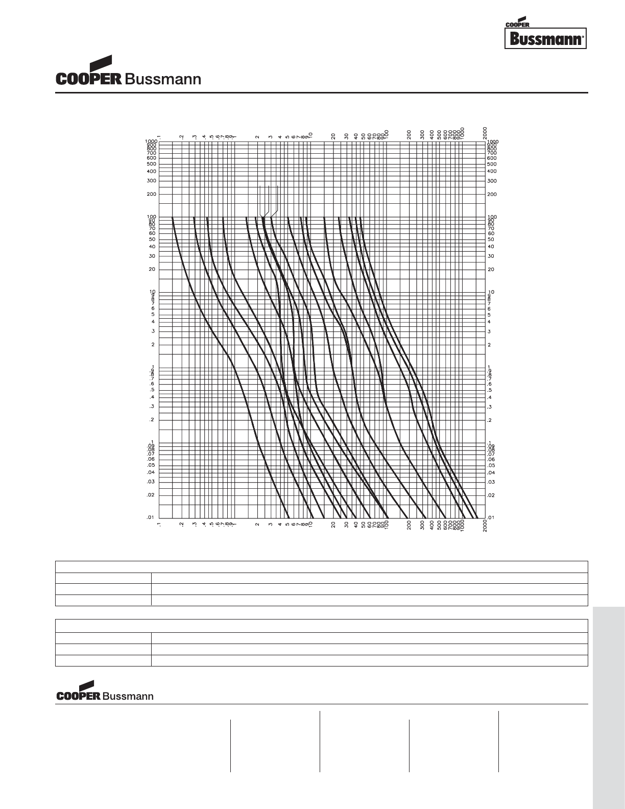
OC-91
Traditional Ferrule Fuses - Ferrule Type
PACKAGING CODE
Packaging Code Description
BK 100 pieces of fuses packed into a cardboard carton
BK1 1,000 pieces of fuses packed into a cardboard carton
CURRENT IN AMPERES
CURRENT IN AMPERES
TIME IN SECONDS
TIME IN SECONDS
CURRENT IN AMPERES
CURRENT IN AMPERES
20
25
30
1/10
2/10
3/10
1/2
1
1-1/4 1-1/2
1-6/10
2
3-2/10
5
6-1/4
10
15
TIME CURRENT CURVE
OPTION CODE
Option Code Description
BBoard Washable - Hermetically sealed to withstand aqueous cleaning
VAxial leads - copper tinned wire with nickel plated brass overcaps
1/4" x 1-1/4" Fuses
MDQ Series Dual Element, Time Delay, Glass Fuse
Visit us on the web at:
www.cooperbussmann.com
Cooper Electronic Technologies
1225 Broken Sound Parkway NW
Suite F
Boca Raton, FL 33487-3533
Tel: 1-561-998-4100
Fax: 1-561-241-6640
Toll Free: 1-888-414-2645
Cooper Bussmann
P.O. Box 14460
St. Louis, MO 63178-4460
Tel: 1-636-394-2877
Fax: 1-800-544-2570
Cooper Electronic Technologies
Cooper (UK) Limited
Burton-on-the-Wolds
Leicestershire • LE12 5TH UK
Tel: +44 (0) 1509 882 737
Fax: +44 (0) 1509 882 786
Cooper Electronic Technologies
Avda. Santa Eulalia, 290
08223
Terrassa, (Barcelona), Spain
Tel: +34 937 362 812
+34 937 362 813
Fax: +34 937 362 719
Asia Pacific
Cooper Electronic Technologies
1 Jalan Kilang Timor
#06-01 Pacific Tech Centre
Singapore 159303
Tel: +65 278 6151
Fax: +65 270 4160
North America Europe
Courtesy of Steven Engineering, Inc.-230 Ryan Way, South San Francisco, CA 94080-6370-Main Office: (650) 588-9200-Outside Local Area: (800) 258-9200-www.stevenengineering.com
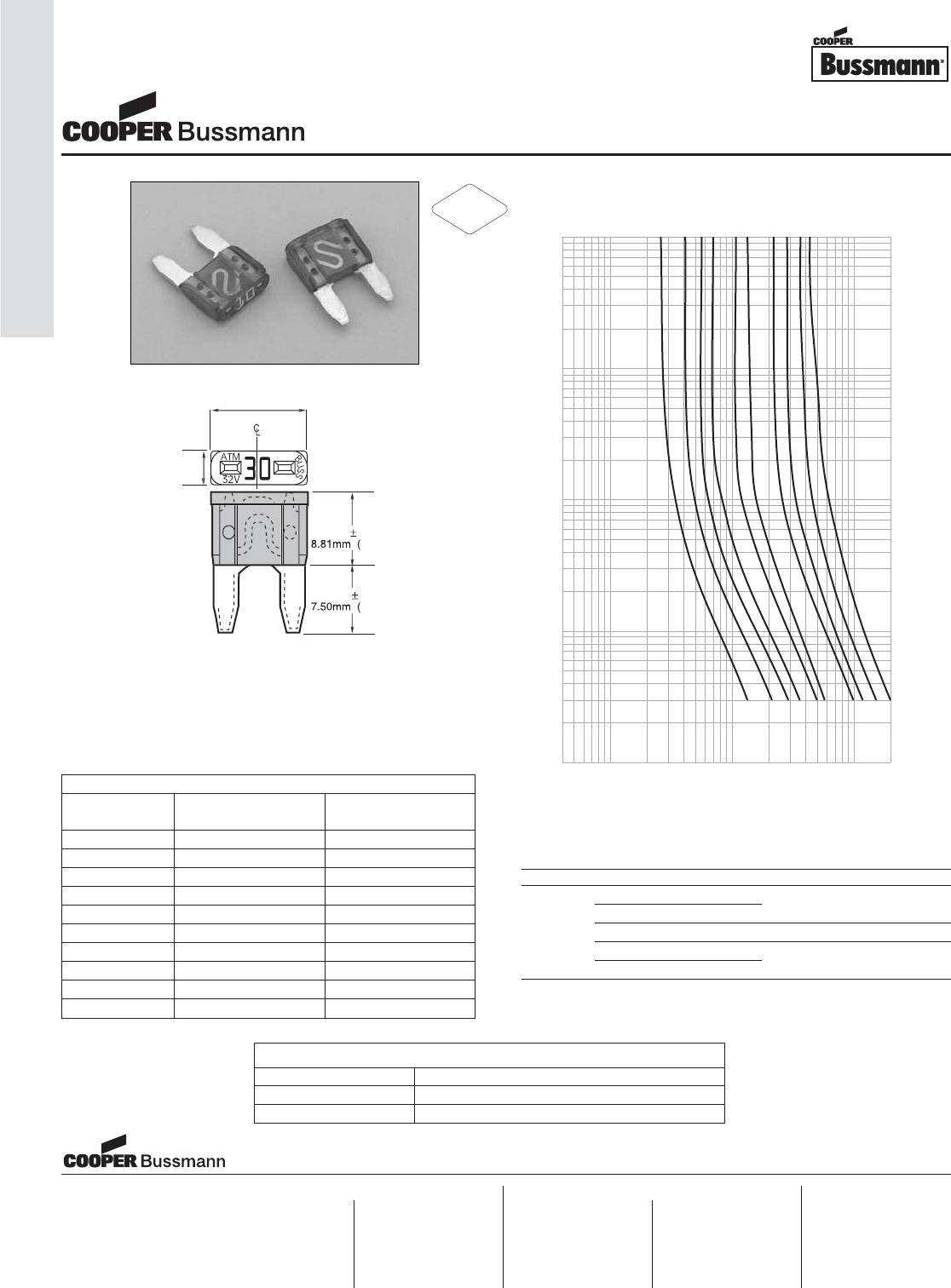
OC-92
Automotive Fuses - Blade
.347"
(
0.016
)
±
0.41
)
.1
5"
3
.
8
1m
m
.4
30
"
1
0
.
9
2mm
.295"
(
(
(
0.012
)
±
0.30
)
.4
1
10
100
200
CURRENT IN AMPERES
100
10
1
.1
.01
TIME IN SECONDS
AMPERE
RATING
2A
3A
4A
5A
7.5A
10A
15A
20A
25A
30A
Catalog Symbol: ATM
Fast-Acting
Ampere Ratings: 2 to 30 Amperes
Interrupting Rating: 1,000 Amperes
Ordering: Specify packaging and product code
Recommended Bussmann Fuseholders
Blade-Type Part Description Fuse Size Wire Size
HHM Fuseholder w/Cover #12 Lead Wire;
HHM-B Body Only 3-30 Amps 4"Length
ATM HHM-C Cover Only — —
HHL Fuseholder w/Cover 2-20 Amps #16 Lead Wire;
HHL-B Body Only 4"Length
Time-Current Characteristic Curves–Average Melt
Dimensional Data
SPECIFICATIONS
Product Body Voltage
Code Color Rating DC
ATM-2 Gray 32V
ATM-3 Violet 32V
ATM-4 Pink 32V
ATM-5 Tan 32V
ATM-7 1/2 Brown 32V
ATM-10 Red 32V
ATM-15 Lt. Blue 32V
ATM-20 Yellow 32V
ATM-25 Natural White 32V
ATM-30 Green 32V
PACKAGING CODE
Packaging Code Description
Blank 5 pieces of fuses packed in a tin
BK 500 pieces of fuses packed in a carton
Blade-Type Fuses
ATM Series, Fast Acting
Visit us on the web at:
www.cooperbussmann.com
Cooper Electronic Technologies
1225 Broken Sound Parkway NW
Suite F
Boca Raton, FL 33487-3533
Tel: 1-561-998-4100
Fax: 1-561-241-6640
Toll Free: 1-888-414-2645
Cooper Bussmann
P.O. Box 14460
St. Louis, MO 63178-4460
Tel: 1-636-394-2877
Fax: 1-800-544-2570
Cooper Electronic Technologies
Cooper (UK) Limited
Burton-on-the-Wolds
Leicestershire • LE12 5TH UK
Tel: +44 (0) 1509 882 737
Fax: +44 (0) 1509 882 786
Cooper Electronic Technologies
Avda. Santa Eulalia, 290
08223
Terrassa, (Barcelona), Spain
Tel: +34 937 362 812
+34 937 362 813
Fax: +34 937 362 719
Asia Pacific
Cooper Electronic Technologies
1 Jalan Kilang Timor
#06-01 Pacific Tech Centre
Singapore 159303
Tel: +65 278 6151
Fax: +65 270 4160
North America Europe
RoHS
2002/95/EC
Courtesy of Steven Engineering, Inc.-230 Ryan Way, South San Francisco, CA 94080-6370-Main Office: (650) 588-9200-Outside Local Area: (800) 258-9200-www.stevenengineering.com
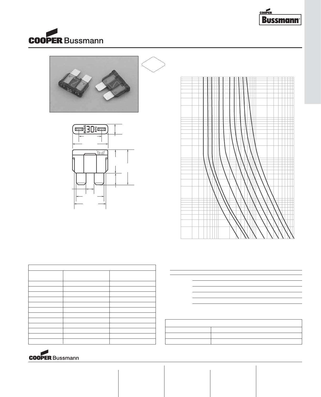
Catalog Symbol: ATC
Fast-Acting
Ampere Rating: 1 to 40 Amperes
Interrupting Rating: 1,000 Amperes
Agency Approvals: U.L. Recognized, (3-40A)
Guide JFHR2, File E56412
Ordering: Specify packaging and product code
Recommended Bussmann Fuseholders*
Blade-Type Part Description Fuse Size Wire Size
HHC Yellow Fuseholder 3-20 Amps #16 Lead Wire
HHF Black Fuseholder w/cover 3-20 Amps #14 Lead Wire
ATC HHD Black Fuseholder 3-30 Amps #12 Lead Wire
HHG Black Fuseholder w/cover 3-30 Amps #12 Lead Wire
HHD-C Cover Only — —
*Also used in Bussmann 1A5600 Fuse Clips (0-20A)
1
10
100
1,000
CURRENT IN AMPERES
100
10
1
.1
.01
TIME IN SECONDS
10
15
20
25
30
AMPERE
RATING
7.5
5
4
3
40
Time-Current Characteristic Curves–Average Melt
12.5mm
.5m
.5m
19.1mm
1m
1m
6
.
6
7m
m
5
.2
5
m
m
11.7mm
1
9
.
3
m
m
93
14.
6
m
m
1
6
.7m
m
4.1
3
m
m
Dimensional Data
.460”
.760”
.207”
.492”
.752”
.263”
.575”
.657”
.163”
SPECIFICATIONS
Product Body Voltage
Code Color Rating DC
ATC-1 Black 32V
ATC-2 Gray 32V
ATC-3 Violet 32V
ATC-4 Pink 32V
ATC-5 Tan 32V
ATC-7 1/2 Brown 32V
ATC-10 Red 32V
ATC-15 Blue 32V
ATC-20 Yellow 32V
ATC-25 Clear 32V
ATC-30 Green 32V
ATC-40 Amber 32V
PACKAGING CODE
Packaging Code Description
Blank 5 pieces of fuses packed in a tin
BK 2,000 pieces of fuses packed in a carton
Blade-Type Automotive Fuses
ATC Series, Fast Acting
Visit us on the web at:
www.cooperbussmann.com
Cooper Electronic Technologies
1225 Broken Sound Parkway NW
Suite F
Boca Raton, FL 33487-3533
Tel: 1-561-998-4100
Fax: 1-561-241-6640
Toll Free: 1-888-414-2645
Cooper Bussmann
P.O. Box 14460
St. Louis, MO 63178-4460
Tel: 1-636-394-2877
Fax: 1-800-544-2570
Cooper Electronic Technologies
Cooper (UK) Limited
Burton-on-the-Wolds
Leicestershire • LE12 5TH UK
Tel: +44 (0) 1509 882 737
Fax: +44 (0) 1509 882 786
Cooper Electronic Technologies
Avda. Santa Eulalia, 290
08223
Terrassa, (Barcelona), Spain
Tel: +34 937 362 812
+34 937 362 813
Fax: +34 937 362 719
Asia Pacific
Cooper Electronic Technologies
1 Jalan Kilang Timor
#06-01 Pacific Tech Centre
Singapore 159303
Tel: +65 278 6151
Fax: +65 270 4160
North America Europe
RoHS
2002/95/EC
OC-93
Automotive Fuses - Blade
Courtesy of Steven Engineering, Inc.-230 Ryan Way, South San Francisco, CA 94080-6370-Main Office: (650) 588-9200-Outside Local Area: (800) 258-9200-www.stevenengineering.com
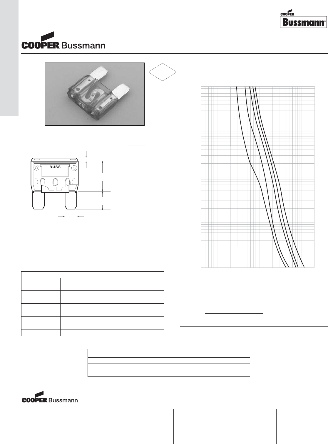
OC-94
Automotive Fuses - Blade
Catalog Symbol: MAX
Fast-Acting
Ampere Rating: 20 to 80 Amperes
Interrupting Rating: 1,000 Amperes
Ordering: Specify packaging and product code
Recommended Bussmann Fuseholders
Blade-Type Part Description Fuse Size Wire Size
HHX Fuseholder w/Cover #6 Lead Wire;
MAX HHX-B Body Only 20-60 Amps 5" Length
HHX-C Cover Only — —
MAXI-FUSE
32 V
30
30
0"
850
.850
(21.6mm)
1.6m
1.6m
"
0
.
5"
"
(12.7mm)
2.7m
2.7m
0"
.
350
0
(8.9mm)
8.9m
8.9m
.
3
1
5
"
(8.0mm
)
All t
o
l
e
r
a
n
ces:
±0.20mm/-0.13mm
±0.008"/-.005"
BUSS
MAXI-FUSE
32 V
4
10
100
1,000
2,000
CURRENT IN AMPERES
100
10
1
.1
.01
TIME IN SECONDS
30
AMPERE
RATING
40
50
60
20
30
40
50
20
Time-Current Characteristic Curves–Average Melt
Dimensional Data
SPECIFICATIONS
Product Body Voltage
Code Color Rating DC
MAX-20 Yellow 32V
MAX-30 Green 32V
MAX-40 Orange 32V
MAX-50 Red 32V
MAX-60 Blue 32V
MAX-70 Tan 32V
MAX-80 Natural 32V
PACKAGING CODE
Packaging Code Description
Blank 1 pieces of fuses packed in a tin
BK 250 pieces of fuses packed in a carton
Blade-Type Fuses
MAX Series
Visit us on the web at:
www.cooperbussmann.com
Cooper Electronic Technologies
1225 Broken Sound Parkway NW
Suite F
Boca Raton, FL 33487-3533
Tel: 1-561-998-4100
Fax: 1-561-241-6640
Toll Free: 1-888-414-2645
Cooper Bussmann
P.O. Box 14460
St. Louis, MO 63178-4460
Tel: 1-636-394-2877
Fax: 1-800-544-2570
Cooper Electronic Technologies
Cooper (UK) Limited
Burton-on-the-Wolds
Leicestershire • LE12 5TH UK
Tel: +44 (0) 1509 882 737
Fax: +44 (0) 1509 882 786
Cooper Electronic Technologies
Avda. Santa Eulalia, 290
08223
Terrassa, (Barcelona), Spain
Tel: +34 937 362 812
+34 937 362 813
Fax: +34 937 362 719
Asia Pacific
Cooper Electronic Technologies
1 Jalan Kilang Timor
#06-01 Pacific Tech Centre
Singapore 159303
Tel: +65 278 6151
Fax: +65 270 4160
North America Europe
RoHS
2002/95/EC
Courtesy of Steven Engineering, Inc.-230 Ryan Way, South San Francisco, CA 94080-6370-Main Office: (650) 588-9200-Outside Local Area: (800) 258-9200-www.stevenengineering.com
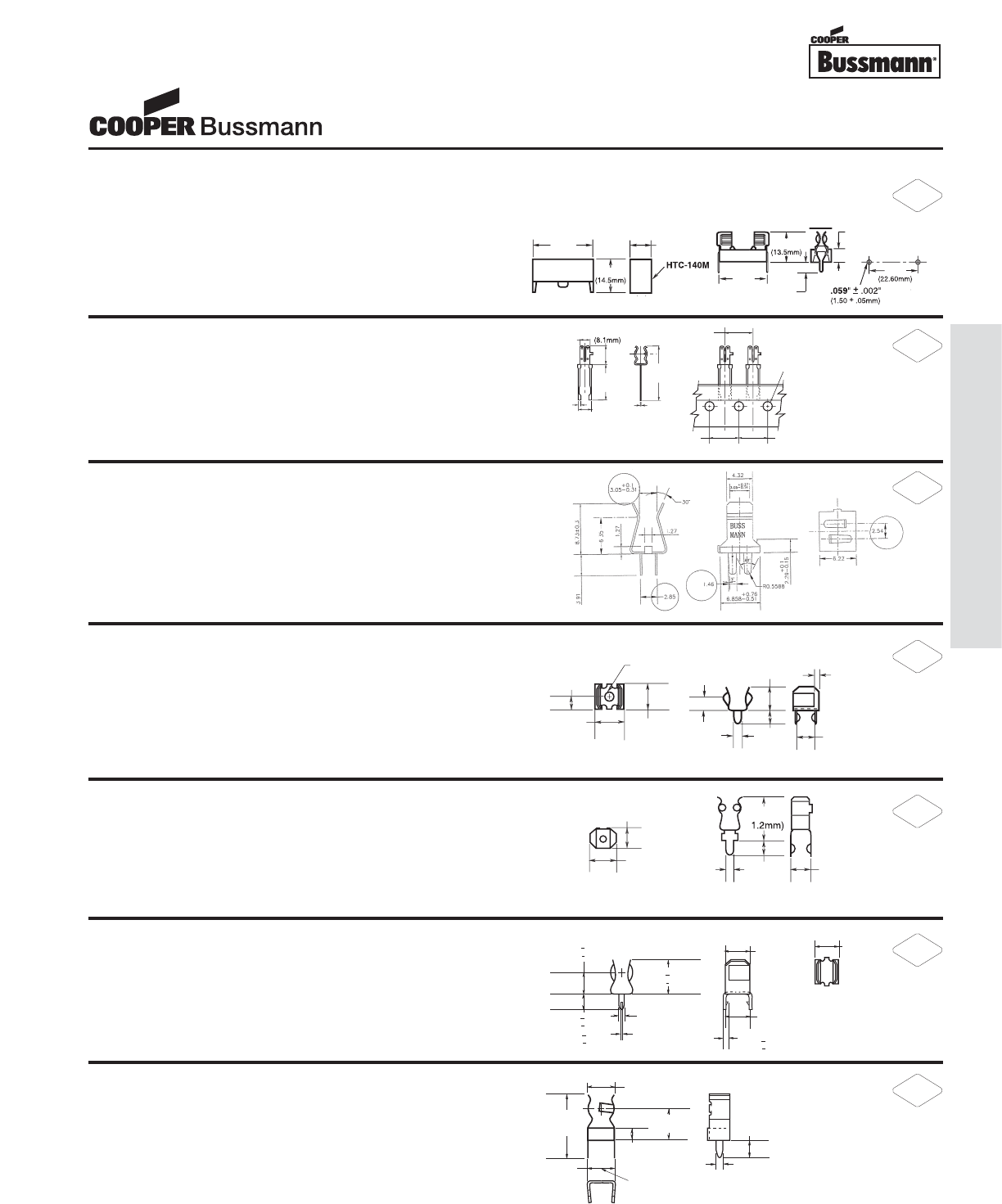
PC Board Fuseclips
for 5mm Diameter Fuses
.866
866
.866
"
"
(
22.0mm
)
.217
"
(
5.5mm
)
.177
"
(
4.5mm
)
.89
0
"
Mountin
g
Hole
s
Dia. (T
yp.)
T
T
.
531
"
C
ove
r
1.047
1.047
"
(
26.6mm
)
217
"
.
3
4
5
"
(
9.0mm
)
.
5
7
1
"
.031"
(
.79mm
)
.217"
(
5.5mm
)
.
0
12
"
(
.3mm
)
.177"
(
4.5mm
)
.
3
1
9
"
BUSS
.61"
6
(15.5mm)
.5
.929"
2
(23.6mm)
6
BUSS
BUSS
.
50
"
(
12.7mm
)
.
50
"
(
12.7mm
)
.
50"
(
12.7mm
)
.1
5
7
"
(
3.99mm
)
.1
80"
(
4.57mm
)
.2
30"
(
5.84mm
)
HTC-211M
PCB Mounted Fuseclip with End Stops
Construction: Tin-plated brass
*Equivalent replacement to HTC-210M
HTC-15M, HTC-140M
PCB Mounted Fuse Holder & Snap-On Cover
Voltage Rating: 250V, 6.3A, 1.6W
HTC-15M (fuse holder), HTC-140M (natural cover),
HTC-150M* (transparent cover)
*Available in bulk only. Use this format: BK/HTC-150M
HTC-200M
PCB Mounted Fuseclip
Construction: Tin-plated bronze
Tape and Fan Fold packed
Ammo Pack (AP/HTC-200M) 1000 pieces per box
1A3399 Series**
PCB Fuseclips with End Stops & Straight Leads
Catalog Numbers Clip Material* Finish
1A3399-01 Beryllium copper* Silver
1A3399-04 Beryllium copper* Bright tin
1A3399-10 Spring bronze Bright tin
*Beryllium copper recommended for amps higher than 15 amps (1⁄4” clips).
1A5601 Series
PCB Fuseclips (0-7A)
Catalog Number Clip Material Finish
1A5601 Cartridge brass Bright tin
1A5602 Series
PCB Fuseclips (0-7A)
Catalog Number Clip Material Finish
1A5602 Cartridge brass Bright tin
1A5018 Series**
PCB High Profile Fuseclips with End Stops & Straight Leads
Catalog Numbers Clip Material* Finish
1A5018-07 Spring bronze Silver
1A5018-10 Spring bronze Bright tin
*Beryllium copper recommended for amps higher than 15 amps (1⁄4” clips).
.1
1
5"
(2.9mm)
.
06
2
"
(
1.6mm
)
.2
5
4
"
(
6.5mm
)
.2
3
7
"
(
6.0mm
)
.12
5"
(
3.2mm
)
.22
5"
(
5.7mm
)
.125
"
(
3.2mm
)
.060
"
(
1.5mm
)
.1
88"
(
4.8mm
)
.
030"
(
1.6mm
)
.440"
4
4
(1
.14
0"
(
3.7mm
)
.
0
47
"
(
1.2mm
)
.1
80"
(
4.6mm
)
.250"
(6.35mm)
.060"
(1.5mm)
.246"
(6.3mm)
.344" + .015"
(8.73mm + 0.38mm)
.266"
(6.75mm)
.344" + .015"
(8.73mm + 0.38mm)
.141" + .015"
(3.58mm + 0.38mm)
.022" + .002"
(0.56mm + 0.05mm) .032" + .002"
(.81mm + .05mm)
.216"
(5.48mm) LEGS TO FIT
IN .052" (1.3mm) DIA.
HOLES ON CENTER
.219"
(5.57mm)
.047"
(1.19mm)
.093"
(2.36mm)
.500"
(12.70mm) .250"
(6.35mm) .140"
(3.56mm)
**For RoHS compliant version, add “-R” option code suffix to part number.
RoHS
2002/95/EC
RoHS
2002/95/EC
RoHS
2002/95/EC
RoHS
2002/95/EC
RoHS
2002/95/EC
RoHS
2002/95/EC
RoHS
2002/95/EC
OC-95
Accessories - Fuseclips
Courtesy of Steven Engineering, Inc.-230 Ryan Way, South San Francisco, CA 94080-6370-Main Office: (650) 588-9200-Outside Local Area: (800) 258-9200-www.stevenengineering.com
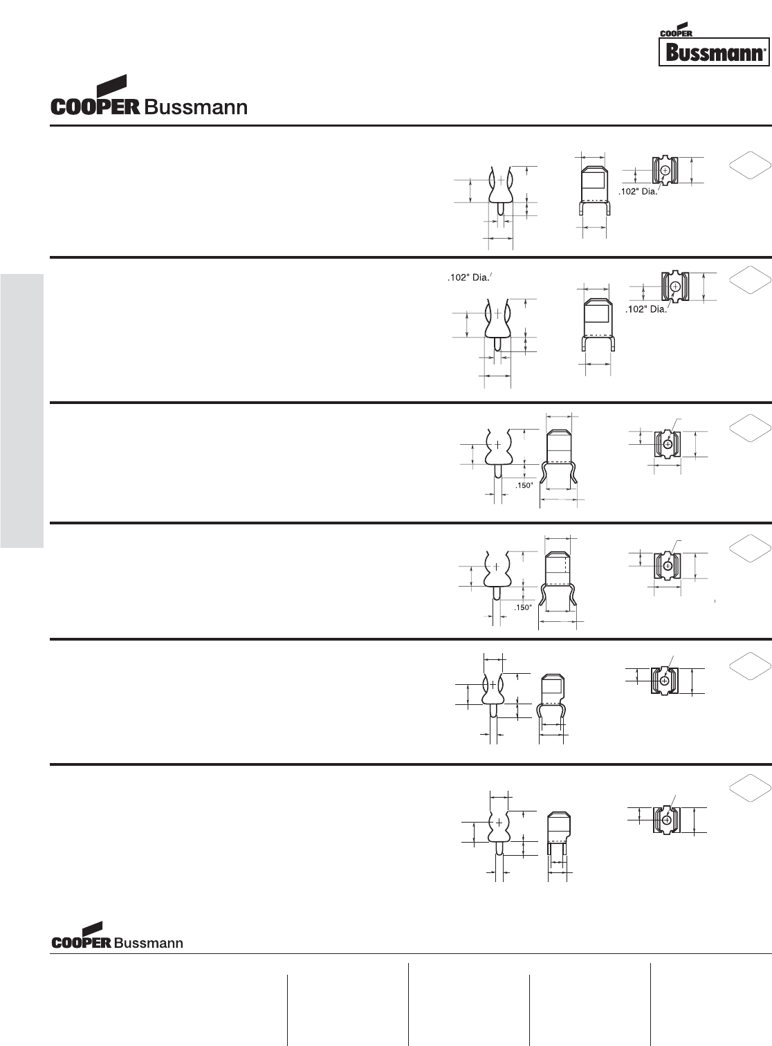
OC-96
Accessories - Fuseclips
PC Board Fuseclips
for 1/4" Diameter Fuses
.24
5"
(
6.2mm
)
.2
80"
(
7.1mm
)
(
7.1mm
)
.410"
1
1
(10.4mm)
(
4
4
.14
0"
(
3.6mm
)
.
060"
(
1.5mm
)
.
3
2
0
"
(
8.13mm
)
(
2.6mm
)
.2
55"
(
6.5mm
)
.2
80"
(
7.1mm
)
.1
55"
(
3.94mm
)
(
2.6mm
)
.24
5"
(
6.2mm
)
.2
80"
(
7.1mm
)
.2
80"
(
7.1mm
)
.410"
1
1
(10.4mm)
(
4
4
.14
0"
(
3.6mm
)
.
060"
(
1.5mm
)
.
3
2
0"
(
8.13mm
)
(
2.6mm
)
.2
55"
(
6.5mm
)
.2
80"
(
7.1mm
)
.1
55"
(
3.94mm
)
(
2.6mm
)
.2
55"
(
6.5mm
)
.410"
1
1
(10.4mm)
4
4m
.
060"
(
1.5mm
)
(
3.81mm
)
.24
5"
(
6.2mm
)
.22
8"
(
5.79mm
)
.
3
2
3"
(
8.20mm
)
.280"
8
8
(
7.
1
1mm)
1m
1m
.102"
(
2.6mm
)
.1
55"
(
3.94mm
)
.
3
2
0"
(
8.13mm
)
()
.255"
(6.5mm)
.410"
(10.4mm)
.080"
(2.03mm)
.265"
(6.7mm)
.155"
(3.9mm)
.290"
(7.4mm)
.360"
(9.14mm)
.312"
(7.9mm)
.132"
(3.4mm)
.187"
(4.8mm)
.312"
(7.9mm)
.132"
(3.4mm)
.187"
(4.8mm)
.250"
(6.5mm)
.420"
(10.67mm)
.080"
(2.03mm)
.285"
(7.24mm)
.155"
(3.9mm)
.290"
(7.4mm)
.360"
(9.14mm)
1A3398 Series**
PCB Fuseclips without End Stops or Straight Leads
Catalog Numbers Clip Material Finish
1A3398-07 Cartridge brass Bright tin
1A1907 Series**
PCB Fuseclips with End Stops & Straight Leads
Catalog Numbers Clip Material* Finish
1A1907-02 Cartridge brass None/bright dipped
1A1907-03 Beryllium copper* Bright tin
1A1907-05 Beryllium copper* Silver
1A1907-06 Cartridge brass Bright tin
*Beryllium copper recommended for amps higher than 15A 1⁄4” clips).
1A1120 Series**
PCB Fuseclips without End Stops or Angled In Leads
Catalog Numbers Clip Material* Finish
1A1120-02 Cartridge brass None/bright dipped
1A1120-05 Beryllium copper* Silver
1A1120-06 Beryllium copper* Bright tin
1A1120-09 Cartridge brass Bright tin
*Beryllium copper recommended for amps higher than 15A (1⁄4” clips).
1A1119 Series**
Fuseclips with End Stops & Angled In Leads
Catalog Numbers Clip Material* Finish
1A1119-04 Beryllium copper* Bright tin
1A1119-05 Beryllium copper* Silver
1A1119-10 Cartridge brass Bright tin
*Beryllium copper recommended for amps higher than 15A (1⁄4” clips).
1A4534 Series**
PCB Fuseclips with End Stops & Angled Out Leads
Catalog Numbers Clip Material* Finish
1A4534-01 Beryllium copper* Bright tin
1A4534-06 Cartridge brass Bright tin
*Beryllium copper recommended for amps higher than 15A (1⁄4” clips).
1A4533 Series**
PCB Fuseclips without End Stops or Angled Out Leads
Catalog Numbers Clip Material* Finish
1A4533-01 Beryllium copper* Bright tin
1A4533-06 Cartridge brass Bright tin
*Beryllium copper recommended for amps higher than 15A (1⁄4” clips).
.2
55"
(
6.5mm
)
.410"
1
1
(10.4mm)
4
4m
.
060"
(
1.5mm
)
(
3.81mm
)
.24
5"
(
6.2mm
)
.22
8"
(
5.79mm
)
.
3
2
3"
(
8.20mm
)
.280"
8
8
(
7.
1
1mm)
1m
1m
.102"
(
2.6mm
)
.1
55"
(
3.94mm
)
.
3
2
0"
(
8.13mm
)
**For RoHS compliant version, add “-R” option code suffix to part number.
Visit us on the web at:
www.cooperbussmann.com
Cooper Electronic Technologies
1225 Broken Sound Parkway NW
Suite F
Boca Raton, FL 33487-3533
Tel: 1-561-998-4100
Fax: 1-561-241-6640
Toll Free: 1-888-414-2645
Cooper Bussmann
P.O. Box 14460
St. Louis, MO 63178-4460
Tel: 1-636-394-2877
Fax: 1-800-544-2570
Cooper Electronic Technologies
Cooper (UK) Limited
Burton-on-the-Wolds
Leicestershire • LE12 5TH UK
Tel: +44 (0) 1509 882 737
Fax: +44 (0) 1509 882 786
Cooper Electronic Technologies
Avda. Santa Eulalia, 290
08223
Terrassa, (Barcelona), Spain
Tel: +34 937 362 812
+34 937 362 813
Fax: +34 937 362 719
Asia Pacific
Cooper Electronic Technologies
1 Jalan Kilang Timor
#06-01 Pacific Tech Centre
Singapore 159303
Tel: +65 278 6151
Fax: +65 270 4160
North America Europe
RoHS
2002/95/EC
RoHS
2002/95/EC
RoHS
2002/95/EC
RoHS
2002/95/EC
RoHS
2002/95/EC
RoHS
2002/95/EC
Courtesy of Steven Engineering, Inc.-230 Ryan Way, South San Francisco, CA 94080-6370-Main Office: (650) 588-9200-Outside Local Area: (800) 258-9200-www.stevenengineering.com
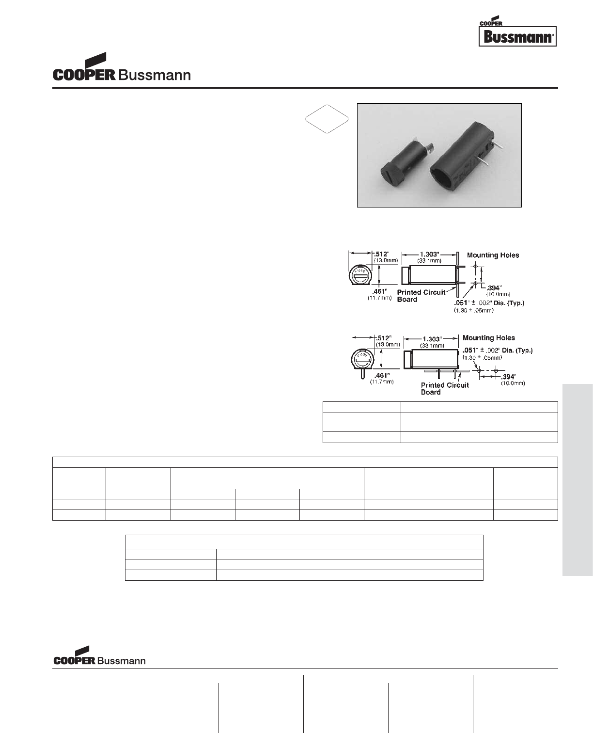
Description
• For 5mm x 20mm fuses
• Fuse carriers are interchangeable
• Both vertical and horizontal mounting features
• Fuse carrier and knob are spring loaded
bayonet type with screwdriver slot
• Solderability in accordance with IEC 68-2-20
• Shock safety of PC2
• High temperature thermoplastic meets:
• UL 94-VO
• Glow wire test: 960°C per IEC 695-2-1
HTC series printed circuit board fuseholders accept
5 x 20mm fuses.
Agency Information
• UL Recognized: IZLT2, E14853A
• CSA Component Certified: Class 6225-01, File 47235
Ordering
• Specify packaging and product code
PACKAGING CODE
Packaging Code Description
Blank 10 pieces of fuseholder packed into a carton
BK 100 pieces of fuseholders packed into a cardboard shelf package
Dimensions
Drawing Not to Scale
Component Material
Clip Tin Plating
Terminals Copper, Tin Plated
Body Thermoplastic
SPECIFICATIONS
Product Voltage Current Rating
Code Rating Agency Approval Ambient Temperature
AC UL CSA SEMKO Temperature Rise Mounting
HTC-45M 250V 6.3A 6.3A 6.3A 24C 41C Vertical
HTC-50M 250V 6.3A 6.3A 6.3A 24C 41C Horizontal
5mm x 20mm Fuseholders
HTC Printed Circuit Board Series
Visit us on the web at:
www.cooperbussmann.com
Cooper Electronic Technologies
1225 Broken Sound Parkway NW
Suite F
Boca Raton, FL 33487-3533
Tel: 1-561-998-4100
Fax: 1-561-241-6640
Toll Free: 1-888-414-2645
Cooper Bussmann
P.O. Box 14460
St. Louis, MO 63178-4460
Tel: 1-636-394-2877
Fax: 1-800-544-2570
Cooper Electronic Technologies
Cooper (UK) Limited
Burton-on-the-Wolds
Leicestershire • LE12 5TH UK
Tel: +44 (0) 1509 882 737
Fax: +44 (0) 1509 882 786
Cooper Electronic Technologies
Avda. Santa Eulalia, 290
08223
Terrassa, (Barcelona), Spain
Tel: +34 937 362 812
+34 937 362 813
Fax: +34 937 362 719
Asia Pacific
Cooper Electronic Technologies
1 Jalan Kilang Timor
#06-01 Pacific Tech Centre
Singapore 159303
Tel: +65 278 6151
Fax: +65 270 4160
North America Europe
RoHS
2002/95/EC
OC-97
Accessories - Fuseholders
Courtesy of Steven Engineering, Inc.-230 Ryan Way, South San Francisco, CA 94080-6370-Main Office: (650) 588-9200-Outside Local Area: (800) 258-9200-www.stevenengineering.com
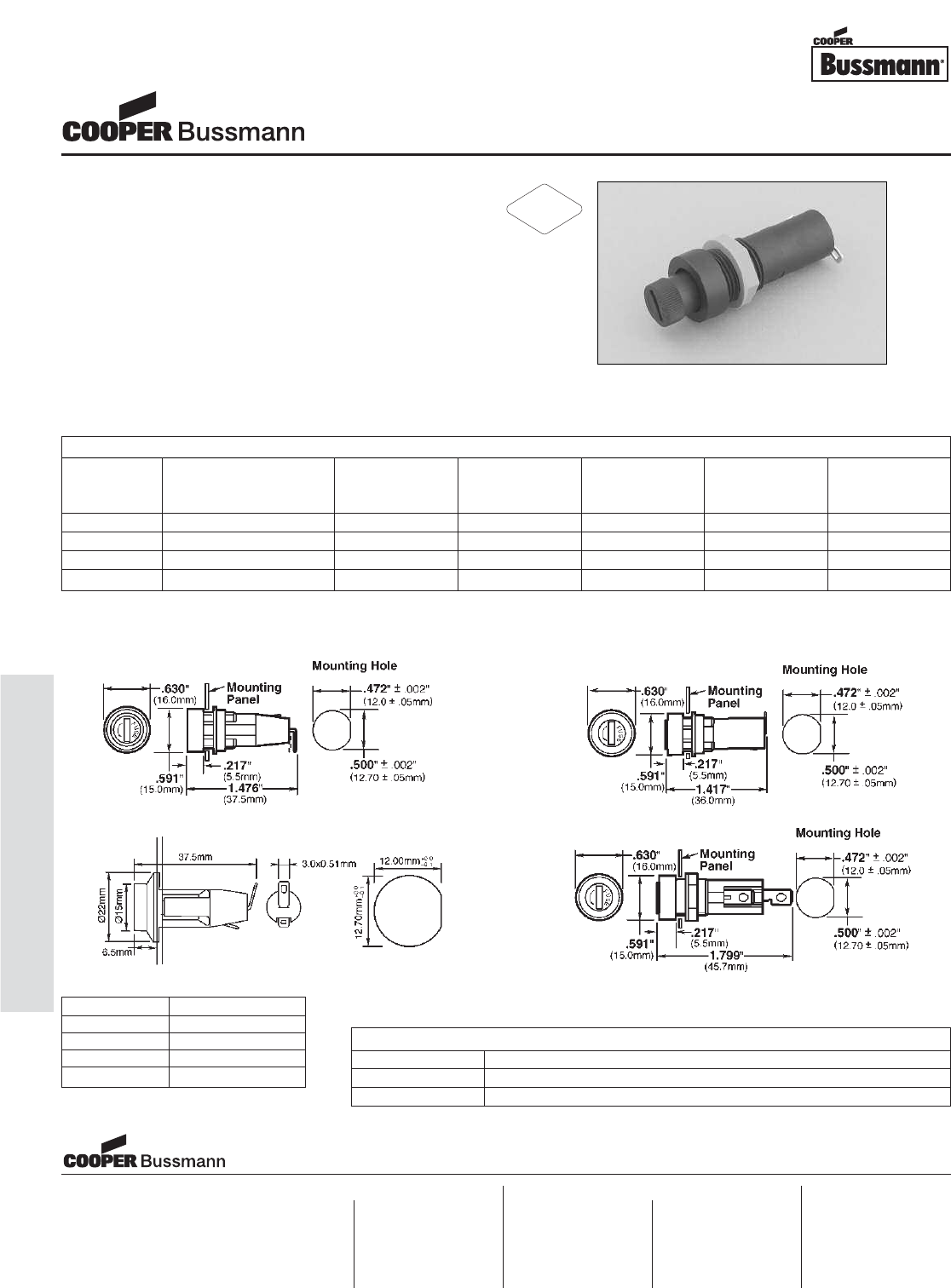
Description
• For 5mm x 20mm fuses
• Tin-plated brass terminals
• Shock safety of PC2
• High temperature Thermoplastic meets:
• UL 94 VO
• Glow wire test: 960°C IEC 695-2-1
• Designed to IEC 68-2-20
Agency Information
• UL Recognized: IZLT2, E14853A
• CSA Component Certified: Class 6225-01, File 47235
Ordering
• Specify packaging and product code
SPECIFICATIONS
Product Voltage Current Maximum
Code Cap Rating Rating Ambient Temperature Temperature
Type AC AC Temperature Rise (C)
HTC-35M Threaded Cap/Carrier 250V 6.3A 24C 43C 75
HTC-40M Screwdriver Slot 250V 6.3A 24C 43C 75
HTC-55M Bayonet Cap/Carrier 250V 6.3A 24C 43C 65
HTC-70M Bayonet Cap/Carrier 250V 10A 24C 43C 65
HTC-35M
HTC-40M
HTC-55M
HTC-70M
Dimensions
Drawing Not to Scale
Component Material
Terminal Tin-Plated Brass
Body Thermoplastic
Cap Thermoplastic
Nut Polycarbonate
PACKAGING CODE
Packaging Code Description
Blank 10 pieces of fuseholders packed into a carton
BK 100 pieces of fuseholders packed into a cardboard shelf package
5mm x 20mm Fuseholders
HTC Panel Mount Series
Visit us on the web at:
www.cooperbussmann.com
Cooper Electronic Technologies
1225 Broken Sound Parkway NW
Suite F
Boca Raton, FL 33487-3533
Tel: 1-561-998-4100
Fax: 1-561-241-6640
Toll Free: 1-888-414-2645
Cooper Bussmann
P.O. Box 14460
St. Louis, MO 63178-4460
Tel: 1-636-394-2877
Fax: 1-800-544-2570
Cooper Electronic Technologies
Cooper (UK) Limited
Burton-on-the-Wolds
Leicestershire • LE12 5TH UK
Tel: +44 (0) 1509 882 737
Fax: +44 (0) 1509 882 786
Cooper Electronic Technologies
Avda. Santa Eulalia, 290
08223
Terrassa, (Barcelona), Spain
Tel: +34 937 362 812
+34 937 362 813
Fax: +34 937 362 719
Asia Pacific
Cooper Electronic Technologies
1 Jalan Kilang Timor
#06-01 Pacific Tech Centre
Singapore 159303
Tel: +65 278 6151
Fax: +65 270 4160
North America Europe
RoHS
2002/95/EC
OC-98
Accessories - Fuseholders
Courtesy of Steven Engineering, Inc.-230 Ryan Way, South San Francisco, CA 94080-6370-Main Office: (650) 588-9200-Outside Local Area: (800) 258-9200-www.stevenengineering.com
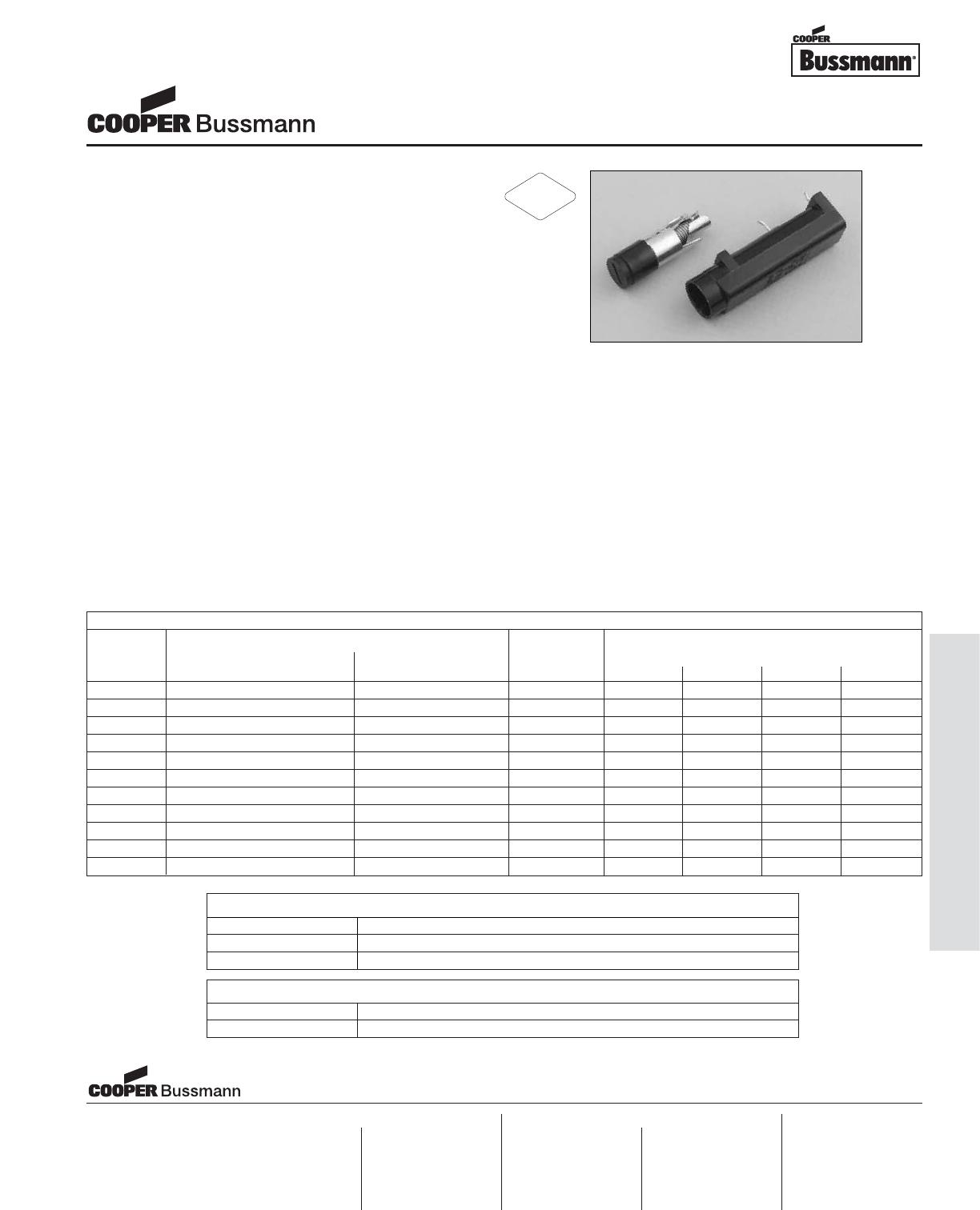
OC-99
Accessories - Fuseholders
Description
• For 1/4" x 1-1/4" and 5mm x 20mm fuses
• Fuse carriers are interchangeable
• Carriers are color coded for easy identification:
• Gray for 1/4" fuses
• Black for 5mm fuses
• Both vertical and horizontal mounting features
• Fuse carrier and knob are spring loaded
bayonet type with screwdriver slot
• “Kicked” terminals (all models) for optimum
wave-soldering
• Stabilizer pins on HBV model
• High dielectric molded thermoplastic meets UL 94 VO
Resistance Ratings
• Insulation Resistance: 10,000 megaohm at 500Vdc
• Contact Resistance: Less than 0.005 ohms at 200mV
Dielectric Strength
• Dielectric Strength: Over 200mV
Agency Information
• UL Recognized: IZLT2, E14853
• CSA Component Acceptance: Class 6225-01,
File 47235
Environmental Data
• Temperature Rating (RTI): The mounting body for all
devices has a temperature rating of 150°C. The knob for
all devices has a temperature rating of 130°C.
Ordering
• Specify packaging, product, and option code
PACKAGING CODE
Packaging Code Description
Blank 10 pieces of fuseholders packed into a carton
BK 100 pieces of fuseholders packed into a cardboard shelf package
OPTION CODE
Option Code Description
-R RoHS compliant version
SPECIFICATIONS
Product Fuseholder Current Rating
Code Body Carrier Voltage Agency Approval
Mount Size Rating UL CSA VDE SEMKO
HBH-I Horizontal 1/4" x 1-1/4" 250V 16A 12A 6.3A 10A
HBH-M Horizontal 5mm x 20mm 250V 16A 12A 6.3A 10A
HBV-I Vertical w/ Stability Pins 1/4" x 1-1/4" 250V 16A 12A 6.3A 10A
HBV-M Vertical w/ Stability Pins 5mm x 20mm 250V 16A 12A 6.3A 10A
HBW-I Vertical w/o Stability Pins 1/4" x 1-1/4" 250V 16A 12A 6.3A 10A
HBW-M Vertical w/o Stability Pins 5mm x 20mm 250V 16A 12A 6.3A 10A
HBH Horizontal na 250V 16A 12A 6.3A 10A
HBV Vertical w/ Stability Pins na 250V 16A 12A 6.3A 10A
HBW Vertical w/o Stability Pins na 250V 16A 12A 6.3A 10A
FBI na 1/4" x 1-1/4" 250V 16A 12A 6.3A 10A
FBM na 5mm x 20mm 250V 16A 12A 6.3A 10A
Fuseholders
HB PCB Series (HBH, HBV, HBW)
Visit us on the web at:
www.cooperbussmann.com
Cooper Electronic Technologies
1225 Broken Sound Parkway NW
Suite F
Boca Raton, FL 33487-3533
Tel: 1-561-998-4100
Fax: 1-561-241-6640
Toll Free: 1-888-414-2645
Cooper Bussmann
P.O. Box 14460
St. Louis, MO 63178-4460
Tel: 1-636-394-2877
Fax: 1-800-544-2570
Cooper Electronic Technologies
Cooper (UK) Limited
Burton-on-the-Wolds
Leicestershire • LE12 5TH UK
Tel: +44 (0) 1509 882 737
Fax: +44 (0) 1509 882 786
Cooper Electronic Technologies
Avda. Santa Eulalia, 290
08223
Terrassa, (Barcelona), Spain
Tel: +34 937 362 812
+34 937 362 813
Fax: +34 937 362 719
Asia Pacific
Cooper Electronic Technologies
1 Jalan Kilang Timor
#06-01 Pacific Tech Centre
Singapore 159303
Tel: +65 278 6151
Fax: +65 270 4160
North America Europe
RoHS
2002/95/EC
Courtesy of Steven Engineering, Inc.-230 Ryan Way, South San Francisco, CA 94080-6370-Main Office: (650) 588-9200-Outside Local Area: (800) 258-9200-www.stevenengineering.com

OC-100
Accessories - Fuseholders
Description
• For 1/4" x 1-1/4" (6.3mm x 32mm) fuses
• Maximum panel thickness 5/16" (7.9mm) thick
• Bayonet-type Knob
• Vibration Resistant
• Military version is designated FHN26G1
• Plastic nut – BK/1A4287
• Metal nut – BK/1A4806-2
• Cap – 9435-1/2
• Neoprene washer – 9732
Agency Information
• UL Recognized: IZLT2, E14853
• CSA Component Acceptance:
Class 6225-01, File 47235
Ordering
• Specify packaging, product, and option code
Environmental Data
• Temperature rating (RTI): The mounting body for
all devices has a temperature rating of 150°C.
The knob for these devices are molded plastic
with a temperature rating of 150°C.
• Thermoplastic meets UL 94 HB
• Terminal Strength: 5 pounds
• Torque: Mounting – 20 inch-pound
• Salt Spray (corrosion): Test condition B
HKP, HKP-L, and HKP-W
HKP-BBHH, HKP-HH, HKP-LW-HH
HKP-OO
Dimensions
Drawing Not to Scale
Component Material
Terminal Tin-Plated Brass
Body Thermoset
Cap Thermoset
Nut Thermoplastic
1/4" x 1-1/4" Fuseholders
HKP Panel Mount Series
RoHS
2002/95/EC
Courtesy of Steven Engineering, Inc.-230 Ryan Way, South San Francisco, CA 94080-6370-Main Office: (650) 588-9200-Outside Local Area: (800) 258-9200-www.stevenengineering.com
OC-101
Accessories - Fuseholders
PACKAGING CODE
Packaging Code Description
Blank 10 pieces of fuseholders packed into a carton
BK 100 pieces of fuseholder components packed separately into a carton
OPTION CODE
Option Code Description
-R RoHS compliant version
SPECIFICATIONS
Product Feature Voltage Current
Code Rating Rating
HKP Standard 250V 30A
HKP-BBHH 1/4" Quick Connects, nut and washer assembled 250V 20A
HKP-HH 1/4" Quick Connects 250V 20A
HKP-L 2250 stand-off barrier 250V 30A
HKP-LW-HH Drip-proof knob, 2250V stand-off barrier and 1/4" quick connects 250V 20A
HKP-OO Snap-lock 250V 30A
HKP-W Drip-proof knob 250V 30A
1/4" x 1-1/4" Fuseholders
HKP Panel Mount Series
Visit us on the web at:
www.cooperbussmann.com
Cooper Electronic Technologies
1225 Broken Sound Parkway NW
Suite F
Boca Raton, FL 33487-3533
Tel: 1-561-998-4100
Fax: 1-561-241-6640
Toll Free: 1-888-414-2645
Cooper Bussmann
P.O. Box 14460
St. Louis, MO 63178-4460
Tel: 1-636-394-2877
Fax: 1-800-544-2570
Cooper Electronic Technologies
Cooper (UK) Limited
Burton-on-the-Wolds
Leicestershire • LE12 5TH UK
Tel: +44 (0) 1509 882 737
Fax: +44 (0) 1509 882 786
Cooper Electronic Technologies
Avda. Santa Eulalia, 290
08223
Terrassa, (Barcelona), Spain
Tel: +34 937 362 812
+34 937 362 813
Fax: +34 937 362 719
Asia Pacific
Cooper Electronic Technologies
1 Jalan Kilang Timor
#06-01 Pacific Tech Centre
Singapore 159303
Tel: +65 278 6151
Fax: +65 270 4160
North America Europe
Courtesy of Steven Engineering, Inc.-230 Ryan Way, South San Francisco, CA 94080-6370-Main Office: (650) 588-9200-Outside Local Area: (800) 258-9200-www.stevenengineering.com
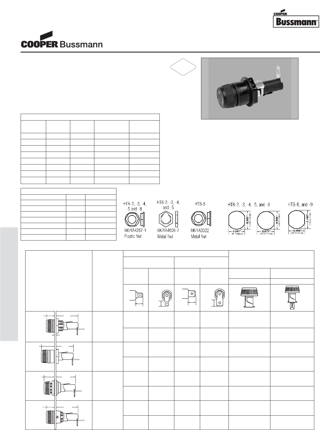
OC-102
Accessories - Fuseholders
Description
• For 1/4" x 1-1/4" and 5mm x 20mm fuses
• All holder bodies have the option of using
1/4" x 1-1/4" or 5mm x 20mm carriers
• Withstands 15 to 20 lbs-in torque to mounting
nut when mounting fuseholder to panel
• High temperature, flame retardant,
Thermoplastic meets UL 94 VO
Agency Information
• UL Recognized: IZLT2, E14853
• CSA Component Acceptance:
Class 6225-01, File 47235
• VDE Certified: 136128, HTB-XXM
• SEMKO Certification: Ref. #0146149/01, HTB-XXM
Replacement Parts Mounting Dimensions
Maximum Panel Thickness
Body Type Inch Millimeters
HTB-2 0.30 7.62
HTB-3 0.30 7.62
HTB-4 0.125 3.18
HTB-5 0.125 3.18
HTB-6 0.30 7.62
HTB-8 0.125 3.18
HTB-9 0.125 3.18
SPECIFICATIONS
Product Current Voltage Fuse Quick
Code Rating Rating Size Connect
HTB-X2I 15A 250V 1/4" x 1-1/4" 3/16"
HTB-X4I 15A 250V 1/4" x 1-1/4" 3/16"
HTB-X6I 20A 250V 1/4" x 1-1/4" 1/4"
HTB-X8I 20A 250V 1/4" x 1-1/4" 1/4"
HTB-X2M 15A 250V 5mm x 20mm 3/16"
HTB-X4M 15A 250V 5mm x 20mm 3/16"
HTB-X6M 16A 250V 5mm x 20mm 1/4"
HTB-X8M 16A 250V 5mm x 20mm 1/4"
HTB-8
HTB-6
HTB-2
HTB-4
Dimensional Data
Terminal Options
Knob Type Carrier Solder/ Carrier Options
‹Ω¡§∑ Quick-Connect ⁄Ω¢∑ Quick-Connect
⁄Ω¢∑ x 1⁄Ω¢∑ 5mm x 20mm
In-Line Rt. Angle In-Line Rt. Angle (“I” Equals Inches) (“M” Equals Metric)
Common Dimensional Data: Knob Knob
Length (Knob Type) - 1.69∑
(42.9mm) Plus In-Line Terminal
(Screwdriver Slotted)
1.75∑(44.5mm)
NOTE: Plus In-Line Terminal
HTB-22I HTB-24I HTB-26I HTB-28I ✓—
—
HTB-22M HTB-24M HTB-26M HTB-28M — ✓
HTB-42I HTB-44I HTB-46I HTB-48I ✓—
—
HTB-42M HTB-44M HTB-46M HTB-48M — ✓
HTB-62I HTB-64I HTB-66I HTB-68I ✓—
—
HTB-62M HTB-64M HTB-66M HTB-68M — ✓
HTB-82I HTB-84I HTB-86I HTB-88I ✓—
—
HTB-82M HTB-84M HTB-86M HTB-88M — ✓
1.125"
(28.6mm)
0.47"
(11.9mm)
0.09" NOM.
(2.4mm)
1.125"
(28.6mm)
0.47"
(11.9mm)
0.92"
(23.4mm)
0.67"
(17.1mm)
0.91"
(23.0mm)
0.69"
(17.5mm)
0.34"
(8.7mm)
0.33"
(8.3mm)
0.47"
(11.9mm) 0.45"
(11.5mm)
Fuseholders and fuse carriers may be ordered separately.
0.30∑
7.62mm
0.125∑
3.18mm
0.30∑
7.62mm
0.125∑
3.18mm
Maximum
Panel
Thickness
Low Profile
Rear Hex Nut
High
Profile
Rear Hex Nut
Front
Hex Nut
Low Profile
Snap-In
Fuseholders
HTB Panel Mount Series
RoHS
2002/95/EC
Courtesy of Steven Engineering, Inc.-230 Ryan Way, South San Francisco, CA 94080-6370-Main Office: (650) 588-9200-Outside Local Area: (800) 258-9200-www.stevenengineering.com
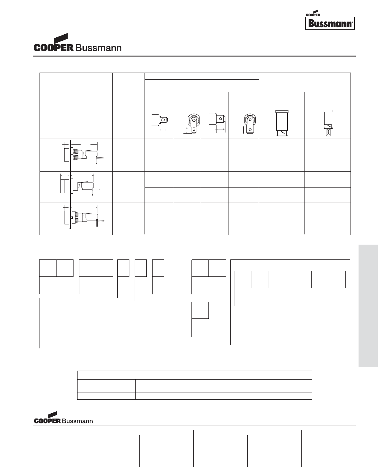
PACKAGING CODE
Packaging Code Description
Blank 10 pieces of fuseholders packed into a carton
BK 100 pieces of fuseholders packed into a cardboard shelf package
S
Packing
(Blank) – Std.
BK/ – Bulk
Rear Terminal Configuration
2 — Solder / ‹Ω¡§∑ Quick-Connect
Solder / ‹Ω¡§∑ Quick-Connect
(In-Line)
4 —
(Right Angle)
6 — ⁄Ω¢∑ Quick-Connect (In-Line)
8 — ⁄Ω¢∑ Quick-Connect (Right Angle)
Fuse Carrier
I — ⁄Ω¢∑ x 1-1⁄Ω¢∑
M — 5mm x 20mm
Splash Proof
(Optional on -2,
-4, -6, and -8)
Body Configuration and Mounting
Finger Grip Holders
2 — Low Profile (Rear Panel Hex-Nut)
4 — High Profile
*6 — (Front Panel Hex-Nut)
8 — Low Profile (Snap-In)
Screwdriver Slotted Holders
3 — Low Profile
5 — High Profile
9 — Low Profile (Snap-In)
Product
Symbol
HTB-
Packaging
(Blank) – Std.
BK/ – Bulk
Fuse Carrier
I — ⁄Ω¢∑ x 1⁄Ω¢∑
M — 5mm x 20mm
Product
Symbol
FT — Knob Type
(For 20, 40, 60,
and 80 Series
Only)
ST — Screwdriver
Slotted (For 30,
50, and 90 Series
Only)
P
-R
RoHS
Compliant
Version
*Profile varies with panel thickness. Holder installs thru rear of panel.
FUSE CARRIER ONLY
Ordering Information
HTB-3
HTB-5
HTB-9
0.17"
(4.37mm)
1.58"
(40.03mm)
0.17"
(4.37mm)
1.59"
(40.08mm)
0.41"
(10.31mm)
1.34"
(34.13mm)
0.34"
(8.7mm) 0.33"
(8.3mm)
0.47"
(11.9mm) 0.45"
(11.5mm)
Dimensional Data
Terminal Options
Knob Type Carrier Solder/ Carrier Options
‹Ω¡§∑ Quick-Connect ⁄Ω¢∑ Quick-Connect
⁄Ω¢∑ ≈ 1⁄Ω¢∑ 5mm ≈20mm
In-Line Rt. Angle In-Line Rt. Angle (“I” Equals Inches) (“M” Equals Metric)
Common Dimensional Data: Screwdriver Screwdriver
Length (Knob Type) - 1.69∑
(42.9mm) Plus In-Line Terminal
(Screwdriver Slotted)
1.75∑(44.5mm)
NOTE: Plus In-Line Terminal
HTB-32I HTB-34I HTB-36I HTB-38I ✓—
—
HTB-32M HTB-34M HTB-36M HTB-38M — ✓
HTB-52I HTB-54I HTB-56I HTB-58I ✓—
—
HTB-52M HTB-54M HTB-56M HTB-58M — ✓
HTB-92I HTB-94I HTB-96I HTB-98I ✓—
—
HTB-92M HTB-94M HTB-96M HTB-98M — ✓
Fuseholders and fuse carriers may be ordered separately.
0.30∑
7.62mm
0.125∑
3.18mm
0.125∑
3.18mm
Maximum
Panel
Thickness
Low Profile
Rear Hex Nut
High Profile
Rear Hex Nut
Low-Profile
Snap-In
Fuseholders
HTB Panel Mount Series
Visit us on the web at:
www.cooperbussmann.com
Cooper Electronic Technologies
1225 Broken Sound Parkway NW
Suite F
Boca Raton, FL 33487-3533
Tel: 1-561-998-4100
Fax: 1-561-241-6640
Toll Free: 1-888-414-2645
Cooper Bussmann
P.O. Box 14460
St. Louis, MO 63178-4460
Tel: 1-636-394-2877
Fax: 1-800-544-2570
Cooper Electronic Technologies
Cooper (UK) Limited
Burton-on-the-Wolds
Leicestershire • LE12 5TH UK
Tel: +44 (0) 1509 882 737
Fax: +44 (0) 1509 882 786
Cooper Electronic Technologies
Avda. Santa Eulalia, 290
08223
Terrassa, (Barcelona), Spain
Tel: +34 937 362 812
+34 937 362 813
Fax: +34 937 362 719
Asia Pacific
Cooper Electronic Technologies
1 Jalan Kilang Timor
#06-01 Pacific Tech Centre
Singapore 159303
Tel: +65 278 6151
Fax: +65 270 4160
North America Europe
OC-103
Accessories - Fuseholders
Courtesy of Steven Engineering, Inc.-230 Ryan Way, South San Francisco, CA 94080-6370-Main Office: (650) 588-9200-Outside Local Area: (800) 258-9200-www.stevenengineering.com
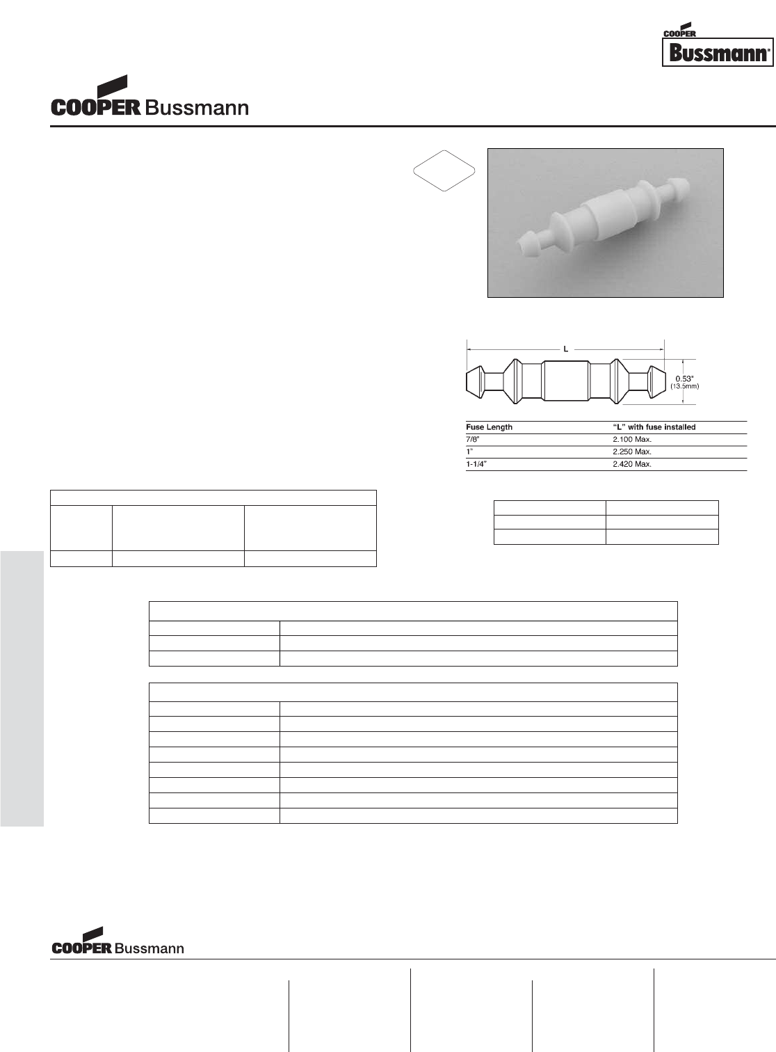
OC-104
Accessories - Fuseholders
Description
• For 1/4" x 7/8" to 1/4" x 1-1/4" fuses
• Accepts #16 to #12 AWG copper wire
• Simple crimp assembly
• “Snap-Lock” feature provides strong positive union
• High visibility yellow color
• Recommended crimp tools:
• Thomas & Betts – ERG-2002
• Channelock No. 909
• General Electric – U.S. & Metric Electrical
Terminal Tool
• UL flammability rating 94 V2
Environmental Data
• Pull Force: 5 pounds minimum to separate
fuseholder housing with fuse inside
Ordering
• Specify packaging, product, and option code
PACKAGING CODE
Packaging Code Description
Blank 10 pieces of fuseholders packed into a carton
BK 1,000 pieces of fuseholders packed into a cardboard shelf package
OPTION CODE
Option Code Description
Y408 #14 AWG insulated wire with 8 inch yellow leads
R408 #14 AWG insulated wire with 8 inch red leads
B408 #14 AWG insulated wire with 8 inch black leads
Y419 #14 AWG insulated wire with 19 inch yellow leads
R419 #14 AWG insulated wire with 19 inch red leads
B419 #14 AWG insulated wire with 19 inch black leads
-R RoHS Compliant version
SPECIFICATIONS
Product Voltage Current
Code Rating Rating
AC AC
HHB 32V 30A
Dimensions
Drawing Not to Scale
Component Material
Body Nylon
Crimp Copper Tin-Plated
1/4" x 7/8" to 1-1/4" Fuseholders
HHB In-Line Series
Visit us on the web at:
www.cooperbussmann.com
Cooper Electronic Technologies
1225 Broken Sound Parkway NW
Suite F
Boca Raton, FL 33487-3533
Tel: 1-561-998-4100
Fax: 1-561-241-6640
Toll Free: 1-888-414-2645
Cooper Bussmann
P.O. Box 14460
St. Louis, MO 63178-4460
Tel: 1-636-394-2877
Fax: 1-800-544-2570
Cooper Electronic Technologies
Cooper (UK) Limited
Burton-on-the-Wolds
Leicestershire • LE12 5TH UK
Tel: +44 (0) 1509 882 737
Fax: +44 (0) 1509 882 786
Cooper Electronic Technologies
Avda. Santa Eulalia, 290
08223
Terrassa, (Barcelona), Spain
Tel: +34 937 362 812
+34 937 362 813
Fax: +34 937 362 719
Asia Pacific
Cooper Electronic Technologies
1 Jalan Kilang Timor
#06-01 Pacific Tech Centre
Singapore 159303
Tel: +65 278 6151
Fax: +65 270 4160
North America Europe
RoHS
2002/95/EC
Courtesy of Steven Engineering, Inc.-230 Ryan Way, South San Francisco, CA 94080-6370-Main Office: (650) 588-9200-Outside Local Area: (800) 258-9200-www.stevenengineering.com
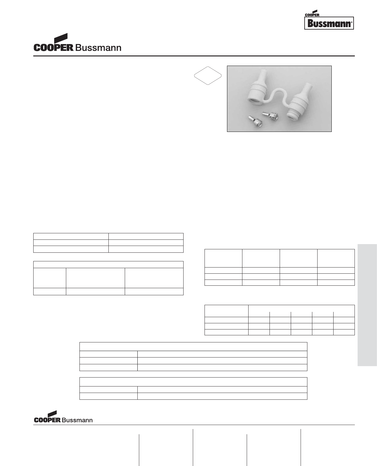
Description
• For 1/4" x 1-1/4" (6.35mm x 31.8mm) fuses
• Ideal for harsh environments
• Water
• Salt Spray
• Ultraviolet Light
• Ozone
• -40° to 150°C temperature range
• Withstands many organic solvents
and rigorous shock and vibration
• Accepts #18 to #12 AWG copper wire
• High visibility yellow color
• Recommended crimp tools:
• Thomas & Betts – WT-112M
• California Terminal Products No. 1250
• Channelock No. 909
• Replacement contact clip: BK/1A2294
• UL flammability rating 94 HB
Ordering
• Specify packaging, product, and option code
Environmental Data
• Temperature Rating (RTI): 100°C
• Waterproof typically to a depth of 1 foot for 2 hours
• Vibration Resistance: Per MIL STD 810C
• Humidity: 85°C/85% relative humidity for 96 hours
• Brittle Point: Less than -60°C
• Abrasion: 54% NBS index
• Fluid resistance: Type and Class AA, BA, BC, BE, CA,
CE per ASTM D-2000 Standard Classification System
for rubbers
• Flame Resistance: Pass FMVSS302 and related slow
burning when tested in accordance with UL 94HB
• Ozone Resistance: Passed 70 Hours in 50 ppm ozone
per ASTM D-5
• Salt Spray: 15% for 166 hours = 0% volume swell
• Xenon Arc Weatherometer
• Heat Aging (% Retention of Mechanical
Properties at 125°C)
PACKAGING CODE
Packaging Code Description
Blank 10 pieces of fuseholders packed into a carton
BK 100 pieces of fuseholders packed into a poly bag
OPTION CODE
Option Code Description
-R RoHS compliant version
SPECIFICATIONS
Product Voltage Current
Code Rating Rating
AC AC
HFB 32V 30A
Component Material
Body Thermoplastic Rubber
Crimp Copper Tin-Plated Tensile 100%
Time Strength Elong. Mod.
(Hrs) (psi) (%) (psi)
0 1100 375 470
500 1130 350 520
1000 1190 350 520
Days
Parameters 1 7 15 30 41.7
Tensile Strength 100 105 115 120 120
% Elongation 90 90 90 90 90
100% Mod. 105 110 120 120 120
1/4" x 1-1/4" Fuseholders
HFB In-Line Waterproof Series
Visit us on the web at:
www.cooperbussmann.com
Cooper Electronic Technologies
1225 Broken Sound Parkway NW
Suite F
Boca Raton, FL 33487-3533
Tel: 1-561-998-4100
Fax: 1-561-241-6640
Toll Free: 1-888-414-2645
Cooper Bussmann
P.O. Box 14460
St. Louis, MO 63178-4460
Tel: 1-636-394-2877
Fax: 1-800-544-2570
Cooper Electronic Technologies
Cooper (UK) Limited
Burton-on-the-Wolds
Leicestershire • LE12 5TH UK
Tel: +44 (0) 1509 882 737
Fax: +44 (0) 1509 882 786
Cooper Electronic Technologies
Avda. Santa Eulalia, 290
08223
Terrassa, (Barcelona), Spain
Tel: +34 937 362 812
+34 937 362 813
Fax: +34 937 362 719
Asia Pacific
Cooper Electronic Technologies
1 Jalan Kilang Timor
#06-01 Pacific Tech Centre
Singapore 159303
Tel: +65 278 6151
Fax: +65 270 4160
North America Europe
RoHS
2002/95/EC
OC-105
Accessories - Fuseholders
Courtesy of Steven Engineering, Inc.-230 Ryan Way, South San Francisco, CA 94080-6370-Main Office: (650) 588-9200-Outside Local Area: (800) 258-9200-www.stevenengineering.com
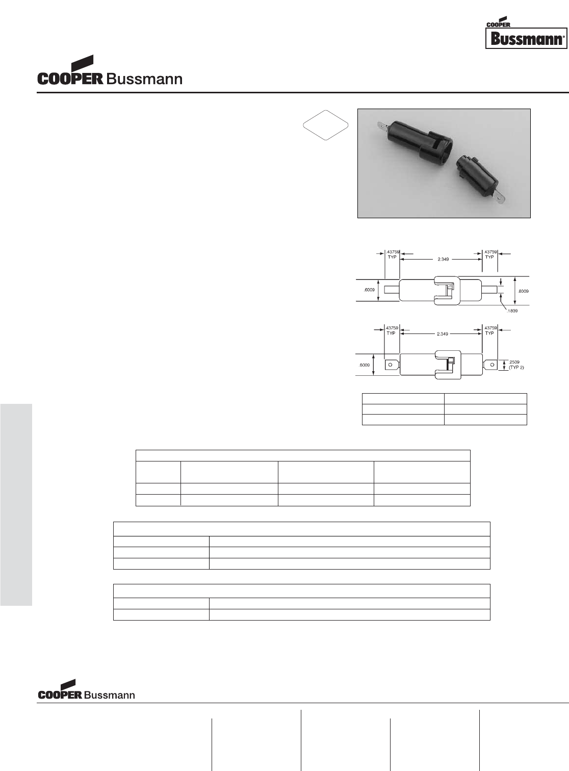
OC-106
Accessories - Fuseholders
Description
• For 1/4" x 1-1/4" (6.35mm x 31.8mm) fuses
• Waterproof for exposed locations
• Accepts #16 to #12 copper wire
• Copper crimp lead material
• Recommended crimp tools:
• Thomas & Betts – WT-112M
• Thomas & Betts – ERG-2002
• Channelock No. 909
• High temperature, flame retardant,
phenolic meets UL 94 HB
• Crimp or 1/4" quick connect terminals
• In-line connection
Agency Information
• UL Recognized: (IZLT2, E14853) HFA recognized with
use of No. 12 AWG copper conductors secured with
Thomas & Betts crimping tool WT-180 or WT-112M
• HFA-HH not UL Recognized
Environmental Data
• Temperature Rating (RTI): 150°C
Ordering
• Specify packaging, product, and option code
PACKAGING CODE
Packaging Code Description
Blank 10 pieces of fuseholders packed into a carton
BK 20 pieces of fuseholders packed into a carton
OPTION CODE
Option Code Description
-R RoHS compliant version
SPECIFICATIONS
Product Voltage Current
Code Rating Rating Terminal
HFA 250V 20A Crimp
HFA-HH 250V 20A 1/4 Quick Connect
Dimensions
Drawing Not to Scale
Component Material
Body Phenolic
Crimp Copper, Tin-Plated
1/4" x 1-1/4" Fuseholders
HFA In-Line Waterproof Series
Visit us on the web at:
www.cooperbussmann.com
Cooper Electronic Technologies
1225 Broken Sound Parkway NW
Suite F
Boca Raton, FL 33487-3533
Tel: 1-561-998-4100
Fax: 1-561-241-6640
Toll Free: 1-888-414-2645
Cooper Bussmann
P.O. Box 14460
St. Louis, MO 63178-4460
Tel: 1-636-394-2877
Fax: 1-800-544-2570
Cooper Electronic Technologies
Cooper (UK) Limited
Burton-on-the-Wolds
Leicestershire • LE12 5TH UK
Tel: +44 (0) 1509 882 737
Fax: +44 (0) 1509 882 786
Cooper Electronic Technologies
Avda. Santa Eulalia, 290
08223
Terrassa, (Barcelona), Spain
Tel: +34 937 362 812
+34 937 362 813
Fax: +34 937 362 719
Asia Pacific
Cooper Electronic Technologies
1 Jalan Kilang Timor
#06-01 Pacific Tech Centre
Singapore 159303
Tel: +65 278 6151
Fax: +65 270 4160
North America Europe
RoHS
2002/95/EC
Courtesy of Steven Engineering, Inc.-230 Ryan Way, South San Francisco, CA 94080-6370-Main Office: (650) 588-9200-Outside Local Area: (800) 258-9200-www.stevenengineering.com
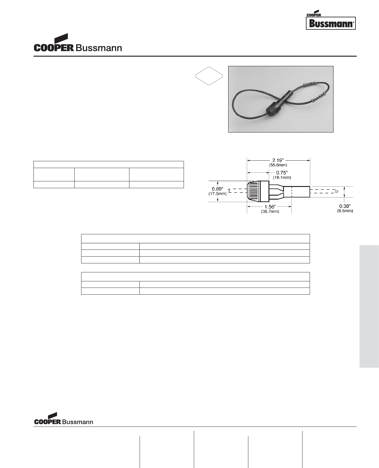
OC-107
Accessories - Fuseholders
Description
• For 1/4" x 7/8" to 1/4" x 1-1/4" fuses
• #14 AWG copper wire leads
• 8" (203mm) leads
• Three springs furnished to accept different fuse lengths
• Wire leads are staked and soldered to the contacts of
the fuseholder
Ordering
• Specify packaging, product, and option code
PACKAGING CODE
Packaging Code Description
Blank 10 pieces of fuseholder packed into a carton
BK 100 pieces of fuseholder packed into a carton
OPTION CODE
Option Code Description
-R RoHS compliant version
Dimensions
Drawing Not to Scale
SPECIFICATIONS
Product Voltage Current
Code Rating Rating
HRK 32V 15A
1/4" x 7/8" to 1-1/4" Fuseholders
HRK Universal In-Line Series
Visit us on the web at:
www.cooperbussmann.com
Cooper Electronic Technologies
1225 Broken Sound Parkway NW
Suite F
Boca Raton, FL 33487-3533
Tel: 1-561-998-4100
Fax: 1-561-241-6640
Toll Free: 1-888-414-2645
Cooper Bussmann
P.O. Box 14460
St. Louis, MO 63178-4460
Tel: 1-636-394-2877
Fax: 1-800-544-2570
Cooper Electronic Technologies
Cooper (UK) Limited
Burton-on-the-Wolds
Leicestershire • LE12 5TH UK
Tel: +44 (0) 1509 882 737
Fax: +44 (0) 1509 882 786
Cooper Electronic Technologies
Avda. Santa Eulalia, 290
08223
Terrassa, (Barcelona), Spain
Tel: +34 937 362 812
+34 937 362 813
Fax: +34 937 362 719
Asia Pacific
Cooper Electronic Technologies
1 Jalan Kilang Timor
#06-01 Pacific Tech Centre
Singapore 159303
Tel: +65 278 6151
Fax: +65 270 4160
North America Europe
RoHS
2002/95/EC
Courtesy of Steven Engineering, Inc.-230 Ryan Way, South San Francisco, CA 94080-6370-Main Office: (650) 588-9200-Outside Local Area: (800) 258-9200-www.stevenengineering.com
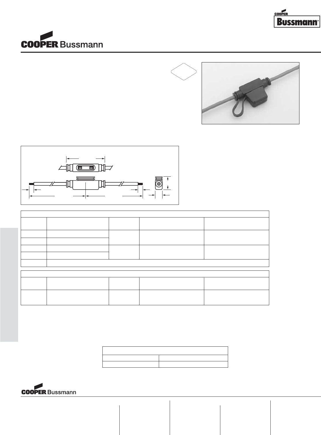
OC-108
Accessories - Fuseholders
Description
• In-Line Fuseholders for MINI®Fuses.
• Voltage Rating: 32Vdc maximum
• Current Rating: See Table
• Body material withstands high temps. Protective cover
has removable straps.
Ordering
• Specify packaging and product code
1.56"
4.75" 4.75"
.25"
.25"
.59"
.41"
MINI®Fuse Blade Type Holder
Catalog Electrical Maximum Continuous
No. Description Fuse Size Connection Current Rating
HHL Black fuseholder w/cover 2-20A #16 black lead wire; 16A*
HHL-B Black fuseholder - Body only 4" length stripped to 1/4"
HHM Black fuseholder w/cover #12 red lead wire; 24A*
HHM-B Black fuseholder - Body only 2-30A 4" length stripped to 1/4"
HHM-C Black cover only
Bulk Products (Bulk Quantity - 1000 Pieces)
Catalog Electrical Maximum Continuous
No. Description Fuse Size Connection Current Rating
BK/HHL-R Black fuseholder - Body only 2-20A #16 red lead wire; 16A*
4" length stripped to 1/4"
PACKAGING CODE
Packaging Code Description
BK 1,000 pieces in a box
* or 80% of fuse rating, whichever is less
A fuse must be properly and fully inserted into the holder to provide a solid connection. Poor or
improper insertion of the fuse can result in failure of the fuse and holder, thus not protecting the
device for which it was intended.
MINI®Fuseholders
HHL & HHM
Visit us on the web at:
www.cooperbussmann.com
Cooper Electronic Technologies
1225 Broken Sound Parkway NW
Suite F
Boca Raton, FL 33487-3533
Tel: 1-561-998-4100
Fax: 1-561-241-6640
Toll Free: 1-888-414-2645
Cooper Bussmann
P.O. Box 14460
St. Louis, MO 63178-4460
Tel: 1-636-394-2877
Fax: 1-800-544-2570
Cooper Electronic Technologies
Cooper (UK) Limited
Burton-on-the-Wolds
Leicestershire • LE12 5TH UK
Tel: +44 (0) 1509 882 737
Fax: +44 (0) 1509 882 786
Cooper Electronic Technologies
Avda. Santa Eulalia, 290
08223
Terrassa, (Barcelona), Spain
Tel: +34 937 362 812
+34 937 362 813
Fax: +34 937 362 719
Asia Pacific
Cooper Electronic Technologies
1 Jalan Kilang Timor
#06-01 Pacific Tech Centre
Singapore 159303
Tel: +65 278 6151
Fax: +65 270 4160
North America Europe
RoHS
2002/95/EC
Courtesy of Steven Engineering, Inc.-230 Ryan Way, South San Francisco, CA 94080-6370-Main Office: (650) 588-9200-Outside Local Area: (800) 258-9200-www.stevenengineering.com
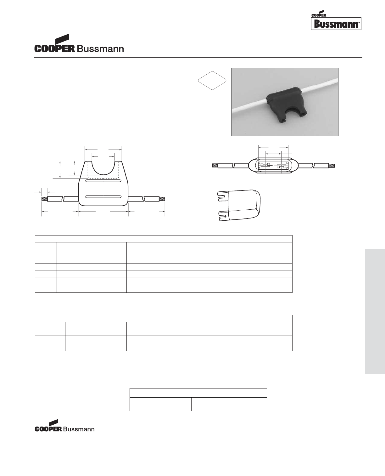
OC-109
Accessories - Fuseholders
Description
• In-Line Fuseholders
• Voltage Rating: 32Vdc maximum
• Current Rating: See Table
Ordering
• Specify packaging and product code
0
.
9
1
"
0
.
5"
0
.
38"
0
.
30"
4.
0
"
+
0
.2
5"
4.
0
"
+
0
.2
5"
1.125"
0
.2
5"
0
.7
8"
0
.
36
4
"
Dimensional Data
Electrical Ratings
Catalog Fuse Electrical Maximum Continuous
Code Description Size Connection Current Rating
HHC Yellow fuseholder 3-20A #16 black leadwire 16A*
HHD Black fuseholder 3-30A #12 yellow leadwire 24A*
HHD-C Cover only Fits HHD only Clear polycarbonate
HHF Black fuseholder 3-20A #16 yellow leadwire 16A*
HHG Black fuseholder w/ cover 3-30A #12 yellow leadwire 24A*
* or 80% of fuse rating, whichever is less.
• For ATC®blade-type fuses.
• “Write-in” space for circuit identification on HHC holders (bright yellow)
* or 80% of fuse rating, whichever is less.
Cover for HHD Fuseholder
Catalog Symbol: HHD-C
Bulk Products (Bulk Quantity - 1000 Pieces)
Catalog Fuse Electrical Maximum Continuous
Code Description Size Connection Current Rating
BK/HHC-R Yellow fuseholder 3-20A #16 red leadwire 16A*
BK/HHF-B Black fuseholder w/ cover 3-20A #16 black leadwire 16A*
PACKAGING CODE
Packaging Code Description
BK 1,000 pieces in a box
A fuse must be properly and fully inserted into the holder to provide a solid connection. Poor or
improper insertion of the fuse can result in failure of the fuse and holder, thus not protecting the
device for which it was intended.
ATC®Fuseholders
HHC, HHD, HHF, HHG
Visit us on the web at:
www.cooperbussmann.com
Cooper Electronic Technologies
1225 Broken Sound Parkway NW
Suite F
Boca Raton, FL 33487-3533
Tel: 1-561-998-4100
Fax: 1-561-241-6640
Toll Free: 1-888-414-2645
Cooper Bussmann
P.O. Box 14460
St. Louis, MO 63178-4460
Tel: 1-636-394-2877
Fax: 1-800-544-2570
Cooper Electronic Technologies
Cooper (UK) Limited
Burton-on-the-Wolds
Leicestershire • LE12 5TH UK
Tel: +44 (0) 1509 882 737
Fax: +44 (0) 1509 882 786
Cooper Electronic Technologies
Avda. Santa Eulalia, 290
08223
Terrassa, (Barcelona), Spain
Tel: +34 937 362 812
+34 937 362 813
Fax: +34 937 362 719
Asia Pacific
Cooper Electronic Technologies
1 Jalan Kilang Timor
#06-01 Pacific Tech Centre
Singapore 159303
Tel: +65 278 6151
Fax: +65 270 4160
North America Europe
RoHS
2002/95/EC
Courtesy of Steven Engineering, Inc.-230 Ryan Way, South San Francisco, CA 94080-6370-Main Office: (650) 588-9200-Outside Local Area: (800) 258-9200-www.stevenengineering.com
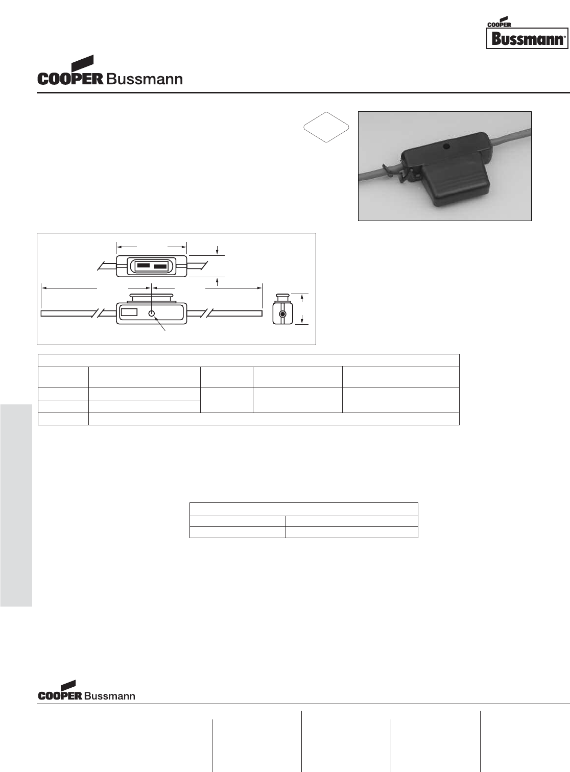
OC-110
Accessories - Fuseholders
3.35"
6.70" 6.70"
1.37"
.265" DIA. HOLE
Description
• In-Line Fuseholders for MAXI®Fuses.
• Voltage Rating: 32Vdc maximum
• Current Rating: See Table
• Firewall mounting hole permits two or more holders to
be mounted together. Cover comes with a removable
strap.
Ordering
• Specify packaging and product code
PACKAGING CODE
Packaging Code Description
BK 100 pieces in a box
MAXI
®
Fuse Blade Type Holder
Catalog Electrical Maximum Continuous
Code Description Fuse Size Connection Current Rating
HHX Black fuseholder w/cover #6 red lead wire;
HHX-B Black fuseholder - Body only 20-60A 5" length with blunt ends 48A*
HHX-C Black cover only
* or 80% of fuse rating, whichever is less
A fuse must be properly and fully inserted into the holder to provide a solid connection. Poor or
improper insertion of the fuse can result in failure of the fuse and holder, thus not protecting the
device for which it was intended.
MAXI®Fuseholders
HHX
Visit us on the web at:
www.cooperbussmann.com
Cooper Electronic Technologies
1225 Broken Sound Parkway NW
Suite F
Boca Raton, FL 33487-3533
Tel: 1-561-998-4100
Fax: 1-561-241-6640
Toll Free: 1-888-414-2645
Cooper Bussmann
P.O. Box 14460
St. Louis, MO 63178-4460
Tel: 1-636-394-2877
Fax: 1-800-544-2570
Cooper Electronic Technologies
Cooper (UK) Limited
Burton-on-the-Wolds
Leicestershire • LE12 5TH UK
Tel: +44 (0) 1509 882 737
Fax: +44 (0) 1509 882 786
Cooper Electronic Technologies
Avda. Santa Eulalia, 290
08223
Terrassa, (Barcelona), Spain
Tel: +34 937 362 812
+34 937 362 813
Fax: +34 937 362 719
Asia Pacific
Cooper Electronic Technologies
1 Jalan Kilang Timor
#06-01 Pacific Tech Centre
Singapore 159303
Tel: +65 278 6151
Fax: +65 270 4160
North America Europe
RoHS
2002/95/EC
Courtesy of Steven Engineering, Inc.-230 Ryan Way, South San Francisco, CA 94080-6370-Main Office: (650) 588-9200-Outside Local Area: (800) 258-9200-www.stevenengineering.com
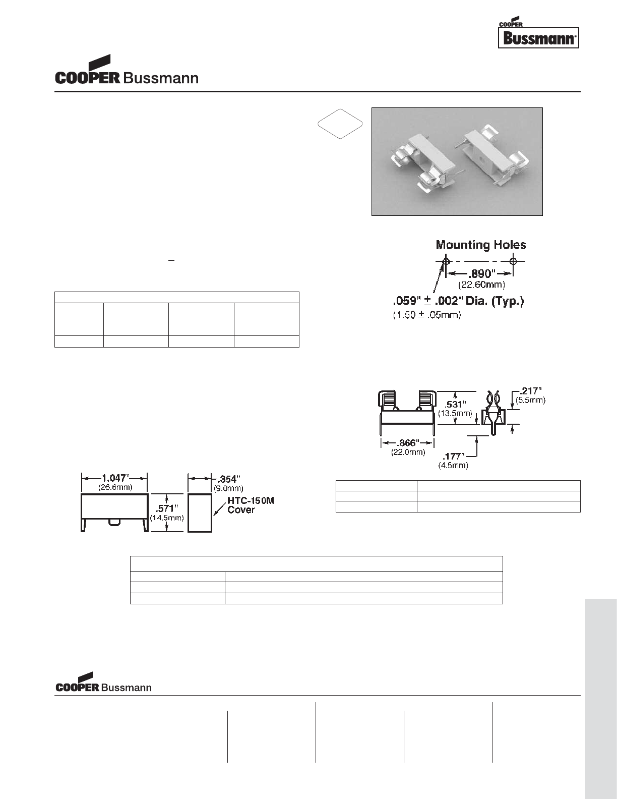
OC-111
Accessories - Fuseblocks
Description
• For 5 x 20mm fuses
• With snap-on cover
• BK/HTC-150M (Transparent Cover)
• Tight cluster mounting
• Clips made of nickel-tin plated spring-bronze
• Available only in bulk of 100 and 1,000 pieces
• High temperature thermoplastic meets:
• UL 94-VO
• Glow wire test: 960°C per IEC 695-2-1
Environmental Data
• Maximum suitable temperature: 110°C
• MSL Level 1 (conditions < 30°C / 85% RH)
Ordering
• Specify packaging and product code
Agency Information
• UL Recognized: IZLT2, E14853
• SEMKO Certificate: 204805
• VDE Certificate: 40004439
PACKAGING CODE
Packaging Code Description
BK 100 pieces of fuse blocks packed into a cardboard shelf package
BK1 1,000 pieces of fuse blocks packed into a carton
Mounting Holes
Dimensions - in (mm)
HTC-15M Fuse Block Only
Drawing Not to Scale
Component Material
Clip Spring-Bronze, Bright Tin Plate
Body Thermoplastic
Dimensions - in (mm)
HTC-150M Fuse Block with Cover
Drawing Not to Scale
SPECIFICATIONS
Catalog Voltage Current
Number Rating Rating Watts
AC AC
HTC-15M 250V 6.3A 1.6W
5 x 20mm Fuse Blocks
HTC Series
Visit us on the web at:
www.cooperbussmann.com
Cooper Bussmann
1225 Broken Sound Parkway NW
Suite F
Boca Raton, FL 33487-3533
Tel: 1-561-998-4100
Fax: 1-561-241-6640
Toll Free: 1-888-414-2645
Cooper Bussmann
P.O. Box 14460
St. Louis, MO 63178-4460
Tel: 1-636-394-2877
Fax: 1-800-544-2570
Cooper Bussmann
Cooper (UK) Limited
Burton-on-the-Wolds
Leicestershire • LE12 5TH UK
Tel: +44 (0) 1509 882 737
Fax: +44 (0) 1509 882 786
Cooper Bussmann
Avda. Santa Eulalia, 290
08223
Terrassa, (Barcelona), Spain
Tel: +34 937 362 812
+34 937 362 813
Fax: +34 937 362 719
Asia Pacific
Cooper Bussmann
1 Jalan Kilang Timor
#06-01 Pacific Tech Centre
Singapore 159303
Tel: +65 278 6151
Fax: +65 270 4160
North America Europe
RoHS
2002/95/EC
Courtesy of Steven Engineering, Inc.-230 Ryan Way, South San Francisco, CA 94080-6370-Main Office: (650) 588-9200-Outside Local Area: (800) 258-9200-www.stevenengineering.com
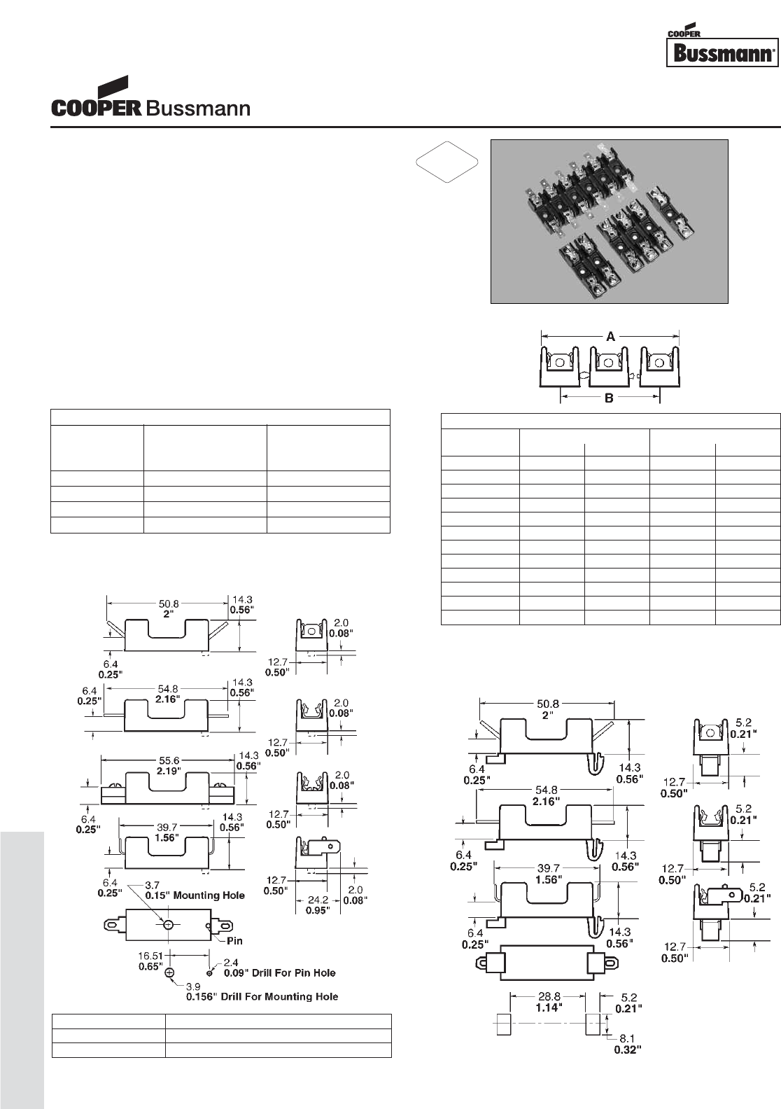
OC-112
Accessories - Fuseblocks
Description
• For 1/4" x 1-1/4" (6.3mm x 32mm) fuses
• Bolt-in and snap-in mounting available
• Tight cluster mounting
• All types of terminal configurations
• Clips made of spring-bronze
• Anti-rotational pin provided
• Flame retardant thermoplastic meets UL 94 VO
Environmental Data
• Temperature Rating (RTI): The mounting body for all
devices (except those with Suffix –1-SNP or –W-SNP),
has a temperature rating of 130°C. The mounting body
for all devices with Suffix –1-SNP has a temperature rat-
ing of 110°C.
Agency Information
• UL Recognized: E14853
• CSA Certified: 47235
SPECIFICATIONS
Voltage Voltage
Rating Rating
AC DC
S-8000 300V 300V
S-8100 300V 300V
S-8200 300V 300V
S-8300 300V 300V
Dimensions
No. of Inches Millimeters
Poles A B A B
1****
21 1/8" 5/8" 28.6 15.9
31 3/4" 1 1/4" 44.4 31.8
42 3/8" 1 7/8" 60.3 47.6
53" 2 1/2" 76.2 63.5
63 5/8" 3 1/8" 92.1 79.4
74 1/4" 3 3/4" 108 95.2
84 7/8" 4 3/8" 123.8 111.1
95 1/2" 5" 139.7 127.0
10 6 1/8" 5 5/8" 155.6 142.9
11 6 3/4" 6 1/4" 171.4 158.8
12 7 3/8" 6 7/8" 187.3 174.6
Multiple Pole
Dimensions
S-8000 Single Pole Bolt-In Mounting Series
S-8000 Single Pole Snap-In Mounting Series
Component Material
Clip Spring-Bronze, Bright Tin-Lead Plate
Body Thermoplastic
1/4" x 1-1/4" Fuseblocks
S-8000 Series
RoHS
2002/95/EC
Courtesy of Steven Engineering, Inc.-230 Ryan Way, South San Francisco, CA 94080-6370-Main Office: (650) 588-9200-Outside Local Area: (800) 258-9200-www.stevenengineering.com
OC-113
Accessories - Fuseblocks
PACKAGING CODE
Packaging Code Description
Blank Varies with number of poles. Contact customer service.
BK/ Varies with number of poles. Contact customer service.
Ordering
• Specify packaging, product, and
option code
Example: BK/S-8001-01-SNP
BK/ S-8 0 01 –01– SNP -R
1234 5 6 7
1. Packaging Code: BK/
2. Series Number: S-8
3. Type Terminal: 0 = Solder
1 = 3/16" Quick Connect
2 = 1/4" Quick Connect
3 = Screw
4. Terminal Angle: 01 = Straight (0°)
02 = 40° Angle
03 = Side*
5. Number of Poles: (01 – 12)
1X = One pole, No Mounting Stud
6. Mounting Style: SNP = Snap-in Mounting
7. RoHS Compliant Version -R
*Available only in single pole
1/4" x 1-1/4" Fuseblocks
S-8000 Series
Visit us on the web at:
www.cooperbussmann.com
Cooper Electronic Technologies
1225 Broken Sound Parkway NW
Suite F
Boca Raton, FL 33487-3533
Tel: 1-561-998-4100
Fax: 1-561-241-6640
Toll Free: 1-888-414-2645
Cooper Bussmann
P.O. Box 14460
St. Louis, MO 63178-4460
Tel: 1-636-394-2877
Fax: 1-800-544-2570
Cooper Electronic Technologies
Cooper (UK) Limited
Burton-on-the-Wolds
Leicestershire • LE12 5TH UK
Tel: +44 (0) 1509 882 737
Fax: +44 (0) 1509 882 786
Cooper Electronic Technologies
Avda. Santa Eulalia, 290
08223
Terrassa, (Barcelona), Spain
Tel: +34 937 362 812
+34 937 362 813
Fax: +34 937 362 719
Asia Pacific
Cooper Electronic Technologies
1 Jalan Kilang Timor
#06-01 Pacific Tech Centre
Singapore 159303
Tel: +65 278 6151
Fax: +65 270 4160
North America Europe
Courtesy of Steven Engineering, Inc.-230 Ryan Way, South San Francisco, CA 94080-6370-Main Office: (650) 588-9200-Outside Local Area: (800) 258-9200-www.stevenengineering.com
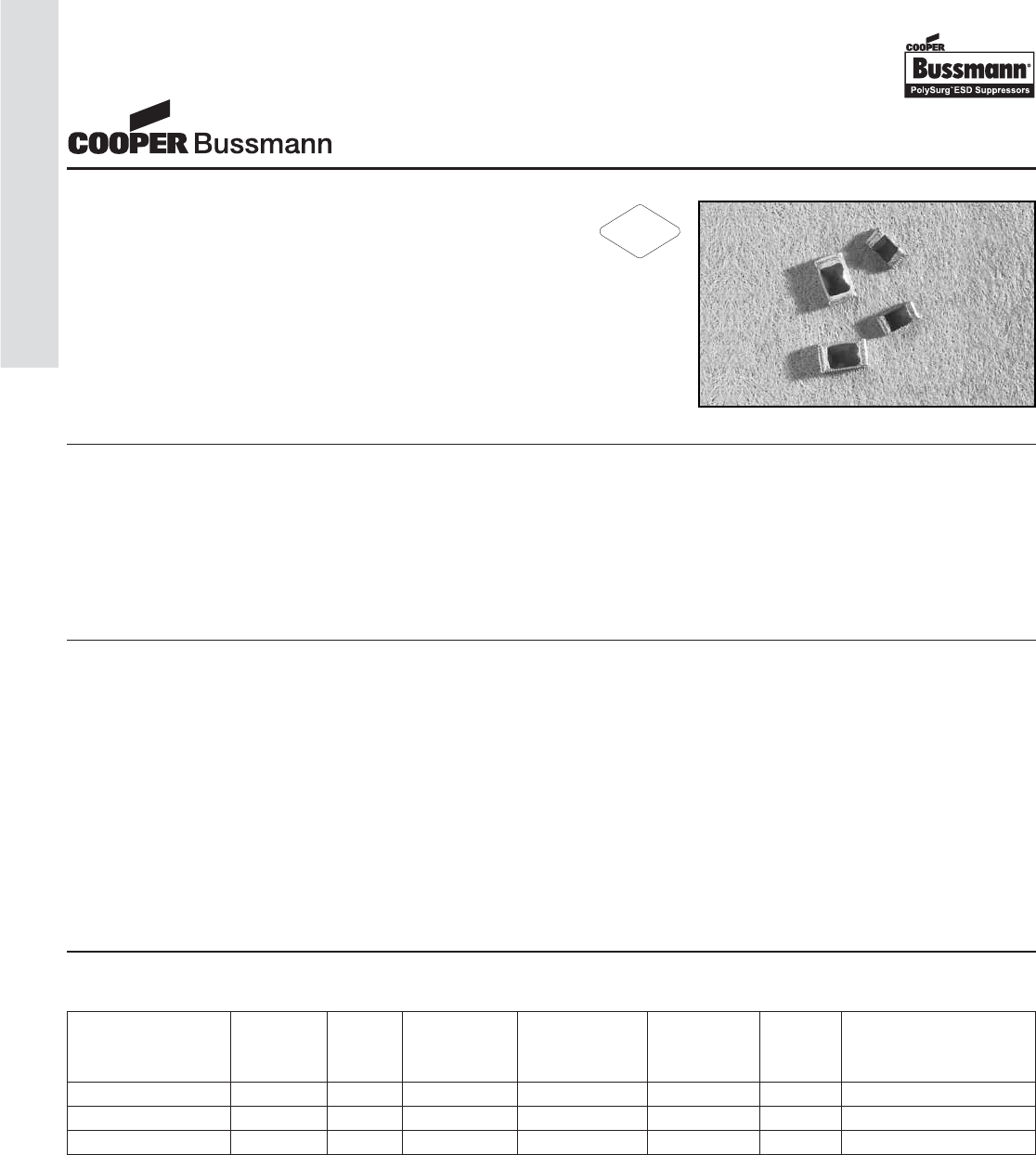
OC-114
ESD Suppression Selection Guide
Our Voltage Variable Material (VVM) has unique
properties that are highly preferred in ESD suppres-
sion applications. The polymer matrix responds to
an over-voltage condition by rapidly changing from
a high impedance state to a low impedance state.
Cooper Bussmann utilizes this polymeric matrix in
PolySurg ESD Suppressors for fast response, ultra
low capacitance, and very low current leakage. The
device is activated by over-voltage threat and clamps
to a low value to protect sensitive circuit components.
What is it:
PolySurg™ ESD Suppressor Selection Guide:
The PolySurg TR and MLP Series are board level
circuit protection devices designed exclusively for the
fast, transient over-voltages associated with ESD.
When a sufficient over-voltage occurs it exhibits a dra-
matic increase in the ability to conduct electrons. The
nature of the material creates a bi-directional part,
which means that only one device is required to pro-
vide complete ESD protection regardless of the surge
polarity. In a typical application, the device is placed
across a signal line leading to an integrated circuit
and ground. The device exhibits minimal capacitance
and is “invisible” to the circuit during the normal oper-
ation. Under normal operating voltages (typically 3 to
15V) the high impedance of the device insulates each
signal line from ground. When an ESD event occurs,
the voltage variable material switches to a conductive
state within nanoseconds. The voltage across signal
line collapses to the clamping level, and current is
shunted through the device to the ground. When the
overvoltage event ends, the circuit returns to its
normal operating state as the device switches back to
its >1012Ohm, high resistance state and “invisibility.”
How it Works:
Features:
• Outstanding ESD protection for high frequency,
low voltage applications.
• Exceeds testing requirements outlined in IEC 61000-4-2
• Extremely low capacitance
• Very low leakage current
• Fast response time
• Bi-directional
• Surface mount
• Solder Termination
Part Package Operating Capacitance Current Clamp
Number Size Lines Voltage (pF @ 1KHz ~ Leakage Voltage Specification
(VDC) 1.8GHz) (nA @ 12VDC) V
0402ESDA-MLP7 0402 1 0 ~ 30 < 0.15 < 0.1 35 IEC61000-4-2, Level 4
0603ESDA-MLP7 0603 1 0 ~ 30 < 0.15 < 0.1 35 IEC61000-4-2, Level 4
0603ESDA-TR1 0603 1 0 ~ 24 < 0.15 < 0.1 35 IEC61000-4-2, Level 4
RoHS
2002/95/EC
ESD Suppression Selection Guide
Polymer ESD Suppressors
Courtesy of Steven Engineering, Inc.-230 Ryan Way, South San Francisco, CA 94080-6370-Main Office: (650) 588-9200-Outside Local Area: (800) 258-9200-www.stevenengineering.com
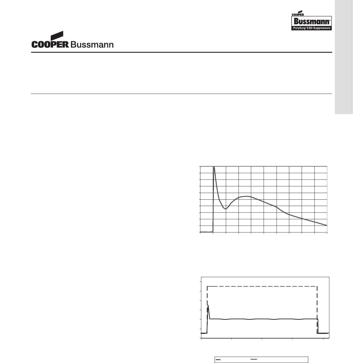
PolySurg™ ESD Suppressors are marked on the tape and reel packages, not individually. Since the product is bi-
directional and symmetrical, no orientation marking is required.
Device Marking
Full product characterization requires use of multiple test methods. Each test method reveals unique information
about the device response. The results of all of the tests must be analyzed to fully understand the PolySurg™ ESD
Suppressor response to an over-voltage event.
Test Methodology
Clamp Voltage – The voltage at which the PolySurg™ device stabilizes during the transition from high to low impedance. This is the voltage
experienced by the circuit, after stabilizing, for the duration of the ESD transient.
Trigger Voltage – The voltage at which the PolySurg™ device begins to function. When the ESD threat voltage reaches this level,
the PolySurg™ device begins the transition from high impedance to low impedance, shunting the ESD energy to ground.
Threat Voltage – The voltage that the test equipment is set to operate (i.e. the voltage across the discharge capacitor).
Peak Current – The maximum instantaneous current level that a device will receive. IEC-61000-4-2 states that the peak current should be
30A at 8kV ESD and 45A at 15kV ESD.
Definition of Terms
The ESD pulse is the defining test for an ESD protec-
tive device. The ESD pulse is an extremely fast rising
transient event. The pulse, as characterized in IEC
61000-4-2, has a rise time of less than 1ns, peak cur-
rents up to 45A, and voltage levels to 15 kV.
Characteristics determined by this test are those such
as voltage overshoot, peak voltage, clamping voltage,
peak current, and device resistance.
Due to the extremely fast rate of rise of the ESD pulse,
the test setup can have a definite impact on the above
factors. Variables such as wiring inductance and probe
capacitance can produce inaccurate readings on an
otherwise capable oscilloscope.
(per IEC 61000-4-2)
0
10
20
30
40
50
60
70
80
90
100
-10 0 10 20 30 40 50 60 70 80 90
Time (nS)
Percent Current
Electrostatic Discharge (ESD) Pulse
The Transmission Line Pulse tester implements a con-
trolled impedance cable to deliver a square wave current
pulse. The advantage of this technique is that the con-
stant current of the square wave allows the behavior of
the protection structure to be more accurately studied.
The actual implementation of this technique produces a
waveform that has a slightly slower rise time that the
ESD pulse but can be correlated to the deliver approxi-
mately the same surge current and energy. This con-
trolled impedance pulse provides a more accurate depic-
tion of the trigger voltage of the device because of the
reduced voltage overshoot caused by a fast rising tran-
sient and the reactive components of the test fixture.
-10
10
30
50
70
90
110
-10 40 90 140 190
Time (nS)
Input VoltageOutput Voltage Activated
Percent Voltage
Transmission Line Pulse (TLP)
ESD Suppression Selection Guide
Polymer ESD Suppressors
OC-115
ESD Suppression Selection Guide
Courtesy of Steven Engineering, Inc.-230 Ryan Way, South San Francisco, CA 94080-6370-Main Office: (650) 588-9200-Outside Local Area: (800) 258-9200-www.stevenengineering.com
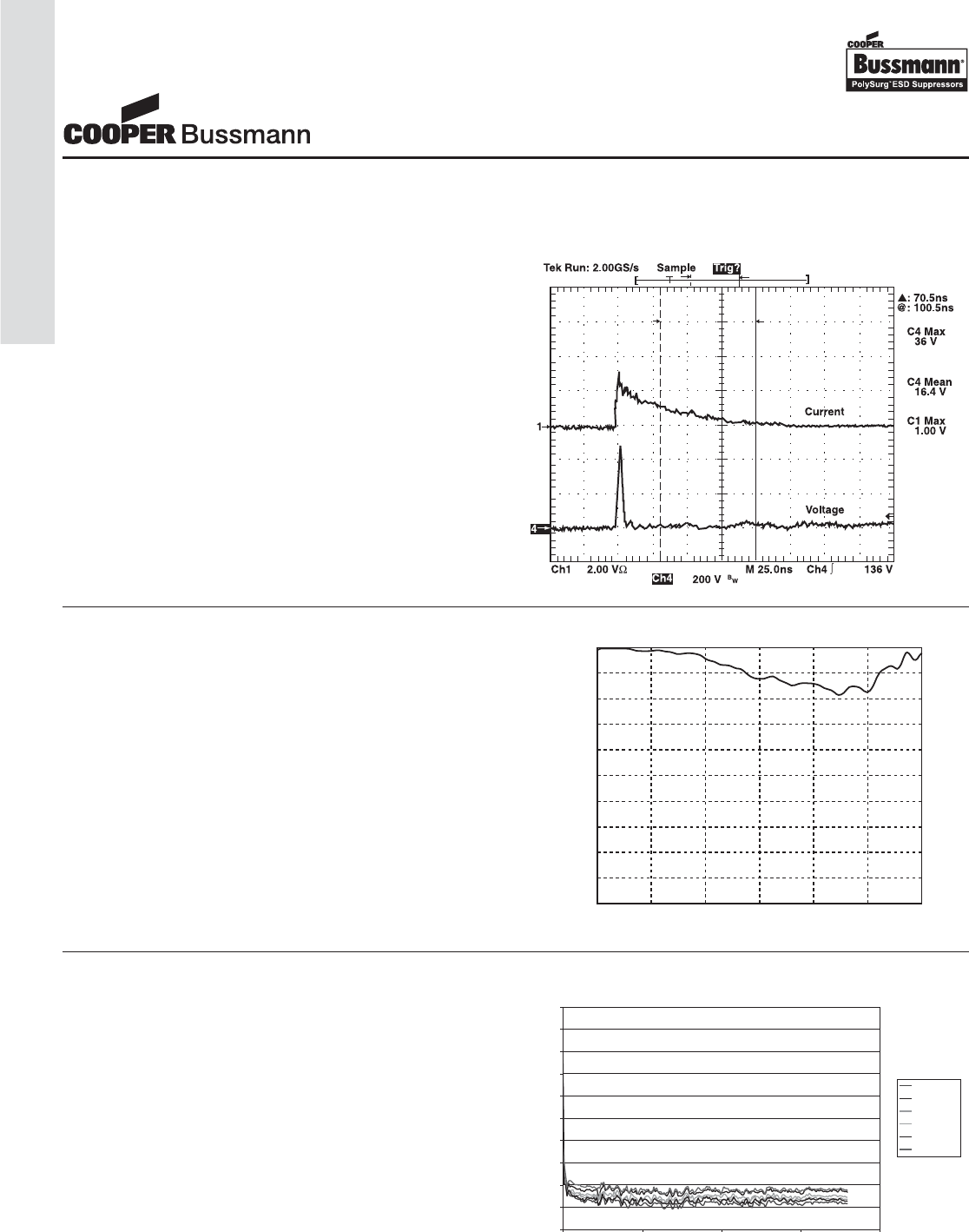
Figure 1. Typical Device Response to 8kV ESD
0
-0.1
-0.2
-0.3
-0.4
-0.5
-0.6
-0.7
-0.8
-0.9
-10 1 2 3 4 5 6
GHz
drop in attenuation (dB)
Figure 2. ESDA device induced interference with Signal Quality
0.10
0.11
0.12
0.13
0.14
0.15
0.16
0.17
0.18
0.19
0.20
0 500 1000 1500 2000
Frequency (MHz)
Capacitance (pF)
0 Pulse
100 Pulse
200 Pulse
300 Pulse
400 Pulse
500 Pulse
Figure 3. Capacitance vs. Frequency
Selected Characterization Data
ESD Transient Pulse Energy Controlled by
PolySurg™
Figure 1 shows typical PolySurg™ ESD Suppressor
response to an 8 kV contact ESD pulse. Triggered
polymer in the device conducts excess energy to ground
and prevents system damage by ESD transient threat. As
the polymer resistance drops current flows to ground.
The top scope trace indicates current, and the bottom
scope trace indicates voltage.
Protects against ESD Voltage Transient
without Affecting Signal Quality
PolySurg™ ESD Suppressors have an ultra low capaci-
tance of <0.15pF and when typically installed from the
signal line to ground have a negligible effect on the signal.
As Figure 2 shows, the test conducted with a precision
network analyzer on a 50 Ωcircuit at up to 6GHz. Only a
0.2dB deviation from the original signal was recorded.
The setup was similar to the addition of the PolySurg™
ESD Suppressor to a circuit with very fast digital signal or
a cellular phone antenna.
Signal Frequency does not affect the
Capacitance of the Device
The device capacitance is very low and constant over
wide frequency range. The typical capacitance is less than
0.15pF over the tested range of 0.1MHz to 1.8GHz. In
addition, as shown in Figure 3, the capacitance will
remain same over the life cycle of the device (i.e. the
number of the ESD pulse does not change the device
capacitance.)
ESD Suppression Selection Guide
Polymer ESD Suppressors
OC-116
ESD Suppression Selection Guide
Courtesy of Steven Engineering, Inc.-230 Ryan Way, South San Francisco, CA 94080-6370-Main Office: (650) 588-9200-Outside Local Area: (800) 258-9200-www.stevenengineering.com
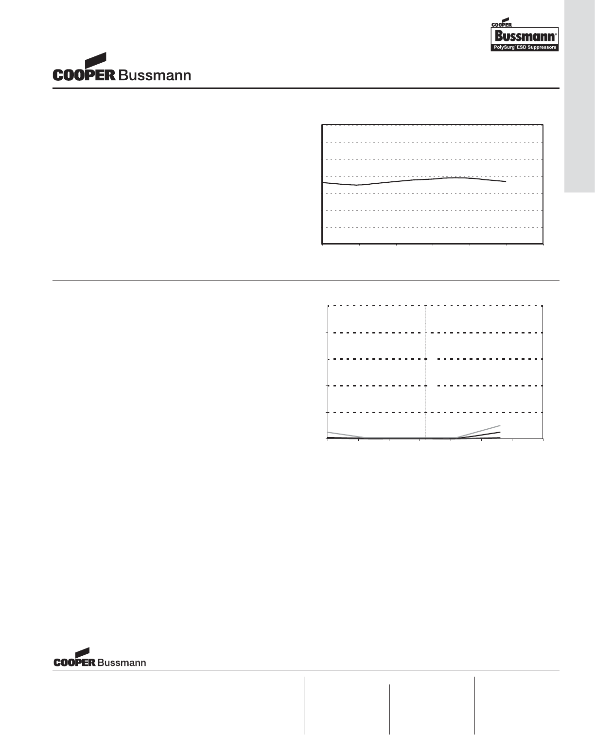
0
10
20
30
40
50
60
70
0 100 200 300 400 500 600
ESD Clamping Voltage (V)
Number of 8 kV ESD Pulses
Figure 4. ESD Clamping Voltage vs. Number of 8 kV ESD Pulse
Figure 5. Average Off State Current Leakage vs. Temperature
24 VDC
12 VDC
6 VDC
Reference Temperature
0
0.2
0.4
0.6
0.8
1
55 -30 -5 20 45 70 95 120
Temperature (°C
)
-
Leakage Current (nA)
Clamp Voltage Remains Consistent
Despite Repeated ESD Pulses
As Figure 4 shows, PolySurg™ ESD Suppressors are
highly reliable and stable over hundreds of pulses.
PolySurg™ ESD Suppressors have been tested with
fast rate ESD pulses at 8kV contact discharge.
Clamping voltage measured at every pulse shows
minimal changes throughout the test.
Typical non-triggered (Off State) Current
Leakage is Very Low at Normal Operating
Voltages and Temperatures
As shown by Figure 5 the current leakage of the
PolySurg™ ESD Suppressor is typically very low, well
under 1nA, even over 12VDC operating voltage.
Some increase in the current leakage may be
expected at much higher operating voltage and
elevated temperature.
Cooper Electronic Technologies
1225 Broken Sound Parkway NW
Suite F
Boca Raton, FL 33487-3533
Tel: 1-561-998-4100
Fax: 1-561-241-6640
Toll Free: 1-888-414-2645
Cooper Bussmann
P.O. Box 14460
St. Louis, MO 63178-4460
Tel: 1-636-394-2877
Fax: 1-800-544-2570
Cooper Electronic Technologies
Cooper (UK) Limited
Burton-on-the-Wolds
Leicestershire • LE12 5TH UK
Tel: +44 (0) 1509 882 737
Fax: +44 (0) 1509 882 786
Cooper Electronic Technologies
Avda. Santa Eulalia, 290
08223
Terrassa, (Barcelona), Spain
Tel: +34 937 362 812
+34 937 362 813
Fax: +34 937 362 719
Asia Pacific
Cooper Electronic Technologies
1 Jalan Kilang Timor
#06-01 Pacific Tech Centre
Singapore 159303
Tel: +65 278 6151
Fax: +65 270 4160
Visit us on the web at:
www.cooperbussmann.com
North America Europe
ESD Suppression Selection Guide
Polymer ESD Suppressors
OC-117
ESD Suppression Selection Guide
Courtesy of Steven Engineering, Inc.-230 Ryan Way, South San Francisco, CA 94080-6370-Main Office: (650) 588-9200-Outside Local Area: (800) 258-9200-www.stevenengineering.com
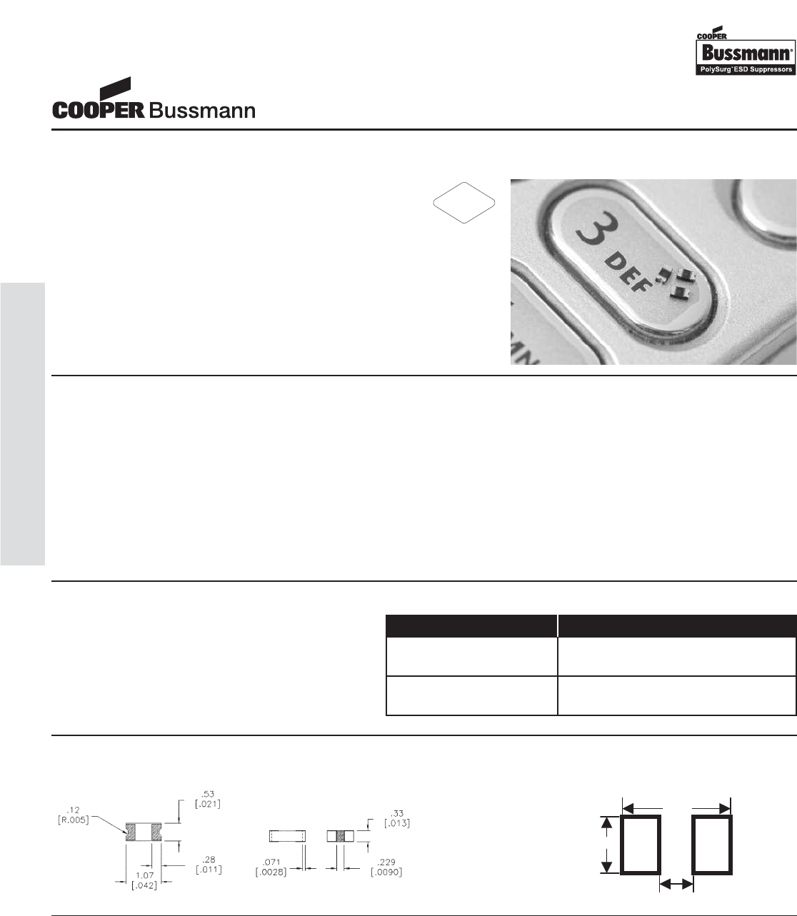
• Computers & Peripherals
• HDTV Equipment
• DVD Players
• A/V Equipment
• Satellite Radio
• Cell Phones
• PDA’s
• Digital Still Cameras
• Digital Camcorders
• MP3 / Multimedia Players
• Set Top Boxes
• External Storage
• DSL Modems
• High Speed Data Ports
• USB 2.0
• IEEE 1394
• HDMI
• DVI
• High Speed Ethernet
• Infiniband®
Applications
The PolySurg™ 0402ESDA-MLP ESD Suppressors
protect valuable high-speed data circuits from ESD
damage without distorting data signals as a result of
its ultra-low (0.05pF typical) capacitance.
Description Ordering Information
Features & Benefits
• Ultra-low capacitance (0.05pF typ.) ideal for high
speed data applications
• Provides ESD protection with fast response time
(<1ns) allowing equipment to pass IEC 61000-4-2 level 4 test
• Single-line, bi-directional device for placement flexibility
• Low profile 0402/1005 design for board space savings
• Low leakage current (<0.1nA typ.) reduces power consumption
0.40
0.70
2.20
The location in the circuit for the MLP series has to be carefully determined. For better performance, the device should be placed
as close to the signal input as possible and ahead of any other component. Due to the high current associated with an ESD
event, it is recommended to use a “0-stub” pad design (pad directly on the signal/data line and second pad directly on common
ground).
Design Considerations
Catalog Number Packaging
0402ESDA-MLP7 10,000 pieces in paper tape on
7" (178mm) reel
0402ESDA-MLP8 2,500 pieces in paper tape on
7" (178mm) reel
Product Dimensions: mm [inches] Solder Pad Recommendation:
mm [inches]
RoHS
2002/95/EC
0402ESDA-MLP
MLP Series ESD Suppressor
OC-118
0402ESDA-MLP, MLP Series ESD Suppressor
Courtesy of Steven Engineering, Inc.-230 Ryan Way, South San Francisco, CA 94080-6370-Main Office: (650) 588-9200-Outside Local Area: (800) 258-9200-www.stevenengineering.com
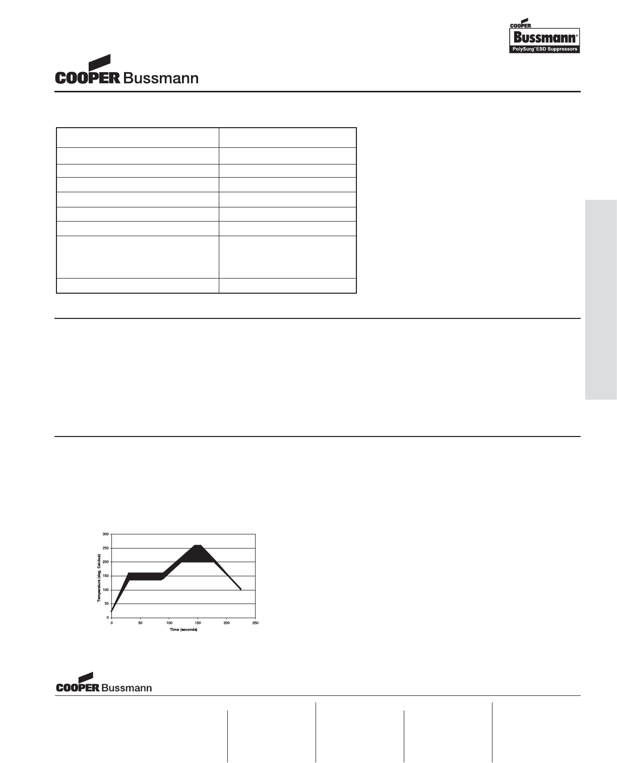
OC-119
0402ESDA-MLP, MLP Series ESD Suppressor
Electrical Characteristics
Characteristic Value
Rated Voltage 30VDC maximum
Clamping Voltage135V typical
Trigger Voltage2300V typical
Capacitance (@1MHz) 0.05pF typ., 0.15pF max.
Attenuation Change (0-6GHz) -0.2dB typical
Leakage Current (@12VDC) <0.1nA typical
ESD Capability
IEC61000-4-2 Direct Discharge 8kV typical
IEC61000-4-2 Air Discharge 15kV typical
ESD Pulse Withstand1>1000 typical
Notes:
1. Per IEC61000-4-2, Level 4 waveform (8kV direct, 30A)
measured 30ns after initiation of pulse.
2. Trigger measurement made using Transmission Line Pulse
(TLP) method.
3. Minor shifting in characteristics may be observed over
multiple ESD pulses at very rapid rate.
Environmental Specifications:
• Load Humidity: 12VDC per EIA/IS-772 Para. 4.4.2, +85°C, 85% RH for 1000 hours
• Thermal Shock: EIA/IS-722 Para 4.6, Air to Air -55°C to +125°C, 5 cycles
• Moisture Resistance Test: MIL-STD-202G Method 106G, 10 cycles
• Mechanical Shock: EIA/IS-722 Para. 4.9
• Vibration: EIA/IS-722 Para. 4.10
• Resistance to Solvent: EIA/IS-722 Para. 4.11
• Operating & Storage Temperature Range: -55°C to +125°C
Soldering Recommendations
• Compatible with lead and lead-free solder reflow processes
• Peak reflow temperatures and durations:
• IR Reflow = 260°C max for 10 sec. max.
• Wave Solder = 260°C max. for 10 sec. max.
• Recommended IR Reflow Profile:
Cooper Electronic Technologies
1225 Broken Sound Parkway NW
Suite F
Boca Raton, FL 33487-3533
Tel: 1-561-998-4100
Fax: 1-561-241-6640
Toll Free: 1-888-414-2645
Cooper Bussmann
P.O. Box 14460
St. Louis, MO 63178-4460
Tel: 1-636-394-2877
Fax: 1-800-544-2570
Cooper Electronic Technologies
Cooper (UK) Limited
Burton-on-the-Wolds
Leicestershire • LE12 5TH UK
Tel: +44 (0) 1509 882 737
Fax: +44 (0) 1509 882 786
Cooper Electronic Technologies
Avda. Santa Eulalia, 290
08223
Terrassa, (Barcelona), Spain
Tel: +34 937 362 812
+34 937 362 813
Fax: +34 937 362 719
Asia Pacific
Cooper Electronic Technologies
1 Jalan Kilang Timor
#06-01 Pacific Tech Centre
Singapore 159303
Tel: +65 278 6151
Fax: +65 270 4160
Visit us on the web at:
www.cooperbussmann.com
North America Europe
0402ESDA-MLP
MLP Series ESD Suppressor
Courtesy of Steven Engineering, Inc.-230 Ryan Way, South San Francisco, CA 94080-6370-Main Office: (650) 588-9200-Outside Local Area: (800) 258-9200-www.stevenengineering.com
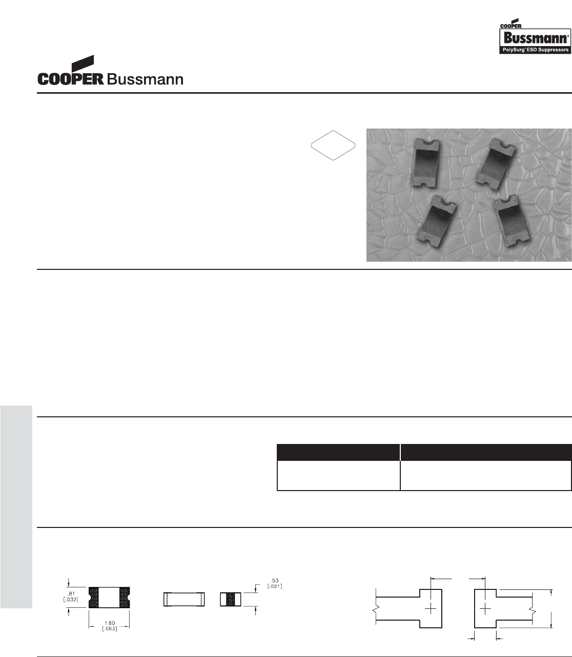
• Computers & Peripherals
• HDTV Equipment
• DVD Players
• A/V Equipment
• Satellite Radio
• Cell Phones
• PDA’s
• Digital Still Cameras
• Digital Camcorders
• MP3 / Multimedia Players
• Set Top Boxes
• External Storage
• DSL Modems
• High Speed Data Ports
• USB 2.0
• IEEE 1394
• HDMI
• DVI
• High Speed Ethernet
• Infiniband®
Applications
The PolySurg™ 0603ESDA-MLP ESD Suppressors
protect valuable high-speed data circuits from ESD
damage without distorting data signals as a result of
its ultra-low (0.05pF typical) capacitance.
Description Ordering Information
Features & Benefits
• Ultra-low capacitance (0.05pF typ.) ideal for high
speed data applications
• Provides ESD protection with fast response time
(<1ns) allowing equipment to pass IEC 61000-4-2 level 4 test
• Single-line, bi-directional device for placement flexibility
• Low profile 0603/1608 design for board space savings
• Low leakage current (<0.1nA typ.) reduces power consumption
1.25
(0.05)
0.50
(0.02)
0.90
(0.035)
The location in the circuit for the MLP series has to be carefully determined. For better performance, the device should be placed
as close to the signal input as possible and ahead of any other component. Due to the high current associated with an ESD
event, it is recommended to use a “0-stub” pad design (pad directly on the signal/data line and second pad directly on common
ground).
Design Considerations
Catalog Number Packaging
0603ESDA-MLP7 5,000 pieces in paper tape on
7" (178mm) reel
Product Dimensions: mm [inches] Solder Pad Recommendation:
mm [inches]
RoHS
2002/95/EC
0603ESDA-MLP
MLP Series ESD Suppressor
OC-120
0603ESDA-MLP, MLP Series Suppressor
Courtesy of Steven Engineering, Inc.-230 Ryan Way, South San Francisco, CA 94080-6370-Main Office: (650) 588-9200-Outside Local Area: (800) 258-9200-www.stevenengineering.com
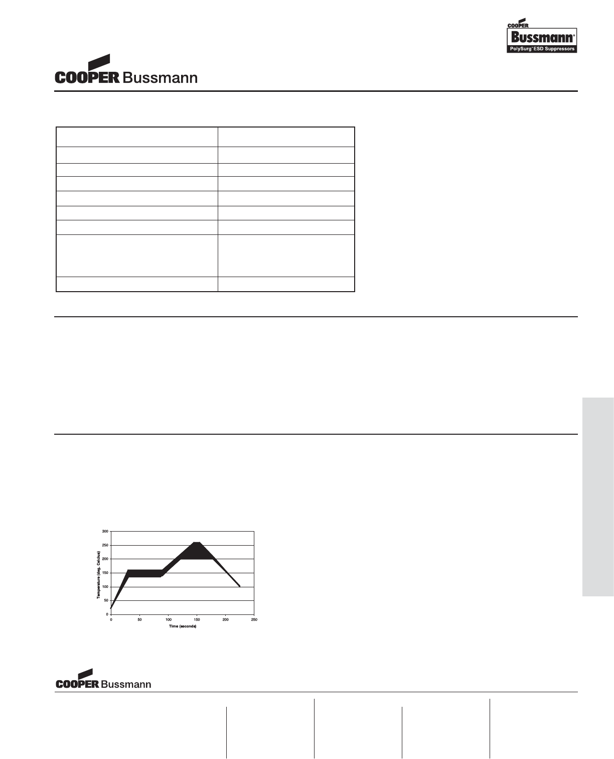
OC-121
0603ESDA-MLP, MLP Series Suppressor
Electrical Characteristics
Characteristic Value
Rated Voltage 30VDC maximum
Clamping Voltage135V typical
Trigger Voltage2300V typical
Capacitance (@1MHz) 0.05pF typ., 0.15pF max.
Attenuation Change (0-6GHz) -0.2dB typical
Leakage Current (@12VDC) <0.1nA typical
ESD Capability
IEC61000-4-2 Direct Discharge 8kV typical
IEC61000-4-2 Air Discharge 15kV typical
ESD Pulse Withstand1>1000 typical
Notes:
1. Per IEC61000-4-2, Level 4 waveform (8kV direct, 30A)
measured 30ns after initiation of pulse.
2. Trigger measurement made using Transmission Line Pulse
(TLP) method.
3. Minor shifting in characteristics may be observed over
multiple ESD pulses at very rapid rate.
Environmental Specifications:
• Load Humidity: 12VDC per EIA/IS-772 Para. 4.4.2, +85°C, 85% RH for 1000 hours
• Thermal Shock: EIA/IS-722 Para 4.6, Air to Air -55°C to +125°C, 5 cycles
• Moisture Resistance Test: MIL-STD-202G Method 106G, 10 cycles
• Mechanical Shock: EIA/IS-722 Para. 4.9
• Vibration: EIA/IS-722 Para. 4.10
• Resistance to Solvent: EIA/IS-722 Para. 4.11
• Operating & Storage Temperature Range: -55°C to +125°C
Soldering Recommendations
• Compatible with lead and lead-free solder reflow processes
• Peak reflow temperatures and durations:
• IR Reflow = 260°C max for 10 sec. max.
• Wave Solder = 260°C max. for 10 sec. max.
• Recommended IR Reflow Profile:
Cooper Electronic Technologies
1225 Broken Sound Parkway NW
Suite F
Boca Raton, FL 33487-3533
Tel: 1-561-998-4100
Fax: 1-561-241-6640
Toll Free: 1-888-414-2645
Cooper Bussmann
P.O. Box 14460
St. Louis, MO 63178-4460
Tel: 1-636-394-2877
Fax: 1-800-544-2570
Cooper Electronic Technologies
Cooper (UK) Limited
Burton-on-the-Wolds
Leicestershire • LE12 5TH UK
Tel: +44 (0) 1509 882 737
Fax: +44 (0) 1509 882 786
Cooper Electronic Technologies
Avda. Santa Eulalia, 290
08223
Terrassa, (Barcelona), Spain
Tel: +34 937 362 812
+34 937 362 813
Fax: +34 937 362 719
Asia Pacific
Cooper Electronic Technologies
1 Jalan Kilang Timor
#06-01 Pacific Tech Centre
Singapore 159303
Tel: +65 278 6151
Fax: +65 270 4160
Visit us on the web at:
www.cooperbussmann.com
North America Europe
0603ESDA-MLP
MLP Series ESD Suppressor
Courtesy of Steven Engineering, Inc.-230 Ryan Way, South San Francisco, CA 94080-6370-Main Office: (650) 588-9200-Outside Local Area: (800) 258-9200-www.stevenengineering.com
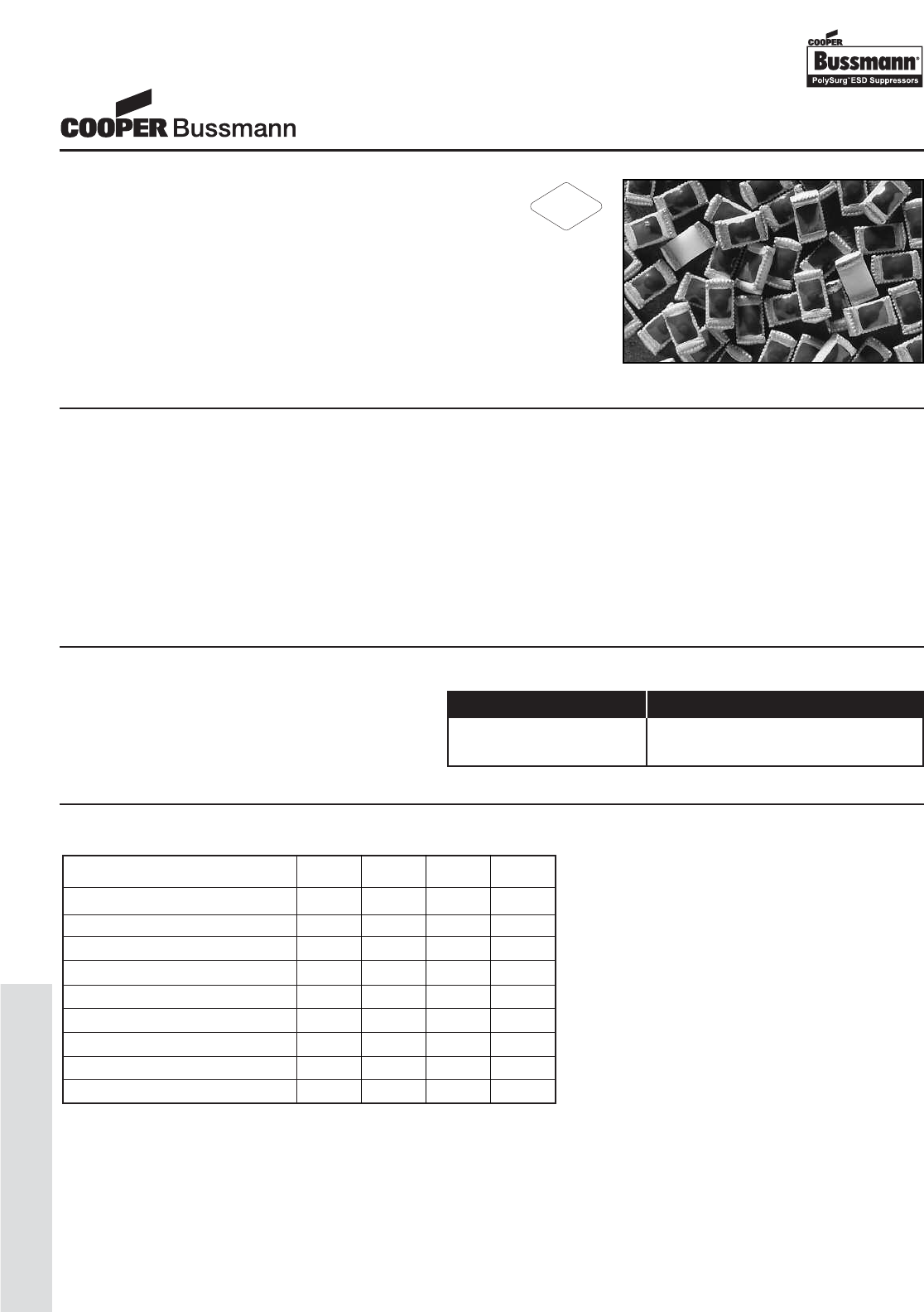
OC-122
0603ESDA-TR, TR Series ESD Suppressor
Part Ratings and Characteristics:
Performance Characteristics Units Min Typ Max
Continuous operating voltage VDC - - 24
Clamping voltage2V-3560
Trigger voltage3V - 125 -
ESD Threat voltage capability4kV -815
Capacitance (@ 1 KHz ~ 1.8GHz) pF - - 0.15
Leakage current (@ 12 VDC) nA 0.01 <0.1 -
Peak current2A - 30 45
Operating temperature °C -56 +25 +105
ESD pulse withstand 2# pulses 20 >5001-
Notes:
1. Some shifting in characteristics may occur when tested over
several hundred ESD pulses at very rapid rate of 1 pulse per
second or faster.
2. Per IEC 61000-4-2, 30A @ 8kV, level 4, clamp measurement
made 30ns after initiation of pulse, all tests in contact discharge
mode.
3. Trigger measurement made using Transmission Line Pulse
(TLP) method
4. PolySURG™ devices are capable of withstanding up to a 15 kV,
45A ESD pulse. Device ratings are given at 8kV per Note 1,
unless otherwise specified.
Features:
• 0603/1608 foot print
• Ideal ESD protection for high frequency, low voltage applications.
• Exceeds testing requirements outlined in IEC 61000-4-2
• Ultra low capacitance (0.15pF maximum)
• Very low leakage current
• Fast response time
• Bi-directional
• Surface mount
RoHS
2002/95/EC
• Computers & Peripherals
• HDTV Equipment
• DVD Players
• A/V Equipment
• Satellite Radio
• Cell Phones
• PDA’s
• Digital Still Cameras
• Digital Camcorders
• MP3 / Multimedia Players
• Set Top Boxes
• External Storage
• DSL Modems
• High Speed Data Ports
• USB 2.0
• IEEE 1394
• HDMI
• DVI
• High Speed Ethernet
• Infiniband®
Applications
The PolySurg™ 0603ESDA-TR ESD Suppressors
protect valuable high-speed data circuits from ESD
damage without distorting data signals as a result of
its ultra-low (0.15pF maximum) capacitance.
Description Ordering Information
Catalog Number Packaging
0603ESDA-TR1 5,000 pieces in paper tape on
7" (178mm) reel
0603ESDA-TR
TR Series ESD Suppressor
Courtesy of Steven Engineering, Inc.-230 Ryan Way, South San Francisco, CA 94080-6370-Main Office: (650) 588-9200-Outside Local Area: (800) 258-9200-www.stevenengineering.com
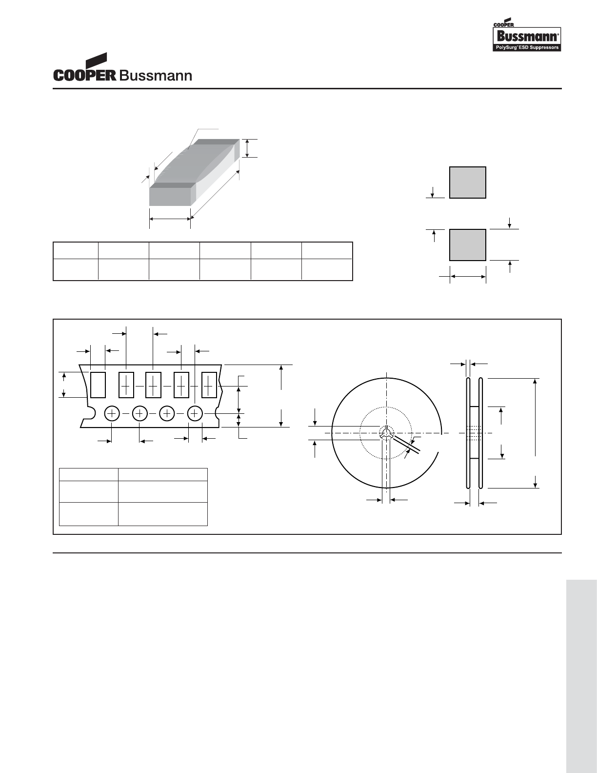
OC-123
0603ESDA-TR, TR Series ESD Suppressor
W
L
H
T
R
1.0 max
(.039 max)
1.1 ref
(.043 ref)
0.60 min
(.023 min)
mm (inches)
Recommended Solder
Pad Outline
(per IPC-SM-782)
4.0±0.1
(.157±.004)
4.0±0.1
(.157±.004)
2.0±0.05
(.079±.002)
8.0±0.30
(.315±.012)
1.5±0.10
(.059±.004)
1.75±0.1
(.069±.004)
13.0±0.5
(.512±.020) 9.0±1.5
(.354±.059)
178.0±2.0
(7.008±.080)
21±0.8
(.827±.032)
2.0±0.5
(.080±.020)
B
A
3.5±0.05
(.138±.002)
60.0±1.5
(2.362±.059)
2.0±0.75
(.079±.030)
Dimension
A
B
0603
1.90±0.20
(.075±0.008)
1.10±0.20
(.043±0.008)
Product Dimension
Tape-and-Reel Specification
EIA Size L W H T R
mm (in)
0603ESDA
1.60 ± 0.10 0.80 ± 0.10 0.50 ± 0.10 0.30 ± 0.20 0.70 ± 0.10
(.063 ± .004) (.031 ± .004) (.020 ± .004) (.012 ± .008) (.028 ± .004)
Environmental Specifications:
• Moisture Resistance per EIA/IS-722 Paragraph 4.4.2. This standard is based upon MIL-STD-202G Method 103B but with tem-
perature and relative humidity at +85°C and 85% RH respectively. Test condition ‘A’ (240Hr) per MIL-STD-202G
• Thermal shock: MIL-STD-202, Method 107G, -55°C to 125°C, 30 min. cycle, 10 cycles
• Vibration: MIL-STD-202F, Method 201A,(10 to 55 to 10 Hz, 1 min. cycle, 2 hrs each in X-Y-Z)
• Chemical resistance: ASTM D-543, 4 hrs @ 40°C, 3 solutions (H2O, detergent solution, defluxer)
• Operating temperature characteristics, measurement at +25°C, +105°C and -56°C
• Full load voltage: 14.4VDC, 18VDC & 24VDC for 1000 hrs, 25°C
• Solder leach resistance and terminal adhesion: Per EIA-576
• Solderability: MIL-STD-202, Method 208 (95% coverage)
0603ESDA-TR
TR Series ESD Suppressor
Courtesy of Steven Engineering, Inc.-230 Ryan Way, South San Francisco, CA 94080-6370-Main Office: (650) 588-9200-Outside Local Area: (800) 258-9200-www.stevenengineering.com
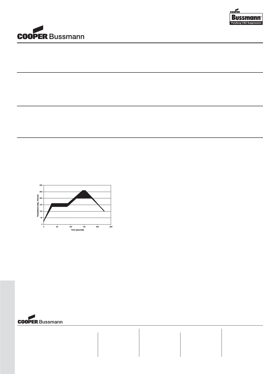
OC-124
0603ESDA-TR, TR Series ESD Suppressor
Device Marking
PolySurg™ ESD Suppressors are marked on the tape and reel packages, not individually. Since the product is bi-directional and
symmetrical, no orientation marking is required.
Design Consideration
The location in the circuit for the TR series has to be carefully determined. For better performance, the device should be placed
as close to the signal input as possible and ahead of any other component. Due to the high current associated with an ESD
event, it is recommended to use a “0-stub” pad design (pad directly on the signal/data line and second pad directly on common
ground).
Processing Recommendations
The TR series currently has a convex profile on the top surface of the part. This profile is a result of the construction of the deice.
They can be processed using standard pick-and-place equipment. The placement and processing techniques for these devices are
similar to those used for chip resistors and chip capacitors.
Soldering Recommendations
• Compatible with lead and lead-free solder reflow processes
• Peak reflow temperatures and durations:
• IR Reflow = 260°C max for 10 sec. max.
• Wave Solder = 260°C max. for 10 sec. max.
• Recommended IR Reflow Profile:
Cooper Electronic Technologies
1225 Broken Sound Parkway NW
Suite F
Boca Raton, FL 33487-3533
Tel: 1-561-998-4100
Fax: 1-561-241-6640
Toll Free: 1-888-414-2645
Cooper Bussmann
P.O. Box 14460
St. Louis, MO 63178-4460
Tel: 1-636-394-2877
Fax: 1-800-544-2570
Cooper Electronic Technologies
Cooper (UK) Limited
Burton-on-the-Wolds
Leicestershire • LE12 5TH UK
Tel: +44 (0) 1509 882 737
Fax: +44 (0) 1509 882 786
Cooper Electronic Technologies
Avda. Santa Eulalia, 290
08223
Terrassa, (Barcelona), Spain
Tel: +34 937 362 812
+34 937 362 813
Fax: +34 937 362 719
Asia Pacific
Cooper Electronic Technologies
1 Jalan Kilang Timor
#06-01 Pacific Tech Centre
Singapore 159303
Tel: +65 278 6151
Fax: +65 270 4160
Visit us on the web at:
www.cooperbussmann.com
North America Europe
0603ESDA-TR
TR Series ESD Suppressor
Courtesy of Steven Engineering, Inc.-230 Ryan Way, South San Francisco, CA 94080-6370-Main Office: (650) 588-9200-Outside Local Area: (800) 258-9200-www.stevenengineering.com
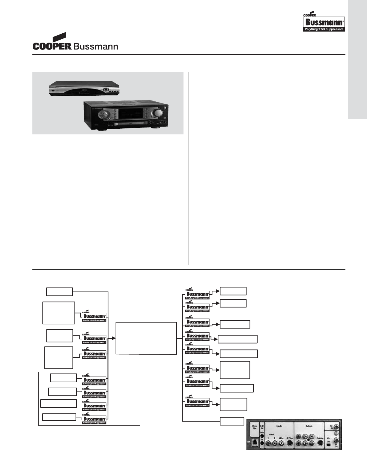
OC-125
Application Notes, ESD Suppression
What Are Set Top Boxes?
The continuing trend is to link broadband signal delivery to the
home entertainment display, and other devices via set top
boxes. Set top boxes used to be just an analog cable
tuner/decoder but now it includes the likes of digital cable,
satellite controller, internet service controllers, digital video
recording systems and home networking.
These devices allow the various cable and satellite signal oper-
ators to deliver a wide variety of services from television to
internet and the hardware manufacturers can provide many
features and benefits including home networking capabilities.
There is digital video recording onto hard disk drives, replacing
the cassette format, allowing pause and replay of and live tele-
vision, or interactive TV. There are new standards being creat-
ed to facilitate the design of the boxes such as a recent refer-
ence blueprint development by communications chipmaker
Broadcom using the Microsoft interactive TV software system.
The set top box is going to be a high volume commodity with
many forms and functions.
Why are Set Top boxes vulnerable to ESD
The more sophisticated boxes include a variety of I/O jacks
such as front panel USB, Audio/Video, S-Video, rear panel
Satellite, cable, TV antenna, Wireless transmitter connection,
home networking HPNA option, Toslink digital input, connec-
tions for CD, DVD,VCR, Outputs for Video, Audio, and more.
Most of these jacks are susceptible to ESD threat.
The PolySurg™ solution to the ESD protection problem
Utilize the 0402ESDA-MLP, 0603ESDA-MLP, or 0603ESDA-
TR1 PolySurg™ devices to protect the set top box electronics
from catastrophic ESD damage at each potential outside metal
contact or connector on each line. Audio, Video, RF, USB and
RS-232 lines may be protected from ESD TVS occurrences on
set top systems.
Design Wins with Set Top boxes
Cooper Bussmann has recorded some notable design wins
already with it’s PolySurg™ ESD Suppressors in applications
involving the protection of set top systems.
ESD Protection of Set Top Appliances with PolySurg™ ESD Suppressors
Protection Against ESD Threat for Set Top System Input/Output Ports with PolySurg™
AC Input
RF Input
Antenna
Cable
Satellite
Front
Panel
I/O Port
Smart Card
RS-232
Keyboard
Audio Port
Video Port
S-Video Port
Digital Audio Port
RJ - 11
RF Out
TV / VCR
Other Device
RJ - 45, Network
USB / USB 2.0
IEEE-1284,
Parallel
Set-Top Box
Digital Satellite Receiver
High Definition Digital Receiver
Digital Cable TV Converter
Interactive Internet TV Terminal
Digital Video Recorder
Audio Port
Video Port
S-Video Port
Digital Audio Port
Future
Protection
Requirements
A Typical Set Top Box Rear View
Application Notes
ESD Suppression
Courtesy of Steven Engineering, Inc.-230 Ryan Way, South San Francisco, CA 94080-6370-Main Office: (650) 588-9200-Outside Local Area: (800) 258-9200-www.stevenengineering.com
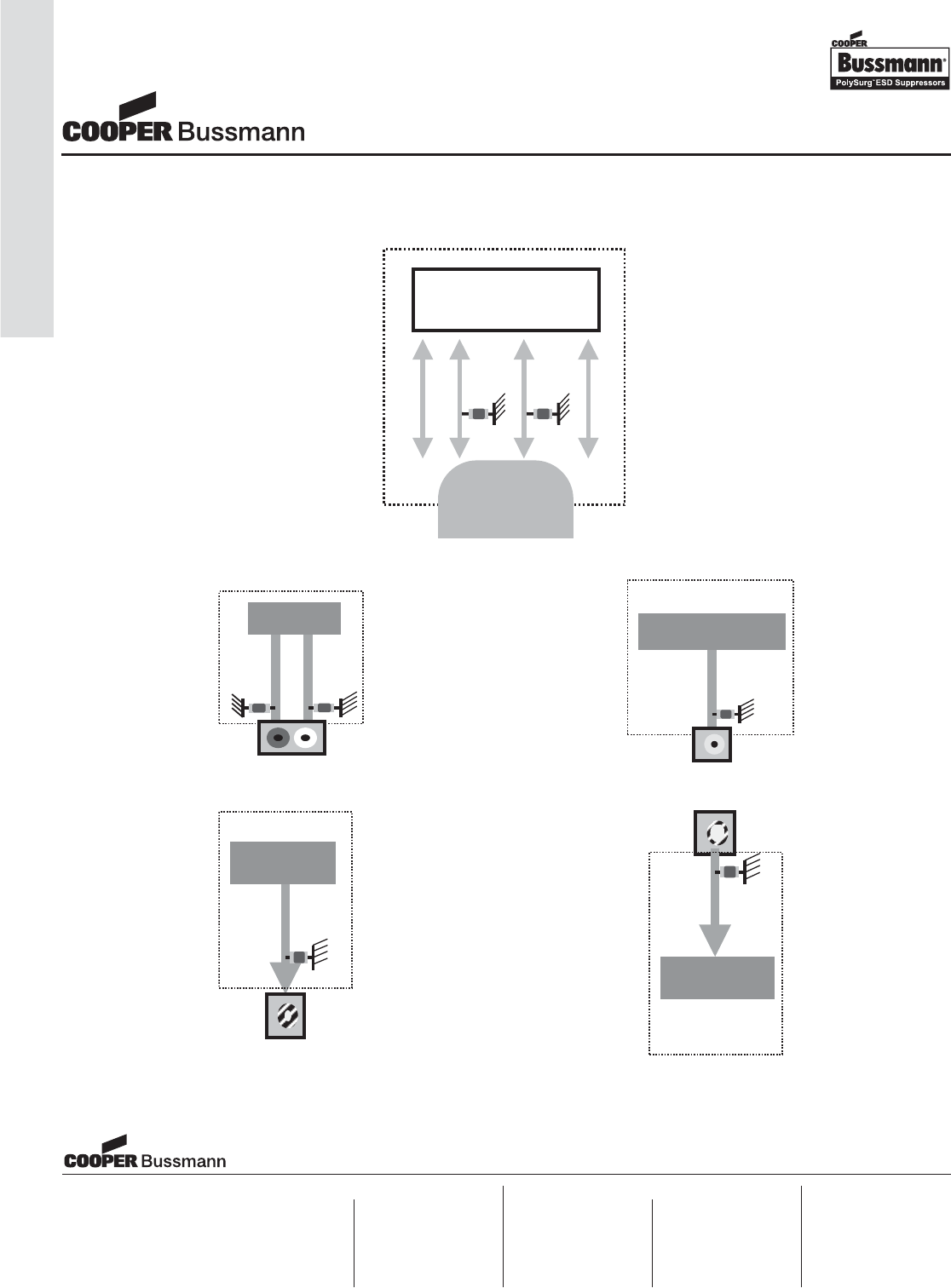
OC-126
Application Notes, ESD Suppression
Typical ESD Protection Applications with
PolySurg™ 0402ESDA-MLP, 0603ESDA-MLP, or 0603ESDA-TR
USB Controller
Amplifier
Audio Output
RF
Modulator
RF Output
RF
Controller
RF Input
Video Processor
Video Output
USB
Port
V+ Data (+) Data (-) GND
Cooper Electronic Technologies
1225 Broken Sound Parkway NW
Suite F
Boca Raton, FL 33487-3533
Tel: 1-561-998-4100
Fax: 1-561-241-6640
Toll Free: 1-888-414-2645
Cooper Bussmann
P.O. Box 14460
St. Louis, MO 63178-4460
Tel: 1-636-394-2877
Fax: 1-800-544-2570
Cooper Electronic Technologies
Cooper (UK) Limited
Burton-on-the-Wolds
Leicestershire • LE12 5TH UK
Tel: +44 (0) 1509 882 737
Fax: +44 (0) 1509 882 786
Cooper Electronic Technologies
Avda. Santa Eulalia, 290
08223
Terrassa, (Barcelona), Spain
Tel: +34 937 362 812
+34 937 362 813
Fax: +34 937 362 719
Asia Pacific
Cooper Electronic Technologies
1 Jalan Kilang Timor
#06-01 Pacific Tech Centre
Singapore 159303
Tel: +65 278 6151
Fax: +65 270 4160
Visit us on the web at:
www.cooperbussmann.com
North America Europe
Application Notes
ESD Suppression
Courtesy of Steven Engineering, Inc.-230 Ryan Way, South San Francisco, CA 94080-6370-Main Office: (650) 588-9200-Outside Local Area: (800) 258-9200-www.stevenengineering.com
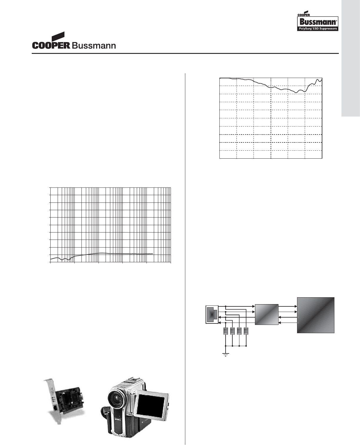
DVI/HDMI High Speed Date Rates
Communication data lines continue to be increasingly vul-
nerable to ESD transients. The ever-increasing bandwidth
of the faster data lines such as the 10/100 or Gigabit
Ethernet, USB 2.0, IEEE-1394b, make the traditional ESD
protection schemes such as silicon based devices, or multi
layer varistors less desirable, due to signal distortion from
the relatively high capacitance of these components.
PolySurg™ ESD Suppressors
The typical capacitance of the device (0402ESDA-MLP,
0603ESDA-MLP, or 0603ESDA-TR) is measured to be
below 0.15pF, in a range of 0.1 kHz to nearly 2 GHz. The
low capacitance throughout this wide frequency range
makes these devices suitable for ESD protection of low
analog signals to fast digital data lines.
Chart 1. The Capacitance of a PolySurg™ ESD
Suppressor from 0.1MHz to 1.8GHz
Another special characteristic of the PolySurg™ ESD
Suppressor is that it is virtually invisible to the circuit at
normal operation. The off-state resistance of the device is
over 1013 Ohms, and the typical current leakage of the
device is a negligible, 0.01nA at 12VDC. As Chart 2 shows,
the additional attenuation in a 50ohm circuit measured at
frequencies up to 6GHz is less than -0.2dbB.
Chart 2. Additional Attenuation in a 50Ohm System
due to the PolySurg™ ESD Suppressor
Example of devices that PolySurg™ ESD Suppressors can
protect from ESD:
• Network interface cards for desktops
• PC cards for laptops
• DSL / Cable modems.
• Routers and switches /hubs
Selected Protection Applications
Ethernet ports: The RJ-45 is the most common Ethernet
connection. The typical 10Base-T/100Base-TX uses 4 out
of 8 lines. Each line in use can be protected with one
PolySurg™ ESD Suppressor installed between the data line
and the ground. For the best performance, place the devices
at the closest location to the RJ-45 port (See Figure 1)
Figure 1. The ESD Protection of 10 / 100 Ethernet (RJ-45)
device with a PolySurg™ ESD Suppressor
Firewire: The IEEE-1394 (Firewire) series are the newest
serial ports for computer and other instruments with data
transfer rates up to 1,600Mbp (1394a is 400Mbps, and
1394b will be 800~1,6000Mbps.) This higher transfer
speed data is more easily subject to distortion (Chart 3).
The PolySurg™ ESD Suppressor can protect data lines
from ESD without distorting the high speed signal possible
from IEEE-1394 connection. All data lines should be
protected individually. (See Figure 2)
ESD Protection of High-Speed Data Lines
0
0.1
0.2
0.3
0.4
0.5
0.6
0.7
0.8
0.9
1
0.1 1 10 100 1000 10000
Frequency (MHz)
)Fp( ecnaticapaC
0
-0.1
-0.2
-0.3
-0.4
-0.5
-0.6
-0.7
-0.8
-0.9
-10 1 2 3 4 5 6
GHz
drop in attenuation (dB)
RJ -45
Controller
Filter
Transformer
TX +
TX -
RX+
RX -
Application Notes
ESD Suppression
OC-127
Application Notes, ESD Suppression
Courtesy of Steven Engineering, Inc.-230 Ryan Way, South San Francisco, CA 94080-6370-Main Office: (650) 588-9200-Outside Local Area: (800) 258-9200-www.stevenengineering.com
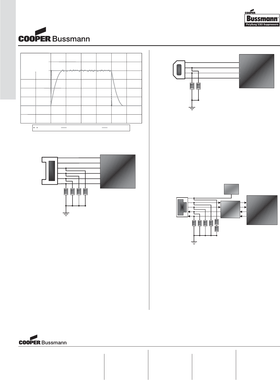
Chart 3. Signal distortion comparisons at 800Mbps
Figure 2. The ESD Protection of Typical IEEE-1394a device
with a PolySurg™ ESD Suppressor
Example of devices that PolySurg™ ESD Suppressor can
protect from ESD:
• Firewire interface cards
• Digital camcorders
• Printers / scanners
• Other peripherals with Firewire capability
USB 2.0: The USB 2.0 has a fast data transfer rate of
400Mbps. A device equipped with USB 2.0 will give the
best performance when protected with the ultra low capaci-
tance PolySurg ESD Suppressor.This will result in much
less data distortion than if zener diodes or multi layer
varistors are used for ESD protection (See Figure 3)
Figure 3. ESD protection of USB 2.0 devices
with a PolySurg™ ESD Suppressor
Special Applications
When the unused data port is connected to a higher oper-
ating voltage such as 24V or higher for special applica-
tions, the PolySurg™ ESD Suppressor can be installed in
series for ESD protection on the higher voltage line. The
operating voltage capability will be increased without
changing total capacitance or the current leakage of the
devices.
Figure 4. The Parallel connection for high voltage line
protection using a PolySurg™ ESD Suppressor on RJ-45
Ideal Signal 50pF Capacitance
0603ESDA
800M bps
(IEE1394)
PWR
IEEE-1394
Controller
GND
Data
Data
Data
Data
USB 2.0
USB 2.0
Controller
Data
GND
PWR
Data
RJ-45
Controller
Filter
Transformer
TX +
TX -
RX+
RX-
High Voltage
Cooper Electronic Technologies
1225 Broken Sound Parkway NW
Suite F
Boca Raton, FL 33487-3533
Tel: 1-561-998-4100
Fax: 1-561-241-6640
Toll Free: 1-888-414-2645
Cooper Bussmann
P.O. Box 14460
St. Louis, MO 63178-4460
Tel: 1-636-394-2877
Fax: 1-800-544-2570
Cooper Electronic Technologies
Cooper (UK) Limited
Burton-on-the-Wolds
Leicestershire • LE12 5TH UK
Tel: +44 (0) 1509 882 737
Fax: +44 (0) 1509 882 786
Cooper Electronic Technologies
Avda. Santa Eulalia, 290
08223
Terrassa, (Barcelona), Spain
Tel: +34 937 362 812
+34 937 362 813
Fax: +34 937 362 719
Asia Pacific
Cooper Electronic Technologies
1 Jalan Kilang Timor
#06-01 Pacific Tech Centre
Singapore 159303
Tel: +65 278 6151
Fax: +65 270 4160
Visit us on the web at:
www.cooperbussmann.com
North America Europe
Application Notes
ESD Suppression
OC-128
Application Notes, ESD Suppression
Courtesy of Steven Engineering, Inc.-230 Ryan Way, South San Francisco, CA 94080-6370-Main Office: (650) 588-9200-Outside Local Area: (800) 258-9200-www.stevenengineering.com
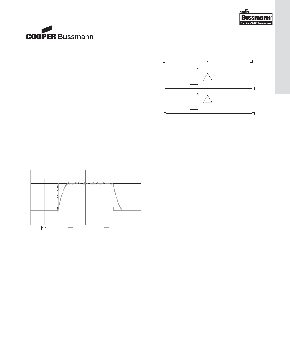
High speed, uncompressed, digital video solutions such as Digital
Visual Interface (DVI) and High Definition Multimedia Interface
(HDMI) utilize small geometry CMOS processes in order to pro-
vide maximum performance in a small package. However these
geometries are more susceptible to electrostatic discharge (ESD)
and the high-speed digital signals present a real challenge when
selecting an appropriate protection device.
DVI/HDMI High Speed Date Rates
DVI equipment can, currently, transmit at up to 1.6 Gbps for a
1600 x 1200 resolution signal. The receiver end can support up to
1.08 Gbps for 1280 x 1024 resolution but will soon increase to
1.65 Gbps. HDMI is an advancement of DVI that handles both
audio and video signals with enough bandwidth for data rates of
up to 5 Gbps. These high-speed data rates require any ESD pro-
tection device to have low capacitance in order to minimize signal
distortion. At high frequency any capacitance will be seen as a low
impedance path to ground, thus loading the data signal. Figure 1
shows the minimal effect of of a PolySurg™ ESD Suppressor on
an 800 Mbps data signal compared to a 50pF capacitor.
Figure 1 – IEE1394 Signal Distortion due to 50pF and
0603ESDA PolySurg™ ESD Suppressor
Traditional low capacitance steering diode solutions have a num-
ber of problems when used in high-speed data applications such
as HDMI & DVI. Diodes are typically connected rail to rail as
shown in Figure 2. During a negative voltage transient the bottom
diode conducts clamping the voltage to a diode drop below
ground. During a positive voltage transient the top diode will con-
duct the surge current (I1) into the power rail. Dumping the surge
current into an unprotected supply rail can cause latch up of the
protection circuit, so an additional transient voltage suppression
(TVS) device between the supply rail and ground is required.
Typically discrete steering diodes are not rated for the high tran-
sient currents associated with ESD. This misuse results in a short
cycle life and eventual diode failure, which is commonly in short
circuit mode. This short circuit failure mode usually results in the
equipment no longer functioning, even though the ESD event has
passed. The preferred failure mode is open, since the equipment
will certainly not operate with a shorted device, but has a potential
to operate longer if the device were to fail open.
Figure 2 – Rail to Rail Diode Connection
In order to make a low capacitance diode a small junction area is
used which presents a high resistance during ESD transients.
Also, diode response time is slow compared to the ESD voltage
rise time and the complete solution has significant parasitic induc-
tance associated with the device leads and tracking. All this results
in a large amount of voltage overshoot and a much higher clamp-
ing voltage. With the HDMI/DVI chip still exposed to several hun-
dred or even one thousand volts following an ESD event, using
this protection technique, there is potentially enough stress to
damage the device.
Other solutions such as zener diodes, multi-layer varistors (MLV’s)
and TVS all exhibit levels of capacitance that are too large for
them to be practical solutions in DVI and HDMI applications. With
capacitance values from 25pF to 500pF coupled with leakage cur-
rents of 0.5-50μA the level of loading on the signal lines becomes
unacceptable.
PolySurg™ ESD Suppressor Product Family
The Cooper Bussmann PolySurg™ ESD Suppressor provides the
solution to the problem of providing ESD protection for these new
high-speed circuits. This product is a bi-directional device that has
leakage current of less than 1nA and capacitance less than
0.15pF. This ultra-low capacitance makes the PolySurg™ ESD
Suppressor a viable solution for high data rate protocols like HDMI
and DVI. With an insertion loss of less than -0.2dB at frequencies
up to 6GHz the PolySurg™ ESD Suppressor is invisible to the
circuit, introducing no additional loading or signal distortion.
The PolySurg™ ESD Suppressor product family is comprised of
the 0402ESDA-MLP, 0603ESDA-MLP, and 0603ESDA-TR series
ESD suppression devices. All are discrete devices exhibiting
ultra-low capacitance to maintain signal integrity while protecting
all but the most sensitive IC’s from the harmful effects of ESD
strikes up to 15kV (air discharge).
Summary
Commercial products require ESD surge protection of all the inter-
face hardware schemes. New higher end consumer electronics
are increasingly using high data rate protocols such as DVI and
HDMI. The traditional protection devices have all been used with
varying success, however the increase in data rates now indicates
a need for ultra low capacitance devices, such as Cooper
Bussmann’s PolySurg™ ESD Suppressors.
ESD Protection for High Speed Digital Video Solutions (DVI & HDMI)
800Mbps
(IEE1394)
Ideal Signal 50pF Capacitance 0603ESDA
Vcc
GND
I1
I2
Application Notes
ESD Suppression
OC-129
Application Notes, ESD Suppression
Courtesy of Steven Engineering, Inc.-230 Ryan Way, South San Francisco, CA 94080-6370-Main Office: (650) 588-9200-Outside Local Area: (800) 258-9200-www.stevenengineering.com

OC-130
Overcurrent
Protection Group
NOTES
Courtesy of Steven Engineering, Inc.-230 Ryan Way, South San Francisco, CA 94080-6370-Main Office: (650) 588-9200-Outside Local Area: (800) 258-9200-www.stevenengineering.com

OC-131
Overcurrent
Protection Group
NOTES
Courtesy of Steven Engineering, Inc.-230 Ryan Way, South San Francisco, CA 94080-6370-Main Office: (650) 588-9200-Outside Local Area: (800) 258-9200-www.stevenengineering.com

OC-132
Overcurrent
Protection Group
NOTES
Courtesy of Steven Engineering, Inc.-230 Ryan Way, South San Francisco, CA 94080-6370-Main Office: (650) 588-9200-Outside Local Area: (800) 258-9200-www.stevenengineering.com
P
OWER
M
ANAGEMENT
Courtesy of Steven Engineering, Inc.-230 Ryan Way, South San Francisco, CA 94080-6370-Main Office: (650) 588-9200-Outside Local Area: (800) 258-9200-www.stevenengineering.com
PM-1
Table of Contents
Inductor Selection Guide . . . . . . . . . . . . . . . . . . . . . . . . . . . . . . . . . Page PM-8
FP2 Series, FLAT-PAC™ . . . . . . . . . . . . . . . . . . . . . . . . . . . . . . . . . . . . . . Page PM-10
High Current
7.2 x 6.7 x 3.0 & 5.0 mm Inductors
FP4 Series, FLAT-PAC™ 4 . . . . . . . . . . . . . . . . . . . . . . . . . . . . . . . . . . . . Page PM-15
High Current
6.8 x 10.2 x 5.0 mm Inductors
FP3 Series, FLAT-PAC™ 3 . . . . . . . . . . . . . . . . . . . . . . . . . . . . . . . . . . . . Page PM-13
High Current
7.25 x 6.5 x 3 mm Powder Iron Inductors
HCP0703 Series . . . . . . . . . . . . . . . . . . . . . . . . . . . . . . . . . . . . . . . . . . . . . Page PM-21
High Current
7.3 x 7.0 x 3.0 mm Pressed Power Inductors
FP1308 Series, FLAT-PAC™ . . . . . . . . . . . . . . . . . . . . . . . . . . . . . . . . . . Page PM-18
High Current
13.7 x 12.95 x 8.0 mm Inductors
HCP1104 Series . . . . . . . . . . . . . . . . . . . . . . . . . . . . . . . . . . . . . . . . . . . . . Page PM-25
High Current
11.5 x 10.25 x 4.0 mm Pressed Power Inductors
HCP1305 Series . . . . . . . . . . . . . . . . . . . . . . . . . . . . . . . . . . . . . . . . . . . . . Page PM-28
High Current
13.8 x 12.9 x 5.0 mm Pressed Power Inductors
HCF1305 Series . . . . . . . . . . . . . . . . . . . . . . . . . . . . . . . . . . . . . . . . . . . . . Page PM-31
High Current
12.5 x 12.5 x 5.0 mm Power Inductors
HC1 Series, HIGH CURRENT 1 . . . . . . . . . . . . . . . . . . . . . . . . . . . . . . . . Page PM-34
High Current
13.0 x 13.0 x 10.0 mm Power Inductors
HC2LP Series, HIGH CURRENT 2LP . . . . . . . . . . . . . . . . . . . . . . . . . . . Page PM-37
High Current
19.2 x 19.2 x 11.18 mm Power Inductors
NEW
NEW
NEW
NEW
Courtesy of Steven Engineering, Inc.-230 Ryan Way, South San Francisco, CA 94080-6370-Main Office: (650) 588-9200-Outside Local Area: (800) 258-9200-www.stevenengineering.com
PM-2
Table of Contents
HC3 Series, HIGH CURRENT 3 . . . . . . . . . . . . . . . . . . . . . . . . . . . . . . . . Page PM-39
High Current
30.0 x 25.3 x 17.5 mm High Power Inductors
HC8 Series, HIGH CURRENT 8 . . . . . . . . . . . . . . . . . . . . . . . . . . . . . . . . Page PM-43
High Current
10.4 x 10.4 x 4.0 mm Powder Iron, Power Inductors
HC7 Series, HIGH CURRENT 7 . . . . . . . . . . . . . . . . . . . . . . . . . . . . . . . . Page PM-41
High Current
13.0 x 13.8 x 5.5 mm Powder Iron, Power Inductors
HC9 Series, HIGH CURRENT 9 . . . . . . . . . . . . . . . . . . . . . . . . . . . . . . . . Page PM-48
High Current
13.8 x 13.1 x 7.5 mm Powder Iron, Power Inductors
HC8LP Series, HIGH CURRENT 8LP . . . . . . . . . . . . . . . . . . . . . . . . . . . Page PM-45
High Current
10.4 x 10.4 x 3.5 mm Powder Iron, Power Inductors
HCPT1309 Series . . . . . . . . . . . . . . . . . . . . . . . . . . . . . . . . . . . . . . . . . . . Page PM-50
High Current
13.2 x 14.0 x 9.0 mm Through-Hole, Powder Iron Inductor
CPL Series . . . . . . . . . . . . . . . . . . . . . . . . . . . . . . . . . . . . . . . . . . . . . . . . . Page PM-52
High Current
Multi-Phase Power Inductors
DR1030 Series . . . . . . . . . . . . . . . . . . . . . . . . . . . . . . . . . . . . . . . . . . . . . . Page PM-56
Shielded Drum
10.5 x 10.3 x 3.0 mm Shielded Power Inductors
DR1040 Series . . . . . . . . . . . . . . . . . . . . . . . . . . . . . . . . . . . . . . . . . . . . . . Page PM-59
Shielded Drum
10.5 x 10.3 x 4.0 mm Shielded Power Inductors
DR1050 Series . . . . . . . . . . . . . . . . . . . . . . . . . . . . . . . . . . . . . . . . . . . . . . Page PM-62
Shielded Drum
10.5 x 10.3 x 5.0 mm Shielded Power Inductors
NEW
NEW
NEW
NEW
NEW
NEW
Courtesy of Steven Engineering, Inc.-230 Ryan Way, South San Francisco, CA 94080-6370-Main Office: (650) 588-9200-Outside Local Area: (800) 258-9200-www.stevenengineering.com
PM-3
Table of Contents
DR Series (DR73, DR74, DR125, DR127) . . . . . . . . . . . . . . . . . . . . . . . . Page PM-65
Shielded Drum
Shielded Power Inductors
DRQ Series (DRQ73, DRQ74, DRQ125, DRQ127) . . . . . . . . . . . . . . . . Page PM-73
Shielded Drum
Dual Winding, Shielded Inductor/Transformer
DR124 Series . . . . . . . . . . . . . . . . . . . . . . . . . . . . . . . . . . . . . . . . . . . . . . . Page PM-70
Shielded Drum
12.3 x 12.3 x 4.5 mm Shielded Power Inductors
SD3110 Series . . . . . . . . . . . . . . . . . . . . . . . . . . . . . . . . . . . . . . . . . . . . . . Page PM-83
Low Profile Shielded Drum
3.1 x 3.1 x 1.0 mm Shielded Inductors
LDS0705 Series . . . . . . . . . . . . . . . . . . . . . . . . . . . . . . . . . . . . . . . . . . . . . Page PM-80
Shielded Drum
8.0 x 7.2 x 5.0 mm Shielded Power Inductors
SD3112 Series . . . . . . . . . . . . . . . . . . . . . . . . . . . . . . . . . . . . . . . . . . . . . . Page PM-86
Low Profile Shielded Drum
3.1 x 3.1 x 1.2 mm Shielded Inductors
SD3114 Series . . . . . . . . . . . . . . . . . . . . . . . . . . . . . . . . . . . . . . . . . . . . . . Page PM-89
Low Profile Shielded Drum
3.1 x 3.1 x 1.4 mm Shielded Inductors
SD3118 Series . . . . . . . . . . . . . . . . . . . . . . . . . . . . . . . . . . . . . . . . . . . . . . Page PM-92
Low Profile Shielded Drum
3.1 x 3.1 x 1.8 mm Shielded Inductors
SD38 Series (SD3812, SD3814) . . . . . . . . . . . . . . . . . . . . . . . . . . . . . . . Page PM-95
Low Profile Shielded Drum
4.0 x 4.0 x 1.2 & 1.4 mm High Power, Shielded Inductors
SDH3812 Series . . . . . . . . . . . . . . . . . . . . . . . . . . . . . . . . . . . . . . . . . . . . . Page PM-98
Low Profile Shielded Drum
4.0 x 4.0 x 1.2 mm High Power, Shielded Inductors
NEW
NEW
NEW
NEW
NEW
NEW
NEW
Courtesy of Steven Engineering, Inc.-230 Ryan Way, South San Francisco, CA 94080-6370-Main Office: (650) 588-9200-Outside Local Area: (800) 258-9200-www.stevenengineering.com
PM-4
Table of Contents
SD Series (SD10, SD12, SD14, SD18, SD20, SD25) . . . . . . . . . . . . . . Page PM-101
Low Profile Shielded Drum
5.2 x 5.2 x (6) Various Heights, Shielded Inductors
SD52 Series . . . . . . . . . . . . . . . . . . . . . . . . . . . . . . . . . . . . . . . . . . . . . . . Page PM-111
Low Profile Shielded Drum
5.2 x 5.2 x 2.0 mm Shielded Inductors
SDQ Series (SDQ12, SDQ25) . . . . . . . . . . . . . . . . . . . . . . . . . . . . . . . . Page PM-108
Low Profile Shielded Drum
Dual Winding, Shielded Inductor/Transformer
SD6020 Series . . . . . . . . . . . . . . . . . . . . . . . . . . . . . . . . . . . . . . . . . . . . . Page PM-117
Low Profile Shielded Drum
6.0 x 6.0 x 2.0 mm Shielded Inductors
SD53 Series . . . . . . . . . . . . . . . . . . . . . . . . . . . . . . . . . . . . . . . . . . . . . . . Page PM-114
Low Profile Shielded Drum
5.2 x 5.2 x 3.0 mm Shielded Inductors
SD6030 Series . . . . . . . . . . . . . . . . . . . . . . . . . . . . . . . . . . . . . . . . . . . . . Page PM-120
Low Profile Shielded Drum
6.0 x 6.0 x 3.0 mm Shielded Inductors
SD7030 Series . . . . . . . . . . . . . . . . . . . . . . . . . . . . . . . . . . . . . . . . . . . . . Page PM-123
Low Profile Shielded Drum
7.0 x 7.0 x 3.0 mm Shielded Inductors
SD8328 Series . . . . . . . . . . . . . . . . . . . . . . . . . . . . . . . . . . . . . . . . . . . . . Page PM-126
Low Profile Shielded Drum
9.5 x 8.3 x 3.0 mm Shielded Inductors
SD8350 Series . . . . . . . . . . . . . . . . . . . . . . . . . . . . . . . . . . . . . . . . . . . . . Page PM-129
Low Profile Shielded Drum
9.5 x 8.3 x 4.5 mm Shielded Inductors
UP2.8B Series, UNI-PAC™ 2.8 . . . . . . . . . . . . . . . . . . . . . . . . . . . . . . . Page PM-132
Unshielded Drum Core
12.9 x 9.4 x 2.8 mm Power Inductors
NEW
NEW
NEW
NEW
NEW
NEW
Courtesy of Steven Engineering, Inc.-230 Ryan Way, South San Francisco, CA 94080-6370-Main Office: (650) 588-9200-Outside Local Area: (800) 258-9200-www.stevenengineering.com
PM-5
Table of Contents
UP0.4C Series, UNI-PAC™ 0.4C . . . . . . . . . . . . . . . . . . . . . . . . . . . . . . Page PM-134
Unshielded Drum Core
6.60 x 4.55 x 2.92 mm Power Inductors
UNI-PAC™ Series (UP1B, UP2B, UP3B, UP4B) . . . . . . . . . . . . . . . . . Page PM-137
Unshielded Drum Core
4 Available Sizes, Power Inductors
UP2C Series, UNI-PAC™ 2C . . . . . . . . . . . . . . . . . . . . . . . . . . . . . . . . . Page PM-135
Unshielded Drum Core
12.9 x 9.4 x 5.2 mm Power Inductors
MP2 Series, MICRO-PAC™ . . . . . . . . . . . . . . . . . . . . . . . . . . . . . . . . . . Page PM-146
Toroid
7.5 x 5.2 x 1.8 mm Low Profile Inductor
LD Series (LD1, LD2) . . . . . . . . . . . . . . . . . . . . . . . . . . . . . . . . . . . . . . . Page PM-143
Unshielded Drum Core
2 Available Sizes, Metalized, Power Inductors
MP2A Series, MICRO-PAC PLUS™ . . . . . . . . . . . . . . . . . . . . . . . . . . . Page PM-147
Toroid
7.5 x 5.2 x 1.8 mm High Power, Low Profile Inductor
ECONO-PAC™/OCTA-PAC®/OCTA-PAC®PLUS Series . . . . . . . . . . . Page PM-149
Toroid
Dual Winding, Inductors/Transformers
VERSA-PAC®(VP1-5, VPH1-5) . . . . . . . . . . . . . . . . . . . . . . . . . . . . . . . . Page PM-157
Transformers
Multi Winding, Configurable, Inductors/Transformers
PoE4W, 7W, 13W Series, Power Over Ethernet Transformer . . . . . . Page PM-165
Transformers
PoE/PD, Configurable, Flyback Transformer
PoE26W, Power Over Ethernet Transformer . . . . . . . . . . . . . . . . . . . Page PM-168
Transformers
PoE/PD, Configurable, Forward Transformer
NEW
Courtesy of Steven Engineering, Inc.-230 Ryan Way, South San Francisco, CA 94080-6370-Main Office: (650) 588-9200-Outside Local Area: (800) 258-9200-www.stevenengineering.com
PM-6
Table of Contents
CCFL TRANSFORMERS . . . . . . . . . . . . . . . . . . . . . . . . . . . . . . . . . . . . Page PM-170
Transformers
Cold Cathode Fluorescent Lamp Inverter Transformers
CMS-SERIES (CMS1, CMS2, CMS3) . . . . . . . . . . . . . . . . . . . . . . . . . . Page PM-178
Common-Mode
3 Available Sizes, Surface Mount, Common Mode Inductors
STANDARD GEOMETRIES . . . . . . . . . . . . . . . . . . . . . . . . . . . . . . . . . . Page PM-173
Standard Geometries Custom
Low Cost Magnetic Components
CS Series, Current Sense . . . . . . . . . . . . . . . . . . . . . . . . . . . . . . . . . . . Page PM-186
Toroid
Through Hole, Current Sense Inductors
CMT-SERIES (CMT1, CMT2, CMT3, CMT4) . . . . . . . . . . . . . . . . . . . . . Page PM-182
Common-Mode
4 Available Sizes, Through-Hole, Common Mode Inductors
LCPI Series, LOW COST POWER INDUCTORS . . . . . . . . . . . . . . . . . Page PM-187
Toroid
Toroidal Power Iron Inductors
Application Notes
Recommended Solder Reflow Profile . . . . . . . . . . . . . . . . . . . . . . . . . . . . . . . . . . . . Page PM-191
Using the Versa-Pac as a Flyback Transformer . . . . . . . . . . . . . . . . . . . . . . . . . . . . Page PM-192
Using the Versa-Pac as a Forward Converter Transformer . . . . . . . . . . . . . . . . . . Page PM-195
Power Inductors Improve Reliability in High Temperature Designs . . . . . . . . . . . Page PM-198
Switching Regulator Inductor Design . . . . . . . . . . . . . . . . . . . . . . . . . . . . . . . . . . . . Page PM-200
Inductor Selection for SEPIC Designs . . . . . . . . . . . . . . . . . . . . . . . . . . . . . . . . . . . . Page PM-202
PoE Power Magnetics - Options and Trends . . . . . . . . . . . . . . . . . . . . . . . . . . . . . . Page PM-204
High Current Inductors for DC-DC Converters . . . . . . . . . . . . . . . . . . . . . . . . . . . . Page PM-206
Magnetics Design Specification Form . . . . . . . . . . . . . . . . . . . . . . . . . . . . Page PM-207
Courtesy of Steven Engineering, Inc.-230 Ryan Way, South San Francisco, CA 94080-6370-Main Office: (650) 588-9200-Outside Local Area: (800) 258-9200-www.stevenengineering.com

PM-7
Table of Contents
This bulletin is intended to present product design solutions and technical information that will help the end user with design applications. Cooper Bussmann
reserves the right, without notice, to change design or construction of any products and to discontinue or limit distribution of any products. Cooper Bussmann
also reserves the right to change or update, without notice, any technical information contained in this bulletin. Once a product has been selected, it should
be tested by the user in all possible applications.
Life Support Policy: Cooper Bussmann does not authorize the use of any of its products for use in life support devices or systems without the express
written approval of an officer of the Company. Life support systems are devices which support or sustain life, and whose failure to perform, when properly used
in accordance with instructions for use provided in the labeling, can be reasonably expected to result in significant injury to the user.
Courtesy of Steven Engineering, Inc.-230 Ryan Way, South San Francisco, CA 94080-6370-Main Office: (650) 588-9200-Outside Local Area: (800) 258-9200-www.stevenengineering.com
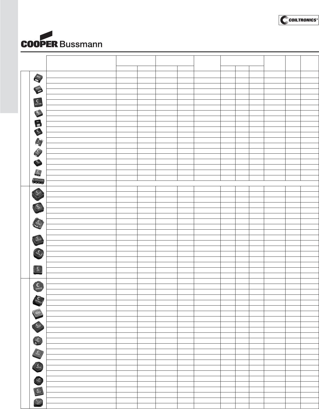
PM-8
INDUCTOR SELECTION GUIDE
Inductor Selection Guide
High Current Shielded Drum (DR Style) Low Profile Shielded Drum (SD Style)
Note 1 = Current ratings listed are the lower value of the Isat and Irms ratings
Note 2 = EMI Rating: 1) Closed magnetic path - best EMI shield; 2) Small gap,
or external shield - some EMI fringing; 3) No shield - Highest EMI
Note 3 = Alternate sizes, terminal styles available
General information needed to select proper inductor:
___I. Inductance and Current requirements
___II. Mounting style (surface mount or thru hole) and
size constraints
___III. Frequency of operation (switching frequency)
___IV. Circuit susceptibility to EMI
___V. Consider using two parts in series for lower
profiles, higher current ratings or higher
inductance values
Maximum Maximum Winding
Product Family Current Rating Inductance Rating Configuration Product Size (mm) Core EMI
Inductance Current
1
Inductance Current
1
(if applicable) L W H Structure Rating
2
SMT/THT
HC3 0.50 78.00 6.0 30.00 - 30.00 25.30 17.50 UI 2 SMT
HC2 LP 0.47 52.90 6.0 16.50 - 19.20 19.20 11.18 UI 2 SMT
HCP1305 0.470 38.00 2.200 20.00 - 13.80 12.90 5.00 EI 1 SMT
HC9 0.200 46.70 47.000 3.65 - 13.80 13.10 7.50 EI 2 SMT
HCF1305 0.470 32.00 4.700 10.40 - 12.50 12.50 5.00 EI 1 SMT
FLAT-PAC (FP1308) 0.110 68.00 0.440 32.00 - 13.70 12.95 8.00 UI 2 SMT
HCP1104 0.200 32.00 0.900 22.00 - 11.50 10.25 4.00 EI 1 SMT
HCPT1309 0.200 43.10 3.310 11.40 - 13.20 14.00 9.00 EI 1 THT
HC7 0.47 23.40 4.7 9.20 - 13.00 13.80 5.50 EI 1 SMT
HC1 0.22 40.50 10.0 5.30 - 13.00 13.00 10.00 UI 2 SMT
HC7 (HC7-R20) 0.20 35.80 0.20 35.80 - 13.00 14.25 6.00 EI 1 SMT
HC8 0.15 39.00 47.0 2.40 - 10.40 10.40 4.00 EI 1 SMT
HC8LP 0.15 29.00 47.0 1.70 - 10.40 10.40 3.50 EI 1 SMT
FLAT-PAC Single (FP4-S_) 0.100 40.00 0.200 30.00 - 6.80 10.20 5.00 UI 2 SMT
HCP0703 0.150 26.00 10.000 3.00 - 7.30 7.00 3.00 EI 1 SMT
FLAT-PAC 5mm (FP2-V_) 0.050 70.00 0.200 19.00 - 7.20 6.70 5.00 UI 2 SMT
FLAT-PAC Single (FP3-S) 0.100 19.00 15.0 2.00 - 7.25 6.50 3.00 EI 1 SMT
FLAT-PAC Single (FP2-S_) 0.047 39.00 0.120 18.00 - 7.20 6.70 3.00 UI 2 SMT
FLAT-PAC Dual (FP2-D_) 0.188 16.00 0.480 9.00 Series 7.20 6.70 3.00 UI 2 SMT
FLAT-PAC Dual (FP2-D_) 0.047 37.00 0.120 18.00 Parallel 7.20 6.70 3.00 UI 2 SMT
CPL (Multi-Phase) See Data Sheet
DRQ127 1.68 8.94 4020.0 0.307 Series 12.50 12.50 8.00 Shld Drum 2 SMT
DRQ127 0.47 17.90 1000.0 0.610 Parallel 12.50 12.50 8.00 Shld Drum 2 SMT
DR127 0.47 17.90 1000.0 0.610 - 12.50 12.50 8.00 Shld Drum 2 SMT
DRQ125 0.47 17.60 1000.0 0.570 Parallel 12.50 12.50 6.00 Shld Drum 2 SMT
DR125 0.47 17.60 1000.0 0.570 - 12.50 12.50 6.00 Shld Drum 2 SMT
DRQ125 1.82 8.80 4032.0 0.283 Series 12.50 12.50 6.00 Shld Drum 2 SMT
DR124 0.47 16.00 1000.0 0.440 - 12.30 12.30 4.50 Shld Drum 2 SMT
DR1050 0.80 9.70 1000.0 0.430 - 10.50 10.30 5.00 Shld Drum 2 SMT
DR1040 1.50 6.50 330.0 0.520 - 10.50 10.30 4.00 Shld Drum 2 SMT
DRQ74 1.18 3.10 4036.0 0.135 Series 7.60 7.60 4.35 Shld Drum 2 SMT
DRQ74 0.33 6.20 1000.0 0.270 Parallel 7.60 7.60 4.35 Shld Drum 2 SMT
DR74 0.33 6.26 1000.0 0.270 - 7.60 7.60 4.35 Shld Drum 2 SMT
DR1030 1.10 7.00 150.0 0.680 - 10.50 10.30 3.00 Shld Drum 2 SMT
DRQ73 1.22 3.10 3980.0 0.128 Series 7.60 7.60 3.55 Shld Drum 2 SMT
LDS0705 0.82 7.68 470.0 0.368 - 8.00 7.20 5.00 Shld Drum 2 SMT
DRQ73 0.33 6.19 1000.0 0.250 Parallel 7.60 7.60 3.55 Shld Drum 2 SMT
DR73 0.33 6.21 1000.0 0.250 - 7.60 7.60 3.55 Shld Drum 2 SMT
SD8350 1.80 5.50 100.0 0.800 - 9.50 8.30 4.50 Shld Drum 2 SMT
SD8328 2.50 4.50 100.0 0.800 - 9.50 8.30 3.00 Shld Drum 2 SMT
SD7030 3.30 3.00 680.0 0.210 - 7.00 7.00 3.00 Shld Drum 2 SMT
SD53 1.10 3.25 100.0 0.440 - 5.20 5.20 3.00 Shld Drum 2 SMT
SD6030 2.70 2.60 680.0 0.160 - 6.00 6.00 3.00 Shld Drum 2 SMT
SDQ25 0.47 3.71 1000.0 0.127 Parallel 5.20 5.20 2.50 Shld Drum 2 SMT
SDQ25 1.57 1.86 4032.0 0.063 Series 5.20 5.20 2.50 Shld Drum 2 SMT
SD25 0.47 3.88 1000.0 0.126 - 5.20 5.20 2.50 Shld Drum 2 SMT
SD14 0.58 3.52 1000.0 0.117 - 5.20 5.20 1.40 Shld Drum 2 SMT
SD6020 3.90 1.95 100.0 0.360 - 6.00 6.00 2.00 Shld Drum 2 SMT
SD52 1.20 2.33 150.0 0.280 - 5.60 5.20 2.00 Shld Drum 2 SMT
SD18 0.47 3.58 1000.0 0.102 - 5.20 5.20 1.80 Shld Drum 2 SMT
SDQ12 1.96 1.39 331.0 0.154 Series 5.20 5.20 1.20 Shld Drum 2 SMT
SDQ12 0.47 2.78 82.0 0.309 Parallel 5.20 5.20 1.20 Shld Drum 2 SMT
SD20 0.47 3.59 1000.0 0.088 - 5.20 5.20 2.00 Shld Drum 2 SMT
SD12 0.47 3.19 1000.0 0.086 - 5.20 5.20 1.20 Shld Drum 2 SMT
SD3118 1.00 2.01 1000.0 0.083 - 3.10 3.10 1.80 Shld Drum 2 SMT
SD3814 0.47 2.81 680.0 0.100 - 4.00 4.00 1.40 Shld Drum 2 SMT
SD10 0.47 2.59 470.0 0.110 - 5.20 5.20 1.00 Shld Drum 2 SMT
SDH3812 0.47 2.69 220.0 0.160 - 4.00 4.00 1.20 Shld Drum 2 SMT
SD3812 0.47 2.53 220.0 0.160 - 4.00 4.00 1.20 Shld Drum 2 SMT
SD3114 1.00 1.60 330.0 0.113 - 3.10 3.10 1.40 Shld Drum 2 SMT
SD3112 1.00 1.39 220.0 0.117 - 3.10 3.10 1.20 Shld Drum 2 SMT
SD3110 0.50 1.54 220.0 0.106 - 3.10 3.10 1.00 Shld Drum 2 SMT
Courtesy of Steven Engineering, Inc.-230 Ryan Way, South San Francisco, CA 94080-6370-Main Office: (650) 588-9200-Outside Local Area: (800) 258-9200-www.stevenengineering.com
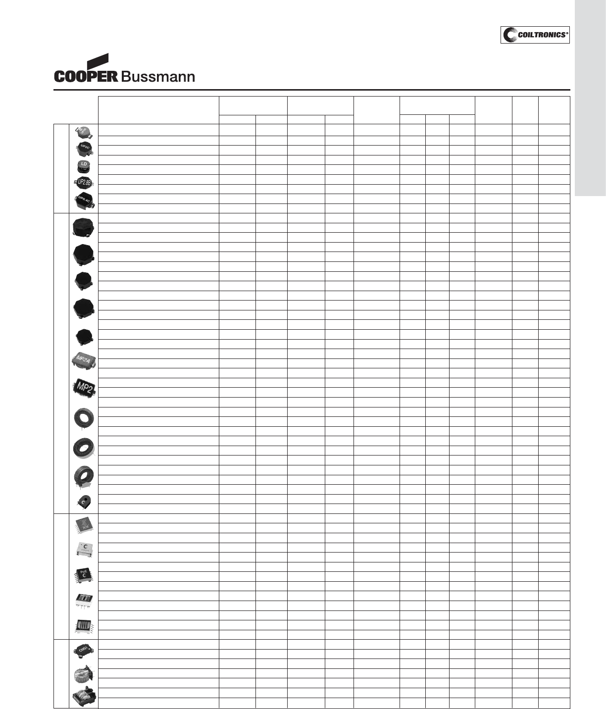
PM-9
INDUCTOR SELECTION GUIDE
Unshielded Drum Core
Inductor Selection Guide
Maximum Maximum Winding
Product Family Current Rating Inductance Rating Configuration Product Size (mm) Core EMI
Inductance Current
1
Inductance Current
1
(if applicable) L W H Structure Rating
2
SMT/THT
UNI-PAC 4B 0.47 19.20 470.0 0.914 - 22.10 15.00 7.87 Drum 3 SMT
UNI-PAC 3B (UP3B) 0.47 16.00 330.0 0.750 - 19.30 13.21 6.80 Drum 3 SMT
UNI-PAC 2C (UP2C) 0.47 12.20 1000.0 0.380 - 12.90 9.40 5.20 Drum 3 SMT
LD2 10.00 3.45 470.0 0.550 7.80 7.00 5.00 Drum 3 SMT
UNI-PAC 2B (UP2B) 0.47 10.60 1000.0 0.300 - 13.79 10.41 6.00 Drum 3 SMT
UNI-PAC 2.8B (UP2.8B) 1.00 3.60 150.0 0.620 - 12.90 9.40 2.80 Drum 3 SMT
UNI-PAC 1B (UP1B) 0.47 6.00 330.0 0.280 - 8.89 6.10 5.00 Drum 3 SMT
LD1 1.00 2.60 68.0 0.460 4.50 4.00 3.20 Drum 3 SMT
UNI-PAC 0.4C (UP0.4C) 1.00 2.88 100.0 0.350 - 6.60 4.45 2.92 Drum 3 SMT
OCTA-PAC Plus 4 (CTX_-4A) 0.33 12.20 300.0 0.75 Parallel 13.97 11.43 6.35 Toroid 1 SMT
OCTA-PAC Plus 4 (CTX_-4A) 1.25 6.09 1211.0 0.37 Series 13.97 11.43 6.35 Toroid 1 SMT
OCTA-PAC 4 (CTX_-4) 0.47 7.00 300.0 0.62 Parallel 13.97 11.43 6.35 Toroid 1 SMT
OCTA-PAC 4 (CTX_-4) 1.76 3.50 1192.0 0.31 Series 13.97 11.43 6.35 Toroid 1 SMT
OCTA-PAC Plus 2 (CTX_-2A) 1.14 5.47 1215.0 0.29 Series 11.43 8.89 5.97 Toroid 1 SMT
OCTA-PAC Plus 2 (CTX_-2A) 0.33 10.90 300.0 0.58 Parallel 11.43 8.89 5.97 Toroid 1 SMT
ECONO-PAC 4P (CTX_-4P) 0.47 7.90 300.0 0.54 Parallel 13.97 11.43 6.35 Toroid 1 SMT
OCTA-PAC Plus 3 (CTX_-3A) 0.33 11.40 300.0 0.54 Parallel 13.97 11.43 4.83 Toroid 1 SMT
ECONO-PAC 4P (CTX_-4P) 1.95 3.95 1195.0 0.27 Series 13.97 11.43 6.35 Toroid 1 SMT
OCTA-PAC Plus 3 (CTX_-3A) 1.47 5.72 1185.0 0.27 Series 13.97 11.43 4.83 Toroid 1 SMT
ECONO-PAC 3P (CTX_-3P) 0.47 6.20 300.0 0.50 Parallel 13.97 11.43 4.83 Toroid 1 SMT
ECONO-PAC 3P (CTX_-3P) 1.85 3.10 1193.0 0.25 Series 13.97 11.43 4.83 Toroid 1 SMT
OCTA-PAC Plus 1 (CTX_-1A) 0.33 10.00 300.0 0.47 Parallel 11.43 8.89 4.19 Toroid 1 SMT
OCTA-PAC Plus 1 (CTX_-1A) 1.61 4.98 1203.0 0.23 Series 11.43 8.89 4.19 Toroid 1 SMT
ECONO-PAC 2P (CTX_-2P) 2.18 2.95 1201.0 0.21 Series 11.43 8.89 5.97 Toroid 1 SMT
ECONO-PAC 2P (CTX_-2P) 0.47 5.90 300.0 0.42 Parallel 11.43 8.89 5.97 Toroid 1 SMT
OCTA-PAC 3 (CTX_-3) 1.54 3.00 1204.0 0.20 Series 13.97 11.43 4.83 Toroid 1 SMT
OCTA-PAC 3 (CTX_-3) 0.47 6.00 300.0 0.40 Parallel 13.97 11.43 4.83 Toroid 1 SMT
OCTA-PAC 2 (CTX_-2) 1.69 3.25 1203.0 0.19 Series 11.43 8.89 5.97 Toroid 1 SMT
OCTA-PAC 2 (CTX_-2) 0.47 6.50 300.0 0.38 Parallel 11.43 8.89 5.97 Toroid 1 SMT
ECONO-PAC 1P (CTX_-1P) 0.47 5.50 300.0 0.32 Parallel 11.43 8.89 4.19 Toroid 1 SMT
ECONO-PAC 1P (CTX_-1P) 1.67 2.75 1199.0 0.16 Series 11.43 8.89 4.19 Toroid 1 SMT
Micro-Pac Plus (MP2A) 0.47 3.52 100.0 0.39 - 7.50 5.20 1.80 Toroid 1 SMT
OCTA-PAC 1 (CTX_-1) 1.60 2.75 1210.0 0.11 Series 11.43 8.89 4.19 Toroid 1 SMT
OCTA-PAC 1 (CTX_-1) 0.47 5.50 300.0 0.22 Parallel 11.43 8.89 4.19 Toroid 1 SMT
Micro-Pac (MP2) 0.47 2.02 47.0 0.31 - 7.50 5.20 1.80 Toroid 1 SMT
Large Toroid (LCPI) Vertical various various various various - various various various Toroid 1 THT
Large Toroid (LCPI) Horizontal various various various various - various various various Toroid 1 THT
Large Toroid (LCPI) w/ Header Vert. various various various various - various various various Toroid 1 THT
Large Toroid (LCPI) w/ Header Horiz. various various various various - various various various Toroid 1 THT
Current Sense various various various various - 17.15 9.53 20.32 Toroid 1 THT
Versa-Pac (VP5/VPH5) multiple multiple multiple multiple 6 windings 28.50 21.00 10.80 E 2 SMT
Versa-Pac (VP4/VPH4) multiple multiple multiple multiple 6 windings 24.60 18.00 10.00 E 2 SMT
Versa-Pac (VP3/VPH3) multiple multiple multiple multiple 6 windings 22.30 17.10 8.40 E 2 SMT
Versa-Pac (VP2/VPH2) multiple multiple multiple multiple 6 windings 16.80 16.30 7.80 E 2 SMT
Versa-Pac (VP1/VPH1) multiple multiple multiple multiple 6 windings 13.00 12.90 6.20 E 2 SMT
Power Over Ethernet/PD 26W (Forward) n/a n/a n/a n/a - 28.50 21.50 10.80 E 2 SMT
PowerOver Ethernet/PD 13W (Flyback) n/a n/a n/a n/a - 24.60 18.00 10.00 E 2 SMT
Power Over Ethernet/PD 7W (Flyback) n/a n/a n/a n/a - 22.30 17.10 8.40 E 2 SMT
Power Over Ethernet/PD 4W (Flyback) n/a n/a n/a n/a - 22.30 17.10 8.40 E 2 SMT
CCFL 14W n/a n/a n/a n/a - 28.50
3
25.40
3
15.00
3
E 2 THT
CCFL 6W n/a n/a n/a n/a - 26.00
3
16.50
3
7.10
3
E 2 SMT
CCFL 4W n/a n/a n/a n/a - 26.00
3
16.50
3
5.50
3
E 2 SMT
CCFL 2.5W n/a n/a n/a n/a - 20.60
3
14.35
3
8.00
3
E 2 SMT
Common-Mode SMT (CMS3) 78.0 4.75 1600 0.75 - 13.97 11.43 6.00 Toroid 1 SMT
Common-Mode SMT (CMS2) 30.0 5.35 1600 0.50 - 11.43 8.89 6.00 Toroid 1 SMT
Common-Mode SMT (CMS1) 5.50 7.00 250 0.85 - 9.40 7.20 2.60 Toroid 1 SMT
Common-Mode Thru-hole (CMT4) Vert 530 6.50 5400 2.00 - 25.00 15.40 25.50 Toroid 1 THT
Common-Mode Thru-hole (CMT3) Horz 530 6.50 5400 2.00 - 25.00 25.00 14.00 Toroid 1 THT
Common-Mode Thru-hole (CMT2) 1600 5.75 30,000 1.50 - 36.50 22.00 44.50 E 2 THT
Common-Mode Thru-hole (CMT1) 940 6.05 66,000 0.74 - 29.50 22.00 36.50 E 2 THT
Toroid Transformers Common-Mode
Note 1 = Current ratings listed are the lower value of the Isat and Irms ratings
Note 2 = EMI Rating: 1) Closed magnetic path - best EMI shield; 2) Small gap,
or external shield - some EMI fringing; 3) No shield - Highest EMI
Note 3 = Alternate sizes, terminal styles available
General information needed to select proper inductor:
___I. Inductance and Current requirements
___II. Mounting style (surface mount or thru hole) and
size constraints
___III. Frequency of operation (switching frequency)
___IV. Circuit susceptibility to EMI
___V. Consider using two parts in series for lower
profiles, higher current ratings or higher
inductance values
Courtesy of Steven Engineering, Inc.-230 Ryan Way, South San Francisco, CA 94080-6370-Main Office: (650) 588-9200-Outside Local Area: (800) 258-9200-www.stevenengineering.com
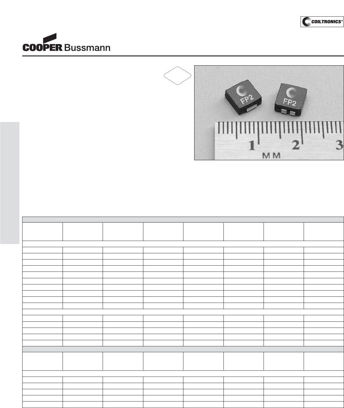
PM-10
HIGH CURRENT (FP2) FLAT-PAC™
Description
• 125°C maximum total temperature operation
• Surface mount inductors designed for higher
speed switch mode applications requiring
lower inductance and high current
• Dual conductors allow for low inductance and high cur-
rent or high inductance and lower current
• Inductance range from .047uH to 0.480uH
• Current range up to 42 Amps
• Meets UL 94V-0 flammability standard
• Ferrite core material
Applications
• Next generation microprocessors
Environmental Data
• Storage temperature range: -40°C to +125°C
• Operating ambient temperature range: -40°C to +125°C
(range is application specific).
• Solder reflow temperature: +260°C max. for 10 seconds
max.
Packaging
• Supplied in tape and reel packaging, 1700 (FP2-S and
FP2-D) and 950 (FP2-S200 and FP2-VXXX) per reel
Parallel Mode
Part Inductance OCL(1) IRMS(2) ISAT(3) DCR(4) Height Volt-μ
Number μH μH±Amps Amps ΩSec (VμS)
(rated) 15% nom. ref.(5)
Single Conductor
FP2-S047-R 0.047 0.047 39.0 42.0 0.00024 3.00 0.75
FP2-S068-R 0.068 0.068 39.0 32.0 0.00024 3.00 0.75
FP2-S082-R 0.082 0.082 39.0 26.0 0.00024 3.00 0.75
FP2-S100-R 0.100 0.100 39.0 22.0 0.00024 3.00 0.75
FP2-S120-R 0.120 0.120 39.0 18.0 0.00024 3.00 0.75
FP2-S200-R 0.200 0.200 37.0 19.0 0.00028 5.00 0.99
FP2-V050-R 0.050 0.050 37.0 70.0 0.00028 5.00 0.99
FP2-V100-R 0.100 0.100 37.0 40.0 0.00028 5.00 0.99
FP2-V120-R 0.120 0.120 37.0 33.0 0.00028 5.00 0.99
FP2-V150-R 0.150 0.150 37.0 25.5 0.00028 5.00 0.99
Double Conductor
FP2-D047-R 0.047 0.047 37.0 42.0 0.00026 3.00 0.75
FP2-D068-R 0.068 0.068 37.0 32.0 0.00026 3.00 0.75
FP2-D082-R 0.082 0.082 37.0 26.0 0.00026 3.00 0.75
FP2-D100-R 0.100 0.100 37.0 22.0 0.00026 3.00 0.75
FP2-D120-R 0.120 0.120 37.0 18.0 0.00026 3.00 0.75
Series Mode
Part Inductance OCL(1) IRMS(2) ISAT(3) DCR(4) Height Volt-μ(5)
Number μH ref. μH Amps Amps ΩSec (VμS)
(rated) ref. ref. ref.
Double Conductor
FP2-D047-R 0.188 0.188 16.0 21.0 0.0013 3.00 1.50
FP2-D068-R 0.272 0.272 16.0 16.0 0.0013 3.00 1.50
FP2-D082-R 0.328 0.328 16.0 13.0 0.0013 3.00 1.50
FP2-D100-R 0.400 0.400 16.0 11.0 0.0013 3.00 1.50
FP2-D120-R 0.480 0.480 16.0 9.0 0.0013 3.00 1.50
Notes: (1) Open Circuit Inductance Test Parameters: 1MHz, .100Vrms, 0.0Adc.
(2) RMS current for an approximate ΔT of 40°C without core loss. It is rec-
ommended that the temperature of the part not exceed 125°C.
(3) Peak current for approximately 30% rolloff at 20°C.
(4) DCR limits 20°C.
(5) Applied Volt-Time product (V-μS) across the inductor. This value repre-
sents the applied V-μS at 500KHz necessary to generate a core loss
equal to 10% of the total losses for 40°C temperature rise.
FLAT-PAC™
Low Profile Inductors
(Surface Mount)
RoHS
2002/95/EC
Courtesy of Steven Engineering, Inc.-230 Ryan Way, South San Francisco, CA 94080-6370-Main Office: (650) 588-9200-Outside Local Area: (800) 258-9200-www.stevenengineering.com
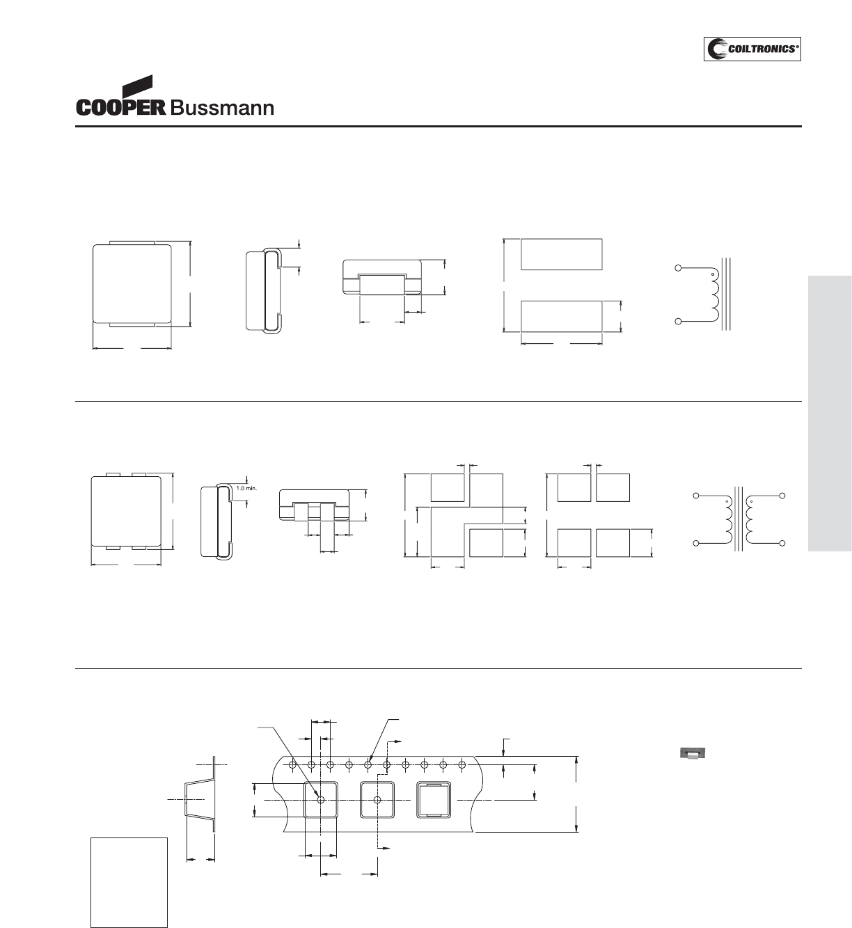
PM-11
HIGH CURRENT (FP2) FLAT-PAC™
Mechanical Diagrams
Single Conductor
Notes: (1) Marking SXXX = S: Single Conductor Style, DXXX = D: Dual
Conductor Style, XXX - last three digits of part number. Date Code:
yww = y: Last Digit of year, ww: week of year.
(2) All Dimensions are in millimeters unless otherwise specified.
(3) For parallel mode operation, connect terminals 1 to 4 and 2 to 3 on
PCB (use Single Conductor PCB Layout) For series mode operation,
connect terminals 2 to 4 on PCB (Dual Conductor Model).
6
.7
0
M
ax
7.2
0
M
ax
(
S or V
)
XX
X
y
w
w
T
O
P VIE
W
2
1
2.50
(
2x
)
7.
50
6
.
50
(
4x
)
1
2
P
C
B PAD LAY
OUT
2
1
SC
HEMATI
C
3
.
0
ref
.
Hei
g
h
t
mm M
ax
1.
30
ref
.
(
2x
)
FR
O
NT VIE
W
S
IDE VIE
W
1.
0
min
.
(
2x
)
Dual Conductor
6
.7
0
M
ax
y
w
w
7.2
0
M
ax
DXXX
T
O
P VIE
W
2
1
3
4
P
C
B PAD LAY
OUT
2.50
(
2x
)
7.
50
3
.
00
(
4x
)
0.5
0
2Windin
g
Mode
2.50 (2x)
7.
50
3
.
00
(
4x
)
0.50 (t
y
p
)
S
eries Mod
e
4.
50
(
2x
)
1.
50
1
4
2
3
1
4
2
3
3
.
00
m
m
M
ax
1.
30
ref
.
(
2x
)
FR
O
NT VIE
W
1.25
(
2x
)
r
e
f
.
1.
00
ref
.
SC
HEMATI
C
Windin
g
1
2
1
Windin
g
2
3
4
S
IDE VIE
W
(
4x
)
Packaging Information
Ko
1.5 Dia
min.
Bo
Ao
12.0
4.0
2.0
1.5 Dia.
+0.1/-0.0
A
A
1.75
7.5 16.0
+/-0.3
1
2
Ao=6.6mm
Bo=7.1mm
Ko=3.2mm
Ko=5.2mm
(FP2-S200
& FP2V)
ACTUAL SIZE
FLAT-PAC’S
FLAT-PAC™
Low Profile Inductors
(Surface Mount)
Direction of Feed ➞
Courtesy of Steven Engineering, Inc.-230 Ryan Way, South San Francisco, CA 94080-6370-Main Office: (650) 588-9200-Outside Local Area: (800) 258-9200-www.stevenengineering.com
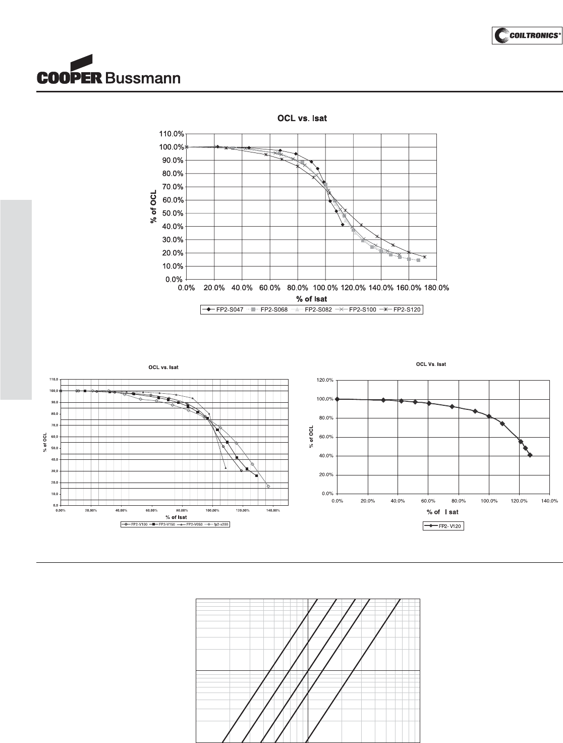
PM-12
HIGH CURRENT (FP2) FLAT-PAC™
Inductance
Characteristics
FLAT-PAC™
Low Profile Inductors
(Surface Mount)
Core Loss
IRMS DERATING WITH CORE LOSS
1000800600
50040030020010080605040302010
% of Applied Volt-μ-Seconds
99
98
97
96
95
94
92
90
80
70
60
50
40
20
0
% of Losses from Irms (maximum)
1MHz
500KHz
300KHz
200KHz
100KHz
Inductance
Characteristics
FLAT-PAC™
Low Profile Inductors
(Surface Mount)
Core Loss
IRMS DERATING WITH CORE LOSS
1000800600
50040030020010080605040302010
% of Applied Volt-μ-Seconds
99
98
97
96
95
94
92
90
80
70
60
50
40
20
0
% of Losses from Irms (maximum)
1MHz
500KHz
300KHz
200KHz
100KHz
Courtesy of Steven Engineering, Inc.-230 Ryan Way, South San Francisco, CA 94080-6370-Main Office: (650) 588-9200-Outside Local Area: (800) 258-9200-www.stevenengineering.com
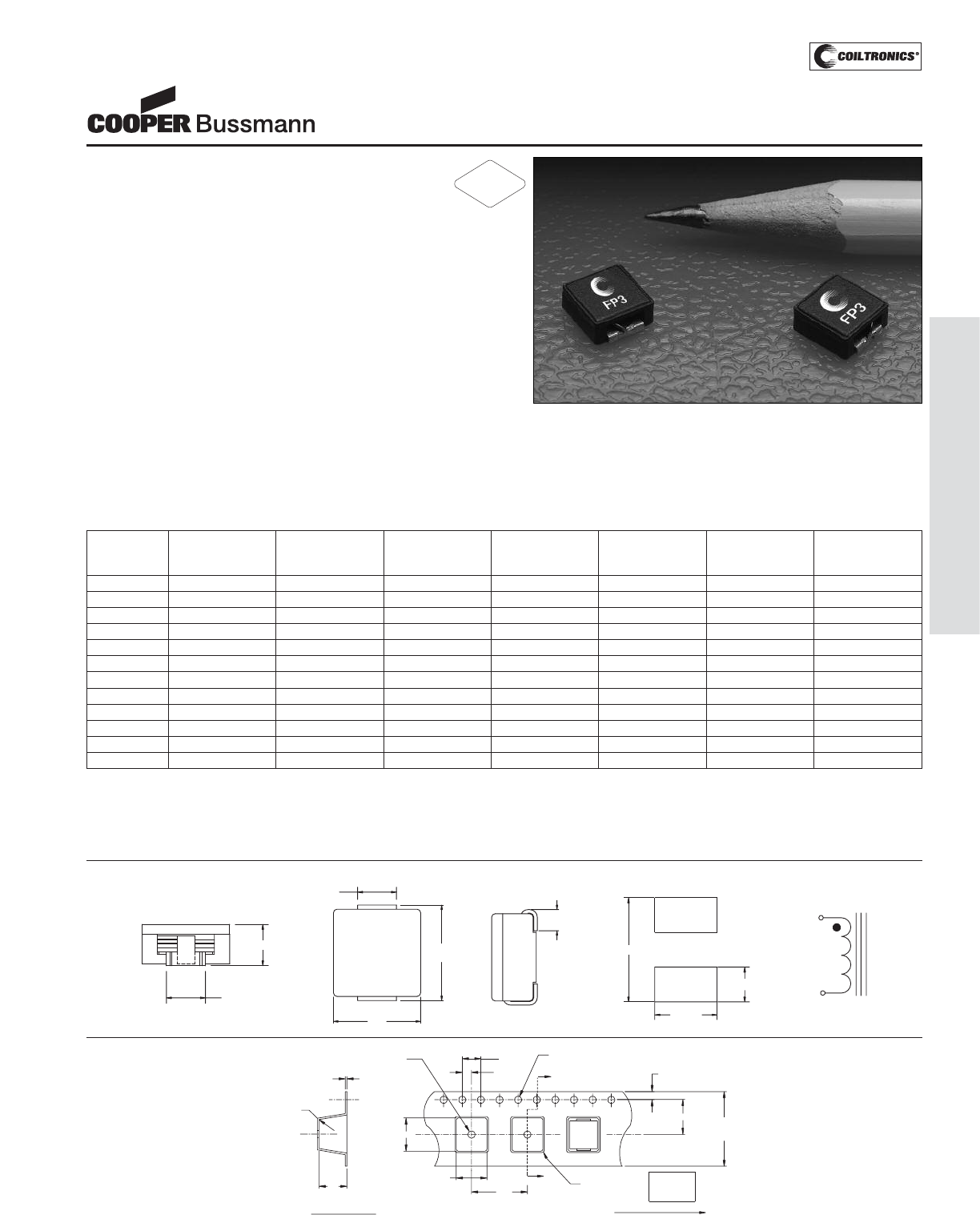
PM-13
HIGH CURRENT (FP3) FLAT-PAC™ 3
Description
• 155°C maximum total temperature operation
• Low profile high current inductors
•Inductance range 0.1uh to 15uh
• Design utilizes high temperature powder iron material with a
non-organic binder to eliminate thermal aging
• Current rating up to 34.7Adc (Higher peak currents may be
attained with a greater rolloff, see rolloff curve)
• Frequency range up to 2MHz
Applications
• Computers and portable power devices
• Energy storage applications
• DC-DC converters
• Input - Output filer application
Environmental Data
• Storage temperature range: -40°C to +155°C
• Operating ambient temperature range: -40°C to +155°C
(range is application specific).
• Solder reflow temperature: +260°C max. for 10 seconds max.
Packaging
• Units supplied in tape and reel packaging.
Reel quantity = 1,700 parts per reel.
Part Rated OCL (1) Irms (2) Isat (3) Isat (4) DCR K-factor (5)
Number Inductance μH ± 15% Amperes Amperes Amperes mOhms @ 20°C
μH Approx. 10% Approx. 15% (Max.)
FP3-R10-R 0.10 0.10 19.0 27 34.7 1.21 803
FP3-R20-R 0.20 0.22 15.3 16 20.8 1.88 482
FP3-R47-R 0.47 0.44 10.9 11.6 14.9 3.67 344
FP3-R68-R 0.68 0.72 9.72 9.0 11.6 4.63 268
FP3-1R0-R 1.00 1.10 6.26 7.4 9.5 11.2 219
FP3-1R5-R 1.50 1.50 5.78 6.2 8.0 13.1 185
FP3-2R0-R 2.00 2.00 5.40 5.4 6.9 15.0 161
FP3-3R3-R 3.30 3.20 3.63 4.3 5.5 30.0 127
FP3-4R7-R 4.70 4.70 3.23 3.5 4.2 40.0 105
FP3-8R2-R 8.20 8.5 2.91 2.6 3.4 74.0 78
FP3-100-R 10.0 10.9 2.30 2.3 3.0 101 69
FP3-150-R 15.0 14.9 2.22 2.0 2.5 127 59
1) OCL (Open Circuit Inductance) Test parameters: 100kHz, 0.1Vrms, 0.0Adc
2) DC current for an approximate ΔT of 40°C without core loss. Derating is neces-
sary for AC currents. PCB layout, trace thickness and width, air-flow, and proximi-
ty of other heat generating components will affect the temperature rise.
It is recommended that the temperature of the part not exceed 155°C under
worst case operating conditions verified in the end application.
3) Isat Amperes Peak for approximately 10% rolloff @ 20°C
4) Isat Amperes Peak for approximately 15% rolloff @ 20°C
5) K-factor: Used to determine B p-p for core loss (see graph). B p-p =K*L*ΔI
B p-p:(Gauss), K: (K factor from table), L: (Inductance in uH), ΔI (Peak to peak
ripple current in Amps).
FLAT-PAC™ 3
Low Profile Inductors
Mechanical Diagrams
TOP VIEW
FRONT VIEW
7.50
4.50 (2x)
2.50 (2x)
RECOMMENDED PCB PAD LAYOUT
2
SCHEMATIC
1
3.00 Max
2.8±0.25
(2x)
XXX 7.25
Max
6.70
Max
yww
2
2.8±0.25
FP3
(2x) 1
SIDE VIEW
1.0 min.
(2x)
4.0
2.0
12.0
Ao
Ko
Bo
16.0
+/-0.3
7.5
1.75
A
2
1
A
Ao= 6.6mm
Bo= 7.1mm
Ko= 3.2mm
0.3 Rad
max.
1.5 Dia
min.
0.30
+/-0.05
1.5 Dia
+0.1/-0.0
0.5 Rad
typ.
Direction of Feed
SECTION A-A
Packaging Information
Dimensions in Millimeters xxx = Inductance value
yww = Date code
RoHS
2002/95/EC
Courtesy of Steven Engineering, Inc.-230 Ryan Way, South San Francisco, CA 94080-6370-Main Office: (650) 588-9200-Outside Local Area: (800) 258-9200-www.stevenengineering.com
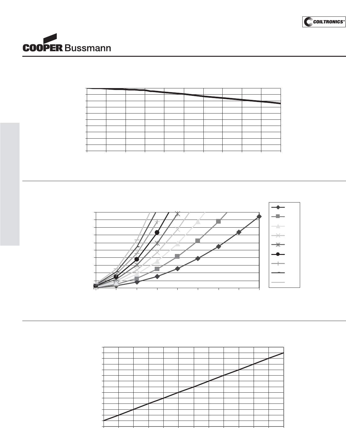
PM-14
HIGH CURRENT (FP3) FLAT-PAC™ 3
OCL vs. Isat
0
10
20
30
40
50
60
70
80
90
100
0 20 40 60 80 100 120 140 160 180 200
% of Isat
%ofOCL
FP3 AC Loss a Frequency (kHz)
tFrequency, kHz
CoreLoss vs. Flux Density
0.00
0.10
0.20
0.30
0.40
0.50
0.60
0.70
0.80
0.90
1.00
250 500 750 1000 1250 1500 1750 2000 2250
B p-p (Gauss)
CoreLoss (W)
200
300
400
500
600
700
800
900
1000
Temperature Rise vs. Watt Loss
0
10
20
30
40
50
60
70
80
90
100
110
120
130
140
0.12 0.24 0.36 0.48 0.61 0.73 0.85 0.97 1.09 1.21 1.33 1.45 1.57
Total Loss (W
)
Temperature Rise (C)
FLAT-PAC™ 3
Low Profile Inductors
Inductance Characteristics
Core Loss
Courtesy of Steven Engineering, Inc.-230 Ryan Way, South San Francisco, CA 94080-6370-Main Office: (650) 588-9200-Outside Local Area: (800) 258-9200-www.stevenengineering.com
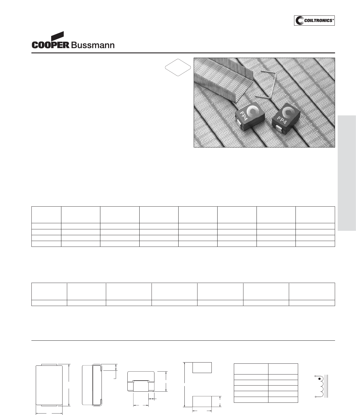
PM-15
HIGH CURRENT (FP4) FLAT-PAC™ 4
Description
• 155°C maximum total temperature operation
• Surface mount inductors designed for high speed,
high current switch mode applications requiring
lower inductance
• Gapped ferrite cores for maximum efficiency
• Inductance values from 0.100 uH to 0.200 uH
• Current range up to 64 Amps
• Meets UL 94V-0 flammability standard
• Ferrite core material
Applications
• Voltage regulator modules (VRMs) for servers,
microprocessors
• High frequency, high current switching power supplies
Environmental Data
• Storage temperature range: -40°C to +155°C
• Operating ambient temperature range: -40°C to +155°C
(range is application specific).
• Solder reflow temperature: +260°C max. for 10 seconds
max.
Packaging
• Supplied in tape and reel packaging,
900 parts per reel
Part Rated OCL (2) Isat (5) Irms (4) DCR DCR Volts-μSec (3)
Number Inductance ± 15% Amperes Amperes Ω@20°C Ω@ 20°C (VuSec)
μH μH Peak (Nom.) (Max.) (ref.)
FP4-100-R 0.100 0.100 64 40 0.00048 0.00065 1.33
FP4-120-R 0.120 0.120 54 40 0.00048 0.00065 1.33
FP4-150-R 0.150 0.150 42 40 0.00048 0.00065 1.33
FP4-200-R 0.200 0.200 30 40 0.00048 0.00065 1.33
1) Units supplied in Tape & Reel packaging; 900 parts on 13" diameter reel.
2) OCL (Open Circuit Inductance) Test parameters: 1MHz, .100Vrms,
0.0Adc & ISAT @20°C
3) Applied Volt-Time product (V-μS) across the inductor.This value represents the
applied V-μS at 500kHz necessary to generate a core loss equal to 10% of the
total losses for 40°C temperature rise.
4) DC current for an approximate ΔT of 40°C without core loss. Derating is neces-
sary for AC currents. PCB layout, trace thickness and width, airflow, and proximi-
ty of other heat generating components will affect the temperature rise. It is rec-
ommended that the temperature of the part not exceed 155°C under worst case
operating conditions verified in the end application.
5) Peak Current for approximately 30% rolloff @ 20°C
FLAT-PAC™ 4
5mm Height Inductors
(Surface Mount)
Mechanical Diagrams
1.0 min.
(2x)
10.20
Max
5.00 Max
1.30 ref.
(2x)
A
6.80
Max
FRONT VIEW
2
yyww R
FP4-XXX
1
10.50
2.50 (2x)
2
SCHEMATIC
1
4.50 (2x)
PCB PAD LAYOUT
TOP VIEW SIDE VIEW
Part Rated OCL (2) Isat (5) Irms (4) DCR Volts-μSec (3)
Number Inductance ± 15% Amperes Amperes @ 25°C (Vus)
μH μH Peak (ref.)
FP4-090SK-R 0.090 0.090 72 33 0.423-0.517 1.33
1) Units supplied in Tape & Reel packaging; 900 parts on 13" diameter reel.
2) OCL (Open Circuit Inductance) Test parameters: 100kHz, 1.0Vrms,
0.0Adc & ISAT @25°C
3) Applied Volt-Time product (V-μS) across the inductor.This value represents the
applied V-μS at 500kHz necessary to generate a core loss equal to 10% of the
total losses for 40°C temperature rise.
4) DC current for an approximate ΔT of 40°C without core loss. Derating is neces-
sary for AC currents. PCB layout, trace thickness and width, airflow, and proximi-
ty of other heat generating components will affect the temperature rise. It is rec-
ommended that the temperature of the part not exceed 155°C under worst case
operating conditions verified in the end application.
5) Peak Current for approximately 20% rolloff @ 25°C
Part Number Dimension
“A” (mm) ref.
FP4-100-R 3.0
FP4-120-R 3.0
FP4-150-R 3.0
FP4-200-R 3.0
FP4-090SK-R 2.8
RoHS
2002/95/EC
Courtesy of Steven Engineering, Inc.-230 Ryan Way, South San Francisco, CA 94080-6370-Main Office: (650) 588-9200-Outside Local Area: (800) 258-9200-www.stevenengineering.com
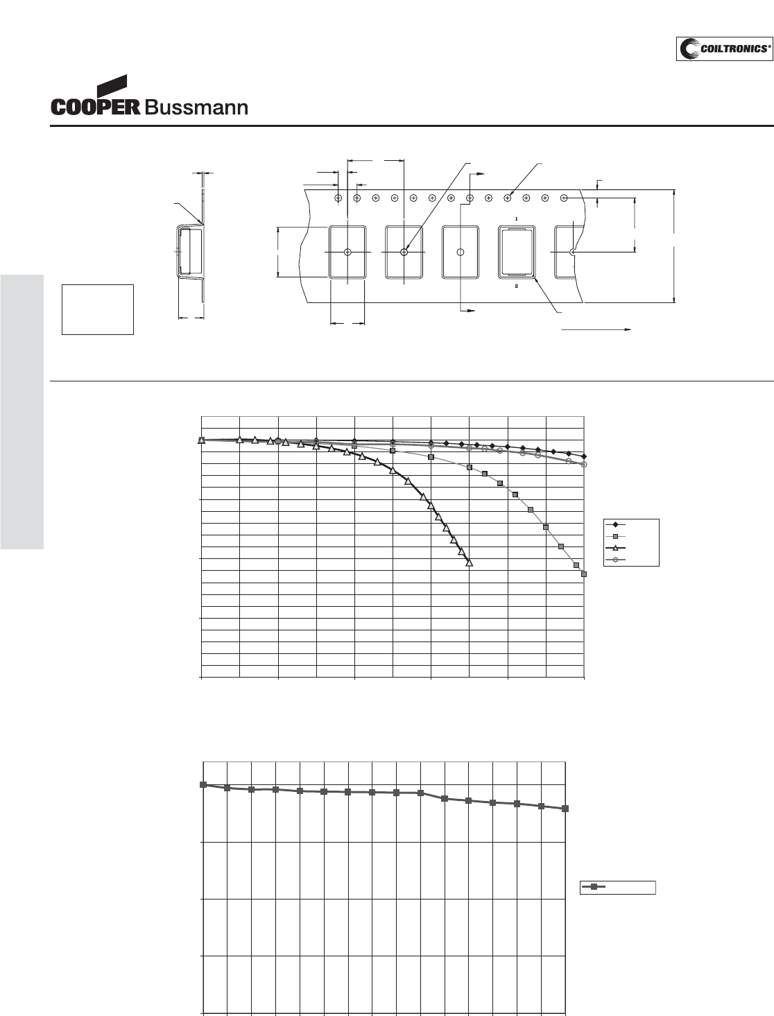
PM-16
HIGH CURRENT (FP4) FLAT-PAC™ 4
Inductance Rolloff vs Isat
0
25
50
75
100
051015 20 25 30 35 40 45 50 55 60 65 70 75
Isat (Adc)
%ofOCL
FP4-090SK
OCL vs. Isat
0.0
25.0
50.0
75.0
100.0
01020304050
Isat (Adc)
% of OCL
FP4-100
FP4-150
FP4-200
FP4-120
FLAT-PAC™ 4
5mm Height Inductors
(Surface Mount)
Inductance Characteristics
Ø1.50 Min.
12.0Ø1.50 +0.1/-0.0
R0.30Max.
1.75±0.10
11.50±0.124.00
±0.3
R0.50 Typ.
Ao
4.00
2.00 ±0.1
Bo
0.35±0.05
Ko
User directionof feed
yyww R
FP4-XXX
A
A
SECTION A-A
Packaging Information
Ao=7.20mm
Bo=10.60mm
Ko=5.40mm
Dimensions in Millimeters xxx = Inductance value
yww = Date code R = Revision level
Courtesy of Steven Engineering, Inc.-230 Ryan Way, South San Francisco, CA 94080-6370-Main Office: (650) 588-9200-Outside Local Area: (800) 258-9200-www.stevenengineering.com
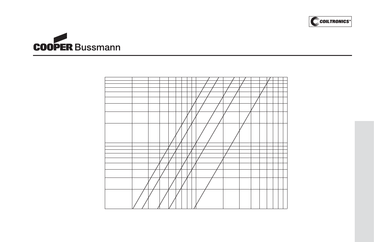
PM-17
HIGH CURRENT (FP4) FLAT-PAC™ 4
1.5MHz
1MHz
500kHz
300kHz
100kHz
40 600 800 100050040030020060 80 100503020
40
20
0
50
60
70
80
98
97
96
95
94
92
90
99
10
% of Losses from Irms (maximum)
% of Applied Volt-μ-Second
Irms Derating with Core Loss
Core Loss
FLAT-PAC™ 4
5mm Height Inductors
(Surface Mount)
Courtesy of Steven Engineering, Inc.-230 Ryan Way, South San Francisco, CA 94080-6370-Main Office: (650) 588-9200-Outside Local Area: (800) 258-9200-www.stevenengineering.com
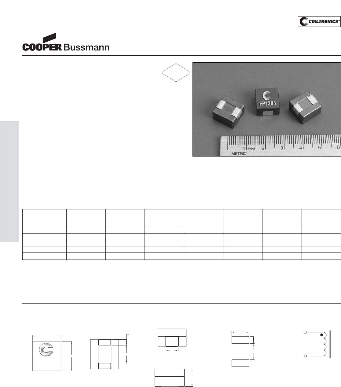
PM-18
HIGH CURRENT (FP1308) FLAT-PAC™ 1308
Description
• 125°C maximum total temperature operation
• 12.9mm x 13.7mm x 8.0mm surface mount package
• High current handling capability, compact footprint
• Ferrite core material
• Inductance range from 110nH to 440nH
• Current range from 120 Amps to 32 Amps
• Frequency range up to 2MHz
Applications
• Voltage Regulator Modules (VRM) for servers and
microprocessors
• Multi-Phase Buck inductors
• High frequency, high current switching power supplies
Environmental Data
• Storage temperature range: -40°C to +125°C
• Operating temperature range: -40°C to +125°C
(range is application specific)
• Solder reflow temperature: +260°C max. for 10 seconds
maximum
Packaging
• Supplied in tape and reel packaging, 450 per reel
FP1308 Series
FLAT-PAC™
High Current Power Inductors
Part Number Rated OCL (1) Irms(2) Isat (3) DCR DCR K-factor
Inductance nH±10% Amperes Amperes mΩ@25°C mΩ@25°C (4)
(nH) (Typical) (Maximum)
FP1308-R11-R 110 110 68 120 0.20 0.24 21.330
FP1308-R21-R 210 210 68 72 0.20 0.24 21.333
FP1308-R26-R 260 260 68 60 0.20 0.24 21.335
FP1308-R32-R 320 320 68 45 0.20 0.24 21.340
FP1308-R44-R 440 440 68 32 0.20 0.24 21.366
(1) Open Circuit Inductance Test Parameters: 100kHz, 1.0V, 0.0Adc.
(2) Irms: DC current for an approximate ΔT of 40°C without core loss. Derating is
necessary for AC currents. PCB layout, trace thickness and width, air-flow, and
proximity of other heat generating components will affect the temperature rise. It
is recommended that the temperature of the part not exceed 125°C under worst
case operating conditions verified in the end application.
(3) Isat Amperes peak for 20% maximum rolloff (@25°C)
(4) K-factor: Used to determine B p-p for core loss (see graph).
B p-p = K*L*ΔI, B p-p(mT), K: (K factor from table), L: (Inductance in μH),
ΔI (Peak to peak ripple current in Amps).
(5) Part Number Definition: FP1308-xxx-R
FP1308 = Product code and size; -xxx = Inductance value in uH;
R = decimal point; If no R is present, third character = # of zeros.
-R suffix = RoHS compliant
RoHS
2002/95/EC
Dimensions are in millimeters.
wwlly = Date Code. R = Revision level.
1
2
FP1308-XXX
wwllyy R
12.95 max.
13.70 max.
8.0 max.
5.4
2.54 (2plcs)
8.0
7.62
3.18
7.2
1
2
TOP VIEW BOTTOM VIEW RECOMMENDED PCB LAYOUT
FRONT VIEW
LEFT VIEW
SCHEMATIC
Mechanical Diagrams
Courtesy of Steven Engineering, Inc.-230 Ryan Way, South San Francisco, CA 94080-6370-Main Office: (650) 588-9200-Outside Local Area: (800) 258-9200-www.stevenengineering.com
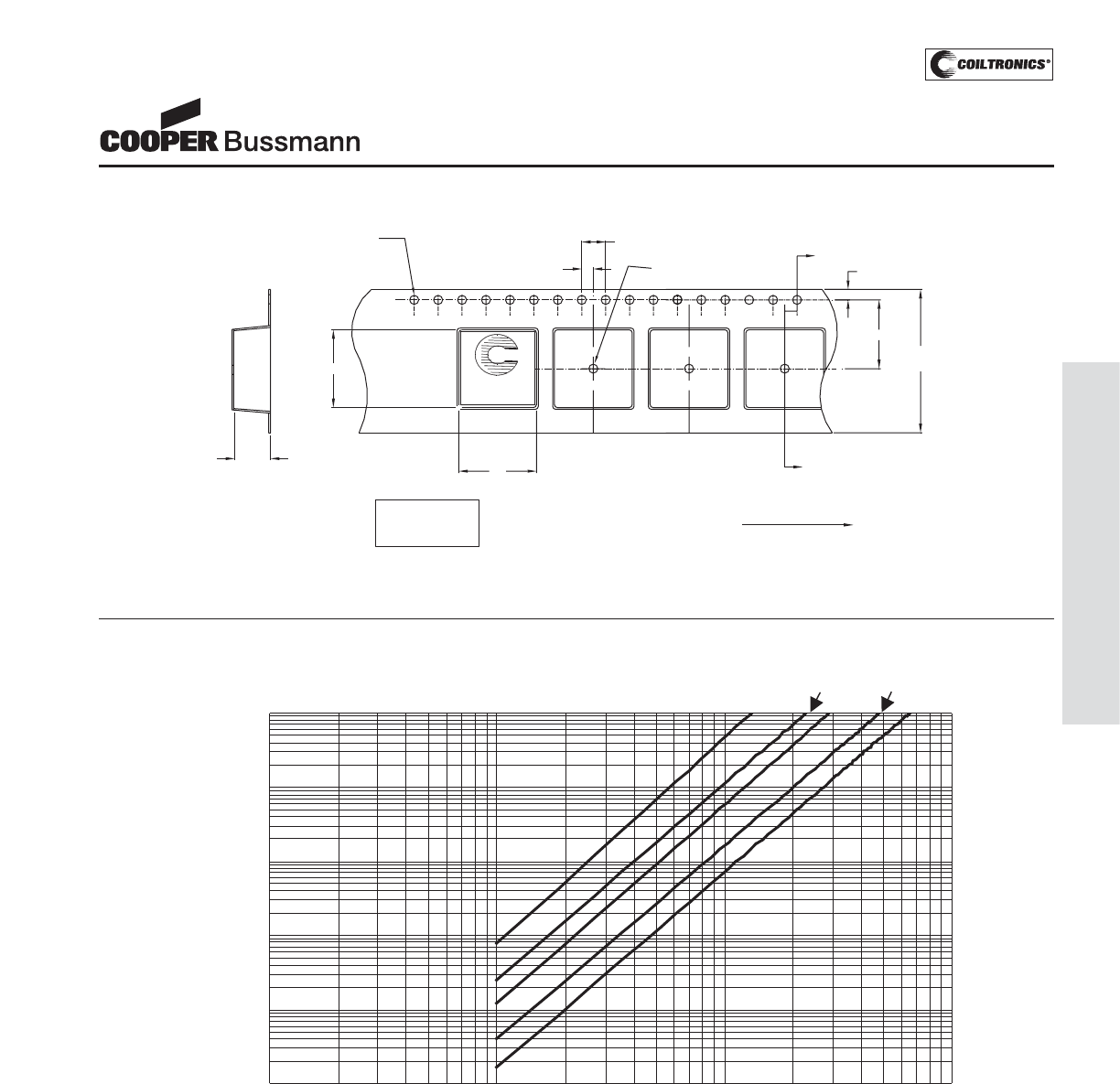
PM-19
HIGH CURRENT (FP1308) FLAT-PAC™ 1308
FP1308 Series
FLAT-PAC™
High Current Power Inductors
Core Loss
Core l oss vs Bp -p
0.0001
0.001
0.01
0.1
1
10
1 10 100 1000
Bp-p(mT)
1MHz
500kHz
300kHz
100kHz
50kHz
Core Loss (W)
2.0
4.0
FP1308-XXX
wwllyy R
1.5 dia
+0.1/-0.0
B0
1.75
24.0
+/-0.3
A
A0
SECTION A-A
K0
User direction of feed
A
1.5 dia
min
11.5
B0= 13.90 mm
A0= 13.20 mm
K0= 8.20 mm Parts packaged on 13" Diameter reel,
450 parts per reel.
Packaging Information
Courtesy of Steven Engineering, Inc.-230 Ryan Way, South San Francisco, CA 94080-6370-Main Office: (650) 588-9200-Outside Local Area: (800) 258-9200-www.stevenengineering.com
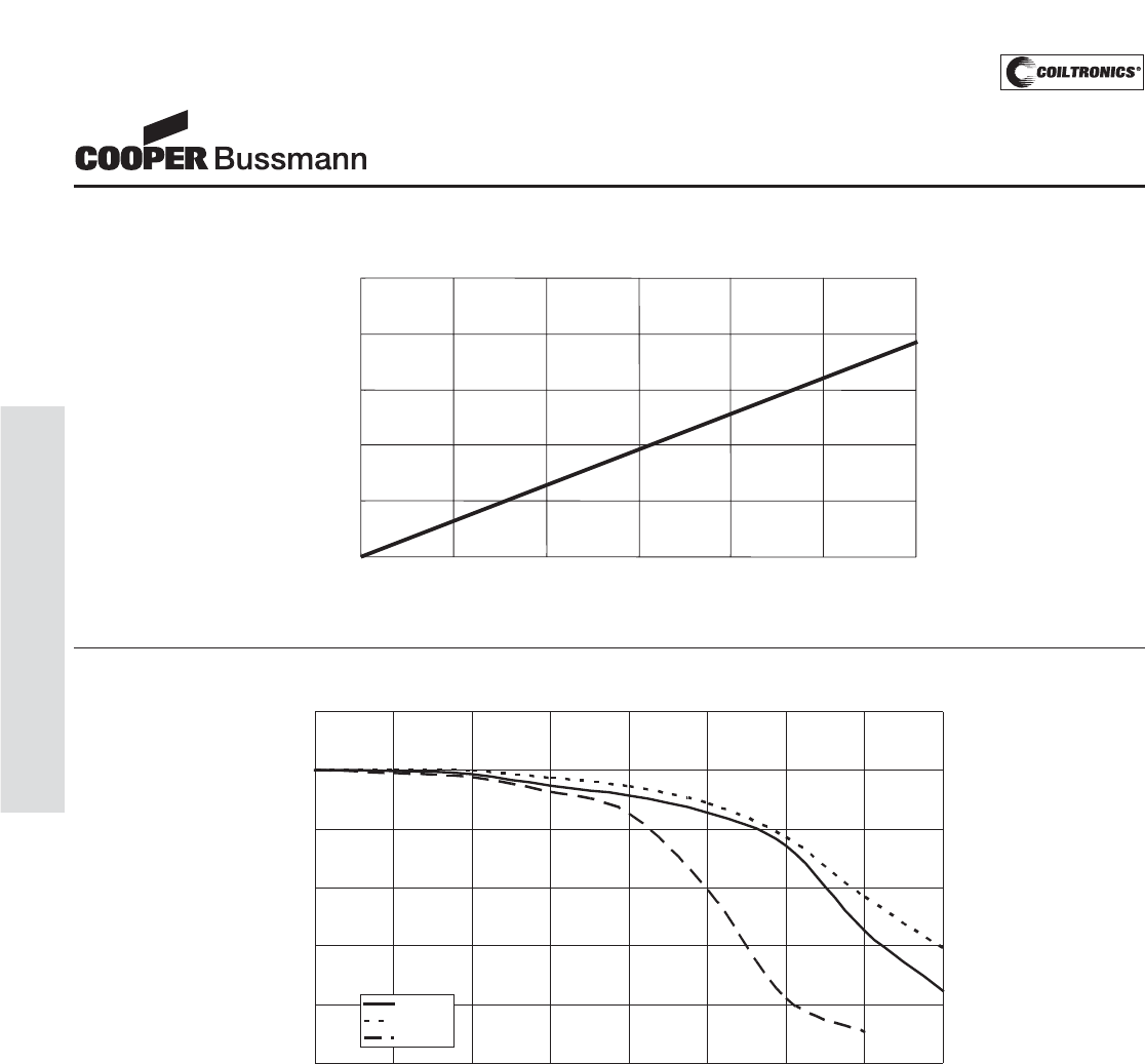
PM-20
HIGH CURRENT (FP1308) FLAT-PAC™ 1308
OCL vs Isat
0%
20%
40%
60%
80%
100%
120%
0% 20% 40% 60% 80% 100% 120% 140% 160%
% of Isat
%ofOCL
+25 Deg.C
-40 Deg.C
+125 Deg.C
Inductance Characteristics
FP1308 Series
FLAT-PAC™
High Current Power Inductors
Temperature Rise vs. Loss
0
20
40
60
80
100
0 0.5 1 1.5 2 2.5 3
Total Loss(W)
Temperature Rise(°C)
Courtesy of Steven Engineering, Inc.-230 Ryan Way, South San Francisco, CA 94080-6370-Main Office: (650) 588-9200-Outside Local Area: (800) 258-9200-www.stevenengineering.com
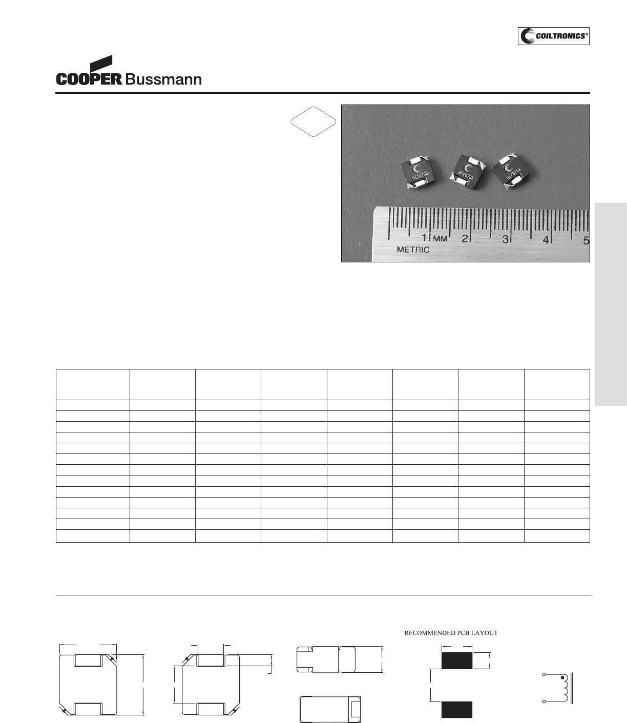
PM-21
HIGH CURRENT (HCP0703)
Description
• 125°C maximum total temperature operation
• 7.0mm x 7.3mm x 3.0mm surface mount package
• Pressed powder iron core material
• Enhanced core coating eliminates rusting and
provides high insulation impedance
• Inductance range from 0.15μH to 10.0μH
• Current range from 52.0 Amps to 3.0 Amps
• Frequency range up to 1MHz
Applications
• Notebook power
• VRM, multi-phase buck regulator
• DC-DC converters
• PC workstations/Servers/Desktop
• Routers
Environmental Data
• Storage temperature range: -55°C to +125°C
• Operating temperature range: -55°C to +125°C
(range is application specific)
• Solder reflow temperature: +260°C max. for 10 seconds
maximum
Packaging
• Supplied in tape and reel packaging,
1500 parts per reel
HCP0703 Series
High Current Pressed Power Inductors
Part Number Rated OCL (1) Irms (2) Isat (3) DCR DCR K-factor
Inductance μH ± 20% Amperes Amperes mΩ@20°C mΩ@20°C (4)
(μH) (Typical) (Maximum)
HCP0703-R15-R 0.15 0.15 26 52 1.9 2.5 1100
HCP0703-R22-R 0.22 0.22 23 40 2.5 2.8 922
HCP0703-R47-R 0.47 0.47 17 26 4.0 4.2 559
HCP0703-R68-R 0.68 0.68 15 25 5.0 5.5 435
HCP0703-R82-R 0.82 0.82 13 24 6.8 8.0 360
HCP0703-1R0-R 1.0 1.0 11 22 9.0 10 356
HCP0703-1R5-R 1.5 1.5 9 18 14 15 307
HCP0703-2R2-R 2.2 2.2 8 14 18 20 206
HCP0703-3R3-R 3.3 3.3 6 13.5 28 30 186
HCP0703-4R7-R 4.7 4.7 5.5 10 37 40 171
HCP0703-6R8-R 6.8 6.8 4.5 8 54 60 140
HCP0703-8R2-R 8.2 8.2 4 7.5 64 68 132
HCP0703-100-R 10.0 10.0 3 7.0 102 105 112
(1) Open Circuit Inductance Test Parameters: 100kHz, 0.25V, 0.0Adc.
(2) Irms: DC current for an approximate ΔT of 40°C without core loss. Derating is
necessary for AC currents. PCB layout, trace thickness and width, air-flow, and
proximity of other heat generating components will affect the temperature rise. It
is recommended that the temperature of the part not exceed 125°C under worst
case operating conditions verified in the end application.
(3) Isat Amperes peak for approximately 20% rolloff (@25°C)
(4) K-factor: Used to determine B p-p for core loss (see graph).
B p-p = K*L*ΔI, B p-p: (Gauss), K: (K factor from table), L: (Inductance in uH),
ΔI (Peak to peak ripple current in Amps).
Dimensions are in millimeters.
wwllyy = Date Code. R = Revision Level.
SCHEMATIC
1
2
7.3 Max.
7.0 Max.
3.0 Max.
2.4+/-0.3
1.27+/-0.3
4.5
1.68
3.40
4.00
HCP0703
XXX
wwllyy R
TOP VIEW FRONT VIEW
BOTTOM VIEW
LEFT VIEW
Mechanical Diagrams
RoHS
2002/95/EC
Courtesy of Steven Engineering, Inc.-230 Ryan Way, South San Francisco, CA 94080-6370-Main Office: (650) 588-9200-Outside Local Area: (800) 258-9200-www.stevenengineering.com
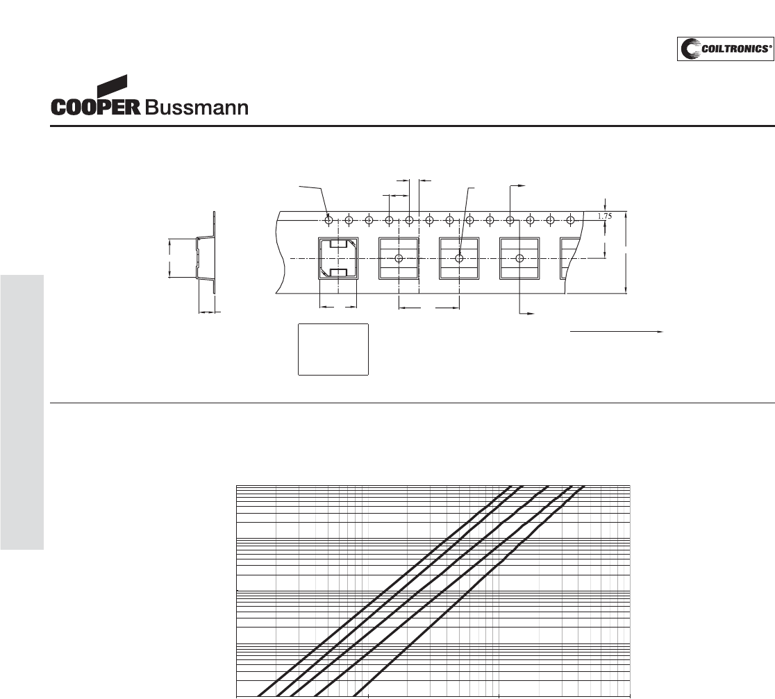
PM-22
HIGH CURRENT (HCP0703)
HCP0703 Series
High Current Pressed Power Inductors
Core Loss
Core Loss vs B p-p
1
10
100
1000
10000
10 100 1000 10000
Bp-p (Guass)
CoreLoss(mW)
1000kHz
700kHz
500kHz
300kHz
100kHz
2.0
1.5 dia
+0.1/-0.0
Bo
Ko
SECTION A-A
7.5
1.5 dia
min
A
A
4.0
16.0
Ao 12.0
HCP0703
XXX
wwllyy R
Ko=3.2 mm
Bo=7.7 mm
Ao=7.3 mm User direction of feed
Packaging Information
Courtesy of Steven Engineering, Inc.-230 Ryan Way, South San Francisco, CA 94080-6370-Main Office: (650) 588-9200-Outside Local Area: (800) 258-9200-www.stevenengineering.com
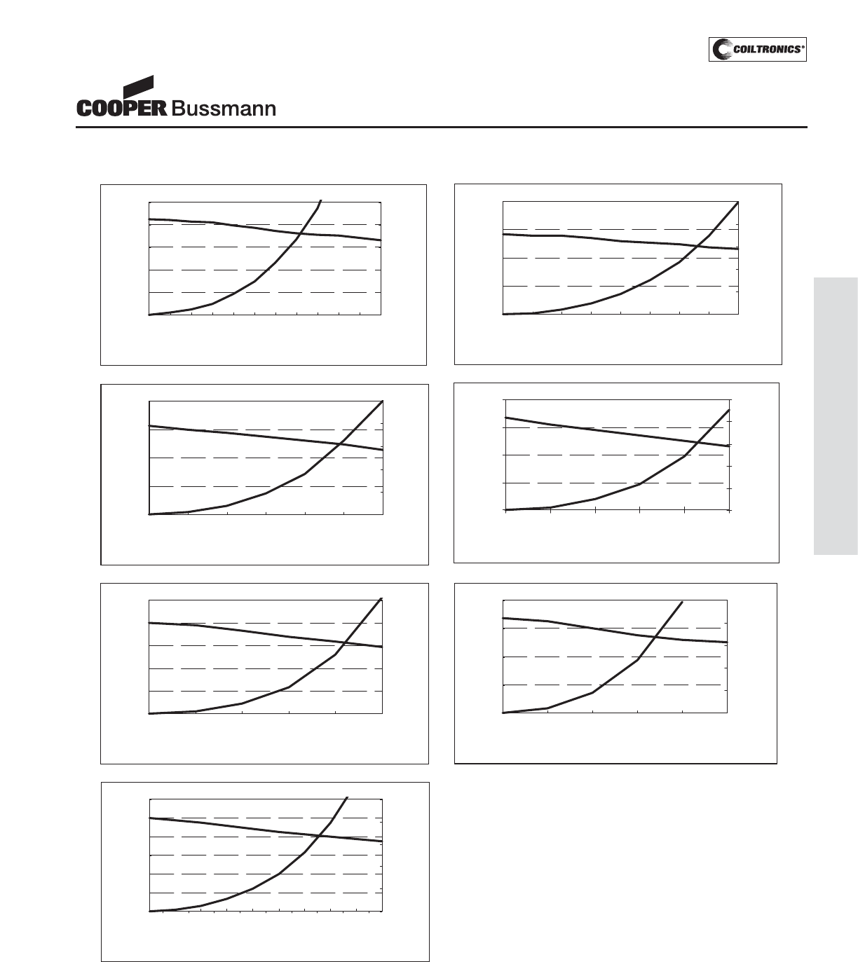
PM-23
HIGH CURRENT (HCP0703)
HCP0703 Series
High Current Pressed Power Inductors
Performance Graphs
0.00
0.04
0.08
0.12
0.16
0.20
0 1020304050
DC Bias(Amps)
Inductance(uH)
0
20
40
60
80
100
Temp.-rise(°C)
HCP0703-R15-R HCP0703-R22-R
0.00
0.07
0.14
0.21
0.28
010203040
DC Bias(Amps)
Inductance(uH)
0
20
40
60
80
100
Temp.-rise
(°C)
HCP0703-R22-R
0.00
0.15
0.30
0.45
0.60
0 5 10 15 20 25 30
DC Bias(Amps)
Inductance(uH)
0
20
40
60
80
100
Temp.-rise
(°C)
HCP0703-R47-R
0.00
0.20
0.40
0.60
0.80
0 5 10 15 20 25
DC Bias(AMPS)
Inductance(uH)
0
20
40
60
80
100
Temp.-rise
(°C)
HCP0703-R68-R
0.00
0.20
0.40
0.60
0.80
1.00
0 5 10 15 20 25
DC Bias(Amps)
Inductance(uH)
0
20
40
60
80
100
Temp.-rise
(°C)
HCP0703-R82-R
0.00
0.30
0.60
0.90
1.20
1.50
1.80
0 2 4 6 8 10 12 14 16 18
DC Bias(Amps)
Inductance(uH)
0
20
40
60
80
100
Temp.-rise
(°C)
HCP0703-1R5-R
0.00
0.30
0.60
0.90
1.20
0 5 10 15 20 25
DC Bias(Amps)
Inductance(uH)
0
20
40
60
80
100
Temp.-rise
(°C)
HCP0703-1R0-R
Courtesy of Steven Engineering, Inc.-230 Ryan Way, South San Francisco, CA 94080-6370-Main Office: (650) 588-9200-Outside Local Area: (800) 258-9200-www.stevenengineering.com
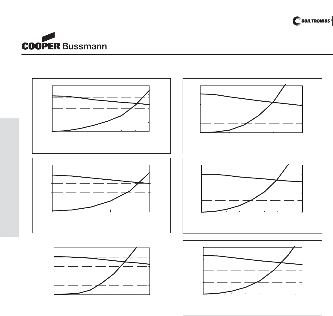
PM-24
HIGH CURRENT (HCP0703)
HCP0703 Series
High Current Pressed Power Inductors
Performance Graphs
0
0.8
1.6
2.4
3.2
4
02468101214
DC Bias(Amps)
Inductance(uH)
0
20
40
60
80
100
Temp.-rise
(°C)
HCP0703-3R3-R
0.0
0.7
1.4
2.1
2.8
02468101214
DC Bias(Amps)
Inductance(uH)
0
20
40
60
80
100
Temp.-rise
(°C)
HCP0703-2R2-R
0.0
1.2
2.4
3.6
4.8
6.0
0246810
DC Bias(AMPS)
Inductance(uH)
0
20
40
60
80
100
Temp.-rise
(°C)
HCP0703-4R7-R
0.0
2.1
4.2
6.3
8.4
012345678
DC Bias(Amps)
Inductance(uH)
0
20
40
60
80
100
Temp.-rise
(°C)
HCP0703-6R8-R
0.0
3.0
6.0
9.0
12.0
01234567
DC Bias(Amps)
Inductance(uH)
0
20
40
60
80
100
Temp.-rise
(°C)
HCP0703-100-R
0.0
2.0
4.0
6.0
8.0
10.0
012345678
DC Bias(Amps)
Inductance(uH)
0
20
40
60
80
100
Temp.-rise
(°C)
HCP0703-8R2-R
Courtesy of Steven Engineering, Inc.-230 Ryan Way, South San Francisco, CA 94080-6370-Main Office: (650) 588-9200-Outside Local Area: (800) 258-9200-www.stevenengineering.com
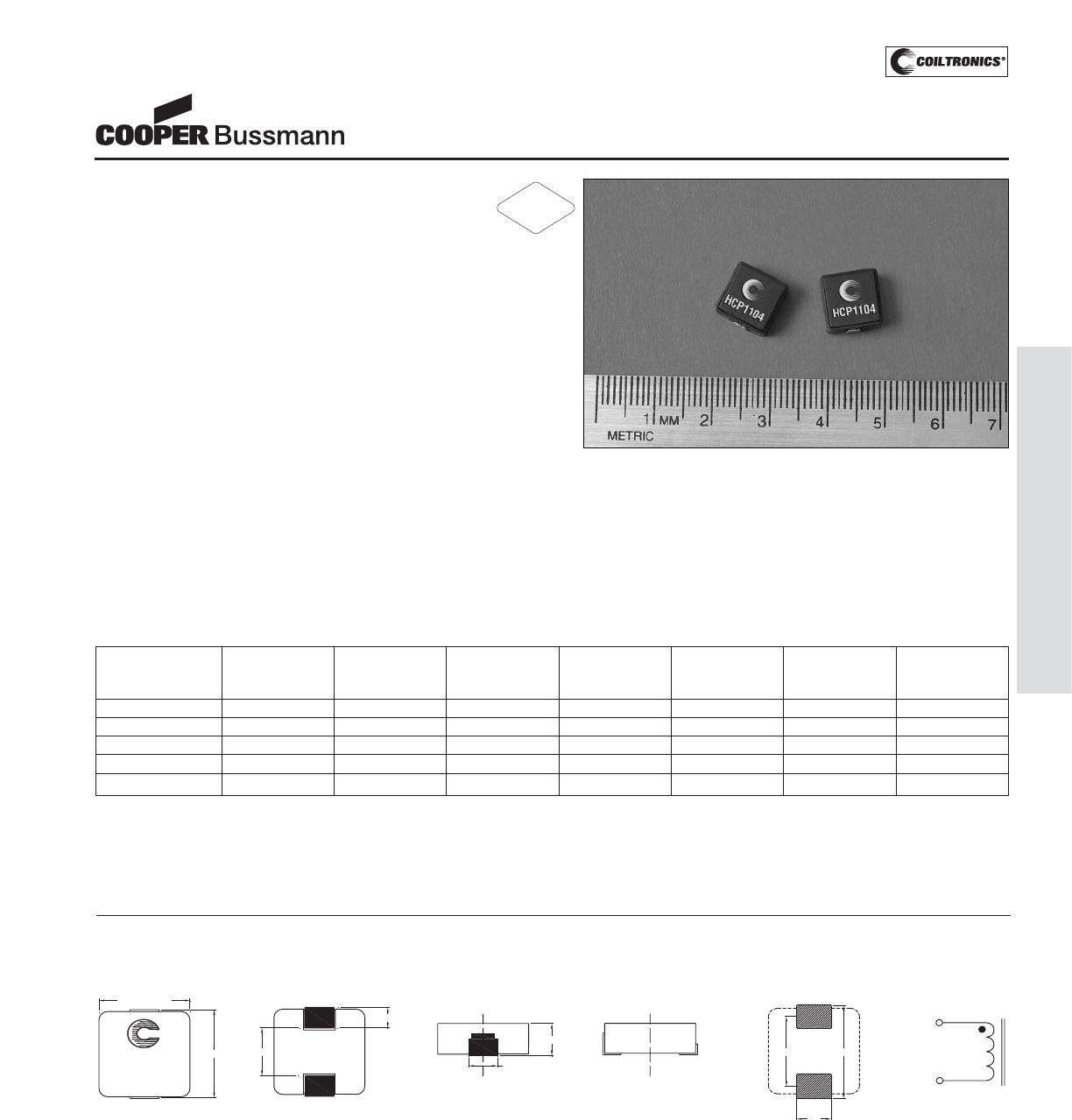
PM-25
HIGH CURRENT (HCP1104)
Description
• 125°C maximum total temperature operation
• Low profile surface mount inductors
• 10mm x 11.5mm x 4.0mm package
• Pressed powder iron core material
• Enhanced core coating eliminates rusting and
provides high insulation impedance
• Inductance range from 0.2μH to 0.9μH
• Current range from 42.0 Amps to 22 Amps
• Frequency range up to 1MHz
Applications
• Notebook power
• VRM, multi-phase buck regulator
• DC-DC converters
• PC workstations/Servers
• Routers
Environmental Data
• Storage temperature range: -55°C to +125°C
• Operating temperature range: -55°C to +125°C
(range is application specific)
• Solder reflow temperature: +260°C max. for 10 seconds
maximum
Packaging
• Supplied in tape and reel packaging,
950 parts per reel
HCP1104 Series
High Current Pressed Power Inductors
Part Number Rated OCL (1) Irms (2) Isat (3) DCR DCR K-factor
Inductance μH ± 20% Amperes Amperes mΩ@20°C mΩ@20°C (4)
(μH) (Typical) (Maximum)
HCP1104-R20-R 0.20 0.20 32 42 0.7 0.9 505
HCP1104-R36-R 0.36 0.36 30 40 1.0 1.2 289
HCP1104-R45-R 0.45 0.45 30 35 1.25 1.4 334
HCP1104-R56-R 0.56 0.56 25 32 1.60 1.8 287
HCP1104-R90-R 0.90 0.90 22 25 2.30 2.5 168
(1) Open Circuit Inductance Test Parameters: 100kHz, 0.25V, 0.0Adc.
(2) Irms: DC current for an approximate ΔT of 40°C without core loss. Derating is
necessary for AC currents. PCB layout, trace thickness and width, air-flow, and
proximity of other heat generating components will affect the temperature rise. It
is recommended that the temperature of the part not exceed 125°C under worst
case operating conditions verified in the end application.
(3) Isat Amperes peak for approximately 20% rolloff (@20°C)
(4) K-factor: Used to determine B p-p for core loss (see graph).
B p-p = K*L*ΔI, B-p-p: (Gauss), K: (K factor from table), L: (Inductance in uH),
ΔI (Peak to peak ripple current in Amps).
Dimensions are in millimeters.
RECOMMENDED PCB LAYOUT SCHEMATIC
1
2
HCP1104-XXX
wwllyy R
4.5
9.2
11.5 max.
10.0+/- 0.254
4.0 max.
3.5 +/- 0.5
TOP VIEW
12.0
FRONT VIEW LEFT VIEW
2.3 +/- 0.3
6.2
1
2
BOTTOM VIEW
wwlly = Date Code. R = Revision Level.
Mechanical Diagrams
RoHS
2002/95/EC
Courtesy of Steven Engineering, Inc.-230 Ryan Way, South San Francisco, CA 94080-6370-Main Office: (650) 588-9200-Outside Local Area: (800) 258-9200-www.stevenengineering.com
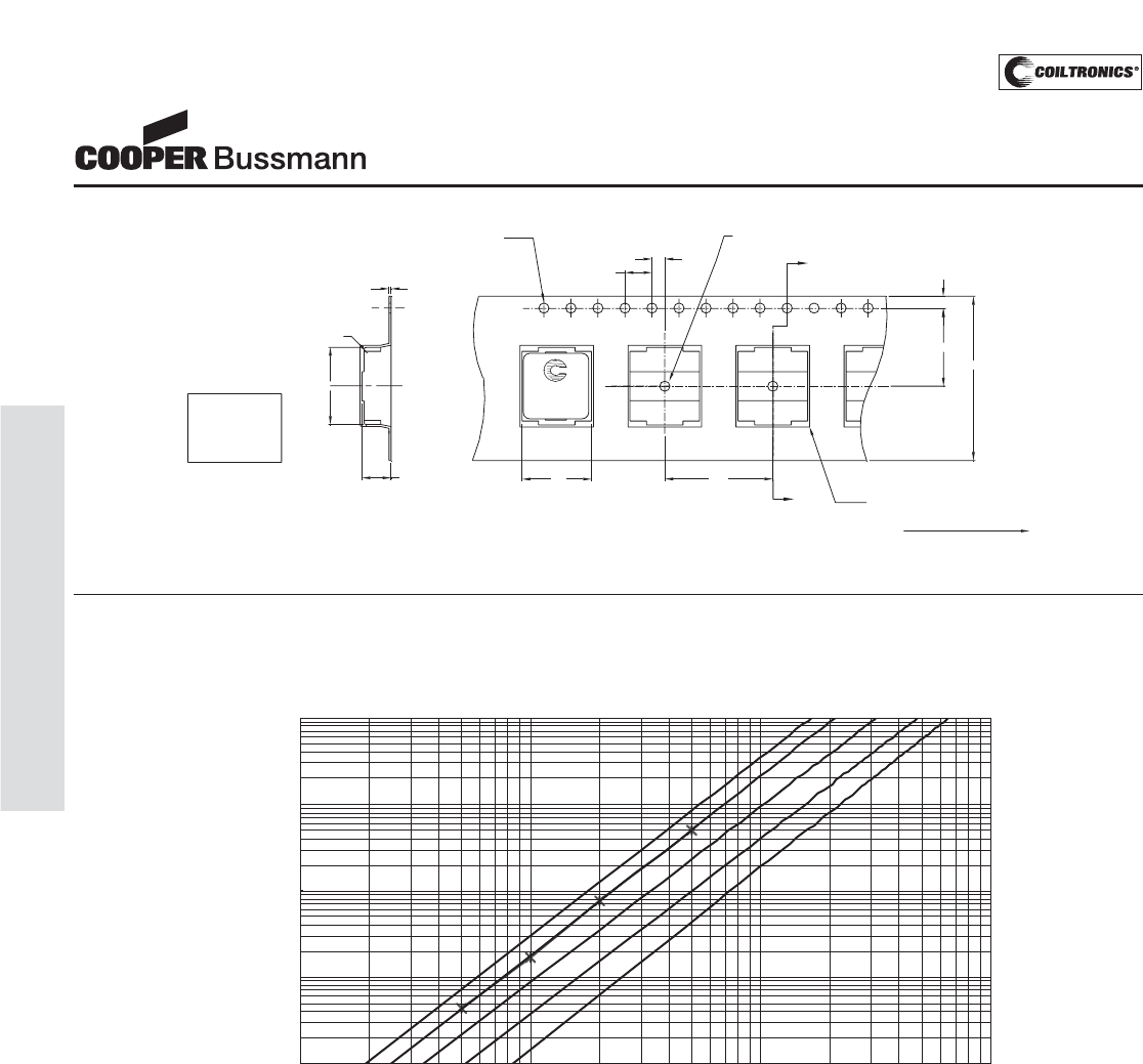
PM-26
HIGH CURRENT (HCP1104)
HCP1104 Series
High Current Pressed Power Inductors
Core Loss
1
10
100
1000
10000
10 100 1000 10000
100kHz
500kHz
700kHz
1000kHz
300kHz
Bp-p (Gauss)
Core Loss vs Bp-p
Core Loss(mW)
Parts packaged on a 13" Diameter reel.
950parts per reel.
2.0
Ko=4.3 mm
Bo=11.5 mm
Ao=10.3 mm
1.5 dia
+0.1/-0.0
Bo
Ko
SECTION A-A
0.35
+/-0.05
0.3Rad
max. 11.5
1.5 dia
min
0.3 rad
typ
A
1.75
A
4.0
User direction of feed
24.0
Ao 16.0
HCP1104-XXX
wwllyy R
Packaging Information
Courtesy of Steven Engineering, Inc.-230 Ryan Way, South San Francisco, CA 94080-6370-Main Office: (650) 588-9200-Outside Local Area: (800) 258-9200-www.stevenengineering.com
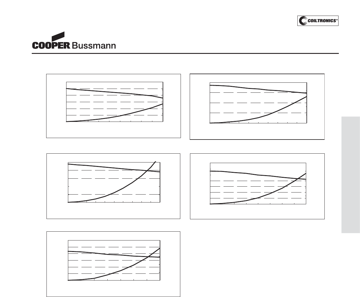
PM-27
HIGH CURRENT (HCP1104)
HCP1104 Series
High Current Pressed Power Inductors
Performance Graphs
0.00
0.10
0.20
0.30
0.40
0 1020304050
DC Bias(Amps)
Inductance(uH)
0
20
40
60
80
100
Temp.-rise
(°C)
HCP1104-R36-R
0.00
0.04
0.08
0.12
0.16
0.20
0.24
010203040
DC Bias(Amps)
Inductance(uH)
0
20
40
60
80
100
Temp.-rise(°C)
HCP1104-R20-R
0.00
0.10
0.20
0.30
0.40
0.50
0 1020304050
DC Bias(Amps)
Inductance(uH)
0
20
40
60
80
100
Temp.-rise
(°C)
HCP1104-R45-R
0.00
0.10
0.20
0.30
0.40
0.50
0.60
0.70
010203040
DC Bias(Amps)
Inductance(uH)
0
20
40
60
80
100
Temp.-rise
(°C)
HCP1104-R56-R
0.00
0.20
0.40
0.60
0.80
1.00
1.20
0 102030
Inductance(uH)
0
20
40
60
80
100
Temp.-rise
(°C)
HCP1104-R90-R
DC Bias(Amps)
Courtesy of Steven Engineering, Inc.-230 Ryan Way, South San Francisco, CA 94080-6370-Main Office: (650) 588-9200-Outside Local Area: (800) 258-9200-www.stevenengineering.com
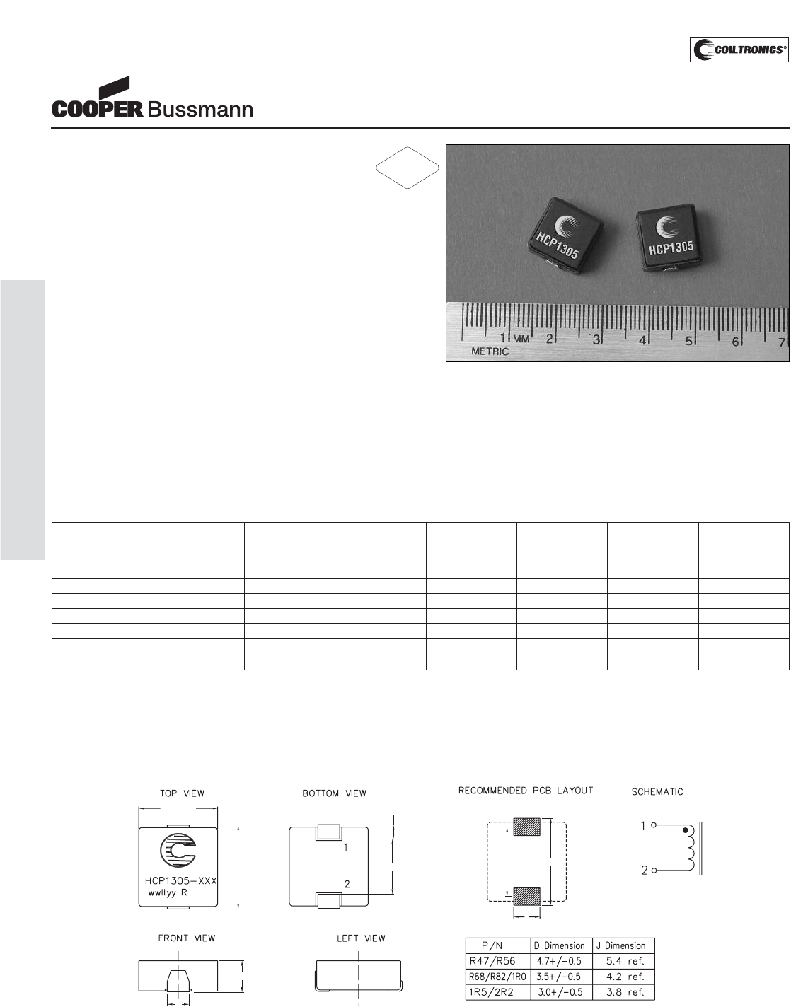
PM-28
HIGH CURRENT (HCP1305)
Description
• 125°C maximum temperature operation
• 12.9mm x 13.8mm x 5.0mm surface
mount package
• Pressed powder iron core material
• Enhanced core coating eliminates rusting and
provides high insulation impedance
• Inductance range from 0.47μH to 2.2μH
• Current range from 65.0 Amps to 20 Amps
• Frequency range up to 1MHz
Applications
• Notebook power
• VRM, multi-phase buck regulator
• DC-DC converters
• PC workstations/Servers/Desktop
• Routers
Environmental Data
• Storage temperature range: -55°C to +125°C
• Operating temperature range: -55°C to +125°C
(range is application specific)
• Solder reflow temperature: +260°C max. for 10 seconds
maximum
Packaging
• Supplied in tape and reel packaging,
400 parts per reel
HCP1305 Series
High Current Pressed Power Inductors
Part Number Rated OCL (1) Irms (2) Isat (3) DCR DCR K-factor
Inductance μH ± 20% Amperes Amperes mΩ@20°C mΩ@20°C (4)
(μH) (Typical) (Maximum)
HCP1305-R47-R 0.47 0.47 38 65 1.1 1.3 181
HCP1305-R56-R 0.56 0.56 36 55 1.3 1.5 130
HCP1305-R68-R 0.68 0.68 34 53 1.5 1.7 172
HCP1305-R82-R 0.82 0.82 31 52 2.0 2.3 167
HCP1305-1R0-R 1.0 1.0 29 50 2.1 2.5 134
HCP1305-1R5-R 1.5 1.5 23 48 3.4 4.1 105
HCP1305-2R2-R 2.2 2.2 20 32 4.6 5.5 77
(1) Open Circuit Inductance Test Parameters: 100kHz, 0.25V, 0.0Adc.
(2) Irms: DC current for an approximate ΔT of 40°C without core loss. Derating is
necessary for AC currents. PCB layout, trace thickness and width, air-flow, and
proximity of other heat generating components will affect the temperature rise. It
is recommended that the temperature of the part not exceed 125°C under worst
case operating conditions verified in the end application.
(3) Isat Amperes peak for approximately 20% rolloff (@20°C)
(4) K-factor: Used to determine B p-p for core loss (see graph).
B p-p = K*L*ΔI, B p-p: (Gauss), K: (K factor from table), L: (Inductance in uH),
ΔI (Peak to peak ripple current in Amps).
Dimensions are in millimeters.
wwlly = Date Code. R = Revision Level.
5.0 max.
12.9 max.
13.8 max.
D
2.54±0.3
8.5
J
11.06 14.20
Mechanical Diagrams
RoHS
2002/95/EC
Courtesy of Steven Engineering, Inc.-230 Ryan Way, South San Francisco, CA 94080-6370-Main Office: (650) 588-9200-Outside Local Area: (800) 258-9200-www.stevenengineering.com
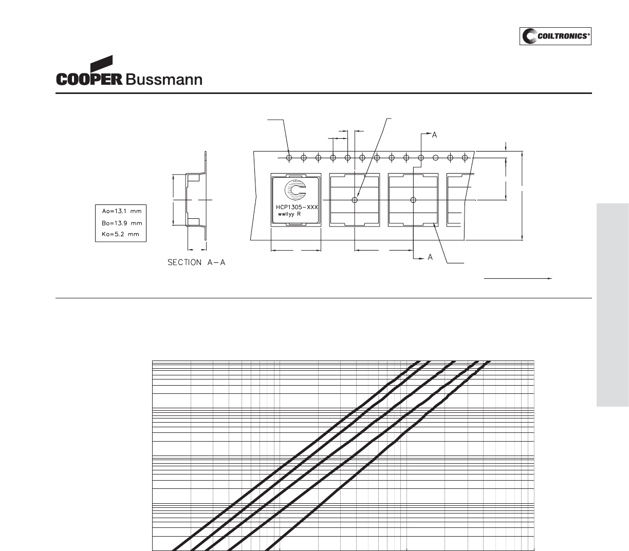
PM-29
HIGH CURRENT (HCP1305)
HCP1305 Series
High Current Pressed Power Inductors
Core Loss
1
10
100
1000
10000
10 100 1000 10000
1000kHz
700kHz
500kHz
300kHz
100kHz
Bp-p(Gauss)
Core Loss (mW)
Core Loss vs Bp-p
2.0
1.5 dia
+0.1/-0.0
Bo
Ko
11.5
1.5 dia
min
0.3 rad
typ
1.75
4.0
User direction of feed
24.0
Ao 16.0
Packaging Information
Courtesy of Steven Engineering, Inc.-230 Ryan Way, South San Francisco, CA 94080-6370-Main Office: (650) 588-9200-Outside Local Area: (800) 258-9200-www.stevenengineering.com
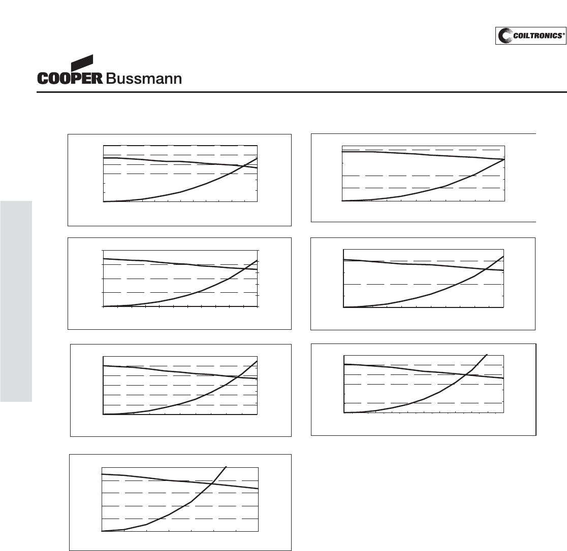
PM-30
HIGH CURRENT (HCP1305)
HCP1305 Series
High Current Pressed Power Inductors
Performance Graphs
0
0.15
0.3
0.45
0.6
0 1020304050
DC Bias(Amps)
Inductance(uH)
0
20
40
60
80
100
Temp.-rise
(
ºC)
HCP1305-R56-R
0.00
0.10
0.20
0.30
0.40
0.50
0.60
0 102030405060
DC Bias(Amps)
Inductance(uH)
0
20
40
60
80
100
Temp.-rise(ºC)
HCP1305-R47-R
0.00
0.20
0.40
0.60
0.80
0 1020304050
DC Bias(AMPS)
Inductance(uH)
0
20
40
60
80
100
Temp.-rise(ºC)
HCP1305-R68-R
0.00
0.20
0.40
0.60
0.80
1.00
0 1020304050
DC Bias(Amps)
Inductance(uH)
0
20
40
60
80
100
Temp.-rise(ºC)
HCP1305-R82-R
0.00
0.30
0.60
0.90
1.20
1.50
1.80
0 1020304050
DC Bias(Amps)
Inductance(uH)
0
20
40
60
80
100
Temp.-rise(ºC)
HCP1305-1R5-R
0.00
0.20
0.40
0.60
0.80
1.00
1.20
0 1020304050
DC Bias(Amps)
Inductance(uH)
0
20
40
60
80
100
Temp.-rise(ºC)
HCP1305-1R0-R
0.00
0.52
1.04
1.56
2.08
2.60
0 5 10 15 20 25 30 35
DC Bias(Amps)
Inductance(uH)
0
20
40
60
80
100
Temp.-rise(ºC)
HCP1305-2R2-R
Courtesy of Steven Engineering, Inc.-230 Ryan Way, South San Francisco, CA 94080-6370-Main Office: (650) 588-9200-Outside Local Area: (800) 258-9200-www.stevenengineering.com
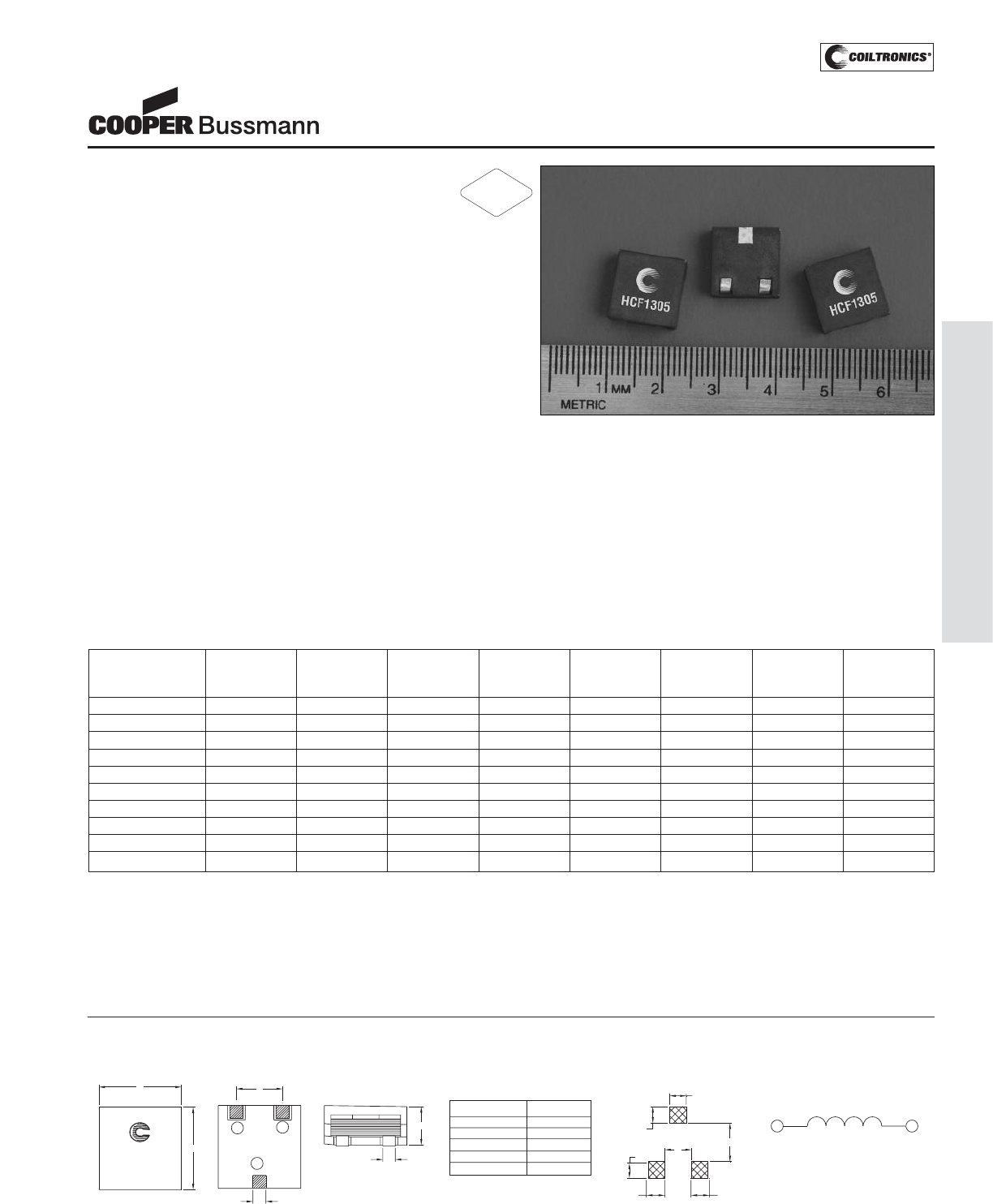
PM-31
HIGH CURRENT (HCF1305)
Description
• 125°C maximum total temperature operation
• 12.5mm x 12.5mm x 5.0mm ferrite core
material package
• Low profile surface mount inductors designed for higher
speed switch mode applications requiring low voltage
and high current
• Design utilizes ferrite core with high DC bias resistance
and low core loss
• Inductance range from 0.47μH to 4.7μH
• Current range from 36.0 Amps to 10.4 Amps
• Frequency range 100kHz to 1MHz
Applications
• Next generation processors
• High current DC-DC converters
• VRM, multi-phase buck regulators
• PC Workstations, Routers, Servers
• Telecom soft switches, Base stations
Environmental Data
• Storage temperature range: -40°C to +125°C
• Operating temperature range: -40°C to +125°C
(range is application specific)
• Solder reflow temperature: +260°C max. for 10 seconds
maximum
Packaging
• Supplied in tape and reel packaging,
600 parts per reel
HCF1305 Series
Power Inductors
Part Number Rated OCL (1) Irms (2) Isat (3) Isat2 (4) DCR DCR K-factor
Inductance μH ± 20% Amperes Amperes Amperes mΩ@20°C mΩ@20°C (5)
(μH) (Typical) (Maximum)
HCF1305-R47-R 0.47 0.47 32.0 36.0 30.0 0.83 1.00 21
HCF1305-R56-R 0.56 0.56 32.0 30.0 22.5 0.83 1.00 21
HCF1305-1R0-R 1.00 1.00 22.0 24.0 20.0 1.58 1.90 14
HCF1305-1R2-R 1.20 1.20 22.0 20.0 15.0 1.58 1.90 14
HCF1305-1R8-R 1.80 1.80 16.3 18.0 15.0 2.58 3.10 10
HCF1305-2R2-R 2.20 2.20 16.3 15.0 11.2 2.58 3.10 10
HCF1305-3R0-R 3.00 3.00 13.2 14.4 12.0 4.08 4.90 8.3
HCF1305-3R3-R 3.30 3.30 13.2 12.5 9.0 4.08 4.90 8.3
HCF1305-4R0-R 4.00 4.00 10.9 12.0 10.0 6.0 7.2 6.9
HCF1305-4R7-R 4.70 4.70 10.9 10.4 7.5 6.0 7.2 6.9
1) OCL: Open Circuit Inductance test parameters: 100kHz, 0.1Vrms, 0.0Adc.
OCL@-40°C can be lower than OCL@20°C by 15% max.
2) Irms: DC current for an approximate DT of 40°C without core loss. Derating is
necessary for AC currents. PCB layout, trace thickness and width, air-flow, and
proximity of other heat generating components will affect the temperature rise. It
is recommended that the temperature of the part not exceed 125°C under worst
case operating conditions verified in the end application.
3) Isat1: Amperes Peak for approximately 30% rolloff (@25°C)
4) Isat2: Amperes Peak for approximately 30% rolloff (@125°C)
5) K-factor: Used to determine B p-p for core loss (see graph). B p-p = K*L*ΔI
B p-p:(mT), K: (K factor from table), L: (Inductance in μH), ΔI (Peak to peak ripple
current in Amps).
Part number definition:
HCF1305-XXX-R
HCF1305 = Product code and size
XXX = Inductance value in uH.
R = Decimal point. If no R is present, third character = #of zeros
-R suffix indicates RoHS compliant
C
B
FRONT VIEW
DHCF1305-XXX
wwllyy R
TOP VIEW
A
E
DIMENSION TABLE
A: 12.5max
B: 12.5max
C: 5.0max
D: 2.00 ref
E: 2.40 +/- 0.10
F: 6.90 +/- 0.30
G: 4.00 Ref.
H: 5.40 Ref.
I: 3.00 Ref.
J: 4.00 Ref.
K: 4.00 Ref.
L: 3.4 Ref.
3
BOTTOM VIEW
F
1 2
H
G
I
SCHEMATIC
1
I
J
2
RECOMMENDED PCB LAYOUT
L
K
Dimensions in Millimeters
wwllyy=Date code, R=Revision Level
Mechanical Diagrams
RoHS
2002/95/EC
Courtesy of Steven Engineering, Inc.-230 Ryan Way, South San Francisco, CA 94080-6370-Main Office: (650) 588-9200-Outside Local Area: (800) 258-9200-www.stevenengineering.com
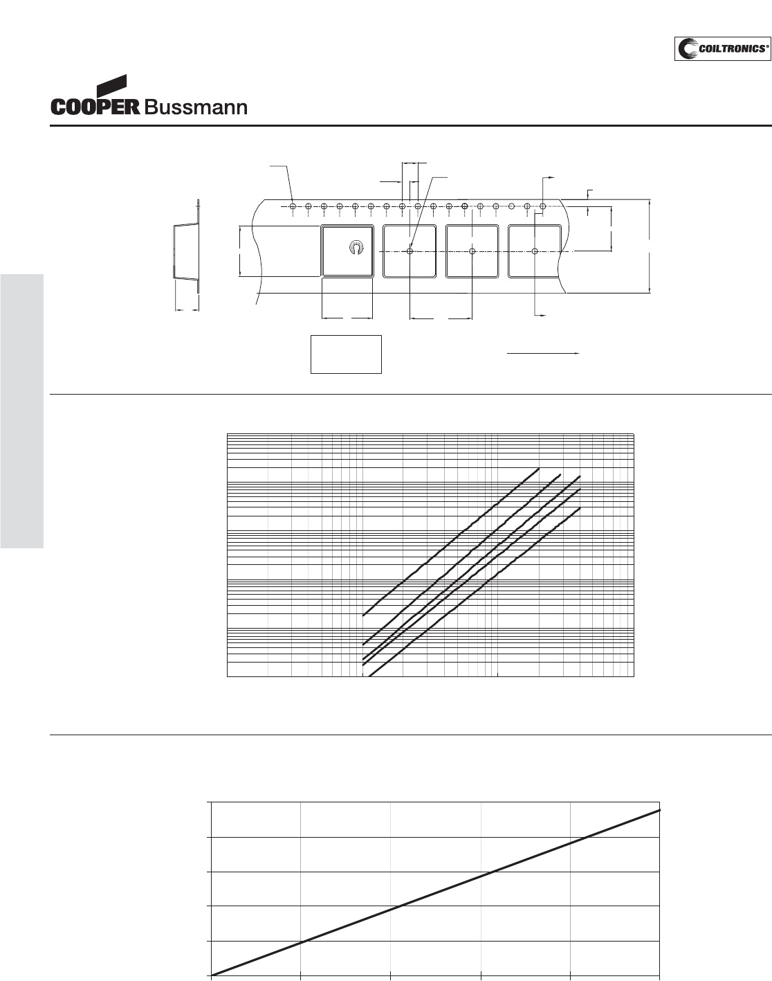
PM-32
HIGH CURRENT (HCF1305)
HCF1305 Series
Power Inductors
Core Loss
100kHz
200kHz
300kHz
500kHz
1MHz
0.0001
0.001
0.01
0.1
1
10
1 10 100 1000
Bp-p (mT)
Core Loss (W)
K0= 5.50 mm
A0= 12.60 mm
B0= 12.60 mm
A0
SECTION A-A
1.5 dia
+0.1/-0.0
B0
K0
HCF1305-XXX
wwlly y-R
User direction of feed
600 parts per reel.
11.5
1.75
A
2.0
4.0
16.00
1.5 dia
min
24.0
+/-0.3
A
Parts packaged on a 13" Diameter reel.
Packaging Information
Temperature Rise vs. Total Loss
Temperature Rise Vs. Power Loss
0
20
40
60
80
100
0 0.4 0.8 1.2 1.6 2
Total Power Loss (W)
TemperatureRise (ºC)
Courtesy of Steven Engineering, Inc.-230 Ryan Way, South San Francisco, CA 94080-6370-Main Office: (650) 588-9200-Outside Local Area: (800) 258-9200-www.stevenengineering.com
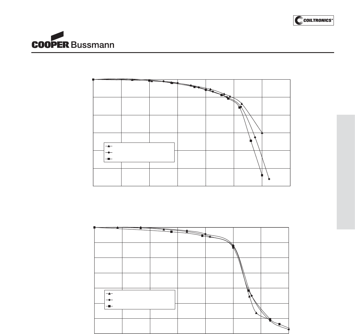
PM-33
HIGH CURRENT (HCF1305)
Normalized Rolloff Curves at 125 Deg. C
30.0%
40.0%
50.0%
60.0%
70.0%
80.0%
90.0%
100.0%
0.0% 20.0% 40.0% 60.0% 80.0% 100.0% 120.0% 140.0%
%of I
SAT2
%ofOCL
R47, 1R0, 1R8, 3R0 and 4R0
R56, 1R2 and 2R2
3R3 and 4R7
HCF1305 Series
Power Inductors
Inductance Characteristics
Normalized Rolloff Curves at 25 Deg. C
40.0%
50.0%
60.0%
70.0%
80.0%
90.0%
100.0%
0.0% 20.0% 40.0% 60.0% 80.0% 100.0% 120.0% 140.0%
%of I
SAT1
%ofOCL
R47, 1R0, 1R8, 3R0 and 4R0
R56, 1R2 and 2R2
3R3 and 4R7
Courtesy of Steven Engineering, Inc.-230 Ryan Way, South San Francisco, CA 94080-6370-Main Office: (650) 588-9200-Outside Local Area: (800) 258-9200-www.stevenengineering.com
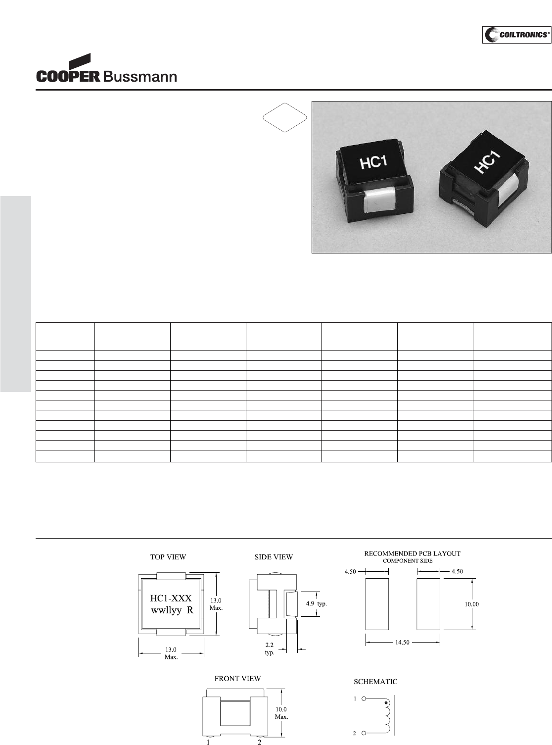
PM-34
HIGH CURRENT (HC1)
Description
•Designed for high current, low voltage applications
• Low DCR, high efficiency
• Foil construction for higher frequency circuit designs
• Suited for IR and vapor reflow solder
• Frequency range 1kHz to 1MHz
• Ferrite core material
Applications
• Next generation microprocessors
• High current DC-DC converters
• Computers
Environmental Data
• Storage temperature range: -40°C to +125°C
• Operating ambient temperature range: -40°C to +85°C
(range is application specific).
• Solder reflow temperature: +260°C max. for 10 seconds
max.
Packaging
• Supplied in tape and reel packaging, 250 per reel
Part Rated OCL (1) Irms (2) Isat (3) DCR (Ω) Volt-μSec (4)
Number Inductance ± 15% Amperes Amperes Max. @ (VμS)
μH μH (Approx.) (Approx.) 20°C (ref.)
HC1-R22-R 0.22 0.218 51.42 40.5 0.00036 1.83
HC1-R30-R 0.30 0.291 51.42 31.8 0.00036 1.83
HC1-R57-R 0.57 0.572 37.83 33.4 0.00068 3.66
HC1-R87-R 0.87 0.866 28.01 31.0 0.00123 5.49
HC1-1R0-R 1.0 1.12 28.01 25.4 0.00123 5.49
HC1-1R7-R 1.7 1.66 22.30 22.2 0.0020 7.33
HC1-2R3-R 2.3 2.29 22.30 16.7 0.0020 7.33
HC1-3R6-R 3.6 3.59 16.76 13.4 0.0035 9.16
HC1-5R1-R 5.1 5.15 12.79 11.2 0.0057 10.99
HC1-7R8-R 7.8 7.85 12.79 6.7 0.0057 10.99
HC1-100-R 10 10.5 12.79 5.3 0.0057 10.99
1) OCL (Open Circuit Inductance) Test parameters: 300KHz, .25Vrms,
0.0Adc & Isat.
2) Irms Amperes for approximately ΔT of 40°C. DC current for an approximate ΔTof
40°C without core loss. Derating is necessary for AC currents. It is recommended
that the temperature of the part not exceed 125°C under worst case operating
conditions verified in the end application.
3) Isat Amperes Peak for approximately 30% rolloff @ 20°C
4) Applied Volt-Time product (V-μS) across the inductor.This value represents the
applied V-μS at 200kHz necessary to generate a core loss equal to 10% of the
total losses for 40°C temperature rise. See Core Loss Graph.
Units supplied in tape & reel packaging; 250 parts on 13" diameter reel.
HIGH CURRENT 1
Power Inductors
Mechanical Diagrams
Dimensions in Millimeters xxx = Inductance value
wwllyy = Date code R = Revision level
RoHS
2002/95/EC
Courtesy of Steven Engineering, Inc.-230 Ryan Way, South San Francisco, CA 94080-6370-Main Office: (650) 588-9200-Outside Local Area: (800) 258-9200-www.stevenengineering.com
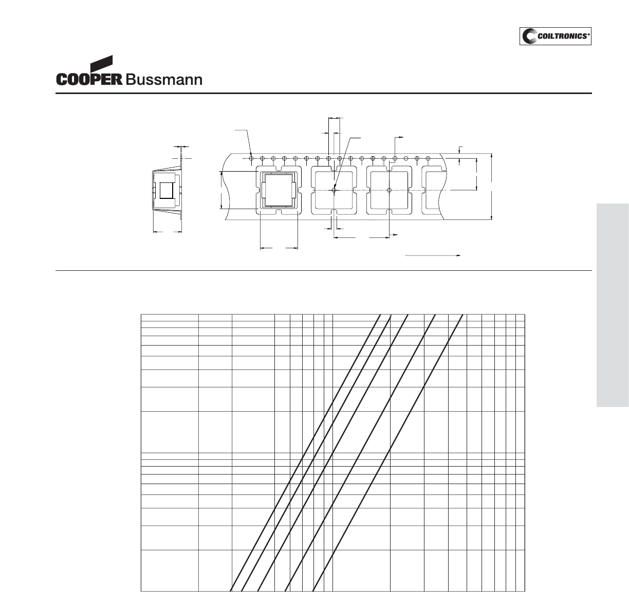
PM-35
HIGH CURRENT (HC1)
HIGH CURRENT 1
Power Inductors
Packaging Information
2.
0
1
2
A
A
H
C
1-XXX
ww
llyy R
S
E
C
TI
O
N A-
A
0
.
35
+
/
-
0
.
05
1
0
.
3
1.
5
di
a
+
0
.1
/
-
0
.
0
1.
5
di
a
mi
n
4.
00
2.
00
2
0
.
00
1.7
11.50
.
24.
0
+/-0.3
0
User direction of fee
d
1
3
.
4
1
3
.
4
Core Loss
10
99
98
3020
97
96
95
94
92
90
80
70
60
50
40
20
0
300 400 500 600 800 1000100908070605040 200
200 KHz
400 KHz
300 KHz
100 KHz
50 KHz
% of Losses from Irms (maximum)
Irms DERATING WITH CORE LOSS
% of Applied Volt-μ-Seconds
Courtesy of Steven Engineering, Inc.-230 Ryan Way, South San Francisco, CA 94080-6370-Main Office: (650) 588-9200-Outside Local Area: (800) 258-9200-www.stevenengineering.com
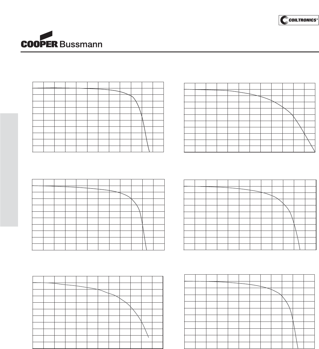
PM-36
HIGH CURRENT (HC1)
Inductance Characteristics
HC1 Inductor (R87)
50
60
70
80
90
100
0 10 20 30 40 50 60 70 80 90 100 110 120
% of Isat
OCL (%)
HC1 Inductor (R22, 7R8)
50
60
70
80
90
100
0 10 20 30 40 50 60 70 80 90 100 110 120
% of Isat
OCL (%)
HC1 Inductor (1R7)
50
60
70
80
90
100
0 10 20 30 40 50 60 70 80 90 100 110 120
% of Isat
OCL (%)
HC1 Inductor (R57, 2R3, 3R6, 5R1)
50
60
70
80
90
100
0 10 20 30 40 50 60 70 80 90 100 110 120
% of Isat
OCL (%)
HC1 Inductor (R30, 100)
50
60
70
80
90
100
0 10 20 30 40 50 60 70 80 90 100 110 120
% of Isat
OCL (%)
HC1 Inductor (1R0)
50
60
70
80
90
100
0 10 20 30 40 50 60 70 80 90 100 110 120
% of Isat
OCL (%)
HIGH CURRENT 1
Power Inductors
Courtesy of Steven Engineering, Inc.-230 Ryan Way, South San Francisco, CA 94080-6370-Main Office: (650) 588-9200-Outside Local Area: (800) 258-9200-www.stevenengineering.com
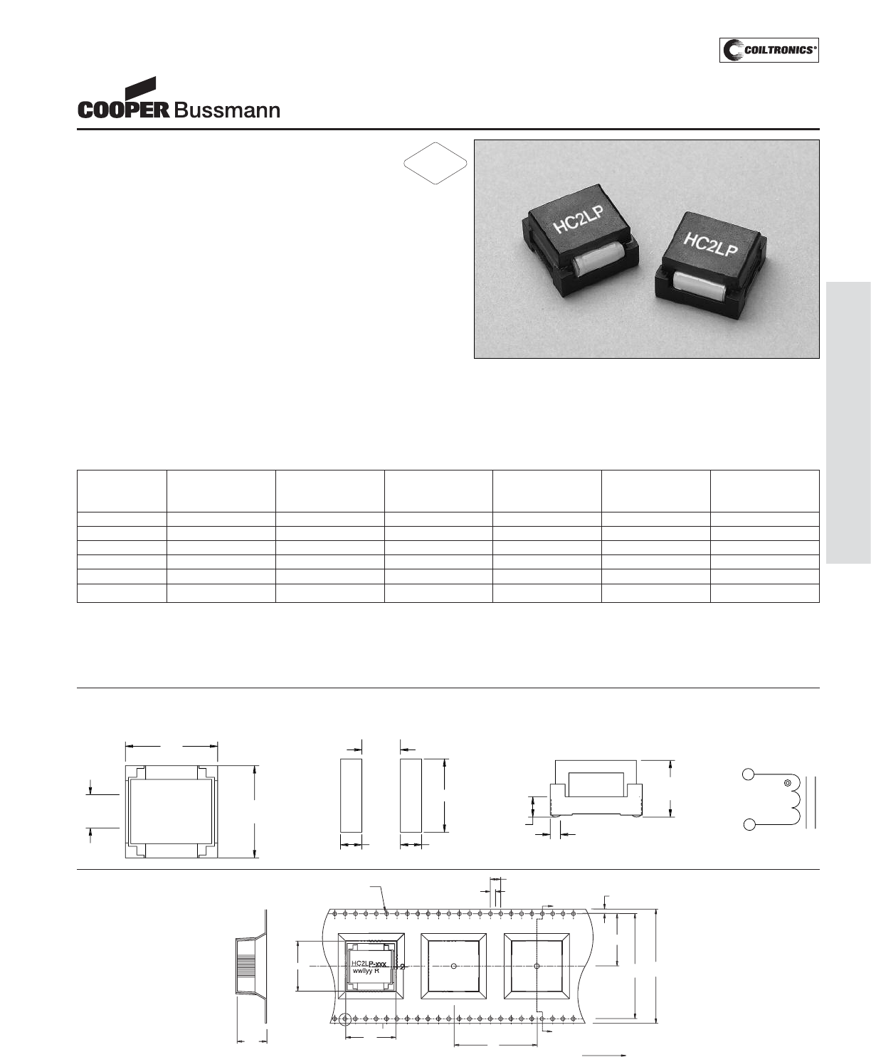
PM-37
HIGH CURRENT (HC2LP)
Description
• Compact footprint for high density, high
current/low voltage applications
• Foil technology that adds higher reliability factor
over the traditional magnet wire used for higher frequen-
cy circuit designs
• Frequency Range up to 1MHz
• Ferrite core material
Applications
• Next generation microprocessors
• Energy storage applications
• DC-DC converters
• Computers
Environmental Data
• Storage temperature range: -40°C to +125°C
• Operating ambient temperature range: -40°C to +85°C
(range is application specific).
• Solder reflow temperature: +260°C max. for 10 seconds
max.
Packaging
• Supplied in tape and reel packaging, 44mm width,
130 parts per 13" reel
Part Rated OCL (1) Irms (2) Isat (3) DCR (4) Volts (5)
Number Inductance μH ± 20% Amperes Amperes Ohms μSec
μH (Typ.) (Typ.) (Max.)
HC2LP-R47-R .47 .52 52.9 63.75 .0006 6.87
HC2LP-R68-R .68 .63 52.9 50.00 .0006 6.87
HC2LP-1R0-R 1.0 1.15 33.0 42.50 .0013 10.31
HC2LP-2R2-R 2.2 2.00 24.3 31.90 .0023 13.75
HC2LP-4R7-R 4.7 4.55 17.0 21.25 .0046 20.62
HC2LP-6R0-R 6.0 6.00 17.0 16.50 .0046 20.62
1) Open Circuit Inductance Test Parameters: 300kHz, 0.250 Vrms, 0.0 Adc
2) DC current for an approximate temperature change of 40°C without core loss.
Derating is necessary for AC currents.
PCB layout, trace thickness and width, air-flow and proximity of other heat gener-
ating components will affect the temperature rise.
It is recommended that the temperature of the part not exceed 125°C under
worst case operating conditions verified in the end application.
3) Peak current for approximately 30% roll-off
4) Values @ 20°C
5) Applied Volt-Time product (V-μS) across the inductor.This value represents the
applied V-μS at 300KHz necessary to generate a core loss equal to 10% of the
total losses for 40°C temperature rise.
HIGH CURRENT 2LP
Low Profile Power Inductors
Mechanical Diagrams
1
2
1
9
.
00
1
0
.
00
5
.
50
5
.
50
9
.
5
typ
1
9
.
2
m
ax
1
9
.
2
m
ax
2.
8
t
yp
2.
3
t
yp
11.1
8
m
ax
FR
O
NT VIE
W
T
O
P VIE
W
SC
HEMATI
C
RE
CO
MMENDED P
C
B PAD LAY
OUT
H
C
2LP-xx
x
wwll
yy
R
1
2
1
40
.
4
+
/
-
0
.1
44
.
0
+
/
-
0
.
3
11
.
3
32
19
.
3
A
1.7
20
.
2
2
.
0
1.
5Dia
+
0
.1
0
-
0
.
00
4
.
0
A
Use
r
d
ir
ect
i
o
n
of
feed
S
E
C
TI
O
N A-A
19
.
3
Packaging Information
Dimensions in Millimeters Parts packaged on 13" Diameter reel,
130 parts per reel.
xxx = Inductance value
wwllyy = Date code R = Revision level
RoHS
2002/95/EC
Courtesy of Steven Engineering, Inc.-230 Ryan Way, South San Francisco, CA 94080-6370-Main Office: (650) 588-9200-Outside Local Area: (800) 258-9200-www.stevenengineering.com
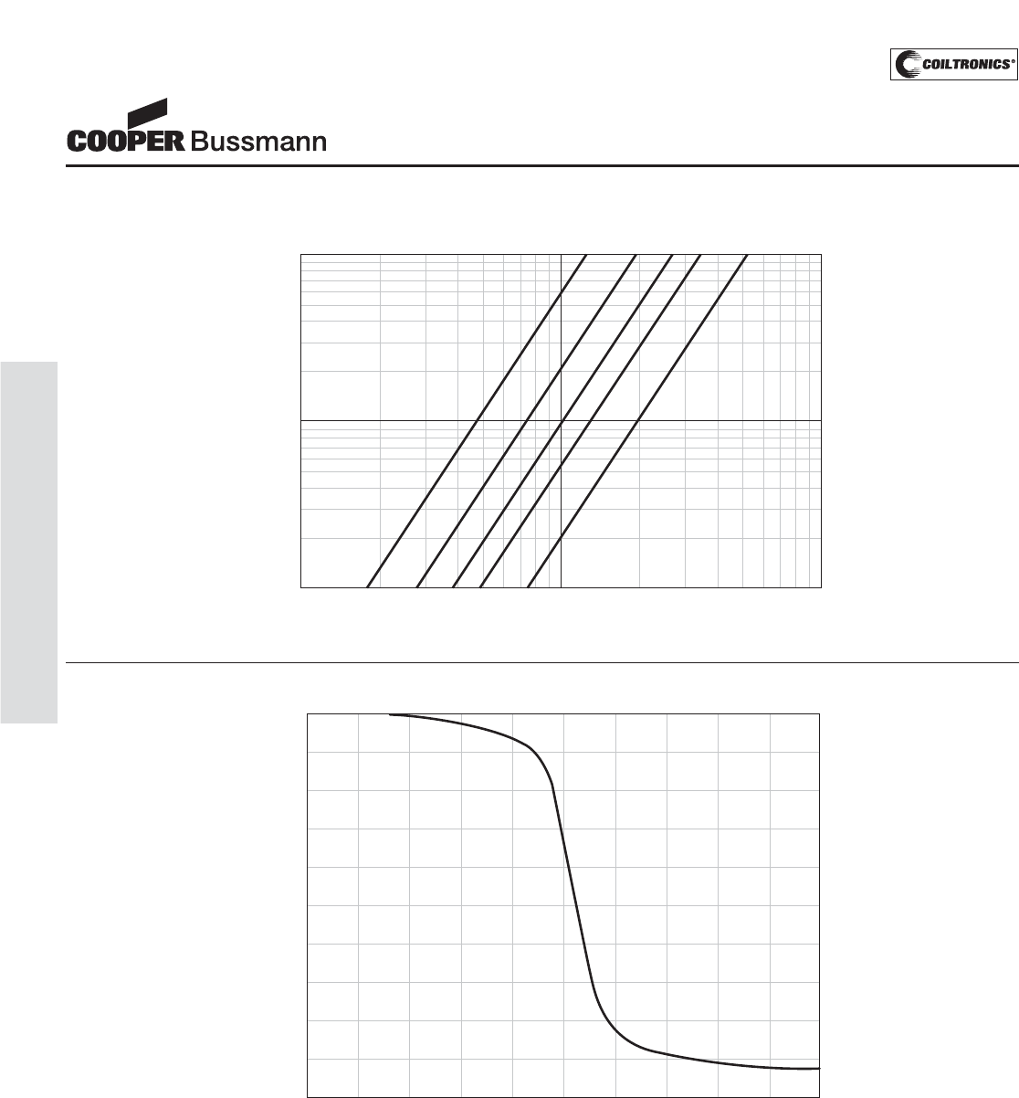
PM-38
HIGH CURRENT (HC2LP)
IRMS DERATING WITH CORE LOSS
1000800600
50040030020010080605040302010
% of Applied Volt-μ-Seconds
99
98
97
96
95
94
92
90
80
70
60
50
40
20
0
% of Losses from Irms (maximum)
1MHz
500KHz
300KHz
200KHz
100KHz
OCL vs. Isat
0 20 40 60 80 100 120 140 160 180 200
0
10
20
30
40
50
60
70
80
90
100
% of ISAT
%ofOCL
HIGH CURRENT 2LP
Low Profile Power Inductors
Inductance Characteristics
Core Loss
Courtesy of Steven Engineering, Inc.-230 Ryan Way, South San Francisco, CA 94080-6370-Main Office: (650) 588-9200-Outside Local Area: (800) 258-9200-www.stevenengineering.com
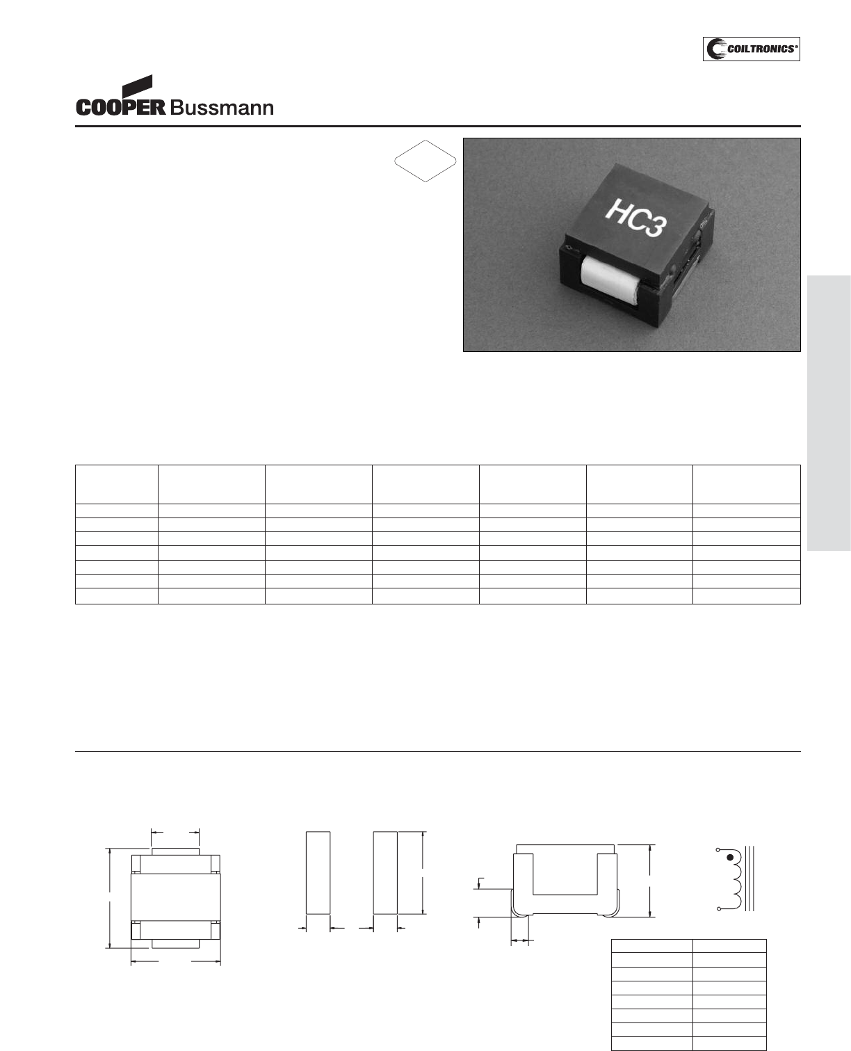
PM-39
HIGH CURRENT (HC3)
Description
• High Density, high current/low voltage
applications
• Foil technology that adds higher reliability
factor over the traditional magnet wire used
for higher frequency circuit designs
• Current range from 78.0 to 33.8 Amps
• Inductance range from 0.50uH to 6.52uH
• Ferrite core material
Applications
• Next generation microprocessors
• Energy storage applications
• DC-DC converters
• Computers
Environmental Data
• Storage temperature range: -40°C to +125°C
• Operating ambient temperature range: -40°C to +85°C
• Solder reflow temperature: +260°C max. for 10 seconds
max.
Packaging
• Supplied in bulk packaging, 24 parts per tray
Part Rated OCL (1) Irms (2) Isat (3) DCR (mΩ) Volts (4)
Number Inductance nominal Amperes Amperes max. @ μSec (VμS)
μH +/-20% μH (Typ.) (Typ.) 20°C (ref.)
HC3-R50-R 0.50 0.50 78.00 120 0.42 17.33
HC3-1R0-R 1.0 1.05 78.00 78 0.42 17.33
HC3-2R2-R 2.2 2.05 55.50 60 0.70 26.01
HC3-3R3-R 3.3 3.63 42.45 46 1.20 34.65
HC3-4R7-R 4.7 4.98 33.80 38 2.17 43.30
HC3-5R6-R 5.6 5.68 33.80 34.5 2.17 43.30
HC3-6R0-R 6.0 6.52 33.80 30.0 2.17 43.30
1) Test Parameters: 300kHz, 0.25 Vrms
2) DC current for approximately ΔT of 40°C without core loss
De-rating is necessary for AC currents. PCB layout, trace thickness and width,
air flow and proximity of other heat generating components will affect temperature
rise. It is recommended that the temperature of the part not exceed 125°C under
worst case conditions verified in the end application.
3) Peak current for approximately 30% rolloff (@20°C)
4) Applied Volt-Time product (V-μS) across the inductor. This value represents the
applied V-μS at 300kHz necessary to generate a core loss equal to 10% of the
total losses for a 40°C temperature rise.
Part number definition:
HC3-XXX-R
HC3 = Product code and size
XXX = Inductance value in uH.
R = Decimal point. If no R is present, third character = #of zeros
-R suffix indicates RoHS compliant
HC3 Series
HIGH CURRENT 3
Power Inductors
Mechanical Diagrams
1
2
HC3
wwllyy R
14.5 typ
25.3 max
30.0 max
22.0
19.0
5.50 5.50
3.0 typ
4.0 typ HT max
TOP VIEW RECOMMENDED
PCB PAD LAYOUT FRONT VIEW SCHEMATIC
Part Number Height max
HC3-R50-R 18.0
HC3-1R0-R 17.5
HC3-2R2-R 17.5
HC3-3R3-R 17.5
HC3-4R7-R 17.5
HC3-5R6-R 17.5
HC3-6R0-R 17.5
wwllyy = Date code R = Revision level
RoHS
2002/95/EC
Courtesy of Steven Engineering, Inc.-230 Ryan Way, South San Francisco, CA 94080-6370-Main Office: (650) 588-9200-Outside Local Area: (800) 258-9200-www.stevenengineering.com
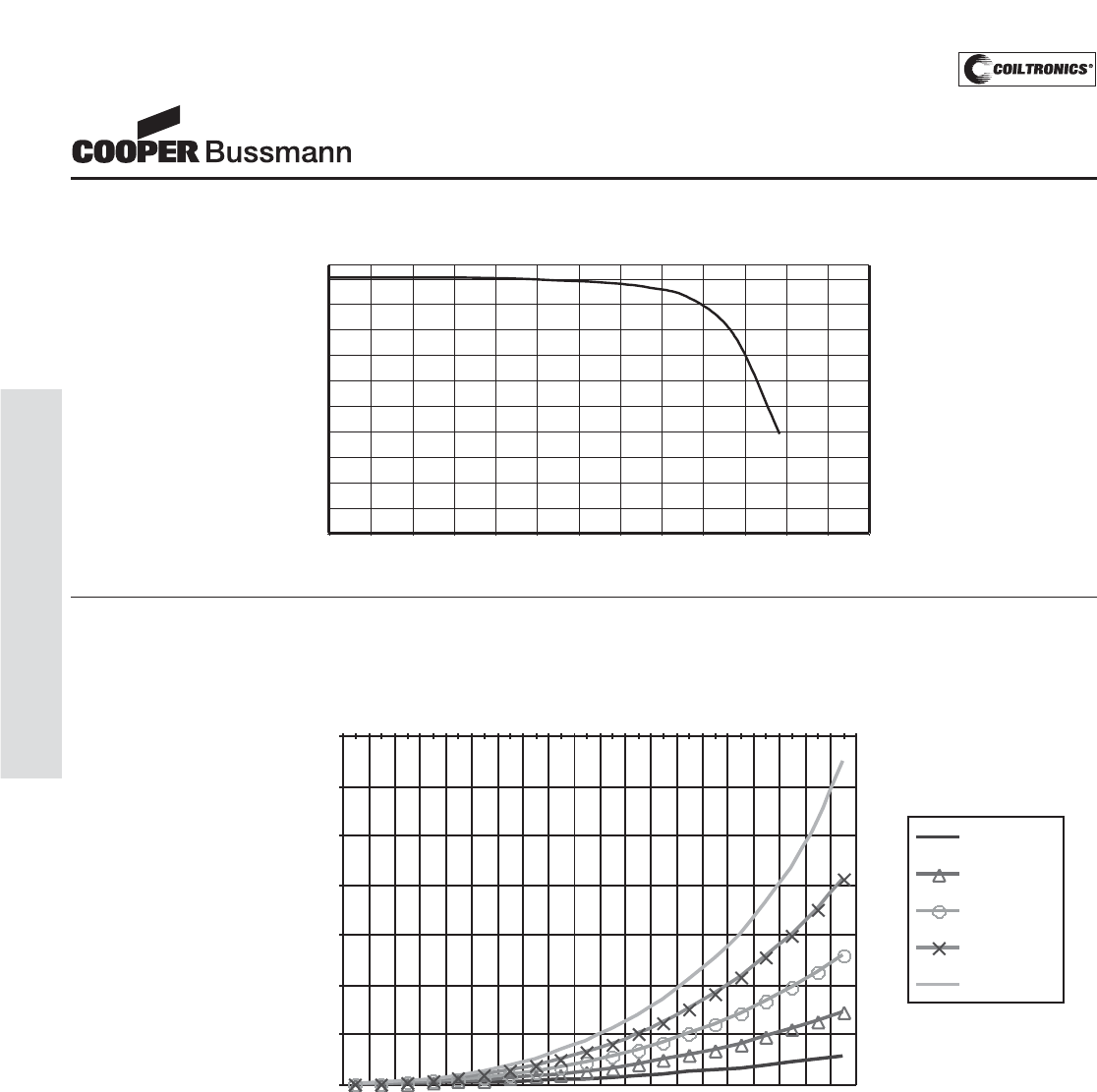
PM-40
HIGH CURRENT (HC3)
HC3 Series
HIGH CURRENT 3
Power Inductors
Irms DERATING WITH CORE LOSS for HC3
30
40
50
60
70
80
90
100
10 30 50 70 90 110 130 150 170 190
% Applied Volt-u Seconds
%of Irms specified from
zero ripple application
100kHz
200kHz
300kHz
400kHz
500kHz
OCL vs Isat
0
10
20
30
40
50
60
70
80
90
100
0 10 20 30 40 50 60 70 80 90 100 110 120 130
%of Isat
%ofOCL
Inductance Characteristics
Core Loss
Courtesy of Steven Engineering, Inc.-230 Ryan Way, South San Francisco, CA 94080-6370-Main Office: (650) 588-9200-Outside Local Area: (800) 258-9200-www.stevenengineering.com
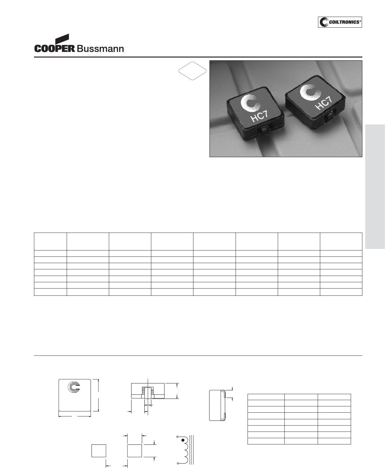
PM-41
HIGH CURRENT (HC7)
Description
• 155°C maximum total temperature operation
• Surface mount inductors designed for higher
speed switch mode applications requiring
lower inductance, low voltage and high current
• Design utilizes high temperature powder iron material
with a non-organic binder to eliminate thermal aging
• Inductance range from 0.22 uH to 4.81 uH
• Current range from 35.8 to 9.8 Amps
• Frequency range 1kHz to 500kHz
Applications
• Next generation microprocessors
• High current DC-DC converters
• VRM, multi-phase buck regulator
• PC, Workstations, Routers
• Telecom soft switches, Base Stations
Environmental Data
• Storage temperature range: -40°C to +155°C
• Operating ambient temperature range: -40°C to +155°C
(range is application specific)
• Solder reflow temperature: +260°C max. for 10 seconds
max.
Packaging
• Supplied in tape and reel packaging, 610 parts per reel
Part Rated OCL (1) Irms (2) Isat (3) Isat (4) DCR (mΩ) Volts (5)
Number Inductance nominal Amperes Amperes Amperes max. @ μSec
μH +/-20% μH (Typ.) 15% rolloff 30% rolloff 20°C (VμS)
HC7-R20-R .20 0.220 35.80 45.8 86.5 0.67 2.27
HC7-R47-R .47 0.534 23.40 27.5 51.9 1.60 3.83
HC7-1R0-R 1.0 1.05 20.30 19.6 37.1 2.10 5.36
HC7-1R5-R 1.5 1.73 14.20 15.3 28.8 4.30 6.90
HC7-2R2-R 2.2 2.58 13.00 12.5 23.6 5.20 8.40
HC7-3R9-R 3.9 3.61 10.40 10.6 20.0 7.90 10.0
HC7-4R7-R 4.7 4.81 9.80 9.2 17.3 9.00 12.6
1) Test Parameters: 100KHz, 1.0Vrms
2) Irms Amperes for approximately ΔT of 40°C above 85°C ambient
3) Isat Amperes Peak for approximately 15% rolloff (@20°C)
4) Isat Amperes Peak for approximately 30% rolloff (@20°C)
5) Applied Volt-Time product (V-μS) across the inductor.This value represents the
applied V-μS at operating frequency necessary to generate additional core loss
which contributes to the 40°C temperature rise. De-rating of the Irms is required
to prevent excessive temperature rise. The 100% V-uS rating is equivalent to a
ripple current Ip-p of 20% of Isat (30% rolloff option).
It is recommended that the temperature of the part not exceed 155°C under worst
case operating conditions verified in the end application.
Units supplied in tape and reel packaging. 13" reels 610 parts per reel.
Carrier tape width = 24 mm. Meets EIA standard
Part number definition:
HC7-XXX-R
HC7 = Product code and size
XXX = Inductance value in uH.
R = Decimal point. If no R is present, third character = #of zeros
-R suffix indicates RoHS compliant
HC7 Series
HIGH CURRENT 7
Power Inductors
Mechanical Diagrams
Maximum Dimension
RECOMMENDED PCB PAD LAYOUT
6.50 typ
3.50 typ
2plcs
3.50 typ
2plcs 1
2
SCHEMATIC
TOP VIEW
HC7-XXX
wwllyy R
13.0
Max
Length
Max
2.60 max
Height
Max
5.10
±0.40
C
L
FRONT VIEW
SIDE VIEW
3.0 ±0.25
(2x)
Dimensions in Millimeters.
All dimensions I+/- 0.2 mm unless otherwise specified.
All soldering surfaces are coplanar within 0.15 mm.
Part Number Height mm Length mm
HC7-R20-R 6.0 14.25
HC7-R47-R 5.5 13.8
HC7-1R0-R 5.5 13.8
HC7-1R5-R 5.5 13.8
HC7-2R2-R 5.5 13.8
HC7-3R9-R 5.5 13.8
HC7-4R7-R 5.5 13.8
wwllyy = Date code R = Revision level
RoHS
2002/95/EC
Courtesy of Steven Engineering, Inc.-230 Ryan Way, South San Francisco, CA 94080-6370-Main Office: (650) 588-9200-Outside Local Area: (800) 258-9200-www.stevenengineering.com
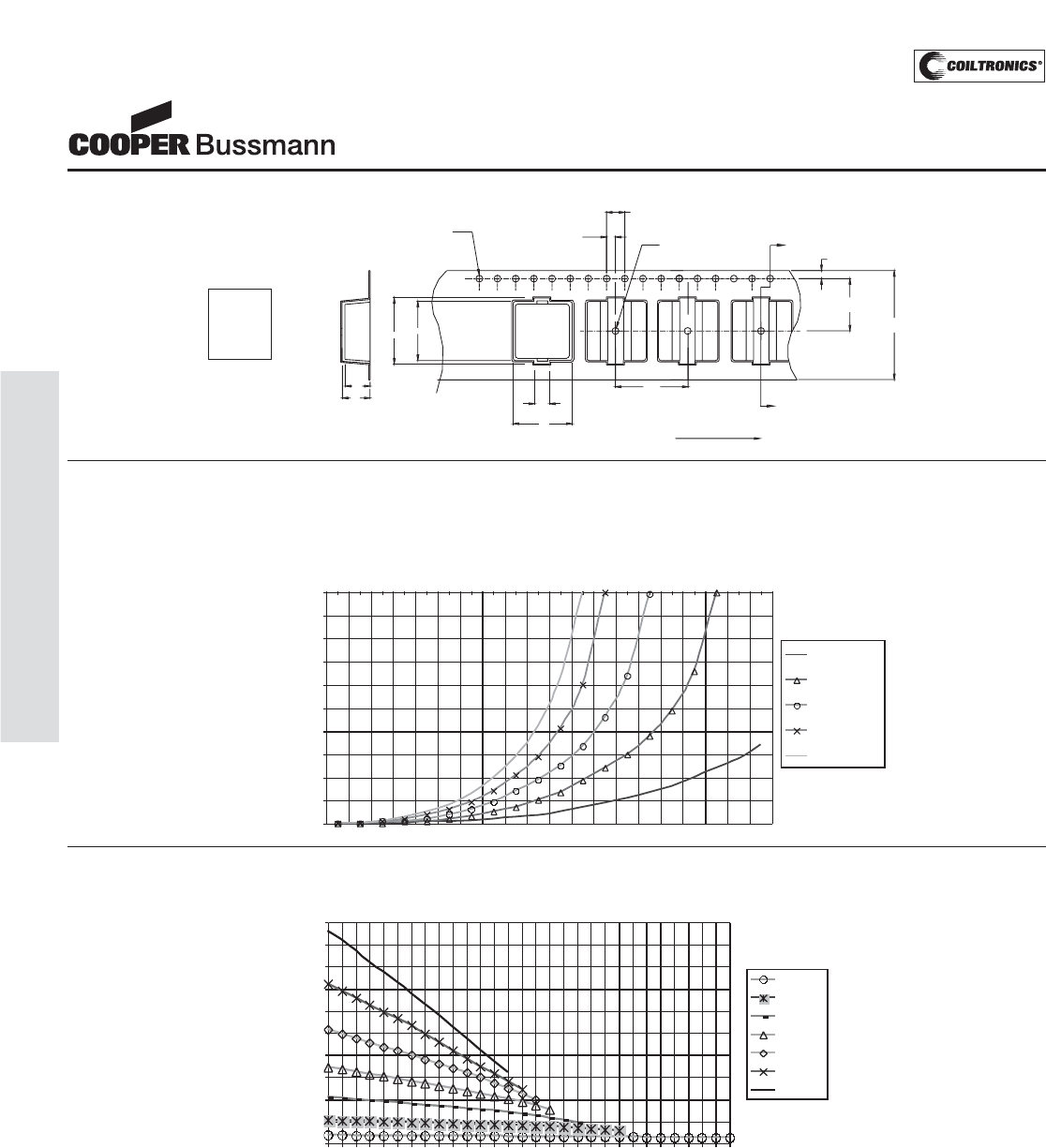
PM-42
HIGH CURRENT (HC7)
Irms DERATING WITH CORE LOSS
0
10
20
30
40
50
60
70
80
90
100
10 20 30 40 50 60 70 80 90 100 110 120 130 140 150 160 170 180 190 200
% of Applied Volt-u-Seconds
% of Irms specified from
zero ripple application
(maximum)
100kHz
200kHz
300kHz
400kHz
500kHz
Inductance vs. Idc
0
0.5
1
1.5
2
2.5
3
3.5
4
4.5
5
0 6 12 18 24 30 36 42 48 54 60 66 72 78 84
DC CURRENT (A)
L
(uH)
HC7-R20
HC7-R47
HC7-1R0
HC7-1R5
HC7-2R2
HC7-3R9
HC7-4R7
HC7 Series
HIGH CURRENT 7
Power Inductors
A1
HC7-XX X
wwllyyR
A0
K1= 6.0 mm
B1= 14.10 mm
A1= 4.00 mm
B0= 13.00 mm
A0= 13.00 mm
K0= 5.6 mm
1.5 dia
+0.1/-0.0
B1 B0
K1
K0
2
1
1.75
16.00
1.5 dia
min
24.0
+/-0.3
A
SECTION A-A
User direction of feed
2.0
4.0
11.5
A
Packaging Information
Core Loss
Inductance Characteristics
Dimensions in Millimeters
Courtesy of Steven Engineering, Inc.-230 Ryan Way, South San Francisco, CA 94080-6370-Main Office: (650) 588-9200-Outside Local Area: (800) 258-9200-www.stevenengineering.com
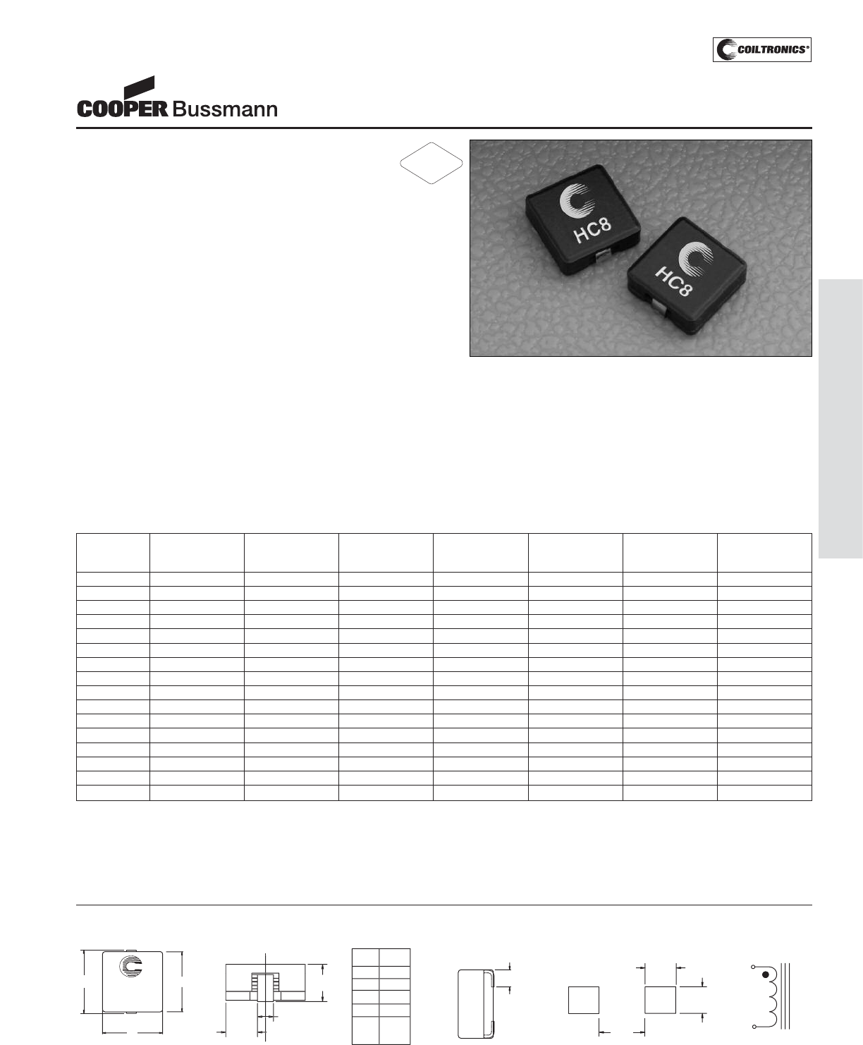
PM-43
HIGH CURRENT (HC8)
Description
• Surface mount inductors, 4.0mm height,
designed for higher speed switch mode
applications requiring low voltage and high current
• 155°C maximum total operating temperature
• Design utilizes high temperature powder iron material
with a non-organic binder to eliminate thermal aging
• Inductance offering expanded for applications
requiring higher inductance.
• Inductance Range from 0.175 uH to 47.3 uH
• Current Range from 39.0 to 2.4 Amps
• Frequency Range 1kHz to 500kHz
Applications
• Next generation microprocessors
• High current DC-DC converters
• VRM, multi-phase buck regulator
• PC, Workstations, Routers
• Telecom soft switches, Base Stations
Environmental Data
• Storage temperature range: -40°C to +155°C
• Operating ambient temperature range: -40°C to +155°C
(range is application specific)
• Solder reflow temperature: +260°C max. for 10 seconds
max.
Packaging
• Supplied in tape and reel packaging, 800 parts per reel
Part Rated OCL (1) Irms (2) Isat (3) Isat (4) DCR (mΩ) Volts (5)
Number Inductance nominal Amperes Amperes Amperes max. @ μSec (VμS)
μH +/-20% μH (Typ.) 15% rolloff 30% rolloff 20°C (ref.)
HC8-R15-R 0.15 0.175 39.0 43 76 0.80 1.5
HC8-R39-R 0.39 0.390 28.3 26 45 1.55 2.5
HC8-R75-R 0.75 0.766 18.8 18.5 32.7 3.40 3.5
HC8-1R2-R 1.2 1.32 16.0 14.4 25.5 4.70 4.5
HC8-1R9-R 1.9 1.90 12.4 11.8 20.9 7.7 5.5
HC8-2R6-R 2.6 2.65 10.2 10.0 17.7 11.4 6.5
HC8-3R5-R 3.5 3.52 8.50 8.7 15.3 16.5 7.5
HC8-4R5-R 4.5 4.52 8.00 7.7 13.5 18.6 8.5
HC8-5R6-R 5.6 5.65 6.70 6.9 12.1 26.3 9.5
HC8-6R9-R 6.9 6.90 6.40 6.2 10.9 28.9 10.5
HC8-8R2-R 8.2 8.27 5.50 5.7 10.0 39.6 11.5
HC8-100-R 10.0 9.77 5.20 5.2 9.2 43.6 12.5
HC8-150-R 15.0 15.02 4.10 4.2 7.4 68.6 15.5
HC8-220-R 22.0 21.40 3.40 3.5 6.2 99.5 18.6
HC8-330-R 33.0 31.65 2.70 2.9 5.1 154 22.6
HC8-470-R 47.0 47.28 2.20 2.4 4.2 237 27.6
1) Test Parameters: 100KHz, 1.0Vrms
2) Irms Amperes for approximately ΔT of 40°C above 85°C ambient
3) Isat Amperes Peak for approximately 15% rolloff (@20°C)
4) Isat Amperes Peak for approximately 30% rolloff (@20°C)
5) Applied Volt-Time product (V-μS) across the inductor. This value represents the
applied V-μS at operating frequency necessary to generate additional core loss
which contributes to the 40°C temperature rise. De-rating of the Irms is required
to prevent excessive temperature rise. The 100% V-uS rating is equivalent to a
ripple current Ip-p of 20% of Isat (30% rolloff option).
It is recommended that the temperature of the part not exceed 155°C under worst
case operating conditions verified in the end application.
Part number definition:
HC8-XXX-R
HC8 = Product code and size
XXX = Inductance value in uH.
R = Decimal point. If no R is present, third character = #of zeros
-R suffix indicates RoHS compliant
HC8 Series
HIGH CURRENT 8
Power Inductors
Mechanical Diagrams
TOP VIEW
10.9
Max
10.4
Max
HC8-XXX
wwll yy R
10.4
Max
FR
ON
TV
I
EW
SIDE VIEW
2.70 ±0.55
(2x)
RECOMMENDED PCB PAD LAYOUT
4.0 typ
3.0 typ
2plcs
3.5 typ
2plcs 1
2
SCHEMATIC
4
.
0
Ma
x
C
L
A
r
ef
3
.
95
2
pl
cs
ref
A
mm
1R
2.1
1
R9
th
r
u
470
2.7
R39
R
7
5
R
1
5
PN
2.1
2.1
2.1
FR
O
NT VIE
W
TABLE
wwllyy = Date code R = Revision level
xxx = Inductance value
RoHS
2002/95/EC
Courtesy of Steven Engineering, Inc.-230 Ryan Way, South San Francisco, CA 94080-6370-Main Office: (650) 588-9200-Outside Local Area: (800) 258-9200-www.stevenengineering.com
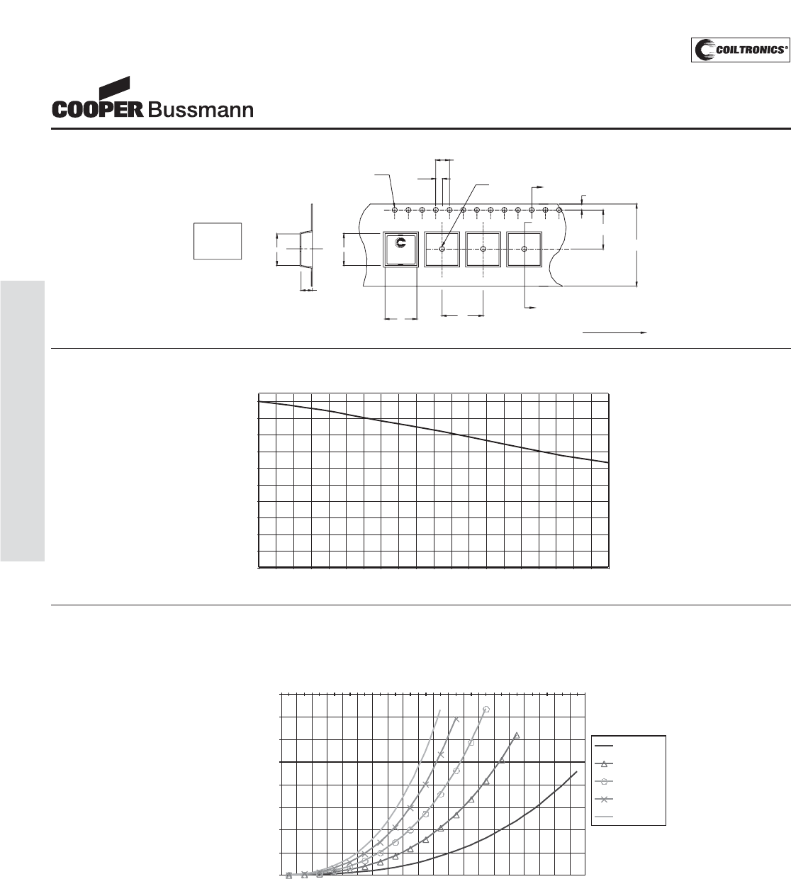
PM-44
HIGH CURRENT (HC8)
HC8 Series
HIGH CURRENT 8
Power Inductors
2.0
Ao
Ko=4.3 mm
Ao=10.4 mm
Bo=11.2 mm
1.5 dia
+0.1
/-0.0
Bo
11.2
Ko
SECTION A-A
HC8-XXX
wwllyyR
16.0
24.0
+/-0.3
11
.5
4.0
1.5 dia
min
1.7
5
User direction of feed
A
A
Packaging Information
Dimensions in Millimeters
Irms DERATING WITH CORE LOSS
84
86
88
90
92
94
96
98
100
10 30 50 70 90 110 130 150 170 190
% Applied Volt-u Seconds
% of Irms specified from
zero ripple application
100kHz
200kHz
300kHz
400kHz
500kHz
OCL vs Isat
0
10
02
30
40
50
60
70
80
90
100
0 10 20 30 40 50 60 70 80 90 100 110 120 130 140 150 160 170 180 190 200
% of Isat
%ofOCL
Inductance Characteristics
Core Loss
Courtesy of Steven Engineering, Inc.-230 Ryan Way, South San Francisco, CA 94080-6370-Main Office: (650) 588-9200-Outside Local Area: (800) 258-9200-www.stevenengineering.com
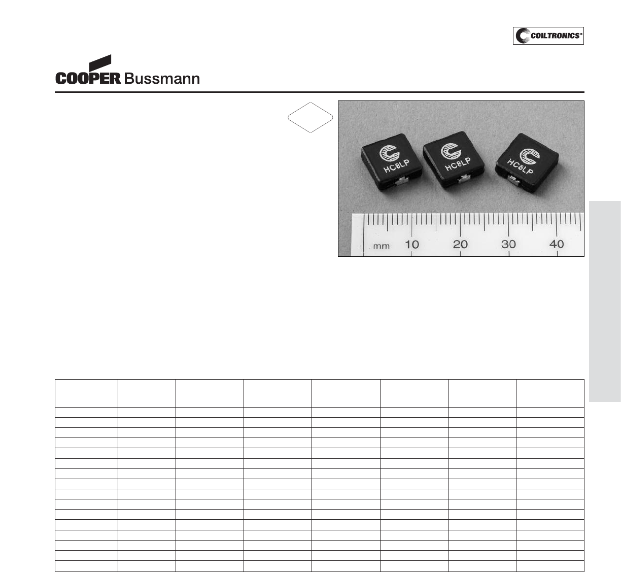
PM-45
HIGH CURRENT (HC8LP)
Description
• 155°C maximum temperature operation
• Low profile surface mount inductors designed
for higher speed switch mode applications
requiring low voltage, and high current
• Design utilizes high temperature powder iron material
with a non-organic binder to eliminate thermal aging
• Inductance range from 0.17 uH to 47.9 uH
• Current range from 29 Amps to 1.8 Amps
• Frequency range 1kHz to 500kHz
Applications
• Next generation processors
• High current DC-DC converters
• VRM, multi-phase buck regulator
• PC Workstations, Routers, Servers
• Telecom soft switches, Base stations
Environmental Data
• Storage temperature range: -40°C to +155°C
• Operating temperature range: -40°C to +155°C
(Range is application specific)
• Solder reflow temperature: +260°C max. for
10 seconds max.
Packaging
• Supplied in tape and reel packaging, 800 parts per reel
Part Rated OCL (1) Irms (2) Isat (3) Isat (4) DCR (mΩ) Volts (5)
Number Inductance nominal Amperes Amperes Amperes max. @ μSec (VμS)
μH +/-20% μH (Typ.) 15% rolloff 30% rolloff 20°C (ref.)
HC8LP-R15-R 0.15 0.170 29.0 31 56 1.40 7.8
HC8LP-R39-R 0.39 0.430 20.2 19 34 2.80 4.7
HC8LP-R75-R 0.75 0.830 15.6 13.5 24 4.70 3.4
HC8LP-1R2-R 1.2 1.35 12.4 10.1 18.7 7.50 2.6
HC8LP-1R9-R 1.9 1.92 10.1 8.7 15.5 11.5 4.1
HC8LP-2R6-R 2.6 2.67 8.3 7.4 13.1 17.1 4.8
HC8LP-3R5-R 3.5 3.56 6.9 6.4 11.4 24.5 5.6
HC8LP-4R5-R 4.5 4.57 6.5 5.6 10.0 27.6 6.3
HC8LP-5R6-R 5.6 5.71 5.5 5.1 9.0 38.9 7.1
HC8LP-6R9-R 6.9 6.98 5.2 4.6 8.1 42.8 7.8
HC8LP-8R2-R 8.2 8.37 4.5 4.2 7.4 58.0 8.6
HC8LP-100-R 10.0 9.90 4.3 6.8 3.8 62.9 9.3
HC8LP-150-R 15.0 15.20 3.4 3.1 5.5 99.4 11.6
HC8LP-220-R 22.0 21.70 2.8 2.6 4.6 149 13.7
HC8LP-330-R 33.0 32.10 2.3 2.1 3.8 224 16.8
HC8LP-470-R 47.0 47.90 1.8 1.7 3.1 344 20.3
1) Open Circuit Inductance test parameters: 100KHz, 1.0V, 0.0Adc
2) Irms: DC current for an approximate DT of 40°C without core loss. Derating is
necessary for AC currents. PCB layout, trace thickness and width, air-flow, and prox-
imity of other heat generating components will affect the temperature rise. It is rec-
ommended that the temperature of the part not exceed 155°C under worst case
operating conditions verified in the end application.
3) Isat Amperes Peak for approximately 15% rolloff (@20°C)
4) Isat Amperes Peak for approximately 30% rolloff (@20°C)
5) Applied Volt-Time product (V-μS) across the inductor.This value represents the
applied V-μS at operating frequency necessary to generate additional core loss
which contributes to the 40°C temperature rise. De-rating of the Irms is required
to prevent excessive temperature rise. The 100% V-uS rating is equivalent to a
ripple current Ip-p of 20% of Isat (30% rolloff option).
Part number definition:
HC8LP-xxx-R
HC8LP = Product code and size
xxx = Inductance in μH. R = decimal point.
If no R is present third character = # of zeros.
-R suffix indicates RoHS compliant
HC8LP Series
Power Inductors
RoHS
2002/95/EC
Courtesy of Steven Engineering, Inc.-230 Ryan Way, South San Francisco, CA 94080-6370-Main Office: (650) 588-9200-Outside Local Area: (800) 258-9200-www.stevenengineering.com
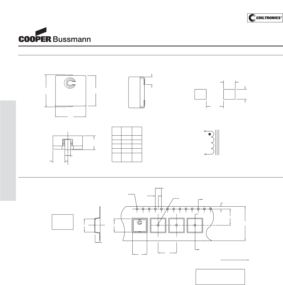
PM-46
HIGH CURRENT (HC8LP)
HC8LP Series
Power Inductors
1.75
11.5
24.0
+/-0.3
User direction of feed
11.2 HC8-XXX
wwllyy R
SECTION A-A A
A
Ko
Bo
Ao
1.5 dia
+0.1/-0.0 1.5 dia
min
4.0
2.0
16.0
Ko=4.3 mm
Bo=11.2 mm
Ao=10.4 mm
13" Dia. EIA-481 compliant reel.
Packaging Information:
Parts packaged on a
800 parts per reel.
Packaging Information
Dimensions in Millimeters
wwllyy = Date Code, R = Revision Level
Mechanical Diagrams
10.4
Max
10.4
Max
HC8LP-XXX
wwllyy R
TOP VIEW
10.9
Max
B
Max
CL
Aref
3.95
2 plcs
ref
FRONT VIEW B
max
mm
1R2 3.3
R39
R75
R15
PN
3.5
3.5
3.5
FRONT VIEW
Dimesional Table
A
ref
mm
2.1
2.1
2.1
2.1
1R9
thru
470 2.7 3.5
2.70 ±0.55
(2 x)
SIDE VIEW
3.5 typ
2plcs
3.0 typ
2plcs
4.0 typ
RECOMMENDED PCB PAD LAYOUT
SCHEMATIC
1
2
Courtesy of Steven Engineering, Inc.-230 Ryan Way, South San Francisco, CA 94080-6370-Main Office: (650) 588-9200-Outside Local Area: (800) 258-9200-www.stevenengineering.com
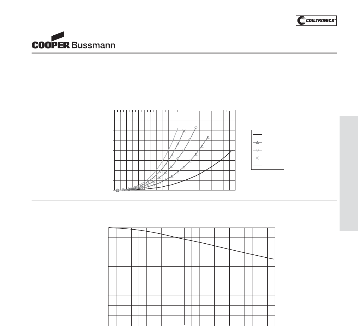
PM-47
HIGH CURRENT (HC8LP)
HC8LP Series
Power Inductors
OCL vs Isat
0
10
20
30
40
50
60
70
80
90
100
0 10 20 30 40 50 60 70 80 90 100 110 120 130 140 150 160 170 180 190 200 210 220
% of Isat
%ofOCL
Rolloff
Core Loss
Irms DERATING WITH CORE LOSS
92
93
94
95
96
97
98
99
100
10 30 50 70 90 110 130 150 170 190
% Applied Volt-u Seconds
% of Irms specified from
zero ripple application
(Maximum)
100kHz
200kHz
300kHz
400kHz
500kHz
Courtesy of Steven Engineering, Inc.-230 Ryan Way, South San Francisco, CA 94080-6370-Main Office: (650) 588-9200-Outside Local Area: (800) 258-9200-www.stevenengineering.com
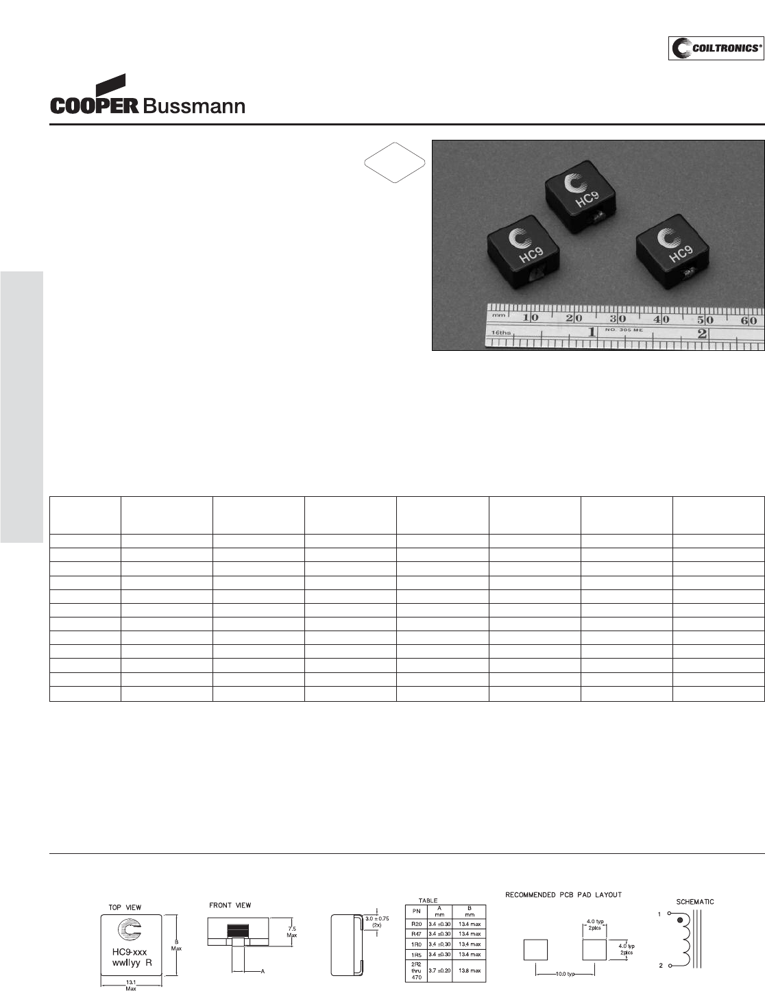
PM-48
HIGH CURRENT (HC9)
Description
• 155°C maximum total temperature operation
• Surface mount inductors designed for higher speed
switch mode applications requiring lower inductance,
low voltage and high current
• Design utilizes high temperature powder iron material
with a non-organic binder to eliminate thermal aging
• Inductance Range from 0.2 uH to 47.0 uH
• Current Range from 95.0 Amps to 3.65 Amps
• Frequency Range 1kHz to 500kHz
Applications
• Next generation processors
• High current DC-DC converters
• VRM, multi-phase buck regulator
• PC, Workstations, Routers, Servers
Environmental Data
• Storage temperature range: -40°C to +155°C
• Operating temperature range: -40°C to +155°C
(range is application specific)
• Solder reflow temperature: +260°C max for 10 seconds
maximum
Packaging
• Supplied in tape and reel packaging, 450 parts per reel
Part Rated OCL (1) Irms (2) Isat (3) Isat (4) DCR (mΩ) Volts (5)
Number Inductance nominal Amperes Amperes Amperes max. @ μSec
μH +/-15% μH (Typ.) 20% rolloff 30% rolloff 20°C (VμS)
HC9-R20-R 0.20 0.218 46.7 65 95 0.50 2.87
HC9-R47-R 0.47 0.544 33.7 40 57 0.88 4.78
HC9-1R0-R 1.0 1.04 23.7 28 41 1.87 6.70
HC9-1R5-R 1.5 1.70 21.0 22 32 2.27 8.46
HC9-2R2-R 2.2 2.53 17.2 18 26 3.37 10.4
HC9-3R3-R 3.3 3.52 14.3 15 22 4.87 12.4
HC9-4R3-R 4.3 4.67 13.0 13.2 19.1 5.90 14.4
HC9-6R8-R 6.8 7.45 10.3 11.4 15.1 9.40 18.1
HC9-100-R 10.0 10.9 8.50 8.6 12.5 14.0 22.0
HC9-220-R 22.0 22.4 6.30 6.0 8.7 25.7 31.5
HC9-330-R 33.0 34.5 4.42 4.8 7.0 48.8 37.3
HC9-470-R 47.0 49.2 3.65 3.9 5.7 72.3 44.8
1) Test Parameters: 100KHz, 1.0Vrms
2) Irms Amperes for approximately ΔT of 40°C without core loss.
De-rating is necessary for AC currents. PCB layout, trace thickness and width,
airflow, and proximity of other heat generating components will affect the temper-
ature rise. It is recommended that the temperature of the part not exceed 155°C
under worst case conditions verified in the end application.
3) Peak current for approximately 20% rolloff @20°C
4) Peak current for approximately 30% rolloff @20°C
5) Applied Volt-Time product (V-μS) across the inductor.This value represents the
applied V-μS at operating frequency necessary to generate additional core loss
which contributes to the 40°C temperature rise. De-rating of the Irms is required
to prevent excessive temperature rise. The 100% V-uS rating is equivalent to a
ripple current Ip-p of 20% of Isat (30% rolloff option).
Part number definition:
First 3 characters = Product code and size.
Last 3 characters = Inductance in μH. R = decimal point.
If no R is present third character = # of zeros.
HC9 Series
HIGH CURRENT 9
Power Inductors
Mechanical Diagrams
Dimensions in Millimeters. All dimensions +/-0.2 mm unless otherwise specified.
wwllyy = Date Code, R = Revision Level
RoHS
2002/95/EC
Courtesy of Steven Engineering, Inc.-230 Ryan Way, South San Francisco, CA 94080-6370-Main Office: (650) 588-9200-Outside Local Area: (800) 258-9200-www.stevenengineering.com
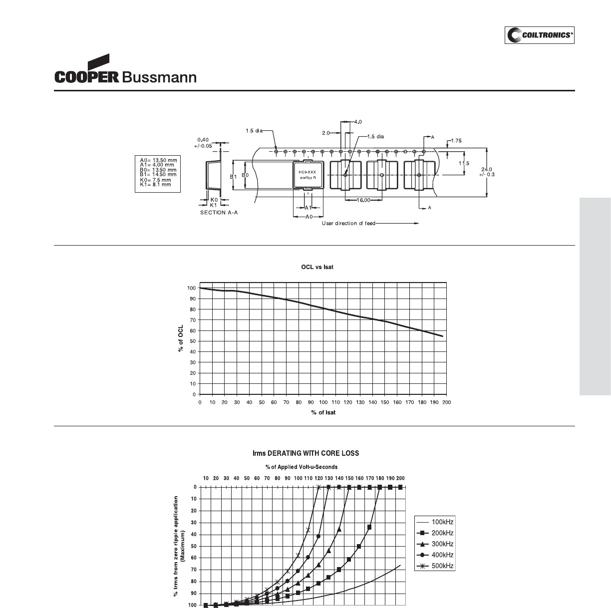
PM-49
HIGH CURRENT (HC9)
HC9 Series
HIGH CURRENT 9
Power Inductors
Packaging Information
Dimensions in Millimeters
Rolloff
Core Loss
Courtesy of Steven Engineering, Inc.-230 Ryan Way, South San Francisco, CA 94080-6370-Main Office: (650) 588-9200-Outside Local Area: (800) 258-9200-www.stevenengineering.com
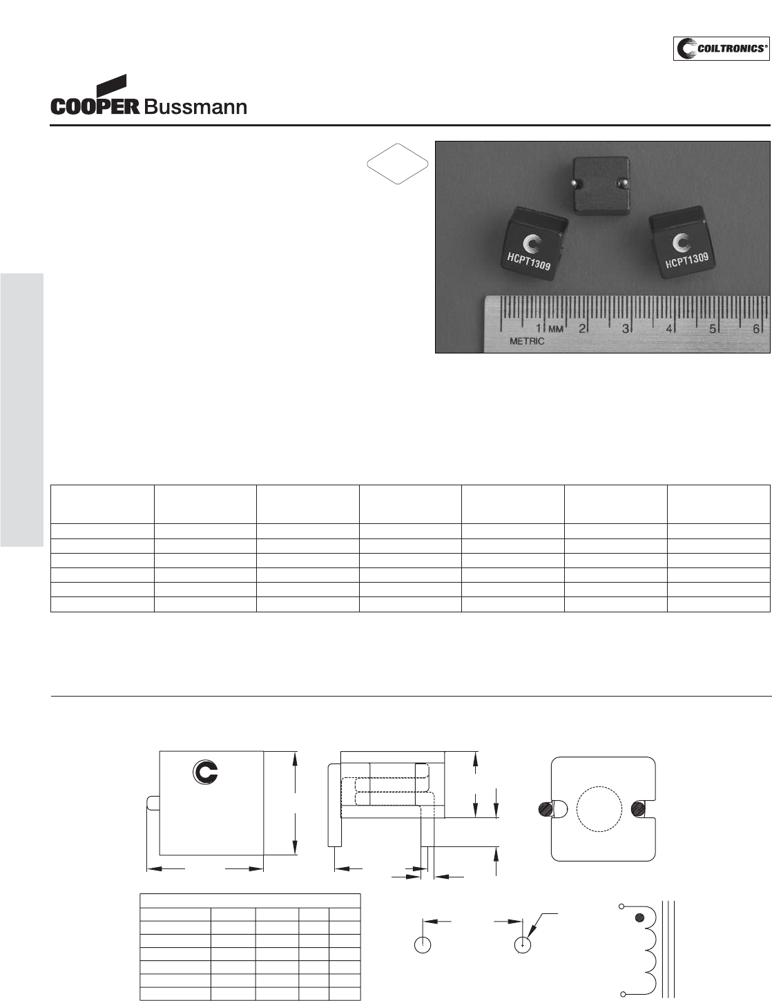
PM-50
HIGH CURRENT (HCPT1309)
Description
• 105°C maximum total temperature operation
• 13.2mm x 13.2mm x 9.0mm through hole
package
• Core material: Powder Iron
• Inductance range from 0.20μH to 3.3μH
• Current range from 90.0 Amps to 11.4 Amps
• Frequency range up to 1MHz
Applications
• Next generation processors
• High current DC-DC converters
• VRM, multi-phase buck regulator
• Desktop computers
• Video game power
Environmental Data
• Storage temperature range: -40°C to +105°C
• Operating temperature range: -40°C to +105°C
(range is application specific)
• Solder reflow temperature: +260°C max. for 10 seconds
maximum
Packaging
• Supplied in bulk packaging, 100 parts per tray
HCPT1309 Series
Power Inductors
Part Number OCL (1) Irms (2) Isat Amperes (3) Isat Amperes (4) DCR (mΩ) K-factor
nominal +/- Amperes Peak 20% Peak 30% nom @20°C (5)
20% (μH) rolloff @20°C rolloff @20°C
HCPT1309-R20-R 0.20 43.1 72.2 90.0 0.426 154.1
HCPT1309-R47-R 0.49 34.0 43.3 55.0 0.624 92.4
HCPT1309-1R0-R 0.96 19.4 30.9 40.0 1.90 66.0
HCPT1309-1R5-R 1.59 13.7 24.1 30.6 3.82 51.4
HCPT1309-2R2-R 2.27 12.5 19.7 25.0 4.10 42.0
HCPT1309-3R3-R 3.31 11.4 16.7 21.0 4.80 35.6
(1) OCL: Open Circuit Inductance test parameters: 100kHz, 0.1Vrms, 0.0Adc.
(2) Irms: DC current for an approximate ΔT of 40°C without core loss. Derating is
necessary for AC currents. PCB layout, trace thickness and width, air-flow, and
proximity of other heat generating components will affect the temperature rise. It
is recommended that the temperature of the part not exceed 105°C under worst
case operating conditions verified in the end application.
(3) Isat Amperes peak for approximately 20% rolloff (@20°C)
(4) Isat Amperes peak for approximately 30% rolloff (@20°C)
(5) K-factor: Used to determine B p-p for core loss (see graph).
B p-p = K*L*ΔI, B p-p: (Gauss), K: (K factor from table), L: (Inductance in uH),
ΔI (Peak to peak ripple current in Amps).
Dimensions are in millimeters.
wwllyy = Date Code. R = Revision Level.
RECOMMENDED PCB PAD LAYOUT 1
2
TOP VIEW FRONT VIEW
ØD
Dimension Table
Part No "A" "B" "C"
HCPT1309-R20
"D"
14.0 12.2 1.63 2.13
HCPT1309-R47 14.0 12.2 1.63 2.13
HCPT1309-1R0 13.7 12.0 1.29 1.6
HCPT1309-1R5 13.5 11.8 1.15 1.40
HCPT1309-2R2 13.5 11.8 1.15 1.40
HCPT1309-3R3 13.5 11.8 1.15 1.40
HCPT1309-xxx
wwllyy R
"B" +/- 1.0
"B" +/- 1.0 "C" typ
"A" MAX
BOTTOM VIEW
13.2 sq
MAX
9.0
max
3.5 +/- 0.5
1
2
SCHEMATIC
Mechanical Diagrams
RoHS
2002/95/EC
Courtesy of Steven Engineering, Inc.-230 Ryan Way, South San Francisco, CA 94080-6370-Main Office: (650) 588-9200-Outside Local Area: (800) 258-9200-www.stevenengineering.com
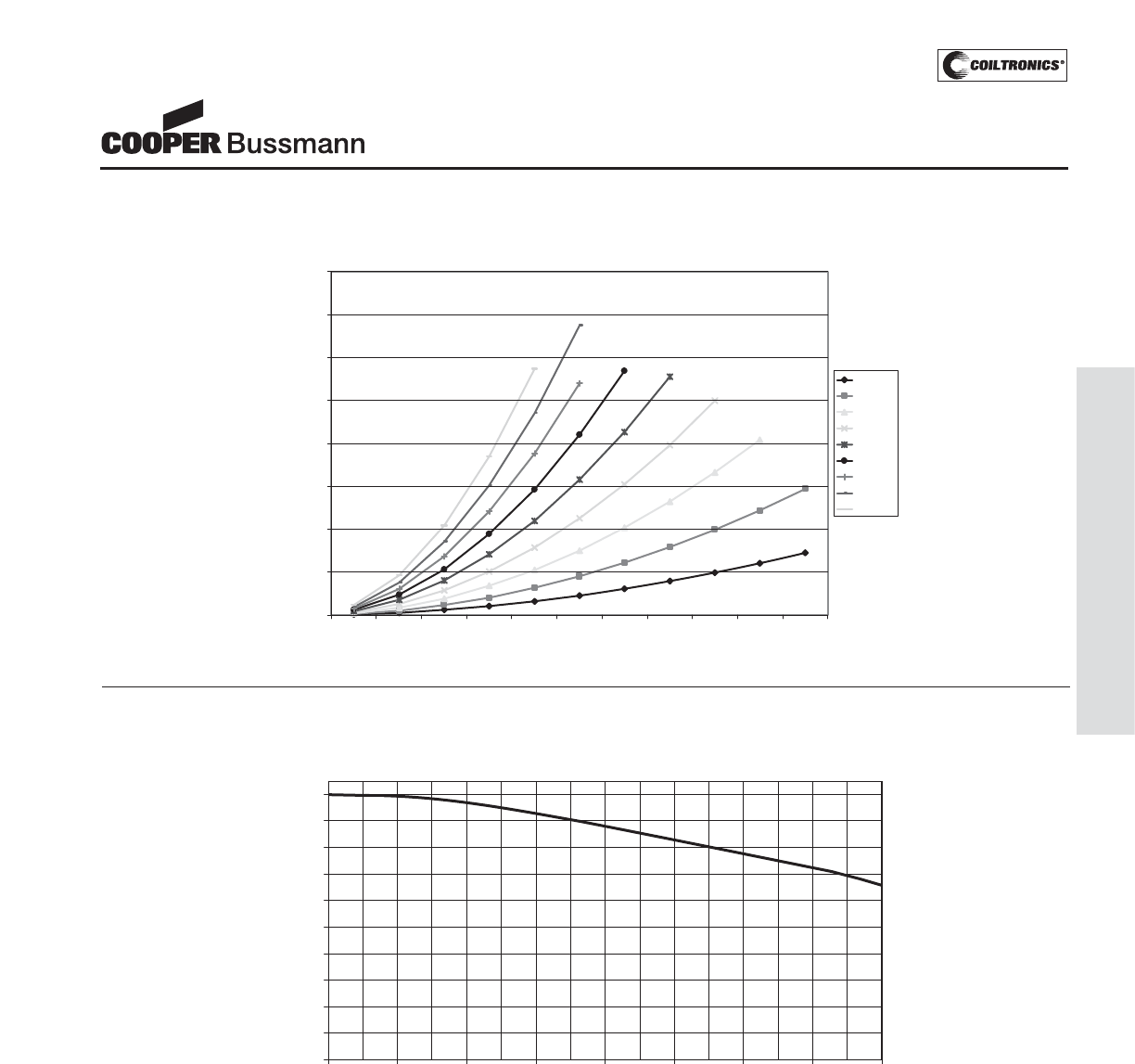
PM-51
HIGH CURRENT (HCPT1309)
HCPT1309 Series
Power Inductors
Core Loss
Core Loss vs. B p-p
0.00
20.00
40.00
60.00
80.00
100.00
120.00
140.00
160.00
250 500 750 1000 1250 1500 1750 2000 2250 2500 2750
B p-p (Gauss)
Core Loss(mW)
200kHz
300kHz
400kHz
500kHz
600kHz
700kHz
800kH
900kHz
1.0MHz
OCL vs Isat
0
10
20
30
40
50
60
70
80
90
100
0 20 40 60 80 100 120 140 160
%of Isat
OCL (%)
Inductance Characteristics
Courtesy of Steven Engineering, Inc.-230 Ryan Way, South San Francisco, CA 94080-6370-Main Office: (650) 588-9200-Outside Local Area: (800) 258-9200-www.stevenengineering.com
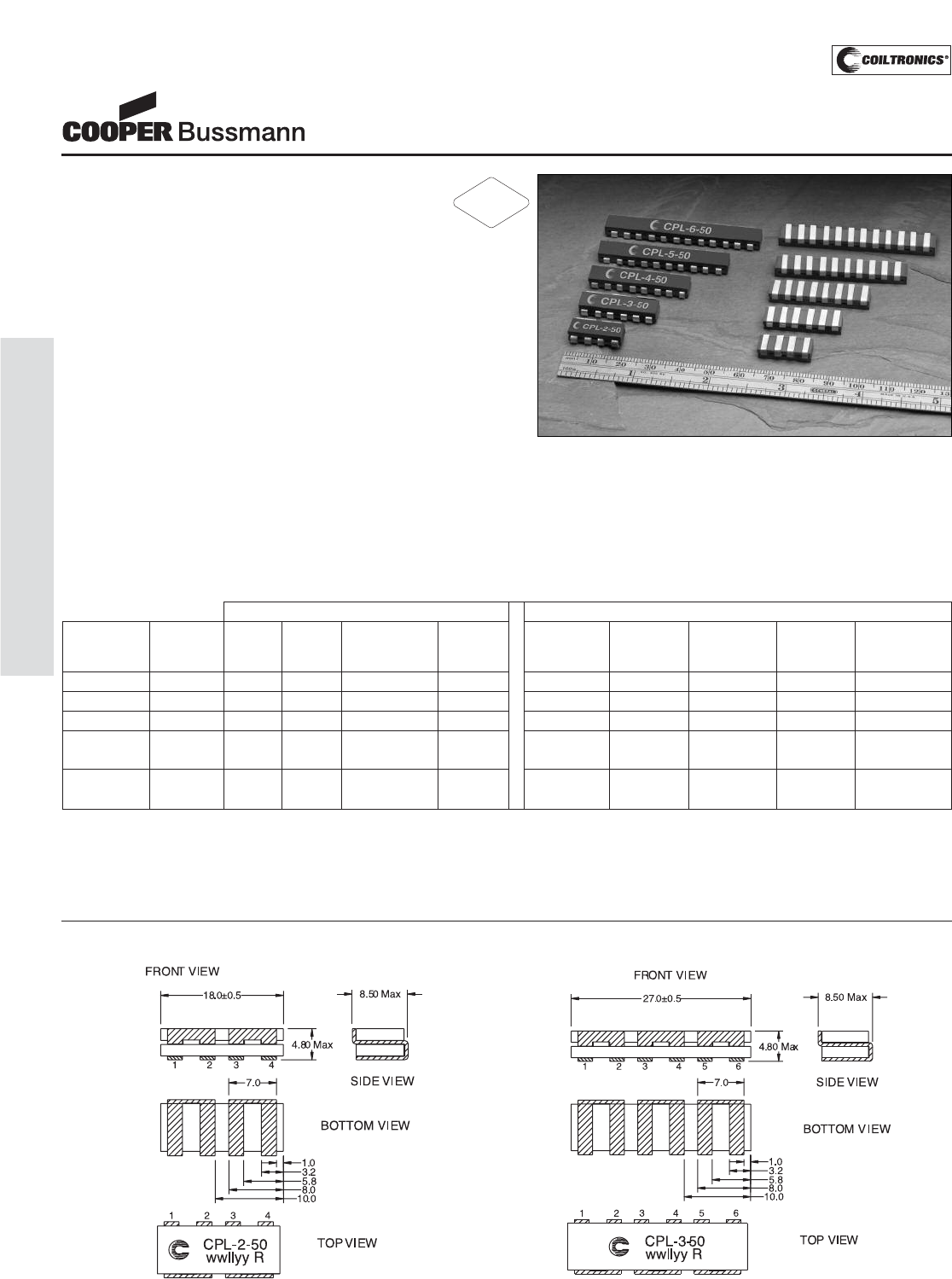
PM-52
HIGH CURRENT (CPL)
Description
• Designed exclusively for use with Volterra
VPR-Devices(A)
• High current multi-phase inductor applications
• Ferrite core material
• 50nH per phase coupled inductor
• 125°C maximum temperature operation
• Frequency range up to 2MHz
• Patents pending
• For tape and reel parts add TR after part number:
CPL-x-xxTR-R
Environmental Data
• Storage temperature range: -40°C to +125°C
• Operating temperature range: -40°C to +125°C
(range is application specific)
• Solder reflow temperature: +260°C max. for
10 seconds maximum
Packaging
• Supplied in bulk trays or tape and reel:
CPL-2-50-R: 120 per tray CPL-2-50TR-R: 750 per reel
CPL-3-50-R: 90 per tray CPL-3-50TR-R: 750 per reel
CPL-4-50-R: 75 per tray CPL-4-50TR-R: 750 per reel
CPL-5-50-R: 60 per tray CPL-5-50TR-R: 750 per reel
CPL-6-50-R: 45 per tray CPL-6-50TR-R: 750 per reel
CPL Series
Multi-Phase
Power Inductors
DCR (Ω) DCR (Ω) Rated (3) I Rated Magnetizing
Inductance nom. @ max. @ Inductance per phase OCL (nH) OCL (nH) Inductance
Part Number Phases 25°C 25°C per phase (nH) (Adc) (3) Pin Number notes 1&2 Pin Number notes 1&2 @ 5Adc (25°C)
CPL-2-50-R 2 0.0005 0.0006 50 ± 20% 40 (1-2) 365 ± 18% (3-4) 365 ± 18% 300
CPL-3-50-R 3 0.0005 0.0006 50 ± 20% 40 (3-4) 490 ± 20% (1-2), (5-6) 365 ± 18% 400
CPL-4-50-R 4 0.0005 0.0006 50 ± 20% 40 (3-4), (5-6) 490 ± 20% (1-2), (7-8) 365 ± 18% 400
CPL-5-50-R 5 0.0005 0.0006 50 ± 20% 40 (3-4), (5-6), 490 ± 20% (1-2), (9-10) 365 ± 18% 400
(7-8)
CPL-6-50-R 6 0.0005 0.0006 50 ± 20% 40 (3-4), 5-6), 490 ± 20% (1-2), (11-12) 365 ± 18% 400
(7-8), (9-10)
(1) OCL (Open Circuit Inductance)
(2) Test parameters: 1MHz, 0.1Vrms, 0.0Adc.
(3) The rated current and rated inductance per phase is determined by Volterra’s
testing and circuit design. Additional information can be provided by contacting
Volterra.
(A) This device is licensed for use only when incorporated within a voltage regulator
employing power regulating devices manufactured by Volterra Semiconductor
Corp. No license is granted expressly or by implication to use this device with
power regulating devices manufactured by any company other than Volterra.
Mechanical Diagrams
Functional Specifications Test Specifications
RoHS
2002/95/EC
Courtesy of Steven Engineering, Inc.-230 Ryan Way, South San Francisco, CA 94080-6370-Main Office: (650) 588-9200-Outside Local Area: (800) 258-9200-www.stevenengineering.com
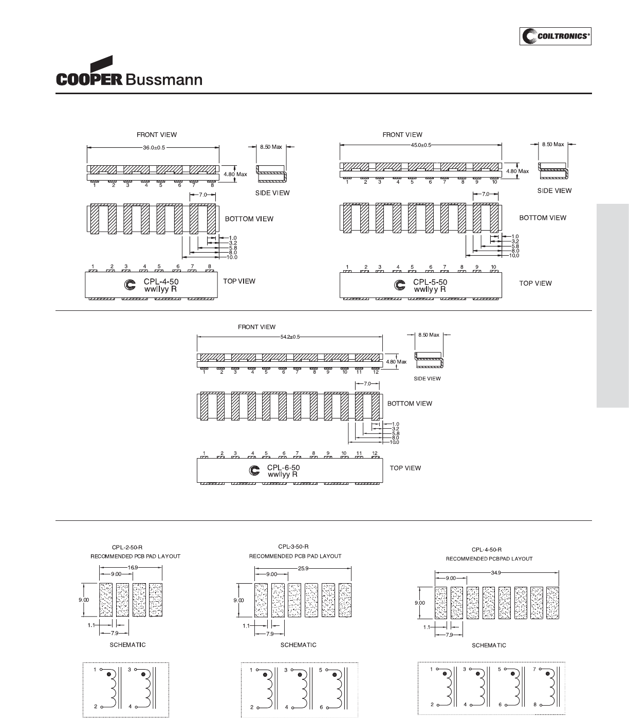
PM-53
HIGH CURRENT (CPL)
CPL Series
Multi-Phase
Power Inductors
Dimensions are in millimeters. All dimensions +/-0.2 mm unless otherwise specified. wwllyy = (date code) R = revision level
Mechanical Diagrams
Schematic/PCB Layout
Courtesy of Steven Engineering, Inc.-230 Ryan Way, South San Francisco, CA 94080-6370-Main Office: (650) 588-9200-Outside Local Area: (800) 258-9200-www.stevenengineering.com
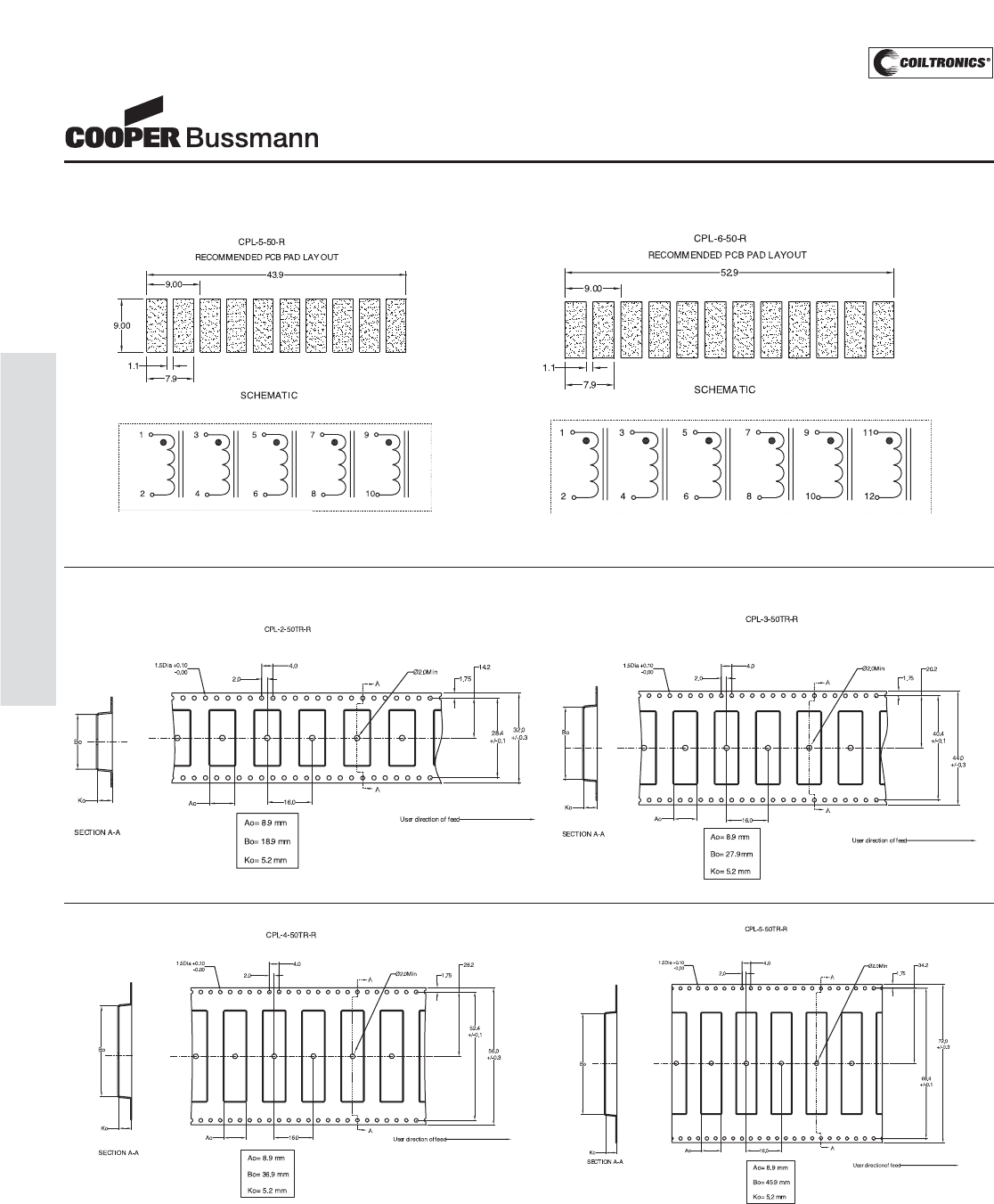
PM-54
HIGH CURRENT (CPL)
CPL Series
Multi-Phase
Power Inductors
Schematic/PCB Layout
Dimensions are in millimeters. All dimensions +/-0.2 mm unless otherwise specified.
Packaging Information (Tape and Reel)
Courtesy of Steven Engineering, Inc.-230 Ryan Way, South San Francisco, CA 94080-6370-Main Office: (650) 588-9200-Outside Local Area: (800) 258-9200-www.stevenengineering.com
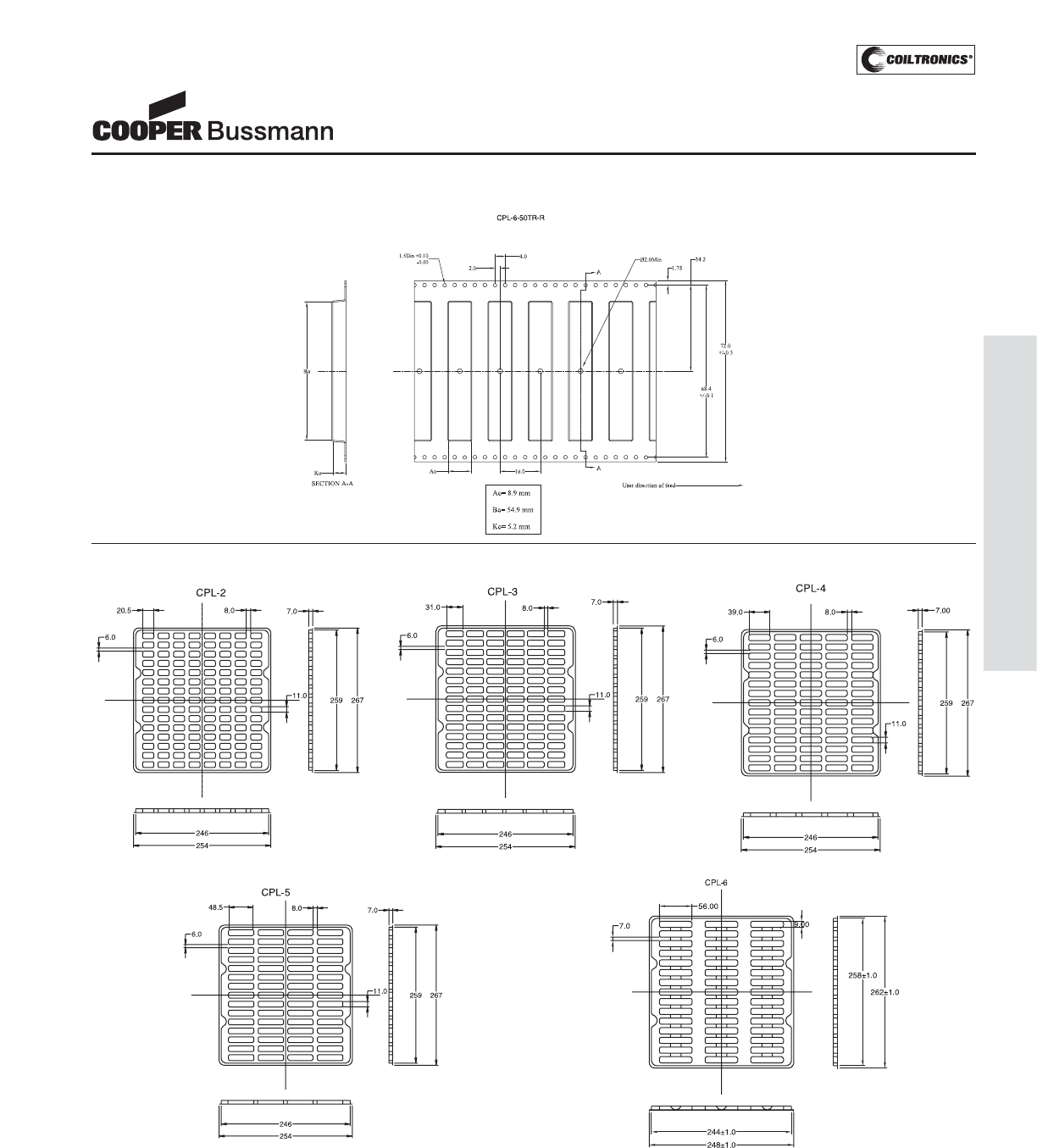
PM-55
HIGH CURRENT (CPL)
CPL Series
Multi-Phase
Power Inductors
Packaging Information (Bulk Tray)
Notes:
Material: 0.8 PVC with internal Anti-Stat
Tolerances: x.xx = ± 0.20, x.x = ± 0.50, x = ± 2.0 unless otherwise specified.
Trays are stackable when rotated 180°.
All dimensions are in mm.
Packaging Information (Tape and Reel)
Courtesy of Steven Engineering, Inc.-230 Ryan Way, South San Francisco, CA 94080-6370-Main Office: (650) 588-9200-Outside Local Area: (800) 258-9200-www.stevenengineering.com
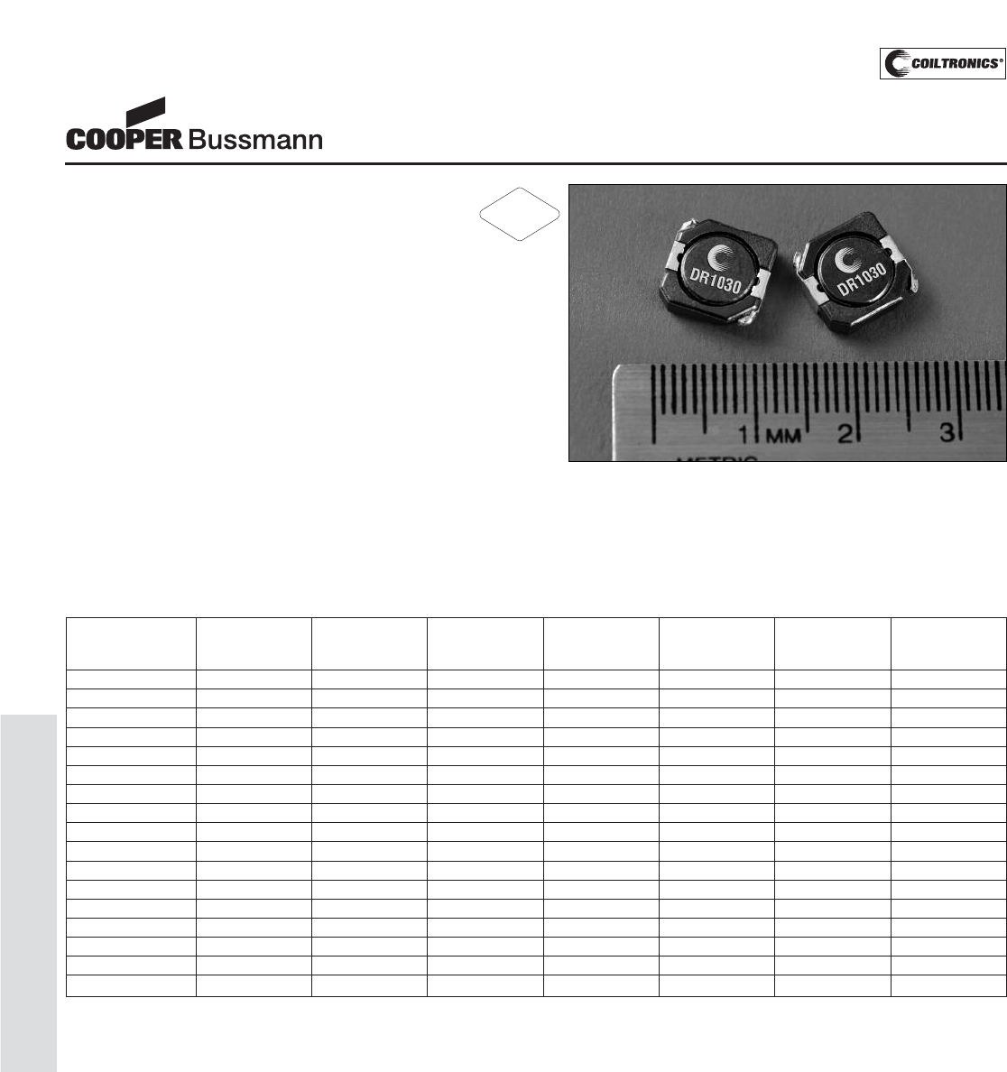
PM-56
SHIELDED DRUM (DR1030)
Description
• 125°C maximum total temperature operation
• Low profile surface mount inductors
• 10.3mm x 10.5mm x 3.0mm shielded drum core
• Ferrite core material
• Inductance range from 1.1μH to 150μH
• Current range from 9.5 Amps to 0.68 Amps
• Frequency range up to 1MHz
Applications
• Computer, DVD players, and portable power devices
• Notebook power, LCD panels
• DC-DC converters
• Input/output filter, Buck/Boost regulators
Environmental Data
• Storage temperature range: -40°C to +125°C
• Operating temperature range: -40°C to +125°C
(range is application specific)
• Solder reflow temperature: +260°C max. for 10 seconds
maximum
Packaging
• Supplied in tape and reel packaging,
1000 parts per reel
DR1030 Series
Low Profile Power Inductors
Part Number Rated OCL (1) Irms (2) Isat (3) DCR DCR K-factor
Inductance μH ± 30% Amperes Amperes mΩ@20°C mΩ@20°C (4)
(μH) (Typical) (Maximum)
DR1030-1R1-R 1.1 1.1 7.0 9.50 6.5 7.9 22
DR1030-1R8-R 1.8 1.9 5.9 7.41 9.1 11.0 17
DR1030-2R8-R 2.8 2.8 5.1 6.08 12.1 14.5 14
DR1030-3R9-R 3.9 4.0 4.3 5.13 16.4 20.0 12
DR1030-5R2-R 5.2 5.2 3.7 4.75 22.9 27.5 10
DR1030-6R8-R 6.8 6.8 3.5 3.90 24.9 30.0 9.0
DR1030-8R2-R 8.2 8.4 3.3 3.54 28.4 34.1 8.0
DR1030-100-R 10 10.4 2.8 3.18 40.2 48.0 7.0
DR1030-150-R 15 14.8 2.3 2.66 57.3 68.8 6.0
DR1030-220-R 22 22.8 1.8 2.19 95.5 114.6 4.5
DR1030-330-R 33 32.4 1.6 1.81 113.6 136.3 4
DR1030-470-R 47 47.9 1.3 1.52 166.6 200.0 3.4
DR1030-680-R 68 66.6 1.1 1.24 253.1 303.7 2.9
DR1030-820-R 82 82.4 1.0 1.14 332.4 382.3 2.6
DR1030-101-R 100 100 0.86 1.05 375.0 450.0 2.4
DR1030-121-R 120 119.3 0.8 0.95 523.4 602.0 1.9
DR1030-151-R 150 155.3 0.68 0.86 590.0 700 1.4
(1) Open Circuit Inductance Test Parameters: 100kHz, 0.1V, 0.0Adc.
(2) Irms: DC current for an approximate ΔT of 40°C without core loss. Derating is
necessary for AC currents. PCB layout, trace thickness and width, air-flow, and
proximity of other heat generating components will affect the temperature rise. It
is recommended that the temperature of the part not exceed 125°C under worst
case operating conditions verified in the end application.
(3) Isat Amperes peak for approximately 35% rolloff max. (@25°C)
(4) K-factor: Used to determine B p-p for core loss (see graph).
B p-p = K*L*ΔI, B p-p(mT), K: (K factor from table), L: (Inductance in uH),
ΔI (Peak to peak ripple current in Amps).
(5) Part Number definition: DR1030-xxx-R
DR1030 = Product code and size, xxx = Inductance value in μH, R = decimal
point. If no R is present third character = # of zeros. -R suffix = RoHS compliant
RoHS
2002/95/EC
Courtesy of Steven Engineering, Inc.-230 Ryan Way, South San Francisco, CA 94080-6370-Main Office: (650) 588-9200-Outside Local Area: (800) 258-9200-www.stevenengineering.com
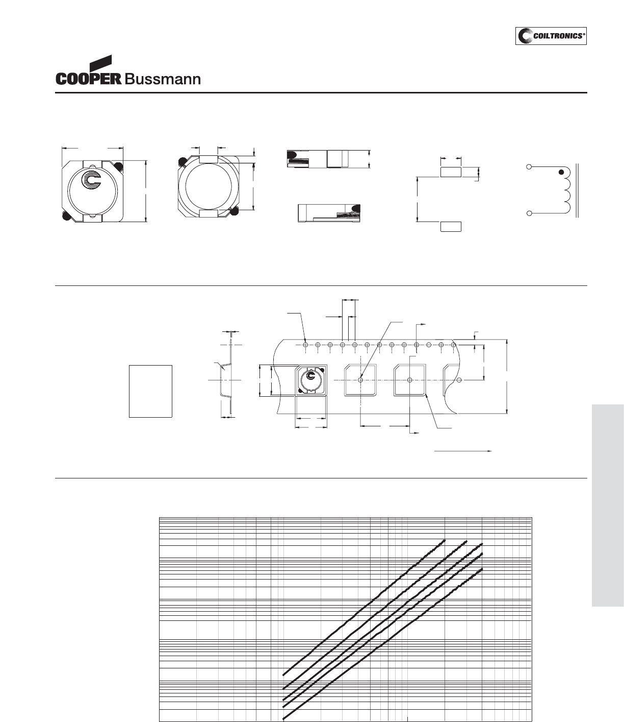
PM-57
SHIELDED DRUM (DR1030)
DR1030 Series
Low Profile Power Inductors
Core Loss
1MHz
500kHz 300kHz
200kHz
100kHz
0.0001
0.001
0.01
0.1
1
10
1 10 100 1000
Core Loss (W)
Bp-p (mT)
1MHz
500kHz 300kHz
200kHz
100kHz
0.0001
0.001
0.01
0.1
1
10
1 10 100 1000
Core Loss (W)
Bp-p (mT)
Dimensions are in millimeters.
2.0
Ko=3.2 mm
B1=10.7 mm
A1=10.5 mm
Bo=11.0 mm
Ao=10.8 mm
1.5 dia
+0.1/-0.0
Bo
Ko
SECTION A-A
0.35
+/-0.05
0.3Rad
max.
B1
wwlly R
XXX
A1
12.0
24.0
+/-0.3
1.5 dia
min
0.5 rad
typ
A
1.75
A
4.0
User direction of feed
Ao 16.0
Packaging Information
1
2
10.3 max.
10.5 max.
3.0 max.
3.0
1.2
7.7
XXX
wwlly R
3.3
1.6
7.3
1
2
RECOMMENDED PCB LAYOUT SCHEMATIC
TOP VIEW FRONT VIEW
BOTTOM VIEW
LEFT VIEW
XXX = Inductance in μH. R = decimal point. If no R is present third character = #of zeros.
wwlly = Date Code. R = Revision Level.
Mechanical Diagrams
Courtesy of Steven Engineering, Inc.-230 Ryan Way, South San Francisco, CA 94080-6370-Main Office: (650) 588-9200-Outside Local Area: (800) 258-9200-www.stevenengineering.com
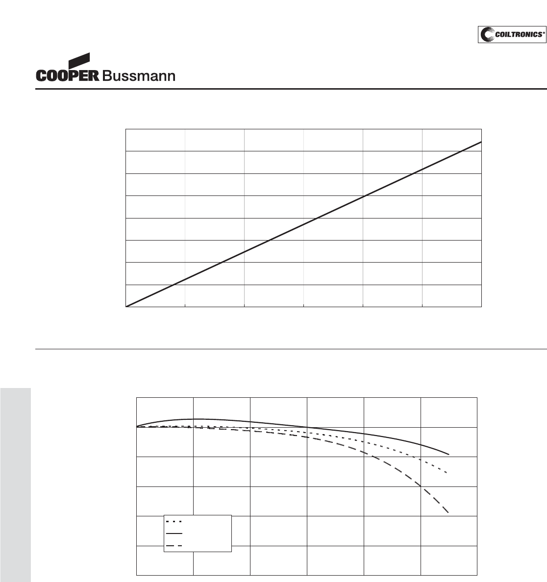
PM-58
SHIELDED DRUM (DR1030)
OCL vs. ISAT
0.0%
20.0%
40.0%
60.0%
80.0%
100.0%
120.0%
0.0% 20.0% 40.0% 60.0% 80.0% 100.0% 120.0%
%of ISAT
%ofOCL
-40 Deg. C
+25 Deg. C
+85 Deg. C
Inductance Characteristics
DR1030 Series
Low Profile Power Inductors
Temperature Rise vs. Total Loss
0
20
40
60
80
100
120
140
160
0.00 0.20 0.40 0.60 0.80 1.00 1.20
Total Loss (W)
Temperature Rise (°C)
Courtesy of Steven Engineering, Inc.-230 Ryan Way, South San Francisco, CA 94080-6370-Main Office: (650) 588-9200-Outside Local Area: (800) 258-9200-www.stevenengineering.com
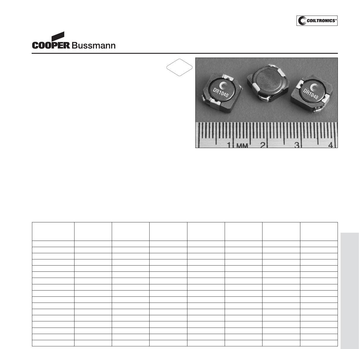
PM-59
SHIELDED DRUM (DR1040)
Description
• 125°C maximum total temperature operation
• Low profile surface mount inductor
• 10.3mm x 10.5mm x 4.0mm shielded drum core
• Ferrite core material
• Inductance range from 1.5μH to 330μH
• Current range from 10.0 Amps to 0.52 Amps
• Frequency range up to 1MHz
Applications
• Notebook power, Portable devices
• Wireless modems, ADSL line cards
• Point of load power supplies
• Battery chargers, Video Cards
• MP3 player, PDA’s, DVD players
• LED driver for notebook computer
• Navigation system, LCD backlighting
• Buck, Boost, or Forward inductor
Environmental Data
• Storage temperature range: -40°C to +125°C
• Operating temperature range: -40°C to +125°C
(range is application specific)
• Solder reflow temperature: +260°C max. for 10 seconds
maximum
Packaging
• Supplied in tape and reel packaging, 850 per reel
DR1040 Series
Low Profile Power Inductors
Part Number Rated OCL (1) Irms(2) Isat (3) DCR (Ω) DCR (Ω) K-factor
Inductance μH±30% Amperes Amperes mΩ@20°C mΩ@20°C (4)
(μH) (Typical) (Maximum)
DR1040-1R5-R 1.5 1.4 6.50 10.00 6.0 8.1 15.48
DR1040-2R5-R 2.5 2.4 6.10 7.80 7.0 9.0 12.04
DR1040-3R8-R 3.8 3.6 5.50 6.40 9.6 13.0 9.85
DR1040-5R2-R 5.2 5.2 5.40 5.50 14.0 17.0 8.33
DR1040-7R0-R 7.0 6.8 4.50 4.80 17.0 20.0 7.22
DR1040-8R2-R 8.2 8.1 3.98 4.60 24.0 29.0 6.37
DR1040-100-R 10 9.6 3.80 4.40 26.0 35.0 5.70
DR1040-150-R 15 14.9 3.10 3.60 37.0 50.0 4.71
DR1040-220-R 22 21.1 2.50 2.90 54.0 73.0 4.01
DR1040-330-R 33 32.6 2.20 2.45 69.0 93.0 3.28
DR1040-470-R 47 45.8 1.90 2.10 95.0 128 2.78
DR1040-680-R 68 65.3 1.42 1.65 152 183 2.30
DR1040-820-R 82 86.8 1.29 1.47 214 260 2.04
DR1040-101-R 100 101.4 1.25 1.35 225 304 1.90
DR1040-151-R 150 148.3 0.85 1.15 356 430 1.57
DR1040-221-R 220 216.2 0.70 0.92 530 640 1.27
DR1040-331-R 330 323.4 0.52 0.70 810 1090 1.03
(1) Open Circuit Inductance Test Parameters: 100kHz, 0.25V, 0.0Adc.
(2) Irms: DC current for an approximate ΔT of 30°C without core loss. Derating is
necessary for AC currents. PCB layout, trace thickness and width, air-flow, and
proximity of other heat generating components will affect the temperature rise.It
is recommended that the temperature of the part not exceed 125°C under worst
case operating conditions verified in the end application.
(3) Isat Amperes peak for approximately 35% rolloff (@25°C)
(4) K-factor: Used to determine B p-p for core loss (see graph).
B p-p = K*L*ΔI, B p-p(mT), K: (K factor from table), L: (Inductance in μH),
ΔI(Peak to peak ripple current in Amps).
(5) Part Number Definition: DR1040-xxx-R
DR1040 = Product code and size; -xxx = Inductance value in uH;
R = decimal point; If no R is present, third character = # of zeros.
-R suffix = RoHS compliant
RoHS
2002/95/EC
Courtesy of Steven Engineering, Inc.-230 Ryan Way, South San Francisco, CA 94080-6370-Main Office: (650) 588-9200-Outside Local Area: (800) 258-9200-www.stevenengineering.com
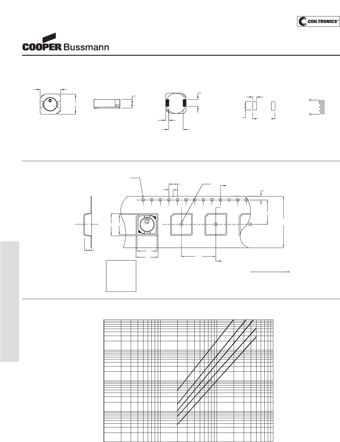
PM-60
SHIELDED DRUM (DR1040)
DR1040 Series
Low Profile Power Inductors
Core Loss
0. 001
0. 01
0. 1
1
10
1 10 100 1000
Bp-p (mT)
Core Loss (W)
100kHz
200kHz
300kHz
500kHz1MHz
B1
wwlly R
XXX
A1
12.0
24.0
+/-0.3
1.5 dia
min
A
1.75
A
4.0
User direction of feed
Ao 16.0
2.0
A1=10.6 mm
Bo=11.0 mm
Ao=10.8 mm
1.5 dia
+0.1/-0.0
Bo
Ko
SECTION A-A
Ko=4.2 mm
B1=10.5 mm Parts packaged on 13" Diameter reel,
850 parts per reel.
Packaging Information
Dimensions are in millimeters.
xxx = Inductance value in uH. R = decimal point. If no R is present third character = # of zeros. wwllyy = Date code, R = Revision level.
wwlly R
XXX
10.5 max
TOP VIEW
1 2 10.3 max
SIDE VIEW
4.0 max
BOTTOM VIEW
7.7
+/- 0.3
1.2 +/- 0.15
(2 Pcs)
1
3.0
+/- 0.1
2
RECOMMENDED PCB LAYOUT
3.2
2plcs 10.5 Ref
1.6
2plcs
SCHEMATI C
2
1
Mechanical Diagrams
Courtesy of Steven Engineering, Inc.-230 Ryan Way, South San Francisco, CA 94080-6370-Main Office: (650) 588-9200-Outside Local Area: (800) 258-9200-www.stevenengineering.com

PM-61
SHIELDED DRUM (DR1040)
60.0%
%ofOCL
120.0%
100.0%
80.0%
40.0%
20.0%
0.0%
0.0% 20.0% 40.0% 60.0% 80.0% 100.0% 120.0% 140.0% 160.0%
% of Isat
OCL vs. Isat
-40 Deg.C
+25 Deg.C
+85 Deg.C
Inductance Characteristics
DR1040 Series
Low Profile Power Inductors
Temperature Rise vs. Loss
0
20
40
60
80
100
120
0 0.2 0.4 0.6 0.8 1 1.2
Total Loss (W)
Temperature Rise(°C)
Courtesy of Steven Engineering, Inc.-230 Ryan Way, South San Francisco, CA 94080-6370-Main Office: (650) 588-9200-Outside Local Area: (800) 258-9200-www.stevenengineering.com
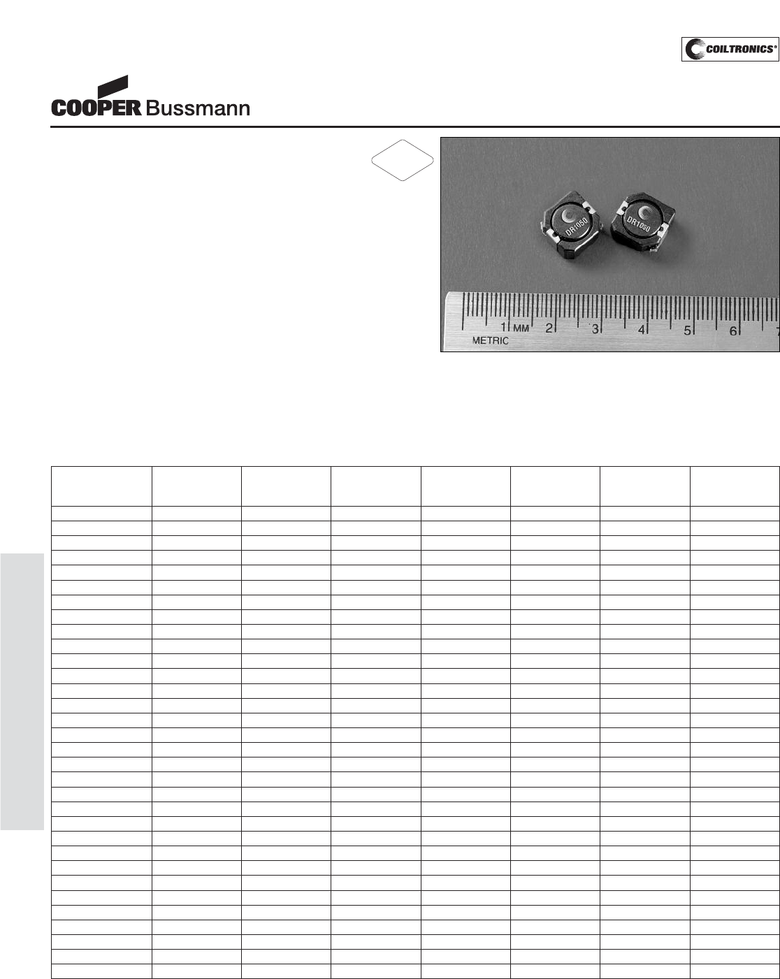
PM-62
SHIELDED DRUM (DR1050)
Description
• 125°C maximum total temperature operation
• Low profile surface mount inductor
• 10.3mm x 10.5mm x 5.0mm shielded drum core
• Ferrite core material
• Inductance range from 0.7μH to 1000μH
• Current range from 13.5 Amps to 0.43 Amps
• Frequency range up to 1MHz
Applications
• Computer, DVD players, and portable power devices
• Notebook power, LCD panels
• DC-DC converters
• Buck, boost, forward, and resonant converters
• Noise filtering and filter chokes
Environmental Data
• Storage temperature range: -40°C to +125°C
• Operating temperature range: -40°C to +125°C
(range is application specific)
• Solder reflow temperature: +260°C max. for 10 seconds
maximum
Packaging
• Supplied in tape and reel packaging, 500 per reel
DR1050 Series
Low Profile Power Inductors
Part Number Rated OCL (1) Irms(2) Isat (3) DCR (Ω) DCR (Ω) K-factor
Inductance μH±30% Amperes Amperes mΩ@20°C mΩ@20°C (4)
(μH) (Typical) (Maximum)
DR1050-R80-R 0.8 0.70 9.70 13.50 3.2 4.0 20.47
DR1050-1R5-R 1.5 1.37 8.60 10.50 4.0 5.0 14.62
DR1050-2R2-R 2.2 2.27 7.52 9.25 5.6 6.8 11.37
DR1050-3R3-R 3.3 3.21 6.50 8.20 8.0 10.0 9.30
DR1050-4R7-R 4.7 4.43 6.13 6.70 9.5 11.9 7.87
DR1050-6R8-R 6.8 6.30 5.45 5.80 13.0 16.5 6.82
DR1050-8R2-R 8.2 8.09 5.24 5.00 15.1 19.0 6.02
DR1050-100-R 10 10.1 4.80 4.58 18.0 22.5 5.39
DR1050-120-R 12 11.6 3.94 4.10 24.3 30.4 4.87
DR1050-150-R 15 14.8 3.80 3.70 26.0 32.5 4.45
DR1050-180-R 18 17.5 3.39 3.30 32.8 41.0 4.09
DR1050-220-R 22 23.5 3.12 3.00 38.7 48.4 3.53
DR1050-270-R 27 26.9 2.82 2.80 42.6 53.3 3.30
DR1050-330-R 33 34.3 2.56 2.50 57.5 71.9 2.92
DR1050-390-R 39 38.3 2.35 2.35 60.7 75.9 2.77
DR1050-470-R 47 47.1 2.06 2.10 89.0 111 2.50
DR1050-560-R 56 56.7 1.96 1.94 98.0 123 2.27
DR1050-680-R 68 67.2 1.84 1.70 111 139 2.09
DR1050-820-R 82 84.4 1.60 1.58 147 184 1.86
DR1050-101-R 100 97.5 1.52 1.45 164 205 1.73
DR1050-121-R 120 118.3 1.30 1.30 223 279 1.57
DR1050-151-R 150 149.2 1.26 1.15 238 298 1.40
DR1050-181-R 180 183.7 1.18 1.08 273 341 1.26
DR1050-221-R 220 221.8 1.00 0.98 377 472 1.15
DR1050-271-R 270 263.5 0.96 0.90 410 513 1.06
DR1050-331-R 330 320.6 0.83 0.80 554 693 0.96
DR1050-391-R 390 396.5 0.76 0.72 648 810 0.86
DR1050-471-R 470 480.5 0.64 0.62 855 1069 0.78
DR1050-561-R 560 572.6 0.62 0.60 970 1213 0.72
DR1050-681-R 680 707.9 0.56 0.55 1095 1369 0.64
DR1050-821-R 820 818.7 0.54 0.50 1185 1481 0.60
DR1050-102-R 1000 1000.2 0.43 0.48 1528 1950 0.54
(1) Open Circuit Inductance Test Parameters: 100kHz, 0.1V, 0.0Adc.
(2) Irms: DC current for an approximate ΔT of 40°C without core loss. Derating is
necessary for AC currents. PCB layout, trace thickness and width, air-flow, and
proximity of other heat generating components will affect the temperature rise. It
is recommended that the temperature of the part not exceed 125°C under worst
case operating conditions verified in the end application.
(3) Isat Amperes peak for approximately 35% rolloff (@25°C)
(4) K-factor: Used to determine B p-p for core loss (see graph).
B p-p = K*L*ΔI, B p-p(mT), K: (K factor from table), L: (Inductance in μH),
ΔI (Peak to peak ripple current in Amps).
(5) Part Number Definition: DR1050-xxx-R
DR1050 = Product code and size; -xxx = Inductance value in uH;
R = decimal point; If no R is present, third character = # of zeros.
-R suffix = RoHS compliant
RoHS
2002/95/EC
Courtesy of Steven Engineering, Inc.-230 Ryan Way, South San Francisco, CA 94080-6370-Main Office: (650) 588-9200-Outside Local Area: (800) 258-9200-www.stevenengineering.com
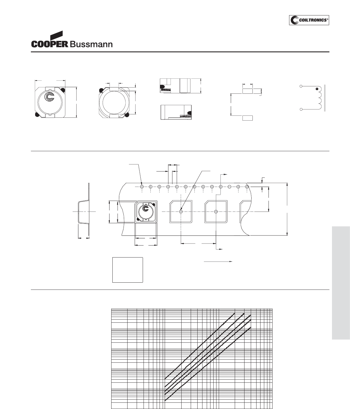
PM-63
SHIELDED DRUM (DR1050)
DR1050 Series
Low Profile Power Inductors
Core Loss
100kHz
200kHz
300kHz
500kHz
0. 0001
0. 001
0. 01
0. 1
1
10
1 10 100 1000
Core Loss (W)
Bp-p (mT)
z
z
z
z
1MH z
2.0
Ko=5.3 mm
B1=10.7 mm
A1=10.5 mm
Bo=11.0 mm
Ao=10.8 mm
1.5 dia
+0.1/-0.0
Bo
Ko
SECTION A-A
B1
wwlly R
XXX
A1
12.0
24.0
+/-0.3
1.5 dia
min
A
1.75
A
4.0
User direction of feed
Ao 16.0
Parts packaged on 13" Diameter reel,
500 parts per reel.
Packaging Information
Dimensions are in millimeters.
xxx = Inductance value in uH. R = decimal point. If no R is present third character = # of zeros. wwllyy = Date code, R = Revision level.
TOP VIEW FRONT VIEW
BOTTOM VIEW
LEFT VIEW
10.3 max.
10.5 max.
5.0 max.
3.0
7.7
XXX
wwlly R
1
2
RECOMMENDED PCB LAYOUT SCHEMATI C
1
2
3.3
7.3
1.6
1.2
Mechanical Diagrams
Courtesy of Steven Engineering, Inc.-230 Ryan Way, South San Francisco, CA 94080-6370-Main Office: (650) 588-9200-Outside Local Area: (800) 258-9200-www.stevenengineering.com
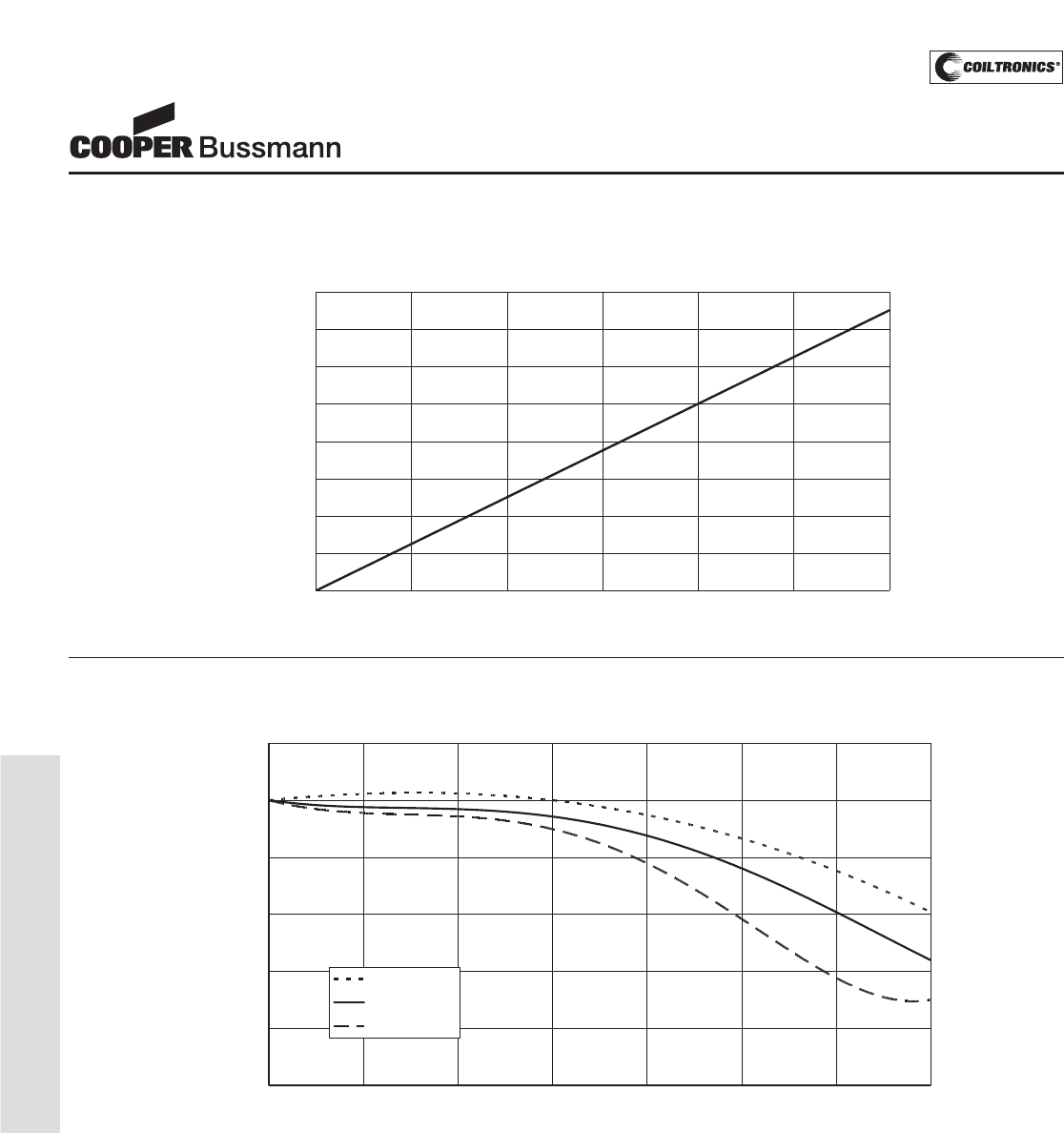
PM-64
SHIELDED DRUM (DR1050)
OCL vs. ISAT
0.0%
20.0%
40.0%
60.0%
80.0%
100.0%
120.0%
0% 20% 40% 60% 80% 100% 120% 140%
% of ISAT
%ofOCL
-40 Deg. C
+25 Deg. C
+85 Deg. C
Inductance Characteristics
DR1050 Series
Low Profile Power Inductors
Temperature Rise vs. Loss
Temperature Rise vs. Total Loss
0.00
20.00
40.00
60.00
80.00
100.00
120.00
140.00
160.00
0.00 0.20 0.40 0.60 0.80 1.00 1.20
Total Loss (W)
Temperature Rise (°C)
Courtesy of Steven Engineering, Inc.-230 Ryan Way, South San Francisco, CA 94080-6370-Main Office: (650) 588-9200-Outside Local Area: (800) 258-9200-www.stevenengineering.com
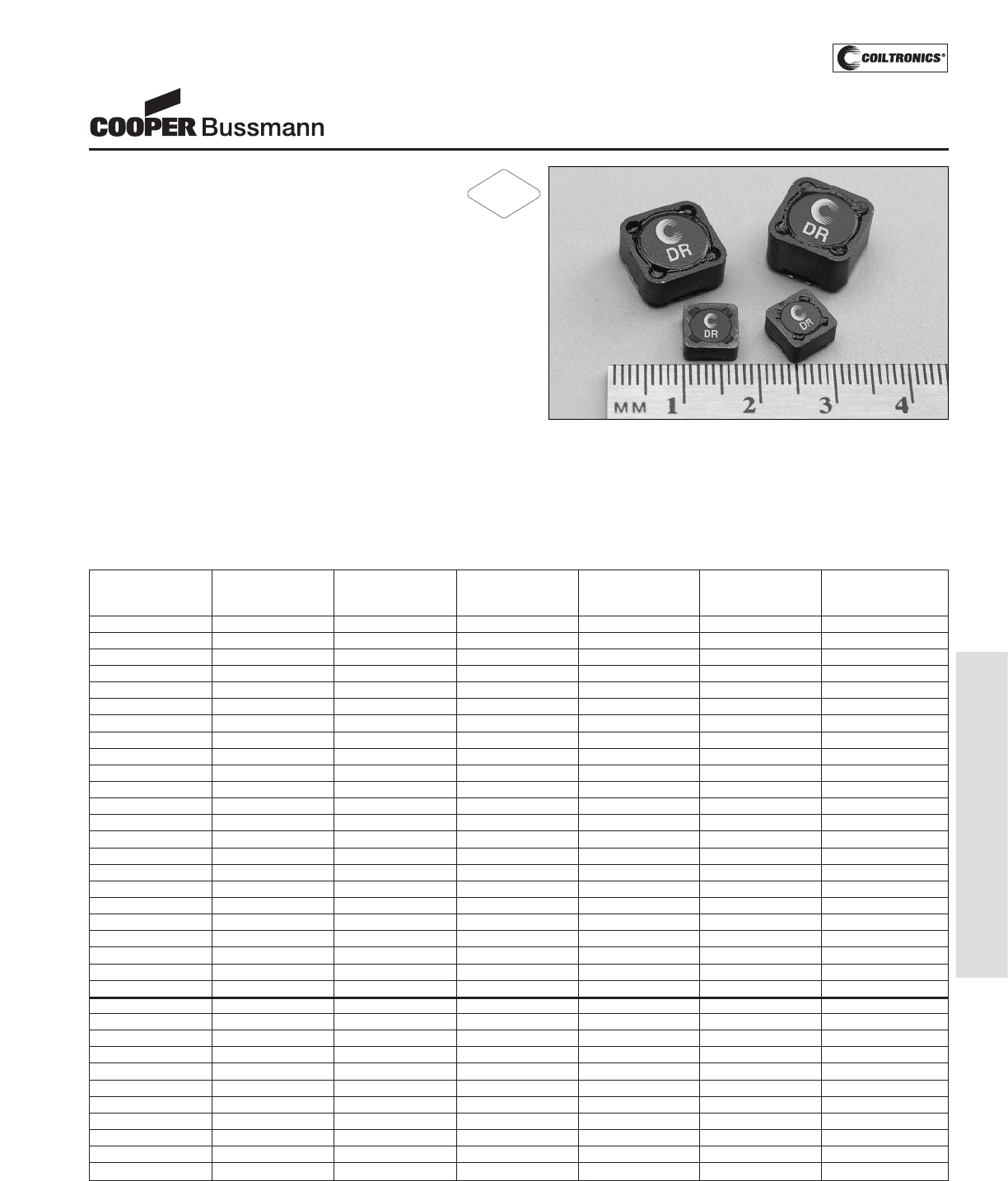
PM-65
SHIELDED DRUM (DR)
Description
• 125°C maximum total temperature operation
• Four sizes of shielded drum core inductors
• Inductance range from 0.33uH to 1000uH
• Current range up to 56 Amps peak
• Magnetic shielding
• Secure mounting
• Ferrite core material
Applications
• Computer, DVD players, and portable power devices
• LCD panels
• DC-DC converters
• Buck, boost, forward, and resonant converters
• Noise filtering and filter chokes
Environmental Data
• Storage temperature range: -40°C to +125°C
• Operating ambient temperature range: -40°C to +125°C
(range is application specific)
• Solder reflow temperature: +260°C max. for 10 seconds
max.
Packaging
• Supplied in tape and reel packaging, 1350 (DR73),
1100 (DR74), 600 (DR125), and 350 (DR127) per reel
DR Series
High Power Density,
High Efficiency, Shielded Inductors
(1) Open Circuit Inductance Test Parameters: 100KHz, 0.25Vrms, 0.0Adc.
(2) RMS current for an approximate ΔT of 40°C without core loss. It is recommend-
ed that the temperature of the part not exceed 125°C.
(3) Peak current for approximate 30% roll off at 20°C.
(4) DCR limits @ 20°C.
(5) Applied Volt-Time product (V-μS) across the inductor. This value represent the
applied V-μS at 100KHz necessary to generate a core loss equal to 10% of the
total losses for 40°C temperature rise.
Part Number Rated OCL(1) Irms(2) Isat(3) DCR(4) Volt-uSec(5)
Inductance +/-20% Amperes Amperes (Ω) Typ.
(μH) (μH) Peak Typ.
DR73-R33-R 0.33 0.306 6.21 14.4 0.0073 1.98
DR73-1R0-R 1.00 0.992 5.28 7.97 0.0102 3.56
DR73-1R5-R 1.50 1.482 4.67 6.52 0.0130 4.36
DR73-2R2-R 2.20 2.070 4.15 5.52 0.0165 5.15
DR73-3R3-R 3.30 3.540 3.31 4.22 0.0259 6.73
DR73-4R7-R 4.70 4.422 3.09 3.78 0.0297 7.52
DR73-6R8-R 6.80 6.480 2.55 3.12 0.0435 9.11
DR73-8R2-R 8.20 8.930 2.19 2.66 0.0592 10.7
DR73-100-R 10.0 10.30 2.08 2.47 0.0656 11.5
DR73-150-R 15.0 15.01 1.83 2.05 0.0844 13.9
DR73-220-R 22.0 22.65 1.62 1.67 0.107 17.0
DR73-330-R 33.0 34.41 1.31 1.35 0.166 21.0
DR73-470-R 47.0 48.62 1.08 1.14 0.241 24.9
DR73-680-R 68.0 68.91 0.89 0.96 0.358 29.7
DR73-820-R 82.0 80.37 0.86 0.89 0.384 32.1
DR73-101-R 100 101.4 0.73 0.79 0.527 36.0
DR73-151-R 150 150.9 0.58 0.65 0.851 44.0
DR73-221-R 220 223.3 0.52 0.53 1.05 53.5
DR73-331-R 330 325.5 0.42 0.44 1.59 64.5
DR73-471-R 470 465.8 0.35 0.37 2.36 77.2
DR73-681-R 680 676.5 0.29 0.31 3.47 93.1
DR73-821-R 820 821.7 0.27 0.28 3.93 103
DR73-102-R 1000 995.0 0.26 0.25 4.34 113
DR74-R33-R 0.33 0.294 6.26 18.4 0.0074 1.71
DR74-1R0-R 1.00 0.952 5.39 10.2 0.0099 3.08
DR74-1R5-R 1.50 1.422 4.94 8.35 0.0118 3.76
DR74-2R2-R 2.20 1.986 4.76 7.06 0.0126 4.45
DR74-3R3-R 3.30 3.396 3.94 5.40 0.0183 5.81
DR74-4R7-R 4.70 5.182 3.34 4.37 0.0254 7.18
DR74-6R8-R 6.80 7.344 2.60 3.67 0.0418 8.55
DR74-8R2-R 8.20 8.566 2.53 3.40 0.0441 9.23
DR74-100-R 10.0 9.882 2.41 3.17 0.0489 9.92
DR74-150-R 15.0 16.09 2.11 2.48 0.0637 12.7
DR74-220-R 22.0 21.73 1.75 2.13 0.0925 14.7
RoHS
2002/95/EC
Courtesy of Steven Engineering, Inc.-230 Ryan Way, South San Francisco, CA 94080-6370-Main Office: (650) 588-9200-Outside Local Area: (800) 258-9200-www.stevenengineering.com
PM-66
SHIELDED DRUM (DR)
(1) Open Circuit Inductance Test Parameters: 100KHz, 0.25Vrms, 0.0Adc.
(2) RMS current for an approximate ΔT of 40°C without core loss. It is recommend-
ed that the temperature of the part not exceed 125°C.
(3) Peak current for approximate 30% roll off at 20°C.
(4) DCR limits @ 20°C.
(5) Applied Volt-Time product (V-μS) across the inductor. This value represent the
applied V-μS at 100KHz necessary to generate a core loss equal to 10% of the
total losses for 40°C temperature rise.
Part Number Rated OCL(1) Irms(2) Isat(3) DCR(4) Volt-uSec(5)
Inductance +/-20% Amperes Amperes (Ω) Typ.
(μH) (μH) Peak Typ.
DR74-330-R 33.0 33.01 1.41 1.73 0.143 18.1
DR74-470-R 47.0 49.64 1.15 1.41 0.216 22.2
DR74-680-R 68.0 69.67 1.03 1.19 0.265 26.3
DR74-820-R 82.0 80.95 0.91 1.11 0.345 28.4
DR74-101-R 100 101.6 0.86 0.99 0.383 31.8
DR74-151-R 150 150.0 0.69 0.81 0.591 38.6
DR74-221-R 220 227.0 0.56 0.66 0.907 47.5
DR74-331-R 330 335.6 0.45 0.54 1.41 57.8
DR74-471-R 470 465.3 0.40 0.46 1.74 68.1
DR74-681-R 680 671.2 0.33 0.38 2.58 81.7
DR74-821-R 820 812.7 0.31 0.35 2.93 89.9
DR74-102-R 1000 1009 0.27 0.31 3.89 100
DR125-R47-R 0.47 0.456 17.6 33.0 0.0018 3.17
DR125-1R0-R 1.00 0.894 15.0 23.6 0.0024 4.43
DR125-1R5-R 1.50 1.478 13.8 18.3 0.0029 5.70
DR125-2R2-R 2.20 2.208 10.9 15.0 0.0045 6.97
DR125-3R3-R 3.30 3.084 9.26 12.7 0.0063 8.23
DR125-4R7-R 4.70 5.274 7.18 9.71 0.0105 10.8
DR125-6R8-R 6.80 6.588 6.64 8.68 0.0123 12.0
DR125-8R2-R 8.20 8.048 5.54 7.86 0.0176 13.3
DR125-100-R 10.0 9.654 5.35 7.17 0.0189 14.6
DR125-150-R 15.0 15.35 4.27 5.69 0.0298 18.4
DR125-220-R 22.0 22.36 3.70 4.71 0.0396 22.2
DR125-330-R 33.0 33.74 3.28 3.84 0.0505 27.2
DR125-470-R 47.0 47.47 2.71 3.24 0.0740 32.3
DR125-680-R 68.0 67.91 2.22 2.70 0.101 38.6
DR125-820-R 82.0 86.89 2.05 2.39 0.128 43.7
DR125-101-R 100 102.7 1.78 2.20 0.170 47.5
DR125-151-R 150 151.1 1.48 1.81 0.248 57.6
DR125-221-R 220 216.8 1.19 1.51 0.384 69.0
DR125-331-R 330 332.6 1.06 1.22 0.482 85.5
DR125-471-R 470 473.1 0.87 1.02 0.718 102
DR125-681-R 680 679.8 0.70 0.85 1.10 122
DR125-821-R 820 828.0 0.60 0.77 1.49 135
DR125-102-R 1000 1008 0.57 0.70 1.69 149
DR125-124-R 120000 120630 0.060 0.069 150 1521
DR127-R47-R 0.47 0.419 17.9 56.0 0.00195 3.50
DR127-1R0-R 1.00 0.821 15.5 40.0 0.00313 4.90
DR127-1R5-R 1.50 1.357 13.5 31.1 0.00341 6.30
DR127-2R2-R 2.20 2.027 12.5 25.5 0.00402 7.70
DR127-3R3-R 3.30 2.831 10.5 21.5 0.00567 9.10
DR127-4R7-R 4.70 4.841 8.25 16.5 0.00917 11.9
DR127-6R8-R 6.80 7.387 7.34 13.3 0.0116 14.7
DR127-8R2-R 8.20 8.861 6.32 12.2 0.0157 16.1
DR127-100-R 10.0 10.47 6.04 11.2 0.0172 17.5
DR127-150-R 15.0 14.09 5.03 9.66 0.0247 20.3
DR127-220-R 22.0 22.93 4.00 7.57 0.0391 25.9
DR127-330-R 33.0 33.92 3.23 6.22 0.0600 31.5
DR127-470-R 47.0 47.05 2.95 5.28 0.0719 37.1
DR127-680-R 68.0 66.48 2.44 4.44 0.105 44.1
DR127-820-R 82.0 79.75 2.09 4.06 0.143 48.3
DR127-101-R 100 99.31 1.96 3.64 0.163 53.9
DR127-151-R 150 144.9 1.59 3.01 0.247 65.1
DR127-221-R 220 221.5 1.29 2.43 0.376 80.5
DR127-331-R 330 323.6 1.04 2.01 0.574 97.3
DR127-471-R 470 467.1 0.85 1.68 0.861 117
DR127-681-R 680 676.7 0.76 1.39 1.08 141
DR127-821-R 820 818.1 0.65 1.27 1.47 155
DR127-102-R 1000 1005 0.61 1.14 1.66 172
DR Series
High Power Density,
High Efficiency, Shielded Inductors
Courtesy of Steven Engineering, Inc.-230 Ryan Way, South San Francisco, CA 94080-6370-Main Office: (650) 588-9200-Outside Local Area: (800) 258-9200-www.stevenengineering.com
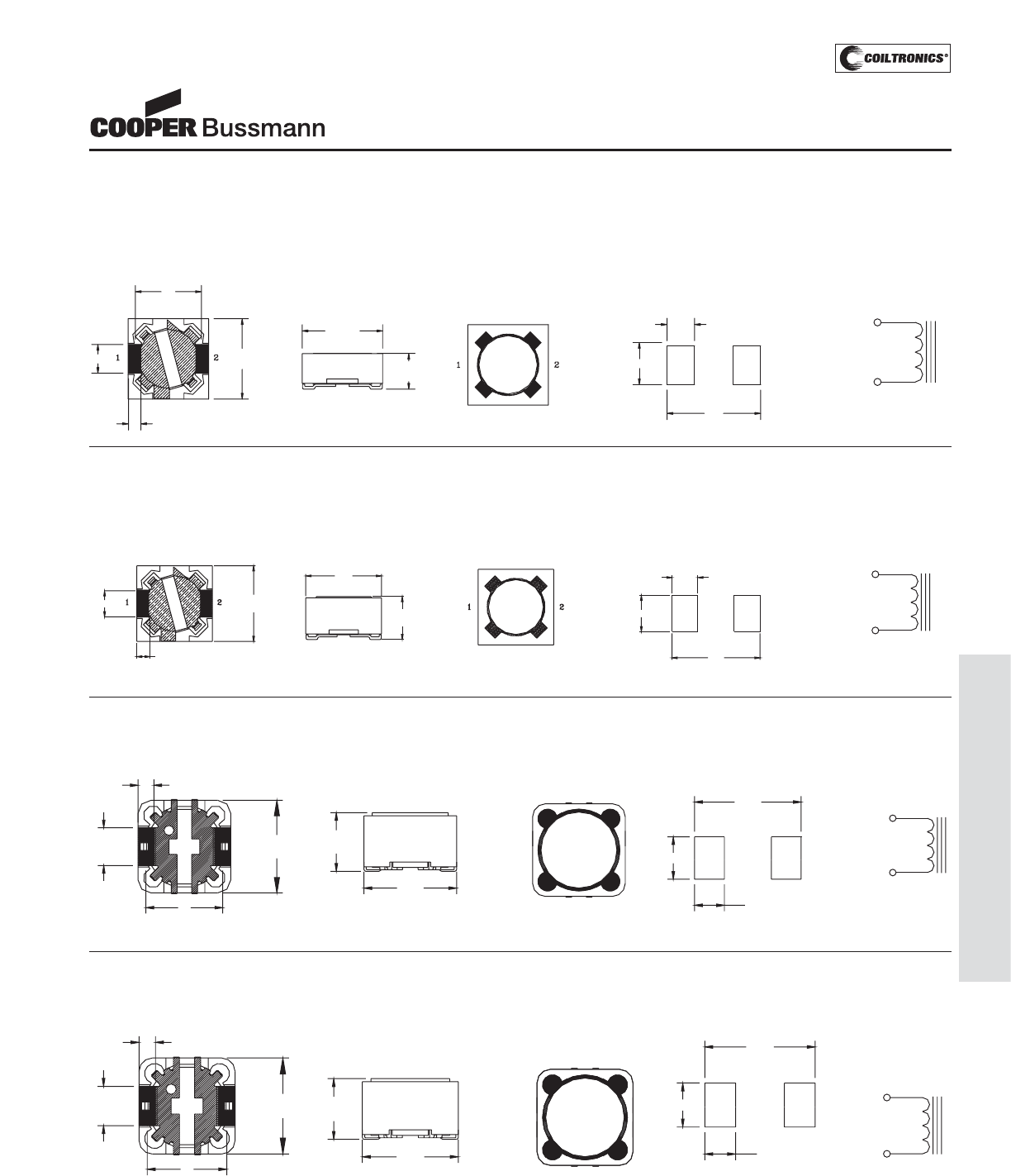
PM-67
SHIELDED DRUM (DR)
DR127-###
wwllyy R
12
2
1
8.00
Max
10
12.50
Max
4.90
Typ
2.05
Typ.
112.50
Max
2
BOTTOM VIEW
TOP VIEW SCHEMATIC
5.50
3.85
13.80
RECOMMENDED PCB LAYOUT
FRONT VIEW
21
12.50
Max
6.00
Max DR125-###
wwllyy R
10
4.90
Typ
2.05
Typ.
112.50
Max
2
2
1
5.50
3.85
13.80
RECOMMENDED PCB LAYOUT SCHEMATIC
TOP VIEW
FRONT VIEW
BOTTOM VIEW
4.35
Max
FRONT VIEW
1.13
2.0 7.6
Max
7.6
Max
BOTTOM VIEW
DR74
###
TOP VIEW
8.50
RECOMMENDED PCB LAYOUT
2.50
3.25
SCHEMATIC
2
1
Mechanical Diagrams
DR73 Series
BOTTOM VIEW
1.13
6.0
2.0 7.6
Max
7.6 Max
FRONT VIEW
3.55
Max
8.50
RECOMMENDED PCB LAYOUT
DR73
###
TOP VIEW
2.50
3.25
SCHEMATIC
2
1
DR74 Series
DR125 Series
DR127 Series
Dimensions in Millimeters. ### = Inductance value per family chart
wwllyy = (date code) R = revision level
DR Series
High Power Density,
High Efficiency, Shielded Inductors
Courtesy of Steven Engineering, Inc.-230 Ryan Way, South San Francisco, CA 94080-6370-Main Office: (650) 588-9200-Outside Local Area: (800) 258-9200-www.stevenengineering.com
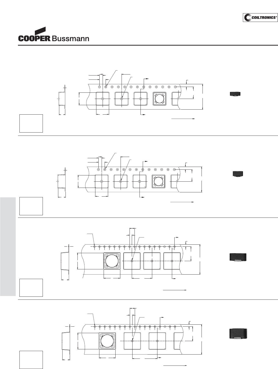
PM-68
SHIELDED DRUM (DR)
A
A
SECTION A-A
Ko
Bo
2.00 ±0.1
4.00
Ø1.50 +0.1/-0.0
Ao
16.00
±0.3
7.50±0.1
1.75±0.10
Ø1.50 Min.
12.00
DR74
xxy
User direction of feed
1
2
DR74 Series
1
2
A
A
SECTION A-A
DR125-###
wwllyy R
K0
1.5 dia
+0.1/-0.0 1.5 dia
min
4.0
2.0
16.00
1.7
11.5
24.0
+/-0.3
User direction of feed
B0
A0
DR125 Series
1
2
A
A
DR127-###
wwllyy R
SECTION A-A
K0
1.5 dia
+0.1/-0.0 1.5 dia
min
4.0
2.0
20.00
1.7
11.5
24.0
+/-0.3
User direction of feed
B0
A0
DR127 Series
Packaging Information
A
A
SECTION A-A
Ko
Bo
2.00 ±0.1
4.00
Ø1.50 +0.1/-0.0
Ao
16.00
±0.3
7.50±0.1
1.75±0.10
Ø1.50 Min.
12.00
DR73
xxy
User direction of feed
1
2
DR73 Series
Dimensions are in millimeters.
ACTUAL SIZE
DR73
ACTUAL SIZE
DR74
ACTUAL SIZE
DR125
ACTUAL SIZE
DR127
DR Series
High Power Density,
High Efficiency, Shielded Inductors
Ao=7.90mm
Bo=7.90mm
Ko=3.80mm Parts packaged on 13" Diameter reel,
1,350 parts per reel.
Ao=7.90mm
Bo=7.90mm
Ko=4.70mm Parts packaged on 13" Diameter reel,
1,100 parts per reel.
Ao=13.0mm
Bo=13.0mm
Ko=6.30mm Parts packaged on 13" Diameter reel,
600 parts per reel.
Ao=13.0mm
Bo=13.0mm
Ko=8.30mm Parts packaged on 13" Diameter reel,
350 parts per reel.
Courtesy of Steven Engineering, Inc.-230 Ryan Way, South San Francisco, CA 94080-6370-Main Office: (650) 588-9200-Outside Local Area: (800) 258-9200-www.stevenengineering.com
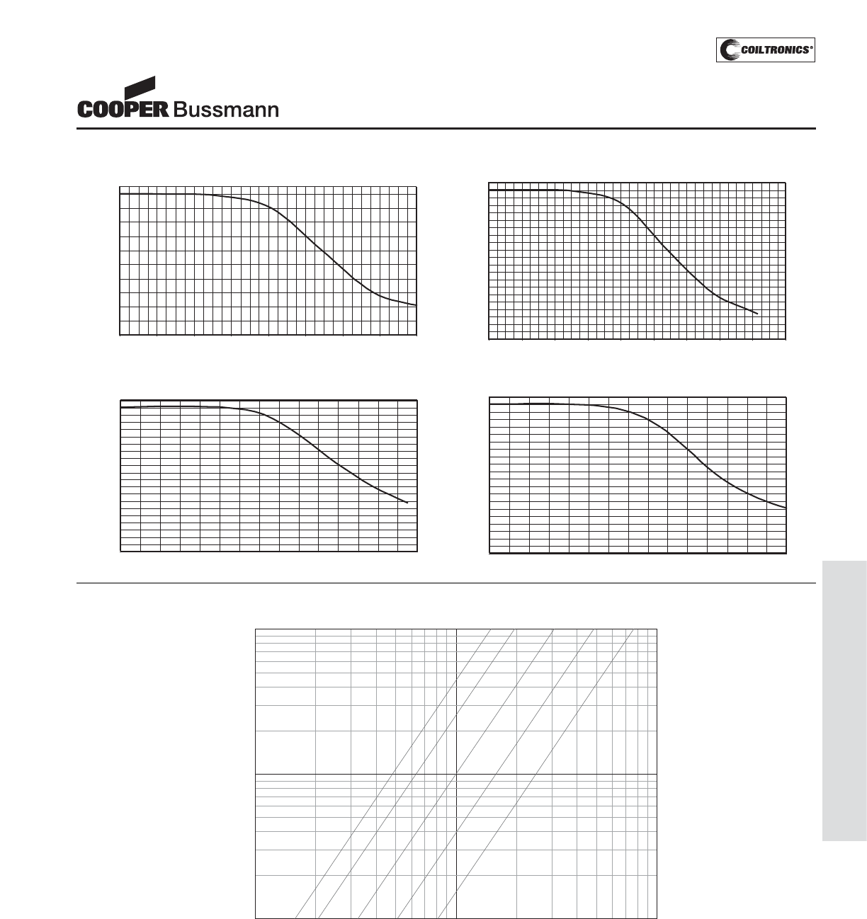
PM-69
SHIELDED DRUM (DR)
OCL vs Isat DR73
0
10
20
30
40
50
60
70
80
90
100
0 20 40 60 80 100 120 140 160
% of Isat
OCL (%)
OCL vs Isat DR74
0
20
40
60
80
100
0 20 40 60 80 100 120 140 160 180
% of Isat
OCL (%)
OCL vs Isat DR125
0
10
20
30
40
50
60
70
80
90
100
0 10 20 30 40 50 60 70 80 90 100 110 120 130 140 150
% of Isat
OCL (%)
OCL vs Isat DR127
0
10
20
30
40
50
60
70
80
90
100
0 10 20 30 40 50 60 70 80 90 100 110 120 130 140 150
% Idc sat
OCL (%)
10 100 1000
99
90
0
% of Applied Volt-μSecond
% of Losses from Irms (maximum)
300 KHz
200 KHz
100 KHz
50 KHz
25 KHz
Irms DERATING WITH CORE LOSS
92
94
96
98
70
50
30
10
80
97
95
60
8060403020 200 300 400 600 800
Inductance Characteristics
Core Loss
DR Series
High Power Density,
High Efficiency, Shielded Inductors
Courtesy of Steven Engineering, Inc.-230 Ryan Way, South San Francisco, CA 94080-6370-Main Office: (650) 588-9200-Outside Local Area: (800) 258-9200-www.stevenengineering.com
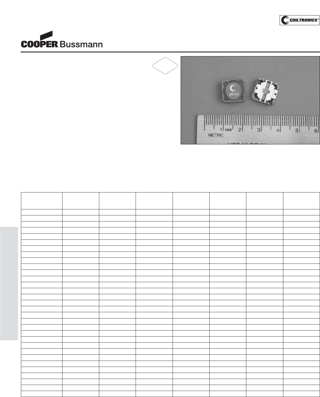
PM-70
SHIELDED DRUM (DR124)
Description
• 125°C maximum total temperature operation
• Low profile surface mount inductor
• 12.3mm x 12.3mm x 4.5mm shielded drum core
• Ferrite core material
• Inductance range from 0.47μH to 1000μH
• Current range from 24.4 Amps to 0.44 Amps
• Frequency range up to 1MHz
Applications
• Notebook power, LCD panels
• Computer, DVD players, and portable power devices
• DC-DC converters
• Buck, boost, forward, and resonant converters
• Noise filtering and filter chokes
Environmental Data
• Storage temperature range: -40°C to +125°C
• Operating temperature range: -40°C to +125°C
(range is application specific)
• Solder reflow temperature: +260°C max. for 10 seconds
maximum
Packaging
• Supplied in tape and reel packaging, 750 per reel
DR124 Series
Low Profile Power Inductors
Part Number Rated OCL (1) Irms(2) Isat (3) DCR (Ω) DCR (Ω) K-factor
Inductance μH±20% Amperes Amperes mΩ@20°C mΩ@20°C (4)
(μH) (Typical) (Maximum)
DR124-R47-R 0.47 0.42 16.0 24.40 2.2 2.7 17.51
DR124-1R0-R 1.0 0.83 13.9 18.00 3.00 3.6 12.50
DR124-1R5-R 1.5 1.37 11.1 14.00 4.75 5.7 9.73
DR124-2R2-R 2.2 2.04 9.1 11.45 5.92 7.1 7.96
DR124-3R9-R 3.9 3.80 7.0 8.40 12.50 15.0 5.84
DR124-4R7-R 4.7 4.88 6.5 7.65 13.50 16.2 5.15
DR124-6R8-R 6.8 6.10 5.6 6.47 18.06 21.7 4.61
DR124-8R2-R 8.2 7.45 5.2 6.22 21.67 26.0 4.17
DR124-100-R 10 8.94 4.5 5.80 23.33 28.0 3.81
DR124-120-R 12 11.5 4.1 4.96 31.67 38.0 3.50
DR124-150-R 15 14.2 3.6 4.62 37.30 44.8 3.02
DR124-180-R 18 16.2 3.4 4.32 46.97 56.4 2.82
DR124-220-R 22 20.7 3.2 3.83 53.99 64.8 2.50
DR124-270-R 27 25.7 2.8 3.44 66.67 80.0 2.24
DR124-330-R 33 31.2 2.6 3.12 80.83 97.0 2.04
DR124-390-R 39 37.3 2.3 2.85 110.00 132.0 1.86
DR124-470-R 47 44.0 2.2 2.63 124.66 149.6 1.72
DR124-560-R 56 54.9 2.0 2.35 144.32 173.2 1.54
DR124-680-R 68 67.1 1.8 2.13 183.33 220.0 1.39
DR124-820-R 82 80.5 1.7 1.94 212.72 255.3 1.27
DR124-101-R 100 95.1 1.5 1.79 256.67 308.0 1.17
DR124-121-R 120 111 1.3 1.65 311.18 373.4 1.08
DR124-151-R 150 146 1.3 1.44 371.02 445.2 0.94
DR124-181-R 180 179 1.1 1.30 501.66 602.0 0.87
DR124-221-R 220 216 1.0 1.15 558.00 669.6 0.77
DR124-271-R 270 256 0.88 1.09 725.00 870.0 0.71
DR124-331-R 330 327 0.83 0.92 825.00 990.0 0.63
DR124-471-R 470 460 0.68 0.74 1242.50 1491.0 0.53
DR124-681-R 680 669 0.56 0.65 1845.83 2215.0 0.45
DR124-821-R 820 825 0.53 0.62 2109.17 2351.0 0.40
DR124-102-R 1000 998 0.44 0.53 2898.00 3477.00 0.37
(1) Open Circuit Inductance Test Parameters: 100kHz, 0.25V, 0.0Adc.
(2) Irms: DC current for an approximate ΔT of 40°C without core loss. Derating is
necessary for AC currents. PCB layout, trace thickness and width, air-flow, and
proximity of other heat generating components will affect the temperature rise. It
is recommended that the temperature of the part not exceed 125°C under worst
case operating conditions verified in the end application.
(3) Isat Amperes peak for approximately 25% rolloff (@25°C)
(4) K-factor: Used to determine B p-p for core loss (see graph).
B p-p = K*L*ΔI, B p-p(mT), K: (K factor from table), L: (Inductance in μH),
ΔI (Peak to peak ripple current in Amps).
(5) Part Number Definition: DR124-xxx-R
DR124 = Product code and size; -xxx = Inductance value in uH;
R = decimal point; If no R is present, third character = # of zeros.
-R suffix = RoHS compliant
RoHS
2002/95/EC
Courtesy of Steven Engineering, Inc.-230 Ryan Way, South San Francisco, CA 94080-6370-Main Office: (650) 588-9200-Outside Local Area: (800) 258-9200-www.stevenengineering.com
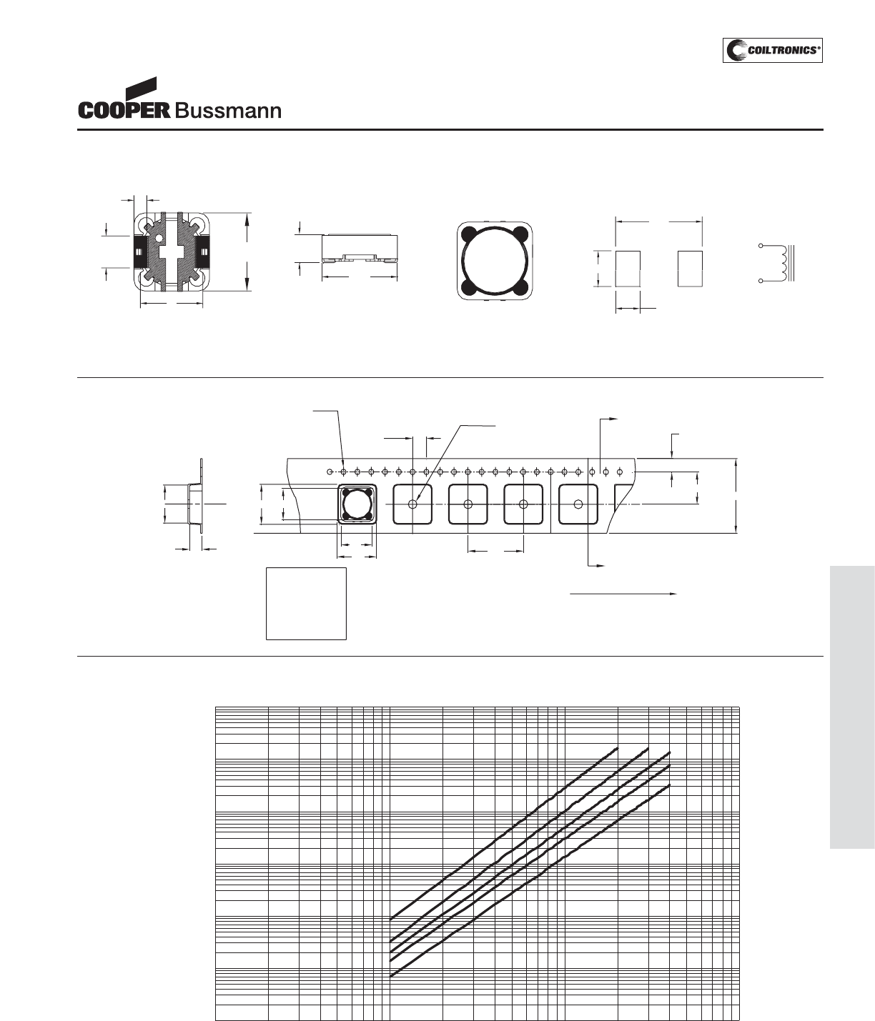
PM-71
SHIELDED DRUM (DR124)
DR124 Series
Low Profile Power Inductors
Core Loss
1MHz
100kHz
200kHz
300kHz
500kHz
0.0001
0.001
0.01
0.1
1
10
100
1 10 100 1000
Bp- p ( m T)
Core Loss (W)
11
DR124-###
wwllyy R
4.0
Ko=5.2 mm
B1=10 mm
A1=10mm
Bo=13.2 mm
Ao=13.2 mm
Bo
Ko
SECTION A-A
B1
1.5 dia
+0.1/-0.0 1.5 dia
min
A
1.75
A
User direction of feed
24.0
Ao
A1
12.6
16.0
Parts packaged on 13" Diameter reel,
750 parts per reel.
Packaging Information
Dimensions are in millimeters.
wwlly = Date code, R = Revision level.
12.30
Max
4.5
Max 21
DR124-###
wwllyy R
10
SCHEMATIC
2
BOTTOM VIEW
5.00
Typ
2.05
Typ.
112.30
Max
2
FRONT VIEW TOP VIEW
5.50
2.65
1
12.9
RECOMMENDED PCB LAYOUT
Mechanical Diagrams
Courtesy of Steven Engineering, Inc.-230 Ryan Way, South San Francisco, CA 94080-6370-Main Office: (650) 588-9200-Outside Local Area: (800) 258-9200-www.stevenengineering.com
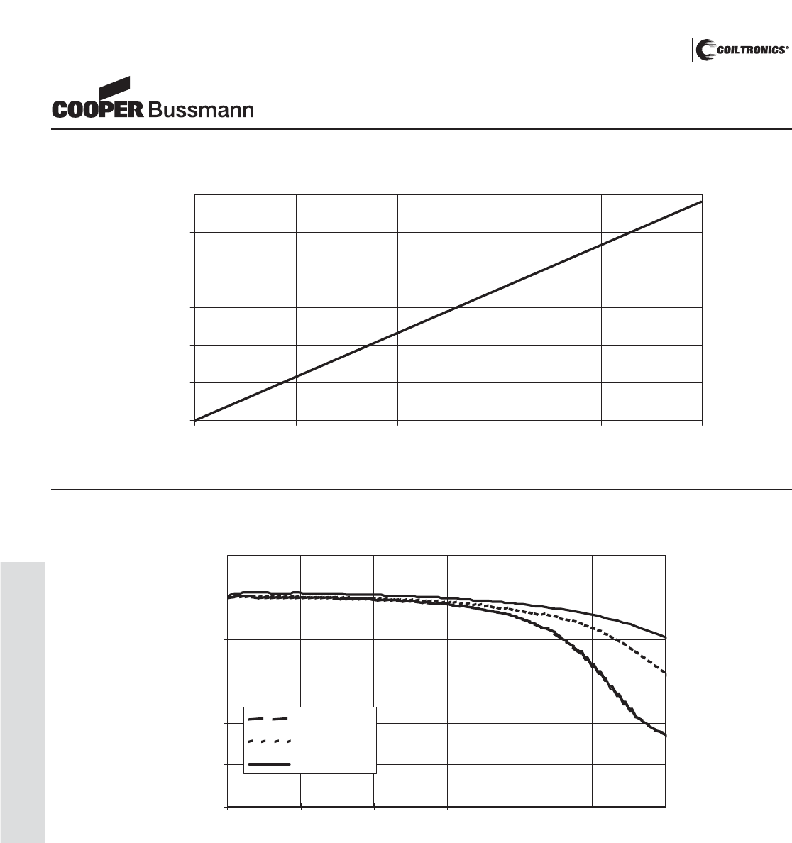
PM-72
SHIELDED DRUM (DR124)
OCL Vs . Is at
0.0%
20.0%
40.0%
60.0%
80.0%
100.0%
120.0%
0.0% 20.0% 40.0% 60.0% 80.0% 100.0% 120.0%
%Isat
%OCL
+85 Deg. C
+25 Deg. C
- 40 Deg. C
Inductance Characteristics
DR124 Series
Low Profile Power Inductors
Temperature Rise vs. Loss
0
20
40
60
80
100
120
0 0.4 0.8 1.2 1.6 2
Total Pow er Loss (W)
Temperature Rise (ºC)
Courtesy of Steven Engineering, Inc.-230 Ryan Way, South San Francisco, CA 94080-6370-Main Office: (650) 588-9200-Outside Local Area: (800) 258-9200-www.stevenengineering.com
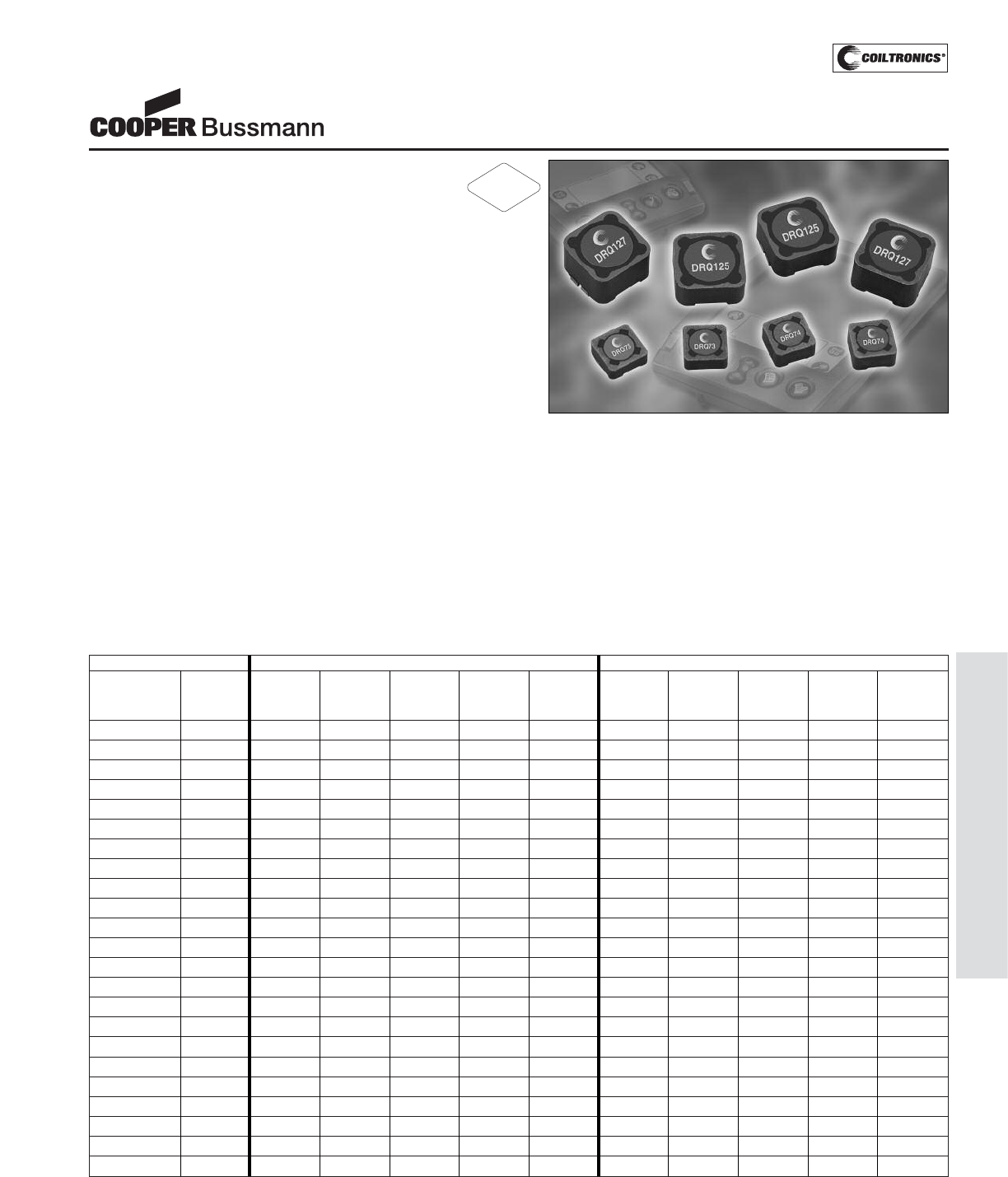
PM-73
SHIELDED DRUM (DRQ)
DRQ Series
Dual Winding, Shielded
Inductors/Transformer
P
P
a
a
r
r
a
a
l
l
l
l
e
e
l
l
R
R
a
a
t
t
i
i
n
n
g
g
s
s
S
S
e
e
r
r
i
i
e
e
s
s
R
R
a
a
t
t
i
i
n
n
g
g
s
s
P
P
a
a
r
r
t
t
N
N
u
u
m
m
b
b
e
e
r
r
R
R
a
a
t
t
e
e
d
d
O
O
C
C
L
L
(
(
1
1
)
)
I
I
r
r
m
m
s
s
(
(
2
2
)
)
I
I
s
s
a
a
t
t
(
(
3
3
)
)
D
D
C
C
R
R
Ω
Ω
(
(
4
4
)
)
V
V
o
o
l
l
t
t
(
(
5
5
)
)
O
O
C
C
L
L
(
(
1
1
)
)
I
I
r
r
m
m
s
s
(
(
2
2
)
)
I
I
s
s
a
a
t
t
(
(
3
3
)
)
D
D
C
C
R
R
Ω
Ω
(
(
4
4
)
)
V
V
o
o
l
l
t
t
(
(
5
5
)
)
I
I
n
n
d
d
u
u
c
c
t
t
a
a
n
n
c
c
e
e
+
+
/
/
-
-
2
2
0
0
%
%
A
A
m
m
p
p
e
e
r
r
e
e
s
s
A
A
m
m
p
p
e
e
r
r
e
e
s
s
t
t
y
y
p
p
.
.
μ
μ
-
-
S
S
e
e
c
c
+
+
/
/
-
-
2
2
0
0
%
%
A
A
m
m
p
p
e
e
r
r
e
e
s
s
A
A
m
m
p
p
e
e
r
r
e
e
s
s
t
t
y
y
p
p
.
.
μ
μ
-
-
S
S
e
e
c
c
(
(
μ
μ
H
H
)
)
(
(
μ
μ
H
H
)
)
P
P
e
e
a
a
k
k
(
(
μ
μ
H
H
)
)
P
P
e
e
a
a
k
k
D
D
R
R
Q
Q
7
7
3
3
-
-
R
R
3
3
3
3
-
-
R
R
0.33 0.306 6.19 14.4 0.0074 1.98 1.224 3.10 7.18 0.0296 3.96
D
D
R
R
Q
Q
7
7
3
3
-
-
1
1
R
R
0
0
-
-
R
R
1.00 0.992 5.25 7.97 0.0103 3.56 3.968 2.63 3.99 0.0411 7.12
D
D
R
R
Q
Q
7
7
3
3
-
-
1
1
R
R
5
5
-
-
R
R
1.50 1.482 4.64 6.52 0.0132 4.36 5.928 2.32 3.26 0.0527 8.72
D
D
R
R
Q
Q
7
7
3
3
-
-
2
2
R
R
2
2
-
-
R
R
2.20 2.070 4.11 5.52 0.0167 5.15 8.280 2.06 2.76 0.0669 10.3
D
D
R
R
Q
Q
7
7
3
3
-
-
3
3
R
R
3
3
-
-
R
R
3.30 3.540 3.31 4.22 0.0259 6.73 14.16 1.66 2.11 0.1035 13.5
D
D
R
R
Q
Q
7
7
3
3
-
-
4
4
R
R
7
7
-
-
R
R
4.70 4.422 3.09 3.78 0.0297 7.52 17.69 1.55 1.89 0.1188 15.0
D
D
R
R
Q
Q
7
7
3
3
-
-
6
6
R
R
8
8
-
-
R
R
6.80 6.480 2.55 3.12 0.0435 9.11 25.92 1.28 1.56 0.1742 18.2
D
D
R
R
Q
Q
7
7
3
3
-
-
8
8
R
R
2
2
-
-
R
R
8.20 8.930 2.19 2.66 0.0592 10.7 35.72 1.10 1.33 0.2368 21.4
D
D
R
R
Q
Q
7
7
3
3
-
-
1
1
0
0
0
0
-
-
R
R
10.0 10.30 2.08 2.47 0.0656 11.5 41.20 1.04 1.24 0.2623 23.0
D
D
R
R
Q
Q
7
7
3
3
-
-
1
1
5
5
0
0
-
-
R
R
15.0 15.01 1.83 2.05 0.0844 13.9 60.04 0.916 1.03 0.339 27.8
D
D
R
R
Q
Q
7
7
3
3
-
-
2
2
2
2
0
0
-
-
R
R
22.0 22.65 1.62 1.67 0.107 17.0 90.60 0.811 0.83 0.429 34.0
D
D
R
R
Q
Q
7
7
3
3
-
-
3
3
3
3
0
0
-
-
R
R
33.0 34.41 1.31 1.35 0.166 21.0 137.6 0.653 0.68 0.665 42.0
D
D
R
R
Q
Q
7
7
3
3
-
-
4
4
7
7
0
0
-
-
R
R
47.0 48.62 1.08 1.14 0.241 24.9 194.5 0.542 0.57 0.965 49.8
D
D
R
R
Q
Q
7
7
3
3
-
-
6
6
8
8
0
0
-
-
R
R
68.0 68.91 0.89 0.96 0.358 29.7 275.6 0.444 0.48 1.43 59.4
D
D
R
R
Q
Q
7
7
3
3
-
-
8
8
2
2
0
0
-
-
R
R
82.0 80.37 0.86 0.89 0.384 32.1 321.5 0.430 0.44 1.54 64.2
D
D
R
R
Q
Q
7
7
3
3
-
-
1
1
0
0
1
1
-
-
R
R
100 101.4 0.73 0.79 0.527 36.0 405.6 0.367 0.39 2.11 72.0
D
D
R
R
Q
Q
7
7
3
3
-
-
1
1
5
5
1
1
-
-
R
R
150 150.9 0.58 0.65 0.851 44.0 603.6 0.289 0.32 3.41 88.0
D
D
R
R
Q
Q
7
7
3
3
-
-
2
2
2
2
1
1
-
-
R
R
220 223.3 0.52 0.53 1.05 53.5 893.2 0.260 0.27 4.20 107
D
D
R
R
Q
Q
7
7
3
3
-
-
3
3
3
3
1
1
-
-
R
R
330 325.5 0.42 0.44 1.59 64.5 1302 0.211 0.22 6.36 129
D
D
R
R
Q
Q
7
7
3
3
-
-
4
4
7
7
1
1
-
-
R
R
470 465.8 0.35 0.37 2.36 77.2 1863 0.173 0.18 9.44 154
D
D
R
R
Q
Q
7
7
3
3
-
-
6
6
8
8
1
1
-
-
R
R
680 676.5 0.29 0.31 3.47 93.1 2706 0.143 0.15 13.88 186
D
D
R
R
Q
Q
7
7
3
3
-
-
8
8
2
2
1
1
-
-
R
R
820 821.7 0.27 0.28 3.93 103 3287 0.134 0.14 15.72 206
D
D
R
R
Q
Q
7
7
3
3
-
-
1
1
0
0
2
2
-
-
R
R
1000 995.0 0.26 0.25 4.34 113 3980 0.128 0.13 17.36 226
1) Open Circuit Inductance Test Parameters: 100kHz, 0.25 Vrms, 0.0 Adc
Parallel: (1,2 - 4,2) Series: (1 - 4) tie (2 - 3)
2) RMS current for an approximate ΔT of 40°C without core loss. It is recommend-
ed that the temperature of the part not exceed 125°C.
3) Peak current for approximately 30% roll-off at 20°C
4) DCR limits @ 20°C
5) Applied Volt-Time product (V-μS) across the inductor.This value represents the
applied V-μS at 100KHz necessary to generate a core loss equal to 10% of the
total losses for a 40°C temperature rise.
6) Turns Ratio (1-2):(3-4) 1:1
Description
• 125°C maximum total temperature operation
• Dual winding inductors that can be used as either
a single inductor, or in coupled inductor/transformer
applications (1:1 turns ratio)
• Four sizes of shielded drum core inductors
• Windings can be connected in series or parallel, offering
a broad range of inductance and current ratings
• Peak current ratings from 0.13 Amps to 56 Amps
• RMS current ratings from 0.128 Amps to 17.9 Amps
• Inductance ratings from 0.33μH to 4.02mH
• Surface Mount
• 200 VAC Isolation between windings
• Ferrite core material
Applications
• As a transformer: SEPIC, flyback
• As an inductor: Buck, boost, coupled inductor
• DC/DC converters
• VRM inductor for CPU and DDR power supplies
• Input and output filter chokes
Environmental Data
• Storage temperature: -40°C to +125°C
• Operating temperature: -40°C to +125°C (Range is
application specific).
• Solder reflow temperature: 260°C max. for 10 seconds
max.
Packaging
• Supplied in tape and reel packaging, 1350 (DRQ73),
1100 (DRQ74), 600 (DRQ125), and 350 (DRQ127)
per reel
RoHS
2002/95/EC
Courtesy of Steven Engineering, Inc.-230 Ryan Way, South San Francisco, CA 94080-6370-Main Office: (650) 588-9200-Outside Local Area: (800) 258-9200-www.stevenengineering.com
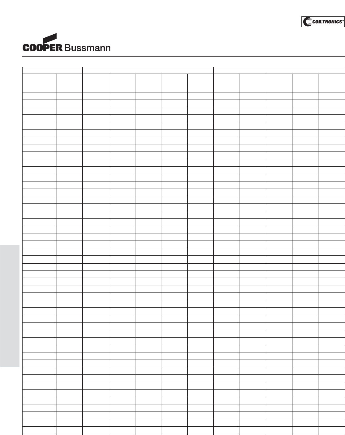
PM-74
SHIELDED DRUM (DRQ)
DRQ Series
Dual Winding, Shielded
Inductors/Transformer
P
P
a
a
r
r
a
a
l
l
l
l
e
e
l
l
R
R
a
a
t
t
i
i
n
n
g
g
s
s
S
S
e
e
r
r
i
i
e
e
s
s
R
R
a
a
t
t
i
i
n
n
g
g
s
s
P
P
a
a
r
r
t
t
N
N
u
u
m
m
b
b
e
e
r
r
R
R
a
a
t
t
e
e
d
d
O
O
C
C
L
L
(
(
1
1
)
)
I
I
r
r
m
m
s
s
(
(
2
2
)
)
I
I
s
s
a
a
t
t
(
(
3
3
)
)
D
D
C
C
R
R
Ω
Ω
(
(
4
4
)
)
V
V
o
o
l
l
t
t
(
(
5
5
)
)
O
O
C
C
L
L
(
(
1
1
)
)
I
I
r
r
m
m
s
s
(
(
2
2
)
)
I
I
s
s
a
a
t
t
(
(
3
3
)
)
D
D
C
C
R
R
Ω
Ω
(
(
4
4
)
)
V
V
o
o
l
l
t
t
(
(
5
5
)
)
I
I
n
n
d
d
u
u
c
c
t
t
a
a
n
n
c
c
e
e
+
+
/
/
-
-
2
2
0
0
%
%
A
A
m
m
p
p
e
e
r
r
e
e
s
s
A
A
m
m
p
p
e
e
r
r
e
e
s
s
t
t
y
y
p
p
.
.
μ
μ
-
-
S
S
e
e
c
c
+
+
/
/
-
-
2
2
0
0
%
%
A
A
m
m
p
p
e
e
r
r
e
e
s
s
A
A
m
m
p
p
e
e
r
r
e
e
s
s
t
t
y
y
p
p
.
.
μ
μ
-
-
S
S
e
e
c
c
(
(
μ
μ
H
H
)
)
(
(
μ
μ
H
H
)
)
P
P
e
e
a
a
k
k
(
(
μ
μ
H
H
)
)
P
P
e
e
a
a
k
k
D
D
R
R
Q
Q
7
7
4
4
-
-
R
R
3
3
3
3
-
-
R
R
0.33 0.294 6.20 18.4 0.0074 1.71 1.176 3.10 9.18 0.0295 3.42
D
D
R
R
Q
Q
7
7
4
4
-
-
1
1
R
R
0
0
-
-
R
R
1.00 0.952 5.33 10.2 0.0100 3.08 3.808 2.66 5.10 0.0400 6.16
D
D
R
R
Q
Q
7
7
4
4
-
-
1
1
R
R
5
5
-
-
R
R
1.50 1.422 4.96 8.35 0.0115 3.76 5.688 2.48 4.17 0.0461 7.52
D
D
R
R
Q
Q
7
7
4
4
-
-
2
2
R
R
2
2
-
-
R
R
2.20 1.986 4.66 7.06 0.0130 4.45 7.944 2.33 3.53 0.0521 8.9
D
D
R
R
Q
Q
7
7
4
4
-
-
3
3
R
R
3
3
-
-
R
R
3.30 3.396 3.94 5.40 0.0183 5.81 13.58 1.97 2.70 0.0732 11.6
D
D
R
R
Q
Q
7
7
4
4
-
-
4
4
R
R
7
7
-
-
R
R
4.70 5.182 3.34 4.37 0.0254 7.18 20.73 1.67 2.19 0.102 14.4
D
D
R
R
Q
Q
7
7
4
4
-
-
6
6
R
R
8
8
-
-
R
R
6.80 7.344 2.60 3.67 0.0418 8.55 29.38 1.30 1.84 0.167 17.1
D
D
R
R
Q
Q
7
7
4
4
-
-
8
8
R
R
2
2
-
-
R
R
8.20 8.566 2.53 3.40 0.0441 9.23 34.26 1.27 1.70 0.177 18.5
D
D
R
R
Q
Q
7
7
4
4
-
-
1
1
0
0
0
0
-
-
R
R
10.0 9.882 2.41 3.17 0.0489 9.92 39.53 1.20 1.58 0.196 19.8
D
D
R
R
Q
Q
7
7
4
4
-
-
1
1
5
5
0
0
-
-
R
R
15.0 16.09 2.11 2.48 0.0637 12.7 64.36 1.05 1.24 0.255 25.4
D
D
R
R
Q
Q
7
7
4
4
-
-
2
2
2
2
0
0
-
-
R
R
22.0 21.73 1.75 2.13 0.0925 14.7 86.92 0.874 1.07 0.371 29.4
D
D
R
R
Q
Q
7
7
4
4
-
-
3
3
3
3
0
0
-
-
R
R
33.0 33.01 1.41 1.73 0.143 18.1 132.0 0.702 0.87 0.574 36.2
D
D
R
R
Q
Q
7
7
4
4
-
-
4
4
7
7
0
0
-
-
R
R
47.0 49.64 1.15 1.41 0.216 22.2 198.6 0.573 0.71 0.865 44.4
D
D
R
R
Q
Q
7
7
4
4
-
-
6
6
8
8
0
0
-
-
R
R
68.0 69.67 1.03 1.19 0.265 26.3 278.7 0.517 0.60 1.06 52.6
D
D
R
R
Q
Q
7
7
4
4
-
-
8
8
2
2
0
0
-
-
R
R
82.0 80.95 0.91 1.11 0.345 28.4 323.8 0.453 0.55 1.38 56.8
D
D
R
R
Q
Q
7
7
4
4
-
-
1
1
0
0
1
1
-
-
R
R
100 101.6 0.86 0.99 0.383 31.8 406.4 0.430 0.49 1.53 63.6
D
D
R
R
Q
Q
7
7
4
4
-
-
1
1
5
5
1
1
-
-
R
R
150 150.0 0.69 0.81 0.591 38.6 600.0 0.346 0.41 2.37 77.2
D
D
R
R
Q
Q
7
7
4
4
-
-
2
2
2
2
1
1
-
-
R
R
220 227.0 0.56 0.66 0.907 47.5 908.0 0.279 0.33 3.63 95
D
D
R
R
Q
Q
7
7
4
4
-
-
3
3
3
3
1
1
-
-
R
R
330 335.6 0.45 0.54 1.41 57.8 1342 0.224 0.27 5.66 116
D
D
R
R
Q
Q
7
7
4
4
-
-
4
4
7
7
1
1
-
-
R
R
470 465.3 0.40 0.46 1.74 68.1 1861 0.202 0.23 6.97 136
D
D
R
R
Q
Q
7
7
4
4
-
-
6
6
8
8
1
1
-
-
R
R
680 671.2 0.33 0.38 2.58 81.7 2685 0.166 0.19 10.3 163
D
D
R
R
Q
Q
7
7
4
4
-
-
8
8
2
2
1
1
-
-
R
R
820 812.7 0.31 0.35 2.93 89.9 3251 0.156 0.17 11.7 180
D
D
R
R
Q
Q
7
7
4
4
-
-
1
1
0
0
2
2
-
-
R
R
1000 1009 0.27 0.31 3.89 100 4036 0.135 0.16 15.6 200
D
D
R
R
Q
Q
1
1
2
2
5
5
-
-
R
R
4
4
7
7
-
-
R
R
0.47 0.456 17.6 33.0 0.0018 3.17 1.824 8.80 16.5 0.0078 6.34
D
D
R
R
Q
Q
1
1
2
2
5
5
-
-
1
1
R
R
0
0
-
-
R
R
1.00 0.894 15.0 23.6 0.0024 4.43 3.576 7.51 11.8 0.0096 8.86
D
D
R
R
Q
Q
1
1
2
2
5
5
-
-
1
1
R
R
5
5
-
-
R
R
1.50 1.478 13.8 18.3 0.0029 5.70 5.912 6.89 9.15 0.0114 11.40
D
D
R
R
Q
Q
1
1
2
2
5
5
-
-
2
2
R
R
2
2
-
-
R
R
2.20 2.208 10.9 15.0 0.0045 6.97 8.832 5.46 7.50 0.0182 13.9
D
D
R
R
Q
Q
1
1
2
2
5
5
-
-
3
3
R
R
3
3
-
-
R
R
3.30 3.084 9.26 12.7 0.0063 8.23 12.34 4.63 6.35 0.0253 16.5
D
D
R
R
Q
Q
1
1
2
2
5
5
-
-
4
4
R
R
7
7
-
-
R
R
4.70 5.274 7.18 9.71 0.0105 10.8 21.10 3.59 4.86 0.0420 21.6
D
D
R
R
Q
Q
1
1
2
2
5
5
-
-
6
6
R
R
8
8
-
-
R
R
6.80 6.588 6.64 8.68 0.0123 12.0 26.35 3.32 4.34 0.0492 24.0
D
D
R
R
Q
Q
1
1
2
2
5
5
-
-
8
8
R
R
2
2
-
-
R
R
8.20 8.048 5.54 7.86 0.0176 13.3 32.19 2.77 3.93 0.0705 26.6
D
D
R
R
Q
Q
1
1
2
2
5
5
-
-
1
1
0
0
0
0
-
-
R
R
10.0 9.654 5.35 7.17 0.0189 14.6 38.62 2.67 3.59 0.0757 29.2
D
D
R
R
Q
Q
1
1
2
2
5
5
-
-
1
1
5
5
0
0
-
-
R
R
15.0 15.35 4.27 5.69 0.0298 18.4 61.40 2.13 2.85 0.120 36.8
D
D
R
R
Q
Q
1
1
2
2
5
5
-
-
2
2
2
2
0
0
-
-
R
R
22.0 22.36 3.70 4.71 0.0396 22.2 89.44 1.84 2.36 0.159 44.4
D
D
R
R
Q
Q
1
1
2
2
5
5
-
-
3
3
3
3
0
0
-
-
R
R
33.0 33.74 3.28 3.84 0.0505 27.2 135.0 1.64 1.92 0.203 54.4
D
D
R
R
Q
Q
1
1
2
2
5
5
-
-
4
4
7
7
0
0
-
-
R
R
47.0 47.47 2.71 3.24 0.0740 32.3 189.9 1.35 1.62 0.297 64.6
D
D
R
R
Q
Q
1
1
2
2
5
5
-
-
6
6
8
8
0
0
-
-
R
R
68.0 67.91 2.22 2.70 0.101 38.6 271.6 1.11 1.35 0.440 77.2
D
D
R
R
Q
Q
1
1
2
2
5
5
-
-
8
8
2
2
0
0
-
-
R
R
82.0 86.89 2.05 2.39 0.128 43.7 347.6 1.03 1.20 0.515 87.4
D
D
R
R
Q
Q
1
1
2
2
5
5
-
-
1
1
0
0
1
1
-
-
R
R
100 102.7 1.78 2.20 0.170 47.5 410.8 0.892 1.10 0.682 95.0
D
D
R
R
Q
Q
1
1
2
2
5
5
-
-
1
1
5
5
1
1
-
-
R
R
150 151.1 1.48 1.81 0.248 57.6 604.4 0.739 0.905 0.991 115.2
D
D
R
R
Q
Q
1
1
2
2
5
5
-
-
2
2
2
2
1
1
-
-
R
R
220 216.8 1.19 1.51 0.384 69.0 867.2 0.594 0.755 1.54 138
D
D
R
R
Q
Q
1
1
2
2
5
5
-
-
3
3
3
3
1
1
-
-
R
R
330 332.6 1.06 1.22 0.482 85.5 1330 0.530 0.610 1.93 171
D
D
R
R
Q
Q
1
1
2
2
5
5
-
-
4
4
7
7
1
1
-
-
R
R
470 473.1 0.87 1.02 0.718 102 1892 0.434 0.510 2.87 204
D
D
R
R
Q
Q
1
1
2
2
5
5
-
-
6
6
8
8
1
1
-
-
R
R
680 679.8 0.70 0.85 1.10 122 2719 0.350 0.425 4.42 244
D
D
R
R
Q
Q
1
1
2
2
5
5
-
-
8
8
2
2
1
1
-
-
R
R
820 828.0 0.60 0.77 1.49 135 3312 0.301 0.385 5.96 270
D
D
R
R
Q
Q
1
1
2
2
5
5
-
-
1
1
0
0
2
2
-
-
R
R
1000 1008 0.57 0.70 1.69 149 4032 0.283 0.350 6.76 298
1) Open Circuit Inductance Test Parameters: 100kHz, 0.25 Vrms, 0.0 Adc
Parallel: (1,2 - 4,2) Series: (1 - 4) tie (2 - 3)
2) RMS current for an approximate ΔT of 40°C without core loss. It is recommend-
ed that the temperature of the part not exceed 125°C.
3) Peak current for approximately 30% roll-off at 20°C
4) DCR limits @ 20°C
5) Applied Volt-Time product (V-μS) across the inductor.This value represents the
applied V-μS at 100KHz necessary to generate a core loss equal to 10% of the
total losses for a 40°C temperature rise.
6) Turns Ratio (1-2):(3-4) 1:1
Courtesy of Steven Engineering, Inc.-230 Ryan Way, South San Francisco, CA 94080-6370-Main Office: (650) 588-9200-Outside Local Area: (800) 258-9200-www.stevenengineering.com
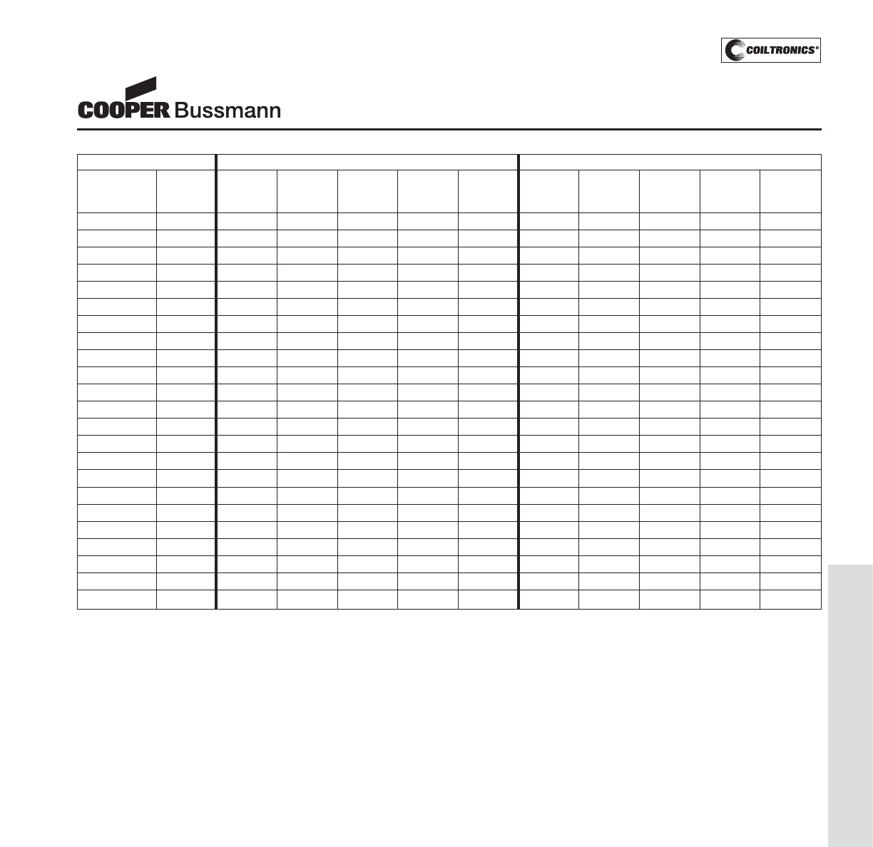
PM-75
SHIELDED DRUM (DRQ)
DRQ Series
Dual Winding, Shielded
Inductors/Transformer
P
P
a
a
r
r
a
a
l
l
l
l
e
e
l
l
R
R
a
a
t
t
i
i
n
n
g
g
s
s
S
S
e
e
r
r
i
i
e
e
s
s
R
R
a
a
t
t
i
i
n
n
g
g
s
s
P
P
a
a
r
r
t
t
N
N
u
u
m
m
b
b
e
e
r
r
R
R
a
a
t
t
e
e
d
d
O
O
C
C
L
L
(
(
1
1
)
)
I
I
r
r
m
m
s
s
(
(
2
2
)
)
I
I
s
s
a
a
t
t
(
(
3
3
)
)
D
D
C
C
R
R
Ω
Ω
(
(
4
4
)
)
V
V
o
o
l
l
t
t
(
(
5
5
)
)
O
O
C
C
L
L
(
(
1
1
)
)
I
I
r
r
m
m
s
s
(
(
2
2
)
)
I
I
s
s
a
a
t
t
(
(
3
3
)
)
D
D
C
C
R
R
Ω
Ω
(
(
4
4
)
)
V
V
o
o
l
l
t
t
(
(
5
5
)
)
I
I
n
n
d
d
u
u
c
c
t
t
a
a
n
n
c
c
e
e
+
+
/
/
-
-
2
2
0
0
%
%
A
A
m
m
p
p
e
e
r
r
e
e
s
s
A
A
m
m
p
p
e
e
r
r
e
e
s
s
t
t
y
y
p
p
.
.
μ
μ
-
-
S
S
e
e
c
c
+
+
/
/
-
-
2
2
0
0
%
%
A
A
m
m
p
p
e
e
r
r
e
e
s
s
A
A
m
m
p
p
e
e
r
r
e
e
s
s
t
t
y
y
p
p
.
.
μ
μ
-
-
S
S
e
e
c
c
(
(
μ
μ
H
H
)
)
(
(
μ
μ
H
H
)
)
P
P
e
e
a
a
k
k
(
(
μ
μ
H
H
)
)
P
P
e
e
a
a
k
k
D
D
R
R
Q
Q
1
1
2
2
7
7
-
-
R
R
4
4
7
7
-
-
R
R
0.47 0.419 17.9 56.0 0.00195 3.50 1.676 8.94 28 0.0078 7.00
D
D
R
R
Q
Q
1
1
2
2
7
7
-
-
1
1
R
R
0
0
-
-
R
R
1.00 0.821 15.5 40.0 0.00261 4.90 3.284 7.74 20 0.0104 9.80
D
D
R
R
Q
Q
1
1
2
2
7
7
-
-
1
1
R
R
5
5
-
-
R
R
1.50 1.357 13.5 31.1 0.00341 6.30 5.428 6.77 15.6 0.0137 12.60
D
D
R
R
Q
Q
1
1
2
2
7
7
-
-
2
2
R
R
2
2
-
-
R
R
2.20 2.027 12.5 25.5 0.00373 7.70 8.108 6.23 12.7 0.0161 15.4
D
D
R
R
Q
Q
1
1
2
2
7
7
-
-
3
3
R
R
3
3
-
-
R
R
3.30 2.831 10.4 21.5 0.00567 9.10 11.32 5.23 10.8 0.0229 18.2
D
D
R
R
Q
Q
1
1
2
2
7
7
-
-
4
4
R
R
7
7
-
-
R
R
4.70 4.841 8.25 16.5 0.00917 11.9 19.36 4.13 8.24 0.0367 23.8
D
D
R
R
Q
Q
1
1
2
2
7
7
-
-
6
6
R
R
8
8
-
-
R
R
6.80 7.387 7.34 13.3 0.0116 14.7 29.55 3.67 6.67 0.0465 29.4
D
D
R
R
Q
Q
1
1
2
2
7
7
-
-
8
8
R
R
2
2
-
-
R
R
8.20 8.861 6.32 12.2 0.0157 16.1 35.44 3.16 6.09 0.0627 32.2
D
D
R
R
Q
Q
1
1
2
2
7
7
-
-
1
1
0
0
0
0
-
-
R
R
10.0 10.47 6.04 11.2 0.0172 17.5 41.88 3.02 5.60 0.0686 35.0
D
D
R
R
Q
Q
1
1
2
2
7
7
-
-
1
1
5
5
0
0
-
-
R
R
15.0 14.09 5.03 9.66 0.0247 20.3 56.36 2.51 4.83 0.0990 40.6
D
D
R
R
Q
Q
1
1
2
2
7
7
-
-
2
2
2
2
0
0
-
-
R
R
22.0 22.93 4.00 7.57 0.0391 25.9 91.72 2.00 3.78 0.157 51.8
D
D
R
R
Q
Q
1
1
2
2
7
7
-
-
3
3
3
3
0
0
-
-
R
R
33.0 33.92 3.23 6.22 0.0600 31.5 135.7 1.61 3.11 0.241 63.0
D
D
R
R
Q
Q
1
1
2
2
7
7
-
-
4
4
7
7
0
0
-
-
R
R
47.0 47.05 2.95 5.28 0.0719 37.1 188.2 1.47 2.64 0.288 74.2
D
D
R
R
Q
Q
1
1
2
2
7
7
-
-
6
6
8
8
0
0
-
-
R
R
68.0 66.48 2.44 4.44 0.105 44.1 265.9 1.22 2.22 0.421 88.2
D
D
R
R
Q
Q
1
1
2
2
7
7
-
-
8
8
2
2
0
0
-
-
R
R
82.0 79.75 2.09 4.06 0.143 48.3 319.0 1.04 2.03 0.573 96.6
D
D
R
R
Q
Q
1
1
2
2
7
7
-
-
1
1
0
0
1
1
-
-
R
R
100 99.31 1.96 3.64 0.163 53.9 397.2 0.980 1.82 0.653 107.8
D
D
R
R
Q
Q
1
1
2
2
7
7
-
-
1
1
5
5
1
1
-
-
R
R
150 144.9 1.59 3.01 0.247 65.1 579.6 0.796 1.51 0.989 130.2
D
D
R
R
Q
Q
1
1
2
2
7
7
-
-
2
2
2
2
1
1
-
-
R
R
220 221.5 1.29 2.43 0.376 80.5 886.0 0.645 1.22 1.50 161
D
D
R
R
Q
Q
1
1
2
2
7
7
-
-
3
3
3
3
1
1
-
-
R
R
330 323.6 1.04 2.01 0.574 97.3 1294 0.522 1.01 2.30 195
D
D
R
R
Q
Q
1
1
2
2
7
7
-
-
4
4
7
7
1
1
-
-
R
R
470 467.1 0.85 1.68 0.861 117 1868 0.427 0.838 3.44 234
D
D
R
R
Q
Q
1
1
2
2
7
7
-
-
6
6
8
8
1
1
-
-
R
R
680 676.7 0.76 1.39 1.08 141 2707 0.380 0.697 4.32 282
D
D
R
R
Q
Q
1
1
2
2
7
7
-
-
8
8
2
2
1
1
-
-
R
R
820 818.1 0.65 1.27 1.47 155 3272 0.325 0.633 5.88 310
D
D
R
R
Q
Q
1
1
2
2
7
7
-
-
1
1
0
0
2
2
-
-
R
R
1000 1005 0.61 1.14 1.66 172 4020 0.307 0.571 6.64 344
1) Open Circuit Inductance Test Parameters: 100kHz, 0.25 Vrms, 0.0 Adc
Parallel: (1,2 - 4,2) Series: (1 - 4) tie (2 - 3)
2) RMS current for an approximate ΔT of 40°C without core loss. It is recommend-
ed that the temperature of the part not exceed 125°C.
3) Peak current for approximately 30% roll-off at 20°C
4) DCR limits @ 20°C
5) Applied Volt-Time product (V-μS) across the inductor.This value represents the
applied V-μS at 100KHz necessary to generate a core loss equal to 10% of the
total losses for a 40°C temperature rise.
6) Turns Ratio (1-2):(3-4) 1:1
Courtesy of Steven Engineering, Inc.-230 Ryan Way, South San Francisco, CA 94080-6370-Main Office: (650) 588-9200-Outside Local Area: (800) 258-9200-www.stevenengineering.com
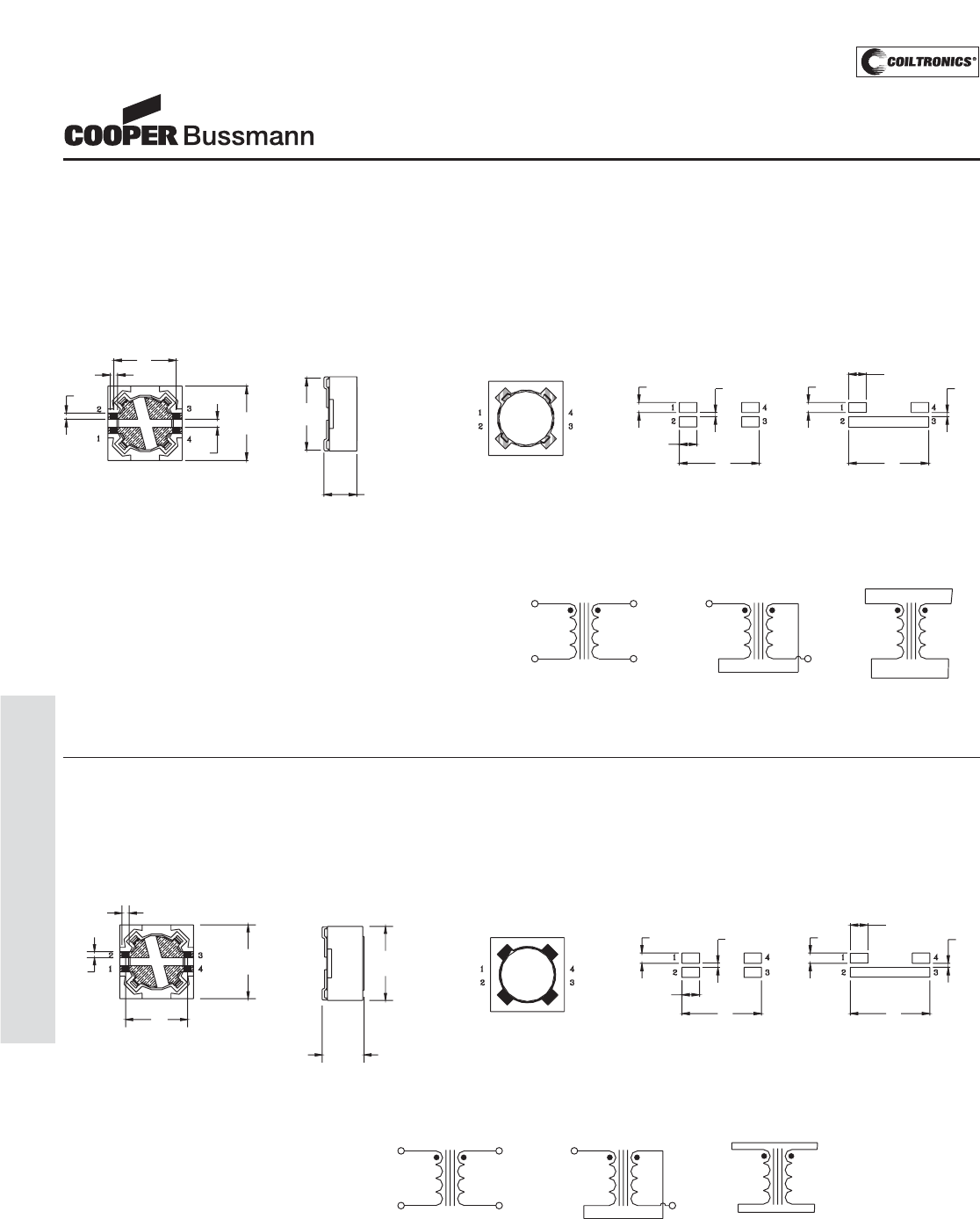
PM-76
SHIELDED DRUM (DRQ)
DRQ Series
Dual Winding, Shielded
Inductors/Transformer
BOTTOM VIEW
0.60
6.1
0.73
7.6
Max
FRONT VIEW TOP VIEW
DRQ74
###
•
7.97.9
Series ModeDual Inductor Mode
1.73
RECOMMENDED PCB LAYOUT
0.40
1.73
1.00 1.00 0.40
Series ModeDual Inductor
L2
3
L1
1
4
2
L1
3
1
SCHEMATIC
L2
4
2
3
1
4
Parallel Mode
L1 L2
2
7.6
Max
4.45
Max
Mechanical Diagrams
DRQ73 Series
BOTTOM VIEW
0.60
6.1
0.73
0.8
0
7.6
Max.
FRONT VIEW TOP VIEW
DRQ73
##
#
•
7.97.9
Series ModeDual Inductor Mode
1.73
RECOMMENDED PCB LAYOUT
0.40
1.73
1.00 1.00 0.40
Series ModeDual Inductor
L2
3
L1
1
4
2
L1
3
1
SCHEMATIC
L2
4
2
3
1
L2L1
4
Parallel Mode
2
3.55 Max
7.6
Max.
DRQ74 Series
Dimensions in Millimeters. ### = Inductance value per family chart
Dot indicates pin #1
Courtesy of Steven Engineering, Inc.-230 Ryan Way, South San Francisco, CA 94080-6370-Main Office: (650) 588-9200-Outside Local Area: (800) 258-9200-www.stevenengineering.com
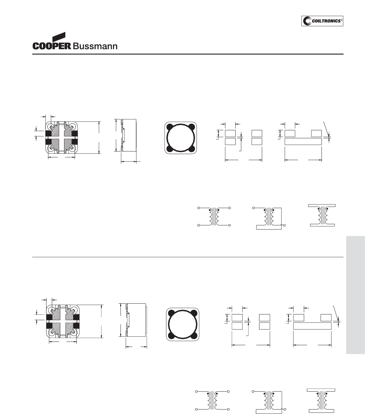
PM-77
SHIELDED DRUM (DRQ)
DRQ Series
Dual Winding, Shielded
Inductors/Transformer
2.50
2.05
10.0
BOTTOM VIEW
2.00
1
212.5
Max
4
31
2
DRQ127
###
wwllyy R
4
3
•
Dual Inductor Mode Series Mode
3.85
13.80
RECOMMENDED PCB LAYOUT
13.80
0.50
3.85
1
2.50 2
0.50
4
3
12.5
Max
8.0
Max
FRONT VIEW TOP VIEW
SCHEMATIC
34
Dual Inductor
1
L1
2
L2
3
Series Mode
L1
1
L2 L2
Parallel Mode
43
12
L1
2
4
2.50
2.05
12.5
Max
10.0
2.00
1
2
4
312.5
Max
BOTTOM VIEW FRONT VI EW TOP VIEW
6.00 Max
1
2
DRQ125
###
wwllyy R
4
3
•
Dual Inductor Mode Series Mode
3.85
13.80
RECOMMENDED PCB LAYOUT
13.80
1
0.50
2
3.85
1
4
2.50
32
0.50
4
3
SCHEMATIC
Series Mode
L1L1 L2
343
Dual Inductor
121
L2L1
L2
434
Parallel Mode
212
Mechanical Diagrams
DRQ125 Series
DRQ127 Series
Dimensions in Millimeters. ### = Inductance value per family chart
wwllyy = (date code) R = revision level
Dot indicates pin #1
Courtesy of Steven Engineering, Inc.-230 Ryan Way, South San Francisco, CA 94080-6370-Main Office: (650) 588-9200-Outside Local Area: (800) 258-9200-www.stevenengineering.com
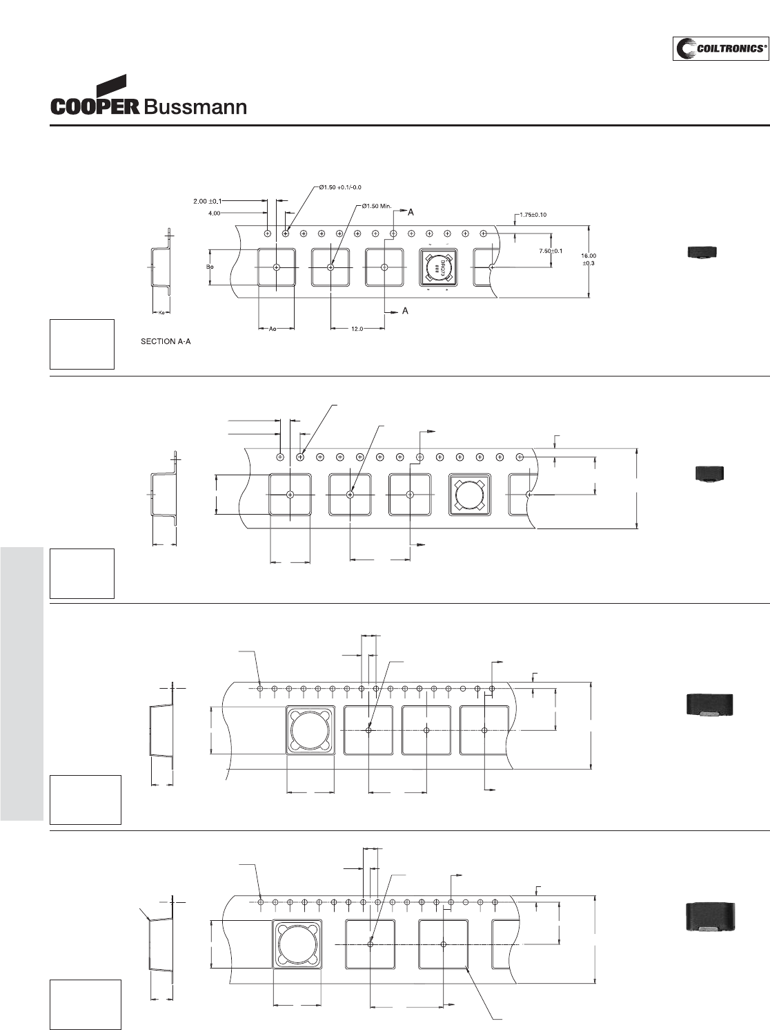
PM-78
SHIELDED DRUM (DRQ)
DRQ Series
Dual Winding, Shielded
Inductors/Transformer
S
E
C
TI
O
N A-
A
A
A
DR
Q
7
4
###
K
o
Bo
B
2.
00
±
0.1
4.
00
Ø
1.
50
+
0
.1
/
-
0
.
0
A
o
1
6
.
00
±
0.3
0
7.
50
±
0
.
1
1.7
5
±
0
.1
0
Ø
1.
50
Min
.
12.00
0
2
1
3
4
DRQ74 Series
1
2
4
3
A
A
DR
Q
12
5
###
ww
ll
y
y
•
S
E
C
TI
O
N A-
A
K
0
1.5 di
a
+
0
.1
/
-
0
.
0
1.
5
di
a
min
4.
0
2.
0
1
6
.
00
1.7
11.5
24.
0
+/-0.3
0
B0
B
A
0
DRQ125 Series
1
2
4
3
A
A
DR
Q
12
7
###
ww
ll
y
y
S
E
C
TI
O
N A-
A
R
0
.
3
max
.
R
0
.
5
TYP
.
K
0
1.
5
di
a
+
0
.1
/
-
0
.
0
1.
5
di
a
min
4.
0
2.
0
2
0
.
00
1.7
11.5
.
24.
0
+/-0.3
0
B0
B
A
0
DRQ127 Series
Packaging Information
DRQ73 Series
Dimensions are in millimeters.
Direction of Feed ➞
Direction of Feed ➞
Direction of Feed ➞
Direction of Feed ➞
Parts packaged on 13" Diameter reel,
1,350 parts per reel.
Parts packaged on 13" Diameter reel,
1,100 parts per reel.
Parts packaged on 13" Diameter reel,
600 parts per reel.
Parts packaged on 13" Diameter reel,
350 parts per reel.
Ao=7.90mm
Bo=7.90mm
Ko=3.80mm
Ao=7.90mm
Bo=7.90mm
Ko=4.70mm
Ao=13.00mm
Bo=13.00mm
Ko=6.30mm
Ao=13.00mm
Bo=13.00mm
Ko=8.30mm
ACTUAL SIZE
DRQ73
ACTUAL SIZE
DRQ74
ACTUAL SIZE
DRQ125
ACTUAL SIZE
DRQ127
Courtesy of Steven Engineering, Inc.-230 Ryan Way, South San Francisco, CA 94080-6370-Main Office: (650) 588-9200-Outside Local Area: (800) 258-9200-www.stevenengineering.com
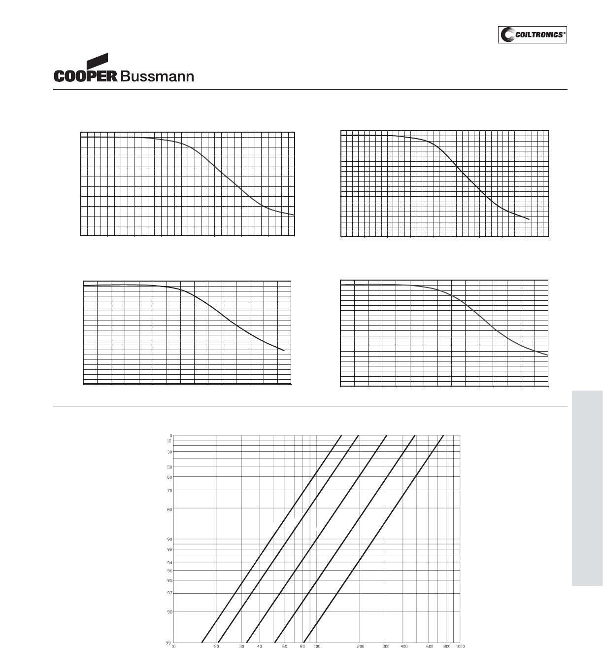
PM-79
SHIELDED DRUM (DRQ)
DRQ Series
Dual Winding, Shielded
Inductors/Transformer
0
10
20
30
40
50
60
70
80
90
100
0 20 40 60 80 100 120 140 160
% of Isat
OCL (%)
OCL vs Isat DRQ73
0
20
40
60
80
100
0 20 40 60 80 100 120 140 160 180
% of Isat
OCL (%)
OCL vs Isat DRQ74
0
10
20
30
40
50
60
70
80
90
100
0 10 20 30 40 50 60 70 80 90 100 110 120 130 140 150
% of Isat
OCL (%)
OCL vs Isat DRQ125
0
10
20
30
40
50
60
70
80
90
100
0 10 20 30 40 50 60 70 80 90 100 110 120 130 140 150
% Idc sat
OCL (%)
OCL vs Isat DRQ127
Irms DERATING WITH CORE LOSS
% of Applied Volt-μSecond
% of Losses from Irms (maximum)
300 KHz
200 KHz
100 KHz
50 KHz
25 KHz
Inductance Characteristics
Core Loss
Courtesy of Steven Engineering, Inc.-230 Ryan Way, South San Francisco, CA 94080-6370-Main Office: (650) 588-9200-Outside Local Area: (800) 258-9200-www.stevenengineering.com
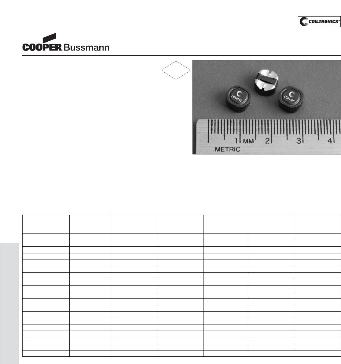
PM-80
SHIELDED DRUM (LDS0705)
Description
• 125°C maximum temperature operation
• 7.8mm x 7.0mm x 5.0mm shielded drum core
• Ferrite core material
• Metalized core mounting utilizes board space
• Inductance range from 0.82μH to 470μH
• Current range from 8.57 Amps to 0.368 Amps
• Frequency range up to 1MHz
Applications
• Buck or Boost Inductor
• Noise filtering and output filter chokes
• Battery Power, DC-DC converters
• Notebook power, PDA’s, Hand held computers
• DVD players
• Cellular phones
Environmental Data
• Storage temperature range: -40°C to +125°C
• Operating temperature range: -40°C to +125°C
(range is application specific)
• Solder reflow temperature: +260°C max. for 10 seconds
maximum
Packaging
• Supplied in tape and reel packaging, 1000 per reel
LDS0705 Series
Shielded Power Inductors
Part Number Rated OCL (1) Irms(2) Isat (3) DCR (Ω) K-factor
Inductance μH Amperes Amperes @20°C (4)
(μH) (Typical)
LDS0705-R82M-R 0.82 0.861±20% 7.68 8.57 0.0040 24.8
LDS0705-1R5M-R 1.5 1.42±20% 6.17 6.67 0.0061 19.3
LDS0705-2R2M-R 2.2 2.13±20% 5.06 5.45 0.009 15.8
LDS0705-3R3M-R 3.3 2.97±20% 4.19 4.62 0.013 13.4
LDS0705-4R7M-R 4.7 5.08±20% 3.32 3.53 0.021 10.2
LDS0705-6R8M-R 6.8 6.34±20% 3.11 3.16 0.024 9.2
LDS0705-8R2M-R 8.2 7.75±20% 2.67 2.86 0.033 8.3
LDS0705-100M-R 10.0 9.30±20% 2.54 2.61 0.036 7.6
LDS0705-150M-R 15.0 14.78±20% 2.04 2.07 0.056 6.0
LDS0705-220M-R 22.0 21.53±20% 1.66 1.71 0.084 5.0
LDS0705-330M-R 33.0 32.50±20% 1.48 1.40 0.107 4.0
LDS0705-470M-R 47.0 45.71±20% 1.21 1.18 0.158 3.4
LDS0705-680M-R 68.0 69.76±20% 0.985 0.952 0.240 2.8
LDS0705-820M-R 82.0 83.67±20% 0.850 0.870 0.323 2.5
LDS0705-101M-R 100.0 98.9±20% 0.808 0.800 0.357 2.3
LDS0705-151M-R 150.0 152.0±20% 0.649 0.645 0.554 1.9
LDS0705-221M-R 220.0 216.5±20% 0.584 0.541 0.68 1.6
LDS0705-331M-R 330.0 329.9±20% 0.470 0.438 1.06 1.3
LDS0705-471M-R 470.0 467.0±20% 0.387 0.368 1.56 1.1
(1) Open Circuit Inductance Test Parameters: 100kHz, 0.1V, 0.0Adc.
(2) Irms: DC current for an approximate ΔT of 30°C without core loss. Derating is
necessary for AC currents. PCB layout, trace thickness and width, air-flow, and
proximity of other heat generating components will affect the temperature rise. It
is recommended that the temperature of the part not exceed 125°C under worst
case operating conditions verified in the end application.
(3) Isat Amperes peak for approximately 15% rolloff (@25°C)
(4) K-factor: Used to determine B p-p for core loss (see graph).
B p-p = K*L*ΔI, B p-p(mT), K: (K factor from table), L: (Inductance in μH),
ΔI (Peak to peak ripple current in Amps).
(5) Part Number Definition: LDS0705-xxx-R
LDS0705 = Product code and size; -xxx = Inductance value in uH;
R = decimal point; If no R is present, third character = # of zeros.
M = Inductance tolerance +/- 20% -R suffix = RoHS compliant
RoHS
2002/95/EC
Courtesy of Steven Engineering, Inc.-230 Ryan Way, South San Francisco, CA 94080-6370-Main Office: (650) 588-9200-Outside Local Area: (800) 258-9200-www.stevenengineering.com
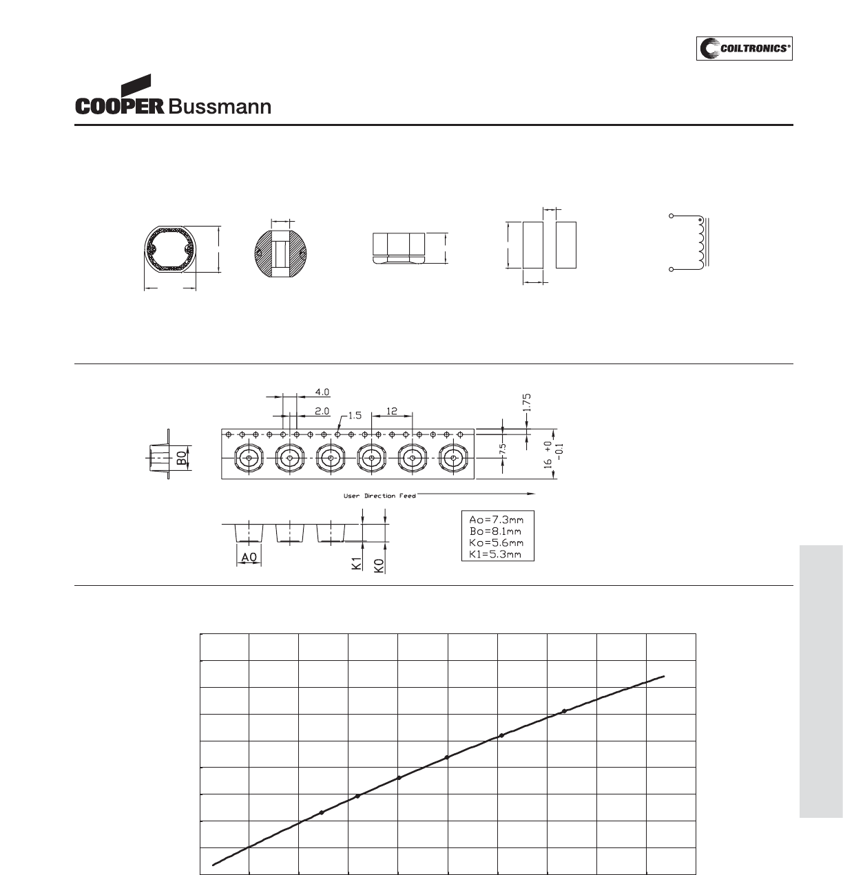
PM-81
SHIELDED DRUM (LDS0705)
LDS0705 Series
Shielded Power Inductors
Temperature Rise vs. Watt Loss
0
10
20
30
40
50
60
70
80
90
0 0.1 0.2 0.3 0.4 0.5 0.6 0.7 0.8 0.9 1
Total Loss (W)
Temp. Rise (°C)
Parts packaged on 13" Diameter reel,
1,000 parts per reel.
Packaging Information
Dimensions are in millimeters.
xxx = Inductance in uH. R = decimal point. If no R is present third character = # of zeros.
wwllyy = Date code, R = Revision level.
RECOMMENDED PCB LAYOUT SCHEMATIC
2
1
TOP VIEW
XXX
wwllyy R
SIDE VIEW
BOTTOM VIEW
7.0±0.2
7.8±0.2
5.0 Max. 7.0
3.0
2.0
2.0 Typ.
Mechanical Diagrams
Courtesy of Steven Engineering, Inc.-230 Ryan Way, South San Francisco, CA 94080-6370-Main Office: (650) 588-9200-Outside Local Area: (800) 258-9200-www.stevenengineering.com
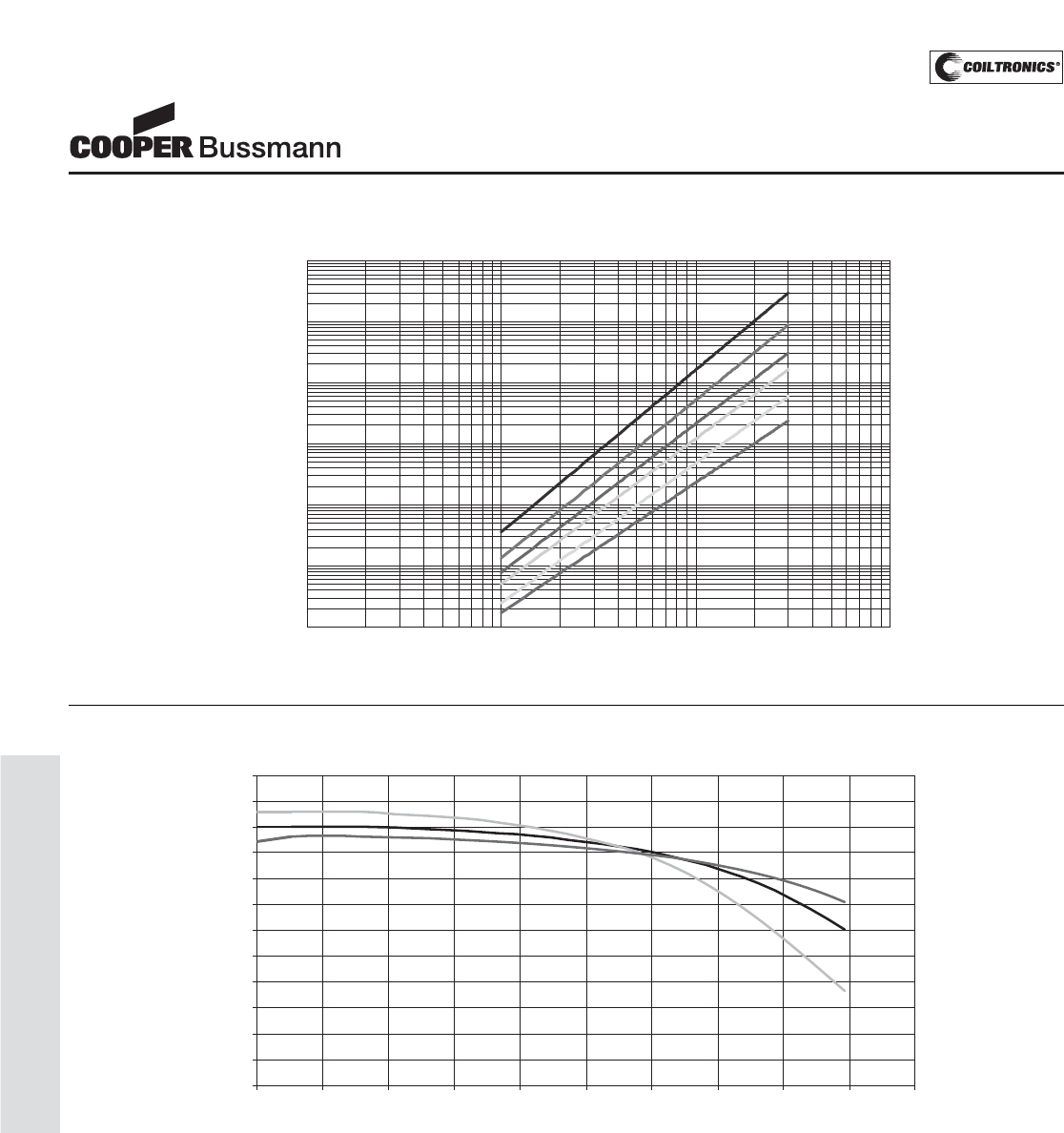
PM-82
SHIELDED DRUM (LDS0705)
OCL vs. Isat
0%
10%
20%
30%
40%
50%
60%
70%
80%
90%
100%
110%
120%
0% 20% 40% 60% 80% 100% 120% 140% 160% 180% 200%
% of Isat
% of OCL
-40
25
85
Inductance Characteristics
LDS0705 Series
Shielded Power Inductors
Core Loss
1MHz
500kHz
300kHz
200kHz
100kHz
50kHz
0.0001
0.001
0.01
0.1
1
10
100
1 10 100 1000
Bp-p (mT)
Core Loss (W)
Courtesy of Steven Engineering, Inc.-230 Ryan Way, South San Francisco, CA 94080-6370-Main Office: (650) 588-9200-Outside Local Area: (800) 258-9200-www.stevenengineering.com
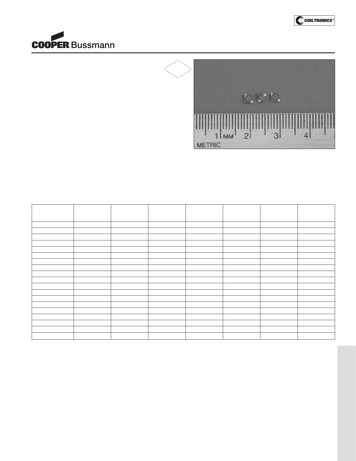
PM-83
LOW PROFILE SHIELDED DRUM (SD3110)
Description
• 125°C maximum total temperature operation
• 3.1mm x 3.1mm x 1.0mm shielded drum core
• Ferrite core material
• Inductance range from 0.5uH to 220uH
• Current range from 2.27 Amps to 0.106 Amps
• Frequency range up to 1MHz
Applications
• Cellular phones, Digital cameras, CD players, PDA’s
• Small LCD displays
• LED driver and LED flash circuits
• Hard disk drives
• Backlighting
• EL panel
Environmental Data
• Storage temperature range: -40°C to +125°C
• Operating temperature range: -40°C to +125°C
(range is application specific)
• Solder reflow temperature: +260°C max. for 10 seconds
maximum
Packaging
• Supplied in tape and reel packaging, 4100 per reel
SD3110 Series
Low Profile Power Inductors
Part Number Rated OCL (1) Part Irms (2) Isat (3) DCR (Ω) K-factor
Inductance (μH) Marking Amperes Amperes typ. @ (4)
(μH) Designator 20°C
SD3110-R50-R 0.50 0.44+/-30% A 1.54 2.27 0.0420 216
SD3110-R82-R 0.82 0.82+/-30% B 1.30 1.67 0.0589 191
SD3110-1R0-R 1.0 1.05+/-30% C 1.21 1.47 0.0683 169
SD3110-1R5-R 1.5 1.60+/-30% D 0.99 1.19 0.103 137
SD3110-2R2-R 2.2 2.27+/-30% E 0.82 1.00 0.149 115
SD3110-3R3-R 3.3 3.48+/-30% F 0.72 0.81 0.195 93
SD3110-4R7-R 4.7 4.96+/-30% G 0.59 0.68 0.285 78
SD3110-6R8-R 6.8 6.70+/-30% H 0.54 0.58 0.346 67
SD3110-8R2-R 8.2 8.01+/-30% I 0.48 0.53 0.432 61
SD3110-100-R 10.0 10.18+/-30% J 0.44 0.47 0.505 54
SD3110-150-R 15.0 15.32+/-20% K 0.36 0.38 0.764 44
SD3110-220-R 22.0 21.49+/-20% L 0.30 0.32 1.13 37
SD3110-330-R 33.0 32.72+/-20% M 0.26 0.26 1.50 30
SD3110-470-R 47.0 46.29+/-20% N 0.22 0.22 2.06 25
SD3110-680-R 68.0 68.04+/-20% O 0.179 0.182 3.13 21
SD3110-820-R 82.0 82.65+/-20% P 0.167 0.166 3.57 19
SD3110-101-R 100 101+/-20% Q 0.146 0.150 4.72 17
SD3110-151-R 150 149+/-20% R 0.127 0.123 6.16 14
SD3110-221-R 220 219+/-20% S 0.106 0.120 9.46 12
(1) Open Circuit Inductance Test Parameters: 100kHz, 0.1V, 0.0Adc.
(2) Irms: DC current for an approximate DT of 40°C without core loss. Derating is
necessary for AC currents. PCB layout, trace thickness and width, air-flow, and
proximity of other heat generating components will affect the temperature rise. It
is recommended that the temperature of the part not exceed 125°C under worst
case operating conditions verified in the end application.
(3) Isat Amperes peak for approximately 30% rolloff (@20°C)
(4) K-factor: Used to determine B p-p for core loss (see graph).
B p-p = K*L*ΔI, B p-p(mT), K: (K factor from table), L: (Inductance in uH),
ΔI (Peak to peak ripple current in Amps).
RoHS
2002/95/EC
Courtesy of Steven Engineering, Inc.-230 Ryan Way, South San Francisco, CA 94080-6370-Main Office: (650) 588-9200-Outside Local Area: (800) 258-9200-www.stevenengineering.com
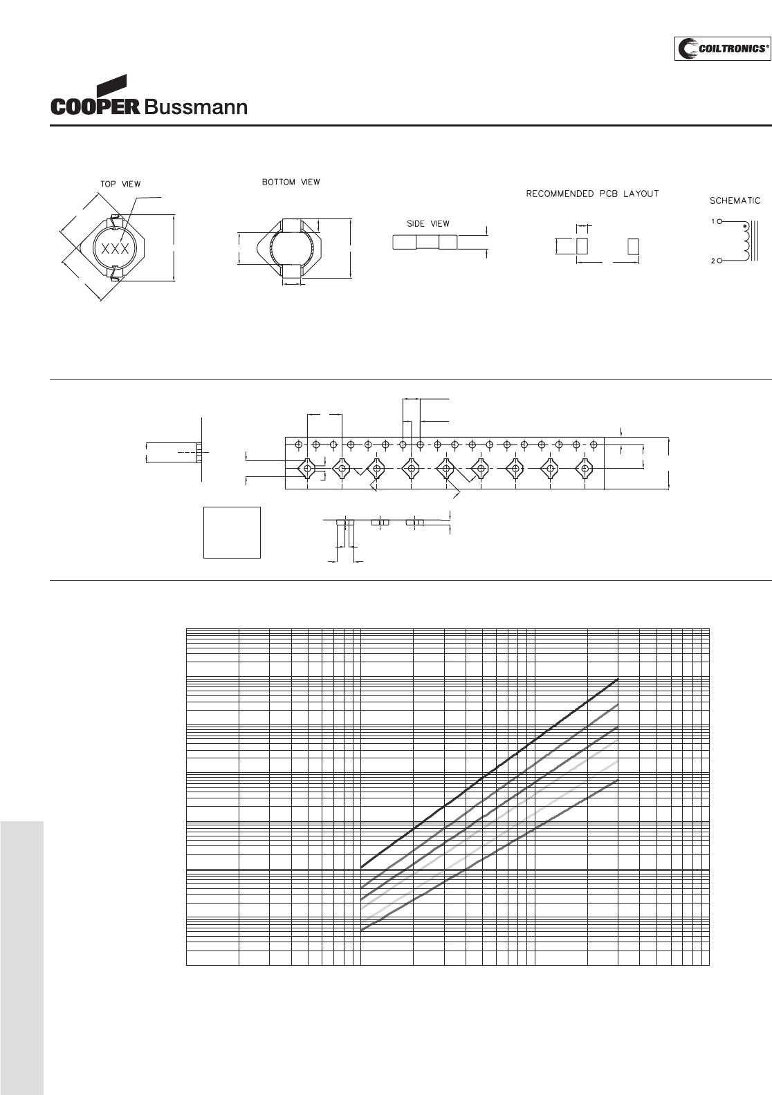
PM-84
LOW PROFILE SHIELDED DRUM (SD3110)
SD3110 Series
Low Profile Power Inductors
Core Loss
1MHz
500kHz
300kHz
200kHz
100kHz
50kHz
0.000001
0.00001
0.0001
0.001
0.01
0.1
1
10
1 10 100 1000
Bp-p (mT)
Core Loss (W)
Dimensions are in millimeters.
3.2
3.2
B1
Bo
A1
4.2
Ao
1.75
2.0
8.0
4.0
5.5 12.0
+/-0.3
Ko
A1=0.90mm
Ao=3.9mm
Bo=3.6mm
B1=1.25mm
Ko=1.2mm Parts packaged on 13" Diameter reel,
4,100 parts per reel.
Packaging Information
1.0 max
Marking
2.0
2 plcs
4.0
1.0
2 plcs
3.1 max.
3.1 max. 1.0 typical
3.6 max
4.0 Max.
0.6 typ.
2.0 typ.
Part Marking:
3 Digit Marking: (1st digit: Indicates inductance value per letter in Part Marking Designator); (2nd digit: Bi-weekly production date code); (3rd digit: Last digit of the year produced).
Mechanical Diagrams
Courtesy of Steven Engineering, Inc.-230 Ryan Way, South San Francisco, CA 94080-6370-Main Office: (650) 588-9200-Outside Local Area: (800) 258-9200-www.stevenengineering.com
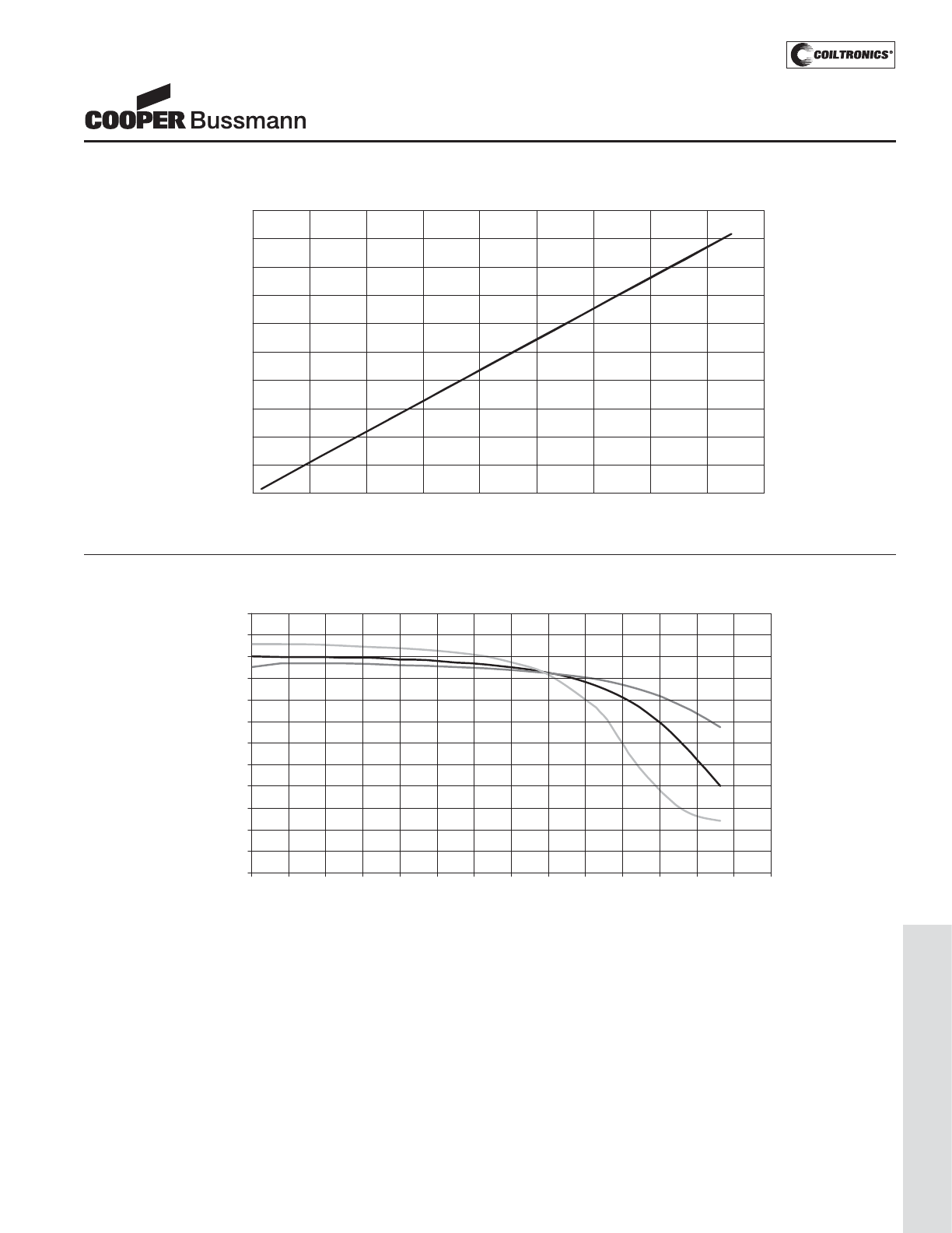
PM-85
LOW PROFILE SHIELDED DRUM (SD3110)
OCL Vs Isat
0%
10%
20%
30%
40%
50%
60%
70%
80%
90%
100%
110%
120%
0% 10% 20% 30% 40% 50% 60% 70% 80% 90% 100% 110% 120% 130% 140%
% of Isat
% of OCL
+85°C
+25°C
-40°C
Inductance Characteristics
SD3110 Series
Low Profile Power Inductors
Temperature Rise vs. Loss
0
10
20
30
40
50
60
70
80
90
100
0 0.04 0.08 0.12 0.16 0.2 0.24 0.28 0.32 0.36
Total Loss (W)
Temp.Rise(°C)
Courtesy of Steven Engineering, Inc.-230 Ryan Way, South San Francisco, CA 94080-6370-Main Office: (650) 588-9200-Outside Local Area: (800) 258-9200-www.stevenengineering.com
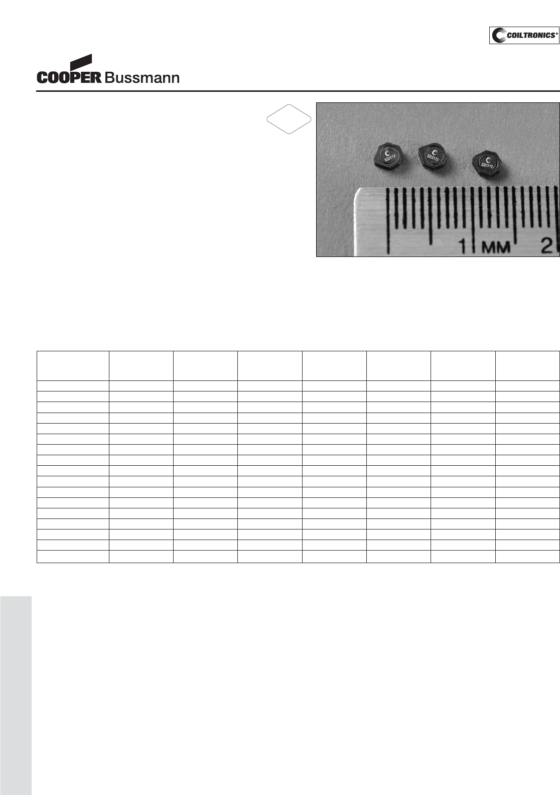
PM-86
LOW PROFILE SHIELDED DRUM (SD3112)
Description
• 125°C maximum total temperature operation
• 3.1mm x 3.1mm x 1.2mm shielded drum core
• Ferrite core material
• Inductance range from 1.0uH to 220uH
• Current range from 1.65 Amps to 0.113 Amps
• Frequency range up to 4MHz
Applications
• Cellular phones, Digital cameras, CD players, PDA’s
• Small LCD displays
• LED driver and LED flash circuits
• Hard disk drives
• Backlighting
• EL panel
Environmental Data
• Storage temperature range: -40°C to +125°C
• Operating temperature range: -40°C to +125°C
(range is application specific)
• Solder reflow temperature: +260°C max. for 10 seconds
maximum
Packaging
• Supplied in tape and reel packaging, 4100 per reel
SD3112 Series
Low Profile Power Inductors
Part Number Rated OCL (1) Part Irms (2) Isat (3) DCR (Ω) K-factor
Inductance (μH) Marking Amperes Amperes typ. @ (4)
(μH) Designator 20°C
SD3112-1R0-R 1.0 1.11+/-30% A 1.39 1.65 0.069 135
SD3112-1R5-R 1.5 1.70+/-30% B 1.16 1.33 0.099 110
SD3112-2R2-R 2.2 2.41+/-30% C 0.97 1.12 0.140 92
SD3112-3R3-R 3.3 3.24+/-30% D 0.90 0.97 0.165 79
SD3112-4R7-R 4.7 4.72+/-30% E 0.74 0.80 0.246 66
SD3112-6R8-R 6.8 6.47+/-30% F 0.68 0.68 0.291 56
SD3112-8R2-R 8.2 8.50+/-30% G 0.57 0.60 0.408 49
SD3112-100-R 10.0 10.01+/-30% H 0.55 0.55 0.446 45
SD3112-150-R 15.0 15.28+/-20% I 0.45 0.44 0.654 37
SD3112-220-R 22.0 21.66+/-20% J 0.37 0.37 0.953 31
SD3112-330-R 33.0 33.30+/-20% K 0.30 0.30 1.48 25
SD3112-470-R 47.0 47.44+/-20% L 0.270 0.25 1.85 21
SD3112-680-R 68.0 68.10+/-20% M 0.228 0.211 2.56 17
SD3112-820-R 82.0 83.19+/-20% N 0.213 0.190 2.93 16
SD3112-101-R 100.0 99.8+/-20% O 0.184 0.174 3.95 14
SD3112-151-R 150.0 149.4+/-20% P 0.149 0.142 6.01 12
SD3112-221-R 220.0 219.9+/-20% Q 0.121 0.117 9.12 10
(1) Open Circuit Inductance Test Parameters: 100kHz, 0.1V, 0.0Adc.
(2) Irms: DC current for an approximate DT of 40°C without core loss. Derating is
necessary for AC currents. PCB layout, trace thickness and width, air-flow, and
proximity of other heat generating components will affect the temperature rise. It
is recommended that the temperature of the part not exceed 125°C under worst
case operating conditions verified in the end application.
(3) Isat Amperes peak for approximately 30% rolloff (@20°C)
(4) K-factor: Used to determine B p-p for core loss (see graph).
B p-p = K*L*ΔI, B p-p(mT), K: (K factor from table), L: (Inductance in uH),
ΔI (Peak to peak ripple current in Amps).
RoHS
2002/95/EC
Courtesy of Steven Engineering, Inc.-230 Ryan Way, South San Francisco, CA 94080-6370-Main Office: (650) 588-9200-Outside Local Area: (800) 258-9200-www.stevenengineering.com
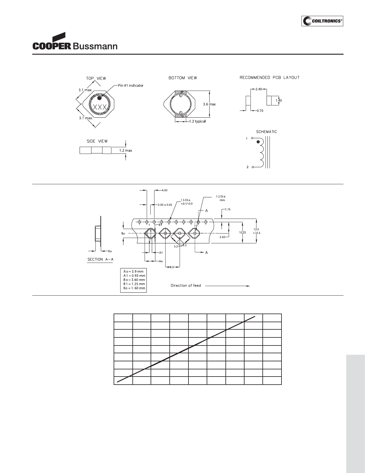
PM-87
LOW PROFILE SHIELDED DRUM (SD3112)
SD3112 Series
Low Profile Power Inductors
DC Current vs. Temperature
0
10
20
30
40
50
60
70
80
90
0 0.05 0.1 0.15 0.2 0.25 0.3 0.35 0.4 0.45
Total Loss (W)
Temp. Rise(°C)
Dimensions are in millimeters.
Parts packaged on 13" Diameter reel,
4,100 parts per reel.
Packaging Information
Part Marking:
3 Digit Marking: (1st digit: Indicates inductance value per letter in Part Marking Designator); (2nd digit: Bi-weekly production date code); (3rd digit: Last digit of the year produced).
Mechanical Diagrams
Courtesy of Steven Engineering, Inc.-230 Ryan Way, South San Francisco, CA 94080-6370-Main Office: (650) 588-9200-Outside Local Area: (800) 258-9200-www.stevenengineering.com
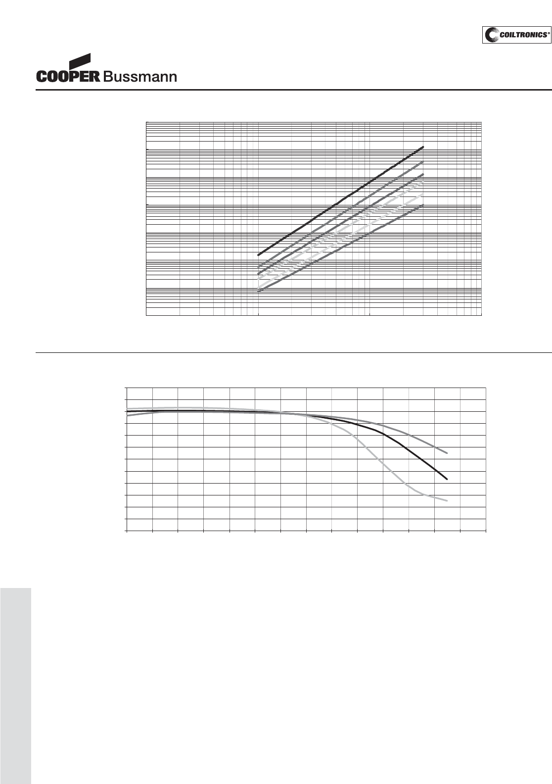
PM-88
LOW PROFILE SHIELDED DRUM (SD3112)
OCL vs Isat
0%
10%
20%
30%
40%
50%
60%
70%
80%
90%
100%
110%
120%
0% 10% 20% 30% 40% 50% 60% 70% 80% 90% 100% 110% 120% 130% 140%
% of Isat
% of OCL
-40°C
25°C
85°C
0%
10%
20%
30%
40%
50%
60%
70%
80%
90%
100%
110%
120%
0% 10% 20% 30% 40% 50% 60% 70% 80% 90% 100% 110%
% of Isat
% of OCL
Inductance Characteristics
SD3112 Series
Low Profile Power Inductors
Core Loss
1MHz
500kHz
300kHz
200kHz
100kHz
50kHz
0.000001
0.00001
0.0001
0.001
0.01
0.1
1
10
1 10 100 1000
Bp-p (mT)
Core Loss (W)
Courtesy of Steven Engineering, Inc.-230 Ryan Way, South San Francisco, CA 94080-6370-Main Office: (650) 588-9200-Outside Local Area: (800) 258-9200-www.stevenengineering.com
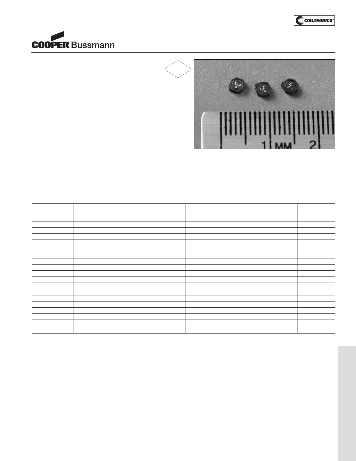
PM-89
LOW PROFILE SHIELDED DRUM (SD3114)
Description
• 125°C maximum total temperature operation
• 3.1mm x 3.1mm x 1.4mm shielded drum core
• Ferrite core material
• Inductance range from 1.0uH to 330uH
• Current range from 2.59 Amps to 0.106 Amps
• Frequency range up to 4MHz
Applications
• Cellular phones, Digital cameras, CD players, PDA’s
• Small LCD displays
• LED driver and LED flash circuits
• Hard disk drives
• Backlighting
• EL panel
Environmental Data
• Storage temperature range: -40°C to +125°C
• Operating temperature range: -40°C to +125°C
(range is application specific)
• Solder reflow temperature: +260°C max. for 10 seconds
maximum
Packaging
• Supplied in tape and reel packaging, 4100 per reel
SD3114 Series
Low Profile Power Inductors
Part Number Rated OCL (1) Part Irms (2) Isat (3) DCR (Ω) K-factor
Inductance (μH) Marking Amperes Amperes typ. @ (4)
(μH) Designator 20°C
SD3114-1R0-R 1.0 1.16+/-30% A 1.60 2.35 0.058 98
SD3114-1R5-R 1.5 1.44+/-30% B 1.39 2.11 0.077 79
SD3114-2R2-R 2.2 2.12+/-30% C 1.17 1.74 0.110 67
SD3114-3R3-R 3.3 3.36+/-30% D 0.95 1.38 0.167 54
SD3114-4R7-R 4.7 4.90+/-30% E 0.77 1.14 0.251 45
SD3114-6R8-R 6.8 6.72+/-30% F 0.71 0.98 0.296 37
SD3114-8R2-R 8.2 8.10+/-30% G 0.68 0.89 0.329 34
SD3114-100-R 10.0 10.4+/-30% H 0.57 0.78 0.458 30
SD3114-150-R 15.0 14.9+/-20% I 0.48 0.66 0.650 25
SD3114-220-R 22.0 22.5+/-20% J 0.43 0.53 0.821 21
SD3114-330-R 33.0 33.1+/-20% K 0.35 0.44 1.23 17
SD3114-470-R 47.0 47.5+/-20% L 0.280 0.37 1.86 14
SD3114-680-R 68.0 68.6+/-20% M 0.239 0.305 2.62 12
SD3114-820-R 82.0 81.8+/-20% N 0.227 0.280 2.91 11
SD3114-101-R 100.0 101.1+/-20% O 0.213 0.252 3.30 10
SD3114-151-R 150.0 149.0+/-20% P 0.172 0.207 5.07 8
SD3114-221-R 220.0 220.9+/-20% Q 0.140 0.170 7.67 6
SD3114-331-R 330.0 329.5+/-20% R 0.113 0.139 11.78 5
(1) Open Circuit Inductance Test Parameters: 100kHz, 0.1V, 0.0Adc.
(2) Irms: DC current for an approximate DT of 40°C without core loss. Derating is
necessary for AC currents. PCB layout, trace thickness and width, air-flow, and
proximity of other heat generating components will affect the temperature rise. It
is recommended that the temperature of the part not exceed 125°C under worst
case operating conditions verified in the end application.
(3) Isat Amperes peak for approximately 30% rolloff (@20°C)
(4) K-factor: Used to determine B p-p for core loss (see graph).
B p-p = K*L*ΔI, B p-p(mT), K: (K factor from table), L: (Inductance in uH),
ΔI (Peak to peak ripple current in Amps).
RoHS
2002/95/EC
Courtesy of Steven Engineering, Inc.-230 Ryan Way, South San Francisco, CA 94080-6370-Main Office: (650) 588-9200-Outside Local Area: (800) 258-9200-www.stevenengineering.com
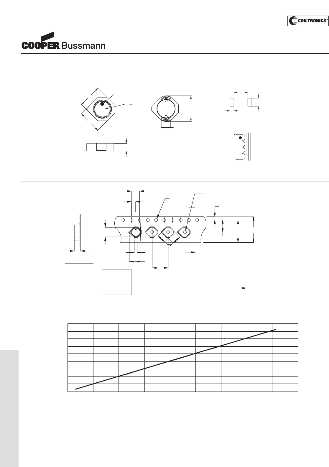
PM-90
LOW PROFILE SHIELDED DRUM (SD3114)
SD3114 Series
Low Profile Power Inductors
DC Current vs. Temperature
0
10
20
30
40
50
60
70
80
90
0 0.05 0.1 0.15 0.2 0.25 0.3 0.35 0.4 0.45
Total Loss(W)
Temp. Rise (°C)
Dimensions are in millimeters.
2
1
10.25 12.0
+/-0.3
1.75
1.5 Dia.
+0.1/-0.0
1.2 Dia
min.
8.0
3.2
B1
3.2
A
5.50
A
Ao = 3.9 mm
A1 = 0.93 mm
Bo = 3.60 mm
B1 = 1.25 mm
Ko = 1.60 mm Direction of feed
A1
Ao
2.00 ¡À0.05
4.00
Ko
SECTION A-A
Bo
Parts packaged on 13" Diameter reel,
4,100 parts per reel.
Packaging Information
2.40
0.70
1.40
RECOMMENDED PCB LAYOUT
SCHEMATI C
BOTTOM VIEW
SIDE VIEW
TOP VIEW
Marking
3.1 max.
3.1 max.
XXX
Pin #1 indicator
1.2 typical
3.7 max
1.4 max
1
2
Part Marking:
3 Digit Marking: (1st digit: Indicates inductance value per letter in Part Marking Designator); (2nd digit: Bi-weekly production date code); (3rd digit: Last digit of the year produced).
Mechanical Diagrams
Courtesy of Steven Engineering, Inc.-230 Ryan Way, South San Francisco, CA 94080-6370-Main Office: (650) 588-9200-Outside Local Area: (800) 258-9200-www.stevenengineering.com
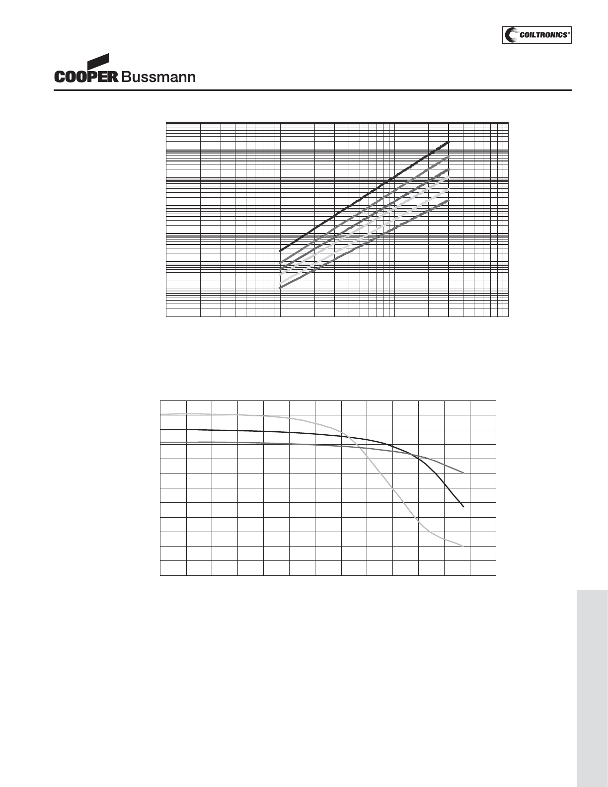
PM-91
LOW PROFILE SHIELDED DRUM (SD3114)
0%
10%
20%
30%
40%
50%
60%
70%
80%
90%
100%
110%
120%
0% 10% 20% 30% 40% 50% 60% 70% 80% 90% 100% 110% 120% 130%
% ofL initia
l
-40°C
25°C
85°C
OCL vs. Isat
Inductance Characteristics
SD3114 Series
Low Profile Power Inductors
Core Loss
1MHz
500kH z
300kHz
200kHz
100kH z
50kHz
0.000001
0.00001
0.0001
0.001
0.01
0.1
1
10
1 10 100 1000
Bp-p (mT)
Core Loss (W)
Courtesy of Steven Engineering, Inc.-230 Ryan Way, South San Francisco, CA 94080-6370-Main Office: (650) 588-9200-Outside Local Area: (800) 258-9200-www.stevenengineering.com
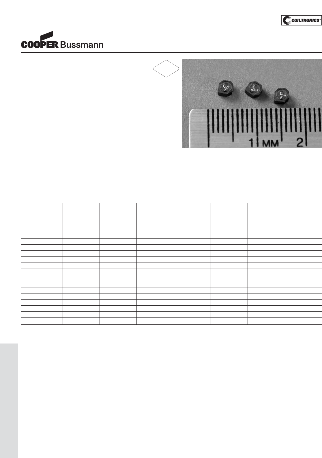
PM-92
LOW PROFILE SHIELDED DRUM (SD3118)
Description
• 125°C maximum total temperature operation
• 3.1mm x 3.1mm x 1.8mm shielded drum core
• Ferrite core material
• Inductance range from 1.0uH to 1000uH
• Current range from 2.94 Amps to 0.083 Amps
• Frequency range up to 4MHz
Applications
• Cellular phones, Digital cameras, CD players, PDA’s
• Small LCD displays
• LED driver and LED flash circuits
• Hard disk drives
• Backlighting
• EL panel
Environmental Data
• Storage temperature range: -40°C to +125°C
• Operating temperature range: -40°C to +125°C
(range is application specific)
• Solder reflow temperature: +260°C max. for 10 seconds
maximum
Packaging
• Supplied in tape and reel packaging, 4100 per reel
SD3118 Series
Low Profile Power Inductors
Part Number Rated OCL (1) Part Irms (2) Isat (3) DCR (Ω) K-factor
Inductance (μH) Marking Amperes Amperes typ. @ (4)
(μH) Designator 20°C
SD3118-1R0-R 1.0 1.04+/-30% A 2.01 3.07 0.041 84
SD3118-1R5-R 1.5 1.44+/-30% B 1.81 2.42 0.051 68
SD3118-2R2-R 2.2 2.12+/-30% C 1.50 2.00 0.074 57
SD3118-3R3-R 3.3 3.36+/-30% D 1.22 1.59 0.113 56
SD3118-4R7-R 4.7 4.90+/-30% E 1.02 1.31 0.162 39
SD3118-6R8-R 6.8 6.72+/-30% F 0.85 1.12 0.232 32
SD3118-8R2-R 8.2 8.10+/-30% G 0.81 1.02 0.257 29
SD3118-100-R 10.0 10.4+/-30% H 0.75 0.90 0.295 26
SD3118-150-R 15.0 14.9+/-20% I 0.62 0.75 0.440 21
SD3118-220-R 22.0 22.5+/-20% J 0.50 0.61 0.676 18
SD3118-330-R 33.0 33.1+/-20% K 0.41 0.51 0.986 14
SD3118-470-R 47.0 47.5+/-20% L 0.370 0.42 1.21 12
SD3118-221-R 220.0 221.9+/-20% M 0.182 0.177 4.77 6
SD3118-331-R 330.0 329.9+/-20% N 0.146 0.145 7.40 5
SD3118-471-R 470.0 470.1+/-20% O 0.131 0.122 9.20 4
SD3118-681-R 680.0 680.3+/-20% P 0.107 0.101 13.70 3
SD3118-102-R 1000.0 999.4+/-20% Q 0.087 0.083 20.90 3
(1) Open Circuit Inductance Test Parameters: 100kHz, 0.1V, 0.0Adc.
(2) Irms: DC current for an approximate DT of 40°C without core loss. Derating is
necessary for AC currents. PCB layout, trace thickness and width, air-flow, and
proximity of other heat generating components will affect the temperature rise. It
is recommended that the temperature of the part not exceed 125°C under worst
case operating conditions verified in the end application.
(3) Isat Amperes peak for approximately 30% rolloff (@20°C)
(4) K-factor: Used to determine B p-p for core loss (see graph).
B p-p = K*L*ΔI, B p-p(mT), K: (K factor from table), L: (Inductance in uH),
ΔI (Peak to peak ripple current in Amps).
RoHS
2002/95/EC
Courtesy of Steven Engineering, Inc.-230 Ryan Way, South San Francisco, CA 94080-6370-Main Office: (650) 588-9200-Outside Local Area: (800) 258-9200-www.stevenengineering.com
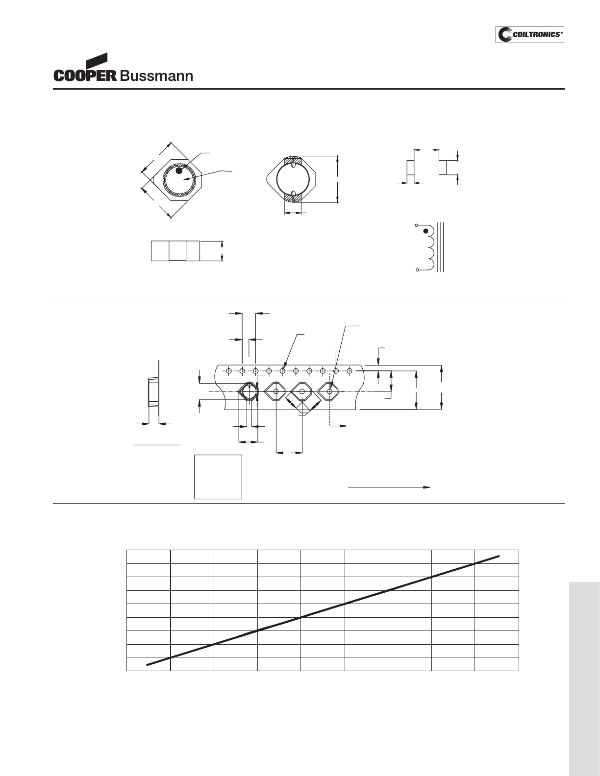
PM-93
LOW PROFILE SHIELDED DRUM (SD3118)
SD3118 Series
Low Profile Power Inductors
DC Current vs. Temperature
0
10
20
30
40
50
60
70
80
90
0 0.05 0.1 0.15 0.2 0.25 0.3 0.35 0.4 0.45
Total Loss(W)
Temp.Rise(°C)
Dimensions are in millimeters.
A1
Ao
4.00
Ko
SECTION A-A
Bo
2
1
10.25 12.0
+/-0.3
1.75
1.5 Dia.
+0.1/-0.0
1.2 Dia
min.
8.0
3.2
B1
3.2
A
5.50
A
Ao = 3.9 mm
A1 = 0.93 mm
Bo = 3.70 mm
B1 = 1.25 mm
Ko = 2.00 mm Direction of feed
2.00 ¡À0.05
Parts packaged on 13" Diameter reel,
4,100 parts per reel.
Packaging Information
SCHEMATIC
1
2
BOTTOM VIEW
SIDE VIEW
TOP VIEW
Marking
3.1 max.
3.1 max.
XXX
Pin #1 indicator
1.2 typical
3.7 max
1.8 max
2.40
0.70
1.40
RECOMMENDED PCB LAYOUT
Part Marking:
3 Digit Marking: (1st digit: Indicates inductance value per letter in Part Marking Designator); (2nd digit: Bi-weekly production date code); (3rd digit: Last digit of the year produced).
Mechanical Diagrams
Courtesy of Steven Engineering, Inc.-230 Ryan Way, South San Francisco, CA 94080-6370-Main Office: (650) 588-9200-Outside Local Area: (800) 258-9200-www.stevenengineering.com
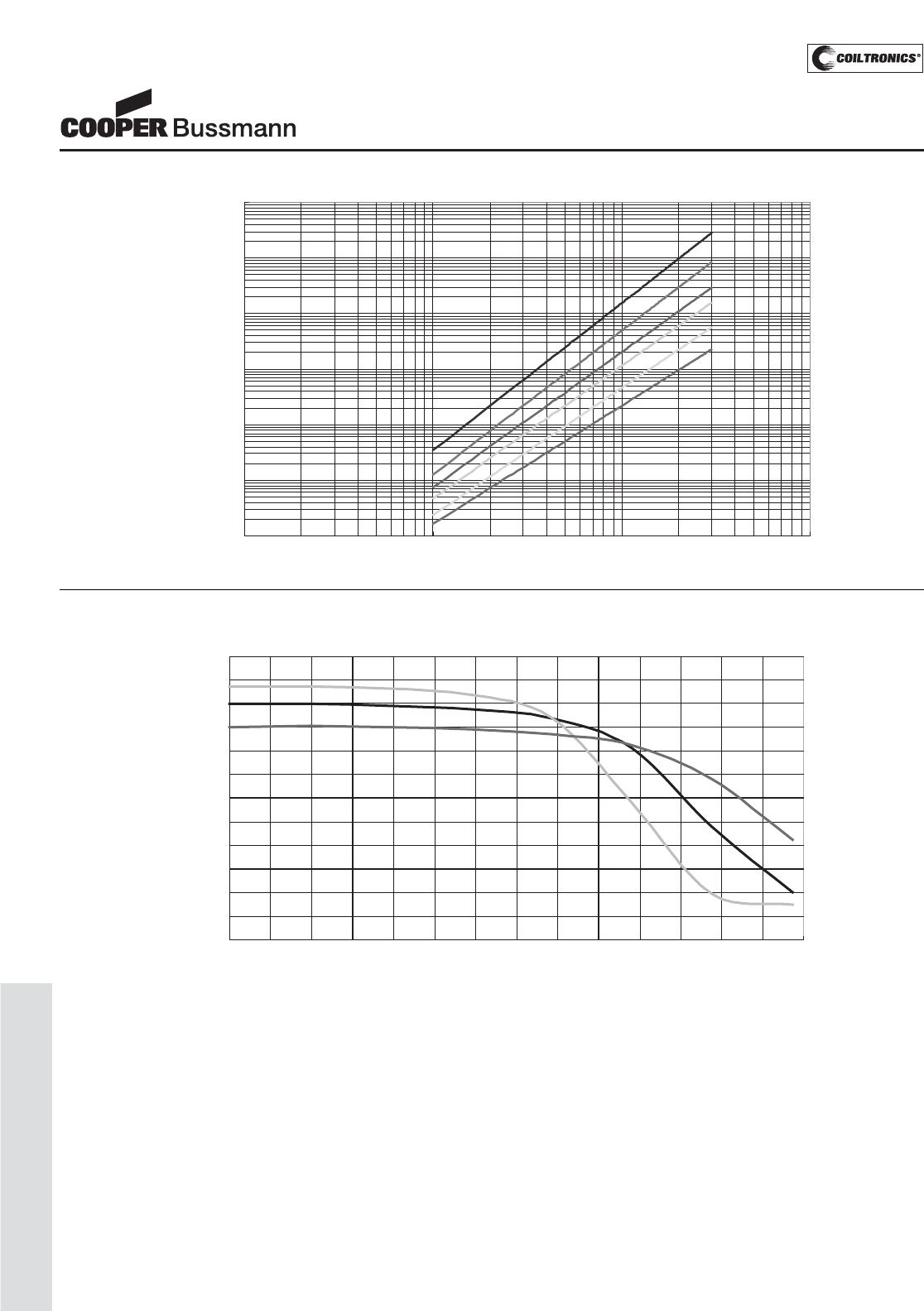
PM-94
LOW PROFILE SHIELDED DRUM (SD3118)
0%
10%
20%
30%
40%
50%
60%
70%
80%
90%
100%
110%
120%
0% 10% 20% 30% 40% 50% 60% 70% 80% 90% 100% 110% 120% 130% 140%
% o
OCL vs. Isat
f Isat
% of L initial
-40°C
25°C
85°C
Inductance Characteristics
SD3118 Series
Low Profile Power Inductors
Core Loss
1MHz
500kHz
300kHz
200kHz
100kHz
50kHz
0.00001
0.0001
0.001
0.01
0.1
1
10
1 10 100 1000
Bp-p (mT)
Core Loss (W)
Courtesy of Steven Engineering, Inc.-230 Ryan Way, South San Francisco, CA 94080-6370-Main Office: (650) 588-9200-Outside Local Area: (800) 258-9200-www.stevenengineering.com
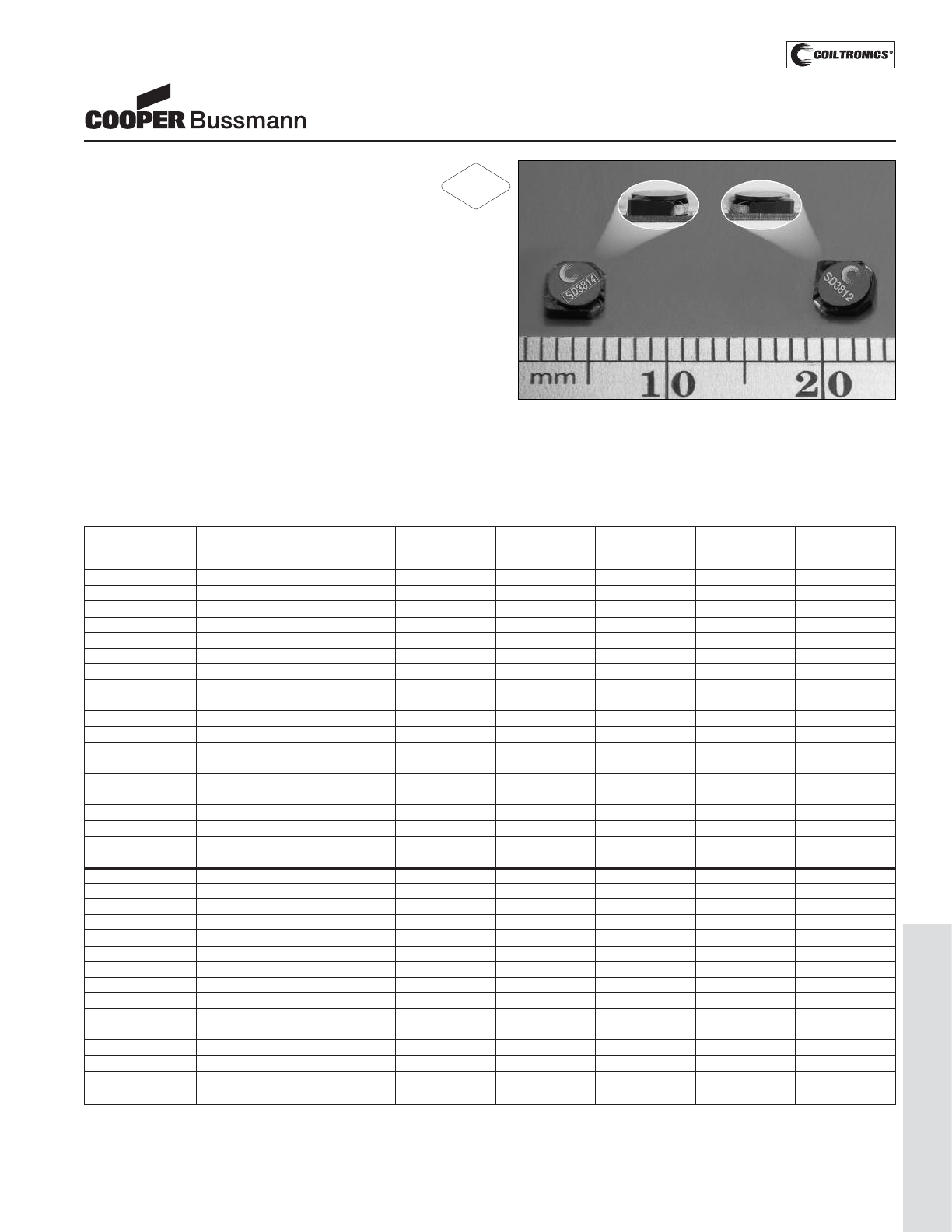
PM-95
LOW PROFILE SHIELDED DRUM (SD38)
Description
• 3.8mm x 3.8mm shielded drum cores available
in two heights: 1.2mm and 1.4mm
• Current range from 4.44 to 0.100 Amps
• Inductance range from 0.47 uH to 680 uH
• Ferrite shielded, low EMI
• Ferrite core material
Applications
• Digital cameras, cellular phones, CD players, and PDAs
• PCMCIA cards
• GPS systems
Environmental Data
• Storage temperature range: -40°C to +125°C
• Operating ambient temperature range: -40°C to +85°C
(range is application specific). Temperature rise is
approximately 40°C at rated rms current
• Solder reflow temperature: +260°C max for 10 seconds
max.
Packaging
• Supplied in tape and reel packaging,
4,150 parts per 13" reel
SD38 Series
Low Profile, Shielded Inductors
(1) Test Parameters: 100KHz, 0.100Vrms, 0.0Adc.
(2) RMS current for an approximate ΔT of 40°C without core loss. It is recommend-
ed that the temperature of the part not exceed 125°C.
De-rating is necessary for AC currents.
(3) Peak current for approximately 30% rolloff at 20°C.
(4) DCR limits @ 20°C.
(5) Applied Volt-Time product (V-uS) across the inductor at 100kHz necessary to
generate a core loss equal to 10% of the total losses for 40°C temperature rise.
De-rating of the Irms is required to prevent excessive temperature rise.
Part Number Rated OCL (1) Part Irms (2) Isat (3) DCR (4) Volt (5)
Inductance +/-15% Marking Amperes Amperes (Ω) u-sec
(μH) (μH) Designator Typ. Typ.
SD3812-R47-R 0.47 0.405 A 2.53 3.89 0.030 2.52
SD3812-1R0-R 1.0 0.845 B 2.00 2.69 0.048 3.64
SD3812-1R2-R 1.2 1.125 C 1.71 2.33 0.066 4.20
SD3812-1R5-R 1.5 1.445 D 1.58 2.06 0.078 4.76
SD3812-2R2-R 2.2 2.205 E 1.32 1.67 0.111 5.88
SD3812-3R3-R 3.3 3.125 F 1.10 1.40 0.159 7.0
SD3812-4R7-R 4.7 4.805 G 0.87 1.13 0.256 8.7
SD3812-6R8-R 6.8 6.845 H 0.80 0.95 0.299 10.4
SD3812-8R2-R 8.2 8.405 I 0.690 0.854 0.406 11.5
SD3812-100-R 10.0 10.125 J 0.662 0.778 0.441 12.6
SD3812-150-R 15.0 15.125 K 0.539 0.636 0.665 15.4
SD3812-220-R 22.0 21.125 L 0.499 0.538 0.776 18.2
SD3812-330-R 33.0 32.805 M 0.399 0.432 1.212 22.7
SD3812-470-R 47.0 47.045 N 0.327 0.361 1.809 27.2
SD3812-680-R 68.0 68.445 O 0.269 0.299 2.666 32.8
SD3812-820-R 82.0 80.645 P 0.259 0.276 2.885 36
SD3812-101-R 100.0 99.405 Q 0.217 0.248 4.099 39
SD3812-151-R 150.0 149.645 R 0.178 0.202 6.130 48
SD3812-221-R 220.0 218.405 S 0.160 0.167 7.585 59
SD3814-R47-R 0.47 0.360 A 2.81 4.44 0.020 2.16
SD3814-R82-R 0.82 0.752 B 2.18 3.08 0.033 3.12
SD3814-1R2-R 1.2 1.001 C 1.85 2.67 0.046 3.60
SD3814-1R5-R 1.5 1.286 D 1.76 2.35 0.051 4.08
SD3814-2R2-R 2.2 1.962 E 1.43 1.90 0.077 5.04
SD3814-3R3-R 3.3 2.781 F 1.31 1.60 0.093 6.0
SD3814-4R7-R 4.7 4.276 G 1.06 1.29 0.141 7.4
SD3814-6R8-R 6.8 6.768 H 0.87 1.03 0.207 9.4
SD3814-8R2-R 8.2 8.228 I 0.753 0.930 0.279 10.3
SD3814-100-R 10.0 9.830 J 0.713 0.851 0.311 11.3
SD3814-150-R 15.0 14.458 K 0.574 0.702 0.481 13.7
SD3814-220-R 22.0 21.186 L 0.519 0.580 0.589 16.6
SD3814-330-R 33.0 32.151 M 0.418 0.471 0.908 20.4
SD3814-470-R 47.0 47.210 N 0.346 0.388 1.322 24.7
SD3814-680-R 68.0 67.324 O 0.285 0.325 1.951 29.5
RoHS
2002/95/EC
Courtesy of Steven Engineering, Inc.-230 Ryan Way, South San Francisco, CA 94080-6370-Main Office: (650) 588-9200-Outside Local Area: (800) 258-9200-www.stevenengineering.com
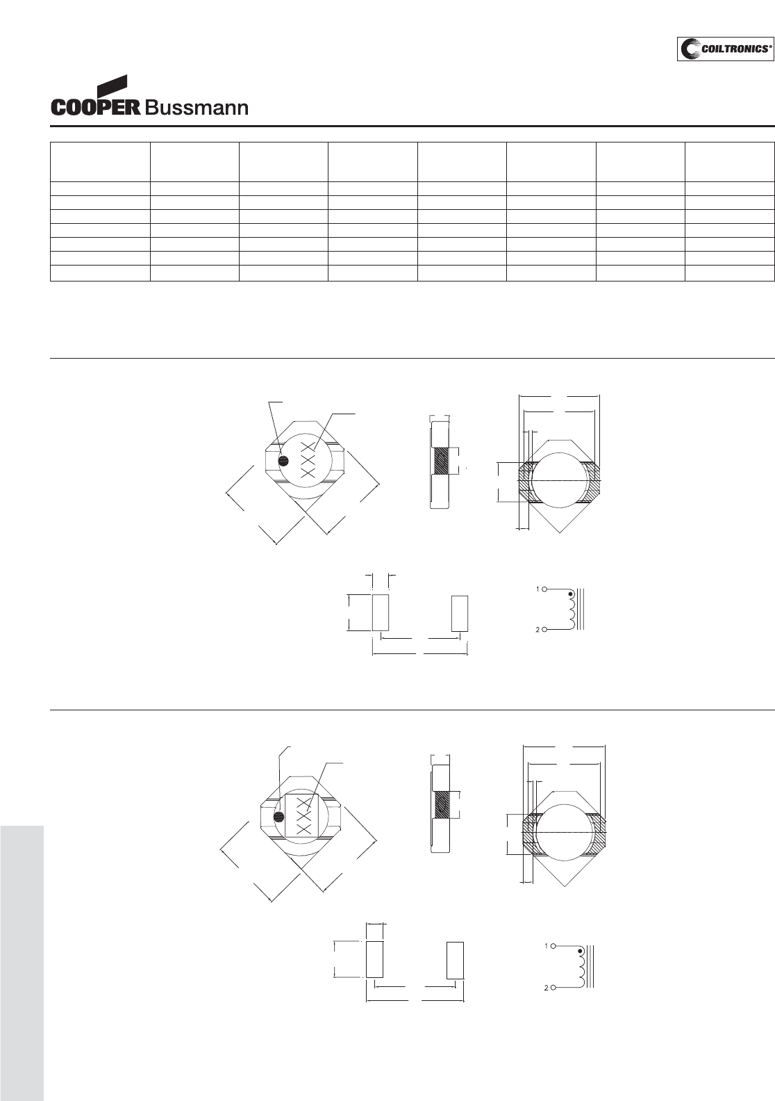
PM-96
LOW PROFILE SHIELDED DRUM (SD38)
(1) Test Parameters: 100KHz, 0.100Vrms, 0.0Adc.
(2) RMS current for an approximate ΔT of 40°C without core loss. It is recommend-
ed that the temperature of the part not exceed 125°C.
De-rating is necessary for AC currents.
(3) Peak current for approximately 30% rolloff at 20°C.
(4) DCR limits @ 20°C.
(5) Applied Volt-Time product (V-uS) across the inductor at 100kHz necessary to
generate a core loss equal to 10% of the total losses for 40°C temperature rise.
De-rating of the Irms is required to prevent excessive temperature rise.
Part Number Rated OCL (1) Part Irms (2) Isat (3) DCR (4) Volt (5)
Inductance +/-15% Marking Amperes Amperes (Ω) u-sec
(μH) (μH) Designator Typ. Typ.
SD3814-820-R 82.0 81.101 P 0.270 0.296 2.174 32
SD3814-101-R 100.0 98.794 Q 0.228 0.268 3.048 36
SD3814-151-R 150.0 149.026 R 0.191 0.219 4.359 44
SD3814-221-R 220.0 217.342 S 0.170 0.181 5.480 53
SD3814-331-R 330.0 326.812 T 0.136 0.148 8.59 65
SD3814-471-R 470.0 470.031 U 0.111 0.123 12.85 78
SD3814-681-R 680.0 680.320 V 0.100 0.102 15.78 94
SD38 Series
Low Profile, Shielded Inductors
Mechanical Diagrams TOP VIEW SIDE VIEW BOTTOM VIEW
RECOMMENDED PCB LAYOUT SCHEMATIC
1.2
max
1.25
±0.12
5.0
1.0
2 plcs
2.5
2plcs
4.0 typ
4.0
max
4.0
max
Pin #1 indicator Marking
(see note A)
2.03
±.0 2
0.09 max
no plating
4.8
MAX
3.65
typ
0.
415 min
SD3812 Series
Note A: 3 digit marking. First digit indicates inductance value per chart above.
Second digit indicates bi-weekly date code.
Third digit of year produced. Box indicates SD3814 part.
TOP VIEW SIDE VIEW BOTTOM VIEW
RECOMMENDED PCB LAYOUT
SCHEMATIC
1.4
max
1.25
±0.12
2.5
2 plcs
1.0
2 plcs
4.0 typ
5.0
4.0
max
4.0
max
Pin #1 indicator
Marking
(see note A)
2.03
±.02
0.09 max
no plating
4.8
MAX
3.65
typ
0.415 min
SD3814 Series
Note A: 3 digit marking. First digit indicates inductance value per chart above.
Second digit indicates bi-weekly date code.
Third digit of year produced. Box indicates SD3814 part.
Courtesy of Steven Engineering, Inc.-230 Ryan Way, South San Francisco, CA 94080-6370-Main Office: (650) 588-9200-Outside Local Area: (800) 258-9200-www.stevenengineering.com
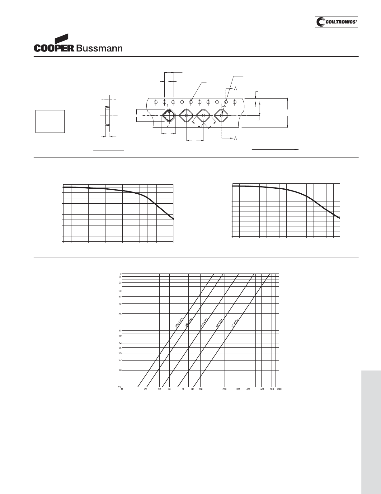
PM-97
LOW PROFILE SHIELDED DRUM (SD38)
SD38 Series
Low Profile, Shielded Inductors
Packaging Information
Ko
1.5 Dia
min.
Bo
8.0
4.00
2.00 ± 0.05 1.5 Dia.
+0.1/-0.0
1.75
5.50
12.0
+/-0.3
Ao
4.5 4.5
SECTION A-A Direction of feed
SD3812/SD3814 Series
Ao=5.1mm
Bo=4.6mm
Ko=1.6mm
Parts packaged on 13" Diameter reel,
4,150 parts per reel.
Inductance Characteristics
OCL vs Isat
SD3812
0
10
20
30
40
50
60
70
80
90
100
0 10 20 30 40 50 60 70 80 90 100 110 120 130
% of Isat
OCL (%)
OCL vs Isat
SD3814
0
10
20
30
40
50
60
70
80
90
100
0 10203040506070809010
0
11
0
12
0
13
0
14
0
15
0
16
0
% of Isat
OCL (%)
Core Loss Irms DERATING WITH CORE LOSS
% of Applied Volt-μSecond
% of Losses from Irms (maximum)
Courtesy of Steven Engineering, Inc.-230 Ryan Way, South San Francisco, CA 94080-6370-Main Office: (650) 588-9200-Outside Local Area: (800) 258-9200-www.stevenengineering.com
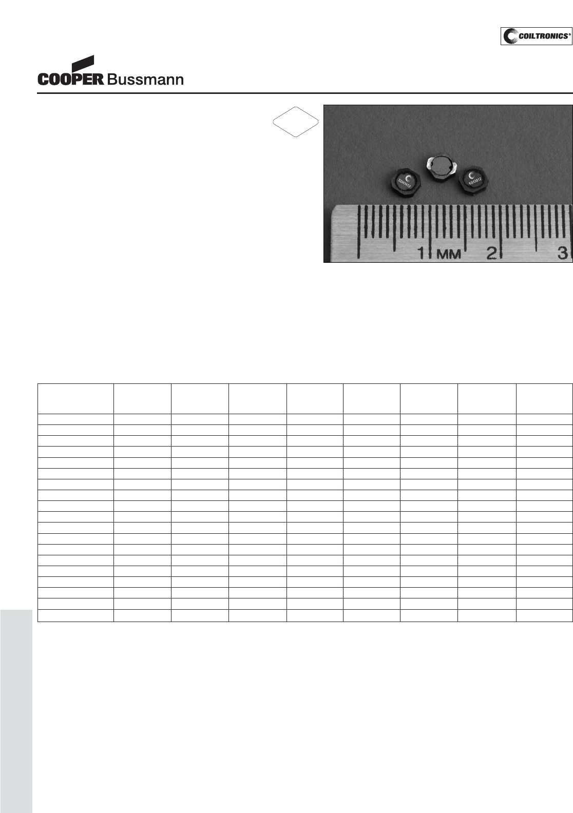
PM-98
LOW PROFILE SHIELDED DRUM (SDH3812)
Description
• 125°C maximum total temperature operation
• 3.8mm x 3.8mm x 1.2mm shielded drum core
• High power density, compact footprint
• Inductance range from 0.47uH to 220uH
• Current range from 4.2 Amps to 0.16 Amps
• Ferrite shielded, low EMI
• Ferrite core material
Applications
• Buck or Boost inductor
• Noise filtering output filter chokes
• LED photo flash
• Handheld devices
• Notebook and battery power
• Cellular phones / PDA’s / GPS systems
• Digital cameras / MP3 players / IP phones
Environmental Data
• Storage temperature range: -40°C to +125°C
• Operating temperature range: -40°C to +125°C
(range is application specific)
• Solder reflow temperature: +260°C max. for 10 seconds
maximum
Packaging
• Supplied in tape and reel packaging, 4150 per reel
SDH3812 Series
Low Profile, High Power, Shielded Inductors
Part Number Rated OCL (1) Part Irms (2) Isat (3) DCR DCR K-factor
Inductance μH ± 20% Marking Amperes Amperes Ω@20°C Ω@20°C (4)
(μH) Designator (Typical) (Maximum)
SDH3812-R47-R 0.47 0.43 A 2.69 4.20 0.027 0.032 145.2
SDH3812-1R0-R 1.0 0.89 B 2.07 3.00 0.045 0.054 100.6
SDH3812-1R2-R 1.2 1.17 C 1.77 2.60 0.062 0.074 87.1
SDH3812-1R5-R 1.5 1.49 D 1.67 2.30 0.069 0.083 76.9
SDH3812-2R2-R 2.2 2.23 E 1.37 1.90 0.104 0.124 62.2
SDH3812-3R3-R 3.3 3.17 F 1.14 1.60 0.148 0.177 52.3
SDH3812-4R7-R 4.7 4.96 G 0.94 1.25 0.220 0.264 42.2
SDH3812-6R8-R 6.8 6.70 H 0.85 1.05 0.265 0.317 35.3
SDH3812-8R2-R 8.2 8.01 I 0.73 0.96 0.342 0.410 33.5
SDH3812-100-R 10.0 9.67 J 0.69 0.88 0.398 0.478 30.4
SDH3812-150-R 15.0 14.45 K 0.56 0.72 0.612 0.735 23.8
SDH3812-220-R 22.0 22.00 L 0.50 0.61 0.750 0.900 20.1
SDH3812-330-R 33.0 32.90 M 0.41 0.49 1.132 1.358 16.1
SDH3812-470-R 47.0 46.20 N 0.34 0.41 1.583 1.900 13.8
SDH3812-680-R 68.0 67.40 O 0.31 0.34 2.000 2.400 11.4
SDH3812-820-R 82.0 81.80 P 0.26 0.31 2.750 3.300 10.3
SDH3812-101-R 100.0 97.50 Q 0.25 0.28 3.042 3.650 9.4
SDH3812-151-R 150.0 149.00 R 0.20 0.22 4.542 5.450 7.6
SDH3812-221-R 220.0 218.50 S 0.16 0.19 7.017 8.420 6.3
(1) Open Circuit Inductance Test Parameters: 100kHz, 0.1V, 0.0Adc.
(2) Irms: DC current for an approximate ΔT of 40°C without core loss. Derating is
necessary for AC currents. PCB layout, trace thickness and width, air-flow, and
proximity of other heat generating components will affect the temperature rise. It
is recommended that the temperature of the part not exceed 125°C under worst
case operating conditions verified in the end application.
(3) Isat Amperes peak for 30% maximum rolloff (@25°C)
(4) K-factor: Used to determine B p-p for core loss (see graph).
B p-p = K*L*ΔI, B p-p(mT), K: (K factor from table), L: (Inductance in uH),
ΔI (Peak to peak ripple current in Amps).
(5) Part Number Definition: SDH3812-xxx-R
SDH3812 = Product code and size; -xxx = Inductance value in uH;
R = decimal point; If no R is present, third character = # of zeros.
-R suffix = RoHS compliant
RoHS
2002/95/EC
Courtesy of Steven Engineering, Inc.-230 Ryan Way, South San Francisco, CA 94080-6370-Main Office: (650) 588-9200-Outside Local Area: (800) 258-9200-www.stevenengineering.com
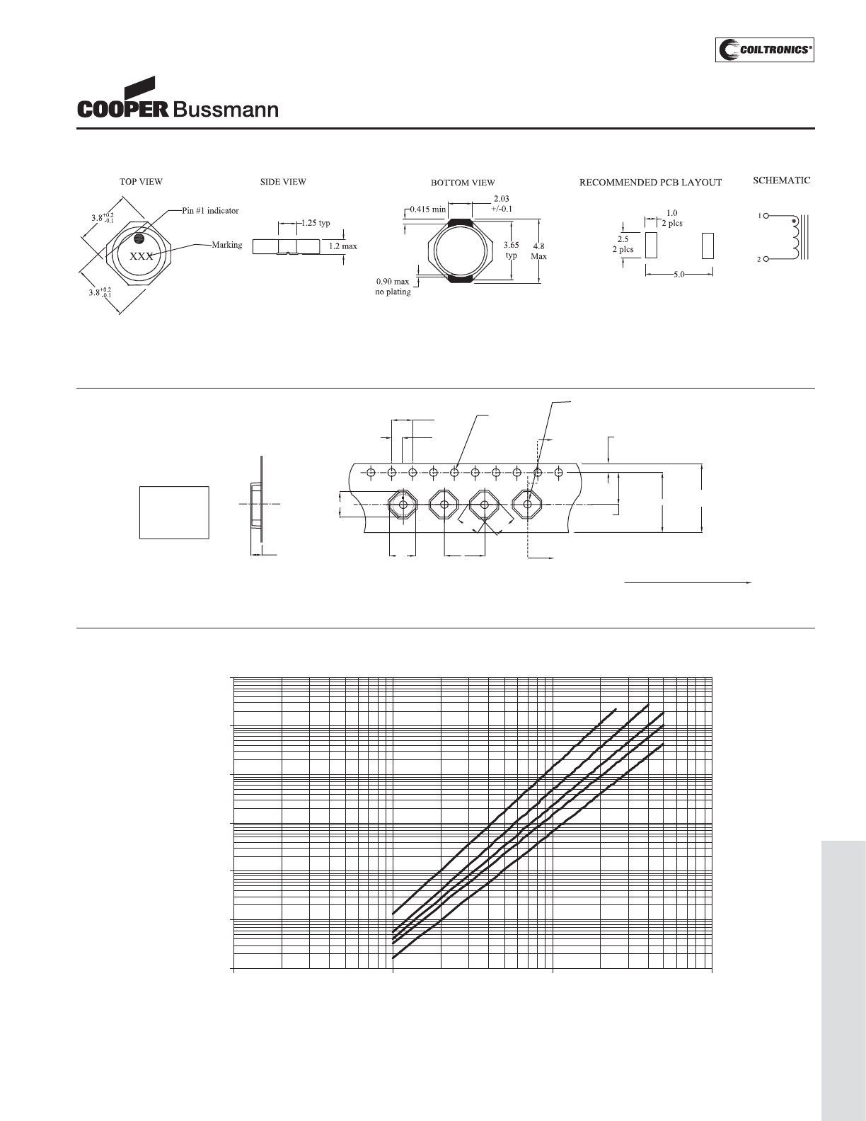
PM-99
LOW PROFILE SHIELDED DRUM (SDH3812)
SDH3812 Series
Low Profile, High Power, Shielded Inductors
Core Loss
1MHz
500kHz 300kHz
200kHz
100kHz
0.000001
0.00001
0.0001
0.001
0.01
0.1
1
1 10 100 1000
Bp-p (mT)
Core Loss (W)
Dimensions are in millimeters.
Direction of feed
Ko
SECTION A-A
1.5 Dia
8
4.00
2.00
1.5 Dia.
A
A
1.75
5.50
12.0
+/-0.3
A0 = 4.9 mm
B0 = 4.9 mm
K0 = 1.6 mm
1
2
10.25
4.2 4.2
Bo
A0
XXX
Parts packaged on 13" Diameter reel,
4,150 parts per reel.
Packaging Information
Part Marking:
3 Digit Marking: (1st digit: Indicates inductance value per Part Marking Designator in chart above); (2nd digit: Bi-weekly production date code); (3rd digit: Last digit of the year produced).
Mechanical Diagrams
Courtesy of Steven Engineering, Inc.-230 Ryan Way, South San Francisco, CA 94080-6370-Main Office: (650) 588-9200-Outside Local Area: (800) 258-9200-www.stevenengineering.com
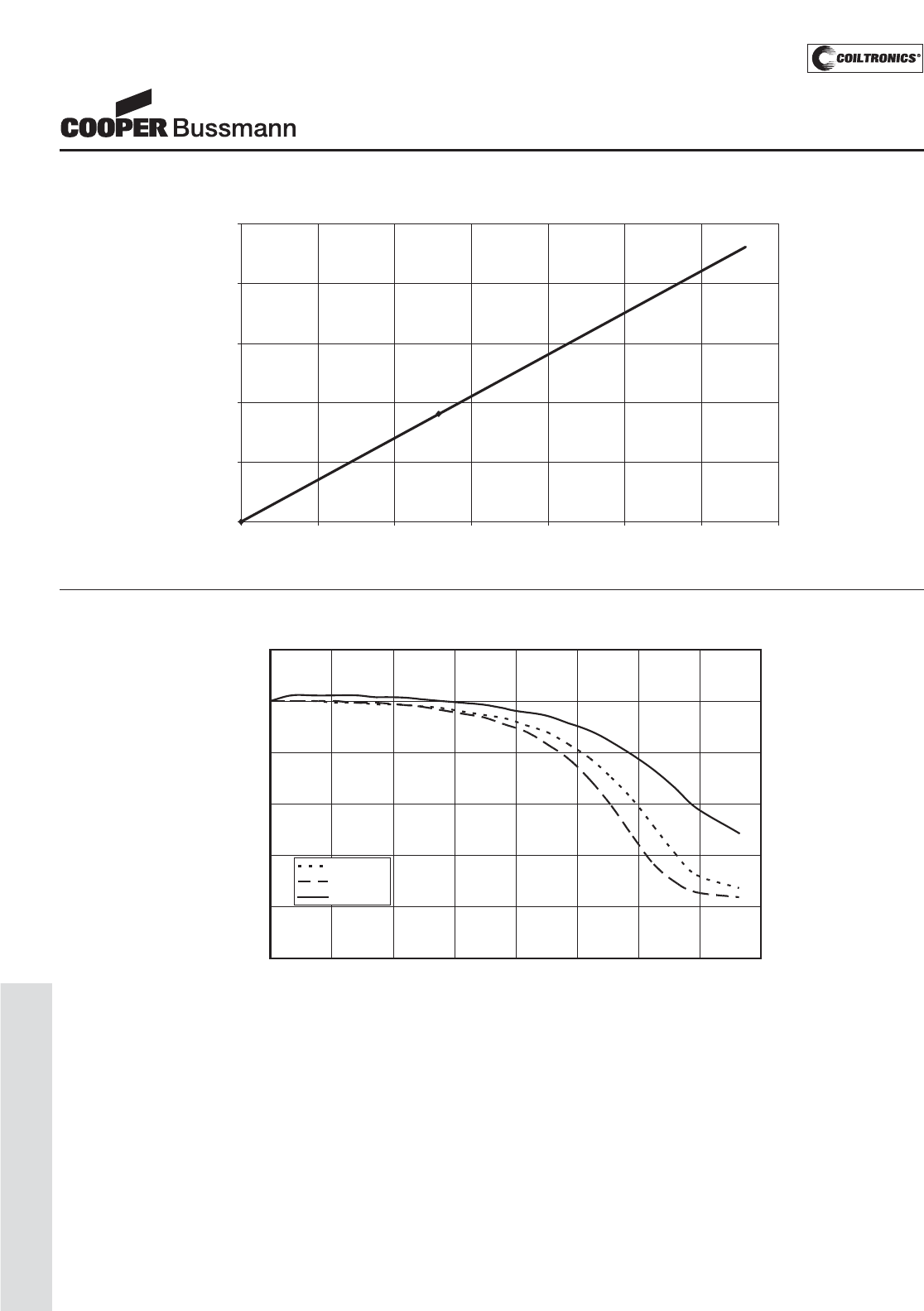
PM-100
LOW PROFILE SHIELDED DRUM (SDH3812)
OCL Vs. Isat
0.00%
20.00%
40.00%
60.00%
80.00%
100.00%
120.00%
0.00% 20.00% 40.00% 60.00% 80.00% 100.00% 120.00% 140.00% 160.00%
Isat %
OCL %
+5 Deg. C
+5 Deg. C
-0 Deg. C
2
8
4
Inductance Characteristics
SDH3812 Series
Low Profile, High Power, Shielded Inductors
Temperature Rise vs. Loss
0
20
40
60
80
100
0 0.1 0.2 0.3 0.4 0.5 0.6 0.7
Total Loss (W)
Temperature Rise (°C)
Courtesy of Steven Engineering, Inc.-230 Ryan Way, South San Francisco, CA 94080-6370-Main Office: (650) 588-9200-Outside Local Area: (800) 258-9200-www.stevenengineering.com
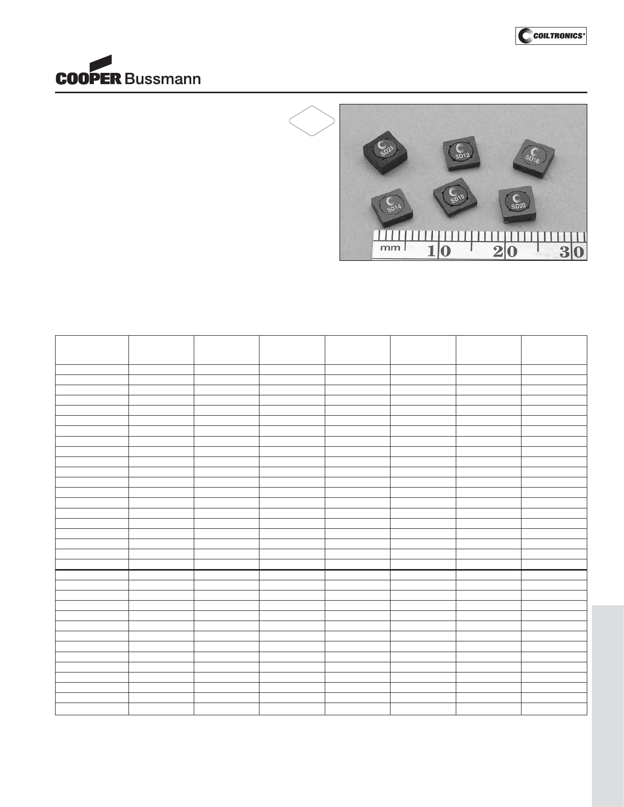
PM-101
LOW PROFILE SHIELDED DRUM (SD)
Description
• Six sizes of shielded drum core inductors with low
profiles (as low as 1.0mm) and high power density
• Inductance range from .47uH to 1000uH
• Current range from 6.00 to 0.088 Amps
• Ferrite shielded, low EMI
• Ferrite core material
Applications
• Digital cameras, CD players, cellular phones, and PDAs
• PCMCIA cards
• GPS systems
Environmental Data
• Storage temperature range: -40°C to +125°C
• Operating ambient temperature range: -40°C to +85°C
(range is application specific). Temperature rise is
approximately 40°C at rated rms current
• Solder reflow temperature: +260°C max. for 10 seconds
max.
Packaging
• Supplied in tape and reel packaging, 3800 (SD10,
SD12, SD14 and SD18), 2900 (SD20 and SD25)
per reel
SD Series
High Power Density,
Low Profile, Shielded Inductors
(1) Open Circuit Inductance Test Parameters: 100KHz, 0.25Vrms, 0.0Adc.
(2) RMS current for an approximate ΔT of 40°C without core loss. It is recommend-
ed that the temperature of the part not exceed 125°C.
(3) SD10,12,18,25 Peak current for approximate 30% roll off at 20°C.
SD14 Peak current for approximate 20% roll off at 20°C.
(4) DCR limits @ 20°C.
5) Applied Volt-Time product (V-uS) across the inductor at 100kHz necessary to
generate a core loss equal to 10% of the total losses for 40°C temperature rise.
Part Number Rated OCL (1) Part Irms (2) Isat (3) DCR (4) Volt
Inductance +/-20% Marking Amperes Amperes (Ω) u-sec
(μH) (μH) Typ. Typ.
SD10-R47-R 0.470 0.453 A 2.59 3.54 0.0249 2.1
SD10-1R0-R 1.00 1.119 B 1.93 2.25 0.0448 3.3
SD10-1R5-R 1.50 1.563 C 1.60 1.91 0.0653 3.9
SD10-2R2-R 2.20 2.081 D 1.35 1.65 0.0912 4.5
SD10-3R3-R 3.30 3.339 E 1.24 1.31 0.1078 5.7
SD10-4R7-R 4.70 4.893 F 1.04 1.08 0.1535 6.9
SD10-6R2-R 6.20 6.743 G 0.94 0.92 0.218 8.1
SD10-8R2-R 8.20 8.889 H 0.800 0.800 0.2607 9.3
SD10-100-R 10.0 10.07 J 0.760 0.752 0.336 9.9
SD10-150-R 15.0 15.55 K 0.613 0.605 0.4429 12.3
SD10-220-R 22.0 22.21 L 0.498 0.506 0.6718 14.7
SD10-330-R 33.0 32.20 M 0.412 0.420 0.9807 17.7
SD10-470-R 47.0 46.63 N 0.337 0.349 1.47 21.3
SD10-680-R 68.0 70.01 O 0.301 0.285 1.84 26.1
SD10-820-R 82.0 83.48 P 0.258 0.261 2.50 28.5
SD10-101-R 100 102.0 Q 0.225 0.236 3.29 31.5
SD10-151-R 150 149.2 R 0.200 0.195 4.15 38.1
SD10-221-R 220 222.2 S 0.161 0.160 6.41 46.5
SD10-331-R 330 330.4 T 0.130 0.131 9.83 56.7
SD10-471-R 470 468.3 U 0.117 0.110 12.10 67.5
SD12-R47-R 0.470 0.490 A 3.19 3.86 0.0246 2.84
SD12-1R2-R 1.20 1.21 B 2.62 2.45 0.0366 4.47
SD12-1R5-R 1.50 1.69 C 2.19 2.08 0.0521 5.28
SD12-2R2-R 2.20 2.25 D 1.83 1.80 0.0747 6.09
SD12-3R3-R 3.30 3.61 E 1.55 1.42 0.1043 7.71
SD12-4R7-R 4.70 4.41 F 1.46 1.29 0.1177 8.53
SD12-6R2-R 6.20 6.25 G 1.21 1.08 0.1699 10.15
SD12-8R2-R 8.20 8.41 H 1.02 0.931 0.2399 11.77
SD12-100-R 10.0 10.89 J 0.938 0.818 0.2844 13.40
SD12-150-R 15.0 15.21 K 0.782 0.692 0.4089 15.83
SD12-220-R 22.0 22.09 L 0.628 0.574 0.6338 19.08
SD12-330-R 33.0 32.49 M 0.519 0.474 0.9289 23.14
SD12-470-R 47.0 47.61 N 0.428 0.391 1.37 28.01
SD12-680-R 68.0 68.89 O 0.341 0.325 2.16 33.70
RoHS
2002/95/EC
Courtesy of Steven Engineering, Inc.-230 Ryan Way, South San Francisco, CA 94080-6370-Main Office: (650) 588-9200-Outside Local Area: (800) 258-9200-www.stevenengineering.com
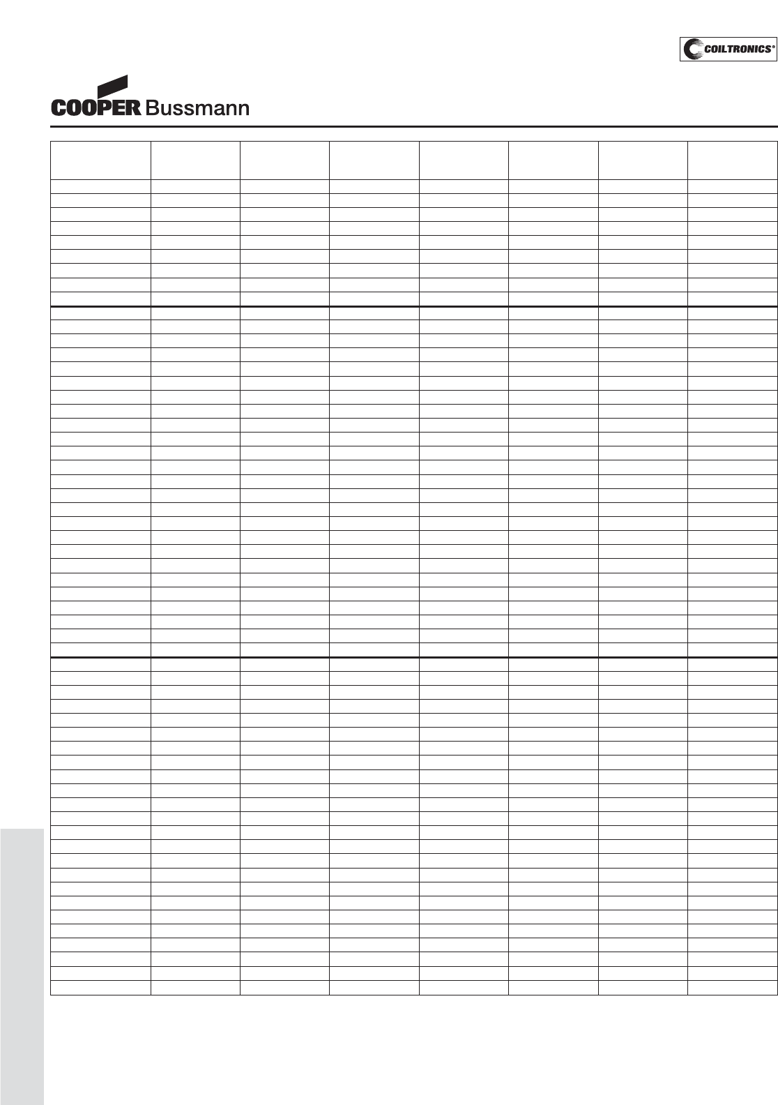
PM-102
LOW PROFILE SHIELDED DRUM (SD)
(1) Open Circuit Inductance Test Parameters: 100KHz, 0.25Vrms, 0.0Adc.
(2) RMS current for an approximate ΔT of 40°C without core loss. It is recommend-
ed that the temperature of the part not exceed 125°C.
(3) SD10,12,18,25 Peak current for approximate 30% roll off at 20°C.
SD14 Peak current for approximate 20% roll off at 20°C.
(4) DCR limits @ 20°C.
5) Applied Volt-Time product (V-uS) across the inductor at 100kHz necessary to
generate a core loss equal to 10% of the total losses for 40°C temperature rise.
Part Number Rated OCL (1) Part Irms (2) Isat (3) DCR (4) Volt
Inductance +/-20% Marking Amperes Amperes (Ω) u-sec
(μH) (μH) Typ. Typ.
SD12-820-R 82.0 82.81 P 0.326 0.297 2.36 36.95
SD12-101-R 100 98.0 Q 0.308 0.273 2.64 40.19
SD12-151-R 150 151.3 R 0.251 0.220 3.96 49.94
SD12-221-R 220 222.0 S 0.229 0.181 4.76 60.49
SD12-331-R 330 334.9 T 0.186 0.148 7.25 74.30
SD12-471-R 470 462.3 U 0.167 0.126 8.95 87.29
SD12-681-R 680 670.8 V 0.149 0.104 11.30 105
SD12-821-R 820 800.9 W 0.129 0.095 14.93 115
SD12-102-R 1000 992.3 X 0.121 0.086 17.20 128
SD14-R58-R 0.58 0.61 A 3.52 4.84 0.0220 3.38
SD14-R87-R 0.87 0.88 B 3.2 3.96 0.0243 4.13
SD14-1R2-R 1.2 1.23 C 2.7 3.35 0.0344 4.88
SD14-1R5-R 1.5 1.63 D 2.53 2.91 0.0390 5.63
SD14-2R0-R 2 2.09 E 2.37 2.56 0.0445 6.38
SD14-2R5-R 2.5 2.62 F 2.05 2.29 0.0595 7.1
SD14-3R2-R 3.2 3.19 G 1.94 2.08 0.0663 7.9
SD14-4R5-R 4.5 4.53 H 1.64 1.74 0.0935 9.4
SD14-6R9-R 6.9 6.98 J 1.35 1.41 0.1363 11.6
SD14-8R8-R 8.8 8.88 K 1.14 1.25 0.1913 13.1
SD14-100-R 10 9.93 L 1.1 1.18 0.2058 13.9
SD14-150-R 15 14.68 M 0.98 0.969 0.2609 16.9
SD14-220-R 22 21.93 N 0.806 0.793 0.3853 20.6
SD14-330-R 33 32.55 O 0.654 0.651 0.5852 25.1
SD14-470-R 47 47.57 P 0.525 0.538 0.9055 30.4
SD14-680-R 68 68.21 Q 0.474 0.449 1.11 36
SD14-820-R 82 83 R 0.408 0.407 1.50 40
SD14-101-R 100 99.25 S 0.386 0.373 1.68 44
SD14-151-R 150 152.4 T 0.315 0.301 2.52 54
SD14-221-R 220 222 U 0.258 0.249 3.77 66
SD14-331-R 330 335.1 V 0.206 0.203 5.92 81
SD14-471-R 470 471.4 W 0.173 0.171 8.34 96
SD14-681-R 680 683.3 X 0.156 0.142 10.3 115
SD14-821-R 820 823.4 Y 0.134 0.129 13.9 126
SD14-102-R 1000 1008 Z 0.126 0.117 15.8 140
SD18-R47-R 0.47 0.49 A 3.58 4.63 0.0201 2.35
SD18-R82-R 0.82 0.81 B 3.24 3.60 0.0247 3.02
SD18-1R2-R 1.20 1.21 C 2.97 2.95 0.0294 3.70
SD18-1R5-R 1.50 1.69 D 2.73 2.49 0.0345 4.37
SD18-2R2-R 2.20 2.25 E 2.55 2.16 0.0398 5.04
SD18-3R3-R 3.30 3.61 F 2.07 1.71 0.0605 6.38
SD18-4R7-R 4.70 4.41 G 1.77 1.54 0.0824 7.06
SD18-6R2-R 6.20 6.25 H 1.61 1.30 0.1000 8.40
SD18-8R2-R 8.20 8.41 J 1.38 1.12 0.1351 9.74
SD18-100-R 10.0 10.89 K 1.28 0.982 0.1584 11.09
SD18-150-R 15.0 15.21 L 1.06 0.831 0.2278 13.10
SD18-220-R 22.0 22.09 M 0.876 0.689 0.3366 15.79
SD18-330-R 33.0 32.49 N 0.715 0.568 0.5057 19.15
SD18-470-R 47.0 47.61 O 0.578 0.470 0.7732 23.18
SD18-680-R 68.0 68.89 P 0.514 0.390 0.9798 27.89
SD18-820-R 82.0 82.81 Q 0.446 0.356 1.30 30.58
SD18-101-R 100 102.01 R 0.419 0.321 1.47 33.94
SD18-151-R 150 151.29 S 0.345 0.263 2.18 41.33
SD18-221-R 220 222.01 T 0.296 0.217 2.95 50.06
SD18-331-R 330 334.89 U 0.248 0.177 4.20 61.49
SD18-471-R 470 479.61 V 0.201 0.148 6.39 73.58
SD18-681-R 680 681.21 W 0.167 0.124 9.28 87.70
SD18-821-R 820 823.69 X 0.145 0.113 12.35 96.43
SD18-102-R 1000 1004 Y 0.136 0.102 14.01 107
SD Series
High Power Density,
Low Profile, Shielded Inductors
Courtesy of Steven Engineering, Inc.-230 Ryan Way, South San Francisco, CA 94080-6370-Main Office: (650) 588-9200-Outside Local Area: (800) 258-9200-www.stevenengineering.com
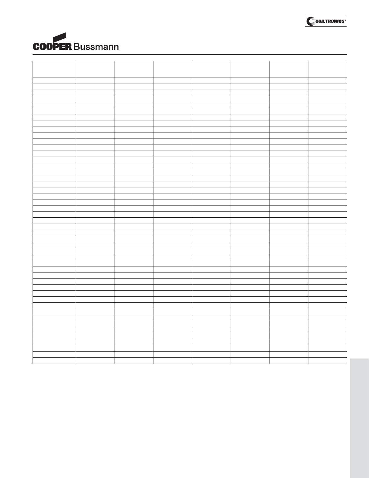
PM-103
LOW PROFILE SHIELDED DRUM (SD)
Part Number Rated OCL (1) Part Irms (2) Isat (3) DCR (4) Volt
Inductance +/-20% Marking Amperes Amperes (Ω) u-sec
(μH) (μH) Typ. Typ.
SD20-R47-R 0.47 0.490 A 3.59 4.00 0.0200 2.28
SD20-1R2-R 1.20 1.21 B 3.07 2.55 0.0275 3.58
SD20-1R5-R 1.50 1.69 C 2.88 2.15 0.0312 4.23
SD20-2R2-R 2.20 2.25 D 2.45 1.87 0.0429 4.88
SD20-3R3-R 3.30 3.61 E 2.17 1.47 0.0547 6.18
SD20-4R7-R 4.70 4.41 F 2.05 1.33 0.0612 6.83
SD20-6R2-R 6.20 6.25 G 1.89 1.12 0.0720 8.13
SD20-8R2-R 8.20 8.41 H 1.61 0.966 0.1000 9.43
SD20-100-R 10.0 9.61 J 1.53 0.903 0.1100 10.08
SD20-150-R 15.0 15.21 K 1.25 0.718 0.1655 12.68
SD20-220-R 22.0 22.09 L 1.12 0.596 0.2053 15.28
SD20-330-R 33.0 32.49 M 0.913 0.491 0.3100 18.53
SD20-470-R 47.0 47.61 N 0.745 0.406 0.4650 22.43
SD20-680-R 68.0 68.89 O 0.610 0.337 0.6947 26.98
SD20-820-R 82.0 82.81 P 0.576 0.308 0.7785 29.58
SD20-101-R 100 98.01 Q 0.495 0.283 1.06 32.18
SD20-151-R 150 151.3 R 0.435 0.228 1.37 39.98
SD20-221-R 220 222.0 S 0.356 0.188 2.04 48.43
SD20-331-R 330 327.6 T 0.294 0.155 2.99 58.83
SD20-471-R 470 470.9 U 0.263 0.129 3.74 70.53
SD20-681-R 680 681.2 V 0.216 0.107 5.56 84.83
SD20-821-R 820 823.7 W 0.204 0.098 6.22 93.28
SD20-102-R 1000 1004.9 X 0.172 0.088 8.73 103
SD25-R47-R 0.47 0.466 A 3.88 6.00 0.0177 2.13
SD25-R82-R 0.82 0.770 B 3.58 4.67 0.0208 2.74
SD25-1R2-R 1.20 1.15 C 3.33 3.81 0.0240 3.34
SD25-1R5-R 1.50 1.61 D 3.12 3.23 0.0274 3.95
SD25-2R2-R 2.20 2.14 E 2.93 2.80 0.0311 4.56
SD25-3R3-R 3.30 3.43 F 2.64 2.21 0.0384 5.78
SD25-4R7-R 4.70 5.03 G 2.39 1.83 0.0467 6.99
SD25-6R8-R 6.80 6.93 H 2.19 1.56 0.0556 8.21
SD25-8R2-R 8.20 7.99 J 1.92 1.45 0.0724 8.82
SD25-100-R 10.0 10.35 K 1.80 1.27 0.0824 10.03
SD25-150-R 15.0 14.45 L 1.67 1.08 0.0956 11.86
SD25-220-R 22.0 22.81 M 1.34 0.857 0.1478 14.90
SD25-330-R 33.0 33.07 N 1.11 0.711 0.2149 17.94
SD25-470-R 47.0 47.89 O 0.919 0.592 0.3156 21.58
SD25-680-R 68.0 68.64 P 0.741 0.482 0.4850 25.84
SD25-820-R 82.0 82.17 Q 0.713 0.441 0.5242 28.27
SD25-101-R 100 100.79 R 0.670 0.398 0.5937 31.31
SD25-151-R 150 148.4 S 0.553 0.328 0.8723 38.00
SD25-221-R 220 222.4 T 0.446 0.268 1.34 46.51
SD25-331-R 330 332.2 U 0.359 0.219 2.07 56.85
SD25-471-R 470 472.4 V 0.293 0.184 3.10 67.79
SD25-681-R 680 677.2 W 0.262 0.154 3.88 81.17
SD25-821-R 820 826.7 X 0.230 0.139 5.04 89.68
SD25-102-R 1000 1003.4 Y 0.216 0.126 5.70 98.80
(1) Open Circuit Inductance Test Parameters: 100KHz, 0.25Vrms, 0.0Adc.
(2) RMS current for an approximate ΔT of 40°C without core loss. It is recommend-
ed that the temperature of the part not exceed 125°C.
(3) SD10,12,18,25 Peak current for approximate 30% roll off at 20°C.
SD14 Peak current for approximate 20% roll off at 20°C.
(4) DCR limits @ 20°C.
5) Applied Volt-Time product (V-uS) across the inductor at 100kHz necessary to
generate a core loss equal to 10% of the total losses for 40°C temperature rise.
SD Series
High Power Density,
Low Profile, Shielded Inductors
Courtesy of Steven Engineering, Inc.-230 Ryan Way, South San Francisco, CA 94080-6370-Main Office: (650) 588-9200-Outside Local Area: (800) 258-9200-www.stevenengineering.com
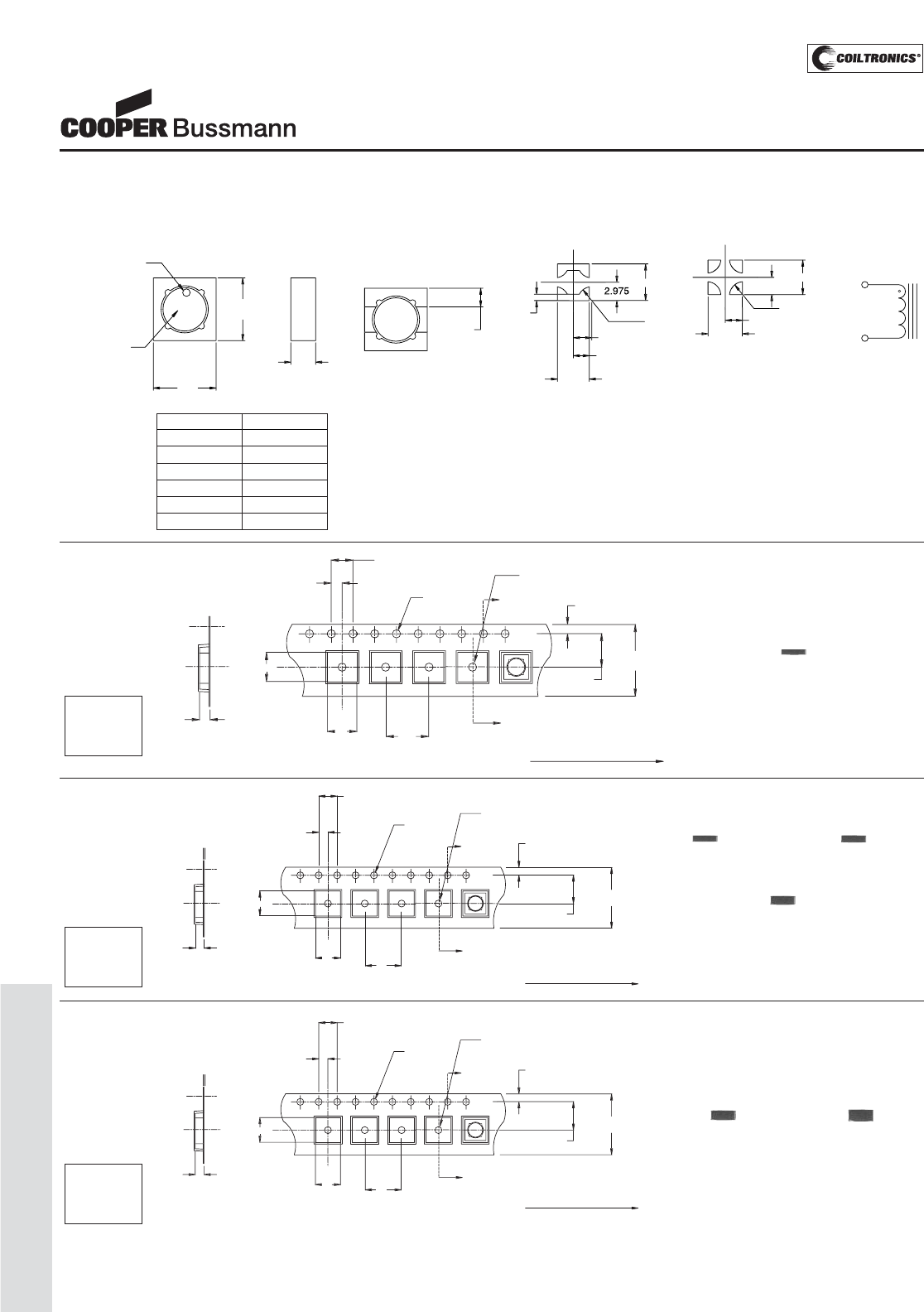
PM-104
LOW PROFILE SHIELDED DRUM (SD)
Dir
ec
tion of f
eed
K
o
S
E
C
TI
O
N A-
A
1.
5
Di
a
min.
Bo
B
Ao
A
8.0
8
0
4.
00
2.
00
±
0
.
05
1
.
5
Dia
.
+
0
.1
/
-
0
.
0
A
A
1.7
5
5
.
50
12.
0
+/-0.3
0
1
2
SD20/25 Series
Dimensions are in millimeters.
Direction of feed
Ko
SECTION A-A
1.5 Dia
min.
Bo
Ao 8.0
4.00
2.00 ± 0.05
1.5 Dia.
+0.1/-0.0
A
A
1.75
5.50
12.0
+/-0.3
1
2
SD12/14/18 Series
Packaging Information
ACTUAL SIZE
SD12
ACTUAL SIZE
SD14
ACTUAL SIZE
SD18
ACTUAL SIZE
SD20
ACTUAL SIZE
SD25
SD Series
High Power Density,
Low Profile, Shielded Inductors
Ao=5.45mm
Bo=5.45mm
Ko=2.00mm Parts packaged on 13" Diameter reel,
3,800 parts per reel.
Dir
ec
tion of f
eed
K
o
S
E
C
TI
O
N A-
A
1.
5
Di
a
min.
Bo
B
Ao
A
8
.
0
4.
00
2.00
2
±
0
.
05
1.
5
Dia
.
+
0
.1
/
-
0
.
0
A
A
1.7
5
5
.
50
12.
0
+/-0.3
0
1
2
SD10 Series
ACTUAL SIZE
SD10
Ao=5.45mm
Bo=5.45mm
Ko=1.20mm Parts packaged on 13" Diameter reel,
3,800 parts per reel.
Ao=5.45mm
Bo=5.45mm
Ko=2.70mm Parts packaged on 13" Diameter reel,
2,900 parts per reel.
Mechanical Diagrams
T
O
P VIE
W
B
O
TT
O
M VIE
W
RE
CO
MMENDED P
C
B LAY
OUT
SCHEMATI
C
2
1
5
.
2
M
ax
5
.
2
Max
a
H
T
1.5 T
y
p
.
R
e
f
.
1
2
S
IDE VIE
W
Pin#1
identifie
r
Part markin
g
(
Note A
)
2
1
R2.2
50
2.
9
7
5
5
.
950
2.975
2
4 PAD LAYOUT
R2.25
0
5.95
9
1.
0
2.975
2
5
.1
5
2.575
2
2 PAD LAY
OUT
5.950
9
(
see chart below
)
Series HT
SD10 1.0mm max
SD12 1.2mm max
SD14 1.45mm max
SD18 1.8mm max
SD20 2.0mm max
SD25 2.5mm max
SD Series
A) Part Marking: Line 1: (1st digit indicates the inductance value per part marking
designator in chart above)
(2nd digit is a bi-weekly production date code)
(3rd digit is the last digit of the year produced)
Line 2: XX (indicates the product size code)
Courtesy of Steven Engineering, Inc.-230 Ryan Way, South San Francisco, CA 94080-6370-Main Office: (650) 588-9200-Outside Local Area: (800) 258-9200-www.stevenengineering.com
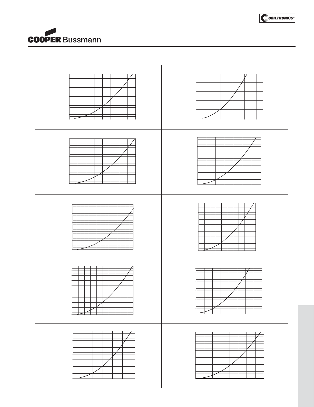
PM-105
LOW PROFILE SHIELDED DRUM (SD)
SD Series
High Power Density,
Low Profile, Shielded Inductors
DC Current vs. Temperature
SD12-330
0.0
10.0
20.0
30.0
40.0
50.0
60.0
70.0
80.0
90.0
100.0
0.00 0.10 0.20 0.30 0.40 0.50 0.60 0.70 0.80
Idc (A)
Temperature Rise (Deg. C)
SD12-470
0.0
10.0
20.0
30.0
40.0
50.0
60.0
70.0
80.0
90.0
100.0
0.00 0.10 0.20 0.30 0.40 0.50 0.60 0.70
Idc (A)
Temperature Rise (Deg. C)
SD10-220
0.0
10.0
20.0
30.0
40.0
50.0
60.0
70.0
80.0
90.0
100.0
0.00 0.10 0.20 0.30 0.40 0.50 0.60 0.70 0.80
Idc (A)
Temperature Rise (Deg. C)
SD10-471
0.0
10.0
20.0
30.0
40.0
50.0
60.0
70.0
80.0
90.0
100.0
0.00 0.05 0.09 0.14 0.18 0.23
Idc (A)
Temperature Rise (Deg. C)
0.0
10.0
20.0
30.0
40.0
50.0
60.0
70.0
80.0
90.0
100.0
0.00 0.20 0.40 0.60 0.80 1.00 1.20 1.40
Idc (A)
SD14-150
Temperature Rise (Deg. C)
SD14-102
0.0
10.0
20.0
30.0
40.0
50.0
60.0
70.0
80.0
90.0
100.0
0.000 0.020 0.040 0.060 0.080 0.100 0.120 0.140 0.160 0.180 0.200
Idc (A)
Temperature Rise (Deg. C)
SD18-100
0.0
10.0
20.0
30.0
40.0
50.0
60.0
70.0
80.0
90.0
100.0
0.0 0.2 0.4 0.6 0.8 1.0 1.2 1.4 1.6 1.8 2.0
Idc (A)
Temperature Rise (Deg. C)
SD18-101
0.0
10.0
20.0
30.0
40.0
50.0
60.0
70.0
80.0
90.0
100.0
0.00 0.10 0.20 0.30 0.40 0.50 0.60 0.70 0.80
Idc (A)
Temperature Rise (Deg. C)
SD20-100
0.0
10.0
20.0
30.0
40.0
50.0
60.0
70.0
80.0
90.0
100.0
0.0 0.4 0.8 1.2 1.6 2.0 2.4
Idc (A)
Temperature Rise (Deg. C)
SD20-101
0.0
10.0
20.0
30.0
40.0
50.0
60.0
70.0
80.0
90.0
100.0
0.00 0.10 0.20 0.30 0.40 0.50 0.60 0.70 0.80
Idc (A)
Temperature Rise (Deg. C)
Courtesy of Steven Engineering, Inc.-230 Ryan Way, South San Francisco, CA 94080-6370-Main Office: (650) 588-9200-Outside Local Area: (800) 258-9200-www.stevenengineering.com
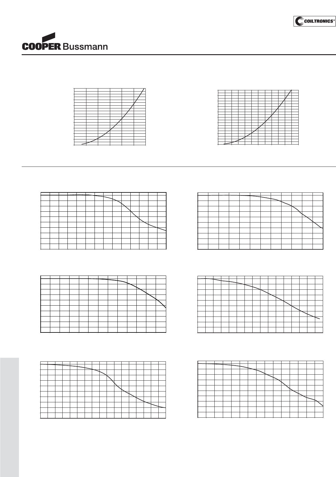
PM-106
LOW PROFILE SHIELDED DRUM (SD)
Inductance Characteristics
OCL vs Isat
SD10
0
10
20
30
40
50
60
70
80
90
100
0 10 20 30 40 50 60 70 80 90 100 110 120 130 140
% of Isat
OCL (%)
OCL vs Isat
SD12
0
10
20
30
40
50
60
70
80
90
100
0 10 20 30 40 50 60 70 80 90 100 110 120
% of Isat
OCL (%)
OCL vs Isat
SD14
0
10
20
30
40
50
60
70
80
90
100
0 102030405060708090100
110 120 130
% of Isat
OCL (%)
OCL vs Isat
SD18
0
10
20
30
40
50
60
70
80
90
100
0 10 20 30 40 50 60 70 80 90 100 110 120 130 140 150 160
% of Isat
OCL (%)
OCL vs Isat
SD25
0
10
20
30
40
50
60
70
80
90
100
0 10 20 30 40 50 60 70 80 90 100 110 120 130 140 150
% of Isat
OCL (%)
OCL vs Isat
SD20
0
10
20
30
40
50
60
70
80
90
100
0 10 20 30 40 50 60 70 80 90 100 110 120 130 140 150 160 170
% of Isat
OCL (%)
SD Series
High Power Density,
Low Profile, Shielded Inductors
DC Current vs. Temperature
SD25-100
0.0
10.0
20.0
30.0
40.0
50.0
60.0
70.0
80.0
90.0
100.0
0.0 0.5 1.0 1.5 2.0 2.5 3.0
Idc (A)
Temperature Rise (Deg. C)
SD25-101
0.0
10.0
20.0
30.0
40.0
50.0
60.0
70.0
80.0
90.0
100.0
0.00 0.20 0.40 0.60 0.80 1.00 1.20
Idc (A)
Temperature Rise (Deg. C)
Courtesy of Steven Engineering, Inc.-230 Ryan Way, South San Francisco, CA 94080-6370-Main Office: (650) 588-9200-Outside Local Area: (800) 258-9200-www.stevenengineering.com

PM-107
LOW PROFILE SHIELDED DRUM (SD)
Core Loss Irms DERATING WITH CORE LOSS
% of Applied Volt-μSecond
% of Losses from Irms (maximum)
SD Series
High Power Density,
Low Profile, Shielded Inductors
Courtesy of Steven Engineering, Inc.-230 Ryan Way, South San Francisco, CA 94080-6370-Main Office: (650) 588-9200-Outside Local Area: (800) 258-9200-www.stevenengineering.com
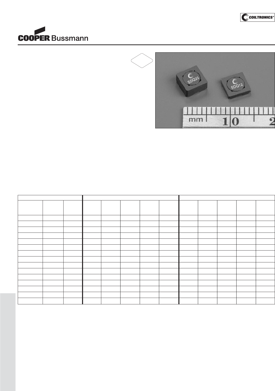
PM-108
LOW PROFILE SHIELDED DRUM (SDQ)
SDQ Series
Low Profile Dual Winding
Shielded Inductor/Transformer
P
P
a
a
r
r
a
a
l
l
l
l
e
e
l
l
R
R
a
a
t
t
i
i
n
n
g
g
s
s
S
S
e
e
r
r
i
i
e
e
s
s
R
R
a
a
t
t
i
i
n
n
g
g
s
s
P
P
a
a
r
r
t
t
N
N
u
u
m
m
b
b
e
e
r
r
R
R
a
a
t
t
e
e
d
d
P
P
a
a
r
r
t
t
O
O
C
C
L
L
(
(
1
1
)
)
I
I
r
r
m
m
s
s
(
(
2
2
)
)
I
I
s
s
a
a
t
t
(
(
3
3
)
)
D
D
C
C
R
R
Ω
Ω
(
(
4
4
)
)
V
V
o
o
l
l
t
t
(
(
5
5
)
)
O
O
C
C
L
L
(
(
1
1
)
)
I
I
r
r
m
m
s
s
(
(
2
2
)
)
I
I
s
s
a
a
t
t
(
(
3
3
)
)
D
D
C
C
R
R
Ω
Ω
(
(
4
4
)
)
V
V
o
o
l
l
t
t
(
(
5
5
)
)
I
I
n
n
d
d
u
u
c
c
t
t
a
a
n
n
c
c
e
e
M
M
a
a
r
r
k
k
i
i
n
n
g
g
+
+
/
/
-
-
2
2
0
0
%
%
A
A
m
m
p
p
e
e
r
r
e
e
s
s
A
A
m
m
p
p
e
e
r
r
e
e
s
s
t
t
y
y
p
p
.
.
μ
μ
-
-
S
S
e
e
c
c
+
+
/
/
-
-
2
2
0
0
%
%
A
A
m
m
p
p
e
e
r
r
e
e
s
s
A
A
m
m
p
p
e
e
r
r
e
e
s
s
t
t
y
y
p
p
.
.
μ
μ
-
-
S
S
e
e
c
c
(
(
μ
μ
H
H
)
)
(
(
μ
μ
H
H
)
)
t
t
y
y
p
p
.
.
(
(
μ
μ
H
H
)
)
t
t
y
y
p
p
.
.
S
S
D
D
Q
Q
1
1
2
2
-
-
R
R
4
4
7
7
-
-
R
R
0.47 A 0.49 2.78 4.34 0.0325 2.45 1.96 1.39 2.17 0.1298 4.90
S
S
D
D
Q
Q
1
1
2
2
-
-
1
1
R
R
0
0
-
-
R
R
1 B 0.81 2.49 3.38 0.0403 3.15 3.24 1.25 1.69 0.1611 6.30
S
S
D
D
Q
Q
1
1
2
2
-
-
1
1
R
R
5
5
-
-
R
R
1.5 C 1.69 1.69 2.34 0.0870 4.55 6.76 0.847 1.17 0.3481 9.10
S
S
D
D
Q
Q
1
1
2
2
-
-
2
2
R
R
2
2
-
-
R
R
2.2 D 2.25 1.60 2.03 0.0977 5.25 9.00 0.800 1.01 0.3908 10.5
S
S
D
D
Q
Q
1
1
2
2
-
-
3
3
R
R
3
3
-
-
R
R
3.3 E 3.61 1.28 1.60 0.1527 6.65 14.44 0.640 0.800 0.6106 13.3
S
S
D
D
Q
Q
1
1
2
2
-
-
4
4
R
R
7
7
-
-
R
R
4.7 F 4.41 1.12 1.45 0.1990 7.35 17.64 0.560 0.724 0.7959 14.7
S
S
D
D
Q
Q
1
1
2
2
-
-
6
6
R
R
2
2
-
-
R
R
6.2 G 6.25 1.02 1.22 0.2387 8.75 25.00 0.512 0.608 0.9548 17.5
S
S
D
D
Q
Q
1
1
2
2
-
-
8
8
R
R
2
2
-
-
R
R
8.2 H 8.41 0.868 1.05 0.3318 10.15 33.64 0.434 0.524 1.33 20.3
S
S
D
D
Q
Q
1
1
2
2
-
-
1
1
0
0
0
0
-
-
R
R
10 J 9.61 0.831 0.981 0.3620 10.85 38.44 0.416 0.490 1.45 21.7
S
S
D
D
Q
Q
1
1
2
2
-
-
1
1
5
5
0
0
-
-
R
R
15 K 15.21 0.658 0.779 0.5766 13.65 60.84 0.329 0.390 2.31 27.3
S
S
D
D
Q
Q
1
1
2
2
-
-
2
2
2
2
0
0
-
-
R
R
22 L 22.09 0.548 0.647 0.8332 16.45 88.36 0.274 0.323 3.33 32.9
S
S
D
D
Q
Q
1
1
2
2
-
-
3
3
3
3
0
0
-
-
R
R
33 M 32.49 0.439 0.533 1.29 19.95 130.0 0.220 0.267 5.18 39.9
S
S
D
D
Q
Q
1
1
2
2
-
-
4
4
7
7
0
0
-
-
R
R
47 N 47.61 0.401 0.441 1.55 24.15 190.4 0.201 0.220 6.21 48.3
S
S
D
D
Q
Q
1
1
2
2
-
-
6
6
8
8
0
0
-
-
R
R
68 O 68.89 0.326 0.366 2.36 29.05 275.6 0.163 0.183 9.43 58.1
S
S
D
D
Q
Q
1
1
2
2
-
-
8
8
2
2
0
0
-
-
R
R
82 P 82.81 0.309 0.334 2.62 31.85 331.2 0.154 0.167 10.49 63.7
1) Test Parameters: 100kHz,.0.25 Vrms 0.0Adc
2) Rms current for approximately ΔT of 40°C without core loss. It is recommended
that the temperature of the part not to exceed 125°C. De-rating is necessary for
AC currents
3) Peak current for approximately 30% rolloff @20°C
4) DCR limits @20°C
5) Applied Volt-Time product (V-μS) across the inductor at 100kHz necessary to
generate a core loss equal to 10% of the total losses for a 40°C temperature
rise. De-rating of the Irms is required to prevent excessive temperature rise.
Part number definition:
First 3 characters = Product code and size.
Last 3 characters = Inductance in uH. R = Decimal point. If no R is present, third
character = # of zeros.
SDQ12-XXX-R
SDQ12 = Product code and Size
XXX = Inductance in uH, R = Decimal point
If no R is present, third character = # of zeros.
-R suffix indicated RoHS compliant
Description
• Dual winding inductors that can be used as either
a single inductor, or in coupled inductor/transformer
applications (1:1 turns ratio)
• Windings can be connected in series or parallel, offering
a broad range of inductance and current ratings
• Current Range from 6.43 to 0.063 Amps
• Inductance range from 0.47μH to 4.03mH
• Ferrite shielded, low EMI
• Ferrite core material
Applications
• As a transformer: SEPIC, flyback
• As an inductor: Buck, boost, coupled inductor
• Digital cameras, CD players, cellular phones, and PDA’s
• PCMCIA cards
• GPS systems
Environmental Data
• Storage temperature: -40°C to +125°C
• Operating temperature: -40°C to +85°C (Range is appli-
cation specific). Temperature rise is approximately 40°C
at rated rms current.
• Solder reflow temperature: 260°C max. for 10 seconds
max.
Packaging
• Supplied in tape and reel packaging, SDQ12 (3,800,
SDQ25 (2,900) parts per reel
RoHS
2002/95/EC
Courtesy of Steven Engineering, Inc.-230 Ryan Way, South San Francisco, CA 94080-6370-Main Office: (650) 588-9200-Outside Local Area: (800) 258-9200-www.stevenengineering.com
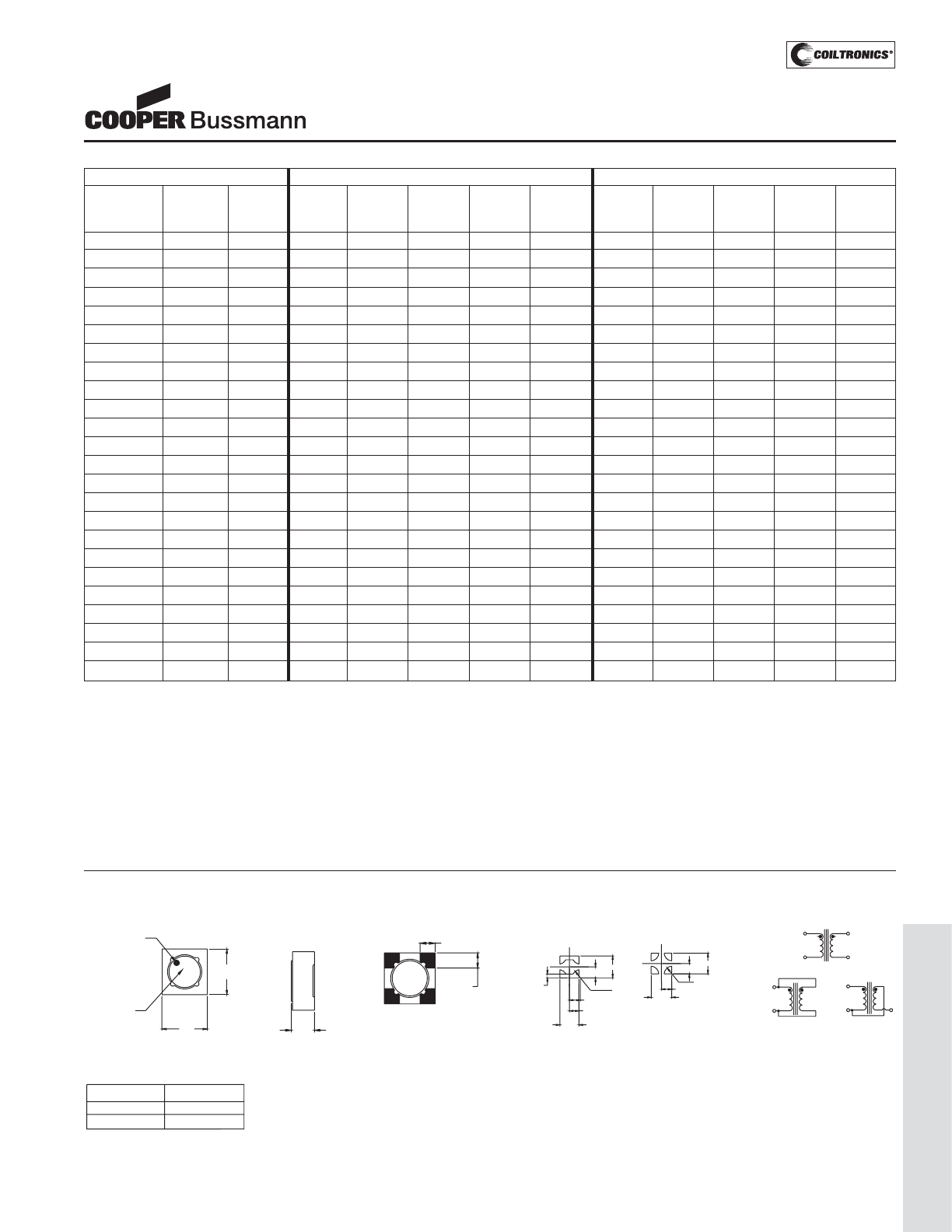
PM-109
LOW PROFILE SHIELDED DRUM (SDQ)
SDQ Series
Low Profile Dual Winding
Shielded Inductor/Transformer
P
P
a
a
r
r
a
a
l
l
l
l
e
e
l
l
R
R
a
a
t
t
i
i
n
n
g
g
s
s
S
S
e
e
r
r
i
i
e
e
s
s
R
R
a
a
t
t
i
i
n
n
g
g
s
s
P
P
a
a
r
r
t
t
N
N
u
u
m
m
b
b
e
e
r
r
R
R
a
a
t
t
e
e
d
d
P
P
a
a
r
r
t
t
O
O
C
C
L
L
(
(
1
1
)
)
I
I
r
r
m
m
s
s
(
(
2
2
)
)
I
I
s
s
a
a
t
t
(
(
3
3
)
)
D
D
C
C
R
R
Ω
Ω
(
(
4
4
)
)
V
V
o
o
l
l
t
t
(
(
5
5
)
)
O
O
C
C
L
L
(
(
1
1
)
)
I
I
r
r
m
m
s
s
(
(
2
2
)
)
I
I
s
s
a
a
t
t
(
(
3
3
)
)
D
D
C
C
R
R
Ω
Ω
(
(
4
4
)
)
V
V
o
o
l
l
t
t
(
(
5
5
)
)
I
I
n
n
d
d
u
u
c
c
t
t
a
a
n
n
c
c
e
e
M
M
a
a
r
r
k
k
i
i
n
n
g
g
+
+
/
/
-
-
2
2
0
0
%
%
A
A
m
m
p
p
e
e
r
r
e
e
s
s
A
A
m
m
p
p
e
e
r
r
e
e
s
s
t
t
y
y
p
p
.
.
μ
μ
-
-
S
S
e
e
c
c
+
+
/
/
-
-
2
2
0
0
%
%
A
A
m
m
p
p
e
e
r
r
e
e
s
s
A
A
m
m
p
p
e
e
r
r
e
e
s
s
t
t
y
y
p
p
.
.
μ
μ
-
-
S
S
e
e
c
c
(
(
μ
μ
H
H
)
)
(
(
μ
μ
H
H
)
)
t
t
y
y
p
p
.
.
(
(
μ
μ
H
H
)
)
t
t
y
y
p
p
.
.
S
S
D
D
Q
Q
2
2
5
5
-
-
R
R
4
4
7
7
-
-
R
R
0.47 A 0.392 3.71 6.43 0.0181 2.31 1.57 1.86 3.21 0.0725 4.62
S
S
D
D
Q
Q
2
2
5
5
-
-
R
R
8
8
2
2
-
-
R
R
0.82 B 0.648 3.37 5.00 0.0221 2.97 2.59 1.68 2.50 0.0883 5.94
S
S
D
D
Q
Q
2
2
5
5
-
-
1
1
R
R
0
0
-
-
R
R
1 C 0.97 3.15 4.09 0.0252 3.63 3.87 1.58 2.05 0.1007 7.26
S
S
D
D
Q
Q
2
2
5
5
-
-
1
1
R
R
5
5
-
-
R
R
1.5 D 1.35 2.97 3.46 0.0283 4.29 5.41 1.49 1.73 0.1130 8.58
S
S
D
D
Q
Q
2
2
5
5
-
-
2
2
R
R
2
2
-
-
R
R
2.2 E 2.31 2.67 2.65 0.0351 5.61 9.25 1.34 1.32 0.1402 11.2
S
S
D
D
Q
Q
2
2
5
5
-
-
3
3
R
R
3
3
-
-
R
R
3.3 F 2.89 2.50 2.37 0.0399 6.27 11.55 1.25 1.18 0.1595 12.5
S
S
D
D
Q
Q
2
2
5
5
-
-
4
4
R
R
7
7
-
-
R
R
4.7 G 5 1.96 1.80 0.0653 8.25 20.00 0.98 0.900 0.2612 16.5
S
S
D
D
Q
Q
2
2
5
5
-
-
6
6
R
R
8
8
-
-
R
R
6.8 H 6.73 1.84 1.55 0.0741 9.57 26.91 0.918 0.776 0.2964 19.1
S
S
D
D
Q
Q
2
2
5
5
-
-
8
8
R
R
2
2
-
-
R
R
8.2 J 8.71 1.57 1.36 0.1015 10.9 34.85 0.785 0.682 0.4059 21.8
S
S
D
D
Q
Q
2
2
5
5
-
-
1
1
0
0
0
0
-
-
R
R
10 K 9.8 1.53 1.29 0.1068 11.6 39.20 0.765 0.643 0.4273 23.1
S
S
D
D
Q
Q
2
2
5
5
-
-
1
1
5
5
0
0
-
-
R
R
15 L 14.79 1.24 1.05 0.1632 14.2 59.17 0.619 0.523 0.6526 28.4
S
S
D
D
Q
Q
2
2
5
5
-
-
2
2
2
2
0
0
-
-
R
R
22 M 22.47 1.01 0.849 0.2431 17.5 89.89 0.507 0.425 0.9724 35.0
S
S
D
D
Q
Q
2
2
5
5
-
-
3
3
3
3
0
0
-
-
R
R
33 N 33.8 0.812 0.692 0.3795 21.5 135.2 0.406 0.346 1.52 42.9
S
S
D
D
Q
Q
2
2
5
5
-
-
4
4
7
7
0
0
-
-
R
R
47 O 47.43 0.749 0.584 0.4461 25.4 189.7 0.374 0.292 1.78 50.8
S
S
D
D
Q
Q
2
2
5
5
-
-
6
6
8
8
0
0
-
-
R
R
68 P 69.19 0.603 0.484 0.6865 30.7 276.8 0.302 0.242 2.75 61.4
S
S
D
D
Q
Q
2
2
5
5
-
-
8
8
2
2
0
0
-
-
R
R
82 Q 81.61 0.580 0.446 0.7435 33.3 326.4 0.290 0.223 2.97 66.7
S
S
D
D
Q
Q
2
2
5
5
-
-
1
1
0
0
1
1
-
-
R
R
100 R 98.57 0.499 0.405 1.00 36.6 394.3 0.249 0.203 4.02 73.3
S
S
D
D
Q
Q
2
2
5
5
-
-
1
1
5
5
1
1
-
-
R
R
150 S 150.2 0.408 0.328 1.50 45.2 600.6 0.204 0.164 6.00 90.4
S
S
D
D
Q
Q
2
2
5
5
-
-
2
2
2
2
1
1
-
-
R
R
220 T 223.1 0.326 0.269 2.36 55.1 892.4 0.163 0.135 9.42 110
S
S
D
D
Q
Q
2
2
5
5
-
-
3
3
3
3
1
1
-
-
R
R
330 U 329.7 0.292 0.222 2.93 67.0 1318.7 0.146 0.111 11.71 134
S
S
D
D
Q
Q
2
2
5
5
-
-
4
4
7
7
1
1
-
-
R
R
470 V 472.4 0.243 0.185 4.25 80.2 1889.6 0.121 0.093 16.99 160
S
S
D
D
Q
Q
2
2
5
5
-
-
6
6
8
8
1
1
-
-
R
R
680 W 677.4 0.197 0.155 6.45 96.0 2709.8 0.098 0.077 25.78 192
S
S
D
D
Q
Q
2
2
5
5
-
-
8
8
2
2
1
1
-
-
R
R
820 X 824.3 0.186 0.140 7.25 106 3297.3 0.093 0.070 28.99 212
S
S
D
D
Q
Q
2
2
5
5
-
-
1
1
0
0
2
2
-
-
R
R
1000 Y 1008.2 0.160 0.127 9.82 117 4032.8 0.080 0.063 39.26 234
1) Test Parameters: 100kHz,.0.25 Vrms 0.0Adc
2) Rms current for approximately ΔT of 40°C without core loss. It is recommended
that the temperature of the part not to exceed 125°C. De-rating is necessary for
AC currents
3) Peak current for approximately 30% rolloff @20°C
4) DCR limits @20°C
5) Applied Volt-Time product (V-μS) across the inductor at 100kHz necessary to
generate a core loss equal to 10% of the total losses for a 40°C temperature
rise. De-rating of the Irms is required to prevent excessive temperature rise.
Part number definition:
First 3 characters = Product code and size.
Last 3 characters = Inductance in uH. R = Decimal point. If no R is present, third
character = # of zeros.
SDQ12-XXX-R
SDQ12 = Product code and Size
XXX = Inductance in uH, R = Decimal point
If no R is present, third character = # of zeros.
-R suffix indicated RoHS compliant
A) Part marking: Line 1 (1st digit inductance value per part marking designator in chart above)
(2nd digit is a bi-weekly production date code)
(3rd digit is the last digit of the year produced)
Line 2: xx (indicates the product size code)
Mechanical Diagrams
5.2
Max
Part marking
(Note A)
4
3
5.2
Max
1
Pin #1 identifier
2
TOP VIEW
HT
SIDE VIEW
1.5 typ ref
3
1
2
4
1.5 Typ.
Ref.
BOTTOM VIEW
1.02
2.575
5.15
4
1
2.975
2.975
R2.
250
5.95
5.950
R2.250
2.975
2.975
5.950
23
4 PAD LAYOUT
RECOMMENDED PCB LAYOUT
2 PAD LAYOUT
2
3
2
SERIES
PARALLEL
3
1
4
1
TRANSFORMER
2
SCHEMATIC
14
4
3
Series HT
SDQ12 1.2mm max
2.5mm max
SDQ25
Courtesy of Steven Engineering, Inc.-230 Ryan Way, South San Francisco, CA 94080-6370-Main Office: (650) 588-9200-Outside Local Area: (800) 258-9200-www.stevenengineering.com
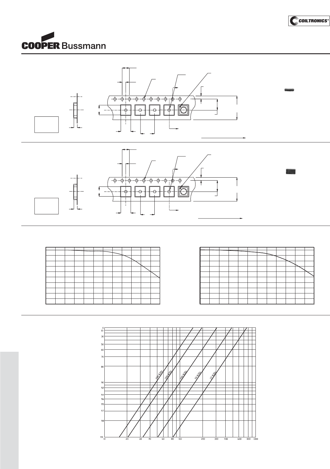
PM-110
LOW PROFILE SHIELDED DRUM (SDQ)
SDQ Series
Low Profile Dual Winding
Shielded Inductor/Transformer
2.00
4.00
Ao
Bo
Direction of feed
Pin #1 indicator
12.0
+/-0.3
5.50
1.75
1.5 Dia.
+0.1/-0.0
1.5 Dia
min.
8.0
A
2
1
A
Ko
SECTION A-A
4
3
Ao=5.45 mm
Bo=5.45 mm
Ko=2.70 mm
SDQ25 Series
Packaging Information
Ao
Bo
Direction of feed
Pin #1 indicator
12.0
+/-0.3
1.75
1.5 Dia.
+0.1/-0.0
1.5 Dia.
min.
8.0
A
A
Ao=5.45 mm
Bo=5.45 mm
Ko=2.00 mm Ko
SECTION A-A
4.00
2.00
1
2
4
35.50
SDQ12 Series
Parts packaged on 13" Diameter reel,
3,800 parts per reel.
Parts packaged on 13" Diameter reel,
2,900 parts per reel.
ACTUAL SIZE
SDQ12
ACTUAL SIZE
SDQ25
OCL vs Isat
SDQ12
0
10
20
30
40
50
60
70
80
90
100
0 102030405060708090100110120
% of Isat
OCL (%)
OCL vs Isat
SDQ25
0
10
20
30
40
50
60
70
80
90
100
0 102030405060708090100110120
% of Isat
OCL (%)
Inductance Characteristics
Irms DERATING WITH CORE LOSS
% of Applied Volt-μSecond
% of Losses from Irms (maximum)
Core Loss
Courtesy of Steven Engineering, Inc.-230 Ryan Way, South San Francisco, CA 94080-6370-Main Office: (650) 588-9200-Outside Local Area: (800) 258-9200-www.stevenengineering.com
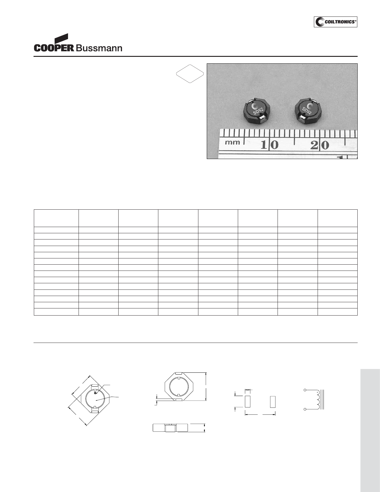
PM-111
LOW PROFILE SHIELDED DRUM (SD52)
Description
• 125°C maximum total temperature operation
• Octagonal shape shielded drum core
• 2mm max height
• Inductance range from 1.2uH to 100uH
• Current range from 3.14 to 0.35 Amps
• Ferrite shielded, low EMI
• Ferrite core material
Applications
• Digital cameras, CD players, cellular phones, and PDAs
• PCMCIA cards
• GPS systems
Environmental Data
• Storage temperature range: -40°C to +125°C
• Operating ambient temperature range: -40°C to +125°C
(range is application specific).
• Solder reflow temperature: +260°C max. for 10 seconds
max.
Packaging
• Supplied in tape and reel packaging, 3500 per reel
SD52 Series
High Power Density,
Low Profile, Shielded Inductors
Part Number Rated OCL (1) Part Irms (2) Isat (3) DCR (4) Volt
Inductance +/-20% Marking Amperes Amperes (Ω) u-sec
(μH) (μH) Typ. Typ.
SD52-1R2-R 1.20 1.20 A 2.33 3.14 0.0279 1.49
SD52-2R2-R 2.20 2.20 B 1.98 2.30 0.0385 2.03
SD52-3R5-R 3.50 3.50 C 1.73 1.82 0.0503 2.57
SD52-4R7-R 4.70 4.70 D 1.63 1.64 0.0568 2.84
SD52-6R8-R 6.80 6.80 E 1.39 1.28 0.0777 3.65
SD52-100-R 10.0 10.0 F 1.11 1.11 0.1215 4.19
SD52-150-R 15.0 15.0 G 0.97 0.88 0.1618 5.27
SD52-220-R 22.0 22.0 H 0.86 0.73 0.2042 6.35
SD52-270-R 27.0 27.0 J 0.73 0.65 0.2864 7.16
SD52-330-R 33.0 33.0 K 0.70 0.61 0.3074 7.70
SD52-470-R 47.0 47.0 L 0.58 0.50 0.4465 9.32
SD52-680-R 68.0 68.0 M 0.47 0.42 0.6829 11.21
SD52-101-R 100 100 N 0.39 0.35 1.0000 13.37
SD52-151-R 150 150 O 0.31 0.28 1.6100 17.00
RE
CO
MMENDED P
C
B LAY
OUT
SC
HEMATI
C
2
1
T
O
P VIE
W
2.
0
2 plc
s
6
.
0
1.
3
2
p
lc
s
5.2 max
2
5.2 max
m
P
in #1 in
d
i
ca
to
r
Part markin
g
(
See note A
)
B
O
TT
O
M VIE
W
2
1
S
IDE VIE
W
2.0 max
m
5.6 max
m
0
.
65
±
0
.1
0
SD52 Series
A) Part Marking: Line 1: (1st digit indicates the inductance value per part marking
designator in chart above)
(2nd digit is a bi-weekly production date code)
(3rd digit is the last digit of the year produced)
Line 2: 52 (indicates the product size code)
Mechanical Diagrams
(1) Open Circuit Inductance Test Parameters: 100KHz, 0.25Vrms, 0.0Adc.
(2) RMS current for an approximate ΔT of 40°C without core loss. It is recommend-
ed that the temperature of the part not exceed 125°C.
(3) Peak current for approximate 30% roll off at 20°C.
(4) DCR limits @ 20°C.
5) Applied Volt-Time product (V-uS) across the inductor at 100kHz necessary to
generate a core loss equal to 10% of the total losses for 40°C temperature rise.
RoHS
2002/95/EC
Courtesy of Steven Engineering, Inc.-230 Ryan Way, South San Francisco, CA 94080-6370-Main Office: (650) 588-9200-Outside Local Area: (800) 258-9200-www.stevenengineering.com
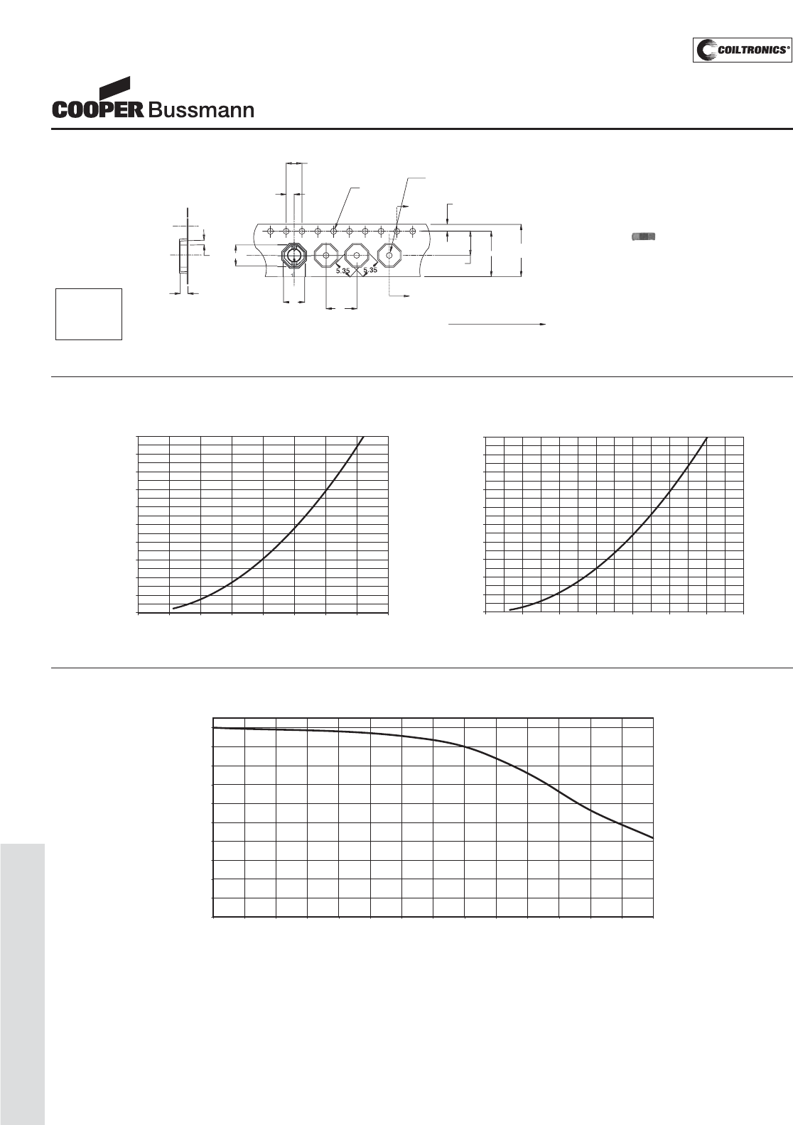
PM-112
LOW PROFILE SHIELDED DRUM (SD52)
SD52 Series
High Power Density,
Low Profile, Shielded Inductors
OCL vs Isat
SD52
0
10
20
30
40
50
60
70
80
90
100
0 10 20 30 40 50 60 70 80 90 100 110 120 130 140
% of Isat
OCL (%)
Inductance Characteristics
DC Current vs. Temperature
SD52-1R2
0.0
10.0
20.0
30.0
40.0
50.0
60.0
70.0
80.0
90.0
100.0
0.0 0.5 1.0 1.5 2.0 2.5 3.0 3.5 4.0
Idc (A)
Temperature Rise (Deg. C)
SD52-101
0.0
10.0
20.0
30.0
40.0
50.0
60.0
70.0
80.0
90.0
100.0
0.00 0.10 0.20 0.30 0.40 0.50 0.60 0.70
Idc (A)
Temperature Rise (Deg. C)
Dimensions are in millimeters.
Dir
ec
tion of f
eed
K
o
S
E
C
TI
O
N A-
A
1.
5
Di
a
min.
Bo
B
Ao
A
8.0
8
0
4.
00
2.
00
±
0
.
05
1.
5
Dia
.
+0.1/-0.
0
A
A
1.7
5
5
.
50
12.
0
+/-0.3
0
2
10.2
0
3
.
0
SD52 Series
ACTUAL SIZE
SD52
Ao=5.72mm
Bo=5.72mm
Ko=2.30mm Parts packaged on 13" Diameter reel,
3,500 parts per reel.
Packaging Information
Courtesy of Steven Engineering, Inc.-230 Ryan Way, South San Francisco, CA 94080-6370-Main Office: (650) 588-9200-Outside Local Area: (800) 258-9200-www.stevenengineering.com
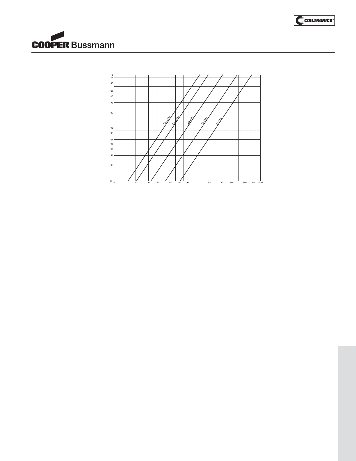
PM-113
LOW PROFILE SHIELDED DRUM (SD52)
SD52 Series
High Power Density,
Low Profile, Shielded Inductors
Core Loss Irms DERATING WITH CORE LOSS
% of Applied Volt-μSecond
% of Losses from Irms (maximum)
Courtesy of Steven Engineering, Inc.-230 Ryan Way, South San Francisco, CA 94080-6370-Main Office: (650) 588-9200-Outside Local Area: (800) 258-9200-www.stevenengineering.com
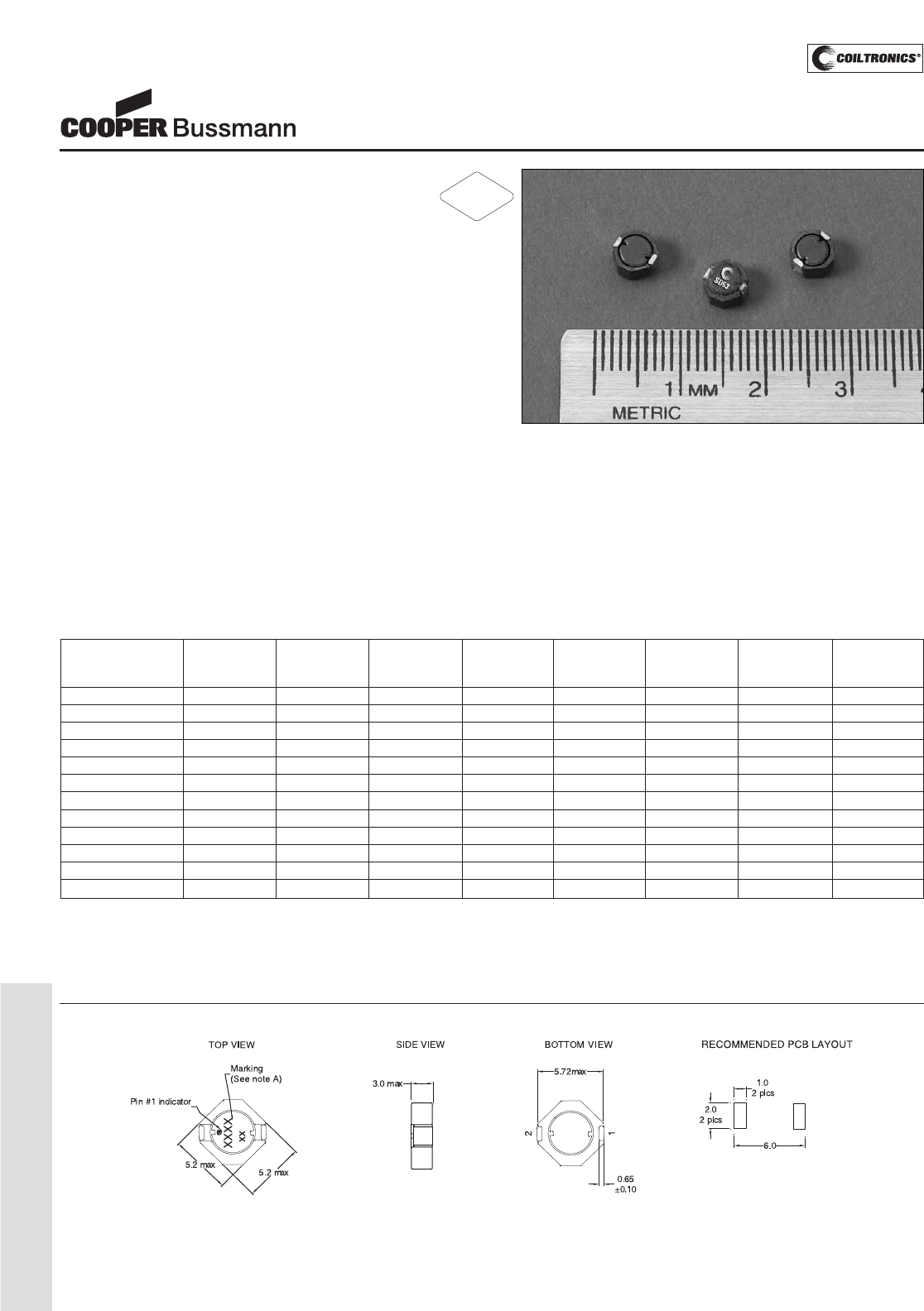
PM-114
LOW PROFILE SHIELDED DRUM (SD53)
Description
• 125°C maximum total temperature operation
• Octagonal shape utilizes board space
• 5.2mm x 5.2mm x 3.0mm surface mount package
• Shielded drum core reduces EMI
• Ferrite core material
• Inductance range from 1.1uH to 100uH
• Current range from 4.08 Amps to 0.44 Amps
Applications
• High Power LED driver
• White LED and OLED displays
• DSL modems, digital cameras
• Buck, Boost Inductor
• Cellular phones, Smart phones
• MP3 players, Digital radio player
• PDA, Palmtop, and wireless handhelds
• Battery power, TFT - LCD Bias supply
Environmental Data
• Storage temperature range: -40°C to +125°C
• Operating temperature range: -40°C to +125°C
(range is application specific)
• Solder reflow temperature: +260°C max. for 10 seconds
maximum
Packaging
• Supplied in tape and reel packaging, 2600 per reel
SD53 Series
Low Profile, Shielded Inductors
Part Number Rated OCL (1) Part Irms (2) Isat (3) DCR DCR K-factor
Inductance μH ± 20% Marking Amperes Amperes Ω@20°C Ω@20°C (4)
(μH) (Typical) (Maximum)
SD53-1R1-R 1.10 1.10 A 3.25 4.80 0.017 0.020 48
SD53-2R0-R 2.00 2.00 B 2.64 3.30 0.023 0.027 35
SD53-3R3-R 3.30 3.30 C 2.26 2.60 0.029 0.034 28
SD53-4R7-R 4.70 4.70 D 2.01 2.10 0.039 0.045 21
SD53-6R8-R 6.80 6.80 E 1.65 1.85 0.059 0.068 20
SD53-100-R 10.0 10.0 F 1.41 1.40 0.077 0.090 15
SD53-150-R 15.0 15.0 G 1.10 1.10 0.122 0.142 12
SD53-220-R 22.0 22.0 H 0.81 0.94 0.179 0.208 10
SD53-330-R 33.0 33.0 I 0.75 0.76 0.221 0.257 8
SD53-470-R 47.0 47.0 J 0.64 0.64 0.303 0.352 7
SD53-680-R 68.0 68.0 K 0.52 0.58 0.452 0.525 6
SD53-101-R 100 100 L 0.44 0.45 0.689 0.801 5
(1) Open Circuit Inductance Test Parameters: 100kHz, 0.1V, 0.0Adc.
(2) Irms: DC current for an approximate ΔT of 40°C without core loss. Derating is
necessary for AC currents. PCB layout, trace thickness and width, air-flow, and
proximity of other heat generating components will affect the temperature rise. It
is recommended that the temperature of the part not exceed 125°C under worst
case operating conditions verified in the end application.
(3) Isat Amperes peak for approximately 30% rolloff (@25°C)
(4) K-factor: Used to determine B p-p for core loss (see graph).
B p-p = K*L*ΔI, B p-p(mT), K: (K factor from table), L: (Inductance in uH),
ΔI (Peak to peak ripple current in Amps).
(5) Part Number Definition: SD53-xxx-R
SD53 = Product code and size; -xxx = Inductance value in uH;
R = decimal point; If no R is present, third character = # of zeros.
-R suffix = RoHS compliant
RoHS
2002/95/EC
Dimensions are in millimeters.
Note A. Part Marking:
4 Digit Marking: Line 1: (1st digit: Indicates inductance value per Part Marking Designator in chart above); (2nd digit: Bi-weekly production date code);
(3rd digit: Last digit of the year produced), (4th digit: Manufacturing code). Line 2: 53 (Indicates the product size code)
Mechanical Diagrams
Courtesy of Steven Engineering, Inc.-230 Ryan Way, South San Francisco, CA 94080-6370-Main Office: (650) 588-9200-Outside Local Area: (800) 258-9200-www.stevenengineering.com
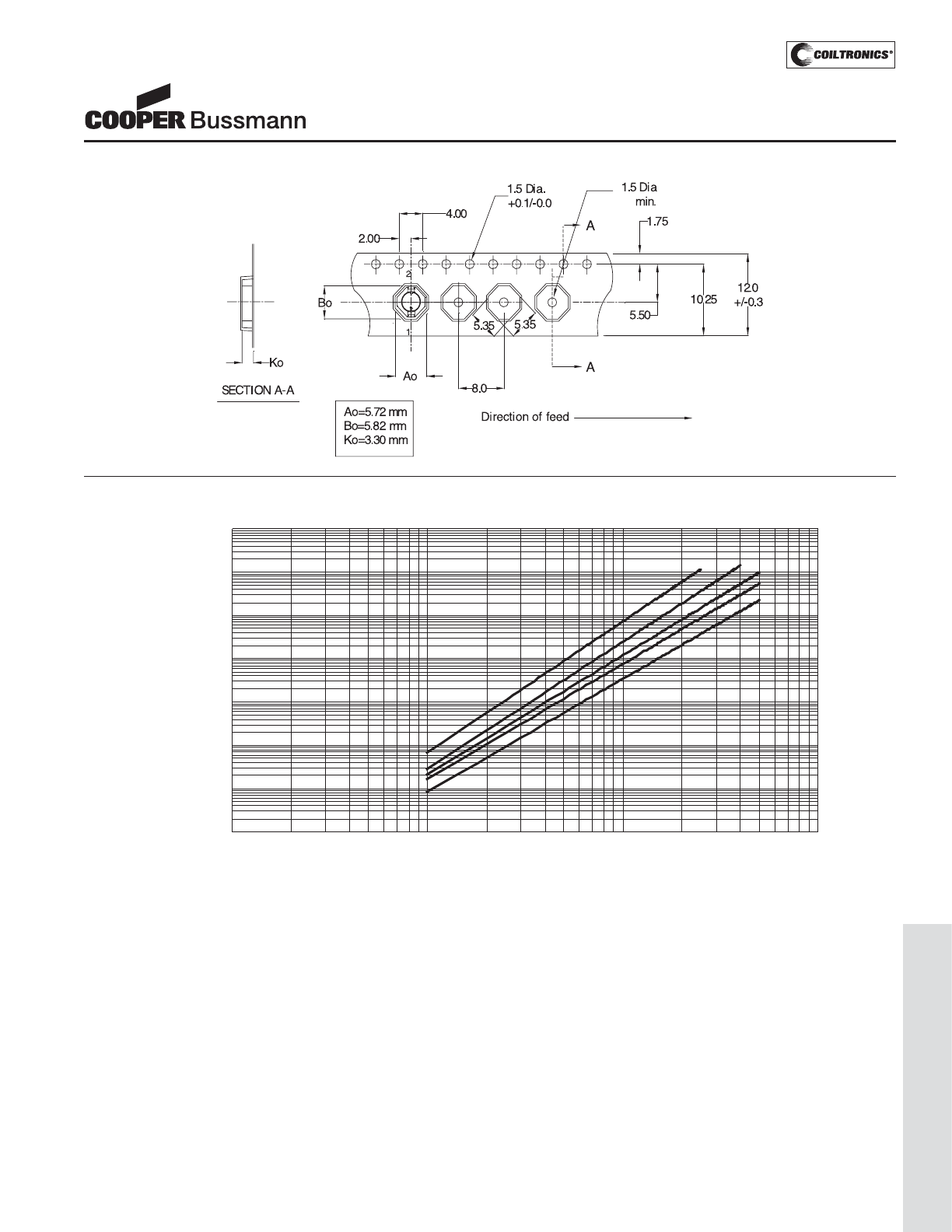
PM-115
LOW PROFILE SHIELDED DRUM (SD53)
SD53 Series
Low Profile, Shielded Inductors
Core Loss
1MHz
500kHz
300kHz
200kHz
100kHz
0.000001
0.00001
0.0001
0.001
0.01
0.1
1
10
1 10 100 1000
Bp-p (m T)
Core Loss (W)
Parts packaged on 13" Diameter reel,
2,600 parts per reel.
Packaging Information
Courtesy of Steven Engineering, Inc.-230 Ryan Way, South San Francisco, CA 94080-6370-Main Office: (650) 588-9200-Outside Local Area: (800) 258-9200-www.stevenengineering.com
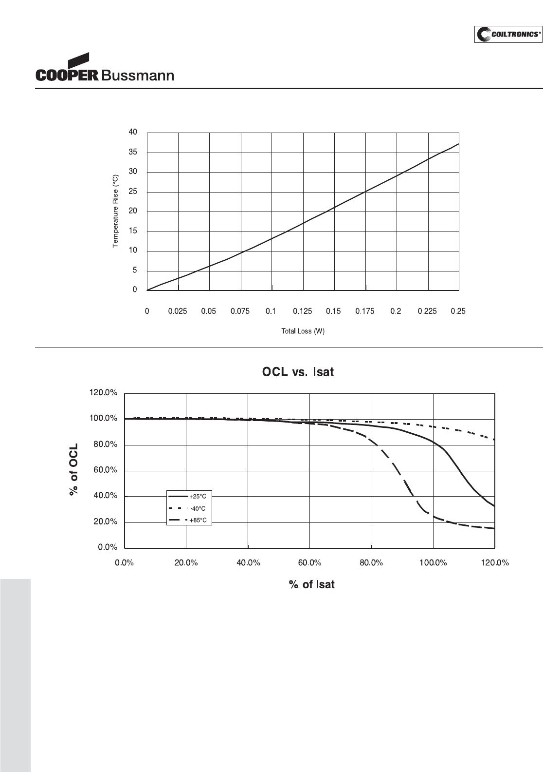
PM-116
LOW PROFILE SHIELDED DRUM (SD53)
Inductance Characteristics
SD53 Series
Low Profile, Shielded Inductors
Temperature Rise vs. Loss
Courtesy of Steven Engineering, Inc.-230 Ryan Way, South San Francisco, CA 94080-6370-Main Office: (650) 588-9200-Outside Local Area: (800) 258-9200-www.stevenengineering.com
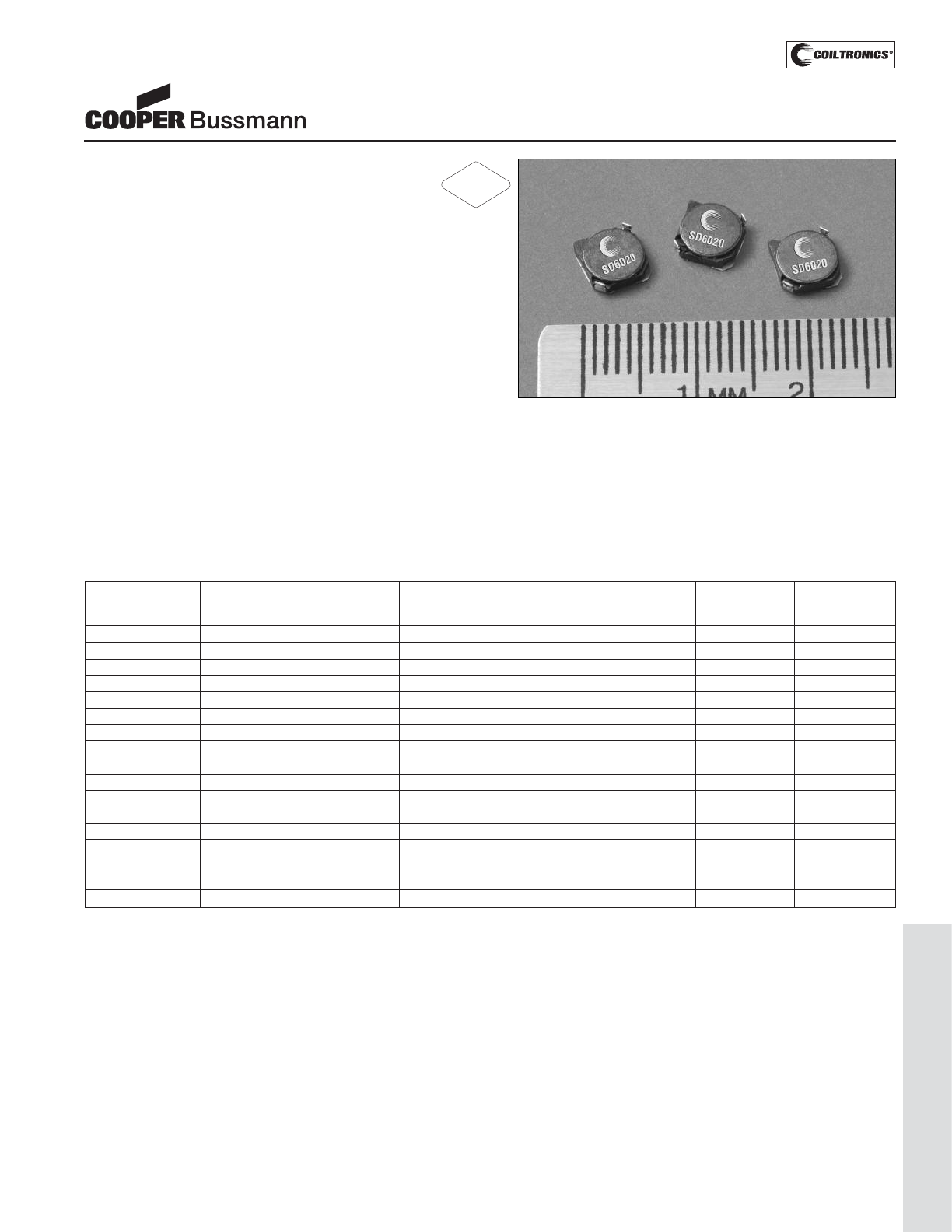
PM-117
LOW PROFILE SHIELDED DRUM (SD6020)
Description
• 125°C maximum temperature operation
• Low profile surface mount inductors
• 6.0mm x 6.0mm x 2.0mm shielded drum core
• Ferrite core material
• Inductance range from 4.1uH to 100uH
• Current range from 2.0 Amps to 0.36 Amps
• Frequency range up to 1MHz
Applications
• Palmtop Computers
• Digital Cameras
• Digital Cordless Phones, PCS Phones
• Cable/DSL Modems, PC Cards
• Wireless Handsets, Hand-Held Instruments
• Battery Backup/power
• DC-DC converters, Buck/Boost regulators
Environmental Data
• Storage temperature range: -40°C to +125°C
• Operating temperature range: -40°C to +125°C
(range is application specific)
• Solder reflow temperature: +260°C max. for 10 seconds
maximum
Packaging
• Supplied in tape and reel packaging, 2600 per reel
SD6020 Series
Low Profile Power Inductors
Part Number Rated OCL (1) Irms (2) Isat (3) DCR DCR K-factor
Inductance μH ± 30% Amperes Amperes mΩ@20°C mΩ@20°C (4)
(μH) (Typical) (Maximum)
SD6020-4R1-R 4.1 3.9 2.22 1.95 47.5 57.0 28.5
SD6020-5R4-R 5.4 5.5 1.80 1.60 63.3 76.0 24.0
SD6020-6R2-R 6.2 6.5 1.63 1.40 80.0 96.0 22.2
SD6020-8R9-R 8.9 8.5 1.47 1.25 96.7 116.0 19.3
SD6020-100-R 10 9.7 1.39 1.20 103.3 124.0 18.1
SD6020-120-R 12 11 1.31 1.10 115.0 138.0 17.1
SD6020-150-R 15 13 1.07 0.97 163.3 196.0 15.4
SD6020-180-R 18 16 1.10 0.85 175.0 210.0 13.9
SD6020-220-R 22 20 0.94 0.80 241.7 290.0 12.7
SD6020-270-R 27 27 0.82 0.75 275.0 330.0 10.9
SD6020-330-R 33 29 0.76 0.65 320.8 385.0 10.5
SD6020-390-R 39 37 0.63 0.57 416.7 500.0 9.2
SD6020-470-R 47 45 0.61 0.54 495.8 595.0 8.2
SD6020-560-R 56 55 0.57 0.50 515.0 618.0 7.8
SD6020-680-R 68 68 0.50 0.43 700.0 840.0 6.7
SD6020-820-R 82 80 0.48 0.41 815.0 978.0 6.3
SD6020-101-R 100 94 0.42 0.36 1000.0 1200.0 5.8
(1) Open Circuit Inductance Test Parameters: 100kHz, 0.1V, 0.0Adc.
(2) Irms: DC current for an approximate ΔT of 40°C without core loss. Derating is
necessary for AC currents. PCB layout, trace thickness and width, air-flow, and
proximity of other heat generating components will affect the temperature rise. It
is recommended that the temperature of the part not exceed 125°C under worst
case operating conditions verified in the end application.
(3) Isat Amperes peak for 35% rolloff (@25°C)
(4) K-factor: Used to determine B p-p for core loss (see graph).
B p-p = K*L*ΔI, B p-p(mT), K: (K factor from table), L: (Inductance in uH),
ΔI (Peak to peak ripple current in Amps).
(5) Part Number Definition: SD6020-xxx-R
SD6020 = Product code and size; -xxx = Inductance value in uH;
R = decimal point; If no R is present, third character = # of zeros.
-R suffix = RoHS compliant
RoHS
2002/95/EC
Courtesy of Steven Engineering, Inc.-230 Ryan Way, South San Francisco, CA 94080-6370-Main Office: (650) 588-9200-Outside Local Area: (800) 258-9200-www.stevenengineering.com
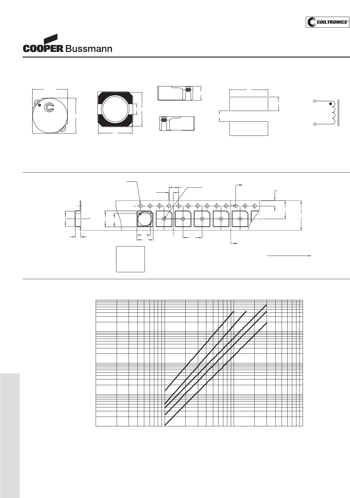
PM-118
LOW PROFILE SHIELDED DRUM (SD6020)
SD6020 Series
Low Profile Power Inductors
Core Loss
1MHz 500kHz
300kHz
200kHz
100kHz
0.0001
0.001
0.01
0.1
1
1 10 100 1000
Bp-p (mT)
Core Loss (W)
Dimensions are in millimeters.
6.3
8.0
2.0
1.5 dia
+0.1/-0.0
Bo
Ko
B1
7.5
1.5 dia
min
A
1.75
A
4.0
12.0
Ao
A1
XXX
wwlly R
User direction of feed
Ko=2.2 mm
B1=5.8 mm
A1=5.8 mm
Bo=6.8 mm
Ao=6.8 mm
SECTION A-A
Parts packaged on 13" Diameter reel,
2,600 parts per reel.
Packaging Information
SCHEMATI C
1
2
6.0 max.
5.5
2.0
2.0 max.
6.0 max.
XXX
wwlly R
TOP VIEW FRONT VIEW
5.5
BOTTOM VIEW
LEFT VIEW
6.3
2.2
2
1
2
RECOMMENDED PCB LAYOUT
xxx = Inductance value in uH. R = decimal point. If no R is present third character = #0f zeros.
wwllyy = Date code, R = Revision level.
Mechanical Diagrams
Courtesy of Steven Engineering, Inc.-230 Ryan Way, South San Francisco, CA 94080-6370-Main Office: (650) 588-9200-Outside Local Area: (800) 258-9200-www.stevenengineering.com
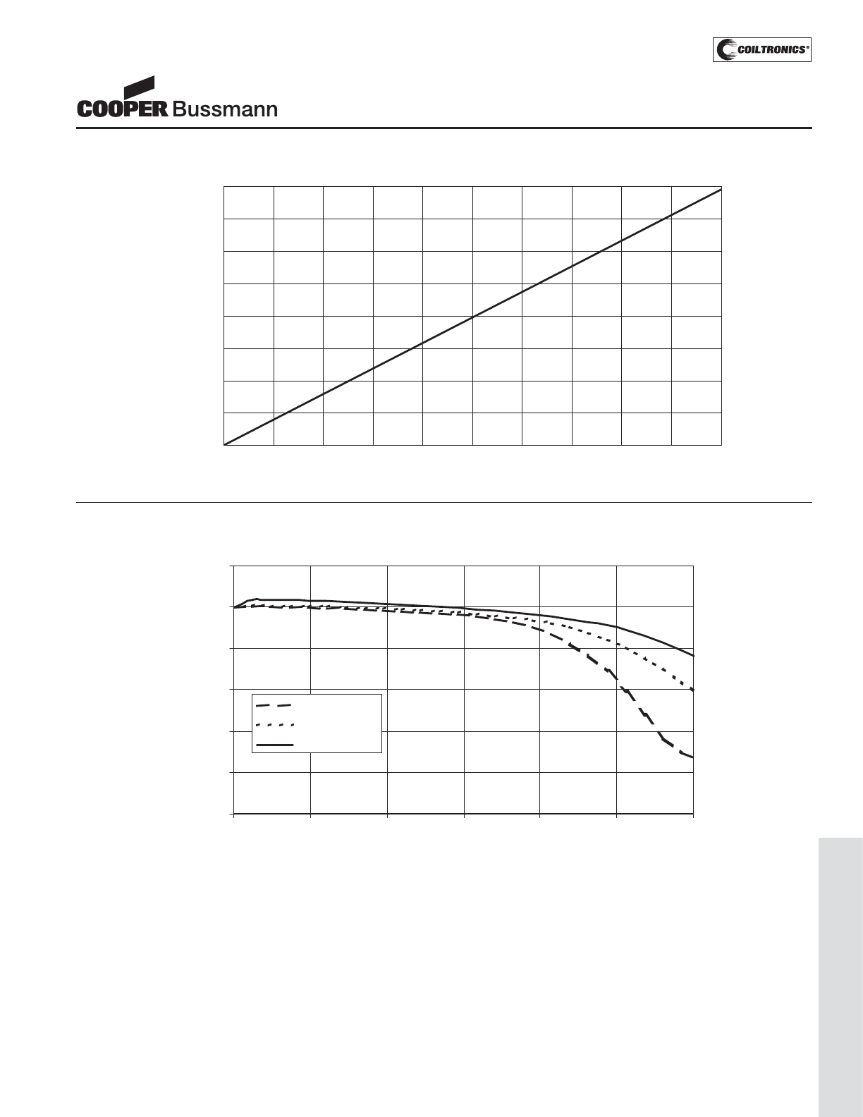
PM-119
LOW PROFILE SHIELDED DRUM (SD6020)
OCL Vs. Isat
0%
20%
40%
60%
80%
100%
120%
0% 20% 40% 60% 80% 100% 120%
% of Isat
% of OC
+85 Deg. C
+25 Deg. C
- 40 Deg. C
Inductance Characteristics
SD6020 Series
Low Profile Power Inductors
Temperature Rise vs. Loss
0.00
20.00
40.00
60.00
80.00
100.00
120.00
140.00
160.00
0.00 0.10 0.20 0.30 0.40 0.50 0.60 0.70 0.80 0.90 1.00
Total Loss (W)
Temperature Rise (°C)
Courtesy of Steven Engineering, Inc.-230 Ryan Way, South San Francisco, CA 94080-6370-Main Office: (650) 588-9200-Outside Local Area: (800) 258-9200-www.stevenengineering.com
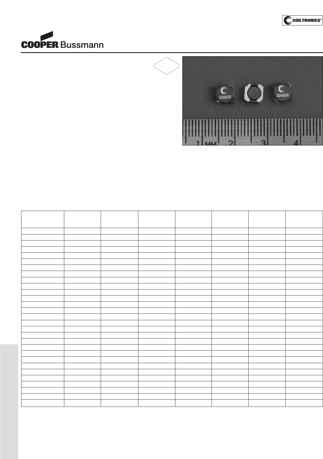
PM-120
LOW PROFILE SHIELDED DRUM (SD6030)
Description
• 125°C maximum total temperature operation
• Low profile surface mount inductors
• 6.0mm x 6.0mm x 3.0mm surface mount package
• Ferrite core material
• Shielded drum core reduces EMI
• Inductance range from 2.7μH to 680μH
• Current range from 4.08 Amps to 0.16 Amps
• Frequency range up to 1MHz
Applications
• Notebook computers, Digital cameras
• DSL modems, PDA’s
• High Power LED driver
• MP3, CD players, GPS receivers
• Cellular phones, Smart phones
• Wireless notebook adapters
• Battery power, TFT-LCD Bias supplies
• PCMCIA, Cardbus32, MiniPCI cards
Environmental Data
• Storage temperature range: -40°C to +125°C
• Operating temperature range: -40°C to +125°C
(range is application specific)
• Solder reflow temperature: +260°C max. for 10 seconds
maximum
Packaging
• Supplied in tape and reel packaging, 2600 per reel
SD6030 Series
Low Profile Power Inductors
Part Number Rated OCL (1) Irms (2) Isat (3) DCR DCR K-factor
Inductance μH ± 30% Amperes Amperes mΩ@20°C mΩ@20°C (4)
(μH) (Typical) (Maximum)
SD6030-2R7-R 2.7 2.7 4.08 2.60 13 18 34
SD6030-3R3-R 3.3 3.3 3.54 2.40 18 24 30
SD6030-4R2-R 4.2 4.1 3.11 2.20 23 31 27
SD6030-5R0-R 5.0 4.9 2.81 1.90 28 38 24
SD6030-5R8-R 5.8 5.8 2.58 1.80 33 45 22
SD6030-7R8-R 7.8 7.8 2.38 1.60 39 53 19
SD6030-100-R 10 9.3 2.15 1.30 48 65 17
SD6030-120-R 12 11.3 1.99 1.20 56 76 16
SD6030-150-R 15 14.1 1.71 1.10 76 103 14
SD6030-180-R 18 17.1 1.65 1.00 82 110 13
SD6030-220-R 22 20.4 1.57 0.90 90 122 12
SD6030-270-R 27 26.0 1.31 0.85 130 175 11
SD6030-330-R 33 32.4 1.26 0.75 140 189 9.3
SD6030-360-R 36 34.4 1.19 0.70 157 212 8.7
SD6030-440-R 44 44.0 1.10 0.62 185 250 7.9
SD6030-520-R 52 52.0 0.99 0.58 226 305 7.2
SD6030-680-R 68 65.6 0.92 0.52 263 355 6.5
SD6030-820-R 82 81.6 0.80 0.46 343 463 5.9
SD6030-101-R 100 94.4 0.76 0.42 385 520 5.6
SD6030-121-R 120 110.1 0.70 0.40 517 620 5.6
SD6030-151-R 150 144.5 0.64 0.35 608 730 5.0
SD6030-181-R 180 175.7 0.55 0.32 817 980 4.5
SD6030-221-R 220 210.9 0.50 0.30 1000 1200 4.0
SD6030-271-R 270 264.2 0.44 0.27 1300 1560 3.6
SD6030-331-R 330 313.5 0.38 0.25 1733 2080 3.3
SD6030-391-R 390 373.7 0.35 0.22 2083 2500 3.0
SD6030-471-R 470 460.0 0.33 0.20 2250 2700 2.8
SD6030-561-R 560 546.2 0.30 0.18 2767 3320 2.5
SD6030-681-R 680 659.4 0.27 0.16 3458 4150 2.3
(1) Open Circuit Inductance Test Parameters: 100kHz, 0.1V, 0.0Adc.
(2) Irms: DC current for an approximate ΔT of 40°C without core loss. Derating is
necessary for AC currents. PCB layout, trace thickness and width, air-flow, and
proximity of other heat generating components will affect the temperature rise. It
is recommended that the temperature of the part not exceed 125°C under worst
case operating conditions verified in the end application.
(3) Isat Amperes peak for 35% rolloff (@25°C)
(4) K-factor: Used to determine B p-p for core loss (see graph).
B p-p = K*L*ΔI, B p-p(mT), K: (K factor from table), L: (Inductance in uH),
ΔI (Peak to peak ripple current in Amps).
(5) Part Number Definition: SD6030-xxx-R
SD6030 = Product code and size; -xxx = Inductance value in uH;
R = decimal point; If no R is present, third character = # of zeros.
-R suffix = RoHS compliant
RoHS
2002/95/EC
Courtesy of Steven Engineering, Inc.-230 Ryan Way, South San Francisco, CA 94080-6370-Main Office: (650) 588-9200-Outside Local Area: (800) 258-9200-www.stevenengineering.com
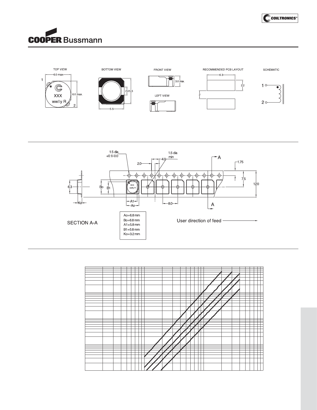
PM-121
LOW PROFILE SHIELDED DRUM (SD6030)
SD6030 Series
Low Profile Power Inductors
Core Loss
1MHz 500kHz 300kHz
200kHz
100kHz
0.0001
0.001
0.01
0.1
1
1 10 100 1000
Core Loss (W)
Bp-p (mT)
Dimensions are in millimeters.
Parts packaged on 13" Diameter reel,
2,600 parts per reel.
Packaging Information
xxx = Inductance value in uH. R = decimal point. If no R is present third character = # of zeros.
wwllyy = Date code, R = Revision level.
Mechanical Diagrams
Courtesy of Steven Engineering, Inc.-230 Ryan Way, South San Francisco, CA 94080-6370-Main Office: (650) 588-9200-Outside Local Area: (800) 258-9200-www.stevenengineering.com
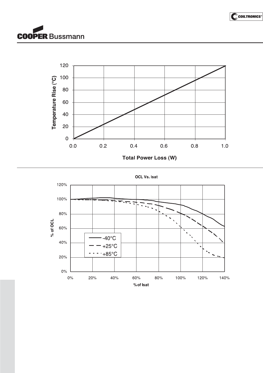
PM-122
LOW PROFILE SHIELDED DRUM (SD6030)
Inductance Characteristics
SD6030 Series
Low Profile Power Inductors
Temperature Rise vs. Loss
Courtesy of Steven Engineering, Inc.-230 Ryan Way, South San Francisco, CA 94080-6370-Main Office: (650) 588-9200-Outside Local Area: (800) 258-9200-www.stevenengineering.com
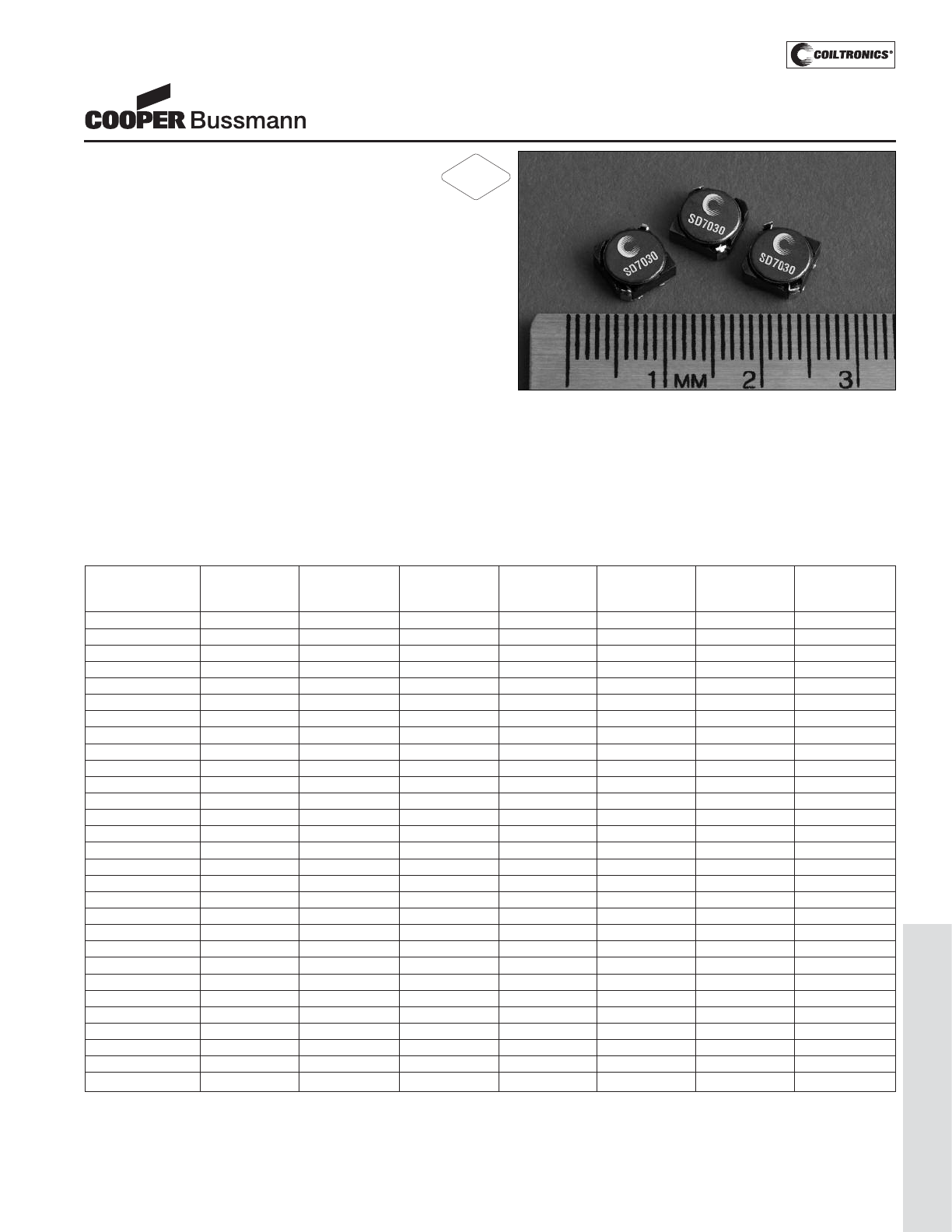
PM-123
LOW PROFILE SHIELDED DRUM (SD7030)
Description
• 125°C maximum total temperature operation
• Low profile surface mount inductors
• 7.0mm x 7.0mm x 3.0mm shielded drum core
• Ferrite core material
• Inductance range from 3.3μH to 680μH
• Current range from 3.7 Amps to 0.21 Amps
• Frequency range up to 1MHz
Applications
• PDA’s, Wireless handsets
• Handheld computers
• MP3 players, CD players, organizers
• Portable computers, GPS receivers
• ADSL/DSL/Cable modems
• Buck and Boost inductor
• Battery power, Li-lon, 2-cell
• Digital still camera
• White LED driver
Environmental Data
• Storage temperature range: -40°C to +125°C
• Operating temperature range: -40°C to +125°C
(range is application specific)
• Solder reflow temperature: +260°C max. for 10 seconds
maximum
Packaging
• Supplied in tape and reel packaging, 1500 per reel
SD7030 Series
Low Profile Power Inductors
Part Number Rated OCL (1) Irms (2) Isat (3) DCR DCR K-factor
Inductance μH ± 30% Amperes Amperes mΩ@25°C mΩ@25°C (4)
(μH) (Typical) (Maximum)
SD7030-3R3-R 3.3 3.3 3.7 3.00 20 24 22
SD7030-3R9-R 3.9 4.1 3.4 2.60 22 27 19
SD7030-5R0-R 5.0 4.9 3.2 2.40 26 31 17
SD7030-6R0-R 6.0 5.8 2.8 2.25 29 35 16
SD7030-7R3-R 7.3 7.0 2.3 2.10 45 54 13
SD7030-8R0-R 8.0 7.8 2.2 1.85 48 58 12
SD7030-100-R 10 10.0 2.1 1.70 54 65 11
SD7030-120-R 12 11.5 1.9 1.55 58 70 10
SD7030-150-R 15 14.6 1.7 1.40 70 84 9.3
SD7030-180-R 18 17.3 1.7 1.32 79 95 8.8
SD7030-220-R 22 21.0 1.4 1.20 107 128 7.6
SD7030-260-R 26 24.9 1.3 1.05 118 142 6.9
SD7030-300-R 30 30.0 1.2 0.97 138 165 6.4
SD7030-390-R 39 39.7 1.1 0.86 175 210 5.7
SD7030-440-R 44 43.4 1.1 0.80 198 238 5.3
SD7030-560-R 56 54.4 0.99 0.73 231 277 4.9
SD7030-680-R 68 66.6 0.85 0.65 253 304 4.3
SD7030-820-R 82 81.4 0.82 0.60 325 390 4.0
SD7030-101-R 100 95.5 0.70 0.54 446 535 3.6
SD7030-121-R 120 115.2 0.67 0.50 629 755 3.3
SD7030-151-R 150 145 0.57 0.44 715 858 2.9
SD7030-181-R 180 174 0.54 0.40 805 966 2.7
SD7030-221-R 220 211 0.51 0.36 1102 1322 2.4
SD7030-271-R 270 264 0.44 0.33 1259 1475 2.2
SD7030-331-R 330 317 0.38 0.30 1438 1725 2.0
SD7030-391-R 390 381 0.36 0.27 1857 2228 1.8
SD7030-471-R 470 460 0.34 0.25 2150 2581 1.7
SD7030-561-R 560 561.0 0.29 0.23 2857 3428 1.5
SD7030-681-R 680 677.2 0.28 0.21 3206 3847 1.4
(1) Open Circuit Inductance Test Parameters: 100kHz, 0.1V, 0.0Adc.
(2) Irms: DC current for an approximate ΔT of 40°C without core loss. Derating is
necessary for AC currents. PCB layout, trace thickness and width, air-flow, and
proximity of other heat generating components will affect the temperature rise. It
is recommended that the temperature of the part not exceed 125°C under worst
case operating conditions verified in the end application.
(3) Isat Amperes peak for approximately 35% rolloff (@25°C)
(4) K-factor: Used to determine B p-p for core loss (see graph).
B p-p = K*L*ΔI, B p-p(mT), K: (K factor from table), L: (Inductance in uH),
ΔI (Peak to peak ripple current in Amps).
(5) Part Number Definition: SD7030-xxx-R
SD7030 = Product code and size; -xxx = Inductance value in uH;
R = decimal point; If no R is present, third character = # of zeros.
-R suffix = RoHS compliant
RoHS
2002/95/EC
Courtesy of Steven Engineering, Inc.-230 Ryan Way, South San Francisco, CA 94080-6370-Main Office: (650) 588-9200-Outside Local Area: (800) 258-9200-www.stevenengineering.com
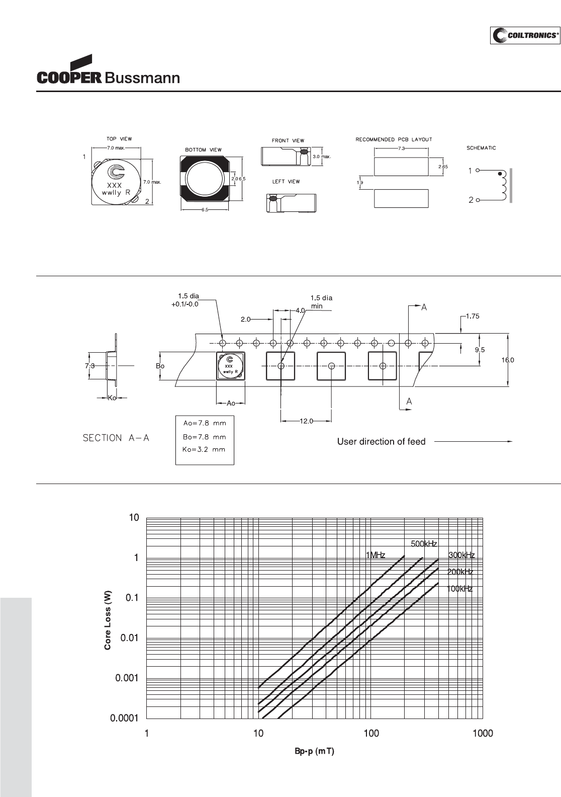
PM-124
LOW PROFILE SHIELDED DRUM (SD7030)
SD7030 Series
Low Profile Power Inductors
Core Loss
Dimensions are in millimeters.
Parts packaged on 13" Diameter reel,
1,500 parts per reel.
Packaging Information
xxx = Inductance value in uH. R = decimal point. If no R is present third character = # of zeros.
wwllyy = Date code, R = Revision level.
Mechanical Diagrams
Courtesy of Steven Engineering, Inc.-230 Ryan Way, South San Francisco, CA 94080-6370-Main Office: (650) 588-9200-Outside Local Area: (800) 258-9200-www.stevenengineering.com
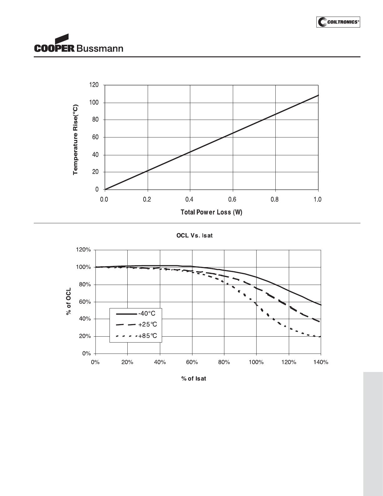
PM-125
LOW PROFILE SHIELDED DRUM (SD7030)
Inductance Characteristics
SD7030 Series
Low Profile Power Inductors
Temperature Rise vs. Loss
Courtesy of Steven Engineering, Inc.-230 Ryan Way, South San Francisco, CA 94080-6370-Main Office: (650) 588-9200-Outside Local Area: (800) 258-9200-www.stevenengineering.com
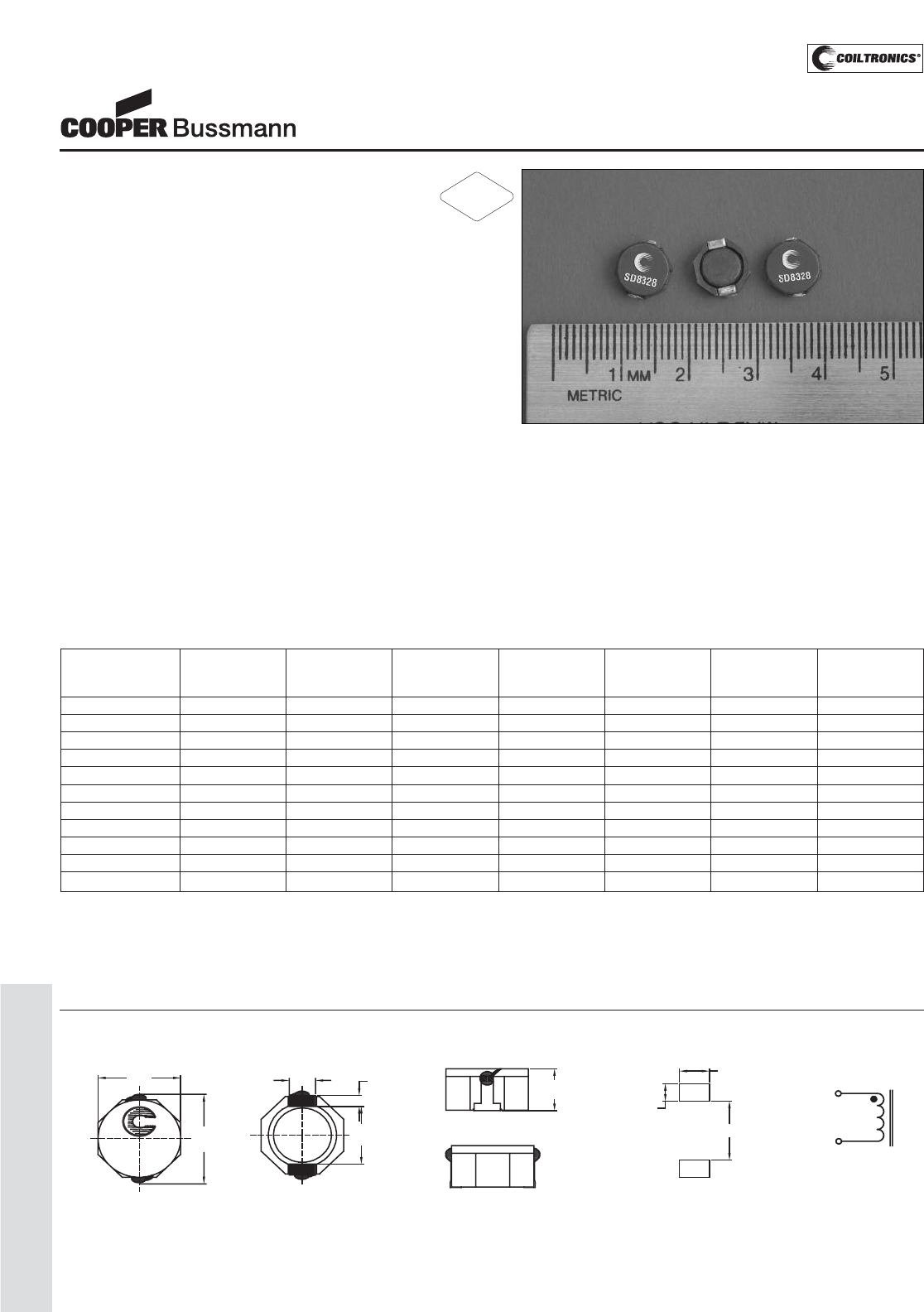
PM-126
LOW PROFILE SHIELDED DRUM (SD8328)
Description
• 125°C maximum temperature operation
• Low profile surface mount inductor
• 8.3mm x 9.5mm x 3.0mm shielded drum core
• Ferrite core material
• Inductance range from 2.7μH to 100μH
• Current range from 6.6 Amps to 0.8 Amps
• Frequency range up to 1MHz
Applications
• Buck or Boost inductor
• Noise filtering output filter chokes
• Notebook power/display
• LCD Monitors/Displays/Televisions
• Battery chargers, LCD bias supplies
• Battery and Industrial power systems
• Computer, DVD players
• Portable power devices, DC-DC converters
Environmental Data
• Storage temperature range: -40°C to +125°C
• Operating temperature range: -40°C to +125°C
(range is application specific)
• Solder reflow temperature: +260°C max. for 10 seconds
maximum
Packaging
• Supplied in tape and reel packaging, 1280 per reel
SD8328 Series
Low Profile Power Inductors
Part Number Rated OCL (1) Irms(2) Isat (3) DCR (Ω) DCR (Ω) K-factor
Inductance μH±30% Amperes Amperes mΩ@20°C mΩ@20°C (4)
(μH) (Typical) (Maximum)
SD8328-2R5-R 2.5 2.7 6.6 4.5 12 15.6 43
SD8328-3R3-R 3.3 3.4 6.1 4.0 14 18.0 33
SD8328-4R7-R 4.7 5.0 4.5 3.6 19 24.7 23
SD8328-7R3-R 7.3 7.6 3.4 2.9 30 39 15
SD8328-100-R 10 9.1 3.3 2.6 36 45 11
SD8328-150-R 15 14.5 2.35 2.0 53 69 7.2
SD8328-220-R 22 21.1 1.85 1.7 76 99 4.9
SD8328-330-R 33 31.9 1.45 1.4 120 156 3.3
SD8328-470-R 47 44.9 1.30 1.2 150 194 2.3
SD8328-680-R 68 64.2 0.98 1.0 220 286 1.6
SD8328-101-R 100 97.0 0.80 0.8 330 430 1.1
(1) Open Circuit Inductance Test Parameters: 100kHz, 0.1V, 0.0Adc.
(2) Irms: DC current for an approximate ΔT of 40°C without core loss. Derating is
necessary for AC currents. PCB layout, trace thickness and width, air-flow, and
proximity of other heat generating components will affect the temperature rise. It
is recommended that the temperature of the part not exceed 125°C under worst
case operating conditions verified in the end application.
(3) Isat Amperes peak for approximately 35% rolloff (@25°C)
(4) K-factor: Used to determine B p-p for core loss (see graph).
B p-p = K*L*ΔI, B p-p(mT), K: (K factor from table), L: (Inductance in μH),
ΔI (Peak to peak ripple current in Amps).
(5) Part Number Definition: SD8328-xxx-R
SD8328 = Product code and size; -xxx = Inductance value in uH;
R = decimal point; If no R is present, third character = # of zeros.
-R suffix = RoHS compliant
RoHS
2002/95/EC
Dimensions are in millimeters.
xxx = Inductance value in uH. R = decimal point. If no R is present third character = # of zeros. wwllyy = Date code, R = Revision level.
RECOMMENDED PCB LAYOUT SCHEMATIC
1
2
9.5
max
8.3
max 3.0
max
2.5
typ 1.2
typ
6.3
typ
XXX
wwlly R
TOP VIEW FRONT VIEW
BOTTOM VIEW
5.7
2.9
1.8
1
2
LEFT VIEW
Mechanical Diagrams
Courtesy of Steven Engineering, Inc.-230 Ryan Way, South San Francisco, CA 94080-6370-Main Office: (650) 588-9200-Outside Local Area: (800) 258-9200-www.stevenengineering.com
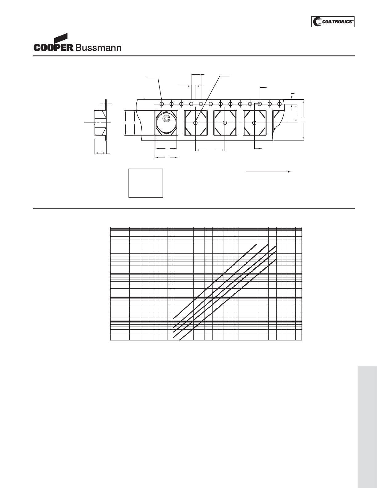
PM-127
LOW PROFILE SHIELDED DRUM (SD8328)
SD8328 Series
Low Profile Power Inductors
Core Loss
100kHz
200kHz
300kHz
500kHz
1MHz
0.0001
0.001
0.01
0.1
1
10
1 10 100 1000
Bp-p (mT)
Core Loss (W)
wwlly R
XXX
12.0
A1
Ao
16.0
User direction of feed
4.0
A1.75
A
1.5 dia
min
7.5
1.5 dia
+0.1/-0.0
B1
SECTION A-A
Ko
Bo
Ao=9.5 mm
Bo=10.0 mm
A1=8.5 mm
B1=9.7 mm
Ko=3.2 mm
2.0
Parts packaged on 13" Diameter reel,
1,280 parts per reel.
Packaging Information
Courtesy of Steven Engineering, Inc.-230 Ryan Way, South San Francisco, CA 94080-6370-Main Office: (650) 588-9200-Outside Local Area: (800) 258-9200-www.stevenengineering.com
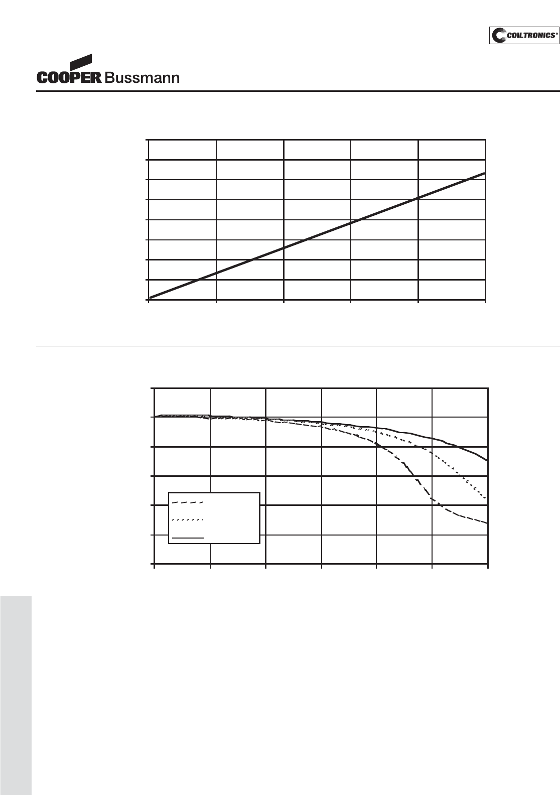
PM-128
LOW PROFILE SHIELDED DRUM (SD8328)
OCL Vs. Isat
0.0%
20.0%
40.0%
60.0%
80.0%
100.0%
120.0%
0.0% 20.0% 40.0% 60.0% 80.0% 100.0% 120.0%
% Isat
% OCL
+85 Deg.C
+25 Deg.C
-40 Deg.C
Inductance Characteristics
SD8328 Series
Low Profile Power Inductors
Temperature Rise vs. Loss
0
20
40
60
80
100
120
140
160
0.0 0.2 0.4 0.6 0.8 1.0
Total Power Loss (W)
Temperature Rise (ºC)
Courtesy of Steven Engineering, Inc.-230 Ryan Way, South San Francisco, CA 94080-6370-Main Office: (650) 588-9200-Outside Local Area: (800) 258-9200-www.stevenengineering.com
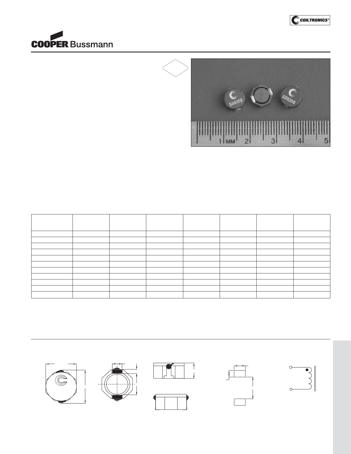
PM-129
LOW PROFILE SHIELDED DRUM (SD8350)
Description
• 125°C maximum total temperature operation
• Low profile surface mount inductor
• 8.3mm x 9.5mm x 4.5mm shielded drum core
• Ferrite core material
• Inductance range from 1.5μH to 100μH
• Current range from 9.1 Amps to 0.8 Amps
• Frequency range up to 1MHz
Applications
• Server/Notebook power
• High Power LED driver, Portable devices
• Base Station, Telecom, and Networking
• Battery Chargers, RAM power supply
• Industrial and Automotive power systems
• Noise filtering output filter chokes
• Buck/Boost converters, Output converters
Environmental Data
• Storage temperature range: -40°C to +125°C
• Operating temperature range: -40°C to +125°C
(range is application specific)
• Solder reflow temperature: +260°C max. for 10 seconds
maximum
Packaging
• Supplied in tape and reel packaging, 750 per reel
SD8350 Series
Shielded Power Inductors
Part Number Rated OCL (1) Irms(2) Isat (3) DCR (Ω) DCR (Ω) K-factor
Inductance μH±30% Amperes Amperes mΩ@20°C mΩ@20°C (4)
(μH) (Typical) (Maximum)
SD8350-1R8-R 1.8 1.5 5.50 9.1 11.8 14.0 16.0
SD8350-3R9-R 3.9 3.2 4.50 6.3 16.2 19.0 9.6
SD8350-4R7-R 4.7 4.2 4.10 5.5 18.5 22.0 8.5
SD8350-6R8-R 6.8 6.8 3.90 4.4 20.8 25.0 7.6
SD8350-100-R 10 9.9 3.20 4.0 31.4 36.0 6.3
SD8350-150-R 15 13.6 2.30 2.9 45.0 53.0 5.3
SD8350-220-R 22 20.4 1.80 2.6 63.5 75.0 4.4
SD8350-330-R 33 31.4 1.40 2.2 111.4 125.0 3.5
SD8350-470-R 47 44.9 1.30 1.8 130.0 150.0 2.9
SD8350-680-R 68 65.1 1.00 1.5 200.8 240.0 2.4
SD8350-101-R 100 99.7 0.80 1.3 308.0 360.0 2.0
(1) Open Circuit Inductance Test Parameters: 100kHz, 0.1V, 0.0Adc.
(2) Irms: DC current for an approximate ΔT of 40°C without core loss. Derating is
necessary for AC currents. PCB layout, trace thickness and width, air-flow, and
proximity of other heat generating components will affect the temperature rise. It
is recommended that the temperature of the part not exceed 125°C under worst
case operating conditions verified in the end application.
(3) Isat Amperes peak for approximately 35% rolloff (@25°C)
(4) K-factor: Used to determine B p-p for core loss (see graph).
B p-p = K*L*ΔI, B p-p(mT), K: (K factor from table), L: (Inductance in μH),
ΔI (Peak to peak ripple current in Amps).
(5) Part Number Definition: SD8350-xxx-R
SD8350 = Product code and size; -xxx = Inductance value in uH;
R = decimal point; If no R is present, third character = # of zeros.
-R suffix = RoHS compliant
RoHS
2002/95/EC
Dimensions are in millimeters.
xxx = Inductance value in uH. R = decimal point. If no R is present third character = # of zeros. wwllyy = Date code, R = Revision level.
RECOMMENDED PCB LAYOUT SCHEMATIC
1
2
9.5 max.
8.3 max.
4.5 max.
2.5
1.2
6.3
XXX
wwlly R
TOP VIEW FRONT VIEW
BOTTOM VIEW
5.7
2.9
1.8
1
2
LEFT VIEW
Mechanical Diagrams
Courtesy of Steven Engineering, Inc.-230 Ryan Way, South San Francisco, CA 94080-6370-Main Office: (650) 588-9200-Outside Local Area: (800) 258-9200-www.stevenengineering.com
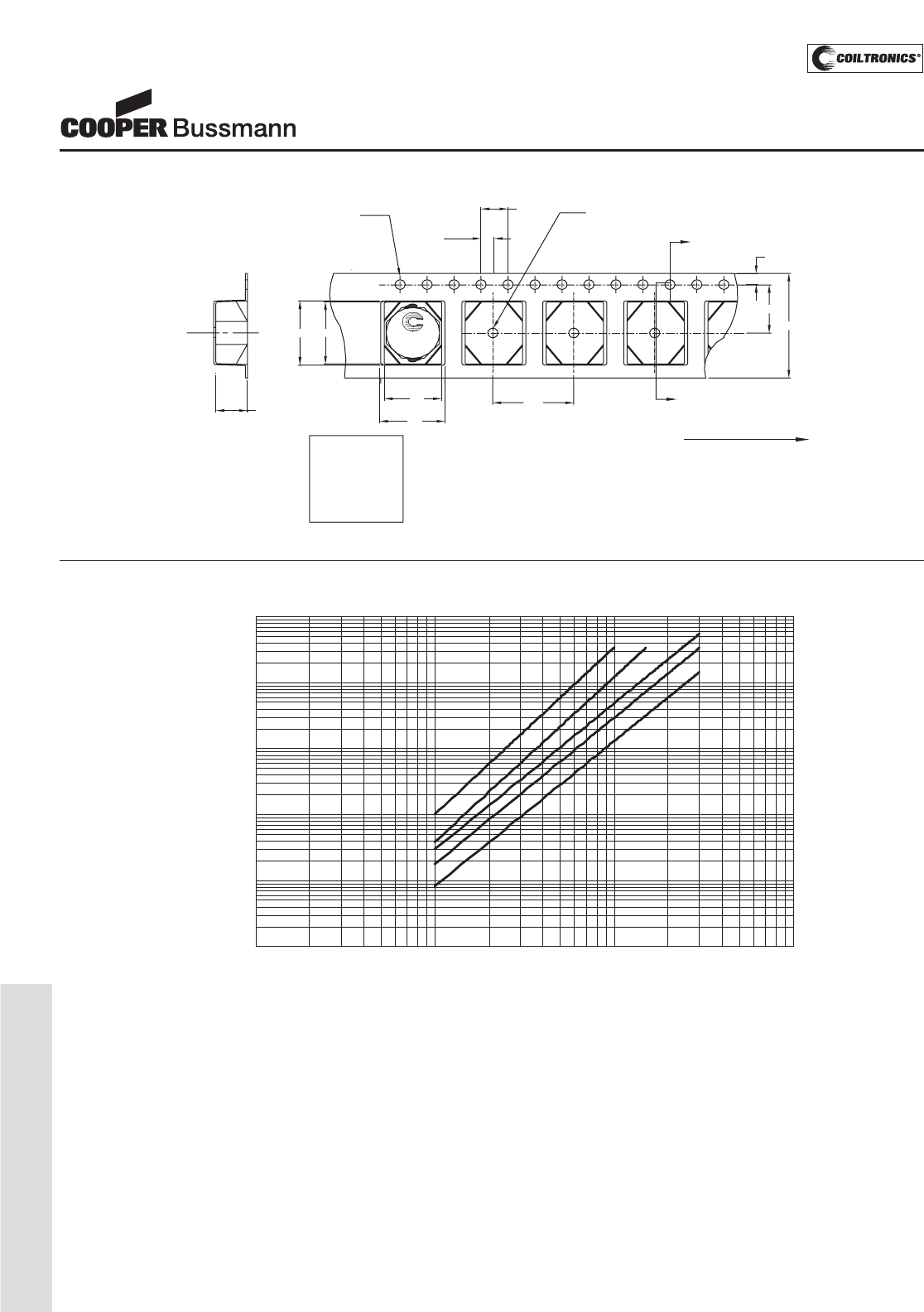
PM-130
LOW PROFILE SHIELDED DRUM (SD8350)
SD8350 Series
Shielded Power Inductors
Core Loss
1MHz 500kHz 300kHz
200kHz
100kHz
0. 000 1
0. 00 1
0. 01
0. 1
1
10
1 10 100 100 0
Bp-p (mT)
Core Loss (W)
2.0
Ko=4.6 mm
B1=9.7 mm
A1=8.5 mm
Bo=10.0 mm
Ao=9.5 mm
1.5 dia
+0.1/-0.0
Bo
Ko
SECTION A-A
B1
7.5
1.5 dia
min
A
1.75
A
4.0
User direction of feed
16.0
Ao
A1 12.0
XXX
wwlly R
Parts packaged on 13" Diameter reel,
750 parts per reel.
Packaging Information
Courtesy of Steven Engineering, Inc.-230 Ryan Way, South San Francisco, CA 94080-6370-Main Office: (650) 588-9200-Outside Local Area: (800) 258-9200-www.stevenengineering.com
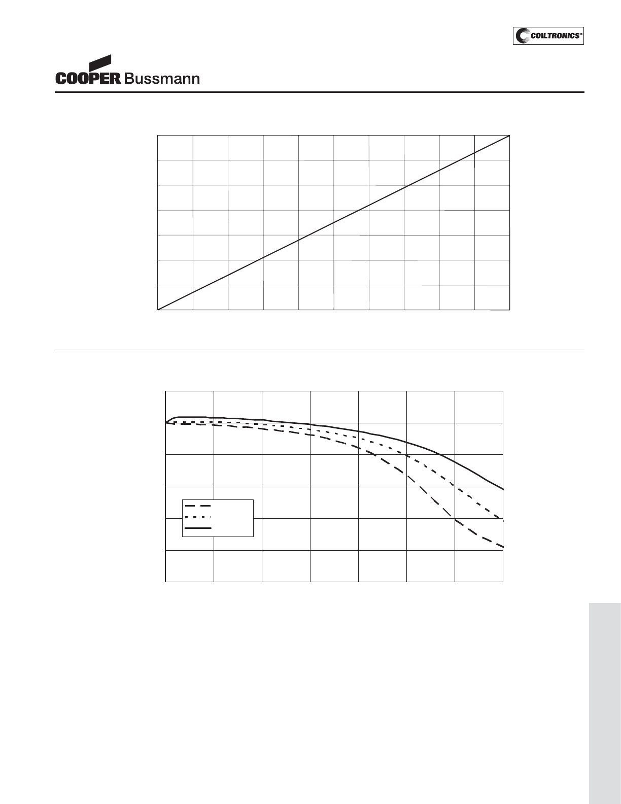
PM-131
LOW PROFILE SHIELDED DRUM (SD8350)
OCL Vs. Isat
0%
20%
40%
60%
80%
100%
120%
0% 20% 40% 60% 80% 100% 120% 140%
% Is at
% OCL
+85 Deg. C
+25 Deg. C
-40 Deg. C
Inductance Characteristics
SD8350 Series
Shielded Power Inductors
Temperature Rise vs. Loss
0
20
40
60
80
100
120
140
0 0.1 0.2 0.3 0.4 0.5 0.6 0.7 0.8 0.9 1
Temperature Rise (°C)
Total Loss (W)
Courtesy of Steven Engineering, Inc.-230 Ryan Way, South San Francisco, CA 94080-6370-Main Office: (650) 588-9200-Outside Local Area: (800) 258-9200-www.stevenengineering.com
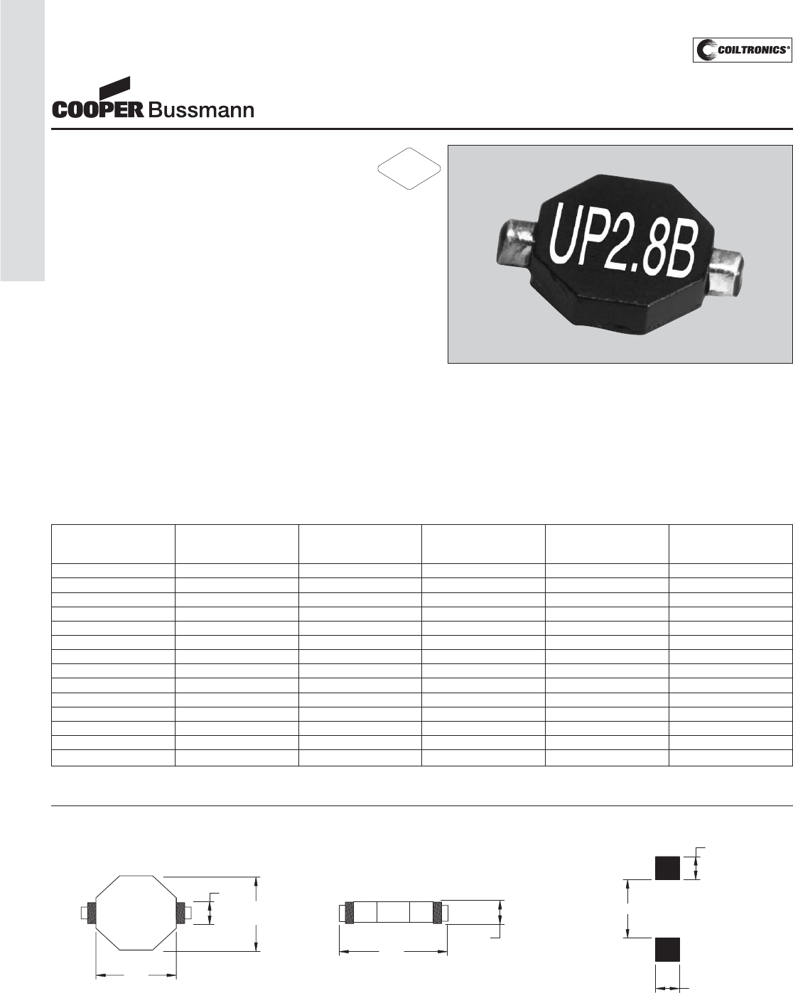
PM-132
UNSHIELDED DRUM CORE (UP2.8B) UNI-PAC™ 2.8B
Description
• Miniature size and rugged construction
• Low DCR and high efficiency
• Suited for IR and vapor reflow solder
• Designed for high shock environments
• Frequency range 1kHz to 2MHz
• Ferrite core material
Applications
• DC-DC converters
• Filter inductors
• Signal conditioning
• Energy storage applications
• Computer, pager and battery powered equipment
Environmental Data
• Storage temperature range: -40°C to +125°C
• Operating ambient temperature range: -40°C to +85°C
range is application specific. Temperature rise is
approximately 40°C at rated RMS current. Maximum
operating temperature is 125°C including ambient.
• Solder reflow temperature: +260°C max. for 10 seconds
max.
Packaging
• Supplied in tape and reel packaging, 1,750 per reel
Part Inductance OCL (1) Irms (2) Isat (3) DCR (4)
Number μH μH ± 20% Amperes Amperes Ohms
(Rated) (Max.)
UP2.8B-1R0-R 1.0 0.98 3.6 8.0 .0286
UP2.8B-1R5-R 1.5 1.59 3.3 6.4 .0349
UP2.8B-2R2-R 2.2 2.44 3.1 5.2 .0356
UP2.8B-3R3-R 3.3 3.24 2.8 4.5 .0474
UP2.8B-4R7-R 4.7 4.15 2.7 3.9 .0478
UP2.8B-6R8-R 6.8 6.73 2.4 3.2 .067
UP2.8B-100-R 10 10 2.1 2.7 .080
UP2.8B-150-R 15 15 1.7 2.2 .120
UP2.8B-220-R 22 22 1.5 1.7 .190
UP2.8B-330-R 33 33 1.3 1.5 .250
UP2.8B-470-R 47 47 1.0 1.2 .340
UP2.8B-680-R 68 68 .89 1.0 .480
UP2.8B-101-R 100 100 .78 .84 .622
UP2.8B-151-R 150 150 .62 .74 .971
UNI-PAC™ 2.8
Low Cost, Low Profile 2.8mm
Power Inductors (Surface Mount)
1) Open Circuit Inductance Test Parameters: 100kHz, 0.250 Vrms, 0.0 Adc
2) RMS current, delta temp. of 40° C ambient temperature of 85° C 3) Peak current for approximately 10% roll-off @ 20°C
4) Values @ 20° C
Mechanical Diagrams
9.4
max
2.63
max 9.4
max
UP2.8B
xxx
wwllyy R
TOP VIEW
FRONT VIEW
12.9
max
2.8
max
7.37
2.79
2.92
Component View
Recommended PCB Layout
Dimensions in Millimeters.
wwllyy = date code R = (revision level)
xxx = Inductance value per family chart
RoHS
2002/95/EC
Courtesy of Steven Engineering, Inc.-230 Ryan Way, South San Francisco, CA 94080-6370-Main Office: (650) 588-9200-Outside Local Area: (800) 258-9200-www.stevenengineering.com
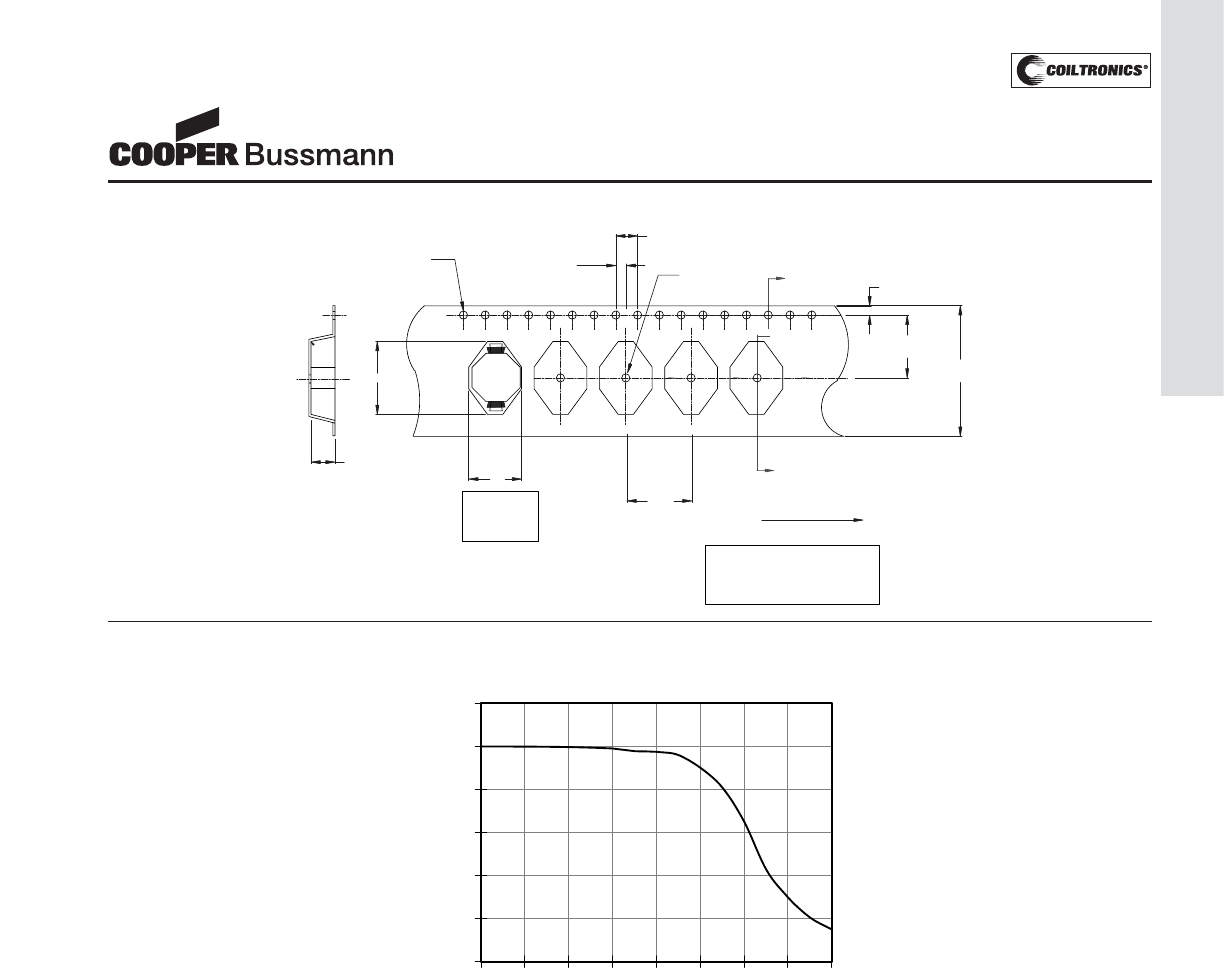
PM-133
UNSHIELDED DRUM CORE (UP2.8B) UNI-PAC™ 2.8B
13" Dia. EIA-481 compliant reel.
Packaging Information:
Parts packaged on a
1,750 parts per reel.
1
2
A
A
Ao=9.7mm
Bo=13.4mm
Ko=3.1mm
SECTION A-A
Ko
Ao
1.5 dia
+0.1/-0.0 1.5 dia
min
4.0
2.0
12.0
1.7
11.5
24.0
+/-0.3
User direction of feed
Bo
Packaging Information
0
20
40
60
80
100
120
0 40 80 120 160
% of Isat
% of Initial Inductance
Inductance Characteristics
UNI-PAC™ 2.8
Low Cost, Low Profile 2.8mm
Power Inductors (Surface Mount)
Courtesy of Steven Engineering, Inc.-230 Ryan Way, South San Francisco, CA 94080-6370-Main Office: (650) 588-9200-Outside Local Area: (800) 258-9200-www.stevenengineering.com
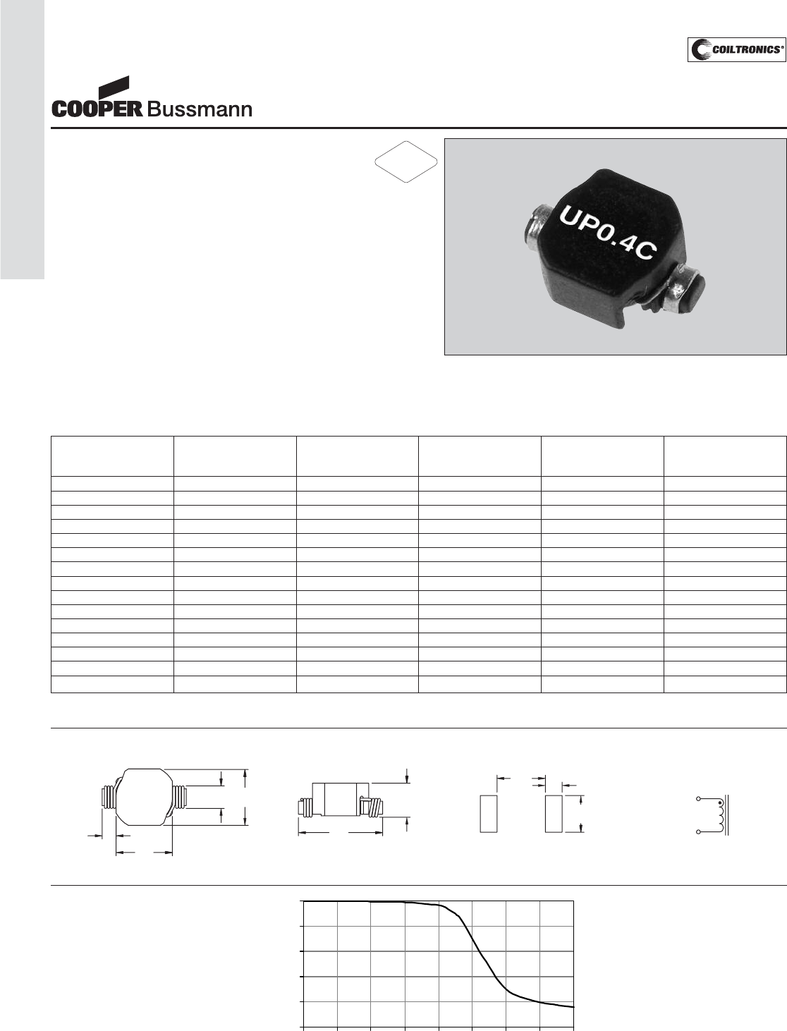
PM-134
UNSHIELDED DRUM CORE (UP0.4C) UNI-PAC™ 0.4C
Description
• Miniature size and rugged construction
• Designed for high shock environments
• Suited for IR and vapor reflow solder
• Frequency range 1kHz to 2MHz
• Ferrite core material
Applications
• Computer, pager and battery powered equipment
Environmental Data
• Storage temperature range: -40°C to +125°C
• Operating ambient temperature range: -40°C to +85°C
range is application specific. Temperature rise is
approximately 40°C at rated RMS current. Maximum
operating temperature is 125°C including ambient.
• Solder reflow temperature: +260°C max. for 10 seconds
max.
Packaging
• Supplied in tape and reel packaging, 2,500 per reel
Part Inductance OCL (1) Irms (2) Isat (3) DCR (4)
Number μH μH ± 20% Amperes Amperes Ohms
(Rated) (Max)
UP0.4C-1R0-R 1.0 1.16 2.88 3.33 0.030
UP0.4C-1R5-R 1.5 1.49 2.58 2.94 0.034
UP0.4C-2R2-R 2.2 2.27 2.15 2.38 0.050
UP0.4C-3R3-R 3.3 3.22 1.89 2.00 0.060
UP0.4C-4R7-R 4.7 4.95 1.55 1.61 0.088
UP0.4C-6R8-R 6.8 7.06 1.30 1.35 0.128
UP0.4C-100-R 10 9.53 1.16 1.16 0.156
UP0.4C-150-R 15 14.5 0.95 0.94 0.250
UP0.4C-220-R 22 21.8 0.76 0.77 0.360
UP0.4C-270-R 27 27.5 0.69 0.68 0.480
UP0.4C-330-R 33 32.2 0.64 0.63 0.560
UP0.4C-390-R 39 39.0 0.59 0.57 0.650
UP0.4C-470-R 47 46.5 0.53 0.53 0.820
UP0.4C-680-R 68 68.2 0.45 0.43 1.10
UP0.4C-101-R 100 102.5 0.37 0.35 1.58
UNI-PAC™ 0.4C
Low Cost, Low Profile
Power Inductors (Surface Mount)
1) Open Circuit Inductance Test Parameters: 100kHz, 0.250 Vrms, 0.0 Adc
2) RMS current, delta temp. of 40°C ambient temperature of 85°C 3) Peak current for approximately 30% roll-off @ 20°C
4) Values @ 20°C
Mechanical Diagrams
TOP VIEW
4.45
max
2.40
max
4.45
ref
1.00 ref
(2x)
1
yww
xxx
2
FRONT VIEW
2.92
max
6.60
max
RECOMMENDED PCB LAYOUT
COMPONENT VIEW
4.06
2.9
(2x)
1.4 (2x) SCHEMATIC
2
1
Dimensions in Millimeters. yww = Date Code xxx = Inductance value per family chart
0%
20%
40%
60%
80%
100%
0% 20% 40% 60% 80% 100% 120% 140% 160%
% of Isat
% of Initial Inductance
Inductance
Characteristics
RoHS
2002/95/EC
Courtesy of Steven Engineering, Inc.-230 Ryan Way, South San Francisco, CA 94080-6370-Main Office: (650) 588-9200-Outside Local Area: (800) 258-9200-www.stevenengineering.com
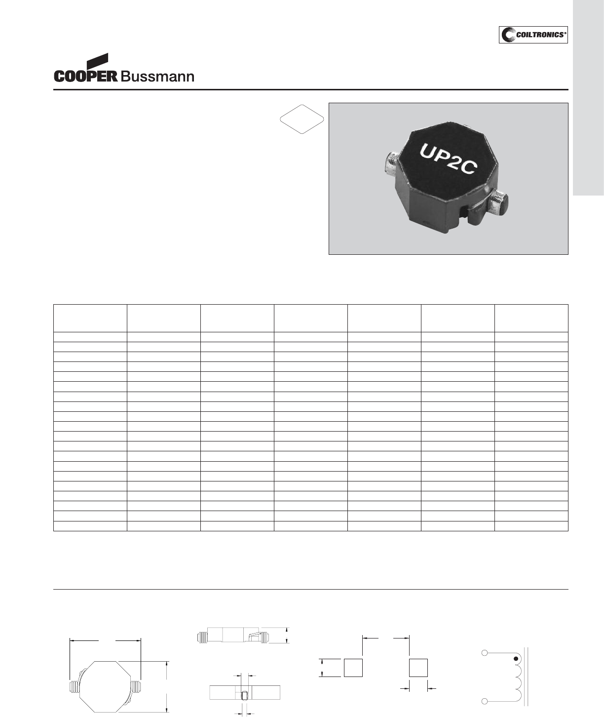
PM-135
UNSHIELDED DRUM CORE (UP2C) UNI-PAC™ 2C
Description
• Miniature surface mount design with rugged
case to eliminate core breakage
• Inductance range from 0.470uH to 1000uH
• Current range up to 18.6 Amps peak
• Meets UL94V-0 flammability standard
• Ferrite core material
Applications
• PDA, computer, and flash memory programs
Environmental Data
• Storage temperature range: -40°C to +125°C
• Operating ambient temperature range: -40°C to +85°C
(range is application specific)
• Solder reflow temperature: +260°C max. for 10 seconds
max. Packaging
• Supplied in tape and reel packaging, 900 per reel
Part Inductance OCL(1) I RMS(2) I SAT(3) DCR(4) Volts(5)
Number μH μH±20% Amperes Amperes mΩμS
(rated) typ. (typ)
UP2C-R47-R 0.470 0.48 12.2 18.6 2.5 4.15
UP2C-1R0-R 1.0 1.03 9.80 11.8 3.9 7.0
UP2C-1R5-R 1.5 1.45 8.10 10.0 5.6 8.3
UP2C-2R2-R 2.2 2.00 7.50 8.67 6.6 9.6
UP2C-3R3-R 3.3 3.30 5.90 6.84 10.5 12.1
UP2C-4R7-R 4.7 4.41 5.62 6.20 11.7 13.4
UP2C-6R8-R 6.8 7.16 4.42 4.82 18.0 17.3
UP2C-100-R 10.0 10.56 3.61 3.94 28.3 21.1
UP2C-150-R 15.0 15.97 3.17 3.17 36.9 26.2
UP2C-220-R 22.0 22.33 2.61 2.65 54.0 31.3
UP2C-330-R 33.0 32.11 2.16 2.20 79.7 37.7
UP2C-470-R 47.0 47.90 1.77 1.83 118.5 45.4
UP2C-680-R 68.0 65.03 1.57 1.53 151.7 54.3
UP2C-101-R 100.0 97.85 1.26 1.24 233.1 67.1
UP2C-151-R 150.0 141.9 1.04 1.02 351.4 81.2
UP2C-221-R 220.0 207.8 0.82 0.85 545.0 97.8
UP2C-331-R 330.0 318.2 0.67 0.70 824.3 120
UP2C-471-R 470.0 470.8 0.56 0.58 1191.4 144
UP2C-681-R 680.0 689.7 0.46 0.48 1774.2 173
UP2C-102-R 1000.0 1080.0 0.38 0.40 2657.1 209
Notes: (1) Open Circuit Inductance Test Parameters: 100KHz, .250Vrms, 0.0Adc.
(2) RMS current for an approximate ΔT of 40°C without core loss, at an
ambient temperature of 85˚C.
(3) Peak current for approximately 30% rolloff @ 20°C.
(4) DCR limits 20°C.
(5) Applied volt-time product (V-uS) across the inductor. This value repre-
sents the applied v-us at 300KHz necessary to generate a core loss
equal to 10% of the total losses for a 40° temperature rise.
UNI-PAC™ 2C
Low Cost Power Inductors
(Surface Mount)
Mechanical Diagrams
9.40
Max.
12.90
Max.
UP2C
xxx
wwllyy R
TOP VIEW
12
5.2
FRONT VIEW
SIDE VIEW
3.0ref
2.5max*
see note A
COMPONENT VIEW
PCB PAD LAYOUT
7.37
2.79
2.92
2
1
SCHEMATIC
Dimensions in Millimeters.
wwllyy = (date code) R = revision level
xxx = Inductance value per family chart
(A) 2.5mm max is width of copper at seating plane. The width above the seating
plane may exceed 2.5mm.
RoHS
2002/95/EC
Courtesy of Steven Engineering, Inc.-230 Ryan Way, South San Francisco, CA 94080-6370-Main Office: (650) 588-9200-Outside Local Area: (800) 258-9200-www.stevenengineering.com
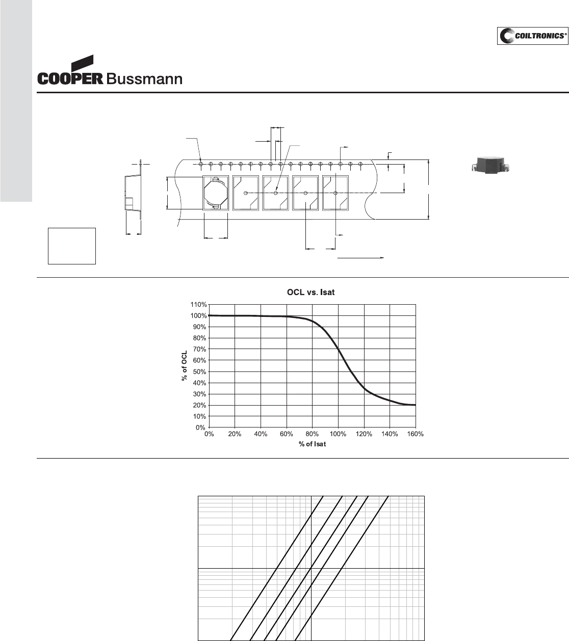
PM-136
UNSHIELDED DRUM CORE (UP2C) UNI-PAC™ 2C
Core Loss
Packaging Information
A
A
SECTION A-A
1
2
K0
1.5 dia
+0.1/-0.0 1.5 dia
min
4.0
2.0
12.0
1.7
11.5
24.0
+/-0.3
User direction of feed
B0
A0
Inductance Characteristics
IRMS DERATING WITH CORE LOSS
1000800600
50040030020010080605040302010
% of Applied Volt-μ-Seconds
99
98
97
96
95
94
92
90
80
70
60
50
40
20
0
% of Losses from Irms (maximum)
1MHz
500KHz
300KHz
200KHz
100KHz
ACTUAL SIZE
UNIPAC 2C
Ao=9.50mm
Bo=13.0mm
Ko=5.7mm
UNI-PAC™ 2C
Low Cost Power Inductors
(Surface Mount)
Courtesy of Steven Engineering, Inc.-230 Ryan Way, South San Francisco, CA 94080-6370-Main Office: (650) 588-9200-Outside Local Area: (800) 258-9200-www.stevenengineering.com
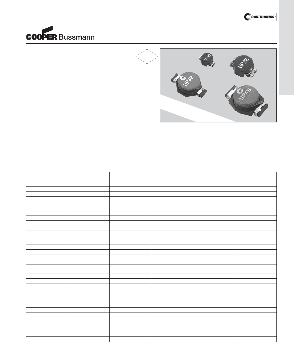
PM-137
UNSHIELDED DRUM CORE (UP) UNI-PAC™
Description
• Miniature surface mount design
• Inductance range from 0.470uH to 1000uH
• Current range from 19.2 to .47 Amps
• Maximum power density
• Ideal for applications requiring low inductance and high
current in a miniature package
• Modified standard products are available
• Protective case eliminates core breakage
• Meets UL 94V-0 flammability standard
• Ferrite core material
Applications
• DC-DC converters on board level and industrial prod-
ucts
Environmental Data
• Storage temperature range: -40°C to +125°C
• Operating ambient temperature range: -40°C to +85°C
(range is application specific)
• Solder reflow temperature: +260°C max. for 10 seconds
max.
Packaging
• Supplied in tape and reel packaging, 900 (UP1B), 550
(UP2B), 450 (UP3B), and 275 (UP4B) per reel
Part Inductance OCL(1) I RMS(2) I SAT(3) DCR(4)
Number μH (rated) μH±20% Amperes Amperes Ohms max.
UP1B-R47-R 0.47 0.569 6.0 7.7 0.0097
UP1B-1R0-R 1.0 1.20 4.4 5.3 0.0177
UP1B-1R5-R 1.5 1.61 4.2 4.5 0.0200
UP1B-2R2-R 2.2 2.62 3.1 3.5 0.0363
UP1B-3R3-R 3.3 3.79 2.9 3.0 0.0428
UP1B-4R7-R 4.7 5.15 2.2 2.6 0.0544
UP1B-6R8-R 6.8 6.87 1.7 2.2 0.0897
UP1B-100-R 10.0 11.00 1.5 1.9 0.1107
UP1B-150-R 15.0 16.00 1.2 1.5 0.1747
UP1B-220-R 22.0 23.50 1.0 1.2 0.2541
UP1B-330-R 33.0 36.00 0.82 0.99 0.3670
UP1B-470-R 47.0 48.50 0.72 0.87 0.4740
UP1B-680-R 68.0 73.52 0.58 0.67 0.7320
UP1B-101-R 100.0 112.67 0.47 0.53 1.11
UP1B-151-R 150.0 152.40 0.40 0.46 1.61
UP1B-221-R 220.0 223.10 0.36 0.38 1.96
UP1B-331-R 330.0 331.90 0.28 0.31 3.10
UP2B-R47-R 0.47 0.595 10.6 11.4 0.0049
UP2B-1R0-R 1.0 1.00 9.3 9.9 0.0065
UP2B-1R5-R 1.5 1.46 8.3 7.9 0.0081
UP2B-2R2-R 2.2 2.56 7.2 6.1 0.0107
UP2B-3R3-R 3.3 3.23 6.5 5.1 0.0128
UP2B-4R7-R 4.7 4.77 5.5 4.2 0.0165
UP2B-6R8-R 6.8 6.63 5.0 3.6 0.0202
UP2B-100-R 10.0 9.73 4.3 3.3 0.0267
UP2B-150-R 15.0 15.43 3.5 2.4 0.0410
UP2B-220-R 22.0 22.50 2.8 2.0 0.0617
UP2B-330-R 33.0 33.13 2.1 1.7 0.0917
UP2B-470-R 47.0 48.65 1.7 1.4 0.1388
UP2B-680-R 68.0 68.17 1.5 1.2 0.1787
UP2B-820-R 82.0 84.1 1.34 1.03 0.2235
UP2B-101-R 100.0 102.60 1.2 0.95 0.2707
UP2B-151-R 150.0 150 1.0 0.77 0.4100
Notes: (1) Open Circuit Inductance Test Parameters: 100KHz, .250Vrms, 0.0Adc.
(2) RMS current for an approximate ΔT of 40°C. at an ambient temperature
of 85˚C.
(3) Peak current for approximately 30% rolloff UP1B, 3B, 4B. 10% rolloff
UP2B @ 20°C
(4) DCR limits 20°C.
UNI-PAC™
Power Inductors
(Surface Mount)
NOW AVAILABLE WITH A
PROTECTIVE CASE
RoHS
2002/95/EC
Courtesy of Steven Engineering, Inc.-230 Ryan Way, South San Francisco, CA 94080-6370-Main Office: (650) 588-9200-Outside Local Area: (800) 258-9200-www.stevenengineering.com
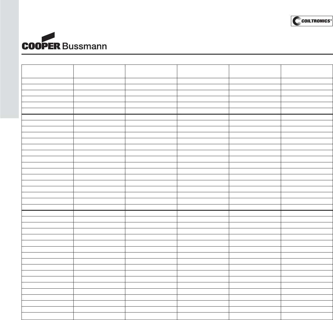
PM-138
UNSHIELDED DRUM CORE (UP) UNI-PAC™
Part Inductance OCL(1) I RMS(2) I SAT(3) DCR(4)
Number μH (rated) μH±20% Amperes Amperes Ohms max.
UP2B-221-R 220.0 223 0.773 0.637 0.6717
UP2B-331-R 330.0 338 0.676 0.510 0.8783
UP2B-471-R 470.0 471 0.553 0.427 1.31
UP2B-681-R 680.0 700 0.452 0.355 1.97
UP2B-821-R 820.0 823 0.423 0.334 2.24
UP2B-102-R 1000.0 1005 0.369 0.300 2.96
UP3B-R47-R 0.47 0.452 16.0 25.1 0.0021
UP3B-1R0-R 1.0 1.34 12.5 15.3 0.0034
UP3B-1R5-R 1.5 2.08 10.0 12.0 0.0053
UP3B-2R2-R 2.2 3.01 9.2 10.2 0.0074
UP3B-3R3-R 3.3 3.96 8.0 9.3 0.0083
UP3B-4R7-R 4.7 5.00 6.5 7.7 0.0114
UP3B-6R8-R 6.8 7.70 5.8 6.2 0.0183
UP3B-100-R 10.0 11.00 4.3 5.2 0.0260
UP3B-150-R 15.0 16.38 3.9 4.3 0.0317
UP3B-220-R 22.0 23.93 3.1 3.7 0.0490
UP3B-330-R 33.0 33.85 2.4 3.0 0.0688
UP3B-470-R 47.0 51.00 1.9 2.4 0.1082
UP3B-680-R 68.0 69.50 1.6 2.0 0.1558
UP3B-101-R 100.0 101.40 1.4 1.8 0.2053
UP3B-151-R 150.0 152.9 1.2 1.4 0.2960
UP3B-331-R 330.0 332.80 0.75 0.98 0.7330
UP4B-R47-R 0.47 0.473 19.2 51.7 0.0019
UP4B-1R0-R 1.0 0.916 17.3 37.3 0.0023
UP4B-1R5-R 1.5 1.52 13.4 28.9 0.0039
UP4B-2R2-R 2.2 2.27 12.0 23.7 0.0048
UP4B-3R3-R 3.3 3.14 11.0 20.2 0.0057
UP4B-4R7-R 4.7 5.34 8.6 15.6 0.0093
UP4B-6R8-R 6.8 6.66 8.3 14.1 0.0100
UP4B-100-R 10.0 9.77 6.8 11.5 0.0150
UP4B-150-R 15.0 15.61 5.5 9.1 0.0230
UP4B-220-R 22.0 22.61 4.5 7.6 0.0340
UP4B-330-R 33.0 34.30 3.7 6.1 0.0520
UP4B-470-R 47.0 48.10 3.1 5.2 0.0740
UP4B-680-R 68.0 69.14 2.4 4.3 0.1200
UP4B-101-R 100.0 99.42 2.0 3.6 0.1700
UP4B-151-R 150.0 146.90 1.7 3.0 0.2392
UP4B-221-R 220.0 221.40 1.4 2.4 0.3571
UP4B-331-R 330.0 330.00 1.1 2.0 0.5800
UP4B-471-R 470.0 470.10 0.91 1.7 0.8330
Notes: (1) Open Circuit Inductance Test Parameters: 100KHz, .250Vrms, 0.0Adc.
(2) RMS current for an approximate ΔT of 40°C. at an ambient temperature
of 85˚C.
(3) Peak current for approximately 30% rolloff UP1B, 3B, 4B. 10% rolloff
UP2B @ 20°C
(4) DCR limits 20°C.
UNI-PAC™
Power Inductors
(Surface Mount)
Courtesy of Steven Engineering, Inc.-230 Ryan Way, South San Francisco, CA 94080-6370-Main Office: (650) 588-9200-Outside Local Area: (800) 258-9200-www.stevenengineering.com
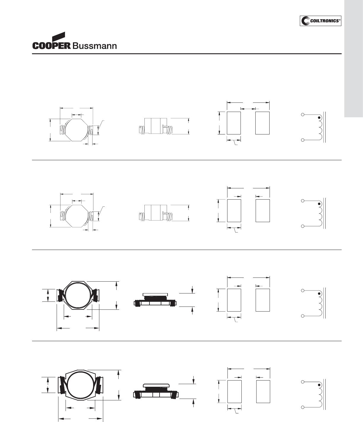
PM-139
UNSHIELDED DRUM CORE (UP) UNI-PAC™
Mechanical Diagrams
UP1B Series
TOP VIEW
6.10
Max
8.89
Max
2.42
Ref 4.04
Max
0.762
Min
UP1B
XXX
wwllyy R
FRONT VIEW
5.0
Max
COMPONENT VIEW
PCB PAD LAYOUT
1.9
4.1
8.89
5.08 SCHEMATIC
1
2
UP2B Series
TOP VIEW
10.41
Max
13.97
Max
4.22
Ref 6.73
Max
0.762
Min
UP2B
XXX
wwllyy R
FRONT VIEW
6.0
Max
14.0
COMPONENT VIEW
PCB PAD LAYOUT
9.4
7.3
2.3
SCHEMATIC
1
2
UP3B Series
TOP VIEW
12.70
19.30
max
13.21
max
12
8.13
max
UP3B
XXX
wwllyy R
6.8
max
SIDE VIEW
19.3
COMPONENT VIEW
PCB PAD LAYOUT
11.7
8.7
3.8
SCHEMATIC
1
2
UP4B Series
22.10
max
TOP VIEW
15.00
max
14.61
12
11.18
max
UP4B
XXX
wwllyy R
SIDE VIEW
7.87
max
22.1
COMPONENT VIEW
PCB PAD LAYOUT
13.5
12.0
4.3
SCHEMATIC
1
2
Dimensions in Millimeters. wwllyy = (date code) R = revision level
xxx = Inductance value per family chart
UNI-PAC™
Power Inductors
(Surface Mount)
Courtesy of Steven Engineering, Inc.-230 Ryan Way, South San Francisco, CA 94080-6370-Main Office: (650) 588-9200-Outside Local Area: (800) 258-9200-www.stevenengineering.com
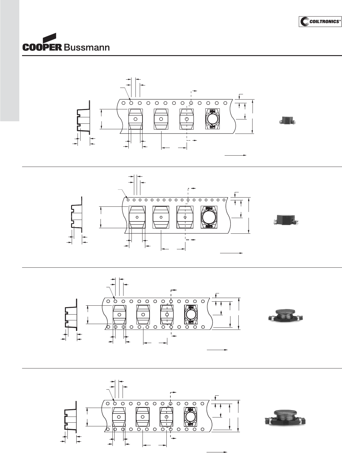
PM-140
UNSHIELDED DRUM CORE (UP) UNI-PAC™
14.3
10.7
5.1
1.5 Dia.
16.0
6.8
5.4
SECTION A-A
A
A1.75
24
11.5
2.0
4.0
Direction of feed
Dimensions in millimeters.
1
2
UP2B Series
ACTUAL SIZE
UNI-PAC 2B
13.5
5.8
4.0
2.0
16.0
1.75
14.2
1
2
1.5 Dia.
7.7
SECTION A-A
A
A
28.4
Direction of feed
Dimensions in millimeters.
19.6
5.9
32
UP3B Series
15.3
11.1
4.0
2.0
24.0
1.75
14.2
1.5 Dia.
9.0
SECTION A-A
A
A
28.4
Direction of feed
Dimensions in millimeters.
22.3
7.2
32
1
2
UP4B Series
ACTUAL SIZE
UNI-PAC 3B
ACTUAL SIZE
UNI-PAC 4B
Packaging Information
6.4
2.3
4.0
2.0
12.0
1.75
16
7.5
1.5 Dia.
5.6
4.4
SECTION A-A
9.3
A
A
Direction of feed
Dimensions in millimeters.
1
2
UP1B Series
ACTUAL SIZE
UNI-PAC 1B
UNI-PAC™
Power Inductors
(Surface Mount)
Parts packaged on 13" Diameter reel,
900 parts per reel.
Parts packaged on 13" Diameter reel,
550 parts per reel.
Parts packaged on 13" Diameter reel,
450 parts per reel.
Parts packaged on 13" Diameter reel,
275 parts per reel.
Courtesy of Steven Engineering, Inc.-230 Ryan Way, South San Francisco, CA 94080-6370-Main Office: (650) 588-9200-Outside Local Area: (800) 258-9200-www.stevenengineering.com
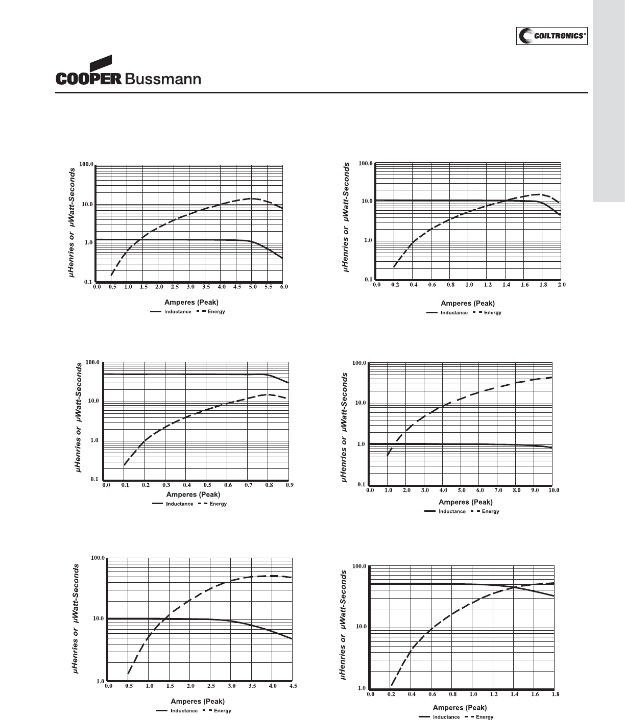
PM-141
UNSHIELDED DRUM CORE (UP) UNI-PAC™
Inductance Characteristics
UP1B-470
Typical Inductance & Energy vs Saturation Current
UP1B-100
Typical Inductance & Energy vs Saturation Current
UP1B-1R0
Typical Inductance & Energy vs Saturation Current
UP2B-470
Typical Inductance & Energy vs Saturation Current
UP2B-100
Typical Inductance & Energy vs Saturation Current
UP2B-1R0
Typical Inductance & Energy vs Saturation Current
UNI-PAC™
Power Inductors
(Surface Mount)
Courtesy of Steven Engineering, Inc.-230 Ryan Way, South San Francisco, CA 94080-6370-Main Office: (650) 588-9200-Outside Local Area: (800) 258-9200-www.stevenengineering.com
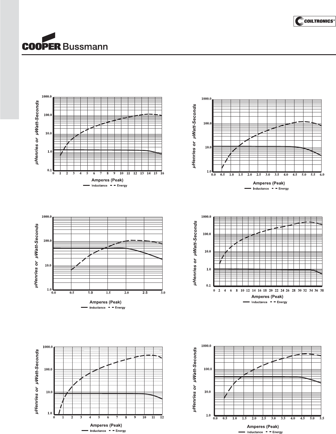
PM-142
UNSHIELDED DRUM CORE (UP) UNI-PAC™
Inductance Characteristics
UP3B-470
Typical Inductance & Energy vs Saturation Current
UP3B-100
Typical Inductance & Energy vs Saturation Current
UP3B-1R0
Typical Inductance & Energy vs Saturation Current
UP4B-100
Typical Inductance & Energy vs Saturation Current
UP4B-470
Typical Inductance & Energy vs Saturation Current
UP4B-1R0
Typical Inductance & Energy vs Saturation Current
UNI-PAC™
Power Inductors
(Surface Mount)
Courtesy of Steven Engineering, Inc.-230 Ryan Way, South San Francisco, CA 94080-6370-Main Office: (650) 588-9200-Outside Local Area: (800) 258-9200-www.stevenengineering.com
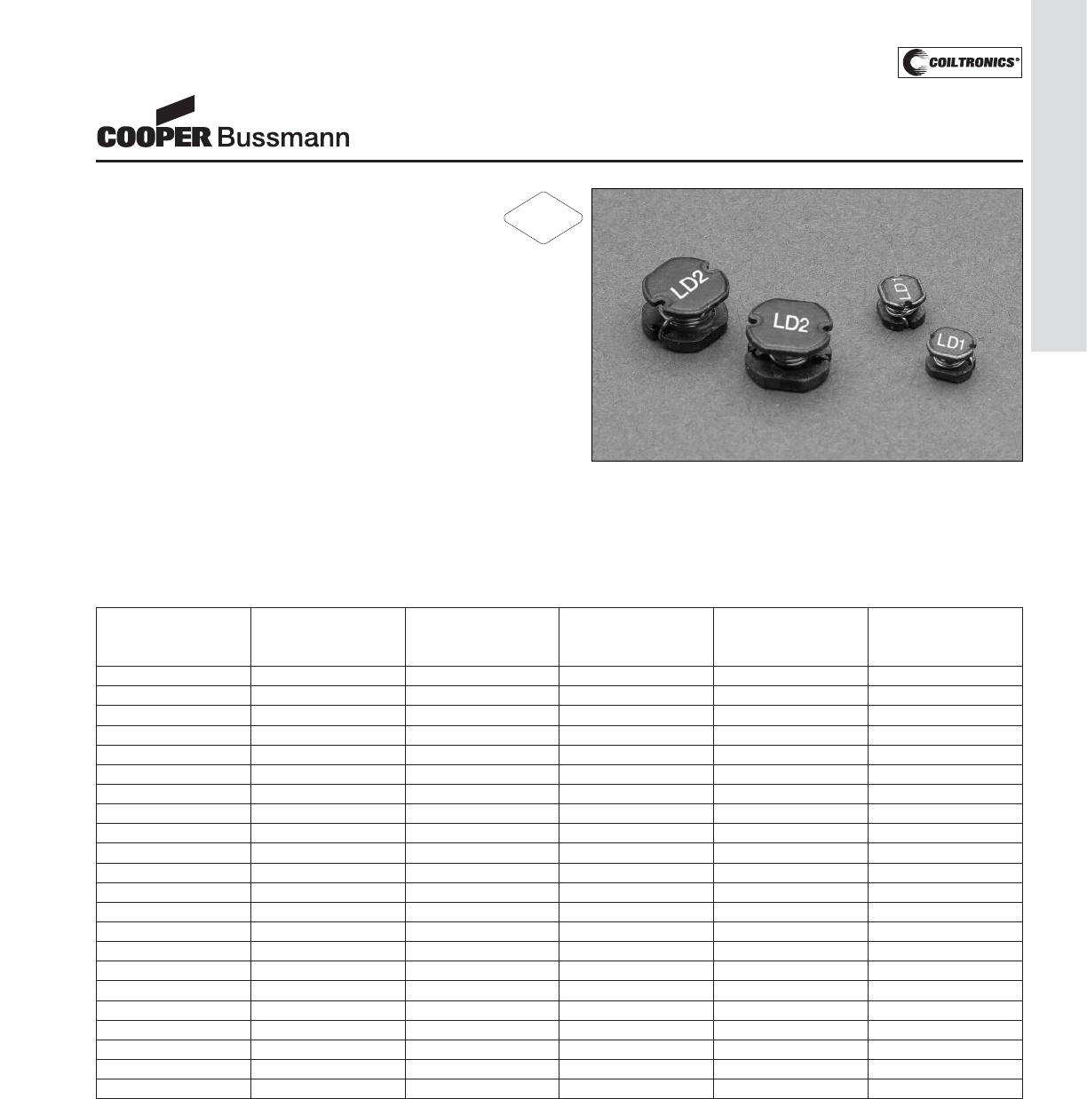
PM-143
UNSHIELDED DRUM CORE (LD)
LD Series
Metalized Drum Core
Power Inductor
Description
• Metalized drum core design utilizes board space
• Current Range from 4.46 to 0.52 Amps
• Inductance range from 1.0 uH to 470uH
• Ferrite core material
Applications
• Buck or Boost inductor
• Noise filtering and output filter chokes
• Computers
• Power Supplies
• Test Equipment Instrumentation
Environmental Data
• Storage temperature: -25°C to +85°C
• Operating ambient temperature: -20°C to +80°C (Range
is application specific). Temperature rise is approximate-
ly 40°C at rated rms current.
• Solder reflow temperature: 260°C max. for 10 seconds
max.
Packaging
• Supplied in tape and reel packaging, LD1 (2,000), LD2
(1,000) parts per reel
Part Rated OCL (1) Irms (2) Isat (3) DCR (4)
Number Inductance Nominal Amperes Amperes (Ω)
(μH) (Max.)
LD1-1R0-R 1.0 1.00 2.66 4.46 0.0330
LD1-1R4-R 1.4 1.40 2.47 3.41 0.0380
LD1-1R8-R 1.8 1.80 2.35 3.05 0.0420
LD1-2R2-R 2.2 2.20 2.22 2.76 0.0470
LD1-2R7-R 2.7 2.70 2.11 2.52 0.0520
LD1-3R3-R 3.3 3.30 2.00 2.32 0.0580
LD1-3R9-R 3.9 3.90 1.75 2.14 0.0760
LD1-4R7-R 4.7 4.70 1.57 2.00 0.0940
LD1-5R6-R 5.6 5.60 1.51 1.75 0.1010
LD1-6R8-R 6.8 6.80 1.41 1.56 0.1170
LD1-8R2-R 8.2 8.20 1.32 1.41 0.1320
LD1-100-R 10 10.0 1.13 1.28 0.1820
LD1-120-R 12 12.0 1.05 1.18 0.2100
LD1-150-R 15 15.0 0.99 1.05 0.2350
LD1-180-R 18 18.0 0.83 0.98 0.3380
LD1-220-R 22 22.0 0.78 0.89 0.3780
LD1-270-R 27 27.0 0.67 0.87 0.5220
LD1-330-R 33 33.0 0.66 0.75 0.5400
LD1-390-R 39 39.0 0.63 0.68 0.5870
LD1-470-R 47 47.0 0.52 0.61 0.8440
LD1-560-R 56 56.0 0.50 0.57 0.9370
LD1-680-R 68 68.0 0.46 0.52 1.12
Notes:
1) Open Circuit Inductance Test Parameters: 100kHz, 0.25Vrms, 0.0Adc +/-20%
except for LD1-330 to LD1-680 and LD2-470 to LD2-471 which is +/-10%
2) RMS current for for an approximate T of 40°C. It is recommended that the
temperature of the part not exceed 125°C
3) Peak current for an approximate 10% rolloff at 20°C
4) DCR limits @ 20°C
RoHS
2002/95/EC
Courtesy of Steven Engineering, Inc.-230 Ryan Way, South San Francisco, CA 94080-6370-Main Office: (650) 588-9200-Outside Local Area: (800) 258-9200-www.stevenengineering.com
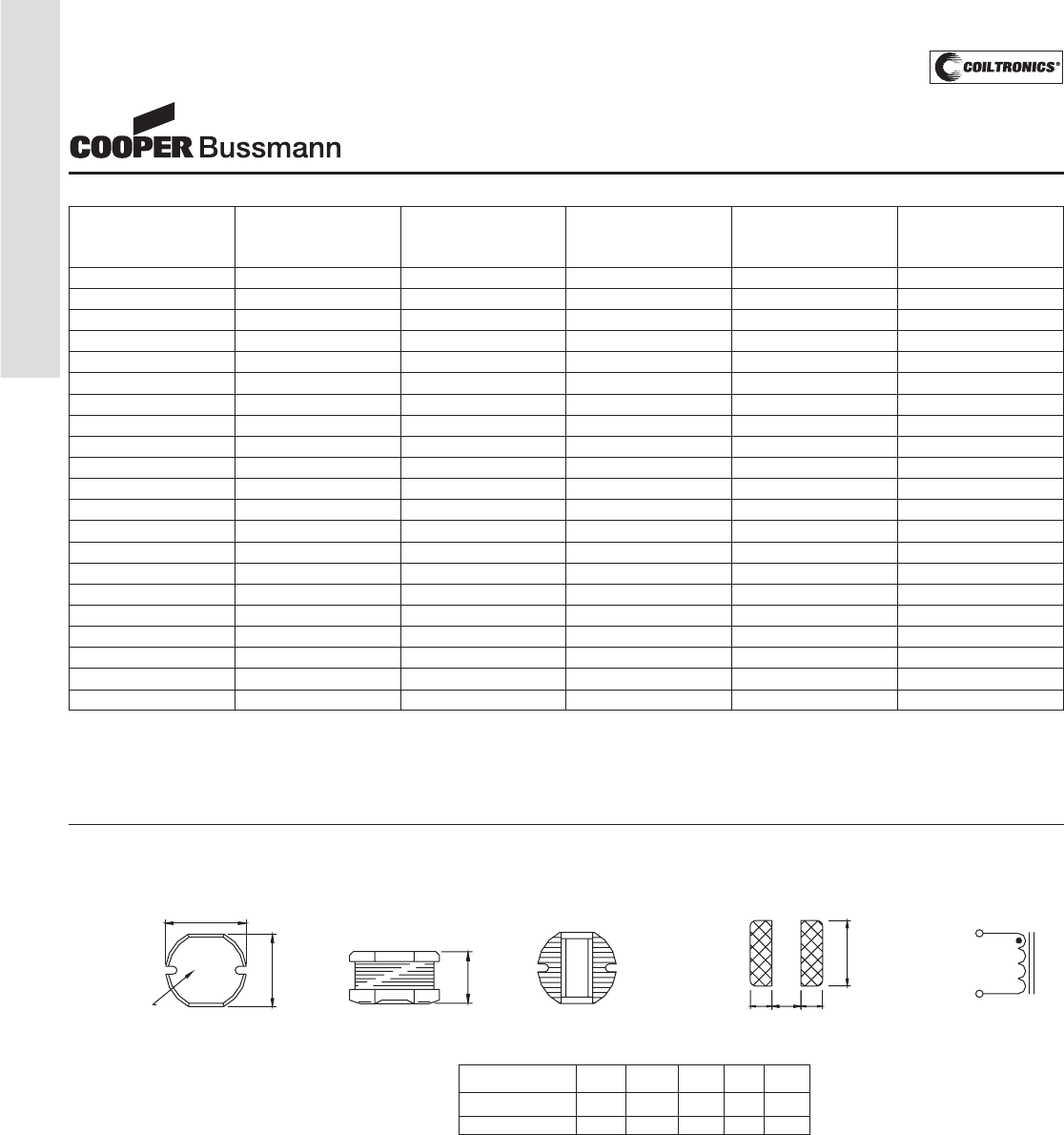
PM-144
UNSHIELDED DRUM CORE (LD)
LD Series
Metalized Drum Core
Power Inductor
Mechanical Diagrams
A
xxx
TOP VIEW
B
Marking
C
FRONT VIEW BOTTOM VIEW
Component Side
RECOMMENDED PCB LAYOUT
II G
H
SCHEMATIC
2
1
Marking:
LD1: xxx=inductance value
per family chart
LD2: "C" logo
xxx=inductance value
Dimension A B C G H I
+/-0.3 +/-0.3 +/-0.3 ref ref ref
LD1 4.5 4.0 3.2 1.5 4.5 1.75
LD2 7.8 7.0 5.0 2.0 7.5 3.0
Part Rated OCL (1) Irms (2) Isat (3) DCR (4)
Number Inductance Nominal Amperes Amperes (Ω)
(μH) (Max.)
LD2-100-R 10 10.0 3.83 3.45 0.0700
LD2-120-R 12 12.0 3.57 3.20 0.0800
LD2-150-R 15 15.0 3.38 2.85 0.0900
LD2-180-R 18 18.0 3.19 2.60 0.1000
LD2-220-R 22 22.0 3.13 2.45 0.1100
LD2-270-R 27 27.0 2.81 2.10 0.1200
LD2-330-R 33 33.0 2.70 2.01 0.1300
LD2-390-R 39 39.0 2.42 1.85 0.1600
LD2-470-R 47 47.0 2.25 1.64 0.1800
LD2-560-R 56 56.0 1.96 1.50 0.2400
LD2-680-R 68 68.0 1.88 1.35 0.2800
LD2-820-R 82 82 1.63 1.28 0.3700
LD2-101-R 100 100 1.53 1.15 0.4300
LD2-121-R 120 120 1.43 1.09 0.4700
LD2-151-R 150 150 1.23 0.95 0.6400
LD2-181-R 180 180 1.15 0.87 0.7100
LD2-221-R 220 220 1.00 0.79 0.9600
LD2-271-R 270 270 0.94 0.73 1.11
LD2-331-R 330 330 0.83 0.64 1.26
LD2-391-R 390 390 0.78 0.58 1.77
LD2-471-R 470 470 0.74 0.55 1.96
Notes:
1) Open Circuit Inductance Test Parameters: 100kHz, 0.25Vrms, 0.0Adc +/-20%
except for LD1-330 to LD1-680 and LD2-470 to LD2-471 which is +/-10%
2) RMS current for for an approximate T of 40°C. It is recommended that the
temperature of the part not exceed 125°C
3) Peak current for an approximate 10% rolloff at 20°C
4) DCR limits @ 20°C
Dimensions in millimeters.
Courtesy of Steven Engineering, Inc.-230 Ryan Way, South San Francisco, CA 94080-6370-Main Office: (650) 588-9200-Outside Local Area: (800) 258-9200-www.stevenengineering.com
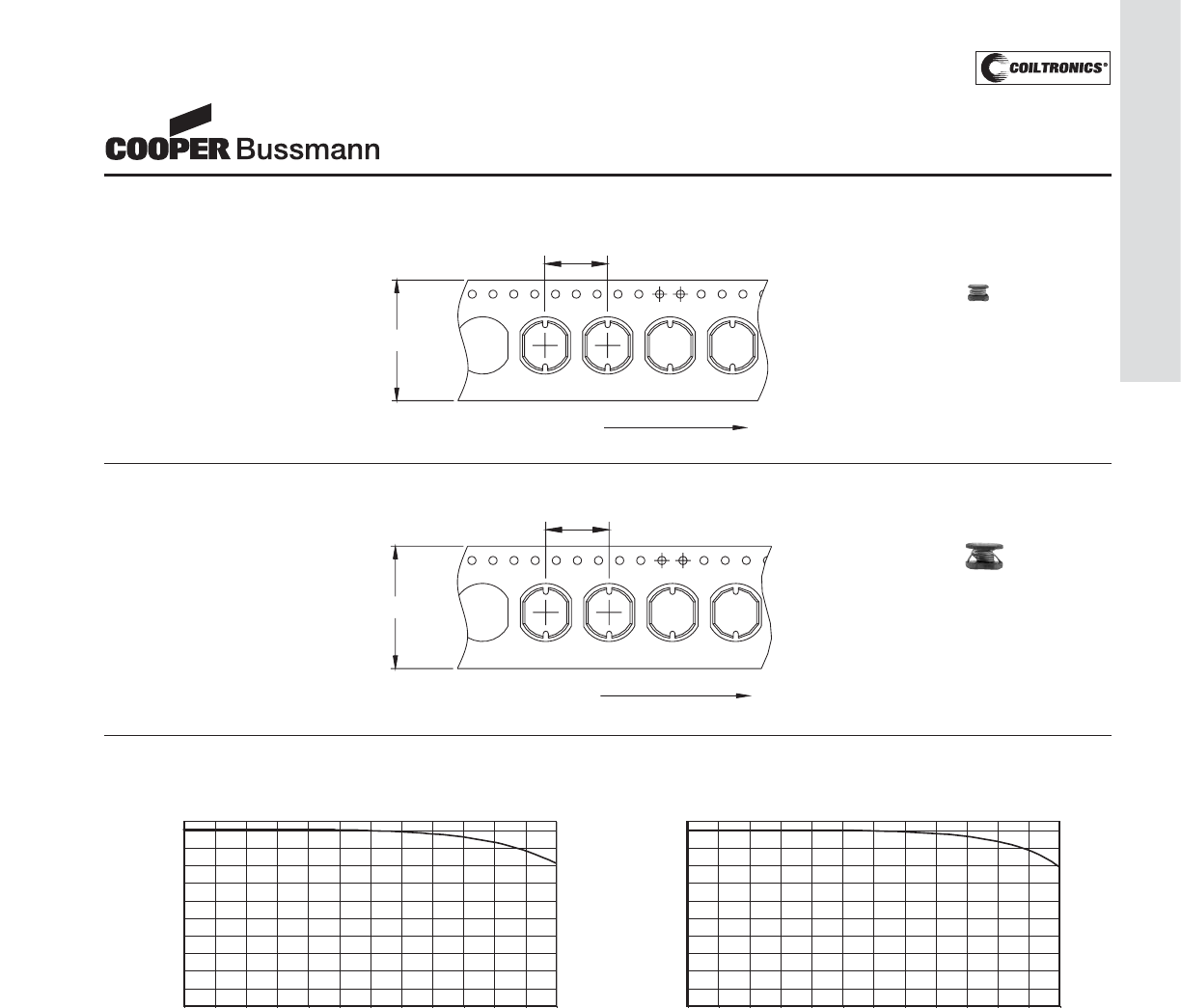
PM-145
UNSHIELDED DRUM CORE (LD)
LD Series
Metalized Drum Core
Power Inductor
xxx
User Direction Feed
12.0
16.0
xxx
xxx
xxx
LD2 Series
Packaging Information
8.0
12.0
xxx
xxx
xxx
xxx
User Direction Feed
LD1 Series
Parts packaged on 13" Diameter reel,
2,000 parts per reel.
Parts packaged on 13" Diameter reel,
1,000 parts per reel.
ACTUAL SIZE
LD1
ACTUAL SIZE
LD2
OCL vs Isat
LD1
0
10
20
30
40
50
60
70
80
90
100
0 102030405060708090100110120
% of Isat
OCL (%)
OCL vs Isat
LD2
0
10
20
30
40
50
60
70
80
90
100
0 102030405060708090100110120
% of Isat
OCL (%)
Inductance Characteristics
Courtesy of Steven Engineering, Inc.-230 Ryan Way, South San Francisco, CA 94080-6370-Main Office: (650) 588-9200-Outside Local Area: (800) 258-9200-www.stevenengineering.com
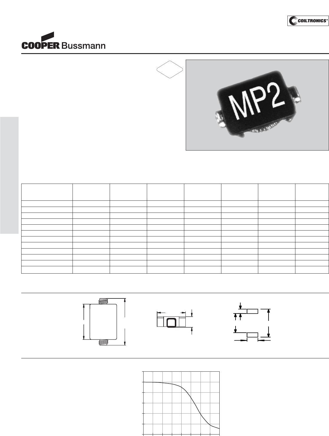
PM-146
TOROID (MP2) MICRO-PAC™
Description
• High performance, ferrite-based, low profile,
surface mount inductors
• Small footprint and closed magnetic field construction
allow for low EMI
• Low DCR and high efficiency
• Ferrite core material
Applications
• PC cards, cellular telephones, pagers, and disk drives
• GPS systems
Environmental Data
• Storage temperature range: -40°C to +125°C
• Operating ambient temperature range: -40°C to +85°C
(range is application specific).
• Solder reflow temperature: +260°C max. for 10 seconds
max.
Packaging
• Supplied in tape and reel packaging, 3900 per reel
Part Inductance OCL (1) Irms (2) Isat (3) DCR (4) Q (5) SRF
Number μH μH ± 20% Amperes Amperes Ohms (Typ.) MHz
(Typ.) (Typ.) (Max.) (Typ.)
MP2-R47-R 0.47 0.40 2.02 3.40 0.075 10 300
MP2-1R0-R 1.0 1.02 1.67 2.10 0.103 20 160
MP2-1R5-R 1.5 1.59 1.51 1.70 0.118 25 155
MP2-2R2-R 2.2 2.29 1.39 1.40 0.130 32 150
MP2-3R3-R 3.3 3.58 1.25 1.10 0.156 42 140
MP2-4R7-R 4.7 4.60 1.18 1.00 0.180 46 130
MP2-6R8-R 6.8 7.02 1.06 0.80 0.202 46 110
MP2-100-R 10.0 9.95 0.98 0.68 0.240 55 100
MP2-150-R 15.0 15.30 0.88 0.54 0.300 65 60
MP2-220-R 22.0 21.80 0.80 0.45 0.360 65 45
MP2-330-R 33.0 33.70 0.64 0.37 0.556 65 35
MP2-470-R 47.0 46.40 0.52 0.31 0.833 65 28
MICRO-PAC™
Low Profile Power Inductors
(Surface Mount)
1) Open Circuit Inductance Test Parameters: 100kHz, 0.250 Vrms, 0.0 Adc
2) RMS current, delta temp. of 40° C ambient temperature of 85° C
3) Peak current for approximately 30% roll-off
4) Values @ 20° C
5) Measured @ 300KHz
Mechanical Diagrams
yww
xxx
7.50
max
5.88
5.2 max.
1.8 max.
1.05
2.00
5.40 7.50
Dimensions in Millimeters.
Specifications are subject to change without notice.
yww = Date Code
xxx = Inductance value per family chart
0
20
40
60
80
100
120
0 40 80 120 160
% of Isat
OCL vs. Isat
% of (OCL)
Inductance
Characteristics
RoHS
2002/95/EC
Courtesy of Steven Engineering, Inc.-230 Ryan Way, South San Francisco, CA 94080-6370-Main Office: (650) 588-9200-Outside Local Area: (800) 258-9200-www.stevenengineering.com
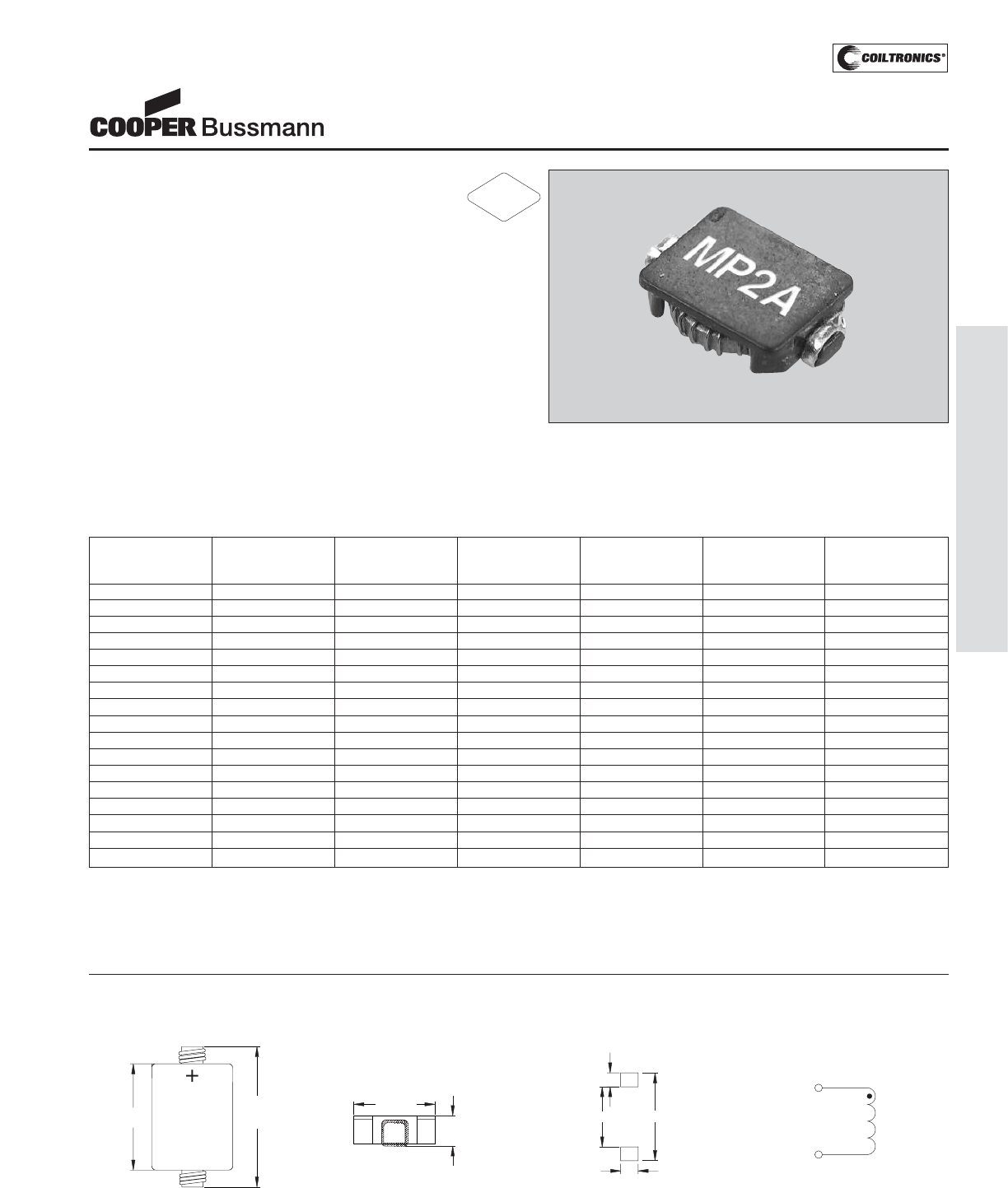
PM-147
TOROID (MP2A) MICRO-PAC PLUS™
Description
• High performance, low profile, surface mount power
inductors with a molybdenum permalloy core
• Small footprint and closed magnetic field construction
ensure low EMI
• Low DCR and high efficiency
• Frequency range up to 500kHz
• MPP core material
Applications
• PC cards, cellular telephones, pagers, and disk drives
• GPS systems
Environmental Data
• Storage temperature range: -40°C to +125°C
• Operating ambient temperature range: -40°C to +85°C
(range is application specific).
• Solder reflow temperature: +260°C max for 10 seconds
max
Packaging
• Supplied in tape and reel packaging, 3900 per reel
Part Inductance OCL(1) DCR(2) I RMS(3) I SAT(4) Volt(5)
Number μH μH±20% typ. Amperes Amperes μsec
(rated) Ω
MP2A-R47-R 0.47 0.47 0.024 3.52 5.80 1.20
MP2A-R68-R 0.68 0.68 0.027 3.31 4.83 1.27
MP2A-1R0-R 1.00 1.21 0.067 2.11 3.63 2.00
MP2A-1R5-R 1.50 1.54 0.073 2.02 3.22 2.09
MP2A-2R2-R 2.20 2.30 0.086 1.87 2.64 2.26
MP2A-3R3-R 3.30 3.21 0.098 1.75 2.23 2.42
MP2A-4R7-R 4.70 4.86 0.117 1.60 1.81 2.64
MP2A-6R8-R 6.80 6.85 0.136 1.49 1.53 2.84
MP2A-8R2-R 8.20 8.54 0.167 1.34 1.54 3.15
MP2A-100-R 10.00 10.02 0.179 1.29 1.42 3.26
MP2A-150-R 15.00 15.18 0.217 1.18 1.16 3.59
MP2A-220-R 22.00 21.40 0.311 0.98 0.97 4.30
MP2A-330-R 33.00 32.74 0.476 0.79 0.79 5.32
MP2A-470-R 47.00 46.48 0.727 0.64 0.66 6.57
MP2A-680-R 68.00 68.53 1.108 0.52 0.54 8.11
MP2A-820-R 82.00 81.15 1.463 0.45 0.50 9.32
MP2A-101-R 100.00 99.65 2.015 0.39 0.45 10.94
Notes: (1) Open Circuit Inductance Test Parameters: 100 kHz, .25Vrms, 0.0Adc.
(2) DCR limits 20°C.
(3) RMS current for an approximate ΔT of 40°C without core loss. It is rec-
ommended that the temperature of the part not exceed 125°C.
(4) Peak current for approximately 30% rolloff at 20°C.
(5) Applied Volt-Time product (V-μS) across the inductor.This value repre-
sents the applied V-μS at 300KHz necessary to generate a core loss
equal to 10% of the total losses for 40°C temperature rise.
MICRO-PAC PLUS™
Low Profile Power Inductors
(Surface Mount)
Mechanical Diagrams
TOP VIEW
5.88 YWW
XXX
7.5
MAX
1
2
SIDE VIEW
1.8
MAX
5.2
MAX 5.40
2.00
7.50
1.05
PCB PAD LAYOUT
1
2
SCHEMATIC
Dimensions in Millimeters.
Specifications are subject to change without notice.
yww = Date Code
xxx = Inductance value per family chart
RoHS
2002/95/EC
Courtesy of Steven Engineering, Inc.-230 Ryan Way, South San Francisco, CA 94080-6370-Main Office: (650) 588-9200-Outside Local Area: (800) 258-9200-www.stevenengineering.com
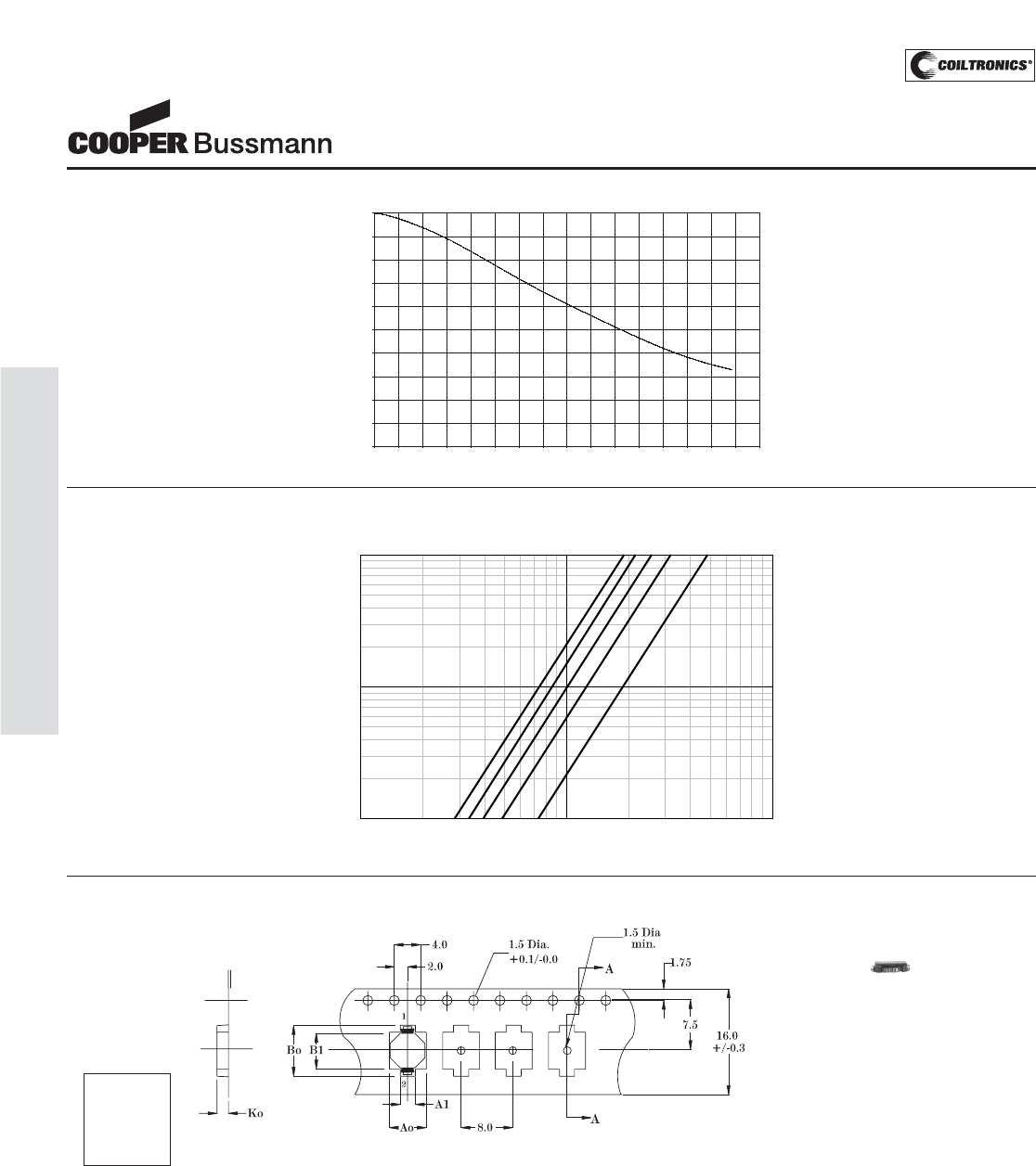
PM-148
TOROID (MP2A) MICRO-PAC PLUS™
Core Loss
Packaging Information for MICRO-PAC™ & MICRO-PAC™ PLUS
0%
10%
20%
30%
40%
50%
60%
70%
80%
90%
100%
0% 10% 20% 30% 40% 50% 60% 70% 80% 90% 100% 110% 120% 130% 140% 150% 160%
% of I sat
OCL vs. Isat
% of OCL
Inductance Characteristics
IRMS DERATING WITH CORE LOSS
1000800600
50040030020010080605040302010
% of Applied Volt-μ-Seconds
99
98
97
96
95
94
92
90
80
70
60
50
40
20
0
% of Losses from Irms (maximum)
500KHz
400KHz
300KHz
200KHz
100KHz
Parts packaged on 13" Diameter reel,
3,900 parts per reel.
ACTUAL SIZE
MICRO-PAC PLUS
Ao=5.6mm
A1=2.3mm
Bo=8.5mm
B1=6.3mm
Ko=2.1mm
MICRO-PAC PLUS™
Low Profile Power Inductors
(Surface Mount)
Courtesy of Steven Engineering, Inc.-230 Ryan Way, South San Francisco, CA 94080-6370-Main Office: (650) 588-9200-Outside Local Area: (800) 258-9200-www.stevenengineering.com
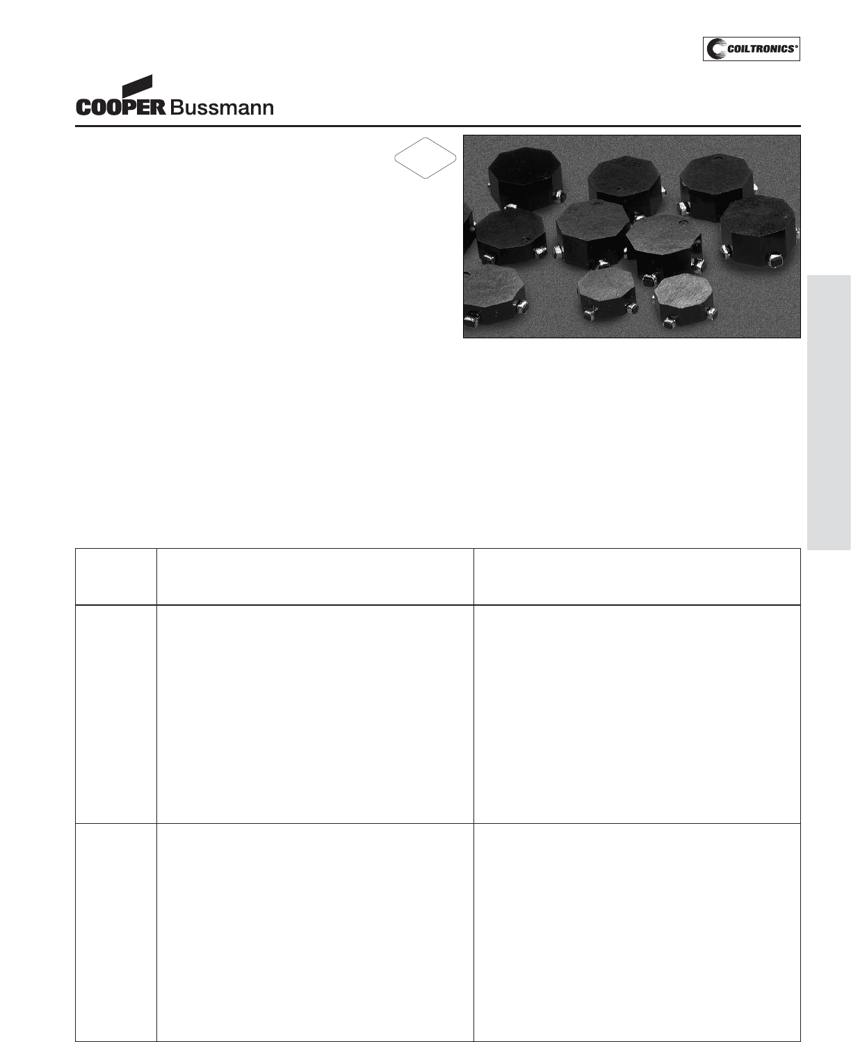
PM-149
TOROID (ECONO-PAC™/OCTA-PAC
®
, OCTA-PAC
®
PLUS
Description
• Surface mount magnetics that can be used as single
or coupled inductors or 1:1 transformers that provide isola-
tion between two windings
• OCTA-PAC’s are designed around high frequency, low loss
MPP core material
• ECONO-PAC’s are a lower cost version of OCTA-PAC’s offer-
ing high saturation flux density, Powder Iron core material
• OCTA-PAC PLUS’s offer higher current ratings and higher sat-
uration flux densities than OCTA-PAC and ECONO-PAC,
Amorphous metal core material
• Secure 4 Terminal Mounting
• Inductor more versatile inductance combination by series or
parallel connections
Applications
• Computer and portable power devices
• LCD panels, DVD players
• Inductor: DC-DC converters
• Buck, boost, forward, and resonant converters
• Noise filtering and filter chokes
• Transformers: 1:1 300Vdc isolation, flyback, sepic
Environmental Data
• Storage temperature range: -40°C to +125°C
• Operating ambient temperature range: -40°C to +85°C (range
is application specific).
• Solder reflow temperature: +260°C max. for 10 seconds max.
Packaging
• Supplied in tape and reel packaging, 1100 (EP01, OPA1, and
OP01), 800 (EP02, OP02, OPA2, EP03, OPA3, and OP03),
and 600 (EP04, OPA4, and OP04) per reel
Legend
Marking
• CTX___-__ (First three digits CTX; Second 2-3 digits =
Inductance Value; Last 1-2 digits, product size & type)
Product Size/Type
• CTX___-1 (-1 = size; no suffix = OCTA-PAC
®
)
• CTX___-1P (-1 = size; P suffix = ECONO-PAC™)
• CTX___-1A (-1 = size; A suffix = OCTA-PAC
®
PLUS)
ECONO-PAC™/OCTA-PAC®
OCTA-PAC®PLUS
Power Inductors and Transformers
Open
C
Circuit
F
Full
L
Load Full
L
Load DC Open
C
Circuit
F
Full
L
Load Full
L
Load DC
Part Inductance Inductance Current Resistance Inductance Inductance Current Resistance
Number μH
+
+/-20% μH
m
min. Adc ohms
m
max. μH
+
+/-20% μH
m
min. Adc ohms
m
max.
CTX0.47-1P-R .42 .31 5.50 .005 1.67 1.25 2.75 .021
CTX0.68-1P-R .60 .43 5.10 .006 2.40 1.74 2.55 .025
CTX1-1P-R 1.07 .73 4.50 .008 4.28 2.92 2.25 .032
CTX2-1P-R 2.02 1.36 3.40 .013 8.08 5.44 1.70 .054
CTX5-1P-R 4.83 3.37 2.00 .040 19.31 13.47 1.00 .161
CTX8-1P-R 8.08 5.31 1.80 .052 32.33 21.23 .90 .207
CTX10-1P-R 9.62 6.23 1.70 .057 38.48 24.94 .85 .227
CTX15-1P-R 15.03 9.62 1.40 .087 60.12 38.47 .70 .348
CTX20-1P-R 20.46 14.12 1.00 .158 81.83 56.47 .50 .634
CTX25-1P-R 25.40 17.07 .96 .177 101.60 68.29 .48 .708
CTX33-1P-R 32.33 22.27 .80 .250 129.32 89.06 .40 1.001
CTX50-1P-R 50.52 33.57 .70 .316 202.07 134.27 .35 1.263
CTX68-1P-R 68.40 43.65 .66 .373 273.61 174.61 .33 1.490
CTX100-1P-R 99.01 63.64 .54 .557 396.06 254.55 .27 2.227
CTX150-1P-R 150.72 96.64 .44 .844 602.87 386.56 .22 3.376
CTX200-1P-R 198.41 130.79 .36 1.208 793.65 523.16 .18 4.831
CTX300-1P-R 299.87 190.05 .32 1.525 1199.46 760.19 .16 6.100
CTX0.47-2P-R .54 .42 5.90 .006 2.18 1.69 2.95 .024
CTX0.68-2P-R .85 .64 5.40 .007 3.40 2.55 2.70 .029
CTX1-2P-R 1.22 .89 5.00 .008 4.90 3.57 2.50 .033
CTX2-2P-R 2.18 1.56 3.90 .014 8.70 6.26 1.95 .055
CTX5-2P-R 4.90 3.57 2.50 .032 19.58 14.26 1.25 .128
CTX8-2P-R 7.65 5.31 2.30 .040 30.60 21.23 1.15 .158
CTX10-2P-R 9.83 6.73 2.10 .045 39.30 26.92 1.05 .179
CTX15-2P-R 14.99 10.51 1.60 .085 59.98 42.02 .80 .339
CTX20-2P-R 19.58 13.37 1.50 .097 78.34 53.48 .75 .387
CTX25-2P-R 24.79 16.60 1.40 .109 99.14 66.38 .70 .436
CTX33-2P-R 32.67 21.29 1.30 .126 130.70 85.17 .65 .503
CTX50-2P-R 49.10 35.31 .82 .305 196.38 141.24 .41 1.221
CTX68-2P-R 68.85 47.93 .76 .362 275.40 191.71 .38 1.445
CTX100-2P-R 99.14 69.56 .62 .541 396.58 278.22 .31 2.162
CTX150-2P-R 148.10 100.07 .56 .665 592.42 400.27 .28 2.660
CTX200-2P-R 201.59 138.49 .46 .951 806.34 553.97 .23 3.804
CTX300-2P-R 300.42 197.52 .42 1.176 1201.70 790.08 .21 4.703
PARALLEL SERIES
RoHS
2002/95/EC
Courtesy of Steven Engineering, Inc.-230 Ryan Way, South San Francisco, CA 94080-6370-Main Office: (650) 588-9200-Outside Local Area: (800) 258-9200-www.stevenengineering.com
PM-150
TOROID (ECONO-PAC™/OCTA-PAC
®
, OCTA-PAC
®
PLUS
Open
C
Circuit
F
Full
L
Load Full
L
Load DC Open
C
Circuit
F
Full
L
Load Full
L
Load DC
Part Inductance Inductance Current Resistance Inductance Inductance Current Resistance
Number μH
+
+/-20% μH
m
min. Adc ohms
m
max. μH
+
+/-20% μH
m
min. Adc ohms
m
max.
CTX0.47-3P-R .46 .35 6.20 .006 1.85 1.42 3.10 .025
CTX0.68-3P-R .67 .50 5.70 .007 2.66 1.98 2.85 .028
CTX1-3P-R .91 .65 5.40 .008 3.63 2.62 2.70 .032
CTX2-3P-R 1.85 1.24 4.60 .011 7.40 4.97 2.30 .045
CTX5-3P-R 4.74 3.04 3.20 .022 18.94 12.15 1.60 .090
CTX8-3P-R 8.16 4.90 2.80 .030 32.63 19.60 1.40 .119
CTX10-3P-R 9.79 5.71 2.70 .033 39.15 22.85 1.35 .131
CTX15-3P-R 14.50 8.50 2.20 .050 58.02 34.01 1.10 .198
CTX20-3P-R 20.15 13.12 1.50 .111 80.59 52.48 .75 .443
CTX25-3P-R 25.33 16.16 1.40 .125 101.31 64.66 .70 .499
CTX33-3P-R 32.63 20.32 1.30 .146 130.54 81.30 .65 .571
CTX50-3P-R 50.02 33.06 .92 .277 200.10 132.24 .46 1.108
CTX68-3P-R 68.84 44.15 .84 .328 275.35 176.61 .42 1.312
CTX100-3P-R 101.31 65.50 .68 .501 405.22 262.02 .34 2.005
CTX150-3P-R 149.85 90.92 .64 .621 599.40 363.68 .32 2.483
CTX200-3P-R 200.10 116.51 .60 .731 800.38 466.03 .30 2.925
CTX300-3P-R 298.39 172.12 .50 .926 1193.55 688.50 .25 3.702
CTX0.47-4P-R .49 .37 7.90 .005 1.95 1.49 3.95 .019
CTX0.68-4P-R .76 .56 7.20 .006 3.05 2.24 3.60 .023
CTX1-4P-R 1.10 .81 5.90 .008 4.39 3.24 2.95 .033
CTX2-4P-R 1.95 1.42 4.60 .014 7.81 5.69 2.30 .055
CTX5-4P-R 5.15 3.56 3.30 .027 20.62 14.23 1.65 .107
CTX8-4P-R 7.81 5.15 3.00 .033 31.23 20.61 1.50 .131
CTX10-4P-R 9.88 6.70 2.50 .047 39.53 26.79 1.25 .187
CTX15-4P-R 14.76 9.52 2.30 .057 59.05 38.09 1.15 .228
CTX20-4P-R 20.62 13.44 1.90 .084 82.47 53.76 .95 .337
CTX25-4P-R 25.65 17.17 1.60 .115 102.60 68.68 .80 .461
CTX33-4P-R 33.21 22.93 1.30 .166 132.86 91.72 .65 .662
CTX50-4P-R 48.80 32.21 1.20 .201 195.20 128.83 .60 .805
CTX68-4P-R 67.37 43.04 1.10 .238 269.50 172.16 .55 .952
CTX100-4P-R 99.09 69.54 .72 .565 396.38 278.15 .36 2.259
CTX150-4P-R 149.45 101.46 .64 .696 597.80 405.83 .32 2.784
CTX200-4P-R 200.11 131.37 .60 .810 800.44 525.47 .30 3.240
CTX300-4P-R 298.93 188.03 .54 1.003 1195.72 752.13 .27 4.011
CTX0.47-1-R .40 .26 5.50 .005 1.60 1.05 2.75 .020
CTX0.68-1-R .63 .41 4.50 .006 2.50 1.63 2.25 .024
CTX1-1-R .90 .56 4.20 .007 3.60 2.24 2.10 .028
CTX2-1-R 2.03 1.00 4.10 .010 8.10 4.01 2.05 .040
CTX5-1-R 4.90 2.66 2.30 .030 19.60 10.64 1.15 .122
CTX8-1-R 8.10 4.08 2.00 .039 32.40 16.34 1.00 .157
CTX10-1-R 10.00 4.85 1.90 .044 40.00 19.40 .95 .176
CTX15-1-R 14.40 8.74 1.10 .080 57.60 34.96 .55 .319
CTX20-1-R 19.60 11.54 1.00 .146 78.40 46.15 .50 .583
CTX25-1-R 25.60 16.35 .74 .167 102.40 65.42 .37 .668
CTX33-1-R 32.40 19.84 .72 .293 129.60 79.37 .36 1.171
CTX50-1-R 50.63 29.34 .64 .365 202.50 117.38 .32 1.461
CTX68-1-R 67.60 39.73 .54 .516 270.40 158.92 .27 2.064
CTX100-1-R 99.23 58.72 .44 .784 396.90 234.88 .22 3.137
CTX150-1-R 148.23 85.16 .38 .965 592.90 340.64 .19 3.861
CTX200-1-R 202.50 107.60 .37 1.142 810.00 430.39 .19 4.567
CTX300-1-R 302.50 191.38 .22 1.431 1210.00 765.54 .11 5.724
CTX0.47-2-R .42 .29 6.50 .005 1.69 1.17 3.25 .019
CTX0.68-2-R .75 .50 5.50 .006 3.01 1.98 2.75 .024
CTX1-2-R 1.18 .76 4.60 .007 4.70 3.04 2.30 .028
CTX2-2-R 2.30 1.27 4.50 .010 9.21 5.07 2.25 .038
CTX5-2-R 4.70 2.66 3.00 .021 18.80 10.65 1.50 .084
CTX8-2-R 7.94 4.18 2.60 .027 31.77 16.72 1.30 .108
CTX10-2-R 10.58 5.18 2.50 .031 42.30 20.72 1.25 .125
CTX15-2-R 15.23 8.53 1.70 .059 60.91 34.10 .85 .236
CTX20-2-R 20.73 12.36 1.30 .107 82.91 49.46 .65 .426
CTX25-2-R 24.86 16.09 1.00 .117 99.45 64.35 .50 .466
CTX33-2-R 31.77 15.90 1.40 .105 127.09 63.59 .70 .420
CTX50-2-R 51.18 28.79 .92 .210 204.73 115.16 .46 .839
CTX68-2-R 67.87 38.71 .78 .303 271.47 154.83 .39 1.214
CTX100-2-R 99.45 57.45 .63 .457 397.81 229.79 .32 1.828
PARALLEL SERIES
ECONO-PAC™/OCTA-PAC®
OCTA-PAC®PLUS
Power Inductors and Transformers
Courtesy of Steven Engineering, Inc.-230 Ryan Way, South San Francisco, CA 94080-6370-Main Office: (650) 588-9200-Outside Local Area: (800) 258-9200-www.stevenengineering.com
PM-151
TOROID (ECONO-PAC™/OCTA-PAC
®
, OCTA-PAC
®
PLUS
Open
C
Circuit
F
Full
L
Load Full
L
Load DC Open
C
Circuit
F
Full
L
Load Full
L
Load DC
Part Inductance Inductance Current Resistance Inductance Inductance Current Resistance
Number μH
+
+/-20% μH
m
min. Adc ohms
m
max. μH
+
+/-20% μH
m
min. Adc ohms
m
max.
CTX150-2-R 147.39 93.46 .43 .560 589.57 373.84 .22 2.241
CTX200-2-R 198.58 122.94 .39 .796 794.30 491.76 .20 3.184
CTX300-2-R 300.80 169.06 .38 1.231 1203.20 676.24 .19 4.929
CTX0.47-3-R .38 .27 6.00 .005 1.54 1.08 3.00 .020
CTX0.68-3-R .60 .42 5.00 .006 2.40 1.67 2.50 .024
CTX1-3-R .86 .57 4.80 .007 3.46 2.28 2.40 .028
CTX2-3-R 1.94 1.05 4.70 .010 7.78 4.22 2.35 .040
CTX5-3-R 4.70 2.56 3.00 .019 18.82 10.26 1.50 .077
CTX8-3-R 7.78 3.74 2.80 .025 31.10 14.98 1.40 .099
CTX10-3-R 9.60 4.38 2.70 .028 38.40 17.54 1.35 .111
CTX15-3-R 15.00 7.26 2.00 .043 60.00 29.06 1.00 .172
CTX20-3-R 20.18 10.76 1.50 .078 80.74 43.04 .75 .312
CTX25-3-R 24.58 15.64 .98 .086 98.30 62.56 .49 .346
CTX33-3-R 32.86 19.69 .96 .083 131.42 78.77 .48 .331
CTX50-3-R 50.78 27.18 .94 .239 203.14 108.71 .47 .956
CTX68-3-R 67.42 36.53 .80 .277 269.66 146.11 .40 1.109
CTX100-3-R 101.40 52.48 .70 .345 405.60 209.93 .35 1.381
CTX150-3-R 149.78 97.16 .38 .430 599.14 388.63 .19 1.718
CTX200-3-R 198.74 119.18 .39 .619 794.98 476.71 .20 2.475
CTX300-3-R 301.06 157.44 .40 .951 1204.22 629.75 .20 3.083
CTX0.47-4-R .44 .32 7.00 .004 1.76 1.29 3.50 .016
CTX0.68-4-R .78 .55 6.00 .005 3.14 2.21 3.00 .020
CTX1-4-R 1.23 .85 5.00 .006 4.90 3.41 2.50 .024
CTX2-4-R 1.76 1.06 4.90 .007 7.06 4.24 2.45 .028
CTX5-4-R 4.90 2.59 4.40 .014 19.60 10.37 2.20 .056
CTX8-4-R 8.28 4.29 3.50 .018 33.12 17.14 1.75 .072
CTX10-4-R 9.60 4.82 3.40 .019 38.42 19.28 1.70 .078
CTX15-4-R 14.16 6.76 3.00 .024 56.64 27.03 1.50 .096
CTX20-4-R 19.60 10.68 2.10 .055 78.40 42.73 1.05 .220
CTX25-4-R 25.92 13.32 2.00 .063 103.68 53.27 1.00 .253
CTX33-4-R 33.12 16.82 1.80 .072 132.50 67.27 .90 .287
CTX50-4-R 50.18 25.03 1.50 .111 200.70 100.11 .75 .443
CTX68-4-R 67.08 35.29 1.20 .157 268.32 141.15 .60 .630
CTX100-4-R 99.23 54.56 .92 .302 396.90 218.25 .46 1.210
CTX150-4-R 148.23 77.17 .82 .372 592.90 308.69 .41 1.488
CTX200-4-R 200.70 111.08 .64 .545 802.82 444.32 .32 2.180
CTX300-4-R 298.12 147.92 .62 .672 1192.46 591.66 .31 2.687
PARALLEL SERIES
ECONO-PAC™/OCTA-PAC®
OCTA-PAC®PLUS
Power Inductors and Transformers
Courtesy of Steven Engineering, Inc.-230 Ryan Way, South San Francisco, CA 94080-6370-Main Office: (650) 588-9200-Outside Local Area: (800) 258-9200-www.stevenengineering.com
PM-152
TOROID (ECONO-PAC™/OCTA-PAC
®
, OCTA-PAC
®
PLUS
ECONO-PAC™/OCTA-PAC®
OCTA-PAC®PLUS
Power Inductors and Transformers
P
P
a
a
r
r
a
a
l
l
l
l
e
e
l
l
R
R
a
a
t
t
i
i
n
n
g
g
s
s
S
S
e
e
r
r
i
i
e
e
s
s
R
R
a
a
t
t
i
i
n
n
g
g
s
s
P
P
a
a
r
r
t
t
N
N
u
u
m
m
b
b
e
e
r
r
R
R
a
a
t
t
e
e
d
d
O
O
C
C
L
L
(
(
1
1
)
)
I
I
s
s
a
a
t
t
.
.
(
(
2
2
)
)
I
I
r
r
m
m
s
s
.
.
(
(
3
3
)
)
D
D
C
C
R
R
Ω
Ω
(
(
4
4
)
)
V
V
o
o
l
l
t
t
(
(
7
7
)
)
O
O
C
C
L
L
(
(
1
1
)
)
I
I
s
s
a
a
t
t
.
.
(
(
2
2
)
)
I
I
r
r
m
m
s
s
.
.
(
(
3
3
)
)
D
D
C
C
R
R
Ω
Ω
(
(
4
4
)
)
V
V
o
o
l
l
t
t
(
(
7
7
)
)
I
I
n
n
d
d
u
u
c
c
t
t
a
a
n
n
c
c
e
e
n
n
o
o
m
m
i
i
n
n
a
a
l
l
A
A
m
m
p
p
e
e
r
r
e
e
s
s
A
A
m
m
p
p
e
e
r
r
e
e
s
s
m
m
a
a
x
x
.
.
μ
μ
-
-
S
S
e
e
c
c
n
n
o
o
m
m
i
i
n
n
a
a
l
l
A
A
m
m
p
p
e
e
r
r
e
e
s
s
A
A
m
m
p
p
e
e
r
r
e
e
s
s
m
m
a
a
x
x
.
.
μ
μ
-
-
S
S
e
e
c
c
(
(
μ
μ
H
H
)
)
+
+
/
/
-
-
2
2
5
5
%
%
P
P
e
e
a
a
k
k
@
@
2
2
0
0
°
°
C
C
.
.
+
+
/
/
-
-
2
2
5
5
%
%
P
P
e
e
a
a
k
k
@
@
2
2
0
0
°
°
C
C
.
.
(
(
μ
μ
H
H
)
)
(
(
μ
μ
H
H
)
)
C
C
T
T
X
X
0
0
.
.
3
3
3
3
-
-
1
1
A
A
-
-
R
R
0.33 0.402 12.5 10.0 0.0037 .93 1.61 6.25 4.98 0.015 1.86
C
C
T
T
X
X
0
0
.
.
6
6
8
8
-
-
1
1
A
A
-
-
R
R
0.68 0.752 9.4 9.0 0.0046 1.24 3.01 4.69 4.48 0.0185 2.49
C
C
T
T
X
X
1
1
-
-
1
1
A
A
-
-
R
R
1.0 1.18 7.5 7.26 0.0070 1.55 4.70 3.75 3.63 0.0282 3.11
C
C
T
T
X
X
2
2
-
-
1
1
A
A
-
-
R
R
2.0 2.30 5.36 5.64 0.012 2.17 9.21 2.68 2.82 0.0470 4.35
C
C
T
T
X
X
5
5
-
-
1
1
A
A
-
-
R
R
5.0 4.70 3.75 4.27 0.020 3.11 18.8 1.88 2.13 0.082 6.21
C
C
T
T
X
X
8
8
-
-
1
1
A
A
-
-
R
R
8.0 7.94 2.88 3.37 0.033 4.04 31.77 1.44 1.69 0.130 8.08
C
C
T
T
X
X
1
1
0
0
-
-
1
1
A
A
-
-
R
R
10.0 10.58 2.5 2.84 0.046 4.66 42.30 1.25 1.42 0.183 9.32
C
C
T
T
X
X
1
1
5
5
-
-
1
1
A
A
-
-
R
R
15.0 15.23 2.08 2.07 0.087 5.59 60.91 1.04 1.03 0.348 11.2
C
C
T
T
X
X
2
2
0
0
-
-
1
1
A
A
-
-
R
R
20.0 20.73 1.79 1.71 0.127 6.52 82.91 0.89 0.86 0.507 13.0
C
C
T
T
X
X
2
2
5
5
-
-
1
1
A
A
-
-
R
R
25.0 24.86 1.63 1.46 0.173 7.14 99.45 0.82 0.73 0.693 14.3
C
C
T
T
X
X
3
3
3
3
-
-
1
1
A
A
-
-
R
R
33.0 34.26 1.39 1.22 0.249 8.39 137.1 0.69 0.61 0.995 16.8
C
C
T
T
X
X
5
5
0
0
-
-
1
1
A
A
-
-
R
R
50.0 51.18 1.14 0.99 0.381 10.3 204.7 0.57 0.49 1.524 20.5
C
C
T
T
X
X
6
6
8
8
-
-
1
1
A
A
-
-
R
R
68.0 67.87 0.99 0.92 0.437 11.8 271.5 0.49 0.46 1.749 23.6
C
C
T
T
X
X
1
1
0
0
0
0
-
-
1
1
A
A
-
-
R
R
100.0 99.45 0.82 0.74 0.686 14.3 397.8 0.41 0.37 2.745 28.6
C
C
T
T
X
X
1
1
5
5
0
0
-
-
1
1
A
A
-
-
R
R
150.0 147.4 0.67 0.67 0.832 17.4 589.6 0.33 0.33 3.329 34.8
C
C
T
T
X
X
2
2
0
0
0
0
-
-
1
1
A
A
-
-
R
R
200.0 198.6 0.58 0.62 0.963 20.2 794.3 0.29 0.31 3.854 40.4
C
C
T
T
X
X
3
3
0
0
0
0
-
-
1
1
A
A
-
-
R
R
300.0 300.8 0.47 0.56 1.181 24.9 1203 0.23 0.28 4.726 49.7
C
C
T
T
X
X
0
0
.
.
3
3
3
3
-
-
2
2
A
A
-
-
R
R
0.33 0.284 18.8 10.9 0.0033 .85 1.14 9.38 5.47 0.0132 1.71
C
C
T
T
X
X
0
0
.
.
6
6
8
8
-
-
2
2
A
A
-
-
R
R
0.68 0.675 12.5 9.4 0.0045 1.28 2.70 6.25 4.68 0.0180 2.56
C
C
T
T
X
X
1
1
-
-
2
2
A
A
-
-
R
R
1.0 1.26 9.38 8.22 0.0058 1.71 5.06 4.69 4.11 0.0233 3.42
C
C
T
T
X
X
2
2
-
-
2
2
A
A
-
-
R
R
2.0 1.98 7.50 6.74 0.0090 2.14 7.90 3.75 3.37 0.035 4.27
C
C
T
T
X
X
5
5
-
-
2
2
A
A
-
-
R
R
5.0 5.06 4.69 4.34 0.021 3.42 20.22 2.34 2.17 0.084 6.84
C
C
T
T
X
X
8
8
-
-
2
2
A
A
-
-
R
R
8.0 7.90 3.75 3.50 0.032 4.27 31.60 1.88 1.75 0.129 8.55
C
C
T
T
X
X
1
1
0
0
-
-
2
2
A
A
-
-
R
R
10.0 11.38 3.13 2.89 0.047 5.13 45.50 1.56 1.45 0.188 10.3
C
C
T
T
X
X
1
1
5
5
-
-
2
2
A
A
-
-
R
R
15.0 15.48 2.68 2.69 0.054 5.98 61.94 1.34 1.35 0.218 12.0
C
C
T
T
X
X
2
2
0
0
-
-
2
2
A
A
-
-
R
R
20.0 20.22 2.34 2.24 0.078 6.84 80.90 1.17 1.12 0.313 13.7
C
C
T
T
X
X
2
2
5
5
-
-
2
2
A
A
-
-
R
R
25.0 25.60 2.08 1.89 0.111 7.69 102.38 1.04 0.94 0.443 15.4
C
C
T
T
X
X
3
3
3
3
-
-
2
2
A
A
-
-
R
R
33.0 34.84 1.79 1.56 0.162 8.97 139.4 0.89 0.78 0.649 17.9
C
C
T
T
X
X
5
5
0
0
-
-
2
2
A
A
-
-
R
R
50.0 49.38 1.50 1.28 0.240 10.7 197.5 0.75 0.64 0.961 21.4
C
C
T
T
X
X
6
6
8
8
-
-
2
2
A
A
-
-
R
R
68.0 66.44 1.29 1.07 0.342 12.4 265.8 0.65 0.54 1.367 24.8
C
C
T
T
X
X
1
1
0
0
0
0
-
-
2
2
A
A
-
-
R
R
100.0 102.38 1.04 0.75 0.695 15.4 409.5 0.52 0.38 2.778 30.8
C
C
T
T
X
X
1
1
5
5
0
0
-
-
2
2
A
A
-
-
R
R
150.0 152.9 0.85 0.68 0.842 18.8 611.8 0.43 0.34 3.366 37.6
C
C
T
T
X
X
2
2
0
0
0
0
-
-
2
2
A
A
-
-
R
R
200.0 197.5 0.75 0.64 0.950 21.4 790.0 0.38 0.32 3.800 42.7
C
C
T
T
X
X
3
3
0
0
0
0
-
-
2
2
A
A
-
-
R
R
300.0 303.7 0.60 0.58 1.174 26.5 1215 0.30 0.29 4.697 53.0
C
C
T
T
X
X
0
0
.
.
3
3
3
3
-
-
3
3
A
A
-
-
R
R
0.33 0.368 15.0 11.4 0.0032 0.97 1.47 7.50 5.72 0.0128 1.93
C
C
T
T
X
X
0
0
.
.
6
6
8
8
-
-
3
3
A
A
-
-
R
R
0.68 0.688 11.3 9.3 0.0048 1.29 2.75 5.63 4.64 0.0194 2.58
C
C
T
T
X
X
1
1
-
-
3
3
A
A
-
-
R
R
1.0 1.08 9.0 8.38 0.0059 1.61 4.20 4.50 4.19 0.0238 3.22
C
C
T
T
X
X
2
2
-
-
3
3
A
A
-
-
R
R
2.0 2.11 6.43 7.26 0.0079 2.26 8.43 3.21 3.63 0.0317 4.51
C
C
T
T
X
X
5
5
-
-
3
3
A
A
-
-
R
R
5.0 5.20 4.09 5.24 0.015 3.54 20.81 2.05 2.62 0.061 7.09
C
C
T
T
X
X
8
8
-
-
3
3
A
A
-
-
R
R
8.0 8.43 3.21 4.23 0.023 4.51 33.77 1.61 2.12 0.093 9.02
C
C
T
T
X
X
1
1
0
0
-
-
3
3
A
A
-
-
R
R
10.0 9.68 3.00 3.64 0.032 4.83 38.70 1.50 1.82 0.126 9.67
C
C
T
T
X
X
1
1
5
5
-
-
3
3
A
A
-
-
R
R
15.0 15.52 2.37 3.25 0.039 6.12 62.09 1.18 1.63 0.158 12.2
C
C
T
T
X
X
2
2
0
0
-
-
3
3
A
A
-
-
R
R
20.0 20.81 2.05 2.43 0.071 7.09 83.25 1.02 1.22 0.282 14.2
C
C
T
T
X
X
2
2
5
5
-
-
3
3
A
A
-
-
R
R
25.0 24.77 1.88 2.34 0.076 7.73 99.07 0.94 1.17 0.306 15.5
C
C
T
T
X
X
3
3
3
3
-
-
3
3
A
A
-
-
R
R
33.0 33.71 1.61 1.93 0.112 9.02 134.8 0.80 0.96 0.449 18.0
C
C
T
T
X
X
5
5
0
0
-
-
3
3
A
A
-
-
R
R
50.0 49.71 1.32 1.56 0.171 11.0 198.8 0.66 0.78 0.686 21.9
1) Open Circuit Inductance Test Parameters: 100kHz, 0.250 Vrms, 0.0 Adc
Parallel: (1,4 - 3,2) Series: (1 - 3) tie (2 - 4)
2) Peak current for approximately 30% roll-off
3) RMS current, delta temp. of 40° C ambient temperature of 85° C
4) DCR @ 20°C
5) Hipot rating: winding to winding: 300Vdc min.
6) Turns Ratio: (1-2):(4-3) 1:1
7) Applied volt-time product (v-us) across the inductor. This value represents the
applied V-us at 300KHz necessary to generate a core loss equal to 10% of the
total losses for a 40°C temperature rise.
Courtesy of Steven Engineering, Inc.-230 Ryan Way, South San Francisco, CA 94080-6370-Main Office: (650) 588-9200-Outside Local Area: (800) 258-9200-www.stevenengineering.com
PM-153
TOROID (ECONO-PAC™/OCTA-PAC
®
, OCTA-PAC
®
PLUS
ECONO-PAC™/OCTA-PAC®
OCTA-PAC®PLUS
Power Inductors and Transformers
P
P
a
a
r
r
a
a
l
l
l
l
e
e
l
l
R
R
a
a
t
t
i
i
n
n
g
g
s
s
S
S
e
e
r
r
i
i
e
e
s
s
R
R
a
a
t
t
i
i
n
n
g
g
s
s
P
P
a
a
r
r
t
t
N
N
u
u
m
m
b
b
e
e
r
r
R
R
a
a
t
t
e
e
d
d
O
O
C
C
L
L
(
(
1
1
)
)
I
I
s
s
a
a
t
t
.
.
(
(
2
2
)
)
I
I
r
r
m
m
s
s
.
.
(
(
3
3
)
)
D
D
C
C
R
R
Ω
Ω
(
(
4
4
)
)
V
V
o
o
l
l
t
t
(
(
7
7
)
)
O
O
C
C
L
L
(
(
1
1
)
)
I
I
s
s
a
a
t
t
.
.
(
(
2
2
)
)
I
I
r
r
m
m
s
s
.
.
(
(
3
3
)
)
D
D
C
C
R
R
Ω
Ω
(
(
4
4
)
)
V
V
o
o
l
l
t
t
(
(
7
7
)
)
I
I
n
n
d
d
u
u
c
c
t
t
a
a
n
n
c
c
e
e
n
n
o
o
m
m
i
i
n
n
a
a
l
l
A
A
m
m
p
p
e
e
r
r
e
e
s
s
A
A
m
m
p
p
e
e
r
r
e
e
s
s
m
m
a
a
x
x
.
.
μ
μ
-
-
S
S
e
e
c
c
n
n
o
o
m
m
i
i
n
n
a
a
l
l
A
A
m
m
p
p
e
e
r
r
e
e
s
s
A
A
m
m
p
p
e
e
r
r
e
e
s
s
m
m
a
a
x
x
.
.
μ
μ
-
-
S
S
e
e
c
c
(
(
μ
μ
H
H
)
)
+
+
/
/
-
-
2
2
5
5
%
%
P
P
e
e
a
a
k
k
@
@
2
2
0
0
°
°
C
C
.
.
+
+
/
/
-
-
2
2
5
5
%
%
P
P
e
e
a
a
k
k
@
@
2
2
0
0
°
°
C
C
.
.
(
(
μ
μ
H
H
)
)
(
(
μ
μ
H
H
)
)
C
C
T
T
X
X
6
6
8
8
-
-
3
3
A
A
-
-
R
R
68.0 68.80 1.13 1.28 0.253 12.9 275.2 0.56 0.64 1.013 25.8
C
C
T
T
X
X
1
1
0
0
0
0
-
-
3
3
A
A
-
-
R
R
100.0 99.07 0.94 1.05 0.379 15.5 396.3 0.47 0.53 1.514 30.9
C
C
T
T
X
X
1
1
5
5
0
0
-
-
3
3
A
A
-
-
R
R
150.0 149.7 0.76 0.86 0.571 19.0 598.7 0.38 0.43 2.283 38.0
C
C
T
T
X
X
2
2
0
0
0
0
-
-
3
3
A
A
-
-
R
R
200.0 198.8 0.66 0.71 0.829 21.9 795.3 0.33 0.35 3.315 43.8
C
C
T
T
X
X
3
3
0
0
0
0
-
-
3
3
A
A
-
-
R
R
300.0 296.2 0.54 0.56 1.309 26.7 1185 0.27 0.28 5.236 53.5
C
C
T
T
X
X
0
0
.
.
3
3
3
3
-
-
4
4
A
A
-
-
R
R
0.33 0.313 22.5 12.2 0.0030 0.98 1.25 11.25 6.09 0.0119 1.96
C
C
T
T
X
X
0
0
.
.
6
6
8
8
-
-
4
4
A
A
-
-
R
R
0.68 0.744 15.0 10.6 0.0040 1.47 2.98 7.50 5.28 0.0158 2.94
C
C
T
T
X
X
1
1
-
-
4
4
A
A
-
-
R
R
1.0 1.39 11.25 9.23 0.0052 1.96 5.57 5.63 4.62 0.0207 3.93
C
C
T
T
X
X
2
2
-
-
4
4
A
A
-
-
R
R
2.0 2.18 9.00 8.38 0.0063 2.45 8.70 4.50 4.19 0.0251 4.91
C
C
T
T
X
X
5
5
-
-
4
4
A
A
-
-
R
R
5.0 4.26 6.43 7.21 0.0085 3.44 17.05 3.21 3.61 0.0339 6.87
C
C
T
T
X
X
8
8
-
-
4
4
A
A
-
-
R
R
8.0 8.70 4.50 5.49 0.015 4.91 34.80 2.25 2.74 0.059 9.81
C
C
T
T
X
X
1
1
0
0
-
-
4
4
A
A
-
-
R
R
10.0 10.53 4.09 4.67 0.020 5.40 42.11 2.05 2.33 0.081 10.8
C
C
T
T
X
X
1
1
5
5
-
-
4
4
A
A
-
-
R
R
15.0 14.70 3.46 3.87 0.029 6.38 58.81 1.73 1.94 0.117 12.8
C
C
T
T
X
X
2
2
0
0
-
-
4
4
A
A
-
-
R
R
20.0 19.58 3.00 3.62 0.034 7.36 78.30 1.50 1.81 0.135 14.7
C
C
T
T
X
X
2
2
5
5
-
-
4
4
A
A
-
-
R
R
25.0 25.14 2.65 3.02 0.048 8.34 100.51 1.32 1.51 0.193 16.7
C
C
T
T
X
X
3
3
3
3
-
-
4
4
A
A
-
-
R
R
33.0 34.80 2.25 2.49 0.071 9.81 139.2 1.13 1.25 0.283 19.6
C
C
T
T
X
X
5
5
0
0
-
-
4
4
A
A
-
-
R
R
50.0 50.11 1.88 2.05 0.104 11.8 200.4 0.94 1.03 0.418 23.6
C
C
T
T
X
X
6
6
8
8
-
-
4
4
A
A
-
-
R
R
68.0 68.21 1.61 1.70 0.153 13.7 272.8 0.80 0.85 0.612 27.5
C
C
T
T
X
X
1
1
0
0
0
0
-
-
4
4
A
A
-
-
R
R
100.0 100.57 1.32 1.37 0.235 16.7 402.3 0.66 0.69 0.939 33.4
C
C
T
T
X
X
1
1
5
5
0
0
-
-
4
4
A
A
-
-
R
R
150.0 153.5 1.07 1.10 0.365 20.6 613.9 0.54 0.55 1.462 41.2
C
C
T
T
X
X
2
2
0
0
0
0
-
-
4
4
A
A
-
-
R
R
200.0 200.4 0.94 0.92 0.521 23.6 801.8 0.47 0.46 2.085 47.1
C
C
T
T
X
X
3
3
0
0
0
0
-
-
4
4
A
A
-
-
R
R
300.0 302.8 0.76 0.75 0.787 29.0 1211 0.38 0.37 3.148 57.9
1) Open Circuit Inductance Test Parameters: 100kHz, 0.250 Vrms, 0.0 Adc
Parallel: (1,4 - 3,2) Series: (1 - 3) tie (2 - 4)
2) Peak current for approximately 30% roll-off
3) RMS current, delta temp. of 40° C ambient temperature of 85° C
4) DCR @ 20°C
5) Hipot rating: winding to winding: 300Vdc min.
6) Turns Ratio: (1-2):(4-3) 1:1
7) Applied volt-time product (v-us) across the inductor. This value represents the
applied V-us at 300KHz necessary to generate a core loss equal to 10% of the
total losses for a 40°C temperature rise.
Courtesy of Steven Engineering, Inc.-230 Ryan Way, South San Francisco, CA 94080-6370-Main Office: (650) 588-9200-Outside Local Area: (800) 258-9200-www.stevenengineering.com
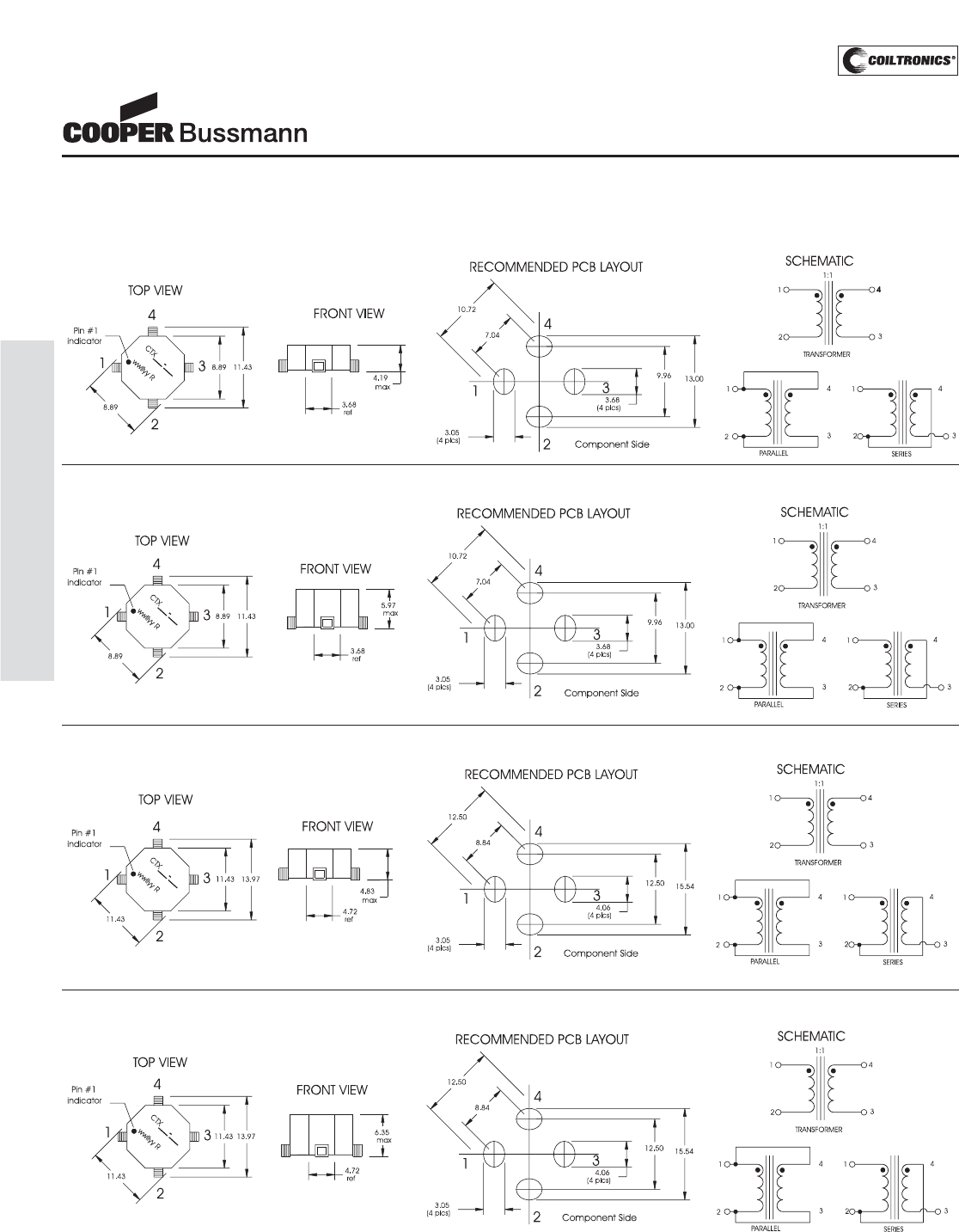
PM-154
TOROID (ECONO-PAC™/OCTA-PAC
®
, OCTA-PAC
®
PLUS
ECONO-PAC™/OCTA-PAC®
OCTA-PAC®PLUS
Power Inductors and Transformers
Mechanical Diagrams
CTX 1, 1P, 1A Series
CTX 2, 2P, 2A Series
CTX 3, 3P, 3A Series
CTX 4, 4P, 4A Series
Dimensions in Millimeters. wwllyy = (date code) R = revision level
Courtesy of Steven Engineering, Inc.-230 Ryan Way, South San Francisco, CA 94080-6370-Main Office: (650) 588-9200-Outside Local Area: (800) 258-9200-www.stevenengineering.com
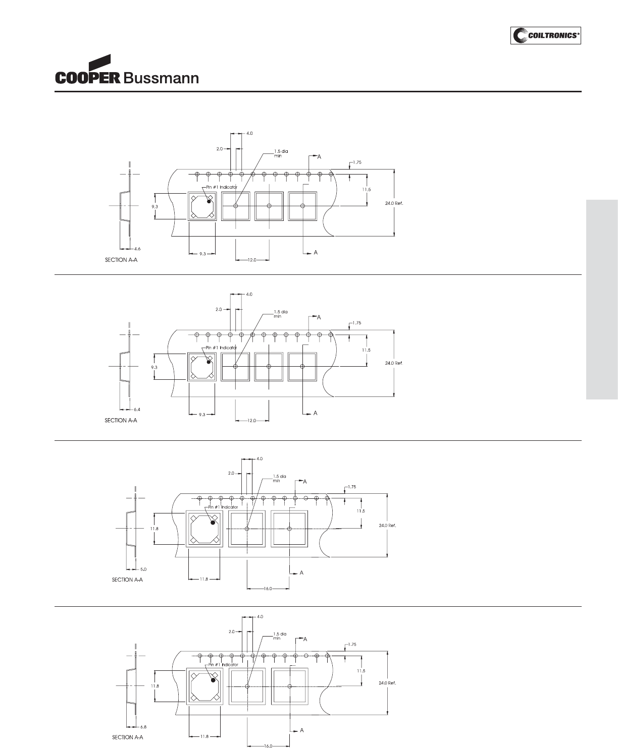
PM-155
TOROID (ECONO-PAC™/OCTA-PAC
®
, OCTA-PAC
®
PLUS
ECONO-PAC™/OCTA-PAC®
OCTA-PAC®PLUS
Power Inductors and Transformers
CTX 2, 2P, 2A Series
CTX 3, 3P, 3A Series
CTX 4, 4P, 4A Series
Packaging Information
CTX 1, 1P, 1A Series
Dimensions are in millimeters.
Direction of Feed ➞
Direction of Feed ➞
Direction of Feed ➞
Direction of Feed ➞
Parts packaged on 13" Diameter reel,
1,100 parts per reel.
Parts packaged on 13" Diameter reel,
800 parts per reel.
Parts packaged on 13" Diameter reel,
800 parts per reel.
Parts packaged on 13" Diameter reel,
600 parts per reel.
Courtesy of Steven Engineering, Inc.-230 Ryan Way, South San Francisco, CA 94080-6370-Main Office: (650) 588-9200-Outside Local Area: (800) 258-9200-www.stevenengineering.com
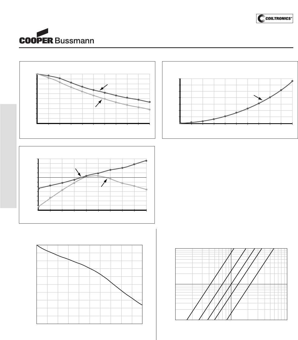
PM-156
TOROID (ECONO-PAC™/OCTA-PAC
®
, OCTA-PAC
®
PLUS
• INDUCTANCE VS. CURRENT:
Inductance will fall off as DC Current is increased.
(See Inductance vs. Current graph).
• FREQUENCY RESPONSE:
Wide-band frequency response to 1 megaHertz.
• CURRENT LIMITATION:
The maximum allowable currents are defined by the internal
“hot-spot” temperatures which are limited to 130°C, including
ambient.
-35 -15 +5 +25 +45 +65 +85 +105 +125
INDUCTANCE VS. TEMPERATURE
Percentage Change
in Inductance
Temperature in Degrees C.
+8
+6
+4
+2
+0
-2
-4
-6
-8
-10
-12
-14
ECONO-PAC
OCTA-PAC
INDUCTANCE VS. CURRENT
Percentage of
Inductance
Per Unit Full Load Current
100
90
80
70
60
50
40
30
20
10
0
0.00 0.25 0.50 0.75 1.00 1.25 1.50 1.75 2.00 2.25 2.50
ECONO-PAC
OCTA-PAC
TEMPERATURE RISE VS. RATED CURRENT
Max. Ambient plus Rise = 125°C
Degrees C
Per Unit Full Load Current
140
120
100
80
60
40
20
0
0.00 0.25 0.50 0.75 1.00 1.25 1.50 1.75 2.00 2.25 2.50
ECONO-PAC & OCTA-PAC
Performance Characteristics
ECONO-PAC™/OCTA-PAC®
OCTA-PAC®PLUS
Power Inductors and Transformers
OCTA-PAC®PLUS Typical Inductance vs. DC Current OCTA-PAC®PLUS Winding Loss Derating with Core Loss
0 20 40 60 80 100 120 140 160 180 200
0
10
20
30
40
50
60
70
80
90
100
% of Isat
% of OCL
1000800600
50040030020010080605040302010
% of Applied Volt-μ-Second Rating
99
98
97
96
95
94
92
90
80
70
60
50
40
20
0
% of Losses from Irms (maximum)
1MHz
500KHz
300KHz
200KHz
100KHz
Courtesy of Steven Engineering, Inc.-230 Ryan Way, South San Francisco, CA 94080-6370-Main Office: (650) 588-9200-Outside Local Area: (800) 258-9200-www.stevenengineering.com
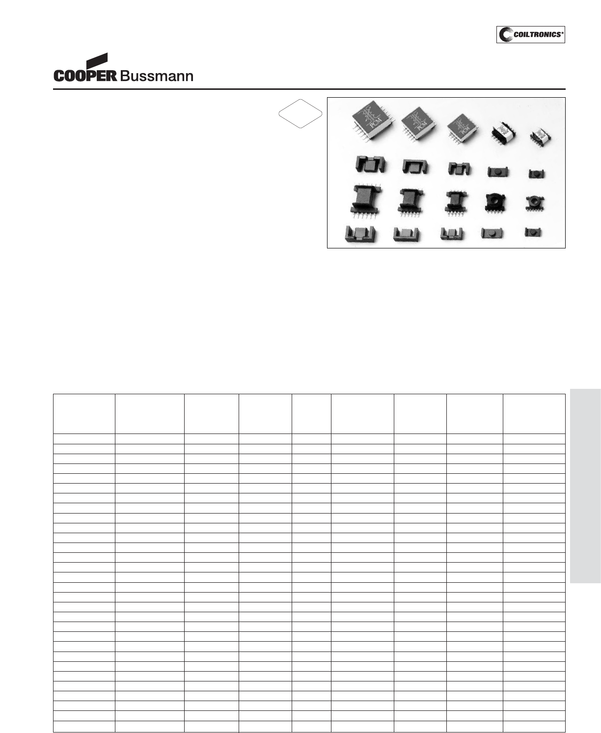
PM-157
TRANSFORMERS (VP1-5/VPH1-5) VERSA-PAC
®
Description
• Six winding, surface mount devices that
offer more than 500 usable inductor or
transformer configurations
• High power density and low profile
• Low radiated noise and tightly coupled windings
• Power range from 1 Watt – 70 Watts
• Frequency range to over 1MHz
• 500 VAC Isolation
• Ferrite core material
Applications
• Inductors: buck, boost, coupled, choke, filter, resonant,
noise filtering, differential, forward, common mode
• Transformers: flyback, feed forward, push-pull, multiple
output, inverter, step-up, step-down, gate drive, base
drive, wide band, pulse, control, impedance, isolation,
bridging, ringer, converter, auto
Environmental Data
• Storage temperature range: -55°C to 125°C
• Operating ambient temperature range: -40°C to +85°C
(range is application specific). The internal “hot spot”
temperature defines the maximum allowable currents,
which are limited to 130°C, including ambient
• Solder reflow temperature: +260°C max for 10 seconds
max.
Packaging
• Supplied in tape and reel packaging, 600 (VP01),
300 (VP02), and 200 (VP03) per reel
• Supplied in bulk packaging (VP04 and VP05)
• VP04 & VP05 tape and reel packaging available.
Please contact factory for details.
VERSA-PAC®
Inductors and Transformers
(Surface Mount)
Leakage Thermal
Part (1) L(BASE)ISAT(BASE)IRMS(BASE)R(BASE) Volt-μSEC(BASE)EPEAK(BASE) Inductance Resistance
Number μH Amps Amps Ohms μVs μJ (BASE) μH °C/Watt
(NOM)(2) (TYP)(3)(4) (TYP)(3)(5) (MAX)(6) (MAX)(7) (TYP)(8) (TYP)(TYP)(9)
VPH1-1400-R(10) 201.6 +/-30% 0.04 0.55 0.344 32.9 0.11 0.212 60.7
VP1-1400-R(10) 89.6 +/-30% 0.06 0.85 0.145 21.8 0.11 0.096 60.7
VPH1-0190-R 27.4 +/-20% 0.29 0.55 0.344 32.9 0.77 0.212 60.7
VP1-0190-R 12.2 +/-20% 0.43 0.85 0.145 21.8 0.77 0.096 60.7
VPH1-0102-R 14.7 +/-20% 0.53 0.55 0.344 32.9 1.45 0.212 60.7
VP1-0102-R 6.5 +/-20% 0.80 0.85 0.145 21.8 1.45 0.096 60.7
VPH1-0076-R 10.9 +/-20% 0.72 0.55 0.344 32.9 1.92 0.212 60.7
VP1-0076-R 4.9 +/-20% 1.06 0.85 0.145 21.8 1.92 0.096 60.7
VPH1-0059-R 8.5 +/-20% 0.92 0.55 0.344 32.9 2.48 0.212 60.7
VP1-0059-R 3.8 +/-20% 1.37 0.85 0.145 21.8 2.48 0.096 60.7
VPH2-1600-R(10) 160 +/-30% 0.07 0.95 0.159 48.3 0.29 0.165 44.0
VP2-1600-R(10) 78.4 +/-30% 0.10 1.26 0.090 33.7 0.29 0.083 44.0
VPH2-0216-R 21.6 +/-20% 0.53 0.95 0.159 48.3 2.11 0.165 44.0
VP2-0216-R 10.6 +/-20% 0.76 1.26 0.090 33.7 2.11 0.083 44.0
VPH2-0116-R 11.6 +/-20% 0.99 0.95 0.159 48.3 3.94 0.165 44.0
VP2-0116-R 5.7 +/-20% 1.41 1.26 0.090 33.7 3.94 0.083 44.0
VPH2-0083-R 8.3 +/-20% 1.39 0.95 0.159 48.3 5.47 0.165 44.0
VP2-0083-R 4.1 +/-20% 1.95 1.26 0.090 33.7 5.47 0.083 44.0
VPH2-0066-R 6.6 +/-20% 1.74 0.95 0.159 48.3 7.01 0.165 44.0
VP2-0066-R 3.2 +/-20% 2.50 1.26 0.090 33.7 7.01 0.083 44.0
VPH3-0780-R(10) 132 +/-30% 0.07 0.97 0.14 39.8 0.24 0.125 43.4
VP3-0780-R(10) 63.2 +/-30% 0.10 1.47 0.061 27.7 0.24 0.058 43.4
VPH3-0138-R 23.3 +/-20% 0.41 0.97 0.14 39.8 1.36 0.125 43.4
VP3-0138-R 11.2 +/-20% 0.59 1.47 0.061 27.7 1.36 0.058 43.4
VPH3-0084-R 14.2 +/-20% 0.67 0.97 0.14 39.8 2.23 0.125 43.4
VP3-0084-R 6.8 +/-20% 0.97 1.47 0.061 27.7 2.23 0.058 43.4
VPH3-0055-R 9.3 +/-20% 1.02 0.97 0.14 39.8 3.38 0.125 43.4
VP3-0055-R 4.5 +/-20% 1.46 1.47 0.061 27.7 3.38 0.058 43.4
VPH3-0047-R 7.94 +/-20% 1.19 0.97 0.14 39.8 4.00 0.125 43.4
VP3-0047-R 3.8 +/-20% 1.73 1.47 0.061 27.7 4.00 0.058 43.4
RoHS
2002/95/EC
Courtesy of Steven Engineering, Inc.-230 Ryan Way, South San Francisco, CA 94080-6370-Main Office: (650) 588-9200-Outside Local Area: (800) 258-9200-www.stevenengineering.com
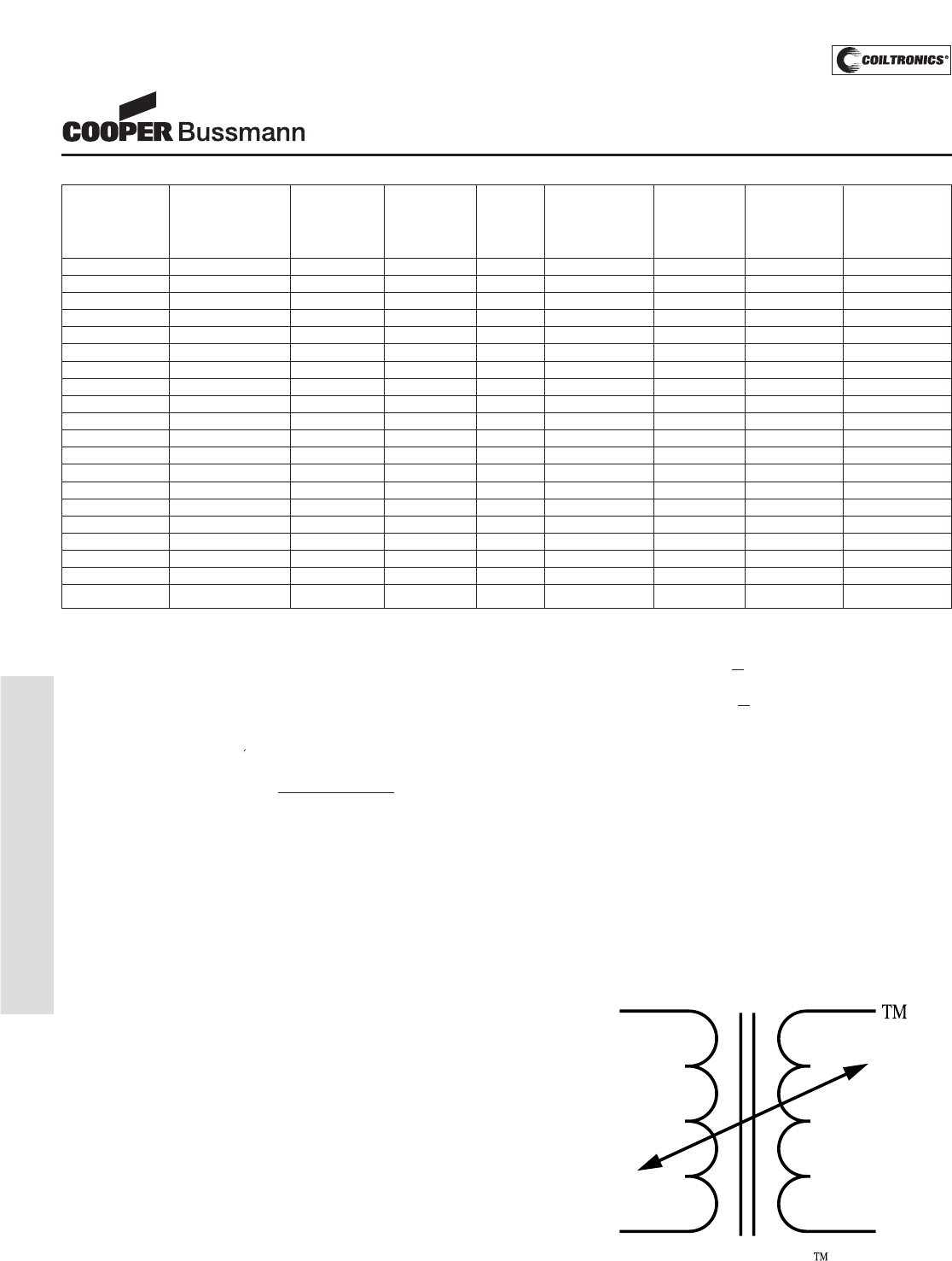
PM-158
TRANSFORMERS (VP1-5/VPH1-5) VERSA-PAC
®
Leakage Thermal
Part (1) L(BASE)ISAT(BASE)IRMS(BASE)R(BASE) Volt-μSEC(BASE)EPEAK(BASE) Inductance Resistance
Number μH Amps Amps Ohms μVs μJ (BASE) μH °C/Watt
(NOM)(2) (TYP)(3)(4) (TYP)(3)(5) (MAX)(6) (MAX)(7) (TYP)(8) (TYP)(TYP)(9)
VPH4-0860-R(10) 159.65 +/-30% 0.11 1.41 0.0828 64.6 0.57 0.156 39.4
VP4-0860-R(10) 87.0 +/-30% 0.15 1.70 0.057 44.7 0.57 0.075 39.4
VPH4-0140-R 23.7 +/-20% 0.65 1.41 0.0828 64.6 3.54 0.156 39.4
VP4-0140-R 11.3 +/-20% 0.95 1.70 0.057 44.7 3.54 0.075 39.4
VPH4-0075-R 12.7 +/-20% 1.21 1.41 0.0828 64.6 6.55 0.156 39.4
VP4-0075-R 6.1 +/-20% 1.75 1.70 0.057 44.7 6.55 0.075 39.4
VPH4-0060-R 10.1 +/-20% 1.52 1.41 0.0828 64.6 8.16 0.156 39.4
VP4-0060-R 4.9 +/-20% 2.18 1.70 0.057 44.7 8.16 0.075 39.4
VPH4-0047-R 7.94 +/-20% 1.94 1.41 0.0828 64.6 10.52 0.156 39.4
VP4-0047-R 3.8 +/-20% 2.81 1.70 0.057 44.7 10.52 0.075 39.4
VPH5-1200-R(10) 173 +/-30% 0.14 1.70 0.0711 98.4 1.11 0.235 30.3
VP5-1200-R(10) 76.8 +/-30% 0.20 2.08 0.047 65.6 1.11 0.105 30.3
VPH5-0155-R 22.3 +/-20% 1.05 1.70 0.0711 98.4 8.83 0.235 30.3
VP5-0155-R 9.9 +/-20% 1.60 2.08 0.047 65.6 8.83 0.105 30.3
VPH5-0083-R 12 +/-20% 1.96 1.70 0.0711 98.4 16.07 0.235 30.3
VP5-0083-R 5.3 +/-20% 2.95 2.08 0.047 65.6 16.07 0.105 30.3
VPH5-0067-R 9.65 +/-20% 2.43 1.70 0.0711 98.4 19.83 0.235 30.3
VP5-0067-R 4.3 +/-20% 3.63 2.08 0.047 65.6 19.83 0.105 30.3
VPH5-0053-R 7.63 +/-20% 3.07 1.70 0.0711 98.4 25.10 0.235 30.3
VP5-0053-R 3.4 +/-20% 4.59 2.08 0.047 65.6 25.10 0.105 30.3
VERSA-PAC temperature rise depends on total power losses and
size. Any other PCM configurations other than those suggested
could run hotter than acceptable.
Certain topologies or applications must be analyzed for needed
requirements and matched with the best VERSA-PAC size and con-
figuration. Proper consideration must be used with all parameters,
especially those associated with current rating, energy storage, or
maximum volt-seconds.
VERSA-PAC should not be used in off-line or safety related appli-
cations.The breakdown voltage from one winding to any other wind-
ing is 500 VAC maximum. PCM
(1) The first three digits in the part number signify the size of the pack-
age. The next four digits specify the AL, or nanoHenries per turn
squared.
(2) LBASE = Nominal Inductance of a single winding.
(3) IBASE is the lessor of ISAT(BASE)and IRMS(BASE).
(4) Peak current that will result in 30% saturation of the core. This cur-
rent value assumes that equal current flows in all six windings. For
applications in which all windings are not simultaneously driven (i.e.
flyback, SEPIC, Cuk, etc.), the saturation current per winding may
be calculated as follows:
ISAT = 6 x ISAT(BASE)
Number of Windings Driven
(5) RMS Current that results in a surface temperature of approximately
40°C above ambient. The 40°C rise occurs when the specified cur-
rent flows through each of the six windings.
(6) Maximum DC Resistance of each winding.
(7) For multiple windings in series, the volt-μsecondTOTAL (μVs)
capability varies as the number of windings in series (S):
Volt-μsecTOTAL = S xVolt-μsec(BASE)
For multiple windings in parallel, the volt-μsecondTOTAL (μVs) capability
is as shown in the table above.
(8) Maximum Energy capability of each winding. This is based on 30%
saturation of the core:
EnergySERIES = S2x1x0.7LBASE xI2
SAT(BASE)
EnergyPARALLEL = P2x1x0.7LBASE xI2
SAT(BASE)
For multiple windings, the energy capability varies as the square of
the number of windings. For example, six windings (either parallel
or series) can store 36 times more energy than one winding.
(9) Thermal Resistance is the approximate surface temperature rise
per Watt of heat loss under still-air conditions. Heat loss is a combi-
nation of core loss and wire loss. The number assumes the under-
lying PCB copper area equals 150% of the component area.
(10) These devices are designed for feed-forward applications, where
load current dominates magnitizing current.
2
2
VERSA-PAC®
Inductors and Transformers
(Surface Mount)
Courtesy of Steven Engineering, Inc.-230 Ryan Way, South San Francisco, CA 94080-6370-Main Office: (650) 588-9200-Outside Local Area: (800) 258-9200-www.stevenengineering.com
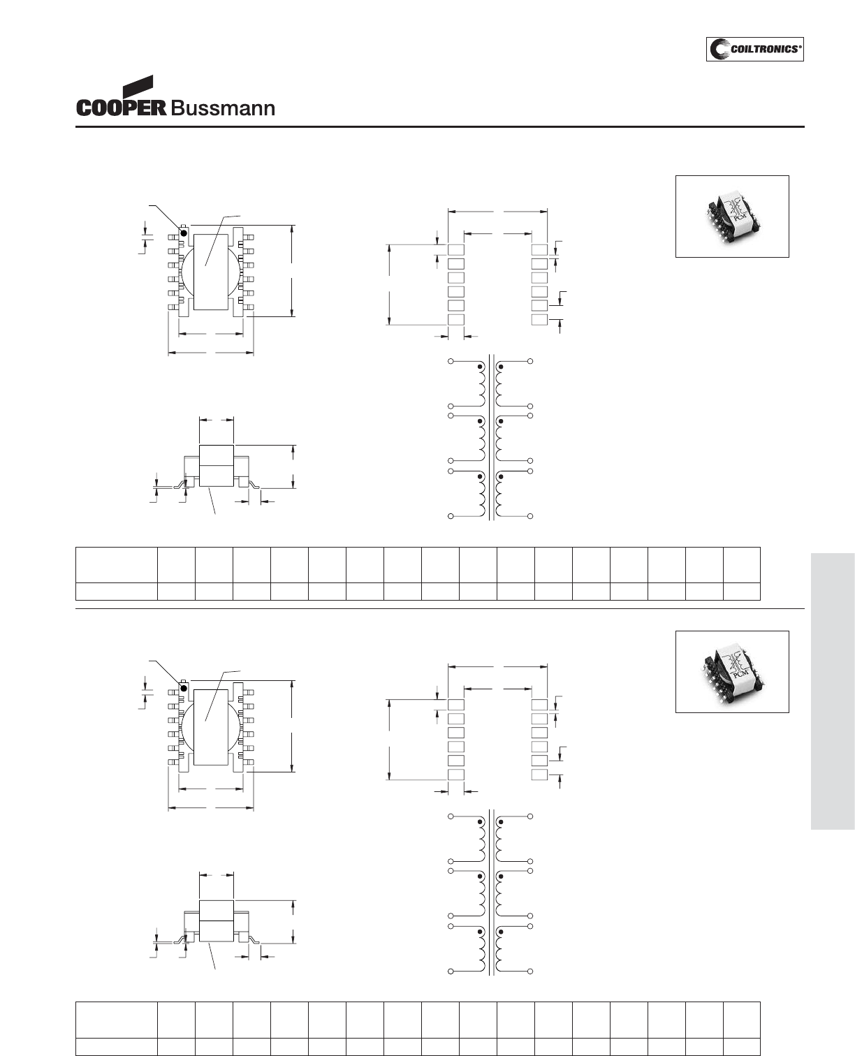
PM-159
TRANSFORMERS (VP1-5/VPH1-5) VERSA-PAC
®
Mechanical Diagrams
VP2 and VPH2
VP1 and VPH1
TOP VIEW
WHITE DOT
PIN #1
D
(12 PLCS)
LOGO (OPTIONAL)
B
C
A
12
7
6
1
FRONT VIEW
I
(12 PLCS) HG
(2 PLCS)
WWLLYY R
E
F
VPH
_
-
____
RECOMMENDED PCB LAYOUT
J
N
M
COMPONENT
SIDE
112
67
L
(12PLCS)
K
(12PLCS) 0
(10PLCS)
P
(10PLCS)
4
1
5
2
68
12
7
11
10
9
31:1:1:1:1:1
NOTES
1) Tolerances A - I are ± 0.25 mm
unless specified otherwise.
2) Tolerances J - P are +/- 0.1 mm
unless specified otherwise.
3) Marking as shown
a) Dot for pin #1 identification
b) On top of unit: -- VPHx-xxx
(product code, size,
4 digit part number per family
table.)
c) On top of unit: Versa Pac
Logo (optional)
d) On bottom of unit: wwllyy =
(date code) R = (revision
level)
4) All soldering surfaces must be
coplanar within 0.102 mm.
ABCDEFGH I JKLMNOP
mm mm mm mm mm mm mm mm mm mm mm mm mm mm mm mm
max ref max ref ref max ref ref ref ref ref max
VP1 and VPH1 12.9 9.2 13.0 0.7 5.9 6.2 1.5 0.1 0.25 11.5 1.5 2.25 9.7 14.2 2.0 0.5
TOP VIEW
WHITE DOT
PIN #1
D
(12 PLCS)
LOGO (OPTIONAL)
B
C
A
12
7
6
1
FRONT VIEW
I
(12 PLCS) HG
(2 PLCS)
WWLLYY R
E
F
VPH
_
-
____
RECOMMENDED PCB LAYOUT
J
N
M
COMPONENT
SIDE
112
67
L
(12PLCS)
K
(12PLCS) 0
(10PLCS)
P
(10PLCS)
4
1
5
2
68
12
7
11
10
9
31:1:1:1:1:1
NOTES
1) Tolerances A - I are ± 0.25 mm
unless specified otherwise.
2) Tolerances J - P are +/- 0.1 mm
unless specified otherwise.
3) Marking as shown
a) Dot for pin #1 identification
b) On top of unit: -- VPHx-xxx
(product code, size,
4 digit part number per family
table.)
c) On top of unit: Versa Pac
Logo (optional)
d) On bottom of unit: wwllyy =
(date code) R = (revision
level)
4) All soldering surfaces must be
coplanar within 0.102 mm.
ABCDEFGH I JKLMNOP
mm mm mm mm mm mm mm mm mm mm mm mm mm mm mm mm
max ref max ref ref max ref ref ref ref ref max
VP2 and VPH2 16.3 12.0 16.8 0.7 6.7 7.8 2.0 0.1 0.30 14.25 1.75 2.5 13.0 18.0 2.5 0.75
VERSA-PAC®
Inductors and Transformers
(Surface Mount)
Courtesy of Steven Engineering, Inc.-230 Ryan Way, South San Francisco, CA 94080-6370-Main Office: (650) 588-9200-Outside Local Area: (800) 258-9200-www.stevenengineering.com
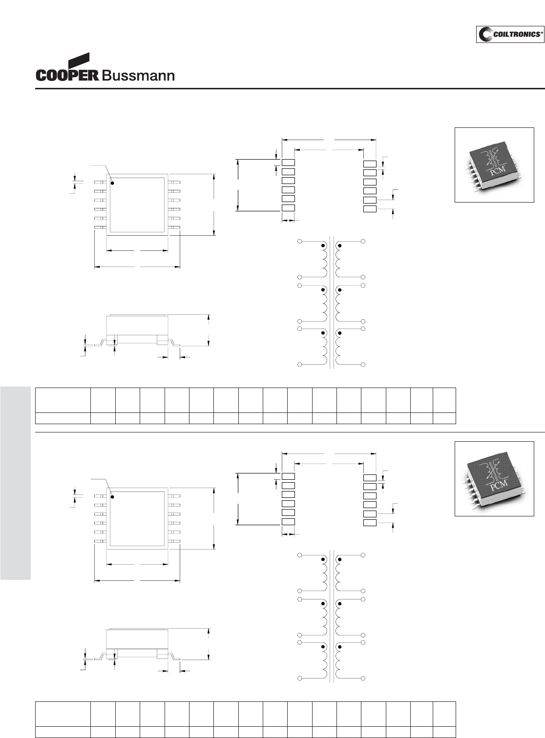
PM-160
TRANSFORMERS (VP1-5/VPH1-5) VERSA-PAC
®
Mechanical Diagrams
VP4 and VPH4
VP3 and VPH3
ABCDEFGH I JKLMNO
mm mm mm mm mm mm mm mm mm mm mm mm mm mm mm
max ref max ref max ref ref ref ref ref max
VP3 and VPH3 17.1 16.0 22.3 0.7 8.4 3.0 0.1 0.4 14.49 1.79 3.43 16.88 23.74 2.54 0.75
TOP VIEW
D
(12 PLCS)
1
6
12
7
LOGO
(OPTIONAL)
VPH
_
-
____
B
C
A
WHITE DOT
PIN #1
FRONT VIEW
H
(12 PLCS) G
(12 PLCS) F (2 PLCS)
E
1
12
2
11
3
10
1:1:1:1:1:1
4
9
5
8
6
7
J
(12PLCS) COMPONENT
SIDE
K (12PLCS)
O
(10PLCS)
N
(10PLCS)
M
L
112
67
I
NOTES
1) Tolerances A - I are ± 0.25 mm
unless specified otherwise.
2) Tolerances J - P are +/- 0.1 mm
unless specified otherwise.
3) Marking as shown
a) Dot for pin #1 identification
b) On top of unit: -- VPHx-xxx
(product code, size,
4 digit part number per family
table.)
c) On top of unit: Versa Pac
Logo (optional)
d) On bottom of unit: wwllyy =
(date code) R = (revision
level)
4) All soldering surfaces must be
coplanar within 0.102 mm.
ABCDEFGH I JKLMNO
mm mm mm mm mm mm mm mm mm mm mm mm mm mm mm
max ref max ref max ref ref ref ref ref max
VP4 and VPH4 18.0 18.0 24.6 0.7 10.0 3.3 0.1 0.4 14.25 1.75 3.43 19.14 26.0 2.5 0.75
TOP VIEW
D
(12 PLCS)
1
6
12
7
LOGO
(OPTIONAL)
VPH
_
-
____
B
C
A
WHITE DOT
PIN #1
FRONT VIEW
H
(12 PLCS) G
(12 PLCS) F (2 PLCS)
E
1
12
2
11
3
10
1:1:1:1:1:1
4
9
5
8
6
7
J
(12PLCS) COMPONENT
SIDE
K (12PLCS)
O
(10PLCS)
N
(10PLCS)
M
L
112
67
I
NOTES
1) Tolerances A - I are ± 0.25 mm
unless specified otherwise.
2) Tolerances J - P are +/- 0.1 mm
unless specified otherwise.
3) Marking as shown
a) Dot for pin #1 identification
b) On top of unit: -- VPHx-xxx
(product code, size,
4 digit part number per family
table.)
c) On top of unit: Versa Pac
Logo (optional)
d) On bottom of unit: wwllyy =
(date code) R = (revision
level)
4) All soldering surfaces must be
coplanar within 0.102 mm.
VERSA-PAC®
Inductors and Transformers
(Surface Mount)
Courtesy of Steven Engineering, Inc.-230 Ryan Way, South San Francisco, CA 94080-6370-Main Office: (650) 588-9200-Outside Local Area: (800) 258-9200-www.stevenengineering.com
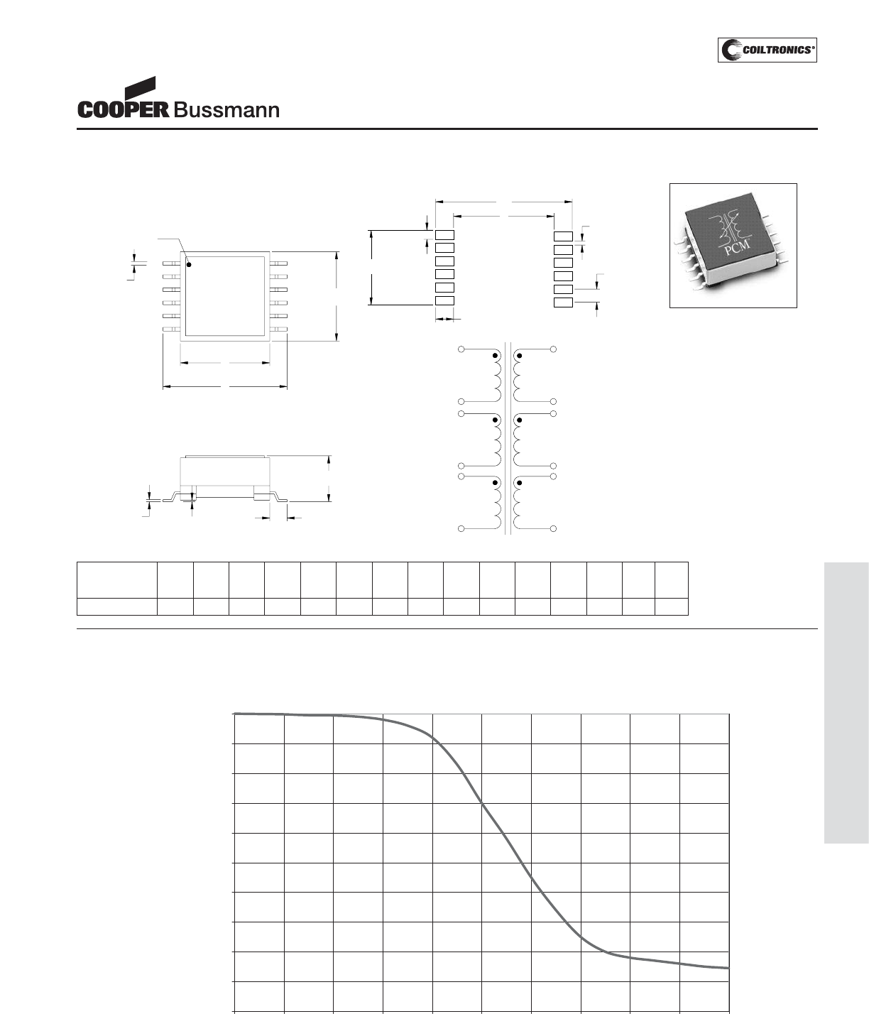
PM-161
TRANSFORMERS (VP1-5/VPH1-5) VERSA-PAC
®
Mechanical Diagrams
Inductance Characteristics
VP5 and VPH5
ABCDEFGH I JKLMNO
mm mm mm mm mm mm mm mm mm mm mm mm mm mm mm
max ref max ref max ref ref ref ref ref max
VP5 and VPH5 21.0 21.0 28.5 0.7 10.8 2.95 0.1 0.4 17.25 2.25 3.15 22.7 29.0 3.0 0.75
TOP VIEW
D
(12 PLCS)
1
6
12
7
LOGO
(OPTIONAL)
VPH
_
-
____
B
C
A
WHITE DOT
PIN #1
FRONT VIEW
H
(12 PLCS) G
(12 PLCS) F (2 PLCS)
E
1
12
2
11
3
10
1:1:1:1:1:1
4
9
5
8
6
7
J
(12PLCS) COMPONENT
SIDE
K (12PLCS)
O
(10PLCS)
N
(10PLCS)
M
L
112
67
I
NOTES
1) Tolerances A - I are ± 0.25 mm
unless specified otherwise.
2) Tolerances J - P are +/- 0.1 mm
unless specified otherwise.
3) Marking as shown
a) Dot for pin #1 identification
b) On top of unit: -- VPHx-xxx
(product code, size,
4 digit part number per family
table.)
c) On top of unit: Versa Pac
Logo (optional)
d) On bottom of unit: wwllyy =
(date code) R = (revision
level)
4) All soldering surfaces must be
coplanar within 0.102 mm.
OCL vs. Isat
0.0%
10.0%
20.0%
30.0%
40.0%
50.0%
60.0%
70.0%
80.0%
90.0%
100.0%
0.0% 20.0% 40.0% 60.0% 80.0% 100.0% 120.0% 140.0% 160.0% 180.0% 200.0%
% of Isat
% of OCL
VERSA-PAC®
Inductors and Transformers
(Surface Mount)
Courtesy of Steven Engineering, Inc.-230 Ryan Way, South San Francisco, CA 94080-6370-Main Office: (650) 588-9200-Outside Local Area: (800) 258-9200-www.stevenengineering.com
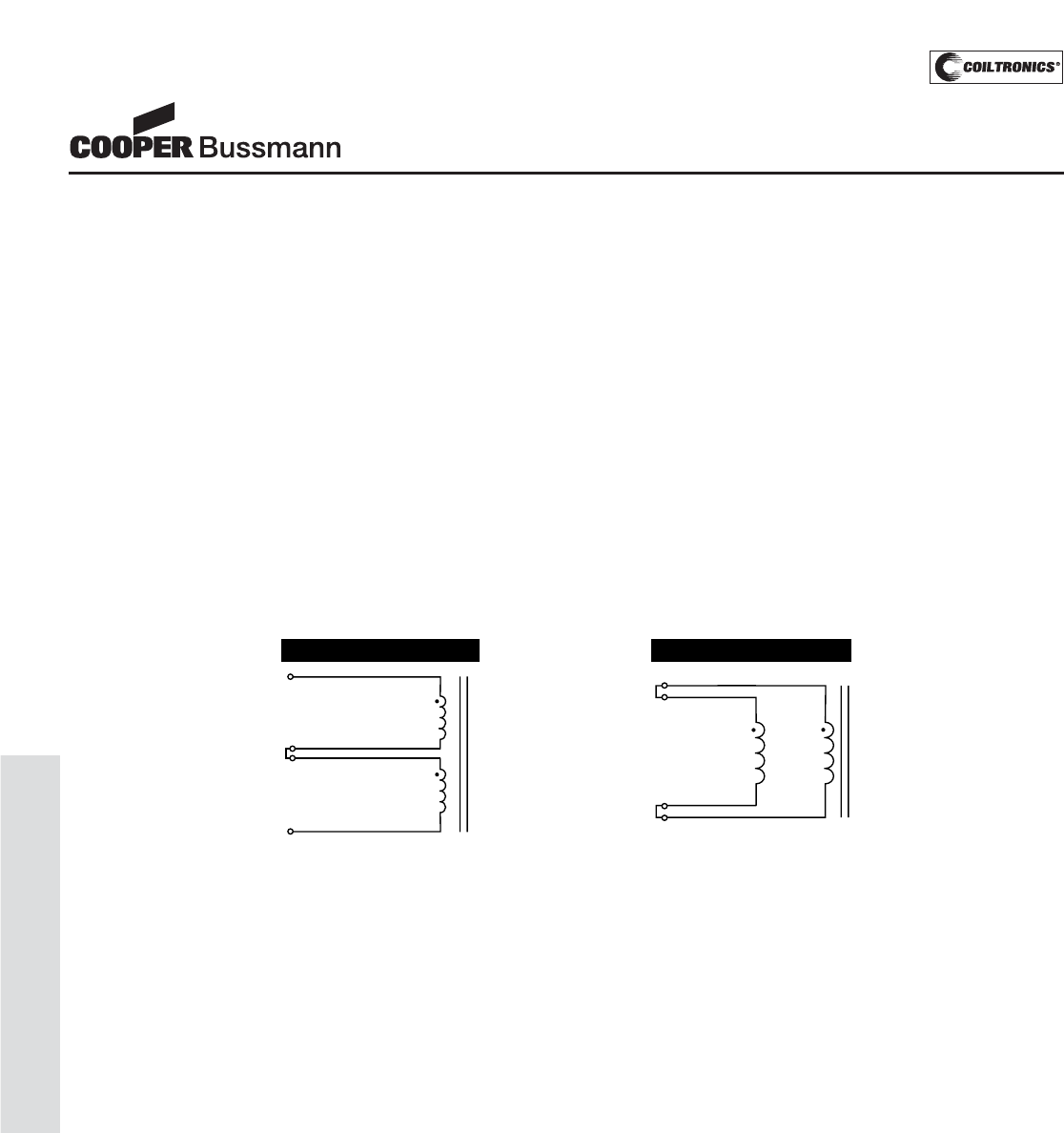
PM-162
TRANSFORMERS (VP1-5/VPH1-5) VERSA-PAC
®
HOW TO USE MULTIPLE WINDINGS
LTOTAL =L
BASE x S2
= 10 μH x 22
= 40 μH
Where:
LBASE = Inductance of a single winding
P = Number of windings in parallel (use 1 with all windings in series)
S = Number of windings in series
IBASE = Maximum current rating of one winding
IMAX =I
BASE x P
= 1 Amp x 1
= 1 Amp
L TOTAL =L
BASE x S2
= 10 μH x 12
= 10 μH
IMAX =IBASE x P
= 1 Amp x 2
= 2 Amps
10μH
1 Amp
10μH
1 Amp
10μH
1 Amp
Series Connected (2 Windings) Parallel Connected (2 Windings)
10μH
1 Amp
Discrete inductors combine like resistors, when connected in series or parallel. For example, inductors in series add and
inductors in parallel reduce in a way similar to Ohm’s Law.
Windings on the same magnetic core behave differently. Two windings in series result in four times the inductance of a
single winding. This is because the inductance varies proportionately to the square of the turns.
Paralleled VERSA-PAC windings result in no change to the net inductance because the total number of turns remains
unchanged; only the effective wire size becomes larger. Two parallel windings result in approximately twice the current
carrying capability of a single winding. The net inductance of a given PCM configuration is based on the number of
windings in series squared multiplied by the inductance of a single winding (LBASE). The current rating of a PCM configuration
is derived by multiplying the maximum current rating of one winding (IBASE) by the number of windings in parallel. Examples of
simple two-winding devices are shown below:
LSeries = L1 + L2 + L3...Ln
LParallel = 1/ [1/L1 + 1/L2 + 1/L3....1/Ln]
VERSA-PAC®
Inductors and Transformers
(Surface Mount)
Courtesy of Steven Engineering, Inc.-230 Ryan Way, South San Francisco, CA 94080-6370-Main Office: (650) 588-9200-Outside Local Area: (800) 258-9200-www.stevenengineering.com
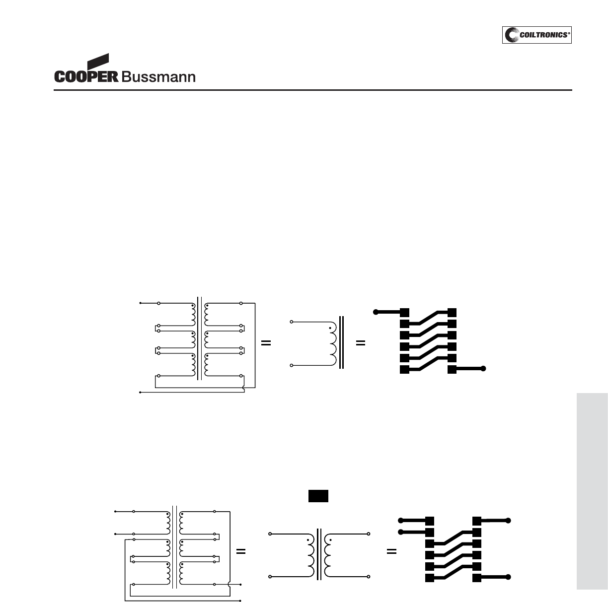
PM-163
TRANSFORMERS (VP1-5/VPH1-5) VERSA-PAC
®
Each VERSA-PAC can be configured in a variety of ways by simply connecting pins together on the Printed Circuit Board
(PCB). As shown below, the connections on the PCB are equal to the pin configuration statement shown at the bottom of the
schematic symbol. Connecting a number of windings in parallel will increase the current carrying capability, while connecting
in series will multiply the inductance. Each VERSA-PAC part can be configured in at least 6 combinations for inductor use or
configured in at least 15 turns ratios for transformer applications. Given 25 VERSA-PAC part numbers, this allows for at least
500 magnetic configurations. The PCM configurations can either be created by the designer or simply chosen from the
existing PCM diagrams. The following inductor example shows 6 windings in series, which result in an inductance of 36 times
the base inductance and 1 times the base current.
1
12
2
11
3
10
4
1
112
6
Component View
7
7
= 36 times the base
Inductance from Data Table.
LTOTAL = 36 x LBASE
9
5
8
6
7
PIN CONFIGURATIONS
(2,12)(3,11)(4,10)(5,9)(6,8)
INDUCTOR EXAMPLE
FOR SIZES VP3, VP4 AND VP5
HOW TO PIN-CONFIGURE VERSA-PAC®
The PCM configurations may be selected from the examples on the following pages or created by the designer. Six PCM
inductor and fifteen PCM transformer configurations and equivalent circuit schematics are shown.The printed circuit board
layout in each example illustrates the connections to obtain the desired inductance or turns ratio. The examples may be
used by the PCB designer to configure VERSA-PAC as desired.
To assist the designer, VERSA-PAC phasing, coupling and thermal issues have been considered in each of the PCM
configurations illustrated. Additionally, the inductance and current ratings, as a function of the respective base values from
the following Data Tables, are shown in each PCM example.Turns ratios are also given for each PCM Transformer shown.
It is important to carefully select the proper VERSA-PAC part in order to minimize the component size without exceeding
the RMS current capability or saturating the core. The Data Tables indicate maximum ratings.
TRANSFORMER EXAMPLE
FOR SIZES VP3, VP4 AND VP5
1
12
2
11
3
10
4112
67
9
5
8
6
7
1
12
2
7
L
PRIMARY
= 1 x L
BASE
I
PRI
= 1 x I
BASE
I
SEC
= 1 x I
BASE
1:5
PIN CONFIGURATIONS
(3,11)(4,10)(5,9)(6,8)
Each VERSA-PAC may be used in at least 15 transformer applications. More than 375 transformer combinations may be
achieved using the available 25 VERSA-PAC parts.
VERSA-PAC®
Inductors and Transformers
(Surface Mount)
Courtesy of Steven Engineering, Inc.-230 Ryan Way, South San Francisco, CA 94080-6370-Main Office: (650) 588-9200-Outside Local Area: (800) 258-9200-www.stevenengineering.com
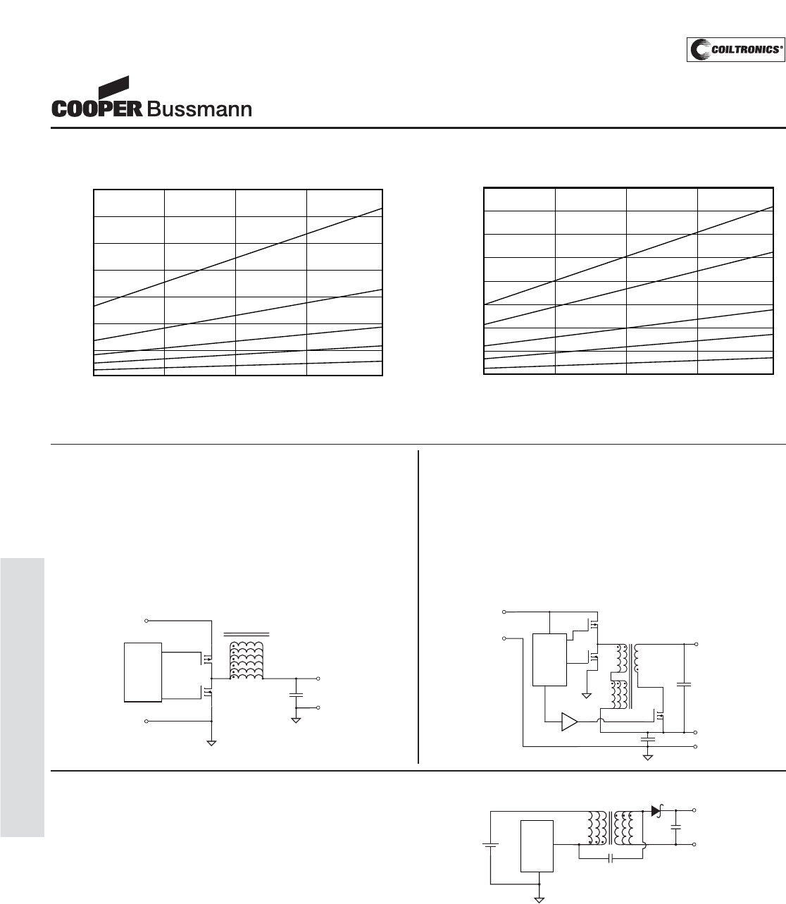
PM-164
TRANSFORMERS (VP1-5/VPH1-5) VERSA-PAC
®
5V to 3.3V Buck Converter With 5V Output
This circuit minimizes both board space and cost by eliminating a
second regulator. VERSA-PAC’s gap serves to prevent core
saturation during the switch on-time and also stores energy for the
+5V load which is delivered during the flyback interval. The +3.3V
buck winding is configured by placing two windings in series while
the +5V is generated by an additional flyback winding stacked on
the 3.3V output. Extra windings are paralleled with primary
windings to handle more current. The turns ratio of 2:1 adds 1.67V
to the +3.3V during the flyback interval to achieve +5V.
+3.3V@
12.5A
+V
RTN
VERSA-PAC
VP5-0083
12
11
10
9
8
7
1
2
3
4
5
6
Synchronous
Controller
IC
+
+V
+5V@
1A
+3.3V@
4.2A
+
RTN
VERSA-PAC
VP5-0083
LEVEL SHIFT
12,11
1,2
7
6
10,9,8
3,4,5
Synchronous
Controller
IC
+
3.3V Buck Converter
This circuit utilizes the gap of the VP5-0083 to handle the 12.5
Amp output current without saturating. In each of the five VERSA-
PAC sizes, the gap is varied to achieve a selection of specific
inductance and current values (see VERSA-PAC Data Table).
All six windings are connected in parallel to minimize AC/DC cop-
per losses and to maximize heat dissipation. With VERSA-PAC,
this circuit works well at or above 300 KHz. Also, the closed flux-
path EFD geometry enables much lower radiation characteristics
than open-path bobbin core style components.
LITHIUM-ION BATTERY TO 3.3V SEPIC CONVERTER
The voltage of a Lithium-Ion Battery varies above and below
+3.3V depending on the degree of charge. The SEPIC configura-
tion takes advantage of VERSA-PAC’s multiple tightly coupled
windings. This results in lower ripple current which lowers noise
and core losses substantially. The circuit does not require a snub-
ber to control the voltage “spike” associated with switch turn-off,
and is quite efficient due to lower RMS current in the windings.
+3.3V@
6A
VERSA-PAC
VP5-0083
12 11 10
123 987
45
+
+
+
6
Controller
IC
W/Integral
Switch
Watts
Frequency, kHz
100
0.0
10.0
20.0
30.0
40.0
50.0
60.0
70.0
200 300 400 500
VP 5
VP 4
VP 3
VP 2
VP 1
Watts
Frequency, kHz
100
0.0
5.0
10.0
15.0
20.0
25.0
30.0
35.0
40.0
200 300 400 500
VP 5
VP 4
VP 3
VP 2
VP 1
Bipolar (Push-Pull) Power vs Frequency Unipolar (Flyback) Power vs Frequency
VERSA-PAC®Performance Characteristics
These curves represent typical power handling capability.
Indicated power levels may not be achievable with all configurations.
VERSA-PAC®
Inductors and Transformers
(Surface Mount)
Courtesy of Steven Engineering, Inc.-230 Ryan Way, South San Francisco, CA 94080-6370-Main Office: (650) 588-9200-Outside Local Area: (800) 258-9200-www.stevenengineering.com
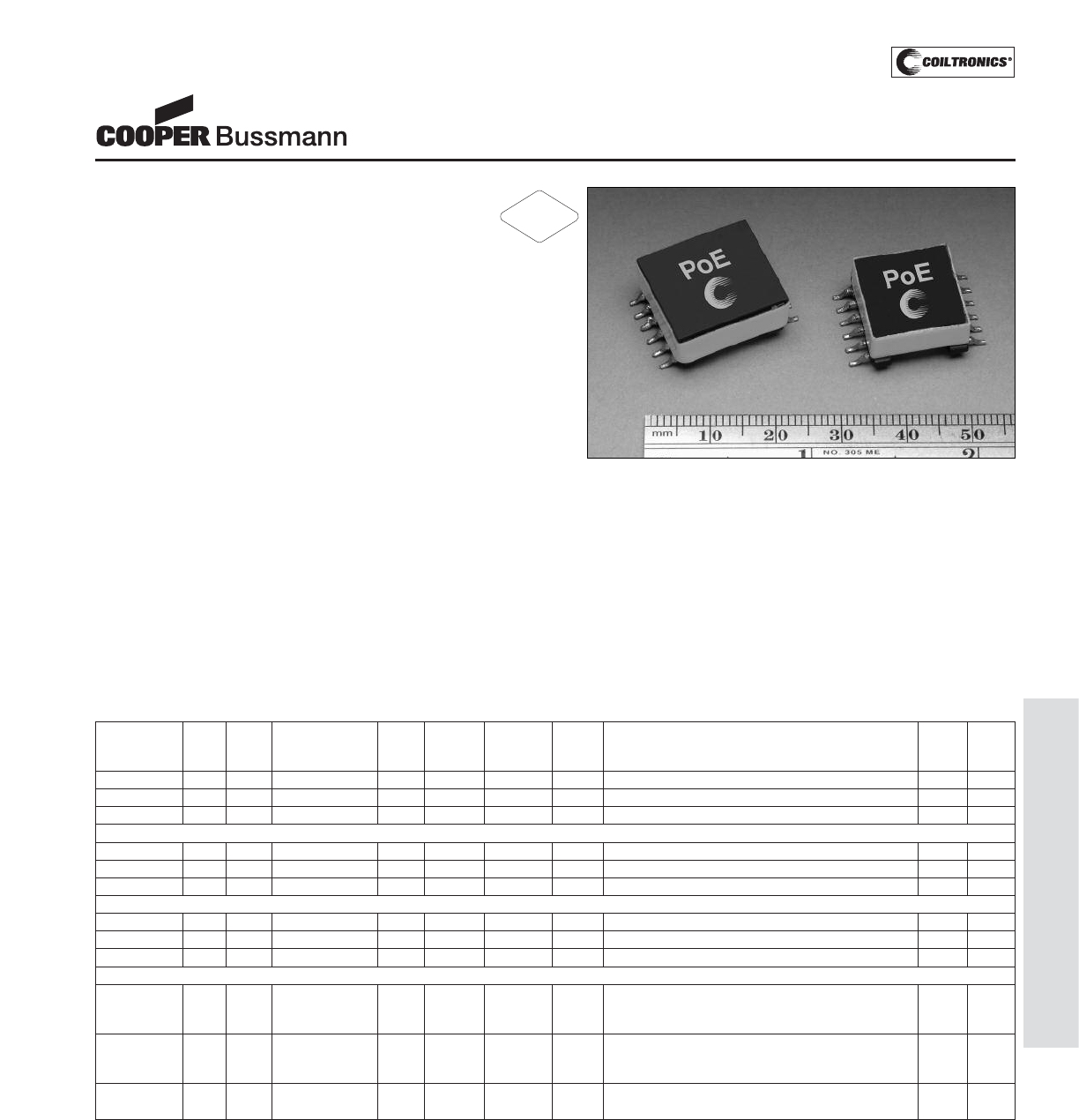
PM-165
TRANSFORMERS (PoE4W, 7W, 13W) FLYBACK
Description
• Versatile design allows multiple output variations
• Flyback topology, 250Khz switching frequency
• Input range from 29.5-60V
• 1500VAC isolation between primary and secondary
• Three power levels 4, 7, and 13watts
• Low leakage inductance
• 11.0 Volt @ 0.10 Amp Feedback Winding
• Ferrite core material
Applications
• For IEEE 802.3af-compliant Power over Ethernet appli-
cations
• UPS, VoiP Phone, Wireless LAN Access point,
Bluetooth Access point, Network Camera, Building
Access Systems
• Retail Point-of-information systems
• Vending/Gaming Machines
Environmental Data
• Storage temperature range: -40°C to +125°C
• Operating ambient temperature range: -40°C to +85°C
(range is application specific)
• Solder reflow temperature: +260°C max. for 10 seconds
max.
Packaging
• Packaging Information: 4 and 7 Watts 200 parts
per 13" reel, 13 Watts 140 parts per 13" reel
1) Test Parameters: 100kHz, 0.100 Vrms, 0.0Adc
2) DCR limits maximum @ 20°C 3) Leakage Inductance 200kHz, 0.01Vrms, 0.0Adc
4) Feedback DCR 1.0 Ohms maximum @20°C
Power Over Ethernet (PoE)/PD
Configurable Transformer
Induct- DCR/ DCR/ Leakage Pri Turn Ratio
ance Output PRI SEC Inductance Current Schematic 1: Pins pri(3-1):fb(5-6):v1(12-7):v2(11-8):v3(10-9) Sche- Dimen-
Part Number Watts (uH) (ohms) (ohms) e (uH) typ. Pk (Adc) Schematic 2: Pins pri(3-1):fb(5-6):v1(12-10):v2(11-9) matic sions
PoE4W3x3.3-R 4 200 (3)x3.3V@0.45A 0.500 0.07 2.75 0.65 1 : 0.52 : 0.16 : 0.16 : 0.16 +/-1% 1 Size 1
PoE4W3x5.0-R 4 200 (3)x5.0V@0.30A 0.500 0.27 2.50 0.65 1 : 0.52 : 0.26 : 0.26 : 0.26 +/-1% 1 Size 1
PoE4W2x12-R 4 200 (2)x12.0V@0.20A 0.500 0.740 1.40 0.65 1 : 0.52 : 0.60 : 0.60 +/-1% 2 Size 1
PoE7W3x3.3-R 7 100 (3)x3.3V@0.75A 0.275 0.03 1.00 1.00 1 : 0.529 : 0.176 : 0.176 : 0.176 +/-1% 1 Size 1
PoE7W3x5.0-R 7 100 (3)x5.0V@0.50A 0.275 0.095 1.00 1.00 1 : 0.529 : 0.265 : 0.265 : 0.265 +/-1% 1 Size 1
PoE7W2x12-R 7 100 (2)x12.0V@0.30A 0.275 0.250 1.00 1.00 1 : 0.529 : 0.588 : 0.588 +/-1% 2 Size 1
PoE13W3x3.3-R 13 100 (3)x3.3V@1.35A 0.250 0.032 1.50 1.60 1 : 0.529 : 0.176 : 0.176 : 0.176 +/-3% 1 Size 2
PoE13W3x5.0-R 13 100 (3)x5.0V@0.90A 0.250 0.075 1.20 1.60 1 : 0.529 : 0.265 : 0.265 : 0.265 +/-3% 1 Size 2
PoE13W2x12-R 13 100 (2)x12.0V@0.60A 0.250 0.280 1.00 1.70 1 : 0.529 : 0.647 : 0.647 +/-3% 2 Size 2
Induct- DCR/ DCR/ Leakage Pri Turn Ratio
ance Output PRI SEC Inductance Current Schematic 2: Pins pri(3-1):fb(5-6):v1(12-10):v2(11-9) Sche- Dimen-
Part Number Watts (uH) (ohms) V1/V2/V3 e (uH) typ. Pk (Adc) Schematic 3: Pins pri(1-3):fb(5-6):v3(12-11):v2(8-7) matic sions
V1:7.0V@1.1A,
PoE13W3VERS-R
13 100 V2:(1)x3.3V@1.1A, 0.250 0.025/0.0 1.00 1.70 1 : 0.529 : 0.350 : 0.176 : 0.088 +/-3% 3 Size 2
V3:1.8V@1.1A 42:0/085
V1:5.0V@1.6A, 0.023/0.0
PoE13W2VERS-R
13 100 V2:3.3V@1.6A 0.250 38/na 1.20 1.70 1 : 0.529 : 0.265 : 0.176 +/-3% 2 Size 2
RoHS
2002/95/EC
Courtesy of Steven Engineering, Inc.-230 Ryan Way, South San Francisco, CA 94080-6370-Main Office: (650) 588-9200-Outside Local Area: (800) 258-9200-www.stevenengineering.com
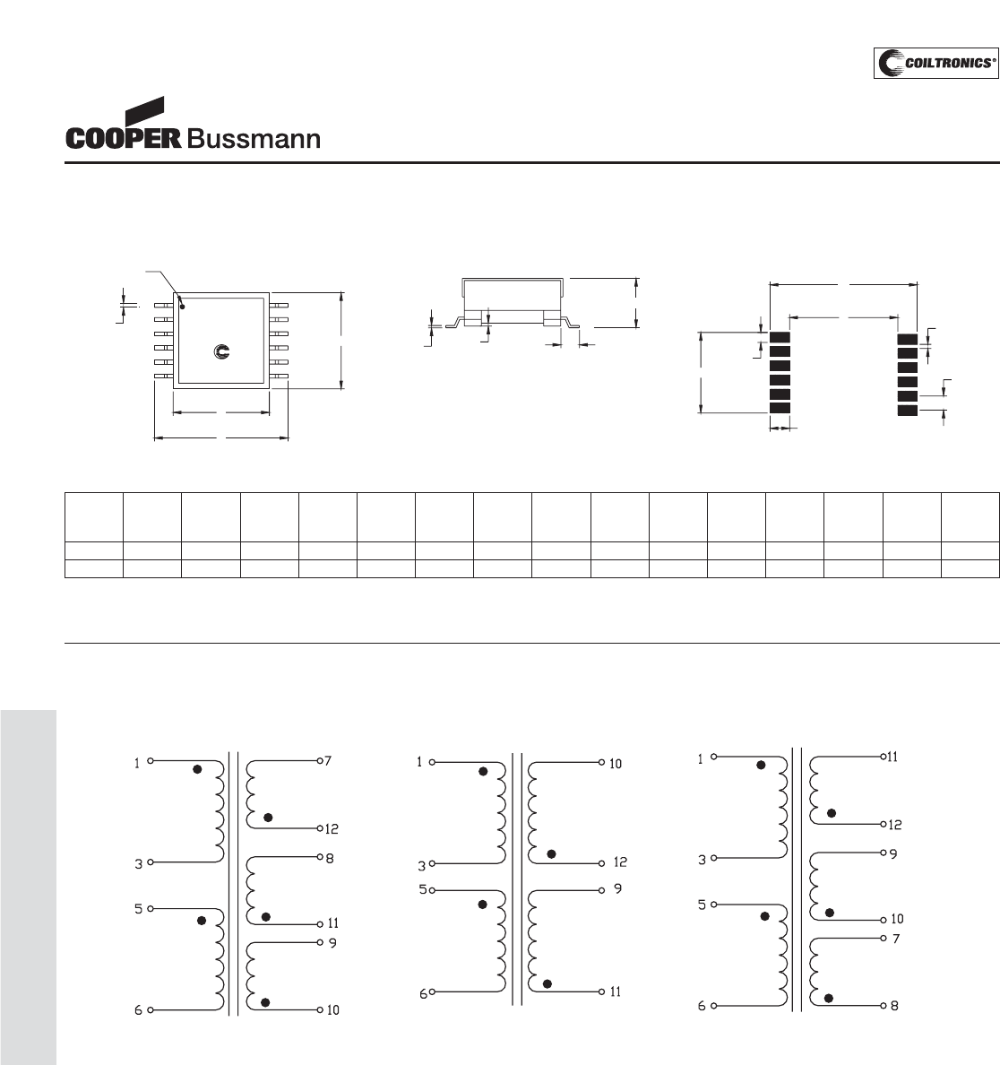
PM-166
TRANSFORMERS (PoE4W, 7W, 13W) FLYBACK
Power Over Ethernet (PoE)/PD
Configurable Transformer
Mechanical Diagrams
DIMENSIONS
E
C
B
TOP VIEW
D
(12 plcs)
6
White Dot Pin #1
1
A
FRONT VIEW
PoE
7
12
O
(10plcs)
N
(10plcs)
J
(12plcs)
I
K
(12plcs)
6
Component Side
7
M
L
1
RECOMMENDED PCB LAYOUT
12
F
(2 plcs)
G
(12 plcs)
H
(12 plcs)
Schematic Diagrams
SCHEMATIC 1 SCHEMATIC 2 SCHEMATIC 3
Primary
Feedback
Output
Output
Output
Primary
Feedback
Output
Output
Output
Primary
Feedback
Output
Output
ABCDEFGH I LM
mm mm mm mm mm mm mm mm mm J K mm mm N O
max. ref. max. ref. max. ref. ref. ref. ref. mm mm ref. max. mm mm
Size 1 17.1 16.0 22.3 0.7 8.4 3.0 0.1 0.4 14.49 1.79 3.43 16.88 23.74 2.54 0.75
Size 2 18.0 18.0 24.6 0.7 10.0 3.3 0.1 0.4 14.25 1.75 3.43 19.14 26.0 2.5 0.75
1) Tolerances A - H are ± 0.25mm unless specified otherwise.
2) Tolerances I - O are ± 0.10mm unless specified otherwise
2) All soldering surfaces are coplaner to within ± 0.102mm.
Courtesy of Steven Engineering, Inc.-230 Ryan Way, South San Francisco, CA 94080-6370-Main Office: (650) 588-9200-Outside Local Area: (800) 258-9200-www.stevenengineering.com
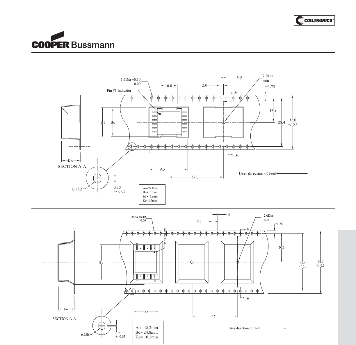
PM-167
TRANSFORMERS (PoE4W, 7W, 13W) FLYBACK
Mechanical Diagrams
Power Over Ethernet (PoE)/PD
Configurable Transformer
PoE 4 and 7 Watt
PoE 13 Watt
Courtesy of Steven Engineering, Inc.-230 Ryan Way, South San Francisco, CA 94080-6370-Main Office: (650) 588-9200-Outside Local Area: (800) 258-9200-www.stevenengineering.com
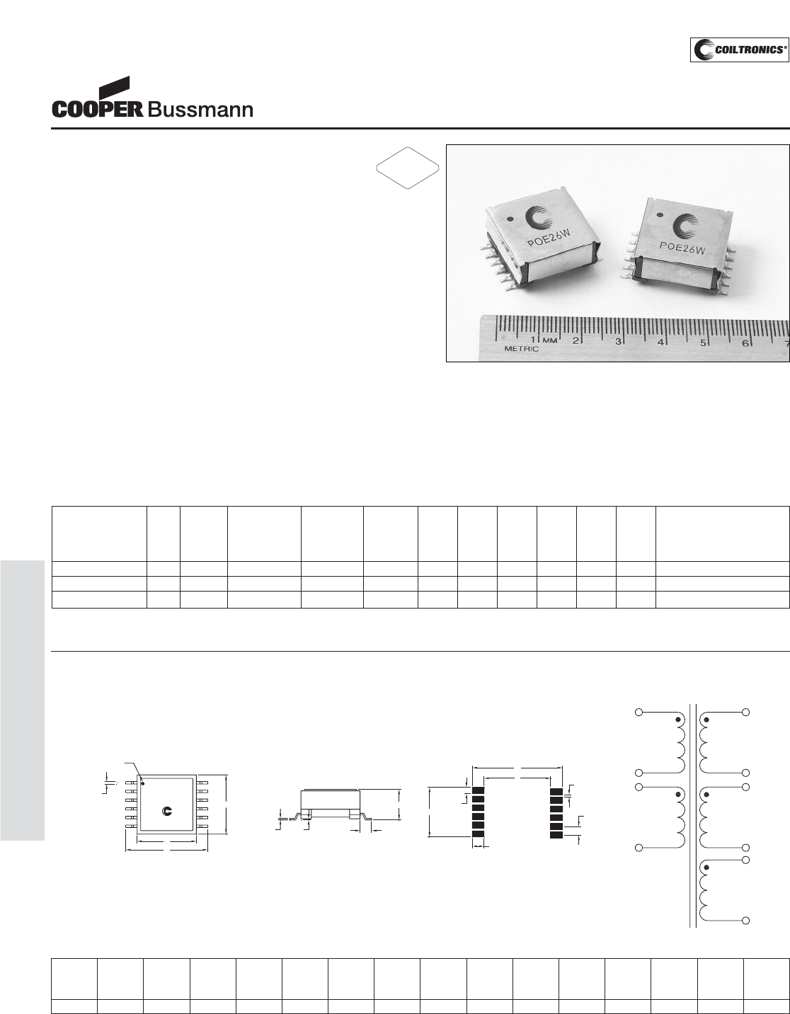
PM-168
TRANSFORMERS (PoE26W) FORWARD
Description
• Versatile design allows multiple output variations
• Forward topology, 300Khz switching frequency
• Input range from 29.5-60V
• 1500VAC isolation between primary and secondary
• Power 26watts
• Low leakage inductance
Applications
• For IEEE 802.3af-compliant Power over Ethernet appli-
cations
• UPS, VoiP Phone, Wireless LAN Access point,
Bluetooth Access point, Network Camera, Building
Access Systems
• Retail Point-of-information systems
• Vending/Gaming Machines
Environmental Data
• Storage temperature range: -40°C to +125°C
• Operating ambient temperature range: -40°C to +85°C
(range is application specific)
• Solder reflow temperature: +260°C max. for
10 seconds maximum
Packaging
• Packaging information: 115 parts per 13" reel
Power Over Ethernet (PoE)/PD
Configurable Transformer
DCR/ DCR/ DCR/ DCR/
Leakage
Pri
Primary Pri Sec Bias Sync Induct. Current Turns ratio pins Pri (2 - 4):
Induct. (ohms) (ohms) (ohms) (ohms) (uh) Pk V1 (12 - 10): V2 (11 - 9):
Part Number Watts (uH) Output Bias Sync max max max max typ. (Adc) Bias (1 - 6): Sync (7 - 8)
PoE26W3.3VS5-R 26 160 (2)x3.3V@4.0A 10.0V@0.1A 5V@0.1A 0.100 0.025 0.90 0.42 1.0 2.6 1:0.29:0.29:0.83:0.42 +/-2%
PoE26W3.3VS10-R 26 160 (2)x3.3V@4.0A 10.0V@0.1A 10V@0.1A 0.100 0.025 0.90 0.90 1.0 2.6 1:0.29:0.29:0.83:0.83 +/-2%
PoE26W5V-R 26 160 (2)x5.0V@2.6A 10.0V@0.1A 5.0V@0.1A 0.100 0.050 0.90 0.42 1.0 2.6 1:0.42:0.42:0.83:0.42 +/-2%
(1) Test parameters: 100kHz, 0.100Vrms, 0.0Adc
(2) DCR limits maximum @ 20°C (3) Leakage Inductance 300kHz, 0.01Vrms, 0.0Adc
Mechanical Diagram
DIMENSIONS
TOP VIEW
FRONT VIEW
RECOMMENDED PCB LAYOUT
PoE
1
76
12
White Dot Pin #1
A
B
D
(12 plcs)
C
H
(12 plcs) G
(12 plcs) F
(2 plcs)
EComponent Side
1
6
12
7
I
J
(12plcs)
K
(12plcs)
N
(10plcs)
O
(10plcs)
L
M
Bias
111
6
8
7
9
4
2
10
12
Primary Output
Output
Sync
SCHEMATIC
ABCDEFGH I LM
mm mm mm mm mm mm mm mm mm J K mm mm N O
max. ref. max. ref. max. ref. ref. ref. ref. mm mm ref. max. mm mm
21.5 22.0 28.5 0.7 10.8 2.95 0.1 0.4 17.25 2.25 3.15 23.2 29.5 3.0 0.75
1) Tolerances A - H are ± 0.25mm unless specified otherwise.
2) Tolerances I - O are ± 0.10mm unless specified otherwise
2) All soldering surfaces are coplaner to within ± 0.102mm.
RoHS
2002/95/EC
Courtesy of Steven Engineering, Inc.-230 Ryan Way, South San Francisco, CA 94080-6370-Main Office: (650) 588-9200-Outside Local Area: (800) 258-9200-www.stevenengineering.com
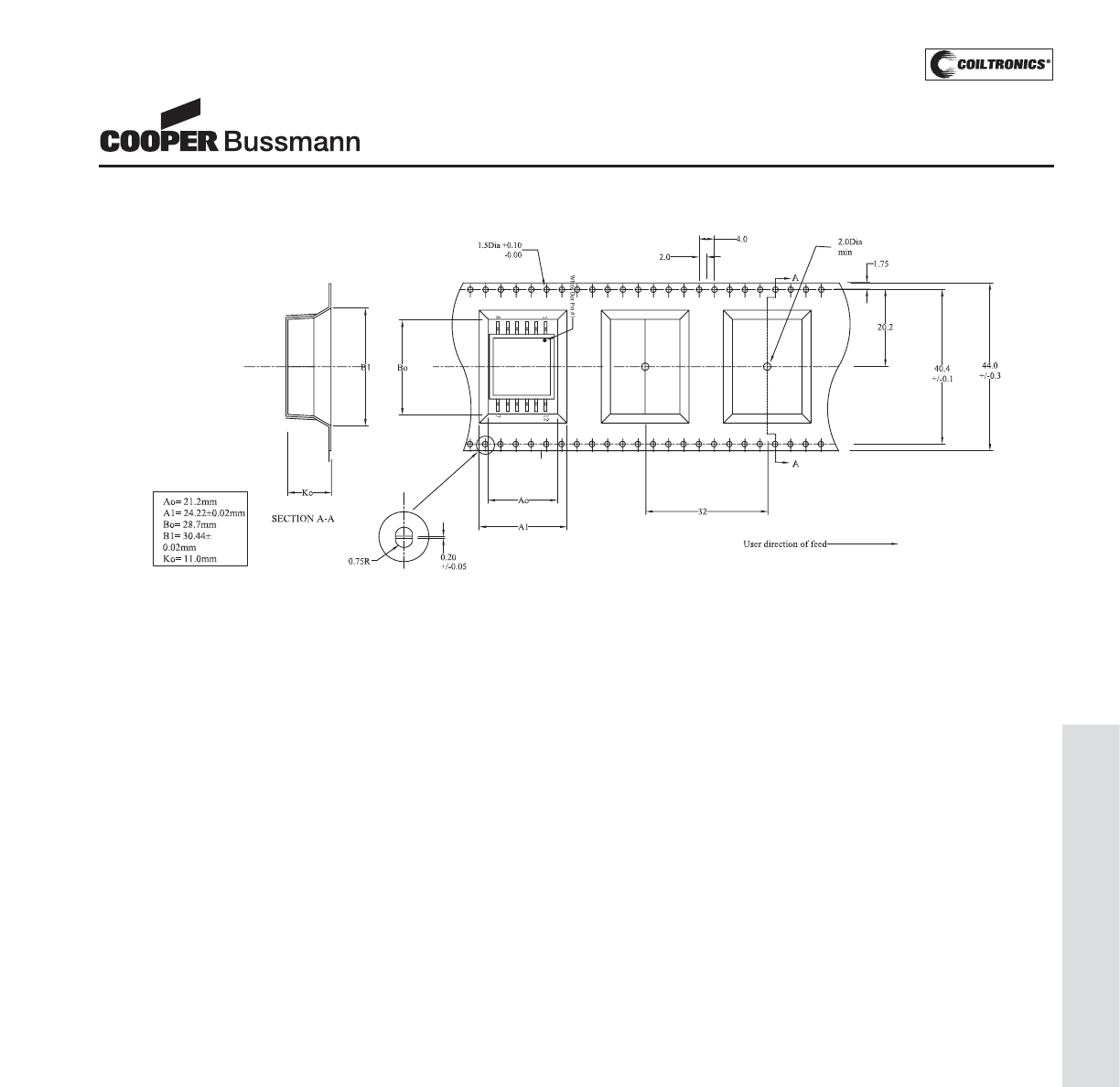
PM-169
TRANSFORMERS (PoE26W) FORWARD
Power Over Ethernet (PoE)/PD
Configurable Transformer
Packaging Information
Courtesy of Steven Engineering, Inc.-230 Ryan Way, South San Francisco, CA 94080-6370-Main Office: (650) 588-9200-Outside Local Area: (800) 258-9200-www.stevenengineering.com

PM-170
TRANSFORMERS (CCFL)
Description
• Transformers for use in CCFL power supplies, avail-
able in through-hole and surface mount
recess or gull wing versions, incorporating
floating or fixed secondary technology
• Supply output current up to 30 milli-Amps
• Frequency range from 40 to 80 KHz
• Deliver output power from 2.5 to 14 Watts
• Operate in royer and other topologies
• Ferrite core material
Applications
• CCFL power supplies
Environmental Data
• Storage temperature range: -40°C to +85°C
• Operating ambient temperature range: 0°C to +70°C
• Solder reflow temperature: +260°C max. for 10 seconds
max.
Packaging
• Supplied in bulk packaging
Part Schematic Pout Lp DCRp DCRs TR Vpri Vsec Is Max Vpri Vsec Mechanical PCB Pad
Number Diagram Watts μH1Ohms Max Ohms Max Ns/Np Volts Max2Volts Max2A rms Abnormal3Abnormal3Dimensions Layout
2.5 WATT VERSIONS
CTX110652-R
A 2.5 43 0.220 285 67 20 1340 .005 30 2000 A A
CTX110655-R
B 2.5 43 0.220 285 67 20 1340 .005 30 2000 A A
CTX110657-R
B 2.5 26 0.212 285 86 15 1340 .005 23 2000 A A
CTX110659-R
B 2.5 19 0.190 285 100 13 1340 .005 23 2000 A A
CTX210652-R
A 2.5 43 0.220 285 67 20 1340 .005 30 2000 B B
CTX210655-R
B 2.5 43 0.220 285 67 20 1340 .005 30 2000 B B
CTX210657-R
B 2.5 26 0.212 285 86 15 1340 .005 23 2000 B B
CTX210659-R
B 2.5 19 0.190 285 100 13 1340 .005 23 2000 B B
4 WATT VERSIONS
CTX210403-R C 4 44 0.220 165 50 26 1340 .007 40 2000 C C
CTX210407-R C 4 27 0.160 220 86 15 1340 .007 23 2000 C C
CTX210409-R C 4 20 0.160 220 100 13 1340 .007 23 2000 C C
CTX210411-R C 4 20 0.160 330 125 10 1340 .007 16 2000 C C
CTX310403-R C 4 44 0.220 165 50 26 1340 .007 40 2000 D D
CTX310407-R C 4 27 0.160 220 86 15 1340 .007 23 2000 D D
CTX310409-R C 4 20 0.160 220 100 13 1340 .007 23 2000 D D
CTX310411-R C 4 20 0.160 330 125 10 1340 .007 16 2000 D D
6 WATT VERSIONS
CTX110600-R D 6 44 0.160 176 67 20 1340 .011 30 2000 E E
CTX110603-R C 6 44 0.160 132 50 26 1340 .011 40 2000 E E
CTX110605-R C 6 44 0.160 176 67 20 1340 .011 30 2000 E E
CTX110607-R C 6 27 0.132 176 86 15 1340 .011 23 2000 E E
CTX110609-R C 6 20 0.132 176 100 13 1340 .011 23 2000 E E
CTX110611-R C 6 20 0.132 291 125 11 1340 .011 16 2000 E E
CTX210600-R D 6 44 0.160 176 67 20 1340 .011 30 2000 F C
CTX210603-R C 6 44 0.160 132 50 26 1340 .011 40 2000 F C
CTX210605-R C 6 44 0.160 176 67 20 1340 .011 30 2000 F C
CTX210607-R C 6 27 0.132 176 86 15 1340 .011 23 2000 F C
CTX210609-R C 6 20 0.132 176 100 13 1340 .011 23 2000 F C
CTX210611-R C 6 20 0.132 291 125 11 1340 .011 16 2000 F C
14 Watt Versions
CTX410805-R E 14 24 0.030 262 67 20 1340 .030 30 2000 G F
CTX410807-R E 14 16 0.024 272 86 15 1340 .030 23 2000 G F
CTX410809-R E 14 16 0.024 314 100 13 1340 .030 23 2000 G F
1
Inductances are nominal values
2
Continuous RMS Voltage
3
Maximum Instantaneous RMS Voltage
CCFL TRANSFORMERS
Cold Cathode Fluorescent
Lamp Inverter Transformers
RoHS
2002/95/EC
Courtesy of Steven Engineering, Inc.-230 Ryan Way, South San Francisco, CA 94080-6370-Main Office: (650) 588-9200-Outside Local Area: (800) 258-9200-www.stevenengineering.com
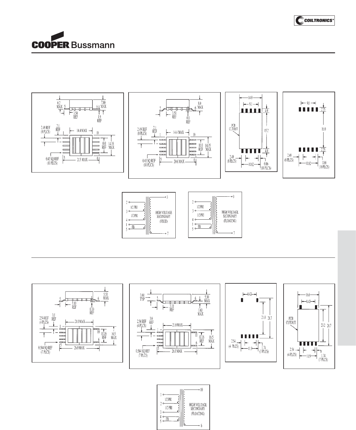
PM-171
TRANSFORMERS (CCFL)
Mechanical Diagrams
2.5 Watt Versions
4 Watt Versions
Schematic A
Pad Layout A
Mechanical A Mechanical B
Schematic B
Dimensions are in millimeters
Dimensions are in millimeters
TOP VIEW
TOP VIEW
Pad Layout B
Schematic C
Pad Layout C Pad Layout DMechanical C Mechanical D
TOP VIEW
TOP VIEW
CCFL TRANSFORMERS
Cold Cathode Fluorescent
Lamp Inverter Transformers
Courtesy of Steven Engineering, Inc.-230 Ryan Way, South San Francisco, CA 94080-6370-Main Office: (650) 588-9200-Outside Local Area: (800) 258-9200-www.stevenengineering.com
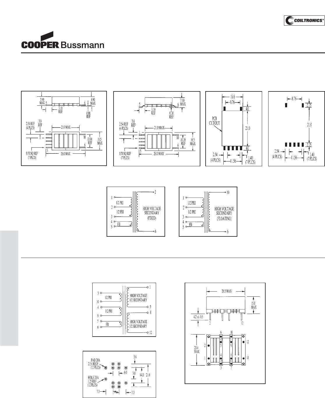
PM-172
TRANSFORMERS (CCFL)
Mechanical DiagramsMechanical Diagrams
6 Watt Versions
14 Watt Versions
Dimensions are in millimeters
Dimensions are in millimeters
Schematic D
Pad Layout E
Schematic C
Pad Layout CMechanical E Mechanical F
TOP VIEW TOP VIEW
Schematic E
Pad Layout F
Mechanical G
BOTTOM VIEW
CCFL TRANSFORMERS
Cold Cathode Fluorescent
Lamp Inverter Transformers
Courtesy of Steven Engineering, Inc.-230 Ryan Way, South San Francisco, CA 94080-6370-Main Office: (650) 588-9200-Outside Local Area: (800) 258-9200-www.stevenengineering.com
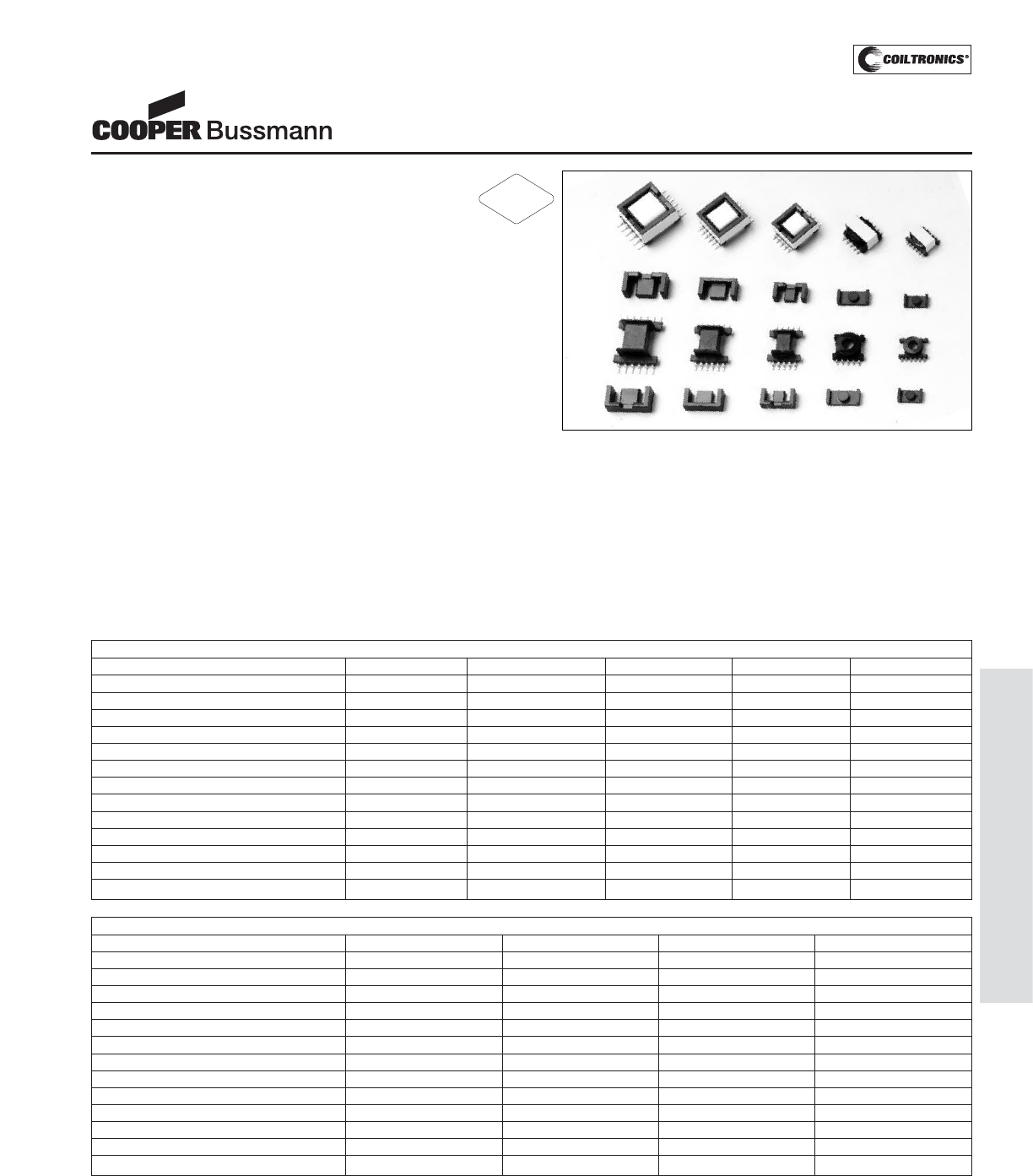
PM-173
TRANSFORMERS (SG) STANDARD GEOMETRIES
Description
• Low cost magnetic components for custom
specifications
• Power range from 1 Watt to 120 Watts
• Frequency range from 20kHz to .5MHz
• High power density and low radiated noise
• Meets UL 94V-0 flammability standard
• Ferrite core material
Applications
• Inductors: buck, boost, coupled, choke, filter, resonant,
noise filtering, differential, forward, common mode
• Transformers: flyback, feed forward, push-pull, multiple
output, inverter, step-up, step-down, gate drive, base
drive, wide band, pulse, control, impedance, isolation,
bridging, ringer, converter, auto
Environmental Data
• Storage temperature range: -55°C to +125°C
• Operating ambient temperature range: -40°C to +85°C
(range is application specific). The internal “hot spot”
temperature defines the maximum allowable currents,
which are limited to 130°C, including ambient
• Solder reflow temperature: +260°C max. for 10 seconds
max.
Packaging
• Supplied in tape and reel packaging (SG01, SG02,
SG03, SG06 and SG07)
• Supplied in bulk packaging (SG04, SG05, SG08
and SG09)
• Consult the factory for SG04 and SG05 tape and reel
packaging
STANDARD GEOMETRIES
Low Cost Magnetic Components
* Fill Factor considered
STANDARD GEOMETRIES SIZES 1 TO 5 CORE AND BOBBIN PARAMETERS
Specifications SG1 SG2 SG3 SG4 SG5
Core ER 11/5 ER 14.5/6 EFD 15 EFD 17 EFD 20
AL-1, nH/T21400 1600 780 1028 1200
AL-2, nH/T2190 216 138 140 155
AL-3, nH/T2102 116 84 75 83
AL-4, nH/T276 83 55 60 67
AL-5, nH/T259 66 47 47 53
Ae, min. core area, cm20.0900 0.1520 0.1220 0.1960 0.3100
Ie, mag. path lgth., cm 1.46 1.90 3.40 4.12 4.70
Ve, core volume, cm30.170 0.330 0.510 0.940 1.460
MLT, ave. turn length, cm 2.1666 2.7051 2.6805 3.2202 3.8359
Wa, usable wdg. area, cm2* 0.0171 0.0302 0.0915 0.1051 0.1441
WaAc, cm40.0015 0.0046 0.0112 0.0206 0.0447
UL flammability rating 94V-0 94V-0 94V-0 94V-0 94V-0
STANDARD GEOMETRIES SIZES 6 TO 9 CORE AND BOBBIN PARAMETERS
Specifications SG6 SG7 SG8 SG9
Core EE8.3 EF12.6 EE13 SEE16
AL-1, nH/T
2
675 1075 1100 1254
AL-2, nH/T
2
96 95 128 153
AL-3, nH/T
2
—— —— —— ——
AL-4, nH/T
2
58 57 77 92
AL-5, nH/T
2
—— —— —— ——
Ae, min. core area, cm
2
0.0600 0.1003 0.1380 0.1848
le, mag. path lgth., cm 1.92 2.96 3.06 3.55
Ve, core volume, cm
3
0.1564 0.3860 0.5479 0.8552
MLT, ave. turn length, cm 2.0880 2.5480 3.2300 3.7780
Wa, usable wdg. area, cm
2
* 0.0317 0.0769 0.1114 0.1849
WaAc, cm
4
0.00190 0.00772 0.01540 0.03416
UL flammability rating 94V-0 94V-0 94V-0 94V-0
RoHS
2002/95/EC
Courtesy of Steven Engineering, Inc.-230 Ryan Way, South San Francisco, CA 94080-6370-Main Office: (650) 588-9200-Outside Local Area: (800) 258-9200-www.stevenengineering.com
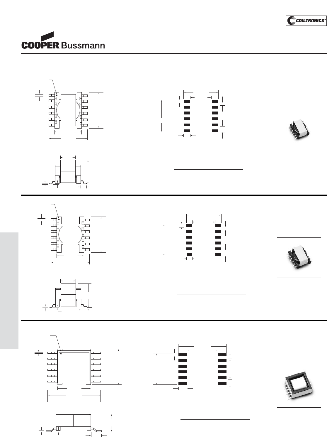
PM-174
TRANSFORMERS (SG) STANDARD GEOMETRIES
Mechanical Diagrams
SG SIZE 1
ER 11/5
.10 REF
.25 REF
6.2
MAX
FRONT VIEW
1.5 REF
5.9 REF
WHITE DOT PIN#1
6
.7 REF
1
12.9
13.0 MAX
MAX
7
TOP VIEW
12
9.2 REF
(12PLCS)
2.25
14.2 MAX
2.0 (10PLCS)
1.5
(12 PLCS)
9.7 REF
.5 (10 PLCS)
11.5 REF
SG SIZE 2
ER 14.5/6
.10 REF
.30 REF
FRONT VIEW
7.4
MAX
2.0 REF
6.7 REF
WHITE DOT PIN#1
6
.7 REF
1
16.3
16.8 MAX
MAX
7
TOP VIEW
12
12.0 REF
(12 PLCS)
2.5
18.0 MAX
2.5 (10 PLCS)
1.75
(12 PLCS)
13.0 REF
.75 (10 PLCS)
14.25 REF
SG SIZE 3
EFD 15
.10 REF
.40 REF
8.4
MAX
FRONT VIEW
3.0 REF
22.3 MAX
TOP VIEW
6
1
7
17.1
MAX
12
.7 REF
16.0 REF
WHITE DOT PIN #1
1.79
(12 PLCS)
3.43
(12 PLCS)
23.74 MAX
2.54 (10 PLCS)
RECOMMENDED PCB PAD PATTERN
COMPONENT VIEW
.75 (10 PLCS)
16.88 REF
14.49 REF
RECOMMENDED PCB PAD PATTERN
COMPONENT VIEW
RECOMMENDED PCB PAD PATTERN
COMPONENT VIEW
PACKAGING INFORMATION
Parts packaged on 13" reels,
600 parts per reel.
Bulk packaging also available.
PACKAGING INFORMATION
Parts packaged on 13" reels,
200 parts per reel.
Bulk packaging also available.
PACKAGING INFORMATION
Parts packaged on 13" reels,
300 parts per reel.
Bulk packaging also available.
STANDARD GEOMETRIES
Low Cost Magnetic Components
Courtesy of Steven Engineering, Inc.-230 Ryan Way, South San Francisco, CA 94080-6370-Main Office: (650) 588-9200-Outside Local Area: (800) 258-9200-www.stevenengineering.com
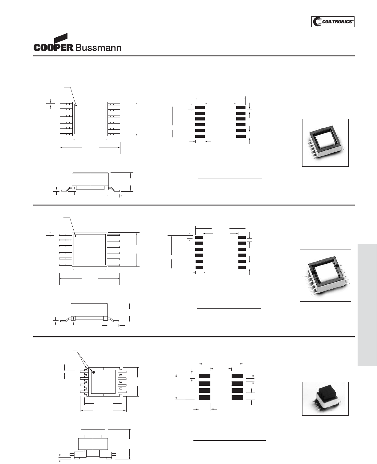
PM-175
TRANSFORMERS (SG) STANDARD GEOMETRIES
SG SIZE 4
EFD 17
PACKAGING INFORMATION
Parts packaged in pick and
place compatible bulk trays,
9.8" x 6.7", 5 rows by 7
columns, 35 parts per tray.
1.75
(12 PLCS)
14.25 REF
3.43
(12 PLCS)
26.0 MAX
2.5 (10 PLCS)
RECOMMENDED PCB PAD PATTERN
COMPONENT VIEW
19.14 REF
.75 (10 PLCS)
PACKAGING INFORMATION
Parts packaged in pick and
place compatible bulk trays,
9.8" x 6.7", 6 rows by 7
columns, 42 parts per tray. Consult factory for
tape and reel packaging.
Consult factory for
tape and reel packaging.
6
1
7
12
.10 REF
.40 REF
10.0
MAX
FRONT VIEW
TOP VIEW
18.0
MAX
.7 REF
24.6 MAX
3.3 REF
18.0 REF
WHITE DOT PIN #1
SG SIZE 5
EFD 20
.10 REF
.40 REF
10.8
MAX
FRONT VIEW
2.95 REF
6
1
7
12
TOP VIEW
WHITE DOT PIN #1
21.0
MAX
.7 REF
28.5 MAX
21.0 REF
2.25
(12 PLCS)
3.15
(12 PLCS)
29.00 MAX
3.0 (10 PLCS)
RECOMMENDED PCB PAD PATTERN
COMPONENT VIEW
22.70 REF
17.25 REF
.75 (10 PLCS)
SG SIZE 6
EE 8.3
TOP VIEW
1
45
8
PIN #1 INDICATORS
10.7 REF
13.8 MAX
9.2
MAX
0.4 REF
FRONT VIEW
0.4 REF
9.6
MAX
RECOMMENDED PCB LAYOUT
COMPONENT VIEW
12.7 MAX
5.8 REF
3.3
(8 PLCS)
7.0 REF
(8 PLCS)
1.0
2.0 (6 PLCS)
1.0 (6 PLCS)
PACKAGING INFORMATION
Parts packaged on 13" reels,
400 parts per reel.
Bulk packaging also available.
STANDARD GEOMETRIES
Low Cost Magnetic Components
Courtesy of Steven Engineering, Inc.-230 Ryan Way, South San Francisco, CA 94080-6370-Main Office: (650) 588-9200-Outside Local Area: (800) 258-9200-www.stevenengineering.com
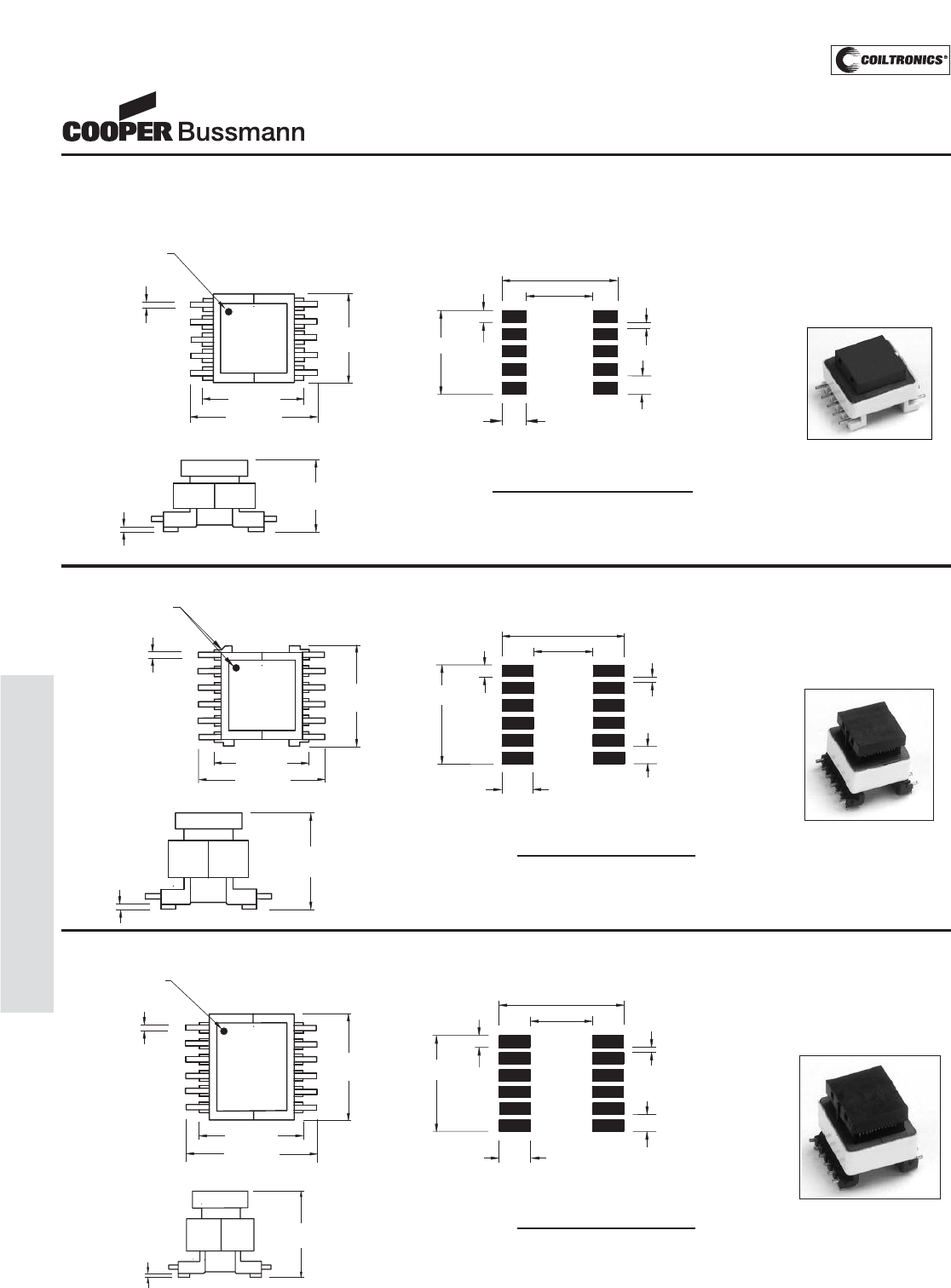
PM-176
TRANSFORMERS (SG) STANDARD GEOMETRIES
RECOMMENDED PCB LAYOUT
COMPONENT VIEW
16.4 MAX
9.4 REF
3.36
(10 PLCS)
(10 PLCS)
11.36 REF 1.2
2.54 (8 PLCS)
1.34 (8 PLCS)
14.4 REF
1
56
10
PIN #1 INDICATOR
18.0 MAX
14.1
MAX
0.4 REF
TOP VIEW
FRONT VIEW
0.4 REF
10.6
MAX
SG SIZE 7
EF 12.6
PACKAGING INFORMATION
Parts packaged on 13" reels,
250 parts per reel.
Bulk packaging also available.
SG SIZE 8
EE 13
PACKAGING INFORMATION
Parts packaged in pick and
place compatible bulk trays,
5 rows by 10 columns.
Total parts per tray = 50.
PACKAGING INFORMATION
Parts packaged in pick and
place compatible bulk trays,
6 rows by 10 columns.
Total parts per tray = 60.
6
12
PIN #1 INDICATORS
17.8 MAX
15.8
MAX
1
0.5 REF
TOP VIEW
7
14.2 REF
RECOMMENDED PCB LAYOUT
COMPONENT VIEW
16.3 MAX
3.60
(12 PLCS)
(12 PLCS)
13.9 REF 1.2
8.8 REF
2.54 (10 PLCS)
1.34 (10 PLCS)
SG SIZE 9
SEE 16
FRONT VIEW
15.0
MAX
0.5 REF
16.8 REF
7
12
PIN #1 INDICATOR
21.0 MAX
17.0
MAX
0.5 REF
6
1
TOP VIEW RECOMMENDED PCB LAYOUT
COMPONENT VIEW
19.2 MAX
9.5 REF
4.7
(12 PLCS)
(12 PLCS)
13.9 REF 1.2
2.54 (10 PLCS)
1.34 (10 PLCS)
FRONT VIEW
0.5 REF
17.4
MAX
STANDARD GEOMETRIES
Low Cost Magnetic Components
Courtesy of Steven Engineering, Inc.-230 Ryan Way, South San Francisco, CA 94080-6370-Main Office: (650) 588-9200-Outside Local Area: (800) 258-9200-www.stevenengineering.com
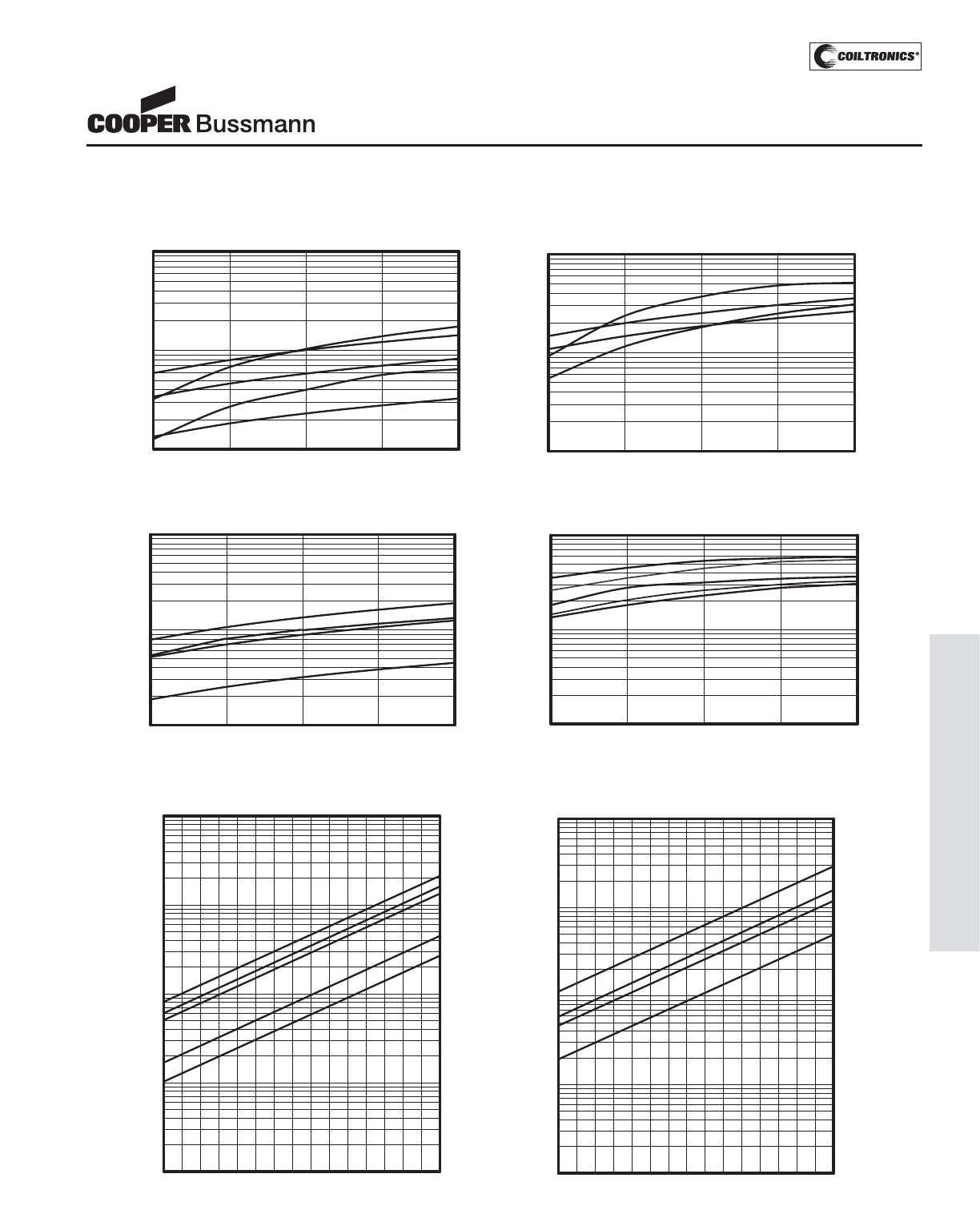
PM-177
TRANSFORMERS (SG) STANDARD GEOMETRIES
Performance Specifications
28
1
100
1000
10000
10
29 30 32 33 34 36 37 39 40 4131 35 38 4227
Size 02
Size 03
Size 04
Size 05
Size 01
Size06
28
1
100
1000
10000
10
29 30 32 33 34 36 37 39 40 4131 35 38 4227
Size07
Size08
Size09
Size01
1.0
10.0
100.0
Watts
100 200 300 400
500
Frequency kHz
Size06
Size02
Size03
1.0
10.0
100.0
Watts
100 200 300 400
500
Size07
Size09
Size05
Size08
Size04
100
Size02
Size07
Size06
Frequency,kHz
1.0
10.0
100.0
Watts
200 300 400
500
Size03
Size01
Frequency,kHz
1.0
10.0
100.0
Watts
100 300 400 500
Size04
200
Size09
Size05
Size08
Frequency, kHz
Frequency, kHz
Frequency, kHz Frequency, kHz
American Wire Gauge American Wire Gauge
Maximum Turns
Maximum Turns
Watts
Watts
Watts
Watts
Unipolar
(Flyback)
Power vs Frequency
Unipolar (Flyback)
Power vs Frequency
Bipolar
(Push-Pull)
Power vs Frequency
Bipolar (Push-Pull)
Power vs Frequency
Maximum Turns
vs American Wire Gauge
Maximum Turns
vs American Wire Gauge
STANDARD GEOMETRIES
Low Cost Magnetic Components
Courtesy of Steven Engineering, Inc.-230 Ryan Way, South San Francisco, CA 94080-6370-Main Office: (650) 588-9200-Outside Local Area: (800) 258-9200-www.stevenengineering.com
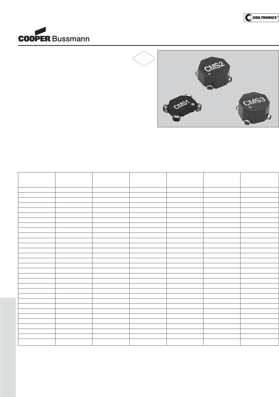
PM-178
COMMON-MODE (CMS)
Description
• 160°C maximum total temperature
• Three sizes of surface mount torroidal common
mode inductors that provide 300Vdc isolation
• Inductance range from 5.5uH to 1600uH
• Current range up to 7.0 Amps
• Noise attenuation up to 44 dB
• Frequency range up to 100 MHz
• Meets UL94V-0 flammability standard
• Ferrite core material
Applications
• EMI filters
• DC-DC brick power supplies
• Discrete output supplies
• Discrete and point-of-use power supplies (PUPS)
Environmental Data
• Storage temperature range: -40°C to +160°C
• Operating ambient temperature range: -40°C to +160°C
(range is application specific)
• Solder reflow temperature: +260°C max for 10 seconds
max.
Packaging
• Supplied in tape and reel packaging, 2,000 (CMS1),
800 (CMS2), and 600 (CMS3) per reel
Part Number OCL I rms. DCR (Ω) typ DCR (Ω) typ Leakage Interwinding
(uH) minimum Amperes @ 20°C @ 20°C Inductance (uH) Capacitance (pF)
(1-2) & (3-4) Max * (1-2) (4-3) typ typ
CMS1-1-R 4.5 7.00 0.0027 0.0027 0.05 2.0
CMS1-2-R 8 5.70 0.0040 0.0040 0.09 2.1
CMS1-3-R 12.6 4.10 0.0077 0.0077 0.14 2.2
CMS1-4-R 18 3.80 0.0089 0.0089 0.20 2.3
CMS1-5-R 25 3.60 0.0100 0.0100 0.28 2.4
CMS1-6-R 32.8 3.10 0.0138 0.0138 0.36 2.5
CMS1-7-R 41.5 2.60 0.019 0.019 0.45 2.6
CMS1-8-R 51.2 2.20 0.026 0.026 0.056 2.7
CMS1-9-R 62 1.90 0.035 0.035 0.68 2.7
CMS1-10-R 73.7 1.65 0.048 0.048 0.81 2.8
CMS1-11-R 100 1.35 0.070 0.070 1.10 2.9
CMS1-12-R 131 1.15 0.100 0.100 1.45 3.0
CMS1-13-R 166 1.00 0.138 0.138 1.83 3.1
CMS1-14-R 205 0.85 0.186 0.186 2.25 3.2
CMS2-1-R 25 5.35 0.005 0.005 0.22 2.0
CMS2-2-R 40 4.40 0.008 0.008 0.34 2.3
CMS2-3-R 57 3.60 0.012 0.012 0.47 2.5
CMS2-4-R 102 2.80 0.019 0.019 0.80 2.8
CMS2-5-R 160 2.30 0.029 0.029 1.25 3.1
CMS2-6-R 230 1.85 0.044 0.044 1.75 3.4
CMS2-7-R 270 1.60 0.060 0.060 2.00 3.6
CMS2-8-R 360 1.35 0.084 0.084 2.60 3.9
CMS2-9-R 460 1.10 0.120 0.120 3.30 4.1
CMS2-10-R 575 0.94 0.170 0.170 4.00 4.3
CMS2-11-R 700 0.80 0.230 0.230 5.00 4.6
CMS2-12-R 915 0.67 0.330 0.330 6.30 4.9
CMS2-13-R 1070 0.58 0.440 0.440 7.30 5.1
CMS2-14-R 1340 0.50 0.620 0.620 9.00 5.4
CMS3-1-R 28 5.70 0.005 0.005 0.31 2.80
CMS3-2-R 45 5.10 0.006 0.006 0.46 3.05
CMS3-3-R 64 4.75 0.007 0.007 0.64 3.30
Definitions:
OCL = Open Circuit Inductance
DCR = Direct Current Resistance
Irms = rms current for approx. a 40°C temperature rise at an ambient temperature of 85°C.
*Operating Temperature: 160°C Max. Inductance values are sustained up to 160°C.
Electrical Characteristics:
OCL (1-2) 0.10Vrms, 100kHz, 0.0Adc: (See Chart)
OCL (4-3) 0.10Vrms, 100kHz, 0.0Adc: (See Chart)
DCR (1-2) typ @ 20°C: (See Chart)
DCR (4-3) typ @ 20°C: (See Chart)
Hipot rating: winding to winding: 300Vdc min. for 1 second.
Turns Ratio: (1-2):(4-3) 1:1
CMS-SERIES
Common Mode Inductors
(Surface Mount)
RoHS
2002/95/EC
Courtesy of Steven Engineering, Inc.-230 Ryan Way, South San Francisco, CA 94080-6370-Main Office: (650) 588-9200-Outside Local Area: (800) 258-9200-www.stevenengineering.com
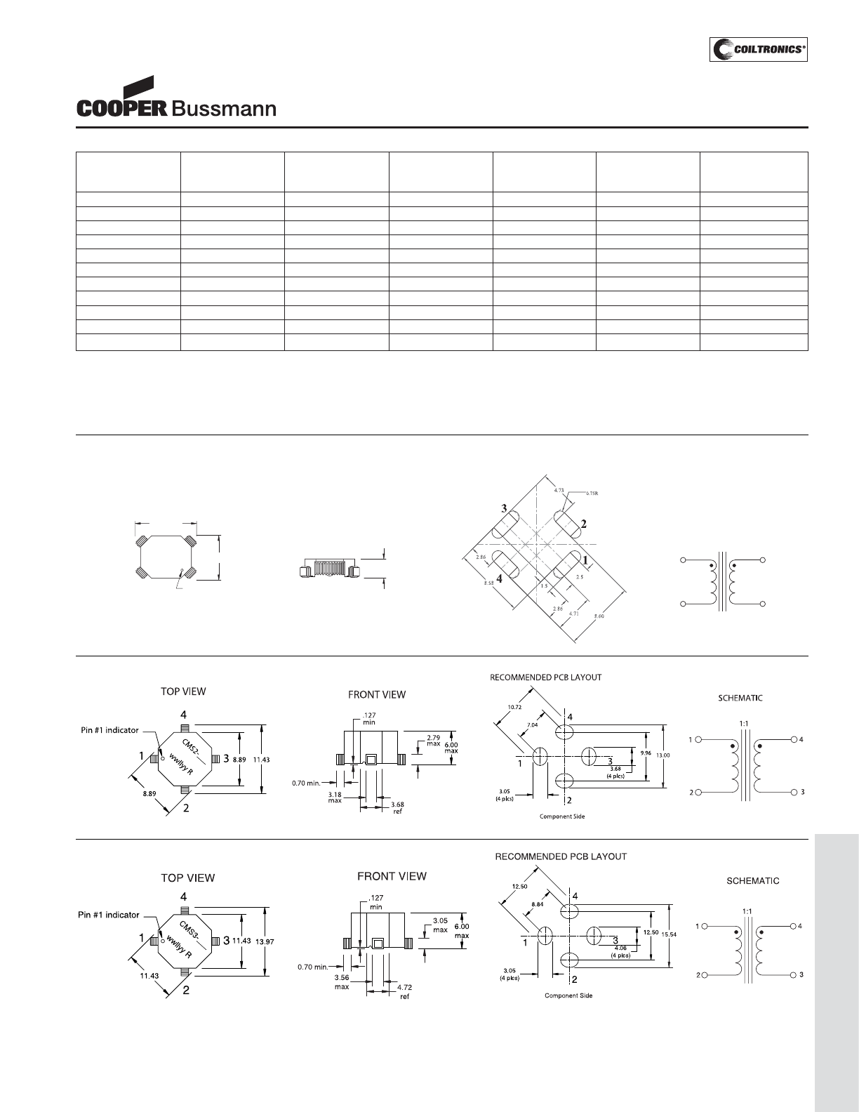
PM-179
COMMON-MODE (CMS)
Mechanical Diagrams
CMS1 Series
Part Number OCL I rms. DCR (Ω) typ DCR (Ω) typ Leakage Interwinding
(uH) minimum Amperes @ 20°C @ 20°C Inductance (uH) Capacitance (pF)
(1-2) & (3-4) Max * (1-2) (4-3) typ typ
CMS3-4-R 88 3.95 0.010 0.010 0.85 3.50
CMS3-5-R 146 3.10 0.017 0.017 1.30 3.70
CMS3-6-R 217 2.85 0.020 0.020 1.90 3.90
CMS3-7-R 258 2.45 0.027 0.027 2.20 4.15
CMS3-8-R 350 2.00 0.040 0.040 3.00 4.40
CMS3-9-R 400 1.70 0.053 0.053 3.30 4.65
CMS3-10-R 518 1.45 0.076 0.076 4.20 4.85
CMS3-11-R 648 1.20 0.107 0.107 5.10 5.10
CMS3-12-R 790 1.05 0.145 0.145 6.10 5.35
CMS3-13-R 1030 0.88 0.210 0.210 7.80 5.55
CMS3-14-R 1310 0.75 0.300 0.300 9.60 5.80
Definitions:
OCL = Open Circuit Inductance
DCR = Direct Current Resistance
Irms = rms current for approx. a 40°C temperature rise at an ambient temperature of 85°C.
*Operating Temperature: 160°C Max. Inductance values are sustained up to 160°C.
Electrical Characteristics:
OCL (1-2) 0.10Vrms, 100kHz, 0.0Adc: (See Chart)
OCL (4-3) 0.10Vrms, 100kHz, 0.0Adc: (See Chart)
DCR (1-2) typ @ 20°C: (See Chart)
DCR (4-3) typ @ 20°C: (See Chart)
Hipot rating: winding to winding: 300Vdc min. for 1 second.
Turns Ratio: (1-2):(4-3) 1:1
3
3
3
33
4
4
4
44
2
2
2
22
1
1
1
11
TOP VIEW
9.4 max
7.2 max
Pin 1 indicator
White dot
wwllyy R
CMS1-
FRONT VIEW
2.6 max
RECOMMENDED PCB LAYOUT
SCHEMATIC
4
1
3
1:1
2
CMS2 Series
CMS3 Series
CMS-SERIES
Common Mode Inductors
(Surface Mount)
wwllyy = Date code R = Revision level
Courtesy of Steven Engineering, Inc.-230 Ryan Way, South San Francisco, CA 94080-6370-Main Office: (650) 588-9200-Outside Local Area: (800) 258-9200-www.stevenengineering.com
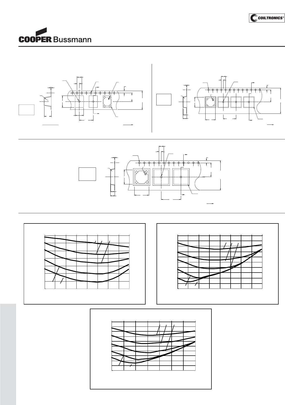
PM-180
COMMON-MODE (CMS)
Attenuation Curves
Packaging Information
CMS1 Series
Direction of feed
.30
+/-0.05
0.3Rad
max.
Ko
SECTION A-A
1.5 Dia
min.
Bo
Ao
12.0
4.0
See note 1
2.0
See note 6
1.5 Dia.
+0.1/-0.0
A
A
1.75
7.5
See note 6 16.0
+/-0.3
0.5Rad
typ.
Pin #1 indicator
Ao= 7.3mm
Bo= 10.1mm
Ko= 2.7mm
CMS2 Series
Ko=6.4mm
Bo=9.3mm
Ao=9.3mm
A
A
SECTION A-A
max.
0.3Rad
0.30
+/-0.05
K
Pin #1 Indicator
B
A
1.5 dia
+0.1/-0.0
1.5 dia
min
4.0
(see note 1)
2.0
(see note 6)
12.0 0.5 rad
typ
1.75
11.5
(see note 6)
24.0
+/-0.3
User direction of feed
6.7
Ko=6.8mm
Bo=11.8mm
Ao=11.8mm
A
A
SECTION A-A
max.
0.3Rad
0.35
+/-0.05
K
Pin #1 Indicator
B
A
1.5 dia
+0.1/-0.0
1.5 dia
min
4.0
(see note 1)
2.0
(see note 6)
16.0
0.5 rad
typ
1.75
11.5
(see note 6)
24.0
+/-0.3
User direction of feed
7.1
CMS3 Series
Attenuation CMS 3 Series
-50
-45
-40
-35
-30
-25
-20
-15
-10
-5
0
12468102040
FREQUENCY (MHz)
-1 -4 -7
-11 -14
dB
Attenuation CMS 2 Series
-50
-45
-40
-35
-30
-25
-20
-15
-10
-5
0
12 46 810204060
FREQUENCY (MHz)
-1 -4 -7
-11 -14
dB
Attenuation CMS 1 Series
-35
-30
-25
-20
-15
-10
-5
0
12 46 810204060
FREQUENCY (MHz)
-1 -4 -7
-11 -14
dB
CMS-SERIES
Common Mode Inductors
(Surface Mount)
Courtesy of Steven Engineering, Inc.-230 Ryan Way, South San Francisco, CA 94080-6370-Main Office: (650) 588-9200-Outside Local Area: (800) 258-9200-www.stevenengineering.com
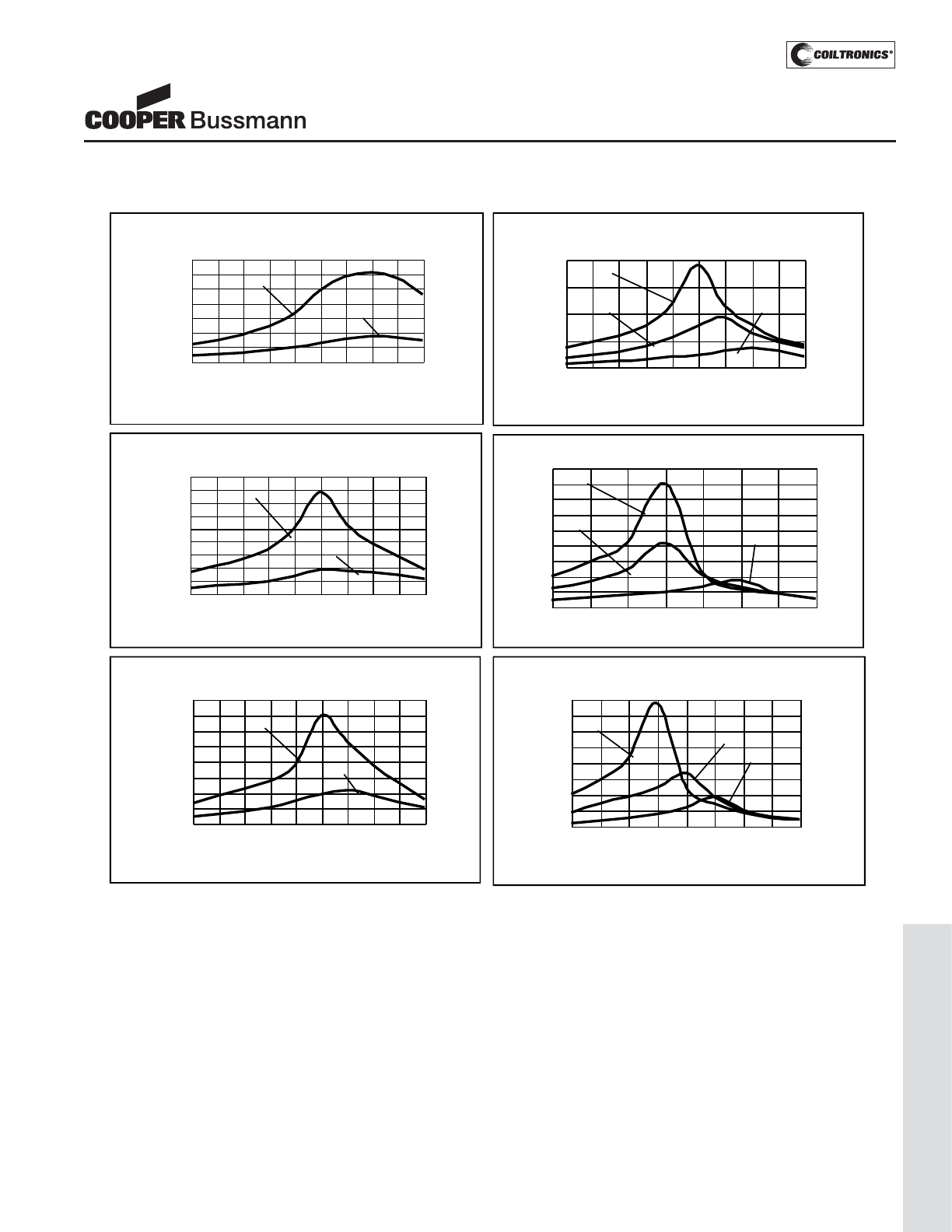
PM-181
COMMON-MODE (CMS)
Impedance Curves
Im
p
edance CMS1-1 & 4
0
50
100
150
200
250
300
350
0.4 0.6 0.8 1 2 3 4 6 8 10
FREQUENCY (MHz)
-4
-1
Impedance CMS1 - 7,11, & 14
0
1000
2000
3000
4000
0.40.60.81234 6810
FREQUENCY (MHz)
-11
-14
-7
Impedance CMS2 - 7,11, & 14
0
2000
4000
6000
8000
10000
12000
14000
16000
18000
0.4 0.6 0.8 1 2 3 4 6
FREQUENCY (MHz)
-11
-14
-7
Impedance CMS3 - 1 & 4
0
200
400
600
800
1000
1200
1400
1600
0.4 0.6 0.8 1 2 3 4 6 8
FREQUENCY (MHz)
-4
-1
Impedance CMS3 - 7,11, & 14
0
2000
4000
6000
8000
10000
12000
14000
16000
0.4 0.6 0.8 1 2 3 4 6 8
FREQUENCY (MHz)
-11
-14
-7
Impedance CMS2 - 1 & 4
0
200
400
600
800
1000
1200
1400
1600
1800
0.4 0.6 0.8 1 2 4 6 8 10 20
FREQUENCY (MHz)
-4
-1
Z (Ohms)
Z (Ohms)
Z (Ohms)
Z (Ohms)
Z (Ohms)
Z (Ohms)
CMS-SERIES
Common Mode Inductors
(Surface Mount)
Courtesy of Steven Engineering, Inc.-230 Ryan Way, South San Francisco, CA 94080-6370-Main Office: (650) 588-9200-Outside Local Area: (800) 258-9200-www.stevenengineering.com
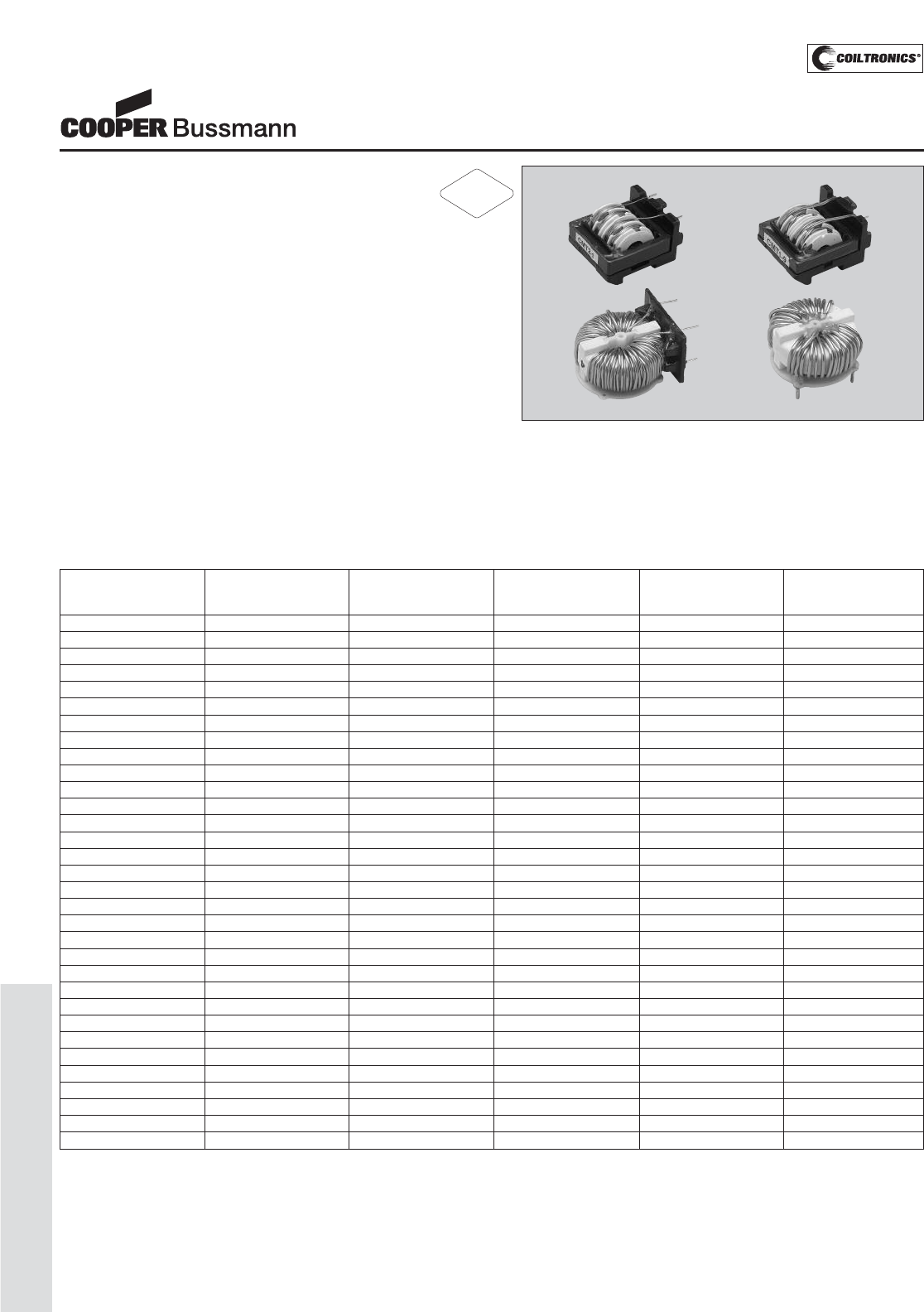
PM-182
COMMON-MODE (CMT)
Description
• Four sizes of through-hole off-line
common mode inductors
• Inductance range from 0.53 - 66 mH
• Current range up to 6.5 Amps
• Noise attenuation up to 68 dB
• Frequency range up to 6 MHz
• Meets UL94V-0 flammability standard
• Ferrite core material
Applications
• Protects AC input from effects of switching regulators
• Off-line power supplies
• EMI filters
• DC-DC converters
• Computer, TV, VCR, audio and office equipment
Environmental Data
• Storage temperature range: -40°C to +125°C
• Operating ambient temperature range: -40°C to +85°C
range is application specific. The internal “hot-spot”
temperature defines the maximum allowable currents,
which are limited to 130°C, including ambient.
Packaging
• Supplied in bulk packaging
Part Number OCL OCL I rms. DCR (Ω) typ DCR (Ω) typ
(mH) min (mH) min Amperes @ 20°C @ 20°C
(1-2) (4-3) max (1-2) (4-3)
CMT1-1-R 66.0 66.0 0.74 1.20 1.20
CMT1-2-R 49.0 49.0 0.88 0.85 0.85
CMT1-3-R 28.0 28.0 1.13 0.50 0.50
CMT1-4-R 21 21 1.37 0.35 0.35
CMT1-5-R 13 13 1.76 0.20 0.20
CMT1-6-R 7.50 7.50 2.27 0.13 0.13
CMT1-7-R 4.20 4.20 2.89 0.08 0.08
CMT1-8-R 2.40 2.40 3.85 0.045 0.045
CMT1-9-R 1.85 1.85 4.53 0.033 0.033
CMT1-10-R 0.94 0.94 6.05 0.018 0.018
CMT2-1-R 30 30 1.50 0.350 0.350
CMT2-2-R 20 20 1.95 0.220 0.220
CMT2-3-R 12 12 2.45 0.135 0.135
CMT2-4-R 8.0 8.0 2.80 0.100 0.100
CMT2-5-R 6.0 6.0 3.40 0.070 0.070
CMT2-6-R 4.8 4.8 3.95 0.053 0.053
CMT2-7-R 3.2 3.2 4.40 0.042 0.042
CMT2-8-R 2.4 2.4 4.75 0.037 0.037
CMT2-9-R 2.0 2.0 5.45 0.028 0.028
CMT2-10-R 1.6 1.6 5.75 0.026 0.026
CMT3-1-R 5.4 5.4 2.0 0.12 0.12
CMT3-2-R 3.5 3.5 2.6 0.08 0.08
CMT3-3-R 2.7 2.7 3.0 0.055 0.055
CMT3-4-R 1.3 1.3 4.0 0.032 0.032
CMT3-5-R 0.92 0.92 5.0 0.021 0.021
CMT3-6-R 0.53 0.53 6.5 0.013 0.013
CMT4-1-R 5.4 5.4 2.0 0.12 0.12
CMT4-2-R 3.5 3.5 2.6 0.08 0.08
CMT4-3-R 2.7 2.7 3.0 0.055 0.055
CMT4-4-R 1.3 1.3 4.0 0.032 0.032
CMT4-5-R 0.92 0.92 5.0 0.021 0.021
CMT4-6-R 0.53 0.53 6.5 0.013 0.013
Definitions:
OCL = Open Circuit Inductance
DCR = Direct Current Resistance
Irms = rms current for 40°C max temperature rise at worst case ambient temperature
of 85°C
Electrical Characteristics:
OCL (1-2) 0.10Vrms, 10kHz, 0.0Adc: (See Chart)
OCL (4-3) 0.10Vrms, 10kHz, 0.0Adc: (See Chart)
DCR (1-2) typ @ 20°C: (See Chart)
DCR (4-3) typ @ 20°C: (See Chart)
Hipot rating: winding to winding: 2400 Vac for 1 second.
Turns Ratio: (1-2):(4-3) 1:1
CMT-SERIES
Common Mode Inductors
(Through-Hole)
RoHS
2002/95/EC
Courtesy of Steven Engineering, Inc.-230 Ryan Way, South San Francisco, CA 94080-6370-Main Office: (650) 588-9200-Outside Local Area: (800) 258-9200-www.stevenengineering.com
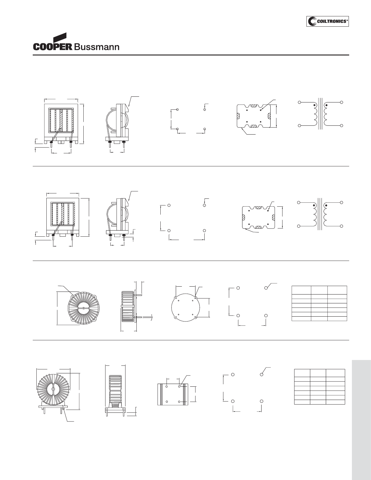
PM-183
COMMON-MODE (CMT)
Mechanical Diagrams
CMT1 Series
1
23
4
23 34
SIDE VIEW
Pin #1 indicator
29.5 max
3.8
typ
10.00
13.00
22.0 max
0.80 dia
36.5 max
1
23
4
component side
1.15 dia ± 0.13
13.0 ± 0.20
10.0 ± 0.20
CMT1-X
wwllyy R
FRONT VIEW BOTTOM VIEW
RECOMMENDED PCB LAYOUT SCHEMATIC
2
1
3
4
CMT2 Series
36.5 max
4.0
± 1.0
15.0
±0.2
26.5 max
1.2 dia
3.2
44.5 max
1
23
4
component side
3.00 dia ± 0.13
21.0 ± 0.20
15.0
± 0.20
CMT2 -
wwllyy R
FRONT VIEW BOTTOM VIEW
RECOMMENDED PCB LAYOUT SCHEMATIC
2
1
3
4
21.0 ±0.2
SIDE VIEW
1
23
4
2334
Pin #1 indicator
CMT3 Series
25.0 max Dia
14 max
5
typ
ØDia
SIDE VIEW
12
43
2
3
1
43
2
component side
15.0 ± 0.20
15.0
± 0.20
TOP VIEW BOTTOM VIEW RECOMMENDED PCB LAYOUT
Pin #1 Indicator "Y" Dia
ref "Z" Dia ref
CMT3-1 0.58 0.83
CMT3-2 0.64 0.90
CMT3-3 0.71 0.97
CMT3-4 0.80 1.06
CMT3-5 0.89 1.15
CMT3-6 0.99 1.25
z dia
15.0
±0.20
15.0
±0.20
3
4
2
1
y dia
CMT4 Series
CMT4-x
wwllyy - R
SIDE VIEW
1
2
3
4
Pin #1 indicator
"Y" Dia
ref "Z" Dia ref
CMT4-1 0.58 0.83
CMT4-2 0.64 0.90
CMT4-3 0.71 0.97
CMT4-4 0.80 1.06
CMT4-5 0.89 1.15
CMT4-6 0.99 1.25
y dia
z dia
1
23
4
component side
12.0 ± 0.20
11.0
± 0.20
FRONT VIEW BOTTOM VIEW RECOMMENDED PCB LAYOUT
12.00
11.00
25.5 max
25.0 max
2
1
41
5.0 typ
15.4 max
(1) All Dimensions are in millimeters unless otherwise
specified
(2) Tolerances are +/- 0.20mm unless stated otherwise.
(3) wwllyy = (Date Code) R = (Revision Level)
Schematic is the same for all the series
CMT-SERIES
Common Mode Inductors
(Through-Hole)
Courtesy of Steven Engineering, Inc.-230 Ryan Way, South San Francisco, CA 94080-6370-Main Office: (650) 588-9200-Outside Local Area: (800) 258-9200-www.stevenengineering.com
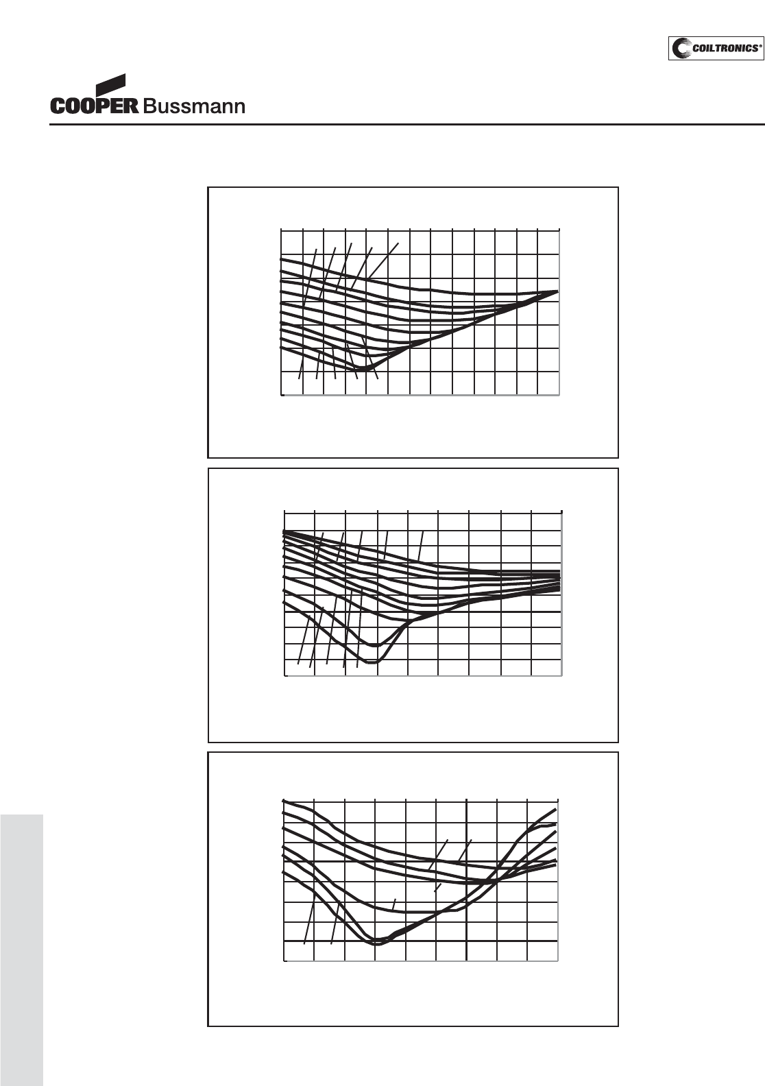
PM-184
COMMON-MODE (CMT)
Attenuation Curves
Attenuation CMT1 Series
-70
-60
-50
-40
-30
-20
-10
0
0.06 0.1 0.2 0.6 1 2 4
FREQUENCY (MHz)
-6 -7 -8 -9 -10
-1 -2 -3 -4 -5
dB
Attenuation CMT3 & CMT4 Common Mode
-50
-45
-40
-35
-30
-25
-20
-15
-10
0.06 0.1 0.2 0.4 0.6 0.8 1246
FREQUENCY (MHz)
-1 -2
-3
-5
-4
-6
dB
Attenuation CMT2 Series
-70
-65
-60
-55
-50
-45
-40
-35
-30
-25
-20
0.08 0.1 0.15 0.2 0.3 0.4 0.5 0.6 0.7 0.8
FREQUENCY (MHz)
-6 -7 -8 -9 -10
-1 -2 -3 -4 -5
dB
CMT-SERIES
Common Mode Inductors
(Through-Hole)
Courtesy of Steven Engineering, Inc.-230 Ryan Way, South San Francisco, CA 94080-6370-Main Office: (650) 588-9200-Outside Local Area: (800) 258-9200-www.stevenengineering.com
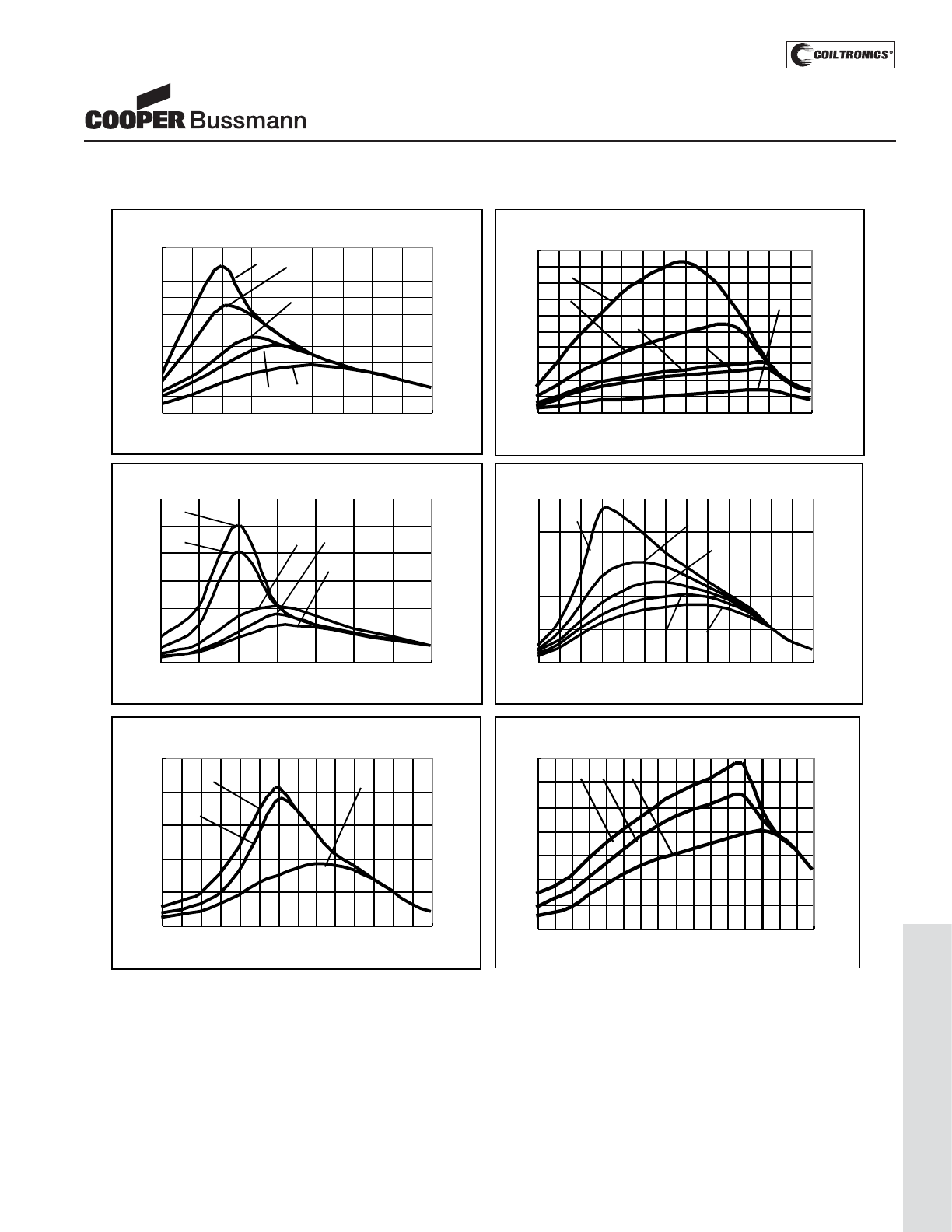
PM-185
COMMON-MODE (CMT)
Impedance Curves
Impedance CMT1 - 1 thru - 5
0
10
20
30
40
50
60
70
80
90
100
0.05 0.1 0.2 0.3 0.4 0.5 0.6 0.7 0.8 0.9
FREQUENCY (MHz)
-1 -2
-3
-4 -5
Impedance CMT1 - 6 thru -10
0
2
4
6
8
10
12
14
16
18
20
0.05 0.2 0.4 0.6 0.8 1 1.4
FREQUENCY (MHz)
-6
-7
-9
-8
-10
Impedance CMT2 - 1 thru - 5
0
20
40
60
80
100
120
0.05 0.1 0.2 0.3 0.4 0.5 0.6 0.7
FREQUENCY (MHz)
-1
-2 -3 -4
-5
Impedance CMT2 - 6 thru -10
0
5
10
15
20
25
0.05 0.1 0.2 0.3 0.4 0.5 0.6 0.7 0.8 0.9 1 1.2 1.4 1.6
FREQUENCY (MHz)
-6 -7
-9
-8
-10
Impedance CMT3 & CMT4
0
0.5
1
1.5
2
2.5
3
3.5
0.06 0.1 0.2 0.4 0.6 0.8 1 2 4
FREQUENCY (MHz)
-4 -5 -6
Impedance CMT3 & CMT4
0
5
10
15
20
25
0.06 0.1 0.2 0.4 0.6 0.8 1 2
FREQUENCY (MHz)
-1
-2
-3
Z (K Ohm)
Z (K Ohm)
Z (K Ohm)
Z (K Ohm)
Z (K Ohm)
Z (K Ohm)
CMT-SERIES
Common Mode Inductors
(Through-Hole)
Courtesy of Steven Engineering, Inc.-230 Ryan Way, South San Francisco, CA 94080-6370-Main Office: (650) 588-9200-Outside Local Area: (800) 258-9200-www.stevenengineering.com
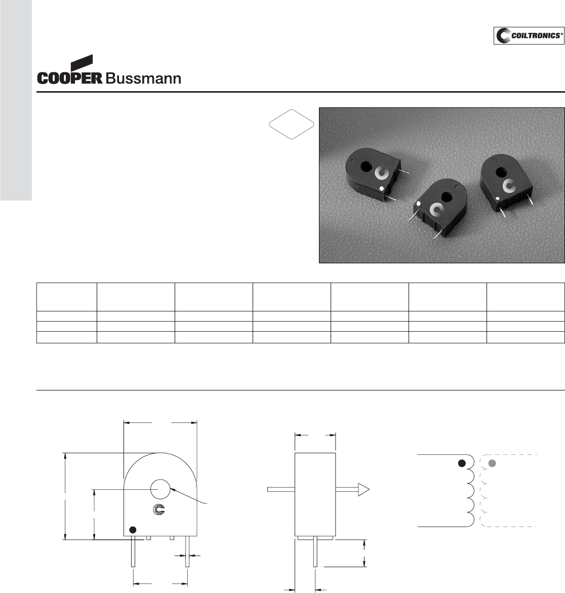
PM-186
TOROID (CS)
Description
• Encapsulated Through Hole Design
• Isolation between Pri and Sec of 3750 Volts
• Materials meet UL Class B
Applications
• Feedback elements linking the output and pulse control
circuitry
• Switch Mode Power Supplies: PFC, Half-bridge,
Full-bridge, Forward
• Off-Line
• Telecom
Part Inductance Turns +/-1% Current Range DCR (Ω) +/-15% Recommended Frequency
Number (mH) AMPS @ 20°C Terminating Range
Resistor
CS-1050-R 5.6 50 1-10 0.60 50 ohms 20k-200kHz
CS-1100-R 22.4 100 2-20 1.3 100 ohms 20k-200kHz
CS-1200-R 89.7 200 4-40 3.3 200 ohms 20k-100kHz
1) Test Parameters: 10kHz, 0.25 Vrms
2) Dimensions in Millimeters
3) Output Voltage is 1v/A with the terminating resistor and is linear over the speci-
fied range
4) Hipot is 3750 Volts from winding to test wire A-B
5) Materials meet UL Class B
6) Polarity Indicator Dot: (This lead is in phase with lead A of conductor A-B)
CS Series
Current Sense
Current Sense Inductors
Mechanical Diagrams
2
0.81
4.57Dia
12.70
17.15
11.74
20.32
1
wwllyy R
CS-xxx
4.77
6.35
9.53
AB
1
2
A
B
xxx = Inductance value
wwllyy = Date code R = Revision level
RoHS
2002/95/EC
Courtesy of Steven Engineering, Inc.-230 Ryan Way, South San Francisco, CA 94080-6370-Main Office: (650) 588-9200-Outside Local Area: (800) 258-9200-www.stevenengineering.com
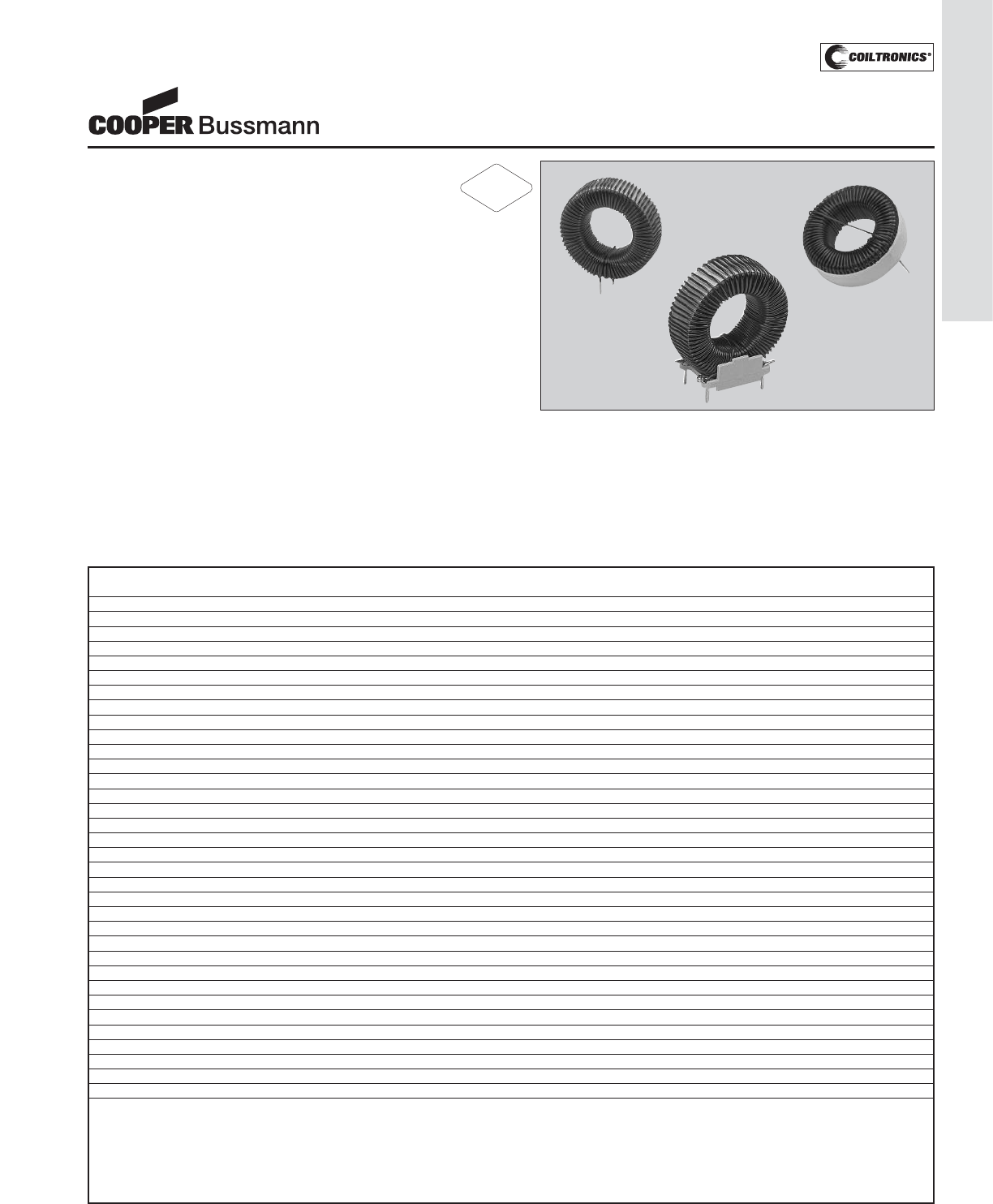
PM-187
TOROID (LCPI)
Description
• Low loss, powdered iron cores with stable
electrical operating characteristics maximize
inductor efficiency by minimizing copper losses
• Available in vertical and horizontal self leaded and head-
er mounted configurations
• Inductance values range from 10uH to 1000uH
• Current values range from 1.5 to 29.5 Amps
• Meets UL 94V-0 flammability standard
• Powder Iron core material
Applications
• Filters
• Buck and boost switches
• Chokes
Environmental Data
• Storage temperature range: -40°C to +105°C
• Operating ambient temperature range: -40°C to +75°C
(range is application specific)
Packaging
• Supplied in bulk packaging
LOW COST POWER INDUCTORS
Toroidal Inductors
V
V
e
e
r
r
t
t
i
i
c
c
a
a
l
l
H
H
o
o
r
r
i
i
z
z
o
o
n
n
t
t
a
a
l
l
H
H
e
e
a
a
d
d
e
e
r
r
M
M
o
o
u
u
n
n
t
t
e
e
d
d
I
I
n
n
d
d
u
u
c
c
t
t
a
a
n
n
c
c
e
e
O
O
C
C
L
L
(
(
1
1
)
)
I
I
D
D
C
C
(
(
2
2
)
)
I
I
S
S
A
A
T
T
(
(
3
3
)
)
V
V
o
o
l
l
t
t
-
-
μ
μ
S
S
e
e
c
c
(
(
4
4
)
)
E
E
n
n
e
e
r
r
g
g
y
y
(
(
5
5
)
)
D
D
C
C
R
R
(
(
Ω
Ω
)
)
(
(
6
6
)
)
P
P
a
a
r
r
t
t
N
N
u
u
m
m
b
b
e
e
r
r
P
P
a
a
r
r
t
t
N
N
u
u
m
m
b
b
e
e
r
r
P
P
a
a
r
r
t
t
N
N
u
u
m
m
b
b
e
e
r
r
μ
μ
H
H
(
(
r
r
a
a
t
t
e
e
d
d
)
)
μ
μ
H
H
+
+
/
/
-
-
2
2
0
0
%
%
A
A
m
m
p
p
e
e
r
r
e
e
s
s
A
A
m
m
p
p
e
e
r
r
e
e
s
s
V
V
μ
μ
S
S
μ
μ
J
J
m
m
a
a
x
x
CTX10-1-52-R CTX10-1-52LP-R CTX10-1-52M-R 10 10.14 2.4 2.1 5.4 15 0.0481
CTX20-1-52-R CTX20-1-52LP-R CTX20-1-52M-R 20 20.22 1.8 2.2 7.8 36 0.0829
CTX50-1-52-R CTX50-1-52LP-R CTX50-1-52M-R 50 50.29 2.6 2.7 16.3 130 0.0715
CTX100-1-52-R CTX100-1-52LP-R CTX100-1-52M-R 100 100.40 2.5 2.4 27.5 197 0.1060
CTX150-1-52-R CTX150-1-52LP-R CTX150-1-52M-R 150 151.70 2.1 2.3 35.7 283 0.1620
CTX250-1-52-R CTX250-1-52LP-R CTX250-1-52M-R 250 250.90 1.9 2.2 47.8 421 0.2210
CTX500-1-52-R CTX500-1-52LP-R CTX500-1-52M-R 500 505.00 1.7 1.9 77.9 645 0.3610
CTX750-1-52-R CTX750-1-52LP-R CTX750-1-52M-R 750 754.40 1.8 2.4 114.3 1530 0.4340
CTX1000-1-52-R CTX1000-1-52LPR CTX1000-1-52M-R 1000 1004.00 1.5 2.1 131.9 1530 0.6380
CTX10-2-52-R CTX10-2-52LP-R CTX10-2-52M-R 10 9.60 4.7 4.5 6.6 68 0.0183
CTX20-2-52-R CTX20-2-52LP-R CTX20-2-52M-R 20 19.60 3.2 3.2 9.4 69 0.0392
CTX50-2-52-R CTX50-2-52LP-R CTX50-2-52M-R 50 50.00 4.9 4.9 21.3 420 0.0326
CTX100-2-52-R CTX100-2-52LP-R CTX100-2-52M-R 100 101.70 4.4 4.3 35.0 643 0.0534
CTX150-2-52-R CTX150-2-52LP-R CTX150-2-52M-R 150 148.00 4.3 4.0 47.6 829 0.0719
CTX250-2-52-R CTX250-2-52LP-R CTX250-2-52M-R 250 251.10 4.2 4.2 66.0 1540 0.0833
CTX500-2-52-R CTX500-2-52LP-R CTX500-2-52M-R 500 499.40 3.1 3.3 104.0 1890 0.1830
CTX750-2-52-R CTX750-2-52LP-R CTX750-2-52M-R 750 749.30 3.4 3.4 147.3 2960 0.2080
CTX10-5-52-R CTX10-5-52LP-R CTX10-5-52M-R 10 9.68 8.7 11.1 9.4 417 0.0104
CTX20-5-52-R CTX20-5-52LP-R CTX20-5-52M-R 20 21.25 7.8 9.3 16.0 643 0.0260
CTX50-5-52-R CTX50-5-52LP-R CTX50-5-52M-R 50 49.60 7.6 9.4 29.3 1530 0.0248
CTX100-5-52-R CTX100-5-52LP-R CTX100-5-52M-R 100 97.20 8.2 7.5 45.7 1890 0.0267
CTX150-5-52-R CTX150-5-52LP-R CTX150-5-52M-R 150 150.60 7.7 7.5 66.0 2960 0.0401
CTX250-5-52-R CTX250-5-52LP-R 250 254.40 9.2 8.1 102.4 5860 0.0400
CTX10-7-52-R CTX10-7-52LP-R CTX10-7-52M-R 10 10.04 11.4 13.5 11.0 640 0.0080
CTX20-7-52-R CTX20-7-52LP-R CTX20-7-52M-R 20 20.96 11.4 14.5 19.1 1540 0.0110
CTX50-7-52-R CTX50-7-52LP-R CTX50-7-52M-R 50 52.27 10.5 10.2 33.5 1900 0.0163
CTX100-7-52-R CTX100-7-52LP-R 100 101.40 12.0 9.1 54.2 2960 0.0167
CTX150-7-52-R CTX150-7-52LP-R 150 152.80 12.8 10.5 79.3 5900 0.0204
CTX10-10-52-R CTX10-10-52LP-R 10 10.04 16.9 20.9 13.2 1530 0.0051
CTX20-10-52-R CTX20-10-52LP-R 20 21.17 16.0 16.0 21.3 1900 0.0070
CTX50-10-52-R CTX50-10-52LP-R 50 52.37 13.9 12.7 38.9 2960 0.0124
CTX100-10-52-R CTX100-10-52LPR 100 99.38 17.6 13.0 64.0 5880 0.0109
CTX10-16-52-R CTX10-16-52LP-R 10 9.90 27.3 29.3 16.9 2970 0.0032
CTX20-16-52-R CTX20-16-52LP-R 20 19.24 31.5 29.5 28.1 5860 0.0034
Notes: (1) Open circuit inductance test parameters: 100kHz, 0.250Vrms, 0 Adc.
(2)
DC current for an approximate ΔT of 30°C at 75°C Ambient with no core loss. See Chart 2 for derating of IDC with core loss.
(3) Peak current for an approximate 30% roll-off in OCL. For other current levels see Chart 1.
(4) Applied Volt-Time product (VμS) across the inductor. This value represents the VμS at 100kHz necessary to generate a core loss equal to 10% of the total
losses for 30°C rise. For other frequencies and operating levels see Chart 2. (Note: skin effect losses not included.)
(5) Energy storage (μJ) at ISAT. For other current levels see Chart 1.
(6) Maximum D.C. resistance at 20°C.
Family Table
RoHS
2002/95/EC
Courtesy of Steven Engineering, Inc.-230 Ryan Way, South San Francisco, CA 94080-6370-Main Office: (650) 588-9200-Outside Local Area: (800) 258-9200-www.stevenengineering.com
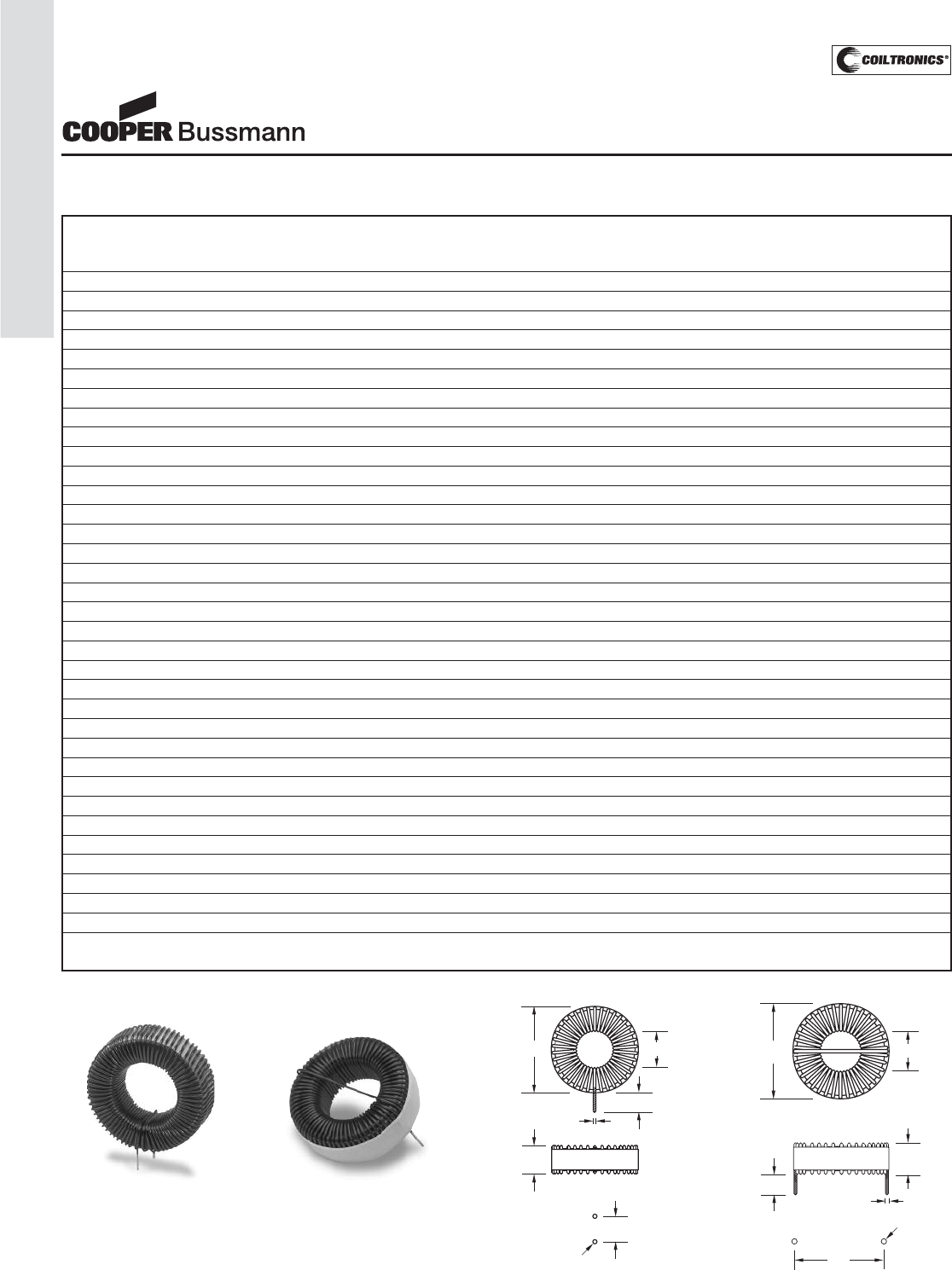
PM-188
TOROID (LCPI)
Vertical and Horizontal Self Leaded Mounting Options
V
V
e
e
r
r
t
t
i
i
c
c
a
a
l
l
P
P
/
/
N
N
H
H
o
o
r
r
i
i
z
z
o
o
n
n
t
t
a
a
l
l
P
P
/
/
N
N
O
O
D
D
I
I
D
D
H
H
t
t
X
X
Y
Y
T
T
H
H
S
S
e
e
e
e
F
F
i
i
g
g
u
u
r
r
e
e
1
1
S
S
e
e
e
e
F
F
i
i
g
g
u
u
r
r
e
e
2
2
(
(
m
m
a
a
x
x
)
)
(
(
t
t
y
y
p
p
)
)
(
(
m
m
a
a
x
x
)
)
(
(
t
t
y
y
p
p
)
)
(
(
t
t
y
y
p
p
)
)
(
(
t
t
y
y
p
p
)
)
(
(
t
t
y
y
p
p
)
)
CTX10-1-52-R CTX10-1-52LP-R 8.6 0.0 4.7 3.8 7.3 0.42 0.67
CTX20-1-52-R CTX20-1-52LP-R 9.1 0.0 6.7 5.6 7.4 0.37 0.62
CTX50-1-52-R CTX50-1-52LP-R 16.2 4.2 9.0 7.5 13.7 0.58 0.83
CTX100-1-52-R CTX100-1-52LP-R 15.5 4.2 12.4 10.7 13.7 0.58 0.83
CTX150-1-52-R CTX150-1-52LP-R 20.7 6.6 9.4 7.8 18.8 0.52 0.77
CTX250-1-52-R CTX250-1-52LP-R 20.9 6.0 13.0 11.0 18.8 0.52 0.77
CTX500-1-52-R CTX500-1-52LP-R 24.0 9.0 15.3 14.0 21.2 0.52 0.77
CTX750-1-52-R CTX750-1-52LP-R 29.8 11.7 17.4 15.6 28.2 0.52 0.77
CTX1000-1-52-R CTX1000-1-52LP-R 29.8 11.7 17.1 15.5 28.0 0.46 0.71
CTX10-2-52-R CTX10-2-52LP-R 12.7 0.0 7.8 6.3 11.0 0.71 0.96
CTX20-2-52-R CTX20-2-52LP-R 12.5 0.0 7.5 6.3 11.0 0.58 0.83
CTX50-2-52-R CTX50-2-52LP-R 21.6 6.1 13.6 11.0 19.5 0.89 1.14
CTX100-2-52-R CTX100-2-52LP-R 24.0 8.8 16.6 13.9 21.8 0.89 1.14
CTX150-2-52-R CTX150-2-52LP-R 30.6 11.2 11.4 9.3 28.5 0.80 1.05
CTX250-2-52-R CTX250-2-52LP-R 31.2 9.1 19.0 15.7 28.5 0.89 1.14
CTX500-2-52-R CTX500-2-52LP-R 36.7 11.7 14.8 12.5 34.5 0.71 0.96
CTX750-2-52-R CTX750-2-52LP-R 43.3 19.9 18.2 15.8 41.5 0.80 1.05
CTX10-5-52-R CTX10-5-52LP-R 22.2 5.4 13.9 11.5 19.9 1.11 1.36
CTX20-5-52-R CTX20-5-52LP-R 24.5 8.8 16.6 14.5 22.0 0.89 1.14
CTX50-5-52-R CTX50-5-52LP-R 32.3 10.1 18.9 16.5 28.8 1.11 1.36
CTX100-5-52-R CTX100-5-52LP-R 37.8 11.2 16.8 13.6 35.5 1.24 1.49
CTX150-5-52-R CTX150-5-52LP-R 46.4 18.8 19.8 16.8 43.4 1.24 1.49
CTX250-5-52-R CTX250-5-52LP-R 53.7 18.8 24.3 20.1 49.4 1.38 1.63
CTX10-7-52-R CTX10-7-52LP-R 25.7 6.5 18.0 16.0 22.4 1.38 1.63
CTX20-7-52-R CTX20-7-52LP-R 32.4 8.5 19.8 16.8 29.2 1.38 1.63
CTX50-7-52-R CTX50-7-52LP-R 39.0 10.8 16.8 13.9 35.7 1.38 1.63
CTX100-7-52-R CTX100-7-52LP-R 48.5 17.1 21.8 17.2 43.4 1.73 1.98
CTX150-7-52-R CTX150-7-52LP-R 54.5 17.1 25.4 21.2 50.9 1.73 1.98
CTX10-10-52-R CTX10-10-52LP-R 34.0 7.0 21.4 17.0 29.6 1.73 1.98
CTX20-10-52-R CTX20-10-52LP-R 40.5 9.0 18.0 14.3 35.2 1.73 1.98
CTX50-10-52-R CTX50-10-52LP-R 47.5 17.1 21.3 17.5 42.8 1.73 1.98
CTX100-10-52-R CTX100-10-52LP-R 57.0 15.0 27.5 21.3 50.6 2.15 2.45
CTX10-16-52-R CTX10-16-52LP-R 50.3 13.0 24.0 18.6 43.0 2.41 2.70
CTX20-16-52-R CTX20-16-52LP-R 59.0 13.0 28.0 23.0 50.7 2.69 2.99
Note: All dimensions are in millimeters.
Ht
T dia.
(typ.)
T dia.
(typ.)
T dia.
10.0 +/- 3
Ht
X
10.0 +/- 3
OD
OD ID ID
Y
H dia
(typ.)
H dia
(typ.)
H dia.
(typ.)
H dia.
(typ.)
VERTICAL
SELF LEADED
MOUNT
HORIZONTAL
SELF LEADED
MOUNT
Drawings are not to scale.
FIGURE 1 FIGURE 2
Mechanical Diagrams
LOW COST POWER INDUCTORS
Toroidal Inductors
Courtesy of Steven Engineering, Inc.-230 Ryan Way, South San Francisco, CA 94080-6370-Main Office: (650) 588-9200-Outside Local Area: (800) 258-9200-www.stevenengineering.com
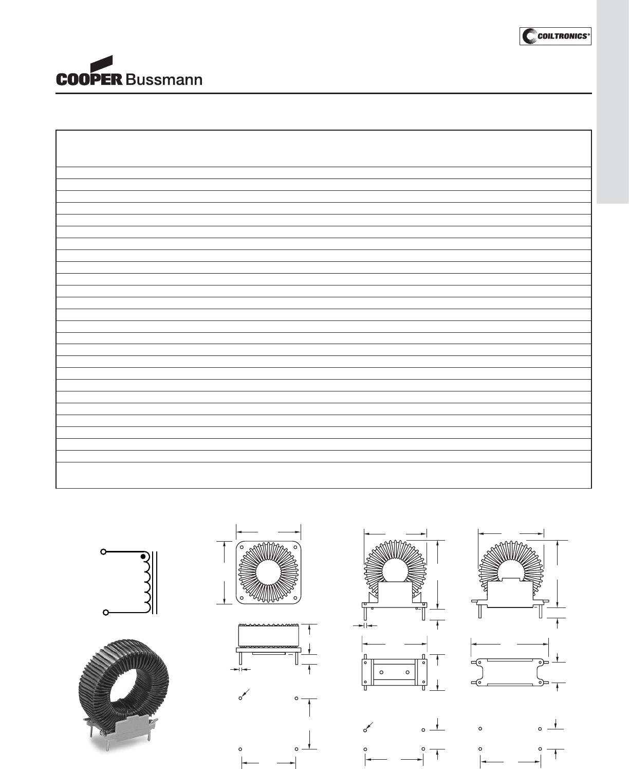
PM-189
TOROID (LCPI)
HEADER MOUNT
Header Mounted Option
H
H
e
e
a
a
d
d
e
e
r
r
M
M
o
o
u
u
n
n
t
t
e
e
d
d
S
S
e
e
e
e
O
O
D
D
A
A
B
B
C
C
X
X
Y
Y
T
T
H
H
P
P
a
a
r
r
t
t
N
N
u
u
m
m
b
b
e
e
r
r
F
F
i
i
g
g
u
u
r
r
e
e
#
#
(
(
m
m
a
a
x
x
)
)
(
(
m
m
a
a
x
x
)
)
(
(
m
m
a
a
x
x
)
)
(
(
m
m
a
a
x
x
)
)
(
(
t
t
y
y
p
p
)
)
(
(
t
t
y
y
p
p
)
)
(
(
t
t
y
y
p
p
)
)
(
(
t
t
y
y
p
p
)
)
CTX10-1-52M-R 3 8.6 9.4 9.4 6.9 6.5 6.5 — —
CTX20-1-52M-R 3 9.1 9.4 9.4 9.0 6.5 6.5 — —
CTX50-1-52M-R 4 16.2 19.6 16.1 20.0 15.3 6.4 — —
CTX100-1-52M-R 4 15.5 19.6 16.1 19.7 15.3 6.4 — —
CTX150-1-52M-R 4 20.7 19.6 16.1 24.2 15.3 6.4 — —
CTX250-1-52M-R 5 20.9 31.0 16.0 22.5 20.3 10.2 1.20 1.45
CTX500-1-52M-R 5 24.0 35.4 21.7 25.0 23.0 15.4 1.20 1.45
CTX750-1-52M-R 5 29.8 35.4 21.7 31.6 23.0 15.4 1.20 1.45
CTX1000-1-52M-R 5 29.8 35.4 21.7 31.2 23.0 15.4 1.20 1.45
CTX10-2-52M-R 3 12.7 13.6 11.4 11.7 10.8 7.5 — —
CTX20-2-52M-R 3 12.5 13.6 11.4 11.4 10.8 7.5 — —
CTX50-2-52M-R 5 21.6 31.0 16.0 23.5 20.3 10.2 1.20 1.45
CTX100-2-52M-R 5 24.0 35.4 21.7 26.0 23.0 15.4 1.20 1.45
CTX150-2-52M-R 5 30.6 31.0 16.0 32.5 20.3 10.2 1.20 1.45
CTX250-2-52M-R 5 31.2 35.4 21.7 33.4 23.0 15.4 1.20 1.45
CTX500-2-52M-R 5 36.7 31.0 16.0 38.4 20.3 10.2 1.20 1.45
CTX750-2-52M-R 5 43.3 35.4 21.7 45.4 23.0 15.4 1.20 1.45
CTX10-5-52M-R 5 22.2 31.0 16.0 22.7 20.3 10.2 1.20 1.45
CTX20-5-52M-R 5 24.5 35.4 21.7 25.5 23.0 15.4 1.20 1.45
CTX50-5-52M-R 5 32.3 35.4 21.7 33.7 23.0 15.4 1.11 1.36
CTX100-5-52M-R 5 37.8 35.4 21.7 40.2 23.0 15.4 1.24 1.49
CTX150-5-52M-R 5 46.4 35.4 21.7 47.0 23.0 15.4 1.24 1.49
CTX10-7-52M-R 5 25.7 35.4 21.7 26.7 23.0 15.4 1.38 1.63
CTX20-7-52M-R 5 32.4 35.4 21.7 34.2 23.0 15.4 1.38 1.63
CTX50-7-52M-R 5 39.0 35.4 21.7 40.3 23.0 15.4 1.38 1.63
Note: All dimensions are in millimeters.
Drawings are not to scale.
FIGURE 3 FIGURE 4 FIGURE 5
0.50d
ia.
ia.
(typ.)(typ.)
C
3.
3.
8+
8+/- 1
Y
X
B
A
2
2
3
3
1
1
4
4
0.70dia.(typ.)
0.70dia.(typ.)
C
4.0+
0+/-
1
4.0 - 1
B
Y
OD
2
2
3
3
1
14
4
X
A
1.25dia.(typ.)
1.25dia.(typ.)
1.0
0d
ia.
ia.
(typ.)
1.00
(typ.)
C
OD
4.25+/- 1.54.25+/- 1.5
B
Y
Pins1&3s1&3:Tdia.ia.
Pins2&4s2&4:1.21.20dia.ia.
Holes1&3s1&3:Hdia.dia.
Holes2&4s2&4:1.45dia.
A
1
2
4
3
2
1
3
4
X
CONNECTION DIA-
GRAM
1
3
LOW COST POWER INDUCTORS
Toroidal Inductors
Courtesy of Steven Engineering, Inc.-230 Ryan Way, South San Francisco, CA 94080-6370-Main Office: (650) 588-9200-Outside Local Area: (800) 258-9200-www.stevenengineering.com
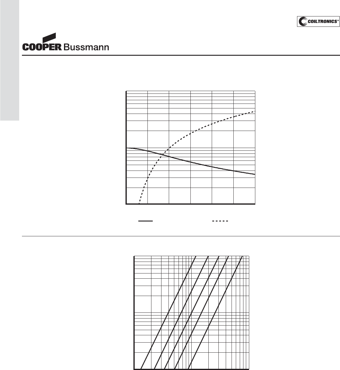
PM-190
TOROID (LCPI)
Inductance Characteristics
Core Loss
0
20
40
50
60
70
80
90
20 kHz
50 kHz
100 kHz
200 kHz
500 kHz
% of Losses from Irms (maximum)
% of applied Volt-μ Seconds
92
94
95
96
97
98
99
10
20
30
40
50
60
80
100
200
300
400
500
600
800
1000
1000
800
600
500
400
300
200
100
80
60
50
40
30
20
10
050
Inductance
% OF ISA T
% of OCL or % of Energy
Energy
100 150 200 250 300
LOW COST POWER INDUCTORS
Toroidal Inductors
Courtesy of Steven Engineering, Inc.-230 Ryan Way, South San Francisco, CA 94080-6370-Main Office: (650) 588-9200-Outside Local Area: (800) 258-9200-www.stevenengineering.com
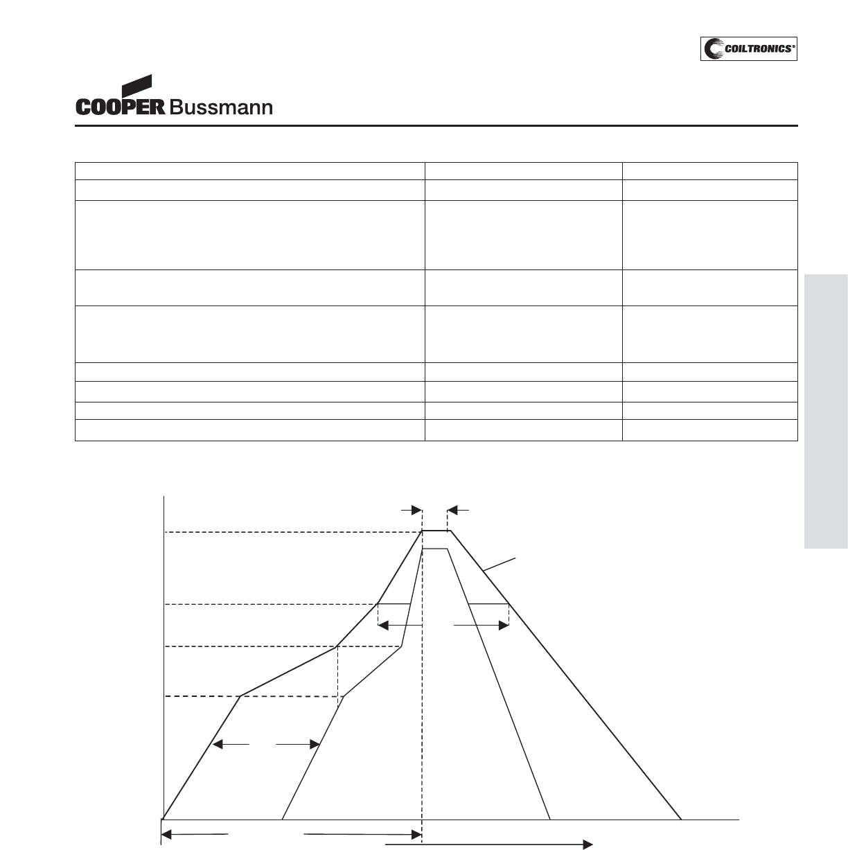
Recommended Solder Reflow Profiles
Profile Feature Standard SnPb Solder Lead (Pb) Free Solder
Average Ramp-Up Rate (TLto TP) 3°C/Second Max. 3°C/Second Max.
Preheat
Temperature Min. (TSmin) 100°C 150°C
Temperature Max. (TSmax) 150°C 200°C
Time (Min to Max) (ts) 60-120seconds 60-120seconds
Tsmax to TL
Ramp-Up Rate 3°C/Second Max.
Time Maintained Above:
Temperature (TL) 183°C 217°C
Time (tL) 60-150 Seconds 60-150 Seconds
Peak Temperature (TP) 235°C +/-5°C 255°C +/-5°C
Time Within 5°C of Actual Peak Temperature (tP) 30 Seconds Max 10 Seconds Max
Ramp Down Rate 6°C/ Second Max. 6°C/ Second Max.
Time 25°C to Peak Temperature 6 Minutes Max 8 Minutes Max
Application Notes
Magnetics
..
Temperature
IL
tP
ts
Preheat
Critical Zone
TL to TL
t 25°C to peak
Time
25°C
TS
min
TS
max
TL
TP
All temperatures refer to the topside of the package, measured on the package body surface
Reference JEDEC J-STD-020B
PM-191
APPLICATION NOTES
Courtesy of Steven Engineering, Inc.-230 Ryan Way, South San Francisco, CA 94080-6370-Main Office: (650) 588-9200-Outside Local Area: (800) 258-9200-www.stevenengineering.com
PM-192
APPLICATION NOTES
Using the Versa-Pac as a Flyback Transformer
The Versa-Pac range of transformers is one of the many
products manufactured under the Cooper Coiltronics®
brand of power magnetics from Cooper Bussmann.
Versa-Pac is available in five sizes and is suitable for
flyback circuits with power levels up to 35W and a maxi-
mum switching frequencies of 500kHz. The VP series
was designed, primarily, for low voltage applications
typically 3.3V, 5V and 12V. With the addition of the VPH
products to the range the Versa-Pac can now be used
for 24V, 48V and, at higher frequencies, even 120V
applications. Each transformer has six identical windings
that can be configured in series and parallel to produce
the required transformer design, the isolation between
these windings is 500Vdc. Full product data is available
on our website: www.cooperbussmann.com
Design Procedure
In order to design a flyback transformer using the Versa-
Pac the following information is required: nominal, mini-
mum and maximum input voltages (Vin(nom), Vin(min) &
Vin(max)), output voltage (Vo), output current (Io) and
switching frequency (Fs).
For the purpose of our example let’s take the following
values:
Vo = 5V, Io = 1A, Vin(min) = 40V, Vin(nom)=48V ,
Vin(max) = 56V and Fs = 200kHz
Using the graph for Unipolar (Flyback) Power v
Frequency from the data sheet select the required Versa-
Pac size by reading off your required output power and
operating frequency.
At 200kHz and 5W this gives a VP3 size.
If the output power requirement can’t be met then the
Versa-Pac is unable to offer a flyback transformer solu-
tion. It may be worth considering a Push-Pull topology, as
this will give better transformer utilization allowing high
output power levels for the same transformer size.
Calculate the turns ratio for a duty cycle (D) of 0.5 using
the equation;
Vo/Vin(nom) = Nsec/Npri x (D/1-D) (1)
Where Nsec is the number of secondary windings and
Npri is the number of primary windings, Npri/Nsec is the
turns ratio which must be rounded to the nearest achiev-
able value (i.e. 0.5, 0.667, 1, 1.5, 2, 3 etc).
5/48 = Nsec/Npri x 0.5/(1-0.5)
Npri/Nsec = (48x1)/5 = 9.6
Rounding down, Npri/Nsec = 5 (max ratio)
Vin(nom) and 0.5 duty cycle are used only as a starting
point, it is possible that using Vin(min) with lower or high
duty cycles you may achieve a more suitable turns ratio.
Calculate the actual duty cycle for Vin(max) using equa-
tion 1 and the calculated turns ratio rounded up or down
to the nearest achievable value.
5/56 = (1/5) x D/(1-D)
0.446-0.446D = D
D = 0.446/1.446 = 0.309
Calculate the primary volt-seconds product using the fol-
lowing equation:
Primary Vs = D x Ts x Vin(max)
Where Ts = 1/Fs (2)
This value should be less than the rated primary Volt-
μsec, if the primary uses one winding the rated Volt-μsec
is the same as Volt-μsec(Base). If the primary is two
windings in series then the rating is then 2 x Volt-
μsec(Base) and for 3 series windings 3 x Volt-μsec(Base)
etc. If the Volt-μsec rating can not be achieved using the
selected Versa-Pac size then you will need to select a
larger size or increase the switching frequency.
Application Notes
Magnetics
Watts
Frequency, kHz
100
0.0
5.0
10.0
15.0
20.0
25.0
30.0
35.0
40.0
200 300 400 500
VP 5
VP 4
VP 3
VP 2
VP 1
Unipolar (Flyback) Power vs Frequency
Courtesy of Steven Engineering, Inc.-230 Ryan Way, South San Francisco, CA 94080-6370-Main Office: (650) 588-9200-Outside Local Area: (800) 258-9200-www.stevenengineering.com

PM-193
APPLICATION NOTES
Application Notes
Magnetics
Primary Vs = 0.309 x 1/200x103x 56 = 86.52Vμsec
The VP3 has a Volt-μsec(Base) of 27.7Vμsec, multiply-
ing this by 5 gives a rating of 138.5Vμsec. So the VP3
size meets the volt-seconds requirements.
If the required volt-seconds rating can’t be achieved you
can reduce the required rating by increasing the switching
frequency. Alternatively you can recalculate the turns ratio
using Vin(min) as this may increase the number of series
primary windings.
Starting with the highest inductance value for the selected
VP size, calculate the output current at which current con-
duction is at the boundary between continuous and dis-
continuous.
Io (boundary) = Ts x Vo x (1-D(max))2/(2 x Ls) (3)
Where Ls is the secondary inductance and Dmax is the
duty cycle at Vin(min).
Selecting the VP3-0780:
D(max) = 0.625/1.625 = 0.385
Ls = 63.2μH
Io (boundary) = 5x10-6 x 5 x (1-0.385)2/
(2 x 63.2x10-6) = 0.075A
As the boundary current is less than the maximum
output current the transformer is operating in contin-
uous mode.
Calculating the peak and rms primary currents we can
determine if the selected Versa-Pac meets the specified
requirements.
For Continuous mode conduction:
Peak Primary Current:
Ipri(peak) = Nsec/Npri x (1/1-D(max))
x Io + (Vin(min) x Ts x D(max))/2 x Lpri (4)
Where Lpri is the primary inductance.
In order to calculate the rms primary current you first
need to calculate the primary current delta and average
peak.
ΔIpri = (Vin(min) x D(max) x Ts)/Lpri (5)
Ipri(avg-pk) = (Ipri(peak) + (Ipri(peak) - ΔIpri))/2 (6)
Ipri(rms) = (D(max) x (Ipri(avg-pk))2)0.5 (7)
Ipri(peak) = 0.2 x 1/(1-0.385) + (40 x 5x10-6 x 0.385)/
(2 x 52x 63.2x10-6) = 0.35A
Peak current is higher than the Isat rating for the
VP3-0780, which is equal to 6/5 x Isat(base). So mov-
ing up to the VP3-0138, we once again find that con-
duction is mainly continuous mode and so peak pri-
mary current:
Ipri(peak) = 0.2 x 1/(1-0.385) + (40 x 5x10-6 x 0.385)/
(2 x 52x 11.2x10-6) = 0.462A
ΔIpri = (40 x 0.385 x 5x10-6)/(52x 11.2x10-6) = 0.275A
Ipri(avg-pk) = (0.462 + (0.462 – 0.275))/2 = 0.325A
Ipri(rms) = (0.385 x 0.3252)0.5 = 0.202A
For the VP3-0138 the Irms rating is 1.47A and the
Isat(base) is 0.59A both of which are sufficiently high
to meet the primary current requirements.
For discontinuous mode conduction:
First we need to calculate the average primary current:
Ipri(avg)= (Vo x Io)/(Vin(min) x Efficiency) (8)
Ipri(peak) = (2 x Ipri(avg))/D(max) (9)
Ipri(rms) = ((Ipri(peak)2x D(max))/3)0.5 (10)
You can now check these results against the Isat and
Irms ratings, bearing in mine that the actual Isat rating:
= (6 x Isat(base))/Number of windings driven (11)
The number of windings driven for a flyback transformer
is the number of series windings used to make up the pri-
mary. So for two series primary windings the rated Isat is
actually 3 times Isat(base).
Finally, calculate the maximum rms secondary current,
For continuous mode:
Isec(rms) = ((1-D(max)) x (Io/(1-D(max)))2)0.5 (12)
Courtesy of Steven Engineering, Inc.-230 Ryan Way, South San Francisco, CA 94080-6370-Main Office: (650) 588-9200-Outside Local Area: (800) 258-9200-www.stevenengineering.com
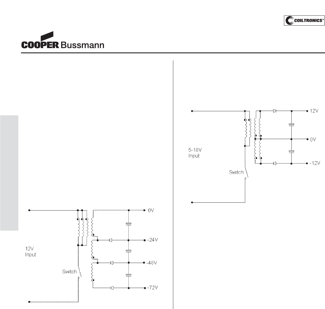
Application Notes
Magnetics
For discontinuous mode:
Isec(rms) = ((1-D(max))/3 x (Isec(peak))2)0.5 (13)
Where, referring to equation 9:
Isec(peak) = Ipri(peak) x Npri/Nsec (14)
Isec(rms) = ((1-0.385) x (1/(1-0.385))2)0.5 = 1.275A
The VP3-0138 has an Irms(base) rating of 1.47A
Examples:
SLIC Power Supply
By connecting three secondary windings in series much
higher output voltages can be achieve, in this example
each secondary winding has a -24V output therefore pro-
viding the -48V and -72V supplies required in SLIC appli-
cations.
Split +/-12V Supply
Using a secondary center tap allows the winding to be
configured for positive and negative outputs. Extra wind-
ings are paralleled with the primary and secondary wind-
ings in order handle more current and reduce losses.
PM-194
APPLICATION NOTES
Courtesy of Steven Engineering, Inc.-230 Ryan Way, South San Francisco, CA 94080-6370-Main Office: (650) 588-9200-Outside Local Area: (800) 258-9200-www.stevenengineering.com
PM-195
APPLICATION NOTES
Using the Versa-Pac as a Forward Converter Transformer
The Versa-Pac range of transformers is one of the many
products manufactured under the Cooper Coiltronics®
brand of power magnetics from Cooper Bussmann.
Versa-Pac is available in five sizes and is suitable for a
maximum switching frequency of 500kHz and power
levels up to 30W, for single ended topologies, or 60W for
bipolar applications. The VP series was designed,
primarily, for low voltage applications typically 3.3V, 5V
and 12V. With the addition of the VPH products to the
range the Versa-Pac can now be used for 24V, 48V and,
at higher frequencies, even 120V applications. Each
transformer has six identical windings that can be
configured in series and parallel to produce the required
transformer design, the isolation between these windings
is 500Vdc. Full product data is available on our website:
www.cooperbussmann.com
Single Ended Forward Converter Design Procedure
In order to design a forward converter transformer using
the Versa-Pac the following information is required: nomi-
nal, minimum and maximum input voltages (Vin(nom),
Vin(min) & Vin(max)), output voltage (Vo), output current
(Io) and switching frequency (Fs).
For the purpose of our example let’s take the following
values:
Vo = 3.3V, Io = 5A, Vin(min) = 40V, Vin(nom)=48V ,
Vin(max) = 56V and Fs = 250kHz
Using the graph for unipolar (Flyback) Power v Frequency
from the data sheet select the required Versa-Pac size by
reading off your required output power and operating fre-
quency.
At 250kHz and 16.5W this gives a VP5 size.
Although the data used in the Power v. Frequency curve
was derived using a flyback topology, as a guide to
Versa-Pac size requirements, it still holds true for unipolar
forward converters.
Calculate the turns ratio for a duty cycle (D) of 0.25 using
the equation;
Vo/Vin(nom) = D x Nsec/Npri (1)
Where Nsec is the number of secondary windings and
Npri is the number of primary windings, Npri/Nsec is the
turns ratio which must be rounded to the nearest achiev-
able value (i.e. 0.5, 0.667, 1, 1.5, 2, 3 etc).
3.3/48 = Nsec/Npri x (0.25)
Npri/Nsec = (48x0.25)/3.3 = 3.6
Rounding down, Npri/Nsec = 3
Vin(nom) and 0.25 duty cycle are used only as a starting
point, it is possible that using Vin(min) with lower or high
duty cycles you may achieve a more suitable turns ratio.
Note: Maximum duty cycle for most unipolar forward con-
verters is 0.5.
Calculate the maximum duty cycle for Vin(min) using
equation 1 and the calculated turns ratio rounded up or
down to the nearest achievable value.
3.3/40 = 1/3 x (D)
(3.3 x 3)/40 = D
D(max) = 0.2475
Calculate the primary volt-seconds product using the fol-
lowing equation:
Primary Vs = D(max) x Ts x Vin(min)
Where Ts = 1/Fs (2)
This value should be less than the rated primary Volt-
μsec, if the primary uses one winding the rated Volt-μsec
is the same as Volt-μsec(Base). If the primary is two
windings in series then the rating is then 2 x Volt-
μsec(Base) and for 3 series windings 3 x Volt-μsec(Base)
etc. If the Volt-μsec rating can not be achieved using the
selected Versa-Pac size then you will need to select a
larger size or increase the switching frequency.
Primary Vs = 0.2475 x 1/250x103x 40 = 39.6Vμsec
Application Notes
Magnetics
Watts
Frequency, kHz
100
0.0
5.0
10.0
15.0
20.0
25.0
30.0
35.0
40.0
200 300 400 500
VP 5
VP 4
VP 3
VP 2
VP 1
Unipolar (Flyback) Power vs Frequency
Courtesy of Steven Engineering, Inc.-230 Ryan Way, South San Francisco, CA 94080-6370-Main Office: (650) 588-9200-Outside Local Area: (800) 258-9200-www.stevenengineering.com
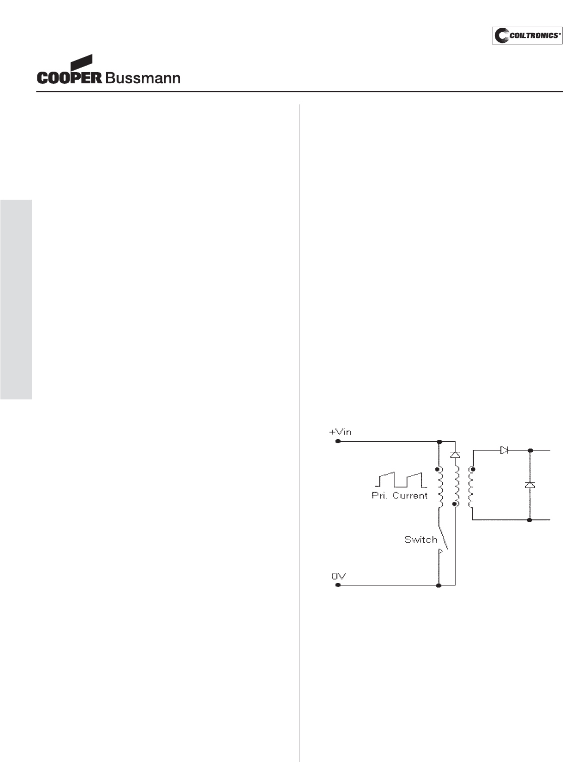
PM-196
APPLICATION NOTES
Application Notes
Magnetics
The VP5 has a Volt-μsec(Base) of 65.6Vμsec, multiply-
ing this by 3 gives a rating of 196.8Vμsec. So the VP5
easily meets the volt-seconds requirements.
If the required volt-seconds rating can’t be achieved you
can reduce the required rating by increasing the switching
frequency. Alternatively you can recalculate the turns ratio
using Vin(max) or a high duty cycle as this may increase
the number of series primary windings.
Starting with the highest inductance value for the selected
VP, calculating the rms primary currents we can deter-
mine if the selected Versa-Pac meets the specified
requirements.
In order to calculate the rms primary current you first
need to calculate the peak current.
Ipri(peak) = Nsec/Npri x (Io + ΔIo/2) + Imag(peak) (3)
Where:
Imag(peak) = (Vin(min) x Ts x D(max))/Lpri (4)
Primary rms current:
Ipri(rms) = (D(max) x (Ipri(avg-pk))2)0.5 (5)
Where:
Ipri(avg-pk) = (Ipri(peak) + (Ipri(peak) -
Imag(peak)))/2 (6)
Assuming ΔIo is set to 10% of Io max, which is achieved
by selection of the correct output inductor value (see
application note EUA001). Using a VP5-1200, the L(base)
is 76.8μH therefore:
Imag(peak) = (40 x 1/250x103x 0.248)/
32x 76.8 x10-6= 0.0574A
Ipri(peak) = 1/3 x (5 + (0.5/2) + 0.0574 = 1.81A
Ipri(avg-pk) = (1.81 + (1.81 – 0.0574))/2 = 1.78A
Ipri(rms) = (0.248 x 1.782)0.5 = 0.89A
The rms current rating, Irms(base), for the VP5-1200
is 2.08A
Finally, calculate the maximum rms secondary current,
Isec(rms) = (D(max) x (Io + Isec(peak)/2)2)0.5 (7)
Where, referring to equation 3:
Isec(peak) = Ipri(peak) x Npri/Nsec (8)
Isec(peak) = 1.81 x 3 = 5.43A
Isec(rms) = (0.248 x ((5 + 5.43)/2)2)0.5 = 2.6A
The rms current rating, Irms(base), for the VP5-1200
is 2.08A. In order to achieve the required rms current
rating at least two parallel windings must be used to
make up the secondary. For improved efficiency it
would be normal practice to use both the spare wind-
ings and have a secondary made up of three parallel
windings.
Transformer Reset
In a practical single ended forward converter design you
need to consider how transformer reset is going to be
achieved. During the switch ‘ON’ period current propor-
tional to the output current plus the magnetizing current
flow in the primary winding, the magnetizing current must
be reset to zero during the switch ‘OFF’ period in order to
prevent converter failure. This can be achieved in a
number of ways, figure 1 shows a method that uses an
auxiliary primary winding connected in anti-phase to the
main primary. This additional winding acts in flyback
mode during the switch ‘OFF’ period recovering the
magnetizing energy in to the supply rail.
Figure 1
For Versa-Pac designs this method limits the converter
maximum duty cycle to 50% and also reduces the num-
ber of possible configurations, as only 5 windings will be
available. Figure 2 shows a simple way of resetting the
transformer using an resistor-capacitor-diode (RCD) net-
work which allows all 6 windings to be used when config-
uring the transformer.
Courtesy of Steven Engineering, Inc.-230 Ryan Way, South San Francisco, CA 94080-6370-Main Office: (650) 588-9200-Outside Local Area: (800) 258-9200-www.stevenengineering.com
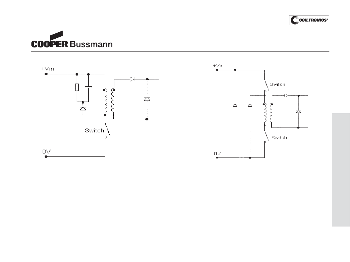
Application Notes
Magnetics
Figure 2
Using an RCD reset network has a number of advan-
tages, it reduces the voltage stress on the switch, it limits
turn off voltage spike and permits operation at greater
than 50% duty cycle. Figure 3 shows a reset method for a
dual switch topology, this method allows the primary
winding to operate in flyback mode with the current flow-
ing through the two recovery diodes. This technique is
similar to that shown in figure 1, the advantages of this
topology include reduced voltage rating requirement for
the switches and no requirement for an auxiliary primary
winding.
Figure 3
PM-197
APPLICATION NOTES
Courtesy of Steven Engineering, Inc.-230 Ryan Way, South San Francisco, CA 94080-6370-Main Office: (650) 588-9200-Outside Local Area: (800) 258-9200-www.stevenengineering.com
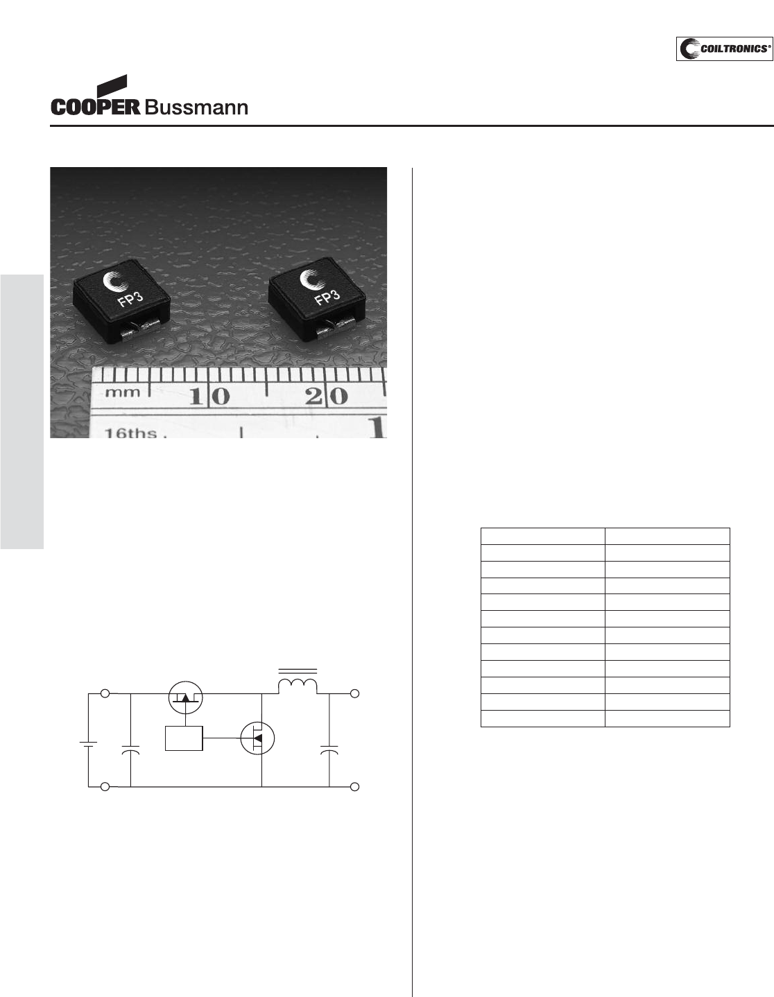
Power Inductors Improve Reliability in High Temperature Designs
The Cooper Coiltronics®brand of High Current FP3™
power inductors from Cooper Bussmann is designed for
high density, medium current applications using a high
temperature iron powder core material. These inductors
do not exhibit the thermal aging issue frequently
associated with iron powder core inductors. In fact the
FP3 core is rated for 200°C without thermal degradation.
The FP3 family is rated for 155°C operation. The
calculations below will allow users to take advantage of
this high temperature capability.
In this example, a buck regulator will be used to convert
a 12V input to a 5V output with a load current of 4.5A.
The operating frequency was chosen to be 600 kHz to
reduce the size of the filter components, while still main-
taining good efficiency. The converter is designed to
have 20% ripple current, so a relatively low ESR output
filter capacitor will be used, as is typical in switching
power supplies.
First calculate the needed inductance value:
V = L * dI/dt where:
V = Vin - Vout (voltage across the inductor)
dT = On time of drive = Vout/Vin/frequency
ΔI = Chosen above to be 20%
Calculate the required inductance:
L = V * dt / ΔI = (12-5)*(12/5/600k)/(0.2*4.5)
L= 4.8 μH
Choose 4.7 μH, the nearest standard value
Recalculate ripple current at 23% using 4.7 μH
Second determine peak to peak flux density, Bp-p:
Bp-p = K * L * ΔI where:
K: K-factor from the adjacent table
L: Inductance μH
ΔI: Peak to peak ripple current (Amps)
Bp-p = 105*4.7*0.23*4.5 = 510 Gauss
Next determine the total losses in the inductor:
Total losses = DC loss + AC loss
DC loss = I2*DCR = 4.52* 0.040 = 0.81 W
(DCR from FP3 datasheet)
AC loss from table at Bp-p of 510 = 0.15 W
Total Loss = DC loss + AC loss = 0.96W
Finally determine the temperature rise.
Total loss = 0.96W, using the table,
Temperature rise is 80°C
Assuming an ambient temperature of 70°C,
The temperature of the inductor is
T = 70 +75 = 150°C
Application Notes
Magnetics
12V
Input
5V
4.5A
PWM
Part Number K-factor
FP3-R10 803
FP3-R20 482
FP3-R47 344
FP3-R68 268
FP3-1R0 219
FP3-1R5 185
FP3-2R0 161
FP3-3R3 127
FP3-4R7 105
FP3-8R2 78
FP3-150 59
PM-198
APPLICATION NOTES
Courtesy of Steven Engineering, Inc.-230 Ryan Way, South San Francisco, CA 94080-6370-Main Office: (650) 588-9200-Outside Local Area: (800) 258-9200-www.stevenengineering.com
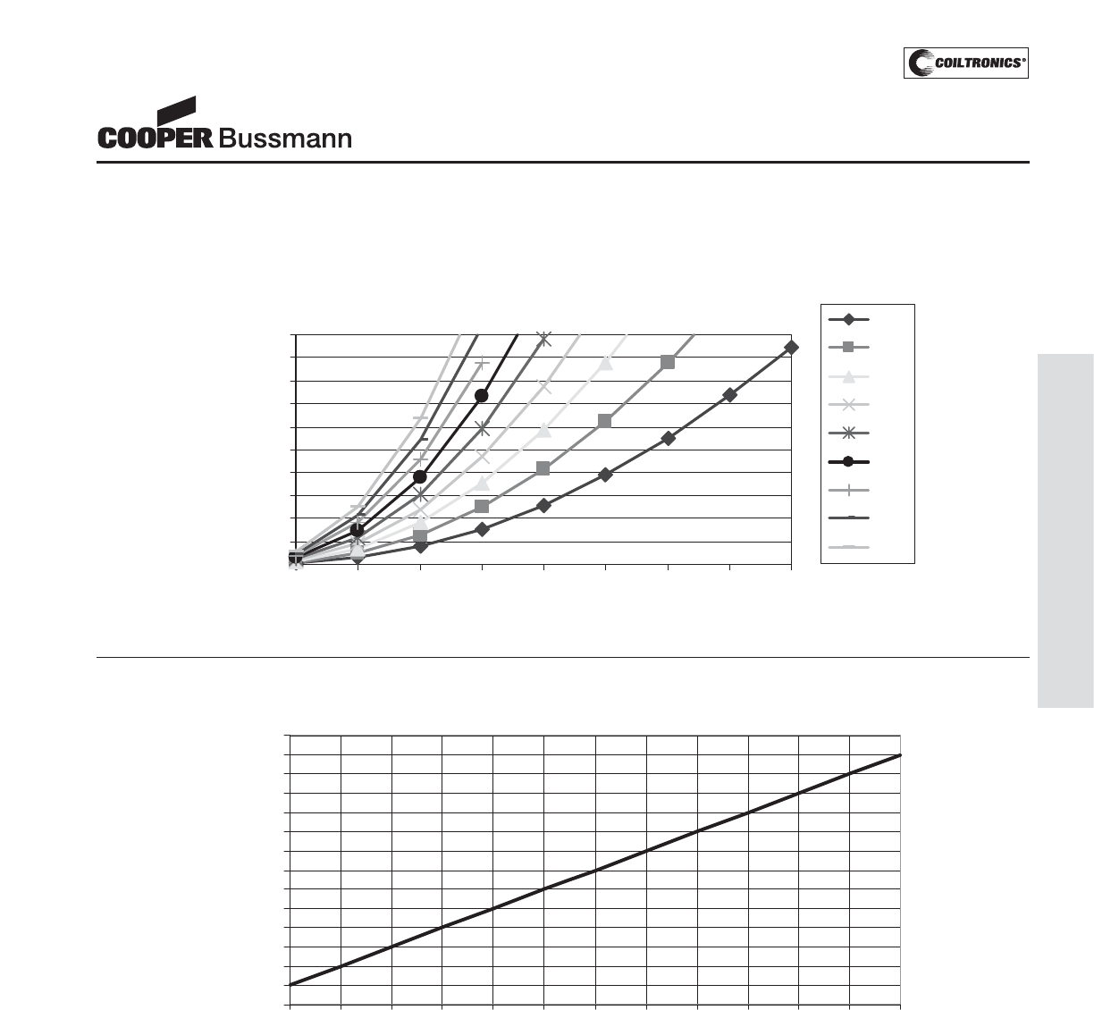
PM-199
APPLICATION NOTES
Application Notes
Magnetics
Note the data assumes no cooling airflow. Cooling will reduce the temperature of the inductor.
The FP3 is rated for 155°C operation.
FP3 AC Loss at Frequency, kHz
CoreLoss vs. Flux Density
0.00
0.10
0.20
0.30
0.40
0.50
0.60
0.70
0.80
0.90
1.00
250 500 750 1000 1250 1500 1750 2000 2250
B p-p
(
Gauss
)
CoreLoss (W)
200
300
400
500
600
700
800
900
1000
Temperature Rise vs. Watt Loss
0
10
20
30
40
50
60
70
80
90
100
110
120
130
140
0.12 0.24 0.36 0.48 0.61 0.73 0.85 0.97 1.09 1.21 1.33 1.45 1.57
Total Loss (W
)
Temperature Rise (C)
Courtesy of Steven Engineering, Inc.-230 Ryan Way, South San Francisco, CA 94080-6370-Main Office: (650) 588-9200-Outside Local Area: (800) 258-9200-www.stevenengineering.com
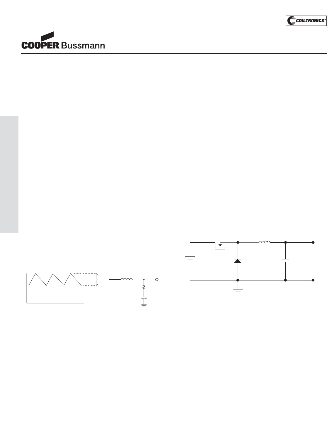
PM-200
APPLICATION NOTES
Switching Regulator Inductor Design
In switching regulator applications the inductor is used as
an energy storage device, when the semiconductor
switch is on the current in the inductor ramps up and
energy is stored. When the switch turns off this energy is
released into the load, the amount of energy stored is
given by;
Energy = 1/2L.I2(Joules) (1)
Where L is the inductance in Henrys and I is the peak
value of inductor current.
The amount by which the current changes during a
switching cycle is known as the ripple current and is
defined by the equation;
V1= L.di/dt (2)
Where V1is the voltage across the inductor, di is the rip-
ple current and dt is the duration for which the voltage is
applied. From this we can see that the value of ripple cur-
rent is dependent upon the value of inductance.
Choosing the correct value of inductance is important in
order to obtain acceptable inductor and output capacitor
sizes and sufficiently low output voltage ripple.
Figure 1
As can be seen from figure 1 inductor current is made up
of AC and DC components, because the AC component
is high frequency it will flow through the output capacitor
as it has a low HF impedance. This will produce a ripple
voltage due to the capacitor ‘equivalent series resistance’
(ESR) that will appear at the output of the switching regu-
lator. This ripple voltage needs to be sufficiently low as
not to effect the operation of the circuit the regulator is
supplying, normally in the order of 10-500mVpk-pk.
Selecting the correct ripple current also impacts on the
size of inductor and output capacitor, the capacitor will
need to have a sufficiently high ripple current rating or it
will overheat and dry out. In order to get a good compro-
mise between inductor and capacitor size a ripple current
value of 10-30% of maximum inductor current should be
chosen. This also means that the current in the inductor
will be continuous for output currents greater that 5-15%
of full load.
Inductor Selection for Buck Converters
When selecting an inductor for a Buck converter, as with
all switching regulators, you will need to define or calcu-
late the following parameters:
• Maximum input voltage
• Output voltage
• Switching frequency
• Maximum ripple current
• Duty cycle
For the example shown in figure 2 lets assume a switch-
ing frequency of 250kHz, input voltage range of
12V±10% and a max ripple current of 220mA.
Figure 2
For an input voltage of 13.2V the duty cycle will be:
D = Vo/Vi= 5/13.2 = 0.379 (3)
Where Vois the output voltage and Viis the input volt-
age.
Voltage across the inductance:
V1= Vi- Vo= 8.2V when the switch is on (4)
V1= - Vo= -5V when the switch is off (5)
Require inductance:
L = V1.dt/di = (8.2 x 0.379/250 x 103)/0.22 (6)
L = 56.5μH
Application Notes
Magnetics
Vout
ESR
Buck Induc r to
2
1
I load dI
0
I Inductor
Switch Buck Inductor
Input Voltage
12 V Freewheeling
Diode Output
Cap
5V
Output
Voltage
Courtesy of Steven Engineering, Inc.-230 Ryan Way, South San Francisco, CA 94080-6370-Main Office: (650) 588-9200-Outside Local Area: (800) 258-9200-www.stevenengineering.com
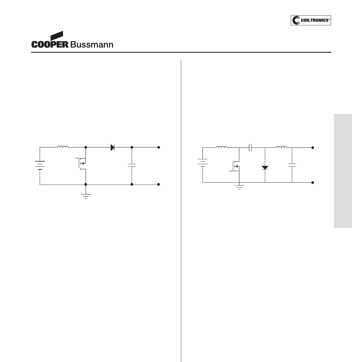
Application Notes
Magnetics
Inductor Selection for Boost Converters
In order to calculate the require value of inductance for
a Boost converter we follow the same procedure as
described for the Buck converter, the difference being that
the equations for duty cycle and inductor voltage change.
Taking maximum input voltage as 5.5V, switching
frequency as 100kHz and maximum ripple current as
0.1A.
Figure 3
Duty cycle:
D = 1 – (Vi/Vo) = 1 – (5.5/12) = 0.542 (7)
Inductor Voltage:
V1= Vi= 5.5V when the switch is on (8)
V1= Vo– Vi= 6.5V when the switch is off (9)
Using equation 6, inductance:
L = (5.5 x 0.542/100 x 103)/0.1
L = 298μH
One thing to note about the Boost converter topology is
that, unlike the Buck converter, inductor current does not
continuously flow to the load. During the switch ‘on’ period
the inductor current flows to ground and the load current
is supplied from the output capacitor. This means that the
output capacitor must have sufficient energy storage
capability and ripple current rating in order to supply the
load current during this period.
Inductor Selection for Buck-Boost Converters
(including Cuk & SEPIC)
The procedure shown here is for the Cuk converter but it
applies equally well to the SEPIC and the single inductor
Buck-Boost topologies. Initially we will consider the circuit
utilizing two separate inductors of equal value and then
look at some of the advantages of using coupled inductors.
For this example we shall use a switching frequency of
200kHz and a maximum ripple current of 200mA.
Figure 4
Duty cycle:
D = Vo/(Vo+ Vi) = 12/(12+18) = 0.4 (10)
Inductor voltages:
V1= Vi= 18V when the switch is on (11)
V1= Vo= 12V when the switch is off (12)
Using equation 6, inductance:
L = (18 x 0.4/200 x 103)/0.2
L = 180μH
Both the SEPIC and Cuk topologies offer advantages
over the single inductor Buck-Boost design. Input current
is continuous resulting in lower peak values, drive circuit
requirements are simple due to switch location and the
use of a coupled inductor reduces the cost and PCB
space penalties of these topologies.
One thing to note when using coupled inductors, for the
total ripple current and total inductive energy stored to
remain the same the inductance of each winding should
be halved (for our example Lcouple = 90μH).
Boost Inductor Diode
Input Voltage
5V Switch Output
Cap
12V
Output
Voltage Diode
Switch Output
Cap Output
Voltage
Inductor 1 Inductor 2
Coupling
Cap
Input 5-18V
-12V
PM-201
APPLICATION NOTES
Courtesy of Steven Engineering, Inc.-230 Ryan Way, South San Francisco, CA 94080-6370-Main Office: (650) 588-9200-Outside Local Area: (800) 258-9200-www.stevenengineering.com
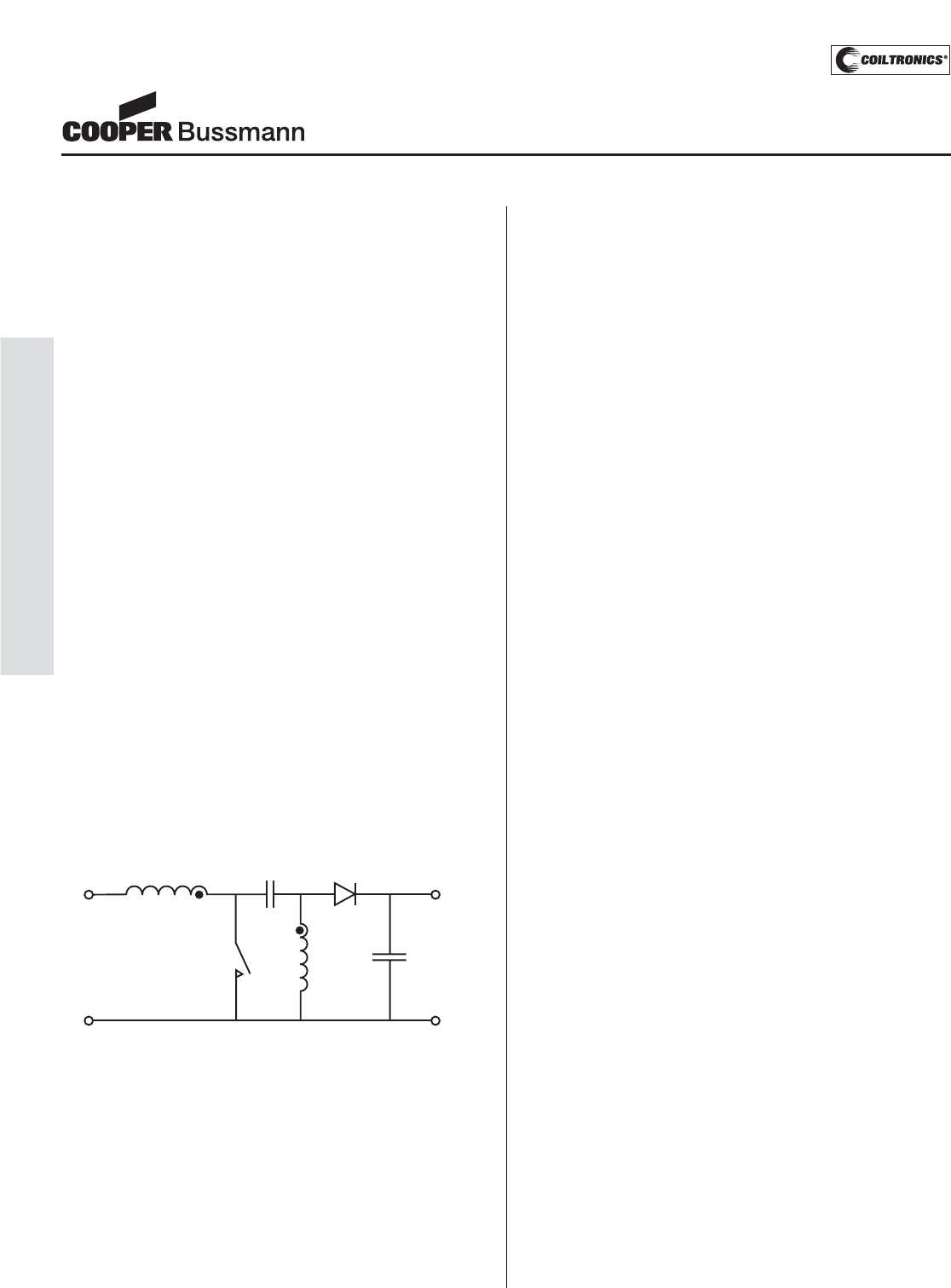
PM-202
APPLICATION NOTES
Inductor Selection for SEPIC Designs
The SEPIC (single-ended primary inductance converter)
in an increasingly popular topology, particularly in battery
powered applications, as the input voltage can be higher
or lower than the output voltage. This presents obvious
design advantages but for many engineers the circuit
operation and component selection is a mystery, for those
that understand the basics the addition of a coupled
inductor is an added complication. This article looks at the
operation of the SEPIC and compares the design proce-
dure for two single winding inductors with a coupled
inductor approach.
Basic Operation
Figure 1 shows the simple circuit diagram for a SEPIC,
during the switch (SW) ON time the voltage across both
inductors is equal to Vin. This is obvious for L1, however it
is not so clear for L2. In order to understand this we first
need to look at the voltage across Cp, neglecting ripple
voltage, this voltage is constantly at the value of Vin. The
simplest way to see this is when the circuit is at equilibri-
um, under these conditions there is no DC voltage across
L1 or L2, so one side of the capacitor is at Vin and the
other at zero volts.
When the switch is ON capacitor Cp is connected in par-
allel with L2, hence the voltage across L2 is the same as
the capacitor voltage, -Vin. This in turn means that diode
D1 is reverse bias and the load current is being supplied
by capacitor Cout. During this period energy is being
stored in L1 from the input and in L2 from Cp.
Figure 1 - Simple SEPIC Circuit
When the switch turns off the current in L1 continues to
flow through Cp, D1 and into Cout and the load recharg-
ing Cp ready for the next cycle. The current in L2 also
flows into Cout and the load, ensuring that Cout is
recharged ready for the next cycle.
During this period the voltage across both L1 and L2 is
equal to Vout, once again this is fairly clear for L2 but no
so for L1. However we already know that the voltage
across Cp is equal to Vin and that the voltage on L2 is
equal to Vout, in order for this to be true the voltage at the
node of Cp and L1 must be Vin + Vout. This in turn
means that the voltage across L1 is (Vin+Vout) – Vin =
Vout.
Inductor Selection
First, let us look at the selection of two separate inductors
for L1 and L2 in the following example:
Input voltage (Vin) – 2.8V – 4.5V
Output (Vout & Iout) – 3.3V, 1A
Switching Frequency (Fs) – 250kHz
Efficiency - 90%
First we need to calculate the duty cycle;
D = Vout/(Vout + Vin)
The worst case condition for inductor ripple current is at
maximum input voltage so;
D = 3.3/(3.3 + 4.5) = 0.423
Normally, the output inductor is sized to ensure that the
inductor current is continuous at minimum load and that
the output voltage ripple does not affect the circuit that
the converter is powering. In this case we will assume a
20% minimum load thus allowing a 40% peak to peak rip-
ple current in the output inductor L2.
Calculating the value of L2;
V = L di/dt
Where V is the voltage applied to the inductor, L in the
inductance, di is the inductor peak to peak ripple current
and dt is the duration the voltage is applied for. Hence;
L = V.dt/di
dt = 1/Fs x D
dt = 1/(250 x 103) x 0.423 = 1.69 μs
V = Vin during the switch ON time so;
L2 = 4.5 x (1.69 x 10-6/0.4)
L2 = 19 μH
Using the nearest preferred value would lead to the
selection of a 22 μH inductor. It is common practice to
select the same value for both input and output inductors
Application Notes
Magnetics
L1
Vin
SW L2
Cp D1
Cout
Vout
+
Courtesy of Steven Engineering, Inc.-230 Ryan Way, South San Francisco, CA 94080-6370-Main Office: (650) 588-9200-Outside Local Area: (800) 258-9200-www.stevenengineering.com

PM-203
APPLICATION NOTES
Application Notes
Magnetics
in SEPIC designs although when two separate parts are
being used it is not essential.
Having selected the inductance value we now need to
calculate the required RMS and peak current ratings for
both inductors.
For input inductor L1;
Irms = (Vout x Iout)/(Vin (min) * efficiency)
Irms = (3.3 x 1)/(2.8 x 0.9) = 1.31A
Ipeak = Irms + (0.5 x Iripple)
Although worst case ripple current is at maximum input
voltage the peak current is normally highest at the mini-
mum input voltage.
Iripple = (V.dt)/L
Iripple = (2.8 x 2.2 x 10-6)/22 x 10 -6 = 0.28A
Ipeak = 1.31 + 0.14 =1.45A
So a 22μH, 1.31Arms & 1.45Apk rated inductor is
required. For example the DR73-220 from Cooper
Coiltronics®, this part is 7.5mm square and 3.5mm high
with 1.62Arms and 1.67Apk current ratings.
For the output inductor L2
Irms = Iout = 1A
Iripple = (4.5 x 1.69 x 10-6)/22 x 10-6 = 0.346A
Ipeak = 1 + 0.173 = 1.173A
So a 22μH, 1Arms & 1.173Apk rated inductor is required,
which for simplicity could be the same DR73-220 inductor
used for L1.
Coupled Inductor Selection
When calculating the value for a coupled inductor you
need to bear in mind that all the current is effectively flow-
ing in one inductor and that if the two windings are close-
ly coupled the ripple current will be split equally between
them. So calculating the inductance value;
L = V.dt/di
From our earlier example the output ripple current needs
to be 0.4Apk-pk, so now we calculate for 0.8A as the
ripple current is split between the two windings
L = 4.5 x (1.69 x 10-6/0.8) = 9.5μH
From this it can be seen that by using a coupled inductor
the required inductance is halved. It is also important to
note that because the two winding are on the same core
they must be the same value. If they are not the voltage
across each winding will not be equal and Cp will act as a
short circuit to the difference.
Continuing with the example using an inductance value of
10μH we now need to calculate the worst case peak cur-
rent requirement. We already know the RMS current in
each winding,
Input inductor RMS current = 1.31A
Output inductor RMS current = 1A
Ipeak = Iin + Iout + (0.5 x Iripple)
Iripple = (2.8 x 2.2 x 10-6)/10 x 10-6 = 0.62A
Ipeak = 1.31 + 1 + 0.31 = 2.62A @ minimum input
voltage
So a 10μH coupled inductor with 2.31Arms and 2.62Apk
current ratings is required, for example DRQ74-100.
This part has the same 7.5mm square footprint as the
DR73-220 that was selected in the example using
separate inductors but is 4.35mm high.
Using a coupled inductor takes up less space on the
PCB and tends to be lower cost than two separate induc-
tors. It also offers the option to have most of the inductor
ripple current flow in either the input or the output. This is
achieved by using a winding construction that positions
most of the leakage inductance in one winding, this will
cause most of the ripple current to appear in the opposite
winding. By doing this the need for input filtering can be
minimized or the output ripple voltage can be reduced to
very low levels when supplying sensitive circuits.
Cooper Bussmann offers a number of coupled inductor
options from the Cooper Coiltronics®range, including the
SDQ and DRQ series of shielded drum inductors and the
Econo-Pac and Octa-Pac range of toroid inductors. With
inductance values from 0.33μH to 1mH and sizes from
5.2mm 2 x 1.2mm high up to 12.5mm 2 x 8mm high
Cooper Coiltronics®offers one of the broadest ranges of
coupled inductor solutions.
Courtesy of Steven Engineering, Inc.-230 Ryan Way, South San Francisco, CA 94080-6370-Main Office: (650) 588-9200-Outside Local Area: (800) 258-9200-www.stevenengineering.com
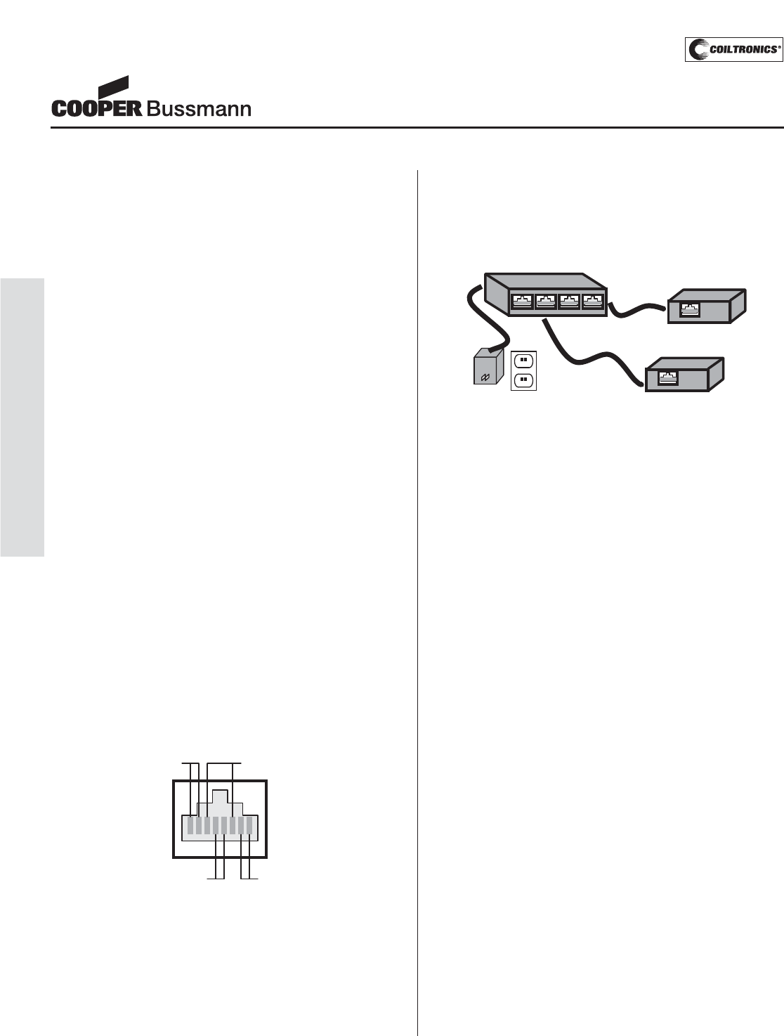
PM-204
APPLICATION NOTES
PoE Power Magnetics - Options and Trends
What is Power over Ethernet technology?
Ethernet enabled devices require both data connectivity
and a power supply. Power over Ethernet (PoE) technol-
ogy allows Ethernet devices to receive power as well as
data over standard category 5 Ethernet cable. PoE is
governed by the standard defined in IEEE802.3af.
Specific details of the 802.3af standard are available
from the Institute of Electrical and Electronic Engineers
at www.ieee.org. This article highlights an easy to use,
low cost Cooper Coiltronics®PoE power magnetic selec-
tion. In short, the PoE port allows a powered device (PD)
to draw up to 12.95W from the power-sourcing equip-
ment (PSE). PSE controls the PoE port and it identifies
PDs via detection and classification before powering the
port. The big advantage of PoE is the elimination of the
nuisance “wall wart” power converters. In this case, the
need to install additional AC power outlets and connect
electrical wires to each terminal is eliminated. Only one
cable is needed for your appliance. PoE promises to cre-
ate a new world of network appliances by saving space,
lower cost, easier maintenance and flexible installation.
What is Power over Ethernet application?
PoE is gaining in popularity and manufacturers already
have products on the market such as VoIP (Voice over
Internet Protocol) telephones, UPS, Wireless LAN
access points, Bluetooth access points, Network cam-
eras, Building access systems, Time and attendance
systems, Retail point-of-information systems, Battery
chargers for mobile phones and PDAs, Vending
machines and Gaming machines.
Cooper Coiltronics Power Over Ethernet Transformer
and characteristics
In order to comply with IEEE802.3af PoE standard,
Powered Device (PD) must meet the isolation require-
ment. Dc-Dc converters solve the isolation problem.
Forward and Flyback switcher topologies can use
Cooper Coiltronics PoE transformers to isolate the PD’s
PoE interface from the rest of its circuitry while stepping
down the PoE input voltage to power the PD circuitry.
Cooper Coiltronics PoE transformers support 1500VAC
isolation in the power converter with feedback voltage of
11V at 0.1A. Available in 4W, 7W and 13W, the trans-
formers accept input voltage range from 29.5V to 60V
using a nominal 250KHz switching frequency. An EFD15
core is used in 4W and 7W transformers while an EFD17
core is used in the 13W transformers. The EFD17 is a
core developed by Cooper Bussmann to fit in between
the EFD15 and EFD20 core sizes, and allows a smaller
solution than most competitive devices for the same
output power. These components operate in ambient
temperatures between -40 and +85 degrees Celsius.
Due to the size, Cooper Coiltronics PoE transformers
can handle DC current of PoE and are rated for
operating temperatures up to 125 degrees Celsius.
Cooper Coiltronics PoE transformers feature split prima-
ry and secondary windings to minimize leakage induc-
tance – minimizing the result of imperfect magnetic link-
ing of one winding to another. These components allow
multiple output variations. 3.3V and 5V PoE transformers
support three outputs while 12V transformers support
two outputs. Each of them has same output current
and voltage. Alternately, the isolated windings can be
combined in series to produce additional voltage
combinations.
PoE13W3VERS has three different outputs, 7V, 3.3V
and 1.8V respectively. These outputs can be connected
in series to produce a converter with 1.8V, 5.1V and
12.1V from the same transformer. The series configura-
tion produces optimal cross regulation between outputs.
PoE13W2VERS has two different outputs, 5V and 3.3V.
VERS refers to the Cooper Coiltronics Versa-Pac®prod-
1 8
Signal Pair 2Signal Pair 1
Spare Pair 2
(Power)
Spare Pair 1
(Power)
RJ-45
Power Sourcing Equipment (PSE)
(Switch/Router/Hub)
AC Power Powered Device (PD)
(Modem/Display/Printer...)
Powered Device (PD)
(Modem/Display/Printer...)
Application Notes
Magnetics
Courtesy of Steven Engineering, Inc.-230 Ryan Way, South San Francisco, CA 94080-6370-Main Office: (650) 588-9200-Outside Local Area: (800) 258-9200-www.stevenengineering.com
PM-205
APPLICATION NOTES
Application Notes
Magnetics
uct lines that offer more than 500 usable inductor or
transformer configurations. The same concept has been
used in the PoE transformer family. Connecting the
windings in parallel will increase the current carrying
capability while connecting in series will increase the
output voltage. These components provide flexibility in
the design to connect the winding in series or parallel,
and thereby achieving higher voltage or current.
Future trend- High Power over Ethernet (HPoE)
The current IEEE802.3af standard is restricted to low
power devices but the demand to standardize high
power PoE is increasing. A standard capable with double
the power limit of 13W on a 48V input was proposed.
High Power over Ethernet needs same level of safety,
reliability and should be backwards compatibility with the
IEEE 802.3af standard. Cooper Coiltronics is also
introducing 26W HPoE transformers. Due to power
and efficiency requirements, Forward converters with
synchronous
rectification are used. A gate drive winding will be
provided on the secondary side. The operating frequency
is 300KHz - available in 3.3V and 5V outputs. The new
standard delivers power to laptops, advanced network
cameras, videophone, flat screen monitor and other
high power consumption Ethernet devices.
Conclusion
With the introduction of the IEEE Power over Ethernet
standard, the advantages of easy installation and
robustness of a powered network has quickly lead to
the introduction of many new network appliances. Higher
power devices demand the same advantage, since
reducing cost is always a driver for implementing new
technology. As a key player manufacturing power
magnetics, Cooper Coiltronics offers a series of
standard PoE products suitable to use in Dc-Dc
converters. Samples are available upon request
and the datasheet is available in the website:
www.cooperbussmann.com.
Courtesy of Steven Engineering, Inc.-230 Ryan Way, South San Francisco, CA 94080-6370-Main Office: (650) 588-9200-Outside Local Area: (800) 258-9200-www.stevenengineering.com
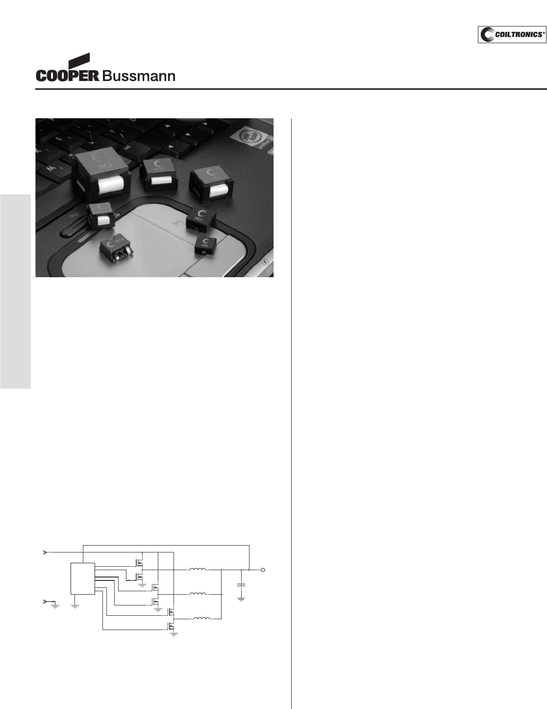
High Current Inductors for DC-DC Converters
State-of-the-art power supply design of DC-DC
converters requires maximum thermal efficiency, low
switching losses and platform scalability. Overall systems
efficiency can be improved by the advancements in
strategic power components. When striving for maximum
efficiency, low switching components losses and parasitic
inductance losses are critical. This is driven by increasing
performance requirements of new microprocessors
ranging from 10A to120A and starting 50nH.
High current inductors can be found in many DC-DC
converter applications such as:
• VRM (Multi-phase for Servers / Desktop /
Notebook computers)
• DDR Memory Power Supply(Synchronous
Buck and Multi-phase Converters)
• GPU Graphics cards (Buck and Multi-phase
Converters)
Voltage Regulators
Multi-phase VRMs for High-End Desktops, Servers,
and Notebook Computers
The evolution of today’s microprocessors requires high
frequency synchronous buck converters to provide highly
efficient power to high current low voltage processors
with fast transient response. High frequency switching
translates back to increased FET losses as the major
contributor to switching loss. The combined DC and AC
loss in inductors is the next highest contributor of power
loss. A roadmap of modern CPU’s shows that processor
current will keep increasing up to 200Amps by 2006
(5 phases, 40A/phase). High current inductors can
positively impact the overall system’s efficiency by up
to 2%. A well packaged high current inductor: provides
higher energy density and low loss (Core and Copper
loss) and can be available in both THT and SMT which
brings flexibility to chipset developers.
Cooper Coiltronics®
Cooper Coiltronics brand magnetics from Cooper
Bussmann offer a wide variety of standard and
customized solutions. We specialized in inductors
and transformers for DC-DC power conversion and
switch-mode applications requiring high frequency
magnetics. Our products are used in many standard
topologies including:
• EMI/ Noise Filter: Common Mode and Series Mode
• Averaging Choke: Buck and Boost
• Coupled Inductors: Coupled Choke, Flyback, Sepic
The Cooper Coiltronics High Current and Flat-Pac induc-
tor product lines provide an optimal mix of innovative
packaging, high efficiency and unbeatable reliability.
We invest in new technologies that deliver superior
performance by providing high power density and
reduced inductor size when compared to conventional
solutions. Core and conductor losses become more
critical as higher switching frequencies are used. Our
designs utilize low loss core materials, new and custom
core shapes in combination with innovative construction
and packaging to provide power supply designers with
the highest performance parts available in the market.
Summary
Cooper Coiltronics magnetic component solutions deliver
high performance, innovative packaging, scalability and
unbeatable reliability. Our wide variety of High Current
and Flat-Pac inductors are specifically developed for
today and tomorrow’s DC-DC converters. For all your
high current inductor and transformer needs,
Cooper Coiltronics is your best power magnetics
solution partner.
Application Notes
Magnetics
PWM
Control
PM-206
APPLICATION NOTES
Courtesy of Steven Engineering, Inc.-230 Ryan Way, South San Francisco, CA 94080-6370-Main Office: (650) 588-9200-Outside Local Area: (800) 258-9200-www.stevenengineering.com
PM-207
MAGNETICS DESIGN SPECIFICATION FORM
Standard 䡺ER 11/5-SG1 䡺ER 14.5/6-SG2 䡺EFD 15-SG3 䡺EFD 17-SG4 䡺EFD 20-SG5
Geometry 䡺EE 8.3-SG6 䡺EF 12.6-SG7 䡺EE 13-SG8 䡺SEE 16-SG9
Topology 䡺Buck 䡺Boost 䡺Flyback 䡺Coupled inductor
䡺Forward 䡺Gate Drive 䡺SEPIC 䡺Common Mode
Company: Application:
Contact: Sales Contact: Date:
Address: Sample Quantity: Quote Only
Phone: Target Cost:
Fax: Email: Estimated Annual Quantity:
Frequency Range: Duty cycle: 䡺Continuous 䡺Discontinuous
Input Voltage:
Power:
Output Voltage (s) @ Continuous Current:
Inductance:
Input Switch Current (Ipk):
Max Ambient Temp:
DC Resistance (DCR):
Dielectric Withstanding Voltage (Hypot):
Mounting: 䡺Surface Mount 䡺Thru-Hole Specify mounting pad or hole dimensions below.
Max Dimensions Length: Width: Height:
Agency Approvals? 䡺Yes Agency and Document Number:
Magnetics Design Specification Form
Schematic, Notes & Sketch:
DESIGN PRIORITY
Cost 䡺
Size 䡺
Efficiency 䡺
Magnetics
Courtesy of Steven Engineering, Inc.-230 Ryan Way, South San Francisco, CA 94080-6370-Main Office: (650) 588-9200-Outside Local Area: (800) 258-9200-www.stevenengineering.com

PM-208
Power Magnetics Group
NOTES
Courtesy of Steven Engineering, Inc.-230 Ryan Way, South San Francisco, CA 94080-6370-Main Office: (650) 588-9200-Outside Local Area: (800) 258-9200-www.stevenengineering.com

P
OWER
M
ANAGEMENT
Courtesy of Steven Engineering, Inc.-230 Ryan Way, South San Francisco, CA 94080-6370-Main Office: (650) 588-9200-Outside Local Area: (800) 258-9200-www.stevenengineering.com
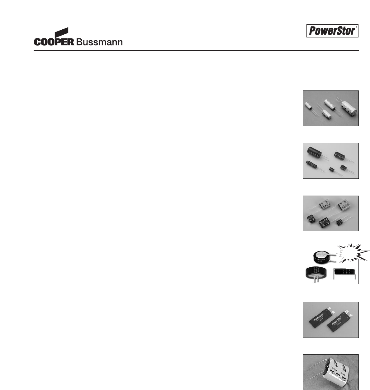
PS-1
Design Guides
Application Guidelines . . . . . . . . . . . . . . . . . . . . . . . . . . . . . . . . . . . . . . . . . . . . . . . . . . . . . . .Page PS-16
Measurement Techniques . . . . . . . . . . . . . . . . . . . . . . . . . . . . . . . . . . . . . . . . . . . . . . . . . . . . .Page PS-20
Aerogel Supercapacitor Calculator . . . . . . . . . . . . . . . . . . . . . . . . . . . . . . . . . . . . . . . . . . . . .Page PS-22
Marketing Bulletins
Design Considerations In Selecting Aerogel Supercapacitors . . . . . . . . . . . . . . . . . . . . . .Page PS-24
Aerogel Supercapacitor Provide Both High Energy and High Power Capability . . . . . . .Page PS-26
Customer / Application Information Worksheet . . . . . . . . . . . . . . . . . . . . . . . . . . . . . . . . . . . . . . .Page PS-30
Table of Contents
PowerStor’s A Series Aerogel Capacitors are unique, ultra-low ESR (Equivalent Series Resistance) cylindrical
devices based on a novel type of carbon foam, known as carbon aerogel. These ultra-low ESR A Series cylindrical
devices are specifically designed for low-duty cycle, high rate pulse power applications.
PowerStor’s B Series are ultra-high capacitance cylindrical supercapacitors designed to complement the original
ultra-low ESR A Series. The B Series have three times the capacitance of the A Series by volume but only two
times the ESR. This combination of ultra-high capacitance and low ESR makes the B Series extremely
versatile for a wide range of high-duty cycle, high rate and main power applications.
Aerogel Supercapacitors - A Series . . . . . . . . . . . . . . . . . . . . . . . . . . . . . .Page PS-4
Aerogel Supercapacitors - B Series . . . . . . . . . . . . . . . . . . . . . . . . . . . . . .Page PS-6
Aerogel Supercapacitors - P Series . . . . . . . . . . . . . . . . . . . . . . . . . . . . . .Page PS-8
PowerStor’s P Series Aerogel Capacitors are designed for 5 volt applications. These devices have ESR values up
to several orders of magnitudes lower than traditional 5V memory backup devices and as a result can also be used in
pulse power and hold-up power applications. P Series supercapacitors are radial leaded devices and available in
vertical and horizontal configurations.
Product Overview . . . . . . . . . . . . . . . . . . . . . . . . . . . . . . . . . . . . . . . . . . . . .Page PS-2
PowerStor’s F series are unique ultra-thin, flat supercapacitors. PowerStor was the first in the world to
commercialize these supercapacitors. Their design is ideal for space-constrained applications, including PCMCIA
cards, hand-held devices, and hybrid battery-supercapacitor packs. F Series supercapacitors are custom designed
with high energy density or ultra-low ESR to meet each different application’s requirements.
Aerogel Supercapacitors - F Series . . . . . . . . . . . . . . . . . . . . . . . . . . . . .Page PS-13
PowerStor’s KR series are high capacitance 5.5V devices that utilize coin cell construction. These devices are
available in horizontal, vertical and cylindrical package styles and are designed for low current memory and RTC
backup applications.
Aerogel Supercapacitors - KR Series . . . . . . . . . . . . . . . . . . . . . . . . . . .Page PS-10
When a standard supercapacitor is not sufficient, PowerStor offers custom product design to meet an
application’s specific requirements. PowerStor has the capability to custom design through rapid prototyping
new supercapacitors by modifying their size and shape, ESR, capacitance, voltage or temperature capabilities.
Custom Product Offering . . . . . . . . . . . . . . . . . . . . . . . . . . . . . . . . . . . . .Page PS-15
NEW
Courtesy of Steven Engineering, Inc.-230 Ryan Way, South San Francisco, CA 94080-6370-Main Office: (650) 588-9200-Outside Local Area: (800) 258-9200-www.stevenengineering.com
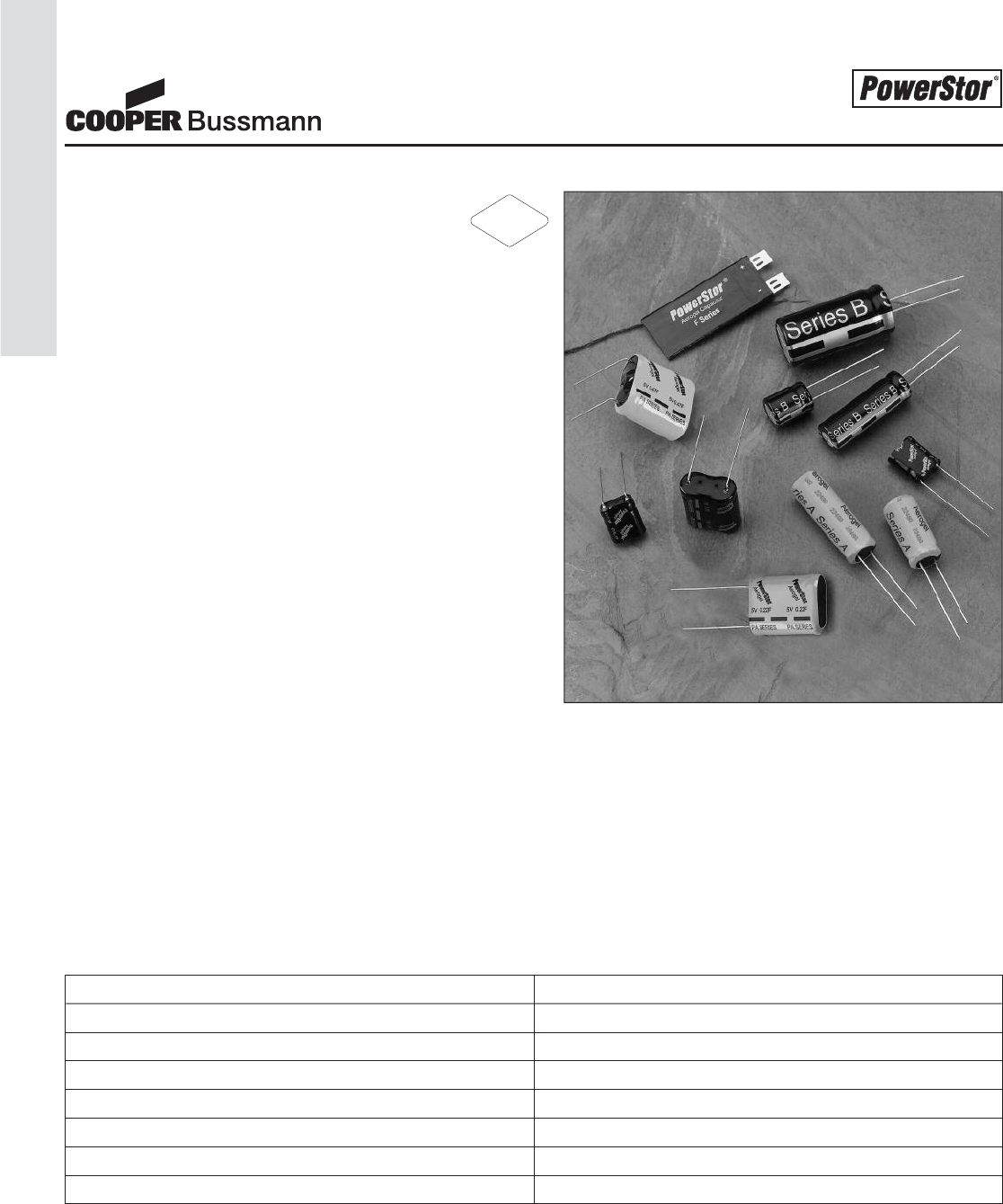
PS-2
Product Overview
Superior Supercapacitor Technology
• Based on novel Aerogel carbon foam
Broad Standard Product Line
• Cylindrical and prismatic packages
• High power (low ESR) and high energy
Custom Product Capabilities
• Application specific designs
• Size and shape, capacitance, ESR, voltage, temperature
Applications
Pulse Power
• Low duty cycle pulse power
• Hybrid battery-supercapacitor systems
• Valve/solenoid actuation, HVAC controls
• Radio transceivers, GSM/GPRS devices
• Automated meters, portable printers
Bridge (or Hold-up) Power
• Portable data terminals
• Tape drives
• Set top gaming devices
• Infusion pumps
• Automotive, avionics, military and medical
Main Power
•Toys
• Solar charged devices (lighting, signaling,
remote monitoring systems)
• Uninterruptible power systems
Memory Backup
• Microprocessor and micro-controller backup
• RAM / SRAM memory protection
• Real time clock (RTC) backup
Features Benefits
Low ESR High discharge power / rate capability
High capacitance Long runtime / high energy density
Stable materials Long life over wide temperature range
Static charge / discharge process; no chemical reactions Nearly infinite cycle life
Series / parallel configurations Higher voltage and energy than individual supercapacitors
Supercapacitor properties can be tailored Custom for specific energy / power requirement
Custom packaging Meet most mechanical requirements
Product Overview
RoHS
2002/95/EC
Courtesy of Steven Engineering, Inc.-230 Ryan Way, South San Francisco, CA 94080-6370-Main Office: (650) 588-9200-Outside Local Area: (800) 258-9200-www.stevenengineering.com
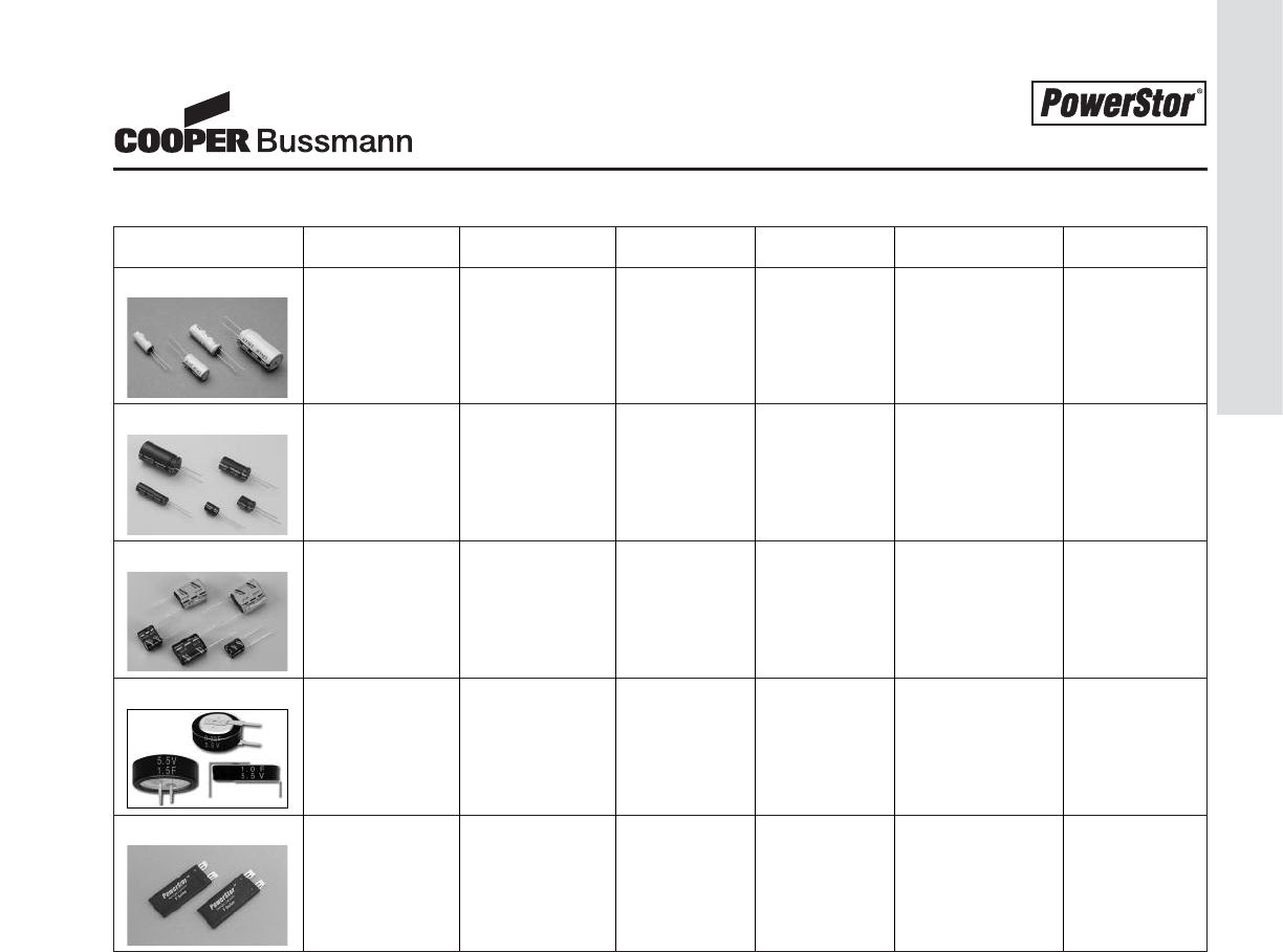
PS-3
Product Overview
Product Code Key Features Key Benefits Capacitance ESR Voltage (Nominal) Temperature
A Series Ultra-low ESR Very High 0.47 to 4.7F 0.025 to 2.5V -25°C to 70°C
(Resistance) pulse power 0.150 Ohms
capability
B Series High energy Long 0.22 to 50F 0.025 to 2.5V -25°C to 70°C
density run-time 3 Ohms
capability
P Series Higher Designed 0.1 to 1F As low as 5V -25°C to 70°C
Voltage for 5V 0.2 Ohms
applications
KR Series High energy Long back-up 0.1 to 1.5F 30 to 5.5V -25°C to 70°C
density & time in 5V 75 Ohms
higher voltage applications
F Series Polymer-foil Fits into space 0.33F 0.250 Ohms 3.6V -20°C to 60°C
laminate constrained
packaging applications as
thin as 2mm
Product Overview
Courtesy of Steven Engineering, Inc.-230 Ryan Way, South San Francisco, CA 94080-6370-Main Office: (650) 588-9200-Outside Local Area: (800) 258-9200-www.stevenengineering.com
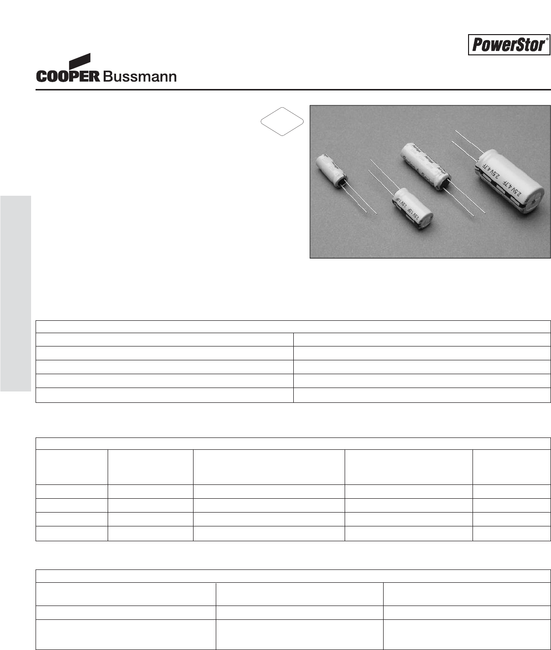
PS-4
Aerogel Supercapacitors - A Series
STANDARD PRODUCTS
Nominal Part Nominal ESR Nominal Dimensions Typical Mass
Capacitance Number (Equivalent Series Resistance) (grams/1 piece)
(F) Measured @ 1kHz (Ω)
0.47 A0820-2R5474-R 0.150 Ø = 8 mm; L = 20 mm 1.8
1.0 A1020-2R5105-R 0.090 Ø = 10 mm; L = 20.5 mm 2.6
1.5 A1030-2R5155-R 0.060 Ø = 10 mm; L = 30 mm 3.8
4.7 A1635-2R5475-R 0.025 Ø = 16 mm; L = 35 mm 10.7
Aerogel Supercapacitors
A Series
Description
The PowerStor®Aerogel Capacitor is a unique,
ultra-high capacitance device based on a novel type
of carbon foam, known as carbon aerogel. Aerogel capacitors
are similar to supercapacitors, ultracapacitors and
electrochemical double layer capacitors (EDLCs) with the
added benefit of low ESR (Equivalent Series Resistance).
Features & Benefits
• Very low ESR
• Low leakage current
• Long cycle life
• High useable capacity
• Very high specific capacitance
also available (B Series)
Applications
• Pulse power
• Hold-up power
• DC/DC converters
• Hybrid battery packs
• Valve / solenoid actuation
SPECIFICATIONS
Working Voltage 2.5 volts
Surge Voltage 3.0 volts
Nominal Capacitance Range 0.47 to 4.7 F
Capacitance Tolerance -20% to +80% (20°C)
Operating Temperature Range -25°C to 70°C
PERFORMANCE
Parameter Capacitance Change ESR
(% of initial measured value) (% of initial specified value)
Life (1000 hrs @ 70°C @ 2.5 volts DC) ≤30 ≤300
Storage - Low and High Temperature ≤30 ≤300
(1000 hrs @ -25°C and 70°C)
CYLINDRICAL DEVICE
RoHS
2002/95/EC
Courtesy of Steven Engineering, Inc.-230 Ryan Way, South San Francisco, CA 94080-6370-Main Office: (650) 588-9200-Outside Local Area: (800) 258-9200-www.stevenengineering.com
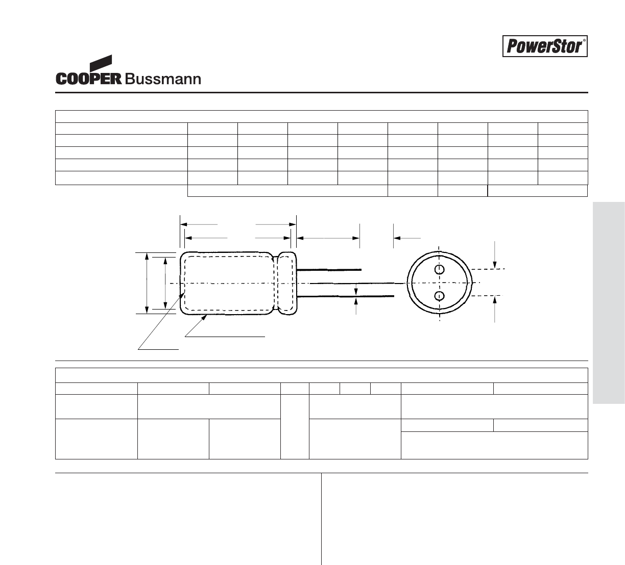
PS-5
Aerogel Supercapacitors - A Series
DIMENSIONS (mm)
Part Number D D' L L' F d' C C'
A0820-2R5474-R 8.0 8.5 20.5 21.0 3.5 0.50 20.0 5.0
A1020-2R5105-R 10.0 10.5 21.8 22.3 5.0 0.60 20.0 5.0
A1030-2R5155-R 10.0 10.5 31.0 31.5 5.0 0.60 20.0 5.0
A1635-2R5475-R 16.0 16.5 37.5 38.0 7.5 0.80 20.0 5.0
Manufacturer
Capacitance (F)
Max. Operating Voltage (V)
Series Code (or part number)
Polarity Marking
Standard packaging: Bulk, 100 units per package.
Special packaging available upon request. Contact
factory.
PART MARKINGPACKAGING INFORMATION
L'
LCC'
F±0.5
Ød'
PVC SLEEVE
VENT
ØD
ØD'
Minimum± 0.02± 0.5Maximum
Note: Longer lead is positive
Aerogel Supercapacitors
A Series
PART NUMBERING SYSTEM
A -2R5
Series Dimensions (mm) Voltage (V) Capacitance (μF)
Code R is decimal
B = Very Diameter Length Value Multiplier
Low ESR 2R5 = 2.5V Example:
475 = 47 x 105μ F or 4.7 F
Courtesy of Steven Engineering, Inc.-230 Ryan Way, South San Francisco, CA 94080-6370-Main Office: (650) 588-9200-Outside Local Area: (800) 258-9200-www.stevenengineering.com
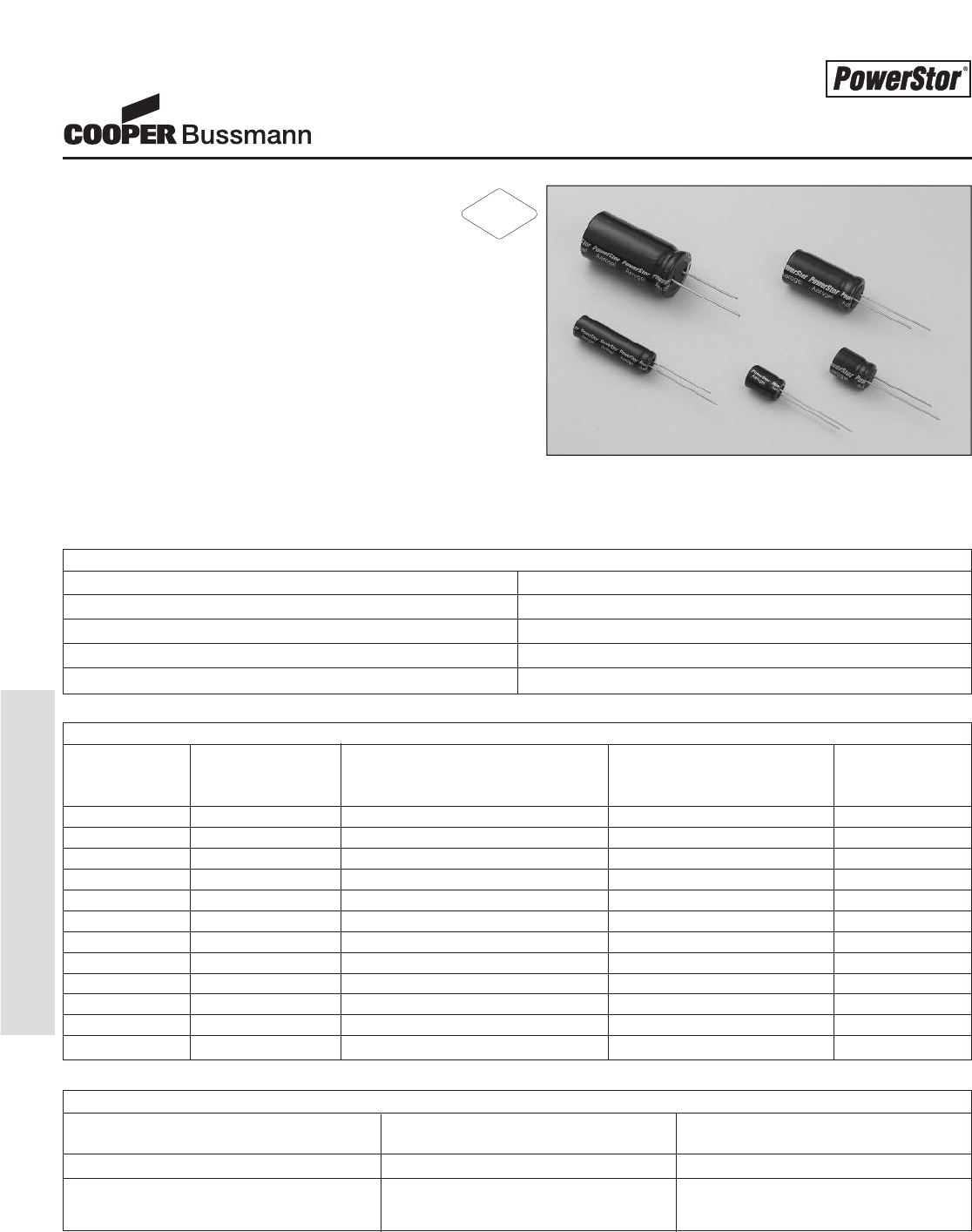
PS-6
Aerogel Supercapacitors - B Series
Aerogel Supercapacitors
B Series
Description
The PowerStor®Aerogel Capacitor is a unique,
ultra-high capacitance device based on a novel type of car-
bon foam, known as carbon aerogel. Aerogel capacitors are
similar to supercapacitors, ultracapacitors and electrochemi-
cal double layer capacitors (EDLCs) with the added benefit
of low ESR (Equivalent Series Resistance).
Features & Benefits
• High specific capacitance
• Very low ESR
• Low leakage currents
• Long cycle life
• Ultra low ESR also avail-
able (A Series)
Applications
• Main power
• Hybrid battery packs
• Hold-up power
• Pulse power
SPECIFICATIONS
Working Voltage 2.5 volts
Surge Voltage 3.0 volts
Nominal Capacitance Range 0.22 to 100 F
Capacitance Tolerance -20% to +80% (20°C)
Operating Temperature Range -25°C to 70°C
STANDARD PRODUCTS
Nominal Part Nominal ESR Nominal Dimensions Typical Mass
Capacitance Number (Equivalent Series Resistance) (grams/1 piece)
(F) Measured @ 1kHz (Ω)
0.22 B0510-2R5224-R 3 Ø = 5 mm; L = 11 mm 0.54
1.0 B0810-2R5105-R 0.400 Ø = 8 mm; L = 13 mm 1.2
1.5 B1010-2R5155-R 0.300 Ø = 10 mm; L = 12.5 mm 1.9
2.2 B0820-2R5225-R 0.200 Ø = 8 mm; L = 20 mm 1.5
3.3 B1020-2R5335-R 0.150 Ø = 10 mm; L = 20.5 mm 2.8
4.7 B0830-2R5475-R 0.150 Ø = 8 mm; L = 30 mm 2.6
6.8 B1030-2R5685-R 0.100 Ø = 10 mm; L = 30 mm 3.9
10 B1325-2R5106-R 0.060 Ø = 13 mm; L = 26 mm 5.6
22 B1635-2R5226-R 0.040 Ø = 16 mm; L = 35 mm 11.0
33 B1835-2R5336-R 0.030 Ø = 18 mm; L = 35 mm 13.5
50 B1840-2R5506-R 0.025 Ø = 18 mm; L = 40 mm 14.7
100 B1860-2R5107-R 0.020 Ø = 18 mm; L = 60 mm 22.0
PERFORMANCE
Parameter Capacitance Change ESR
(% of initial measured value) (% of initial specified value)
Life (1000 hrs @ 70°C @ 2.5 volts DC) ≤30 ≤300
Storage - low and high temperature ≤30 ≤300
(1000 hrs @ -25°C and 70°C)
CYLINDRICAL DEVICE
RoHS
2002/95/EC
Courtesy of Steven Engineering, Inc.-230 Ryan Way, South San Francisco, CA 94080-6370-Main Office: (650) 588-9200-Outside Local Area: (800) 258-9200-www.stevenengineering.com
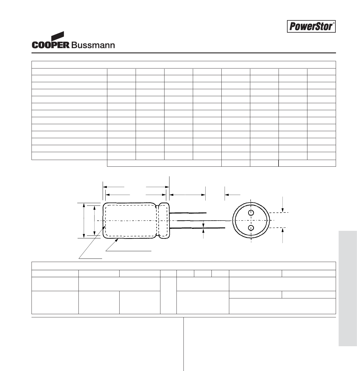
PS-7
Aerogel Supercapacitors - B Series
DIMENSIONS (mm)
Part Number D D' L L' F d' C C'
B0510-2R5224-R 5.0 5.5 11.5 12.0 2.0 0.50 20.0 5.0
B0810-2R5105-R 8.0 8.5 13.0 13.5 3.5 0.50 20.0 5.0
B1010-2R5155-R 10.0 10.5 13.9 14.4 5.0 0.60 20.0 5.0
B0820-2R5225-R 8.0 8.5 20.5 21.0 3.5 0.50 20.0 5.0
B1020-2R5335-R 10.0 10.5 21.8 22.3 5.0 0.60 20.0 5.0
B0830-2R5475-R 8.0 8.5 30.5 31.0 3.5 0.50 20.0 5.0
B1030-2R5685-R 10.0 10.5 31.0 31.5 5.0 0.60 20.0 5.0
B1325-2R5106-R 13.0 13.5 27.9 28.4 5.0 0.60 20.0 5.0
B1635-2R5226-R 16.0 16.5 37.5 38.0 7.5 0.80 20.0 5.0
B1835-2R5336-R 18.0 18.5 37.5 38.0 7.5 0.80 20.0 5.0
B1840-2R5506-R 18.0 18.5 41.5 42.0 7.5 0.80 20.0 5.0
B1860-2R5107-R 18.0 18.5 59.5 60.0 7.5 0.80 20.0 5.0
Manufacturer
Capacitance (F)
Max. Operating Voltage (V)
Series Code (or part number)
Polarity Marking
Standard packaging: Bulk, 100 units per package.
Special packaging available upon request. Contact
factory.
PART MARKINGPACKAGING INFORMATION
L'
LCC'
F±0.5
Ød'
PVC SLEEVE
VENT
ØD
ØD'
PART NUMBERING SYSTEM
B -2R5
Series Dimensions (mm) Voltage (V) Capacitance
Code R is decimal
B = High Diameter Length Value Multiplier
Capacitance 2R5 = 2.5V Example:
475 = 47 x 105μ F or 4.7 F
Minimum± 0.02± 0.5Maximum
Note: Longer lead is positive
Aerogel Supercapacitors
B Series
Courtesy of Steven Engineering, Inc.-230 Ryan Way, South San Francisco, CA 94080-6370-Main Office: (650) 588-9200-Outside Local Area: (800) 258-9200-www.stevenengineering.com
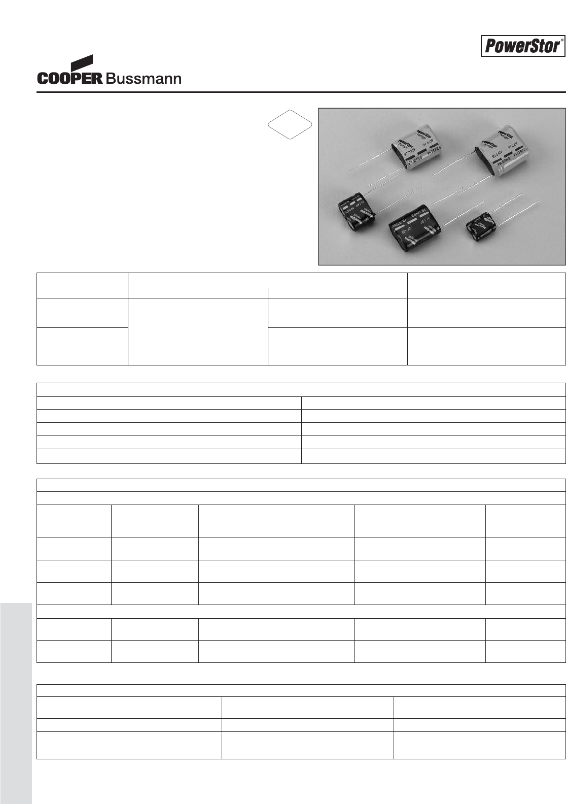
PS-8
Aerogel Supercapacitors - P Series
Aerogel Supercapacitors
P Series
Description
The PowerStor®Aerogel Capacitor is a unique,
ultra-high capacitance device based on a novel type of
carbon foam, known as carbon aerogel. Aerogel capacitors
are similar to supercapacitors, ultracapacitors and
electrochemical double layer capacitors (EDLCs) with the
added benefit of low ESR (Equivalent Series Resistance).
The P Series is available in an ultra-low ESR version, PA or
a low ESR but higher energy density version, PB.
SPECIFICATIONS
Working Voltage 5.0 volts
Surge Voltage 6.0 volts
Nominal Capacitance Range 0.1 to 1.0 F
Capacitance Tolerance -20% to +80% (20°C)
Operating Temperature Range -25°C to 70°C
SERIES FEATURES AND BENEFITS APPLICATIONS
Generic Specific
PA 5.0 volts Ultra-low ESR Pulse power
Low ESR Bridge or hold up power
High capacitance Low ESR with higher Bridge or hold up power
PB Long cycle life energy density Memory backup
Low leakage currents Battery swap out
STANDARD PRODUCTS
LOW ESR (PB SERIES)
Nominal Part Nominal ESR Nominal Dimensions Typical Mass
Capacitance Number (Equivalent Series Resistance) (grams/1 piece)
(F) Measured @ 1kHz (Ω)
0.1 PB-5R0V104-R 10 5.5 x 10.8 x 12.5 mm 1.1
PB-5R0H104-R
0.47 PB-5R0V474-R 2 8.5 x 16.8 x 14.0 mm 2.4
PB-5R0H474-R
1.0 PB-5R0V105-R 1 8.5 x 16.8 x 21.5 mm 3.5
PB-5R0H105-R
ULTRA-LOW ESR (PA SERIES)
0.22 PA-5R0V224-R 0.30 8.5 x 16.8 x 21.5 mm 3.5
PA-5R0H224-R
0.47 PA-5R0V474-R 0.20 10.5 x 20.8 x 22.5 mm 5.4
PA-5R0H474-R
PERFORMANCE
Parameter Capacitance Change ESR
(% of initial measured value) (% of initial specified value)
Life (1000 hrs @ 70°C @ 5.0 volts DC) ≤30 ≤300
Storage - Low and High Temperature ≤30 ≤300
(1000 hrs @ -25°C and 70°C)
LEADED DEVICE
RoHS
2002/95/EC
Courtesy of Steven Engineering, Inc.-230 Ryan Way, South San Francisco, CA 94080-6370-Main Office: (650) 588-9200-Outside Local Area: (800) 258-9200-www.stevenengineering.com
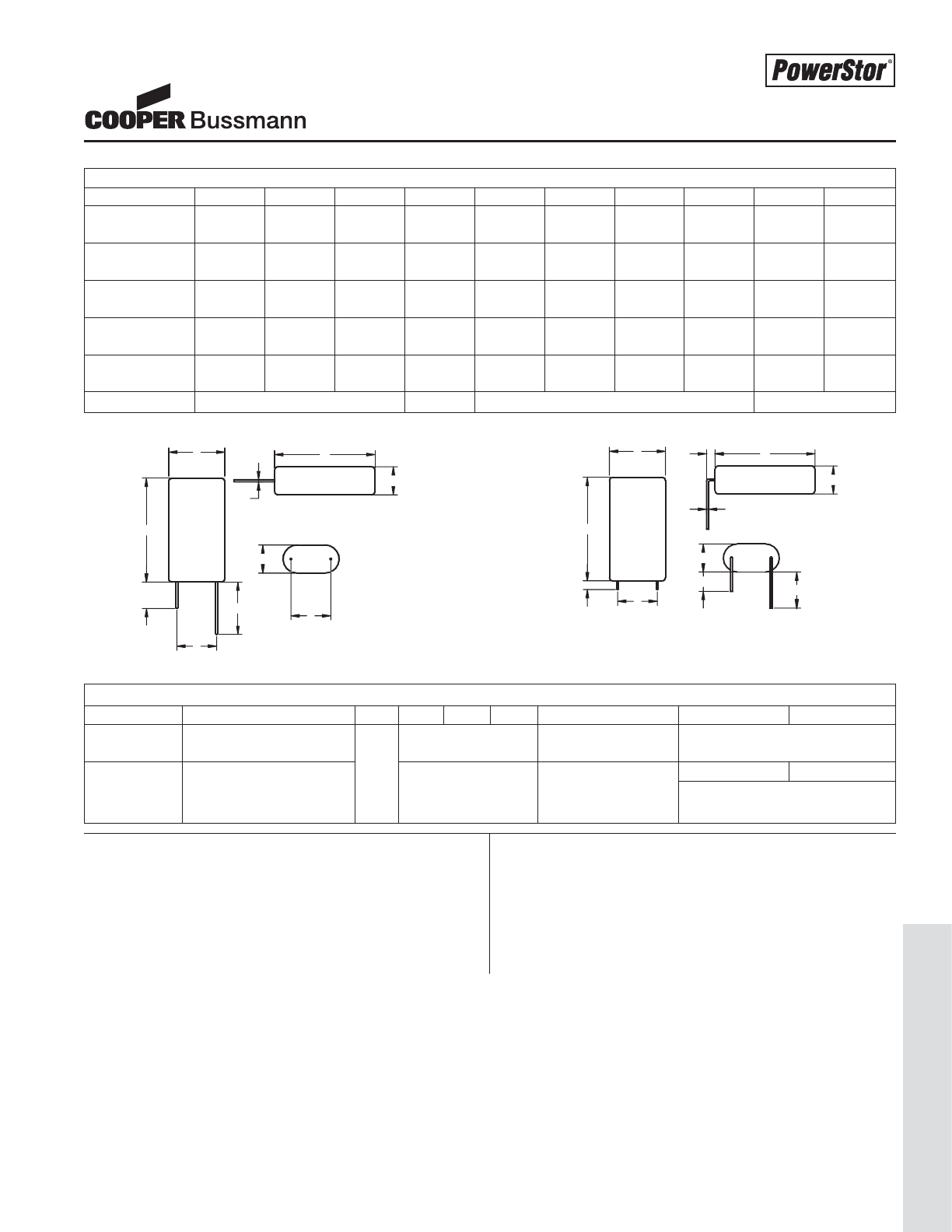
PS-9
Aerogel Supercapacitors - P Series
Aerogel Supercapacitors
P Series
DIMENSIONS (mm)
Part Number A B C d’ D D’ E E’ F P
PB-5R0V104-R 6.0 11.3 13.0 0.5 20 15 25 20 2.0 7.3
PB-5R0H104-R
PB-5R0V474-R 9.0 17.3 14.5 0.5 20 15 25 20 2.0 11.8
PB-5R0H474-R
PB-5R0V105-R 9.0 17.3 22.0 0.5 20 15 25 20 2.0 11.8
PB-5R0H105-R
PA-5R0V224-R 9.0 17.3 22.0 0.5 20 15 25 20 2.0 11.8
PA-5R0H224-R
PA-5R0V474-R 11.0 21.3 23.0 0.6 20 15 25 20 2.0 5.3
PA-5R0H474-R
Tolerances Maximum ± 0.02 Minimum ± 0.5
Manufacturer
Capacitance (F)
Max. Operating Voltage (V)
Polarity Marking
Standard packaging: Bulk, 100 units per package.
Larger bulk packages available upon request.
PART MARKINGPACKAGING INFORMATION
VERTICAL HORIZONTAL
B
C
P
C
A
A
D
E
d'
P
B
C
P
E'
F C
A
A
D'
F
d'
Note: Longer lead is positive
PART NUMBERING SYSTEM
P-5R0
Series Version Voltage (V) Configuration Capacitance (μF)
Code R is decimal
A = Ultra-low ESR V = Vertical Value Multiplier
P = Pack - or - 5R0 = 5.0V - or - Example:
B = High Capacitance H = Horizontal 474 = 47 x 104μ F or 0.47 F
Courtesy of Steven Engineering, Inc.-230 Ryan Way, South San Francisco, CA 94080-6370-Main Office: (650) 588-9200-Outside Local Area: (800) 258-9200-www.stevenengineering.com
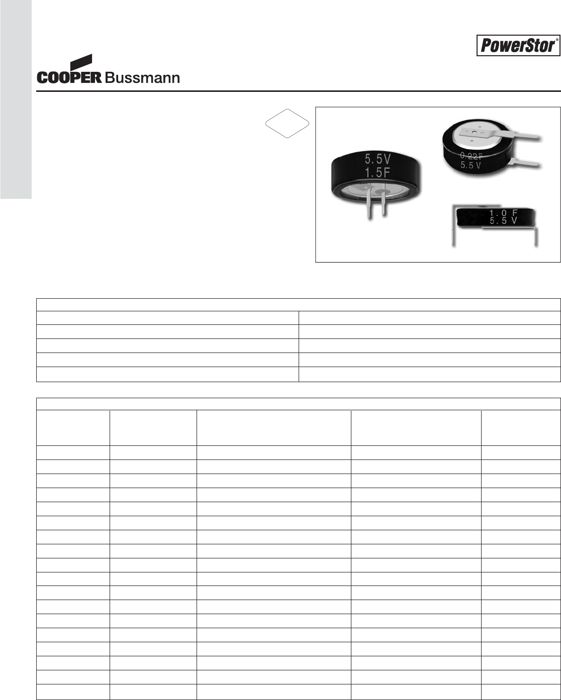
PS-10
Aerogel Supercapacitors - KR Series
STANDARD PRODUCTS
Nominal Part Nominal ESR Nominal Dimensions Typical Mass
Capacitance Number (Equivalent Series Resistance) (grams/1 piece)
(F) Measured @ 1kHz (Ω)
0.1 KR-5R5V104-R 75 Ø=11.5mm; L=12.5mm; P=5mm 1.4
0.1 KR-5R5H104-R 75 Ø=11.5mm; L=5mm; P=10mm 1.4
0.1 KR-5R5C104-R 75 Ø=13.5mm; L=7.5mm; P=5mm 3.3
0.22 KR-5R5V224-R 75 Ø=11.5mm; L=12.5mm; P=5mm 1.4
0.22 KR-5R5H224-R 75 Ø=11.5mm; L=5mm; P=10mm 1.4
0.22 KR-5R5C224-R 75 Ø=13.5mm; L=7.5mm; P=5mm 3.3
0.33 KR-5R5V334-R 50 Ø=11.5mm; L=12.5mm; P=5mm 1.4
0.33 KR-5R5H334-R 50 Ø=11.5mm; L=5mm; P=10mm 1.4
0.33 KR-5R5C334-R 50 Ø=13.5mm; L=7.5mm; P=5mm 3.3
0.47 KR-5R5V474-R 50 Ø=11.5mm; L=12.5mm; P=5mm 1.4
0.47 KR-5R5H474-R 50 Ø=11.5mm; L=5mm; P=10mm 1.4
0.47 KR-5R5C474-R 50 Ø=13.5mm; L=7.5mm; P=5mm 3.3
1.0 KR-5R5V105-R 30 Ø=19mm; L=19.5mm; P=5mm 4.2
1.0 KR-5R5H105-R 30 Ø=19mm; L=6.5mm; P=20mm 4.2
1.0 KR-5R5C105-R 30 Ø=21.5mm; L=7.5mm; P=5mm 9.1
1.5 KR-5R5V155-R 30 Ø=19mm; L=19.5mm; P=5mm 4.2
1.5 KR-5R5H155-R 30 Ø=19mm; L=6.5mm; P=20mm 4.2
1.5 KR-5R5C155-R 30 Ø=21.5mm; L=7.5mm; P=5mm 9.1
Aerogel Supercapacitors
KR Series
Description
The Cooper PowerStor®Aerogel Capacitor is a unique,
ultra-high capacitance device based on a novel type of car-
bon form, known as carbon aerogel. Aerogel capacitors are
similar to Supercapacitors, ultracapacitors and electrochemi-
cal double layer capacitor (EDLCs) with the added benefit of
low ESR (Equivalent Series Resistance)
The KR series offers a wide range of high capacitance coin
cell style products for use in memory & RTC back-up applica-
tions. End products include computers, cameras, cam-
corders, telephones, printers, car stereos, CCTV, set top box
and PDP.
SPECIFICATIONS
Working Voltage 5.5 volts
Surge Voltage 6.3 volts
Nominal Capacitance Range 0.1 to 1.5 F
Capacitance Tolerance -20% to +80% (20°C)
Operating Temperature Range -25°C to 70°C
RoHS
2002/95/EC
Courtesy of Steven Engineering, Inc.-230 Ryan Way, South San Francisco, CA 94080-6370-Main Office: (650) 588-9200-Outside Local Area: (800) 258-9200-www.stevenengineering.com
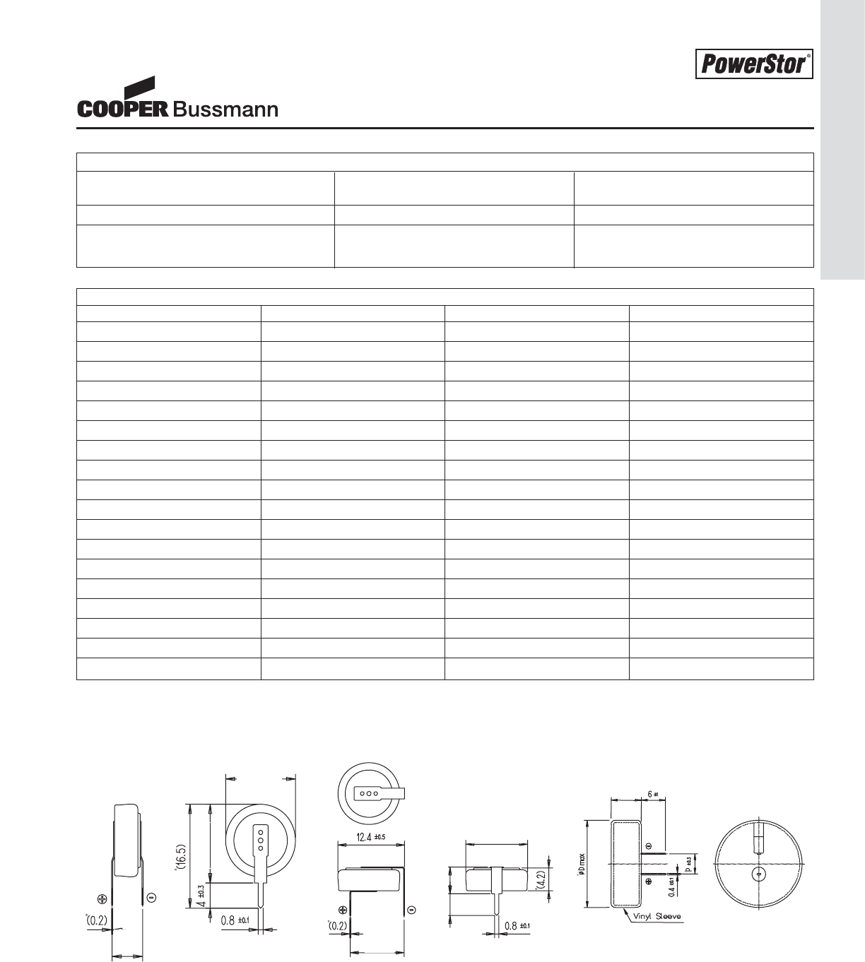
PS-11
Aerogel Supercapacitors - KR Series
DIMENSIONS (mm)
Part Number Ø D H P
KR-5R5V104-R 11.5 12.5 5
KR-5R5H104-R 11.5 5 10
KR-5R5C104-R 13.5 7.5 5
KR-5R5V224-R 11.5 12.5 5
KR-5R5H224-R 11.5 5 10
KR-5R5C224-R 13.5 7.5 5
KR-5R5V334-R 11.5 12.5 5
KR-5R5H334-R 11.5 5 10
KR-5R5C334-R 13.5 7.5 5
KR-5R5V474-R 11.5 12.5 5
KR-5R5H474-R 11.5 5 10
KR-5R5C474-R 13.5 7.5 5
KR-5R5V105-R 19 19.5 5
KR-5R5H105-R 19 6.5 20
KR-5R5C105-R 21.5 7.5 5
KR-5R5V155-R 19 19.5 5
KR-5R5H155-R 19 6.5 20
KR-5R5C155-R 21.5 7.5 5
V type H type C type
H
ØD
P
H
3. 0 ±0.3 H
ØD
P
Aerogel Supercapacitors
KR Series
PERFORMANCE
Parameter Capacitance Change ESR
(% of initial measured value) (% of initial specified value)
Life (1000 hrs @ 70°C @ 5.5 volts DC) ≤ 30 ≤ 400
Storage - Low and High Temperature ≤ 30 ≤ 400
(1000 hrs @ -25°C and 70°C)
For parts 0.1F to 0.47F
Courtesy of Steven Engineering, Inc.-230 Ryan Way, South San Francisco, CA 94080-6370-Main Office: (650) 588-9200-Outside Local Area: (800) 258-9200-www.stevenengineering.com
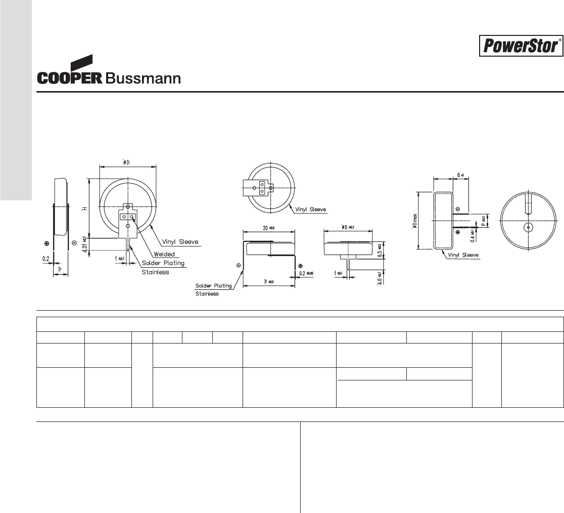
PS-12
Aerogel Supercapacitors - KR Series
Manufacturer
Capacitance (F)
Max. Operating Voltage (V)
Polarity Marking
Standard packaging: Bulk, 500 units per package.
For 0.1F to 0.47F 500 pcs/bag
For 1.0F to 1.5F 100 pcs/tray, 5 trays per box
PART MARKINGPACKAGING INFORMATION
PART NUMBERING SYSTEM
KR–5R5 –R
Series Version Voltage (V) Configuration Capacitance (μF)
Code R is decimal
K = Coin V = Vertical Value Multiplier RoHS
Cell R = Leaded 5R5 = 5.5V H = Horizontal Example: Compliant
C = Cylindrical 474 = 47 x 104μF or 0.47 F
Aerogel Supercapacitors
KR Series
V type H type C type
H
H
For parts 1.0F to 1.5F
Courtesy of Steven Engineering, Inc.-230 Ryan Way, South San Francisco, CA 94080-6370-Main Office: (650) 588-9200-Outside Local Area: (800) 258-9200-www.stevenengineering.com
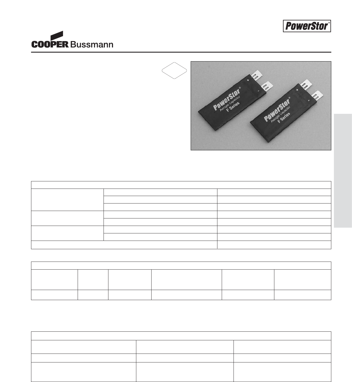
PS-13
Aerogel Supercapacitors - F Series
Aerogel Supercapacitors
F Series
Description
The PowerStor®Aerogel Capacitor is a unique,
ultra-high capacitance device based on a novel type of
carbon foam, known as carbon aerogel. Aerogel capacitors
are similar to supercapacitors, ultracapacitors and
electrochemical double layer capacitors (EDLCs) with the
added benefit of low ESR (Equivalent Series Resistance).
Applications – Low ESR
• High rate pulse applications
• GSM / GPRS applications
• PDA / Data Terminals
• Hybrid Battery-Capacitor packs
SPECIFICATIONS
Working (nominal) 3.6 volts
Voltage Working (maximum) 4.2 volts
Surge 5.0 volts
Operating @ 3.6 volts -20°C to 60°C
Temperature Range Storage -30°C to 75°C
Nominal 0.33 F
Capacitance Tolerance -20% to +80% (25°C)
Pulse Current (maximum) 2A
CUSTOM PRODUCT
Nominal Voltage Part ESR (nominal @ 25°C) Nominal Typical Mass
Capacitance (V) Number Measured @ 1kHz (Ω) Dimensions (grams/1 piece)
(F)
0.33 3.6 FC-3R6334-R 0.250 2 x 17 x 40 mm 1.9
Features & Benefits
• Ultra-low ESR
• Long cycle life
• Low leakage current
• Thin design
• High capacitance
PERFORMANCE
Parameter Capacitance Change ESR Change
(% of initial specified value) (% of initial specified value)
Life (1000 hrs @ 60°C @ 3.6 volts) ≤30 % TBD
Storage - low and high temperature ≤30 % TBD
(1000 hrs @ -30°C and 75°C)
RoHS
2002/95/EC
Courtesy of Steven Engineering, Inc.-230 Ryan Way, South San Francisco, CA 94080-6370-Main Office: (650) 588-9200-Outside Local Area: (800) 258-9200-www.stevenengineering.com
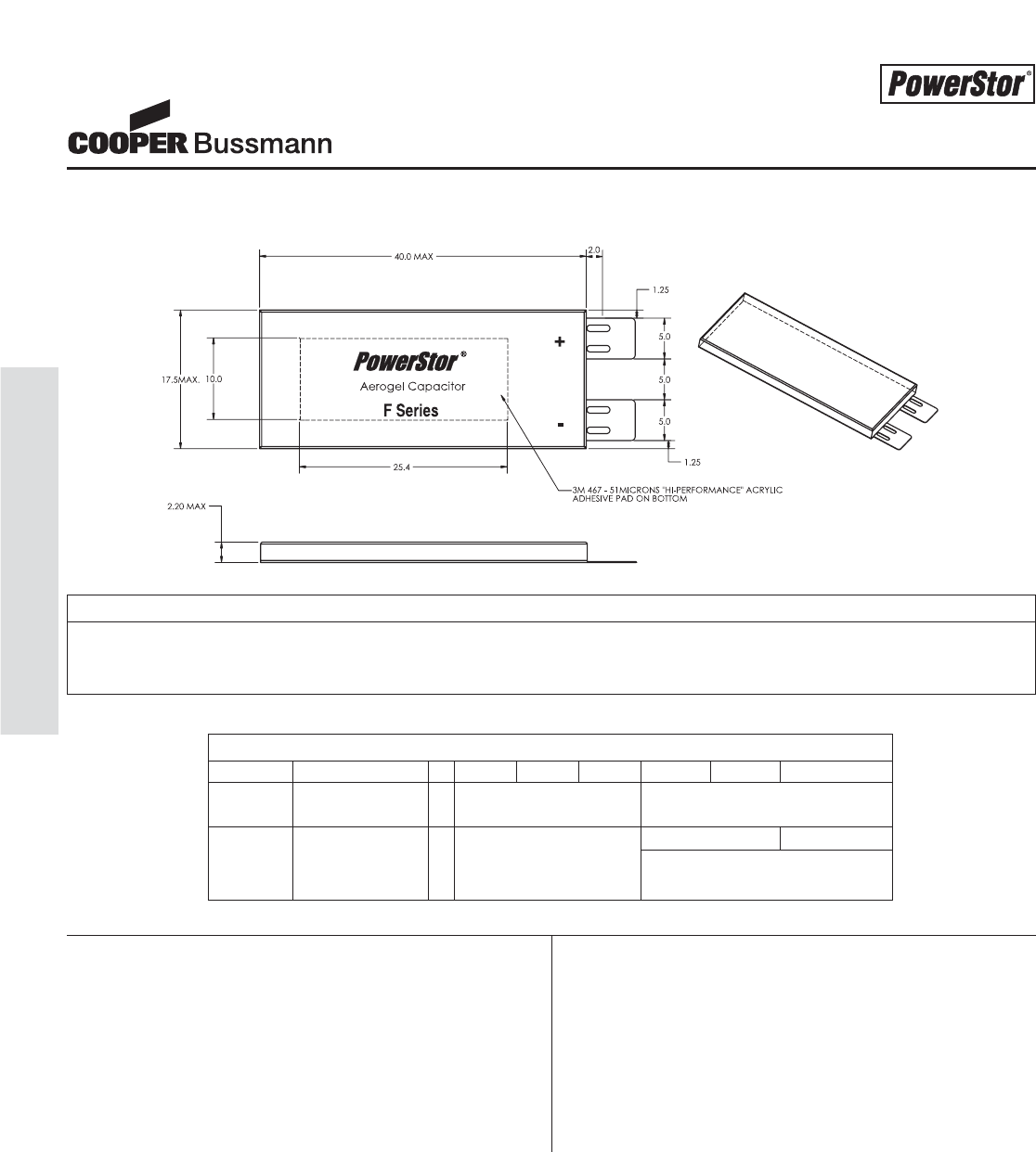
PS-14
Aerogel Supercapacitors - F Series
DRAWINGS (MM)
ASSEMBLY INSTRUCTIONS
This device should not be put through a solder reflow process. Do not expose the body of the aerogel supercapacitor to either the solder-
ing iron or melted solder. Minimize the time that the soldering iron is in direct contact with the leads of the aerogel supercapacitor. Use
appropriate heat sinking to minimize heat transfer to the aerogel supercapacitor.
Manufacturer Name
Series Code (or Part Number)
Polarity Marking
Packaging: 200 pieces per tray
5 trays (1000 pieces) per box
PART MARKINGPACKAGING INFORMATION
PART NUMBERING SYSTEM
F C - 3 R 6 3 3 4
Series Model Voltage (V) Capacitance (μ F)
Code R is decimal
F = Value Multiplier
Flat Pack 3R6 = 3.6V 334 = 33 x 104μF
Series or 0.33 F
Aerogel Supercapacitors
F Series
Courtesy of Steven Engineering, Inc.-230 Ryan Way, South San Francisco, CA 94080-6370-Main Office: (650) 588-9200-Outside Local Area: (800) 258-9200-www.stevenengineering.com
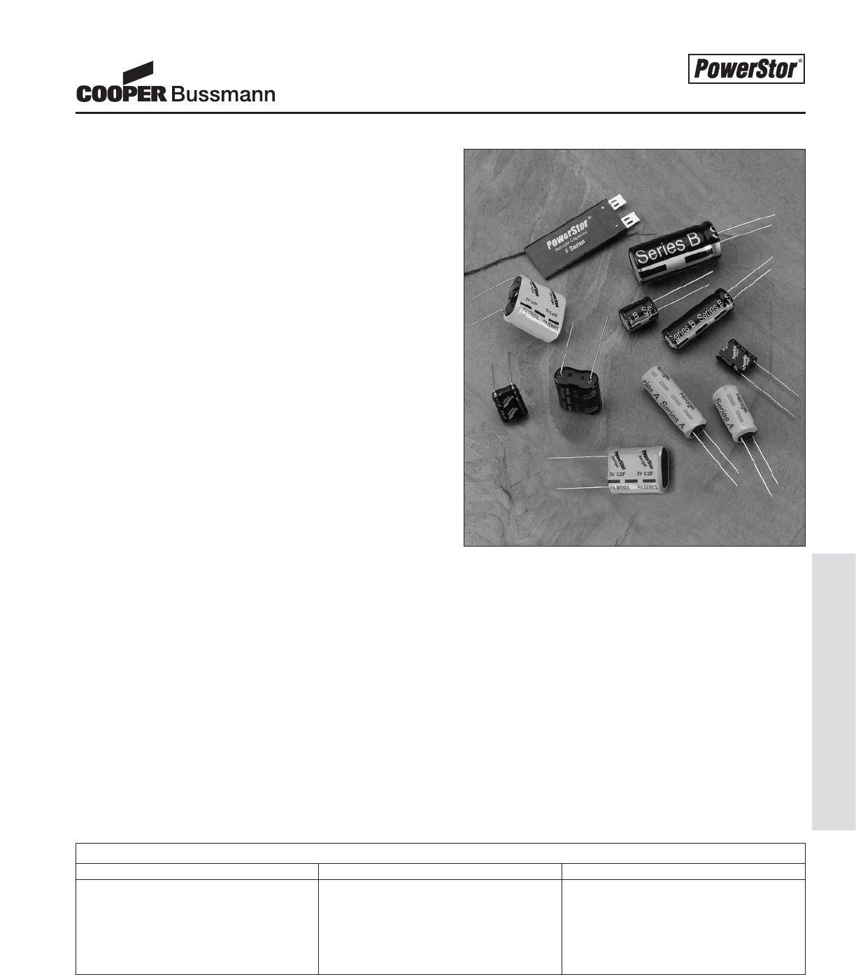
Description
Cooper Bussmann’s supercapacitor solutions, using
PowerStor’s carbon aerogel technology, offer the added benefit
of customization. Application specific supercapacitors can be
designed by modifying their size and shape, ESR (Equivalent
Series Resistance), capacitance, voltage or temperature
capability.
In the portable device market, many applications are space
constrained. Using thin aluminum-polymer laminate,
supercapacitors under 1mm thick are achievable. These F
Series supercapacitors are ideal for PCMCIA cards. Traditional
cylindrical can-style A and B Series supercapacitors are
available as well as larger, very high capacitance cylindrical
and prismatic supercapacitors.
Pulse discharge capability is important for many portable or
remote applications to power transmitters, activate solenoids
or valves, assist motors or to improve the high rate discharge
capability of a low power battery system. PowerStor’s carbon
aerogel supercapacitors can be modified to achieve very low
ESR providing high rate discharge capability. In applications
where capacitance is important but ultra-low ESR is not
required, the supercapacitor can be modified to provide
higher energy density with marginally higher ESR.
A single supercapacitor has a nominal working voltage rating of
2.5V. Any application up to and including 2.5V can be operated
by a single supercapacitor, however many applications require
3.6V, 5.0V or even higher. P Series supercapacitors have been
designed for 3.6 and 5.0V applications. Custom multi-superca-
pacitor configurations are available for 12V, 24V or other
voltage ratings. Either passive or active voltage balancing
is used for all multi-supercapacitor configurations to ensure
good reliability.
Some applications require a wider temperature range than the
standard –25°C to 70°C. For these industrial or specialized
applications, supercapacitors can be designed to meet a more
severe range of –40°C to 85°C.
PowerStor Aerogel Supercapacitors provide solutions for a
wide range of applications. With a variety of package types,
adjustable capacitance and ESR, higher voltage ratings and
wider temperature range capability, supercapacitors can be
designed to meet the requirements of most applications.
Features and Benefits
•
Application specific designs
•
Customized form factors to meet most mechanical
requirements
•
Tailored capacitance, ESR, and temperature capability
•
Series configurations for higher voltages
•
Complete system solutions
The electrical parameters can be used to calculate capacitance and ESR requirements and predict your supercapacitor solution. Use our
PowerStor Aerogel Supercapacitor Excel Calculator available at www.cooperbussmann.com.
CRITICAL SUPERCAPACITOR PARAMETERS FOR CUSTOMIZATION
Electrical Mechanical Environmental
Working Voltage (V) _______ Max. Length (mm) _______ Max. Temperature (°C) _______
Minimum Voltage (V) _______ Width/Diam. (mm) _______ Min. Temperature (°C) _______
Current draw (A) _______ Height (mm) _______
Discharge time (sec) _______ Lead/Connector _______
Custom Product Offering
Application Types
•
Pulse power
•
Bridge or hold-up power
•
Main power
•
Memory backup
Application Segments
•
Industrial
•
Consumer
•
Medical
•
Automotive
•
Military
PS-15
Custom Product Offering
Courtesy of Steven Engineering, Inc.-230 Ryan Way, South San Francisco, CA 94080-6370-Main Office: (650) 588-9200-Outside Local Area: (800) 258-9200-www.stevenengineering.com
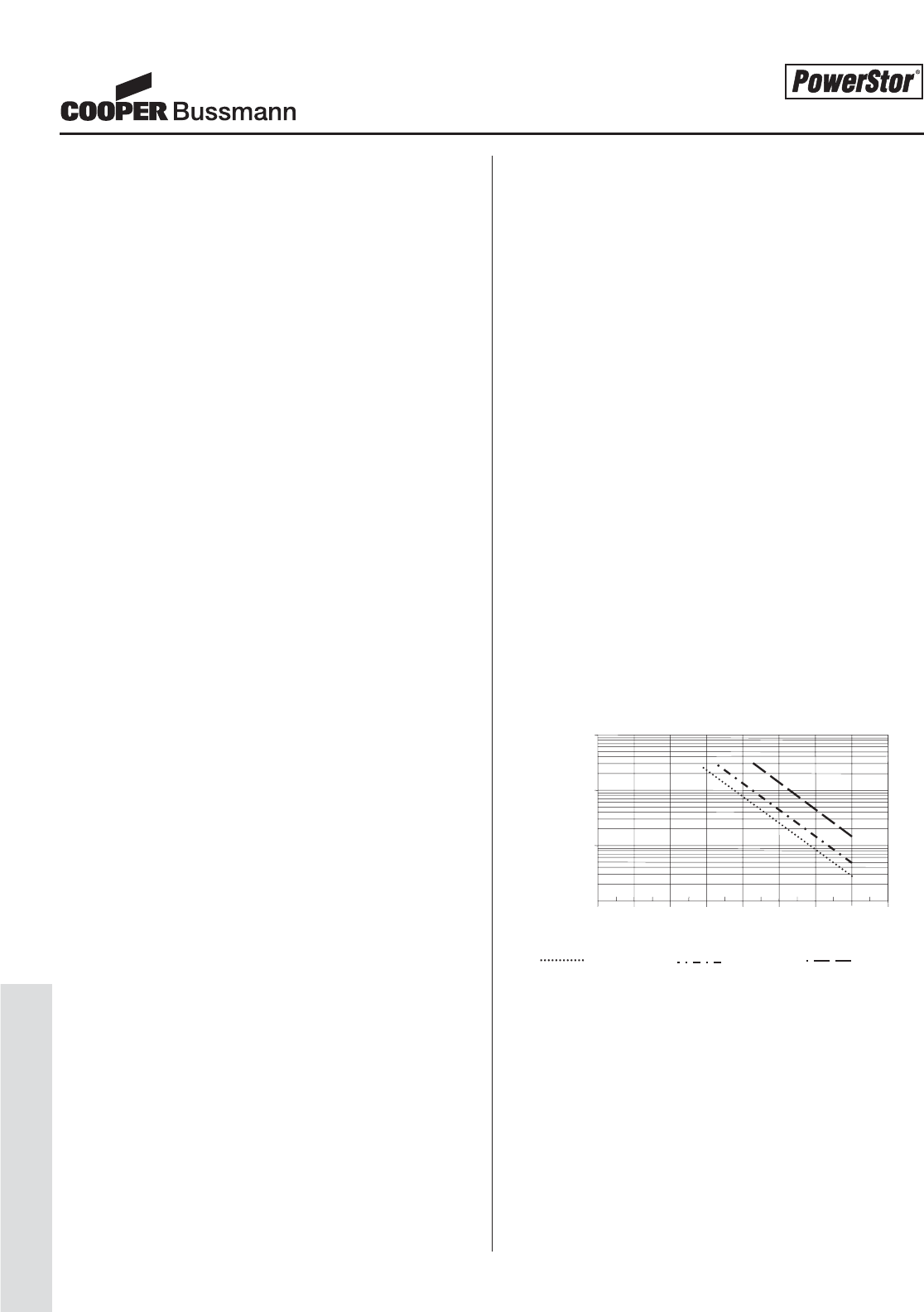
PS-16
Design Guides
Application Guidelines
This document provides basic guidelines for application develop-
ment using aerogel capacitors, also known as
supercapacitors. If questions arise during your development
process and are not answered in this document, contact Cooper
Bussmann.
Lifetime
PowerStor supercapacitors have a longer lifetime than secondary
batteries, but their lifetime is not infinite. The basic end-of-life
failure mode for a supercapacitor is an increase in equivalent
series resistance (ESR) and/or a decrease in capacitance. The
actual end-of-life criteria are dependent on the application
requirements. Prolonged exposure to elevated temperatures,
high applied voltage and excessive current will lead to increased
ESR and decreased capacitance. Reducing these parameters
will lengthen the lifetime of a supercapacitor. In general,
cylindrical supercapacitors have a similar construction to
electrolytic capacitors, having a liquid electrolyte inside an
aluminum can sealed with a rubber bung. Over many years, the
supercapacitor will dry out, similar to an electrolytic capacitor,
causing high ESR and eventually end-of-life.
Voltage
Supercapacitors are rated with a nominal recommended working
or applied voltage. The values provided are set for long life at
their maximum rated temperature. If the applied voltage exceeds
this recommended voltage, the result will be reduced lifetime. If
the voltage is excessive for a prolonged time period, gas genera-
tion will occur inside the supercapacitor and may result in leak-
age or rupture of the safety vent. Short-term overvoltage can
usually be tolerated by the supercapacitor.
Polarity
PowerStor supercapacitors are designed with symmetrical elec-
trodes, meaning they are similar in composition. When a super-
capacitor is first assembled, either electrode can be designated
positive or negative. Once the supercapacitor is charged for the
first time during the 100% QA testing operation, the electrodes
become polarized. Every supercapacitor either has a negative
stripe or sign denoting polarity. Although they can be shorted to
zero volts, the electrodes maintain a very small amount of
charge. Reverse polarity is not recommended, however previ-
ously charged supercapacitors have been discharged to -2.5V
with no measurable difference in capacitance or ESR. Note: the
longer they are held charged in one direction, the more polarized
they become. If reversed charged after prolonged charging in
one direction, the life of the supercapacitor may be shortened.
Ambient Temperature
The standard temperature rating for PowerStor supercapacitors is
–25°C to 70°C. Temperature in combination with voltage can
affect the lifetime of a supercapacitor. In general, raising the
ambient temperature by 10°C will decrease the lifetime of a
supercapacitor by a factor of two. As a result, it is recommended
to use the supercapacitor at the lowest temperature possible to
decrease internal degradation and ESR increase. If this is not
possible, decreasing the applied voltage to the supercapacitor
will assist in offsetting the negative effect of the high temperature.
For instance, 85°C ambient temperature can be reached if the
applied voltage is reduced to 1.8V per supercapacitor.
At temperatures lower than normal room temperature, it is possi-
ble to apply voltages slightly higher than the recommended work-
ing voltage without significant increase in degradation and reduc-
tion in lifetime. Raising the applied voltage at low temperatures
can be useful to offset the increased ESR seen at low tempera-
tures. Increased ESR at higher temperatures is a result of per-
manent degradation / electrolyte decomposition inside the super-
capacitor. At low temperatures, however, increased ESR is only
a temporary phenomenon due to the increased viscosity of the
electrolyte and slower movement of the ions.
Operating Life vs. Temperature and Charge Voltage
The above plot shows the time taken for capacitance to drop by
30% at 1.8V & 2.5V and by 50% at 2.5V for continuous operation
at a given temperature. This can be used to estimate the operat-
ing life for specific applications where the minimum allowable
capacitance value is known.
Discharge Characteristics
Supercapacitors discharge with a sloping voltage curve. When
determining the capacitance and ESR requirements for an appli-
cation, it is important to consider both the resistive and capacitive
1,000,000
10,000
001010 2020 3030 4040 5050 6060 7070 8080
1,000
100,000
30% drop in capacitance
@ 2.5V continuous.
30% drop in capacitance
@ 1.8V continuous. 50% drop in capacitance
@ 2.5V continuous.
Life (Hours)
Temperature (Celsius)
Courtesy of Steven Engineering, Inc.-230 Ryan Way, South San Francisco, CA 94080-6370-Main Office: (650) 588-9200-Outside Local Area: (800) 258-9200-www.stevenengineering.com

PS-17
Design Guides
Application Guidelines
discharge components. In high current pulse applications, the
resistive component is the most critical. In low current, long dura-
tion applications, the capacitive discharge component is the most
critical. The formula for the voltage drop, Vdrop, during a dis-
charge at Icurrent for tseconds is:
Vdrop = I(R + t )
C
To minimize voltage drop in a pulse application, use a superca-
pacitor with low ESR (R value). To minimize voltage drop in a
low current application, use a supercapacitor with large capaci-
tance (C value).
An Aerogel Capacitor Calculator program is available online at
http://www.cooperbussmann.com for predicting electrical require-
ments and matching these requirements to various supercapaci-
tor configurations / alternatives.
Charge Methods
Supercapacitors can be charged using various methods including
constant current, constant power, constant voltage or by parallel-
ing to an energy source, i.e. battery, fuel cell, DC converter, etc.
If a supercapacitor is configured in parallel with a battery, adding
a low value resistor in series will reduce the charge current to the
supercapacitor and will increase the life of the battery. If a series
resistor is used, ensure that the voltage outputs of the superca-
pacitor are connected directly to the application and not through
the resistor, otherwise the low impedance of the supercapacitor
will be nullified. Many battery systems exhibit decreased
lifetime when exposed to high current discharge pulses.
The maximum recommended charge current, I, for a
supercapacitor where Vwis the charge voltage and Ris
the supercapacitor impedance is calculated as follows:
I=Vw
5R
Overheating of the supercapacitor can occur from continuous
overcurrent or overvoltage charging. Overheating can lead to
increased ESR, gas generation, decreased lifetime, leakage,
venting or rupture. Contact the factory if you plan to use a higher
charge current or higher voltage than specified.
Self Discharge and Leakage Current
Self discharge and leakage current as essentially the same thing
measured in different ways, due to the supercapacitor construc-
tion there is a high impedance internal current path from the
anode to the cathode. This means that in order to maintain the
charge on the capacitor a small amount of additional current is
required, during charging this is referred to as leakage current.
When the charge voltage is removed, and the capacitor is not
loaded, this additional current will discharge the supercapacitor
and is referred to as the self discharge current.
In order to get a realistic measurement of leakage or self dis-
charge current the supercapacitor must be charged for in excess
of 100 hours, this again is due to the capacitor construction. The
supercapacitor can be modeled as several capacitors connected
in parallel each with an increasing value of series resistance. The
capacitors with low values of series resistance charge quickly thus
increasing the terminal voltage to the same level as the charge
voltage. However, if the charge voltage is removed these capaci-
tors will discharge in to the parallel capacitors with higher series
resistance if they are not fully charged. The result of this being that
the terminal voltage will fall giving the impression of high self dis-
charge current. It should be noted that the higher the capacitance
value the longer it will take for the device to be fully charged, see
figure 2 in the Measurement Techniques section for more details.
Series Configurations of Supercapacitors
Individual supercapacitors are limited to 2.5V (P Series reaches
5V using two supercapacitors in series). As many applications
require higher voltages, supercapacitors can be configured in
series to increase the working voltage. It is important to ensure
that the individual voltages of any single supercapacitor do not
exceed its maximum recommended working voltage as this could
result in electrolyte decomposition, gas generation, ESR increase
and reduced lifetime.
Capacitor voltage imbalance is caused, during charge and dis-
charge, by differences in capacitance value and, in steady state,
by differences in capacitor leakage current. During charging
series connected capacitors will act as a voltage divider so higher
capacitance devices will receive greater voltage stress. For exam-
ple if two 1F capacitors are connected in series, one at +20% of
nominal capacitance the other at –20% the worst-case voltage
across the capacitors is given by:
Vcap1 =V
supply x(C
cap1 /(C
cap1 +C
cap2)
where Ccap1 has the +20% capacitance.
So for a Vsupply =5V,
Vcap1 = 5V x (1.2 / (1.2 + 0.8) = 3V
From this it can be seen that, in order to avoid exceeding the
supercapacitor surge voltage rating of 3V, the capacitance values
of series connected parts must fall in a +/-20% tolerance range.
Alternatively a suitable active voltage balancing circuit can be
Courtesy of Steven Engineering, Inc.-230 Ryan Way, South San Francisco, CA 94080-6370-Main Office: (650) 588-9200-Outside Local Area: (800) 258-9200-www.stevenengineering.com
PS-18
Design Guides
employed to reduce voltage imbalance due to capacitance mis-
match. It should be noted that the most appropriate method of
voltage balancing will be application specific.
Passive Voltage Balancing
Passive voltage balancing uses voltage-dividing resistors in paral-
lel with each supercapacitor. This allows current to flow around
the supercapacitor at a higher voltage level into the supercapaci-
tor at the lower voltage level, thus balancing the voltage. It is
important to choose balancing resistor values that provide for
higher current flow than the anticipated leakage current of the
supercapacitors, bearing in mind that the leakage current will
increase at higher temperatures.
Passive voltage balancing is only recommended for applications
that don’t regularly charge and discharge the supercapacitor and
that can tolerate the additional load current of the balancing resis-
tors. It is suggested that the balancing resistors be selected to
give additional current flow of at least 50 times the worst-case
supercapacitor leakage current (3.3 kΩto 22 kΩdepending on
maximum operating temperature). Although higher values of bal-
ancing resistor will work in most cases they are unlikely to pro-
vide adequate protection when significantly mismatched parts
are connected in series.
Active Voltage Balancing
Active voltage balancing circuits force the voltage at the nodes of
series connected supercapacitors to be the same as a fixed ref-
erence voltage; regardless of how any voltage imbalance occurs.
As well as ensuring accurate voltage balancing active circuits typ-
ically draw much lower levels of current in steady state and only
require larger currents when the capacitor voltage goes out of
balance. These characteristics make active voltage balancing cir-
cuits ideal for applications that charge and discharge the super-
capacitors frequently as well as those with a finite energy source
such as a battery.
Reverse Voltage Protection
When series connected supercapacitors are rapidly discharged
the voltage on low capacitance value parts can potential go neg-
ative. As explained previously, this is not desirable and can
reduce the operating life of the supercapacitor. One simple way
of protecting against reverse voltage is to add a diode across the
capacitor, configured so that it is normally reverse bias. By using
a suitably rated zener diode in place of a standard diode the
supercapacitor can also be protected against overvoltage events.
Care must be taken to ensure that the diode can withstand the
available peak current from the power source.
Soldering Information
Excessive heat may cause deterioration of the electrical charac-
teristics of the aerogel supercapacitor, electrolyte leakage or an
increase in internal pressure.
Follow the specific instructions listed below.
In addition:
• Do not dip aerogel supercapacitor body into melted solder.
• Only flux the leads of the aerogel supercapacitor.
• Ensure that there is no direct contact between the sleeve of the
aerogel supercapacitor and the PC board or any other compo-
nent. Excessive solder temperature may cause sleeve to shrink
or crack.
• Avoid exposed circuit board runs under the aerogel
supercapacitor to prevent electrical shorts.
Manual Soldering
Do not touch the aerogel supercapacitor’s external sleeve with
the soldering rod or the sleeve will melt or crack. The recom-
mended temperature of the soldering rod tip is less than 260°C
(maximum: 350°C) and the soldering duration should be less
than 5 seconds. Minimize the time that the soldering iron is in
direct contact with the terminals of the aerogel supercapacitor as
excessive heating of the leads may lead to higher equivalent
series resistance (ESR).
Wave Soldering
Use a maximum preheating time of 60 seconds for PC boards
0.8 mm or thicker. Preheating temperature should
be limited to less than 100°C.
Use the following table for wave soldering on leads only:
Reflow Soldering
Do not use reflow soldering on PowerStor supercapacitors
using infrared or convection oven heating methods unless the
supercapacitor is specifically rated to withstand reflow soldering
temperatures.
Application Guidelines
Solder Bath Solder Exposure Time (seconds)
Temperature (°C) Recommended Maximum
220 7 9
240 7 9
250 5 7
260 3 5
Courtesy of Steven Engineering, Inc.-230 Ryan Way, South San Francisco, CA 94080-6370-Main Office: (650) 588-9200-Outside Local Area: (800) 258-9200-www.stevenengineering.com
PS-19
Design Guides
Application Guidelines
Ripple Current
Although PowerStor aerogel supercapacitors have very low resis-
tance in comparison to other supercapacitors, they do have high-
er resistance than aluminum electrolytic capacitors and are more
susceptible to internal heat generation when exposed to ripple
current. Heat generation leads to
electrolyte decomposition, gas generation, increased ESR and
reduced lifetime. In order to ensure long lifetime, the maximum
ripple current recommended should not increase the surface
temperature of the supercapacitor by more
than 3°C.
Circuit Board Design
Do not design exposed circuit board runs under the
supercapacitor. An electrical short could occur if the
supercapacitor electrolyte leaked onto the circuit board.
Circuit Board Cleaning
Avoid cleaning of circuit boards, however if the circuit board must
be cleaned use static or ultrasonic immersion in a
standard circuit board cleaning fluid for no more than 5
minutes and a maximum temperature of 60°C. Afterwards thor-
oughly rinse and dry the circuit boards. In general,
treat supercapacitors in the same manner you would an
aluminum electrolytic capacitor.
Long Term Storage
Do not store supercapacitors in any of the following
environments:
• High temperature and/or high humidity
• Direct contact with water, salt water, oil or other chemicals
• Direct contact with corrosive materials, acids, alkalis, or toxic
gases
• Direct exposure to sunlight
• Dusty environment
• Environment subject to excessive shock and/or vibration
Transportation Information
PowerStor supercapacitors are non-regulated by the US DOT
(Department of Transport) and IATA. The correct international
shipping description is “Electronic Parts – Capacitors”.
Emergency Procedures
If a supercapacitor is found to be overheating or if you smell a
sweet odor, immediately disconnect any power or load to the
supercapacitor. Allow the supercapacitor to cool down, then dis-
pose of properly. Do not expose your face or hands to an over-
heating supercapacitor. Contact the factory for a Material Safety
Data Sheet if a supercapacitor leaks or vents. If exposed to elec-
trolyte:
• Skin Contact: Wash exposed area thoroughly with
soap and water.
• Eye Contact: Rinse eyes with water for 15 minutes
and seek medical attention.
• Ingestion: Drink milk/water and induce vomiting;
seek medical attention.
Note: In general the electrolyte, using the NFPA/HMIS
(0 to 4) rating system, has slight (1 out of 4) health and
fire hazard and minimal (0 out of 4) reactivity hazard.
Regulatory Information
PowerStor supercapacitors are rated non-hazardous under the
OSHA hazard communication standard (29 CFR 1910.1200)
General Safety Considerations
• Supercapacitors may vent or rupture if overcharged,
reverse charged, incinerated or heated above 150°C.
• Do not crush, mutilate, nail penetrate or disassemble.
• High case temperature (burn hazard) may result from
abuse of supercapacitor.
Disposal Procedures
PowerStor supercapacitors are non-regulated under RCRA
Waste Code. Supercapacitors may however be disposed of by a
specialized industrial waste processor or by incineration. Use
caution when incinerating as the supercapacitor can explode
unless it is crushed or punctured prior to incineration. Wear pro-
tective gear, such as face shields or goggles, coats/aprons and
gloves. Use high temperature to incinerate the supercapacitors
as the plastic (poly vinyl chloride) sleeving can produce chlorine
gas at lower incineration temperatures.
Courtesy of Steven Engineering, Inc.-230 Ryan Way, South San Francisco, CA 94080-6370-Main Office: (650) 588-9200-Outside Local Area: (800) 258-9200-www.stevenengineering.com
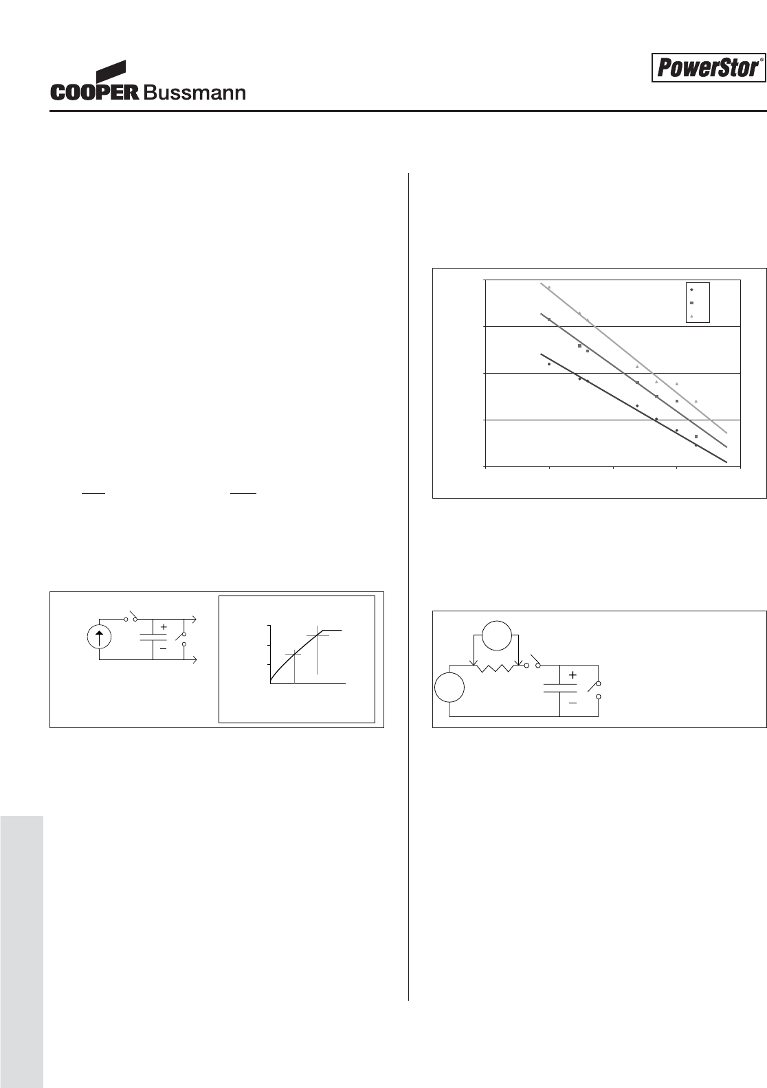
PS-20
Design Guides
Methods for Measuring Capacitance, Inflow Current, Internal Resistance and ESR
Capacitance Measurement:
Supercapacitors exhibit considerable “dielectric absorption”
charge storage. As such, some traditional methods of
measuring capacitance may not yield accurate results when
measuring supercapacitors. A method for measuring
capacitance in supercapacitors is outlined below. This
method is recommended over others such as determining
the 63 percent voltage point and using the time in a RC
time constant calculation.
The following test circuit can be set up with a common
laboratory power supply set to the specified current and
voltage limits. The charging waveform, shown in Figure 1,
is best recorded with a digital oscilloscope. The cursor
function can be conveniently used to directly read the time
points between the 1.5 volt and 2.5 volt crossing. The
basic equation for the average current in a capacitor is:
i=C(ΔV), solving for C: C=i(Δt)
ΔtΔV
For i= 1 ampere and ΔV= 1 volt, therefore C = Δt.
Capacitance in this example is numerically equal to the time
in seconds for the capacitor to charge from 1.5V to 2.5V.
Figure 1
Because dielectric absorption is pronounced, the device
under test should be well discharged before beginning the
test to ensure consistent results. If the device has previous-
ly been charged, then its terminals should be shorted for at
least 15 minutes before beginning the test.
Inflow Current Measurement:
Since supercapacitors exhibit pronounced dielectric absorp-
tion, the measurement of actual leakage current, or self-dis-
charge current, is made difficult. When a supercapacitor is
charged to its working voltage, the inflow current exhibits
large, slowly decaying values for long times. The inflow cur-
rent is the sum of dielectric absorption current flow and
actual leakage current. Dielectric absorption current flow
represents charge going into storage, but deeply buried in
terms of possessing a very long time constant. The inflow
current as a function of time is essentially logarithmic, as
shown in Figure 2:
Figure 2
These typical curves are measured with the test circuit
below. The parts were short circuited for 2 days prior to
beginning the test. Therefore, stored dielectric absorption
charge was essentially non-existent.
Figure 3
True leakage currents, where dielectric absorption goes to
zero, take over 100 hours to reach as shown in Figure 2.
These leakage currents are on the order of only a few
microamperes. To continue to measure inflow current
beyond this point, one needs to use instrumentation capable
of accurately measuring microvolts and/or a larger resistor
value can be used in the circuit in Figure 3.
Internal Resistance and ESR (equivalent series
resistance) Measurement:
For product specification purposes ESR or AC impedance is
measured using a commercial LCR bridge at 1 kHz. This
produces a rather precise, reproducible value. Another
Working Voltage
constant
1 amp
C (F) = t (sec)
* if device has been previously charged,
short its terminals for at least 15 minutes
DUT
Time - seconds (t)
measure t between 1.5 volt and 2.5 volts
*
V(t) 3
2
1
0
Volts (v)
After time t:
inflow current (μA) = millivolts x 10
100 ohms
Working Voltage DUT
V
source
milli-
volts
1
10
100
1000
10000
0.1 1 10 100 1000
Time (Hours)
1F
10F
50F
Inflow Current (μ
μ
A)
Measurement Techniques
Courtesy of Steven Engineering, Inc.-230 Ryan Way, South San Francisco, CA 94080-6370-Main Office: (650) 588-9200-Outside Local Area: (800) 258-9200-www.stevenengineering.com
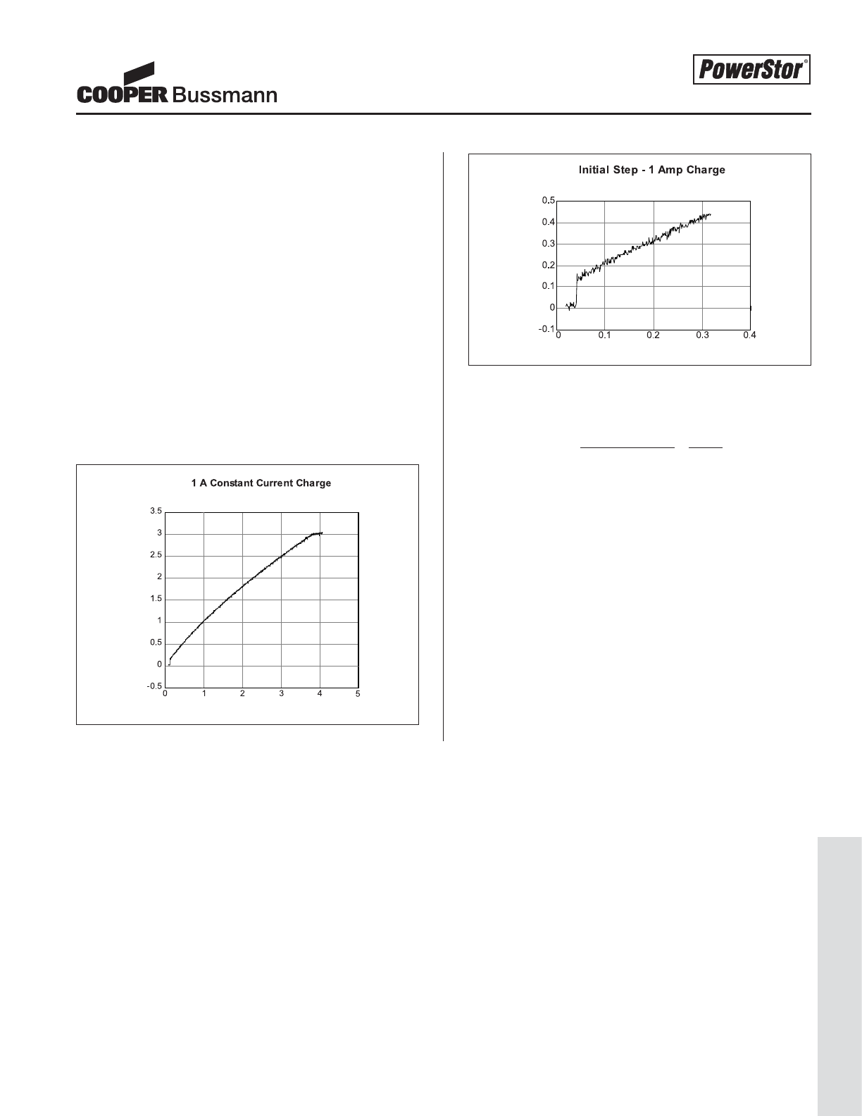
PS-21
Design Guides
method is used to measure what is called the internal resis-
tance or DC impedance and can be performed with the
same instrumentation used to measure capacitance
(described above). This method produces a value for inter-
nal resistance which is not nearly as precise and repro-
ducible as the ESR measurement. However, internal resis-
tance is more directly related to device behavior in many
pulse power applications.
Shown in Figure 4 is the oscilloscope trace obtained using
the capacitance test circuit and method. An enlargement of
the beginning of the trace is shown in Figure 5. The instan-
taneous voltage step which occurs the moment the 1
ampere charging current is applied is used to calculate
internal resistance. The internal resistance or DC imped-
ance is equal to the step voltage divided by 1 ampere. For
devices which exhibit lower internal resistance than this
example, a higher constant current is required.
Figure 4
Figure 5
In this example:
Internal resistance = initial voltage step = 0.15 V= 0.15 Ohms
constant current 1 A
Studies have shown that the internal resistance or DC
impedance value is usually between 1.1 and 1.5 times the
measured ESR or AC impedance value.
voltage - (v)
time - seconds (t)
voltage - (v)
time - seconds (t)
Measurement Techniques
Courtesy of Steven Engineering, Inc.-230 Ryan Way, South San Francisco, CA 94080-6370-Main Office: (650) 588-9200-Outside Local Area: (800) 258-9200-www.stevenengineering.com
PS-22
Design Guides
Performing supercapacitor calculations and predicting
solutions for applications can be tedious, therefore PowerStor®
has developed an Aerogel Supercapacitor Calculator in
Microsoft Excel®. This program is available online at
http://www.cooperbussmann.com. An example of this
program is shown on the following page.
To determine the aerogel supercapacitor requirements for an
application, four key parameters are required:
•Working voltage, Vw, in Volts
• Minimum voltage, Vmin in Volts
• Average discharge current, I, in Amps
• If necessary convert power, P, in Watts to current, where
I=P/V
avg
• Discharge time, t, in seconds
Simply enter these four parameters into the calculator in step
1 and the program will calculate:
• Energy requirement, W, in Joules
• Minimum capacitance requirement, C, in Farads
• Maximum resistance, R, in Ohms
In step 2, select the operating parameters specific to the
application including whether the discharge is more similar to
a DC pulse or AC pulse at a 1kHz frequency. Next select the
operating temperature and use the "deviation from nominal
capacitance" factor to build in a safety margin, if necessary.
The program will then use these correction factors for both
capacitance and resistance throughout the remainder of the
calculations.
The pull-down menu in step 3 has a list of PowerStor superca-
pacitor products. Select the appropriate supercapacitor that
meets both the capacitance and resistance requirements from
step 1. In this step there is an option to configure supercapac-
itors in parallel and/or to force the number of supercapacitors
in series to a specific number. For example, the calculator
would recommend six 2.5V supercapacitors for an automobile
voltage of 14.4V (14.4V / 2.5V per supercapacitor = 5.76
supercapacitors, which round up to 6). In practice, increasing
the number of supercapacitors to eight in automobile applica-
tions lowers the voltage to 1.8V per supercapacitor, providing
an increased reliability margin for high temperature exposure,
with a direct result of longer life. The number of supercapaci-
tors in series (actual) can be overwritten from the calculated
value.
Confirmation of the predicted aerogel supercapacitor solution
is done in step 4. First the total capacitance and resistance
values calculated are compared to the required values. Next
the energy and hold-up time requirements are confirmed. If
the energy and hold-up time are insufficient, chose a larger
supercapacitor or increase the number of supercapacitors in
parallel. Finally, the voltage drop is confirmed. The calculated
components of resistive and capacitive discharge are summed
and compared to the maximum value allowed. If the maxi-
mum voltage drop value is exceeded, simply chose a superca-
pacitor solution with lower ESR or increase the number of
supercapacitors in parallel.
Our goal for this calculator was to assist you in finding a
solution for your design challenges. Note: this program is
only intended to predict aerogel supercapacitor solutions. All
calculated solutions should be tested in the final application.
Contact Cooper Bussmann directly for further assistance and
application support.
Aerogel Supercapacitor Calculator
Courtesy of Steven Engineering, Inc.-230 Ryan Way, South San Francisco, CA 94080-6370-Main Office: (650) 588-9200-Outside Local Area: (800) 258-9200-www.stevenengineering.com
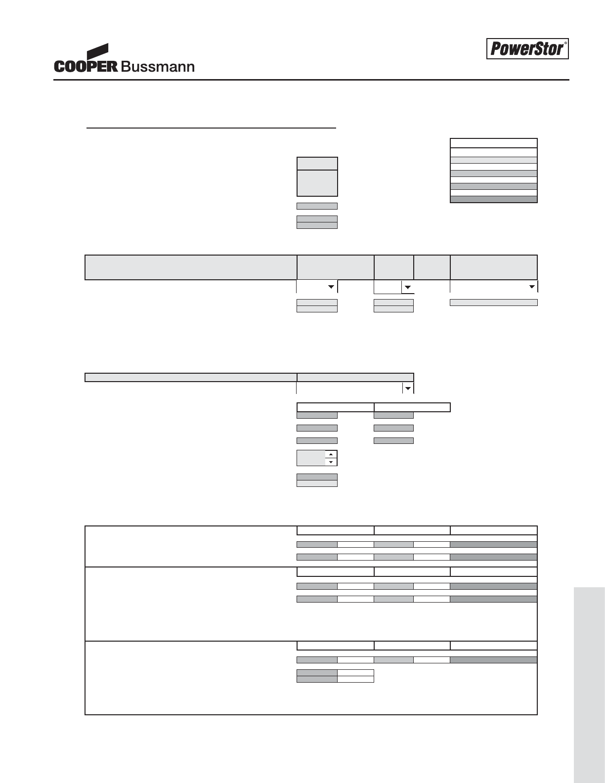
PS-23
Design Guides
Aerogel Supercapacitor Calculator
PowerStor Aerogel Supercapacitor Calculations for: Enter Company or Project Name
09/04/02
Four Simple Steps for Determining Supercapacitor Requirements
1. Enter values for Working Voltage, Minimum Voltage, Current and Time Legend
Enter Known Input Values in Yellow
Valu
e
Working Voltage (Vw) Vw = 2.5 Volts Required Values in Gray
Minimum Voltage [Vmin] Vmin = 1Volts
Current [I] I= 1Amps Calculated Values in Light Blue
Time [t] t= 1second
s
Comments in Gree
n
Energy needed during hold-up period (Minimum) W = (Vw+Vmin)/2*I*t = 1.75 Joules
Desired Capacitance (Minimum) C = 2 Vw*I*t / (Vw^2 - Vmin^2) = 0.6667 Farads
Desired Impedance (Maximum) R = (Vw - Vmin) / I = 1.500 Ohms
2. Select Operating Parameters and Correction Factors from pull-down menu
Use pull-down menu for Correction Factors to Capacitance and ESR Discharge Pulse
Frequency Temperature Deviation from Specified
Capacitance (-20% to +80%)
Capacitance Correction Factors : 1 0.8 1
ESR Correction Factors : 1.5 2.25
3. Choose Supercapacitor from pull-down menu to meet Desired Capacitance and Desired Impedance
Note 1: Total Capacitance equals 1/2x for two in series, 1/3x for three in series, etc.
Note 2: Total Capacitance equals 2x for two in parallel, 3x for three in parallel, etc.
Note 3: Total Resistance equals 2x for two in series, 3x for three in series, etc.
Note 4: Total Resistance equals 1/2x for two in parallel, 1/3x for three in parallel, etc.
Use pull-down menu to choose a specific model Supercapacitor
Single Device Capacitance C = 2.2 Farads 1.76 Farads
Single Device Resistance R = 0.225 Ohms 0.759375 Ohms
Single Device Max Voltage Vmax = 2.5 Volts 2.500 Volts
# supercapacitor(s) in parallel Increase p to increase Capacitance or 1
reduce Resistance
# supercapacitor(s) in series (min. calculated) Vw / Vcap (A = 2.5V; B = 2.5V; P = 5.0V) = 1.00
# supercapacitor(s) in series (actual) (See Note 5 s (rounded up) = 1
Note 5: Formula for # supercapacitor(s) in series (actual) can be manually overwritten if lower or higher Vw per supercapacitor desired. View Corrected Value for actual Single Device Max Voltage.
4. Confirm Time requirement is met for hold-up applications and/or Voltage Drop is acceptable for pulse applications.
Final Supercapacitor Configuration Comments
Total Capacitance C = 1.76 Farads 0.6667 Farads Capacitance Value Met
Total Resistance R = 0.759375 Ohms 1.500 Ohms Resistance Value Met
Check Energy and Time Requirements Comments
Energy available in supercapacitor(s) W = 1/2 C * (Vw^2 - Vmin^2) = 4.62 Joules 1.75 Joules Energy Value Met
Max. Hold-up Time with chosen supercapacitor(s) t = C (Vw - IR -Vmin) / I = 1.30 seconds 1 seconds Time Requirement Met
If Energy is insufficient, choose a Single Device with higher Capacitance or increase # supercapacitors in parallel.
Check to ensure that Energy available in supercapacitors is greater than Energy needed during hold-up period, or Maximum Hold-up Time is sufficient.
Check Voltage Drop Comments
Total Voltage Drop of supercapacitor(s) = Vdrop (resistive) + Vdrop (capacitive) = 1.328 Volts 1.500 Volts Voltage Drop Acceptable
Voltage drop (resistive) Vdrop (resistive) = IR = 0.759 Volts
Voltage drop (capacitive) Vdrop (capacitive) = I (t / C) 0.568 Volts
If Total Voltage Drop is greater than Maximum Allowed, determine whether resistance or capacitance is the main factor.
Choose supercapacitors with either more capacitance or less resistance, or increase # capacitors in parallel.
If Total Voltage Drop is less than Maximum Voltage Drop Allowed, STOP.
This program is intended to provide product design solutions that will help the user with design applications.
Once a product design solution has been determined, it should be tested by the user in all possible applications.
© Cooper Electronic Technologies 2002
Calculated Values Required Values
Calculated Values Required Values
Part Number Capacitance ESR (AC @ 1 kHz)
Calculated Values Required Values
Standard Values Corrected Values
B0820-2R5225 2.2 F 0.225 Ohms
DC -20°C Nominal Capacitance
Courtesy of Steven Engineering, Inc.-230 Ryan Way, South San Francisco, CA 94080-6370-Main Office: (650) 588-9200-Outside Local Area: (800) 258-9200-www.stevenengineering.com
PS-24
Marketing Bulletins
Two major applications of aerogel supercapacitors are high
pulse power applications and short-term hold-up power.
Pulse power applications are characterized by very short,
but high current delivery to a load, i.e. during the transmit
period in a GSM mobile device. Hold-up applications are
characterized by the requirement to continue to deliver load
power for times on the order of seconds or minutes. An
example of a hold-up application is the parking of the
read/write head in a disk drive when power to the unit is
shut off. Each of these applications emphasize different
performance parameters of the device. High pulse power
applications benefit primarily from the aerogel supercapaci-
tor's low internal resistance (R), while hold-up power appli-
cations benefit from the supercapacitor's large capacitance
(C) value.
This Marketing Bulletin presents the formulae used to calcu-
late your application requirements and uses two examples
to illustrate their use. A program titled “Aerogel
Supercapacitor Calculator” designed in a Microsoft®Excel
spreadsheet is also available for your use.
Definitions
The following definitions are used in this note:
Symbol Unit of Description
Measure
C Farads Nominal capacitance value of the
aerogel supercapacitor.
R Ohms The nominal internal resistance of the
aerogel supercapacitor.
ESR Ohms Equivalent Series Resistance mea-
sured at 1 kHz.
Vwv Volts Normal or working charge voltage in
the circuit application.
Vmin Volts The minimum voltage required to
operate the device.
Iload Amps In a hold-up application this is the
average current that continues to be
delivered to the load. It is an average
as the load current will increase as the
voltage decreases from Vwv to Vmin.
t Seconds This is the required hold-up time in
the circuit, or in pulse applications,
t is the pulse duration.
Vdrop Volts The total decrease in working voltage
at the end of the discharge or high
current pulse.
Hold-Up Power Applications
An approximate calculation can estimate the value of an
aerogel supercapacitor needed in most applications. This
calculation equates the energy needed during the hold-up
period to the energy decrease in the supercapacitor, start-
ing at Vwv and ending at Vmin.
Energy needed during hold-up period: 1/2 Iload (Vwv +V
min)t
Energy decrease in supercapacitor: 1/2 C(Vwv2–Vmin2)
Therefore, the minimum capacitance value that guarantees
hold-up to Vmin (neglecting voltage drop due to IR) is:
C=I
load(Vwv +V
min)t in Farads
(Vwv2–Vmin2)
Example:
Suppose a tape drive supply is 5.0V and can operate safely
down to 3.0V. If the DC motor requires up to 2 seconds of
hold-up prior to safe shutdown at 0.5A, then the use of the
above equation predicts that the hold-up capacitor must be
at least 0.5F.
One A Series supercapacitor can supply the required
capacitance. However, the nominal operating voltage of
2.5V is exceeded by the 5V requirement. Therefore, two
aerogel supercapacitors must be configured in series. If two
equal value supercapacitors are used, then the voltage
across each device will be approximately 2.5V, which is the
nominal voltage rating.
In the data sheets the A1020-2R5105 supercapacitor is list-
ed with a nominal capacitance of 1.0F and when configured
two in series, provides 1.0F / 2 = 0.5F. Theoretically this
solution should work, but with a –20% end of the tolerance
range, this solution does not provide significant margin.
Stepping up to the next supercapacitor, the A1030-2R5155
would provide 1.5F / 2 = 0.75F at 5V. With a –20% toler-
ance, the minimum value could be as low as 1.2F / 2 = 0.6F.
This supercapacitor solution provides a sufficient safety
margin. After the high current pulse, the tape drive goes
into a very low current mode to hold up the electronics and
uses the remaining energy in the supercapacitor.
In this example, balancing the voltage across the series
combination is recommended to ensure neither device
exceeds the maximum voltage rating. See the notes on
voltage balancing in PS-5508 Application Guidelines.
Design Considerations In
Selecting Aerogel Supercapacitors
Design Considerations In Selecting Aerogel Supercapacitors
Courtesy of Steven Engineering, Inc.-230 Ryan Way, South San Francisco, CA 94080-6370-Main Office: (650) 588-9200-Outside Local Area: (800) 258-9200-www.stevenengineering.com
PS-25
Marketing Bulletins
Pulse Power Applications
Pulse power applications are characterized by a relatively
low value of continuous current with brief, high current
requirements. Applications have pulses that range from less
than 1 millisecond to as high as a few seconds, and the
pulse current can be orders of magnitude higher than the
continuous or background current. The duty cycle of the
pulses is usually low, typically less than 20 %.
A worst-case design analysis assumes that the aerogel
capacitor is the sole supplier of energy during the pulse. In
this case the total drop in working voltage in the circuit con-
sists of two components: the instantaneous voltage drop
due to load current supplied through the internal resistance
of the capacitor, and the drop in capacitor voltage at the end
of the pulse period. This relationship is shown in the follow-
ing equation.
Vdrop =I
load (R + t/C)
Inspection of this equation shows that the capacitor must
have low R and a high value of C if the voltage drop is to be
small.
For most pulse power applications the value of R is more
important than the value of C. This is illustrated using this
equation for the A1030-2R5155 supercapacitor. Its internal
resistance, R, can be estimated by using the DC ESR, nom-
inally 0.075 Ohms (DC ESR = AC ESR x 1.5 = 0.060 Ohms
x 1.5 = 0.090 Ohms). The specified capacitance is 1.5F.
For a 0.001 second pulse, t/C is less than 0.001 Ohms.
Even for a 0.010 second pulse, t/C is only 0.0067 Ohms.
Clearly the value of R (0.090 Ohms) dominates the outcome
of Vdrop in the equation above.
Example:
A GSM/GPRS wireless modem requires a pulse current of
up to 2A for 0.6 milliseconds every 4.6 milliseconds. Note
the pulse width doubles or quadruples with GPRS. These
modems are now available in a PCMCIA card for notebook
computers. The constraints of the notebook and the PCM-
CIA connection are an output voltage of 3.3 +/- 0.3V and a
maximum current provided by the notebook of 1A. Many
power amplifiers (PA) have a minimum voltage requirement
of 3.0V. As it is possible for a notebook computer to output
only 3.0V, the voltage to the PA must first be boosted (3.6V
is common). With a working voltage of 3.6V and a minimum
voltage of 3.0V, the allowable voltage drop due to resistance
is 0.6V.
Choosing the F Series Flat Pack FC-3R6334-R
supercapacitor yields 0.33F with 0.200 Ohms AC
impedance or 0.25 Ohms DC impedance, R. During a 2A
transmit pulse the battery provides approximately 1A and
the supercapacitor provides the remaining 1A of current.
Using the above formula, the voltage drop, IR, due to
resistance is 1A x 0.25 Ohms = 0.25V. The capacitive
component, I(t/C), is small at 0.002V compared to the
resistive voltage drop.
Conclusions
Both hold-up power applications and pulse power applica-
tions can be designed by using the simple equations pre-
sented above. When the working voltage of the circuit
exceeds the maximum operating voltage rating of the aero-
gel supercapacitor, equal value supercapacitors should be
put in series arrangement. Often, the series arrangement
should be balanced to ensure equal voltage sharing. In
pulse power applications the voltage drop across the inter-
nal resistance of the device is usually the critical factor. The
aerogel capacitor’s ultra-low internal resistance provides a
new solution to the high impedance problems characteristic
of most battery systems.
Design Considerations In
Selecting Aerogel Supercapacitors
Courtesy of Steven Engineering, Inc.-230 Ryan Way, South San Francisco, CA 94080-6370-Main Office: (650) 588-9200-Outside Local Area: (800) 258-9200-www.stevenengineering.com
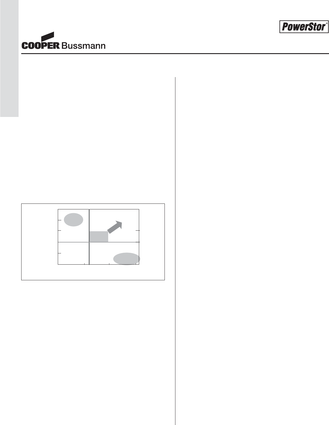
PS-26
Marketing Bulletins
The ultimate energy storage device should have high ener-
gy density that can be released rapidly. High energy batter-
ies have been developed as single use or rechargeable sys-
tems but typically require minutes to hours to discharge, not
seconds. For high power, standard capacitors are capable
of discharging rapidly but have low energy density.
First generation supercapacitors also referred to as ultraca-
pacitors and Electrochemical Double Layer Capacitors
(EDLC), have relatively high energy density but also very
high ESR (equivalent series resistance) and are therefore
only used in very low power memory backup applications.
New aerogel supercapacitors have been developed incorpo-
rating both the high energy density of batteries (100 times
the energy of electrolytic capacitors) and the high power of
capacitors (10 to 100 times the power of batteries) as
shown in Figure 1.
Figure 1
Imagine the possible uses of a high energy, high power
energy storage device, sometimes referred to as "A solution
looking for a problem". Many engineers have and these
new supercapacitors are finding their way into a wide range
of new applications. In many instances, the supercapacitor
is the enabling technology for these new applications.
High power supercapacitors are designed similar to elec-
trolytic capacitors however supercapacitors use high surface
area carbon for accumulation of charge as opposed to the
low surface area foils in electrolytic capacitors. An electric
double layer is formed at the interface of the solid carbon
electrode and liquid electrolyte. Aerogel supercapacitors
use aerogel carbon as the active material, while the rest of
the industry typically uses activated carbon. Aerogel carbon
is known for its high level of purity, high usable surface area
and high electrical conductivity. Key features for aerogel
supercapacitors include:
• Extremely low ESR for high power and low loss during
operation
• High energy density for long run-time
• Ultra low leakage current (can hold a charge for sev-
eral weeks)
•Wide operating temperature range
• Can be cycled hundreds of thousands of times with
very fast charge and discharge rates, as opposed to
only hundreds of cycles for batteries.
Aerogel supercapacitors have reasonably high energy den-
sity compared with rechargeable batteries. In some applica-
tions, batteries have far more energy than is required, take
too long to charge, do not like to be held fully charged or
shallow discharged (NiCd memory effect) on a continuous
basis without periodic maintenance, or do not cycle long
enough. In applications such as electronic toys, UPS sys-
tems or solar charged lighting, aerogel supercapacitors
have replaced batteries as a better alternative.
Aerogel supercapacitor designs include 2.5V radial leaded
cylindrical and 5V leaded rectangular devices. There is also
a new low profile, flat pack design with thickness ranging
from 4 mm to as low as 1 mm. Large cylindrical and pris-
matic designs up to 2500F are also available.
These supercapacitors have characteristics that make them
ideal for applications in electronic circuits, portable devices
and systems powered by batteries, fuel cells or dc power
supplies. The aerogel supercapacitors can be used in appli-
cations ranging from low tech (toys) to medium tech (elec-
tronic control systems, valves and solenoids) to high tech
(microprocessor- controlled devices).
Aerogel supercapacitors provide:
• Pulse power characterized by short, high current puls-
es delivered to a load, allowing the use of a smaller
power supply or battery
• Hold-up or bridge power to a device or equipment for
seconds, minutes or days when the main power or
battery fails or when the battery is swapped out
• Main power or battery replacement
Pulse Power
A growing number of applications today require short bursts
of power, including phones, wireless modems, radio trans-
ceivers, motors, valves and solenoids. An engineer now
has two battery design options: (1) use a larger battery (or
Aerogel Supercapacitors Provide Both
High Energy and High Power Capability
High power aerogel supercapacitors enable new pulse, bridge and main power applications.
Electrolytic
Capacitors
Aerogel
Capacitors
Li - ion
10-2
10-1
NiCd
NiMH
103
102
10110 Farad/cc
Energy
Density
(WH/L) 1001 Farad/cc
10 10 10 10
Power Density (W/L)
234 5
Development
Path
Courtesy of Steven Engineering, Inc.-230 Ryan Way, South San Francisco, CA 94080-6370-Main Office: (650) 588-9200-Outside Local Area: (800) 258-9200-www.stevenengineering.com

PS-27
Marketing Bulletins
power supply) capable of the high pulse current or (2) use a
smaller battery (or power supply) with higher energy density
(at the expense of lower power density) configured in paral-
lel with a high power supercapacitor. The second option is
known as a battery-supercapacitor hybrid configuration and
results in a high energy / high power device with smaller
size, lower weight and lower cost than the first option of a
larger battery or power supply
Pulse Power Calculations
Pulse power applications are characterized by a relatively
low value of continuous current with brief, high current
requirements. Applications have pulses that range from less
than 1 msec to as high as a few seconds, and the pulse
current can be orders of magnitude higher than the continu-
ous or background current. The duty cycle of the pulses is
usually low, typically less than 20 %.
A worst-case design analysis assumes that the aerogel
supercapacitor is the sole supplier of current during the
pulse. In this case the total drop in working voltage in the
circuit consists of two components: (1) instantaneous volt-
age drop due to the internal resistance of the supercapaci-
tor, and (2) capacitive drop during the discharge pulse.
This relationship is:
Vdrop =I
load (R + t/C)
Vdrop = Change in voltage (V)
Iload = Load current (A)
R = Internal resistance (Ohms)
t = Time (sec)
C = Capacitance (Farads)
For a small voltage drop, this equation shows that the
supercapacitor must have low R and high C. For many
pulse power applications where t is small, the value of R is
more important than the value of C. For example a lower
ESR 1.5F aerogel supercapacitor has an estimated internal
resistance of 0.060Ω. For a 0.001sec pulse, t/C is less than
0.001Ω. Even for a 0.010 sec pulse, it is only 0.007Ω.
Clearly, the value of R (0.060Ω) dominates the outcome of
Vdrop in Equation (1) for short pulse power applications.
Where t is large, 3 seconds for example, t/C = 2Ωand now
C dominates the outcome of Vdrop in Equation (1).
Ultra thin (down to 1mm), low ESR supercapacitors have
been developed for GSM / GPRS applications, including
wireless PCMCIA modems. Type II PCMCIA cards have
only 5mm inside clearance, but with a two-sided 1mm circuit
board, the supercapacitor height restriction can be as low
as 2mm. New thin supercapacitors using flexible packaging
have been developed with very low ESR. The PCMCIA
specification allows less than 1A of current to flow from the
notebook battery to the PC card but GSM / GPRS transmis-
sions requires up to 2A. GSM transmits for approximately
0.6 milliseconds every 4.6 milliseconds then runs at lower
currents for receive and standby modes in the remaining 4
milliseconds. The supercapacitor is charged by the excess
or available battery current in 4 milliseconds between the
0.6 millisecond discharges.
The GPRS protocol allows higher transmission rates with
double to quadruple transmit times of GSM. Although low
ESR is the primary design criteria to minimize the voltage
drop from the supplied voltage (3.3V) to the minimum volt-
age required for the power amplifier (3V), supercapacitors
have significantly more capacitance than other capacitor
technologies allowing the extended pulse lengths of GPRS.
An example of an application requiring more capacitance to
minimize voltage drop during a pulse discharge is digital
cameras. Low ESR supercapacitors enable alkaline batter-
ies to last longer in digital cameras. The challenge is to run
longer on fewer, low power alkaline batteries. The high
power requirement of the zoom motor causes alkaline bat-
teries to fail before they have released all of their stored
energy. Due to the relatively long (several seconds) dis-
charge pulse requirement for the zoom motor, larger capaci-
tance (6 to 10F) supercapacitors have been found to extend
the useful life of the alkaline batteries.
Figure 2 compares 2 AA alkaline batteries (top) to 2 AA
alkaline batteries connected in parallel to a single 6F super-
capacitor (bottom), without additional circuitry. To simulate
the zoom motor in a digital camera, each system was
discharged at 4 Watts for 3 seconds every 3 minutes.
This sequence resulted in 55 zoom cycles every 10,000
seconds. The voltage drop was larger for the battery (left)
compared to the hybrid (right). The battery-supercapacitor
hybrid ran approximately three times longer than the battery
alone.
Hold-up or Bridge Power
Hold-up power applications are characterized by a short,
high current or "bridge power" pulse followed by a longer,
low current drain. Standard memory backup type superca-
pacitors are capable of the low current drain but unable to
handle the short, high current pulse due to their high ESR.
During the pulse, the system voltage will drop below the
lower voltage allowed by the device’s electronics and the
system will shut down. For these applications, new low
Aerogel Supercapacitors Provide Both
High Energy and High Power Capability
Courtesy of Steven Engineering, Inc.-230 Ryan Way, South San Francisco, CA 94080-6370-Main Office: (650) 588-9200-Outside Local Area: (800) 258-9200-www.stevenengineering.com
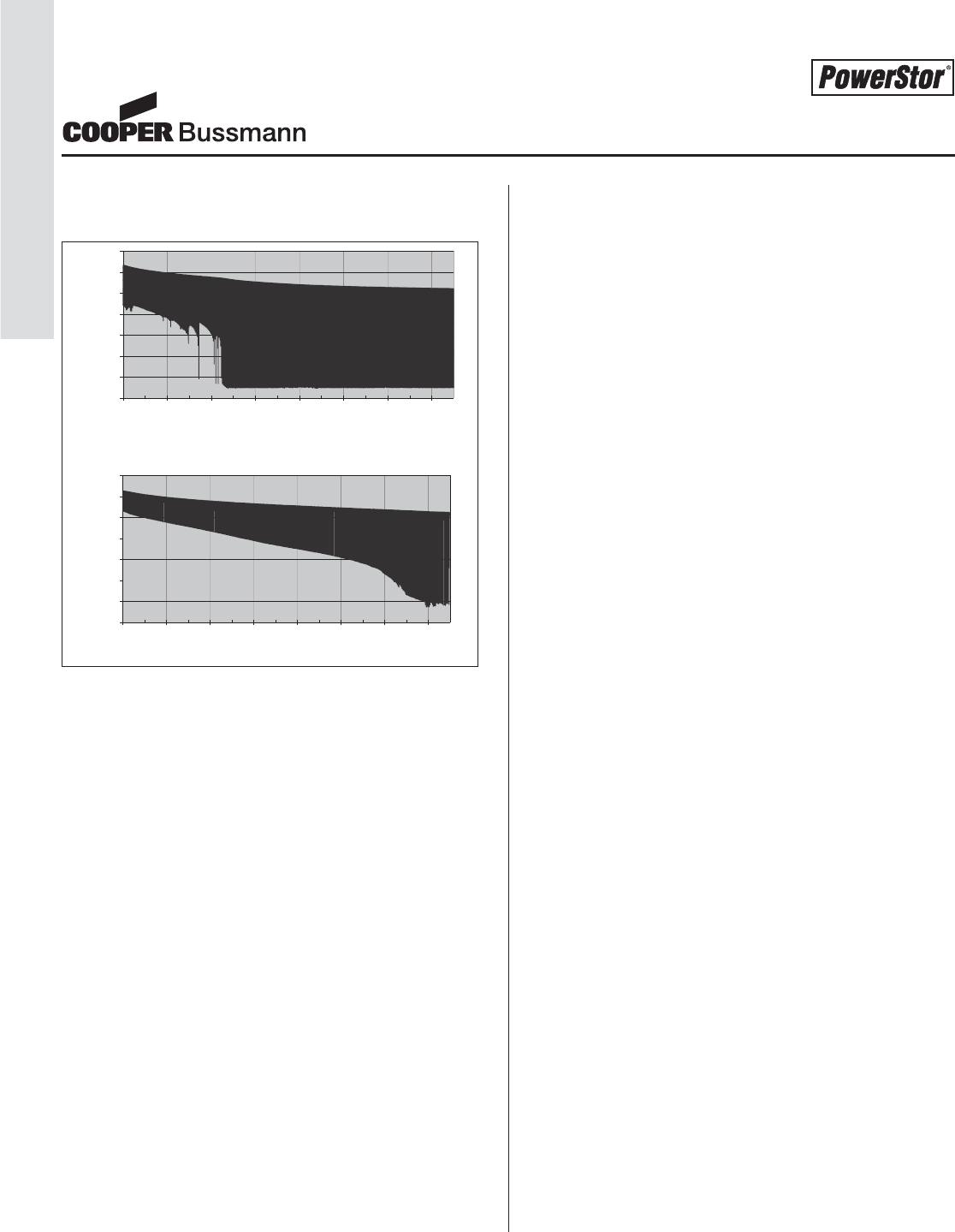
ESR aerogel supercapacitors are capable of handling the
high current pulse to minimize the voltage drop.
Figure 2
Bridge power examples include solid-state hard drives and
portable data terminals. In the solid-state hard drive, all
memory is stored in DRAM. When main power is lost, the
information in the DRAM must be transferred to non-volatile
memory. This requires a high discharge current for a num-
ber of seconds after which the device requires a very low
current to maintain the system.
Portable data terminals use supercapacitors to "bridge"
between swapping of batteries when the device is in opera-
tion and not simply in sleep mode. Batteries can also fall
out or become temporarily disconnected if the device is
dropped. To prevent loss of data, supercapacitors are
designed to provide continuous power to the portable data
terminal until it is able to safely power down or the battery is
swapped or reconnected.
Main Power
The energy density for today’s supercapacitors has grown
substantially and is now only 3 to 10 times lower than some
rechargeable batteries (i.e. lead-acid), but with the added
benefits of nearly infinite cycle life, very short recharge
times and very high power density. Supercapacitors can be
charged directly from alkaline batteries, solar panels or
other DC power sources. As a result some portable and
remote applications are now using supercapacitors in place
of rechargeable batteries.
The toy cars and airplanes that claim "Charge In Under 10
Seconds" all use supercapacitors as the main power source
and alkaline batteries to charge them. The fast charge is
particularly important for children as their attention spans
are not long enough to wait for batteries to charge.
Solar charging is particularly important in remote applica-
tions. With 365 charge/discharge cycles per year, recharge-
able batteries require frequent replacement. These applica-
tions include remote monitoring systems, transmitters, light-
ing and traffic signs. New portable applications currently
under development include flashlights, remote controls and
radios all charged using solar power.
Another main power application that is ideal for supercapac-
itors is local area or restaurant pagers. These pagers run
for up to two hours while the patron is waiting for a table.
After being returned to the host/hostess, the pager only
requires a 10 second charge for the next customer. Nickel
cadmium batteries perform poorly in these shallow depth-of-
discharge applications due to their "memory" effect (loss of
capacity due to continuous shallow discharges). As a
result, constant battery replacement is no longer an issue or
added cost when supercapacitors designed to last the life of
the product are used for main power.
Design Considerations
Energy and Capacitance Calculations
To determine your aerogel supercapacitor requirements,
four key parameters are required:
•Working voltage, Vwv, in Volts
• Minimum voltage, Vmin, in Volts
• Average discharge current, Iload, in Amps
• (if necessary convert power, P, in Watts, to current,
Iload, where Iload = P/Vavg)
• Discharge time, t, in seconds
One can estimate the value of an aerogel supercapacitor
needed for most applications (Note 1). This calculation
equates the energy needed during the discharge period to
the energy decrease in the aerogel supercapacitor, from
Vwv to Vmin.
Energy needed for discharge:
1/2 Iload (Vwv +V
min)t (Joules)
Aerogel Supercapacitors Provide Both
High Energy and High Power Capability
0
0.5
1
1.5
2
2.5
3
3.5
0 10000 20000 30000 40000 50000 60000 70000
Time (Seconds)
Voltage (V)
0
0.5
1
1.5
2
2.5
3
3.5
0 10000 20000 30000 40000 50000 60000 70000
Time (Seconds)
0 10000 20000 30000 40000 50000 60000 70000
Time (Seconds)
0 10000 20000 30000 40000 50000 60000 70000
Time (Seconds)
Voltage (V)
PS-28
Marketing Bulletins
Courtesy of Steven Engineering, Inc.-230 Ryan Way, South San Francisco, CA 94080-6370-Main Office: (650) 588-9200-Outside Local Area: (800) 258-9200-www.stevenengineering.com
PS-29
Marketing Bulletins
Aerogel Supercapacitors Provide Both
High Energy and High Power Capability
Energy decrease in supercapacitor:
1/2 C(Vwv2–Vmin2)(Joules)
Therefore, the minimum capacitance value that guarantees
hold-up to Vmin is:
C=I
load(Vwv +V
min)t in Farads
(Vwv2–Vmin2)
Voltage Balancing
When the working voltage of the circuit exceeds the maxi-
mum operating voltage rating of a single supercapacitor, a
series configuration is required. Often, the series arrange-
ment requires balancing to ensure equal voltage sharing.
Either passive or active balancing can be used to maintain
similar voltages among supercapacitors where the leakage
currents may be slightly different.
Passive balancing uses equal value resistors in parallel with
the supercapacitors. Using high value resistors, small cur-
rents are allowed to flow between the supercapacitors to
maintain similar voltages. Resistors with high values result
in lower leakage currents on the order of microamperes, an
important design consideration for hybrid battery-superca-
pacitor solutions. Lower value resistors lead to higher leak-
age currents but faster voltage equilibration of mismatched
components, and can be used where the main power is
delivered by a continuous source of power (power supply or
fuel cell).
Active balancing uses a microprocessor to measure voltage
differences and open gates allowing equilibration to occur
quickly but only when needed. Active balancing does not
add significant current leakage in the final configuration, but
comes at a higher price than passive balancing. High relia-
bility applications, with higher voltages (> 5V), typically use
active balancing.
Summary
High power, high energy aerogel supercapacitors offer solu-
tions for applications by providing pulse, hold-up, or main
power.
Note 1: An Aerogel-Supercapacitor-Calculator program is
available online at http://www.cooperbussmann.com and
can be used to predict required energy, capacitance and
ESR for any application.
Courtesy of Steven Engineering, Inc.-230 Ryan Way, South San Francisco, CA 94080-6370-Main Office: (650) 588-9200-Outside Local Area: (800) 258-9200-www.stevenengineering.com
PS-30
Customer / Application Information Worksheet
Customer / Application
Information Worksheet
The following worksheet will enable us to understand your Aerogel Supercapacitor application better and to communicate more
effectively when we discuss the application with you. All information provided will be held confidential.
Date_____________________________
Company_______________________________Contact Name ________________________________________________________
Phone _________________________________Fax ____________________________email________________________________
Application Description: ________________________________________________________________________________________
__________________________________________________________________________________________________________
__________________________________________________________________________________________________________
__________________________________________________________________________________________________________
Medical? __ No __ Yes If Yes, Class _________ (I, II, or III)
Company Type:
_____OEM _____Systems Integrator _____Distributor _____Consultant
_____Educational _____Government _____Military _____Other ____________________
Application Type:
_____Pulse Power _____Main Power _____Memory Backup or Hold-Up Power
Circuit Information:
Desired working voltage (V) ____________________volts Minimum allowable voltage (Vmin)______________________volts
Average current draw (I) ______________________Amps Duration of current draw (t) ________________________seconds
Capacitor Calculations:
PowerStor has developed a Calculator program using Microsoft®Excel. Knowing a few simple parameters for the application, this
program will assist in determining the optimum Aerogel Capacitor Solution by:
1. Calculating Minimum Capacitance, Maximum ESR, and Capacitor Configuration.
2. Using a pull-down menu with all of PowerStor’s Aerogel Capacitor offerings for comparison to the calculated values.
The Powerstor Aerogel Capacitor Calculator is available at www.cooperbussmann.com for download.
For Typical Hold-Up Power Applications:
Energy needed during hold up period: W = IVt = ___________ in Joules
Energy decrease in capacitor: W= 1/2 C(V2–Vmin2) = ___________ in Joules
Desired C is: C = 2IVt = ___________Farads
V2–V
min2
For Typical Pulse Power Applications:
Maximum ESR: ESR(maximum) = Vdrop /I = __________Ohms
W= Energy (Joules) C= Capacitance (Farads) V= Voltage (volts) I= Current (Amps) t= Time (seconds)
Vmin = Min. voltage (volts) ESR = Equivalent Series Resistance (Ohms) Vdrop = Allowable drop in working voltage (volts)
Courtesy of Steven Engineering, Inc.-230 Ryan Way, South San Francisco, CA 94080-6370-Main Office: (650) 588-9200-Outside Local Area: (800) 258-9200-www.stevenengineering.com
PS-31
Customer / Application Information Worksheet
Optimum Solution:
Capacitor Part Number ________________________
# of Capacitors in Series Configuration ______
# of Capacitors in Parallel Configuration ______
Additional Information
Max. Operating Temp. (C) ______ % Time at Max. Temp. ______
Min. Operating Temp. (C) ______ % Time at Min. Temp. ______
Typical Operating Temp. (C) ______ % Time at Typical Temp. ______
Max. Storage Temp. (C) ______
Min. Storage Temp. (C) ______
Dimensional / Package Requirements
Max. Package Size (L, W, H, diam., etc.) ___________________________________________________________________
Package Style (thru-hole, SMT, etc.) ______________________________________________________________________
Industry package _____________________________________________________________________________________
Additional ___________________________________________________________________________________________
___________________________________________________________________________________________________
Product Schedule Date Required QTY or EAU
Initial Samples __________________ __________________
Pre-production __________________ __________________
Production __________________ __________________
Expected Years of Operation ____________________________________
Target Cost $___________at Estimated Annual Usage Qty.________(pcs.)
Additional Information (Circuit diagram, product configuration, packaging, notes, etc.)
Customer / Application
Information Worksheet
Courtesy of Steven Engineering, Inc.-230 Ryan Way, South San Francisco, CA 94080-6370-Main Office: (650) 588-9200-Outside Local Area: (800) 258-9200-www.stevenengineering.com

PS-32
NOTES
Aerogel Supercapacitors
Courtesy of Steven Engineering, Inc.-230 Ryan Way, South San Francisco, CA 94080-6370-Main Office: (650) 588-9200-Outside Local Area: (800) 258-9200-www.stevenengineering.com

©2007 Cooper Bussmann • Boca Raton, FL 33487
561-998-4100 • www.cooperbussmann.com
CB-5010 2007
Products And Technical Expertise
Delivered Worldwide
Customer Assistance
Customer Satisfaction Team
The Cooper Bussmann Customer Satisfaction Team is
available to answer questions regarding Cooper
Bussmann products and services. Calls should be made
Monday – Friday, 8:00 a.m. – 4:30 p.m. for all
US time zones.
The Customer Satisfaction Team can be reach via:
• Phone: 636-527-3877
• Toll-free fax: 800-544-2570
• E-mail: customerservice@cooperbussmann.com
Emergency and After-Hours Orders
To accommodate time-critical needs, Cooper Bussmann
offers emergency and after-hours service for next flight
out or will call. Customers pay only standard price for
the circuit protection device, rush freight charges and a
modest emergency fee for this service. Emergency and
after-hours orders should be placed through the
Customer Satisfaction Team. Call:
• Monday – Friday, 8:00 a.m. – 4:30 p.m.
Central Time 636-527-3877
• After hours 314-995-1342
Application Engineering
Application Engineering assistance is available to all
customers. The Application Engineering team is staffed
by degreed electrical engineers and available by phone
with technical and application support Monday – Friday,
8:00 a.m. – 5:00 p.m. Central Time.
Application Engineering can be reached via phone, fax
or e-mail:
• Phone: 636-527-1270 (Cooper Bussmann
®
, PolySurg™)
• Phone: 561-998-4100 (Coiltronics
®
, PowerStor
®
)
• Fax: 636-527-1607
• E-mail: fusetech@cooperbussmann.com
Online Resources
Visit www.cooperbussmann.com and click on Electronics
for the following resources:
• Product cross reference
• RoHS status query
• Sample ordering
• Design calculators
• Literature downloads
Your Authorized Cooper Bussmann Distributor is:
Courtesy of Steven Engineering, Inc.-230 Ryan Way, South San Francisco, CA 94080-6370-Main Office: (650) 588-9200-Outside Local Area: (800) 258-9200-www.stevenengineering.com
