ULTRA BEAM Series Brochure
2014-09-04
: Pdf 119866-Brochure 119866-Brochure 662488 Batch7 unilog
Open the PDF directly: View PDF ![]() .
.
Page Count: 4
82
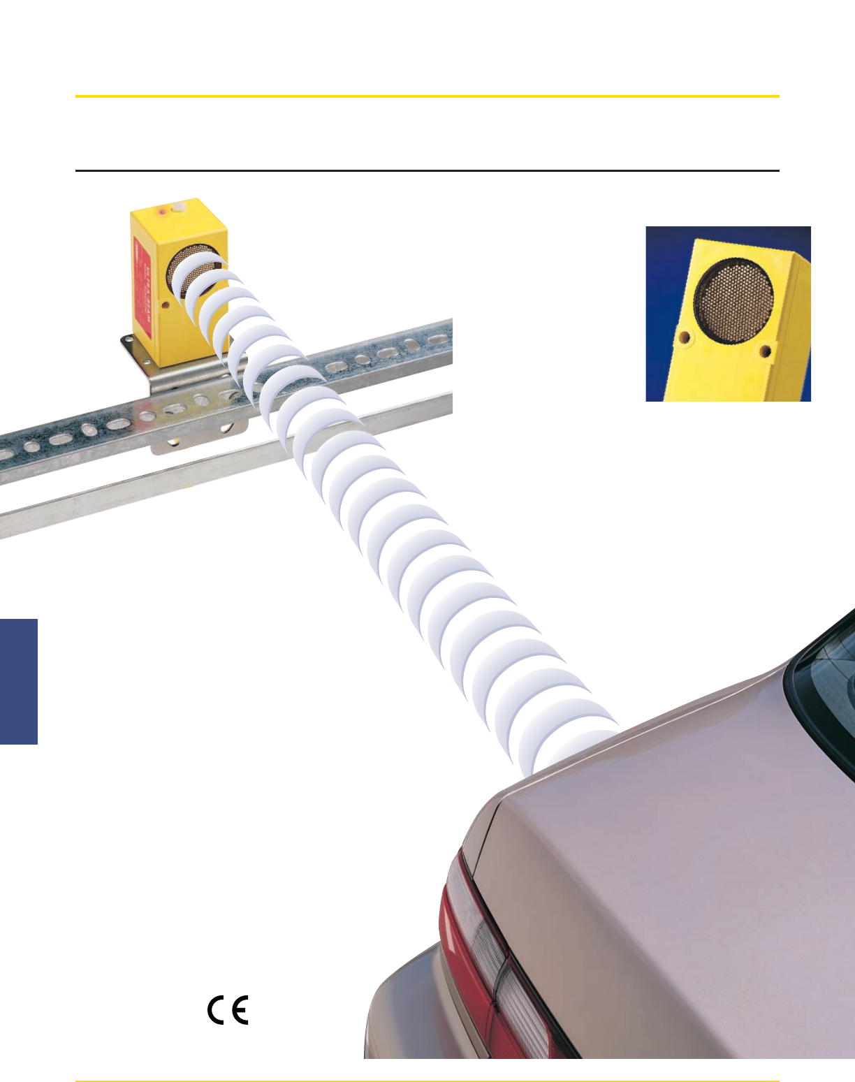
U-GAGETM ULTRA-BEAMTM Series - Ultrasonic Sensors
ULTRA-BEAMTM Series - Ultrasonic Sensor
Banner Engineering Corp. • Minneapolis, U.S.A. • bannerengineering.com • Tel: 763.544.3164
Long 0.5 to 6 m range.
(20" to 20')
• Electrostatic transducer provides economical,
reliable, close or long-distance sensing
independent of color or texture of target object
• Adjustable sensing window in analog output units
can be 300 mm to 5.6 m (12" to 18') wide and
adjusted using NULL and SPAN adjustments on
top of unit
Rugged construction.
• Electrostatic transducer with
metal mesh protective screen.
• Housing is molded VALOX®
with epoxy-encapsulated
circuitry, meeting many sensing
requirements, rated NEMA 1, 3,
and 12.
Switched electromechanical or analog outputs.
• Switched unit has simple range adjustment to limit response to
background objects
• Analog units offer 0 to +10V dc sourcing and 0 to 20 mA dc
sinking outputs, positive or negative slope
• Easily interfaced to variable speed DC drives,
microprocessors and PLCs
AC & DC Voltage inputs.
• Choose models for 18-30V dc, 105-130V ac,
or 210-260V ac operation
• All models use mini-style quick
disconnect cables
U-GAGE™
Courtesy of Steven Engineering, Inc. ! 230 Ryan Way, South San Francisco, CA 94080-6370 ! Main Office: (650) 588-9200 ! Outside Local Area: (800) 258-9200 ! www.stevenengineering.com
U-GAGE™
83
U-GAGETM ULTRA-BEAMTM Series - Model Selection
Banner Engineering Corp. • Minneapolis, U.S.A. • bannerengineering.com • Tel: 763.544.3164
50.0 mm
(1.97 in)
Range Adjustment
(Remove Nylon Screw for Access)
LED Indicator
Transducer
ø 38.1 mm (1.50 in)
M5 (#10)
Screw Clearance (2)
Mini-Style QD Connector
Threaded Base M30 x 1.5
40.1 mm
(1.58 in)
48.8 mm
(1.92 in)
45.0 mm
(1.77 in)
64.5 mm
(2.54 in)
4.8 mm
(0.19 in)
89.9 mm
(3.54 in)
14 mm
(0.6 in)
107.4 mm
(4.23 in)
50.0 mm
(1.97 in)
Span Adjust
LED Indicator
Transducer
ø 38.1 mm (1.50 in)
Null Adjust
M5 (#10)
Screw Clearance (2)
Mini-Style QD Connector
Threaded Base M30 x 1.5
40.1 mm
(1.58 in)
48.8 mm
(1.92 in)
45.0 mm
(1.77 in)
64.5 mm
(2.54 in)
4.8 mm
(0.19 in)
89.9 mm
(3.54 in)
14 mm
(0.6 in)
107.4 mm
(4.23 in)
Neg.-Pos. Slope Switch
(inside Cover)
* Models with a QD connector require a mating cable.
ULTRA-BEAMTM Series Models
Models Range Cable* Supply Voltage Output Type
SU925QD-24
SUA925QD
SUB925QD
SU923QD
SUA923QD
SUB923QD
500 mm to 6 m
(20" to 20')
500 mm to 6 m
(20" to 20')
5-pin Mini QD
5-pin Mini QD
5-pin Mini QD
4-pin Mini QD
5-pin Mini QD
5-pin Mini QD
18 to 30V dc
105 to 130V ac
210 to 250V ac
18 to 30V dc
105 to 130V ac
210 to 250V ac
SPDT
E/M
Relay
Analog
0-10V dc
or 0-20 mA
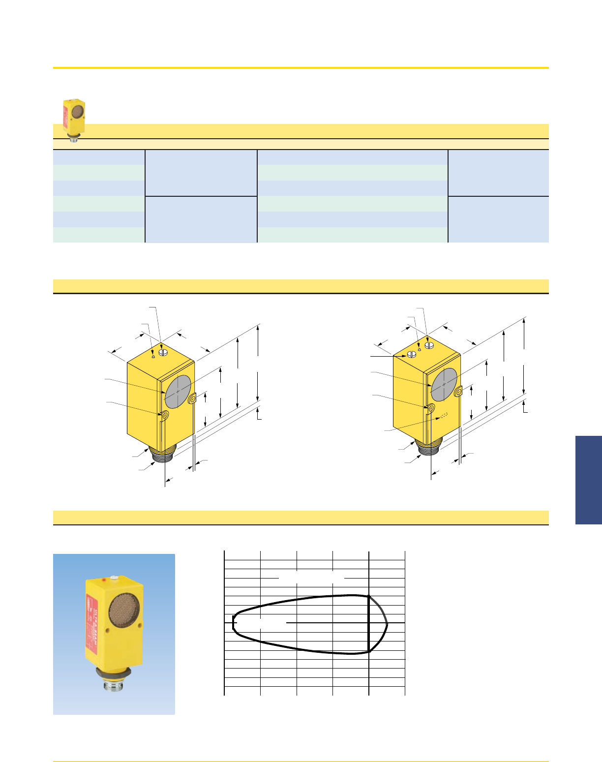
ULTRA-BEAM Series with Switched Output ULTRA-BEAM Series with Analog Output
5101520250
0
2
4
6
2
4
6
ULTRA-BEAM
Distance to 2' x 2' Target–Feet
Sensing Axis
Beam Width–Feet
NOTES:
1) Response pattern is drawn for the
maximum range setting of the
ULTRA-BEAM.
2) Response pattern is drawn for a
2-square foot solid surface.
3) Symmetry of the pattern may be
assumed in all sensing planes.
4) The rounded portion of the curve
past the 20 foot point indicates an
area where sensing is unreliable.
Effective range is from 20 inches
to 20 feet (0.5 to 6 meters).
ULTRA BEAM Series Response Pattern
Courtesy of Steven Engineering, Inc. ! 230 Ryan Way, South San Francisco, CA 94080-6370 ! Main Office: (650) 588-9200 ! Outside Local Area: (800) 258-9200 ! www.stevenengineering.com
U-GAGE™
Banner Engineering Corp. • Minneapolis, U.S.A. • bannerengineering.com • Tel: 763.544.3164
84
U-GAGETM ULTRA-BEAMTM Series - Ultrasonic Sensors
ULTRA-BEAMTM 923 Series (Analog Output) Specifications
Ultrasonic proximity
Model SU923QD: 18 to 30V dc, 5VA
Model SUA923QD: 105 to 130V ac (50/60Hz), 5VA
Model SUB923QD: 210 to 260V ac (50/60Hz), 5VA
50Khz
20 to 240 inches at 20˚C (0.5 to 6 meters)
Minimum required target area is 1 square foot (0.1 square meter) for each 10' (3 meters) of sensing range.
Sensing window depth is adjustable from 12" to 220" via two top-mounted 15-turn clutched potentiometers with slotted brass
elements (NULL and SPAN adjustments). This adjustable window may be placed anywhere within the 20" to 240" sensing range.
Two analog solid-state outputs: 0 to +10V dc (sourcing); minimum 500Ωload and 0 to 20mA dc (sinking); 4.0 dc maximum
voltage drop. Both outputs may be set for either “positive slope” or “negative slope”
0.5% of sensing distance
1% of full scale range
100 milliseconds
0.2% of sensing distance/deg.C
IP54, NEMA 1, 3 & 12
Top-mounted red LED indicator lights whenever power is applied to the sensor, and pulses at a 0 to 10Hz rate which is
proportional to analog output voltage (sourcing output) and current (sinking output)
Inputs are protected against polarity reversal (DC models); both analog outputs are protected against short circuit of outputs
(AC and DC models).
4-pin (for SU923QD) or 5-pin (for SUA923QD and SUB923QD) Quick Disconnect (“QD”) type connectors are standard.
NOTE: use 4-conductor (model MBCC-412) or 5-conductor (model MBCC-512) SO-type cable, 12' long (order separately)
Overall dimensions 4.7"H x 2.0"W x 1.9"D: rugged molded Valox housing: epoxy-encapsulated circuitry. Mounting nut and
lockwasher supplied.
0˚ to + 50˚C (+32˚ to +122˚F). Maximum humidity 90% (non-condensing conditions).
Sensing Mode
Supply Voltage
Ultrasonic Frequency
Sensing Range
Sensing Window
Adjustments
Outputs
Analog Resolution
Linearity
Response Time
Temperature effect
Environmental rating
Indicator LED
Circuit Protection
Cable
Construction
Operating Temp. Range
Model: SUA925QD 105 to 130V ac, 50/60Hz
Model: SUB925QD 210 to 260V ac, 50/60Hz. 6VA
Model: SU925QD-24, 18 to 30 V dc, 4VA
20 to 240 inches (0.5 to 6 meters).
Minimum required target area is 1 square foot (0.1 square meter) for each 10' (3 meters) of sensing range.
5% of range setting.
15-turn clutched potentiometer with slotted brass element, located under o-ring gasketed access screw on top of sensor. Use
small, flat screwdriver to adjust.
One form “C” SPDT relay, silver-nickel alloy contacts. Capacity: 150 watts of 600 VA maximum power (resistive load).
Maximum voltage: 250V ac or 30V dc (resistive load). Maximum current: 5 amps (resistive load).
Minimum load: 5V dc @ 100 milliamps. Mechanical life: 10,000,000 operations.
NOTE: install suitable value metal oxide varistor (MOV) across contact(s) used to switch an inductive load.
0.5% of sensing distance
1% of full scale range
100 milliseconds ON and OFF.
0.2% of sensing distance/deg.C
IP54, NEMA 1, 3 & 12
Red LED indicator on top of sensor lights when object is sensed (when output relay is energized).
Integral threaded 5-pin quick-disconnect. 12' mating cable, model MBCC-512, is sold separately.
Epoxy-encapsulated circuitry. Rugged, glass-filled VALOX housing. NEMA 1, 3 and 12.
0˚ to +50˚C (+32˚ to 122˚F)
ULTRA-BEAMTM 925 Series (E/M Relay Output) Specifications
Supply Voltage
Sensing Range
Sensing Hysteresis
Range Adjustment
Output
Discrete Repeatability
Linearity
Response Time
Temperature effect
Environmental rating
Indicator LED
Output Connector
Construction
Operating Temperature
Courtesy of Steven Engineering, Inc. ! 230 Ryan Way, South San Francisco, CA 94080-6370 ! Main Office: (650) 588-9200 ! Outside Local Area: (800) 258-9200 ! www.stevenengineering.com
U-GAGE™
Banner Engineering Corp. • Minneapolis, U.S.A. • bannerengineering.com • Tel: 763.544.3164 85
U-GAGETM ULTRA-BEAMTM Series - Ultrasonic Sensors
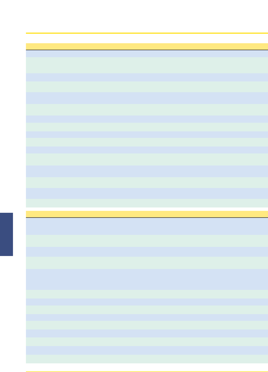
ULTRA-BEAMTM Series Functional Schematic and Hookup Information
Brown
Blue
Supply
Voltage Filter
Regulator
LED Driver
Voltage
Source
Current Sink
Black
White
0 to +10V dc
0 to 20 mA
923 Series
925 Series
Quick-Disconnect Cables
Style Model Length Pin-Outs Connector
SJT Style Cable
2" (50 mm)
5
432
11" Dia.
(25 mm)
Brown Blue
Black
Yellow
White
4
32
11" Dia.
(25 mm)
White Brown Blue Black
4-Pin Mini
Straight
5-Pin Euro
Straight
5-Pin Mini
w/shield
MBCC-406
MBCC-412
MBCC-430
MBCC-506
MBCC-515
MBCC-530
MBCC2-506
MBCC2-512
MBCC2-530
2 m (6.5')
4 m (12')
9 m (30')
2 m (6.5')
5 m (15')
10 m (30')
2 m (6.5')
4 m (15')
9 m (30')
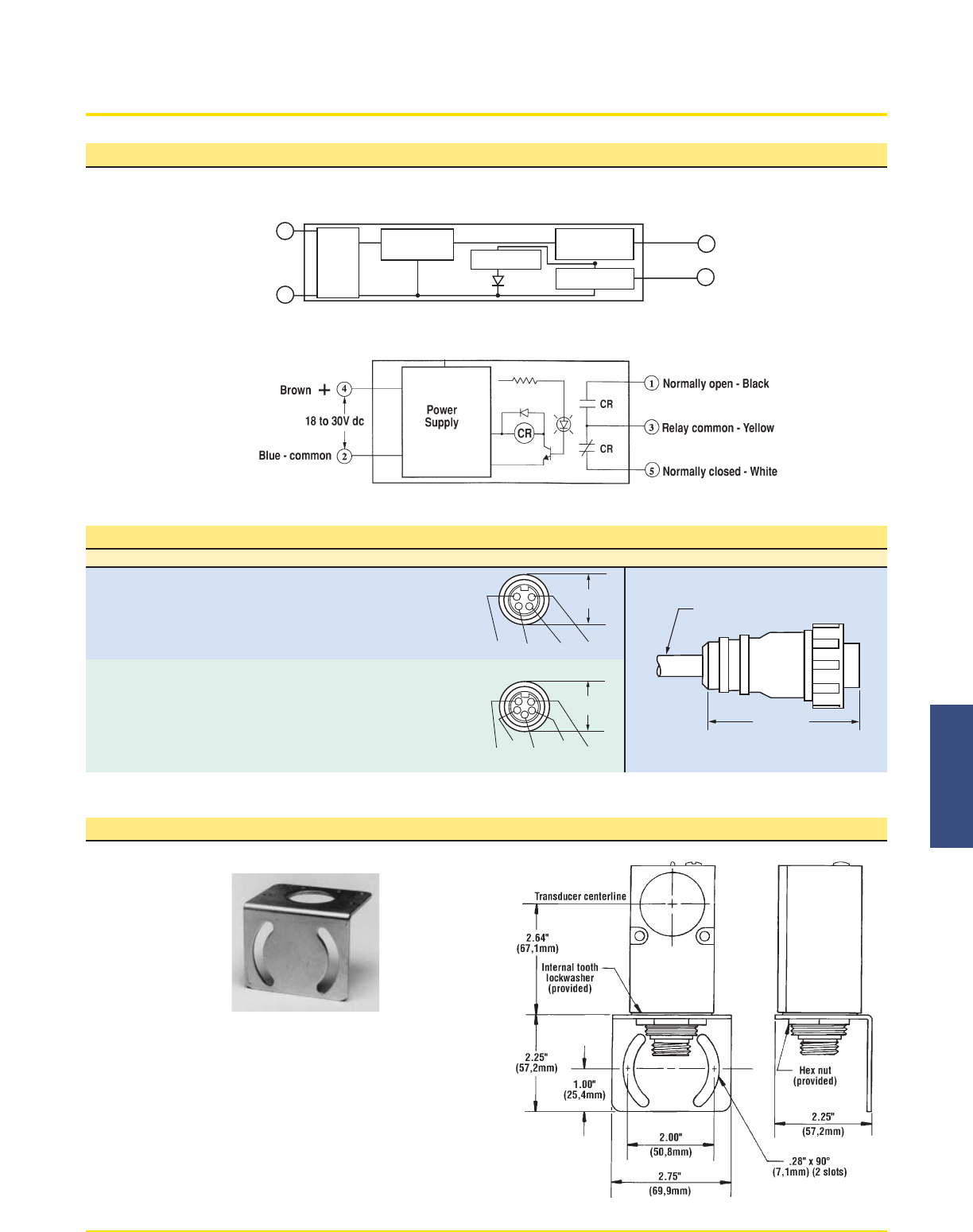
Mounting Bracket ULTRA-BEAM Series Dimension Drawing
SMB900
Accessory mounting
bracket model SMB900
has curved mounting
slots for versatility in
mounting and orientation.
The sensors mount to the
bracket by its threaded
base, using a jam nut and
lockwasher (both supplied). The bracket material is
11-gauge zinc-plated steel. The curved mounting slots
have clearance for 1/4" screws.
The internal tooth lockwasher and the hex mounting nut
shown in the drawings are supplied with the sensor.
Courtesy of Steven Engineering, Inc. ! 230 Ryan Way, South San Francisco, CA 94080-6370 ! Main Office: (650) 588-9200 ! Outside Local Area: (800) 258-9200 ! www.stevenengineering.com
