120435 Catalog
103618-Catalog 103618-Catalog 103618-Catalog 782856 Batch7 unilog cesco-content
592529-Brochure 592529-Brochure 592529-Brochure 782856 batch2_2 unilog cesco-content
120435-Catalog 120435-Catalog 120435-Catalog 782856 Batch7 unilog cesco-content
2014-07-29
: Pdf 120435-Catalog 120435-Catalog 782856 Batch6 unilog
Open the PDF directly: View PDF ![]() .
.
Page Count: 60
CADWELD®Welded
Electrical Connections
For Copper-Clad Steel Conductors

Table of Contents
Type . . . . . . . . . . . . . . . . . . . . . . page
Pictorial Index . . . . . . . . . . . . . . . . . . . . 2
Mold Numbering System . . . . . . . . . . . . 4
Cable-to-Cable
SS . . . . . . . . . . . . . . . . . . . . . . . . . . . . . 5
TA . . . . . . . . . . . . . . . . . . . . . . . . . . . . . 6
XA / XB . . . . . . . . . . . . . . . . . . . . . . . . . 9
PT . . . . . . . . . . . . . . . . . . . . . . . . . . . . 10
PC . . . . . . . . . . . . . . . . . . . . . . . . . . . . 11
Cable-to-Ground Rod
GB. . . . . . . . . . . . . . . . . . . . . . . . . . . . 12
GR. . . . . . . . . . . . . . . . . . . . . . . . . . . . 13
GT . . . . . . . . . . . . . . . . . . . . . . . . . . . . 15
GY. . . . . . . . . . . . . . . . . . . . . . . . . . . . 17
Cable-to-Steel
HA / HS . . . . . . . . . . . . . . . . . . . . . . . . 19
HA (pipe) . . . . . . . . . . . . . . . . . . . . . . . 20
HC / HT . . . . . . . . . . . . . . . . . . . . . . . . 21
VS . . . . . . . . . . . . . . . . . . . . . . . . . . . . 22
VS (pipe) . . . . . . . . . . . . . . . . . . . . . . . 23
VF / VB . . . . . . . . . . . . . . . . . . . . . . . . 24
VT / VG . . . . . . . . . . . . . . . . . . . . . . . . 25
VV . . . . . . . . . . . . . . . . . . . . . . . . . . . . 26
VN. . . . . . . . . . . . . . . . . . . . . . . . . . . . 27
Cable-to-Lug
GL . . . . . . . . . . . . . . . . . . . . . . . . . . . . 28
LA . . . . . . . . . . . . . . . . . . . . . . . . . . . . 29
Lugs of LA . . . . . . . . . . . . . . . . . . . . . . 30
Cable-to-Stud
HX / HV . . . . . . . . . . . . . . . . . . . . . . . . 31
www.erico.com
Materials, Tools and Accessories
Welding Material . . . . . . . . . . . . . . . . 32
Wrap Sleeves . . . . . . . . . . . . . . . . . . . 33
Mold Sealers . . . . . . . . . . . . . . . . . . . . 33
Cable Cleaning Brushes . . . . . . . . . . . 34
Cable Clamps . . . . . . . . . . . . . . . . . . . 34
Rasp . . . . . . . . . . . . . . . . . . . . . . . . . . 34
Torch Head . . . . . . . . . . . . . . . . . . . . . 35
Galvanizing Touch-Up . . . . . . . . . . . . . 35
Mold Cleaning Brush . . . . . . . . . . . . . 36
Slag Removal Spade . . . . . . . . . . . . . . 36
Disks . . . . . . . . . . . . . . . . . . . . . . . . . . 36
Wear Plates. . . . . . . . . . . . . . . . . . . . . 37
Split Crucibles . . . . . . . . . . . . . . . . . . . 37
Handle Clamps . . . . . . . . . . . . . . . . . . 38
Vertical Mold Support . . . . . . . . . . . . . 38
Chain Support. . . . . . . . . . . . . . . . . . . 38
Magnetic Handle Clamps . . . . . . . . . . 39
Fence Fabric Attachment. . . . . . . . . . . 39
Ground Rod Drivers . . . . . . . . . . . . . . 40
Pliers . . . . . . . . . . . . . . . . . . . . . . . . . . 41
Screwdriver . . . . . . . . . . . . . . . . . . . . . 41
Welding Tray. . . . . . . . . . . . . . . . . . . . 41
Tool Kits . . . . . . . . . . . . . . . . . . . . . . . 41
Ground System Testers . . . . . . . . . . . . 42
CADWELD®PLUS . . . . . . . . . . . . . . . 43
Technical Information
Copper-Clad Steel . . . . . . . . . . . . . . . . 45
Conductor Chart. . . . . . . . . . . . . . . . . 45
Ground Rods Chart. . . . . . . . . . . . . . . 45
Concentric Wire Chart . . . . . . . . . . . . 46
Solid Wire Chart . . . . . . . . . . . . . . . . . 46
Cast Iron Pipe Chart . . . . . . . . . . . . . . 47
Fence Post Sections Chart . . . . . . . . . . 47
Copper Busbar Chart . . . . . . . . . . . . . 47
Steel Pipe Chart . . . . . . . . . . . . . . . . . 48
Steel Wire Chart . . . . . . . . . . . . . . . . . 48
Other CADWELD®Connections . . . 49-56
WARNING
ERICO products shall be installed and used only as indicated in ERICO's product instruction sheets and training materials. Instruction sheets are available at www.erico.com and from your ERICO customer service representative.
Improper installation, misuse, misapplication or other failure to completely follow ERICO's instructions and warnings may cause product malfunction, property damage, serious bodily injury and death.
WARRANTY
ERICO products are warranted to be free from defects in material and workmanship at the time of shipment. NO OTHER WARRANTY, WHETHER EXPRESS OR IMPLIED (INCLUDING ANY WARRANTY OF MERCHANTABILITY OR
FITNESS FOR A PARTICULAR PURPOSE), SHALL EXIST IN CONNECTION WITH THE SALE OR USE OF ANY ERICO PRODUCTS. Claims for errors, shortages, defects or nonconformities ascertainable upon inspection must be made in
writing within 5 days after Buyer's receipt of products. All other claims must be made in writing to ERICO within 6 months from the date of shipment or transport. Products claimed to be nonconforming or defective must, upon
ERICO's prior written approval in
accordance with its standard terms and procedures governing returns, promptly be returned to ERICO for inspection. Claims not made as provided above and within the applicable time period will be barred. ERICO shall in no
event be responsible if the products have not been stored or used in accordance with its specifications and recommended procedures. ERICO will, at its option, either repair or replace nonconforming or defective products for which
it is responsible or return the purchase price to the Buyer. THE FOREGOING STATES BUYER'S EXCLUSIVE REMEDY FOR ANY BREACH OF ERICO WARRANTY AND FOR ANY CLAIM, WHETHER SOUNDING IN CONTRACT, TORT OR
NEGLIGENCE, FOR LOSS OR INJURY CAUSED BY THE SALE OR USE OF ANY PRODUCT.
LIMITATION OF LIABILITY
ERICO excludes all liability except such liability that is directly attributable to the willful or gross negligence of ERICO's employees. Should ERICO be held liable its liability shall in no event exceed the total purchase price under the
contract. ERICO SHALL IN NO EVENT BE RESPONSIBLE FOR ANY LOSS OF BUSINESS OR PROFITS, DOWNTIME OR DELAY, LABOR, REPAIR OR MATERIAL COSTS OR ANY SIMILAR OR DISSIMILAR CONSEQUENTIAL LOSS OR DAMAGE
INCURRED BY BUYER.

Copper-Clad Steel (CCS) Conductors
This catalog lists the most popular CADWELD connections for copper-clad steel construction. Look in
the index for the connection you need. If you cannot find the connection you need, contact ERICO®
or your local distributor or agent.
1. What connection do you require?
Available connections are listed in the pictorial index, which also shows the degree of difficulty
in making the connection, and ease of mold cleaning. We strongly recommend that wherever
possible you use molds listed in this catalog. After selecting the connection, turn to the
appropriate page and select the mold, welding material and tools you need.
2. What are the conductor sizes?
This catalog covers connections between copper-clad steel conductors to each other, to
concentric stranded copper cable, to lugs, to ground rods, to rebar, and to rail. For sizes not
listed, contact your local CADWELD distributor, agent, or ERICO.
Note: Other ERICO catalogs describe connections to conductors for solid or concentric stranded
copper conductors, busbar, lightning protection cable, steel cable, etc.
3. You must have the following to make a weld:
1. CADWELD engineered mold.
2. Welding material required by your mold.
3. Handle clamps and or frame.
4. CADWELD®PLUS control unit or flint ignitor.
5. Lugs, sleeves, packing material listed on the page with the mold as required.
1
www.erico.com
How to Order CADWELD®Products
Copper-clad steel (CCS) conductors are composed of a steel core with a continuous and constant
copper cladding that is thoroughly bonded throughout. CCS conductors combine the strength of
steel with the high conductivity and corrosion resistance of copper.
CADWELD®welded electrical connections have been used to join CCS conductors for over 40 years.
The CADWELD exothermic process fuses the CCS conductors together to form a connection that will
not corrode, loosen, or increase in resistance for the intended service life of the installation. CCS
conductors may also be welded to copper conductors, rebar or any other horizontal or vertical steel
surface or structure for electrical grounding.
CADWELD welded electrical connections are preferable to mechanical connections for CCS
conductors. Mechanical connections rely on the deformation of the conductors and the pressure
exerted by the connector on the conductor to reduce the contact resistance. Since the core of CCS
conductors is steel, a CCS conductor will not deform as much as a pure copper conductor and
therefore an exothermically welded connection is better suited for this application.
2www.erico.com
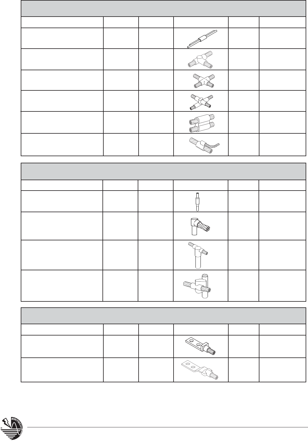
CABLE TO CABLE
Horizontal Splice
Horizontal Tee
Horizontal X, Same Plane
Horizontal X
Parallel Tap
Horizontal Parallel
Name Page Type Ease Split
SS
TA
XA
XB
PT
PC
1
1
1
1
1
1
Vertical
Horizontal
Horizontal
Horizontal
Vertical
Vertical
CABLE TO GROUND ROD
Ground Rod Splice
Cable to Ground Rod -
Tap
Cable to Ground Rod -
Through
Cable to Ground Rod -
Through / Side
Name Page Type Ease Split
GB
GR
GT
GY
1
1
1
1
Vertical
Vertical
Vertical
Vertical
CABLE TO LUG
Cable to Lug
Cable to Lug
28
29
Name Page Type Ease Split
GL
LA
1
1
Vertical
Horizontal
5
6
9
9
10
11
12
13
15
17
3
www.erico.com
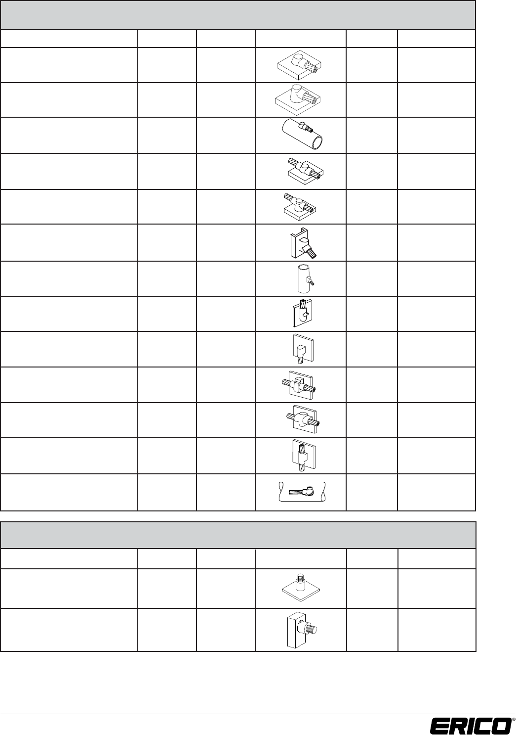
CABLE TO STEEL
Horizontal Steel Surface
Horizontal Steel Surface
Horizontal Steel Pipe
Horizontal Steel Surface
Horizontal Steel Surface
Vertical Steel Surface
Vertical Steel Pipe
Vertical Steel Surface
Vertical Steel Surface
Vertical Steel Surface
Vertical Steel Surface
Vertical Steel Surface
Vertical Steel Surface
19
19
20
21
22
22
23
24
24
25
25
26
27
Name Page Type Ease Split
HA
HS
HA, Pipe
HC
HT
VS
VS, Pipe
VF
VB
VT
VG
VV
VN
1
1
1
1
1
1
*
*
*
*
*
Vertical
Vertical
Vertical
Vertical
*
*
Vertical
*
CABLE TO STUD
Steel or Copper Studs to
Steel Surface
Steel or Copper Studs to
Steel Surface
31
31
Name Page Type Ease Split
HX
HV
1
1
Vertical
Horizontal
4www.erico.com
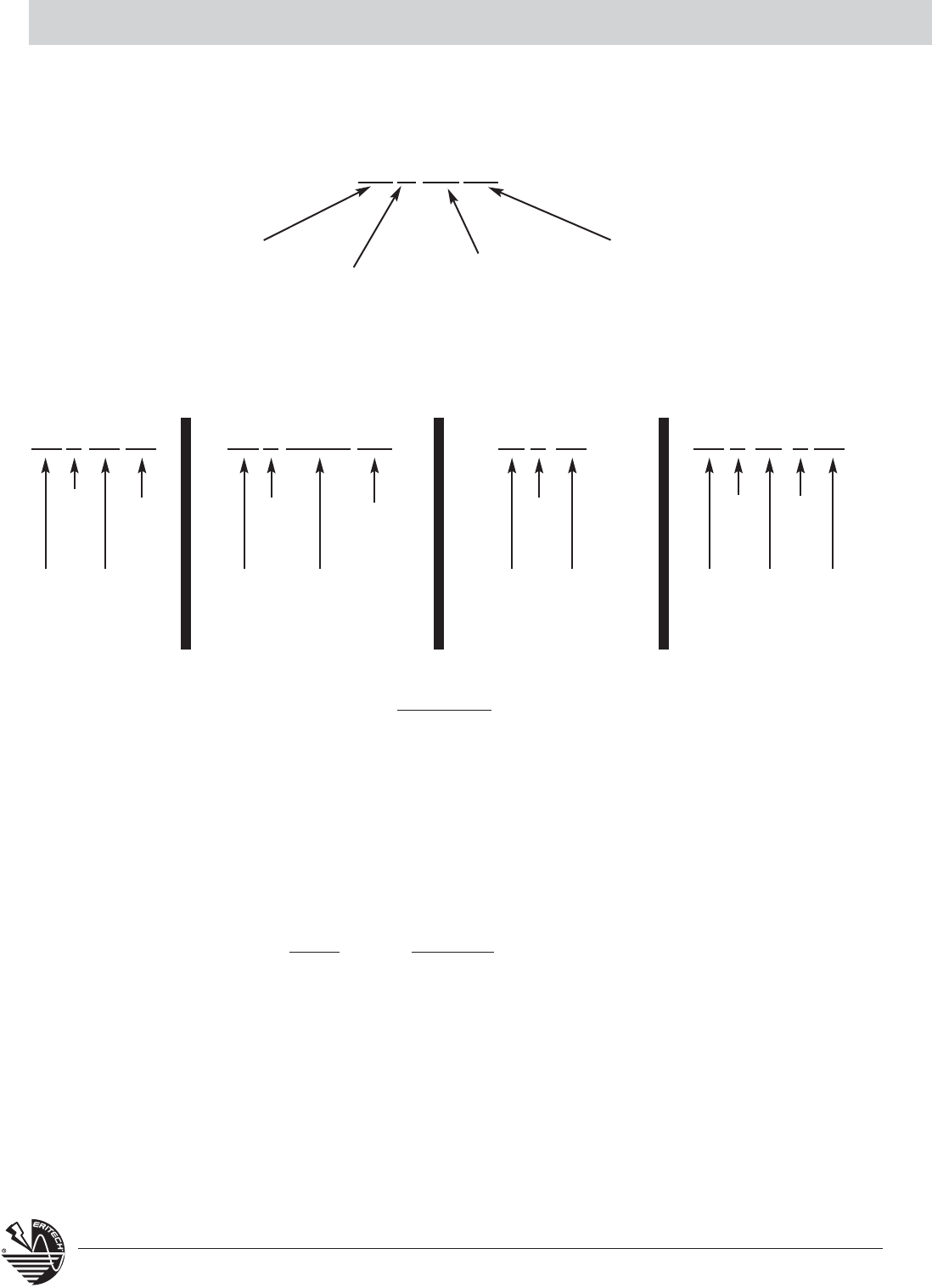
The CADWELD®Mold Numbering System
Code for
Tap Conductor
The CADWELD®mold part number gives, in code, the complete information of the mold
– type of connection, mold price key, and conductor size(s).
XXX-XXXX
TAC-9F9C G TC-P16 9H
EXAMPLES
SSC-9F VSC-9D-V5C
Mold
Type
Type
TA
Price
Key
C
19 / #9
7 / #7
Type
GT
Price
Key
C
5/8”
Copper-Clad
Ground Rod
19/#7
Type
VS
Price
Key
C
Vertical
Pipe
Cable
7 / #6
4” - 6”
Pipe
Type
SS
Price
Key
C
19 / #9
Mold Price
Key
Code for
Main or Run
Conductor
Certain tools may be required for various connections.
If required, these tools are listed on the same page as the connection and in Section A.
• Some tools listed in Section A can save you a lot of time.
• Also refer to A9E, Contractor Tips, to make your job easier, and learn about labor saving ideas.
REQUIRED TOOLS SUMMARY
Required tools are listed with each mold. For your reference, handle clamps and/or frame are summarized below.
MOLD REQUIRED
A* Includes frame with handle
C, Q & R Requires L160
D, F & Z Requires L159
E* Includes frame but also requires L160
J* Includes frame but also requires L159
K*, M* & V* Includes frame with handles
* To order mold only - without handles or frame - add suffix “M” to mold part number.
5
www.erico.com
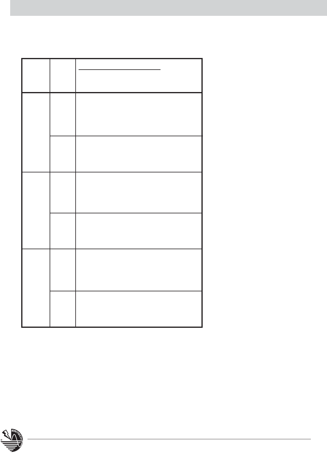
Horizontal Connection SS
SUGGESTED TOOLS
REQUIRED TOOLS
CABLE SIZE MOLD WELDING
(sq mm) PART NO. MATERIAL1
7/#10 SSC9A 32
7/#8 SSC9B 45
7/#7 SSC9C 65
7/#6 SSC9D 90
7/#5 SSC9E 115
19/#9 SSC9F 115
19/#8 SSC9G 115
19/#7 SSC9H 150
19/#6 SSC9J 200
1 For CADWELD®PLUS add suffix “PLUSF20” (refer page 44)
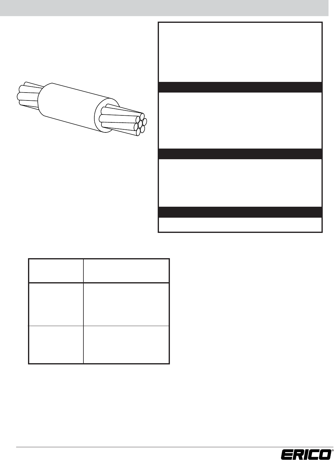
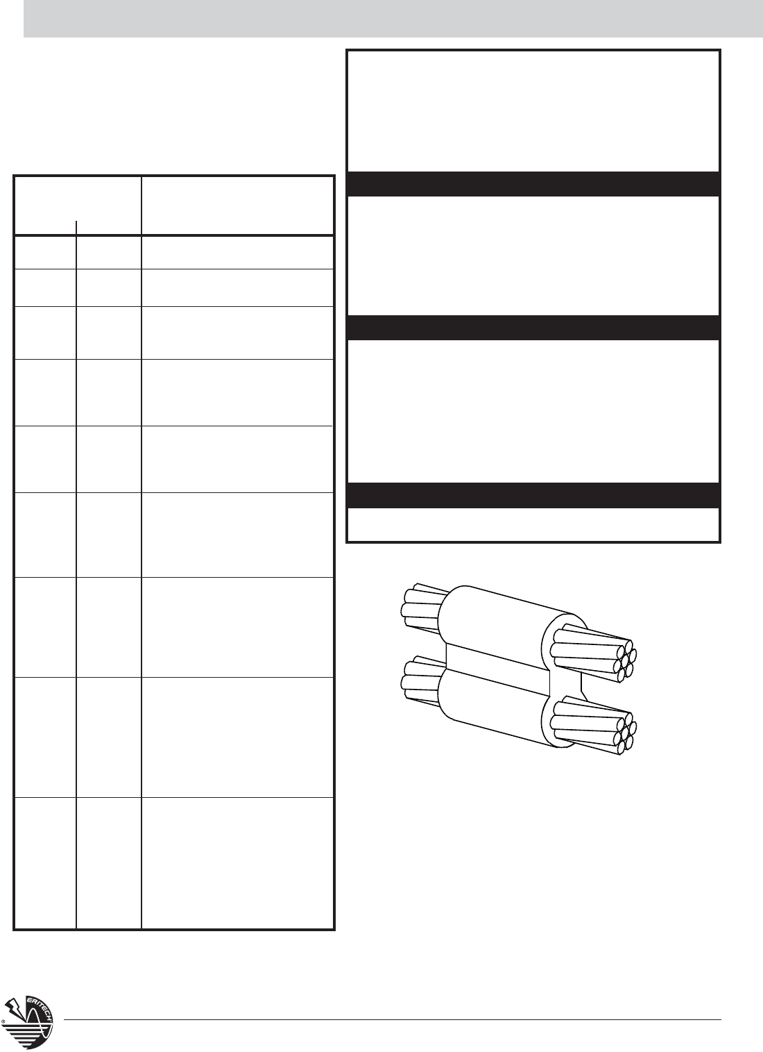
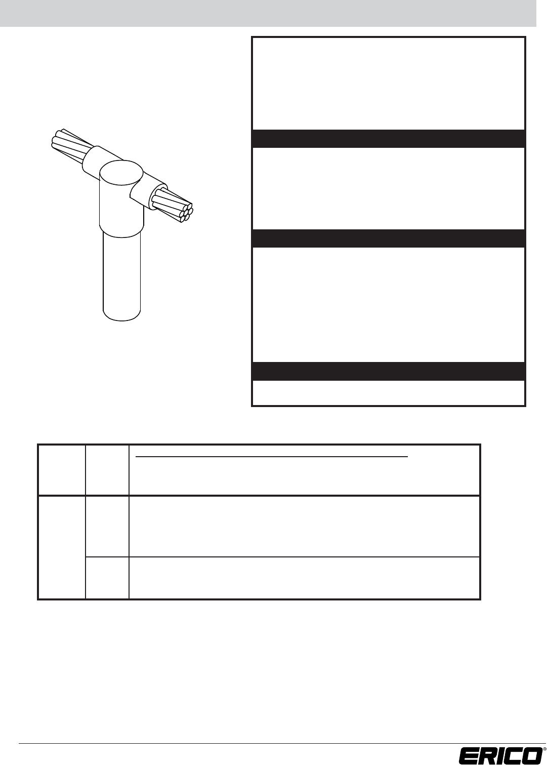
HORIZONTAL SPLICE
• Splice of horizontal cables.
• Concentric stranded copper cable unless otherwise noted.
• Solid conductor may be copper or copper-clad.
• Also available are splices of different and mixed cable
sizes. For copper-clad DSA cables, contact ERICO®.
•Bold letter in mold part number is the price key.
SS
For Stranded Copper-
Clad Steel Conductors
Part No.
Handle Clamps
for C Price Key Molds
L160
for D Price Key Molds
L159
CADWELD®PLUS Control Unit or PLUSCU
Flint Ignitor T320
Cable Cleaning Brush T313 or T314
Slag Removal Spade B136A or B136B
Mold Cleaning Brush T394
Cable Clamp B265
Torch Head T111
ACCESSORIES
• See Section A

6www.erico.com
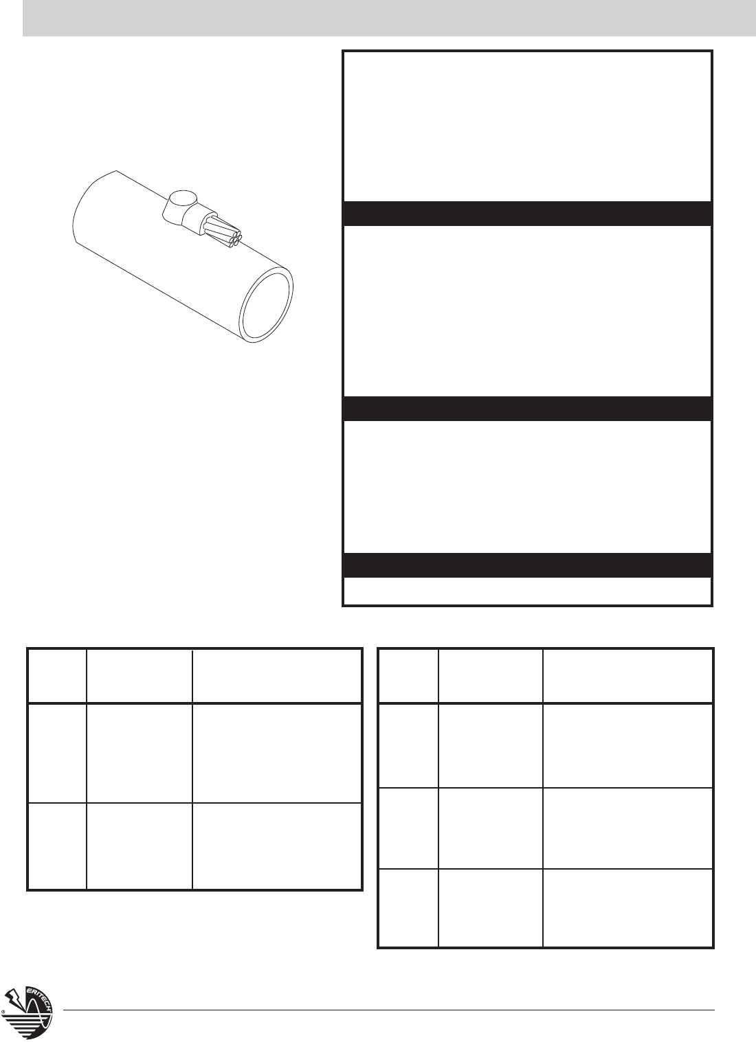
Horizontal Tee TA
TA
CABLE SIZE
(sq mm) MOLD WELDING
Run Tap PART NO. MATERIAL1
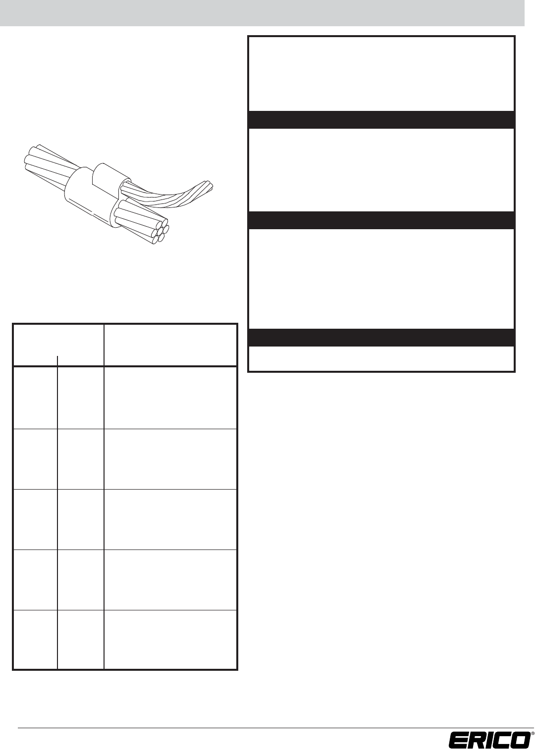
HORIZONTAL TEE CONNECTIONS
• Tee of horizontal run and tap cables.
• Concentric stranded copper cable unless otherwise noted.
• Solid conductor may be copper or copper-clad.
•Bold letter in mold part number is the price key.
CABLE SIZE
(sq mm) MOLD WELDING
Run Tap PART NO. MATERIAL1
7/#10 7/#10 TAC9A9A 45
7/#8 TAC9B9B 65
7/#8 7/#10 TAC9B9A 45
2/0* TAC9B2G 65
4/0* TAC9B2Q 90
7/#7 TAC9C9C 90
7/#8 TAC9C9B 90
7/#7 7/#10 TAC9C9A 45
2/0* TAC9C2G 90
4/0* TAC9C2Q 115
7/#6 TAC9D9D 115
7/#7 TAC9D9C 90
7/#6 7/#8 TAC9D9B 90
7/#10 TAC9D9A 45
2/0* TAC9D2G 90
4/0* TAC9D2Q 115
7/#5 TAC9E9E 150
7/#6 TAC9E9D 115
7/#7 TAC9E9C 90
7/#5 7/#8 TAC9E9B 90
7/#10 TAC9E9A 90
2/0* TAC9E2G 90
4/0* TAC9E2Q 150
19/#9 TAC9F9F 150
7/#5 TAC9F9E 150
7/#6 TAC9F9D 150
19/#9 7/#7 TAC9F9C 90
7/#8 TAC9F9B 90
2/0* TAC9F2G 90
4/0* TAC9F2Q 150
19/#8 TAC9G9G 200
19/#9 TAC9G9F 150
7/#5 TAC9G9E 150
19/#8 7/#6 TAC9G9D 150
7/#7 TAC9G9C 90
7/#8 TAC9G9B 90
2/0* TAC9G2G 90
4/0* TAC9G2Q 150
SUGGESTED TOOLS
REQUIRED TOOLS
Part No.
Handle Clamps
for C Price Key Molds
L160
for D Price Key Molds
L159
CADWELD®PLUS Control Unit or PLUSCU
Flint Ignitor T320
Cable Cleaning Brush T313 or T314
Slag Removal Spade B136A or B136B
Mold Cleaning Brush T394
Cable Clamp B265
Torch Head T111
1 For CADWELD®PLUS add suffix “PLUSF20” (refer page 44)
*Concentric stranded copper cable
1 For CADWELD®PLUS add suffix “PLUSF20” (refer page 44)
*Concentric stranded copper cable
For Stranded Copper-
Clad Steel Conductors
ACCESSORIES
• See Section A
7
www.erico.com
Horizontal Tee TA
CABLE SIZE
(sq mm) MOLD WELDING
Run Tap PART NO. MATERIAL1
CABLE SIZE
(sq mm) MOLD WELDING
Run Tap PART NO. MATERIAL1
19/#7 TAC9H9H 200
19/#8 TAC9H9G 200
19/#9 TAC9H9F 200
7/#5 TAC9H9E 150
19/#7 7/#6 TAC9H9D 150
7/#7 TAC9H9C 90
7/#8 TAC9H9B 90
2/0* TAC9H2G 90
4/0* TAC9H2Q 150
500* TAC9H3Q 250
19/#6 TAC9J9J 2-150
19/#7 TAC9J9H 200
19/#8 TAC9J9G 200
19/#9 TAC9J9F 200
19/#6 7/#5 TAC9J9E 150
7/#6 TAC9J9D 115
2/0* TAC9J2G 90
4/0* TAC9J2Q 150
500* TAC9J3Q 2-150
19/#6 TAC2G9J 115
19/#7 TAC2G9H 115
19/#8 TAC2G9G 115
2/0* 19/#9 TAC2G9F 115
7/#5 TAC2G9E 115
7/#6 TAC2G9D 90
7/#7 TAC2G9C 90
7/#8 TAC2G9B 90
7/#10 TAC2G9A 65
19/#6 TAC2Q9J 150
19/#7 TAC2Q9H 150
19/#8 TAC2Q9G 150
4/0* 19/#9 TAC2Q9F 150
7/#5 TAC2Q9E 150
7/#6 TAC2Q9D 150
7/#7 TAC2Q9C 90
7/#8 TAC2Q9B 90
7/#10 TAC2Q9A 90
19/#6 TAC2V9J 150
19/#7 TAC2V9H 150
19/#8 TAC2V9G 150
250* 19/#9 TAC2V9F 150
7/#5 TAC2V9E 150
7/#6 TAC2V9D 150
7/#7 TAC2V9C 90
7/#8 TAC2V9B 90
7/#10 TAC2V9A 90
19/#6 TAD3Q9J 2-150
19/#7 TAC3Q9H 250
19/#8 TAC3Q9G 200
500* 19/#9 TAC3Q9F 200
7/#5 TAC3Q9E 200
7/#6 TAC3Q9D 150
7/#7 TAC3Q9C 115
7/#8 TAC3Q9B 115
1 For CADWELD®PLUS add suffix “PLUSF20” (refer page 44)
*Concentric stranded copper cable
1 For CADWELD®PLUS add suffix “PLUSF20” (refer page 44)
*Concentric stranded copper cable
For Stranded Copper-Clad Steel Conductors
8www.erico.com
Horizontal X XA / XB
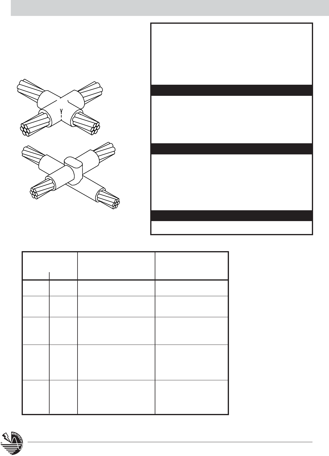
HORIZONTAL X CONNECTIONS
•XA– Cross of horizontal cables, tap cable cut – cables in
same plane.
•XB– Cross of horizontal cables, lapped and not cut.
• Concentric stranded copper cable unless otherwise noted.
• Solid conductor may be copper or copper-clad.
•Bold letter in mold part number is the price key.
• See Section A
CABLE SIZE TYPE XA TYPE XB
(sq mm) MOLD WELDING MOLD WELDING
run tap PART NO. MATERIAL1PART NO. MATERIAL1
7/#10 7/#10 XAC9A9A 65 XBC9A9A 90
7/#8 XAC9B9B 90 XBC9B9B 150
7/#8 7/#10 XAC9B9A 90 XBC9B9A 115
7/#7 XAC9C9C 115 XBQ9C9C 200
7/#7 7/#8 XAC9C9B 115 XBQ9C9B 200
7/#10 XAC9C9A 115 XBQ9C9A 150
7/#6 XAC9D9D 200 XBQ9D9D 250
7/#7 XAC9D9C 150 XBQ9D9C 200
7/#6 7/#8 XAC9D9B 150 XBQ9D9B 200
7/#10 XAC9D9A 115 XBQ9D9A 150
7/#5 XAC9E9E 200 XBQ9E9E 250
7/#5 7/#6 XAC9E9D 200 XBQ9E9D 250
7/#7 XAC9E9C 150 XBQ9E9C 200
7/#8 XAC9E9B 150 XBQ9E9B 200
ACCESSORIES
XB
XA
SUGGESTED TOOLS
REQUIRED TOOLS
Part No.
Handle Clamps
for C Price Key Molds
L160
for D Price Key Molds
L159
CADWELD®PLUS Control Unit or PLUSCU
Flint Ignitor T320
Cable Cleaning Brush T313 or T314
Slag Removal Spade
#65 w/m & smaller B136A
#90 w/m & larger B136B
Mold Cleaning Brush T394
Cable Clamp B265
Torch Head T111
1 For CADWELD®PLUS add suffix “PLUSF20” (refer page 44)
For Stranded Copper-
Clad Steel Conductors
9
www.erico.com
CABLE SIZE TYPE XA TYPE XB
(sq mm) MOLD WELDING MOLD WELDING
Run Tap PART NO. MATERIAL1PART NO. MATERIAL1
19/#9 XAC9F9F 200 XBQ9F9F 2-150
7/#5 XAC9F9E 200 XBQ9F9E 2-150
19/#9 7/#6 XAC9F9D 200 XBQ9F9D 2-150
7/#7 XAC9F9C 150 XBQ9F9C 250
7/#8 XAC9F9B 150 XBQ9F9B 250
19/#8 XAC9G9G 250 XBZ9G9G 2-200
19/#9 XAC9G9F 250 XBZ9G9F 2-200
19/#8 7/#5 XAC9G9E 250 XBQ9G9E 2-150
7/#6 XAC9G9D 200 XBQ9G9D 2-150
7/#7 XAC9G9C 150 XBQ9G9C 250
7/#8 XAC9G9B 150 XBQ9G9B 250
19/#7 XAD9H9H 2-150 XBZ9H9H 500
19/#8 XAD9H9G 2-150 XBZ9H9G 500
19/#7 19/#9 XAD9H9F 2-150 XBZ9H9F 500
7/#5 XAD9H9E 2-150 XBZ9H9E 2-200
7/#6 XAC9H9D 250 XBZ9H9D 2-200
7/#7 XAC9H9C 250 XBQ9H9C 2-150
7/#8 XAC9H9B 250 XBQ9H9B 250
19/#6 XAD9J9J 500 XBZ9J9J 3-250
19/#7 XAD9J9H 500 XBZ9J9H 3-200
19/#8 XAD9J9G 2-200 XBZ9J9G 3-200
19/#6 19/#9 XAD9J9F 2-150 XBZ9J9F 500
7/#5 XAD9J9E 2-150 XBZ9J9E 500
7/#6 XAD9J9D 2-150 XBZ9J9D 500
7/#7 XAC9J9C 250 XBZ9J9C 2-200
7/#8 XAC9J9B 250 XBQJF9B 2-150
For Stranded Copper-Clad Steel Conductors
Horizontal X XA / XB
1 For CADWELD®PLUS add suffix “PLUSF20” (refer page 44)
10 www.erico.com
Parallel Horizontal PT
CABLE SIZE
(sq mm) MOLD WELDING
run tap PART NO. MATERIAL1
7/#10 7/#10 PTC9A9A 65
7/#8 7/#8 PTC9B9B 90
7/#10 PTC9B9A 65
7/#7 PTC9C9C 115
7/#7 7/#8 PTC9C9B 115
7/#10 PTC9C9A 90
7/#6 PTC9D9D 150
7/#6 7/#7 PTC9D9C 150
7/#8 PTC9D9B 115
7/#10 PTC9D9A 115
7/#5 PTC9E9E 200
7/#5 7/#6 PTC9E9D 200
7/#7 PTC9E9C 150
7/#8 PTC9E9B 150
19/#9 PTC9F9F 250
7/#5 PTC9F9E 200
19/#9 7/#6 PTC9F9D 200
7/#7 PTC9F9C 150
7/#8 PTC9F9B 150
19/#8 PTD9G9G 2-150
19/#9 PTC9G9F 250
19/#8 7/#5 PTC9G9E 200
7/#6 PTC9G9D 200
7/#7 PTC9G9C 150
7/#8 PTC9G9B 150
19/#7 PTD9H9H 2-150
19/#8 PTD9H9G 2-150
19/#9 PTC9H9F 250
19/#7 7/#5 PTC9H9E 200
7/#6 PTC9H9D 200
7/#7 PTC9H9C 150
7/#8 PTC9H9B 150
19/#6 PTD9J9J 2-200
19/#7 PTD9J9H 2-150
19/#8 PTD9J9G 2-150
19/#6 19/#9 PTC9J9F 250
7/#5 PTC9J9E 200
7/#6 PTC9J9D 200
7/#7 PTC9J9C 150
7/#8 PTC9J9B 150
PARALLEL HORIZONTAL CONDUCTORS
• Parallel through connection of horizontal cables.
• Run conductor is on the bottom of molds.
• Concentric strand copper cable unless otherwise noted.
• Solid conductor may be copper or copper-clad.
•Bold letter in mold part number is the price key.
PT
SUGGESTED TOOLS
REQUIRED TOOLS
Part No.
Handle Clamps
for C Price Key Molds
L160
for D Price Key Molds
L159
CADWELD®PLUS Control Unit or PLUSCU
Flint Ignitor T320
Cable Cleaning Brush T313 or T314
Slag Removal Spade
#65 w/m & smaller B136A
#90 w/m & larger B136B
Mold Cleaning Brush T394
Cable Clamp B265
Torch Head T111
1 For CADWELD®PLUS add suffix “PLUSF20” (refer page 44)
For Stranded Copper-
Clad Steel Conductors
ACCESSORIES
• See Section A
11
www.erico.com
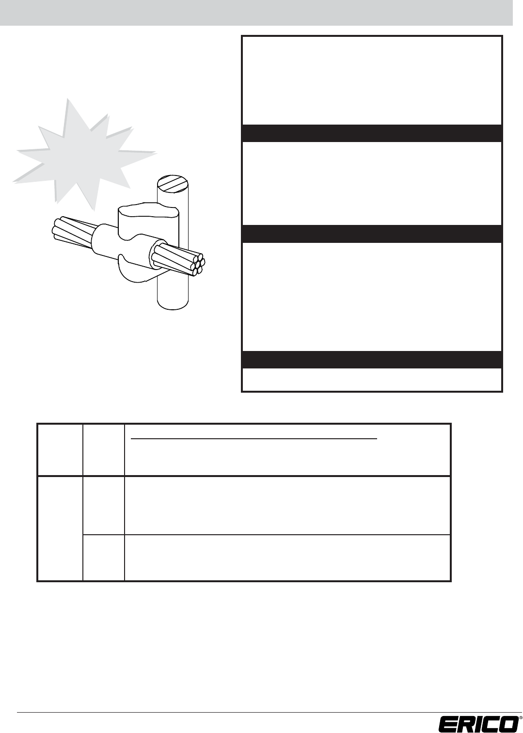
Parallel Tap Connections PC
PARALLEL TAP CONNECTIONS
• Parallel through connection of horizontal cables.
• Solid conductor may be copper or copper-clad.
• Concentric strand copper cable unless otherwise noted.
•Bold letter in mold part number is the price key.
SUGGESTED TOOLS
REQUIRED TOOLS
Part No.
Handle Clamps
for C Price Key Molds
L160
for D Price Key Molds
L159
CADWELD®PLUS Control Unit or PLUSCU
Flint Ignitor T320
Cable Cleaning Brush T313 or T314
Slag Removal Spade
#65 w/m & smaller B136A
#90 w/m & larger B136B
Mold Cleaning Brush T394
Cable Clamp B265
Torch Head T111
CABLE SIZE
(sq mm) MOLD WELDING
run tap PART NO. MATERIAL1
8 SOL PCC9A1D 32
6 SOL PCC9A1G 32
7/#10 6* PCC9A1H 32
4* PCC9A1L 45
2* PCC9A1V 65
8 SOL PCC9B1D 45
6 SOL PCC9B1G 45
7/#8 6* PCC9B1H 45
4* PCC9B1L 45
2* PCC9B1V 65
8 SOL PCC9C1D 45
6 SOL PCC9C1G 45
7/#7 6* PCC9C1H 45
4* PCC9C1L 65
2* PCC9C1V 65
8 SOL PCC9D1D 65
6 SOL PCC9D1G 65
7/#6 6* PCC9D1H 65
4* PCC9D1L 65
2* PCD9D1V 90
8 SOL PCC9E1D 65
6 SOL PCC9E1G 65
7/#5 6* PCC9E1H 65
4* PCC9E1L 90
2* PCC9E1V 90
1 For CADWELD®PLUS add suffix “PLUSF20” (refer page 44)
*Concentric stranded copper cable
For Stranded Copper-
Clad Steel Conductors
ACCESSORIES
• See Section A
PC
12 www.erico.com
Ground Rod Splice GB
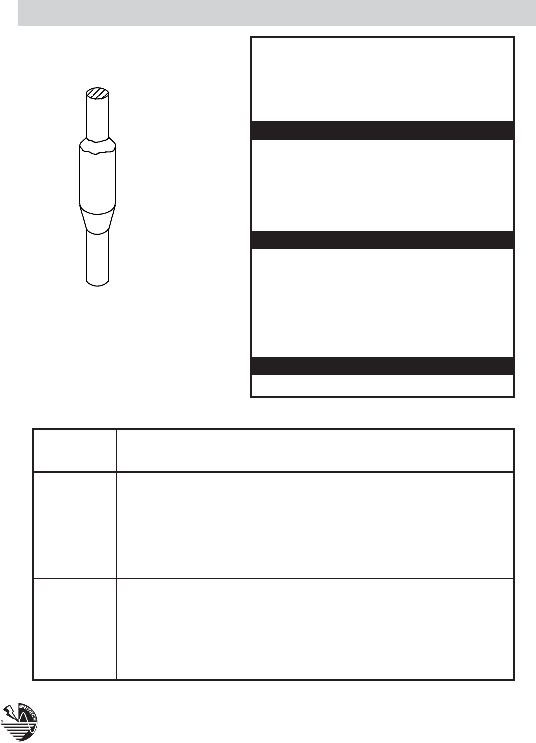
GROUND ROD SPLICE
• CADWELD®ground rod splices are very strong and use
the proven corrosion resistant CADWELD connection.
• CADWELD ground rod splices are available for
copper-clad, galvanized or stainless ground rods.
•Bold letter in mold part number is the price key.
GROUND
ROD SIZE MOLD WELDING
Dia. (mm)
GROUND ROD TYPE PART NO. MATERIAL
1
1/2”
Steel or Copper-Clad Sectional (9/16” Threads)
HDGBC14 250
Copper-Clad Plain (Unthreaded)
HDGBC15 250
Copper-Clad Sectional With 1/2” Threads)
HDGBC13 250
5/8”
Copper-Clad; 0.563” Diameter Fits Both
HDGBD16 2-150
Plain And Sectional (Threaded) Rods
0.625” Diameter Stainless, Stainless Clad, Galvanized, Etc.
HDGBD31 2-150
3/4”
Copper-Clad; 0.682” Diameter Fits Both Plain And
HDGBD18 2-200
Sectional (Threaded) Rods
0.75” Diameter Fits Both Plain And Sectional (Threaded) Rods
HDGBD33 2-200
1” Copper-Clad; 0.914” Diameter Fits Both Plain
HDGBF22 3-250
And Sectional (Threaded) Rods
1.00” Diameter Stainless, Stainless Clad, Galvanized, Etc.
HDGBF37 3-250
GB SUGGESTED TOOLS
REQUIRED TOOLS
Part No.
Handle Clamps
for C Price Key Molds
L160
for D Price Key Molds
L159
CADWELD®PLUS Control Unit or PLUSCU
Flint Ignitor T320
Ground Rod Splice Clamp B120
Cable Cleaning Brush T313 or T314
Slag Removal Spade
#65 w/m & smaller B136A
#90 w/m & larger B136B
Mold Cleaning Brush T394
Cable Clamp B265
File T329
Torch Head T111
1 For CADWELD®PLUS add suffix “PLUSF20” (refer page 44)
ACCESSORIES
• See Section A
13
www.erico.com
Cable to Ground Rod GR
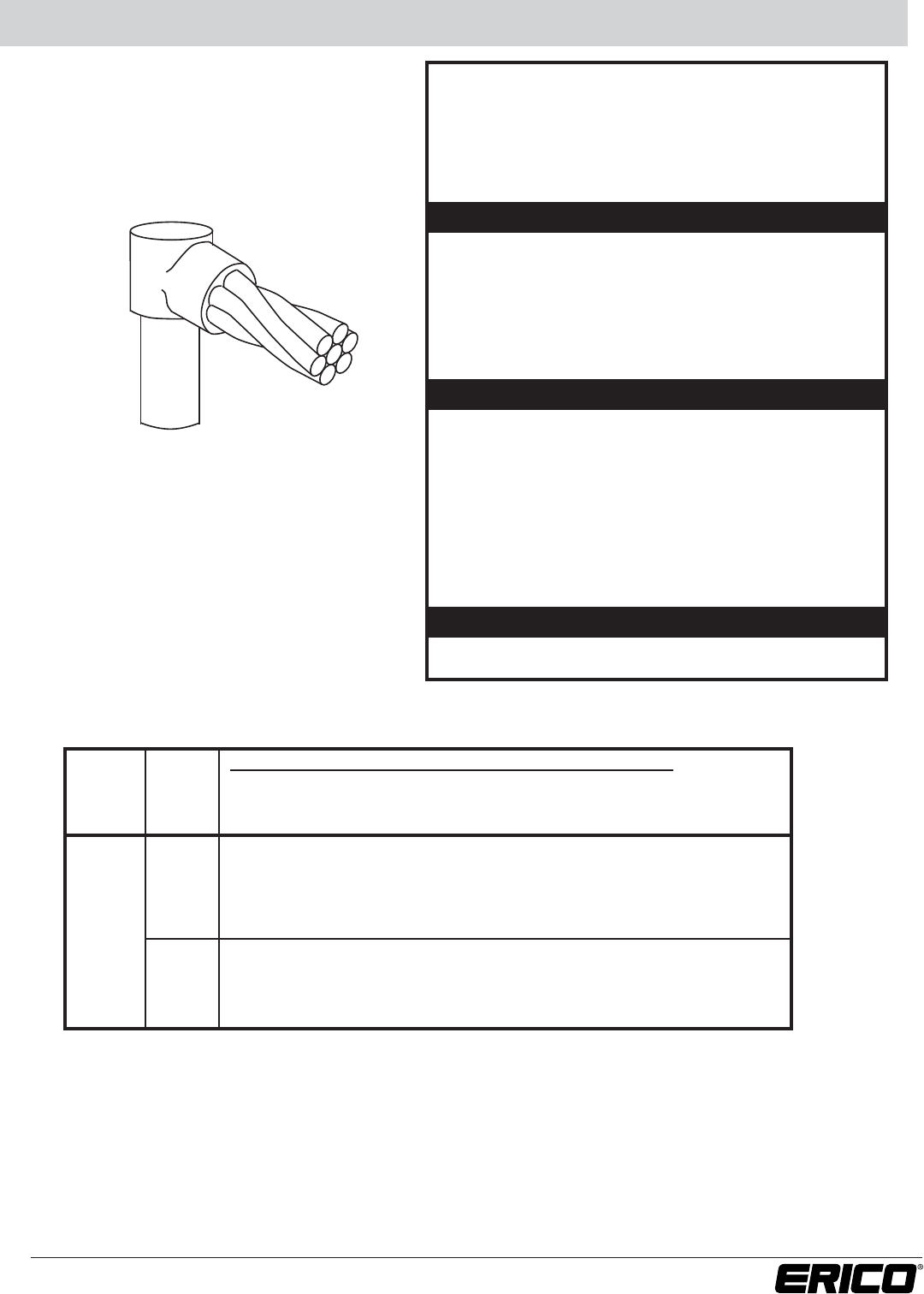
CABLE TO GROUND ROD
• Single cable to top of ground rod. Concentric strand
copper cable unless otherwise noted. For copper-clad,
galvanized, stainless clad or stainless steel ground rods.
•Bold letter in mold part number is the price key.
MOLD PART NUMBER
GROUND
CABLE
STEEL OR COPPER- COPPER-CLAD COPPER-CLAD
ROD SIZE SIZE CLAD SECTIONAL PLAIN SECTIONAL WELDING
Dia. (mm) (sq mm)
(WITH 9/16” THREADS)
(UNTHREADED)
(WITH 1/2” THREADS)
MATERIAL1
7/#10 GRC149A GRC159A GRC139A 65
7/#8 GRC149B GRC159B GRC139B 90
7/#7 GRC149C GRC159C GRC139C 90
7/#6 GRC149D GRC159D GRC139D 90
1/2”
7/#5 GRC149E GRC159E GRC139E 90
19/#9 GRC149F GRC159F GRC139F 90
19/#8 GRC149G GRC159G GRC139G 90
GR
SUGGESTED TOOLS
REQUIRED TOOLS
Part No.
Handle Clamps
for C Price Key Molds
L160
for D Price Key Molds
L159
CADWELD®PLUS Control Unit or PLUSCU
Flint Ignitor T320
Cable Cleaning Brush T313 or T314
Slag Removal Spade
#65 w/m & smaller B136A
#90 w/m & larger B136B
Mold Cleaning Brush T394
Cable Clamp B265
File T329
Torch Head T111
1 For CADWELD®PLUS add suffix “PLUSF20” (refer page 44)
For Stranded Copper-
Clad Steel Conductors
ACCESSORIES
• See Section A
14 www.erico.com
Cable to Ground Rod GR
For Stranded Copper-Clad Steel Conductors
MOLD PART NUMBER
GROUND CABLE
COPPER-CLAD
ROD SIZE SIZE
SECTIONAL (THREADED)
WELDING
Dia. (mm) (sq mm) OR PLAIN STEEL MATERIAL1
7/#10 GRC169A GRC319A 65
7/#8 GRC169B GRC319B 90
7/#7 GRC169C GRC319C 90
7/#6 GRC169D GRC319D 90
7/#5 GRC169E GRC319E 90
5/8”
19/#9 GRC169F GRC319F 90
19/#8 GRC169G GRC319G 115
19/#7 GRC169H GRC319H 150
19/#6 GRC169J GRC319J 150
7/#10 GRC189A GRC339A 90
7/#8 GRC189B GRC339B 90
7/#7 GRC189C GRC339C 90
7/#6 GRC189D GRC339D 90
7/#5 GRC189E GRC339E 90
3/4”
19/#9 GRC189F GRC339F 90
19/#8 GRC189G GRC339G 115
19/#7 GRC189H GRC339H 150
19/#6 GRC189J GRC339J 150
7/#10 GRC229A GRC379A 150
7/#8 GRC229B GRC379B 150
7/#7 GRC229C GRC379C 150
7/#6 GRC229D GRC379D 150
7/#5 GRC229E GRC379E 150
1”
19/#9 GRC229F GRC379F 150
19/#8 GRC229G GRC379G 200
19/#7 GRC229H GRC379H 200
19/#6 GRC229J GRC379J 200
1 For CADWELD®PLUS add suffix “PLUSF20” (refer page 44)
15
www.erico.com
Cable to Ground Rod GT
CABLE TO GROUND ROD
• Through cable to top of ground rod. Connections are for
concentric strand copper cable unless otherwise noted.
• For copper-clad, galvanized, stainless clad or stainless
steel ground rods.
•Bold letter in mold part number is the price key.
GT
SUGGESTED TOOLS
REQUIRED TOOLS
Part No.
Handle Clamps
for C Price Key Molds
L160
for D Price Key Molds
L159
CADWELD®PLUS Control Unit or PLUSCU
Flint Ignitor T320
Cable Cleaning Brush T313 or T314
Slag Removal Spade
#65 w/m & smaller B136A
#90 w/m & larger B136B
Mold Cleaning Brush T394
Cable Clamp B265
File T329
Torch Head T111
For Stranded Copper-
Clad Steel Conductors
MOLD PART NUMBER
GROUND
CABLE
STEEL OR COPPER- COPPER-CLAD COPPER-CLAD
ROD SIZE SIZE CLAD SECTIONAL PLAIN SECTIONAL WELDING
Dia. (mm) (sq mm)
(WITH 9/16” THREADS)
(UNTHREADED)
(WITH 1/2” THREADS)
MATERIAL1
7/#10 GTC149A GTC159A GTC139A 90
7/#8 GTC149B GTC159B GTC139B 90
7/#7 GTC149C GTC159C GTC139C 90
7/#6 GTC149D GTC159D GTC139D 115
1/2”
7/#5 GTC149E GTC159E GTC139E 150
19/#9 GTC149F GTC159F GTC139F 150
19/#8 GTC149G GTC159G GTC139G 200
1 For CADWELD®PLUS add suffix “PLUSF20” (refer page 44)
ACCESSORIES
• See Section A
16 www.erico.com
Cable to Ground Rod GT
For Stranded Copper-Clad Steel Conductors
MOLD PART NUMBER
GROUND
CABLE
COPPER-CLAD
ROD SIZE SIZE
SECTIONAL (THREADED)
WELDING
Dia. (mm) (sq mm)
OR PLAIN
STEEL MATERIAL1
7/#10 GTC169A GTC319A 90
7/#8 GTC169B GTC319B 115
7/#7 GTC169C GTC319C 115
7/#6 GTC169D GTC319D 115
7/#5 GTC169E GTC319E 150
5/8”
19/#9 GTC169F GTC319F 150
19/#8 GTC169G GTC319G 200
19/#7 GTC169H GTC319H 250
19/#6 GTC169J GTC319J 250
7/#10 GTC189A GTC339A 90
7/#8 GTC189B GTC339B 115
7/#7 GTC189C GTC339C 115
7/#6 GTC189D GTC339D 115
7/#5 GTC189E GTC339E 150
3/4”
19/#9 GTC189F GTC339F 150
19/#8 GTC189G GTC339G 200
19/#7 GTC189H GTC339H 250
19/#6 GTC189J GTC339J 250
7/#10 GTC229A GTC379A 150
7/#8 GTC229B GTC379B 150
7/#7 GTC229C GTC379C 150
7/#6 GTC229D GTC379D 150
7/#5 GTC229E GTC379E 200
1”
19/#9 GTC229F GTC379F 200
19/#8 GTC229G GTC379G 200
19/#7 GTC229H GTC379H 250
19/#6 GTC229J GTC379J 250
1 For CADWELD®PLUS add suffix “PLUSF20” (refer page 44)
17
www.erico.com
Cable to Ground Rod GY
CABLE TO GROUND ROD
• Through cable to side of ground rod.
• Concentric strand copper cable unless otherwise noted.
• Ground rods can be copper-clad, galvanized, stainless
clad or stainless steel.
•Bold letter in mold part number is the price key.
SUGGESTED TOOLS
REQUIRED TOOLS
Part No.
Handle Clamps
for C Price Key Molds
L160
for D Price Key Molds
L159
CADWELD®PLUS Control Unit or PLUSCU
Flint Ignitor T320
Cable Cleaning Brush T313 or T314
Slag Removal Spade
#65 w/m & smaller B136A
#90 w/m & larger B136B
Mold Cleaning Brush T394
Cable Clamp B265
File T329
Torch Head T111
1 For CADWELD®PLUS add suffix “PLUSF20” (refer page 44)
NEW
Two-piece
mold
MOLD PART NUMBER
GROUND
CABLE
STEEL OR COPPER- COPPER-CLAD COPPER-CLAD
ROD SIZE SIZE CLAD SECTIONAL PLAIN SECTIONAL WELDING
Dia. (mm) (sq mm)
(WITH 9/16” THREADS)
(UNTHREADED)
(WITH 1/2” THREADS)
MATERIAL1
7/#10 GYR149A GYR159A GYR139A 90
7/#8 GYR149B GYR159B GYR139B 115
7/#7 GYR149C GYR159C GYR139C 115
7/#6 GYR149D GYR159D GYR139D 150
1/2”
7/#5 GYR149E GYR159E GYR139E 150
19/#9 GYR149F GYR159F GYR139F 150
19/#8 GYR149G GYR159G GYR139G 200
For Stranded Copper-
Clad Steel Conductors
GY
ACCESSORIES
• See Section A
18 www.erico.com
Cable to Ground Rod GY
MOLD PART NUMBER
GROUND
CABLE COPPER-CLAD
ROD SIZE SIZE
SECTIONAL (THREADED)
WELDING
Dia. (mm)
(sq mm) OR PLAIN STEEL MATERIAL1
7/#10 GYR169A GYR319A 90
7/#8 GYR169B GYR319B 115
7/#7 GYR169C GYR319C 115
7/#6 GYR169D GYR319D 150
5/8” 7/#5 GYR169E GYR319E 150
19/#9 GYR169F GYR319F 150
19/#8 GYR169G GYR319G 200
19/#7 GYF169H GYF319H 2-150
19/#6 GYF169J GYF319J 2-200
7/#10 GYR189A GYR339A 90
7/#8 GYR189B GYR339B 115
7/#7 GYR189C GYR339C 115
7/#6 GYR189D GYR339D 150
3/4” 7/#5 GYR189E GYR339E 200
19/#9 GYR189F GYR339F 200
19/#8 GYR189G GYR339G 250
19/#7 GYF189H GYF339H 2-200
19/#6 GYF189J GYF339J 500
7/#10 GYR229A GYR379A 90
7/#8 GYR229B GYR379B 115
7/#7 GYR229C GYR379C 115
7/#6 GYR229D GYR379D 150
1” 7/#5 GYR229E GYR379E 200
19/#9 GYR229F GYR379F 200
19/#8 GYR229G GYR379G 250
19/#7 GYF229H GYF379H 2-200
19/#6 GYF229J GYF379J 500
For Stranded Copper-Clad Steel Conductors
1 For CADWELD®PLUS add suffix “PLUSF20” (refer page 44)
19
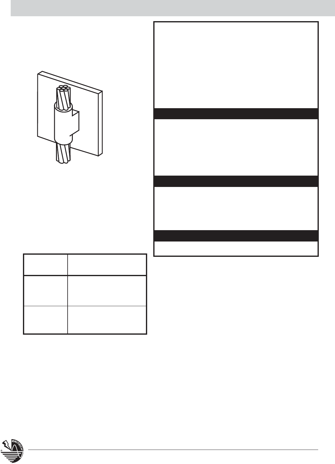
www.erico.com
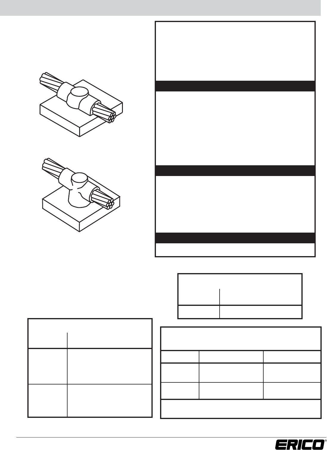
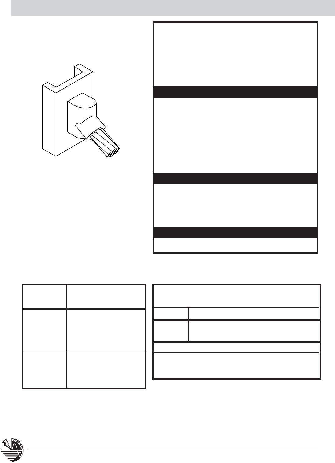
Horizontal Steel Surface HA / HS
HS Cable off surface
TYPE HA
CABLE SIZE MOLD WELDING
(sq mm) PART NO. MATERIAL1
7/#10 HAA9A 65
TYPE HS
CABLE SIZE MOLD WELDING
(sq mm) PART NO. MATERIAL1
7/#8 HSC9B 90
7/#7 HSC9C 90
7/#6 HSC9D 115
7/#5 HSC9E 115
19/#9 HSC9F 115
19/#8 HSC9G 150
19/#7 HSC9H 200
19/#6 HSC9J 200
Cable to Steel Pipe (Types HA and HS) –
Use flat surface mold part number with suffix.
Cable
Nominal Pipe Diameter
Suffix
7/#10 12” and smaller Nominal Pipe Size
14” and larger None
7/#8 thru 19/#9
28” and smaller Nominal Pipe Size
30” and larger None
Example: 7/#10 cable to 3-1/2” pipe, HAA9A3.50
HA Cable on surface
HORIZONTAL STEEL SURFACE
• Horizontal concentric copper conductor to flat steel
surface or top of horizontal pipe
• A test weld should be made to check the possibility
of burn-through on thin sections or thin wall pipe.
• Concentric stranded copper cable listed.
•Bold letter in mold part number is the price key.
SUGGESTED TOOLS
REQUIRED TOOLS
Part No..
Handle Clamps*
Flat Surface for C Price Key Molds
L160
for D Price Key Molds
L159
Pipe
(curved surface)
for C Price Key Molds
B160V
for D Price Key Molds
B159V
CADWELD®PLUS Control Unit or PLUSCU
Flint Ignitor T320
Cable Cleaning Brush T313 or T314
Slag Removal Spade
#65 w/m & smaller B136A
#90 w/m & larger B136B
Mold Cleaning Brush T394
Cable Clamp B265
Torch Head T111
Rasp T321
1 For CADWELD®PLUS add suffix “PLUSF20” (refer page 44)
For Stranded Copper-
Clad Steel Conductors
ACCESSORIES
• See Section A
For welds to copper surface, contact factory or your local distributor or agent.
*Handles are included with A Price Key Molds.
20 www.erico.com
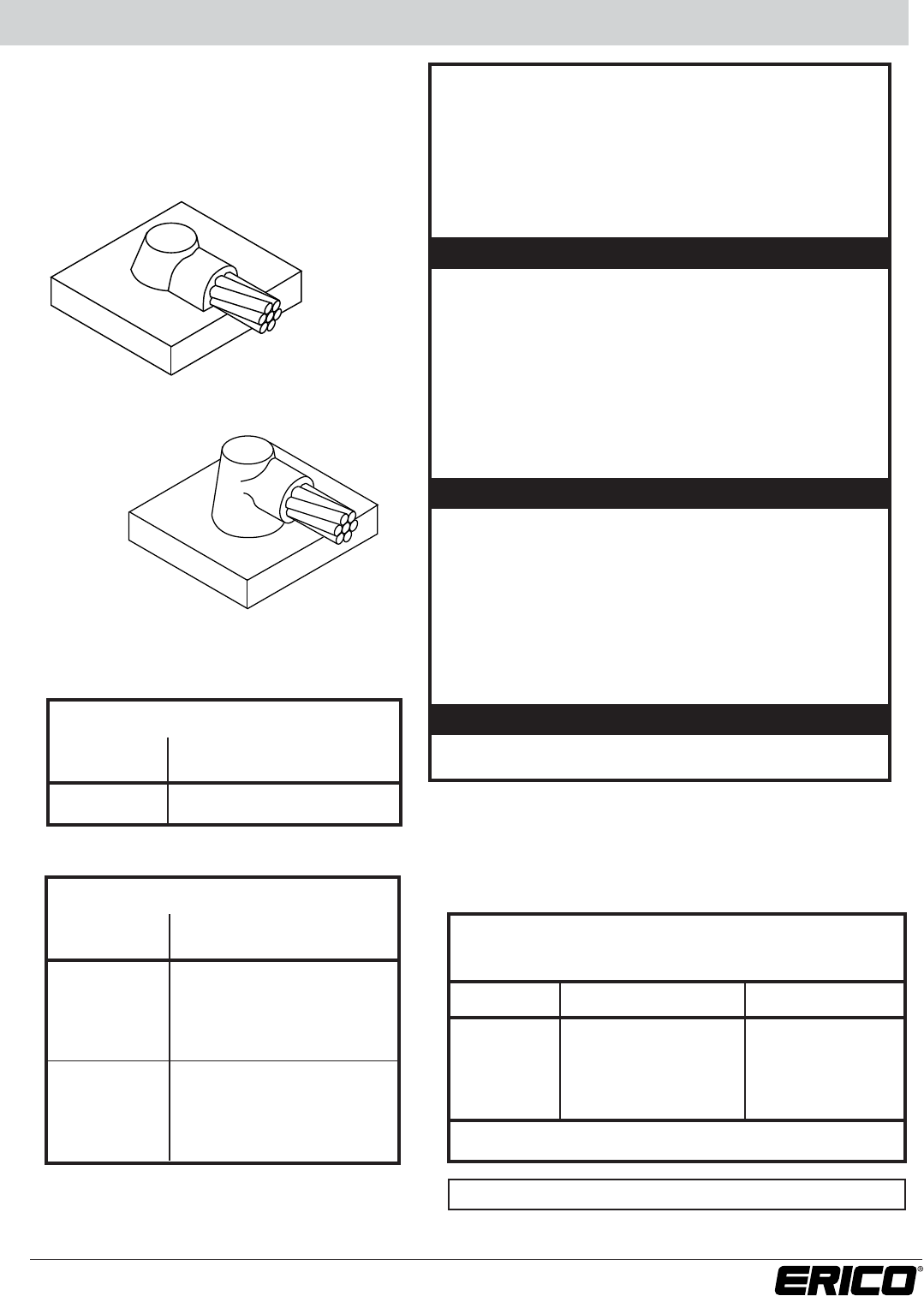
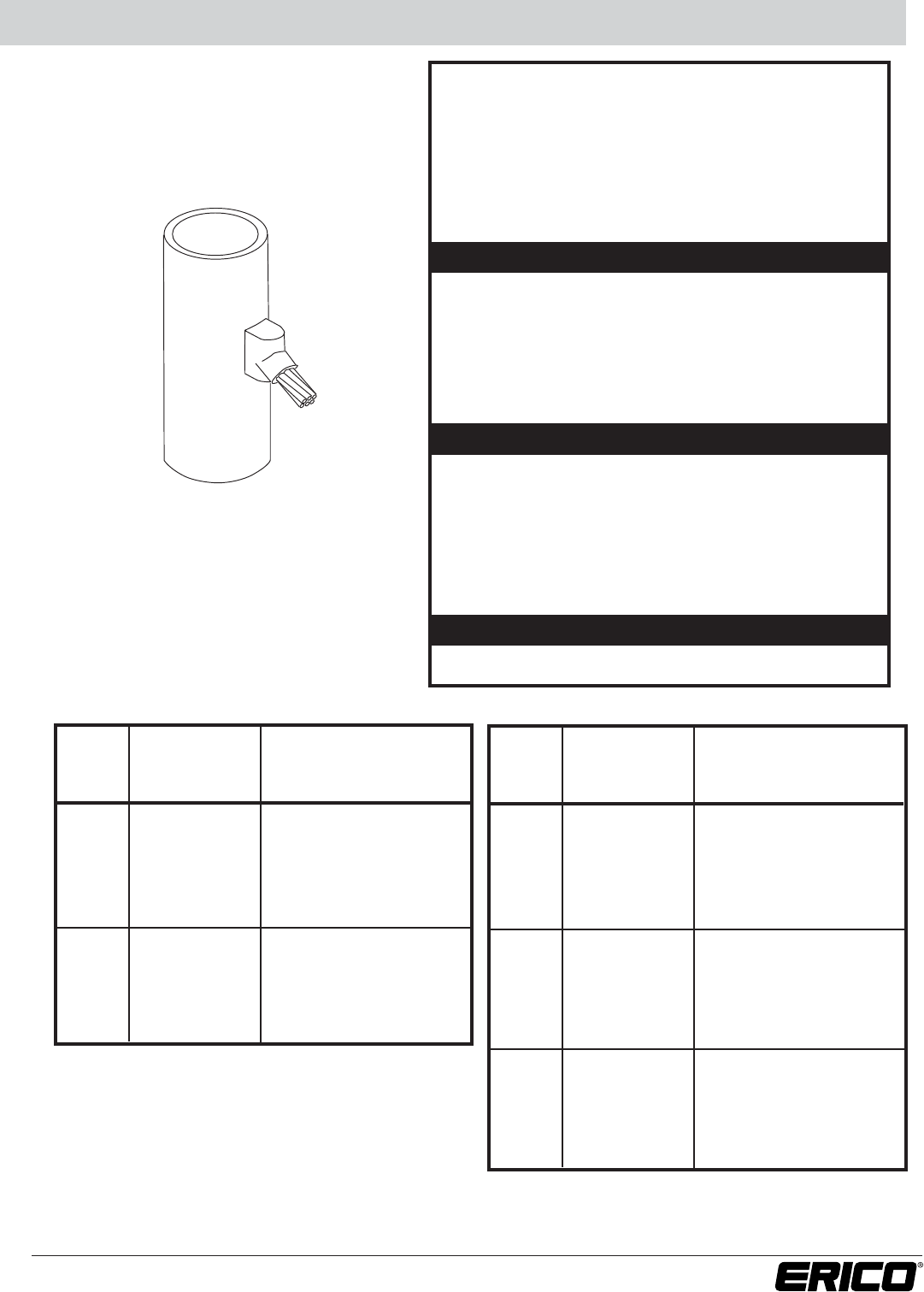
Range of Horizontal Steel Pipes HA
For Stranded Copper-
Clad Steel Conductors
RANGE OF HORIZONTAL STEEL PIPES
• Horizontal conductor to top of horizontal steel pipe.
•A test weld should be made to check the possibility of
burn-through on thin sections or thin wall pipe.
• When only one pipe size is involved, see Cable to Steel
Pipe table on previous page.
• Concentric stranded copper cable listed.
•Bold letter in mold part number is the price key.
SUGGESTED TOOLS
REQUIRED TOOLS
Part No.
Handle Clamps*
Flat Surface for C Price Key Molds
L160
for D Price Key Molds
L159
Pipe
(curved surface)
for C Price Key Molds
B160V
for D Price Key Molds
B159V
CADWELD®PLUS Control Unit or PLUSCU
Flint Ignitor T320
Cable Cleaning Brush T313 or T314
Slag Removal Spade
#65 w/m & smaller B136A
#90 w/m & larger B136B
Mold Cleaning Brush T394
Rasp T321
Torch Head T111
• See Section A
MOLD
CABLE
NOMINAL PART
WELDING
SIZE PIPE
SIZE NO.
MATERIAL1
1-1/4” to 2” Pipe HAA9A162C 65
7/#10 3” to 4” Pipe HAA9A350C 65
6” to 8” Pipe HAA9A7C 65
10” to 12” Pipe HAA9A11C 65
14” Pipe or Larger (2)
3” to 4” Pipe HAH9B350C 90
7/#8 6” to 10” Pipe HAH9B8C 90
12” to 28” Pipe HAH9B20C 90
30” Pipe or Larger (2)
MOLD
CABLE
NOMINAL PART
WELDING
SIZE PIPE
SIZE NO.
MATERIAL1
3” to 4” Pipe HAH9C350C 90
7/#7 6” to 10” Pipe HAH9C8C 90
12” to 28” Pipe HAH9C20C 90
30” Pipe or Larger (2)
3” to 4” Pipe HAH9D350C 115
7/#6 6” to 10” Pipe HAH9D8C 115
12” to 28” Pipe HAH9D20C 115
30” Pipe or Larger (2)
3” to 4” Pipe HAH9E350C 115
7/#5 6” to 8” Pipe HAH9E8C 115
12” to 28” Pipe HAH9E20C 115
30” Pipe or Larger (2)
1 For CADWELD®PLUS add suffix “PLUSF20” (refer page 44)
(2) Use flat surface mold part number. See previous page.
(2) Use flat surface mold part number. See previous page.
ACCESSORIES
HA Cable to Horizontal Steel Pipe
*Handles are included with A Price Key Molds.
21
www.erico.com
Horizontal Steel Surface HC / HT
For Stranded Copper-
Clad Steel Conductors
RANGE OF HORIZONTAL STEEL PIPES
• Cable to horizontal flat steel surface or cable to top of
horizontal steel pipe.
•A test weld should be made to check the possibility of
burn-through on thin sections or thin wall pipe.
• Concentric stranded copper cable listed.
•Bold letter in mold part number is the price key.
SUGGESTED TOOLS
REQUIRED TOOLS
Part No..
Handle Clamps*
Flat Surface for C Price Key Molds
L160
for D Price Key Molds
L159
Pipe
(curved surface)
for C Price Key Molds
B160V
for D Price Key Molds
B159V
CADWELD®PLUS Control Unit or PLUSCU
Flint Ignitor T320
Cable Cleaning Brush T313 or T314
Slag Removal Spade
#65 w/m & smaller B136A
#90 w/m & larger B136B
Mold Cleaning Brush T394
Rasp T321
Torch Head T111
• See Section A
ACCESSORIES
Cable to horizontal Steel Pipe (Types HC and HT) –
Use flat surface mold part number with suffix.
Cable
Nominal Pipe Diameter
Suffix
7/#10 12” and smaller Nominal Pipe Size
14” and larger None
7/#8 thru 28” and smaller Nominal Pipe Size
19/#6 30” and larger None
Example: 7/#10 cable to 6” pipe, HCA9A6
TYPE HC
CABLE SIZE MOLD WELDING
(sq mm) PART NO. MATERIAL1
7/#10 HCA9A 65
1 For CADWELD®PLUS add suffix “PLUSF20” (refer page 44)
TYPE HT
CABLE SIZE MOLD WELDING
(sq mm) PART NO. MATERIAL1
7/#8 HTC9B 90
7/#7 HTC9C 115
7/#6 HTC9D 150
7/#5 HTC9E 150
19/#9 HTC9F 150
19/#8 HTC9G 200
19/#7 HTC9H 250
19#6 HTC9J 2-150
HC Cable on surface
HT Cable off surface
22 www.erico.com
Vertical Steel Surface VS
CABLE SIZE MOLD WELDING
(sq mm) PART NO. MATERIAL1
7/#10 VSC9A 65
7/#8 VSC9B 90
7/#7 VSC9C 90
7/#6 VSC9D 115
7/#5 VSC9E 115
19/#9 VSC9F 115
19/#8 VSC9G 150
19/#7 VSC9H 200
19/#6 VSC9J 200
VS
VERTICAL STEEL SURFACE
• Cable down at 45° to vertical steel surface including pipe.
• Cable to vertical flat steel surface; cable to side of vertical
or horizontal steel pipe.
• Concentric stranded copper cable listed.
•A test weld should be made to check the possibility
of burn through on thin sections or thin wall pipe.
•Bold letter in mold part number is the price key.
Cable to Vertical Steel Pipe –
Use flat surface mold part number; add Vand suffix.
Cable Nominal Pipe Diameter Suffix
7/#10 thru 30” and smaller
Nominal Pipe Size
19/#9 32” and larger None
Example: 7/#7 to 4” pipe, VSC9CV4
Cable to horizontal steel pipe-
Add Hand nominal pipe size to flat surface mold number
Example: 7/#8 to 8” pipe, VSC9BH8
SUGGESTED TOOLS
ACCESSORIES
REQUIRED TOOLS
Part No.
Handle Clamps
Flat Surface
for C Price Key Molds
L160
for D Price Key Molds
L159
Pipe
for C Price Key Molds
B160V
for D Price Key Molds
B159V
(Pipes 10ø-250 mm dia. add B158)
CADWELD®PLUS Control Unit or PLUSCU
Flint Ignitor T320
Cable Cleaning Brush T313 or T314
Mold Cleaning Tool T394
Mold Cleaning Brush B265
Rasp T321
Torch Head T111
• See Section A
1 For CADWELD®PLUS add suffix “PLUSF20” (refer page 44)
For Stranded Copper-
Clad Steel Conductors
23
www.erico.com
Range of Vertical Pipes VS Pipe
SUGGESTED TOOLS
REQUIRED TOOLS
RANGE OF VERTICAL PIPES
• Cable down at 45° to vertical steel surface including pipe.
•A test weld should be made to check the possibility
of burn through on thin sections or thin wall pipe.
•When only one pipe size rather than a range sizes is
involved, see Cable to Steel Pipe Table on previous page.
• Concentric stranded copper cable listed.
• Bold letter in mold part number is the price key.
Part No.
Handle Clamps
for C Price Key Molds
L160
for D Price Key Molds
L159
CADWELD®PLUS Control Unit or PLUSCU
Flint Ignitor T320
Cable Cleaning Brush T313 or T314
Slag Removal Spade
#65 w/m & smaller B136A
#90 w/m & larger B136B
Rasp T321
Torch Head T111
Mold Cleaning Brush T394
VS
MOLD
CABLE
NOMINAL PART
WELDING
SIZE PIPE
SIZE NO.
MATERIAL1
1-1/2” to 4” Pipe VSC9AV3C 45
4” to 6” Pipe VSC9AV5C 45
7/#10 6” to 10” Pipe VSC9AV8C 45
12” to 30” Pipe VSC9AV21C 45
32” Pipe or Larger (2)
2” to 4” Pipe VSC9BV3C 90
4” to 6” Pipe VSC9BV5C 90
7/#8 6” to 10” Pipe VSC9BV8C 90
12” to 30” Pipe VSC9BV21C 90
32” Pipe or Larger (2)
1 For CADWELD®PLUS add suffix “PLUSF20” (refer page 44)
(2) Use flat surface mold part number. See previous page.
MOLD
CABLE
NOMINAL PART
WELDING
SIZE PIPE
SIZE NO.
MATERIAL1
2” to 4” Pipe VSC9C3C 90
4” to 6” Pipe VSC9CV5C 90
7/#7 6” to 10” Pipe VSC9CV8C 90
12” to 30” Pipe VSC9CV21C 90
32” Pipe or Larger (2)
2” to 4” Pipe VSC9DV3C 115
4” to 6” Pipe VSC9DV5C 115
7/#6 6” to 10” Pipe VSC9DV8C 115
12” to 30” Pipe VSC9DV21C 115
32” Pipe or Larger (2)
2” to 4” Pipe VSC9EV3C 115
4” to 6” Pipe VSC9EV5C 115
7/#5 6” to 10” Pipe VSC9EV8C 115
12” to 30” Pipe VSC9EV21C 115
32” Pipe or Larger (2)
(2) Use flat surface mold part number. See previous page.
ACCESSORIES
• See Section A
For Stranded Copper-
Clad Steel Conductors
24 www.erico.com
Vertical Steel Surface VB / VF
For Stranded Copper-
Clad Steel Conductors
SUGGESTED TOOLS
REQUIRED TOOLS
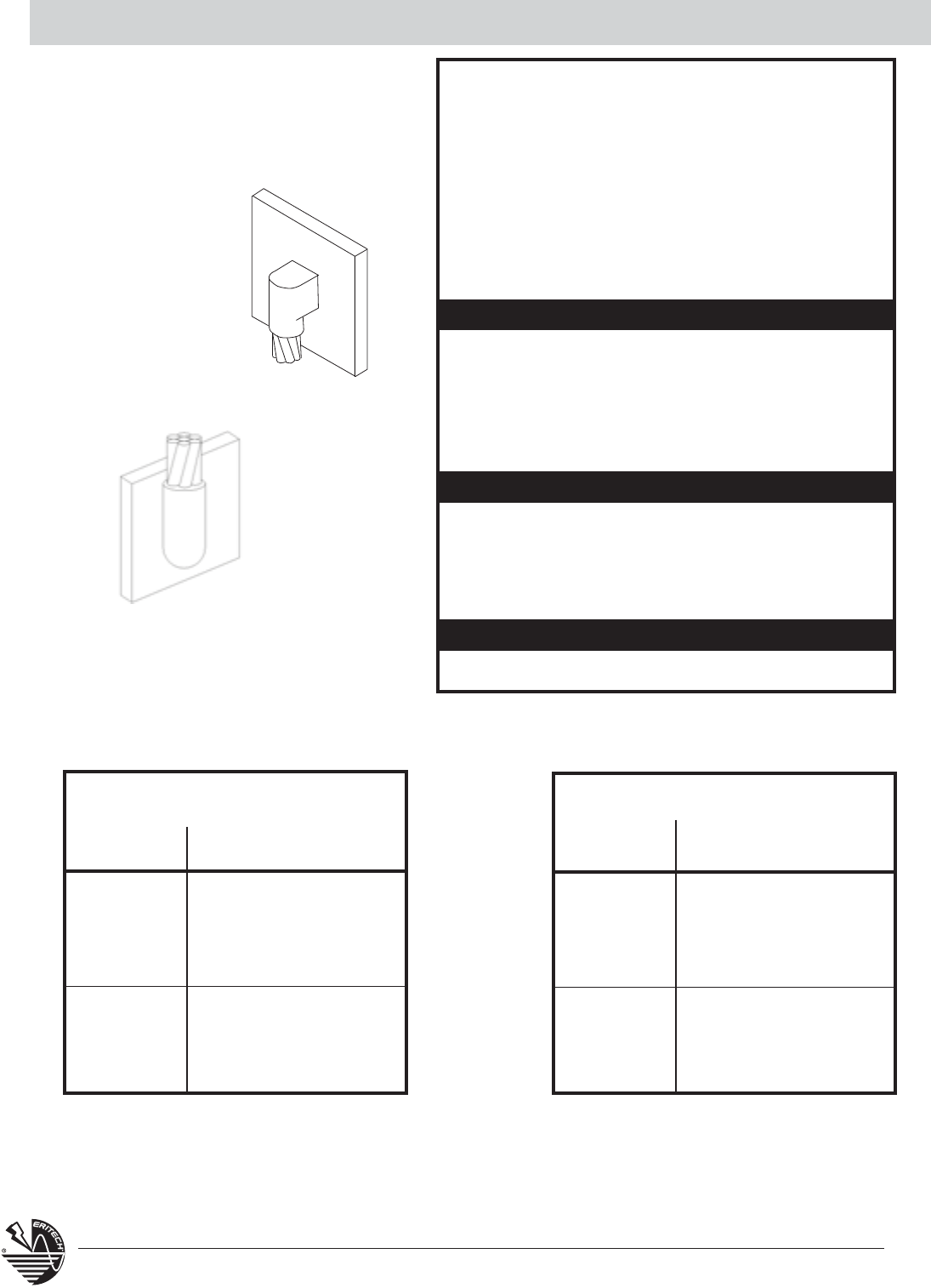
VERTICAL STEEL SURFACE
• Connection of vertical cable to vertical flat steel surface
or to side of vertical or horizontal steel pipe.
•A test weld should be made to check the possibility
of burn through on thin sections or thin wall pipe.
•Cable to steel pipe. Add pipe orientation and nominal
pipe size to flat surface mold part number. Examples:
VFC9CV6, 7/#7 conductor to vertical 6” pipe VFC9AH4,
7/#10 condctor to horizontal 4” pipe.
• Concentric stranded copper cable listed.
• Bold letter in mold part number is the price key.
Part No.
Handle Clamps
for C Price Key Molds
L160
for D Price Key Molds
L159
CADWELD®PLUS Control Unit or PLUSCU
Flint Ignitor T320
Cable Cleaning Brush T313 or T314
Slag Removal Spade B136A or B136B
Mold Cleaning Brush T394
Rasp T321
Torch Head T111
ACCESSORIES
• See Section A
VB Cable down to vertical
steel surface
VF Cable up to vertical
steel surface
1 For CADWELD®PLUS add suffix “PLUSF20” (refer page 44)
TYPE VB
CABLE SIZE MOLD WELDING
(sq mm) PART NO. MATERIAL1
7/#10 VBC9A 65
7/#8 VBC9B 115
7/#7 VBC9C 115
7/#6 VBC9D 150
7/#5 VBC9E 150
19/#9 VBC9F 200
19/#8 VBC9G 200
19/#7 VBC9H 250
19/#6 VBR9J 2-150
TYPE VF
CABLE SIZE MOLD WELDING
(sq mm) PART NO. MATERIAL1
7/#10 VFC9A 90
7/#8 VFC9B 150
7/#7 VFC9C 150
7/#6 VFR9D 200
7/#5 VFR9E 200
19/#9 VFR9F 200
19/#8 VFR9G 250
19/#7 VFF9H 2-150
19/#6 VFF9J 2-200
25
www.erico.com
Vertical Steel Surface VG / VT
SUGGESTED TOOLS
REQUIRED TOOLS
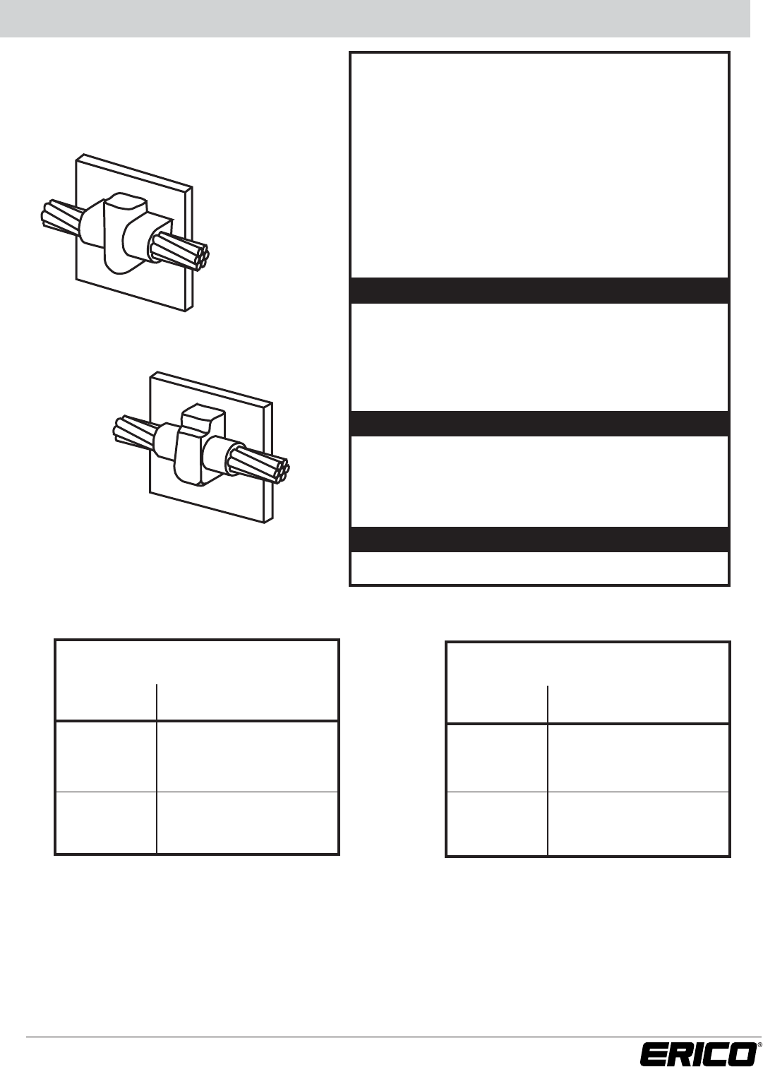
VERTICAL STEEL SURFACE
• CADWELD®through connections to vertical flat steel
surface; cable to vertical side of horizontal pipe (Type VG
only); cable to vertical steel pipe (Type VT only).
•A test weld should be made to check the possibility
of burn through on thin sections or thin wall pipe.
•Cable to steel pipe. Add nominal pipe size to flat surface
mold part number. Examples: Horizontal Piipe, Use Type
VG, add nominal pipe size suffix, for 7/#7 to 6 in. pipe,
VGC9C6 for Vertical Pipe, Use Type VT, add nominal pipe
size suffix, Example for 7/#8 to 4 in. pipe, VTC9B4.
• Concentric stranded copper cable listed.
• Bold letter in mold part number is the price key.
Part No.
Handle Clamps
for C Price Key Molds
L160
for D Price Key Molds
L159
CADWELD®PLUS Control Unit or PLUSCU
Flint Ignitor T320
Cable Cleaning Brush T313 or T314
Slag Removal Spade B136A or B136B
Mold Cleaning Brush T394
Rasp T321
Torch Head T111
ACCESSORIES
• See Section A
TYPE VG
CABLE SIZE MOLD WELDING
(sq mm) PART NO. MATERIAL1
7/#10 VGC9A 65
7/#8 VGC9B 115
7/#7 VGC9C 115
19/#6 VGC9D 150
19/#5 VGC9E 150
19/#9 VGC9F 150
1 For CADWELD®PLUS add suffix “PLUSF20” (refer page 44)
TYPE VT
CABLE SIZE MOLD WELDING
(sq mm) PART NO. MATERIAL1
7/#10 VTC9A 90
7/#8 VTC9B 115
7/#7 VTC9C 115
19/#6 VTC9D 150
19/#5 VTC9E 150
19/#9 VTC9F 150
VG Cable on surface
VT Cable off surface
For Stranded Copper-
Clad Steel Conductors
26 www.erico.com
Vertical Steel Surface VV
For Stranded Copper-
Clad Steel Conductors
VV SUGGESTED TOOLS
REQUIRED TOOLS
VERTICAL STEEL SURFACE
• Through connections to vertical flat surface or to side of
vertical or horizontal steel pipe.
•A test weld should be made to check the possibility
of burn through on thin sections or thin wall pipe.
•Cable to steel pipe. Add pipe orientation and nominal
pipe size to flat surface mold part number. Examples:
VVR9CV6, 7/#7 conductor to vertical 6” pipe VVR9AH46,
7/#10 to horizontal 6” pipe.
• Concentric stranded copper cable listed.
• Bold letter in mold part number is the price key.
Part No.
Handle Clamps
for C Price Key Molds
L160
for D Price Key Molds
L159
CADWELD®PLUS Control Unit or PLUSCU
Flint Ignitor T320
Cable Cleaning Brush T313 or T314
Slag Removal Spade B136A or B136B
Mold Cleaning Brush T394
Rasp T321
Torch Head T111
ACCESSORIES
• See Section A
CABLE SIZE MOLD WELDING
(sq mm) PART NO. MATERIAL1
7/#10 VVC9A 115
7/#8 VVR9B 200
7/#7 VVR9C 200
7/#6 VVR9D 250
7/#5 VVR9E 250
19/#9 VVR9F 250
1 For CADWELD®PLUS add suffix “PLUSF20” (refer page 44)
27
www.erico.com
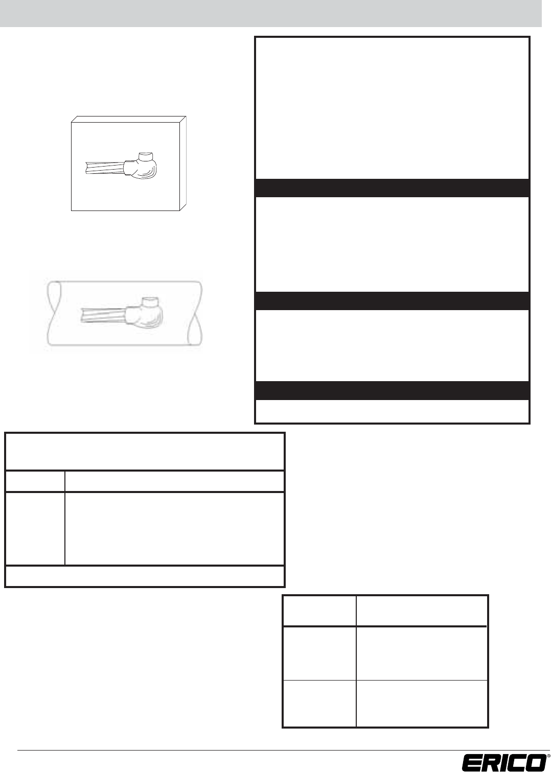
Vertical Steel Surface VN
For Stranded Copper-
Clad Steel Conductors
VN Cable on Pipe
Right hand shown - RH
VN Cable on Flat Surface
Right hand shown - RH
SUGGESTED TOOLS
REQUIRED TOOLS
VERTICAL STEEL SURFACE
• Conductor to vertical flat steel surface or cable to the side
of horizontal steel pipe.
•A test weld should be made to check the possibility
of burn through on thin sections or thin wall pipe.
•Cable to steel pipe. Add pipe orientation and nominal
pipe size to flat surface mold part number. Example:
VNC9CLH4 - weld on left end of conductor, #4 pipe, 7/#7
stranded conductor.
• Concentric stranded copper cable listed.
• Bold letter in mold part number is the price key.
Part No.
Handle Clamps
for C Price Key Molds
L160
for D Price Key Molds
L159
CADWELD®PLUS Control Unit or PLUSCU
Flint Ignitor T320
Cable Cleaning Brush T313 or T314
Slag Removal Spade B136A or B136B
Mold Cleaning Brush T394
Rasp T321
Torch Head T111
ACCESSORIES
• See Section A
CABLE SIZE MOLD WELDING
(sq mm) PART NO. MATERIAL1
7/#10 VNC9A 65
7/#8 VNC9B 90
7/#7 VNC9C 90
7/#6 VNC9D 115
7/#5 VNC9E 115
19/#9 VNC9F 115
1 For CADWELD®PLUS add suffix “PLUSF20” (refer page 44)
Cable to Horizontal Steel Pipe (Type VN) –
Use flat surface mold part number with suffix.
Cable Nominal Pipe Size Suffix
#1 and 12” and smaller
Nominal Pipe Size
smaller 14” and larger None
1/0 thru 28” and smaller Nominal Pipe Size
250 30” and larger None
Example: 2/0 cable to 4” pipe, VNC-2G-LH-4
28 www.erico.com
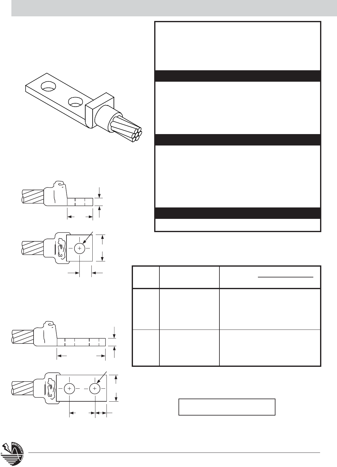
Copper Lugs GL
CABLE MOLD WELDING LUG SIZE GL LUG NUMBER
SIZE NUMBER MATERIAL1
T X W 1 HOLE 2 HOLES
7/#10 GLCCE9A 32 1/8 x 1 B121CE B122-CE
7/#8 GLCCE9B 45 1/8 x 1 B121CE B122-CE
7/#7 GLCCE9C 45 1/8 x 1 B121CE B122-CE
7/#6 GLCCE9D 65 1/8 x 1 B121CE B122-CE
7/#5 GLCDE9E 65 3/16 x 1 B121DE B122-DE
19/#9 GLCDE9F 65 3/16 x 1 B121DE B122DE
19/#8 GLCDE9G 90 3/16 x 1 B121DE B122DE
19/#7 GLCDE9H 90 3/16 x 1 B121DE B122DE
19/#6 GLCEE9J 115 1/4 x 1 B121EE B122EE
1-HOLE
31.75
mm
min.
14.29 mm D.
W
15.875
mm
T
2-HOLE
76.2 mm min.
14.29 mm D.
W
15.875 mm
T
44.45
mm
COPPER LUGS
• Lugs and connections for equipment and structures.
Ideal for power applications.
• Concentric stranded copper cable is listed.
•Bold letter in mold part number is the price key.
GL
Lug and connection SUGGESTED TOOLS
REQUIRED TOOLS
Part No.
Handle Clamps
for C Price Key Molds
L160
for D Price Key Molds
L159
CADWELD®PLUS Control Unit or PLUSCU
Flint Ignitor T320
Cable Cleaning Brush T313 or T314
Slag Removal Spade
#65 w/m & smaller B136A
#90 w/m & larger B136B
Mold Cleaning Brush T394
Cable Clamp B265
Torch Head T111
1 For CADWELD®PLUS add suffix “PLUSF20” (refer page 44)
For Stranded Copper-
Clad Steel Conductors
ACCESSORIES
• See Section A
NEMA Drilled Lugs-B122 Series
NEMA Drilled Lugs-B121 Series
All lugs are tin plated copper.
29
www.erico.com
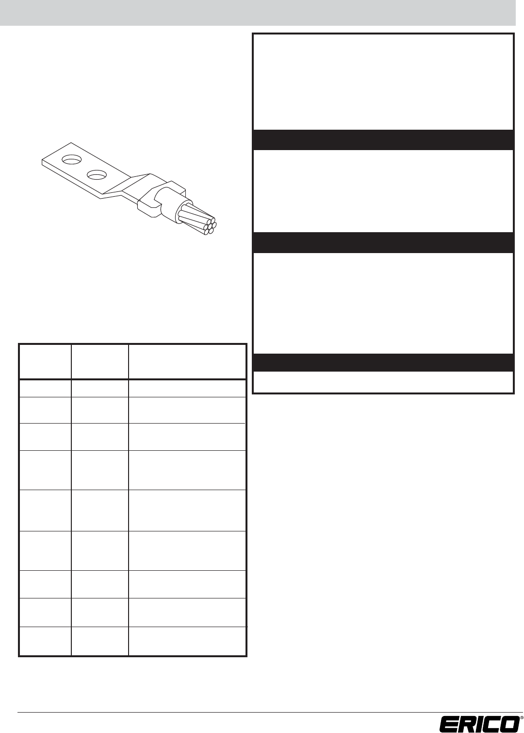
Copper Lugs LA
COPPER LUGS (METRIC)
• Cable to lug and connections. Can be either field
fabricated from copper busbar or factory-made lugs.
Ideal for power applications. Connection must be made
with cable and lug horizontal.
• Concentric stranded copper cable is listed.
• Bold letter in mold part number is the price key.
LA
Lug and connection SUGGESTED TOOLS
REQUIRED TOOLS
Part No.
Handle Clamps
for C Price Key Molds
L160
for D Price Key Molds
L159
CADWELD®PLUS Control Unit or PLUSCU
Flint Ignitor T320
Cable Cleaning Brush T313 or T314
Slag Removal Spade
#65 w/m & smaller B136A
#90 w/m & larger B136B
Mold Cleaning Brush T394
Cable Clamp B265
Torch Head T111
1 For CADWELD®PLUS add suffix “PLUSF20” (refer page 44)
See page 30 for Lugs.
ACCESSORIES
• See Section A
For Stranded Copper-
Clad Steel Conductors
CABLE SIZE BUS OR LUG MOLD
WELDING
(sq mm) SIZE (mm)
PART NUMBER
MATERIAL1
7/#10 3/16 x 1 LAC9ADE 65
7/#8 3/16 x 1 LAC9BDE 65
1/4 x 1 LAC9BEE 65
7/#7 3/16 x 1 LAC9CDE 90
1/4 x 1 LAC9CEE 90
3/16 x 1 LAC9DDE 90
7/#6 1/4 x 1 LAC9DEE 90
1/4 x 1-1/2 LAC9DEG 90
3/16 x 1 LAC9EDE 90
7/#5 1/4 x 1 LAC9EEE 90
1/4 x 1-1/2 LAC9EEG 90
3/16 x 1 LAC9FDE 90
19/#9 1/4 x 1 LAC9FEE 90
1/4 x 1-1/2 LAC9FEG 90
19/#8 1/4 x 1 LAC9GEE 115
1/4 x 1-1/2 LAC9GEG 115
19/#7 1/4 x 1 LAC9HEE 150
1/4 x 1-1/2 LAC9HEG 150
19/#6 1/4 x 1 LAC9JEE 200
1/4 x 1-1/2 LAC9JEG 200
30 www.erico.com
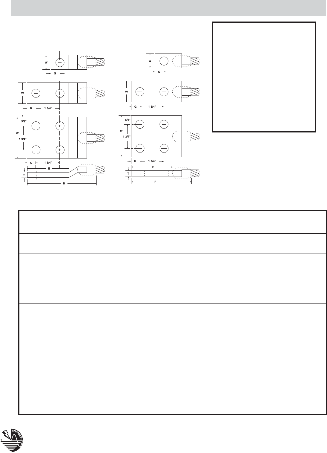
NEMA Lugs LA
*Approximate
**Non-NEMA drillings. Two holes for 3/8” screws on 1” centers. For use with B1612Q CADWELD®Ground Plate.
LA Offset Lug LA Straight Lug
LUGS FOR TYPE LA LUG
CONNECTIONS
NEMA lugs for Type LA
connections are made fom
electrolytic grade copper bar
stock to provide an efficient
bolting surface for grounding
applications. All listed lugs are
tin plated.
For sizes not listed or for 45° or 90°
lugs, contact factory.
LUG NO. OF BOLT LA LUG PART NO. DIMENSIONS IN INCHES SIZE IN
SIZE HOLES SIZE STRAIGHT OFFSET T W G E F* H* Kcmil
1/8 x 1 1 3/8 B101CE B101CEOL 1/8 1 1/2 7/8 2-3/8 3-1/8 159
2 1/2 B102CE B102CEOL 1/8 1 5/8 3 4-1/2 5-1/4 159
1 1/2 B101DE B101DEOL 3/16 1 9/16 1-1/8 2-7/8 3-5/8 239
3/16 x 1 2 1/2 B102DE B102DEOL 3/16 1 5/8 3 4-3/4 5-1/2 239
2** 3/8 B103DEOL 3/16 1 7/16 1-7/8 4-3/8 239
1/4 x 1 1 1/2 B101EE B101EEOL 1/4 1 5/8 1-1/8 3 3-5/8 318
2 1/2 B102EE B102EEOL 1/4 1 5/8 3 4-7/8 5-5/8 318
1/4 x 1-1/2 1 5/8 B101EG B101EGOL 1/4 1-1/2 3/4 1-1/2 3 4-1/8 478
2 1/2 B102EG B102EGOL 1/4 1-1/2 5/8 3 4-7/8 5-5/8 478
1/4 x 2 2 1/2 B102EH B102EHOL 1/4 2 5/8 3 5-1/4 6 637
3/8 x 1-1/2 1 5/8 B101GG B101GGOL 3/8 1-1/2 3/4 1-1/2 3-3/4 4-3/4 716
2 1/2 B102GG B102GGOL 3/8 1-1/2 5/8 3 5-3/4 7 716
3/8 x 2 1 5/8 B101GH B101GHOL 3/8 2 1 2-1/8 4-3/8 5-5/8 955
2 1/2 B102GH B102GHOL 3/8 2 5/8 3 5-3/4 7 955
1/2 x 2 2 1/2 B102JH B102JHOL 1/2 2 5/8 3 5-3/4 7 1374
1/4 x 3 4 1/2 B104EK B104EKOL 1/4 3 5/8 3 5-1/2 6-1/4 955
3/8 x 3 4 1/2 B104GK B104GKOL 3/8 3 5/8 3 6 7 1432
1/2 x 3 4 1/2 B104JK B104JKOL 1/2 3 5/8 3 6-1/4 7-1/4 1910
31
www.erico.com
Copper and Steel Studs HX / HV
SUGGESTED TOOLS
REQUIRED TOOLS
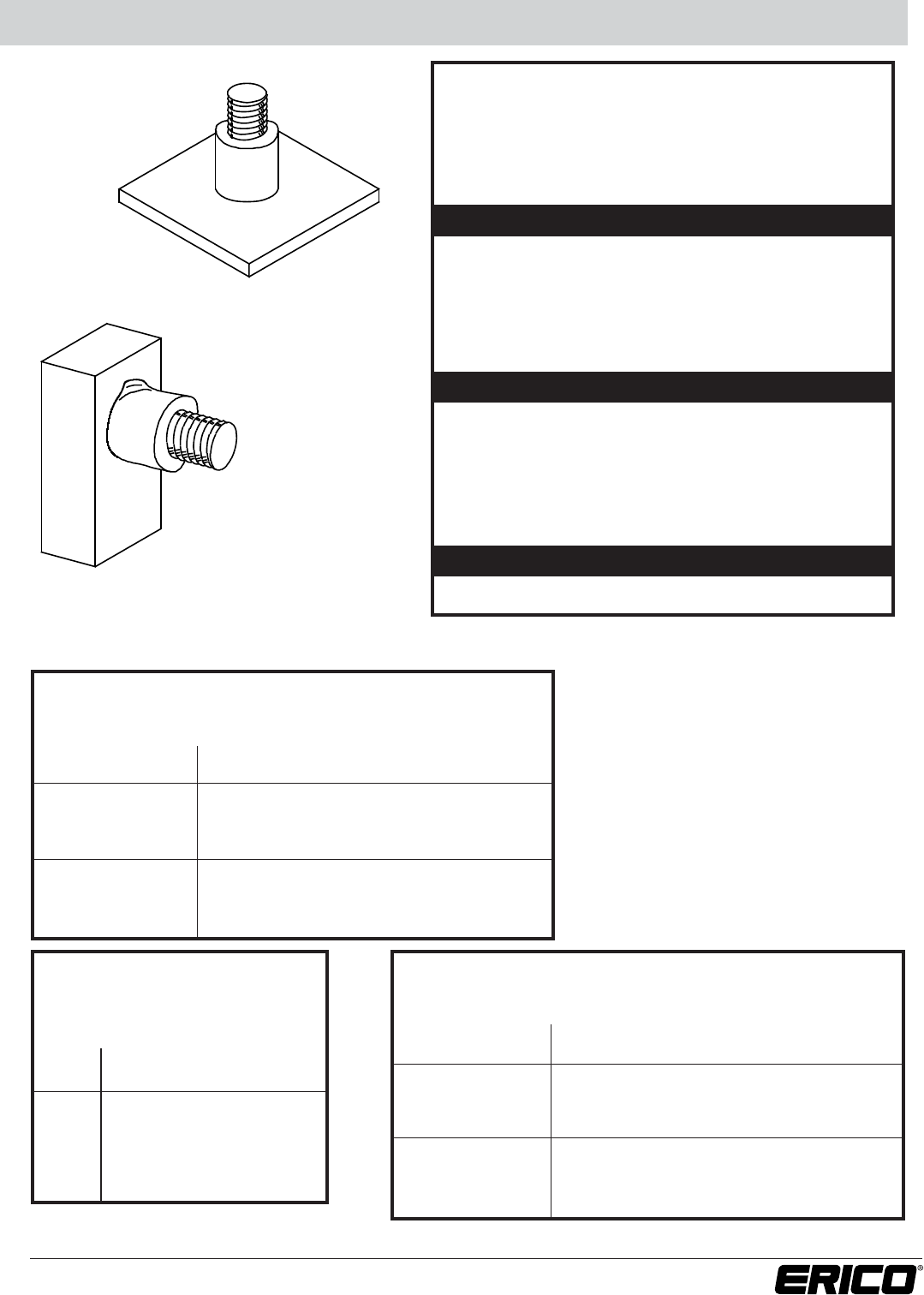
COPPER AND STEEL STUDS
• Connections of copper and steel studs to steel surfaces.
Copper studs on grounded structures provide a
convenient point of attachment of temporary protective
ground clamps.
• Bold letter in mold part number is the price key.
Part No.
Handle Clamps
for C Price Key Molds
L160
for D Price Key Molds
L159
CADWELD®PLUS Control Unit or PLUSCU
Flint Ignitor T320
Mold Cleaning Brush T394
Rasp T321
Torch Head T111
Mold Scraper Tool
#65 w/m & smaller B136A
#90 w/m & larger B136B
HX Vertical stud to
horizontal steel surface
HV Horizontal stud to horizontal
steel surface
*or silicon bronze
ACCESSORIES
• See Section A
Type HX Connections for Steel Surfaces Only
STEEL STUDS ONLY
STUD MOLD
TYPE HX WELD DIMENSIONS
WELDING
SIZE PART NO.
A (thickness) B (diameter)
MATERIAL
1/4” HXC10 3/8” 3/4” 25
5/16” HXC11 3/8” 3/4” 25
3/8” HXC12 9/16” 7/8” 45
1/2” HXC14 5/8” 1-1/16” 65
3/4” HXC18 5/8” 1-1/2” 150
1” HXC22 15/16” 1-5/8” 2-150
Type HV Connections for Steel Surfaces Only
STEEL STUDS ONLY
STUD MOLD
TYPE HX WELD DIMENSIONS
WELDING
SIZE PART NO.
A (thickness) B (diameter)
MATERIAL
1/4” HVC10 3/8” 3/4” 25
5/16” HVC11 3/8” 3/4” 25
3/8” HVC12 9/16” 7/8” 45
1/2” HVC14 5/8” 1-1/16” 65
3/4” HVC18 5/8” 1-1/2” 150
1” HVC22 15/16” 1-5/8” 250
Type HV Connections for
Steel Surfaces only
COPPER* STUDS ONLY
STUD MOLD WELDING
SIZE PART NO. MATERIAL
1/2” HVC14CU 115
5/8” HVC31CU 150
3/4” HVC33CU 250
7/8” HVD35CU 2-150
1” HVD37CU 2-150
32 www.erico.com
Materials, Tools and Accessories Section A
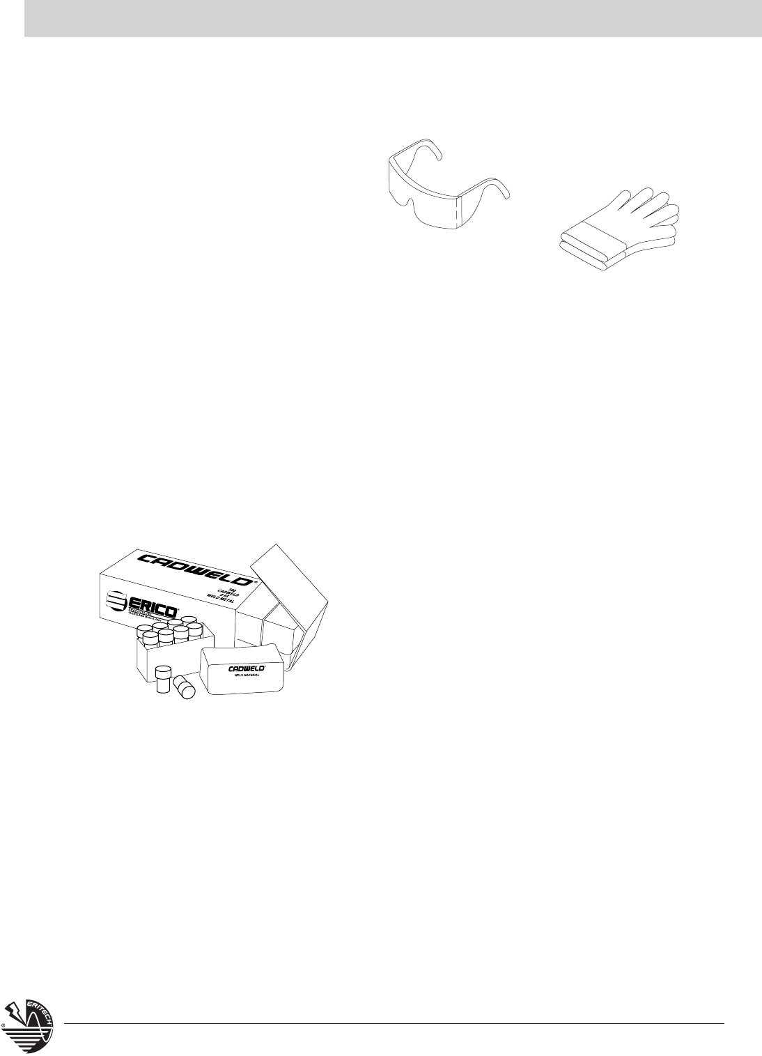
SAFETY FIRST
ERICO®recommends SAFETY FIRST
when making CADWELD®Connections.
We offer the following gloves and
glasses as shown
Safety Glasses
These glasses may be
worn separately or over
prescription glasses.
Gloves
Heavy canvas gloves
with leather palms.
T378L
T393
CADWELD®WELDING MATERIAL
CADWELD Welding Material is a mixture of copper oxide and aluminum, packaged by size in plastic
tubes. Each tube contains the starting material at the bottom of the plastic tube, with the Welding
Material on top. These materials are not explosive and not subject to spontaneous ignition. These
containers are packaged in boxes along with metal disks. Each weld uses one disk. Disks are
included with the Welding Material.
Five types of CADWELD Welding Materials are used for
grounding connections:
1. F20 or standard Welding Material is used for all
grounding connections with the exception of those to
cast iron or to load bearing rail. The Standard Welding
Material containers have clear (or natural) caps. Standard
Welding Material is also used with most FX molds.
2. XL Welding Material is used with CADWELD®EXOLON
molds. CADWELD EXOLON Welding Material containers
have white caps.
3. XF-19 Alloy Welding Material is used for all connections to cast iron such as Type HB and
others. XF-19 Welding Material containers have orange caps.
For DUCTILE IRON, see Section 3, Cast Iron Containers
4. CADWELD F80 Alloy Welding Material is used for all connections to load bearing rail such
as Type W Bonds. F80 Welding Material containers have yellow caps.
5. Cathodic connections require different welding material and molds. Contact ERICO for
cathodic connection applications.
33
www.erico.com
Materials, Tools and Accessories Section A
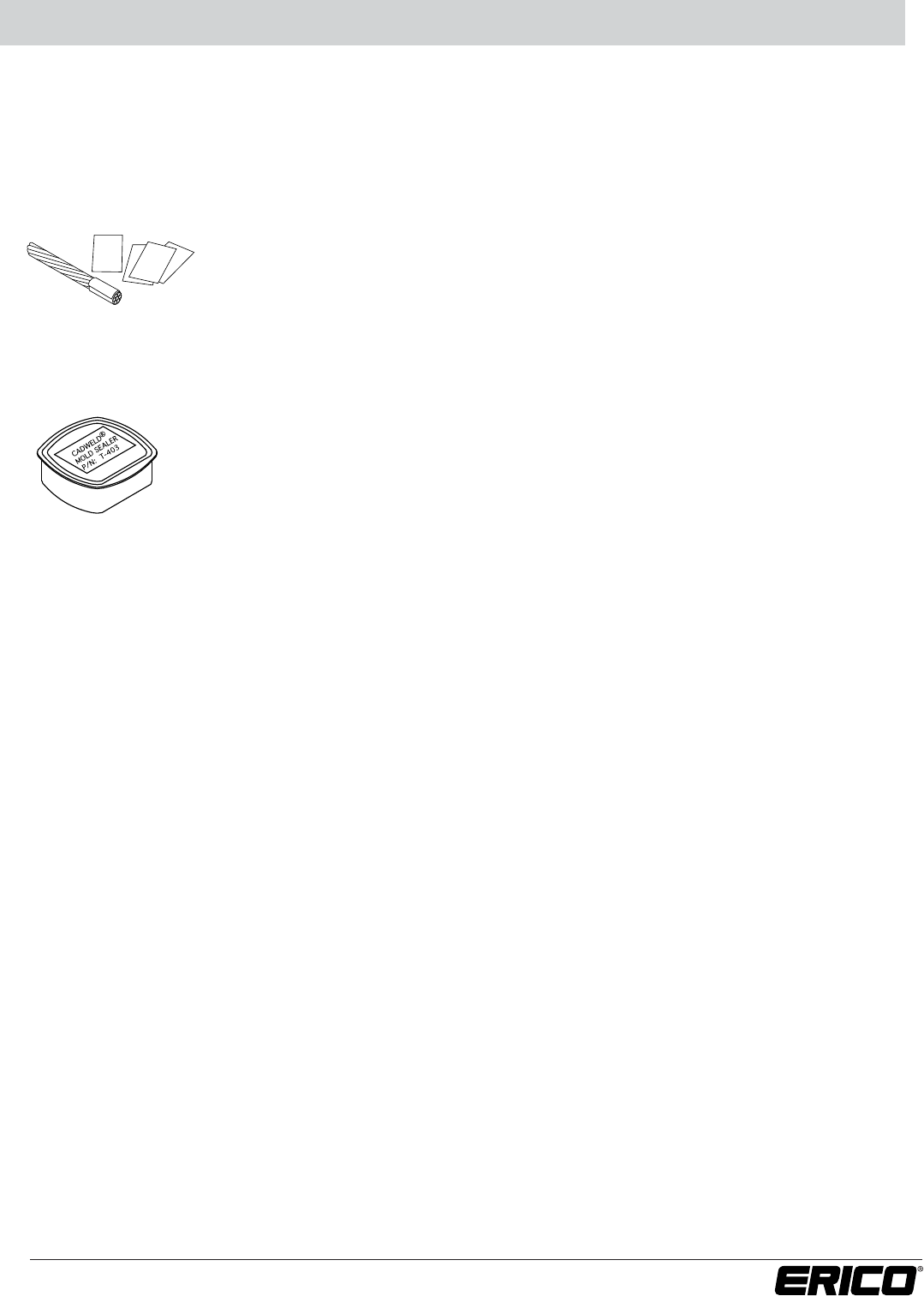
ADAPTING MOLDS TO FIT CONDUCTORS
CADWELD®Wrap Sleeve B140A
CADWELD Wrap Sleeve is wrapped around the cable until the diameter is about
the same as the cable opening in the mold.
CADWELD®Mold Sealer
T403 CADWELD Mold Sealer is ideal for sealing hot or cold molds to retard
leakage from large stranded conductors. It is required on certain molds such as
Types HA, HB, HC, VG and VN. It prolongs useful mold life when the cable
opening becomes worn.
It is available in a convenient 2 pound package.
B140A
T403
Cables smaller than indicated on mold tag can be welded by using either Wrap Sleeve or
Adapter Sleeves.
34 www.erico.com
Materials, Tools and Accessories Section A
CABLE AND WORK SURFACE PREPARATION
Cable Cleaning Brushes
Two types of brushes are available to aid in removing oxides and
cleaning copper surfaces. T313 Card Cloth Brush with short stiff bristles
is generally preferred for cleaning concentric conductors and busbars,
which are not heavily oxidized.
T314 Cable Cleaning Brush
T314 Cable Cleaning Brush cleans any conductor and is especially
useful for coarse or very dirty conductors. The brushes can be rotated
to provide new cleaning bristles and are replaceable.
T313
T314
B265
T321
Cable Clamp B265
The B265 Cable clamp should be used with hard drawn copper cable,
copper-clad steel conductors or any cable under tension. Use of the
clamp aids in preventing cable movement and prolongs mold life.
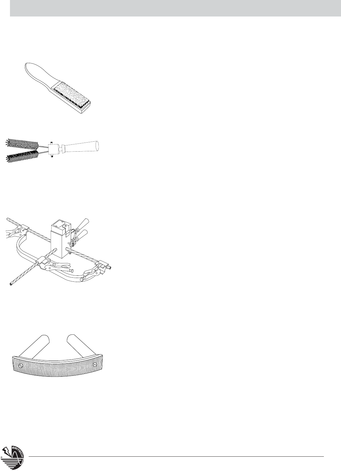
Rasp
T321 rasp is used to remove rust from any steel surface or galvanizing
from hot dipped galvanized steel to expose the bare steel for welding.
The curved blade makes it an efficient tool for flat surfaces. T321A
Replacement blades are also available.
Materials, Tools and Accessories Section A
T111
T372A
T319
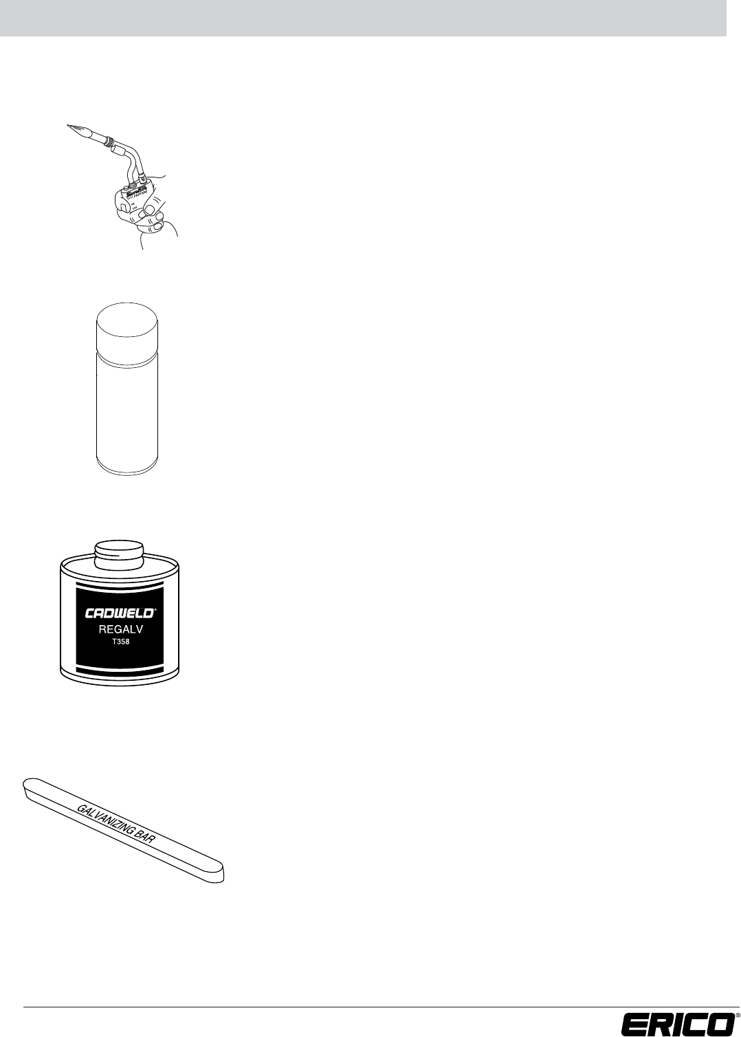
Surefire™Torch Head
T111 Self igniting propane torch head. Squeeze the control knob for an
instant flame. Release and it’s out. No flame adjusting. The burn tip remains
cool during normal use. Operates on its side or upside down. Can withstand 60
MPH winds without flareout. Fits all standard 14 and 16 oz. propane cylinders.
SUREFIRE™ is a trademark of IPI
Galvanizing Touch-Up
Easy to use galvanizing paint in a spray can is used to touch up heat affected
areas on galvanized steel surfaces after welding. The damage to the galvanizing
is often minimal so the repair is often cosmetic. T372A galvanizing compound
available in 12 ounce aerosol can.
T358 Regalv
T358 Regalv is a 97% zinc rich organic coating which also can be used to
repair galvanized surfaces. The brush is attached to the cap.
Galvanizing Bar
T319 Galvanizing Bar is used to repair a galvanized surface that has been
damaged by welding or drilling. This is a low temperature, self-fluxing
material. Often there is sufficient heat after making the CADWELD®
Connection to melt the bar or a small torch may be used.
35
www.erico.com
T358
36 www.erico.com
Materials, Tools and Accessories Section A
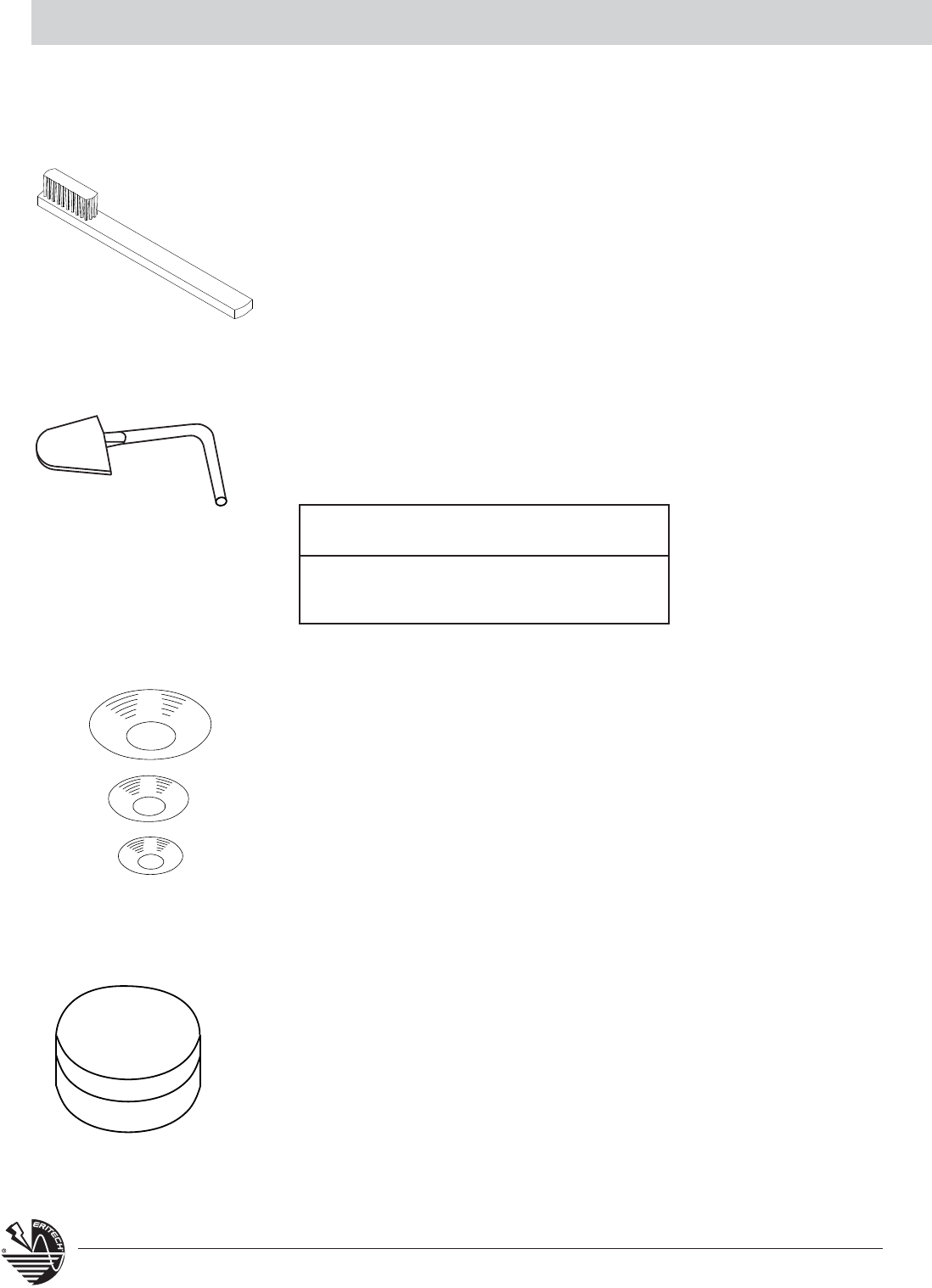
Mold Cleaning Brush
Mold cleaning brush T394 is very useful for removing slag from molds –
especially vertically split molds.
Slag Removal Spades
Slag Removal Spades are useful for removing the slag after making a
CADWELD®Connection – especially useful with horizontally split molds.
Disks
Each time a weld is made, a new disk is required. The disk sits on the
bottom of the crucible. Its purpose is to hold the powdered welding
material until the reaction takes place. The slag produced by the reaction
rises to the surface and the molten copper settles to the bottom of the
crucible where it melts the disk and melts through the conductors to
produce a permanent molecular bond.
Disks are available in three sizes:
B117A used in molds using #15 thru #32 welding material (3/4" diameter).
B117B used in molds using #45 thru #115 welding material (1" diameter).
B117C used in molds using #150 thru #500 welding material (1-1/2" diameter).
Disks are included with Welding Material and are not required for
CADWELD®PLUS.
Disk Kit
A disk container (T328) which includes 20 of each of the three sizes of
steel disks is available for your convenience. Kit P/N T328D.
MOLD CARE AND USE
T394
B136A
B136B
T328D
Slag Spade Using
Part No. Material Size
B-136-A #65 & Smaller
B-136-B #90 & Larger
37
www.erico.com
CADWELD®MOLDS
Materials, Tools and Accessories Section A
Wear Plates
Wear Plates reduce mechanical abrasion of molds at cable entry
points and help prevent leakage of molten metal (particularly on
larger 7 strand conductor). These features prolong mold life.
Most CADWELD molds are available with factory mounted wear
plates for the following sizes:
Copper-clad steel conductors: 7/#10 thru 19/#6
Ground rods: 1/2” thru 1”
To order WEAR PLATES specify: Mold Part No. followed by the
suffix “-W” i.e., TAC9F9FW.
Not available with types HA, HB, HC, LJ, certain PTs, & PCs, RR,
VB, VF, VG VN, XA, CXBQ or XBZ.
Following are the number of Wear Plates (W.P.) used on the
various types listed in this catalog.
Split Crucible Molds
Molds made with a horizontal opening and solid crucible section may be
specified as a SPLIT CRUCIBLE TYPE. The SPLIT CRUCIBLE MOLD allows for
easier cleaning, but lead times are longer.
To order a SPLIT CRUCIBLE TYPE specify: Mold Part No. followed by the
suffix “-L” i.e., TAC2Q2QL.
Available in Type TA, XA, XB, (C & D mold price only), LE and LJ connections.
*Available only on molds for 2” and narrower bus size.
**Available only on mold for 7/#10 and larger run and tap.
TYPE W.P. TYPE W.P. TYPE W.P.
GB 1 HT 2 RC 2
GB-GR 2 LA 1 RD 2
GB-GT 3 LE 2 SS 2
GL 1 LL 1* TA 3
GR 2 PC 2** VS 1
GT 3 PT 2** VT 2
GY 3 RA 1 VV 1
HS 1 RB 2 XB 4
A semi-permanent graphite mold is used for making most CADWELD
Connections. The mold controls the direction and speed of the molten
CADWELD welding material flow and its final solidified shape. The
graphite used in a CADWELD mold is a high temperature type that lasts
for an average of 50 or more CADWELD connections under normal usage.
38 www.erico.com
Materials, Tools and Accessories Section A
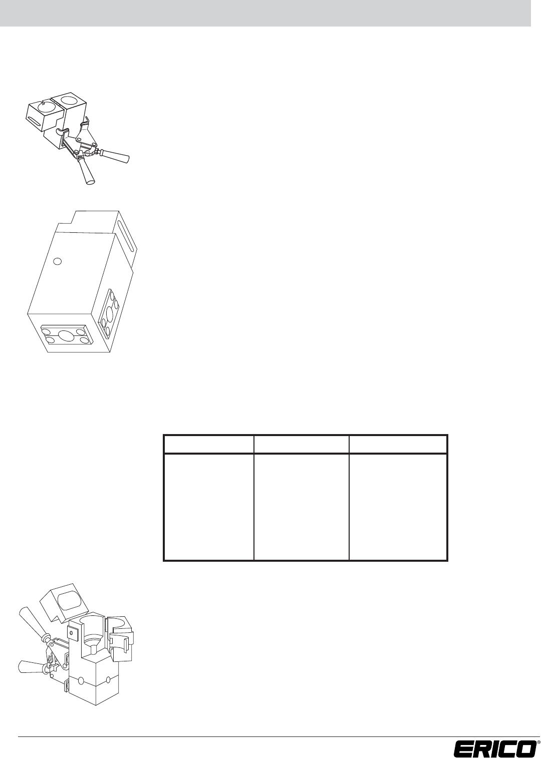
CADWELD®Handle Clamps
Handle Clamps such as the one shown are required for most molds. Specialized
frames
with handles are used on some molds. Flint ignitors are included with all
Handle Clamps.
The following Handle Clamps are most widely used.
1. L160 for all molds having a "C", "E", "Q", or "R" mold price key.
(3" wide molds)
2. L159 for all molds having a "D", "F", "J" or "Z" mold price key.
(4" wide molds)
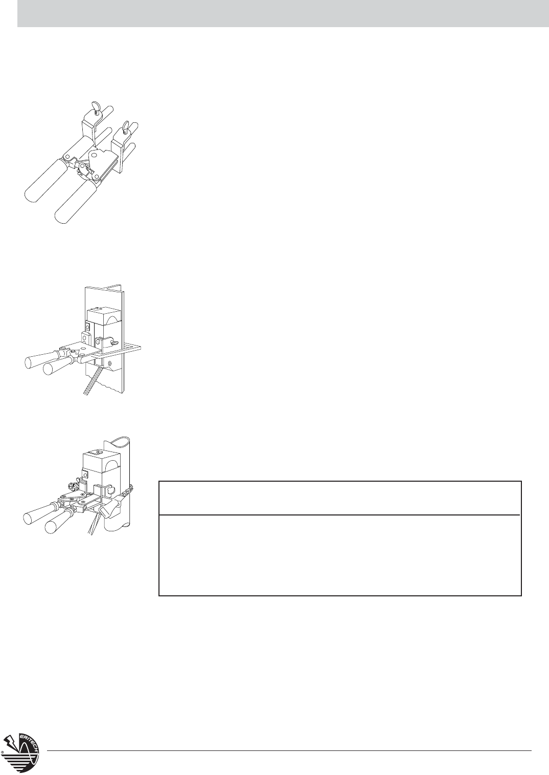
Vertical Surface Mold Support
The CADWELD mold can be securely held to a vertical "H" column or angle by using
the Vertical Surface Mold Support. It is easily attached to an existing L159 or L160
Handle Clamp. For use with Types VB, VG, VN, and VS molds, fits steel up to 1”
thick, for Type VF mold, 3/4” thick.
B134: For use with L160 E-Z CHANGE Handle Clamp
B135: For use with L159 E-Z CHANGE Handle Clamp
Chain Support Handle Clamps
The CADWELD mold can be securely held to a pipe using the clamp assembly
consisting of a modified L159 or L160 Handle Clamp with built-in Pipe Attachment.
The above clamps are equipped with 20” length of chain which will fit up to
4” pipes. Extra 20” length of chain, B158, is available to fit up to 10” pipes.
MOLD FASTENING AND MOUNTING
38 www.erico.com
Clamp Fits For Following
Part No. Mold Price Connection Types Pipe
B159V D & F VS,VF,VB, & VV Vertical
B160V C & R VS,VF,VB, & VV Vertical
B159VT D & F VT Vertical
B160VT C & R VT Vertical
B159H D & F HA,HS,HC, & HT Horizontal
B160H C & R HA,HS,HC, & HT Horizontal
Materials, Tools and Accessories Section A
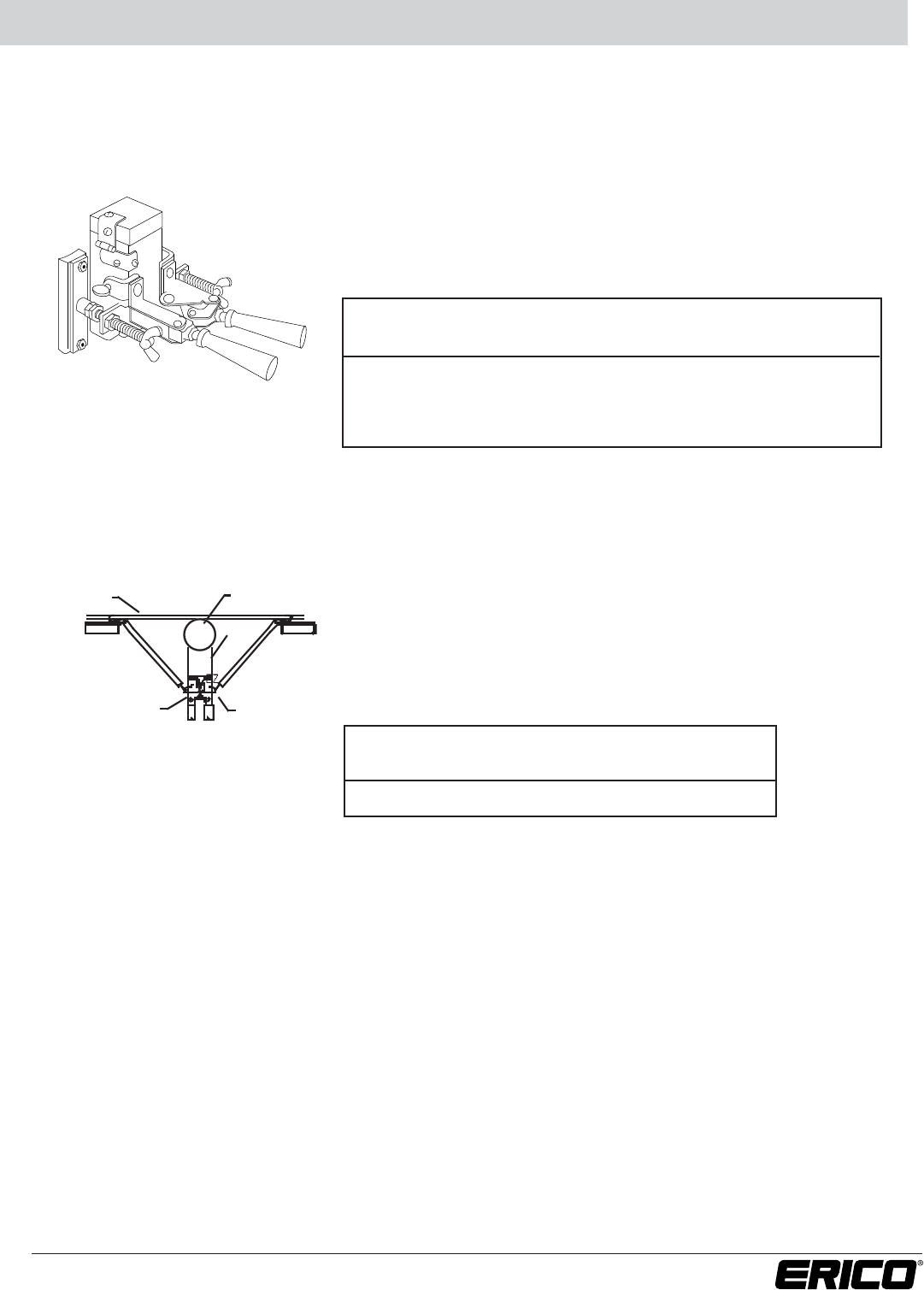
Magnetic Handle Clamps
The CADWELD®mold can be securely held to a large flat or
slightly curved vertical surface using the Handle Clamp with
Magnetic Support. Used on vertically split molds.
Fence Fabric Attachment Assembly
An easy to use, labor saving, Fence Fabric Attachment Assembly
fastens to your existing L159 or L160 Handle Clamp to firmly
hold your mold to the fence post after the fence fabric has been
attached. Ideal for retrofit jobs.
FENCE FABRIC FENCE POST
MOLD
EZ HANDLE FENCE FABRIC
ATTACHMENT
ASSEMBLY
Clamp Fits Mold Minimum Width
Part No. Price Key Required*
B396 C & R Price Key 8”
B159M D & F Price Key 10-1/2”
B399AM T Price Key 6”
B399BM P & N Price Key 7”
*Width will vary slightly depending upon the type of connection being made.
Fence Fabric Attachment Fits
Part No. Handles
B827A L160, L159
39
www.erico.com
Materials, Tools and Accessories Section A
Ground Rod Driving Sleeves**
Use a CADWELD®ground rod driving sleeve to prevent mushrooming top of ground rod.
Ground Rod Size Part No.
1/2” Copper Bonded or Steel Rod B137-14
5/8” Copper Bonded (.563” diameter) B137-16
5/8” Steel (.625” diameter) B137-31
3/4” Copper Bonded (.682” diameter) B137-18
3/4” Steel (.750” diameter) B137-33
1” Copper Bonded (.914” diameter) B137-22
1” Steel (1.00” diameter) B137-37
** For plain (unthreaded) ground rods only.
Ground Rod Splice Clamp
The B120 Ground Rod Splice Clamp must be used to support the upper rod and
provide a method of correctly positioning the rods and mold while splicing the rods.
(Type HDGB and GB Connection).
GROUND ROD SPECIALTY TOOLS
B120
T320
B321-30
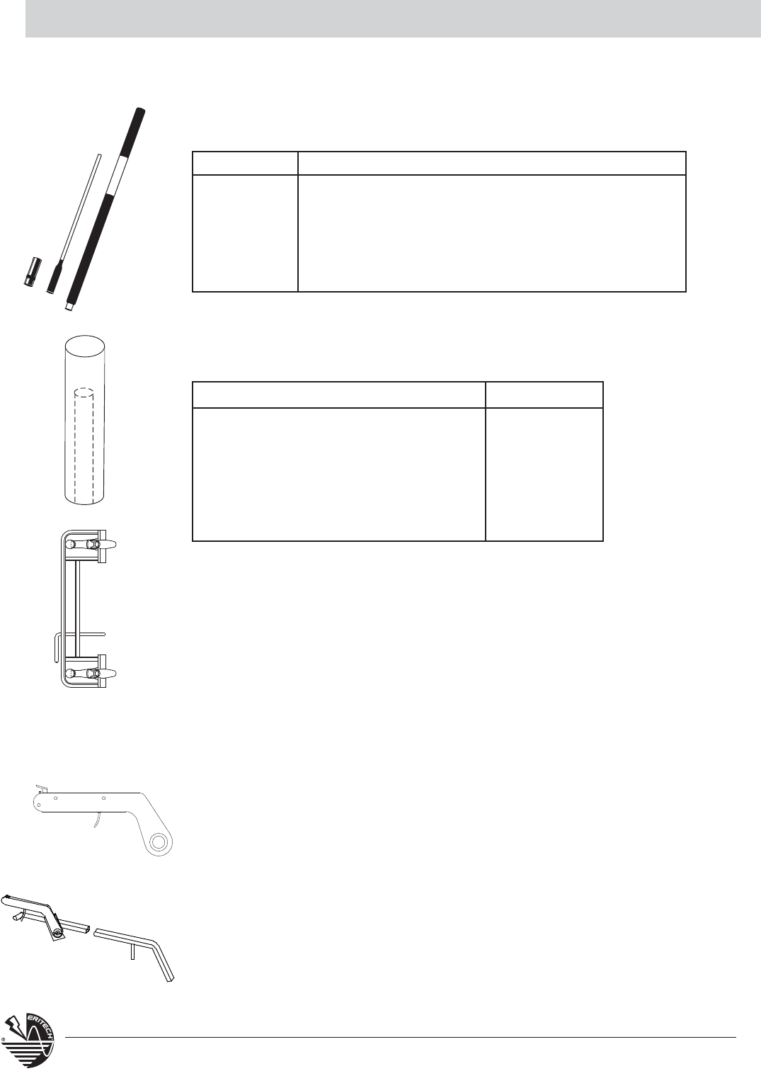
Ground Rod Drivers
Product # Description
EGRD58 5' Driver body with insert for up to 5/8" ground rods
EGRD58I*
Replacement insert for 5/8" copper-bonded ground rods
EGRD34 5' Driver body with insert for up to 3/4" ground rods
EGRD34I* Replacement insert for 3/4" copper-bonded ground rods
and 5/8” galvanized ground rods
*Both 5/8" and 3/4" inserts fit standard body of EGRD58 or EGRD34.
OTHER TOOLS
Flint Ignitors
T320 CADWELD Flint Ignitors are used to ignite the starting material when making
a CADWELD Connection. An ignitor is included with each Handle Clamp or frame.
T320A Replacement Flints are also available.
Flint Ignitor Extension
B321-30 Flint Ignitor Extension attaches to the T320 Flint Ignitor and allows the
installer to be about 30” from the mold. Ideal for such operations where the mold
is in a narrow trench and the installer is at ground level.
40 www.erico.com
Materials, Tools and Accessories Section A
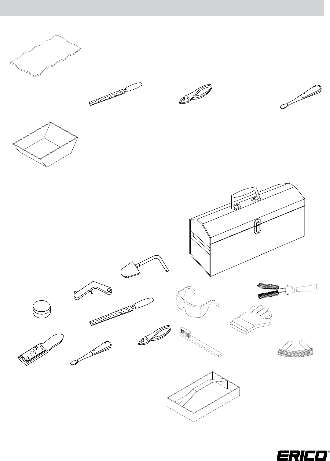
Ceramic Blanket
The woven Ceramic Blanket (Part T306) can be used to hold a hot mold or
keep the work surface free of slag when cleaning the mold.
File
T329
T306
T328D
T320
B136A
T329
T313 T305
T304
T393
T378L
T394
T321
T314
T396
XLB974-B2
Pliers
T304
Screwdriver
T305
Welding Tray
The Welding Tray (Part No. XLB974-B2) can contain a spill of molten welding
material. It is for personnel safety. Recommended when working overhead or
over expensive equipment.
TOOL KITS
TOOL TRAY
Tool Box T396
A tool box is highly recommended to carry tools,
molds, welding material and a propane torch.
Tool Kit T315A
Other Tool Kits can be
made for your particular
requirements.
Tool Tray Only: T331
Ideal for carrying one or two molds,
welding material, propane torch and tools.
Tool Box T396 is
included in Tool Kit T315A
T331
Tool Tray T331 is not
included in Tool Kit T315A
41
www.erico.com
42 www.erico.com
Materials, Tools and Accessories Section A
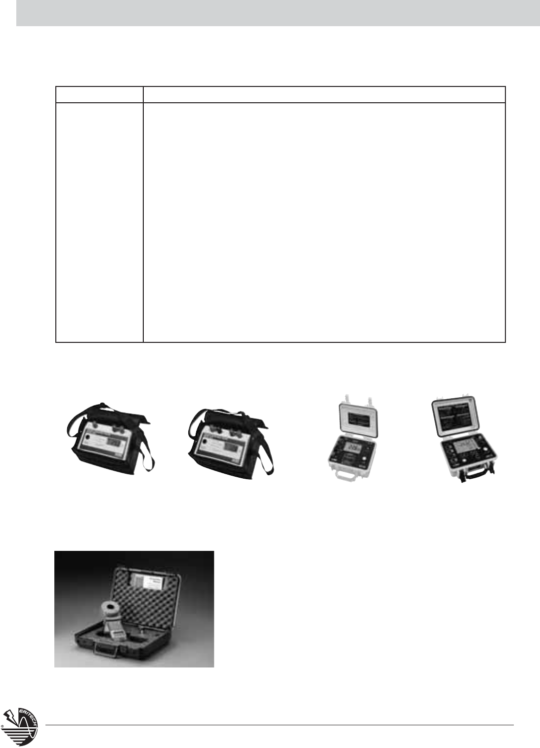
Ground System Testers
EST3640 EST4610 EST4630 EST6472
EST401
The EST401 clamp-on ground resistance tester measures ground
rod and small grid resistance without the use of auxillary ground
rods. The EST401 can be used in multi-grounded systems without
disconnecting the ground under test. By performing measurements
on intact ground systems, the user can measure the resisance to
ground and verify the continuity of the grounding
connections and bonds. With the current management function,
the EST401 is ideal for measuring ground current at pole ground
rods, service entrances, pad-mounted transformers, transmission
towers and service panels.
EST Series
Product # Description
EST3640 2-pole and 3-pole ground/earth resistance measurements,
10mΩ to 1999Ω
EST4610 2-, 3- and 4-point soil resistance measurements, 10mΩ to 1999Ω
EST4630 2-, 3- and 4-point measurements, rechargeable 9.6V NiMH battery pack
and durable case
EST6472 3- and 4-point measurements up to 99,000Ω, uses 2-clamp method
(selective ground testing), frequency scan from 40 to 5078Hz for
optimum test accuracy in electrically noisy environments, automatic
calculation of Rho
ESR182 Clamp-on probe for use with EST6472
EST401 Clamp-on ground resistance tester
ESTREELKIT500 Set of two 500-ft test leads on heavy duty insulated thermoplastic 11"
diameter reels with integral carrying handle, ideal for three point fall-of-
potential measurements at large sites, cranks for fast test lead retrieval
43
www.erico.com
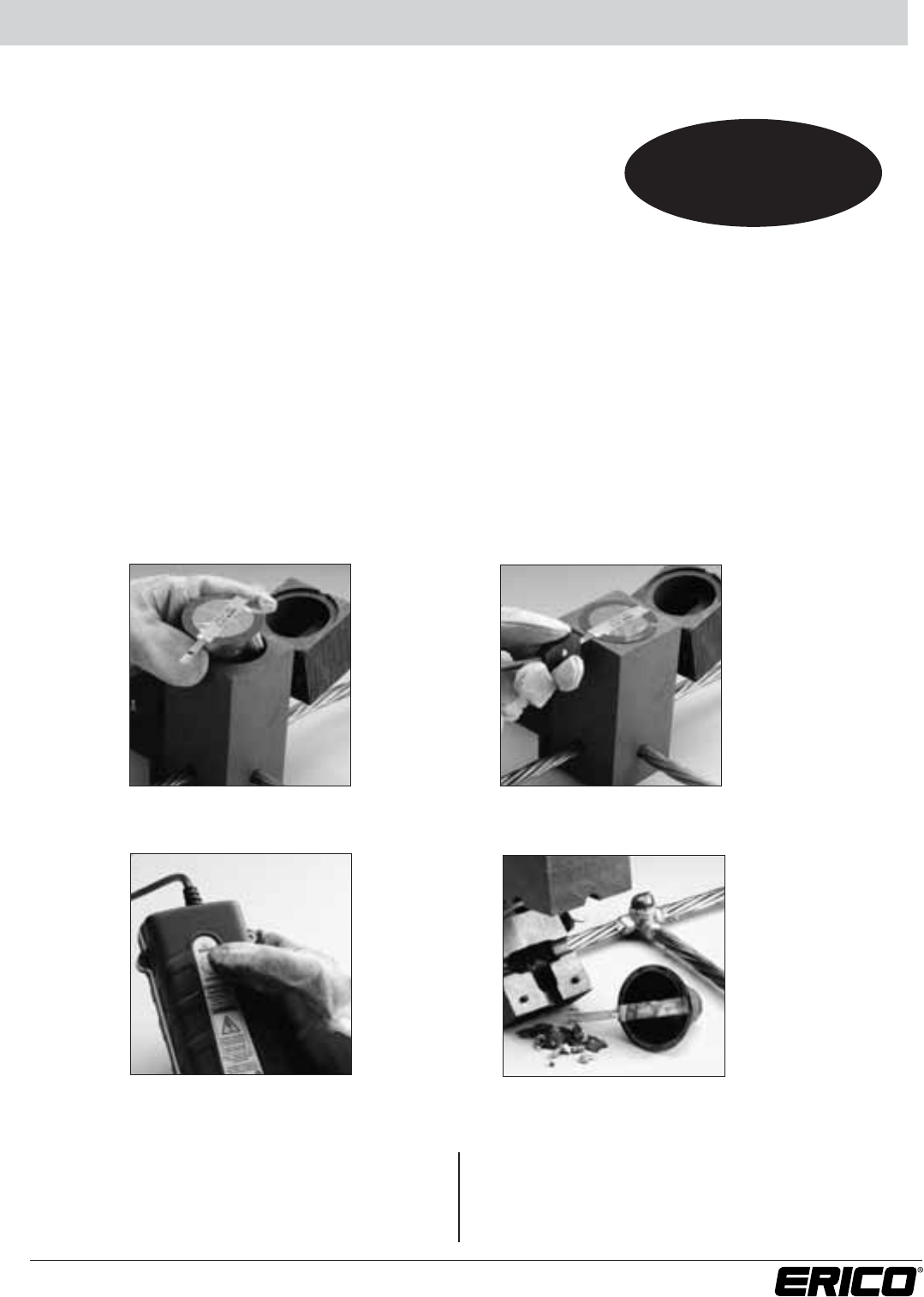
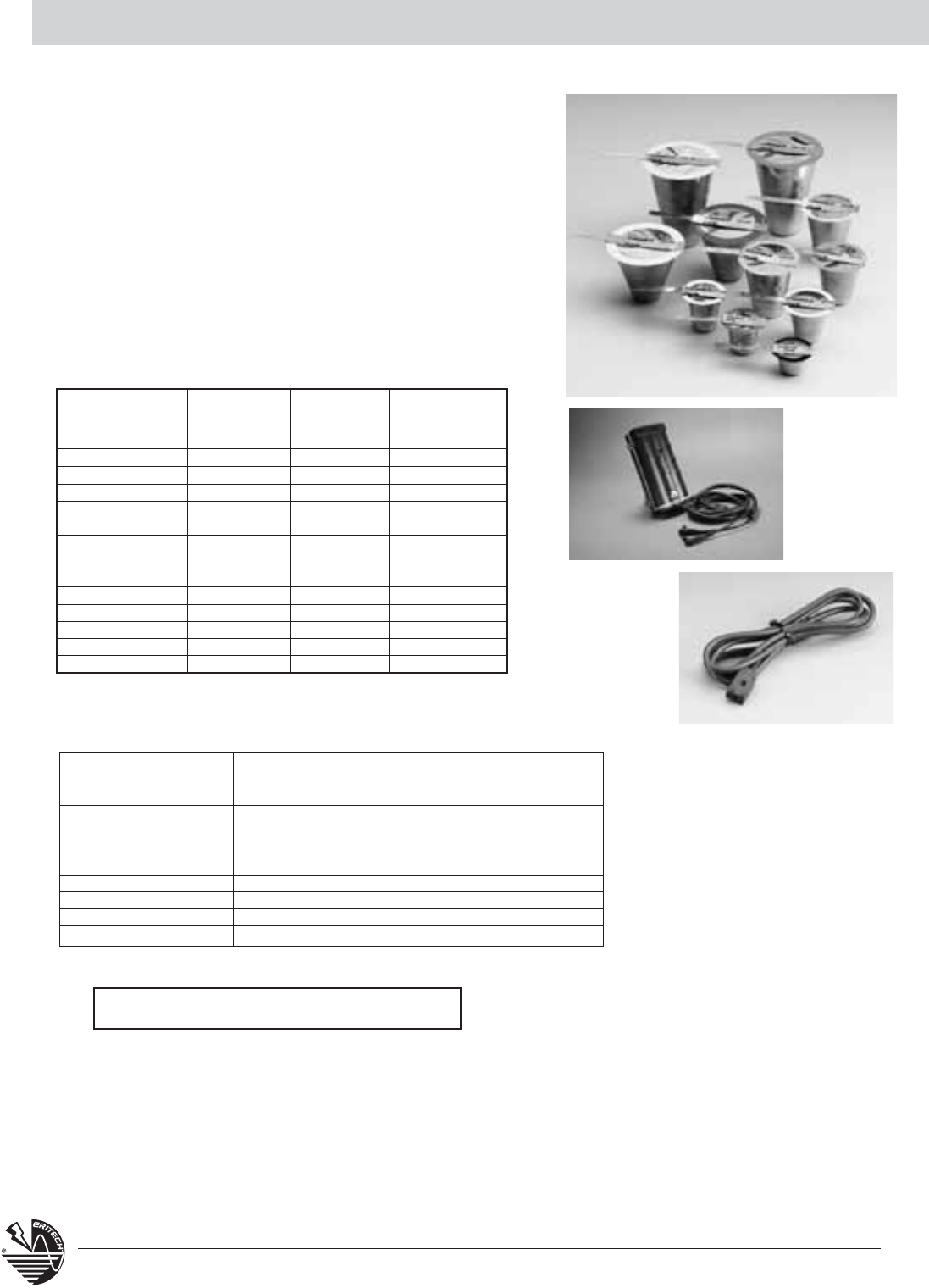
CADWELD®PLUS
The CADWELD®PLUS system:
Installation is Easy!
4 Simple Steps For Permanently Welded Electrical Connections
• Consists of a tamper proof, disposable, moisture-resistant welding
material cup. The welding material, disk and ignition source
are incorporated into the self-contained package
• Long shelf life
• Completes welds at distances of up to 6 ft/1.8 meters
(up to 15 ft/4.6 meters with optional lead)
•
Requires minimum components – no starting material, no disks, no flint igniters
• Easy to handle, store and transport
–
by air, land or sea in unlimited quantities
• Reduces installation time
• Has color-coded welding material containers – by size and alloy type – for easy identification
•
Has electronic ignition with a CE/UL battery powered controller box that is designed for 600 connections
with one set of 8 standard AA batteries (included) – requiring no special batteries or chargers
• Designed for use in standard CADWELD®molds including CADWELD®MULTI
Insert CADWELD PLUS package into mold
(may require use of a cover/baffle)
Press and hold control unit switch
and wait for the ignition
Attach control unit termination
clip to ignition strip
Open the mold and remove the expended
steel cup – no special disposal required
Proven Safety and
Proven Performance
with No Equal
1
2
3
4
CADWELD PLUS Control Unit initiates the reaction
of
the metal crucible. The standard unit includes a
6-foot (1.8 meter)
high
temperature control unit
lead. The lead attaches to the ignition strip using a
custom made, purpose-designed termination clip.
After the termination clip is installed on the ignition
strip, the installer pushes and holds the ignition button
to start a charging
and discharging sequence. Within
a
few seconds the control unit sends a predetermined
voltage to the ignition strip and the reaction is initiated.
44 www.erico.com
PLUSCU
PLUSCULD
European
Article Number
165700
165701
165702
165703
165704
165705
165706
165707
165708
165709
165710
165711
165712
Size Indentification
Ring Color
Black
Red
White
Light Blue
Dark Green
Gray
Orange
Dark Blue
Yellow
Purple
Light Green
Brown
Light Brown
Traditional Welding
Material Part Number
(Clear Cap)
15
25
32
45
65
90
115
150
200
250
use 2 x 150
use 2 x 200
500
CADWELD PLUS
Part Number
15PLUSF20
25PLUSF20
32PLUSF20
45PLUSF20
65PLUSF20n
90PLUSF20
115PLUSF20
150PLUSF20
200PLUSF20
250PLUSF20
300PLUSF20
400PLUSF20
500PLUSF20
CADWELD PLUS for Grounding Applications
Accessories
European
Part
Article
Description
Number
Number
PLUSCU 165738 CADWELD PLUS Control Unit with plug-in, replaceable lead
PLUSCU15L 165745
CADWELD PLUS Control Unit with 15 ft. (4.6 m) plug-in, replaceable lead
MC2X2KIT 165740 Kit, Baffle Cover, Graphite - 2” X 2” Mold
MC25X3KIT 165744 Kit, Baffle Cover, Graphite - 2
1
⁄
2
” X 3” Mold
MC3X3KIT 165741 Kit, Baffle Cover, Graphite - 3” X 3” Mold
MC4X4KIT 165742 Kit, Baffle Cover, Graphite - 4” X 4” Mold
PLUSCULDQC
PLUSCULDQC
Plug-in, Replacement Lead, 6 ft. (1.8 m)
PLUSCULD15QC
PLUSCULD15QC
Plug-in, Replacement Lead, 15 ft. (4.6 m)
Gram weight PLUS weld metal type i.e. 45PLUSF20
CADWELD®PLUS uses the following color
codes and general product nomenclature:
CADWELD PLUS Patent Numbers 6,553,911 6,703,578
CADWELD®PLUS
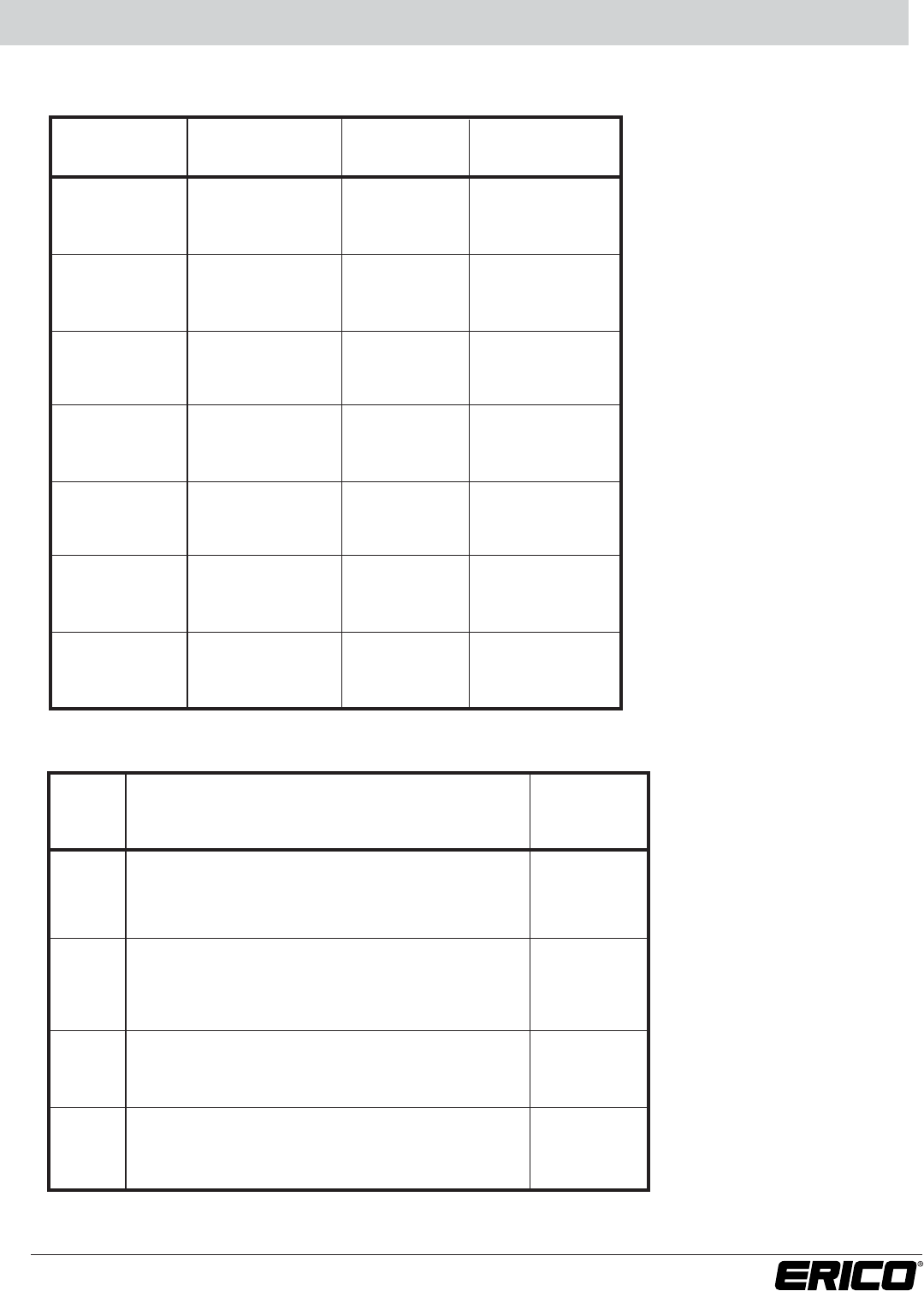
45
www.erico.com
GROUND RODS
CADWELD
Nominal Thread Rod Ground Rod
Size Material Type Size
Diameter
Code
Copper-bonded Sectional 9/16" .505 14
1/2" Steel* Plain – .500 14
Copper-bonded Plain – .475 15
Copper-bonded Sectional 1/2" .447 13
Copper-bonded Sectional 5/8" .563 16
5/8" Steel* Plain – .625 31
Galvanized Steel** Plain – .631 31
Copper-bonded Plain – .563 16
Copper-bonded Sectional 3/4" .682 18
3/4" Steel* Plain – .750 33
Copper-bonded Plain – .682 18
Copper-bonded Sectional 1" .914 22
1" Steel* Plain – 1.00 37
Copper-bonded Plain – .914 22
* Plain steel, stainless steel and stainless steel clad rods.
** Manufactured in accordance with NEMA GR-1.
COPPER-CLAD STEEL CONDUCTORS
CADWELD®Cable Nominal Cross Sectional
Cable Code Stranding Dia. (inches) Area (kcmil)
7Y 3/#10 .220 31.15
7X 3/#9 CW .247 39.28
9Y 3/#8 CW .277 49.53
9A 7/#10 CW .306 72.68
9X 3/#7 CW .311 62.45
9T 7/#9 CW .343 91.65
9W 3/#6 CW .349 78.75
9B 7/#8 CW .385 115.60
9V 3/#5 CW .392 99.31
9C 7/#7 CW .433 145.70
9D 7/#6 CW .486 183.80
9E 7/#5 CW .546 231.71
9F 19/#9 CW .572 248.80
9L 7/#4 CW .613 292.20
9G 19/#8 CW .642 313.70
9H 19/#7 CW .721 395.50
7W 37/#9 CW .801 484.40
9J 19/#6 CW .810 498.80
7V 37/#8 CW .899 610.90
9K 19/#5 CW .910 628.90
9M 37/#7 CW 1.010 770.30
Technical Information
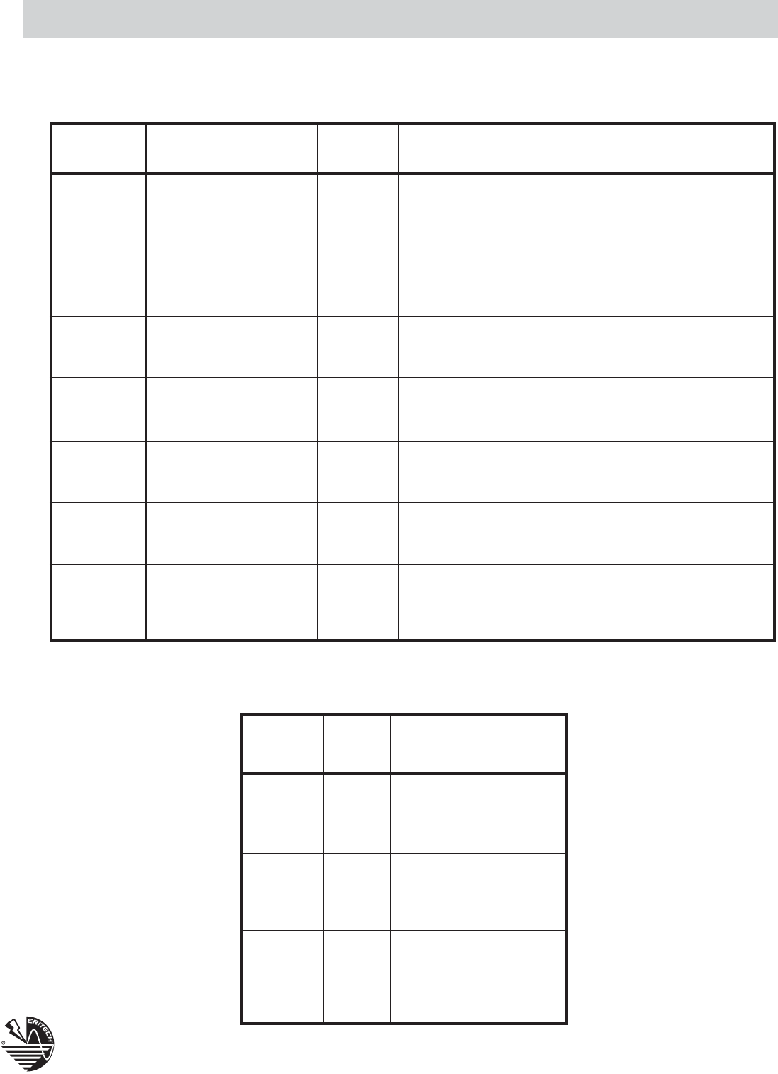
46 www.erico.com
BARE CLASS A, B, AND C CONCENTRIC STRANDED CONDUCTOR
Based on A.S.T.M. Standard Specifications.
CADWELD®Size in Size Conductor NUMBER OF WIRES / Strand Dia. Inches
Cable code Circular mils A.W.G. Dia. In. 7 19 37 61 91
4Y 1,000,000 1.152 .1644* .1280 .1048
4Q 800,000 1.031 .1470* .1145 .0938
4L 750,000 .998 .1424* .1109 .0908
4G 700,000 .964 .1375* .1071 .0877
3X 600,000 .893 .1273 .0992 .0812
3Q 500,000 .813 .1622* .1162 .0905
3H 400,000 .728 .1451 .1040 .0810
3D 350,000 .681 .1357 .0973 .0757
3A 300,000 .630 .1257 .0900 .0701
2V 250,000 .575 .1147 .0822 .0640
2Q 211,600 4/0 .528 .1739 .1055 .0756
2L 167,800 3/0 .470 .1548 .0940 .0673
2G 133,100 2/0 .419 .1379 .0837 .0600
2C 105,500 1/0 .373 .1228 .0745 .0534
1Y 83,690 1 .332 .1093 .0664 .0476
1V 66,370 2 .292 .0974 .0591
1Q 52,630 3 .260 .0867 .0526
1L 41,740 4 .232 .0772 .0469
1H 26,240 6 .184 .0612 .0372
1E 16,510 8 .146 .0486 .0295
1B 10,380 10 .116 .0385 .0234
6,530 12 .092 .0305 .0185
4,110 14 .073 .0242 .0147
* Class AA
BARE SOLID COPPER WIRE
Based on A.S.T.M. Standard Specifications
Cross Sectional
CADWELD Size Area Wire
Cable code A.W.G. Circular Mils Dia. In.
2P 4/0 211,600 .4600
2K 3/0 167,800 .4096
2F 2/0 133,100 .3648
2B 1/0 105,500 .3249
1X 1 83,690 .2893
1T 2 66,370 .2576
1P 3 52,630 .2294
1K 4 41,740 .2043
1G 6 26,250 .1620
1D 8 16,510 .1285
1A 10 10,380 .1019
12 6,530 .0808
14 4,110 .0064
Technical Information
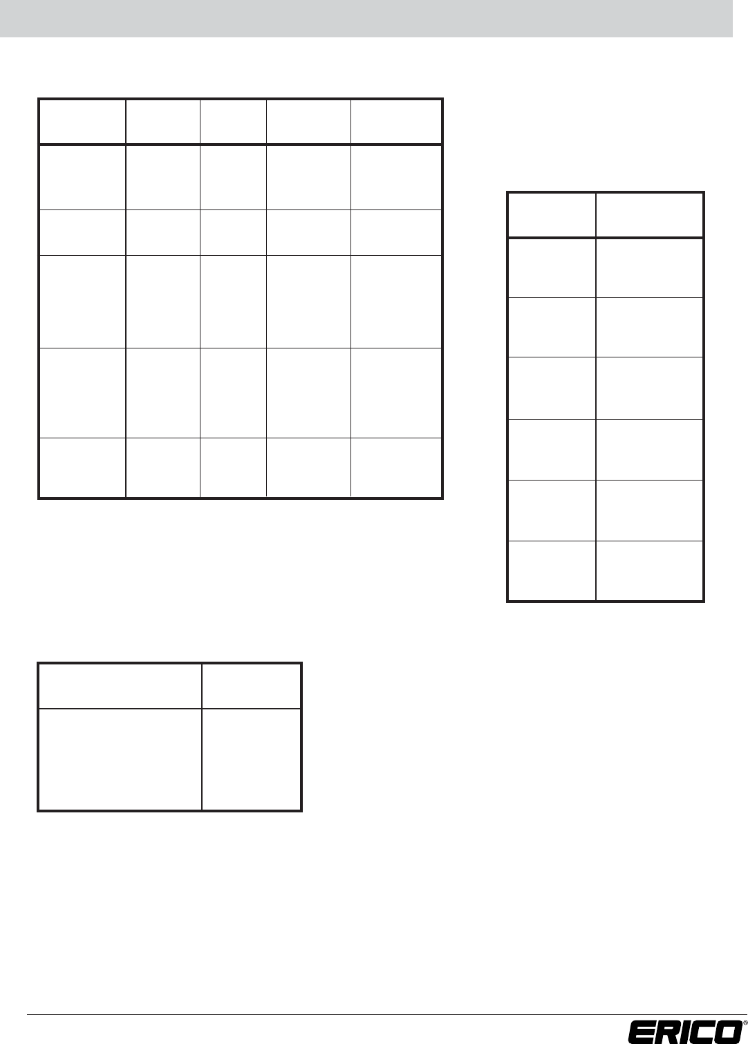
RECTANGULAR COPPER BUSBAR
CADWELD®Thickness Width Circular Weight
Busbar Code Inches Inches Mil Size Lbs. per Foot
CE 1 159,200 .484
CG 1/8 1-1/2 238,700 .726
CH 2 318,300 .969
DE 3/16 1 238,700 .727
DH 2 477,500 1.45
EE 1 318,300 .969
EG 1-1/2 477,500 1.45
EH 1/4 2 636,600 1.94
EK 3 954,900 2.91
EM 4 1,273,000 3.88
GE 1 477,500 1.45
GG 1-1/2 716,200 2.18
GH 3/8 2 954,900 2.91
GK 3 1,432,000 4.36
GM 4 1,910,000 5.81
JH 2 1,273,000 3.88
JK 1/2 3 1,910,000 5.81
JM 4 2,546,000 7.75
CAST IRON PIPE –
CLASS A THRU D
AWWA Specification 1908,
ASA A21.2 Class 100-250.
Nominal Size Actual O.D.
(Inches) (Inches)
4 4.80 to 5.00
6 6.90 to 7.10
8 9.05 to 9.30
10 11.10 to 11.40
12 13.20 to 13.50
14 15.30 to 15.70
16 17.40 to 17.80
18 19.50 to 19.90
20 21.60 to 22.1
24 25.80 to 26.30
30 31.70 to 32.70
36 38.00 to 39.20
42 44.20 to 45.60
48 50.50 to 52.00
54 56.70 to 58.40
60 62.80 to 64.80
72 75.30 to 76.90
84 87.50 to 88.50
Other Standard Sections
used for Fence Posts
CADWELD
Section Mold Code
1-1/2" square PS15
2" square PS20
2-1/2" square PS25
3" square PS30*
1.875 x 1.625 x .133 “H” PH1
2.25 x 1.95 x .143 “H” PH2
* For D or F mold price only
Technical Information
47
www.erico.com
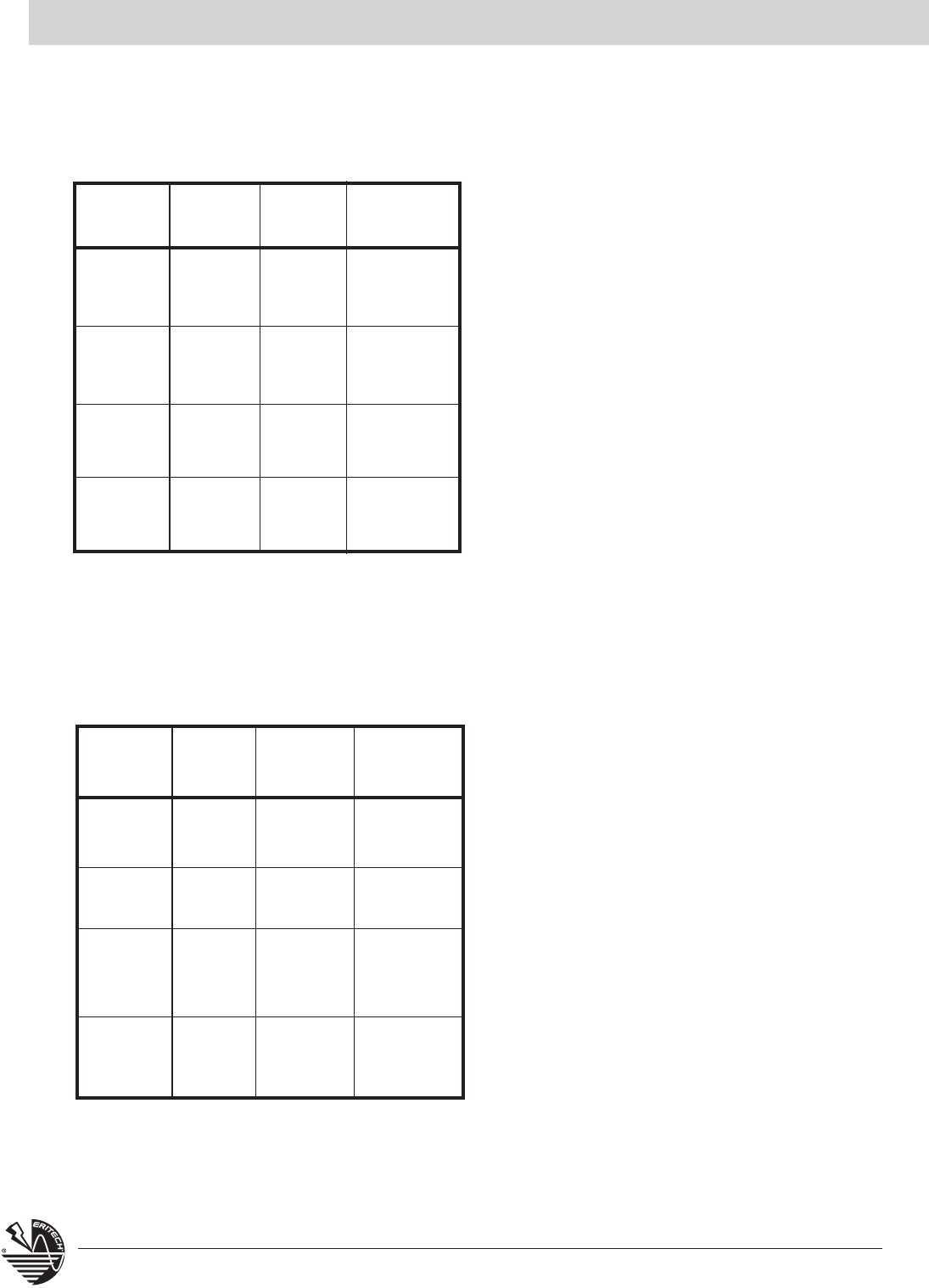
48 www.erico.com
Technical Information
STEEL PIPE SIZES
STANDARD WEIGHT ASTM A53-90-B
(SCHEDULE 40) ANSI/ASME B36.10M-1985
Nominal Wall
Size O.D. Thickness CADWELD
In Inches Inches Mold Code
1 1.315 .133 1
1-1/4 1.660 .140 1.25
1-1/2 1.900 .145 1.50
2 2.375 .154 2
2-1/2 2.875 .203 2.50
3 3.500 .216 3
3-1/2 4.000 .226 3.50
4 4.500 .237 4
5 5.563 .258 5
6 6.625 .280 6
8 8.625 .322 8
10 10.750 .365 10
STANDARD STEEL WIRE GAGE
(WASHBURN MOEN GAGE) SOLID
Gage Dia. Gage Diameter
No. Inches No. Inches
7/0 .4900 6 .1920
6/0 .4615 7 .1770
5/0 .4305 8 .1620
4/0 .3938 9 .1483
3/0 .3625 10 .1350
2/0 .3310 11 .1205
1/0 .3065 12 .1055
1 .2830 13 .0915
2 .2625 14 .0800
3 .2437 15 .0720
4 .2253 16 .0625
5 .2070 17 .0540
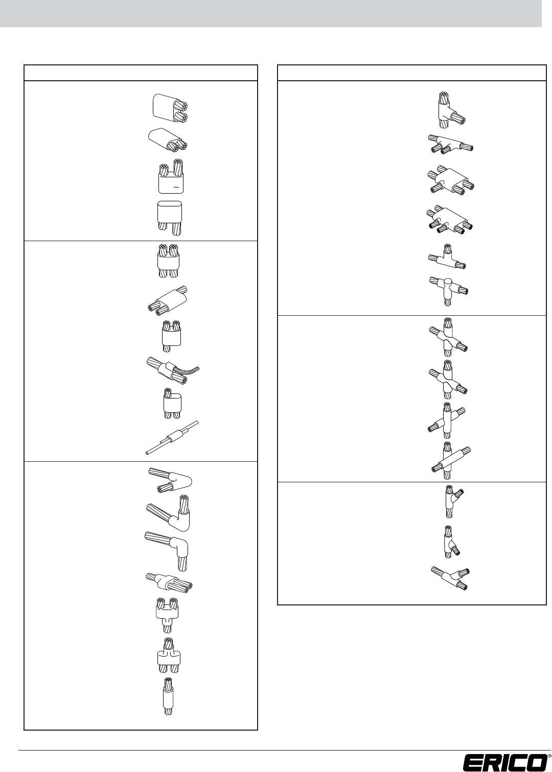
49
www.erico.com
Other Cable to Cable Connections
The connections shown below are for use only where connections shown in this catalog are not suitable.
PJ 1 V
PK 2 *
PM 3 V
PN 3 V
PH 3 V
PA 2 *
PB 3 V
PC 1 V
PD 3 V
PG 1 V
PP 1 *
PQ 3 V
PR 2 V
SC 1 *
SD 3 V
SE 3 V
SV 3 V
NAME TYPE EASE SPLIT
Parallel dead
end
Parallel Tap
Splice
TC 3 V
TD 3 *
TE 3 *
TF 3 V
TL 3 V
TV 3 V
XC 3 V
XD 3 V
XF 3 *
XG 3 *
YC 3 V
YD 3 V
YE 3 V
NAME TYPE EASE SPLIT
Tee
X vertical
(horizontal cable
uncut)
X vertical
(vertical cable uncut)
X vertical
(neither cable cut)
X vertical
(neither cable cut)
X - 45° tap
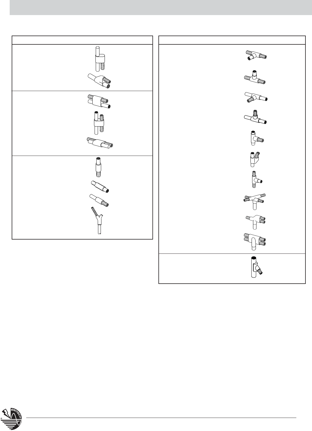
50 www.erico.com
Other Cable to Ground Rods or Other Connections
GQ 3 V
GS 1 V
DQ 1 V
GP 3 V
GW 1 V
GD 3 V
GE 1 V
GF 1 V
GV 1 V
GG 1 *
GH 3 V
GJ 1 *
GK 3 V
GM 2 V
GN 2 V
GX 3 V
NB 4 *
NC 1 V
ND 1 V
VW 2 V
NAME TYPE EASE SPLIT
Parallel tap
Parallel thru
Splice
Tee
NAME TYPE EASE SPLIT
Y - 45° tap
The connections shown below are for use only where connections shown in this catalog are not suitable.
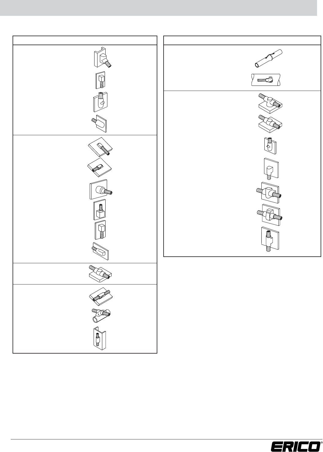
51
www.erico.com
Other Cable to Steel or Cast Iron Connections
The connections shown below are for use only where connections shown in this catalog are not suitable.
VH 1 V
VJ 1 V
VK 1 V
VR 1 V
HF 1 *
HG 2 *
VA 1 V
VC 1 V
VE 2 V
VL 1 V
HE 1 *
HJ 2 *
HK 1 V
VX 2 V
HB 1 *
VN 1 *
HC 1 *
HT 1 V
VF 1 V
VB 2 V
VG 1 V
VT 1
VV 1 V
NAME TYPE EASE SPLIT
Tap cast iron
Tap steel
Thru cast iron
Thru steel
NAME TYPE EASE SPLIT
Pipe
Other connections
to steel
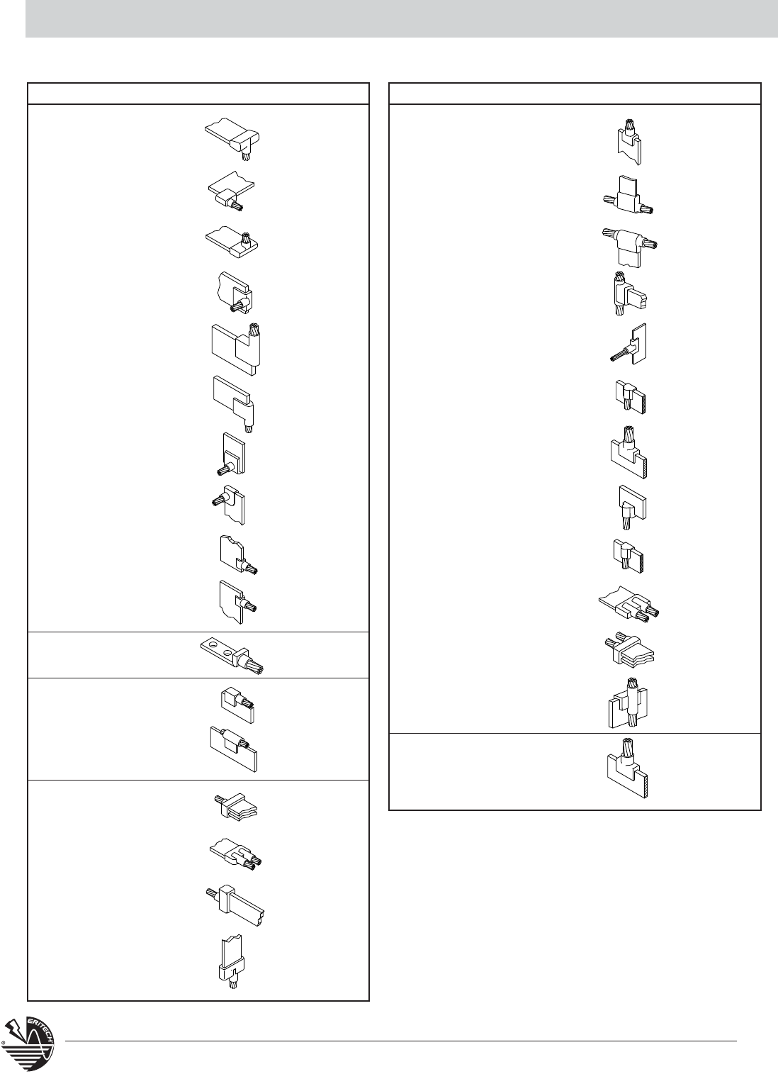
52 www.erico.com
Other Cable to Busbar or Lug Connections
DN 2 V
LX 2 *
LY 3 *
MA 2 *
MB 3 *
MC 3 *
MD 3 *
ME 2 *
MF 3 *
MG 2 V
PL 1 V
LV 1 V
LW 1 V
DM 2 *
DS 2 *
LB 1 V
LC 3 V
NAME TYPE EASE SPLIT
Ell
Lug
Parallel tap
Parallel thru
Splice
Tee
LD 3 V
LF 3 *
LG 3 V
LH 3 *
LK 2 V
LL 1 V
LM 1 V
LN 4 *
LP 2 *
LS 2 *
LT 2 *
LQ 2 V
LR 2 *
NAME TYPE EASE SPLIT
Splice
The connections shown below are for use only where connections shown in this catalog are not suitable.
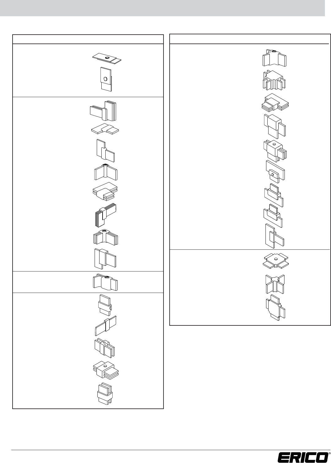
53
www.erico.com
TW 1 *
TX 1 V
DJ 4 V
EN 2 *
EQ 4 V
ER 2 *
ES 3 *
ET 2 V
EV 3 *
EP 1 V
BJ 2 V
BC 3 V
BD 3 *
BF 2 *
BG 2 *
BH 4 V
NAME TYPE EASE SPLIT
Button-weld
Ell
Parallel tap
X
Splice
BK 2 *
BL 3 *
BN 3 *
BR 2 V
BS 2 V
BT 4 *
BV 3 *
DE 3 V
EE 3 V
EA 4 V
EC 4 *
ED 4 V
NAME TYPE EASE SPLIT
Tee
Other Busbar to Busbar Connections
The connections shown below are for use only where connections shown in this catalog are not suitable.
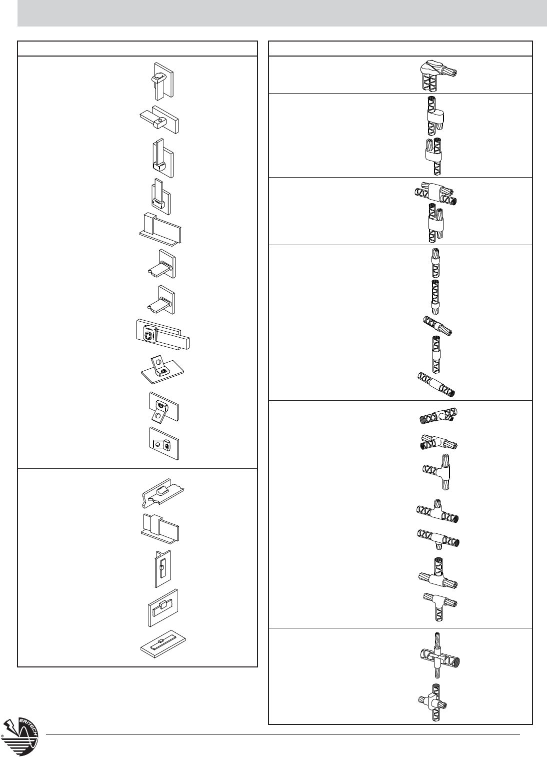
54 www.erico.com
Other Busbar Connections / Other Rebar Connections
CD 3 V
CK 2 V
CF 1 V
CC 1 V
CH 1 V
BX 3 V
BY 3 V
CA 3 V
CB 2 V
CJ 2 V
DC 3 *
DD 3 V
DF 2 V
HL 1 V
HM 1 V
HN 1 *
NAME TYPE EASE SPLIT
Tap
Thru
RK 1 *
RL 2 V
RM 2 V
RN 2 V
RP 2 V
RQ 2 V
XJ 1 *
RC 1 V
DT 2 V
DR 2 V
RV 2 V
RT 2 V
RW 2 V
RE 2 V
RF 2 V
RG 1 V
SF 2 V
SR 1 V
RH 1 *
NAME TYPE EASE SPLIT
Ell
Parallel tap
Parallel thru
X
Splice
Tee
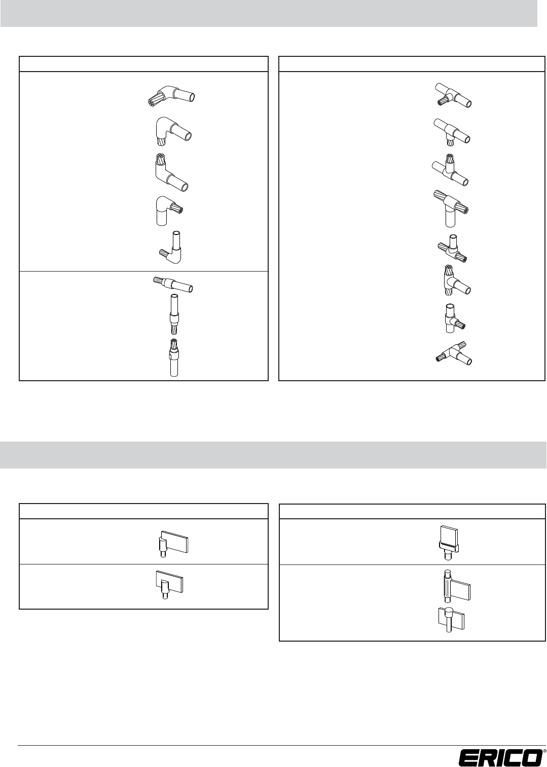
55
www.erico.com
Cable to Copper Tube Connections
DP 1 *
MV 2 V
MW 3 V
MX 2 V
MY 3 V
MH 1 V
MJ 3 V
MK 3 V
NAME TYPE EASE SPLIT
Ell Tee ML 1 *
MM 3 *
MP 3 *
MQ
MR 3 *
MS 3 *
MT 3 *
NA 1 *
NAME TYPE EASE SPLIT
Splice
CL 1 V
CM 3 V
Ell
Tee Tee
Splice CS 3 V
CQ 3 V
CR 1 V
NAME TYPE EASE SPLIT NAME TYPE EASE SPLIT
BUS BAR TO GROUND RODS
The connections shown below are for use only where connections shown in this catalogue are not suitable
The connections shown below are for use only where connections shown in this catalog are not suitable.
Busbar to Ground Rods Connections
The connections shown below are for use only where connections shown in this catalog are not suitable.
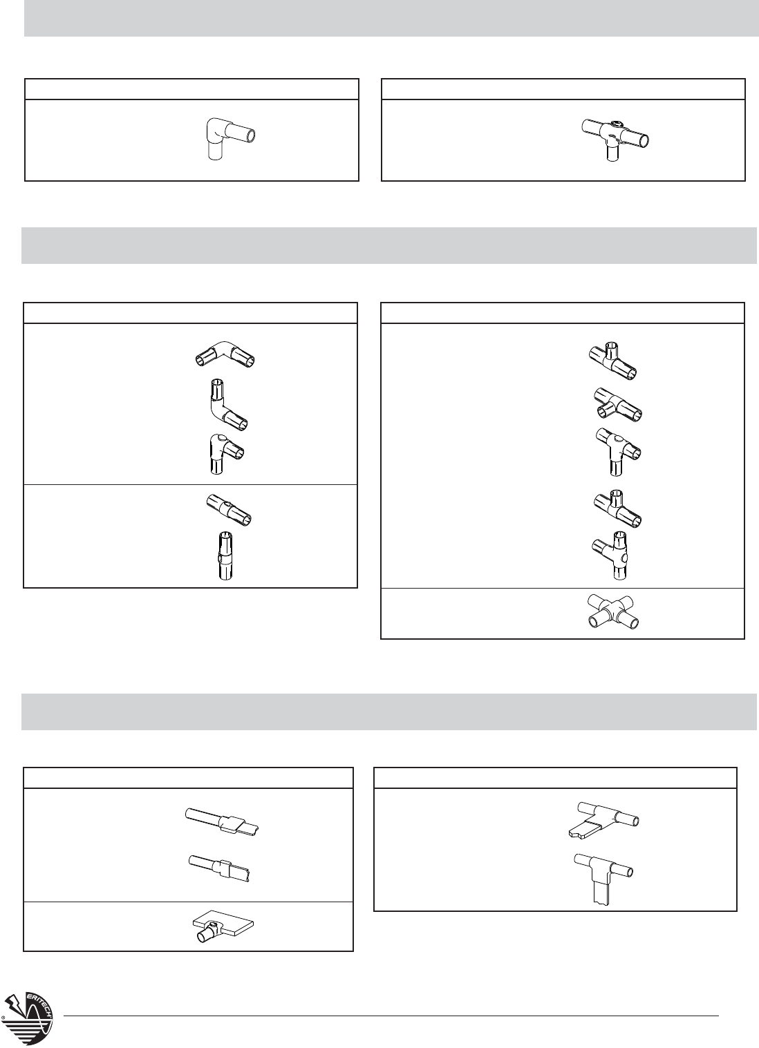
56 www.erico.com
Copper Tube to Ground Rods Connections
The connections shown below are for use only where connections shown in this catalog are not suitable.
Copper Tube to Copper Tube Connections
The connections shown below are for use only where connections shown in this catalog are not suitable.
Copper Tube to Busbar or Lugs Connections
The connections shown below are for use only where connections shown in this catalog are not suitable.
FT 1 V
NAME TYPE EASE SPLIT
Ell FV 1 V
NAME TYPE EASE SPLIT
Tee
FK 1 *
FL 3 V
FM 2 V
FD1 V
FE 3 V
Ell Tee
X
Splice
FH 3 V
FF 1 *
FG 2 V
FH 3 V
FJ 3 V
XT 4 *
NAME TYPE EASE SPLIT NAME TYPE EASE SPLIT
FN 1 *
FP 1 V
EW 2 V
Tee
Tee
Splice FR 2 *
FS 1 V
NAME TYPE EASE SPLIT
NAME TYPE EASE SPLIT
57
www.erico.com
SURGE AND LIGHTNING PROTECTION
ELECTRICAL GROUNDING
and BONDING
Molds & Welding Material
CADWELD® EXOLON – Low Emission
CADWELD®ONE-SHOT – Disposable Molds
Lugs, Tools & Accessories
Ground Rods & Accessories
Chemical Ground Rods
Ground Clamps
Ground Plate Electrodes
Ground Rod Couplings
Ground Rod Drivers
Ground Rods – Copperbonded
Galvanized, Stainless Steel
Bonding Products
Aircraft Ground Receptacles
Bonding Jumpers
Equipment Ground Plates
Equipotential Mesh
Fence & Gate Bonds
Grounding & Bonding Bars
Perimeter Busbars
Personnel Safety Mats
Split Bolts
SRG - Signal Reference Grids
Static Bonding Products
Switch Handle Bonds
TIA / EIA Ground Bars
Water-Pipe Clamps
Miscellaneous Grounding Products
GEM Ground Enhancement Material
Ground Inspection Wells
Ground Test Instruments
Grounding Conductor
LIGHTNING PROTECTION
Lightning Protection Products
ERITECH®SYSTEM 2000
– Conventional Lightning Protection
ERITECH® SYSTEM 3000
– Active Lightning Protection
Lightning Warning System
Industrial Stack Protection
Support Equipment
Air Terminals, Bases, Conductors, Masts
Fasteners & Fittings
SURGE PROTECTION
Surge Protection Products
Service Entrance
OEM Protection Components
Data & Signal Line Protection
Load Cell Protection
Branch Panel
Complete Home Protectors
Telecommunication Shelter Protection
Automation & Control Protection

AutoCad is a registered trademark of Autodesk, Inc.
Copperweld is a registered trademark of Copperweld Corporation
IEEE is a registered trademark of The Institute of Electrical and Electronics Engineers, Inc.
NEC is a registered trademark of National Fire Protection Association, Inc.
NEMA is a registered trademark of National Electrical Manufacturers Association
Surefire is a registered trademark of Newell-Rubbermade Company
Copyright ©2009 ERICO International Corporation. All rights reserved.
CADDY, CADWELD, CRITEC, ERICO, ERIFLEX, ERITECH, and LENTON are registered trademarks of ERICO International Corporation. E815C-WWEN E1277CT09WWEN 012WB9
AUSTRALIA
Phone 1-800-263-508
Fax 1-800-423-091
BELGIUM
Phone 0800-757-48
Fax 0800-757-60
CANADA
Phone +1-800-677-9089
Fax +1-800-677-8131
CHILE
Phone +56-2-370-2908
Fax +56-2-369-5657
DENMARK
Phone 808-89-372
Fax 808-89-373
FRANCE
Phone 0-800-901-793
Fax 0-800-902-024
GERMANY
Phone 0-800-189-0272
Fax 0-800-189-0274
HONG KONG
Phone +852-2764-8808
Fax +852-2764-4486
HUNGARY
Phone 06-800-16538
Fax +39-0244-386-107
INDONESIA
Phone +62-21-575-0941
Fax +62-21-575-0942
ITALY
Phone 800-870-938
Fax 800-873-935
MEXICO
Phone +52-55-5260-5991
Fax +52-55-5260-3310
NETHERLANDS
Phone 0800-0200-135
Fax 0800-0200-136
NORWAY
Phone 800-100-73
Fax 800-100-66
SINGAPORE
Phone +65-6-268-3433
Fax +65-6-268-1389
SPAIN
Phone 900-993-154
Fax 900-807-333
SWEDEN
Phone 020-790-908
Fax 020-798-964
SWITZERLAND
Phone 0800-55-86-97
Fax 0800-55-96-15
THAILAND
Phone +66-2-267-5776
Fax +66-2-636-6988
UNITED KINGDOM
Phone 0808-2344-670
Fax 0808-2344-676
UNITED STATES
Phone 1-800-753-9221
Fax +1-440-248-0723
POLAND
Phone +48-71-349-04-60
Fax +48-71-349-04-61
BRAZIL
Phone +55-11-3623-4333
Fax +55-11-3621-4066
www.erico.com
CHINA
Phone +86-21-3430-4878
Fax +86-21-5831-8177
UNITED ARAB
EMIRATES
Phone +971-4-881-7250
Fax +971-4-881-7270
