Data Sheet S85001 0589 Rate Compensation Heat Detectors Brochure
111623-Catalog 111623-Catalog 111623-Catalog Batch9 unilog cesco-content
2014-09-27
: Pdf 121291-Brochure 121291-Brochure 793017 Batch8 unilog
Open the PDF directly: View PDF ![]() .
.
Page Count: 4
Page 1 of 4 DATA SHEET S85001-0589
Not to be used for installation purposes. Issue 2
Edwards Signaling Catalog u Conventional Initiating
06-27-13
MEA
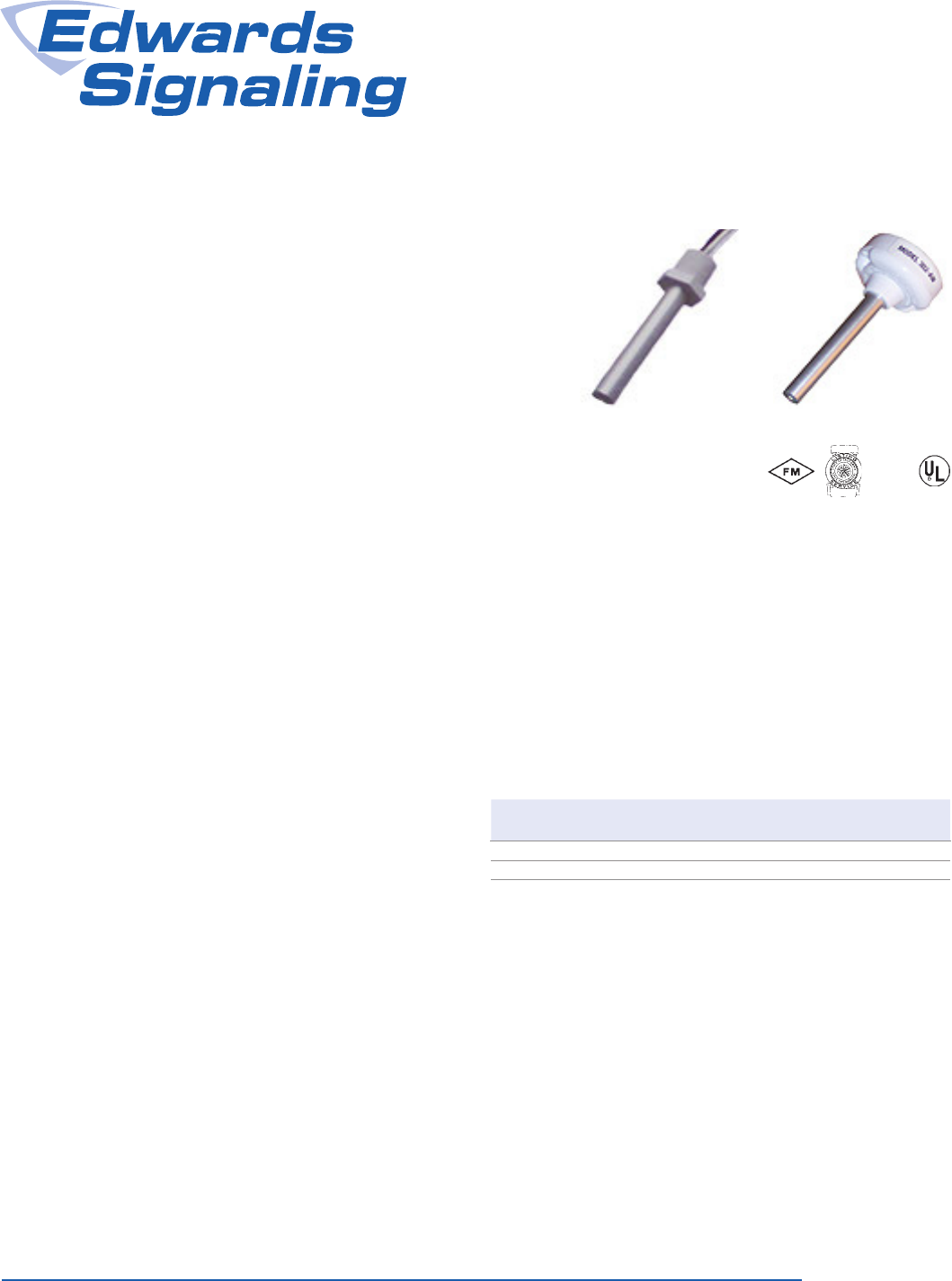
Rate Compensation
Heat Detectors
302 Series
Box mount Surface Mount
Overview
Series 302 heat detectors are designed for use in normal environ-
ments as well as environments where the detectors are subject to
weather, moisture (internal condensation), and explosive atmo-
spheres. They are normally-open devices designed to close an
electrical circuit upon activation. All models feature rate compen-
sation and are available with either 135 °F (57.2 °C) or 194 °F (90
°C) ratings. They are self restoring, hermetically sealed, shock and
corrosion resistant, and are tamperproof.
Standard Features
• Rate compensation offsets thermal lag
• Self-restoring – no manual reset required
• Explosion proof and weatherproof models available
• Weatherproof models available that do not require a special
backbox
• Box mount and surface mount models available
Application
Sensors rated at 135 °F (57.2 °C) will not respond to momentary
temperature fluctuations less than 30 °F/minute between 60 °F
(16 °C) and 100 °F (38 °C). Sensors rated at 194°F (90 °C) will not
respond to momentary temperature fluctuations less than 50 °F/
minute between 60 °F (16 °C) and 150 °F (66 °C). 302 Series sen-
sors should not be used in environments where conditions exceed
these parameters. Do not install them in hot air ducts, in front of
heaters, in paint booths that use heat to cure paint, or any other
location subject to temperature fluctuation.
Sensor’s Rated
Temperature
Minimum Ambient
Air Temperature
Maximum Ceiling
Temperature
135 °F (57.2 °C) -40 °F (-40 °C) 100 °F (38 °C)
194 °F (90 °C) -40 °F (-40 °C) 150 °F (66 °C)
The sensor's aluminum tube acts as a heat collector when sourc-
es of heat radiate directly on the tube. Install these sensors out of
direct sunlight and away from radiating heat sources including the
direct flow from heaters and heat ducts.
Page 2 of 4 DATA SHEET S85001-0589
Not to be used for installation purposes. Issue 2
Typical Wiring
Black
302 Series Detectors
White
End of
Line
Resistor
To control
panel or
next device
Electrical Rating
Voltage Current
6-125 VAC 5 amps
6-25 VDC 1 amp
125 VDC 0.5 amp
Maintenance
302 Series heat sensors are low maintenance. Sensors automati-
cally restore when temperatures drop below their rated tempera-
tures. The accumulation of dust and dirt does not normally affect
the sensors’ operation.
Testing
Testing for operation is simple and can be done before or after the
sensor has been installed. Heat the sensor with a hair dryer (do
not use any device with an open flame to test sensors). The sen-
sor should operate shortly after the hot air is applied.
Refer to NFPA 72, National Fire Alarm Code and/or the local
authority having jurisdiction to determine testing frequency, record
keeping, and other testing considerations.
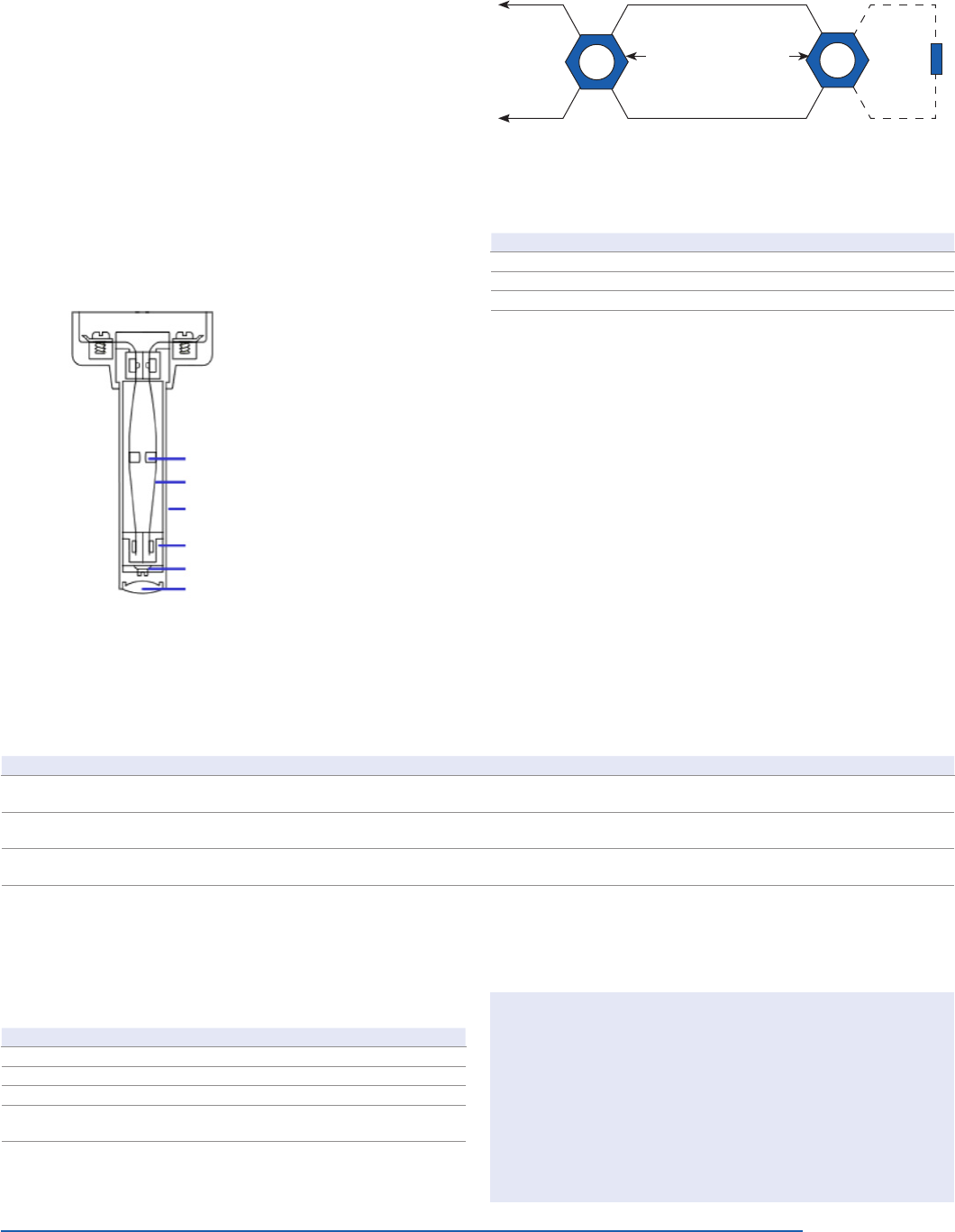
Rate Compensation
302 Series sensors feature rate compensation, which improves
performance by offsetting thermal lag, an inherent property of
conventional fixed temperature heat sensors.
A slow rate of temperature rise allows the heat to penetrate the
inner expansion struts. The tubular shell and the struts expand
slowly until the total device has been heated to its rated tempera-
ture level of 135 °F (57.2 °C) or 194 °F (90 °C). At this point, the
silver contact points close and an alarm is initiated.
When subjected to a rapid rate temperature rise, there is not as
much time for heat to penetrate the inner strut. However, the rapid
lengthening of the shell allows the struts to come together at a
lower level.
When the surrounding air temperature returns to below the rated
level, the shell contracts, forcing the contacts to open, thus auto-
matically resetting the sensor.
Fine silver contact
Expansion struts
High expansion sensing
shell, 0.040 anodized aluminum
Heat control sleeve
Setting screw
Devcon hermetic seal
WARNING – Use For Property Protection Only: Heat detectors do not protect life against fire
and smoke. In most fires, hazardous levels of smoke, heat and toxic gases can build up before a
heat sensor would initiate an alarm. Independent studies indicate that heat sensors should only
be used when property protection alone is involved. In cases where life safety is a factor, the use
of smoke detectors is recommended.
Under no circumstances should heat detectors be relied upon as the sole measure to ensure fire
safety. However, if they are spaced in accordance with the specifications found under Application,
these sensors can contribute, within an overall fire safety program, to reducing the risk of avoid-
able property losses.
When used with automatic fire suppression systems such as pre-action and deluge sprinkler
systems, carbon dioxide systems, halon systems, and dry chemical systems, at least two sen-
sors should be used to initiate the alarm. This is commonly referred to as cross-zoning or priority
matrix zoning and is necessary to eliminate premature discharge of the system. Refer to NFPA 72
for more information.
Detector Spacing
Model 302 302-AW 302-ET 302-EPM
UL- Vertical Spacing
(all models)
50' x 50'
(15.2 x 15.2 m)
50' x 50'
(15.2 x 15.2 m)
50' x 50'
(15.2 x 15.2 m)
40' x 40'
(12.2 x 12.2 m)
UL- Horizontal Spacing
(all models)
40' x 40'
(12.2 x 12.2 m)
40' x 40'
(12.2 x 12.2 m)
40' x 40'
(12.2 x 12.2 m)
30' x 30'
(9.1 x 9.1m)
FM - Horizontal
or vertical spacing.*
30' x 30'
(9.1 x 9.1m)
30' x 30'
(9.1 x 9.1m)
30' x 30'
(9.1 x 9.1m) Not Listed
Spacing is based on smooth ceilings that are up to 10' (3 m) high. Refer to NFPA 72 for ceilings that are not considered smooth or are higher than 10' (3
m).
* EPM models are not FM approved.
Dimensions
Model ET EMP
Tube Length 3" (76.2 mm) 3" (76.2 mm)
Tube Diameter 0.5" (12.7 mm) 0.5" (12.7 mm)
NPT Thread 0.5" (12.7 mm) 0.5" (12.7 mm)
Hex Base 1" (25.4 mm) plastic 1.25" (31.75 mm)
brass
Page 3 of 4 DATA SHEET S85001-0589
Not to be used for installation purposes. Issue 2
Ordering Information
Interior applications Ship Wt.
302-135
Heat Detector - Rate Compensation, Interior
Vertical Surface Mount FM & UL, 135 °F (57.2
°C)
For interior mounting. 0.2 lb. (0.09
kg)
302-194
Heat Detector - Rate Compensation, Interior
Vertical Surface Mount FM & UL, 194°F (90
°C).
Moisture & dust proof applications Ship Wt.
302-AW-135
All-weather Heat Detector - Rate
Compensation, Vertical Mounting FM & UL,
135 °F (57.2 °C)
Hermetically sealed for moisture proof
or dust proof installations. Requires no
special back box when the all-weather
leads are properly spliced to “THW”
or equivalent type wire and splices are
moisture proof. For indoor or outdoor
use.
0.2 lb. (0.09
kg)
302-AW-194
All-weather Heat Detector - Rate
Compensation, Vertical Mounting FM & UL,
194°F (90 °C)
Moisture & dust proof applications (box mount) Ship Wt.
302-ET-135
All-weather Heat Detector - Rate
Compensation, Vertical, Box Mount (½"
NPT), FM & UL, 135 °F (57.2 °C). Requires
STONCO27 or equivalent.
Hermetically sealed for moisture proof
or dust proof installations. Requires no
special back box. Has plastic hexagonal
grip bushing with ½" conduit threads
for attachment to threaded hub cover,
or any outlet box. For indoor or outdoor
use when watertight seal is required,
use weatherproof box.
0.2 lb. (0.09
kg)
302-ET-194
All-weather Heat Detector - Rate
Compensation, Vertical, Box Mount (½"
NPT), FM & UL, 194°F (90 °C). Requires
STONCO27 or equivalent.
Explosion proof applications Ship Wt.
302-EPM-
135
Heat Detector - Rate Compensation,
Explosionproof Mounting UL (Not FM
approved), 135 °F (57.2 °C). RequiresJALX-11
or equivalent
Explosion proof for installation in
hazardous locations. Has hexagonal
grip bushing with ½" conduit threads for
attachment to threaded hub covers of
series JL fixture fitting manufactured by
Killark Electric Co., or equivalent. Must
be hand tightened only. For indoor use
only.
0.3 lb. (0.14
kg)
302-EPM-
194
Heat Detector - Rate Compensation,
Explosionproof Mounting UL (not FM
approved), 194°F (90 °C). RequiresJALX-11
or equivalent.
Adapter plate Ship Wt.
AP-P Decorative white plastic adaptor plate for mounting 302 and 302-AW to any 3" outlet box
or 4" octagon outlet box.
0.1 lb. (0.05
kg)
Outlet body Ship Wt.
STONCO27 3 ½" Weatherproof, round backbox and cover (½" thread hubs back, four sides and cover) 3.0 lb. (1.4 kg)
Explosion proof outlet body Ship Wt.
JALX11 Explosion proof outlet body with cover (½" thread hubs back, four sides and cover) - Killark 3.5 lb. (1.6 kg)

Page 4 of 4 DATA SHEET S85001-0589
Not to be used for installation purposes. Issue 2
06-27-13
Contact us...
Phone: 1-800-336-4206
Web: www.edwardssignaling.com
Edwards Signaling is
an EDWARDS brand.
3 Farm Glen Boulevard
Farmington, CT 06032
In Canada, contact Chubb Edwards...
Email: inquiries@chubbedwards.com
Web: www.chubbedwards.com
© 2013 UTC Fire & Security Americas
Corporation, Inc. All rights reserved.
Specifications subject to change
without notice. Edwards is part of UTC
Climate, Controls & Security, a unit of
United Technologies Corporation.
