SSAC ECS Series Current Sensors Data Sheet Brochure
2016-10-06
: Pdf 124237-Brochure 124237-Brochure B5 unilog
Open the PDF directly: View PDF ![]() .
.
Page Count: 2
Current
Sensors &
Monitors
8.4 Low Voltage Products & Systems
1TRC 001 009 C0202 ABB Inc. • 888-385-1221 • Technical assistance 800-377-7722 • www.ssac.com
Accessories
Description
The ECS Series of Single Phase AC Current Sensors is a universal, overcurrent or undercurrent sensing control.
Its built-in toroidal sensor eliminates the inconvenience of installing a stand-alone current transformer. Includes
onboard adjustments for current sensing mode, trip point, and trip delay. Detects over or under current events like
locked rotor, loss of load, an open heater or lamp load, or proves an operation is taking place or has ended.
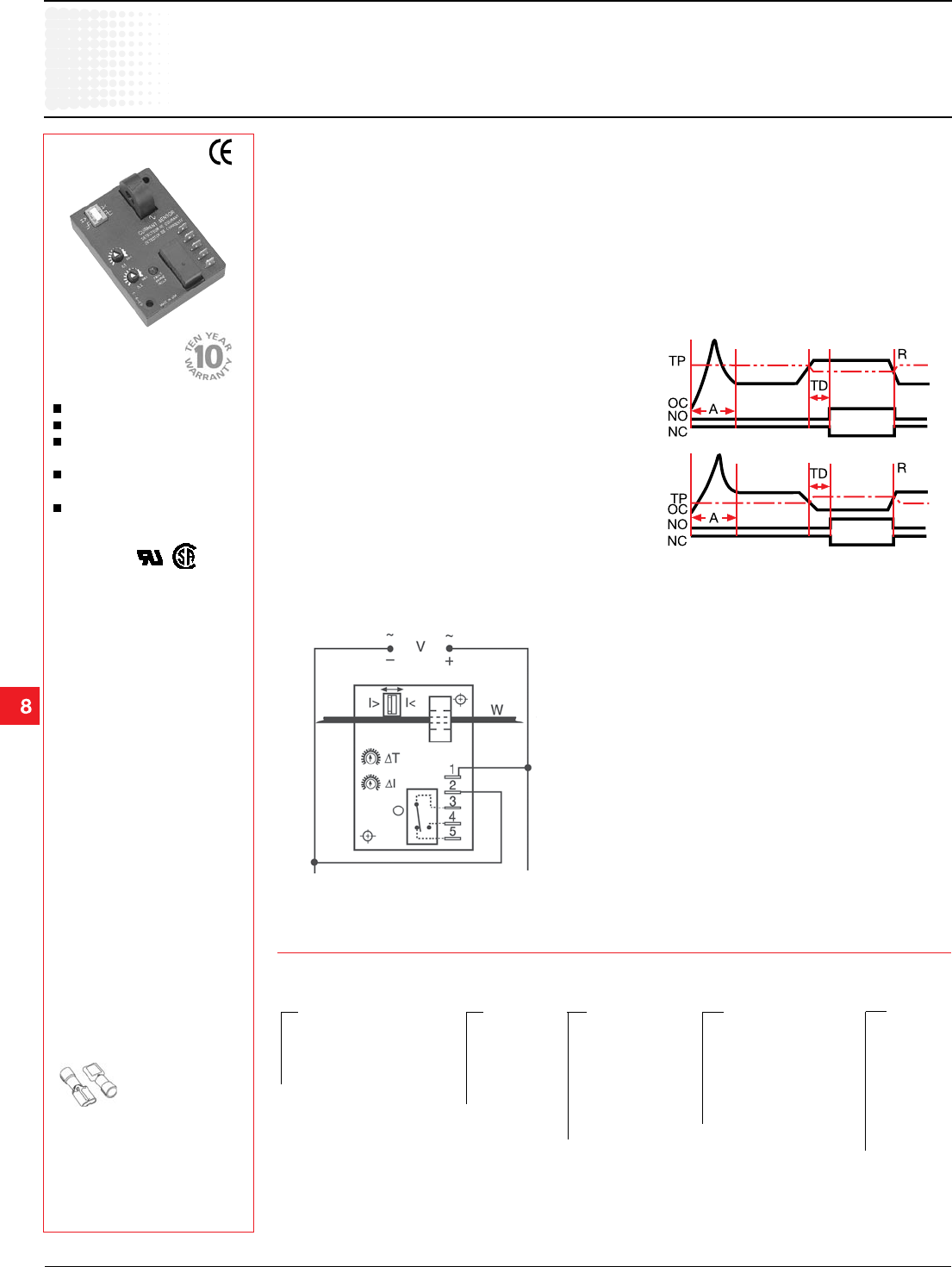
Operation
Input voltage must be supplied at all times for proper
operation. When a fault is sensed throughout the trip
delay, the output relay is energized. When the current
returns to the normal run condition, the output and the
delay are reset. If a fault is sensed and then corrected
before the trip delay is completed, the relay will not
energize and the trip delay is reset to zero.
Adjustment
Select the desired function, over or under current
sensing. Set the trip point and trip delay to approximate
settings. Apply power to the ECS and the monitored
load. Turn adjustment and watch the LED. LED will
light; turn slightly in opposite direction until LED is off.
Adjustment can be done while connected to the control
circuitry if the trip delay is set at maximum.
See accessory pages for
specifications.
Toroidal Through Hole Wiring
0.5...50 A Trip Point
Adjustable or Factory Fixed
Trip Delays
10 A SPDT Isolated Output
Contacts
5% Trip Point Hysteresis
(Dead Band)
Approvals:
Over/Under Current Sensing
ECS Series
Current Sensor
Connection
Example P/N:
Function
TP = Trip Point R = Reset OC = Monitored Cur
rent
NO = Normally Open Contact NC = Normally
Closed Contact A = Sensing Delay On Start Up
TD = Trip Delay
Overcurrent
Undercurrent
Relay contacts are isolated.
Dashed lines are internal connections.
–A - 0.150 ... 7 s
–B - 0.5 ... 50 s
–0 - 0.5 ... 5 A
–1 - 2 ... 20 A
–H - 5 ... 50 A
Fixed -
Specify 2 ... 50 A
in 1 A increments
–1 - 12 V DC
–2 - 24 V AC
–3 - 24 V DC
–4 - 120 V AC
–6 - 230 V AC
Input Trip Point Trip Delay Sensing Delay
on Start up
–F - Factory Fixed:
Adjustable Ranges Adjustable Ranges
Specify .08 ... 50 s
ECS41AC Fixed – ECSH610AD
–ECS -(selectable over or
under current sensing)
–ECSH -(overcurrent sensing)
–ECSL - (undercurrent sensing)
X
Series
Female quick connect
P/Ns:
P1015-13
(AWG 10/12)
P1015-64
(AWG 14/16)
P1015-14
(AWG 18/22)
V = Voltage I> = Overcurrent I< = Undercurrent
W = Insulated Wire Carrying Monitored Current
Ordering Table
–Blank - 0 s
–C - 1 s
–D - 2 s
–E - 3 s
–F - 4 s
–G - 5 s
–H - 6 s
X X X X
ECS02B01 12.28.04
Current
Sensors &
Monitors
Low Voltage Products & Systems 8.5
ABB Inc. • 888-385-1221 • Technical assistance 800-377-7722 • www.ssac.com 1TRC 001 009 C0202
Technical Data
Over/Under Current Sensing
ECS Series
Current Sensor
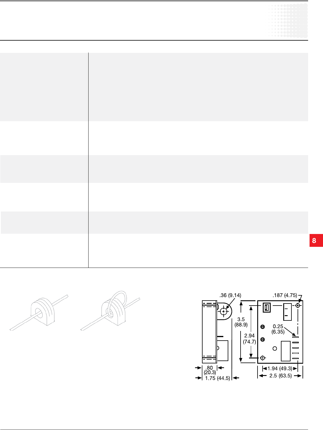
Mechanical View
Inches (Millimeters)
Multiple Turns To Increase Sensitivity
To increase sensitivity, multiple turns may be made through the ECS’s toroidal
sensor. The trip point range is divided by the number of turns through the
toroidal sensor to create a new range.
Using an External Current Transformer (CT)
Select a 2 VA, 0 to 5 A output CT, rated for the current to be monitored. Select
ECS adjustment range 0. Pass the CT’s secondary wire lead through the ECS’s
toroid and connect both ends together.
Sensor
Type Toroidal, through hole wiring
Mode Over or under current, switch selectable on the unit or factory fixed
Trip Point Range 0.5 ... 50 A in 3 adjustable ranges or fixed
Tolerance: Adjustable Guaranteed range
Fixed 0.5 ... 25 A: 0.5 A or +/-5% whichever is less; 26 ... 50 A: +/-2.5%
Maximum Allowable Current
Steady – 50 A turns; Inrush – 300 A turns for 10 s
Trip Point Hysteresis ≅+/-5%
Trip Point vs. Temperature +/-5%
Response Time ≤ 75 ms
Frequency 45 ... 500 Hz
Type of Detection Peak detection
Trip Delay
Type Analog
Range: Adjustable 0.150 ... 7 s; 0.5 ... 50 s (Guaranteed ranges)
Factory Fixed 0.08 ... 50 s (+/-10%)
Delay vs. Temperature +/-15%
Sensing Delay on Startup Factory fixed 0 ... 6 s: +40% ... 0%
Input
Voltage 24 , 120, or 230 V AC; 12 or 24 V DC
Tolerance 12 V DC & 24 V DC/AC -15% ... +20%
120 & 230 V AC -20% ... +10%
Line Frequency 50 ... 60 Hz
Output
Type Electromechanical relay
Form Isolated single pole double throw (SPDT)
Rating 10 A resistive at 240 V AC; 1/4 hp at 125 V AC; 1/2 hp at 250 V AC
Life Mechanical – 1 x 10⁶ ; Electrical – 1 x 10⁵
Protection
Circuitry Encapsulated
Isolation Voltage ≥ 2500 V RMS input to output
Insulation Resistance ≥ 100 MΩ
Mechanical
Mounting Surface mount with two #6 (M3.5 x 0.6) screws
Termination
0.25 in. (6.35 mm) male quick connect terminals (5)
Humidity 95% relative, non-condensing
Operating/Storage Temperature -40°C ... +60°C / -40°C ... +85°C
Weight ≅ 6.4 oz (181 g)
ECS02B01 12.28.04
