01 PCP 1 125384 Catalog
98609-Catalog 98609-Catalog 98609-Catalog 785901 Batch7 unilog cesco-content
2016-09-04
: Pdf 125384-Catalog 125384-Catalog B4 unilog
Open the PDF directly: View PDF ![]() .
.
Page Count: 242 [warning: Documents this large are best viewed by clicking the View PDF Link!]

Automation and Control
The Essential Guide
$ 7.00
CONTENTS
Description Page
Motor Control . . . . . . . . . . . . . . . . . . . . . . . . . . . . . . . . . . . . . . . . . . . . . . . . . . . . . 1 -2
AC Drives . . . . . . . . . . . . . . . . . . . . . . . . . . . . . . . . . . . . . . . . . . . . . . . . . . . . . . . 2 - 2
Machine Control . . . . . . . . . . . . . . . . . . . . . . . . . . . . . . . . . . . . . . . . . . . . . . . . . . 3 - 2
Operator Interface . . . . . . . . . . . . . . . . . . . . . . . . . . . . . . . . . . . . . . . . . . . . . . . . . 4 - 2
Machine Sensing . . . . . . . . . . . . . . . . . . . . . . . . . . . . . . . . . . . . . . . . . . . . . . . . . 5 - 2
Programmable Logic Control . . . . . . . . . . . . . . . . . . . . . . . . . . . . . . . . . . . . . . . . 6 - 2
Human Machine Interface . . . . . . . . . . . . . . . . . . . . . . . . . . . . . . . . . . . . . . . . . . . 7 - 2
AS-I Networking . . . . . . . . . . . . . . . . . . . . . . . . . . . . . . . . . . . . . . . . . . . . . . . . . . 8 - 2
Machine Safeguarding . . . . . . . . . . . . . . . . . . . . . . . . . . . . . . . . . . . . . . . . . . . . . 9 - 2
Motion . . . . . . . . . . . . . . . . . . . . . . . . . . . . . . . . . . . . . . . . . . . . . . . . . . . . . . . . . 10 - 2
Catalog
04

The Te
Sys
range makes you a full part of it,
offering you ever greater…
■ simplicity…
■ compactness…
■ transparency…
■ flexibility…
* Simply Smart : using ingenuity and intelligence to continually improve ease of use.
Power control
and protection
The essential guide
A simplified selection
guide that allows you to
quickly select the
components you need to
build your motor starters
and controllers.
A range of simple,
compact and advanced
components for power
control and protection.
Welcome to the Simply Smart* world,
compliments of Telemecanique
New horizons are opening up to you.
Increase your productivity - adopt our solutions which help to
simplify selection and implementation.
Motor starters
Ready-to-use component combinations, designed to work together
in perfect harmony.
Best operation and level of coordination guaranteed by a major
manufacturer.
Motor controllers
Application-based selection guides allowing fast selection from a
wide range of components.
Solutions for a variety of power control applications: lighting,
capacitor switching, heating, changeover contactor pairs, resistive
loads, upstream protection.
Te
Sys
for a new start
Motor control components
Te
Sys
control relays ___________________________ 1-2
■ CA2K and CA3K Relays
■ CAD Relays
Te
Sys
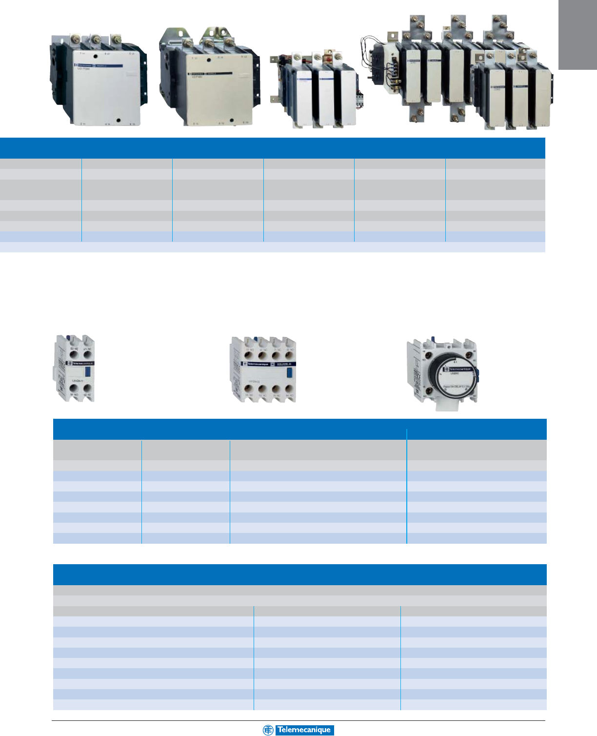
contactors ______________________________ 1-5
■ K-line (6–12 amperes)
■ D-line (12–150 amperes)
■ F-line (115–800 amperes)
Te
Sys
manual motor starters & protectors ______
1-14
■ GV2ME and GV2P (1–32 amperes)
■ GV3M (1–80 amperes)
■ GV7R (20–220 amperes)
Disconnect Switches _________________________ 1-20
■ Type GS1 (Fused 30–800 amperes)
■ Type LK3 (Unfused 30–1200 amperes)
Overload and Protective Relays _________ 1-22
■ Type K (for use on K-line contactors)
■ Type D (for use on D-line contactors)
■ Type F (for use on F-line contactors)
■ Thermistor Probe Relays (Type LT3)
Manual Motor Control Switches _____________ 1-26
■ Mini Vario (10–20 amperes)
■ Vario (10–115 amperes)
Te
Sys
Motor Starters _________________________ 1-28
■ U-line (0–32 amperes)
NEMA Type
Contactors and starters _______________________________ 1-30
Combination starters__________________________________ 1-32
Solid state overload relays _____________________________ 1-36
Definite purpose contactors ____________________________ 1-38
Lighting contactors ___________________________________ 1-40
Manual starters and switches ___________________________ 1-41
Accessories and replacement parts ______________________ 1-44
Industrial control relays ________________________________ 1-46
Operating mechanisms, circuit breaker & disconnect switch ___ 1-47
Protection systems
Circuit breakers and relays _____________________________ 1-50
MOTOR
CONTROL
Contents
1-2
MOTOR
CONTROL
www.telemecanique.com For additional options and information, reference catalog 8501CT0101.
IEC type
industrial
control relays
Te
Sys
® Type CA2K, CA3K and CA4K
CA2-K control relays (0.8–1.15 Uc)
(0.85–1.1UC)
Volts ac, 50/60 Hz 12 24 36 42 48 110 120 127 208
220/230
230
230/240 380/400
400
400/415
440 480 500
660/690
Code J7 B7 C7 D7 E7 F7 G7 FC7 L7 M7 P7 U7 Q7 V7 N7 R7 T7 S7 Y7
Up to and including 240 V. Coil with integral suppression device available: add 2 to the code required. Example: J72.
CA3-K control relays (0.8–1.15 Uc)
Volts dc 12 20 24 36 48 60 72 100 110 125 200 220 230 240 250
Code JD ZD BD CD ED ND SD KD FD GD LD MD MPD MUD UD
Coil with integral suppression device available: add 3 to the code required. Example: JD3
CA4-K, low consumption control relays (wide range coil : 0.7–1.3 Uc)
Volts dc 12 24 48 72
Code JW3 BW3 EW3 SW3
Control relays
■ Mounting on 35 mm DIN 3 track or 4 screw direct mounting Control Circuit Type of Termination Contact Configuration Catalog Number (1)
■ Screws in open “ready-to-tighten” position Supply Consumption N.O. N.C.
■ NEMA A600, Q600 40 CA2KN40••
■ IEC AC15, DC13 ac 4.5 VA screw clamp 3 1 CA2KN31••
22 CA2KN22••
40 CA2KN403••
ac 4.5 VA spring terminals 3 1 CA2KN313••
22 CA2KN223••
40 CA2KN407••
ac 4.5 VA Slip-on 1 x 6.35 or 2 x 2.8 3 1 CA2KN317••
22 CA2KN227••
40 CA2KN405••
ac 4.5 VA solder pins for printed circuit board 3 1 CA2KN315••
22 CA2KN225••
40 CA3KN40••
dc 3 W screw clamp 3 1 CA3KN31••
22 CA3KN22••
40 CA3KN403••
dc 3 W spring terminals 3 1 CA3KN313••
22 CA3KN223••
40 CA3KN407••
dc 3 W Slip-on 1 x 6.35 or 2 x 2.8 3 1 CA3KN317••
22 CA3KN227••
40 CA3KN405••
dc 3 W solder pins for printed circuit board 3 1 CA3KN315••
22 CA3KN225••
Low consumption control relays
■ Compatible with programmable controller outputs 40 CA4KN40•••
■ LED indicator incorporated dc 1.8 W screw clamp 3 1 CA4KN31•••
■ Wide range coil (70 to 130% Uc), suppressor fitted as standard 2 2 CA4KN22•••
■ Mounting on 35 mm DIN 3 track or 4 screw direct mounting 40 CA4KN403•••
■ Screws in open “ready-to-tighten” position dc 1.8 W spring terminals 3 1 CA4KN313•••
22 CA4KN223•••
40 CA4KN407•••
dc 1.8 W Slip-on 1 x 6.35 or 2 x 2.8 3 1 CA4KN317•••
22 CA4KN227•••
40 CA4KN405•••
dc 1.8 W solder pins for printed circuit board 3 1 CA4KN315•••
22 CA4KN225•••
(1) Complete the catalog number by adding the proper voltage code from the table below. Example: CA4KN227BW3.
CA2KN40••
CA2KN403•• CA4KN405•••CA3KN407••
1-3
MOTOR
CONTROL
For additional options and information, reference catalog 8501CT0101.
Instantaneous auxiliary contact blocks
■ Clip-on front mounting, 1 block per control relay Type of Connection Contact Configuration Catalog Number
■ Auxiliary contact module not suitable for safety circuits N.O. N.C.
20LA1KN20
02LA1KN02
11LA1KN11
screw clamp 40LA1KN40 (1)
31LA1KN31 (1)
22LA1KN22 (1)
13LA1KN13 (1)
04LA1KN04 (1)
20LA1KN203
02LA1KN023
11LA1KN113
spring terminals 40LA1KN403 (1)
31LA1KN313 (1)
22LA1KN223 (1)
13LA1KN133 (1)
04LA1KN043 (1)
20LA1KN207
02LA1KN027
11LA1KN117
Slip-on 1 x 6.35 or 2 x 2.8 40LA1KN407 (1)
31LA1KN317 (1)
22LA1KN227 (1)
13LA1KN137 (1)
04LA1KN047 (1)
(1) Not to be used on CA4KN relays
Electronic time delay contact blocks
■ Relay output, with common point changeover contact, 240 Vac/Vdc, 2 A maximum.
■ Control voltage: 0.85–1.1 Uc.
■ Maximum switching capacity: 250 VA or 150 W.
■ Operating temperature: - 10 to + 60 °C (+14° F to 140° F).
■ Reset time: 1.5 sec. during the time delay period, 0.5 sec. after the time delay.
■ Clip-on front mounting, 1 block per control relay
Voltage Type Timing Range Composition C.O. Catalog Number
24–48 Vac/ Vdc On-delay 1–30 seconds 1 LA2KT2E
110–240 Vac On-delay 1–30 seconds 1 LA2KT2U
1-4
MOTOR
CONTROL
www.telemecanique.com For additional options and information, reference catalog 8501CT0101.
IEC type
industrial
control relays
Te
Sys
Type CAD
AC 50/60 Hz coil
Volts 12 24 48 120 208 240 277 480 600
Code J7 B7 E7 G7 LE7 U7 W7 T7 X7
DC coil (coils have built in suppression as standard)
Volts 12 24 36 48 60 72 110 125 220 250 440
Code JD BD CD ED ND SD FD GD MD UD RD
DC low consumption coil (coils have built in suppression as standard)
Volts 5 12 24 48 72
Code AL JL BL EL SL
Instantaneous control relays
Terminal Type Number of Contacts Contact Configuration Catalog Number (1)
N.O. N.C.
50 CAD50••
screw clamp 5 32 CAD32••
50 CAD503••
spring terminal 5 32 CAD323••
50 CAD506••
ring tongue 5 32 CAD326••
(1) Complete the catalog number by adding the proper voltage code from the table below. Example: CAD50G7.
CAD32••
CAD503••
CAD326••
1-5
MOTOR
CONTROL
For additional options and information, reference catalog 8501CT0101.
Instantaneous auxiliary contact blocks (for use in normal operation environments)
Number of Contacts
Max. Number per Device (clip-on mounting)
Termination Type Contact Composition Catalog Number
Front Left Side Only N.O. N.C.
20LADN20
21–Screw Clamp 1 1 LADN11
02LADN02
20LADN203
21–Spring Terminal 1 1 LADN113
02LADN023
20LAD8N20
2–1 (not for DC devices) Screw Clamp 1 1 LAD8N11
02LAD8N02
40LADN40
31LADN31
41–Screw Clamp 2 2 LADN22
13LADN13
04LADN04
40LADN403
31LADN313
41–Spring Terminal 2 2 LADN223
13LADN133
04LADN043
4 1 – Screw Clamp 2 2 LADC22 (4)
4 1 – Spring Terminal 2 2 LADC223 (4)
Instantaneous auxiliary contact blocks with dust and damp protected contacts (for use in particularly harsh industrial environments)
Number of Contacts Max. Number per Device Contact Composition Catalog Number
Front Mounting Sealed (1) Normal
N.O. N.C. N.O. N.C.
2–––– LA1DX20
21 –2––– LA1DX02
2–2–– LA1DY20
41 2––2– LA1DZ40
2––11 LA1DZ31
(1) Grounding terminal points (2 terminals jumpered together; see diagram on page 8 of Catalog 8501CT0101).
Time delay auxiliary contact blocks
Number and Type Max. Number per Device Time Delay Type Termination Type Range Catalog Number
of Contacts Front Mounting
0.1 to 3 sec. (2) LADT0
1 N.C. and 1 N.O. 1 On-Delay screw clamp 0.1 to 30 sec. LADT2
10 to 180 sec. LADT4
1 to 30 sec. (3) LADS2
0.1 to 3 sec. (2) LADT03
1 N.C. and 1 N.O. 1 On-Delay spring terminal 0.1 to 30 sec. LADT23
10 to 180 sec. LADT43
1 to 30 sec. (3) LADS23
0.1 to 3 sec. (2) LADR0
1 N.C. and 1 N.O. 1 Off-Delay screw clamp 0.1 to 30 sec. LADR2
10 to 180 sec. LADR4
0.1 to 3 sec. (2) LADR03
1 N.C. and 1 N.O. 1Off-Delay spring terminal 0.1 to 30 sec. LADR23
10 to 180 sec. LADR43
(Lockout Cover, see page 7 of Catalog 8501CT0101.)
(2) With extended scale from 0.1 to 0.6 s.
(3) With switching time of 40 ms ± 15 ms between opening of the N.C. contact and closing of the N.O. contact.
(4) Includes 1 N.O. & 1 N.C. overlapping contact
1-6
MOTOR
CONTROL
www.telemecanique.com For additional options and information, reference catalog 8502CT9901.
Connections
■ screw clamp terminals
Rated operational current Ie max AC-3 6 A 9 A 12 A
(Ue ≤ 440V) Ie AC-1 - 20 A -
Horsepower ratings 115/120 V 1 phase 0.5 hp 0.5 hp 0.5 hp
(UL ratings) 230/240 V 1 phase 1.0 hp 1.5 hp 1.5 hp
208 V 3 phase 1.5 hp 3 hp 2 hp
240 V 3 phase 1.5 hp 3 hp 3 hp
480 V 3 phase 3 hp 5 hp 7.5 hp
600 V 3 phase 3 hp 5 hp 10 hp
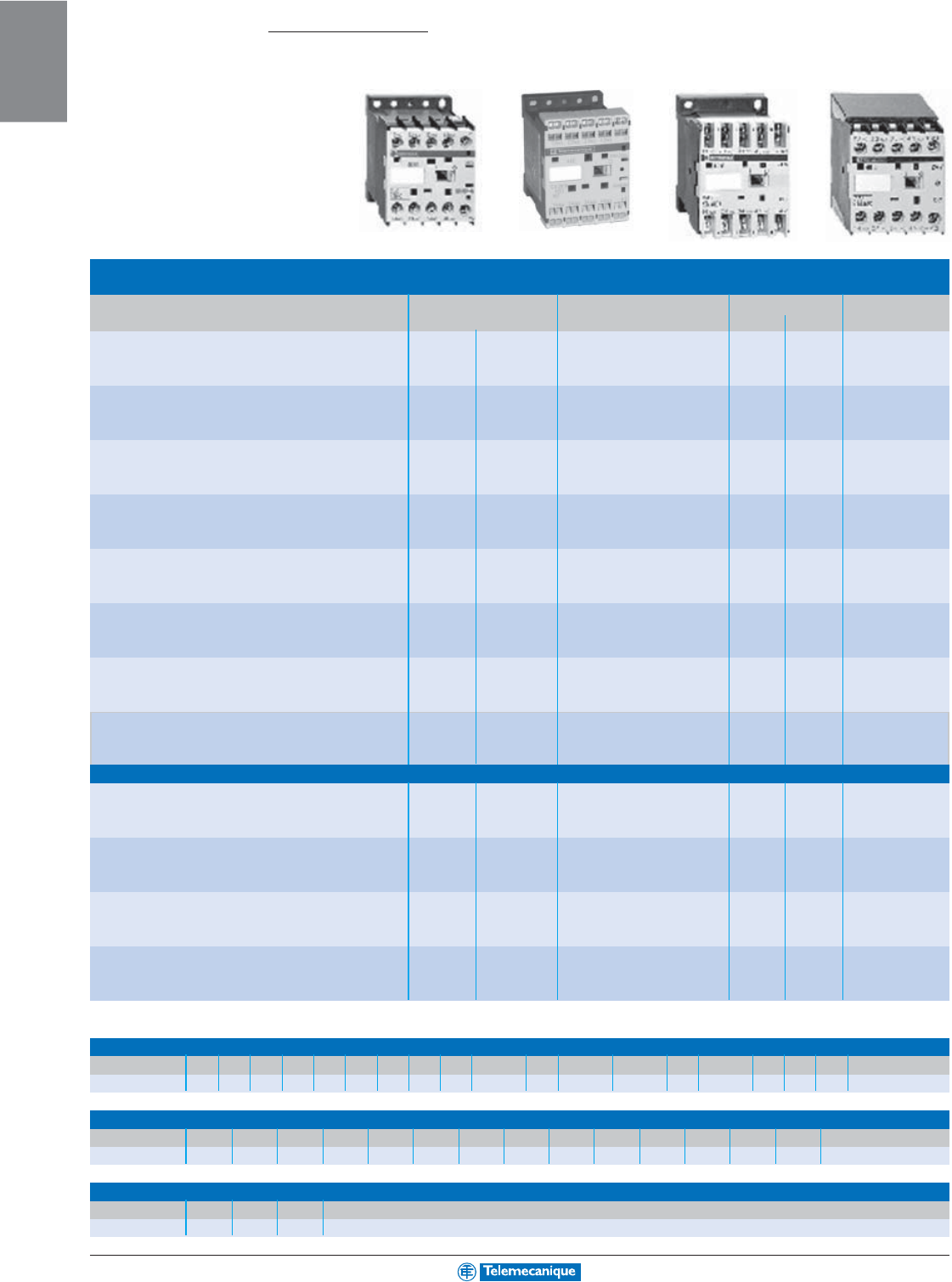
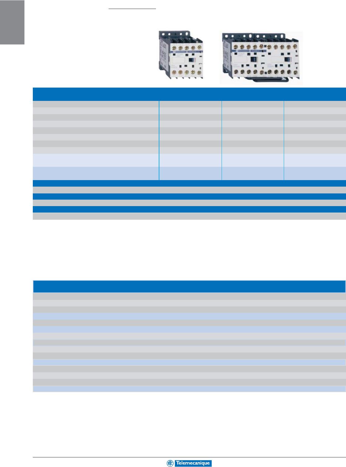
Contactor type (1) ac LC1K06•• LC1K09•• LC1K12••
dc LP1K06•• or LP4K06•• LP1K09•• or LP4K09•• LP1K12•• or LP4K12••
Reversing contactor type (1) ac LC2K06•• LC2K09•• LC2K12••
(with mechanical interlock) dc LP2K06•• or LP5K06•• LP2K09•• or LP5K09•• LP2K12•• or LP5K12••
■ spring terminals
Add the number 3 before the voltage code. Example LC1K0610•• becomes LC1K06103••
■ Slip-on connectors, 1 x 6.35 or 2 x 2.8
Add the number 7 before the voltage code. Example LC1K0610•• becomes LC1K06107••
■ solder pins for printed circuit boards
Add the number 5 before the voltage code. Example LC1K0610•• becomes LC1K06105••
(1) Catalog number completed by adding 01 for N.C. auxiliary contact, or 10 for N.O. auxiliary contact, and adding the coil voltage code from the table below.
Example of complete catalog number: LC1K0910BD.
Standard control circuit voltages
ac supply
Contactors LC1K (0.8–1.15 Uc)
(0.85–1.1UC for M7, U7, Q7, N7, Y7 only)
Volts 12 20 24 36 42 48 110 115 120 127 200/208
220/230
230
230/240
50/60 Hz J7 Z7 B7 C7 D7 E7 F7 FE7 G7 FC7 L7
M7
P7
U7
Volts 256 277
380/400
400
400/415
440 480 500 575 600
660/690
50/60 Hz W7 UE7
Q7
V7
N7
R7 T7 S7 SC7 X7
Y7
Example of complete catalog number: LC1K0910P7
dc
supply
Contactors LP1K and LP2K (0.8–1.15 Uc)
Volts 12 20 24 36 48 60 72 100 110 125 155 174 200 220 230 240 250
Code JD ZD BD CD ED ND SD KD FD GD PD QD LD MD MPD MUD UD
Low consumption
Contactors LP4K and LP5K (0.7–1.30 Uc), coil suppression as standard
Volts 12 20 24 48 72 110 120
Code JW3 ZW3 BW3 EW3 SW3 FW3 GW3
Contactors 0.5 to 10 Hp
Te
Sys
K-line
1-7
MOTOR
CONTROL
For additional options and information, reference catalog 8502CT9901.
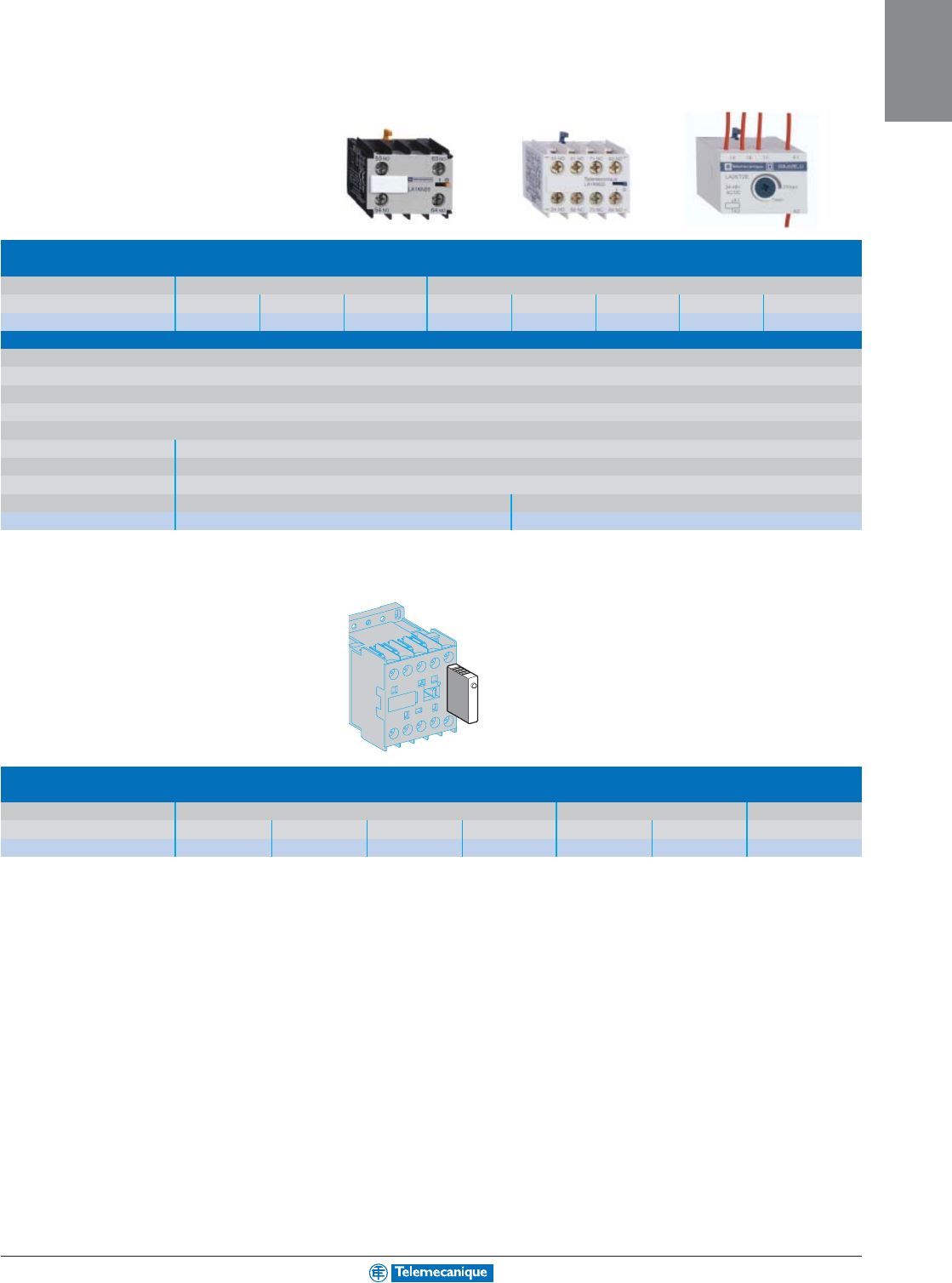
Auxiliary contact blocks
■
instantaneous, screw clamp connections (1)
■
for LCpp
pp
pK, LPpp
pp
pK
■
for LCpp
pp
pK, LC1, LP2K
Contact arrangement 2 N.O. - 2 N.C. 1 N.O. 1 N.C. 4 N.O. 3 N.O. 1 N.C. 2 N.C. 2 N.C. 1 N.O. 3 N.C. - 4 N.C.
Catalog number LA1KN20 LA1KN02 LA1KN11 LA1KN40 LA1KN31 LA1KN22 LA1KN13 LA1KN04
■
Electronic time delay
Relay outputs, with common point changeover contact, ac or
dc 24–48, 2 A maximum
Control voltage 0.85–1.1Uc
Maximum switching capacity 250 VA or 150 W
Operating temperature -10 to + 60°C
Reset time: 1.5 s for time delay period, 0.5 s after the time delay period
Type On-delay
Timing range 1–30 s
Contact arrangement 1 C/O (Form C)
Voltage ac or dc 24–48 V ac 110–240
Catalog number LA2KT2E LA2KT2U
(1) Also available with spring and slip-on terminals.
Suppressor modules
For LC1, LP1K
Type (2) Varistor (ac and dc) Diode (dc) + zener RC (ac)
Voltage 12–24 V 32–48 V 50–129 V 130–250 V 12–24 V 32–48 V 220–250 V
Catalog number LA4KE1B LA4KE1E LA4KE1FC LA4KE1UG LA4KC1B LA4KC1E LA4KA1U
(2) For details on levels of protection, refer to Catalog #8502CT9901.
1-8
MOTOR
CONTROL
www.telemecanique.com For additional options and information, reference catalog 8502CT9901.
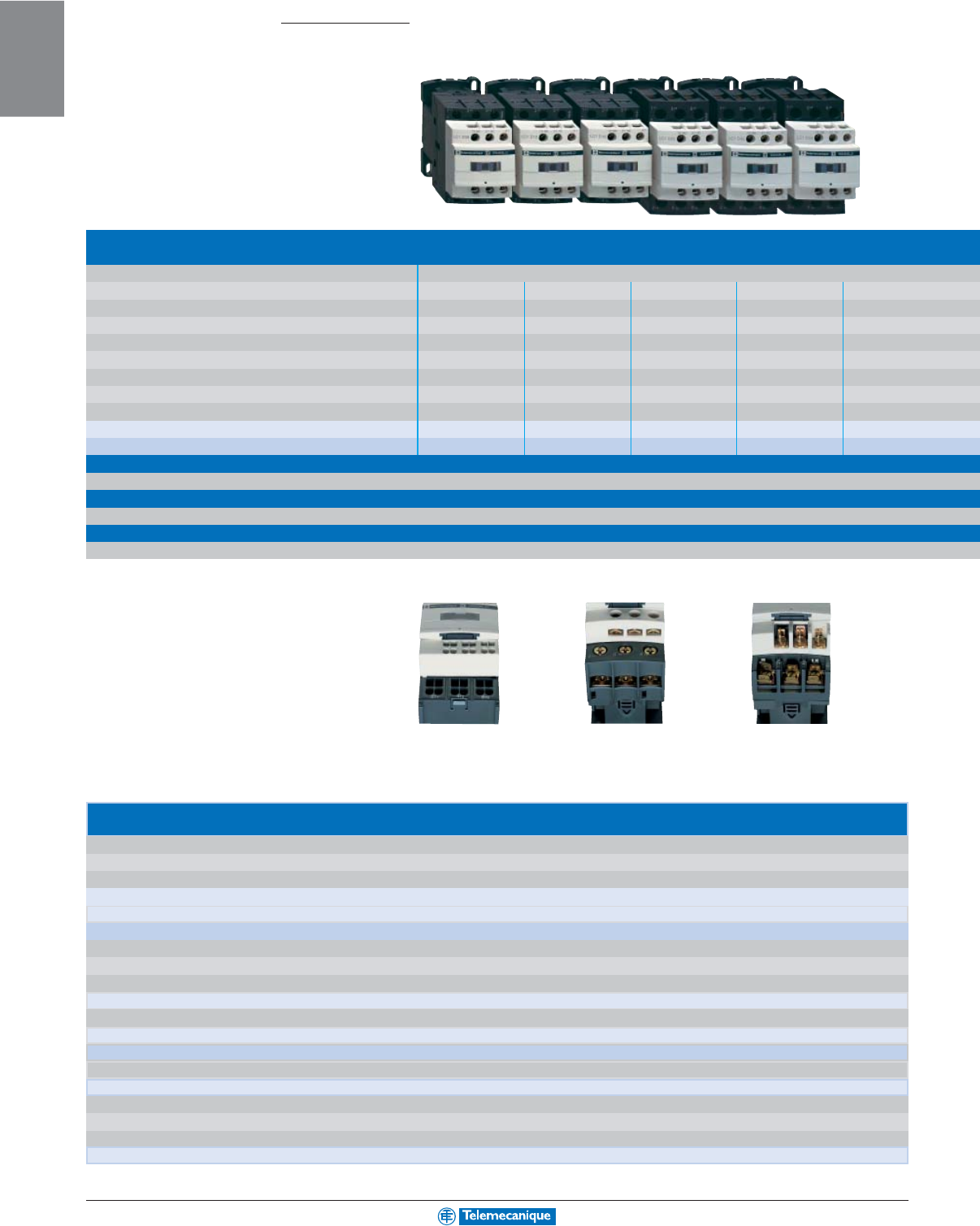
Connections
■
screw clamp terminals or connectors
Rated operational voltage 690 V
Rated operational current Ie max AC-3 9 A 12 A 18 A 25 A 32 A
(Ue ≤ 440V) Ie AC-1 20 A 25 A 32 A 40 A 50 A
Horsepower ratings 115/120 V single phase 0.5 hp 1 hp 1 hp 2 hp 2 hp
(UL ratings) 220/230 V single phase 1 hp 2 hp 3 hp 3 hp 5 hp
208 V three phase 2 hp 3 hp 5 hp 7.5 hp 10 hp
240 V three phase 2 hp 3 hp 5 hp 7.5 hp 10 hp
480 V three phase 5 hp 7.5 hp 10 hp 15 hp 20 hp
600 V three phase 7.5 hp 10 hp 15 hp 20 hp 30 hp
Contactor type (1) LC1D09 LC1D12 LC1D18 LC1D25 LC1D32
Reversing contactor type (with mechanical interlock) LC2D09 LC2D12 LC2D18 LC2D25 LC2D32
■
spring terminals up to D38 only
Add the number 3 before the voltage code. Example LC1D09P7 becomes LC1093P7
■
ring tongue
Add the number 6 before the voltage code. Example LC1D09P7 becomes LC1096P7
■
slip-on connectors 2 x 6.35 (power) and 1 x 6.35 (control) up to D12 only
Add the number 9 before the voltage code. Example LC1D09P7 becomes LC1099P7
(1) Catalog number to be completed by adding the coil voltage code from the table below. Example of complete catalog number: LC1D09P7.
Standard control circuit voltages
ac
supply
Volts 24 42 48 110 115 120 208 220 230 240 380 415 440
Contactors LC1D09–D150 (D09 through D38 and D150 available with 50/60 Hz only)
50/60 Hz B7 D7 E7 F7 FE7 G7 LE7 M7 P7 U7 Q7 N7 R7
50 Hz B5 D5 E5 F5 FE5 G5 - M5 P5 U5 Q5 N5 R5
60 Hz B6 - E6 F6 --L6M6-U6Q6-R6
dc
supply
Volts 12 24 36 48 60 72 110 125 220 440
Contactors LC1D09–D38 (coils with integral suppression device fitted as standard)
0.7–1.25 Uc JD BD CD ED ND SD FD GD MD RD
Contactors LC1D40–D95
0.85–1.1 Uc JD BD CD ED ND SD FD GD MD RD
0.75–1.2 Uc JW BW CW EW - SW FW - MW -
Contactors LC1D115 and D150 (coils with integral suppression device fitted as standard)
0.75–1.2 Uc -BD-EDND SD FD GD MD RD
Low consumption
Volts dc 512202448110120 250
Contactors LC1D09–D38 (coils with integral suppression device fitted as standard)
0.7–1.25 Uc AL JL ZL BL EL FL ML UL
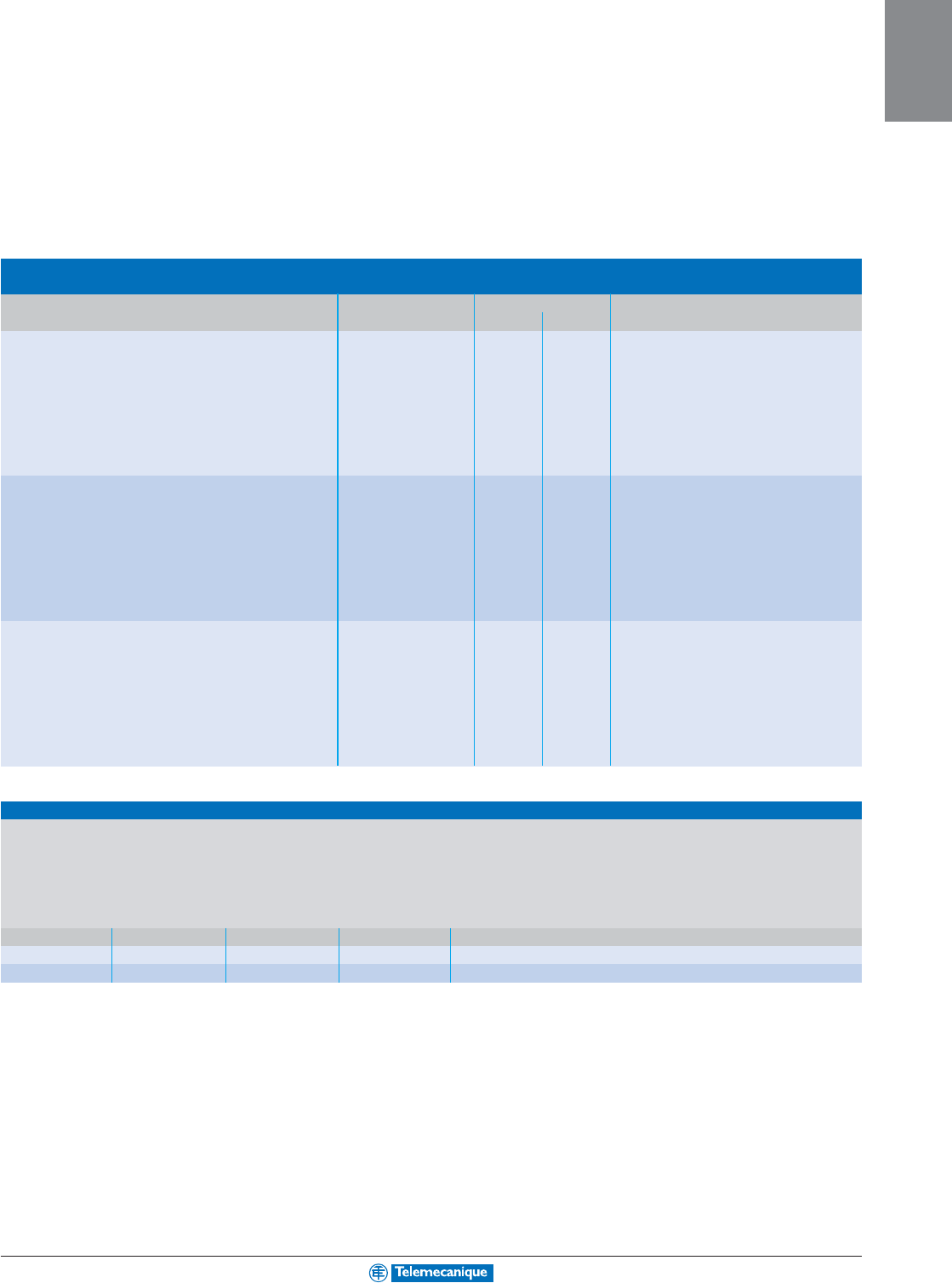
Contactors 0.5 to 125 Hp
Te
Sys
D-line
LC1D183 LC1D189LC1D186
For enclosed version of D-Line starters up to
80 A, reference catalog 8502CT9901.
1-9
MOTOR
CONTROL
For additional options and information, reference catalog 8502CT9901.
Mounting accessories for 3-pole reversing contactors
2 identical contactors with screw clamp terminals or connectors, horizontally mounted
Mechanical interlock Set of connections Mechanical interlock
■
with an electrical interlocking kit for the contactors
LC1D09–D38 LAD9R1V included
■
with integral electrical interlocking
LC1D40–D65 LA9D6569 LA9D4002
LC1D80 and D95 (ac)LA9D8069 LA9D4002
LC1D80 and D95 (dc)LA9D8069 LA9D8002
LC1D115 and D150 LA9D11569 LA9D11502
■
without electrical interlocking
LC1D09–D38 LAD9R1 included
LC1D40–D65 LA9D6569 LA9D50978
LC1D80 and D95 (ac)LA9D8069 LA9D50978
LC1D80 and D95 (dc)LA9D8069 LA9D80978
Mechanical latch blocks
Clip-on front mounting, manual or electrical unlatching control
For use on contactor Catalog number Standard control circuit voltages (50/60 Hz)
24 V 42/48 V 110/127 V 220/240 V 380/415 V
LC1D40–D65 ac
or dc LA6DK10•BEF MQ
LC1D80–D150 ac, LC1D80 and D115 LA6DK20•BEF MQ
LC1D09–D38 ac
or dc LAD6K10•BEF MQ
1 000 V on c supply, 690 V on a supply
38 A 40 A 50 A 65 A 80 A 95 A 115 A 150 A
–60 A 80 A 80 A 125 A – 200 A –
2 hp 3 hp 3 hp 5 hp 7.5 hp 7.5 hp – –
5 hp 5 hp 7.5 hp 10 hp 15 hp 15 hp – –
10 hp 10 hp 15 hp 20 hp 25 hp 25 hp 30 hp 40 hp
10 hp 10 hp 15 hp 20 hp 30 hp 30 hp 40 hp 50 hp
20 hp 30 hp 40 hp 50 hp 60 hp 60 hp 75 hp 100 hp
30 hp 30 hp 40 hp 50 hp 60 hp 60 hp 100 hp 125 hp
LC1D38 LC1D40 LC1D50 LC1D65 LC1D80 LC1D95 LC1D115 LC1D150
LC2D38 LC2D40 LC2D50 LC2D65 LC2D80 LC2D95 LC2D115 LC2D150
1-10
MOTOR
CONTROL
www.telemecanique.com For additional options and information, reference catalog 8502CT9901.
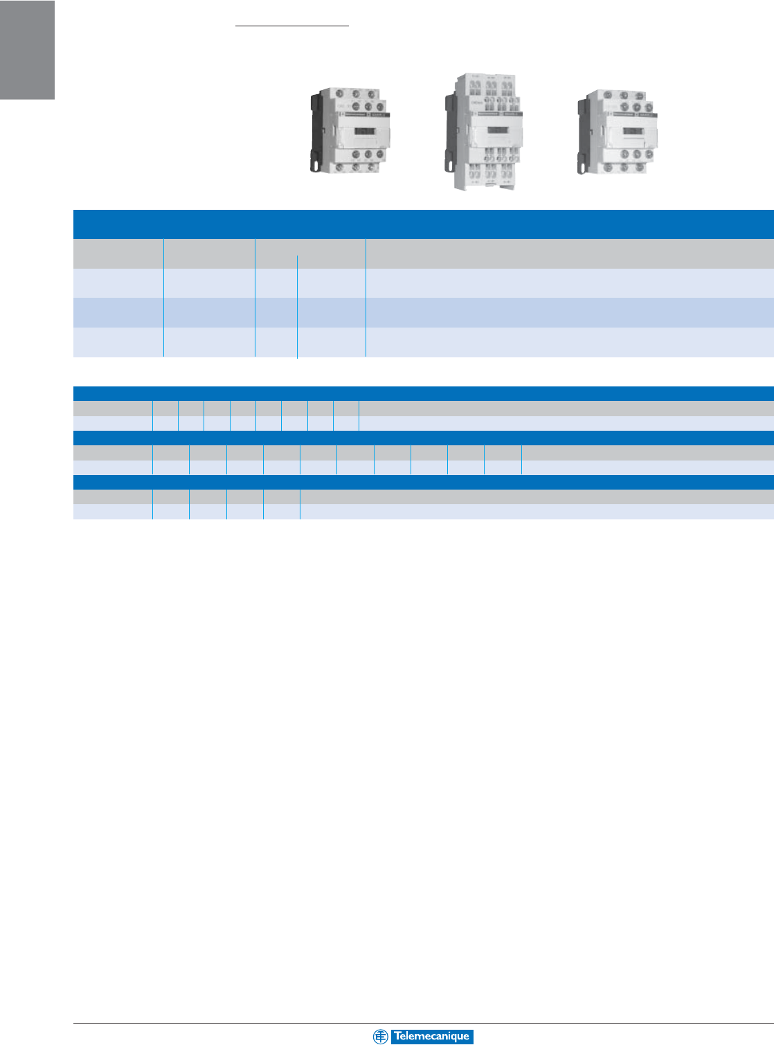
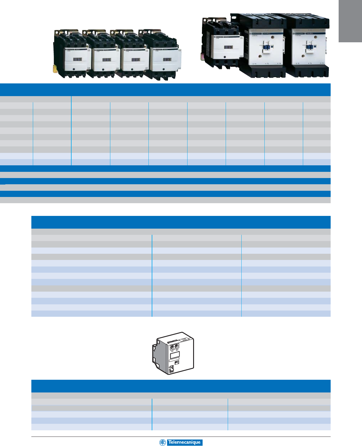
Contactors
0.5 to 125 Hp
Te
Sys
D-line
Maximum number of auxiliary contacts that can be fitted
Contactors
Instantaneous auxiliary contact blocks
Time delay
Control circuit Contactor size Side mounting Front mounting Front mounting
1 contact 2 contacts 4 contacts
ac LC1D09–D38 1 on LH side and - 1 or 1 or 1
LC1D40–D95 (50/60 Hz) 1 on each side or 2 and 1 or 1 or 1
LC1D40–D95 (50 or 60 Hz) 1 on each side and 2 and 1 or 1 or 1
LC1D115 and D150 1 on LH side - and 1 or 1 or 1
dc LC1D09–D38 --1or 1 or 1
LC1D40–D95 -1or 1 or 1 or 1
LC1D115 and D150 1 on LH side and - 1 or 1 or 1
Low Consumption LC1D09–D38 --1--
LC1DT20–DT40 --1
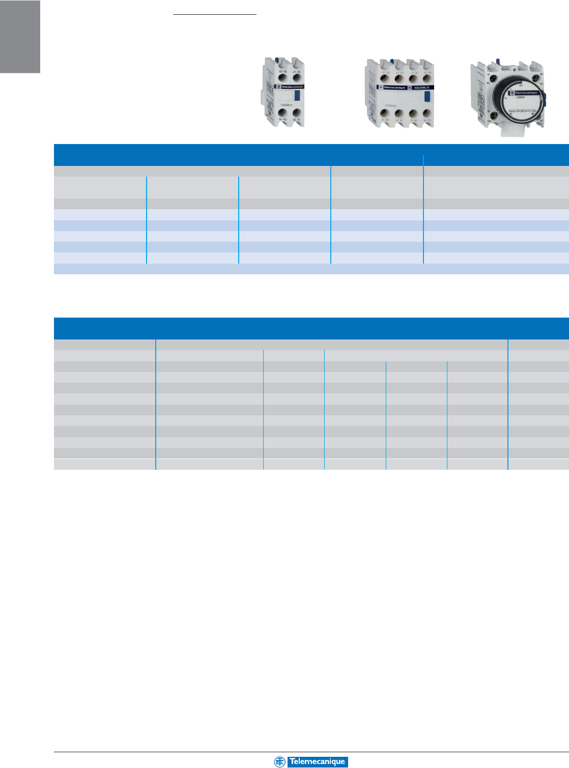
Auxiliary contact blocks
■
instantaneous, for connection by screw clamp terminals
■
time delay
■
front mounting
■
side mounting
■
front mounting
Contact Catalog No. Contact Catalog No. Contact Catalog No. Contact Catalog No. Type Range Catalog No.
Arrangement Arrangement Arrangement Arrangement
N.O. N.C. N.O. N.C. N.O. N.C. N.O. N.C.
1- LADN10 11 LADN11 22 LADN22 11 LAD8N11 On-delay 0.1–3 s LADT0
-1 LADN01 2- LADN20 13 LADN13 2- LAD8N20 0.1–30 s LADT2
-2 LADN02 4- LADN40 -2 LAD8N02 10–180 s LADT4
-4 LADN04 Off-delay 0.1–3 s LADR0
31 LADN31 0.1–30 s LADR2
10–180 s LADR4
1-11
MOTOR
CONTROL
For additional options and information, reference catalog 8502CT9901.
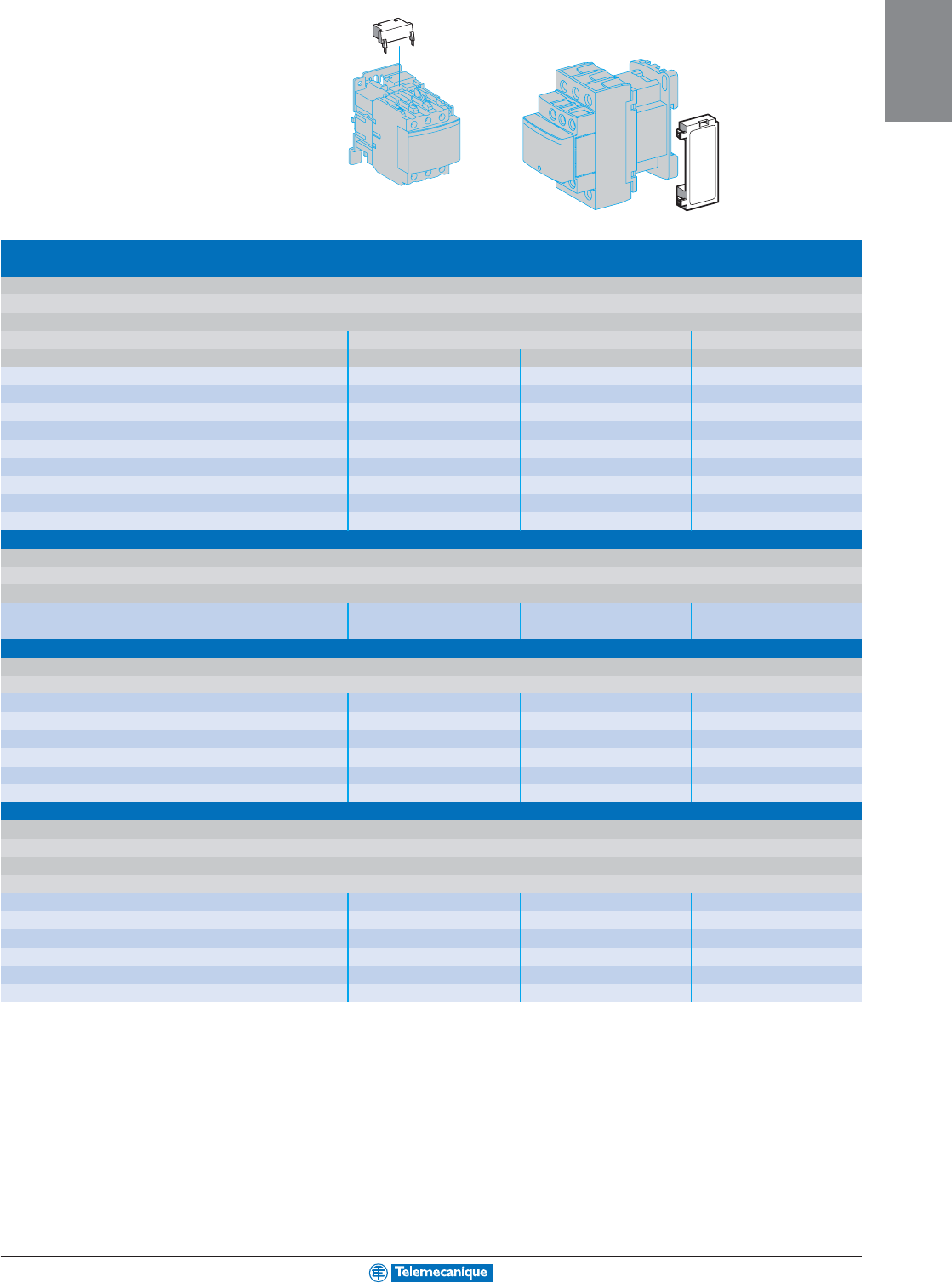
Suppressor modules
Varistors (peak limiting)
Protection provided by limiting the transient voltage to 2 Uc max.
Maximum reduction of transient voltage peaks.
Slight increase in drop-out time (1.1 to 1.5 times the normal time)
Mounting For use with contactorType Catalog Number
Rating
Volts ac Volts dc
Clip-on D09–D38 12–24 V - LAD4VE
50–127 V - LAD4VG
110–240 V - LAD4VU
Screw clamp D40–D115 24–48 V - LA4DE2E
50–127 V - LA4DE2G
110–250 V - LA4DE2U
D40–D115 - 24–48 V LA4DE3E
-50–127 V LA4DE3G
-110–250 V LA4DE3U
Diodes
No overvoltage or oscillating frequency.
Increase in drop-out time (6 to 10 times the normal time).
Polarised component.
Screw clamp D40–D95 (3P) - 24–250 V LA4DC3U
D65 and D80 (4P)
Bidirectional peak limiting diode
Protection provided by limiting the transient voltage to 2 Uc max.
Maximum reduction of transient voltage peaks.
Clip-on D09–D38 24 V - LAD4TB
72 V - LAD4TS
Screw clamp D40–D95 24 V - LA4DB2B
72 V - LA4DB2S
D40–D95 - 24 V LA4DB3B
-72 V LA4DB3S
RC circuits (Resistor-Capacitor)
Effective protection for circuits highly sensitive to "high frequency" interference.
For use only in cases where the voltage is virtually sinusoidal, i.e. less than - 5% total harmonic distortion.
Voltage limited to 3 Uc max and oscillating frequency limited to 400 Hz max.
Slight increase in drop-out time (1.2 to 2 times the normal time)
Clip-on D09–D38 12–24 V - LAD4RCE
110–240 V - LAD4RCU
Screw clamp D40–D150 24–48 V - LA4DA2E
50–127 V - LA4DA2G
110–240 V - LA4DA2U
380–415 V - LA4DA2N
For enclosed versions, reference catalog 8502CT9901.
1-12
MOTOR
CONTROL
www.telemecanique.com For additional options and information, reference catalog 8502CT9901.
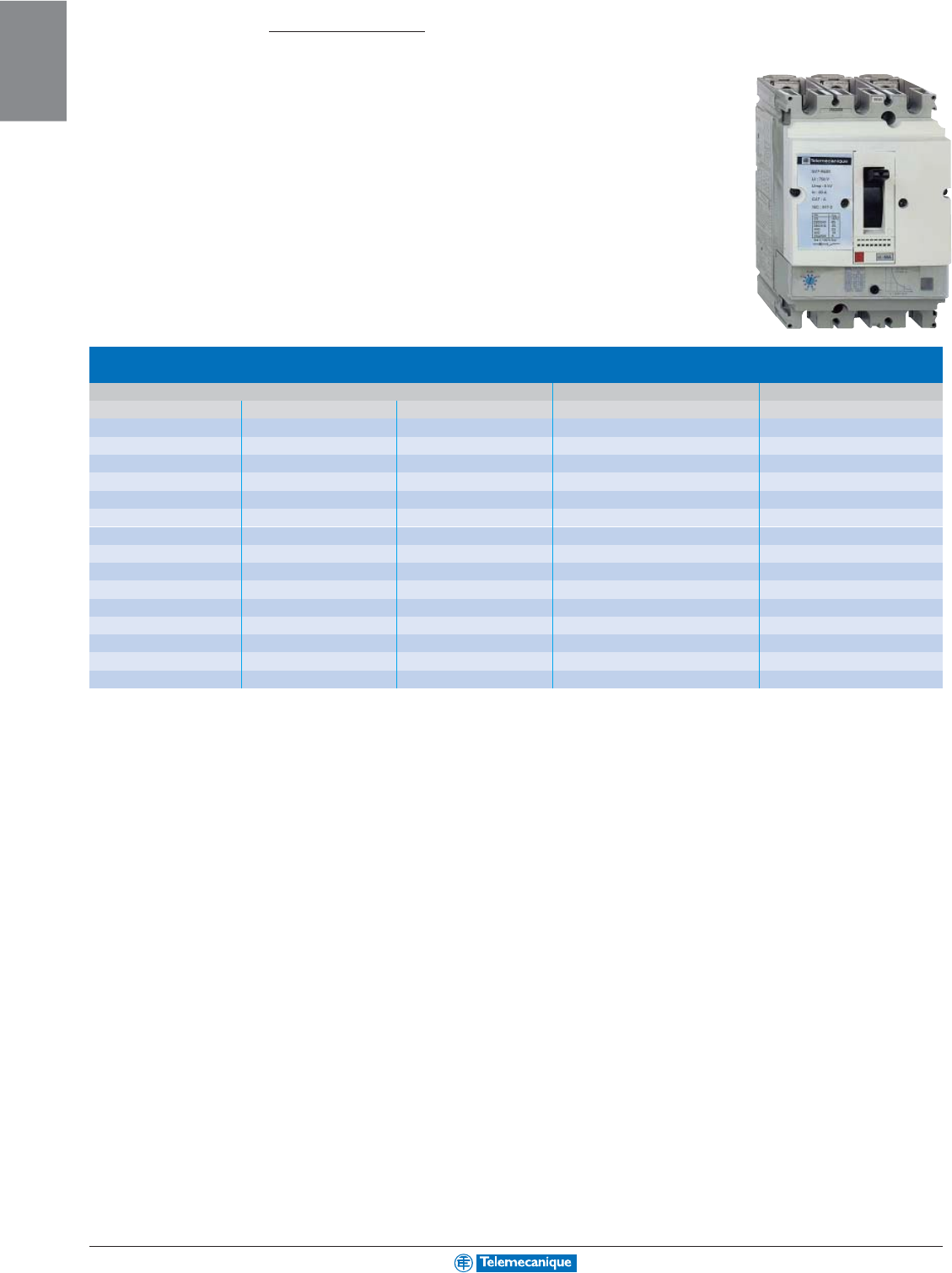
Rated operational current Ie max AC-3 (Ue ≤ 440V) 115 A 150 A 185 A 225 A 265 A 330 A
Ie AC-1 (θ ≤ 40° C) 200 A 250 A 275 A 315 A 350 A 400 A
Rated operational voltage 1 000 V 1 000 V 1 000 V 1 000 V 1 000 V 1 000 V
Horsepower ratings 208 V three phase 30 hp 40 hp 50 hp (2) 60 hp 75 hp
(UL ratings) 240 V three phase 40 hp 50 hp 60 hp (2) 75 hp 100 hp
480 V three phase 75 hp 100 hp 125 hp (2) 150 hp 200 hp
600 V three phase 100 hp 125 hp 150 hp (2) 175 hp 250 hp
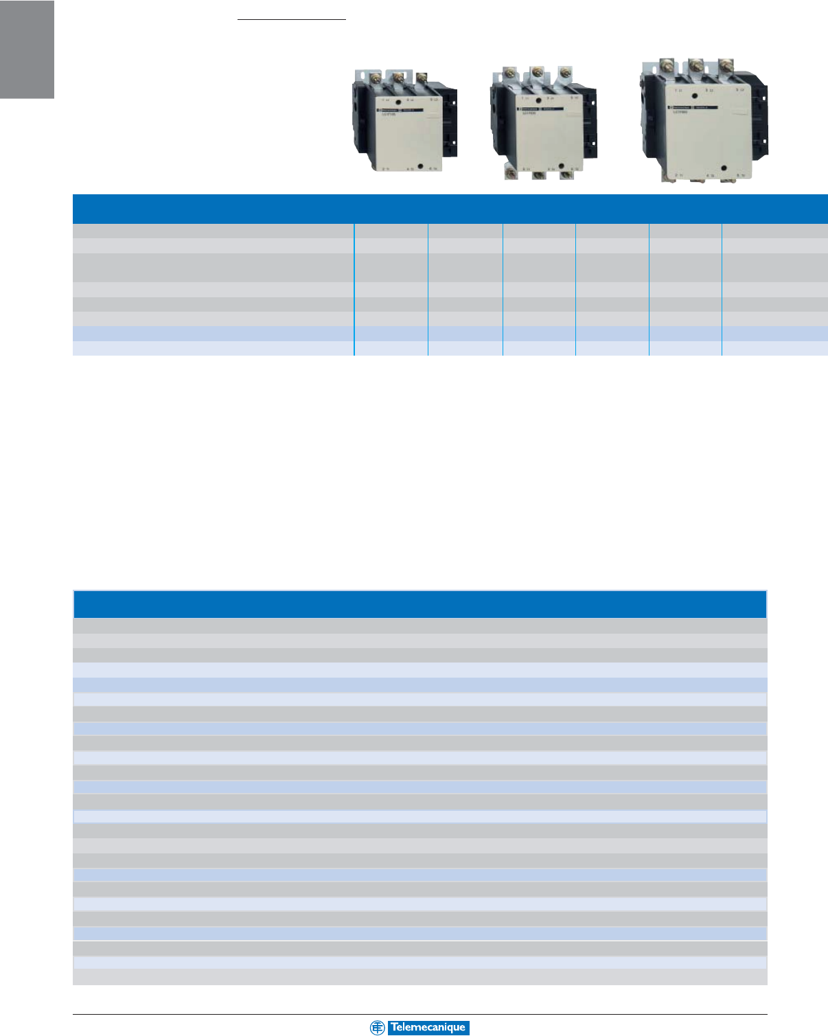
Contactor type (1) LC1F115 LC1F150 LC1F185 LC1F225 LC1F265 LC1F330
Reversing contactor type (1) LC2F115 LC2F150 LC2F185 LC2F225 LC2F265 -
(1) Basic catalog number to be completed by adding the coil voltage code from the table below. Example of complete catalog number: LC1F185G7.
(2) Current rated only.
Contactors 30 to 900 Hp
Te
Sys
F-line
Standard control circuit voltages
ac supply
Volts 24 48 110 115 120 208 220 230 240 380 400 415 440
Contactors LC1F115–F225
(0.85–1.1UC)
50 Hz (coil LX1) B5 E5 F5 FE5 - - M5 P5 U5Q5V5N5-
60 Hz (coil LX1) -E6F6-G6L6M6-U6Q6--R6
40–400 Hz (coil LX9) -E7F7FE7 G7 L7 M7 P7 U7 Q7 V7 N7 R7
Contactors LC1F265–F330
(0.85–1.1UC)
40–400 Hz (coil LX1) B7 E7 F7 FE7 G7 L7 M7 P7 U7 Q7 V7 N7 R7
Contactors LC1F400–F630
(0.85–1.1UC)
40–400 Hz (coil LX1) -E7F7FE7 G7 (1) L7 M7 P7 U7 Q7 V7 N7 R7
Contactor LC1F780
(0.85–1.1UC)
40–400 Hz (coil LX1) --F7FE7F7L7 M7 P7 U7 Q7 V7 N7 R7
Contactor LC1F800
(0.7–1.3UC)
40–400 Hz (coil LX1) --FE7 FE7 FE7 - P7 P7 P7 V7 V7 V7 V7
dc supply
Volts 24 48 110 125 220 230 250 400 440
Contactors LC1F115–F330
(0.85–1.1UC)
(coil LX4F) BD ED FD GD MD MD UD - RD
Contactors LC1F400–F630
(0.85–1.1UC)
(coil LX4F) -EDFDGDMD-UD-RD
Contactor LC1F780
(0.85–1.1UC)
(coil LX4F) --FDGDMD-UD-RD
Contactor LC1F800
(0.7–1.3UC)
(coil LX4F) --FWFWMWMW- QW-
Example: For a 630 A contactor with a 110 V c coil, order LC1F630F7
(1) F7 for LC1F630
1-13
MOTOR
CONTROL
For additional options and information, reference catalog 8502CT9901.
Auxiliary contact blocks
■
instantaneous
■
time delay 1N.O. + 1 N.C.
Contact Catalog No. Contact Catalog No. Contact Catalog No. Type Range Catalog No.
Arrangement Arrangement Arrangement
N.O. N.C. N.O. N.C. N.O. N.C.
1- LADN10 11 LADN11 22 LADN22 On-delay 0.1–3 s LADT0
-1 LADN01 2- LADN20 13 LADN13 0.1–30 s LADT2
-2 LADN02 4- LADN40 10–180 s LADT4
-4 LADN04 1–30 s LADS2
31 LADN31 Off-delay 0.1–3 s LADR0
22 LADC22 0.1–30 s LADR2
10–180 s LADR4
Mounting accessories for 3-pole reversing contactors for motor control
2 identical contactors, horizontally mounted
Mechanical interlock with an electrical interlocking kit for the contactors
Contactor type Set of connections Mechanical interlock
LC1F115 LA9FF976 LA9FF970
LC1F150 LA9F15076 LA9FF970
LC1F185 LA9FG976 LA9FG970
LC1F225 LA9F22576 LA9FG970
LC1F265 LA9FH976 LA9FJ970
LC1F330 LA9FJ976 LA9FJ970
LC1F400 LA9FJ976 LA9FJ970
LC1F500 LA9FK976 LA9FJ970
LC1F630 or LC1F800 LA9FL976 LA9FL970
400 A 500 A 630 A 780 A 800 A
500 A 700 A 1 000 A 1 600 A 1 000 A
1 000 V 1 000 V 1 000 V 1 000 V 1 000 V
100 hp 150 hp 250 hp (2) -
125 hp 200 hp 300 hp (2) 450 hp
250 hp 400 hp 600 hp (2) 800 hp
300 hp 500 hp 800 hp (2) 900 hp
LC1F400 LC1F500 LC1F630 LC1F780 LC1F800
For customer assembly
1-14
MOTOR
CONTROL
www.telemecanique.com For additional options and information, reference catalog 2520CT0001.
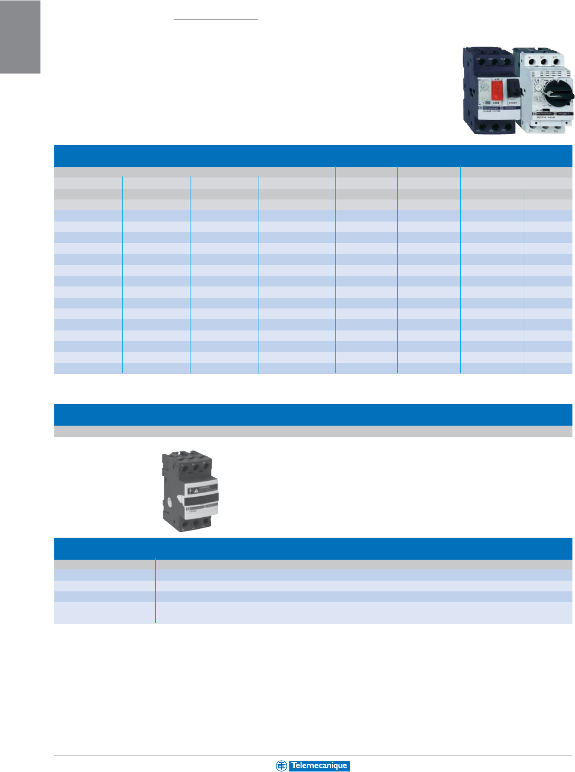
Manual motor starters GV2ME and GV2P for connection by screw clamp terminals
GV2ME with pushbutton control, GV2P control by rotary knob
Horsepower ratings of 3-phase motors 50/60 Hz Setting range Magnetic Catalog Number
200 V 230 V 460 V 575 V of thermal tripping
trips current Pushbutton Rotary Handle
AA
---- 0.1–0.16 1.5 GV2ME01 GV2P01
----0.16–0.25 2.4 GV2ME02 GV2P02
----0.25–0.40 5 GV2ME03 GV2P03
----0.40–0.63 8 GV2ME04 GV2P04
--0.5 0.5 0.63–1 13 GV2ME05 GV2P05
--0.75 1 1–1.6 22.5 GV2ME06 GV2P06
0.5 0.5 1 1.5 1.6–2.5 33.5 GV2ME07 GV2P07
0.75 1 2 3 2.5–4 51 GV2ME08 GV2P08
1.5 1.5 3 5 4–6.3 78 GV2ME10 GV2P10
2357.5 6–10 138 GV2ME14 GV2P14
331010 9–14 170 GV2ME16 GV2P16
551015 13–18 223 GV2ME20 GV2P20
57.5 15 20 17–23 327 GV2ME21 GV2P21
57.5 15 20 20–25 327 GV2ME22 GV2P22
10 10 20 30 24–32 416 GV2ME32 GV2P32
Manual
motor
starters
0.1 to 30 Hp
Type GV2ME and GV2P
Thermal-magnetic circuit-breakers GV2-ME for connection by spring terminals
Add the number 3 to the end of the catalog number. Example GV2-ME223 (available up to GV2-ME22)
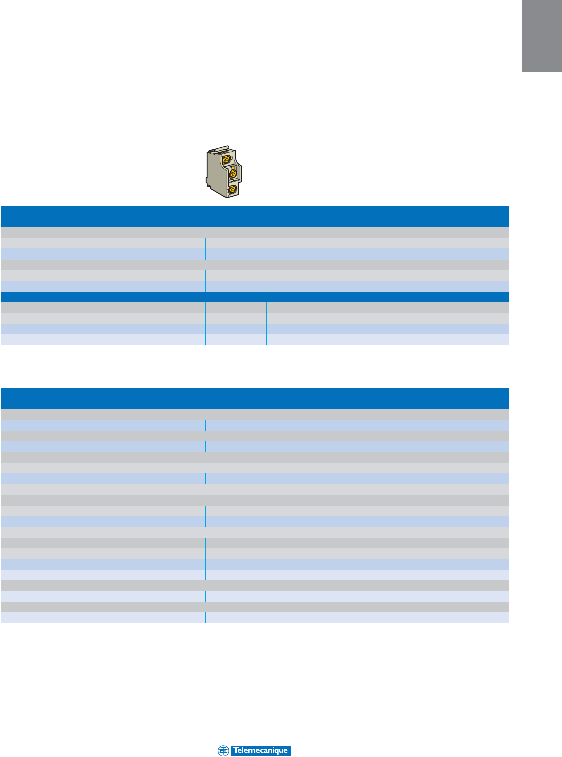
Fuse holder—30 A rated, type CC or KTK-R fuses
Catalog Number
With screw terminals LS1D30
With spring terminals LS1D303
Auxiliary pole (screw terminals; LA8D324
mount on left or right side)
1-15
MOTOR
CONTROL
For additional options and information, reference catalog 2520CT0001.
Accessories for GV2ME and GV2P
Combination block
For mounting on LC1K or LP1K LC1D09–D38 LAD31, LAD311 or LC1D09–D38
GV2AF01 GV2AF3 GV2AF4
Sets of 3-pole busbars
63 A 45 mm pitch 54 mm pitch 72 mm pitch
Number of tap-offs 2 GV2G245 GV2G254 GV2G272
3GV2G345 GV2G354
4GV2G445 GV2G454 GV2G472
5GV2G554
Protective end cover
For unused busbar outlets GV1G10
Terminal blocks
For supply to one or more GV2G busbar sets connection from the top can be fitted with current limiter GV1L3 (GV2ME and GV2P)
GV1G09 GV1G05
Padlockable external operator for GV2P (150 to 290 mm)
Padlocking In “On” and “Off” position In “Off” position
Handle black red
Legend plate blue yellow
IP 54 GV2AP01 GV2AP02
Padlocking device
For all GV2 devices For use with up to 6 padlocks (padlocks not supplied) Ø 6 mm shank max
GV2V03
Add-on blocks
Contact blocks
Contact arrangement N.O. or N.C. N.O. + N.C. N.O. + N.O. (fault) + N.C. N.C. + N.O. N.O. SPDT
Instantaneous auxiliary contacts
Mounting front GVAE1 GVAE11 GVAE20
LH side GVAN11 GVAN20
Fault signalling contact + instantaneous auxiliary contact
LH side GVAD1010 GVAD1001 GVAD0110
GVAD0101
Short-circuit signalling contact
LH side GVAM11
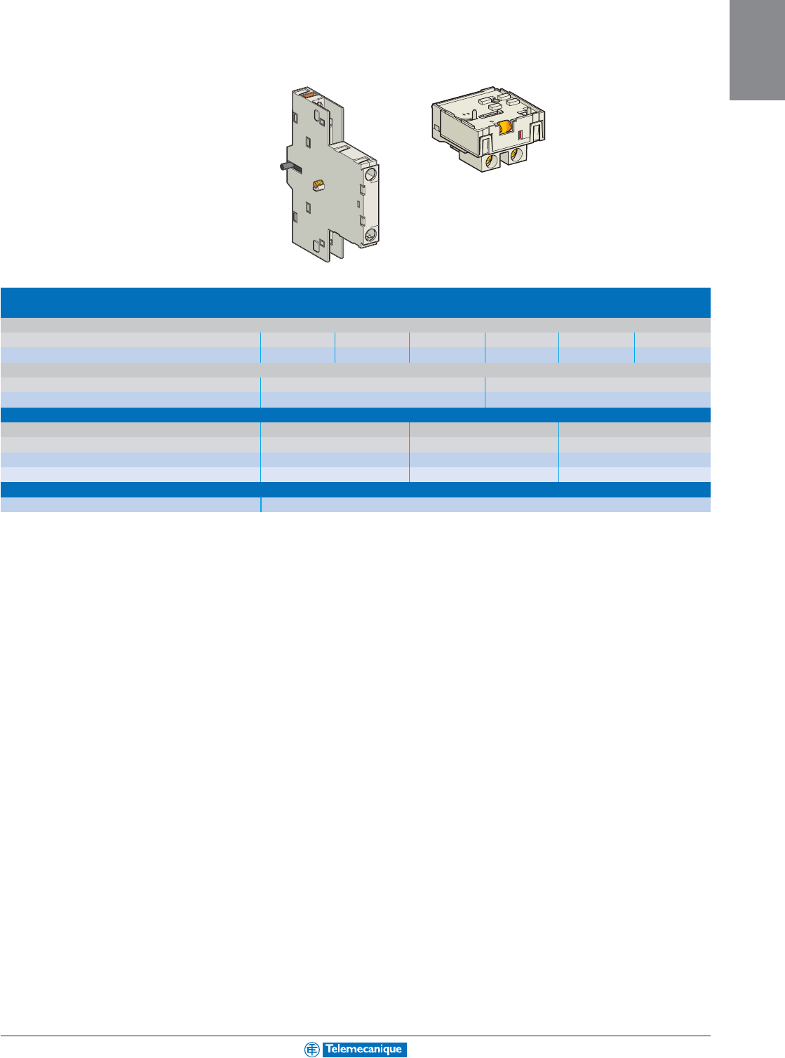
Electric trips
Undervoltage or shunt trips (1)
Side mounting (1 block on RH side of device) 50 Hz 60 Hz
Voltage 24 V GVA
•
025 GVA
•
026
48 V GVA
•
055 GVA
•
056
100 V GVA
•
107
100–110 V GVA
•
107
110–115 V GVA
•
115 GVA
•
116
120–127 V GVA
•
125
127 V GVA
•
115
200 V GVA
•
207
200–220 V GVA
•
207
220–240 V GVA
•
225 GVA
•
226
380–400 V GVA
•
385 GVA
•
386
415–440 V GVA
•
415
415 V GVA
•
416
(1) Undervoltage trips: replace the
•
with U, shunt trips: replace the
•
with S
1-16
MOTOR
CONTROL
www.telemecanique.com For additional options and information, reference catalog 2520CT0001.
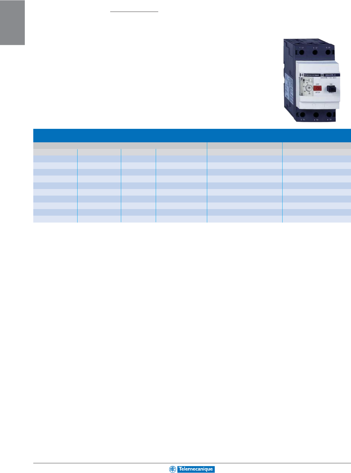
Manual
motor
starters
0.5 to 60 Hp
Type GV3ME
Manual motor starters GV3ME for connection by screw clamp terminals
Pushbutton control
Horsepower ratings of 3-phase motors 50/60 Hz Setting range of thermal trips Catalog Number
200 V 230 V 460 V 575 V A
--0.75 1 1–1.6 GV3ME06
0.5 0.5 1 1.5 1.6–2.5 GV3ME07
0.75 1 2 3 2.5–4 GV3ME08
1.5 1.5 3 - 4–6 GV3ME10
2357.5 6–10 GV3ME14
351010 10–16 GV3ME20
57.5 15 20 16–25 GV3ME25
10 10 30 30 25–40 GV3ME40
20 20 40 60 40–63 GV3ME63
20 25 50 60 56–80 GV3ME80
1-17
MOTOR
CONTROL
For additional options and information, reference catalog 2520CT0001.
Add-on blocks
Contact blocks
Instantaneous auxiliary contacts (1 per device)
Normal early break type contacts N.C. + N.O. (2)
N.O. + N.O. N.C. + N.O. + N.O. N.O. + N.O. + N.O. N.O. + N.O. (1) N.C. + N.O. (1)
GV3A01 GV3A02 GV3A03 GV3A05 GV3A06 GV3A07
Fault signalling contact
Normal early break type contacts N.C. N.O.
GV3A08 GV3A09
Electric trips
Voltage 50 Hz 110, 120, 127 V 220, 240 V 380, 415 V
60 Hz 120, 127 V 277 V 440, 480 V
Undervoltage trip GV3B11 GV3B22 GV3B38
Shunt trip GV3D11 GV3D22 GV3D38
Padlocking device
Start button (for bare device) GV1V02
(1) + 2 volt free terminals.
(2) Normal early break contacts.
1-18
MOTOR
CONTROL
www.telemecanique.com For additional options and information, reference catalog 2520CT0001.
Manual
motor
starters
0.5 to 200 Hp
Type GV7R
Manual motor starters GV7R for connection by screw clamp terminals
Control by rocker lever
Horsepower ratings of 3-phase motors 50/60 Hz Setting range of thermal trips Catalog Number
230 V 460V 575 V A
5101512–20 GV7RE20
5101512–20 GV7RS20
7.5 15 20 15–25 GV7RE25
7.5 15 20 15–25 GV7RS25
10 30 30 25–40 GV7RE40
10 30 30 25–40 GV7RS40
15 30 40 30–50 GV7RE50
30 60 75 48–80 GV7RE80
30 60 75 48–80 GV7RS80
30 75 100 60–100 GV7RE100
30 75 100 60–100 GV7RS100
50 100 150 90–150 GV7RE150
50 100 150 90–150 GV7RS150
75 150 200 132–220 GV7RE220
75 150 200 132–220 GV7RS220
1-19
MOTOR
CONTROL
For additional options and information, reference catalog 2520CT0001.
Add-on blocks
Contact blocks
Auxiliary contacts
Contact type C/O (Form C)
GV7AE11
Thermal or magnetic fault discrimination (trip on thermal fault)
24–48 Vac or 24–72 Vdc 110–240 Vac/dc
GV7AD111 GV7AD112
Electric trips
Voltage 50/60 Hz 48 V 110–130 V 200–240 V 380–440 V
50 Hz 525 V
Undervoltage trip (1) GV7AU055 GV7AU107 GV7AU207 GV7AU387 GV7AU525
Shunt trip (1) GV7AS055 GV7AS107 GV7AS207 GV7AS387 GV7AS525
(1) For mounting of a GV7AD or a GV7AU or AS
Accessories
Terminal shields IP 405
Supplied with the sealing accessory GV7AC01
Phase barriers
Safety accessories GV7AC04
used when fitting of shields is impossible
Insulating screens
Ensure insulation between GV7AC05
the connections and the backplate
Kit for combination with contactor
Allowing link between the circuit-breaker and the contactor LC1F115 to F185 LC1F225 and F26 LC1D115 and D150
GV7AC06 GV7AC07 GV7AC08
Rotary handles
Handle black red
Legend plate black yellow
■
direct IP 40 GV7AP03 GV7AP04
■
extended IP 55 GV7AP01 GV7AP02
Conversion accessory
for mounting on enclosure door IP 43 GV7AP05
Locking device
For circuit-breaker not fitted with a rotary handle GV7V01
1-20
MOTOR
CONTROL
www.telemecanique.com
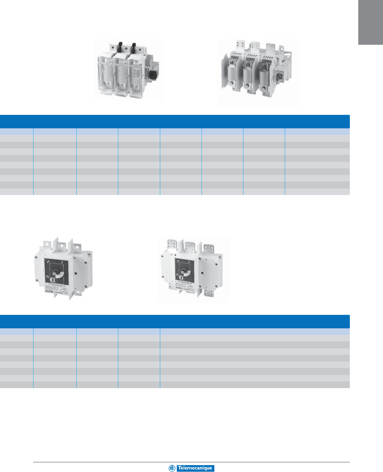
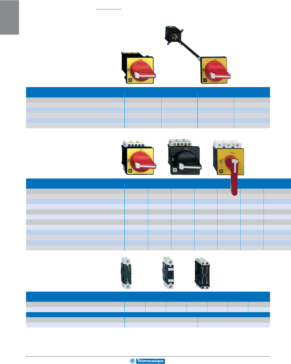
Disconnect
switches Type GS1 fusible and LK3 non-fused
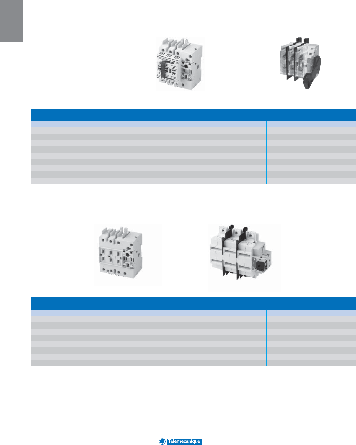
GS1 fusible disconnect switch 30–800 A
Catalog Number GS1DDU3 GS1DU3 GS1EERU20 GS1EERU30 GS1EEU3
Switch Type Compact fused Compact fused Fused Fused Fused
Fuses CC J CC CC CC
Amps 30 30 30 30 30
Poles 33233
Operator Style Thru-the-door Thru-the-door Side handle Side handle Thru-the-door
Max. HP 3 Phase:
kW/hp at 240V 5.5/7.5 5.5/7.5 n/a 5.5/7.5 5.5/7.5
kW/hp at 480V 11/15 11/15 n/a 11/15 11/15
kW/hp at 600V 15/20 15/20 n/a 15/20 15/20
LK3 non-fused disconnect switch 30–1200 A
Catalog Number LK3GU3 LK3GU3 LK3JU3 LK3MU3 (1) LK3QU3 (1)
Switch Type Compact Non-fused Non-fused Non-fused Non-fused Non-fused
Amps 30 60 100 200 400
Poles 33333
Operator Style Thru-the-door Thru-the-door Thru-the-door Thru-the-door Thru-the-door
Max. HP 3 Phase:
kW/hp at 240V 5.5.7.5 11/15 22/30 45/60 90/125
kW/hp at 480V 11/15 22/30 45/60 90/125 185/250
kW/hp at 600V 15/20 37/50 55/75 110/150 250/350
(1) Terminal lugs must be ordered separately.
Compact 30A Switch
GS1DDU3
30A Side Handle
GS1EERU30
Compact 30A Switch
LK3DU3
200A Switch
LK3MU3
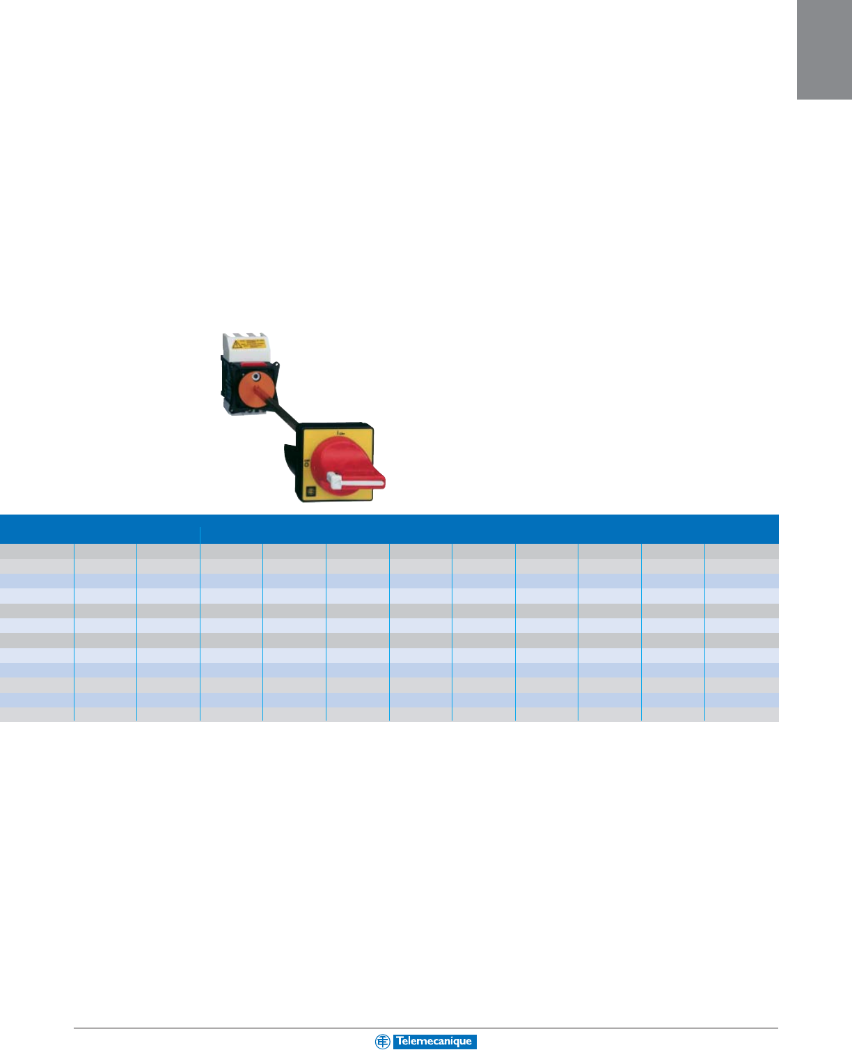
For additional options and information, reference catalog 9421CT0301.
1-21
MOTOR
CONTROL
GS1EU3 GS1GU3 GS1JU3 (1) GS1MU3 (1) GS1QU3 (1) GS1SU3 (1) GS1TU3 (1)
Fused Fused Fused Fused Fused Fused Fused
JJJJJJL
30 60 100 200 400 600 800
3333333
Thru-the-door Thru-the-door Thru-the-door Thru-the-door Thru-the-door Thru-the-door Thru-the-door
5.5/7.5 11/15 22/30 45/60 90/125 185/250 185/250
11/15 22/30 45/60 90/125 185/250 370/500 370/500
15/20 37/50 55/75 110/150 250/350 370/500 370/500
LK3SU3 (1) LK3TU3 (1) LK3UU3 (1) LK3WU3
Non-fused Non-fused Non-fused Non-fused
600 800 1000 1200
3333
Thru-the-door Thru-the-door Thru-the-door Thru-the-door
150/200 185/250 185/250 185/250
300/400 370/500 370/500 370/500
250/350 370/500 370/500 370/500
(1) Terminal lugs must be ordered separately.
200A Switch
GS1MU3
800A Switch
GS1TU3
600A Switch
LK3SU3
800A Switch
LK3TU3
For additional options and information, reference catalog 9421CT0301.
1-22
MOTOR
CONTROL
www.telemecanique.com For additional options and information, reference catalog 8502CT9901.
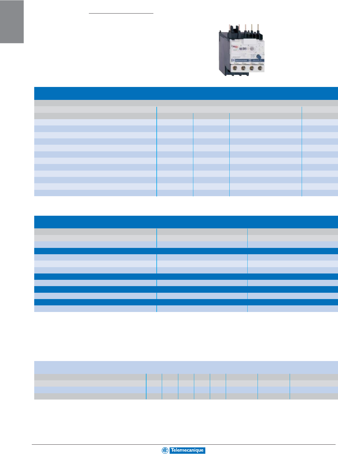
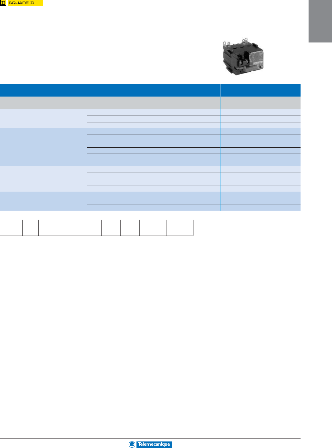
Thermal
overload
relays
Standard control circuit voltages
ac supply
Volts 12 24 48 110 125 220/230 380/400 415/440
50/60 Hz. Consumption, inrush and sealed < 100 VA -BEF-M Q N
dc supply
Consumption, inrush and sealed < 100 W JBEFGM - -
0.11 to 11.5 A
K-line
Thermal overload relays, model k
adjustable from 0.11 to 12 A
Connection by screw clamp terminals, direct mounting on contactors LC1K, manual or automatic reset
Relay setting range Fuses to be used with selected relay—international applications
(1)
Catalog Number
Class 10 A aM gG BS88
0.11–0.16 A 0.25 A 0.5 A - LR2K0301
0.16–0.23 A 0.25 A 0.5 A - LR2K0302
0.23–0.36 A 0.5 A 1 A - LR2K0303
0.36–0.54 A 1 A 1.6 A - LR2K0304
0.54–0.8 A 1 A 2 A - LR2K0305
0.8–1.2 A 2 A 4 A 6 A LR2K0306
1.2–1.8 A 2 A 6 A 6 A LR2K0307
1.8–2.6 A 2 A 6 A 10 A LR2K0308
2.6–3.7 A 4 A 10 A 16 A LR2K0310
3.7–5.5 A 6 A 16 A 16 A LR2K0312
5.5–8 A 8 A 20 A 20 A LR2K0314
8–11.5 A 10 A 25 A 20 A LR2K0316
Thermal overload relays for use on class 10 unbalanced loads: for above catalog numbers LR2K0305 to LR2K0316 only, replace the prefix LR2 with LR7.
Example LR7K0310.
Accessories
Prewiring kit
Allowing direct connection of the N.C. contact For use on
of relay LRD01–35 or LR3D01– D35 to the contactor LC1D09–D18 LAD7C1
LC1D25–D38 LAD7C2
Terminal blocks (2)
For clip-on mounting on 35 mm mounting rail (AM1DP200) LRD01–35 and LR3D01–D35 LAD7B10
or screw clamp LRD3•••, LR3D3•••, LRD35•• LA7D3064 (3)
For independent mounting of the relay LR2K•••• LA7K0064
Terminal block adapter
For mounting a relay beneath an LC1D115 or D150 contactor LRD3•••, LR3D3•••, LRD35•• LA7D3058
Stop or electrical reset
Remote (4) LRD01–35 and LR3D01–D35 LAD703• (5)
Tripping or electrical reset device
Remote (4) All D-line relays except LRD01–35 and LR3D01–D35 LA7D03• (5)
(1) Short circuit protection for North American applications: circuit breakers selected in accordance with NEC and local codes; fuses selected with maximum of 400% full load current.
(2) Terminal blocks are supplied with terminals protected against direct finger contact and screws in the open “ready-to-tighten” position.
(3) To order a terminal block for connection by lug-clamps, the catalog number becomes LA7D30646.
(4) The time for which the coil of remote tripping or electrical resetting device LA7D03 or LAD703 can remain energized depends on its rest time: 1 s pulse duration with 9 s rest time;
maximum pulse duration of 20 s with a rest time of 300 s. Minimum pulse time 200 ms.
(5) Catalog number to be completed by adding the code indicating the control circuit voltage.
1-23
MOTOR
CONTROL
For additional options and information, reference catalog 8502CT9901.
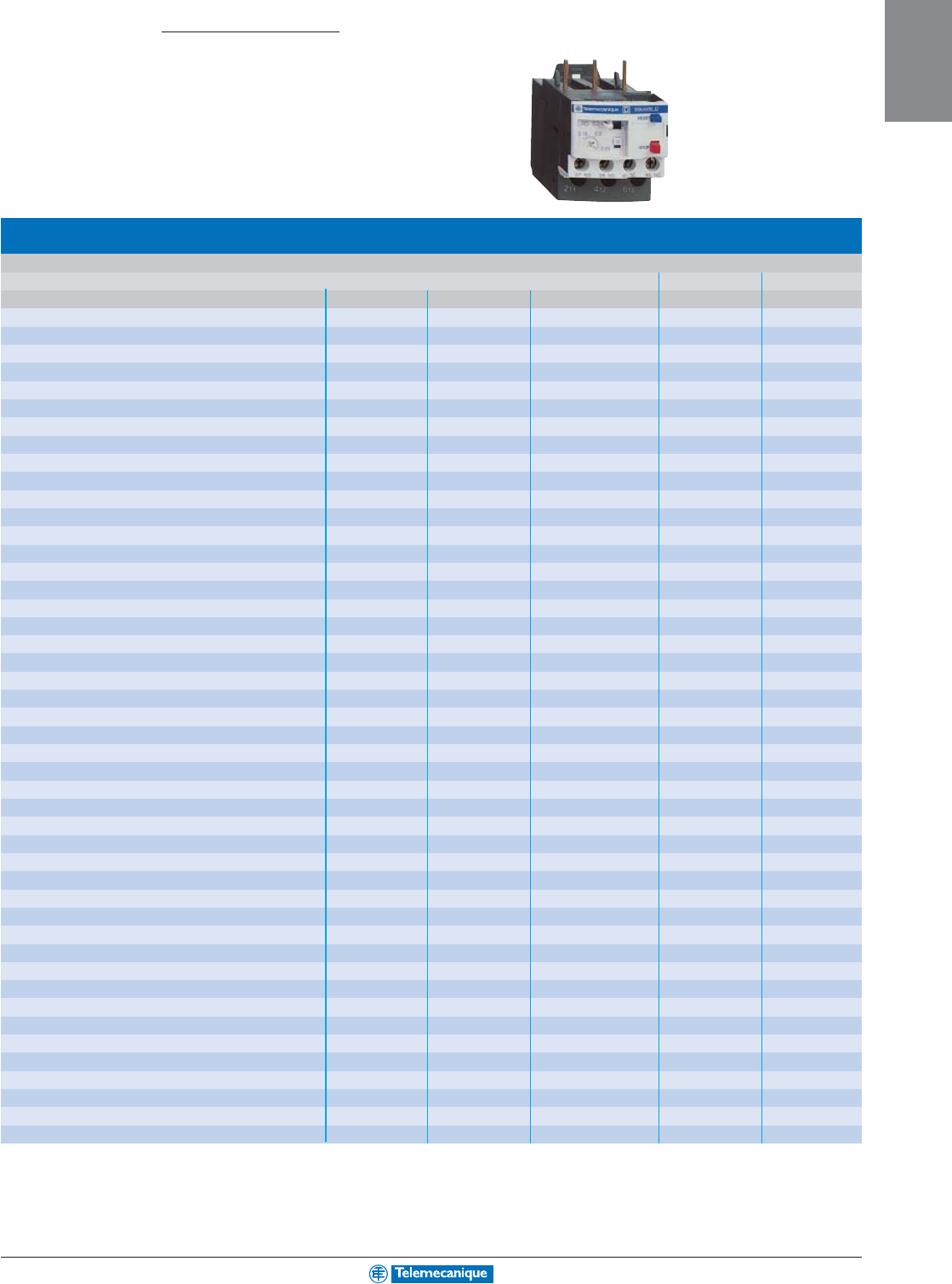
Thermal
overload
relays
0.1 to 140 A
D-line
Thermal overload relays, model d
adjustable from 0.1 to 140 A
Compensated relays with manual or automatic reset, with relay trip indicator, for a.c. or d.c.
Relay setting range Fuses to be used with selected relay—international applications
(1)
With contactor Catalog Number
aM gG BS88
Class 10 A 0.10–0.16 A 0.25 A 2 A - LC1D09–D38 LRD01
0.16–0.25 A 0.5 A 2 A - LC1D09–D38 LRD02
0.25–0.40A 1 A 2 A - LC1D09–D38 LRD03
0.40–0.63 A 1 A 1.6 A - LC1D09–D38 LRD04
0.63–1 A 2 A 4 A - LC1D09–D38 LRD05
1–1.7 A 2 A 4 A 6 A LC1D09–D38 LRD06
1.6–2.5 A 4 A 6 A 10 A LC1D09–D38 LRD07
2.5–4 A 6 A 10 A 16 A LC1D09–D38 LRD08
4–6 A 8 A 16 A 16 A LC1D09–D38 LRD10
5.5–8 A 12 A 20 A 20 A LC1D09–D38 LRD12
7–10 A 12 A 20 A 20 A LC1D09–D38 LRD14
9–13 A 16 A 25 A 25 A LC1D12–D38 LRD16
12–18 A 20 A 35 A 32 A LC1D18–D38 LRD21
16–24 A 25 A 50 A 50 A LC1D25–D38 LRD22
23–32 A 40 A 63 A 63 A LC1D25–D38 LRD32
30–38 A 50 A 80 A 80 A LC1D32 and D38 LRD35
17–25 A 25 A 50 A 50 A LC1D40–D95 LRD3322
23–32 A 40 A 63 A 63 A LC1D40–D95 LRD3353
30–40 A 40 A 100 A 80 A LC1D40–D95 LRD3355
37–50 A 63 A 100 A 100 A LC1D40–D95 LRD3357
48–65 A 63 A 100 A 100 A LC1D50–D95 LRD3359
55–70 A 80 A 125 A 125 A LC1D50–D95 LRD3361
63–80 A 80 A 125 A 125 A LC1D65–D95 LRD3363
80–104 A 100 A 160 A 160 A LC1D80 and D95 LRD3365
80–104 A 125 A 200 A 160 A LC1D115 and D150 LRD4365
95–120 A 125 A 200 A 200 A LC1D115 and D150 LRD4367
110–140 A 160 A 250 A 200 A LC1D150 LRD4369
80–104 A 100 A 160 A 160 A (2) LRD33656
95–120 A 125 A 200 A 200 A (2) LRD33676
110–140 A 160 A 250 A 200 A (2) LRD33696
Class 20 A 6 A 10 A 16 A LC1D09–D32 LRD1508
4–6 A 8 A 16 A 16 A LC1D09–D32 LRD1510
5.5–8 A 12 A 20 A 20 A LC1D09–D32 LRD1512
7–10 A 16 A 20 A 25 A LC1D09–D32 LRD1514
9–13 A 16 A 25 A 25 A LC1D12–D32 LRD1516
12–18 A 25 A 35 A 40 A LC1D18–D32 LRD1521
17–25 A 32 A 50 A 50 A LC1D25 and D32 LRD1522
23–28 A 40 A 63 A 63 A LC1D25 and D32 LRD1530
25–32 A 40 A 63 A 63 A LC1D25 and D32 LRD1532
17–25 A 32 A 50 A 50 A LC1D40–D95 LR2D3522
23–32 A 40 A 63 A 63 A LC1D40–D95 LR2D3553
30–40 A 50 A 100 A 80 A LC1D40–D95 LR2D3555
37–50 A 63 A 100 A 100 A LC1D50–D95 LR2D3557
48–65 A 80 A 125 A 100 A LC1D50–D95 LR2D3559
55–70 A 100 A 125 A 125 A LC1D65–D95 LR2D3561
63–80 A 100 A 160 A 125 A LC1D65–D80 LR2D3563
(1) Short circuit protection for North American applications: circuit breakers selected in accordance with NEC and local codes; fuses selected with maximum of 400% full load current.
(2) Separate mounting
Screw clamp terminal connections or connectors. For spring terminal connections on LRD01 to LRD22, add 3 to the end of the catalog number. Example: LRD01 becomes LRD013.
For lug-clamp connections, add 6 to the end of the catalog number. Example: LRD01 becomes LRD016.
For thermal overload relays for use with class 10 unbalanced loads, with connection by screw clamp terminals, change the prefix in the catalog number above from LRD (except
LRD-4•••) to LR3D. Example LRD01 becomes LR3D01.
1-24
MOTOR
CONTROL
www.telemecanique.com
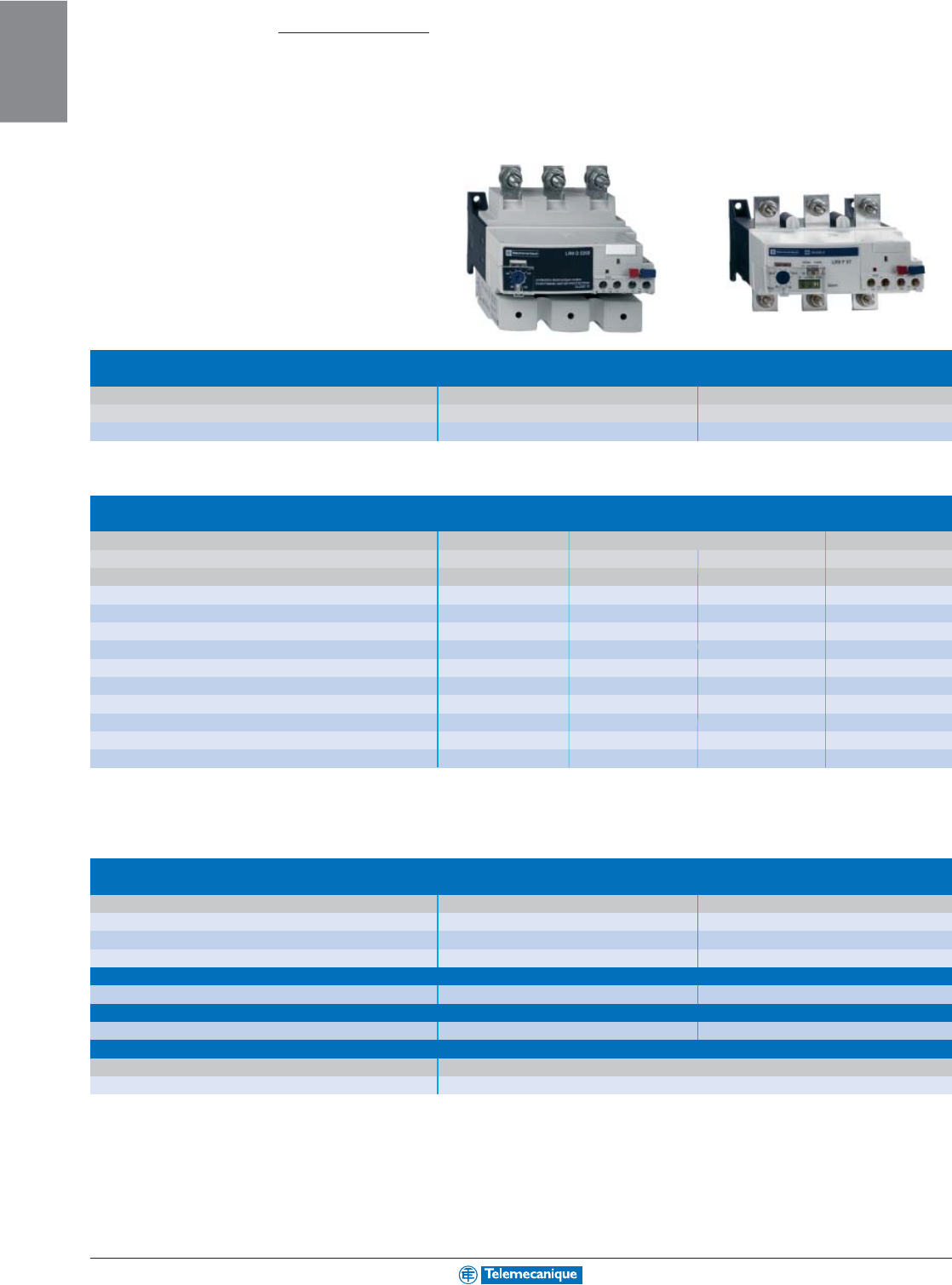
Electronic
thermal
overload
relays
For use with contactor LC1D LC1F
Motor current 60–150 A 30–630 A
Basic catalog number, to be completed LR9D LR9F
60 to 630 A
Type LR9
Relay setting range Fuse to be used with selected relay For mounting Compensated and differential
( international applications
(1)
)beneath contactor LC1 Class 10 Class 20 Class 10 or 20
aM gG (selectable)
60–100 100 160 D115 and D150 LR9D5367 LR9D5567
90–150 160 250 D115 and D150 LR9D5369 LR9F5569
30–50 50 80 F115–F185 LR9F5357 LR9F5557 LR9F57
48–80 80 125 F115–F185 LR9F5363 LR9F5563 LR9F63
60–100 100 200 F115–F185 LR9F5367 LR9F5567 LR9F67
90–150 160 250 F115–F185 LR9F5369 LR9F5569 LR9F69
132–220 250 315 F185–F400 LR9F5371 LR9F5571 LR9F71
200–330 400 500 F225–F500 LR9F7375 LR9F7575 LR9F75
300–500 500 800 F225–F500 LR9F7379 LR9F7579 LR9F79
380–630 630 800 F400–F630 and F800 LR9F7381 LR9F7581 LR9F81
Accessories
Remote control
Function Reset Stop and/or Reset
Electrical reset (2) LA7D03• (3)
Reset by flexible cable (length 0.5 m) LA7D305
Adapter for door interlock mechanism LA7D1020
Operating head for pushbutton
Spring return ZA2BL639 ZA2BL432
Rod with snap-off end
Adjustable from 17 to 120 mm ZA2BZ13
Insulated terminal blocks
For relays LR9F5•57, F5•63, F5•67, F5•69 Set of 2 blocks
LA9F103
(1) Short circuit protection for North American applications: circuit breakers selected in accordance with NEC and local codes; fuses selected with maximum of 400% full load current.
(2) The time for which the coil of remote electrical reset device LA7D03 can remain energized depends on its rest time: 1 s pulse with 9 s rest time; 5 s pulse duration with 30 s rest
time; 10 s pulse duration with 90 s rest time: maximum pulse duration 20 s with rest time of 300 s. Minimum pulse time: 200 ms.
(3) Catalog number to be completed by adding the coil voltage code, see page 1-22.
For additional options and information, reference catalog 8502CT9901.
1-25
MOTOR
CONTROL
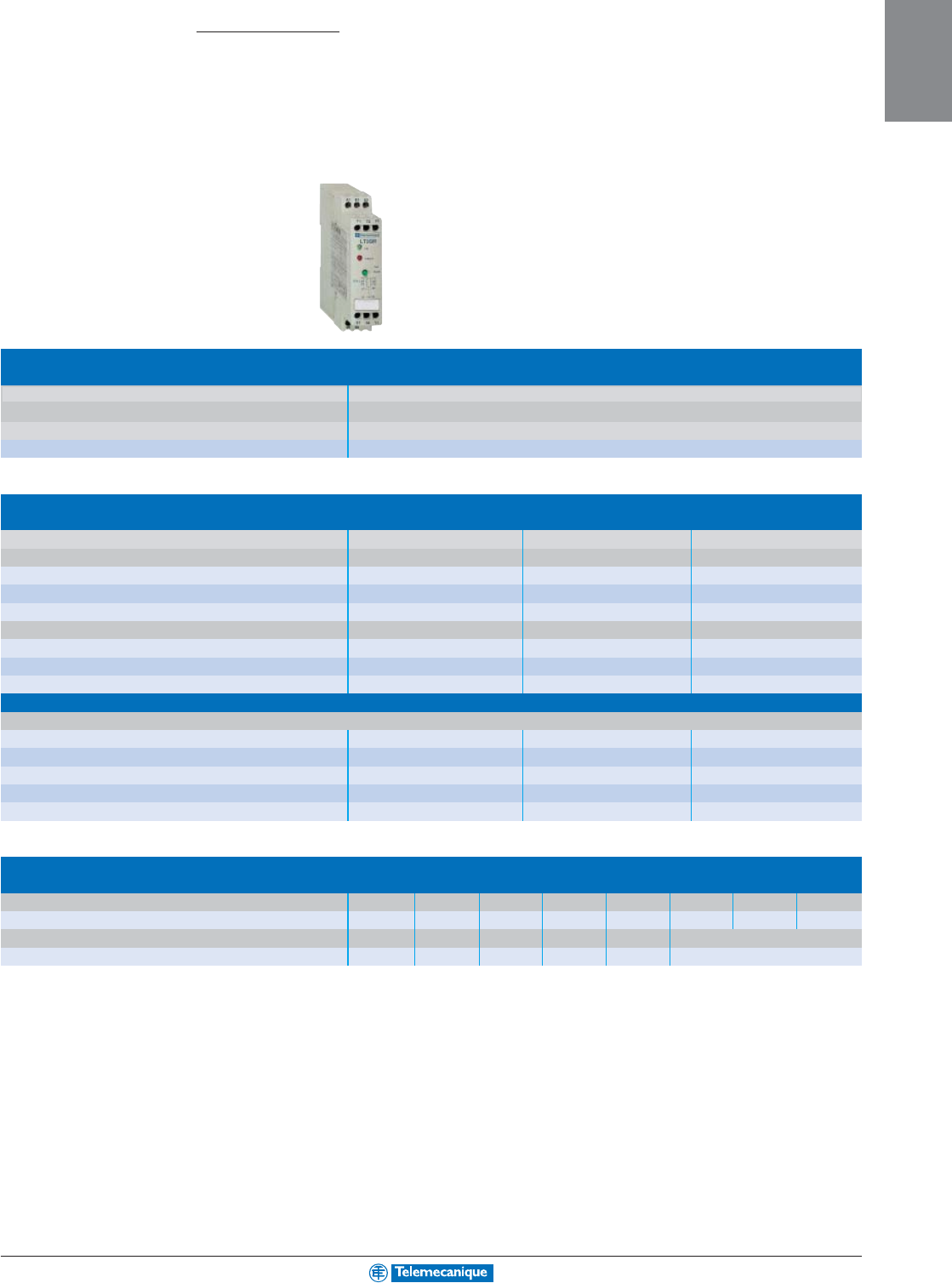
Electronic
protection
relays for use
with PTC
thermistor
probes
For use with contactor LC1D or LC1F
Motor current No limit
Connection Cage connectors
Basic catalog number, to be completed LT3S
0 to 800 A
Type LT3
Protection units
with automatic reset with thermistor short-circuit detection
■
without fault memory
Voltage Output Contact Catalog Number
On front panel: fault and voltage signalling indicator
ac 50/60 Hz 115 V N.C. LT3SE00F
230 V N.C. LT3SE00M
dc 24 V N.C. LT3SE00F
On front panel: fault and voltage signalling indicator
ac 50/60 Hz 115/230 V N.C. + N.O. LT3SA00M
dc 24/48 V N.C. + N.O. LT3SA00ED
ac 50/60 Hz or dc 24–230 V 2 C/O LT3SA00MW
■
with fault memory
On front panel: fault and voltage signalling indicator, Test and Reset button
ac 50/60 Hz 400 V N.C. + N.O. LT3SM00V
24/48 V N.C. + N.O. LT3SM00E
115/230 V N.C. + N.O. LT3SM00M
dc 24/48 V N.C. + N.O. LT3SM00ED
ac 50/60 Hz or dc 24–230 V 2 C/O LT3SM00MW
Accessories
PTC thermistor probes for LT3 and LT6 relays
Normal operating temperature (NOT) 90 °C110 °C 120 °C 130 °C 140 °C 150 °C 160 °C 170 °C
Integrated triple probes DA1TT090 DA1TT110 DA1TT120 DA1TT130 DA1TT140 DA1TT150 DA1TT160 DA1TT170
Normal operating temperature (NOT) 60 °C 70 °C 80 °C 90 °C 100 °C
Surface probes DA1TS060 DA1TS070 DA1TS080 DA1TS090 DA1TS100
(1) Comprising 2 x 3-1/2" diskettes, 1 x 2 m connection cable with 2 SUB-D 9-pin connectors (female-female)
For additional options and information, reference catalog 8502CT9901.
1-26
MOTOR
CONTROL
www.telemecanique.com
10 to 175 A
Mini Vario™ and Vario™ switches
Manual motor
control switches
Mini-Vario switch
Mounting
■
on door
■
at back of an enclosure
Switch rating UL/IEC (A) 10/12 16/20 10/12 16/20
Red handle (Ø 4 to Ø 8 shank)
Yellow front plate 60 x 60 mm VCDN12 VCDN20 VCCDN12 VCCDN20
Black handle (Ø 4 to Ø 8 shank)
Black front plate 60 x 60 mm VBDN12 VBDN20
Switch base only VN12 VN20
Vario switch disconnectors
Mounting
■
on door
Switch rating UL/IEC (A) 10/12 16/20 20/25 20/32 25/40 45/63 63/80
Red handle (Ø 4 to Ø 8 shank)
Yellow front plate 60 x 60 mm VCD02 VCD01 VCD0 VCD1 VCD2
4 screw mounting VCF02 VCF01 VCF0 VCF1 VCF2 VCF3 VCF4
Long red handle (Ø 4 to Ø 8 shank)
Yellow front plate 90 x 90 mm 4 screw mounting
Black handle (Ø 4 to Ø 8 shank)
Black front plate 60 x 60 mm VBD02 VBD01 VBD0 VBD1 VBD-2
4 screw mounting VBF02 VBF01 VBF0 VBF1 VBF2 VBF3 VBF4
Long black handle (Ø 4 to Ø 8 shank)
Black front plate 90 x 90 mm 4 screw mounting
Switch base only V02 V01 V0 V1 V2 V3 V4
Add-on modules
Main pole modules
Rating UL/IEC (A) 10/12 16/20 20/25 20/32 25/40 45/63 63/80
VZ02 VZ01 VZ0 VZ1 VZ2 VZ3 VZ4
Auxiliary contact block modules
Contact types N.O. + N.C. N.O. + N.O.
VZ7 VZ20
For additional options and information, reference catalog 9421CT0301.
1-27
MOTOR
CONTROL
■
at back of an enclosure
100/125 115/175 10/12 16/20 20/25 20/32 25/40 45/63 63/80 100/125 115/175
VCCD02 VCCD01 VCCD0 VCCD1 VCCD2
VCCF02 VCCF01 VCCF0 VCCF1 VCCF2 VCCF3 VCCF4
VCF5 VCF6 VCCF5 VCCF6
VBF5 VBF6
V5 V6 V02 V01 V0 V1 V2 V3 V4 V5 V6
For additional options and information, reference catalog 9421CT0301.
1-28
MOTOR
CONTROL
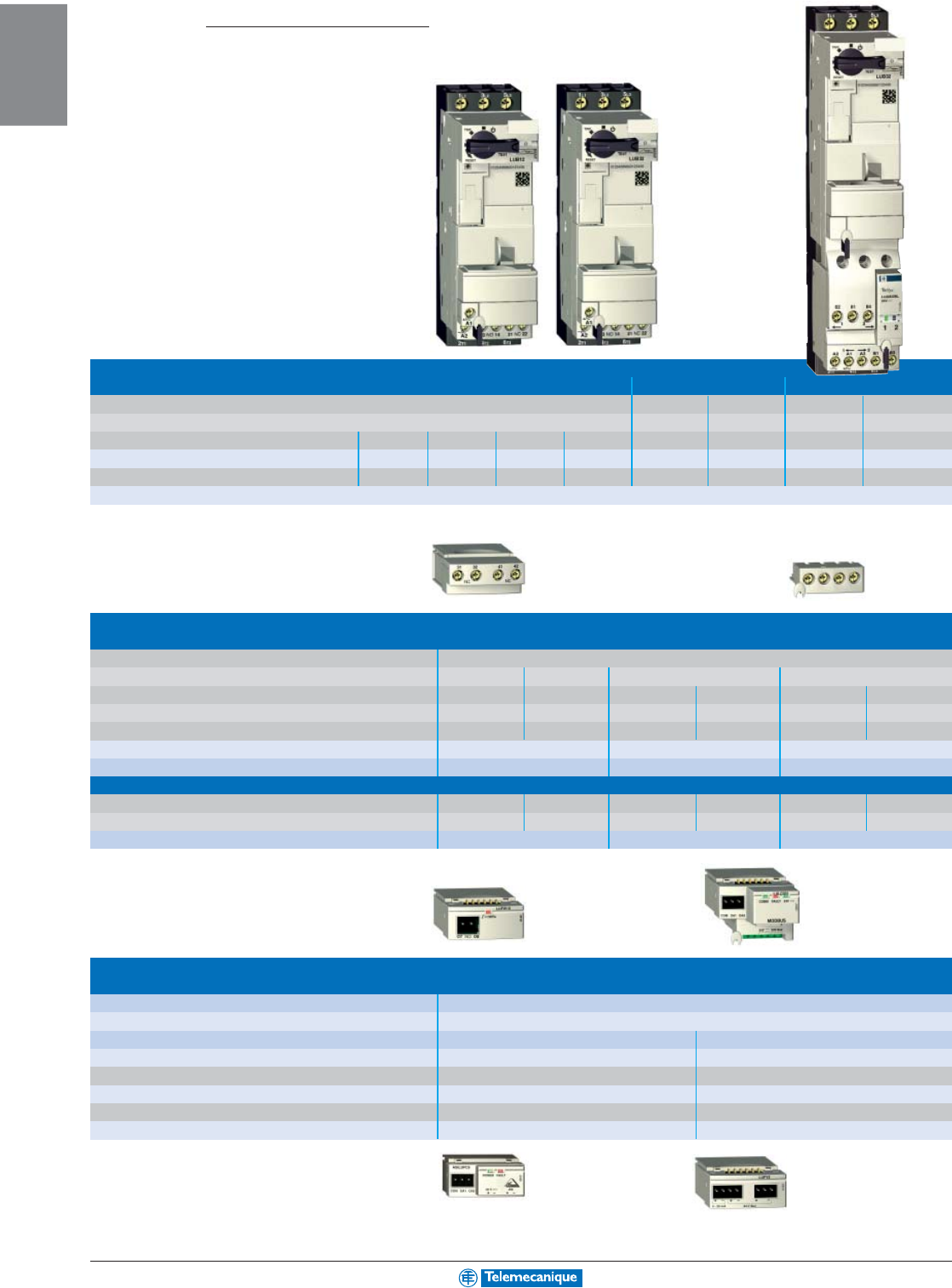
www.telemecanique.com
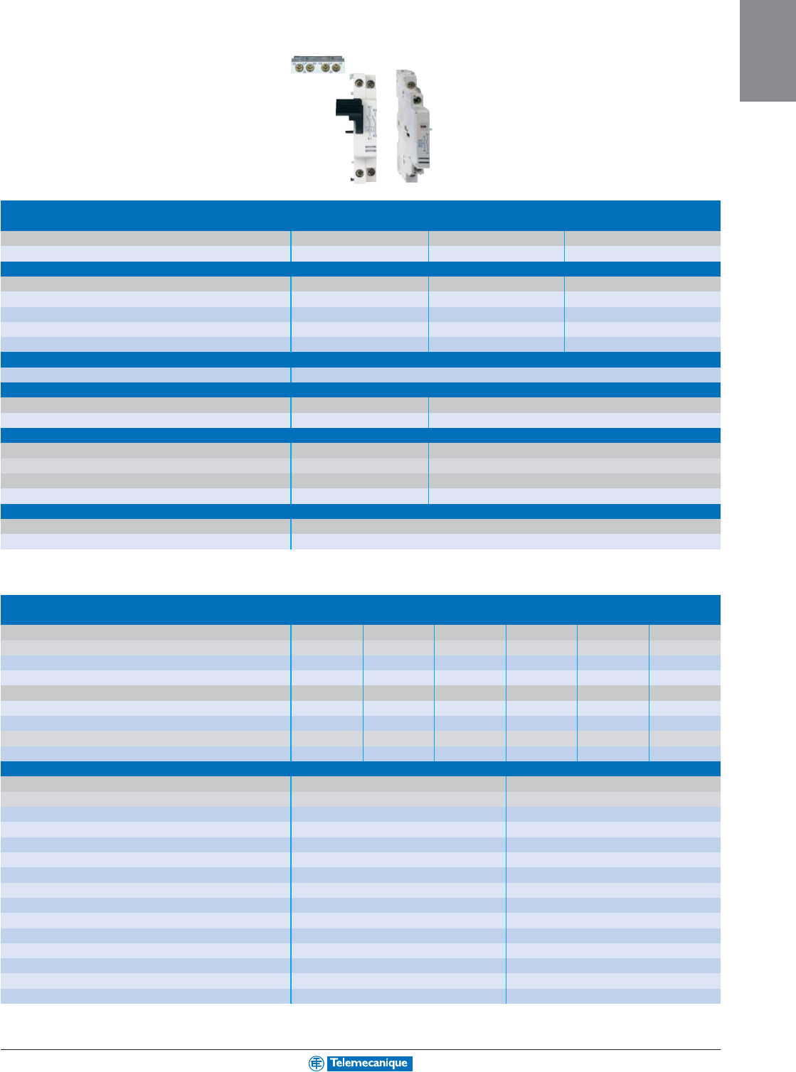
Power base
for D.O.L. starter
■
Non reversing
■
Reversing
Connection by screw clamp Catalog Current Catalog Current
number rating number rating
Operational voltage 200/208V 230/240 V 460 V 575/600 V
Horsepower ratings (UL ratings) 3 3 7.5 10 LUB12 12 A LU2B12•• 12 A
10 10 20 25 LUB32 32 A LU2B32•• 32 A
0 to 32 A
Type U
Te
Sys
starter-controller
Add-on blocks
Contact blocks
Signalling Contact
■
status of starter-controller power poles N.O. (53-54)
■
fault N.C. (95-96) N.C. (95-96) N.O. (97-98)
■
control handle in position O N.O. (17-18) N.O. (17-18)
Connection Item 1 1 1 1 1 1
■
screw clamp terminals 1 + 2 LUA1D11 LUA1C11 LUA1C20
■
without connections 1 LUA1D110 LUA1C110 LUA1C200
Auxiliary contact blocks
N.O. N.C. N.O. N.C. N.O. N.C.
2- 11- 2
■
screw clamp terminals 3 LUFN20 LUFN11 LUFN02
Function modules
■
parallel wiring LUFC00
■
alarm LUFW10
■
communication As-i Modbus
ASILUFC5 LULC031
■
indication of motor load 4–20 mA
LUFV2
■
fault differentiation and reset manual reset automatic reset
LUFDH20 LUFDA10
For additional options and information, reference catalog 8502CT0201.
1-29
MOTOR
CONTROL
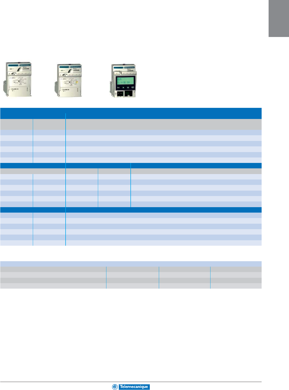
Standard Advanced Multifunction
Standard control circuit voltages
Volts 24 48–72 110–240
dc BL - -
ac B- -
dc or ac - ES (1) FU (2)
(1) dc: 48–72 V, ac: 48 V.
(2) dc: 110–220 V, ac: 110–240 V.
Control units
■
standard Class 10
Setting range Clip-in mounting Catalog Number (1)
on power base
0.15–0.6 12 and 32 LUCAX6••
0.35–1.4 12 and 32 LUCA1X••
1.25–5 12 and 32 LUCA05••
3–12 12 and 32 LUCA12••
4.5–18 32 LUCA18••
8–32 32 LUCA32••
■
advanced Class 10 Class 20
For motor type
■
three-phase
■
single-phase
■
three-phase
0.15–0.6 12 and 32 LUCBX6•• LUCCX6•• LUCDX6••
0.35–1.4 12 and 32 LUCB1X•• LUCC1X•• LUCD1X••
1.25–5 12 and 32 LUCB05•• LUCC05•• LUCD05••
3–12 12 and 32 LUCB12•• LUCC12•• LUCD12••
4.5–18 32 LUCB18•• LUCC18•• LUCD18••
8–32 32 LUCB32•• LUCC32•• LUCD32••
■
multifunction Class 5 to 35
0.15–0.6 12 and 32 LUCMX6BL
0.35–1.4 12 and 32 LUCM1XBL
1.25–5 12 and 32 LUCM05BL
3–12 12 and 32 LUCM12BL
4.5–18 32 LUCM18BL
8–32 32 LUCM32BL
(1) Basic catalog number to be completed by adding the voltage code from the table below.
For additional options and information, reference catalog 8502CT0201.
1-30
MOTOR
CONTROL
www.telemecanique.com
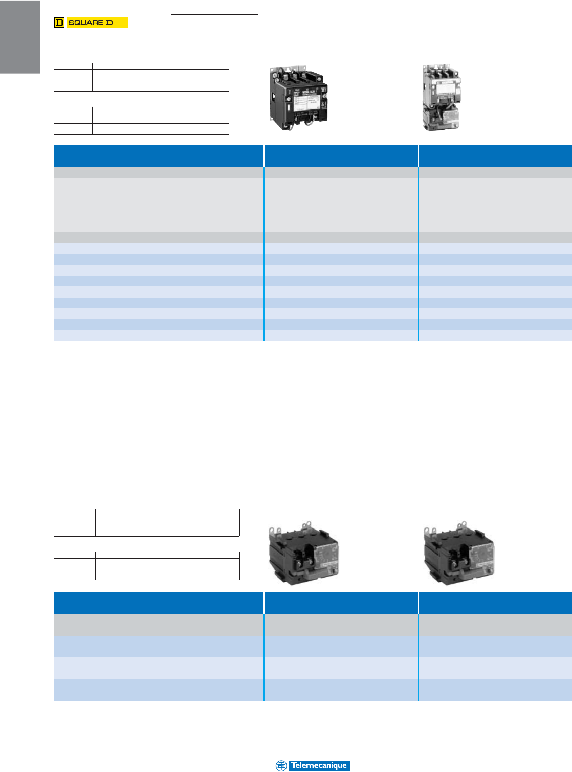
NEMA Type
Contactors and starters
3-pole contactors and starters,
open style
(1) Standard control circuit voltages:
Volts 24 110 120 208 220
50 Hz –V02 ––V03
60 Hz V01 (4) –V02 V08 –
Volts 240 380 440 480 600
50 Hz –V05 V06 ––
60 Hz V03 ––V06 V07
For 24 V and 120 V coils add the letter “S” for separate control. Example: 8502 SAO 12 V01S.
Type Contactors Starters
3-pole, open style 3-pole, open style
Characteristics
NEMA Standard power ratings Maximum Basic catalog no. Complete with code Basic catalog no. Complete with code
size of 3-phase motors 50/60 Hz continuous indicating control circuit voltage (1) indicating control circuit voltage (1)
current and optional Forms (2) optional Forms (2) and “H” code (3)
Motor voltage
200 V 230 V 460 V 575 V
Hp
kW
Hp
kW
Hp
kW
Hp
kW A
00
1.5
1.1
1.5
1.1
2
1.5
2
1.5 9 8502 SAO 12
pppppp
pppppp
ppp 8536 SAO 12
pppppp
pppppp
ppp
0
3
2.2
3
2.2
5
3.7
5
3.7 18 8502 SBO 2
pppppp
pppppp
ppp 8536 SBO 2
pppppp
pppppp
ppp
1
7.5
5.5
7.5
5.5
10
7.5
10
7.5 27 8502 SCO 2
pppppp
pppppp
ppp 8536 SCO 3
pppppp
pppppp
ppp
2
10
7.5
15
11
25
18.5
25
18.5 45 8502 SDO 2
pppppp
pppppp
ppp 8536 SDO 1
pppppp
pppppp
ppp
3
25
18,5
30
22
50
37
50
37 90 8502 SEO 2
pppppp
pppppp
ppp 8536 SEO 1
pppppp
pppppp
ppp
4
40
30
50
37
100
75
100
75 135 8502 SFO 2
pppppp
pppppp
ppp 8536 SFO 1
pppppp
pppppp
ppp
5
75
55
100
75
200
150
200
150 270 8502 SGO 2
pppppp
pppppp
ppp 8536 SGO 1
pppppp
pppppp
ppp
6
150
110
200
150
400
300
400
300 540 8502 SHO 2
pppppp
pppppp
ppp 8536 SHO 2
pppppp
pppppp
ppp
7
–
–
300
220
600
450
600
450 810 8502 SJO 2
pppppp
pppppp
ppp 8536 SJO 2
pppppp
pppppp
ppp
(2) For optional Forms, please consult your nearest Square D/Schneider Electric sales office.
(3) Add the letter “H” for Solid State Overload Relays, see tables below.
(4) 24 V coil is not available for sizes 4 to 7. Available for sizes 00–3, specify the letter “S” for separate control.
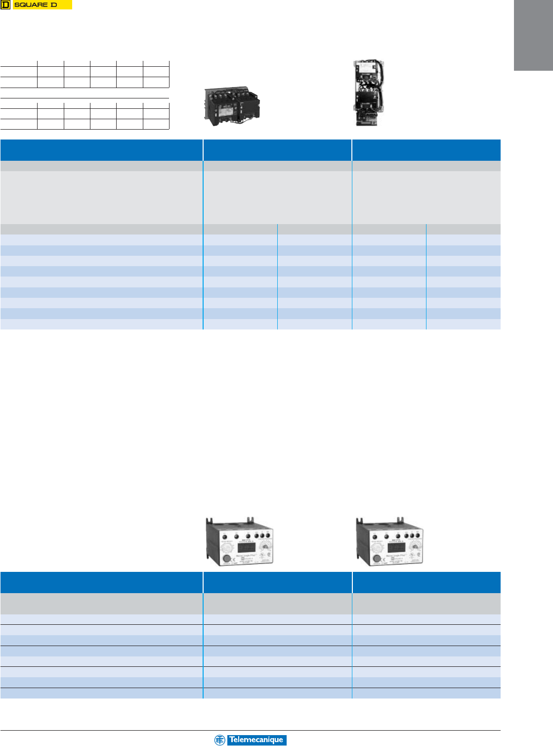
Solid State Overload Relays
(6) Standard current ranges dependent on starter size:
Size 00 0 1 2 3
Current
ranges A
1.5–4.5
(8)
6–18 9–27 15–45 30–90
Size 4 5 6 7
Current
ranges A 40–135 90–270 180–540
(8)
270–810
(9)
Form addersMotor Logic
®
solid state relays
Motor Logic
®
solid state relays
Without additional auxiliary contact With additional auxiliary contact
Description Current For use Suffix to be added Suffix to be added to
range with to the starter catalog no. (7) the starter catalog no. (7)
Base unit, (6) 8536 Spp
pp
ppp
pp
pH10 H11
Trip class 10 8736 Spp
pp
ppp
pp
p
Base unit, (6) 8536 Spp
pp
ppp
pp
pH20 H21
Trip class 20 8736 Spp
pp
ppp
pp
p
Feature unit (6) 8536 Spp
pp
ppp
pp
pH30 H31
8736 Spp
pp
ppp
pp
p
(7) Example: 8536 SAO 12 V01 H10.
(8) Only available with feature units.
(9) Only available with feature units with auxiliary contact.
For additional information, reference Catalog 8502CT9701.
1-31
MOTOR
CONTROL
(1) Standard control circuit voltages:
Volts 24 110 120 208 220
50 Hz –V02 ––V03
60 Hz V01 (4) –V02 V08 –
Volts 240 380 440 480 600
50 Hz –V05 V06 ––
60 Hz V03 ––V06 V07
For 24 V and 120 V coils add the letter “S” for separate control. Example: 8702 SAO 4 V01S.
Type Reversing contactors Reversing starters
3-pole, open style 3-pole, open style
Characteristics
NEMA Standard power ratings Maximum Basic catalog no. Complete with code Basic catalog no. Complete with code
size of 3-phase motors 50/60 Hz continuous indicating control circuit voltage (1) indicating control circuit voltage (1)
current and optional Forms (2) optional Forms (2) and “H” code (3)
Motor voltage
200 V 230 V 460 V 575 V
Hp
kW
Hp
kW
Hp
kW
Hp
kW A Vertical Side by side Vertical Side by side
00
1.5
1.1
1.5
1.1
2
1.5
2
1.5 9 –8702 SAO 4
pppppp
pppppp
ppp –8736 SAO 16
pppppp
pppppp
ppp
0
3
2.2
3
2.2
5
3.7
5
3.7 18 8702 SBO 12
pppppp
pppppp
ppp 8702 SBO 4
pppppp
pppppp
ppp 8736 SBO 10
pppppp
pppppp
ppp 8736 SBO 4
pppppp
pppppp
ppp
1
7.5
5.5
7.5
5.5
10
7.5
10
7.5 27 8702 SCO 7
pppppp
pppppp
ppp 8702 SCO 8
pppppp
pppppp
ppp 8736 SCO 7
pppppp
pppppp
ppp 8736 SCO 8
pppppp
pppppp
ppp
2
10
7.5
15
11
25
18.5
25
18.5 45 8702 SDO 1
pppppp
pppppp
ppp 8702 SDO 2
pppppp
pppppp
ppp 8736 SDO 1
pppppp
pppppp
ppp 8736 SDO 2
pppppp
pppppp
ppp
3
25
18.5
30
22
50
37
50
37 90 8702 SEO 1
pppppp
pppppp
ppp 8702 SEO 2
pppppp
pppppp
ppp 8736 SEO 1
pppppp
pppppp
ppp 8736 SEO 2
pppppp
pppppp
ppp
4
40
30
50
37
100
75
100
75 135 8702 SFO 1
pppppp
pppppp
ppp 8702 SFO 3
pppppp
pppppp
ppp 8736 SFO 1
pppppp
pppppp
ppp 8736 SFO 3
pppppp
pppppp
ppp
5
75
55
100
75
200
150
200
150 270 8702 SGO 1
pppppp
pppppp
ppp 8702 SGO 3
pppppp
pppppp
ppp 8736 SGO 1
pppppp
pppppp
ppp 8736 SGO 3
pppppp
pppppp
ppp
6
150
110
200
150
400
300
400
300 540 –8702 SHO 1
pppppp
pppppp
ppp –8736 SHO 1
pppppp
pppppp
ppp
7
–
–
300
220
600
450
600
450 810 –8702 SJO 1
pppppp
pppppp
ppp –8736 SJO 1
pppppp
pppppp
ppp
(2) For optional Forms, please consult your nearest Square D/Schneider Electric sales office.
(3) Add the letter “H” for Solid State Overload Relays, see tables below.
(4) 24 V coil is not available for sizes 4 to 7. Available for sizes 00–3, specify the letter “S” for separate control.
Solid State Overload Relays
Form adders
Motor Logic® PLUS solid state relays Motor Logic® PLUS solid state relays
200 to 480 V 600 V
Suffix to be added Suffix to be added
Current range to the starter catalog no. (7) to the starter catalog no. (7)
0.5–2.3 A B20 B24
2–9 A B30 B34
6–27 A B40 B44
10–45 A B50 B54
20–90 A B60 B64
60–135 A B70 B74
120–270 A B80 B84
240–540 A B90 B94
(7) Example: 8536 SAO 12 V01 B20.
3-pole reversing contactors and
reversing starters, open style
For additional information, reference Catalog 8502CT9701.
1-32
MOTOR
CONTROL
www.telemecanique.com
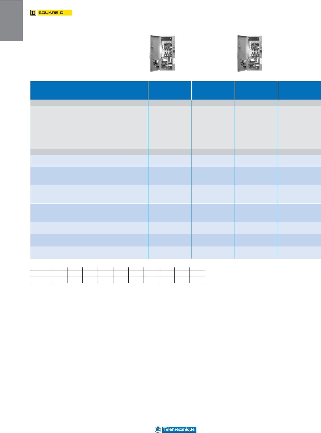
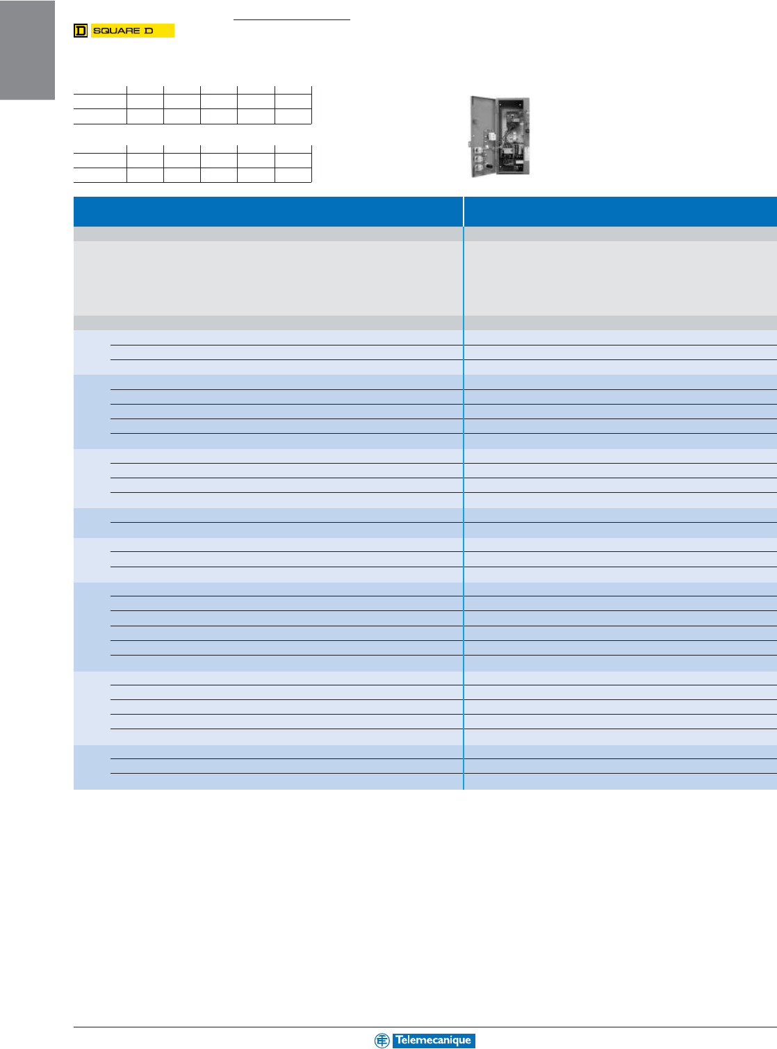
NEMA Type
Combination starters
3-pole disconnect switch starters
Type 3-pole starters 3-pole starters, 3-pole starters, 3-pole starters,
non-reversing non-reversing non-reversing non-reversing
with Class H fuses with Class R fuses with Class H fuses with Class R fuses
Characteristics
Size Standard power ratings Fuse Basic catalog no. Basic catalog no. Basic catalog no. Basic catalog no.
NEMA of 3-phase motors 50/60 Hz size Complete with code Complete with code Complete with code Complete with code
indicating control indicating control indicating indicating
circuit voltage (1) circuit voltage (1) circuit voltage (1) circuit voltage (1)
optional Forms (2) and optional Forms (2) optional Forms (2) and optional Forms (2)
Motor voltage (starter voltage) and H code (3) and H code (3)
200 V (208 V) 230 V (240 V) 460 V (480 V) 575 V (600 V)
Hp
kW
Hp
kW
Hp
kW
Hp
kW A
0
3
2.2
3
2.2
–
–
–
–308538 SBG 12
pppppp
pppppp
ppp 8538 SBG 32
pppppp
pppppp
ppp 8538 SBA (4) 2
pppppp
pppppp
ppp 8538 SBA (5) 2
pppppp
pppppp
ppp
–
–
–
–
5
3.75
5
3.75 30 8538 SBG 13
pppppp
pppppp
ppp 8538 SBG 33
pppppp
pppppp
ppp 8538 SBA (4) 3
pppppp
pppppp
ppp 8538 SBA (5) 3
pppppp
pppppp
ppp
1
5
3.75
5
3.75
–
–
–
–308538 SCG 12
pppppp
pppppp
ppp 8538 SCG 32
pppppp
pppppp
ppp 8538 SCA (4) 2
pppppp
pppppp
ppp 8538 SCA (5) 2
pppppp
pppppp
ppp
–
–
–
–
10
7.5
10
7.5 30 8538 SCG 14
pppppp
pppppp
ppp 8538 SCG 34
pppppp
pppppp
ppp 8538 SCA (4) 4
pppppp
pppppp
ppp 8538 SCA (5) 4
pppppp
pppppp
ppp
7.5
5.5
7.5
5.5
–
–
–
–608538 SCG 13
pppppp
pppppp
ppp 8538 SCG 33
pppppp
pppppp
ppp 8538 SCA (4) 3
pppppp
pppppp
ppp 8538 SCA (5) 3
pppppp
pppppp
ppp
2
10
7.5
15
11
–
–
–
–608538 SDG 12
pppppp
pppppp
ppp 8538 SDG 32
pppppp
pppppp
ppp 8538 SDA (4) 2
pppppp
pppppp
ppp 8538 SDA (5) 2
pppppp
pppppp
ppp
–
–
–
–
15
11
15
11 30 8538 SDG 16
pppppp
pppppp
ppp 8538 SDG 36
pppppp
pppppp
ppp 8538 SDA (4) 6
pppppp
pppppp
ppp 8538 SDA (5) 6
pppppp
pppppp
ppp
–
–
–
–
25
18.5
25
18.5 60 8538 SDG 14
pppppp
pppppp
ppp 8538 SDG 34
pppppp
pppppp
ppp 8538 SDA (4) 4
pppppp
pppppp
ppp 8538 SDA (5) 4
pppppp
pppppp
ppp
3
20
15
25
18.5
–
–
–
–100 8538 SEG 15
pppppp
pppppp
ppp 8538 SEG 35
pppppp
pppppp
ppp 8538 SEA (4) 5
pppppp
pppppp
ppp 8538 SEA (5) 5
pppppp
pppppp
ppp
–
–
–
–
50
37
50
37 100 8538 SEG 13
pppppp
pppppp
ppp 8538 SEG 33
pppppp
pppppp
ppp 8538 SEA (4) 3
pppppp
pppppp
ppp 8538 SEA (5) 3
pppppp
pppppp
ppp
25
18,5
30
22
–
–
–
–200 8538 SEG 12
pppppp
pppppp
ppp 8538 SEG 32
pppppp
pppppp
ppp 8538 SEA (4) 2
pppppp
pppppp
ppp 8538 SEA (5) 2
pppppp
pppppp
ppp
4
40
30
50
37
–
–
–
–200 8538 SFG 15
pppppp
pppppp
ppp 8538 SFG 35
pppppp
pppppp
ppp 8538 SFA (4) 5
pppppp
pppppp
ppp 8538 SFA (5) 5
pppppp
pppppp
ppp
–
–
–
–
100
75
100
75 200 8538 SFG 13
pppppp
pppppp
ppp 8538 SFG 33
pppppp
pppppp
ppp 8538 SFA (4) 3
pppppp
pppppp
ppp 8538 SFA (5) 3
pppppp
pppppp
ppp
5
75
55
100
75
–
–
–
–400 8538 SGG 15
pppppp
pppppp
ppp 8538 SGG 35
pppppp
pppppp
ppp 8538 SGA (4) 5
pppppp
pppppp
ppp 8538 SGA (5) 5
pppppp
pppppp
ppp
–
–
–
–
200
150
200
150 400 8538 SGG 13
pppppp
pppppp
ppp 8538 SGG 33
pppppp
pppppp
ppp 8538 SGA (4) 3
pppppp
pppppp
ppp 8538 SGA (5) 3
pppppp
pppppp
ppp
6
150
110
200
150
–
–
–
–600 8538 SHG 13
pppppp
pppppp
ppp 8538 SHG 33
pppppp
pppppp
ppp 8538 SHA (4) 3
pppppp
pppppp
ppp 8538 SHA (5) 3
pppppp
pppppp
ppp
–
–
–
–
400
300
400
300 600 8538 SHG 12
pppppp
pppppp
ppp 8538 SHG 32
pppppp
pppppp
ppp 8538 SHA (4) 2
pppppp
pppppp
ppp 8538 SHA (5) 2
pppppp
pppppp
ppp
(1) Standard control circuit voltages:
Volts 24 110 120 208 220 240 380 440 480 600
50 Hz –V02 ––V03 –V05 V06 ––
60 Hz V01
(6)(7)
–V02
(6)
V08 –V03 ––V06 V07
For 24 V and 120 V coils add the letter “S” for separate control. Example: 8538 SBG 12 V01S.
(2) For optional Forms, please consult your nearest Square D/Schneider Electric sales office.
(3) Add the letter “H” for Solid State Overload Relays, see table on page opposite.
(4) To order a unit with external reset, replace (4) with “2”. To order a unit without external reset, replace (4) with “1”.
(5) To order a unit with external reset, replace (5) with “4”. To order a unit without external reset, replace (5) with “3”.
(6) To order this voltage code, add the letter “S” (separate contol).
(7) 24 V coil not available for sizes 4 to 6. Available for sizes 0 to 3, specify letter “S” (separate contol).
NEMA 1 general purpose enclosure NEMA 12 dust-tight and drip-tight
industrial use enclosure
For additional information, reference Catalog 8538CT9701.
1-33
MOTOR
CONTROL
Form adders Motor Logic
®
solid state relays
For use Current Description Suffix to be added
with range to the starter catalog no. (9)
8538 Spp
pp
pG 1pp
pp
p/Spp
pp
pA 1pp
pp
p/Spp
pp
pA 2pp
pp
p(8) Base unit, Trip Class 10 H10
(except 8538 SDG 16/SDA 16/SDA 26) (8) Base unit, Trip Class 20 H20
(8) Feature unit H30
8538 SBG 12/13, 3...9 A Base unit, Trip Class 10 H109
8538 SBA 12/22/13/23, 3...9 A Base unit, Trip Class 20 H209
8538 SCG 12/14, 1.5–4.5 A Feature unit H308
8538 SCA 12/22/14/24, 3–9 A Feature unit H309
8538 SDG 16,
8538 SDA 16/26
8538 SCG 12/14 6–18 A Base unit, Trip Class 10 H100
8538 SCA 12/22/14/24, 6–18 A Base unit, Trip Class 20 H200
8538 SDG 16 6–18 A Feature unit H300
8538 SDA 16/26
8538 SDG 16, 9–27 A Base unit, Trip Class 10 H101
8538 SDA 16/26 9–27 A Base unit, Trip Class 20 H201
9–27 A Feature unit H301
(8) Standard current ranges dependent on starter size:
Size 00 0 1 2 3 4 5 6 7
Current
ranges A 3–96–18 9–27 15–45 30–90 45–135 90–270 180–540
(10)
270–810
(11)
(9) Example: 8538 SBG 12 V01 H10.
(10) Only available with feature units.
(11) Only available with feature units with auxiliary contact.
Solid state overload Relays
For additional information, reference Catalog 9065CT9701.
1-34
MOTOR
CONTROL
www.telemecanique.com
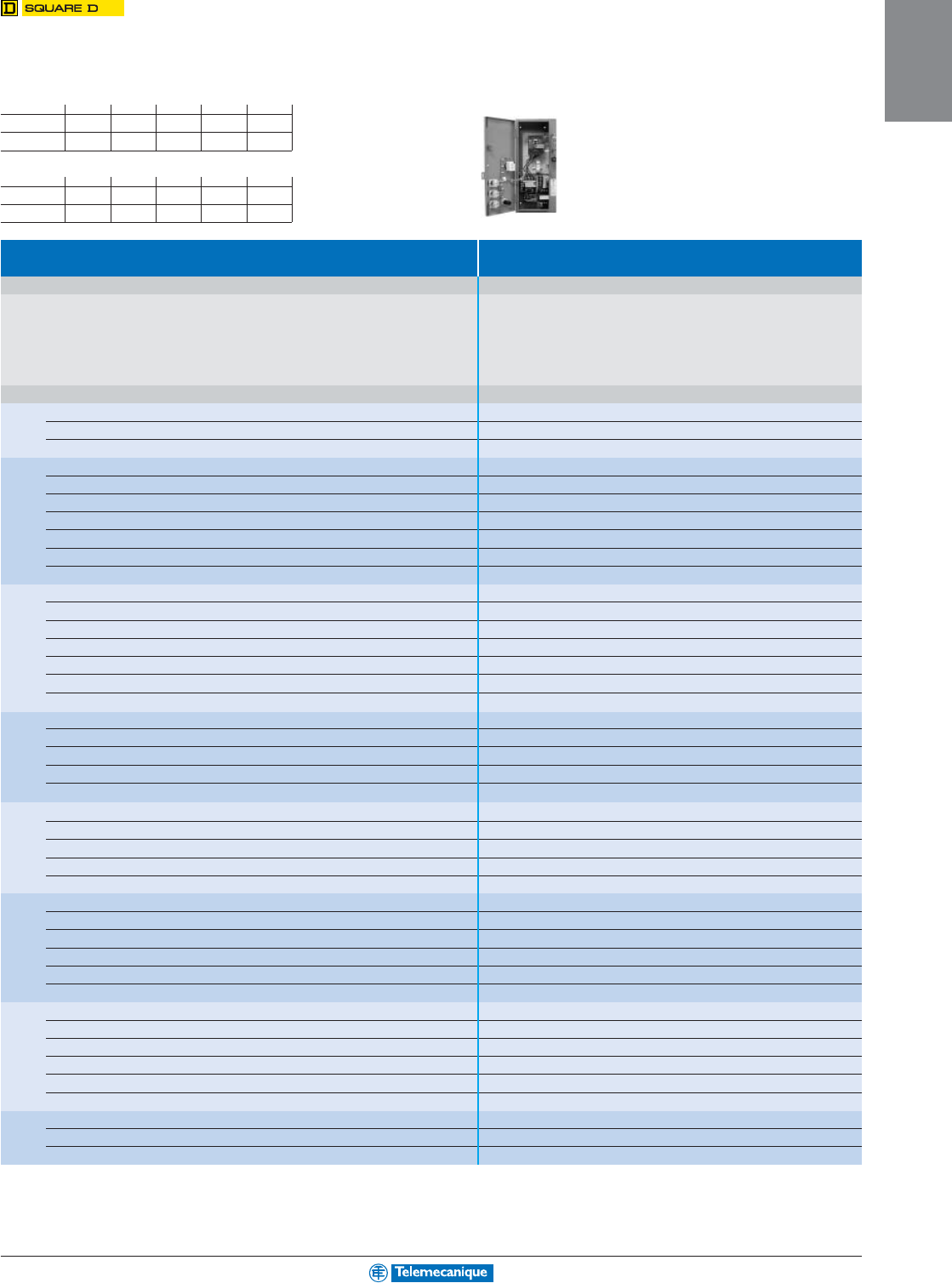
Combination starters
Mag-Gard®
circuit-breaker starters
(1) Standard control circuit voltages:
Volts 24 110 120 208 220
50 Hz –V02 ––V03
60 Hz V01
(4)(5)
–V02
(4)
V08 –
Volts 240 380 440 480 600
50 Hz –V05 V06 ––
60 Hz V03 ––V06 V07
For 24 V and 120 V coils add the letter “S” for separate control. Example: 8539 SCG 41 V02 H10S.
Type 3-pole circuit breaker starters,
non-reversing
Characteristics
NEMA Standard power ratings Circuit-breaker Basic catalog no. Complete with code indicating
size of 3-phase motors 50/60 Hz control circuit voltage (1), optional Forms (2)
and “H” code (3)
Motor voltage (starter voltage)
200 V (208 V) 230 V (240 V) 460 V (480 V) 575 V (600 V)
Hp
kW
Hp
kW
Hp
kW
Hp
kW
0
0.3
0.2
0.3
0.2
1
0.75
1
0.75 GJL 36003 MO1 8539 SBG 41
pppppp
pppppp
ppp
1
0.75
1
0.75
3
2.2
3
2.2 GJL 36007 MO2 8539 SBG 42
pppppp
pppppp
ppp
3
2.2
3
2.2
5
3.7
5
3.7 GJL 36015 MO3 8539 SBG 43
pppppp
pppppp
ppp
1
0.3
0.2
0.3
0.2
1
0.75
1
0.75 GJL 36003 MO1 8539 SCG 41
pppppp
pppppp
ppp
1
0.75
1
0.75
3
2.2
3
2.2 GJL 36007 MO2 8539 SCG 42
pppppp
pppppp
ppp
3
2.2
3
2.2
7.5
5.5
10
7.5 GJL 36015 MO3 8539 SCG 43
pppppp
pppppp
ppp
5
3.7
7.5
5.5
10
7.5
–
–GJL 36030 MO4 8539 SCG 44
pppppp
pppppp
ppp
7.5
5.5
–
–
–
–
–
–GJL 36050 MO5 8539 SCG 45
pppppp
pppppp
ppp
2
3
2.2
3
2.2
7.5
5.5
10
7.5 GJL 36015 MO3 8539 SDG 41
pppppp
pppppp
ppp
5
3.7
7.5
5.5
15
11
20
15 GJL 36030 MO4 8539 SDG 42
pppppp
pppppp
ppp
10
7.5
10
7.5
25
18.5
25
18.5 GJL 36050 MO5 8539 SDG 43
pppppp
pppppp
ppp
–
–
15
11
–
–
–
–GJL 36075 MO6 8539 SDG 44
pppppp
pppppp
ppp
3
–
–
–
–
25
18.5
30
22 GJL 36050 MO5 8539 SEG 41
pppppp
pppppp
ppp
25
18.5
30
22
30
22
50
37 FAL 36100 18M 8539 SEG 42
pppppp
pppppp
ppp
4
30
22
–
–
75
55
100
75 KAL 36250 25M 8539 SFG 42
pppppp
pppppp
ppp
–
–
40
30
–
–
–
–KAL 36250 26M 8539 SFG 43
pppppp
pppppp
ppp
–
–
50
37
100
75
–
–KAL 36250 29M 8539 SFG 44
pppppp
pppppp
ppp
5
–
–
–
–
–
–
125
90 KAL 36250 29M 8539 SGG 41
pppppp
pppppp
ppp
50
37
–
–
–
–
150
110 KAL 36250 30M 8539 SGG 42
pppppp
pppppp
ppp
–
–
60
45
125
90
–
–KAL 36250 31M 8539 SGG 43
pppppp
pppppp
ppp
60
45
75
55
150
110
200
150 LAL 36400 32M 8539 SGG 44
pppppp
pppppp
ppp
75
55
–
–
–
–
–
–LAL 36400 33M 8539 SGG 45
pppppp
pppppp
ppp
–
–
100
75
200
150
–
–LAL 36400 35M 8539 SGG 46
pppppp
pppppp
ppp
6
–
–
–
–
–
–
250
185 LAL 36400 35M 8539 SHG 42
pppppp
pppppp
ppp
100
75
–
–
250
185
300
220 LAL 36400 36M 8539 SHG 43
pppppp
pppppp
ppp
125
90
150
110
300
220
400
300 MAL 36600 40M 8539 SHG 44
pppppp
pppppp
ppp
150
110
–
–
350
250
–
–MAL 36600 42M 8539 SHG 45
pppppp
pppppp
ppp
–
–
200
150
400
300
–
–MAL 36600 44M 8539 SHG 46
pppppp
pppppp
ppp
7
–
–
–
–
–
–
500
370 MAL 36800 44M 8539 SJG 41
pppppp
pppppp
ppp
–
–
250
185
500
370
600
450 MAL 36800 45M 8539 SJG 42
pppppp
pppppp
ppp
–
–
300
220
600
450
–
–MAL 361000 47M 8539 SJG 43
pppppp
pppppp
ppp
(2) For optional Forms, please consult your nearest Square D/Schneider Electric sales office.
(3) Add the letter “H” for Motor Logic
®
solid state overload relays, see page 1-30.
Motor Logic
®
PLUS solid state overload relays are not available on combination starters.
(4) For this voltage code, add the letter “S” (separate contol).
(5) 24 V coil not available for sizes 4 to 6. Available for sizes 0 to 3, specify letter “S” (separate contol).
NEMA 1 general purpose enclosure
For additional information, reference Catalog 8538CT9701.
NEMA Type
1-35
MOTOR
CONTROL
Thermal-magnetic
circuit-breaker starters
(1) Standard control circuit voltages:
Volts 24 110 120 208 220
50 Hz –V02 ––V03
60 Hz V01
(4)(5)
–V02
(4)
V08 –
Volts 240 380 440 480 600
50 Hz –V05 V06 ––
60 Hz V03 ––V06 V07
For 24 V and 120 V coils add the letter “S” for separate control. Example: 8539 SBG 1 V02 H10S.
Type 3-pole thermal-magnetic circuit-breaker starters,
non-reversing
Characteristics
NEMA Standard power ratings Circuit-breaker Basic catalog no. Complete with code indicating
size of 3-phase motors 50/60 Hz control circuit voltage (1), optional Forms (2)
and “H “code (3)
Motor voltage (starter voltage)
200 V (208 V) 230 V (240 V) 460 V (480 V) 575 V (600 V)
Type Current rating
Hp
kW
Hp
kW
Hp
kW
Hp
kW A
0
2
1.5
2
1.5
–
–
–
–FAL 158539 SBG 1
pppppp
pppppp
ppp
–
–
–
–
5
3.7
5
3.7 FAL 15 8539 SBG 2
pppppp
pppppp
ppp
3
2.2
3
2.2
–
–
–
–FAL 208539 SBG 3
pppppp
pppppp
ppp
1
5
3.7
–
–
–
–
–
–FAL 358539 SCG 5
pppppp
pppppp
ppp
7.5
5.5
–
–
–
–
–
–FAL 508539 SCG 2
pppppp
pppppp
ppp
–
–
5
3.7
–
–
–
–FAL 308539 SCG 1
pppppp
pppppp
ppp
–
–
7.5
5.5
–
–
–
–FAL 458539 SCG 6
pppppp
pppppp
ppp
–
–
–
–
7.5
5.5
10
7.5 FAL 20 8539 SCG 3
pppppp
pppppp
ppp
–
–
–
–
10
7.5
–
–FAL 258539 SCG 7
pppppp
pppppp
ppp
–
–
–
–
–
–
7.5
5.5 FAL 15 8539 SCG 8
pppppp
pppppp
ppp
2
10
7.5
10
7.5
–
–
–
–FAL 608539 SDG 1
pppppp
pppppp
ppp
–
–
15
11
–
–
–
–FAL 808539 SDG 7
pppppp
pppppp
ppp
–
–
–
–
7.5
5.5
–
–FAL 208539 SDG 3
pppppp
pppppp
ppp
–
–
–
–
20
15
25
18,5 FAL 60 8539 SDG 4
pppppp
pppppp
ppp
–
–
–
–
25
18,5
–
–FAL 708539 SDG 5
pppppp
pppppp
ppp
–
–
–
–
–
–
15
11 FAL 35 8539 SDG 8
pppppp
pppppp
ppp
–
–
–
–
–
–
20
15 FAL 45 8539 SDG 9
pppppp
pppppp
ppp
3
15
11
20
15
40
30
50
37 FAL 90 8539 SEG 3
pppppp
pppppp
ppp
20
15
25
18.5
50
37
–
–FAL 100 8539 SEG 1
pppppp
pppppp
ppp
25
18.5
30
22
–
–
–
–KAL 110 8539 SEG 5
pppppp
pppppp
ppp
–
–
–
–
30
22
40
30 FAL 80 8539 SEG 6
pppppp
pppppp
ppp
–
–
–
–
–
–
30
22 FAL 60 8539 SEG 4
pppppp
pppppp
ppp
4
30
22
–
–
75
55
–
–KAL 125 8539 SFG 3
pppppp
pppppp
ppp
40
30
50
37
100
75
–
–KAL 200 8539 SFG 4
pppppp
pppppp
ppp
–
–
40
30
–
–
100
75 KAL 150 8539 SFG 1
pppppp
pppppp
ppp
–
–
–
–
60
45
75
55 KAL 110 8539 SFG 5
pppppp
pppppp
ppp
–
–
–
–
–
–
60
45 FAL 100 8539 SFG 6
pppppp
pppppp
ppp
5
50
37
–
–
–
–
150
110 LAL 200 8539 SGG 6
pppppp
pppppp
ppp
60
45
75
55
150
110
200
150 LAL 250 8539 SGG 1
pppppp
pppppp
ppp
75
55
–
–
–
–
–
–LAL 300 8539 SGG 4
pppppp
pppppp
ppp
–
–
60
45
125
90
–
–LAL 225 8539 SGG 3
pppppp
pppppp
ppp
–
–
100
75
200
150
–
–LAL 350 8539 SGG 2
pppppp
pppppp
ppp
–
–
–
–
–
–
125
90 KAL 200 8539 SGG 7
pppppp
pppppp
ppp
6
100
75
125
90
250
185
300
220 MAL 450 8539 SHG 4
pppppp
pppppp
ppp
125
90
150
110
300
220
400
300 MAL 600 8539 SHG 3
pppppp
pppppp
ppp
150
110
–
–
350
250
–
–MAL 600 8539 SHG 5
pppppp
pppppp
ppp
–
–
200
150
400
300
–
–MAL 800 8539 SHG 7
pppppp
pppppp
ppp
–
–
–
–
–
–
250
185 MAL 250 8539 SHG 6
pppppp
pppppp
ppp
–
–
–
–
–
–
350
250 MAL 500 8539 SHG 2
pppppp
pppppp
ppp
7
–
–
250
185
500
370
600
450 MAL 900 8539 SJG 2
pppppp
pppppp
ppp
–
–
300
220
600
450
–
–MAL 1000 8539 SJG 3
pppppp
pppppp
ppp
–
–
–
–
–
–
500
370 MAL 800 8539 SJG 1
pppppp
pppppp
ppp
(2) For optional Forms, please consult your nearest Square D/Schneider Electric sales office.
(3) Add the letter “H” for Motor Logic
®
solid state overload relays, see page 1-30.
Motor Logic
®
PLUS solid state overload relays are not available on combination starters.
(4) For this voltage code, add the letter “S” (separate contol).
(5) 24 V coil not available for sizes 4 to 6. Available for sizes 0 to 3, specify letter “S” (separate contol).
NEMA 1 general purpose enclosure
For additional information, reference Catalog 8538CT9701.
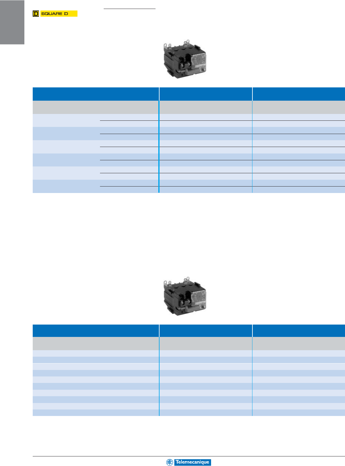
1-36
MOTOR
CONTROL
www.telemecanique.com
Solid State Overload Relays
Motor Logic®
Base units
Type Base units Base units for retrofit
for separate mounting to Type S starters (2)
NEMA Size Full load Type Catalog no. Catalog no.
3-phase current range
00C (1) 3–9 A Trip Class 10 9065 SSC 10 9065 SSC 10
Tr ip Class 20 9065 SSC 20 9065 SSC 20
0 (1) 6–18 A Trip Class 10 9065 SS 010 9065 SS 010
Tr ip Class 20 9065 SS 020 9065 SS 020
1 (1) 9–27 A Trip Class 10 9065 SS 110 9065 SS 110
Tr ip Class 20 9065 SS 120 9065 SS 120
215–45 A Trip Class 10 9065 SS 210 9065 SR 210
Tr ip Cass 20 9065 SS 220 9065 SR 220
330–90 A Trip Class 10 9065 SS 310 9065 SR 310
Tr ip Class 20 9065 SS 320 9065 SR 320
445–135 A Trip Class 10 9065 SS 410 9065 SR 410
Tr ip Cass 20 9065 SS 420 9065 SR 420
Motor Logic®
feature units
Type Feature units Feature units
for separate mounting for retrofit to Type S starters
(2)
NEMA Size Full load Type Catalog no. Catalog no.
3-phase current range
00B (1) 1.5–4.5 A Trip Class 10/20 9065 SFB 20 9065 SFB 20
00C (1) 3–9 A Trip Class 10/20 9065 SFC 20 9065 SFC 20
0 (1) 6–18 A Trip Class 10/20 9065 SF 020 9065 SF 020
1 (1) 9–27 A Trip Class 10/20 9065 SF 120 9065 SF 120
215–45 A Trip Class 10/20 9065 SF 220 9065 ST 220
330–90 A Trip Class 10/20 9065 SF 320 9065 ST 320
445–135 A Trip Class 10/20 9065 SF 420 9065 ST 420
5 (3) 90–270 A Trip Class 10/20 –9065 ST 520
6(3) 180–540 A Trip Class 10/20 –9065 ST 620
7 (3) 270–810 A Trip Class 10/20 –9065 ST 720
(1) For power connection kit, see table on page opposite.
(2) For Type S starter catalog numbers, see page 1-30.
(3) Replacement for existing Type S starters with an existing Motor Logic
®
solid state overload relay. Does not include primary current transformer or additional components.
For additional information, reference Catalog 9065CT9701.
NEMA Type
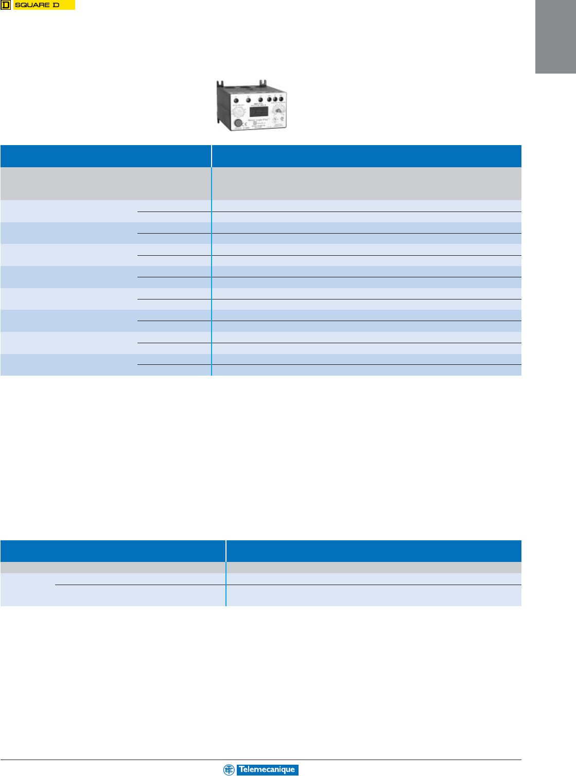
1-37
MOTOR
CONTROL
Motor Logic® PLUS
programmable units
Type Base units for separate mounting
NEMA Size Current Voltage Catalog no.
3-phase range
AV
00.5–2.3 200–480 9065 SPB 4
600 9065 SPB 6
02–9 200–480 9065 SPC 4
600 9065 SPC 6
16–27 200–480 9065 SP 14
600 9065 SP 16
210–45 200–480 9065 SP 24
600 9065 SP 26
320–90 200–480 9065 SP 34
600 9065 SP 36
4 (1) 60–135 200–480 9065 SP 44
600 9065 SP 46
5 (2) 120–270 200–480 9065 SP 54
600 9065 SP 56
6 (3) 240–540 200–480 9065 SP 64
600 9065 SP 66
(1) Size 4 requires the use of an external current transformer. Ratio of 150:5 recommended.
(2) Size 5 requires the use of an external current transformer. Ratio of 300:5 recommended.
(3) Size 6 requires the use of an external current transformer. Ratio of 600:5 recommended.
Accessories
Type Power connection kits
Type Description For use on Catalog no.
Lug connector For separate mounting 9065 Sp (Sizes 00B/00C/0/1) 9999 LLO
kits For mounting on 9065 Sp (Sizes 00B/00C/0/1) 9999 LBO
Type S starters
For additional information, reference Catalog 9065CT9701.
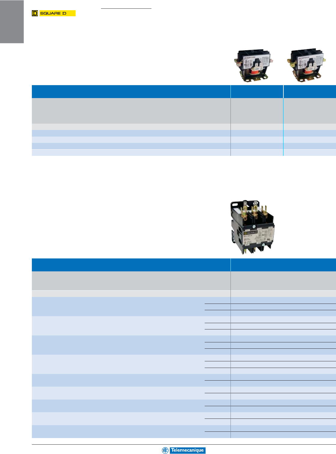
1-38
MOTOR
CONTROL
www.telemecanique.com
For additional information, reference Catalog 8910CT9301R6/97.
Definite purpose contactors
Compact contactors,
single-pole and 2-pole
Type Compact contactors Compact contactors
single-pole 2-pole
(3)
Full Locked rotor Resistive Motor power N.O. Basic catalog number. Basic catalog number.
load current load 115 V 230 V 230 V 460/575 V poles Complete with code Complete with code
current 277 V 480 V 575 V current single-phase single-phase 3-phase 3-phase indicating control indicating control
circuit voltage (1) circuit voltage (1)
AAAA A
Hp
kW
Hp
kW
Hp
kW
Hp
kW
20 100 100 80 25
1
0.75
2
1.5
–
–
–
–1 or 2 8910 DP 11
pppppp
pppppp
ppp 8910 DP 12
pppppp
pppppp
ppp
25 125 125 100 30
2
1.5
3
2.2
–
–
–
–1 or 2 8910 DP 21
pppppp
pppppp
ppp 8910 DP 22
pppppp
pppppp
ppp
30 150 150 120 40
2
1.5 (1) (1)
–
–
–
–1 or 2 8910 DP 31
pppppp
pppppp
ppp 8910 DP 32
pppppp
pppppp
ppp
40 240 200 160 50 (2)
2
1.5
5
3.7
–
–
–
–1 or 2 8910 DP 41
pppppp
pppppp
ppp 8910 DP 42
pppppp
pppppp
ppp
(1) 3 hp (2.2 kW) for 1-pole device; 5 hp (3.7 kW) for 2-pole device.
2, 3 and 4-pole,
contactors
Type 2, 3 and 4-pole,
contactors
(3)
Full Locked rotor Resistive Motor power N.O. poles Basic catalog number.
load current load 115 V 230 V 230 V 460/575 V Complete with code indicating
current 277 V 480 V 575 V current single-phase single-phase 3-phase 3-phase control circuit voltage (1)
AAAA A
Hp
kW
Hp
kW
Hp
kW
Hp
kW
20 120 100 80 25
1
1.1
2
1.5
5
3.7
7.5
5.5 2 8910 DPA 12
pppppp
pppppp
ppp
38910 DPA 13
pppppp
pppppp
ppp
48910 DPA 14
pppppp
pppppp
ppp
25 150 125 100 35
2
1.5
3
2.2
7.5
5.5
10
7.5 2 8910 DPA 22
pppppp
pppppp
ppp
38910 DPA 23
pppppp
pppppp
ppp
48910 DPA 24
pppppp
pppppp
ppp
30 180 150 120 40
2
1.5
5
3.7
10
7.5
15
11 2 8910 DPA 32
pppppp
pppppp
ppp
38910 DPA 33
pppppp
pppppp
ppp
48910 DPA 34
pppppp
pppppp
ppp
40 240 200 160 50
3
2.2
7.5
5.5
10
7.5
20
15 2 8910 DPA 42
pppppp
pppppp
ppp
38910 DPA 43
pppppp
pppppp
ppp
48910 DPA 44
pppppp
pppppp
ppp
50 300 250 200 62
3
2.2
10
7.5
15
11
30
22 2 8910 DPA 52
pppppp
pppppp
ppp
38910 DPA 53
pppppp
pppppp
ppp
60 360 300 240 75
5
3.7
10
7.5
25
18.5
30
22 2 8910 DPA 62
pppppp
pppppp
ppp
38910 DPA 63
pppppp
pppppp
ppp
75 450 375 300 94
5
3.7
15
11
25
18.5
40
30 2 8910 DPA 72
pppppp
pppppp
ppp
38910 DPA 73
pppppp
pppppp
ppp
90 540 450 360 120
7.5
5.5
20
15
30
22
50
37 2 8910 DPA 92
pppppp
pppppp
ppp
38910 DPA 93
pppppp
pppppp
ppp
120 720 600 480 120
10
7.5
25
18.5
40
30
75
55 2 8910 DPA 122
pppppp
pppppp
ppp
38910 DPA 123
pppppp
pppppp
ppp
NEMA Type
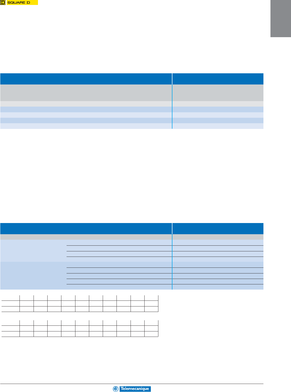
1-39
MOTOR
CONTROL
For additional information, reference Catalog 8910CT9301R6/97.
4-pole contactors
Type 4-pole contactors
with 2 N.O. and 2 N.C. poles
Full Locked rotor Resistive Motor power N.O. N.C. Basic catalog number.
load current load 115 V 230 V 230 V 460/575 V poles poles Complete with code indicating
current 277 V 480 V 575 V current single-phase single-phase 3-phase 3-phase (3) (7) control circuit voltage (1)
AAAA A
Hp
kW
Hp
kW
Hp
kW
Hp
kW
20 120 100 80 25
1
0.75
2
1.5
5
3.7
7.5
5.5 2 2 8910 DPA 14
pppppp
pppppp
ppp Y392
25 150 125 100 35
2
1.5
3
2.2
7.5
5.5
10
7.5 2 2 8910 DPA 24
pppppp
pppppp
ppp Y392
30 180 150 120 40
2
1.5
5
3.7
10
7.5
15
11 2 2 8910 DPA 34
pppppp
pppppp
ppp Y392
40 240 200 160 50
3
2.2
7.5
5.5
10
7.5
20
15 2 2 8910 DPA 44
pppppp
pppppp
ppp Y392
Accessories
Type External auxiliary contacts
For use on Description Catalog number
8910 DPA 1 N.O. contact 9999 D10
1 N.C. contact 9999 D01
1 N.O. and 1 N.C. contacts 9999 D11
2 N.O. contacts 9999 D20
8910 DPA 122/123 1 N.O. contact 9999 SX6
1 N.C. contact 9999 SX7
1 N.O. and 1 N.C. isolated contacts 9999 SX8
1 N.O. overlapping contact 9999 SX9
1 N.C. overlapping contact 9999 SX10
(1) Standard control circuit voltages for 8910 DP/DPA :
Volts 24 110 120 208-240 220 277 440 480 550 600
50 Hz V14 V02 ––V09 –V06
(4)
–V07
(5)
–
60 Hz V14 –V02 V09 –V04 –V06
(4)
–V07
(5)
Standard control circuit voltage for 8910 DPA 122/DPA 123:
Volts 24 110 120 208 220 230-240 440 480 550 600
50 Hz V12 V02 ––V03 –V06 –V07 –
60 Hz V01
(6)
–V02 V08 –V03 –V06 –V07
(2) 50 A resistive limited to 277 V (single pole device only). All other contactors rated 40 A resistive (above 277 V).
(3) Above 240 V, all lines must be switched.
(4) Not available for type 8910 DP 11 to 8910 DP 31 single-pole devices.
(5) Not available for type 8910 DP single and 2-pole devices.
(6) Only available on types 8910 DPA 122/DPA 123.
(7) N.C. poles on outside. N.C. poles “open” before N.O. poles “close”.

1-40
MOTOR
CONTROL
www.telemecanique.com
Lighting contactors
Multipole contactors
Types L and LX
Type Multipole contactors, open style, Multipole contactors, open style,
electrically held
(2)
mechanically held
(2)
Thermal operating Number of poles (3) Basic catalog no. Complete with code Basic catalog no. Complete with code
current (A) indicating control circuit voltage (1) indicating control circuit voltage (1)
20 28903 LO 20
pppppp
pppppp
ppp 8903 LXO 20
pppppp
pppppp
ppp
38903 LO 30
pppppp
pppppp
ppp 8903 LXO 30
pppppp
pppppp
ppp
48903 LO 40
pppppp
pppppp
ppp 8903 LXO 40
pppppp
pppppp
ppp
68903 LO 60
pppppp
pppppp
ppp 8903 LXO 60
pppppp
pppppp
ppp
88903 LO 80
pppppp
pppppp
ppp 8903 LXO 80
pppppp
pppppp
ppp
10 8903 LO 1000
pppppp
pppppp
ppp 8903 LXO 1000
pppppp
pppppp
ppp
12 8903 LO 1200
pppppp
pppppp
ppp 8903 LXO 1200
pppppp
pppppp
ppp
Multipole contactors Type S
(1) Standard control circuit voltages:
Volts 24 (4) 110 120 208 220
50 Hz –V02 ––V03
60 Hz V01 –V02 V08 –
Volts 240 277 440 480
50 Hz ––V06 –
60 Hz V03 V04 –V06
For Forms and kits, please consult your nearest Square D/Schneider Electric sales office.
Type Multipole contactors, open style, Multipole contactors, open style,
electrically held
(2)
mechanically held
(2)
Thermal operating Number of poles Basic catalog no. Complete with code Basic catalog no. Complete with code
current (A) indicating control circuit voltage (1) indicating control circuit voltage (1)
30 28903 SMO 1
pppppp
pppppp
ppp 8903 SMO 10
pppppp
pppppp
ppp
38903 SMO 2
pppppp
pppppp
ppp 8903 SMO 11
pppppp
pppppp
ppp
48903 SMO 3
pppppp
pppppp
ppp 8903 SMO 12
pppppp
pppppp
ppp
58903 SMO 4
pppppp
pppppp
ppp 8903 SMO 13
pppppp
pppppp
ppp
60 28903 SPO 1
pppppp
pppppp
ppp 8903 SPO 10
pppppp
pppppp
ppp
38903 SPO 2
pppppp
pppppp
ppp 8903 SPO 11
pppppp
pppppp
ppp
48903 SPO 3
pppppp
pppppp
ppp 8903 SPO 12
pppppp
pppppp
ppp
58903 SPO 4
pppppp
pppppp
ppp 8903 SPO 13
pppppp
pppppp
ppp
100 28903 SQO 1
pppppp
pppppp
ppp 8903 SQO 10
pppppp
pppppp
ppp
38903 SQO 2
pppppp
pppppp
ppp 8903 SQO 11
pppppp
pppppp
ppp
48903 SQO 3
pppppp
pppppp
ppp 8903 SQO 12
pppppp
pppppp
ppp
58903 SQO 4
pppppp
pppppp
ppp 8903 SQO 13
pppppp
pppppp
ppp
200 28903 SVO 1
pppppp
pppppp
ppp 8903 SVO 10
pppppp
pppppp
ppp
38903 SVO 2
pppppp
pppppp
ppp 8903 SVO 11
pppppp
pppppp
ppp
48903 SVO 3
pppppp
pppppp
ppp 8903 SVO 12
pppppp
pppppp
ppp
58903 SVO 4
pppppp
pppppp
ppp –
300 28903 SXO 1
pppppp
pppppp
ppp 8903 SXO 13
pppppp
pppppp
ppp
38903 SXO 2
pppppp
pppppp
ppp 8903 SXO 14
pppppp
pppppp
ppp
400 (5) 2 8903 SYO 1
pppppp
pppppp
ppp 8903 SYO 16
pppppp
pppppp
ppp
38903 SYO 2
pppppp
pppppp
ppp 8903 SYO 17
pppppp
pppppp
ppp
600 (5) 2 8903 SZO 1
pppppp
pppppp
ppp 8903 SZO 18
pppppp
pppppp
ppp
38903 SZO 2
pppppp
pppppp
ppp 8903 SZO 19
pppppp
pppppp
ppp
800 (5) 2 8903 SJO 1
pppppp
pppppp
ppp 8903 SJO 10
pppppp
pppppp
ppp
38903 SJO 2
pppppp
pppppp
ppp 8903 SJO 11
pppppp
pppppp
ppp
(2) All lighting contactors are provided with separate control as standard, except electrically held 400, 600 and 800 A devices.
Electrically held 400, 600 and 800 A devices are provided with common control.
(3) For factory conversion of N.O. contacts to N.C., order following this example: for 2 N.O. + 2 N.C., order catalog no. 8903 LO 22.
There is a maximum of eight N.C. poles for Type 8903 L contactors and a maximum of six N.C. poles for Type 8903 LX contactors (field conversion only).
Versions are available with up to 12 N.C. poles (factory only).
(4) 24 V coils are not available for 200–800 A devices.
(5) Form F4T is provided as standard on electrically held devices 400–800 A; include line voltage when ordering. Control voltage is 120–60.
For 400–800 A devices—must specify line voltage, not control voltage.
For additional information, reference Catalog 8903CT9701.
(30 A
fluorescent
ballast load)
NEMA Type
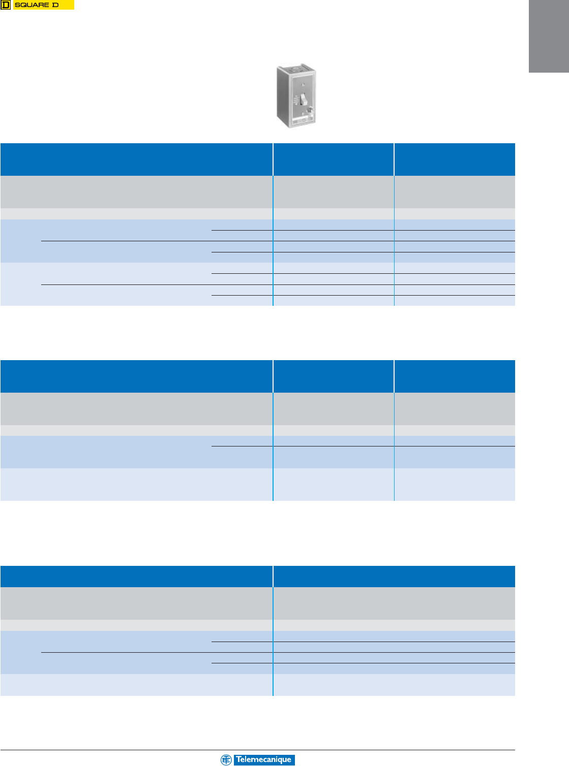
1-41
MOTOR
CONTROL
Manual starters and switches
Manual starters Type F, general purpose
surface mounting enclosure (NEMA 1)
Type Single units, Single units,
standard starters starters with handle
padlockable in the ‘O’ position
Type of Number Maximum power Maximum Features Catalog no. Catalog no.
operator of poles of single-phase motors
continuous
115-230 Vac 115-230 Vdc 277 Vac
current
Hp
kW
Hp
kW
Hp
kW A
Toggle 1
1
0.75
-
-
1
0.75 16 Standard 2510 FG 1 2510 FG 5
operator With red pilot light 2510 FG 1P 2510 FG 5P
(1) 2
1
0.75
0.75
0.55
1
0.75 16 Standard 2510 FG 2 2510 FG 6
With red pilot light 2510 FG 2P 2510 FG 6P
Removable
1
1
0.75
-
-
1
0.75 16 Standard 2510 FG 3 –
key With red pilot light 2510 FG 3P –
(1) 2
1
0.75
0.75
0.55
1
0.75 16 Standard 2510 FG 4 –
With red pilot light 2510 FG 4P –
Type Duplex units, Duplex units,
1 starter 2 starters
in duplex enclosure in one enclosure
Type of Number Maximum power Maximum Features Catalog no. Catalog no.
operator of poles of single-phase motors
continuous
115-230 Vac 115-230 Vdc 277 Vac
current
Hp
kW
Hp
kW
Hp
kW A
Toggle 2 (3)
1
0.75
0.75
0.55
1
0.75 16 Standard 2510 FG 02 2510 FG 22
operator With red pilot light 2510 FG 02P 2510 FG 22P
(1) (2)
Removable
2 (3)
1
0.75
0.75
0.55
1
0.75 16 With red pilot light 2510 FG 04P 2510 FG 44P
key
(1) (2)
Type Duplex units,
starters with “AUTO-OFF-HAND” selector switch
Type of Number Maximum power Maximum Features Catalog no.
operator of poles of single-phase motors
continuous
115-230 Vac 115-230 Vdc 277 Vac
current
Hp
kW
Hp
kW
Hp
kW A
Toggle 1
1
0.75
-
-
1
0.75 16 Standard 2510 FG 71
operator With red pilot light 2510 FG 71P
(1) 2
1
0.75
0.75
0.55
1
0.75 16 Standard 2510 FG 72
With red pilot light 2510 FG 72P
Removable
2
1
0.75
0.75
0.55
1
0.75 16 With red pilot light 2510 FG 74P
key (1)
(1) One thermal unit is required
(2) For two starters in one enclosure, two thermal units are required.
(3) Two poles for each starter.
For additional information, reference Catalog 2570CT9701.
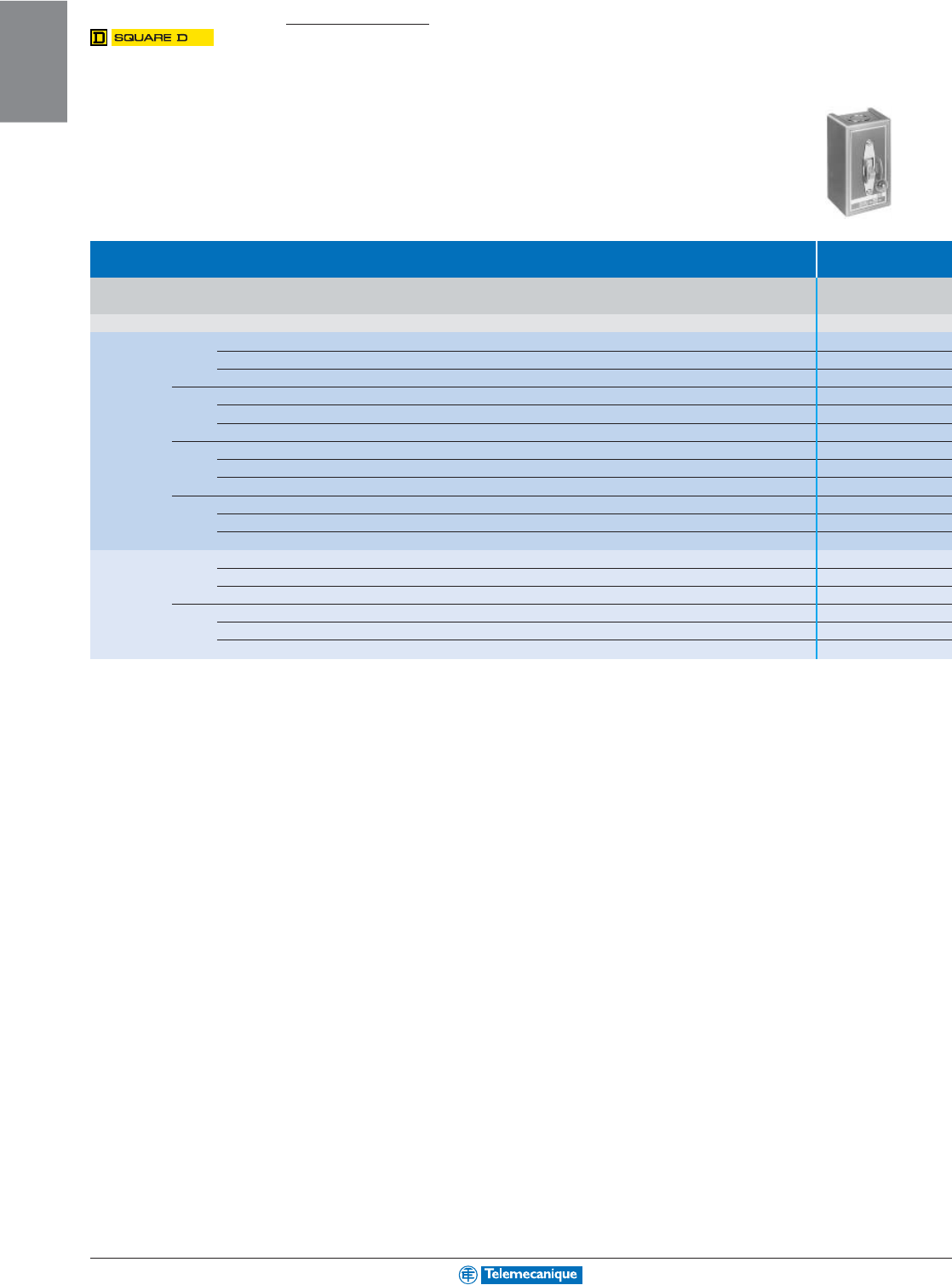
1-42
MOTOR
CONTROL
www.telemecanique.com
Manual starters and switches
Manual switches Type K, in general
purpose surface mounting enclosure
(NEMA 1)
Type Non-reversing
Type of No. of Maximum motor powers
Max. continuous
Catalog no.
operator poles 115 Vac 230 Vac 460 Vac 575 Vac 90 Vdc 115 Vdc 230 Vdc current
Hp
kW
Hp
kW
Hp
kW
Hp
kW
Hp
kW
Hp
kW
Hp
kW A Features
Toggle 2
2
1.5
2
1.5
3
2.2
3
2.2
1
0.75
2
1.5
1.5
1.1 30 Standard 2510 KG 1
operator
2
1.5
2
1.5
3
2.2
3
2.2
1
0.75
2
1.5
1.5
1.1 30 (1) 115 Vac 2510 KG 1A
2
1.5
2
1.5
3
2.2
3
2.2
1
0.75
2
1.5
1.5
1.1 30 (1) 230 Vac 2510 KG 1B
3
2
1.5
7.5
5.6
10
7.5
10
7.5
1
0.75
2
1.5
1.5
1.1 30 Standard 2510 KG 2
2
1.5
7.5
5.6
10
7.5
10
7.5
1
0.75
2
1.5
1.5
1.1 30 (1) 208–277 Vac 2510 KG 2B
2
1.5
7.5
5.6
10
7.5
10
7.5
1
0.75
2
1.5
1.5
1.1 30 (1) 440–600 Vac 2510 KG 2C
2
2
1.5
3
2.2
7.5
5.6
10
7.5
1
0.75
2
1.5
1.5
1.1 30 Standard 2510 KG 5
2
1.5
3
2.2
7.5
5.6
10
7.5
1
0.75
2
1.5
1.5
1.1 30 (1) 115 Vac 2510 KG 5A
2
1.5
3
2.2
7.5
5.6
10
7.5
1
0.75
2
1.5
1.5
1.1 30 (1) 230 Vac 2510 KG 5B
3
2
1.5
7.5
5.6
15
11.2
20
14.9
1
0.75
2
1.5
1.5
1.1 30 Standard 2510 KG 6
2
1.5
7.5
5.6
15
11.2
20
14.9
1
0.75
2
1.5
1.5
1.1 30 (1) 208–277 Vac 2510 KG 6B
2
1.5
7.5
5.6
15
11.2
20
14.9
1
0.75
2
1.5
1.5
1.1 30 (1) 440–600 Vac 2510 KG 6C
Removable 2
2
1.5
2
1.5
3
2.2
3
2.2
1
0.75
2
1.5
1.5
1.1 30 Standard 2510 KG 3
key
2
1.5
2
1.5
3
2.2
3
2.2
1
0.75
2
1.5
1.5
1.1 30 (1) 115 Vac 2510 KG 3A
2
1.5
2
1.5
3
2.2
3
2.2
1
0.75
2
1.5
1.5
1.1 30 (1) 230 Vac 2510 KG 3B
3
2
1.5
7.5
5.6
10
7.5
10
7.5
1
0.75
2
1.5
1.5
1.1 30 Standard 2510 KG 4
2
1.5
7.5
5.6
10
7.5
10
7.5
1
0.75
2
1.5
1.5
1.1 30 (1) 208–277 Vac 2510 KG 4B
2
1.5
7.5
5.6
10
7.5
10
7.5
1
0.75
2
1.5
1.5
1.1 30 (1) 440–600 Vac 2510 KG 4C
(1) With red pilot light
For additional information, reference Catalog 2510CT9701.
(Single
phase)
(Three
phase)
(Single
phase)
(Three
phase)
(Single
phase)
(Three
phase)
NEMA Type
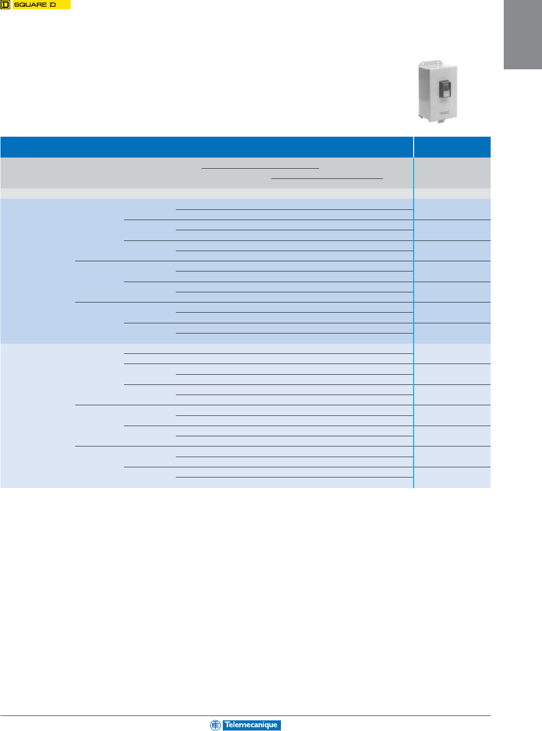
1-43
MOTOR
CONTROL
Manual switches Types T and M,
in general purpose surface mounting
enclosure (NEMA 1)
Type Non-reversing
Type of No. of NEMA Size Ratings Catalog no.
operator poles Motor voltage Max. power
DC 3-phase Single-phase
V
Hp
kW
Hp
kW
Hp
kW
Toggle operator AC 2 M-0 115
–
–
–
–
1
0.75 2510 TBG 1
230
–
–
–
–
2
1.5
M-1 115
–
–
–
–
2
1.5 2510 TCG 1
230
–
–
–
–
3
2.2
M-1P 115
–
–
–
–
3
2.2 2510 TCG 2
230
–
–
–
–
5
3.7
AC 3 M-0 200–230
–
–
3
(2) 2.2 (2)
–
–2510 TBG 2
380–575
–
–
5
(3) 3.7 (3)
–
–
M-1 200–230
–
–
7.5
(2) 5.5 (2)
–
–2510 TCG 3
380–575
–
–
10
(3) 7.5 (3)
–
–
DC 2 M-0 115
1
0.75
–
–
–
–2510 TBG 4
230
1.5
1.1
–
–
–
–
M-1 115
1.5
1.1
–
–
–
–2510 TCG 5
230
2
1.5
–
–
–
–
Pushbutton AC 2 M-0 115
–
–
–
–
1
0.75 2510 MBG 1
230
–
–
–
–
2
1.5
M-1 115
–
–
–
–
2
1.5 2510 MCG 1
230
–
–
–
–
3
2.2
M-1P 115
–
–
–
–
3
2.2 2510 MCG 2
230
–
–
–
–
5
3.7
AC 3 M-0 200–230
–
–
3
(2) 2.2 (2)
–
–2510 MBG 2
380–575
–
–
5
(3) 3.7 (3)
–
–
M-1 200–230
–
–
7.5
(2) 5.5 (2)
–
–2510 MCG 3
380–575
–
–
10
(3) 7.5 (3)
–
–
DC 2 M-0 115
1
0.75
–
–
–
–2510 MBG 4
230
1.5
1.1
–
–
–
–
M-1 115
1.5
1.1
–
–
–
–2510 MCG 5
230
2
1.5
–
–
–
–
(2) Value for 230 V.
(3) Value for 575 V.
For additional information, reference Catalog 2510CT9701.
1-44
MOTOR
CONTROL
www.telemecanique.com
Accessories
Replacement parts kits
Type Replacement
parts kits
Description For use with Number of poles Catalog no.
NEMA Size in the kit
Class Type or current
Replacement parts kits 8502, 8536, 8538, SA (Series B) 00 3 9998 SJ 1
(the kit contains the moving and 8539, 8702, 8736 SB 0 3 9998 SL 2
stationary contacts, contact 49998 SL 12
springs and necessary hardware) SB, SC (power pole adder) 0 and 1 1 9998 SL 22
SC 1 and 1P 3 9998 SL 3
14 9998 SL 13
SD 2 3 9998 SL 4
49998 SL 14
SD (power pole adder) 2 1 9998 SL 24
SE 3 2 9998 SL 6
39998 SL 7
SF 4 2 9998 SL 8
39998 SL 9
SG 5 2 9998 SL 10
39998 SL 11
SH 6 2 9998 SL 25
39998 SL 26
SJ 7 2 9998 SL 30
39998 SL 31
8903 L (Series C) and LX (Series B) 20 A 4 9998 RA 5B
SM 30 A 3 9998 SL 3
49998 SL 13
SP 60 A 3 9998 SL 4
49998 SL 14
SQ 100 A 2 9998 SL 6
39998 SL 7
SV 200 A 2 9998 SL 8
39998 SL 9
SX 300 A 2 9998 SL 10
39998 SL 11
SY 400 A 2 9998 SL 25
39998 SL 26
SZ 600 A 2 9998 SL 32
39998 SL 33
SJ 800 A 2 9998 SL 30
3 9998 SL 31
8910 DPA 1pp
pp
p20 A 1 9998 DRC 1
DPA 2pp
pp
p25 A 1 9998 DRC 2
DPA 3pp
pp
p30 A 1 9998 DRC 3
DPA 4pp
pp
p40 A 1 9998 DRC 4
DPA 5pp
pp
p50 A 1 9998 DRC 5
DPA 6pp
pp
p60 A 1 9998 DRC 6
DPA 7pp
pp
p75 A 1 9998 DRC 7
DPA 9pp
pp
p90 A 1 9998 DRC 9
DPA 123 120 A 1 9998 DRC 12
For additional information, reference Catalog 8502CT9701.
NEMA Type
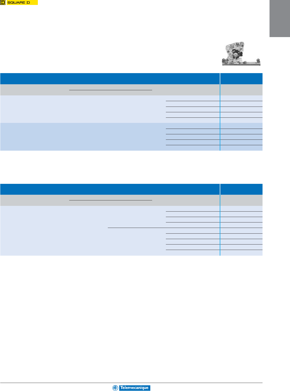
1-45
MOTOR
CONTROL
Type External
contact kits
Description For use with Type of contact Catalog no.
Class Type NEMA size or current
External convertible contact kits 8502, 8702, SA to SJ 00 to 7 1 N.O. contact 9999 SX 6
8536, 8736 1 N.C. contact 9999 SX 7
8903
(Type S only
)SM to SJ 30–800 A 2 isolated contacts 1 N.O. and 1 N.C. 9999 SX 8
1 N.O. overlapping contact 9999 SX 9 (1)
1 N.C. overlapping contact 9999 SX 10 (1)
External non-convertible contact kits 8502, 8702, SA to SJ 00 to 7 1 N.O. contact 9999 SX 13
8536, 8736 1 N.C. contact 9999 SX 14
8903
(Type S only
)SM to SJ 30–800 A 2 isolated contacts 1 N.O. and 1 N.C. 9999 SX 15
1 N.O. overlapping contact 9999 SX 16 (1)
1 N.C. overlapping contact 9999 SX 17 (1)
(1) These products must be used together and must be mounted on the same side of the contactor. They are suitable for applications where it is necessary for a N.O. contact to overlap
a N.C. contact.
External auxiliary contacts
Type External auxiliary
contacts
Description For use with Type of contact Catalog no.
Class Type
External auxiliary contacts 8910 DPA 1 N.O. contact 9999 D10
1 N.C. contact 9999 D01
2 isolated contacts 1 N.O. and 1 N.C. 9999 D11
2 N.O. contacts 9999 D20
DPA 122/123 1 N.O. contact 9999 SX6
1 N.C. contact 9999 SX7
2 isolated contacts 1 N.O. and 1 N.C. 9999 SX8
1 N.O. overlapping contact 9999 SX9
1 N.C. overlapping contact 9999 SX10
External auxiliary contacts
For additional information, reference Catalog 8502CT9701.
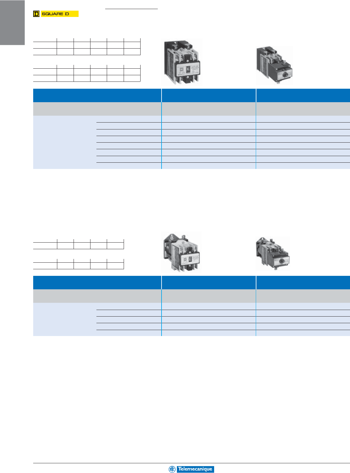
1-46
MOTOR
CONTROL
www.telemecanique.com
Industrial control relays
AC relays
AC Control relay AC Latching relay
Continuous Load Rating Normally Open Convertible Basic catalog no. Complete with code Basic catalog no. Complete with code
Inductive / resistive Instantaneous Contacts indicating control circuit voltage (1) indicating control circuit voltage (1)
10 A / 10 A 0 8501XO00
pppppp
pppppp
ppp –
28501XO20
pppppp
pppppp
ppp 8501XO20XL
pppppp
pppppp
ppp
38501XO30
pppppp
pppppp
ppp 8501XO30XL
pppppp
pppppp
ppp
48501XO40
pppppp
pppppp
ppp 8501XO40XL
pppppp
pppppp
ppp
68501XO60
pppppp
pppppp
ppp 8501XO60XL
pppppp
pppppp
ppp
88501XO80
pppppp
pppppp
ppp 8501XO80XL
pppppp
pppppp
ppp
10 8501XO1000
pppppp
pppppp
ppp –
12 8501XO1200
pppppp
pppppp
ppp –
A maximum of 8 N.C. contacts is allowed on 9–12 pole relays.
Note: Unlatch coil is rated for intermittent duty and should be connected through a N.O. contact of the relay if the input signal is maintained. Order one more N.O. contact than the
application requires to use as a coil clearing contact.
DC relays
DC Control relay DC Latching relay
Continuous Load Rating Normally Open Convertible Basic catalog no. Complete with code Basic catalog no. Complete with code
Inductive / resistive Instantaneous Contacts indicating control circuit voltage (2) indicating control circuit voltage (2)
5 A / 5 A 0 8501XDO00
pppppp
pppppp
ppp –
28501XDO20
pppppp
pppppp
ppp 8501XDO20XDL
pppppp
pppppp
ppp
48501XDO40
pppppp
pppppp
ppp 8501XDO40XDL
pppppp
pppppp
ppp
68501XDO60
pppppp
pppppp
ppp 8501XDO60XDL
pppppp
pppppp
ppp
88501XDO80
pppppp
pppppp
ppp 8501XDO80XDL
pppppp
pppppp
ppp
Note: Unlatch coil is rated for intermittent duty and should be connected through a N.O. contact of the relay if the input signal is maintained. Order one more N.O. contact than the
application requires to use as a coil clearing contact.
For additional information, reference Catalog 8501CT9601.
(1) Standard AC control circuit voltages:
Volts 24 110 120 208 220
50 Hz V12 V02 ––V03
60 Hz V01 –V02 V08 –
Volts 240 440 480 550 600
50 Hz –V06 –V07 –
60 Hz V03 –V06 –V07
Example: 8501 XO20 V02.
(2) Standard DC control circuit voltages:
Volts 12 24 48 72
V51 V53 V56 V58
Volts 115 125 230 250
V62 V62 V66 V66
Example: 8501 XDO80 V53.
NEMA Type
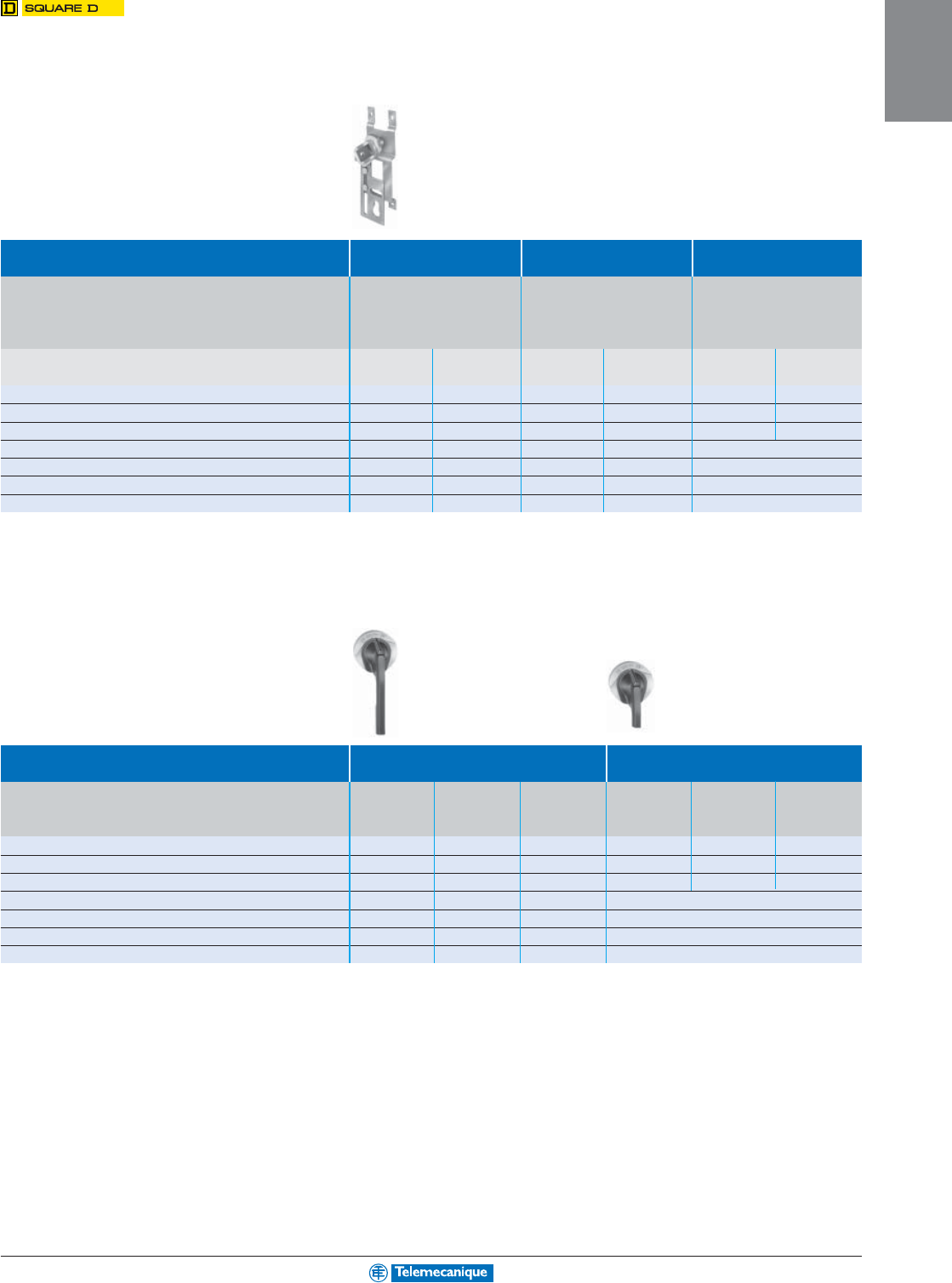
1-47
MOTOR
CONTROL
Circuit breaker operating mechanisms
Door mounted kits
Complete kit Std. shaft /std. handle Long shaft /std. handle Long shaft / short handle
Does not include circuit breaker Includes: Includes: Includes:
Operating mechanism Operating mechanism Operating mechanism
Standard 6" handle Standard 6" handle Short 3" handle
Use with: Standard shaft kit Long shaft kit Long shaft kit
Circuit breaker Number Frame Catalog
Mounting depth
Catalog
Mounting depth
Catalog
Mounting depth
or interrupter type of poles size (A) number min.-max. (1) number min.-max. (1) number min.-max. (1)
GJL 3 75, 100 9421LG1 5-1/2–10-1/4 9421LG4 5-1/2–20-7/8 9421LG3 5-1/2–20-7/8
FAL, FCL, FHL 2–3 100 9421LN1 5-1/2–10-7/16 9421LN4 5-1/2–21 9421LN3 5-1/2–21
KAL, KCL, KHL 2–3 250 9421LP1 6-1/4–11-3/16 9421LP4 6-1/4–21-3/4 9421LP3 6-1/4–21-3/4
LAL, LHL, Q4L 2–3 400 9421LR1 6-5/16–10-7/8 9421LR4 6-5/16–21-1/2 (3)
MEL, MXL 2–3 800 9421LT1 (2) 7-3/16–11-5/8 9421LT4 (2) 7-3/16–22-1/4 (3)
MAL, MHL 2–3 1000 9421LT1 (2) 7-3/16–11-5/8 9421LT4 (2) 7-3/16–22-1/4 (3)
NAL, NCL, NEL, NXL 2–3 1200 9421LX1 (2) 8-1/4–12-3/4 9421LX4 (2) 8-1/4–23-3/8 (3)
(1) Mounting depth measured from circuit breaker mounting surface (control panel) to outside of enclosure door in inches.
(2) Types LT1, LT4, LX1, and LX4 include an 8” handle rather than a 6” handle.
(3) 3" handles are not recommended for use with these circuit breakers.
Handles
Use With Standard Handle Assemblies Special 3'' Version
Circuit breaker Number Frame Type Type Type Type Type Type
or interrupter type of poles size (A) 1, 3R, 12 3R, 4 3R, 4, 4X 1, 3R, 12 3R, 4 3R, 4, 4X
(Painted) (Painted)
(Chrome Plated)
(Painted) (Painted)
(Chrome Plated)
GJL 3 75 9421LH6 9421LH46 9421LC46 9421LH43 9421LH43 9421LC43
FAL, FCL, FHL 2–3 100 9421LH6 9421LH46 9421LC46 9421LH43 9421LH43 9421LC43
KAL, KCL, KHL 2–3 250 9421LH6 9421LH46 9421LC46 9421LH43 9421LH43 9421LC43
LAL, LHL, Q4L 2–3 400 9421LH6 9421LH46 9421LC46 (3)
MEL, MXL 2–3 800 9421LH48 9421LH48 9421LC48 (3)
MAL, MHL 2–3 1000 9421LH48 9421LH48 9421LC48 (3)
NAL, NCL, NEL, NXL 2–3 1200 9421LH48 9421LH48 9421LC48 (3)
(3) 3" handles are not recommended for use with these circuit breakers.
For additional information, reference Catalog 9420CT9701.
Operating Mechanism
(includes lockout)
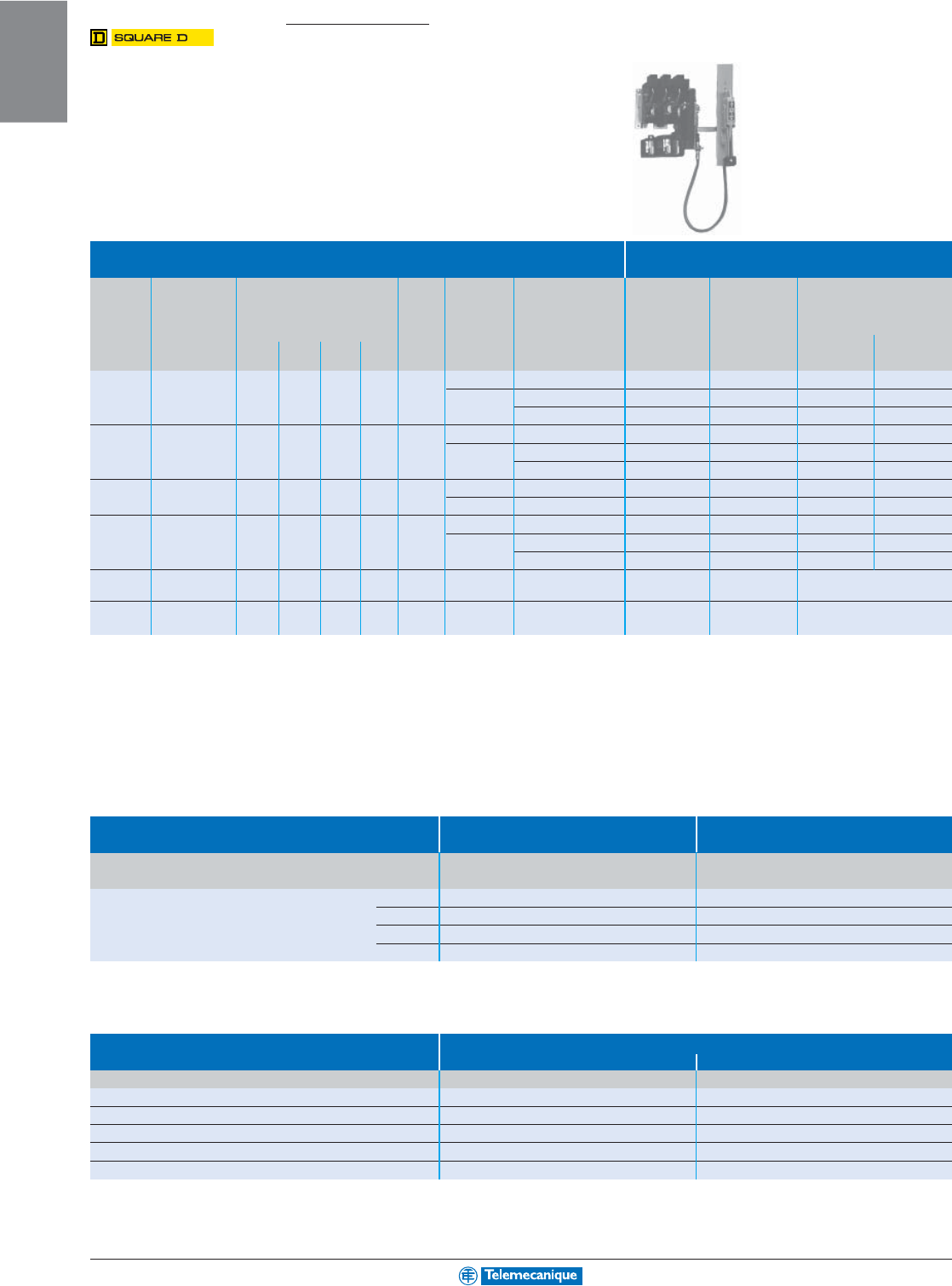
1-48
MOTOR
CONTROL
www.telemecanique.com
Disconnect switches
Variable depth and cable operated
Disconnect switches
Switch for use
Variable Fuse clip rating with cable operators
depth Maximum horsepower ratings
(1)
DC (amperes) non- Switch and operating ONLY—Switch and operating mechanism
mtg. AC systems volts Using interchangeable type mechanism only—does not include and handle mechanism—overpacked
Disconnect range (Motor volts) 2 poles For Class H, J, K does not include handle mechanism Includes Type A1 Includes Type A2
switch min.–max. 208 240 480 600 250 V Fuse or R fuses only handle mechanism or cable operator handle mechanism handle mechanism
size (inches) (200) (230) (460) (575) max. type 250 V 600 V Type Type Type Type
30 A 6-5/8"–18" 7.5 7.5 15 20 5 None — — 9421TCN30 9421TCN30C 9421ATCN301 9421ATCN302
H, K, J, R 30 — 9421TCF30 9421TCF30C 9421ATCF301
9421
ATCF302
60 30 9421TCF33 9421TCF33C 9421ATCF331
9421
ATCF332
60 A 6-5/8"–18" 15 15 30 50 10 None — — 9421TDN60 9421TDN60C 9421ATDN601
9421
ATDN602
H, K, J, R 60 30 9421TDF60 9421TDF60C 9421ATDF601
9421
ATDF602
—60 9421TDF63 9421TDF63C 9421ATDF631
9421
ATDF632
100 A 6-5/8"–18" 25 30 60 75 20 None — — 9421TEN10 9421TEN10C 9421ATEN101
9421
ATEN102
H, K, J, R 100 100 9421TEF10 9421TEF10C 9421ATEF101
9421
ATEF102
200 A 9-1/8-–19-1/4 (2) 40 60 125 150 40 None — — 9421TF1 —9421ATF11
9421
ATF21
H, K, J, R 200 200 9421TF2 —9421ATF12
9421
ATF22
—4009421TF3 (3) —9421ATF13 (3)
9421
ATF23 (3)
400 A 11.38 75 125 250 350 50
None — — 9421TG1 (6)(7)
—
Fixed Depth(4) (A5 or A6 Handle)
400 A 15.87–19 (5) 75 125 250 350 50
H, K, J, R
400 400
9421TG2 (6)(7)
—
Adj. Depth (4) (A7 or A8 Handle)
(1) Refers to rating of switch only.
(2) 9422 R2 will extend maximum mounting depth 7"
(3) Accommodates Class J fuses only.
(4) Switches are either fixed-depth or adjustable; the handle will determine installation.
(5) In steps of 0.63 inches.
(6) Commercially available enclosures may not accept type TG operating mechanisms.
Contact enclosure manufacturer for availability of enclosures for use with these switches.
(7) Right hand flange mounting only.
Cable operator and handles
Cable Mechanisms (8) Cable Mechanisms with A1 Handle
for Types 1, 3, 3R, 4 and 12
Disconnect Switch Types Cable Catalog number Catalog number
Switch Size Length
30 A, 60 A, 100 A TCF, TCN, TDF, TDN, TEF, TEN 36" 9421CFT30 9421CFT31
48" 9421CFT40 –
60" 9421CFT50 9421CFT51
120" 9421CFT10 9421CFT11
(8) Must purchase handle mechanism separately (9422, A1, A2, A3 or A4).
Handle NEMA Type Enclosure
1, 3, 3R, 4 (sheet steel), 12 4,4X (stainless steel) (10)
Type of Handle Catalog number Catalog number
6" HANDLE (9) 9421A1 9421A2
4" HANDLE (9) 9421A3 9421A4
12" HANDLE (fixed depth) (11) 9421A5 9421A6
12" HANDLE (variable depth) (11) 9421A7 9421A8
10" HANDLE (12) 9421A9 9421A10
(9) For use with 30–200 Ampere switches and all circuit breaker mechanisms.
(10) All external metal parts are either stainless steel or a chrome-plated non-ferrous die casting.
(11) For use with 400 Ampere Type TG1 and TG2 disconnect switches ONLY.
(12) For use with Type D2 remote or dual adaptor kit.
For additional information, reference Catalog 9420CT9701.
NEMA Type
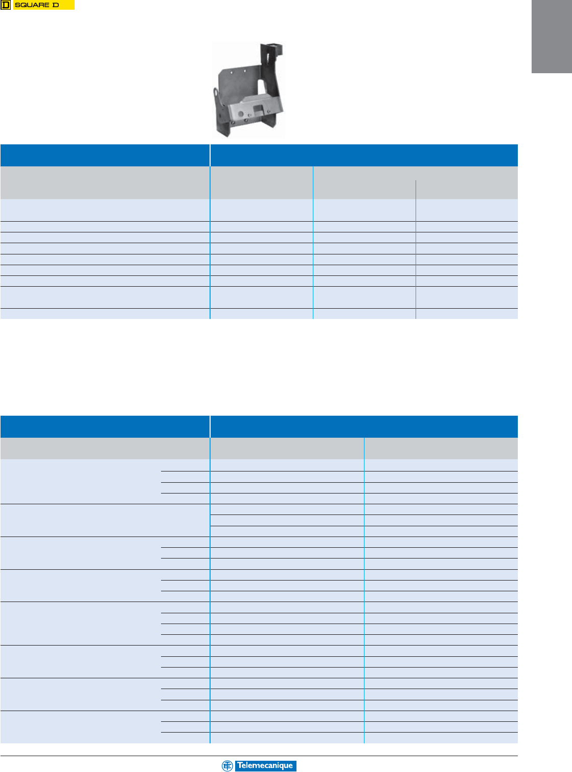
1-49
MOTOR
CONTROL
Circuit breaker operating mechanisms
Flange mounted
Use with: Operating mechanism
Circuit breaker Number Frame Variable depth Operating mechanism only —Operating mechanism and handle mechanism
frame size of poles size (A) mtg. range (In.) does not include Includes Type A1 (2) Includes Type A2 (2)
min.-max. (1) handle mechanism handle mechanism handle mechanism
Square D circuit breakers
GJL 3 100 6.00–17.75 9422RG1 9422ARG11 9422ARG21
FAL, FHL 2–3 100 5.38–17.75 9422RN1 9422ARN11 9422ARN21
KAL, KHL 2–3 250 6.38–17.88 9422RP1 9422ARP11 9422ARP21
LAL, LHL, Q4L 2–3 400 7.44–18.25 9422RR1 9422ARR11 9422ARR21
MEL, MXL 2–3 800 9.00–18.38 9422R T1 9422ART11 9422ART21
MAL, MHL 2–3 1200 9.00–18.38 9422RT1 9422ART11 9422ART21
NAL, NCL, NEL, NXL 2–3 1200 11.00–18.37 9422RX1 ––
Merlin Gerin circuit breakers
MG-NSF 3 250 5.88–17.75 9422RQ1 ––
MG-NSJ 3 600 9.00–17.75 9422RS1 ––
(1) Class 9422 Type R2 will extend mounting depth 7 inches.
(2) For handle information, see page 1-48.
Cable operators
Cable operators
Circuit breaker No. of Frame size Cable length Cable mechanism Cable mechanisms with A1 handle
type poles for Types 1, 3, 3R, 4, 12 (1)
GJL 3 100 36" 9422CGJ30 9422CGJ31
48" 9422CGJ40 9422CGJ41
60" 9422CGJ50 9422CGJ51
120" 9422CGJ10 9422CGJ11
FAL, FHL 2-3 100 36" 9422CFA30 9422CFA31
9422CFA50 9422CFA51
9422CFA10 9422CFA11
KAL, KHL 2-3 250 36" 9422CKA30 9422CKA31
60" 9422CKA50 9422CKA51
120" 9422CKA10 9422CKA11
LAL, LHL, Q4L 2-3 400 36" 9422CLA30 9422CLA31
60" 9422CLA50 9422CLA51
120" 9422CLA10 9422CLA11
MG-NSF 3 250 36” 9422CSF30 –
60" 9422CSF50 –
84" 9422CSF70 –
120" 9422CSF10 –
MG-NSF 4 250 36” 9422CSF304 –
60" 9422CSF504 –
120" 9422CSF104 –
MG-NSJ 3 600 36” 9422CSJ30 –
60" 9422CSJ50 –
120" 9422CSJ10 –
MG-NSJ 4 600 36” 9422CSJ304 –
60" 9422CSJ504 –
120" 9422CSJ104 –
For additional information, reference Catalog 9420CT9701.

1-50
MOTOR
CONTROL
www.telemecanique.com
Supply Power
Circuit breakers
Powerpact and J-frame
Frame / product H-frame J-frame
Number of poles 2, 3 2, 3
Current rating 15–150 A 150–250 A
Interuption rating (kA) HD HG HJ HL JD JG JJ JL
240 Vac 25 65 100 125 25 65 100 125
480 Vac 18 35 65 100 18 35 65 100
600 Vac 14 18 25 50 14 18 25 50
Standard UL, IEC, CSA, NOM UL, IEC, CSA, NOM
Handle actuators Ye s Ye s
See Catalog 0611CT0401
Multi 9™ circuit breakers
Frame / product UL489 C60N UL1077 C60N
Number of poles 1, 2, 3 1, 2, 3, 4
Current rating 0.5–35 A 0.5–63
Trip curve C and D B, C, D
Interuption rating (kA) 1P 2P 3P 1P 2P 3P 4P
120 Vac 10 10 10 10 10 10 10
240 Vac 5 10 10 5 10 10 10
480Y/277 Vac — — — 5 5 5 5
60 Vdc 10 — — 10 — — —
125 Vdc — 10 — — 10 — —
Standard UL489, IEC, CSA UL1077, IEC, CSA
Handle actuators Ye s Ye s
See Multi 9 System Catalog 0860CT0201
Vigirex™ relay
RH10M relay
Packaging/mounting DIN Mount (Multi 9 profile)
Standard UL1053 and CSA C22.2 No. 144
Reset (after trip) Manual reset
Sensitivity (Milliamperes) 30 100 300 500 1 A
Time delay Inst. Inst. Inst. Inst. Inst.
Supply power 12–24 Vac/12–48 Vdc 56300 56302 56305 56306 56307
110–130 Vac 56320 56322 56325 56326 56327
220–240 Vac 56330 56332 56335 56336 56337
See Vigirex Catalog 0972CT0301
Protection
systems
1-51
MOTOR
CONTROL
Circuit protection
Vigirex™ relay
RH21M relay
Packaging/mounting DIN Mount (Multi 9 profile)
Standard UL1053 and CSA C22.2 No. 144
Reset (after trip) Manual reset
Sensitivity (Milliamperes) 30 or 300 mA (selectable)
Time delay Inst at 30 mA; Inst or 60 ms at 300 mA
Supply power 12–24 Vac/12–48 Vdc 56360
110–130 Vac 56362
220–240 Vac 56363
See Vigirex Catalog 0972CT0301
RH99M relay
Packaging/mounting DIN Mount (Multi 9 profile)
Standard UL1053 and CSA C22.2 No. 144
Reset (after trip) Manual and automatic reset available
Sensitivity (Amperes) 0.03, 0.1, 0.3, 0.5, 1, 3, 5, 10, 30
Time delay (in seconds) Inst., 0.05, 0.15, 0.25, 0.31, 0.5, 0.8, 1.0, 4.5
Supply power Manual reset Automatic reset
12–24 Vac/12–48 Vdc 56370 56390
110–130 Vac 56372 56392
220–240 Vac 56373 56393
See Vigirex Catalog 0972CT0301
Vigirex toroid sensors
Toroid sensors
Packaging/mounting Closed Toroid
Standard UL489, IEC, CSA
Current Rating (Amperes) 65 85 160 250 400 630
Window Diameter (inches) 1.18 1.97 3.15 4.72 7.87 11.81
Window Diameter (mm / in.) 30 / 1.18 50 / 1.97 80 / 3.15 120 / 4.72 200 / 7.87 300 / 11.81
Model TA30 PA50 IA80 MA120 SA200 GA300
Catalog number 50437 50438 50439 50440 50441 50442
See Vigirex Catalog 0972CT0301
The simplicity
of a complete offer
Welcome to the Simply Smart*
products of Telemecanique
Altivar adjustable speed drives and Altistart soft starts open the
doors to increased productivity by offering you simple, compact,
open and flexible solutions:
b Ready to use
b Easy to integrate
b Large choice of communication networks and configuration tools
b Many functions to meet your specific applications
… so many solutions to increase your productivity.
* Simply Smart : using ingenuity and intelligence to continually improve ease of use.
PowerSuite
:
a unique software for all
Altistart and Altivar products.
Customize your settings with
minimum effort!
b Clear definition of parameters
b Prepare and print the configurations
b Compare configurations
b Easy to duplicate configurations for
similar applications
b Remote monitoring and diagnostics
The essential guide
Soft starts and
adjustable speed drives
Altistart / Altivar
A simplified selection guide
enabling you to quickly
select the soft start or the
drive suitable for your
application.
Additional flexibility
with the pocket PC
Graphic display of settings,
Current status,
Diagnostics…
Altistart / Altivar selection guide ...............................
page 2-2
Soft starts
Adjustable speed drives
Dialog and communication ......................................
page 2-20
a solution for every
soft starting and
adjustable speed
application
Contents
Small machines
Large machines
Small machines
Large machines,
variable torque
applications
Large machines,
constant torque
applications
b 0.25–75 hp
Altistart 01 -
page 2-6
b 2–1200 hp
Altistart 48 -
page 2-8
b 3–600 hp
Enclosed 48 -
page 2-4
b 1–350 hp
Enclosed 58M
page 2-5
b 1–100 hp
Econoflex
page 2-4
b 1–500 hp
Enclosed 58M
page 2-5
b 0.25–20 hp
Altivar 31 -
page 2-12
b 0.25–3 hp
Altivar 11
page 2-10
b 0.50–500 hp
Altivar 58
TRX
page 2-14
b 0.50–350 hp
Altivar 58
TRX
page 2-16
b 1–500 hp
Motor control centers
page 2-5
AC
DRIVES
2-2
AC
DRIVES
www.telemecanique.com
Selection guide
Type of machine Small machines
Key application/market segment • pumps • agitators • commercial kitchen equipment
• fans • packaging equipment
• conveyors • parking gates
• door controls
Soft starts/drives
Soft starts AC drives Reversing starter
applications
Altistart 01 Altivar 11 Altivar 31
Supply voltage ranges
Single phase 110–230 V Single phase 100–120 V Single phase 200–240 V
for 50/60 Hz line supply
Three phase 200–690 V Single phase 200–240 V Three phase 200–240 V
Three phase 200–230 V Three phase 380–500 V
Three phase 525–600 V
Motor power
0.37–75 kW 0.18–2.2 kW 0.18–15 kW
0.25–75 hp 0.25–3 hp 0.25–20 hp
Drive
Output frequency 50/60 Hz 0.5–200 Hz 0.5–500 Hz
Type of control Voltage ramp Sensorless flux vector control
Tr ansient overtorque 200–300% of the nominal motor 150–170% of the nominal motor 170–200% of the nominal motor
torque for 200 ms torque torque
Functions
Number of functions 7 26 50
Number of preset speeds – 4 16
Number of I/O Analog inputs – 1 3
Logic inputs 3 4 6
Analog outputs – 1 1
Logic outputs 1 1 1
Relay outputs 1 1 2
Communication
Integrated – – Modbus and CANopen
Available as an option Modbus, Ethernet TCP/IP, – DeviceNet, Ethernet TCP/IP,
Profibus DP and Fipio when Fipio, Profibus DP
combined with TeSys U-line
motor starter
Cards
(available as an option) – – –
Standards and certifications
IEC/EN 60947-4-2 EN 50178, EN 61800-3 EN 50178, EN 61800-3
UL, CSA, CE, CCC, C-TICK EN 55011 - EN 55022 EN 55011 - EN 55022:
class B and class A gr.1 class A, class B with option
NOM 117 - C-TICK - CSA C-TICK - UL - N998 - CE - CSA
UL - N998 - CE
Pages 2-6 to 2-7 2-10 to 2-11 2-12 to 2-13
Reference literature
8637CT0401 – 8800CT0401
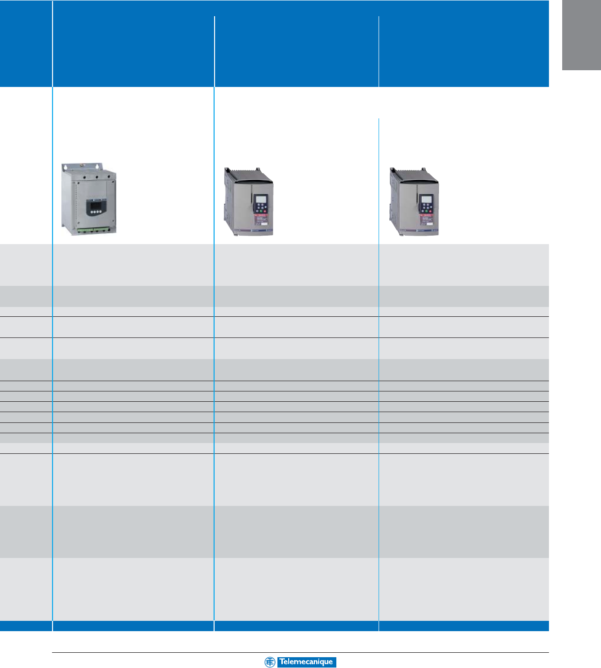
2-3
AC
DRIVES
For other versions, consult your nearest Square D/Schneider Electric sales office.
Large machines
Fixed speed machines Variable torque machines Constant torque machines
for reduced voltage starting/stopping
• industrial facility
• industrial facility • centrifugal fans • compressors
• compressors • centrifugal pumps • conveyors
• conveyors • extruders
• fans • packaging
• pumps
Soft starts AC drives
Altistart 48 Altivar 58
TRX
Altivar 58
TRX
Three phase 208–690 V Single phase 200–240 V Single phase 200–240 V
Three phase 200–240 V Three phase 200–240 V
Three phase 380–460 V Three phase 380–500 V
3–900 kW 0.37–315 kW 0.37–220 kW
2–1200 hp 0.50–500 hp 0.50–350 hp
0.1–500 Hz 0.1–500 Hz
Torque ramp control Sensorless flux vector Sensor/sensorless flux vector control
50/60 Hz control
200–300% of the nominal motor torque 110% of the nominal motor torque 200% of the nominal motor torque
for 100 ms for 60 sec. for 2 sec. 170% for 60 sec.
36 > 60 > 60
–8 8
12 to 3 2 to 3
44 to 6 4 to 6
11 to 2 1 to 2
20 to 1 0 to 1
32 2
Modbus Modbus Modbus
DeviceNet, Ethernet TCP/IP, AS-Interface, CANopen, AS-Interface, CANopen,
Profibus DP, Fipio DeviceNet, Ethernet TCP/IP, DeviceNet, Ethernet TCP/IP,
Fipio, I
NTER
B
US
-S, Lonworks, Modbus, Fipio, I
NTER
B
US
-S, Modbus, Modbus Plus,
Modbus Plus, METASYS N2, Profibus DP, Uni-Telway
Siemens P1, Profibus DP, Uni-Telway
– Pump switching card Multi-motor card, Multi-parameter card,
“Controller Inside” programmable card Simple positioning card,
I/O extension card “Controller Inside” programmable card,
115 Vac logic input card I/O extension card,
115 Vac logic input card
IEC/EN 60947-4-2 EN 50178 - IEC 1800-3 EN 50178 - EN 55011
EMC class A and B EN 55011 class A EN 55022 class A,
UL, CSA, NOM, CE, CCC, EN 55022 class B class B with option
GOST, CCIB, C-TICK, DNV UL - N998 - CE IEC 61000-4/2/4-3/4-4/4-5
IEC 61800-3 - DNV - GOST
UL - CE - CSA - N998 - NOM 117
2-8 to 2-9 2-14 to 2-15 2-16 to 2-18
8836CT9701R2/00 8806CT9901R2/03 8806CT9901R2/03
• centrifuges
• hoisting
• crushers
• presses
• grinders
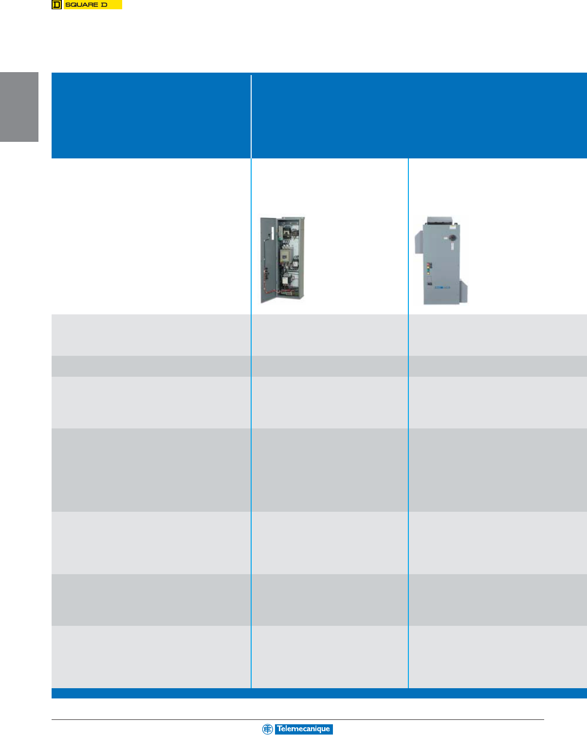
2-4
AC
DRIVES
www.telemecanique.com
Selection guide
Type of motor control
Key application/market segment • pumps • agitators • commercial/mechanical
• fans • mixers • HVAC/fans
• conveyors • grinders • pumps
• centrifuges • crushers
• lifts • presses
Packaged soft starts/drives
Soft starts Adjustable speed drives
Enclosed 48 Econoflex
Distribution voltage ranges
Three phase 208–600 Vac Three phase 208–480 Vac
for 50/60 Hz line supply
Horsepower ratings
3–600 hp 1–100 hp (VT)
Configurable options
Pre-engineered and customization Pre-engineered
• non-reversing • drive controller
• reversing • drive with isolation and bypass
• shunt trip
Enclosure ratings
Type 1, 12, 3R Type 1, 12K, 3R
Communication networks
Modbus Modbus
Modbus Plus Lonworks
Ethernet METASYS N2
Devicenet
Standards and certifications
UL 508 UL 508C
cUL cUL
Seismic qualified (AC156)
Floor mount
Reference literature
8636BR0401 8839HO9902
8638CT0401 8806CT9901
Integrated control protected within enclosures, optimized with
disconnects, circuit breakers, fuses, contactors, push buttons,
selector switches, control logic, communication and miscellaneous
options designed to meet application requirements.

2-5
AC
DRIVES
For other versions, consult your nearest Square D/Schneider Electric sales office.
• industrial facility • water/wastewater • high density construction
• pumps • clean power drives • industrial & process control applications
• fans • high horsepower
• compressors • pumps
• conveyors
• extruders
Adjustable speed drives Adjustable speed drives Soft starts & adjustable speed drives
Enclosed 58M Powergard (18 pulse) Motor control centers
Three phase 208–480 Vac Three phase 480 Vac Three phase 208–600 Vac
1–500 hp (VT) 75–500 hp (VT) 3–600 hp soft starts
1–350 hp (CT) 1–500 hp adjustable speed drives
Pre-engineered and customization Pre-engineered and customization Pre-engineered and customization
• drive controller • drive controller
• drive with integrated bypass • configurable with barriered bypass or
• drive with barriered bypass SSRVS bypass
Type 1, 1A, 12 Type 1, 1A Type 1, 12, 3R
Modbus Modbus Modbus
Modbus Plus Modbus Plus Modbus Plus
DeviceNet DeviceNet DeviceNet
Ethernet Ethernet Ethernet
METASYS N2 METASYS N2 METASYS N2
Lonworks Lonworks Profibus
UL 508A UL 508A UL845
UL 508C UL 508C CSA
CSA / cUL
Seismic qualified (AC156)
Floor mount
8800SM0301 Consult factory 8998BR9701
8806CT9901 8998CT9701
Now available
in ATV 58
TRX
version
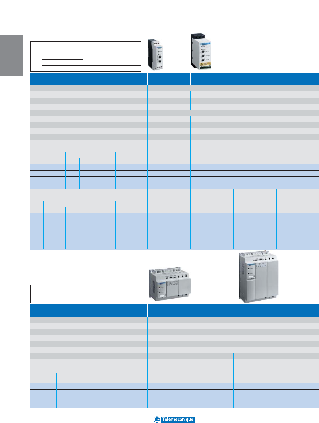
2-6
AC
DRIVES
www.telemecanique.com
Type of starter Soft start Soft start and soft stop
Motor power 0.25–7.5 hp 1.0–20 hp
Degree of protection IP 20
Peak current reduction No (1 controlled phase) Yes (2 controlled phases)
Adjustable starting time 1–5 s 1–10 s
Adjustable stopping time No: freewheel stop Yes: 1–10 s
Adjustable starting torque 30–80% of rated motor starting torque
Logic inputs
-
3 logic inputs (Start, stop and kickstart)
Logic outputs -1 logic output
Relay outputs -1 relay output
Control supply voltage
110–240 Vac ± 10%, 24 Vdc ± 10%
Built into the soft start
Supply voltage
Single phase 110–230 V
Motor power
110 V 230 V Nominal current
Hp kW Hp (A)
–0.37 0.25 3 ATS01N103FT
0.25 0.75 0.5 6 ATS01N106FT
0.33 1.1 1 9 ATS01N109FT
0.5 1.5 2 12 ATS01N112FT
Supply voltage
3-phase
200–480 V
3-phase
200–240 V
3-phase
380–415 V
3-phase
440–480 V
Motor power
208 V 230 V 400 V 460 V Nominal current
Hp kW Hp kW Hp (A)
0.5 0.37–0.55 0.5 1.1 1–1.5 3 ATS01N103FT –––
10.75–1.1 1–1.5 2.2 2–3 6 ATS01N106FT ATS01N206LU ATS01N206QN ATS01N206RT
1.5–2 1.5 2 4 5 9 ATS01N109FT ATS01N209LU ATS01N209QN ATS01N209RT
32.2 3 5.5 7.5 12 ATS01N112FT ATS01N212LU ATS01N212QN ATS01N212RT
54–5.5 5–7.5 7.5–11 10–15 22 –ATS01N222LU ATS01N222QN ATS01N222RT
7.5–10
7.5 10 15 20 32 –ATS01N232LU ATS01N232QN ATS01N232RT
Type of starter Soft start and soft stop
Motor power 10 to 60 hp
Degree of protection IP 20 on front panel
Peak current reduction Ye s
Adjustable starting and stopping times 1–25 s
Adjustable starting torque 30–80% of rated motor starting torque
Logic inputs 2 logic inputs (start and stop)
Relay outputs 1 relay output (1 more optional)
Control supply voltage 110 Vdc ± 10% Built into the soft start
Supply voltage 3-phase 230–690 V 3-phase 400 V
Motor power
230 V 400 V 460 V 575 V 690 V Nominal current
kW Hp kW Hp Hp kW (A)
7.5 10 15 20 30 30 32 ATS01N230LY –
11 15 22 30 40 37 44 ATS01N244LY ATS01N244Q
18.5 25 37 50 60 55 72 ATS01N272LY ATS01N272Q
22 30 45 60 75 75 85 ATS01N285LY ATS01N285Q
Altistart 01
0.25 to 75 hp
0.37–75 kW
Small machines
Soft starts
Dimensions (W x H x D) mm In.
ATS01 N103FT / N106 FT 22.5 x 100 x 100 0.89 x 3.94 x 3.94
N109FT / N112 FT 45 x 124 x 113 1.77 x 4.88 x 4.45
N206pp / N209pp / N212pp
N222pp / N232pp 45 x 154 x 113 1.77 x 6.06 x 4.45
Dimensions (W x H x D) mm In.
ATS01 N230pp/N244pp 180 x 146 x 126 180 x 5.75 x 4.96
N272pp/N285pp 180 x 254.5 x 126 7.09 x 10.02 x 4.96
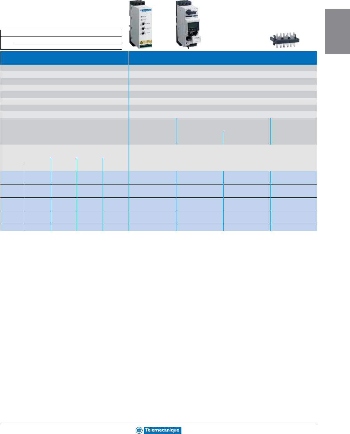
2-7
AC
DRIVES
For other versions, consult your nearest Square D/Schneider Electric sales office.
Soft starts with TeSys U-line
motor starter
Type of starter Soft stop and soft start
Motor power 1.0 to 20 hp
Degree of protection IP 20
Peak current reduction Ye s
Adjustable starting and stopping times 1–10 s
Adjustable starting torque 30–80% of rated motor starting torque
Logic inputs 3 logic inputs (start, stop and kickstart)
Logic outputs 1 logic output
Relay outputs 1 relay output
Control supply voltage Built into the soft start
Catalog numbers TeSys U-line motor starter Power connector
soft start
between ATSU and TeSys
Power base Control
U-line motor starter:
unit (1) VW3G4104 (2)
Supply voltage 3-phase 200–480 V
Motor power
230 V 400 V 460 V
Nominal
kW Hp kW Hp
current (A)
0.75 1 1.5 2 6 ATSU01N206LT LUB12 LUCpp
pp
p05BL –
1.1 1.5 2.2 3 6 ATSU01N206LT LUB12 LUCpp
pp
p12BL
1.5 23–9ATSU01N209LT LUB12 LUCpp
pp
p12BL –
–459ATSU01N209LT LUB12 LUCpp
pp
p12BL
2.2 3––12ATSU01N212LT LUB12 LUCpp
pp
p12BL –
3– 5.5 7.5 12 ATSU01N212LT LUB32 LUCpp
pp
p18BL
45 7.5 10 22 ATSU01N222LT LUB32 LUCpp
pp
p18BL –
5.5 7.5 11 15 22 ATSU01N222LT LUB32 LUCpp
pp
p32BL
7.5 10 15 20 32 ATSU01N232LT LUB32 LUCpp
pp
p32BL –
(1) To create the complete catalog number, replace pp
pp
p in the catalog number with: “A” for a standard control unit, “M” for a multifunction unit and “B” for an expandable unit.
(2) This power connector is included with ATSU01 soft starts.
Dimensions (W x H x D) mm In.
ATSU01
N206LT / N209LT/N212LT 45 x 124 x 113 1.77 x 4.88 x 4.45
N222LT / N232LT 45 x 154 x 113 1.77 x 6.06 x 4.45
2-8
AC
DRIVES
www.telemecanique.com
Altistart 48
2 to 1200 hp
3 to 900 kW
Large machines
Soft starts
Supply voltage 3-phase 208–690 V
Application duty cycle Standard duty Severe duty
(1)
Starter control supply voltage 110–230 V
Protection Degree of protection IP 20: ATS48D17Y to ATS48C11Y soft starts
IP 00: ATS48C14Y to ATS48M12Y soft starts
Motor thermal protection Class 10 Class 20
EMC Class A On all soft starts
Class B On all soft starts up to ATS48C17Y
Starting mode Torque ramp control
I/O Analog inputs 1 PTC probe
Logic inputs 4, 2 of which are configurable
Logic outputs 2 configurable
Analog outputs 1
Relay outputs 3, 2 of which are configurable
Dialog Integrated or remote display terminal, or PowerSuite software (2)
Communication (2) Integrated Modbus
Available as an option DeviceNet, Ethernet TCP/IP, Profibus DP, Fipio
Motor power
Nominal
208 V 230 V 460 V 575 V 230 V 400 V 440 V 500 V 525 V 660 V 690 V
current
Hp kW (A)
23 7.5 10 3 5.5 5.5 7.5 7.5 9 11 12 – ATS48D17Y
35 1015 4 7.5 7.5 9 9 11 15 17 ATS48D17Y ATS48D22Y
57.5 15 20 5.5 11 11 11 11 15 18.5 22 ATS48D22Y ATS48D32Y
7.5 10 20 25 7.5 15 15 18.5 18.5 22 22 32 ATS48D32Y ATS48D38Y
10 – 25 30 9 18.5 18.5 22 22 30 30 38 ATS48D38Y ATS48D47Y
–1530401122223030373747ATS48D47Y ATS48D62Y
15 20 40 50 15 30 30 37 37 45 45 62 ATS48D62Y ATS48D75Y
20 25 50 60 18.5 37 37 45 45 55 55 75 ATS48D75Y ATS48D88Y
25 30 60 75 22 45 45 55 55 75 75 88 ATS48D88Y ATS48C11Y
30 40 75 100 30 55 55 75 75 90 90 110 ATS48C11Y ATS48C14Y
40 50 100 125 37 75 75 90 90 110 110 140 ATS48C14Y ATS48C17Y
50 60 125 150 45 90 90 110 110 132 160 170 ATS48C17Y ATS48C21Y
60 75 150 200 55 110 110 132 132 160 200 210 ATS48C21Y ATS48C25Y
75 100 200 250 75 132 132 160 160 220 250 250 ATS48C25Y ATS48C32Y
100 125 250 300 90 160 160 220 220 250 315 320 ATS48C32Y ATS48C41Y
125 150 300 350 110 220 220 250 250 355 400 410 ATS48C41Y ATS48C48Y
150 – 350 400 132 250 250 315 315 400 500 480 ATS48C48Y ATS48C59Y
–200 400 500 160 315 355 400 400 560 560 590 ATS48C59Y ATS48C66Y
200 250 500 600 – 355 400 – – 630 630 660 ATS48C66Y ATS48C79Y
250 300 600 800 220 400 500 500 500 710 710 790 ATS48C79Y ATS48M10Y
350 350 800 1000 250 500 630 630 630 900 900 1000 ATS48M10Y ATS48M12Y
400 450 1000 1200 355 630 710 800 800 – – 1200 ATS48M12Y –
(1) Starting time greater than 30 seconds (fans, high inertia machines and compressors).
(2) For more information concerning PowerSuite software and communication protocols, see pages 2-20–2-22.
Accessory
Type of accessory Remote display terminal
[Includes 3 m (9.8') cable with connectors, with seals, plastic bezel,
screws for IP 65 keypad mounting on door of enclosure.]
Catalog number VW3G48101
Dimensions (W x H x D) mm In.
ATS48 D17Y to D47Y 160 x 275 x 190 6.30 x 10.83 x 7.48
D62Y to C11Y 190 x 290 x 235 7.48 x 11.42 x 9.25
C14Y to C17Y 200 x 340 x 265 7.87 x 13.39 x 10.43
C21Y to C32Y 320 x 380 x 265 12.60 x 14.96 x 10.43
C41Y to C66Y 400 x 670 x 300 15.75 x 26.38 x 11.81
C79Y to M12Y 770 x 890 x 315 30.31 x 35.04 x 12.40
2-9
AC
DRIVES
For other versions, consult your nearest Square D/Schneider Electric sales office.
Soft starts
(1)
Supply voltage 3-phase 208–500 V
Application duty cycle Standard duty Severe duty
(2)
Starter control supply voltage 110–230 V
Characteristics Identical to 208–690 V soft starts
Motor power
Nominal
208 V 230 V 460 V 230 V 400 V 440 V 500 V
current
Hp kW (A)
–7.5 15 5.5 11 11 15 22 – ATS48D17YS316
7.5 10 20 7.5 15 15 18.5 29 ATS48D17YS316 ATS48D22YS316
10 10 30 9 18.5 22 22 38 ATS48D22YS316 ATS48D32YS316
15 20 40 15 22 30 37 55 ATS48D32YS316 ATS48D38YS316
20 25 50 18.5 30 37 45 66 ATS48D38YS316 ATS48D47YS316
25 30 60 22 45 45 55 81 ATS48D47YS316 ATS48D62YS316
30 40 75 30 55 55 75 107 ATS48D62YS316 ATS48D75YS316
40 50 100 37 55 75 90 130 ATS48D75YS316 ATS48D88YS316
50 60 125 45 75 90 110 152 ATS48D88YS316 ATS48C11YS316
60 75 150 55 90 110 132 191 ATS48C11YS316 ATS48C14YS316
75 100 200 75 110 – 160 242 ATS48C14YS316 ATS48C17YS316
100 125 250 90 132 200 200 294 ATS48C17YS316 ATS48C21YS316
125 150 300 110 160 220 250 364 ATS48C21YS316 ATS48C25YS316
150 – 350 132 220 250 315 433 ATS48C25YS316 ATS48C32YS316
200 200 450 160 250 355 400 554 ATS48C32YS316 ATS48C41YS316
–– 600 220 315 500 500 710 ATS48C41YS316 ATS48C48YS316
–– – 250 355 560 630 831 ATS48C48YS316 ATS48C59YS316
–– –– 400 710 710 1022 ATS48C59YS316 ATS48C66YS316
–– – 315 500 710 800 1143 ATS48C66YS316 ATS48C79YS316
–– – 475 630 900 900 1368 ATS48C79YS316 ATS48M10YS316
–– –– 710 – – 1732 ATS48M10YS316 ATS48M12YS316
–– – 500 – – – 2078 ATS48M12YS316 –
(1) For wiring in series with the windings of a 6 or 12 lead delta-wound motor.
(2) Starting time greater than 30 seconds (fans, high inertia machines and compressors).
Dimensions (W x H x D) mm In.
ATS48 D17p to D47p160 x 275 x 190 6.30 x 10.83 x 7.48
D62p to C11p190 x 290 x 235 7.48 x 11.42 x 9.25
C14p to C17p200 x 340 x 265 7.87 x 13.39 x 10.43
C21p to C32p320 x 380 x 265 12.60 x 14.96 x 10.43
C41p to C66p400 x 670 x 300 15.75 x 26.38 x 11.81
C79p to M12p770 x 890 x 315 30.31 x 35.04 x 12.40
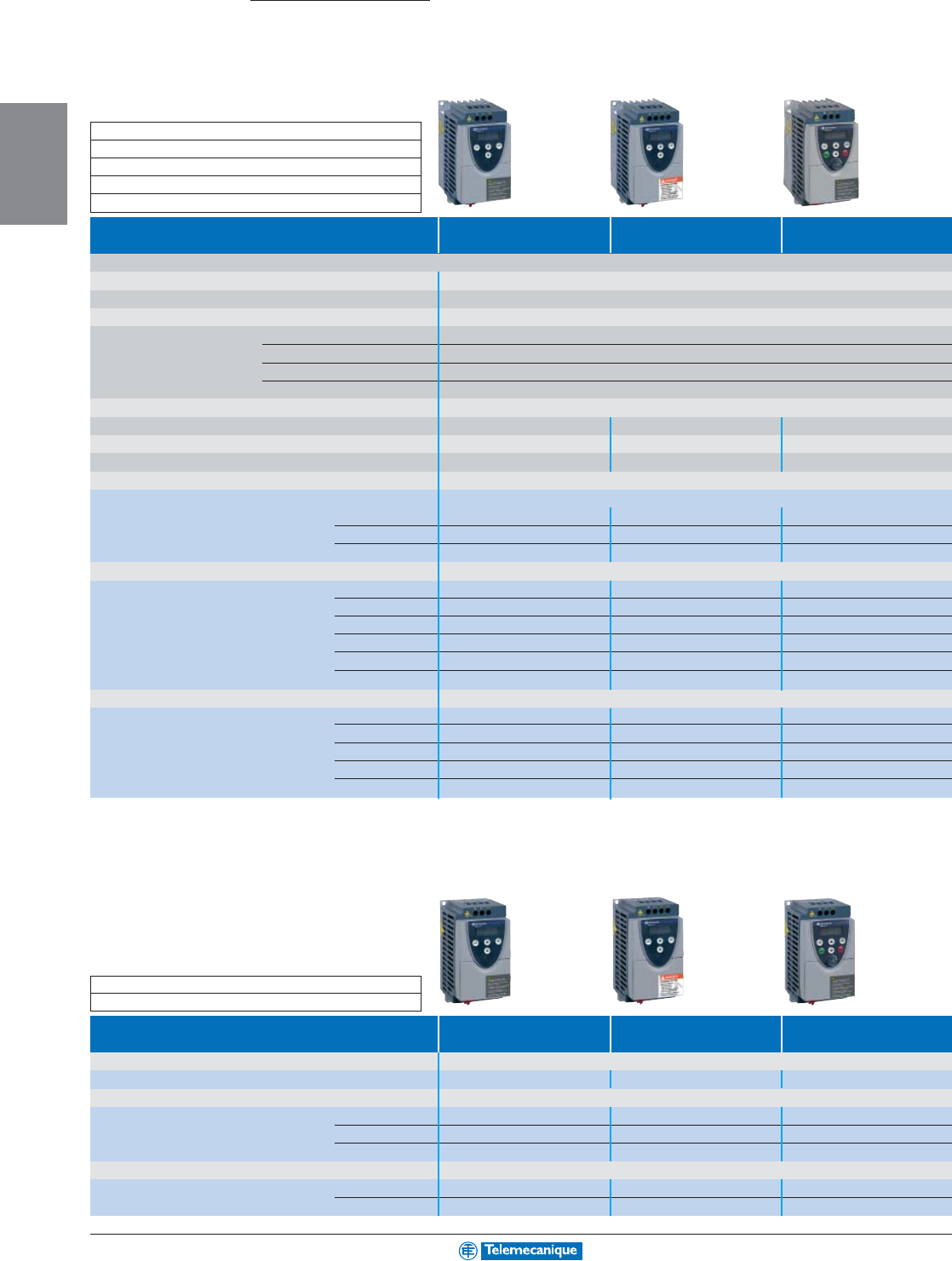
2-10
AC
DRIVES
www.telemecanique.com
Altivar 11
0.25 to 3 hp
Small machines
AC drives with heatsinks
Range Europe America Asia
Output frequency 0.5–200 Hz
Type of control Sensorless flux vector control
Speed range 1 to 20
Degree of protection IP 20
I/O Analog inputs 1 configurable analog input
Logic inputs 4 assignable logic inputs
Outputs 1 PWM open collector output assignable as logic or analog output
Relay outputs 1 protected relay logic output
Dialog Integrated display terminal or PowerSuite software workshop (2)
EMC Integrated class B filter
External filter available as an option
External filter available as an option
Local controls (3)/negative logic No No Yes
Standard NEC 1999 Motor Current Rated No Yes No
Supply voltage Single phase 100–120 V
Motor power kW Hp
0.18 0.25 – ATV11HU05F1U Size 1 ATV11HU05F1A Size 1
0.37 0.5 – ATV11HU09F1U Size 2 ATV11HU09F1A Size 2
0.75 1 – ATV11HU18F1U Size 4 ATV11HU18F1A Size 4
Supply voltage Single phase 200–240 V
Motor power 0.18 0.25 ATV11HU05M2E Size 1 ATV11HU05M2U Size 1 ATV11HU05M2A Size 1
0.37 0.5 ATV11HU09M2E Size 2 ATV11HU09M2U Size 2 ATV11HU09M2A Size 2
0.55 ATV11HU12M2E Size 3 – –
0.75 1 ATV11HU18M2E Size 3 ATV11HU18M2U Size 3 ATV11HU18M2A Size 3
1.5 2 ATV11HU29M2E Size 4 ATV11HU29M2U Size 4 ATV11HU29M2A Size 4
2.2 3 ATV11HU41M2E Size 4 ATV11HU41M2U Size 4 ATV11HU41M2A Size 4
Supply voltage Three phase 200–230 V
Motor power 0.18 0.25 –ATV11HU05M3U Size 1 ATV11HU05M3A Size 1
0.37 0.5 – ATV11HU09M3U Size 2 ATV11HU09M3A Size 2
0.75 1 – ATV11HU18M3U Size 3 ATV11HU18M3A Size 3
1.5 2 – ATV11HU29M3U Size 4 ATV11HU29M3A Size 4
2.2 3 – ATV11HU41M3U Size 4 ATV11HU41M3A Size 4
(1) Asia range: add 7 mm to depth (height of the potentiometer)
(2) PowerSuite software, see page 2-20
(3) Local controls: Run/Stop keys and potentiometer
AC drives with base plates
Range Europe America Asia
Supply voltage kW Hp Single phase 100–120 V
Motor power 0.37 0.5 –ATV11PU09F1U ATV11PU09F1A
Supply voltage Single phase 200–240 V
Motor power 0.37 0.5 ATV11PU09M2E ATV11PU09M2U ATV11PU09M2A
0.55 ATV11PU12M2E ––
0.75 1 ATV11PU18M2E ATV11PU18M2U ATV11PU18M2A
Supply voltage Three phase 200–230 V
Motor power 0.37 0.5 –ATV11PU09M3U ATV11PU09M3A
0.75 1 –ATV11PU18M3U ATV11PU18M3A
(1) Asia range: add 7 mm to depth (height of the potentiometer)
Dimensions (W x H x D) (1) mm In.
Size 1:72 x 142 x 101 2.83 x 5.59 x 3.98
Dimensions (W x H x D) (1) mm In.
Size 1:72 x 142 x 101 2.83 x 5.59 x 3.98
Size 2:72 x 142 x 125 2.83 x 5.59 x 4.92
Size 3:72 x 142 x 138 2.83 x 5.59 x 5.43
Size 4:117 x 142 x 156 4.61 x 5.59 x 6.14
2-11
AC
DRIVES
For other versions, consult your nearest Square D/Schneider Electric sales office.
Additional EMC input filters
Supply voltage Single phase Three phase
100–120 V 200–240 V 200–230 V
Europe range Drive type ATV11 – HU05M2E to HU41M2E –
Catalog numbers Filters –Integrated –
America range Drive type ATV11 HU05F1U, HU09F1U HU05M2U to HU18M2U HU05M3U to HU18M3U
Catalog numbers Filters VW3A11401 VW3A11401 VW3A11403
Drive type ATV11 HU18F1U HU29M2U - HU41M2U HU29M3U to HU41M3U
Catalog numbers Filters VW3A11402 VW3A11402 VW3A11404
Asia range Drive type ATV11 HU05F1A - HU09F1A HU05M2A to HU18M2A HU05M3A to HU18M3A
Catalog numbers Filters VW3A11401 VW3A11401 VW3A11403
Drive type ATV11 HU18F1A - HU18F1A HU29M2A - HU41M2A HU29M3A to HU41M3A
Catalog numbers Filters VW3A11402 VW3A11402 VW3A11404
Accessories
Accessory Mounting plates Grounding plate Braking module
for DIN rail for EMC mounting
Description Width 35 mm (1.38") Minimum dynamic braking
resistance value 75 Ω
Catalog numbers Drive type ATV11 HU05ppp HU18F1pAll ATV11 models All ATV11 models
HU09ppp HU29ppp
HU12M2pHU41ppp
HU18pp –
Accessories VW3A11851 VW3A11852 VW3A11831 VW3A11701
Braking resistors: Please consult bulletin VDOC06N908C.
2-12
AC
DRIVES
www.telemecanique.com
Altivar 31
0.25 to 20 hp
Small machines
AC drives
Supply voltage Single phase Three phase
200–240 V 200–240 V 380–500 V 525–600 V
Output frequency 0.5–500 Hz
Type of control Sensorless flux vector control
Speed range 1 to 50
Degree of protection IP 31 and IP 41 on upper part and IP 21 on connection terminals
I/O Analog inputs 3 configurable analog inputs
Logic inputs 6 programmable logic inputs
Analog/logic outputs Choice of: 1 current analog output or 1 voltage analog output (assignable as logic output)
Relay outputs 2 relay logic outputs
Dialog Integrated display terminal with or without local controls (1) or PowerSuite software workshop (2)
Communication (3) Integrated Modbus and CANopen
Available as an option DeviceNet, Ethernet TCP/IP, Fipio, Profibus DP
EMC Class A Integrated class A filter
External filter avail. as an option
Integrated class A filter –
Class B External filter available as an option –
Motor power kW Hp
0.18 0.25 ATV31H018M2 S3 ATV31H018M3X S1 ––
0.37 0.5 ATV31H037M2 S3 ATV31H037M3X S1 ATV31H037N4 S6 –
0.55 0.75 ATV31H055M2 S4 ATV31H055M3X S2 ATV31H055N4 S6 –
0.75 1 ATV31H075M2 S4 ATV31H075M3X S2 ATV31H075N4 S6 ATV31H075S6X S6
1.1 1.5 ATV31HU11M2 S6 ATV31HU11M3X S5 ATV31HU11N4 S5 –
1.5 2 ATV31HU15M2 S6 ATV31HU15M3X S5 ATV31HU15N4 S6 ATV31HU15S6X S6
2.2 3 ATV31HU22M2 S7 ATV31HU22M3X S6 ATV31HU22N4 S7 ATV31HU22S6X S7
3– – ATV31HU30M3X S7 ATV31HU30N4 S7 –
45 – ATV31HU40M3X S7 ATV31HU40N4 S7 ATV31HU40S6X S7
5.5 7.5 – ATV31HU55M3X S8 ATV31HU55N4 S8 ATV31HU55S6X S8
7.5 10 – ATV31HU75M3X S8 ATV31HU75N4 S8 ATV31HU75S6X S8
11 15 – ATV31HD11M3X S9 ATV31HD11N4 S9 ATV31HD11S6X S9
15 20 – ATV31HD15M3X S9 ATV31HD15N4 S9 ATV31HD15S6X S9
(1) For drive with local controls (Run/Stop keys and potentiometer) add an “A” at the end of the catalog number.
(2) (3) PowerSuite software and communication protocols, see page 2-20.
(4) Add 8 mm (0.31") to depth (height of potentiometer).
Accessory
Type of accessory Remote display terminal
[Includes 3 m (9.8') cable with connectors, with seals, plastic bezel,
screws for IP 65 keypad mounting on door of enclosure.]
Catalog number VW3A31101
For more information on accessories, reference Catalog #8800CT0401.
Dimensions (W x H x D) (4) mm In.
Size 1:72 x 145 x 120 2.83 x 5.71 x 4.72
Size 2 & 3:72 x 145 x 130 2.83 x 5.71 x 5.12
Size 4:72 x 145 x 140 2.83 x 5.71 x 5.51
Size 5:105 x 143 x 130 4.13 x 5.63 x 5.12
Size 6:105 x 143 x 150 4.13 x 5.63 x 5.91
Size 7:140 x 184 x 150 5.51 x 7.24 x 5.91
Size 8:180 x 232 x 170 7.09 x 9.13 x 6.69
Size 9:245 x 330 x 190 9.65 x 12.99 x 7.48
2-13
AC
DRIVES
For other versions, consult your nearest Square D/Schneider Electric sales office.
Supply voltage Single phase Three phase
200–240 V 200–240 V 380–500 V
Maximum length of shielded cable (1) Class A 5 m (16.4') 50 m (164') 5 m (16.4') 5 m (16.4') 50 m (164')
Class B – 20 m (65') – – 20 m (65')
Catalog numbers Drive type ATV31 H018M2 to H075M2 H018M3X to H075M3X H037N4 to HU15N4
Filters Integrated VW3A31401 VW3A31402 Integrated VW3A31404
Drive type ATV31 HU11M2 to HU15M2 HU11M3X to HU22M3X HU22N4 to HU40N4
Filters Integrated VW3A31403 VW3A31404 Integrated VW3A31406
Drive type ATV31 HU22M2 HU30M3X - HU40M3X HU55N4 - HU75 N4
Filters Integrated VW3A31405 VW3A31406 Integrated VW3A31407
Drive type ATV31 – HU55M3X - HU75M3X HD11N4 - HD15N4
Filters VW3A31407 Integrated VW3A31409
Drive type ATV31 – HD11M3X - HD15M3X –
Filters VW3A31408
(1) Maximum lengths for shielded cables connecting motors to drives for a switching frequency of 2 to 16 kHz
Minimum Dynamic Braking
Resistance Values
Drive PA to PB Min. Resistance Value
ΩΩ
ΩΩ
Ω
ATV31H018M2, ATV31H037M2 40
ATV31H055M2, ATV31H075M2
ATV31HU11M2, ATV31HU15M2 27
ATV31H018M3X, ATV31H037M3X 40
ATV31H055M3X, ATV31H075M3X
ATV31HU11M3X, ATV31HU15M3X 27
ATV31H037N4, ATV31H055N4 80
ATV31H075N4
AATV31HU11N4, ATV31HU15N4 54
ATV31HU22N4
ATV31HU22M2 25
ATV31HU22M3X
ATV31HU30M3X 16
ATV31HU30N4 55
ATV31HU40N4 36
ATV31HU22M3X 25
Additional EMC input filters
Accessories
Type 1 conduit entry kit ATV28 substitution kit DIN rail kit
Drive size 1, 2 VW3A31811 VW3A31821 VW3A11851
3, 4 VW3A31812 VW3A31821 VW3A11851
5VW3A31813 VW3A31822 VW3A31852
6VW3A31814 VW3A31822 VW3A31852
7VW3A31815 ––
8VW3A31816 VW3A31823 –
9VW3A31817 ––
Drive PA to PB Min. Resistance Value
ΩΩ
ΩΩ
Ω
ATV31HU30M3X 16
ATV31HU30N4 55
ATV31HU40N4 36
ATV31H/KU55N4 29
ATV31H/KU75N4 19
ATV31HU55S6X 34
ATV31HU75S6X 23
ATV31HU40M3X 16
ATV31H/KD11N4, ATV31H/KD15N4 20
ATV31HD11S6X, ATV31HD15S6X 24
ATV31HU55M3X, ATV31HU75M3X 8
ATV31HD11M3X, ATV31HD15M3X 5
2-14
AC
DRIVES
www.telemecanique.com
Altivar 58
TRX
0.50 to 500 hp
Large machines
AC drives
Drive type ATV58
TRX
Supply voltage Single phase 200–240 V Three phase 200–240 V Three phase 380–460 V
Description Altivar 58
Output frequency 0.1–500 Hz
Type of flux vector control Sensorless flux vector control
Speed range 1 to 60
Degree of protection IP 21 and IP 41 on upper part for drives up to 100 hp
IP 00 on lower part and IP 20 on other sides for drives above 100 hp
I/O Analog inputs 1 voltage analog input and 1 current analog input
Logic inputs 4 assignable logic inputs
Analog outputs 1 assignable analog output
Logic outputs 2 relay logic outputs
Dialog Integrated or remote display terminal, or PowerSuite software (1)
Communication (2) Integrated Modbus
Available as an option AS-Interface, CANopen, DeviceNet, Ethernet TCP/IP, Fipio, Interbus-S, Lonworks, Modbus, Modbus Plus,
METASYS N2, Profibus DP, Siemens P1, Uni-Telway
EMC Class A Integrated filter Integrated filter (2–10 hp) Integrated filter (1–3 hp)
Class B External filter available as an option
Motor power kW Hp
0.37 0.5 ATV58HU09M2ZU Size 1 – –
0.75 1 ATV58HU18M2ZU Size 1 – ATV58HU18N4ZU Size 2
1.5 2 ATV58HU29M2ZU Size 2 ATV58HU29M2ZU Size 2 ATV58HU29N4ZU Size 2
2.2 3 ATV58HU41M2ZU Size 2 ATV58HU41M2ZU Size 2 ATV58HU41N4ZU Size 2
3–ATV58HU72M2ZU Size 3 ATV58HU54M2ZU Size 3 –
45ATV58HU90M2ZU Size 4 ATV58HU72M2ZU Size 3 ATV58HU54N4XZU (3) Size 3
5.5 7.5 ATV58HD12M2ZU Size 4 ATV58HU90M2ZU Size 4 ATV58HU72N4XZU (3) Size 3
7.5 10 – ATV58HD12M2ZU Size 4 ATV58HU90N4XZU (3) Size 3
11 15 – ATV58HD16M2XZU Size 6 ATV58HD12N4XZU (3) Size 4
15 20 – ATV58HD23M2XZU Size 6 ATV58HD16N4XZU (3) Size 4
18.5 25 – ATV58HD28M2XZU Size 7 ATV58HD23N4XZU (3) Size 5
22 30 – ATV58HD33M2XZU Size 7 ATV58HD28N4XZU (3) Size 6
30 40 – ATV58HD46M2XZU Size 7 ATV58HD33N4XZU (3) Size 6
37 50 – – ATV58HD46N4XZU (3) Size 6
45 60 – – ATV58HD54N4XZU (3) Size 7
55 75 – – ATV58HD64N4XZU (3) Size 7
75 100 – – ATV58HD79N4XZU (3) Size 7
90 125 – – ATV58HC10N4XZU (4) Size 8
110 150 – – ATV58HC13N4XZU (4) Size 9
132 200 – – ATV58HC15N4XZU (4) Size 9
160 250 – – ATV58HC19N4XZU (4) Size 9
200 300 – – ATV58HC23N4XZU (4) Size 10
220 350 – – ATV58HC25N4XZU (4) Size 10
250 400 – – ATV58HC28N4XZU (4) Size 10
280 450 – – ATV58HC31N4XZU (4) Size 10
315 500 – – ATV58HC33N4XZU (4) Size 10
(1) (2) PowerSuite software and communication protocols, see page 2-20.
(3) To receive Class A EMC filter, delete the “X” from the catalog number.
(4) Integrated EMC filter not available.
Dimensions (W x H x D)
mm In.
Size 1: 113 x 206 x 167 4.45 x 8.11 x 6.57
Size 2: 150 x 230 x 184 5.91 x 9.06 x 7.24
Size 3: 175 x 286 x 184 6.89 x 11.26 x 7.24
Size 4: 230 x 325 x 210 9.06 x 12.80 x 8.27
Size 5: 230 x 415 x 210 9.06 x 16.34 x 8.27
Size 6: 240 x 550 x 283 9.45 x 21.65 x 11.14
Size 7: 350 x 650 x 304 13.78 x 25.59 x 11.97
Size 8: 370 x 630 x 360 14.57 x 24.80 x 14.17
Size 9: 480
x
680
x
400 18.90
x
26.77
x
15.75
Size 10: 660
x
950
x
440 25.98
x
37.40
x
17.32
2-15
AC
DRIVES
For other versions, consult your nearest Square D/Schneider Electric sales office.
Type of accessory Operator terminal Remote terminal option
Description Ordered separately.
3 m cable with connectors, with seals, plastic bezel, and
screws for IP 65 keypad mounting on door of enclosure.
Drive type All Altivar 58 drives All Altivar 58 drives
Catalog numbers VW3A58101U VW3A58103
I/O extension and specific cards
Type of card (1) I/O extension Pump switching Logic input module
Description 2 logic inputs 24 Vdc Control of an entire pumping Provides 115 Vac to 24 Vdc
1 open collector logic output 24 Vdc
or compression station conversion for LI1, LI2, LI3 & LI4
1 analog output 0/20 mA
1 bipolar analog input ± 10 V
Catalog number VW3A58201U VW3A58210U VW3A58275U
(1) “Controller Inside” programmable card: Please consult your nearest Square D/Schneider Electric sales office.
Additional EMC input filters
Keypad accessories
Supply voltage Single phase Three phase
200–240 V 200–240 V 380–500 V 440–460 V
Maximum length of shielded cable (1) Class A 50 m (164') 50 m (164') 50 m (164') 200 m (656') 100 m (328')
Class B 20 m (65') 20 m (65') 20 m (65') 100 m (328') 25 m (82')
Catalog numbers Drive type ATV58 HU09M2, HU18M2 HU29M2, HU41M2
HU18N4, HU29N4, HU41N4
–HC10N4X
Filters VW3A58401 VW3A58402 VW3A58402 VW3A68415
Drive type ATV58 HU29M2, HU41M2, HU54M2, HU72M2
HU54N4, HU72N4, HU90N4
–HC13N4X, HC15N4X,
HC19N4X
Filters VW3A58402 VW3A58403 VW3A58403 VW3A68435
Drive type ATV58 HU72M2 HU90M2, HD12M2,
HD12N4, HD16N4
–HC23N4X, HC25N4X,
Filters VW3A58403 VW3A58404 VW3A58404 HC28N4X, HC31N4X
Drive type ATV58 HU90M2, HD12M2 HD16M2X, HD23M2X HD23N4 – HC33N4X
Filters VW3A58404 VW3A58407 VW3A58405 VW3A68465
Drive type ATV58 HD28M2X, HD33M2X, HD28N4X HD28N4
HD46M2X
Filters VW3A58408 VW3A58406
Drive type ATV58 HD33N4X, HD46N4X
HD33N4, HD46N4
Filters VW3A58407
Drive type ATV58 HD54N4X, HD64N4X
HD54N4, HD64N4
HD79N4X HD79N4
Filters VW3A58408
(1) Maximum lengths for shielded cables connecting motors to drives for a switching frequency of 0.5 to 12 kHz
These limits are given as examples only as they vary depending on the stray capacitance of the motors and the cables used.
2-16
AC
DRIVES
www.telemecanique.com
Large machines, constant torque
AC drives
Altivar 58
TRX
0.50 to 350 hp
Drive type Altivar 58 Altivar 58F
Supply voltage Single phase Three phase Three phase Three phase
200–240 V 200–240 V 380–500 V 380–500 V
Output frequency 0.1–500 Hz 0.1–450 Hz
Type of flux vector control Sensorless Sensor/Sensorless
Speed range 1 to 100
1 to 1000 with encoder feedback
Degree of protection IP 21 for unprotected drives and IP 41 on the upper part for drives up to 75 hp
IP 00 on lower part and IP 20 on other sides for drives above 75 hp
I/O Analog inputs 1 voltage analog input and 1 current analog input +5 V encoder inputs
Logic inputs 4 assignable logic inputs A, A-, B, B-
Analog outputs 1 assignable analog output
Logic outputs 2 relay logic outputs
Dialog Integrated or remote display terminal or PowerSuite software (1)
Communication (2) Integrated Modbus
Available as an option AS-Interface, CANopen, DeviceNet, Ethernet TCP/IP, Fipio, Interbus-S, Lonworks, Modbus, Modbus Plus,
Profibus DP, Uni-Telway
EMC Class A Integrated filter Integrated filter (2–10 hp) Integrated filter (1–3 hp) Integrated filter
Class B External filter available as an option
Motor power kW Hp Keypad included
0.37 0.5 ATV58HU09M2ZU S1 –––
0.75 1 ATV58HU18M2ZU S1 – ATV58HU18N4ZU S2 ATV58FHU18N4KU S2
1.5 2 ATV58HU29M2ZU S2 ATV58HU29M2ZU S2 ATV58HU29N4ZU S2 ATV58FHU29N4KU S2
2.2 3 ATV58HU41M2ZU S2 ATV58HU41M2ZU S2 ATV58HU41N4ZU S2 ATV58FHU41N4KU S2
3– ATV58HU72M2ZU (3) S3 ATV58HU54M2ZU S3 ATV58HU54N4XZU (4) S3 ATV58FHU54N4KU S3
45 ATV58HU90M2ZU (3) S4 ATV58HU72M2ZU S3 ATV58HU72N4XZU (4) S3 ATV58FHU72N4KU S3
5.5 7.5 ATV58HD12M2ZU (3) S4 ATV58HU90M2ZU S4 ATV58HU90N4XZU (4) S3 ATV58FHU90N4KU S3
7.5 10 – ATV58HD12M2ZU S4 ATV58HD12N4XZU (4) S4 ATV58FHD12N4KU S4
11 15 – ATV58HD16M2XZU S6 ATV58HD16N4XZU (4) S4 ATV58FHD16N4KU S4
15 20 – ATV58HD23M2XZU S6 ATV58HD23N4XZU (4) S5 ATV58FHD23N4KU S5
18.5 25 – ATV58HD28M2XZU S7 ATV58HD28N4XZU (4) S6 ATV58FHD28N4KU S6
22 30 – ATV58HD33M2XZU S7 ATV58HD33N4XZU (4) S6 ATV58FHD33N4KU S6
30 40 – ATV58HD46M2XZU S7 ATV58HD46N4XZU (4) S6 ATV58FHD46N4KU S6
37 50 – – ATV58HD54N4XZU (4) S7 ATV58FHD54N4KU S7
45 60 – – ATV58HD64N4XZU (4) S7 ATV58FHD64N4KU S7
55 75 – – ATV58HD79N4XZU (4) S7 ATV58FHD79N4KU S7
75 100 – – ATV58HC13N4XZU (5) S9 –
90 125 – – ATV58HC15N4XZU (5) S9 –
110 150 – – ATV58HC19N4XZU (5) S9 –
132 200 – – ATV58HC23N4XZU (5) S10 –
160 250 – – ATV58HC25N4XZU (5) S10 –
200 300 – – ATV58HC31N4XZU (5) S10 –
220 350 – – ATV58HC33N4XZU (5) S10 –
(1) (2) PowerSuite software and communication protocols, see page 2-20.
(3) Must be used with a line reactor, see page 2-19.
(4) To receive Class A EMC filter, delete the “X” from the catalog number.
(5) Integrated EMC filter not available.
Keypad accessories
Type of accessory Operator terminal Remote terminal option
Description Ordered separately.
3 m (9.8') cable with connectors, with seals, plastic bezel,
& screws for IP 65 keypad mounting on door of enclosure.
Drive type All Altivar 58 drives All Altivar 58 drives
Catalog numbers VW3A58101U VW3A58103
Dimensions (W x H x D)
mm In.
Size 1: 113 x 206 x 167 4.45 x 8.11 x 6.57
Size 2: 150 x 230 x 184 5.91 x 9.06 x 7.24
Size 3: 175 x 286 x 184 6.89 x 11.26 x 7.24
Size 4: 230 x 325 x 210 9.06 x 12.80 x 8.27
Size 5: 230 x 415 x 210 9.06 x 16.34 x 8.27
Size 6: 240 x 550 x 283 9.45 x 21.65 x 11.14
Size 7: 350 x 650 x 304 13.78 x 25.59 x 11.97
Size 8: 370 x 630 x 360 14.57 x 24.80 x 14.17
Size 9: 480
x
680
x
400 18.90
x
26.77
x
15.75
Size 10: 660
x
950
x
440 25.98
x
37.40
x
17.32
2-17
AC
DRIVES
For other versions, consult your nearest Square D/Schneider Electric sales office.
Accessories
Type of accessory Control card ventilation Type 1 conduit entry kits
Description Fan subassembly Use on wall-mounted drive controllers
and mounting accessories
Catalog numbers Drive type ATV58 HU09M2, HU18M2 HU09M2, HU18M2 HU29M2, HU41M2
HU18N4, HU29N4, HU41N4
Accessories VW3A58821 VW3A58842 VW3A58843
Drive type ATV58 HU29M2, HU41M2, HU18N4 HU54M2, HU72M2 HU90M2, HD12M2
HU29N4, HU41N4 U54N4, U72N4, U90N4 HD12N4, HD16N4, HD23N4
Accessories VW3A58822 VW3A58844 VW3A58845
Drive type ATV58 HU54M2, HU72M2, HU54N4 HD16M2, HD23M2 HD28M2, HD33M2, HD46M2
HU72N4, HU90N4 HD28N4, HD23N4, HD46N4 HD54N4, HD64N4, HD79N4
Accessories VW3A58823 VW3A58846 VW3A58847
Drive type ATV58 HU90M2, D12M2, D12N4 HC10N4X HC13N4X, HC15N4X, HC19N4X
D16N4, D23N4
Accessories VW3A58824 VW3A58848 VW3A58849
Drive type ATV58 HD16M2X, HD23M2X, HD28N4 HC23N4X, HC25N4X, –
HD33N4, HD46N4, HD28N4X HC28N4X, HC31N4X,
HD33N4X, HD46N4X HC33N4X
Accessories VW3A58825 VW3A58850 –
Drive type ATV58 HD28M2X, HD33M2X, HD46M2X – –
HD54N4, HD64N4, HD79N4,
HD54N4X, HD64N4X, HD79N4X
Accessories VW3A58826 – –
I/O extension and application cards
Type of card (1)
I/O extension I/O extension Multi-motor Multi-parameter Simple positioning Logic input
module
Description 2 logic inputs 2 logic inputs 2 non reassignable Switching: 6 logic inputs Provides 115 Vac
24 Vdc 24 Vdc logic inputs 24 Vdc automatic or by 24 Vdc to 24 Vdc conversion for
1 open collector logic 1 open collector logic 1 open collector logic input 1 open collector LI1, LI2, LI3 & LI4
output 24 Vdc output 24 Vdc logic output 24 Vdc up to 16 sets logic output 24 Vdc
1 analog output 1 analog output 1 analog output of 13 parameters, 1 analog output
0–20 mA scalable 0–20 mA scalable 0–20 mA scalable 6 of which are 0–20 mA scalable
1 bipolar analog input encoder inputs 1 bipolar analog input predefined, 7 are 1 bipolar analog input
± 10 V 24 V A, A-, B, B- ± 10 V configurable ± 10 V
Catalog numbers VW3A58201U VW3A58202U VW3A58211 VW3A58212 VW3A58213 VW3A58275U
(1) “Controller Inside” programmable card: Please consult your nearest Square D/Schneider Electric sales office.
2-18
AC
DRIVES
www.telemecanique.com
Braking resistors in Type 1 enclosure
Supply voltage Single phase Three phase
200–240 V 200–240 V 380–500 V
Catalog numbers (1) Drive type ATV58
HU09M2 (1), HU18M2 (1)
–HU18N4, HU29N4, HU41N4
HU54N4, HU72N4
Resistors protected VW3A66711
Drive type ATV58 HU41M2 HU29M2, HU41M2 HU90N4, HD12N4
Resistors protected VW3A66712
Drive type ATV58 – HU54M2, HU72M2 HD16N4, HD23N4
Resistors protected VW3A66713
Drive type ATV58 – HU90M2, HD12M2 HD28N4, HD33N4, HD46N4
Resistors protected VW3A66714
Drive type ATV58 – HD16M2X, HD23M2X HD54N4,
Resistors protected VW3A66715
Drive type ATV58 – HD28M2X, HD33M2X, HD46M2X HD64N4, HD79N4
Resistors protected VW3A66716
(1) To be used with a braking transistor module—catalog number: VW3A58701
Large machines
Additional EMC input filters
Supply voltage Single phase Three phase
200–240 V 200–240 V 380–500 V 440–460 V
Maximum length of shielded cable (1) Class A 50 m (164') 50 m (164') 50 m (164') 200 m (656') 100 m (328')
Class B 20 m (65') 20 m (65') 20 m (65') 100 m (328') 25 m (82')
Catalog numbers Drive type ATV58 HU09M2, HU18M2 HU29M2, HU41M2
HU18N4, HU29N4, HU41N4
–HC10N4X
Filters VW3A58401 VW3A58402 VW3A58402 VW3A68415
Drive type ATV58 HU29M2, HU41M2, HU54M2, HU72M2
HU54N4, HU72N4, HU90N4
–HC13N4X, HC15N4X,
HC19N4X
Filters VW3A58402 VW3A58403 VW3A58403 VW3A68435
Drive type ATV58 HU72M2 HU90M2, HD12M2,
HD12N4, HD16N4
–HC23N4X, HC25N4X,
Filters VW3A58403 VW3A58404 VW3A58404 HC28N4X, HC31N4X
Drive type ATV58 HU90M2, HD12M2 HD16M2X, HD23M2X HD23N4 – HC33N4X
Filters VW3A58404 VW3A58407 VW3A58405 VW3A68465
Drive type ATV58 HD28M2X, HD33M2X, HD28N4X HD28N4
HD46M2X
Filters VW3A58408 VW3A58406
Drive type ATV58 HD33N4X, HD46N4X
HD33N4, HD46N4
Filters VW3A58407
Drive type ATV58 HD54N4X, HD64N4X
HD54N4, HD64N4
HD79N4X HD79N4
Filters VW3A58408
(1) Maximum lengths for shielded cables connecting motors to drives for a switching frequency of 0.5 to 12 kHz
These limits are given as examples only as they vary depending on the stray capacitance of the motors and the cables used.
Altivar 58
TRX
0.50 to 350 hp
2-19
AC
DRIVES
For other versions, consult your nearest Square D/Schneider Electric sales office.
Line reactors
Line reactors for variable torque or constant torque applications
Supply voltage Single phase 208–230 V Three phase 208–230 V Three phase 480 V
Degree of protection Type 1 enclosed
Motor power Hp
0.5 RL00812 Size 1 – –
1RL01212 Size 1 RL00412 Size 1 RL00212 Size 1
2RL01812 Size 1 RL00812 Size 1 RL00413 Size 1
3RL02512 Size 2 RL01212 Size 1 RL00413 Size 1
(3 kW) RL03512 Size 2 – –
5RL04512 Size 2 RL01812 Size 1 RL00813 Size 2
7.5 RL08012 Size 2 RL02512 Size 2 RL01213 Size 2
10 – RL03512 Size 2 RL01813 Size 2
15 – RL04512 Size 2 RL02513 Size 2
20 – RL05512 Size 2 RL03513 Size 2
25 – RL08012 Size 2 RL03513 Size 2
30 – RL10012 Size 2 RL04513 Size 2
40 – RL13012 Size 2 RL05513 Size 2
50 – RL16012 Size 2 RL08013 Size 2
60 – – RL08013 Size 2
75 – – RL10013 Size 2
100 – – RL13013 Size 2
125 – – RL16013 Size 2
150 – – RL20013 Size 2
200 – – RL25013 Size 3
250 – – RL32013 Size 3
300 – – RL40013 Size 3
350–400 – – RL50013 Size 3
450–500 – – RL60013 Size 3
Motor protecting output filters
Motor protecting output filters for variable torque or constant torque applications
Supply voltage Three phase 480 V
Degree of protection Type 1 enclosed
Motor power Hp
1–2 KLCUL4A1 Size 1
3KLCUL6A1 Size 1
5KLCUL8A1 Size 1
7.5 KLCUL12A1 Size 1
10 KLCUL16A1 Size 1
15 KLCUL25A1 Size 1
20–25 KLCUL35A1 Size 1
30 KLCUL45A1 Size 1
40 KLCUL55A1 Size 1
50–60 KLCUL80A2 Size 2
75 KLCUL110A2 Size 2
100 KLCUL130A2 Size 2
125 KLCUL160A2 Size 2
150 KLCUL200A3 Size 3
200 KLCUL250A3 Size 3
250 KLCUL300A3 Size 3
300 KLCUL360A3 Size 3
350 KLCUL420A3 Size 3
400 KLCUL480A3 Size 3
450–500 KLCUL600A3 Size 3
Dimensions (H x W x D) mm In.
Size 1:203 x 203 x 152 8 x 8 x 6
Size 2:381 x 330 x 330 15 x 13 x 13
Size 3:610 x 432 x 432 24 x 17 x 17
Dimensions (H x W x D) mm In.
Size 1:311 x 318 x 171 12.25 x 12.50 x 6.75
Size 2:486 x 394 x 394 19.13 x 15.50 x 15.50
Size 3:562 x 521 x 619 22.13 x 20.50 x 24.37
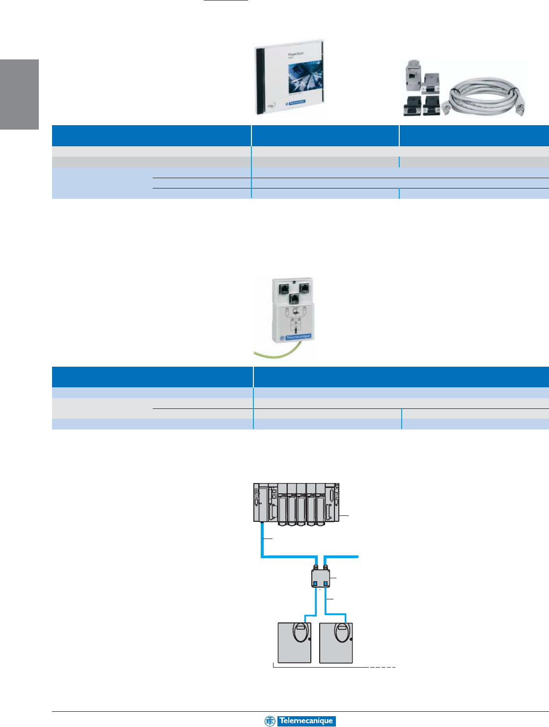
2-20
AC
DRIVES
www.telemecanique.com
Altivar/Altistart
Dialog and communication
PowerSuite software
Multilingual configuration software For PC For Pocket PC
Equipped with X scale or equivalent microprocessor
Configuration of AC drives, soft starts and starters Altistart 48 soft starts, Altivar AC drives and TeSys U-line motor starter
Environment Microsoft Windows ® Microsoft Pocket PC 2003
Catalog numbers PowerSuite CD-ROM (1) VW3A8104
PowerSuite upgrade CD-ROM VW3A8105
Cable connection kit VW3A8106 VW3A8111
(1) Contents: Software, technical documentation and the ABC configurator program
CANopen communication bus:
connection accessories
Drives Altivar 31
Tap junction VW3CANTAP2
Cables Description 2 RJ45 connectors
Cable length 0.3 m (1') 1 m (3.3')
Catalog numbers VW3CANCARR03 VW3CANCARR1
1PLC
2CANopen trunk cable
3CANopen tap junction VW3CANTAP2
4CANopen drop cable VW3CANCARRpp
1
3
2
4
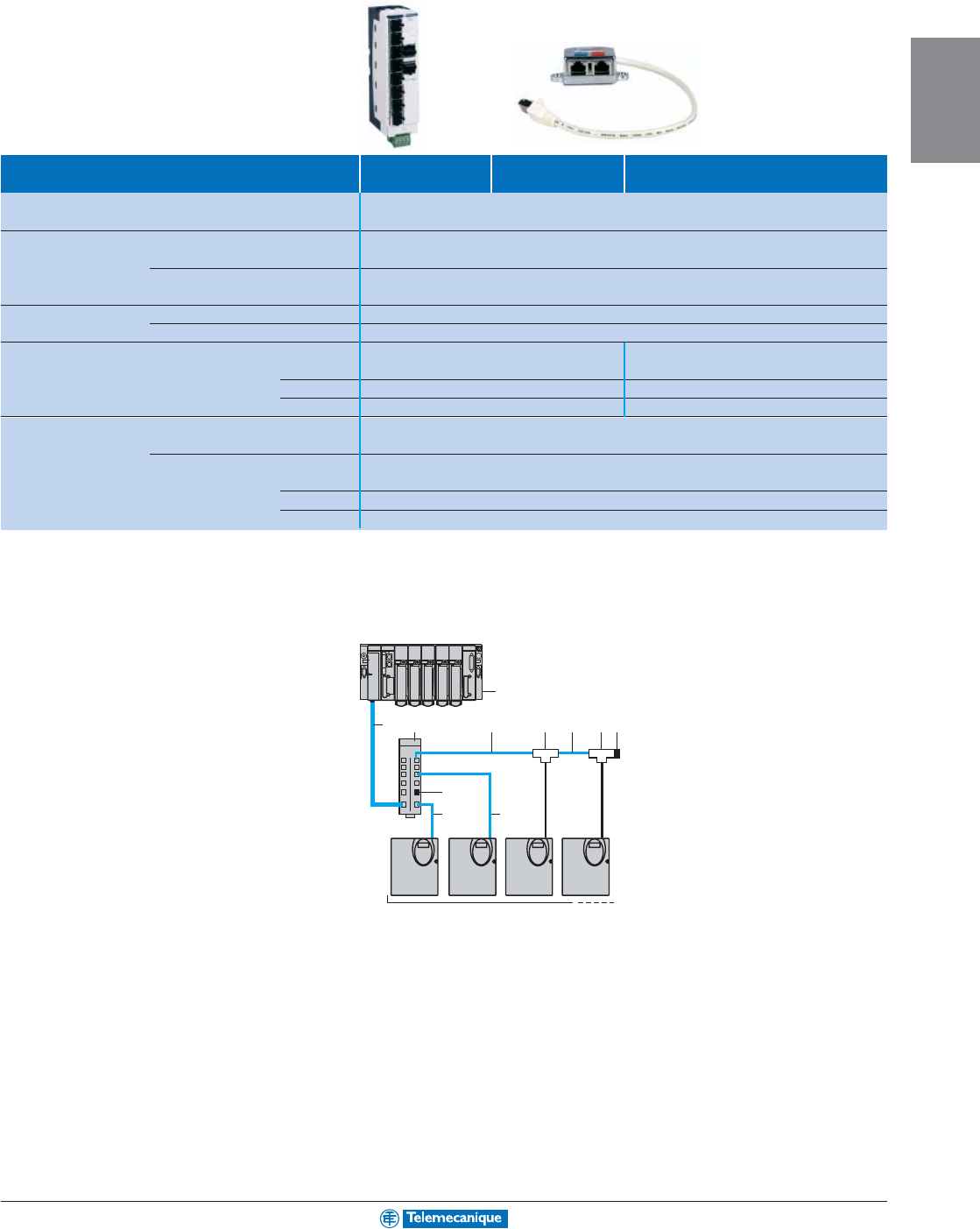
2-21
AC
DRIVES
For other versions, consult your nearest Square D/Schneider Electric sales office.
Modbus communication bus:
connection accessories
Soft starts/drives Altistart 48 Altivar 31 Altivar 58
TRX
Splitter box Description 10 RJ45 connectors and 1 screw terminal block
Catalog number LU9GC3
Line terminators For RJ 45 connector R = 120 Ω, C = 1 nF
Catalog number VW3A8306RC
For screw terminals R = 120 Ω, C = 1 nF
Catalog number VW3A8306DRC
T-junction boxes With integrated cable 0.3 m (1') VW3A8306TF03
With integrated cable 1 m (3.3') VW3A8306TF10
Modbus drop cables Description 2 RJ45 connectors 1 RJ45 and 1 DB9
Catalog numbers 0.3 m (1') VW3A8306R03 –
1 m (3.3') VW3A8306R10 VW3A58306R10
3 m (9.8') VW3A8306R30 VW3A58306R30
Shielded twisted Description 1 RJ45 connector and one stripped end
double pair cables Catalog number 3 m (9.8') VW3A8306D30
RS 485 Description Supplied without connector
Catalog numbers 100 m (328') TSXCSA100
200 m (656') TSXCSA200
500 m (1640') TSXCSA500
Connection via splitter boxes
and RJ 45 connectors
1 PLC
2 Modbus cable depending on the type
of PLC
3 Modbus splitter box LU9GC3
4 Modbus drop cables
VW3A8306Rpp
5 Line terminators VW3A8306RC
6 Modbus T-junction boxes
VW3A8306 TFpp (with cable)
5
44
1
243 46 6 5
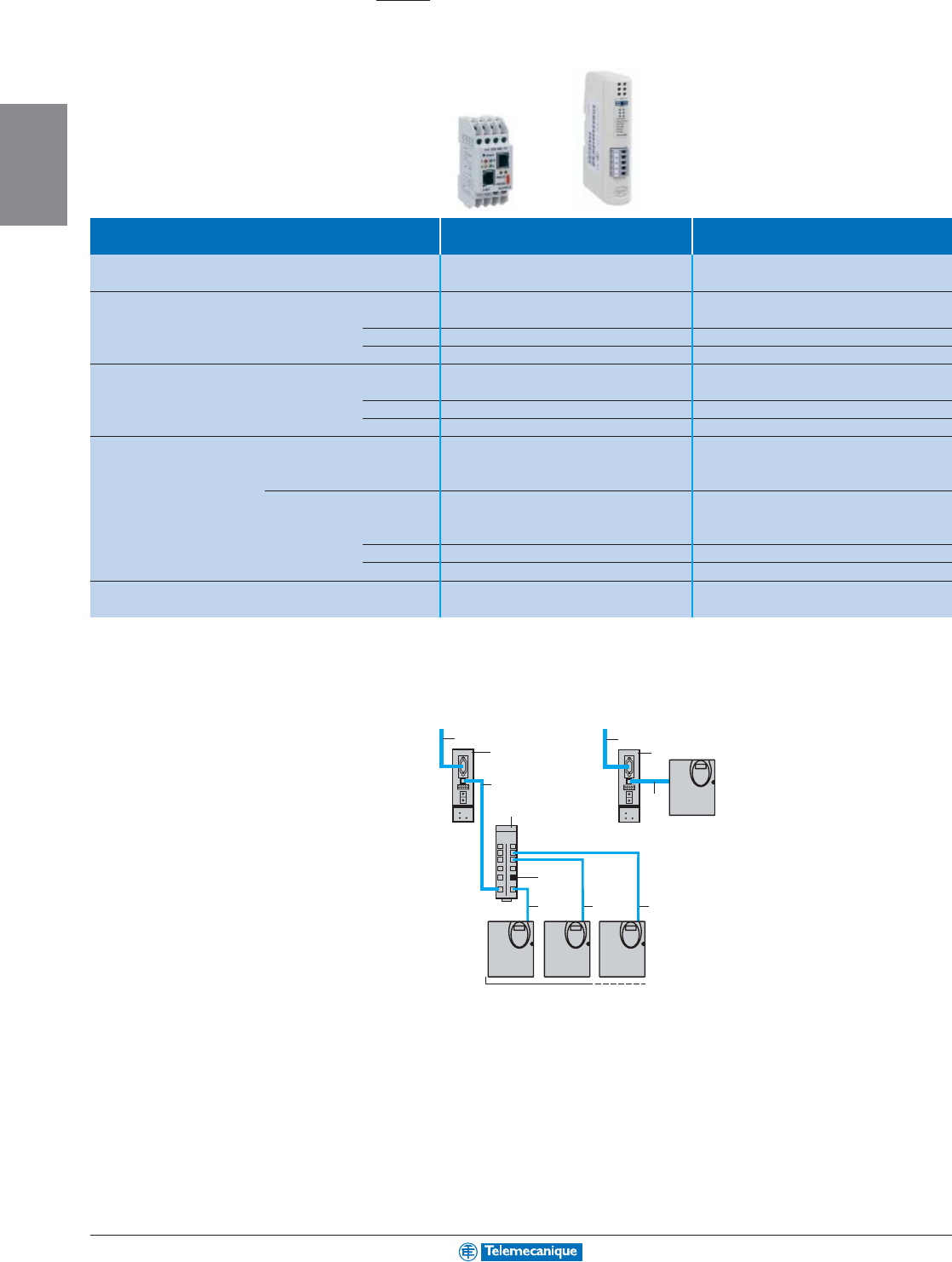
2-22
AC
DRIVES
www.telemecanique.com
Dialog and communication
Communication bridges and gateways
Altivar/Altistart
Soft starts/drives Altistart 48/Altivar 31 Altivar 58
TRX
Ethernet/Modbus Catalog numbers Bridge 174CEV30020 –
Cable VW3A8306D30
DeviceNet/Modbus Catalog numbers Gateway LUFP9 –
0.3 m (1') cable VW3A8306R03 –
1 m (3.3') cable VW3A8306R10 –
3 m (9.8') cable VW3A8306R30 –
Fipio/Modbus Catalog numbers Gateway LUFP1 –
0.3 m (1') cable VW3A8306R03 –
1 m (3.3') cable VW3A8306R10 –
3 m (9.8') cable VW3A8306R30 –
ProfibusDP/Modbus Parameter setting Standard configurator
Catalog numbers Gateway LA9P307 –
1 m (3.3') cable VW3P07306R10 –
Parameter setting ABC configurator program
Catalog numbers Gateway LUFP7 –
0.3 m (1') cable VW3A8306R03 –
1 m (3.3') cable VW3A8306R10 –
3 m (9.8') cable VW3A8306R30 –
Lonworks to Modbus Catalog numbers Gateway –VW3A58312PU (1)
Ethernet/Modbus Catalog numbers Bridge EGX400 (2) EGX400 (2)
(1) Supplied with cable for connection to drive.
(2) Allows web page access to Te
Sys
U-line, Altistart 48, Altivar 31 and Altivar 58
TRX
.
1 To network
2 Bridge or gateway modules
3 Modbus drop cables
VW3A8306 Rpp or
VW3P07306R10 PLC cables
4 Modbus splitter box LU9GC3
5 Modbus drop cables
VW3A8306Rpp
6 Line terminator
VW3A8306RC
2
1
6
55 5
3
4
2
1
3
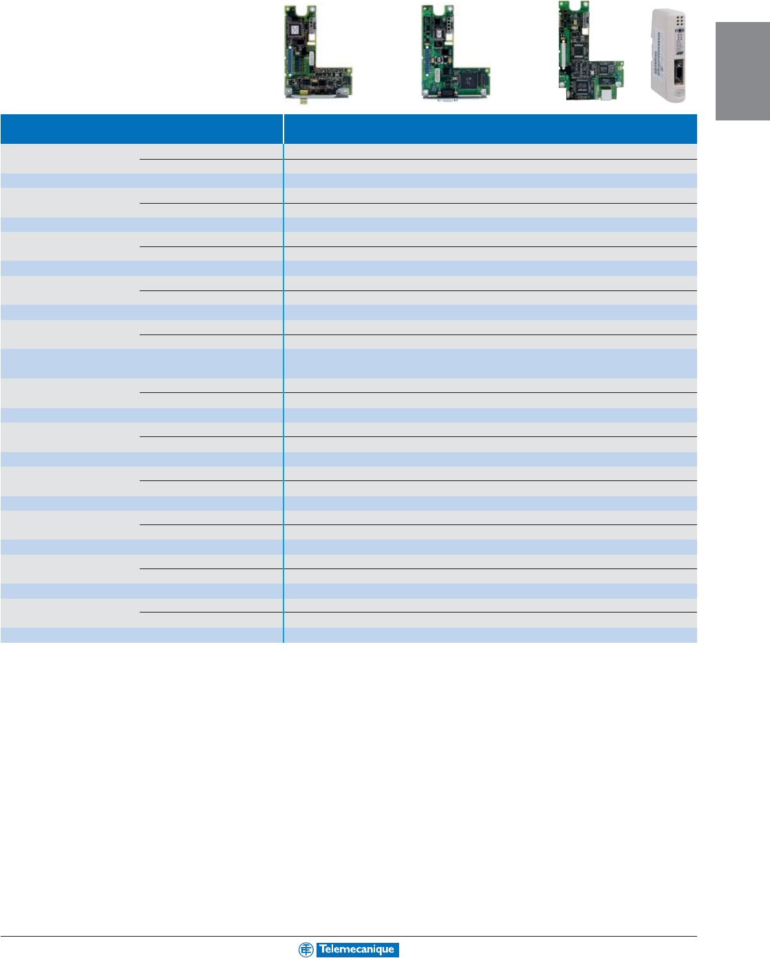
2-23
AC
DRIVES
For other versions, consult your nearest Square D/Schneider Electric sales office.
Communication cards and modules
Drives Altivar 58
TRX
AS-Interface Max. no. of drives controlled 31
Transmission speed 166 kbps
Catalog number VW3A58305
CANopen Max. no. of drives controlled 63
Transmission speed 125/250/500/1000 kbps
Catalog number VW3A58308
DeviceNet Max. no. of drives controlled 63
Transmission speed 125/250/500 kbps
Catalog number VW3A58309U
Ethernet Max. no. of drives controlled –
Transmission speed 10/100 Mbps
Catalog number VW3A58310U
Fipio Max. no. of drives controlled 62
Transmission speed 1 Mbps
Catalog number VW3A58311 for ATV58F and ATV58 TRX >100 hp
VW3A58301U for ATV58 TRX ≤100 hp
I
NTER
B
US
-S Max. no. of drives controlled 64
Transmission speed 1 Mbps
Catalog number VW3A58304EU
METASYS N2 Max. no. of drives controlled 255
Transmission speed 4800–19,200 bps
Catalog number VW3A58354U
Modbus Max. no. of drives controlled 31
Transmission speed 4800–19,200 bps
Catalog number VW3A58303U
Modbus Plus Max. no. of drives controlled 64
Transmission speed 1 Mbps
Catalog number VW3A58302U
Profibus DP Max. no. of drives controlled 126
Transmission speed 9600 bps–12 Mbps
Catalog number VW3A58307U
Uni-Telway Max. no. of drives controlled 28
Transmission speed 4800–19,200 bps
Catalog number VW3A58303U
A compact, simple and advanced
offer for your Small Automation
Systems.
Welcome to the Simply Smart* world, compliments of
Telemecanique.
Through a consistent approach to solving automation challenges
of machinery and processes, the offer is broad, but simple to
apply. From relays to nano PLCs, Telemecanique products are
simple to select, apply and operate.
Save time and
improve reliability
with products that
are simple to
select and to use
(tailored
ergonomics,
simplified
mounting and
wiring,
assembly without
tools…).
Save space
with products
that are always
more compact,
thus simplifying
integration in
your installations.
Improve
flexibility with a
modular offer for
easily resolving
your changing
needs
(interchangeable
functions and
options, common
accessories and
options…).
* Simply Smart : using ingenuity and intelligence to continually improve ease of use.
Control and
connection
components
The essential
guide
A simplified
selection guide
enabling you to
quickly select all
the products
required to build
your small
automation system
equipment
(simple installations
& compact machines)
Control and
connection
components,
a complete
synergy
with other
Telemecanique
automation
system products.
Opt for an offer that is complete,
economical and accessible to all
”
“
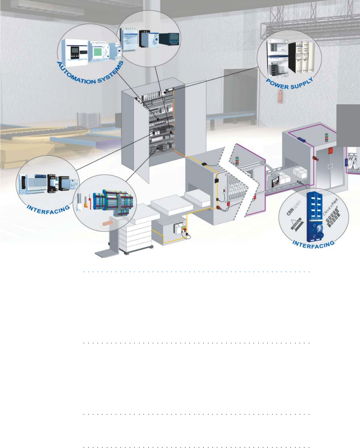
Pages
Automation systems
Zelio® Control - Control and measurement relays ..............3-2
Zelio Count - Counters .......................................................3-4
Zelio Time - Timing relays ..................................................3-6
Zelio Logic - Smart relays ................................................3-26
Twido™ programmable controllers ...................................3-10
Interfacing
Terminal blocks and cable ends .......................................3-18
Zelio Relay - Plug-in relays ..............................................3-22
Telefast® pre-wired system ...............................................3-12
Passive splitter boxes .......................................................3-14
Splitter boxes for fieldbus .................................................3-16
Power supply
Phaseo power supplies ......................................................3-9
MACHINE
CONTROL
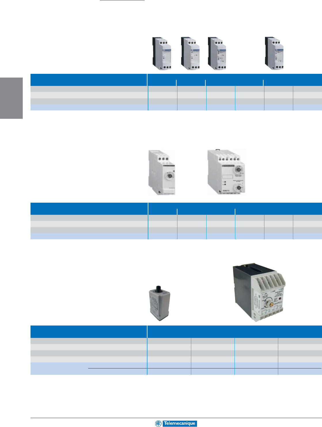
3-2
MACHINE
CONTROL
www.telemecanique.com
Zelio
®
Control Relays
Control relays for 3-phase supplies
Function Phase reversal and presence of phases
+ Undervoltage
+ Over and undervoltage + Imbalance
Adjustable time delay without without 0.1–10 s 0.1–10 s 0.1–10 s 0.1–10 s
Supply voltage 200–500 V 380–500 V 200–240 V 380–500 V 200–240 V 380–500 V
Output 2 N.C./2 N.O. 2 N.C./2 N.O. 2 N.C./2 N.O. 2 N.C./2 N.O. 2 N.C./2 N.O. 2 N.C./2 N.O.
Catalog number RM4TG20 RM4TU02 RM4TR31 (1) RM4TR32 (1) RM4TA31 RM4TA32
(1) Relay with adjustable voltage thresholds.
Function Phase reversal and presence of phases
+
Undervoltage
+ Imbalance
Adjustable time delay Fixed 0.3s 0.2–10s Fixed 0.2s Fixed 0.2s 0.1–10s 0.1–10 s
Supply voltage 230–440 V 380–550 V 230 V 230 V 185–275 V 320–480 V
Output 2 N.C./2 N.O. 2 N.C./2 N.O. 2 N.C./2 N.O. 2 N.C./2 N.O. 2 N.C./2 N.O. 2 N.C./2 N.O.
Catalog number RM84873004 RM84873015 RM84873511(1) RM84873501(2) RM84873310 RM84873311
Function Phase reversal, phase loss, phase imbalance, and undervoltage
Mounting Type Plug-in Plug-in Panel Mount Panel Mount
Undervoltage setting 180–240 V 360–480 V 180–240 V 360–480 V
Supply voltage 240 V 60 Hz 480 V 60 Hz 240 V 60 Hz 480 V 60 Hz
Output 1 N.C./1 N.O. 1 N.C./1 N.O. 2 N.C./2 N.O. 2 N.C./2 N.O.
Catalog number relay 8430MPSV24 8430MPSV29 8430MPDV24 8430MPDV29
socket 8501NR51 8501NR82 ––
Automation
systems
For additional information on RM4, reference Catalog 8430CT0001. For additional information on 8430, reference Catalog 8430CT9701.
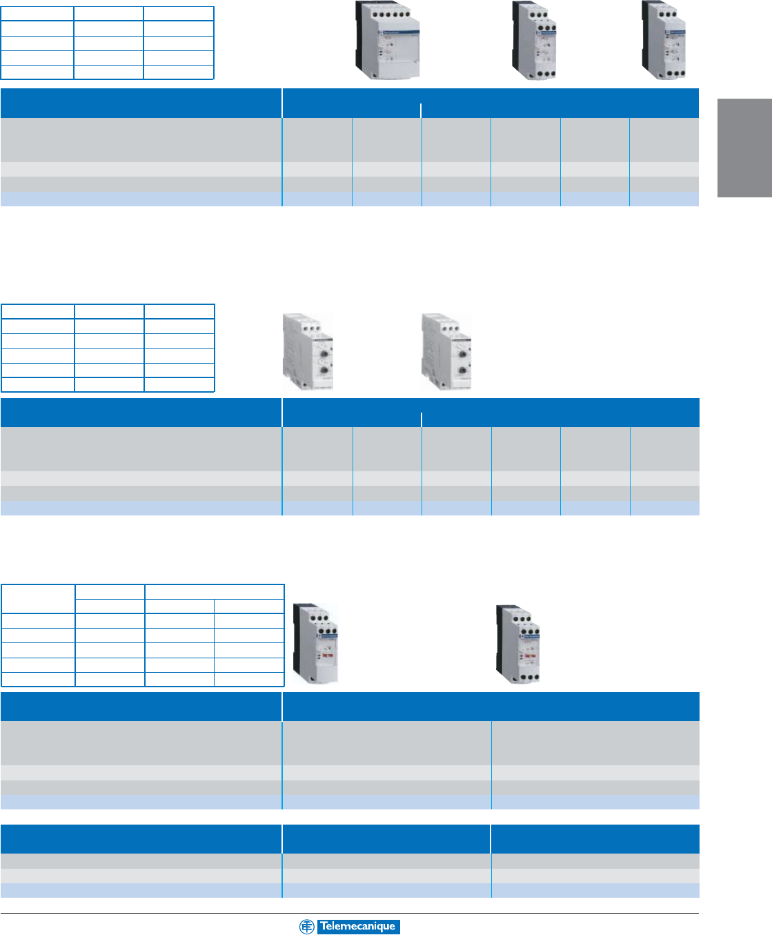
3-3
MACHINE
CONTROL
Zelio
®
Control Relays
Current and voltage measurement relays
Function Detection of
over and under current over and under voltage
Measuring range 3–30 mA 0.3–1.5 A 0.05 –0.5 V 1–10 V 30–300 V 160–300 V
10–100 mA 1–5 A 0.3 –3 V 5–50 V 50–500 V
0.1–1 A 3–15 A 0.5–5 V 10–100 V
Adjustable time delay 0.05–30 s 0.05–30 s 0.05 –30 s 0.05–30 s 0.05–30 s 0.1–10 s
Output 2 N.C./2 N.O. 2 N.C./2 N.O. 2 N.C./2 N.O. 2 N.C./2 N.O. 2 N.C./2 N.O. 2 N.C./2 N.O.
Catalog number RM4JA31•• (1) RM4JA32•• (1) RM4UA31•• (1) RM4UA32•• (1) RM4UA33•• (1) RM4UB35
Function Detection of
over and under current over and under voltage
Measuring range 3–20 mA 0.01–1 A 0.2 –2 V 15–150 V 9.6–15.6 Vdc
10–100 mA 0.5–5 A 1–10 V 30–300 V 20–80 Vac/dc 20–80 Vac/dc
50–500 mA 1–10 A 6–60 V 60–600 V 65–260 Vac/dc 65–260 Vac/dc
Adjustable time delay 0.1–3 s 0.1–3 s 0.1–3 s 0.1–3 s 0.1–3 s 0.1–3 s
Output 1 N.C./1 N.O. 1 N.C./1 N.O. 1 N.C./1 N.O. 1 N.C./1 N.O. 1 N.C./1 N.O. 1 N.C./1 N.O.
Catalog number RM8487102•(2) RM8487103•(2) RM8487202•(2) RM8487203•(2) RM8487204•(3) RM8487205•(3)
Liquid level control relays
Control relays Empty or fill
Sensitivity scale 5–100 kΩ0.25–5 kΩ
2.5 –50 kΩ
25–500 kΩ
Time delay without adjustable, 0.1 to 10 s
Output 1 N.C./1 N.O. 2 N.C./2 N.O.
Catalog number RM4LG01• (4) RM4LA32•• (4)
Liquid level control probe type Measuring electrode and 1 simple stainless steel electrode
catalog number electrode in PVC protective casing
Mounting suspended suspended
Maximum operating temperature 100°C / 212°F 100°C / 212°F
Catalog number LA9RM201 RM79696043
(4) Basic catalog number. To be completed with the letters
indicating the required voltage, as shown below:
RM4-LG01 RM4-LA32
Voltage Vac, 50/60 Hz Vac, 50/60 Hz Vdc
24 V BB–
24–240 V –MWMW
110–130 V FF–
220–240 V MM–
380–415 V QQ–
(2)(3) Basic catalog number. To be completed with the numbers
indicating the required voltage, as shown below:
Voltage (2) (3)
20–80 Vac/dc –6
24 Vac 1–
65–260 Vac/dc –7
120 Vac 3–
240 Vac 4–
(1) Basic catalog number. To be completed with the letters
indicating the required voltage, as shown below:
Voltage Vac, 50/60 Hz Vdc
24–240 V MW MW
110–130 V F–
220–240 V M–
380–415 V Q–
For additional information on RM4, reference Catalog 8430CT0001.
3-4
MACHINE
CONTROL
www.telemecanique.com
Zelio
®
Count—Counters
Totalizers
Display LCD
Supply voltage Internal Battery
Number of digits displayed 8
Counting frequency 40 Hz or 7.5 kHz 40 Hz or 7 kHz
Type of zero reset Electric Electric
Front face dimensions, W x H (mm / in.) 48 x 24 / 1.89 x 0.94 48 x 24 / 1.89 x 0.94
Catalog number RC87610050 RC87610340
Hour counters
Display LCD
Supply voltage Internal Battery
Number of digits displayed 6
Counting frequency –
Type of zero reset Electric Electric
Front face dimensions, W x H (mm / in.) 48 x 24 / 1.89 x 94 48 x 24 / 1.89 x 94
Catalog number RC87610150 RC87610440
Multifunction counters
Display LCD LED
Number of digits displayed 5
Counting frequency 30 Hz to 9 kHz
Type of reset Manual, electric or automatic
Front face dimensions, W x H (mm / in.) 48 x 48 / 1.89 x 1.89
Output 2 N.O. 2 solid state 2 N.O. 2 solid state
Catalog number Supply voltage 10–30 Vdc RC87618222 RC87618262 RC87618322 RC87618362
20–55 Vac RC87618224 RC87618264 RC87618324 RC87618364
80–260 Vac RC87618228 RC87618268 RC87618328 RC87618368
Automation
systems
3-5
MACHINE
CONTROL
Zelio
®
Count—Counters
Totalizers
Display Mechanical LCD
Supply voltage 24 Vdc Battery
Number of digits displayed 56688
Counting frequency 20 Hz 10 Hz 25 Hz 25 Hz 7.5 kHz
Type of zero reset Manual Without Manual Without Manual
(1)
Front face dimensions, W x H (mm) 41.5 x 31 30 x 20 60 x 50 60 x 50 48 x 24
(in.) 1.63 x 1.22 1.18 x 0.79 2.36 x 1.97 2.36 x 1.97 1.89 x 0.94
Catalog number XBKT50000U10M XBKT60000U00M XBKT60000U10M XBKT80000U00M XBKT81030U33E
(1) With electrical interlocking.
Hour counters
Display Mechanical LCD
Supply voltage 24 Vac 230 Vac Battery
Number of digits / display 7 (99,999.99 h) 7 (99,999.99 h) 8 (999,999.99 h)
Supply frequency 50 Hz 50 Hz Mode: 1/100 hour
Type of zero reset Without Without Manual (1)
Front face dimensions, W x H (mm / in.) 48 x 48 / 1.89 x 1.89 48 x 48 / 1.89 x 1.89 48 x 24 / 1.89 x 0.94
Catalog number XBKH70000004M XBKH70000002M XBKH81000033E
(1) With electrical interlocking.
Multifunction counters
Display LCD LED
Number of digits displayed 6
Counting frequency 5 kHz
Type of reset Manual, electric and automatic
Front face dimensions, W x H (mm / in.) 48 x 48 / 1.89 x 1.89
Preselection number 1212
Catalog number Supply voltage 24 Vdc XBKP61130G30E XBKP61230G30E XBKP62130G30E XBKP62230G30E
115 Vac XBKP61130G31E XBKP61230G31E ––
230 Vac XBKP61130G32E XBKP61230G32E XBKP62130G32E XBKP62230G32E
3-6
MACHINE
CONTROL
www.telemecanique.com
Zelio
®
Time—Timing relays
Industrial timers
Type of single function relay On-delay Off-delay
width 22.5 mm (0.89 in.), relay output
External control no yes no yes yes
Supply voltage 24 Vac/dc 24 Vac/dc 24–240 Vac/dc 24 Vac/dc 24 Vac/dc
110–240 Vac 42–48 Vac/dc 42–48 Vac/dc 42–48 Vac/dc
110–240 Vac 110–240 Vac 110–240 Vac
Timing range 0.05 s–300 h 0.05 s–300 h 0.05 s–10 mn 0.05 s–300 h 0.05 s–300 h
Output 1 N.C./1 N.O. 2 N.C./2 N.O. (1) 1 N.C./1 N.O. 2 N.C./2 N.O.
(1)
1 N.C./1 N.O.
Catalog number RE7TL11BU RE7TP13BU RE7RB11MW RE7RL13BU RE7RM11BU
(1) 1 selectable in instantaneous mode.
Type of single function relay Repeat cycle Interval
width 22.5 mm (0.89 in.), relay output
External control yes no
Supply voltage 24 Vac/dc 24 Vac/dc
42–48 Vac/dc 110–240 Vac
110–240 Vac
Timing range 0.05 s–300 h 0.05 s–300 h
Output 1 N.C./1 N.O. 1 N.C./1 N.O.
Catalog number RE7CV11BU RE7PE11BU
Type of multifunction relay 6 functions
(2)
8 functions
(3)
Supply voltage 24 Vac/dc 24 Vac/dc
42–48 Vac/dc 110–240 Vac
110–240 Vac
Timing range 0.05 s–300 h 0.05 s–300 h
Output 1 N.C./1 N.O. 2 N.C./2 N.O. (1 selectable in instantaneous mode)
Catalog number RE7ML11BU RE7MY13BU
(2) RE7ML11BU functions: On-delay, Off-delay, Interval with start on energization, Interval with start on opening of remote control contact, Repeat cycle with star t during the OFF
period, Repeat cycle with start during the ON period.
(3)
REMY13BU functions: On-delay, Off-delay, Interval with start on energisation, Interval with start on opening of remote control contact, Repeat cycle with start during the OFF period,
Repeat cycle with start during the ON period, Star-delta starting with double On-delay timing, Star-delta starting with contact for switching to star connection.
Automation
systems
For additional information, reference Catalog 9050CT0001.
3-7
MACHINE
CONTROL
Type of modular timer On-delay Multifunction
(1)
width 17.5 mm (0.69 in.), relay output
External control no – –
Supply voltage 24 Vdc / 24–240 Vac 24 Vdc / 24–240 Vac 12–240 Vac/dc
Timing range 0.1 s–100 h 0.1 s–100 h 0.1 s–100 h
Output 1 N.C./1 N.O. 1 N.C./1 N.O. 1 N.C./1 N.O.
Catalog number RE88826115 RE88826105 RE88826103
(1) Multifunction: On-delay, Off-delay, Totalizer, Repeat cycle, One shot, Interval.
Type of modular timer Repeat cycle Interval Off delay One shot
width 17.5 mm (0.69 in.), relay output
External control ––––
Supply voltage 24 Vdc / 24–240 Vac 24 Vdc / 24–240 Vac 24 Vdc / 24–240 Vac
24 Vdc / 24–240 Vac
Timing range 0.1 s–100 h 0.1 s–100 h 0.1 s–100 h 0.1 s–100 h
Output 1 N.C./1 N.O. 1 N.C./1 N.O. 1 N.C./1 N.O. 1 N.C./1 N.O.
Catalog number RE88826155 RE88826145 RE88826135 RE88826125
Type of modular timer On-delay Multifunction (1)
width 17.5 mm (0.69 in.), solid-state output
Supply voltage 24–240 Vac/dc 24–240 Vac
Timing range 0.1 s–100 h 0.1 s–100 h
Output solid-state solid-state
Catalog number RE88826014 RE88826004
(1) Multifunction: On-delay, Off-delay, Totalizer, Repeat cycle, One shot, Interval.
Modular timers
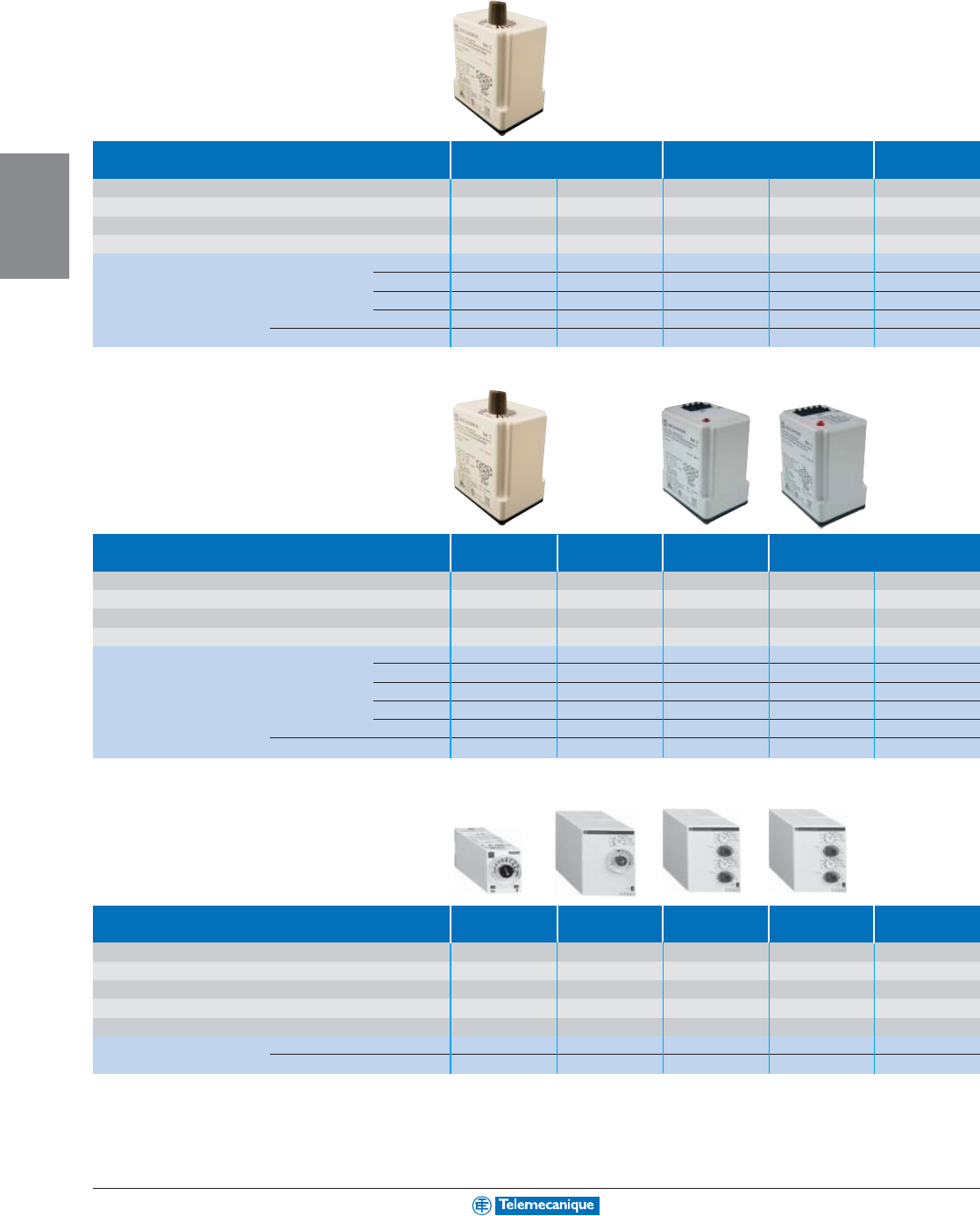
3-8
MACHINE
CONTROL
www.telemecanique.com
Zelio
®
Time—Timing relays
Plug-in timers
Type of plug-in timer On-Delay Off-delay Interval
Supply Voltage 24 Vac/dc 120 Vac/110 Vdc 24 Vac/dc 120 Vac/110 Vdc 120 Vac/110 Vdc
Relay Output 2 N.C./2 N.O. 2 N.C./2 N.O. 2 N.C./2 N.O. 2 N.C./2 N.O. 2 N.C./2 N.O.
Resistive Contact Rating 10 A 10 A 10 A 10 A 10 A
Output Pins 8811118
Catalog Number Timing range 0.1–10 sec 9050JCK11V14 9050JCK11V20 9050JCK21V14 9050JCK21V20 9050JCK31V20
0.3–30 sec 9050JCK12V14 9050JCK12V20 9050JCK22V14 9050JCK22V20 9050JCK32V20
0.6–60 sec 9050JCK13V14 9050JCK13V20 9050JCK23V14 9050JCK23V20 9050JCK33V20
1.2–120 sec 9050JCK14V14 9050JCK14V20 9050JCK24V14 9050JCK24V20 9050JCK34V20
Relay socket 8501NR51 8501NR51 8501NR61 8501NR61 8501NR51
Type of plug-in timer One Shot Repeat Cycle On- Delay Multifuction
Supply Voltage 120 Vac/110 Vdc 120 Vac/110 Vdc 120 Vac 24 Vac 120 Vac
Relay Output 2 N.C./2 N.O. 2 N.C./2 N.O. 2 N.C./2 N.O. 2 N.C./2 N.O. 2 N.C./2 N.O.
Resistive Contact Rating 10 A 10 A 10 A 10 A 10 A
Output Pins 11 8 8 11 11
Catalog Number Timing range 0.1–10 sec 9050JCK41V20 9050JCK51V20 –––
0.3–30 sec 9050JCK42V20 9050JCK52V20 –––
0.6–60 sec 9050JCK43V20 9050JCK53V20 –––
1.2–120 sec 9050JCK44V20 9050JCK54V20 –––
0.05 s to 999 m
––9050JCK60V20 9050JCK70V14 9050JCK70V20
Relay socket 8501NR51 8501NR51 8501NR51 8501NR61 8501NR61
Type of plug-in timer Miniature On-Delay Off- Delay Repeat Cycle Multifuction
On-Delay
Supply Voltage 100–127 Vac 24 Vdc/24–240Vac 24 Vdc/24–240Vac 24 Vdc/24–240Vac 24 Vdc/24–240Vac
Timing Range 0.1 s to 100 h 0.1 s to 100 h 0.1 s to 100 h 0.1 s to 100 h 0.1 s to 100 h
Relay Output 4 N.C./4 N.O. 2 N.C./2 N.O. 2 N.C./2 N.O. 2 N.C./2 N.O. 2 N.C./2 N.O.
Resistive Contact Rating 5 A 8 A 8 A8 A8 A
Output Pins 14 8 11 11 11
Catalog Number RE88896206 RE88867215 RE88867435 RE88867455 RE88867305
Relay socket 8501NR45 8501NR51 8501NR61 8501NR61 8501NR61
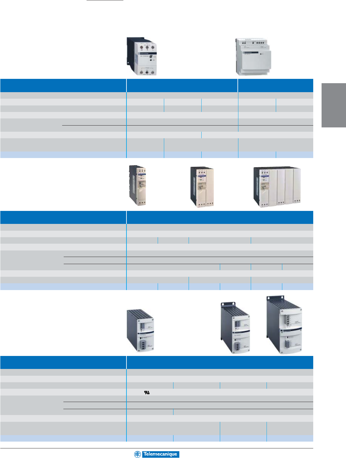
3-9
MACHINE
CONTROL
Power supply
Phaseo power supplies and transformers
Power supplies for control circuits
Type of power supply Compact Modular
1-phase regulated switch mode
AUTO reset of wide range automatic protection AUTO reset of automatic protection
Input voltage 100–240 Vac, 110–220 Vdc (compatible) 100–240 Vac
Output voltage 24 Vdc 24 Vdc 24 Vdc 12 Vdc 24 Vdc
Nominal Power / Current 7.5 W / 0.3 A 15 W / 0.6 A 30 W / 1.2 A 22 W / 1.9 A 30 W / 1.3 A
Certifications cULus, TÜV UL, CSA, TÜV
Conformity to standards Safety UL508, IEC/EN 60950 IEC/EN 60950, IEC/EN 61131-2/A11
EMC EN 50081-2, EN 50082-2
EN 50081-2, IEC 61000-6-2 (EN 50082-2)
Emission Conducted and radiated EN 55011, EN 55022 cIass A EN 55011, EN 55022 cIass B
Dimensions, W x D x H mm 45 x 70 x 75 45 x 95 x 75 72 x 70 x 110
in. 1.77 x 2.76 x 2.95 1.77 x 3.74 x 2.95 2.83 x 2.76 x 4.33
Catalog number ABL7CEM24003 ABL7CEM24006 ABL7CEM24012 ABL7RM1202 ABL7RM2401
Type of power supply Universal, wide range
1-phase regulated switch mode AUTO reset of automatic protection
Input voltage 100–240 Vac, 110–230 Vdc (version ABL7RP••)
Output voltage 24 Vdc
Nominal Power / Current 48 W / 2 A 72 W / 3 A 120 W / 5 A 240 W / 10 A
Certifications UL, CSA, TÜV, Ctick
Conformity to standards Safety IEC/EN 60950
EMC EN 50081-2, IEC 61000-6-2 (EN 50082-2)
Low frequency harmonic currents – EN 61000-3-2 – EN 61000-3-2
Emission Conducted and radiated EN 55011, EN 55022 cIass B
Dimensions, W x D x H (mm / in.)
27 x 120 x 120 / 1.06 x 4.72 x 4.72 54 x 120 x 120 / 2.13 x 4.72 x 4.72 135 x 120 x 120 / 5.31 x 4.72 x 4.72
Catalog number ABL7RE2402 ABL7RE2403 ABL7RE2405 ABL7RP2405(1) ABL7RE2410 ABL7RP2410(1)
(1) AUTO/MAN reset of automatic protection.
Type of power supply Industrial, wide range
3-phase regulated switch mode AUTO/MAN reset of automatic protection
Input voltage 3 phase x 400–520 Vac
Output voltage 24 Vdc
Nominal Power / Current 120 W / 5 A 240 W / 10 A 480 W / 20 A 960 W / 40 A
Certifications cULus, c us
Conformity to standards Safety IEC/EN 60950
EMC EN 50081-1, EN 50082-2
Low frequency harmonic currents – EN61000-3-2
Emission Conducted and radiated EN 55011, EN 55022 cIass B
Dimensions, W x D x H mm 68 x 171 x 127 84 x 240 x 209 106 x 275 x 242
in. 2.68 x 6.73 x 5.00 3.31 x 9.45 x 8.23 4.17 x 10.83 x 9.53
Catalog number ABL7UES24050 ABL7UPS24100 ABL7UPS24200 ABL7UPS24400
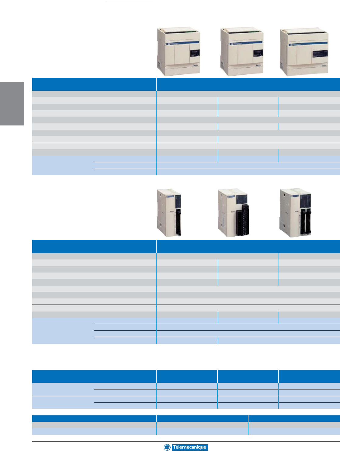
3-10
MACHINE
CONTROL
www.telemecanique.com
Twido™ programmable controller
Bases
Type of base Compact
Supply voltage 100–240 Vac
Number of discrete inputs/outputs 10 16 24
Number of discrete inputs (24 Vdc) 6 sink/source 9 sink/source 14 sink/source
Number of discrete outputs 4 relay, 2 A 7 relay, 2 A 10 relay, 2 A
Type of connection Screw terminal block, non removable
Number of I/O expansion modules possible ––4
Counting 3 @ 5 kHz, 1 @ 20 kHz
Serial ports 1 x RS 485 1 x RS 485; optional: 1 x RS 232C or RS485
Protocols Modbus Master/Slave, ASCII, remote I/Os
Dimensions, W x D x H (mm / in.) 80 x 70 x 90 / 3.15 x 2.76 x 3.54 80 x 70 x 90 / 3.15 x 2.76 x 3.54 95 x 70 x 90 / 3.74 x 2.76 x 3.54
Catalog number TWDLCAA10DRF TWDLCAA16DRF TWDLCAA24DRF
Clock (optional) TWDXCPRTC
Display (optional) TWDXCPODC
Type of base Modular
Number of discrete inputs/outputs 20 40
Number of discrete inputs (24 Vdc) (1) 12 sink/source 12 sink/source 24 sink/source
Number of discrete outputs 8 transistor, source 0.3 A
6 relay and 2 transistor, source 0.3 A
16 transistor, source 0.3 A
Type of connection HE 10 connector Removable screw terminal block HE 10 connector
Number of I/O expansion modules possible 477
Supply voltage 24 Vdc
Integrated counting and positioning Counting: 2 @ 5 kHz, 2 @ 20 kHz; Positioning: PLS / PWM 2 @ 7 kHz
Serial ports 1 x RS 485; optional: 1 x RS 232C or RS485
Protocols Modbus Master/Slave, ASCII, remote I/Os
Dimensions, W x D x H (mm / in.)
35.4 x 70 x 90 / 1.39 x 2.76 x 3.54 47.5 x 70 x 90 / 1.87 x 2.76 x 3.54 47.5 x 70 x 90 / 1.87 x 2.76 x 3.54
Catalog number TWDLMDA20DTK (1) TWDLMDA20DRT TWDLMDA40DTK (1)
Clock (optional) TWDXCPRTC
Display (optional) TWDXCPODM
Memory expansion (optional) –TWDXCPMFK64
(1) Also available: SINK transistor output versions (TWDLMDA20DUK and TWDLMDA40DUK) .
Accessories
Pre-wired system for modules with For Modular Bases For Inputs For Outputs
HE 10 connector TWDLMDA20DTK/40DTK TWDDI16DK/32DK TWDDO16TK/32TK
TwidoFast “bared” cable L = 3 m (9.8') TWDFCW30M TWDFCW30K TWDFCW30K
L = 5 m (16.4') TWDFCW50M TWDFCW50K TWDFCW50K
Telefast connection bases L = 1 m (3.3') TWDFST20DR10 TWDFST16D10 TWDFST16DR10
L = 2 m (6.6') TWDFST20DR20 TWDFST16D20 TWDFST16DR20
Memory Cartridge and Software Memory cartridge TwidoSoft software
Description Application update with cable
Catalog number TWDXCPMFK32 TWDSPU1001V10M
Automation
systems
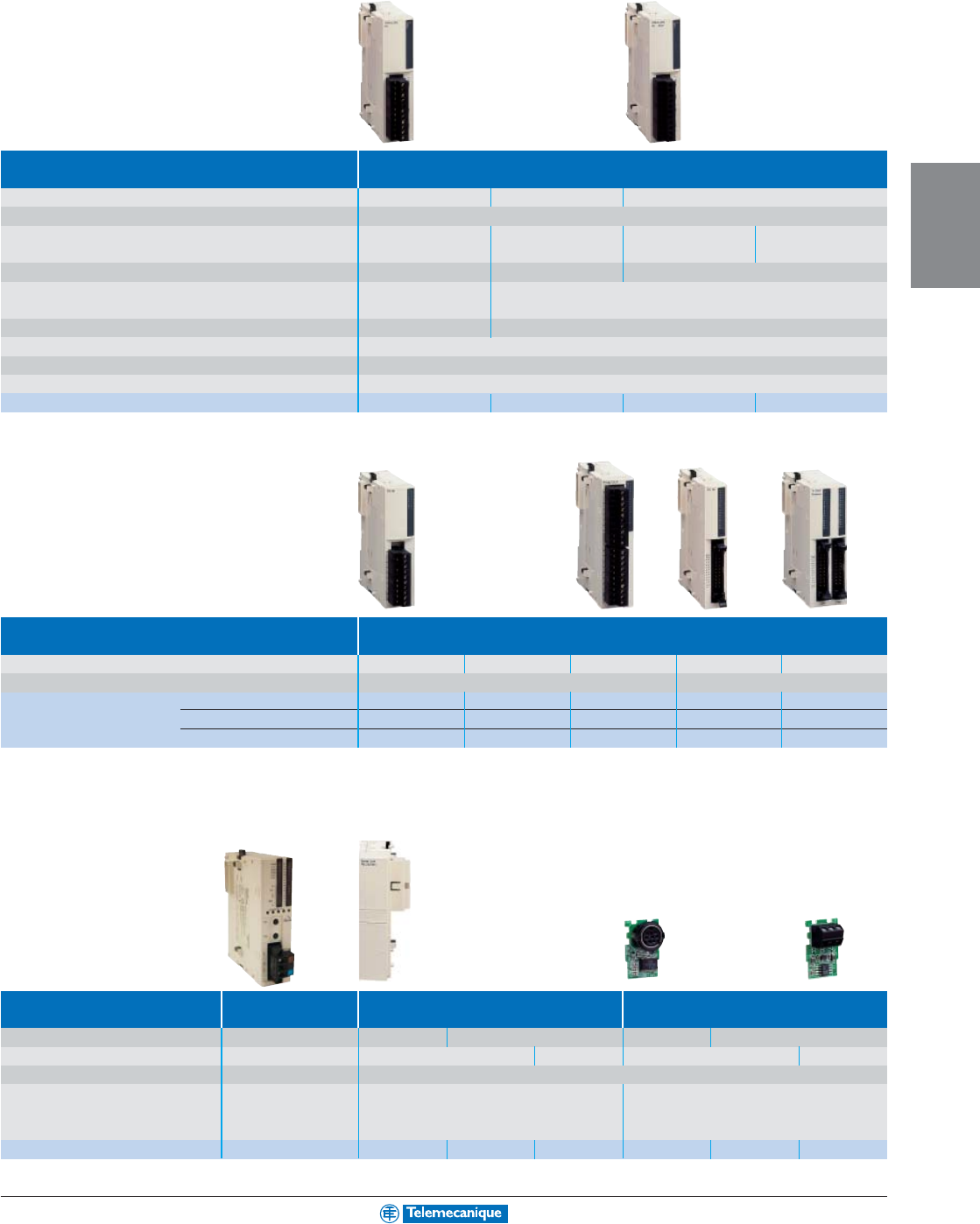
3-11
MACHINE
CONTROL
Input/output modules
Type of module Analog
Number of Analog inputs/outputs 2 inputs 1 output 2 inputs / 1 output
Connection Removable screw terminal block
Inputs Range
0–10 V (non differential)
–
0–10 V (non differential)
Thermocouple, type K, J, T
4–20 mA (differential) 4–20 mA (differential)
Thermocouple, 3-wire Pt 100
Resolution 12 bits (4096 points) – 12 bits (4096 points)
Outputs Range – 0–10 V
4–20 mA
Resolution – 12 bits (4096 points)
Input error (accuracy at 25°C (77°F) ± 0.2% of full scale
Supply voltage 24 Vdc
Dimensions, W x D x H (mm / in.) 23.5 x 70 x 90 / 0.93 x 2.76 x 3.54
Catalog number TWDAMI2HT TWDAMO1HT TWDAMM3HT TWDALM3LT
Type of module Discrete
Number of Discrete inputs/outputs 8 4 Inputs / 4 Outputs 16 16 32
Connection Removable screw terminal block HE 10 connectors
Catalog number Inputs 24 Vdc (1) TWDDDI8DT TWDDMM8DRT TWDDDI16DT TWDDDI16DK TWDDDI32DK
Relay outputs 2 A TWDDRA8RT TWDDMM8DRT TWDDRA16RT ––
Transistor outputs, source 0.1 A TWDDDO8TT (2) ––TWDDDO16TK (2) TWDDDO32TK (2)
(1) All inputs are sink/source.
(2) Also available: SINK transistor output versions (TWDDDO8UT, TWDDDO16UK and TWDDDO32UK).
Communication modules
Type of module Twido AS-Interface Serial interface module Serial interface adaptor
Master
Communication type (non isolated) AS-Interface RS 232C RS 485 RS 232C RS 485
Connection Screw terminal Mini-DIN connector Screw terminals Mini-DIN connector
Screw terminals
Protocol AS-I, V2 Modbus Master/Slave, ASCII, remote I/Os
Twido base compatibility Modular base TWD LMDA Compact base TWD LCAA 16/24 DRF
Modular base via built-in display module TWDXCPODM
Catalog number TWDNOI10M3 TWDNOZ232D TWDNOZ485D TWDNOZ485T TWDNAC232D TWDNAC485D TWDNAC485T
Compact base
TWD LCAA 24 DRF
and all modular bases
TWD LMDA
For additional information, reference DIA3ED2031004EN.
3-12
MACHINE
CONTROL
www.telemecanique.com
Telefast
®
2 pre-wired system
Passive I/O sub-bases “Discrete”
Type of connection sub-base Optimum
Number of channels 16 16
Max. current per channel 0.5 A 0.5 A
Control voltage / output voltage 24 Vdc / 24 Vdc 24 Vdc / 24 Vdc
LED per channel –Yes
Number of terminals per channel/on row number 1/2 1/1 2/2 3/3
Dimensions, W x D x H (mm / in.)
55x59x67 / 2.17x2.32x2.64
106 x 60 x 49 / 4.17 x 2.36 x 1.93
Catalog number –ABE7H16C11 ABE7H16C21 ABE7H16C31
Cable L = 1 m (3.3') ABE7H20E100 (1) –––
Cable L = 2 m (6.6') ABE7H20E200 (1) –––
Cable L = 3 m (9.8') ABE7H20E300 (1) –––
Connection cable recommended for Modicon, TSX Micro and Premium PLCs, L = 1 m: (3.3') (2) ABFH20H100
(1) Connection cable supplied for PLCs.
(2) For a 2 m (6.6') length cable, replace the number 1 in the catalog number by 2, and for a 3 m (9.8') length, by 3. (Example: ABFH20H100 becomes ABFH20H200).
Type of connection sub-base Universal
Number of channels 16
Max. current per channel 0.5 A
Control voltage / output voltage 24 Vdc / 24 Vdc
LED per channel –Ye s ––Ye s Ye s
Number of terminals per channel/on row number 1/1 1/1 1/2 2/2 2/2 3/3
Dimensions, W x D x H (mm / in.) 125 x 58 x 70 / 4.92 x 2.28 x 2.76 125 x 58 x 70 / 4.92 x 2.28 x 2.76
Catalog number ABE7H16R10 ABE7H16R11 ABE7H16R50 ABE7H16R20 ABE7H16R21 ABE7H16R31
Connection cable recommended for Modicon, TSX Micro and Premium PLCs, L = 1 m: (3.3') ABFH20H100 (2)
(2) For a 2 m (6.6') length cable, replace the number 1 in the catalog number by 2, and for a 3 m (9.8') length, by 3. (Example: ABFH20H100 becomes ABFH20H200).
Type of connection sub-base For counter and Passive distribution Distribution and supply
analog channels with shielding continuity of analog channels
Number of channels 1 counter channel (3) 8 8
Max. current per channel 25 mA 25 mA 25 mA
Control voltage / output voltage 24 Vdc / 24 Vdc
Number of terminals per channel 22 or 4 2 or 4
Dimensions, W x D x H (mm / in.) 143 x 58 x 70 / 5.63 x 2.28 x 2.76 125 x 58 x 70 / 4.92 x 2.28 x 2.76 125 x 58 x 70 / 4.92 x 2.28 x 2.76
Catalog number ABE7CPA01 ABE7CPA02 ABE7CPA03
Connection cable recommended TSX Micro L = 2.5 m (8.2') TSXCCPS15 ––
for Modicon PLCs (4) Premium L = 3 m (9.8') TSXCAP030
(3) Or 8 inputs + 2 outputs, analog .
(4) Connection cables available for other PLCs, please refer to Catalog 8501CT9801.
Interfacing
84 x 58 x 70 /
3.31 x 2.28 x 2.76
3-13
MACHINE
CONTROL
Sockets with plug-in relays and terminals
Type of connection sub-base With soldered solid-state With soldered solid-state With soldered electro-
relay inputs relay outputs mechanical relay outputs
Number of channels 16 16 16
Max. current per channel 12 mA 0.5 A 2 A 5 A
Input voltage / output voltage 24 Vdc / - 110 Vac / - - / 24 Vdc - / 5–30 Vdc, 230 Vac
Number of contacts ––1 N.O.
Polarity distribution ––(1) Volt-free (4)
Number of terminals per channel 2
Dimensions, W x D x H (mm / in.) 206 x 58 x 77 / 8.11 x 2.28 x 3.03
Catalog number ABE7S16E2B1 ABE7S16E2F0
ABE7S16S2B0(2)
ABE7S16S1B2 ABE7R16S111 ABE7R16S210
Connection cable recommended for Modicon, TSX Micro and Premium PLCs, L = 1 m (3.3'): ABFH20H100 (3)
(1) Contact common per group of 8 channels.
(2) With fault detection signal (can only be used with modules with protected outputs).
(3) For a 2 m (6.6') length cable, replace the number 1 in the catalog number by 2, and for a 3 m (9.8') length, by 3. (Example: ABFH20H100 becomes ABFH20H200).
(4) No shared commons.
Type of connection sub-base With plug-in electromechanical relays
Number of channels 16
Max. current per channel 5 A 2.5 A 4 A 5 A
Control voltage / output voltage 24 Vdc / 5–24 Vdc, 230 Vac
Number of contacts 1 N.O. 1 N.C./1 N.O. 2 N.C./2 N.O.
Polarity distribution (5) (6) Volt-free (no shared commons)
Number of terminals per channel 22 or 3 2 to 6
Dimensions, W x D x H (mm / in.) 211 x 64 x 89 / 8.30 x 2.52 x 3.50
272 x 74 x 89 / 10.71 x 2.91 x 3.50
Catalog number ABE7R16T111 ABE7R16T212 ABE7R16T210 ABE7R16T230 ABE7R16T330 ABE7R16T370
Connection cable recommended for Modicon, TSX Micro and Premium PLCs, L = 1 m (3.3'): ABFH20H100 (7)
(5) Contact common per group of 4 channels.
(6) Common on both poles.
(7) For a 2 m (6.6') length cable, replace the number 1 in the catalog number by 2, and for a 3 m (9.8') length, by 3. (Example: ABFH20H100 becomes ABFH20H200).
Connection cables for PLCs
(8)
Input/Output functions Discrete Analog Analog Counter Axis control
and counter
Catalog number Cable L = 1 m (3.3') ABFH20H100 ––––
Cable L = 2 m (6.6') ABFH20H200 ABFY25S200 ––TSXCXP213
Cable L = 2.5 m (8.2') ––TSXCCPS15 TSXCCPH15 –
Cable L = 3 m (9.8') ABFH20H300 TSXCAP030 –––
Cable L = 6 m (19.7') ––––TSXCXP613
(8) Modicon, TSX Micro and Premium PLCs.
For other connection cables and accessories, please refer to Catalog 85019801.
110 x 54 x 89 /
4.33 x 2.13 x 3.50
3-14
MACHINE
CONTROL
www.telemecanique.com
Passive splitter boxes
IP67, Telefast ABE9
Type of connection To PLC using multicore cable
Number of channels 48
Type of female connector M12, 5-pin M12, 5-pin
Max. number of signals 816
Max. current per channel 4 A
Max. current per splitter box 16 A (1 mm
2
)
Product certification cULus
Dimensions, W x D x H (mm / in.) 50.2 x 42 x 92.2 / 1.98 x 1.65 x 3.63 50.2 x 42 x 149.2 / 1.98 x 1.65 x 5.87
Catalog number Without LEDs
Cable L = 5 m (16.4')
ABE9C1240L05 ABE9C1280L05
Cable L = 10 m ABE9C1240L10 ABE9C1280L10
With LEDs (1)
Cable L = 5 m (16.4')
ABE9C1241L05 ABE9C1281L05
Cable L = 10 m ABE9C1241L10 ABE9C1281L10
(1) Green LED: power supply status, yellow LED: channel status.
Type of connection To PLC using M23 connector
Number of channels 48
Type of female connector M12, 5-pin M12, 5-pin
Max. number of signals 816
Max. current per channel 4 A
Max. current per splitter box 16 A
Product certification cULus
Dimensions, W X D x H (mm / in.) 50.2 x 36.5 x 92.2 / 1.98 x 1.44 x 3.63 50.2 x 36.5 x 149.2 / 1.98 x 1.44 x 5.87
Catalog number Without LEDs ABE9C1240C23 ABE9C1280C23
With LEDs (1) ABE9C1241C23 ABE9C1281C23
(1) Green LED: power supply status, yellow LED: channel status.
Accessories
Type of accessory Splitter boxes w/o cable Terminal connectors Sealing plugs
Without LEDs With LEDs
Cable L = 5 m
Cable L = 10 m
(sold in lots of 10)
(16.4') (32.8')
Catalog number 4-channel ABE9C1240M ABE9C1241M ABE9XCA1405 ABE9XCA1410 –
8-channel ABE9C1280M ABE9C1281M ABE9XCA1805 ABE9XCA1810 –
for M12 connector ––––FTXCM12B
Interfacing
3-15
MACHINE
CONTROL
Cabling accessories
M12 / M12 jumper cables
Type Male / Female jumper cables
Type of male connector, interface side M12, 3-pin, straight, screw thread M12, 4-pin, straight, screw thread M12, 5-pin, straight, screw thread
Type of female connector, sensor side M12, 3-pin, straight, screw thread M12, 4-pin, straight, screw thread M12, 5-pin, straight, screw thread
Cable (1) PUR, black PUR, black PUR, black
Catalog number Cable L = 1 m (3.3') XZCR1511040A1 XZCR1511041C1 XZCR1511064D1
L = 2 m (6.6') XZCR1511040A2 XZCR1511041C2 XZCR1511064D2
M12 or DIN jumper cables
Type Male / Female jumper cables
Type of male connector, interface side M12, 3-pin M12, 3-pin M12, 3-pin
straight, screw thread straight, screw thread straight, screw thread
Type of female connector, sensor side M8, 3-pin M8, 3-pin DIN 43650A
straight, clip together straight, screw thread elbowed, screw thread
Cable (1) PUR, black PUR, black PUR, black
Catalog number Cable L = 1 m (3.3') XZCR1501040G1 XZCR1509040H1 XZCR1523062K1
L = 2 m (6.6') XZCR1501040G2 XZCR1509040H2 XZCR1523062K2
Connectors, splitter box
Type Connectors Pre-wired connectors Splitter box “Y”
Type of male connector, interface side M12, 4-pin M12, 5-pin, straight, screw thread 1 x M12 1 x M12
Type of female connector, sensor side – – 2 x M12 2 x M8
Cable (1) – PUR, black –
Catalog number Straight connector, screw thread
XZCC12MDM40B
–FTXCY1212 FTXCY1208
Elbowed connector, screw thread
XZCC12MCM40B
–––
Cable L = 0.5 m (1.6') –XZCP1564L05 ––
L = 2 m (6.6') –XZCP1564L2 ––
(1) PUR = polyurethane.
3-16
MACHINE
CONTROL
www.telemecanique.com
Splitter boxes for fieldbus
Plastic enclosure, IP67, Advantys FTB
Type of bus CANopen DeviceNet ProfiBus InterBus
Number of channels 8
Type of female connector M12, 5-pin
Max. voltage / current of inputs 24 Vdc / 200 mA
Max. voltage / current of outputs 24 Vdc / 1.6 A
Max. current per splitter box 8 A
Product certification cULus
Dimensions, W X D x H (mm / in.) 63 x 50.5 x 220 / 2.48 x 1.99 x 8.66
63x69x220 / 2.48x2.72x8.66
Diagnostics Splitter boxes By LED for: bus and I/O undervoltage + I/O short-circuit + I/O power supply
Channels By LED for: I/O short-circuit + wire breakage fault + I/O fault
Catalog number 16 inputs FTB1CN16EP0 FTB1DN16EP0 FTB1DP16EP0 FTB1IB16EP0
8 inputs/8 outputs FTB1CN08E08SP0 FTB1DN08E08SP0 FTB1DP08E08SP0 FTB1IB08E08SP0
12 inputs/4 outputs FTB1CN12E04SP0 FTB1DN12E04SP0 FTB1DP12E04SP0 FTB1IB12E04SP0
16 configurable inputs/outputs FTB1CN16CP0 FTB1DN16CP0 FTB1DP16CP0 FTB1IB16CP0
Metal enclosure, IP67, Advantys FTB
Type of bus DeviceNet ProfiBus
Number of channels 8
Type of female connector M12, 5-pin
Max. voltage / current of inputs 24 Vdc / 200 mA
Max. voltage / current of outputs 24 Vdc / 1.6 A
Max. current per splitter box 8 A
Product certification cULus
Dimensions, W x D x H (mm / in.) 62.7 x 38.9 x 224.7 / 2.47 x 1.53 x 8.85
Diagnostics Splitter boxes By LED for: bus and I/O undervoltage + I/O short-circuit + I/O power supply
Channels By LED for: I/O short-circuit + wire breakage fault + I/O fault
Catalog number 16 inputs FTB1DN16EM0 FTB1DP16EM0
8 inputs/8 outputs/configurable outputs FTB1DN08E08CM0 FTB1DP08E08CM0
16 configurable inputs/outputs FTB1DN16CM0 FTB1DP16CM0
Interfacing
For additional information, reference DIA6EC2030901EN.
3-17
MACHINE
CONTROL
Accessories for FTB splitter boxes
(1)
Bus connection cables
Type of bus CANopen DeviceNet ProfiBus InterBus
Type of female connector M12, 5-pin, at either end –
Connector coding A encoded B encoded –
Catalog number Cable L = 0.3 m (9.8') FTXCN3203 FTXDP3203 –
L = 0.6 m (19.7') FTXCN3206 FTXDP3206 FTXIB1206 (2)
L = 1 m (3.3') FTXCN3210 FTXDP3210 FTXIB1210 (2)
L = 2 m (6.6') FTXCN3220 FTXDP3220 FTXIB1220 (2)
L = 3 m (9.8') FTXCN3230 FTXDP3230 –
L = 5 m (16.4') FTXCN3250 FTXDP3250 FTXIB1250 (2)
(2) Catalog number includes the Bus connection cable + the power supply cable.
Power supply connection cables
Type of bus CANopen DeviceNet ProfiBus
Type of female connector Type 7/8, 5-pin, at either end
Catalog number Cable L = 0.6 m (19.7') FTXDP2206
L = 1 m (3.3') FTXDP2210
L = 2 m (6.6') FTXDP2220
L = 5 m (16.4') FTXDP2250
Type of female connector Type 7/8, 5-pin, at one end (other end free)
Catalog number Cable L = 1.5 m FTXDP2115
L = 3 m (9.8') FTXDP2130
L = 5 m (16.4') FTXDP2150
Accessories
Type of bus CANopen DeviceNet ProfiBus Interbus
Catalog number Configuration CD-ROM FTXES00
Diagnostics M12 adaptor FTXDG12
Power supply T-connector FTXCNCT1 –
Line terminator FTXCNTL12 FTXDPTL12 –
(1) For sensor and actuator cabling accessories:
see page 3-15
3-18
MACHINE
CONTROL
www.telemecanique.com
Ter minal blocks
Insulation displacement technology
Clip-on mounting on 35 mm rails Terminal blocks End barrier
2-pole jumper (1)
(sold in lots of 100) (sold in lots of 10) (sold in lots of 10)
#30–18 AWG Pass through blocks AB1AA135U2GR AB1AAAC122GR AB1RRAL22
Grounding blocks AB1AATP135U2 AB1AAAC122VE -
#18–14 AWG Pass through blocks AB1AA235U2GR AB1AAAC122GR AB1RRAL22
Grounding blocks AB1AATP235U2 AB1AAAC122VE -
(1) For a 3, 4, 5 or 10-pole jumper replace the last number of the catalog number (2) by 3, 4, 5 or 10 respectively. (Example: AB1RAL22 becomes AB1RAL23).
Spring clamp technology
Clip-on mounting on 35 mm rails Terminal blocks End barrier
2-pole jumper (1)
(sold in lots of 100) (sold in lots of 10) (sold in lots of 10)
#22–12 AWG Pass through blocks AB1RR235U2GR AB1RRAC242GR AB1RRAL22 (1)
Grounding blocks AB1RRTP235U2 AB1RRTPAC242 –
#22–10 AWG Pass through blocks AB1RR435U2GR AB1RRAC242GR AB1RRAL42 (1)
Grounding blocks AB1RRTP435U2 AB1RRTPAC242 –
#24–8 AWG Pass through blocks AB1RR635U2GR –AB1RRAL62
Grounding blocks AB1RRTP635U2 ––
#24–6 AWG Pass through blocks AB1RR1035U2GR (2) –AB1RRAL102
Grounding blocks AB1RRTP1035U2 (2) ––
#24–4 AWG Pass through blocks AB1RR1635U2GR (2) –AB1RRAL162
Grounding blocks AB1RRTP1635U2 (2) ––
(1) For a 3, 4, 5 or 10-pole jumper replace the last number of the catalog number (2) by 3, 4, 5 or 10 respectively. (Example: AB1RRAL22 becomes AB1RRAL23).
(2) Sold in lots of 50.
Screw clamp technology
Clip-on mounting on 35 mm rails Terminal blocks End barrier
2-pole jumper (1)
(sold in lots of 100) (sold in lots of 50) (sold in lots of 10)
#22–12 AWG Pass through blocks AB1VV235U AB1AC24 AB1ALN22 (1)
Grounding blocks –––
#22–10 AWG Pass through blocks AB1VV435U AB1AC24 AB1ALN42 (1)
Grounding blocks AB1TP435U ––
#22–8 AWG Pass through blocks AB1VV635U AB1AC6 AB1ALN62 (1)
Grounding blocks AB1TP635U ––
#16–6 AWG Pass through blocks AB1VVN1035U (2) AB1ACN10 AB1ALN102 (1)
Grounding blocks AB1TP1035U (2) ––
#12–4 AWG Pass through blocks AB1VVN1635U (2) AB1ACN16 AB1ALN162 (1)
Grounding blocks AB1TP1635U (2) ––
(1) For a 3, 4, 5 or 10-pole jumper replace the last number of the catalog number (2) by 3, 4, 5 or 10 respectively. (Example: AB1ALN22 becomes AB1ALN23).
(2) Sold in lots of 50.
Interfacing
For additional information, reference Catalog 9080CT9901R5/02.
3-19
MACHINE
CONTROL
Ter minal blocks—NEMA
Screw clamp technology
Mounting on 35mm 77
77
7 or Square D track Terminal block End barrier 2-pole jumper
(Sold in lots of 50) (Sold in lots of 10) (Sold in lots of 10)
#22–10 AWG 9080GM6 9080GM6B 9080GH700 (3)
#22–8 AWG 9080GR6 9080GM6B 9080GH72
#22–10 AWG 9080GK6 9080GK6B (1) 9080GH72
#18–4 AWG 9080GC6 9080GC6B 9080GH74
#12 AWG–1/0 9080GD6 (2) 9080GD6B 9080GH76
#6 AWG–250 kcmil 9080GE6 (2) ––
(1) Sold in lots of 50.
(2) Sold in lots of 10.
(3) Sold in lots of 20.
Thermal-magnetic circuit protectors
Mounting on 35mm 77
77
7 track. Thermal Single-pole (4) Single-pole 2-pole
Rating (Sold in lots of 6) (Sold in lots of 6)
Catalog Number 0.1 A 9080GCB01 ––
0.5 A 9080GCB05 GB2CB05 GB2CD05
0.8 A 9080GCB08 ––
1.0 A 9080GCB10 GB2CB06 GB2CD06
1.2 A 9080GCB12 ––
1.5 A 9080GCB15 ––
2.0 A 9080GCB20 GB2CB07 GB2CD07
2.5 A 9080GCB25 ––
3.0 A 9080GCB30 GB2CB08 GB2CD08
4.0 A 9080GCB40 GB2CB09 GB2CD09
5.0 A 9080GCB50 GB2CB10 GB2CD10
6.0 A –GB2CB12 GB2CD12
7.0 A 9080GCB70 ––
8.0 A –GB2CB14 GB2CD14
10 .0 A 9080GCB100 GB2CB16 GB2CD16
12.0 A –GB2CB20 GB2CD20
15.0 A 9080GCB150 ––
(4) Can also be mounted on Square D track.
For additional information, reference Catalog 9080CT9601.
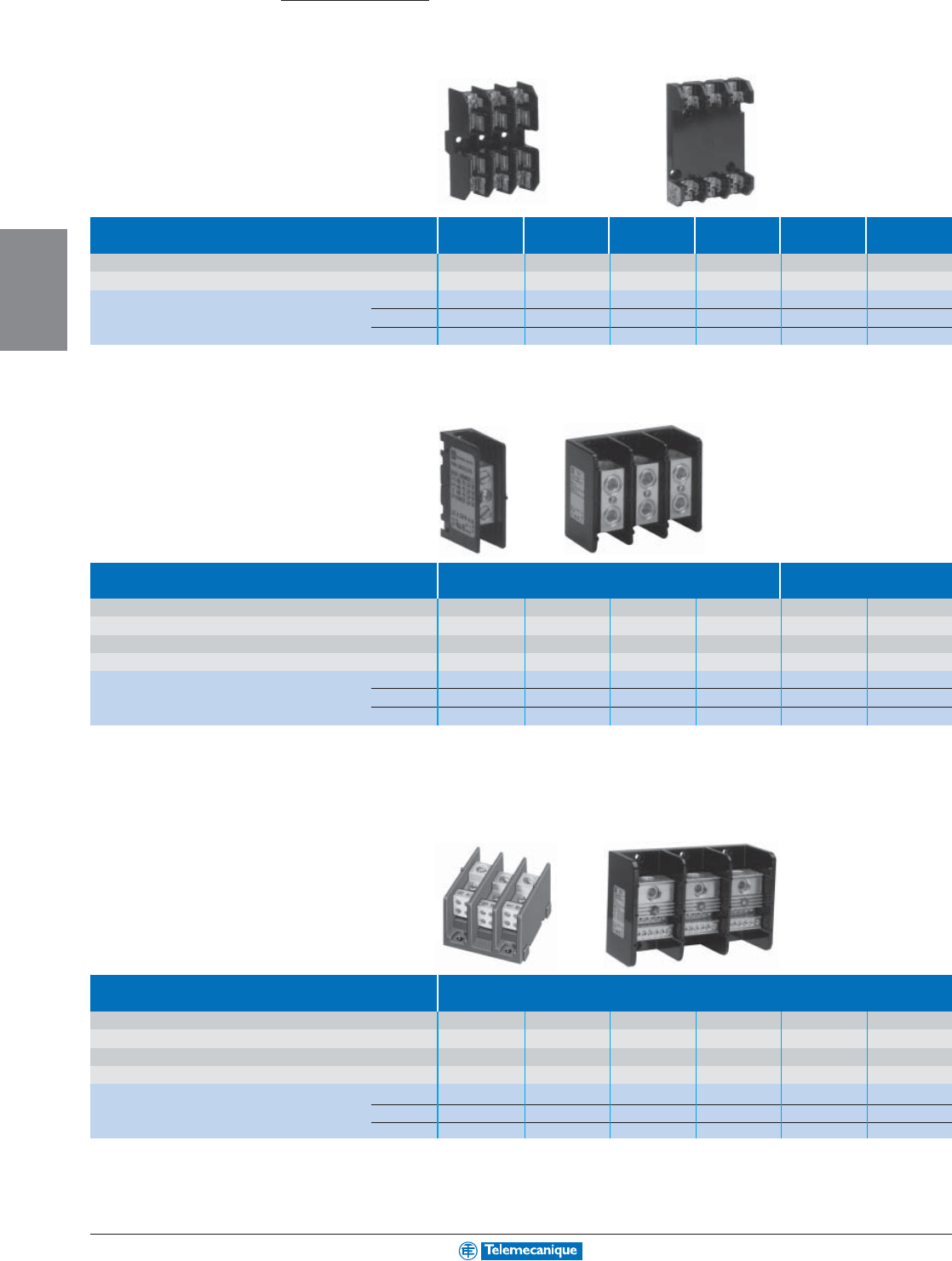
3-20
MACHINE
CONTROL
www.telemecanique.com
Ter minal blocks—NEMA
Fuseholders
Fuse Type Type M Class CC Class H Class H Class R Class R
Maximum voltage rating 600 600 250 600 250 600
Maximum current rating 30 30 30 30 30 30
1-pole 9080FB1611M 9080FB1611CC 9080FB1211 9080FB1611 9080FB1211R 9080FB1611R
2-pole 9080FB2611M 9080FB2611CC 9080FB2211 9080FB2611 9080FB2211R 9080FB2611R
3-pole 9080FB3611M 9080FB3611CC 9080FB3211 9080FB3611 9080FB3211R 9080FB3611R
Power Distribution Blocks
Splitter Blocks Aluminum Lugs Copper Lugs
Main wire (Number of wires in)
(1) #14–2 AWG (1) #14–2/0 AWG (1) #6–350 kcmil (1) #6–600 kcmil (1) #18–1/0 AWG (1) #6–250 kcmil
Branch wire (Number of wires out)
(1) #14–2 AWG (1) #14–2/0 AWG (1) #6–350 kcmil (1) #6–600 kcmil (1) #18–1/0 AWG (1) #6–250 kcmil
Maximum voltage rating 600 600 600 600 600 600
Maximum current rating—Cu wire 115 175 310 420 150 255
1-pole
9080LBA161101 9080LBA162101 9080LBA163101 9080LBA164101 9080LBC162101 9080LBC163101
2-pole
–9080LBA262101 9080LBA263101 –––
3-pole
9080LBA361101 9080LBA362101 9080LBA363101 9080LBA364101 9080LBC362101 9080LBC363101
Distribution Blocks Aluminum Lugs
Main wire (Number of wires in)
(1) #14–2 AWG (1) #14–2/0 AWG (1) #6–400 kcmil (1) #6–400 kcmil (1) #6–400 kcmil (1) #4–500 kcmil
Branch wire (Number of wires out)
(4) #18–10 AWG (4) #14–4 AWG (4) #14–2 AWG (6) #14–2 AWG (8) #14–2 AWG (12) #14–2 AWG
Maximum voltage rating
600 600 600 600 600 600
Maximum current rating—Cu wire
115 175 335 335 335 380
1-pole 9080LBA161104 9080LBA162104 9080LBA163104 9080LBA163106 9080LBA164108 9080LBA165112
2-pole 9080LBA261104 9080LBA262104 9080LBA263104 9080LBA263106 9080LBA264108 9080LBA265112
3-pole 9080LBA361104 9080LBA362104 9080LBA363104 9080LBA363106 9080LBA364108 9080LBA365112
Interfacing
For additional information, reference Catalog 9080CT9603.
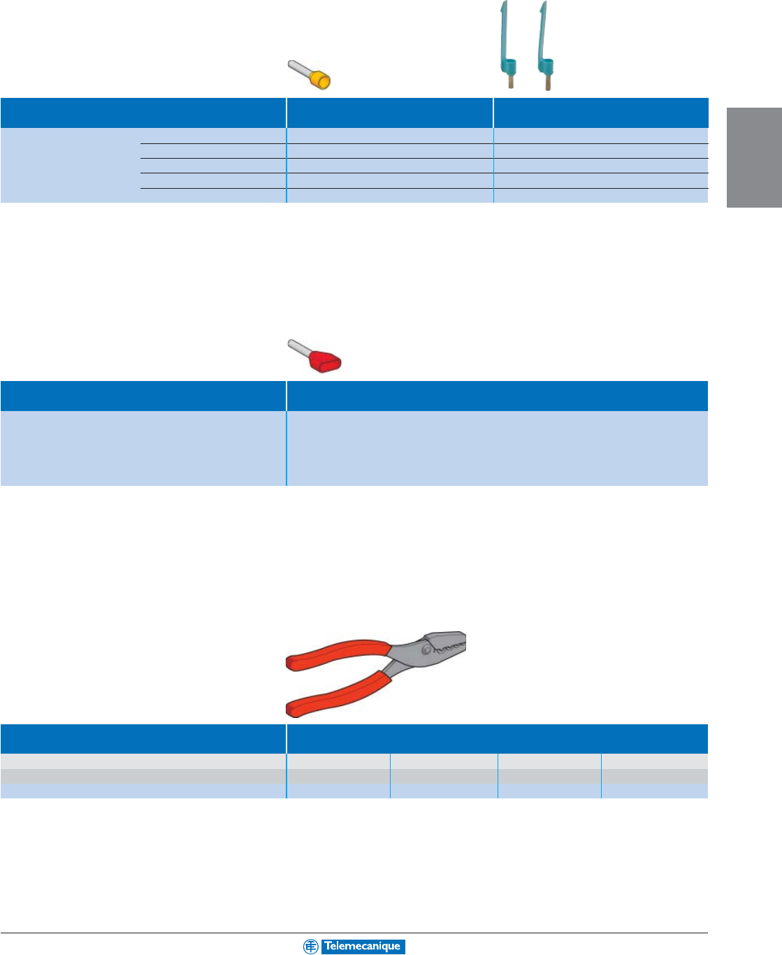
3-21
MACHINE
CONTROL
Insulated cable ends
Single cable ends Without Marking Flag With Marking Flag
(Sold in lots of 1000) (Sold in lots of 1000)
#22 AWG White DZ5CE005UL DZ5CA005UL
#20 AWG Blue DZ5CE007UL DZ5CA007UL
#18 AWG Red DZ5CE010UL DZ5CA010UL
#16 AWG Black DZ5CE015UL DZ5CA015UL
#14 AWG Grey DZ5CE025UL DZ5CA025UL
Dual cable ends Without Marking Flag
(Sold in lots of 500)
#22 AWG White AZ5DE005
#20 AWG Blue AZ5DE007
#18 AWG Red AZ5DE010
#16 AWG Black AZ5DE015
#14 AWG Grey AZ5DE025 (1)
(1) Sold in lots of 250.
Cabling accessories
Type Pliers/cutters
Functions Stripping Cutting/stripping Crimping Crimping
AWG 20–12 20–12 22–6 8–2
Catalog number AT1PA7 AT2PE1 AT1PA2 AT2PA4
For additional information, reference Catalog 9080CT9701.
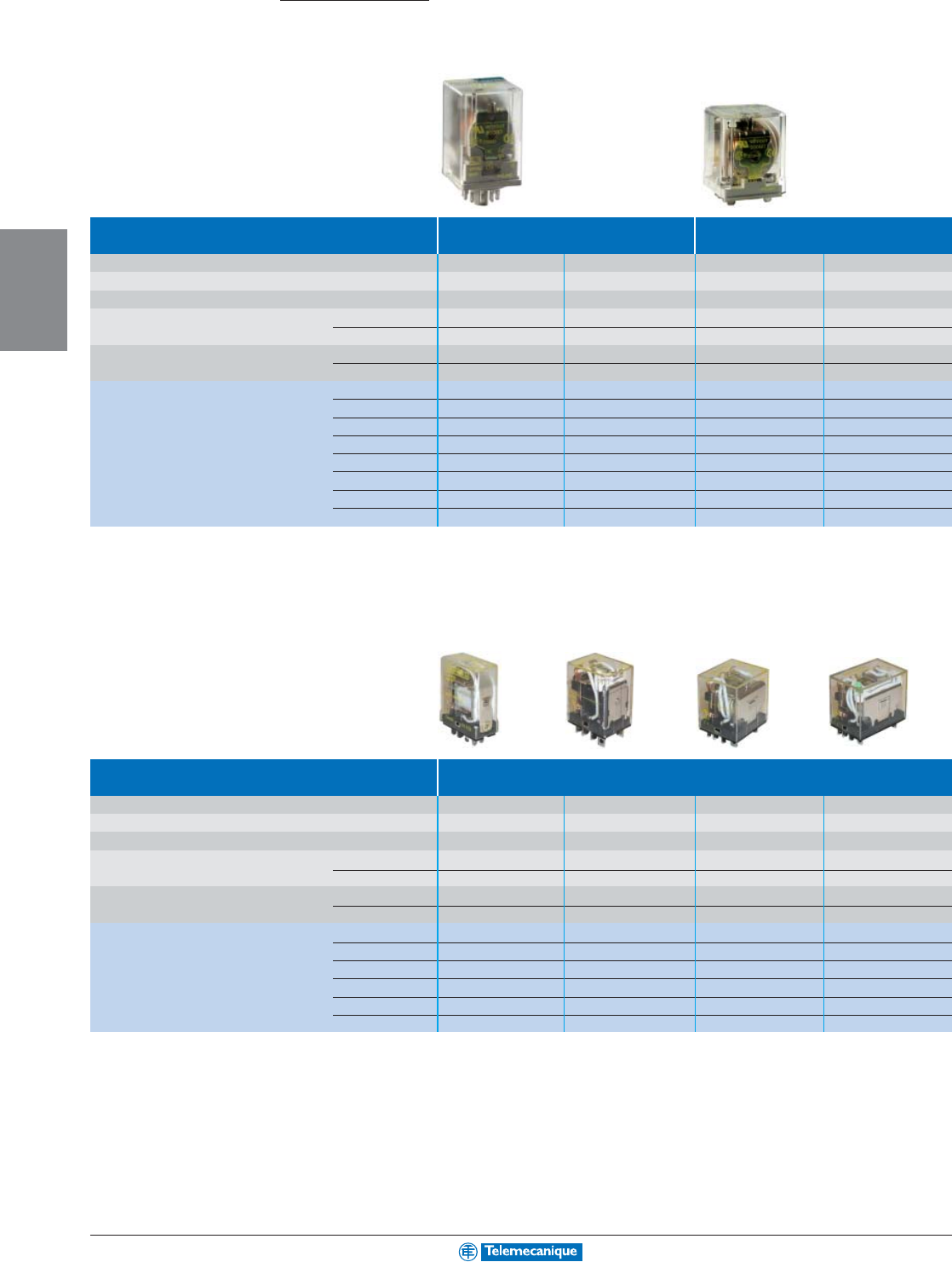
3-22
MACHINE
CONTROL
www.telemecanique.com
Interfacing
General purpose relays
Plug-in relays
Plug-in relays Tube type termination Spade type termination
Resistive rating (@ 120 Vac) 10 A 10 A 15 A 15 A
Number of Form C contacts 2323
Contact material Silver Nickel Silver Nickel Silver Cadmium Oxide Silver Cadmium Oxide
Average consumption, inrush Vac coils 3.6 VA 3.6 VA 3.6 VA 3.6 VA
Vdc coils 1.5 W 1.5 W 1.5 W 1.5 W
Voltage range Vac coils +10 to -15% +10 to -15% +10 to -15% +10 to -15%
Vdc coils +10 to -25% +10 to -25% +10 to -25% +10 to -25%
Catalog number 24 Vac 8501KP12V14 8501KP13V14 8501KU12V14 8501KU13V14
120 Vac 8501KP12V20 8501KP13V20 8501KU12V20 8501KU13V20
240 Vac 8501KP12V24 8501KP13V24 8501KU12V24 8501KU13V24
12 Vdc 8501KPD12V51 8501KPD13V51 8501KUD12V51 8501KUD13V51
24Vdc 8501KPD12V53 8501KPD13V53 8501KUD12V53 8501KUD13V53
110 Vdc 8501KPD12V60 8501KPD13V60 8501KUD12V60 8501KUD13V60
Relay socket 8501NR51 8501NR61 8501NR82 8501NR82
Hold down clip 8501NH51 8501NH61 8501NH82 8501NH82
Miniature plug-in relays
Miniature plug-in relays Spade type termination
Resistive rating (@ 120 Vac) 15 A 10 A 10 A 10 A
Number of Form C contacts 1234
Contact material Silver Cadmium Oxide Silver Cadmium Oxide Silver Cadmium Oxide Silver Cadmium Oxide
Average consumption, inrush Vac coils 1.52 VA 2.2 VA 2.9 VA 3.7 VA
Vdc coils 0.7 W 0.9 W 1.0 W 1.0 W
Voltage range Vac coils +10 to -15% +10 to -15% +10 to -15% +10 to -15%
Vdc coils +10 to -20% +10 to -20% +10 to -20% +10 to -20%
Catalog number 24 Vac 8501RS41V14 8501RS42V14 8501RS43V14 8501RS44V14
120 Vac 8501RS41V20 8501RS42V20 8501RS43V20 8501RS44V20
12 Vdc 8501RSD41V51 8501RSD42V51 8501RSD43V51 8501RSD44V51
24 Vdc 8501RSD41V53 8501RSD42V53 8501RSD43V53 8501RSD44V53
Relay socket 8501NR41 8501NR42 8501NR43 8501NR34
Hold down clip –8501NH42 8501NH42 8501NH42
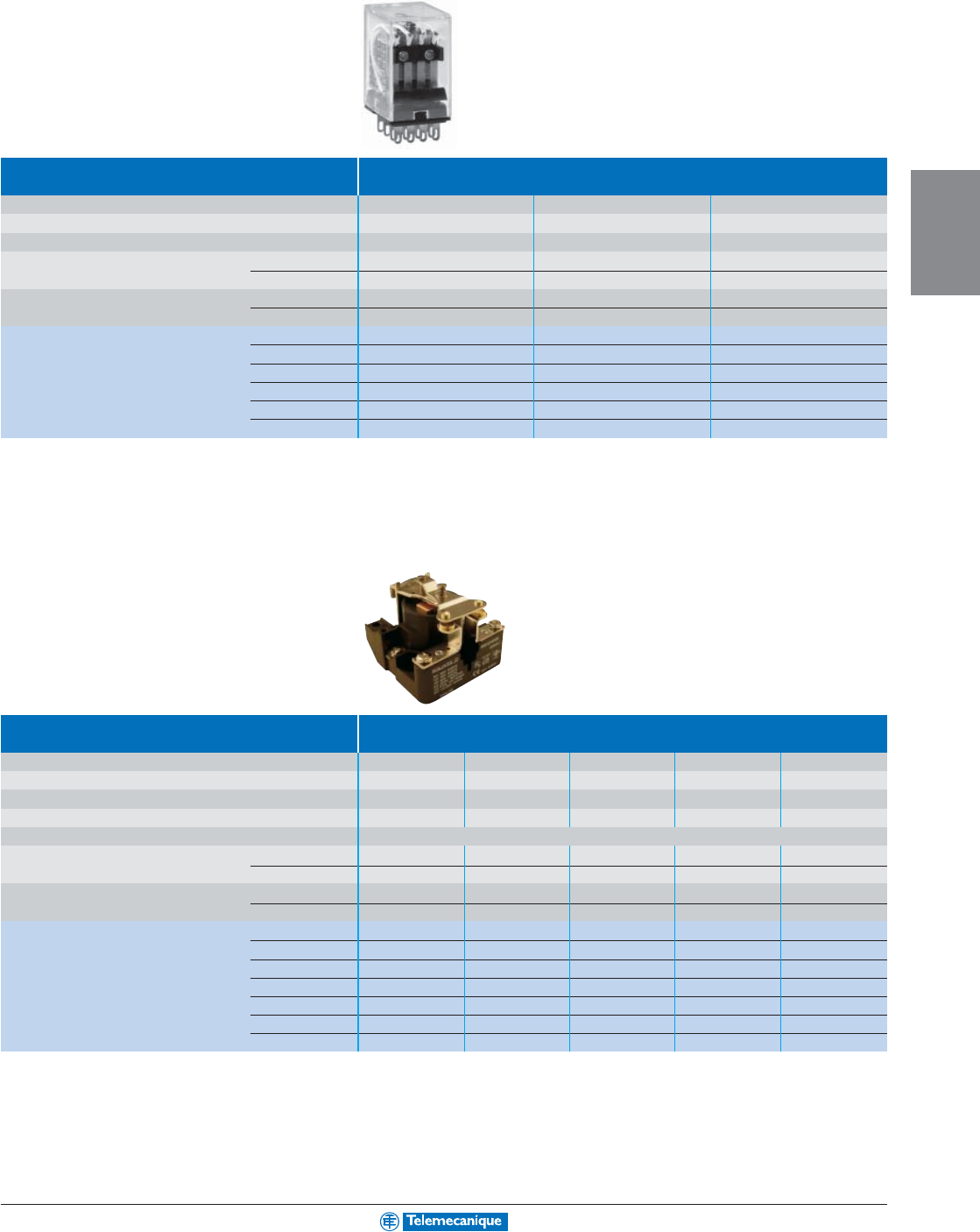
3-23
MACHINE
CONTROL
Miniature plug-in relays
For additional information, reference Catalog 8501CT0301.
Miniature plug-in relays Spade type termination
Resistive Rating (@ 120 Vac) 1 A 3 A 5 A
Number of Form C contacts 444
Contact material
Bifurcated Fine Silver Gold Flashed
Fine Silver Gold Flashed Silver Cadmium Oxide
Average consumption, inrush Vac coils 1.2 VA 1.2 VA 1.2 VA
Vdc coils 0.9 W 0.9 W 0.9 W
Voltage range Vac coils +10 to -15% +10 to -15% +10 to -15%
Vdc coils +10 to -20% +10 to -20% +10 to -20%
Catalog number 24 Vac 8501RS24V14 8501RS4V14 8501RS14V14
120 Vac 8501RS24V20 8501RS4V20 8501RS14V20
12 Vdc 8501RSD24V51 8501RSD4V51 8501RSD14V51
24 Vdc 8501RSD24V53 8501RSD4V53 8501RSD14V53
Relay socket 8501NR45 8501NR45 8501NR45
Hold down clip 8501NH45 8501NH45 8501NH45
Power relays
Power relays Vac rated contacts
Resistive rating (@ 300 Vac) 30 A 30 A 30A 30 A 30 A
Resistive rating (@ 600 Vac) 10 A 5 A 10 A 5 A 5 A
Single phase horsepower rating 21.5 2 1.5 1.5
Contact arrangement 1 N.O. 2 N.O. 1 N.C. 1 N.C. & 1 N.O. 2 N.C. & 2 N.O.
Contact material Silver Cadmium Oxide
Average consumption, inrush Vac coils 10 VA 10 VA 10 VA 10 VA 10 VA
Vdc coils 2 W 2 W 2 W 2 W 2 W
Voltage range Vac coils +10 to -15% +10 to -15% +10 to -15% +10 to -15% +10 to -15%
Vdc coils +10 to -20% +10 to -20% +10 to -20% +10 to -20% +10 to -20%
Catalog number 24 Vac 8501CO6V14 8501CO7V14 8501CO8V14 8501CO15V14 8501CO16V14
120 Vac 8501CO6V20 8501CO7V20 8501CO8V20 8501CO15V20 8501CO16V20
208 Vac 8501CO6V08 8501CO7V08 8501CO8V08 8501CO15V08 8501CO16V08
240 Vac 8501CO6V24 8501CO7V24 8501CO8V24 8501CO15V24 8501CO16V24
277 Vac 8501CO6V04 8501CO7V04 8501CO8V04 8501CO15V04 8501CO16V04
480 Vac 8501CO6V29 8501CO7V29 8501CO8V29 8501CO15V29 8501CO1V29
24 Vdc 8501CDO6V53 8501CDO7V53 8501CDO8V53 8501CDO15V53 8501CDO16V53
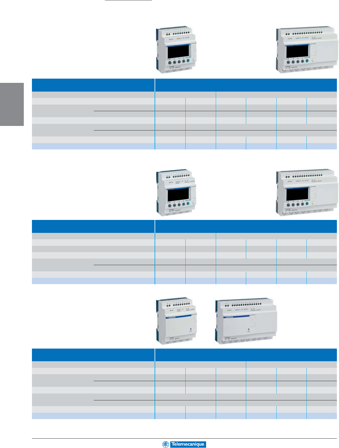
3-24
MACHINE
CONTROL
www.telemecanique.com
Zelio Logic™ Smart relays
Zelio Logic Compact SR2
Automation
Compact smart relays With display, dc power supply
Supply voltage 12 Vdc 24 Vdc
Number of inputs/outputs 12 20 10 12 20 20
Number of inputs discrete inputs 8 12 6 8 12 12
of which 0–10 V analog inputs 4 6 –426
Number of outputs 4 relay 8 relay 4 relay 48 relay 8
Dimensions, W x D x H mm
71.2x59.5x107.6 124.6x59.5x107.6 71.2x59.5x107.6 124.6x59.5x107.6
in. 2.80x2.34x4.24 4.90x2.34x4.24 2.80x2.34x4.24 4.90x2.34x4.24
Clock yes yes no yes no yes
References
SR2B121JD SR2B201JD SR2A101BD (1) SR2B12pp
pp
pBD (2) SR2A201BD (1) SR2B20pp
pp
pBD (2)
(1) Programming of this smart relay in LADDER language only. For other smart relay modules, programming options include LADDER language, Function Block Diagram (FBD) and
Sequential Function Chart (SFC) languages.
(2) Replace
pp
pp
p
by the number “1” to order a smart relay with relay outputs and by “2” for a smart relay with transistor outputs (Example: SR2B121BD)
Compact smart relays With display, ac power supply
Supply voltage 24 Vac 100/240 Vac
Number of inputs/outputs 12 20 10 12 20 20
Number of discrete inputs 812681212
Number of outputs 4 relay 8 relay 4 relay 4 relay 8 relay 8 relay
Dimensions, W x D x H mm
71.2x59.5x107.6 124.6x59.5x107.6 71.2x59.5x107.6 124.6x59.5x107.6
in. 2.80x2.34x4.24 4.90x2.34x4.24 2.80x2.34x4.24 4.90x2.34x4.24
Clock yes yes no no no no
References SR2B121B SR2B201B SR2A101FU (1) SR2B121FU SR2A201FU (1) SR2B201FU
(1) Programming of smart relay in LADDER language only
Compact smart relays Without display and without buttons
Supply voltage 24 Vdc 100/240 Vac
Number of inputs/outputs 10 12 20 10 12 20
Number of inputs discrete inputs 6 8 12 6 8 12
of which 0–10 V analog inputs -46–––
Number of outputs 4 relay 4 relay 8 relay 4 relay 4 relay 8 relay
Dimensions, W x D x H mm
71.2x59.5x107.6 124.6x59.5x107.6 71.2x59.5x107.6 124.6x59.5x107.6
in. 2.80x2.34x4.24 4.90x2.34x4.24 2.80x2.34x4.24 4.90x2.34x4.24
Clock no yes yes no yes yes
References SR2D101BD (1) SR2E121BD (2) SR2E201BD (2) SR2D101FU (1) SR2E121FU SR2E201FU
(1) Programming of smart relay in LADDER language only
(2) For version with 24 Vac supply (0 analog inputs), delete the letter D from the end of the reference (SR2E121B and SR2E201B)
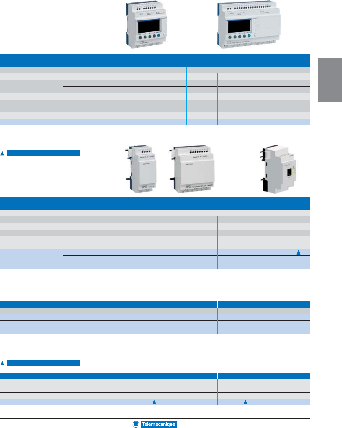
3-25
MACHINE
CONTROL
Available 2nd quarter 2004
Available 2nd quarter 2004
Zelio Logic Modular SR3
Modular smart relays* With display
Supply voltage 24 Vdc 24 Vac 100/240 Vac
Number of inputs/outputs 10 26 10 26 10 26
Number of inputs discrete inputs 6 16 6 16 6 16
of which 0–10 V analog inputs 4 6 – – – –
Number of outputs 4 10 4 relay 10 relay 4 relay 10 relay
Dimensions, W x D x H mm
71.2x59.5x107.6 124.6x59.5x107.6 71.2x59.5x107.6 124.6x59.5x107.6 71.2x59.5x107.6 124.6x59.5x107.6
in. 2.80x2.34x4.24 4.90x2.34x4.24 2.80x2.34x4.24 4.90x2.34x4.24 2.80x2.34x4.24 4.90x2.34x4.24
Clock yes yes yes yes yes yes
References SR3B10
pp
pp
p
BD (1) SR3B26
pp
pp
p
BD (1) SR3B101B SR3B261B SR3B101FU SR3B261FU
* Each modular base can be fitted with one communication module and one I/O expansion module.
(1) Replace
pp
pp
p
by the number “1” to order a smart relay with relay outputs and by “2” for a smart relay with transistor outputs (Example: SR3B101BD)
Expansion modules
(2)
Inputs / Outpus Communication
Usage For modular smart relays SR3Bppppp MODBUS network
Number of inputs/outputs 6 10 14 –
Number of discrete inputs 468–
Number of outputs 2 relay 4 relay 6 relay –
Dimensions, W x D x H mm 35.5x59.5x107.6 72x59.5x107.6 72x59.5x107.6 35.5x59.5x107.6
in. 1.40x2.34x4.24 2.83x2.34x4.24 2.83x2.34x4.24 1.40x2.34x4.24
References 24 Vdc SR3XT61BD SR3XT101BD SR3XT141BD SR3MBU01BD
24 Vac SR3XT61B SR3XT101B SR3XT141B –
100–240 Vac SR3XT61FU SR3XT101FU SR3XT141FU –
(2) The power supply for the expansion modules is provided via the Zelio Logic modular relays
Zelio Soft™ software and back-up memory
Software and back-up memory Multilingual programmming software Back-up memory
Description PC CD-ROM (Windows 95/98, NT, 2000, XP, ME) (3) EEPROM
References SR2SFT01 SR2MEM01
PC/Smart relay connecting cable SR2CBL01 –
Interface for USB port SR2CBL06 –
(3) CD-ROM containing “Zelio Soft” software, an application library, a self-training manual, installation instructions and a user’s manual.
Communication interface
Interface and software Communication interface Programming software
Supply voltage 12/24 Vdc –
Description –PC CD ROM (Windows 95/98, NT, 2000, XP, ME)
Dimensions, W x D x H (mm / in.) 72x59.5x107.6 / 2.83x2.34x4.24 –
References SR2COM01 SR2SFT03
For additional information, reference DIA3ED2031108 EN.
Welcome to the Simply Smart* world
compliments of Telemecanique
Telemecanique, the world leader for control and signaling components,
offers you its ranges of Push Buttons, Selector Switches, Pilot Lights,
Beacons and Indicating Banks (including audible units) and
components for Hoisting applications.
Unequalled and of the highest quality, it is the largest offer on the
market. It intelligently adapts to all types of applications and works
exceptionally well on new equipment in both industrial and commercial
environments, and is well suited for MRO use.
bb
bb
b
Openness:
in perfect synergy with other Telemecanique equipment,
this offer optimizes the design of your Operator Interface solutions.
bb
bb
b
Simplicity: clip together components insure simple, secure and fast
assembly.
bb
bb
b
Ingenuity: LED technology for all signaling functions: “Super
Bright” LED offer for applications requiring a high level of visibility.
bb
bb
b
Robustness: mechanical performance much higher than standard
requirements.
bb
bb
b
Flexibility: modular construction, the products evolve with the
automation system.
bb
bb
b
Compactness: the overall dimensions are the smallest on the
market.
* Simply Smart : using ingenuity and intelligence to continually improve ease of use.
Optimize the design of your
Operator Interface solutions
Control and signalling units
The essential guide
A selection of the
most popular selling
products enabling you
to quickly locate the
most appropriate
solution for your
application.
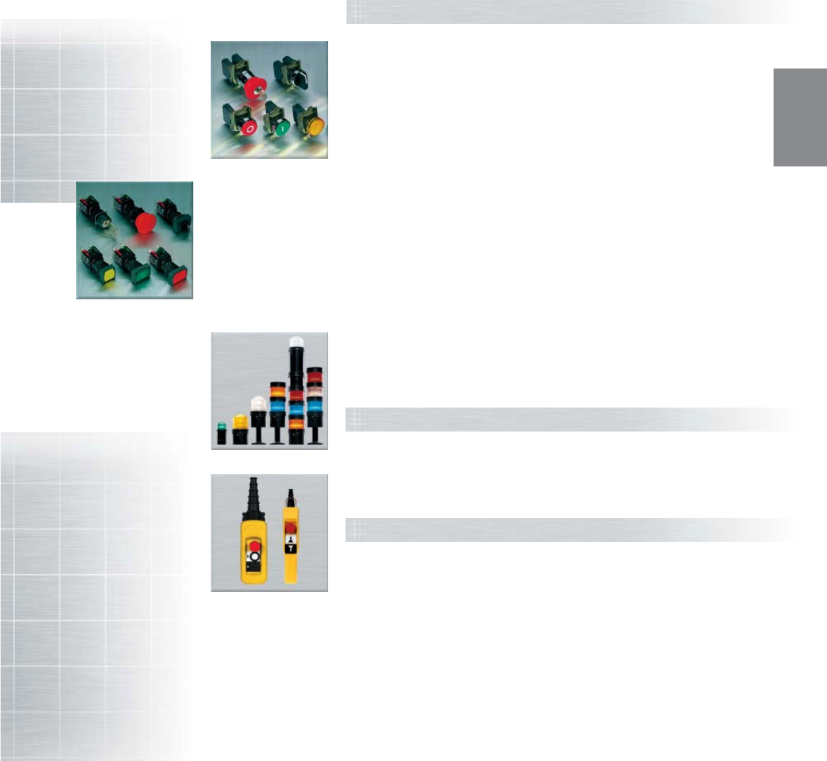
Contents
Control and Signaling Units
Beacons and indicating banks
Components for hoisting applications
Push Buttons, Selector Switches and Pilot Lights ........................... 4-2
with Plastic Bezels—16mm XB6
Push Buttons, Selector Switches and Pilot Lights ........................... 4-6
with Metal Bezels—22mm XB4
Push Buttons, Selector Switches and Pilot Lights ......................... 4-10
with Plastic Bezels—22mm XB5
Control Stations ............................................................................. 4-13
Pre-assembled with XB5 22mm units XAL
Push Buttons, Selector Switches and Pilot Lights ......................... 4-14
with Metal Ring Nuts—30mm 9001Type K
Push Buttons, Selector Switches and Pilot Lights ......................... 4-16
with Plastic Ring Nuts – 30mm 9001 Type SK
Enclosures .................................................................................... 4-18
XAL, XAP and KY for user assembly
Compact Pilot Lights 8, 12 and 17.5mm ....................................... 4-19
XVL and Type O
Pendant control stations ................................................................ 4-22
XAC and Type BW ready to use
Pendant control stations ................................................................ 4-23
XAC and Type SKYP for user assembly
Control stations ............................................................................. 4-25
Types B, KY and SKY, Standard and Heavy Duty
Beacons and indicating banks ...................................................... 4-20
XVB 70mm and XVP 50mm
OPERATOR
INTERFACE
4-2
OPERATOR
INTERFACE
www.telemecanique.com
=++
=+
Illuminated push buttons
Type of head Flush push
Shape of head rectangular (2)
Degree of protection IP 65 / NEMA & UL Type 4, 4X, 13
Mounting (mm) panel cut-out 16.2
mounting centers 24 x 18 with rectangular head, 18 x 18 with square or circular head
Dimensions (mm) W x H x D (below head) 24 x 18 x 50 with rectangular head, 18 x 18 x 50 with square or circular head
Connection Tags for 2.8 x 0.5 Quick connectors or for soldering
Type of push Spring return
Complete products Products for user assembly
12–24 Vac/dc
Catalog number white N.O. XB6 DW1B1B ZB6 Ep1B (1) ZB6 Z1B ZB6 DW1 (2)
N.C. + N.O. XB6 DW1B5B ZB6 Ep1B (1) ZB6 Z5B ZB6 DW1 (2)
green N.O. XB6 DW3B1B ZB6 Ep3B (1) ZB6 Z1B ZB6 DW3 (2)
N.C. + N.O. XB6 DW3B5B ZB6 Ep3B (1) ZB6 Z5B ZB6 DW3 (2)
red N.C. XB6 DW4B2B ZB6 Ep4B (1) ZB6 Z2B ZB6 DW4 (2)
N.C. + N.O. XB6 DW4B5B ZB6 Ep4B (1) ZB6 Z5B ZB6 DW4 (2)
yellow N.O. XB6 DW5B1B ZB6 Ep5B (1) ZB6 Z1B ZB6 DW5 (2)
N.C. + N.O. XB6 DW5B5B ZB6 Ep5B (1) ZB6 Z5B ZB6 DW5 (2)
blue N.O. XB6 DW6B1B ZB6 Ep6B (1) ZB6 Z1B ZB6 DW6 (2)
N.C. + N.O. XB6 DW6B5B ZB6 Ep6B (1) ZB6 Z5B ZB6 DW6 (2)
Type of push Maintained
Catalog number white N.O. XB6 DF1B1B ZB6 Ep1B (1) ZB6 Z1B ZB6 DF1 (2)
N.C. + N.O. XB6 DF1B5B ZB6 Ep1B (1) ZB6 Z5B ZB6 DF1 (2)
green N.O. XB6 DF3B1B ZB6 Ep3B (1) ZB6 Z1B ZB6 DF3 (2)
N.C. + N.O. XB6 DF3B5B ZB6 Ep3B (1) ZB6 Z5B ZB6 DF3 (2)
red N.C. XB6 DF4B2B ZB6 Ep4B (1) ZB6 Z2B ZB6 DF4 (2)
N.C. + N.O. XB6 DF4B5B ZB6 Ep4B (1) ZB6 Z5B ZB6 DF4 (2)
yellow N.O. XB6 DF5B1B ZB6 Ep5B (1) ZB6 Z1B ZB6 DF5 (2)
N.C. + N.O. XB6 DF5B5B ZB6 Ep5B (1) ZB6 Z5B ZB6 DF5 (2)
blue N.O. XB6 DF6B1B ZB6 Ep6B (1) ZB6 Z1B ZB6 DF6 (2)
N.C. + N.O. XB6 DF6B5B ZB6 Ep6B (1) ZB6 Z5B ZB6 DF6 (2)
Pilot lights
Type of head Smooth lens cap
Shape of head rectangular (2)
Complete products Products for user assembly
12–24 Vac/dc
Catalog number white XB6 DV1BB ZB6 Ep1B (1) ZB6 DV1 (2)
green XB6 DV3BB ZB6 Ep3B (1) ZB6 DV3 (2)
red XB6 DV4BB ZB6 Ep4B (1) ZB6 DV4 (2)
yellow XB6 DV5BB ZB6 Ep5B (1) ZB6 DV5 (2)
blue XB6 DV6BB ZB6 Ep6B (1) ZB6 DV6 (2)
(1) Basic catalog number, to be completed by the letter B, G or M indicating the required voltage. See voltage table above.
(2) For products with a square head, replace the letter D in the catalog number by the letter C (XB6 DW1B1B becomes XB6 CW1B1B).
For products with a circular head, replace the letter D in the catalog number by the letter A (XB6 DW1B1B becomes XB6 AW1B1B).
Control and signalling units 16 mm
with plastic bezel
Complete operators
with integral LED
(1):
Voltage Letter (p)
12–24 Vac/dc (15 mA) B
48–120 Vac (25 mA) G
230–240 Vac (25 mA) M
+0.2
0
XB6
4-3
OPERATOR
INTERFACE
For other versions, consult your nearest Square D/Schneider Electric sales office
.
=+
=+
Push buttons
Type of head Flush push
Shape of head rectangular (2)
Degree of protection IP 65 / NEMA & UL Type 4, 4X, 13
Mounting (mm) panel cut-out 16.2
mounting centers 24 x 18 with rectangular head, 18 x 18 with square or circular head
Dimensions (mm) W x H x D (below head) 24 x 18 x 50 with rectangular head, 18 x 18 x 50 with square or circular head
Connection Tags for 2.8 x 0.5 Quick connectors or for soldering
Type of push Spring return
Complete products Products for user assembly
Catalog number white N.O. XB6 DA11B ZB6 Z1B ZB6 DA1 (2)
N.C. + N.O. XB6 DA15B ZB6 Z5B ZB6 DA1 (2)
black N.O. XB6 DA21B ZB6 Z1B ZB6 DA2 (2)
N.C. XB6 DA22B ZB6 Z2B ZB6 DA2 (2)
N.C. + N.O. XB6 DA25B ZB6 Z5B ZB6 DA2 (2)
green N.O. XB6 DA31B ZB6 Z1B ZB6 DA3 (2)
N.C. + N.O. XB6 DA35B ZB6 Z5B ZB6 DA3 (2)
red N.O. XB6 DA41B ZB6 Z1B ZB6 DA4 (2)
N.C. XB6 DA42B ZB6 Z2B ZB6 DA4 (2)
N.C. + N.O. XB6 DA45B ZB6 Z5B ZB6 DA4 (2)
yellow N.O. XB6 DA51B ZB6 Z1B ZB6 DA5 (2)
N.C. + N.O. XB6 DA55B ZB6 Z5B ZB6 DA5 (2)
blue N.O. XB6 DA61B ZB6 Z1B ZB6 DA6 (2)
N.C. + N.O. XB6 DA65B ZB6 Z5B ZB6 DA6 (2)
30 mm mushroom head Emergency stop push buttons
Type of head Trigger action
Shape of head cylindrical
Type of push Turn to release
Complete products Products for user assembly
Catalog number red 1 N.C. + 1 N.O. XB6 AS8345B ZB6 Z5B ZB6 AS834
Type of push Key release, Ronis 200
Catalog number red 1 N.C. + 1 N.O. XB6 AS9345B ZB6 Z5B ZB6 AS934
(2) For products with a square head, replace the letter D in the catalog number by the letter C (XB6 DA11B becomes XB6 CA11B).
For products with a circular head, replace the letter D in the catalog number by the letter A (XB6 DA11B becomes XB6 AA11B).
+0.2
0
Non-illuminated complete operators
4-4
OPERATOR
INTERFACE
www.telemecanique.com
=+
=+
Selector switches and key switches
Type of head Black handle
Shape of head rectangular (1)
Degree of protection IP 65 / NEMA & UL Type 4, 4X, 13 (except key switches)
Mounting (mm) panel cut-out 16.2
mounting centers 24 x 18 with rectangular head, 18 x 18 with square or circular head
Dimensions (mm) W x H x D (below head) 24 x 18 x 50 with rectangular head, 18 x 18 x 50 with square or circular head
Connection Tags for 2.8 x 0.5 Quick connectors or for soldering
Type of operator Black handle
Complete products Products for user assembly
Number and type of positions 2 positions 2 positions 2 positions
maintained maintained spring return to center
Catalog number N.O. XB6 DD221B ZB6 Z1B ZB6 DD22 (1) ZB6 Z1B ZB6 DD24 (1)
N.C. + N.O. XB6 DD225B ZB6 Z5B ZB6 DD22 (1) ZB6 Z5B ZB6 DD24 (1)
Number and type of positions 3 positions 3 positions 3 positions
maintained maintained spring return to center
Catalog number N.C. + N.O. XB6 DD235B ZB6 Z5B ZB6 DD23 (1) ZB6 Z5B ZB6 DD25 (1)
Type of operator Ronis key, no. 200
Complete products Products for user assembly
Number and type of positions 2 positions 2 positions 2 positions
maintained maintained spring return to center
Catalog number N.C. + N.O. XB6 DGC5B ZB6 Z5B ZB6 DGC (1) ZB6 Z5B ZB6 DGB (1)
Number and type of positions 3 positions 3 positions 3 positions
maintained maintained spring return to center
Catalog number N.C. + N.O. XB6 DGH5B ZB6 Z5B ZB6 DGH (1) ZB6 Z5B ZB6 DGS (1)
(1) For products with a square head, replace the letter D in the catalog number by the letter C (XB6 DD221B becomes XB6 CD221B).
For products with a circular head, replace the letter D in the catalog number by the letter A (XB6 DD221B becomes XB6 AD221B).
+0.2
0
XB6
60°45°
60°
60°45°
60°60°45°
60°
70°45°70°
70°45°70°70°45°70°
Control and signalling units 16 mm
with plastic bezel
Complete operators, selector switches
4-5
OPERATOR
INTERFACE
For other versions, consult your nearest Square D/Schneider Electric sales office
.
Sub-assemblies & accessories for 16 mm
plastic bezel control and signalling units
Sub-assemblies Bodies for push buttons and Bodies for pilot lights
selector switches
Rated operational characteristics, AC-15: Ue = 240 V and Ie = 1.5 A or Ue = 120 V and Ie = 3 A Consumption
Positive operation of contacts conforming to IEC/EN 60947-5-1: N.C. contacts with positive opening operation, 15 mA 12–24 Vac/dc
positive opening force 20 N 25 mA 48–120 Vac
25 mA 230–240 Vac
Type of Body Contacts Pilot light 12–24 V 48–120 V 230–240 V
contact + contacts bodies
Catalog number N.O. ZB6 Z1B ZB6 E1B White ZB6 EB1B ZB6 EG1B ZB6 EM1B
N.C. ZB6 Z2B ZB6 E2B Green ZB6 EB3B ZB6 EG3B ZB6 EM3B
2 N.O. ZB6 Z3B –Red ZB6 EB4B ZB6 EG4B ZB6 EM4B
2 N.C. ZB6 Z4B –Yellow ZB6 EB5B ZB6 EG5B ZB6 EM5B
N.O. + N.C. ZB6 Z5B –Blue ZB6 EB6B ZB6 EG6B ZB6 EM6B
Accessories
Body Bezel tightening tool Nut Anti-rotation plate
+ bulb extractor
Application Fitting contact blocks Fixing the switch and Fixing head to panel Selector switches,
changing bulbs Emergency Stops
Catalog number ZB6Y009 ZB6Y905 ZB6Y002 ZB6Y003
Protective cover for push buttons and switches Female Quick connector/ Blanking plug
Solder tab
Application
Circular and square head Rectangular head Sold in lots of 100 pieces
Plugging an unused knockout
Catalog number ZB6YA001 ZB6YD001 ZB6Y004 ZB6Y005
Legends Std. Plate (24 X 28 mm) Circular, 45 mm
for 8 X 21 mm Legend
With blank legend insert
Yellow
White or yellow Black or red Blank Emergency stop Arrêt d’urgence
Catalog number ZB6YD21 ZB6YD22 ZB6Y7001 ZB6Y7330 ZB6Y7130
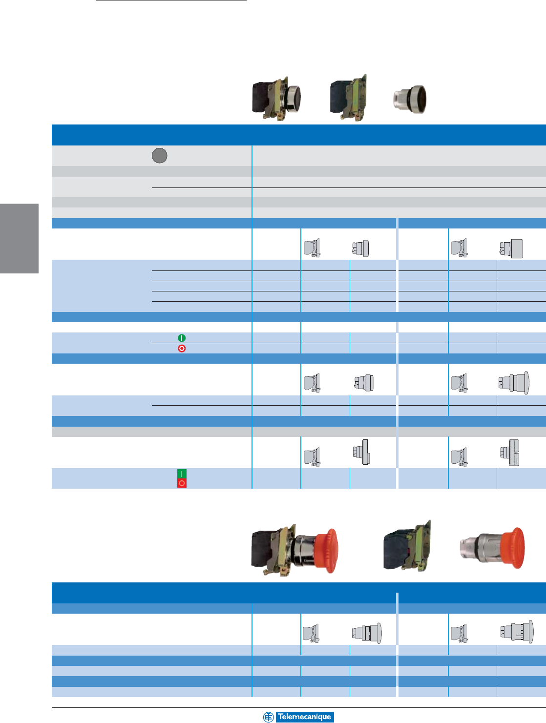
4-6
OPERATOR
INTERFACE
www.telemecanique.com
=+
=+
Push buttons, spring return
Type of head Chromium plated circular bezel
Degree of protection IP 65 / NEMA & UL Type 4X, 13 (IP 66 for booted push buttons)
Mounting (mm) panel cut-out 22.5 (22.3 )
mounting centers 30 x 40
Depth (mm) below head 43
Connection Screw clamp terminals
Type of push Flush Flush, booted
Products Complete For user assembly Complete For user assembly
Catalog number black N.O. XB4 BA21 ZB4 BZ101 ZB4 BA2 XB4 BP21 ZB4 BZ101 ZB4 BP2
green N.O. XB4 BA31 ZB4 BZ101 ZB4 BA3 XB4 BP31 ZB4 BZ101 ZB4 BP3
red N.C. XB4 BA42 ZB4 BZ102 ZB4 BA4 XB4 BP42 ZB4 BZ102 ZB4 BP4
yellow N.O. XB4 BA51 ZB4 BZ101 ZB4 BA5 XB4 BP51 ZB4 BZ101 ZB4 BP5
blue N.O. XB4 BA61 ZB4 BZ101 ZB4 BA6 XB4 BP61 ZB4 BZ101 ZB4 BP6
Type of push Flush
With international marking Products Complete For user assembly
Catalog number green N.O. XB4 BA3311 ZB4 BZ101 ZB4 BA331
red N.C. XB4 BA4322 ZB4 BZ102 ZB4 BA432
Type of push Projecting Mushroom head, 40 mm
Products Complete For user assembly Complete For user assembly
Catalog number black N.O. – – – XB4 BC21 ZB4 BZ101 ZB4 BC2
red N.C. XB4 BL42 ZB4 BZ102 ZB4 BL4 –––
Type of push Double-headed push buttons Double-headed push buttons, booted
Degree of protection IP 40 IP 66
With international marking Products Complete For user assembly Complete For user assembly
Catalog number green / N.C. + N.O. XB4 BL845 ZB4 BZ105 ZB4 BL8434 XB4 BL945 ZB4 BZ105 ZB4 BL9434
red
40 mm mushroom head Emergency stop push buttons
Trigger action
Type of push Push-pull (N.C.) Push-pull (N.C. + N.O.)
Products Complete For user assembly Complete For user assembly
Catalog number red N.C. or N.C. + N.O. XB4 BT42 ZB4 BZ102 ZB4 BT4 XB4 BT845 ZB4 BZ105 ZB4 BT84
Type of push Turn to release (N.C.) Turn to release (N.C. + N.O.)
Catalog number red N.C. or N.C. + N.O. XB4 BS542 ZB4 BZ102 ZB4 BS54 XB4 BS8445 ZB4 BZ105 ZB4 BS844
Type of push Key release (N.C.) Key release (N.C. + N.O.)
Catalog number red N.C. or N.C. + N.O. XB4 BS142 ZB4 BZ102 ZB4 BS14 XB4 BS9445 ZB4 BZ105 ZB4 BS944
XB4
+0.4
0
Control and signalling units 22 mm
with metal bezel
Non-illuminated complete operators
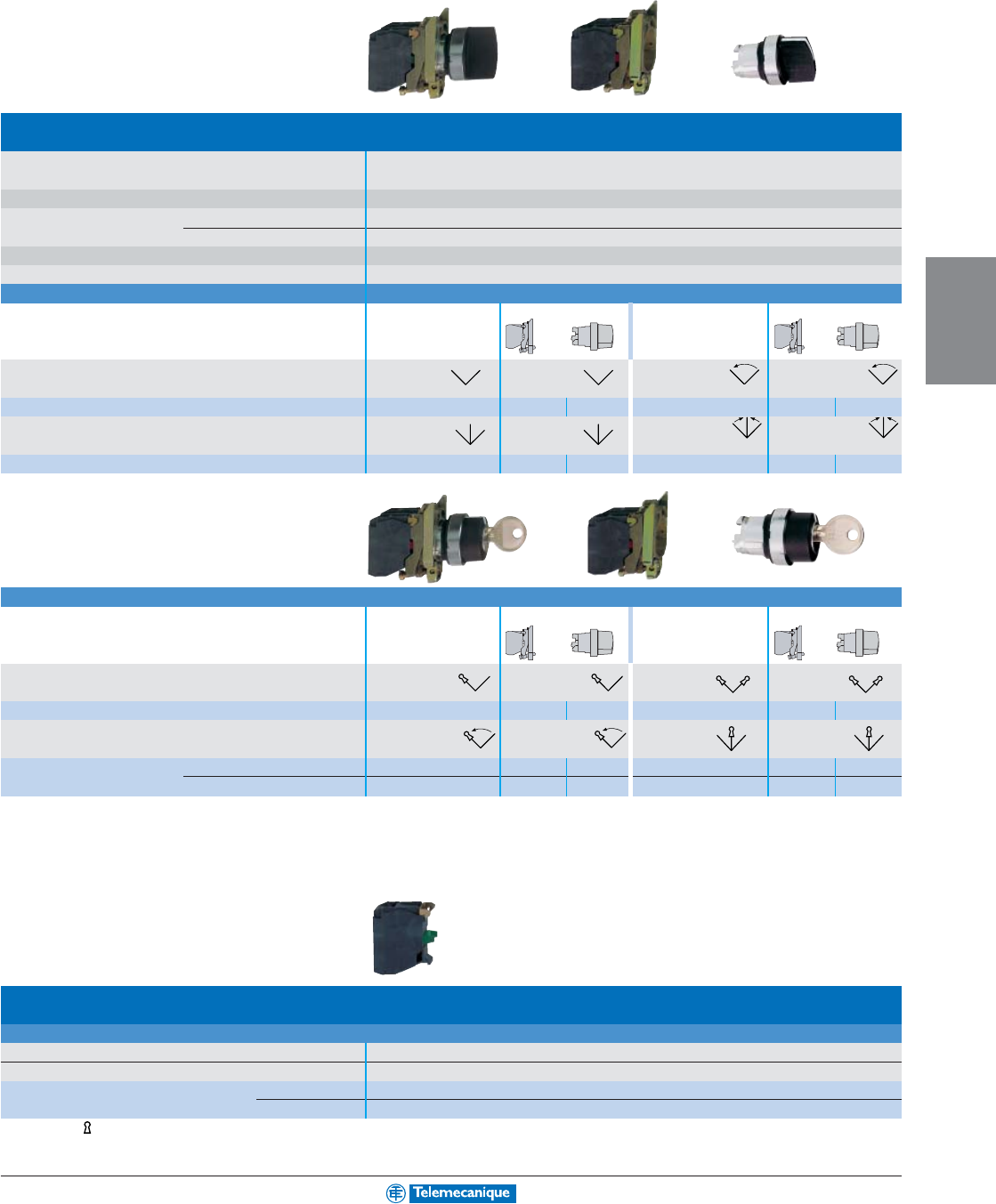
4-7
OPERATOR
INTERFACE
For other versions, consult your nearest Square D/Schneider Electric sales office
.
=+
=+
Selector switches and key switches
Type of head Chromium plated circular bezel
Degree of protection IP 65 / NEMA & UL Type 4X, 13
Mounting (mm) panel cut-out 22.5 (22.3 )
mounting centers 30 x 40
Depth (mm) below head 43
Connection Screw clamp terminals
Type of operator Handle
Products Complete For user assembly Complete For user assembly
Number and type of positions 2 positions 2 positions 2 positions 2 positions
maintained maintained spring return to left spring return to left
Catalog number black N.O. XB4 BD21 ZB4 BZ101 ZB4 BD2 XB4 BD41 ZB4 BZ101 ZB4 BD4
Number and type of positions 3 positions 3 positions 3 positions 3 positions
maintained maintained spring return to center spring return to center
Catalog number black N.O. + N.O. XB4 BD33 ZB4 BZ103 ZB4 BD3 XB4 BD53 ZB4 BZ103 ZB4 BD5
Type of operator Key, no. 455
Products Complete For user assembly Complete For user assembly
Number and type of positions (1) 2 positions 2 positions 2 positions 2 positions
maintained maintained maintained maintained
Catalog number key N.O. XB4 BG21 ZB4 BZ101 ZB4 BG2 XB4 BG41 ZB4 BZ101 ZB4 BG4
Number and type of positions 2 positions 2 positions 3 positions 3 positions
spring return to left spring return to left maintained maintained
Catalog number key N.O. XB4 BG61 ZB4 BZ101 ZB4 BG6 –––
key N.O. + N.O. – – – XB4 BG33 ZB4 BZ103 ZB4 BG3
Add-on contact blocks
Electrical blocks
Single contact blocks
Rated operational characteristics AC-15, 240 V - 3 A, NEMA A600, Q600, 10 A AC continuous carrying
Positive operation of contacts conforming to IEC/EN 60947-5-1 All functions incorporating a N.C. contact are positive opening operation
Catalog number N.O. ZBE 101
N.C. ZBE 102
(1) The symbol indicates key withdrawal position.
+0.4
0
Complete operators, selector switches
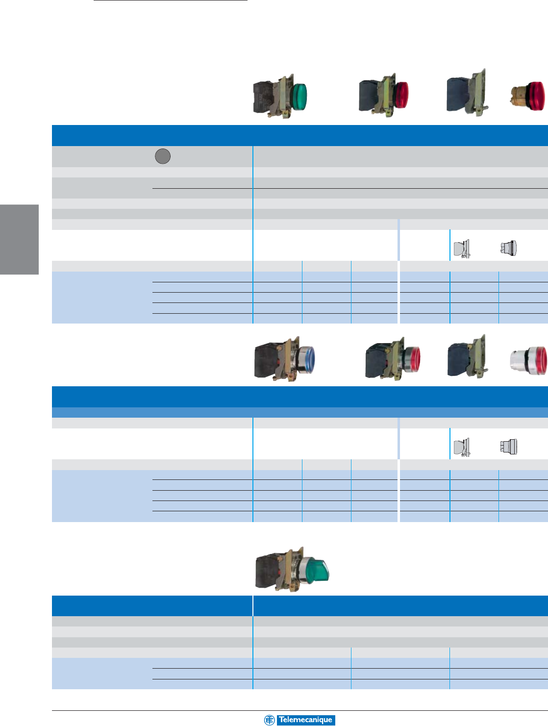
4-8
OPERATOR
INTERFACE
www.telemecanique.com
=+
=+
XB4
+0.4
0
Pilot lights
Type of head Circular bezel
Smooth lens cap
Degree of protection IP 65 / NEMA & UL Type 4X, 13
Mounting (mm) panel cut-out 22.5 (22.3 )
mounting centers 30 x 40
Depth below head 43
Connection Screw clamp terminals
Light source Integral LED Direct supply for BA 9s bulb (not included)
Products Complete Complete For user assembly
Supply voltage 24 Vac/dc 48–120 Vac
230–240 Vac
250 V max., 2.4 W max.
Catalog number white XB4 BVB1 XB4 BVG1 XB4 BVM1 XB4 BV61 ZB4 BV6 ZB4 BV01
green XB4 BVB3 XB4 BVG3 XB4 BVM3 XB4 BV63 ZB4 BV6 ZB4 BV03
red XB4 BVB4 XB4 BVG4 XB4 BVM4 XB4 BV64 ZB4 BV6 ZB4 BV04
yellow XB4 BVB5 XB4 BVG5 XB4 BVM5 XB4 BV65 ZB4 BV6 ZB4 BV05
blue XB4 BVB6 XB4 BVG6 XB4 BVM6 XB4 BV66 ZB4 BV6 ZB4 BV06
Illuminated push buttons and selector switches
Type Flush push, spring return, illuminated push buttons
Light source Integral LED Direct supply for BA 9s bulb (not included)
Products Complete Complete For user assembly
Supply voltage 24 Vac/dc 48–120 Vac
230–240 Vac
250 V max., 2.4 W max.
Catalog number white N.C. + N.O. XB4 BW31B5 XB4 BW31G5 XB4 BW31M5 XB4 BW3165 ZB4 BW065 ZB4 BW31
green N.C. + N.O. XB4 BW33B5 XB4 BW33G5 XB4 BW33M5 XB4 BW3365 ZB4 BW065 ZB4 BW33
red N.C. + N.O. XB4 BW34B5 XB4 BW34G5 XB4 BW34M5 XB4 BW3465 ZB4 BW065 ZB4 BW34
yellow N.C. + N.O. XB4 BW35B5 XB4 BW35G5 XB4 BW35M5 XB4 BW3565 ZB4 BW065 ZB4 BW35
blue N.C. + N.O. XB4 BW36B5 XB4 BW36G5 XB4 BW36M5 XB4 BW3665 ZB4 BW065 ZB4 BW36
Type Illuminated selector switches
(2 position maintained)
Degree of protection IP 65
Light source Integral LED
Products Complete
Supply voltage 24 Vac/dc 48–120 Vac 230–240 Vac
Catalog number green N.C. + N.O. XB4 BK123B5 XB4 BK123G5 XB4 BK123M5
red N.C. + N.O. XB4 BK124B5 XB4 BK124G5 XB4 BK124M5
yellow N.C. + N.O. XB4 BK125B5 XB4 BK125G5 XB4 BK125M5
Control and signalling units 22 mm
with metal bezel
Illuminated complete operators
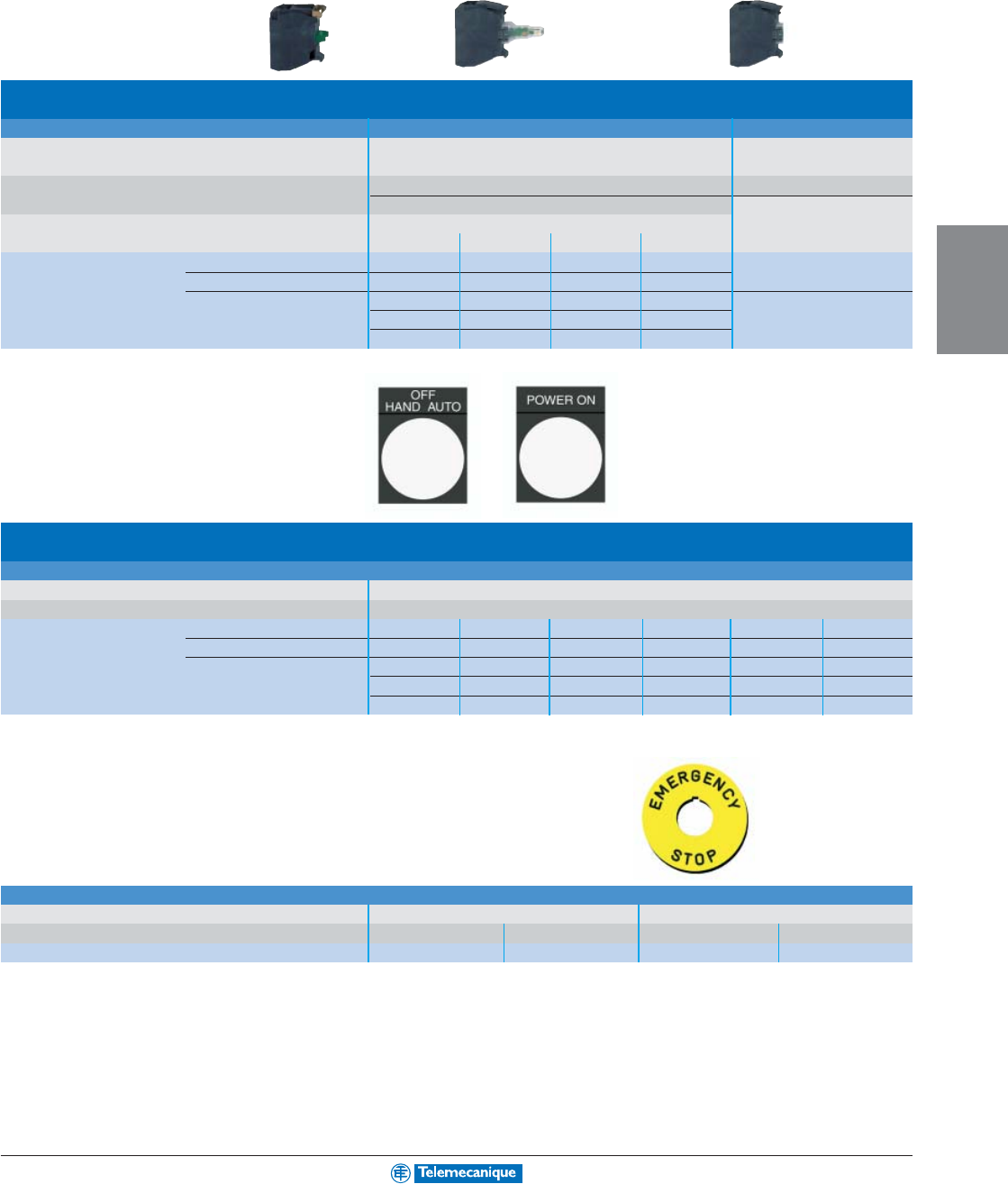
4-9
OPERATOR
INTERFACE
For other versions, consult your nearest Square D/Schneider Electric sales office
.
Electrical blocks
Single contact blocks Light blocks with integral LED Light block, direct supply
Rated operational characteristics AC-15, 240 V - 3 A Consumption
NEMA A600, Q600, 10 A 18 mA 24 Vac/dc
Positive operation of contacts N.C. contacts with positive 14 mA 120 Vac
conforming to IEC/EN 60947-5-1 opening operation 14 mA 240 Vac To combine with heads
To combine with heads for integral LED for BA 9s bulb (not included)
24 Vac/dc 48–120 Vac 230–240 Vac 250 V max., 2.4 W max.
Catalog number N.O. ZBE 101 white ZBV B1 ZBV G1 ZBV M1 ZBV 6
N.C. ZBE 102 green ZBV B3 ZBV G3 ZBV M3 Color provided by lens
red ZBV B4 ZBV G4 ZBV M4
yellow ZBV B5 ZBV G5 ZBV M5
blue ZBV B6 ZBV G6 ZBV M6
Accessories
Legend holders, 30 x 40 mm, for 8 x 27 mm legends
With blank legend (for engraving)
With English language marked legend
Background Black background/white text
Catalog number Black or red ZBY2101 CLOSE ZBY2314
EMERGENCY STOP
ZBY2330 OFF ZBY2312
White or yellow ZBY4101 DOWN ZBY2308
HAND-OFF-AUTO
ZBY2387 OFF-ON ZBY2367
ON ZBY2311 OPEN ZBY2313 POWER ON ZBY2326
RESET ZBY2322 RUN ZBY2334 START ZBY2303
STOP ZBY2304 STOP-START ZBY2366 UP ZBY2307
Circular legend for mushroom head Emergency Stop push button
Yellow with black text Blank EMERGENCY STOP
60 mm 90 mm 60 mm 90 mm
Catalog number ZBY9101 ZBY8101 ZBY9330 ZBY8330
Separate components and
legend plates 22 mm
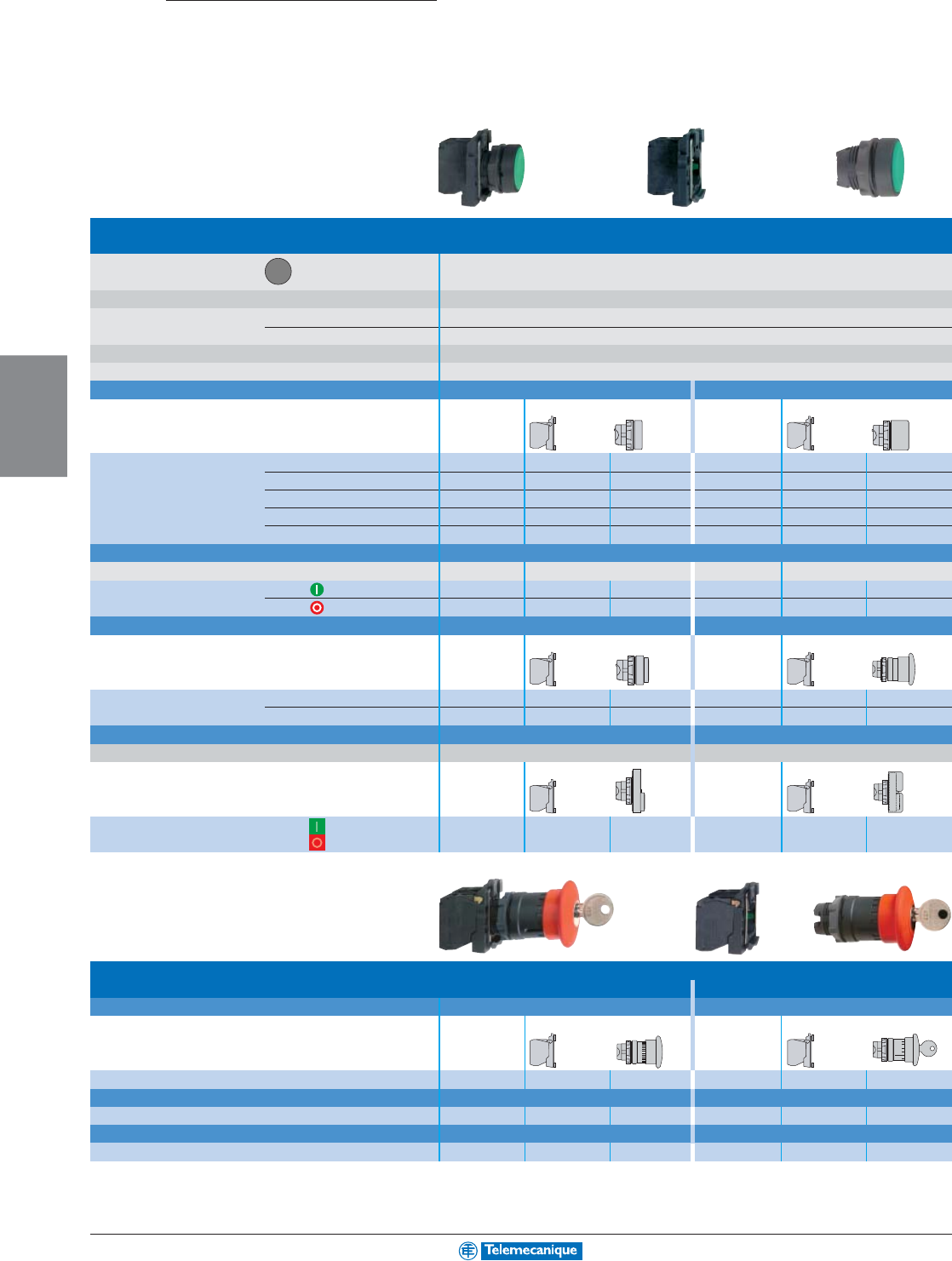
4-10
OPERATOR
INTERFACE
www.telemecanique.com
=+
=+
Push buttons, spring return
Type of head Circular bezel
Degree of protection IP 65 / NEMA & UL Type 4X, 13 . (IP 66 for booted push buttons)
Mounting (mm) panel cut-out 22.5 (22.3 )
mounting centers 30 x 40
Depth (mm) below head 43
Connection Screw clamp terminals
Type of push Flush Flush, booted
Products Complete For user assembly Complete For user assembly
Catalog number black N.O. XB5 AA21 ZB5 AZ101 ZB5 AA2 XB5 AP21 ZB5 AZ101 ZB5 AP2
green N.O. XB5 AA31 ZB5 AZ101 ZB5 AA3 XB5 AP31 ZB5 AZ101 ZB5 AP3
red N.C. XB5 AA42 ZB5 AZ102 ZB5 AA4 XB5 AP42 ZB5 AZ102 ZB5 AP4
yellow N.O. XB5 AA51 ZB5 AZ101 ZB5 AA5 XB5 AP51 ZB5 AZ101 ZB5 AP5
blue N.O. XB5 AA61 ZB5 AZ101 ZB5 AA6 XB5 AP61 ZB5 AZ101 ZB5 AP6
Type of push Flush
With international marking Products Complete For user assembly
Catalog number green N.O. XB5 AA3311 ZB5 AZ101 ZB5 AA331
red N.C. XB5 AA4322 ZB5 AZ102 ZB5 AA432
Type of push Projecting Mushroom head, 40 mm
Products Complete For user assembly Complete For user assembly
Catalog number black N.O. – – – XB5 AC21 ZB5 AZ101 ZB5 AC2
red N.C. XB5 AL42 ZB5 AZ102 ZB5 AL4 –––
Type of push Double-headed push buttons Double-headed push buttons, booted
Degree of protection IP 40 IP 66
With international marking Products Complete For user assembly Complete For user assembly
Catalog number green / N.C. + N.O. XB5 AL845 ZB5 AZ105 ZB5 AL8434 XB5 AL945 ZB5 AZ105 ZB5 AL9434
red
40 mm mushroom head Emergency stop push buttons
Trigger action
Type of push Push-pull (N.C.) Push-pull (N.C. + N.O.)
Unmarked Products Complete For user assembly Complete For user assembly
Catalog number red N.C. or N.C. + N.O. XB5 AT42 ZB5 AZ102 ZB5 AT4 XB5 AT845 ZB5 AZ105 ZB5 AT84
Type of push Turn to release (N.C.) Turn to release (N.C. + N.O.)
Catalog number red N.C. or N.C. + N.O. XB5 AS542 ZB5 AZ102 ZB5 AS54 XB5 AS8445 ZB5 AZ105 ZB5 AS844
Type of push Key release (N.C.) Key release (N.C. + N.O.)
Catalog number red N.C. or N.C. + N.O. XB5 AS142 ZB5 AZ102 ZB5 AS14 XB5 AS9445 ZB5 AZ105 ZB5 AS944
+0.4
0
XB5
Control and signalling units 22 mm
with plastic bezel
Non-illuminated complete operators
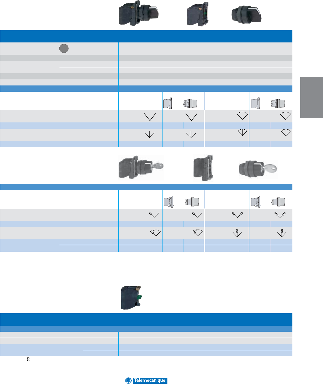
4-11
OPERATOR
INTERFACE
For other versions, consult your nearest Square D/Schneider Electric sales office
.
=+
=+
Selector switches and key switches
Type of head Circular bezel
Degree of protection IP 65 / NEMA & UL Type 4X, 13
Mounting (mm) panel cut-out 22.5 (22.3 )
mounting centers 30 x 40
Depth (mm) below head 43
Connection Screw clamp terminals
Type of operator Handle
Products Complete For user assembly Complete For user assembly
Number and type of positions 2 positions 2 positions 2 positions 2 positions
maintained maintained spring return to left spring return to left
Catalog number black N.O. XB5 AD21 ZB5 AZ101 ZB5 AD2 XB5 AD41 ZB5 AZ101 ZB5 AD4
Number and type of positions 3 positions 3 positions 3 positions 3 positions
maintained maintained spring return to center spring return to center
Catalog number black N.O. + N.O. XB5 AD33 ZB5 AZ103 ZB5 AD3 XB5 AD53 ZB5 AZ103 ZB5 AD5
Type of operator Key, no. 455
Products Complete For user assembly Complete For user assembly
Number and type of positions (1) 2 positions 2 positions 2 positions 2 positions
maintained maintained maintained maintained
Catalog number key N.O. XB5 AG21 ZB5 AZ101 ZB5 AG2 XB5 AG41 ZB5 AZ101 ZB5 AG4
Number and type of positions 2 positions 2 positions 3 positions 3 positions
spring return to left spring return to left maintained maintained
Catalog number key N.O. XB5 AG61 ZB5 AZ101 ZB5 AG6 –––
key N.O. + N.O. – – – XB5 AG33 ZB5 AZ103 ZB5 AG3
Add-on contact blocks
Electrical blocks
Single contact blocks
Rated operational characteristics AC-15, 240 V - 3 A, NEMA A600, Q600, 10 A AC continuous carrying
Positive operation of contacts conforming to IEC/EN 60947-5-1 All functions incorporating a N.C. contact are positive opening operation
Catalog number N.O. ZBE 101
N.C. ZBE 102
(1) The symbol indicates key withdrawal position.
+0.4
0
Complete operators, selector switches
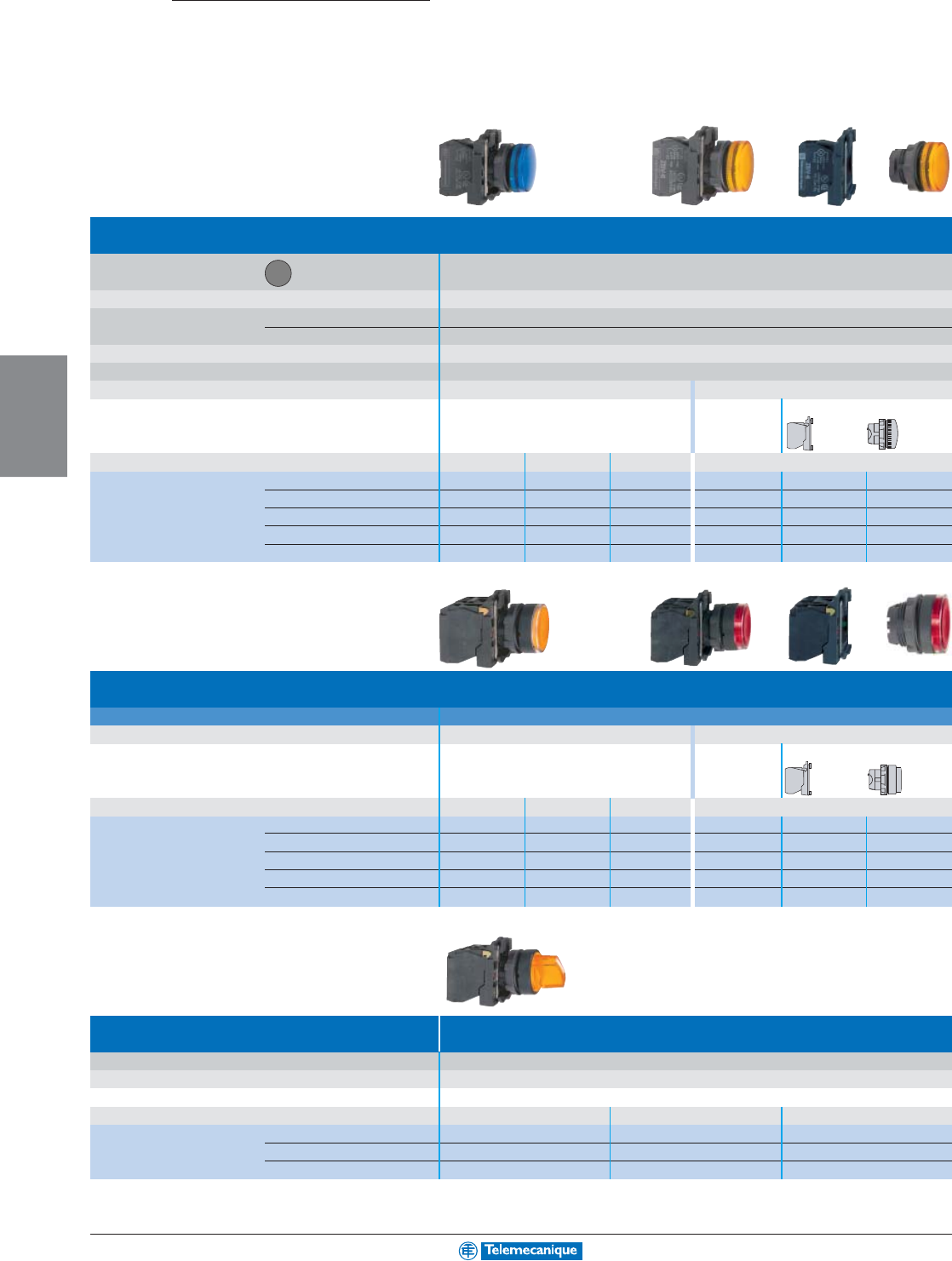
4-12
OPERATOR
INTERFACE
www.telemecanique.com
=+
=+
XB5
Pilot lights
Type of head Circular bezel
Smooth lens cap
Degree of protection IP 65 / NEMA & UL Type 4X, 13
Mounting (mm) panel cut-out 22.5 (22.3 )
mounting centers 30 x 40
Depth below head 43
Connection Screw clamp terminals
Light source Integral LED Direct supply for BA 9s bulb (not included)
Products Complete Complete For user assembly
Supply voltage 24 Vac/dc 48–120 Vac
230–240 Vac
250 V max., 2.4 W max.
Catalog number white XB5 AVB1 XB5 AVG1 XB5 AVM1 XB5 AV61 ZB5 AV6 ZB5 AV01
green XB5 AVB3 XB5 AVG3 XB5 AVM3 XB5 AV63 ZB5 AV6 ZB5 AV03
red XB5 AVB4 XB5 AVG4 XB5 AVM4 XB5 AV64 ZB5 AV6 ZB5 AV04
yellow XB5 AVB5 XB5 AVG5 XB5 AVM5 XB5 AV65 ZB5 AV6 ZB5 AV05
blue XB5 AVB6 XB5 AVG6 XB5 AVM6 XB5 AV66 ZB5 AV6 ZB5 AV06
Illuminated push buttons and selector switches
Type Flush push, spring return, illuminated push buttons
Light source Integral LED Direct supply for BA 9s bulb (not included)
Products Complete Complete For user assembly
Supply voltage 24 Vac/dc 48–20 Vac
230–240 Vac
250 V max., 2.4 W max.
Catalog number white N.C. + N.O. XB5 AW31B5 XB5 AW31G5 XB5 AW31M5 XB5 AW3165 ZB5 AW065 ZB5 AW31
green N.C. + N.O. XB5 AW33B5 XB5 AW33G5 XB5 AW33M5 XB5 AW3365 ZB5 AW065 ZB5 AW33
red N.C. + N.O. XB5 AW34B5 XB5 AW34G5 XB5 AW34M5 XB5 AW3465 ZB5 AW065 ZB5 AW34
yellow N.C. + N.O. XB5 AW35B5 XB5 AW35G5 XB5 AW35M5 XB5 AW3565 ZB5 AW065 ZB5 AW35
blue N.C. + N.O. XB5 AW36B5 XB5 AW36G5 XB5 AW36M5 XB5 AW3665 ZB5 AW065 ZB5 AW36
Type Illuminated selector switches
(2 position maintained)
Degree of protection IP 65 / NEMA & UL Type 4X, 13
Light source Integral LED
Products Complete
Supply voltage 24 Vac/dc 48–120 Vac 230–240 Vac
Catalog number green N.C. + N.O. XB5 AK123B5 XB5 AK123G5 XB5 AK123M5
red N.C. + N.O. XB5 AK124B5 XB5 AK124G5 XB5 AK124M5
yellow N.C. + N.O. XB5 AK125B5 XB5 AK125G5 XB5 AK125M5
+0.4
0
Control and signalling units 22 mm
with plastic bezel
Illuminated complete operators
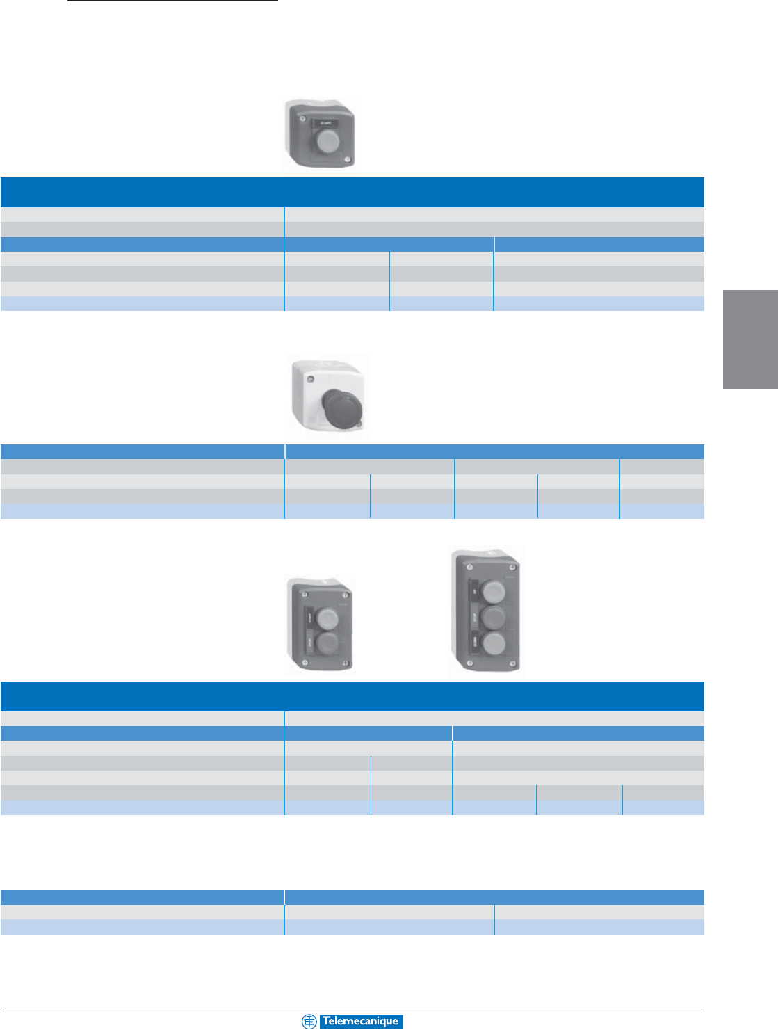
4-13
OPERATOR
INTERFACE
For other versions, consult your nearest Square D/Schneider Electric sales office
.
Control stations
For XB5 control and signalling units 22 mm
with plastic bezel
Complete stations with 1 push button
(light gray RAL 7035 base with dark gray RAL 7016 cover)
Degree of protection IP 65 / NEMA & UL Type 4X and 13
Dimensions (mm) W x H x D 68 x 68 x 113 max. (with key release 40 mm mushroom head push button)
1 momentary push button
1 mushroom head push button 40 mm, momentary
Type of push Flush black Flush red Red
Type of Contact 1 N.O. 1 N.C. 1 N.C.
Text on legend holder Start Stop Emergency stop on red legend
Catalog number XALD101 XALD111 XALD164
Complete stations
Emergency stop (light gray RAL 7035 base with yellow RAL 1012 cover)
1 mushroom head push button 40 mm, red Tur n-to-release Key release (Key no. 455) Push-pull
Type Standard Trigger action Standard Trigger action Standard
Type of contact 1 N.C. 1 N.C. 1 N.C. 1 N.C. 1 N.C.
Catalog number XALK174 XALK178 XALK184 XALK188 XALK194
Complete stations with 2 and 3 push buttons
(light gray RAL 7035 base with dark gray RAL 7016 cover)
Dimensions (mm) W x H x D 2-way control stations: 68 x 106 x 62; 3-way control stations: 68 x 136 x 62
2 Function 3 Function
2 momentary push buttons 3 momentary push buttons
Type of Push (Flush)
1 black/1 red 1 black/1 black
1 black/1 red/1 black
Type of Contact 1 N.O./1 N.C. 2 N.O. 1 N.O./1 N.C./1 N.O.
Text on legend Start/Stop Forward/Reverse Open/Stop/Close
Forward/Stop/Reverse
Up/Stop/Down
Catalog Number XALD211 XALD221 XALD341 XALD311 XALD321
Accessories Standard contact blocks
Description N.O. contact N.C. contact
Catalog number ZEN L1111 ZEN L1121
XAL
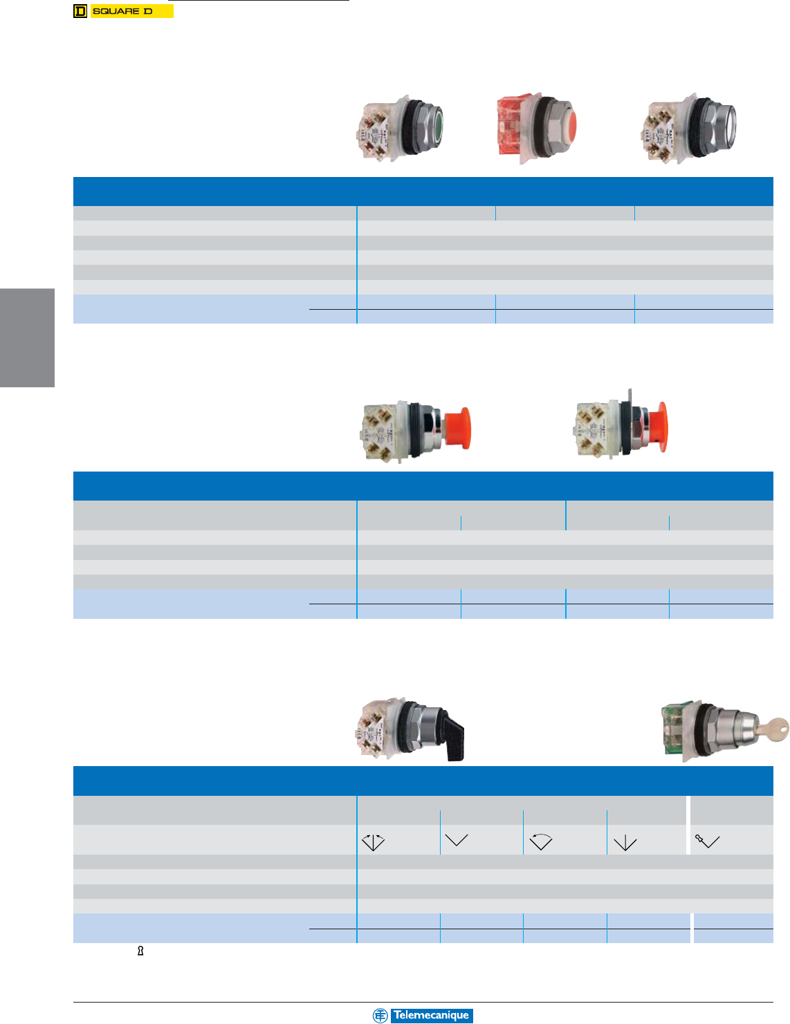
4-14
OPERATOR
INTERFACE
www.telemecanique.com
Push buttons, spring return
Type of push Full guard No guard Extended guard
Color of push Multi-color (set of 7 clip-in colored caps)
Degree of protection IP 66 / NEMA & UL Type 1, 2, 3, 3R, 4, 6, 12 and 13
Mounting panel cut-out 1-7/32" (30.5 mm)
Depth below head (mm) 42
Connection Screw clamp terminals
Catalog number N.O. + N.C. 9001KR1UH13 9001KR3UH13 9001KR2UH13
N.O. 9001KR1UH5 9001KR3UH5 9001KR2UH5
Mushroom head Emergency stop push buttons
Type of push Spring return, red Push-pull, red
35 mm mushroom head 57 mm mushroom head 40 mm mushroom head 35 mm mushroom head
Degree of protection IP 66 / NEMA & UL Type 1, 2, 3, 3R, 4, 6, 12 and 13
Mounting panel cut-out 1-7/32" (30.5 mm)
Depth below head (mm) 42
Connection Screw clamp terminals
Catalog number N.O. + N.C. 9001KR24RH13 9001KR25RH13 9001KR9R94H13 9001KR9R20H13
N.C. 9001KR24RH6 9001KR25RH6 9001KR9R94H6 9001KR9R20H6
Selector switches and key switches
Type of operator Long black handle Key, no. E10
positions (1) 3 - spring return 2 - maintained 2 - spring return 3 - maintained 2 - maintained
Number and type
of positions
Degree of protection IP 66 / NEMA & UL Type 1, 2, 3, 3R, 4, 6, 12 and 13
Mounting panel cut-out 1-7/32" (30.5 mm)
Depth below head (mm) 42
Connection Screw clamp terminals
Catalog number N.O. – 9001KS11FBH5 9001KS34FBH5 ––
N.O. + N.C. 9001KS53FBH1 ––9001KS43FBH1 9001KS11K1H1
(1) The symbol indicates key withdrawal position.
9001K
Control and signalling units 30 mm
with metal ring nut
Non-illuminated complete operators
Universal 7 color—black, red, green,
yellow, orange, blue & white
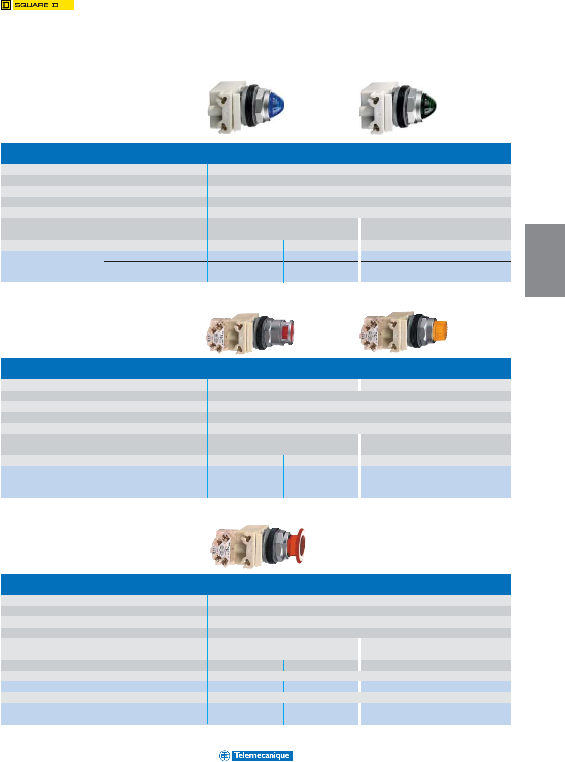
4-15
OPERATOR
INTERFACE
For other versions, consult your nearest Square D/Schneider Electric sales office
.
Pilot lights
Type of head Smooth lens cap
Degree of protection IP 66 / NEMA & UL Type 1, 2, 3, 3R, 4, 6, 12 and 13
Mounting panel cut-out 1-7/32" (30.5 mm)
Depth below head (mm) 46
Connection Screw clamp terminals
Type of light block With high luminosity LED (included) Incandescent BA 9s bulb
Transformer type
24 Vac/dc 120 Vac/dc 120 Vac
Catalog number green 9001KP35LGG9 9001KP38LGG9 9001KP1G9
red 9001KP35LRR9 001KP38LRR9 9001KP1R9
yellow 9001KP35LYA9 9001KP38LYA9 9001KP1A9
Illuminated push buttons, spring return
Type of head Spring return full guard No guard
Degree of protection IP 66 / NEMA & UL Type 1, 2, 3, 3R, 4, 6, 12 and 13
Mounting panel cut-out 1-7/32" (30.5 mm)
Depth below head (mm) 71
Connection Screw clamp terminals
Type of light block With high luminosity LED (included) Incandescent BA 9s bulb
Transformer type
24 Vac/dc 120 Vac/dc 120 Vac
Catalog number green N.O. + N.C. 9001K3L35LGGH13 9001K3L38LGGH13 9001K2L1RH13
red N.O. + N.C. 9001K3L35LRRH13 9001K3L38LRRH13 9001K2L1GH13
yellow N.O. + N.C. 9001K3L35LYAH13 9001K3L38LYAH13 9001K2L1AH13
Illuminated 41 mm mushroom head push buttons, high luminosity LED
Degree of protection IP 66 / NEMA & UL Type 1, 2, 3, 3R, 4, 6, 12 and 13
Mounting (mm) panel cut-out 1-7/32" (30.5 mm)
Depth below head (mm) 71
Connection Screw clamp terminals
Type of light block With high luminosity LED (included) Incandescent BA 9s bulb
Transformer type
24 Vac/dc 120 Vac/dc 120 Vac
Type of head 2 position, push-pull
Catalog number red N.O. + N.C. 9001KR9P35LRRH13 9001KR9P38LRRH13 9001KR9P1RH13
Type of head 3 position, push-pull (pull: spring return, center: maintained, push: spring return)
Catalog number red N.O. + N.C. 9001KR8P35LRRH25 9001KR8P38LRRH25 9001KR8P1RH25
late break
Illuminated complete operators
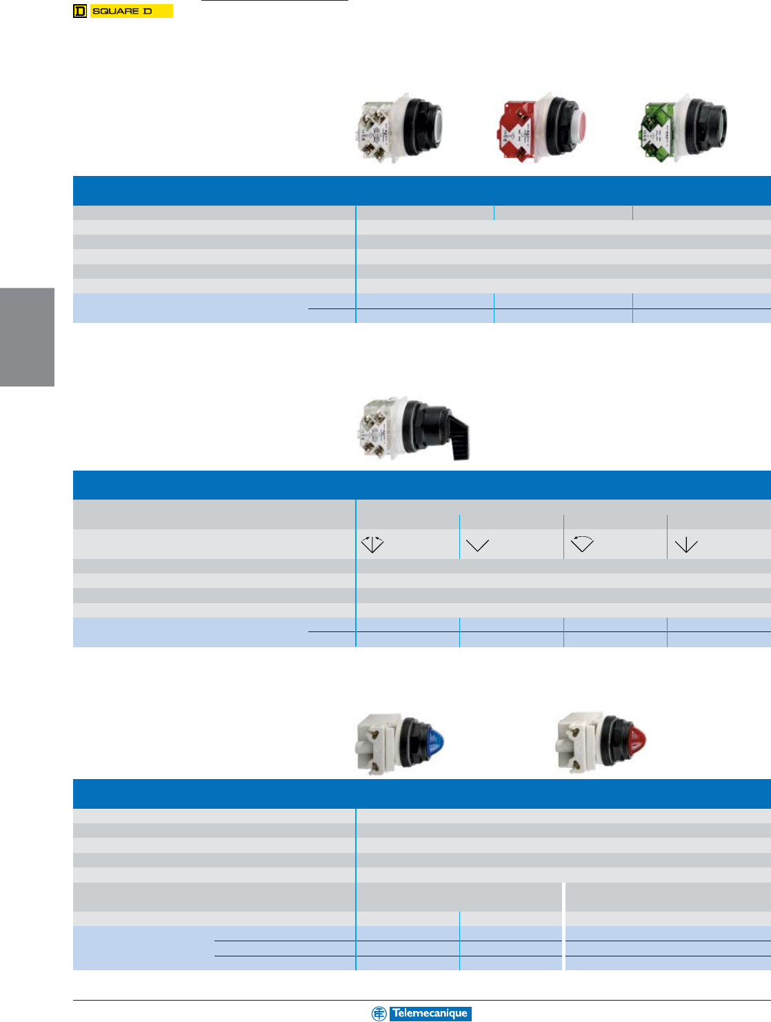
4-16
OPERATOR
INTERFACE
www.telemecanique.com
Push buttons, spring return
Type of push Full guard No guard Extended guard
Color of push Multi-color (set of 7 clip-in colored caps)
Degree of protection IP 66 / NEMA & UL Type 1, 2, 3, 3R, 4, 4X, 12 and 13
Mounting panel cut-out 1-7/32" (30.5 mm)
Depth below head (mm) 42
Connection Screw clamp terminals
Catalog number N.O. + N.C. 9001SKR1UH13 9001SKR3UH13 9001SKR2UH13
N.O. 9001SKR1UH5 9001SKR3UH5 9001SKR2UH5
Selector switches
Type of operator Long black handle
positions 3 - spring return 2 - maintained 2 - spring return 3 - maintained
Number and type
of positions
Degree of protection IP 66 / NEMA & UL Type 1, 2, 3, 3R, 4, 4X, 12 and 13
Mounting panel cut-out 1-7/32" (30.5 mm)
Depth below head (mm) 42
Connection Screw clamp terminals
Catalog number N.O. – 9001SKS11FBH5 9001SKS34FBH5 –
N.O. + N.C. 9001SKS53FBH1 ––9001SKS43FBH1
Pilot lights
Type of head Smooth lens cap
Degree of protection IP 66 / NEMA & UL Type 1, 2, 3, 3R, 4, 4X, 12 and 13
Mounting panel cut-out 1-7/32" (30.5 mm)
Depth below head (mm) 46
Connection Screw clamp terminals
Type of light block With high luminosity LED (included) Incandescent BA 9s bulb
Transformer type
24 Vac/dc 120 Vac/dc 230 Vac
Catalog number green 9001SKP35LGG9 9001SKP38LGG9 9001SKP1G9
red 9001SKP35LRR9 9001SKP38LRR9 9001SKP1R9
yellow 9001SKP35LYA9 9001SKP38LYA9 9001SKP1A9
9001SK
Control and signalling units 30 mm
with plastic ring nut
Complete operators and pilot lights
Universal 7 color—black, red, green,
yellow, orange, blue & white
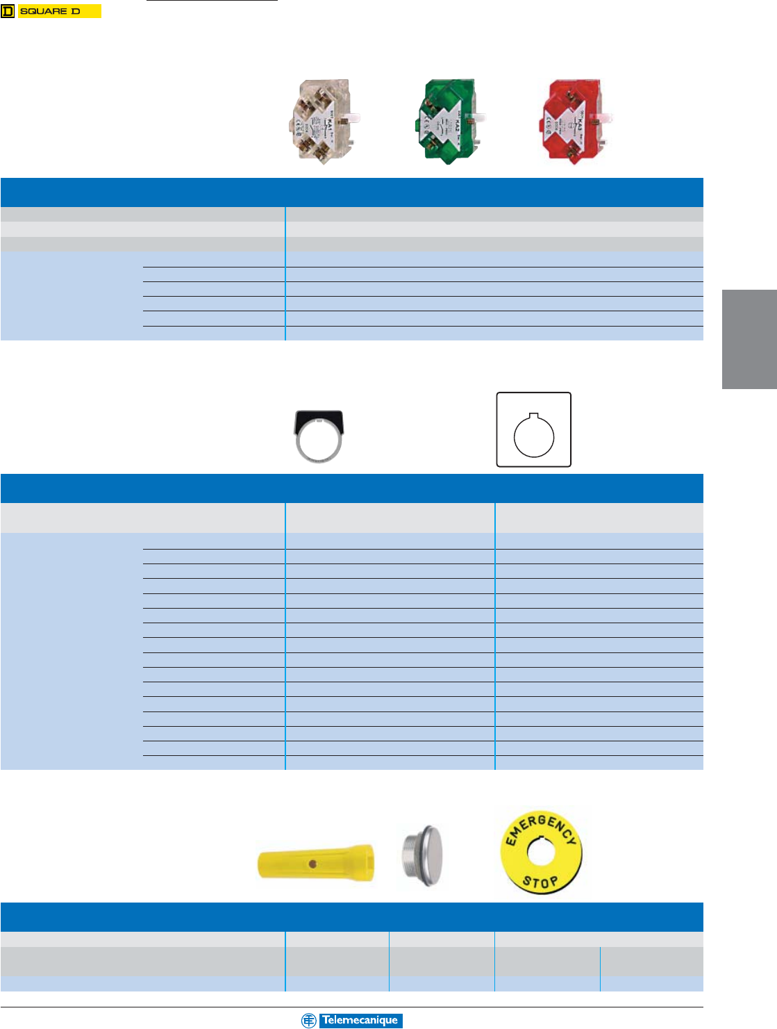
4-17
OPERATOR
INTERFACE
For other versions, consult your nearest Square D/Schneider Electric sales office
.
OFF ON
Contact blocks with protected terminals
Type of contact Single and dual contact blocks
Contact rating NEMA & UL Type A600/Q600, AC continuous carrying—10 A
Connection Screw clamp terminals
Catalog number N.O. + N.C. 9001KA1
N.O. 9001KA2
N.C. 9001KA3
N.O. (early close) + N.C. 9001KA4
N.C., late break 9001KA5
N.O., early close 9001KA6
Legends
Type Aluminum, size 44 x 43 mm Plastic, size 57 x 57 mm
Color of legend black background white background
Marking Blank 9001KN200 9001KN100WP
START 9001KN201 9001KN101WP
STOP (red background) 9001KN202 9001KN102RP
ON 9001KN203 9001KN103WP
FORWARD 9001KN206 9001KN106WP
REVERSE 9001KN207 9001KN107WP
CLOSE 9001KN208 9001KN108WP
OPEN 9001KN209 9001KN109WP
DOWN 9001KN210 9001KN110WP
UP 9001KN211 9001KN111WP
HIGH 9001KN214 9001KN114WP
LOW 9001KN215 9001KN115WP
RESET 9001KN223 9001KN123WP
OFF-ON 9001KN244 9001KN144WP
ON-OFF 9001KN245 9001KN145WP
HAND-OFF-AUTO 9001KN260 9001KN160WP
Accessories
Type Ring nut wrench Blanking plug Emergency stop round yellow legend
for 9001K/SK Chrome plated
for 30 mm knockout 60 mm 90 mm
Catalog number 9001K95 9001K52 9001KN9330 9001KN8330
Accessories for plastic and metal
30 mm control and signalling units
9001K/SK
4-18
OPERATOR
INTERFACE
www.telemecanique.com
XAL 22 mm (plastic, for use with XB5 devices)
Empty Enclosures (1) IP 66 / NEMA & UL Type 4, 12 and 13
Type Number of Holes Dimensions (H x W x D) Catalog number
Light gray base “RAL 7035” 1 68 x 68 x 53 XALD01
Dark gray lid “RAL 7016” 2 106 x 68 x 53 XALD02
3136 x 68 x 53 XALD03
4166 x 68 x 53 XALD04
5196 x 68 x 53 XALD05
Light gray base “RAL 7035”
Yellow lid “RAL 1012” 1 68 x 68 x 53 XALK01
(1) For customer assembly using XB5 operators, 22 mm starting on page 4-10.
XAP 22 mm (metallic, for use with XB4 devices)
Empty enclosures (2) IP65 / NEMA & UL Type 4, 13
Mounting 1.58 in (40 mm) centerline spacing of holes
Type Usable Depth Dimensions (H x W) # of 22 mm knock-outs Catalog number
Die Cast 1.93 in (49 mm) 80 x 80 1 XAPG19201
Zinc 130 x 80 2 XAPG29202
Gray RAL 7032 175 x 80 3 XAPG39203
2.93 (74.5 mm) 80 x 80 1 XAPG19501
130 x 80 2 XAPG29502
175 x 80 3 XAPG39503
220 x 80 4 XAPG49504
Aluminum 2.93 (74.5 mm) 310 x 85 5 XAPG59505
(2) For customer assembly using XB4 operators, 22 mm starting on page 4-6.
KY 30 mm (metallic, for use with Type K and SK devices) (3)
Type Number of 30 mm cut-outs NEMA ratings Catalog number
Aluminum 11, 3, 4, 6, 12, 13 9001KY1
21, 3, 4, 6, 12, 13 9001KY2
31, 3, 4, 6, 12, 13 9001KY3
41, 3, 4, 6, 12, 13 9001KY4
Stainless steel 11, 3, 4, 4X, 13 9001KYSS1
21, 3, 4, 4X, 13 9001KYSS2
31, 3, 4, 4X, 13 9001KYSS3
(3) For customer assembly using Type K and SK devices, 30 mm starting on page 4-14.
XAL
XAP
KY
Empty enclosures, 22 mm & 30 mm
for user assembly
4-19
OPERATOR
INTERFACE
For other versions, consult your nearest Square D/Schneider Electric sales office
.
LED pilot lights With black bezel With integral lens cap
Type of head Protruding LED, 8 mm Covered LED, 8 mm Covered LED, 12 mm
Degree of protection IP 40
Mounting (mm) panel cut-out 8.2 mm 8.2 mm 12.2 mm
mounting centers 12.5 x 12.5 mm 10.5 x 10.5 mm 16.5 x 16.5 mm
Dimensions (mm) Depth (below head) 32 34 45
Connection Tags 2.8 x 0.5 Tags 2.8 x 0.5 Screw clamp connectors
Catalog number (1) green XVL A1p3 (1) XVL A2p3 (1) XVL A3p3 (1)
red XVL A1p4 (1) XVL A2p4 (1) XVL A3p4 (1)
yellow XVL A1p5 (1) XVL A2p5 (1) XVL A3p5 (1)
Tightening key For 8 mm pilot lights For 12 mm pilot lights
Catalog number XVL X08 XVL X12
(1) Basic catalog number, to be completed by replacing p with the number 1, 2, 3 or 4 indicating the required voltage. See voltage table above.
9001 Type O Incandescent pilot lights
Degree of protection NEMA & UL Type 13
Mounting (mm) panel cut-out 17.5 mm
Overall dimensions (mm) 21 x 47
Connection 5 x 0.5 mm Quick connect
Voltage AC/DC Color Catalog Number
12 Vac/dc 170 mA Red 9001OR12
Green 9001OG12
Amber 9001OA12
Clear 9001OC12
Ye llow 9001OY12
White 9001OW12
Blue (Fluted) 9001FB12
24 Vac/dc 73 mA Red 9001OR24
Green 9001OG24
Amber 9001OA24
Clear 9001OC24
Ye llow 9001OY24
White 9001OW24
Blue (Fluted) 9001FB24
120 Vac/dc 25 mA Red 9001OR120
Green 9001OG120
Amber 9001OA120
Clear 9001OC120
Ye llow 9001OY120
White 9001OW120
Blue (Fluted) 9001FB120
Compact pilot lights
8, 12 and 17.5 mm
(1):
Voltage
Number (p)
5 Vdc (25 mA) 1
12 Vdc (18 mA) 2
24 Vdc (18 mA) 3
XVL
Type O
4-20
OPERATOR
INTERFACE
www.telemecanique.com
Beacons and indicator banks
70 mm
Illuminated beacons XVB L, 70 mm Steady incandescent Flashing light signalling
Steady or flashing LED
Light source
Incandescent BA 15d bulb, 10 W max.
BA 15d Incandescent
“Flash” strobe unit
LED BA 15d (not included) (not included) 10 Joule
Degree of protection IP 65 / NEMA Type 4X (indoor)
Rated insulation voltage 250 V
Beacon catalog number (1) 12–230 Vac/dc XVB L3pp
pp
p––
24 Vac/dc – XVB L4Bpp
pp
pXVB L8Bpp
pp
p
120 Vac – XVB L4Mpp
pp
pXVB L8Gpp
pp
p
230 Vac – XVB L4Mpp
pp
pXVB L8Mpp
pp
p
Indicator banks XVB C, 70 mm Base units Steady incandescent Flashing light signalling Audible
2 to 5 units
(3)
Steady or flashing LED units
(90 db at 1 m)
Light source –
Incandescent BA 15d bulb, 10 W max.
BA 15d
“Flash” –
LED BA 15d (not included)
Incandescent
strobe unit,
(not included) 10 Joule
Degree of protection IP 65 / NEMA Type 4X (indoor)
Rated insulation voltage 250 V
Base unit catalog number with cover XVB C21 ––––
Lens unit catalog number (1) 12– 230 Vac/dc – XVB C3pp
pp
p–––
24 Vac/dc – – XVB C4Bpp
pp
pXVB C8Bpp
pp
p–
120 Vac – – XVB C4Mpp
pp
pXVB C8Gpp
pp
p–
230 Vac – – XVB C4Mpp
pp
pXVB C8Mpp
pp
p–
Audible unit catalog number 12 to 48 Vac/dc – – – – XVB C9B
unidirectional 120 to 230 Vac – – – – XVB C9M
(1) To obtain the complete catalog number, replace the pp
pp
p by the number designating the color as follows: 1 = white, 3 = green, 4 = red, 6 = blue, 8 = orange.
XVB
Accessories
Bulbs and LEDs Indicator banks
XVB
Light source Incandescent Incandescent LED, Flashing LED,
bulb, BA 15d bulb, BA 15d BA 15d BA 15d
base fitting base fitting base fitting base fitting
Catalog number (1) 12 V DL1 BEJ (7 W) DL1 BLJ (10 W) – –
24 V DL1 BEB (6.5 W) DL1 BLB (10 W) DL1 BDBpp
pp
pDL1 BKBpp
pp
p
120 V DL1 BEG (7 W) DL1 BLG (10 W) DL1 BDGpp
pp
pDL1 BKGpp
pp
p
230 V DL1 BEM (7 W) DL1 BLM (10 W) DL1 BDMpp
pp
pDL1 BKMpp
pp
p
(1) To obtain the complete catalog number, replace the pp
pp
p by the number designating the color as follows: 1 = white, 3 = green, 4 = red, 6 = blue, 8 = orange.
Mounting accessories For beacons and indicator banks
type XVB
Length 100 mm 400 mm 800 mm
Black aluminum support tube XVB C02 XVB C03 XVB C04
Black mounting plates
mounting tulip for use w/support tube
XVB C11
right angle mounting bracket XVB C12
1/2" NPT conduit adapter XVBC00
4-21
OPERATOR
INTERFACE
For other versions, consult your nearest Square D/Schneider Electric sales office
.
Miniature beacons
45 & 50 mm
Miniature illuminated beacons XVD LS Steady incandescent “Flash” signalling
45 mm Steady or flashing LED
Light source Incandescent BA 15d bulb, 5 W max. “Flash” strobe unit, 0.5 J
LED BA 15d (not included)
Degree of protection IP 40
Rated insulation voltage 250 V
Beacon catalog number (1) 24–230 Vac/dc XVD LS3pp
pp
p–
24 Vac/dc – XVD LS6Bpp
pp
p
120 Vac – XVD LS6Gpp
pp
p
230 Vac – XVD LS6Mpp
pp
p
(1) To obtain the complete catalog number, replace the pp
pp
p by the number designating the color as follows: 3 = green, 4 = red, 5 = orange, 6 = blue, 7 = clear, 8 = yellow.
Indicator banks XVP, 50 mm Base unit Steady or “Flash” signalling Audible units
1 to 5 units
(2)
, black clamping ring
(3)
flashing light (55–85 dB
signalling at 1 m)
Light source –Incandescent, LED “Flash” strobe “Flash” strobe –
BA 15d bulb , 7 W unit, 0.3 Joule unit, 0.6 Joule
max. (not included)
Degree of protection IP 65 / NEMA & UL Type 1, 12, 13
Rated insulation voltage 250 V
Base unit with cover XVP C21 ––––
Catalog number (1) 250 V max. XVP C3pp
pp
p–––
24 Vdc – XVP C6Bpp
pp
p–XVP C09B
120 Vac – – XVP C6Gpp
pp
pXVP C09G
230 Vac – – XVP C6Mpp
pp
pXVP C09M
(1) To obtain the complete catalog number, replace the pp
pp
p by the number designating the color as follows: 3 = green, 4 = red, 5 = orange, 6 = blue, 7 = clear, 8 = yellow.
(2) An indicator bank comprises: 1 base unit + 1 to 5 illuminated units or 1 audible unit max.
(3) To order products with an off-white ring, add the letter W to the end of the catalog number (example: base unit + green lens unit: XVP C21W + XVP C33W, etc.).
Accessories
Bulbs and LEDs Indicator banks Beacons
XVP XVP or XVDLS XVD LS
Light source Incandescent LED, Flashing LED, Incandescent
bulb, BA 15d BA 15d BA 15d bulb, BA 15d
base fitting base fitting base fitting base fitting
Catalog number (1) 12 V DL1 BEJ (7 W) – – –
24 V DL1 BEB (6.5 W) DL1 BDBpp
pp
pDL1 BKBpp
pp
pDL1 BEBS (4 W)
120 V DL1 BEG (7 W) DL1 BDGpp
pp
pDL1 BKGpp
pp
pDL1 BEGS (5 W)
230 V DL1 BEM (7 W) DL1 BDMpp
pp
pDL1 BKMpp
pp
pDL1 BEMS (5 W)
(1) To obtain the complete catalog number, replace the pp
pp
p by the number designating the color as follows: 1 = white, 3 = green, 4 = red, 6 = blue, 8 = orange.
Mounting accessories For beacons and indicator banks
type XVP
Length 112 mm 260 mm 410 mm
Chrome plated support tube (4) XVP C02 XVP C03 XVP C04
Black mounting plate (4) right angle XVP C12
(4) Aluminum support tube with tulip mounting base. To order an off-white XVP unit, add the letter W to the end of the catalog number (example: XVP C03W).
XVD-LS
XVP
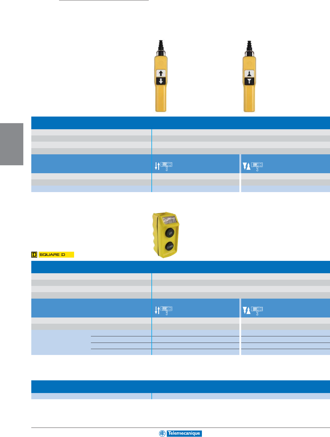
4-22
OPERATOR
INTERFACE
www.telemecanique.com
XAC/
BW
Type XAC A “Pistol grip”
Degree of protection IP 65 / NEMA & UL Type 4, 4X
Rated operational characteristics AC 15 (240 V 3 A), DC 13, NEMA A600/Q600
Conventional thermal current 10 A
Connection Screw clamp terminals
For control of single-speed motors 2-speed motors
Dimensions (mm) W x H x D 52 x 295 x 71 52 x 295 x 71
Number of operators mechanically interlocked 22
Catalog number XAC A201 XAC A207
Type BW pendant station
Degree of protection IP 65 / NEMA & UL Type 4, 4X
Rated operational characteristics NEMA B600/P600
Conventional thermal current 5 A
Connection Screw clamp terminals
For control of single-speed motors 2-speed motors
Dimensions (mm) W x H x D 56 x 119 x 75 56 x 119 x 75
Number of operators mechanically interlocked 22
Catalog number UP-DOWN 9001BW72Y 9001BW82Y
FOR-REV 9001BW73Y –
ON-OFF (1) 9001BW74Y –
START-STOP (1) 9001BW76Y –
(1) Maintained contact.
Type BW pendant station accessories
Hanger bracket and sealing kit 9001B350
Pendant control stations
for control circuits
Ready to use
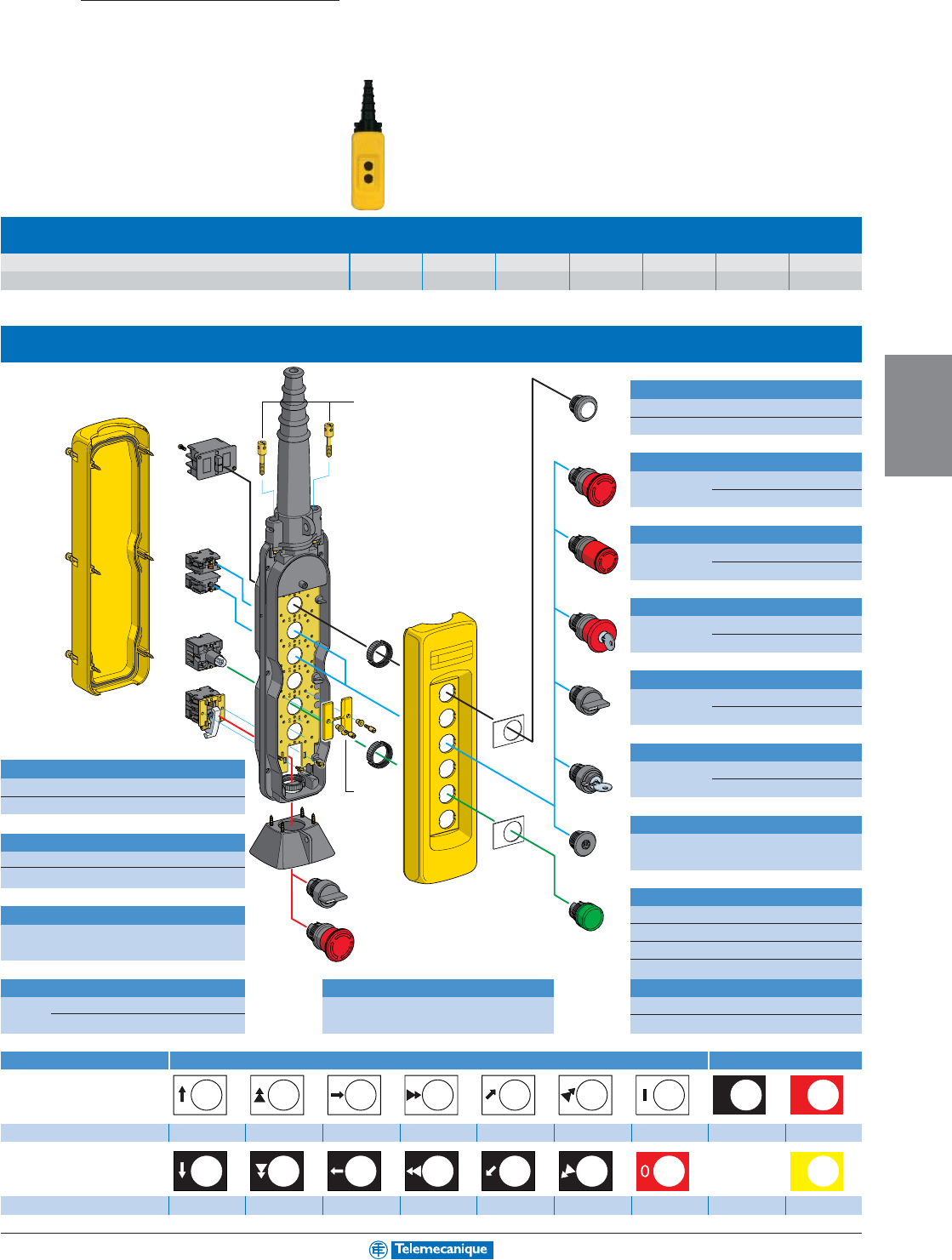
4-23
OPERATOR
INTERFACE
For other versions, consult your nearest Square D/Schneider Electric sales office
.
XAC-A941
●
ZA2-BS834
ZA2-BS54
ZA2-BS
●●
ZA2-BS14
ZB2-SZ3
ZA2-BD
●
XAC-B961
XAC-A009
XAC-S
● ● ●
ZB2-BE
● ● ●
XAC-A982
ZB2-BV00
●
XEN-G1
●
91
ZB2-BY
● ● ● ●
ZB2-BY
● ● ● ●
ZA2-BG
●
ZA2-BD
●
ZA2-BV0
●
START
STOP
Empty enclosures type XAC A
Number of holes 2 3 4 5 6 8 12
Catalog number XAC A02 XAC A03 XAC A04 XAC A05 XAC A06 XAC A08 XAC A12
Separate components (for mounting in enclosures XAC A)
Booted operators
white XAC A9411
black XAC A9412
Mushroom head, latching
turn to release 30 mm ZA2 BS44
40 mm ZA2 BS54
Mushroom head, latching, trigger action
turn to release 30 mm ZA2 BS834
40 mm ZA2 BS844
Mushroom head, latching
key release 30 mm ZA2 BS74
40 mm ZA2 BS14
Selector switch
2 pos. maintained ZA2 BD2
3 pos. maintained ZA2 BD3
Key switch
Contact blocks key no. 455 2 pos. maintained ZA2 BG4
Single-speed N.O. ZB2 BE101 3 pos. maintained ZA2 BG5
Single-speed N.C. ZB2 BE102
Blanking plug
Contacts blocks for XAC A941pwith seal and ZB2 SZ3
Single-speed N.C. + N.O. + N.O. (1)
XEN G1491 mounting nut
2-speed N.C. + N.O. + N.O. (2) XEN G1191
(1) simultaneous (2) staggered Pilot light heads
white ZA2 BV01
green ZA2 BV03
red ZA2 BV04
yellow ZA2 BV05
Contact blocks (for mounting in enclosure base)
Protective guard (for base mounted units) Pilot light bodies 250 V max.
N.O. XAC S101 For selector switch or XAC A982 direct supply ZB2 BV006
N.C. + N.O. XAC S105 mushroom head push button direct supply, through resistor ZB2 BV007
Legends, 30 x 40 mm With symbols conforming to NF E 52-124 With text
Catalog number ZB2 BY4901 ZB2 BY4903 ZB2 BY4907 ZB2 BY4909 ZB2 BY4913 ZB2 BY4915 ZB2 BY4930 ZB2 BY2303 ZB2 BY2304
blank
white or yellow
background
Catalog number ZB2 BY2904 ZB2 BY2906 ZB2 BY2910 ZB2 BY2912 ZB2 BY2916 ZB2 BY2918 ZB2 BY2931 ZB2 BY4101
Stations for user assembly
Interlock
For use with XACA941pXACA009
for mechanical interlock between opposing functions
XAC
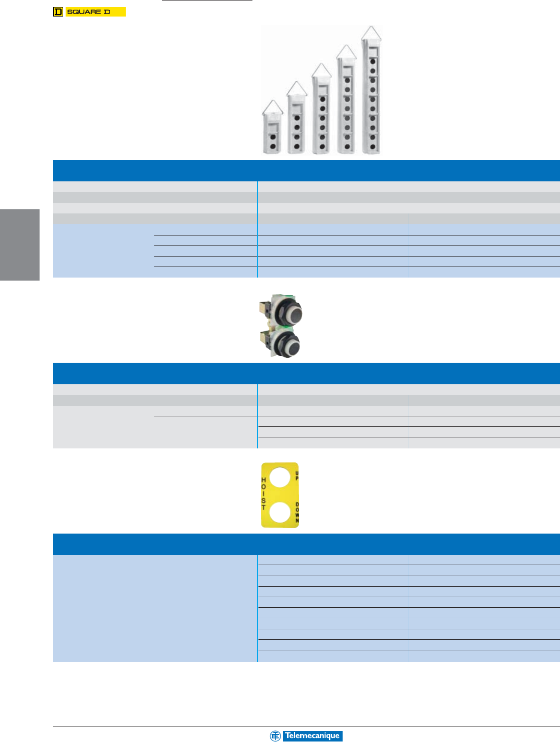
4-24
OPERATOR
INTERFACE
www.telemecanique.com
Heavy duty pendant control stations
Stations for user assembly
Type SKYP heavy duty pendant stations
Material
Polymeric
Degree of protection NEMA & UL Type 1, 3, 4, 4X and 13
For outdoor use UV protected
Size Conduit Entrance Size Catalog number
2 Button 3/4"–14NPT 9001SKYP2
4 Button 3/4"–14 NPT 9001SKYP4
6 Button 1"–11-1/2 NPT 9001SKYP6
8 Button 1-1/4"–11-1/2 NPT 9001SKYP8
10 Button 1-1/4"–11-1/2 NPT 9001SKYP10
Push button units—2button
Contact rating
NEMA & UL Type A600/P600 10 A thermal Single Speed—Momentary Interlocked 9001SKRU1
NEMA & UL Type B600 5 A thermal Two Speed—Momentary Interlocked 9001SKRU2
Three Speed—Momentary Interlocked 9001SKRU3
Four Speed—Momentary Interlocked 9001SKRU4
Five Speed—Momentary Interlocked 9001SKRU5
Double legend plates for opposing functions
For SKRU1 through SKRU05 Blank-Blank 9001SKN200
Hoist: Up-Down 9001SKN201
Trolley: East-West 9001SKN202
Trolley: Fwd.-Rev. 9001SKN203
Trolley: North-South 9001SKN204
Bridge: Fwd.-Rev. 9001SKN205
Bridge: East-West 9001SKN206
Bridge: North-South 9001SKN207
Start-Stop 9001SKN208
Reset-Stop 9001SKN209
Type SKYP
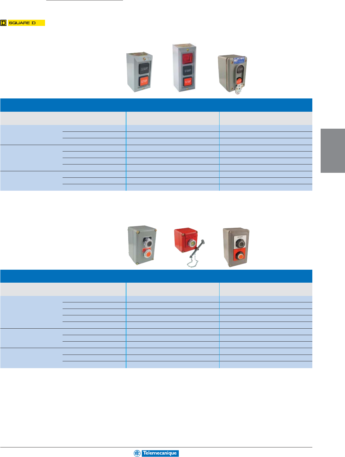
4-25
OPERATOR
INTERFACE
For other versions, consult your nearest Square D/Schneider Electric sales office
.
Type B standard duty control stations
Number of Operators
Nameplate Markings and Features
Surface Mounting Watertight and Dusttight
NEMA & UL Type 1 NEMA & UL Type 4
1Stop (Mushroom Button) 9001BG103 9001BW151
Stop (Lockout) 9001BG104 9001BW148
Hand-Off-Auto (Selector Switch) 9001BG112 –
2Start-Stop 9001BG201 9001BW240
Start-Stop (Lockout on Stop) 9001BG204 9001BW241
Up-Down 9001BG208 9001BW243
Start-Stop (Maintained Contact) 9001BG215 9001BW255
3Forward - Reverse - Stop 9001BG302 –
Open - Close - Stop 9001BG303 –
Up - Down - Stop 9001BG305 –
Type KY and SKY 30 mm control stations
Number of Operators
Nameplate Markings and Features
Die Cast Aluminum Type K Operators Polymeric Type SK Operators
NEMA & UL Type 1, 3 & 13 NEMA & UL Type 4x & 13
1Start 9001KYK11 9001SKY101
Stop (Mushroom) 9001KYK13 9001SKY103
To Stop - Break Glass (Red Enclosure)
9001KYK117 –
Off - On (Selector Switch) 9001KYK110 9001SKY110
Hand - Off - Auto (Selector Switch) 9001KYK111 9001SKY111
2Start - Stop 9001KYK21 9001SKY201
Up - Down 9001KYK25 9001SKY205
Open - Close 9001KYK26 9001SKY206
3Forward - Reverse - Stop 9001KYK31 9001SKY301
Up - Down - Stop 9001KYK32 9001SKY302
Open - Close - Stop 9001KYK33 9001SKY303
Control stations
Standard and heavy duty
Type B
Type KY/SKY
Select from Telemecanique’s major innovations:
A worldwide detection first for improving productivity.
A complete offer for resolving your most commonly encountered detection
problems:
■ product selection simplified ■ maintenance simplified
■ product availability simplified ■ detection simplified
■ installation and setting-up simplified using a single supplier.
Improved simplicity for improved productivity.
OEMs
Distributors
Users
with
Osiconcept
Improve performance by
making your machines
less complicated and more
intelligent.
with
Osiconcept
Improve customer exper-
tise with an efficient prod-
uct line offering simplified
selection and improved
selling potential.
with
Osiconcept
Improve performance by
reducing maintenance
time with products that are
simpler and unequalled in
flexibility.
Osiconcept series:
Multi-purpose
products providing
multiple functions.
This series also
includes Osiconcept
products.
Osi-Standard series:
Designed for essential
and repetitive functions.
Application-specific series:
Offers functions specifically
for specialist needs, thus
providing the ideal solution
for your more complex
applications.
Select the sensor according to your specific requirements
Welcome to the Simply Smart* world,
compliments of Telemecanique
* Simply Smart : using ingenuity and intelligence to
continually improve ease of use.
The essential guide to Machine Sensing solutions
A selection of the top selling sensor
products for simplicity in selection.
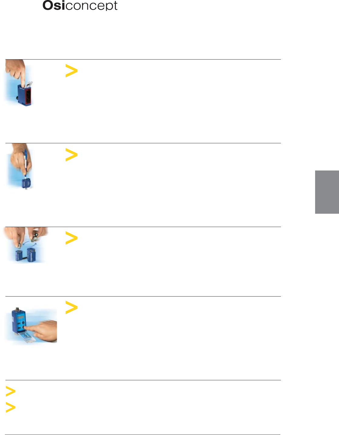
A complete range
of innovative and
simple to use sensors
Capacitive proximity sensors
Ultrasonic proximity sensors
A single product
that automatically
adapts to all
modes of sensing
More than 5,000
interchangeable
configurations
within 24 hours
Osiswitch
Limit switches
Osiris
Photo-electric sensors
A user friendly
product at last;
easy to program
prior to installation
and to modify
during operation
A simple press of the teach button
automatically configures the sensor
for optimal performance in any
condition.
One type of metal operating head
for 5 different bodies.
Modularity
also in connections and contacts.
Detects any target regardless of material or shape
■ Detection from a few millimeters to several tens of meters
■ Accessories
■ Products for specific applications
Detection by contact with rigid objects
■ N.C. contacts with positive opening operation
■ Object speed y 1.5 m/s
■ Specific products for particular applications
A single product
that automatically
adapts to all
mounting
environments
Osiprox
Inductive proximity sensors
A simple press of the teach button
automatically configures the
sensor for optimal performance
whether mounted in or out of metal.
Detection of metal objects—in or out of metal
surroundings
■ Sensing distance/object y 60 mm
■ Cylindrical and rectangular body styles
■ Specific products for particular applications
Osiprox (other technologies)
Detection of any object or material
■ Sensing distance/object y 20 mm
Detection using sound waves
■ Sensing distance/object y 1 m
Nautilus
Sensors for pressure control
Ergonomic, tactile feedback keys
plus scrolling menu on large 4 digit
display.
Page 5-2
Page 5-22
Page 5-27
Detection by contact with fluid
■ Electronic pressure and vacuum switches
■ Analog pressure sensors
■ Electromechanical pressure and vacuum switches
Page 5-12
Page 5-20
9007C Limit switches
Page 5-32
MACHINE
SENSING
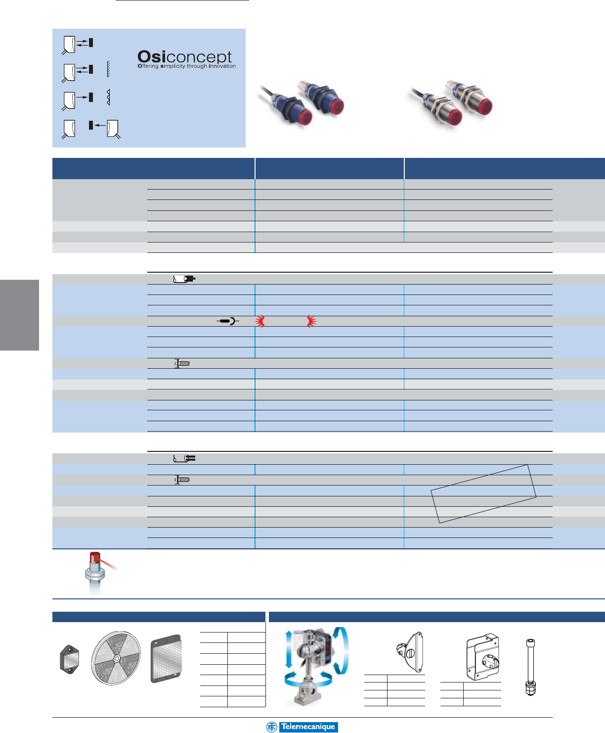
5-2
MACHINE
SENSING
www.telemecanique.com
▲ Tr ansmitter and receiver sold separately
XUB XUB
Osiris
Photo-electric sensors
Multi-Mode
A single product that automatically
adapts to all environments.
Programmable N.O. / N.C.
N.O.: object present = output ON
N.C.: no object present = output ON
Background
Reflector
Thru-beam accessory
18mm tubular plastic 18mm tubular metal
Max / usable sensing distance diffuse
30
cm
/ 11.8
in.
30
cm
/ 11.8
in.
diffuse, with background supp.
12
cm
/ 4.7
in.
12
cm
/ 4.7
in.
polarized retro
2
m
/ 6.5
ft.
2
m
/ 6.5
ft.
thru-beam ▲
15
m
/ 49.2
ft.
15
m
/ 49.2
ft.
Mounting (mm) M18 x 1 M18 x 1
Enclosure M (metal) P (plastic) / Dimensions (mm) Ø x L or W x H x L P / M18 x 64 M / M18 x 64
Common characteristics Adjustment of sensing distance: teach mode / Alignment LEDs: yes /
Sensors for dc applications c
(solid-state output: transistor)
Connection: pre-cabled, PvR (2 m)
T / R 3-wire PNP programmable N.O. / N.C. XUB0APSNL2 XUB0BPSNL2
NPN programmable N.O. / N.C. XUB0ANSNL2 XUB0BNSNL2
PNP / NPN programmable N.O. / N.C. – –
Connection: M12 connector (M8 for XUM)
T / R 3-wire PNP programmable N.O. / N.C. XUB0APSNM12 XUB0BPSNM12
NPN programmable N.O. / N.C. XUB0ANSNM12 XUB0BNSNM12
PNP / NPN programmable N.O. / N.C. – –
Connection: screw clamp terminals
T / R 3-wire PNP / NPN programmable N.O. / N.C. – –
Switching capacity (mA) main output / alarm output 100 / – 100 / –
Common characteristics Supply voltage limits, min/max (V) including ripple: 10 to 36
Thru-beam accessory pre-cabled (2 m) XUB0AKSNL2T XUB0BKSNL2T
connector XUB0AKSNM12T XUB0BKSNM12T
screw terminals, M12 cable gland – –
Sensors for ac or dc applications a / c
10 to 36 Vdc / 20 to 264 Vac including ripple on dc
Connection: pre-cabled, PvR (2 m)
T / R
programmable N.O. / N.C. with time delay
––
Connection: screw clamp terminals
T / R
programmable N.O. / N.C. with time delay
––
LED output state indicator / power on LED – –
Switching frequency (Hz) – –
Time delay(s) – –
Thru-beam accessory pre-cabled, PvR (2 m) – –
screw terminals, M12 cable gland – –
Snap-C
®
compatible
on M12 only
Accessories (sold separately)
Reflectors
XUZC24 XUZC80 XUZC50
3D mountings with ball joint
Bracket with ball joint
for sensors and
reflector
XUZC50
for
XUM… XUZM2004
XUK… XUZK2004
XUX… XUZX2004
for
XUB… XUZB2003
XUM… XUZM2003
XUK… XUZK2003
XUX… XUZX2003 XUZ2001
Protective housing
with ball joint
M12 rod for ball
joint
Reflectors (mm)
Ø 16 XUZC16
Ø 21 XUZC21
24 x 21 XUZC24
Ø 31 XUZC31
Ø 39 XUZC39
Ø 80 XUZC80
50 x 50 XUZC50
90° head
All the above Osiris 18mm sensors are available with an integral 90° head.
Replace the "N" with a "W".
Example: For pre-cabled versions: XUB0APSNL2 becomes XUB0APSWL2.
For connector versions: XUB0APSNM12 becomes XUB0APSWM12.
Also available in an 18mm,
2-wire ac/dc classic version.
Please see the Sensors
Specification Guide 9006CT0101.
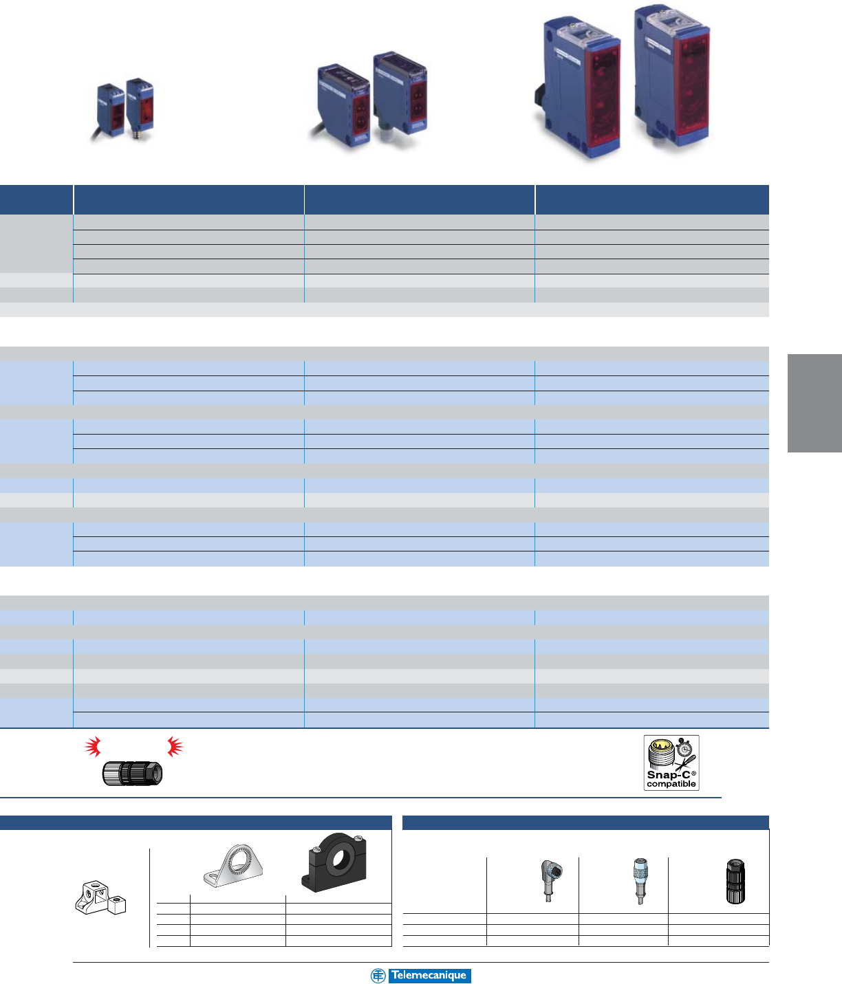
5-3
MACHINE
SENSING
For additional information, reference catalog 9006CT0101
Snap-C
®
compatible
XUM XUK XUX
Miniature rectangular Compact rectangular 50 x 50 Compact rectangular
40
cm
/ 1.3
ft.
1
m
/ 3.28
ft.
2
m
/ 6.5
ft.
10
cm
/ 4
in.
30
cm
/ 11.8
in.
1.3
m
/ 4.2
ft.
3
m
/ 9.8
ft.
4
m
/ 13
ft.
11
m
/ 36
ft.
14
m
/ 45.8
ft.
30
m
/ 98.2
ft.
40
m
/ 131
ft.
direct: (mounting holes 25.5), M3 screws direct: (mounting holes 40 x 40), M4 screws direct: (mounting holes 30 / 38 to 40 / 50 / 74), M5 screws
P / 12 x 34 x 20 P / 18 x 50 x 50 P / 30 x 92 x 71
Temperature range: - 25 to + 55 °C (-13 to +131 °F) / Degree of protection (conforming to IEC 60529): IP67 (XUK: IP65)
XUM0APSAL2 ––
XUM0ANSAL2 ––
–XUK0AKSAL2 –
XUM0APSAM8 (1) – –
XUM0ANSAM8 (1) – –
–XUK0AKSAM12 XUX0AKSAM12
––XUX0AKSAT16
100 / 50 100 / 50 100 / 100
Switching frequency (Hz): 250 / Overload and short-circuit protection: yes / LED output state indicator: yes / power on LED: yes
XUM0AKSAL2T XUK0AKSAL2T –
XUM0AKSAM8T (1) XUK0AKSAM12T XUX0AKSAM12T
––XUX0AKSAT16T
relay output, 3 A
–XUK0ARCTL2 –
––XUX0ARCTT16
– yes / yes yes / yes
–2020
–Adjustment from 0 to 15 s, on energization, on de-energization or monostable
–XUK0ARCTL2T –
––XUX0ARCTT16T
Mounting brackets
Connector innovation
New, innovative connector that is universal, simple and fast.
For all Telemecanique brand sensors with Snap-C compatible M12 connectors (pointed pins):
– cabling to the required length without using a screwdriver or a soldering iron,
– ready in just a few seconds, no wire stripping required.
XUZ2003
Mounting
support for
M12 rod
Single bracket
for standard with ball joint
XUB...
XUZA118 (stnls. steel)
XUZA218 (plastic)
XUM... XUZA50 –
XUK... XUZA51 –
XUX... XUZX2000 –
(1) M8 not Snap-C® compatible.
length 2 m 90°straight Snap-C
w/o LED
M8 XSZCS111 XSZCS101 –
M12 XSZCD111Y XSZCD101Y XZCC12FDM40V
U20 XSZCK111Y XSZCK101Y –
Plug-in female connectors, including pre-wired versions
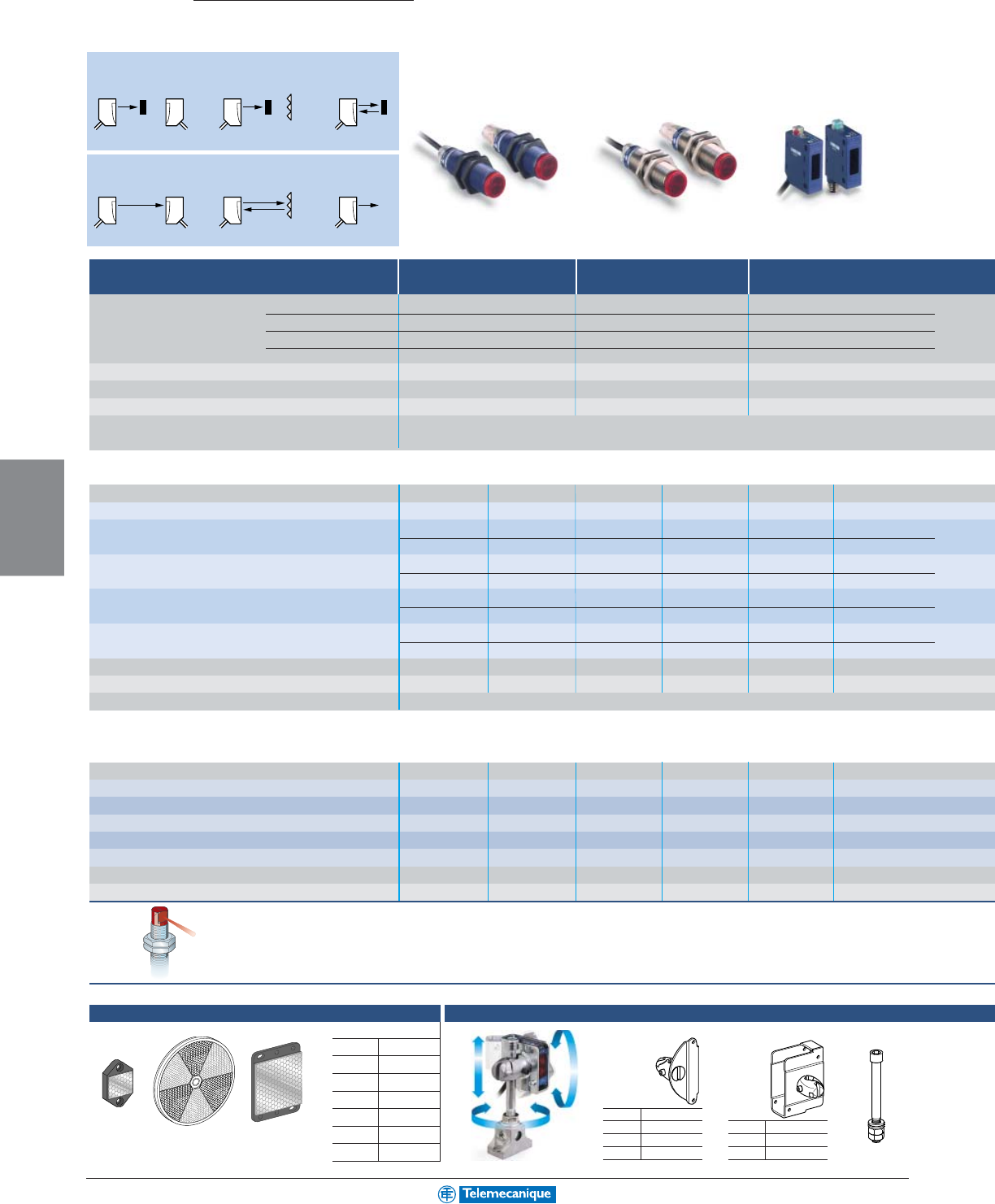
5-4
MACHINE
SENSING
www.telemecanique.com
▲ Tr ansmitter and receiver sold separately
XUB XUB XUM
Osiris
Photo-electric sensors
Standard
Object present detection N.O. Output ON / object present
Thru-beam Reflex Diffuse
(T) (R) (T/R) (T/R)
No object present detection N.C.Output ON / no object present
Thru-beam Reflex Diffuse
(T) (R) (T/R) (T/R)
18mm tubular plastic 18mm tubular metal Miniature rectangular
Max / usable sensing distance Diffuse
60
cm
/ 2
ft.
60
cm
/ 2
ft.
40
cm
/ 1.3
ft.
Polarized retro
2
m
/ 6.5
ft.
2
m
/ 6.5
ft.
2
m
/ 6.5
ft.
Retro
4
m
/ 13
ft.
4
m
/ 13
ft.
4
m
/ 13
ft.
Thru-beam ▲
15
m
/ 49
ft.
15
m
/ 49
ft.
8
m
/ 26
ft.
Mounting (mm) M18 x 1 M18 x 1 direct: (mting holes 25.5), M3 screws
Enclosure M (metal) P (plastic) / Dim. (mm) Ø x L or W x H x L P / M18 x 46 M / M18 x 46 P / 12 x 34 x 27
Alignment LEDs – – yes
Common characteristics Temperature range: - 25 to + 55 °C (-13 to +131 °F) / Degree of protection (conforming to IEC 60529): IP67 (XUK: IP65)
Sensors for dc applications c
(solid-state output: transistor)
Connection 2 m cable M12 connector 2 m cable M12 connector 2 m cable M8 connector
Transmitter XUB2AKSNL2T XUB2AKSNM12T XUB2BKSNL2T XUB2BKSNM12T XUM2AKSNL2T XUM2AKSNM8T
Receiver or T/R, 3-wire PNP (1) Diffuse, adjustable N.O. XUB5APANL2 XUB5APANM12 XUB5BPANL2 XUB5BPANM12 XUM5APANL2 XUM5APANM8
N.C. XUB5APBNL2 XUB5APBNM12 XUB5BPBNL2 XUB5BPBNM12 XUM5APBNL2 XUM5APBNM8
Polarized retro N.O. XUB9APANL2 XUB9APANM12 XUB9BPANL2 XUB9BPANM12 XUM9APANL2 XUM9APANM8
N.C. XUB9APBNL2 XUB9APBNM12 XUB9BPBNL2 XUB9BPBNM12 XUM9APBNL2 XUM9APBNM8
Retro N.O. XUB1APANL2 XUB1APANM12 XUB1BPANL2 XUB1BPANM12 XUM1APANL2 XUM1APANM8
N.C. XUB1APBNL2 XUB1APBNM12 XUB1BPBNL2 XUB1BPBNM12 XUM1APBNL2 XUM1APBNM8
Thru-beam N.O. XUB2APANL2R XUB2APANM12R XUB2BPANL2R XUB2BPANM12R XUM2APANL2R XUM2APANM8R
N.C. XUB2APBNL2R XUB2APBNM12R XUB2BPBNL2R XUB2BPBNM12R XUM2APBNL2R XUM2APBNM8R
Supply voltage limits, min/max (V) including ripple 10–36 10–36 10–36 10–36 10–30 10–30
Switching frequency (Hz) 500 500 500 500 500 500
Common characteristics for dc versions Switching capacity, max (mA): 100 / Overload and short-circuit protection: yes /
(1) For versions with NPN output, replace "P" with an "N". Example: XUB1APANL2 becomes XUB1ANANL2.
Sensors for ac or dc applications a / c
10 to 36 Vdc / 20 to 264 Vac including ripple on dc relay output, 3A
Connection – – – – – –
Transmitter ––––––
Receiver or T/R Diffuse N.O. + N.C. – – – – – –
Polarized retro N.O. + N.C. – – – – – –
Retro N.O. + N.C. – – – – – –
Thru-beam N.O. + N.C. – – – – – –
Switching frequency (Hz) – – – – – –
LED output state indicator / power on LED – – – – – –
90° head
All the above Osiris 18mm sensors are available with an integral 90° head.
Replace the "N" with a "W".
Example: For pre-cabled versions: XUB0APSNL2 becomes XUB0APSWL2.
For connector versions: XUB0APSNM12 becomes XUB0APSWM12.
Accessories (sold separately)
Reflectors
XUZC24 XUZC80 XUZC50
3D mountings with ball joint
Bracket with ball joint
for sensors and
reflector
XUZC50
for
XUM… XUZM2004
XUK… XUZK2004
XUX… XUZX2004
for
XUB… XUZB2003
XUM… XUZM2003
XUK… XUZK2003
XUX… XUZX2003 XUZ2001
Protective housing
with ball joint
M12 rod for ball
joint
Reflectors (mm)
Ø 16 XUZC16
Ø 21 XUZC21
24 x 21 XUZC24
Ø 31 XUZC31
Ø 39 XUZC39
Ø 80 XUZC80
50 x 50 XUZC50
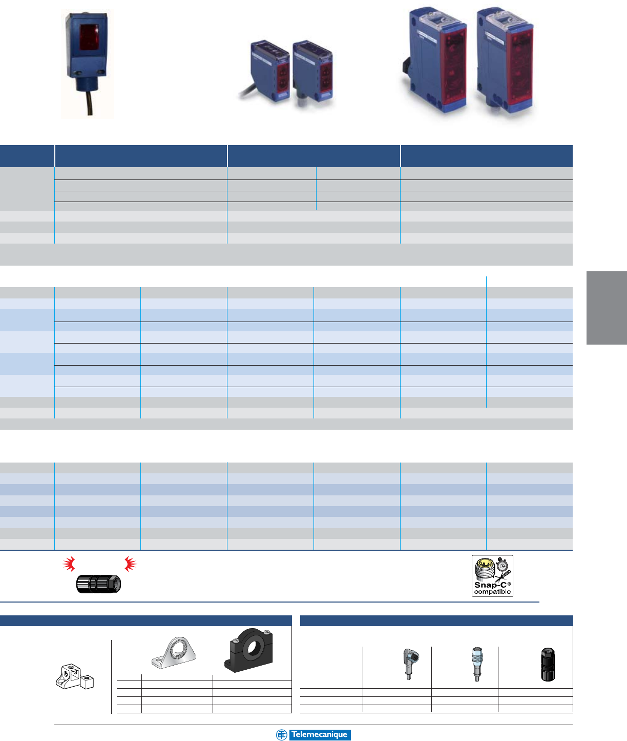
5-5
MACHINE
SENSING
For additional information, reference catalog 9006CT0101
Snap-C
®
compatible
XUK XUXXUC
Compact rectangular Subcompact rectangular 50 x 50 Compact rectangular
dc ac
1.2
m
/ 3.9
ft. (adjustable)
1
m
/ 3.28
ft.
1
m
/ 3.28
ft.
2.1
m
/ 6.8
ft.
9
m
/ 29
ft.
5
m
/ 16
ft.
4
m
/ 13
ft.
11
m
/ 36.1
ft.
–9
m
/ 29
ft.
7
m
/ 23
ft.
14
m
/ 46
ft.
60
m
/ 196
ft.
30
m
/ 98
ft.
20
m
/ 65
ft.
40
m
/ 131
ft.
direct: (mounting holes 30 / 38 / 40 / 50 / 74), M5 screws direct: (mounting holes 40 x 40), M4 screws direct: (mounting holes 30 / 38 to 40 / 50 / 74), M5 screws
P / 95 x 45 x 44 P / 18 x 50 x 50 P / 30 x 92 x 71
yes yes yes
/ LED output state indicator and power on LED: yes
2 m cable M12 connector 2 m cable M12 connector
screw terms, M12 gland
M12 connector
––XUK2AKSNL2T XUK2AKSNM12T XUX0AKSAT16T XUX0AKSAM12T
XUC8AKSNL2 XUC8AKSAM12 XUK5APANL2 XUK5APANM12 XUX5APANT16 XUX5APANM12
XUC8AKSNL2 XUC8AKSAM12 XUK5APBNL2 XUK5APBNM12 XUX5APBNT16 XUX5APBNM12
XUC9AKSAL2 XUC9AKSAM12 XUK9APANL2 XUK9APANM12 XUX9APANT16 XUX9APANM12
XUC9AKSAL2 XUC9AKSAM12 XUK9APBNL2 XUK9APBNM12 XUX9APBNT16 XUX9APBNM12
––XUK1APANL2 XUK1APANM12 XUX1APANT16 XUX1APANM12
––XUK1APBNL2 XUK1APBNM12 XUX1APBNT16 XUX1APBNM12
XUC2AKSAL2 XUCZAKSAM12 XUK2APANL2R XUK2APANM12R XUX2APANT16R XUX2APANM12R
XUC2AKSAL2 XUCZAKSAM12 XUK2APBNL2R XUK2APBNM12R XUX2APBNT16R XUX2APBNM12R
10–38 10–38 10–30 10–30 10–36 10–36
500 500 500 500 500 500
LED output state indicator : yes / power on LED: yes
––pre-cabled, L = 2 m –
screw terms, ISO16 cbl. gland
–
––XUK2ARCNL2T –XUX0ARCTT16T –
XUC8ARCTL2 XUC8ARCTU78 XUK5ARCNL2 –XUX5ARCNT16 –
XUC9ARCTL2 XUC9ARCTU78 XUK9ARCNL2 –XUX9ARCNT16 –
––XUK1ARCNL2 –XUX1ARCNT16 –
XUC2ARCTL2 XUCZARCTU78 XUK2ARCNL2R –XUX2ARCNT16R –
20 – 20 – 20 –
yes / yes – yes / yes – yes / yes –
Connector innovation
New, innovative connector that is universal, simple and fast.
For all Telemecanique brand sensors with Snap-C compatible M12 connectors (pointed pins):
– cabling to the required length without using a screwdriver or a soldering iron,
– ready in just a few seconds, no wire stripping required.
Mounting brackets
XUZ2003
Mounting
support for
M12 rod
Single bracket
for standard with ball joint
XUB...
XUZA118 (stnls. steel)
XUZA218 (plastic)
XUM... XUZA50 –
XUK... XUZA51 –
XUX... XUZX2000 –
length 2 m 90°straight Snap-C
w/o LED
M8 XSZCS111 XSZCS101 –
M12 XSZCD111Y XSZCD101Y XZCC12FDM40V
U20 XSZCK111Y XSZCK101Y –
Plug-in female connectors, including pre-wired versions
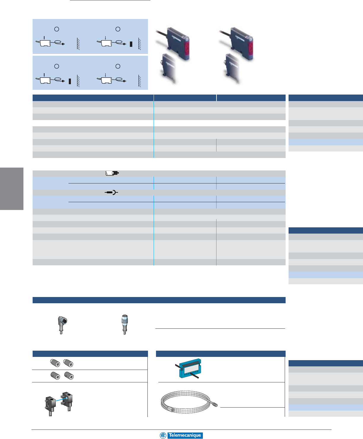
5-6
MACHINE
SENSING
www.telemecanique.com
A
Teach
B
Teach
A
Teach
B
Teach
XUD XUD
Osiris
Photo-electric sensors
Fiber optics
Amplifier
Standard Multi-Modes
System For plastic cables
Max / usable sensing distance See cables
Mounting (mm) DIN rail or direct on 25mm mounting holes, M3 screws
Dimensions (mm) H x W x L 40 x 10 x 65
Case: P (plastic) P
Sensitivity adjustment via teach mode
Alignment LEDs yes yes and 4-digit display
Temperature range °C (°F) - 10 to + 55 (- 14 to + 131) - 10 to + 55 (- 14 to + 131)
Degree of protection (conforming to IEC 60529) IP65 with 1mm Ø cable / IP64 with 0.5mm Ø cable
Sensors for dc applications c
(solid-state output: transistor)
Connection: pre-cabled, PVC (2 m)
Amplifier 3-wire PNP programmable N.O. / N.C. XUDA1PSML2 XUDA2PSML2
references 3-wire NPN programmable N.O. / N.C. XUDA1NSML2 XUDA2NSML2
Connection: M8 connector
Amplifier 3-wire PNP programmable N.O. / N.C. XUDA1PSMM8 XUDA2PSMM8
references 3-wire NPN programmable N.O. / N.C. XUDA1NSMM8 XUDA2NSMM8
Supply voltage limits, min/max (V) including ripple 10 to 30
Switching capacity (mA) main output 100
Alarm output (switching capacity, mA) – 50
Overload and short-circuit protection yes yes
LED output state indicator yes yes
Switching frequency (Hz) 1000 1000 (standard mode)
5000 (fast mode). Sensing distance
reduced by half
Programmable timer – 40 ms on beam break
Accessories
Object present detection N.O. Output ON / object present
No object present detection N.C.Output ON / no object present
(1) Models suitable for use with
XUFZ01 and XUFZ02
System
Sensing distance (mm)
Cable cross-section
Cable Ø (mm)
Sheath Ø
Temperature range °C (°F)
References
Mounting
(2) With XUF-Z04 mounting
bracket with lens.
(3) Depending on length
and lens mounting brackets.
(1) Models suitable for use with
XUFZ01 and XUFZ02
System
Sensing distance (mm)
Cable cross-section
Cable Ø (mm)
Sheath Ø
Temperature range °C (°F)
References
Mounting
(1) Models suitable for use with
XUFZ01 and XUFZ02
System
Sensing distance (mm)
Cable cross-section
Cable Ø (mm)
Sheath Ø
Temperature range °C (°F)
References
Mounting
For thru-beam system plastic fiber optics
Lenses For increasing sensing
distance (pair) XUFZ01
With 90° mirror (pair) XUFZ02
Mounting brackets with lens (set of 2)
Front screw mounting for
fiber optics XUF-Z920 XUFZ04
For all fiber optic cables (all systems)
Cable trimmer
For trimming cable to length
(included with all plastic
cables) XUFZ11
Protective sheath, metallic
Length 1 m, for plastic cables
with threaded tips
For M4 thread XUFZ210
For M6 thread XUFZ310
length 5 m
90°, without LED, fig. 1 XSZCS152
Straight, without LED, fig. 2 XSZCS142
Pre-wired plug-in female connectors suitable for use with amplifier XUD-pppM8
Fig. 1 Fig. 2
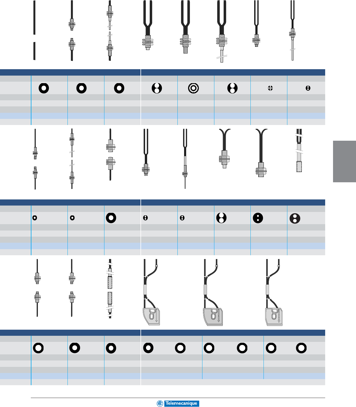
5-7
MACHINE
SENSING
For additional information, reference catalog 9006CT0101
M4 / M2.6 (1) M4/L = 90 mm M6 M4 / M6 M6/L = 90 mm M4 / M2.6 M4/L = 90 mm
Thru-beam (pairs) Diffuse
250 to 900
(3)
200 or 1500
(1)
180 70 60 60 15 18
Ø 1 Ø 1 Ø 1 Ø 1 Ø 1 + 16 Ø 0.265 Ø 1 Ø 0.5 + 4 Ø 0.23 Ø 0.5
Ø 2.2 Ø 2.2 Ø 2.2 Ø 2.2 x 2 Ø 2.2 x 2 Ø 2.2 x 2 Ø 1 x 2 Ø 1 x 2
-25 to +60 (-13 to +140) -25 to +60 (-13 to +140) -25 to +60 (-13 to +140) -25 to +60 (-13 to +140) -25 to +60 (-13 to +140) -25 to +60 (-13 to +140) -25 to +60 (-13 to +140) -25 to +60 (-13 to +140)
XUFZ920 XUFN12301 XUFN12311 XUFN05321 XUFN05323 XUFN05331 XUFN02323 XUFN01331
(2) M4 x 0.7 M4 x 0.7 M6 x 0.75 M6 x 0.75 / M4 x 0.7 M6 x 0.75 M4 x 0.7 M4 x 0.7
Teflon cables for
Long distance cables Flexible cables for food processing or
with integral lens Long distance cables reciprocal movement chemical industries
M3 / M2.6 (1) M3/L = 90 mm M8/L = 20 mm M4 / M2.6 M3/L = 15 mm M6/L = 15 mm M6/L = 17 mm Ø 6 / L = 16mm
Thru-beam (pairs) Diffuse
50 or 1000
(1)
30 2500 18 6 95 55 70
Ø 0.5 Ø 0.5 Ø 1 Ø 0.5 Ø 0.265 Ø 1.5 Ø 1 Ø 1
Ø 1 Ø 1 Ø 2.2 Ø 1 x 2 Ø 1 x 2 Ø 2.2 x 2 Ø 2.2 x 2 Ø 2.2 x 2
-25 to +60 (-13 to +140) -25 to +60 (-13 to +140) -25 to +60 (-13 to +140) -25 to +60 (-13 to +140) -25 to +60 (-13 to +140) -25 to +60 (-13 to +140) -25 to +60 (-13 to +140) -25 to +60 (-13 to +140)
XUFN35301 XUFN35311 XUFN2L01L2 XUFN01321 XUFN04331 XUFN5P01L2 XUFN5S01L2 XUFN5T01L2
M3 x 0.5 M3 x 0.5 M8 x 1.25 M4 x 0.7 M3 x 0.5 M6 x 0.75 M6 x 0.75 by supplied clip
Long distance cables Flexible cables Teflon cables
M4 / M2.6 (1) M4 / M2.6 (1) Ø 5/L = 20 mm
Thru-beam (pairs) Focused diffuse for full color sensor XURC4
300 or 2000
(1)
100 or 750
(1)
1000 10 20 30
Ø 1.5 Ø 1 Ø 1 Transmitter Ø 1 Receiver Ø 1.5 Transmitter Ø 1.5 Receiver Ø 1.5 Transmitter and Receiver Ø 1.5
Ø 2.2 Ø 2.2 Ø 2.2 Ø 2.2 x 2 Ø 2.2 x 2 Ø 2.2 x 2
-25 to +60 (-13 to +140) -25 to +60 (-13 to +140) -25 to +60 (-13 to +140)
- 10 to + 55 (- 14 to + 131) - 10 to + 55 (- 14 to + 131) - 10 to + 55 (- 14 to + 131)
XUFN2P01L2 XUFN2S01L2 XUFN2T01L2 XUFN5L01L2 XUFN5L02L2 XUFN5L03L2
M2.6 x 0.45 / M4 x 0.7 M2.6 x 0.45 / M4 x 0.7 by clip (included) 2 elongated holes Ø 3.2 x 6.7 for M3 screws / mounting holes = 9.8 mm
Plastic fiber optic cables (length 2 m)
5-8
MACHINE
SENSING
www.telemecanique.com
Osiris
Photo-electric sensors
Application Specific
Packaging series
(1) With 50 x 50 mm reflector;
0.6 m with 24 x 21 reflector.
(2) 0.007 m with XURZ02
0.018 m with XURZ01.
Lenses for color mark or UV detection
XURZ01
Accessories
Lens for doubling sensing distance
Transparent materials detection Color mark reader
Retroreflective Retroreflective Diffuse Diffuse
(reflector not included) (with teach mode and (manual) (with teach mode)
50 x 50 reflector)
Max sensing distance
80
cm
/ 2.6
ft. (1)
1.5
m
/ 4.9
ft.
9
mm
/ .35
in. (2)
9
mm
/ .35
in.
(2)
Mounting (mm) M18 x 1 direct: holes 40 x 40
direct: 21 x 28, M5 screws
direct: 21 x 28, M5 screws
Enclosure M (metal) P (plastic) P P M M
Sensitivity adjustment potentiometer with teach mode button with teach mode button
Alignment LEDs – yes yes yes
Temperature range °C (°F) -10 to +55 (+14 to +131) -25 to +55 (-13 to +131) -10 to +55 (+14 to +131) -10 to +55 (+14 to +131)
Degree of protection (conforming to IEC 60529) IP67 IP65 IP67 IP67
Sensors for dc applications c
(solid-state output: transistor)
Connection: pre-cabled, PVC (2 m)
Dimensions (mm) Ø x L or H x W x L M18 x 55 50 x 18 x 50 – –
Transmitter/Receiver 3-wire PNP light switching ––––
dark switching ––––
3-wire NPN light switching ––––
dark switching ––––
Transmitter/Receiver 3-wire PNP light/dark prog. switching XUBH01353 –––
3-wire NPN light/dark prog. switching XUBJ01353 –––
Transmitter/Receiver 3-wire PNP/NPN
light/dark prog. switching – XUKT1KSML2 ––
Connection: M12 connector
Dimensions (mm) Ø x L or H x W x L M18 x 68 50 x 18 x 80 100 x 30 x 62.5 96 x 31 x 64
Transmitter/Receiver 3-wire PNP light switching ––––
dark switching ––––
3-wire NPN light switching ––––
dark switching ––––
Transmitter/Receiver 3-wire PNP light/dark prog. switching XUBH01353D –––
3-wire NPN light/dark prog. switching XUBJ01353D –––
Transmitter/Receiver 3-wire PNP/NPN
light/dark prog. switching – XUKT1KSMM12 XURK0955D XURK1KSMM12
Supply voltage limits, min/max (V) including ripple 10 to 30 10 to 30 10 to 30 10 to 30
Switching capacity, max (mA) 100 100 200 200
Overload and short-circuit protection / LED output state indicator
yes / yes yes / yes yes / yes yes / yes
Switching frequency (Hz) 500 1500 10,000 10,000
Reflectors
XUZC24
XUZC80
XUZC50
(mm)
Ø 16 XUZC16
Ø 21 XUZC21
24 x 21 XUZC24
Ø 31 XUZC31
Ø 39 XUZC39
Ø 80 XUZC80
50 x 50 XUZC50
length 2 m 90°straight Snap-C
w/o LED
M8 XSZCS111 XSZCS101 –
M12 XSZCD111Y XSZCD101Y XZCC12FDM40V
U20 XSZCK111Y XSZCK101Y –
Plug-in female connectors, including pre-wired versions
5-9
MACHINE
SENSING
For additional information, reference catalog 9006CT0101
(4) Nominal sensing
distance 10 m.
Use between 10 and
20 cm for optimum
liquid detection.
(3) Depending on fiber optic
cable selected, see table
below.
Guide type System Reference Sensing dist.
Focused Diffuse XUFN5L01L2 10 mm
XUFN5L02L2 20 mm
XUFN5L03L2 30 mm
Standard Diffuse XUFN05321 5 mm
Thru-beam (color detection XUFN12301 + XUFZ01 250 mm
by transparency)
XURZ02
Ring for fixed focusing
Fiber optic guides for use with full color sensor XURC4...
UV sensor Full color sensor Diffuse Opaque and transparent Liquid detection
label detection
Diffuse Diffuse Diffuse
Thru-beam or Diffuse (3) Diffuse with adjustable
Thru-beam Thru-beam
(manual) (with teach mode) (with integral amplifier) (with integral amplifier)
b/ground suppression
infra-red infra-red
20
mm
/ .79
in.
9
mm
/ .35
in. (2)
40–60
mm
/ 1.6–2.3
in.
5–25
mm
/ 0.2–1
in.
(3)
1
m
/ 3.3
ft.
2
mm
/ .07
in.
20
cm
/ 7.8
in.
(4)
M18 x 1
direct: holes 28, M5 screws direct: holes 68x42, M5 screws
on rail, holes 16
direct: holes 40 x 40
direct: holes 18 direct: holes 20
MMMMP MP
with teach mode button with teach mode button with teach mode button with teach mode button
yes yes yes yes yes yes yes
-25 to +55 (-13 to +131) -10 to +55 (+14 to +131) -10 to +55 (+14 to +131) -10 to +55 (+14 to +131) -25 to +55 (-13 to +131) 0 to +55 (+32 to +131) 0 to + 40 (+32 to +104)
IP67 IP67 IP67 IP65 IP65 IP65 IP65
––80 x 30 x 57 82 x 25 x 44 50 x 18 x 50 – 47 x 13 x 33
––XURC3PPML2 XURC4PPML2 –––
–––––––
––XURC3NPML2 XURC4NPML2 –––
––––––
–––––––
–––––––
––––XUK8AKSNL2 –XUMW1KSNL2
M 18 x 95 96 x 31 x 64 – – 50 x 18 x 80 97 x 20 x 26 –
XU5M18U1D ––––––
–––––––
–––––––
–––––––
–––––––
–––––––
–XURU1KSMM12 ––XUK8AKSNM12 XUVK0252VS (M8) –
10 to 30 10 to 30 10 to 30 10 to 30 10 to 30 10 to 30 10 to 30
100 200 100 100 100 100 100
yes / yes yes / yes yes / yes yes / yes yes / yes yes / yes yes / yes
1000 2000 1200 1200 250 10,000 1000
5-10
MACHINE
SENSING
www.telemecanique.com
Osiris
Photo-electric sensors
Application Specific
Assembly, Material Handling
Sturdy and compact Window frames for Fork design with integral
dynamic detection amplifier for indexing
Diffuse
(1)
Thru-beam
(2)
Thru-beam
Max sensing distance
0.07
m
/ 2.7
in.
0.12 / 0.18 / 0.25
m
30
mm
/ 1.18
in.
Mounting (mm) M8 x 1
d
irect: 222.5, M5 screws centers 47
Enclosure M (metal) P (plastic) M M P
Sensitivity adjustment potentiometer – –
Alignment LEDs – yes –
Temperature range °C (°F) - 25 to + 55 (- 13 to + 131) 0 to + 60 (+ 32 to + 140) - 5 to + 55 (+ 23 to + 131)
Degree of protection (conforming to IEC 60529) IP67 IP65 IP54
Sensors for dc applications c
(solid-state output: transistor)
Connection: pre-cabled (2 m)
Dimensions (mm) Ø x L or H x W x L M8 x 40 – 58 x 14 x 68
Transmitter/Receiver 3-wire PNP N.O. XUAH0515 –XUVH0312
N.C. XUAH0525 ––
3-wire NPN N.O. XUAJ0515 –XUVJ0312
N.C. XUAJ0525 ––
Transmitter/Receiver 3-wire PNP N.O. / N.C. programmable – – –
3-wire NPN N.O. / N.C. programmable – – –
Connection: connector
Dimensions (mm) Ø x L or H x W x L M8 x 46 205 / 265 / 335 x 25 x 230 –
Transmitter/Receiver 3-wire PNP N.O. XUAH0515S ––
N.C. XUAH0525S ––
3-wire NPN N.O. XUAJ0515S ––
N.C. XUAJ0525S ––
Transmitter/Receiver 3-wire PNP N.O. / N.C. programmable – – –
3-wire NPN N.O. / N.C. programmable – – –
Transmitter/Receiver 3-wire internal size 200 x 120 mm – XUVF120M12 –
PNP/NPN programmable internal size 200 x 180 mm – XUVF180M12 –
output ON or OFF
internal size 200 x 250 mm – XUVF250M12 –
Connection: screw clamp terminals
Dimensions (mm) H x W x L – – –
Receiver or T/R 3-wire PNP –– –
Supply voltage limits, min/max (V) including ripple 10 to 30 18 to 30 19 to 38
Switching capacity, max (mA) 100 400 150
Overload and short-circuit protection / LED output state indicator
yes / yes yes / yes yes / yes
Switching frequency (Hz) 700 500 1000
(1) Thru-beam also available.
(2) Dynamic fork models available.
(3) With 4 to 20 mA analog output.
5-11
MACHINE
SENSING
For additional information, reference catalog 9006CT0101
Analog output Very long sensing distance High excess gain to resist Stainless steel version for
for position control or accurate sensing accumulation of dirt resistance to harsh agents
Diffuse Thru-beam laser Thru-beam Polarized retro Diffuse
0.20 to 0.80
m
/ 7.8
in.
to 2.6
ft.
100
m
/ 328
ft.
70
m
/ 230
ft.
3
m
/ 9.8
ft.
0.15
m
/ 5.9
in.
centers 30 - 1/2 in. NPT cable gland
M18 x 1 M18 x 1 M18 x 1 M18 x 1
PPMM (stainless steel) M (stainless steel)
–––
yes yes yes – –
- 25 to + 60 (- 13 to + 140) - 10 to + 45 (+ 14 to + 113) - 25 to + 55 (- 13 to + 131) - 25 to + 55 (- 13 to + 131) - 25 to + 55 (- 13 to + 131)
IP67 IP67 IP67 IP67 IP67
–––M18 x 62 M18 x 62
–––––
–––––
–––––
–––––
–––XU9N18PP341 XU5N18PP341
–––XU9N18NP341 XU5N18NP341
–M18 x 76 M18 x 95 M18 x 72 M18 x 72
––XU2M18AP20D (3) – –
–––––
–––––
–––––
–XU2P18PP340DL –XU9N18PP341D XU5N18PP341D
–XU2P18NP340DL –XU9N18NP341D XU5N18NP341D
–––––
–––––
–––––
86 x 27 x 83 – – – –
XUJK803538 ––––
20 to 30 10 to 30 10 to 30 10 to 30 10 to 30
max: 20, min: 4 100 100 100 100
yes / yes yes / yes yes / yes yes / yes yes / yes
10,000 500 30 500 500
Food Processing
Laser
class II
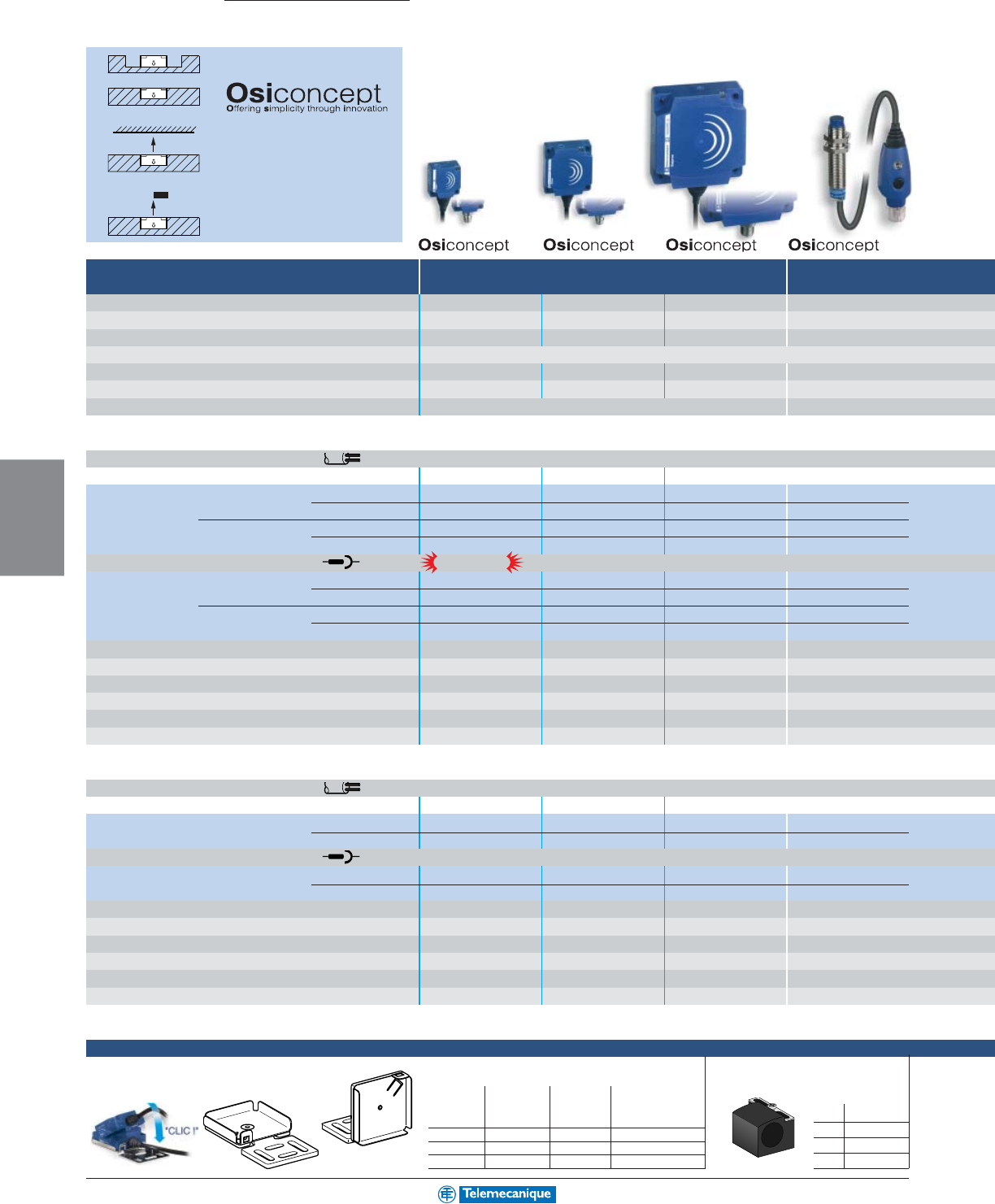
5-12
MACHINE
SENSING
www.telemecanique.com
Snap-C
®
compatible
Osiprox
Inductive proximity sensors
Multi-Mode
A single product that automatically
adapts to all installation environ-
ments.
Accurate position detection using
teach mode.
Non shielded in metal
Shielded in metal
Type E Type C Type D Ø 12
26 x 26 40 x 40 80 x 80
Nominal sensing distance Sn
15
mm
25
mm
60
mm
5
mm
Usable sensing distance S (mm) shielded / non-shielded 0 to 10 / 0 to 15 0 to 15 / 0 to 25 0 to 40 / 0 to 60 0 to 3.4 / 0 to 5
Precision adjustment zone (mm) shielded / non-shielded 5 to 10 / 5 to 15 8 to 15 / 8 to 25 20 to 40 / 20 to 60 1.7 to 3.4 / 1.7 to 5
Mounting in metal shielded or non-shielded via Osiconcept teach mode
Enclosure M (metal) P (plastic) PPPP
Temperature range °C (°F) - 25 to + 70 (- 13 to +158) - 25 to + 70 (- 13 to +158) - 25 to + 70 (- 13 to +158) - 25 to + 70 (- 13 to +158)
Degree of protection (conforming to IEC 60529) pre-cabled: IP68 (with connector: IP67) IP67
Sensors for dc applications c (3-wire)
Connection: pre-cabled, PvR (2 m)
Dimensions (mm) Ø x L or W x H x L 26 x 26 x 13 40 x 40 x 15 80 x 80 x 26 M12 x 54
3-wire PNP N.O. XS8E1A1PAL2 XS8C1A1PAL2 XS8D1A1PAL2 –
N.C. XS8E1A1PBL2 XS8C1A1PBL2 XS8D1A1PBL2 –
NPN N.O. XS8E1A1NAL2 XS8C1A1NAL2 XS8D1A1NAL2 –
N.C. XS8E1A1NBL2 XS8C1A1NBL2 XS8D1A1NBL2 –
Connection: M8 or M12 connector
3-wire PNP N.O. XS8E1A1PAM8 XS8C1A1PAM8 XS8D1A1PAM12 XS612B2PAL01M12 (2)
N.C. XS8E1A1PBM8 XS8C1A1PBM8 XS8D1A1PBM12 XS612B2PBL01M12 (2)
NPN N.O. XS8E1A1NAM8 XS8C1A1NAM8 XS8D1A1NAM12 XS612B2NAL01M12 (2
N.C. XS8E1A1NBM8 XS8C1A1NBM8 XS8D1A1NBM12 XS612B2NBL01M12 (2)
Supply voltage limits, min/max (V) including ripple 10 to 36 10 to 36 10 to 36 10 to 36
Switching capacity, max (mA) 100 200 200 100
Overload and short-circuit protection yes yes yes yes
LED output state indicator and power on LED yes / yes yes / yes yes / yes yes / yes
Voltage drop, closed state (V) at I nominal 2222
Switching frequency (Hz) 2000 1000 150 1000
Sensors for ac or dc applications a / c (2-wire)
Connection: pre-cabled, PvR (2 m)
Dimensions (mm) Ø x L or W x H x L 26 x 26 x 13 40x 40x 15 80 x 80 x 26 –
2-wire ac / dc without N.O. XS8E1A1MAL2 XS8C1A1MAL2 XS8D1A1MAL2 –
short-circuit protection (1) N.C. XS8E1A1MBL2 XS8C1A1MBL2 XS8D1A1MBL2 –
Connection: 1/2" 20 UNF connector
2-wire ac / dc without N.O. XS8E1A1MAL01U20 XS8C1A1MAL01U20 XS8D1A1MAU20 –
short-circuit protection (1) N.C. XS8E1A1MBL01U20 XS8C1A1MBL01U20 XS8D1A1MBU20 –
Supply voltage limits, min/max (V) including ripple on dc 20 to 264 20 to 264 20 to 264 –
Switching capacity, max (mA) 200 a or c300 a / 200 c300 a / 200 c–
LED output state indicator / power on LED yes / yes yes / yes yes / yes –
Residual current, open state (mA) 1.5 1.5 1.5 –
Voltage drop, closed state (V) at I nominal 5.5 5.5 5.5 –
Switching frequency (Hz) ac / dc 50 / 1000 50 / 1000 50 / 1000 –
(1) It is necessary to place a 0.8 A quick-blow fuse in series with the load.
Accessories
Mounting brackets
Mounting bracket with indexing pin
for cylindrical sensors
M8 XSZB108
M12 XSZB112
M18 XSZB118
M30 XSZB130
adaptor plate
for block type
straight 90°sensors
XSE / XSC / XSD
Type E XSZBE00 XSZBE90 XSZBE10
Type C XSZBC00 XSZBC90 XSZBC10
Type D – – XSZBD10
For flat sensors, forms E, C and D
on M12 only
flat
90°
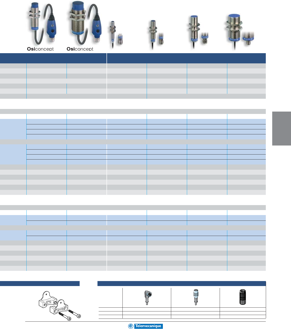
5-13
MACHINE
SENSING
For additional information, reference catalog 9006CT0101
Ø 18 Ø 30 Ø 8 Ø 12 Ø 18 Ø 30
10
mm
18
mm
2.5
mm
4
mm
8
mm
15
mm
0 to 7 / 0 to 10 0 to 12 / 0 to 18 0 to 2 0 to 3.2 0 to 6.4 0 to 12
3.5 to 7 / 3.5 to 10 6 to 12 / 6 to 18 ––––
shielded or non-shielded via Osiconcept teach mode shielded shielded shielded shielded
MMMMMM
- 25 to + 70 (- 13 to +158) - 25 to + 70 (- 13 to +158) - 25 to + 70 (- 13 to +158) - 25 to + 70 (- 13 to +158) - 25 to + 70 (- 13 to +158) - 25 to + 70 (- 13 to +158)
IP67 IP67 pre-cabled: IP68 (with connector: IP67)
M18 x 67 M30 x 71 M8 x 50 M12 x 50 M18 x 60 M30 x 60
––XS608B1PAL2 XS612B1PAL2 XS618B1PAL2 XS630B1PAL2
––XS608B1PBL2 XS612B1PBL2 XS618B1PBL2 XS630B1PBL2
––XS608B1NAL2 XS612B1NAL2 XS618B1NAL2 XS630B1NAL2
––XS608B1NBL2 XS612B1NBL2 XS618B1NBL2 XS630B1NBL2
XS618B2PAL01M12 (2) XS630B2PAL01M12 (2) XS608B1PAM12 XS612B1PAM12 XS618B1PAM12 XS630B1PAM12
XS618B2PBL01M12 (2) XS630B2PBL01M12 (2) XS608B1PBM12 XS612B1PBM12 XS618B1PBM12 XS630B1PBM12
XS618B2NAL01M12 (2) XS630B2NAL01M12 (2) XS608B1NAM12 XS612B1NAM12 XS618B1NAM12 XS630B1NAM12
XS618B2NBL01M12 (2) XS630B2NBL01M12 (2) XS608B1NBM12 XS612B1NBM12 XS618B1NBM12 XS630B1NBM12
10 to 36 10 to 36 10 to 58 10 to 58 10 to 58 10 to 58
100 100 200 200 200 200
yes yes yes yes yes yes
yes / yes yes / yes yes / – yes / – yes / – yes / –
222222
1000 1000 2500 2500 1000 500
–––M12 x 50 M18 x 60 M30 x 60
–––XS612B1MAL2 XS618B1MAL2 XS630B1MAL2
–––XS612B1MBL2 XS618B1MBL2 XS630B1MBL2
–––XS612B1MAU20 XS618B1MAU20 XS630B1MAU20
–––XS612B1MBU20 XS618B1MBU20 XS630B1MBU20
–––20 to 264 20 to 264 20 to 264
–––200 300 a / 200 c300 a / 200 c
–––yes / – yes / – yes / –
–––1.51.5 1.5
–––5.55.5 5.5
–––25
a
/ 1000
c
25
a
/ 1000
c
25
a
/ 500
c
(2) Pigtail cable (L = 0.15 m) with end mounted remote control and M12 connector.
XS6 remote control mounting bracket
XSZBPM12
Plug-in female connectors, including pre-wired versions
length 2 m 90°straight Snap-C
w/o LED
M8 XSZCS111 XSZCS101 –
M12 XSZCD111Y XSZCD101Y XZCC12FDM40V
U20 XSZCK111Y XSZCK101Y –
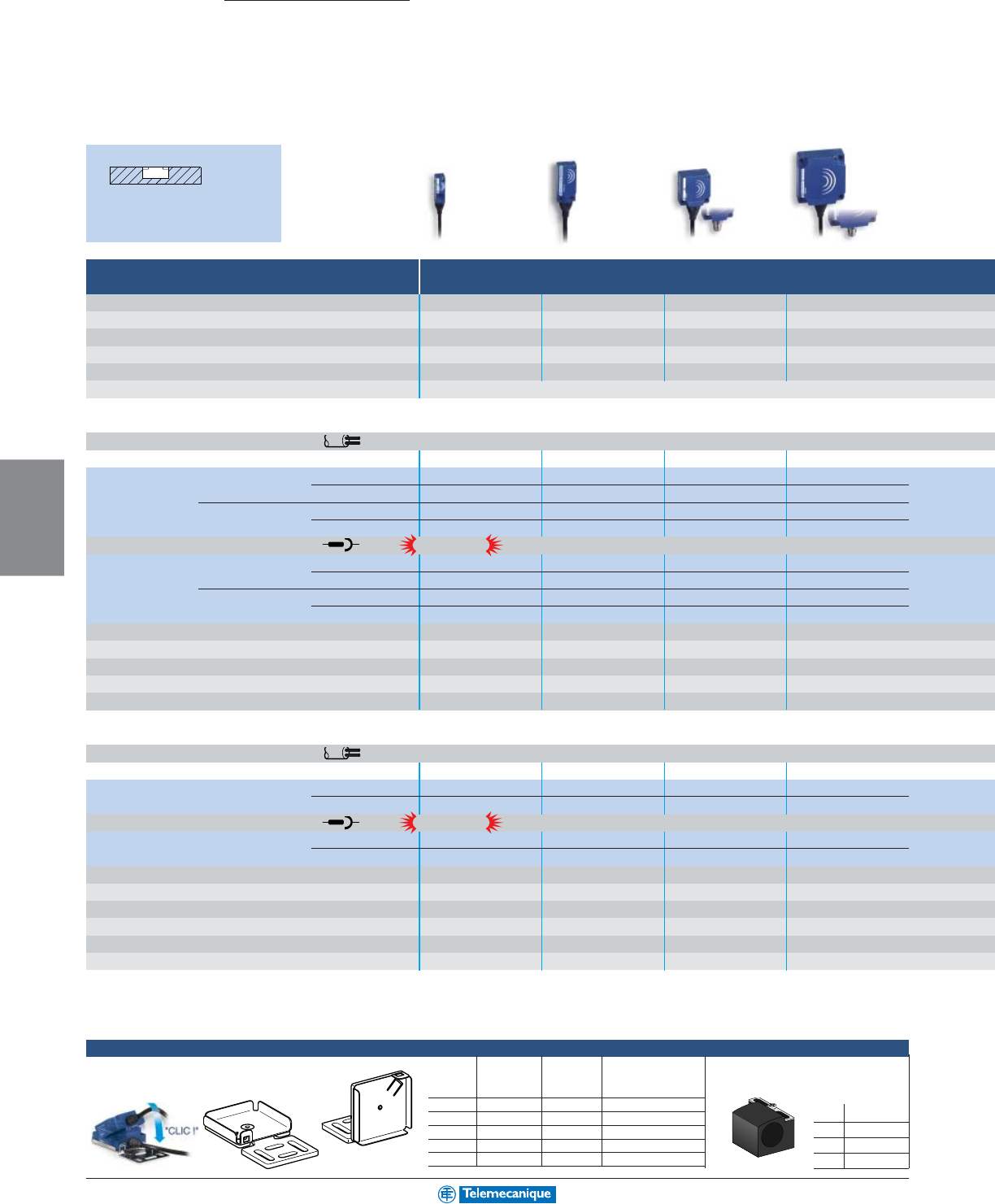
5-14
MACHINE
SENSING
www.telemecanique.com
Snap-C
®
compatible
Snap-C
®
compatible
Osiprox
Inductive proximity sensors
Standard
Shielded in
metal
Accessories
Type J Type F Type E Type C
8 x 22 15 x 32 26 x 26 40 x 40
Nominal sensing distance Sn
2.5
mm
5
mm
10
mm
15
mm
Usable sensing distance (mm) 0 to 2 0 to 4 0 to 8 0 to 12
Flush mounting in metal shielded shielded shielded shielded
Enclosure M (metal) P (plastic) PPPP
Temperature range °C (°F) - 25 to + 70 (- 13 to +158) - 25 to + 70 (- 13 to +158) - 25 to + 70 (- 13 to +158) - 25 to + 70 (- 13 to +158)
Degree of protection (conforming to IEC 60529) pre-cabled: IP68 (with connector: IP67)
Sensors for dc applications c (3-wire)
Connection: pre-cabled, PvR (2 m)
Dimensions (mm) Ø x L or W x H x L 8 x 22 x 8 15 x 32 x 8 26 x 26 x 13 40 x 40 x 15
3-wire PNP N.O. XS7J1A1PAL2 XS7F1A1PAL2 XS7E1A1PAL2 XS7C1A1PAL2
N.C. XS7J1A1PBL2 XS7F1A1PBL2 XS7E1A1PBL2 XS7C1A1PBL2
NPN N.O. XS7J1A1NAL2 XS7F1A1NAL2 XS7E1A1NAL2 XS7C1A1NAL2
N.C. XS7J1A1NBL2 XS7F1A1NBL2 XS7E1A1NBL2 XS7C1A1NBL2
Connection: M8 or M12 connector
3-wire PNP N.O. XS7J1A1PAL01M8 (1) XS7F1A1PAL01M8 (1) XS7E1A1PAM8 XS7C1A1PAM8
N.C. XS7J1A1PBL01M8 (1) XS7F1A1PBL01M8 (1) XS7E1A1PBM8 XS7C1A1PBM8
NPN N.O. XS7J1A1NAL01M8 (1) XS7F1A1NAL01M8 (1) XS7E1A1NAM8 XS7C1A1NAM8
N.C. XS7J1A1NBL01M8 (1) XS7F1A1NBL01M8 (1) XS7E1A1NBM8 XS7C1A1NBM8
Supply voltage limits, min/max (V) including ripple 10 to 36 10 to 36 10 to 36 10 to 36
Switching capacity, max (mA) 100 100 100 100
Overload and short-circuit protection / LED output state indicator yes / yes yes / yes yes / yes yes / yes
Voltage drop, closed state (V) at I nominal 2222
Switching frequency (Hz) 2000 2000 1000 1000
Sensors for ac or dc applications a / c (2-wire)
Connection: pre-cabled, PvR (2 m)
Dimensions (mm) Ø x L or W x H x L 8 x 22 x 8 15 x 32 x 8 26 x 26 x 13 40 x 40 x 15
2-wire non N.O. XS7J1A1DAL2 XS7F1A1DAL2 XS7E1A1DAL2 XS7C1A1DAL2
polarized N.C. XS7J1A1DBL2 XS7F1A1DBL2 XS7E1A1DBL2 XS7C1A1DBL2
Connection: M8 or M12 connector
2-wire non N.O. XS7J1A1DAL01M8 (1) XS7F1A1DAL01M8 (1) XS7E1A1DAM8 XS7C1A1DAM8
polarized N.C. XS7J1A1DBL01M8 (1) XS7F1A1DBL01M8 (1) XS7E1A1DBM8 XS7C1A1DBM8
Supply voltage limits, min/max (V) including ripple 10 to 36 10 to 36 10 to 36 10 to 36
Switching capacity, max (mA) 100 100 100 100
Overload and short-circuit protection / LED output state indicator yes / yes yes / yes yes / yes yes / yes
Residual current, open state (mA) 0.5 0.5 0.5 0.5
Voltage drop, closed state (V) at I nominal 4444
Switching frequency (Hz) ac / dc 4000 5000 1000 1000
(1) Pigtail cable (L = 0.15 m) with M8 connector.
Mounting brackets
Mounting clamp with indexing pin for
cylindrical sensors
M8 XSZB108
M12 XSZB112
M18 XSZB118
M30 XSZB130
For flat sensors, forms E, C and D
adaptor plate for
block type sensors
flat 90°XSE / XSC / XSD
Type J XSZBJ00 XSZBJ90 –
Type F XSZBF00 XSZBF90 –
Type E XSZBE00 XSZBE90 XSZBE10
Type C XSZBC00 XSZBC90 XSZBC10
Type D XSZBD00 –XSZBD10
on M12 only
on M12 only
flat
90°
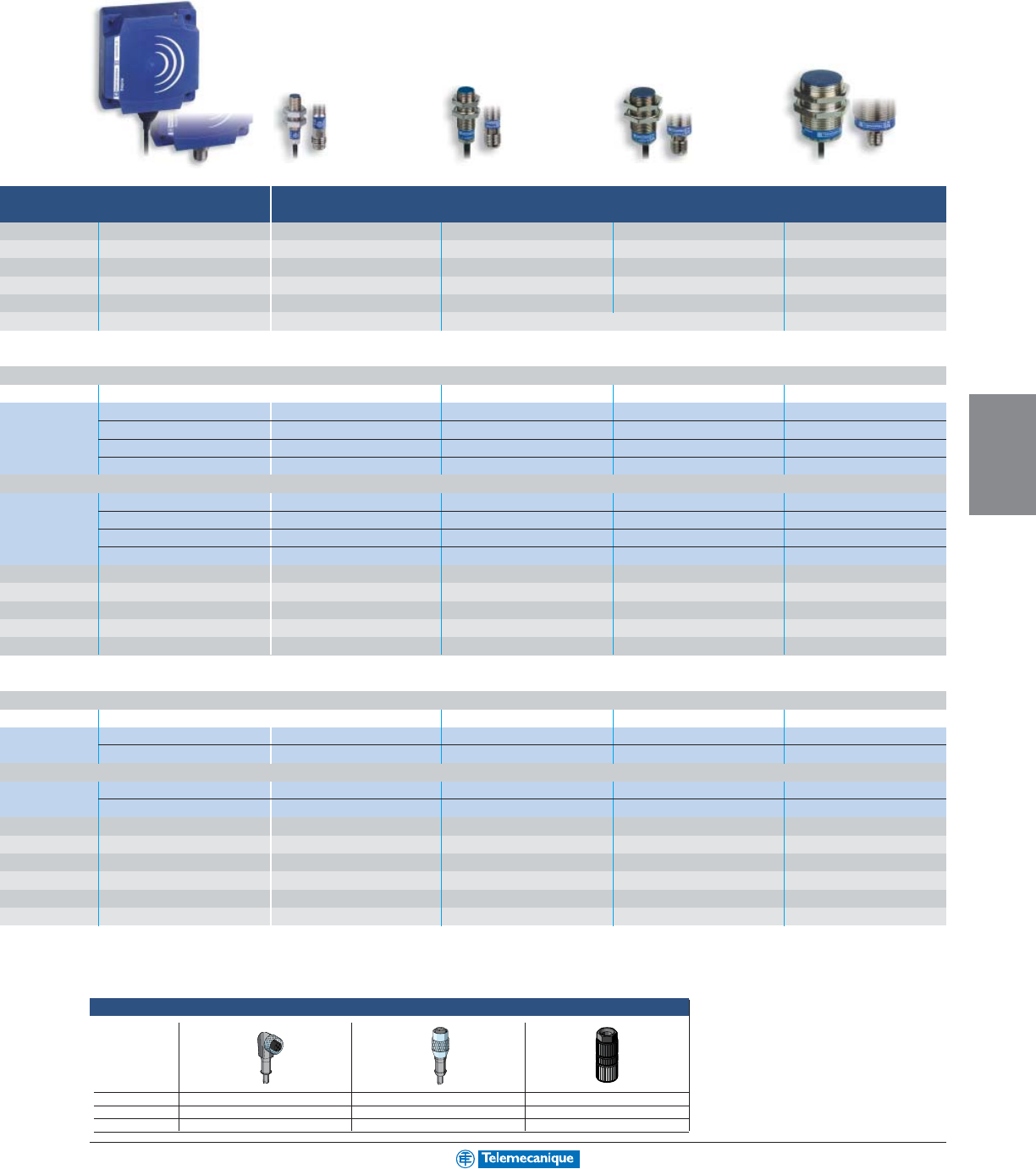
5-15
MACHINE
SENSING
For additional information, reference catalog 9006CT0101
Type D Ø 8 Ø 12 Ø 18 Ø 30
80 x 80
40
mm
1.5
mm
2
mm
5
mm
10
mm
0 to 32 0 to 1.2 0 to 1.6 0 to 4 0 to 8
shielded shielded shielded shielded shielded
PMMMM
- 25 to + 70 (- 13 to +158) - 25 to + 70 (- 13 to +158) - 25 to + 70 (- 13 to +158) - 25 to + 70 (- 13 to +158) - 25 to + 70 (- 13 to +158)
pre-cabled: IP68 (with connector: IP67) IP67 pre-cabled: IP68 (with connector: IP67)
80 x 80 x 26 M8 x 33 M12 x 33 M18 x 36.5 M30 x 40.6
XS7D1A1PAL2 XS508B1PAL2 XS512B1PAL2 XS518B1PAL2 XS530B1PAL2
XS7D1A1PBL2 XS508B1PBL2 XS512B1PBL2 XS518B1PBL2 XS530B1PBL2
XS7D1A1NAL2 XS508B1NAL2 XS512B1NAL2 XS518B1NAL2 XS530B1NAL2
XS7D1A1NBL2 XS508B1NBL2 XS512B1NBL2 XS518B1NBL2 XS530B1NBL2
XS7D1A1PAM12 XS508B1PAM8 XS512B1PAM12 XS518B1PAM12 XS530B1PAM12
XS7D1A1PBM12 XS508B1PBM8 XS512B1PBM12 XS518B1PBM12 XS530B1PBM12
XS7D1A1NAM12 XS508B1NAM8 XS512B1NAM12 XS518B1NAM12 XS530B1NAM12
XS7D1A1NBM12 XS508B1NBM8 XS512B1NBM12 XS518B1NBM12 XS530B1NBM12
10 to 36 10 to 36 10 to 36 10 to 36 10 to 36
100 200 200 200 200
yes / yes yes / yes yes / yes yes / yes yes / yes
22222
100 5000 5000 2000 1000
80 x 80 x 26 M8 x 50 M12 x 50 M18 x 52.5 M30 x 50
XS7D1A1DAL2 XS508B1DAL2 XS512B1DAL2 XS518B1DAL2 XS530B1DAL2
XS7D1A1DBL2 XS508B1DBL2 XS512B1DBL2 XS518B1DBL2 XS530B1DBL2
XS7D1A1DAM12 XS508B1DAM12 XS512B1DAM12 XS518B1DAM12 XS530B1DAM12
XS7D1A1DBM12 XS508B1DBM12 XS512B1DBM12 XS518B1DBM12 XS530B1DBM12
10 to 36 10 to 58 10 to 58 10 to 58 10 to 58
100 100 100 100 100
yes / yes yes / yes yes / yes yes / yes yes / yes
0.5 0.5 0.5 0.5 0.5
44444
100 4000 4000 3000 2000
Plug-in female connectors, including pre-wired versions
length 2 m 90°straight Snap-C
w/o LED
M8 XSZCS111 XSZCS101 –
M12 XSZCD111Y XSZCD101Y XZCC12FDM40V
U20 XSZCK111Y XSZCK101Y –
5-16
MACHINE
SENSING
www.telemecanique.com
Osiprox
Inductive proximity sensors
Application Specific
Plastic cylindrical (Food processing)
Non shielded
in metal
Shielded
in metal
Ø 8 Ø 12 Ø 18 Ø 30
Nominal sensing distance Sn
2.5
mm
4
mm
8
mm
15
mm
Usable sensing distance (mm) 0 to 2 0 to 3.2 0 to 6.4 0 to 12
Flush mounting in metal non-shielded non-shielded non-shielded non-shielded
Enclosure M (metal) P (plastic) PPPP
Temperature range °C (°F) - 25 to + 80 (- 13 to +176) - 25 to + 80 (- 13 to +176) - 25 to + 80 (- 13 to +176) - 25 to + 80 (- 13 to +176)
Degree of protection (conforming to IEC 60529) pre-cabled: IP68 (with connector: IP67)
Sensors for dc applications c (3-wire)
Connection: pre-cabled, PvR (2 m)
Dimensions (mm) Ø x L or W x H x L M8 x 33 M12 x 33 M18 x 33.5 M30 x 40.5
3-wire PNP N.O. XS4P08PA340 XS4P12PA340 XS4P18PA340 XS4P30PA340
N.C. XS4P08PB340 XS4P12PB340 XS4P18PB340 XS4P30PB340
NPN N.O. XS4P08NA340 XS4P12NA340 XS4P18NA340 XS4P30NA340
N.C. XS4P08NB340 XS4P12NB340 XS4P18NB340 XS4P30NB340
0 to 10 V output plastic ––––
4 to 20 mA output metal shielded ––––
plastic shielded ––––
plastic non-shielded ––––
Connection: M8 or M12 connector
3-wire PNP N.O. XS4P08PA340S XS4P12PA340D XS4P18PA340D XS4P30PA340D
N.C. XS4P08PB340S XS4P12PB340D XS4P18PB340D XS4P30PB340D
NPN N.O. XS4P08NA340S XS4P12NA340D XS4P18NA340D XS4P30NA340D
N.C. XS4P08NB340S XS4P12NB340D XS4P18NB340D XS4P30NB340D
0 to 10 V output ––––
4 to 20 mA output ––––
Supply voltage limits, min/max (V) including ripple 10 to 38 10 to 38 10 to 38 10 to 38
Switching capacity, max (mA) 200 200 200 200
Short-circuit protection / LED output state indicator yes / yes yes / yes yes / yes yes / yes
Linearity error ––––
Voltage drop, closed state (V) at I nominal 2222
Operating frequency (Hz) 5000 5000 2000 1000
Sensors for ac or dc applications a / c (2-wire)
Connection: pre-cabled, PvR (2 m)
Dimensions (mm) Ø x L M8 x 50 M12 x 50 M18 x 60 M30 x 60
2-wire without short- N.O. XS4P08MA230 XS4P12MA230 XS4P18MA230 XS4P30MA230
circuit protection (1) N.C. XS4P08MB230 XS4P12MB230 XS4P18MB230 XS4P30MB230
Connection: U20 connector
2-wire without short- N.O. XS4P08MA230K XS4P12MA230K XS4P18MA230K XS4P30MA230K
circuit protection (1) N.C. XS4P08MB230K XS4P12MB230K XS4P18MB230K XS4P30MB230K
Supply voltage limits, min/max (V) including ripple on dc 20 to 264 20 to 264 20 to 264 20 to 264
Switching capacity, max (mA) 100 200 300 a / 200 c300 a / 200 c
LED output state indicator yes yes yes yes
Residual current, open state (mA) 0.6 0.6 0.6 0.6
Voltage drop, closed state (V) at I nominal 5.5 5.5 5.5 5.5
Switching frequency (Hz) ac / dc 25 a / 3000 c25 a / 3000 c25 a / 2000 c25 a / 1000 c
(1) It is necessary to place a 0.4 A quick-blow fuse in series with the load.
For accessories, see page 5-14.
5-17
MACHINE
SENSING
For additional information, reference catalog 9006CT0101
Type F Type E Type C Type D Ø 12 Ø 18 Ø 30
8 x 32 26 x 26 40 x 40 80 x 80
5
mm
10
mm
15
mm
40
mm M:
2
mm / P:
4
mm M:
5
mm / P:
8
mm M:
10
mm / P:
15
mm
1 to 4 1 to 10 2 to 15 5 to 40 M: 0.2 to 2 / P: 0.4 to 4 M: 0.5 to 5 / P: 0.8 to 8 M: 1 to 10 / P: 1.5 to 15
shielded shielded shielded shielded
shielded/non-shielded shielded/non-shielded
shielded/non-shielded
PPPPM or PM or P M or P
- 25 to + 70 (- 13 to +158) - 25 to + 70 (- 13 to +158) - 25 to + 70 (- 13 to +158) - 25 to + 70 (- 13 to +158) - 25 to + 70 (- 13 to +158) - 25 to + 70 (- 13 to +158) - 25 to + 70 (- 13 to +158)
pre-cabled: IP68 (with connector: IP67)
15 x 32 x 8 26 x 26 x 13 40 x 40 x 15 80 x 80 x 26 Ø 12 x 50 Ø 18 x 50 Ø 30 x 52.5
–––––––
–––––––
–––––––
–––––––
XS9F111A1L2 XS9E111A1L2 XS9C111A1L2 XS9D111A1L2 XS4P12AB110 XS4P18AB110 XS4P30AB110
––––XS1M12AB120 XS1M18AB120 XS1M30AB120
XS9F111A2L2 XS9E111A2L2 XS9C111A2L2 XS9D111A2L2 –––
––––XS4P12AB120 XS4P18AB120 XS4P30AB120
–––––––
–––––––
–––––––
–––––––
XS9F111A1L01M8 (2) XS9E111A1L01M12 (2) XS9C111A1L01M12 (2) XS9D111A1M12 –––
XS9F111A2L01M8 (2) XS9E111A2L01M12 (2) XS9C111A2L01M12 (2) XS9D111A2M12 –––
10–36 10–36 10–36 10–36 10–38 10–38 10–38
–––––––
–––––––
5 % 5 %5 %5 %4 %4 %4 %
–––––––
2000 1000 1000 100 1500 500 300
–––––––
–––––––
–––––––
–––––––
–––––––
–––––––
–––––––
–––––––
–––––––
–––––––
–––––––
(2) Pigtail cable (L = 0.15 m) with end connector.
Analog (Position control)
For connection accessories, see page 5-15.
5-18
MACHINE
SENSING
www.telemecanique.com
Osiprox
Inductive proximity sensors
Application Specific
Miniature cylindrical
(Assembly)
Shielded in
metal
Ø 4 Ø 5 Ø 6.5
Nominal sensing distance Sn
1
mm
1
mm
1.5
mm
Usable sensing distance (mm) 0 to 0.8 0 to 0.8 0 to 1.2
Flush mounting in metal shielded
Enclosure M (metal) P (plastic) M
Adjustment means –
Temperature range °C (°F) - 25 to + 70 (- 13 to + 158)
Degree of protection (conforming to IEC 60529) IP67
Dimensions (mm) Ø x L or W x H x L Ø 4 x 29 M5 x 29 M6.5 x 33
Maximum speed of passing target (impulses/min) – – –
Sensing range (impulses/min) – – –
Sensors for dc applications c (3-wire)
Connection: pre-cabled, PvR (2 m)
4-wire PNP / NPN N.O. / N.C. programmable – – –
3-wire PNP N.O. XS1L04PA310 XS1N05PA310 XS1L06PA340
N.C. slow version – – –
fast version – – –
N.O. XS1L04NA310 XS1N05NA310 XS1L06NA340
Connection: M8 or M12 connector
3-wire PNP N.O. XS1L04PA310S XS1N05PA311S (2) XS1L06PA340S
N.C. – – –
NPN N.O. XS1L04NA310S XS1N05NA311S (2) XS1L06NA340S
N.C. – – –
Connection: M12 connector
4-wire PNP / NPN N.O. / N.C. programmable – – –
Supply voltage limits, min/max (V) including ripple 5–30 5–30 10–38
Switching capacity, max (mA) 100 100 200
Short-circuit protection / LED output state indicator / Power on LED
yes / yes / – yes / yes / – yes / yes / –
Voltage drop, closed state (V) at I nominal 2 2 2
Switching frequency (Hz) 5000 5000 2500
Sensors for ac or dc applications a / c (2-wire)
(2) Stainless steel nominal sensors,Sn = 0.8 mm.
Connection: pre-cabled, PvR (2 m)
2-wire ac/dc without short- N.O. – – –
circuit protection (4) N.C. – – –
N.C. slow version – – –
fast version – – –
Supply voltage limits, min/max (V), 50-60 Hz – – –
Switching capacity, max (mA) – – –
LED output state indicator / Power on LED – – –
Residual current, open state (mA) – – –
Voltage drop, closed state (V) at I nominal – – –
Switching frequency (Hz) – – –
Accessories
Mounting brackets
Mounting bracket with indexing
pin for cylindrical sensors M4 XSZB104
M5 XSZB105
M6.5 XSZB165
M8 XSZB108
For flat sensors, forms E and C
M12 XSZB112
M18 XSZB118
M30 XSZB130
straight 90°
Type E XSZBE00 XSZBE90
Type C XSZBC00 XSZBC90
flat
90°
5-19
MACHINE
SENSING
For additional information, reference catalog 9006CT0101
Speed control Ferrous / non-ferrous
materials
Type E Type C Ø 30 Ø 18 Ø 30
26 x 26 40 x 40
10
mm
15
mm
10
mm
5
mm
10
mm
0 to 8 0 to 12 0 to 8 0 to 4 0 to 8
shielded shielded
PPMMM
teach mode teach mode – –
- 25 to + 70 (- 13 to + 158) 0 to + 50 (+ 32 to + 122)
IP67 pre-cabled: IP68 (with connector: IP67)
26 x 26 x 13 40 x 40 x 15 M30 x 81 M18 x 70 M30 x 60
48000 48000 6000–48000 (1) – –
6–6000 6–6000 6–150 / 120–3000 (1) – –
(1) 6–150 and 6000 impulses/min for XSAV11373 and XSAV11801 (slow version); 120–3000 and 48000 impulses/min for XSAV12373 and XSAV12801 (fast version).
–––XS1M18KPM40 XS1M30KPM40
–––––
––XSAV11373 ––
––XSAV12373 ––
–––––
–––––
XS9E11RPBL01M12 (3) XS9C11RPBL01M12 (3) – – –
–––––
–––––
Pigtail with M12 con., L = 0.8 m
–––XS1M18KPM40D XS1M30KPM40LD
10 to 36 10 to 36 10 to 58 10 to 38
100 200 200 200
yes / yes / yes yes / yes / yes yes / yes / – yes / yes / –
2222.6
–––1000
(3) Pigtail cable (L = 0.15 m) with end mounted remote control and M12 connector.
–––––
XS9E11RMBL01U20 (4) XS9C11RMBL01U20 (4) – – –
––XSAV11801 (5) – –
––XSAV12801 (5) – –
20 to 264 20 to 264 20 to 264 – –
100 300 a / 200 c350 a / 200 c––
yes / yes yes / yes yes / – – –
1.5 1.5 1.5 – –
5.5 5.5 5.7 – –
–––––
(4) Pigtail cable (L = 0.15 m) with end mounted remote control and1/2-20UNF connector. (5) It is necessary to place a quick-blow fuse in series with the load.
XS9 remote control
mounting bracket
XSZBPM12
Plug-in female connectors, including pre-wired versionsPlug-in female connectors, including pre-wired versions
For connection accessories, see page 5-15.
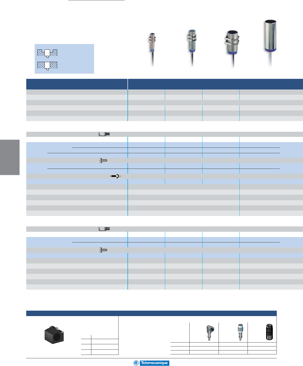
5-20
MACHINE
SENSING
www.telemecanique.com
Capacitive
Detection of all materials
Non
shielded in
metal
Shielded in
metal
Ø 12 Ø 18 Ø 30 Ø 32
Nominal sensing distance Sn
2
mm
5
mm
10
mm
15
mm
Usable sensing distance (mm) 0–1.44 0–3.6 0–7.2 0–10.8
Flush mounting in metal shielded
Enclosure M (metal) P (plastic) MMMM
Temperature range °C (°F) 0 to + 50 (+ 32 to +122) - 25 to + 70 (- 13 to + 158) - 25 to + 70 (- 13 to + 158) - 25 to + 70 (- 13 to + 158)
Degree of protection (conforming to IEC 60529) IP67 IP67 IP67 IP63
Sensors for dc applications c
Connection: pre-cabled, PVC (2 m)
Dimensions (mm) Ø x L or W x D x H M12 x 50 M18 x 60 M30 x 60 –
3-wire PNP N.O. XT1M12PA372 XT1M18PA372 XT1M30PA372 –
N.C. XT1M12PB372 XT1M18PB372 XT1M30PB372 –
NPN N.O. XT1M12NA372 XT1M18NA372 XT1M30NA372 –
Connection: screw clamp terminals
3-wire PNP N.O. + N.C. complementary functions ––––
NPN N.O. + N.C. complementary functions ––––
Connection: M12 connector (M8 for XX512...)
4-wire PNP / NPN N.O. ––––
Supply voltage limits, min/max (V) including ripple 10 to 38 –
Switching capacity, max (mA) 300 –
Short-circuit protection / LED output state indicator yes / yes –
Voltage drop, closed state (V) at I nominal 2 –
Switching frequency (Hz) 100 –
Ultrasound frequency (kHz) – –
Sensors for ac or dc applications a / c (2-wire)
Connection: pre-cabled, PVC (2 m)
Dimensions (mm) Ø x L or W x D x H – M18 x 60 M30 x 60 32 x 80
2-wire ac N.O. – XT1M18FA262 XT1M30FA262 XT1L32FA262
N.C. – XT1M18FB262 XT1M30FB262 XT1L32FB262
Connection: screw clamp terminals
2-wire ac programmable N.O. or N.C. ––––
Supply voltage limits, min/max (V) including ripple on dc – 20 to 264 20 to 264 90 to 250
Switching capacity, max (mA) – 300 300 250
LED output state indicator – yes yes yes
Residual current, open state (mA) – 1.5 / 120 V 1.5 / 120 V 7
Voltage drop, closed state (V) at I nominal – 5.5 5.5 9
Switching frequency (Hz) – 25 25 10
Mounting brackets
Mounting bracket with indexing pin for cylindrical
sensors
M12 XSZB112
M18 XSZB118
M30 XSZB130
Ø32 XUZB32
Accessories
Plug-in female connectors, including pre-wired versions
Osiprox
Other technologies
length 2 m 90 °straight Snap-C
w/o LED
M8 XSZCS111 XSZCS101 –
M12 XSZCD111Y XSZCD101Y XZCC12FDM40V
U20 XSZCK111Y XSZCK101Y –
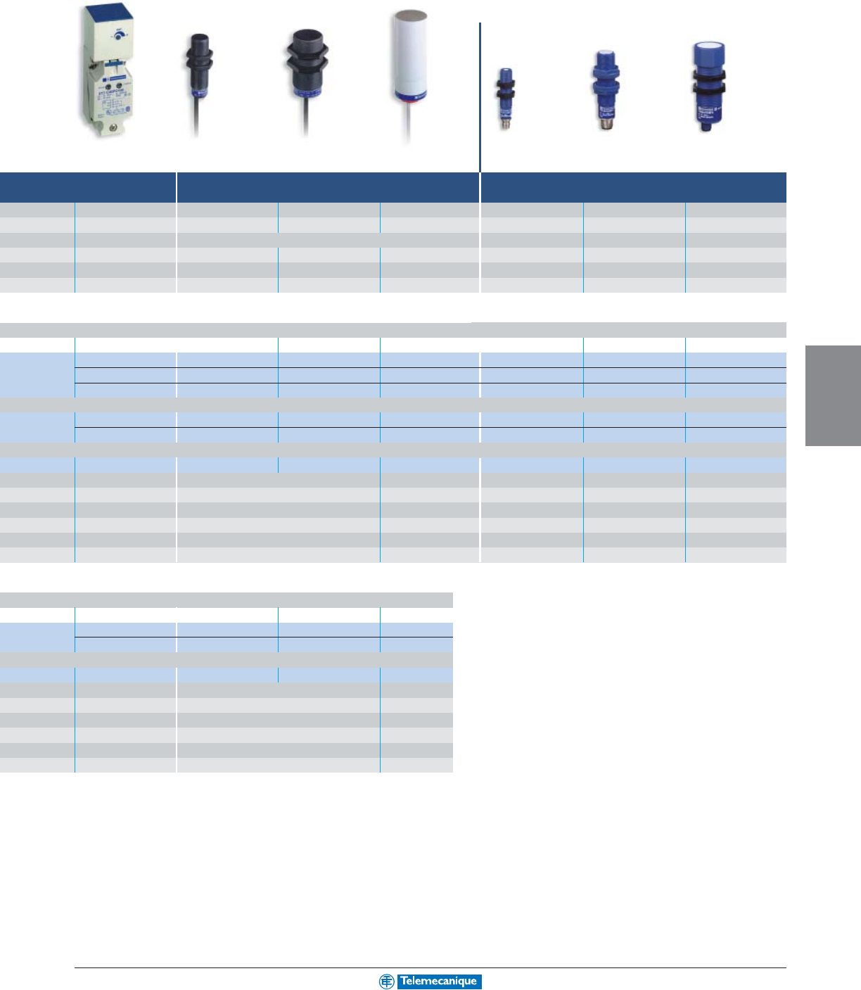
5-21
MACHINE
SENSING
For additional information, reference catalog 9006CT0101
40 x 40 Ø 18 Ø 30 Ø 32 Ø 12 Ø 18 Ø 30
15
mm
8
mm
15
mm
20
mm
51
mm
152
mm
1
m
0 to 10.8 0–5.8 0–10.8 0–14.4 6.4–51 25.4–152 51–991
non-shielded non-shielded – – –
PPPPPPP
- 25 to + 70 (- 13 to + 158) - 25 to + 70 (- 13 to + 158) - 25 to + 70 (- 13 to + 158) - 25 to + 70 (- 13 to + 158) - 20 to + 65 (- 4 to + 149)0 to + 60 (+ 32 to + 122) 0 to + 60 (+ 32 to + 122)
IP67 IP67 IP67 IP63 IP67 IP67 IP67
40 x 40 x 117 M18 x 60 M30 x 60 – M12 x 50 M18 x 65 M30 x 85
–XT4P18PA372 XT4P30PA372 ––––
–––––––
–XT4P18NA372 XT4P30NA372 ––––
XT7C40PC440 ––––––
XT7C40NC440 ––––––
––––XX512A1KAM8 XX518A1KAM12 XX630A1KAM12
10 to 58 10 to 38 – 10 to 28 10 to 28 10 to 28
200 300 – 100 100 100
yes / yes yes / yes – yes / yes yes / – yes / yes
22 –111
100 100 – – – –
–– –500500 200
40 x 40 x 117 M18 x 60 M30 x 60 Ø 32 x 80
–XT4P18FA262 XT4P30FA262 XT4L32FA262
––XT4P30FB262 XT4L32FB262
XT7C40FP262 – – –
20 to 264 20 to 264 90 to 250
350 300 250
yes yes yes
1.5 1.5 / 120V 7
5.5 5.5 9
25 25 10
Detection of conductive materials
Ultrasonic
Detection of any material
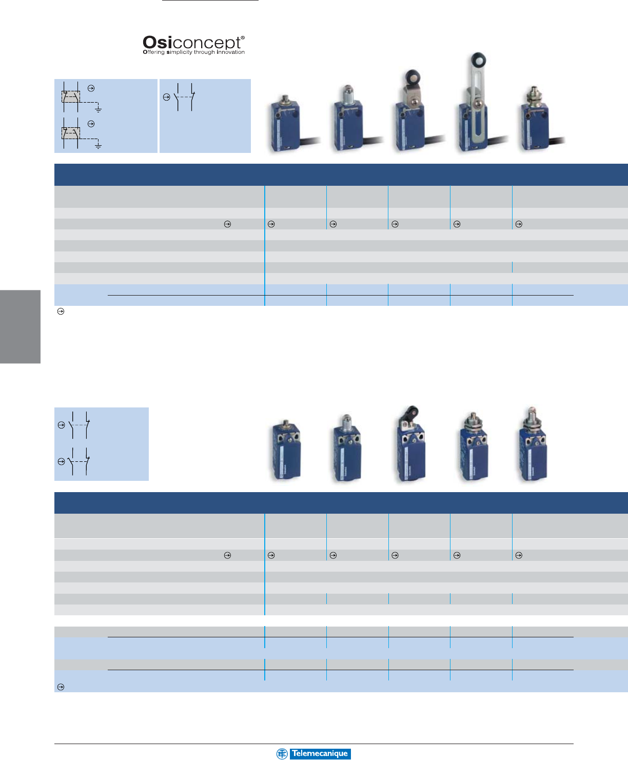
5-22
MACHINE
SENSING
www.telemecanique.com
13
14
22 21
BK
WH
B
K
B
U
BN
GN-YE
BK
W
H
BK
BU
BN
GN-YE
13
14
22 21
1314
22 21
Osiswitch
Limit switches
Complete switches
(adaptable sub-assemblies, see pages 5-24–5-25)
XCMD / XCMN
2-pole contact
N.C. + N.O.
snap action
2-pole contact
N.C. + N.O.
slow break
XCKT
2-pole contact
N.C. + N.O.
snap action
Miniature type XCMD metal, pre-cabled
Type of operator Metal Steel Plastic Variable length M12 head
end plunger roller plunger roller lever plastic metal
roller lever end plunger
Actuation speed (in m/s) 0.5 0.5 1.5 1.5 0.5
Switches conforming to standard IEC 60947-5-1 section 3
Degree of protection conforming to IEC 60529 IP66 and IP67
Rated operational characteristics a ac 15; B 300 (Ue = 240 V, Ie = 1.5 A) / c dc 13; R 300 (Ue = 250 V, Ie = 0.1 A)
Cable entry Pre-cabled, adjustable direction, length = 1 m (other lengths available on request)
Mounting holes (mm) 20 M12
Body dimensions (mm) W x D x H 30 x 16 x 50
Complete switch (2-pole N.C. + N.O. snap action) XCMD2110L1 XCMD2102L1 XCMD2115L1 XCMD2145L1 XCMD21F0L1
(2-pole N.C. + N.O. break before make, slow break) XCMD2510L1 XCMD2502L1 XCMD2515L1 XCMD2545L1 XCMD25F0L1
Positive opening operation
Compact type XCKD metal and XCKP plastic conforming to standard EN 50047
Type of operator Metal Steel Plastic roller lever, M18 head M18 head
end plunger roller plunger horizontal actuation metal steel
end plunger roller plunger
Actuation speed (in m/s) 0.5 0.5 1 0.5 0.5
Switches conforming to standard IEC 60947-5-1 section 3
Degree of protection conforming to IEC 60529 IP66 and IP67
Rated operational characteristics a ac 15; A 300 (Ue = 240 V, Ie = 3 A) / c dc 13; Q 300 (Ue = 250 V, Ie = 0.27 A)
Cable entry 1 tapped entry for 1/2 in. NPT cable gland
Mounting holes (mm) 20 20 20 M18 x 1 M18 x 1
Body dimensions (mm) W x D x H 31 x 30 x 65
Metal switches
Complete switch (2-pole N.C. + N.O. snap action) XCKD2110N12 XCKD2102N12 XCKD2121N12 XCKD21H0N12 XCKD21H2N12
(2-pole N.C. + N.O. break before make, slow break) XCKD2510N12 XCKD2502N12 XCKD2521N12 XCKD25H0N12 XCKD25H2N12
Plastic, double insulated switches
Complete switch (2-pole N.C. + N.O. snap action) XCKP2110N12 XCKP2102N12 XCKP2121N12 XCKP21H0N12 XCKP21H2N12
(2-pole N.C. + N.O. break before make, slow break) XCKP2510N12 XCKP2502N12 XCKP2521N12 XCKP25H0N12 XCKP25H2N12
Positive opening operation
XCKP
2-pole contact
N.C. + N.O.
snap action
2-pole contact
N.C. + N.O.
slow break
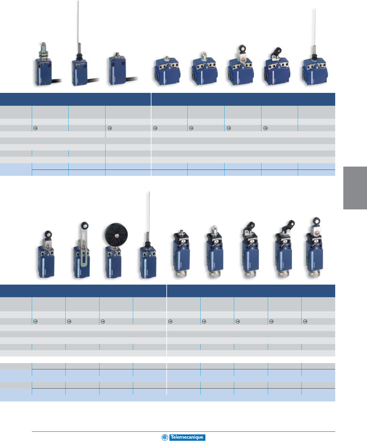
5-23
MACHINE
SENSING
Compact type XCKT, plastic, 2 cable entries
M12 head Cat End Metal Metal Plastic Plastic roller Cat
steel whisker plunger end plunger roller plunger roller lever lever, horizontal whisker
roller plunger actuation
0.1 1 0.5 0.5 0.5 1.5 1 1
– –
IP65 IP66 and IP67
a ac 15; A 300 (Ue = 240 V, Ie = 3 A) / c dc 13; Q 300 (Ue = 250 V, Ie = 0.27 A)
pre-cabled, length = 1m 2 tapped entries for 1/2 in. NPT cable gland
M12 20 20 20 or 40
30 x 16 x 59 58 x 30 x 51
XCMD21F2L1 XCMD2106L1 XCMN2110L1 XCKT2110N12 XCKT2102N12 XCKT2118N12 XCKT2121N12 XCKT2106N12
XCMD25F2L1 XCMD2506L1 ––––––
With reset facility XCPR and XCDR
Plastic Variable length Rubber Cat Metal Steel Plastic roller Plastic roller Plastic
roller lever plastic roller lever whisker end plunger roller lever lever,
horizontal
lever, vertical roller lever
roller lever Ø 50 mm
actuation
actuation
1.5 1.5 1.5 1 0.5 0.5 1 1 1.5
–
IP66 and IP67
a ac 15; A 300 (Ue = 240 V, Ie = 3 A) / c dc 13; Q 300 (Ue = 250 V, Ie = 0.27 A)
1 tapped entry for 1/2 in. NPT cable gland
20 20 20 20 20 20 20 20 20
31 x 30 x 95
XCKD2118N12 XCKD2145N12 XCKD2139N12 XCKD2106N12 XCDR2110N12 XCDR2102N12 XCDR2121N12 XCDR2127N12 XCDR2118N12
XCKD2518N12 XCKD2545N12 XCKD2539N12 XCKD2506N12 XCDR2510N12 XCDR2502N12 XCDR2521N12 XCDR2527N12 XCDR2518N12
XCKP2118N12 XCKP2145N12 XCKP2139N12 XCKP2106N12 XCPR2110N12 XCPR2102N12 XCPR2121N12 XCPR2127N12 XCPR2118N12
XCKP2518N12 XCKP2545N12 XCKP2539N12 XCKP2506N12 XCPR2510N12 XCPR2502N12 XCPR2521N12 XCPR2527N12 XCPR2518N12
For additional information, reference catalog 9006CT0101
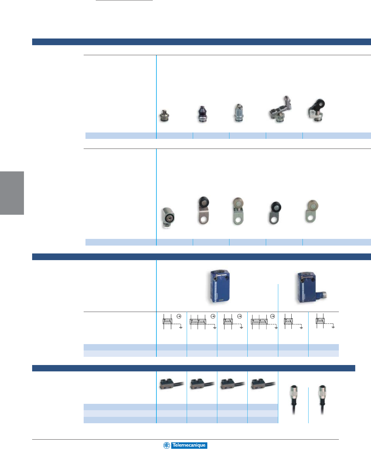
5-24
MACHINE
SENSING
www.telemecanique.com
BK
WH
B
K
B
U
BN
GN-YE
BK
WH
BK
BU
BN
GN-YE
RD
WH
RD
BU
BN
GN-YE
BK
WH
BK
BK
WH
BK
BU
BN
GN-YE
RD
WH
RD
BU
BN
GN-YE
BK
WH
BK
BK
WH
B
K
B
U
BN
GN-YE
Osiswitch
Limit switches
Adaptable sub-assemblies for miniature
Plastic roller
lever, horizontal
actuation
Metal
end plunger
Steel
roller plunger
Retractable steel
roller lever plunger
Metal end plunger
with elastomer boot
Metal plunger and multi-directional heads
Heads - common to miniature and compact bodies
Description
Bodies / contact assemblies
Connection of miniature bodies
ZCE10 ZCE11 ZCE02 ZCE24 (2) ZCE21
Rotary head
without lever,
spring return, for
actuation from
LH or RH side
Steel roller lever,
track:
24/31 mm (ZCMD)
29/36 mm (ZCD/P/T)
Plastic roller lever,
track:
16/39 mm (ZCMD)
21/44 mm (ZCD/P/T)
Steel roller lever,
track:
16/39 mm (ZCMD)
21/44 mm (ZCD/P/T)
Plastic roller lever,
track:
24/31 mm (ZCMD)
29/36 mm (ZCD/P/T)
Description
Type of contact
Metal body
Plastic body
ZCMD21 ZCMD39 ZCMD25 ZCMD37 ZCMD21C12 ZCMD21M12
––––––
Miniature
Specific pre-cabled
connection components
L = 1 m
L = 2 m
L = 5 m
Option: pre-wired M12 connector, L = 2 m
5-pin 4-pin
for ZCMD21 for ZCMD39 for ZCMD25 for ZCMD37
ZCMC21L1 ZCMC39L1 ZCMC25L1 ZCMC37L1
ZCMC21L2 ZCMC39L2 ZCMC25L2 ZCMC37L2
ZCMC21L5 ZCMC39L5 ZCMC25L5 ZCMC37L5 XSZCD1501Y XSZCD101Y
2-pole N.C. + N.O. 1 single-pole
2-pole N.C. + N.O.
3-pole N.C.+N.C.+N.O.
2-pole N.C. + N.O.
3-pole N.C.+N.C.+N.O.
Snap action Snap action
Snap action Snap action Slow break Slow break M12 5-pin connector M12 4-pin connector
ZCE01 ZCY15 (2) ZCY16 (2) ZCY25 (2) ZCY26 (2)
Metal rotary heads and levers
(1) Recommended for use with body: ZCD... / ZCP... / ZCT... (2) Recommended for use with body: ZCMD...
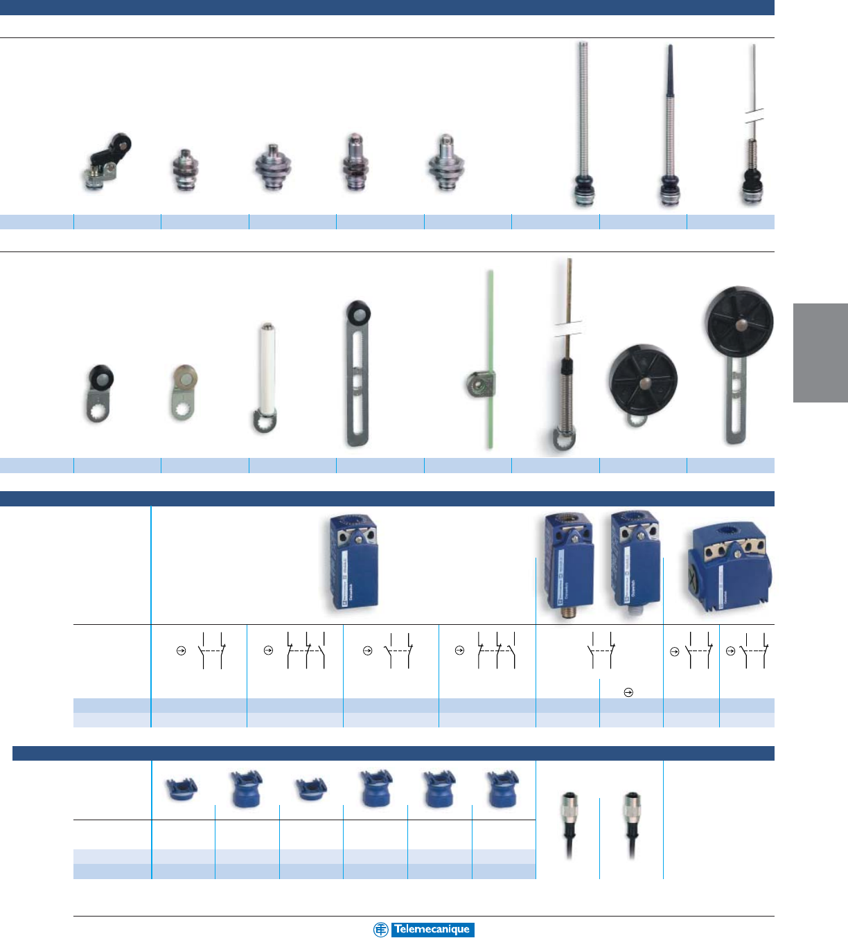
5-25
MACHINE
SENSING
1314
22 21
32 31
22 21
1314
13
14
22 21
1314
22 21
1314
22 21
13
14
22 21
32 31
22 21
1314
and compact switches
Plastic roller
lever, vertical
actuation
M12 head
metal
plunger
M18 head
metal
plunger
M12 head
steel
roller plunger
M18 head
steel
roller plunger
Spring lever Spring lever
with plastic end
Cat whisker
Plastic roller lever,
track:
20/36 mm (ZCMD)
24/40 mm (ZCD/P/T)
Steel roller lever,
track:
20/36 mm (ZCMD)
24/40 mm (ZCD/P/T)
Ceramic
roller lever
Variable length
plastic roller lever
Round,
glass fiber
rod lever
Ø 3 mm
L = 125 mm
Metal
spring
lever
Plastic
roller lever
Ø 50 mm
Adjustable plastic
roller lever
Ø 50 mm
ZCE27 ZCEF0 (2) ZCEH0 (1) ZCEF2 (2) ZCEH2 (1) ZCE08 ZCE07 ZCE06
ZCY18 (1) ZCY19 (1) ZCY22 ZCY45 ZCY55 ZCY91 ZCY39 ZCY49
Removable cable
gland (3)
Description
Metal
Plastic
Option: pre-wired M12 connector,
L = 2 m
5-pin 4-pin
XSZCD1501Y XSZCD101Y
ZCT Pg 11 cable gland
versions:
replace the suffix P16 by G11.
Example:
ZCT21P16 becomes ZCT21G11
ZCT 1/2 NPT versions:
replace the suffix P16 by
N12 (adaptor).
Example:
ZCT21P16 becomes ZCT21N12
For ISO M16 For ISO M20 For Pg 11 For Pg 13.5 For 1/2” NPT
For PF 1/2 (G12
)
cable gland cable gland cable gland cable gland cable gland cable gland
ZCDEP16 ZCDEP20 ZCDEG11 ZCDEG13 ZCDEN12 ZCDEF12
ZCPEP16 ZCPEP20 ZCPEG11 ZCPEG13 ZCPEN12 ZCPEF12
2-pole N.C. + N.O. - Snap action
2-pole N.C. + N.O. 3-pole N.C. + N.C. + N.O. 2-pole N.C. + N.O. 3-pole N.C. + N.C. + N.O. 5-pin connector 4-pin connector (3)
2-pole N.C. + N.O. 2-pole N.C.+N.O.
Snap action Snap action Slow break Slow break Snap action
Slow break
ZCD21 ZCD39 ZCD25 ZCD37 ZCD21M12 –––
ZCP21 ZCP39 ZCP25 ZCP37 –ZCP21M12 ZCT21P16 ZCT25P16
Compact
Type of contact
Metal body
Plastic body
Connection of compact bodies
(3) Plastic and metal cable glands are not interchangeable.
For additional information, reference catalog 9006CT0101
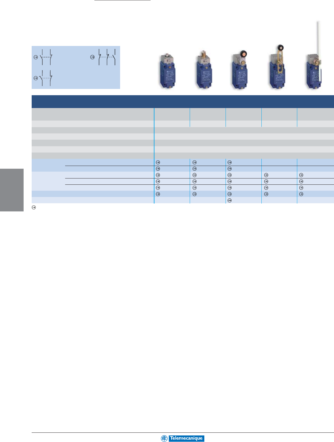
5-26
MACHINE
SENSING
www.telemecanique.com
13
14
22
21
13
14
22
21
31
32
21
22
14 13
Osiswitch
Limit switches
Standard
XCKJ, XCKS, XCKM
2-pole contact
N.C. + N.O.
snap action
2-pole contact
N.C. + N.O.
slow break
3-pole contact
N.C. + N.C. +
N.O.
snap action
Type XCKJ metal, fixed body, conforming to standard EN 50041
Type of operator Metal Steel Plastic Variable length Polyamide, Ø 6 mm
end plunger roller plunger roller lever plastic rod lever
roller lever L = 200 mm
Actuation speed (in m/s) 0.5 1 1.5 1.5 1.5
Degree of protection conforming to IEC 60529 IP66
Rated operational characteristics a ac 15; A 300 (Ue = 240 V, Ie = 3 A) / c dc 13; Q 300 (Ue = 250 V, Ie = 0.27 A)
Cable entry (1) 1 tapped entry for 1/2 in. NPT cable gland
Mounting holes (mm) 30 x 60
Body dimensions (mm) W x D x H 40 x 44 x 77
Complete switch (2-pole N.C. + N.O. snap action) XCKJ161 XCKJ167 XCKJ10511 XCKJ10541 XCKJ10559
(2-pole N.C. + N.O. break before make, slow break) XCKJ561 XCKJ567 XCKJ50511 XCKJ50541 XCKJ50559
Body (2-pole N.C. + N.O. snap action) ZCKJ1 ZCKJ1 ZCKJ1 ZCKJ1 ZCKJ1
(2-pole N.C. + N.O. break before make, slow break) ZCKJ5 ZCKJ5 ZCKJ5 ZCKJ5 ZCKJ5
(3-pole N.C. + N.C. + N.O. snap action) ZCKJD39 ZCKJD39 ZCKJD39 ZCKJD39 ZCKJD39
Associated head (including operator) ZCKE61 ZCKE67 ZCKE05 ZCKE05 ZCKE05
Operating lever for rotary head – – ZCKY11 ZCKY41 ZCKY59
Positive opening operation
For additional information, reference catalog 9006CT0101
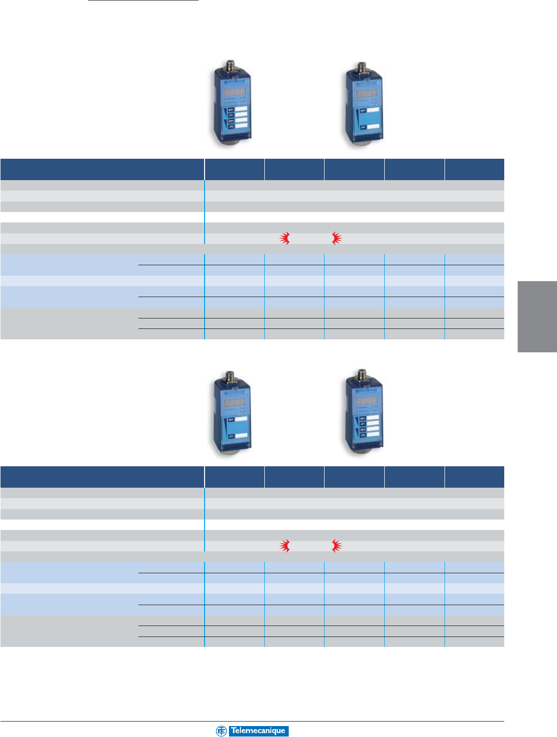
5-27
MACHINE
SENSING
Snap-C
®
compatible
Snap-C
®
compatible
Nautilus
Sensors for pressure control
Electronic pressure switches
XMLF
Setting range lower limit (PB) : vacuum switches -1.16 to -14.5 1.16 to 14.5 2.90 to 36 11.6 to 145 46 to 580
(psi) (1) upper limit (PH): pressure switches
Ambient air temperature (°C / °F) -25 to +80 / -13 to +176
Degree of protection (conforming to IEC 60529) IP67
Voltage limits (V) 24 c (c 17 to 33)
Dimensions (mm / in.) H x W x D 113 x 46 x 58 / 4.45 x 1.81 x 2.28
Fluid connection 1/4" NPT female (2)
Electrical connection M12 connector
Configurable with digital display, connection by M12 connector (3)
Analog and 4 to 20 mA XMLFM01D2026 XMLF001D2026 XMLF002D2026 XMLF010D2026 XMLF040D2026
solid-state output 200 mA 0 to 10 V XMLFM01D2126 XMLF001D2126 XMLF002D2126 XMLF010D2126 XMLF040D2126
Dual stage pressure switches, solid-state output 200 mA XMLFM01D2036 XMLF001D2036 XMLF002D2036 XMLF010D2036 XMLF040D2036
Analog sensors 4 to 20 mA XMLFM01D2016 XMLF001D2016 XMLF002D2016 XMLF010D2016 XMLF040D2016
0 to 10 V XMLFM01D2116 XMLF001D2116 XMLF002D2116 XMLF010D2116 XMLF040D2116
Permissible differential (psi) Min at low setting 0.44 0.44 1.09 4.4 17.4
(pressure switches) Min at high setting 0.44 0.44 1.09 4.4 17.4
Max at high setting 13.8 13.8 34.5 138 551
Setting range upper limit (PH): pressure switches 116 to 1450 186 to 2320 290 to 3625 464 to 5800 696 to 8700
(psi)
(1)
Ambient air temperature (°C / °F) -25 to +80 / -13 to +176
Degree of protection (conforming to IEC 60529) IP67
Voltage limits (V) 24 c (c 17 to 33)
Dimensions (mm / in.) H x W x D 113 x 46 x 58 / 4.45 x 1.81 x 2.28
Fluid connection 1/4" NPT female (2)
Electrical connection M12 connector
Configurable with digital display, connection by M12 connector (3)
Analog and 4 to 20 mA XMLF100D2026 XMLF160D2026 XMLF250D2026 XMLF400D2026 XMLF600D2026
solid-state output 200 mA 0 to 10 V XMLF100D2126 XMLF160D2126 XMLF250D2126 XMLF400D2126 XMLF600D2126
Dual stage pressure switches, solid-state output 200 mA XMLF100D2036 XMLF160D2036 XMLF250D2036 XMLF400D2036 XMLF600D2036
Analog sensors 4 to 20 mA XMLF100D2016 XMLF160D2016 XMLF250D2016 XMLF400D2016 XMLF600D2016
0 to 10 V XMLF100D2116 XMLF160D2116 XMLF250D2116 XMLF400D2116 XMLF600D2116
Permissible differential (psi) Min at low setting 44 70 109 174 261
(pressure switches) Min at high setting 44 70 109 174 261
Max at high setting 1378 2204 3444 5510 8265
(1) Fluids controlled: hydraulic oils, air, fresh water, sea water, corrosive fluids from -15 to +80°C / -13 to +176°F.
(2) Available with other fluid connections: 1/4"BD female and SAE 7/16-20 UNF.
(3) Also available in ac 120 V version with 2.5 A relay output and SAE 7/8-16 UN connector.
Straight—M12, 2 meter cable, catalog no. XZCP1164L2
90°—M12, 2 meter cable, catalog no. XZCP1234L2
For additional information, reference Catalog 9014CT0201.
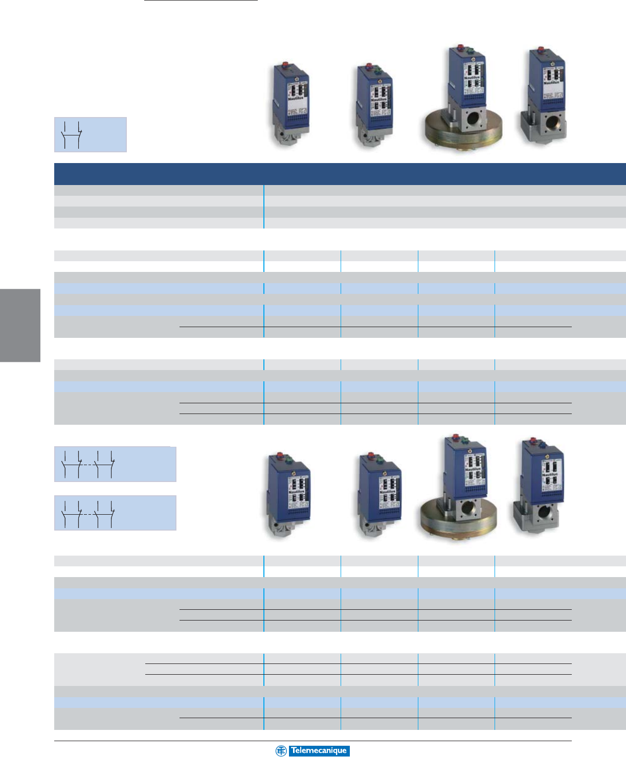
5-28
MACHINE
SENSING
www.telemecanique.com
12 11
13
14
12 11
13
14
22 21
23
24
12 11
13
14
22 21
23
24
Nautilus
Sensors for pressure control
Electromechanical pressure and
XMLA and B
Size (psi) Max. PH Rising -14.5 73 14.5 36
Environmental characteristics Ambient air temperature (°C / °F): -25 to +70 / -13 to +158
Rated operational characteristics a AC-15; B300 (Ue = 240 V, Ie = 1.5 A - Ue = 120 V, Ie = 3 A) / c DC-13; R300 (Ue = 250 V, Ie = 0.1 A)
Fluid connection 1/4" NPT female (other connections possible, please contact us)
Electrical connection Screw terminals, tapped entry 1/2" NPT
Type XMLA fixed differential (1), single threshold detection
Setting range (psi) of upper limit (PH): pressure switches -4.06 to -14.5 (5) – 0.44 to 14.5 2.18 to 36
Dimensions ( in.) H x W x D 4.45 x 1.38 x 2.95 4.45 x 1.38 x 2.95 6.38 x 4.33 x 4.33 6.22 x 2.17 x 3.05
With setting scale, screw terminal connections (2)
1 N.C./1 N.O. single-pole, snap action contact XMLAM01V2S13 – XMLA001R2S13 XMLA002A2S13
Without setting scale, screw terminal connections (2)
1 N.C./1 N.O. single-pole, snap action contact XMLAM01V1S13 – XMLA001R1S13 XMLA002A1S13
Natural differential (psi) at low setting 3.48 (3) – 0.29 1.89
subtract from PH to give PB at high setting 3.48 (3) – 0.58 1.89
Type XMLB adjustable differential (1), regulation between 2 thresholds
Setting range (psi) of upper limit (PH): pressure switches -2.03 to -14.5 (5) -7.3 to 73 0.72 to 14.5 4.35 to 36
With setting scale, screw terminal connections (2)
1 N.C./1 N.O. single-pole, snap action contact XMLBM02V2S13 XMLBM05A2S13 XMLB001R2S13 XMLB002A2S13
Possible differential (psi) Min at low setting 1.88 (4) 7.3 0.58 2.32
subtract from PH to give PB Min at high setting 1.88 (4) 7.3 0.87 3.04
Max at high setting 11.6 (4) 87 10.9 25
XMLC and D
Type XMLC adjustable differential (1), regulation between 2 thresholds
Setting range (psi) of upper limit (PH): pressure switches -2.03 to -14.5 (5) -8 to 73 0.73 to 14.5 4.35 to 36
Dimensions (in.) H x W x D 4.45 x 1.81 x 3.35 4.45 x 1.81 x 3.35 6.89 x 4.33 x 4.33 6.22 x 2.17 x 3.54
With setting scale, screw terminal connections
2 N.C./2 N.O. single-pole simultaneous snap action contacts XMLCM02V2S13 XMLCM05A2S13 XMLC001R2S13 XMLC002B2S13
Possible differential (psi) Min at low setting 1.89 (4) 6.5 0.43 1.89
subtract from PH to give PB Min at high setting 2.03 (4) 6.5 0.58 2.47
Max at high setting 11.6 (4) 87 11.6 29
Type XMLD fixed differential (1), dual stage, for detection at each threshold
Setting range 2
nd
stage switching point (PB2) -1.74 to -14.5 (5) – 1.74 to 14.5 4.93 to 36
(psi) 1
st
stage switching point (PB1) -1.45 to -14.2 – 0.58 to 13.3 2.90 to 34
Spread between 2 stages (PB2 – PB1) 0.29 to 12.8 – 1.16 to 10.6 2.03 to 21.8
Without setting scale, screw terminal connections
2 N.C./2 N.O. single-pole snap action contacts (1 per stage) XMLDM02V1S13 –XMLD001R1S13 XMLD002B1S13
Natural differential (psi) at low setting 1.45 (3) – 0.44 2.03
subtract from PH 1/2 to give PB 1/2 at high setting 1.45 (3) – 1.02 2.76
1 N.C./1 N.O.
single-pole
contact,
snap action
2 N.C./2 N.O.
single-pole contacts,
snap action
(1 per stage)
2 N.C./2 N.O.
single-pole contacts,
simultaneous,
snap action
XMLD
XMLC
(all devices shown are with setting scale)
(all devices shown are with setting scale)
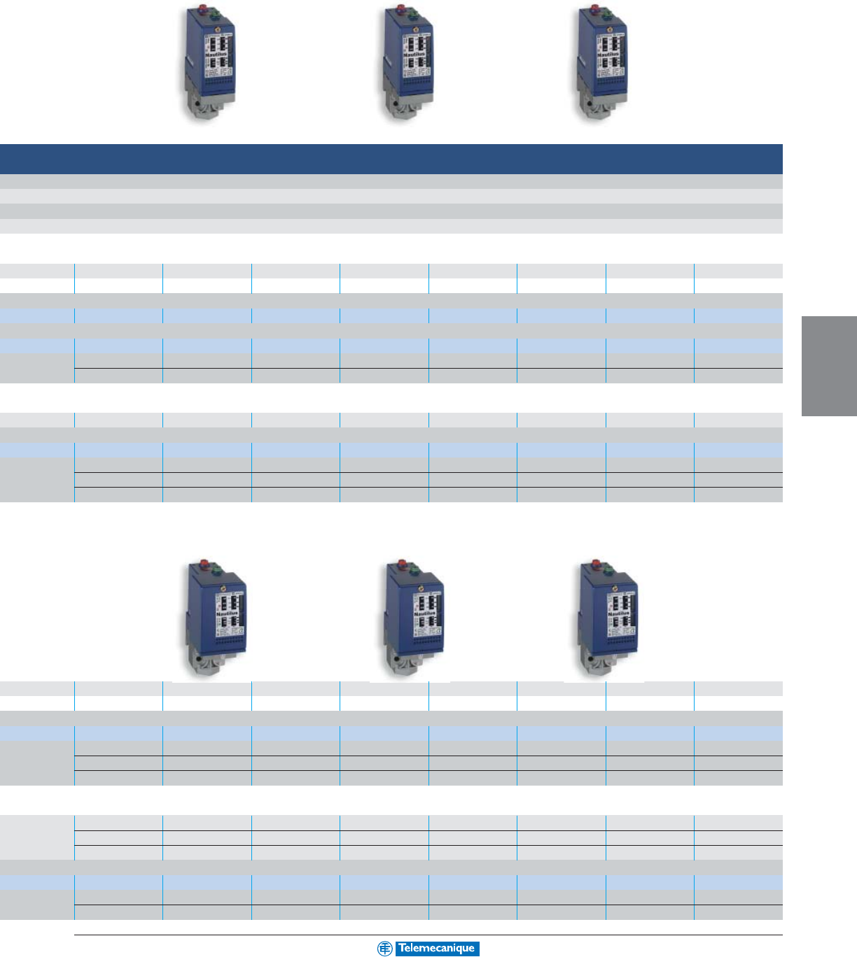
5-29
MACHINE
SENSING
vacuum switches
58 145 290 508 1015 2320 4350 7250
Degree of protection (conforming to IEC 60529): IP66
conforming to IEC 60947-5-1 Appendix A, EN 60947-5-1
5.8 to 58 8.7 to 145 10.2 to 290 22 to 508 73 to 1015 145 to 2320 290 to 4350 435 to 7250
4.45 x 1.38 x 2.95 4.45 x 1.38 x 2.95 4.45 x 1.38 x 2.95 4.45 x 1.38 x 2.95 4.45 x 1.38 x 2.95 4.45 x 1.38 x 2.95 4.45 x 1.38 x 2.95 4.45 x 1.38 x 2.95
XMLA004A2S13 XMLA010A2S13 XMLA020A2S13 XMLA035A2S13 XMLA070D2S13 XMLA160D2S13 XMLA300D2S13 XMLA500D2S13
XMLA004A1S13 XMLA010A1S13 XMLA020A1S13 XMLA035A1S13 XML-A070D1S13 XMLA160D1S13 XMLA300D1S13 XMLA500D1S13
5.1 7.3 5.8 18.1 44 80 239 290
5.1 7.3 14.5 18.1 109 261 508 653
3.62 to 58 10.2 to 145 18.9 to 290 51 to 508 102 to 1015 145 to 2320 319 to 4350 435 to 7250
XMLB004A2S13 XMLB010A2S13 XMLB020A2S13 XMLB035A2S13 XMLB070D2S13 XMLB160D2S13 XMLB300D2S13 XMLB500D2S13
2.9 8.3 14.5 25 68 135 281 334
3.62 12.3 23 37 128 302 537 763
35 109 160 290 725 1450 2900 4350
(1) Fluids controlled: hydraulic oils, air, fresh water, sea water, corrosive fluids, ≤508 psi: up to 70°C (158°F), from 1015 to 7250 psi: up to 160°C (320°F).
(2) For connection by DIN 43650A connector (IP65), replace the letter "S" in the reference by "C". Example: XMLB010A2S13 becomes XMLB010A2C13.
(3) For vacuum switch: natural differential to be added to PB to give PH.
(4) For vacuum switch: possible differential to be added to PB to give PH.
(5) Setting range (psi) of lower limit (PB): vacuum switch.
4.35 to 58 10.2 to 145 18.9 to 290 51 to 508 102 to 1015 174 to 2320 319 to 4350 435 to 7250
4.45 x 1.81 x 3.35 4.45 x 1.81 x 3.35 4.45 x 1.81 x 3.35 4.45 x 1.81 x 3.35 4.45 x 1.81 x 3.35 4.45 x 1.81 x 3.35 4.45 x 1.81 x 3.35 4.45 x 1.81 x 3.35
XMLC004B2S13 XMLC010B2S13 XMLC020B2S13 XMLC035B2S13 XMLC070D2S13 XMLC160D2S13 XMLC300D2S13 XMLC500D2S13
2.18 6.5 10.2 14.5 65 131 232 276
2.47 10.2 14.5 22 129 305 508 754
36 116 160 319 870 1590 3480 4930
5.8 to 58 17.4 to 145 31 to 290 64 to 508 136 to 1015 239 to 2320 522 to 4350 595 to 7250
2.76 to 55 7.5 to 135 13.0 to 272 28 to 471 96 to 974 152 to 2233 363 to 4191 363 to 7018
3.05 to 32 9.9 to 84 18.0 to 138 36 to 296 41 to 667 87 to 1204 160 to 2741 232 to 3538
XMLD004B1S13 XMLD010B1S13 XMLD020B1S13 XMLD035B1S13 XMLD070D1S13 XMLD160D1S13 XMLD300D1S13 XMLD500D1S13
2.18 6.5 10.2 22 73 128 247 305
2.76 8.7 18.9 38 138 290 609 943
For additional information, reference Catalog 9012CT9701.

5-30
MACHINE
SENSING
www.telemecanique.com
SAME
POLARITY
SAME
POLARITY
1
3
2
4
SAME
POLARITY
Electromechanical pressure
9012G Machine Tool
Size (psi) PB falling 3 to 150 5 to 250
Environmental characteristics Ambient air temperature (°C / °F): -23 to +85 / -9 to +185
Rated operational characteristics B600
Fluid connection 1/4" NPT female
Electrical connection Screw terminals
Type GDW fixed differential, single threshold detection
Setting range (psi) of upper limit (PH): pressure switches 9 to 156 15 to 260
Dimensions ( in.) H x W x D 5.93 x 3.50 x 2.63 5.93 x 3.50 x 2.63
With setting scale, screw terminal connections
1 N.C./1 N.O. single-pole, snap action contact GDW5 GDW6
Without setting scale, screw terminal connections
2 N.C./2 N.O. double-pole, snap action contact GDW25 GDW26
Natural differential (psi) at mid-range 6 ± 0.8 10 ± 1.5
subtract from PH to give PB
Type GAW adjustable differential, regulation between 2 thresholds
Setting range (psi) of upper limit (PH): pressure switches 9 to 180 15 to 299
Screw terminal connections
1 N.C./1 N.O. single-pole, snap action contact GAW5 GAW6
Possible differential (psi) at mid-range 6–30 psi 10–49 psi
subtract from PH to give PB
9012G Industrial
Size (psi) PH falling 3 to 150 3 to 150
Type GNG, GNO adjustable differential, regulation between 2 thresholds
Setting range (psi) of upper limit (PH): pressure switches 3 to 150 3 to 150
Dimensions (in.) H x W x D 6.94 x 2.06 x 2.75 5.41 x 2.06 x 2.46
With setting scale, screw terminal connections
1 N.C./1 N.O. single-pole, single throw GNG5 GNO5
Possible differential (psi) at mid-range 4.2–22 4.2–22
subtract from PH to give PB
Type GRG, GRD fixed differential, dual stage, for detection at each threshold
Screw terminal connections
1 N.C./1 N.O. single-pole, single throw GRG5 GRO5
Natural differential (psi) at mid-range 4.2 ± 1 4.2 ± 1
subtract from PH 1/2 to give PB 1/2
1 N.O./1 N.C.
single-pole,
double throw
contact,
snap action
2 N.O./2 N.C.
double-pole,
double throw
contact,
snap action
Type G Machine
Tool
1 N.O./1 N.C.
single-pole,
double throw
contact
Type G Industrial
Open Type
NEMA Type 1
For additional information, reference Catalog 9012CT9701.
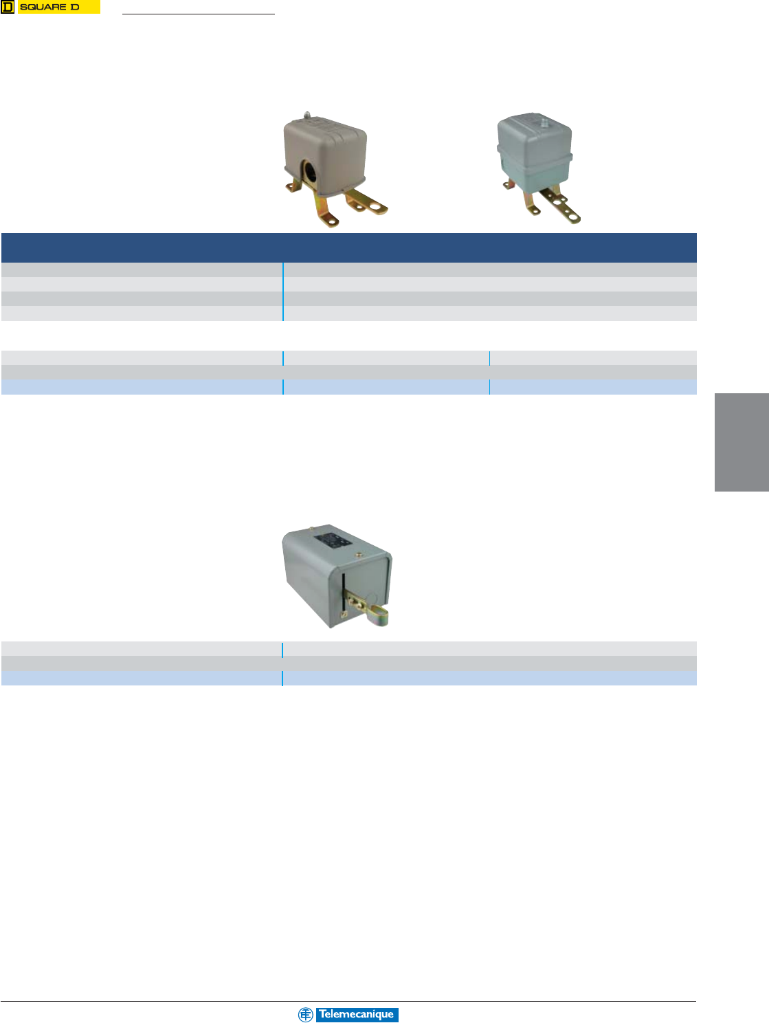
5-31
MACHINE
SENSING
Electromechanical Float Switches
9036
General duty Heavy duty
Environmental characteristics Ambient air temperature (°C / °F): -30 to +105 / -22 to +220
Rated operational characteristics A600; for hp rating, see Catalog
Float operated –
Electrical connection Screw terminals
Type 9036D and 9036G
Dimensions (mm / in.) H x W x D 100 x 66 x 100 / 3.97 x 2.53 x 3.93 132 x 87 x 98 / 5.20 x 3.43 x 3.87
Screw terminal connections
Double-pole, single throw DG2 GG2
9038A
Type 9038A
Dimensions (mm / in.) H x W x D 175 x 119 x 114 / 6.88 x 4.69 x 4.50
Screw terminal connections
2 double-pole, single throw mechanisms 9038AG1
For additional information, reference Catalog 9034CT9701.
These switches will not work without a float switch kit. See Catalog for float switch kit selection.
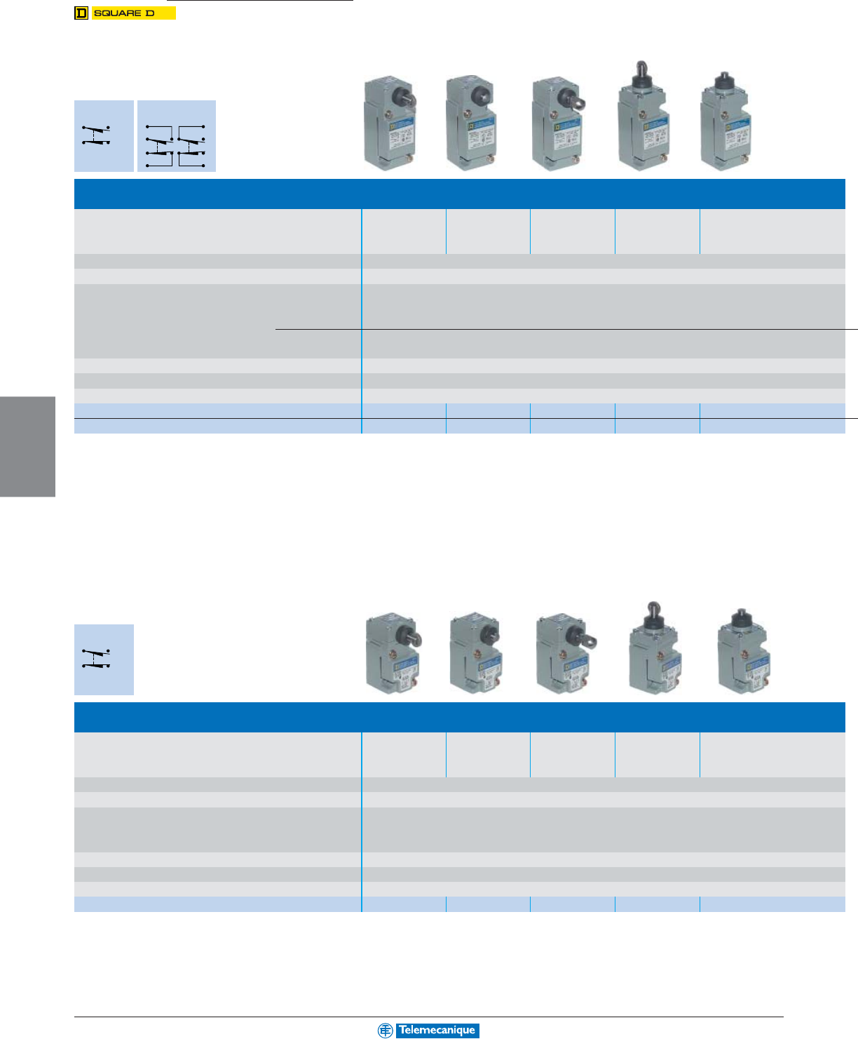
5-32
MACHINE
SENSING
www.telemecanique.com
For additional information, reference Catalog 9006CT0101.
9007C
Heavy Duty Industrial Limit switches
Standard plug-in body metal type
Complete standard type
Type of operator Side roller plunger Side push rod
Side push rod plunger
Top roller plunger Top push rod
spring return plunger spring adjustable (2) spring return plunger spring
vertical roller (1) return spring return return
Conforming to standards (Products)
UL 508, EN 60947-1, EN 60947-5-1, IEC 60947, C22-2-14-95, CE conformity documentation
Degree of protection conforming to IEC 60529 IP 67,
NEMA Type 6P
Rated operational characteristics hard contacts
(top half of body) Single pole AC Voltage : NEMA A600 (Ue = 600 V, Ie = 1,2 A); Ithe = 10 A
DC Voltage : NEMA Q600 (Ue = 600 V, Ie = 0,1 A); Ithe = 2.5 A
Two poles AC Voltage : NEMA A600 (Ue = 600 V, Ie = 1,2 A); Ithe = 10 A
DC Voltage : NEMA R300 (Ue = 250 V, Ie = 0,11 A); Ithe = 1 A
Cable entry 1/2-14 NPT standard, optional M20 x 1,5 mm for ISO cable gland
Mounting Holes (inches/mm) 1.17x2.35 / 30 x 60
Body dimensions (inches/mm) W x D x H 1.55x1.79x4.02 / 39 x 45 x 102
1 N.O. 1 N.C. snap action 9007C54F 9007C54G 9007C54GD 9007C54D 9007C54E
2 N.O. 2 N.C. snap action 9007C62F 9007C62G 9007C62GD 9007C62D 9007C62E
Compact plug-in body metal type
Complete compact type
Type of operator Side roller plunger Side push rod
Side push rod plunger
Top roller plunger Top push rod
spring return plunger spring adjustable (2) spring return plunger spring
vertical roller (1) return spring return return
Conforming to standards (Products)
UL 508, EN 60947-1, EN 60947-5-1, IEC 60947, C22-2-14-95, CE conformity documentation
Degree of protection conforming to IEC 60529 IP 67,
NEMA Type 6P
Rated operational characteristics hard contacts
(top half of body) Single pole AC Voltage : NEMA A600 (Ue = 600 V, Ie = 1,2 A); Ithe = 10 A
DC Voltage : NEMA Q600 (Ue = 600 V, Ie = 0,1 A); Ithe = 2.5 A
Cable entry 1/2-14 NPT standard, optional M20 x 1,5 mm for ISO cable gland
Mounting Holes (inches/mm) 1.17x1.47 / 30 x 37
Body dimensions (inches/mm) W x D x H 1.55x1.79x3.14 / 39 x 45 x 80
1 N.O. 1 N.C. snap action 9007C52F 9007C52G 9007C52GD 9007C52D 9007C52E
34
12
1 N.O. 1 N.C.
snap action
3
4
2
1
7
8
6
5
2 N.O. 2 N.C.
snap action
34
12
1 N.O. 1 N.C.
snap action
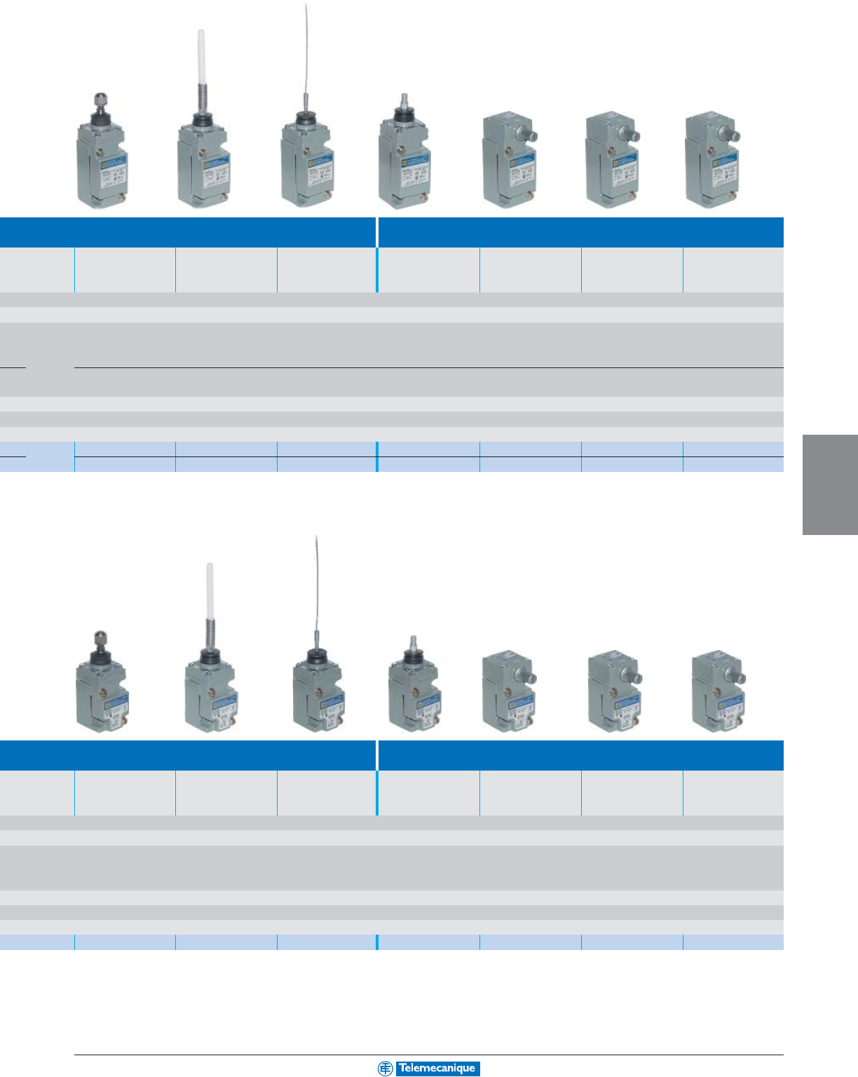
5-33
MACHINE
SENSING
For additional information, reference Catalog 9006CT0101.
with 1 cable entry
Standard type for adaptable sub-assemblies
(1)
Top push rod plunger Wobble stick DELRIN Cat whisker Wobble stick Standard pre-travel Low differential spring Maintained contact
adjustable spring return extension (3) universal (3) spring return return
9007C54ED 9007C54J 9007C54L 9007C54JKC 9007C54B2 9007C54A2 9007C54C
9007C62ED 9007C62J 9007C62L 9007C62JKC 9007C62B2 9007C62A2 9007C62C
with 1 cable entry
Standard type for adaptable sub-assemblies
(1)
Top push rod plunger Wobble stick DELRIN Cat whisker Wobble stick Standard pre-travel Low differential spring Maintained contact
adjustable spring return extension (3) universal (3) spring return return
9007C52ED 9007C52J 9007C52L 9007C52JKC 9007C52B2 9007C52A2 9007C52C
(1) Sub-assemblies wobble stick extension and lever arm, see page 4.
(2) Can be converted to horizontal roller type in the field. To order horizontal roller version add the letter H at the end of the equivalent vertical roller version type.
(3) To lock the nut in the desired position, crimp the slot near the bottom of the nut.
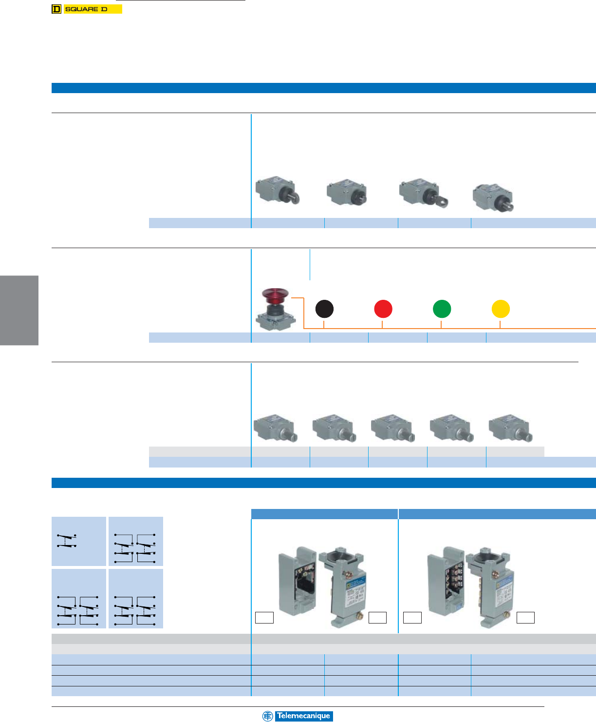
5-34
MACHINE
SENSING
www.telemecanique.com
34
12
1 N.O. 1 N.C.
snap action
3
4
2
1
7
8
6
5
2 N.O. 2 N.C.
snap action
3
4
2
1
7
8
6
5
2 N.O. 2 N.C.
snap action
Two stage
3
4
2
1
7
8
6
5
2 N.O. 2 N.C.
snap action
Neutral position
For additional information, reference Catalog 9006CT0101.
9007C
Heavy Duty Industrial Limit switches
Adaptable sub-assemblies for standard
Common heads for standard and compact switches
Complete heads for linear and multi-directional movements
Type of operator
Side plunger heads
Side roller plunger spring Side push rod plunger Side push rod plunger Side push rod plunger
return vertical roller spring return adjustable spring return maintained contact
Reference 9007F 9007G 9007GD 9007H
Adaptable heads for linear and multi-directional movements
Type of operator Mushroom button for palm operated turret head
Palm operated turret
Diameter 1.38 inches (35 mm)
Choose Mushroom Head Color
head without mush Black Red Green Yellow
room button
Reference 9007R 2358C6G3 2358C6G2 2358C6G6 2358C6G8
Adaptable heads for rotary movements (for assembly with lever arm type)
Type of operator Standard pre-travel Low differential Neutral position, Neutral position, Maintained contact
spring return spring return standard pre-travel low differential
spring return spring return
Type of direction
CW & CCW CW & CCW CW & CCWCW & CCW CW (trip) CCW (reset)
Reference 9007B 9007A 9007T10 9007T5 9007C
Sub-assembly plug-in body metal type with 1 cable entry
Standard body = base (CT..) + top (CO..)
Single pole Two pole
Plug-in unit (Top) Plug-in receptacle (base) Plug-in unit (Top) Plug-in receptacle (base)
with contacts with scew terminals with contacts with scew terminals
Cable entry 1/2-14 NPT standard, (optional M20 x 1,5 mm for ISO cable gland)
Mounting Holes (inches/mm) 1.17x2.35 / 30 x 60
Single pole. 1 N.O. 1 N.C. snap action 9007CT54 9007CO54 ––
Two pole. 2 N.O. 2 N.C. snap action ––9007CT62 9007CO62
Two stage. 2 N.O. 2 N.C. snap action ––9007CT66 9007CO66
Neutral position 2 N.O. 2 N.C. snap action ––9007CT68 9007CO68
CT.. CO.. CT.. CO..
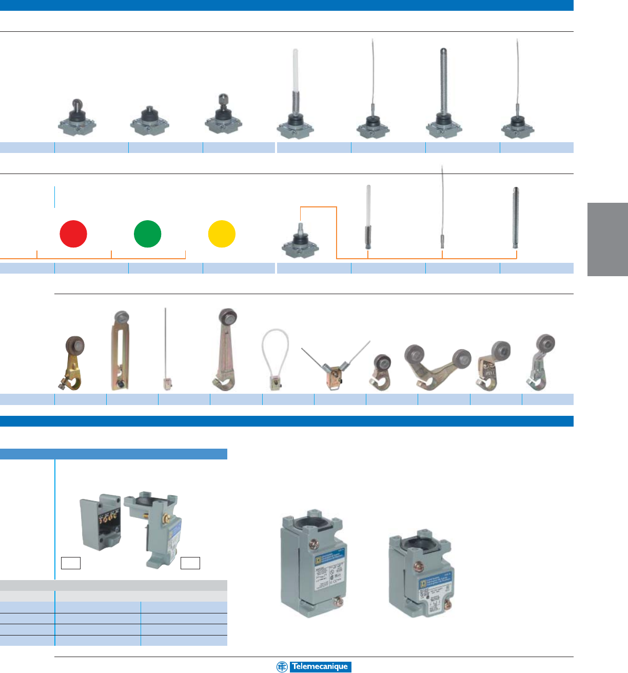
5-35
MACHINE
SENSING
For additional information, reference Catalog 9006CT0101.
Top plunger heads Multi-directional heads
Top roller plunger Top push rod plunger Top push rod plunger Wobble stick Wobble Wobble Cat whisker
spring return spring return adjustable spring return DELRIN stick wire stick coil
extension extension extension
9007D 9007E 9007ED 9007J 9007K 9007KC 9007L
Wobble stick extensions for the universal head
Diameter 2.25 inches (57,2 mm)
Choose Mushroom Head Color
Wobble stick universal
Red Green Yellow
2358C22G3 2358C22G6 2358C22G8 9007JKC 9007WJ 9007WK 9007WKC
Lever arms types
9007MA11 9007HA1 9007FA1 9007EA1 9007FA6 9007LA19 9007AA1 9007LA4 9007KB11 9007KA11
Compact body = base (CT..) + top (CO..)
Single pole
Plug-in unit (Top) Plug-in receptacle (base)
with contacts with scew terminals
1.17x1.47 / 30 x 37
9007CT52 9007CO52
––
––
––
and compact bodies
Standard body Compact body
CT.. CO..

The
essential
guide
Welcome to the world of
Simply Smart* from Telemecanique
With Transparent Ready, Schneider Electric has applied market
standards to its control system architectures, making data
exchange even easier. Smart and simple to use, the Telemecanique
software offer ensures maximum efficiency in terms of application
development and maintenance, while its high-performance PLCs
help to achieve optimum installation availability and
productivity. Committed to maximizing your investment over the
long term, Schneider Electric makes it easy for you to develop
your applications with complete peace of mind.
*Simply Smart: So intelligent, it’s easy to use.
Unity, taking you into a new world
of automation
At the heart of the Telemecanique offer, Unity is the new generation
software and hardware automation platform.
Open:
Based on
universal Microsoft
Visio, VBA and XML
software standards,
Unity is designed to
allow your tools to work
together.
Smart:
Unity provides
a common IEC
development
environment for
Modicon Premium,
Atrium and Quantum
platforms.
With Unity, you can
reduce development
cycles and improve
quality by reusing
program standards.
Flexible:
The new
range of Modicon
Premium, Atrium and
Quantum processors
offers extended
memory capabilities
and greater execution
performance.
A simplified selection
guide to identify, at a
glance, all the
products you need
for developing control
system applications,
from small, simple
machines to complex
installatio
ns.
Smart solutions for all
your control system applications
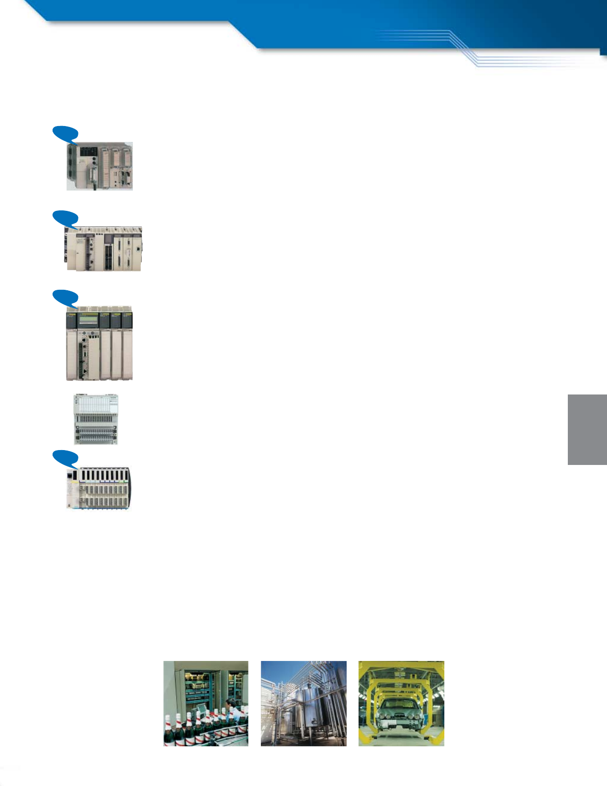
New
New
New
New
PROGRAMMABLE
LOGIC CONTROL
Contents
A wide range of specialized platforms...
Modicon TSX Micro,
ideal for machine builders.
At the heart of the machine, TSX Micro offers compactness,
modularity and integration benefits.
- CANopen machine bus connection
- Low-cost Ethernet connection
- Double memory capacity
Modicon Premium,
ideal for manufacturing applications.
Outstanding flexibility for distributed architectures and integration of
advanced control system functions.
- New high-performance processors
- Onboard Ethernet
- CANopen machine bus connection, from entry level
- USB connection
Modicon Quantum,
ideal for process applications.
High level of performance for process control and
architecture availability.
- New high-performance processors
- Onboard Ethernet
- Memory expansion option via PCMCIA
- USB connection
Modicon Momentum M1/M1E,
ideal for distributed architectures.
Compactness and flexibility for I/O control distribution on Ethernet.
Modicon Compact
Advantys STB,
ideal for machine builders.
The perfect I/O integration solution.
page 6-2
page 6-8
page 6-16
page 6-24
page 6-28
page 6-32
6-2
PROGRAMMABLE
LOGIC CONTROL
www.telemecanique.com
Modicon TSX Micro platform
Basic configuration
Type of processor TSX 3705 TSX 3708 TSX 3710
Power supply 110–240 Vac 24 Vdc
Number of slots Standard 2 (1 available) 3 (1 available) 2 (1 available)
On extension – – 2
Number of integrated discrete I/O modules 1 (16 I, 12 Q) 2 (32 I, 24 Q) 1 (16 I, 12 Q) 1 (16 I, 12 Q)
Number of integrated analog I/O modules ––––
Type of integrated I/O I: 24 Vdc, Q: relay I: 24 Vdc, Q: relay I: 24 Vdc, Q: sol.st. 0.5 A I: 24 Vdc, Q: relay
Application-specific modules (counter, position control) 2 half-size 2 half-size
Bus AS-Interface – 1 half-size
CANopen – –
Fipio – –
Networks Modbus Plus, Fipway – –
Ethernet TCP/IP – 1 external module
Memory capacity Integrated 11 K words 14 K words
With PCMCIA extension – –
Execution time Boolean 0.25 µs 0.25 µs
for one instruction Numerical 4.81 µs 4.81 µs
Catalog number With screw terminals TSX3705028DR1 TSX3708056DR1 TSX3710128DT1 TSX3710128DR1
With HE 10 connector (1) ––TSX3710128DTK1 –
(1) For use with Telefast 2 wiring system
(2) Basic configuration provided without I/O modules
Memory extension
Type of PCMCIA card for TSX 3721/22 Application
Technology
SRAM Flash EPROM Backup
Memory size (3) 32 K words TSXMRP032P TSXMFP032P TSXMFPBAK032P
32 K words/128 K words TSXMRP232P TSXMFP232P –
64 K words TSXMRP064P TSXMFP064P –
64 K words/128 K words TSXMRP264P TSXMFP264P –
128 K words TSXMRP0128P TSXMFP0128P –
128 K words/128 K words TSXMRP2128P (4) ––
(3) The 1
st
value corresponds to the size of the application area, the second to the size of the area for data storage (menus, production data, etc).
(4) These cards have an additional SRAM area for storing application object symbols.
Connection accessories: See the “Modicon TSX Micro automation platform” Catalog #AUTC101272123EN
Automation
6-3
PROGRAMMABLE
LOGIC CONTROL
TSX 3710 TSX 3721 TSX 3722
24 Vdc 110–240 Vac 24 Vdc 110–240 Vac 24 Vdc 110–240 Vac
2 (1 available) 3 (3 available) 3 (3 available)
222
2 (32 I, 32 Q) 1 (16 I, 12 Q) 1 (16 I, 12 Q) – –
–––– 1 (8 I, 1 Q)
I: 24 Vdc, Q: sol. st. 0.1 A
I: 115 Vac, Q: relay I: 24 Vdc, Q: relay – I: 0–10 V or 0/4–20 mA, Q: 0–10 V
2 half-size 4 half-size 4 half-size (2 integrated channels)
1 half-size 1 half-size 1 half-size
–1 PCMCIA card 1 PCMCIA card
–1 PCMCIA card 1 PCMCIA card
–1 PCMCIA card 1 PCMCIA card
1 external module 1 external module 1 external module
14 K words 20 K words 20 K words
–128 K words + 128 K words for file storage 128 K words + 128 K words for file storage
0.25 µs 0.13 µs (0.19 µs with PCMCIA) 0.13 µs (0.19 µs with PCMCIA)
4.81 µs 4.50 µs 4.50 µs
–TSX3710028AR1 TSX3710028DR1 TSX3721101 (2) TSX3721001 (2) TSX3722101 (2) TSX3722001 (2)
TSX3710164DTK1 – –
Mini extension rack
Type of rack 2 slots
For use with TSX3710/21/22
Catalog number 4 positions TSXRKZ2
Process power supplies see page 3-9.
For additional information, reference Catalog #AUTC101272123EN.
6-4
PROGRAMMABLE
LOGIC CONTROL
www.telemecanique.com
Modicon TSX Micro platform
Discrete I/O modules
Type of module Discrete inputs
Connection By HE 10 connector (1) By screw terminals (2)
Module format Half Standard Half
Number of channels 12 32 8
Input voltage 24 Vdc positive logic TSXDEZ12D2K – TSXDEZ32D2 –
24 Vdc positive/negative logic –TSXDEZ12D2 – –
100–120 Vac –––TSXDEZ08A4
200–240 Vac –––TSXDEZ08A5
(1) For use with Telefast 2 wiring system
(2) Terminal block supplied with the module
Type of module Discrete outputs
Solid state Relay
Connection
By HE 10 conn. (1)
By screw terms. (2)
Module format Half Standard Half
Number of protected channels 8324832
Protection of outputs Ye s Ye s Ye s N o N o
Output voltage/current 24 Vdc/0.5 A TSXDSZ08T2K TSXDSZ08T2 TSXDSZ32T2 – – –
24 Vdc/2 A –––TSXDSZ04T22 – –
24 Vdc/1 A per channel ––––TSXDSZ08R5 –
24–240 Vac/1 A per channel –––––TSXDSZ32R5
(1) For use with Telefast 2 wiring system
(2) Terminal block supplied with the module
Type of module Discrete I/O
Connection By HE 10 connector (1) By screw terminals (2)
Module format Half Standard
Number of inputs 81632161616
Number of outputs 8 solid state 12 solid state 32 solid state 12 solid state 12 solid state 12 solid state
Protection of outputs Ye s N o
Voltage/current 24 Vdc/0.5 A TSXDMZ16DTK TSXDMZ28DTK – TSXDMZ28DT – –
output 24 Vdc/0.1 A ––TSXDMZ64DTK – – –
100–120 Vac/50 VA ––––TSXDMZ28DR TSXDMZ28AR
(1) For use with Telefast 2 wiring system
(2) Terminal block supplied with the module
Connection accessories: See the “Modicon TSX Micro automation platform” Catalog #AUTC101272123EN
Automation
6-5
PROGRAMMABLE
LOGIC CONTROL
Analog I/O modules
Type of module Analog inputs
High level with common point High level isolated
Connection By screw terminals (supplied) By screw terminals (supplied)
Number of channels 84
Resolution 11 bits + sign 12 bits 16 bits
Input signal ± 10 V, 0–10 V 0–20 mA, 4–20 mA (1)
Catalog number
TSXAEZ801 TSXAEZ802 TSXAEZ414
(1) ± 10 V, 0–10 V, 0–5 V, 1–5 V, 0–20 mA, 4–20 mA, (Type B, E, J, K, L, N, R, S, T, U), Pt 100, Ni 1000 (2 or 4-wire), thermal probe, thermocouple
Type of module Analog outputs
With common point
Connection By screw terminals (supplied) By screw terminals (supplied)
Number of channels 42
Resolution 11 bits + sign 11 bits + sign or 12 bits
Input signal ± 10 V, 0–10 V ± 10 V, 0–20 mA, 4–20 mA
Catalog number TSXASZ401 TSXASZ200
Type of module Analog I/O Analog I/O
Integrated High level with common point
Connection By 15-way SUB-D connector (not supplied) By screw terminals (supplied)
Number of inputs 84
Number of outputs 12
Resolution 8 bits 11 bits + sign or 12 bits
I/O signal 0–10 V, 0–20 mA, 4–20 mA ± 10 V, 0–10 V, 0–20 mA, 4–20 mA
Catalog number TSX3722 (2) TSXAMZ600
(2) Catalog numbers: see pages 6-2 and 6-3, TSX3722 basic configuration
For additional information, reference Catalog #AUTC101272123EN.
6-6
PROGRAMMABLE
LOGIC CONTROL
www.telemecanique.com
Modicon TSX Micro platform
Integrated counter modules
Type of module Counting on Integrated counting on
discrete I/O module TSX 3722
Type of inputs for Sensors, limit switches Sensors, limit switches
Totem Pole incremental encoders Totem Pole incremental encoders
Frequency 500 Hz 10 kHz
Response time 8 ms 8 ms
Number of channels 2 (1) 2 (2)
Catalog number TSX37 (3) TSX3722 (3)
(1) On the first 4 inputs of the 28, 32 or 64 discrete I/O modules
(2) Plus 2 channels on the discrete I/O
(3) Catalog numbers: see pages 6-2 and 6-3, TSX37 basic configuration
Counter/position control modules
Type of module Counter Positioning
Type of inputs for 2-wire PNP sensors 24 Vdc SSI or parallel absolute encoder
Totem Pole incremental encoders 5 Vdc RS 422, 10–30 Vdc 5 Vdc, 10–30 Vdc
Frequency 40 kHz 40 kHz 500 kHz 200 or 1000 kHz
Response time 5 ms 5 ms 5 ms
Number of channels 12 1
Catalog number TSXCTZ1A TSXCTZ2A TSXCTZ2AA TSXCTZ1B
Connection accessories: See the “Modicon TSX Micro automation platform” Catalog #AUTC101272123EN
AutomationAutomation
6-7
PROGRAMMABLE
LOGIC CONTROL
Communication modules
Type of module Ethernet TCP/IP
For TSX 3710/21/22 PLCs
Speed 10/100 Mbps 10/100 Mbps
Standard services TCP/IP(Uni-TE, Modbus) TCP/IP(Uni-TE, Modbus)
Transparent Ready Global Data – –
I/O Scanning Yes Yes
TCP Open – –
Web server Standard services Yes Yes
FactoryCast services – Yes with 8 Mb of user Web pages and graphics editor
Catalog number TSXETZ410 TSXETZ510
Type of module Sensor bus, machine bus and fieldbus
AS-Interface CANopen Fipio
Name and description Half size in-rack PCMCIA card PCMCIA card
Speed 167 Kbps 20 Kbps–1 Mbps dep. on distance 1 Mbps
Catalog number TSXSAZ10 TSXCPP110 TSXFPP10
Type of module Serial links
Uni-Telway, Modbus
Name and description Integrated port PCMCIA card
Speed 19.2 Kbps 1.2–19.2 Kbps
Catalog number With interface RS 485 TSX37 (1) TSXSCP114
RS 232D –TSXSCP111
20mA CL –TSXSCP112
(1) Catalog numbers: see pages 6-2 and 6-3, TSX3705/08/10 PLCs with link integrated on TER terminal port, or TSX3721/22 PLCs with link integrated on AUX terminal port.
Type of module Other networks
Modbus Plus Fipway
Name and description PCMCIA card PCMCIA card
Speed 1 Mbps 1 Mbps
Catalog number TSXMBP100 TSXFPP20
For additional information, reference Catalog #AUTC101272123EN.
6-8
PROGRAMMABLE
LOGIC CONTROL
www.telemecanique.com
Modicon Premium platform
Processors under Unity Pro software
Type of processor TSX 5700 TSX 5710 TSX 5720
1 rack 4 racks max. 16 racks max.
Number of I/O Discrete 256 512 1024
in racks Analog 12 24 80
Integrated process control No No Yes
Application-specific channels (counter, position control, weighing) 4 8 24
Bus AS-Interface 1 2 4
CANopen 1 (included) 1 1
I
NTER
B
US
, Profibus DP – 1 1
Networks (Ethernet, Modbus Plus, Fipway) 1 1 1
Memory capacity Integrated 96 Kb data/prog 96 Kb data/prog 160 Kb data/prog
With PCMCIA extension 96 Kb data/128 Kb prog. 96 Kb data/224 Kb prog. 160 Kb data/768 Kb prog.
Execution time Boolean 0.50 µs 0.50 µs 0.19 µs
for one instruction On word or arithmetic 0.62 µs 0.62 µs 0.25 µs
Catalog number Without integrated port TSXP570244M (2) TSXP57104M TSXP57204M
Integrated Ethernet –TSXP571634M TSXP572634M
Integrated Fipio –TSXP57154M TSXP57254M
(1) The second value corresponds to the integrated memory capacity when the processor is equipped with a PCMCIA memor y card
(2) Also available in “ready-to-use” version, consisting of a 6-slot non-extendable rack, a power supply module, a TSXP570244 processor and a 40kHz 4-channel counter module:
TSXP57CD024M (24 Vdc) and TSXP57CA024M (100–240 Vac)
(3) PC format card on ISA bus
Processors
under PL7 software
Type of processor TSX 5710 TSX 5720
4 racks max. 16 racks max.
Number of I/O Discrete 512 1024
in racks Analog 24 80
Integrated process control No Yes
Application-specific channels (counter, position control, weighing) 8 24
Bus AS-Interface 2 4
CANopen 1 (with TSXP57103M) 1
I
NTER
B
US
, Profibus DP _ 1
Networks (Ethernet, Modbus Plus, Fipway) 1 1
Memory capacity Integrated 32 K words data/prog. 48 K words data/prog. (4)
With PCMCIA extension 32 K words data/64 K words prog. 32 K words data/160 K words prog.
Execution time Boolean 0.50 µs 0.19 µs
for one instruction On word or arithmetic 0.62 µs 0.25 µs
Catalog number Without integrated port TSXP57103M TSXP57203M
Integrated Ethernet –TSXP572623M
Integrated Fipio TSXP57153M TSXP57253M
Integrated Ethernet and Fipio –TSXP572823M
(4) The second value corresponds to the processor with integrated Fipio bus manager link.
(5) PC format card for PCI bus.
Automation
Launch 2nd half 2004
6-9
PROGRAMMABLE
LOGIC CONTROL
Atrium coprocessors
under Unity Pro software
TSX 5730 TSX 5740 TSX 5750 PCI 5720 PCI 5730
16 racks max. 16 racks max. 16 racks max. 16 racks max. 16 racks max.
1024 2040 2040 1024 1024
128 256 512 80 128
Ye s Ye s Ye sYesYes
32 64 64 24 32
88848
11111
34513
34524
192 Kb data/prog. 320/440 Kb (1) data/prog. 640/896 Kb (1) data/prog. 160 Kb data/prog. 224 Kb data/prog.
1792 Kb 440 Kb data/2048 Kb prog. 896 Kb data/7168 Kb prog. 160 Kb data/768 Kb prog. 224 Kb data/1792 Kb prog.
0.12 µs 0.06 µs 0.037 µs 0.19 µs 0.12 µs
0.17 µs 0.08 µs 0.045 µs 0.25 µs 0.17 µs
TSXP57304M – – TSXPCI57204M (3) –
TSXP573634M TSXP574634M TSXP575634M – –
TSXP57354M TSXP57454M TSXP57554M – TSXPCI57354M (3)
Atrium coprocessors
under PL7 software
TSX 5730 TSX 5740 PCX 5720 PCX 5730
16 racks max. 16 racks max. 16 racks max. 16 racks max.
1024 2040 1024 1024
128 256 80 128
Ye s Ye s Ye s Ye s
32 64 24 32
88 48
11 11
22 12
34 13
64/80 K words data/prog. (4) 96 K words data/prog. 48 K words data/prog. 80 K words data/prog.
32 K words data/384 K words prog. 32 K words data/512 K words prog. 32 K words data/160 K words prog. 32 K words data/384 K words prog.
0.12 µs 0.06 µs 0.19 µs 0.12 µs
0.17 µs 0.08 µs 0.25 µs 0.17 µs
TSXP57303M – TPCX57203M (5) –
TSXP573623M – – –
TSXP57353M TSXP57453M – TPCX57353M (5)
–TSXP574823M – –
For additional information, reference Catalog #8000CT0302.
6-10
PROGRAMMABLE
LOGIC CONTROL
www.telemecanique.com
Modicon Premium platform
Memory extension for Unity Pro
processors
Type of PCMCIA card Application Additional data
Technology SRAM Flash EPROM SRAM
Memory size 128 Kb TSXMRPP128K TSXMFPP128K –
224 Kb TSXMRPP224K TSXMFPP224K –
384 Kb TSXMRPP384K – –
448 Kb TSXMRPC448K (1) ––
512 Kb – TSXMCPC512K (2) –
1 Mb TSXMRPC001M (1) ––
2 Mb TSXMRPC002M (1) TSXMCPC002M (2) –
3 Mb TSXMRPC003M (1) ––
7 Mb TSXMRPC007M (1) –TSXMRPF008M
8 Mb ––TSXMRPF008M
(1) The user can reserve part of the memory space for data storage (menus, production data).
(2) These cards have an additional SRAM area for storing data (menus, production data).
Memory extension for
PL7 processors
Type of PCMCIA card Application Additional data
Technology SRAM Flash EPROM SRAM
Memory size (3) 32 K words TSXMRP032P TSXMFP032P –
32 K words/128 K words TSXMRP232P TSXMFP232P –
64 K words TSXMRP064P TSXMFP064P –
64 K words/128 K words TSXMRP264P TSXMFP264P –
128 K words TSXMRP0128P TSXMFP0128P –
128 K words/128 K words TSXMRP2128P (4) ––
256 K words TSXMRP0256P – –
256 K words/640 K words TSXMRP3256P (4) ––
384 K words/640 K words TSXMRP3384P – –
512 K words TSXMRP0512P (4) ––
2048 K words ––TSXMRPDS2048P
(3) The 1
st
value corresponds to the size of the application area, the second to the size of the area for data storage (menus, production data, etc).
(4) These cards have an additional SRAM area for storing application object symbols.
Automation
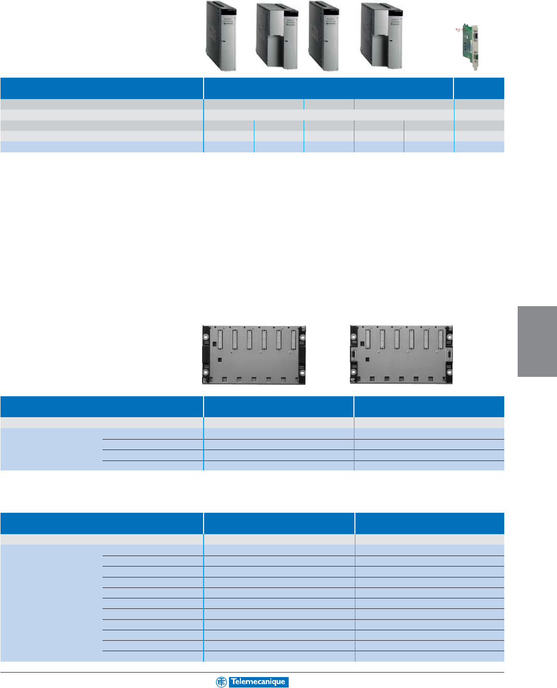
6-11
PROGRAMMABLE
LOGIC CONTROL
Power supply modules
(1)
Type of power supply module for Premium Atrium
(2)
Input voltage 24 Vdc 110–240 Vac 100–120/200–240 Vac 24 Vdc
Output voltage 5 Vdc/24 Vdc 5 Vdc
Total useful power 30 W 50 W 26 W 50 W 77 W 26 W
Format Standard Double Standard Double Double –
Catalog number TSXPSY1610M TSXPSY3610M TSXPSY2600M TSXPSY5500M TSXPSY8500M TSXPSI2010
(1) Process power supplies see page 3-9.
(2) Only for Unity coprocessors
Racks
Type of rack Non extendable Extendable
For configuration 1 rack Multi-rack (16 max.)
Catalog number 4 positions –TSXRKY4EX
6 positions TSXRKY6 TSXRKY6EX
8 positions TSXRKY8 TSXRKY8EX
12 positions TSXRKY12 TSXRKY12EX
Connection accessories
Type Bus X daisy chaining cable for Line terminators
extendable racks
–Set of 2
Catalog number – TSXTLYEX
L = 1 m (3.3 ft) TSXCBY010K –
L = 3 m (9.8 ft) TSXCBY030K –
L = 5 m (16.4 ft) TSXCBY050K –
L = 12 m (39.4 ft) TSXCBY120K –
L = 18 m (59.1 ft) TSXCBY180K –
L = 28 m (91.9 ft) TSXCBY280K –
L = 38 m (124.7 ft) TSXCBY380K –
L = 50 m (164 ft) TSXCBY500K –
L = 72 m (236.2 ft) TSXCBY720K –
L = 100 m (328.1 ft) TSXCBY1000K –
For additional information, reference Catalog #8000CT0302.
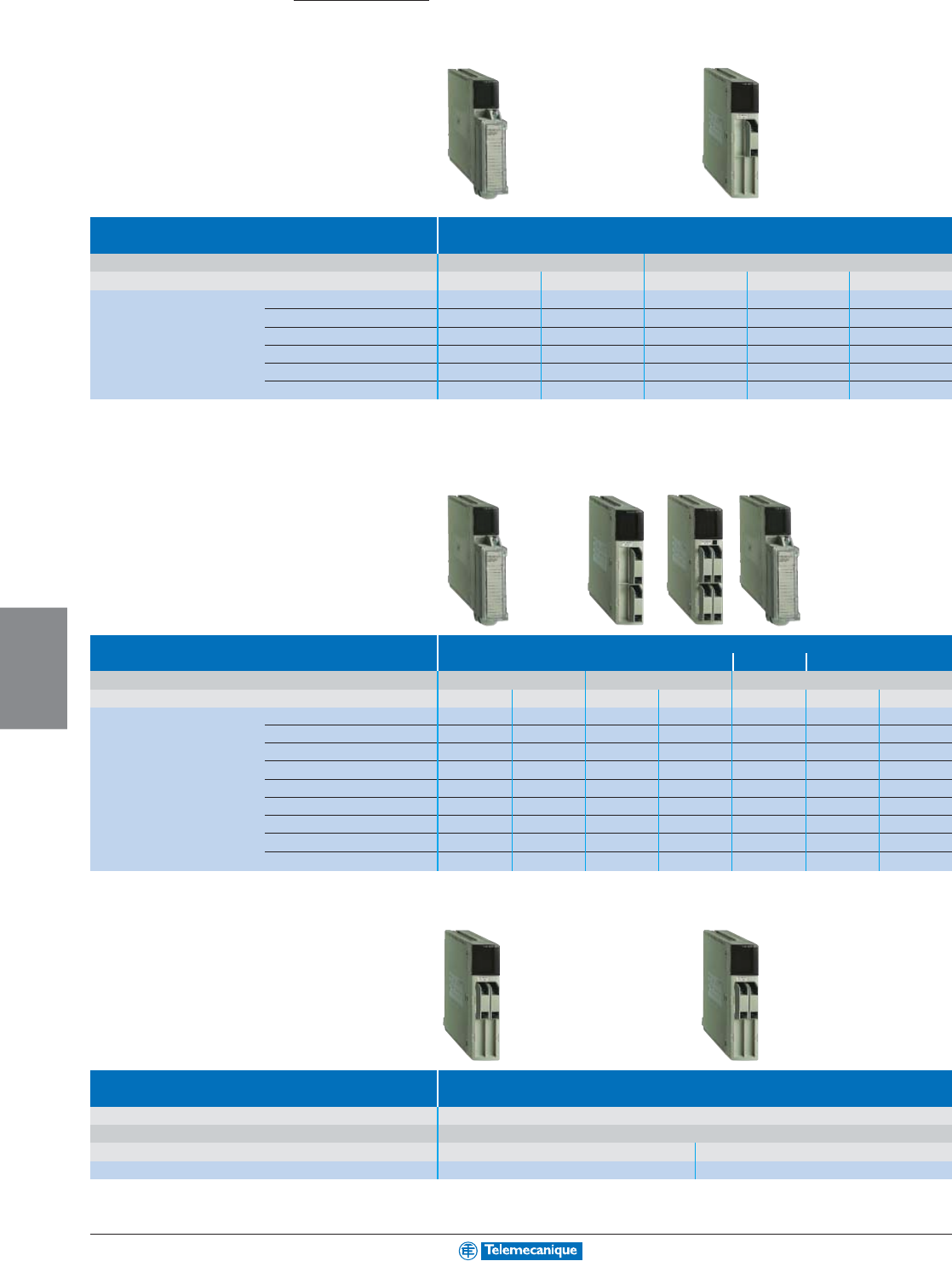
6-12
PROGRAMMABLE
LOGIC CONTROL
www.telemecanique.com
Modicon Premium platform
Discrete I/O modules
Type of module Discrete inputs
Connection By screw terminals TSXBLY01 (1) By HE 10 connector (2)
Number of isolated channels 81616 (3) 32 64
Input voltage 24 Vdc TSXDEY08D2 TSXDEY16D2 TSXDEY16FK TSXDEY32D2K TSXDEY64D2K
48 Vdc – TSXDEY16D3 – TSXDEY32D3K –
24 Vac – TSXDEY16A2 (4) –––
48 Vac –TSXDEY16A3 – – –
100–120 Vac –TSXDEY16A4 – – –
200–240 Vac –TSXDEY16A5 – – –
(1) Terminal block to be ordered separately
(2) For use with Telefast 2 wiring system
(3) Module with high-speed isolated inputs (filtering from 0.1 to 7.5 ms) able to activate the event-triggered task
(4) Module also compatible with 24 Vdc negative logic
Type of module Discrete outputs
Solid state Relay Triac
Connection
By screw terminals TSXBLY01 (1)
By HE10 conn. (2) By screw terminals TSXBLY01 (1)
Number of protected channels 81632648816
Output voltage/current 24 Vdc/0.5 A
TSXDSY08T2 TSXDSY16T2
–––––
24 Vdc/2 A
TSXDSY08T22
––––––
24 Vdc/0.1 A ––
TSXDSY32T2K TSXDSY64T2K
–––
48 Vdc/1 A
TSXDSY08T31
––––––
48 Vdc/0.25 A –
TSXDSY16T3
–––––
24ø–48 Vdc; 24–240 Vac/5 A –––
–TSXDSY08R5A
––
24–120 Vdc/5 A –––
–TSXDSY08R4D
––
48–240 Vac/1 A per channel ––––––
TSXDSY16S5
48–40 Vac/2 A per channel –––––
TSXDSY08S5
–
(1) Terminal block to be ordered separately
(2) For use with Telefast 2 wiring system
Type of module Discrete I/O
Connection By HE 10 connector (2)
Number of inputs 16 high-speed
Number of protected outputs 12 solid state 12 reflex or timed
Output voltage/current 24 Vdc/0.5 A TSXDMY28FK TSXDMY28RFK
(2) For use with Telefast 2 wiring system
Connection accessories: See the “Modicon Premium automation platform” Catalog #8000CT0302.
Automation
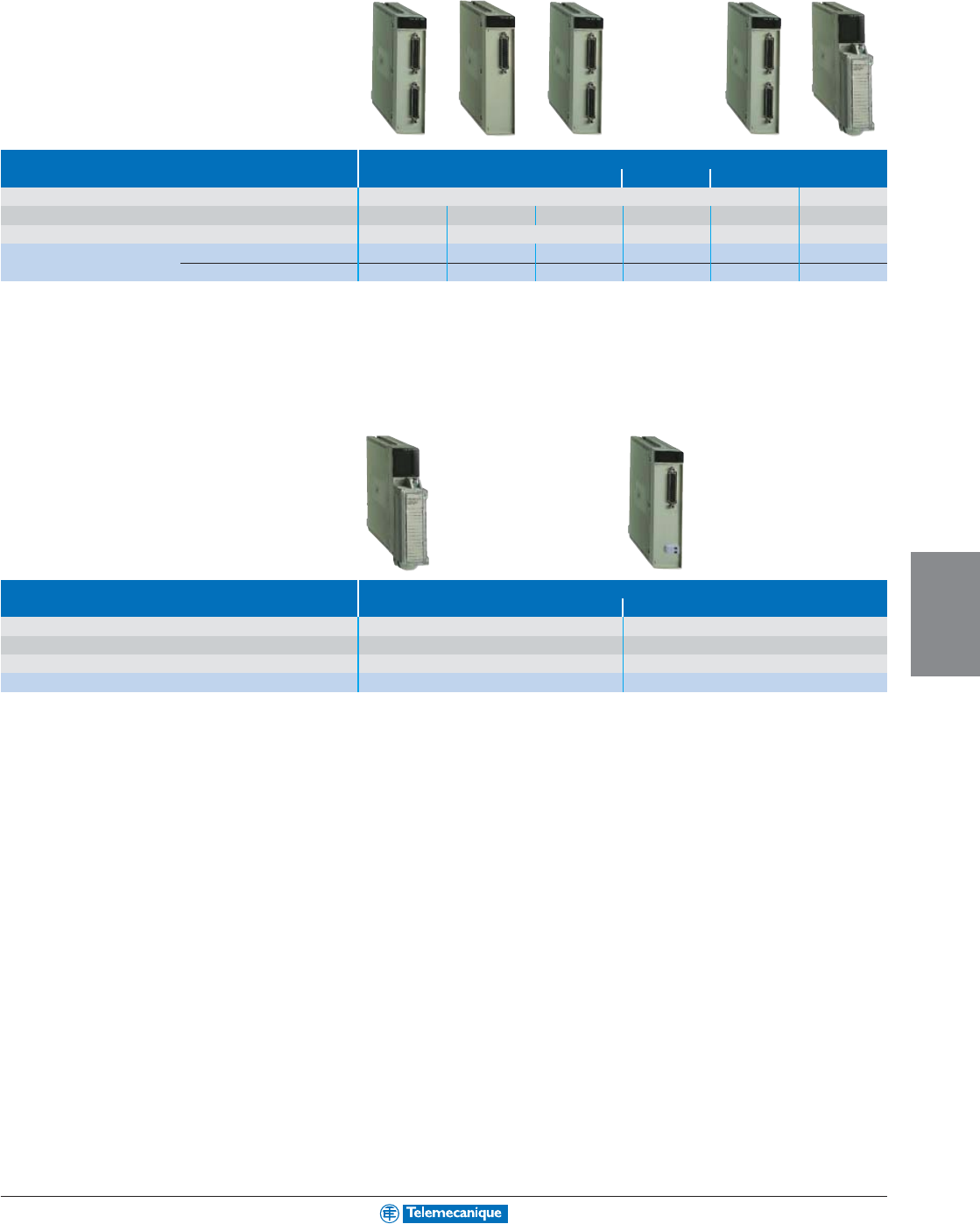
6-13
PROGRAMMABLE
LOGIC CONTROL
Analog I/O modules
Type of module Analog input
High level with common point
High level isolated
Low level isolated
Connection By 25-way SUB-D connector
By terminal block (1)
Number of channels 4 high-speed 8 16 8 16 4
Resolution 16 bits 12 bits 16 bits 16 bits 16 bits
Catalog number High level input (2) TSXAEY420 TSXAEY800 TSYAEY1600 TSXAEY810 – –
Multi-range
––––TSXAEY1614 (3) TSXAEY414 (4)
(1) Screw terminals TSXBLY01 to be ordered separately
(2) ± 10 V, 0–10 V, 0–5 V, 1–5 V, 0–20 mA, 4–20 mA
(3) ± 63 mV thermocouple (B, E, J, K, L, N, R, S, T, U)
(4) ± 10 V, ± 5 V, 0–10 V, 0–5 V, 1–5 V, 0–20 mA, 4–20 mA, -13–+63 mV, 0–400 W, 0–3850 W, thermal probe, thermocouple
Type of module Analog output
Isolated With common point
Connection By screw terminals TSXBLY01 (5) By 25-way SUB-D connector
Number of channels 48
Resolution 11 bits + sign 13 bits + sign
Catalog number Input signal (6) TSXASY410 TSXASY800
(5) Terminal block to be ordered separately
(6) ± 10 V, 0–10 V, 0–20 mA, 4–20 mA.
Connection accessories: See the “Modicon Premium automation platform” Catalog #8000CT0302.
For additional information, reference Catalog #8000CT0302.
6-14
PROGRAMMABLE
LOGIC CONTROL
www.telemecanique.com
Modicon Premium platform
Counter modules
Type of module Counter
Counter/measurement
Electronic cam
Type of inputs for Sensors (1) Sensors (1) Incremental encoders (2)
Incremental encoders (2) Encoders (2)(3) Absolute encoders (4)
Counting 40 kHz 500 kHz/200 kHz (4)
Cycle time 5 ms 10 ms 1 ms –
Number of channels 242128 cams
Number of axes –––1
Catalog number TSXCTY2A TSXCTY4A TSXCTY2C TSXCCY1128
(1) For 2/3-wire PNP/NPN 24 Vdc sensors
(2) For 5 Vdc RS422, 10–30 Vdc Totem Pole incremental encoders
(3) For SSI serial or parallel output absolute encoders
(4) For RS485 serial or parallel output absolute encoders
Motion control modules
Type of module Stepper Servomotors
(asynchronous/brushless) (brushless)
Control outputs RS422 +/- 10V SERCOS
Compatible with ranges Twin Line Altivar, Twin Line, Lexium Lexium
Functions (5) – Linear axes Infinite axes Linear or infinite axes
–Linear interpolation
Follower axes – Follower axes
Number of axes 224238 (6)
Catalog number TSXCFY21 TSXCAY21 TSXCAY41 TSXCAY22 TSXCAY33 TSXCSY84
(5) Other functions: See the “Modicon Premium automation platform” Catalog #8000CT0302.
(6) 8 real axes, 4 imaginary axes, 4 external setpoints/A 16-axis module is also available (real axes, imaginary axes or external setpoints) TSXCSY164
Weighing modules
Type of module ISP Plus
supplied uncalibrated supplied calibrated and offer
Load cell inputs 50 measurements (for 1 to 8 load cells)
Outputs 2 discrete and 1 RS 485 for display unit
Catalog number Without display unit TSXISPY101 (7)
With display unit TSXXBTH100 TSXISPY111 (7)
(7) Please consult your nearest Square D/Schneider Electric sales office.
Connection accessories: See the “Modicon Premium automation platform” Catalog #8000CT0302.
Automation
6-15
PROGRAMMABLE
LOGIC CONTROL
Communication modules
Type of module Ethernet TCP/IP
Speed 10 Mbps 10/100 Mbps
Standard services Ethway, TCP/IP (Uni-TE, Modbus) TCP/IP (Uni-TE, Modbus)
Transparent Ready Global Data – – Yes Yes Yes –
I/O Scanning – – Yes Yes Yes –
TCP Open – Yes – – Yes –
Web server Standard services – Yes Yes Yes Yes Yes
FactoryCast services – Yes – – Yes –
FactoryCast HMI services – – – – – Yes
Catalog number TSXETY110 TSXETY110WS TSXP57 (1) TSXETY4103 TSXETY5103 TSXWMY100
(1) Catalog numbers: see pages 6-8 and 6-9, Premium processors with integrated Ethernet TCP/IP port
Type of module Sensor bus, machine bus and fieldbus
AS-Interface CANopen Fipio I
NTER
B
US
Profibus DP
Name and description In-rack PCMCIA Integrated port In-rack In-rack
Speed 167 Kbps 20 K–1 Mbps 1 Mbps 0.5 Mbps 9.6 K–12 Mbps
Catalog number TSXSAY1000 TSXCPP110 TSXP57 (2) TSXIBY100 TSXPBY100
(2) Catalog numbers: see pages 6-8 and 6-9, Premium processors with integrated Fipio port
Type of module Serial links
Uni-Telway Modbus ASCII
Name and description Integrated port In-rack PCMCIA In-rack PCMCIA PCMCIA
Speed 19.2 Kbps 19.2 Kbps 1.2–19.2 Kbps 19.2 Kbps 1.2–19.2 Kbps 1.2–19.2 Kbps
Catalog number With interface RS 485 TSXP57 (1) TSXSCY21601 TSXSCP114 TSXSCY11601 TSXSCP114 TSXSCP114
RS 232D ––TSXSCP111 – TSXSCP111 TSXSCP111
20mA CL ––TSXSCP112 – TSXSCP112 TSXSCP112
(1) Catalog numbers: see pages 6-8 and 6-9, Premium processors with integrated Ethernet TCP/IP port
Type of module Other networks
Modbus Plus Fipway
Name and description PCMCIA card PCMCIA card
Speed 1 Mbps 1 Mbps
Catalog number TSXMBP100 TSXFPP20
For additional information, reference Catalog #8000CT0302.
6-16
PROGRAMMABLE
LOGIC CONTROL
www.telemecanique.com
Modicon Quantum platform
Processors
Type of processor Basic processor
Max. number of Local Unlimited (27 slots max.)
discrete I/O (1) Remote/distributed 31744 inputs (RIO)/8000 inputs (DIO) and 31744 outputs (RIO)/8000 outputs (DIO)
Max. number of Local Unlimited (27 slots max.)
analog I/O (1) Remote/distributed 1984 inputs (RIO)/500 inputs (DIO) and 1984 outputs (RIO)/500 outputs (DIO)
Type of application-specific I/O Intrinsically safe I/O, counter, motion control, high-speed interrupt inputs,
time-stamp, serial link, AS-Interface sensor/actuator bus
Communication ports (2) Integrated Modbus 1 RS 232 2 RS 232/RS 485
Modbus Plus 1 integrated, 2 in local rack
Ethernet TCP/IP 2 in local rack
Fieldbus I
NTER
B
US
/Profibus DP: 2 in local rack Profibus DP: 2 in local rack
Memory capacity Integrated 256 Kb 512 Kb 2 Mb
With PCMCIA extension _ _
Data storage _ _
Catalog number Unity Pro ––140CPU31110
Concept/ProWORX 140CPU11302 140CPU11303 –
(1) The maximum values for the number of discrete or analog I/O are not cumulative
(2) The numbers of communication modules are not cumulative, 2 or 6 in local rack, depending on model
(3) Processor compatible with Unity Pro software after updating its firmware (via OS-Loader included in Unity Pro)
Power supply modules
(4)
Type Quantum power supply
Input voltage 24 Vdc 48–60 Vdc 100–150 Vdc 120–230 Vac 115/230 Vac
Output current 8 A/3 A (5) 8 A 8 A/3 A (5) 8 A/3 A (5) 11 A
Catalog number Type Standalone (4) 140CPS21100 – 140CPS51100 140CPS11100 –
Summable 140CPS21400 140CPS41400 – – 140CPS11420
Redundant 140CPS22400 140CPS42400 140CPS52400 140CPS12400 140CPS12420
(4) Process power supplies see page 3-9.
(5) The output current for the standalone power supply modules is 3 A
PCMCIA memory extension
Type of PCMCIA card Application storage Data file storage
for Unity processors 140CPU65/67
Technology SRAM Flash EPROM SRAM
Memory size 512 Kb/512 Kb (6) –TSXMCPC512K –
1 Mb (7) TSXMRPC001M – –
2 Mb (7) TSXMRPC002M – –
2 Mb/1 Mb (6) –TSXMCPC002M –
3 Mb (7) TSXMRPC003M – –
4 Mb ––TSXMRPF004M
7 Mb (7) TSXMRPC007M – –
8 Mb ––TSXMRPF008M
(6) The 1
st
value corresponds to the size of the application area, the second to the size of the additional data area for storing data (menus, production data, etc)
(7) By configuration the user can reserve part of the memory space for data storage (menus, production data, etc)
Automation
6-17
PROGRAMMABLE
LOGIC CONTROL
Basic processor/ Advanced processors Hot Standby
moderate applications redundant applications
Unlimited (27 slots max.) Unlimited (26 slots max.)
31744 inputs (RIO)/8000 inputs (DIO) and 31744 outputs (RIO)/8000 outputs (DIO)
Unlimited (27 slots max.)
1984 inputs (RIO)/500 inputs (DIO) and 1984 outputs (RIO)/500 outputs (DIO)
Intrinsically safe I/O, counter, motion control, high-speed interrupt inputs, time-stamp, serial link, AS-Interface sensor/actuator bus
2 RS 232 1 RS 232/485
1 integrated, 6 in local rack
6 in local rack 1 integrated, 6 in local rack 6 in local rack
I
NTER
B
US
/Profibus DP: 6 in local rack Profibus DP: 6 in local rack
2 Mb 4 Mb 2 Mb
_7 Mb
_8 Mb
140CPU43412U 140CPU53414U 140CPU65150 140CPU65160 140CPU67160
140CPU43412A (3) 140CPU53414A (3) –––
Backplanes
Type Backplane Backplane extension
(1)
Catalog number – 140XBE10000
Numbers 2 slots 140XBP00200 –
of slots 3 slots 140XBP00300 –
4 slots 140XBP00400 –
6 slots 140XBP00600 –
10 slots 140XBP01000 –
16 slots 140XBP01600 –
(1) Local extension module, to be placed in main rack and secondary rack
Connection accessories
(2)
Type Cable for extension racks (main and secondary)
Catalog number L = 1 m (3.3 ft) 140XCA71703
L = 2 m (6.6 ft) 140XCA71706
L = 3 m (9.8 ft) 140XCA71709
(2) Other accessories: See the “Modicon Quantum automation platform” Catalog #8000CT0301.
For additional information, reference Catalog #8000CT0301.
6-18
PROGRAMMABLE
LOGIC CONTROL
www.telemecanique.com
Modicon Quantum platform
Discrete I/O modules
Type of module Discrete inputs
Connection By screw terminals 140XTS00200 (to be ordered separately)
Number of isolated channels 16 4 groups of 8 3 groups of 8 2 groups of 8 6 groups of 16 8 groups of 2
Input voltage 5 Vdc TTL (negative logic) – 140DDI15310 ––––
24 Vdc – 140DDI35300
(1)
––140DDI36400 –
10–60 Vdc – 140DDI85300 –––140DDI84100
20–30 Vdc – 140DSI35300
(1)
––––
125 Vdc – – 140DDI67300 –––
24 Vac 140DAI34000 140DAI35300 ––––
48 Vac 140DAI44000 140DAI45300 ––––
115 Vac 140DAI54000 140DAI55300 –140DAI54300 ––
230 Vac 140DAI74000 140DAI75300 ––––
(1) For negative logic, replace 00 at the end of the catalog number with 10, for example 140DDI35300 becomes 140DDI35310.
Type of module Discrete outputs
Solid state
Connection By screw terminals 140XTS00200 (to be ordered separately)
Number of protected channels 16 4 groups of 8 4 groups of 4 2 groups of 8 6 groups of 16 2 groups of 6
Output voltage/current 5 Vdc TTL/0.075 A (2) –
140DDO15310
––––
24 Vdc/0.5 A –
140DDO35301(1)
––––
10–30 Vdc/0.5 A (3) – 140DVO85300 ––––
19.2–30 Vdc/0.5 A – – – – 140DDO36400 –
10–60 Vdc/2 A – – – 140DDO84300 ––
24–125 Vdc/0.75 A – – – – – 140DDO88500
24–48 Vac/4 A – – 140DAO84220 –––
24–115 Vac/4 A
140DAO84010
–––––
24–230 Vac/ 4-3 A
140DAO84000
140DAO85300 ––––
100–230 Vac/4-3 A – – 140DAO84210 –––
(1) For negative logic, replace 01 at the end of the Catalog number with 10, for example 140DDO35301 becomes 140DDO35310.
(2) Negative logic
(3) Controlled outputs
Type of module Discrete I/O Discrete outputs
Solid state Relay
Connection By screw terminals 140XTS00200 (to be ordered separately) –
Number of I/O In 2 groups of 8 1 group of 4 – –
Out 2 groups of 4 4 isolated 16 N.O. 8 N.O./8 N.C.
Input voltage 24 Vdc 125 Vac 125 Vdc – –
Output voltage/current 30 Vdc/15 A 125 Vac/4 A 125 Vdc/4 A
150 Vdc or 250 Vac/2 A 150 Vdc or 250 Vac/5 A
Catalog number 140DDM39000 140DAM59000 140DDM69000 140DRA84000 140DRC83000
Connection accessories: See the “Modicon Quantum automation platform” Catalog #8000CT0301.
Automation
6-19
PROGRAMMABLE
LOGIC CONTROL
Analog I/O modules
Type of module Analog inputs
Connection By screw terminals 140XTS00200 (to be ordered separately)
Number of channels 8168
Input signal 4–20 mA 0–25/20 mA (1) RTD Thermocouple
1–5 V 4–20 mA Pt, Ni (2)
Resolution 12 bits 0–25000 points up to 16 bits 12 bits + sign 16 bits
Catalog number 140ACI03000 140ACI04000 140AVI03000 140ARI03010 140ATI03000
(1) 0–25 mA, ± 20 mA, 4–20 mA, 0–10 V, ± 10 V, 0–5 V, ± 5 V, 1–5 V.
(2) Type B, E, J, K, R, S, T, mV
Type of module Analog output
Connection By screw terminals 140XTS00200 (to be ordered separately)
Number of channels 484
Input signal 4–20 mA 0–25/20 mA 0–10 V, ± 10 V
4–20 mA 0–5 V, ± 5 V
Resolution 12 bits 0–25000 points 12 bits
Catalog number 140ACO02000 140ACO13000 140AVO02000
Type of module Analog I/O
Connection By screw terminals 140XTS00200 (to be ordered separately)
Number of inputs 4
Number of outputs 2
Input signal 0–20 mA, ± 20 mA, 4–20 mA, 0–10 V, ± 10 V, 0–5 V, ± 5 V, 1–5 V.
Resolution Inputs 16 bits, outputs 12 bits
Catalog number 140AMM09000
For additional information, reference Catalog #8000CT0301.
6-20
PROGRAMMABLE
LOGIC CONTROL
www.telemecanique.com
Modicon Quantum platform
Intrinsically safe I/O modules
Type of module I/O
Discrete Analog
Connection By screw terminal 140XTS33200 (to be ordered separately)
Number of inputs 8–8 –
Number of outputs –8– 8
Input signal 8 Vac no load 45 mA@11 Vdc RTD 0–25/20 mA 0–25/20 mA
max. per point Thermocouple (1) 4–20 mA 4–20 mA
4–200 mA
Resolution ––12 bits + sign 0–25000 points 15 bits
Catalog number 140DII33000 140DIO33000 140AII33000 140AII33010 140AIO33000
(1) Type J, K, E, T, S, R, B, mV
Counter and special purpose modules
Type of module High-speed counter
High-speed inputs
Time-stamp system
with interrupt
Type of inputs for Incremental Incremental or Discrete 24 Vdc (2) DCF 77 Discrete
counters quadrature 24 Vdc (3) 24–125 Vdc
Counting frequency 100 kHz 500 kHz – –
Number of channels 5216132
Catalog number 140EHC10500 140EHC20200 140HLI34000 140DCF07700 140ERT85410
(2) 3 operating modes: Interrupt, latch, high-speed inputs, on rising or falling edge.
(3) For GPS or DCF time receiver
Motion control modules
Type of module Servomotor
Single axis Multi-axis
Control outputs RS 422 incremental encoder SERCOS digital link
Compatible with the ranges Lexium Lexium
Functions Master/slave position capture Point synchronization, length measurement, count probe,
Synchronization of master/slave axes
motion on probe input, capture catalog number,
Torque control Rotary blade
Number of axes 1 real, 1 remote With MMFStart programming kit (4)
Processor –66 MHz 133 MHz
Catalog number 140MSB10100 140MMS42501 140MMS53502
(4) 8 real axes, 4 imaginary axes, 4 remote axes, 4 coordinate sets, 4 follower sets, cam profiles
Connection accessories: See the “Modicon Quantum automation platform” Catalog #8000CT0301.
Automation
6-21
PROGRAMMABLE
LOGIC CONTROL
Communication modules
Type of module Ethernet TCP/IP
Speed
10/100 Mbps
Standard services TCP/IP(Modbus)
Transparent Ready Global Data Yes – – Yes Yes –
I/O Scanning Yes Yes – Yes Yes –
FDR server Yes – – Yes Yes –
SNMP protocol Yes Yes Yes Yes Yes Yes
Web server Standard services Yes Yes Yes Yes Yes Yes
FactoryCast services – – Yes – Yes Yes
FactoryCast HMI services – – – – – Yes
Catalog number 140CPU651 (1) 140NOE77100 140NOE77110 140NOE77101 140NOE77111 140NWM10000
(1) Catalog numbers: see pages 6-16 and 6-17, Quantum processors with integrated Ethernet TCP/IP
Type of module Sensor bus, machine bus and fieldbus
Modbus Plus AS-Interface
Name and description Integrated link AS-I version 1.0
Speed 1 Mbps 167 Kbps
Catalog number 140CPU (2) 140EIA92100
(2) Catalog numbers: see pages 6-16 and 6-17, Quantum processors with integrated Modbus Plus
Type of module Serial link
Modbus ASCII
Name and description Integrated link In-rack
Speed 19.2 Kbps 19.2 Kbps
Catalog number 140CPU (3) (4) 140ESI06210
(3) Catalog numbers: see pages 6-16 and 6-17, Quantum processors with integrated Modbus
(4) RS 232/RS 485 on 140CPU651xx and 140CPU67160 processors and RS 232 on 140CPU31110, 140CPU43412A, 140CPU53414A processors.
For additional information, reference Catalog #8000CT0301.
6-22
PROGRAMMABLE
LOGIC CONTROL
www.telemecanique.com
Unity software
For Modicon Premium, Atrium and Quantum PLCs
Type of software Unity Pro Large (L) Unity Pro X Large (XL)
Compatibility Premium, Atrium, Quantum
Type of license Single (1 station)
Catalog number UNYSPULFUCD10 UNYSPUEFUCD10
Other characteristics: See the “Premium and Quantum automation platform” Catalog
Unity Pro programming software to increase productivity
Unity Pro is the common programming, debugging and operating software for the Modicon
Premium, Atrium and Quantum ranges of PLCs. It is based on the standards set by PL7 and
Concept software and provides a comprehensive set of new functions for greater productivity
and openness to other software.
The five IEC61131-3 languages are supported as standard in Unity Pro with all the
debugging functions, on the simulator or directly online with the PLC.
Thanks to independent symbolic memory variables, structured data and user function blocks,
the application objects directly reflect the application-specific components of the automated
process.
Using graphic libraries, the Unity Pro operator screens are configured in the application by
the user. Operator access is simple and direct.
Debugging and maintenance are made simple by animated graphic objects.
For diagnostics, a display window provides a clear display in chronological order (time-
stamped at source) of all system and application faults. The navigation function for finding
the causes of faults traces missing conditions back to the source.
The standard XML Web format for exchanging data has been adopted as the source format
for Unity applications. All or part of the application can be exchanged with other software in
the project simply using the Import/Export function.
The converters integrated in Unity Pro automatically convert IEC 61131-3 PL7 and Concept
standards and applications.
Specialist tools
Unity Studio has been designed to manage multi-application projects. Unity Studio is a
genuine software suite incorporating Unity Pro, Power Suite for drives and motor starters,
XBT-L1000 for HMI and OFS for real-time communication. It provides every application
expert with an engineering platform that is open to his own development methodology.
Based on the Microsoft Visio editor for describing the application, Unity Studio can be used
in particular for synchronizing applications on Ethernet.
For batch/process applications, Unity Application Generator (UAG) is the design and
generation tool for PLC and HMI integration. Based on a re-usable object approach (PID,
motor, valve, etc) in accordance with standard ISA S88, UAG generates the PLC code and
the elements required for the HMI system. Single entry of data ensures speed and
consistency between the two systems.
Unity Developer’s Edition (UDE) gives VBA, VB or C++ developers access to all
the Unity Pro and Unity Studio object servers. In particular, it can be used for developing
made-to-measure solutions such as the creation of interfaces with an electrical CAD
system, a variables generator or PLC programs.
For additional information on Modicon Premium, reference Catalog #8000CT0302. For additional information on Modicon Quantum, reference Catalog #8000CT0301.
Automation
6-23
PROGRAMMABLE
LOGIC CONTROL
Programming software
For Modicon TSX Micro, Premium
and Atrium
PL7 is the common programming, debugging and operating software for the TSX Micro and Premium
ranges of PLCs as well as Atrium coprocessors (see pages 6-2, 6-8 and 6-16).
PL7 offers 4 IEC languages: Instruction List (IL), Ladder Diagram (LD), Structured Text (ST) and
Sequential Function Chart (SFC). You can use the most suitable language for each function in your
application, making use of the multi-tasking structure of the processors.
For using application-specific functions, PL7 directly integrates the application-specific screens
required for configuration and adjustment as well as supervisory and diagnostics activities.
Type of software PL7 Micro for TSX Micro platform
Type of license version 4.4 Single (1 station) Single with SyCon V2.8 Group (3 stations) Open Team (10 stations)
Catalog number Software package (1) TLXCDPL7MPPU44M TLXCDPL7MPPC44M TLXCD3PL7MPPU44M TLXOTPL7MP44M
Update (2) TLXRCDPL7MP44M TLXRCDPL7MPC44M TLXRCD3PL7MP44M –
PL7 Junior for TSX Micro/Premium and Atrium coprocessor platforms
Type of license version 4.4 Single (1 station) Group (3 stations)
Catalog number Software package (1) TLXCDPL7JPU44M TLXCD3PL7JPU44M
Update (2) TLXRCDPL7JP44M TLXRC3DPL7JP44M
Upgrade (3) TLXUCDPL7JP44M TLXUCD3PL7JP44M
PL7 Pro for TSX Micro/Premium and Atrium coprocessor platforms
Type of license version 4.4 Single (1 station) Group (3 stations) Open Team (10 stations) Open Site
Catalog number Software package (1) TLXCDPL7PPU44M TLXCD3PL7PPU44M TLXOTPL7PP44M TLXOSPL7PP44M
Update (2) TLXRCDPL7PP44M TLXRCD3PL7PP44M – –
Upgrade (3) TLXUCDPL7PP44M TLXUCD3PL7PP44M – –
(1) PU at the end of the catalog number: software package supplied with cable for USB port on PC, replace with P for cable for RS 232C port on PC.
(2) From the previous software version. (3) From lower level, earlier version software.
For Modicon Quantum/Momentum/Compact
Concept is the powerful IEC programming software for the Momentum, Compact and Quantum range of
PLCs. It provides advanced Microsoft Windows based tools that deliver a multi-language development
environment for control system programming.
Uses familiar, standardized editors, bundled in a single application to create and integrate PLC control,
communication and diagnostic logic.
Five IEC editors give users the freedom to choose the programming language that fits their application
requirements: Function Block Diagram (FBD), Ladder Diagram (LD), Sequential Function Chart (SFC),
Structured Text (ST) and Instruction List (IL).
Type of software Concept for Quantum/Momentum platforms
Type of license version 2.6 Single (1 station) Group (3 stations) 10 users (10 stations) Site
Software catalog numbers Concept S 372SPU47101V26 – – –
Concept M 372SPU47201V26 – – –
Concept XL 372SPU47401V26 372SPU47411V26 372SPU47421V26 372SPU47431V26
Update catalog numbers Concept S (3) 372ESS47101 – – –
Concept M (3) 372ESS47201 – – –
Concept XL (3) 372ESS47401 372ESS47403 372ESS47410 372ESS47400
(3) From an earlier software version.
ProWORX 32 is the flexible, easy-to-use cross-platform LL984-programming software for Modicon range
PLCs. It gives you the power to program your Modicon controllers online or offline, manage your I/O
subsystems, and analyze your plant’s activity in real-time, all in a familiar Windows environment.
ProWORX 32 provides client/server capabilities to organize user-groups and -rights, store projects at a
central location and realize office-plant floor bridging.
The project emulator provides the ability to test projects prior to running them in the PLC run-time
environment to ensure your system will run at peak efficiency.
Type of software ProWORX for Quantum/Momentum platforms
Type of license version 1.1 Single (1 station) Group (3 stations) Multi-user (10 stations) Site
Software catalog numbers ProWORX 32 Server 372SPU78001PSEV – – –
ProWORX 32 Suite 372SPU78001PSSV – – –
ProWORX 32 Client, Full Dev. 372SPU78001PDEV 372SPU78001PSTH 372SPU78001PSTE 372SPU78001SITE
ProWORX 32 Online 372SPU78101PONL – – –
ProWORX 32 Lite 372SPU71001PLDV 372SPU71001PLTH 372SPU71001PLTE –
Upgrade to ProWORX 32 catalog numbers (4) 372SPU78401LPUP 372SPU78401LPTH 372SPU78401LPTE –
(4) Only possible for customers, who are “up-to-date” with CSP (continuing support program)
For additional information on Modicon Premium, reference Catalog #8000CT0302. For additional information on Modicon Quantum, reference Catalog #8000CT0301
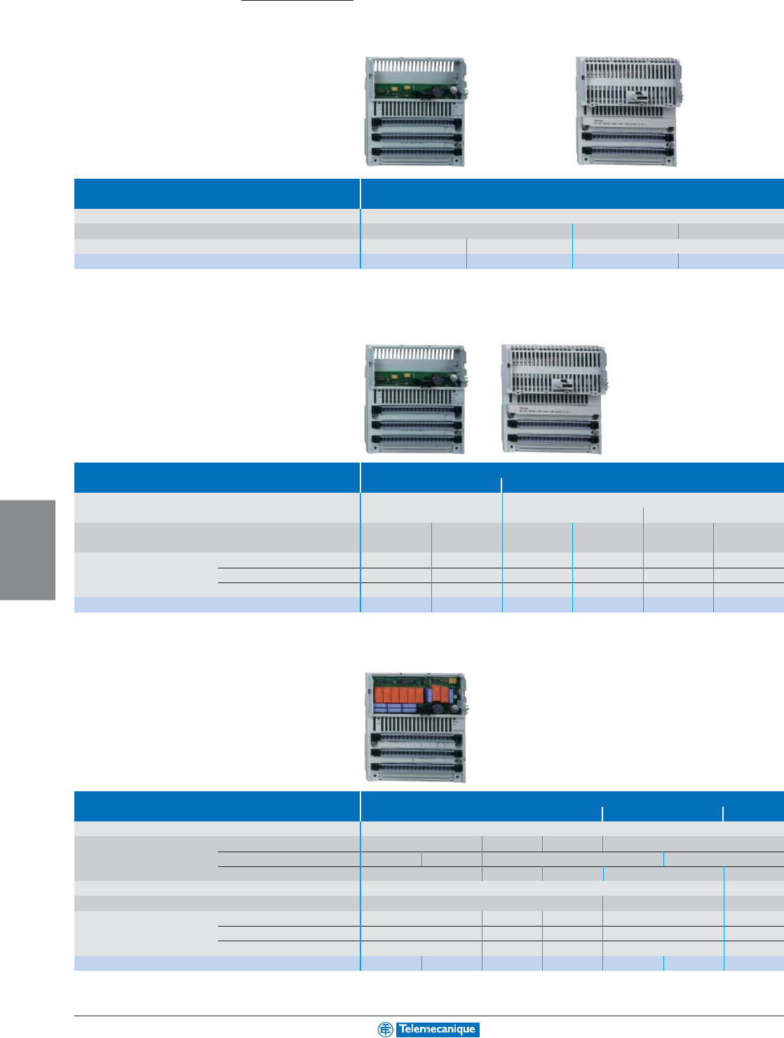
6-24
PROGRAMMABLE
LOGIC CONTROL
www.telemecanique.com
Modicon Momentum distributed I/O
Discrete I/O modules
Type of module Multibus discrete inputs
Connection By screw terminals 170XTS00100 or spring terminals 170XTS00200 (to be ordered separately)
Input voltage 24 Vdc 120 Vac 230 Vac
Number of channels 16 (1 common point) 32 (2 common points) 16 (2 common points)
Catalog number 170ADI34000 170ADI35000 170ADI54050 170ADI74050
Type of module Multibus discrete outputs
Solid state Triac
Connection By screw terminals 170XTS00100 or spring terminals 170XTS00200 (to be ordered separately)
Output voltage 24 Vdc 120 Vac 230 Vac
Number of protected channels 16 32 8 16 8 16
(2 common pt) (2 common pts) (2 common pts) (2 common pts) (2 common pts) (2 common pts)
Output current Per channel 0.5 A 0.5 A 2 A 0.5 A 2 A 0.5 A
Per group of channels 4 A 8 A 4 A 4 A 4 A 4 A
Per module 8 A 16 A 8 A 8 A 8 A 8 A
Catalog number 170ADO34000 170ADO35000 170ADO53050 170ADO54050 170ADO73050 170ADO74050
Type of module Multibus discrete I/O
Solid state Relay Triac
Connection By screw terminals 170XTS00100 or spring terminals 170XTS00200 (to be ordered separately)
Number of channels Inputs 16 (1 common pt)
16 (4 com. pts.) 16 (1 com. pt.)
10 (1 common point)
Input logic Positive (1) Negative Positive –
Outputs 16 (2 common points)
8 (2 common pts)
12 (1x8, 1x4) 8 (2 common pts)
8 (1 common pt)
Input voltage 24 Vdc 120 Vac
Output voltage 24 Vdc 24–230 Vac/20–115 Vdc 120 Vac
Output current Per output 0.5 A 2 A 0.5 A 2 A 0.5 A
Per group of channels 4 A 4 A 4/2 A 8 A 4 A
Per module 8 A 16 A 6 A 16 A 4 A
Catalog number
170ADM35010 170ADM35015 170ADM37010 170ADM39010 170ADM39030 170ARM37030 170ADM69051
(1) For a version with high-speed positive logic, replace the 0 at the end of the catalog number with 1. E.g. 170ADM35010 becomes 170ADM35011
Connection accessories: See the “Modicon Momentum automation platform” Catalog #AUTC101272123EN.
Automation
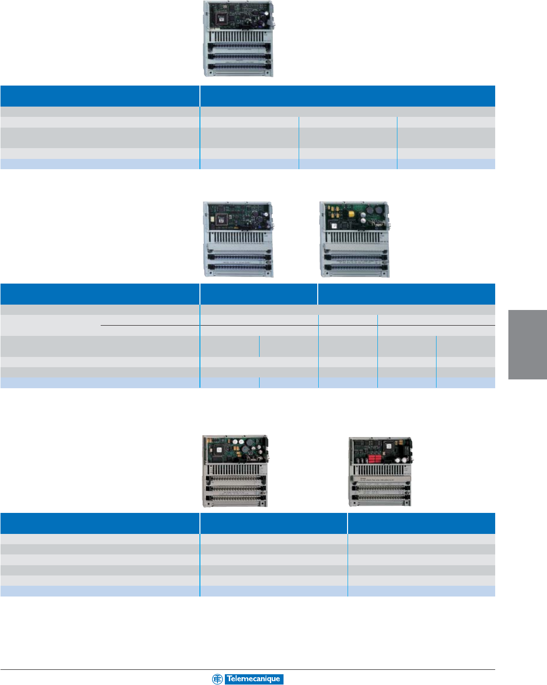
6-25
PROGRAMMABLE
LOGIC CONTROL
Analog I/O modules
Type of module Multibus analog inputs
Connection By screw terminals 170XTS00100 or spring terminals 170XTS00200 (to be ordered separately)
Number of channels 8 isolated 16 with common point 4 isolated
Input signal ± 5 V, ± 10 V, ± 20 mA, ± 5 V, ± 10 V, 4–20 mA Multi-range ± 25 mV, ± 10 mV
1–5 V, 4–20 mA (1)
Resolution 14 bits + sign, 15 bits unipolar 12 bits + sign 15 bits + sign
Catalog number 170AAI03000 170AAI14000 170AAI52040
(1) Temperature probe: Pt 100, Pt 1000, Ni 100, Ni 1000, Thermocouple: B, E, J, K, N, R, S, T.
Type of module Multibus analog outputs Analog I/O and
multibus discrete I/O
Connection By screw terminals 140XTS00200 (to be ordered separately)
Number of channels Inputs –
4 differential + 4 discrete
6 with com pt + 8 discrete (24 Vdc)
Outputs 4
2 + 2 discrete (24Vdc)
4 with com pt + 8 discrete (24 Vdc)
Input signal ± 10 V, 0–20 mA ± 10 V, 4–20 mA
± 5 V, ± 10 V, ± 20 mA,
0–10 V ± 10 V
1–5 V, 4–20 mA
Output signal –± 10 V, 4–20 mA 0–10 V ± 10 V
Resolution 12 bits + sign
12–14 bits dep. on signal
14 bits 14 bits
Catalog number 170AAO12000 170AAO92100 170AMM09000 170ANR12090 170ANR12091
Application-specific I/O modules
Type of module High-speed counter Discrete I/O
with Modbus port
Type of inputs for Incremental or absolute encoders RS 485 Modbus port
Operating voltage 24 Vdc 120 Vac
Counting frequency 200 kHz –
Number of channels 2 independent –
Number of discrete I/O 2 x 3 inputs/2 x 2 outputs 6 inputs/3 outputs
Catalog number 170AEC92000 170ADM54080
For additional information, reference Catalog #AUTC101272123EN.
6-26
PROGRAMMABLE
LOGIC CONTROL
www.telemecanique.com
Modicon Momentum distributed I/O
Communication modules
Type of module Ethernet Sensor bus, machine bus and fieldbus
TCP/IP Fipio I
NTER
B
US
(1)
Profibus DP
Speed 10 Mbps 10/100 Mbps 1 Mbps 0.5 Mbps 9.6 K–12 Mbps
Manager PLC –Premium - -
Redundancy No No No No
Standard services Modbus TCP/IP – – –
Catalog number 170ENT11002 170ENT11001 170FNT11001 170INT11000 (1) 170DNT11000
(1) Generation 4, twisted pair medium, with optical fiber catalog number: 170INT12000
Type of module Other networks
Modbus Plus DeviceNet
Speed 1 Mbps 0.5 Mbps
Manager PLC Premium or Quantum Quantum –
Redundancy No Yes No
Standard services –––
Catalog number 170PNT11020 70PNT16020 170LNT71000
Optional modules
Type of module Modbus Plus Asynchronous serial link
Communication ports 1 Modbus Plus 2 redundant Modbus Plus 1 RS 232/RS 485 Modbus
Real-time clock Integrated, ± 13 sec/day accuracy
Connection By 9-way SUB-D connector
Catalog number 172PNN21022 172PNN26022 172JNN21032
Connection accessories
Type RS 232C communication cable
Length 1 m (3.3') 3 m (9.8') 6 m (19.7')
Catalog number 110XCA28201 110XCA28202 110XCA28203
Other connection accessories: See the “Modicon Momentum automation platform” Catalog #AUTC101272123EN.
Automation
6-27
PROGRAMMABLE
LOGIC CONTROL
Processors
Type of processor M1
Number of I/O Discrete 2048 I/O 2048 I/2048 Q 8192 I/O
Registers 2048 words 4096 words 26048 words
Integrated communication ports
Modbus 1 RS 232C
1 RS 232C + 1 RS 485
1 RS 232C
1 RS 232C + 1 RS 485
Ethernet TCP/IP –
I/O bus (1) – 1 I/O port –
Transparent Ready Embedded Web server –
Memory capacity RAM 64 Kb 256 Kb 512 Kb
Flash 256 Kb 256 Kb 512 Kb
User, 984 LL language (2) 2.4 K 12 K 18 K
User, IEC language (3) – 160 K 240 K
Data 2 K 4 K 24 K
Cycle time 1 ms/K 0.63 ms/K 1 ms/K 0.63 ms/K 1 ms/K
Catalog number 171CCS70000 171CCS70010 171CCS78000 171CCS76000 171CCC78010
(1) I/O bus derived from I
NTER
B
US
bus.
(2) ProWORX 32 or Concept programming software.
(3) Concept programming software.
Type of processor M1 M1E
Number of I/O Discrete 8192 I/O
Registers 26048 words
Integrated communication ports
Modbus 1 RS 232C 1 RS 485 –
Ethernet TCP/IP – 1 integrated Ethernet port
I/O bus (1) 1 I/O port – 1 I/O port
Transparent Ready Embedded Web server – Standard services
Memory capacity RAM 512 Kb 544 Kb
Flash 512 Kb 1 Mb 512 Kb 1 Mb
User, 984 LL language (2) 18 K
User, IEC language (3) 240 K – 200 K – 200 K
Data 24 K
Cycle time 1 ms/K 0.3 ms/K
Catalog number 171CCC76010 171CCC98020 171CCC98030 171CCC96020 171CCC96030
Power supply module
(4)
Type of power supply module for Momentum processors
Input voltage 120 or 230 Vac (selected by jumper)
Output voltage 24 Vdc
Output current 0.7 A
Catalog number 170CPS11100
(4) Process power supplies see page 3-9.
For additional information, reference Catalog #AUTC101272123EN.
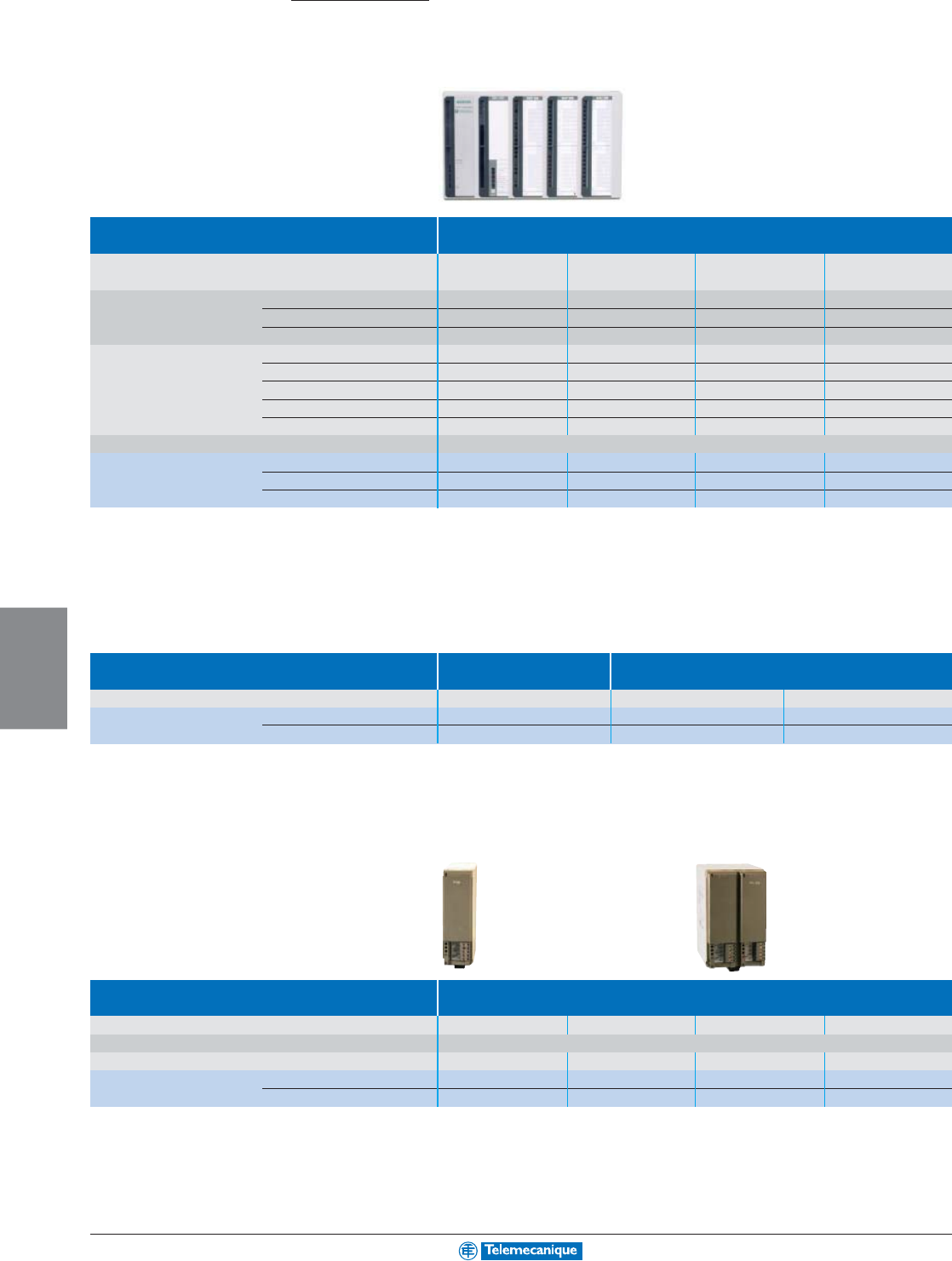
6-28
PROGRAMMABLE
LOGIC CONTROL
www.telemecanique.com
Modicon Compact 984
Processors
Automation
Type of processor 80386 32 bit
Number of I/O 512 words 1024 words 512 words 512 words
(256 in/256 out) (512 in/512 out) (256 in/256 out) (256 in/256 out)
Integrated communication ports Modbus 222–
Modbus Plus 11–1
PCMCIA II slot 11––
Memory capacity RAM 512 Kb 1 Mb 512 Kb 512 Kb
Flash 1 Mb 1 Mb 1 Mb 1 Mb
User, 984 LL language (1) 16 K words 32 K words 16 K words 8 K words
User, IEC language (2) 220 Kb 620 Kb 220 Kb 220 Kb
Data 48 K words 96 K words 48 K words 24 K words
Cycle time 1 Kbit instructions 0.36 ms
Catalog number Standard PCE984275 PCE984285 PCE984258 PCE984265
With conformal coating PCE984275C PCE984285C PCE984258C PCE984265C
Railroad standard EN50.155 ––PCE984258R –
(1) ProWORX 32 or Concept programming software.
(2) Concept programming software.
Backplanes
Type of backplane Primary Secondary
Number of slots 2 CPU, 3 I/O 5 I/O 2 I/O
Catalog number Standard ASHDTA200 ASHDTA201 ASHDTA202
With conformal coating ASHDTA200C ASHDTA201C ASHDTA202C
Power supply module
Type of power supply module for Modicon Compact 984
Input voltage range 95–253 Vac 105–150 Vdc
90–264 Vac, 8.5–13.8 Vdc 90–264 Vac, 8.5–13.8 Vdc
Output voltage 24 Vdc (±5%)
Output current (continuous) 0–1.0 A 0.1–1.5 A 0.1–2.0 A 0.1–2.0 A
Catalog number Standard ASP120000 ASP120125 ASPRTU252 ASPRTU258
With conformal coating ––ASPRTU252C ASPRTU258C
6-29
PROGRAMMABLE
LOGIC CONTROL
Analog I/O modules
Type of module Analog inputs
Number of channels (1) 4 two-pole inputs 2 two-pole inputs 4 four-pole RTDs or 8 two-pole voltage sensors
Input signal ±10 Vdc ±1 Vdc, ±10 Vdc ±5 Vdc, ±10 Vdc ±0.5 Vdc linear
±0.5,±1,±5,±10 Vdc
±0.5 Vdc linear
±20 mA
0–1 Vdc, 0–10 Vdc 0–5 Vdc, 0–10 Vdc
±0.99 Vdc nonlinear 0–0.5, 0–1, 0–5, ±0.99 Vdc nonlinear
±20 mA, 0–20 mA
±20 mA 0–10 Vdc
Resolution 12 bits + sign 11 bits + sign 15 bits + sign 12 bits + sign 15 bits + sign –
Catalog number Standard ASBADU205 ASBADU206 ASBADU210 ASBADU204 ASBADU214 –
Standard –ASBADU256 – – – ASBADU254
With conformal coating –ASBADU256C – – – ASBDAP254C
For 4 four-pole RTDs or 8 thermocouples, reference Catalog #ASBADU257/257C.
Type of module Analog output
Number of channels
22 x 282
Output voltage +10 Vdc +1, +5, +10 Vdc ±10 Vdc +10 Vdc
Resolution 11 bits + sign 12 bits + sign 11 bits + sign 11 bits + sign
Catalog number Standard ASBDAU202 ASBDAU204 ASBDAU208 ASBDAU252
With conformal coating –––ASBDAU252C
Type of module Intelligent and specialty
Number of channels 45 discrete in 4 frequency in - counter input 4
1 discrete out 4 process in - enable inputs 4
1 analog out 4
semiconductor in
2
relay outputs 4
Frequency/counter 0–10 kHz – – 5–50kHz 500 kHz 10 kHz
Motion control –Encoder Resolver – – –
Counter/positioner ––––––
Catalog number Standard ASBVRC200 ASBMOT201 ASBMOT202 ASBFRQ204 ASBZAE201 ASBZAE204
Standard ASBCTR224 – – – – –
For additional information, reference Catalog #AUTC000196122EN.
6-30
PROGRAMMABLE
LOGIC CONTROL
www.telemecanique.com
Modicon Compact 984
Discrete I/O modules
Automation
Type of module Discrete inputs
Input voltage 12–60 Vdc 5 Vdc TTL 24 Vdc 24 Vdc 110 Vdc ±40% 24 Vdc
true high true low sink true high true low sink true high
Number of inputs 2 groups of 8 1 group of 16
Catalog number Standard ASBDEP214 ASBDEP215 ASBDEP216 ASBDEP217 – ASBDEO216
Standard ASBDEP254 – – – ASBDEP257 –
With conformal coating ASBDEP254C – – – ASBDEP257C –
Type of module Discrete outputs
Output voltage 24 Vdc 5–24Vdc 24–150 Vdc, 24–250 Vac 24–230 Vac 24–250 Vac,
true high true low sink true high 24–154 Vdc
Number of outputs 2x8 transistors 2x8 transistors 4x1 relay 8x1 relay 2x4 triacs 2x8 triacs 1x8 relays
Catalog number Standard ASBDAO216 ASBDAP217 ASBDAP204 ASBDAP208 ASBDAP210 ASBDAP218 ASBDAP258
Standard ASBDAP216N – – – – – –
With conformal coating ––––––ASBDAP258C
Type of module Discrete combined input/output
Input voltage 120 Vac 24 Vdc 60 Vdc 24 Vdc 66–154 Vdc
true high true high true high true high
Output voltage 120 Vac, 24–110 Vdc 20–30 Vdc 24–110 Vdc 24–154 Vdc
-15% +10% 24–250 Vac true high 24–250 Vac 24–250 Vac
Number of inputs 41 group of 8
Number of outputs 41 group of 4 relays 1x8 transistors 1 group of 4 relays
Catalog number Standard ASBDAP211 ASBDAP212 ASBDAP292 ASBDAP220 – –
Standard –––ASBDAP250 ASBDAP252 ASBDAP253
With conformal coating –––ASBDAP250C ASBDAP252C ASBDAP253C
6-31
PROGRAMMABLE
LOGIC CONTROL
48 Vdc 60 Vdc 230 Vac 115 Vac
true high true high true high true high
2 groups of 8 1 group of 8 8 groups of 1 2 groups of 8
ASBDEP297 ASBDEP296 ASBDEP208 ASBDEP210 ASBDEP211 ASBDEP218
––––––
––––––
For additional information, reference Catalog #AUTC000196122EN.
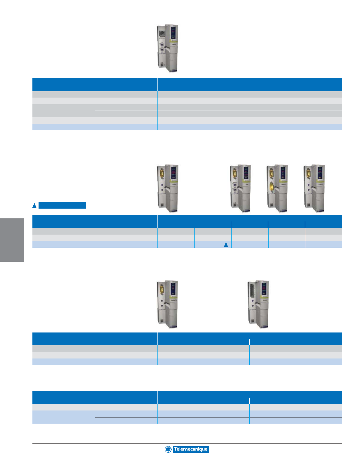
6-32
PROGRAMMABLE
LOGIC CONTROL
www.telemecanique.com
Advantys STB distributed I/O
Communication modules
Type of module Ethernet TCP/IP
Binary speed 10 Mbps
Protocol Modbus TCP/IP
Transparent Ready Embedded Web server Standard services
Ethernet services
SNMP agent, FDR client (replacement of faulty equipment), BOOTP (allocation of IP addresses by a server)
Max. number of addressable I/O modules 32 per island
Catalog number STBNIP2212
Type of module
CANopen Fipio I
NTER
B
US
Profibus DP
Max. number of addressable I/O modules 32 per island 20 per island 32 per island 32 per island 32 per island
Binary speed 20 K–1 Mbps 20 K–800 Kbps 1 Mbps 0.5 Mbps 9.6 K–12 Mbps
Catalog number STBNCO2212 STBNCO1113 STBNFP2212 STBNIB2212 STBNDP2212
Type of module
Modbus Plus DeviceNet
Max. number of addressable I/O modules 32 per island 32 per island
Speed 1 Mbps 125, 250 or 500 Kbps
Catalog number STBNMP2212 STBNDN2212
Connection accessories
Type of accessory Removable terminals for
24 Vdc power supply DeviceNet
Use All modules DeviceNet module
Catalog number Screw terminals STBXTS1120 (1) STBXTS1111
Spring terminals STBXTS2120 (1) STBXTS2111
(1) To be ordered separately, sold in lots of 10.
Connection accessories: See the “Advantys STB distributed I/O” Catalog #DIA6EC203901EN.
Automation
Launch 3rd quarter 2004
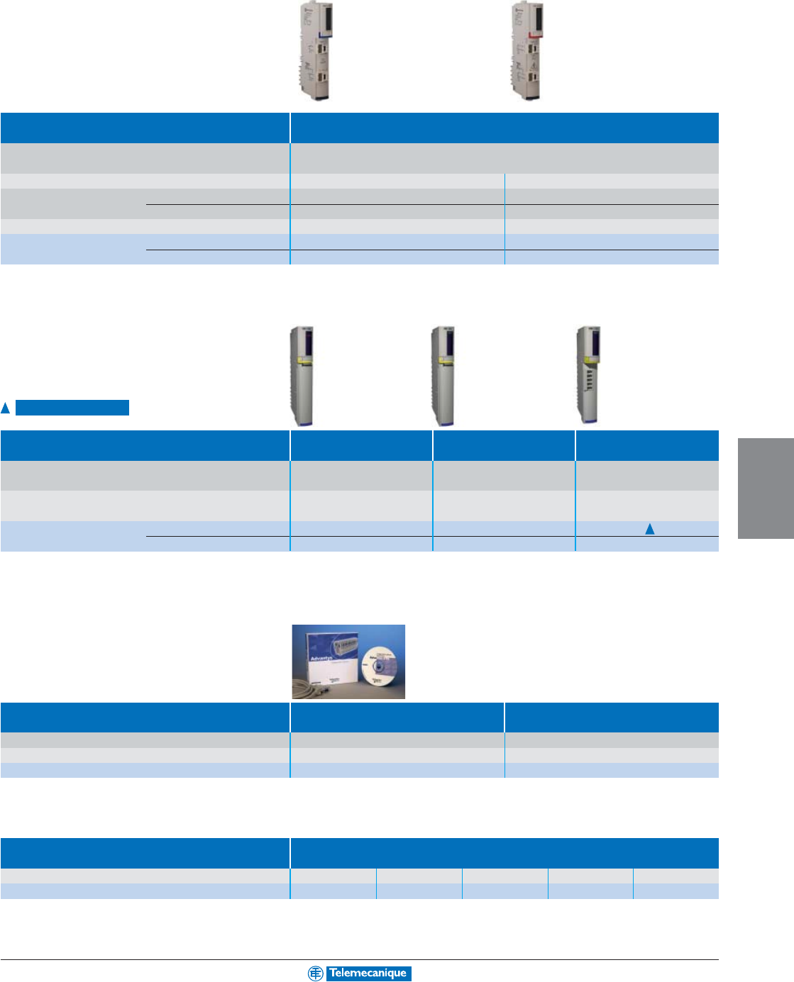
6-33
PROGRAMMABLE
LOGIC CONTROL
Power distribution modules
(1)
Type of module Power Distribution Modules (PDM)
Connection by removable terminals Screw STBXTS1130 (2)
Spring STBXTS2130 (2)
Supply voltage 24 Vdc 115–230 Vac
Maximum current Inputs 4 A at 30°C (86°F), 2.5 A at 60°C (140°F) 5 A at 30°C (86°F), 2.5 A at 60°C (140°F)
Outputs 8 A at 30°C (86°F), 5 A at 60°C (140°F) 10 A at 30°C (86°F), 2.5 A at 60°C (140°F)
Sensor/actuator bus voltage range 19.2–30 Vdc 85–265 Vac
Catalog number Module STBPDT3100 STBPDT2100
Base STBXBA2200 STBXBA2200
(1) Process power supplies see page 3-9.
(2) To be ordered separately, sold in lots of 10.
Bus extension modules
Type of module End of Segment Module End of Segment Module Connection
(EOS) (BOS) to CANopen devices
Connection by removable terminals – Screw STBXTS1120 (2) Screw STBXTS1110 (3)
–Spring STBXTS2120 (2) Spring STBXTS2110 (3)
Use For placing at end of segment For placing at head of each For placing at end of last
(except for the last) extension segment segment
Catalog number Module STBXBE1000 STBXBE1200 STBXBE2100
Base STBXBA2400 STBXBA2300 STBXBA2000
(2) To be ordered separately, sold in lots of 10.
(3) To be ordered separately, sold in lots of 20.
Software and memory card
Type Advantys configuration software Removable memory card
Use Single user license –
Memory size – 32 Kb
Catalog number STBSPU1000 STBXMP4440
Connection accessories
Type of accessory Island bus extension cable
Length 0.3 m (1') 1 m (3.3') 4.5 m (14.8') 10 m (32.8') 14 m (45.9')
Catalog number STBXCA1001 STBXCA1002 STBXCA1003 STBXCA1004 STBXCA1006
Connection accessories: See the “Advantys STB distributed I/O” Catalog #DIA6EC203901EN.
Launch 2rd quarter 2004
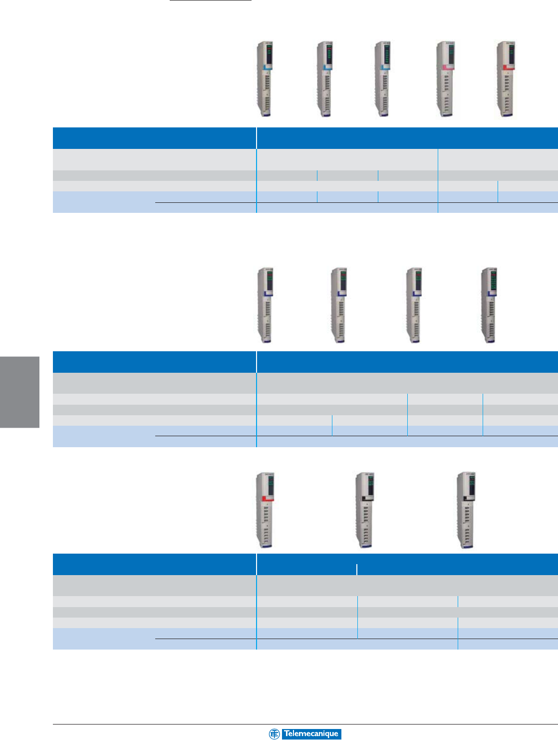
6-34
PROGRAMMABLE
LOGIC CONTROL
www.telemecanique.com
Advantys STB distributed I/O
Discrete I/O modules
Type of module Discrete inputs
Connection by removable terminals Screw STBXTS1100 (1) Screw STBXTS1110 (1)
Spring STBXTS2100 (1) Spring STBXTS2110 (1)
Number of channels 2462
Input voltage 24 Vdc 115 Vac 230 Vac
Catalog number Module STBDDI3230 STBDDI3420 STBDDI3610 STBDAI5230 STBDAI7220
Base STBXBA1000 STBXBA2000
(1) To be ordered separately, sold in lots of 20.
Type of module Discrete solid state outputs
Connection by removable terminals Screw STBXTS1100 (1)
Spring STBXTS2100 (1)
Number of channels 246
Output voltage 24 Vdc 24 Vdc 24 Vdc
Output current 0.5 A 2 A 0.5 A 0.5 A
Catalog number Module STBDDO3200 STBDDO3230 STBDDO3410 STBDDO3600
Base STBXBA1000
(1) To be ordered separately, sold in lots of 20.
Type of module Discrete outputs
Tr iac Relay
Connection by removable terminals Screw STBXTS1110 (1)
Spring STBXTS2110 (1)
Number of channels 22 N.C./2 N.O. 2 N.C.+ 2 N.O.
Output voltage 115–230 Vac 24 Vdc or 115–230 Vac
Output current
2 A at 30°C (86°F), 1 A at 60°C (140°F)
2 A per contact 7 A per contact
Catalog number Module STBDAO8210 STBDRC3210 STBDRA3290
Base STBXBA2000 STBXBA3000
(1) To be ordered separately, sold in lots of 20.
Connection accessories: See the “Advantys STB distributed I/O” Catalog #DIA6EC203901EN.
Automation
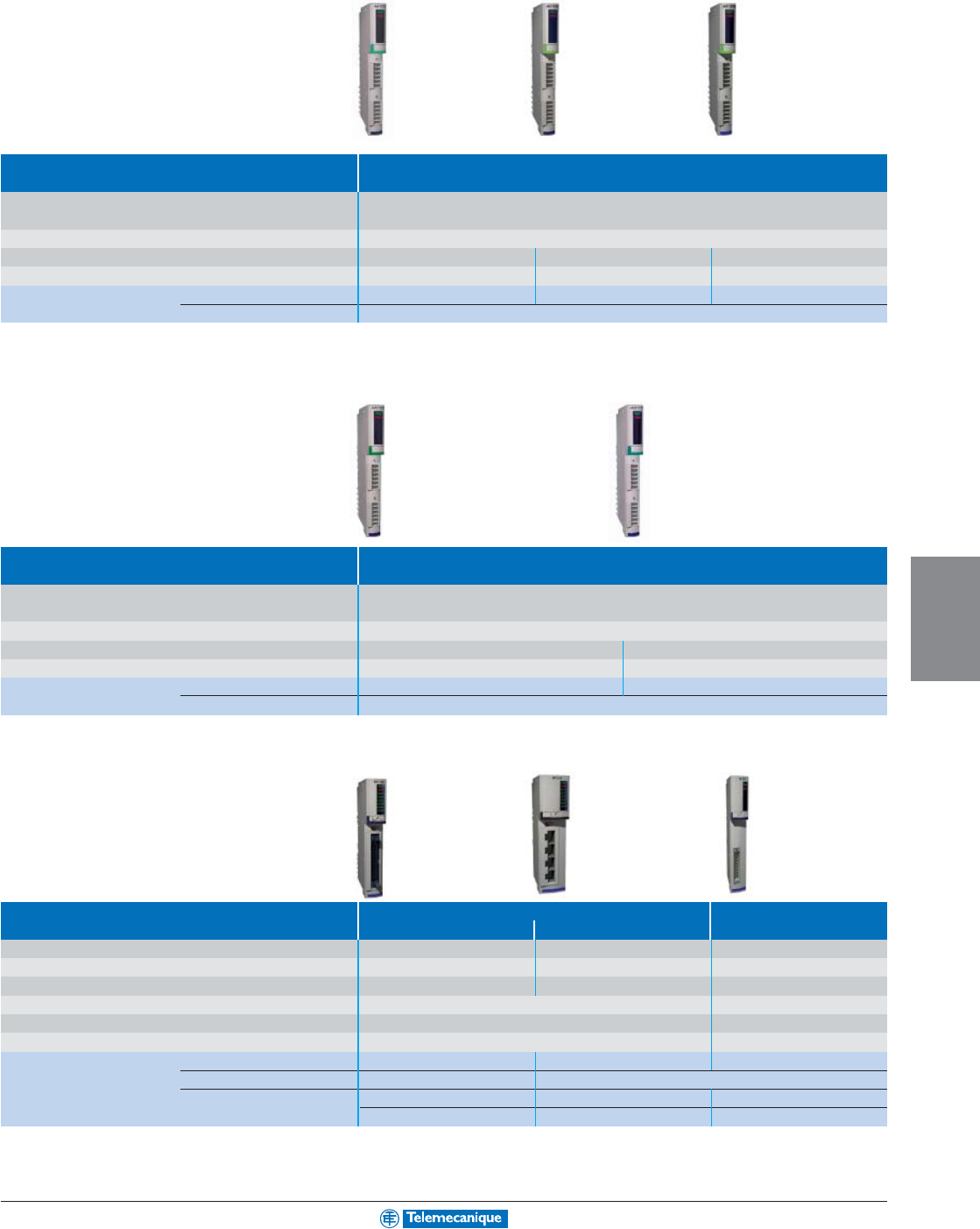
6-35
PROGRAMMABLE
LOGIC CONTROL
Analog I/O modules
Type of module Analog inputs
Connection by removable terminals Screw STBXTS1100 (1)
Spring STBXTS2100 (1)
Number of channels 2
Input signal -10 – +10 V 0–20 mA Multi-range (2)
Resolution 11 bits + sign 12 bits 15 bits + sign
Catalog number Module STBAVI1270 STBACI1230 STBART0200
Base STBXBA1000
(1) To be ordered separately, sold in lots of 20.
(2) Thermocouple B, E, J, K, R, S, T. Thermal probe Pt 100, Pt 1000, Ni 100, Ni 1000, cu 10, ± 80 mV.
Type of module Analog outputs
Connection by removable terminals Screw STBXTS1100 (1)
Spring STBXTS2100 (1)
Number of channels 2
Output signal -0 – +10 V, -10 – +10 V 0–20 mA
Resolution 11 bits + sign or 12 bits 12 bits
Catalog number Module STBAVO1250 STBACO1210
Base STBXBA1000
(1) To be ordered separately, sold in lots of 20.
Application-specific modules
Type of module For motor starters Counter
Tego Power TeSys model U (1)
Connection by connector 1 HE10 4 RJ45 Spring STBXTS2150 (2)
Number of inputs 16 12 4
Number of outputs 882
Input voltage 24 Vdc 24 Vdc
Output voltage/current 24 Vdc/0.1 A per channel 24 Vdc/0.5 A
Number of channels –1 counter channel 40 kHz
Catalog number Module STBEPI1145 STBEPI2145 STBEHC3020
Base STBXBA2000 STBXBA3000
Connection cables STBXCA3002 (L= 1 m [3.3 ft]) 490NTW00002 (L= 2 m [6.6 ft]) –
STBXCA3003 (L= 2 m [6.6 ft]) 490NTW00005 (L= 5 m [16.4 ft]) –
(1) For 2/3-wire PNP/NPN 24 Vdc sensors, 24 Vdc incremental encoders, mechanical contacts
(2) To be ordered separately
Connection accessories: See the “Advantys STB distributed I/O” Catalog #DIA6EC203901EN.
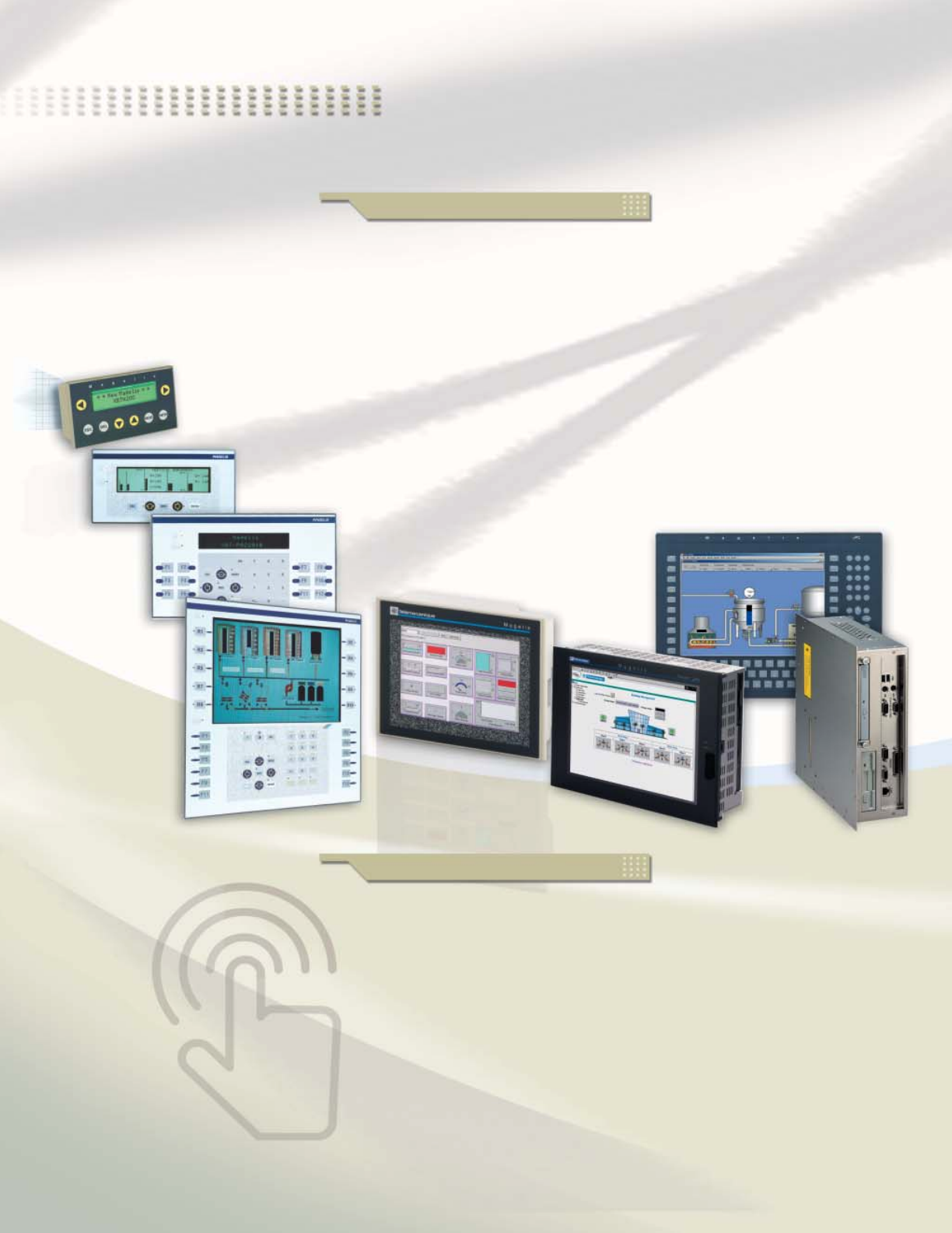
Automation systems at
Simply Smart*
Welcome to the Simply Smart* world,
compliments of Telemecanique
In order to improve the performance of your production equipment,
Telemecanique products offer you a complete range of hardware and
software specifically for Human/Machine dialogue.
Compact, the range of Magelis display units, terminals and industrial PCs
is characterized by its ease of implementation.
Ingenious, the software range simplifies the design of your HMI (Human
Machine Interfaces) applications.
Take advantage of these new Telemecanique product offers that are open to
new information and communication technologies.
Used in conjunction with other Telemecanique equipment, they ensure an
optimal solution for the operation of your automation systems.
*Simply Smart:
using ingenuity and intelligence
to continually improve ease of use.
Hardware range
Robust and simple
The new Magelis range, comprising display units,
terminals, graphic terminals with keypad or touchscreen
and
i
PC industrial PCs, offers improved robustness for
ensuring the availability of your installation.
Due to its reduced size and high performance, this range
meets the needs of machine manufacturers, system
integrators and users. Other features include easy
installation, set-up, and openness to Web technologies
using the Ethernet Transparent Ready architecture.

Display units ......................................................... p 7-2
Te r minals .............................................................. p 7-3
Graphic Terminals ................................................ p 7-4
Graphic terminals open to NTIC........................... p 7-5
(New Technology for Information and Communication)
Accessories for display units and terminals ......... p 7-6
Industrial PCs “all in one” ..................................... p 7-7
Modular industrial PCs ......................................... p 7-8
XBTL and Vijeo Designer
configuration software .......................................... p 7-10
Vijeo Look control software .................................. p 7-11
Monitor Pro supervision software ......................... p 7-12
FactoryCast Web .................................................. p 7-13
Ingenuity and user-friendliness
To benefit from perfect interoperability,
select Telemecanique software.
b XBTL1001/L1003 configuration
software for display units and terminals.
b Vijeo Designer, multi-platform software which
operates on the new graphic terminals in the Magelis
range.
b Vijeo Look, supervision software specifically
for small and medium size applications.
b Monitor Pro, supervision software for distributed
architectures, providing complete mastery of your
production management.
b The FactoryCast HMI Web server executes the
following functions at the source: data acquisition,
real-time databases, storage, alarm management and
E-mail services, as well as monitoring your installation
via animated Web pages.
Human/Machine
Interfaces
The essential guide
A selection of the most
popular selling products
enabling you to quickly
locate the most appropriate
solution for your application
... from the display unit to
the industrial PC
Contents
Software range
your beck and call
HUMAN MACHINE
INTERFACE
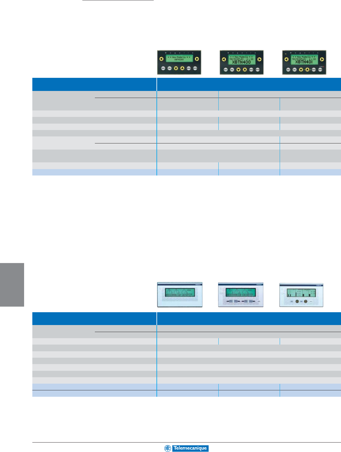
7-2
HUMAN MACHINE
INTERFACE
www.telemecanique.com
Magelis Display units
With alphanumeric screen
Type Compact display units
Display Capacity 2 lines, 20 characters 4 lines, 20 characters
Type Back-lit LCD, green Back-lit LCD, green Back-lit LCD, 3 colors:
green, orange, red
Data entry Via keypad with 8 keys (4 with changeable legends)
Functions Representation of variables Alphanumeric Alphanumeric Alphanumeric
Communication Downloadable protocols Uni-Telway, Modbus Uni-Telway, Modbus Uni-Telway, Modbus
Development software XBTL1001 and XBTL1003 (on Windows 98, 2000 and XP)
Dimensions W x D x H mm 132 x 78 x 74 132 x 104 x 74
in. 5.20 x 3.07 x 2.91 5.20 x 4.09 x 2.91
Compatibility with PLCs Twido, Nano, TSX Micro, Premium, Quantum Twido, Nano, TSX Micro, Premium,
TSX series 7, Momentum, Quantum
Supply voltage 5 Vdc 5 Vdc 24 Vdc, external
Catalog numbers XBTN200 XBTN400 XBTN401
With matrix screen
Type Multilingual display units
Display Capacity 8 lines, 40 characters
Type Back-lit LCD, monochrome
Data entry Function / service keys – 4 / 1 – / 5
Functions Representation of variables Alphanumeric, bargraph, gauge
Communication Downloadable protocols Multiple (Uni-Telway, Modbus, AEG and for Allen Bradley, GE Fanuc, Omron, Siemens PLCs)
Development software XBTL1001 and XBTL1003 (on Windows 98, 2000 and XP)
Dimensions W x D x H (mm / in.) 202 x 64.8 x 111.3 / 7.95 x 2.55 x 4.38
Compatibility with PLCs Twido, Nano, TSX Micro, Premium, Quantum
Supply voltage 24 Vdc
Without printer link, without log XBTHM007010 XBTHM027010 XBTHM017010
With printer link, with log – – XBTHM017110
7-3
HUMAN MACHINE
INTERFACE
For additional information, consult your nearest Square D/Schneider Electric sales office.
Te r minals
With alphanumeric screen
Type 2 line multilingual alphanumeric terminals
Display Capacity 2 lines, 20 characters
Type Fluorescent matrix, green Back-lit LCD, green
Data entry Function / service keys 8 / 9 12 / 10 8 / 9 12 / 10
Numeric keys – 12 – 12
Functions Representation of variables Alphanumeric
Communication Downloadable protocols Multiple (Uni-Telway, Modbus, AEG and for Allen Bradley, GE Fanuc, Omron, Siemens PLCs)
Development software XBTL1001 and XBTL1003 (on Windows 98, 2000 and XP)
Dimensions W x D x H (mm / in.) 253 x 62.5 x 152 / 9.96 x 2.46 x 5.98
Compatibility with PLCs Twido, Nano, TSX Micro, Premium, Quantum Twido, Nano, TSX Micro, Premium, Quantum
Supply voltage 24 Vdc 24 Vdc
Without printer link, without log XBTP012010 XBTP022010 XBTP011010 XBTP021010
With printer link, with log – XBTP022110 – XBTP021110
With matrix screen
Type 8 line multilingual matrix screen terminals
Display Capacity 8 lines, 40 characters
Type Back-lit LCD, monochrome
Data entry Function / service keys 12 / 10
Numeric / soft function keys 12 / 4
Functions Representation of variables Alphanumeric, bargraph, gauge
Communication Downloadable protocols Multiple (Uni-Telway, Modbus, AEG and for Allen Bradley, GE Fanuc, Omron, Siemens PLCs)
Development software XBTL1001 and XBTL1003 (on Windows 98, 2000 and XP)
Dimensions W x D x H (mm / in.) 253 x 62.5 x 155 / 9.96 x 2.46 x 6.10
Compatibility with PLCs Twido, Nano, TSX Micro, Premium
Supply voltage 24 Vdc
Without printer link, without log XBTPM027010
With printer link, with log XBTPM027110
7-4
HUMAN MACHINE
INTERFACE
www.telemecanique.com
Magelis
Graphic terminals
With keypad
Type Terminals with keypad
Display Screen size 5.7" 10.4"
Type Back-lit monochrome LCD, green TFT, 256 colors
16 levels of gray
Data entry Soft function keys with LED 8 10
Static function keys with LED 10 + legends 12 + legends
Service keys 12 12
Alphanumeric keys 12 + 3 alphanumeric access
Functions Representation of variables Alphanumeric, bitmap, bargraph, gauge, potentiometer, selector
Menus 125 records maximum with 5000 values maximum
Curves 16 16
Alarm logs Yes Yes
Communication Downloadable protocols Uni-Telway, Modbus, AEG and for Allen Bradley, GE Fanuc, Omron, Siemens PLCs
Bus and networks Fipway, Modbus Plus with PCMCIA card (except XBTF011110)
Development software XBTL1003 (on Windows 98, 2000 and XP)
Dimensions W x D x H (mm / in.)
220.3 x 88 x 265 / 8.67 x 3.46 x 10.43
296 x 91 x 332 / 11.65 x 3.58 x 13.07
Compatibility with PLCs Twido, Nano, TSX Micro, Premium, Quantum
RJ45 Ethernet 10/100 TCP/IP connector no no yes
Supply voltage 24 Vdc 24 Vdc
Catalog numbers XBTF011110 / F011310 XBTF024510 XBTF024610
With touchscreen
Type Terminals with touchscreen
Display Screen size 5.7" 10.4"
Type LCD STN, 256 colors LCD TFT, 256 colors
Data entry Touchscreen Touchscreen
Functions Representation of variables Alphanumeric, bitmap, bargraph, gauge, potentiometer, selector
Menus 125 records maximum with 5000 values maximum
Curves 16 16
Alarm logs Yes Yes
Communication Downloadable protocols Uni-Telway, Modbus, AEG and for Allen Bradley, GE Fanuc, Omron, Siemens PLCs
Bus and networks Fipway, Modbus Plus with PCMCIA card (except XBTF032110)
Development software XBTL1003 (on Windows 98, 2000 and XP)
Dimensions W x D x H (mm / in.)
197 x 92.6 x 147 / 7.76 x 3.65 x 5.79
296 x 91 x 222 /11.65 x 3.58 x 8.74
Compatibility with PLCs Twido, Nano, TSX Micro, Premium, Quantum
RJ45 Ethernet 10/100 TCP/IP connector no no yes
Supply voltage 24 Vdc 24 Vdc
Catalog numbers XBTF032110 / F032310 XBTF034510 XBTF034610
7-5
HUMAN MACHINE
INTERFACE
For additional information, consult your nearest Square D/Schneider Electric sales office.
Graphic terminals open to NTIC
(New Technology for Information and Communication)
With 5.7" touchscreen
Type Optimum Multifunction
Display LCD screen size 5.7" 5.7" 5.7" 5.7"
Type Back-lit STN Back-lit STN, monochrome STN, color TFT, color
monochrome, blue black and white 64 colors 256 colors (1)
Functions Representation of variables Alphanumeric, bitmap, bargraph, gauge, button, light, clock, flashing light, keypad
Curves yes, with log yes, with log yes, with log
Alarm logs yes, incorporated yes, incorporated yes, incorporated
Communication Downloadable protocols Uni-Telway, Modbus Uni-Telway, Modbus Uni-Telway, Modbus, Uni-Telway, Modbus Uni-Telway, Modbus,
Modbus TCP/IP Modbus TCP/IP
Bus and networks
––Ethernet, IEEE 802.3 –Ethernet, IEEE 802.3
10 BASE-T, RJ45 10 BASE-T, RJ45
Development software Vijeo Designer VJDSPULFUCDV10M (on Windows 2000 and XP)
Dimensions W x D x H mm 207 x 58 x 157 171 x 60 x 138 132 x 74 x 78
in. 8.15 x 2.28 x 6.18 6.73 x 2.36 x 5.43 5.20 x 2.91 x 3.07
Compatibility with PLCs Twido, Nano, TSX Micro, Premium, Quantum
Built-in Ethernet 10/100 TCP/IP no no yes no yes
Supply voltage 24 Vdc 24 Vdc 24 Vdc 24 Vdc 24 Vdc
Catalog numbers XBTG2110 XBTG2120 XBTG2130 XBTG2220 XBTG2330
With 7.4", 10.4" or 12.1" touchscreen
Type Multifunction
Display LCD screen size 7.4" 10.4" 10.4" 12.1"
Type TFT, color STN, color TFT, color TFT, color
256 colors (1) 64 colors 256 colors (1) 256 colors (1)
Functions Representation of variables Alphanumeric, bitmap, bargraph, gauge, button, light, clock, flashing light, keypad
Curves yes, with log yes, with log yes, with log
Alarm logs yes, incorporated yes, incorporated yes, incorporated
Communication Downloadable protocols Uni-Telway, Modbus Uni-Telway, Modbus, Uni-Telway, Modbus, Uni-Telway, Modbus,
Modbus TCP/IP Modbus TCP/IP Modbus TCP/IP
Bus and networks – Ethernet, IEEE 802.3 10 BASE-T, RJ45
Development software Vijeo Designer VJDSPULFUCDV10M (on Windows 2000 and XP)
Dimensions W x D x H (mm / in.) 215 x 60 x 170 / 8.46 x 2.36 x 6.69 317 x 58 x 243 / 12.48 x 2.28 x 5.43
Compatibility with PLCs Twido, Nano, TSX Micro, Premium, Quantum
“Compact Flash” card slot yes yes yes yes yes
Built-in Ethernet 10/100 TCP/IP no yes yes yes yes
Supply voltage 24 Vdc 24 Vdc 24 Vdc 24 Vdc 24 Vdc
Catalog numbers XBTG4320 XBTG4330 XBTG5230 XBTG5330 XBTG6330
(1) 64 colors if in flash mode.
7-6
HUMAN MACHINE
INTERFACE
www.telemecanique.com
Magelis
Accessories
For display units and terminals
Connection cables PC to Magelis transfer cables (2.5 m / 8.2 ft)
Application PC to all XBTN200 and N400 PC to all XBT except PC to XBTG
XBTN200, N400 and XBTG
Type of connector RJ45 / MiniDin + SUB D 9 SUB D 9 / SUB D 25 SUB D 9 / MiniDin
Physical link RS 232C RS 232C TTL
Catalog numbers XBTZ945 XBTZ915 XBTZG915
Connection cables Telemecanique PLC connection cables (2.5 m / 8.2 ft)
Application XBTN200, N400 to all XBT (except XBTN200, N400) to
Twido, Nano, Twido, Nano, Quantum Momentum
TSX Micro, Premium TSX Micro, Premium (port 1)
Type of connector MiniDin / SUB D 25 RJ45 / MiniDin SUB D 9 / SUB D 25 RJ45 / SUB D 25
Physical link RS 485 RS 485 RS 232 RS 232
Catalog numbers XBTZ968 XBTZ978 XBTZ9710 XBTZ9711
Network cards PCMCIA type III card
Compatibility XBTF XBTF
Protocol Modbus Plus Fipway
Catalog numbers TSXMBP100 TSXFPP20
Memory cards PCMCIA type II card “Compact Flash” card
Compatibility XBTF XBTG (except XBTG2110)
Capacity 16 Mb 16 Mb 32 Mb
Catalog numbers XBTMEM16 XBTZGM16 XBTZGM32
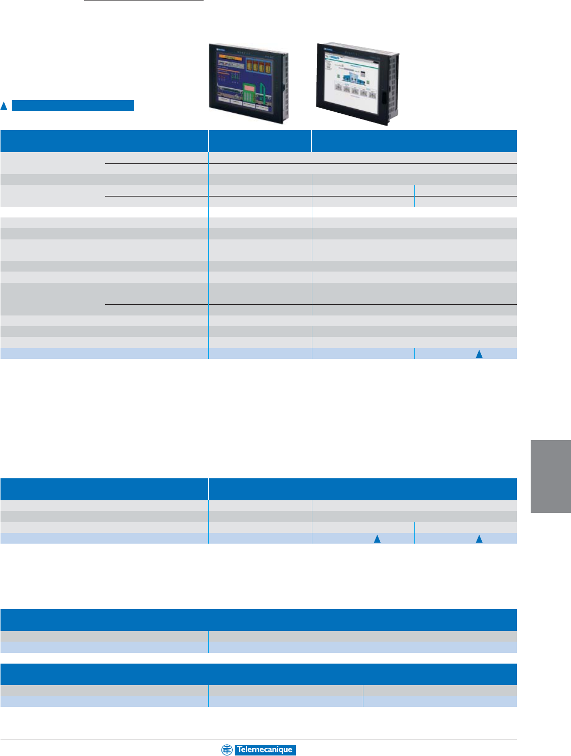
7-7
HUMAN MACHINE
INTERFACE
For additional information, consult your nearest Square D/Schneider Electric sales office.
Magelis
Industrial PCs “all in one”
Smart i PC and Compact i PC ranges
Type Smart
i
PC Compact
i
PC
Display Size 15" active matrix XGA (1024 x 768)
Type Back-lit active matrix TFT color LCD (262,144 colors)
Data entry Via touchscreen Via touchscreen
Processor Type VIA VIA Intel Pentium 4 Mobile
Frequency 667 MHz 667 MHz 1.7 GHz
Internal hard disk –≥ 20 Gb IDE, 2 1/2"
RAM memory 128 Mb expandable up to 512 Mb 256 Mb expandable up to 512 Mb (1 memory slot max.)
CD-ROM drive –Yes, 24X
Expansion slots 2 PCMCIA slots 1 PCI bus slot, 2 PCMCIA slots,
–1 Compact Flash slot
Ethernet TCP/IP network 1 x 10 BASE-T/100 BASE-TX (RJ45)
Operating system Windows XPe integrated Windows 2000 pre-installed
Input/output ports 2 x USB, 1 x COM1, 1 x COM2, 2 x USB, 1 x COM1, 1 x COM2,
1 x LPT1 (parallel), 1 x PS/2 keyboard
1 x LPT1 (parallel), 1 x PS/2 keyboard and 1 x PS/2 mouse
on front panel – 1 x USB
Mounting hardware Mounting hardware included with each product for mounting on panel or enclosure door
Dimensions W x D x H (mm / in.)
395 x 62 x 294 / 15.55 x 2.44 x 11.57
395 x 100 x 294 / 15.55 x 3.94 x 11.57
Supply voltage 24 Vdc 115–230 Vac
Catalog numbers MPCST52NDJ00T MPCKT52NAA00N MPCKT55NAA00N
Combined offers (bundle packs)
Magelis Compact
i
PC can be supplied with software packages.
Specifications identical to standard industrial PCs shown above.
Type Compact
i
PC
Processor Type VIA Intel Pentium 4M
Applications Vijeo Look Vijeo Look
Pre-installed software Vijeo Look 2.5 RT1024 Vijeo Look 2.5 RT1024 Vijeo Look 2.5 BT1024
Catalog numbers MPCKT52NAA00A MPCKT55NAA00A MPCKT55NAA00B
Accessories
Compact Flash card
Capacity 512 Mb (empty) for Smart
i
PC or Compact
i
PC
Catalog numbers MPCYN00CFE00N
RAM memory expansion
Capacity 512 Mb SO DIMM for VIA 512 Mb SO DIMM for Pentium 4 Mobile
Catalog numbers MPCYK02RAM512 MPCYK05RAM512
Launch 3rd quarter 2004
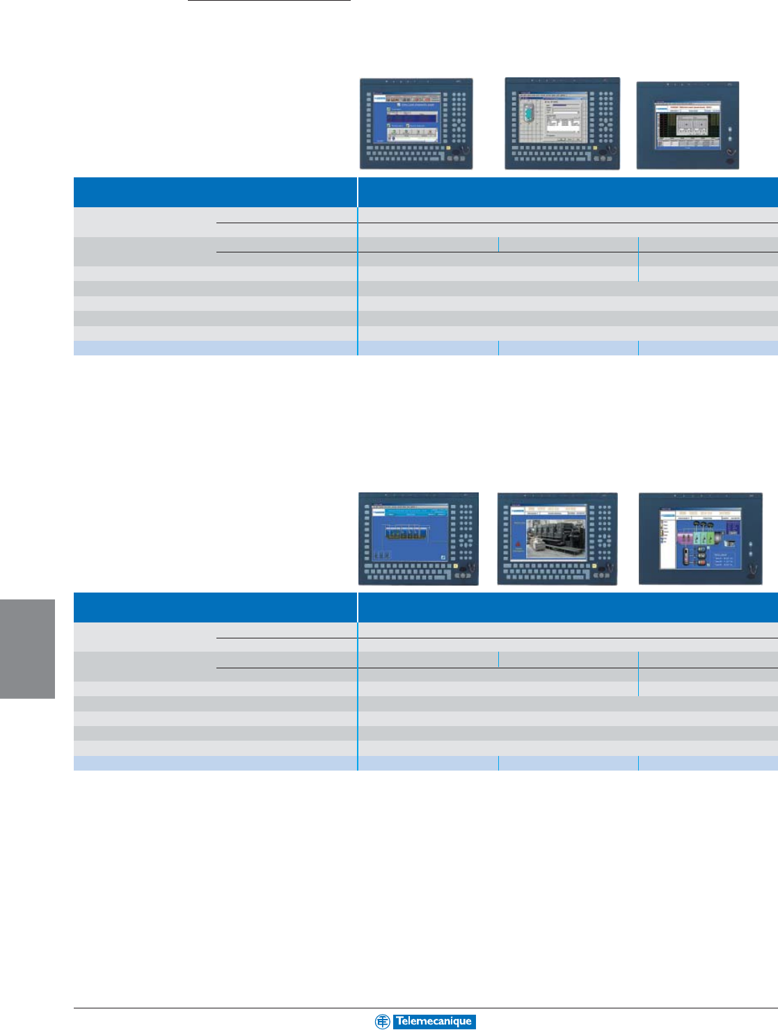
7-8
HUMAN MACHINE
INTERFACE
www.telemecanique.com
Magelis
Modular industrial PCs
Modular i PC Modular range
Type 12" front panel screen
Display Size 12" active matrix SVGA (800 x 600)
Type Back-lit active matrix TFT color LCD (262,144 colors)
Data entry Via keyboard Via keyboard and touchscreen Via touchscreen
Keyboard 70 standard IBM keys + 2 x 10 user function keys –
Dimensions W x D x H (mm / in.) 410 x 52.7 x 330 / 16.14 x 2.07 x 12.99
380 x 52.7x 330 / 14.96 x 2.07 x 12.99
Input/Output ports on front panel 1 x IrDA infrared and 1 x PS/2 keyboard/mouse
Required hardware 1 central unit Control box or 1 central unit Control box pack (combined offer)
Mounting hardware Mounting hardware included with each screen for mounting on panel or enclosure door
Supply voltage 115–230 Vac from Control box unit
Catalog numbers MPCNA20NNN00N MPCNB20NNN00N MPCNT20NNN00N
Type 15" front panel screen
Display Size 15" active matrix XGA (1024 x 768)
Type Back-lit active matrix TFT color LCD (262,144 colors)
Data entry Via keyboard Via keyboard and touchscreen Via touchscreen
Keyboard 70 standard IBM keys + 2 x 10 user function keys -
Dimensions W x D x H 480 x 52.7 x 370 / 18.90 x 2.07 x 14.57
460 x 52.7x 340 / 18.90 x 2.07 x 13.39
Input/Output ports on front panel 1 x IrDA infrared and 1 x PS/2 keyboard/mouse
Required hardware 1 central unit Control box or 1 central unit Control box pack (combined offer)
Mounting hardware Mounting hardware included with each screen for mounting on panel or enclosure door
Supply voltage 115–230 Vac from Control box unit
Catalog numbers MPCNA50NNN00N MPCNB50NNN00N MPCNT50NNN00N
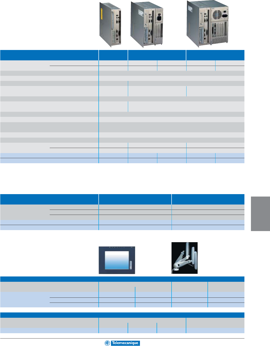
7-9
HUMAN MACHINE
INTERFACE
For additional information, consult your nearest Square D/Schneider Electric sales office.
Modular industrial PCs
Modular i PC range
Central unit Control box type Small Medium Large
Processor Type Intel Celeron Intel Celeron Intel Pentium III Intel Celeron Intel Pentium III
Frequency 566 MHz 566 MHz 850 MHz 566 MHz 850 MHz
Internal hard disk ≥ 20 Gb IDE, 2 1/2"
RAM memory 128 Mb SDRAM expandable up to 512 Mb (2 memory slots max.)
CD-ROM drive Optional Yes, removable 24X
Expansion slots – 3 slots 6 slots
(1 ISA bus, 1 PCI bus and 1 ISA/PCI bus) (2 ISA bus, 3 PCI bus and 1 ISA/PCI bus)
Ethernet TCP/IP network 1 x 10 BASE-T/100 BASE-TX (RJ45)
Bus and networks – With additional card on ISA or PCI bus: Modbus/Uni-Telway/Fipio bus,
Modbus Plus/Fipway networks, I
NTER
B
US
-S/Profibus DP/CANopen Third party bus
Video card built-in PCI 64 bit controller, 2 Mb RAM
Operating system Windows 2000 pre-installed
Input/output ports 2 x USB, 1 x COM1, 1 x COM4 and 1 x LPT1 (parallel)
1 x external VGA video screen, 1 x PS/2 keyboard (1) and 1 x PS/2 pointing device (1)
Required hardware 1 front panel screen or as a stand-alone (2)
Mounting hardware Mounting hardware included with each screen for mounting on panel or enclosure door
Dimensions W x D x H mm
310 x 310 x 94.2
310 x 310 x 184.5 310 x 310 x 258
in.
12.20 x 12.20 x 3.71 12.20 x 12.20 x 7.26 12.20 x 12.20 x 10.16
115–230 Vac supply voltage
MPCAN02NAA00N MPCBN02NAA00N MPCBN05NAA00N MPCCN02NAA00N MPCCN05NAA00N
24 Vdc supply voltage
MPCAN02NDA00N MPCBN02NDA00N MPCBN05NDA00N MPCCN02NDA00N MPCCN05NDA00N
(1) Port not operational when the central unit Control box is used with the front panel screen.
(2) To use the Control box without a front panel screen, mounting panel MPCNP00NNN00N is required.
Combined offers (bundle packs)
Magelis i PC central unit Control boxes (115–230 Vac supply) can be supplied with software packages.
Specifications identical to standard Control box units shown above.
Central unit Control box type Small Medium
Processor Type Intel Celeron, 566 MHz Intel Celeron, 566 MHz
Pre-installed software Pack A “Monitoring RT” Vijeo Look, 1024 I/O Run Time Vijeo Look supervision, 1024 I/O Run Time
Pack B “Monitoring BT/RT” –
Vijeo Look supervision, 1024 I/O Build Time/Run Time
Pack A, 115–230 Vac supply voltage MPCAN02NAA00A MPCBN02NAA00A
Pack B, 115–230 Vac supply voltage –MPCBN02NAA00B
Accessories
Separate components
Description External LCD flat screen, flush mounting Swivel arm Qwerty keyboard
12" SVGA (800 x 600) 15" XGA (1024 x 768) for external screen 101 keys, PS/2
Catalog numbers ––MPCYN00ARM00N MPCYN00KBD00N
115–230 Vac supply voltage MPCYS20NAN00N MPCYS50NAN00N ––
24 Vdc supply voltage MPCYS20NDN00N MPCYS50NDN00N ––
Separate components for Control box
Description SDRAM memory expansion CD-ROM drive for Small Control box
64 Mb 128 Mb 256 Mb MPCAN0
Catalog numbers
MPCYN00RAM064 MPCYN00RAM128 MPCYN00RAM256 MPCYN00CDR00N
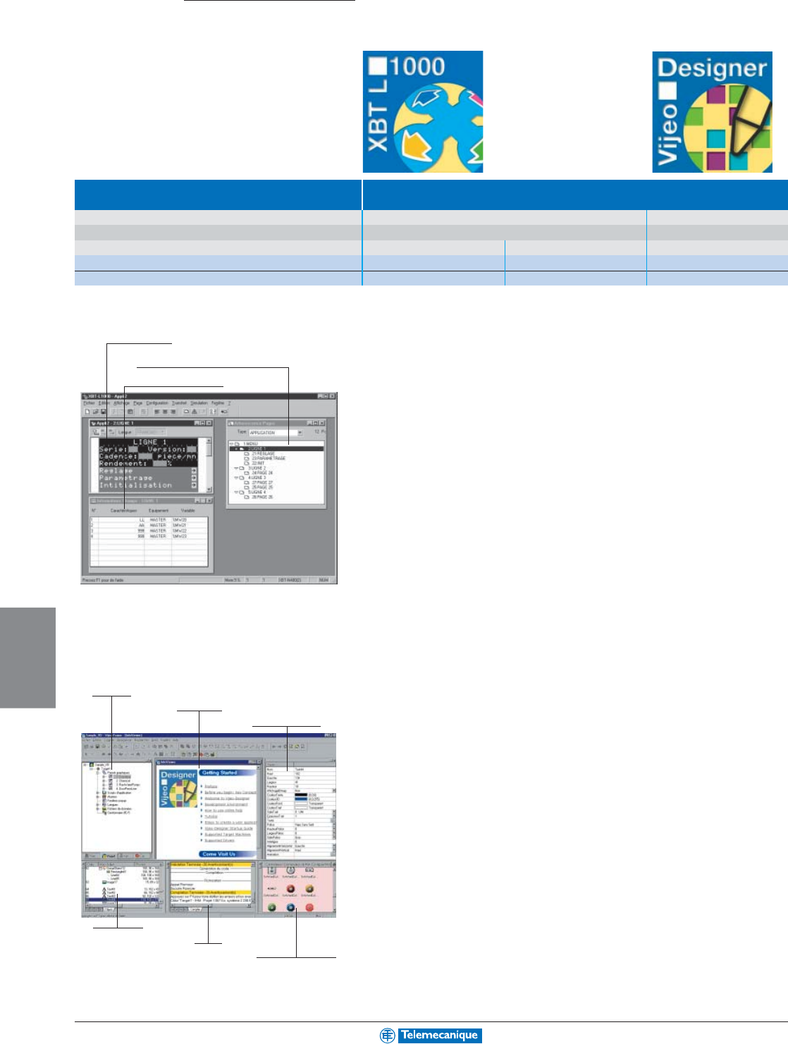
7-10
HUMAN MACHINE
INTERFACE
www.telemecanique.com
Configuration software
XBTL /
Vijeo Designer
Type Configuration software
Compatibility All XBT except XBTG XBTG
Operating system Windows 98, 2000 and XP Windows 2000 and XP
Version (1) Light (not for XBTF) Complete Vijeo Designer complete
Catalog numbers for PC CD-ROM XBTL1001M XBTL1003M VJDSPULFUCDV10M
Catalog numbers for CD-ROM update – XBTLUP1004 –
(1) Demonstration version available, XBTL1001M / L1003M demo: XBTL1003DEMO, Vijeo Designer demo: VJDSPULTUCDV10M
XBTL1001 / L1003 for
Magelis display units and terminals
The XBTL1001/L1003 configuration software can be used to create operator dialogue applications designed
for controlling automation systems for:
all XBTN/H/HM display units, XBTP/PM/E terminals with software XBTL1001,
all XBTN/H/HM display units, XBTP/PM/E and F terminals with software XBTL1003.
Applications created using the XBTL1001/L1003 software are independent to the protocol used. The same
operator dialogue application can be used with PLCs available from the principal manufacturers.
Configuration
The XBTL1001/L1003 configuration software enables simple creation of various types of pages: application
pages (can be interlinked), alarm pages, help pages, menu pages, etc.
Vijeo Designer for
Magelis touchscreen graphic terminals XBTG
The Vijeo Designer configuration software can be used to create operator dialogue applications designed for
controlling automation systems for all the Magelis range of New Technology (NTIC) terminals: XBTG.
Configuration
The Vijeo Designer configuration software enables operator dialogue projects to be easily and quickly
performed due to advanced ergonomics using 6 configurable windows.
Vijeo Designer configuration software also offers complete application management tools:
• Project creation, a project being one or several applications.
• Cross-referencing of application variables.
• Application synoptics documentation.
• A simulation mode for easy testing of the application from the design office.
• Alarming, trending and data logging
Powerful graphics editor for easy creation of synoptics.
8 types of object animation for animated synoptics.
Page tree structure window
Field information window
Navigator
Information
Object properties
Object listing
Report
Library of animated
graphic objects
Application page
7-11
HUMAN MACHINE
INTERFACE
For additional information, consult your nearest Square D/Schneider Electric sales office.
Control software
Vijeo Look
Type Control software
Compatibility All Telemecanique PLCs and Third party PLCs
Operating system Windows 2000 and XP
Input/Output size 1024 I/O
Version Build Time/Run Time Run Time
Catalog numbers for PC CD-ROM VJLSMDBTLV25M VJLSMDRTLV25M
Vijeo Look for industrial PCs
Presentation
Vijeo Look 2.5 is a SCADA (Supervisory Control And Data Acquisition) software package designed for
stand-alone stations, that offers perfect synergy between the Web and HMI (Human Machine Interface).
It is based on open and standardized technologies.
Easy to implement, it offers all the standard functions of a graphic supervision tool.
Vijeo Look is supplied with a pre-configured OFS (OPC Factory Server) Data Server. It is compatible with
PCs running Windows 2000 Professional or Windows XP Professional and enables the creation of
applications based on all Telemecanique new and old generation PLCs.
The functions of Vijeo Look control software can be used for:
• Acquisition of PLC tags.
• Visualization of these tags.
• Process supervision and control.
• Recording the values of the PLC tags or internal tags of the process in a database.
• Embedded software processing.
The Inputs/Outputs are tags from the OPC Server (or those of the Inputs/Outputs of TSX Micro/Premium
PLCs exchanged automatically). They are used for visualization and embedded processing.
Simple and innovative, Vijeo Look offers optimal solutions.
Structure of the offer
2 types of software license are available for Vijeo Look:
• Build Time/Run Time for application development and execution.
• Run Time for the execution of applications created with a Build Time/Run Time license.
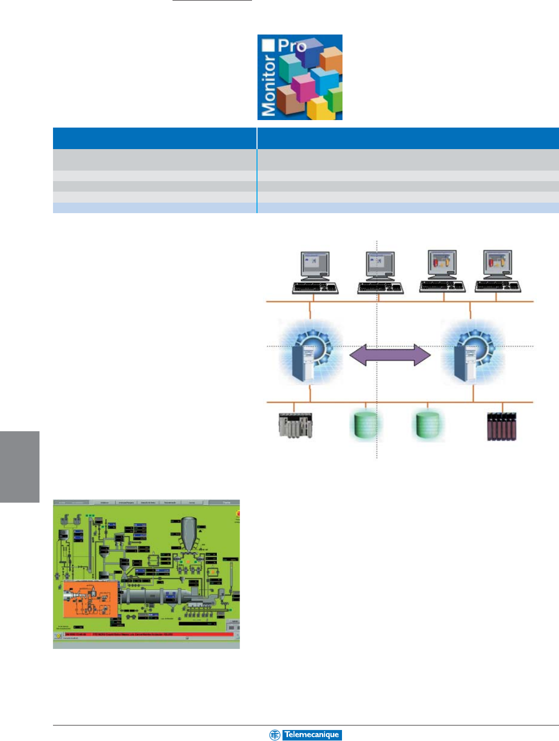
7-12
HUMAN MACHINE
INTERFACE
www.telemecanique.com
Monitor Pro
Supervision software
Type Supervision software
Compatibility All Telemecanique PLCs and other PLCs on the market via communication drivers or using the standard
OPC
Operating system Windows 2000 service Pack 3 and Windows XP
Input/Output size 11 sizes comprising 300 I/Os to unlimited I/Os (4800 tags to unlimited)
Versions Development (Build Time/Run Time) and Execution (Run Time)
Catalog numbers for PC CD-ROM Please contact your nearest Square D/Schneider Electric sales office
Multi-level architecture
Description
Monitor Pro V7.2 is a SCADA (Supervisory Control And Data Acquisition) software solution. Its real-time
high performance server offers excellent processing capability, mainly due to the application objects. In
addition, its client-server architecture enables it to easily adapt to the topology of your application: multi-
server for sharing the processing, multi-user for a wide distribution of information or in redundancy mode
for your “high availability” applications.
• The graphic interface offers a library of graphic objects. Based on Windows technology, they can easily
be customised.
• The Configuration Explorer: an intuitive environment for configuration of the real-time data server that
also enables object orientated configuration.
• Relational databases access interface, supplied with SQL Server 2000. Monitor Pro V7.2 easily
enables recording of the production data or access to the stored information. Monitor Pro V7.2 also
operates with Oracle, Sybase, Dbase IV and databases supporting the ODBC standard.
• Improved availability: Monitor Pro incorporates redundancy services ensuring a high level of
architecture availability.
• Integrated traceability functions, for real-time monitoring of the quality of your production as well as
logging all the actions of the operators.
• Net client, for remote monitoring.
Monitor Pro V7.2 is the supervision software that adapts to your needs. It offers you real-time monitoring
of production and enables you to optimise the operation of your equipment.
Monitor Pro
Clients development and
execution stations
Data/information
Monitor Pro
Development servers stations
Redundancy
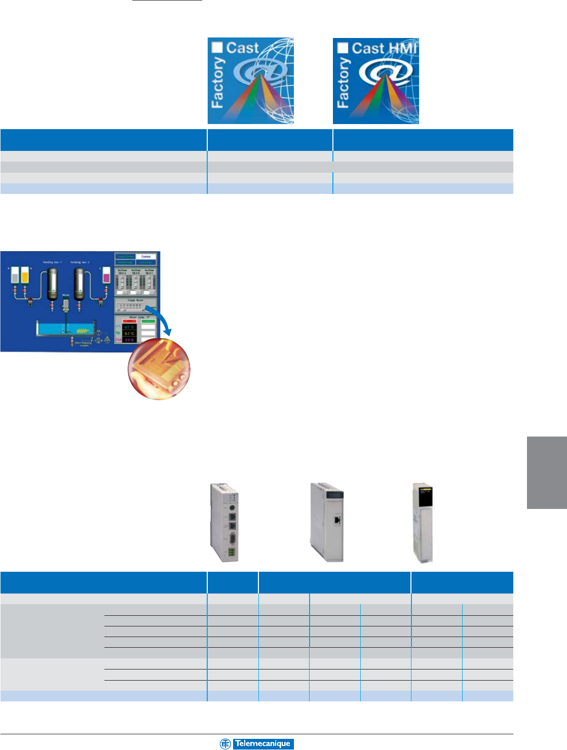
7-13
HUMAN MACHINE
INTERFACE
For additional information, consult your nearest Square D/Schneider Electric sales office.
Embedded Web servers
FactoryCast
Implementation software FactoryCast FactoryCast HMI
Compatibility with Telemecanique PLCs TSX Micro, Premium, Quantum Premium, Quantum
Operating system Windows 2000 and XP
Application Configuration of FactoryCast modules
Development and implementation of FactoryCast HMI application
Catalog numbers for multilingual PC CD-ROM Included with FactoryCast modules TLXCDFCHMIV1M
FactoryCast
Remote diagnostic functions using simple Internet browser
• Secure access to the diagnostics system and application
• Numerical or graphical display and adjustment of data
• Customizable web pages and diagnostics
FactoryCast HMI
Identical diagnostic functions as FactoryCast + new HMI functions embedded in a PLC module:
• Real-time database and acquisition of PLC data (1000 variables)
• Calculation and data manipulation capability
• Advanced alarm management with e-mail
• Archiving of data in relational databases (SQL, Oracle, MySQL)
(Available on Telemecanique Quantum and Premium PLCs)
FactoryCast Web server modules
Automation platform TSX Micro Premium Quantum
Data rate 10/100 Mbit/s 10 Mbit/s 10/100 Mbit/s 10/100 Mbit/s
Ethernet services Modbus TCP/IP Protocol Yes Yes Yes Yes Yes Yes
Uni-TE TCP/IP Protocol Yes Yes Yes – – –
Ethway Protocol – Yes – – – –
Global Data – – Yes – Yes –
I/O Scanning – – Yes – Yes –
Embedded Web server Standard Web services Yes Yes Yes Yes Yes Yes
FactoryCast services Yes Yes Yes Yes Yes Yes
FactoryCast HMI services – – – Yes – Yes
Catalog numbers
TSXETZ510 TSXETY110WS TSXETY5103 TSXWMY100 140NOE77111 140NWM10000
E-mail
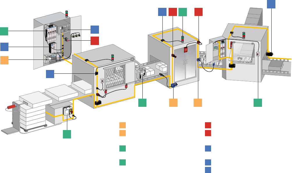
1
2
2 2
2
1
1
2 2
2
1
2
1
3
3
3
2
1
1
2
1
2
1
2
3
AS-Interface
(Actuator Sensor Interface)
The cabling system that meets your
needs for industrial Automation
System Integration
IP20 interface
IP67 interface
Dedicated control
components
Dedicated dialogue
components
AS-Interface
The essential guide
A simplified selection
guide enabling you to
quickly select all the
necessary products and
accessories to build your
installation.
The required information
is detailed in product
selection tables.
(See page 8-12 for
guidelines to using the
tables)
The
“Smart Cable”
Safety monitor
Safety interface
Power supply units and
earth fault detection
AS-Interface master
Connection components
AS-I
NETWORKING
AS-Interface cabling system
Contents
Interfaces for generic products
8-2
IP20 interfaces
IP67 interfaces
Dedicated components
8-4
For control
For dialogue
Safety solutions
8-6
Safety monitors
Safety interfaces
Installation system
8-8
Master modules,
power supply units
Cables, repeaters
Accessories
Tools
8-11
Adjustment and
addressing terminals
These IP20 or IP67 interfaces allow most
standard automation components to be con-
nected to the AS-Interface cable.
These inputs & acuators can be connected
directly to the AS-Interface cable. An
integrated circuit (ASIC) built into the
products manages all interfacing functions
and communication.
The incorporation of safety functions in the
AS-Interface system is achieved by adding a
safety monitor and a safety interface,
connected together with other standard
AS-Interface components on the same
yellow cable.
Sensors and actuators are connected to
the processing unit by the AS-Interface
system. This system comprises a cable and
accessories, a master module and a power
supply unit.
The terminals enable the assigning of an
address to each interface and component in
the system and diagnostics of the installa-
tion.
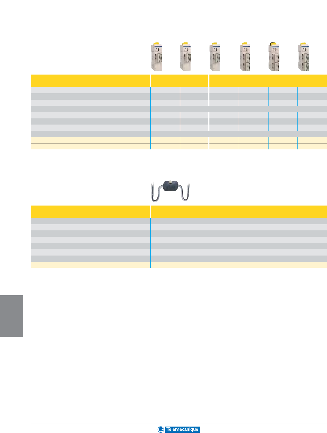
8-2
AS-I
NETWORKING
www.telemecanique.com
AS-Interface
Interfaces for generic products
IP20 for mounting in enclosure
Modular interface, width 25 mm (0.98") Analog Digital
V2.1
Number of inputs 2 (0 to 10 V) 2 (0/4 to 20 mA) 4 4 4 (1) 2
Number of outputs – – – 4 relay, 2A 4 solid st., 0.5A 1 triac, 2A
Type of addressing Standard Standard Extended (A/B) Standard Standard Extended (A/B)
Supply by AS-Interface Inputs and sensor supply (200 mA max.)
Supply by 24 Vdc external source (black AUX cable) – – – – Outputs –
AS-Interface profile 7.3.F.D 7.3.F.D 0.A.7.0 7.0.F.E 7.0.F.E 3.A.7.0
Maximum consumption from AS-Interface (excluding sensor supply) 60 mA 60 mA 85 mA 130 mA 80 mA 110 mA
Dimensions W x D x H (mm / in.) 25 x 70 x 87 / 0.98 x 2.76 x 3.43
Catalog numbers ASI20MA2VU ASI20MA2VI ASI20MT4IE ASI20MT4I4OR ASI20MT4I4OS
ASI20MT2I1OTE
Accessory (2) for connection to flat cables XZCG0122 XZCG0122 XZCG0122 XZCG0122 ASIDCPFIL20 XZCG0122
(1) For 4 isolated inputs (sensors supplied from external source), add the letter A to the end of the reference. Example: ASI20MT4I4OS becomes ASI20MT4I4OSA.
(2) Or direct screw terminal connection (without accessory), (other accessories, see page 8-9).
Interface for control and signalling units For 2 control units and 2 pilot lights
V1
Number of inputs 2
Number of outputs 2 solid state, 0.5A
Type of addressing Standard
Supply by AS-Interface Inputs and pilot lights
AS-Interface profile 3.F
Maximum consumption from AS-Interface 80 mA
Dimensions W x D x H (mm / in.) 52 x 15 x 38 / 2.05 x 0.59 x 1.50
Catalog number XALSZ1
Direct screw terminal connection to AS-Interface or by accessory for flat cable: XZCG0122, (other accessories, see page 8-9).
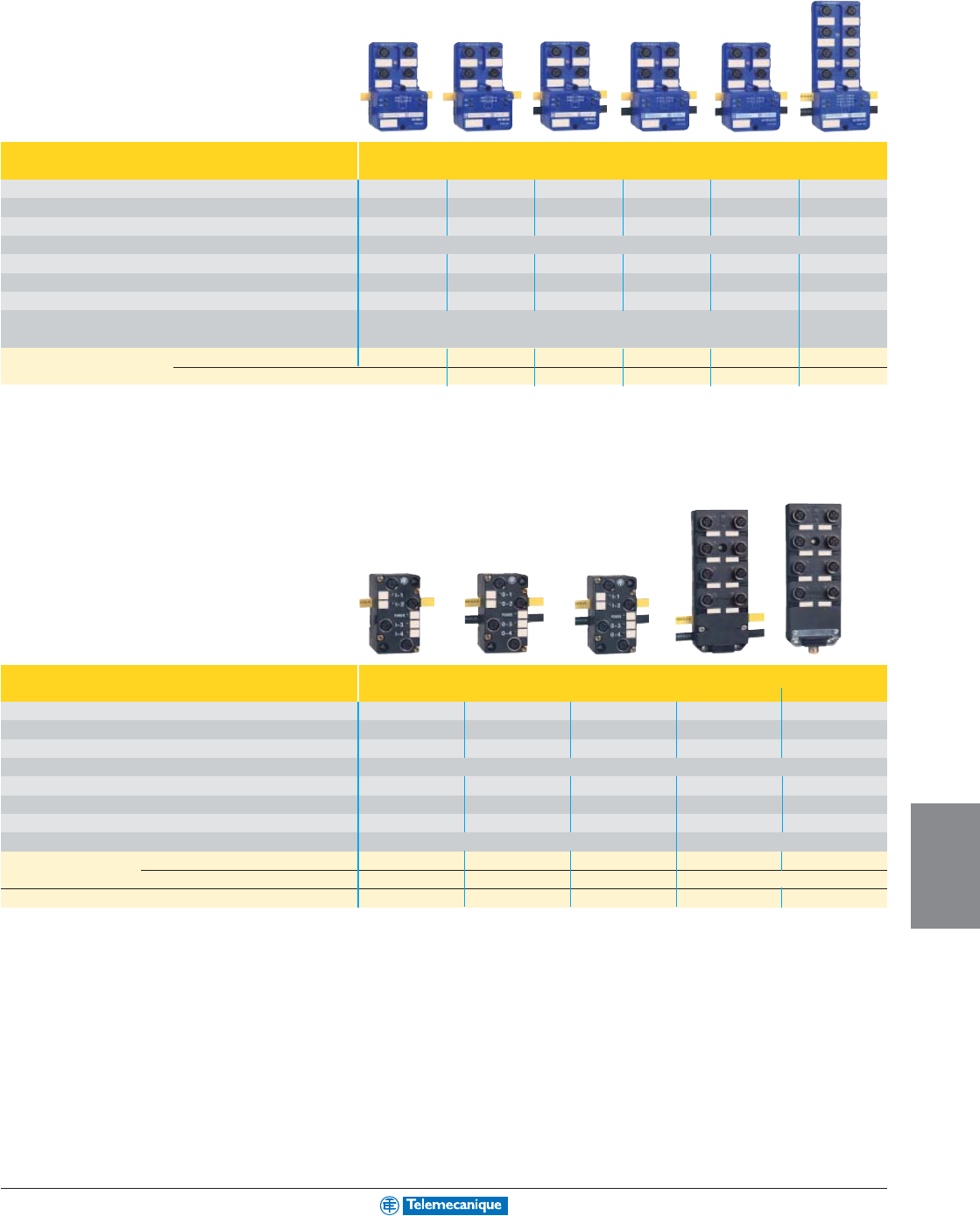
8-3
AS-I
NETWORKING
For additional information, reference Catalog 8340CT0001.
IP67 for mounting on machine
Modular interface, M12 connector inputs / outputs Connection to AS-Interface and external supply (AUX) by IDC
V2.1
Number of inputs 4 4 – 2 2 4
Number of outputs – – 4 solid state, 2A 2 solid state, 2A 2 solid state, 2A
4 solid state, 2A
Type of addressing Standard Extended (A/B) Standard Standard Extended (A/B) Standard
Supply by AS-Interface Inputs and sensor supply (200 mA max.)
Supply by 24 Vdc external source (black AUX cable) – – Outputs Outputs Outputs Outputs
AS-Interface profile 0.0.F.E 0.A.7.0 8.0.F.E 3.0.F.E B.A.7.0 7.0.F.E
Maximum consumption from AS-Interface (excluding sensor supply) 58 mA 58 mA 34 mA 48 mA 48 mA 72 mA
Dimensions W x D x H (mm / in.) 60 x 48 x 106 / 2.36 x 1.89 x 4.17 60x48x156 /
2.36 x1.89x6.14
Catalog number (5) Interface ASIME4I ASIME4IE ASIME4O ASIME2I2O ASIME2I2OE ASIME4I4O
Connection base ASIB4VM12 ASIB4VM12 ASIB4VM12 ASIB4VM12 ASIB4VM12 ASIB8VM12
(5) To obtain a complete product, order the interface and its connection base. (Example: ASIME4I + ASIB4VM12).
Compact interface, M12 connector inputs / outputs Connection to AS-Interface and external supply (AUX)
V1
by IDC (Insulation Displacement Connector) by male M12
Number of inputs 4 – 2 4 4
Number of outputs – 4 solid state, 2 A 2 solid state, 2 A 4 solid state, 2 A 4 solid state, 2 A
Type of addressing Standard Standard Standard Standard Standard
Supply by AS-Interface Inputs and sensor supply (200 mA max.)
Supply by external source (AUX) – Outputs Outputs Outputs Outputs
AS-Interface profile 0.0 8.0 3.0 7.0 7.0
Maximum consumption from AS-Interface (excluding sensor supply) 45 mA 30 mA 35 mA 60 mA 60 mA
Dimensions W x D x H (mm / in.) 45 x 47 x 80 / 1.77 x 1.85 x 3.15 60 x 28 x 152 / 2.36 x 1.10 x5.98
Catalog number (8) Interface XZSDA40D3 XZSDA04D32 XZSDA22D32 XZSCA44D21 XZSCA44D22
Connection base for AS-Interface & AUX XZSDE1113 XZSDE1133 XZSDE1133 Integrated in the interface
Recommended accessory for connection to AS-Interface cable & AUX
––––ASIDCPM12D20
(8) To obtain a complete product, order the interface and its connection base. (Example: XZSDA40D3 + XZSDE1113), except for interfaces with integrated connection base.
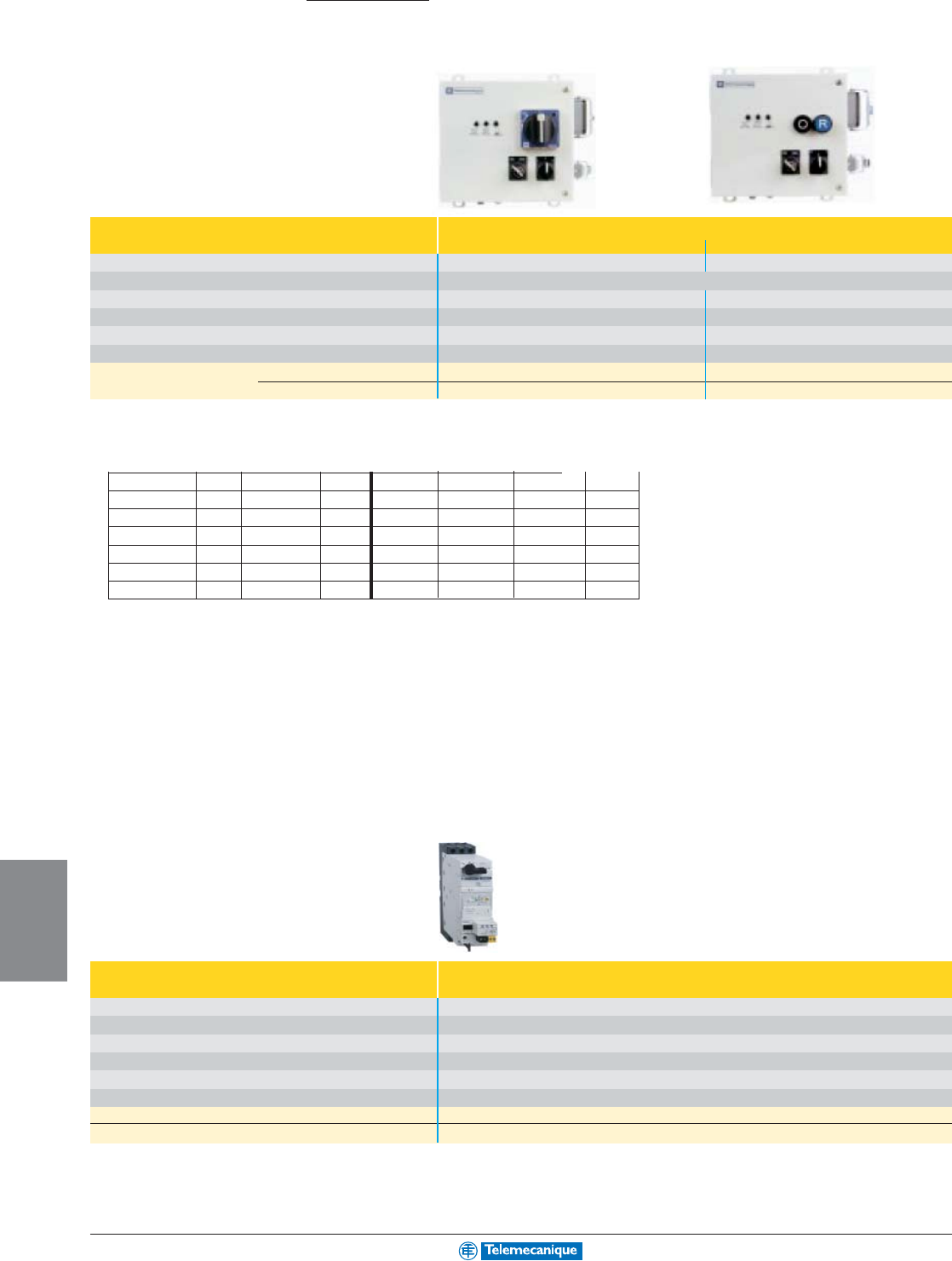
8-4
AS-I
NETWORKING
www.telemecanique.com
AS-Interface
Dedicated components
For control
Starter in metal enclosure Control by
V1
Black rotary knob (blue background)
Pushbuttons
Type of addressing Standard Standard
Supply by AS-Interface Inputs, sensor supply (1)
Supply by 24 Vdc external source (black AUX cable) (1) (1)
AS-Interface profile 7.D 7.D
Maximum consumption from AS-Interface 120 mA 120 mA
Dimensions W x D x H (mm / in.) 175 x 175 x 195 / 6.89 x 6.89 x7.68 175 x 175 x 195 / 6.89 x 6.89 x7.68
Catalog number (2) Non reversing LF1MPiiii
iiii
iiDU LF1MMiiii
iiii
iiDU
(see table below) Reversing LF2MPiiii
iiii
iiDU LF2MMiiii
iiii
iiDU
Connection to AS-Interface and external supply (AUX) by accessory for flat cable: ASIDCPM12D03 (AS-Interface and AUX cables) or XZCG01205D (AS-Interface cable).
(1) Contactors supplied by AS-Interface or external source, configurable directly on terminal block.
(2) To complete the reference, replace iiii
iiii
ii by the numbers indicated in the table below. (Example: LF1MPiiii
iiii
iiD becomes LF1MP00D).
kW Hp A iiii
iiii
ii kW Hp A iiii
iiii
ii
––without MCB 00 0.75 1.5 1.6 to 2.5 07
0.06 – 0.16 to 0.25 02 1.1 / 1.5 3 2.5 to 4 08
0.09 – 0.25 to 0.40 03 2.2 5 4 to 6.3 10
0.12 / 0.18 – 0.40 to 0.63 04 3 / 4 5 6 to 10 14
0.25 0.5 0.63 to 1 05 5.5 10 9 to 14 16
0.37/ 0.55 1 1 to 1.6 06
kW= Motor power ratings in category AC-3, 400/415V, in kilowatts.
A= Adjustable range of circuit-breaker thermal trips, in amperes.
Hp= three phase horsepower at 575 Vac.
Communication interface for TeSys model U
V2.1
Type of addressing Standard
Supply by AS-Interface –
Supply by external source (AUX) Coil
AS-Interface profile 7.D.F.0
Maximum consumption from AS-Interface 30 mA30 mA
Dimensions W x D x H (mm / in.) depending on LU model
Catalog number ASILUFC5
Recommended accessory for connection to AS-Interface cable (3) ASIDCPFIL20
(3) Or direct screw terminal connection to AS-Interface and external supply (AUX), (other accessories, see page 8-9).
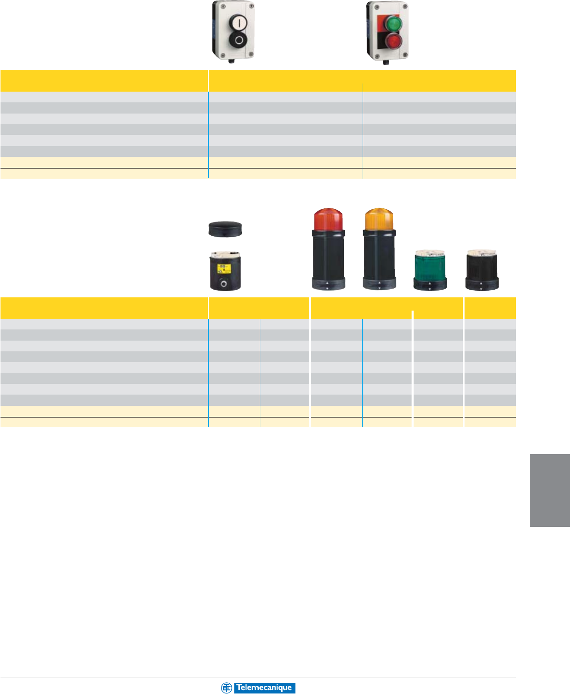
8-5
AS-I
NETWORKING
For additional information, reference Catalog 8340CT0001.
For dialogue
Keypads and Control stations Control stations with 2 pushbuttons
V1 Black and white Illuminated
Type of addressing Standard Standard
Supply by AS-Interface Buttons Buttons and pilot lights
Supply by external source (AUX) – –
AS-Interface profile 3.F 3.F
Consumption from AS-Interface < 40 mA < 80 mA
Dimensions W x D x H mm / (in.) 68 x 62 x 128 / 2.68 x 2.44 x 5.04 68 x 68 x 128 / 2.68 x 2.68 x 5.04
Catalog number XALS2001 XALS2003
Recommended accessory for connection to AS-Interface cable (4) ASIDCPM12D03 ASIDCPM12D03
(4) Or direct screw terminal connection to AS-Interface and external supply (AUX), (other accessories, see page 8-9).
Indicator banks, Ø 70 mm
(7)
Base units and cover Illuminated units Audible
V1
“Flash” discharge tube Steady light
unit
Type of addressing Standard Standard – – – –
Connection to AS-Interface cable and AUX (male M12 connector) yes
yes, remote L=1m
––––
Supply by AS-Interface (5) (5) – – – –
Supply by external source (AUX) (5) (5) – – – –
AS-Interface profile 8.F 8.F – – – –
Consumption from AS-Interface, supply by AS-Interface / external 250 / 30 mA 250 / 30 mA – – – –
Light source – – 5 Joule 10 Joule LED –
Buzzer – – – – –
70
to 80
db at 1m
Catalog number XVBC21A XVBC21B XVBC6Bii
ii
i (6) XVBC8Bii
ii
i (6) XVBC2Bii
ii
i (6) XVBC9B
Recommended accessory for connection to AS-Interface cable & AUX
ASIDCPM12D03
XZCG0120 ––––
(5) Illuminated units supplied by AS-Interface or externally, configurable by shunt.
(6) To complete the reference, replace the ii
ii
i by the following number designating the colour: green: 3, red: 4 orange: 5, blue: 6, clear: 7, yellow: 8
(7) To obtain a complete indicator bank, order a base unit + the illuminated or audible units (5 units maximum).
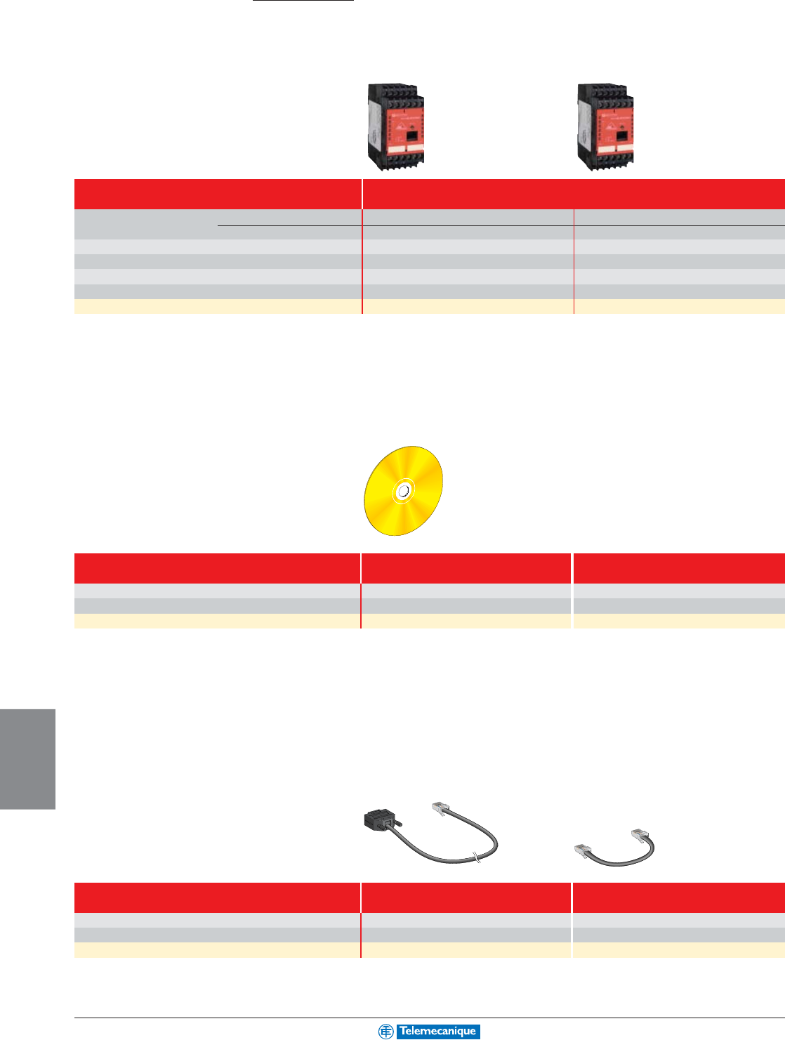
8-6
AS-I
NETWORKING
www.telemecanique.com
AS-Interface
safety at work
Safety solutions
Safety monitors and Software
Safety monitors Category 4 conforming to EN954-1
V2.1
Number of circuits Safety 2 N.O. 2 x 2 N.O.
Auxiliary 1 solid state 2 solid state
Display (number of LEDs) 5 8
AS-Interface profile 7.F 7.F
AS-Interface compatibility V1 / V2 V1 / V2
Dimensions W x D x H (mm / in.) 45 x 120 x 104 / 1.77 x 4.72 x 4.09 45 x 120 x 104 / 1.77 x 4.72 x 4.09
Catalog number ASISAFEMON1 (1) ASISAFEMON2 (1)
(1) User guide ASISMONDOCA (EN/FR/DE) or ASISMONDOCB (ES/IT/PT), to be ordered separately.
Direct screw terminal connection to AS-Interface or by accessory for flat cable XZCG0122.
Setting-up software EN / FR / DE ES / IT / PT
Media CD-ROM PC CD-ROM PC
Environment Windows Windows
Catalog number ASISWIN ASISWINB
Accessories Cable Cable
for monitor parametering RS 232 for monitor to monitor transfer
Degree of protection IP20 IP20
Cable length 2 m (6.6') 0.2 m (7.87")
Catalog number ASISCPC ASISCM
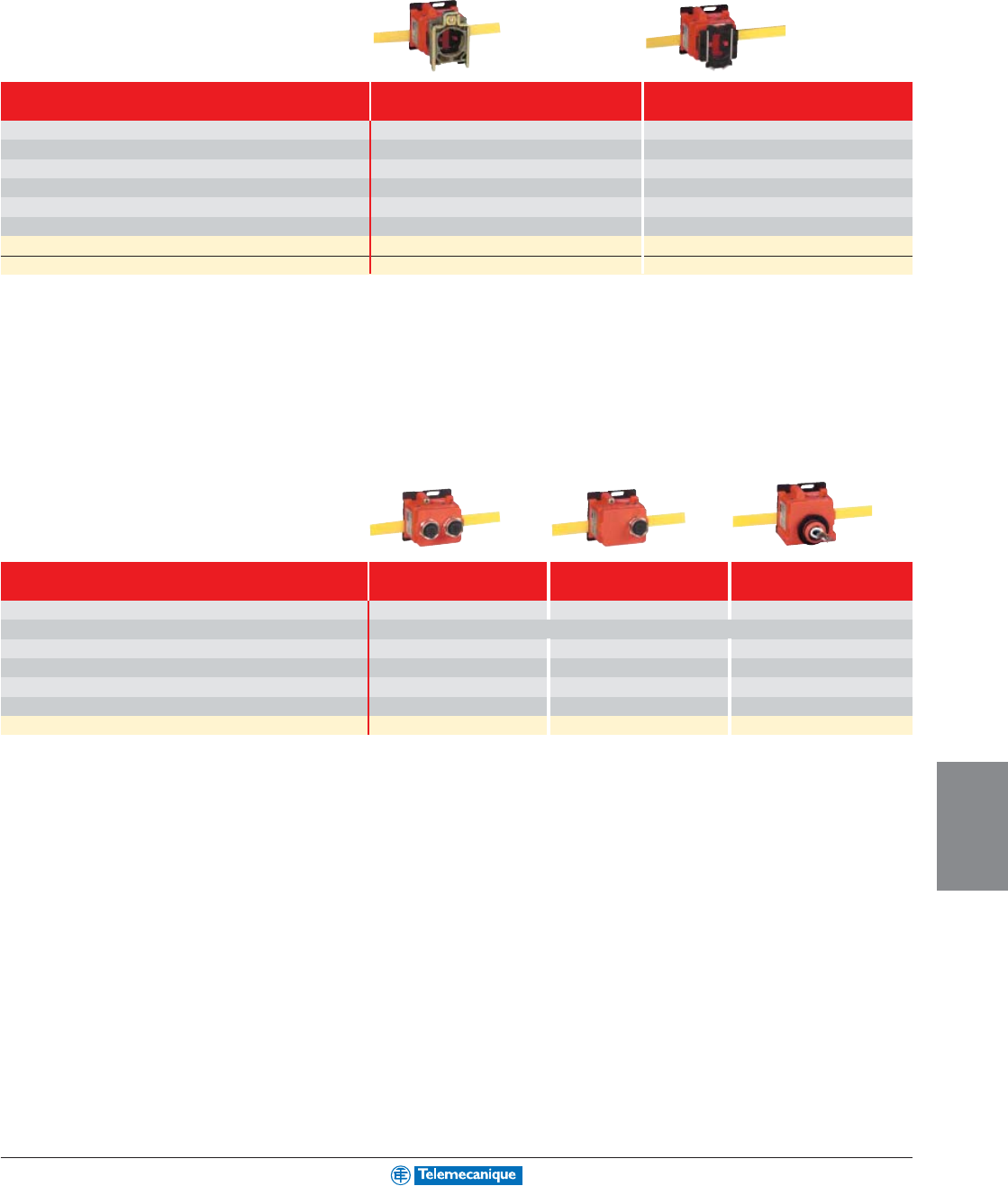
8-7
AS-I
NETWORKING
For additional information, reference Catalog 8340CT0001.
Safety interfaces
Interface for Ø 22 Emergency stop Metal Plastic
V2.1 XB4 range XB5 range
Type of addressing Standard Standard
Supply by AS-Interface Emergency stop Emergency stop
AS-Interface profile 0.B.0 0.B.0
Consumption from AS-Interface 45 mA 45 mA
Degree of protection IP20 IP20
Dimensions W x D x H (mm / in.) 40 x 46.5 x 68 / 1.57 x 1.83 x 2.68 40 x 40 x 64 / 1.57 x 1.57 x 2.52
Reference with N.C. + N.C. contact (head not included with interface)
ASISSLB4 ASISSLB5
Reference of head (Ø 40 latching mushroom head, turn to release)
ZB4BS844 (2) ZB5AS844 (2)
(2) For references of other heads, refer to the "Preventa safety solutions" catalogue.
Interface for other safety products 2 x M12 entries
(3)
1 x M12 entry 1 x ISO M16 entry
(4)
V2.1
Type of addressing Standard Standard Standard
Supply by AS-Interface Inputs and sensor supply (200 mA max.)
AS-Interface profile 0.B.0 0.B.0 0.B.0
Consumption from AS-Interface 45 mA 45 mA 45 mA
Degree of protection IP67 IP67 IP67
Dimensions W x D x H (mm / in.) 40 x 40 x 58 / 1.57 x 1.57 x 2.28 40 x 40 x 58 / 1.57 x 1.57 x 2.28 40 x 40 x 58 / 1.57 x 1.57 x 2.28
Catalog number ASISSLC2 ASISSLC1 ASISSLLS
(3) For connection using 2 pre-wired connectors, or 1 pre-wired connector + 1 connector.
(4) For 1 x ISO M20 entry, include adaptor DE9RI2016 (sold in lots of 5).
Connection accessories, see pages 8-9 and 8-10
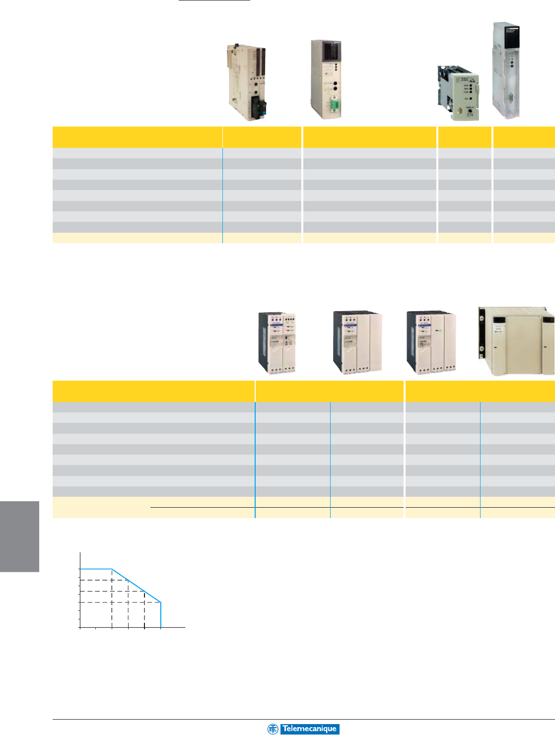
8-8
AS-I
NETWORKING
www.telemecanique.com
1
C
urrent in A at
30
V A
S
-Interfac
e
C
urrent in A at 24 V
0
1
2
3
4
5
6
5
.
8
4.
5
3
7
2
3
4
5
AS-Interface
Installation system
Master modules
Platform Twido Premium Micro Quantum
Maximum number of master modules per PLC (2) 2 2, 4 or 8 depending on processor 1 8 (1)
Compatibility with AS-Interface interfaces and components V1/V2 V1/V2 V1 V1
Direct connection to AS-Interface cable by terminal block by terminal block by terminal block by terminal block
Maximum number of addresses 62 62 31 31
Type of addressing Standard/Extended (A/B) Standard/Extended (A/B) Standard Standard
Compatibility with analogue interfaces Yes Yes – –
Compatibility with safety interfaces Yes Yes Yes Yes
AS-Interface profile M.2.E M2 M2
Catalog number TWDNOI10M3 TSXSAY1000 TSXSAZ10 140EIA92100
(1) 4 per local rack, 4 per remote I/O, 2 per distributed I/O.
(2) See Twido section of catalog TWDNOI10M3.
Power supply units
Type of supply AS-Interface AS-Interface + Auxiliary
Input voltage 100 to 240 Vac 100 to 240 Vac 100 to 240 Vac
100 to 120, 200 to 240 Vac
AS-Interface output voltage 30 Vdc 30 Vdc 30 Vdc 30 Vdc
Auxiliary output voltage – – 24 Vdc 24 Vdc
AS-Interface nominal power 73 W 146 W 73 W 61–153 W
Auxiliary nominal power – – 72 W 72–168 W
AS-Interface nominal current 2.4 A 4.8 A 2.4 A 5 A (3)
AUX nominal current – – 3 A 7 A (3)
Direct connection to AS-Interface cable by terminal block by terminal block by terminal block by terminal block
Dimensions W x D x H (in.) 2.13 x 4.72 x 4.72 3.19 x 4.72 x 4.72 3.19 x 4.72 x 4.72 8.86 x 5.31 x 5.96
Catalog number without earth fault detection ASIABLB3002 ASIABLB3004 ASIABLM3024 TSXSUPA05
with earth fault detection ASIABLD3002 ASIABLD3004 – –
(3) Power supply unit with constant maximum output, see curve above.
8-9
AS-I
NETWORKING
For additional information, reference Catalog 8340CT0001.
Cables and repeater
Type Yellow AS-Interface cable Black Auxiliary cable Repeater
(4)
Wire c.s.a. 2 x 1.5 mm
2
(16 AWG) 2 x 1.5 mm
2
(16 AWG) –
Catalog number Cable L = 20 m (66') XZCB10201 (3) XZCB10202 (3) –
L = 50 m (164') XZCB10501 (3) XZCB10502 (3) –
L = 100 m (328') XZCB11001 (3) XZCB11002 (3) –
Catalog number of repeater – – XZMA1
(3) Standard cable. For TPE cable (oil and vapour resistant) add the letter H to the end of the reference, example: XZCB10201 becomes XZCB10201H.
(4) Enables an AS-Interface network to be extended by 100 m. Direct connection to the AS-Interface yellow cable by IDC.
IP67 tap-offs for flat cable
(For connecting interfaces and components)
Connection to cable by IDC AS-Interface AS-Interface + Auxiliary
Cable extremity M12 connector (5) Bared wires (6) M12 connector (5) Bared wires (7)
Reference Cable L = 0.3 m (1') – – ASIDCPM12D03 –
catalog number L = 0.6 m (2') XZCG01205D – – –
L = 1 m (3.3') XZCG0121D – – –
L = 2 m (6.6') – XZCG0122 ASIDCPM12D20 ASIDCPFIL20
L = 5 m (16.4') – – – ASIDCPFIL50
(5) Female 5-pin M12 end connector, screw threaded for connection with M12 male connector.
(6) 2 x 0.34 mm
2
(22 AWG) for product with terminal block.
(7) 4 x 0.34 mm
2
(22 AWG) for product with terminal block.
Connection to cable by IDC AS-Interface AS-Interface 2 AS-Interface
+ Auxiliary or 2 Auxiliary
Tap-off 4 x M12 connectors 1 x M12 connector 1 flat cable
5-pin female, screw threaded 5-pin female, screw threaded
Catalog number Tap-off XZSDP40D1 (8) XZCG0120 –
IDC connection base XZSDE1133 – XZSDE1113
Cover – – XZSDP (8)
(8) For the complete product, include the connection base.
8-10
AS-I
NETWORKING
www.telemecanique.com
AS-Interface
Installation system
Jumper cables M12 / M12
Type Male / Female jumper cable
Male connector type, interface side M12, 3-pin, straight, screw thread. M12, 4-pin, straight, screw thread.
M12, 5-pin, straight, screw thread.
Female connector type, sensor side M12, 3-pin, straight, screw thread. M12, 4-pin, straight, screw thread.
M12, 5-pin, straight, screw thread.
Cable PUR, black PUR, black PUR, black
Reference Cable L = 1 m (3.3') XZCR1511040A1 XZCR1511041C1 XZCR1511064D1
catalog number L = 2 m (6.6') XZCR1511040A2 XZCR1511041C2 XZCR1511064D2
M12 / M8 or DIN jumper leads
Type Male / Female jumper cable
Male connector type, interface side M12, 3-pin, straight, screw thread. M12, 3-pin, straight, screw thread.
M12, 3-pin, straight, screw thread.
Female connector type, sensor side M8, 3-pin, straight (1) M8, 3-pin, straight, screw thread.
DIN 43650A, elbowed, screw thrd.
Cable PUR, black PUR, black PUR, black
Reference Cable L = 1 m (3.3') XZCR1501040G1 XZCR1509040H1 XZCR1523062K1
catalog number L = 2 m (6.6') XZCR1501040G2 XZCR1509040H2 XZCR1523062K2
(1) Clip together connector.
Connectors, splitter box
Type Connectors Pre-wired connectors Splitter box
Male connector type, interface side M12, 4-pin M8, 3-pin
M12, 5-pin, straight, screw thread.
1 x M12, 5-pin, straight, screw thrd.
Female connector type, sensor side – – –
2 x M12, 5-pin, straight, screw thrd.
Cable – – PUR, black –
Catalog number Straight connector, screw thread.
XZCC12MDM40B XZCC8MDM30V
–XZLC1220C1
Elbowed connector, screw thread.
XZCC12MCM40B
–– –
Cable L = 0.5 m (1.6') – – XZCP1564L05 –
Cable L = 2 m (6.6') – – XZCP1564L2 –
8-11
AS-I
NETWORKING
For additional information, reference Catalog 8340CT0001.
Tools
Adjustment and addressing terminals
Display 25 mm (.98") LCD screen 13 mm (.51") LCD screen
Degree of protection IP40 IP20
AS-Interface voltage / current measurement yes no
Addresses stored in memory yes no
Access to functions direct by selector switch by scrolling menu
Compatibility V1/V2 V1/V2
Typical battery life 2500 addressing operations 250 read/write operations
Catalog number ASITERV2 XZMC11
Reference with set of 7 leads + protective cover for terminal ASITERV2SET –
Addressing accessories for terminals
ASITERV2 and XZMC11
Product connection Infrared addressing Socket Specific connection
base
For products ASISSL…/ ASI20M…/ ASIME / ABE8 to / APP1 / ASILUF to / XZSCA44D21
XBZS43 / ASI20M / VW3 / XBLC
Catalog number ASITERIR1 XZMG12 XZMG13
Product connection M12, male M12, female Jack plug Specific connec-
tion base
(2)
For products (3) XVB… / XAL… / LF… XZSD… XZSD…
XZSCA44D22
Catalog number ASITERACC1M ASITERACC1F ASITERACC2 ASITERACC3
(2) For use with ASITERACC2.
(3) For connection to AS-Interface cable using T connector XZCG0120.
8-12
AS-I
NETWORKING
www.telemecanique.com
S S S S
A AM
100 m 100 m
A
S SS S
A A A A
S S S S S SS S
100 m 100 m 50 m 50 m 100 m 100 m
M
M A S
1Product family, interfaces or components, etc.
2AS-Interface version: (V1 and V2.1 compatibility, see table below).
V1: version enabling mounting of 31 interfaces or components per master module using products with standard addressing.
V2.1: version enabling mounting of 31 interfaces or components per master module using products with standard addressing or 62 interfaces or
components per master module using products with extended A/B addressing.
Diagnostic information, such as a short-circuit on a sensor supply, is signalled to the PLC.
3Each input enables connection of a sensor (detectors, switches, pushbuttons, etc.).
4Each output enables connection of an actuator (contactors, solenoids, pilot lights, etc.).
5Standard addressing: enables connection of 31 interfaces or components.
Extended addressing: enables connection of 62 interfaces or components.
6Indicates the circuits that can be supplied directly by the AS-Interface (example: yellow cable).
7Indicates the circuits requiring an external supply source. This voltage can be distributed by the flat black cable.
8The profile is very useful when replacing an existing product and ensures full interchangeability. For V2.1 products, the 3rd character of the profile can
be changed by the user using the adjustment or addressing terminal.
9Enables the power of the AS-Interface supply to be established.
10 Overall dimensions of product.
11 Enables the product to be ordered.
12 Accessory best suited for connection of product. Other types of accessory can equally be used.
Usage guidelines
Selection tables
Power supply: Only use PELV type power supply units such as those listed on page 8-8. Do not use any other power supply type.
Calculating the length of the AS-Interface network: Add the length of the yellow cable to 2 x the length of the connection accessories. Example: 50 m yellow cable and 5
tap-offs with 2 m (6.6') cable (ref. ASI-DCPM12D20) => network length = 50 + (2 x 5 x 2) = 70 m. [164' + (2 x 16.4' x 2) = 230']
It is recommended that unnecessary cable runs are avoided.
The maximum length of the network is 100 m (328'), but this can be extended to 200 m (656') by using 1 repeater or to 300 m (984') by using 2 repeaters (see page 9). By
positioning the master module at the center of the network, it is possible to achieve 500 m (1640'). It is not possible to exceed this value using a single master.
Master module Power supply Interface or component
The AS-Interface cable:
Preferably use the flat yellow cable and respect the polarities (+ brown, – blue).
However, it is possible to use standard cabling, particularly in enclosures, but ensure that the 2 wires are not twisted in order to avoid reversal of the AS-Interface + and
AS-Interface –.
Some AS-Interface rules
1
2
3
4
5
6
7
8
9
10
11
12
Modular interface, width 25 mm (.98") Analog Digital
V2.1
Number of inputs 2 (0 to 10V) 2 (0/4 to 20mA) 4
Number of outputs – – –
Type of addressing Standard Standard Extended (A/B)
Supply by AS-Interface Inputs and sensor supply (200 mA max.)
Supply by 24 Vdc external source (black AUX cable) – – –
AS-Interface profile 7.3.F.D 7.3.F.D 0.A.7.0
Maximum consumption from AS-Interface (excluding sensor supply) 60 mA 60 mA 85 mA
Dimensions W x D x H (mm / in.) 25x70x87 mm 25x70x87 mm 25x70x87 mm
Catalog number ASI20MA2VU ASI20MA2VI ASI20MT4IE
Accessory for connection to flat cables XZCG0122 XZCG0122 XZCG0122
Compatibility between V1 and V2.1 master modules and V1 and V2.1 interfaces or components
Master Interfaces and components Analog interfaces
modules V1 V2.1 V2.1
V1 Ye s Yes (1) No
V2.1 Yes (1) Yes Yes
(1) Diagnostic information, such as a short-circuit on a sensor supply, is not signalled to the PLC.
V1 and V2.1 interfaces and components can be combined on the same master module.
328' 328' 328' 328' 164' 164' 328' 328'
Preventa
TM
Machine Safeguarding Products
Preventa Machine
Safeguarding Product
Solutions:
Developed to match multiple application
configurations, Preventa Machine
Safeguarding Products are easy to select,
install and operate due to their flexible
functionality and compact design.
• Safety Controllers
• Safety Relays
• Safety Interlock Switches
• Non-Contact Safety Interlock Switches
• Safety Limit Switches
• Light Curtains
• Cable Pull Switches
Maintaining Safe and
Compliant Working
Environments
With Preventa safeguarding products,
Schneider Electric offers the most complete
line of safety solutions for your machinery
and industrial processes. From stand-alone
safety monitoring to integrated safety
control systems, the Telemecanique
comprehensive line of Preventa safety
products can provide the appropriate level
of machine safeguarding no matter what
your industry or application.
The Preventa Advantage:
Experience
Industry-leading expertise in advanced switching and sensing technologies, with
over 30 years of safety product innovation.
Compliance
All devices are UL, CSA, and CE compliant and are designed to work together to
meet applicable Domestic and International safety standards and requirements.
Single Source
Comprehensive machine safeguarding product offering that allows for single
safety function operation or integration into a total safety system solution.
Flexibility
Single components that can perform multiple safety functions in a
variety of conditions makes for easier product selection and a
smaller, more manageable product inventory.
Global Reach
Worldwide supplier for compliant solutions and fast delivery.
C
o
n
t
e
n
t
s
Pr
ocess
- Safet
y
controller
s
-Safet
y
rela
ys
D
etect
- Safet
y
interlock switche
s
- Non-contact safet
y
interlock switche
s
- Safet
y
limit switches
- Li
g
ht curtain
s
Dialo
g
- Emer
g
ency sto
p
—
Cable
p
ull switche
s
9-2
9
9-10
9-6
Pa
ge
MACHINE
SAFEGUARDING
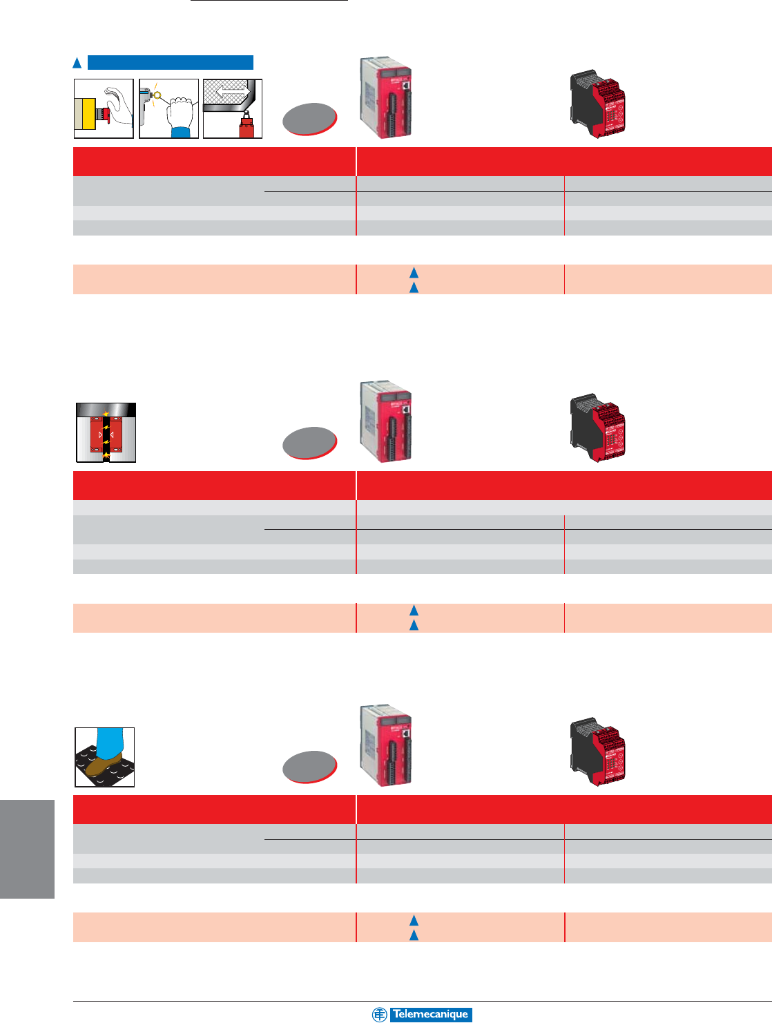
9-2
MACHINE
SAFEGUARDING
www.telemecanique.com
Process
Safety controllers
• emergency stops and limit switches
For monitoring
Maximum category of the solution Category 4
(EN 954-1)
Number of circuits Safety 4 N.O. + 6 solid-state 3 N.O. per function
Additional – 3 solid-state
Display (number of LEDs) 30 12
Width of housing (mm / in.) 74 / 2.91 45 / 1.77
Universal solutions: safety controllers (for monitoring several safety functions simultaneously)
Supply voltage 24 Vdc XPSMC16X (with 16 inputs) (2) XPSMP11123P (1)
XPSMC32X (with 32 inputs) (2) –
• Non-contact safety interlock switches
Maximum category of the solution Category 4
(EN 954-1)
For monitoring Non-contact safety interlock switches
Number of circuits Safety 4 N.O. + 6 solid-state 3 N.O. per function
Additional – 3 solid-state
Display (number of LEDs) 30 12
Width of housing (mm / in.) 74 / 2.91 45 / 1.77
Universal solutions: safety controllers (for monitoring several safety functions simultaneously)
Supply voltage 24 Vdc XPSMC16X (with 16 inputs) (2) XPSMP11123P (1)
XPSMC32X (with 32 inputs) (2) –
• safety mats and safety edges
Maximum category of the solution Category 3
(EN 954-1)
Number of circuits Safety 4 N.O. + 6 solid-state 3 N.O. per function
Additional – 3 solid-state
Display (number of LEDs) 30 12
Width of housing (mm / in.) 74 / 2.91 45 / 1.77
Universal solutions: safety controllers (for monitoring several safety functions simultaneously)
Supply voltage 24 Vdc XPSMC16X (with 16 inputs) (2) XPSMP11123P (1)
XPSMC32X (with 32 inputs) (2) –
(1) For version with non-removable terminal block, delete the letter P from the end of the catalog number (example: XPSMP11123P becomes XPSMP11123).
(2) XPSMCWIN configuration software, configuration cable TSXPCX1031, adapter XPSMCCPC and set of plug in connectors with screw terminals XPSMCTS16 or XPSMCTS32
or set of plug in connectors with spring terminals XPSMCTC16 or XPSMCTC32 must be ordered separately.
Available 2nd quarter 2004
Universal
Universal
Universal
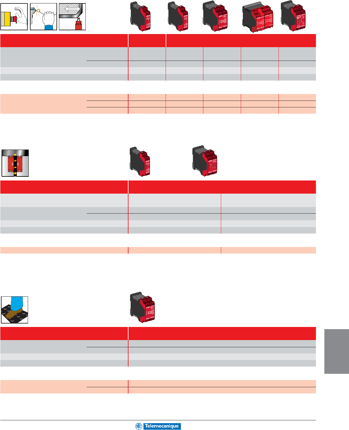
9-3
MACHINE
SAFEGUARDING
Maximum category of the solution Category 3 Category 4
(EN 954-1)
Number of circuits Safety 3 N.O. 3 N.O. 3 N.O. 7 N.O.
3
N.O.+3 N.O.
time
delay
Additional 1 solid-state – 1 N.C. + 4 solid-state 2 N.C. + 4 solid-state 3 solid-state
Display (number of LEDs) 2 3 4 4 11
Width of housing (mm / in.) 22.5 / 0.89 22.5 / 0.89 45 / 1.77 90 / 3.54 45 / 1.77
Optimum solutions: safety modules (for monitoring 1 safety function)
Supply voltage 24 Vdc – – – – XPSAV11113P (1)
24 Vac/dc XPSAC5121P (1) XPSAF5130P (1) XPSAK311144P (1) XPSAR311144P (1) –
24 Vdc/120 Vac – – XPSAK351144P (1) XPSAR351144P (1) –
(1) For version with non-removable terminal block, delete the letter P from the end of the catalog number (example: XPSAV11113P becomes XPSAV11113)
.
• Non-contact safety interlock switches
Maximum category of the solution Category 4
(EN 954-1)
For monitoring 2 non-contact safety 6 non-contact safety
interlock switches maximum interlock switches maximum
Number of circuits Safety 2 N.O. 2 N.O.
Additional 2 solid-state 2 solid-state
Display (number of LEDs) 3 15
Width of housing (mm / in.) 22.5 / 0.89 45 / 1.77
Optimum solutions: safety modules (for monitoring 1 safety function)
Supply voltage 24 Vdc XPSDMB1132P (1) XPSDME1132P (1)
(1) For version with non-removable terminal block, delete the letter P from the end of the catalog number (example: XPSDMB1132P becomes XPSDMB1132).
• safety mats and safety edges
Maximum category of the solution Category 3
(EN 954-1)
Number of circuits Safety 3 N.O.
Additional 1 N.C. + 4 solid-state
Display (number of LEDs) 4
Width of housing (mm / in.) 45 / 1.77
Optimum solutions: safety modules (for monitoring 1 safety function)
Supply voltage 24 Vac/dc XPSAK311144P (1)
24 Vdc/120 Vac XPSAK351144P (1)
(1) For version with non-removable terminal block, delete the letter P from the end of the catalog number (example: XPSAK311144P becomes XPSAK311144).
Safety relays
• emergency stops and limit switches
For additional information, reference Catalog #9007CT0201.
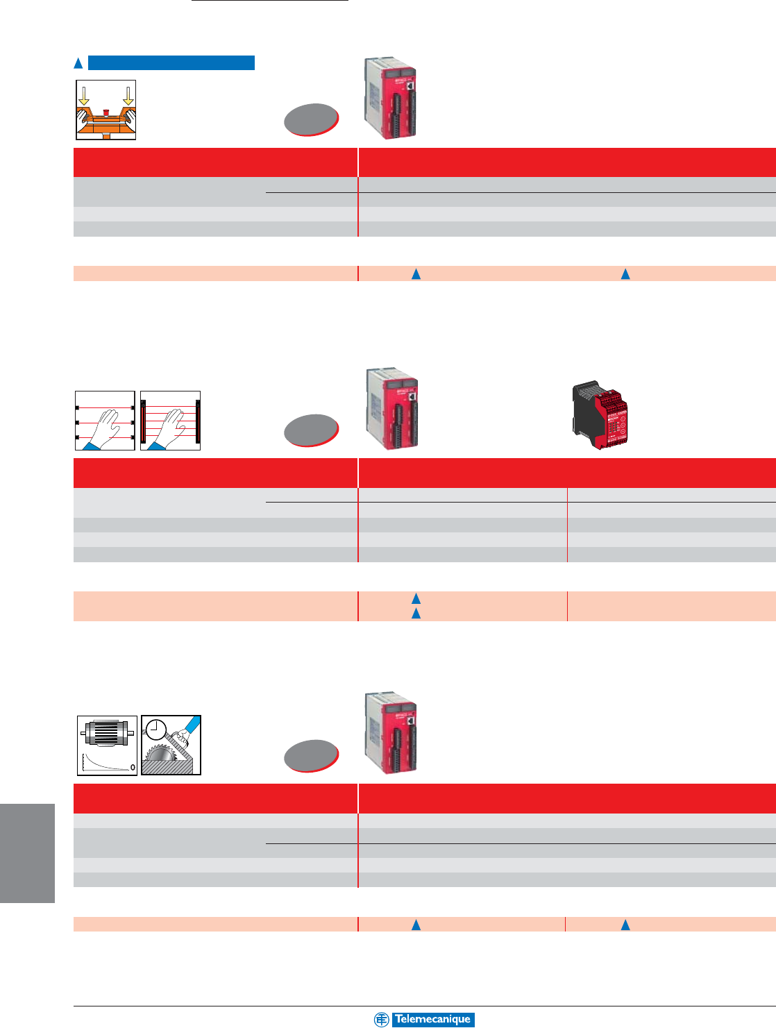
9-4
MACHINE
SAFEGUARDING
www.telemecanique.com
Maximum category of the solution Category 4
(EN 954-1)
Number of circuits Safety 4 N.O. + 6 solid-state
Additional –
Display (number of LEDs) 30
Width of housing (mm / in.) 74 / 2.91
Universal solutions: safety controllers (for monitoring several safety functions simultaneously)
Supply voltage 24 Vdc XPSMC16X (with 16 inputs) (2) XPSMC32X (with 32 inputs) (2)
.
• light curtains
Maximum category of the solution Category 4
(EN 954-1)
Number of circuits Safety 4 N.O. + 6 solid-state 3 N.O. per function
Additional – 3 solid-state
Display (number of LEDs) 30 12
Width of housing (mm / in.) 74 / 2.91 45 / 1.77
Integral Muting function Ye s N o
Universal solutions: safety controllers (for monitoring several safety functions simultaneously)
Supply voltage 24 Vdc XPSMC16X (with 16 inputs) (2) XPSMP11123P (1)
XPSMC32X (with 32 inputs) (2) –
•
zero speed and time delay
Maximum category of the solution Category 4
(EN 954-1)
For monitoring Motor zero speed, time delay, elevators
Number of circuits Safety 4 N.O. + 6 solid-state
Additional –
Display (number of LEDs) 30
Width of housing (mm / in.) 74 / 2.91
Universal solutions: safety controllers (for monitoring several safety functions simultaneously)
Supply voltage 24 Vdc XPSMC16X (with 16 inputs) (2) XPSMC32X (with 32 inputs) (2)
(1) For version with non-removable terminal block, delete the letter P from the end of the catalog number (example: XPSMP11123P becomes XPSMP11123).
(2) XPSMCWIN configuration software, configuration cable TSXPCX1031, adapter XPSMCCPC and set of plug in connectors with screw terminals XPSMCTS16 or XPSMCTS32
or set of plug in connectors with spring terminals XPSMCTC16 or XPSMCTC32 must be ordered separately.
Process
Safety controllers
• two-hand control
For monitoring
Available 2nd quarter 2004
0,0
0,2
0,4
0,6
0,8
1,0
Universal
Universal
Universal
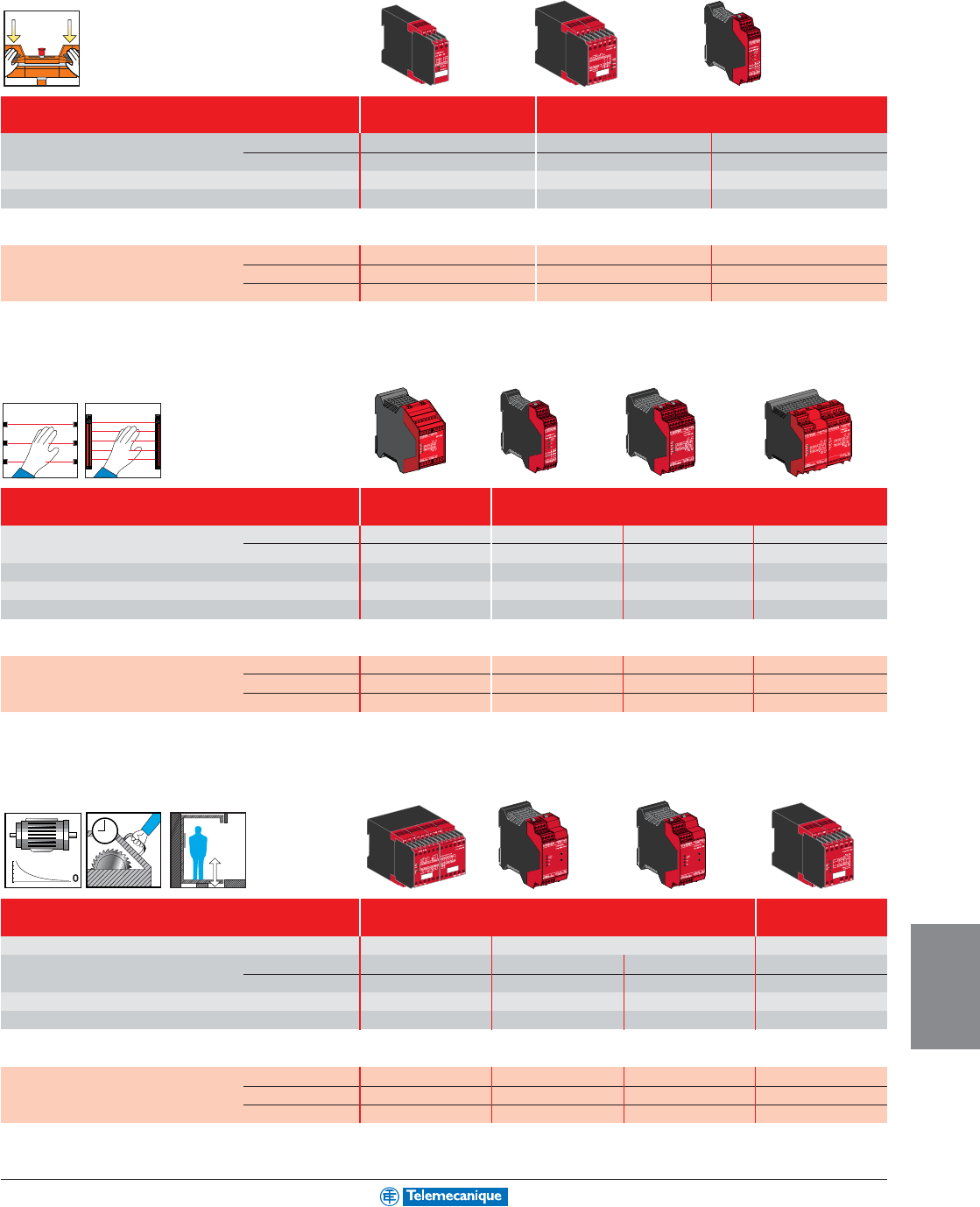
9-5
MACHINE
SAFEGUARDING
Safety relays
• two-hand control
Maximum category of the solution Category 1 Category 4
(EN 954-1) (type IIIA to EN 574) (type IIIC to EN 574)
Number of circuits Safety 1 N.O. 2 N.O. 2 N.O.
Additional 1 N.C. 1 N.C. 2 solid-state
Display (number of LEDs) 2 3 3
Width of housing (mm / in.) 22.5 / 0.89 45 / 1.77 22.5 / 0.89
Optimum solutions: safety modules (for monitoring 1 safety function)
Supply voltage 24 Vdc – XPSBC1110 XPSBF1132P (1)
24 Vac/dc XPSBA5120 ––
120 Vac XPSBA3420 XPSBC3410
(1) For version with non-removable terminal block, delete the letter P from the end of the catalog number (example: XPSBF1132P becomes XPSBF1132).
• light curtains
Maximum category of the solution Category 2 Category 4
(EN 954-1)
Number of circuits Safety 2 N.O. 3 N.O. 3 N.O. 7 N.O.
Additional 4 solid-state – 1 N.C. + 4 solid-state 1 N.C. + 4 solid-state
Display (number of LEDs) 4 3 4 4
Width of housing (mm / in.) 45 / 1.77 22.5 / 0.89 45 / 1.77 90 / 3.54
Integral Muting function Ye s N o N o N o
Optimum solutions: safety modules (for monitoring 1 safety function)
Supply voltage 24 Vdc XPSCM1144P (1) – – –
24 Vac/dc – XPSAFL5130P (1) XPSAK311144P (1) XPSAR311144P (1)
24 Vdc/120 Vac – – XPSAK351144P (1) XPSAR351144P (1)
(1) For version with non-removable terminal block, delete the letter P from the end of the catalog number (example: XPSCM1144P becomes XPSCM1144).
•
zero speed, time delay and elevators
Maximum category of the solution Category 3 Category 4
(EN 954-1)
For monitoring
Motor zero speed
Safety time delay Elevators
Number of circuits Safety 1 N.O. + 1 N.C. 1 N.O. time delay 1 N.O. pulse 2 N.O.
Additional 2 solid-state 2 N.C. + 2 solid-state 2 N.C. + 2 solid-state 2 solid-state
Display (number of LEDs) 4 4 4 4
Width of housing (mm / in.) 90 / 3.54 45 / 1.77 45 / 1.77 45 / 1.77
Optimum solutions: safety modules (for monitoring 1 safety function)
Supply voltage 24 Vdc XPSVN1142 –––
24 Vac/dc – XPSTSA5142P (2) XPSTSW5142P (2) XPSDA5142
120 Vac XPSVN3442 XPSTSA3442P (2) XPSTSW3442P (2) XPSDA3442
(2) Removable terminal block version only.
0,0
0,2
0,4
0,6
0,8
1,0
For additional information, reference Catalog #9007CT0201.
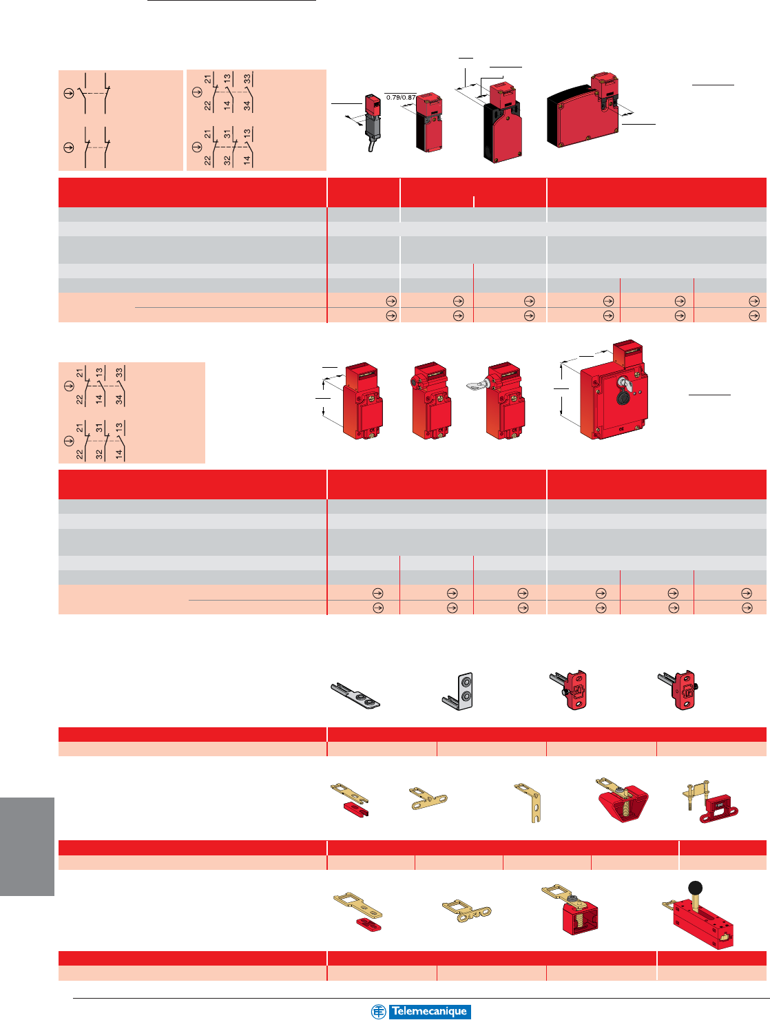
9-6
MACHINE
SAFEGUARDING
www.telemecanique.com
Actuation speed (min → max)
Degree of protection
Rated operational characteristics
(conforming to IEC/EN 60947-5-1)
Dimensions (body + head) W x D x H (inches)
Solenoid supply voltage
Complete switch
(N.C.+N.O. stag.: XCSMP/PA/TE) (N.C.+N.O.+N.O.: XCSTA)
(N.C.+N.C.: XCSPA/TE) (N.C.+N.C.+N.O.: XCSMP/
TA)
Type XCSMP Type XCSPA and TA Type XCSTE
with 6.6 ft. cable 1x
1/2" NPT entry
2x
11 mm entry
(2)
1 x 11 mm entry (2)
2 in/s to 59 in/s 0.39 in/s to 19.7 in/s 0.39 in/s to 19.7 in/s
IP 67,
Type 4, 4X indoor, 12
AC 15, C 300 AC 15, A 300 AC 15, B 300
DC 13, Q 300 DC 13, Q 300 DC 13, Q 300
1.18 x 0.6 x 3.42 1.18 x 1.18 x 4.4 2.05 x 1.18 x 4.5 4.32 x 1.3 x 3.67
––– 24 Vac/dc 120 Vac/dc 230 Vac/dc
XCSMP59L2 (3)
XCSPA593 XCSTA593 XCSTE5313 XCSTE5333 XCSTE5343
XCSMP70L2 (3)
XCSPA793 XCSTA793 XCSTE7313 XCSTE7333 XCSTE7343
2-pole contact
Slow break
(N.C. + N.O.)
2-pole contact
Slow break
(N.C. + N.C.)
3-pole contact
Slow break
(N.C. + N.O. + N.O.)
3-pole contact
Slow break
(N.C. + N.C. + N.O.)
Detect
Safety interlock switches
and actuating keys
Plastic, double insulated switches
Without locking Locking without power (1)
3-pole contact
Slow break
(N.C. + N.O. + N.O.)
3-pole contact
Slow break
(N.C. + N.C. + N.O.)
Without locking With interlocking, manual unlocking
By button By key lock
Locking without
power (1)
(1) For locking with power, refer to the Machine Safeguarding Products Catalog #9007CT0201.
(2) With 1/2" NPT conduit adapter.
Actuation speed (min → max)
Degree of protection
Rated operational characteristics
(conforming to IEC/EN 60947-5-1)
Dimensions (body + head) W x D x H (inches)
Solenoid supply voltage
Complete switch (N.C. + N.O. + N.O.)
(N.C. + N.C. + N.O.)
Type XCSA/B/C Type XCSE
1 x 1/2" NPT conduit entry 2 x 1/2" NPT conduit entry
0.39 in/s to 19.7 in/s 0.39 in/s to 19.7 in/s
IP 67,
UL Type 4, 4X, 12
IP 67,
UL Type 4, 4X, 12
AC 15, A 300 AC 15, B 300
DC 13, Q 300 DC 13, Q 300
1.57 x 1.73 x 4.47 2.05 x 1.73 x 4.47 2.05 x 1.73 x 4.47 3.86 x 1.73 x 5.75
––– 24 Vac/dc 110/120 Vac/dc 220/240 Vac/dc
XCSA503 XCSB503 XCSC503 XCSE5313 XCSE5333 XCSE5343
XCSA703 XCSB703 XCSC703 XCSE7313 XCSE7333 XCSE7343
Metal switches
(1) For locking with power, refer to the Machine Safeguarding Products Catalog #9007CT0201.
Actuating keys and accessories
Straight
Wide
L=40 mm / 1.57" (1)
Right-angled
Pivoting
Actuating keys
Retaining device
Straight Right-angled
Catalog number
Actuating keys
XCSZ81 XCSZ84 XCSZ83 XCSZ85
For safety interlock switches XCSMP
Pivoting, RH door Pivoting, LH door
Guard/door retainer
Straight Wide Pivoting
Catalog number XCSZ11 XCSZ12 XCSZ14 XCSZ13 XCSZ21
For safety interlock switches XCSPA/TA/TE
(1) For L = 29 mm / 1.14", catalog number = XCSZ15.
Catalog number
Actuating keys Door lock
XCSZ01 XCSZ02 XCSZ03 XCSZ05
For safety interlock switches XCSA/B/C/E
Millimeters
Inches
Millimeters
Inches
1314
22 21
11
12
22 21
2
0/
2
2
20/22
0.79/0.87
40.3
1.57
20/22
0.79/0.87
95
88
95
3.70
88
3.46
30
1.18
60
2.36
20/22
0.79/0.87
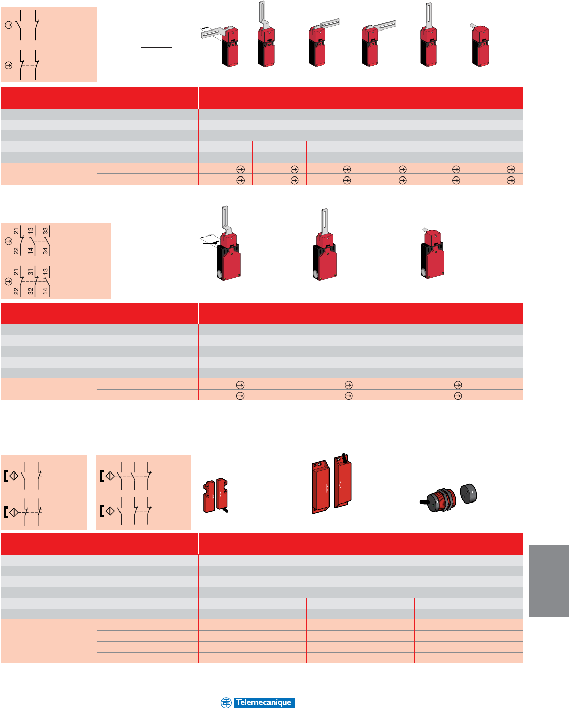
9-7
MACHINE
SAFEGUARDING
2-pole contact
Slow break
(N.C. + N.O.)
2-pole contact
Slow break
(N.C. + N.C.)
Safety interlock switches
with rotary lever or rotary shaft
Stainless steel, elbowed (flush with rear of switch) lever Stainless steel straight lever Stainless steel
Lever to left Lever centered Lever to right
Lever to left or right
Lever centered
shaft, L = 1.18"
Minimum torque (actuation / positive opening)
Degree of protection
Rated operational characteristics
Dimensions (body + head) W x D x H (inches)
Tripping angle
Complete switch (N.C. + N.O., break before make)
(N.C. + N.C.)
Type XCSPL with rotary lever or XCSPR with rotary shaft
1 x 1/2" NPT conduit entry
0.88 in-lb (0.1 N•m) / 2.2 in-lb (0.25 N•m)
IP67, Type 4, 4X indoor, 12
AC 15, A 300 / DC 13, Q 300 (conforming to IEC/EN 60947-5-1)
1.18 x 1.18 x 6.3 1.18 x 1.18 x 6.3 1.18 x 1.18 x 6.3 1.18 x 1.18 x 6.3 1.18 x 1.18 x 6.3 1.18 x 1.18 x 3.79
5°5°5°5°5°5°
XCSPL593 XCSPL583 XCSPL573 XCSPL563 XCSPL553 XCSPR553
XCSPL793 XCSPL783 XCSPL773 XCSPL763 XCSPL753 XCSPR753
Plastic switches
3-pole contact
Slow break
(N.C. + N.O. + N.O.)
3-pole contact
Slow break
(N.C. + N.C. + N.O.)
Stainless steel, elbowed (flush with Stainless steel straight lever
Stainless steel shaft
rear of switch) lever—Lever centered Lever centered Length 1.18"
Minimum torque (actuation / positive opening)
Degree of protection
Rated operational characteristics
Dimensions (body + head) W x P x H (inches)
Tripping angle
Complete switch
(N.C. + N.O. + N.O., 2 N.O. staggered)
(N.C. + N.C. + N.O., N.O.
staggered)
Type XCSTL with rotary lever or XCSTR with rotary shaft
2 x 11 mm conduit entry with 1/2" NPT conduit adapter
0.88 in-lb (0.1 N•m) / 4.0 in-lb (0.45 N•m)
IP 67,
Type 4, 4X indoor, 12
AC 15, A 300 / DC 13, Q 300 (conforming to IEC/EN 60947-5-1)
2.05 x 1.18 x 7.00 2.05 x 1.18 x 7.00 2.05 x 1.18 x 4.60
5°5°5°
XCSTL583 XCSTL553 XCSTR553
XCSTL783 XCSTL753 XCSTR753
Metal switches
Rectangular Rectangular Cylindrical
With LED (2) With LED (2) With LED (2)
Non-contact safety interlock switches
Switches for actuation
Degree of protection
Type of contact
Rated operational characteristics
Dimensions W x D x H (inches)
Operating zone (3)
Switch with coded magnet (N.C. + N.O., N.C. staggered)
(N.C. + N.C., 1 N.C. staggered)
(N.C. + N.O. + N.O., 1 N.C. staggered)
(N.C. + N.C. + N.O., 1 N.C. staggered)
Type XCSDM non-contact safety interlock switches
Pre-wired, L = 2 m (6.6 ft)
Face to face, face to side, side to side Face to face
IP 66 + IP 67
REED
Ue = 24 Vdc, Ie = 100 mA
0.63 x 0.27 x 2.00 0.98 x 0.51 x 3.36 M30 Dia. x 1.52
Sao: 0.20", Sar: 0.59" Sao: 0.31", Sar: 0.79" Sao: 0.31", Sar: 0.79
XCSDMC5912 –XCSDMR5912
XCSDMC7912 –XCSDMR7912
–XCSDMP5012 –
–XCSDMP7012 –
Contact
(N.C. + N.O.,
N.C.
staggered)
Contact
(N.C. + N.C.,
1 N.C.
staggered)
Contact
(N.C. + N.O. +
N.O., 1 N.C.
staggered)
Contact
(N.C. + N.C. +
N.O., 1 N.C.
staggered)
Plastic switches
(1) Contact states shown are with the magnet present.
(2) For version without LED indicator, replace the last 1 in the catalog number with 0 (example: XCSDMC5912 becomes XCSDMC5902).
(3) Sao: assured operating distance. Sar: assured release distance.
(1) (1)
Millimeters
Inches
1314
22 21
11
12
22 21
20/22
0.79/0.87
40.3
1.57
20/22
0.79/0.87
BK
BU
WH
BN
BK
BU
WH
BN
PK GY
BK WH
BU BN
PK GY
BK WH
BU BN
For additional information, reference Catalog #9007CT0201.
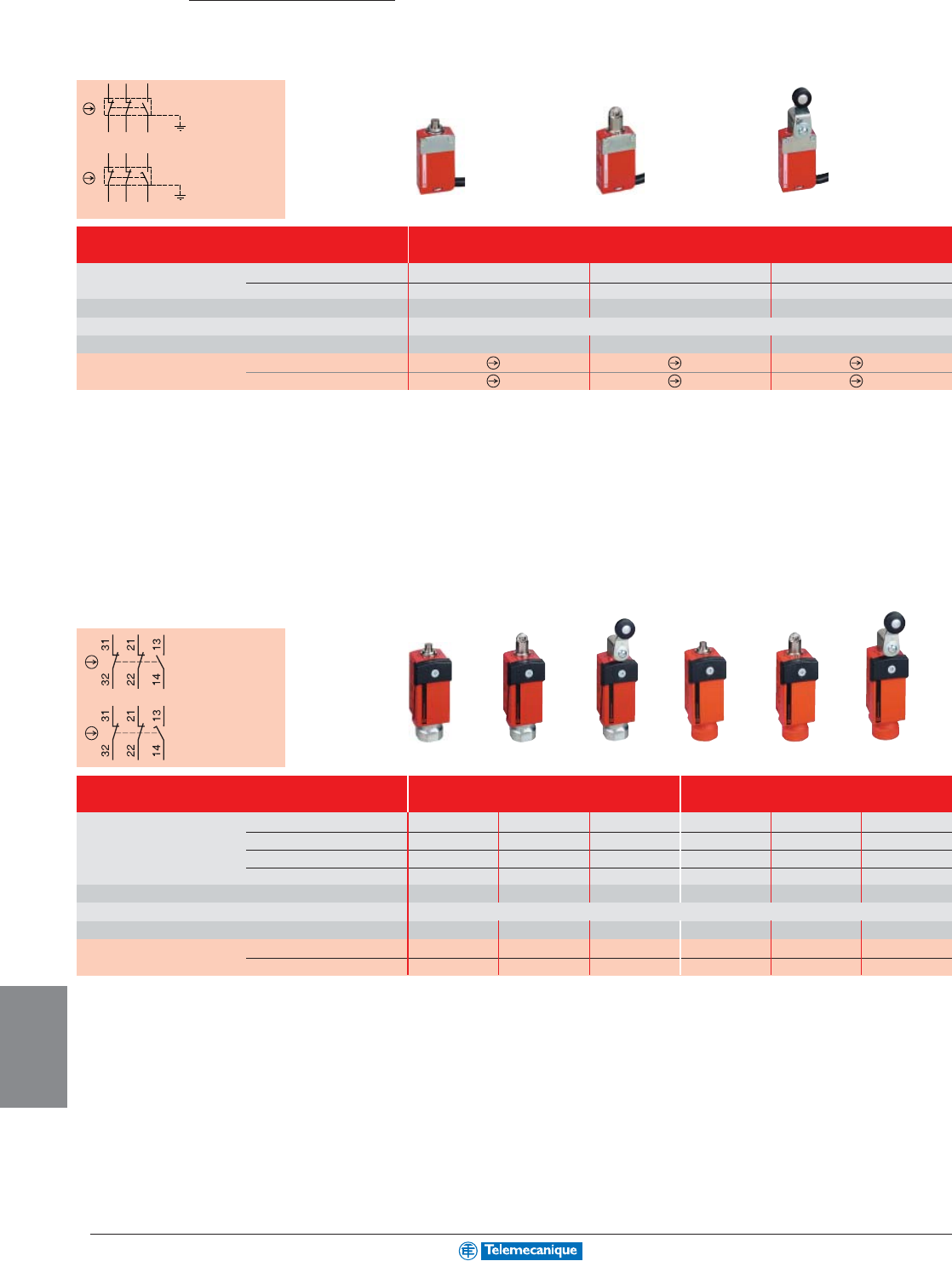
9-8
MACHINE
SAFEGUARDING
www.telemecanique.com
Detect
Safety limit switches
Safety limit switches
3-pole contact
N.C. + N.C. + N.O.
Slow break
3-pole contact
N.C. + N.C. + N.O.
Snap action
Type XCSM, metal
pre-wired with 2 m (6.6 ft) cable (1)
Actuation speed (min → max) slow break
snap action
Minimum force or torque (actuation / positive opening)
Degree of protection
Dimensions (body + head) W x D x H
Complete switch N.C. + N.C. + N.O. snap action
N.C. + N.C. + N.O. slow break
19.7 ft/min. / 1.64 ft/sec. 19.7 ft/min. / 1.64 ft/sec. 19.7 ft/min. / 4.9 ft/sec.
0.39 in/min. / 1.64 ft/sec. 0.39 in/min. / 1.64 ft/sec. 0.39 in/min. / 4.9 ft/sec.
1.9 lb (8.5 N) / 9.5 lb (42.4 N) 1.6 lb (7 N) / 7.9 lb (35 N)
0.9 in-lb (0.1 N•m) / 4.4 in-lb (0.5 Nm)
IP66 + IP67 + IP68, Type 4, 4x, 6, 12
1.18" 0.63" x 2.36" (30 x 16 x 60 mm) 1.18" 0.63" x 2.77" (30 x 16 x 70.5 mm) 1.18" x 1.28" x 3.70" (30 x 32 x 94 mm)
XCSM3910L2 XCSM3902L2 XCSM3915L2
XCSM3710L2 XCSM3702L2 XCSM3715L2
(1) For a 5 m (16.4 ft) long cable, replace the last digit of the catalog number with 5 (example: XCSM3910L2 becomes XCSM3910L5).
Miniature switches
3-pole contact
N.C. + N.C. + N.O.
Slow break
3-pole contact
N.C. + N.C. + N.O.
Snap action
Type XCSD, metal Type XCSP, plastic
1 x 1/2" NPT conduit (2) 1 x 1/2" NPT conduit (2)
Actuation speed slow break min
max
snap action min
max
Minimum force or torque (actuation / positive opening)
Degree of protection
Dimensions (body + head) W x D x H (inches)
Complete switch N.C. + N.C. + N.O. snap action
N.C. + N.C. + N.O. slow break
19.7 ft/min. 19.7 ft/min. 19.7 ft/min. 19.7 ft/min. 19.7 ft/min. 19.7 ft/min.
1.64 ft/sec. 1.64 ft/sec. 4.9 ft/sec. 1.64 ft/sec. 1.64 ft/sec. 4.9 ft/sec.
0.39 in/min. 0.39 in/min. 0.39 in/min. 0.39 in/min. 0.39 in/min. 0.39 in/min.
1.64 ft/sec. 1.64 ft/sec. 4.9 ft/sec. 1.64 ft/sec. 1.64 ft/sec. 4.9 ft/sec.
3.72 lb /10.12 lb 2.7 lb / 8.09 lb 0.89 in-lb / 2.21 in-lb 3.72 lb /10.12 lb 2.7 lb / 8.09 lb 0.89 in-lb / 2.21 in-lb
IP66 + IP67, Type 4, 4x, 12
1.34 x 1.36 x 3.50 1.34 x 1.36 x 3.92 1.34 x 1.67 x 4.78 1.34 x 1.36 x 3.50 1.34 x 1.36 x 3.92 1.34 x 1.67 x 4.78
XCSD3910N12 XCSD3902N12 XCSD3918N12 XCSP3910N12 XCSP3902N12 XCSP3918N12
XCSD3710N12 XCSD3702N12 XCSD3718N12 XCSP3710N12 XCSP3702N12 XCSP3718N12
(2) For other conduit entries, refer to the Machine Safeguarding Products Catalog #9007CT0201.
Compact switches
Metal Roller plunger Thermoplastic
end plunger roller lever
Metal Roller plunger Thermoplastic Metal Roller plunger Thermoplastic
end plunger roller lever end plunger roller lever
RD-WH
RD
BU
BN
GN-YE
BK-WH
BK
RD-WH
RD
BU
BN
GN-YE
BK-WH
BK
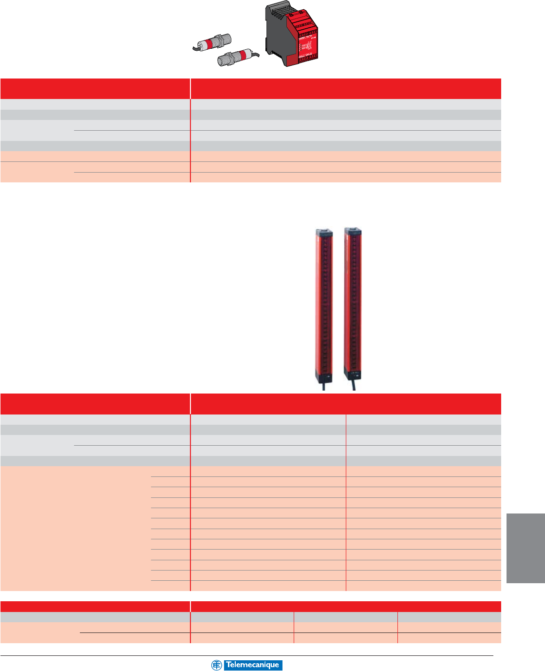
9-9
MACHINE
SAFEGUARDING
Light curtains
Type 2
Light curtain
Height protected (conforming to EN 999)
Nominal sensing distance (Sn)
Number of circuits Safety
Additional
Response time
Modules (integral muting function) 24 Vdc
Thru-beam pairs, Pre-cabled, L = 5m (16.4 ft) PNP
axially aligned M12 connector PNP
Type 2 conforming to IEC/EN 61496-1
750–1200 mm / 29.53"–47.2" (1 to 4 beams)
8 m / 26.2 ft
2 N.O.
4 solid-state
< 25 ms
XPSCM1144P (1)
XU2S18PP340L5 (2)
XU2S18PP340D (2)
(2) For alignment at 90° to the mounting axes, insert the letter W in the catalog number before the last letter (example: XU2S18PP340L5 becomes XU2S18PP340WL5).
Type 4
Sensing range
Minimum object sensitivity (MOS)
Number of circuits Safety
Additional
Response time
Transmitter + receiver protected height 260 / 10.3
(mm / in) 350 / 13.8
435 / 17.2
520 / 20.6
610 / 24.1
700 / 27.6
870 / 34.3
955 / 37.7
1045 / 41.2
1215 / 47.9
1390 / 54.9
1570 / 61.8
Type 4 conforming to IEC/EN 61496-1.
Pre-wired with 0.25m (9.8 in) cable with connector.
0.3–7.5 m /
1 to 24 ft
0.3–9 m /
1 to 29.5 ft
14 mm (0.55 in) finger protection 30 mm (1.18 in) hand protection
2 solid-state PNP 2 solid-state PNP
1 solid-state PNP 1 solid-state PNP
20–40 ms depending on model 20–30 ms depending on model
XUSLTQ6A0260 –
XUSLTQ6A0350 XUSLTR5A0350
XUSLTQ6A0435 –
XUSLTQ6A0520 XUSLTR5A0520
XUSLTQ6A0610 –
XUSLTQ6A0700 XUSLTR5A0700
XUSLTQ6A0870 XUSLTR5A0870
XUSLTQ6A0955 –
XUSLTQ6A1045 XUSLTR5A1045
XUSLTQ6A1215 XUSLTR5A1215
XUSLTQ6A1390 XUSLTR5A1390
–XUSLTR5A1570
(1) For version with non removable terminal block, delete the letter P from the end of the reference (example: XPSCM1144P becomes XPSCM1144).
Compact range
Connector cables
Length
Pre-wired with connector receiver cable
(shielded cable) transmitter cable
10 m (32.8 ft) 15 m (49.2 ft) 30 m (98.4 ft)
XSZTCR10 XSZTCR15 XSZTCR30
XSZTCT10 XSZTCT15 XSZTCT30
Light curtain functions
• Auto/Manual,
• Monitoring of external switching devices (EDM: External Devices Monitoring),
• Test input (MTS: Monitoring Test Signal),
• Blanking (ECS/B),
• Floating Blanking (FB),
• Blanking + Floating Blanking,
• Alignment aid by LED display of each light beam broken,
• LED display of operating modes and alarms.
For additional information, reference Catalog #9007CT0201.
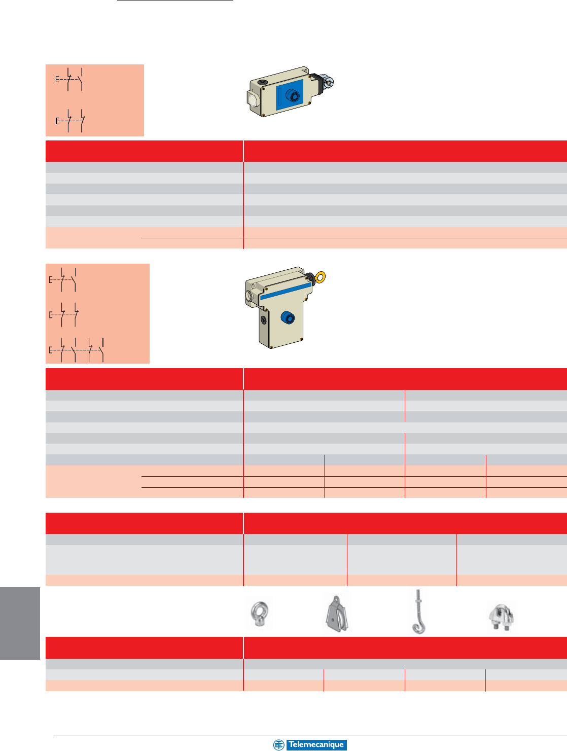
9-10
MACHINE
SAFEGUARDING
www.telemecanique.com
For emergency stop buttons, see pages 4-3, 4-6, 4-10, 4-13 and 4-14 in the operator interface section.
Dialog
Emergency stops
Cable pull switches
Latching when tripped
1/2" NPT conduit entry
Booted pushbutton reset
0.01
50 gn / 10 gn
IP 65, Type 4, 12
AC-15, A300 / DC-13, Q300 (conforming to IEC/EN 60947-5-1)
201 x 71 x 68 / 7.90 x 2.80 x 2.70
≤ 15 m (50 ft)
XY2CH13150 Standard reset XY2CH13250 Booted reset
XY2CH13170 Standard reset XY2CH13270 Booted reset
Mechanical life (millions of operating cycles)
Shock / vibration resistance
Degree of protection
Rated operational characteristics
Dimensions W x D x H (mm / in)
Operating cable length
Contact N.C. + N.O. slow break
N.C. + N.C. slow break
N.C. + N.O. contact
slow break
N.C. + N.C. contact
slow break
Latching when tripped
1/2" NPT conduit entry
Booted pusbutton reset
Mechanical life (millions of operating cycles)
Shock / vibration resistance
Degree of protection
Rated operational characteristics
Dimensions W x D x H (mm / in)
Operating cable length
Contact
N.C. + N.O. slow break
N.C. + N.C. slow break
2 N.C. + 2 N.O. slow break
0.01
50 gn / 10 gn
IP 65, Type 4, 12
AC-15, A300 / DC-13, Q300 (conforming to IEC/EN 60947-5-1)
229 x 82 x 142 / 9.00 x 3.23 x 5.60
≤ 50 m (165 ft)
Standard reset Std. reset with pilot light Booted reset Booted reset with pilot light
XY2CE1A150 (1) – XY2CE1A250 (1) –
XY2CE1A170 (1) – XY2CE1A270 (1) –
XY2CE1A190 (1) XY2CE1A196 (1) XY2CE1A290 (1) XY2CE1A296 (1)
For operating cable length ≤ 15 m (50 ft.)
For operating cable length ≤ 50 m (165 ft)
N.C. + N.O. contact
slow break
N.C. + N.C. contact
slow break
2 N.C. + 2 N.O.
contact
slow break
Cable kits
For use with XY2CH XY2CE XY2CE
Contains 1 cable - 34.4' (10.5m) long, 1 cable - 83.7' (25.5m) long, 1 cable - 165.6' (50.5m) long,
1 cable clamp and 1 end spring 4 cable clamps, 1 turnbuckle, 4 cable clamps, 1 turnbuckle,
3 cable end protectors, 1 cable 3 cable end protectors, 1 cable
support, 1 end spring support, 1 end spring
Part Number XY2CZ9310 XY2CZ9325 XY2CZ9350
Accessories
For use with all XY2CE and XY2CH
Style Cable support Pulley Pulley support Cable clamp
Part Number XY2CZ601 XY2CZ708 XY2CZ705 XY2CZ523
12 11
22 21
12 11
14 13
12
11
22
21
12
11
14
13
12
11
14
13
12
11
14
13
(1) Right cable mount listed. For left hand cable mount, replace the first 1 after the “CE” with 2 (example: XY2CE1A150 changes to XY2CE2A150)
For additional information, reference Catalog #9007CT0201.
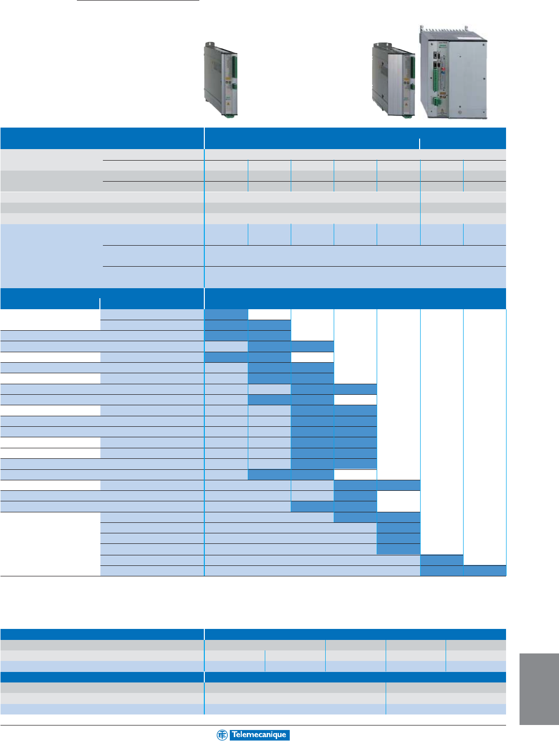
10-1
MOTION
Lexium
®
drives
For SER and BPH brushless motors
Type of MHDA drive Digital for controlling brushless motors
Lexium 17D Lexium 17D HP
Power supply Voltage 208–480 Vac 3-phase
Current 1.8 A rms 3.6 A rms 7.2 A rms 12 A rms 24 A rms 48 A rms 84 A rms
Output current Continuous 1.5 A rms 3 A rms 6 A rms 10 A rms 20 A rms 40 A rms 70 A rms
Intermittent (5 s) 3 A rms 6 A rms 12 A rms 20 A rms 40 A rms 80 A rms 140 A rms
Anti-start Integrated (1) Integrated
Braking resistor Integrated Not integrated
EMC filter Integrated Not integrated
Catalog number Analog control mode
MHDA MHDA MHDA MHDA MHDA MHDA MHDA
1004A00 1008A00 1017A00 1028A00 1056A00 1112A00 1198A00
Optional card for AM0SER001V000
SERCOS mode (2)
Communication cards (2) Fipio bus: AM0FIP001V000, Modbus Plus network: AM0MBP001V000, Profibus DP bus:
AM0PBS001V000,
Type of associated brushless motor (3)
Lexium SER (IP41 or IP56) Lexium BPH (IP65 or IP67) Continuous torque at standstill/peak torque at standstill
BPH0552S 8000 rpm 3.5/9.7 in-lb
BPH0751N 6000 rpm 8/16.8 in-lb 11.5/30.1 in-lb
SER39A4L7S 6000 rpm 9.7/22.1 in-lb 9.7/35.4 in-lb
SER39B4L3S 6000 rpm 19.5/38.9 in-lb 19.5/70.8 in-lb
BPH0752N 6000 rpm 11.5/22.1 in-lb 20.4/42.5 in-lb
SER39C4L3S 6000 rpm 25.7/41.6 in-lb 25.7/83.2 in-lb
BPH0952N 6000 rpm 32.7/63.7 in-lb 38.1/119 in-lb
SER3BA4L3S 6000 rpm 40.7/80.4 in-lb 40.7/135 in-lb
SER3BA4L5S 6000 rpm 41/73 in-lb 41/133 in-lb
BPH0953N 6000 rpm 53/119 in-lb 53/180 in-lb
SER3BB4L3S 6000 rpm 58/106 in-lb 58/177 in-lb
SER3BB4L5S 6000 rpm 58/140 in-lb 58/221 in-lb
BPH1152N 6000 rpm 65/120 in-lb 65/171 in-lb
BPH1153N 6000 rpm 60/119 in-lb 93/168 in-lb
SER3BC4L5S 6000 rpm 89/150 in-lb 89/248 in-lb
SER3BC4L7S 3000 rpm 89/142 in-lb 89/283 in-lb
BPH1422N 4000 rpm 101/159 in-lb 106/266 in-lb
SER3BD4L5D 6000 rpm 119/257 in-lb
SER3BD4L7S 3000 rpm 119/212 in-lb 119/336 in-lb
BPH1423N 4000 rpm 128/212 in-lb 150/372 in-lb
BPH1902N 4000 rpm 221/332 in-lb
BPH1903K 4000 rpm 319/504 in-lb
BPH1904K 4000 rpm 407/674 in-lb
BPH1907K 4000 rpm
664/1390 in-lb
BPH190AK 4000 rpm
797/1443 in-lb 885/2036 in-lb
(1) For drives without integrated anti-start function, replace the A in the catalog number with N. Example: MHDA1004A00 becomes MHDA1004N00.
(2) Exclusive use (1 slot only).
(3) Complete catalog numbers with type of integrated sensor, degree of protection: See the “Lexium motion control” Catalog #AUTCD21124207EN.
Accessories
Type of accessory External braking resistor
Use for drives MDHA1004/1008
MDHA1017/1028/1056
MDHA1112 MDHA1198
Power 250 W 500 W 1500 W 860 W 1600 W
Catalog number AM0RFE001V025 AM0RFE001V050 AM0RFE001V150 AM0RFE002V086 AM0RFE002V160
Type of accessory Input choke (compulsory)
Use for drives MDHA1112 MDHA1198
Characteristics 60 A rms continuous 75 A rms continuous
Catalog number AM0CHK170 AM0CHK212
Connection accessories and cables: See our “Lexium motion control” Catalog #AUTCD21124207EN.
Motion
control
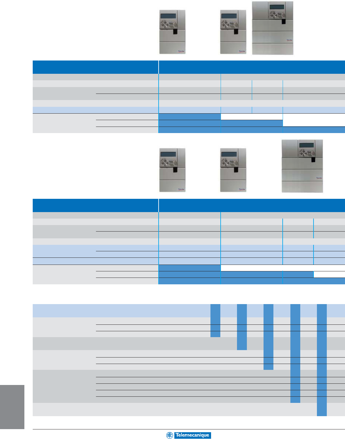
10-2
MOTION
www.telemecanique.com
Twin Line™ drives
For SER brushless motors
Type of drive Digital for brushless motors
Control integrated in the PLC
Power supply Voltage 230 Vac single phase 230–480 Vac 3-phase
Motor Power 0.75 kW rms 1.5 kW rms 3 kW rms 8 kW rms
Output current Continuous 3 A rms 3 A rms 6 A rms 16 A rms
Discontinuous (5 s) 6 A rms 6 A rms 20 A rms 32 A rms
Degree of protection IP20
Catalog number (1) TLD13 22F2pppp
pppp
pp1pp
pp
p142F3pppp
pppp
pp1pp
pp
p162F3pppp
pppp
pp1pp
pp
p182F3pppp
pppp
pp1pp
pp
p1
Type of associated SER364/366/368/36A 12000 rpm
brushless motor (2) SER39A/39B/39C/39D 6000 rpm 6000 rpm
SER3BA/3BB/3BC/3BD 6000/4500 rpm 6000/4500 rpm 6000/4500 rpm
(1) Complete the catalog numbers using the table below
(2) Complete catalog numbers of brushless motors: See the “Twin Line motion control” Catalog #8000CT0101R8/02.
Type of drive Digital for brushless motors
Command via discrete control, fieldbus or integrated programmable motion controller
Power supply Voltage 230 Vac single phase 230–480 Vac 3-phase
Motor Power 0.75 kW rms 1.5 kW rms 3 kW rms 8 kW rms
Output current Continuous 3 A rms 3 A rms 6 A rms 16 A rms
Discontinuous (5 s) 6 A rms 6 A rms 20 A rms 32 A rms
Degree of protection IP 20 IP 20 IP 20
Command via (1) Discrete control TLC43 22F21pppppppp
pppppppp
pppp 42F31pppppppp
pppppppp
pppp 62F31pppppppp
pppppppp
pppp 82F31pppppppp
pppppppp
pppp
Fieldbus TLC53 22F2pppppppppp
pppppppppp
ppppp 42F3pppppppppp
pppppppppp
ppppp 62F3pppppppppp
pppppppppp
ppppp 82F3pppppppppp
pppppppppp
ppppp
Programmable motion controller (1) TLC63 22F2pppppppppp
pppppppppp
ppppp 42F3pppppppppp
pppppppppp
ppppp 62F3pppppppppp
pppppppppp
ppppp 82F3pppppppppp
pppppppppp
ppppp
Type of associated SER364/366/368/36A 12000 rpm
brushless motor (2) SER39A/39B/39C/39D 6000 rpm 6000 rpm 6000 rpm
SER3BA/3BB/3BC/3BD 6000/4500 rpm 6000/4500 rpm 6000/4500 rpm
(1) Complete the catalog numbers using the table below
(2) Complete catalog numbers of brushless motors: See our “Twin Line motion control” Catalog #8000CT0101R8/02.
Complete each of the above catalog numbers pp
pp
ppp
pp
ppp
pp
ppp
pp
ppp
pp
p
Slot M1 No module 1
RS 422C encoder module 2
PULSE-C module 3
Slot M2 Sincos Hiperface 2
Slot M3 No module (TLD13) 1
No encoder simulation (TLD43/53/63) 1
ESIM3-C encoder simulation 2
Slot M4 No module 1
communication RS 485C (TLC43/53/63), ESIM1-C module (TLD13) 2
I
NTER
B
US
(TLC43/53/63), ESIM2-C module (TLD13) 3
CANopen/DeviceNet (TLC43/53/63), SSI-C module (TLD13) 4
Profibus DP (TLC43/53/63) 5
Integrated holding None (TLD43/53/63) 1
brake controller
Connection accessories: See the “Twin Line motion control” Catalog #8000CT0101R8/02.

Catalog No. 0140CT0401 March 2004 © 2004 Schneider Electric All Rights Reserved
Schneider Electric
8001 Highway 64 East
Knightdale, NC 27545
1-888-SquareD
(1-888-778-2733)
www.schneider-electric.com
www.telemecanique.com
Schneider Canada Inc.
19 Waterman Avenue
M4B 1 Y2
Toronto, Ontario
1-800-565-6699
www.schneider-electric.ca
