125836 Catalog
2014-09-05
: Pdf 125836-Catalog 125836-Catalog 715629 Batch7 unilog
Open the PDF directly: View PDF ![]() .
.
Page Count: 459 [warning: Documents this large are best viewed by clicking the View PDF Link!]
- Commercial Heat Tracing Products and Services
- Design Guides
- Pipe Freeze Protection and Flow Maintenance — XL-Trace System
- Fire Sprinkler System Freeze Protection — XL-Trace System
- Roof and Gutter De-icing — IceStop System
- Surface Snow Melting – MI Mineral Insulated Heating Cable System
- Surface Snow Melting and Anti-icing – ElectroMelt
- Freezer Frost Heave Prevention – RaySol and MI Heating Cable System
- Floor Heating – RaySol, Mineral Insulated , and QuickNet Heating Systems
- Technical Data Sheets
- XL-Trace
- IceStop
- ElectroMelt
- RaySol
- MI Heating Cable — For commercial applications
- MI Heating Cable — For freezer frost heave prevention applications
- MI Heating Cable — For surface snow melting in concrete, asphalt, and pavers
- MI Heating Cable — For heat loss replacement, floor heating and radiant space heating
- QuickNet
- ACS-30
- C910-485
- ECW-GF, ECW-GF-DP
- HTPG
- SMPG1
- SMPG3
- APS-3C
- APS-4C
- SC-40C
- ETI PD Pro
- ETI GF Pro
- RM-3
- RM-4
- CIT-1, GIT-1, SIT-6E
- EC-TS
- AMC-F5
- AMC-1A
- AMC-1B
- ProtoNode
- RMM2
- RTD-200
- RTD3CS, RTD10CS, and RTD50CS
- RTD4AL
- RayClic
- FTC
- ElectroMelt Connection Kits and Accessories

commercial HeaT TraciNG
ProducTs aNd services
THERMAL MANAGEMENT SOLUTIONS WWW.PENTAIRTHERMAL.COM

44 PENTAIR
44 THERMAL MANAGEMENT SOLUTIONS
We provide quality solutions for winter safety, comfort and
performance to building and infrastructure design, construc-
tion, operation and maintenance professionals. From pipe
freeze protection to maintaining fluid temperatures and
melting snow, detecting leaks or heating floors, you can rely
on Pentair Thermal Managements’ solutions & services for
greater safety, comfort and performance.
As the inventor of self-regulating heat tracing, our Raychem
brand is recognized for technical leadership in the industries
we serve. Raychem cable delivers the appropriate amount
of heat exactly when and where it is needed, adjusting the
output produced in response to ambient and process condi-
tions, making it ideal for heat management systems. Since
inventing the technology, Pentair Thermal Management has
sold over one billion feet of Raychem brand self-regulating
cable. In addition to a self-regulating product set addressing
a full range of temperature needs, we also offer other types
of heating cables, control and monitoring solutions, and a full
range of services related to our products.
The Pyrotenax brand mineral insulated heating cables and
wiring have led the industry for more than 75 years. Able to
withstand extreme, harsh environments, Pyrotenax cables
provide the most reliable heat-tracing solution for high-
temperature applications.
The DigiTrace line of products offers the industry's most
complete range of dedicated heat-tracing control and
monitoring systems, from simple thermostats to
advanced networked systems, with easy-to-use
interface technologies that put information and
programming at your fingertips.
The Tracer Turnkey Solutions Team is widely regarded as
the premiere provider of turnkey heat-tracing solutions.
With our full suite of services, from design to installation,
we are capable of handling heat-tracing projects of any size
and scope. By focusing on safety and utilizing time-tested
methods and solutions, Pentair Thermal Management's
heat-tracing designs and installations are timely, thorough,
and cost-effective.
Rely on Pentair Thermal Managements’ solutions & services
for greater safety, comfort and performance for your build-
ings and infrastructure projects.
THE HEART OF OUR SOLUTIONS
BUILDING &
INFRASTRUCTURE SOLUTIONS
This brochure highlights our heat tracing products and services for the com-
mercial construction industry. Our commercial heating products are used in
the following applications:
• Pipe Freeze Protection & Flow Maintenance
• Roof & Gutter De-Icing
• Surface Snow Melting & Anti-Icing
• Freezer Frost Heave Prevention
• Floor Heating
• Hot Water Temperature Maintenance
Snow Melting
Heat Tracing Floor Heating
Leak Detection Turnkey
Solutions
Fire and
Performance
Wiring
Roof & Gutter
De-Icing
CommerCial heat-traCinG
offerinG
Technical
Data Sheets
Pipe Freeze
Protection
and Flow
Maintenance
Roof and
Gutter
De-Icing
Surface Snow
Melting – MI
Surface Snow
Melting and
Anti-Icing –
ElectroMelt
Freezer Frost
Heave
Prevention
Floor Heating
Fire Sprinkler
System Freeze
Protection
In cold locations, thermal insulation alone cannot keep water pipes from
freezing, nor can it keep grease disposal and fuel lines free flowing. The
Raychem XL-Trace self-regulating heating cable system prevents general
water pipes and fire sprinkler lines from freezing and provides flow
maintenance for grease and fuel lines.
The energy-efficient XL-Trace heating cable keeps total operating costs
down by adjusting power output in response to ambient temperatures.
Easy to install, the XL-Trace cable can be cut to length on site and over-
lapped at valves, flanges, and pumps.
APPLICATIONS
Raychem XL-Trace System
Raychem XL-Trace
System for Flow
Maintenance
ii PENTAIR
ii THERMAL MANAGEMENT SOLUTIONS
PIPE FREEZE PROTECTION
AND FLOW MAINTENANCE
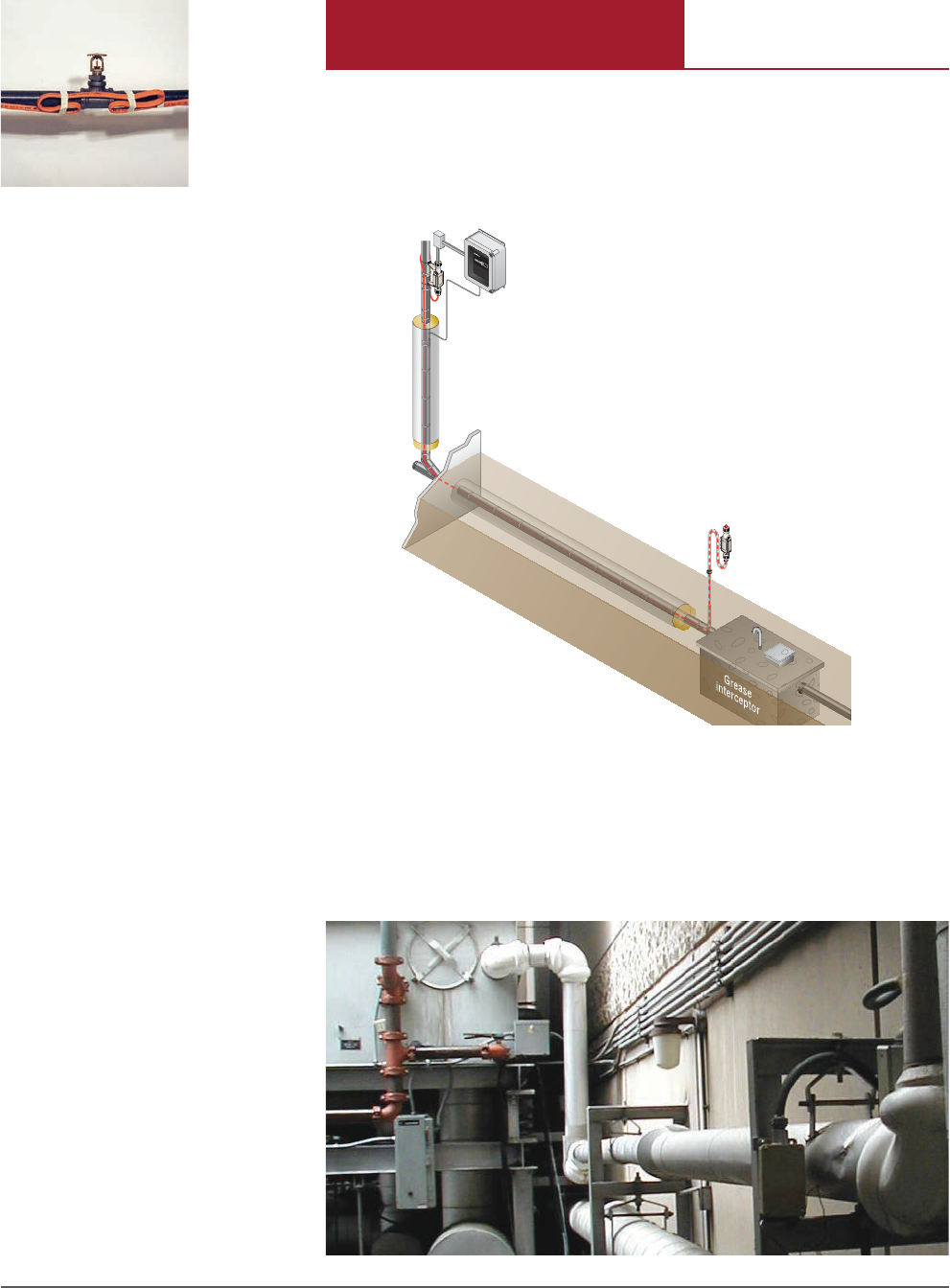
Roofs and gutters can be severely damaged by ice buildup. Heavy icicles
can fall and cause serious injury. Standing water can leak through to
interior walls and furnishings. The Raychem IceStop system helps you
avoid these problems.
The IceStop self-regulating heating cable can be cut to length for easy
installation in plastic, copper, steel, or aluminum gutters, and on flat or
pitched roofs, valleys and overhangs. The low operating temperature of
the heating cable also makes it safe for use on modern membrane roofs.
Raychem IceStop System for Roof & Gutter De-Icing
Raychem IceStop System
ROOF & GUTTER DEICING
iii
FLOORHEATING iii
COMMERCIAL HEAT TRACING
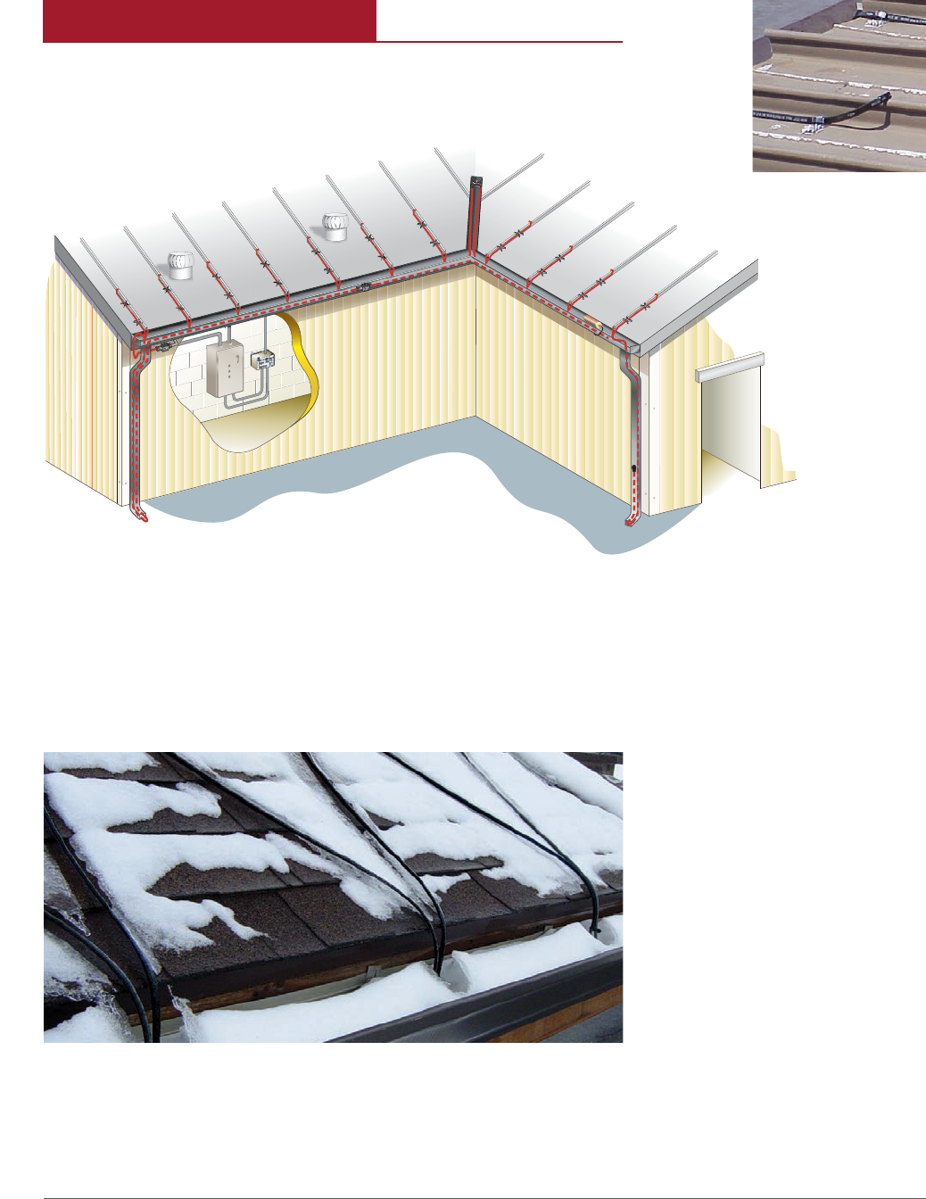
In winter, snow and ice can accumulate on outdoor concrete and asphalt
surfaces used by people and vehicles. Proven, reliable and efficient,
Pyrotenax MI and Raychem ElectroMelt snow melting systems keep side-
walks, stairways, driveways, parking garage ramps, loading docks, store
entryways, and other areas free of snow and ice during even the worst
weather conditions.
The Raychem ElectroMelt system incorporates a rugged cut-to-length
self-regulating heating cable that automatically adjusts power output in
response to concrete temperature.
The Pyrotenax MI system incorporates a rugged copper mineral insulated
constant wattage heating cable that is protected by a high density
polyethylene outer jacket.
Pyrotenax MI System
Pyrotenax MI Snow
Melting System
APPLICATIONS
Raychem ElectroMelt
System
iv PENTAIR
iv THERMAL MANAGEMENT SOLUTIONS
SURFACE SNOW MELTING &
ANTIICING
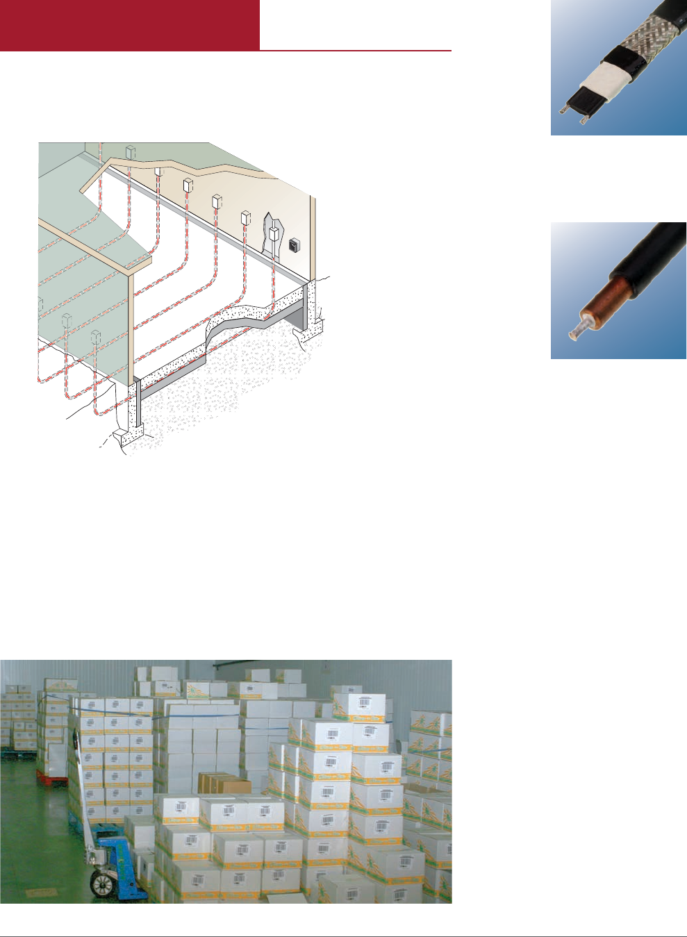
Subfreezing temperatures inside cold rooms and freezers cause heat to
be lost from the soil under the floor, even when it is well insulated.
As the soil freezes, capillary action draws water into the frozen areas
where the water forms a concentrated ice mass. As the ice mass grows,
it heaves the freezer floor and columns, causing damage. Installing
Raychem RaySol or Pyrotenax MI heating cables in the subfloor under the
freezer-floor insulation can prevent this problem.
Raychem RaySol or
Pyrotenax MI System
for Freezer Frost Heave
Prevention
Raychem RaySol System
Pyrotenax MI System
v
Floorheating v
commercial heat tracing
FREEZER FROST HEAVE
PREVENTION
AF
2
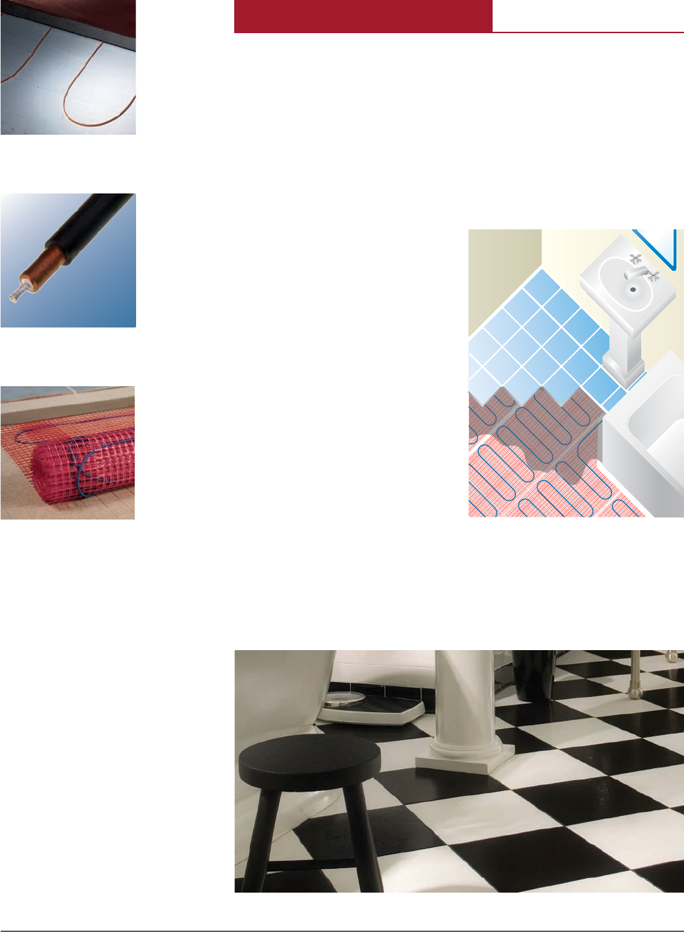
Raychem QuickNet
System for Comfort
Floor Heating
Raychem RaySol System
Pyrotenax MI System
QuickNet Floor Heating
System
Floor heating is becoming increasingly desirable in office buildings,
hotels, garages and homes. Pentair Thermal Management offer solutions
for the following floor heating applications:
• Heat-loss replacement as a heat source to prevent the floor over a cold space
from cooling below room temperature
• Comfort floor heating as a supplemental heat source
• Radiant space heating as a primary heat source
APPLICATIONS
Pentair Thermal Management
offers multiple solutions for each
of these applications, including
Raychem RaySol, Pyrotenax MI,
and the Raychem QuickNet floor
heating system.
vi PENTAIR
vi THERMAL MANAGEMENT SOLUTIONS
FLOOR HEATING
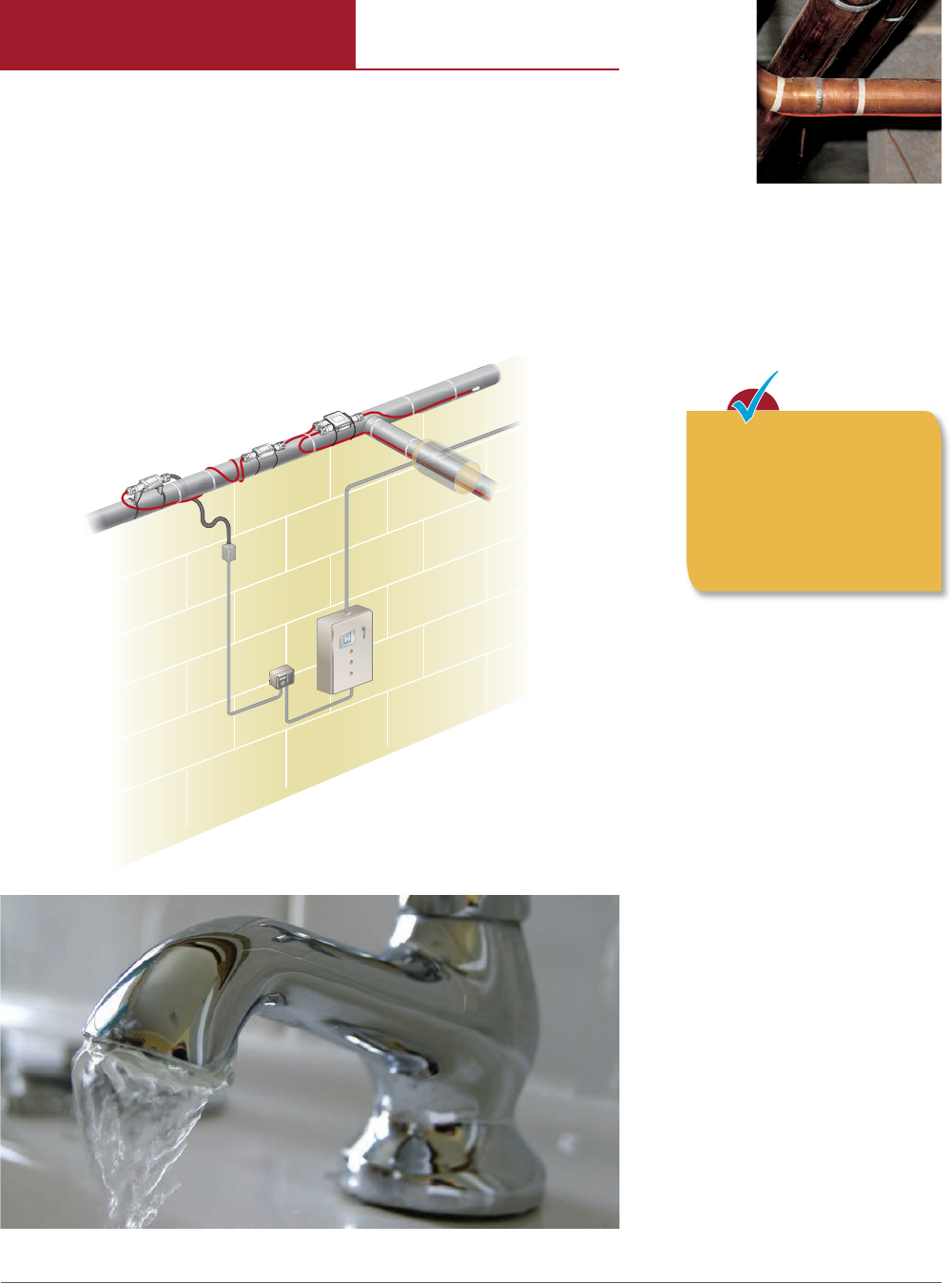
Raychem HWAT System for Hot
Water Temperature Maintenance
Raychem HWAT System
Recirculation systems in large commercial buildings can lead to high
energy costs and wasted water. The Raychem HWAT system is a simple,
reliable alternative to recirculation. Attached to hot-water supply pipes,
HWAT heating cables compensate for heat loss and maintain hot water
temperature throughout the building.
Engineered for direct installation on hot-water supply pipes to maintain
water temperature, HWAT heating cables eliminate the need for return
piping valves, or pumps. This lowers installation cost and takes up
less building space. The HWAT system’s energy savings, water savings
and minimal maintenance requirements significantly reduces building
operating costs.
S
M
A
R
T
T
I
P
For HWAT design
assistance, please refer to
the Hot Water Temperature
Maintenance Product
Selection and Design Guide
(H57538)
HOT WATER TEMPERATURE
MAINTENANCE
vii
Floorheating vii
commercial heat tracing
XL-Trace
Pipe Freeze
Protection and Flow
Maintenance
ElectroMelt
Surface Snow Melting
and Anti-Icing
IceStop
Roof and Gutter
De-Icing
RaySol
Floor Heating,
Heat-Loss
Replacement and
Freezer Frost
Heave Prevention
HWAT
Hot Water Temperature
Maintenance
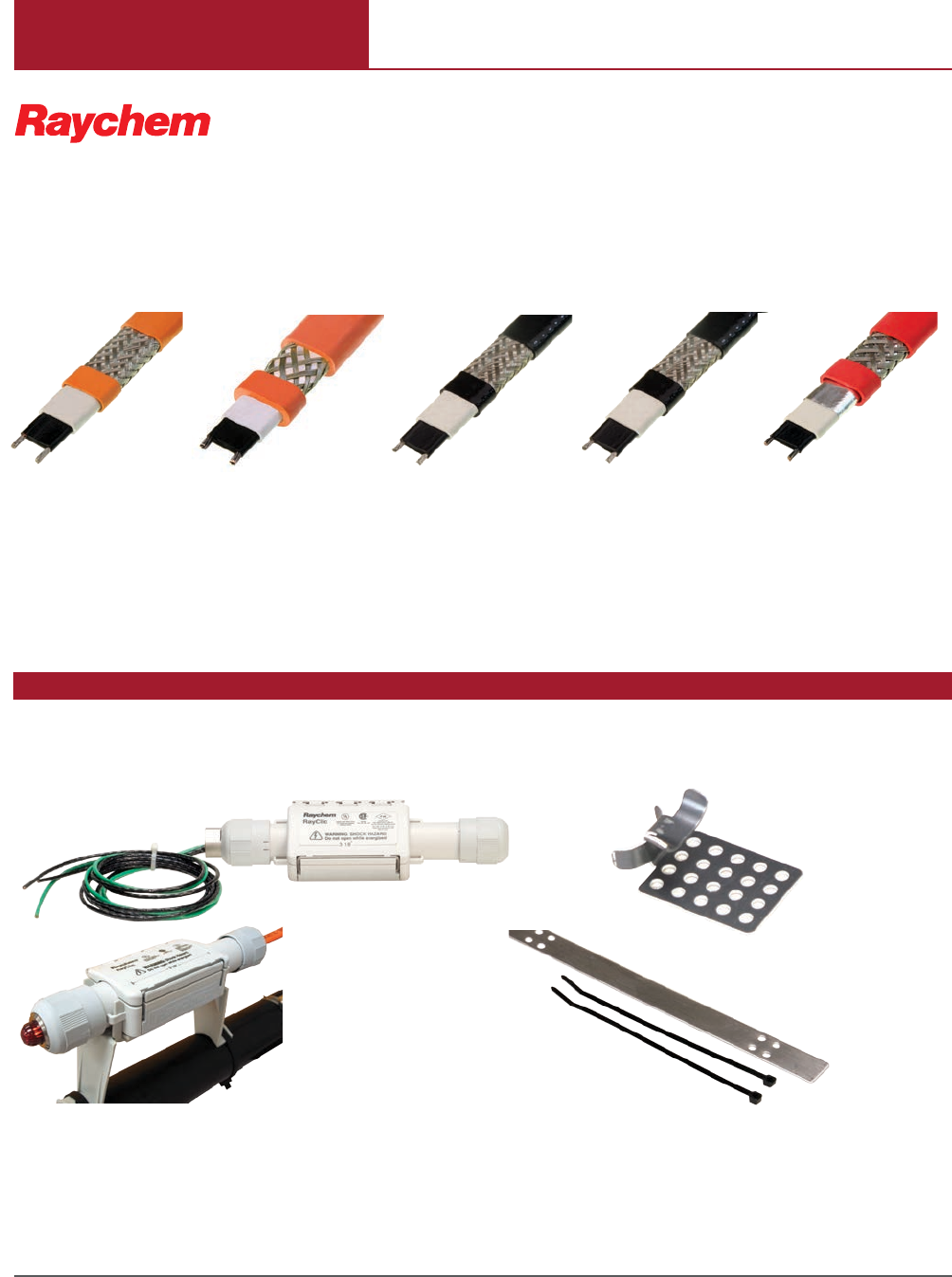
RayClic-PC Power Connection GMK-RC Roof Clip
RayClic-LE Lighted End Seal
Raychem power, splice tee and end seal kits and accessories are vital parts of the heat-tracing system.
GMK-RAKE Hanger
Bracket
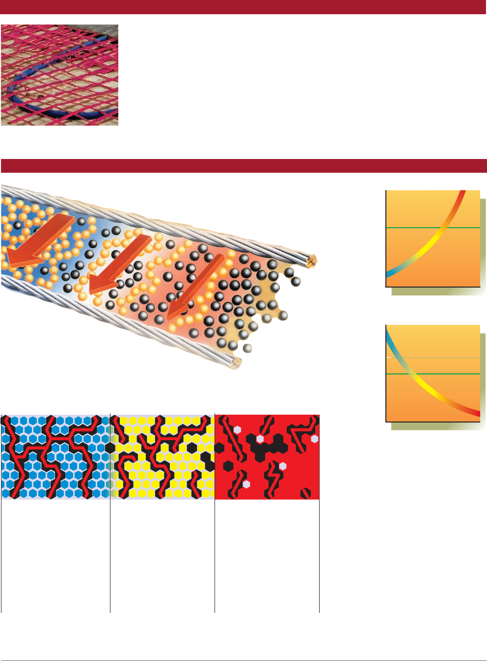
Raychem self-regulating heating cables consist of two parallel conductors
embedded in a conductive polymer heating core. The core is radiation-
cross linked to ensure long-term reliability. The self-regulating heating
cable automatically adjusts power output to compensate for temperature
changes. As the temperature drops, the number of electrical paths
through the core increases and more heat is produced. Conversely, as the
temperature rises, the core has fewer electrical paths and less heat is
produced.
COMMERCIAL HEATING PRODUCTS
RAYCHEM SELFREGULATING
HEATING CABLES
RAYCHEM CONNECTION KITS AND ACCESSORIES
viii PENTAIR
viii THERMAL MANAGEMENT SOLUTIONS
QuickNet
Comfort Floor Heating
How self-regulation works in
Raychem conductive-polymer heaters:
At low temperature,
there are many
conducting paths,
resulting in high output
and rapid heat-up. Heat
is generated only when
it is needed and
precisely where it is
At moderate
temperature, there are
fewer conducting paths
because the heating
cable efficiently adjusts
by decreasing output,
eliminating any
possibility of
overheating.
At high temperature,
there are few
conducting paths and
output is
correspondingly lower,
conserving energy
during operation.
Temperature
Resistance
Temperature
Power
Constant Wattage
Constant Wattage
Self-regulating
Self-regulating
RAYCHEM FLOOR HEATING MAT
RAYCHEM SELFREGULATING HEATING CABLES
ix
Floorheating ix
commercial heat tracing

Roof and Gutter De-Icing, and Floor Heating
Roof and Gutter De-Icing, Surface Snow Melting, Anti-Icing, Freezer Frost
Heave Prevention, and Floor Heating
Surface Snow Melting, Anti-Icing, and Floor Heating
Pyrotenax mineral insulated heating cables consist of a single or dual
conductor surrounded by magnesium oxide insulation, a solid copper
sheath, and an extruded high density polyethylene jacket. The mineral
insulated series-type technology provides a reliable and constant heat
source that is ideal for surface snow melting, anti-icing, floor heating,
and freezer frost heave prevention.
Copper mi heatinG CaBles
hDpe jaCKeteD Copper mi heatinG CaBles
alloy 825 mi heatinG CaBles
pyrotenaX mineral
insulateD heatinG CaBles
xPENTAIR
xTHERMAL MANAGEMENT SOLUTIONS
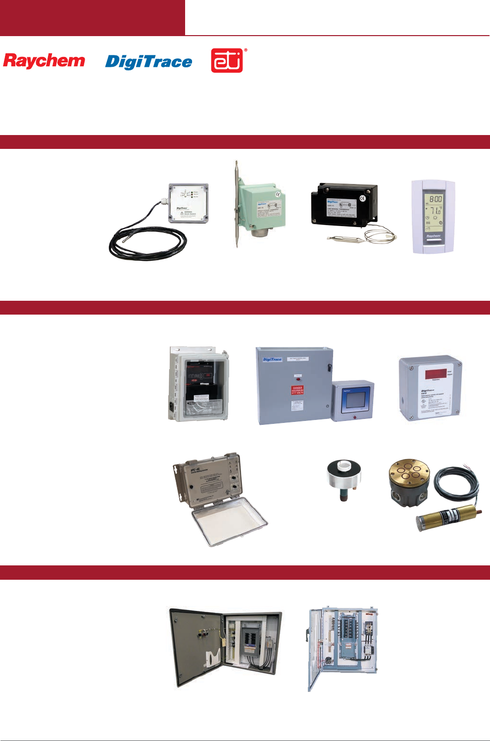
Our thermostats provide simple
on/off control for pipe freeze
protection, flow maintenance
applications, and floor
heating.
Our microprocessor-based control-
lers provide accurate control and
feedback for critical heat-tracing
applications, including freeze
protection for sprinkler piping
systems.
ETI® snow controllers automati-
cally energize snow melting, and
roof and gutter de-icing systems
when both precipitation and low
temperature are detected.
DigiTrace dedicated power-
distribution panels reduce costly
field wiring and controller costs.
Available for heat tracing, surface
snow melting, anti-icing, and roof
and gutter de-icing applications.
SMPG
C910-485
CIT-1
EC-TS AMC-1A
HTPG
QuickStat-TC
GIT-1
SIT-6E
AMC-F5
ACS-30
THERMOSTATS
ELECTRONIC CONTROLLERS AND SENSORS
POWER DISTRIBUTION
CONTROL & MONITORING
SYSTEMS
APS-4C
ECW-GF
xi
Floorheating xi
commercial heat tracing

WEB SERVICES AND SOFTWARE
All the tools and information you need to design, select, and purchase a
complete system for any commercial heating application. Use our Web-
based Design Wizards. Download, print, browse product information, or
submit a question.
On our interactive frequently asked questions and answers (FAQ) page,
you’ll find questions broken down by markets and product lines. If your
question does not appear, simply submit a new question. A Pentair
Thermal Management technical expert will answer your question and post
it to the web site.
XL-ERATE
XL-ERATE is an on-line com-
mercial pipe freeze protection and
flow maintenance design tool. The
program generates a complete
Raychem XL-Trace bill of material
and can also facilitate a quotation
if desired.
SnoCalc
SnoCalc is an on-line surface snow
melting design tool that selects the
appropriate heating cables, con-
nection kits and accessories. Your
design information, from cable
selection to circuit length, cable
power and more, are all displayed
and available for download. The
program also selects a control
solution and even allows you to
submit a request for quote online.
HotCAP
HotCAP is a hot water cost
analysis program that compares
the relative economics between
the Raychem HWAT system and a
recirculation system. Comparisons
include installation and operat-
ing costs as well as time-to-tap,
wasted water, and life cycle.
ACS-30 Program Integrator
The ACS-30 Program Integrator is
a utility used on Microsoft Windows
PCs that allows the user to easily
set up circuit databases—providing
invaluable help for commissioning
the heating cable control system.
VISIT WWW.PENTAIRTHERMAL.COM
DESIGN TOOLS
ONLINE TECHNICAL SUPPORT
xii PENTAIR
xii THERMAL MANAGEMENT SOLUTIONS

Visit our web site at
www.pentairthermal.com or
contact us at 1-800-545-6258.
BEFORE YOU BUY, WEIGH THE FACTS: FOR PROVEN HEATING
SOLUTIONS, LOOK TO
THE LEADER.
PENTAIR THERMAL
MANAGEMENT NORTH
AMERICAN OPERATIONS
Greater selection
Offering the most complete product line of proven heating
technologies to better satisfy your unique needs.
More innovation
As a world leader in heating cable technologies, design
optimization, construction, and control and monitoring
systems, we invented many of today’s industry standards.
More manufacturing experience
Quality-driven manufacturing processes, combined with
years of manufacturing self-regulating and mineral-
insulated cables gives you products proven to be the most
reliable.
Menlo Park, CA
Redwood City, CA
Trenton, Ontario
Baton Rouge, LA
Houston, TX
Worldwide Headquarters
Edmonton, Alberta
Fort McMurray, Alberta
Philadelphia, PA
Headquarters
Service/Sales Centers
Manufacturing Centers
Chicago, IL
Seattle, WA
Milton, Ontario
xiii
FLOORHEATING
COMMERCIAL HEAT TRACING

Pipe Freeze Protection
and Flow Maintenance
Fire Sprinkler System
Freeze Protection
Roof and Gutter
De-Icing
Surface Snow
Melting – MI
Surface Snow
Melting – ElectroMelt
Freezer Frost
Heave Prevention
Floor Heating Technical Data
Sheets
This section provides individual design guides for Pentair Thermal Management
Commercial Heating products. These design guides are also available in .pdf format
on our web site at www.pentairthermal.com
CONTENTS
Pipe Freeze Protection and Flow Maintenance — XL-Trace System ..............3
Fire Sprinkler System Freeze Protection — XL-Trace System ..................47
Roof and Gutter De-Icing — IceStop System ................................87
Surface Snow Melting – MI Mineral Insulated Heating Cable System ..........127
Surface Snow Melting and Anti-Icing – ElectroMelt .........................169
Freezer Frost Heave Prevention – RaySol and MI Heating Cable System ........203
Floor Heating – RaySol, Mineral Insulated, and QuickNet Heating Systems .....259
Design guiDes
1 THERMAL MANAGEMENT SOLUTIONS

THERMAL MANAGEMENT SOLUTIONS2
Pipe Freeze Protection
and Flow Maintenance
Fire Sprinkler System
Freeze Protection
Roof and Gutter
De-Icing
Surface Snow
Melting – MI
Surface Snow
Melting – ElectroMelt
Freezer Frost
Heave Prevention
Floor Heating Technical Data
Sheets
This step-by-step design guide provides the tools necessary to design a Raychem
XL-Trace pipe freeze protection or flow maintenance system. For other applications
or for design assistance, contact your Pentair Thermal Management representative
or phone Pentair Thermal Management at (800)545-6258. Also, visit our web site at
www.pentairthermal.com.
Contents
Introduction ...........................................................3
How to Use this Guide ..............................................4
Safety Guidelines ..................................................4
Warranty .........................................................5
System Overview .......................................................5
XL-Trace Applications ...............................................5
Self-Regulating Heating Cable Construction ............................6
Pipe Freeze Protection Applications .......................................7
Typical Pipe Freeze Protection System .................................7
General Water Piping ...............................................8
Flow Maintenance Applications ..........................................10
Typical Flow Maintenance System ....................................10
Greasy Waste Lines ...............................................11
Fuel Lines .......................................................13
Pipe Freeze Protection and Flow Maintenance Design .......................14
Design Step by Step ...............................................14
Step 1 Determine design conditions and pipe heat loss ...............14
Step 2 Select the heating cable ...................................19
Step 3 Determine the heating cable length .........................22
Step 4 Determine the electrical parameters ........................24
Step 5 Select the connection kits and accessories ...................28
Step 6 Select the control system ..................................33
Step 7 Select the power distribution ..............................35
Step 8 Complete the Bill of Materials ..............................37
XL-Trace System Pipe Freeze Protection and Flow Maintenance
Design Worksheet ..................................................38
INTRODUCTION
This design guide presents Pentair Thermal Management’s recommendation for
designing an XL-Trace pipe freeze protection and flow maintenance system for the
following applications:
• Freeze protection of general water piping (aboveground and buried)
• Flow maintenance of waste lines (aboveground and buried)
• Flow maintenance of fuel lines (aboveground)
3THERMAL MANAGEMENT SOLUTIONS EN-RaychemXLTracePipeFreezeProtection-DG-H55838 11/13
PIPE FREEZE PROTECTION AND FLOW
MAINTENANCE XLTRACE SYSTEM

This guide does not cover applications in which any of the following conditions exist:
• Hazardous locations, as defined in the national electrical codes
• Pipe temperature other than specified in Table 1 on page 5
• Pipe maintenance temperatures above 150°F (65°C)
• Supply voltage other than 120 V or 208–277 V
For designing XL-Trace pipe freeze protection system for fire sprinkler
piping, please refer to the XL-Trace System for Fire Sprinkler Freeze Protection
Design Guide (H58489).
If your application conditions are different, or if you have any questions, contact your
Pentair Thermal Management representative or contact Pentair Thermal
Management directly at (800)545-6258.
How to Use this Guide
This design guide presents Pentair Thermal Management’s recommendations
for designing an XL-Trace pipe freeze protection or flow maintenance system. It
provides design and performance data, electrical sizing information, and application
configuration suggestions. Following these recommendations will result in a reliable,
energy-efficient system.
OTHER REQUIRED DOCUMENTS
This guide is not intended to provide comprehensive installation instructions. For
complete XL-Trace pipe freeze protection and flow maintenance system installation
instructions, please refer to the following additional required documents:
• XL-Trace System Installation and Operation Manual (H58033)
• Additional installation instructions are included with the connection kits, thermo-
stats, controllers, and accessories
If you do not have these documents, you can obtain them from the Pentair Thermal
Management web site at www.pentairthermal.com.
For products and applications not covered by this design guide, please contact your
Pentair Thermal Management representative or call Pentair Thermal Management
directly at (800)545-6258.
Safety Guidelines
As with any electrical equipment, the safety and reliability of any system depends
on the quality of the products selected and the manner in which they are installed
and maintained. Incorrect design, handling, installation, or maintenance of any of
the system connection kits could damage the system and may result in inadequate
performance, overheating, electric shock, or fire. To minimize these risks and to
ensure that the system performs reliably, read and carefully follow the information,
warnings, and instructions in this guide.
This symbol identifies important instructions or information.
This symbol identifies particularly important safety warnings that must be
followed.
WARNING: To minimize the danger of fire from sustained electrical arcing
if the heating cable is damaged or improperly installed, and to comply with the
requirements of Pentair Thermal Management, agency certifications, and national
electrical codes, ground-fault equipment protection must be used on each heating
cable branch circuit. Arcing may not be stopped by conventional circuit protection.
PIPE FREEZE PROTECTION AND FLOW MAINTENANCE XLTRACE SYSTEM
THERMAL MANAGEMENT SOLUTIONS
EN-RaychemXLTracePipeFreezeProtection-DG-H55838 11/13
4

Pipe Freeze Protection
and Flow Maintenance
Fire Sprinkler System
Freeze Protection
Roof and Gutter
De-Icing
Surface Snow
Melting – MI
Surface Snow
Melting – ElectroMelt
Freezer Frost
Heave Prevention
Floor Heating Technical Data
Sheets
Warranty
Pentair Thermal Management’s standard limited warranty applies to all products.
An extension of the limited warranty period to ten (10) years from the date of
installation is available if a properly completed online warranty form is submitted
within thirty (30) days from the date of installation. You can access the complete
warranty on our web site at www.pentairthermal.com.
SYSTEM OVERVIEW
The XL-Trace system provides freeze protection and flow maintenance for
aboveground and buried pipe applications. The XL-Trace system is based on self-
regulating heating cable technology. Pentair Thermal Management offers the option
of three self-regulating heating cables with the XL-Trace system: 5XL, 8XL, and 12XL
(208–277 V only) for applications using 120 and 208–277 V power supplies. The cable’s
output is reduced automatically as the pipe warms, so there is no possibility of
failure due to overheating.
An XL-Trace system includes the heating cable, power connection, splice, tee
connections, controls, contactors, power distribution panels, accessories, and the
tools necessary for a complete installation.
XL-Trace Applications
Identify which of the standard XL-Trace applications below pertain to your
installation. Proceed to the appropriate design sections that follow.
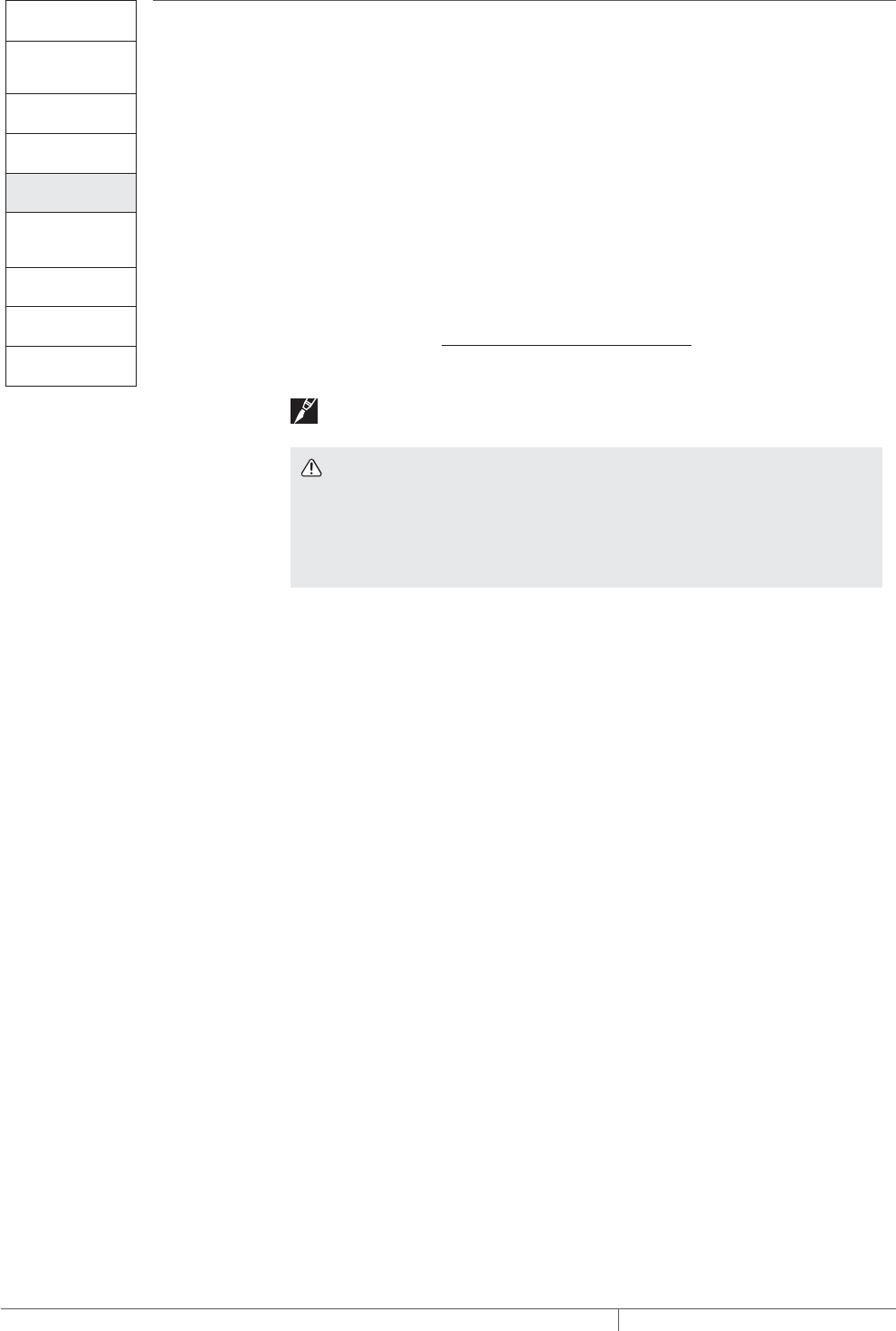
TABLE 1 XLTRACE APPLICATIONS
Application Description
Specific application
requirements
Pipe freeze protection
General water pipingFreeze protection (40°F [4°C]
minimum) of insulated, metal
or plastic water piping
“Aboveground piping” on page8
“Buried piping,” page 9
Flow maintenance
Greasy waste lines Flow maintenance (110°F
[43°C] minimum) for insulated
greasy waste lines
“Aboveground piping” on page11
“Buried piping” on page12
Fuel lines Flow maintenance (40°F [4°C]
minimum) for insulated metal
piping containing #2 fuel oil
“For aboveground piping only,”
page 13
Note: If your application does not fit these guidelines, contact your local Pentair
Thermal Management representative or call (800) 545-6258.
System Overview
5THERMAL MANAGEMENT SOLUTIONS EN-RaychemXLTracePipeFreezeProtection-DG-H55838 11/13

Self-Regulating Heating Cable Construction
Raychem XL-Trace self-regulating heating cables are comprised of two parallel
nickel-plated bus wires in a cross-linked polymer core, a tinned copper braid, and a
fluoropolymer or polyolefin outer jacket. These cables are cut to length, simplifying
the application design and installation.
Nickel-plated copper bus wire
Self-regulating conductive core
Modified polyolefin inner jacket
Tinned-copper braid
Polyolefin or
fluoropolymer outer jacket
Fig. 1 XL-Trace heating cable construction
With self-regulating technology, the number of electrical paths between bus wires
changes in response to temperature fluctuations. As the temperature surrounding
the heater decreases, the conductive core contracts microscopically. This contraction
decreases electrical resistance and creates numerous electrical paths between the
bus wires. Current flows across these paths to warm the core.
As the temperature rises, the core expands microscopically. This expansion
increases electrical resistance and the number of electrical paths decreases. The
heating cable automatically reduces its output.
At low temperature,
there are many
conducting paths,
resulting in high output
and rapid heat-up. Heat
is generated only when it
is needed and precisely
where it is needed.
At high temperature,
there are few
conducting paths
and output is
correspondingly
lower, conserving
energy during
operation.
At moderate temperature,
there are fewer conducting
paths because the heating
cable efficiently adjusts by
decreasing output, eliminating
any possibility of overheating.
The following graphs illustrate the response of self-regulating heating
cables to changes in temperature. As the temperature rises, electrical
resistance increases, and our heaters reduce their power output.
Temperature
Resistance
Power
Temperature
Constant wattage
Constant wattage
Self-regulating
Self-regulating
Fig. 2 Self-regulating heating cable technology
PIPE FREEZE PROTECTION AND FLOW MAINTENANCE XLTRACE SYSTEM
THERMAL MANAGEMENT SOLUTIONS
EN-RaychemXLTracePipeFreezeProtection-DG-H55838 11/13
6
Pipe Freeze Protection
and Flow Maintenance
Fire Sprinkler System
Freeze Protection
Roof and Gutter
De-Icing
Surface Snow
Melting – MI
Surface Snow
Melting – ElectroMelt
Freezer Frost
Heave Prevention
Floor Heating Technical Data
Sheets
PIPE FREEZE PROTECTION APPLICATIONS
A pipe freeze protection system is designed to maintain the pipe temperature at a
minimum of 40°F (4°C) to prevent freezing.
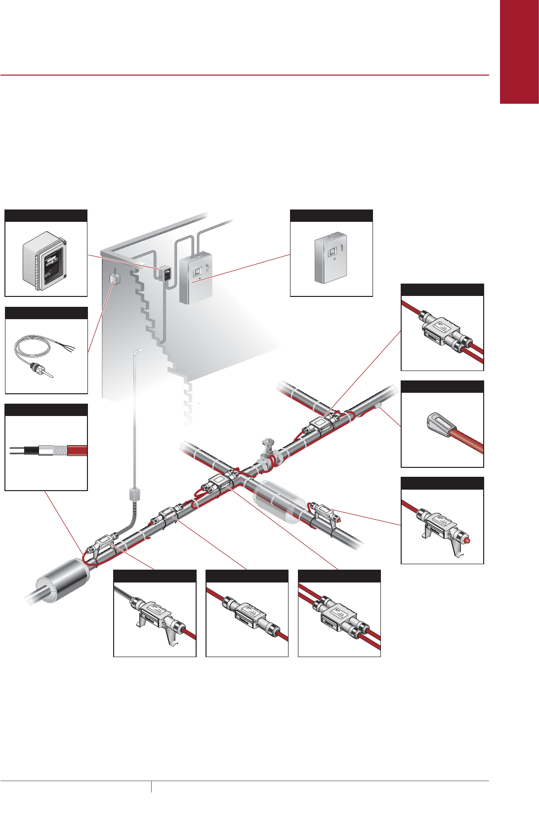
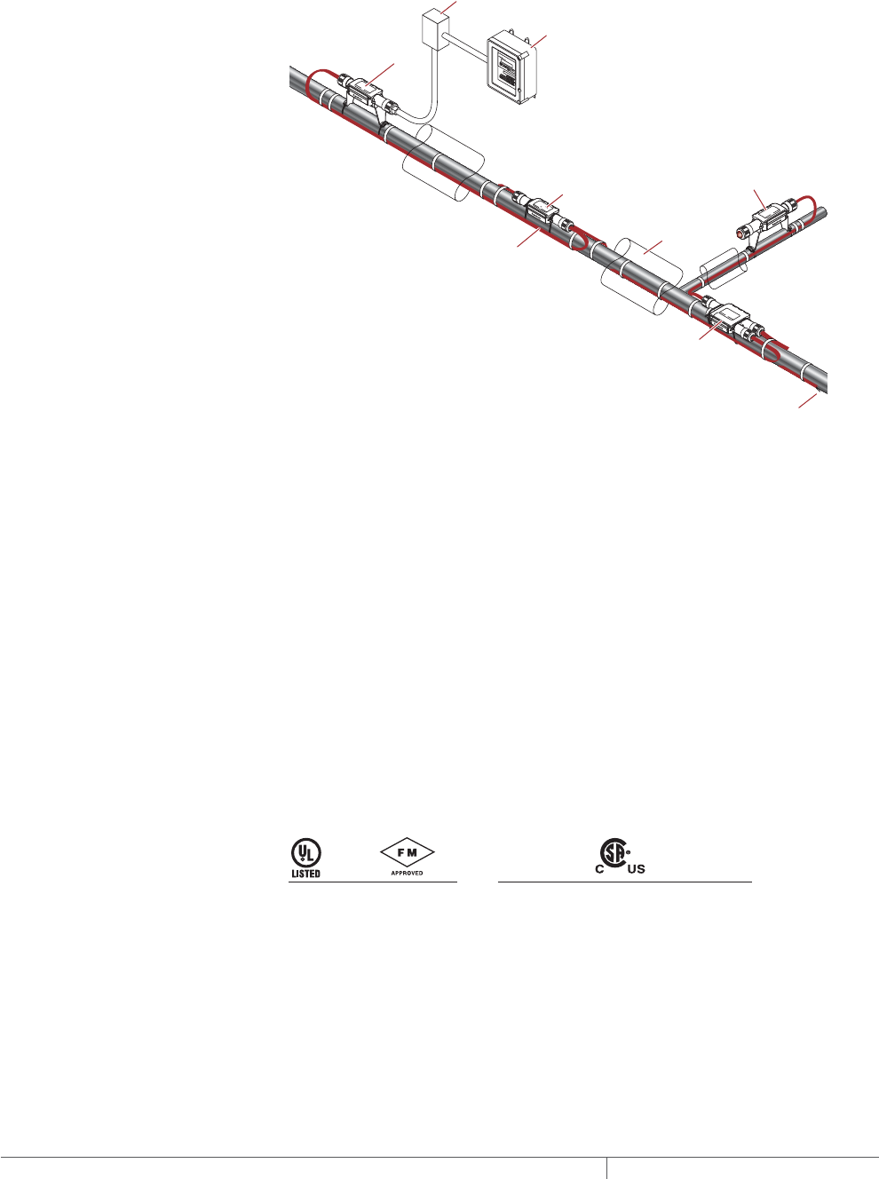
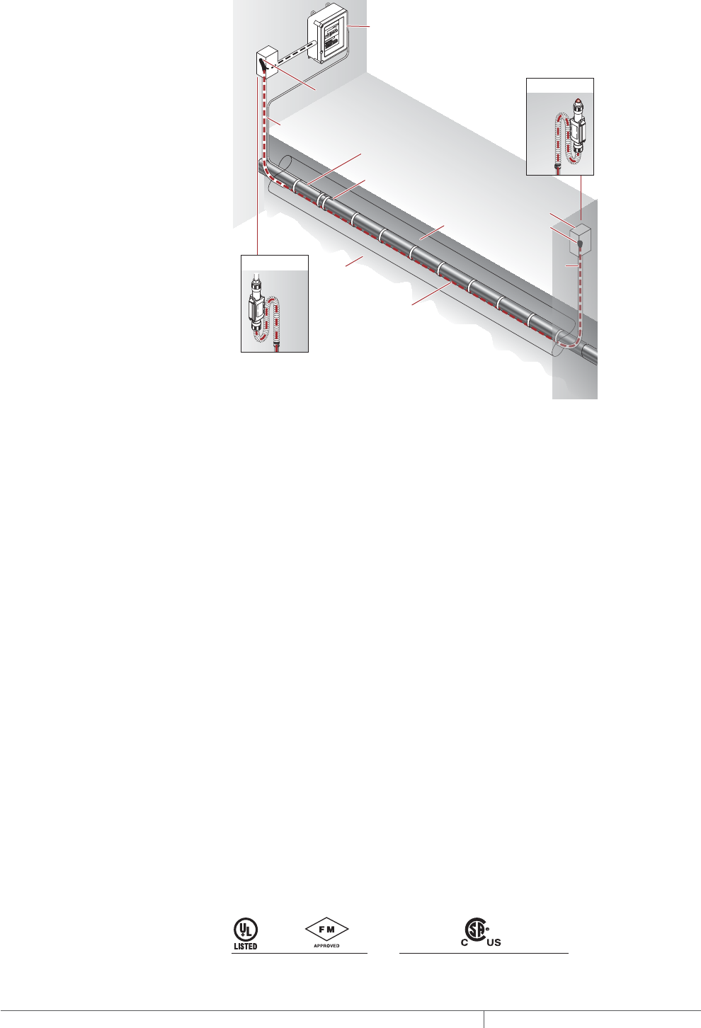
Typical Pipe Freeze Protection System
A typical pipe freeze protection system includes the XL-Trace self-regulating heating
cables, connection kits, ambient temperature control, and power distribution.
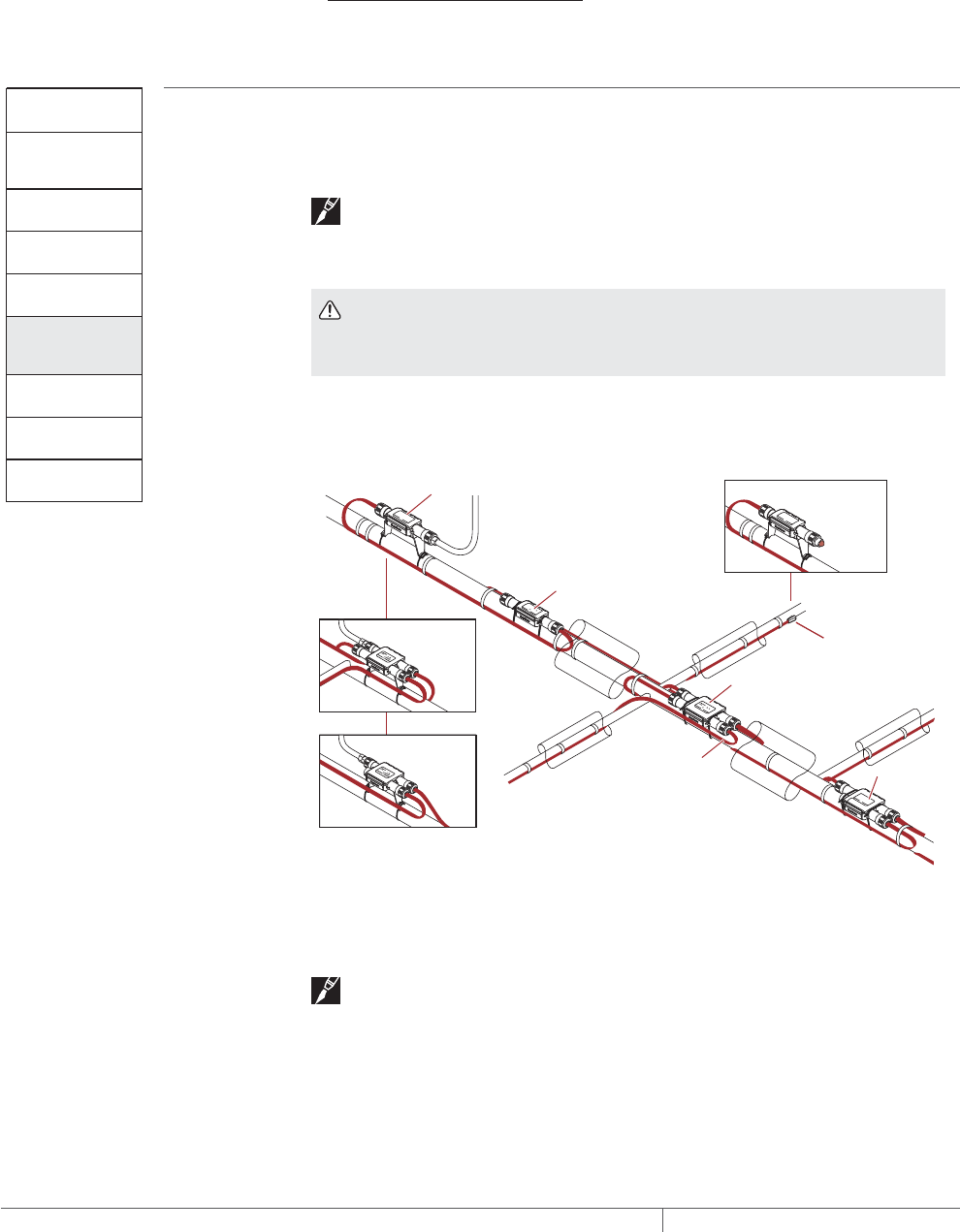
Fig. 3 Typical XL-Trace pipe freeze protection system
Lighted End Seal
Heating Cable
End Seal Kit
Tee Kit
Power Distribution Panel
Power Connection Kit Splice Kit Cross Kit
Ambient RTD
Electronic Controller
Pipe Freeze Protection Applications
7THERMAL MANAGEMENT SOLUTIONS EN-RaychemXLTracePipeFreezeProtection-DG-H55838 11/13
General Water Piping
General water piping is defined as metal or plastic water piping located in
nonhazardous locations.
ABOVEGROUND PIPING
RayClic-PC
power connection
Junction
box
XL-Trace
heating cable
RayClic-S
splice
RayClic-T
tee
Insulation
RayClic-LE
lighted end seal
(optional)
RayClic-E
end seal
DigiTrace C910-485
Electronic controller
Fig. 4 Typical aboveground piping system
Application Requirements
The system complies with Pentair Thermal Management requirements for
aboveground general water piping when:
• The heating cable is permanently secured to insulated metal pipes with GT-66
glass tape, or to plastic pipes using AT-180 aluminum tape.
• A 30-mA ground-fault protection device (GFPD) is used.
• The heating cable is installed per manufacturer’s instructions with approved Ray-
chem connection kits. See Table 13 on page 29 and the XL-Trace System Instal-
lation and Operation Manual (H58033).
Cable Selection
See “Other Required Documents” page 15.
Approvals
UL Listed, FM Approved, and c-CSA-us Certified for nonhazardous locations.
5XL1-CR, -CT
5XL2-CR, -CT 8XL1-CR, -CT
8XL2-CR, -CT 5XL1-CR, -CT
5XL2-CR, -CT 8XL1-CR, -CT
8XL2-CR, -CT 12XL2-CR, -CT
-w
PIPE FREEZE PROTECTION AND FLOW MAINTENANCE XLTRACE SYSTEM
THERMAL MANAGEMENT SOLUTIONS
EN-RaychemXLTracePipeFreezeProtection-DG-H55838 11/13
8
Pipe Freeze Protection
and Flow Maintenance
Fire Sprinkler System
Freeze Protection
Roof and Gutter
De-Icing
Surface Snow
Melting – MI
Surface Snow
Melting – ElectroMelt
Freezer Frost
Heave Prevention
Floor Heating Technical Data
Sheets
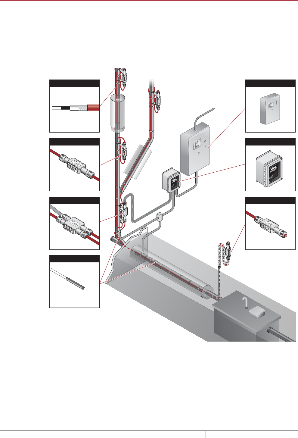
BURIED PIPING
RTD10CS
Insulation
Conduit
XL-Trace
heating cable
with -CT jacket
Ground
Alternate
power connection
Alternate
end seal
Ground
Wall
RayClic-LE*
RayClic-PC*
Junction box
RayClic-E
end seal
Conduit
Wall
with wall
mounting
bracket
with wall
mounting
bracket
FTC-XC
power
connection
*To protect the heating cable, run cable
inside Convolex tubing between the
conduit and the RayClic connection kits.
DigiTrace C910-485
Electronic controller
Conduit for
temperature
sensor
Fig. 5 Typical buried piping system
Application Requirements
The system complies with Pentair Thermal Management requirements for use on
buried insulated metal or plastic pipe when:
• The heating cable is permanently secured to metal pipes with GT-66 glass tape or
to plastic pipes using AT-180 aluminum tape.
• The pipeline is buried at least 2-feet deep.
• All heating cable connections (power, splice, tee, and end termination) are made
above-ground. No buried or in-conduit splices or tees are allowed.
• The heating cable has a fluoropolymer outer jacket (-CT).
• The power connection and end seal are made in UL Listed and CSA Certified
junction boxes above grade.
• The heating cable is protected from the pipe to the power connection box in UL
Listed and CSA Certified water-sealed conduit (minimum 3/4-inch diameter) suit-
able for the location.
• A 30-mA ground-fault protection device (GFPD) is used.
• Closed-cell, waterproof thermal insulation with fire-retardant, waterproof cover-
ing is used.
• The heating cable is installed per manufacturer’s instructions with approved
Pentair Thermal Management connection kits. See Table 15 on page 31 and the
XL-Trace System Installation and Operation Manual (H58033).
Cable Selection
See “Pipe Heat Loss Calculations,” page 15.
Approvals
UL Listed, FM Approved, and c-CSA-us Certified for nonhazardous locations.
5XL1-CT
5XL2-CT 8XL1-CT
8XL2-CT 5XL1-CT
5XL2-CT 8XL1-CT
8XL2-CT 12XL2-CT
-w
Pipe Freeze Protection Applications
9THERMAL MANAGEMENT SOLUTIONS EN-RaychemXLTracePipeFreezeProtection-DG-H55838 11/13
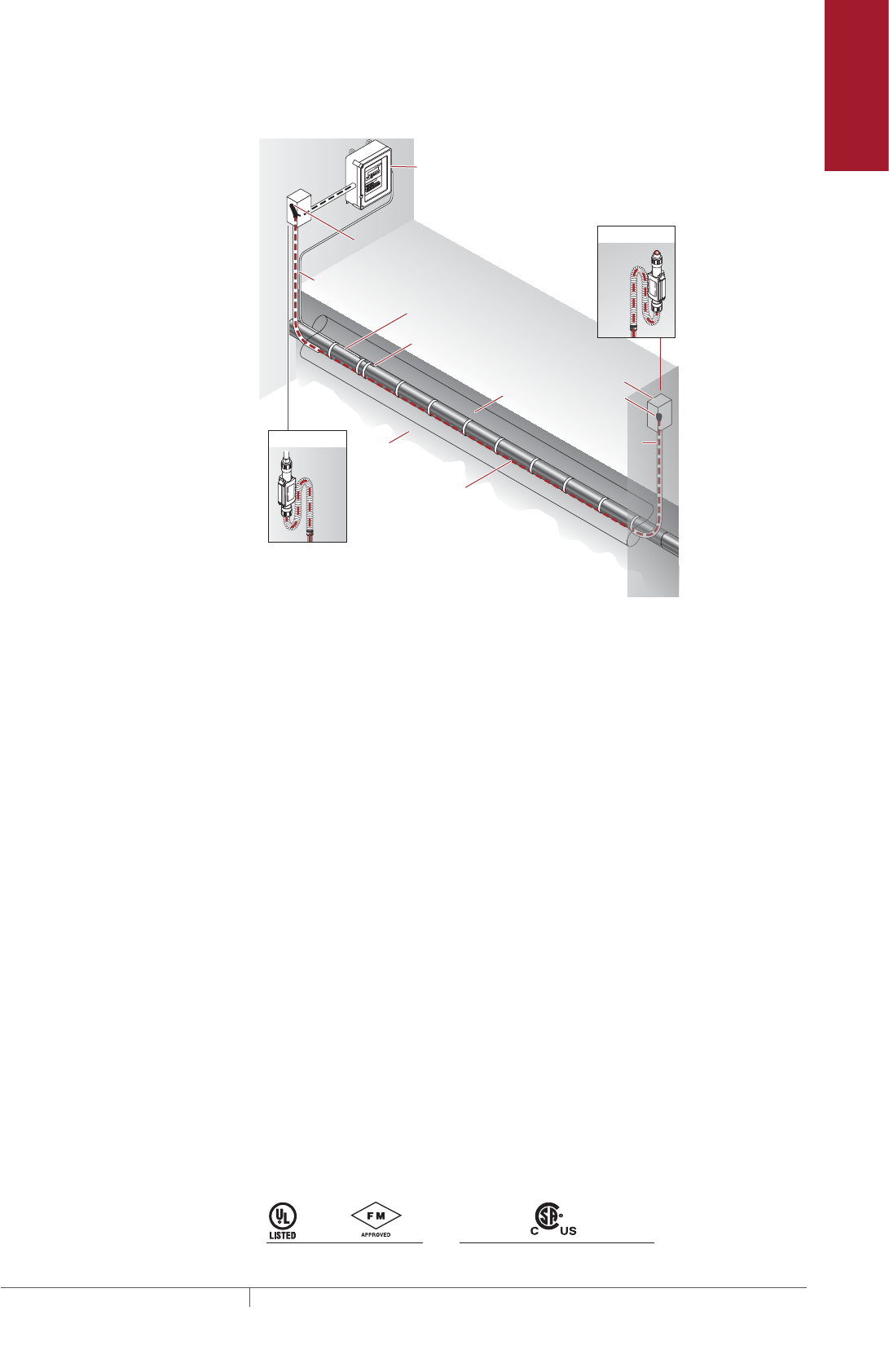
FLOW MAINTENANCE APPLICATIONS
A flow maintenance system is designed to maintain cooking greasy waste lines and
#2 fuel oil lines above the temperature at which the viscosity inhibits fluid flow.
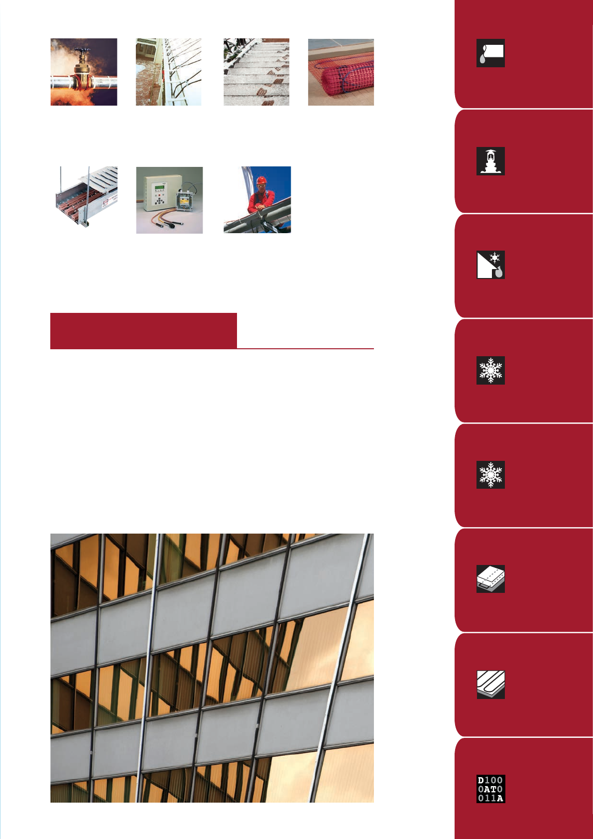
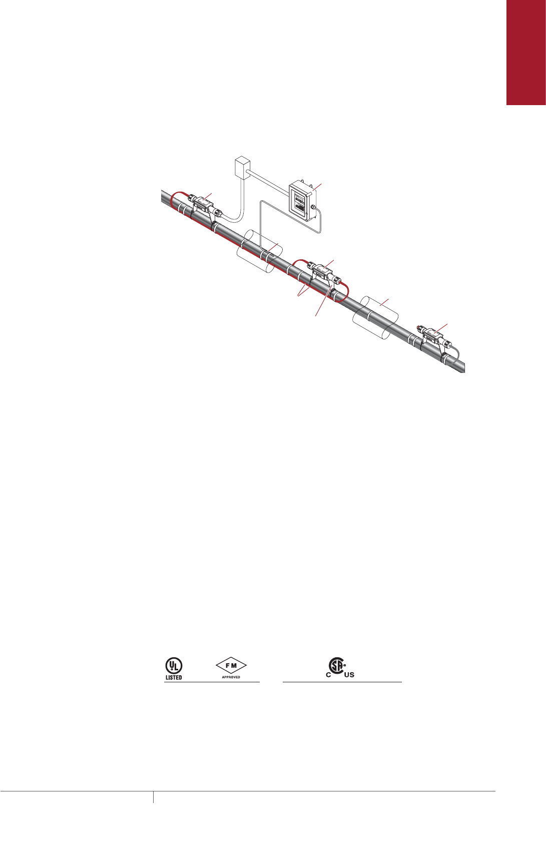
Typical Flow Maintenance System
A typical flow maintenance system includes the XL-Trace self-regulating heating
cables with a fluoropolymer outer jacket, connection kits, line-sensing temperature
control and power distribution.
Splice Kit
Powered Tee Kit
Heating Cable
Lighted End Seal
Power Distribution Panel
Grade
Electronic Controller
RTD
Fig. 6 Typical XL-Trace flow maintenance system
PIPE FREEZE PROTECTION AND FLOW MAINTENANCE XLTRACE SYSTEM
THERMAL MANAGEMENT SOLUTIONS
EN-RaychemXLTracePipeFreezeProtection-DG-H55838 11/13
10
Pipe Freeze Protection
and Flow Maintenance
Fire Sprinkler System
Freeze Protection
Roof and Gutter
De-Icing
Surface Snow
Melting – MI
Surface Snow
Melting – ElectroMelt
Freezer Frost
Heave Prevention
Floor Heating Technical Data
Sheets
Greasy Waste Lines
Greasy waste lines are defined as piping used for the disposal of waste oils and fats
created in the cooking process. Typical applications include greasy waste lines from
commercial restaurants. A grease-line flow maintenance system is designed to
maintain a 110°F (43°C) minimum fluid temperature.
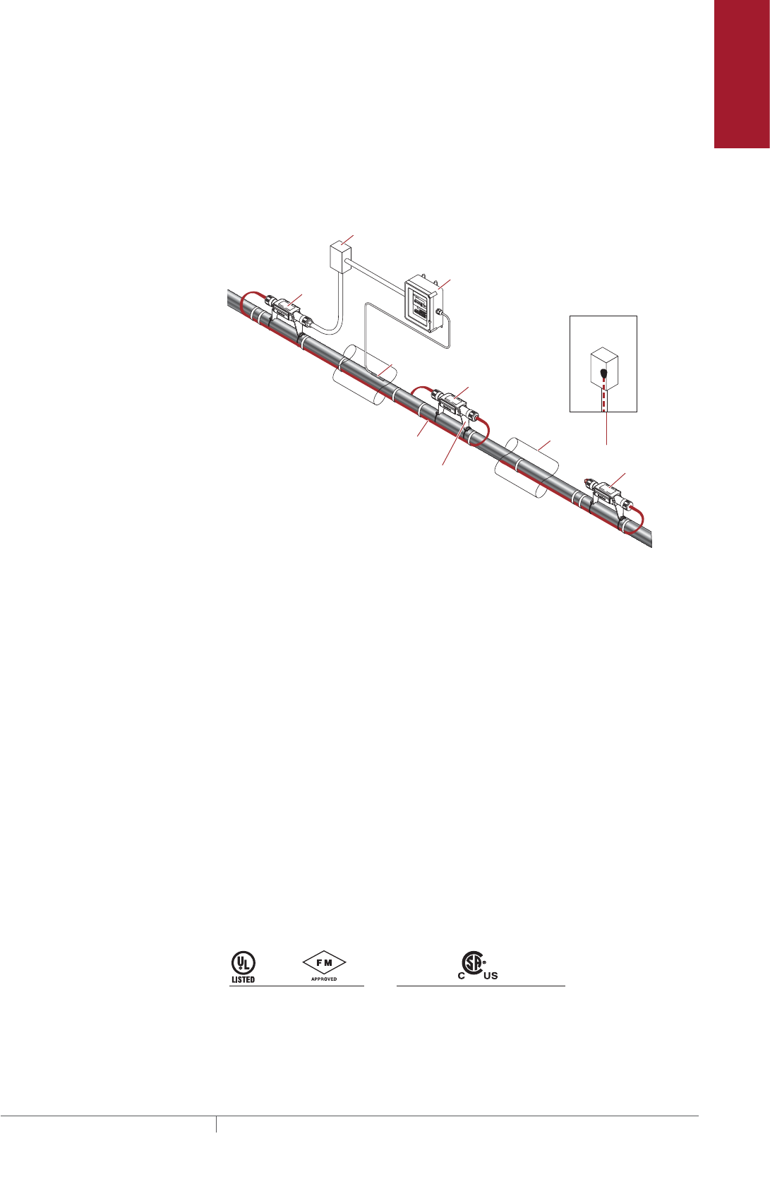
ABOVEGROUND PIPING
RayClic-PC
power
connection
Junction
box
RayClic-S
splice
Insulation
RayClic-LE
lighted end seal
RayClic-E
Alternate
end seal
XL-Trace
heating cable
with -CT jacket
RayClic-SB-04
pipe mounting bracket
DigiTrace C910-485
Electronic controller
RTD10CS
Fig. 7 Typical aboveground piping system
Application Requirements
The system complies with Pentair Thermal Management requirements for
aboveground greasy waste lines when:
• The heating cable is permanently secured to metal pipes with GT-66 glass tape,
or to plastic pipes using AT-180 aluminum tape.
• The heating cable must have a fluoropolymer outer jacket (-CT).
• A 30-mA ground-fault protection device (GFPD) is used.
• Tees and splices are installed using pipe mounting brackets, not in direct contact
with piping.
• The heating cable is installed per manufacturer’s instructions with approved Pen-
tair Thermal Management connection kits. See Table 13 on page 29 and the XL-
Trace System Installation and Operation Manual (H58033).
Cable Selection
See “Pipe Heat Loss Calculations,” page 15.
Approvals
XL-Trace systems (-CT only) are UL Listed, FM Approved, and c-CSA-us Certified for
nonhazardous locations.
5XL1-CT
5XL2-CT 8XL1-CT
8XL2-CT 5XL1-CT
5XL2-CT 8XL1-CT
8XL2-CT 12XL2-CT
-w
Flow Maintenance Applications
11THERMAL MANAGEMENT SOLUTIONS EN-RaychemXLTracePipeFreezeProtection-DG-H55838 11/13
BURIED PIPING
RTD10CS
Insulation
Conduit
XL-Trace
heating cable
with -CT jacket
Ground
Alternate
power connection
Alternate
end seal
Ground
Wall
RayClic-LE*
RayClic-PC*
Junction box
RayClic-E
end seal
Conduit
Wall
with wall
mounting
bracket
with wall
mounting
bracket
FTC-XC
power
connection
*To protect the heating cable, run cable
inside Convolex tubing between the
conduit and the RayClic connection kits.
DigiTrace C910-485
Electronic controller
Conduit for
temperature
sensor
Fig. 8 Typical buried greasy waste line
Application Requirements
The system complies with Pentair Thermal Management requirements for buried
greasy waste lines when:
• The heating cable is permanently secured to metal pipes with GT-66 glass tape,
or to plastic pipes using AT-180 aluminum tape.
• The heating cable must have a fluoropolymer outer jacket (-CT).
• The pipeline is buried at least 2-feet deep.
• All heating cable splices or tees are made aboveground. No buried or in-conduit
splices or tees are allowed.
• The power connection and end seal are made in UL Listed and CSA Certified
junction boxes above grade.
• The heating cable is protected from the pipe to the power connection box in UL
Listed and CSA Certified conduit (minimum 3/4-inch diameter) suitable for the
location.
• A 30-mA ground-fault protection device (GFPD) is used.
• Closed-cell, waterproof thermal insulation with fire-retardant, waterproof cover-
ing is used.
• The heating cable is installed per manufacturer’s instructions with approved
Pentair Thermal Management connection kits. See Table 15 on page 31 and the
XL-Trace System Installation and Operation Manual (H58033).
Cable Selection
See “Heating Cable Catalog Number” on page19.
Approvals
XL-Trace systems (-CT only) are UL Listed, FM Approved, and c-CSA-us Certified for
nonhazardous locations.
5XL1-CT
5XL2-CT 8XL1-CT
8XL2-CT 5XL1-CT
5XL2-CT 8XL1-CT
8XL2-CT 12XL2-CT
-w
PIPE FREEZE PROTECTION AND FLOW MAINTENANCE XLTRACE SYSTEM
THERMAL MANAGEMENT SOLUTIONS
EN-RaychemXLTracePipeFreezeProtection-DG-H55838 11/13
12
Pipe Freeze Protection
and Flow Maintenance
Fire Sprinkler System
Freeze Protection
Roof and Gutter
De-Icing
Surface Snow
Melting – MI
Surface Snow
Melting – ElectroMelt
Freezer Frost
Heave Prevention
Floor Heating Technical Data
Sheets
Fuel Lines
Fuel lines are defined as those carrying #2 fuel oil. A fuel line flow maintenance
system is designed to maintain a 40°F (4°C) minimum fluid temperature to maintain
flow.
FOR ABOVEGROUND PIPING ONLY
RayClic-S
splice
XL-Trace
heating cable
with -CT jacket
RTD10CS
RayClic-LE
lighted end seal
Junction
box
Insulation
RayClic-PC
power
connection
RayClic-SB-04
pipe mounting bracket
DigiTrace C910-485
Electronic controller
Fig. 9 Typical aboveground piping system
Application Requirements
The system complies with Pentair Thermal Management requirements for
aboveground #2 fuel oil piping when:
• The heating cable is permanently secured to metal pipes with GT-66 glass tape or
to plastic pipes using AT-180 aluminum tape.
• The heating cable must have a fluoropolymer outer jacket (-CT).
• Tees and splices are installed using pipe mounting brackets, not in direct contact
with piping.
• A 30-mA ground-fault protection device (GFPD) is used.
• The heating cable is installed per manufacturer’s instructions with approved
Pentair Thermal Management connection kits. See Table 13 on page 29 and the
XL-Trace System Installation and Operation Manual (H58033).
Cable Selection
See “Pipe Heat Loss Calculations,” page 15.
Approvals
XL-Trace systems (-CT only) are UL Listed, FM Approved, and c-CSA-us Certified for
nonhazardous locations.
5XL1-CT
5XL2-CT 8XL1-CT
8XL2-CT 5XL1-CT
5XL2-CT 8XL1-CT
8XL2-CT 12XL2-CT
-w
Flow Maintenance Applications
13THERMAL MANAGEMENT SOLUTIONS EN-RaychemXLTracePipeFreezeProtection-DG-H55838 11/13
PIPE FREEZE PROTECTION AND FLOW MAINTENANCE DESIGN
This section details the design steps necessary to design your application. The
examples provided in each step are intended to incrementally illustrate the project
parameter output for two sample designs from start to finish. As you go through each
step, use the “XL-Trace System Pipe Freeze Protection and Flow Maintenance Design
Worksheet,” page 38, to document your project parameters, so that by the end of
this section you will have the information you need for your Bill of Materials.
XL-Erate, the commercial pipe freeze protection and flow maintenance design
software is available at http://www.pentairthermal.com to assist with your design.
Design Step by Step
Your system design requires the following essential steps.
Determine design conditions and pipe heat loss
Select the heating cable
Determine the heating cable length
Determine the electrical parameters
Select the connection kits and accessories
Select the control system
Select the power distribution
Complete the Bill of Materials
Pipe Freeze Protection
and Flow Maintenance
1. Determine design
conditions and
heat loss
2. Select the heating
cable
3. Determine the
heating cable length
4. Determine the
electrical parameters
5. Select the
connection kits
and accessories
6. Select the control
system
7. Select the power
distribution
8. Complete the Bill
of Materials
Step Determine design conditions and pipe heat loss
Collect the following information to determine your design conditions:
• XL-Trace application (from Table 1)
• Location
– Indoors
– Outdoors
– Aboveground
– Buried
• Maintain temperature (TM)
• Maximum system temperature (TMAX)
• Minimum ambient temperature (TA)
• Pipe diameter and material
• Pipe length
• Thermal insulation type and thickness
• Supply voltage
Example: Pipe Freeze Protection – Water Piping
Location Aboveground, outdoor
Maintain temperature (TM) 40°F (4°C)
Maximum system temperature (TMAX) 80°F (27°C)
Minimum ambient temperature (TA) –20°F (–29°C)
Pipe diameter and material 2-inch plastic
Pipe length 300 ft (91 m)
Thermal insulation type and thickness 1-inch fiberglass
Supply voltage 120 V
PIPE FREEZE PROTECTION AND FLOW MAINTENANCE XLTRACE SYSTEM
THERMAL MANAGEMENT SOLUTIONS
EN-RaychemXLTracePipeFreezeProtection-DG-H55838 11/13
14
Pipe Freeze Protection
and Flow Maintenance
Fire Sprinkler System
Freeze Protection
Roof and Gutter
De-Icing
Surface Snow
Melting – MI
Surface Snow
Melting – ElectroMelt
Freezer Frost
Heave Prevention
Floor Heating Technical Data
Sheets
Example: Pipe Freeze Protection – Greasy Waste Line
Location Buried
Maintain temperature (TM) 110°F (43°C)
Maximum system temperature (TMAX) 125°F (52°C)
Minimum ambient temperature (TA) 50°F (10°C) (soil temperature)
Pipe diameter and material 4-inch metal
Pipe length 200 ft (61 m)
Thermal insulation type and thickness 1-inch rigid cellular urethane
Supply voltage 208 V
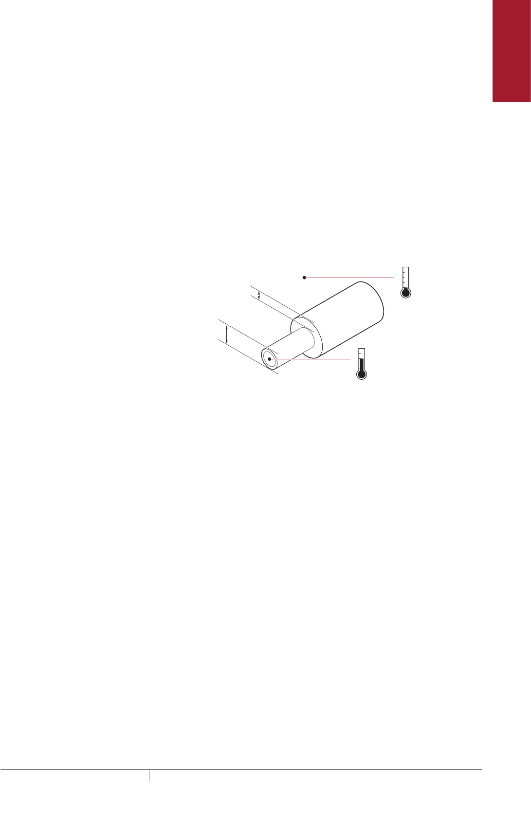
PIPE HEAT LOSS CALCULATIONS
To select the proper heating cable you must first determine the pipe heat loss. To
do this you must first calculate the temperature differential (∆T) between the pipe
maintain temperature and the minimum ambient temperature.
20
40
60
80
−40
−20
0
+20
+40
Maintain
temperature
°F
°F
Minimum
ambient
temperature
Thermal insulation thickness
Pipe or
tubing
diameter
Fig. 10 Pipe heat loss
Calculate temperature differential ∆T
To calculate the temperature differential (∆T), use the formula below:
∆T = TM – TA
Example: Pipe Freeze Protection – Water Piping
TM 40°F (4°C)
TA –20°F (–29°C)
∆T = 40°F – (–20°F) = 60°F
∆T = 4°C – (–29°F) = 33°C
Example: Flow Maintenance – Greasy Waste Line
TM 110°F (43°C)
TA 50°F (10°C)
∆T = 110°F – (50°F) = 60°F
∆T = 43°C – (10°C) = 33°C
Determine the pipe heat loss
Match the pipe size, insulation thickness, and temperature differential (∆T) from
Table 2 to determine the base heat loss of the pipe (QB).
Pipe Freeze Protection and Flow Maintenance Design
15THERMAL MANAGEMENT SOLUTIONS EN-RaychemXLTracePipeFreezeProtection-DG-H55838 11/13

Example: Pipe Freeze Protection – Water Piping
Pipe diameter 2 inch
Insulation thickness 1 inch
∆T 60°F (33°C)
Heat loss (QB) for 60°F must be calculated through interpolation between ∆T at 50°F
and ∆T at 100°F from Table 2. For difference between the ∆T of 50°F and the ∆T of
100°F:
QB-50 3.2 W/ft (from Table 2)
QB-100 6.8 W/ft (from Table 2)
∆T interpolation ∆T 60°F is 20% of the distance between ∆T 50°F and ∆T 100°F
QB-60 QB-50 + [0.20 x (QB-100 – QB-50)] = 3.2 + [0.20 x (6.8 – 3.2)] = 3.9 W/ft
Pipe heat loss (QB) 3.9 W/ft Tm 40°F (12.9 W/m Tm 4°C)
Example: Flow Maintenance – Greasy Waste Line
Pipe diameter 4 inch
Insulation thickness 1 inch
∆T 60°F (33°C)
QB for 60°F must be calculated through interpolation between ∆T at 50°F and ∆T at
100°F from Table 2. For difference between the ∆T of 50°F and the ∆T of 100°F:
QB-50 5.4 W/ft (from Table 2)
QB-100 11.2 W/ft (from Table 2)
∆T interpolation ∆T 60°F is 20% of the distance between ∆T 50°F and ∆T 100°F
QB-60 QB-50 + [0.20 x (QB-100 – QB-50)] = 5.4 + [0.20 x (11.2 – 5.4)] = 6.6 W/ft
Pipe heat loss QB 6.6 W/ft Tm 110°F (21.5 W/m Tm 43°C)
Compensate for insulation type and pipe location
The base heat loss is calculated for a pipe insulated with thermal insulation with a
k-factor ranging from 0.2 to 0.3 BTU/hr–°F-ft²/in (fiberglass or foamed elastomer)
in an outdoor, or buried application. To get the heat loss for pipes insulated with
alternate types of thermal insulation and for pipes installed indoors, multiply the
base heat loss of the pipe (QB) from Step 3 by the insulation multiple from Table 4
and the indoor multiple from Table 3 to get the corrected heat loss:
QCORRECTED = QB x Insulation multiple x Indoor multiple
Example: Pipe Freeze Protection – Water Piping
Location Aboveground, outdoor
Thermal insulation thickness and type 1-inch fiberglass
Pipe heat loss QB 3.9 W/ft TM 40°F (12.9 W/m TM 4°C)
QCORRECTED 3.9 W/ft x 1.00 x 1.00 = 3.9 W/ft Tm 40°F
(12.9 W/m Tm 4°C)
Example: Flow Maintenance – Greasy Waste Line
Location Buried
Thermal insulation type and thickness 1-inch rigid cellular urethane
Pipe heat loss QB = 6.6 W/ft TM 110°F (21.5 W/m TM 43°C)
QCORRECTED = 6.6 W/ft x 0.6 x 1.00 = 4.0 W/ft Tm 110°F
(13.1 W/m Tm 43°C)
PIPE FREEZE PROTECTION AND FLOW MAINTENANCE XLTRACE SYSTEM
THERMAL MANAGEMENT SOLUTIONS
EN-RaychemXLTracePipeFreezeProtection-DG-H55838 11/13
16
Pipe Freeze Protection
and Flow Maintenance
Fire Sprinkler System
Freeze Protection
Roof and Gutter
De-Icing
Surface Snow
Melting – MI
Surface Snow
Melting – ElectroMelt
Freezer Frost
Heave Prevention
Floor Heating Technical Data
Sheets
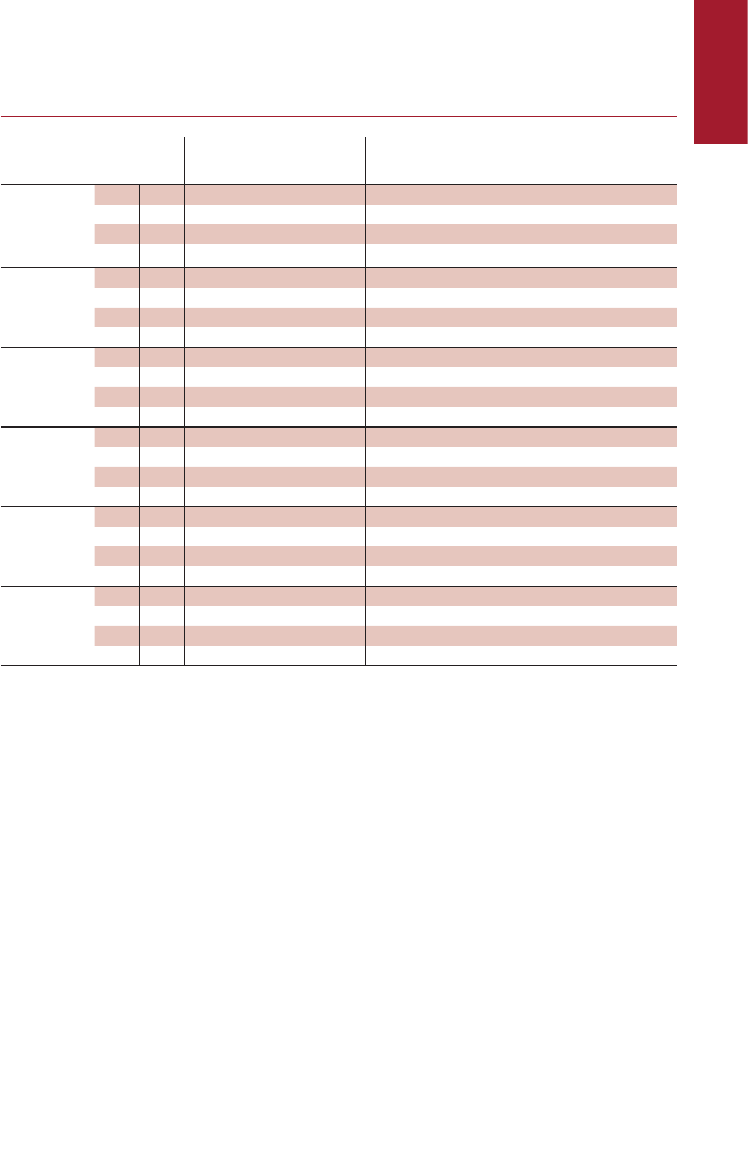
TABLE 2 PIPE HEAT LOSS Qb FOR OUTDOOR OR BURIED PIPE W/FT FOR 1/2 TO 31/2 INCHES
Insulation
thickness
(in)
(∆T) Pipe diameter (IPS) in inches
°F °C 1/2 3/4 1 1-1/4 1-1/2 2 2-1/2 3 3-1/2
0.5 20 11 1.0 1.2 1.4 1.6 1.8 2.2 2.5 3.0 3.4
50 28 2.5 2.9 3.5 4.1 4.6 5.5 6.5 7.7 8.6
100 56 5.2 6.1 7.2 8.6 9.6 11.5 13.5 16.0 18.0
150 83 8.1 9.5 11.2 13.4 14.9 17.9 21.1 25.0 28.1
1.0 20 11 0.6 0.7 0.8 1.0 1.1 1.3 1.5 1.7 1.9
50 28 1.6 1.9 2.2 2.5 2.8 3.2 3.8 4.4 4.9
100 56 3.4 3.9 4.5 5.2 5.8 6.8 7.8 9.1 10.2
150 83 5.3 6.1 7.0 8.2 9.0 10.6 12.2 14.2 15.9
1.5 20 11 0.5 0.6 0.7 0.8 0.8 1.0 1.1 1.3 1.4
50 28 1.3 1.5 1.7 1.9 2.1 2.4 2.8 3.2 3.6
100 56 2.8 3.1 3.5 4.0 4.4 5.1 5.8 6.7 7.4
150 83 4.3 4.8 5.5 6.3 6.9 8.0 9.1 10.5 11.6
2.0 20 11 0.5 0.5 0.6 0.6 0.7 0.8 0.9 1.0 1.1
50 28 1.1 1.3 1.4 1.6 1.8 2.0 2.3 2.6 2.9
100 56 2.4 2.7 3.0 3.4 3.7 4.2 4.8 5.5 6.0
150 83 3.7 4.2 4.7 5.3 5.8 6.6 7.5 8.5 9.4
2.5 20 11 0.4 0.5 0.5 0.6 0.6 0.7 0.8 0.9 1.0
50 28 1.0 1.2 1.3 1.4 1.6 1.8 2.0 2.3 2.5
100 56 2.2 2.4 2.7 3.0 3.3 3.7 4.2 4.7 5.2
150 83 3.4 3.7 4.2 4.7 5.1 5.8 6.5 7.4 8.1
3.0 20 11 0.4 0.4 0.5 0.5 0.6 0.6 0.7 0.8 0.9
50 28 1.0 1.1 1.2 1.3 1.4 1.6 1.8 2.0 2.2
100 56 2.0 2.2 2.4 2.7 2.9 3.3 3.7 4.2 4.6
150 83 3.1 3.4 3.8 4.3 4.6 5.2 5.8 6.6 7.1
4.0 20 11 0.3 0.4 0.4 0.5 0.5 0.5 0.6 0.7 0.7
50 28 0.9 0.9 1.0 1.1 1.2 1.4 1.5 1.7 1.8
100 56 1.8 2.0 2.1 2.4 2.5 2.9 3.2 3.5 3.8
150 83 2.8 3.0 3.4 3.7 4.0 4.4 4.9 5.5 6.0
Note: Multiply the W/ft heat loss values by 3.28 for W/m.
Pipe Freeze Protection and Flow Maintenance Design
17THERMAL MANAGEMENT SOLUTIONS EN-RaychemXLTracePipeFreezeProtection-DG-H55838 11/13
TABLE 1.2 CONTINUED PIPE HEAT LOSS Qb
FOR OUTDOOR OR BURIED PIPE W/FT FOR 4 TO 20 INCHES
Insulation
thickness
(in)
(∆T) Pipe diameter (IPS) in inches
°F °C 4 6 8 10 12 14 16 18 20
0.5 20 11 3.8 5.3 6.8 8.4 9.9 10.8 12.2 13.7 15.2
50 28 9.6 13.6 17.4 21.4 25.2 27.5 31.3 35.0 38.8
100 56 20.0 28.4 36.3 44.6 52.5 57.4 65.2 73.0 80.8
150 83 31.2 44.3 56.6 69.6 81.9 89.5 101.7 113.8 126.0
1.0 20 11 2.1 2.9 3.7 4.5 5.3 5.8 6.5 7.3 8.0
50 28 5.4 7.5 9.4 11.5 13.5 14.7 16.6 18.6 20.5
100 56 11.2 15.6 19.7 24.0 28.1 30.6 34.7 38.7 42.8
150 83 17.5 24.3 30.7 37.4 43.8 47.8 54.1 60.4 66.7
1.5 20 11 1.5 2.1 2.6 3.2 3.7 4.0 4.5 5.0 5.5
50 28 3.9 5.3 6.7 8.1 9.4 10.2 11.5 12.9 14.2
100 56 8.1 11.1 13.9 16.8 19.6 21.3 24.0 26.8 29.5
150 83 12.7 17.3 21.6 26.2 30.5 33.2 37.5 41.8 46.1
2.0 20 11 1.2 1.7 2.1 2.5 2.9 3.1 3.5 3.9 4.3
50 28 3.1 4.2 5.2 6.3 7.3 7.9 8.9 9.9 10.9
100 56 6.6 8.8 10.9 13.1 15.2 16.5 18.6 20.7 22.8
150 83 10.2 13.8 17.0 20.5 23.8 25.8 29.0 32.3 35.5
2.5 20 11 1.1 1.4 1.7 2.1 2.4 2.6 2.9 3.2 3.5
50 28 2.7 3.6 4.4 5.2 6.1 6.6 7.4 8.2 9.0
100 56 5.6 7.4 9.1 10.9 12.6 13.7 15.3 17.0 18.7
150 83 8.7 11.6 14.2 17.0 19.7 21.3 23.9 26.5 29.1
3.0 20 11 0.9 1.2 1.5 1.8 2.0 2.2 2.5 2.7 3.0
50 28 2.4 3.1 3.8 4.5 5.2 5.6 6.3 7.0 7.6
100 56 4.9 6.5 7.9 9.4 10.8 11.7 13.1 14.5 15.9
150 83 7.7 10.1 12.4 14.7 16.9 18.3 20.5 22.6 24.8
4.0 20 11 0.8 1.0 1.2 1.4 1.6 1.7 1.9 2.1 2.3
50 28 2.0 2.5 3.1 3.6 4.1 4.4 5.0 5.5 6.0
100 56 4.1 5.3 6.4 7.5 8.6 9.3 10.3 11.4 12.4
150 83 6.4 8.3 10.0 11.8 13.4 14.5 16.1 17.8 19.4
Note: Multiply the W/ft heat loss values by 3.28 for W/m.
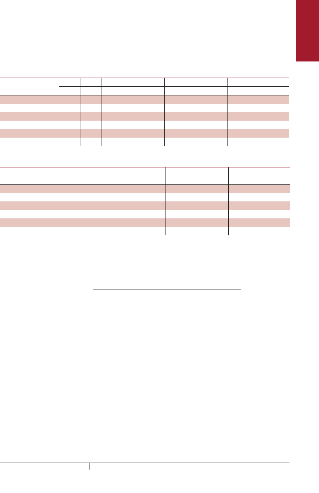
TABLE 3 INDOOR PIPE HEAT LOSS MULTIPLES
Fiberglass thickness (in) Indoor multiple
0.5 0.79
1 0.88
1.5 0.91
2 0.93
2.5 0.94
3 0.95
4 0.97
PIPE FREEZE PROTECTION AND FLOW MAINTENANCE XLTRACE SYSTEM
THERMAL MANAGEMENT SOLUTIONS
EN-RaychemXLTracePipeFreezeProtection-DG-H55838 11/13
18
Pipe Freeze Protection
and Flow Maintenance
Fire Sprinkler System
Freeze Protection
Roof and Gutter
De-Icing
Surface Snow
Melting – MI
Surface Snow
Melting – ElectroMelt
Freezer Frost
Heave Prevention
Floor Heating Technical Data
Sheets
TABLE 4 INSULATION HEAT LOSS MULTIPLES
k factor at 50°F (10°C)
(BTU/hr–°F-ft²/in) Insulation multiple Examples of preformed pipe insulation
0.1–0.2 0.6 Rigid cellular urethane (ASTM C591)
0.2–0.3 1.0 Glass fiber (ASTM C547)
Foamed elastomer (ASTM C534)
0.3–0.4 1.4 Cellular glass (ASTM C552)
Mineral fiber blanket (ASTM C553)
Pipe Freeze Protection
and Flow Maintenance
2. Select the heating
cable
3. Determine the
heating cable length
4. Determine the
electrical parameters
5. Select the
connection kits
and accessories
6. Select the control
system
7. Select the power
distribution
8. Complete the Bill
of Materials
1. Determine design
conditions and
heat loss
Step Select the heating cable
To select the appropriate XL-Trace heating cable for your application, you must
determine your cable supply voltage, power output, and outer jacket. Once you select
these, you will be able to determine the catalog number for your cable.
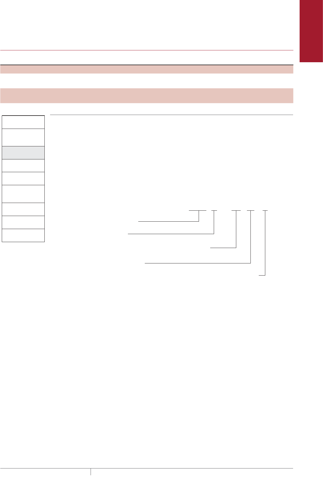
HEATING CABLE CATALOG NUMBER
Before beginning, take a moment to understand the structure underlying heating
cable catalog numbers. You will refer to this numbering convention throughout the
product selection process. Your goal is to determine the catalog number for the
product that best suits your needs.
Fig. 11 Heating cable catalog number
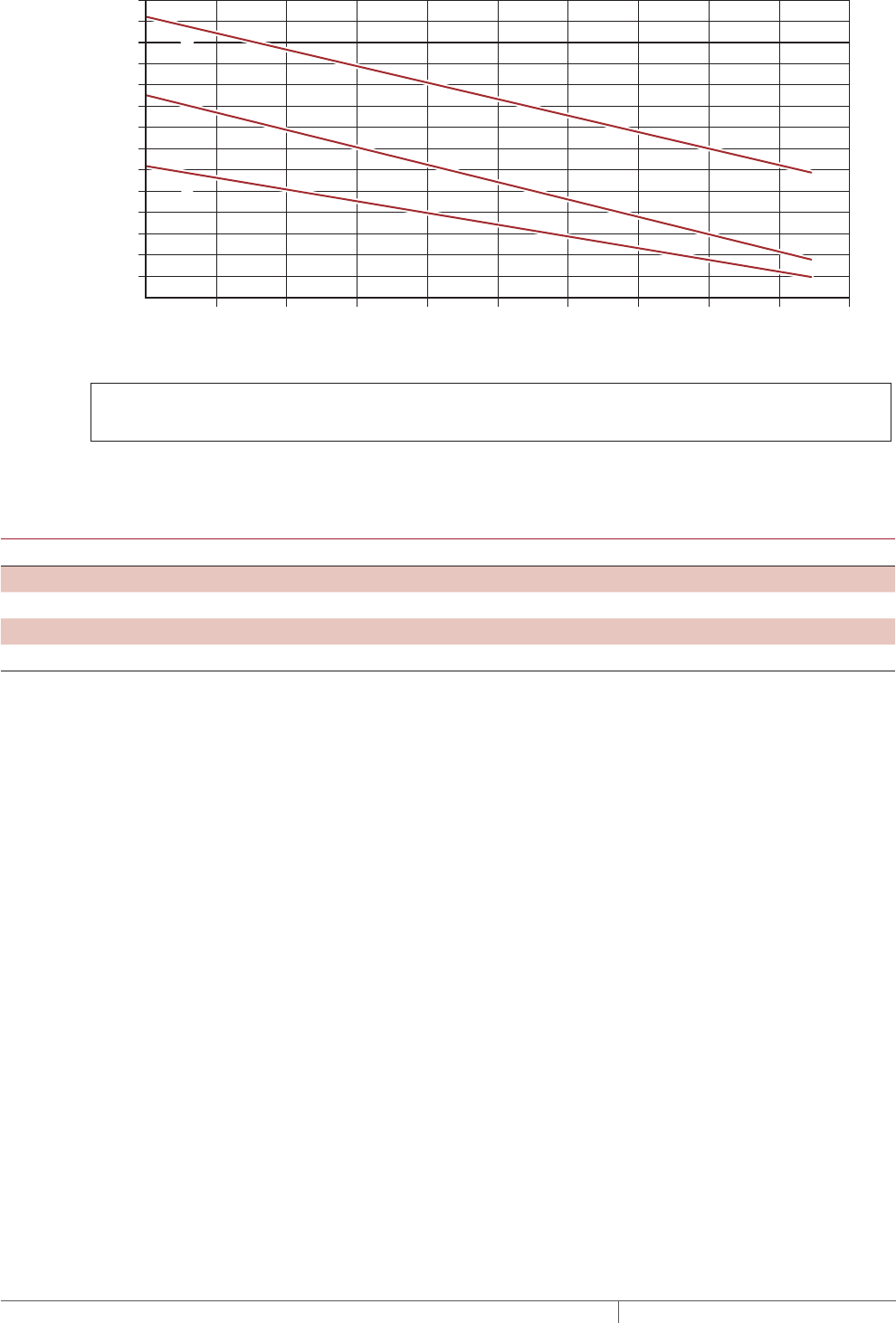
Select the heating cable from Fig. 12 that provides the required power output to
match the corrected heat loss for your application. Fig. 12 shows the power output
for the heating cables on metal pipe at 120/208 volts. To correct the power output
for other applied voltage or plastic pipes multiply the power output at the desired
maintain temperature by the factors listed in Table 5. If the pipe heat loss, QCORRECTED,
is between the two heating cable power output curves, select the higher-rated
heating cable.
Catalog number: 5, 8 or 12 XL 1 or 2 -CR -CT
Power output (W/ft)
Product family
Voltage 1 = 120 V (only available for 5 or 8)
2 = 208, 240, 277 V (available for 5, 8, or 12)
Jacket type: Polyolefin
Fluoropolymer (required for buried pipes, grease and fuel lines)
or
Pipe Freeze Protection and Flow Maintenance Design
19THERMAL MANAGEMENT SOLUTIONS EN-RaychemXLTracePipeFreezeProtection-DG-H55838 11/13
5XL1-CR and 5XL1-CT (120 V)
5XL2-CR and 5XL2-CT (208 V)
8XL1-CR and 8XL1-CT (120 V)
8XL2-CR and 8XL2-CT (208 V)
12XL2-CR and 12XL2-CT (208 V)
Pipe temperature
Power W/ft
50
(10)
30
(–1)
40
(5)
60
(15)
70
(21)
80
(27)
90
(32)
100
(38)
110
(43)
120
(49)
130
(54)
°F
(°C)
10
8
14
12
6
4
2
0
Fig. 12 Heating cable power output on metal pipe
TABLE 5 POWER OUTPUT CORRECTION FACTORS
Voltage correction factors 5XL1 8XL1 5XL2 8XL2 12XL2
120 V 1.00 1.00 – – –
208 V – – 1.00 1.00 1.00
240 V – – 1.12 1.12 1.14
277 V – – 1.29 1.27 1.30
Plastic pipe correction factor
(With AT-180 Aluminum tape)
0.75 0.75 0.75 0.75 0.75
Confirm that the corrected power output of the heating cable selected is greater
than the corrected pipe heat loss (QCORRECTED). If QCORRECTED is greater than the power
output of the highest-rated heating cable, you can:
• Use two or more heating cables run in parallel
• Use thicker insulation to reduce heat loss
• Use insulation material with a lower k factor to reduce heat loss
Example: Pipe Freeze Protection – Water Piping
Pipe maintain temperature (TM) 40°F (4°C) (from Step 1)
QCORRECTED QCORRECTED = 3.9 W/ft TM 40°F (13.1 W/m TM 4°C)
Supply voltage 120 V (from Step 1)
Pipe material Plastic (from Step 1)
Select heating cable: QB = 3.9 W/ft TM 40°F (from Step 1)
5XL1= 5.6 W/ft 40°F (from Fig. 12)
Supply voltage correction factor 1.00 (from Table 5)
Pipe material correction factor Plastic = 0.75 (from Table 5)
Corrected heating cable power 5.6 W/ft x 1.00 x 0.75 = 4.2 W/ft
Selected heating cable 5XL1
PIPE FREEZE PROTECTION AND FLOW MAINTENANCE XLTRACE SYSTEM
THERMAL MANAGEMENT SOLUTIONS
EN-RaychemXLTracePipeFreezeProtection-DG-H55838 11/13
20

Pipe Freeze Protection
and Flow Maintenance
Fire Sprinkler System
Freeze Protection
Roof and Gutter
De-Icing
Surface Snow
Melting – MI
Surface Snow
Melting – ElectroMelt
Freezer Frost
Heave Prevention
Floor Heating Technical Data
Sheets
Example: Flow Maintenance – Greasy Waste Line
Pipe maintain temperature (TM) 110°F (43°C) (from Step 1)
QCORRECTED 3.9 W/ft TM 110°F (13.1 W/m TM 43°C)
Supply voltage 208 V (from Step 1)
Pipe material Metal (from Step 1)
Select heating cable: QB = 3.9 W/ft TM 110°F (from Step 1)
12XL2= 7.0 W/ft 110°F (from Fig. 12)
Supply voltage correction factor 1.00 (from Table 5)
Pipe material correction factor Metal = 1.00
Corrected heating cable power 7.0 x 1.00 x 1.00 = 7.0 W/ft
Selected heating cable 12XL2
CONFIRM EXPOSURE TEMPERATURE RATING FOR THE HEATING CABLE
Refer to Table 6 to verify that the maximum system temperature does not exceed the
exposure temperature of the selected heating cable.
TABLE 6 HEATING CABLE TEMPERATURE RATINGS
5XL1 5XL2 8XL1 8XL2 12XL2
Maximum maintain temperature (TM) 150°F
(65°C)
150°F
(65°C)
150°F
(65°C)
150°F
(65°C)
150°F
(65°C)
Maximum exposure temperature (TE XP) 150°F
(65°C)
150°F
(65°C)
150°F
(65°C)
150°F
(65°C)
185°F
(85°C)
Example: Pipe Freeze Protection – Water Piping
Maximum system temperature (TMAX) 80°F (27°C) (from Step 1)
Selected heating cable 5XL1 (from previous step)
Maximum heating cable exposure temperature (TEXP) 150°F (65°C) (from Table 6)
TMAX < TEXP Yes
Example: Flow Maintenance - Greasy Waste Line
Maximum system temperature (TMAX) 125°F (52°C) (from Step 1)
Selected heating cable 12XL2 (from previous step)
Maximum heating cable exposure temperature (TEXP) 185°F (85°C)(from Table 6)
TMAX < TEXP Yes
SELECT OUTER JACKET
Select the appropriate heating cable outer jacket for the application. Jacket options
are:
-CR Compatible with most XL-Trace applications
-CT Required for buried pipe freeze protection and for grease and fuel line flow
maintenance; may be used in other XL-Trace applications for improved
mechanical strength and chemical resistance.
Example: Pipe Freeze Protection – Water Piping
Selection: 5XL1-CR
Example: Flow Maintenance - Greasy Waste Line
Selection: 12XL2-CT
Pipe Freeze Protection and Flow Maintenance Design
21THERMAL MANAGEMENT SOLUTIONS EN-RaychemXLTracePipeFreezeProtection-DG-H55838 11/13

Pipe Freeze Protection
and Flow Maintenance
2. Select the heating
cable
3. Determine the
heating cable length
4. Determine the
electrical parameters
5. Select the
connection kits
and accessories
6. Select the control
system
7. Select the power
distribution
8. Complete the Bill
of Materials
1. Determine design
conditions and
heat loss
Step Determine the heating cable length
In Step 2 you selected the appropriate heating cable and the number of runs of
heating cable required for the pipe. Multiply the length of the pipe by the number of
heating cable runs for the heating cable length.
Additional heating cable will be required for heat sinks and connection kits. Use
Table 7 and Table 8 to determine the additional footage required for heat sinks
(valves, flanges, and pipe supports). You will determine the additional heating cable
for connection kits in Step 5. Round up fractional lengths to ensure heating cable
lengths are sufficient.
TABLE 7 ADDITIONAL HEATING CABLE FOR VALVES
Pipe diameter (IPS) (inches) Heating cable (feet (meters))
1/2 0.8 (0.24)
3/4 1.3 (0.4)
1 2.0 (0.6)
1-1/4 3.3 (1.1)
1-1/2 4.3 (1.3)
2 4.3 (1.3)
3 4.3 (1.3)
4 4.3 (1.3)
6 5.0 (1.5)
8 5.0 (1.5)
10 5.6 (1.7)
12 5.9 (1.9)
14 7.3 (2.2)
18 9.4 (2.9)
20 10.5 (3.2)
TABLE 8 ADDITIONAL HEATING CABLE FOR PIPE SUPPORTS AND FLANGES
Support Additional cable
Pipe hangers (insulated) No additional heating cable
Pipe hangers noninsulated
and U-bolt supports
Add 2x pipe diameter
Welded support shoes Add 3x the length of the shoe
Flanges Add 2x pipe diameter
Note: For applications where more than one heating cable is required per foot of pipe,
this correction factor applies for each cable run.
Heating cable length = Pipe length x No. heating cable runs
Total heating cable
length required
(Pipe length x No.
heating cable runs)
Additional heating cable
for heat sinks (valves, pipe
supports, and flanges)
= +
PIPE FREEZE PROTECTION AND FLOW MAINTENANCE XLTRACE SYSTEM
THERMAL MANAGEMENT SOLUTIONS
EN-RaychemXLTracePipeFreezeProtection-DG-H55838 11/13
22

Pipe Freeze Protection
and Flow Maintenance
Fire Sprinkler System
Freeze Protection
Roof and Gutter
De-Icing
Surface Snow
Melting – MI
Surface Snow
Melting – ElectroMelt
Freezer Frost
Heave Prevention
Floor Heating Technical Data
Sheets
Example: Pipe Freeze Protection – Water Piping
Pipe length 300 ft (91 m) (from Step 1)
Pipe diameter 2-inch plastic (from Step 1)
Number of heating cable runs 1 (from Step 2)
Valves 3 gate valves
4.3 ft x 3 gate valves = 12.9 ft (3.9 m)
Pipe supports 5 pipe hangers with U-bolts
2-inch pipe diameter = 2 / 12 = 0.17 ft
[0.17 ft pipe diameter x 2] x 5 pipe supports
= 1.7 ft (0.5 m)
Flanges 0
Total heating cable for heat sinks 12.9 ft (3.9 m) + 1.7 ft (0.5 m) = 14.6 ft (4.4 m)
Rounded up to 15 ft (5 m)
Total heating cable length required 300 ft (91 m) x 1 run + 15 ft = 315 ft (96 m) of 5XL1-CR
(Note: AT-180 Aluminum tape is required for
installing heating cable on plastic pipe.)
Example: Flow Maintenance – Greasy Waste Line
Pipe length 200 ft (61 m) (from Step 1)
Pipe diameter 4-inch metal (from Step 1)
Number of heating cable runs 1 (from Step 2)
Valves 2 gate valves
[4.3 ft x 2 gate valves] x 1 run = 8.6 ft (2.6 m)
Pipe supports 2 non-insulated hangers
4-inch pipe diameter = 4 /12 = 0.33 ft
[(0.33 ft pipe diameter x 2) x 2 pipe supports] x
1 run = 1.3 ft (0.4 m)
Flanges 2
4-inch pipe diameter = 4 /12 = 0.33 ft
[(2 x 0.33 ft (pipe diameter)) x 2 flanges] x 1 run
= 1.3 ft (0.4 m)
Total heating cable for heat sinks 8.6 ft (2.6 m) + 1.3 ft (0.4 m) + 1.3 ft (0.4 m)
= 11.2 ft (2.2 m)
Rounded up to 12 ft (3 m)
Total heating cable length required 200 ft x 1 run + 12 ft = 212 ft (65 m) of 12XL2-CT
Pipe Freeze Protection and Flow Maintenance Design
23THERMAL MANAGEMENT SOLUTIONS EN-RaychemXLTracePipeFreezeProtection-DG-H55838 11/13
Pipe Freeze Protection
and Flow Maintenance
2. Select the heating
cable
3. Determine the
heating cable length
4. Determine the
electrical parameters
5. Select the
connection kits
and accessories
6. Select the control
system
7. Select the power
distribution
8. Complete the Bill
of Materials
1. Determine design
conditions and
heat loss
Step Determine the electrical parameters
To determine the electrical requirements for your application, you must determine
the number of circuits and calculate the transformer load.
DETERMINE NUMBER OF CIRCUITS
To determine the number of circuits, you need to know:
• Total heating cable length
• Supply voltage
• Minimum start-up temperature
Use Table 9 to determine the maximum circuit length allowed. If the total heating
cable length exceeds the maximum circuit length for the expected start-up
temperature, more than one circuit will be required.
Number of circuits = Heating cable length required
Maximum heating cable circuit
length
Important: Select the smallest appropriate ground-fault circuit breaker size.
WARNING: To minimize the danger of fire from sustained electrical arcing if
the heating cable is damaged or improperly installed, and to comply with the
requirements of Pentair Thermal Management, agency certifications, and
national electrical codes, ground-fault equipment protection must be used on
each heating cable branch circuit. Arcing may not be stopped by conventional
circuit protection.
PIPE FREEZE PROTECTION AND FLOW MAINTENANCE XLTRACE SYSTEM
THERMAL MANAGEMENT SOLUTIONS
EN-RaychemXLTracePipeFreezeProtection-DG-H55838 11/13
24
Pipe Freeze Protection
and Flow Maintenance
Fire Sprinkler System
Freeze Protection
Roof and Gutter
De-Icing
Surface Snow
Melting – MI
Surface Snow
Melting – ElectroMelt
Freezer Frost
Heave Prevention
Floor Heating Technical Data
Sheets
TABLE 9 MAXIMUM CIRCUIT LENGTH IN FEET
40°F / 110°F Maintain*
Start-up
temperature
(°F)
CB
size
(A)
5XL1 8XL1 5XL2 8XL2 12XL2
120 V 120 V 208 V 240 V 277 V 208 V 240 V 277 V 208 V 240 V 277 V
–20°F 15 101 76 174 178 183 131 138 146 111 114 117
20 134 101 232 237 245 175 184 194 148 151 156
30 201 151 349 356 367 262 276 291 223 227 234
40 270 201 465 474 478 349 368 388 297 303 312
0°F 15 115 86 199 203 209 149 157 166 120 122 126
20 153 115 265 271 279 199 209 221 160 163 168
30 230 172 398 406 419 298 314 331 239 244 252
40 270 210 470 490 530 370/399 390/420 420/443 319 326 336
20°F 15 134 100 232 237 244 173 182 192 126 129 133
20 178 133 309 315 325 231 243 257 169 172 177
30 270 200 464 473 488 346 365 385 253 258 266
40 270 210 470 490 530 370/462 390/486 420/513 340/349 344 355
40°F 15 160 119 278 283 292 206 217 229 142 145 150
20 214 159 370 378 390 275 290 306 190 194 200
30 270 210 470 490 530 370/416 390/438 420/462 285 291 300
40 270 210 470 490 530 370/554 390/584 420/616 340/398 360/406 380/419
50°F
(buried)
15 – – – – – 228 240 254 152 155 160
20 – – – – – 304 320 338 203 207 213
30 – – – – – 457 481 507 304 310 320
40 – – – – – 609 641 676 405 414 427
65°F
(indoors grease)
15 – – – – – 272 286 302 169 172 178
20 – – – – – 362 381 402 225 230 237
30 – – – – – 543 572 603 338 345 356
40 – – – – – 610 660 720 430 460 490
* When maximum circuit length is listed in:
• black type, the value is for applications with a 40°F maintain
• red type, the value is for applications with a 110°F maintain
Pipe Freeze Protection and Flow Maintenance Design
25THERMAL MANAGEMENT SOLUTIONS EN-RaychemXLTracePipeFreezeProtection-DG-H55838 11/13
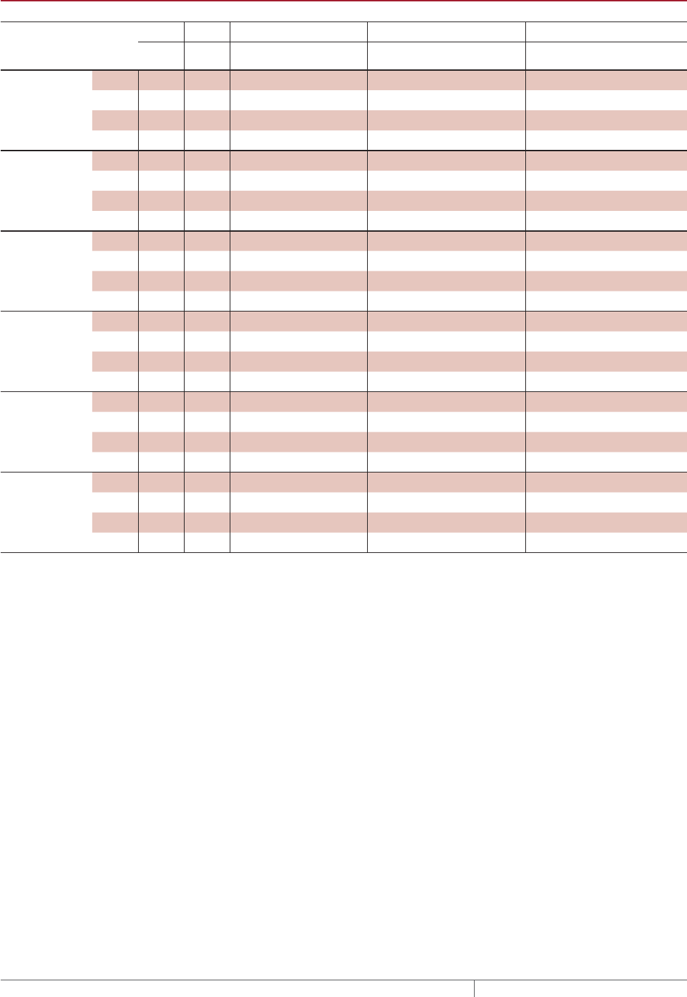
TABLE 10 MAXIMUM CIRCUIT LENGTH IN METERS
4°C / 43°C Maintain*
Start-up
temperature
(°C)
CB
size
(A)
5XL1 8XL1 5XL2 8XL2 12XL2
120 V 120 V 208 V 240 V 277 V 208 V 240 V 277 V 208 V 240 V 277 V
–29°C 15 31 23 53 54 56 40 42 44 34 35 36
20 41 31 71 72 75 53 56 59 45 46 48
30 61 46 106 108 112 80 84 89 68 69 71
40 82 61 142 145 149 106 112 118 90 92 95
–18°C 15 35 26 61 62 64 45 48 51 36 37 38
20 47 35 81 83 85 61 64 67 49 50 51
30 70 52 121 124 128 91 96 101 73 74 77
40 82 64 143 149 162 113/122 119/128 128/135 97 99 102
–7°C 15 41 31 71 72 74 53 56 59 39 39 41
20 54 41 94 96 99 70 74 78 51 52 54
30 82 61 141 144 149 106 111 117 77 79 81
40 82 64 143 149 162 113/141 119/148 128/156 104/106 105 108
4°C 15 49 36 85 86 89 63 66 70 43 44 46
20 65 48 113 115 119 84 88 93 58 59 61
30 82 64 143 149 162 113/127 119/134 128/141 87 89 91
40 82 64 143 149 162 113/169 119/178 128/188 104/121 110/124 116/128
10°C
(buried grease)
15 – – – – – 70 73 77 46 47 49
20 – – – – – 93 98 103 62 63 65
30 – – – – – 139 147 155 93 95 98
40 – – – – – 186 195 206 124 126 130
18°C
(indoors grease)
15 – – – – – 83 87 92 52 53 54
20 – – – – – 110 116 123 69 70 72
30 – – – – – 166 174 184 103 105 108
40 – – – – – 186 201 220 131 140 149
* When maximum circuit length is listed in:
• black type, the value is for applications with a 4°C maintain
• red type, the value is for applications with a 43°C maintain
Example: Pipe Freeze Protection – Water Piping
Total heating cable length 315 ft of 5XL1-CR (from Step 3)
Supply voltage 120 V (from Step 1)
Minimum start-up temperature –20°F (–29°C) (from Step 1)
Number of circuits 315 ft / (201 ft max CL) = 1.6 circuits
Round up to 2 circuits
Example: Flow Maintenance – Greasy Waste Line
Total heating cable length 223 ft of 12XL2-CT (from Step 3)
Supply voltage 208 V (from Step 1)
Minimum start-up temperature 50°F (10°C) (from Step 1)
Number of circuits 223 ft / 304 ft = 0.7 circuits
Round up to 1 circuit
PIPE FREEZE PROTECTION AND FLOW MAINTENANCE XLTRACE SYSTEM
THERMAL MANAGEMENT SOLUTIONS
EN-RaychemXLTracePipeFreezeProtection-DG-H55838 11/13
26
Pipe Freeze Protection
and Flow Maintenance
Fire Sprinkler System
Freeze Protection
Roof and Gutter
De-Icing
Surface Snow
Melting – MI
Surface Snow
Melting – ElectroMelt
Freezer Frost
Heave Prevention
Floor Heating Technical Data
Sheets
DETERMINE TRANSFORMER LOAD
Transformers must be sized to handle the load of the heating cable. Use the
following tables to calculate the total transformer load.
TABLE 11 TRANSFORMER SIZING AMPERES/FOOT
Minimum start-up
temperature (°F)
5XL1 8XL1 5XL2 8XL2 12XL2
120 120 208 240 277 208 240 277 208 240 277
–20 0.119 0.159 0.069 0.067 0.065 0.092 0.087 0.082 0.108 0.106 0.102
0 0.105 0.139 0.060 0.059 0.057 0.080 0.076 0.072 0.100 0.098 0.095
20 0.090 0.120 0.052 0.051 0.049 0.069 0.066 0.062 0.095 0.093 0.090
40 0.075 0.101 0.043 0.042 0.041 0.058 0.055 0.052 0.084 0.083 0.080
50 – – – – – 0.053 0.050 0.047 0.079 0.077 0.075
65 – – – – – 0.044 0.042 0.040 0.072 0.070 0.067
TABLE 12 TRANSFORMER SIZING AMPERES/METER
Minimum start-up
temperature (°C)
5XL1 8XL1 5XL2 8XL2 12XL2
120 120 208 240 277 208 240 277 208 240 277
–20 0.391 0.521 0.226 0.221 0.215 0.301 0.286 0.270 0.354 0.347 0.336
–18 0.343 0.457 0.198 0.194 0.188 0.264 0.251 0.238 0.329 0.322 0.312
–7 0.294 0.394 0.170 0.166 0.161 0.227 0.216 0.205 0.311 0.305 0.296
4 0.246 0.331 0.142 0.139 0.135 0.191 0.181 0.172 0.276 0.271 0.263
10 – – – – – 0.172 0.164 0.155 0.259 0.254 0.246
18 – – – – – 0.145 0.138 0.130 0.233 0.228 0.221
Use Table 11 or Table 12 to determine the applied voltage and the maximum A/ft
(A/m) at the minimum start up temperature to calculate the transformer load as
follows:
Example: Pipe Freeze Protection – Water Piping
Total heating cable length 315 ft of 5XL1-CR (from Step 3)
Minimum start-up temperature –20°F (–29°C) (from Step 1)
Circuit breaker sizing 30 A
1000 = Transformer
load (kW)
Max A/ft at minimum start-up temperature x Heating cable length (ft)
x Supply voltage
= (0.119 A/ft x 315 ft x 120 V) / 1000
= 4.5 kWTransformer load (kW)
1000
Max A/ft at –20°F x Total feet
x Supply voltage
Pipe Freeze Protection and Flow Maintenance Design
27THERMAL MANAGEMENT SOLUTIONS EN-RaychemXLTracePipeFreezeProtection-DG-H55838 11/13
Example: Flow Maintenance – Greasy Waste Line
Total heating cable length 212 ft of 12XL2-CT (from Step 3)
Supply voltage 208 V
Minimum start-up temperature 50°F (10°C) (from Step 1)
Pipe Freeze Protection
and Flow Maintenance
2. Select the heating
cable
3. Determine the
heating cable length
4. Determine the
electrical parameters
5. Select the
connection kits
and accessories
6. Select the control
system
7. Select the power
distribution
8. Complete the Bill
of Materials
1. Determine design
conditions and
heat loss
Step Select the connection kits and accessories
All XL-Trace systems require a power connection and end seal kit. Splice and tee kits
are used as required. Use Table 13 on page29 (for aboveground applications) and
Table 15 on page 31 (for buried applications) to select the appropriate connection kits.
Note: Add extra cable on your Bill of Materials for power connections, tees, and
end seals. See Table 13 on page 29, Table 15 on page 31, and Table 16 on
page32 for more information.
WARNING: Approvals and performance are based on the use of Pentair
Thermal Management-specified parts only. Do not substitute parts or use vinyl
electrical tape.
ABOVEGROUND PIPING
Fig. 13 RayClic connection system
Use the following table for general piping, and greasy waste and fuel lines. Develop a
bill of materials from the connection kits listed in this table.
Note: Connection kits must be off the pipe when installed on greasy waste, fuel
oil, or pipes exceeding 150°F (65°C).
= (0.079 A/ft x 212 ft x 208 V) / 1000
= 3.5 kWTransformer load (kW)
1000
Max A/ft at 50°F x Total feet
x Supply voltage
RayClic-PT
powered
tee
RayClic-PC
powered connection
RayClic-S
splice
RayClic-X
cross tee
RayClic-T
tee
RayClic-PS
powered
splice
RayClic-LE
lighted end seal
RayClic-E
end seal
Alternate
lighted end seal
Alternate
connection kits
XL-Trace
heating cable
PIPE FREEZE PROTECTION AND FLOW MAINTENANCE XLTRACE SYSTEM
THERMAL MANAGEMENT SOLUTIONS
EN-RaychemXLTracePipeFreezeProtection-DG-H55838 11/13
28
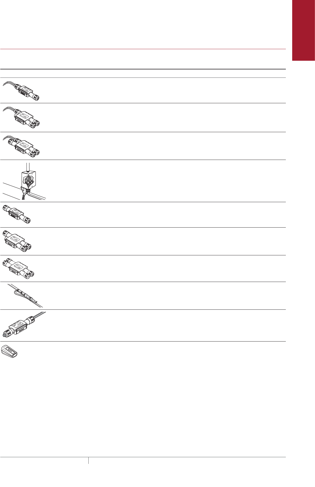
Pipe Freeze Protection
and Flow Maintenance
Fire Sprinkler System
Freeze Protection
Roof and Gutter
De-Icing
Surface Snow
Melting – MI
Surface Snow
Melting – ElectroMelt
Freezer Frost
Heave Prevention
Floor Heating Technical Data
Sheets
TABLE 13 CONNECTION KITS AND ACCESSORIES FOR ABOVEGROUND PIPING
Catalog
number Description
Standard
packaging Usage
Heating
cable
allowance¹
Connection kits
RayClic-PC Power connection and end seal (RayClic-
SB-04 pipe mounting bracket included)
1 1 per circuit 2 ft (0.6 m)
RayClic-PS Powered splice and end seal (RayClic-
SB-04 pipe mounting bracket included)
1 1 per circuit 4 ft (1.2 m)
RayClic-PT Powered tee and end seal (RayClic-SB-04
pipe mounting bracket included)
1 1 per circuit 6 ft (1.8 m)
FTC-P²Power connection and end seal kit
Note: FTC-P is required for circuits requir-
ing 40 A circuit breakers.
1 1 per circuit 2 ft (0.6 m)
RayClic-S Splice used to join two
sections of heating cable
1 As required 2 ft (0.6 m)
RayClic-T Tee kit with end seal;
use as needed for pipe
branches
1 As required 2 ft (0.6 m)
RayClic-X Cross connection to connect four heating
cables
1 As required 8 ft (2.4 m)
FTC-HST³Low-profile splice/tee; use as
needed for pipe branches
2 As required 3 ft (0.9 m)
RayClic-LE Lighted end seal (RayClic-SB-04 pipe
mounting bracket included)
1 Alternate end seal 2 ft (0.6 m)
RayClic-E Replacement end seal 1 Additional end seal 0.3 ft (0.1 m)
Pipe Freeze Protection and Flow Maintenance Design
29THERMAL MANAGEMENT SOLUTIONS EN-RaychemXLTracePipeFreezeProtection-DG-H55838 11/13
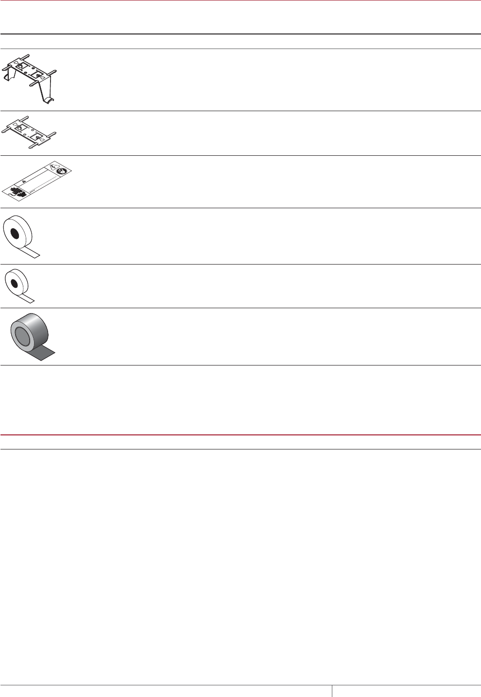
TABLE 13 CONNECTION KITS AND ACCESSORIES FOR ABOVEGROUND PIPING
Catalog
number Description
Standard
packaging Usage
Heating
cable
allowance¹
Accessories
RayClic-SB-04 Pipe mounting bracket. Required
for mounting the kits off the pipe
for exposure temperatures greater
than 150°F (65°C) and for grease
and fuel line splices and tees.
1 As required
–
RayClic-SB-02 Wall mounting bracket 1 As required
–
© 2013 Pentair Thermal Management LLC
WWW.PENTAIRTHERMAL.COM
PN C77203-000 H57657 07/13
Electric Heat Tracing
WARNING
SHOCK AND FIRE HAZARD: System must be installed and
maintained according to manufacturer's instructions. Follow
electrical lockout procedures before working on this line or
removing thermal insulation.
ETL “Electric Traced” label (use 1 label
per 10 feet of pipe)
1 1 label per 10 feet
(3m) of pipe
–
GT-66 Glass cloth adhesive tape for
attaching heating cable to pipe at
40°F (4°C) or above.
66 ft (20m) See Table 14
–
GS-54 Glass cloth adhesive tape for
attaching heating cable to pipe
above –40°F (–40°C).
54 ft (20m) See Table 14
–
AT-180 Aluminum tape. Required for
attaching heating cable to plastic
pipe (use 1 foot of tape per foot of
heating cable).
180 ft
(55 m)
1 ft/ft [0.3 m/m] of
heating cable
–
¹ Allow extra heating cable for ease of component installation.
² Junction box not included.
³ One RayClic-E end seal is required for each FTC-HST used as a tee kit.
TABLE 14 QUANTITY OF GLASS CLOTH ADHESIVE TAPE REQUIRED ATTACH AT 1FOOT INTERVALS
Pipe size (in) <2 3 4 6 8 10
Feet of pipe per GT-66 roll 60 (18 m) 50 (15 m) 40 (12 m) 25 (8 m) 20 (6 m) 15 (5 m)
Feet of pipe per GS-54 roll 49 (15 m) 41 (13 m) 33 (10 m) 20 (6 m) 16 (5 m) 12 (4 m)
PIPE FREEZE PROTECTION AND FLOW MAINTENANCE XLTRACE SYSTEM
THERMAL MANAGEMENT SOLUTIONS
EN-RaychemXLTracePipeFreezeProtection-DG-H55838 11/13
30
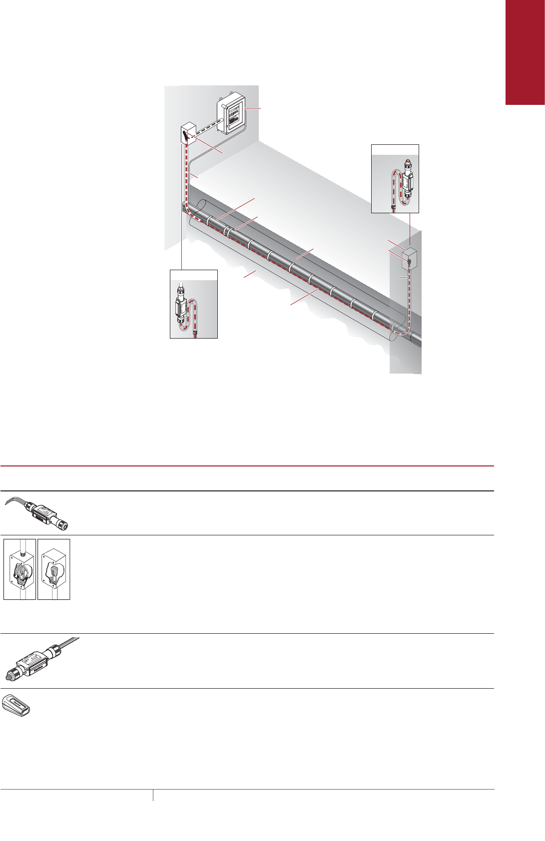
Pipe Freeze Protection
and Flow Maintenance
Fire Sprinkler System
Freeze Protection
Roof and Gutter
De-Icing
Surface Snow
Melting – MI
Surface Snow
Melting – ElectroMelt
Freezer Frost
Heave Prevention
Floor Heating Technical Data
Sheets
BURIED PIPING
RTD10CS
Insulation
Conduit
XL-Trace
heating cable
with -CT jacket
Ground
Alternate
power connection
Alternate
end seal
Ground
Wall
RayClic-LE*
RayClic-PC*
Junction box
RayClic-E
end seal
Conduit
Wall
with wall
mounting
bracket
with wall
mounting
bracket
FTC-XC
power
connection
*To protect the heating cable, run cable
inside Convolex tubing between the
conduit and the RayClic connection kits.
DigiTrace C910-485
Electronic controller
Conduit for
temperature
sensor
Fig. 14 Typical buried piping system
Use the following for buried water piping and greasy waste lines. Note that all
connections must be aboveground and that no splices/tees are allowed. Develop a
bill of materials from the connection kits in this table.
TABLE 15 CONNECTION KITS AND ACCESSORIES FOR BURIED PIPING
Catalog
number
Description
Standard
packaging
Usage
Heating cable
allowance
¹
RayClic-PC Power connection and end seal
(RayClic-SB-04 pipe mounting bracket
included)
1 1 per circuit 2 ft (0.6 m)
FTC-XC The FTC-XC power connection and end
seal kit is for use with XL-Trace heating
cable that is run through conduit to a
junction box. Materials for one power
connection and end seal is included in
the kit.
Note: FTC-XC is required for circuits
requiring 40 A circuit breakers.
1 1 per circuit 2 ft (0.6 m)
RayClic-LE Lighted end seal (RayClic-SB-04 pipe
mounting bracket included)
1 Alternate end
seal
2 ft (0.6 m)
RayClic-E Replacement end seal 1 Additional end
seal
0.3 ft (0.1 m)
Pipe Freeze Protection and Flow Maintenance Design
31THERMAL MANAGEMENT SOLUTIONS EN-RaychemXLTracePipeFreezeProtection-DG-H55838 11/13
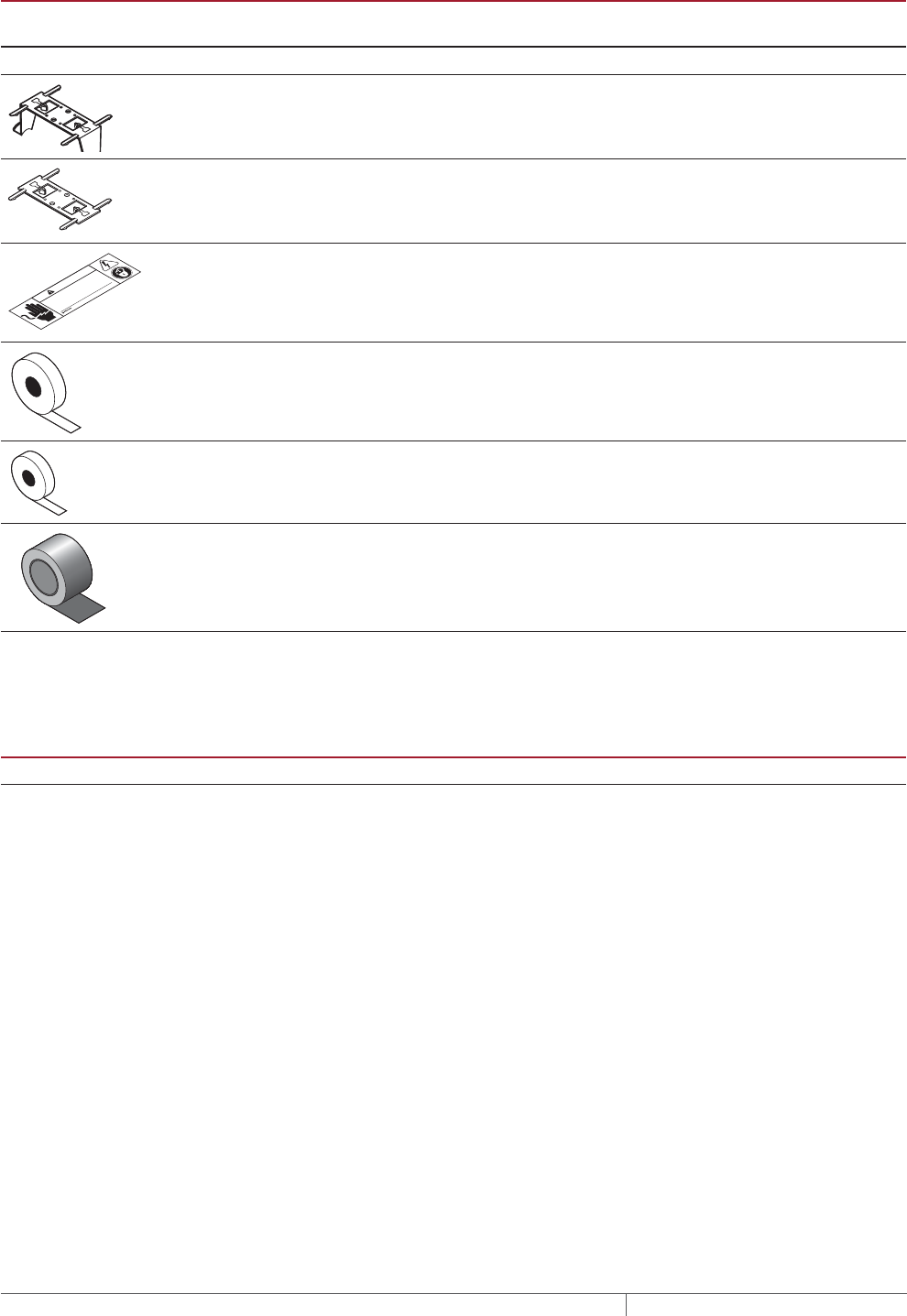
TABLE 15 CONNECTION KITS AND ACCESSORIES FOR BURIED PIPING
Catalog
number
Description
Standard
packaging
Usage
Heating cable
allowance
¹
Accessories
RayClic-SB-04 Pipe mounting bracket 1 As required –
RayClic-SB-02 Wall mounting bracket 1 As required –
© 2013 Pentair Thermal Management LLC
WWW.PENTAIRTHERMAL.COM
PN C77203-000 H57657 07/13
Electric Heat Tracing
WARNING
SHOCK AND FIRE HAZARD: System must be installed and
maintained according to manufacturer's instructions. Follow
electrical lockout procedures before working on this line or
removing thermal insulation.
ETL “Electric Traced” label (use 1
label per 10 feet of pipe)
1 1 label per 10 feet
(3m) of pipe
–
GT-66 Glass cloth adhesive tape for
attaching heating cable to pipe at
40°F (4°C) or above.
66 ft (20m) See Table 16 –
GS-54 Glass cloth adhesive tape for
attaching heating cable to pipe
above –40°F (–40°C).
54 ft (20m) See Table 16 –
AT-180 Aluminum tape. Required for
attaching heating cable to plastic
pipe (use 1 foot of tape per foot of
heating cable).
180 ft (55 m) 1 ft/ft [0.3 m/m] of
heating cable
–
¹ Allow extra heating cable for ease of component installation.
TABLE 16 QUANTITY OF GLASS CLOTH ADHESIVE TAPE REQUIRED ATTACH AT 1FOOT INTERVALS
Pipe size (in) <2 3 4 6 8 10
Feet of pipe per GT-66 roll 60 (18 m) 50 (15 m) 40 (12 m) 25 (8 m) 20 (6 m) 15 (5 m)
Feet of pipe per GS-54 roll 49 (15 m) 41 (13 m) 33 (10 m) 20 (6 m) 16 (5 m) 12 (4 m)
PIPE FREEZE PROTECTION AND FLOW MAINTENANCE XLTRACE SYSTEM
THERMAL MANAGEMENT SOLUTIONS
EN-RaychemXLTracePipeFreezeProtection-DG-H55838 11/13
32
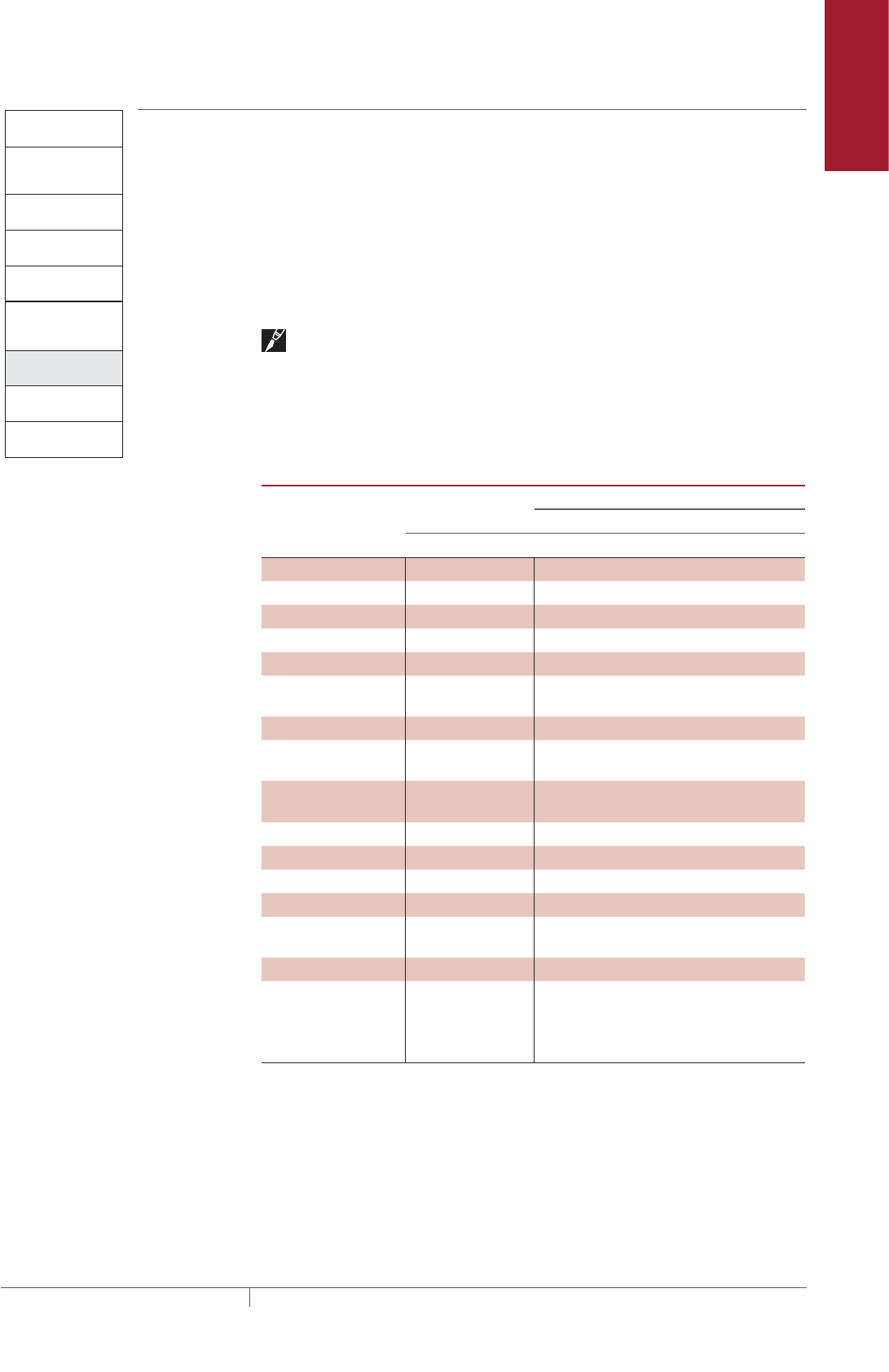
Pipe Freeze Protection
and Flow Maintenance
Fire Sprinkler System
Freeze Protection
Roof and Gutter
De-Icing
Surface Snow
Melting – MI
Surface Snow
Melting – ElectroMelt
Freezer Frost
Heave Prevention
Floor Heating Technical Data
Sheets
Pipe Freeze Protection
and Flow Maintenance
2. Select the heating
cable
3. Determine the
heating cable length
4. Determine the
electrical parameters
5. Select the
connection kits
and accessories
6. Select the control
system
7. Select the power
distribution
8. Complete the Bill
of Materials
1. Determine design
conditions and
heat loss
Pipe Freeze Protection
and Flow Maintenance Step Select the control system
Temperature controls save energy by ensuring that the system is energized only
when necessary. Pentair Thermal Management offers a wide variety of monitoring
and control options, including:
• Electronic thermostats provide higher accuracy of the heating cable circuit with
thermistor sensors and built-in ground-fault protection.
• Electronic controllers provide superior accuracy with RTD temperature sensors,
built-in ground-fault protection, monitoring and alarm output.
• Modbus® protocol communication over RS-485 system is supported using
DigiTrace ProtoNode multi-protocol gateways.
Note: Greasy waste flow maintenance requires line sensing controllers such as
the DigiTrace ECW-GF, DigiTrace C910-485, or the DigiTrace ACS-30.
Use the following table to identify the control system suitable for your application.
Contact your Pentair Thermal Management representative or contact Pentair
Thermal Management directly at (800) 545-6258 for more information.
TABLE 17 TEMPERATURE CONTROL OPTIONS
Application
Electronic
thermostat
Electronic controllers
Single-point Multipoint
ECW-GF C910-485 ACS-30
Ambient sensing x x x
Line sensing x x x
Buried pipe x x x
Sensor Thermistor RTD* RTD*
Sensor length 35 ft multiple options multiple options
Set point range 32°F to 200°F
(0°C to 93°C)
–76°F to 1058°F
(–60°C to 570°C)
"
Enclosure NEMA 4X NEMA 4X "
Deadband 2°F to 10°F
(2°C to 6°C)
3°F (1.6°C) "
Enclosure limits –40°F to 140°F
(–40°C to 60°C)
–40°F to 140°F
(–40°C to 60°C)
"
Switch rating 30 A 30 A "
Switch type DPST DPST "
Electrical rating 100–277 V 100–277 V "
Approvals c-UL-us c-CSA-us "
Ground-fault
protection
30 mA fixed 20 mA to 250mA "
Alarm outputs "
AC relay 2 A at 277 Vac 100–277 V, 0.75 A
max.
"
Dry contact relay 2 A at 48 Vdc 48 Vac/dc, 500 mA
max.
"
* not included with unit
Pipe Freeze Protection and Flow Maintenance Design
33THERMAL MANAGEMENT SOLUTIONS EN-RaychemXLTracePipeFreezeProtection-DG-H55838 11/13
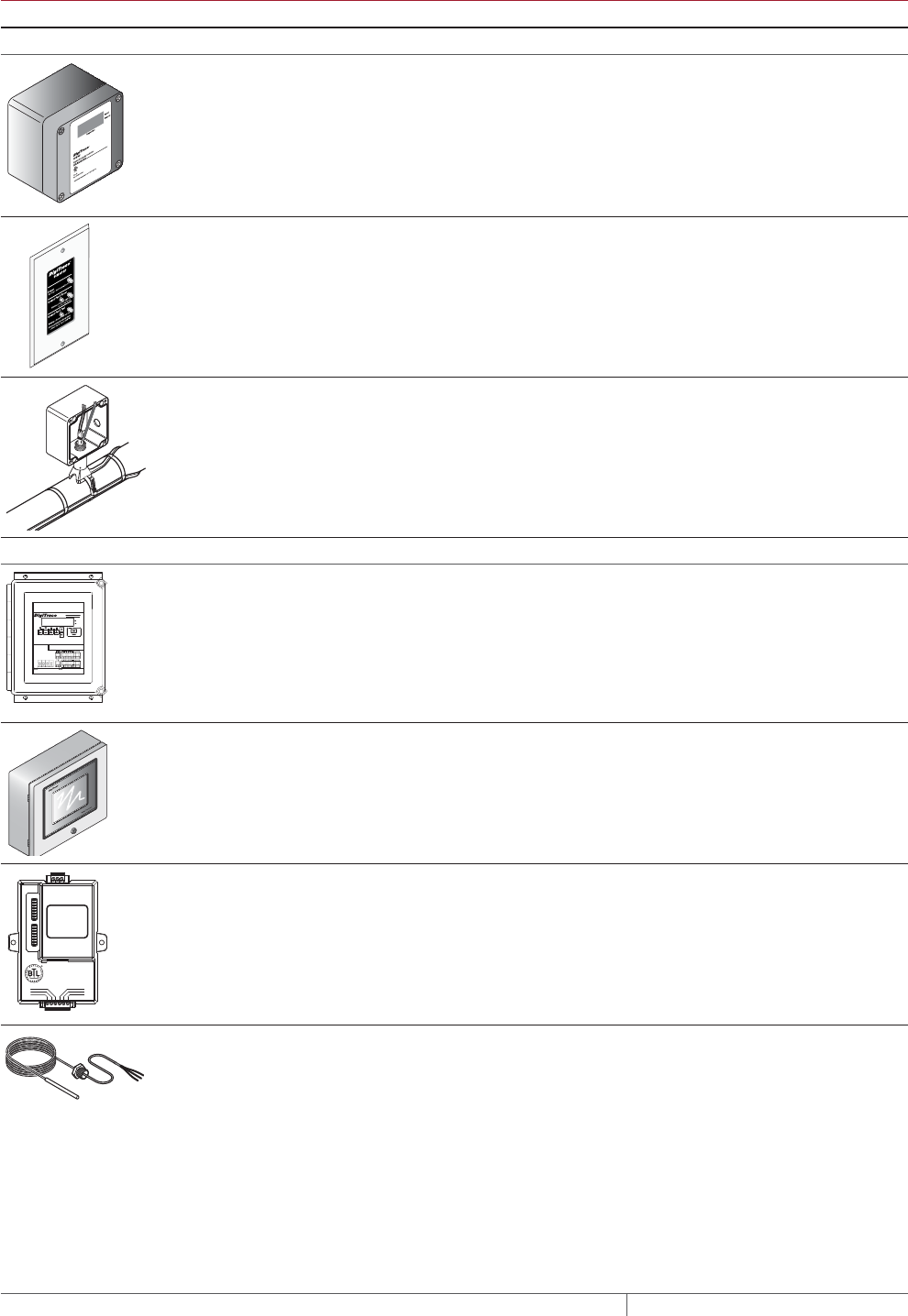
TABLE 18 CONTROL SYSTEMS
Catalog number Description
Electronic Thermostats and Accessories
ECW-GF The ECW-GF electronic controller provides accurate temperature control with inte-
grated 30-mA ground-fault protection. The controller can be programmed to maintain
temperatures up to 200°F (93°C) at voltages from 100 to 277 V and can switch current
up to 30 Amperes. The ECW-GF is complete with a 25-ft (7.6-m) temperature sensor
for line, slab or ambient sensing temperature control, and is housed in a NEMA 4X
rated enclosure. The controller features an AC/DC dry alarm contact relay.
ECW-GF-DP An optional remote display panel (ECW-GF-DP) can be added to provide ground-fault
or alarm indication in applications where the controller is mounted in inaccessible
locations.
FTC-PSK The FTC-PSK pipe stand and power connection kit is for use with XL-Trace heat-
ing cables. The stand is designed specifically for the DigiTrace ECW-GF electronic
controllers and is compatible with other junction boxes that have 1 inch NPT entries,
threaded or non-threaded. Materials for one power connection and end seal are
included in the kit.
Electronic Controllers and Sensors
C910-485 The C910-485 is a compact, full-featured microprocessor-based single-point heat-
trace controller. The C910-485 provides control and monitoring of electrical heat-trac-
ing circuits for both freeze protection and temperature maintenance, and can be set to
monitor and alarm for high and low temperature, high and low current, ground-fault
level, and voltage. The DigiTrace C910-485 controller is available with an electrome-
chanical relay (EMR) for use in ordinary areas. The C910-485 comes with an RS-485
communication module.
ACS-UIT2
ACS-PCM2-5
The DigiTrace ACS-30 Advanced Commercial Control System is a multipoint electron-
ic control and monitoring system for heat-tracing used in commercial freeze protec-
tion and flow maintenance applications. The DigiTrace ACS-30 system can control up
to 260 circuits with multiple networked ACS-PCM2-5 panels, with a single ACS-UIT2
user interface terminal. The ACS-PCM2-5 panel can directly control up to 5 individual
heat-tracing circuits using electromechanical relays rated at 30 A up to 277 V.
By FieldServer Technologies
www.ProtoCessor.com
PROTOCESSOR
SERIAL ETHERNET
PROTONODE
FRAME GND
- PWR
+PWR
RS 485+
RS 485 -
RS 485 GND
S3
S2
S1
S0
B3
B2
B1
B0
A7
A6
A5
A4
A3
A2
A1
A0
ProtoNode-LER
ProtoNode-RER
The DigiTrace ProtoNode is an external, high performance multi-protocol gateway
for customers needing protocol translation between Building Management Systems
(BMS) and the DigiTrace ACS-30 or C910-485 controllers.
The ProtoNode-LER is for LonWorks® systems; and the ProtoNode-RER is for
BACnet® or Metasys® N2 systems.
RTD-200
RTD3CS
RTD10CS
RTD50CS
Three-wire RTD (Resistance Temperature Device) used with DigiTrace C910-485 and
ACS-30 controllers.
RTD-200: 6-ft (1.8 m) fluoropolymer with 1/2-in NPT bushing
RTD3CS: 3-ft (0.9 m) flexible armor with 1/2-in NPT bushing
RTD10CS: 10-ft (3 m) flexible armor with 1/2-in NPT bushing
RTD50CS: 50-ft (3 m) flexible armor with 1/2-in NPT bushing
PIPE FREEZE PROTECTION AND FLOW MAINTENANCE XLTRACE SYSTEM
THERMAL MANAGEMENT SOLUTIONS
EN-RaychemXLTracePipeFreezeProtection-DG-H55838 11/13
34
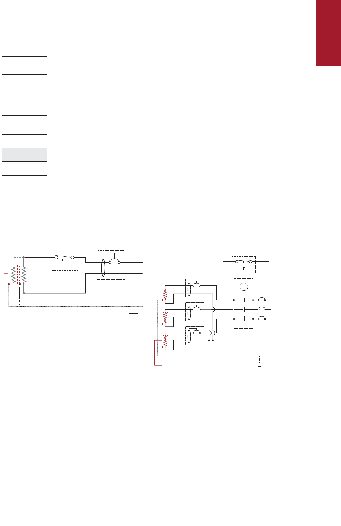
Pipe Freeze Protection
and Flow Maintenance
Fire Sprinkler System
Freeze Protection
Roof and Gutter
De-Icing
Surface Snow
Melting – MI
Surface Snow
Melting – ElectroMelt
Freezer Frost
Heave Prevention
Floor Heating Technical Data
Sheets
2. Select the heating
cable
3. Determine the
heating cable length
4. Determine the
electrical parameters
5. Select the
connection kits
and accessories
6. Select the control
system
7. Select the power
distribution
8. Complete the Bill
of Materials
Pipe Freeze Protection
and Flow Maintenance
1. Determine design
conditions and
heat loss
Pipe Freeze Protection
and Flow Maintenance Step Select the power distribution
Once the heating cable circuits have been defined, you must select how to provide
power to them. Power to the XL-Trace heating cables can be provided in several
ways: directly through the temperature control, through external contactors, or
through HTPG power distribution panels.
SINGLE CIRCUIT CONTROL
Heating cable circuits that do not exceed the current rating of the selected
temperature control device shown in Table 18 can be switched directly (see Fig. 15).
GROUP CONTROL
If the current draw exceeds the switch rating, or if the controller will activate more
than one circuit (group control, an external contactor must be used (see Fig. 15 on
page 35).
Large systems with many circuits should use an HTPG power distribution panel.
The HTPG is a dedicated power-distribution, control, ground-fault protection,
monitoring, and alarm panel for freeze protection and broad temperature
maintenance heat-tracing applications. This enclosure contains an assembled
circuit-breaker panelboard. Panels are equipped with ground-fault circuit breakers
with or without alarm contacts. The group control package allows the system to
operate automatically in conjunction with an ambient-sensing thermostat, individual
electronic, or duty cycle controller.
Fig. 15 Single circuit and group control
Single circuit control Group control
Temperature
controller 1-pole
GFEP breaker
1
N
G
Heating
cable
ø
øsupply
C
Temperature
controller
Contactor
1-pole
GFEP breaker
N
G (Typ 3)
ø2
ø1
ø3
3-phase 4-wire
supply (WYE)
3-pole main
breaker
ø
ø
1 supply
N
Heating cable
sheath, braid
or ground
Heating cable
sheath, braid
or ground
Pipe Freeze Protection and Flow Maintenance Design
35THERMAL MANAGEMENT SOLUTIONS EN-RaychemXLTracePipeFreezeProtection-DG-H55838 11/13
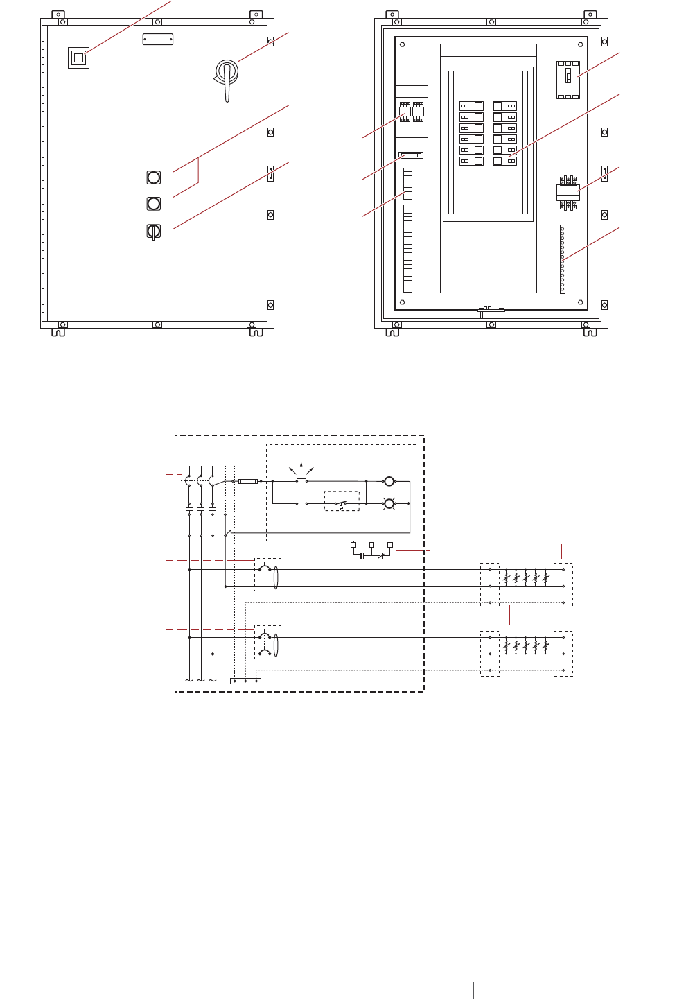
Fig. 16 HTPG power distribution panel
Fig. 17 HTPG power schematic
A
COMMON ALARM
PUSH TO ACKNOWLEDGE
HAND/OFF/AUTO
1
2
3
4
5
6
7
8
9
10
11
12
Main circuit
breaker
Main
contactor
Distribution
panelboard
Fuse holder
C
POWER ON
TB 1
TB 2
ARR
Ground
bus bar
Selector switch
Alarm relay
(optional)
Terminals
(optional)
Push button for
light testing
Alarm horn (optional)
Alarm option shown above
Door
disconnect
(optional)
N
Ø1
Three-pole main
circuit breaker
Panel
energized
Contactor
coil
C NC
External controller/
thermostat*
Hand Auto
Off
Three-pole main
contactor
Ø3
Ø2
Power
connection
Heating cable
One-pole with 30-mA
ground-fault trip
(120/277 Vac)
Two-pole with 30-mA
ground-fault trip
(208/240 Vac)
Alarm
remote
annunciation
(with alarm
option)
Heating
cable
circuit
Heating
cable
circuit
G
End seal
Heating cable shealth, braid or ground
Three-phase, 4 wire supply (Wye)
PIPE FREEZE PROTECTION AND FLOW MAINTENANCE XLTRACE SYSTEM
THERMAL MANAGEMENT SOLUTIONS
EN-RaychemXLTracePipeFreezeProtection-DG-H55838 11/13
36

Pipe Freeze Protection
and Flow Maintenance
Fire Sprinkler System
Freeze Protection
Roof and Gutter
De-Icing
Surface Snow
Melting – MI
Surface Snow
Melting – ElectroMelt
Freezer Frost
Heave Prevention
Floor Heating Technical Data
Sheets
TABLE 19 POWER DISTRIBUTION
Catalog number Description
Power Distribution
A
COMMON ALARM
PUSH TO ACKNOWLEDGE
HAND/OFF/AUTO
C
POWER ON
HTPG Heat-tracing power distribution panel with ground-fault and monitoring for group
control.
Contactors
E104 Three-pole, 100 Amp per pole, 600 V maximum contactor housed in UL Listed, CSA
Certified, NEMA 4X enclosure with two 1-inch conduit entries. When ordering, select
coil voltage (110–120, 208–240, 277 V).
Enclosure dimensions: 13-1/2 in x 9-1/5 in x 6-11/16 in (343 mm x 234 mm x 170 mm).
E304 Three-pole, 40 Amp per pole, 600 V maximum contactor housed in UL Listed, CSA
Certified NEMA 4X enclosure with two 1-inch conduit entries. When ordering, select coil
voltage
(110–120, 208–240, 277 V).
Enclosure dimensions: 9-1/2 in x 7-1/5 in x 6-11/16 in (241 mm x 183 mm x 170 mm).
2. Select the heating
cable
3. Determine the
heating cable length
4. Determine the
electrical parameters
5. Select the
connection kits
and accessories
6. Select the control
system
7. Select the power
distribution
8. Complete the Bill
of Materials
Pipe Freeze Protection
and Flow Maintenance
1. Determine design
conditions and
heat loss
Pipe Freeze Protection
and Flow Maintenance
Step Complete the Bill of Materials
If you used the Design Worksheet to document all your design parameters, you
should have all the details necessary complete your Bill of Materials.
Pipe Freeze Protection and Flow Maintenance Design
37THERMAL MANAGEMENT SOLUTIONS EN-RaychemXLTracePipeFreezeProtection-DG-H55838 11/13
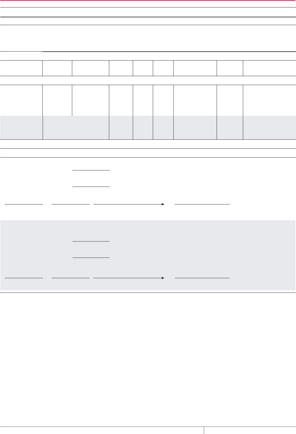
XLTRACE SYSTEM PIPE FREEZE PROTECTION AND FLOW MAINTENANCE DESIGN WORKSHEET
Step Determine design conditions and pipe heat loss
Design conditions
XL-Trace
application Location
Maintain
temp.
(Tm)
Max.
system
temp.
(Tma x)
Min.
ambient
temp.
(Ta)
Pipe diameter
and material
Pipe
length
Thermal insulation
type and thickness
Pipe freeze protection
❑ Water piping ❑ Indoors
❑ Outdoors
❑ Aboveground
❑ Buried ______ ______ ______ ____ in
❑ Metal
❑ Plastic ____ ft (m)
❑ Fiberglass
❑ ________ ___ in
Flow maintenance
❑ Greasy waste
lines
❑ Indoors
❑ Outdoors
❑ Aboveground
❑ Buried ______ ______ ______ ____ in
❑ Metal
❑ Plastic ____ ft (m)
❑ Fiberglass
❑ ________ ___ in
❑ Fuel lines ❑ Indoors
❑ Outdoors
❑ Aboveground
❑ Buried ______ ______ ______ ____ in
❑ Metal
❑ Plastic ____ ft (m)
❑ Fiberglass
❑ ________ ___ in
Example:
0 Water piping 0 Aboveground
0 Outdoor 40°F 80°F –20°F 2 in 0 Plastic 300 ft 0 Fiberglass 1 in
Pipe heat loss
Calculate temperature differential ∆T
Pipe maintain temperature (TM)
°F (°C)
Ambient temperature (TA)
°F (°C)
TM∆T
−=
Example: Pipe Freeze Protection − Water Piping
TA
Pipe maintain temperature (TM)
°F
(from Step 1)
(from Step 1)
Ambient temperature (TA)
°F
TM∆T
40 °F
40 °F
−20 °F
−20 °F 60 °F
−=
TA
PIPE FREEZE PROTECTION AND FLOW MAINTENANCE XLTRACE SYSTEM
THERMAL MANAGEMENT SOLUTIONS
EN-RaychemXLTracePipeFreezeProtection-DG-H55838 11/13
38
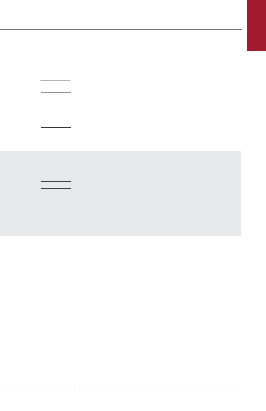
Pipe Freeze Protection
and Flow Maintenance
Fire Sprinkler System
Freeze Protection
Roof and Gutter
De-Icing
Surface Snow
Melting – MI
Surface Snow
Melting – ElectroMelt
Freezer Frost
Heave Prevention
Floor Heating Technical Data
Sheets
Determine the pipe heat loss: See Table 2 for the base heat loss of the pipe (QB). If the ∆T for your system is not listed, interpolate between
the two closest values.
QB-50 ∆T1
W/ft (W/m)
QB-100 ∆T2
W/ft (W/m)
QB
W/ft (W/m)
in
in
°F (°C)
W/ft (W/m)
W/ft (W/m)
Example: Pipe Freeze Protection − Water Piping
Pipe diameter 2 in
1 in
60°F
Insulation thickness
3.2 W/ft
6.8 W/ft
∆T
QB-50
QB-100
Pipe diameter
Insulation thickness
∆T
QB-50
QB-50
∆T 60°F is 20% of the distance between ∆T 50°F and ∆T 100°F
QB-50 + [0.20 x (QB-100 − QB-50)]
∆T interpolation
3.2 + [0.20 x (6.8 − 3.2)] = 3.9 W/ft
QB-60
3.9 W/ft @ TM 40°F
Pipe heat loss (QB-60)
XL-Trace System Pipe Freeze Protection and Flow Maintenance Design Worksheet
39THERMAL MANAGEMENT SOLUTIONS EN-RaychemXLTracePipeFreezeProtection-DG-H55838 11/13

Compensate for insulation type and pipe location
See Table 2 for the pipe heat loss (QB). If the ∆T for your system is not listed, interpolate between the two closest values.
See Table 3 for indoor multiple
See Table 4 for insulation multiple
QB
QCORRECTED
QB
x=
W/ft (W/m)
Insulation multiple
Indoor multiple (if applicable)
Location
Insulation thickness and type
Insulation multiple xIndoor multiple
(if applicable)
Example: Pipe Freeze Protection − Water Piping
Location Aboveground, indoor
1-in fiberglass
Thermal insulation thickness and type
3.9 W/ft @ TM 40°F
Indoor multiple
1.00
Insulation multiple
N/A
3.9 W/ft 1.00
3.9 W/ft @ TM 40°F
QCORRECTED QB
x = =
Insulation multiple
QB
PIPE FREEZE PROTECTION AND FLOW MAINTENANCE XLTRACE SYSTEM
THERMAL MANAGEMENT SOLUTIONS
EN-RaychemXLTracePipeFreezeProtection-DG-H55838 11/13
40

Pipe Freeze Protection
and Flow Maintenance
Fire Sprinkler System
Freeze Protection
Roof and Gutter
De-Icing
Surface Snow
Melting – MI
Surface Snow
Melting – ElectroMelt
Freezer Frost
Heave Prevention
Floor Heating Technical Data
Sheets
Step Select the heating cable
Power output data: See Fig. 12
Power output correction factors: See Table 5
Heating cable temperature ratings: See Table 6
Select outer jacket
❑ -CR
❑ -CT
Example: Pipe Freeze Protection – Water Piping
5XL1-CR
Power at rated V factor
x
Pipe maintain temperature (TM) (from Step 1)
(from Step 1)
(from Step 1)
(from Step 1)
(from Step 1)
(from Step 1)
(from Step 1)
(from Step 1)
Corrected heat loss (QCORRECTED)
Supply voltage
Pipe material (metal or plastic)
XL-Trace application (water, fuel oil, or greasy waste)
Pipe freeze protection: general water piping, sprinkler piping
Flow maintenance: greasy waste lines, fuel lines
Maximum system use temperature (TMAX)
Plastic pipe correction factor
=
Corrected power
Heating cable selected
Power at TM (120/208 V)
Power output correction factor
Plastic pipe correction factor
Is the heating cable power output (PCORRECTED) ≥ the corrected heat loss?
If No, then design with additional runs of heating cable or thicker thermal insulation.
Yes
ENo
E
Maintain temperature (TM)40°F
3.9 W/ft @ TM 40°F
120 V
plastic
QB = 3.9 W/ft @ TM 40°F
Select curve C: 5XL1 = 5.6 W/ft @ 40°F
Power output correction factor: 120 V = 1.00
Pipe material correction factor: Plastic = 0.75
Corrected heating cable power: 5.6 @/ft x 1.00 x 0.75 = 4.2 W/ft
Select: 5XL1
Maximum system temperature (TMAX): 80°F
Maximum heating cable exposure temperature (TEXP): 150°F
TMAX < TEXP: Yes
Corrected heat loss (QCORRECTED)
Supply voltage
Pipe material (metal or plastic*)
(*AT-180 aluminum tape required for
installing heating cable on plastic pipes)
Example: Pipe Freeze Protection − Water Piping
XL-Trace System Pipe Freeze Protection and Flow Maintenance Design Worksheet
41THERMAL MANAGEMENT SOLUTIONS EN-RaychemXLTracePipeFreezeProtection-DG-H55838 11/13
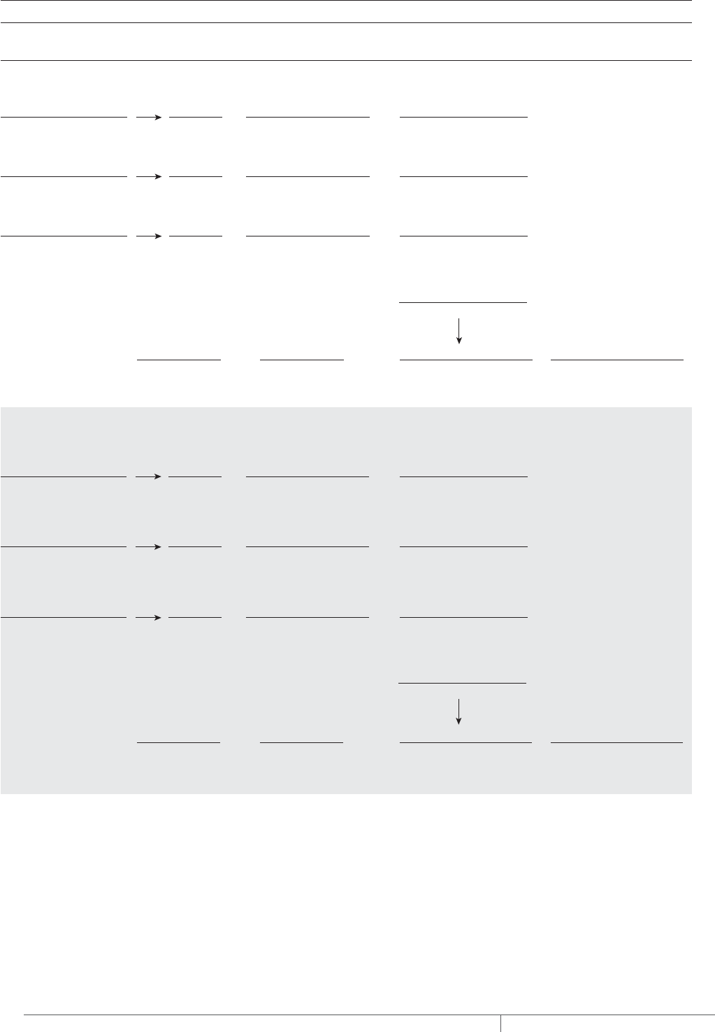
Step Determine the heating cable length
For additional heating cable allowance for valves: See Table 7.
For additional heating cable allowance for pipe supports and flanges: See Table 8.
Pipe length
( )
x +
Total heating cable
length required
Number of heating
cable runs
Total heating cable length
Heat sinks
=
Additional cable for valves,
pipe supports, and flanges
Type of valves
x
Total heating cable
for valves
How many
=
Additional heating cable
Type of pipe supports
x
Total heating cable
for pipe supports
How many
=
Additional heating cable
*2-in pipe diameter = 0.17 ft
Type of flanges
x
Total heating cable
for flanges
How many
=
Additional heating cable
Total heating cable for heat sinks:
Pipe length
( )
x +
Total heating cable
length required
300 ft 1 15 ft 315 ft
Number of heating
cable runs
Total heating cable length
Heat sinks
=
Additional cable for valves,
pipe supports, and flanges
Type of valves
x
Total
Gate valves 3 4.3 ft 12.9 ft
How many
=
Additional heating cable
Example:
Type of pipe supports
x
Total
Pipe hangers noninsulated
and U-bolt supports 5 (0.17 ft* x 2 = 0.34 ft) 1.7 ft
How many
=
Additional heating cable
*2-in pipe diameter = 0.17 ft
Type of flanges
x
Total
n/a 0 0 0 ft
How many
=
Additional heating cable
14.6 ft rounded up to 15 ftTotal:
PIPE FREEZE PROTECTION AND FLOW MAINTENANCE XLTRACE SYSTEM
THERMAL MANAGEMENT SOLUTIONS
EN-RaychemXLTracePipeFreezeProtection-DG-H55838 11/13
42

Pipe Freeze Protection
and Flow Maintenance
Fire Sprinkler System
Freeze Protection
Roof and Gutter
De-Icing
Surface Snow
Melting – MI
Surface Snow
Melting – ElectroMelt
Freezer Frost
Heave Prevention
Floor Heating Technical Data
Sheets
Step Determine the electrical parameters
Determine maximum circuit length and number of circuits
See Table 9 and Table 10.
Determine transformer load
See Table 11 and Table 12.
201 ft315 ft 1.6 circuits, round up to 2
315 ft of 5XL1-CR
−20°F
201 ft
/ =
Number of circuitsMaximum heating cable circuit length
Total heating cable length required
T 120 V T 208 V
T 240 V T 277 V
Total heating cable length required
Supply voltage:
T 15 A T 20 A
T 30 A T 40 A
Circuit breaker size:
Minimum start-up temperature
Maximum circuit length
/ =
Number of circuitsMaximum heating cable circuit length
Total heating cable length required
T 120 V T 208 V
T 240 V T 277 V
Total heating cable length required
Supply voltage:
T 15 A T 20 A
T 30 A T 40 A
Circuit breaker size:
Minimum start-up temperature
Maximum circuit length
Example:
9
9
x / 1000 = Transformer
load (kW)
0.119 A/ft 315 ft 120 V 4.5 kW
Max A/ft at minimum start-up temperature Heating cable length xSupply voltage
Example:
x / 1000 = Transformer
load (kW)
Max A/ft at minimum start-up temperature Heating cable length xSupply voltage
XL-Trace System Pipe Freeze Protection and Flow Maintenance Design Worksheet
43THERMAL MANAGEMENT SOLUTIONS EN-RaychemXLTracePipeFreezeProtection-DG-H55838 11/13

Step Select the connection kits and accessories
See Table 13.
Connection kits – Aboveground Description Quantity
Heating cable
allowance
❑ RayClic-PC
❑ RayClic-PS
❑ RayClic-PT
❑ FTC-P
❑ RayClic-S
❑ RayClic-T
❑ RayClic-X
❑ FTC-HST
❑ FTC-PSK
❑ RayClic-LE
❑ RayClic-E
Power connection and end seal
Power splice and end seal
Powered tee and end seal
Power connection and end seal
Splice
Tee kit with end seal
Cross connection
Low-profile splice/tee
Pipe stand and power connection kit
Lighted end seal
Extra end seal
____________
____________
____________
____________
____________
____________
____________
____________
____________
____________
____________
__________________
__________________
__________________
__________________
__________________
__________________
__________________
__________________
__________________
__________________
__________________
Connection kits – Buried Description Quantity
Heating cable
allowance
❑ RayClic-PC
❑ FTC-XC
❑ RayClic-LE
❑ RayClic-E
Power connection and end seal
Power splice and end seal
Lighted end seal
Extra end seal
____________
____________
____________
____________
__________________
__________________
__________________
__________________
Accessories – Aboveground
and buried Description Quantity
❑ RayClic-SB-04
❑ RayClic-SB-02
❑ ETL
❑ GT-66
❑ GS-54
❑ AT-180
Pipe mounting bracket
Wall mounting bracket
“Electric-Traced” label
Glass cloth adhesive tape
Glass cloth adhesive tape
Aluminum tape (for plastic pipes)
_____________
_____________
_____________
_____________
_____________
_____________
+ =
Total heating cable
length required
Total heating cable allowance for connection kits
Total heating cable length
Total heating cable
allowance for connection kits
PIPE FREEZE PROTECTION AND FLOW MAINTENANCE XLTRACE SYSTEM
THERMAL MANAGEMENT SOLUTIONS
EN-RaychemXLTracePipeFreezeProtection-DG-H55838 11/13
44

Pipe Freeze Protection
and Flow Maintenance
Fire Sprinkler System
Freeze Protection
Roof and Gutter
De-Icing
Surface Snow
Melting – MI
Surface Snow
Melting – ElectroMelt
Freezer Frost
Heave Prevention
Floor Heating Technical Data
Sheets
Step Select the control system
See Table 18.
Thermostats, controllers
and accessories Description Quantity
❑ ECW-GF
❑ ECW-GF-DP
❑ C910-485
❑ ACS-UIT2
❑ ACS-PCM2-5
❑ ProtoNode-LER
❑ ProtoNode-RER
❑ RTD3CS
❑ RTD10CS
❑ RTD-200
❑ RTD50CS
Electronic thermostat with 25-ft sensor
Remote display panel for ECW-GF
Microprocessor-based single-point heat-tracing controller
ACS-30 user interface terminal
ACS-30 power control panel
Multi-protocol gateway
Multi-protocol gateway
Resistance temperature device
Resistance temperature device
Resistance temperature device
Resistance temperature device
_____________
_____________
_____________
_____________
_____________
_____________
_____________
_____________
_____________
_____________
_____________
Step Select the power distribution
See Table 19.
Power distribution Description Quantity
❑ HTPG Heat-tracing power distribution panel for group control _____________
Contactors Description Quantity
❑ E104
❑ E304
Three-pole, 100 Amp per pole contactor
Three-pole, 40 Amp per pole contactor
_____________
_____________
Step Complete the Bill of Materials
Use the information recorded in this worksheet to complete the Bill of Materials.
XL-Trace System Pipe Freeze Protection and Flow Maintenance Design Worksheet
45THERMAL MANAGEMENT SOLUTIONS EN-RaychemXLTracePipeFreezeProtection-DG-H55838 11/13

PIPE FREEZE PROTECTION AND FLOW MAINTENANCE XLTRACE SYSTEM
THERMAL MANAGEMENT SOLUTIONS
EN-RaychemXLTracePipeFreezeProtection-DG-H55838 11/13
46
Pipe Freeze Protection
and Flow Maintenance
Fire Sprinkler System
Freeze Protection
Roof and Gutter
De-Icing
Surface Snow
Melting – MI
Surface Snow
Melting – ElectroMelt
Freezer Frost
Heave Prevention
Floor Heating Technical Data
Sheets
This step-by-step design guide provides the tools necessary to design a Raychem
XL-Trace fire sprinkler freeze protection system. For other applications or for design
assistance, contact your Pentair Thermal Management representative or phone
Pentair Thermal Management at (800)545-6258. Also, visit our web site at
www.pentairthermal.com.
Contents
Introduction ..........................................................47
How to Use this Guide .............................................48
Safety Guidelines .................................................48
Warranty ........................................................48
System Overview ......................................................49
Approvals ........................................................49
Self-Regulating Heating Cable Construction ...........................50
Fire Suppression System Freeze Protection Applications .....................51
Typical Pipe Freeze Protection System ................................51
Fire Supply Lines .................................................52
Sprinkler Standpipes ..............................................54
Branch Lines with Sprinklers .......................................55
Freezer Application ................................................56
Fire Suppression System Freeze Protection Design ..........................57
Design Step by Step ...............................................57
Step 1 Determine design conditions and pipe heat loss ...............58
Step 2 Select the heating cable ...................................63
Step 3 Determine the heating cable length .........................65
Step 4 Determine the electrical parameters ........................67
Step 5 Select the connection kits and accessories ...................70
Step 6 Select the control system ..................................75
Step 7 Complete the Bill of Materials ..............................76
Installation and Maintenance ............................................77
XL-Trace System Fire Sprinkler System Freeze Protection Design Worksheet ....78
INTRODUCTION
This design guide presents Pentair Thermal Management’s recommendations for
designing an XL-Trace pipe freeze protection system for fire sprinkler piping. It
provides design and performance data, control options, electrical sizing information,
and application configuration suggestions. This guide does not give information on
how to design your fire protection system.
This guide does not cover applications in which any of the following conditions exist:
• Hazardous locations, as defined in national electrical codes
• Supply voltage other than 120 V or 208–277 V
If your application conditions are different, or if you have any questions, contact your
Pentair Thermal Management representative or contact Pentair Thermal
Management directly at (800)545-6258.
FIRE SPRINKLER SYSTEM FREEZE
PROTECTION XLTRACE SYSTEM
47THERMAL MANAGEMENT SOLUTIONS EN-RaychemXLTraceFireSprinkler-DG-H58489 11/13
How to Use this Guide
This design guide takes you step by step through designing a freeze protection
system for fire suppression piping. Following these recommendations will result in a
reliable, energy-efficient system.
OTHER REQUIRED DOCUMENTS
This guide is not intended to provide comprehensive installation instructions. For
complete system installation instructions, please refer to the following additional
required documents:
• XL-Trace System Installation and Operation Manual (H58033)
• Additional installation instructions are included with the connection kits,
controllers, and accessories
If you do not have the above documents, you can obtain them from the Pentair
Thermal Management web site at www.pentairthermal.com.
For products and applications not covered by this design guide, please contact your
Pentair Thermal Management representative or call Pentair Thermal Management
directly at (800) 545-6258.
Safety Guidelines
As with any electrical equipment, the safety and reliability of any system depends
on the quality of the products selected and the manner in which they are installed
and maintained. Incorrect design, handling, installation, or maintenance of any of
the system connection kits could damage the system and may result in inadequate
performance, overheating, electric shock, or fire. To minimize these risks and to
ensure that the system performs reliably, read and carefully follow the information,
warnings, and instructions in this guide.
This symbol identifies important instructions or information.
This symbol identifies particularly important safety warnings that must be
followed.
WARNING: To minimize the danger of fire from sustained electrical arcing
if the heating cable is damaged or improperly installed, and to comply with the
requirements of Pentair Thermal Management, agency certifications, and national
electrical codes, ground-fault equipment protection must be used on each heating
cable branch circuit. Arcing may not be stopped by conventional circuit protection.
Warranty
Pentair Thermal Management’s standard limited warranty applies to all products.
An extension of the limited warranty period to ten (10) years from the date of
installation is available if a properly completed online warranty form is submitted
within thirty (30) days from the date of installation. You can access the complete
warranty on our web site at www.pentairthermal.com.
FIRE SPRINKLER SYSTEM FREEZE PROTECTION XLTRACE SYSTEM
THERMAL MANAGEMENT SOLUTIONS
EN-RaychemXLTraceFireSprinkler-DG-H58489 11/13
48

Pipe Freeze Protection
and Flow Maintenance
Fire Sprinkler System
Freeze Protection
Roof and Gutter
De-Icing
Surface Snow
Melting – MI
Surface Snow
Melting – ElectroMelt
Freezer Frost
Heave Prevention
Floor Heating Technical Data
Sheets
SYSTEM OVERVIEW
The XL-Trace system is designed to freeze protect aboveground and buried supply
pipes, fire standpipes, branch lines and branch lines containing sprinklers when run
in areas subject to freezing.
Pentair Thermal Management offers the option of three self-regulating heating
cables with the XL-Trace system; 5XL, 8XL, and 12XL for applications using 120 V and
208–277 V power supplies. The XL-Trace system is based on self-regulating heating
cable technology whereby the heating cable’s output is reduced automatically as the
pipe warms; eliminating the possibility of sprinkler system overheating.
An XL-Trace system includes the heating cable, power connection, splice, tee
connections, controls, power distribution panels, accessories, and the tools
necessary for a complete installation.
Approvals
The 2007 edition of NFPA 13 (Standard for the Installation of Sprinkler Systems)
allows Listed electrical heat tracing to freeze protect fire suppression systems
including supply lines, standpipes and branch lines containing sprinklers. XL-Trace
is c-CSA-us Certified for use on fire suppression systems under CSA C22.2 No. 130-
03 for Canada and IEEE 515.1-2005 for the US. The system covered in this manual
includes supply lines, stand pipes, branch lines and sprinkler heads.
XL-Trace systems are also UL and ULC Listed for freeze-protecting sprinkler
supply lines, standpipes up to 20 inches in diameter and branch lines not containing
sprinklers.
System Overview
49THERMAL MANAGEMENT SOLUTIONS EN-RaychemXLTraceFireSprinkler-DG-H58489 11/13
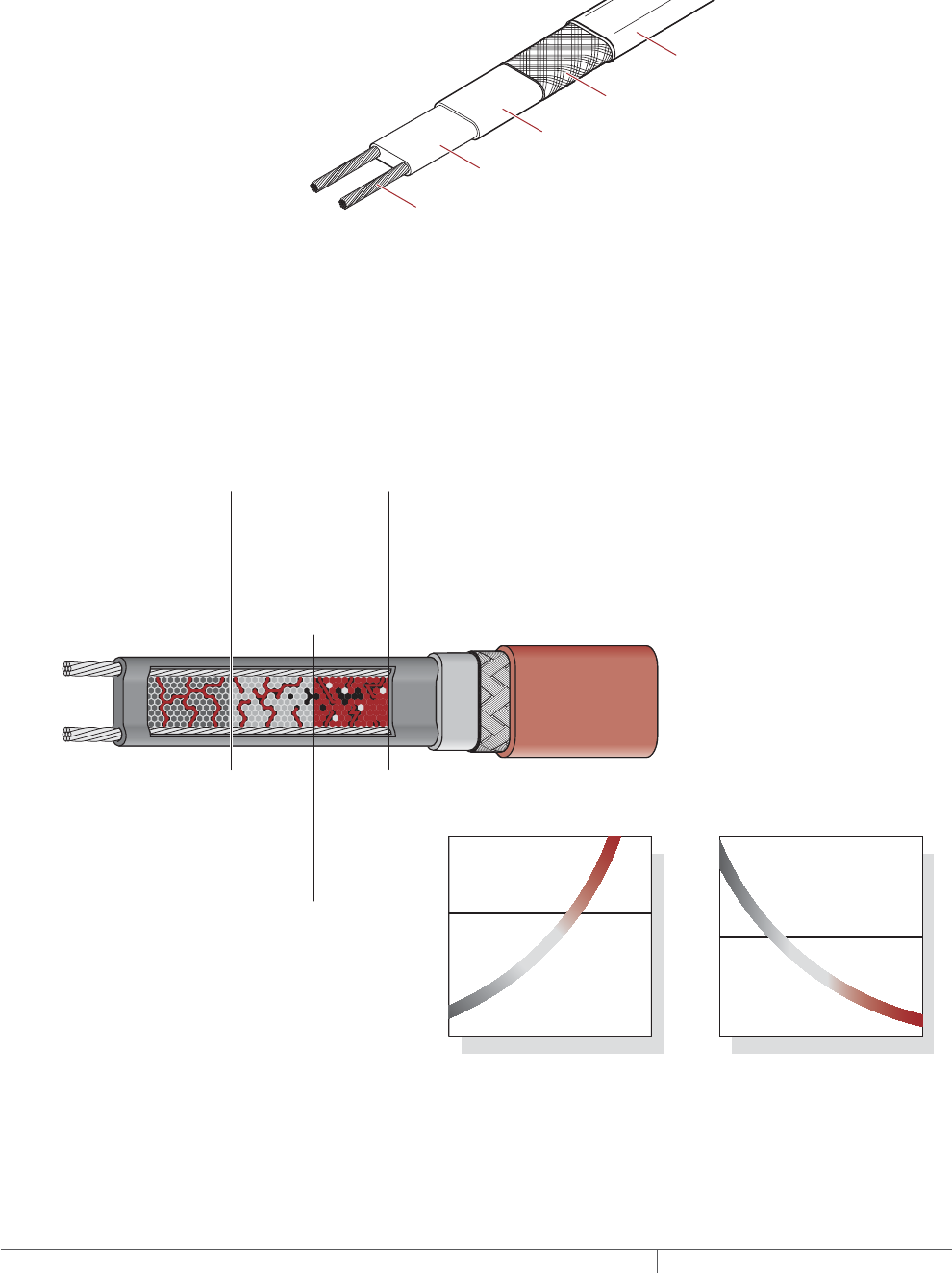
Self-Regulating Heating Cable Construction
Raychem XL-Trace self-regulating heating cables are comprised of two parallel
nickel-plated bus wires in a cross-linked polymer core, a tinned copper braid, and a
fluoropolymer or polyolefin outer jacket. These cables are cut to length, simplifying
the application design and installation.
Nickel-plated copper bus wire
Self-regulating conductive core
Modified polyolefin inner jacket
Tinned-copper braid
Polyolefin or
fluoropolymer outer jacket
Fig. 1 XL-Trace heating cable construction
With self-regulating technology, the number of electrical paths between bus wires
changes in response to temperature fluctuations. As the temperature surrounding
the heater decreases, the conductive core contracts microscopically. This contraction
decreases electrical resistance and creates numerous electrical paths between the
bus wires. Current flows across these paths to warm the core.
As the temperature rises, the core expands microscopically. This expansion
increases electrical resistance and the number of electrical paths decreases. The
heating cable automatically reduces its output.
At low temperature,
there are many
conducting paths,
resulting in high output
and rapid heat-up. Heat
is generated only when it
is needed and precisely
where it is needed.
At high temperature,
there are few
conducting paths
and output is
correspondingly
lower, conserving
energy during
operation.
At moderate temperature,
there are fewer conducting
paths because the heating
cable efficiently adjusts by
decreasing output, eliminating
any possibility of overheating.
The following graphs illustrate the response of self-regulating heating
cables to changes in temperature. As the temperature rises, electrical
resistance increases, and our heaters reduce their power output.
Temperature
Resistance
Power
Temperature
Constant wattage
Constant wattage
Self-regulating
Self-regulating
Fig. 2 Self-regulating heating cable technology
FIRE SPRINKLER SYSTEM FREEZE PROTECTION XLTRACE SYSTEM
THERMAL MANAGEMENT SOLUTIONS
EN-RaychemXLTraceFireSprinkler-DG-H58489 11/13
50
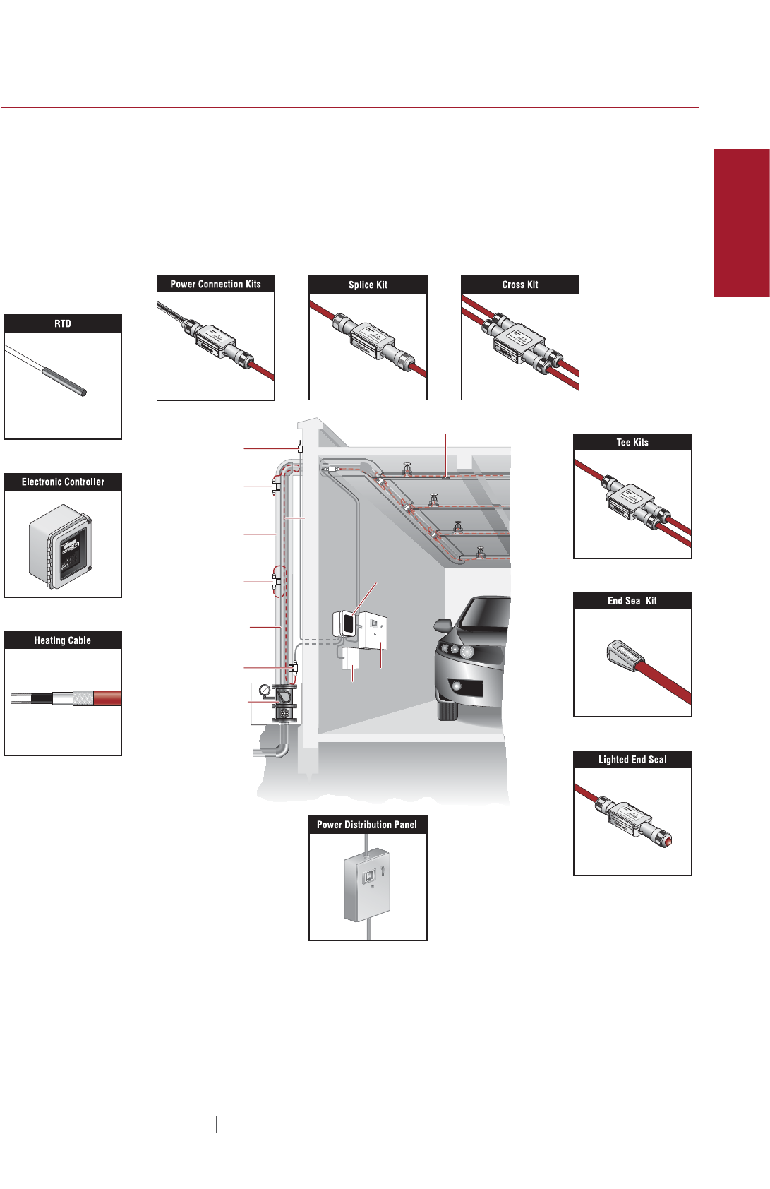
Pipe Freeze Protection
and Flow Maintenance
Fire Sprinkler System
Freeze Protection
Roof and Gutter
De-Icing
Surface Snow
Melting – MI
Surface Snow
Melting – ElectroMelt
Freezer Frost
Heave Prevention
Floor Heating Technical Data
Sheets
FIRE SUPPRESSION SYSTEM FREEZE PROTECTION APPLICATIONS
A freeze protection system is designed to maintain water temperature at a minimum
of 40°F (4°C) to prevent fire suppression piping from freezing.
Typical Pipe Freeze Protection System
A typical freeze protection system includes the XL-Trace self-regulating heating
cables, connection kits, temperature control, and power distribution.
Standpipe
Thermal insulation
Control valves
in heated enclosure
RayClic-PC
power connection
RayClic-S splice
RayClic-LE
lighted end seal
Ambient sensing RTD
Ground
XL-Trace
Power
distribution
panel
Fire
alarm
panel
DigiTrace C910-485
electronic
controller
Line sensing RTD
Fig. 3 Typical XL-Trace pipe freeze protection system
Fire Suppression System Freeze Protection Applications
51THERMAL MANAGEMENT SOLUTIONS EN-RaychemXLTraceFireSprinkler-DG-H58489 11/13
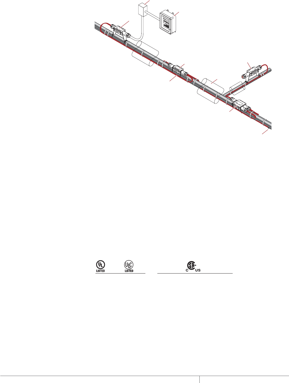
Fire Supply Lines
XL-Trace is designed to maintain fire supply lines at 40°F (4°C) in areas subject to
freezing.
ABOVEGROUND SUPPLY PIPING
RayClic-PC
power connection
Junction
box
XL-Trace
heating cable
RayClic-S
splice
RayClic-T
tee
Insulation
RayClic-LE
lighted end seal
(optional)
RayClic-E
end seal
DigiTrace C910-485
Electronic controller
Fig. 4 Typical aboveground supply piping system
Application Requirements
The system complies with Pentair Thermal Management requirements for
aboveground general water piping when:
• The heating cable is permanently secured to insulated metal pipes with GT-66
glass tape or to plastic pipes using AT-180 aluminum tape.
• DigiTrace C910-485 or ACS-30 controllers with integrated ground-fault protection
and alarm contacts are used and are connected to a fire control panel.
• The heating cable is installed per manufacturer’s instructions with approved
Raychem connection kits. See Table 11 on page 71 and the XL-Trace System
Installation and Operation Manual (H58033).
Approvals
UL Listed and c-CSA-us Certified for nonhazardous locations.
5XL1-CR, -CT
5XL2-CR, -CT 8XL1-CR, -CT
8XL2-CR, -CT 5XL1-CR, -CT
5XL2-CR, -CT 8XL1-CR, -CT
8XL2-CR, -CT 12XL2-CR, -CT
-w
FIRE SPRINKLER SYSTEM FREEZE PROTECTION XLTRACE SYSTEM
THERMAL MANAGEMENT SOLUTIONS
EN-RaychemXLTraceFireSprinkler-DG-H58489 11/13
52
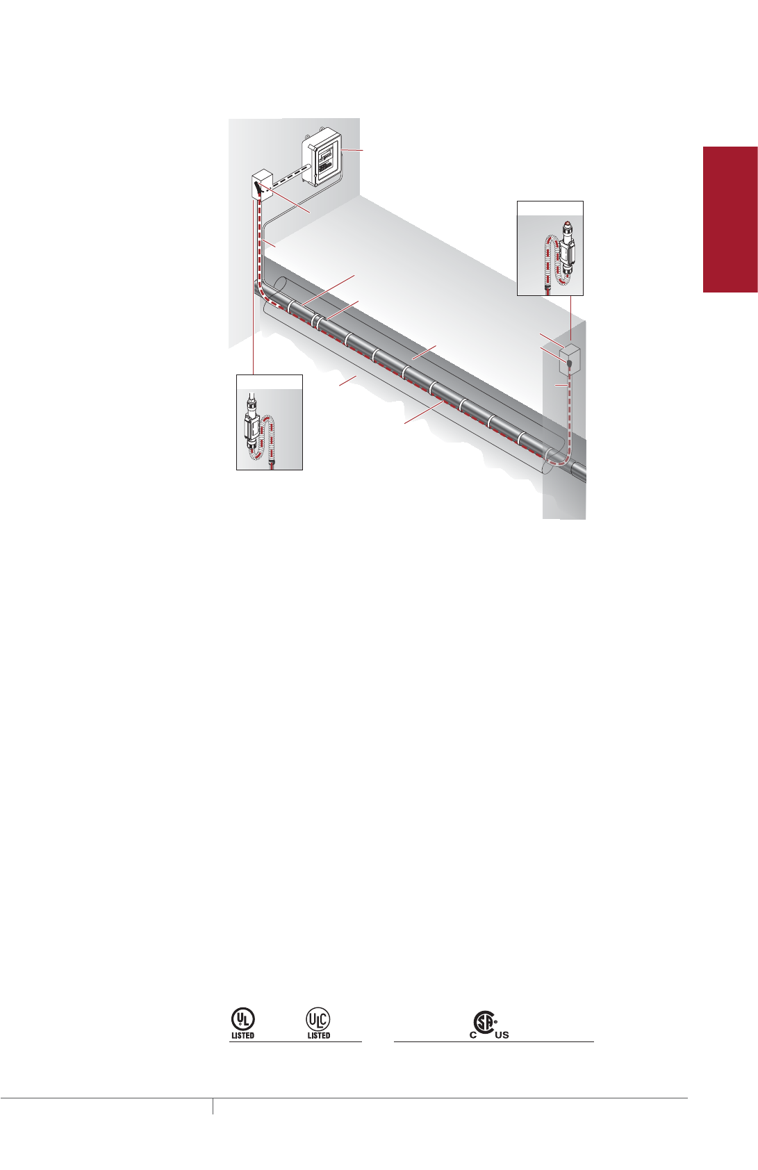
Pipe Freeze Protection
and Flow Maintenance
Fire Sprinkler System
Freeze Protection
Roof and Gutter
De-Icing
Surface Snow
Melting – MI
Surface Snow
Melting – ElectroMelt
Freezer Frost
Heave Prevention
Floor Heating Technical Data
Sheets
BURIED PIPING
Temperature sensor
Insulation
Conduit
XL-Trace
heating cable
with -CT jacket
Ground
Alternate
power connection
Alternate
end seal
Ground
Wall
RayClic-LE*
RayClic-PC*
Junction box
RayClic-E
end seal
Conduit
Wall
with wall
mounting
bracket
with wall
mounting
bracket
FTC-XC
power
connection
*To protect the heating cable, run cable
inside Convolex tubing between the
conduit and the RayClic connection kits.
DigiTrace C910-485
Electronic controller
Conduit for
temperature
sensor
Fig. 5 Typical buried piping system
Application Requirements
The system complies with Pentair Thermal Management requirements for use on
buried insulated metal or plastic pipe when:
• The heating cable is permanently secured to insulated metal pipes with GT-66
glass tape or to plastic pipes using AT-180 aluminum tape.
• The pipeline is buried at least 2-feet deep.
• The heating cable has a fluorpolymer outer jacket (-CT).
• All heating cable connections (power, splice, tee, and end termination) are made
aboveground. No buried or in-conduit splices or tees are allowed.
• The power connection and end seal are made in UL Listed and CSA Certified
junction boxes, or RayClic connection kits, above grade.
• The heating cable is protected from the pipe to the power connection box in UL
Listed and CSA Certified water-sealed conduit (minimum 3/4-inch diameter) suit-
able for the location.
• DigiTrace C910-485 or ACS-30 controllers with integrated ground-fault protection
and alarm contacts are used and are connected to a fire control panel.
• Closed-cell, waterproof thermal insulation with fire-retardant, waterproof cover-
ing approved for direct burial is used.
• The heating cable is installed per manufacturer’s instructions with approved
Pentair Thermal Management connection kits. See Table 13 on page 73 and the
XL-Trace System Installation and Operation Manual (H58033).
Approvals
UL Listed and c-CSA-us Certified for nonhazardous locations.
5XL1-CT
5XL2-CT 8XL1-CT
8XL2-CT 5XL1-CT
5XL2-CT 8XL1-CT
8XL2-CT 12XL2-CT
-w
Fire Suppression System Freeze Protection Applications
53THERMAL MANAGEMENT SOLUTIONS EN-RaychemXLTraceFireSprinkler-DG-H58489 11/13
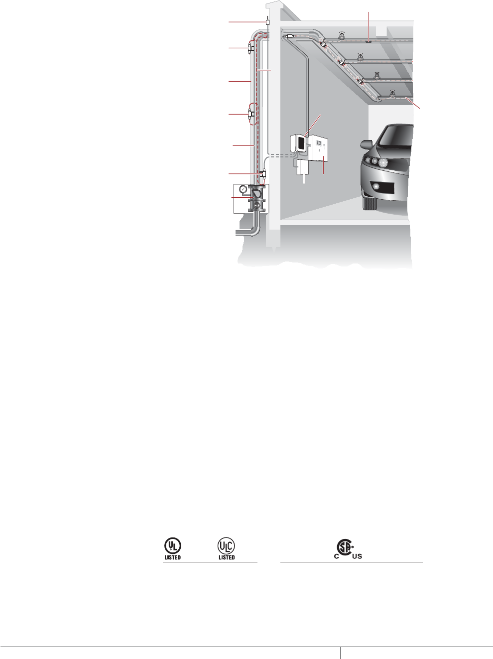
Sprinkler Standpipes
XL-Trace is designed to maintain fire suppression system standpipes at 40°F (4°C) in
areas subject to freezing.
FOR ABOVEGROUND STANDPIPES
Standpipe
Thermal insulation
Control valves
in heated enclosure
RayClic-PC
power connection
RayClic-S splice
RayClic-LE
lighted end seal
Ambient sensing RTD
Ground
XL-Trace
Power
distribution
panel
Fire
alarm
panel
DigiTrace C910-485
electronic
controller
Refer to Branch
Lines with
Sprinkler section
for information on
heat tracing
sprinkler heads.
Line sensing RTD
Fig. 6 Standard sprinkler standpipe heating system layout
Application Requirements
The system complies with Pentair Thermal Management requirements for freeze
protection of sprinkler system piping when:
• The heating cable is permanently secured to insulated metal pipes with GT-66
glass tape or to plastic pipes using AT-180 aluminum tape.
• Schedule 5, 10, 20, or 40 steel sprinkler standpipe up to and including 20 inches
in diameter is used.
• UL Listed fiberglass or closed cell flame-retardant insulation with weatherproof
cladding is used.
• DigiTrace C910-485 or ACS-30 controllers with integrated ground-fault protection
and alarm contacts are used and are connected to a fire control panel.
• The heating cable is installed per manufacturer’s instructions with approved
Pentair Thermal Management connection kits. See Table 11 on page 71 and the
XL-Trace System Installation and Operation Manual (H58033).
Approvals
UL Listed and c-CSA-us Certified for nonhazardous locations.
5XL1-CR, -CT
5XL2-CR, -CT 8XL1-CR, -CT
8XL2-CR, -CT 5XL1-CR, -CT
5XL2-CR, -CT 8XL1-CR, -CT
8XL2-CR, -CT 12XL2-CR, -CT
-w
FIRE SPRINKLER SYSTEM FREEZE PROTECTION XLTRACE SYSTEM
THERMAL MANAGEMENT SOLUTIONS
EN-RaychemXLTraceFireSprinkler-DG-H58489 11/13
54
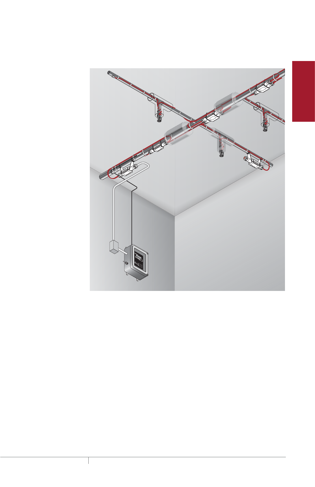
Pipe Freeze Protection
and Flow Maintenance
Fire Sprinkler System
Freeze Protection
Roof and Gutter
De-Icing
Surface Snow
Melting – MI
Surface Snow
Melting – ElectroMelt
Freezer Frost
Heave Prevention
Floor Heating Technical Data
Sheets
Branch Lines with Sprinklers
XL-Trace is designed to maintain branch lines containing sprinklers at 40°F (4°C) in
areas subject to freezing.
Power
connection
Splice
Line sensing
RTD
Cross
End seal
Tee
Insulation
Sprinkler
DigiTrace
C910-485
RayClic-LE
lighted end seal
(optional)
Junction
box
Ambient
sensing
RTD
Fig. 7 Typical fire suppression system for branch lines with sprinklers
Application Requirements
The system complies with Pentair Thermal Management requirements for fire
suppression branch lines with sprinklers when:
• The heating cable is permanently secured to metal pipes with GT-66 glass tape,
or to plastic pipes using AT-180 aluminum tape.
• DigiTrace C910-485 or ACS-30 controllers with integrated ground-fault protection
with alarm contacts are used and are connected to a fire control panel.
• The sprinkler design accounts for the sprinkler shadow created by the outer di-
ameter of the thermal pipe insulation.
• Closed-cell, waterproof thermal insulation with fire-retardant, waterproof cover-
ing is used.
• The heating cable is installed per manufacturer’s instructions with approved
Pentair Thermal Management connection kits. See Table 13 on page 73 and the
XL-Trace System Installation and Operation Manual (H58033).
• Additional heating cable is installed to compensate for sprinkler heads, sprigs,
valves and pipe supports as detailed in the Table 6 on page 66 of this document
and the XL-Trace System Installation and Operation Manual (H58033).
Fire Suppression System Freeze Protection Applications
55THERMAL MANAGEMENT SOLUTIONS EN-RaychemXLTraceFireSprinkler-DG-H58489 11/13
Approvals
c-CSA-us Certified for use in U.S. and Canada in nonhazardous locations.
5XL1-CR, -CT
5XL2-CR, -CT 8XL1-CR, -CT
8XL2-CR, -CT
-w
Freezer Application
XL-Trace is designed to keep condensate in dry sprinklers from freezing and may be
installed in freezers located in areas subject to freezing.
Power
distribution
panel
Fire
alarm
panel
DigiTrace
C910-485
electronic
controller
RTDThermal insulation
Freezer
Building
XL-Trace
Fig. 8 Typical fire suppression system for freezer applications
Application Requirements
The system complies with Pentair Thermal Management requirements for fire
suppression systems for freezer applications when:
• The system is for freezer and freezer within a freezer applications.
• The heating cable is permanently secured to metal pipes with GT-66 glass tape,
or to plastic pipes using AT-180 aluminum tape.
• DigiTrace C910-485 or ACS-30 controllers with integrated ground-fault protection
and alarm contacts are used and are connected to a fire control panel.
• Closed-cell, waterproof thermal insulation with fire-retardant, waterproof cover-
ing is used for pipes and sprigs in areas subject to freezing.
• The sprinkler design accounts for sprinkler shadow created by the outer diameter
of the thermal pipe insulation.
• The heating cable is installed per manufacturer’s instructions with approved
Pentair Thermal Management connection kits. See Table 13 on page 73 and the
XL-Trace System Installation and Operation Manual (H58033).
• Additional heating cable is installed to compensate for sprinkler heads, sprigs,
valves and pipe supports as detailed in the Table 6 on page 66 of this document
and the XL-Trace System Installation and Operation Manual (H58033).
Approvals
c-CSA-us Certified for use in U.S. and Canada in nonhazardous locations.
5XL1-CR, -CT
5XL2-CR, -CT 8XL1-CR, -CT
8XL2-CR, -CT
-w
FIRE SPRINKLER SYSTEM FREEZE PROTECTION XLTRACE SYSTEM
THERMAL MANAGEMENT SOLUTIONS
EN-RaychemXLTraceFireSprinkler-DG-H58489 11/13
56

Pipe Freeze Protection
and Flow Maintenance
Fire Sprinkler System
Freeze Protection
Roof and Gutter
De-Icing
Surface Snow
Melting – MI
Surface Snow
Melting – ElectroMelt
Freezer Frost
Heave Prevention
Floor Heating Technical Data
Sheets
FIRE SUPPRESSION SYSTEM FREEZE PROTECTION DESIGN
This section details the design steps necessary to design your application. The
examples provided in each step are intended to incrementally illustrate the project
parameter output for two sample designs from start to finish. As you go through
each step, use the “XL-Trace System Fire Sprinkler System Freeze Protection Design
Worksheet,” page 78, to document your project parameters, so that by the end of
this section you will have the information you need for your Bill of Materials.
XL-Erate, the commercial pipe freeze protection and flow maintenance design
software, is available at http://www.pentairthermal.com to assist with your design.
Design Step by Step
Your system design requires the following essential steps.
Determine design conditions and pipe heat loss
Select the heating cable
Determine the heating cable length
Determine the electrical parameters
Select the connection kits and accessories
Select the control system
Complete the Bill of Materials
Fire Suppression System Freeze Protection Design
57THERMAL MANAGEMENT SOLUTIONS EN-RaychemXLTraceFireSprinkler-DG-H58489 11/13

Pipe Freeze Protection
and Flow Maintenance
1. Determine design
conditions and
pipe heat loss
2. Select the heating
cable
3. Determine the
heating cable length
4. Determine the
electrical parameters
5. Select the
connection kits
and accessories
6. Select the control
system
7. Complete the Bill
of Materials
Step Determine design conditions and pipe heat loss
Collect the following information to determine your design conditions:
• Location
– Indoors
– Outdoors
– Aboveground
– Buried
• Maintain temperature (TM)
• Minimum ambient temperature (TA)
• Pipe diameter and material
• Pipe length
• Thermal insulation type and thickness
• Supply voltage
Example: Fire Standpipe
Location Aboveground, outdoors
Maintain temperature (TM) 40°F (4°C)
Minimum ambient temperature (TA) –20°F (–29°C)
Pipe diameter and material 10-inch metal
Pipe length 50 ft (16.4 m)
Thermal insulation type and thickness 1 1/2-inch fiberglass
Supply voltage 208 V
Branch Line with Sprinkler
Location Indoors
Maintain temperature (TM) 40°F (4°C)
Minimum ambient temperature (TA) 0°F (–18°C)
Pipe diameter and material 1-inch metal
Pipe length 200 ft (61 m)
Thermal insulation type and thickness 1/2-inch closed-cell foamed elastomer
Supply voltage 208 V
FIRE SPRINKLER SYSTEM FREEZE PROTECTION XLTRACE SYSTEM
THERMAL MANAGEMENT SOLUTIONS
EN-RaychemXLTraceFireSprinkler-DG-H58489 11/13
58
Pipe Freeze Protection
and Flow Maintenance
Fire Sprinkler System
Freeze Protection
Roof and Gutter
De-Icing
Surface Snow
Melting – MI
Surface Snow
Melting – ElectroMelt
Freezer Frost
Heave Prevention
Floor Heating Technical Data
Sheets
PIPE HEAT LOSS CALCULATIONS
To select the proper heating cable you must first determine the pipe heat loss. To
do this you must first calculate the temperature differential (∆T) between the pipe
maintain temperature and the minimum ambient temperature.
20
40
60
80
−40
−20
0
+20
+40
Maintain
temperature
°F
°F
Minimum
ambient
temperature
Thermal insulation thickness
Pipe or
tubing
diameter
Fig. 9 Pipe heat loss
Calculate temperature differential ∆T
To calculate the temperature differential ∆T), use the formula below:
∆T = TM – TA
Example: Fire Standpipe
TM 40°F (4°C)
TA –20°F (–29°C)
∆T = 40°F – (–20°F) = 60°F
∆T = 4°C – (–29°C) = 33°C
Example: Branch Line with Sprinkler
TM 40°F (4°C)
TA 0°F (-18°C)
∆T = 40°F – (0°F) = 40°F
∆T = 4°C – (–18°C) = 22°C
Determine the pipe heat loss
Match the pipe size, insulation thickness, and temperature differential (∆T) from
Table 1 on page 61 to determine the base heat loss of the pipe (QB).
Example: Fire Standpipe
Pipe diameter 10 inch
Insulation thickness 1 1/2 inch
∆T 60°F (33°C)
Heat loss (QB) for 60°F must be calculated through interpolation between ∆T at 50°F
and ∆T at 100°F from Table 1. For difference between the ∆T of 50°F and the∆T of
100°F:
QB-50 8.1 W/ft (from Table 1)
QB-100 16.8 W/ft (from Table 1)
∆T interpolation ∆T 60°F is 20% of the distance between ∆T 50°F and ∆T 100°F
QB-60
Q
B
-50 + [0.20 x (Q
B
-100 – Q
B
-50)] = 8.1 + [0.20 x (16.8 – 8.1)] = 9.8 W/ft
Pipe heat loss (QB) 9.8 W/ft Tm 40°F (32.1 W/m TM 4°C)
Fire Suppression System Freeze Protection Design
59THERMAL MANAGEMENT SOLUTIONS EN-RaychemXLTraceFireSprinkler-DG-H58489 11/13

Example: Branch Line with Sprinkler
Pipe diameter 1 inch
Insulation thickness 1/2 inch
∆T 40°F (22°C)
QB for 40°F must be calculated through interpolation between ∆T at 20°F and ∆T at
50°F from Table 1. For difference between the ∆T of 20°F and the ∆T of 50°F:
QB-20 1.4 W/ft (from Table 1)
QB-50 3.5 W/ft (from Table 1)
∆T interpolation ∆T 40°F is 67% of the distance between ∆T 20°F and ∆T 50°F
QB-40 QB-50 + [0.67 x (QB-50 – QB-20)] = 1.4 + [0.67 x (3.5 – 1.4)] = 2.8 W/ft
Pipe heat loss QB 2.8 W/ft Tm 40°F (9.2 W/m Tm 4°C)
Compensate for insulation type and pipe location
The base heat loss is calculated for a pipe insulated with thermal insulation with a
k-factor ranging from 0.2 to 0.3 BTU/hr–°F–ft²/in (fiberglass or foamed elastomer)
in an outdoor, or buried application. To get the heat loss for pipes insulated with
alternate types of thermal insulation and for pipes installed indoors, multiply the
base heat loss of the pipe (QB) from Step 3 by the insulation multiple from Table 3 on
page 62 and the indoor multiple from Table 2 on page 62 to get the corrected
heat loss:
QCORRECTED = QB x Insulation multiple x Indoor multiple
Example: Fire Standpipe
Location Aboveground, outdoors
Thermal insulation thickness and type 1 1/2-inch fiberglass
Pipe heat loss QB 9.8 W/ft TM 40°F (32.1 W/m TM 4°C)
QCORRECTED 9.8 W/ft x 1.00 x 1.00 = 9.8 W/ft Tm 40°F
(32.1 W/m Tm 4°C)
Example: Branch Line with Sprinkler
Location Aboveground, indoors
Thermal insulation type and thickness 1/2-inch closed cell foamed elastomer
Pipe heat loss QB = 2.8 W/ft TM 40°F (9.2 W/m TM 4°C)
QCORRECTED = 2.8 W/ft x 1.0 x 0.79 = 2.20 W/ft Tm 410°F
(7.3W/m TM 4°C)
FIRE SPRINKLER SYSTEM FREEZE PROTECTION XLTRACE SYSTEM
THERMAL MANAGEMENT SOLUTIONS
EN-RaychemXLTraceFireSprinkler-DG-H58489 11/13
60
Pipe Freeze Protection
and Flow Maintenance
Fire Sprinkler System
Freeze Protection
Roof and Gutter
De-Icing
Surface Snow
Melting – MI
Surface Snow
Melting – ElectroMelt
Freezer Frost
Heave Prevention
Floor Heating Technical Data
Sheets
TABLE 1 PIPE HEAT LOSS Qb FOR OUTDOOR OR BURIED PIPE W/FT FOR 1/2 TO 31/2 INCHES
Insulation
thickness
(in)
(∆T) Pipe diameter (IPS) in inches
°F °C 1/2 3/4 1 1-1/4 1-1/2 2 2-1/2 3 3-1/2
0.5 20 11 1.0 1.2 1.4 1.6 1.8 2.2 2.5 3.0 3.4
50 28 2.5 2.9 3.5 4.1 4.6 5.5 6.5 7.7 8.6
100 56 5.2 6.1 7.2 8.6 9.6 11.5 13.5 16.0 18.0
150 83 8.1 9.5 11.2 13.4 14.9 17.9 21.1 25.0 28.1
1.0 20 11 0.6 0.7 0.8 1.0 1.1 1.3 1.5 1.7 1.9
50 28 1.6 1.9 2.2 2.5 2.8 3.2 3.8 4.4 4.9
100 56 3.4 3.9 4.5 5.2 5.8 6.8 7.8 9.1 10.2
150 83 5.3 6.1 7.0 8.2 9.0 10.6 12.2 14.2 15.9
1.5 20 11 0.5 0.6 0.7 0.8 0.8 1.0 1.1 1.3 1.4
50 28 1.3 1.5 1.7 1.9 2.1 2.4 2.8 3.2 3.6
100 56 2.8 3.1 3.5 4.0 4.4 5.1 5.8 6.7 7.4
150 83 4.3 4.8 5.5 6.3 6.9 8.0 9.1 10.5 11.6
2.0 20 11 0.5 0.5 0.6 0.6 0.7 0.8 0.9 1.0 1.1
50 28 1.1 1.3 1.4 1.6 1.8 2.0 2.3 2.6 2.9
100 56 2.4 2.7 3.0 3.4 3.7 4.2 4.8 5.5 6.0
150 83 3.7 4.2 4.7 5.3 5.8 6.6 7.5 8.5 9.4
2.5 20 11 0.4 0.5 0.5 0.6 0.6 0.7 0.8 0.9 1.0
50 28 1.0 1.2 1.3 1.4 1.6 1.8 2.0 2.3 2.5
100 56 2.2 2.4 2.7 3.0 3.3 3.7 4.2 4.7 5.2
150 83 3.4 3.7 4.2 4.7 5.1 5.8 6.5 7.4 8.1
3.0 20 11 0.4 0.4 0.5 0.5 0.6 0.6 0.7 0.8 0.9
50 28 1.0 1.1 1.2 1.3 1.4 1.6 1.8 2.0 2.2
100 56 2.0 2.2 2.4 2.7 2.9 3.3 3.7 4.2 4.6
150 83 3.1 3.4 3.8 4.3 4.6 5.2 5.8 6.6 7.1
4.0 20 11 0.3 0.4 0.4 0.5 0.5 0.5 0.6 0.7 0.7
50 28 0.9 0.9 1.0 1.1 1.2 1.4 1.5 1.7 1.8
100 56 1.8 2.0 2.1 2.4 2.5 2.9 3.2 3.5 3.8
150 83 2.8 3.0 3.4 3.7 4.0 4.4 4.9 5.5 6.0
Note: Multiply the W/ft heat loss values by 3.28 for W/m.
Fire Suppression System Freeze Protection Design
61THERMAL MANAGEMENT SOLUTIONS EN-RaychemXLTraceFireSprinkler-DG-H58489 11/13

TABLE 1 CONTINUED PIPE HEAT LOSS Qb
FOR OUTDOOR OR BURIED PIPE W/FT FOR 4 TO 20 INCHES
Insulation
thickness
(in)
(∆T) Pipe diameter (IPS) in inches
°F °C 4 6 8 10 12 14 16 18 20
0.5 20 11 3.8 5.3 6.8 8.4 9.9 10.8 12.2 13.7 15.2
50 28 9.6 13.6 17.4 21.4 25.2 27.5 31.3 35.0 38.8
100 56 20.0 28.4 36.3 44.6 52.5 57.4 65.2 73.0 80.8
150 83 31.2 44.3 56.6 69.6 81.9 89.5 101.7 113.8 126.0
1.0 20 11 2.1 2.9 3.7 4.5 5.3 5.8 6.5 7.3 8.0
50 28 5.4 7.5 9.4 11.5 13.5 14.7 16.6 18.6 20.5
100 56 11.2 15.6 19.7 24.0 28.1 30.6 34.7 38.7 42.8
150 83 17.5 24.3 30.7 37.4 43.8 47.8 54.1 60.4 66.7
1.5 20 11 1.5 2.1 2.6 3.2 3.7 4.0 4.5 5.0 5.5
50 28 3.9 5.3 6.7 8.1 9.4 10.2 11.5 12.9 14.2
100 56 8.1 11.1 13.9 16.8 19.6 21.3 24.0 26.8 29.5
150 83 12.7 17.3 21.6 26.2 30.5 33.2 37.5 41.8 46.1
2.0 20 11 1.2 1.7 2.1 2.5 2.9 3.1 3.5 3.9 4.3
50 28 3.1 4.2 5.2 6.3 7.3 7.9 8.9 9.9 10.9
100 56 6.6 8.8 10.9 13.1 15.2 16.5 18.6 20.7 22.8
150 83 10.2 13.8 17.0 20.5 23.8 25.8 29.0 32.3 35.5
2.5 20 11 1.1 1.4 1.7 2.1 2.4 2.6 2.9 3.2 3.5
50 28 2.7 3.6 4.4 5.2 6.1 6.6 7.4 8.2 9.0
100 56 5.6 7.4 9.1 10.9 12.6 13.7 15.3 17.0 18.7
150 83 8.7 11.6 14.2 17.0 19.7 21.3 23.9 26.5 29.1
3.0 20 11 0.9 1.2 1.5 1.8 2.0 2.2 2.5 2.7 3.0
50 28 2.4 3.1 3.8 4.5 5.2 5.6 6.3 7.0 7.6
100 56 4.9 6.5 7.9 9.4 10.8 11.7 13.1 14.5 15.9
150 83 7.7 10.1 12.4 14.7 16.9 18.3 20.5 22.6 24.8
4.0 20 11 0.8 1.0 1.2 1.4 1.6 1.7 1.9 2.1 2.3
50 28 2.0 2.5 3.1 3.6 4.1 4.4 5.0 5.5 6.0
100 56 4.1 5.3 6.4 7.5 8.6 9.3 10.3 11.4 12.4
150 83 6.4 8.3 10.0 11.8 13.4 14.5 16.1 17.8 19.4
Note: Multiply the W/ft heat loss values by 3.28 for W/m.
TABLE 2 INDOOR PIPE HEAT LOSS MULTIPLES
Fiberglass thickness (in) Indoor multiple
0.5 0.79
1 0.88
1.5 0.91
2 0.93
2.5 0.94
3 0.95
4 0.97
TABLE 3 INSULATION HEAT LOSS MULTIPLES
k factor at 50°F (10°C) (BTU/hr–°F–ft²/in) Insulation multiple Examples of preformed pipe insulation
0.1–0.2 0.6 Rigid cellular urethane (ASTM C591)
0.2–0.3 1 Glass fiber (ASTM C547)
Foamed elastomer (ASTM C534)
0.3–0.4 1.4 Cellular glass (ASTM C552)
Mineral fiber blanket (ASTM C553)
FIRE SPRINKLER SYSTEM FREEZE PROTECTION XLTRACE SYSTEM
THERMAL MANAGEMENT SOLUTIONS
EN-RaychemXLTraceFireSprinkler-DG-H58489 11/13
62
Pipe Freeze Protection
and Flow Maintenance
Fire Sprinkler System
Freeze Protection
Roof and Gutter
De-Icing
Surface Snow
Melting – MI
Surface Snow
Melting – ElectroMelt
Freezer Frost
Heave Prevention
Floor Heating Technical Data
Sheets
Pipe Freeze Protection
and Flow Maintenance
2. Select the heating
cable
3. Determine the
heating cable length
4. Determine the
electrical parameters
5. Select the
connection kits
and accessories
6. Select the control
system
7. Complete the Bill
of Materials
1. Determine design
conditions and
pipe heat loss
Step Select the heating cable
To select the appropriate XL-Trace heating cable for your application, you must
determine your cable supply voltage, power output, and outer jacket. Once you have
selected these, you will be able to determine the catalog number for your cable.
HEATING CABLE CATALOG NUMBER
Before beginning, take a moment to understand the structure of the heating cable
catalog numbers. You will refer to this numbering convention throughout the product
selection process. Your goal is to determine the catalog number for the product that
best suits your needs.
Fig. 10 Heating cable catalog number
Select the heating cable from Fig. 11 that provides the required power output to
match the corrected heat loss for your application. Fig. 11 shows the power output
for the heating cables on metal pipe at 120/208 volts. To correct the power output
for other applied voltage or plastic pipes multiply the power output at the desired
maintain temperature by the factors listed in Table 4 on page 64. If the pipe heat
loss, QCORRECTED, is between the two heating cable power output curves, select the
higher-rated heating cable.
5XL1-CR and 5XL1-CT (120 V)
5XL2-CR and 5XL2-CT (208 V)
8XL1-CR and 8XL1-CT (120 V)
8XL2-CR and 8XL2-CT (208 V)
12XL2-CR and 12XL2-CT (208 V)
Pipe temperature
Power W/ft
50
(10)
30
(–1)
40
(5)
60
(15)
70
(21)
80
(27)
90
(32)
100
(38)
110
(43)
120
(49)
130
(54)
°F
(°C)
10
8
14
12
6
4
2
0
Fig. 11 Heating cable power output on metal pipe
Catalog number: 5, 8 or 12 XL 1 or 2 -CR -CT
Power output (W/ft)
Product family
Voltage 1 = 120 V (only available for 5 or 8)
2 = 208, 240, 277 V (available for 5, 8, or 12)
Jacket type: Polyolefin
Fluoropolymer (required for buried pipes)
or
Fire Suppression System Freeze Protection Design
63THERMAL MANAGEMENT SOLUTIONS EN-RaychemXLTraceFireSprinkler-DG-H58489 11/13

TABLE 4 POWER OUTPUT CORRECTION FACTORS
Voltage correction factors 5XL1 8XL1 5XL2 8XL2 12XL2
120 V 1.00 1.00 – – –
208 V – – 1.00 1.00 1.00
240 V – – 1.12 1.12 1.14
277 V – – 1.29 1.27 1.30
Plastic pipe correction factor
(With AT-180 Aluminum tape)
0.75 0.75 0.75 0.75 0.75
Confirm that the corrected power output of the heating cable selected is greater
than the corrected pipe heat loss (QCORRECTED). If QCORRECTED is greater than the power
output of the highest-rated heating cable, you can:
• Use two or more heating cables run in parallel
• Use thicker insulation to reduce heat loss
• Use insulation material with a lower k factor to reduce heat loss
Example: Fire Standpipe
Pipe maintain temperature (TM) 40°F (4°C) (from Step 1)
QCORRECTED QCORRECTED = 9.8 W/ft TM 40°F (32.1 W/m TM 4°C)
Supply voltage 208 V (from Step 1)
Pipe material Metal (from Step 1)
Select heating cable QCORRECTED = 9.8 W/ft TM 40°F (from Step 1)
12XL2 = 12.4 W/ft 40°F (from Fig. 11)
Supply voltage correction factor 1.00 (from Table 4)
Pipe material correction factor Metal = 1.00 (from Table 4)
Corrected heating cable power 9.8 W/ft x 1.00 x 1.00 = 9.8 W/ft
Selected heating cable 12XL2
Example: Branch Line with Sprinkler
Pipe maintain temperature (TM) 40°F (4°C) (from Step 1)
QCORRECTED
2.8 W/ft x 1.0 x 0.97 = 2.2 W/ft
TM 40°F (7.3W/m
TM 4°C)
Supply voltage 208 V (from Step 1)
Pipe material Metal (from Step 1)
Select heating cable QCORRECTED = 2.2 W/ft TM 40°F (from Step 1)
5XL2 = 5.6 W/ft 40°F (from Fig. 11)
Supply voltage correction factor 1.00 (from Table 4)
Pipe material correction factor Metal = 1.00
Corrected heating cable power 5.6 x 1.00 x 1.00 = 5.6 W/ft
Selected heating cable 5XL2
FIRE SPRINKLER SYSTEM FREEZE PROTECTION XLTRACE SYSTEM
THERMAL MANAGEMENT SOLUTIONS
EN-RaychemXLTraceFireSprinkler-DG-H58489 11/13
64
Pipe Freeze Protection
and Flow Maintenance
Fire Sprinkler System
Freeze Protection
Roof and Gutter
De-Icing
Surface Snow
Melting – MI
Surface Snow
Melting – ElectroMelt
Freezer Frost
Heave Prevention
Floor Heating Technical Data
Sheets
SELECT OUTER JACKET
Select the appropriate heating cable outer jacket for the application. Jacket options
are:
-CR Compatible with most XL-Trace applications
-CT Required for buried piping; may be used in other XL-Trace applications for
improved mechanical strength and chemical resistance.
Example: Fire Standpipe
Location: Aboveground, outdoors
Selection: 12XL2-CR
Example: Branch Line with Sprinkler
Location: Aboveground, indoors
Selection: 5XL2-CR
Pipe Freeze Protection
and Flow Maintenance
2. Select the heating
cable
3. Determine the
heating cable length
4. Determine the
electrical parameters
5. Select the
connection kits
and accessories
6. Select the control
system
7. Complete the Bill
of Materials
1. Determine design
conditions and
pipe heat loss
Step Determine the heating cable length
In Step 2 you selected the appropriate heating cable and the number of runs of
heating cable required for the pipe. Multiply the length of the pipe by the number of
heating cable runs for the heating cable length.
Heating cable length = Pipe length x No. heating cable runs
Additional heating cable will be required for heat sinks and connection kits. Use
Table 5 and Table 6 to determine the additional footage required for heat sinks
(valves, flanges, and pipe supports). You will determine the additional heating cable
for connection kits in Step 5. Round up fractional lengths to ensure heating cable
lengths are sufficient.
Total heating cable
length required
(Pipe length x No.
heating cable runs)
Additional heating cable for heat sinks
(valves, pipe supports, and flanges)
= +
TABLE 5 ADDITIONAL HEATING CABLE FOR VALVES
Pipe diameter (IPS) inches Heating cable feet (meters)
1/2 0.8 (0.24)
3/4 1.3 (0.4)
1 2.0 (0.6)
1-1/4 3.3 (1.1)
1-1/2 4.3 (1.3)
2 4.3 (1.3)
3 4.3 (1.3)
4 4.3 (1.3)
6 5.0 (1.5)
8 5.0 (1.5)
10 5.6 (1.7)
12 5.9 (1.9)
14 7.3 (2.2)
18 9.4 (2.9)
20 10.5 (3.2)
Fire Suppression System Freeze Protection Design
65THERMAL MANAGEMENT SOLUTIONS EN-RaychemXLTraceFireSprinkler-DG-H58489 11/13

TABLE 6 ADDITIONAL HEATING CABLE FOR PIPE SUPPORTS, FLANGES AND
SPRINKLERS
Support Additional cable
Pipe hangers (insulated) No additional heating cable
Pipe hangers (noninsulated) and
U-bolt supports
Add 2x pipe diameter
Welded support shoes Add 3x the length of the shoe
Flanges Add 2x pipe diameter
Sprinklers
Sprinkler without sprig Add 4x pipe diameter
Sprinkler with sprig Add 3x sprig length
Dry sprinkler for freezer application Add 2x sprinkler length
Note: For applications where more than one heating cable is required per foot of pipe,
this correction factor applies for each cable run.
Example: Fire Standpipe
Pipe length 50 ft (60 m) (from Step 1)
Pipe diameter 10-inch metal (from Step 1)
Number of heating cable runs 1 (from Step 2)
Valves 1 control valve
5.6 ft x 1 valve = 5.6 ft (1.7 m)
Pipe supports 5 pipe hangers with U-bolts
10-inch pipe diameter = 10/12 = 0.83
[0.83 ft pipe diameter x 2] x 5 pipe supports
= 8.3 ft (2.5 m)
Flanges 3
10-inch pipe diameter – 10/12 = 0.83 ft
[0.83 ft pipe diameter x 2] x 3 pipe supports
= 5.0 ft (1.5 m)
Total heating cable for heat sinks 5.6 ft (1.7 m) + 8.3 ft (2.5 m) + 5.0 ft (1.5 m)
= 18.9 ft (4.2 m) Rounded up to 19 ft (65 m)
Total heating cable length required 50 ft (15 m) x 1 run + 19 ft = 69 ft (21 m) of 12XL2-CR
Example: Branch Line with Sprinkler
Pipe length 200 ft (61 m) (from Step 1)
Pipe diameter 1-inch metal (from Step 1)
Number of heating cable runs 1 (from Step 2)
Valves 2 gate valves
[2.0 ft x 2 gate valves] x 1 run = 4.0 ft (1.2 m)
Pipe supports 10 noninsulated hangers
1-inch pipe diameter = 1 /12 = 0.1 ft
[0.1 ft pipe diameter x 2) x 10 pipe supports] x 1 run
= 2.0 ft (0.6 m)
Sprinklers 20 with 1 foot sprigs
[3 x 1 ft sprig] x 20 = 60 ft (18.3 m)
Total heating cable for heat sinks 4.0 ft (1.2 m) + 2.0 ft (0.6 m) + 60 ft (18.3 m)
= 66 ft (20.1 m)
Total heating cable length required 200 ft x 1 run + 66 ft = 266 ft (81 m) of 5XL2-CR
FIRE SPRINKLER SYSTEM FREEZE PROTECTION XLTRACE SYSTEM
THERMAL MANAGEMENT SOLUTIONS
EN-RaychemXLTraceFireSprinkler-DG-H58489 11/13
66
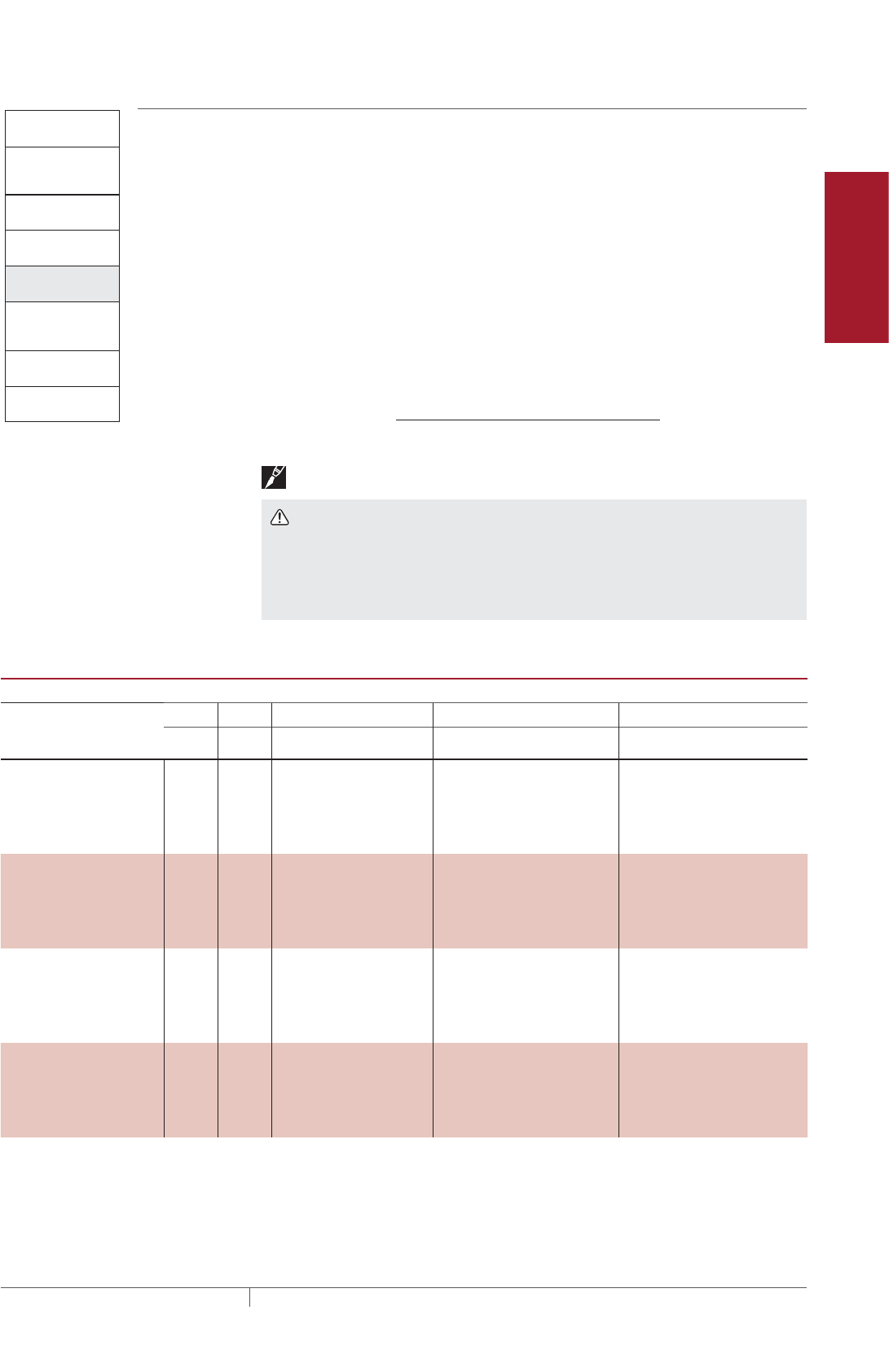
Pipe Freeze Protection
and Flow Maintenance
Fire Sprinkler System
Freeze Protection
Roof and Gutter
De-Icing
Surface Snow
Melting – MI
Surface Snow
Melting – ElectroMelt
Freezer Frost
Heave Prevention
Floor Heating Technical Data
Sheets
Pipe Freeze Protection
and Flow Maintenance
2. Select the heating
cable
3. Determine the
heating cable length
4. Determine the
electrical parameters
5. Select the
connection kits
and accessories
6. Select the control
system
7. Complete the Bill
of Materials
1. Determine design
conditions and
pipe heat loss
Step Determine the electrical parameters
To determine the electrical requirements for your application, you must determine
the number of circuits and calculate the transformer load.
DETERMINE NUMBER OF CIRCUITS
To determine the number of circuits, you need to know:
• Total heating cable length
• Supply voltage
• Minimum start-up temperature
Use Table 7 to determine the maximum circuit length allowed. If the total heating
cable length exceeds the maximum circuit length for the expected start-up
temperature, more than one circuit will be required.
Number of circuits = Heating cable length required
Maximum heating cable circuit length
Important: Select the smallest appropriate ground-fault circuit breaker size.
WARNING: To minimize the danger of fire from sustained electrical arcing if
the heating cable is damaged or improperly installed, and to comply with the
requirements of Pentair Thermal Management, agency certifications, and national
electrical codes, ground-fault equipment protection must be used on each heating
cable branch circuit. Arcing may not be stopped by conventional circuit protection.
TABLE 7 MAXIMUM CIRCUIT LENGTH IN FEET
40°F Maintain
Start-up
temperature
(°F)
CB size
(A)
5XL1 8XL1 5XL2 8XL2 12XL2
120 V 120 V 208 V 240 V 277 V 208 V 240 V 277 V 208 V 240 V 277 V
–20°F 15 101 76 174 178 183 131 138 146 111 114 117
20 134 101 232 237 245 175 184 194 148 151 156
30 201 151 349 356 367 262 276 291 223 227 234
40 270 201 465 474 478 349 368 388 297 303 312
0°F 15 115 86 199 203 209 149 157 166 120 122 126
20 153 115 265 271 279 199 209 221 160 163 168
30 230 172 398 406 419 298 314 331 239 244 252
40 270 210 470 490 530 370 390 420 319 326 336
20°F 15 134 100 232 237 244 173 182 192 126 129 133
20 178 133 309 315 325 231 243 257 169 172 177
30 270 200 464 473 488 346 365 385 253 258 266
40 270 210 470 490 530 370 390 420 340 344 355
40°F 15 160 119 278 283 292 206 217 229 142 145 150
20 214 159 370 378 390 275 290 306 190 194 200
30 270 210 470 490 530 370 390 420 285 291 300
40 270 210 470 490 530 370 390 420 340 360 380
Fire Suppression System Freeze Protection Design
67THERMAL MANAGEMENT SOLUTIONS EN-RaychemXLTraceFireSprinkler-DG-H58489 11/13

TABLE 8 MAXIMUM CIRCUIT LENGTH IN METERS
Start-up
temperature
(°C)
CB size
(A)
4°C Maintain
5XL1 8XL1 5XL2 8XL2 12XL2
120 V 120 V 208 V 240 V 277 V 208 V 240 V 277 V 208 V 240 V 277 V
–29°C 15 31 23 53 54 56 40 42 44 34 35 36
20 41 31 71 72 75 53 56 59 45 46 48
30 61 46 106 108 112 80 84 89 68 69 71
40 82 61 142 145 149 106 112 118 90 92 95
–18°C 15 35 26 61 62 64 45 48 51 36 37 38
20 47 35 81 83 85 61 64 67 49 50 51
30 70 52 121 124 128 91 96 101 73 74 77
40 82 64 143 149 162 113 119 128 97 99 102
–7°C 15 41 31 71 72 74 53 56 59 39 39 41
20 54 41 94 96 99 70 74 78 51 52 54
30 82 61 141 144 149 106 111 117 77 79 81
40 82 64 143 149 162 113 119 128 104 105 108
4°C 15 49 36 85 86 89 63 66 70 43 44 46
20 65 48 113 115 119 84 88 93 58 59 61
30 82 64 143 149 162 113 119 128 87 89 91
40 82 64 143 149 162 113 119 128 104 110 116
Example: Fire Standpipe
Total heating cable length 69 ft (21 m) of 12XL2-CR (from Step 3)
Supply voltage 208 V (from Step 1)
Minimum start-up temperature –20°F (–29°C) (from Step 1)
Number of circuits 69 ft / (111 ft max 15 A CB at –20°F) = 0.6 circuits
Round up to 1 circuit
Example: Branch Line with Sprinkler
Total heating cable length 266 ft (81 m) of 5XL2-CT (from Step 3)
Supply voltage 208 V (from Step 1)
Minimum start-up temperature 0°F (–18°C) (from Step 1)
Number of circuits 266 ft / (398 ft max 30 A CB at 0°F) = 0.67 circuits
Round up to 1 circuit
DETERMINE TRANSFORMER LOAD
Transformers must be sized to handle the load of the heating cable. Use the
following tables to calculate the total transformer load.
FIRE SPRINKLER SYSTEM FREEZE PROTECTION XLTRACE SYSTEM
THERMAL MANAGEMENT SOLUTIONS
EN-RaychemXLTraceFireSprinkler-DG-H58489 11/13
68
Pipe Freeze Protection
and Flow Maintenance
Fire Sprinkler System
Freeze Protection
Roof and Gutter
De-Icing
Surface Snow
Melting – MI
Surface Snow
Melting – ElectroMelt
Freezer Frost
Heave Prevention
Floor Heating Technical Data
Sheets
TABLE 9 TRANSFORMER SIZING AMPERES/FOOT
Minimum start-up
temperature (°F)
5XL1 8XL1 5XL2 8XL2 12XL2
120 120 208 240 277 208 240 277 208 240 277
–20 0.119 0.159 0.069 0.067 0.065 0.092 0.087 0.082 0.108 0.106 0.102
0 0.105 0.139 0.060 0.059 0.057 0.080 0.076 0.072 0.100 0.098 0.095
20 0.090 0.120 0.052 0.051 0.049 0.069 0.066 0.062 0.095 0.093 0.090
40 0.075 0.101 0.043 0.042 0.041 0.058 0.055 0.052 0.084 0.083 0.080
TABLE 10 TRANSFORMER SIZING AMPERES/METER
Minimum start-up
temperature (°C)
5XL1 8XL1 5XL2 8XL2 12XL2
120 120 208 240 277 208 240 277 208 240 277
–20 0.391 0.521 0.226 0.221 0.215 0.301 0.286 0.270 0.354 0.347 0.336
–18 0.343 0.457 0.198 0.194 0.188 0.264 0.251 0.238 0.329 0.322 0.312
–7 0.294 0.394 0.170 0.166 0.161 0.227 0.216 0.205 0.311 0.305 0.296
4 0.246 0.331 0.142 0.139 0.135 0.191 0.181 0.172 0.276 0.271 0.263
Use Table 9 or Table 10 to determine the applied voltage and the maximum A/ft (A/m)
at the minimum start-up temperature to calculate the transformer load as follows:
1000 = Transformer
load (kW)
Max A/ft at minimum start-up temperature x Heating cable length (ft)
x Supply voltage
Example: Fire Standpipe
Total heating cable length 69 ft (21 m) of 12XL2-CR (from Step 3)
Supply voltage 208 V
Minimum start-up temperature –20°F (–29°C) (from Step 1)
= (0.108 A/ft x 69 ft x 208 V) / 1000
= 1.68 kWTransformer load (kW)
1000
Max A/ft at –20°F x Total feet
x Supply voltage
Example: Branch Line with Sprinkler
Total heating cable length 266 ft (81 m) of 5XL2-CT (from Step 3)
Supply voltage 208 V
Minimum start-up temperature 0°F (–18°C) (from Step 1)
= (0.060 A/ft x 266 ft x 208 V) / 1000
= 3.3 kWTransformer load (kW)
1000
Max A/ft at 0°F x Total feet
x Supply voltage
Fire Suppression System Freeze Protection Design
69THERMAL MANAGEMENT SOLUTIONS EN-RaychemXLTraceFireSprinkler-DG-H58489 11/13
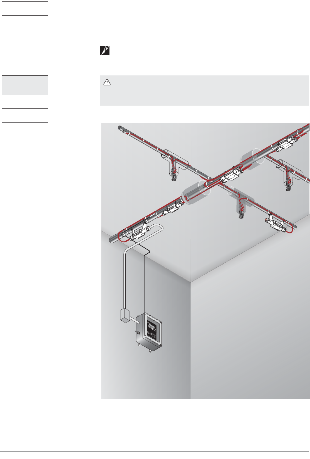
Pipe Freeze Protection
and Flow Maintenance
2. Select the heating
cable
3. Determine the
heating cable length
4. Determine the
electrical parameters
5. Select the
connection kits
and accessories
6. Select the control
system
7. Complete the Bill
of Materials
1. Determine design
conditions and
pipe heat loss
Step Select the connection kits and accessories
All XL-Trace systems require a power connection and end seal kit. Splice and tee kits
are used as required. Use Table 11 on page 71 (for aboveground applications) and
Table 13 on page 73 (for buried applications) to select the appropriate connection
kits.
Note: Add extra cable on your Bill of Materials for power connections, tees, and
end seals. See Table 11 on page 71, Table 13 on page 73, and Table 14 on page
74 for more information.
WARNING: Approvals and performance are based on the use of Pentair
Thermal Management-specified parts only. Do not substitute parts or use vinyl
electrical tape.
ABOVEGROUND PIPING
Fig. 12 RayClic connection system
Use the following table for general piping, standpipe and sprinkler. Develop a Bill of
Materials from the connection kits listed in the following table.
Power
connection
Splice
Line sensing
RTD
Cross
End seal
Tee
Insulation
Sprinkler
DigiTrace
C910-485
RayClic-LE
lighted end seal
(optional)
Junction
box
Ambient
sensing
RTD
FIRE SPRINKLER SYSTEM FREEZE PROTECTION XLTRACE SYSTEM
THERMAL MANAGEMENT SOLUTIONS
EN-RaychemXLTraceFireSprinkler-DG-H58489 11/13
70
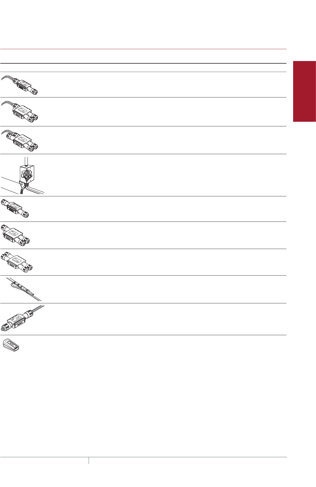
Pipe Freeze Protection
and Flow Maintenance
Fire Sprinkler System
Freeze Protection
Roof and Gutter
De-Icing
Surface Snow
Melting – MI
Surface Snow
Melting – ElectroMelt
Freezer Frost
Heave Prevention
Floor Heating Technical Data
Sheets
TABLE 11 CONNECTION KITS AND ACCESSORIES FOR ABOVEGROUND PIPING
Catalog
number
Description
Standard
packaging
Usage
Heating cable
allowance
¹
Connection kits
RayClic-PC Power connection and end seal (RayClic-
SB-04 pipe mounting bracket included)
1 1 per circuit 2 ft (0.6 m)
RayClic-PS Powered splice and end seal (RayClic-
SB-04 pipe mounting bracket included)
1 1 per circuit 4 ft (1.2 m)
RayClic-PT Powered tee and end seal (RayClic-SB-04
pipe mounting bracket included)
1 1 per circuit 6 ft (1.8 m)
FTC-P²Power connection and end seal kit
Note: FTC-P is required for circuits
requiring 40 A circuit breakers.
1 1 per circuit 3 ft (0.9 m)
RayClic-S Splice used to join two
sections of heating cable
1 As required 2 ft (0.6 m)
RayClic-T Tee kit with end seal;
use as needed for pipe
branches
1 As required 3 ft (0.9 m)
R
RayClic-X Cross connection to connect four heating
cables
1 As required 8 ft (2.4 m)
FTC-HST³Low-profile splice/tee; use as
needed for pipe branches
2 As required 3 ft (0.9 m)
RayClic-LE Lighted end seal (RayClic-SB-04 pipe
mounting bracket included)
1 Alternate end seal 2 ft (0.6 m)
RayClic-E Replacement end seal 1 Additional end seal 0.3 ft (0.1 m)
Fire Suppression System Freeze Protection Design
71THERMAL MANAGEMENT SOLUTIONS EN-RaychemXLTraceFireSprinkler-DG-H58489 11/13
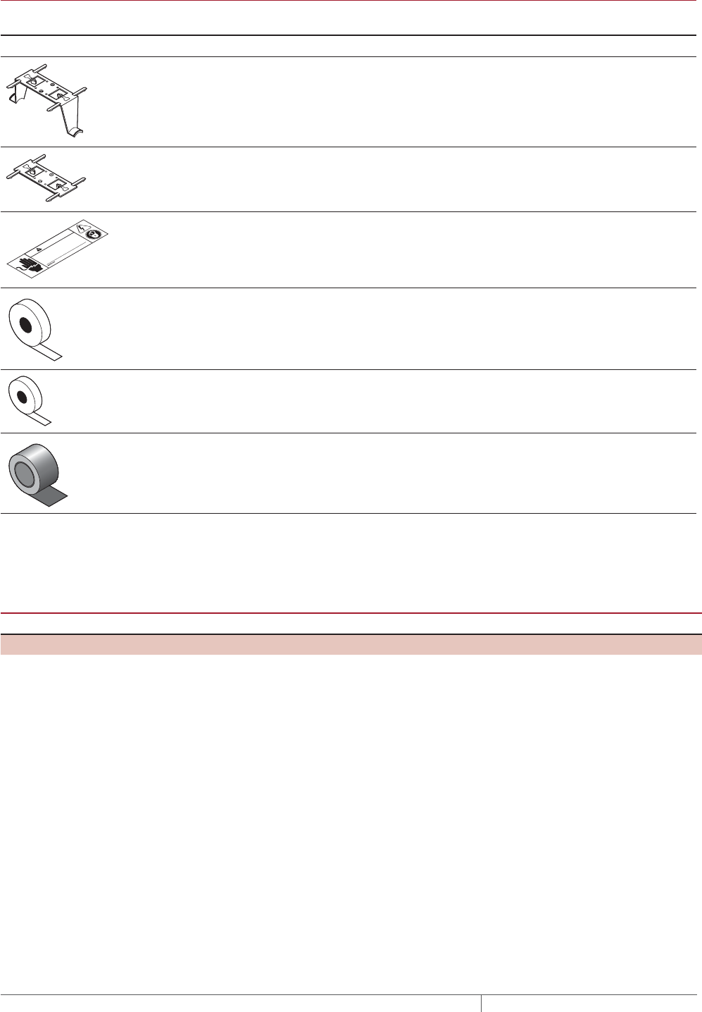
TABLE 11 CONNECTION KITS AND ACCESSORIES FOR ABOVEGROUND PIPING
Catalog
number
Description
Standard
packaging
Usage
Heating cable
allowance
¹
Accessories
RayClic-SB-04 Pipe mounting bracket. Required
for mounting the kits off the pipe
for exposure temperatures greater
than 150°F (65°C) and for grease
and fuel line splices and tees.
1 As required –
RayClic-SB-02 Wall mounting bracket 1 As required –
© 2013 Pentair Thermal Management LLC
WWW.PENTAIRTHERMAL.COM
PN C77203-000 H57657 07/13
Electric Heat Tracing
WARNING
SHOCK AND FIRE HAZARD: System must be installed and
maintained according to manufacturer's instructions. Follow
electrical lockout procedures before working on this line or
removing thermal insulation.
ETL “Electric Traced” label (use 1 label
per 10 feet of pipe)
1 1 label per 10 feet
(3m) of pipe
–
GT-66 Glass cloth adhesive tape for
attaching heating cable to pipe at
40°F (4°C) or above.
66 ft (20m) See Table 12 –
GS-54 Glass cloth adhesive tape for
attaching heating cable to pipe
above –40°F (–40°C).
54 ft (20m) See Table 12 –
AT-180 Aluminum tape. Required for
attaching heating cable to plastic
pipe (use 1 foot of tape per foot of
heating cable)
180 ft (55 m) 1 ft/ft (0.3 m/m) of
heating cable
–
¹ Allow extra heating cable for ease of component installation.
² Junction box not included.
³ One RayClic-E end seal is required for each FTC-HST used as a tee kit.
TABLE 12 QUANTITY OF GLASS CLOTH ADHESIVE TAPE REQUIRED ATTACH AT 1FOOT INTERVALS
Pipe size (in) <2 3 4 6 8 10
Feet of pipe per GT-66 roll 60 (18 m) 50 (15 m) 40 (12 m) 25 (8 m) 20 (6 m) 15 (5 m)
Feet of pipe per GS-54 roll 49 (15 m) 41 (13 m) 33 (10 m) 20 (6 m) 16 (5 m) 12 (4 m)
FIRE SPRINKLER SYSTEM FREEZE PROTECTION XLTRACE SYSTEM
THERMAL MANAGEMENT SOLUTIONS
EN-RaychemXLTraceFireSprinkler-DG-H58489 11/13
72
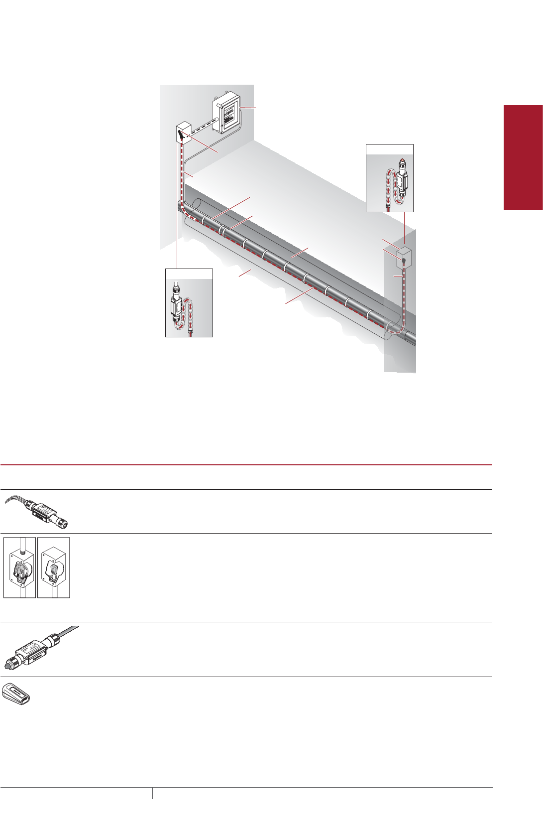
Pipe Freeze Protection
and Flow Maintenance
Fire Sprinkler System
Freeze Protection
Roof and Gutter
De-Icing
Surface Snow
Melting – MI
Surface Snow
Melting – ElectroMelt
Freezer Frost
Heave Prevention
Floor Heating Technical Data
Sheets
BURIED PIPING
Temperature sensor
Insulation
Conduit
XL-Trace
heating cable
with -CT jacket
Ground
Alternate
power connection
Alternate
end seal
Ground
Wall
RayClic-LE*
RayClic-PC*
Junction box
RayClic-E
end seal
Conduit
Wall
with wall
mounting
bracket
with wall
mounting
bracket
FTC-XC
power
connection
*To protect the heating cable, run cable
inside Convolex tubing between the
conduit and the RayClic connection kits.
DigiTrace C910-485
Electronic controller
Conduit for
temperature
sensor
Fig. 13 Typical buried supply piping system
Use the following for buried water supply piping. Note that all connections must be
aboveground and that no splices/tees are allowed. Develop a Bill of Materials from
the connection kits in this table.
TABLE 13 CONNECTION KITS AND ACCESSORIES FOR BURIED PIPING
Catalog
number
Description
Standard
packaging
Usage
Heating cable
allowance
¹
RayClic-PC Power connection and end seal kit
(RayClic-SB-04 pipe mounting bracket
included)
1 1 per circuit 2 ft (0.6 m)
FTC-XC²The FTC-XC power connection and end
seal kit is for use with XL-Trace heating
cable that is run through conduit to a junc-
tion box. Materials for one power connec-
tion and end seal is included in the kit.
Note: FTC-XC is required for circuits
requiring 40 A circuit breakers.
1 1 per circuit 2 ft (0.6 m)
RayClic-LE Lighted end seal (RayClic-SB-04 pipe
mounting bracket included)
1 Alternate end seal 2 ft (0.6 m)
RayClic-E Replacement end seal 1 Additional end seal 0.3 ft (0.1 m)
Fire Suppression System Freeze Protection Design
73THERMAL MANAGEMENT SOLUTIONS EN-RaychemXLTraceFireSprinkler-DG-H58489 11/13
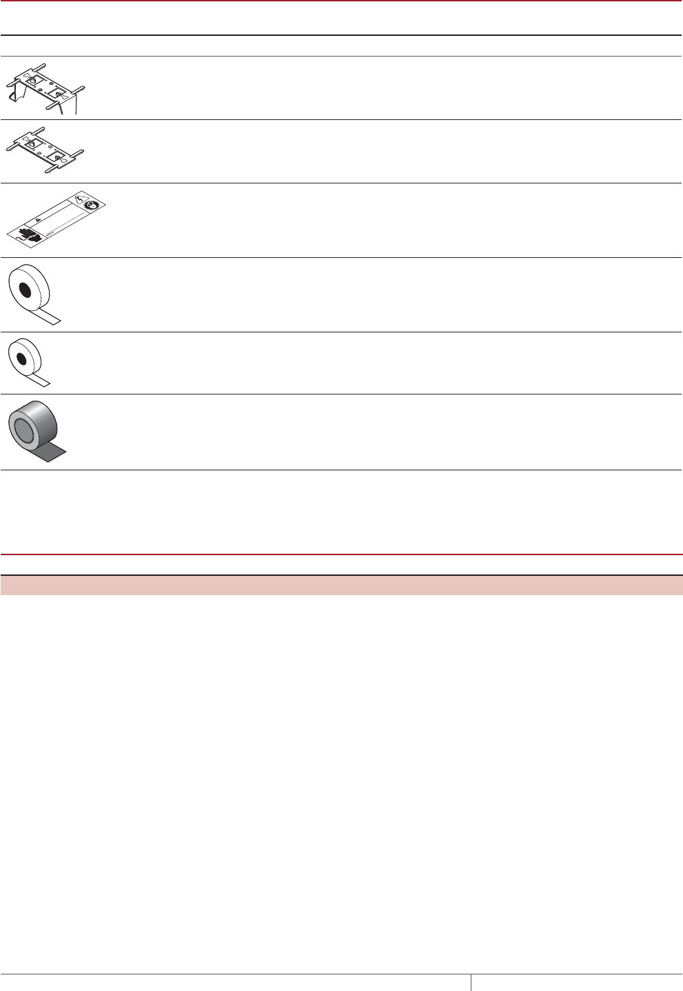
TABLE 13 CONNECTION KITS AND ACCESSORIES FOR BURIED PIPING
Catalog
number
Description
Standard
packaging
Usage
Heating cable
allowance
¹
Accessories
RayClic-SB-04 Pipe mounting bracket 1 As required –
RayClic-SB-02 Wall mounting bracket 1 As required –
© 2013 Pentair Thermal Management LLC
WWW.PENTAIRTHERMAL.COM
PN C77203-000 H57657 07/13
Electric Heat Tracing
WARNING
SHOCK AND FIRE HAZARD: System must be installed and
maintained according to manufacturer's instructions. Follow
electrical lockout procedures before working on this line or
removing thermal insulation.
ETL “Electric Traced” label (use 1
label per 10 feet of pipe)
1 1 label per 10 feet
(3m) of pipe
–
GT-66 Glass cloth adhesive tape for
attaching heating cable to pipe at
40°F (4°C) or above
66 ft (20m) See Table 14 –
GS-54 Glass cloth adhesive tape for
attaching heating cable to pipe
above –40°F (–40°C)
54 ft (20m) See Table 14 –
AT-180 Aluminum tape. Required for
attaching heating cable to plastic
pipe (use 1 foot of tape per foot of
heating cable)
180 ft (55 m) 1 ft/ft (0.3 m/m) of
heating cable
–
¹ Allow extra heating cable for ease of component installation.
² Junction box not included.
TABLE 14 QUANTITY OF GLASS CLOTH ADHESIVE TAPE REQUIRED ATTACH AT 1FOOT INTERVALS
Pipe size (in) <2 3 4 6 8 10
Feet of pipe per GT-66 roll 60 (18 m) 50 (15 m) 40 (12 m) 25 (8 m) 20 (6 m) 15 (5 m)
Feet of pipe per GS-54 roll 49 (15 m) 41 (13 m) 33 (10 m) 20 (6 m) 16 (5 m) 12 (4 m)
FIRE SPRINKLER SYSTEM FREEZE PROTECTION XLTRACE SYSTEM
THERMAL MANAGEMENT SOLUTIONS
EN-RaychemXLTraceFireSprinkler-DG-H58489 11/13
74
Pipe Freeze Protection
and Flow Maintenance
Fire Sprinkler System
Freeze Protection
Roof and Gutter
De-Icing
Surface Snow
Melting – MI
Surface Snow
Melting – ElectroMelt
Freezer Frost
Heave Prevention
Floor Heating Technical Data
Sheets
Pipe Freeze Protection
and Flow Maintenance
2. Select the heating
cable
3. Determine the
heating cable length
4. Determine the
electrical parameters
5. Select the
connection kits
and accessories
6. Select the control
system
7. Complete the Bill
of Materials
1. Determine design
conditions and
pipe heat loss
Pipe Freeze Protection
and Flow Maintenance Step Select the control system
Temperature control with heating cable circuit supervision is required by approval
agencies, codes and Pentair Thermal Management. To satisfy this requirement
Pentair Thermal Management offers a wide variety of monitoring and control options
for fire suppression system.
DigiTrace C910-485 and ACS-30 are the only controllers approved for this
application:
• Temperature controls save energy by ensuring that the system is energized only
when necessary.
• Superior accuracy and reliability with RTD temperature sensors.
• Integrated 30 mA ground-fault protection for cost savings and circuit protection.
• Self-test features to ensure the heating cable circuit integrity even when the sys-
tem is not in demand.
• Modbus® protocol communication over RS-485 system is supported using
DigiTrace ProtoNode multi-protocol gateways.
• Dry contact alarm relay outputs for loss of power, low temperature, RTD failure,
relay failure and ground-fault trip.
Note: NFPA 13 requires that heat tracing for fire suppression systems are
supervised by controllers with alarm relays connected to the fire control panel.
Use the following table to identify the control system suitable for your application.
Contact your Pentair Thermal Management representative or contact Pentair
Thermal Management directly at (800) 545-6258 for more information and other
control options.
TABLE 15 TEMPERATURE CONTROL OPTIONS
Application DigiTrace C910-485 DigiTrace ACS-30
Ambient sensing x x
Line sensing x x
Buried pipe x x
Proportional ambient control x x
Fire sprinklers x x
Sensor RTD RTD
Sensor length See data sheet See data sheet
Setpoint range 30°F to 200°F (–1°C to 92°C) "
Enclosure NEMA 4X "
Differential 3°F (1.6°C) "
Setpoint repeatability 3°F (1.6°C) "
Enclosure limits –40°F to 140°F (–40°C to 60°C) "
Switch rating 30 A 30 A
Switch type DPST DPST
Electrical rating 100–277 V 100–277 V
Approvals c-CSA-us c-CSA-us
Ground-fault protection 20 mA to 100 mA 20 mA to 100mA
BMS interface Standard Modbus¹
Alarm outputs x x
AC relay dry contact relay x x
¹ DigiTrace ProtoNode multi-protocol gateways are available from Pentair Thermal Management.
Fire Suppression System Freeze Protection Design
75THERMAL MANAGEMENT SOLUTIONS EN-RaychemXLTraceFireSprinkler-DG-H58489 11/13
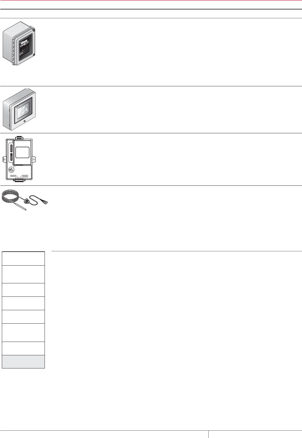
TABLE 16 CONTROL SYSTEMS
Catalog number Description
Electronic Controllers and Sensors
C910-485 The DigiTrace C910-485 is a compact, full-featured microprocessor-based single-
point heat-trace controller. The C910-485 provides control and monitoring of electrical
heat-tracing circuits for both freeze protection and temperature maintenance, and can
be set to monitor and alarm for high and low temperature, and ground-fault level. The
C910-485 controller is available with an electromechanical relay (EMR). Communica-
tions modules are available for remote control and configuration.
The DigiTrace C910-485 includes RS-485 communications module for interfacing with
Building Management Systems (BMS) and fire control panels.
ACS-UIT2
ACS-PCM2-5
The DigiTrace ACS-30 Advanced Commercial Control System is a multipoint electronic
control and monitoring system for heat-tracing used in commercial freeze protection
and flow maintenance applications. The DigiTrace ACS-30 system can control up to 260
circuits with multiple networked ACS-PCM2-5 panels, with a single ACS-UIT2 user
interface terminal. The ACS-PCM2-5 panel can directly control up to 5 individual heat-
tracing circuits using electromechanical relays rated at 30 A up to 277 V.
By FieldServer Technologies
www.ProtoCessor.com
PROTOCESSOR
SERIAL ETHERNET
PROTONODE
FRAME GND
- PWR
+PWR
RS 485+
RS 485 -
RS 485 GND
S3
S2
S1
S0
B3
B2
B1
B0
A7
A6
A5
A4
A3
A2
A1
A0
ProtoNode-LER
ProtoNode-RER
The DigiTrace ProtoNode is an external, high performance multi-protocol gateway for
customers needing protocol translation between Building Management Systems (BMS)
and the DigiTrace ACS-30 or C910-485 controllers.
The ProtoNode-LER is for LonWorks® systems; and the ProtoNode-RER is for BACnet®
or Metasys® N2 systems.
RTD-200
RTD3CS
RTD10CS
RTD50CS
Three-wire RTD (Resistance Temperature Device) used with DigiTrace C910-485 and
ACS-30 controllers.
RTD-200: 6-ft (1.8 m) fluorpolymer with 1/2-in NPT bushing
RTD3CS: 3-ft (0.9 m) flexible armor with 1/2-in NPT bushing
RTD10CS: 10-ft (3 m) flexible armor with 1/2-in NPT bushing
RTD50CS: 50-ft (3 m) flexible armor with 1/2-in NPT bushing
2. Select the heating
cable
3. Determine the
heating cable length
4. Determine the
electrical parameters
5. Select the
connection kits
and accessories
6. Select the control
system
7. Complete the Bill
of Materials
Pipe Freeze Protection
and Flow Maintenance
1. Determine design
conditions and
pipe heat loss
Pipe Freeze Protection
and Flow Maintenance Step Complete the Bill of Materials
If you used the Design Worksheet to document all your design parameters, you
should have all the details necessary complete your Bill of Materials.
FIRE SPRINKLER SYSTEM FREEZE PROTECTION XLTRACE SYSTEM
THERMAL MANAGEMENT SOLUTIONS
EN-RaychemXLTraceFireSprinkler-DG-H58489 11/13
76
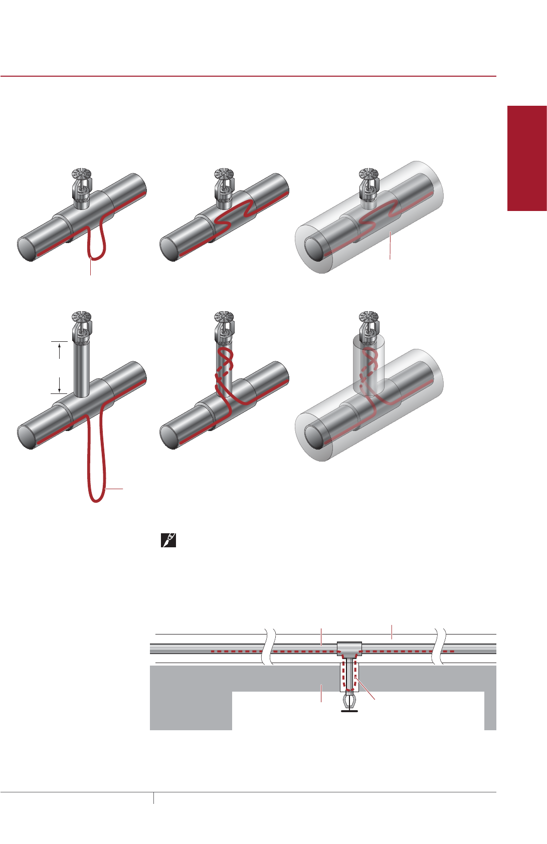
Pipe Freeze Protection
and Flow Maintenance
Fire Sprinkler System
Freeze Protection
Roof and Gutter
De-Icing
Surface Snow
Melting – MI
Surface Snow
Melting – ElectroMelt
Freezer Frost
Heave Prevention
Floor Heating Technical Data
Sheets
INSTALLATION AND MAINTENANCE
Follow the installation and maintenance procedures in the XL-Trace System
Installation and Operation Manual (H58033) when installing XL-Trace on fire
suppression systems with the following additional instructions.
When installing XL-Trace on sprinklers follow the methods shown below:
Sprinkler head without sprig
Sprinkler head with sprig
Additional heating cable length = Pipe diameter x 4
Additional heating cable length = Sprig length x 3
Sprig
length
Insulation
(Use outer diameter of thermal insulation
when determining the spray shadowing in
your sprinkler system.)
Fig. 14 XL-Trace on sprinklers
Note: The orientation and type of sprinkler head shown above is only for
reference. The illustrations only depict the amount of heat tracing required and how
to install it.
When installing XL-Trace on dry pendant sprinklers used in freezer applications
follow the methods shown below:
Freezer
Thermal pipe insulation
Sprinkler pipe
XL-Trace heating cable
Length = 2 x dry sprinkler length
Freezer wall
insulation
Fig. 15 XL-Trace on extended pendant sprinklers
Installation and Maintenance
77THERMAL MANAGEMENT SOLUTIONS EN-RaychemXLTraceFireSprinkler-DG-H58489 11/13
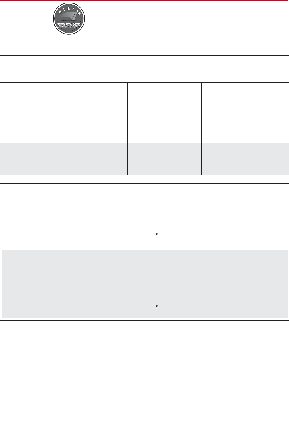
XLTRACE SYSTEM FIRE SPRINKLER SYSTEM FREEZE PROTECTION DESIGN WORKSHEET
XL-Erate, the commercial pipe freeze protection and flow maintenance design
software is available at http://www.pentairthermal.com to assist with your design.
Step Determine design conditions and pipe heat loss
Design conditions
Fire sprinkler
system Location
Maintain
temp.
(TM)
Min.
ambient
temp.
(TA)
Pipe diameter
and material
Pipe
length
Thermal insulation
type and thickness
❑ Supply piping
❑ Standpipe
❑ Indoors
❑ Outdoors
❑ Aboveground
❑ Buried
______ ______ ____ in
❑ Metal
❑ Plastic _____ ft (m)
❑ Fiberglass
❑ ________ ____ in
❑ Sprinkler piping ❑ Indoors
❑ Outdoors
❑ Aboveground
❑ Buried
______ ______ ____ in
❑ Metal
❑ Plastic _____ ft (m)
❑ Fiberglass
❑ ________ ____ in
❑ Branchpipe ❑ Indoors
❑ Outdoors
❑ Aboveground
______ ______ ____ in
❑ Metal
❑ Plastic _____ ft (m)
❑ Fiberglass
❑ ________ ____ in
❑ Branchpipe with
sprinkler
❑ Indoors
❑ Outdoors
❑ Aboveground
______ ______ ____ in
❑ Metal
❑ Plastic _____ ft (m)
❑ Fiberglass
❑ ________ ____ in
Example:
0 Branch line
with sprinkler
0 Indoor 40°F 50°F 1 in 0 Metal 200 ft 0 Foam
elastomer
1/2 in
Pipe heat loss
Calculate temperature differential ∆T
Pipe maintain temperature (TM)
°F (°C)
Ambient temperature (TA)
°F (°C)
TM∆T
−=
Example: Pipe Freeze Protection − Branch line with sprinkler
TA
Pipe maintain temperature (TM)
°F
(from Step 1)
(from Step 1)
Ambient temperature (TA)
°F
TM∆T
40 °F
40 °F
0 °F
0 °F 40 °F
−=
TA
FIRE SPRINKLER SYSTEM FREEZE PROTECTION XLTRACE SYSTEM
THERMAL MANAGEMENT SOLUTIONS
EN-RaychemXLTraceFireSprinkler-DG-H58489 11/13
78
Pipe Freeze Protection
and Flow Maintenance
Fire Sprinkler System
Freeze Protection
Roof and Gutter
De-Icing
Surface Snow
Melting – MI
Surface Snow
Melting – ElectroMelt
Freezer Frost
Heave Prevention
Floor Heating Technical Data
Sheets
Determine the pipe heat loss: See Table 1 for the base heat loss of the pipe (QB). If the ∆T for your system is not listed, interpolate be-
tween the two closest values.
QB-T1 ∆T1
W/ft (W/m)
QB-T2 ∆T2
W/ft (W/m)
QB
W/ft (W/m)
in
in
°F (°C)
W/ft (W/m)
W/ft (W/m)
Example: Pipe Freeze Protection − Branch line with sprinkler
Pipe diameter 1 in
1/2 in
40°F
Insulation thickness
1.4 W/ft
3.5 W/ft
∆T
QB-T1
QB-T2
Pipe diameter
Insulation thickness
∆T
QB-T1
QB-T2
∆T 40°F is 67% of the distance between ∆T 20°F and ∆T 50°F
∆T interpolation
QB-50 + [0.67 x (QB-50 − QB-20)] = 1.4 + [0.67 x (3.5 − 1.4)] = 2.8 W/ftQB-40
2.8 W/ft @ TM 40°F (9.2 W/m @ TM4°C)
Pipe heat loss (QB)
XL-Trace System Fire Sprinkler System Freeze Protection Design Worksheet
79THERMAL MANAGEMENT SOLUTIONS EN-RaychemXLTraceFireSprinkler-DG-H58489 11/13

Compensate for insulation type and pipe location
See Table 1 for the pipe heat loss (QB). If the ∆T for your system is not listed, interpolate between the two closest values.
See Table 3 for insulation multiple
See Table 2 for indoor multiple
QB
QCORRECTED
QB
x=
W/ft (W/m)
Insulation multiple
Indoor multiple (if applicable)
Location
Insulation thickness and type
Insulation multiple xIndoor multiple
(if applicable)
Example: Pipe Freeze Protection − Branch line with sprinklers
Location Indoors
1-1/2 in foamed elastomer
Insulation thickness and type
2.8 W/ft @ TM 40°F (9.2 W/m @ TM 4°C)
Indoor multiple
1.00
Insulation multiple
0.79
2.8 W/ft x 1.0 x 0.79 = 2.2 W/ft @ TM40°F (7.3/m @ TM4°C)
QCORRECTED
QB
FIRE SPRINKLER SYSTEM FREEZE PROTECTION XLTRACE SYSTEM
THERMAL MANAGEMENT SOLUTIONS
EN-RaychemXLTraceFireSprinkler-DG-H58489 11/13
80

Pipe Freeze Protection
and Flow Maintenance
Fire Sprinkler System
Freeze Protection
Roof and Gutter
De-Icing
Surface Snow
Melting – MI
Surface Snow
Melting – ElectroMelt
Freezer Frost
Heave Prevention
Floor Heating Technical Data
Sheets
Step Select the heating cable
Power output data: See Fig. 11
Power output correction factors: See Table 4
Select outer jacket
❑ -CR
❑ -CT (Required for buried applications)
Power at rated V factor
x
Pipe maintain temperature (TM) (from Step 1)
(from Step 1)
(from Step 1)
(from Step 1)
(from Step 1)
(from Step 1)
(from Step 1)
(from Step 1)
Corrected heat loss (QCORRECTED)
Supply voltage
Pipe material (metal or plastic)
XL-Trace sprinkler application
Indoor/outdoor
Aboveground/buried
Location
Plastic pipe correction factor
=
Corrected power
Heating cable selected
Power at TM (120/208 V)
Power output correction factor
Plastic pipe correction factor
If No, then design with additional runs of heating cable or thicker thermal insulation.
Is the heating cable power output (PCORRECTED) ≥ the corrected heat loss? Yes
ENo
E
Maintain temperature (TM)40°F
2.2 W/ft @ TM 40°F
208 V
metal
QB = 2.2 W/ft @ TM 40°F
Select curve C: 5XL2 = 5.6 W/ft @ 40°F
Power output correction factor: 208 V = 1.00
Pipe material correction factor: Metal = 1.00
Corrected heating cable power: 5.6 @/ft x 1.00 x 1.00 = 5.6 W/ft
Select: 5XL2
Corrected heat loss (QCORRECTED)
Supply voltage
Pipe material (metal or plastic)
(*AT-180 aluminum tape required for
installing heating cable on plastic pipes)
Example: Pipe Freeze Protection − Branch line with sprinklers
Location Aboveground, indoors
5XL2-CRSelection:
Example: Pipe Freeze Protection − Branch line with sprinklers
XL-Trace System Fire Sprinkler System Freeze Protection Design Worksheet
81THERMAL MANAGEMENT SOLUTIONS EN-RaychemXLTraceFireSprinkler-DG-H58489 11/13
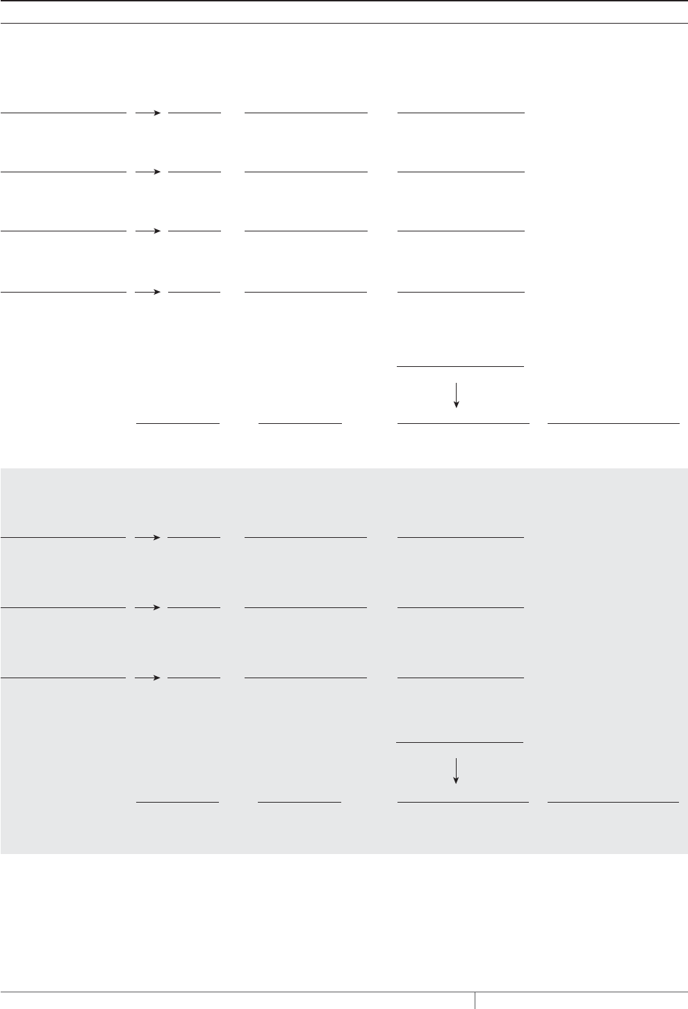
Step Determine the heating cable length
For additional heating cable allowance for valves: See Table 5
For additional heating cable allowance for pipe supports, flanges and sprinklers: See Table 6.
Pipe length
( )
x +
Total heating cable
length required
Number of heating
cable runs
Total heating cable length
Additional heating cable for heat sinks
=
Additional cable for valves,
pipe supports, flanges, and sprinklers
Type of valves
x
Total heating cable
for valves
How many
=
Additional heating cable
Type of pipe supports
x
Total heating cable
for pipe supports
How many
=
Additional heating cable
Type of flanges
x
Total heating cable
for flanges
How many
=
Additional heating cable
Total heating cable for heat sinks:
Pipe length
( )
x +
Total heating cable
length required
200 ft 1 66 ft 266 ft
Number of heating
cable runs
Total heating cable length
Additional heating cable for heat sinks
=
Additional cable for valves,
pipe supports, flanges, and sprinklers
Type of valves
x
Total
Gate valves 2 2 ft 4 ft
How many
=
Additional heating cable
Example:
Type of pipe supports
x
Total
Noninsulated hangers 10 (0.1 ft* x 2) x 10 = 2 ft 1.7 ft
How many
=
Additional heating cable
(*1-in pipe = 1-in/12-in = 0.1 ft)
Type of sprinklers
x
Total
1 foot springs 20 3 60 ft
How many
=
Additional heating cable
66 ftTotal:
Type of sprinklers
x
Total heating cable
for sprinklers
How many
=
Additional heating cable
FIRE SPRINKLER SYSTEM FREEZE PROTECTION XLTRACE SYSTEM
THERMAL MANAGEMENT SOLUTIONS
EN-RaychemXLTraceFireSprinkler-DG-H58489 11/13
82

Pipe Freeze Protection
and Flow Maintenance
Fire Sprinkler System
Freeze Protection
Roof and Gutter
De-Icing
Surface Snow
Melting – MI
Surface Snow
Melting – ElectroMelt
Freezer Frost
Heave Prevention
Floor Heating Technical Data
Sheets
Step Determine the electrical parameters
Determine maximum circuit length and number of circuits
See Table 7 and Table 8.
Determine transformer load
See Table 9 and Table 10.
398 ft266 ft 0.67 circuits, round up to 1
266 ft of 5XL2-CT
0°F
0.67 ft
/ =
Number of circuitsMaximum heating cable circuit length
Total heating cable length required
T 120 V T 208 V
T 240 V T 277 V
Total heating cable length required
Supply voltage:
T 15 A T 20 A
T 30 A T 40 A
Circuit breaker size:
Minimum start-up temperature
Maximum circuit length
/ =
Number of circuitsMaximum heating cable circuit length
Total heating cable length required
T 120 V T 208 V
T 240 V T 277 V
Total heating cable length required
Supply voltage:
T 15 A T 20 A
T 30 A T 40 A
Circuit breaker size:
Minimum start-up temperature
Number of circuits
Example:
9
9
x / 1000 = Transformer
load (kW)
0.06 A/ft 266 ft 208 V 3.3 kW
Max A/ft* at minimum start-up temperature Heating cable length xSupply voltage
Example:
x / 1000 = Transformer
load (kW)
Max A/ft* at minimum start-up temperature Heating cable length xSupply voltage
XL-Trace System Fire Sprinkler System Freeze Protection Design Worksheet
83THERMAL MANAGEMENT SOLUTIONS EN-RaychemXLTraceFireSprinkler-DG-H58489 11/13

Step Select the connection kits and accessories
See Table 11.
Connection kits – Aboveground Description Quantity
Heating cable
allowance
❑ RayClic-PC
❑ RayClic-PS
❑ RayClic-PT
❑ FTC-P
❑ RayClic-S
❑ RayClic-T
❑ RayClic-X
❑ FTC-HST
❑ RayClic-LE
❑ RayClic-E
Power connection and end seal
Power splice and end seal
Powered tee and end seal
Power connection and end seal
Splice
Tee kit with end seal
Cross connection
Low-profile splice/tee
Lighted end seal
Extra end seal
____________
____________
____________
____________
____________
____________
____________
____________
____________
____________
__________________
__________________
__________________
__________________
__________________
__________________
__________________
__________________
__________________
__________________
Connection kits – Buried Description Quantity
Heating cable
allowance
❑ RayClic-PC
❑ FTC-XC
❑ RayClic-LE
❑ RayClic-E
Power connection and end seal
Power splice and end seal
Lighted end seal
Extra end seal
____________
____________
____________
____________
__________________
__________________
__________________
__________________
Accessories – Aboveground and
buried Description Quantity
❑ RayClic-SB-04
❑ RayClic-SB-02
❑ ETL
❑ GT-66
❑ GS-54
❑ AT-180
Pipe mounting bracket
Wall mounting bracket
“Electric-Traced” label
Glass cloth adhesive tape
Glass cloth adhesive tape
Aluminum tape (for plastic pipes)
_____________
_____________
_____________
_____________
_____________
_____________
+ =
Total heating cable
length required
Total heating cable allowance for connection kits
Total heating cable length
Total heating cable
allowance for connection kits
FIRE SPRINKLER SYSTEM FREEZE PROTECTION XLTRACE SYSTEM
THERMAL MANAGEMENT SOLUTIONS
EN-RaychemXLTraceFireSprinkler-DG-H58489 11/13
84

Pipe Freeze Protection
and Flow Maintenance
Fire Sprinkler System
Freeze Protection
Roof and Gutter
De-Icing
Surface Snow
Melting – MI
Surface Snow
Melting – ElectroMelt
Freezer Frost
Heave Prevention
Floor Heating Technical Data
Sheets
Step Select the control system
See Table 16.
Thermostats, controllers
and accessories Description Quantity
❑ C910-485
❑ ACS-UIT2
❑ ACS-PCM2-5
❑ ProtoNode-LER
❑ ProtoNode-RER
❑ RTD3CS
❑ RTD10CS
❑ RTD-200
❑ RTD50CS
Microprocessor-based single-point heat-tracing controller
with RS-485 communication
ACS-30 user interface terminal
ACS-30 power control panel
Multi-protocol gateway
Multi-protocol gateway
Resistance temperature device
Resistance temperature device
Resistance temperature device
Resistance temperature device
_____________
_____________
_____________
_____________
_____________
_____________
_____________
_____________
_____________
Step Complete the Bill of Materials
Use the information recorded in this worksheet to complete the Bill of Materials.
XL-Trace System Fire Sprinkler System Freeze Protection Design Worksheet
85THERMAL MANAGEMENT SOLUTIONS EN-RaychemXLTraceFireSprinkler-DG-H58489 11/13

FIRE SPRINKLER SYSTEM FREEZE PROTECTION XLTRACE SYSTEM
THERMAL MANAGEMENT SOLUTIONS
EN-RaychemXLTraceFireSprinkler-DG-H58489 11/13
86
87THERMAL MANAGEMENT SOLUTIONS EN-RaychemIceStopRoofGutterDeIcing-DG-H56070 11/13
Pipe Freeze Protection
and Flow Maintenance
Fire Sprinkler System
Freeze Protection
Roof and Gutter
De-Icing
Surface Snow
Melting – MI
Surface Snow
Melting – ElectroMelt
Freezer Frost
Heave Prevention
Floor Heating Technical Data
Sheets
This step-by-step design guide provides the tools necessary to design a Raychem
IceStop roof and gutter de-icing system. For other applications or for design
assistance, contact your Pentair Thermal Management representative or phone
Pentair Thermal Management at (800)545-6258. Also, visit our web site at
www.pentairthermal.com.
Contents
Introduction ..........................................................87
How to Use this Guide .............................................88
Safety Guidelines .................................................88
Warranty ........................................................88
System Overview ......................................................89
Typical System ...................................................89
Self-Regulating Heating Cable Construction ...........................90
Approvals ........................................................91
Roof and Gutter De-Icing Design .........................................91
Design Step by Step ...............................................91
Step 1 Determine design conditions ...............................92
Step 2 Select the heating cable ...................................93
Step 3 Determine the heating cable length ..........................94
Step 4 Determine the electrical parameters ........................102
Step 5 Select the connection kits .................................104
Step 6 Select attachment accessories and method ..................107
Step 7 Select the control system and power distribution ..............113
Step 8 Complete the Bill of Materials .............................119
IceStop System Roof and Gutter De-Icing Design Worksheet .................120
INTRODUCTION
Raychem IceStop is a roof and gutter de-icing system that provides drain paths for
the following applications:
• Roofs made from standard roofing materials, including shake, shingle, rubber,
tar, wood, metal, and plastic.
• Gutters made from standard materials, including metal, plastic, and wood.
• Downspouts made from standard materials, including metal and plastic.
The guide does not cover applications in which any of the following conditions exist:
• Preventing snow movement on roofs — IceStop will not keep snow or ice from
falling off the roof. IceStop is designed to remove melt water, not accumulated
snow. Snow fences or snow guards should be used to eliminate snow movement.
• Melting snow on a roof and/or reduction of snow load — IceStop is designed to
remove melt water, not accumulated snow.
If your application conditions are different, or if you have any questions, contact
your Pentair Thermal Management representative, or contact Pentair Thermal
Management directly at (800) 545-6258.
ROOF AND GUTTER DEICING
ICESTOP SYSTEM
THERMAL MANAGEMENT SOLUTIONS
EN-RaychemIceStopRoofGutterDeIcing-DG-H56070 11/13
88
How to Use this Guide
This design guide presents Pentair Thermal Management’ recommendations
for designing an IceStop roof and gutter de-icing system. It provides design
and performance data, electrical sizing information, and heating-cable layout
suggestions. Following these recommendations will result in a reliable, energy-
efficient system.
OTHER REQUIRED DOCUMENTS
This guide is not intended to provide comprehensive installation instructions. For
complete IceStop roof and gutter de-icing system installation instructions, please
refer to the following additional required documents:
• IceStop System Installation and Operation Manual (H58067)
• Additional installation instructions that are included with the connection kits,
thermostats, controllers, and accessories
If you do not have these documents, you can obtain them from the Pentair Thermal
Management web site at www.pentairthermal.com.
For products and applications not covered by this design guide, please contact your
Pentair Thermal Management representative or call Pentair Thermal Management
directly at (800)545-6258.
Safety Guidelines
As with any electrical equipment, the safety and reliability of any system depends
on the quality of the products selected and the manner in which they are installed
and maintained. Incorrect design, handling, installation, or maintenance of any of
the system components could damage the system and may result in inadequate
performance, overheating, electric shock, or fire. To minimize these risks and to
ensure that the system performs reliably, read and carefully follow the information,
warnings, and instructions in this guide.
This symbol identifies important instructions or information.
This symbol identifies particularly important safety warnings that must be
followed.
WARNING: To minimize the danger of fire from sustained electrical arcing if
the heating cable is damaged or improperly installed, and to comply with the
requirements of Pentair Thermal Management, agency certifications, and national
electrical codes, ground-fault equipment protection must be used on each heating
cable branch circuit. Arcing may not be stopped by conventional circuit protection.
Warranty
Pentair Thermal Management’ standard limited warranty applies to Raychem Roof
and Gutter De-icing Systems.
An extension of the limited warranty period to ten (10) years from the date of
installation is available, except for the control and distribution systems, if a properly
completed online warranty form is submitted within thirty (30) days from the date of
installation. You can access the complete warranty on our web site at
www.pentairthermal.com.
ROOF AND GUTTER DEICING ICESTOP SYSTEM
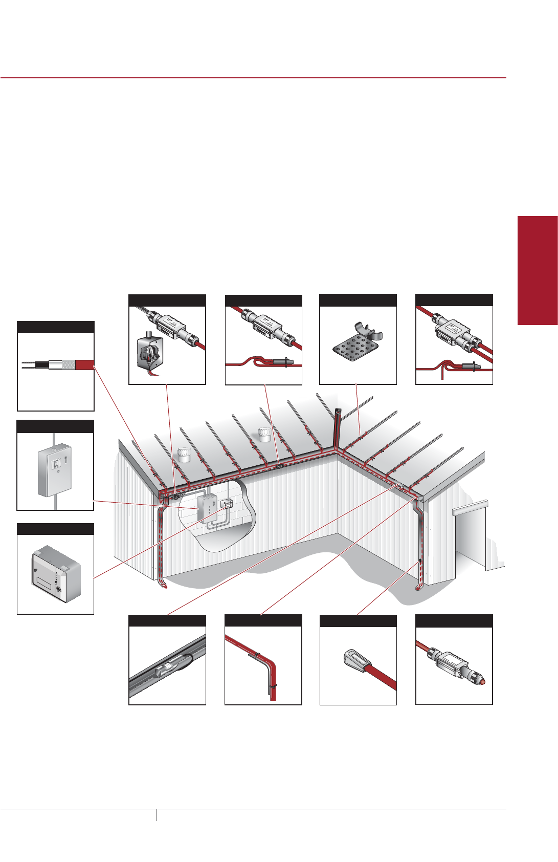
89THERMAL MANAGEMENT SOLUTIONS EN-RaychemIceStopRoofGutterDeIcing-DG-H56070 11/13
Pipe Freeze Protection
and Flow Maintenance
Fire Sprinkler System
Freeze Protection
Roof and Gutter
De-Icing
Surface Snow
Melting – MI
Surface Snow
Melting – ElectroMelt
Freezer Frost
Heave Prevention
Floor Heating Technical Data
Sheets
SYSTEM OVERVIEW
The Raychem IceStop system can prevent ice dams and icicles by maintaining a
continuous path for melt water to drain from the roof. The IceStop system uses
a self-regulating heating cable which reduces heat output automatically as the
cable warms to above freezing, resulting in lower energy use, and eliminating the
possibility of overheating. A typical roof and gutter de-icing system includes the
IceStop self-regulating heating cables, connection kits, control system and power
distribution.
Typical System
A typical system includes the following:
• IceStop self-regulating heating cable
• Connection kits and accessories
• Control system
• Power distribution
Power Connection Kits Splice Kits Attachment Kits Tee Kits
Gutter Sensor Downspout Hanger Kit End Seal Kit
Heating Cable
Power Distribution Panel
APS-4
SUPPLY
SNOW
HEATER
GROUND FAULT
GROUND FAULT
HEATER CYCLE
RESET
TEST
HOLD ON TIME (HRS)
Snow/Ice Melting Controller
SUPPLY : 277 VAC, 50/60HZZ, 35VA
HEATER: 377 VAC, 40 AMP. MAX RESIS
USE ONLY COPPER CONDUCTORS HAVING
SUFFICIENT AMPACITY.
SEE INSTALLATION INSTRUCTIONS
WARNING
DANGER OF ELECTRICAL SHOCK OR ELCTROCUTION
Lethal voltages are present beneath this cover. Servicee by
qualified personnel only. More than one disconnect may be
required to de-energize this control for servicing.
Snow Controller
Lighted End Seal
Fig. 1 Typical IceStop roof and gutter de-icing system
System Overview
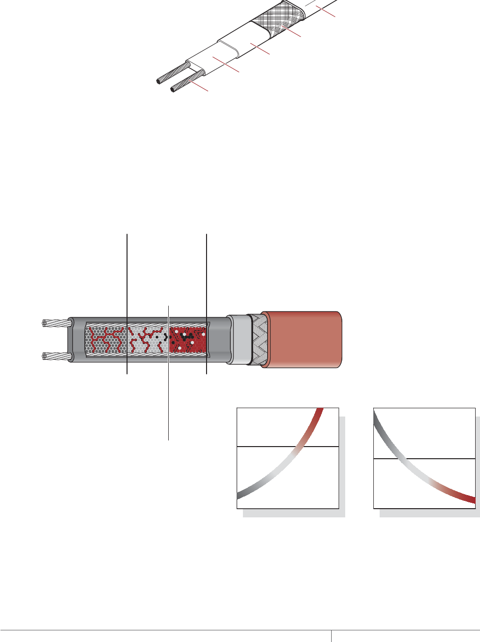
THERMAL MANAGEMENT SOLUTIONS
EN-RaychemIceStopRoofGutterDeIcing-DG-H56070 11/13
90
Self-Regulating Heating Cable Construction
Raychem IceStop self-regulating heating cables are comprised of two parallel
nickel-coated bus wires in a cross-linked polymer core, a tinned copper braid and a
fluoropolymer or polyolefin outer jacket. These cables are cut to length simplifying
the application design and installation.
Nickel-plated copper bus wire
Self-regulating conductive core
Modified polyolefin inner jacket
Tinned-copper braid
Fluoropolymer (-XT) or
modified polyolefin (-X) outer jacket
Fig. 2 IceStop heating cable construction
With self-regulating technology, the number of electrical paths between bus wires
changes in response to temperature fluctuations. As the temperature surrounding
the heater decreases, the conductive core contracts microscopically. This contraction
decreases electrical resistance and creates numerous electrical paths between the
bus wires. Current flows across these paths to warm the core.
As the temperature rises, the core expands microscopically. This expansion
increases electrical resistance and the number of electrical paths decreases. The
heating cable automatically begins to reduce its output.
At low temperature,
there are many conduct-
ing paths, resulting in
high output and rapid
heat-up. Heat is
generated only when it is
needed and precisely
where it is needed.
At high temperature,
there are few conducting
paths and output is
correspondingly lower,
conserving energy
during operation.
At moderate temperature,
there are fewer conducting
paths because the heating
cable efficiently adjusts by
decreasing output, eliminating
any possibility of overheating.
The following graphs illustrate the response of self-regulating heating
cables to changes in temperature. As the temperature rises, electrical
resistance increases, and our heaters reduce their power output.
Temperature
Resistance
Power
Temperature
Constant wattage
Constant wattage
Self-regulating
Self-regulating
Fig. 3 Self-regulating heating cable technology
ROOF AND GUTTER DEICING ICESTOP SYSTEM

91THERMAL MANAGEMENT SOLUTIONS EN-RaychemIceStopRoofGutterDeIcing-DG-H56070 11/13
Pipe Freeze Protection
and Flow Maintenance
Fire Sprinkler System
Freeze Protection
Roof and Gutter
De-Icing
Surface Snow
Melting – MI
Surface Snow
Melting – ElectroMelt
Freezer Frost
Heave Prevention
Floor Heating Technical Data
Sheets
Approvals
The IceStop roof and gutter de-icing system is UL Listed, CSA Certified, and FM
Approved for use in nonhazardous locations. GM-1XT and GM-2XT are FM Approved
for use in Class I, Division 2 hazardous locations.
-ws
ROOF AND GUTTER DEICING DESIGN
This section details the design steps necessary to design your application. The
example provided in each step is intended to incrementally illustrate the project
parameter output for a sample design from start to finish. As you go through each
step, use the “IceStop System Roof and Gutter De-Icing Design Worksheet” on
page120, to document your project parameters, so that by the end of this section,
you will have the information you need for your Bill of Materials.
Design Step by Step
Determine design conditions
Select the heating cable
Determine the heating cable length
Determine the electrical parameters
Select the connection kits
Select attachment accessories and method
Select the control system and power distribution
Complete the Bill of Materials
Roof and Gutter De-Icing Design

THERMAL MANAGEMENT SOLUTIONS
EN-RaychemIceStopRoofGutterDeIcing-DG-H56070 11/13
92
Roof and Gutter
De-Icing
1. Determine design
conditions
2. Select the heating
cable
3. Determine the
heating cable length
4. Determine the
electrical parameters
5. Select the
connection kits
6. Select attachment
accessories and
method
7. Select the control
system and power
distribution
8. Complete the Bill
of Materials
Step Determine design conditions
Collect the following information to determine your design conditions:
• Type of roof
• Layout
– Roof edge
– Eave overhang
– Gutters
- Length
- Depth
- Width
– Roof valley
– Roof/wall intersections
– Downspouts
• Supply voltage
• Minimum start-up temperature
• Control method
PREPARE SCALE DRAWING
Draw to scale the roof of the building noting roof valleys, different roof levels
and gutter and downspout locations. Note rating and location of voltage supply.
Measurements for each distinct section of the roof system, the gutters and
the downspouts, will allow for an accurate systems design, including control
configuration.
Example: Roof and Gutter De-Icing System
Type of roof Sloped roof – standard with wood shingles and
gutters
Layout
Roof edge 50 ft (15.2 m) x 2 roof edges = 100 ft (30.5 m)
Eave overhang 24 inch (60 cm)
Gutters 2 gutters
Length 50 ft (15.2 m) x 2 roof edges = 100 ft (30.5 m)
Depth 6 in (15 cm)
Width 4 in (11 cm)
Roof valley 20 ft (6.1 m)
Downspouts 12 ft (3.7 m) x 2 downspouts = 24 ft (7.4 m)
Supply voltage 208 V
Minimum start-up temperature 20°F (–7°C)
Control method Automatic controller
ROOF AND GUTTER DEICING ICESTOP SYSTEM
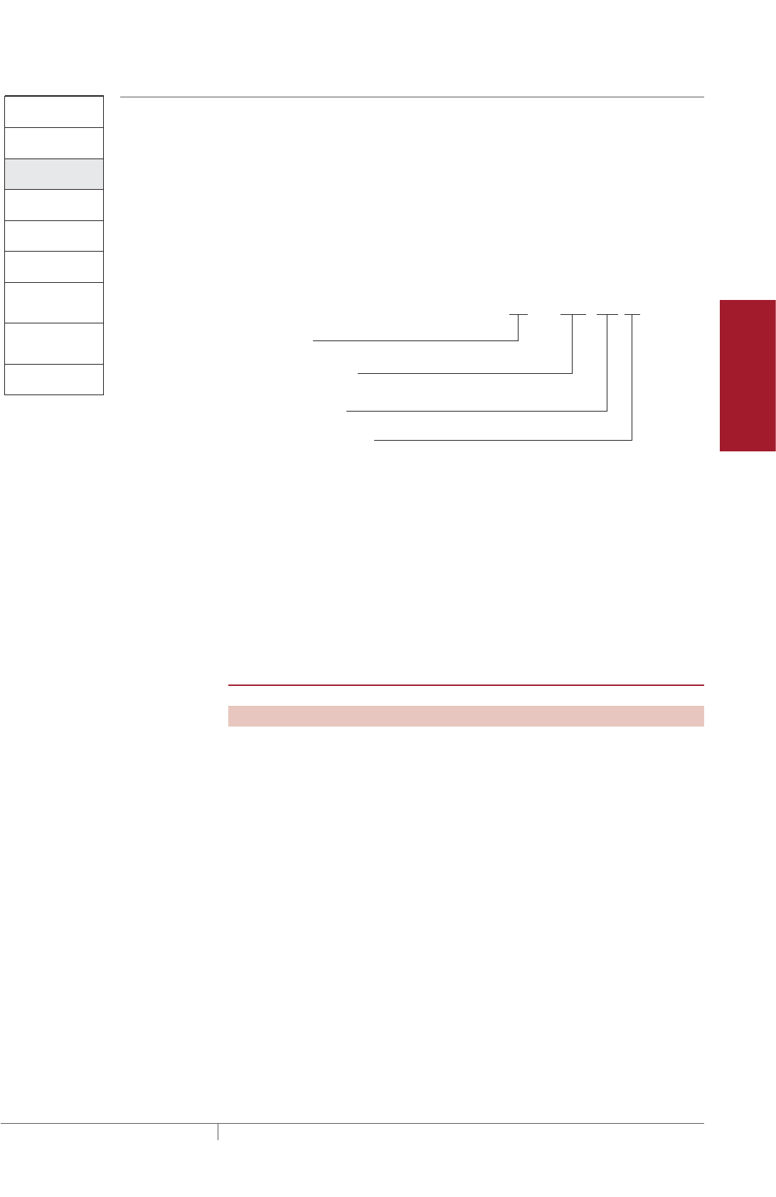
93THERMAL MANAGEMENT SOLUTIONS EN-RaychemIceStopRoofGutterDeIcing-DG-H56070 11/13
Pipe Freeze Protection
and Flow Maintenance
Fire Sprinkler System
Freeze Protection
Roof and Gutter
De-Icing
Surface Snow
Melting – MI
Surface Snow
Melting – ElectroMelt
Freezer Frost
Heave Prevention
Floor Heating Technical Data
Sheets
Roof and Gutter
De-Icing
1. Determine design
conditions
2. Select the heating
cable
3. Determine the
heating cable length
4. Determine the
electrical parameters
5. Select the
connection kits
6. Select attachment
accessories and
method
7. Select the control
system and power
distribution
8. Complete the Bill
of Materials
Step Select the heating cable
To select the appropriate IceStop heating cable for your application, use the supply
voltage from Step 1, and select the appropriate outer jacket material. Once you
select these, you will be able to determine the catalog number for your cable.
HEATING CABLE CATALOG NUMBER
Before beginning, take a moment to understand the structure underlying the heating
cable catalog numbers. You will refer to this numbering convention throughout the
product selection process. Select the appropriate heating cable catalog number
based on the voltage and outer jacket, as indicated below.
Catalog number: GM — 1 or 2 -X -XT
Product family
Voltage 1 = 120 V
2 = 208–277 V
Jacket type: Polyolefin
Fluoropolymer
or
or
Fig. 4 Heating cable catalog number
SELECT HEATING CABLE SUPPLY VOLTAGE
Select the heating cable supply voltage. Note that a higher supply voltage will allow
for longer circuit lengths. Supply voltage options include:
1 = 120 V
2 = 208–277 V
EVALUATE HEATING CABLE SPECIFICATIONS
Use the following table to evaluate heating cable specifications that describe some
important aspects of the heating cable.
TABLE 1 ICESTOP SELFREGULATING HEATING CABLE SPECIFICATIONS
Power output (nominal) 12 W/ft (39 W/m) in ice or snow
Minimum installation temperature 0°F (–18°C)
Minimum bend radius 5/8 in (16 mm)
SELECT OUTER JACKET
Select the appropriate heating cable outer jacket for the application. Jacket options
include:
-X A polyolefin outer jacket (-X) is more economical for less demanding
applications.
-XT A fluoropolymer outer jacket (-XT) provides maximum abrasion, chemical,
and mechanical resistance.
Example: Roof and Gutter De-Icing System
Supply voltage 208 V (from Step 1)
Catalog number GM-2XT
Roof and Gutter De-Icing Design
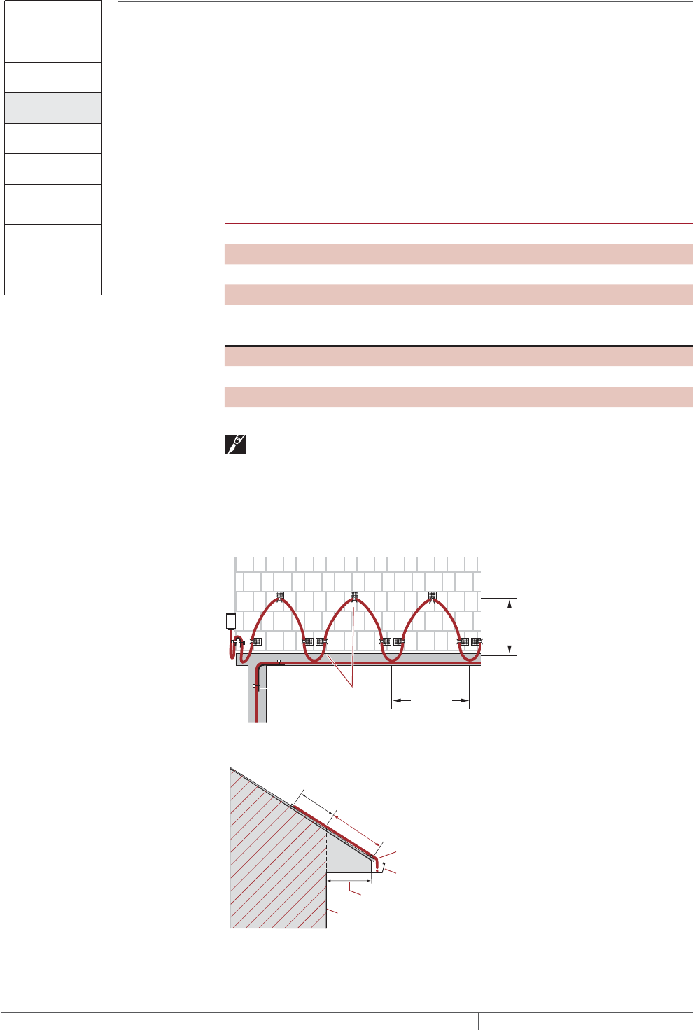
THERMAL MANAGEMENT SOLUTIONS
EN-RaychemIceStopRoofGutterDeIcing-DG-H56070 11/13
94
Roof and Gutter
De-Icing
1. Determine design
conditions
2. Select the heating
cable
3. Determine the
heating cable length
4. Determine the
electrical parameters
5. Select the
connection kits
6. Select attachment
accessories and
method
7. Select the control
system and power
distribution
8. Complete the Bill
of Materials
Step Determine the heating cable length
To determine the required heating cable length for your application, you will need to
determine the heating cable layout for each roof and gutter section that requires ice
protection. Detailed sketches of the building from Step 1 can ensure each area
and level is accounted for. The following guide will help determine length of cable
required for a variety of roof types and sections. For applications not covered in this
section, please contact Pentair Thermal Management for assistance.
Heating cable layout depends primarily on the roof type and its related roof features.
The following sections show typical layouts on standard roof types
TABLE 2 ROOF TYPES AND AREAS
Roof type Page
Sloped roof – standard page 95
Sloped roof – standing seam page96
Flat roof page97
Sloped roof without gutters page98
Roof features
Roof valley page99
Roof/wall intersections page99
Gutters page100
Downspouts page101
Important: For optimum performance, the heating cable should be in contact
with snow or ice. Installing the heating cable under the roofing or the roofing
materials will reduce the efficiency of the heating system. Please contact Pentair
Thermal Management for assistance.
Fig. 5 and Fig. 6 below illustrate several important terms:
Tracing
width
Tracing
height
Clips
Downspout
hanger
Fig. 5 Front view of roof with IceStop system
12" (30 cm)
Area where ice dams are
most likely to form
Eave overhang
Exterior wall
Heating cable
Gutter
Roof
Heated
area
Fig. 6 Side view of roof with IceStop system
ROOF AND GUTTER DEICING ICESTOP SYSTEM
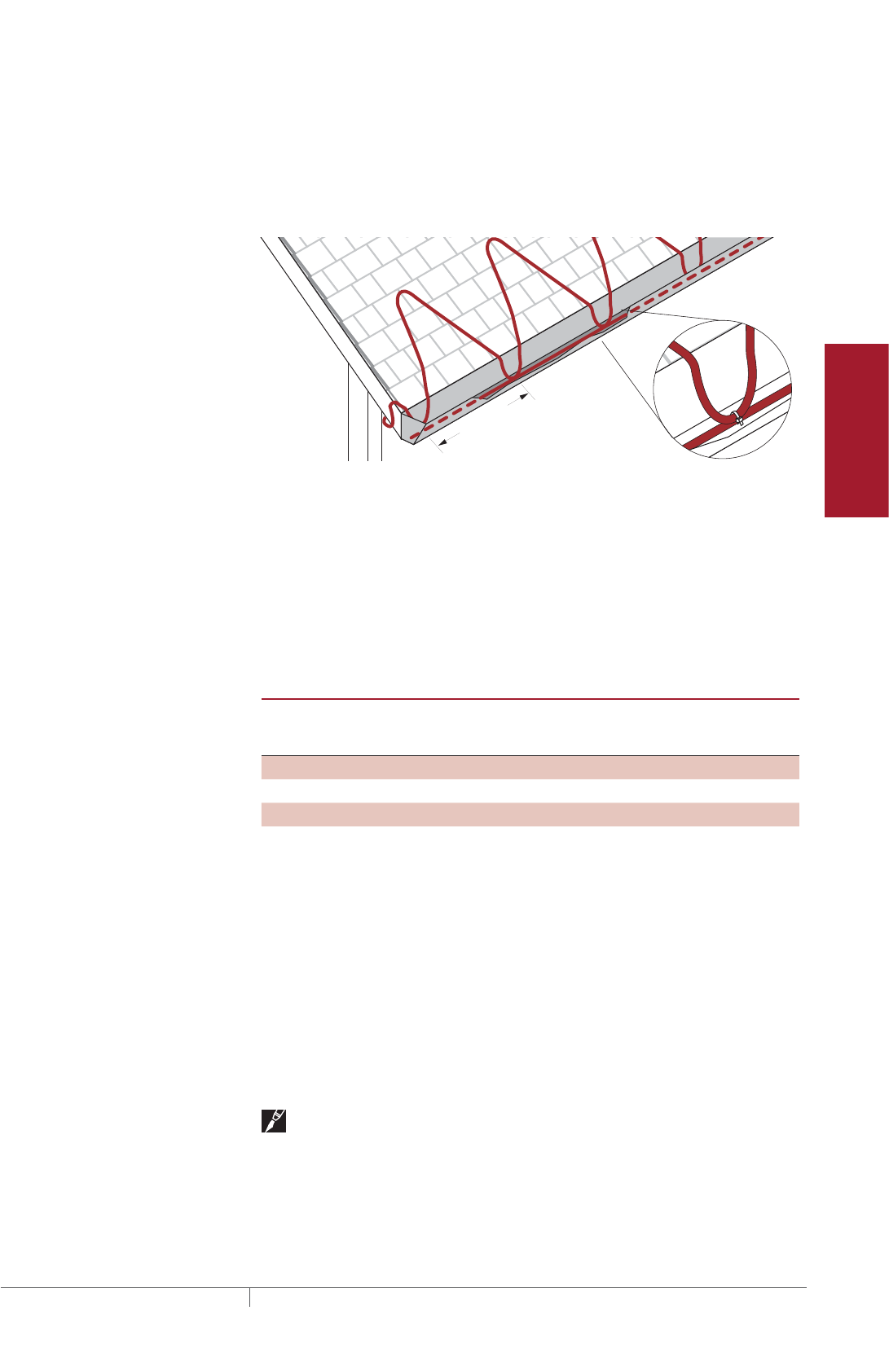
95THERMAL MANAGEMENT SOLUTIONS EN-RaychemIceStopRoofGutterDeIcing-DG-H56070 11/13
Pipe Freeze Protection
and Flow Maintenance
Fire Sprinkler System
Freeze Protection
Roof and Gutter
De-Icing
Surface Snow
Melting – MI
Surface Snow
Melting – ElectroMelt
Freezer Frost
Heave Prevention
Floor Heating Technical Data
Sheets
SLOPED ROOF STANDARD
For sloped roofs, ice dams may form at the roof edge. To maintain a continuous
path for melt water runoff, route the heating cable in a zig-zag pattern as shown
in Fig. 7 and follow the appropriate attachment recommendations in “Step 6 Select
attachment accessories and method” on page107. Additional heating cable may be
needed for other gutters, downspouts, and valleys.
2' (60 cm)
Fig. 7 Layout in a zig-zag pattern
• Install the heating cable on the roof in a zig-zag pattern as shown in Fig. 7.
• Run heating cable up the roof until it is 12 inches (30 cm) past the exterior wall
into the heated area (see Fig. 6 on page94).
• Use Table 3 to determine how much heating cable to use per foot of roof edge.
This will determine how much heating cable you need to trace on the roof. Ad-
ditional heating cable will be needed for gutters, downspouts, and component
connections.
TABLE 3 ICESTOP HEATING CABLE LENGTH FOR SLOPED ROOF STANDARD
Eave
overhang
distance Tracing width Tracing height
Feet of heating
cable per foot
of roof edge
Meters of heating
cable per meter
of roof edge
0 2 ft (60 cm) 12 in (30 cm) 2.5 ft 2.5 m
12 in (30 cm) 2 ft (60 cm) 24 in (60 cm) 3.1 ft 3.1 m
24 in (60 cm) 2 ft (60 cm) 36 in (90 cm) 4.2 ft 4.2 m
36 in (90 cm) 2 ft (60 cm) 48 in (120 cm) 5.2 ft 5.2 m
For roofs without gutters, add 6 inches of heating cable per foot of roof edge (0.5
meters of heating cable per meter of roof edge) to allow for a 2–3 inch (5–8 cm) drip
loop to hang off the roof edge as shown in Fig. 10 on page98.
For roofs with gutters, heating cable must be run to the bottom of the gutter. You
can determine the amount of extra heating cable required by adding twice the gutter
depth per foot of roof edge to the amount determined in Table 3.
For example, for a 6 inch deep gutter, add 1 foot of heating cable per foot of roof edge
to the amount determined using Table 3.
Additional heating cable must be run along the bottom of the gutter. See “Gutters”
on page100.
Note: Attachment methods are not shown in Fig. 7. For attachment methods,
proceed to “Step 6 Select attachment accessories and method” on page107.
Roof and Gutter De-Icing Design
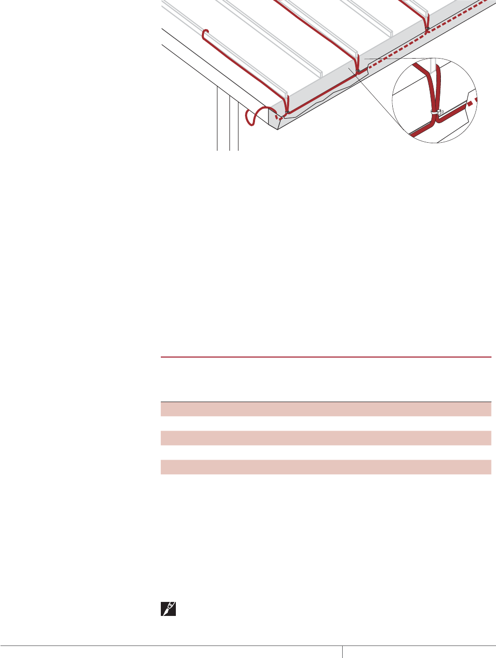
THERMAL MANAGEMENT SOLUTIONS
EN-RaychemIceStopRoofGutterDeIcing-DG-H56070 11/13
96
SLOPED ROOF STANDING SEAM
For sloped standing-seam metal roofs, ice dams may form at the roof edge. To
maintain a continuous path for melt water to run off, route the heating cable along
the seams as shown in Fig. 8 and follow the attachment recommendations in “Step 6
Select attachment accessories and method” on page107. Additional heating cable
may be needed for gutters, downspouts, and valleys.
Fig. 8 Layout on a standing seam roof
• Run the heating cable up one side of the seam, loop it over to the other side, and
return it to the bottom of the gutter. Continue along the bottom of the gutter to
the third seam and repeat the process (Fig. 8 on page96). If the seams are
more than 24 inches (60 cm) apart, trace every seam.
• Run the heating cable up the seam until it is 12 inches (30 cm) past the exterior
wall and into a heated area, Fig. 6 on page94.
• If the roofing materials continue down the fascia, contact your local Pentair Thermal
Management representative or Pentair Thermal Management directly for design
assistance.
• If there are no gutters, refer to “Heated Drip Edges” on page112, for information
on how to install heating cable for this application.
TABLE 4 ICESTOP HEATING CABLE LENGTH FOR SLOPED ROOF
STANDING SEAM
Eave overhang
distance
Standing seam
spacing Tracing height
Feet of heating
cable per foot
of roof edge
Meters of
heating cable
per meter of
roof edge
12 in (30 cm) 18 in (45 cm) 24 in (60 cm) 2.8 ft 2.8 m
24 in (60 cm) 18 in (45 cm) 36 in (90 cm) 3.6 ft 3.6 m
36 in (90 cm) 18 in (45 cm) 48 in (120 cm) 4.3 ft 4.3 m
12 in (30 cm) 24 in (60 cm) 24 in (60 cm) 2.4 ft 2.4 m
24 in (60 cm) 24 in (60 cm) 36 in (90 cm) 2.9 ft 2.9 m
36 in (90 cm) 24 in (60 cm) 48 in (120 cm) 3.6 ft 3.6 m
For standing seam roofs without gutters, add 6 inches (0.1 meter) of heating cable
for each seam traced to allow for a 2–3 inch (5–8 cm) drip loop to hang off the roof
edge as shown in Fig. 10.
For standing seam roofs with gutters, heating cable must be run to the bottom of the
gutter. You can determine the amount of extra heating cable required by adding twice
the gutter depth per seam traced to the amount determined in Table 4.
Additional heating cable will be needed for component connections and downspouts.
Note: Attachment methods are not shown in Fig. 8. For attachment methods,
proceed to “Step 6 Select attachment accessories and method” on page107.
ROOF AND GUTTER DEICING ICESTOP SYSTEM
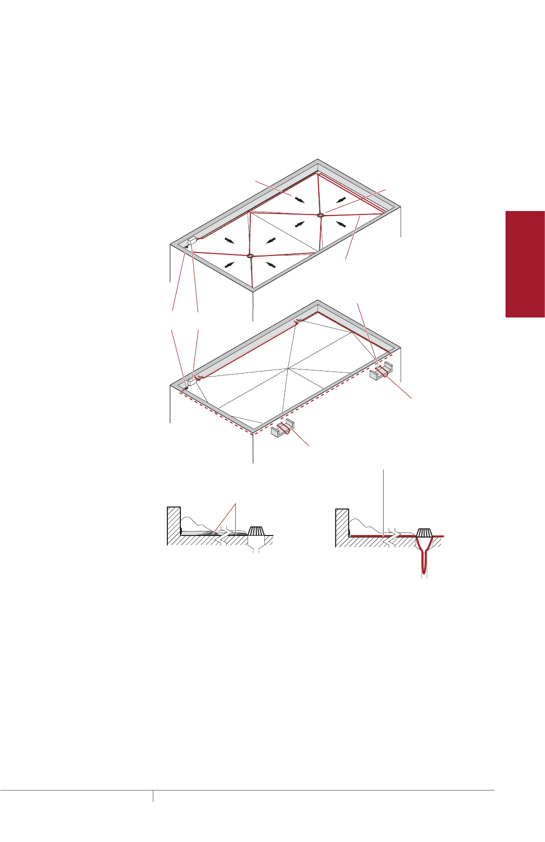
97THERMAL MANAGEMENT SOLUTIONS EN-RaychemIceStopRoofGutterDeIcing-DG-H56070 11/13
Pipe Freeze Protection
and Flow Maintenance
Fire Sprinkler System
Freeze Protection
Roof and Gutter
De-Icing
Surface Snow
Melting – MI
Surface Snow
Melting – ElectroMelt
Freezer Frost
Heave Prevention
Floor Heating Technical Data
Sheets
FLAT ROOF
Ice dams may occur on flat roofs at the edge flashing and at drains. Flat roofs are
typically pitched toward drains and these paths often become obstructed by snow
and ice. To maintain a continuous path for melt water to run off, route the heating
cable as shown in Fig. 9 and follow the appropriate attachment recommendations
in “Step 6 Select attachment accessories and method” on page107. Additional
heating cable may be needed for downspouts.
Junction
box
Cable
end seal
Drain
Slope
Ice can form around
drain and at roof edges
where adjacent snow
thaws during the day
and refreezes at night.
Heating cable provides a
continuous heated path to
allow melt water to run off
the roof before it refreezes.
Heating cable should be positioned around
the perimeter and in the valleys of a flat roof.
The heating cable must extend into the drain or
scupper to allow the melt water to exit the roof.
Scupper
Drip loop
Fig. 9 Layout on a flat roof
• Place heating cable around perimeter.
• Trace valleys from perimeter to drain.
• Extend heating cable into internal downspouts at least 12 inches (30 cm) into
heated space.
• External downspouts and scuppers must be treated carefully. A path must be pro-
vided for the valley/perimeter heating cable to the point of discharge (see Fig. 17
on page101).
• To avoid damage, do not walk on the heating cable.
Roof and Gutter De-Icing Design
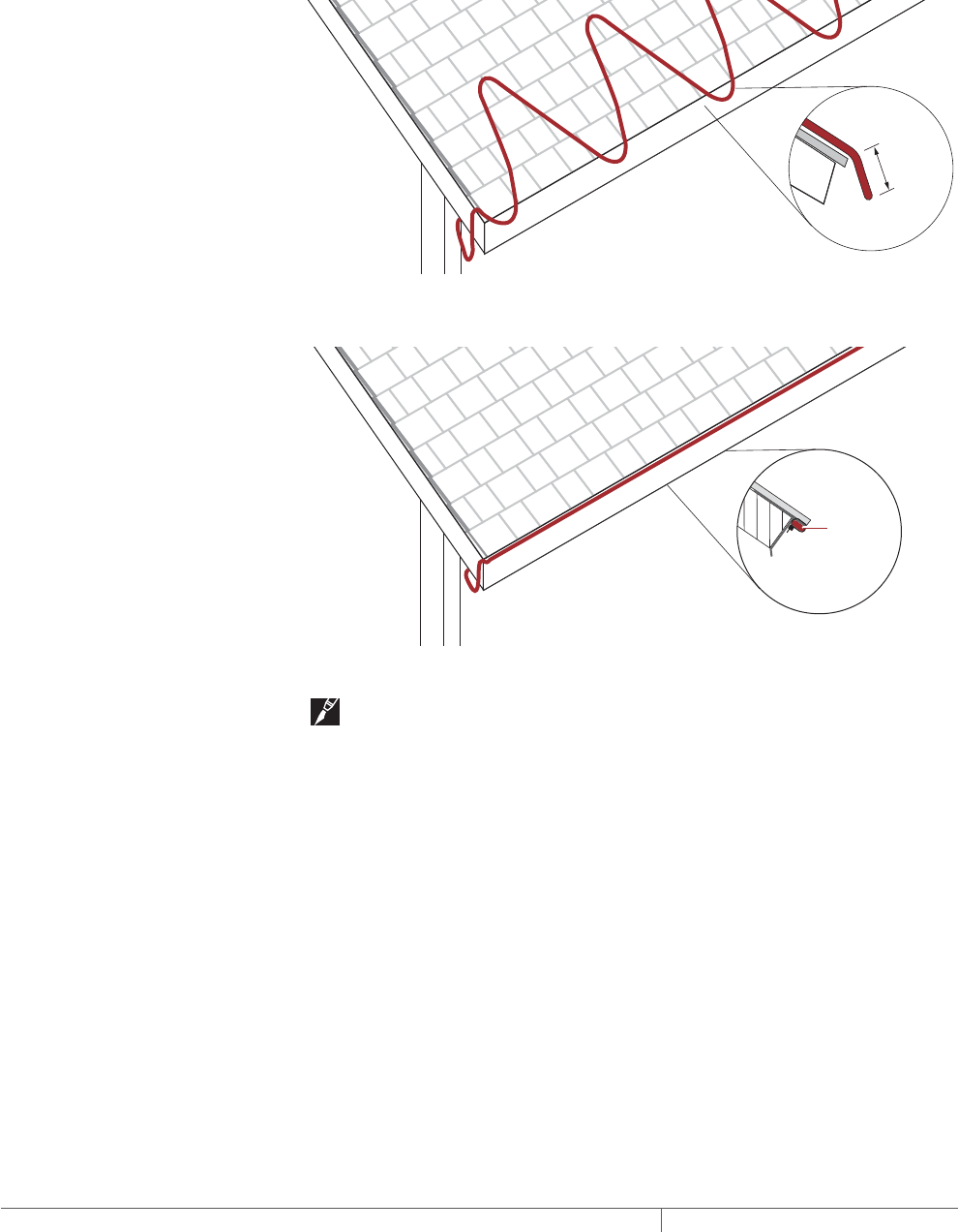
THERMAL MANAGEMENT SOLUTIONS
EN-RaychemIceStopRoofGutterDeIcing-DG-H56070 11/13
98
SLOPED ROOF WITHOUT GUTTERS
When gutters are not used on a building, ice dams may form at the roof edge. To
maintain a continuous path for melt water to run off, a drip loop or heated drip edge
may be used. Drip loops and drip edges allow water to drip free of the roof edge.
Route the heating cable as shown in Fig. 10 or Fig. 11 below and follow the
appropriate attachment recommendations in “Step 4 Determine the electrical
parameters” on page102. Additional heating cable may be needed for valleys.
2"–3"
(5–8 cm)
Fig. 10 Layout for heated drip loops
IceStop
heating
cable
Fig. 11 Layout for heated drip edge
Note: Attachment methods are not shown in the above illustrations. For
attachment methods, proceed to “Step 6 Select attachment accessories and
method” on page107.
OTHER CONSIDERATIONS
• Ice will build up on the surfaces below the drip loop or drip edge if gutters are not
used.
• Ice may also build up on the vertical surfaces if there isn’t a sufficient overhang or
if there is a strong wind. Using a gutter system will prevent this ice buildup.
ROOF AND GUTTER DEICING ICESTOP SYSTEM
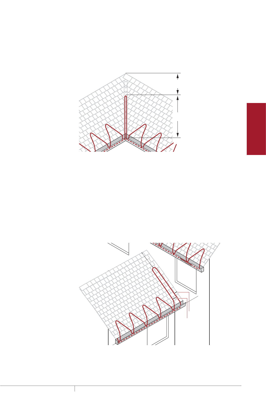
99THERMAL MANAGEMENT SOLUTIONS EN-RaychemIceStopRoofGutterDeIcing-DG-H56070 11/13
Pipe Freeze Protection
and Flow Maintenance
Fire Sprinkler System
Freeze Protection
Roof and Gutter
De-Icing
Surface Snow
Melting – MI
Surface Snow
Melting – ElectroMelt
Freezer Frost
Heave Prevention
Floor Heating Technical Data
Sheets
ROOF VALLEYS
Ice dams may form at the valley on a roof where two different slopes meet. To
maintain a continuous path for melt water, run the heating cable up and down the
valley as shown in Fig. 12 and follow the appropriate attachment recommendations
in “Step 6 Select attachment accessories and method” on page107. Additional
heating cable may be needed for the roof surface, gutters, and downspouts.
2/3
1/3
Fig. 12 Layout for a roof valley
• Trace two-thirds of the way up each valley with a double run of heating cable (loop
up and back once).
• The heating cable must extend into the gutter. If you don’t have gutters, the heat-
ing cable should extend over the edge 2 to 3 inches (5 to 8 cm) to form a drip loop.
• For attachment methods, proceed to “Step 6 Select attachment accessories and
method” on page107.
ROOF/WALL INTERSECTIONS
Roof/wall intersections can be treated in the same manner as valleys. Snow has
a tendency to collect at this interface. Providing a loop of heating cable two-thirds
of the way up the slope will provide a path for the extra melt water in this area to
escape.
2"–3"
4"–6"
1/3
2/3
Fig. 13 Layout for a roof/wall intersection.
• Extend a loop of heating cable two-thirds of the way up the slope adjacent to the
wall.
• Position the closest heating cable approximately 2 to 3 inches (5 to 8 cm) from the
wall. Position the second heating cable 4 to 6 inches (10 to 16 cm) from the first.
Roof and Gutter De-Icing Design
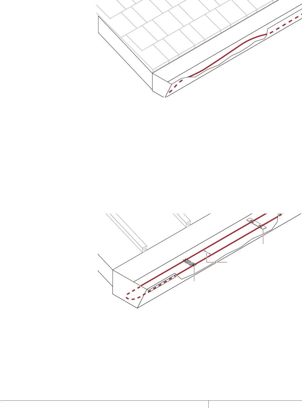
THERMAL MANAGEMENT SOLUTIONS
EN-RaychemIceStopRoofGutterDeIcing-DG-H56070 11/13
100
GUTTERS
Ice may accumulate in gutters and at the roof edge. To maintain a continuous
path for melt water to run off, route the heating cable as shown in Fig. 14 below.
Additional heating cable may be needed for the roof surface, downspouts, and
valleys.
Fig. 14 Layout in standard gutters — up to 6" (16 cm) wide
• Use one run of heating cable in the gutter.
• No attachment to gutter is normally required. If attachment is desired, use a roof
clip such as a Raychem GMK-RC clip.
• Continue heating cable down the inside of the downspout. See “Downspouts,”
page101, for more information.
In wide gutters, snow and ice can bridge over the tunnel created by a single
heating cable and prevent melt water from getting into the gutter and downspouts.
To maintain a continuous path for melt water to run off, run the heating cable
in the gutter as shown in Fig. 15 below and follow the appropriate attachment
recommendations in “Step 6 Select attachment accessories and method” on
page107. Additional heating cable may be needed for the roof surface, downspouts,
and valleys.
6" (15 cm) spacing
maximum
GM-RAKE
GMK-RC
Fig. 15 Layout in wide gutters — 6" to 12" (16 to 31 cm) wide
• Use two parallel runs of heating cable. Separate the two runs of heating cable
with a pair of GMK-RC clips or a single GM-RAKE downspout hanger bracket.
• No attachment to the gutter is normally required. If attachment is desired, use a
GMK-RC with appropriate adhesive.
• Continue heating cable down the inside of the downspout. See “Downspouts,”
page101 for more information.
ROOF AND GUTTER DEICING ICESTOP SYSTEM
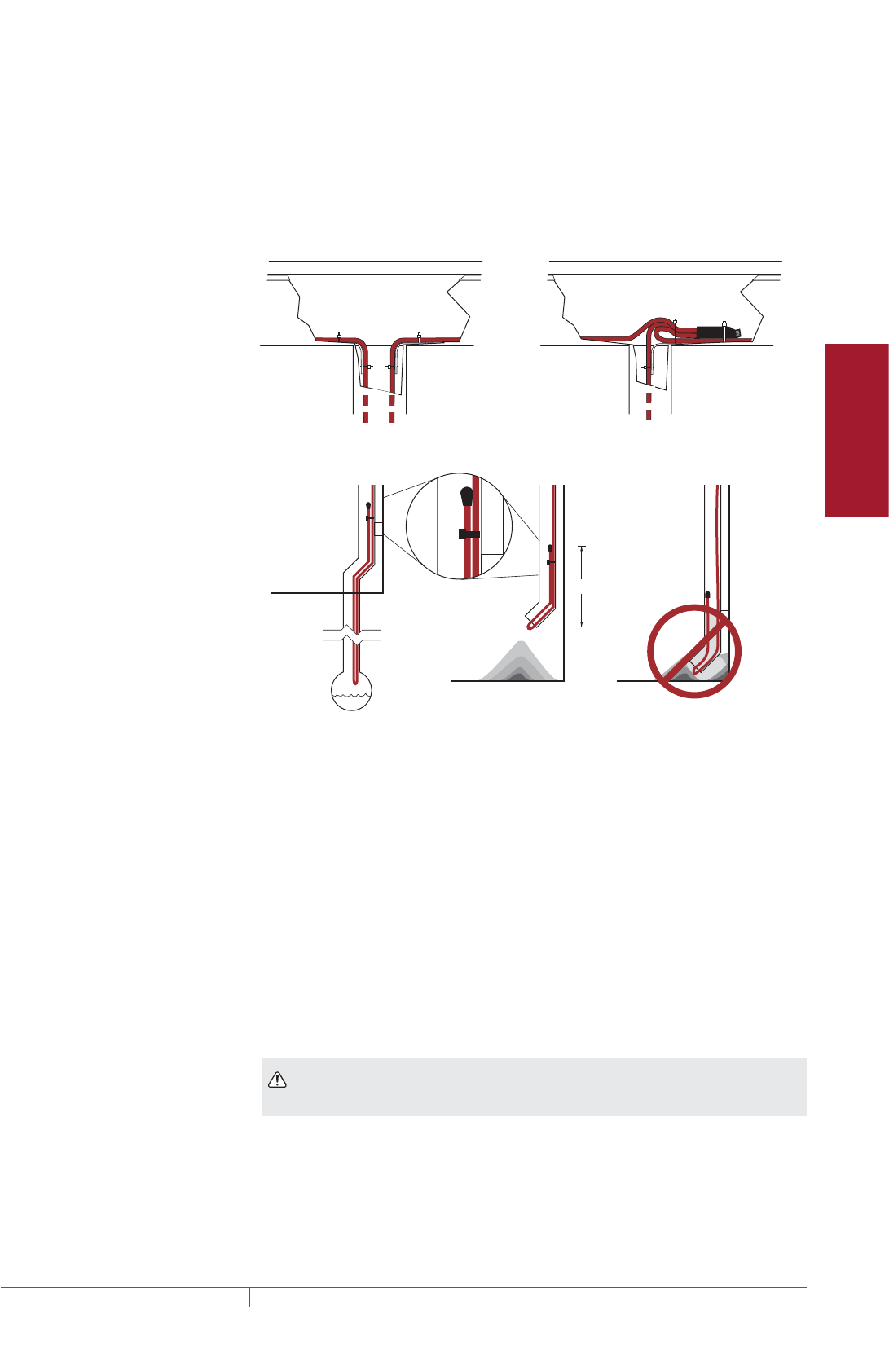
101THERMAL MANAGEMENT SOLUTIONS EN-RaychemIceStopRoofGutterDeIcing-DG-H56070 11/13
Pipe Freeze Protection
and Flow Maintenance
Fire Sprinkler System
Freeze Protection
Roof and Gutter
De-Icing
Surface Snow
Melting – MI
Surface Snow
Melting – ElectroMelt
Freezer Frost
Heave Prevention
Floor Heating Technical Data
Sheets
DOWNSPOUTS
Ice may form in downspouts and prevent melt water from escaping from the roof. To
maintain a continuous path for melt water to run off, run the heating cable inside the
downspout to the end as shown in Fig. 16 and Fig. 17 below. Follow the appropriate
attachment recommendations in “Step 6 Select attachment accessories and
method” on page107. Additional heating cable may be needed for the roof surface,
gutters, and valleys.
Fig. 16 Heating cable at top of downspout
Drain removes melt water
below the frost line.
Accumulated ice
may block drains.
Accumulated ice
can be removed.
12"
Fig. 17 Heating cable at bottom of downspout
• If the downspout ends underground, the heating cable should extend into a
heated area or below the frost line.
• For low water-flow situations, teeing the heating cable so that a single run goes
down the downspout is usually sufficient. For high water-flow situations, where
ambient temperatures often fall below –10°F (–23°C), or where it isn’t convenient
to tee the heating cable, use two runs by running the heating cable down to the
bottom and then back to the top.
• Leave drip loops below the downspout at bottom.
• If a single run of heating cable is used, the end seal should be looped back up at
least 12 inches (30 cm) inside the downspout.
• If the downspout ends near the ground, water will refreeze on the ground and
build up around the downspout, eventually blocking the opening.
WARNING: To prevent mechanical damage, do not leave the end seal exposed
at the end of the downspout.
Roof and Gutter De-Icing Design

THERMAL MANAGEMENT SOLUTIONS
EN-RaychemIceStopRoofGutterDeIcing-DG-H56070 11/13
102
Example: Roof and Gutter De-Icing System
Type of roof Sloped roof – standard with wood shingles and gutters
(from 1)
Layout
Roof edge 100 ft (30.5 m) (from Step 1)
Eave overhang 24 inch (60 cm) (from Step 1)
Requires 4.2 ft of heating cable per foot of roof edge
(4.2 m per meter of roof edge). See Table 2.
Gutters
Length 100 ft (30.5 m) (from Step 1)
= 100 ft (30.5 m) heating cable
Depth 6 in (11 cm) x 2 (from Step 1)
= 1 foot of additional heating cable 4.2 ft + 1 ft = 5.2 ft x 100 ft
= 520 ft (158.5 m) heating cable
Width 4 in (from Step 1)
therefore single run of heating cable at indicated gutter length
Roof valley 20 ft (6.1 m) (from Step 1) x 1.33 = 26.6
= rounded to 27 ft (8.3 m) heating cable
Downspouts Two 12 ft (3.7 m) (from Step 1)
= 26 ft (8.0 m) heating cable
(Single runs in each downspout with 1 ft (0.3 m) loop back
from bottom)
Total heating cable length 673 ft (205.2 m)
Additional heating cable will be required for connection kits. After determining kit
requirements, heating cable allowances for each will be added to total heating cable
length for Bill of Materials.
Roof and Gutter
De-Icing
1. Determine design
conditions
2. Select the heating
cable
3. Determine the
heating cable length
4. Determine the
electrical parameters
5. Select the
connection kits
6. Select attachment
accessories and
method
7. Select the control
system and power
distribution
8. Complete the Bill
of Materials
Step Determine the electrical parameters
This section will help you determine the electrical parameters for an IceStop system
including circuit breaker sizing and maximum circuit length. Total required heating
cable length divided by maximum heating cable circuit length will determine the
number of circuits required for your snow melting solution.
DETERMINE MAXIMUM CIRCUIT LENGTH
To determine maximum circuit length, it is important to establish a minimum startup
temperature for the system. Table 5 provides maximum circuit lengths based on
minimum startup temperature, circuit breaker rating and supply voltage. Colder
temperature startup requires shorter maximum circuit lengths. The use of an
automatic system, which energizes the system above 20°F (–7°C), ensures that you
can use maximum circuit lengths. Manual control systems may require you to use
shorter circuit lengths to compensate for startup below 20°F (–7°C).
ROOF AND GUTTER DEICING ICESTOP SYSTEM
103THERMAL MANAGEMENT SOLUTIONS EN-RaychemIceStopRoofGutterDeIcing-DG-H56070 11/13
Pipe Freeze Protection
and Flow Maintenance
Fire Sprinkler System
Freeze Protection
Roof and Gutter
De-Icing
Surface Snow
Melting – MI
Surface Snow
Melting – ElectroMelt
Freezer Frost
Heave Prevention
Floor Heating Technical Data
Sheets
Select the smallest appropriate circuit breaker size. A 30-mA ground-fault protection
device (GFPD) must be used to provide protection from arcing or fire, and to comply
with warranty requirements, agency certifications, and national electrical codes. If
the heating cable is improperly installed, or physically damaged, sustained arcing
or fire could result. If arcing does occur, the fault current may be too low to trip
conventional circuit breakers.
TABLE 5 MAXIMUM CIRCUIT LENGTH IN FEET METERS
Heating cable
Start-up
temperature
Circuit breaker size Max.
A/ft (A/m)15 A 20 A 30 A 40 A ¹
GM-1X and -1XT at 120 V 32°F (0°C) 100 (30) 135 (41) 200 (61) – 0.120 (0.394)
20°F (–7°C) 95 (29) 125 (38) 185 (56) 200 (61) 0.126 (0.414)
0°F (–18°C) 80 (24) 100 (30) 155 (47) 200 (61) 0.150 (0.492)
GM-2X and -2XT at 208 V 32°F (0°C) 190 (58) 250 (76) 380 (116) – 0.063 (0.207)
20°F (–7°C) 180 (55) 235 (72) 355 (108) 380 (116) 0.067 (0.220)
0°F (–18°C) 145 (44) 195 (59) 290 (88) 380 (116) 0.083 (0.272)
GM-2X and -2XT at 240 V 32°F (0°C) 200 (61) 265 (81) 400 (122) – 0.060 (0.197)
20°F (–7°C) 190 (58) 250 (76) 370 (113) 400 (122) 0.063 (0.207)
0°F (–18°C) 155 (47) 205 (62) 305 (93) 400 (122) 0.077 (0.253)
GM-2X and -2XT at 277 V 32°F (0°C) 215 (66) 290 (88) 415 (126) – 0.056 (0.184)
20°F (–7°C) 200 (61) 265 (81) 400 (122) 415 (126) 0.060 (0.197)
0°F (–18°C) 165 (50) 225 (69) 330 (101) 415 (126) 0.073 (0.240)
¹ Only FTC-P power connection, FTC-HST splice/tee, and RayClic-E end kits may be used with 40-A circuits.
WARNING: To minimize the danger of fire from sustained electrical arcing if
the heating cable is damaged or improperly installed, and to comply with the
requirements of Pentair Thermal Management, agency certifications, and national
electrical codes, ground-fault equipment protection must be used on each heating
cable branch circuit. Arcing may not be stopped by conventional circuit protection.
Example: Roof and Gutter De-Icing System
Startup temperature 20°F (–7°C) (from Step 1)
Circuit breakers 30 A
Supply voltage 208 V (from Step 1)
Maximum circuit length 355 ft (108 m) (from Table 5)
DETERMINE NUMBER OF CIRCUITS
Use the following formula to determine number of circuits for the system:
Number of circuits = Heating cable length required
Maximum heating cable circuit length
Example: Roof and Gutter De-Icing System
Total heating cable length 673 ft (205.2 m) (from Step 3)
Maximum circuit length 355 ft (108 m) (from above)
Number of circuits 673 ft / 355 ft = 1.9 rounded to 2 circuits
Roof and Gutter De-Icing Design

THERMAL MANAGEMENT SOLUTIONS
EN-RaychemIceStopRoofGutterDeIcing-DG-H56070 11/13
104
DETERMINE TRANSFORMER LOAD
The total transformer load is the sum of load on all the circuit breakers in the
system.
Calculate the Circuit Breaker Load (CBL) as:
CBL (kW) =
Circuit breaker rating (A) x 0.8 x Supply voltage
___________________________________________________
1000
If the CBL is equal on all circuit breakers, calculate the Total Transformer Load as
follows:
Total Transformer Load (kW) = CBL x Number of circuits
If the CBL is not equal on all circuit breakers, calculate the Total Transformer Load
as follows:
Total Transformer Load (kW) = CBL1 + CBL2 + CBL3...+ CBLN
Example: Roof and Gutter De-Icing System
Circuit breaker load (CBL) = (30 A x 0.8 x 208 V) / 1000 = 5 kW
Total transformer load = 5 kW x 2 circuits = 10 kW
Roof and Gutter
De-Icing
1. Determine design
conditions
2. Select the heating
cable
3. Determine the
heating cable length
4. Determine the
electrical parameters
5. Select the
connection kits
6. Select attachment
accessories and
method
7. Select the control
system and power
distribution
8. Complete the Bill
of Materials
Step Select the connection kits
A typical IceStop system may have several connection kits to seal and power the
heating cable. The connection kits work together with the IceStop heating cable to
provide a safe and reliable de-icing system that is easy to install and maintain. The
available accessories are listed in Table 6. A complete IceStop system also consists
of attachment accessories and adhesives which we discuss later in “Step 6 Select
attachment accessories and method” on page107.
The self-regulating IceStop heating cable is cut to length at the job site. In order to
seal the heating cable from the environment and provide power, Pentair Thermal
Management approved connection kits must be used. A power connection kit is
required to attach power to one end of the heating cable. An end seal is required, and
is provided with each power connection to seal the other end. Splice and tee kits are
also available to connect two or three heating cables together.
RayClic and FTC connection kits are available for the IceStop system. The RayClic
connection kits are insulation-displacement quick connect systems. The FTC
connection kits use heat-shrinkable tubing and crimp barrels. All of these
connection kits are outlined in Table 6 below. Additional heating cable will be
required to allow for connection kit assembly and drip loops.
ROOF AND GUTTER DEICING ICESTOP SYSTEM
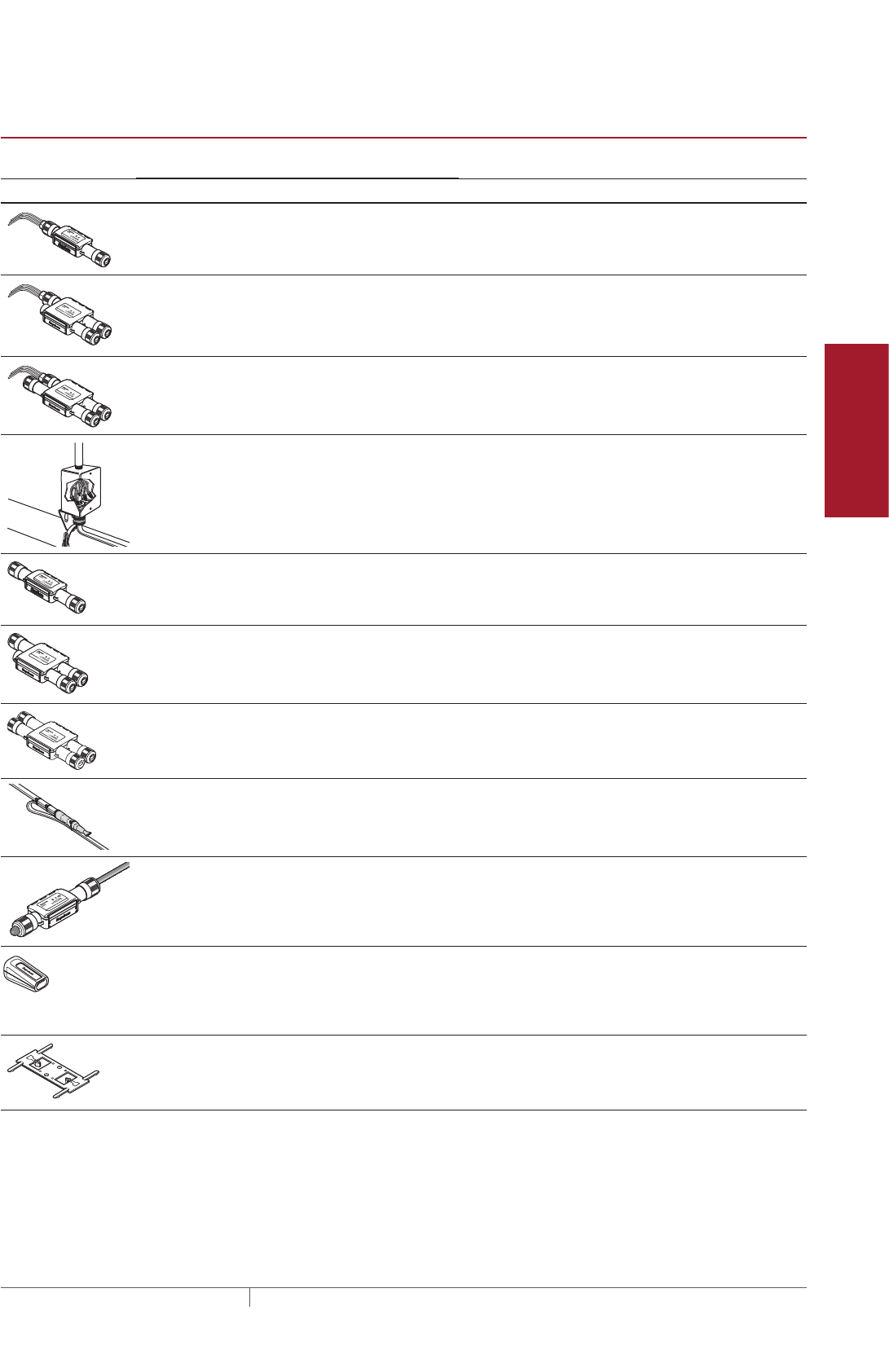
105THERMAL MANAGEMENT SOLUTIONS EN-RaychemIceStopRoofGutterDeIcing-DG-H56070 11/13
Pipe Freeze Protection
and Flow Maintenance
Fire Sprinkler System
Freeze Protection
Roof and Gutter
De-Icing
Surface Snow
Melting – MI
Surface Snow
Melting – ElectroMelt
Freezer Frost
Heave Prevention
Floor Heating Technical Data
Sheets
TABLE 6 CONNECTION KITS
Catalog
number Description
Standard
packaging Usage
Heating cable
allowance ¹
Connection kits
RayClic-PC Power connection and end seal
(RayClic-SB-04 pipe mounting
bracket included)
1 1 per circuit 2 ft (0.6 m)
RayClic-PS Powered splice and end seal
(RayClic-SB-04 pipe mounting
bracket included)
1 1 per circuit 4 ft (1.2 m)
RayClic-PT Powered tee and end seal
(RayClic-SB-04 pipe mounting
bracket included)
1 1 per circuit 6 ft (1.8 m)
FTC-P²Power connection and end seal
Note: FTC-P is required for
circuits requiring 40 A circuit
breakers.
1 1 per circuit 2 ft (0.6 m)
RayClic-S Splice 1 As required 2 ft (0.6 m)
RayClic-T Tee kit with end seal 1 As required 3 ft (0.9 m)
RayClic-X Cross connection to connect
four heating cables
1 As required 8 ft (2.4 m)
FTC-HST³Low-profile splice/tee 2 As required 2 ft (0.6 m)
RayClic-LE Lighted end seal
(RayClic-SB-04 pipe
mounting bracket included)
1 Alternate end seal 2 ft (0.6 m)
RayClic-E Extra end seal 1 Additional end seal 0.3 ft (0.1 m)
Accessories
RayClic-SB-02 Wall mounting bracket 1 Required for every
RayClic connection
kit
–
¹ Additional heating cable required for connection kit assembly and drip loops.
² Junction box not included.
³ One RayClic-E end seal is required for each FTC-HST used as a tee kit.
Roof and Gutter De-Icing Design

THERMAL MANAGEMENT SOLUTIONS
EN-RaychemIceStopRoofGutterDeIcing-DG-H56070 11/13
106
Example: Roof and Gutter De-Icing System
Connection kit
Quantity
Heating cable allowance
RayClic-PC 2 4 ft (1.2 m)
RayClic-PS 2 8 ft (2.4 m)
RayClic-SB-02 4 NA
Determine how much additional heating cable you need for the connection kits.
Example: Roof and Gutter De-Icing System
Sloped roof – standard 520 ft (158.5 m)
Gutters 100 ft (30.5 m)
Roof valley 27 ft (8.3 m)
Downspouts 26 ft (8.0 m)
Total heating cable allowance for connection kits 12 ft (4.0 m)
Total heating cable length required 685 ft (208.8 m)
ROOF AND GUTTER DEICING ICESTOP SYSTEM

107THERMAL MANAGEMENT SOLUTIONS EN-RaychemIceStopRoofGutterDeIcing-DG-H56070 11/13
Pipe Freeze Protection
and Flow Maintenance
Fire Sprinkler System
Freeze Protection
Roof and Gutter
De-Icing
Surface Snow
Melting – MI
Surface Snow
Melting – ElectroMelt
Freezer Frost
Heave Prevention
Floor Heating Technical Data
Sheets
Roof and Gutter
De-Icing
1. Determine design
conditions
2. Select the heating
cable
3. Determine the
heating cable length
4. Determine the
electrical parameters
5. Select the
connection kits
6. Select attachment
accessories and
method
7. Select the control
system and power
distribution
8. Complete the Bill
of Materials
Step Select attachment accessories and method
A typical IceStop system also consists of various attachment accessories and
adhesives for attaching the heating cable to the roof. The available accessories are
listed in Table 7he adhesives in Table 9. The type of attachment accessories you need
will depend on the type of roof you have. See Table 8 for details.
Always check with the roofing manufacturer for recommendations on how to
attaching heating cables to their roofing material.
TABLE 7 ATTACHMENT ACCESSORIES
Catalog
number Description
Standard
packaging Usage
Heating cable
allowance
GMK-RC Roof clips 50/box 1 box per 35' of roof edge when
zig-zag layout is used.
See Table 8 for other layout
options.
–
GMK-RAKE Hanger bracket 1 1 hanger per cable in down-
spout or as required for me-
chanical protection.
See Table 8 for other layout
options.
–
CT-CABLE-TIE UV-resistant cable tie 100/box As required.
–
Roof and Gutter De-Icing Design

THERMAL MANAGEMENT SOLUTIONS
EN-RaychemIceStopRoofGutterDeIcing-DG-H56070 11/13
108
Heating cable attachment depends primarily upon the roof type. The following table
shows the recommended attachment methods for typical roof materials and roof
areas.
TABLE 8 ATTACHMENT METHODS FOR TYPICAL ROOFS
Roof material
Recommended
attachment method
Alternate attachment
method
Shake/shingle “Mechanical Attachment,”
page109
Rubber/membrane “Belt Loop Approach,” page110 “Adhesive Attachment,”
page109
Metal “Mechanical Attachment,”
page109
“Adhesive Attachment,”
page109
“Belt Loop Approach,”
page110
Wood “Mechanical Attachment,”
page109
Other “Attachment Methods for Other
Areas,” page111
Area Attachment method
Gutters Recommend using hanger clips
glued to gutter for security if
possible (see page111)
Downspouts Downspout hangers (page111)
Drip edges Attached to a flat sheet or
standard drip edge, or installed
informed sheet metal (see
page112)
Component locations Drip loops
Roof edges with
no gutter
Drip loops
Note: Do not use adhesives on slate or tile roofs. Please contact roofing manufacturer
for a recommended attachment method or contact your Pentair Thermal Management
representative.
Adhesive is not supplied by Pentair Thermal Management. Follow manufacturer’s
instructions for surface preparation and installation.
TABLE 9 ADHESIVES
Adhesive Description Color
Approximate
tooling time
Cure
time
Dispensing
equipment
Momentive
Performance
Materials, Inc.
RTV167
Neutral-cure
silicone adhesive
Gray 20 minutes 48 hours Caulking gun
SpeedBonder®
H3300
Methacrylate
adhesive
Tan 15 minutes 24 hours 2 part mixing
dispenser
SpeedBonder
H4800
Methacrylate
adhesive
Light
yellow
45 minutes 24 hours 2 part mixing
dispenser
Plexus® MA300 Methacrylate
adhesive
Yellow 15 minutes 16 hours 2 part mixing
dispenser
Plexus MA310 Methacrylate
adhesive
Yellow 30 minutes 16 hours 2 part mixing
dispenser
Note: Before using adhesives on metal roofs check with the roofing manufacturer.
Trademarks are the property of their respective owners.
ROOF AND GUTTER DEICING ICESTOP SYSTEM
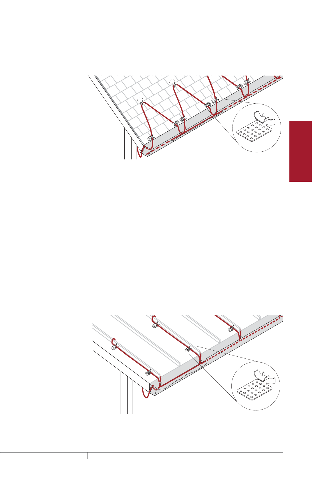
109THERMAL MANAGEMENT SOLUTIONS EN-RaychemIceStopRoofGutterDeIcing-DG-H56070 11/13
Pipe Freeze Protection
and Flow Maintenance
Fire Sprinkler System
Freeze Protection
Roof and Gutter
De-Icing
Surface Snow
Melting – MI
Surface Snow
Melting – ElectroMelt
Freezer Frost
Heave Prevention
Floor Heating Technical Data
Sheets
ROOF ATTACHMENT METHODS
Mechanical Attachment
One of the most common attachment methods is to use Raychem GMK-RC roof
clips. It can be used on all surfaces where nails or screws are acceptable.
Fig. 18 GMK-RC clip attachment
• The GMK-RC roof clips are used to secure IceStop heating cable. This
multipurpose bracket attaches with a screw, nail, or adhesive to many types of
roofs and gutters.
• One box of 50 GMK-RC roof clips is sufficient to attach the heating cable on 35
feet (9.1m) of roof edge using a zig-zag layout. Your layout may require additional
clips.
• For layouts other than the standard zig-zag, use one clip for each 5 to 10 feet (1.5
to 3m) of unsupported heating cable and at every change of heating cable direction.
• For standard sloped roofs, the loops of heating cable being zig-zag on the roof
should be attached using a UV-resistant cable tie to the heating cable run in the
gutter.
• For standing-seam roofs, the heating cable should be cable-tied together at the
bottom of the seam.
• For high wind areas, it is recommended to use a UV resistant cable tie to further
secure the heating cable to the attachment clip.
Adhesive Attachment
For roofs where penetrating attachments are not desired, use the GMK-RC roof clip
attached by adhesive.
Fig. 19 GMK-RC clip on standing-seam roof
Roof and Gutter De-Icing Design
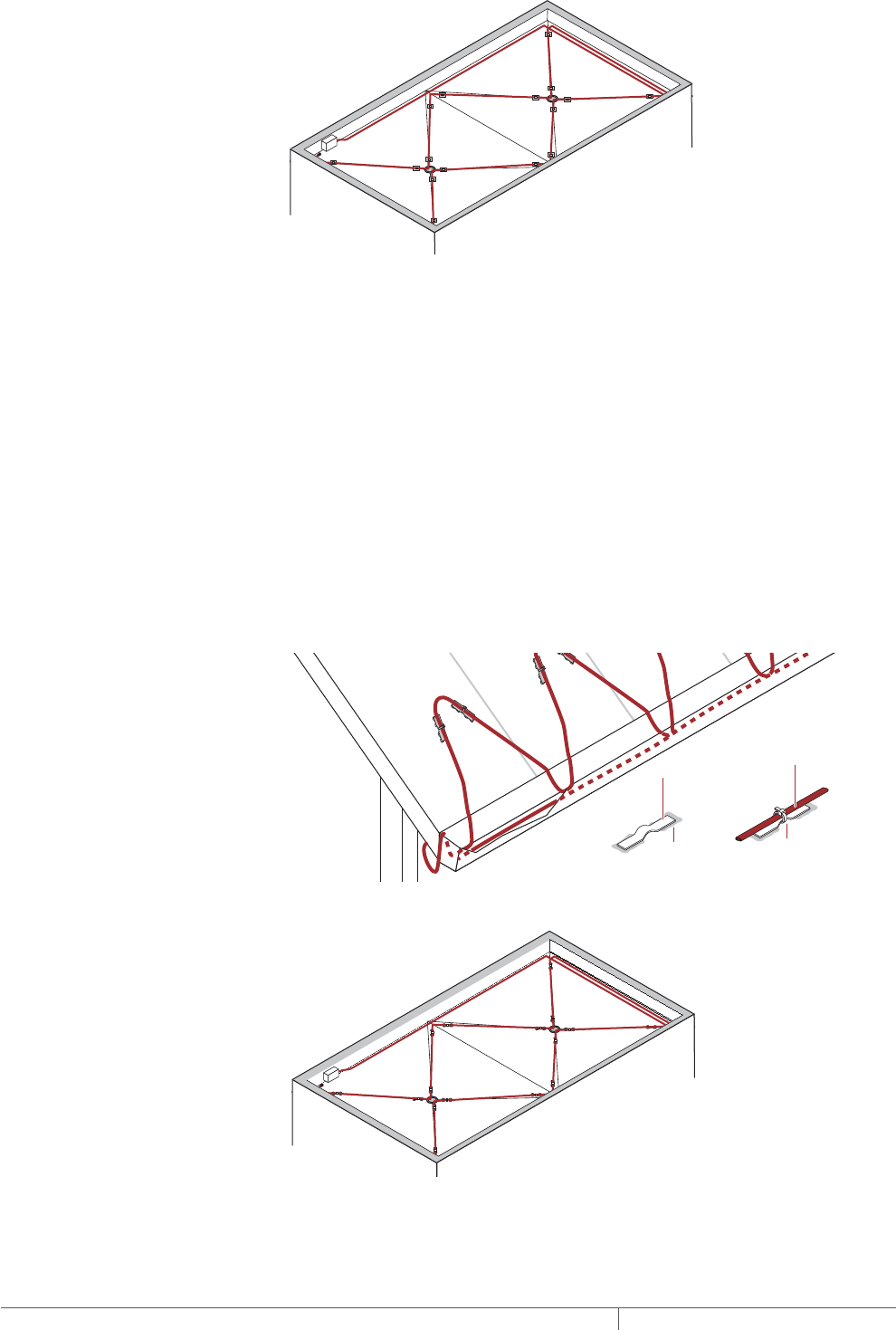
THERMAL MANAGEMENT SOLUTIONS
EN-RaychemIceStopRoofGutterDeIcing-DG-H56070 11/13
110
Fig. 20 GMK-RC clip on flat roof
• The GMK-RC roof clips are used to secure IceStop heating cable. The clip
attaches with adhesive (not supplied by Pentair Thermal Management) to many
types of roofs and gutters.
• Several different adhesives are recommended by Pentair Thermal Management.
See Table 9 on page108 or contact Pentair Thermal Management for alternatives.
• On a standing seam roof, use four clips on each seam being traced. On a flat sur-
face, use one clip for every 5 to 10 feet (1.5 to 3 m) of unsupported heating cable
and at every change of direction.
• Follow all recommendations from the adhesive manufacturer with regard to
cleaning and preparing the roof surface for the adhesive.
Belt Loop Approach
With the belt loop approach, strips of roofing materials are fastened to the roof using
standard means for that particular type of roof. The heating cable is attached with a
UV-resistant cable tie to the loop formed by this material.
Strip of roof
material
Roof
adhesive
Cable tie
Heating
cable
Fig. 21 Belt loop approach on a sloped roof
Fig. 22 Belt loop approach on a flat roof
ROOF AND GUTTER DEICING ICESTOP SYSTEM
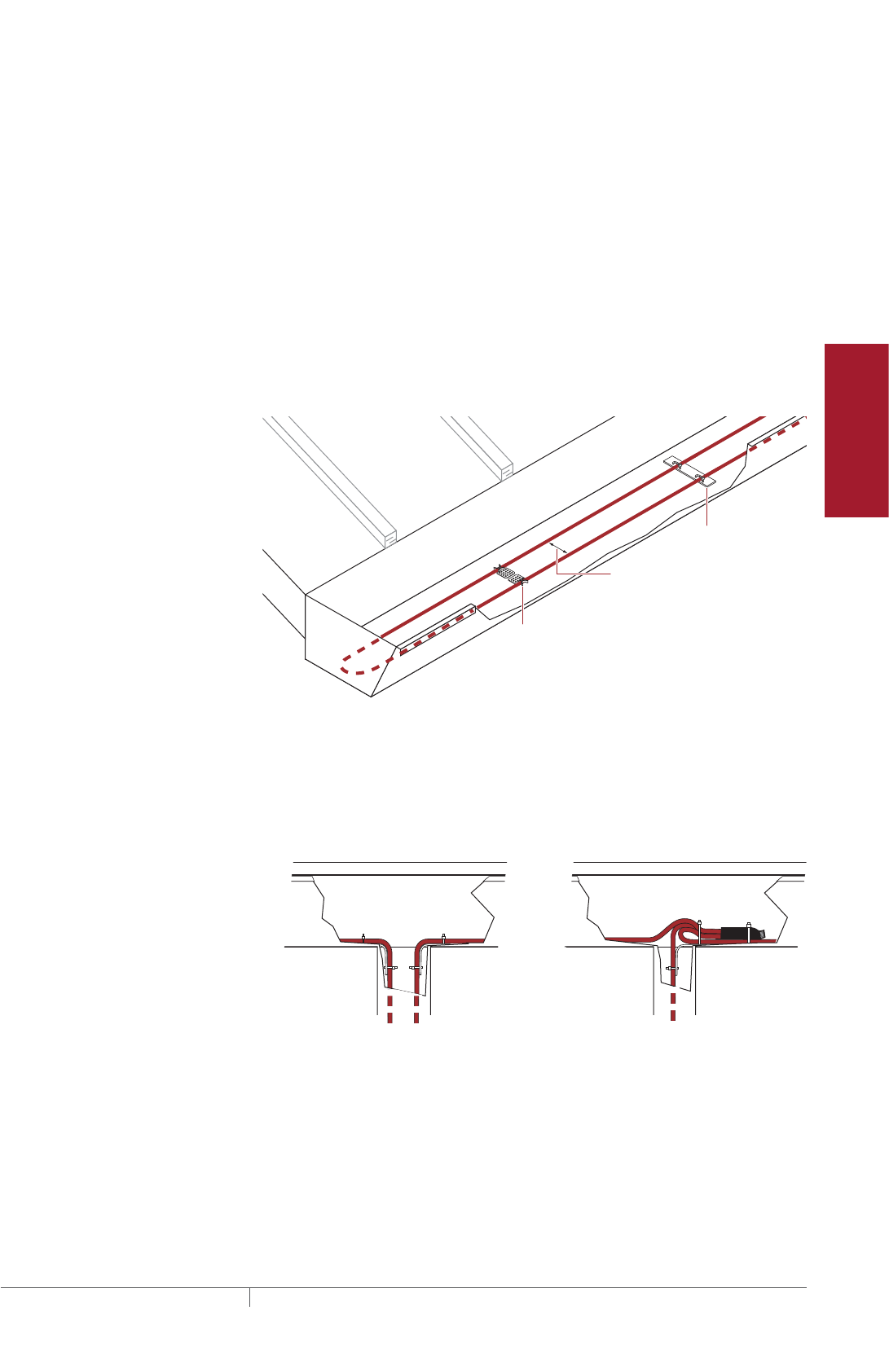
111THERMAL MANAGEMENT SOLUTIONS EN-RaychemIceStopRoofGutterDeIcing-DG-H56070 11/13
Pipe Freeze Protection
and Flow Maintenance
Fire Sprinkler System
Freeze Protection
Roof and Gutter
De-Icing
Surface Snow
Melting – MI
Surface Snow
Melting – ElectroMelt
Freezer Frost
Heave Prevention
Floor Heating Technical Data
Sheets
• The belt loop method of securing the IceStop heating cable involves using a small
piece of roofing material to form a “belt loop.”
• Use at least one belt loop for every 5 to 10 feet (1.5 to 3 m) of unsupported heating
cable and at every heating cable change of direction.
ATTACHMENT METHODS FOR OTHER AREAS
Gutters
Attachment is not generally required for standard gutters. If attachment is desired,
such as in high-wind areas, use GMK-RC adhesive-mounted attachment clips.
Several different adhesives are recommended by Pentair Thermal Management. See
Table 9 on page108.
For large gutters (6 to 12 inches wide [15 cm to 30 cm]), use two runs of heating
cable separated by GMK-RC roof clips. It is not necessary to attach the clips to the
gutter. Use one pair of GMK-RC roof clips for every 10 feet (3 m).
6" (15 cm) spacing
maximum
GM-RAKE
GMK-RC
Fig. 23 GMK-RC clip in a gutter
Downspouts
The IceStop heating cable needs to be attached at the top of each downspout, using
one GM-RAKE downspout hanger per heating cable. The GM-RAKE downspout
hanger clamps around the heating cable and attaches to the fascia with a screw or
nail.
Fig. 24 GM-RAKE downspout hangers
• GM-RAKE downspout hangers protect the heating cable from damage from sharp
edges and also provide support for the weight of the heating cable.
• Use two GM-RAKE downspout hangers for double-traced downspouts.
• Attach the GM-RAKE downspout hangers to the structure with a nail or other
suitable method.
Roof and Gutter De-Icing Design
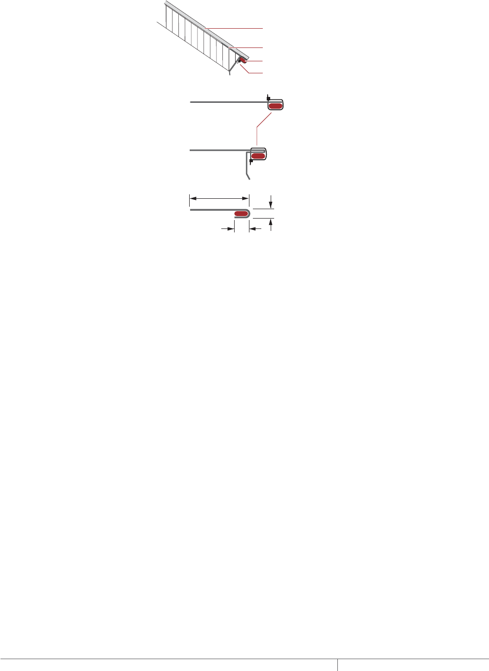
THERMAL MANAGEMENT SOLUTIONS
EN-RaychemIceStopRoofGutterDeIcing-DG-H56070 11/13
112
Heated Drip Edges
When installing a heated drip edge, you can attach the heating cable to the roof’s
drip edge or to a flat sheet of sheet metal with a UV-resistant cable tie, or place the
heating cable in a formed (J-channel) piece of sheet metal.
Roofing material
Metal drip edge
IceStop heating cable
UV-resistant cable tie
UV-resistant cable tie
Attached to flat sheet
Installed in a formed sheet
Attached to standard drip edge
2 3/4" (7 cm)
1/4" (0.6 cm)
3/4" (1.9 cm)
Fig. 25 Heated drip edge attachment guidelines
• The illustrations above are guidelines for heating cable attachment in a heated
drip edge application. Pentair Thermal Management does not manufacture drip
edge attachment clips.
• Use 20-gauge or thicker corrosion-resistant sheet metal.
• Contact your Pentair Thermal Management representative or Pentair Thermal
Management directly for specific recommendations.
Example: Roof and Gutter De-Icing System
100 ft (30.5 m) roof edge and 2 gutters
GMK-RC 3 boxes of 50
GM-RAKE 2
ROOF AND GUTTER DEICING ICESTOP SYSTEM

113THERMAL MANAGEMENT SOLUTIONS EN-RaychemIceStopRoofGutterDeIcing-DG-H56070 11/13
Pipe Freeze Protection
and Flow Maintenance
Fire Sprinkler System
Freeze Protection
Roof and Gutter
De-Icing
Surface Snow
Melting – MI
Surface Snow
Melting – ElectroMelt
Freezer Frost
Heave Prevention
Floor Heating Technical Data
Sheets
Roof and Gutter
De-Icing
1. Determine design
conditions
2. Select the heating
cable
3. Determine the
heating cable length
4. Determine the
electrical parameters
5. Select the
connection kits
6. Select attachment
accessories and
method
7. Select the control
system and power
distribution
8. Complete the Bill
of Materials
Step Select the control system and power distribution
CONTROL SYSTEMS
Three control methods are commonly used with roof de-icing systems:
• Manual on/off control
• Ambient thermostat
• Automatic moisture/temperature controller
All three methods require contactors if any significant length of heating cable is
being used. The contactor must be sized to carry the load. Each method offers
a trade-off of initial cost versus energy efficiency and ability to provide effective
de-icing. If the system is not energized when needed, ice will form. If the system
is energized when de-icing is not needed, there will be unnecessary power
consumption. Choose the control method that best meets the project performance
requirements. Contact your Pentair Thermal Management representative for details.
For Class I, Division 2 hazardous locations, use an agency-approved controller or
thermostat suitable for the same area use.
Manual On/Off Control
A manually controlled system is operated by a switch that controls the system power
contactor. This method requires constant supervision to work effectively. A manual
system can be controlled by a building management system.
Ambient Thermostat
When an ambient sensing thermostat is used, the roof and gutter system will be
energized when the ambient temperature is below freezing. This will ensure the
heating cable is energized any time the water might freeze.
TABLE 10 ECWGF THERMOSTAT
Number of heating cable
circuits
Single
Sensor Thermistor
Sensor length 35 ft
Set point range 32°F to 200°F (0°C to 93°C)
Enclosure NEMA 4X
Deadband 2°F to 10°F (2°C to 6°C)
Enclosure limits –40°F to 140°F (–40°C to 60°C)
Switch rating 30 A
Switch type DPST
Electrical rating 100−277 V
Approvals c-UL-us Listed
Ground-fault protection 30 mA fixed
Alarm outputs
AC relay
Dry contact relay
2 A at 277 Vac
2 A at 48 Vdc
Roof and Gutter De-Icing Design

THERMAL MANAGEMENT SOLUTIONS
EN-RaychemIceStopRoofGutterDeIcing-DG-H56070 11/13
114
Automatic Moisture/Temperature Controller
The most conservative approach from an energy-consumption point of view is an
automatic moisture/temperature sensor. Pentair Thermal Management supplies an
automatic moisture/temperature sensor, which consists of a control panel, one or
more gutter sensors, and one or more aerial snow sensors. Table 11 outlines the
options for this approach.
The gutter sensor should be mounted in gutters near downspouts. It senses the
actual environmental conditions, such as temperature and moisture. A gutter
sensor is recommended for each critical area that needs to be monitored for icing
conditions (such as when one side of a building gets sun in the morning and the
other side gets sun in the afternoon, or one side gets the prevailing winds and the
other side is protected). An aerial-mounted snow sensor is also recommended.
Having both gutter and snow sensors allows for snow to begin melting in the gutters
at the onset of any snow or ice condition.
For areas where a large number of circuits are required, the DigiTrace ACS-30
can be used. The Roof & Gutter De-icing control mode in the ACS-30 includes
an External Device control option. This option allows a Snow/Moisture sensing
controller (from Table 11) to be integrated into the ACS-30 system. Note that sensors
(snow or gutter) cannot be directly connected to the ACS-30 system. Refer to the
ACS-30 Programming Guide (H58692) for more information on system setup.
TABLE 11 AUTOMATIC CONTROLLERS
Application APS-3C APS-4C SC-40C PD Pro GF Pro
Snow controller Snow controller
with ground-fault
protection
Satellite contactor Snow controller Snow controller
with ground-fault
protection
Number of sensors 1 to 6 1 to 6 1 to 6 1 to 2 1 to 2
Set point 38°F (3°C) and
moisture
38°F (3°C) and
moisture
38°F (3°C) and
moisture
38°F (3°C) and
moisture
38°F (3°C) and
moisture
High limit
temperature set
point
40°F to 90°F (4°C to
32°C) adjustable
40°F to 90°F (4°C to
32°C) adjustable
40°F to 90°F (4°C to
32°C) adjustable
NA NA
Enclosure NEMA 3R NEMA 3R NEMA 3R NEMA 4X NEMA 4X
Temperature
operating limits
–40°F to 160°F
(–40°C to 71°C)
–40°F to 160°F
(–40°C to 71°C)
–40°F to 160°F
(–40°C to 71°C)
–31°F to 130°F
(–35°C to 55°C)
–31°F to 130°F
(–35°C to 55°C)
Electrical rating 24 A, 120 V
24 A, 208–240 V
50 A, 208–240 V
40 A, 277 V
50 A, 277–480 V
50 A, 600 V
50 A, 208/240 V
40 A, 277 V
50 A, 277–480 V
50 A, 600 V
30 A, 120 V 30 A, 208-277 V
Approvals c-UL-us Listed c-UL-us Listed c-UL-us Listed c-UL-us Listed c-UL-us Listed
Ground-fault
protection
Not included 30 mA 30 mA, 60 mA and
120 mA
Not included 30 mA
TABLE 12 MOISTURE/TEMPERATURE SENSORS
Application GIT-1 CIT-1
Gutter-mounted
moisture/temperature
Aerial-mounted
moisture/temperature
Set point 38°F (3°C) 38°F (3°C)
ROOF AND GUTTER DEICING ICESTOP SYSTEM
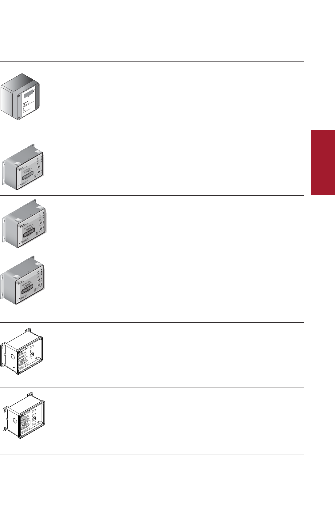
115THERMAL MANAGEMENT SOLUTIONS EN-RaychemIceStopRoofGutterDeIcing-DG-H56070 11/13
Pipe Freeze Protection
and Flow Maintenance
Fire Sprinkler System
Freeze Protection
Roof and Gutter
De-Icing
Surface Snow
Melting – MI
Surface Snow
Melting – ElectroMelt
Freezer Frost
Heave Prevention
Floor Heating Technical Data
Sheets
TABLE 13 CONTROL SYSTEMS
Catalog number
Description
Electronic Thermostats and Accessories
ECW-GF Electronic ambient sensing controller with 30-mA ground-fault protection. The control-
ler can be programmed to maintain temperatures up to 200°F (93°C) at voltages from
100 to 277 V and can switch current up to 30 Amperes. The ECW-GF is complete with
a 25-ft (7.6-m) temperature sensor and is housed in a NEMA 4X rated enclosure. The
controller features an AC/DC dry alarm contact relay.
An optional ground-fault display panel (ECW-GF-DP) can be added to provide ground-
fault or alarm indication in applications where the controller is mounted in inaccessible
locations.
Snow Melting Controllers
APS-3C Automatic snow melting controller housed in a NEMA 3R enclosure provides effective,
economical automatic control of all snow melting applications. CSA Certified, c-UL-us
Listed, available in 120 V and 208-240 V, 50/60 Hz models, 24-Amp DPDT output relay,
adjustable hold-on timer.
Enclosure dimensions: 11-1/2 in x 9-1/8 in x 6-9/16 in (292 mm x 232 mm x 167 mm)
APS-4C Automatic snow melting controller housed in a NEMA 3R enclosure provides effective,
economical automatic control of all snow melting applications. The APS-4C can
operate with any number of SC-40C satellite contactors for larger loads. Features
include: 277 V single-phase or 208–240, 277/480, and 600 V three-phase models,
built-in 3-pole contactor, integral 30 mA ground-fault circuit interrupter and an
adjustable hold-on timer.
Enclosure dimensions: 11-1/2 in x 9-1/8 in x 6-9/16 in (292 mm x 232 mm x 167 mm)
SC-40C Satellite contactor power control peripheral for an APS-4C snow melting controller,
housed in a NEMA 3R enclosure. Features include: 277 V single-phase or 208–240,
277/480 and 600 V three-phase models, built-in 3-pole contactor and integral 30 mA
ground-fault circuit interrupter.
Enclosure dimensions: 11-1/2 in x 9-1/8 in x 6 in (292 mm x 232 mm x 152 mm)
Gutter De-Icing Controllers
HEATER CYCLE
ETI PD Pro Automatic snow and ice melting controller for pavement, sidewalks, loading docks,
roofs, gutters and downspouts in commercial and residential environments.
The PD Pro interfaces with up to two sensors, (any combination of CIT-1, GIT-1 or SIT-
6E) to meet site requirements. The PD Pro is housed in an environmentally-sheltered
Type 4X enclosure and weighs only 3 pounds.
ETI GF Pro Automatic snow and ice melting controller for pavement, sidewalks, loading docks,
roofs, gutters and downspouts in commercial and residential environments.
The GF Pro interfaces with up to two sensors, (any combination of CIT-1, GIT-1 or SIT-
6E) to meet site requirements. The GF Pro is housed in an environmentally-sheltered
Type 4X enclosure and weighs only 3 pounds.
Features a built-in 30 mA, self-testing Ground-Fault Equipment Protection (GFEP)
capability, digitally filtered to minimize false tripping. A ground-fault alarm must be
manually reset using the Test/Reset switch before heater operation can continue.
Roof and Gutter De-Icing Design
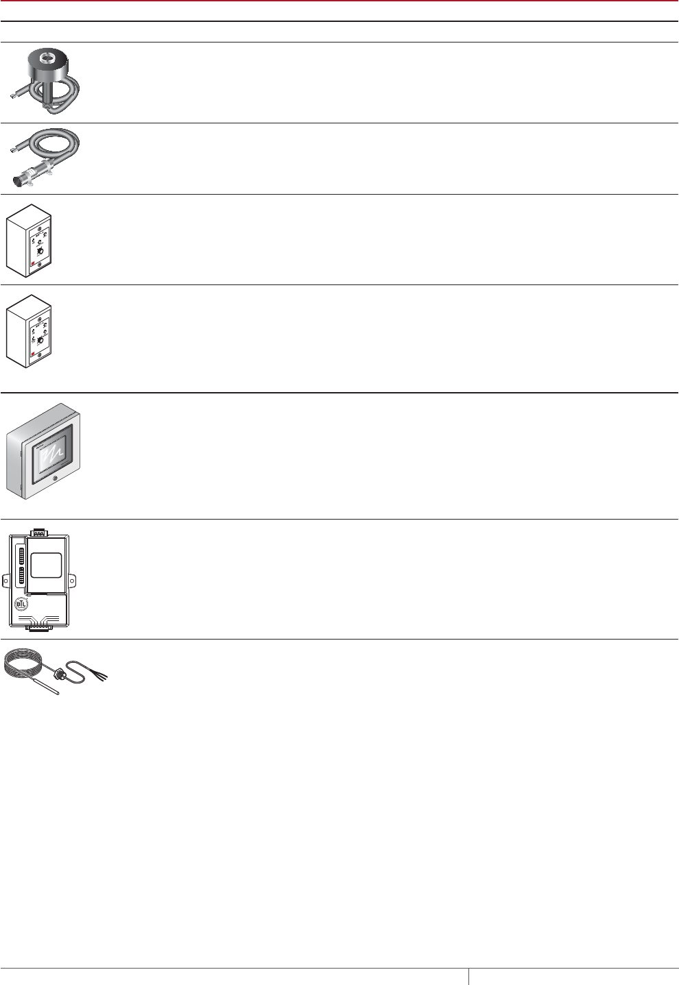
THERMAL MANAGEMENT SOLUTIONS
EN-RaychemIceStopRoofGutterDeIcing-DG-H56070 11/13
116
TABLE 13 CONTROL SYSTEMS
Catalog number
Description
Snow Melting and Gutter De-Icing Sensors and Accessories
CIT-1 Overhead snow sensor that detects precipitation or blowing snow at ambient tem-
peratures below 38°F (3.3°C). For use with an APS-3C or APS-4C automatic snow
controller, or an SC-40C satellite contactor.
GIT-1 Gutter sensor that detects moisture at ambient temperatures below 38°F (3.3°C).
For use with an APS-3C or APS-4C automatic snow controller, or a SC-40C satellite
contactor.
RCU-3 The RCU–3 provides control and status display to the APS–3C controller from a
remote location. It has a 2, 4, 6 or 8 hour CYCLE TIME adjustment, independent of
APS-3C setting.
RCU-4 The RCU–4 provides control and status display to the APS–4C controller and SC-40C
Satellite Contactor from a remote location. It has a 2, 4, 6 or 8 hour CYCLE TIME
adjustment, independent of the APS-4C or SC-40C setting.
Electronic Controllers
ACS-UIT2
ACS-PCM2-5
The DigiTrace ACS-30 Advanced Commercial Control System is a multipoint electronic
control and monitoring system for heat-tracing used in various commercial applica-
tions such as pipe freeze protection, roof and gutter de-icing, surface snow melting,
hot water temperature maintenance and floor heating. The DigiTrace ACS-30 system
can control up to 260 circuits with multiple networked ACS-PCM2-5 panels, with a
single ACS-UIT2 user interface terminal. The ACS-PCM2-5 panel can directly control
up to 5 individual heat-tracing circuits using electro-mechanical relays rated at 30 A
up to 277 V.
By FieldServer Technologies
www.ProtoCessor.com
PROTOCESSOR
SERIAL ETHERNET
PROTONODE
FRAME GND
- PWR
+PWR
RS 485+
RS 485 -
RS 485 GND
S3
S2
S1
S0
B3
B2
B1
B0
A7
A6
A5
A4
A3
A2
A1
A0
ProtoNode-LER
ProtoNode-RER
The DigiTrace ProtoNode is an external, high performance multi-protocol gateway for
customers needing protocol translation between Building Management Systems (BMS)
and the DigiTrace ACS-30 or C910-485 controllers.
The ProtoNode-LER is for LonWorks® systems; and the ProtoNode-RER is for
BACnet® or Metasys® N2 systems.
RTD-200
RTD3CS
RTD10CS
RTD50CS
Three-wire RTD (Resistance Temperature Device) used with DigiTrace C910-485 and
ACS-30 controllers.
RTD-200: 6-ft (1.8 m) fluorpolymer with 1/2-in NPT bushing
RTD3CS: 3-ft (0.9 m) flexible armor with 1/2-in NPT bushing
RTD10CS: 10-ft (3 m) flexible armor with 1/2-in NPT bushing
RTD50CS: 50-ft (3 m) flexible armor with 1/2-in NPT bushing
ROOF AND GUTTER DEICING ICESTOP SYSTEM
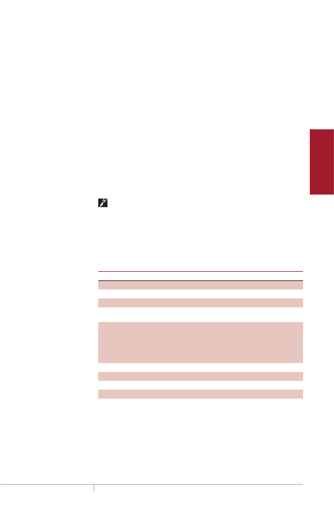
117THERMAL MANAGEMENT SOLUTIONS EN-RaychemIceStopRoofGutterDeIcing-DG-H56070 11/13
Pipe Freeze Protection
and Flow Maintenance
Fire Sprinkler System
Freeze Protection
Roof and Gutter
De-Icing
Surface Snow
Melting – MI
Surface Snow
Melting – ElectroMelt
Freezer Frost
Heave Prevention
Floor Heating Technical Data
Sheets
Example: Roof and Gutter De-Icing System
208 V system with 2 circuits
APS-4C 1
SC-40C 1
GIT-1 2 (one for each gutter section)
CIT-1 1
POWER DISTRIBUTION
Once the heating cable circuits and control have been defined, you must select how
to provide power to them. Power to the IceStop heating cables can be provided in
several ways: directly through the controller, through external contactors, or through
SMPG power distribution panels.
Single circuit control
Heating cable circuits that do not exceed the current rating of the selected control
device shown in Table 11 can be switched directly (see Fig. 26).
Group control
If the current draw exceeds the switch rating, or if the controller will activate more
than one circuit (group control), an external contactor must be used.
Note: Large systems with many circuits should use an SMPG power distribution
panel. The SMPG is a dedicated power-distribution, control, ground-fault protection,
monitoring, and alarm panel for roof and gutter de-icing applications. This enclosure
contains an assembled circuit-breaker panelboard. Panels are equipped with
ground-fault circuit breakers with or without alarm contacts. The group control
package allows the system to operate automatically in conjunction with an ambient-
sensing thermostat, individual electronic, or duty cycle controller.
TABLE 14 POWER DISTRIBUTION PANELS
Application SMPG1
Control panel
Controller EUR-5A included
Number of sensors Up to 6
Enclosure NEMA 1/12, NEMA 3R/4
Temperature operating
limits
Without space heater
14°F to 122°F
(–10°C to 50°C)
With a space heater
–40°F to 122°F
(–40°C to 50°C)
Supply voltage 208 V, 277 V
Circuit breaker rating 15 A, 20 A, 30 A, 40 A, 50 A
Approvals c-UL-us
Ground-fault protection Yes
Roof and Gutter De-Icing Design
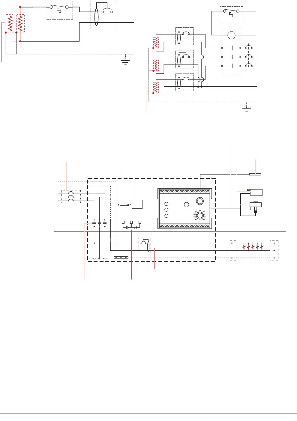
THERMAL MANAGEMENT SOLUTIONS
EN-RaychemIceStopRoofGutterDeIcing-DG-H56070 11/13
118
Single circuit control Group control
Temperature
controller 1-pole
GFEP breaker
1
N
G
Heating
cable
ø
øsupply
C
Temperature
controller
Contactor
1-pole
GFEP breaker
N
G (Typ 3)
ø2
ø1
ø3
3-phase 4-wire
supply (WYE)
3-pole main
breaker
ø
ø
1 supply
N
Heating cable
sheath, braid
or ground
Heating cable
sheath, braid
or ground
Fig. 26 Single circuit and group control
N
G
Ø2
Ø3
Ø1
Three-pole
main contactor
Fuse
Main circuit breaker
(optional)
3-phase 4-wire
supply (WYE)
24 V
One-pole with 30 mA
ground-fault trip (277 V)
Remote annunciation alarm
(circuit breaker
with alarm type #3)
GIT-1
CIT-1
Heating cable
sheath, braid
or ground
Aerial snow sensor
Gutter ice sensor
High
temperature
sensor
Single Ø
connection
SNOW/ICE
SUPPLY
EUR-5A SNOW SWITCH
AUTOMATIC SNOW/ICE MELTING CONTROL PANEL
HEATER
HEATER
CYCLE
HOURS
0
2
4 6
8
10
TEMPERATURE
Control transformer
N
G
Ø2
Ø3
Ø1
Three-pole
main contactor
Fuse
3-phase 4-wire
supply (WYE)
24 V
One-pole with 30 mA
ground-fault trip (277 V)
Remote annunciation alarm
(circuit breaker
with alarm type #3)
GIT-1
Heating cable
sheath, braid
or ground
Aerial snow sensor
Gutter ice sensor
High
temperature
sensor
Single Ø
connection
SNOW/ICE
SUPPLY
EUR-5A SNOW SWITCH
AUTOMATIC SNOW/ICE MELTING CONTROL PANEL
HEATER
HEATER
CYCLE
HOURS
0
2
4 6
8
10
TEMPERATURE
Control transformer
Fig. 27 Typical wiring diagram of group control with SMPG1
ROOF AND GUTTER DEICING ICESTOP SYSTEM
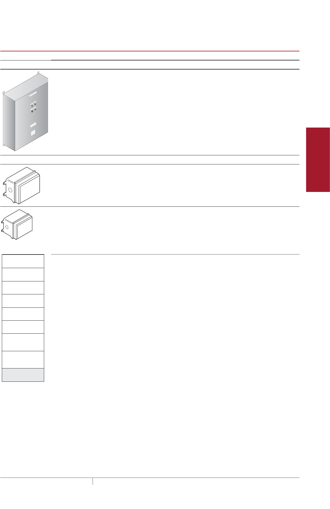
119THERMAL MANAGEMENT SOLUTIONS EN-RaychemIceStopRoofGutterDeIcing-DG-H56070 11/13
Pipe Freeze Protection
and Flow Maintenance
Fire Sprinkler System
Freeze Protection
Roof and Gutter
De-Icing
Surface Snow
Melting – MI
Surface Snow
Melting – ElectroMelt
Freezer Frost
Heave Prevention
Floor Heating Technical Data
Sheets
TABLE 15 POWER DISTRIBUTION
Catalog number Description
Power Distribution and Control Panels
NP
NP
NP
NP
NP
NP NP
SMPG1 Single-phase power distribution panel that includes ground-fault protection, monitor-
ing, and control for snow melting systems. Single-phase voltages include 208 and
277V.
Contactors and Junction Boxes
E104 Three-pole, 100 A per pole, 600 V maximum contactor housed in UL Listed, CSA Certi-
fied, NEMA 4X enclosure with two 1-inch conduit entries. When ordering, select coil
voltage (110–120, 208–240, 277 V).
Enclosure dimensions: 13-1/2 in x 9-1/5 in x 6-11/16 in (343 mm x 234 mm x 170 mm).
E304 Three-pole, 40 A per pole, 600 V maximum contactor housed in UL Listed, CSA Certified
NEMA 4X enclosure with two 1-inch conduit entries. When ordering, select coil voltage
(110–120, 208–240, 277 V).
Enclosure dimensions: 9-1/2 in x 7-1/5 in x 6-11/16 in (241 mm x 183 mm x 170 mm).
Roof and Gutter
De-Icing
1. Determine design
conditions
2. Select the heating
cable
3. Determine the
heating cable length
4. Determine the
electrical parameters
5. Select the
connection kits
6. Select attachment
accessories and
method
7. Select the control
system and power
distribution
8. Complete the Bill
of Materials
Step Complete the Bill of Materials
If you used the Design Worksheet to document all your project parameters, you
should have all the details you need to complete your Bill of Materials.
Roof and Gutter De-Icing Design

THERMAL MANAGEMENT SOLUTIONS
EN-RaychemIceStopRoofGutterDeIcing-DG-H56070 11/13
120
ICESTOP SYSTEM ROOF AND GUTTER DEICING DESIGN WORKSHEET
Step Determine design conditions
Type of roof Layout
Supply
voltage
Min. start-up
temperature Control method
❑ Sloped roof – standard
❑ Sloped roof – standing seam
❑ Flat roof
Roof edge
Length of roof edge (ft/m) __________
Number of edges __________
Eave overhang
Distance of overhang (in/cm) _______
Gutters
Length of gutters (ft/m) __________
Number of gutters __________
Depth of gutters (in/cm) __________
Width of gutters (in/cm) __________
Roof valley
Height of roof valley (ft/m) __________
Number of roof valleys __________
Roof/wall intersection
Height of intersection (ft/m) ________
Number of intersections __________
Downspouts
Downspout height (ft/m) __________
Number of downspouts __________
❑ 120 V
❑ 208–277 V ______ (°F/°C)
❑ Manual on/off control
❑ Ambient thermostat
❑ Automatic controller
Roof material
❑ Shake/shingle
❑ Rubber membrane
❑ Metal
❑ Wood
❑ Other: __________________
x =Total length of roof edges
50 ft 2 100 ft
Length of roof edge
Roof edge:
Number of edges
x = Total length of gutters
50 ft 2 100 ft
Length of gutter
Gutters:
6 in
Depth of gutter
4 in
Width of gutter
Number of gutters
20 ft 1
Height of roof valley
Roof valley:
Number of roof valleys
x = Total downspout height
12 ft 2 24 ft
Downspout height
Downspouts:
Number of downspouts
24 in
Eave overhang:
Example:
9 Sloped roof – standard with wood shingles and gutters
208 V
Supply voltage:
20°F
Minimum start-up temperature:
Automatic controller
Control method:
ROOF AND GUTTER DEICING ICESTOP SYSTEM

121THERMAL MANAGEMENT SOLUTIONS EN-RaychemIceStopRoofGutterDeIcing-DG-H56070 11/13
Pipe Freeze Protection
and Flow Maintenance
Fire Sprinkler System
Freeze Protection
Roof and Gutter
De-Icing
Surface Snow
Melting – MI
Surface Snow
Melting – ElectroMelt
Freezer Frost
Heave Prevention
Floor Heating Technical Data
Sheets
Step Select the heating cable
See Fig. 4.
Product family
Use catalog number:
Example catalog number: 2 XT GM-2XT
GM
Product family
Product family
—
Supply voltage Outer jacket
T 1 = 120 V
T 2 = 208, 240, 277 V
T -X polyolefin
T -XT fluoropolymer
GM —
Supply voltage Catalog number
Catalog number
Outer jacket
Supply voltage Outer jacket
IceStop System Roof and Gutter De-Icing Design Worksheet

THERMAL MANAGEMENT SOLUTIONS
EN-RaychemIceStopRoofGutterDeIcing-DG-H56070 11/13
122
Step Determine the heating cable length
Roof edge (ft/m)
Sloped roof – standard
Sloped roof – standing seam
Flat roof
Gutters
No gutters – heated drip edge
Roof valleys
Roof/wall intersection
Downspouts
with requires
Eave overhang (in/cm) Heating cable per foot of roof edge
(ft/m)
=
Gutter depth (ft/m)
x +=2 =
Additional heating cable (ft/m) Heating cable per foot
of roof edge (ft/m)
Roof edge (ft/m)
x 1 =
Height of roof valley (ft/m)
x x
Number of roof valleys
=
1.33
Height of intersection (ft/m)
x
Number of intersections
=
1.33
Roof perimeter (ft/m)
x x
From perimeter to drains (ft/m) Into internal downspouts (ft/m)
Height of downspouts (ft/m)
x
Number of downspouts
=
x
Runs of heating cable
per downspout
Total heating cable for roof edge (ft/m)
=
Roof edge (ft/m)
xHeating cable with gutter depth allowance (ft/m)
=
Gutter length (ft/m) Gutter width multiplier
x
Roof edge (ft/m)
with requires
Eave overhang (in/cm) Heating cable per foot of roof edge
(ft/m)
Heating cable for flat roof
(ft/m)
Heating cable with gutter
depth allowance (ft/m)
Heating cable for gutters (ft/m)
Heating cable for heated drip edge (ft/m)
Heating cable for roof valleys (ft/m)
Heating cable for
roof/wall intersections (ft/m)
Heating cable per downspout (ft/m)
Total heating cable length
Feet of roof edge (ft/m)
with requires
Eave overhang (in/cm) Heating cable per foot of roof edge (ft/m)
100 ft
Example: Sloped roof – standard with eave overhang and gutters
6 in
100 ft
100 ft
20 ft
12 ft 2 1 24 ft
226 ft *
673 ft
1 26.6 ft rounded to 27 ft *
1 100 ft *
5.2 ft 520 ft *
1 ft 4.2 ft 5.2 ft
24 in 4.2 ft
Gutter depth (ft/m)
x +=2 =
Additional heating cable (ft/m) Heating cable per foot
of roof edge (ft/m)
Height of roof valley (ft/m)
x x
Number of roof valleys
=
1.33
Height of downspouts (ft/m)
x
Number of downspouts
=
x
Runs of heating cable
per downspout
Total heating cable for roof edge (ft/m)
=
Roof edge (ft/m)
x
Heating cable with gutter
depth allowance (ft/m)
=
Gutter length (ft/m) Gutter width multiplier
x
Heating cable with gutter
depth allowance (ft/m)
Heating cable for gutters (ft/m)
Heating cable for roof valleys (ft/m)
Heating cable per downspouts (ft/m)
=
+
Drip loop allowance
(1 ft with loopback)
Feet heating cable for downspouts
=
* Total heating cable length
ROOF AND GUTTER DEICING ICESTOP SYSTEM

123THERMAL MANAGEMENT SOLUTIONS EN-RaychemIceStopRoofGutterDeIcing-DG-H56070 11/13
Pipe Freeze Protection
and Flow Maintenance
Fire Sprinkler System
Freeze Protection
Roof and Gutter
De-Icing
Surface Snow
Melting – MI
Surface Snow
Melting – ElectroMelt
Freezer Frost
Heave Prevention
Floor Heating Technical Data
Sheets
Step Determine the electrical parameters
Determine maximum circuit length and number of circuits (See Table 5)
Determine the maximum circuit length and number of circuits
Circuit breaker load (kW)
0.8 1000
Circuit breaker rating x x /( ) =
Supply voltage
Determine transformer load
Calculate the circuit breaker load (CBL)
If the CBL is equal on all circuits, calculate the transformer load as:
If the CBL is NOT equal on all circuits, calculate the transformer load as:
Total transformer load (kW)Circuit breaker load (kW)x =
Number of breakers
Total transformer load (kW)CBL1 + CBL2 + CBL3... + CBLN
=
Example:
Circuit breaker load (kW)
30 A 208 V
0.8 1000 4.99 kW rounded to 5 kW
Circuit breaker rating x x /( ) =
Total transformer load (kW)
5 kW 2 10 kW
Circuit breaker load (kW) x =
Determine transformer load
Supply voltage
Number of breakers
/ =
Number of circuitsMaximum heating cable circuit length
Total heating cable length required
T 120 V T 208 V
T 240 V T 277 V
Total heating cable
length required
Supply voltage:
T 15 A T 20 A
T 30 A T 40 A
Circuit breaker size:
Start-up temperature
Maximum circuit length
/ =
Number of circuits
673 ft 355 ft 1.9 circuits, round up to 2
Total heating cable length required
T 120 V T 208 V
T 240 V T 277 V
Total heating cable
length required
Supply voltage:
673 ft of GM-2XT 9
T 15 A T 20 A
T 30 A T 40 A
Circuit breaker size: 9
20°F
Start-up temperature
355 ft
Maximum circuit length
Maximum heating cable circuit length
IceStop System Roof and Gutter De-Icing Design Worksheet

THERMAL MANAGEMENT SOLUTIONS
EN-RaychemIceStopRoofGutterDeIcing-DG-H56070 11/13
124
Step Select the connection kits (See Table 6)
Connection kits and
accessories Description Quantity
Heating cable
allowance
❑ RayClic-PC
❑ RayClic-PS
❑ RayClic-PT
❑ FTC-P
❑ RayClic-S
❑ RayClic-T
❑ RayClic-X
❑ FTC-HST
❑ RayClic-LE
❑ RayClic-E
❑ RayClic-SB-02
Power connection and end seal
Power splice and end seal
Powered tee and end seal
Power connection and end seal
Splice
Tee kit with end seal
Cross connection
Low-profile splice/tee
Lighted end seal
Extra end seal
Wall mounting bracket
_____________
_____________
_____________
_____________
_____________
_____________
_____________
_____________
_____________
_____________
_____________
__________________
__________________
__________________
__________________
__________________
__________________
__________________
__________________
__________________
__________________
__________________
+ =
Total heating cable
length required
Total heating cable allowance for connection kits
Total heating cable length
Total heating cable
allowance for connection kits
Example:
Connection kit catalog number Quantity
Heating cable
allowance
9 RayClic-PC 24 ft
9 RayClic-PS 28 ft
9 RayClic-SB-02 4NA
673 ft 12 ft 685 ft
12 ft
+ =
Total heating cable
length required
Total heating cable allowance for connection kits
Total heating cable length
Total heating cable
allowance for connection kits
Step Select attachment accessories and method
See “Table 7 Attachment Accessories” “Table 8 Attachment Methods for Typical Roofs” and “Table 9 Adhesives”
Adhesive is not supplied by Pentair Thermal Management
Attachment accessories Description Quantity
❑ GMK-RC
❑ GMK-RAKE
❑ CT-CABLE-TIE
Roof clips
Hanger bracket
UV-resistant cable tie
____________
____________
____________
Example:
100 ft roof edge and 2 gutters
9 GMK-RC 3 boxes of 50 (from Table 7)
9 GM-RAKE 2 (from Table 7)
ROOF AND GUTTER DEICING ICESTOP SYSTEM
125THERMAL MANAGEMENT SOLUTIONS EN-RaychemIceStopRoofGutterDeIcing-DG-H56070 11/13
Pipe Freeze Protection
and Flow Maintenance
Fire Sprinkler System
Freeze Protection
Roof and Gutter
De-Icing
Surface Snow
Melting – MI
Surface Snow
Melting – ElectroMelt
Freezer Frost
Heave Prevention
Floor Heating Technical Data
Sheets
Step Select the control system and power distribution
Control Systems
See “Table 10 ECW-GF Thermostat” “Table 11 Automatic Controllers” “Table 12 Moisture/Temperature Sensors” “Table 13 Control Systems”
Thermostats, controllers
and accessories Description Quantity
❑ ECW-GF
❑ APS-3C
❑ APS-4C
❑ SC-40C
❑ ETI PD Pro
❑ ETI GF Pro
❑ CIT-1
❑ GIT-1
❑ RCU-3
❑ RCU-4
❑ ACS-UIT2
❑ ACS-PCM2-5
❑ ProtoNode-LER
❑ ProtoNode-RER
❑ RTD3CS
❑ RTD10CS
❑ RTD200
❑ RTD50CS
Electronic thermostat with 25-ft sensor
Automatic snow melting controller
Automatic snow melting controller
Satellite contactor
Gutter de-icing controller
Gutter de-icing controller
Overhead snow sensor
Gutter sensor
Remote control unit for APS-3C
Remote control unit for APS-4C
ACS-30 user interface terminal
ACS-30 power control panel
Multi-protocol gateway
Multi-protocol gateway
Resistance temperature device for DigiTrace ACS-30
Resistance temperature device for DigiTrace ACS-30
Resistance temperature device for DigiTrace ACS-30
Resistance temperature device for DigiTrace ACS-30
____________
____________
____________
____________
____________
____________
____________
____________
____________
____________
____________
____________
____________
____________
____________
____________
____________
____________
Example:
Supply voltage 208 V (from Step 1)
Controller(s) 9 APS-4C
9 SC-40C
1
1
Snow melting and gutter de-icing
sensors and accessories
9 GIT-1
9 CIT-1
2 (one for each gutter section)
1
Power distribution
See “Table 14 Power Distribution Panels” and “Table 15 Power Distribution”
Power distribution and control
panels
Description Quantity
❑ SMPG1 Single-phase power distribution panel ____________
Contactors Description Quantity
❑ E104
❑ E304
Three-pole, 100 A per pole contactor
Three-pole, 40 A per pole contactor
____________
____________
Step Complete the Bill of Materials
Use the information recorded in this worksheet to complete the Bill of Materials.
IceStop System Roof and Gutter De-Icing Design Worksheet

THERMAL MANAGEMENT SOLUTIONS
EN-RaychemIceStopRoofGutterDeIcing-DG-H56070 11/13
126
ROOF AND GUTTER DEICING ICESTOP SYSTEM
127THERMAL MANAGEMENT SOLUTIONS EN-PyrotenaxMISurfaceSnowMelting-DG-H57045 11/13
Pipe Freeze Protection
and Flow Maintenance
Fire Sprinkler System
Freeze Protection
Roof and Gutter
De-Icing
Surface Snow
Melting – MI
Surface Snow
Melting – ElectroMelt
Freezer Frost
Heave Prevention
Floor Heating Technical Data
Sheets
This step-by-step design guide provides the tools necessary to design a Pyrotenax
Mineral Insulated heating cable surface snow melting system. For other applications
or for design assistance, contact your Pentair Thermal Management representative
or phone Pentair Thermal Management at (800)545-6258. Also, visit our web site at
www.pentairthermal.com.
Contents
Introduction .........................................................127
How to Use this Guide ............................................128
Safety Guidelines ................................................128
Warranty .......................................................128
System Overview .....................................................129
Typical System ..................................................129
MI Heating Cable Construction .....................................130
MI Heating Cable Configuration .....................................130
Approvals .......................................................131
Surface Snow Melting Applications ......................................131
Surface Snow Melting Design ...........................................132
Design Step by Step ..............................................132
Step 1 Determine design conditions ..............................133
Step 2 Determine the required watt density ........................135
Step 3 Determine the total area to be protected .....................136
Step 4 Select the heating cable ..................................141
Step 5 Determine heating cable spacing ...........................148
Step 6 Determine the electrical parameters ........................150
Step 7 Select the control system and power distribution ..............152
Step 8 Select the accessories ....................................161
Step 9 Complete the Bill of Materials .............................162
Pyrotenax MI System Surface Snow Melting Design Worksheet ...............163
INTRODUCTION
The Pyrotenax Mineral Insulated (MI) heating cable system is designed for surface
snow melting in concrete and asphalt, and under pavers.
If your application conditions are different, or if you have any questions, contact your
Pentair Thermal Management representative or contact Pentair Thermal
Management directly at (800)545-6258.
SURFACE SNOW MELTING MI
MINERAL INSULATED HEATING CABLE SYSTEM
THERMAL MANAGEMENT SOLUTIONS
EN-PyrotenaxMISurfaceSnowMelting-DG-H57045 11/13
128
How to Use this Guide
This design guide presents Pentair Thermal Management’ recommendations for
designing a Pyrotenax Mineral Insulated (MI) heating cable surface snow melting
system. It provides design and performance data, electrical sizing information, and
heating cable layout suggestions. Following these recommendations will result in a
reliable, energy-efficient system.
Follow the design steps in the section “Surface Snow Melting Design” on page132
and use the “Pyrotenax MI System Surface Snow Melting Design Worksheet” on
page163 to document the project parameters that you will need for your project’s
Bill of Materials.
OTHER REQUIRED DOCUMENTS
This guide is not intended to provide comprehensive installation instructions. For
complete Pyrotenax MI surface snow melting system installation instructions, please
refer to the following additional required documents:
• Surface Snow Melting – MI Installation and Operation Manual (H57754)
• Additional installation instructions included with thermostats, controllers, and ac-
cessories
If you do not have these documents, you can obtain them from the Pentair Thermal
Management web site at www.pentairthermal.com.
For products and applications not covered by this design guide, including
installations in hazardous locations or where electromagnetic interference (EMI) may
be of concern, such as traffic loop detectors, please contact your Pentair Thermal
Management representative or call Pentair Thermal Management at (800)545-6258.
Safety Guidelines
As with any electrical equipment, the safety and reliability of any system depends
on the quality of the products selected and the manner in which they are installed
and maintained. Incorrect design, handling, installation, or maintenance of any of
the system components could damage the system and may result in inadequate
performance, overheating, electric shock, or fire. To minimize these risks and to
ensure that the system performs reliably, read and carefully follow the information,
warnings, and instructions in this guide.
This symbol identifies important instructions or information.
This symbol identifies particularly important safety warnings that must be
followed.
WARNING: To minimize the danger of fire from sustained electrical arcing if
the heating cable is damaged or improperly installed, and to comply with the
requirements of Pentair Thermal Management, agency certifications, and national
electrical codes, ground-fault equipment protection must be used on each heating
cable branch circuit. Arcing may not be stopped by conventional circuit protection.
Warranty
Pentair Thermal Management’s standard limited warranty applies to Pyrotenax
Snow Melting Systems.
An extension of the limited warranty period to ten (10) years from the date of
installation is available, except for the control and distribution systems, if a properly
completed online warranty form is submitted within thirty (30) days from the date of
installation. You can access the complete warranty on our web site at
www.pentairthermal.com.
SURFACE SNOW MELTING MI MINERAL INSULATED HEATING CABLE SYSTEM
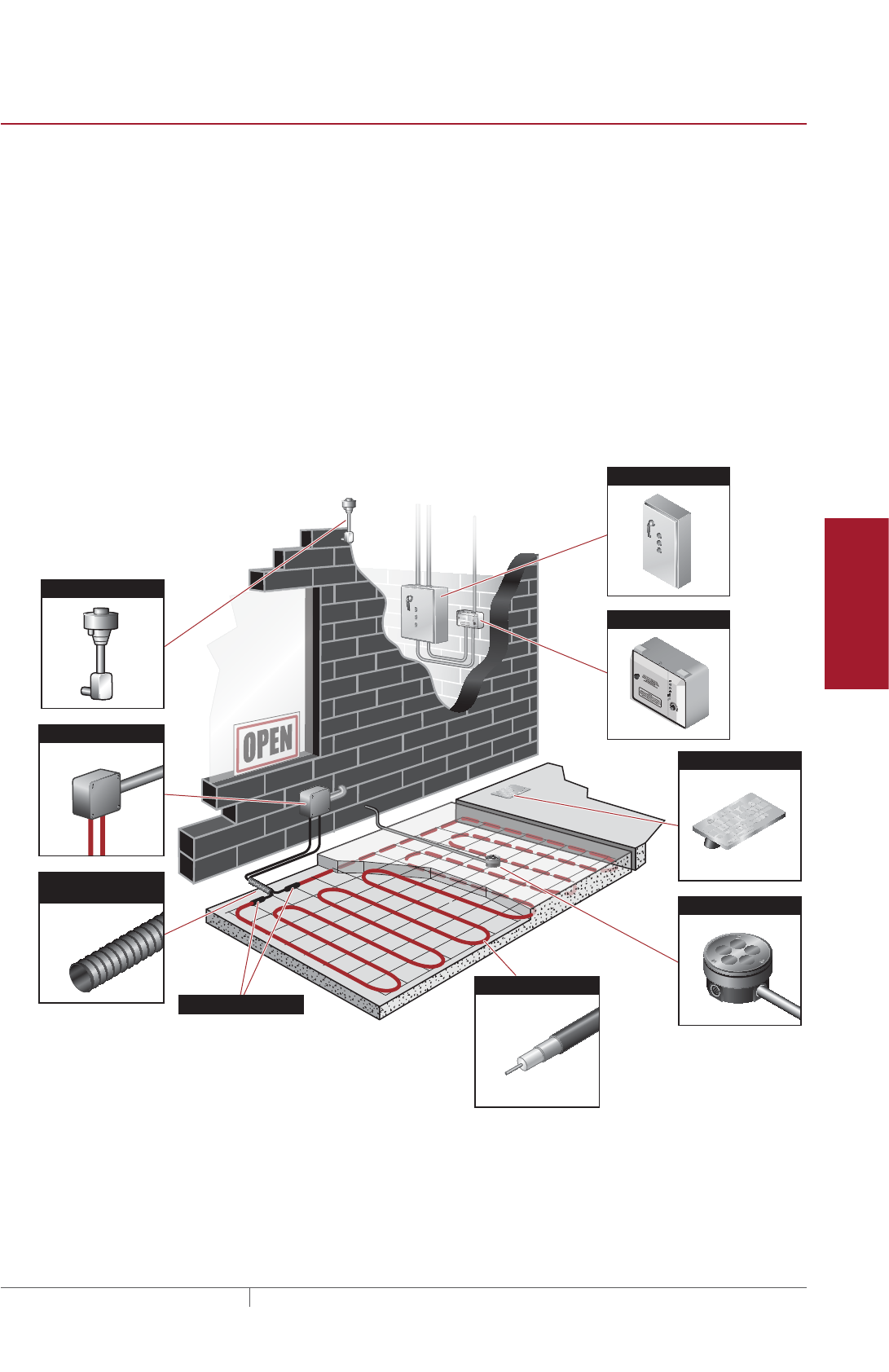
129THERMAL MANAGEMENT SOLUTIONS EN-PyrotenaxMISurfaceSnowMelting-DG-H57045 11/13
Pipe Freeze Protection
and Flow Maintenance
Fire Sprinkler System
Freeze Protection
Roof and Gutter
De-Icing
Surface Snow
Melting – MI
Surface Snow
Melting – ElectroMelt
Freezer Frost
Heave Prevention
Floor Heating Technical Data
Sheets
SYSTEM OVERVIEW
The Pyrotenax MI heating cable surface snow melting system provides snow melting
for concrete, asphalt, and pavers. The copper-sheathed, mineral insulated heating
cables are coated with a high-density polyethylene (HDPE) jacket and are supplied as
complete factory-assembled cables ready to connect to a junction box. The series-
type technology, inherent to all mineral insulated heating cables, provides a reliable
and consistent heat source that is ideal for embedded snow melting applications.
The system includes heating cable, junction boxes, a control system and sensors,
power distribution, and the tools necessary for a complete installation.
Typical System
A typical system includes the following:
• MI heating cable
• Junction boxes and accessories
• Snow controller and sensors
• Power distribution
Aerial Snow Sensor
Caution Sign
Pavement Snow Sensor
Heating Cable
Hot/Cold Joint
Flexible Nonmetallic
Conduit
Junction Box
Power Distribution Panel
Snow Controller
Fig. 1 Typical Pyrotenax MI system
System Overview
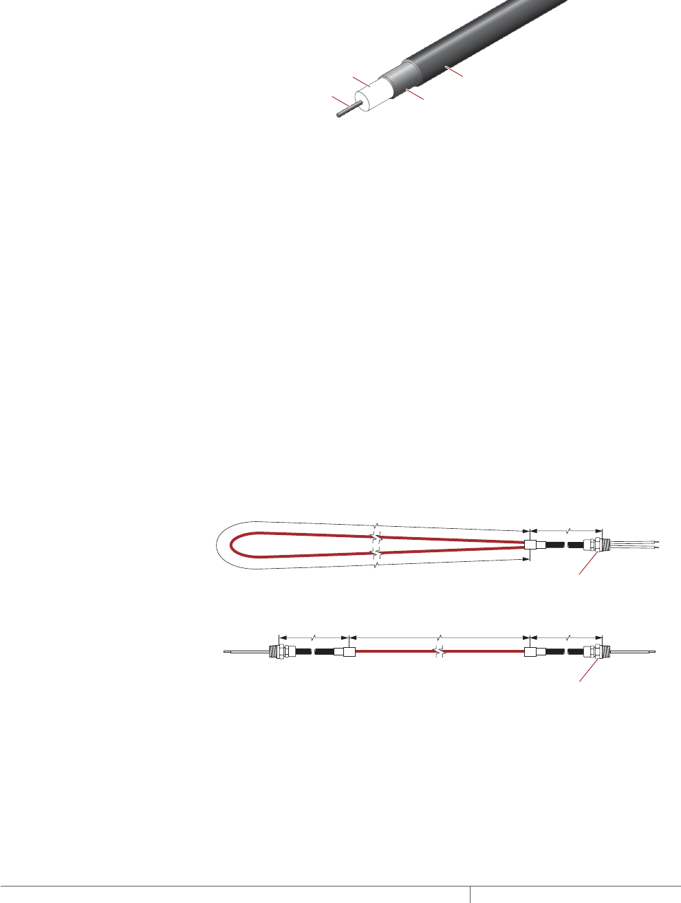
THERMAL MANAGEMENT SOLUTIONS
EN-PyrotenaxMISurfaceSnowMelting-DG-H57045 11/13
130
MI Heating Cable Construction
Standard surface snow melting MI heating cables are comprised of a single
conductor surrounded by magnesium oxide insulation, a solid copper sheath, and
an extruded high density polyethylene (HDPE) jacket. The HDPE jacket protects
the copper sheath from corrosive elements that can exist in surface snow melting
applications.
Heating conductor
Single-conductor cable
Copper sheath
HDPE jacket
Insulation (magnesium oxide)
Fig. 2 MI heating cable construction
Custom engineered heating cables are also available for applications outside the
scope of this design guide. For design criteria, including the maximum cable loading
(watts/foot) for installations in concrete, asphalt and paver applications, refer to
the MI Heating Cable for Commercial Applications data sheet (H56990) or contact
Pentair Thermal Management at (800) 545-6258 for design assistance.
MI Heating Cable Configuration
MI heating cables are supplied as complete factory-fabricated assemblies consisting
of an MI heating section that is joined to a section of MI nonheating cold lead and
terminated with NPT-threaded connectors. Two configurations are available for
standard heating cables:
1. Type SUA, consisting of a looped cable joined to a single 7 ft (2.1 m) cold lead
with one 1/2-in NPT-threaded connector.
2. Type SUB, consisting of a single run of cable with a 15 ft (4.6 m) cold lead and a
1/2-in NPT-threaded connector on each end. Where custom cold lead lengths
are required for the heating cables shown in Table 2, Table 3, Table 4, and
Table 5, contact your Pentair Thermal Management sales representative for
assistance.
Type SUA
Type SUB Heated length
Heated length
Cold lead length
15 ft (4.6 m)
Cold lead length
7 ft (2.1 m)
NPT-threaded
connector
NPT-threaded
connector
Cold lead length
15 ft (4.6 m)
Fig. 3 MI heating cable configurations
SURFACE SNOW MELTING MI MINERAL INSULATED HEATING CABLE SYSTEM

131THERMAL MANAGEMENT SOLUTIONS EN-PyrotenaxMISurfaceSnowMelting-DG-H57045 11/13
Pipe Freeze Protection
and Flow Maintenance
Fire Sprinkler System
Freeze Protection
Roof and Gutter
De-Icing
Surface Snow
Melting – MI
Surface Snow
Melting – ElectroMelt
Freezer Frost
Heave Prevention
Floor Heating Technical Data
Sheets
Approvals
The Pyrotenax MI surface snow melting system is UL Listed and CSA Certified for
installation in nonhazardous locations in concrete and asphalt, and under pavers
where the cables are embedded in concrete. For paver snow melting installations
where the heating cables are embedded in sand or limestone screenings, special
permission is required from the Authority Having Jurisdiction, e.g. the local
inspection authority.
De-Icing and Snow
Melting Equipment
421H -PS
SURFACE SNOW MELTING APPLICATIONS
SURFACE SNOW MELTING
Surface snow melting systems provide the required heat flux (W/ft² or W/m²) to melt
snow and ice on ramps, slabs, driveways, sidewalks, platform scales, and stairs and
prevent the accumulation of snow under normal snow conditions.
APPLICATION REQUIREMENTS AND ASSUMPTIONS
The design for a standard surface snow melting application is based on the
following:
Reinforced Concrete Heating cable
• 4 to 6 in (10 to 15 cm) thick
• Placed on grade
• Standard density
• Secured to reinforcing steel, mesh or
with prepunched strapping
• Located approximately 2 in (5 cm) below
finished surface, but not exceeding 3 in
(7.5 cm)
Asphalt
• Install on 1 in (2.5 cm) asphalt base
layer if a concrete base is used in
construction
• Placed on grade
• Secured with prepunched strapping
• Located 2 in (5 cm) below finished
surface
Pavers
• 1 ½ to 2 ¼ in (4 to 6 cm) thick pavers
• Minimum 1 in (2.5 cm) limestone
screenings or sand layer
• Placed on an approved compacted
base or concrete slab
• Secured to the compacted base or con-
crete with mesh or prepunched
strapping
• Located in a minimum 1 in (2.5 cm) layer
of limestone screenings or sand
Nonstandard applications are not covered in this design guide, but are available by
contacting your Pentair Thermal Management representative for design assistance.
Using proprietary computer modeling based on a finite difference program for
nonstandard applications, Pentair Thermal Management can design an appropriate
snow melting system.
The following are examples of nonstandard applications not addressed in this design
guide:
• Concrete thinner than 4 in (10 cm)
• Concrete thicker than 6 in (15 cm)
• Lightweight concrete
• Ramps, walkways, and stairs with air
below
• Concrete without reinforcing bar or
mesh
• Retrofitting of heating cable to existing
pavement
Surface Snow Melting Applications

THERMAL MANAGEMENT SOLUTIONS
EN-PyrotenaxMISurfaceSnowMelting-DG-H57045 11/13
132
SURFACE SNOW MELTING DESIGN
This section details the steps necessary to design your application. The examples
provided in each step are intended to incrementally illustrate sample project designs
from start to finish. As you go through each step, use the “Pyrotenax MI System
Surface Snow Melting Design Worksheet” on page163 to document your project
parameters, so that by that end of this section, you will have the information you
need for your Bill of Materials.
Design Step by Step
Your system design requires the following essential steps:
Determine design conditions
Determine the required watt density
Determine the total area to be protected
Select the heating cable
Determine heating cable spacing
Determine the electrical parameters
Select the control system and power distribution
Select the accessories
Complete the Bill of Materials
SURFACE SNOW MELTING MI MINERAL INSULATED HEATING CABLE SYSTEM
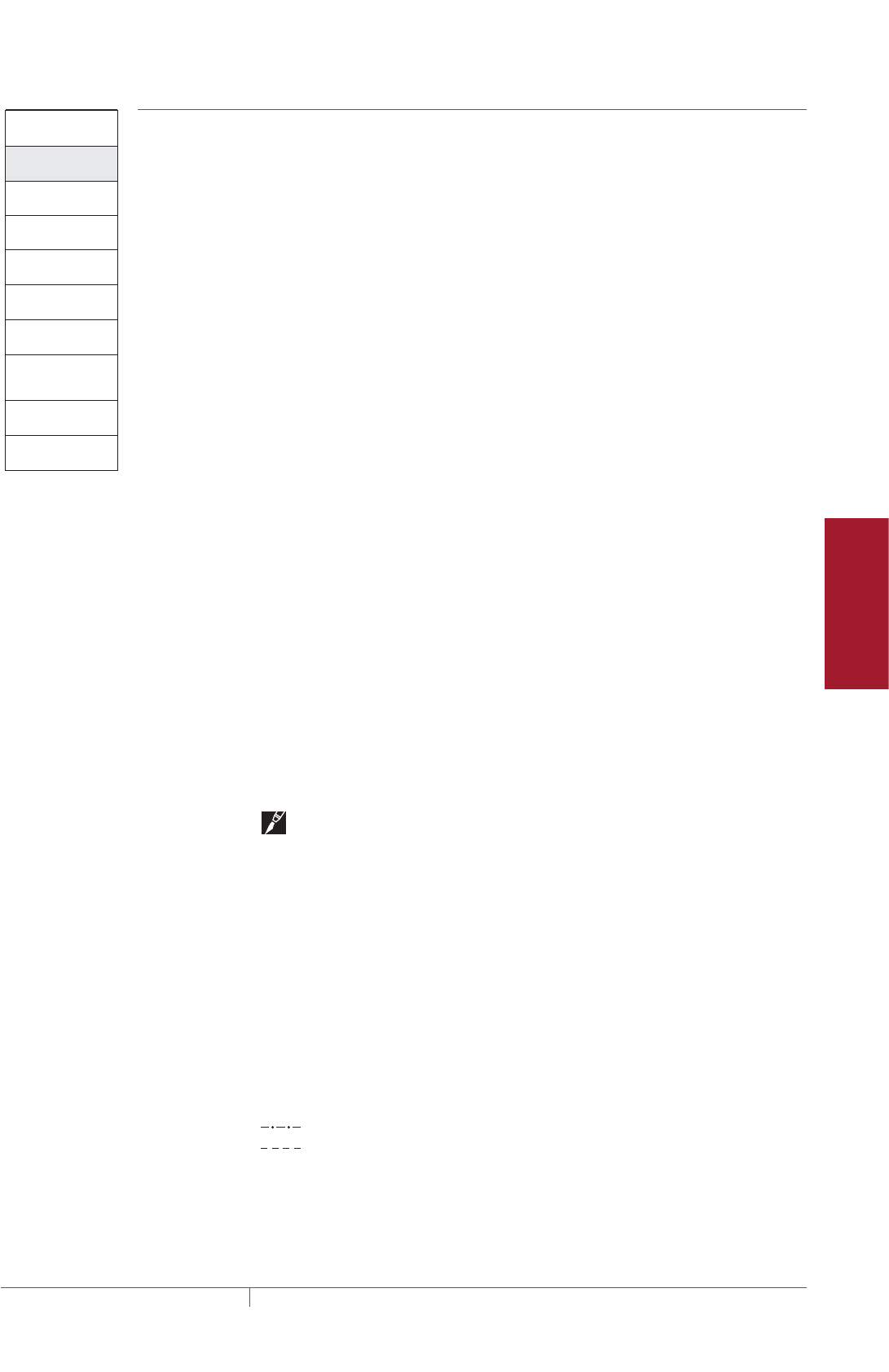
133THERMAL MANAGEMENT SOLUTIONS EN-PyrotenaxMISurfaceSnowMelting-DG-H57045 11/13
Pipe Freeze Protection
and Flow Maintenance
Fire Sprinkler System
Freeze Protection
Roof and Gutter
De-Icing
Surface Snow
Melting – MI
Surface Snow
Melting – ElectroMelt
Freezer Frost
Heave Prevention
Floor Heating Technical Data
Sheets
Surface Snow Melting
1. Determine design
conditions
2. Determine the
required watt density
3. Determine the total
area to be protected
4. Select the heating
cable
5. Determine heating
cable spacing
7. Select the control
system and power
distribution
8. Select the
accessories
9. Complete the Bill
of Materials
6. Determine the
electrical parameters
Step Determine design conditions
Collect the following information to determine your design conditions:
• Environment
– Geographical location
• Paving material
– Concrete
– Asphalt
– Pavers
• Size and layout
– Slab surface area
– Ramp surface area
– Stairs
- Number of stairs
- Stair width
- Riser height
- Stair depth
- Landing surface area
– Wheel tracks
- Track length
– Concrete joints
– Surface drains
– Location of area structures
– Other information as appropriate
• Supply voltage
• Phase (single-phase or three-phase)
• Control method
– Automatic snow melting controller
– Slab sensing thermostat
– Manual on/off control
Note: Drainage must be a primary concern in any snow melting system design.
Improper drainage will result in ice formation on the surface of the heated area once
the system is de-energized. Ice formation along the drainage path away from the
heated area may create an ice dam and prohibit proper draining. If your design
conditions may lead to drainage problems, please contact Pentair Thermal
Management Technical Support for assistance.
PREPARE SCALE DRAWING
Draw to scale the area in which the snow melting cables will be installed, and note
the rating and location of the voltage supply. Include stairs and paths for melting
water runoff. Show concrete joints, surface drains, and location of area structures
including post installations for railings, permanent benches, and flagpoles.
Measurements for each distinct section of the snow melting application, including
stairs, will allow for an accurate system design, including control configuration. Use
these symbols to indicate the heating cable expansion and crack-control joints:
S
Power connection
End seal
Splice
Expansion joint
Crack-control joint
Expansion joint kit
E
P
Fig. 4 Design symbols
Surface Snow Melting Design

THERMAL MANAGEMENT SOLUTIONS
EN-PyrotenaxMISurfaceSnowMelting-DG-H57045 11/13
134
Example: Surface Snow Melting System
Geographical location Philadelphia, PA
Ramp surface area 45 ft x 12 ft (13.7 m x 3.66 m)
Paving material Concrete
Supply voltage 480 V, three-phase
Control method Automatic snow melting controller
Example: Surface Snow Melting System for Stairs
Geographical location Philadelphia, PA
Number of stairs 5
Stair width 5 ft (1.52 m)
Riser height 8 in (20 cm)
Stair depth 11 in (28 cm)
Landing surface area 5 ft x 3 ft (1.52 m x 0.91 m)
Paving material Concrete
Supply voltage 208 V, single-phase
Control method Slab sensing thermostat
Example: Surface Snow Melting System for Wheel Tracks
Geographical location Philadelphia, PA
Track length 28 ft (8.5 m)
Paving material Asphalt
Supply voltage 240 V, single-phase
Control method Automatic snow melting controller
SURFACE SNOW MELTING MI MINERAL INSULATED HEATING CABLE SYSTEM
135THERMAL MANAGEMENT SOLUTIONS EN-PyrotenaxMISurfaceSnowMelting-DG-H57045 11/13
Pipe Freeze Protection
and Flow Maintenance
Fire Sprinkler System
Freeze Protection
Roof and Gutter
De-Icing
Surface Snow
Melting – MI
Surface Snow
Melting – ElectroMelt
Freezer Frost
Heave Prevention
Floor Heating Technical Data
Sheets
Surface Snow Melting
1. Determine design
conditions
2. Determine the
required watt density
3. Determine the total
area to be protected
4. Select the heating
cable
5. Determine heating
cable spacing
7. Select the control
system and power
distribution
8. Select the
accessories
9. Complete the Bill
of Materials
6. Determine the
electrical parameters
Step Determine the required watt density
For maximum performance from any snow melting system, you must first take
into account the local snowfall patterns. A system design that works well in one
city may be inadequate in another. The energy required to melt snow varies with air
temperature, wind speed, relative humidity, snow density, and the depth of the snow
on the pavement.
SURFACE SNOW MELTING
Table 1 summarizes the required watt density for most major cities in North America
based on typical minimum ambient temperatures and the snowfall patterns. Select
the city from the list, or closest city, where similar climatic conditions exist.
TABLE 1 REQUIRED WATT DENSITY FOR SURFACE SNOW MELTING
Watts/ft2Watts/m2
City
Concrete
Asphalt
or
pavers
Concrete
stairs Concrete
Asphalt
or
pavers
Concrete
stairs
USA
Baltimore, MD 35 40 40 377 431 431
Boston, MA 35 40 45 377 431 484
Buffalo, NY 40 45 45 431 484 484
Chicago, IL 35 40 40 377 431 431
Cincinnati, OH 35 40 40 377 431 431
Cleveland, OH 35 40 40 377 431 431
Denver, CO 35 40 40 377 431 431
Detroit, MI 35 40 40 377 431 431
Great Falls, MT 50 50 55 538 538 592
Greensboro, NC 35 35 40 377 377 431
Indianapolis, IN 35 40 40 377 431 431
Minneapolis, MN 50 50 55 538 538 592
New York, NY 35 40 45 377 431 484
Omaha, NE 45 50 50 484 538 538
Philadelphia, PA 35 40 45 377 431 484
Salt Lake City, UT 35 35 40 377 377 431
Seattle, WA 35 35 40 377 377 431
St. Louis, MO 35 40 45 377 431 484
Canada
Calgary, AB 45 45 50 484 484 538
Edmonton, AB 50 50 55 538 538 592
Fredericton, NB 40 45 45 431 484 484
Halifax, NS 35 40 40 377 431 431
Moncton, NB 40 40 45 431 431 484
Montreal, QC 45 45 50 484 484 538
Ottawa, ON 45 45 50 484 484 538
Prince George, BC 50 55 55 538 592 592
Quebec, QC 45 45 50 484 484 538
Regina, SK 50 55 55 538 592 592
Saskatoon, SK 50 50 55 538 538 592
St. John, NB 40 45 45 431 484 484
St. John’s, NF 35 35 40 377 377 431
Sudbury, ON 40 45 50 431 484 538
Thunder Bay, ON 50 55 55 538 592 592
Toronto, ON 35 40 40 377 431 431
Vancouver, BC 35 40 40 377 431 431
Winnipeg, MB 50 55 55 538 592 592
Surface Snow Melting Design
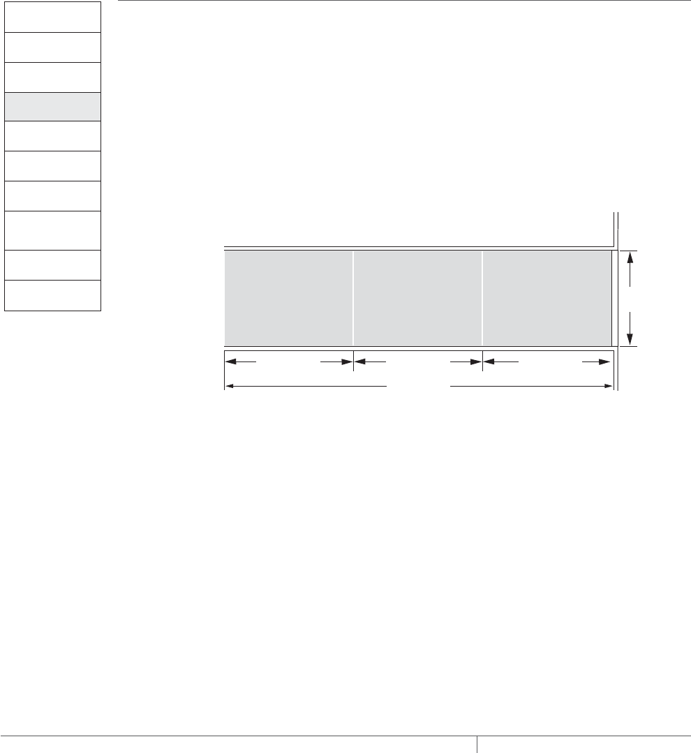
THERMAL MANAGEMENT SOLUTIONS
EN-PyrotenaxMISurfaceSnowMelting-DG-H57045 11/13
136
Example: Surface Snow Melting System
Geographical location Philadelphia, PA (from Step 1)
Paving material Concrete (from Step 1)
Required watt density 35 W/ft2 (377 W/m2) (from Table 1)
Example: Surface Snow Melting System for Stairs
Geographical location Philadelphia, PA (from Step 1)
Paving material Concrete (from Step 1)
Required watt density 45 W/ft2 (484 W/m2) (from Table 1)
Example: Surface Snow Melting System for Wheel Tracks
Geographical location Philadelphia, PA (from Step 1)
Paving material Asphalt (from Step 1)
Required watt density 40 W/ft2 (431 W/m2) (from Table 1)
Surface Snow Melting
1. Determine design
conditions
2. Determine the
required watt density
3. Determine the total
area to be protected
4. Select the heating
cable
5. Determine heating
cable spacing
7. Select the control
system and power
distribution
8. Select the
accessories
9. Complete the Bill
of Materials
6. Determine the
electrical parameters
Step Determine the total area to be protected
SURFACES
To select the proper heating cable you need to know the size of the surface area
you will be protecting from snow accumulation. For large areas, divide the area
into smaller subsections no greater than 400 ft² (37.2 m²). For three-phase voltage
supplies, create multiples of three equal areas not exceeding 400 ft² (37.2 m²) as
shown in Fig. 5. Do not exceed 20 ft (6.1m) in any direction. If assistance is required
to select heating cables for irregularly-shaped areas, please contact your Pentair
Thermal Management representative.
Total surface area (ft²/m²) = Length (ft/m) x Width (ft/m)
BA 12 ft
3.66 m)
C
45 ft (13.7 m)
15 ft (4.57 m) 15 ft (4.57 m) 15 ft (4.57 m)
Fig. 5 Example for surface snow melting
Joints in Concrete
Many large concrete slabs are constructed with control and expansion joints. There
are three types of joints that can be placed in concrete slabs. An explanation of each
follows:
1. Crack-control joints (sawcuts) are intended to control where the slab will crack.
Their exact location is determined by the concrete installers before the concrete is
poured. Because of the reinforcement in the base slab, there is rarely a shearing
action caused by differential vertical movement between the concrete on either side
of the crack. As a precautionary measure, however, either of the two methods of
crossing control joints shown in Fig. 7 should be used. Minimize the number of times
the joint is crossed as shown in Fig. 7. When installing cables using the two-pour
method, control joints must be placed in both the base slab and the surface slab.
SURFACE SNOW MELTING MI MINERAL INSULATED HEATING CABLE SYSTEM
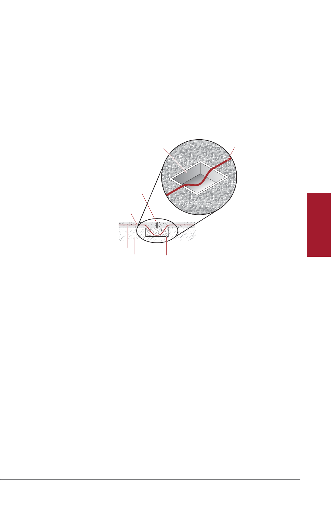
137THERMAL MANAGEMENT SOLUTIONS EN-PyrotenaxMISurfaceSnowMelting-DG-H57045 11/13
Pipe Freeze Protection
and Flow Maintenance
Fire Sprinkler System
Freeze Protection
Roof and Gutter
De-Icing
Surface Snow
Melting – MI
Surface Snow
Melting – ElectroMelt
Freezer Frost
Heave Prevention
Floor Heating Technical Data
Sheets
2. Construction joints are joints that occur when the concrete pour is going to
stop but will resume at a later date. Therefore their location may not be known
beforehand. However, the rebar is left protruding out of the first pour so that it enters
the next pour and therefore shearing action rarely occurs due to differential vertical
movement between the concrete on either side of the joint. As a precautionary
measure, either of the two methods of crossing control joints shown in Fig. 7 should
be used.
3. Expansion joints are placed where a concrete slab abuts a structure, such as
a building, a slab, or a foundation, etc. Since the reinforcement does not cross
expansion joints, differential movement will occur between the slab and the
adjoining structure. Avoid crossing expansion joints with the heating cable. If this is
not possible, expansion joints can be crossed using a sand filled metal box as shown
in Fig. 6.
Well drained
gravel base
Concrete slab
Expansion
joint
Heating
cable
Heating
cable
Metal
box
(sand not shown)
6 in x 6 in x 4 in
(15 cm x 15 cm x 10 cm)
metal box filled with sand
Fig. 6 Crossing expansion joints
Cold leads may cross expansion joints provided that they are fed through nonmetallic
conduit to protect against shear (see Fig. 7).
Important Points to Remember
• Concrete slabs should have crack-control joints at intervals typically not exceed-
ing 20 ft (6.1 m).
• When crossing crack-control joints, protect the cable as shown in Fig. 7 or design
for a sufficient number of heating cables to avoid crossing control joints altogether.
• Avoid crossing expansion joints. If possible, design for a sufficient number of
heating cables so that the cables do not cross expansion joints.
Surface Snow Melting Design
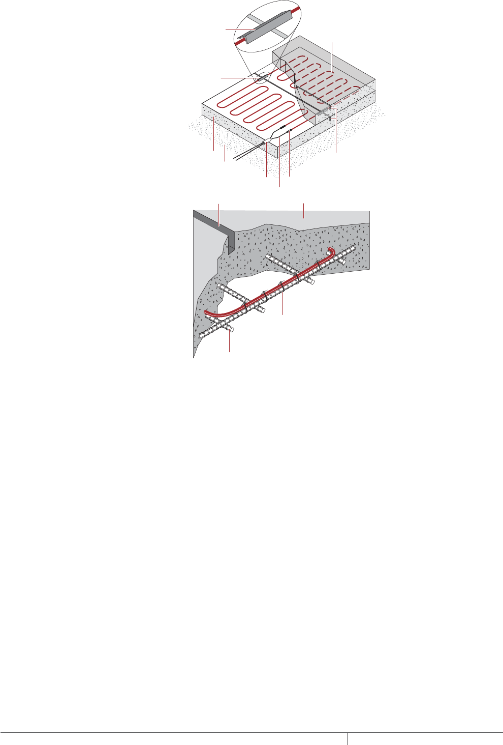
THERMAL MANAGEMENT SOLUTIONS
EN-PyrotenaxMISurfaceSnowMelting-DG-H57045 11/13
138
Angle iron
Hot/cold joints
Cold leads
Control joints
(cut into both bottom
and top slabs for two
pour installations)
Well-drained base
Nonmetallic
conduit
Base slab
Heating cable
1 x 1 x 12 in
(2.5 x 2.5 x 30 cm)
angle iron filled
with RTV or silicone
rubber caulk
Control joint
Steel rebar
Heating cable secured
to rebar with plastic
tie wraps
Concrete
Fig. 7 Method of crossing crack-control joints with MI heating cable in concrete slabs
SURFACE SNOW MELTING MI MINERAL INSULATED HEATING CABLE SYSTEM
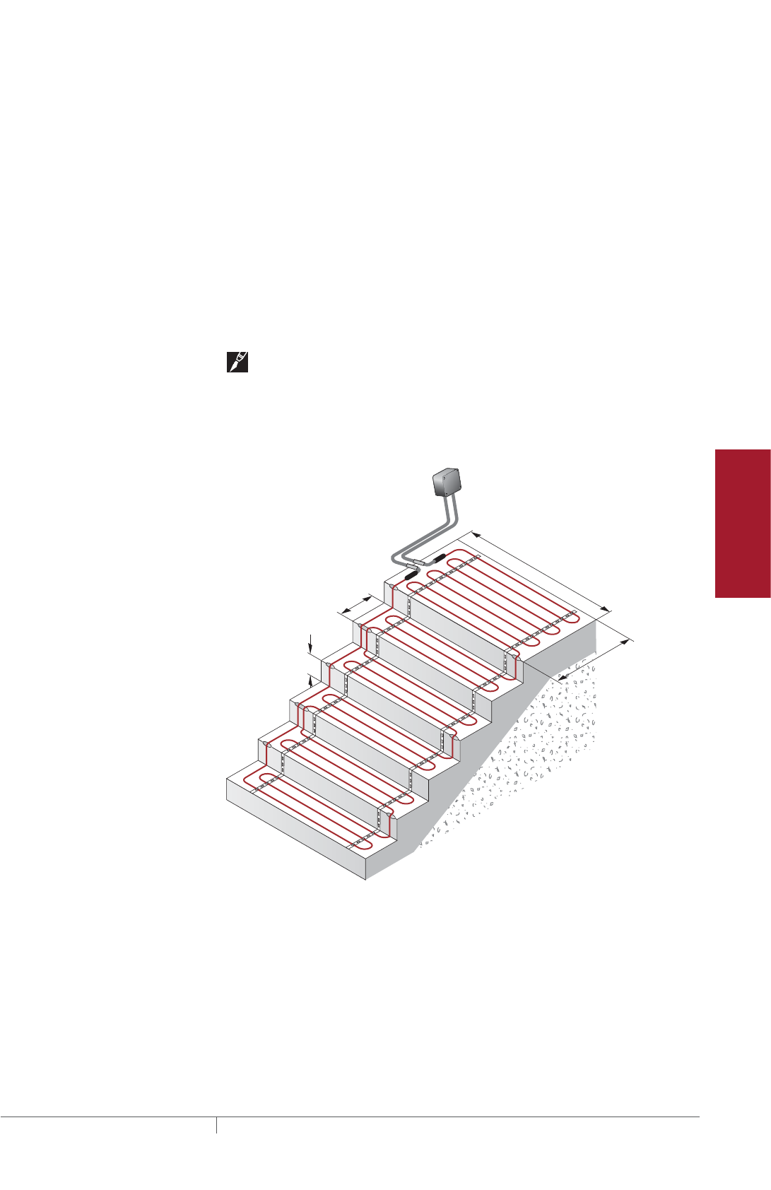
139THERMAL MANAGEMENT SOLUTIONS EN-PyrotenaxMISurfaceSnowMelting-DG-H57045 11/13
Pipe Freeze Protection
and Flow Maintenance
Fire Sprinkler System
Freeze Protection
Roof and Gutter
De-Icing
Surface Snow
Melting – MI
Surface Snow
Melting – ElectroMelt
Freezer Frost
Heave Prevention
Floor Heating Technical Data
Sheets
Example: Surface Snow Melting System
Total ramp surface area 45 ft x 12 ft = 540 ft² (from Step 1)
(13.7 m x 3.66 m = 50.1 m²)
For three-phase, divide the ramp 15 ft x 12 ft = 180 ft² (see Fig. 5)
into three equal subsections (4.57 m x 3.66 m = 16.7 m²)
Continue with “Step 4 Select the heating cable” on page141, and use Table 2 or
Table 3 to select an appropriate heating cable.
STAIRS
Snow melting applications in concrete stairs present a problem distinct from snow
melting on single layer surfaces. Heat loss in stairs occurs from the two exposed
surfaces: the top of each stair and its side. Melting snow and ice from stairs requires
one run of heating cable be installed 2 to 3 in (5 to 7.5 cm) maximum from the front,
or nose, of each stair at a depth of 2 in (5 cm) below the surface of the stair.
Note: Stairs typically require a heating cable that is a specific length. In many
cases, it may not be possible to find a SUA/SUB heating cable of the exact length,
and a custom engineered heating cable will be required. In these cases, or for
elevated stairs or stairs that are not concrete, please contact your Pentair Thermal
Management representative for assistance in designing a custom engineered
heating cable.
8 in
(20 cm)
Riser
height
11 in
(28 cm)
Stair
depth
5 ft (1.52 m)
Width
3 ft
(0.91 m)
Junction
box
Fig. 8 Example for concrete stair
Typically, three runs of cable are used for stairs with a depth of 10.5 to 12 in
(27–30 cm); two runs of cable may be used for stairs with a depth of less than 10.5 in
(27 cm). Riser height is typically 8 in (20 cm). For stairs greater than 12 in (30 cm) in
depth, contact your Pentair Thermal Management representative.
Use the formulas below to determine the length of cable required for stairs (a) and
for an attached landing (b), if any, where no expansion joint exists between the stair
and landing.
Surface Snow Melting Design
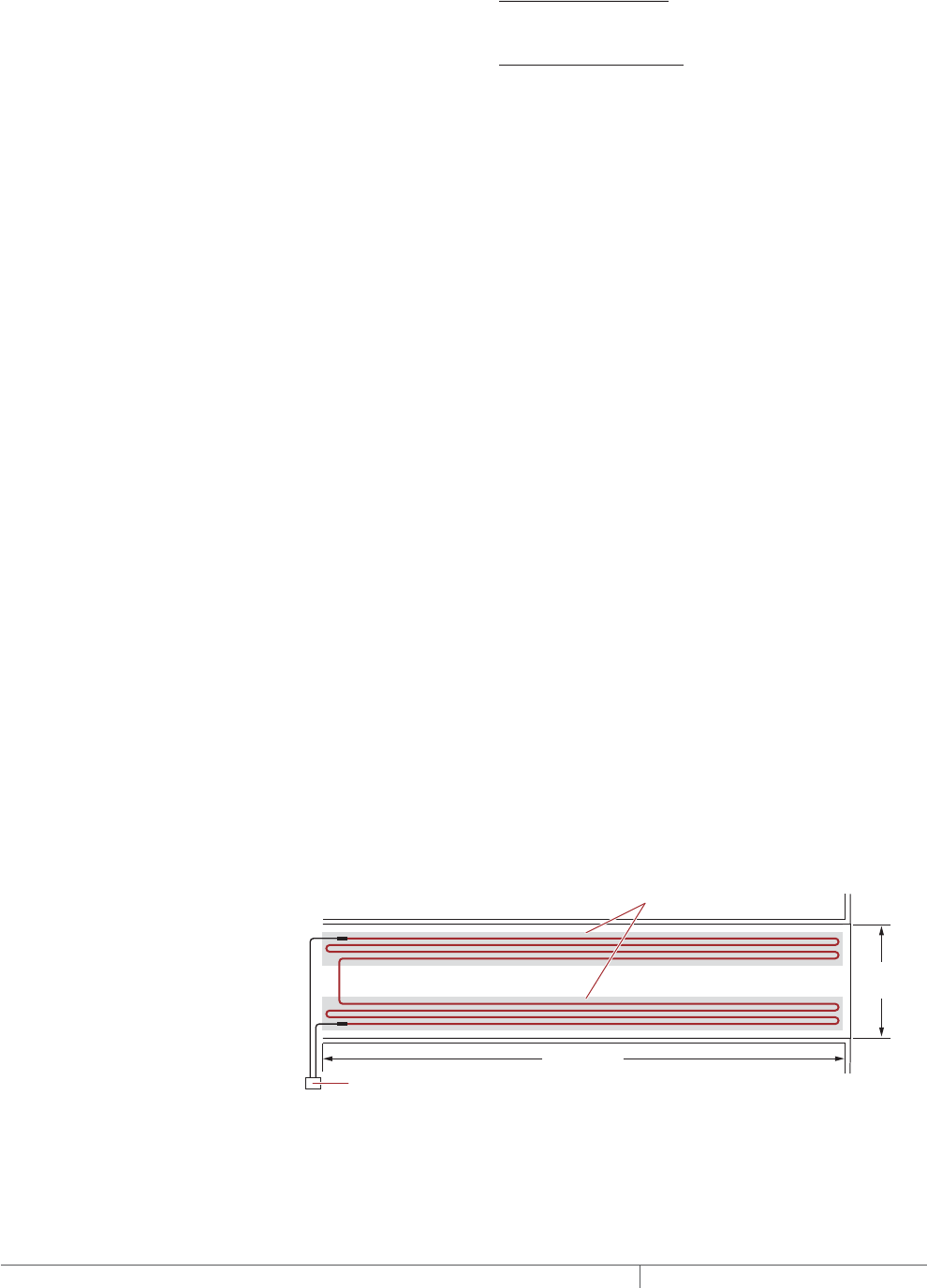
THERMAL MANAGEMENT SOLUTIONS
EN-PyrotenaxMISurfaceSnowMelting-DG-H57045 11/13
140
Length of cable
for stair (ft/m)
No. of stairs = x [(No. of runs per stair x stair width (ft/m))
+ (2 x riser height (ft/m))]
(a)
Length of cable for
attached landing (ft)
Landing area (ft2) x 12
4.5
=
(b)
Length of cable for
attached landing (m)
Landing area (m2) x 1000
115
=
For applications where the landing area is very large or where an expansion joint
exists between the stairs and landing, consider the stairs and landing as two
separate areas. In these cases, determine the length of cable required for the stairs
as shown above and select the cable for the landing as shown for surface snow
melting.
Example: Surface Snow Melting System for Stairs
Number of stairs 5 stairs (from Step 1)
Stair width 5 ft (1.52 m) (from Step 1)
Riser height 8 in (20 cm) convert to 0.7 ft (0.2 m) (from Step 1)
Stair depth 11 in (28 cm) (from Step 1)
Number of cable runs per stair 3 runs (for 11 in (28 cm) stair depth)
Length of cable for stair 5 stairs x [(3 x 5 ft) + (2 x 0.7 ft)] = 82 ft
5 stairs x [(3 x 1.52 m) + (2 x 0.2 m)] = 25 m
Landing surface area 5 ft x 3 ft = 15 ft² (from Step 1)
1.52 m x 0.91 m = 1.4 m²
Length of cable for attached landing (15 ft² x 12) / 4.5 = 40 ft
(1.4 m² x 1000) / 115 = 12.2 m
Total heating cable length required 82 ft + 40 ft = 122 ft
25 m + 12.2 m = 37.2 m
Continue with “Step 4 Select the heating cable” on page141‚ and use Table 4 on
page146 to select an appropriate heating cable.
WHEEL TRACKS
To reduce power consumption for concrete and asphalt driveways, it may be
sufficient to snow melt only the wheel tracks. However, do not snow melt only
the wheel tracks in paver applications because of potential problems with pavers
sinking.
It is not necessary to calculate the area of the wheel track to select the heating
cable. Four runs of heating cable per wheel track spaced evenly over the track width,
typically 18 in (46cm), will provide sufficient heat for snow melting.
28 ft (8.5 m)
10 ft
(3.0 m)
Junction box
Heated area
Fig. 9 Example for wheel tracks
SURFACE SNOW MELTING MI MINERAL INSULATED HEATING CABLE SYSTEM

141THERMAL MANAGEMENT SOLUTIONS EN-PyrotenaxMISurfaceSnowMelting-DG-H57045 11/13
Pipe Freeze Protection
and Flow Maintenance
Fire Sprinkler System
Freeze Protection
Roof and Gutter
De-Icing
Surface Snow
Melting – MI
Surface Snow
Melting – ElectroMelt
Freezer Frost
Heave Prevention
Floor Heating Technical Data
Sheets
Example: Surface Snow Melting System for Wheel Tracks
Wheel track length 28 ft (8.5 m) (from Step 1)
Typical wheel track width 18 in (46 cm)
Continue with “Step 4 Select the heating cable” on page141 and use Table 5 on
page147 to select an appropriate heating cable.
Surface Snow Melting
1. Determine design
conditions
2. Determine the
required watt density
3. Determine the total
area to be protected
4. Select the heating
cable
5. Determine heating
cable spacing
7. Select the control
system and power
distribution
8. Select the
accessories
9. Complete the Bill
of Materials
6. Determine the
electrical parameters
Step Select the heating cable
Three-phase supply voltages, including 208 V, 480 / 277 V, and 600 / 347 V, are
commonly used for snow melting applications for large areas. For small areas, a
single-phase supply voltage must be used. A snow melting system designed for a
three-phase supply uses three identical heating cables in each circuit, resulting in
the following advantages: fewer circuits, reduced distribution system costs, and a
balanced heating system load.
SURFACES
Select a heating cable from Table 2 on page142 or Table 3 on page143. When
selecting cables from Table 2, ensure that the selected cable is suitable for use
when embedded in the paving material being used. The heating cables in Table 3
are suitable for surface snow melting applications where the cables will be directly
embedded only in concrete. To select a cable, first calculate the required heating
cable output (watts) by multiplying the watt density by the area or subsection area.
Under the appropriate voltage in Table 2 or Table 3, select a heating cable from the
shaded column with a heating cable output equal to or up to 30% greater than the
calculated wattage. In cases where the surface area has been divided into equal
subsections, select the appropriate number of heating cables.
Required watts = Watt density x Area
Number of cables = Number of subsection areas
Example: Surface Snow Melting System
Supply voltage 480 V, three-phase (from Step 1)
Required watt density for ramp 35 W/ft² (377 W/m²) (from Step 2)
Subsection area (for 3 equal areas) 180 ft² (16.7 m²) (from Step 3)
Required watts (for each subsection) 35 W/ft² x 180 ft² = 6300 W
377 W/m² x 16.7 m² = 6300 W
Heating cable catalog number SUB20
Cable wattage 6450 W
Cable voltage 480 V (for cables connected in Delta
configuration)
Heating cable length 340 ft (103.6 m)
Number of cables 3 (one cable required for each subsection)
Surface Snow Melting Design

THERMAL MANAGEMENT SOLUTIONS
EN-PyrotenaxMISurfaceSnowMelting-DG-H57045 11/13
142
TABLE 2 SELECTION TABLE FOR CONCRETE, ASPHALT, AND PAVER AREAS
Heating cable
catalog number
Heating cable output Heating cable length
Heating cable
current
Concrete Asphalt Pavers ¹(W) (ft) (m) (A)
120 V
SUA5 Yes Yes Yes 550 40 12.2 4.6
SUA9 Yes Yes Yes 1100 66 20.1 9.2
208 V
SUA4 Yes Yes No 1600 68 20.7 7.7
SUA7 Yes Yes No 2300 95 29 11.1
SUB1 Yes Yes No 3100 132 40.2 14.9
SUB3 Yes Yes Yes 3900 280 85.3 18.8
SUB5 Yes Yes No 5500 260 79.2 26.4
SUB7 Yes Yes No 7000 310 94.5 33.7
SUB9 Yes Yes Yes 9000 630 192 43.3
SUB10 Yes Yes Yes 13000 717 218.5 62.5
240 V
SUA3 Yes Yes Yes 2000 140 42.7 8.3
SUA8 Yes Yes Yes 3200 177 53.9 13.3
SUB2 Yes Yes Yes 4000 240 73.1 16.7
SUB3 Yes Yes Yes 5200 280 85.3 21.7
SUB4 Yes Yes Yes 6000 320 97.5 25
SUB5 Yes No No 7350 260 79.2 30.6
SUB6 Yes Yes Yes 7500 375 114.3 31.3
SUB8 Yes Yes Yes 9000 550 167.6 37.5
SUB7 Yes No No 9250 310 94.5 38.5
SUB9 Yes Yes Yes 12000 630 192 50
SUB10 Yes Yes No 17000 717 218.5 70.8
277 V
SUA3 Yes Yes Yes 2740 140 42.7 9.9
SUA8 Yes Yes No 4100 177 53.9 14.8
SUB15 Yes Yes Yes 4250 225 68.6 15.3
SUB2 Yes Yes No 5300 240 73.1 19.1
SUB16 Yes Yes Yes 6180 310 94.5 22.3
SUB3 Yes Yes No 6850 280 85.3 24.7
SUB4 Yes Yes No 8000 320 97.5 28.9
SUB17 Yes Yes Yes 8700 440 134.1 31.4
SUB6 Yes No No 10200 375 114.3 36.8
SUB18 Yes Yes No 12000 560 170.7 43.3
SUB8 Yes Yes No 12200 550 167.6 44.0
SUB9 Yes No No 16400 630 192 59.2
480 V
SUB19 Yes Yes Yes 4700 245 74.7 9.8
SUB20 Yes Yes Yes 6450 340 103.6 13.4
SUB21 Yes Yes Yes 8700 440 134.1 18.1
SUB22 Yes Yes No 11000 525 160 22.9
1 Cables embedded in sand or limestone screenings.
Note: Type SUA cables supplied with 7 ft (2.1 m) cold lead. Type SUB cables supplied with 15 ft (4.6 m) cold leads. Tolerance on
heating cable length is –0% to +3%.
To modify cold lead length, contact your Pentair Thermal Management sales representative.
SURFACE SNOW MELTING MI MINERAL INSULATED HEATING CABLE SYSTEM
143THERMAL MANAGEMENT SOLUTIONS EN-PyrotenaxMISurfaceSnowMelting-DG-H57045 11/13
Pipe Freeze Protection
and Flow Maintenance
Fire Sprinkler System
Freeze Protection
Roof and Gutter
De-Icing
Surface Snow
Melting – MI
Surface Snow
Melting – ElectroMelt
Freezer Frost
Heave Prevention
Floor Heating Technical Data
Sheets
TABLE 2 SELECTION TABLE FOR CONCRETE, ASPHALT, AND PAVER AREAS
Heating cable
catalog number
Heating cable output Heating cable length
Heating cable
current
Concrete Asphalt Pavers ¹(W) (ft) (m) (A)
600 V
SUB11 Yes Yes Yes 4100 225 68.6 6.8
SUB12 Yes Yes Yes 5800 310 94.5 9.7
SUB13 Yes Yes Yes 8000 428 130.5 13.3
SUB14 Yes Yes Yes 11000 548 167 18.3
1 Cables embedded in sand or limestone screenings.
Note: Type SUA cables supplied with 7 ft (2.1 m) cold lead. Type SUB cables supplied with 15 ft (4.6 m) cold leads. Tolerance on
heating cable length is –0% to +3%.
To modify cold lead length, contact your Pentair Thermal Management sales representative.
The heating cables in Table 3 have been specifically designed for use only in
concrete. Do not use these cables in asphalt or for paver areas because they exceed
the maximum watts per foot loading for these applications (embedded in asphalt 25
watts/foot maximum; embedded in sand/limestone screenings for paver areas – 20
watts/foot maximum). To select a cable, calculate the required heating cable output
(watts) as shown in the example earlier in this section.
TABLE 3 SELECTION TABLE FOR CONCRETE AREAS
Heating cable
catalog number
Heating cable
output
Heating cable
length
Heating cable
current
(W) (ft) (m) (A)
208 V
SUB1402 1400 50 15.2 6.7
SUB1702 1700 64 19.5 8.2
SUB2002 2000 72 22.0 9.6
SUB2402 2400 90 27.4 11.5
SUB2802 2800 103 31.4 13.5
SUB3402 3400 121 36.9 16.3
SUB3902 3900 139 42.4 18.8
SUB4502 4500 160 48.8 21.6
SUB5502 5500 197 60.1 26.4
SUB6402 6400 226 68.9 30.8
SUB7802 7800 277 84.5 37.5
SUB10302 10300 368 112.2 49.5
SUB12802 12800 455 138.7 61.5
SUB16102 16100 576 175.6 77.4
Note: Type SUB cables supplied with 15 ft (4.6 m) cold leads. Tolerance on heating cable
length is –0% to +3%. To modify cold lead length, contact your Pentair Thermal
Management sales representative.
Surface Snow Melting Design
THERMAL MANAGEMENT SOLUTIONS
EN-PyrotenaxMISurfaceSnowMelting-DG-H57045 11/13
144
TABLE 3 SELECTION TABLE FOR CONCRETE AREAS
Heating cable
catalog number
Heating cable
output
Heating cable
length
Heating cable
current
(W) (ft) (m) (A)
240 V
SUB1604 1600 59 18.0 6.7
SUB2004 2000 74 22.6 8.3
SUB2304 2300 84 25.6 9.6
SUB2804 2800 103 31.4 11.7
SUB3204 3200 120 36.6 13.3
SUB3904 3900 140 42.7 16.3
SUB4504 4500 160 48.8 18.8
SUB5204 5200 185 56.4 21.7
SUB6404 6400 225 68.6 26.7
SUB7304 7300 263 80.2 30.4
SUB9004 9000 320 97.6 37.5
SUB11904 11900 426 129.9 49.6
SUB14704 14700 528 161.0 61.3
SUB18604 18600 664 202.4 77.5
277 V
SUB1807 1800 70 21.3 6.5
SUB2307 2300 85 25.9 8.3
SUB2707 2700 95 29.0 9.7
SUB3207 3200 119 36.3 11.6
SUB3807 3800 135 41.2 13.7
SUB4507 4500 162 49.4 16.2
SUB5207 5200 184 56.1 18.8
SUB6007 6000 213 64.9 21.7
SUB7307 7300 262 79.9 26.4
SUB8507 8500 300 91.5 30.7
SUB10307 10300 372 113.4 37.2
SUB13707 13700 491 149.7 49.5
SUB17207 17200 600 182.9 62.1
347 V
SUB2305 2300 85 25.9 6.6
SUB2905 2900 107 32.6 8.4
SUB3405 3400 119 36.3 9.8
SUB4105 4100 148 45.1 11.8
SUB4705 4700 171 52.1 13.5
SUB5605 5600 205 62.5 16.1
SUB6505 6500 231 70.4 18.7
SUB7505 7500 267 81.4 21.6
SUB9205 9200 327 99.7 26.5
SUB10605 10600 380 115.9 30.5
SUB13005 13000 463 141.2 37.5
SUB17205 17200 614 187.2 49.6
Note: Type SUB cables supplied with 15 ft (4.6 m) cold leads. Tolerance on heating cable
length is –0% to +3%. To modify cold lead length, contact your Pentair Thermal
Management sales representative.
SURFACE SNOW MELTING MI MINERAL INSULATED HEATING CABLE SYSTEM
145THERMAL MANAGEMENT SOLUTIONS EN-PyrotenaxMISurfaceSnowMelting-DG-H57045 11/13
Pipe Freeze Protection
and Flow Maintenance
Fire Sprinkler System
Freeze Protection
Roof and Gutter
De-Icing
Surface Snow
Melting – MI
Surface Snow
Melting – ElectroMelt
Freezer Frost
Heave Prevention
Floor Heating Technical Data
Sheets
TABLE 3 SELECTION TABLE FOR CONCRETE AREAS
Heating cable
catalog number
Heating cable
output
Heating cable
length
Heating cable
current
(W) (ft) (m) (A)
480 V
SUB3208 3200 118 36.0 6.7
SUB4008 4000 147 44.8 8.3
SUB4708 4700 163 49.7 9.8
SUB5708 5700 202 61.6 11.9
SUB6608 6600 233 71.0 13.8
SUB7908 7900 278 84.8 16.5
SUB9008 9000 320 97.6 18.8
SUB10408 10400 368 112.2 21.7
SUB12808 12800 450 137.2 26.7
SUB14808 14800 520 158.5 30.8
SUB18008 18000 640 195.1 37.5
600 V
SUB4006 4000 147 44.8 6.7
SUB5106 5100 181 55.2 8.5
SUB5806 5800 207 63.1 9.7
SUB7106 7100 254 77.4 11.8
SUB8206 8200 293 89.3 13.7
SUB9806 9800 350 106.7 16.3
SUB11206 11200 402 122.6 18.7
SUB13006 13000 462 140.9 21.7
SUB15906 15900 566 172.6 26.5
Note: Type SUB cables supplied with 15 ft (4.6 m) cold leads. Tolerance on heating cable
length is –0% to +3%. To modify cold lead length, contact your Pentair Thermal
Management sales representative.
STAIRS
For stairs, select a heating cable from Table 4. Under the appropriate voltage,
select a cable from the shaded column with a length equal to or up to 20 ft (6.1 m)
longer than the calculated length from Step 3. Next, confirm that the watt density is
equal to, or greater than, the watt density determined from Step 2. If a cable of the
required length is not available, please contact your Pentair Thermal Management
representative for assistance in designing a custom heating cable.
Anticipate and design for the addition of railings or other follow on construction that
will require cutting or drilling into the concrete as damage to installed heating cable
may occur. Allow for at least 4 in (10 cm) clearance between the heating cable and
any planned cuts or holes.
Example: Surface Snow Melting System for Stairs
Supply voltage 208 V, single-phase (from Step 1)
Required watt density 45 W/ft² (484 W/m²) (from Step 2)
Total heating cable length required 122 ft (37.2 m) (from Step 3)
Heating cable catalog number SUB1
Cable wattage 3100 W
Cable voltage 208 V
Heating cable length 132 ft (40.2 m)
Number of cables 1
Installed watt density 55 W/ft² (592 W/m²) (from Table 4)
Surface Snow Melting Design

THERMAL MANAGEMENT SOLUTIONS
EN-PyrotenaxMISurfaceSnowMelting-DG-H57045 11/13
146
TABLE 4 SELECTION TABLE FOR CONCRETE STAIRS
Heating cable
catalog number
Heating cable
length
Watt density Heating
cable
output
Heating
cable
current3 runs cable 12 runs cable 2
(ft) (m) (W/ft2) (W/m2) (W/ft2) (W/m2) (W) (A)
120 V
SUA5 40 12.2 40 431 – – 550 4.6
SUA9 66 20.1 50 538 40 431 1100 9.2
208 V
SUA4 68 20.7 55 592 55 592 1600 7.7
SUA7 95 29.0 55 592 55 592 2300 11.1
SUB1 132 40.2 55 592 55 592 3100 14.9
SUB3 280 85.3 40 431 – – 3900 18.8
SUB5 260 79.2 55 592 50 538 5500 26.4
SUB7 310 94.5 55 592 50 538 7000 33.7
SUB9 630 192.0 40 431 – – 9000 43.3
240 V
SUA3 140 42.7 40 431 – – 2000 8.3
SUB2 240 73.1 50 538 40 431 4000 16.7
SUB3 280 58.3 55 592 40 431 5200 21.7
SUB4 320 97.5 55 592 45 484 6000 25.0
SUB6 375 114.3 55 592 45 484 7500 31.3
SUB8 550 167.6 50 538 40 431 9000 37.5
SUB9 630 192.0 55 592 45 484 12000 50.0
277 V
SUA3 140 42.7 55 592 45 484 2740 9.9
SUB15 225 68.6 55 592 45 484 4250 15.3
SUB2 240 73.1 55 592 50 538 5300 19.1
SUB16 310 94.5 55 592 45 484 6180 22.3
SUB3 280 85.3 55 592 55 592 6850 24.7
SUB4 320 97.5 55 592 55 592 8000 28.9
SUB17 440 134.1 55 592 45 484 8700 31.4
SUB6 375 114.3 55 592 55 592 10200 36.8
SUB18 560 170.7 55 592 50 538 12000 43.3
480 V
SUB19 245 74.7 55 592 45 484 4700 9.8
SUB20 340 103.6 55 592 45 484 6450 13.4
SUB21 440 134.1 55 592 45 484 8700 18.1
SUB22 525 160.0 55 592 50 538 11000 22.9
600 V
SUB11 225 68.6 55 592 40 431 4100 6.8
SUB12 310 94.5 55 592 45 484 5800 9.7
SUB13 428 130.5 55 592 45 484 8000 13.3
SUB14 548 167.0 55 592 45 484 11000 18.3
1 Based on stairs with a depth of 10.5–12 in (27–30 cm) and 3 runs of cable
2 Based on stairs with a depth of less than 10.5 in (27 cm) and 2 runs of cable
Note: Type SUA cables supplied with 7 ft (2.1 m) cold lead. Type SUB cables supplied with 15 ft (4.6 m) cold leads. Tolerance on heat-
ing cable length is –0% to +3%.
To modify cold lead length, contact your Pentair Thermal Management sales representative.
SURFACE SNOW MELTING MI MINERAL INSULATED HEATING CABLE SYSTEM
147THERMAL MANAGEMENT SOLUTIONS EN-PyrotenaxMISurfaceSnowMelting-DG-H57045 11/13
Pipe Freeze Protection
and Flow Maintenance
Fire Sprinkler System
Freeze Protection
Roof and Gutter
De-Icing
Surface Snow
Melting – MI
Surface Snow
Melting – ElectroMelt
Freezer Frost
Heave Prevention
Floor Heating Technical Data
Sheets
WHEEL TRACKS
The heating cables shown in Table 5 will allow for four runs of cable in each wheel
track. Under the appropriate voltage, select a heating cable from the shaded column
for the wheel track length required. For wheel tracks outside the scope of this
design guide, please contact your Pentair Thermal Management representative for
assistance in designing a custom engineered heating cable.
Example: Surface Snow Melting System for Wheel Tracks
Supply voltage 240 V, single-phase (from Step 1)
Wheel track length 28 feet (8.5 m)
Heating cable catalog number SUB2
Cable wattage 4000 W
Cable voltage 240 V
Heating cable length 240 ft (73.1 m)
Number of cables 1
TABLE 5 SELECTION TABLE FOR CONCRETE AND ASPHALT WHEEL TRACKS
Heating
cable
catalog
number
Wheel track length
Spacing
(inches) Spacing (cm)
Heating cable
length
Heating
cable
output
Heating
cable
current
(ft) (m)
Normal
heat
High
heat
Normal
heat
High
heat (ft) (m) (W) (A)
208 V
SUA7 8 – 11 2.4 – 3.4 7 5 18 13 95 29 2300 11.1
SUB1 12 – 15 3.5 – 4.6 7 5 18 13 132 40.2 3100 14.9
SUA8 16 – 21 4.7 – 6.4 4 3 10 8 177 54 2400 11.5
SUB5 22 – 31 6.5 – 9.5 6 5 15 13 260 79.2 5500 26.4
SUB7 32 – 38 9.6 – 11.6 6 5 15 13 310 94.5 7000 33.7
SUB6 39 – 46 11.7 – 14.0 4 3 10 8 375 114.3 5700 27.4
SUB8 47 – 68 14.1 – 20.7 4 3 10 8 550 167.7 6800 32.7
SUB9 69 – 78 20.8 – 23.8 4 3 10 8 630 192 9000 43.3
SUB10 79 – 88 23.9 – 26.8 5 4 13 10 717 218.5 13000 62.5
240 V
SUA3 8 – 16 2.4 – 4.9 4 3 10 8 140 42.7 2000 8.3
SUA8 17 – 21 5.0 – 6.4 5 4 13 10 177 53.9 3200 13.3
SUB2 22 – 29 6.5 – 8.8 5 4 13 10 240 73.1 4000 16.7
SUB3 30 – 34 8.9 – 10.4 5 4 13 10 280 85.3 5200 21.7
SUB4 35 – 39 10.5 – 11.9 5 4 13 10 320 97.5 6000 25
SUB6 40 – 46 12.0 – 14.0 6 5 15 13 375 114.3 7500 31.3
SUB8 47 – 68 14.1 – 20.7 5 4 13 10 550 167.6 9000 37.5
SUB9 69 – 78 20.8 – 23.8 6 5 15 13 630 192 12000 50
SUB10 79 – 88 23.9 – 26.8 7 5 18 13 717 218.5 17000 70.8
277 V
SUA3 11 – 16 3.4 – 4.9 6 5 15 13 140 42.7 2740 9.9
SUB15 17 – 27 5.0 – 8.2 6 5 15 13 225 68.6 4250 15.3
SUB16 28 – 38 8.3 – 11.6 6 5 15 13 310 94.5 6180 22.3
SUB17 39 – 54 11.7 – 16.5 6 5 15 13 440 134.1 8700 31.4
SUB18 55 – 69 16.6 – 21.0 6 5 15 13 560 170.7 12000 43.3
SUB9 ¹ 70 – 78 21.1 – 23.8 7 6 18 15 630 192 16400 59.2
1 Not for asphalt applications; for use when embedded in concrete only
Note: Type SUA cables supplied with 7 ft (2.1 m) cold lead. Type SUB cables supplied with 15 ft (4.6 m) cold leads. Tolerance on
heating cable length is –0% to +3%.
To modify cold lead length, contact your Pentair Thermal Management sales representative.
Surface Snow Melting Design
THERMAL MANAGEMENT SOLUTIONS
EN-PyrotenaxMISurfaceSnowMelting-DG-H57045 11/13
148
TABLE 5 SELECTION TABLE FOR CONCRETE AND ASPHALT WHEEL TRACKS
Heating
cable
catalog
number
Wheel track length
Spacing
(inches) Spacing (cm)
Heating cable
length
Heating
cable
output
Heating
cable
current
(ft) (m)
Normal
heat
High
heat
Normal
heat
High
heat (ft) (m) (W) (A)
480 V
SUB19 20 – 29 6.1 – 8.8 6 5 15 13 245 74.7 4700 9.8
SUB20 30 – 41 8.9 – 12.5 6 5 15 13 340 103.6 6450 13.4
SUB21 42 – 54 12.6 – 16.5 6 5 15 13 440 134.1 8700 18.1
SUB22 55 – 64 16.6 – 19.5 6 5 15 13 525 160 11000 22.9
600 V
SUB11 20 – 27 6.1 – 8.2 6 4 15 10 225 68.6 4100 6.8
SUB12 28 – 38 8.3 – 11.6 6 5 15 13 310 94.5 5800 9.7
SUB13 39 – 52 11.7 – 15.9 6 5 15 13 428 130.5 8000 13.3
SUB14 53 – 67 16.0 – 20.4 6 5 15 13 548 167 11000 18.3
1 Not for asphalt applications; for use when embedded in concrete only
Note: Type SUA cables supplied with 7 ft (2.1 m) cold lead. Type SUB cables supplied with 15 ft (4.6 m) cold leads. Tolerance on
heating cable length is –0% to +3%.
To modify cold lead length, contact your Pentair Thermal Management sales representative.
Surface Snow Melting
1. Determine design
conditions
2. Determine the
required watt density
3. Determine the total
area to be protected
4. Select the heating
cable
5. Determine heating
cable spacing
7. Select the control
system and power
distribution
8. Select the
accessories
9. Complete the Bill
of Materials
6. Determine the
electrical parameters
Step Determine heating cable spacing
SURFACES
Determine the spacing between runs of heating cables using the formula below. For
concrete installations, do not exceed 10 in (25 cm) spacing of cable, and for asphalt
and paver installations do not exceed 6 in (15 cm) spacing. If the cable spacing for
asphalt or pavers exceeds 6 in (15 cm), contact your Pentair Thermal Management
representative for assistance.
To determine heating cable spacing required for surface snow melting
Cable spacing (in) = Area (ft²) x 12 in
Heating cable length (ft)
Cable spacing (cm) = Area (m²) x 100 cm
Heating cable length (m)
Round to the nearest 1/2 in or nearest 1 cm to obtain cable spacing.
Note: If a large area has been divided into subsections or if a three-phase
voltage supply is used, the area in the above equations will be the subsection area
and the heating cable length will be the length of the cable selected for the
subsection area.
SURFACE SNOW MELTING MI MINERAL INSULATED HEATING CABLE SYSTEM

149THERMAL MANAGEMENT SOLUTIONS EN-PyrotenaxMISurfaceSnowMelting-DG-H57045 11/13
Pipe Freeze Protection
and Flow Maintenance
Fire Sprinkler System
Freeze Protection
Roof and Gutter
De-Icing
Surface Snow
Melting – MI
Surface Snow
Melting – ElectroMelt
Freezer Frost
Heave Prevention
Floor Heating Technical Data
Sheets
Example: Surface Snow Melting System
Subsection area 180 ft² (16.7 m²) (from Step 3)
Heating cable catalog number SUB20 (from Step 4)
Heating cable length 340 ft (103.6 m) (from Step 4)
Cable spacing (180 ft² x 12 in) / 340 ft = 6.4 in
Rounded to 6.5 in
(16.7 m² x 100 cm) / 103.6 m = 16.1 cm
Rounded to 16 cm
STAIRS
For concrete stairs with a depth of 10.5–12 in (27–30 cm), use three runs of cable
with one run 2 to 3 in (5–7.5 cm) maximum from the front edge of the stair (this is
where snow and ice build-up is the most dangerous) and the remaining two runs
spaced equally apart from this run of cable. For stairs with a depth of less than
10.5in (27 cm), use two runs of cable with one run 2 to 3 in (5–7.5 cm) maximum
from the front edge of the stair and the second run spaced 4 in (10 cm) from this run
of cable. Up to 20 ft (6.1 m) of excess cable may be used up in an attached landing,
preferably, or by adding an extra run to one or more stairs.
For attached landings, space heating cables 4.5 in (11.5 cm) apart; up to 20 ft
(6.1m) of excess cable may be used up in the landing, decreasing cable spacing as
necessary to accommodate the extra cable.
Example: Surface Snow Melting System for Stairs
Heating cable catalog number SUB1 (from Step 4)
Stair depth 11 in (28 cm) (from Step 1)
Cable spacing – stairs 3 runs per stair spaced as described above
Cable spacing – landing 4.5 in (11.5 cm)
WHEEL TRACKS
For wheel tracks, use the spacing shown in Selection Table for Concrete and Asphalt
Wheel Tracksfor “Normal” or “High” heat. Use the spacing for “High heat” for all
asphalt applications, or where a watt density of 45W/ft²
(484 W/m²) or higher is required.
Example: Surface Snow Melting System for Wheel Tracks
Paving material Asphalt (from Step 1) – high heat required
Heating cable catalog number SUB2 (from Step 4)
Cable spacing 4 in (10 cm) (from Table 5)
Surface Snow Melting Design
THERMAL MANAGEMENT SOLUTIONS
EN-PyrotenaxMISurfaceSnowMelting-DG-H57045 11/13
150
Surface Snow Melting
1. Determine design
conditions
2. Determine the
required watt density
3. Determine the total
area to be protected
4. Select the heating
cable
5. Determine heating
cable spacing
7. Select the control
system and power
distribution
8. Select the
accessories
9. Complete the Bill
of Materials
6. Determine the
electrical parameters
Step Determine the electrical parameters
DETERMINE NUMBER OF CIRCUITS
For single phase circuits, individual heating cables are generally connected to
separate circuit breakers. Multiple heating cables may be connected in parallel
to reduce the number of circuits with permission from the Authority Having
Jurisdiction. The single-phase heating cable current is shown in the appropriate
selection table.
For three-phase circuits used in snow melting systems, the three heating cables
are generally connected in the Delta configuration shown in Fig. 11 on page156.
Heating cables may also be connected using the Wye configuration shown in
Fig. 12 on page157, but this configuration is less common. For both Delta and Wye
configurations, each set of three equal cables form a single circuit.
SELECT BRANCH CIRCUIT BREAKER
The safety and reliability of any snow melting system depends on the quality of
the products selected and the manner in which they are installed and maintained.
Incorrect design, handling, installation, or maintenance of any of the system
components could damage the snow melting system and may result in inadequate
snow melting, electric shock, or fire. To minimize the risk of fire, Pentair Thermal
Management and national electrical codes require a grounded metallic covering
on all heating cables. Pentair Thermal Management, agency certifications, and
national electrical codes require a grounded metallic covering on all heating cables.
They also require that all heating cables be protected with ground-fault equipment
protection.
WARNING: To minimize the danger of fire from sustained electrical arcing if
the heating cable is damaged or improperly installed, and to comply with the
requirements of Pentair Thermal Management, agency certifications, and national
electrical codes, ground-fault equipment protection must be used on each heating
cable branch circuit. Arcing may not be stopped by conventional circuit protection.
The power output and heating cable current draw for the snow melting cables are
shown in Table 2 through Table 5.
For single-phase circuits, the load current must not exceed 80% of the circuit
breaker rating.
Load current = Heating cable current (for a single circuit)
Circuit breaker rating = Load current x 1.25
For a Delta connected three-phase circuit, shown in Fig. 11 on page156, the load
current can be determined by multiplying the heating cable current times 1.732 and
it must not exceed 80% of the 3-pole circuit breaker rating.
Load current = Heating cable current x 1.732 (for a single Delta connected circuit)
Circuit breaker rating = Load current x 1.25
For a Wye connected three-phase circuit, shown in Fig. 12 on page157, the load
current is the same as the heating cable current and it must not exceed 80% of the
3-pole circuit breaker rating.
Load current = Heating cable current (for a single Wye connected circuit)
Circuit breaker rating = Load current x 1.25
Record the number and ratings of the circuit breakers to be used. Use ground-fault
protection devices (GFPDs) for all applications. For three-phase circuits, ground fault
may be accomplished using a shunt trip 3-pole breaker and a ground fault sensor.
Circuit breaker rating (A) ___________ Number of circuit breakers ___________
SURFACE SNOW MELTING MI MINERAL INSULATED HEATING CABLE SYSTEM

151THERMAL MANAGEMENT SOLUTIONS EN-PyrotenaxMISurfaceSnowMelting-DG-H57045 11/13
Pipe Freeze Protection
and Flow Maintenance
Fire Sprinkler System
Freeze Protection
Roof and Gutter
De-Icing
Surface Snow
Melting – MI
Surface Snow
Melting – ElectroMelt
Freezer Frost
Heave Prevention
Floor Heating Technical Data
Sheets
DETERMINE TRANSFORMER LOAD
The total transformer load is the sum of the loads in the system. Calculate the Total
Transformer Load as follows:
For cables of equal wattage:
Transformer load (kW) =
Cable (W) x Number of cables
1000
When cable wattages are not equal:
Transformer load (kW) =
Cable1 (W) + Cable2 (W) + Cable3 (W)... + CableN (W)
1000
Example: Surface Snow Melting System
Heating cable catalog number SUB20 (from Step 4)
Heating cable current 13.4 A (from Table 2)
Load current 13.4 x 1.732 = 23.2 A
Circuit breaker rating 30 A breaker, 80% loading 24 A
Number of circuit breakers 1
Cable power output 6450 W (from Step 4)
Number of cables 3 (from Step 4)
Total transformer load (6450 W x 3) / 1000 = 19.4 kW
Example: Surface Snow Melting System for Stairs
Heating cable catalog number SUB1 (from Step 4)
Heating cable current 14.9 A (from Table 4)
Load current 14.9 A
Circuit breaker rating 20 A breaker, 80% loading 16 A
Number of circuit breakers 1
Cable power output 3100 W (from Step 4)
Number of cables 1 (from Step 4)
Total transformer load 3100 W / 1000 = 3.1 kW
Example: Surface Snow Melting System for Wheel Tracks
Heating cable catalog number SUB2 (from Step 4)
Heating cable current 16.7 A (from Table 5)
Load current 16.7 A
Circuit breaker rating 30 A breaker, 80% loading 24 A
Number of circuit breakers 1
Cable power output 4000 W (from Step 4)
Number of cables 1 (from Step 4)
Total transformer load 4000 W / 1000 = 4.0 kW
Surface Snow Melting Design

THERMAL MANAGEMENT SOLUTIONS
EN-PyrotenaxMISurfaceSnowMelting-DG-H57045 11/13
152
Surface Snow Melting
1. Determine design
conditions
2. Determine the
required watt density
3. Determine the total
area to be protected
4. Select the heating
cable
5. Determine heating
cable spacing
7. Select the control
system and power
distribution
8. Select the
accessories
9. Complete the Bill
of Materials
6. Determine the
electrical parameters
Step Select the control system and power distribution
CONTROL SYSTEM
Select a control system from the following three options keeping in mind that an
automatic snow melting controller offers the highest system reliability and the
lowest operating cost.
• Manual on/off control
• Slab sensing thermostat
• Automatic snow melting controller
If the current rating of the control means is exceeded, all three methods will require
contactors sized to carry the load. Each method offers a tradeoff, balancing initial
cost versus energy efficiency and ability to provide effective snow melting. If the
system is not energized when required, snow will accumulate. If the system is
energized when it is not needed, there will be unnecessary power consumption.
Choose the control method that best meets the project performance requirements.
For additional information, refer to “Power Distribution” on page156 or contact your
Pentair Thermal Management representative for details.
Manual On/Off Control
A manually controlled system is operated by a switch that controls the system power
contactor. This method requires constant supervision to work effectively. A manual
system can be controlled by a building management system.
Slab Sensing Thermostat
A slab sensing thermostat can be used to energize the system whenever the slab
temperature is below freezing, but is not energy efficient when used as the sole
means of control. The slab sensing thermostat is recommended for all snow melting
applications, even when an automatic snow controller is used, and is required for
all asphalt and paver installations (for asphalt, it prevents surface damage due
to overheating). The snow melting controllers shown in Table 4 include a slab
temperature sensor.
Automatic Snow Melting Controller
With an automatic snow melting controller, the snow melting system is automatically
energized when both precipitation and low temperature are detected. When
precipitation stops or the ambient temperature rises above freezing, the system
is de-energized. In addition, a slab sensor de-energizes the system when the slab
temperature reaches the slab sensor set point even if freezing precipitation is still
present. Using an automatic snow controller with a slab sensor offers the most
energy-efficient control solution. For additional information, refer to Fig. 10.
For areas where a large number of circuits are required, the DigiTrace ACS-30 can
be used. The Surface Snow Melting control mode in the ACS-30 includes an External
Device control option. This option allows a Snow/Moisture sensing controller
(from Table 6) to be integrated into the ACS-30 system. Note that sensors (snow
or gutter) cannot be directly connected to the ACS-30 system. Refer to the ACS-30
Programming Guide (H58692) for more information on system setup.
SURFACE SNOW MELTING MI MINERAL INSULATED HEATING CABLE SYSTEM
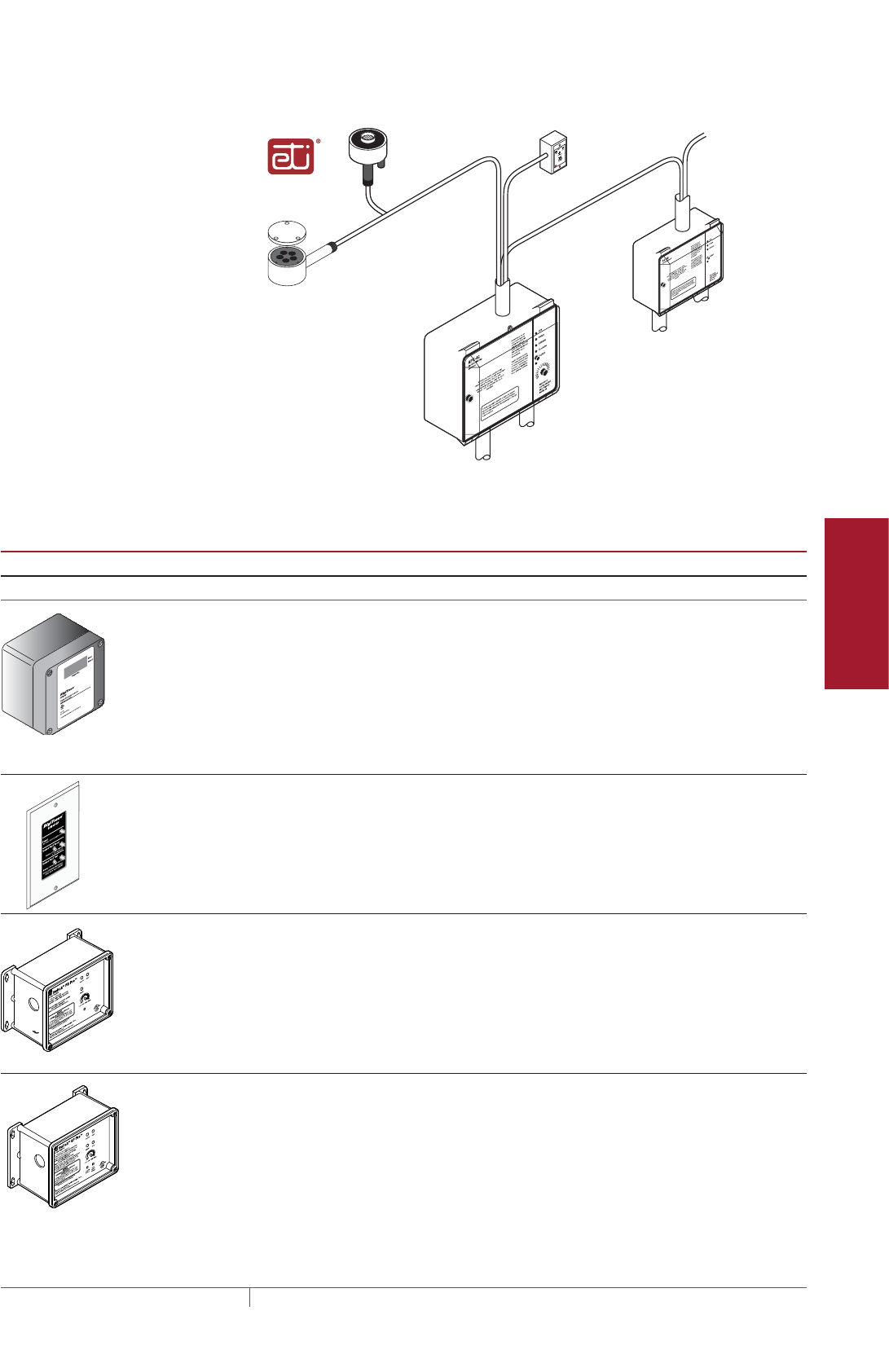
153THERMAL MANAGEMENT SOLUTIONS EN-PyrotenaxMISurfaceSnowMelting-DG-H57045 11/13
Pipe Freeze Protection
and Flow Maintenance
Fire Sprinkler System
Freeze Protection
Roof and Gutter
De-Icing
Surface Snow
Melting – MI
Surface Snow
Melting – ElectroMelt
Freezer Frost
Heave Prevention
Floor Heating Technical Data
Sheets
CIT-1
snow sensor
To power supply
APS-4C (shown) with SC-40C satelllite
contactor or APS-3C snow controller
Optional
SC-40C
satellite
contactor
To additional
SC-40C satellite
contactors
To heating cable(s)
To heating cable(s)
Optional
RCU-3 or RCU-4
remote control unit
To power supply
SIT-6E pavement
mounted sensor
Note: APS-4C, APS-3C
and SC-40C include an
integral high limit
temperature sensor
Fig. 10 Automatic snow melting control system
TABLE 6 CONTROL SYSTEMS
Catalog number
Description
Slab Sensing Thermostat and Accessory
ECW-GF Electronic ambient sensing controller with 30-mA ground-fault protection. The control-
ler can be programmed to maintain temperatures up to 200°F (93°C) at voltages from
100 to 277 V and can switch current up to 30 Amperes. The ECW-GF is complete with
a 25-ft (7.6-m) temperature sensor and is housed in a Type 4X rated enclosure. The
controller features an AC/DC dry alarm contact relay.
An optional ground-fault display panel (ECW-GF-DP) that can be added to provide
ground-fault or alarm indication in applications where the controller is mounted in
inaccessible locations.
ECW-GF-DP An optional remote display panel (ECW-GF-DP) that can be added to provide ground-
fault or alarm indication in applications where the controller is mounted in inacces-
sible locations.
HEATER CYCLE
ETI PD Pro Automatic snow and ice melting controller for pavement, sidewalks, loading docks,
roofs, gutters and downspouts in commercial and residential environments.
The PD Pro interfaces with up to two sensors, (any combination of CIT-1, GIT-1 or SIT-
6E) to meet site requirements. The PD Pro is housed in an environmentally-sheltered
Type 4X enclosure and weighs only 3 pounds.
ETI GF Pro Automatic snow and ice melting controller for pavement, sidewalks, loading docks,
roofs, gutters and downspouts in commercial and residential environments.
The GF Pro interfaces with up to two sensors, (any combination of CIT-1, GIT-1 or SIT-
6E) to meet site requirements. The GF Pro is housed in an environmentally-sheltered
Type 4X enclosure and weighs only 3 pounds.
Features a built-in 30-mA, self-testing Ground-Fault Equipment Protection (GFEP)
capability, digitally filtered to minimize false tripping. A ground-fault alarm must be
manually reset using the Test/Reset switch before heater operation can continue.
Surface Snow Melting Design
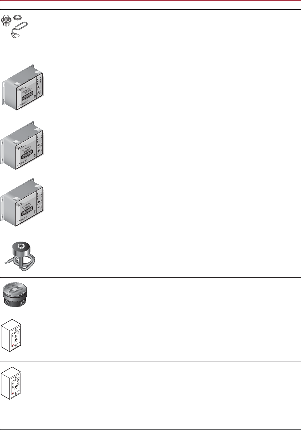
THERMAL MANAGEMENT SOLUTIONS
EN-PyrotenaxMISurfaceSnowMelting-DG-H57045 11/13
154
TABLE 6 CONTROL SYSTEMS
Catalog number
Description
MI-GROUND-KIT Grounding kit for nonmetallic enclosures.
Automatic Snow Melting Controllers
APS-3C Automatic snow melting controller housed in a Type 3R enclosure provides effective,
economical automatic control of all snow melting applications. Features include:
120V or 208–240 V models, 24-A DPDT output relay and an adjustable hold-on timer.
Enclosure dimensions: 11-1/2 in x 9-1/8 in x 6-9/16 in (292 mm x 232 mm x 167 mm)
APS-4C Automatic snow melting controller housed in a Type 3R enclosure provides effective,
economical automatic control of all snow melting applications. The APS-4C can oper-
ates with any number of SC-40C satellite contactors for larger loads. Features include:
277 V single-phase or 208–240, 277/480, and 600 V three-phase models, built-in 3-pole
contactor, integral 30 mA ground-fault circuit interrupter and an adjustable hold-on
timer.
Enclosure dimensions: 11-1/2 in x 9-1/8 in x 6-9/16 in (292 mm x 232 mm x 167 mm)
SC-40C Satellite contactor power control peripheral for an APS-4C snow melting controller,
housed in a NEMA 3R enclosure. Features include: 277 V single-phase or 208–240,
277/480 and 600 V three-phase models, built-in 3-pole contactor and integral 30 mA
ground-fault circuit interrupter.
Enclosure dimensions: 11-1/2 in x 9-1/8 in x 6 in (292 mm x 232 mm x 152 mm)
Snow Melting Sensors and Accessories
CIT-1 Overhead snow sensor that detects precipitation or blowing snow at ambient temper-
atures below 38°F (3.3°C). For use with either an APS-3C or APS-4C automatic snow
melting controller.
SIT-6E Pavement-mounted sensor signals for the heating cable to turn on when the
pavement temperature falls below 38°F (3.3°C) and precipitation in any form is
present. Microcontroller technology effectively eliminates ice bridging while ensuring
accurate temperature measurement. For use with either an APS-3C or APS-4C
automatic snow melting controller.
RCU-3 The RCU–3 provides control and status display to the APS–3C controller from a remote
location. It has a 2, 4, 6 or 8 hour CYCLE TIME adjustment, independent of APS-3C
setting.
RCU-4 The RCU–4 provides control and status display to the APS–4C controller and SC-40C
Satellite Contactor from a remote location. It has a 2, 4, 6 or 8 hour CYCLE TIME
adjustment, independent of the APS-4C or SC-40C setting.
SURFACE SNOW MELTING MI MINERAL INSULATED HEATING CABLE SYSTEM
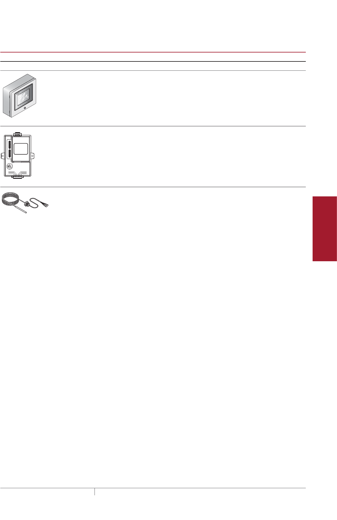
155THERMAL MANAGEMENT SOLUTIONS EN-PyrotenaxMISurfaceSnowMelting-DG-H57045 11/13
Pipe Freeze Protection
and Flow Maintenance
Fire Sprinkler System
Freeze Protection
Roof and Gutter
De-Icing
Surface Snow
Melting – MI
Surface Snow
Melting – ElectroMelt
Freezer Frost
Heave Prevention
Floor Heating Technical Data
Sheets
TABLE 6 CONTROL SYSTEMS
Catalog number
Description
Electronic Controllers
ACS-UIT2
ACS-PCM2-5
The DigiTrace ACS-30 Advanced Commercial Control System is a multipoint
electronic control and monitoring system for heat-tracing used in various commercial
applications such as pipe freeze protection, roof and gutter de-icing, surface snow
melting, hot water temperature maintenance and floor heating. The DigiTrace ACS-30
system can control up to 260 circuits with multiple networked ACS-PCM2-5 panels,
with a single ACS-UIT2 user interface terminal. The ACS-PCM2-5 panel can directly
control up to 5 individual heat-tracing circuits using electromechanical relays rated at
30 A up to 277 V.
By FieldServer Technologies
www.ProtoCessor.com
PROTOCESSOR
SERIAL ETHERNET
PROTONODE
FRAME GND
- PWR
+PWR
RS 485+
RS 485 -
RS 485 GND
S3
S2
S1
S0
B3
B2
B1
B0
A7
A6
A5
A4
A3
A2
A1
A0
ProtoNode-LER
ProtoNode-RER
The DigiTrace ProtoNode is an external, high performance multi-protocol gateway for
customers needing protocol translation between Building Management Systems (BMS)
and the DigiTrace ACS-30 or C910-485 controllers.
The ProtoNode-LER is for LonWorks® systems; and the ProtoNode-RER is for
BACnet® or Metasys® N2 systems.
RTD10CS
RTD-200
RTD50CS
Stainless steel jacketed three-wire RTD (Resistance Temperature Detector) used with
DigiTrace C910-485 and ACS-30 controllers.
RTD10CS: 10-ft (3 m) flexible armor, with 18-in (457 mm) lead wire and 1/2-inch NPT
bushing.
RTD-200: 6-ft (1.8 m) fluoropolymer with 1/2-in NPT bushing.
RTD50CS: 50-ft (3 m) flexible armor with 1/2-in NPT bushing
Surface Snow Melting Design
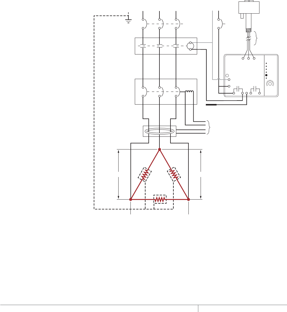
THERMAL MANAGEMENT SOLUTIONS
EN-PyrotenaxMISurfaceSnowMelting-DG-H57045 11/13
156
POWER DISTRIBUTION
Three-phase, 4-wire voltage supplies such as 208 V, 480 V, and 600 V are commonly
used for snow melting applications, especially for large areas. Designing the snow
melting system using a three-phase voltage supply results in a balanced heating
system load, since three identical cables are used in each circuit. In addition, since
three cables are used in each circuit, the result is a system with fewer circuits. For
small areas, it may not be possible to select three cables, and one or two heating
cables, single-phase connected, must be used.
The Delta wiring configuration shown in Fig. 11 is commonly used for three-phase
snow melting circuits. Each circuit comprises three heating cables of equal wattage
and connected as shown.
Fig. 12 shows the less common Wye wiring configuration. In this case, the three
heating cables are also of equal wattage, but most important is that the heating
cable voltage must equal the phase-to-neutral supply voltage.
APS-3C
APS
blakgb
bllfkldffd
fjsosfnfloo
dl;gffglf
Snow/Ice Melting
Controller
APS-3C
Automatic snow
controller
Slab temperature
sensor
To ground
fault module
3-pole circuit
breaker with shunt
trip/external ground
fault sensor
3-pole contactor
120 volt coil
Ground fault
sensor
Up to
2000 ft
Control power
120 V CIT-1
Snow sensor
15 A
A B C
A
B
C
C
Supply power
480 V, 3Ø, 4 W
MCB
480 V480 V
480 V
Note: For Delta connected heating
cables, the current in the supply
feeder, contactor, and breaker is equal
to the “Heating Cable Current” x 1.732.
Ground
20 A 20 A
Heating
cable sheath,
braid or ground
Fig. 11 Typical three-phase DELTA connected heating cables with automatic snow melting
controller
SURFACE SNOW MELTING MI MINERAL INSULATED HEATING CABLE SYSTEM

157THERMAL MANAGEMENT SOLUTIONS EN-PyrotenaxMISurfaceSnowMelting-DG-H57045 11/13
Pipe Freeze Protection
and Flow Maintenance
Fire Sprinkler System
Freeze Protection
Roof and Gutter
De-Icing
Surface Snow
Melting – MI
Surface Snow
Melting – ElectroMelt
Freezer Frost
Heave Prevention
Floor Heating Technical Data
Sheets
APS-3C
APS
blakgb
bllfkldffd
fjsosfnfloo
dl;gffglf
Snow/Ice Melting
Controller
20 A 20 A
15 A
A B C
A
B
C
N
C
MCB
277 V
277 V
277 V
APS-3C
Automatic snow
controller
To ground
fault module
3-pole contactor
120 volt coil
3-pole circuit
breaker with shunt
trip/external ground-
fault sensor
Ground fault
sensor
Up to
2000 ft
Control power
120 V CIT-1
Snow sensor
Note: For Wye connected heating
cables, the current in the supply
feeder, contactor, and breaker is equal
to the “Heating Cable Current.”
Slab temperature
sensor
Ground
Supply power
480 V, 3Ø, 4 W
Heating cable
sheath, braid
or ground
Fig. 12 Typical three-phase WYE connected heating cables with automatic snow melting
controller
Connecting heating cables in Delta or Wye configuration using three-phase voltage
supplies reduces the number of circuits required because three heating cables
are used in each circuit. For example, if you select three heating cables to operate
on 480V, single-phase (i.e.480 V across each cable), you need three 2-conductor
feeders, three 2-pole contactors, and three 2-pole breakers (i.e. three circuits)
as shown in Fig. 13. If the same three heating cables are connected in Delta
configuration to the 480 V, three-phase supply, you need one 3-conductor feeder,
one 3-pole contactor, and one 3-pole breaker (i.e. one circuit) as shown in Fig. 11. In
addition, decreasing the number of circuits will reduce the cost of the distribution
system.
Surface Snow Melting Design
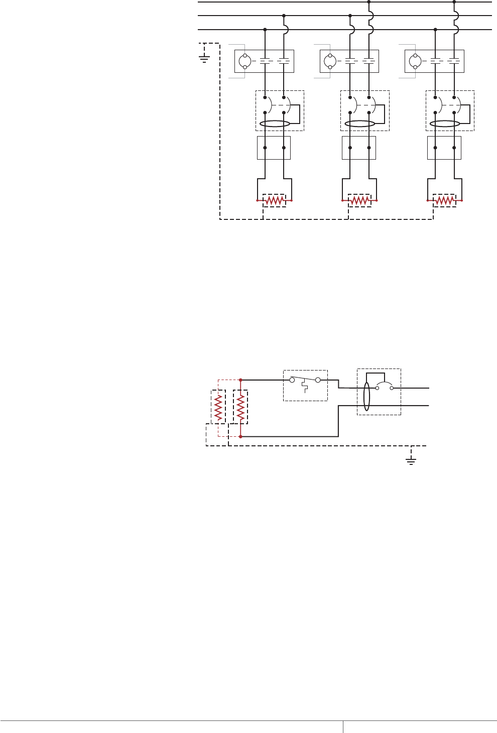
THERMAL MANAGEMENT SOLUTIONS
EN-PyrotenaxMISurfaceSnowMelting-DG-H57045 11/13
158
C
B
A
Ground
Contactor
JB
C
Supply
voltage
Breaker Breaker Breaker
Cable 1
Contactor
JB
C
Cable 2
Contactor
JB
C
Cable 3
Heating cable
sheath, braid
or ground
Fig. 13 Simplified single-phase connected heating cables
SINGLE CIRCUIT CONTROL
Heating cable circuits that do not exceed the current rating of the selected controller
can be switched directly. Fig. 14 shows a typical single-phase circuit where the
heating cable is controlled by a thermostat. When the total electrical load exceeds
the rating of the controller or if a single-pole controller is used to control a three-
phase circuit, an external contactor is required. In Fig. 11 and Fig. 12, the snow
melting controller is used to control the three-phase connected heating cables
through a contactor.
Temperature
controller 1-pole
GFEP breaker
1
N
Heating
cable
ø
øsupply
Ground
Heating cable
sheath, braid
or ground
Fig. 14 Single circuit control
GROUP CONTROL
Multiple single-phase or three-phase circuits may be activated by a single snow
melting controller or thermostat (group control).
The SMPG power distribution panel is designed to control snow melting circuits
installed in medium sized areas. This panel is available in single-phase (SMPG1) and
three-phase (SMPG3) versions and includes ground fault protection, monitoring, and
control for snow melting systems. The snow melting system is energized after the
integrated snow controller receives an input from any of the remote sensors.
SURFACE SNOW MELTING MI MINERAL INSULATED HEATING CABLE SYSTEM
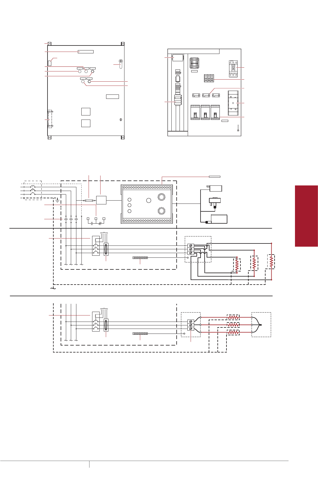
159THERMAL MANAGEMENT SOLUTIONS EN-PyrotenaxMISurfaceSnowMelting-DG-H57045 11/13
Pipe Freeze Protection
and Flow Maintenance
Fire Sprinkler System
Freeze Protection
Roof and Gutter
De-Icing
Surface Snow
Melting – MI
Surface Snow
Melting – ElectroMelt
Freezer Frost
Heave Prevention
Floor Heating Technical Data
Sheets
Exterior View Interior View
NP
NP
NP
NP
NP
G
NP
NP
NP
PDB
G
NP
NP
R
NP
Nameplate
Mounting brackets
Heater thermostat (3R only)
Power on light
Heater cycle
timed control
HTC energized light
Alarm acknowledge
Heater (3R only)
Door lock
handle
Snow/Ice
melt controller
Ground bar
Control wiring
C.B. tripped alarm
EUR - 5A
Main breaker
(optional)
Control power
transformer
Heat trace
contactor
CB1
GFS1
CB2 CB3
ground-fault
sensors
Power distribution
block
Branch
breakers
(3 pole)
GFS2 GFS3 HTC
Fig. 15 SMPG3 power distribution panel
N
Three-pole
main contactor
FuseMain circuit breaker (optional)
Incoming
power
Ground 24 V
To ground fault module
Current
transformers
Remote annunciation
alarm circuit breaker
with alarm type #3)
GIT-1
CIT-1
SIT-6E
Three-pole circuit breaker
with shunt trip/external
ground fault sensor
Three-pole circuit breaker
with shunt trip/external
ground fault sensor
Ground
Aerial
snow sensor
Gutter
ice sensor
Slab
temperature sensor
Pavement-mounted
sensor
SNOW/ICE
SUPPLY
EUR-5A SNOW SWITCH
AUTOMATIC SNOW/ICE MELTING CONTROL PANEL
HEATER
HEATER
CYCLE
HOURS
0
45°F
50°F
55°F
60°F 65°F 70°F
75°F
80°F
85°F
2
4 6
8
10
TEMPERATURE
Control transformer
Junction box
To ground fault module
Current
transformers Ground
3 Ø Wye connected
heating cables
3 Ø Delta connected
heating cables
Junction box Junction box
Heating
cables
Terminal
block
A
A1
C1
B1
B C
Heating
cable
sheath,
braid
or
ground
Heating cable
sheath, braid
or ground
Fig. 16 Typical wiring diagram of group control with SMPG3
Surface Snow Melting Design
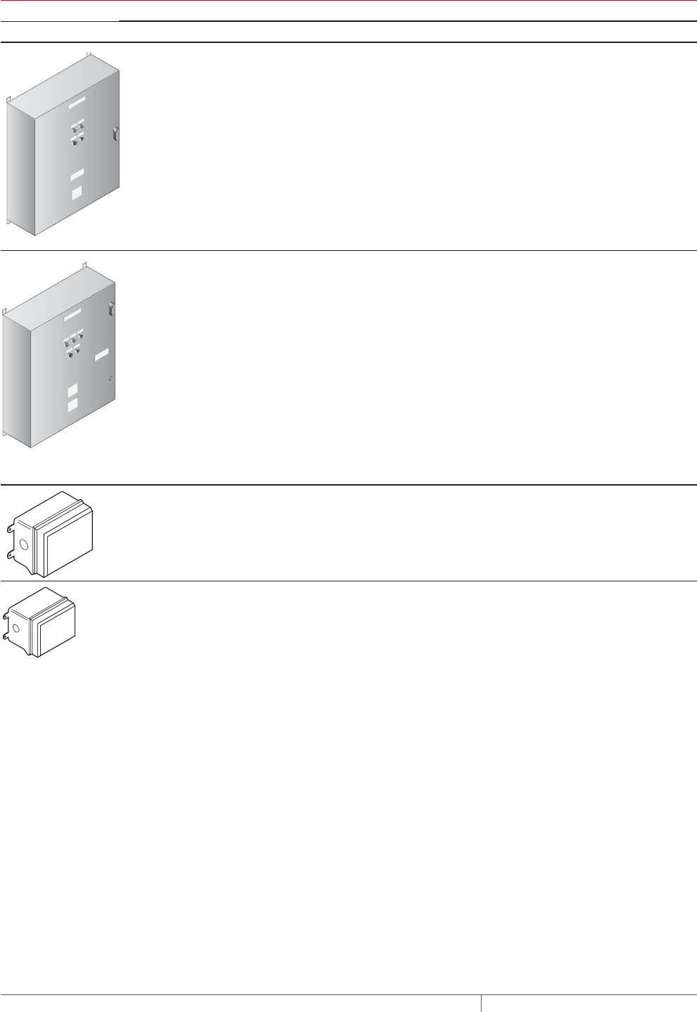
THERMAL MANAGEMENT SOLUTIONS
EN-PyrotenaxMISurfaceSnowMelting-DG-H57045 11/13
160
TABLE 7 POWER DISTRIBUTION
Catalog number Description
Power Distribution and Control Panels
NP
NP
NP
NP
NP
NP NP
SMPG1 Single-phase power distribution panel that includes ground-fault protection, monitor-
ing, and control for snow melting systems. Single-phase voltages include 208 and 277 V.
Refer to the SMPG1 data sheet (H57680) for information on selecting a control panel.
If standard configurations do not meet your requirements, contact your Pentair Thermal
Management representative for a quotation on a custom SMPG1 panel.
NP
NP
NP
NP
NP
NP NP
NP NP
SMPG3 Three-phase power distribution panel that includes ground-fault protection, monitor-
ing, and control for snow melting systems. Three-phase voltages include 208, 480, and
600 V. Refer to the SMPG3 data sheet (H57814) for information on selecting a control
panel.
If standard configurations do not meet your requirements, contact your Pentair Thermal
Management representative for a quotation on a custom SMPG3 panel.
Contactors and Junction Boxes
E104 Three-pole, 100 A per pole, 600 V maximum contactor housed in UL Listed, CSA Certi-
fied, Type 4X enclosure with two 1-inch conduit entries. When ordering, select coil volt-
age (110–120, 208–240, 277 V).
Enclosure dimensions: 13-1/2 in x 9-1/5 in x 6-11/16 in (343 mm x 234 mm x 170 mm).
E304 Three-pole, 40 A per pole, 600 V maximum contactor housed in UL Listed, CSA Certified
Type 4X enclosure with two 1-inch conduit entries. When ordering, select coil voltage
(110–120, 208–240, 277 V).
Enclosure dimensions: 9-1/2 in x 7-1/5 in x 6-11/16 in (241 mm x 183 mm x 170 mm).
Example: Surface Snow Melting System
Automatic snow melting controller APS-4C
Quantity 1
Pavement-mounted sensor SIT-6E
Quantity 1
Example: Surface Snow Melting System for Stairs
Slab sensing thermostat ECW-GF
Quantity 1
Example: Surface Snow Melting System for Wheel Tracks
Automatic snow melting controller APS-4C
Quantity 1
Overhead snow sensor CIT-1
Quantity 1
SURFACE SNOW MELTING MI MINERAL INSULATED HEATING CABLE SYSTEM
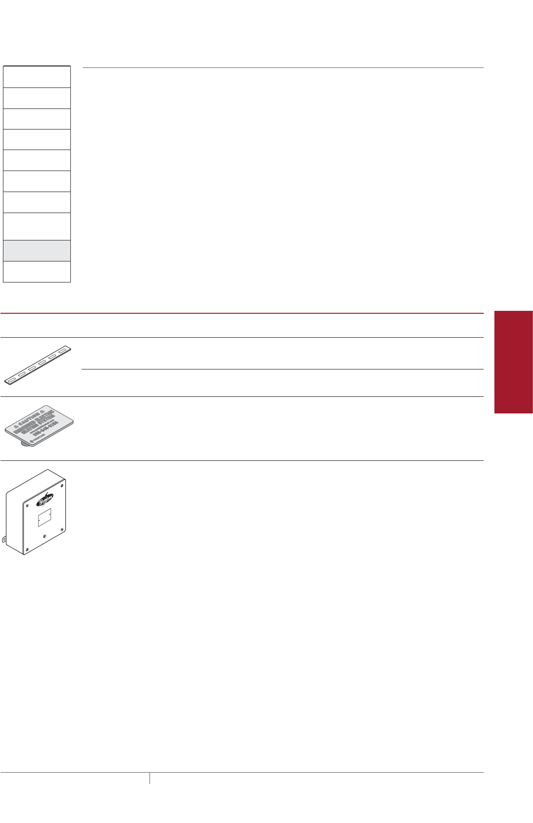
161THERMAL MANAGEMENT SOLUTIONS EN-PyrotenaxMISurfaceSnowMelting-DG-H57045 11/13
Pipe Freeze Protection
and Flow Maintenance
Fire Sprinkler System
Freeze Protection
Roof and Gutter
De-Icing
Surface Snow
Melting – MI
Surface Snow
Melting – ElectroMelt
Freezer Frost
Heave Prevention
Floor Heating Technical Data
Sheets
Surface Snow Melting
1. Determine design
conditions
2. Determine the
required watt density
3. Determine the total
area to be protected
4. Select the heating
cable
5. Determine heating
cable spacing
7. Select the control
system and power
distribution
8. Select the
accessories
9. Complete the Bill
of Materials
6. Determine the
electrical parameters
Step Select the accessories
A typical Pyrotenax snow melting system consists of several accessories. All of the
accessories work together to provide a safe and reliable snow melting system that is
easy to install and maintain.
We recommend using the following as appropriate.
TABLE 8 ACCESSORIES
Catalog
number Description
Standard
packaging Usage
HARD-SPACER-
GALV-25MM-
25M
Galvanized steel prepunched strapping 82 ft (25 m)
rolls
No. rolls = 0.005 x area (ft²)
No. rolls = 0.05 x area (m²)
HARD-SPACER-
SS-25MM-25M
Stainless steel prepunched strapping 82 ft (25 m)
rolls
No. rolls = 0.005 x area (ft²)
No. rolls = 0.05 x area (m²)
SMCS Snow melt caution sign
Dimensions 6 x 4 in (150 x 100 mm)
1 1 minimum per system
D1297TERM4 A cast aluminum junction box (Type 3) for
installation in nonhazardous and CID2 loca-
tions. Three 1/2" NPT entries on bottom,
provided with plugs. Includes 4-pole termi-
nal block (CSA - 600 V, 65 A, 18 - 6 AWG;
UL - 300 V, 65 A, 18 - 6 AWG). External
mounting feet. CSA approved for Class I,
Div. 2, Groups A, B, C, and D.
Enclosure dimensions: 6 in x 6 in x 4 in
(150 mm x 150 mm x 100 mm).
1
Surface Snow Melting Design

THERMAL MANAGEMENT SOLUTIONS
EN-PyrotenaxMISurfaceSnowMelting-DG-H57045 11/13
162
Example: Surface Snow Melting System
Junction box Contractor supplied
Prepunched strapping ¹ HARD-SPACER-GALV-25MM-25M
Quantity 3
Snow melt caution sign SMCS
Quantity 2
¹ Only required for two-pour slab construction
Example: Surface Snow Melting System for Stairs
Junction box D1297TERM4
Quantity 1
Prepunched strapping ¹ HARD-SPACER-GALV-25MM-25M
Quantity 1
Snow melt caution sign SMCS
Quantity 1
¹ Only required for two-pour slab construction
Example: Surface Snow Melting System for Wheel Tracks
Junction box D1297TERM4
Quantity 1
Prepunched strapping ¹ HARD-SPACER-GALV-25MM-25M
Quantity 1
Snow melt caution sign SMCS
Quantity 1
¹ Only required for two-pour slab construction
Surface Snow Melting
1. Determine design
conditions
2. Determine the
required watt density
3. Determine the total
area to be protected
4. Select the heating
cable
5. Determine heating
cable spacing
7. Select the control
system and power
distribution
8. Select the
accessories
9. Complete the Bill
of Materials
6. Determine the
electrical parameters
Step Complete the Bill of Materials
If you used the Design Worksheet to document all your design parameters, you
should have all the details you need to complete the Bill of Materials.
SURFACE SNOW MELTING MI MINERAL INSULATED HEATING CABLE SYSTEM
163THERMAL MANAGEMENT SOLUTIONS EN-PyrotenaxMISurfaceSnowMelting-DG-H57045 11/13
Pipe Freeze Protection
and Flow Maintenance
Fire Sprinkler System
Freeze Protection
Roof and Gutter
De-Icing
Surface Snow
Melting – MI
Surface Snow
Melting – ElectroMelt
Freezer Frost
Heave Prevention
Floor Heating Technical Data
Sheets
PYROTENAX MI SYSTEM SURFACE SNOW MELTING DESIGN WORKSHEET
Step Determine design conditions
Application and
environment Size and layout
Supply
voltage Phase Control method
T Surface snow melting
Geographical location:
_______________________
Paving material
T Concrete
T Asphalt
T Pavers
Slab surface area (ft² / m²): ____________
Ramp surface area (ft² / m²): __________
Stairs
Number of stairs: _____________
Stair width (ft/m): _____________
Riser height (in/cm): _____________
Stair depth (in/cm): _____________
Landing surface area (ft² / m²):________
Wheel tracks
Track length (ft/m): _____________
Concrete joints: _____________
Surface drains: _____________
Location of area structures: ___________
Other information as appropriate:
____________________________________
____________________________________
____________________________________
T 120 V
T 208 V
T 240 V
T 277 V
T 347 V
T 480 V
T 600 V
T Single-phase
T Three-phase
T Automatic snow melting
controller
T Slab-sensing thermostat
T Manual on/off control
Example:
0 Surface snow melting
0 Philadelphia, PA
0 Concrete ramp
Ramp surface: 45 ft x 12 ft 0 480 V 0 Three-phase 0 Automatic snow
melting controller
Step Determine the required watt density
Surface snow melting system for slabs, ramps, stairs, and wheel tracks: See Table 1
Geographical location:
_______________________________
Paving material:
_______________________________
Required watt density:
_______________________________
Example: Surface Snow Melting System
Ramp surface
Geographical location: Philadelphia, PA (from Step 1)
Paving material: Concrete (from Step 1)
Required watt density: 35 W/ft2 (from Table 1)
Pyrotenax MI System Surface Snow Melting Design Worksheet

THERMAL MANAGEMENT SOLUTIONS
EN-PyrotenaxMISurfaceSnowMelting-DG-H57045 11/13
164
Step Determine the total area to be protected
x = Surface area to be protected (ft2/m2)Length (ft/m) Width (ft/m)
Total ramp/slab surface area
For large areas and areas using a three-phase voltage supply
Landing (attached to stairs)
Stairs
Calculate the heating cable needed for stairs and landing
Determine the number of cable runs needed
Stair depth: < 10.5 in (27 cm): 2 cable runs
Stair depth: 10.5–12 in (27–30 cm): 3 cable runs
Wheel tracks
Wheel track length:
x 12) / 4.5 = Length of cable for attached landing (ft)Landing area (ft2)
Landing area (m2)
/ x = = Subsection area to be protected (ft2/m2)Length (ft/m) Width (ft/m)Length of each
subsection (ft/m)
No. of subsections
x x + 2 x(
(
)[ ] =Length of cable for stairs (ft/m)No. of stairs
Cable runs needed:
Calculate the heating cable length for stairs
Note: For three-phase voltage supplies, use multiples of three equal subsections.
Calculate the heating cable length for landing
No. runs per stair ( )
Riser height (ft/m)Stair width (f/m)
x 1000) / 115 = Length of cable for attached landing (m)
(
+ = Total heating cable length required (ft/m)Length of cable
for stairs (ft/m)
Length of cable
for landing (ft/m)
Example: Surface Snow Melting System
45 ft 15 ft 12 ft 180 ft2
Calculate the surface area of the ramp for three-phase application
Ramp
/ x = = Subsection area to be protected (ft2)Length (ft) Width (ft)Length of each subsection (ft)
3
SURFACE SNOW MELTING MI MINERAL INSULATED HEATING CABLE SYSTEM

165THERMAL MANAGEMENT SOLUTIONS EN-PyrotenaxMISurfaceSnowMelting-DG-H57045 11/13
Pipe Freeze Protection
and Flow Maintenance
Fire Sprinkler System
Freeze Protection
Roof and Gutter
De-Icing
Surface Snow
Melting – MI
Surface Snow
Melting – ElectroMelt
Freezer Frost
Heave Prevention
Floor Heating Technical Data
Sheets
Step Select the heating cable
Surfaces: See Table 2 and Table 3.
Supply voltage: (from Step 1)
Required watt density: (from Step 2)
Subsection area: (from Step 3)
Heating cable catalog number:
Cable wattage:
Cable voltage:
Heating cable length:
x = Required watts for area (W)Watt density (W/ft2) (W/m2)
Number of cables = Number of subsection areas
Area (ft2/m2)
Example: Surface Snow Melting System
Supply voltage: 480 V, three-phase (from Step 1)
Required watt density for ramp: 35 W/ft² (from Step 2)
Subsection area (for 3 equal areas): 180 ft² (from Step 3)
Required watts (for each subsection): 35 W/ft² x 180 ft² = 6300 W
Heating cable catalog number: SUB20
Cable wattage: 6450 W
Cable voltage: 480 V (for cables connected in Delta configuration)
Heating cable length: 340 ft
Number of cables: 3 (one cable required for each subsection)
Stairs: See Table 4
Supply voltage: ______________________________________ (from Step 1)
Required watt density: ______________________________________ (from Step 2)
Total heating cable length required: ______________________________________ (from Step 3)
Heating cable catalog number: ______________________________________
Cable wattage: ______________________________________
Cable voltage: ______________________________________
Heating cable length: ______________________________________
Number of cables: ______________________________________
Installed watt density: ______________________________________ (from Table 4)
Wheel Tracks: See Table 5
Supply voltage: ______________________________________ (from Step 1)
Wheel track length: ______________________________________
Heating cable catalog number: ______________________________________
Cable wattage: ______________________________________
Cable voltage: ______________________________________
Heating cable length: ______________________________________
Number of cables: ______________________________________
Pyrotenax MI System Surface Snow Melting Design Worksheet

THERMAL MANAGEMENT SOLUTIONS
EN-PyrotenaxMISurfaceSnowMelting-DG-H57045 11/13
166
Step Determine the heating cable spacing
x 12 in) / ( = Heating cable spacing (in)Surface area (ft2)
Imperial
Heating cable length (ft)
x 12) / ( = Heating cable spacing (in)
180 ft2340 ft 6.4 in rounded to 6.5 in
Surface area (ft2)
Cable spacing
Surfaces
Heating cable length (ft)
x 100 cm) / ( = Heating cable spacing (cm) Surface area (m2)
Metric
Round to the nearest 1/2 in or 1 cm to obtain cable spacing.
Heating cable length (m)
Example: Surface Snow Melting System
Subsection area: 180 ft² (from Step 3)
Heating cable catalog number: SUB20 (from Step 4)
Heating cable length: 340 ft (from Step 4)
x 12 in) / ( = Heating cable spacing (in)Surface area (ft2)
Imperial
Heating cable length (ft)
x 12) / ( = Heating cable spacing (in)
180 ft2340 ft 6.4 in rounded to 6.5 in
Surface area (ft2)
Cable spacing
Surfaces
Heating cable length (ft)
x 100 cm) / ( = Heating cable spacing (cm) Surface area (m2)
Metric
Round to the nearest 1/2 in or 1 cm to obtain cable spacing.
Heating cable length (m)
Stairs
Stair depth: ______________________________________ (from Step 1)
Cable spacing – stairs: ______________________________________ (refer to Step 5)
Cable spacing – landing: ______________________________________ (refer to Step 5)
Wheel Tracks: See Table 5
Paving material: ______________________________________ (from Step 1)
Heating cable catalog number: ______________________________________ (from Step 4)
Cable spacing: ______________________________________ (refer to Step 5)
SURFACE SNOW MELTING MI MINERAL INSULATED HEATING CABLE SYSTEM

167THERMAL MANAGEMENT SOLUTIONS EN-PyrotenaxMISurfaceSnowMelting-DG-H57045 11/13
Pipe Freeze Protection
and Flow Maintenance
Fire Sprinkler System
Freeze Protection
Roof and Gutter
De-Icing
Surface Snow
Melting – MI
Surface Snow
Melting – ElectroMelt
Freezer Frost
Heave Prevention
Floor Heating Technical Data
Sheets
Step Determine the electrical parameters
Circuit breaker rating (A)Minimum circuit breaker rating (A)Load current (A)
Circuit breaker rating (A)
Load current = Heating cable current (from selection tables)
Number of circuit breakers
( ) =
Determine circuit breaker rating and number of circuits
Example: Surface Snow Melting System
For single-phase circuit
x 1.25 =
Circuit breaker rating (A)Minimum circuit breaker rating (A)Load current (A)
Load current = Heating cable current (from selection tables) x 1.732
( ) =
For Delta connected three-phase circuit
x 1.25 =
Circuit breaker rating (A)Minimum circuit breaker rating (A)Load current (A)
Load current = Heating cable current (from selection tables)
( ) =
For Wye connected three-phase circuit
Circuit breaker rating (A)Minimum circuit breaker rating (A)
23.2 A
6450 W 3 19.4 kW
29.0 A 30 A
Load current (A)
Heating cable catalog number: SUB20 (from Step 4)
Number of heating cables: 3 (from Step 4)
Cable power output: 6450 W (from Step 4)
Load current: 13.4 A (from Table 2) x 1.732 = 23.2 A
( ) =
For Delta connected three-phase circuit
x 1.25 =
x 1.25 =
Transformer load (kW)Cable (W)
(
)
) =
Determine transformer load
For cables of equal wattage
x / 1000
Number of cables
Transformer load (kW)Cable1 (W)
( =
When cable wattages are not equal
Transformer load (kW)Cable (W)
( ) =
x / 1000
Number of cables
+ + + / 1000
Cable2 (W) Cable3 (W)... CableN (W)
Pyrotenax MI System Surface Snow Melting Design Worksheet
THERMAL MANAGEMENT SOLUTIONS
EN-PyrotenaxMISurfaceSnowMelting-DG-H57045 11/13
168
Step Select the control system and power distribution
Control Systems
See Table 6 Control Systems.
Thermostats, controllers and
accessories Description Quantity
T ECW-GF
T ECW-GF-DP
T ETI PD Pro
T ETI GF-Pro
T MI-GROUND-KIT
T APS-3C
T APS-4C
T SC-40C
T CIT-1
T SIT-6E
T RCU-3
T RCU-4
T ACS-UIT2
T ACS-PCM2-5
T ProtoNode-LER
T ProtoNode-RER
T RTD3CS
T RTD10CS
T RTD200
T RTD50CS
Electronic thermostat with 25-ft sensor
Remote display panel for ECW-GF
Automatic snow and ice melting controller
Automatic snow and ice melting controller
Grounding kit for nonmetallic enclosures
Automatic snow melting controller
Automatic snow melting controller
Satellite contactor
Overhead snow sensor
Pavement-mounted sensor
Remote control unit for APS-3C
Remote control unit for APS-4C
ACS-30 user interface terminal
ACS-30 power control panel
Multi-protocol gateway
Multi-protocol gateway
Resistance temperature device for DigiTrace ACS-30
Resistance temperature device for DigiTrace ACS-30
Resistance temperature device for DigiTrace ACS-30
Resistance temperature device for DigiTrace ACS-30
____________
____________
____________
____________
____________
____________
____________
____________
____________
____________
____________
____________
____________
____________
____________
____________
____________
____________
____________
____________
Power Distribution and Control Panels
See Table 7 Power Distribution.
Power distribution and control
panels Description Quantity
T SMPG1
T SMPG3
Single-phase power distribution panel
Three-phase power distribution panel
____________
____________
Contactors Description Quantity
T E104
T E304
Three-pole, 100 A per pole contactor
Three-pole, 40 A per pole contactor
____________
____________
Example: Surface Snow Melting System
0 APS-4C Automatic snow melting controller
0 SIT-6E Pavement-mounted sensor
1
1
Step Select the accessories
See Table 8 Accessories.
Accessories Description Quantity
T HARD-SPACER-GALV-25MM-25M
T HARD-SPACER-SS-25MM-25M
T SMCS
T D1297TERM4
Galvanized steel prepunched strapping
Stainless steel prepunched strapping
Snow melt caution sign
Cast aluminum junction box
____________
____________
____________
____________
Example: Surface Snow Melting System
0 Junction box
0 HARD-SPACER-GALV-25MM-25M1 Prepunched strapping
0 SMCS Snow melt caution sign
¹ Only required for two-pour slab construction
(contractor supplied)
3
2
Step Complete the Bill of Materials
Use the information recorded in this worksheet to complete the Bill of Materials.
SURFACE SNOW MELTING MI MINERAL INSULATED HEATING CABLE SYSTEM
169THERMAL MANAGEMENT SOLUTIONS EN-RaychemElectroMeltSnowMelting-DG-H53393 11/13
Pipe Freeze Protection
and Flow Maintenance
Fire Sprinkler System
Freeze Protection
Roof and Gutter
De-Icing
Surface Snow
Melting – MI
Surface Snow
Melting – ElectroMelt
Freezer Frost
Heave Prevention
Floor Heating Technical Data
Sheets
This step-by-step design guide provides the tools necessary to design a Raychem
ElectroMelt heating cable surface snow melting and anti-icing system. For other
applications or for design assistance, contact your Pentair Thermal Management
representative or phone Pentair Thermal Management at (800)545-6258. Also, visit
our web site at www.pentairthermal.com.
Contents
Introduction .........................................................169
How to Use this Guide ............................................170
Safety Guidelines ................................................170
Warranty .......................................................170
System Overview .....................................................171
Typical System ..................................................171
Self-Regulating Heating Cable Construction ..........................172
Approvals .......................................................173
Surface Snow Melting and Anti-Icing Applications ..........................173
Surface Snow Melting and Anti-Icing Design ..............................174
Design Step by Step ..............................................174
Step 1 Determine design conditions ..............................175
Step 2 Select the heating cable ..................................176
Step 3 Determine the required watt density ........................177
Step 4 Determine heating cable spacing ...........................179
Step 5 Determine the total area to be protected .....................181
Step 6 Determine heating cable length ............................182
Step 7 Determine the electrical parameters ........................184
Step 8 Select the connection kits and accessories ...................186
Step 9 Select the control system and power distribution ..............189
Step 10 Complete the Bill of Materials ............................195
ElectroMelt System Surface Snow Melting and Anti-Icing Design Worksheet ....196
INTRODUCTION
Raychem ElectroMelt heating cable systems can be used as a surface snow melting
system when installed in concrete pavement or under paving stones. It can also be
used as an anti-icing system but only when installed in concrete pavement.
Important: ElectroMelt is not approved for use in asphalt.
If your application conditions are different, or if you have any questions, contact your
Pentair Thermal Management representative or contact Pentair Thermal
Management directly at (800)545-6258.
SURFACE SNOW MELTING AND
ANTIICING ELECTROMELT
THERMAL MANAGEMENT SOLUTIONS
EN-RaychemElectroMeltSnowMelting-DG-H53393 11/13
170
How to Use this Guide
This design guide presents Pentair Thermal Management’ recommendations for
designing an ElectroMelt surface snow melting and anti-icing system. It provides
design and performance data, electrical sizing information, and heating-cable layout
suggestions. Following these recommendations will result in a reliable, energy-
efficient system.
Follow the design steps in the section “Surface Snow Melting and Anti-Icing Design,”
page 174 and use the “ElectroMelt System Surface Snow Melting and Anti-Icing
Design Worksheet,” page 196 to document the project parameters that you will
need for your project’s Bill of Materials.
OTHER REQUIRED DOCUMENTS
This guide is not intended to provide comprehensive installation instructions. For
complete ElectroMelt surface snow melting system and anti-icing installation
instructions, please refer to the following additional required documents:
• ElectroMelt System Installation and Operation Manual (H58086)
• Additional installation instructions that are included with the connection kits,
thermostats, controllers and accessories
If you do not have these documents, you can obtain them from the Pentair Thermal
Management web site at www.pentairthermal.com.
For products and applications not covered by this design guide, please contact your
Pentair Thermal Management representative or call Pentair Thermal Management
directly at (800)545-6258.
Safety Guidelines
As with any electrical equipment, the safety and reliability of any system depends
on the quality of the products selected and the manner in which they are installed
and maintained. Incorrect design, handling, installation, or maintenance of any of
the system components could damage the system and may result in inadequate
performance, overheating, electric shock, or fire. To minimize these risks and to
ensure that the system performs reliably, read and carefully follow the information,
warnings, and instructions in this guide.
This symbol identifies important instructions or information.
This symbol identifies particularly important safety warnings that must be
followed.
WARNING: To minimize the danger of fire from sustained electrical arcing if
the heating cable is damaged or improperly installed, and to comply with the
requirements of Pentair Thermal Management, agency certifications, and national
electrical codes, ground-fault equipment protection must be used on each heating
cable branch circuit. Arcing may not be stopped by conventional circuit protection.
Warranty
Pentair Thermal Management’ standard limited warranty applies to Raychem Snow
Melting Systems.
An extension of the limited warranty period to ten (10) years from the date of
installation is available, except for the control and distribution systems, if a properly
completed online warranty form is submitted within thirty (30) days from the date of
installation. You can access the complete warranty on our web site at
www.pentairthermal.com.
SURFACE SNOW MELTING AND ANTIICING ELECTROMELT
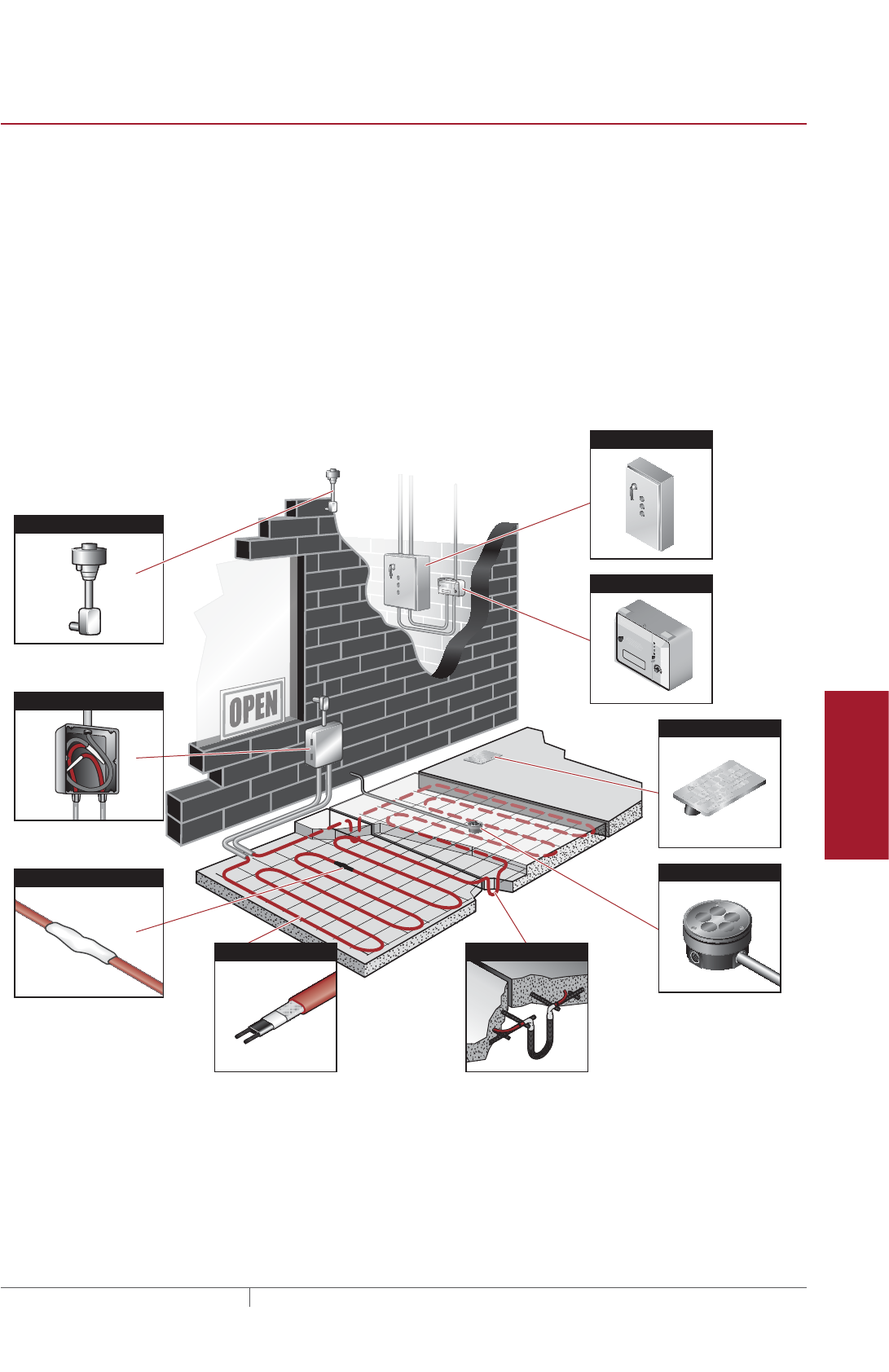
171THERMAL MANAGEMENT SOLUTIONS EN-RaychemElectroMeltSnowMelting-DG-H53393 11/13
Pipe Freeze Protection
and Flow Maintenance
Fire Sprinkler System
Freeze Protection
Roof and Gutter
De-Icing
Surface Snow
Melting – MI
Surface Snow
Melting – ElectroMelt
Freezer Frost
Heave Prevention
Floor Heating Technical Data
Sheets
SYSTEM OVERVIEW
The Raychem ElectroMelt system provides surface snow melting and anti-icing for
concrete surfaces and pavers. The ElectroMelt system uses a self-regulating heating
cable that reduces heat output automatically as the pavement warms, resulting in
lower energy use, and eliminating the possibility of overheating. The system includes
heating cable, connection kits, junction boxes, a control system and sensors, power
distribution panels, and the tools necessary for a complete installation.
Typical System
A typical system includes the following:
• ElectroMelt self-regulating heating cable
• Connection kits and accessories
• Snow controller and sensors
• Power distribution
Aerial Snow Sensor
Heating Cable Splice
Heating Cable Expansion Joint Kit
Power Distribution Panel
Pavement Snow Sensor
Caution Sign
Power Connection and End Seal
Snow Controller
APS-4
SUPPLY
SNOW
HE
ATER
GROUND
FAU
L
T
GROUND
FAUL
T
HE
A
TER
C
YCLE
RESET
TEST
HOLD ON TIME
(HRS)
Snow
/Ice Melting Contr
oller
SUPPL
Y : 277 VAC,
50/60HZZ, 35VA
HEATER: 377 VAC,
40 AMP
. MAX RESIS
USE ONLY COPPER CONDUCTORS HAVING
SUFFICIE
NT AMPACITY.
SEE INSTALLA
TION INSTRUCTIONS
WARNING
DANGER OF ELECTR
ICAL SHOCK OR ELCTROCUTION
Le
thal voltages are p
resent beneath this cover. Servicee by
qual
ified perso
nnel o
nly. More
tha
n one discon
nect may be
re
quire
d to de-e
nergize
this co
ntrol for se
rvicin
g.
GROUND
FAU
L
T
GROUND
FAUL
T
HOLD ON TIME
(HRS)
SNOW
HEATER
GROUND
FAU
L
T
GROUND
FAUL
T
HEATER
CYCLE
RESET
TEST
HOLD ON TIME
(HRS)
SUPPL
Y : 277 VAC,
50/60HZZ, 35VA
HEATER: 37
7
VAC,
40 AMP
. MAX RESIS
USE ONLY COPPER CONDUCTORS HAVING
SUFFICIE
NT AMPACITY.
SEE INSTALLA
TION INSTRUCTIONS
WARNING
DANGER OF ELECTR
ICAL SHOCK OR ELCTROCUTION
Le
thal voltages are p
resent beneath this cover. Servicee by
qual
ified perso
nnel o
nly. More
tha
n one discon
nect may be
re
quire
d to de-e
nergize
this co
ntrol for se
rvicin
g.
APS-4
SUPPLY
Snow
/Ice Melting C
ontroller
Fig. 1 Typical ElectroMelt system
System Overview
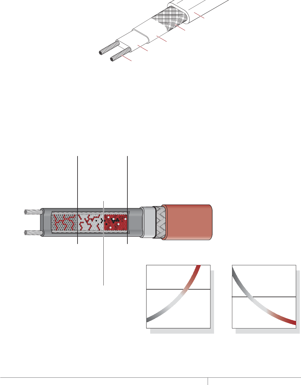
THERMAL MANAGEMENT SOLUTIONS
EN-RaychemElectroMeltSnowMelting-DG-H53393 11/13
172
Self-Regulating Heating Cable Construction
The ElectroMelt self-regulating heating cable is embedded in concrete pavement
to melt snow and ice that might otherwise accumulate on the surface. The heating
cable responds to the local concrete temperature, increasing heat output when
concrete temperature drops and decreasing heat output when concrete temperature
rises. The self-regulating heating cable cannot overheat and destroy itself, even
if overlapped in the concrete, and therefore does not require the use of overlimit
thermostats.
Nickel-plated copper bus wire
Self-regulating conductive core
Modified polyolefin inner jacket
Tinned-copper braid
Modified polyolefin outer jacket
Fig. 2 ElectroMelt heating cable construction
With self-regulating technology, the number of electrical paths between bus wires
changes in response to temperature fluctuations. As the temperature surrounding
the heater decreases, the conductive core contracts microscopically. This contraction
decreases electrical resistance and creates numerous electrical paths between the
bus wires. Current flows across these paths to warm the core.
As the temperature rises, the core expands microscopically. This expansion
increases electrical resistance and the number of electrical paths decreases. The
heating cable automatically reduces its output.
At low temperature,
there are many
conducting paths,
resulting in high output
and rapid heat-up. Heat
is generated only when it
is needed and precisely
where it is needed.
At high temperature,
there are few conduct-
ing paths and output is
correspondingly lower,
conserving energy
during operation.
At moderate temperature,
there are fewer conducting
paths because the heating
cable efficiently adjusts by
decreasing output, eliminating
any possibility of overheating.
The following graphs illustrate the response of self-regulating heating
cables to changes in temperature. As the temperature rises, electrical
resistance increases, and our heaters reduce their power output.
Temperature
Resistance
Power
Temperature
Constant wattage
Constant wattage
Self-regulating
Self-regulating
Fig. 3 Self-regulating heating cable technology
SURFACE SNOW MELTING AND ANTIICING ELECTROMELT

173THERMAL MANAGEMENT SOLUTIONS EN-RaychemElectroMeltSnowMelting-DG-H53393 11/13
Pipe Freeze Protection
and Flow Maintenance
Fire Sprinkler System
Freeze Protection
Roof and Gutter
De-Icing
Surface Snow
Melting – MI
Surface Snow
Melting – ElectroMelt
Freezer Frost
Heave Prevention
Floor Heating Technical Data
Sheets
Approvals
The ElectroMelt surface snow melting and anti-icing system is UL Listed and CSA
Certified for use in nonhazardous locations.
-ws
SURFACE SNOW MELTING AND ANTIICING APPLICATIONS
SURFACE SNOW MELTING
Surface snow melting systems prevent the accumulation of snow on ramps, slabs,
driveways, sidewalks, platform scales, and stairs under most snow conditions.
ANTIICING
Anti-icing systems keep the surface temperature above freezing at all times to
prevent ice formation. Anti-icing applications require a higher watt density and
longer hours of operation than a surface snow melting system.
APPLICATION REQUIREMENTS AND ASSUMPTIONS
The design for a standard surface snow melting and anti-icing application is based
on the following:
Reinforced Concrete
• 4 to 6 inches (10 to 15 cm) thick
• Placed on grade
• Standard density
Heating cable
• Secured to reinforcement steel or
mesh
• Located 1 1/2 to 2 inches (4 to 6 cm)
below finished surface
Pavers
• Concrete pavers 1 to 1 1/2
(2.5 to 4 cm) inches thick
• Placed on concrete or mortar base on
grade
Heating cable
• Secured to mesh
• Embedded in concrete or mortar base
below the pavers
For products and applications not covered by this guide, contact your Pentair
Thermal Management representative for design assistance. Using proprietary
computer modeling, Pentair Thermal Management can design the appropriate
system for these applications.
The following are examples of applications not addressed in this design guide:
• Concrete thinner than 4 inches (10 cm)
• Concrete thicker than 6 inches (15 cm)
• Lightweight concrete
• Concrete with pavers thicker than 1 1/2 inches (4 cm)
• Ramps and walkways with air below
• Concrete without reinforcement
• Retrofitting of heating cable to existing pavement
• Pavers composed of material other than concrete
Surface Snow Melting and Anti-Icing Applications

THERMAL MANAGEMENT SOLUTIONS
EN-RaychemElectroMeltSnowMelting-DG-H53393 11/13
174
SURFACE SNOW MELTING AND ANTIICING DESIGN
This section details the steps necessary to design your application. The examples
provided in each step are intended to incrementally illustrate sample designs from
start to finish. As you go through each step, use the “ElectroMelt System Surface
Snow Melting and Anti-Icing Design Worksheet,” page 196 to document your project
parameters, so that by that end of this section you will have the information you need
for your Bill of Materials.
Design Step by Step
Your system design requires the following essential steps:
Determine design conditions
Select the heating cable
Determine the required watt density
Determine heating cable spacing
Determine the total area to be protected
Determine heating cable length
Determine the electrical parameters
Select the connection kits and accessories
Select the control system and power distribution
Complete the Bill of Materials
SURFACE SNOW MELTING AND ANTIICING ELECTROMELT

175THERMAL MANAGEMENT SOLUTIONS EN-RaychemElectroMeltSnowMelting-DG-H53393 11/13
Pipe Freeze Protection
and Flow Maintenance
Fire Sprinkler System
Freeze Protection
Roof and Gutter
De-Icing
Surface Snow
Melting – MI
Surface Snow
Melting – ElectroMelt
Freezer Frost
Heave Prevention
Floor Heating Technical Data
Sheets
Surface Snow Melting
and Anti-Icing
1. Determine design
conditions
2. Select the heating
cable
3. Determine the
required watt density
4. Determine heating
cable spacing
5. Determine the total
area to be protected
9. Select the control
system and
power distribution
6. Determine heating
cable length
7. Determine the
electrical parameters
8. Select the connection
kits and accessories
10. Complete the Bill
of Materials
Step Determine design conditions
Collect the following information to determine your design conditions:
• Application (surface snow melting or anti-icing)
• Environment
– For surface snow melting: Geographical location
– For anti-icing: Minimum ambient temperature and average wind speed
• Paving material
• Size and layout
– Slab surface area
– Ramp surface area
– Stairs
- Number of stairs
- Width of stair
- Riser height
- Depth of stair
- Landing dimensions
– Wheel tracks
- Track length
– Concrete joints
– Surface drains
– Location of area structures
– Other information as appropriate
• Supply voltage
• Automatic or manual control method
Note: Drainage must be a primary concern in any snow melting system design.
Improper drainage can result in ice formation on the surface of the heated area once
the system is de-energized. Ice formation along the drainage path away from the
heated area may create an ice dam and prohibit proper draining. If your design
conditions may lead to drainage problems, please contact Pentair Thermal
Management Technical Support for assistance.
PREPARE SCALE DRAWING
Draw to scale the snow melting area and note the rating and location of the voltage
supply. Include stairs and paths for melting water runoff. Show concrete joints,
surface drains, and location of area structures including post installations for
railings, permanent benches, and flagpoles. Measurements for each distinct section
of the snow melting application, including stairs, will allow for an accurate system
design, including control configuration. Use these symbols to indicate the heating
cable expansion and crack-control joints:
S
Power connection
End seal
Splice
Expansion joint
Crack-control joint
Expansion joint kit
E
P
Fig. 4 Design symbols
Surface Snow Melting and Anti-Icing Design
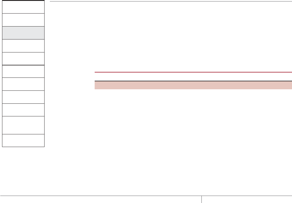
THERMAL MANAGEMENT SOLUTIONS
EN-RaychemElectroMeltSnowMelting-DG-H53393 11/13
176
Example: Surface Snow Melting System
Application Surface snow melting
Geographical location Buffalo, NY
Size and layout 80 ft x 50 ft (24.4 m x 15.2 m)
Paving material Concrete slab
Stairs:
Number of stairs 10
Width of stair 5 ft (1.5 m)
Riser height 6 in (15 cm)
Depth of stair 12 in (30 cm)
Supply voltage 277 V
Phase Single-phase
Control method Automatic snow melting controller
Example: Anti-Icing System
Application Anti-icing
Minimum ambient temperature 10°F (–12°C)
Average wind speed 20 mph (32 kmph)
Size and layout 80 ft x 50 ft (24.4 m x 15.2 m)
Paving material Concrete slab
Stairs:
Number of stairs 10
Width of stair 5 ft (1.5 m)
Riser height 6 in (20 cm)
Depth of stair 12 in (30 cm)
Supply voltage 277 V
Phase Single-phase
Control method Slab sensing thermostat
Surface Snow Melting
and Anti-Icing
1. Determine design
conditions
2. Select the heating
cable
3. Determine the
required watt density
4. Determine heating
cable spacing
5. Determine the total
area to be protected
9. Select the control
system and
power distribution
6. Determine heating
cable length
7. Determine the
electrical parameters
8. Select the connection
kits and accessories
10. Complete the Bill
of Materials
Step Select the heating cable
Pentair Thermal Management offers the option of two self-regulating heating cables
with the ElectroMelt system. Cable selection is independent of application and
depends only upon supply voltage. ElectroMelt heating cables must only be powered
by single phase voltage. In applications where the power supply is three-phase, all
circuits must be wired to provide single-phase voltage to the heating cables. Select
the appropriate cable based on the supply voltage available for the application area.
TABLE 1 ELECTROMELT SELFREGULATING HEATING CABLE
Supply voltage Catalog number
208 V, 240 V, 277 V EM2-XR
347 V EM3-XR
Example: Surface Snow Melting System
Supply voltage 277 V (from Step 1)
Heating cable EM2-XR
Example: Anti-Icing System
Supply voltage 277 V (from Step 1)
Heating cable EM2-XR
SURFACE SNOW MELTING AND ANTIICING ELECTROMELT

177THERMAL MANAGEMENT SOLUTIONS EN-RaychemElectroMeltSnowMelting-DG-H53393 11/13
Pipe Freeze Protection
and Flow Maintenance
Fire Sprinkler System
Freeze Protection
Roof and Gutter
De-Icing
Surface Snow
Melting – MI
Surface Snow
Melting – ElectroMelt
Freezer Frost
Heave Prevention
Floor Heating Technical Data
Sheets
Surface Snow Melting
and Anti-Icing
1. Determine design
conditions
2. Select the heating
cable
3. Determine the
required watt density
4. Determine heating
cable spacing
5. Determine the total
area to be protected
9. Select the control
system and
power distribution
6. Determine heating
cable length
7. Determine the
electrical parameters
8. Select the connection
kits and accessories
10. Complete the Bill
of Materials
Step Determine the required watt density
SURFACE SNOW MELTING
For maximum performance from any snow melting system, you must first take into
account the local snowfall and icing patterns. A system design that works well in one
city may be inadequate in another. The energy required to melt snow varies with air
temperature, wind speed, relative humidity, snow density, and the depth of the snow
on the pavement.
Table 2 summarizes the required watt density for most major cities in North
America based on typical minimum ambient temperatures and the snowfall and
icing patterns. Select the city from the list, or closest city, where similar climatic
conditions exist.
TABLE 2 REQUIRED WATT DENSITY FOR SURFACE SNOW MELTING
Watts/ft2Watts/m2
City Concrete Pavers Concrete Pavers
USA
Baltimore, MD 35 40 377 431
Boston, MA 35 40 377 431
Buffalo, NY 40 45 431 484
Chicago, IL 35 40 377 431
Cincinnati, OH 35 40 377 431
Cleveland, OH 35 40 377 431
Denver, CO 35 40 377 431
Detroit, MI 35 40 377 431
Great Falls, MT 50 50 538 538
Greensboro, NC 35 35 377 377
Indianapolis, IN 35 40 377 431
Minneapolis, MN 50 50 538 538
New York, NY 35 40 377 431
Omaha, NE 45 50 484 538
Philadelphia, PA 35 40 377 431
Salt Lake City, UT 35 35 377 377
Seattle, WA 35 35 377 377
St. Louis, MO 35 40 377 431
Canada
Calgary, AB 45 45 484 484
Edmonton, AB 50 50 538 538
Fredericton, NB 40 45 431 484
Halifax, NS 35 40 377 431
Moncton, NB 40 40 431 431
Montreal, QC 45 45 484 484
Ottawa, ON 45 45 484 484
Prince George, BC 50 55 538 592
Quebec, QC 45 45 484 484
Regina, SK 50 55 538 592
Saskatoon, SK 50 50 538 538
St. John, NB 40 45 431 484
St. John’s, NF 35 35 377 377
Sudbury, ON 40 45 431 484
Thunder Bay, ON 50 55 538 592
Toronto, ON 35 40 377 431
Vancouver, BC 35 40 377 431
Winnipeg, MB 50 55 538 592
Note: To provide faster heat-up, the required watt density in Table 2 is greater than what is
suggested by ASHRAE.
Surface Snow Melting and Anti-Icing Design
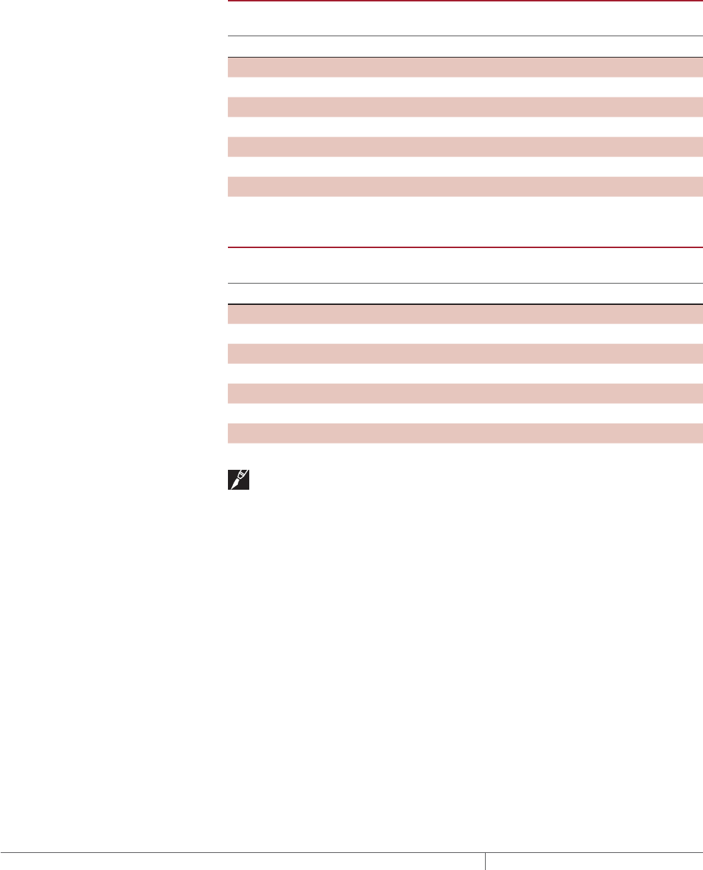
THERMAL MANAGEMENT SOLUTIONS
EN-RaychemElectroMeltSnowMelting-DG-H53393 11/13
178
Example: Surface Snow Melting System
Geographical location Buffalo, NY (from Step 1)
Required watt density 40 W/ft2 (431 W/m²) (from Table 2)
ANTIICING
From the minimum ambient temperature and average wind speed that you
determined in Step 1 for your anti-icing application, use the tables below to
determine the required watt density for that application.
TABLE 3 REQUIRED WATT DENSITY FOR ICEFREE SURFACES W/FT2
Minimum ambient
temperature
Average wind speed during freezing periods
°F
5 mph 10 mph 15 mph 20 mph
20°F 30 30 35 40
10°F 30 30 35 45
0°F 30 40 45 60
–10°F 30 45 60 80
–20°F 35 55 80 –
–30°F 40 65 – –
–40°F 45 75 – –
TABLE 4 REQUIRED WATT DENSITY FOR ICEFREE SURFACES W/M2
Minimum ambient
temperature
Average wind speed during freezing periods
°C
8 kmph 16 kmph 24 kmph 32 kmph
–7°C 323 323 377 431
–12°C 323 323 377 484
–18°C 323 431 484 646
–23°C 323 484 646 861
–29°C 377 592 861 –
–34°C 431 699 – –
–40°C 484 807 – –
Note: This procedure is derived from finite model studies of 4-inch slabs and is
applicable to standard concrete pavement from 4 to 6 inches thick placed directly on
grade. If your application involves other materials or construction, contact your
Pentair Thermal Management representative.
Example: Anti-Icing System
Minimum ambient temperature 10°F (–12°C) (from Step 1)
Average wind speed 20 mph (32 kmph) (from Step 1)
Required watt density 45 W/ft2 (484 W/m2) (from Table 3 and Table 4)
SURFACE SNOW MELTING AND ANTIICING ELECTROMELT
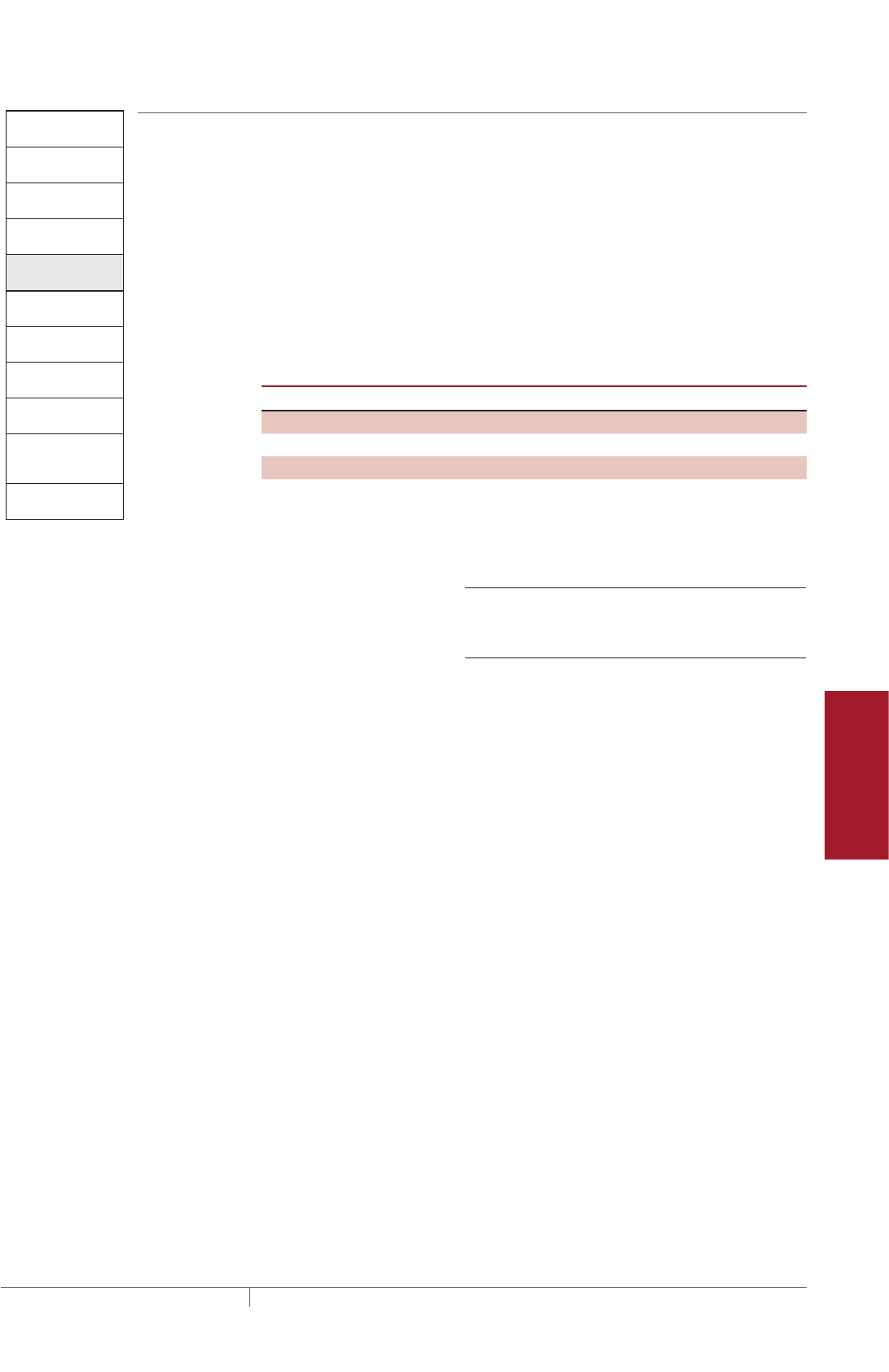
179THERMAL MANAGEMENT SOLUTIONS EN-RaychemElectroMeltSnowMelting-DG-H53393 11/13
Pipe Freeze Protection
and Flow Maintenance
Fire Sprinkler System
Freeze Protection
Roof and Gutter
De-Icing
Surface Snow
Melting – MI
Surface Snow
Melting – ElectroMelt
Freezer Frost
Heave Prevention
Floor Heating Technical Data
Sheets
Surface Snow Melting
and Anti-Icing
1. Determine design
conditions
2. Select the heating
cable
3. Determine the
required watt density
4. Determine heating
cable spacing
5. Determine the total
area to be protected
9. Select the control
system and power
distribution
6. Determine heating
cable length
7. Determine the
electrical parameters
8. Select the connection
kits and accessories
10. Complete the Bill
of Materials
Step Determine heating cable spacing
SURFACES
To determine your heating cable spacing, you need to know your applications’s power
output and required watt density.
The power output from the ElectroMelt heating cable depends on the cable type and
the supply voltage used in the application. Table 5 lists power output per linear foot
of heating cable determined by the supply voltage. Divide this figure by the required
watt density that you determined in Step 3. You will get the required heating cable
spacing in feet or meters as applicable. Multiply this figure by 12 inches or by 100
centimeters to determine your heating cable spacing.
TABLE 5 HEATING CABLE SPACING IN CONCRETE
Supply voltage Catalog number Power output W/ft (W/m)
208 V EM2-XR 30 (98)
240 V EM2-XR 32 (105)
277 V EM2-XR 34 (112)
347 V EM3-XR 24 (79)
To determine cable spacing required for surface snow melting and anti-icing
Heating cable spacing (in) = (W/ft power output of cable per Table 5) x 12 in
W/ft² requirement from Step 3
Heating cable spacing (cm) = (W/m power output of cable per Table 5) x 100 cm
W/m² requirement from Step 3
Round answer to nearest whole number of inches or centimeters.
Example: Surface Snow Melting System
Supply voltage 277 V (from Step 1)
Heating cable EM2-XR (from Step 2)
Power output 34 W/ft (112 W/m²) (from Table 5)
Spacing (34 W/ft x 12 in) /40 W/ft² = 10.2 in
Rounded to 10 in
(112 W/m x 100 cm) / 431 W/m² = 26 cm
Example: Anti-Icing System
Supply voltage 277 V (from Step 1)
Heating cable EM2-XR (from Step 2)
Power output 34 W/ft (from Table 5)
Spacing (34 W/ft x 12 in) / 45 W/ft² = 9.1 in
Rounded to 9 in
(112 W/m x 100 cm) / 484 w/m² = 23.1 cm
Rounded to 23 cm
Surface Snow Melting and Anti-Icing Design
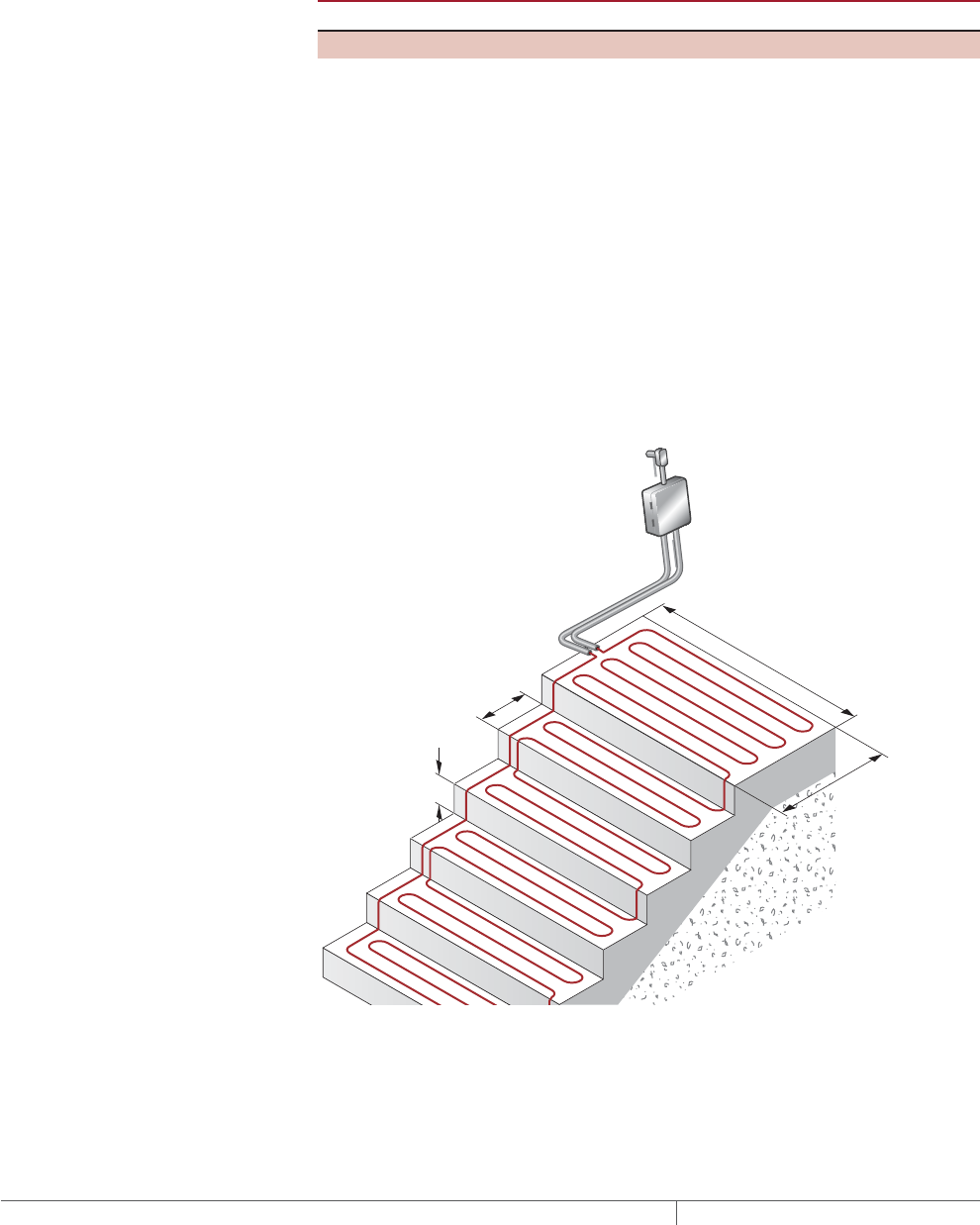
THERMAL MANAGEMENT SOLUTIONS
EN-RaychemElectroMeltSnowMelting-DG-H53393 11/13
180
STAIRS
Heat loss in stairs occurs from the two exposed surfaces: the top of the stair and
its side. Watt density requirements are therefore greater for snow melting and anti-
icing. Rather than calculating heating cable spacing in the stair, refer to Table 6 and
determine the number of runs of heating cable per stair based on the depth of the
stair. Space the heating cable evenly across the depth of the stair with one run 2 in
(5 cm) from the front, or nose, of the stair. This method will provide sufficient watt
density for both snow melting and anti-icing.
TABLE 6 HEATING CABLE RUNS PER STAIR
Stair depth Number of cable runs per stair
Less than 10.5 in (27 cm) 2
10.5–12 in (27–30 cm) 3
For landings in the stairway, use cable spacing as calculated for surfaces. As with
stairs, a run of heating cable must be placed 2 in (5 cm) from the exposed edge of
the landing leading to the stairs.
Anticipate and design for the addition of railings or other follow on construction that
will require cutting or drilling into the concrete as damage to installed heating cable
may occur. Allow for at least 4 inches clearance between the heating cable and any
planned cuts or holes.
Example: Surface Snow Melting and Anti-Icing System
Depth of stair 12 in (30 cm) (from Step 1)
Number of cable runs per stair 3 runs
Spacing Equally spaced across the width of the stair with
one run 2 in (5 cm) from the front edge
6 in
Riser
height (15 cm)
12 in
Stair
depth
(30 cm)
5 ft (1.5 m)
Width
3 ft
Landing depth
(0.9 m)
Junction
box
Fig. 5 Typical heating cable layout for concrete stairs
SURFACE SNOW MELTING AND ANTIICING ELECTROMELT
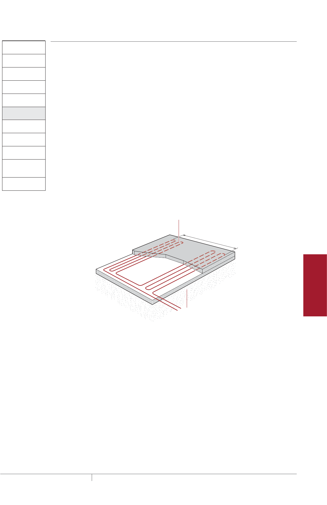
181THERMAL MANAGEMENT SOLUTIONS EN-RaychemElectroMeltSnowMelting-DG-H53393 11/13
Pipe Freeze Protection
and Flow Maintenance
Fire Sprinkler System
Freeze Protection
Roof and Gutter
De-Icing
Surface Snow
Melting – MI
Surface Snow
Melting – ElectroMelt
Freezer Frost
Heave Prevention
Floor Heating Technical Data
Sheets
Surface Snow Melting
and Anti-Icing
1. Determine design
conditions
2. Select the heating
cable
3. Determine the
required watt density
4. Determine heating
cable spacing
5. Determine the total
area to be protected
9. Select the control
system and
power distribution
6. Determine heating
cable length
7. Determine the
electrical parameters
8. Select the connection
kits and accessories
10. Complete the Bill
of Materials
Step Determine the total area to be protected
SURFACES
To determine the total amount of heating cable, you need to determine the surface
area you will be protecting from snow and ice accumulation. If assistance is required
in designing for irregular shaped areas, please contact your Pentair Thermal
Management representative.
Example: Surface Snow Melting System
Total area of concrete slab 80 ft x 50 ft = 4000 ft²
(24.4 m x 15.2 m = 370.8 rounded to = 371 m²)
Example: Anti-Icing System
Total area of concrete slab 80 ft x 50 ft = 4000 ft²
(24.4 m x 15.2 m = 370.8 rounded to = 371 m²)
WHEEL TRACKS
To reduce power consumption for concrete driveways, it may be sufficient to provide
snow melting for only the wheel tracks.
Design wheel track applications with the same spacing used for concrete slabs.
Heating cable should run to the edge of each side of the wheel track and be laid in a
serpentine pattern along the length of the wheel track.
Cable in 6 in minimum
(15 cm) from edge
unless curbs used
6'6" (2 m) typ.
Structurally sound well-
drained base designed to
handle expected load and
environmental conditions
Fig. 6 Wheel track example
STAIRS
Surface area of the stairs is not required to determine heating cable required.
Surface Snow Melting and Anti-Icing Design

THERMAL MANAGEMENT SOLUTIONS
EN-RaychemElectroMeltSnowMelting-DG-H53393 11/13
182
Surface Snow Melting
and Anti-Icing
1. Determine design
conditions
2. Select the heating
cable
3. Determine the
required watt density
4. Determine heating
cable spacing
5. Determine the total
area to be protected
9. Select the control
system and power
distribution
6. Determine heating
cable length
7. Determine the
electrical parameters
8. Select the connection
kits and accessories
10. Complete the Bill
of Materials
Step Determine heating cable length
SURFACES
Calculate the heating cable length by dividing the total heated area by the heating
cable spacing calculated in the previous steps. In Step 8, you will need to add
additional heating cable for connection kits and end terminations which will then
give you the total heating cable length.
Calculate the heating cable length for the surface as follows:
Heating cable length = Heated area (ft²) x 12
Heating cable spacing (in)
Heated area (m²) x 100
Heating cable spacing (cm)
Example: Surface Snow Melting System for Concrete Slab
Total area of concrete slab 4000 ft² (371 m²) (from Step 5)
Cable spacing 10 in (26 cm) (from Step 4)
(4000 ft² x 12 in) / 10 in spacing = 4800 ft
(371 m² x 100 cm) / 26 cm spacing = 1427 m
Heating cable length 4800 ft (1427 m)
Example: Anti-Icing System for Concrete Slab
Total area of concrete slab 4000 ft² (371 m²) (from Step 5)
Cable spacing 9 in (23 cm) (from Step 4)
(4000 ft² x 12 in) / 9 in spacing = 5333 ft
(371 m² x 100 cm) / 23 cm spacing = 1613 m
Heating cable length 5333 ft (1613 m)
SURFACE SNOW MELTING AND ANTIICING ELECTROMELT
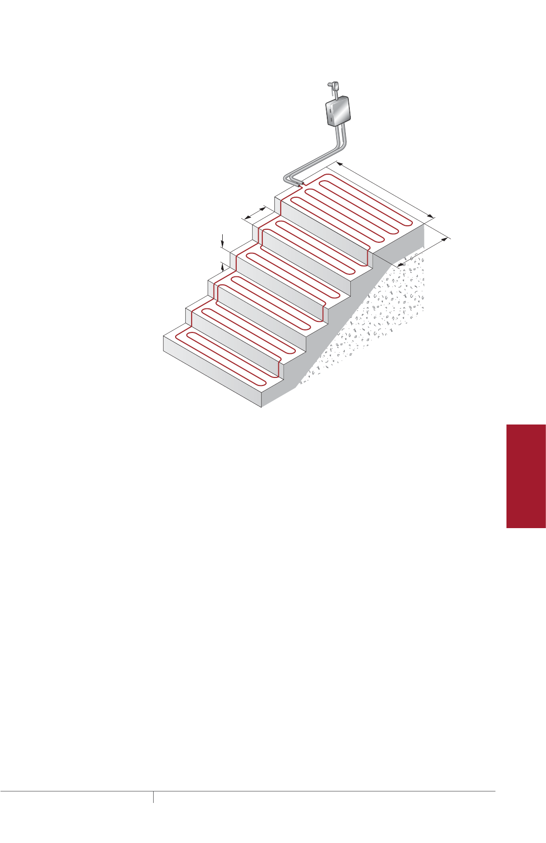
183THERMAL MANAGEMENT SOLUTIONS EN-RaychemElectroMeltSnowMelting-DG-H53393 11/13
Pipe Freeze Protection
and Flow Maintenance
Fire Sprinkler System
Freeze Protection
Roof and Gutter
De-Icing
Surface Snow
Melting – MI
Surface Snow
Melting – ElectroMelt
Freezer Frost
Heave Prevention
Floor Heating Technical Data
Sheets
STAIRS
6 in
Riser height
(15 cm)
12 in
Stair depth
(30 cm)
5 ft (1.5 m)
Width
3 ft
Landing depth
(0.9 m)
Junction
box
Fig. 7 Concrete stair example
Use the formula below to determine the length of cable required for stairs. Stair area
is not needed for the cable length calculation. Two or three runs of heating cable will
be installed per stair as determined in Step 3. For landing areas, use the equation for
surfaces.
Length of cable
for stair (ft) (m)
No. of stairs = x [(No. runs per stair x width of stair) + (2 x riser height)]
Example: Surface Snow Melting and Anti-Icing System for Stairs
Number of stairs 10 stairs (from Step 1)
Number of cable runs per stair 3 runs
Width of stair 5 ft (1.5 m) (from Step 1)
Riser height 6 in (15 cm) convert to 0.5 ft (0.15 m) (from Step 1)
10 stairs x [(3 x 5 ft) + (2 x 0.5 ft)] = 160 ft
10 stairs x [(3 x 1.5 m) + (2 x 0.15 m)] = 48 m
Heating cable length 160 ft (48 m)
For applications where the landing area is very large or where an expansion joint
exists between the stairs and landing, consider the stairs and landing as two
separate areas. In these cases, determine the length of cable required for the stairs
as shown earlier in this section and select the cable for the landing as shown for
ramps, slabs, driveways, sidewalks, platform scales.
Surface Snow Melting and Anti-Icing Design
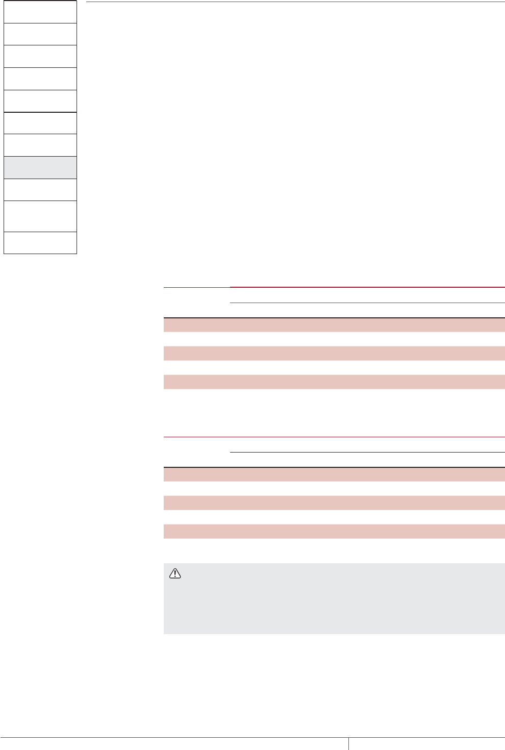
THERMAL MANAGEMENT SOLUTIONS
EN-RaychemElectroMeltSnowMelting-DG-H53393 11/13
184
Surface Snow Melting
and Anti-Icing
1. Determine design
conditions
2. Select the heating
cable
3. Determine the
required watt density
4. Determine heating
cable spacing
5. Determine the total
area to be protected
9. Select the control
system and
power distribution
6. Determine heating
cable length
7. Determine the
electrical parameters
8. Select the connection
kits and accessories
10. Complete the Bill
of Materials
Step Determine the electrical parameters
This section will help you determine the electrical parameters for an ElectroMelt
system including circuit breaker sizing and maximum circuit length. Total required
heating cable length divided by maximum circuit length will determine the number of
circuits required for your snow melting solution.
DETERMINE MAXIMUM CIRCUIT LENGTH
To determine maximum circuit length, it is important to establish a minimum startup
temperature for the system. The following tables provide maximum circuit lengths
based on minimum startup temperature, circuit breaker rating, and supply voltage.
Colder temperature startup requires shorter maximum circuit lengths. The use of an
automatic system, which energizes the system above 20°F (–7°C), ensures that you
can use maximum circuit lengths. Manual control systems may require you to use
shorter circuit lengths to compensate for startup below 20°F (–7°C).
A 30-mA ground-fault protection device (GFPD) must be used to provide protection
from arcing or fire, and to comply with warranty requirements, agency certifications,
and national electrical codes. If the heating cable is improperly installed, or
physically damaged, sustained arcing or fire could result. If arcing does occur, the
fault current may be too low to trip conventional circuit breakers.
TABLE 7 MAXIMUM CIRCUIT LENGTH FOR STARTUP AT 20°F 7°C IN FEET
METERS USING AN AUTOMATIC SNOW CONTROL SYSTEM
Circuit Breaker
(A)
Heating cable supply voltage
208 V 240 V 277 V 347 V
15 80 (24) 85 (26) 100 (31) 120 (37)
20 105 (32) 115 (35) 130 (40) 165 (50)
30 160 (49) 170 (52) 195 (59) 250 (76)
40 210 (64) 230 (70) 260 (79) 330 (101)
50 265 (81) 285 (87) 325 (99) †
TABLE 8 MAXIMUM CIRCUIT LENGTH FOR STARTUP AT 0°F 18°C IN FEET
METERS USING A MANUAL CONTROL SYSTEM
Circuit Breaker
(A)
Heating cable supply voltage
208 V 240 V 277 V 347 V
15 75 (23) 80 (24) 90 (27) 107 (33)
20 100 (31) 110 (34) 120 (37) 148 (45)
30 145 (44) 160 (49) 180 (55) 225 (69)
40 200 (61) 210 (64) 240 (73) 288 (88)
50 245 (75) 265 (81) 300 (91) †
† Not permitted
WARNING: To minimize the danger of fire from sustained electrical arcing if
the heating cable is damaged or improperly installed, and to comply with the
requirements of Pentair Thermal Management, agency certifications, and national
electrical codes, ground-fault equipment protection must be used on each heating
cable branch circuit. Arcing may not be stopped by conventional circuit protection.
Example: Surface Snow Melting and Anti-Icing System with Automatic Snow
Control
Startup temperature 20°F (–7°C) (from Step 1)
Circuit breakers 50 A
Supply voltage 277 V (from Step 1)
Maximum circuit length 325 ft (99 m) (from Table 7)
SURFACE SNOW MELTING AND ANTIICING ELECTROMELT

185THERMAL MANAGEMENT SOLUTIONS EN-RaychemElectroMeltSnowMelting-DG-H53393 11/13
Pipe Freeze Protection
and Flow Maintenance
Fire Sprinkler System
Freeze Protection
Roof and Gutter
De-Icing
Surface Snow
Melting – MI
Surface Snow
Melting – ElectroMelt
Freezer Frost
Heave Prevention
Floor Heating Technical Data
Sheets
DETERMINE NUMBER OF CIRCUITS
Use the following formula to determine number of circuits for the system:
Number of circuits = Heating cable length required
Maximum heating cable circuit length
Example: Surface Snow Melting
Surfaces
Total heating cable length 4800 ft (1427 m) (from Step 6)
Maximum circuit length 325 ft (99 m) (from above)
Number of circuits 4800 / 325 = 14.8 rounded to 15 circuits
Stairs
Total heating cable length 160 ft (48 m) (from Step 6)
Maximum circuit length 325 ft (99 m) (from above)
Number of circuits 160 / 325 = 0.5 rounded to 1 circuit
Example: Anti-Icing System
Surfaces
Total heating cable length 5333 ft (1613 m) (from Step 6)
Maximum circuit length 325 ft (99 m)
Number of circuits 5333 / 325 = 16.4 rounded to 17 circuits
Stairs
Total heating cable length 160 ft (48m) (from Step 6)
Maximum circuit length 325 ft (99 m) (from above)
Number of circuits 160 / 325 = 0.5 rounded to 1 circuit
DETERMINE TRANSFORMER LOAD
The total transformer load is the sum of load on all the circuit breakers in the
system.
Calculate the Circuit Breaker Load (CBL) as:
CBL (kW) =
Circuit breaker rating (A) x 0.8 x Supply voltage
1000
Calculate the Total Transformer Load as follows:
If the CBL is equal on all circuit breakers, calculate the Total Transformer Load as:
Total Transformer Load (kW) = CBL x Number of circuits
If the CBL is not equal on all circuit breakers, calculate the Total Transformer Load as:
Total Transformer Load (kW) = CBL1 + CBL2 + CBL3...+ CBLN
Surface Snow Melting and Anti-Icing Design

THERMAL MANAGEMENT SOLUTIONS
EN-RaychemElectroMeltSnowMelting-DG-H53393 11/13
186
Example: Surface Snow Melting
Circuit breaker load (50 A x 0.8 x 277 V) / 1000 = 11.1 kW
Transformer Load 11.1 kW x 16 circuits = 177.6 kW rounded to 178 kW
178 kW
Example: Anti-Icing System
Circuit breaker load (50 A x 0.8 x 277 V) / 1000 = 11.1 kW
Transformer load 11.1 kW x 18 circuits = 199.8 kW rounded to 200 kW
200 kW
Surface Snow Melting
and Anti-Icing
1. Determine design
conditions
2. Select the heating
cable
3. Determine the
required watt density
4. Determine heating
cable spacing
5. Determine the total
area to be protected
9. Select the control
system and
power distribution
6. Determine heating
cable length
7. Determine the
electrical parameters
8. Select the connection
kits and accessories
10. Complete the Bill
of Materials
Step Select the connection kits and accessories
Pentair Thermal Management provides all the connection kits and accessories
necessary to satisfy code, approval agency, and warranty requirements for the
ElectroMelt system. Additional heating cable will be required for connection kits
and end terminations. Adding the additional heating cable allowances needed with
the heating cable length required for the layout will give you the total heating cable
length required.
Prepare a drawing of your system showing distinct circuits, layout of cables,
connection kits, expansion joints, drains, heated pathways for meltwater, power
connections, junction boxes, and sensors. Determine length of cable from slab for
power connection for all circuits. If possible, avoid crossing expansion, crack control,
or other pavement joints. Use the EMK-XEJ expansion joint kit to protect the heating
cable if crossing is unavoidable.
Junction boxes must be mounted above grade to prevent water entry. Use an EMK-
XJB or equivalent UL Listed or CSA Certified weatherproof junction box. Protect
heating cable from slab to junction box inside individual 1-inch rigid metal conduits.
Do not penetrate floors or walls with conduit, nor insulate the conduit.
SURFACE SNOW MELTING AND ANTIICING ELECTROMELT
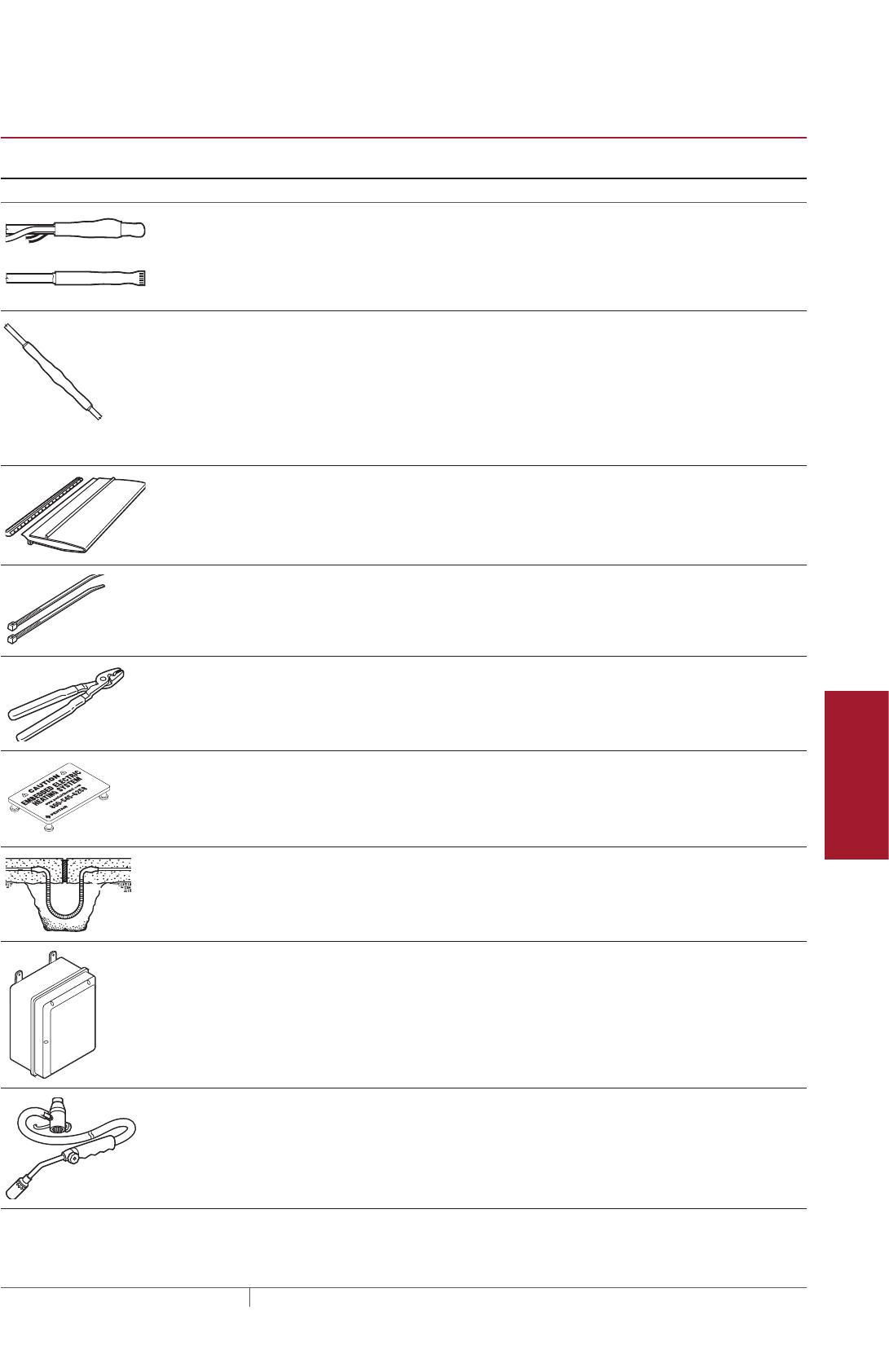
187THERMAL MANAGEMENT SOLUTIONS EN-RaychemElectroMeltSnowMelting-DG-H53393 11/13
Pipe Freeze Protection
and Flow Maintenance
Fire Sprinkler System
Freeze Protection
Roof and Gutter
De-Icing
Surface Snow
Melting – MI
Surface Snow
Melting – ElectroMelt
Freezer Frost
Heave Prevention
Floor Heating Technical Data
Sheets
TABLE 9 CONNECTION KITS AND ACCESSORIES
Catalog
number Description
Standard
packaging Usage
Heating cable
allowance ¹
Connection Kits
Power connection EMK-XP
End seal EMK-XP
EMK-XP Power connection and
end seal kit
1 1 per circuit 3 ft (1 m) for connection
plus conduit length for
power connection and
conduit length for end
seal
EMK-XS Splice kit 1 As required 1 ft (30 cm)
Accessories
EMK-XJR Jacket repair kit 1 As required –
EMK-CT Nylon cable ties 100/pack 1 per foot of cable
used
–
EMK-XT Crimping tool 1 ––
SMCS Snow melt caution sign
Dimensions: 6 x 4 in (150 x 100 mm)
11 minimum
per system
–
EMK-XEJ Expansion joint kit 1 1 per expansion
joint crossing
1 1/2 ft (45 cm)
EMK-XJB Junction box
Dimensions: 15 1/2 x 11 3/4 x 7 5/8 in
(394 x 299 x 194 mm)
1 1–2 ft (30–60 cm) for
each end in the junction
box
Maximum of two
circuits per EMK-XJB
FH-2616A-1 Propane torch is suitable for heat
shrinking the connection kits;
includes a hose, a handle assembly,
and comes equipped with a regulat-
ing valve.
Shipping weight: 5 lbs (2.27 kg)
¹ Allow extra heating cable for ease of component installation.
Surface Snow Melting and Anti-Icing Design

THERMAL MANAGEMENT SOLUTIONS
EN-RaychemElectroMeltSnowMelting-DG-H53393 11/13
188
Example: Surface Snow Melting System
Number of circuits 15 for concrete slab + 1 for stairs = 16
Power connection kits 16 power connection kits
Conduit length (from slab to junction box)
Power connection 15 ft (4.5 m)
End seal 15 ft (4.5 m)
(15 ft + 15 ft) x 16 circuits = 480 ft
(4.5 m + 4.5 m) x 16 circuits = 144 m
Heating cable allowance for each power connection
3 ft x 16 circuits = 48 ft
1 m x 16 circuits = 16 m
Total heating cable length required 528 ft (160 m)
Example: Anti-Icing System
Number of circuits 17 for concrete slab + 1 for stairs = 18
Power connection kits 18 power connection kits
Conduit length (from slab to junction box)
Power connection 15 ft (4.5 m)
End seal 15 ft (4.5 m)
(15 ft + 15 ft) x 18 circuits = 540 ft
(4.5 m + 4.5 m) x 18 circuits = 162 m
Heating cable allowance for each power connection
3 ft x 18 circuits = 54 ft
1 m x 18 circuits = 18 m
Total heating cable length required 594 ft (180 m)
SURFACE SNOW MELTING AND ANTIICING ELECTROMELT

189THERMAL MANAGEMENT SOLUTIONS EN-RaychemElectroMeltSnowMelting-DG-H53393 11/13
Pipe Freeze Protection
and Flow Maintenance
Fire Sprinkler System
Freeze Protection
Roof and Gutter
De-Icing
Surface Snow
Melting – MI
Surface Snow
Melting – ElectroMelt
Freezer Frost
Heave Prevention
Floor Heating Technical Data
Sheets
Surface Snow Melting
and Anti-Icing
1. Determine design
conditions
2. Select the heating
cable
3. Determine the
required watt density
4. Determine heating
cable spacing
5. Determine the total
area to be protected
9. Select the control
system and
power distribution
6. Determine heating
cable length
7. Determine the
electrical parameters
8. Select the connection
kits and accessories
10. Complete the Bill
of Materials
Step Select the control system and power distribution
CONTROL SYSTEMS
Select a control system from the following three options, but keep in mind that
an automatic snow controller offers the highest system efficiency and the lowest
operating cost.
• Manual on/off control
• Slab sensing thermostat
• Automatic snow melting controller
If the current rating of the control means is exceeded, all three methods will require
contactors sized to carry the load. Each method offers a tradeoff balancing initial
cost versus energy efficiency and ability to provide effective snow melting. If the
system is not energized when required, snow will accumulate. If the system is
energized when it is not needed, there will be unnecessary power consumption.
Choose the control method that best meets the project performance requirements.
For additional information, refer to the “Typical Control Diagrams,” Table 7, or contact
your Pentair Thermal Management representative for details.
Manual On/Off Control
A manually controlled system is operated by a switch that controls the system power
contactor. This method requires constant supervision to work effectively. A manual
system can be controlled by a building management system.
Slab Sensing Thermostat
A slab sensing thermostat can be used to energize the system whenever the slab
temperature is below freezing, but is not energy efficient when used as the sole
means of control. The slab sensing thermostat is recommended for all snow melting
applications, even when an automatic snow controller is used, and is required for
all asphalt and paver installations (for asphalt, it prevents surface damage due to
overheating).
Automatic Snow Melting Controller
With an automatic snow controller, the snow melting system is automatically
energized when both precipitation and low temperature are detected. When
precipitation stops or the ambient temperature rises above freezing, the system
is de-energized. In addition, a slab sensor de-energizes the system after the slab
reaches the slab sensing set point even if freezing precipitation is still present. Using
an automatic snow controller with a slab sensor offers the most energy-efficient
control solution.
For areas where a large number of circuits are required, the DigiTrace ACS-30 can
be used. The Surface Snow Melting control mode in the ACS-30 includes an External
Device control option. This option allows a Snow/Moisture sensing controller (from
Table 10) to be integrated into the ACS-30 system. Note that sensors (snow or
gutter) cannot be directly connected to the ACS-30 system. Refer to the ACS-30
Programming Guide (H58692) for more information on system setup.
Surface Snow Melting and Anti-Icing Design
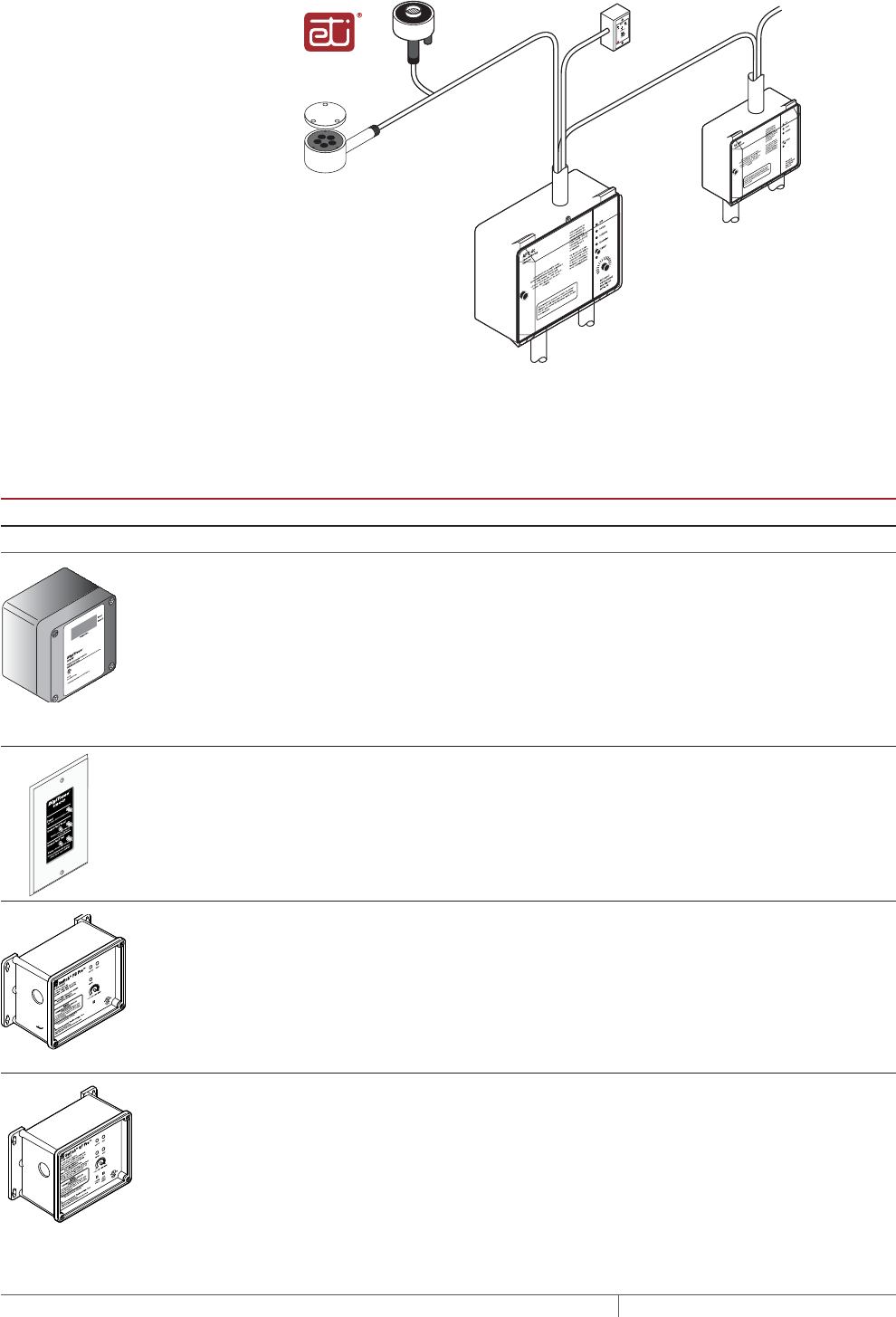
THERMAL MANAGEMENT SOLUTIONS
EN-RaychemElectroMeltSnowMelting-DG-H53393 11/13
190
CIT-1
snow sensor
To power supply or incorporate the ETI snow
melting control system into a power
distribution panel
APS-4C (shown) with SC-40C satelllite
contactor or APS-3C snow controller
Optional
SC-40C
satellite
contactor
To additional
SC-40C satellite
contactors
To heating cable(s)
To heating cable(s)
Optional
RCU-3 or RCU-4
remote control unit
To power supply
SIT-6E pavement
mounted sensor
Environmental Technology, Inc, (ETI) of
South Bend, Indiana offers a complete
line of automatic controllers for snow
melting applications.
Fig. 8 Automatic snow melting control system
TABLE 10 CONTROL SYSTEMS
Catalog number
Description
Slab Sensing Thermostat
ECW-GF Electronic ambient sensing controller with 30-mA ground-fault protection. The control-
ler can be programmed to maintain temperatures up to 200°F (93°C) at voltages from
100 to 277 V and can switch current up to 30 Amperes. The ECW-GF is complete with
a 25-ft (7.6-m) temperature sensor and is housed in a Type 4X rated enclosure. The
controller features an AC/DC dry alarm contact relay.
An optional ground-fault display panel (ECW-GF-DP) that can be added to provide
ground-fault or alarm indication in applications where the controller is mounted in
inaccessible locations.
ECW-GF-DP An optional remote display panel (ECW-GF-DP) can be added to provide ground-fault
or alarm indication in applications where the controller is mounted in inaccessible
locations.
HEATER CYCLE
ETI PD Pro Automatic snow and ice melting controller for pavement, sidewalks, loading docks,
roofs, gutters and downspouts in commercial and residential environments.
The PD Pro interfaces with up to two sensors, (any combination of CIT-1, GIT-1 or SIT-
6E) to meet site requirements. The PD Pro is housed in an environmentally-sheltered
Type 4X enclosure and weighs only 3 pounds.
ETI GF Pro Automatic snow and ice melting controller for pavement, sidewalks, loading docks,
roofs, gutters and downspouts in commercial and residential environments.
The GF Pro interfaces with up to two sensors, (any combination of CIT-1, GIT-1 or SIT-
6E) to meet site requirements. The GF Pro is housed in an environmentally-sheltered
Type 4X enclosure and weighs only 3 pounds.
Features a built-in 30 mA, self-testing Ground-Fault Equipment Protection (GFEP)
capability, digitally filtered to minimize false tripping. A ground-fault alarm must be
manually reset using the Test/Reset switch before heater operation can continue.
SURFACE SNOW MELTING AND ANTIICING ELECTROMELT
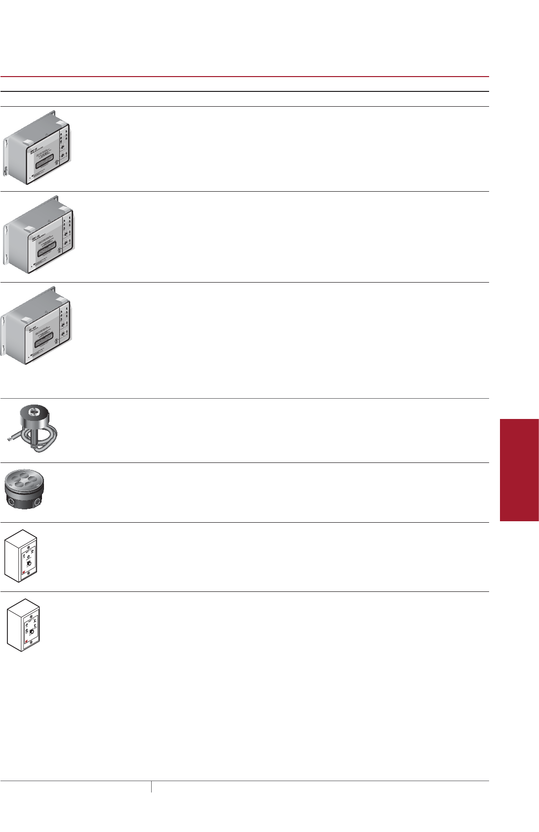
191THERMAL MANAGEMENT SOLUTIONS EN-RaychemElectroMeltSnowMelting-DG-H53393 11/13
Pipe Freeze Protection
and Flow Maintenance
Fire Sprinkler System
Freeze Protection
Roof and Gutter
De-Icing
Surface Snow
Melting – MI
Surface Snow
Melting – ElectroMelt
Freezer Frost
Heave Prevention
Floor Heating Technical Data
Sheets
TABLE 10 CONTROL SYSTEMS
Catalog number
Description
Automatic Snow Melting Controllers
APS-3C Automatic snow melting controller housed in a Type 3R enclosure provides effective,
economical automatic control of all snow melting applications. Features include:
120V or 208–240 V models, 24-A DPDT output relay and an adjustable hold-on timer.
Enclosure dimensions: 11-1/2 in x 9-1/8 in x 6-9/16 in (292 mm x 232 mm x 167 mm)
APS-4C Automatic snow melting controller housed in a Type 3R enclosure provides effective,
economical automatic control of all snow melting applications. The APS-4C can oper-
ate with any number of SC-40C satellite contactors for larger loads. Features include:
277 V single-phase or 208–240, 277/480, and 600 V three-phase models, built-in
3-pole contactor, integral 30 mA ground-fault circuit interrupter and an adjustable
hold-on timer.
Enclosure dimensions: 11-1/2 in x 9-1/8 in x 6-9/16 in (292 mm x 232 mm x 167 mm)
SC-40C Satellite contactor power control peripheral for an APS-4C snow melting control-
ler, housed in a Type 3R enclosure. Features include: 277 V single-phase or 208–240,
277/480 and 600 V three-phase models, built-in 3-pole contactor and integral 30 mA
ground-fault circuit interrupter.
Enclosure dimensions: 11-1/2 in x 9-1/8 in x 6 in (292 mm x 232 mm x 152 mm)
Snow Melting and Gutter De-Icing Sensors and Accessories
CIT-1 Overhead snow sensor that detects precipitation or blowing snow at ambient temper-
atures below 38°F (3.3°C). For use with either an APS-3C or APS-4C automatic snow
melting controller.
SIT-6E Pavement-mounted sensor signals for the heating cable to turn on when the
pavement temperature falls below 38°F (3.3°C) and precipitation in any form is
present. Microcontroller technology effectively eliminates ice bridging while ensuring
accurate temperature measurement. For use with either an APS-3C or APS-4C
automatic snow melting controller.
RCU-3 The RCU–3 provides control and status display to the APS–3C controller from a
remote location. It has a 2, 4, 6 or 8 hour CYCLE TIME adjustment, independent of
APS-3C setting.
RCU-4 The RCU–4 provides control and status display to the APS–4C controller and SC-40C
Satellite Contactor from a remote location. It has a 2, 4, 6 or 8 hour CYCLE TIME
adjustment, independent of the APS-4C or SC-40C setting.
Surface Snow Melting and Anti-Icing Design
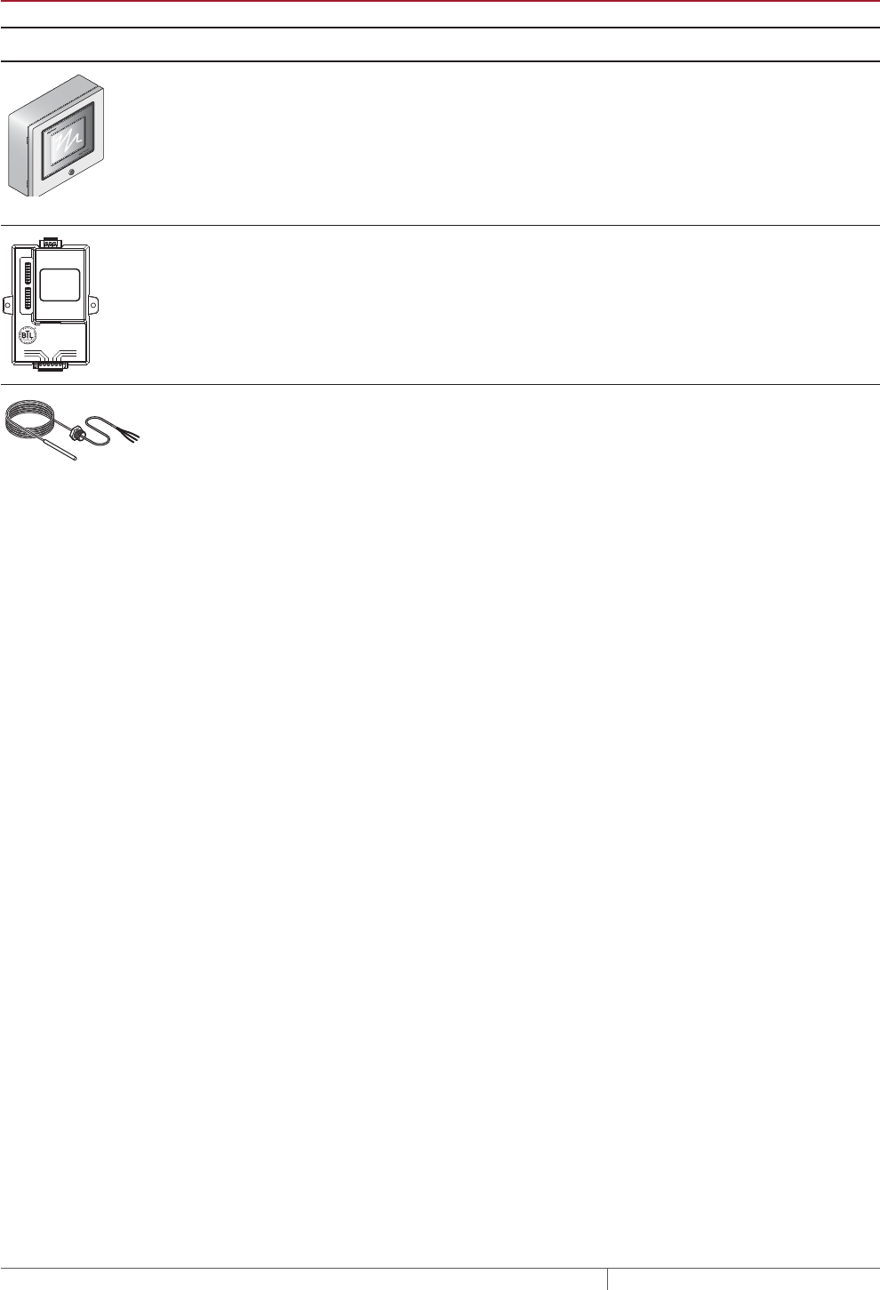
THERMAL MANAGEMENT SOLUTIONS
EN-RaychemElectroMeltSnowMelting-DG-H53393 11/13
192
TABLE 10 CONTROL SYSTEMS
Catalog number
Description
Electronic Controllers
ACS-UIT2
ACS-PCM2-5
The DigiTrace ACS-30 Advanced Commercial Control System is a multipoint
electronic control and monitoring system for heat-tracing used in various commercial
applications such as pipe freeze protection, roof and gutter de-icing, surface snow
melting, hot water temperature maintenance and floor heating. The DigiTrace ACS-30
system can control up to 260 circuits with multiple networked ACS-PCM2-5 panels,
with a single ACS-UIT2 user interface terminal. The ACS-PCM2-5 panel can directly
control up to 5 individual heat-tracing circuits using electromechanical relays rated at
30 A up to 277 V.
By FieldServer Technologies
www.ProtoCessor.com
PROTOCESSOR
SERIAL ETHERNET
PROTONODE
FRAME GND
- PWR
+PWR
RS 485+
RS 485 -
RS 485 GND
S3
S2
S1
S0
B3
B2
B1
B0
A7
A6
A5
A4
A3
A2
A1
A0
ProtoNode-LER
ProtoNode-RER
The DigiTrace ProtoNode is an external, high performance multi-protocol gateway for
customers needing protocol translation between Building Management Systems (BMS)
and the DigiTrace ACS-30 or C910-485 controllers.
The ProtoNode-LER is for LonWorks® systems; and the ProtoNode-RER is for
BACnet® or Metasys® N2 systems.
RTD10CS
RTD-200
RTD50CS
Stainless steel jacketed three-wire RTD (Resistance Temperature Detector) used with
DigiTrace C910-485 and ACS-30 controllers.
RTD10CS: 10-ft (3 m) flexible armor, with 18-in (457 mm) lead wire and 1/2-inch NPT
bushing.
RTD-200: 6-ft (1.8 m) fluoropolymer with 1/2-in NPT bushing.
RTD50CS: 50-ft (3 m) flexible armor with 1/2-in NPT bushing
POWER DISTRIBUTION
Single Circuit Control
Heating cable circuits that do not exceed the current rating of the selected
temperature control can be switched directly (see Fig. 9).
Group Control
If the current draw exceeds the switch rating, or if the controller will activate more
than one circuit, or group control, an external contactor must be used (see Fig. 9).
Large systems with many circuits should use an SMPG power distribution panel.
The SMPG is a dedicated power-distribution, control, ground-fault protection,
monitoring, and alarm panel for surface snow melting and anti-icing applications.
This enclosure contains an assembled circuit-breaker panelboard. Panels are
equipped with ground-fault circuit breakers with or without alarm contacts. The
group control package allows the system to operate automatically in conjunction
with an ambient-sensing thermostat, individual electronic, or duty cycle controller.
SURFACE SNOW MELTING AND ANTIICING ELECTROMELT
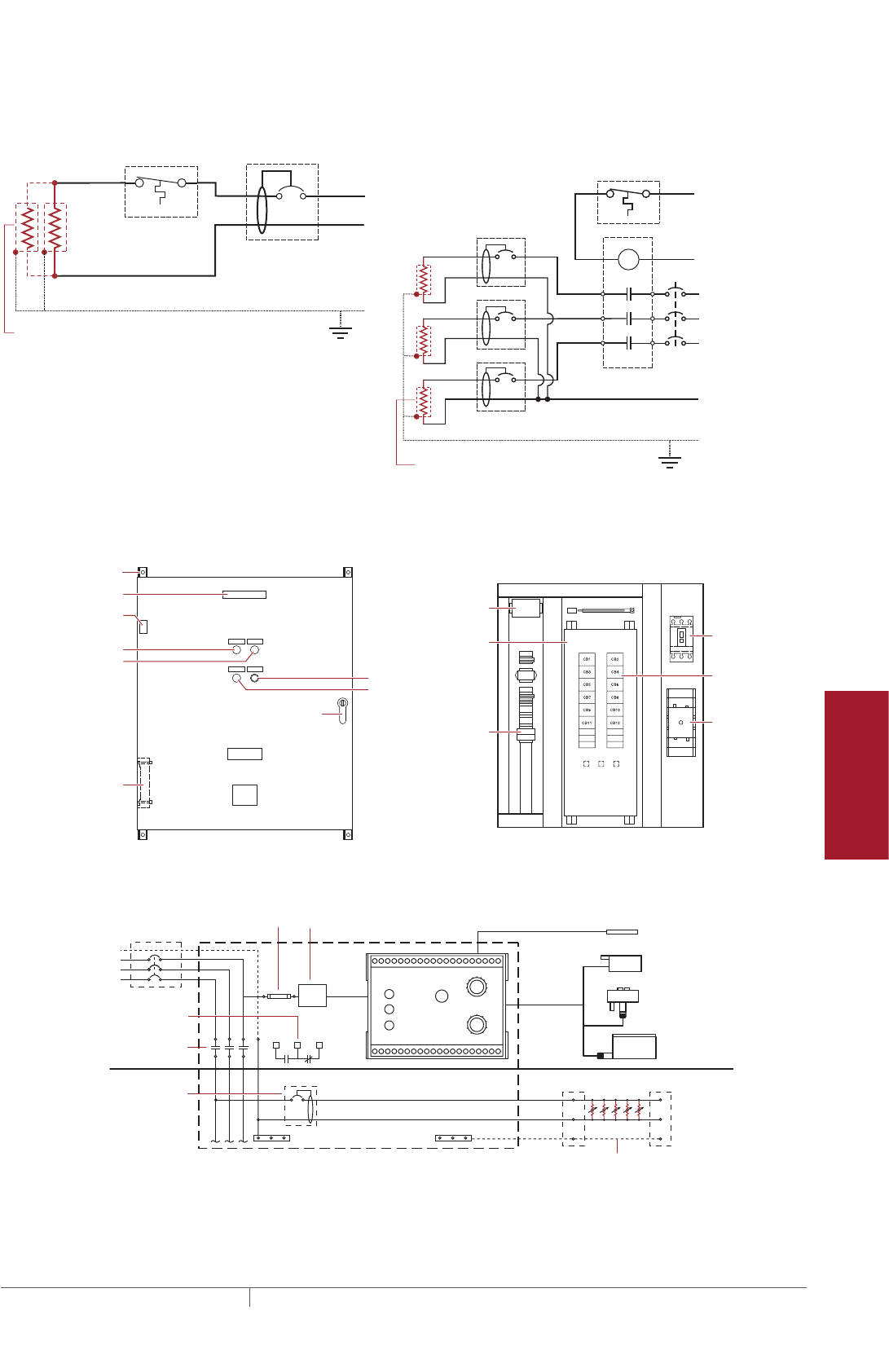
193THERMAL MANAGEMENT SOLUTIONS EN-RaychemElectroMeltSnowMelting-DG-H53393 11/13
Pipe Freeze Protection
and Flow Maintenance
Fire Sprinkler System
Freeze Protection
Roof and Gutter
De-Icing
Surface Snow
Melting – MI
Surface Snow
Melting – ElectroMelt
Freezer Frost
Heave Prevention
Floor Heating Technical Data
Sheets
Single circuit control Group control
Temperature
controller 1-pole
GFEP breaker
1
N
G
Heating
cable
ø
øsupply
C
Temperature
controller
Contactor
1-pole
GFEP breaker
N
G (Typ 3)
ø2
ø1
ø3
3-phase 4-wire
supply (WYE)
3-pole main
breaker
ø
ø
1 supply
N
Heating cable
sheath, braid
or ground
Heating cable
sheath, braid
or ground
Fig. 9 Single circuit and group control
Exterior View Interior View
NP
NP
NP
NP
G
NP
NP
G
NP
R
NP
Nameplate
Mounting brackets
Heater thermostat
(3R only)
Power on light
HTC energized light
C.B. tripped alarm
Heater (3R only)
Door lock handle
Snow/Ice
melt controller
Ground bar
Panelboard
lugs
Control wiring
Heater cycle
atimed control
EUR - 5A
Main breaker
(optional)
Heat trace
contactor
Branch
breakers
(2 pole)
Panel
board
Fig. 10 SMPG1 power distribution panel
N
Three-pole main contactor
FuseMain circuit breaker (optional)
Incoming
power
GND
24 V
One-pole with 30-mA
ground-fault trip (277 V)
Remote annunciation alarm
(circuit breaker
with alarm type #3)
GIT-1
CIT-1
SIT-6E
Braid
Aerial
snow sensor
Gutter
ice sensor
Slab
temperature sensor
Pavement-mounted
sensor
Single Ø
connection
SNOW/ICE
SUPPLY
EUR-5A SNOW SWITCH
AUTOMATIC SNOW/ICE MELTING CONTROL PANEL
HEATER
HEATER
CYCLE
HOURS
0
45°F
50°F
55°F
60°F 65°F 70°F
75°F
80°F
85°F
2
4 6
8
10
TEMPERATURE
Control transformer
Fig. 11 Typical wiring diagram of group control with SMPG1
Surface Snow Melting and Anti-Icing Design
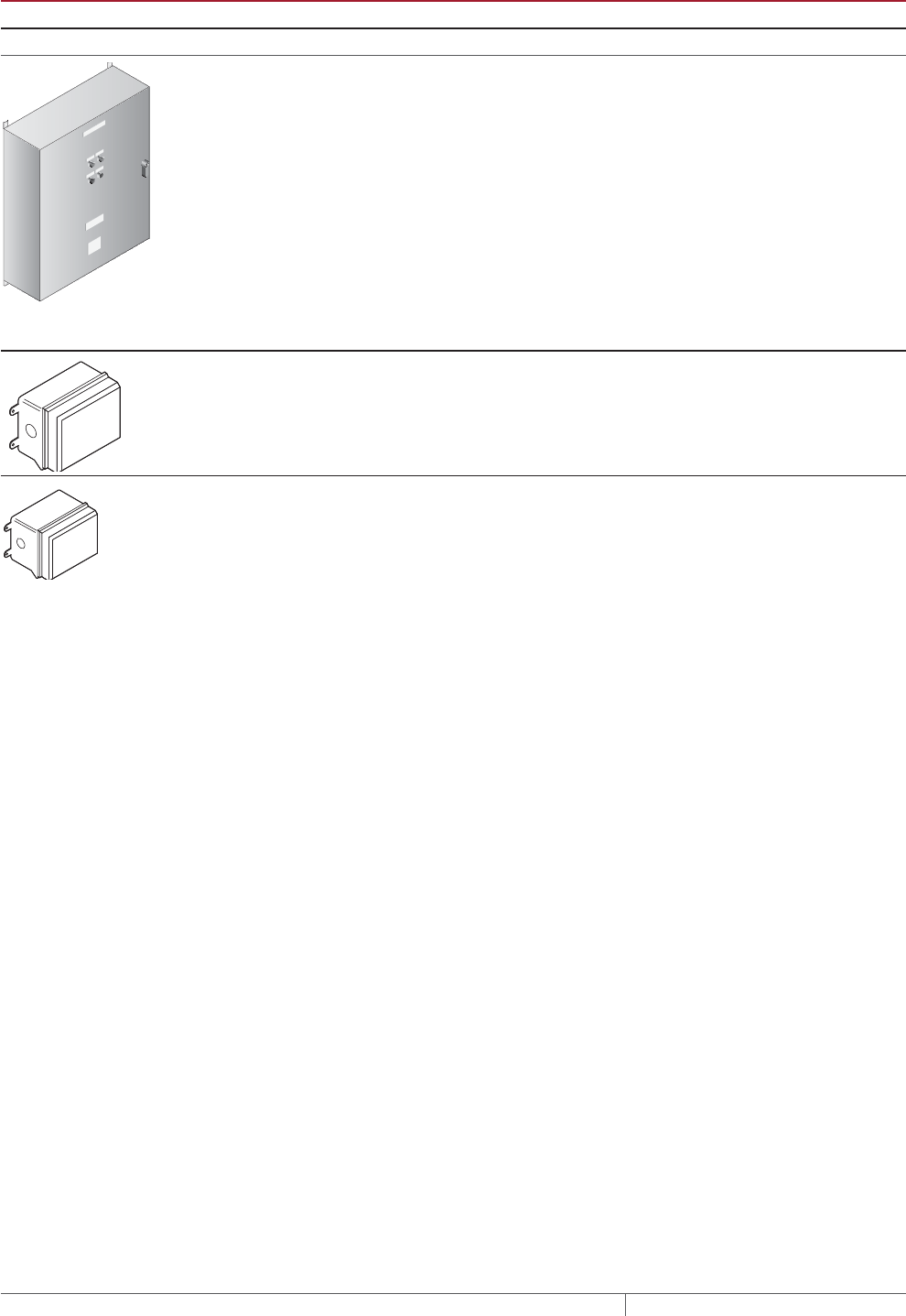
THERMAL MANAGEMENT SOLUTIONS
EN-RaychemElectroMeltSnowMelting-DG-H53393 11/13
194
TABLE 11 POWER DISTRIBUTION
Catalog number Description
Power Distribution and Control Panels
NP
NP
NP
NP
NP
NP NP
SMPG1 Single-phase power distribution panel that includes ground-fault protection, monitor-
ing, and control for snow melting systems. Single-phase voltages include 208 and 277 V.
If standard configurations do not meet your needs, custom SMPG panels are available
and processed under the catalog number SMPG-GENERAL, part number P000000763.
Please contact your Pentair Thermal Management representative for a custom SMPG
panel quotation.
Contactors
E104 Three-pole, 100 A per pole, 600 V maximum contactor housed in UL Listed, CSA Certi-
fied, NEMA 4X enclosure with two 1-inch conduit entries. When ordering, select coil
voltage (110–120, 208–240, 277 V).
Enclosure dimensions: 13-1/2 in x 9-1/5 in x 6-11/16 in (343 mm x 234 mm x 170 mm).
E304 Three-pole, 40 A per pole, 600 V maximum contactor housed in UL Listed, CSA Certified
NEMA 4X enclosure with two 1-inch conduit entries. When ordering, select coil voltage
(110–120, 208–240, 277 V).
Enclosure dimensions: 9-1/2 in x 7-1/5 in x 6-11/16 in (241 mm x 183 mm x 170 mm).
Example: Surface Snow Melting System
This system has 16 circuits and will require a specially designed control panel.
As many as eight SIT-6E sensors can be used in this configuration. The amount
depends upon designer preference.
Example: Anti-Icing System
This system has 18 circuits and will require a specially designed control panel.
As many as eight SIT-6E sensors can be used in this configuration. The amount
depends upon designer preference.
SURFACE SNOW MELTING AND ANTIICING ELECTROMELT

195THERMAL MANAGEMENT SOLUTIONS EN-RaychemElectroMeltSnowMelting-DG-H53393 11/13
Pipe Freeze Protection
and Flow Maintenance
Fire Sprinkler System
Freeze Protection
Roof and Gutter
De-Icing
Surface Snow
Melting – MI
Surface Snow
Melting – ElectroMelt
Freezer Frost
Heave Prevention
Floor Heating Technical Data
Sheets
Surface Snow Melting
& Anti-Icing
1. Determine design
conditions
2. Select the heating
cable
3. Determine the
required watt density
4. Determine heating
cable spacing
5. Determine the total
area to be protected
9. Select the control
system and
power distribution
6. Determine heating
cable length
7. Determine the
electrical parameters
8. Select the connection
kits and accessories
10. Complete the Bill
of Materials
Step 0Complete the Bill of Materials
If you used the Design Worksheet to document all your design parameters, you
should have all the details you need to complete the Bill of Materials.
Surface Snow Melting and Anti-Icing Design
THERMAL MANAGEMENT SOLUTIONS
EN-RaychemElectroMeltSnowMelting-DG-H53393 11/13
196
ELECTROMELT SYSTEM SURFACE SNOW MELTING AND ANTIICING DESIGN WORKSHEET
Step Determine design conditions
Application Size and layout
Supply
voltage Phase Control method
❑ Surface snow melting
Geographical location:
_____________________
❑ Anti-icing
Minimum ambient temperature:
_____________________
Average wind speed during
freezing periods (mph/kmph):
____________________
Paving material
❑ Concrete pavement
❑ In concrete under paving stones
Slab surface (ft/m) __________________
Ramp surface (ft/m) _________________
Stairs
Number of stairs ______________
Width of stair (ft/m) ______________
Riser height (in/cm) ______________
Depth of stair (in/cm) ______________
Landing dimensions
(ft/m) ______________
Wheel tracks
Track length (ft/m) ____________
❑ 208 V
❑ 240 V
❑ 277 V
❑ 347 V
❑ Single-phase ❑ Manual on/off control
❑ Slab-sensing thermostat
❑ Automatic snow melting
controller
Example:
9 Surface snow melting
9 Buffalo, NY
9 Concrete slab
Slab surface: 80 ft x 50 ft
Stairs
Number of stairs 10
Width of stair 5 ft
Riser height 6 in
Depth of stair 12 in
9 277 V 9 Single-phase 9 Automatic snow melting
controller
Step Select the heating cable
See Table 1
❑ EM2-XR ❑ EM3-XR
Example:
9 EM2-XR
Step Determine the required watt density
Surface snow melting
See Table 2
Anti-icing
See Table 3 and Table 4
Geographical location: _________________________
Required watt density (W/ft²)(W/m²): ___________________________
Minimum ambient temperature (°F/°C): _______
Average wind speed during freezing periods (mph/kmph): ______
Required watt density (W/ft²)(W/m²): _______
Example:
Geographical location: Buffalo, NY
Required watt density: 40 W/ft²
SURFACE SNOW MELTING AND ANTIICING ELECTROMELT

197THERMAL MANAGEMENT SOLUTIONS EN-RaychemElectroMeltSnowMelting-DG-H53393 11/13
Pipe Freeze Protection
and Flow Maintenance
Fire Sprinkler System
Freeze Protection
Roof and Gutter
De-Icing
Surface Snow
Melting – MI
Surface Snow
Melting – ElectroMelt
Freezer Frost
Heave Prevention
Floor Heating Technical Data
Sheets
Step Determine heating cable spacing
See Table 5
34 W/ft
12 in 3
3
Equally spaced across the width of the stair
with one run 2 in from the front edge
40 W/ft210 in
Power output (W/ft) Watt density (W/ft2)
x
( )
Heating cable spacing (in)
12 in/ft
Power output (W/ft)
Stairs
Surfaces
Surfaces
Calculate the heating cable needed for stairs and landing
Determine the number of cable runs needed:
Depth of stair: <10.5 in (27 cm): 2 cable runs
Depth of stair: 10.5–12 in (27–30 cm): 3 cable runs
Cable runs needed:
Concrete stair depth (in/cm): Number of cable runs: Spacing:
Stairs
Calculate the heating cable needed for stairs and landing
Determine the number of cable runs needed:
Depth of stair: <10.5 in (27 cm): 2 cable runs
Depth of stair: 10.5–12 in (27–30 cm): 3 cable runs
Cable runs needed:
/
x
( )
12 in/ft /
=
Watt density (W/ft2)
Example:
Note: Round result to the nearest whole number of inches or centimeters.
Heating cable spacing (in/cm)
=
Concrete stair depth (in/cm): Number of cable runs: Spacing:
Note: Round result to the nearest whole number of inches or centimeters.
Step Determine the total area to be protected
x
80 ft 4000 ft2
Length
50 ft
Width
xSurface area to be protected (ft2/m2)Length (ft/m) Width (ft/m)
=
Example:
Surfaces
Surface area to be protected (ft)
=
ElectroMelt System Surface Snow Melting and Anti-Icing Design Worksheet

THERMAL MANAGEMENT SOLUTIONS
EN-RaychemElectroMeltSnowMelting-DG-H53393 11/13
198
Step Determine the heating cable length
xHeating cable length for surface
4000 ft2
12 in 10 in 4800
Total concrete slab area
Calculate the heating cable for stairs and landing
/ =
Heating cable spacing
x x x =
=
=
=
=
+( () )
10
No. of stairs
32
No. of runs per stair
5 ft
Width of stair
0.5 ft
Riser height
160 ft
4960 ft
Heating cable length for stairs
[ ]
Note: Additional heating cable for connection kits and end terminations is calculated in Step 8.
Calculate the heating cable for stairs and landing
Surfaces
Surfaces
x x x+( () )
No. of stairs 2
No. of runs per stair Width of stair (ft/m) Riser height (ft/m) Heating cable length for stairs (ft/m)
[ ]
Note: Additional heating cable for connection kits and end terminations is calculated in Step 8.
Example:
x
Heating cable length for surface (ft/m)
12 in
Total concrete slab area (ft2/m2)/Heating cable spacing (in/cm)
Calculate heating cable needed for wheel tracks
x 2 x 4 runs
Wheel track to be protected (ft/m)
Length (ft/m)
Total heating cable length required (ft/m)
Total heating cable length required
SURFACE SNOW MELTING AND ANTIICING ELECTROMELT

199THERMAL MANAGEMENT SOLUTIONS EN-RaychemElectroMeltSnowMelting-DG-H53393 11/13
Pipe Freeze Protection
and Flow Maintenance
Fire Sprinkler System
Freeze Protection
Roof and Gutter
De-Icing
Surface Snow
Melting – MI
Surface Snow
Melting – ElectroMelt
Freezer Frost
Heave Prevention
Floor Heating Technical Data
Sheets
Step Determine the electrical parameters
See Table 7 and Table 8
Number of circuits
4800 ft 325 ft 14.8 rounded to 15
Heating cable length required for surface / =
Maximum heating cable circuit length
Determine number of circults: Surfaces
Number of circuitsHeating cable length required for surface (ft/m) / =
Maximum heating cable circuit length (ft/m)
Determine number of circults
Circuit breaker load (kW)
0.8 1000
Circuit breaker rating (Amps ) x x /
(
)=
Supply voltage
Determine total transformer load
Calculate the total transformer load as follows:
Calculate circuit breaker load (CBL)
If the CBL is equal on all circuits, calculate the transformer load as:
If the CBL is NOT equal on all circuits, calculate the transformer load as:
Total transformer load (kW)Circuit breaker load (kW) x =
Number of breakers
Total transformer load (kW)CBL1 + CBL2 + CBL3... + CBLN
=
Example:
Number of circuits
160 ft 325 ft 0.5 rounded to 1
Heating cable length required for surface / =
Maximum heating cable circuit length
Determine number of circults: Stair
Circuit breaker load (kW)
50 A 277 V
0.8 1000 11.1 kW
Circuit breaker rating x x /( ) =
Supply voltage
Total transformer load (kW)
11.1 kW 16 177.6 kW rounded to 178
Circuit breaker load (kW) x =
Determine transformer load
Number of breakers
ElectroMelt System Surface Snow Melting and Anti-Icing Design Worksheet

THERMAL MANAGEMENT SOLUTIONS
EN-RaychemElectroMeltSnowMelting-DG-H53393 11/13
200
Step Select the connection kit and accessories
See Table 9
Connection kits Description Quantity
Heating cable
allowance
T EMK-XP
T EMK-XS
Power connection and end seal kit
Splice kit
____________
____________
__________________
__________________
Accessories Description Quantity
T EMK-XJR
T EMK-CT
T EMK-XT
T SMCS
T EMK-XEJ
T EMK-XJB
T FH-2616A-1
Jacket repair kit
Nylon cable ties
Crimping tool
Snow melt caution sign
Expansion joint kit
Junction box
Propane torch
____________
____________
____________
____________
____________
____________
____________
__________________
__________________
+ =
Total heating cable
length required
Total heating cable allowance for connection kitsTotal heating cable length
Total heating cable
allowance for connection kits
15 1 16 16
15 ft 15 ft 480 ft
480 ft
16
3 ft 16 48 ft
48 ft
630 ft 63 693 ft
528 ft
Total no. of circuitsNumber circuits for concrete slab + = Total no. of power connection kits
=
Circuit(s) for stairs +Circuit(s) for expansion joints
Total conduit length (ft/m)Power connection conduit length
(slab to junction box) (ft/m)
+ x( ) =
End seal conduit length
(slab to junction box) (ft/m)
Total number of circuits
Total heating cable allowance
per power connection (ft/m)
Cable allowance per
circuit connection (ft/m)
x =
Total number of circuits
Total additional
heating cable (ft/m)
Total conduit length (ft/m) + =
=Total heating cable with
connection kit allowance (ft/m)
Total allowance per
power connection kit (ft/m)
Total heating cable length (ft/m) Total heating cable allowance (ft/m)
+
Example:
Total no. of circuitsNumber circuits for concrete slab+ = Total no. of power connection kits
=
Circuit(s) for stairs +Circuit(s) for expansion joints
Total conduit lengthPower connection conduit length
(slab to junction box)
+ x( ) =
End seal conduit length
(slab to junction box)
Total number of circuits
Total heating cable allowance
per power connection
Cable allowance per
circuit connection
x =
Total number of circuits
Total additional heating cableTotal conduit length + =
=Total heating cable with
connection kit allowance
Total allowance per
power connection kit
Total heating cable length Total heating cable allowance
+
SURFACE SNOW MELTING AND ANTIICING ELECTROMELT

201THERMAL MANAGEMENT SOLUTIONS EN-RaychemElectroMeltSnowMelting-DG-H53393 11/13
Pipe Freeze Protection
and Flow Maintenance
Fire Sprinkler System
Freeze Protection
Roof and Gutter
De-Icing
Surface Snow
Melting – MI
Surface Snow
Melting – ElectroMelt
Freezer Frost
Heave Prevention
Floor Heating Technical Data
Sheets
Step Select the control system and power distribution
Control Systems
See Table 10.
Thermostats, controllers
and accessories Description Quantity
T ECW-GF
T ECW-GF-DP
T ETI PD Pro
T ETI GF-Pro
T APS-3C
T APS-4C
T SC-40C
T CIT-1
T SIT-6E
T RCU-3
T RCU-4
T ACS-UIT2
T ACS-PCM2-5
T ProtoNode-LER
T ProtoNode-RER
T RTD3CS
T RTD10CS
T RTD-200
T RTD50CS
Electronic thermostat with 25-ft sensor
Remote display panel for ECW-GF
Automatic snow and ice melting controller
Automatic snow and ice melting controller
Automatic snow and ice melting controller
Automatic snow and ice melting controller
Satellite contactor
Overhead snow sensor
Pavement-mounted sensor
Remote control unit for APS-3C
Remote control unit for APS-4C
ACS-30 user interface terminal
ACS-30 power control panel
Multi-protocol gateway
Multi-protocol gateway
Resistance temperature device for DigiTrace ACS-30
Resistance temperature device for DigiTrace ACS-30
Resistance temperature device for DigiTrace ACS-30
Resistance temperature device for DigiTrace ACS-30
____________
____________
____________
____________
____________
____________
____________
____________
____________
____________
____________
____________
____________
____________
____________
____________
____________
____________
____________
Power Distribution
See Table 11.
Power distribution and
control panels Description Quantity
T SMPG1 Single-phase power distribution panel ____________
Contactors and junction boxes Description Quantity
T E104
T E304
Three-pole, 100 A per pole contactor
Three-pole, 40 A per pole contactor
____________
____________
Step Complete the Bill of Materials
Use the information recorded in this worksheet to complete the Bill of Materials.
ElectroMelt System Surface Snow Melting and Anti-Icing Design Worksheet

THERMAL MANAGEMENT SOLUTIONS
EN-RaychemElectroMeltSnowMelting-DG-H53393 11/13
202
SURFACE SNOW MELTING AND ANTIICING ELECTROMELT

203THERMAL MANAGEMENT SOLUTIONS EN-FreezerFrostHeavePrevention-DG-H58139 11/13
Pipe Freeze Protection
and Flow Maintenance
Fire Sprinkler System
Freeze Protection
Roof and Gutter
De-Icing
Surface Snow
Melting – MI
Surface Snow
Melting – ElectroMelt
Freezer Frost
Heave Prevention
Floor Heating Technical Data
Sheets
This step-by-step design guide provides the tools necessary to design a Raychem
RaySol self-regulating heating cable system or a Pyrotenax Mineral Insulated
heating cable system for freezer frost heave prevention. For other applications or
for design assistance, contact your Pentair Thermal Management representative or
phone Pentair Thermal Management at (800)545-6258. Also, visit our web site at
www.pentairthermal.com.
Contents
Introduction .........................................................204
How to Use this Guide ............................................204
Safety Guidelines ................................................204
Warranty .......................................................205
System Overview .....................................................205
Typical System ..................................................206
Self-Regulating Heating Cable Construction ..........................208
MI Heating Cable Construction .....................................209
Approvals .......................................................210
Freezer Frost Heave Prevention Design ..................................210
Design Assumptions ..............................................210
Design Step by Step RaySol and MI Heating Cables in Conduit ...........211
Step 1 Determine the freezer configuration ........................212
Step 2 Select the heating cable ..................................213
Step 3 Determine the heating cable conduit spacing and freezer load ...216
Step 4 Determine the heating cable layout and length ................217
Step 5 Determine the electrical parameters ........................224
Step 6 Select the connection kits and accessories ..................226
Step 7 Select the control system .................................227
Step 8 Select the power distribution ..............................229
Step 9 Complete the Bill of Materials .............................231
Design Step by Step MI Heating Cables Directly Embedded ..............232
Step 1 Determine the freezer configuration ........................233
Step 2 Determine heat loss and freezer load .......................234
Step 3 Select the heating cable, layout and length ...................236
Step 4 Determine the heating cable spacing ........................243
Step 5 Determine the electrical parameters ........................243
Step 6 Select the accessories ....................................245
Step 7 Select the control system .................................246
Step 8 Select the power distribution ..............................247
Step 9 Complete the Bill of Materials .............................250
RaySol and MI Heating Cable in Conduit Freezer Frost Heave Prevention
Design Worksheet .................................................251
MI Cables Directly Embedded Freezer Frost Heave Prevention
Design Worksheet .................................................256
FREEZER FROST HEAVE PREVENTION
RAYSOL AND MI HEATING CABLE SYSTEM

THERMAL MANAGEMENT SOLUTIONS
EN-FreezerFrostHeavePrevention-DG-H58139 11/13
204
INTRODUCTION
Pentair Thermal Management offers two different heating cable technologies for
freezer frost heave prevention: Raychem RaySol self-regulating heating cable system
and Pyrotenax MI heating cable system. Both RaySol and MI heating cables can be
installed in conduit. Only MI heating cables can be embedded directly in the subfloor
(concrete, sand, or compacted fill).
If your application conditions are different, or if you have any questions, contact
your Pentair Thermal Management representative or contact Pentair Thermal
Management directly at (800)545-6258.
How to Use this Guide
This design guide presents Pentair Thermal Management’ recommendations
for designing freezer frost heave prevention systems. It provides design and
performance data, electrical sizing information, and heating cable layout
suggestions. Following these recommendations will result in a reliable, energy-
efficient system.
Follow the design steps in the respective “Design” sections and use the appropriate
“RaySol and MI Heating Cable in Conduit Freezer Frost Heave Prevention Design
Worksheet” on page251 and “MI Cables Directly Embedded Freezer Frost Heave
Prevention Design Worksheet” on page256 to document the project parameters that
you will need for your project’s Bill of Materials.
OTHER REQUIRED DOCUMENTS
This guide is not intended to provide comprehensive installation instructions. For
complete freezer frost heave prevention system installation instructions, please refer
to the following additional required documents:
• Raychem RaySol Floor Heating and Frost Heave Prevention Installation and Op-
eration Manual (H58138)
• Pyrotenax Mineral Insulated Heating Cable Floor Heating and Frost Heave Pre-
vention Installation and Operation Manual (H58137)
• Additional installation instructions are included with the connection kits, thermo-
stats, controllers, and accessories
If you do not have these documents, you can obtain them from the Pentair Thermal
Management web site at www.pentairthermal.com.
For products and applications not covered by this design guide, please contact your
Pentair Thermal Management representative or call Pentair Thermal Management
directly at (800)545-6258.
Safety Guidelines
As with any electrical equipment, the safety and reliability of any system depends
on the quality of the products selected and the manner in which they are installed
and maintained. Incorrect design, handling, installation, or maintenance of any of
the system components could damage the system and may result in inadequate
performance, overheating, electric shock, or fire. To minimize these risks and to
ensure that the system performs reliably, read and carefully follow the information,
warnings, and instructions in this guide.
This symbol identifies important instructions or information.
This symbol identifies particularly important safety warnings that must be
followed.
FREEZER FROST HEAVE PREVENTION RAYSOL AND MI HEATING CABLE SYSTEM
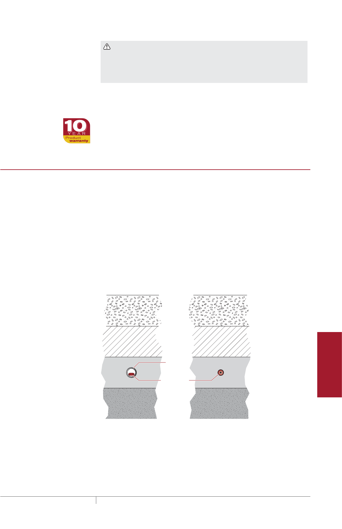
205THERMAL MANAGEMENT SOLUTIONS EN-FreezerFrostHeavePrevention-DG-H58139 11/13
Pipe Freeze Protection
and Flow Maintenance
Fire Sprinkler System
Freeze Protection
Roof and Gutter
De-Icing
Surface Snow
Melting – MI
Surface Snow
Melting – ElectroMelt
Freezer Frost
Heave Prevention
Floor Heating Technical Data
Sheets
WARNING: To minimize the danger of fire from sustained electrical arcing
if the heating cable is damaged or improperly installed, and to comply with the
requirements of Pentair Thermal Management, agency certifications, and national
electrical codes, ground-fault equipment protection must be used on each heating
cable branch circuit. Arcing may not be stopped by conventional circuit protection.
Warranty
Pentair Thermal Management’s standard limited warranty applies to Raychem and
Pyrotenax Freezer Frost Heave Prevention Systems.
An extension of the limited warranty period to ten (10) years from the date of
installation is available, except for the control and distribution systems, if a properly
completed online warranty form is submitted within thirty (30) days from the date of
installation. You can access the complete warranty on our web site at
www.pentairthermal.com.
SYSTEM OVERVIEW
Subfreezing temperatures inside cold rooms, freezers, and ice arenas cause heat
to be lost from the soil under the floor, even when it is well insulated. As the soil
freezes, capillary action draws water into the frozen areas where the water forms
a concentrated ice mass. As the ice mass grows, it heaves the freezer floor and
columns, causing damage.
Pentair Thermal Management offers two different heating cable technologies for
freezer frost heave prevention: Raychem RaySol self-regulating heating cable and
Pyrotenax MI heating cable system. Both RaySol and MI heating cables can be
installed in conduit. Only MI heating cables can be embedded directly in the subfloor
(sand, compacted fill or concrete). The electrical conduit carrying the heating cable
or the directly embedded heating cable is installed in the subfloor under the freezer-
floor insulation, as illustrated below. The subfloor layer may be a reinforced concrete
slab, a concrete mud slab, a bed of compacted sand, or simply compacted fill.
Concrete
RaySol or MI heating
cable in conduit
MI heating cable
directly embedded
Insulation
Subfloor
Conduit
Heating cable
Soil
Fig. 1 Typical freezer frost heave installation
System Overview

THERMAL MANAGEMENT SOLUTIONS
EN-FreezerFrostHeavePrevention-DG-H58139 11/13
206
The RaySol self-regulating heating cable provides a cut-to-length solution. The
backbone of the system is the self-regulating heating cable available for 120 and
208–277 V applications. As Fig. 4 on page208 indicates, the cable’s output is
reduced automatically as the subfloor warms, so there is no possibility of failure due
to overheating. Since there is no possibility of overheating, RaySol may be operated
without thermostatic control. Elements of a RaySol system include the heating cable,
termination, splice connections and accessories, controls, power distribution panels,
and the tools necessary for a complete installation.
Pyrotenax MI heating cable can be used for single-phase and three-phase
applications up to 600 V and the cable can be installed in conduit or directly
embedded in sand (recommended), concrete, or compacted fill. For directly
embedded applications, long cable runs can be accommodated allowing frost heave
prevention systems to be designed for large freezers and ice arenas using only a few
circuits. Pyrotenax MI heating cables are rugged factory-terminated cables
(Fig. 6 and Fig. 7) that are engineered to suit your application, power and
configuration requirements. Elements of an MI system include the heating cable,
accessories, controls, power distribution panels, and the tools for a complete
installation.
Typical System
A typical system includes the following:
• RaySol self-regulating heating cable or Pyrotenax MI heating cable
• Connection kits (for RaySol only)
• Junction boxes
• Temperature control and power distribution systems
FREEZER FROST HEAVE PREVENTION RAYSOL AND MI HEATING CABLE SYSTEM
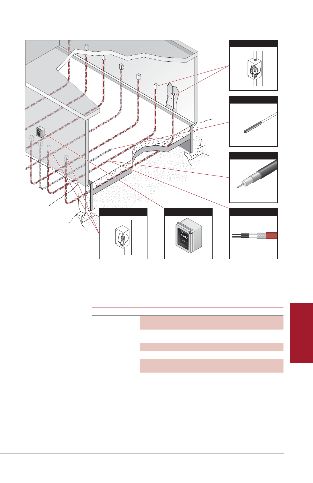
207THERMAL MANAGEMENT SOLUTIONS EN-FreezerFrostHeavePrevention-DG-H58139 11/13
Pipe Freeze Protection
and Flow Maintenance
Fire Sprinkler System
Freeze Protection
Roof and Gutter
De-Icing
Surface Snow
Melting – MI
Surface Snow
Melting – ElectroMelt
Freezer Frost
Heave Prevention
Floor Heating Technical Data
Sheets
RaySol
Mineral insulated
Heating Cable
Heating Cable
RTD
End Seal
Power Connection
Controller
Fig. 2 Typical freezer frost heave system
The following table lists the heating cable, required connection kits, and accessories
for a RaySol and MI heating cable systems.
TABLE 1 HEATING CABLES AND CONNECTION KITS
Catalog Number Description
Heating cable RaySol-1
RaySol-2
120 V
208–277 V
HDPE jacketed copper sheath
MI heating cable
≤600 V
Connection kits
for RaySol
heating cables
FTC-XC Power connection and end seal
RayClic-E End seal
FTC-HST Splice (as required – not for use
inside conduit)
System Overview
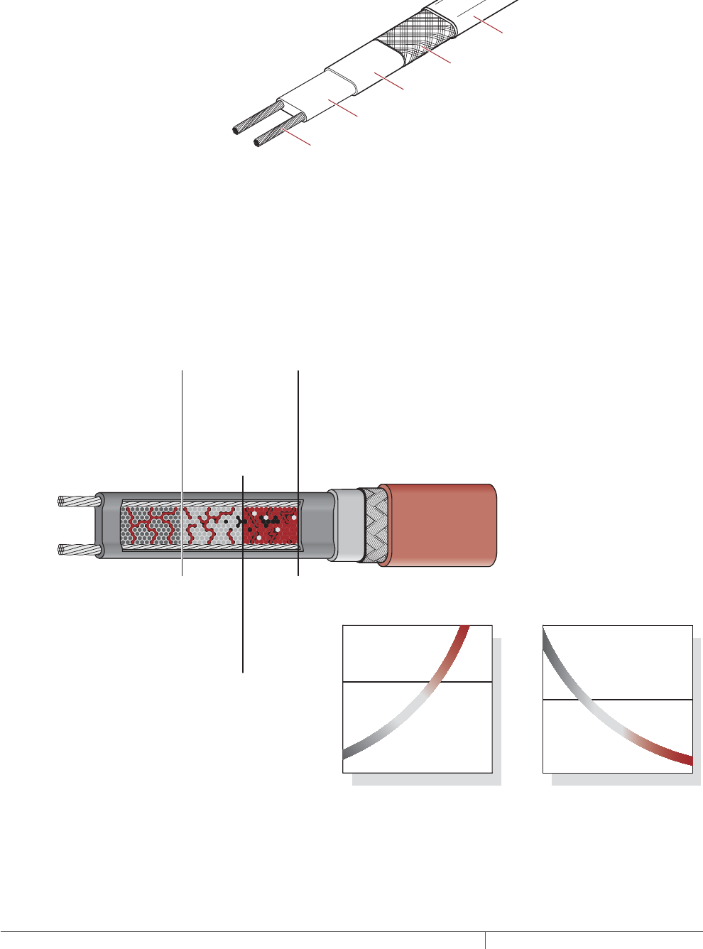
THERMAL MANAGEMENT SOLUTIONS
EN-FreezerFrostHeavePrevention-DG-H58139 11/13
208
Self-Regulating Heating Cable Construction
Raychem RaySol self-regulating heating cables are comprised of two parallel
nickel-coated bus wires in a cross-linked polymer core, a tinned copper braid, and a
fluoropolymer outer jacket. These cables are cut to length simplifying the application
design and installation.
Nickel-plated copper bus wires
Self-regulating conductive core
Modified polyolefin inner jacket
Tinned-copper braid
Fluoropolymer outer jacket
Fig. 3 Typical RaySol heating cable construction
With self-regulating technology, the number of electrical paths between bus wires
changes in response to temperature fluctuations. As the temperature surrounding
the heater decreases, the conductive core contracts microscopically. This contraction
decreases electrical resistance and creates numerous electrical paths between the
bus wires. Current flows across these paths to warm the core.
As the temperature rises, the core expands microscopically. This expansion
increases electrical resistance and the number of electrical paths decreases. The
heating cable automatically reduces its output.
At low temperature,
there are many
conducting paths,
resulting in high output
and rapid heat-up. Heat
is generated only when it
is needed and precisely
where it is needed.
At high temperature,
there are few
conducting paths and
output is correspond-
ingly lower, conserving
energy during
operation.
At moderate temperature,
there are fewer conducting
paths because the heating
cable efficiently adjusts by
decreasing output,
eliminating any possibility
of overheating.
The following graphs illustrate the response of self-regulating heating
cables to changes in temperature. As the temperature rises, electrical
resistance increases, and our heaters reduce their power output.
Temperature
Resistance
Power
Temperature
Constant wattage
Constant wattage
Self-regulating
Self-regulating
Fig. 4 Self-regulating heating cable technology
FREEZER FROST HEAVE PREVENTION RAYSOL AND MI HEATING CABLE SYSTEM
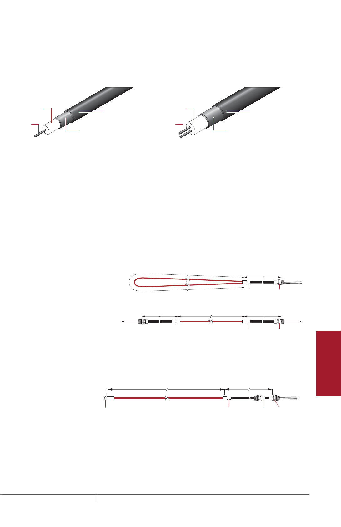
209THERMAL MANAGEMENT SOLUTIONS EN-FreezerFrostHeavePrevention-DG-H58139 11/13
Pipe Freeze Protection
and Flow Maintenance
Fire Sprinkler System
Freeze Protection
Roof and Gutter
De-Icing
Surface Snow
Melting – MI
Surface Snow
Melting – ElectroMelt
Freezer Frost
Heave Prevention
Floor Heating Technical Data
Sheets
MI Heating Cable Construction
Pyrotenax MI heating cables used for frost heave prevention applications are
comprised of one or two conductors surrounded by magnesium oxide insulation and
a solid copper sheath with an extruded high density polyethylene (HDPE) jacket or
Alloy 825 stainless steel sheath for directly embedded or in conduit applications.
Heating
conductor
Dual-conductor cable (32, 62 series)
Copper or Alloy 825 sheath
Single-conductor cable (61 series)
Heating cable construction
Heating
conductors
HDPE jacket
(for copper shealth only)
Copper sheath
HDPE jacket
Insulation
(magnesium oxide)
Insulation
(magnesium oxide)
Fig. 5 Typical MI heating cable construction
These heating cables are supplied as complete factory-fabricated assemblies
consisting of an MI heating cable that is joined to a section of MI non-heating cold
lead and terminated with NPT connectors. Three configurations are available: Type
SUA consisting of a looped cable joined to a single 7 ft (2.1 m) cold lead with one
1/2-in NPT connector; Type SUB/FFHP consisting of a single run of cable with a
15 ft (4.6 m) cold lead and a 1/2-in NPT connector on each end; and Type FFHPC
consisting of a single run of cable joined to a single 7 ft (2.1m) cold lead with one
1/2-in NPT connector.
Types SUA and SUB/FFHP heating cables (Fig. 6) are used for directly embedded
applications, and Type FFHPC heating cables (Fig. 7) are used for installation in
conduit. Type FFHPC heating cables are supplied with a bare copper sheath cold lead
and a 3/4-in NPT reversed gland connector and a pulling eye. The reversed gland
connector provides a seal for the end of the conduit (see Fig. 13 on page223).
Hot/cold
joint
NPT threaded
connector
Hot/cold
joint
NPT threaded
connector
Heated length
Heated length Cold lead length
Cold lead length
Cold lead length
Type SUA
Design A
Type SUB and FFHP
Design B
Fig. 6 Configurations for directly embedded installations
NPT threaded
connector
Hot/cold
joint
Reversed
gland
Heated length Cold lead length
Pulling eye
Type FFHPC
Design D
Fig. 7 Configuration for installation in conduit
Pentair Thermal Management offers all the major components necessary for system
installation. Details of these components and additional accessories can be found
later in this section.
System Overview

THERMAL MANAGEMENT SOLUTIONS
EN-FreezerFrostHeavePrevention-DG-H58139 11/13
210
Approvals
Installation of Raychem RaySol and Pyrotenax MI heating cable systems is governed
by national and local electrical codes. Pentair Thermal Management, the NEC, and
the CEC all require the use of ground-fault protection of equipment to reduce the
risk of fire caused by damage or improper installation.
RaySol system is UL Listed and CSA Certified for use in nonhazardous locations.
-w
MI system is c-CSA-us Certified and FM Approved for use in nonhazardous locations.
-PS
FREEZER FROST HEAVE PREVENTION DESIGN
This section details the steps necessary to design your application. The examples
provided in each step are intended to incrementally illustrate the project parameter
output for sample designs from start to finish. As you go through each step, use the
appropriate “RaySol and MI Heating Cable in Conduit Freezer Frost Heave Prevention
Design Worksheet” on page251 and “MI Cables Directly Embedded Freezer Frost
Heave Prevention Design Worksheet” on page256 to document your project
parameters, so that by that end of this section, you will have the information you
need for your Bill of Materials.
This section contains two major parts:
1. Design Step by Step RaySol and MI Heating Cables in Conduit (see page211)
2. Design Step by Step MI Heating Cable Directly Embedded (see page232)
Design Assumptions
When using this guide to design a system you need the following information:
• Size and layout of freezer or ice arena
• Freezer operating temperature
• Insulation R-value
• Supply voltage and phase
• Control recommendations (over-limit thermostat and monitoring)
The information and recommendations in this section are based on the following
design assumptions:
• The information in this guide is based on the application of the RaySol and MI
heating cables in the subfloor on grade only.
• Any size freezer or cold room operating below 32°F (0°C) may experience frost
heaving.
• The heating cable is located in a sub-slab underneath the insulation. (see Fig. 1)
• The heating cable is in conduit embedded in concrete, sand, or soil (or directly
embedded if using MI heating cables). If you are using a different medium, contact
Pentair Thermal Management for an analysis.
For products and applications not covered by this design guide, please contact your
Pentair Thermal Management representative or call Pentair Thermal Management
directly at (800) 545-6258.
FREEZER FROST HEAVE PREVENTION RAYSOL AND MI HEATING CABLE SYSTEM

211THERMAL MANAGEMENT SOLUTIONS EN-FreezerFrostHeavePrevention-DG-H58139 11/13
Pipe Freeze Protection
and Flow Maintenance
Fire Sprinkler System
Freeze Protection
Roof and Gutter
De-Icing
Surface Snow
Melting – MI
Surface Snow
Melting – ElectroMelt
Freezer Frost
Heave Prevention
Floor Heating Technical Data
Sheets
Design Step by Step RaySol and MI Heating Cables in Conduit
This section guides you through the steps necessary to design your system using
RaySol self-regulating or MI heating cables in conduit.
Your system design requires the following essential steps:
Determine the freezer configuration
Select the heating cable
A. RaySol heating cable in conduit
B. MI heating cable in conduit
Determine the heating cable conduit spacing and freezer load
Determine the heating cable layout and length
A. RaySol heating cable in conduit
B. MI heating cable in conduit
Determine the electrical parameters
A. RaySol heating cable in conduit
B. MI heating cable in conduit
Select the connection kits and accessories
Select the control system
Select the power distribution
Complete the Bill of Materials
The “RaySol and MI Heating Cable in Conduit Freezer Frost Heave Prevention Design
Worksheet” on page251 is included to help you document the project parameters
that you will need for your project’s Bill of Materials.
Freezer Frost Heave Prevention Design
THERMAL MANAGEMENT SOLUTIONS
EN-FreezerFrostHeavePrevention-DG-H58139 11/13
212
Freezer Frost Heave
Prevention System
Design Steps (in Conduit)
1. Determine the
freezer configuration
2. Select the heating
cable
4. Determine the
heating cable
layout and length
5. Determine the
electrical parameters
6. Select the
connection kits
and accessories
7. Select the control
system
8. Select the power
distribution
9. Complete the Bill
of Materials
3. Determine
heating cable
conduit spacing
and freezer load
Step Determine the freezer configuration
GATHERING INFORMATION
The following information is required to complete the freezer frost heave prevention
system design.
• Size and layout of freezer or ice arena
• Freezer operating temperature
• Insulation R-value
• Supply voltage (single-phase)
• Control requirements
PREPARE SCALE DRAWING
Draw to scale the floor area to be heated. Carefully note the limits of the area to
be heated. Show all concrete joints on the drawing and note the location and size
of obstacles, such as floor drains, pipe penetrations, conduit runs (if required),
columns, fixtures, and voltage supply location.
80'
(24.4 m)
40'
(12.2 m)
Side A
Side B
Fig. 8 Typical freezer example
DETERMINE THE FREEZER OPERATING TEMPERATURE
Determine the temperature at which your freezer operates. If it operates at more
than one temperature, or if the operating temperature may be changed in the future,
base the spacing selection on the lowest anticipated operating temperature.
RECORD INSULATION RVALUE
The insulation R-value is the thermal resistance of the floor’s insulation. Normally
the R-value will be printed on the insulation material. If that is not the case, you can
calculate it by dividing the insulation thickness in inches by the insulation thermal
conductivity.
FREEZER FROST HEAVE PREVENTION RAYSOL AND MI HEATING CABLE SYSTEM

213THERMAL MANAGEMENT SOLUTIONS EN-FreezerFrostHeavePrevention-DG-H58139 11/13
Pipe Freeze Protection
and Flow Maintenance
Fire Sprinkler System
Freeze Protection
Roof and Gutter
De-Icing
Surface Snow
Melting – MI
Surface Snow
Melting – ElectroMelt
Freezer Frost
Heave Prevention
Floor Heating Technical Data
Sheets
Example: RaySol and MI heating cables in conduit
Area 80 ft x 40 ft = 3200 ft²
(24.4 m x 12.2 m = 297 m²)
Freezer operating temperature –20°F (–29°C)
Insulation R-value R-40 (40 ft²·°F·hr/Btu)
Supply voltage 208 V, single-phase
Freezer Frost Heave
Prevention System
Design Steps (in Conduit)
1. Determine the
freezer configuration
2. Select the heating
cable
4. Determine the
heating cable
layout and length
5. Determine the
electrical parameters
6. Select the
connection kits
and accessories
7. Select the control
system
8. Select the power
distribution
9. Complete the Bill
of Materials
3. Determine
heating cable
conduit spacing
and freezer load
Step Select the heating cable
The heating cable you select will depend on your system:
A. RaySol heating cable in conduit
B. MI heating cable in conduit
STEP 2A: FOR RAYSOL HEATING CABLE IN CONDUIT
Select the heating cable based on the operating voltage determined in Step 1. For
120 volts, select RaySol-1; for 208/240/277 V, select RaySol-2.
TABLE 2 RAYSOL HEATING CABLE
Supply voltage Catalog number
120 V RaySol-1
208–277 V RaySol-2
Example: RaySol heating cables in conduit
Supply voltage 208 V (from Step 1)
Catalog number RaySol-2
STEP 2B: FOR MI HEATING CABLE IN CONDUIT
Select the heating cable from Table 3 based on the operating voltage from Step 1 and
the freezer length. The freezer length must be equal to or within the minimum and
maximum “Freezer length” shown in the shaded columns. For the example in Fig. 8,
under 208 V, select the heating cable that corresponds to the Minimum (80 ft/24.4 m)
and Maximum (84 ft/25.6 m) “Freezer length” in the shaded columns.
If your freezer is longer than 104 ft (32 m), or the supply voltage is different than
those listed, or the system will be powered from a three-phase supply, please
contact your Pentair Thermal Management representative or Pentair Thermal
Management at (800) 545- 6258 for a custom design.
If it is not possible to install the conduit runs parallel to the freezer length (Side A),
then select the heating cable based on the freezer width (Side B).
Freezer Frost Heave Prevention Design
THERMAL MANAGEMENT SOLUTIONS
EN-FreezerFrostHeavePrevention-DG-H58139 11/13
214
TABLE 3 SELECTION TABLE FOR MI HEATING CABLES IN CONDUIT
Catalog
number
Freezer length Heated length
Power
output Heating
cable
current
(A) ¹
Min
(ft)
Max
(ft)
Min
(m)
Max
(m) (ft) (m) (W)
120 V
FFHPC1 15 19 4.6 5.8 15 4.6 105 0.9
FFHPC2 20 24 6.1 7.3 20 6.1 120 1.0
FFHPC3 25 29 7.6 8.8 25 7.6 145 1.2
FFHPC4 30 34 9.1 10.4 30 9.1 175 1.5
FFHPC5 35 39 10.7 11.9 35 10.7 240 2.0
FFHPC6 40 44 12.2 13.4 40 12.2 315 2.6
FFHPC7 45 49 13.7 14.9 45 13.7 280 2.3
FFHPC8 50 54 15.2 16.5 50 15.2 360 3.0
FFHPC9 55 59 16.8 18.0 55 16.8 330 2.8
FFHPC10 60 64 18.3 19.5 60 18.3 400 3.3
FFHPC11 65 69 19.8 21.0 65 19.8 370 3.1
FFHPC12 70 74 21.3 22.6 70 21.3 515 4.3
FFHPC13 75 79 22.9 24.1 75 22.9 480 4.0
FFHPC14 80 84 24.4 25.6 80 24.4 450 3.8
FFHPC15 85 89 25.9 27.1 85 25.9 565 4.7
FFHPC16 90 94 27.4 28.7 90 27.4 535 4.5
FFHPC17 95 99 29.0 30.2 95 29.0 750 6.3
FFHPC18 100 104 30.5 31.7 100 30.5 720 6.0
208 V
FFHPC19 25 29 7.6 8.8 25 7.6 155 0.7
FFHPC20 30 34 9.1 10.4 30 9.1 190 0.9
FFHPC21 35 39 10.7 11.9 35 10.7 205 1.0
FFHPC22 40 44 12.2 13.4 40 12.2 270 1.3
FFHPC23 45 49 13.7 14.9 45 13.7 350 1.7
FFHPC24 50 54 15.2 16.5 50 15.2 315 1.5
FFHPC25 55 59 16.8 18.0 55 16.8 390 1.9
FFHPC26 60 64 18.3 19.5 60 18.3 425 2.0
FFHPC27 65 69 19.8 21.0 65 19.8 390 1.9
FFHPC28 70 74 21.3 22.6 70 21.3 540 2.6
FFHPC29 75 79 22.9 24.1 75 22.9 505 2.4
FFHPC30 80 84 24.4 25.6 80 24.4 475 2.3
FFHPC31 85 89 25.9 27.1 85 25.9 635 3.1
FFHPC32 90 94 27.4 28.7 90 27.4 600 2.9
FFHPC33 95 99 29.0 30.2 95 29.0 570 2.7
FFHPC34 100 104 30.5 31.7 100 30.5 720 3.5
¹ Single-phase current shown
Tolerance on cable length is –0% to +1%.
All heating cables supplied with 3/4-in NPT reversed gland and pulling eye.
Type FFHPC cables supplied with 7 ft (2.1 m) long cold lead.
FREEZER FROST HEAVE PREVENTION RAYSOL AND MI HEATING CABLE SYSTEM
215THERMAL MANAGEMENT SOLUTIONS EN-FreezerFrostHeavePrevention-DG-H58139 11/13
Pipe Freeze Protection
and Flow Maintenance
Fire Sprinkler System
Freeze Protection
Roof and Gutter
De-Icing
Surface Snow
Melting – MI
Surface Snow
Melting – ElectroMelt
Freezer Frost
Heave Prevention
Floor Heating Technical Data
Sheets
TABLE 3 SELECTION TABLE FOR MI HEATING CABLES IN CONDUIT
Catalog
number
Freezer length Heated length
Power
output Heating
cable
current
(A) ¹
Min
(ft)
Max
(ft)
Min
(m)
Max
(m) (ft) (m) (W)
277 V
FFHPC35 30 34 9.1 10.4 30 9.1 230 0.8
FFHPC36 35 39 10.7 11.9 35 10.7 240 0.9
FFHPC37 40 44 12.2 13.4 40 12.2 255 0.9
FFHPC38 45 49 13.7 14.9 45 13.7 285 1.0
FFHPC39 50 54 15.2 16.5 50 15.2 380 1.4
FFHPC40 55 59 16.8 18.0 55 16.8 350 1.3
FFHPC41 60 64 18.3 19.5 60 18.3 465 1.7
FFHPC42 65 69 19.8 21.0 65 19.8 430 1.6
FFHPC43 70 74 21.3 22.6 70 21.3 400 1.4
FFHPC44 75 79 22.9 24.1 75 22.9 500 1.8
FFHPC45 80 84 24.4 25.6 80 24.4 480 1.7
FFHPC46 85 89 25.9 27.1 85 25.9 530 1.9
FFHPC47 90 94 27.4 28.7 90 27.4 500 1.8
FFHPC48 95 99 29.0 30.2 95 29.0 700 2.5
FFHPC49 100 104 30.5 31.7 100 30.5 670 2.4
¹ Single-phase current shown
Tolerance on cable length is –0% to +1%.
All heating cables supplied with 3/4-in NPT reversed gland and pulling eye.
Type FFHPC cables supplied with 7 ft (2.1 m) long cold lead.
Example: MI heating cables in conduit
Supply voltage 208 V
Freezer (Side A) length 80 ft (24.4 m) (from Step 1)
Catalog number FFHPC30
Power output 475 W
Freezer Frost Heave Prevention Design
THERMAL MANAGEMENT SOLUTIONS
EN-FreezerFrostHeavePrevention-DG-H58139 11/13
216
Freezer Frost Heave
Prevention System
Design Steps (in Conduit)
1. Determine the
freezer configuration
2. Select the heating
cable
4. Determine the
heating cable
layout and length
5. Determine the
electrical parameters
6. Select the
connection kits
and accessories
7. Select the control
system
8. Select the power
distribution
9. Complete the Bill
of Materials
3. Determine
heating cable
conduit spacing
and freezer load
Step Determine the heating cable conduit spacing and freezer load
FOR RAYSOL AND MI CABLE SYSTEMS
In this step you will determine the conduit spacing, and freezer loads for the RaySol
or MI heating cable systems. Use the freezer operating temperature and the floor
insulation R-value to select the correct spacing shown in Table 4. If your calculated
R-value or freezer operating temperature does not match the values in the table, use
the values that give the closer spacing.
Within each cell in Table 4, there are two numbers: conduit spacing and freezer load.
Freezer load is the additional cooling load imposed on the cooling system by the
freezer frost heave prevention heating cable. It is the heat transferred through the
insulation into the freezer, expressed in W/ft² (W/m²) of floor area.
TABLE 4 RAYSOL AND MI CONDUIT SPACING AND FREEZER LOAD
Freezer operating
temperature
Floor insulation R-value
(ft²·°F·hr/Btu)
R-10 R-20 R-30 R-40
30°F (–1°C) Conduit spacing in (cm) 96 (244) 96 (244) 96 (244) 96 (244)
Freezer load W/ft² (W/m²) 0.7 (8) 0.4 (4) 0.3 (3) 0.2 (2)
20°F (–7°C) Conduit spacing in (cm) 81 (206) 96 (244) 96 (244) 96 (244)
Freezer load W/ft² (W/m²) 0.8 (9) 0.5 (5) 0.3 (3) 0.3 (3)
10°F (–12°C) Conduit spacing in (cm) 63 (160) 96 (244) 96 (244) 96 (244)
Freezer load W/ft² (W/m²) 1.0 (11) 0.6 (6) 0.4 (4) 0.3 (3)
0°F (–18°C) Conduit spacing in (cm) 51 (130) 84 (213) 96 (244) 96 (244)
Freezer load W/ft² (W/m²) 1.2 (13) 0.8 (9) 0.5 (5) 0.4 (4)
–10°F (–23°C) Conduit spacing in (cm) 42 (107) 72 (183) 96 (244) 96 (244)
Freezer load W/ft² (W/m²) 1.5 (16) 0.8 (9) 0.6 (6) 0.5 (5)
–20°F (–29°C) Conduit spacing in (cm) 36 (91) 63 (160) 87 (221) 96 (244)
Freezer load W/ft² (W/m²) 1.8 (19) 1.0 (11) 0.6 (6) 0.5 (5)
–30°F (–34°C) Conduit spacing in (cm) 33 (84) 57 (145) 78 (198) 93 (236)
Freezer load W/ft² (W/m²) 2.0 (22) 1.1 (12) 0.8 (9) 0.6 (6)
–40°F (–40°C) Conduit spacing in (cm) 30 (76) 51 (130) 69 (175) 84 (213)
Freezer load W/ft² (W/m²) 2.3 (25) 1.2 (13) 0.8 (9) 0.7 (8)
Example: RaySol and MI heating cables in conduit
Freezer operating temperature –20°F (–29°C) (from Step 1)
Insulation R-value R-40 (40 ft²·°F·hr/Btu) (from Step 1)
Conduit spacing 96 in (244 cm)
Freezer load 0.5 W/ft2 (5 W/m2)
FREEZER FROST HEAVE PREVENTION RAYSOL AND MI HEATING CABLE SYSTEM
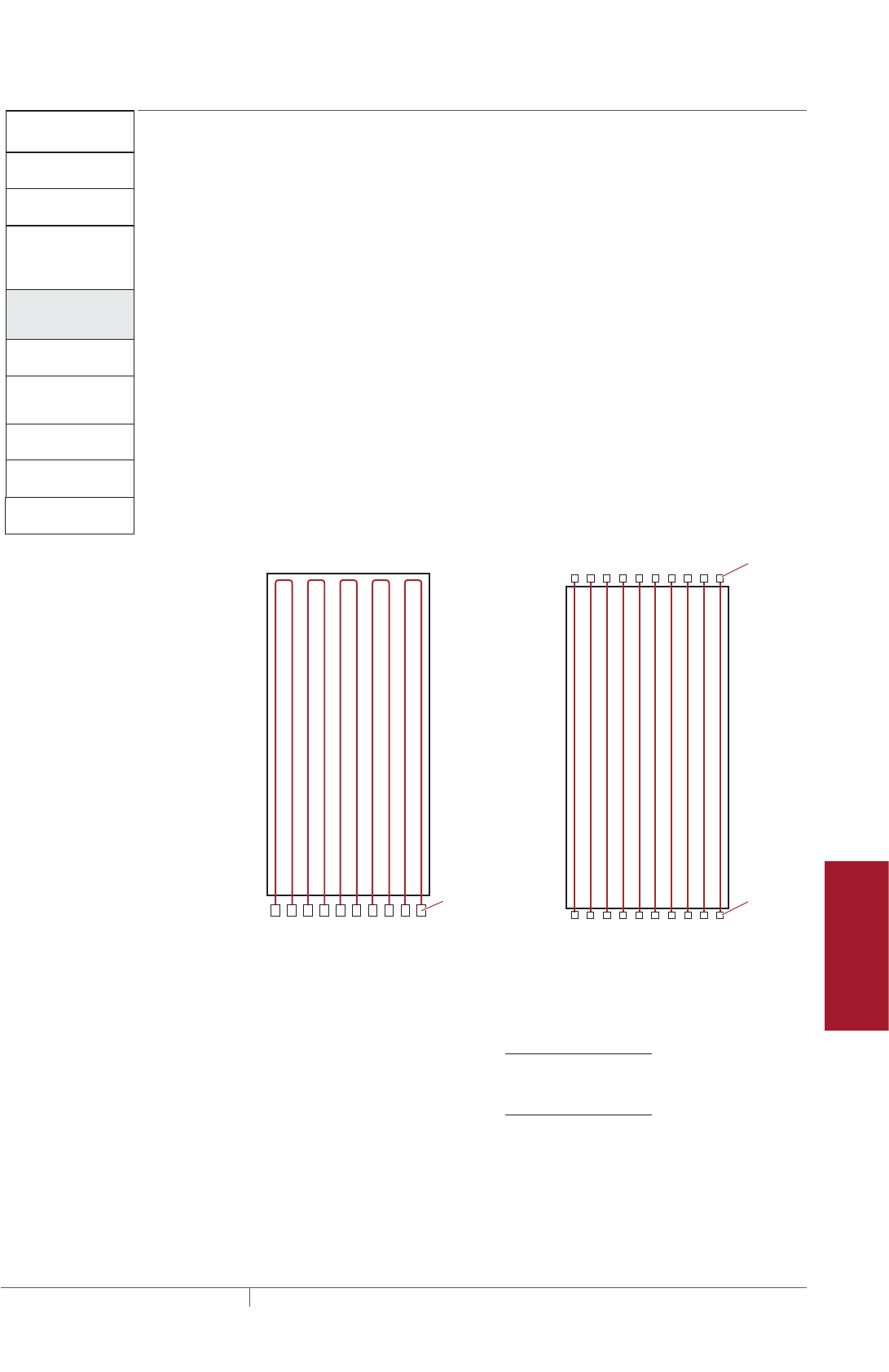
217THERMAL MANAGEMENT SOLUTIONS EN-FreezerFrostHeavePrevention-DG-H58139 11/13
Pipe Freeze Protection
and Flow Maintenance
Fire Sprinkler System
Freeze Protection
Roof and Gutter
De-Icing
Surface Snow
Melting – MI
Surface Snow
Melting – ElectroMelt
Freezer Frost
Heave Prevention
Floor Heating Technical Data
Sheets
Freezer Frost Heave
Prevention System
Design Steps (in Conduit)
1. Determine the
freezer configuration
2. Select the heating
cable
4. Determine the
heating cable
layout and length
5. Determine the
electrical parameters
6. Select the
connection kits
and accessories
7. Select the control
system
8. Select the power
distribution
9. Complete the Bill
of Materials
3. Determine
heating cable
conduit spacing
and freezer load
Step Determine the heating cable layout and length
STEP 4A FOR RAYSOL HEATING CABLE IN CONDUIT
Estimate number of conduit runs
To calculate the number of conduit runs and heating cable length from your scaled
drawing, refer to Fig. 9 and Fig. 10.
Define Side “A” as the side that is parallel to the conduit runs. Side “A” cannot be
greater than the maximum circuit length for RaySol (Table 5).
Define Side “B” as the side that is perpendicular to the conduit runs. Refer to Fig. 9
and Fig. 10 for examples of Side A and Side B.
Two basic types of heating cable layouts are used:
1. The hairpin layout (Fig. 9) is used both in smaller freezers where it results in
material and labor savings over the straight run layout (Fig. 10), and in other
freezers where only one wall of the freezer is accessible for mounting junction
boxes.
2. The straight run layout (Fig. 10) is used when the freezer dimension exceeds
one-half the maximum heating cable circuit length (insufficient heating cable
allowed for a run down and back).
Side A
Side B
Junction
boxes
Side A
Side B
Junction
boxes
Junction
boxes
Fig. 9 Hairpin layout Fig. 10 Straight run layout
Calculate the number of estimated conduit runs as follows:
Estimated number of conduit runs = Side B (ft) x 12
Conduit spacing (in)
Side B (m) x 100
Conduit spacing (cm)
Freezer Frost Heave Prevention Design

THERMAL MANAGEMENT SOLUTIONS
EN-FreezerFrostHeavePrevention-DG-H58139 11/13
218
Round the estimated number of conduit runs to the next larger whole number. For
example, if the result is 7.4, then 8 conduit runs are required. It may be necessary to
recalculate the conduit spacing following this step.
Example: RaySol heating cables in conduit
Side B length 40 ft (12.2 m) (from Step 1)
Conduit spacing 96 in (244 cm) (from Step 3)
Number of conduit runs
Side B x 12 / spacing (in) 40 ft x 12 / 96 in = 5
Side B x 100 / spacing (cm) 12.2 m x 100 / 244 cm = 5
Estimate the heating cable length required for conduit runs
Multiply the conduit length (Side A) by the number of conduit runs to determine the
length of heating cable required for the freezer area.
Heating cable length = Conduit length (Side A) x number of conduit runs
Example: RaySol heating cables in conduit (continued)
Heating cable length required 80 ft (24.4 m) x 5 = 400 ft (122 m)
Determine the maximum circuit length for the heating cable length and layout
For the appropriate supply voltage, use Table 5 to select the maximum circuit length
which is closest to, but greater than the length calculated. Select the smallest
appropriate circuit breaker size.
TABLE 5 RAYSOL MAXIMUM CIRCUIT LENGTHS IN FEET METERS
Supply voltage
120 V 208 V 240 V 277 V
Circuit
breaker size
(A)
ft m ft m ft m ft m
15 180 54.9 305 93.0 335 102.1 375 114.3
20 240 73.2 410 125.0 450 137.2 500 152.4
30 240 73.2 410 125.0 450 137.2 500 152.4
40 240 73.2 410 125.0 450 137.2 500 152.4
If the heating cable length required is greater than the maximum circuit length,
multiple circuits must be used.
When Side A x 2 is less than or equal to the maximum circuit length, then the conduit
run can be looped into the hairpin layout (Fig. 9). In a hairpin configuration, when you
have an odd number of conduit runs, one run will be a straight run as shown in Fig.
11.
FREEZER FROST HEAVE PREVENTION RAYSOL AND MI HEATING CABLE SYSTEM
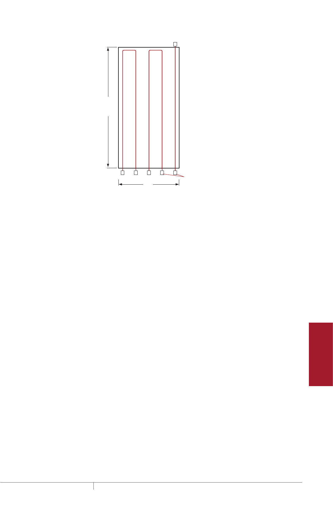
219THERMAL MANAGEMENT SOLUTIONS EN-FreezerFrostHeavePrevention-DG-H58139 11/13
Pipe Freeze Protection
and Flow Maintenance
Fire Sprinkler System
Freeze Protection
Roof and Gutter
De-Icing
Surface Snow
Melting – MI
Surface Snow
Melting – ElectroMelt
Freezer Frost
Heave Prevention
Floor Heating Technical Data
Sheets
80'
(24.4 m)
40'
(12.2 m)
Side A
Side B
Junction
boxes
Fig. 11 Layout for example (two hairpins and one straight run)
Example: RaySol heating cables in conduit (continued)
Heating cable length required 400 ft (122 m)
Supply voltage 208 V (from Step 1)
Maximum circuit length 410 ft (125 m) (from Table 5)
Number of circuits 1
Power supply One 20 A circuit breaker
Run in two hairpin loops and one straight run
(see Fig. 11)
Ground-Fault Protection
A 30-mA ground-fault protection device (GFPD) must be used to provide protection
from arcing or fire, and to comply with warranty requirements, agency certifications,
and national electrical codes. If the heating cable is improperly installed, or
physically damaged, sustained arcing or fire could result. If arcing does occur, the
fault current may be too low to trip conventional circuit breakers.
Freezer Frost Heave Prevention Design

THERMAL MANAGEMENT SOLUTIONS
EN-FreezerFrostHeavePrevention-DG-H58139 11/13
220
Determine additional heating cable allowance
Additional heating cable is required to make power connections and to route the
circuits to junction boxes. This extra heating cable shall not be considered when
determining the maximum heating cable length for circuit breaker sizing. In order to
estimate the total heating cable length, you will need to take the heating cable length
you already calculated, and then add heating cable allowances, as follows:
Estimated total heating cable length = Required heating cable + End allowances + Connection kit
allowances
TABLE 6 RAYSOL ADDITIONAL HEATING CABLE ALLOWANCE
Heating cable
allowance Description Hairpin layout Straight run layout
End allowances From end of conduit
to junction box
8 ft per hairpin
conduit
8 ft per straight run
conduit
Connection kit
allowances
Required to
assemble the
connection kit
4 ft per kit 4 ft per kit
The end allowance is the length of heating cable installed in protective conduit
between the heated floor and the power connection junction box. The connection
kit allowance (usually 2ft per end) is the length of heating cable inside the power
connection junction box.
Example: RaySol heating cables in conduit (continued)
Heating cable length required 400 ft (122 m)
End allowance 2 hairpin runs = 16 ft (4.9 m)
1 straight run = 8 ft (2.4 m)
Connection kit allowance 2 hairpin runs (2 FTC-XC kits) = 8 ft (2.4 m)
1 straight run (1 FTC-XC kit) = 4 ft (1.2 m)
Total heating cable allowance [16 ft (4.9 m) + 8 ft (2.4 m)] + [8 ft (2.4 m) +
4 ft (1.2 m)] = 36 ft (11 m)
Total heating cable length required 400 ft (122 m) + 36 ft (11 m)
= 436 ft (133 m) of RaySol-2
Locate the junction boxes for a RaySol heating cable system
The heating cable connects to the branch circuit wiring in a junction box using a
Raychem FTC-XC power connection and end seal kit. The heating cable is routed
from the subfloor to a junction box located above grade through protective conduit.
In most freezer frost heave prevention applications, separate junction boxes are used
for the power connection and end seal.
FREEZER FROST HEAVE PREVENTION RAYSOL AND MI HEATING CABLE SYSTEM

221THERMAL MANAGEMENT SOLUTIONS EN-FreezerFrostHeavePrevention-DG-H58139 11/13
Pipe Freeze Protection
and Flow Maintenance
Fire Sprinkler System
Freeze Protection
Roof and Gutter
De-Icing
Surface Snow
Melting – MI
Surface Snow
Melting – ElectroMelt
Freezer Frost
Heave Prevention
Floor Heating Technical Data
Sheets
Lay out heating cable runs, circuits, and junction boxes
After determining the approximate total length of heating cable, the number of
circuits, and the junction box location, do a trial layout. In making the trial layout,
follow these recommendations:
• Start and end each circuit in a junction box.
• Do not design more than one run of heating cable per conduit.
• Arrange the conduit so it uniformly covers the area to be heated.
• Maintain the design conduit spacing within 4 in (10 cm).
• Do not extend the heating cable beyond the room or area in which it originates.
• Do not cross expansion or other subfloor joints.
• Do not route the conduit closer than 4 in (10 cm) to the edge of the subfloor,
drains, anchors, or other material in the concrete.
• Do not exceed the maximum circuit length allowed on a branch circuit breaker as
given in Table 5.
• The maximum length of heating cable that can be pulled through conduit is
500feet (150 m). The maximum total degree of conduit turn is 360 degrees.
• When the combined lengths of two or more circuit runs are less than the maxi-
mum circuit length allowed, these runs can be combined in parallel on one circuit
breaker.
Record circuit information
Reconfigure the trial circuit layout until the design meets all of the previous
recommendations. Assign each circuit to a circuit breaker in a specific panel board
and record each circuit length.
Freezer Frost Heave Prevention Design
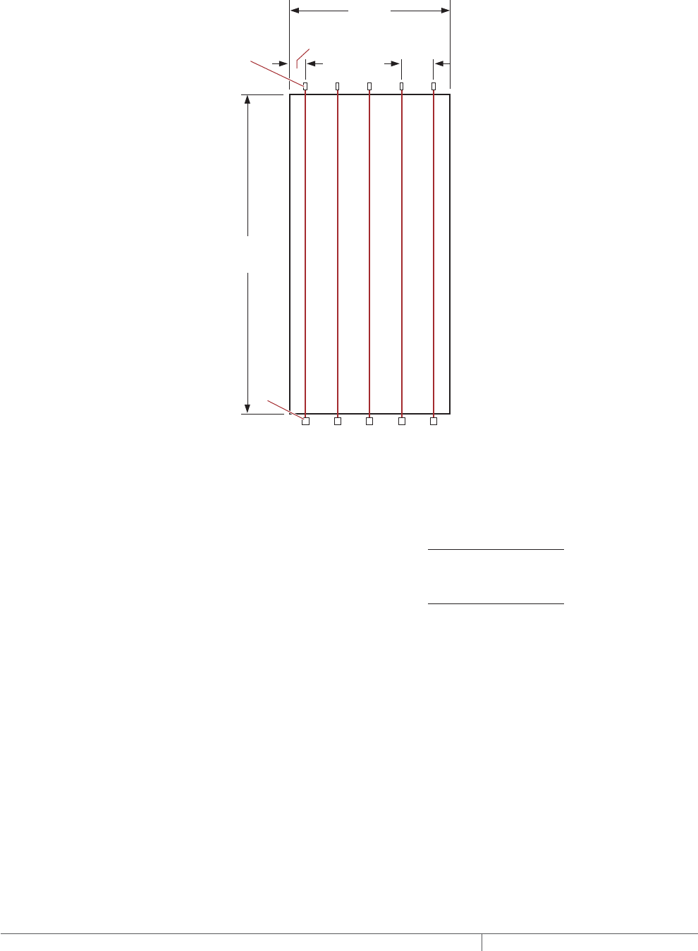
THERMAL MANAGEMENT SOLUTIONS
EN-FreezerFrostHeavePrevention-DG-H58139 11/13
222
STEP 4B FOR MI HEATING CABLE IN CONDUIT
Estimate number of conduit runs
MI cables in conduit can only be installed using the straight run layout shown in
Fig. 12.
Side A
Conduit cap
96"
(244 cm)
typ
48"
(122 cm)
typ
40'
(12.2 m)
80'
(24.4 m)
Side B
Junction
boxes
Fig. 12 Layout for straight run example
To calculate the number of conduit runs from your scaled drawing, refer to Fig. 12,
and calculate as follows:
Estimated number of conduit runs = Side B (ft) x 12
Conduit spacing (in)
Side B (m) x 100
Conduit spacing (cm)
Round the estimated number of conduit runs to the next larger whole number. For
example, if the result is 7.4, then 8 conduit runs are required. It may be necessary to
recalculate the conduit spacing following this step.
Note: If the heating cable was selected using the freezer width (Side B) in Step 2, use
Side A in the above formula.
FREEZER FROST HEAVE PREVENTION RAYSOL AND MI HEATING CABLE SYSTEM
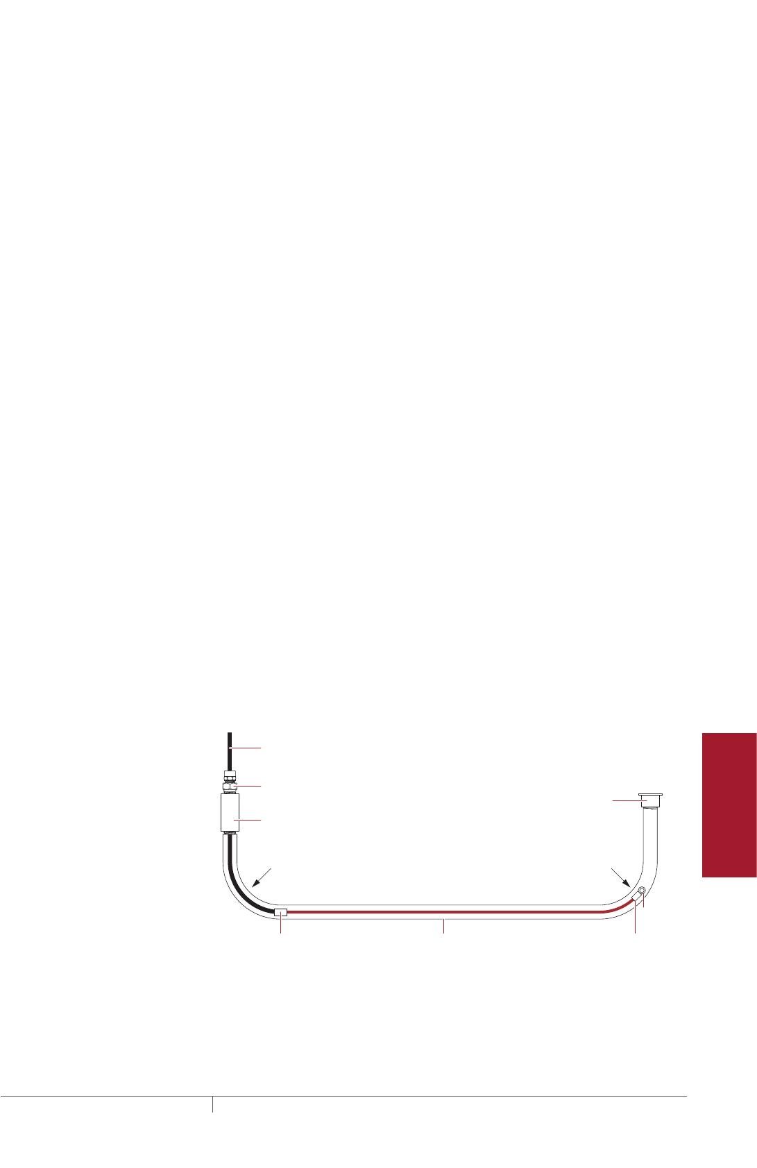
223THERMAL MANAGEMENT SOLUTIONS EN-FreezerFrostHeavePrevention-DG-H58139 11/13
Pipe Freeze Protection
and Flow Maintenance
Fire Sprinkler System
Freeze Protection
Roof and Gutter
De-Icing
Surface Snow
Melting – MI
Surface Snow
Melting – ElectroMelt
Freezer Frost
Heave Prevention
Floor Heating Technical Data
Sheets
Example: MI heating cables in conduit
Side B length 40 ft (12.2 m) (from Step 1)
Conduit spacing 96 in (244 cm) (from Step 3)
Number of conduit runs
Side B x 12 / spacing (in) 40 ft x 12 / 96 in = 5
Side B x 100 / spacing (cm) 12.2 m x 100 / 244 cm = 5
Determine the number of MI heating cables
Number of heating cables required = Number of conduit runs
Example: MI heating cables in conduit (continued)
Heating cable FFHPC30 (from Step 2)
Number of conduit runs 5
Number of heating cables required 5
Locate the junction boxes for an MI heating cable system
Pyrotenax MI heating cables are factory terminated with 7 ft (2.1 m) long non-heating
cold leads, making it possible to connect two or three heating cables to a single
junction box. A Pyrotenax D1297TERM4 may be used where two heating cables are
connected in parallel. A junction box is only required for the power connection end.
Lay out the MI heating cable runs, circuits, and junction boxes
After determining the number of heating cables required, the number of circuits, and
the junction box locations, do a trial layout. In making the trial layout, follow these
recommendations:
• The conduits must be laid out in straight runs as shown in Fig. 12.
• Where cable lengths exceed 50 ft (15.2 m), the conduit must be accessible from
both ends to allow long runs of cable to be pulled into the conduit.
• If it is necessary to stub-up the ends of the conduit, use a minimum 12 in (30 cm)
radius as shown in Fig. 13.
• Arrange the conduits so that they uniformly cover the area to be heated.
• Maintain the design conduit spacing within 4 in (10 cm).
• Do not cross expansion or other subfloor joints.
• Do not route the conduit closer than 4 in (10 cm) to the edge of the subfloor,
drains, anchors, or other material in the concrete.
Female
NPT fitting
Reversed
gland
Cold
lead
Conduit / pipeHot/cold joint End
cap
Pulling
eye
Conduit
cap
12 in (30 cm)
radius
12 in (30 cm)
radius
Fig. 13 Installation where conduit ends stub-up
Freezer Frost Heave Prevention Design

THERMAL MANAGEMENT SOLUTIONS
EN-FreezerFrostHeavePrevention-DG-H58139 11/13
224
Freezer Frost Heave
Prevention System
Design Steps (in Conduit)
1. Determine the
freezer configuration
2. Select the heating
cable
4. Determine the
heating cable
layout and length
5. Determine the
electrical parameters
6. Select the
connection kits
and accessories
7. Select the control
system
8. Select the power
distribution
9. Complete the Bill
of Materials
3. Determine
heating cable
conduit spacing
and freezer load
Step Determine the electrical parameters
5A FOR RAYSOL HEATING CABLE IN CONDUIT
Determine number of circuits
For RaySol, the circuit breaker sizing was determined in Step 4 using Table 5. Record
the number and ratings of the circuit breakers to be used on the worksheet.
A 30-mA ground-fault protection device (GFPD) must be used to provide protection
from arcing or fire, and to comply with warranty requirements, agency certifications,
and national electrical codes. If the heating cable is improperly installed, or
physically damaged, sustained arcing or fire could result. If arcing does occur, the
fault current may be too low to trip conventional circuit breakers.
WARNING: To minimize the danger of fire from sustained electrical arcing if
the heating cable is damaged or improperly installed, and to comply with the
requirements of Pentair Thermal Management, agency certifications, and national
electrical codes, ground-fault equipment protection must be used on each heating
cable branch circuit. Arcing may not be stopped by conventional circuit protection.
Determine transformer load
The total transformer load is the sum of the loads on all the circuit breakers in the
system.
Calculate the Circuit Breaker Load (CBL) as:
CBL (kW) = Circuit breaker rating (A) x 0.8 x Supply voltage
1000
Calculate the Total Transformer Load as follows:
Total Transformer Load (kW) = CBL1 + CBL2 + CBL3...+ CBLN
Example: RaySol heating cables in conduit
Circuit breaker size One 20 A circuit (from Step 4)
Supply voltage 208 V (from Step 1)
Circuit breaker load (20 A x 0.8 x 208) / 1000 = 3.3 kW
Total transformer load 3.3 kW
FREEZER FROST HEAVE PREVENTION RAYSOL AND MI HEATING CABLE SYSTEM

225THERMAL MANAGEMENT SOLUTIONS EN-FreezerFrostHeavePrevention-DG-H58139 11/13
Pipe Freeze Protection
and Flow Maintenance
Fire Sprinkler System
Freeze Protection
Roof and Gutter
De-Icing
Surface Snow
Melting – MI
Surface Snow
Melting – ElectroMelt
Freezer Frost
Heave Prevention
Floor Heating Technical Data
Sheets
5B FOR MI HEATING CABLE IN CONDUIT
For MI heating cable, the power output and current draw is shown in Table 3. Heating
cables may be individually connected to circuit breakers, but to reduce the number
of circuits, cables may be connected in parallel. When connecting heating cables
in parallel, total the individual heating cable currents to 80% of the circuit breaker
rating.
Determine number of circuits
Refer to Table 3 to determine the Amps for the selected heating cable. Next,
calculate the total Amps to determine the circuit breaker requirements, as follows:
Total Amps = Amps per cable x Number of heating cables required
From the Total Amps, determine the most appropriate circuit breaker size and
number of circuit breakers.
A 30-mA ground-fault protection device (GFPD) must be used to provide protection
from arcing or fire, and to comply with warranty requirements, agency certifications,
and national electrical codes. If the heating cable is improperly installed, or
physically damaged, sustained arcing or fire could result. If arcing does occur, the
fault current may be too low to trip conventional circuit breakers.
WARNING: To minimize the danger of fire from sustained electrical arcing if
the heating cable is damaged or improperly installed, and to comply with the
requirements of Pentair Thermal Management, agency certifications, and national
electrical codes, ground-fault equipment protection must be used on each heating
cable branch circuit. Arcing may not be stopped by conventional circuit protection.
Determine transformer load
The total transformer load is the sum of the loads in the system. Calculate the Total
Transformer Load as follows:
Transformer load (kW) = Cable1 (W) + Cable2 (W) + Cable3 (W)... + CableN (W)
1000
Example: MI heating cables in conduit
Amps/cable 2.3 A (from Table 3)
Total Amps 2.3 A x 5 = 11.5 A (5 cables wired in parallel on one
circuit)
Circuit breaker size 15 A circuit breaker, 80% loading 12 A
Number of circuit breakers 1
Cable power output 475 W (from Step 2)
Number of cables 5 (from Step 4)
Total Transformer load (475 W x 5) / 1000 = 2.4 kW
Record the number and ratings of the circuit breakers to be used and total
transformer load on the worksheet.
Freezer Frost Heave Prevention Design
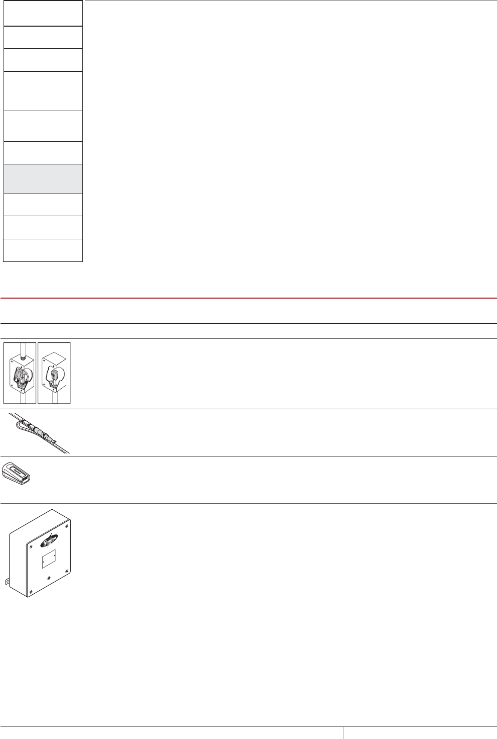
THERMAL MANAGEMENT SOLUTIONS
EN-FreezerFrostHeavePrevention-DG-H58139 11/13
226
Freezer Frost Heave
Prevention System
Design Steps (in Conduit)
1. Determine the
freezer configuration
2. Select the heating
cable
4. Determine the
heating cable
layout and length
5. Determine the
electrical parameters
6. Select the
connection kits
and accessories
7. Select the control
system
8. Select the power
distribution
9. Complete the Bill
of Materials
3. Determine
heating cable
conduit spacing
and freezer load
Step Select the connection kits and accessories
For RaySol systems, determine the number of junction boxes, power connections,
end seals and splice kits required.
• Hairpin and straight layouts have one junction box per conduit end (see Fig. 9 and
Fig. 10).
For MI systems, determine the number of junction boxes required.
• Straight run layout has one junction box per conduit run (see Fig. 12 for MI cable).
SELECT JUNCTION BOX
For RaySol and MI cable, use a UL Listed and/or CSA Certified junction box that is
suitable for the location. Use a box with minimum internal volume of 16 cubic inches
if the box is metallic and 19 cubic inches if the box is not metallic. Metal junction
boxes, such as the Pyrotenax D1297TERM4, are recommended for MI cable.
TABLE 7 CONNECTION KITS AND ACCESSORIES
Catalog
number Description
Standard
packaging Usage
RaySol Connection Kits
FTC-XC Power connection and end seal.
(Junction box not included)
1 1 per conduit run
FTC-HST Low-profile splice/tee 2 As required (for use
inside intermediate
pull box or cable
tray)
RayClic-E Extra end seal 1 Replacement end
seal
Accessories
D1297TERM4 A cast aluminum junction box (NEMA 3) for installa-
tion in nonhazardous and CID2 locations. Three 1/2-in
NPT entries on bottom, provided with plugs. Includes
4-pole terminal block (CSA - 600 V, 65 A, 18 - 6 AWG;
UL - 300 V, 65 A, 18 - 6 AWG). External mounting feet.
CSA approved for Class I, Div. 2, Groups A, B, C, and D.
(for MI only)
Enclosure dimensions: 6 in x 6 in x 4 in (150 mm x
150 mm x 100 mm).
1 For MI systems
only
FREEZER FROST HEAVE PREVENTION RAYSOL AND MI HEATING CABLE SYSTEM
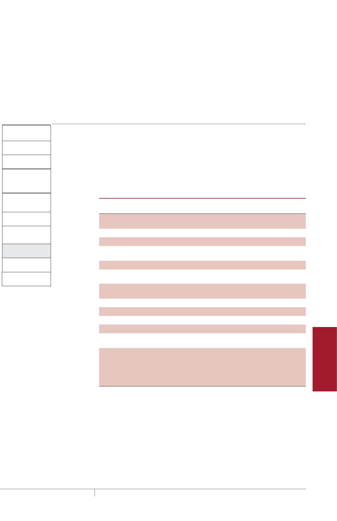
227THERMAL MANAGEMENT SOLUTIONS EN-FreezerFrostHeavePrevention-DG-H58139 11/13
Pipe Freeze Protection
and Flow Maintenance
Fire Sprinkler System
Freeze Protection
Roof and Gutter
De-Icing
Surface Snow
Melting – MI
Surface Snow
Melting – ElectroMelt
Freezer Frost
Heave Prevention
Floor Heating Technical Data
Sheets
Example: RaySol heating cables in conduit
Power connection and end seal kit FTC-XC
Quantity 3
Junction box Contractor supplied
Quantity 6
Example: MI heating cables in conduit
Junction box D1297TERM
Quantity 5
Freezer Frost Heave
Prevention System
Design Steps (in Conduit)
1. Determine the
freezer configuration
2. Select the heating
cable
4. Determine the
heating cable
layout and length
5. Determine the
electrical parameters
6. Select the
connection kits
and accessories
7. Select the control
system
8. Select the power
distribution
9. Complete the Bill
of Materials
3. Determine
heating cable
conduit spacing
and freezer load
Step Select the control system
The following control systems are suitable for both RaySol and MI heating cable frost
heave protection systems. For MI cable, a temperature controller must be used to
maintain the subfloor temperature at 40°F (5°C). For RaySol or MI heating cable
installations where temperature control and temperature monitoring is desired, a
Pentair Thermal Management DigiTraceC910-485 or DigiTrace ACS-30 controller is
recommended.
TABLE 8 TEMPERATURE CONTROL OPTIONS
Features
DigiTrace
ECW-GF
DigiTrace
C910-485 2
DigiTrace
ACS-30
Number of heating
cable circuits
Single Single Multiple
Sensor Thermistor RTD ¹See data sheet
Sensor length 25 ft Varies "
Set point range 32°F to 200°F
(0°C to 93°C)
–0°F to 200°F
(–18°C to 93°C)
"
Enclosure NEMA 4X NEMA 4X "
Deadband 2°F to 10°F
(2°C to 6°C)
1°F to 10°F
(1°C to 6°C)
"
Enclosure limits –40°F to 140°F
(–40°C to 60°C)
–40°F to 140°F
(–40°C to 60°C)
"
Switch rating 30 A 30 A "
Switch type DPST DPST "
Electrical rating 100–277 V 100–277 V "
Approvals c-UL-us c-CSA-us "
Ground-fault
protection
30 mA fixed 20 mA to 100 mA
(adjustable)
"
Alarm outputs
AC relay 2 A at 277 Vac 100–277 V,
0.75 A max.
"
Dry contact relay 2 A at 48 Vdc 48 Vac/dc, 500 mA
max.
"
¹ Ordered separately
² The C910-485 is available to provide RS-485 communication capability. Connect to the
BMS using DigiTrace ProtoNode multi-protocol gateways
Freezer Frost Heave Prevention Design
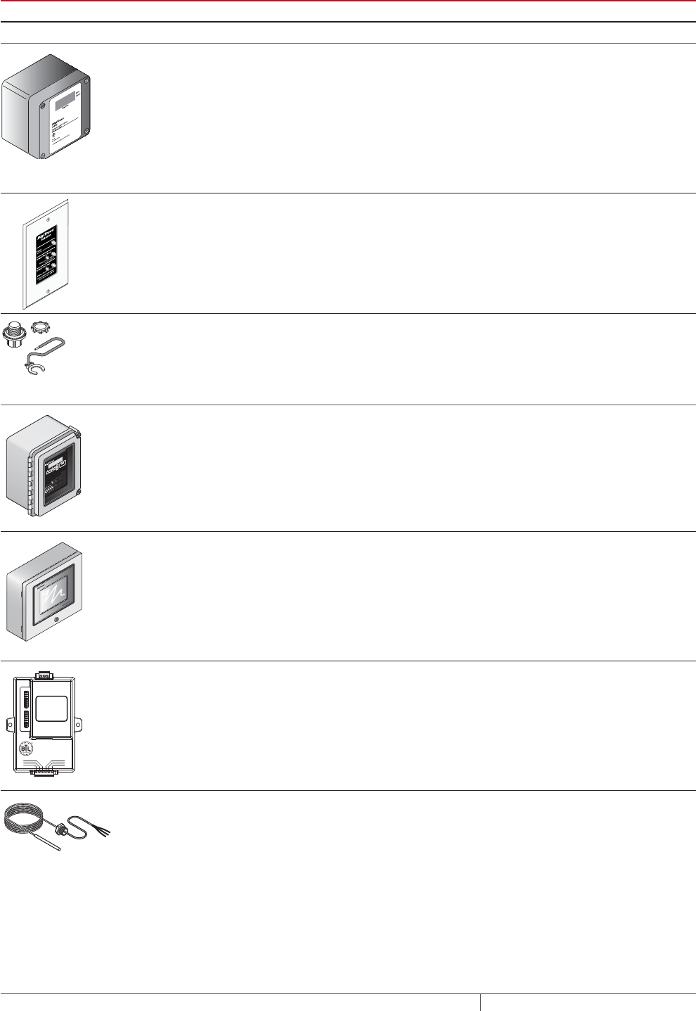
THERMAL MANAGEMENT SOLUTIONS
EN-FreezerFrostHeavePrevention-DG-H58139 11/13
228
TABLE 9 CONTROL SYSTEMS
Catalog number Description
Electronic thermostats and accessories
ECW-GF Electronic ambient sensing controller with 30-mA ground-fault protection. The control-
ler can be programmed to maintain temperatures up to 200°F (93°C) at voltages from
100 to 277 V and can switch current up to 30 Amperes. The ECW-GF is complete with
a 25-ft (7.6-m) temperature sensor and is housed in a Type 4X rated enclosure. The
controller features an AC/DC dry alarm contact relay.
An optional ground-fault display panel (ECW-GF-DP) can be added to provide ground-
fault or alarm indication in applications where the controller is mounted in inaccessible
locations.
ECW-GF-DP An optional remote display panel (ECW-GF-DP) can be added to provide ground-fault
or alarm indication in applications where the controller is mounted in inaccessible
locations.
MI-GROUND-KIT Grounding kit for nonmetallic enclosures (for MI only)
Electronic controllers and sensors
C910-485 The DigiTrace C910-485 is a compact, full featured, microprocessor-based, single-point
commercial heating cable controller. The C910-485 provides control and monitoring
of electrical heating cable circuits for commercial heating applications, with built-in
ground-fault protection. The C910-485 can be set to monitor and alarm for high and low
temperature, high and low current, ground-fault level, and voltage. Communications
modules are available for remote control and configuration.
ACS-UIT2
ACS-PCM2-5
The DigiTrace ACS-30 Advanced Commercial Control System is a multipoint electronic
control and monitoring system for heat-tracing used in various commercial applica-
tions such as pipe freeze protection, roof and gutter de-icing, surface snow melting, hot
water temperature maintenance and floor heating. The DigiTrace ACS-30 system can
control up to 260 circuits with multiple networked ACS-PCM2-5 panels, with a single
ACS-UIT2 user interface terminal. The ACS-PCM2-5 panel can directly control up to
5 individual heat-tracing circuits using electro-mechanical relays rated at 30 A up to
277 V.
By FieldServer Technologies
www.ProtoCessor.com
PROTOCESSOR
SERIAL ETHERNET
PROTONODE
FRAME GND
- PWR
+PWR
RS 485+
RS 485 -
RS 485 GND
S3
S2
S1
S0
B3
B2
B1
B0
A7
A6
A5
A4
A3
A2
A1
A0
ProtoNode-LER
ProtoNode-RER
The DigiTrace ProtoNode is an external, high performance multi-protocol gateway for
customers needing protocol translation between Building Management Systems (BMS)
and the DigiTrace ACS-30 or C910-485 controllers.
The ProtoNode-LER is for LonWorks® systems; and the ProtoNode-RER is for
BACnet® or Metasys® N2 systems.
RTD10CS
RTD-200
RTD50CS
Stainless steel jacketed three-wire RTD (Resistance Temperature Detector) used with
DigiTrace C910-485 and ACS-30 controllers.
RTD10CS: 10-ft (3 m) flexible armor, with 18-in (457 mm) lead wire and 1/2-inch NPT
bushing.
RTD-200: 6-ft (1.8 m) fluoropolymer with 1/2-in NPT bushing.
RTD50CS: 50-ft (3 m) flexible armor with 1/2-in NPT bushing
Example: RaySol and MI heating cables in conduit
Electronic thermostat DigiTrace C910-485
Quantity 1
FREEZER FROST HEAVE PREVENTION RAYSOL AND MI HEATING CABLE SYSTEM
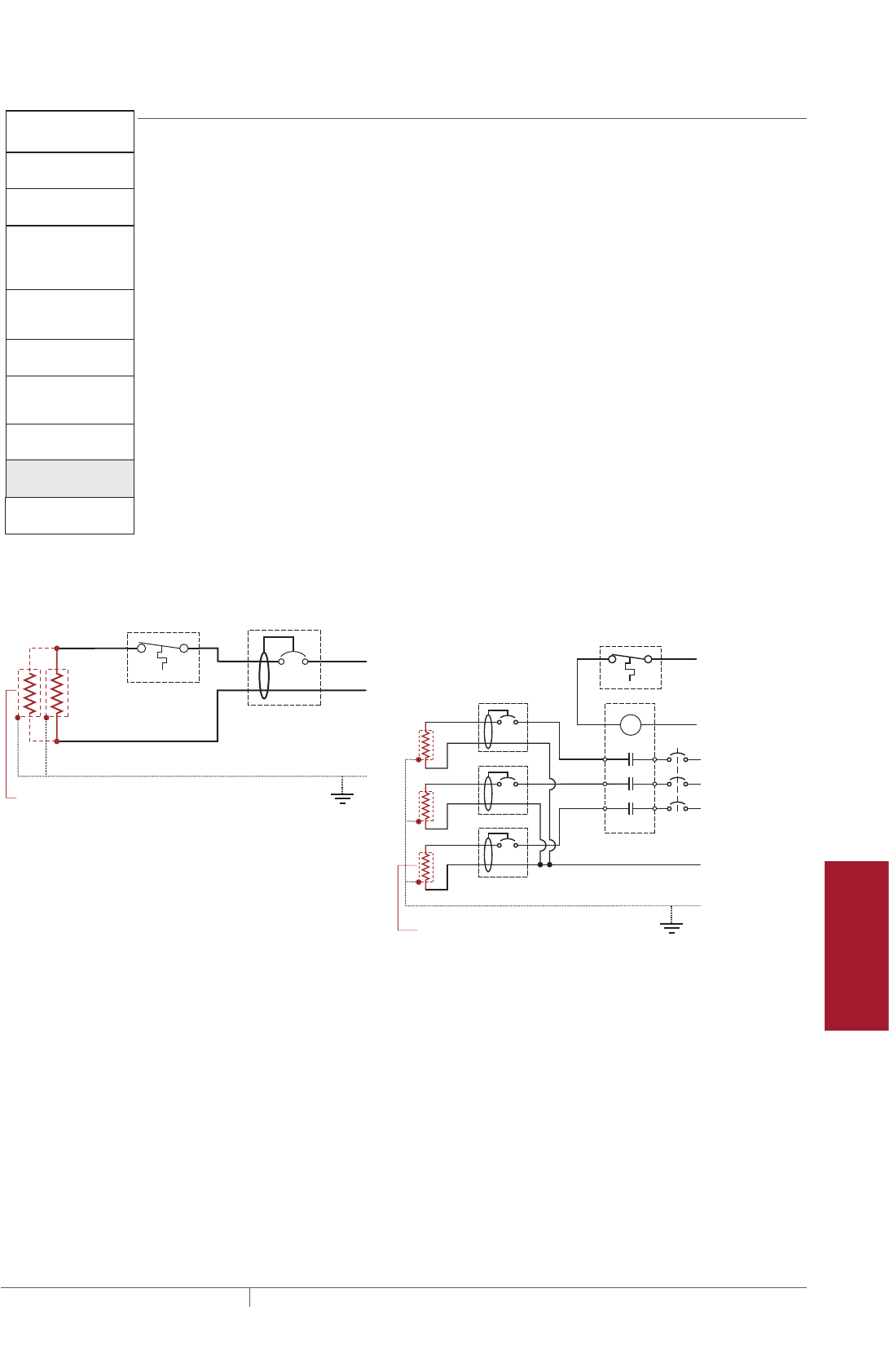
229THERMAL MANAGEMENT SOLUTIONS EN-FreezerFrostHeavePrevention-DG-H58139 11/13
Pipe Freeze Protection
and Flow Maintenance
Fire Sprinkler System
Freeze Protection
Roof and Gutter
De-Icing
Surface Snow
Melting – MI
Surface Snow
Melting – ElectroMelt
Freezer Frost
Heave Prevention
Floor Heating Technical Data
Sheets
Freezer Frost Heave
Prevention System
Design Steps (in Conduit)
1. Determine the
freezer configuration
2. Select the heating
cable
4. Determine the
heating cable
layout and length
5. Determine the
electrical parameters
6. Select the
connection kits
and accessories
7. Select the control
system
8. Select the power
distribution
9. Complete the Bill
of Materials
3. Determine
heating cable
conduit spacing
and freezer load
Step Select the power distribution
FOR RAYSOL AND MI HEATING CABLE IN CONDUIT
Power to the heating cables can be provided in several ways:
• Directly to the power connection kits (RaySol only)
• Directly through the temperature controller
• Through external contactors or through HTPG power distribution panels
Single circuit control
Heating cable circuits that do not exceed the current rating of the selected controller
can be switched directly (Fig. 14). When the total electrical load exceeds the rating of
the controller, an external contactor is required.
RaySol systems without temperature control can be connected directly to the power
connection kits from the ground-fault circuit breakers in subpanels.
Group control
If the controller will activate multiple circuits (group control) then an external
contactor must be used (Fig. 14).
Single circuit control Group control
Temperature
controller 1-pole
GFEP breaker
1
N
G
Heating
cable
ø
øsupply
C
Temperature
controller
Contactor
1-pole
GFEP breaker
N
G
ø2
ø1
ø3
3-phase 4-wire
supply (WYE)
3-pole main
breaker
ø
ø
1 supply
N
Heating cable
sheath, braid
or ground
Heating cable
sheath, braid
or ground
Fig. 14 Single circuit and group control
Freezer Frost Heave Prevention Design
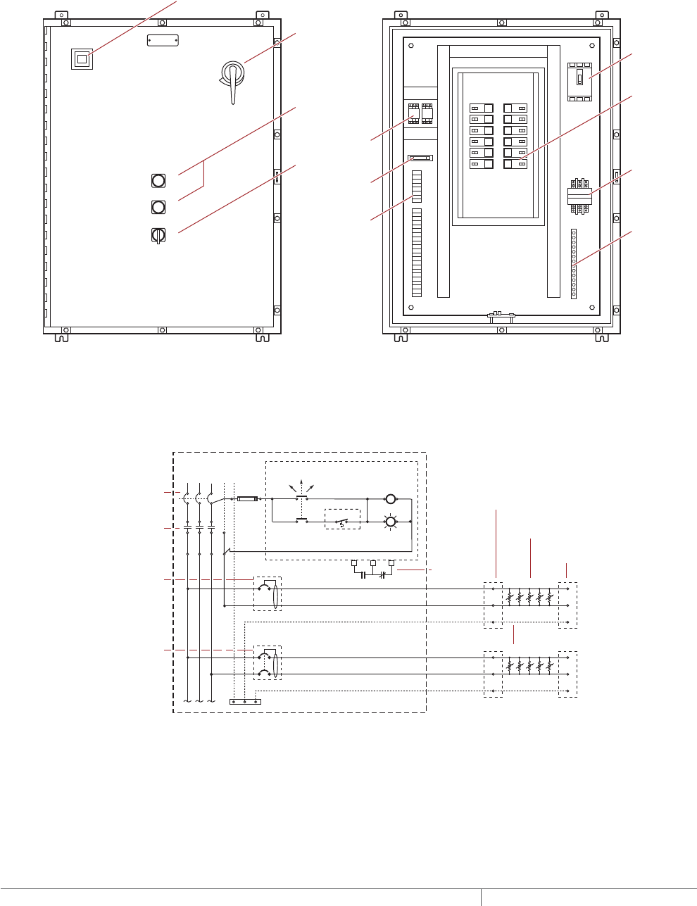
THERMAL MANAGEMENT SOLUTIONS
EN-FreezerFrostHeavePrevention-DG-H58139 11/13
230
Large systems with many circuits should use an HTPG power distribution panel. The
HTPG is a dedicated power-distribution, control, ground-fault protection, monitoring,
and alarm panel for freeze protection and broad temperature-maintenance
heat-tracing applications. This enclosure contains an assembled circuit-breaker
panelboard. Panels are equipped with ground-fault circuit breakers with or
without alarm contacts. The group control package allows the system to operate
automatically in conjunction with a temperature control system.
A
COMMON ALARM
PUSH TO ACKNOWLEDGE
HAND/OFF/AUTO
1
2
3
4
5
6
7
8
9
10
11
12
Main circuit
breaker
Main
contactor
Distribution
panelboard
Fuse holder
C
POWER ON
TB 1
TB 2
ARR
Ground
bus bar
Selector switch
Alarm relay
(optional)
Terminals
(optional)
Push button for
light testing
Alarm horn (optional)
Alarm option shown above
Door
disconnect
(optional)
Fig. 15 HTPG power distribution panel
N
Ø1
Three-pole main
circuit breaker
Panel
energized
Contactor
coil
C NC
External controller/
thermostat*
Hand Auto
Off
Three-pole main
contactor
Ø3
Ø2
Power
connection
Heating cable
One-pole with 30-mA
ground-fault trip
(120/277 Vac)
Two-pole with 30-mA
ground-fault trip
(208/240 Vac)
Alarm
remote
annunciation
(with alarm
option)
Heating
cable
circuit
Heating
cable
circuit
G
End seal
Heating cable shealth, braid or ground
Three-phase, 4 wire supply (Wye)
Fig. 16 HTPG power schematic
FREEZER FROST HEAVE PREVENTION RAYSOL AND MI HEATING CABLE SYSTEM

231THERMAL MANAGEMENT SOLUTIONS EN-FreezerFrostHeavePrevention-DG-H58139 11/13
Pipe Freeze Protection
and Flow Maintenance
Fire Sprinkler System
Freeze Protection
Roof and Gutter
De-Icing
Surface Snow
Melting – MI
Surface Snow
Melting – ElectroMelt
Freezer Frost
Heave Prevention
Floor Heating Technical Data
Sheets
TABLE 10 POWER DISTRIBUTION
Catalog number Description
Power Distribution and Control Panels
A
COMMON ALARM
PUSH TO ACKNOWLEDGE
HAND/OFF/AUTO
C
POWER ON
HTPG Heat-tracing power distribution panel with ground-fault and monitoring for group
control.
Contactors
E104 Three-pole, 100 A per pole, 600 V maximum contactor housed in UL Listed, CSA Certi-
fied, NEMA 4X enclosure with two 1-inch conduit entries. When ordering, select coil
voltage (110–120, 208–240, 277 V).
Enclosure dimensions: 13-1/2 in x 9-1/5 in x 6-11/16 in (343 mm x 234 mm x 170 mm).
E304 Three-pole, 40 A per pole, 600 V maximum contactor housed in UL Listed, CSA Certified
NEMA 4X enclosure with two 1-inch conduit entries. When ordering, select coil voltage
(110–120, 208–240, 277 V).
Enclosure dimensions: 9-1/2 in x 7-1/5 in x 6-11/16 in (241 mm x 183 mm x 170 mm).
Example: RaySol and MI heating cables in conduit
Single circuit control No contactor required
Freezer Frost Heave
Prevention System
Design Steps (in Conduit)
1. Determine the
freezer configuration
2. Select the heating
cable
4. Determine the
heating cable
layout and length
5. Determine the
electrical parameters
6. Select the
connection kits
and accessories
7. Select the control
system
8. Select the power
distribution
9. Complete the Bill
of Materials
3. Determine
heating cable
conduit spacing
and freezer load
Step Complete the Bill of Materials
If you used the Design Worksheet to document all your design parameters, you
should have all the details necessary complete your Bill of Materials.
Freezer Frost Heave Prevention Design

THERMAL MANAGEMENT SOLUTIONS
EN-FreezerFrostHeavePrevention-DG-H58139 11/13
232
Design Step by Step MI Heating Cables Directly Embedded
Embedding cables directly in sand (recommended), concrete, or compacted
fill subfloors has the advantage of simpler installation and reduced costs. The
number of electrical circuits can be minimized considerably compared to a similar
installation using conduit. If embedded in a concrete subfloor below the insulation,
the cable must not cross any joints in the subfloor.
Follow these steps to design your system:
Determine the freezer configuration
Determine heat loss and freezer load
Select the heating cable, layout and length
Determine the heating cable spacing
Determine the electrical parameters
Select the accessories
Select the control system
Select the power distribution
Complete the Bill of Materials
The “MI Cables Directly Embedded Freezer Frost Heave Prevention Design
Worksheet” on page256 is included to help you document the project parameters
that you will need for your project’s Bill of Materials.
FREEZER FROST HEAVE PREVENTION RAYSOL AND MI HEATING CABLE SYSTEM

233THERMAL MANAGEMENT SOLUTIONS EN-FreezerFrostHeavePrevention-DG-H58139 11/13
Pipe Freeze Protection
and Flow Maintenance
Fire Sprinkler System
Freeze Protection
Roof and Gutter
De-Icing
Surface Snow
Melting – MI
Surface Snow
Melting – ElectroMelt
Freezer Frost
Heave Prevention
Floor Heating Technical Data
Sheets
Freezer Frost Heave
Prevention System
Design Steps
(Embedded)
1. Determine the
freezer configuration
2. Determine heat loss
and freezer load
4. Determine the
heating cable spacing
5. Determine the
electrical parameters
6. Select the
accessories
7. Select the control
system
8. Select the power
distribution
9. Complete the Bill
of Materials
3. Select the heating
cable, layout and
length
Step Determine the freezer configuration
GATHERING INFORMATION
The following information is required to complete the freezer frost heave prevention
system design.
• Size and layout of freezer or ice arena
• Freezer operating temperature
• Insulation R-value
• Supply voltage and phase
• Control requirements
PREPARE SCALE DRAWING
Draw to scale the floor area to be heated. Carefully note the limits of the area to be
heated. Show all concrete joints on the drawing and note the location and size of
obstacles, such as floor drains, pipe penetrations, columns, fixtures, and voltage
supply location.
Side A
20'
(6.1 m)
Side B
40'
(12.2 m)
Fig. 17 Typical freezer example – single-phase
DETERMINE FREEZER OPERATING TEMPERATURE
Determine the temperature at which your freezer operates. If it operates at more
than one temperature, or if the operating temperature may be changed in the future,
base the design on the lowest anticipated operating temperature.
RECORD INSULATION RVALUE
The insulation R-value is the thermal resistance of the floor’s insulation. Normally
the R-value will be printed on the insulation material. If that is not the case, you can
calculate it by dividing the insulation thickness in inches by the insulation thermal
conductivity.
Freezer Frost Heave Prevention Design

THERMAL MANAGEMENT SOLUTIONS
EN-FreezerFrostHeavePrevention-DG-H58139 11/13
234
Example: MI heating cables directly embedded – Single-phase
Area 40 ft x 20 ft = 800 ft2
(12.2 m x 6.1 m = 74 m²)
Freezer operating temperature –30°F (–34°C)
Insulation R-value R-20 (20 ft²·°F·hr/Btu)
Supply voltage 208 V, single-phase
Example: MI heating cables directly embedded – Three-phase
Area 80 ft x 80 ft = 6400 ft²
(24.4 m x 24.4 m = 595 m²)
Freezer operating temperature –20°F (–29°C)
Insulation R-value R-20 (20 ft²·°F·hr/Btu)
Supply voltage 208 V, three-phase
Freezer Frost Heave
Prevention System
Design Steps
(Embedded)
1. Determine the
freezer configuration
2. Determine heat loss
and freezer load
4. Determine the
heating cable spacing
5. Determine the
electrical parameters
6. Select the
accessories
7. Select the control
system
8. Select the power
distribution
9. Complete the Bill
of Materials
3. Select the heating
cable, layout and
length
Step Determine heat loss and freezer load
In Table 11, we have calculated the heat loss for directly embedded MI heating cable
systems based on the freezer temperatures and the floor insulation R-values; from
this table, you will select your design power and freezer load. If your calculated
R-value or freezer operating temperature does not match the values in the table, use
the values that give the higher design power.
Within each cell, there are two numbers; design power and freezer load. Freezer
load is the additional cooling load imposed on the cooling system by the freezer frost
heave prevention heating cable. It is the heat transferred through the insulation into
the freezer, expressed in W/ft² (W/m²) of floor area.
FREEZER FROST HEAVE PREVENTION RAYSOL AND MI HEATING CABLE SYSTEM

235THERMAL MANAGEMENT SOLUTIONS EN-FreezerFrostHeavePrevention-DG-H58139 11/13
Pipe Freeze Protection
and Flow Maintenance
Fire Sprinkler System
Freeze Protection
Roof and Gutter
De-Icing
Surface Snow
Melting – MI
Surface Snow
Melting – ElectroMelt
Freezer Frost
Heave Prevention
Floor Heating Technical Data
Sheets
TABLE 11 MI HEATING CABLE: DESIGN POWER REQUIREMENT AND FREEZER LOAD BASED ON 40°F 5°C CONTROL
Freezer operating
temperature
Floor insulation R-value (ft2·°F·hr/Btu)
R-10 R-20 R-30 R-40
30°F (–1°C) Design power W/ft² (W/m²) 0.5 (5.4) 0.2 (2.2) 0.1 (1.1) 0.1 (1.1)
Freezer load W/ft² (W/m²) 0.7 (7.5) 0.4 (4.3) 0.3 (3.2) 0.3 (3.2)
20°F (–7°C) Design power W/ft² (W/m²) 0.6 (6.5) 0.4 (4.3) 0.2 (2.2) 0.1 (1.1)
Freezer load W/ft² (W/m²) 0.8 (8.6) 0.5 (5.4) 0.4 (4.3) 0.3 (3.2)
10°F (–12°C) Design power W/ft² (W/m²) 0.9 (9.7) 0.6 (6.5) 0.3 (3.2) 0.2 (2.2)
Freezer load W/ft² (W/m²) 1.0 (10.8) 0.6 (6.5) 0.4 (4.3) 0.3 (3.2)
0°F (–18°C) Design power W/ft² (W/m²) 1.1 (11.8) 0.7 (7.5) 0.5 (5.4) 0.3 (3.2)
Freezer load W/ft² (W/m²) 1.3 (14.0) 0.8 (8.6) 0.5 (5.4) 0.4 (4.3)
–10°F (–23°C) Design power W/ft² (W/m²) 1.4 (15.1) 0.8 (8.6) 0.6 (6.5) 0.4 (4.3)
Freezer load W/ft² (W/m²) 1.5 (16.1) 0.8 (8.6) 0.6 (6.5) 0.5 (5.4)
–20°F (–29°C) Design power W/ft² (W/m²) 1.6 (17.2) 0.9 (9.7) 0.7 (7.5) 0.5 (5.4)
Freezer load W/ft² (W/m²) 1.8 (19.4) 1.0 (10.8) 0.7 (7.5) 0.6 (6.5)
–30°F (–34°C) Design power W/ft² (W/m²) 1.7 (18.3) 1.1 (11.8) 0.8 (8.6) 0.6 (6.5)
Freezer load W/ft² (W/m²) 2.0 (21.5) 1.1 (11.8) 0.8 (8.6) 0.6 (6.5)
–40°F (–40°C) Design power W/ft² (W/m²) 2.0 (21.5) 1.2 (12.9) 0.8 (8.6) 0.7 (7.5)
Freezer load W/ft² (W/m²) 2.3 (24.7) 1.2 (12.9) 0.8 (8.6) 0.7 (7.5)
Example: MI heating cables directly embedded – Single-phase
Freezer operating temperature –30°F (–34°C) (from Step 1)
Insulation R-value R-20 (20 ft²·°F·hr/Btu) (from Step 1)
Design power 1.1 W/ft² (11.8 W/m²)
Freezer load 1.1 W/ft² (11.8 W/m²)
Example: MI heating cables directly embedded – Three-phase
Freezer operating temperature –20°F (–29°C) (from Step 1)
Insulation R-value R-20 (20 ft²·°F·hr/Btu) (from Step 1)
Design power 0.9 W/ft² (9.7 W/m²)
Freezer load 1.0 W/ft² (10.8 W/m²)
Freezer Frost Heave Prevention Design

THERMAL MANAGEMENT SOLUTIONS
EN-FreezerFrostHeavePrevention-DG-H58139 11/13
236
Freezer Frost Heave
Prevention System
Design Steps
(Embedded)
1. Determine the
freezer configuration
2. Determine heat loss
and freezer load
4. Determine the
heating cable spacing
5. Determine the
electrical parameters
6. Select the
accessories
7. Select the control
system
8. Select the power
distribution
9. Complete the Bill
of Materials
3. Select the heating
cable, layout and
length
Step Select the heating cable, layout and length
To select the correct MI heating cable for the heated area, you must determine the
wattage required for the area or subsection area.
For small freezers, one heating cable may be sufficient. For large freezers, it may be
necessary to divide the freezer into two or more equal subsection areas. To balance
the load in a three-phase circuit, three cables will be required, or a multiple of three
cables when more than one three-phase circuit is required. If the heating cables are
to be embedded in a concrete subfloor, divide the area so that the heating cables will
not cross any joints in the subfloor.
The heating cables shown in Table 12 are general purpose cables and may be used
for a variety of applications depending on the supply voltage; the heating cables in
Table 13 have been optimized for frost heave prevention applications. If assistance
is required to select heating cables for irregular shaped areas or applications
outside the scope of this design guide, contact your Pentair Thermal Management
representative for assistance in designing a custom heating cable.
SINGLEPHASE SUPPLY
Small freezer areas require only one heating cable. Large freezer areas may require
two or more heating cables.
• Divide large freezer areas into equal subsection areas, if possible.
• Calculate the power required for the total area (small freezers) or for each sub-
section area (large freezers) by multiplying the design power
(from Table 11) by the total area or subsection area.
Power required = Design power x Total area (or Subsection area)
Simply select the heating cable from Table 12 or Table 13 based on the total area
or subsection area. Under the appropriate voltage, make sure that the total area
or subsection area falls within the minimum and maximum range of the “Area
coverage” columns and verify that the “Cable wattage” shown directly across from
the “Area coverage” is equal to or higher than the calculated “Power required” for
the total area or subsection area (see example following).
Note: If two or more cables in the Tables meet the requirements, use the cable
with the lower wattage.
FREEZER FROST HEAVE PREVENTION RAYSOL AND MI HEATING CABLE SYSTEM

237THERMAL MANAGEMENT SOLUTIONS EN-FreezerFrostHeavePrevention-DG-H58139 11/13
Pipe Freeze Protection
and Flow Maintenance
Fire Sprinkler System
Freeze Protection
Roof and Gutter
De-Icing
Surface Snow
Melting – MI
Surface Snow
Melting – ElectroMelt
Freezer Frost
Heave Prevention
Floor Heating Technical Data
Sheets
In cases where the freezer area has been divided into equal subsections, select the
appropriate number of heating cables. Where heating cables are directly embedded
in concrete subfloors, calculate the wattage required for each area bounded by joints
in the subfloor and select an appropriate cable for each area.
20'
(6.1 m)
40'
(12.2 m)
1Ø Supply Junction box
Fig. 18 Single-phase layout
Example: MI heating cables directly embedded – Single-phase
Area 800 ft² (74 m²) (See Fig. 18)
Design power 1.1 W/ft² (11.8 W/m²) (from Step 2)
Power required Design power x Area = 1.1 W/ft² x 800 ft² = 880 W
(11.8 W/m² x 74 m² = 880 W)
Supply voltage 208 V, single-phase (from Step 1)
Catalog number SUB19
Cable wattage 885 W
Heated length 245 ft (74.7 m)
Quantity 1
Freezer Frost Heave Prevention Design
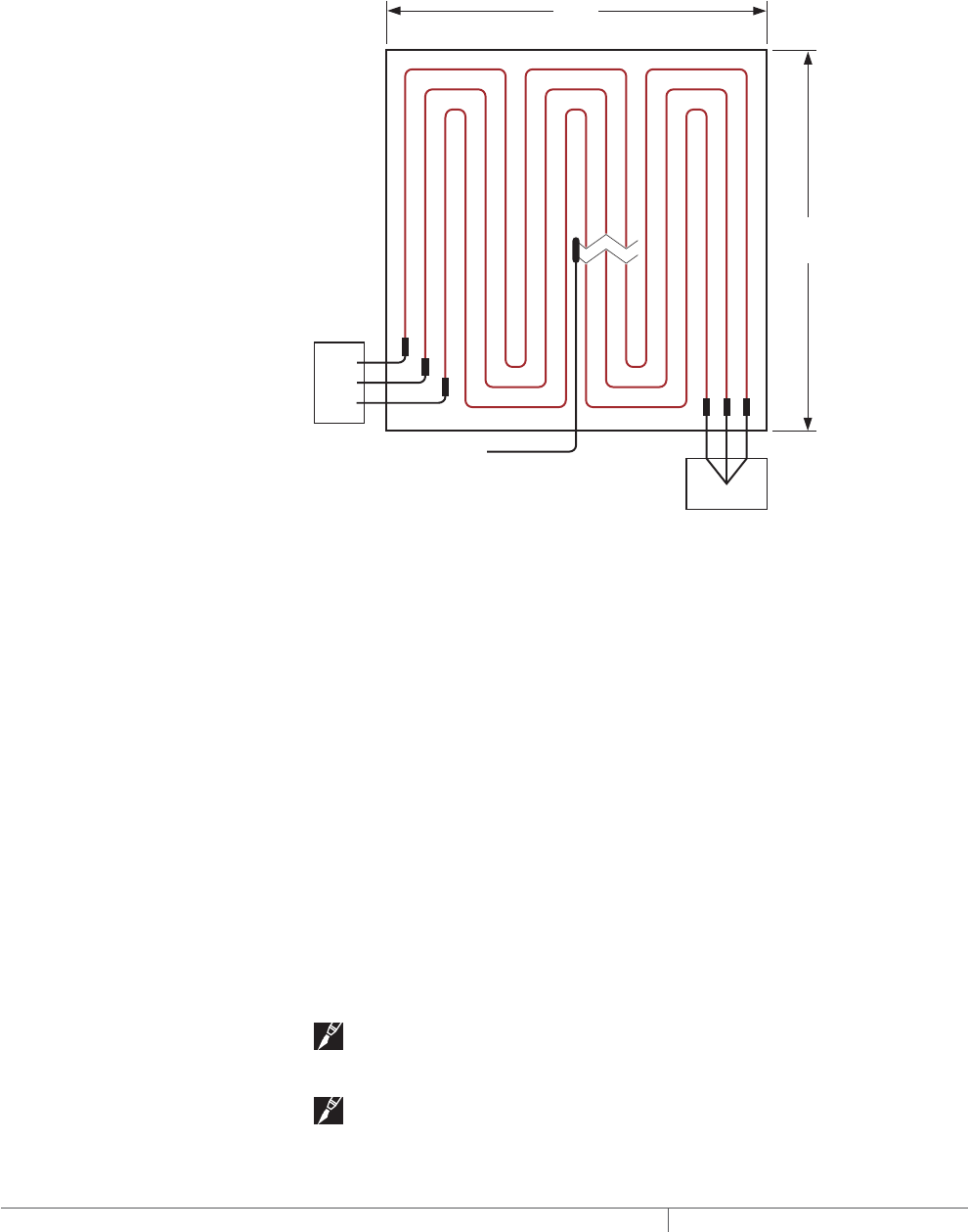
THERMAL MANAGEMENT SOLUTIONS
EN-FreezerFrostHeavePrevention-DG-H58139 11/13
238
THREEPHASE SUPPLY
Designing the frost heave prevention system using a three-phase voltage supply has
the added advantages of fewer circuits, reduced distribution costs, and a balanced
heating system load and is recommended for large freezers.
Three-phase voltages include 208/120 V, 480/277 V, and 600/347 V. When selecting
heating cables for three-phase voltages, cable layout will be easier if the heating
cables are wye connected (Fig. 19); therefore select the cables based on the phase-
to-neutral voltage (e.g.,select 277 V cables for a 480 V supply).
80'
(24.4 m)
80'
(24.4 m)
Junction
box
Junction
box
To temperature controller
3ø
supply
Fig. 19 Three-phase wye connected heating cable layout
Since a balanced three-phase system requires three cables, each cable will occupy
1/3 of the freezer area when installed.
• Calculate the “Power required” by multiplying the design power from Table 11 by
the total freezer area.
• Divide the total freezer area by three to determine the “Area coverage for each
cable.”
• Calculate the "Wattage for each cable" by dividing the “Power required” by three.
Wattage for each cable = (Design power x Total freezer area) / 3
Simply select the heating cable from Table 12 on page240 or Table 13 on page241
based on the area coverage for each cable. Under the appropriate voltage, make
sure that the area coverage for each cable falls within the minimum and maximum
range of the “Area coverage” columns and verify that the “Cable wattage” shown
directly across from the “Area coverage” is equal to or higher than the calculated
“Wattage for each cable” (see example following). Three of the same cables are
required for balanced three-phase systems.
Note: If two or more cables in the Tables meet the requirements, use the cable
with the lower wattage.
Note: For very large freezers, it may be necessary to divide the freezer into
subsections and use two or more three-phase circuits.
FREEZER FROST HEAVE PREVENTION RAYSOL AND MI HEATING CABLE SYSTEM

239THERMAL MANAGEMENT SOLUTIONS EN-FreezerFrostHeavePrevention-DG-H58139 11/13
Pipe Freeze Protection
and Flow Maintenance
Fire Sprinkler System
Freeze Protection
Roof and Gutter
De-Icing
Surface Snow
Melting – MI
Surface Snow
Melting – ElectroMelt
Freezer Frost
Heave Prevention
Floor Heating Technical Data
Sheets
Example: MI heating cables directly embedded – Three-phase
Area 6400 ft² (595 m²) (see Fig. 19)
Design power 0.9 W/ft² (9.7 W/m²) (from Step 2)
Power required (Design Power x Area) =
(0.9 W/ft² x 6400 ft²) = 5760 W
(9.7 W/m² x 595 m²) = 5760 W
Area coverage for each cable Area/3 = 6400 ft²/3 = 2133 ft²
(595 m²/3 = 198.3 m²)
Wattage for each cable Power required/3 = 5760/3 = 1920 W
Supply voltage 208 V, three-phase (from Step 1)
(select 120 volt cable for wye connection)
Catalog number SUB8
Cable wattage 2300 W
Cable voltage 120 V
Heated length 550 ft (167.6 m)
Quantity 3
Freezer Frost Heave Prevention Design

THERMAL MANAGEMENT SOLUTIONS
EN-FreezerFrostHeavePrevention-DG-H58139 11/13
240
TABLE 12 SELECTION TABLE FOR MI HEATING CABLES FOR DIRECTLY EMBEDDED CABLES
Catalog
number
Area coverage Cable
wattage
(W)
Heated length ¹
Heating cable current
(A)²
Min
(ft2)
Max
(ft2)
Min
(m2)
Max
(m2) (ft) (m)
120 V and 208 V, three-phase wye
SUA3 205 700 19.1 65.1 500 140 42.7 4.2
SUA4 220 340 20.4 31.6 550 68 20.7 4.6
SUA7 300 480 27.9 44.6 750 95 29.0 6.3
SUA8 310 885 28.8 82.2 800 177 53.9 6.7
SUB1 420 660 39.0 61.3 1000 132 40.2 8.3
SUB2 400 1200 37.2 111.5 1000 240 73.1 8.3
SUB3 520 1400 48.3 130.1 1300 280 85.3 10.8
SUB4 600 1600 55.8 148.7 1500 320 97.5 12.5
SUB5 750 1300 69.7 120.8 1800 260 79.2 15.0
SUB6 780 1875 72.5 174.3 1900 375 114.3 15.8
SUB7 940 1550 87.4 144.1 2300 310 94.5 19.2
SUB8 930 2750 86.4 255.6 2300 550 167.6 19.2
SUB9 1250 3150 116.2 292.8 3000 630 192.0 25.0
SUB10 1700 3585 158.0 333.2 4300 717 218.5 35.8
208 V
SUA1 260 540 24.2 50.2 650 108 32.9 3.1
SUA6 650 1320 60.4 122.7 1560 264 80.5 7.5
SUB19 350 1225 32.5 113.8 885 245 74.7 4.3
SUB20 480 1700 44.6 158.0 1210 340 103.6 5.8
SUB21 650 2200 60.4 204.5 1640 440 134.1 7.9
SUB22 820 2625 76.2 244.0 2060 525 160.0 9.9
240 V
SUB19 350 1225 32.5 113.8 1175 245 74.7 4.9
SUB20 480 1700 44.6 158.0 1615 340 103.6 6.7
SUB21 650 2200 60.4 204.5 2180 440 134.1 9.1
SUB22 820 2625 76.2 244.0 2745 525 160.0 11.4
277 V and 480 V, three-phase wye
SUB19 400 1225 37.2 113.8 1565 245 74.7 5.6
SUB20 550 1700 51.1 158.0 2150 340 103.6 7.8
SUB21 720 2200 66.9 204.5 2900 440 134.1 10.5
SUB22 940 2625 87.4 244.0 3650 525 160.0 13.2
347 V and 600 V, three-phase wye
SUB11 540 1125 50.2 104.6 1400 225 68.6 4.0
SUB12 770 1550 71.6 144.1 1950 310 94.5 5.6
SUB13 1060 2140 98.5 198.9 2700 428 130.5 7.8
SUB14 1440 2740 133.8 254.6 3700 548 167.0 10.7
¹ Tolerance on heating cable length is –0% to +3%
² Single-phase current shown
Note: Type SUA cables supplied with 7 ft (2.1 m) long cold lead; type SUB cables supplied with 15 ft (4.6 m) long cold leads.
FREEZER FROST HEAVE PREVENTION RAYSOL AND MI HEATING CABLE SYSTEM
241THERMAL MANAGEMENT SOLUTIONS EN-FreezerFrostHeavePrevention-DG-H58139 11/13
Pipe Freeze Protection
and Flow Maintenance
Fire Sprinkler System
Freeze Protection
Roof and Gutter
De-Icing
Surface Snow
Melting – MI
Surface Snow
Melting – ElectroMelt
Freezer Frost
Heave Prevention
Floor Heating Technical Data
Sheets
TABLE 13 SELECTION TABLE FOR MI HEATING CABLES FOR DIRECTLY EMBEDDED CABLES
Catalog
number
Area coverage Cable
wattage
(W)
Heated length
¹
Heating cable current
(A)²
Min
(ft2)
Max
(ft2)
Min
(m2)
Max
(m2) (ft) (m)
120 V and 208 V, three-phase Wye
FFHP1 163 290 15.1 27.0 405 58 17.7 3.4
FFHP2 205 360 19.1 33.5 510 72 22.0 4.3
FFHP3 231 415 21.5 38.6 580 83 25.3 4.8
FFHP4 282 510 26.2 47.4 705 102 31.1 5.9
FFHP5 328 585 30.5 54.4 820 117 35.7 6.8
FFHP6 392 700 36.4 65.1 980 140 42.7 8.2
FFHP7 450 800 41.8 74.3 1125 160 48.8 9.4
FFHP8 519 925 48.2 86.0 1300 185 56.4 10.8
FFHP9 637 1130 59.2 105.0 1590 226 68.9 13.3
FFHP10 733 1310 68.1 121.7 1830 262 79.9 15.3
FFHP11 900 1600 83.6 148.7 2250 320 97.6 18.8
FFHP12 1186 2130 110.2 198.0 2965 426 129.9 24.7
FFHP13 1470 2640 136.6 245.4 3675 528 161.0 30.6
FFHP14 1862 3320 173.0 308.6 4650 664 202.4 38.8
208 V
FFHP15 281 505 26.1 46.9 700 101 30.8 3.4
FFHP16 352 630 32.7 58.6 880 126 38.4 4.2
FFHP17 401 720 37.2 66.9 1000 144 43.9 4.8
FFHP18 492 880 45.7 81.8 1230 176 53.7 5.9
FFHP19 568 1015 52.8 94.3 1420 203 61.9 6.8
FFHP20 678 1215 63.0 112.9 1700 243 74.1 8.2
FFHP21 778 1390 72.3 129.2 1945 278 84.8 9.4
FFHP22 901 1600 83.8 148.7 2250 320 97.6 10.8
FFHP23 1098 1970 102.1 183.1 2745 394 120.1 13.2
FFHP24 1268 2275 117.8 211.4 3170 455 138.7 15.2
FFHP25 1553 2785 144.4 258.8 3885 557 169.8 18.7
240 V
FFHP26 326 580 30.3 53.9 815 116 35.4 3.4
FFHP27 407 725 37.9 67.4 1020 145 44.2 4.3
FFHP28 463 830 43.0 77.1 1160 166 50.6 4.8
FFHP29 567 1015 52.7 94.3 1420 203 61.9 5.9
FFHP30 656 1170 61.0 108.7 1640 234 71.3 6.8
FFHP31 786 1395 73.1 129.6 1965 279 85.1 8.2
FFHP32 900 1600 83.6 148.7 2250 320 97.6 9.4
FFHP33 1038 1850 96.5 171.9 2600 370 112.8 10.8
FFHP34 1274 2260 118.4 210.0 3185 452 137.8 13.3
FFHP35 1471 2610 136.7 242.6 3680 522 159.1 15.3
FFHP36 1800 3200 167.3 297.4 4500 640 195.1 18.8
¹ Tolerance on heating cable length is –0% to +3%.
² Single-phase current shown
Note: Type FFHP cables supplied with 15 ft (4.6 m) long cold leads.
Freezer Frost Heave Prevention Design
THERMAL MANAGEMENT SOLUTIONS
EN-FreezerFrostHeavePrevention-DG-H58139 11/13
242
TABLE 13 SELECTION TABLE FOR MI HEATING CABLES FOR DIRECTLY EMBEDDED CABLES
Catalog
number
Area coverage Cable
wattage
(W)
Heated length
¹
Heating cable current
(A)²
Min
(ft2)
Max
(ft2)
Min
(m2)
Max
(m2) (ft) (m)
277 V and 480 V, three-phase wye
FFHP37 375 670 34.9 62.3 940 134 40.9 3.4
FFHP38 468 840 43.5 78.1 1170 168 51.2 4.2
FFHP39 536 955 49.8 88.8 1340 191 58.2 4.8
FFHP40 656 1170 60.9 108.7 1640 234 71.3 5.9
FFHP41 758 1350 70.4 125.5 1895 270 82.3 6.8
FFHP42 908 1610 84.4 149.6 2270 322 98.2 8.2
FFHP43 1037 1850 96.4 171.9 2590 370 112.8 9.4
FFHP44 1201 2130 111.6 198.0 3000 426 129.9 10.8
FFHP45 1462 2625 135.8 244.0 3655 525 160.1 13.2
FFHP46 1697 3015 157.7 280.2 4240 603 183.8 15.3
FFHP47 2074 3700 192.7 343.9 5185 740 225.6 18.7
347 V and 600 V, three-phase wye
FFHP48 470 840 43.7 78.1 1175 168 51.2 3.4
FFHP49 588 1050 54.7 97.6 1470 210 64.0 4.2
FFHP50 672 1195 62.4 111.1 1680 239 72.9 4.8
FFHP51 819 1470 76.1 136.6 2050 294 89.6 5.9
FFHP52 950 1690 88.3 157.1 2375 338 103.0 6.8
FFHP53 1133 2025 105.3 188.2 2830 405 123.5 8.2
FFHP54 1295 2325 120.3 216.1 3240 465 141.8 9.3
FFHP55 1500 2675 139.4 248.6 3750 535 163.1 10.8
FFHP56 1838 3275 170.8 304.4 4600 655 199.7 13.3
FFHP57 2126 3775 197.6 350.8 5315 755 230.2 15.3
¹ Tolerance on heating cable length is –0% to +3%.
² Single-phase current shown
Note: Type FFHP cables supplied with 15 ft (4.6 m) long cold leads.
FREEZER FROST HEAVE PREVENTION RAYSOL AND MI HEATING CABLE SYSTEM

243THERMAL MANAGEMENT SOLUTIONS EN-FreezerFrostHeavePrevention-DG-H58139 11/13
Pipe Freeze Protection
and Flow Maintenance
Fire Sprinkler System
Freeze Protection
Roof and Gutter
De-Icing
Surface Snow
Melting – MI
Surface Snow
Melting – ElectroMelt
Freezer Frost
Heave Prevention
Floor Heating Technical Data
Sheets
Freezer Frost Heave
Prevention System
Design Steps
(Embedded)
1. Determine the
freezer configuration
2. Determine heat loss
and freezer load
4. Determine the
heating cable spacing
5. Determine the
electrical parameters
6. Select the
accessories
7. Select the control
system
8. Select the power
distribution
9. Complete the Bill
of Materials
3. Select the heating
cable, layout and
length
Step Determine the heating cable spacing
To determine the spacing between runs of heating cables, use the formula below:
Cable spacing (in) = Area (ft²) x 12 in
Heated length (ft)
Cable spacing (cm) = Area (m²) x 100 cm
Heated length (m)
Note: If a large area has been divided into subsections or if a three-phase
voltage supply is used, the “Area” in the above equations will be the subsection area
or area coverage for each cable and the “Heated length” will be the length of the
selected cable.
Example: MI heating cables directly embedded – Single-phase
Area 800 ft² (74 m²) (from Step 3)
Catalog number SUB19 (from Step 3)
Heated length 245 ft (74.7 m) (from Step 3)
Cable spacing 800 ft² x 12 / 245 ft = 39.2 in
rounded to 39 in
74 m² x 100 / 74.7 m = 99.1 cm
rounded to 99 cm
Example: MI heating cables directly embedded – Three-phase
Area coverage for each cable 2133 ft² (198.3 m²) (from Step 3)
Catalog number SUB8 (from Step 3)
Heated length 550 ft (167.6 m) (from Step 3)
Cable spacing 2133 ft² x 12 / 550 ft = 46.5 in
rounded to 47 in
198.3 m² x 100 / 167.6 m = 118.3 cm
rounded to 118 cm
Freezer Frost Heave
Prevention System
Design Steps (Embedded)
1. Determine the
freezer configuration
2. Determine heat loss
and freezer load
4. Determine the
heating cable spacing
5. Determine the
electrical parameters
6. Select the
accessories
7. Select the control
system
8. Select the power
distribution
9. Complete the Bill
of Materials
3. Select the heating
cable, layout and
length
Step Determine the electrical parameters
DETERMINE NUMBER OF CIRCUITS
For single-phase circuits, when connecting individual heating cables to circuit
breakers, the cable current draw must not exceed 80% of the circuit breaker rating.
To reduce the number of circuits, multiple heating cables may be connected in
parallel. When multiple cables are connected in parallel, the total of the individual
heating cable currents must not exceed 80% of the circuit breaker rating. The single-
phase heating cable current is shown in Table 12 and Table 13.
For three-phase circuits used in frost heave protection systems, the three heating
cables are generally connected in the wye configuration shown in Fig. 21 on
page248. For a wye connected three-phase circuit, the current draw is the same
as the single-phase heating cable current and must not exceed 80% of the 3-pole
circuit breaker rating.
A 30-mA ground-fault protection device (GFPD) must be used to provide protection
from arcing or fire, and to comply with warranty requirements, agency certifications,
and national electrical codes. If the heating cable is improperly installed, or
physically damaged, sustained arcing or fire could result. If arcing does occur, the
fault current may be too low to trip conventional circuit breakers.
Freezer Frost Heave Prevention Design

THERMAL MANAGEMENT SOLUTIONS
EN-FreezerFrostHeavePrevention-DG-H58139 11/13
244
WARNING: To minimize the danger of fire from sustained electrical arcing if
the heating cable is damaged or improperly installed, and to comply with the
requirements of Pentair Thermal Management, agency certifications, and national
electrical codes, ground-fault equipment protection must be used on each heating
cable branch circuit. Arcing may not be stopped by conventional circuit protection.
SELECT BRANCH CIRCUIT BREAKER SIZE
Record the number and ratings of the circuit breakers to be used. Use ground-fault
protection devices (GFPDs) for all applications. For three-phase circuits, ground fault
may be accomplished using a shunt trip 3-pole breaker and a ground fault sensor.
DETERMINE TRANSFORMER LOAD
The total transformer load is the sum of the wattages of the selected heating cables.
Calculate the Total Transformer Load as follows:
Transformer load (kW) =
Cable1 (W) + Cable2 (W) + Cable3 (W)... + CableN (W)
1000
Example: MI heating cables directly embedded – Single-phase
Amps 4.3 A (from Table 12)
Circuit breaker size 15 A breaker, 80% loading 12 A
Number of circuit breakers 1
Cable power output 885 W (from Step 3)
Number of cables 1 (from Step 3)
Transformer load 885 W / 1000 = 0.9 kW
Example: MI heating cables directly embedded – Three-phase
Amps/cable 19.2 A (from Table 12)
Circuit breaker size 25 A, 3-pole breaker, 80% loading 20 A
Number of circuit breakers 1 (3 cables wye connected – see Fig. 21)
Cable power output 2300 W (from Step 3)
Number of cables 3 (from Step 3)
Total Transformer load (2300 W x 3) / 1000 = 6.9 kW
Record the number and ratings of the circuit breakers to be used and total
transformer load on the worksheet.
FREEZER FROST HEAVE PREVENTION RAYSOL AND MI HEATING CABLE SYSTEM
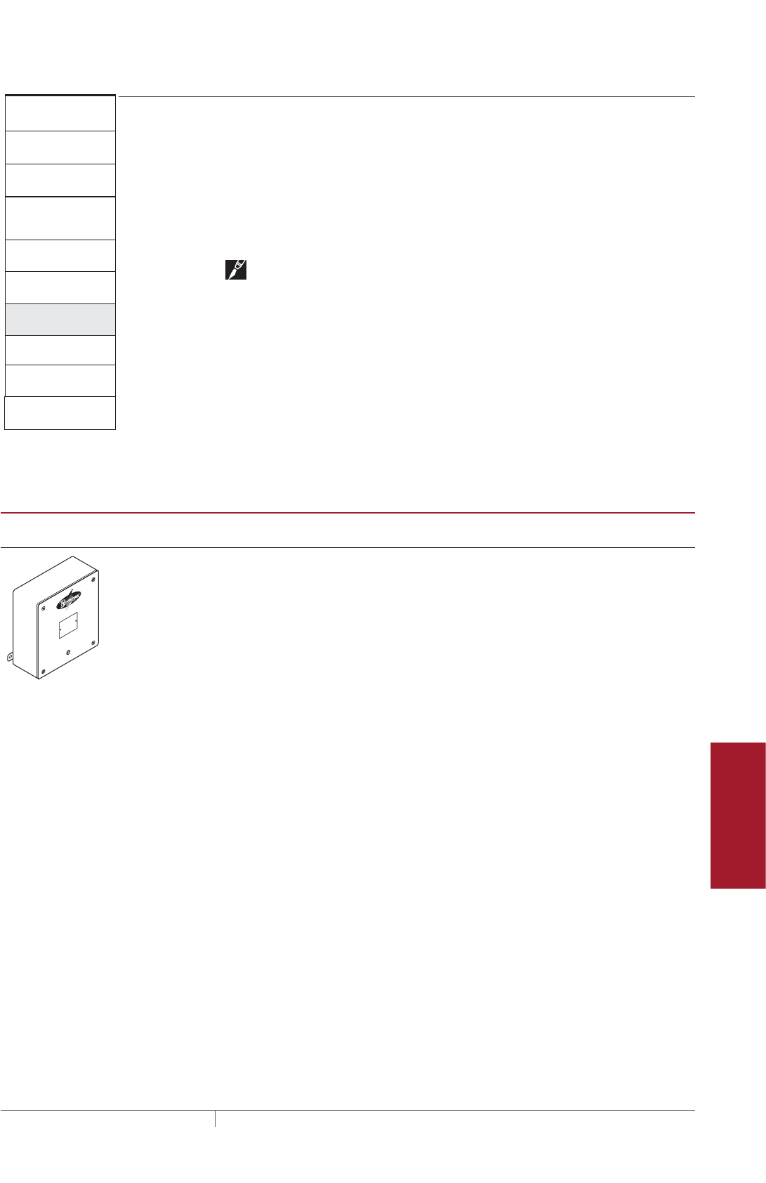
245THERMAL MANAGEMENT SOLUTIONS EN-FreezerFrostHeavePrevention-DG-H58139 11/13
Pipe Freeze Protection
and Flow Maintenance
Fire Sprinkler System
Freeze Protection
Roof and Gutter
De-Icing
Surface Snow
Melting – MI
Surface Snow
Melting – ElectroMelt
Freezer Frost
Heave Prevention
Floor Heating Technical Data
Sheets
Freezer Frost Heave
Prevention System
Design Steps (Embedded)
1. Determine the
freezer configuration
2. Determine heat loss
and freezer load
4. Determine the
heating cable spacing
5. Determine the
electrical parameters
6. Select the
accessories
7. Select the control
system
8. Select the power
distribution
9. Complete the Bill
of Materials
3. Select the heating
cable, layout and
length
Step Select the accessories
For your embedded system, determine the number of junction boxes required.
SELECT JUNCTION BOX
Select a UL Listed and/or CSA Certified junction box that is suitable for the location,
such as the Pyrotenax D1297TERM4. Use a box with minimum internal volume of 16
cubic inches if the box is metallic and 19 cubic inches if the box is not metallic. Metal
junction boxes are recommended.
Note: The junction box must be accessible according to the national electrical
codes.
After determining the number of heating cables required, the number of circuits, and
the junction box locations, do a trial layout. In making the trial layout, follow these
recommendations:
• Install the heating cables in a sand layer beneath the insulation.
• Maintain the design spacing within 4 in (10 cm).
• When directly embedded in the concrete floor, do not cross expansion joints in the
floor.
• Do not route the cables closer than 4 in (10 cm) to the edge of the subfloor,
drains, anchors, or other material.
TABLE 14 ACCESSORIES
Catalog
number Description
Standard
packaging Usage
D1297TERM4 A cast aluminum junction box (Type 3) for installation
in nonhazardous and CID2 locations. Three 1/2-in NPT
entries on bottom, provided with plugs. Includes 4-pole
terminal block (CSA - 600 V, 65 A, 18 - 6 AWG; UL - 300
V, 65 A, 18 - 6 AWG). External mounting feet. CSA ap-
proved for Class I, Div. 2, Groups A, B, C, and D. (for MI
only)
Enclosure dimensions: 6 in x 6 in x 4 in
(150 mm x 150 mm x 100 mm).
1 For MI cable only
Example: MI heating cables directly embedded – Single-phase
Junction box D1297TERM4
Quantity required 1
Example: MI heating cables directly embedded – Three-phase
Junction box Contractor supplied
Quantity required 2
Freezer Frost Heave Prevention Design
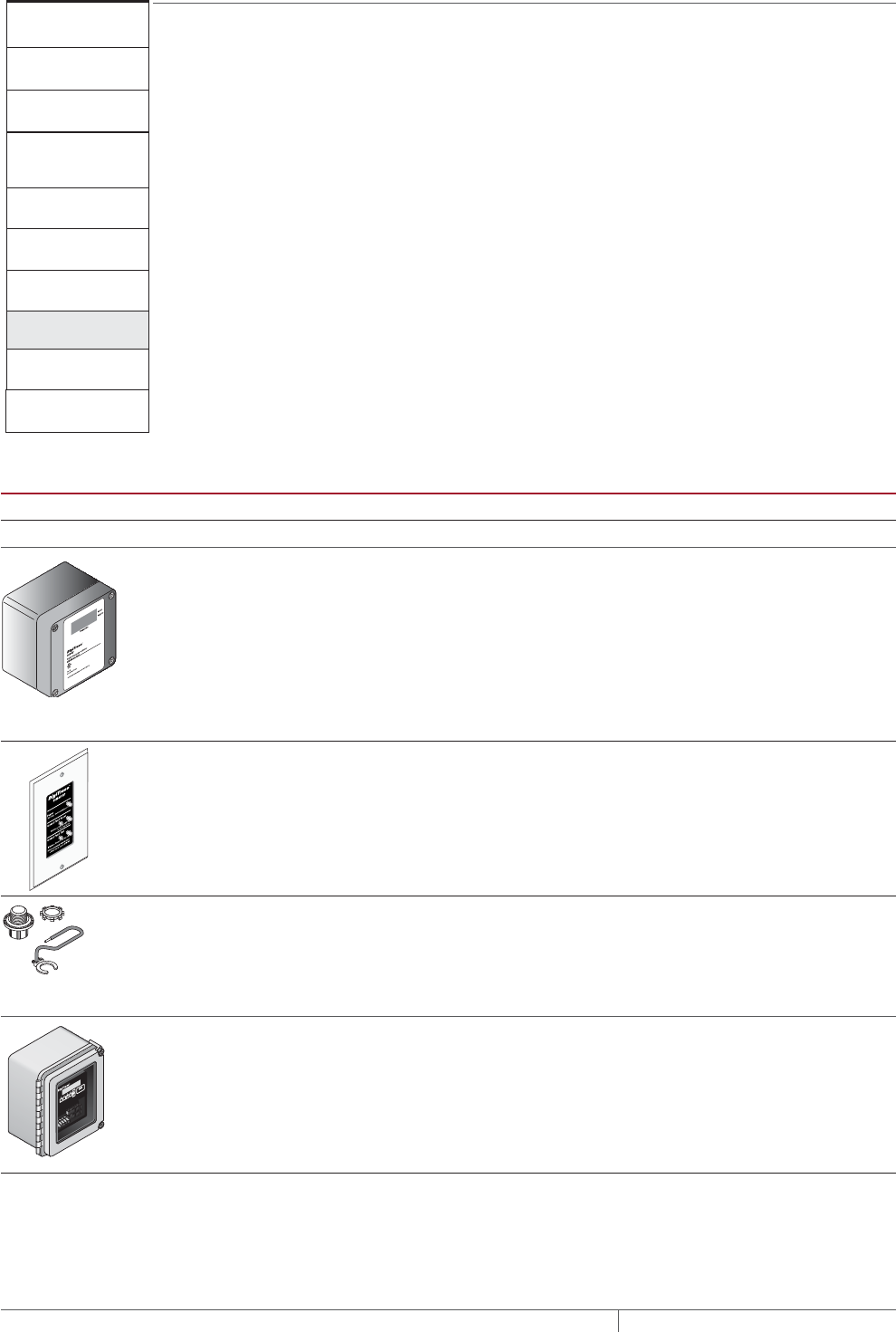
THERMAL MANAGEMENT SOLUTIONS
EN-FreezerFrostHeavePrevention-DG-H58139 11/13
246
Freezer Frost Heave
Prevention System
Design Steps (Embedded)
1. Determine the
freezer configuration
2. Determine heat loss
and freezer load
4. Determine the
heating cable spacing
5. Determine the
electrical parameters
6. Select the
accessories
7. Select the control
system
8. Select the power
distribution
9. Complete the Bill
of Materials
3. Select the heating
cable, layout and
length
Step Select the control system
For MI cable, a temperature controller must be used to maintain the subfloor
temperature at 40°F (4°C). For installations where temperature control and
temperature monitoring is desired, a Pentair Thermal Management DigiTrace C910-
485 or DigiTrace ACS-30 controller is recommended. For additional information on
temperature controller options, refer to Table 8 on page227.
TABLE 15 CONTROL SYSTEMS
Catalog number
Description
Electronic thermostats and accessories
ECW-GF Electronic ambient sensing controller with 30-mA ground-fault protection. The control-
ler can be programmed to maintain temperatures up to 200°F (93°C) at voltages from
100 to 277 V and can switch current up to 30 Amperes. The ECW-GF is complete with
a 25-ft (7.6-m) temperature sensor and is housed in a Type 4X rated enclosure. The
controller features an AC/DC dry alarm contact relay.
An optional ground-fault display panel (ECW-GF-DP) can be added to provide ground-
fault or alarm indication in applications where the controller is mounted in inaccessible
locations.
ECW-GF-DP An optional remote display panel (ECW-GF-DP) that can be added to provide ground-
fault or alarm indication in applications where the controller is mounted in inacces-
sible locations.
MI-GROUND-KIT Grounding kit for nonmetallic enclosures (for MI only)
Electronic controllers and sensors
C910-485 The DigiTrace C910-485 is a compact, full featured, microprocessor-based, single-point
commercial heating cable controller. The C910-485 provides control and monitoring
of electrical heating cable circuits for commercial heating applications, with built-in
ground-fault protection. The C910-485 can be set to monitor and alarm for high and low
temperature, high and low current, ground-fault level, and voltage. Communications
modules are available for remote control and configuration.
FREEZER FROST HEAVE PREVENTION RAYSOL AND MI HEATING CABLE SYSTEM
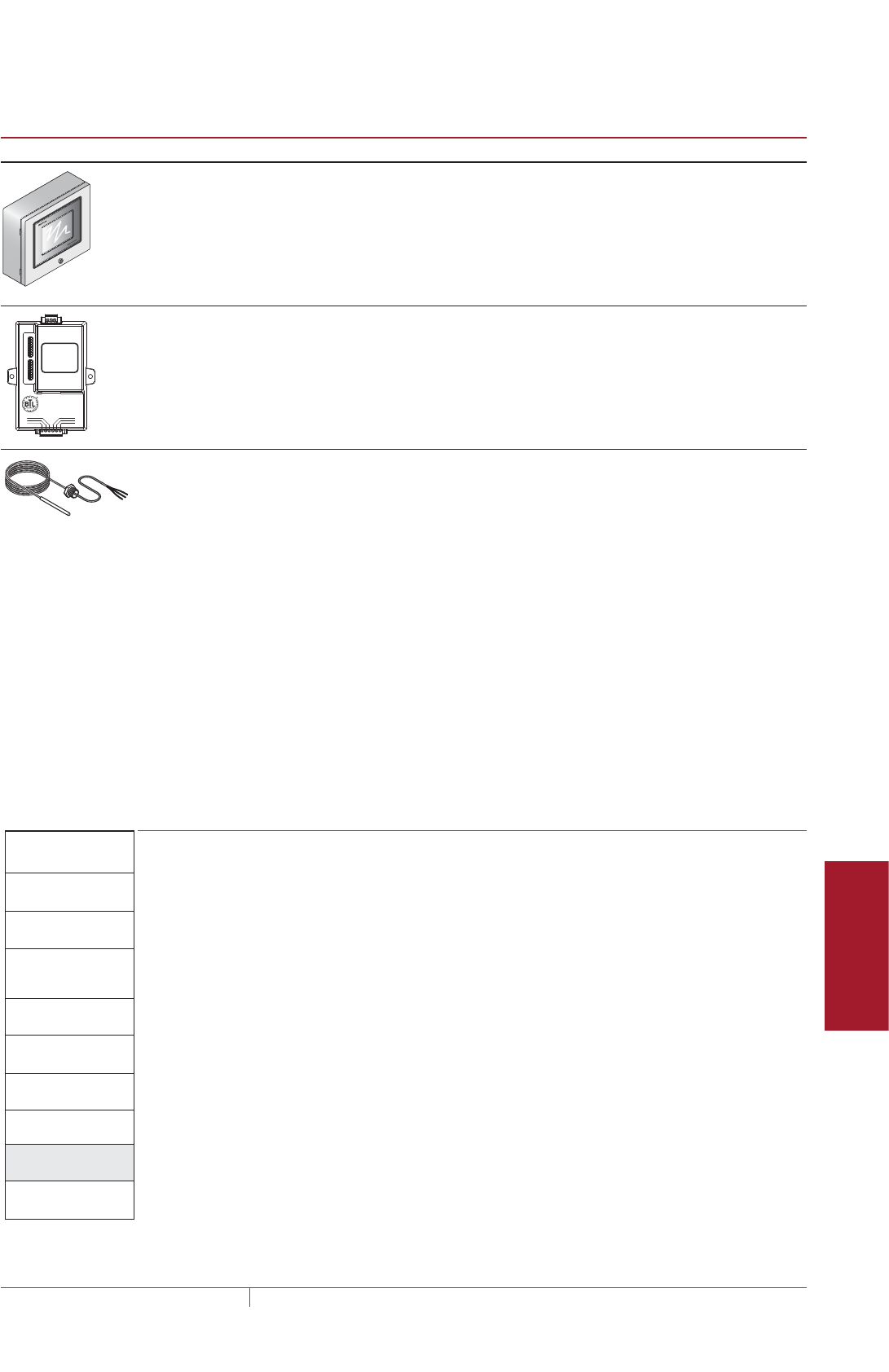
247THERMAL MANAGEMENT SOLUTIONS EN-FreezerFrostHeavePrevention-DG-H58139 11/13
Pipe Freeze Protection
and Flow Maintenance
Fire Sprinkler System
Freeze Protection
Roof and Gutter
De-Icing
Surface Snow
Melting – MI
Surface Snow
Melting – ElectroMelt
Freezer Frost
Heave Prevention
Floor Heating Technical Data
Sheets
TABLE 15 CONTROL SYSTEMS
Catalog number
Description
ACS-UIT2
ACS-PCM2-5
The DigiTrace ACS-30 Advanced Commercial Control System is a multipoint electronic
control and monitoring system for heat-tracing used in various commercial applica-
tions such as pipe freeze protection, roof and gutter de-icing, surface snow melting, hot
water temperature maintenance and floor heating. The DigiTrace ACS-30 system can
control up to 260 circuits with multiple networked ACS-PCM2-5 panels, with a single
ACS-UIT2 user interface terminal. The ACS-PCM2-5 panel can directly control up to 5
individual heat-tracing circuits using electromechanical relays rated at 30 A up to
277 V.
By FieldServer Technologies
www.ProtoCessor.com
PROTOCESSOR
SERIAL ETHERNET
PROTONODE
FRAME GND
- PWR
+PWR
RS 485+
RS 485 -
RS 485 GND
S3
S2
S1
S0
B3
B2
B1
B0
A7
A6
A5
A4
A3
A2
A1
A0
ProtoNode-LER
ProtoNode-RER
The DigiTrace ProtoNode is an external, high performance multi-protocol gateway for
customers needing protocol translation between Building Management Systems (BMS)
and the DigiTrace ACS-30 or C910-485 controllers.
The ProtoNode-LER is for LonWorks® systems; and the ProtoNode-RER is for
BACnet® or Metasys® N2 systems.
RTD10CS
RTD-200
RTD50CS
Stainless steel jacketed three-wire RTD (Resistance Temperature Detector) used with
DigiTrace C910-485 and ACS-30 controllers.
RTD10CS: 10-ft (3 m) flexible armor, with 18-in (457 mm) lead wire and 1/2-inch NPT
bushing
RTD-200: 6-ft (1.8 m) fluoropolymer with 1/2-in NPT bushing
RTD50CS: 50-ft (3 m) flexible armor with 1/2-in NPT bushing
Example: MI heating cables directly embedded – Single-phase
Single circuit, electronic controller DigiTrace C910-485
Quantity 1
Example: MI heating cables directly embedded – Three-phase
Single circuit, monitoring requested DigiTrace ACS-30*
Quantity 1
*Use ACS-30 General part number (P000001232) for custom three-phase panels. Please
contact your Pentair Thermal Management representative for a custom ACS-PCM2-5
panel quotation.
Freezer Frost Heave
Prevention System
Design Steps (Embedded)
1. Determine the
freezer configuration
2. Determine heat loss
and freezer load
4. Determine the
heating cable spacing
5. Determine the
electrical parameters
6. Select the
accessories
7. Select the control
system
8. Select the power
distribution
9. Complete the Bill
of Materials
3. Select the heating
cable, layout and
length
Step Select the power distribution
Power to the heating cables can be provided in three ways:
1. Directly through the temperature controller
2. Through external contactors activated by a temperature controller
3. Through an HTPG power distribution panel
SINGLE CIRCUIT CONTROL
Heating cable circuits that do not exceed the current rating of the selected controller
can be switched directly (Fig. 20). When the total electrical load exceeds the rating
of the controller or if a single-pole temperature controller is used to control a three-
phase circuit (Fig. 21), an external contactor is required.
GROUP CONTROL
If the temperature controller will activate multiple single-phase or three-phase
circuits (group control), then an external contactor must be used. In Fig. 20, three
single-phase circuits are activated by a temperature controller through an external
contactor.
Freezer Frost Heave Prevention Design
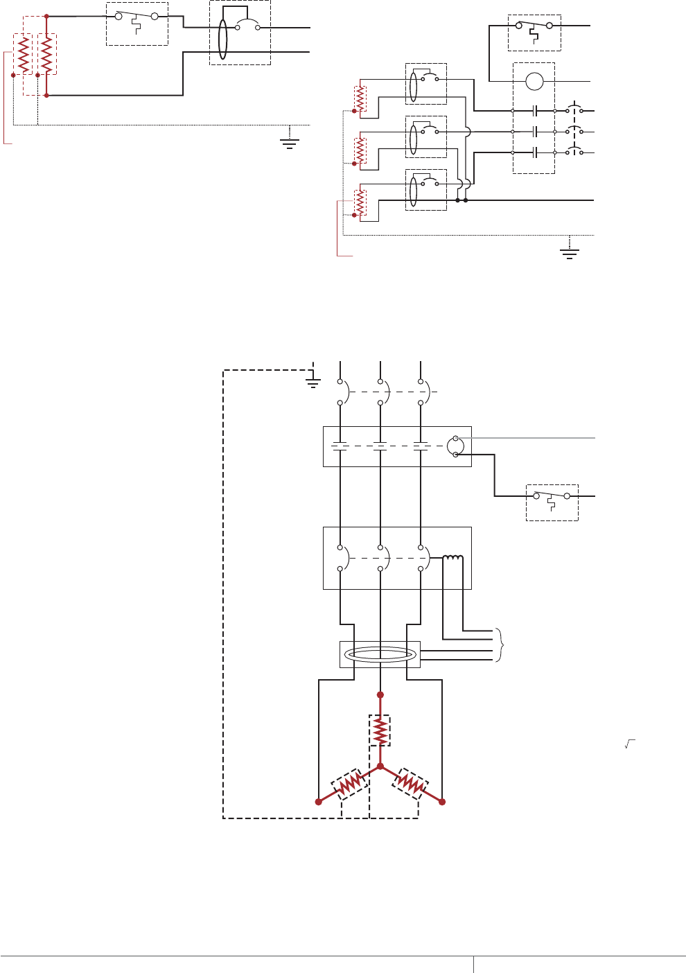
THERMAL MANAGEMENT SOLUTIONS
EN-FreezerFrostHeavePrevention-DG-H58139 11/13
248
Single circuit control Group control
Temperature
controller 1-pole
GFEP breaker
1
N
G
Heating
cable
ø
øsupply
C
Temperature
controller
Contactor
1-pole
GFEP breaker
N
G
ø2
ø1
ø3
3-phase 4-wire
supply (WYE)
3-pole main
breaker
ø
ø
1 supply
N
Heating cable
sheath, braid
or ground
Heating cable
sheath, braid
or ground
Fig. 20 Single circuit and group control
A B C
A
B
C
N
C
MCB
To ground
fault module
3-pole contactor
120 volt coil
3-pole circuit
breaker with shunt
trip/external ground-
fault sensor
Ground fault
sensor
Ground
Three-phase
4-wire supply
Heating cable
sheath, braid
or ground
Temperature
controller
to
120 V
Note: For Wye connected heating
cables, the current in the supply feeder,
contactor, and breakers is equal to the
‘Single Phase Heating Cable Current.’
Note: Heating cable voltage is the same
as the phase-to-neutral voltage (VØ-N / 3 )
Fig. 21 Typical three-phase wye connected cables with temperature controller and
contactor
FREEZER FROST HEAVE PREVENTION RAYSOL AND MI HEATING CABLE SYSTEM
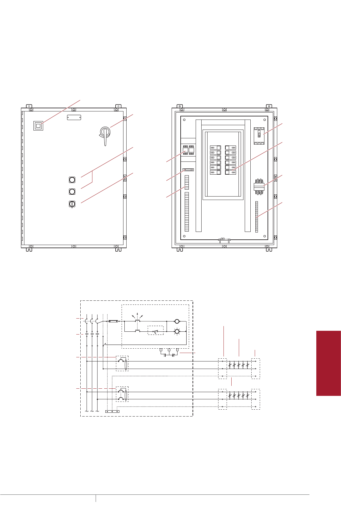
249THERMAL MANAGEMENT SOLUTIONS EN-FreezerFrostHeavePrevention-DG-H58139 11/13
Pipe Freeze Protection
and Flow Maintenance
Fire Sprinkler System
Freeze Protection
Roof and Gutter
De-Icing
Surface Snow
Melting – MI
Surface Snow
Melting – ElectroMelt
Freezer Frost
Heave Prevention
Floor Heating Technical Data
Sheets
Large systems with many circuits should use an HTPG power distribution panel. The
HTPG is a dedicated power-distribution, control, ground-fault protection, monitoring,
and alarm panel for freeze protection and broad temperature-maintenance
heat-tracing applications. This enclosure contains an assembled circuit-breaker
panelboard. Panels are equipped with ground-fault circuit breakers with or
without alarm contacts. The group control package allows the system to operate
automatically in conjunction with a temperature control system.
A
COMMON ALARM
PUSH TO ACKNOWLEDGE
HAND/OFF/AUTO
1
2
3
4
5
6
7
8
9
10
11
12
Main circuit
breaker
Main
contactor
Distribution
panelboard
Fuse holder
C
POWER ON
TB 1
TB 2
ARR
Ground
bus bar
Selector switch
Alarm relay
(optional)
Terminals
(optional)
Push button for
light testing
Alarm horn (optional)
Alarm option shown above
Door
disconnect
(optional)
Fig. 22 HTPG power distribution panel
N
Ø1
Three-pole main
circuit breaker
Panel
energized
Contactor
coil
C NC
External controller/
thermostat*
Hand Auto
Off
Three-pole main
contactor
Ø3
Ø2
Power
connection
Heating cable
One-pole with 30-mA
ground-fault trip
(120/277 Vac)
Two-pole with 30-mA
ground-fault trip
(208/240 Vac)
Alarm
remote
annunciation
(with alarm
option)
Heating
cable
circuit
Heating
cable
circuit
G
End seal
Heating cable shealth, braid or ground
Three-phase, 4 wire supply (Wye)
Fig. 23 Typical HTPG power schematic
Freezer Frost Heave Prevention Design
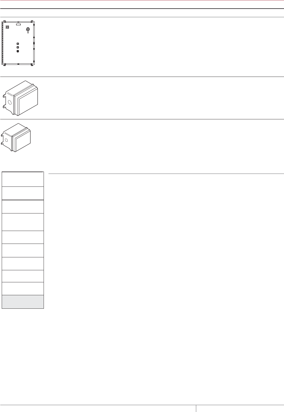
THERMAL MANAGEMENT SOLUTIONS
EN-FreezerFrostHeavePrevention-DG-H58139 11/13
250
TABLE 16 POWER DISTRIBUTION
Catalog number Description
Power distribution and control panels
A
COMMON ALARM
PUSH TO ACKNOWLEDGE
HAND/OFF/AUTO
C
POWER ON
HTPG Heat-tracing power distribution panel with ground-fault and monitoring for group control.
Contactors
E104 Three-pole, 100 A per pole, 600 V maximum contactor housed in UL Listed, CSA Certi-
fied, Type 4X enclosure with two 1-inch conduit entries. When ordering, select coil volt-
age (110–120, 208–240, 277 V).
Enclosure dimensions: 13-1/2 in x 9-1/5 in x 6-11/16 in (343 mm x 234 mm x 170 mm).
E304 Three-pole, 40 A per pole, 600 V maximum contactor housed in UL Listed, CSA Certified
Type 4X enclosure with two 1-inch conduit entries. When ordering, select coil voltage
(110–120, 208–240, 277 V).
Enclosure dimensions: 9-1/2 in x 7-1/5 in x 6-11/16 in (241 mm x 183 mm x 170 mm).
Freezer Frost Heave
Prevention System
Design Steps
(Embedded)
1. Determine the freezer
configuration
2. Determine heat loss
and freezer load
4. Determine the heating
cable spacing
5. Determine the
electrical parameters
6. Select the
accessories
7. Select the control
system
8. Select the power
distribution system
9. Complete the Bill
of Materials
3. Select the heating
cable, layout and
length
Step Complete the Bill of Materials
If you used the Design Worksheet to document all your design parameters, you
should have all the details necessary complete your Bill of Materials.
FREEZER FROST HEAVE PREVENTION RAYSOL AND MI HEATING CABLE SYSTEM

251THERMAL MANAGEMENT SOLUTIONS EN-FreezerFrostHeavePrevention-DG-H58139 11/13
Pipe Freeze Protection
and Flow Maintenance
Fire Sprinkler System
Freeze Protection
Roof and Gutter
De-Icing
Surface Snow
Melting – MI
Surface Snow
Melting – ElectroMelt
Freezer Frost
Heave Prevention
Floor Heating Technical Data
Sheets
RAYSOL AND MI HEATING CABLE IN CONDUIT FREEZER FROST HEAVE PREVENTION DESIGN WORKSHEET
Step Determine the freezer configuration (RaySol and MI heating cable systems)
Determine freezer area (from scale drawing)
Determine freezer
operating
temperature
Record insulation
R-value Supply voltage
x =
Freezer area
(ft2/m2)
Side A (length)
(ft/m)
Side B (width)
(ft/m) ______________°F/°C
_____________
ft²·°F·hr/Btu ______________ Volts
Example: RaySol and MI heating cables
80 ft 40 ft 3200 ft2
x = Freezer area (ft2)Side A (length) (ft) Side B (width) (ft) –20°F R-40 (40 ft2·°F·hr/Btu) 208 Volts
Step Select the heating cable
RaySol heating cable MI heating cable
Supply voltage
❑ 120 V
❑ 208 V
❑ 240 V
❑ 277 V
Catalog number: ____________________
Supply voltage
❑ 120 V
❑ 208 V
❑ 277 V
Freezer side A length (ft/m): ____________________
Catalog number: ____________________
Power output (W): ____________________
Example: RaySol heating cable
Supply voltage
0 208 V
Catalog number: RaySol-2
Supply voltage
0 208 V
Freezer side A length: 80 ft
Catalog number: FFHPC30
Power output: 475 W
Step Determine the heating cable conduit spacing and freezer load (RaySol and MI heating cable systems)
Based on the insulation R-value and freezer operating temperature you recorded in Step 1, use Table 4 to select the following:
Conduit spacing (in/cm) ___________________________ Freezer load (W/ft²) (W/m²) ___________________________
Example: For RaySol and MI heating cables
Conduit spacing: 96 in Freezer load: 0.5 W/ft2
RaySol and MI Heating Cable in Conduit Freezer Frost Heave Prevention Design Worksheet

THERMAL MANAGEMENT SOLUTIONS
EN-FreezerFrostHeavePrevention-DG-H58139 11/13
252
Step Determine the heating cable layout and length
RaySol heating cable in conduit MI heating cable in conduit
1. Estimate the number of conduit runs
Imperial
x 12( ) =/ Estimated number
of conduit runs
Side B (ft) Conduit spacing (in)
x 100( ) =/ Estimated number
of conduit runs
Side B (m) Conduit spacing (cm)
x 12
( ) =/ Estimated number
of conduit runs
40 ft 96 in 5
Side B (ft) Conduit spacing (in)
Metric
x 12( ) =/ Estimated number
of conduit runs
Side B (ft) Conduit spacing (in)
x 100
(
)=/ Estimated number
of conduit runs
Side B (m) Conduit spacing (cm)
x 12( ) =/ Estimated number
of conduit runs
40 ft 96 in 5
Side B (ft) Conduit spacing (in)
If necessary, round to the next whole number
1. Estimate the number of conduit runs
Imperial
x 12( ) =/ Estimated number
of conduit runs
Side B (ft) Conduit spacing (in)
x 100( ) =/ Estimated number
of conduit runs
Side B (m) Conduit spacing (cm)
x 12
( ) =/ Estimated number
of conduit runs
40 ft 96 in 5
Side B (ft) Conduit spacing (in)
Metric
x 12( ) =/ Estimated number
of conduit runs
Side B (ft) Conduit spacing (in)
x 100
( )
=/ Estimated number
of conduit runs
Side B (m) Conduit spacing (cm)
x 12( ) =/ Estimated number
of conduit runs
40 ft 96 in 5
Side B (ft) Conduit spacing (in)
If necessary, round to the next whole number
Example: RaySol heating cable
x 12( ) =/ Estimated number
of conduit runs
Side B (ft) Conduit spacing (in)
x 100( ) =/ Estimated number
of conduit runs
Side B (m) Conduit spacing (cm)
x 12( ) =/ Estimated number
of conduit runs
40 ft 96 in 5
Side B (ft) Conduit spacing (in)
Example: MI heating cable
x 12( ) =/ Estimated number
of conduit runs
Side B (ft) Conduit spacing (in)
x 100( ) =/ Estimated number
of conduit runs
Side B (m) Conduit spacing (cm)
x 12( ) =/ Estimated number
of conduit runs
40 ft 96 in 5
Side B (ft) Conduit spacing (in)
2. Estimate the heating cable length required for conduit runs
80 ft 5 400 ft
x =
Heating cable
length required (ft/m)
Side A (ft/m) Number of
conduit runs
x = Heating cable
length required (ft)
Side A (ft) Number of
conduit runs
2. Determine the number of MI heating cables
5
x 12
( ) =/ Estimated number
of conduit runs
Side B (ft) Conduit spacing (in)
=
Number of conduit runs
5
Number of heating cables required
=
Number of conduit runs Number of heating cables required
x 100( ) =/ Estimated number
of conduit runs
Side B (m) Conduit spacing (cm)
Example: RaySol heating cable
80 ft 5 400 ft
x = Heating cable
length required (ft/m)
Side A (ft/m) Number of
conduit runs
x = Heating cable
length required (ft)
Side A (ft) Number of
conduit runs
Example: MI heating cable
5
x 12
( ) =/ Estimated number
of conduit runs
Side B (ft) Conduit spacing (in)
=
Number of conduit runs
5
Number of heating cables required
=
Number of conduit runs Number of heating cables required
x 100
( ) =/ Estimated number
of conduit runs
Side B (m) Conduit spacing (cm)
3. Determine the maximum circuit length (see Table 5)
Maximum circuit length
(ft/m)
Heating cable
length required
(ft/m)
Supply voltage
(V)
Maximum circuit length
(ft)
400 ft 208 V 410 ft
Heating cable
length required (ft)
Supply voltage
(V)
Is the heating cable length required > the maximum circuit length?
❑ No – One circuit is sufficient
❑ Yes – Multiple circuits are required
Number of circuits Power supply
Number of circuits Power supply
1One 20 A circuit breaker
Example: RaySol heating cable
Maximum circuit length
(ft/m)
Heating cable
length required
(ft/m)
Supply voltage
(V)
Maximum circuit length
(ft)
400 ft 208 V 410 ft
Heating cable
length required (ft)
Supply voltage
(V)
Is the heating cable length required > the maximum circuit length?
0 No – One circuit is sufficient
Number of circuits Power supply
Number of circuits Power supply
1One 20 A circuit breaker
4. Determine layout
Is Side A x 2 ≤ to the maximum circuit length?
❑ Yes – Conduit can be looped in hairpin configuration
❑ Odd number of conduit runs – One conduit run will be straight
❑ Even number of conduit runs – All conduit run are looped in hairpin configuration
❑ No – Use a straight run layout
Example: RaySol heating cable
Is Side A x 2 ≤ to the maximum circuit length?
0 Yes – Conduit can be looped in hairpin configuration
0 Odd number of conduit runs – One conduit run will be straight
Layout: Run in two hairpin loops and one straight run
FREEZER FROST HEAVE PREVENTION RAYSOL AND MI HEATING CABLE SYSTEM

253THERMAL MANAGEMENT SOLUTIONS EN-FreezerFrostHeavePrevention-DG-H58139 11/13
Pipe Freeze Protection
and Flow Maintenance
Fire Sprinkler System
Freeze Protection
Roof and Gutter
De-Icing
Surface Snow
Melting – MI
Surface Snow
Melting – ElectroMelt
Freezer Frost
Heave Prevention
Floor Heating Technical Data
Sheets
Step Determine the heating cable layout and length
5. Determine end allowances and kit connection kit allowances (see Table 6) and total heating cable length required.
Determine end allowances
Number of straight
run conduits
Heating cable length for end allowances
x 8 ft =
Number of
hairpin conduits
x 8 ft =
Number of straight
run conduits
Heating cable length for end allowances
x 8 ft =
Number of
hairpin conduits
x 8 ft =
2 16 ft
1 8 ft
24 ft
Example: RaySol heating cable
Number of straight
run conduits
Heating cable length for end allowances
x 8 ft =
Number of
hairpin conduits
x 8 ft =
Number of straight
run conduits
Heating cable length for end allowances
x 8 ft =
Number of
hairpin conduits
x 8 ft =
2 16 ft
1 8 ft
24 ft
Determine connection kit allowances
Number of FTC-XC
kits for straight run conduits
Heating cable length for connection kit allowances
x 4 ft =
Number of FTC-XC
kits for hairpin conduits
x 4 ft =
1 4 ft
12 ft
2 8 ft
Number of FTC-XC
kits for straight run conduits
Heating cable length for connection kit allowances
x 4 ft =
Number of FTC-XC
kits for hairpin conduits
x 4 ft =
Example: RaySol heating cable
Number of FTC-XC
kits for straight run conduits
Heating cable length for connection kit allowances
x 4 ft =
Number of FTC-XC
kits for hairpin conduits
x 4 ft =
1 4 ft
12 ft
2 8 ft
Number of FTC-XC
kits for straight run conduits
Heating cable length for connection kit allowances
x 4 ft =
Number of FTC-XC
kits for hairpin conduits
x 4 ft =
Determine total heating cable length required for conduit runs and allowances
=++
Heating cable length
for conduit runs
(ft/m)
Heating cable length
for end allowances
(ft/m)
Heating cable length
for connection kit
allowances (ft/m)
Total heating cable
length required (ft/m)
=++
Heating cable length
for conduit runs (ft)
Heating cable length
for end allowances (ft)
Heating cable length
for connection kit
allowances (ft)
Total heating cable
length required (ft)
400 ft 24 ft 12 ft 436 ft
Example: RaySol heating cable
=++
Heating cable length
for conduit runs
(ft/m)
Heating cable length
for end allowances
(ft/m)
Heating cable length
for connection kit
allowances (ft/m)
Total heating cable
length required (ft/m)
=++
Heating cable length
for conduit runs (ft)
Heating cable length
for end allowances (ft)
Heating cable length
for connection kit
allowances (ft)
Total heating cable
length required (ft)
400 ft 24 ft 12 ft 436 ft
RaySol and MI Heating Cable in Conduit Freezer Frost Heave Prevention Design Worksheet
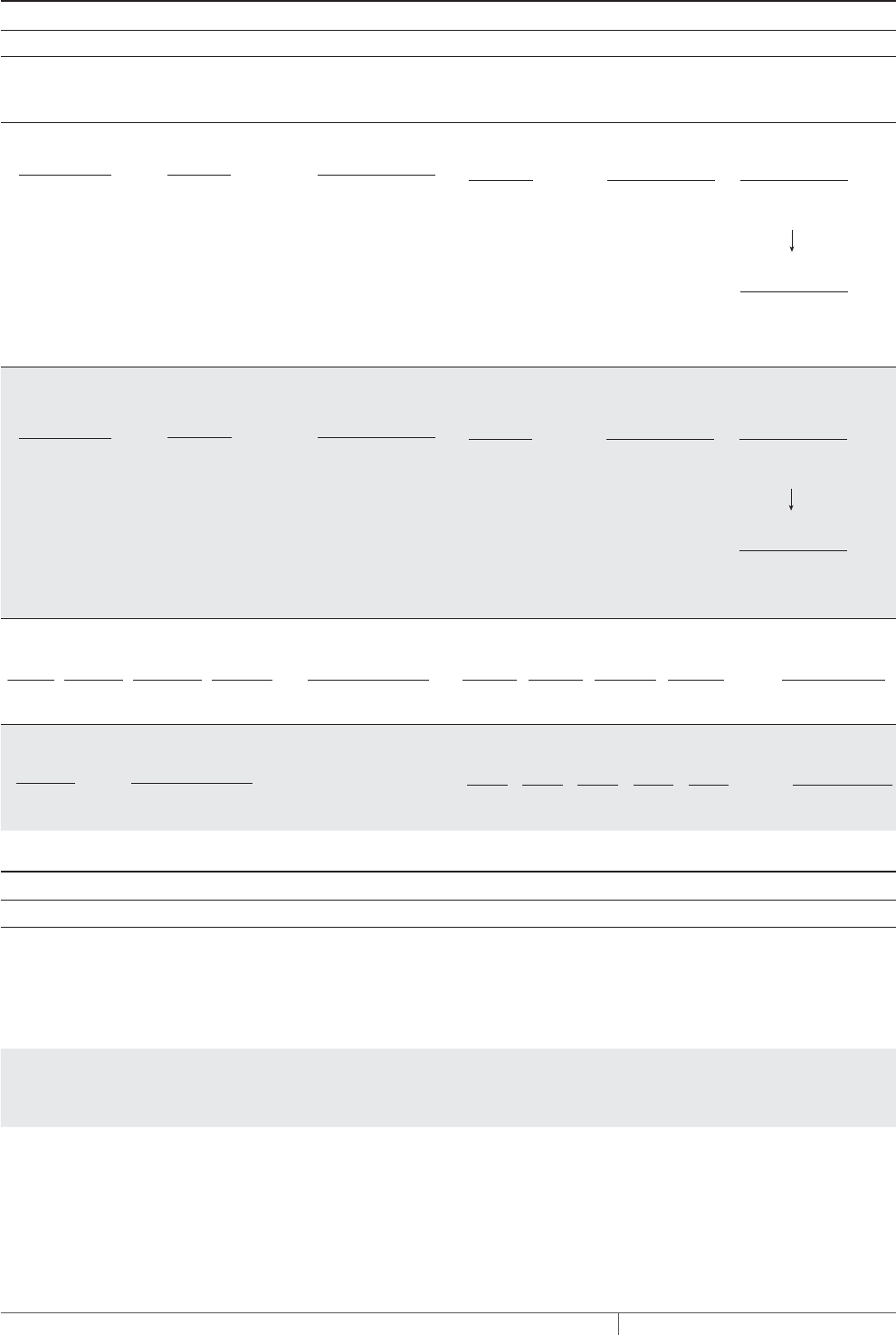
THERMAL MANAGEMENT SOLUTIONS
EN-FreezerFrostHeavePrevention-DG-H58139 11/13
254
Step Determine the electrical parameters
RaySol heating cable in conduit MI heating cable in conduit
Determine number of circuits
Circuit breaker rating (A): ______________ (from Step 4, Table 5)
Number of circuits: ______________ (from Step 4)
Determine circuit breaker rating and number of circuits
Circuit breaker rating (A): ______________
Number of circuits: ______________
Calculate circuit breaker load
20 A 208 V 3.3 kW
Circuit breaker
rating (A)
x
(x0.8
Circuit breaker load
Supply
voltage
)=/ 1000
Circuit breaker
rating (A)
x
(
x0.8
Circuit breaker load
(kW)
Supply
voltage
)
=/ 1000
Calculate circuit breaker rating and number of circuits
Total current
(A)
*Use next largest available circuit breaker or break into smaller circuits
= =x 1.25
( )
Minimum circuit
breaker rating (A)*
Circuit breaker
rating (A)
=
Number of circuits
11.5 A 14.4 A 15 A
1
Total current
(A)
*Use next largest available circuit breaker or break into smaller circuits
= =x 1.25
( )
Minimum circuit
breaker rating (A)*
Circuit breaker
rating (A)
=
Number of circuits
Example: RaySol heating cable
20 A 208 V 3.3 kW
Circuit breaker
rating (A)
x
(x0.8
Circuit breaker load
Supply
voltage
)=/ 1000
Circuit breaker
rating (A)
x
(x0.8
Circuit breaker load
(kW)
Supply
voltage
)=/ 1000
Example: MI heating cable
Total current
(A)
*Use next largest available circuit breaker or break into smaller circuits
= =x 1.25
( )
Minimum circuit
breaker rating (A)*
Circuit breaker
rating (A)
=
Number of circuits
11.5 A 14.4 A 15 A
1
Total current
(A)
*Use next largest available circuit breaker or break into smaller circuits
= =x 1.25
( )
Minimum circuit
breaker rating (A)*
Circuit breaker
rating (A)
=
Number of circuits
Calculate total transformer load
Total transformer
load (kW)
CBL1
+
CBL2
+
CBLN
CBL3 ...
+ =
Total transformer
load (kW)
CBL1
=
3.3 kW 3.3 kW
Calculate total transformer load
Total transformer
load (kW)
Cable1 (W)
+( )
Cable2 (W)
+
CableN (W)Cable3 (W)...
+/ 1000 =
Total transformer
load
Cable1
+
475 W
Cable2
+
475 W
Cable3
+
475 W
Cable4
+
475 W
Cable5
475 W 2.4 kW
)( / 1000 =
Example: RaySol heating cable
Total transformer
load (kW)
CBL1
+
CBL2
+
CBLN
CBL3 ...
+ =
Total transformer
load (kW)
CBL1
=
3.3 kW 3.3 kW
Example: MI heating cable
Total transformer
load (kW)
Cable1 (W)
+( )
Cable2 (W)
+
CableN (W)Cable3 (W)...
+/ 1000 =
Total transformer
load
Cable1
+
475 W
Cable2
+
475 W
Cable3
+
475 W
Cable4
+
475 W
Cable5
475 W 2.4 kW
)( / 1000 =
Step Select the connection kits and accessories
Connection kits and accessories Description Quantity
❑ FTC-XC
❑ FTC-HST
❑ RayClic-E
❑ D1297TERM4
Power connection and end seal
Low-profile splice/tee
Extra end seal
Cast aluminum junction box (for MI cable only)
____________
____________
____________
____________
Example:
0 FTC-XC Power connection and end seal 3 (for RaySol)
0 D1297TERM4 Cast aluminum junction box (for MI cable only) 5 (for MI)
FREEZER FROST HEAVE PREVENTION RAYSOL AND MI HEATING CABLE SYSTEM

255THERMAL MANAGEMENT SOLUTIONS EN-FreezerFrostHeavePrevention-DG-H58139 11/13
Pipe Freeze Protection
and Flow Maintenance
Fire Sprinkler System
Freeze Protection
Roof and Gutter
De-Icing
Surface Snow
Melting – MI
Surface Snow
Melting – ElectroMelt
Freezer Frost
Heave Prevention
Floor Heating Technical Data
Sheets
Step Select the control system
Thermostats, controllers,
and accessories Description Quantity
❑ ECW-GF
T ECW-GF-DP
❑ MI-GROUND-KIT
❑ C910-485
❑ ACS-UIT2
❑ CS-PCM2-5
❑ ProtoNode-LER
❑ ProtoNode-RER
❑ RTD10CS
❑ RTD-200
❑ RTD50CS
Electronic thermostat with 25-ft sensor
Remote display panel for ECW-GF
Grounding kit for nonmetallic enclosures
Microprocessor-based single-point heat-trace controller
ACS-30 user interface terminal
ACS-30 power control panel
Multi-protocol gateway
Multi-protocol gateway
Resistance temperature device for DigiTrace C910-485 & ACS-30
Resistance temperature device for DigiTrace C910-485 & ACS-30
Resistance temperature device for DigiTrace C910-485 & ACS-30
____________
____________
____________
____________
____________
____________
____________
____________
____________
____________
____________
Example:
0 DigiTrace C910-485 Microprocessor-based single-point heat-trace controller 1
Step Select the power distribution
Power distribution Description Quantity
❑ HTPG Heat-tracing power distribution panel for group control ____________
Contactors Description Quantity
❑ E104
❑ E304
Three-pole, 100 A per pole contactor
Three-pole, 40 A per pole contactor
____________
____________
Step Complete the Bill of Materials
Use the information recorded in this worksheet to complete the Bill of Materials.
RaySol and MI Heating Cable in Conduit Freezer Frost Heave Prevention Design Worksheet

THERMAL MANAGEMENT SOLUTIONS
EN-FreezerFrostHeavePrevention-DG-H58139 11/13
256
MI CABLES DIRECTLY EMBEDDED FREEZER FROST HEAVE PREVENTION DESIGN WORKSHEET
Step Determine the freezer configuration
Determine freezer area (from scale drawing)
Determine freezer
operating
temperature
Record insulation
R-value
Supply
voltage Phase
x = Freezer area
(ft2/m2)
Side A (length)
(ft/m)
Side B (width)
(ft/m) ______________°F/°C
_____________
ft2·°F·hr/Btu _____ Volts _____ Phase
Example:
40 ft 20 ft 800 ft2
x = Freezer area (ft2)Side A (length)
(ft)
Side B (width)
(ft)
–30°F
R-20 (20 ft2·°F·hr/
Btu) 208 V
Single
phase
Step Determine the heat loss and freezer load
Based on the insulation R-value and freezer operating temperature you recorded in Step 1, use Table 11 to select the following:
Design power _______________W/ft² (W/m²) Freezer load _______________W/ft² (W/m²)
1.1 W/ft2
Example:
1.1 W/ft2
Design power Freezer load
Step Select the heating cable, layout and length
Use Table 12 and Table 13 to select your heating cable and determine your cable wattage.
Heating cable voltage
❑ 120 V
❑ 208 V
❑ 240 V
❑ 277 V
❑ 347 V
Example:
Design power
(W/ft2) / (W/m2)
x =
Area (ft2/m2) Power required
(W)
Catalog number Cable wattage
(W)
Heated length
(ft)
Design power
(W/ft2)
x =
Area (ft2) Power required
(W)
Catalog number Cable wattage
(W)
Heated length
(ft)
208 V
1.1 W/ft2800 ft2880 W SUB19 885 W 245 ft
Quantity
Quantity
1
FREEZER FROST HEAVE PREVENTION RAYSOL AND MI HEATING CABLE SYSTEM

257THERMAL MANAGEMENT SOLUTIONS EN-FreezerFrostHeavePrevention-DG-H58139 11/13
Pipe Freeze Protection
and Flow Maintenance
Fire Sprinkler System
Freeze Protection
Roof and Gutter
De-Icing
Surface Snow
Melting – MI
Surface Snow
Melting – ElectroMelt
Freezer Frost
Heave Prevention
Floor Heating Technical Data
Sheets
Step Determine the heating cable spacing
Imperial Metric
Example:
800 ft2245 ft 39.2 in rounded to 39 in
Area (ft2)
x 12 /
If necessary, round to whole number.
=
Heated length (ft) Cable spacing (in)
Area (ft2)
x 12 / =
Heated length (ft) Cable spacing (in)
Area (m2)
x 100 / =
Heated length (m) Cable spacing (cm)
Step Determine the electrical parameters
Determine circuit breaker rating and number of circuits
Circuit breaker rating (A): _____________________________ Number of circuits: _____________________________
Calculate circuit breaker rating and number of circuits
Example
Total current (A)
*Use next largest available circuit breaker or break into smaller circuits
*Use next largest available circuit breaker or break into smaller circuits
= = =x 1.25
(
)
Minimum circuit breaker rating (A)* Circuit breaker rating (A) Number of circuits
Total current (A)
= = =x 1.25
(
)
Minimum circuit breaker rating (A)* Circuit breaker rating (A) Number of circuits
4.3 A 5.4 A 15 A 1
Total transformer load (kW)
Cable1 (W)
+( )
Cable2 (W)
+
CableN (W)Cable3 (W)...
+ / 1000 =
Total transformer load
Cable1
( ) / 1000 =
885 W 0.9 kW
Example
Calculate total transformer load
Example
Total current (A)
*Use next largest available circuit breaker or break into smaller circuits
*Use next largest available circuit breaker or break into smaller circuits
= = =x 1.25
( )
Minimum circuit breaker rating (A)* Circuit breaker rating (A) Number of circuits
Total current (A)
= = =x 1.25
( )
Minimum circuit breaker rating (A)* Circuit breaker rating (A) Number of circuits
4.3 A 5.4 A 15 A 1
Total transformer load (kW)
Cable1 (W)
+
(
)
Cable2 (W)
+
CableN (W)Cable3 (W)...
+ / 1000 =
Total transformer load
Cable1
(
) / 1000 =
885 W 0.9 kW
Example
Step Select the accessories
Accessory Description Quantity
❑ D1297TERM4 Cast aluminum junction box _____________
Example:
0 D1297TERM4 Cast aluminum junction box 1
MI Cables Directly Embedded Freezer Frost Heave Prevention Design Worksheet
THERMAL MANAGEMENT SOLUTIONS
EN-FreezerFrostHeavePrevention-DG-H58139 11/13
258
Step Select the control system
Thermostats, controllers,
and accessories Description Quantity
❑ ECW-GF
T ECW-GF-DP
❑ MI-GROUND-KIT
❑ C910-485
❑ ACS-UIT2
❑ ACS-PCM2-5
❑ ProtoNode-LER
❑ ProtoNode-RER
❑ RTD10CS
❑ RTD-200
❑ RTD50CS
Electronic thermostat with 25-ft sensor
Remote display panel for ECW-GF
Grounding kit for nonmetallic enclosures
Microprocessor-based single-point heat-trace controller
ACS-30 user interface terminal
ACS-30 power control panel
Multi-protocol gateway
Multi-protocol gateway
Resistance temperature device for DigiTrace C910-485 & ACS-30
Resistance temperature device for DigiTrace C910-485 & ACS-30
Resistance temperature device for DigiTrace C910-485 & ACS-30
____________
____________
____________
____________
____________
____________
____________
____________
____________
____________
____________
Example:
0 DigiTrace C910-485 Microprocessor-based single-point heat-trace controller 1
Step Select the power distribution
Power distribution Description Quantity
❑ HTPG Heat-tracing power distribution panel for group control _____________
Contactors Description Quantity
❑ E104
❑ E304
Three-pole, 100 A per pole contactor
Three-pole, 40 A per pole contactor
_____________
_____________
Step Complete the Bill of Materials
Use the information recorded in this worksheet to complete the Bill of Materials.
FREEZER FROST HEAVE PREVENTION RAYSOL AND MI HEATING CABLE SYSTEM
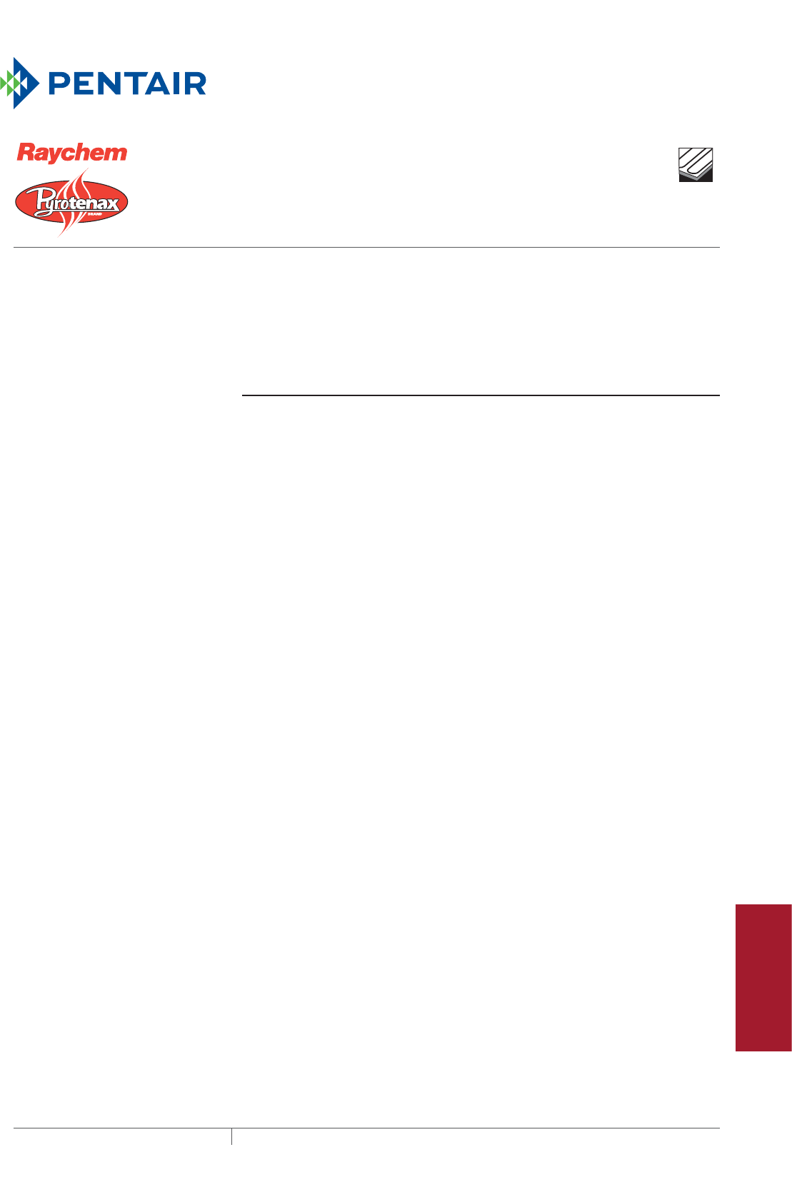
259THERMAL MANAGEMENT SOLUTIONS EN-FloorHeatingSystem-DG-H58157 11/13
Pipe Freeze Protection
and Flow Maintenance
Fire Sprinkler System
Freeze Protection
Roof and Gutter
De-Icing
Surface Snow
Melting – MI
Surface Snow
Melting – ElectroMelt
Freezer Frost
Heave Prevention
Floor Heating Technical Data
Sheets
This step-by-step design guide provides the tools necessary to design a floor
heating system using Raychem RaySol self-regulating heating cable system,
Pyrotenax Mineral Insulated heating cable system, or Raychem QuickNet floor
heating system. For other applications or for design assistance, contact your Pentair
Thermal Management representative or phone Pentair Thermal Management at
(800)545-6258. Also, visit our web site at www.pentairthermal.com.
Contents
Introduction .........................................................260
How to Use this Guide ............................................260
Safety Guidelines ................................................260
Warranty .......................................................261
System Overview .....................................................262
Typical System ..................................................263
Self-Regulating Heating Cable Construction ..........................265
MI Heating Cable Construction .....................................267
QuickNet Floor Heating Mat Construction ............................268
Floor Heating Application Design. . . . . . . . . . . . . . . . . . . . . . . . . . . . . . . . . . . . . . . . 269
Design Step by Step ..............................................269
Step 1 Determine the application ................................270
Step 2 Select the heating cable system and installation method .......271
Step 3 Determine the floor configuration ..........................271
Step 4 Determine the heating cable spacing, layout and length ........275
Step 5 Determine the electrical parameters .......................298
Step 6 Select the connection kits and accessories ..................302
Step 7 Select the control system .................................305
Step 8 Select the power distribution .............................308
Step 9 Complete the Bill of Materials .............................313
Floor Heating Pre-Design Worksheet ....................................314
RaySol Heating Cable Floor Heating Design Worksheet .....................315
Heat Loss Replacement ...........................................315
Comfort Floor Heating ............................................318
MI Heating Cable Floor Heating Design Worksheet .........................323
Heat Loss Replacement ...........................................323
Comfort Floor Heating ............................................325
Radiant Space Heating ............................................326
QuickNet Floor Heating System Design Worksheet .........................331
Comfort Heating .................................................331
FLOOR HEATING RAYSOL, MINERAL
INSULATED, AND QUICKNET HEATING SYSTEMS

THERMAL MANAGEMENT SOLUTIONS
EN-FloorHeatingSystem-DG-H58157 11/13
260
INTRODUCTION
Pentair Thermal Management offers three different heating cable systems for floor
heating: Raychem RaySol, Pyrotenax MI, and Raychem QuickNet. RaySol heating
cables and MI heating cables can be directly attached to the bottom of the concrete
floor or be directly embedded in the concrete floor or in a thick mortar bed. QuickNet
floor heating mats must be embedded in thin-set or self-leveling mortar.
If your application conditions are different than described in this guide, or if you have
any questions, contact your Pentair Thermal Management representative or contact
Pentair Thermal Management directly at (800) 545-6258.
How to Use this Guide
This design guide presents Pentair Thermal Management’ recommendations for
designing floor heating systems. It provides design and performance data, electrical
sizing information, control selection and heating-cable layout suggestions. Following
these recommendations will result in a reliable, energy-efficient system.
Follow the design steps and use the appropriate design worksheets to document the
project parameters that you will need for your project’s Bill of Materials.
OTHER REQUIRED DOCUMENTS
This guide is not intended to provide comprehensive installation instructions. For
complete floor heating system installation instructions, please refer to the following
additional required documents:
• Raychem RaySol Floor Heating and Freezer Frost Heave Prevention Installation
and Operation Manual (H58138)
• Pyrotenax Mineral Insulated Heating Cable Floor Heating and Freezer Frost
Heave Prevention Installation and Operation Manual (H58137)
• Raychem QuickNet System Installation Manual (H57704)
• Additional installation instructions are included with the connection kits, thermo-
stats, controllers, and accessories
If you do not have these documents, you can obtain them from the Pentair Thermal
Management web site at www.pentairthermal.com.
For products and applications not covered by this design guide, please contact your
Pentair Thermal Management representative or call Pentair Thermal Management
directly at (800)545-6258.
Safety Guidelines
As with any electrical equipment, the safety and reliability of any system depends
on the quality of the products selected and the manner in which they are installed
and maintained. Incorrect design, handling, installation, or maintenance of any of
the system components could damage the system and may result in inadequate
performance, overheating, electric shock, or fire. To minimize these risks and to
ensure that the system performs reliably, read and carefully follow the information,
warnings, and instructions in this guide.
FLOOR HEATING RAYSOL, MINERAL INSULATED, AND QUICKNET HEATING SYSTEMS
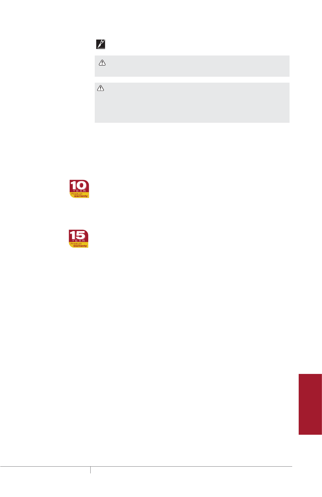
261 THERMAL MANAGEMENT SOLUTIONS EN-FloorHeatingSystem-DG-H58157 11/13
Pipe Freeze Protection
and Flow Maintenance
Fire Sprinkler System
Freeze Protection
Roof and Gutter
De-Icing
Surface Snow
Melting – MI
Surface Snow
Melting – ElectroMelt
Freezer Frost
Heave Prevention
Floor Heating Technical Data
Sheets
This symbol identifies important instructions or information.
This symbol identifies particularly important safety warnings that must be
followed.
WARNING: To minimize the danger of fire from sustained electrical arcing if
the heating cable is damaged or improperly installed, and to comply with the
requirements of Pentair Thermal Management, agency certifications, and national
electrical codes, ground-fault equipment protection must be used on each heating
cable branch circuit. Arcing may not be stopped by conventional circuit protection.
Warranty
Pentair Thermal Management’ standard limited warranty applies to Raychem and
Pyrotenax Floor Heating Systems.
FOR RAYCHEM RAYSOL AND PYROTENAX MI HEATING CABLES
An extension of the limited warranty period to ten (10) years from the date of
installation is available, except for the control and distribution systems, if a properly
completed online warranty form is submitted within thirty (30) days from the date of
installation. You can access the complete warranty on our web site at
www.pentairthermal.com.
FOR RAYCHEM QUICKNET FLOOR HEATING SYSTEM
The QuickNet system standard limited warranty is two (2) years from the date of
purchase. An extension of the limited warranty period to fifteen (15) years is available
for the QuickNet mat only, if a properly completed online warranty form is submitted
within thirty (30) days from the date of purchase. You can access the complete
warranty on our web site at www.raychemfloorheating.com.
Introduction

THERMAL MANAGEMENT SOLUTIONS
EN-FloorHeatingSystem-DG-H58157 11/13
262
SYSTEM OVERVIEW
There are three main floor heating applications:
• Heat loss replacement
• Comfort floor heating (includes concrete floor heating)
• Radiant space heating
Pentair Thermal Management offers three different heating cable systems for floor
heating: Raychem RaySol self-regulating, Pyrotenax MI, and Raychem QuickNet.
Each product has specific design and installation considerations and this guide will
address how to design the system that best suits your needs. RaySol and MI heating
cables can be installed in multiple methods; however, the most common methods
will be covered.
HEAT LOSS REPLACEMENT
Raychem RaySol and Pyrotenax MI heating cables can be used to eliminate the
chill felt from the heat lost through floors over non-heated areas such as garages,
loading docks or arcades. The heating cables achieve this by replacing the heat
normally lost through the floor insulation over a cold space.
For heat loss replacement, both RaySol and MI heating cables can be used and are
attached to the bottom of the concrete floor.
COMFORT FLOOR HEATING
QuickNet floor heating mats and Raychem RaySol and Pyrotenax MI heating
cables can heat floors in places such as lobbies, foyers, bathrooms, kitchens and
gymnasiums. The heating cables are used to raise the floor temperature to 80°F
(27°C) or warmer so it is comfortable to walk on the floor in bare feet.
For comfort floor heating, all three heating cable technologies can be used. RaySol
and HDPE jacketed copper sheathed MI heating cables can be directly embedded in
mortar or concrete. QuickNet heating mats must be embedded in thin-set or self-
leveling mortar under ceramic tile or natural stone.
RADIANT SPACE HEATING
RaySol and MI heating cable systems can be designed to provide primary space
heating for rooms with concrete floors. RaySol heating cable systems must be
custom designed through Pentair Thermal Management. Contact your Pentair
Thermal Management representative or call Pentair Thermal Management at
(800) 545-6258 for design assistance.
For radiant space heating, both RaySol and MI heating cables can be used and are
directly embedded in mortar or concrete.
FLOOR HEATING RAYSOL, MINERAL INSULATED, AND QUICKNET HEATING SYSTEMS
263 THERMAL MANAGEMENT SOLUTIONS EN-FloorHeatingSystem-DG-H58157 11/13
Pipe Freeze Protection
and Flow Maintenance
Fire Sprinkler System
Freeze Protection
Roof and Gutter
De-Icing
Surface Snow
Melting – MI
Surface Snow
Melting – ElectroMelt
Freezer Frost
Heave Prevention
Floor Heating Technical Data
Sheets
Typical System
The following illustration shows a typical heat loss replacement system.
Controller
Splice Kit
Mineral insulated
Heating cable Heating cable
RaySol
Power Connection Kit
Fig. 1 Typical heat loss replacement system
The following illustration shows a typical heat loss replacement installation.
Concrete
Insulation
Heating cable
Fig. 2 Typical heat loss replacement installation
System Overview
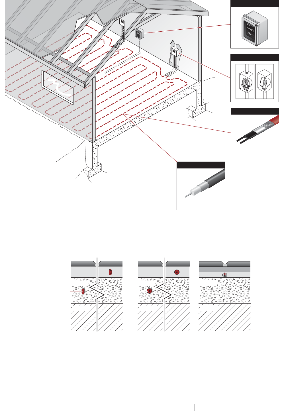
THERMAL MANAGEMENT SOLUTIONS
EN-FloorHeatingSystem-DG-H58157 11/13
264
The following illustration shows a typical comfort floor heating system.
Heating cable
Mineral insulated
RaySol
Heating cable
Thermostat
Power Connection Kit
Fig. 3 Typical comfort floor heating system
The following illustration shows a typical comfort floor heating system installation.
Insulation
RaySol heating cable
in concrete in mortar
MI heating cable
in concrete in mortar
QuickNet mat
RaySol
heating
cable
Concrete
Tile
Thin-set or self-leveling mortar
Thin-set or self-leveling mortar
Insulation
Concrete
Tile
Mortar
Insulation
Concrete
Tile
Mortar
MI
heating
cable
tile, laminate & hardwood floors
Fig. 4 Typical comfort floor heating system installation
A radiant space heating system is similar to the illustration in Fig. 3. RaySol heating
cable systems must be custom designed through Pentair Thermal Management.
Contact your Pentair Thermal Management representative or call Pentair Thermal
Management at (800) 545-6258 for design assistance.
FLOOR HEATING RAYSOL, MINERAL INSULATED, AND QUICKNET HEATING SYSTEMS
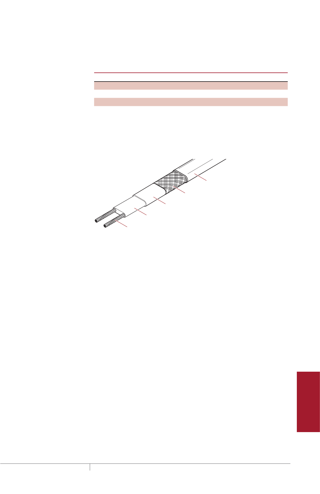
265 THERMAL MANAGEMENT SOLUTIONS EN-FloorHeatingSystem-DG-H58157 11/13
Pipe Freeze Protection
and Flow Maintenance
Fire Sprinkler System
Freeze Protection
Roof and Gutter
De-Icing
Surface Snow
Melting – MI
Surface Snow
Melting – ElectroMelt
Freezer Frost
Heave Prevention
Floor Heating Technical Data
Sheets
Table 1 summarizes which heating cable can be used for which floor heating
application.
TABLE 1 FLOOR HEATING APPLICATIONS AND RECOMMENDED HEATING
CABLES
Application
RaySol MI QuickNet
Heat loss replacement x x –
Comfort floor heating x x x
Radiant space heating x x –
Self-Regulating Heating Cable Construction
Raychem RaySol self-regulating heating cables are comprised of two parallel
nickel-coated bus wires in a cross-linked polymer core, a tinned copper braid, and a
fluoropolymer outer jacket. These cables are cut to length simplifying the application
design and installation.
Nickel-plated copper bus wires
Self-regulating conductive core
Modified polyolefin inner jacket
Tinned-copper braid
Fluoropolymer outer jacket
Fig. 5 Typical RaySol heating cable construction
With self-regulating technology, the number of electrical paths between bus wires
changes in response to temperature fluctuations. As the temperature surrounding
the heater decreases, the conductive core contracts microscopically. This contraction
decreases electrical resistance and creates numerous electrical paths between the
bus wires. Current flows across these paths to warm the core.
As the temperature rises, the core expands microscopically. This expansion
increases electrical resistance and the number of electrical paths decreases. The
heating cable automatically reduces its output.
System Overview
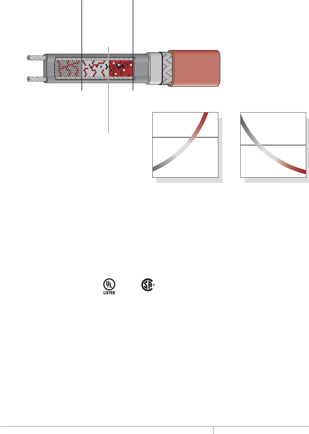
THERMAL MANAGEMENT SOLUTIONS
EN-FloorHeatingSystem-DG-H58157 11/13
266
At low temperature,
there are many
conducting paths,
resulting in high output
and rapid heat-up. Heat
is generated only when it
is needed and precisely
where it is needed.
At high temperature,
there are few conduct-
ing paths and output is
correspondingly lower,
conserving energy
during operation.
At moderate temperature,
there are fewer conducting
paths because the heating
cable efficiently adjusts by
decreasing output, eliminating
any possibility of overheating.
The following graphs illustrate the response of self-regulating heating
cables to changes in temperature. As the temperature rises, electrical
resistance increases, and our heaters reduce their power output.
Temperature
Resistance
Power
Temperature
Constant wattage
Constant wattage
Self-regulating
Self-regulating
Fig. 6 Self-regulating heating cable technology
CODES AND APPROVALS
The RaySol system is UL Listed for heat loss replacement, comfort floor heating and
radiant space heating applications.
The RaySol system is CSA Certified for comfort floor heating and radiant space
heating applications. For heat loss replacement applications where the cable is
attached to the bottom of the concrete floor, contact Pentair Thermal Management
for additional information.
-w
FLOOR HEATING RAYSOL, MINERAL INSULATED, AND QUICKNET HEATING SYSTEMS
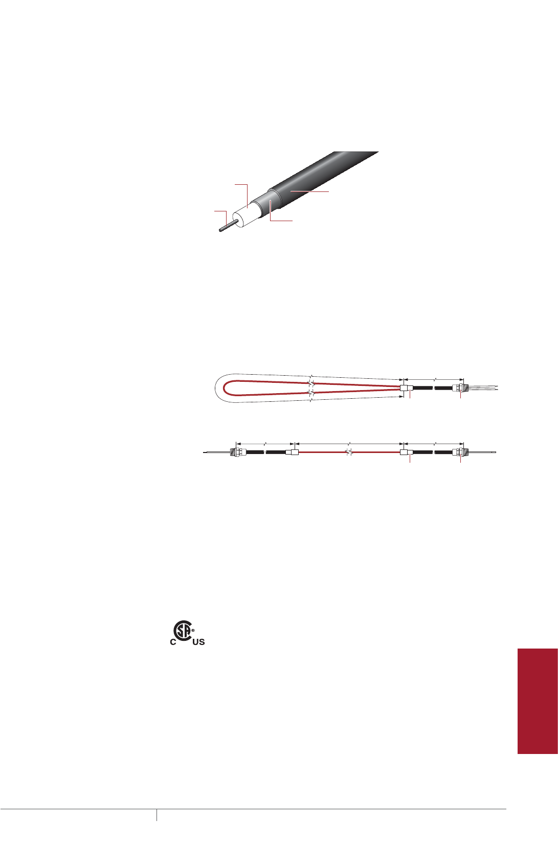
267 THERMAL MANAGEMENT SOLUTIONS EN-FloorHeatingSystem-DG-H58157 11/13
Pipe Freeze Protection
and Flow Maintenance
Fire Sprinkler System
Freeze Protection
Roof and Gutter
De-Icing
Surface Snow
Melting – MI
Surface Snow
Melting – ElectroMelt
Freezer Frost
Heave Prevention
Floor Heating Technical Data
Sheets
MI Heating Cable Construction
Pyrotenax MI heating cables used for floor heating applications are comprised of
a single conductor surrounded by magnesium oxide insulation and a solid copper
sheath. For embedded applications, such as comfort floor heating and radiant space
heating, the heating cable also has an extruded high density polyethylene (HDPE)
jacket.
Heating
conductor
Single-conductor cable (61 series)
Heating cable construction
Copper sheath
HDPE jacket
(for embedded cables only)
Insulation
(magnesium oxide)
Fig. 7 Typical MI heating cable construction
The heating cables are supplied as complete factory-fabricated assemblies
consisting of an MI heating cable that is joined to a section of MI non-heating cold
lead and terminated with NPT connectors. Two configurations are available: Type
SUA consisting of a looped cable joined to a single 7 ft (2.1 m) cold lead with one
1/2-in NPT connector; and Types SUB, HLR and FH consisting of a single run of
cable with a 15 ft (4.6 m) cold lead and a 1/2-in NPT connector on each end.
Hot/cold
joint
NPT threaded
connector
Hot/cold
joint
NPT threaded
connector
Heated length
Heated length Cold lead length
Cold lead length
Cold lead length
Type SUA
Types SUB, HLR and FH
Fig. 8 Configurations for surface mount or directly embedded in concrete installations
Pentair Thermal Management offers all the components necessary for system
installation. Details of these components and additional accessories can be found
later in this design guide.
CODES AND APPROVALS
The MI system is c-CSA-us Certified for comfort floor heating and radiant space
heating applications. For heat loss replacement applications where the cable is
attached to the bottom of the concrete floor, contact Pentair Thermal Management
for additional information.
-PS
System Overview
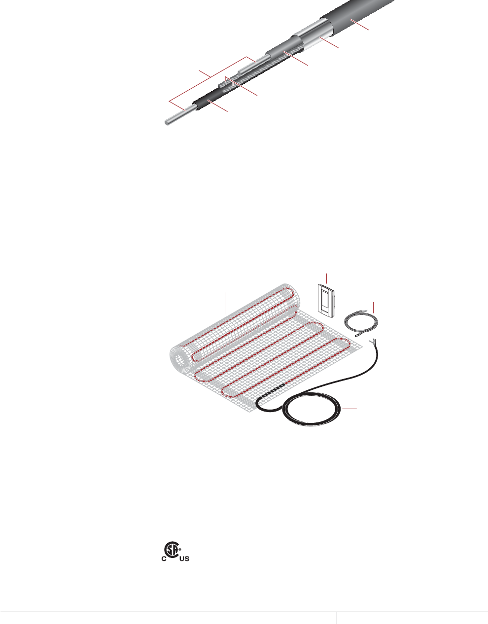
THERMAL MANAGEMENT SOLUTIONS
EN-FloorHeatingSystem-DG-H58157 11/13
268
QuickNet Floor Heating Mat Construction
Raychem QuickNet is an electric floor heating system for installation directly under
ceramic tiles, natural stone, laminate and engineered wood. The floor heating mats
are pre-terminated for use with 120, 208 or 240V, and are available in 20-inch
(51 cm) widths for areas ranging from 10 to 200 ft² (0.9 to 18.6 m²).
QuickNet heating cables are comprised of two fluoropolymer jacketed conductors,
ground wires, Mylar foil and a fluoropolymer outer jacket.
Ground wires
Conductors
Mylar foil
Outer fluoro-
polymer jacket
Fluoropolymer jacket
Fluoropolymer
jacket
Fig. 9 QuickNet heating cable construction
The QuickNet floor heating system includes the heating cable woven into an
adhesive-backed fiberglass mesh that allows for simple roll-out installation
without worrying about heating cable spacing. The mats emit no measurable
electromagnetic fields due to the shielded dual conductor design and require
only one cold lead connection, making it easy to lay out and install. Each standard
QuickNet floor heating kit includes a programmable Energy Star-rated QuickStat-TC
thermostat with built-in GFCI protection and floor sensor. Extension kits without the
thermostat are also available.
QuickNet floor
heating mat Floor
temperature
sensor
Cold lead
QuickStat-TC
thermostat
Fig. 10 QuickNet floor heating system components
CODES AND APPROVALS
Installation of Raychem QuickNet floor heating systems are governed by national
and local electrical codes. Pentair Thermal Management, the NEC, and the CEC
all require the use of ground-fault protection to reduce the risk of fire caused by
damage or improper installation.
The QuickNet system is c-CSA-us Certified for use in nonhazardous locations.
FLOOR HEATING RAYSOL, MINERAL INSULATED, AND QUICKNET HEATING SYSTEMS

269 THERMAL MANAGEMENT SOLUTIONS EN-FloorHeatingSystem-DG-H58157 11/13
Pipe Freeze Protection
and Flow Maintenance
Fire Sprinkler System
Freeze Protection
Roof and Gutter
De-Icing
Surface Snow
Melting – MI
Surface Snow
Melting – ElectroMelt
Freezer Frost
Heave Prevention
Floor Heating Technical Data
Sheets
FLOOR HEATING APPLICATION DESIGN
This section guides you through the steps necessary to design the correct system for
your application. The examples provided in each step are intended to incrementally
illustrate the project parameter output for sample designs from start to finish. As
you go through each step, use the appropriate design worksheets to document your
project parameters, so that by the end of this section, you will have the information
you need for your Bill of Materials.
For products and applications not covered by this design guide, please contact your
Pentair Thermal Management representative or call Pentair Thermal Management
directly at (800) 545-6258.
Design Step by Step
Your system design requires the following essential steps:
Determine the application
– Heat loss replacement
– Comfort floor heating
– Radiant space heating
Select the heating cable system and installation method
– Heat loss replacement
– Comfort floor heating
– Radiant space heating
Determine the floor configuration
Determine the heating cable spacing, layout, and length
– RaySol heating cables
– MI heating cables
– QuickNet floor heating mats
Determine the electrical parameters
Select the connection kits and accessories
Select the control system
Select the power distribution
Complete the Bill of Materials
Depending on the heating cable system you select, use one of the following
worksheets to help you document the project parameters you will need for your
project’s Bill of Materials:
• Preliminary worksheet for determining your project’s application and product line
on page314.
• The “RaySol Heating Cable Floor Heating Design Worksheet” on page315.
• The “MI Heating Cable Floor Heating Design Worksheet” on page323.
• The “QuickNet Floor Heating System Design Worksheet” on page331.
Floor Heating Application Design

THERMAL MANAGEMENT SOLUTIONS
EN-FloorHeatingSystem-DG-H58157 11/13
270
Floor Heating System
Design Steps
1. Determine the
application
3. Determine the
floor configuration
4. Determine the
heating cable spacing,
layout and length
5. Determine the
electrical parameters
6. Select the
connection kits
and accessories
7. Select the control
system
8. Select the power
distribution
9. Complete the Bill
of Materials
2. Select the heating
cable system and
installation method
Step Determine the application
This step further defines the specific application and design assumptions. Once the
application is verified, you will select the appropriate heating system in Step 2.
HEAT LOSS REPLACEMENT
A heat loss replacement system uses RaySol and MI heating cables for concrete
floors built over garages, loading docks, arcades, or other cold spaces. The design
goal is to prevent the floor over a cold space from cooling below room temperature.
The heating cable system achieves this by replacing the heat normally lost through
the floor insulation over a cold space.
A successful design must conform to the following requirements:
• The floor to be heated is indoors where the room temperature above the floor is
approximately 70°F (21°C).
• RaySol and MI heating cables will be attached to the bottom of the concrete floor.
If it is necessary to install RaySol or MI cables in conduit or to directly embed the
MI cables in the concrete floor, contact your Pentair Thermal Management repre-
sentative or Pentair Thermal Management at (800) 545-6258 for design
assistance.
• The bottom of the floor is insulated.
COMFORT FLOOR HEATING
A comfort floor heating system uses RaySol, MI heating cables, or QuickNet floor
heating mats for bathrooms, kitchens, foyers, schools, or gymnasiums. The design
goal is to raise the floor temperature to 80°F (27°C) or above so it is comfortable
to walk on the floor with bare feet. RaySol and HDPE jacketed copper sheathed MI
heating cables are directly embedded in mortar or concrete. QuickNet heating mats
must be embedded in thin-set or self-leveling mortar and must be installed under
ceramic or natural stone.
A successful design must conform to the following requirements:
• For RaySol, the floor to be heated is indoors, and is located on grade or is located
above an area where the ambient temperature is approximately 70°F (21°C) or the
bottom of the floor is insulated.
• For MI and QuickNet, the floor to be heated is indoors, and is located on grade or
is located above an area where the ambient temperature is approximately 70°F
(21°C) or the bottom of the floor is insulated with minimum R-20 insulation when
exposed to the outside ambient air temperature.
• RaySol and HDPE jacketed copper sheathed MI heating cables are embedded in
a standard concrete floor or embedded in a mortar layer (at least 3/4 in (2 cm)
thick) under ceramic tile or natural stone.
• QuickNet floor heating mats are embedded in a thin-set or self-leveling mortar
layer and installed under ceramic tile or natural stone.
• The heating cables or floor heating mats shall not be installed in shower floors,
under tubs and spas, or under other permanent fixtures.
RADIANT SPACE HEATING
RaySol and MI heating cable systems can be designed to provide primary space
heating for rooms with concrete floors. RaySol heating cable systems must be
custom designed by Pentair Thermal Management. Contact your Pentair Thermal
Management representative or call Pentair Thermal Management at (800) 545-6258
for design assistance.
A successful design must conform to the following requirements:
• The Btu requirement and total heated area are provided by the customer.
• The bottom of the floor is insulated or located on grade.
FLOOR HEATING RAYSOL, MINERAL INSULATED, AND QUICKNET HEATING SYSTEMS
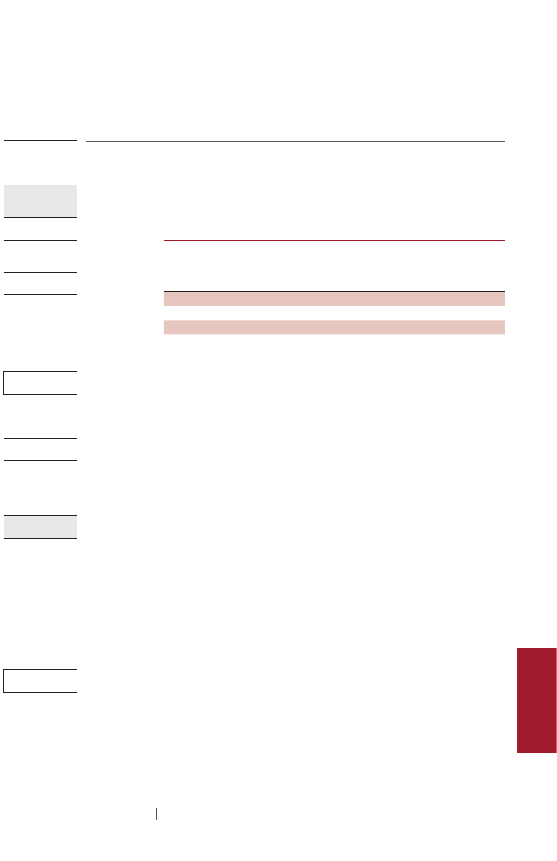
271 THERMAL MANAGEMENT SOLUTIONS EN-FloorHeatingSystem-DG-H58157 11/13
Pipe Freeze Protection
and Flow Maintenance
Fire Sprinkler System
Freeze Protection
Roof and Gutter
De-Icing
Surface Snow
Melting – MI
Surface Snow
Melting – ElectroMelt
Freezer Frost
Heave Prevention
Floor Heating Technical Data
Sheets
• RaySol and HDPE jacketed copper sheathed MI heating cables are embedded in a
concrete floor or embedded in mortar (at least 3/4 in (2 cm) thick), under ceramic
tile or natural stone.
• The heating cable shall not be installed in shower floors, under tubs and spas, or
under other permanent fixtures.
Floor Heating System
Design Steps
1. Determine the
application
3. Determine the
floor configuration
4. Determine the
heating cable spacing,
layout and length
5. Determine the
electrical parameters
6. Select the
connection kits
and accessories
7. Select the control
system
8. Select the power
distribution
9. Complete the Bill
of Materials
2. Select the heating
cable system and
installation method
Step Select the heating cable system and installation method
In this step you will determine the heating cable system and installation method to
suit your specific needs. Table 2 indicates the various installation methods that will
be discussed in this design guide for each heating cable technology as it pertains to
each application.
TABLE 2 INSTALLATION METHODS BY HEATING CABLE AND APPLICATION
Heat loss
replacement Comfort floor heating
Radiant space
heating
Installation
method
RaySol MI RaySol MI QuickNet RaySol MI
Attach to bottom x x – – – – –
Embed in concrete – – x x – x x
Embed in mortar bed – – x x – x x
Embed in thin-set or
self-leveling mortar
– – – – x – –
Floor Heating System
Design Steps
1. Determine the
application
3. Determine the
floor configuration
4. Determine the
heating cable spacing,
layout and length
5. Determine the
electrical parameters
6. Select the
connection kits
and accessories
7. Select the control
system
8. Select the power
distribution
9. Complete the Bill
of Materials
2. Select the heating
cable system and
installation method
Step Determine the floor configuration
All floor heating applications require determining the area to be heated. For heat
loss replacement and comfort floor heating you will also need the minimum ambient
design temperature and the insulation R-value. For radiant space heating you will
need to provide the Btu requirement.
In this design guide, two floor layouts will be used to illustrate all floor heating
applications. The first example will be for heat loss replacement and the second
example will be for comfort floor heating and radiant space heating.
HEAT LOSS REPLACEMENT
GATHERING INFORMATION
When using this guide to design a system you need the following information:
• Size and layout of exposed floor
• Minimum ambient design temperature
• Insulation R-value
• Supply voltage and phase
• Control requirements
Floor Heating Application Design

THERMAL MANAGEMENT SOLUTIONS
EN-FloorHeatingSystem-DG-H58157 11/13
272
PREPARE SCALE DRAWING
Draw to scale the floor area to be heated. Carefully note the limits of the area to be
heated. Show all concrete joints on the drawing and note the voltage supply location,
and location and size of obstacles, such as floor drains, pipe penetrations, conduit
runs, columns and fixtures.
For heat loss replacement, the entire floor is considered the area to be heated.
Heated area = Total area
Side A
80 ft (24.4 m)
Side B
40 ft (12.2 m)
Fig. 11 Floor layout for heat loss replacement example
DETERMINE MINIMUM AMBIENT DESIGN TEMPERATURE
Determine the lowest temperature that is expected below the floor insulation.
RECORD INSULATION RVALUE
The insulation R-value is the thermal resistance of the floor’s insulation. Normally,
the R-value will be printed on the insulation material. If that is not the case, you can
calculate it by dividing the insulation thickness in inches by the insulation thermal
conductivity.
Example: RaySol heating cables for heat loss replacement
Heated area 80 ft x 40 ft = 3200 ft² (see Fig. 11)
(24.4 m x 12.2 m = 297.4 m²)
Minimum ambient design temperature –10°F (–23°C)
Insulation R-value R-20 (20 ft²·°F·hr/Btu)
Supply voltage and phase 208 V, single-phase
Control requirements Electronic thermostat, monitoring requested
Example: MI heating cables for heat loss replacement
Heated area 80 ft x 40 ft = 3200 ft² (see Fig. 11)
(24.4 m x 12.2 m = 297.4 m²)
Minimum ambient design temperature –10°F (–23°C)
Insulation R-value R-20 (20 ft²·°F·hr/Btu)
Supply voltage and phase 208 V, three-phase
Control requirements Electronic thermostat, monitoring requested
Advance to Step 4, page275.
FLOOR HEATING RAYSOL, MINERAL INSULATED, AND QUICKNET HEATING SYSTEMS

273 THERMAL MANAGEMENT SOLUTIONS EN-FloorHeatingSystem-DG-H58157 11/13
Pipe Freeze Protection
and Flow Maintenance
Fire Sprinkler System
Freeze Protection
Roof and Gutter
De-Icing
Surface Snow
Melting – MI
Surface Snow
Melting – ElectroMelt
Freezer Frost
Heave Prevention
Floor Heating Technical Data
Sheets
COMFORT FLOOR HEATING
GATHERING INFORMATION
When using this guide to design a system you need the following information:
• Size and layout of floor
• Minimum ambient design temperature
• Insulation R-value
• Supply voltage and phase
• Control requirements
For comfort floor heating, it is also important to note the locations of shower floors,
tubs, spas, toilets, and other permanent fixtures and subtract these areas from the
total area.
Heated area = Total area – Permanent fixture space
Side A
34 ft (10.4 m)
Hotel lobby
4 Columns
(11 ft2 / 1 m2)
Counter (22 ft2 / 2 m2)
Entrance
Side B
20 ft (6.1 m)
Fig. 12 Floor layout for comfort floor heating example
DETERMINE MINIMUM AMBIENT DESIGN TEMPERATURE
Determine the lowest temperature that is expected below the floor insulation.
RECORD INSULATION RVALUE
The insulation R-value is the thermal resistance of the floor’s insulation. Normally,
the R-value will be printed on the insulation material. If that is not the case, you can
calculate it by dividing the insulation thickness in inches by the insulation thermal
conductivity.
Example: Comfort floor heating (RaySol and MI heating cables, QuickNet heating
mats)
Heated area (34 ft x 20 ft) – (22 ft² + 11 ft²) = 647 ft²
(see Fig. 12)
(10.4 m x 6.1 m) – (2 m² + 1 m²) = 60.4 m²
Minimum ambient design temperature 10°F (–12°C)
Insulation R-value R-30 (30 ft²·°F·hr/Btu)
Supply voltage and phase 208 V, single-phase
Control requirements Electronic thermostat
Advance to Step 4, page275.
Floor Heating Application Design
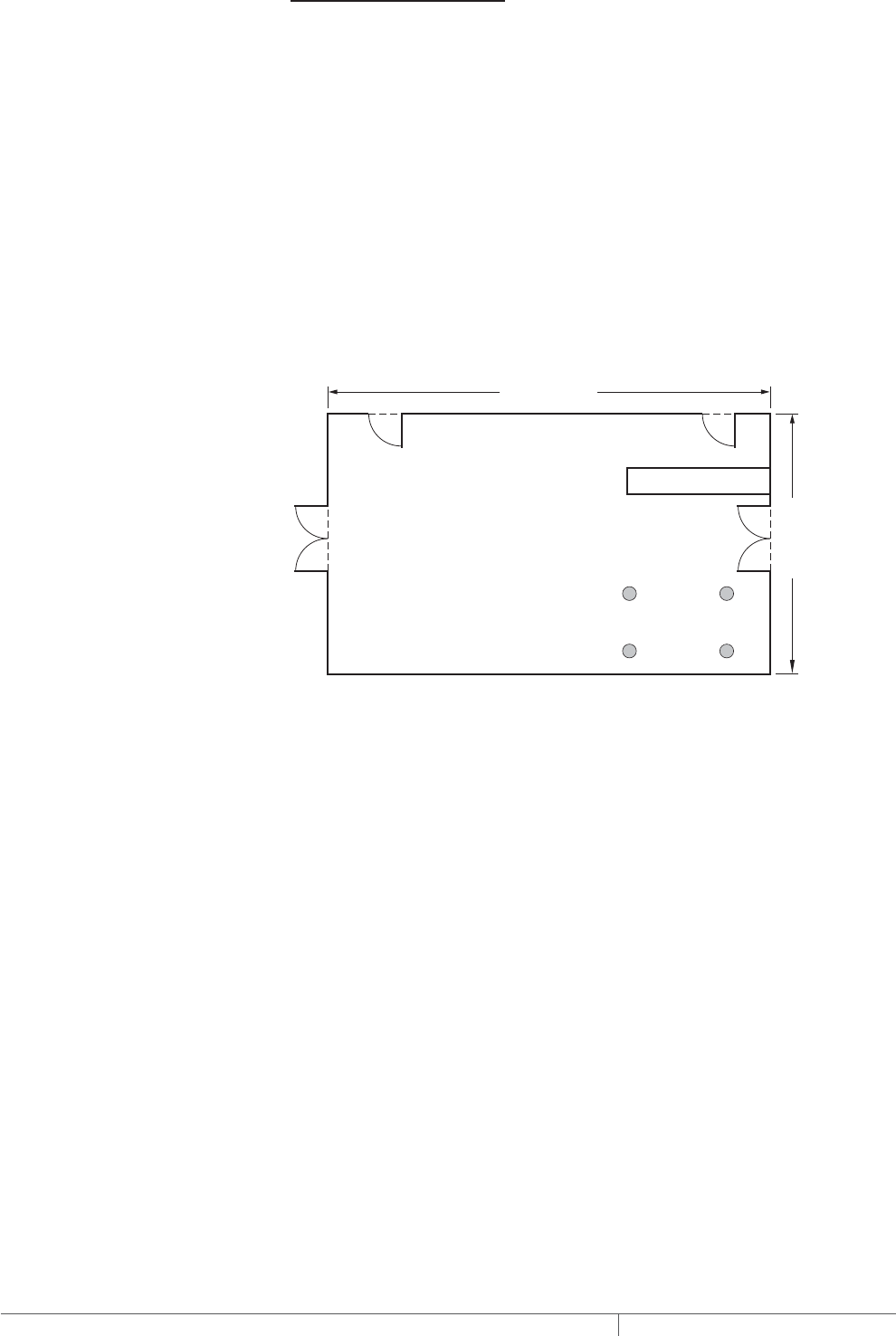
THERMAL MANAGEMENT SOLUTIONS
EN-FloorHeatingSystem-DG-H58157 11/13
274
RADIANT SPACE HEATING
GATHERING INFORMATION
When using this guide to design a system you need the following information:
• Size and layout of floor
• The Btu requirement (heat loss) calculated by the engineer or architect
• Supply voltage and phase
• Control requirements
For radiant space heating, the heat loss, or Btu required, is based on the total area of
the room. However, the heating cable must not be installed under the area occupied
by columns, fixtures, shower floors, tubs and spas, toilets and other permanent
fixtures. To determine the area in which the heating cable will be installed, subtract
the area occupied by these permanent fixtures from the total area.
Heated area = Total area – Permanent fixture space
Side A
34 ft (10.4 m)
Hotel lobby
4 Columns
(11 ft2 / 1 m2)
Counter (22 ft2 / 2 m2)
Entrance
Side B
20 ft (6.1 m)
Fig. 13 Floor layout for radiant space heating example
Example: MI heating cables for radiant space heating
Floor area (34 ft x 20 ft) – (22 ft² + 11 ft²) = 647 ft²
(see Fig. 13)
(10.4 m x 6.1 m) – (2 m² + 1 m²) = 60.4 m²
Btu requirement 34,800 Btu / hr (supplied by engineer)
Supply voltage and phase 208 V, single-phase
Control requirements Electronic thermostat
Advance to Step 4.
FLOOR HEATING RAYSOL, MINERAL INSULATED, AND QUICKNET HEATING SYSTEMS

275 THERMAL MANAGEMENT SOLUTIONS EN-FloorHeatingSystem-DG-H58157 11/13
Pipe Freeze Protection
and Flow Maintenance
Fire Sprinkler System
Freeze Protection
Roof and Gutter
De-Icing
Surface Snow
Melting – MI
Surface Snow
Melting – ElectroMelt
Freezer Frost
Heave Prevention
Floor Heating Technical Data
Sheets
Floor Heating System
Design Steps
1. Determine the
application
3. Determine the
floor configuration
4. Determine the
heating cable spacing,
layout and length
5. Determine the
electrical parameters
6. Select the
connection kits
and accessories
7. Select the control
system
8. Select the power
distribution
9. Complete the Bill
of Materials
2. Select the heating
cable system and
installation method
Step Determine the heating cable spacing, layout and length
In this step you will select the heating cable and determine the spacing, layout and
length. This section is organized by heating cable type with specific design criteria
for each application and installation method.
• For RaySol self-regulating heating cable design
– For heat loss replacement, see below.
– For comfort floor heating, see page279.
• For MI heating cable design
– For heat loss replacement, see page283.
– For comfort floor heating, see page288.
– For radiant space heating, see page292.
• For QuickNet floor heating design, see page294.
RAYSOL SELFREGULATING HEATING CABLE SYSTEM DESIGN
HEAT LOSS REPLACEMENT
Design a RaySol heating cable system for heat loss replacement as follows:
1. Select the appropriate RaySol heating cable
Select the heating cable based on the operating voltage. For 120 V, select RaySol-1;
for 208–277 V, select RaySol-2.
TABLE 3 RAYSOL HEATING CABLE
Supply voltage Catalog number
120 V RaySol-1
208–277 V RaySol-2
Example: RaySol heating cables for heat loss replacement
Supply voltage 208 V (from Step 3)
Catalog number RaySol-2
Floor Heating Application Design
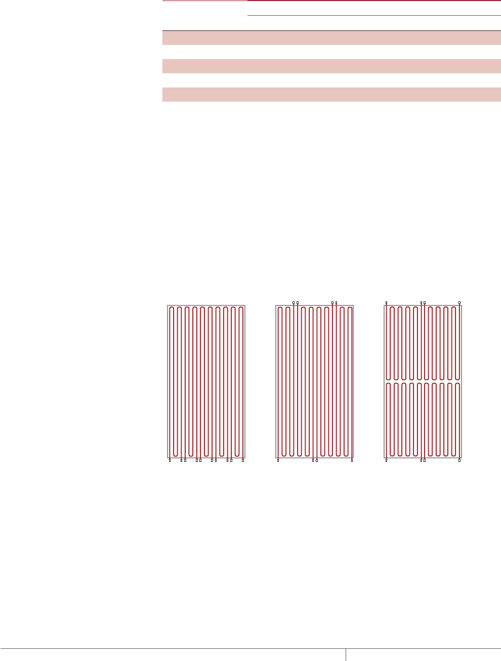
THERMAL MANAGEMENT SOLUTIONS
EN-FloorHeatingSystem-DG-H58157 11/13
276
2. Determine the RaySol heating cable spacing
Use the minimum ambient design temperature and the floor insulation R-value
(from Step 3) to select the correct spacing shown in Table 4 for heat loss
replacement. If the calculated R-value or minimum design temperature does not
match the values in the table, use the values that give the closer spacing.
TABLE 4 RAYSOL HEATING CABLE SPACING FOR HEAT LOSS REPLACEMENT
Minimum ambient
design temperature
Floor insulation R-value (ft
²
·°F·hr/Btu)
R-10 R-20 R-30 R-40
50°F (10°C) 30 in (73 cm) 36 in (91 cm) 36 in (91 cm) 36 in (91 cm)
30°F (–1°C) 24 in (61 cm) 30 in (76 cm) 36 in (91 cm) 36 in (91 cm)
10°F (–12°C) 21 in (53 cm) 30 in (76 cm) 30 in (76 cm) 36 in (91 cm)
–10°F (–23°C) 18 in (46 cm) 24 in (61 cm) 30 in (76 cm) 36 in (91 cm)
–30°F (–34°C) 15 in (38 cm) 24 in (61 cm) 30 in (76 cm) 36 in (91 cm)
If the space below the floor is maintained at 50–70°F (10–21°C), insulate the floor to
R-10 minimum and select a heating cable spacing from the 50°F (10°C) row in
Table 4.
Example: RaySol heating cables for heat loss replacement
Minimum ambient design temperature –10°F (–23°C) (from Step 3)
Insulation R-value R-20 (from Step 3)
Heating cable spacing 24 in (61 cm)
3. Determine the RaySol heating cable layout and length
Estimate the heating cable length The length of heating cable and the number of
heating cable circuits can be estimated before a detailed layout is done if the heating
cable spacing, total heated area, and the available branch circuit breaker rating are
known. Fig. 14 shows typical layouts when the heating cable is directly attached to
the bottom of the floor.
CBA
Fig. 14 Typical heating cable layouts for heat loss replacement
FLOOR HEATING RAYSOL, MINERAL INSULATED, AND QUICKNET HEATING SYSTEMS
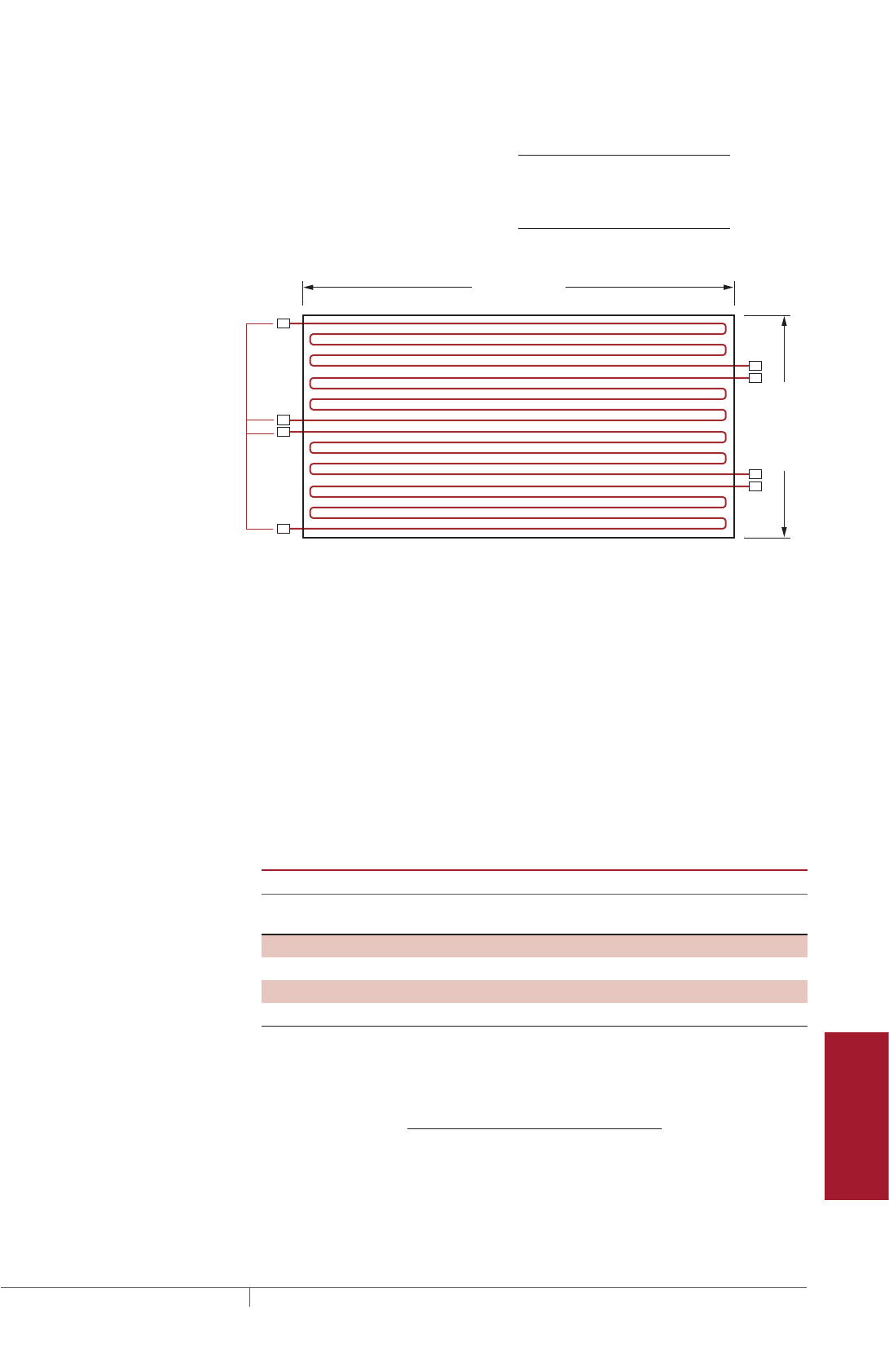
277 THERMAL MANAGEMENT SOLUTIONS EN-FloorHeatingSystem-DG-H58157 11/13
Pipe Freeze Protection
and Flow Maintenance
Fire Sprinkler System
Freeze Protection
Roof and Gutter
De-Icing
Surface Snow
Melting – MI
Surface Snow
Melting – ElectroMelt
Freezer Frost
Heave Prevention
Floor Heating Technical Data
Sheets
Estimate the heating cable length required:
Estimated heating cable length (ft) = Heated area (ft²) x 12
Spacing (in)
Estimated heating cable length (m) = Heated area (m²) x 100
Spacing (cm)
Side A
80 ft (24.4 m)
Junction boxes
Side B
40 ft (12.2 m)
Fig. 15 RaySol heating cable layout for heat loss replacement
Example: RaySol heating cable length for heat loss replacement
Heated area 3200 ft² (297.4 m²) (from Step 3, Fig. 11)
Estimated heating cable length 3200 ft² x 12 / 24 in = 1600 ft
297.4 m² x 100 / 61 cm = 487.5 m
4. Determine the maximum circuit length for the heating cable length
For the appropriate supply voltage, use Table 5 to select the maximum circuit length
which is closest to, but greater than the length calculated. If the estimated heating
cable length required is greater than the maximum circuit length, multiple circuits
must be used.
TABLE 5 MAXIMUM RAYSOL CIRCUIT LENGTH IN FEET METERS WHEN
ATTACHING HEATING CABLE TO THE BOTTOM OF THE FLOOR 40°F 4°C
STARTUP*
Supply voltage
120 V 208 V 240 V 277 V
Circuit breaker size
(A)
ft m ft m ft m ft m
15 120 36.6 205 62.5 210 64.0 215 65.5
20 160 48.8 275 83.8 285 86.9 290 88.4
30 240 73.2 410 125.0 425 129.5 430 131.1
40 240 73.2 410 125.0 425 129.5 430 131.1
*For start-up temperatures less than 40°F (4°C), contact your Pentair Thermal Management repre-
sentative.
Calculate the estimated number of circuits as follows:
Number of circuits = Estimated heating cable length (ft/m)
Maximum circuit length (ft/m)
Round the number of circuits to the next larger whole number.
Floor Heating Application Design

THERMAL MANAGEMENT SOLUTIONS
EN-FloorHeatingSystem-DG-H58157 11/13
278
Example: RaySol heating cable length for heat loss replacement
Estimated heating cable length 1600 ft (487.5 m) (from earlier in this step)
Supply voltage 208 V (from Step 3)
Maximum circuit length 410 ft (125 m) (from Table 5)
Number of circuits 1600 ft / 410 ft = 4 circuits (rounded)
Power supply Four 30 A circuit breakers (from Table 5)
5. Determine the additional heating cable allowance
Additional heating cable is required to make power connections and to route the
circuits to junction boxes. This extra heating cable need not be considered when
determining the maximum heating cable length for circuit breaker sizing. In order to
estimate the total heating cable length, you will need to take the estimated heating
cable length you already calculated, and then add heating cable allowances, as
follows:
Estimated total heating cable length = Estimated heating cable length + End allowances + Connection kit allowances
TABLE 6 RAYSOL ADDITIONAL HEATING CABLE ALLOWANCE
Heating cable allowance Description Length of cable
End allowances From end of protective conduit to
junction box
4 ft (1 m) per end
Connection kit allowances Required to assemble the
connection kit (one per circuit)
4 ft (1 m) per kit
Example: RaySol heating cable for heat loss replacement
Estimated heating cable length 1600 ft (487 m) (from earlier in this step)
End allowance 4 circuits x 4 ft per end x 2 ends = 32 ft (10 m)
(from Table 6)
Connection kit allowances 4 connection kits x 4 ft per kit = 16 ft (5 m)
(from Table 6)
Total heating cable allowances 32 ft (10 m) + 16 ft (5 m) = 48 ft (15 m)
Estimated total heating cable length 1600 ft (487 m) + 48 ft (15 m) = 1648 ft (502 m)
6. Locate the junction boxes for the RaySol heating cable system
The heating cable connects to the branch circuit wiring in a junction box with the
RaySol FTC-P power connection and end seal kit.
The junction boxes may be distributed around the area to be heated, or collected at
a single location. In many applications, the heating cable can be laid out so that all
power connections and end seals can be grouped in a common area without using
extra heating cable. If this can be done, select the common junction box location to
minimize the electrical conduit and wire needed to reach the branch circuit breakers.
Refer to Fig. 14 on page276 for examples of typical layouts of cable attached to the
bottom of concrete floors.
7. Lay out the heating cable runs, circuits, and junction boxes
After determining the estimated total heating cable length, the number of circuits,
and the junction box location, do a trial layout. In making the trial layout, follow these
recommendations:
• Start and end each circuit in a junction box. The power connection and end seal
may be located in the same box or in different boxes.
• Arrange the heating cable run so it uniformly covers the area to be heated.
• Maintain the design heating cable spacing within 1 in (2.5 cm).
• Do not route the heating cable closer than 4 in (10 cm) to the edge of the subfloor,
drains, anchors, or other material in the concrete.
FLOOR HEATING RAYSOL, MINERAL INSULATED, AND QUICKNET HEATING SYSTEMS

279 THERMAL MANAGEMENT SOLUTIONS EN-FloorHeatingSystem-DG-H58157 11/13
Pipe Freeze Protection
and Flow Maintenance
Fire Sprinkler System
Freeze Protection
Roof and Gutter
De-Icing
Surface Snow
Melting – MI
Surface Snow
Melting – ElectroMelt
Freezer Frost
Heave Prevention
Floor Heating Technical Data
Sheets
• Do not exceed the maximum length of heating cable allowed on a branch circuit
breaker as given in Table 5.
• When the combined lengths of two or more circuit runs are less than the maxi-
mum circuit length allowed, these runs can be combined in parallel on one circuit
breaker.
8. Record the circuit information
Reconfigure the trial circuit layout until the design meets all of the previous
recommendations. Assign each circuit to a circuit breaker in a specific panel board
and record each circuit length.
Advance to Step 5, page298.
COMFORT FLOOR HEATING
Design a RaySol heating cable system for comfort floor heating as follows:
1. Select the appropriate RaySol heating cable
Select the heating cable based on the operating voltage (see Table 3 on page275).
For 120 V, select RaySol-1; for 208–277 V, select RaySol-2.
Example: RaySol heating cables for comfort floor heating
Supply voltage 208 V (from Step 3)
Catalog number RaySol-2
2. Determine the RaySol heating cable spacing
Use the minimum ambient design temperature and the floor insulation R-value
(from Step 3) to select the correct spacing shown in Table 7 for comfort floor heating.
If the calculated R-value or minimum design temperature does not match the values
in the table, use the values that give the closer spacing.
TABLE 7 RAYSOL HEATING CABLE SPACING FOR COMFORT FLOOR HEATING
Minimum ambient
design temperature
Floor insulation R-value (ft2·°F·hr/Btu)
R-10 R-20 R-30 R-40
50°F (10°C) 8 in (20 cm) 9 in (23 cm) 9 in (23 cm) 9 in (23 cm)
30°F (–1°C) 7 in (18 cm) 8 in (20 cm) 8 in (20 cm) 8 in (20 cm)
10°F (–12°C) 7 in (18 cm) 7 in (18 cm) 8 in (20 cm) 8 in (20 cm)
–10°F (–23°C) 6 in (15 cm) 7 in (18 cm) 7 in (18 cm) 8 in (20 cm)
–30°F (–34°C) 6 in (15 cm) 7 in (18 cm) 7 in (18 cm) 7 in (18 cm)
For on-grade installations use heating cable on 9 in (23 cm) centers.
If the space below the floor is maintained at more than 50°F (10°C), insulate the floor
to R-10 minimum and select heating cable spacing from the 50°F (10°C) row in
Table 7.
Example: RaySol heating cables for comfort floor heating
Minimum ambient design temperature 10°F (–23°C) (from Step 3)
Insulation R-value R-30 (from Step 3)
Heating cable spacing 8 in (20 cm)
Floor Heating Application Design
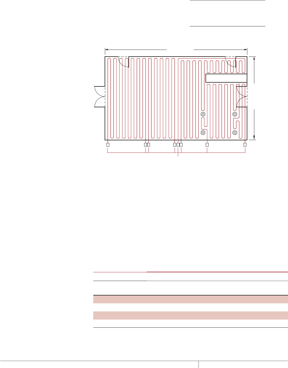
THERMAL MANAGEMENT SOLUTIONS
EN-FloorHeatingSystem-DG-H58157 11/13
280
3. Determine the RaySol heating cable layout and length
Estimate the heating cable length The length of heating cable and the number of
heating cable circuits can be estimated before a detailed layout is done if the heating
cable spacing, total heated area, and the available branch circuit breaker rating are
known.
Estimate the heating cable length required:
Estimated heating cable length (ft) = Heated area (ft²) x 12
Spacing (in)
Estimated heating cable length (m) = Heated area (m²) x 100
Spacing (cm)
Junction boxes
Side A
Side B
20 ft (6.1 m)
34 ft (10.4 m)
Fig. 16 RaySol heating cable layout for comfort floor heating
Example: RaySol heating cable length for comfort floor heating
Heated area 647 ft² (60.4 m²) (from Step 3)
Estimated heating cable length 647 ft² x 12 / 8 in = 971 ft
60.4 m² x 100 / 20 cm = 302 m
4. Determine the maximum circuit length for the heating cable length and layout
For the appropriate supply voltage, use Table 8 to select the maximum circuit length
which is closest to, but greater than the length calculated. If the estimated heating
cable length required is greater than the maximum circuit length, multiple circuits
must be used.
TABLE 8 MAXIMUM RAYSOL CIRCUIT LENGTH IN FEET METERS WHEN
EMBEDDED IN CONCRETE OR MORTAR 40°F 4°C STARTUP*
Supply voltage
120 V 208 V 240 V 277 V
Circuit breaker size
(A)
ft m ft m ft m ft m
15 80 24.4 135 41.1 140 42.7 145 44.2
20 105 32.0 185 56.4 185 56.4 195 59.4
30 160 48.8 275 83.8 280 85.3 290 88.4
40 170 51.8 280 85.3 320 97.5 360 109.7
* For start-up temperatures less than 40°F, contact your Pentair Thermal Management representative.
FLOOR HEATING RAYSOL, MINERAL INSULATED, AND QUICKNET HEATING SYSTEMS

281 THERMAL MANAGEMENT SOLUTIONS EN-FloorHeatingSystem-DG-H58157 11/13
Pipe Freeze Protection
and Flow Maintenance
Fire Sprinkler System
Freeze Protection
Roof and Gutter
De-Icing
Surface Snow
Melting – MI
Surface Snow
Melting – ElectroMelt
Freezer Frost
Heave Prevention
Floor Heating Technical Data
Sheets
Note: If RaySol is installed in a bathroom, a 5 mA GFCI breaker must be used. In
this case, the circuit breaker size cannot exceed 30 A.
Calculate the estimated number of circuits as follows:
Number of circuits = Estimated heating cable length (ft/m)
Maximum circuit length (ft/m)
Round the number of circuits to the next larger whole number.
Example: RaySol heating cable length for comfort floor heating
Estimated heating cable length 971 ft (302 m) (from earlier in this step)
Supply voltage 208 V (Step 3)
Maximum circuit length 275 ft (83.8 m) (from Table 8)
Number of circuits 971 ft / 275 ft (302 m / 83.8 m)
= 4 circuits (rounded)
Power supply Four 30 A circuit breakers (from Table 8)
5. Determine the additional heating cable allowances
Additional heating cable is required to make power connections and to route the
circuits to junction boxes. This extra heating cable shall not be considered when
determining the maximum heating cable length for circuit breaker sizing. In order to
estimate the total heating cable length, you will need to take the estimated heating
cable length you already calculated, and then add heating cable allowances, as
follows:
Estimated total heating cable length = Estimated heating cable length + End allowances + Connection kit allowances
Refer to Table 6 on page278 to calculate the additional RaySol heating cable
allowances.
Example: RaySol heating cable for comfort floor heating
Estimated heating cable length 971 ft (302 m) (from earlier in this step)
End allowance 4 circuits x 4 ft per end x 2 ends = 32 ft (10 m)
(from Table 6)
Connection kit allowances 4 connection kits x 4 ft per end = 16 ft (5 m)
(from Table 6)
Total heating cable allowances 32 ft (10 m) + 16 ft (5 m) = 48 ft (15 m)
Estimated total heating cable length 971 ft (302 m) + 48 ft (15 m) = 1019 ft (317 m)
6. Locate the junction boxes for RaySol heating cable system
The heating cable connects to the branch circuit wiring in a junction box with the
RaySol FTC-XC power connection and end seal kit.
The junction boxes may be distributed around the area to be heated, or collected at
a single location. In many applications the heating cable can be laid out so that all
power connections and end seals can be grouped in a common area without using
extra heating cable. If this can be done, select the common junction box location to
minimize the electrical conduit and wire needed to reach the branch circuit breakers.
Typical heating cable layout for comfort floor heating is similar to the examples
shown in Fig. 14 on page276 for heat loss replacement.
Fig. 17 illustrates the proper method to route the RaySol heating cable from the
mortar bed up to the junction box using protective conduit.
Floor Heating Application Design
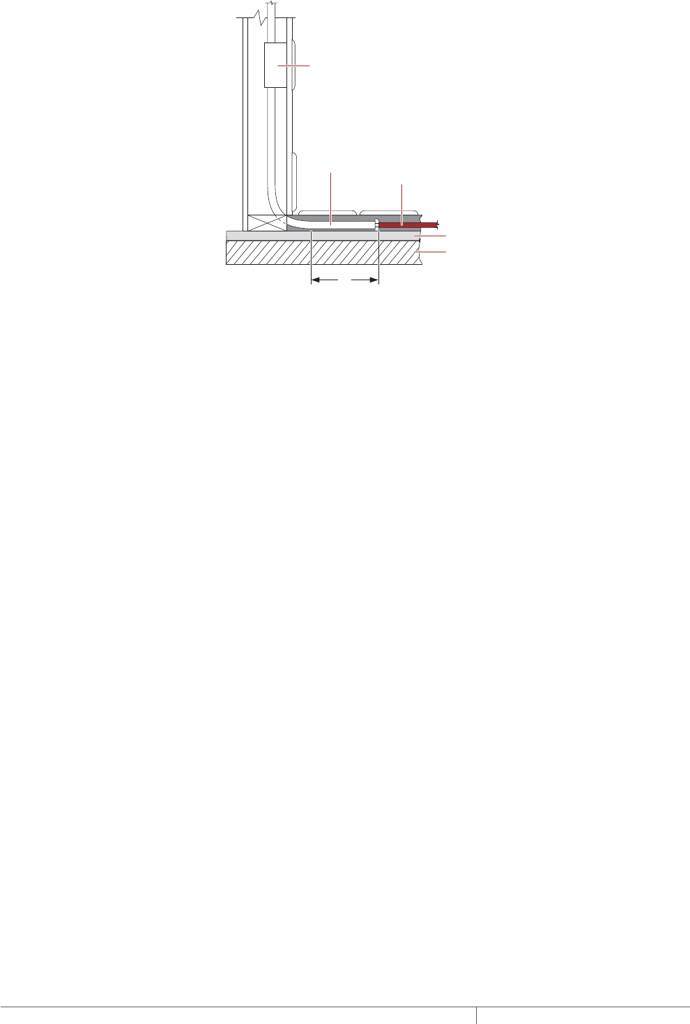
THERMAL MANAGEMENT SOLUTIONS
EN-FloorHeatingSystem-DG-H58157 11/13
282
Junction box
3/4" (min) conduit
Heating cable
Subfloor
Insulation
Mortar
6"
Fig. 17 Typical RaySol comfort floor heating installation
7. Lay out heating cable runs, circuits, and junction boxes
After determining the approximate total length of heating cable, the number of
circuits, and the junction box location, do a trial layout. In making the trial layout,
follow these recommendations:
• Start and end each circuit in a junction box. The power connection and end seal
may be located in the same box or in different boxes.
• Arrange the heating cable run so it uniformly covers the area to be heated.
• Maintain the design heating cable spacing within 1 in (2.5 cm).
• Do not extend the heating cable beyond the room or area in which it originates.
• Do not install cables under shower floors, tubs and spas, toilets and other per-
manent fixtures.
• Do not cross expansion, crack control, or other subfloor joints.
• Do not route the heating cable closer than 4 in (10 cm) to the edge of the subfloor,
drains, anchors, or other material in the concrete.
• Do not exceed the maximum length of heating cable allowed on a branch circuit
breaker as given in Table 8.
• When the combined lengths of two or more circuit runs are less than the maxi-
mum circuit length allowed, these runs can be combined in parallel on one circuit
breaker.
8. Record the circuit information
Reconfigure the trial circuit layout until the design meets all of the previous
recommendations. Assign each circuit to a circuit breaker in a specific panel board
and record each circuit length.
Advance to Step 5, page298.
FLOOR HEATING RAYSOL, MINERAL INSULATED, AND QUICKNET HEATING SYSTEMS

283 THERMAL MANAGEMENT SOLUTIONS EN-FloorHeatingSystem-DG-H58157 11/13
Pipe Freeze Protection
and Flow Maintenance
Fire Sprinkler System
Freeze Protection
Roof and Gutter
De-Icing
Surface Snow
Melting – MI
Surface Snow
Melting – ElectroMelt
Freezer Frost
Heave Prevention
Floor Heating Technical Data
Sheets
MI HEATING CABLE SYSTEM DESIGN
A single heating cable may be sufficient for small floor areas. For large floor areas,
it may be necessary to divide the area into two or more equal subsections (Fig. 19 on
page288). For a three-phase voltage supply, divide the total area into three equal
subsections (Fig. 18 on page285) or a multiple of three equal subsections when
more than one circuit is necessary. If expansion joints will be used in the floor, divide
the area so that the heating cables will not cross any expansion joints.
Designing the floor heating system using a three-phase voltage supply has the
added advantages of fewer circuits, reduced distribution costs, and a balanced
heating system load and is recommended for large areas.
Three-phase voltage supplies include 208/120 V, 480/277 V, and 600/347 V. The
heating cables may be connected in delta or wye configuration as shown in Fig. 24
on page309 and Fig. 25 on page310. If the heating cables are connected in the
delta configuration, select the cables based on the phase-to-phase voltage (example:
select 208 V cables for a 208 V supply). If the heating cables are connected in the wye
configuration, select the cables based on the phase-to-neutral voltage (example:
select 120 V cables for a 208 V supply).
HEAT LOSS REPLACEMENT
SELECT THE HEATING CABLE
Table 9 lists the heat loss for minimum design temperature and insulation R-value
determined in Step 3. Select your design power from this table. If your calculated
R-value or minimum design temperature does not match the values in the table, use
the values that give the higher design power.
TABLE 9 DESIGN POWER BASED ON 70°F 21°C CONTROL
Minimum design
temperature
Floor insulation R-value (ft
2
·°F·hr/Btu)
R-10 R-20 R-30 R-40
Design power - W/ft2 (W/m2)
30°F (–1°C) 2.2 (23.7) 1.6 (17.2) 1.4 (15.1) 1.3 (14.0)
20°F (–7°C) 2.5 (26.9) 1.8 (19.4) 1.5 (16.1) 1.4 (15.1)
10°F (–12°C) 2.8 (30.1) 1.9 (20.4) 1.6 (17.2) 1.5 (16.1)
0°F (–18°C) 3.0 (32.3) 2.0 (21.5) 1.7 (18.3) 1.5 (16.1)
–10°F (–23°C) 3.3 (35.5) 2.2 (23.7) 1.8 (19.4) 1.6 (17.2)
–20°F (–29°C) 3.6 (38.7) 2.3 (24.7) 1.9 (20.4) 1.7 (18.3)
–30°F (–34°C) 3.9 (42.0) 2.5 (26.9) 2.0 (21.5) 1.7 (18.3)
–40°F (–40°C) 4.1 (44.1) 2.6 (28.0) 2.1 (22.6) 1.8 (19.4)
The heating cables shown in Table 10 have been optimized for heat loss replacement
applications. They are manufactured with a bare copper sheath and are designed
to be attached to the bottom of the concrete floor. Do not use these heating cables
for embedded applications. If assistance is required to select heating cables
for embedded heat loss replacement applications, irregular shaped areas, or
applications outside the scope of this design guide, contact your Pentair Thermal
Management representative or Pentair Thermal Management at (800) 545-6258 for
design assistance.
Floor Heating Application Design

THERMAL MANAGEMENT SOLUTIONS
EN-FloorHeatingSystem-DG-H58157 11/13
284
Single-phase supply
Small floor areas require only one heating cable. Large floor areas may require two
or more heating cables.
• Divide large floor areas into equal subsection areas, if possible (see Fig. 19 on
page288).
• Calculate the power required for the total area (small floor areas) or for each
subsection area (large floor areas) by multiplying the design power (from Table 9)
by the total area or subsection area.
Power required = Design power x Total area (or Subsection area)
Simply select the heating cable from Table 10 on page286 based on the total area
or subsection area. Under the appropriate voltage, make sure that the total area
or subsection area falls within the minimum and maximum range of the “Area
coverage” columns and verify that the “Cable wattage” shown directly across from
the “Area coverage” is equal to or higher than the calculated “Power required” for
the total area or subsection area.
In cases where the floor area has been divided into equal subsections, select the
appropriate number of heating cables.
Note: Several heating cables in Table 10 may satisfy the requirements. Selecting
one cable over another will simply result in a higher or lower watt density or different
cable spacing. It may be desirable to select the lowest wattage cable that satisfies
the area coverage to reduce the breaker size, or a longer cable to reduce cable
spacing. Reduced cable spacing will provide a more uniform floor temperature.
Three-phase supply
Since a balanced three-phase system requires three cables, each cable will occupy
1/3 of the floor area when installed.
• Divide the total heated floor area into three equal subsections (Fig. 18) or a
multiple of three equal subsections when more than one circuit is necessary.
• Calculate the power required for each subsection by multiplying the design power
(from Table 9) by the subsection area.
Power required = Design power x Subsection area
Simply select the heating cable from Table 10 on page286 based on the subsection
area. Under the appropriate voltage, make sure that the subsection area falls within
the minimum and maximum range of the “Area coverage” column and verify that the
“Cable wattage” shown directly across from the “Area coverage” is equal to or higher
than the calculated “Power required” for the subsection area.
Select the appropriate number of heating cables equal to the number of subsection
areas (multiples of three cables required).
Note: Several heating cables in Table 10 may satisfy the requirements. Selecting
one cable over another will simply result in a higher or lower watt density or different
cable spacing. It may be desirable to select the lowest wattage cable that satisfies
the area coverage to reduce the breaker size, or a longer cable to reduce cable
spacing. Reduced cable spacing will provide a more uniform floor temperature.
FLOOR HEATING RAYSOL, MINERAL INSULATED, AND QUICKNET HEATING SYSTEMS
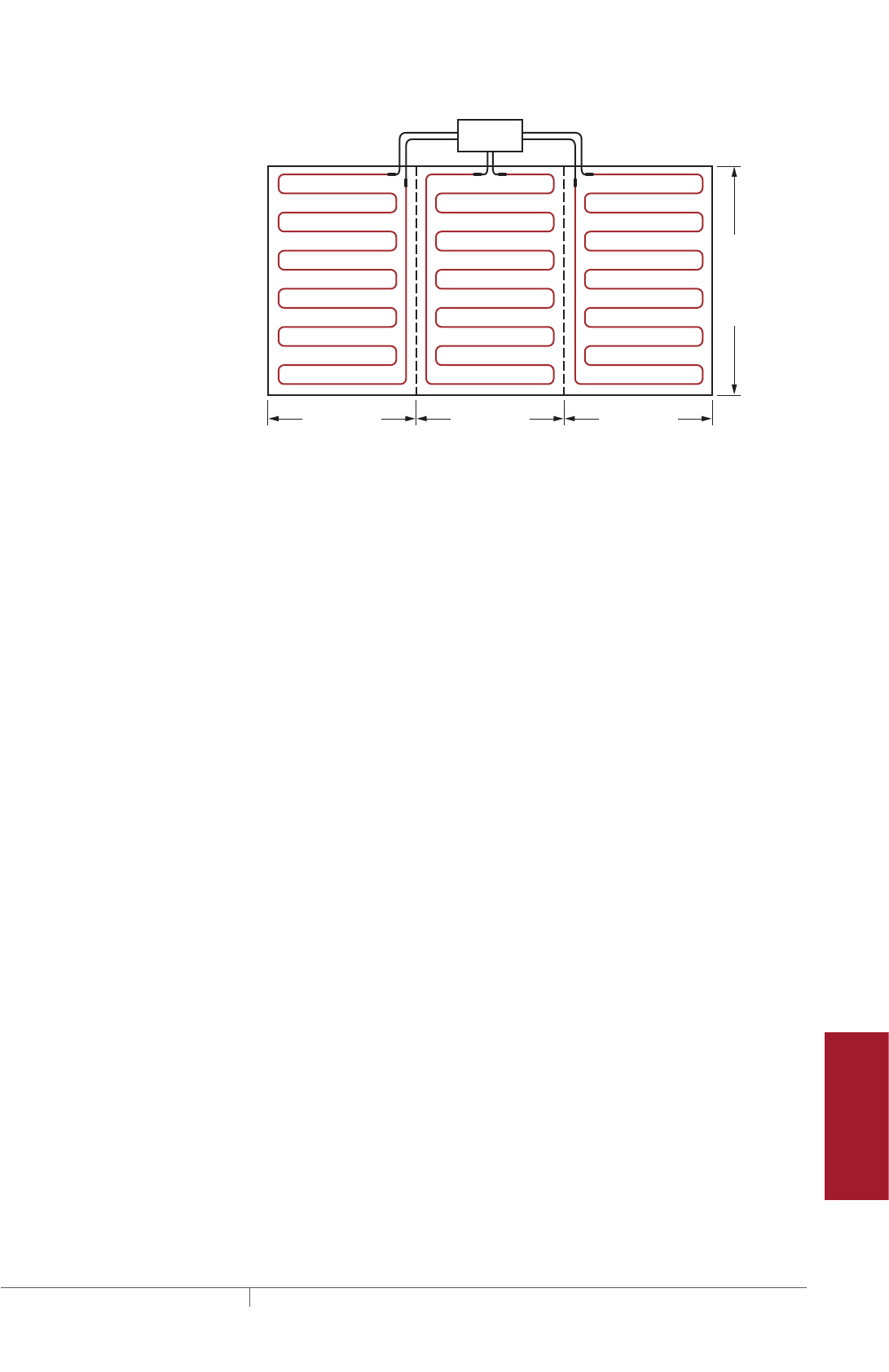
285 THERMAL MANAGEMENT SOLUTIONS EN-FloorHeatingSystem-DG-H58157 11/13
Pipe Freeze Protection
and Flow Maintenance
Fire Sprinkler System
Freeze Protection
Roof and Gutter
De-Icing
Surface Snow
Melting – MI
Surface Snow
Melting – ElectroMelt
Freezer Frost
Heave Prevention
Floor Heating Technical Data
Sheets
26.7 ft (8.1 m)
40 ft (12.2 m)
26.7 ft (8.1 m)26.7 ft (8.1 m)
3-phase
supply
Junction box
Fig. 18 Typical three-phase heating cable layout for heat loss replacement
Example: MI heating cables for heat loss replacement
Heated area 3200 ft² (297.4 m²) (from Step 3)
Supply voltage and phase 208 V, three-phase (from Step 3)
Minimum ambient design temperature –10°F (–23°C) (from Step 3)
Insulation R-value R-20 (20 ft²·°F·hr/Btu) (from Step 3)
Design power 2.2 W/ft² (23.7 W/m²) (from Table 9)
Subsection area 3200 ft² / 3 = 1067 ft² (see Fig. 18)
297.4 m² / 3 = 99.1 m²
Power required (for each subsection) (Design power x Subsection area) =
2.2 W/ft² x 1067 ft² = 2347 W
23.7 W/m² x 99.1 m² = 2347 W
Heating cable catalog number HLR24 (from Table 10)
Cable wattage 5150 W (from Table 10)
Cable voltage 208 V (for cables connected in Delta
configuration)
Heating cable length 420 ft (128.0 m) (from Table 10)
Number of cables 3 (one cable required for each subsection)
Floor Heating Application Design

THERMAL MANAGEMENT SOLUTIONS
EN-FloorHeatingSystem-DG-H58157 11/13
286
TABLE 10 SELECTION TABLE FOR HEAT LOSS REPLACEMENT
Catalog
number
Area coverage
Cable wattage
(W)
Heated length
Heating cable current
(A)
Min
(ft2)
Max
(ft2)
Min
(m2)
Max
(m2) (ft) (m)
120 V and 208 V, three-phase Wye
HLR1 56 88 5 8 330 70 21.3 2.8
HLR2 89 132 8 12 540 44 13.4 4.5
HLR3 112 165 10 15 670 55 16.8 5.6
HLR4 127 189 12 18 760 63 19.2 6.3
HLR5 156 231 14 21 935 77 23.5 7.8
HLR6 180 267 17 25 1080 89 27.1 9.0
HLR7 216 318 20 30 1295 106 32.3 10.8
HLR8 246 366 23 34 1475 122 37.2 12.3
HLR9 286 420 27 39 1715 140 42.7 14.3
HLR10 349 516 32 48 2100 172 52.4 17.5
HLR11 404 594 38 55 2425 198 60.4 20.2
HLR12 492 732 46 68 2950 244 74.4 24.6
HLR13 654 966 61 90 3925 322 98.2 32.7
208 V
HLR14 156 228 14 21 935 76 23.2 4.5
HLR15 195 285 18 26 1170 95 29.0 5.6
HLR16 221 327 20 30 1325 109 33.2 6.4
HLR17 271 399 25 37 1625 133 40.5 7.8
HLR18 312 462 29 43 1875 154 47.0 9.0
HLR19 373 552 35 51 2240 184 56.1 10.8
HLR20 427 633 40 59 2565 211 64.3 12.3
HLR21 495 729 46 68 2970 243 74.1 14.3
HLR22 609 888 57 83 3655 296 90.2 17.6
HLR23 697 1035 65 96 4180 345 105.2 20.1
HLR24 858 1260 80 117 5150 420 128.0 24.8
HLR25 1129 1680 105 156 6780 560 170.7 32.6
240 V
HLR26 179 264 17 25 1075 88 26.8 4.5
HLR27 224 330 21 31 1345 110 33.5 5.6
HLR28 256 375 24 35 1535 125 38.1 6.4
HLR29 314 459 29 43 1880 153 46.6 7.8
HLR30 362 531 34 49 2170 177 54.0 9.0
HLR31 431 636 40 59 2590 212 64.6 10.8
HLR32 494 729 46 68 2965 243 74.1 12.4
HLR33 571 840 53 78 3430 280 85.4 14.3
HLR34 696 1035 65 96 4175 345 105.2 17.4
HLR35 810 1185 75 110 4860 395 120.4 20.3
HLR36 990 1455 92 135 5940 485 147.9 24.8
HLR37 1316 1920 122 178 7900 640 195.1 32.9
Note: Type HLR cables supplied with 15 ft (4.6 m) long cold lead
Heating cable length tolerance is –0% to +3%.
FLOOR HEATING RAYSOL, MINERAL INSULATED, AND QUICKNET HEATING SYSTEMS
287 THERMAL MANAGEMENT SOLUTIONS EN-FloorHeatingSystem-DG-H58157 11/13
Pipe Freeze Protection
and Flow Maintenance
Fire Sprinkler System
Freeze Protection
Roof and Gutter
De-Icing
Surface Snow
Melting – MI
Surface Snow
Melting – ElectroMelt
Freezer Frost
Heave Prevention
Floor Heating Technical Data
Sheets
TABLE 10 SELECTION TABLE FOR HEAT LOSS REPLACEMENT
Catalog
number
Area coverage
Cable wattage
(W)
Heated length
Heating cable current
(A)
Min
(ft2)
Max
(ft2)
Min
(m2)
Max
(m2) (ft) (m)
277 V and 480 V, three-phase wye
HLR38 206 306 19 28 1235 102 31.1 4.5
HLR39 258 381 24 35 1550 127 38.7 5.6
HLR40 294 435 27 40 1765 145 44.2 6.4
HLR41 361 531 34 49 2170 177 54.0 7.8
HLR42 416 615 39 57 2495 205 62.5 9.0
HLR43 497 735 46 68 2985 245 74.7 10.8
HLR44 571 840 53 78 3425 280 85.4 12.4
HLR45 656 975 61 91 3935 325 99.1 14.2
HLR46 807 1188 75 110 4845 396 120.7 17.5
HLR47 927 1380 86 128 5560 460 140.2 20.1
HLR48 1142 1680 106 156 6850 560 170.7 24.7
HLR49 1516 2220 141 206 9100 740 225.6 32.9
347 V and 600 V, three-phase wye
HLR50 259 381 24 35 1560 127 38.7 4.5
HLR51 322 480 30 45 1930 160 48.8 5.6
HLR52 368 546 34 51 2205 182 55.5 6.4
HLR53 452 666 42 62 2715 222 67.7 7.8
HLR54 519 774 48 72 3110 258 78.7 9.0
HLR55 625 918 58 85 3750 306 93.3 10.8
HLR56 717 1050 67 98 4300 350 106.7 12.4
HLR57 826 1215 77 113 4955 405 123.5 14.3
HLR58 1014 1485 94 138 6080 495 150.9 17.5
HLR59 1163 1725 108 160 6980 575 175.3 20.1
HLR60 1433 2100 133 195 8600 700 213.4 24.8
480 V
HLR61 360 525 33 49 2160 175 53.4 4.5
HLR62 448 660 42 61 2685 220 67.1 5.6
HLR63 512 750 48 70 3070 250 76.2 6.4
HLR64 627 918 58 85 3770 306 93.3 7.9
HLR65 721 1065 67 99 4330 355 108.2 9.0
HLR66 863 1272 80 118 5175 424 129.3 10.8
HLR67 990 1455 92 135 5940 485 147.9 12.4
HLR68 1143 1680 106 156 6860 560 170.7 14.3
HLR69 1391 2070 129 192 8350 690 210.4 17.4
600 V
HLR70 447 660 42 61 2685 220 67.1 4.5
HLR71 559 825 52 77 3360 275 83.8 5.6
HLR72 639 939 59 87 3835 313 95.4 6.4
HLR73 781 1152 73 107 4690 384 117.1 7.8
HLR74 903 1329 84 124 5420 443 135.1 9.0
HLR75 1078 1590 100 148 6470 530 161.6 10.8
HLR76 1240 1815 115 169 7440 605 184.5 12.4
HLR77 1429 2100 133 195 8570 700 213.4 14.3
Note: Type HLR cables supplied with 15 ft (4.6 m) long cold lead
Heating cable length tolerance is –0% to +3%.
Advance to "Determine the heating cable spacing" on page293.
Floor Heating Application Design
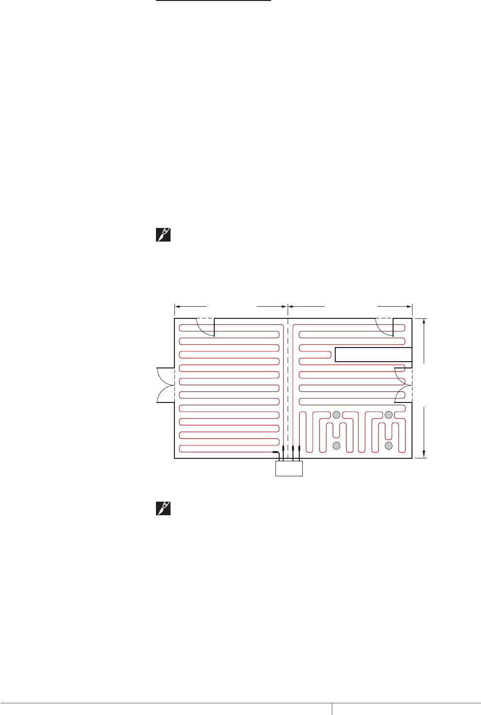
THERMAL MANAGEMENT SOLUTIONS
EN-FloorHeatingSystem-DG-H58157 11/13
288
COMFORT FLOOR HEATING
The heating cables shown in Table 12 have been optimized for comfort floor heating
applications. If assistance is required to select heating cables for irregular shaped
areas, or applications outside the scope of this design guide, contact your Pentair
Thermal Management representative or Pentair Thermal Management at
(800) 545-6258 for design assistance.
Single-phase supply
Small floor areas require only one heating cable. Large floor areas may require two
or more heating cables.
• Divide large floor areas into equal subsection areas, if possible (Fig. 19).
Simply select the heating cable from Table 11 or Table 12 based on the total area
or subsection area. Under the appropriate voltage, make sure that the total area
or subsection area falls within the minimum and maximum range of the “Area
coverage” column.
In cases where the heated floor area has been divided into equal subsections, select
the appropriate number of heating cables.
Note: Several heating cables in Table 11 may satisfy the requirements. Selecting
one cable over another will simply result in a higher or lower watt density or different
cable spacing. It may be desirable to select the lowest wattage cable that satisfies
the area coverage to reduce the breaker size, or a longer cable to reduce cable
spacing. Reduced cable spacing will provide a more uniform floor temperature.
16.2 ft (4.94 m)
Subsection 1 Subsection 2
Junction
box
17.8 ft (5.43 m)
20 ft (6.1 m)
Fig. 19 Typical heating cable layout for comfort floor heating
Note: In Fig. 19, the subsections are equal heated areas.
Example: MI heating cables for comfort floor heating
Heated area 647 ft² (60.4 m²) (from Step 3)
Supply voltage and phase 208 V, single-phase (from Step 3)
Subsection area 647 ft² / 2 = 324 ft² (see Fig. 19)
60.4 m² / 2 = 30.2 m²
Heating cable catalog number FH21 (from Table 12)
Cable wattage 3390 W (from Table 12)
Cable voltage 208 V (from Table 12)
Heating cable length 425 ft (129.6 m) (from Table 12)
Number of cables 2 (one cable required for each subsection)
FLOOR HEATING RAYSOL, MINERAL INSULATED, AND QUICKNET HEATING SYSTEMS
289 THERMAL MANAGEMENT SOLUTIONS EN-FloorHeatingSystem-DG-H58157 11/13
Pipe Freeze Protection
and Flow Maintenance
Fire Sprinkler System
Freeze Protection
Roof and Gutter
De-Icing
Surface Snow
Melting – MI
Surface Snow
Melting – ElectroMelt
Freezer Frost
Heave Prevention
Floor Heating Technical Data
Sheets
Three-phase supply
Since a balanced three-phase system requires three cables, each cable will occupy
1/3 of the heated floor area when installed.
• Divide the total heated floor area into three equal subsections or a multiple of
three equal subsections when more than one circuit is necessary.
Simply select the heating cable from Table 11 or Table 12 based on the subsection
area. Under the appropriate voltage, make sure that the subsection area falls within
the minimum and maximum range of the “Area coverage” column.
Select the appropriate number of heating cables equal to the number of subsection
areas (multiples of three cables required).
Note: Several heating cables in Table 11 may satisfy the requirements. Selecting
one cable over another will simply result in a higher or lower watt density or different
cable spacing. It may be desirable to select the lowest wattage cable that satisfies
the area coverage to reduce the breaker size, or a longer cable to reduce cable
spacing. Reduced cable spacing will provide a more uniform floor temperature.
TABLE 11 SELECTION TABLE FOR COMFORT FLOOR HEATING
Catalog
number
Area coverage
Cable wattage
(W)
Heated length
Heating cable current
(A)
Min
(ft2)
Max
(ft2)
Min
(m2)
Max
(m2) (ft) (m)
120 V and 208 V, three-phase wye
SUA2 30 42 2.8 3.9 425 55 16.8 3.5
SUA3 43 64 4.0 5.9 500 140 42.7 4.2
SUA4 45 51 4.2 4.7 550 68 20.7 4.6
SUA7 63 71 5.9 6.6 750 95 29.0 6.3
SUA8 65 97 6.0 9.0 800 177 54.0 6.7
SUB1 87 100 8.0 9.3 1000 132 40.2 8.3
SUB2 83 125 7.7 11.6 1000 240 73.2 8.3
SUB3 107 160 10.0 14.9 1300 280 85.4 10.8
SUB4 125 187 11.6 17.4 1500 320 97.6 12.5
SUB5 154 195 14.3 18.1 1800 260 79.3 15.0
SUB6 160 240 14.9 22.3 1900 375 114.3 15.8
SUB7 194 235 18.0 21.8 2300 310 94.5 19.2
SUB8 191 287 17.8 26.7 2300 550 167.7 19.2
SUB9 257 385 23.9 35.8 3000 630 192.1 25.0
SUB10 359 538 33.4 50.0 4300 717 218.6 35.8
208 V
SUA1 50 81 4.6 7.5 650 108 32.9 3.1
SUA6 130 198 12.1 18.4 1560 264 80.5 7.5
SUB19 74 110 6.9 10.2 885 245 74.7 4.3
SUB20 101 152 9.4 14.1 1210 340 103.7 5.8
SUB21 137 205 12.7 19.1 1640 440 134.1 7.9
SUB22 160 256 14.9 23.8 2060 525 160.1 9.9
240 V
SUA1 70 81 6.5 7.5 900 108 32.9 3.8
SUA6 175 198 16.3 18.4 2100 264 80.5 8.8
SUB19 98 146 9.1 13.6 1175 245 74.7 4.9
SUB20 135 202 12.5 18.8 1615 340 103.7 6.7
SUB21 182 274 16.9 25.5 2180 440 134.1 9.1
SUB22 229 345 21.3 32.1 2745 525 160.1 11.4
Note: Type SUA cables supplied with 7 ft (2.1 m) foot long cold lead: type SUB cables supplied with 15.1 (4.8 m) long cold lead.
Heating cable length tolerance is –0% to +3%.
Floor Heating Application Design
THERMAL MANAGEMENT SOLUTIONS
EN-FloorHeatingSystem-DG-H58157 11/13
290
TABLE 11 SELECTION TABLE FOR COMFORT FLOOR HEATING
Catalog
number
Area coverage
Cable wattage
(W)
Heated length
Heating cable current
(A)
Min
(ft2)
Max
(ft2)
Min
(m2)
Max
(m2) (ft) (m)
277 V (and 480 V, three-phase wye)
SUB19 130 184 12.1 17.1 1565 245 74.7 5.6
SUB20 179 255 16.6 23.7 2150 340 103.7 7.8
SUB21 242 330 22.5 30.7 2900 440 134.1 10.5
SUB22 304 394 28.3 36.6 3650 525 160.1 13.2
347 V and 600 V, three-phase wye
SUB11 114 169 10.6 15.7 1400 225 68.6 4.0
SUB12 162 233 15 21.6 1950 310 94.5 5.6
SUB13 223 321 20.8 29.8 2700 428 130.5 7.8
SUB14 305 411 28.3 38.2 3700 548 167.1 10.7
Note: Type SUA cables supplied with 7 ft (2.1 m) foot long cold lead: type SUB cables supplied with 15.1 (4.8 m) long cold lead.
Heating cable length tolerance is –0% to +3%.
TABLE 12 SELECTION TABLE FOR COMFORT FLOOR HEATING
Catalog
number
Area coverage
Cable wattage
(W)
Heated length
Heating cable current
(A)
Min
(ft2)
Max
(ft2)
Min
(m2)
Max
(m2) (ft) (m)
120 V and 208 V, three-phase wye
FH1 36 41 3.4 3.8 440 54 16.5 3.7
FH2 42 51 3.9 4.7 545 68 20.7 4.5
FH3 52 58 4.8 5.4 625 77 23.5 5.2
FH4 59 71 5.5 6.6 760 95 29.0 6.3
FH5 72 82 6.7 7.6 880 109 33.2 7.3
FH6 83 98 7.7 9.1 1055 130 39.6 8.8
FH7 99 113 9.2 10.5 1200 150 45.7 10.0
FH8 114 130 10.6 12.1 1390 173 52.7 11.6
FH9 131 158 12.2 14.6 1715 210 64.0 14.3
FH10 159 185 14.8 17.2 1960 245 74.7 16.3
FH11 186 230 17.3 21.4 2400 300 91.5 20.0
208 V
FH12 60 72 5.6 6.7 755 94 28.7 3.6
FH13 73 89 6.8 8.2 940 118 36.0 4.5
FH14 90 101 8.3 9.3 1075 134 40.9 5.2
FH15 102 123 9.5 11.4 1320 164 50.0 6.3
FH16 124 143 11.5 13.2 1520 190 57.9 7.3
FH17 144 169 13.4 15.7 1830 225 68.6 8.8
FH18 170 195 15.8 18.1 2080 260 79.3 10.0
FH19 196 230 18.2 21.4 2400 300 91.5 11.5
FH20 231 274 21.5 25.4 2960 365 111.3 14.2
FH21 275 325 25.6 30.2 3390 425 129.6 16.3
FH22 326 390 30.3 36.2 4160 520 158.5 20.0
Note: Type FH cables supplied with 15 ft (4.6 m) long cold lead.
Tolerance on heating cable length is –0% to +3%.
FLOOR HEATING RAYSOL, MINERAL INSULATED, AND QUICKNET HEATING SYSTEMS
291 THERMAL MANAGEMENT SOLUTIONS EN-FloorHeatingSystem-DG-H58157 11/13
Pipe Freeze Protection
and Flow Maintenance
Fire Sprinkler System
Freeze Protection
Roof and Gutter
De-Icing
Surface Snow
Melting – MI
Surface Snow
Melting – ElectroMelt
Freezer Frost
Heave Prevention
Floor Heating Technical Data
Sheets
TABLE 12 SELECTION TABLE FOR COMFORT FLOOR HEATING
Catalog
number
Area coverage
Cable wattage
(W)
Heated length
Heating cable current
(A)
Min
(ft2)
Max
(ft2)
Min
(m2)
Max
(m2) (ft) (m)
240 V
FH23 70 84 6.5 7.8 875 108 32.9 3.6
FH24 85 101 7.9 9.4 1095 135 41.2 4.6
FH25 102 119 9.5 11.1 1240 155 47.3 5.2
FH26 120 145 11.2 13.5 1515 190 57.9 6.3
FH27 146 164 13.6 15.2 1785 215 65.5 7.4
FH28 165 195 15.3 18.1 2110 260 79.3 8.8
FH29 196 225 18.2 20.9 2400 300 91.5 10.0
FH30 226 265 21.0 24.6 2780 345 105.2 11.6
FH31 266 320 24.7 29.7 3430 420 128.0 14.3
FH32 321 375 29.8 34.9 3920 490 149.4 16.3
FH33 376 450 34.9 41.8 4800 600 182.9 20.0
277 V and 480 V, three-phase wye
FH34 80 97 7.4 9.0 1005 125 38.1 3.6
FH35 98 119 9.1 11.0 1270 155 47.3 4.6
FH36 120 135 11.1 12.5 1440 178 54.3 5.2
FH37 136 165 12.6 15.3 1760 218 66.5 6.4
FH38 166 195 15.4 18.1 2020 253 77.1 7.3
FH39 196 225 18.2 20.9 2435 300 91.5 8.8
FH40 226 260 21.0 24.2 2780 345 105.2 10.0
FH41 261 310 24.3 28.8 3200 400 122.0 11.6
FH42 311 370 28.9 34.4 3915 490 149.4 14.1
FH43 371 435 34.5 40.4 4535 564 172.0 16.4
FH44 436 518 40.5 48.1 5560 690 210.4 20.1
347 V and 600 V, three-phase wye
FH45 100 120 9.3 11.2 1275 155 47.3 3.7
FH46 121 150 11.2 13.9 1585 195 59.5 4.6
FH47 151 170 14.0 15.8 1825 220 67.1 5.3
FH48 171 205 15.9 19.1 2230 270 82.3 6.4
FH49 206 240 19.1 22.3 2550 315 96.0 7.3
FH50 241 285 22.4 26.5 3050 376 114.6 8.8
FH51 286 330 26.6 30.7 3500 430 131.1 10.1
FH52 331 380 30.8 35.3 4040 497 151.5 11.6
FH53 381 465 35.4 43.2 4935 610 186.0 14.2
FH54 466 533 43.3 49.5 5650 710 216.5 16.3
480 V
FH55 140 167 13.0 15.5 1760 215 65.5 3.7
FH56 168 205 15.6 19.1 2190 270 82.3 4.6
FH57 206 235 19.2 21.8 2480 310 94.5 5.2
FH58 236 285 21.9 26.5 3030 380 115.9 6.3
FH59 286 335 26.6 31.1 3530 435 132.6 7.4
FH60 336 395 31.2 36.7 4220 520 158.5 8.8
FH61 396 455 36.8 42.3 4800 600 182.9 10.0
FH62 456 518 42.4 48.1 5565 690 210.4 11.6
Note: Type FH cables supplied with 15 ft (4.6 m) long cold lead.
Tolerance on heating cable length is –0% to +3%.
Floor Heating Application Design
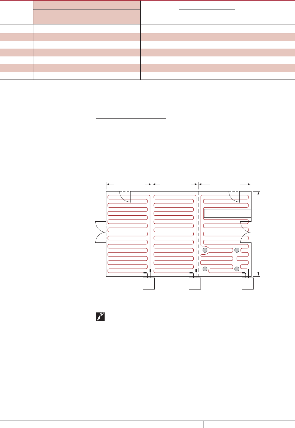
THERMAL MANAGEMENT SOLUTIONS
EN-FloorHeatingSystem-DG-H58157 11/13
292
TABLE 12 SELECTION TABLE FOR COMFORT FLOOR HEATING
Catalog
number
Area coverage
Cable wattage
(W)
Heated length
Heating cable current
(A)
Min
(ft2)
Max
(ft2)
Min
(m2)
Max
(m2) (ft) (m)
600 V
FH63 170 210 15.8 19.5 2185 270 82.3 3.6
FH64 211 255 19.6 23.7 2715 340 103.7 4.5
FH65 256 295 23.8 27.4 3120 385 117.4 5.2
FH66 296 360 27.5 33.5 3830 470 143.3 6.4
FH67 361 420 33.6 39.0 4400 545 166.2 7.3
FH68 421 488 39.1 45.3 5275 650 198.2 8.8
Note: Type FH cables supplied with 15 ft (4.6 m) long cold lead.
Tolerance on heating cable length is –0% to +3%.
Advance to "Determine the heating cable spacing" on page293.
RADIANT SPACE HEATING
For radiant space heating, the total heat loss in Btu/hr or wattage is supplied by the
customer. Heating cables can be selected for single phase or three-phase voltage
supplies as shown for comfort floor heating, but based on the heat loss in watts
required for each area. Use Table 11 or Table 12 to select a heating cable from the
“Cable wattage” column that is equal to or the next highest wattage than the wattage
specified.
10.8 ft (3.3 m)
Junction box
10.8 ft (3.3 m) 12.4 ft (3.8 m)
Subsection 1 Subsection 2 Subsection 3
20 ft (6.1 m)
Junction box Junction box
Fig. 20 Typical heating cable layout for radiant space heating
Note: In Fig. 20, the subsections are equal heated areas.
FLOOR HEATING RAYSOL, MINERAL INSULATED, AND QUICKNET HEATING SYSTEMS

293 THERMAL MANAGEMENT SOLUTIONS EN-FloorHeatingSystem-DG-H58157 11/13
Pipe Freeze Protection
and Flow Maintenance
Fire Sprinkler System
Freeze Protection
Roof and Gutter
De-Icing
Surface Snow
Melting – MI
Surface Snow
Melting – ElectroMelt
Freezer Frost
Heave Prevention
Floor Heating Technical Data
Sheets
Example: MI heating cables for radiant space heating
Heated area 647 ft² (60.4 m²) (from Step 3)
Supply voltage and phase 208 V, single phase (from Step 3)
Subsection area 647 ft² / 3 = 216 ft²
60.4 m² / 3 = 20.1 m²
Btu requirement 34,800 Btu/hr (from Step 3)
Power required 34,800 Btu/hr / 3.412 = 10200 W
Power per subsection 10200 W / 3 = 3400 W
Heating cable catalog number FH21 (from Table 12)
Cable wattage 3390 W
Cable voltage 208 V (from Table 12)
Heating cable length 425 ft (129.6 m) (from Table 12)
Number of cables 3 (one heating cable per subsection)
Note: Divide Btu/hr by 3.412 to convert to watts.
Advance to "Determine the heating cable spacing" following.
DETERMINE THE HEATING CABLE SPACING
In this section you will determine the heating cable spacing for heat loss
replacement, comfort floor heating and radiant space heating.
For heat loss replacement, the heated area in the equation following is the total floor
area. For comfort floor heating and radiant space heating, the heated area does not
include the space occupied by tubs and spas, toilets, cabinets, and other permanent
fixtures. This heated floor area was determined in Step 3.
Cable spacing (in) = Heated area (ft²) x 12 in
Heating cable length (ft)
Cable spacing (cm) = Heated area (m²) x 100 cm
Heating cable length (m)
Round to the nearest 1/2 in or nearest 1 cm to obtain cable spacing.
Note: If a large area has been divided into subsections or if a three-phase
voltage supply is used, the heated area in the above equations will be the subsection
area and the heating cable length will be the length of the cable selected for the
subsection.
Example: MI heating cables for heat loss replacement
Subsection area 1067 ft² (99.1 m²)
Heating cable catalog number HLR24 (from Table 10)
Heating cable length 420 ft (128.0 m) (from Table 10)
Cable spacing (1067 ft² x 12 in) / 420 ft = 30.5 in
Rounded to 31 in
(99.1 m² x 100 cm) / 128.0 m = 77.4 cm
Rounded to 77 cm
Floor Heating Application Design

THERMAL MANAGEMENT SOLUTIONS
EN-FloorHeatingSystem-DG-H58157 11/13
294
Example: MI heating cables for comfort floor heating
Subsection area 324 ft² (30.2 m²)
Heating cable catalog number FH21 (from Table 12)
Heating cable length 425 ft (129.6 m) (from Table 12)
Cable spacing (324 ft² x 12 in) / 425 ft = 9.1 in
Rounded to 9 in
(30.2 m² x 100 cm) / 129.6 m = 23.3 cm
Rounded to 23 cm
Example: MI heating cables for radiant space heating
Subsection area 216 ft² (20.1 m²)
Heating cable catalog number FH21 (from Table 12)
Heating cable length 425 ft (129.6 m) (from Table 12)
Cable spacing (216 ft² x 12 in) / 425 ft = 6.1 in
Rounded to 6 in
(20.1 m² x 100 cm) / 129.6 m = 15.5 cm
Rounded to 15 cm
Advance to Step 5, page298.
QUICKNET FLOOR HEATING SYSTEM DESIGN
COMFORT FLOOR HEATING
The QuickNet floor heating mat system is the simplest surface floor heating product
to design. The mats are provided in predetermined sizes with the cable pre-spaced
for constant watt density. The available mat sizes are listed in Table 13.
Design a QuickNet floor heating system for comfort floor heating as follows:
1. Select the correct sized QuickNet heating mat
Select the QuickNet floor heating mat that is closest to, but no larger than the
heated area. The QuickStat-TC thermostat has built-in GFCI protection and can
be used with a standard circuit breaker to directly control 120-V heating mats in
areas up to 140 ft2 (13 m2) or 240-V heating mats in areas up to 280 ft2. For heated
areas greater than 140 ft2 (13 m2), select a standard 240-V QuickNet kit and a 240-V
QuickNet Extension kit. For heated areas greater than 280 ft2, multiple circuits and
the group control method (Fig. 23 on page309) must be used. In this case, select a
standard 240-V QuickNet kit and appropriate number of 240-V QuickNet extension
kits that will come close to, but does not exceed the heated area.
Note: QuickNet 240-V floor heating mats can be powered by a 208-V power
supply. With the reduced power supply voltage, the power output will be reduced by
approximately 25%.
Example: QuickNet heating mats for comfort floor heating
Heated area 647 ft² (60.4 m²) (from Step 3)
Supply voltage and phase 208 V, single-phase (from Step 3)
Required heating mats 50 ft² (4.6 m²) x 1
80 ft² (7.4 m²) x 1
100 ft² (9.3 m²) x 5
Total heating mat area 630 ft² (58.6 m²)
Heating mat quantities QUICKNET-050-2 – Qty 1 (thermostat included)
QUICKNET-080X-2 – Qty 1
QUICKNET-100X-2 – Qty 5
FLOOR HEATING RAYSOL, MINERAL INSULATED, AND QUICKNET HEATING SYSTEMS

295 THERMAL MANAGEMENT SOLUTIONS EN-FloorHeatingSystem-DG-H58157 11/13
Pipe Freeze Protection
and Flow Maintenance
Fire Sprinkler System
Freeze Protection
Roof and Gutter
De-Icing
Surface Snow
Melting – MI
Surface Snow
Melting – ElectroMelt
Freezer Frost
Heave Prevention
Floor Heating Technical Data
Sheets
TABLE 13 AVAILABLE QUICKNET HEATING MAT SIZES
Catalog number
Heated area
Mat dimensions
Power Output (W)
Current (A)
Resistance
(Ohms)
ft2m2120 V 208 V 240 V
120 V QuickNet Standard Kit (with thermostat)
QUICKNET-010-1 10 0.9 20 in x 6.2 ft 120 1 120
QUICKNET-015-1 15 1.4 20 in x 9.2 ft 180 1.5 80
QUICKNET-020-1 20 1.9 20 in x 12.1 ft 240 2 60
QUICKNET-025-1 25 2.3 20 in x 15.1 ft 300 2.5 48
QUICKNET-030-1 30 2.8 20 in x 18.4 ft 360 3 40
QUICKNET-035-1 35 3.3 20 in x 21.3 ft 420 3.5 35
QUICKNET-040-1 40 3.7 20 in x 24.3 ft 480 4 30
QUICKNET-045-1 45 4.2 20 in x 27.5 ft 540 4.5 27
QUICKNET-050-1 50 4.6 20 in x 30.5 ft 600 5 24
QUICKNET-060-1 60 5.6 20 in x 36.4 ft 720 6 20
QUICKNET-070-1 70 6.5 20 in x 42.7 ft 840 7 17
QUICKNET-080-1 80 7.4 20 in x 48.9 ft 960 8 15
QUICKNET-090-1 90 8.4 20 in x 55 ft 1080 9 13
QUICKNET-100-1 100 9.3 20 in x 61 ft 1200 10 12
120 V Extension Kit (without thermostat)
QUICKNET-010X-1 10 0.9 20 in x 6.2 ft 120 1 120
QUICKNET-015X-1 15 1.4 20 in x 9.2 ft 180 1.5 80
QUICKNET-020X-1 20 1.9 20 in x 12.1 ft 240 2 60
QUICKNET-025X-1 25 2.3 20 in x 15.1 ft 300 2.5 48
QUICKNET-030X-1 30 2.8 20 in x 18.4 ft 360 3 40
QUICKNET-035X-1 35 3.3 20 in x 21.3 ft 420 3.5 35
QUICKNET-040X-1 40 3.7 20 in x 24.3 ft 480 4 30
QUICKNET-045X-1 45 4.2 20 in x 27.5 ft 540 4.5 27
QUICKNET-050X-1 50 4.6 20 in x 30.5 ft 600 5 24
QUICKNET-060X-1 60 5.6 20 in x 36.4 ft 720 6 20
QUICKNET-070X-1 70 6.5 20 in x 42.7 ft 840 7 17
QUICKNET-080X-1 80 7.4 20 in x 48.9 ft 960 8 15
QUICKNET-090X-1 90 8.4 20 in x 55 ft 1080 9 13
QUICKNET-100X-1 100 9.3 20 in x 61 ft 1200 10 12
208 V or 240 V QuickNet Standard Kit (with thermostat)
QUICKNET-050-2 50 4.6 20 in x 30.5 ft 450 600 2.5 96
QUICKNET-060-2 60 5.6 20 in x 36.4 ft 540 720 3 80
QUICKNET-080-2 80 7.4 20 in x 48.9 ft 720 960 4 60
QUICKNET-100-2 100 9.3 20 in x 61 ft 900 1200 5 48
208 V or 240 V Extension Kit (without thermostat)
QUICKNET-050X-2 50 4.6 20 in x 30.5 ft 450 600 2.5 96
QUICKNET-060X-2 60 5.6 20 in x 36.4 ft 540 720 3 80
QUICKNET-080X-2 80 7.4 20 in x 48.9 ft 720 960 4 60
QUICKNET-100X-2 100 9.3 20 in x 61 ft 900 1200 5 48
2. Locate the junction box
The QuickStat-TC thermostat must be installed in an electrical junction box. Ensure
that the junction box is at a convenient height – typically 5 feet above the floor and
within reach of the cold lead and the floor temperature sensor.
3. Lay out the heating mat
Layout the mat according to your design, using as few turns as possible and
ensuring that the cold lead is near the electrical junction box. To make a turn in the
direction the mat is being installed, cut the mesh with scissors being careful not to
damage the heating cable.
Note: Do not cut the heating cable.
Floor Heating Application Design
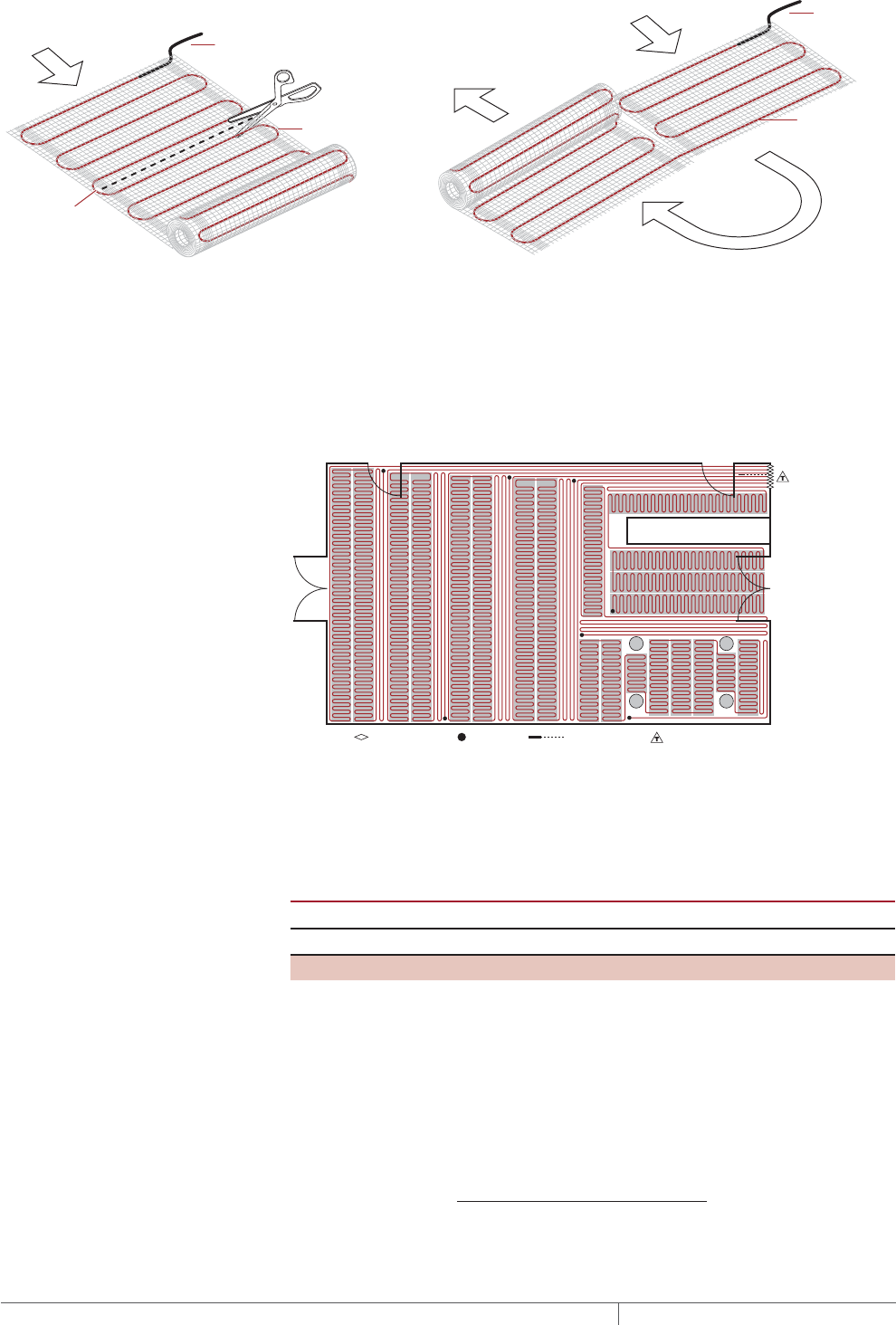
THERMAL MANAGEMENT SOLUTIONS
EN-FloorHeatingSystem-DG-H58157 11/13
296
Cold lead
Heating cable
Cold lead
Heating cable
DO NOT cut
heating cable
Fig. 21 Changing the direction of the mat
Since the heated area is slightly larger than the QuickNet mat, lay out the mat in
the areas you most want heated. The areas without a mat will not be heated and will
not be warm. The predetermined QuickNet spacing must be maintained to ensure
proper floor heating. In some cases, it may be necessary to pull the heating cable
out of the mat to cover small or irregular shaped areas. In this case, be careful
to remove the cable from the mat (do not cut the heating cable) and use the self-
adhesive mat to hold the cable down on the floor.
Start End Sensor Thermostat
Fig. 22 QuickNet floor heating mat layout for comfort floor heating
4. Determine the maximum circuit area for the heating mat
The maximum circuit area is determined by the supply voltage.
TABLE 14 MAXIMUM QUICKNET CIRCUIT AREA
Supply voltage Maximum circuit area
15 A Breaker 20 A Breaker
120 V 120 ft²140 ft²
208 / 240 V 240 ft²280 ft²
If the heated area is less than the maximum circuit area, then the QuickNet floor
heating mats can be directly controlled by the QuickStat-TC thermostat (single
circuit control). The QuickStat-TC thermostat has built-in GFCI protection and can be
used with a standard circuit breaker. If the heated area is larger than the maximum
circuit area, multiple circuits and group control (Fig. 23) must be used.
Calculate the estimated number of circuits as follows:
Number of circuits = Total heated area
Maximum circuit area
Round the number of circuits to the next largest whole number.
FLOOR HEATING RAYSOL, MINERAL INSULATED, AND QUICKNET HEATING SYSTEMS

297 THERMAL MANAGEMENT SOLUTIONS EN-FloorHeatingSystem-DG-H58157 11/13
Pipe Freeze Protection
and Flow Maintenance
Fire Sprinkler System
Freeze Protection
Roof and Gutter
De-Icing
Surface Snow
Melting – MI
Surface Snow
Melting – ElectroMelt
Freezer Frost
Heave Prevention
Floor Heating Technical Data
Sheets
Example: QuickNet heating mats for comfort floor heating
Control method Group control
Maximum circuit area 280 ft²
Number of circuits 647 ft2 / 280 ft2 = 3 (rounded)
(1-100 ft2 circuit, 1-250 ft2 circuit, 1-280 ft2)
Advance to Step 5.
Floor Heating Application Design
THERMAL MANAGEMENT SOLUTIONS
EN-FloorHeatingSystem-DG-H58157 11/13
298
Floor Heating System
Design Steps
1. Determine the
application
3. Determine the
floor configuration
4. Determine the
heating cable spacing,
layout and length
5. Determine the
electrical parameters
6. Select the
connection kits
and accessories
7. Select the control
system
8. Select the power
distribution
9. Complete the Bill
of Materials
2. Select the heating
cable system and
installation method
Step Determine the electrical parameters
In this step you will determine the electrical parameters. This section is organized by
heating cable type.
For RaySol self-regulating heating cables, see below.
For MI heating cables, see page299.
For QuickNet floor heating mats, see page301.
RAYSOL SELFREGULATING HEATING CABLE
DETERMINE NUMBER OF CIRCUITS
Record the number of circuits (from Step 4) to be used on the worksheet.
SELECT BRANCH CIRCUIT BREAKING RATING
For RaySol, the circuit breaker rating was determined in Step 4 using Table 5 or
Table 8.
Use ground-fault protection devices (GFPDs) for all RaySol heating cable
applications.
WARNING: To minimize the danger of fire from sustained electrical arcing if
the heating cable is damaged or improperly installed, and to comply with the
requirements of Pentair Thermal Management, agency certifications, and national
electrical codes, ground-fault equipment protection must be used on each heating
cable branch circuit. Arcing may not be stopped by conventional circuit protection.
DETERMINE TRANSFORMER LOAD
The total transformer load is the sum of the loads on all the circuit breakers in the
system.
Calculate the Circuit Breaker Load (CBL) as:
CBL (kW) =
Circuit breaker rating (A) x 0.8 x Supply voltage
1000
Calculate the Total Transformer Load as follows:
Total Transformer Load (kW) = CBL1 + CBL2 + CBL3...+ CBLN
Example: RaySol heating cables for heat loss replacement
Heating cable catalog number RaySol-2 (from Step 4)
Number of circuits 4 (from Step 4)
Circuit breaker rating 30 A breaker (from Step 4)
Circuit breaker load (30 A x 0.8 x 208 V) / 1000 = 5kW
Total transformer load 5 kW x 4 = 20 kW
Example: RaySol heating cables for comfort floor heating
Heating cable catalog number RaySol-2 (from Step 4)
Number of circuits 4 (from Step 4)
Circuit breaker rating 30 A breaker (from Step 4)
Circuit breaker load (30 A x 0.8 x 208 V) / 1000 = 5kW
Total transformer load 5 kW x 4 = 20 kW
Advance to Step 6, page302.
FLOOR HEATING RAYSOL, MINERAL INSULATED, AND QUICKNET HEATING SYSTEMS

299 THERMAL MANAGEMENT SOLUTIONS EN-FloorHeatingSystem-DG-H58157 11/13
Pipe Freeze Protection
and Flow Maintenance
Fire Sprinkler System
Freeze Protection
Roof and Gutter
De-Icing
Surface Snow
Melting – MI
Surface Snow
Melting – ElectroMelt
Freezer Frost
Heave Prevention
Floor Heating Technical Data
Sheets
MI HEATING CABLE
DETERMINE NUMBER OF CIRCUITS
For single-phase circuits, individual heating cables are normally connected to
separate circuit breakers. Multiple heating cables may be connected in parallel
to reduce the number of circuits with permission from the Authority Having
Jurisdiction. The single-phase heating cable current is shown in Table 10, Table 11,
and Table 12.
For three-phase circuits used in floor heating systems, the three heating cables
are generally connected in the delta configuration shown in Fig. 24 on page309.
Heating cables may also be connected using the wye configuration shown in Fig.
25 on page310, but this configuration is less common. For both delta and wye
configurations, each set of three equal cables form a single circuit.
SELECT BRANCH CIRCUIT BREAKING RATING
The power output and heating cable current draw for the floor heating cables are
shown in Table 10, Table 11, and Table 12.
For single-phase circuits, the load current must not exceed 80% of the circuit
breaker rating.
Load current = Heating cable current (for a single circuit)
Circuit breaker rating = Load current / 0.8
For a Delta connected three-phase circuit, shown in Fig. 24 on page309, the load
current can be determined by multiplying the heating cable current times 1.732 and
it must not exceed 80% of the 3-pole circuit breaker rating.
Load current = Heating cable current x 1.732 (for a single Delta connected circuit)
Circuit breaker rating = Load current / 0.8
For a Wye connected three-phase circuit, shown in Fig. 25 on page310, the load
current is the same as the heating cable current and it must not exceed 80% of the
3-pole circuit breaker rating.
Load current = Heating cable current (for a single Wye connected circuit)
Circuit breaker rating = Load current / 0.8
Record the number and ratings of the circuit breakers to be used. Use ground-fault
protection devices (GFPDs) for all applications. For three-phase circuits, ground fault
may be accomplished using a shunt trip three-pole breaker and ground fault sensor.
Circuit breaker rating (amps) ________ Number of circuit breakers ________
WARNING: To minimize the danger of fire from sustained electrical arcing if
the heating cable is damaged or improperly installed, and to comply with the
requirements of Pentair Thermal Management, agency certifications, and
national electrical codes, ground-fault equipment protection must be used on
each heating cable branch circuit. Arcing may not be stopped by conventional
circuit protection.
Floor Heating Application Design

THERMAL MANAGEMENT SOLUTIONS
EN-FloorHeatingSystem-DG-H58157 11/13
300
DETERMINE TRANSFORMER LOAD
The total transformer load is the sum of the loads in the system. Calculate the Total
Transformer Load as follows:
For cables of equal wattage:
Transformer load (kW) = Cable (W) x Number of cables
1000
When cable wattages are not equal:
Transformer load (kW) = Cable1 (W) + Cable2 (W) + Cable3 (W)... + CableN (W)
1000
Example: MI heating cables for heat loss replacement
Heating cable catalog number HLR24 (from Step 4)
Heating cable current 24.8 A (from Table 10)
Load current 24.8 x 1.732 = 43 A
Circuit breaker rating 60 A breaker, 80% loading 48 A
Number of circuit breakers 1 (3-pole breaker)
Cable wattage 5150 W (from Step 4)
Number of cables 3 (from Step 4)
Total transformer load (5150 W x 3) / 1000 = 15.5 kW
Example: MI heating cables for comfort floor heating
Heating cable catalog number FH21 (from Step 4)
Heating cable current 16.3 A (from Table 12)
Load current 16.3 A
Circuit breaker rating 25 A breaker, 80% loading 20 A
Number of circuit breakers 2
Cable wattage 3390 W (from Step 4)
Number of cables 2 (from Step 4)
Total transformer load (3390 W x 2) / 1000 = 6.8 kW
Example: MI heating cables for radiant space heating
Heating cable catalog number FH21 (from Step 4)
Heating cable current 16.3 A (from Table 12)
Load current 16.3 A
Circuit breaker rating 25 A breaker, 80% loading 20 A
Number of circuit breakers 3
Cable wattage 3390 W (from Step 4)
Number of cables 3 (from Step 4)
Total transformer load (3390 W x 3) / 1000 = 10.2 kW
Advance to Step 6, page302.
FLOOR HEATING RAYSOL, MINERAL INSULATED, AND QUICKNET HEATING SYSTEMS

301 THERMAL MANAGEMENT SOLUTIONS EN-FloorHeatingSystem-DG-H58157 11/13
Pipe Freeze Protection
and Flow Maintenance
Fire Sprinkler System
Freeze Protection
Roof and Gutter
De-Icing
Surface Snow
Melting – MI
Surface Snow
Melting – ElectroMelt
Freezer Frost
Heave Prevention
Floor Heating Technical Data
Sheets
QUICKNET FLOOR HEATING MATS
DETERMINE NUMBER OF CIRCUITS
Record the number of circuits (from Step 4) to be used on the worksheet.
SELECT BRANCH CIRCUIT BREAKER RATING
The recommended method of controlling the QuickNet floor heating mats is through
the QuickStat-TC thermostat supplied with the QuickNet heating system. The
QuickStat-TC thermostat has built-in GFCI protection and can be used with a 20 A
maximum standard circuit breaker to directly control 120 V heating mats in areas up
to 140 ft2 (13 m2) or 208/240 V heating mats in areas up to a 280 ft2 (26 m2). If several
QuickNet mats are required to cover areas larger than 280 ft2 (26 m2), then group
control should be used (see Step 8).
WARNING: To minimize the danger of fire from sustained electrical arcing if
the heating cable is damaged or improperly installed, and to comply with the
requirements of Pentair Thermal Management, agency certifications, and
national electrical codes, ground-fault equipment protection must be used on
each heating cable branch circuit. Arcing may not be stopped by conventional
circuit protection. The QuickStat-TC thermostat includes built-in GFCI protection
that meets this requirement.
DETERMINE TRANSFORMER LOAD
The total transformer load is the sum of the loads in the system. Calculate the Total
Transformer Load as follows:
For cables of equal wattage:
Transformer load (kW) =
Cable (W) x Number of cables
1000
When cable wattages are not equal:
Transformer load (kW) =
Cable1 (W) + Cable2 (W) + Cable3 (W)... + CableN (W)
1000
Example: QuickNet heating mats for comfort floor heating
Number of circuits 3 (from Step 4)
Circuit breaker rating 20 A breaker, 80% loading 16 A
Number of circuit breakers 3
Total power output 450 W + 720 W + (900 W x 5) = 5670 W
Total transformer load 5670 W / 1000 = 5.7 kW
Advance to Step 6.
Floor Heating Application Design
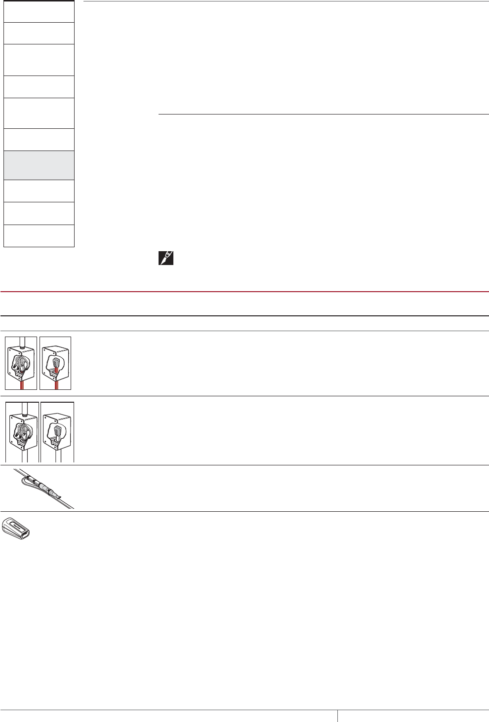
THERMAL MANAGEMENT SOLUTIONS
EN-FloorHeatingSystem-DG-H58157 11/13
302
Floor Heating System
Design Steps
1. Determine the
application
3. Determine the
floor configuration
4. Determine the
heating cable spacing,
layout and length
5. Determine the
electrical parameters
6. Select the
connection kits
and accessories
7. Select the control
system
8. Select the power
distribution
9. Complete the Bill
of Materials
2. Select the heating
cable system and
installation method
Step Select the connection kits and accessories
In this step you will determine the number of junction boxes, power connections, end
seals and splice kits required. This section is separated by heating cable type.
For RaySol self-regulating heating cables, see below.
For MI heating cables, see page303.
For QuickNet floor heating mats, see page304.
RAYSOL SELFREGULATING HEATING CABLE
SELECT NUMBER OF POWER CONNECTION KITS
For heat loss replacement, one FTC-P power connection kit and two junction boxes
are required per circuit. For comfort floor heating, one FTC-XC power connection kit
and two junction boxes are required per circuit
SELECT JUNCTION BOX
Select a contractor-supplied UL Listed and/or CSA Certified junction box that is
suitable for the location. Use a box with minimum internal volume of 16 cubic inches
if the box is metallic and 19 cubic inches if the box is not metallic.
Note: The junction box must be accessible according to national electrical codes.
TABLE 15 CONNECTION KITS AND ACCESSORIES
Catalog
number Description
Standard
packaging Usage
RaySol Connection Kits
FTC-P Power connection and end seal.
(Junction box not included)
1 1 per cable run (for heat loss
replacement)
FTC-XC Power connection and end seal.
(Junction box not included)
1 1 per cable run (for comfort
floor heating and radiant
space heating)
FTC-HST Low-profile splice/tee 2 As required (for embedded
applications, splice must be
accessible)
RayClic-E Extra end seal 1 Replacement end seal
Example: RaySol heating cables for heat loss replacement
Junction box Contractor supplied
Quantity 8
Connection kit FTC-P
Quantity 4
Example: RaySol heating cables for comfort floor heating
Junction box Contractor supplied
Quantity 8
Connection kit FTC-XC
Quantity 4
Advance to Step 7, page305.
FLOOR HEATING RAYSOL, MINERAL INSULATED, AND QUICKNET HEATING SYSTEMS
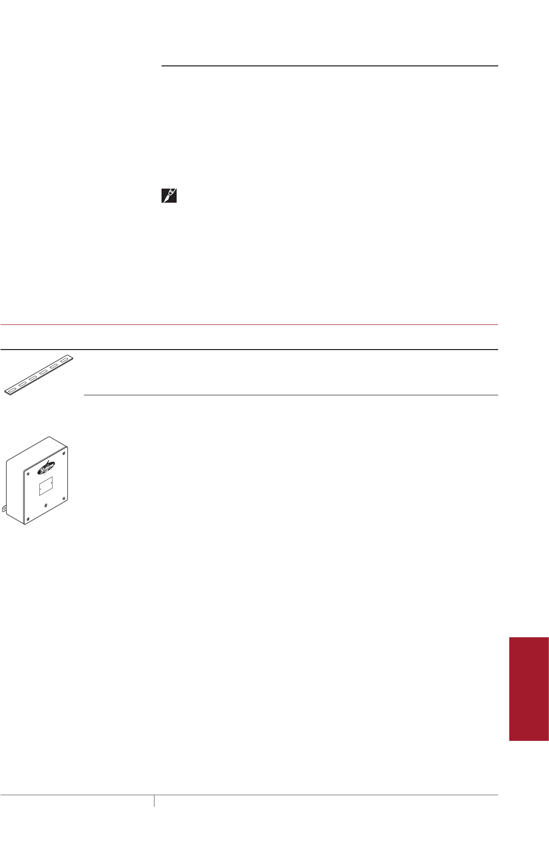
303 THERMAL MANAGEMENT SOLUTIONS EN-FloorHeatingSystem-DG-H58157 11/13
Pipe Freeze Protection
and Flow Maintenance
Fire Sprinkler System
Freeze Protection
Roof and Gutter
De-Icing
Surface Snow
Melting – MI
Surface Snow
Melting – ElectroMelt
Freezer Frost
Heave Prevention
Floor Heating Technical Data
Sheets
MI HEATING CABLES
A typical Pyrotenax floor heating system consists of several accessories. All of the
accessories work together to provide a safe and reliable floor heating system that is
easy to install and maintain.
SELECT JUNCTION BOX
Select a UL Listed and/or CSA Certified junction box that is suitable for the location,
such as the Pyrotenax D1297TERM4. Use a box with minimum internal volume of 16
cubic inches if the box is metallic and 19 cubic inches if the box is not metallic. Metal
junction boxes are recommended.
Note: The junction box must be accessible according to the national electrical codes.
SELECT PREPUNCHED STRAPPING
For heat loss replacement applications, use stainless steel prepunched strapping
attached to the bottom of the concrete floor to secure the heating cables at the
proper spacing. For floor heating applications where the heating cable is embedded
in concrete or mortar floors, use galvanized steel prepunched strapping to maintain
the heating cables at the proper spacing.
Number of rolls required = Total area (ft2) x 0.005 (Total area (m2) x 0.05)
TABLE 16 ACCESSORIES
Catalog
number Description
Standard
packaging Usage
HARD-SPACER-
GALV-25MM-
25M
Galvanized steel prepunched strapping.
Note: Use when cable is embedded in
concrete or mortar.
82 ft (25 m)
rolls
No. rolls = 0.005 x area (ft²)
No. rolls = 0.05 x area (m²)
HARD-SPACER-
SS-25MM-25M
Stainless steel prepunched strapping
Note: Use with all heat loss replacement
applications.
82 ft (25 m)
rolls
No. rolls = 0.005 x area (ft²)
No. rolls = 0.05 x area (m²)
D1297TERM4 A cast aluminum junction box (NEMA 3) for
installation in nonhazardous and CID2 locations.
Three 1/2" NPT entries on bottom, provided with
plugs. Includes 4-pole terminal block (CSA -
600 V, 65 A, 18 - 6 AWG; UL - 300 V, 65 A, 18 - 6
AWG). External mounting feet. CSA approved for
Class I, Div. 2, Groups A, B, C, and D.
Enclosure dimensions: 6 in x 6 in x 4 in
(150 mm x 150 mm x 100 mm).
1
Example: MI heating cables for heat loss replacement
Junction box Contractor supplied
Quantity 1 (7 entries)
Prepunched strapping HARD-SPACER-SS-25MM-25M
Quantity 16
Example: MI heating cables for comfort floor heating
Junction box D1297TERM4
Quantity 2
Prepunched strapping¹ HARD-SPACER-GALV-25MM-25M
Quantity 4
Example: MI heating cables for radiant space heating
Junction box D1297TERM4
Quantity 3
Prepunched strapping¹ HARD-SPACER-GALV-25MM-25M
Quantity 4
¹ For comfort floor heating and radiant space heating applications in slab floors,
prepunched strapping may not be required if it is possible to attach the heating
cable to the reinforcement.
Advance to Step 7, page305.
Floor Heating Application Design
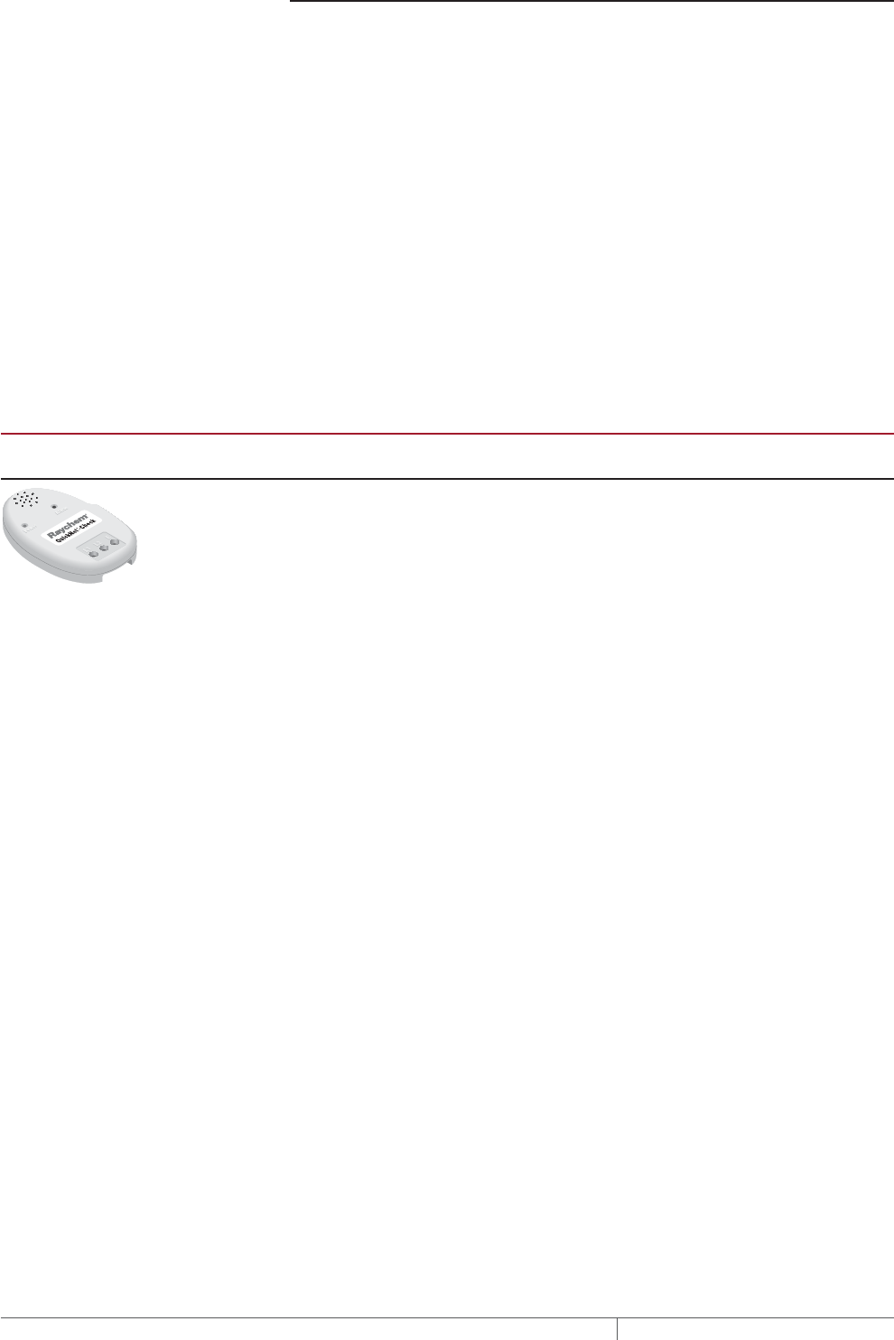
THERMAL MANAGEMENT SOLUTIONS
EN-FloorHeatingSystem-DG-H58157 11/13
304
QUICKNET FLOOR HEATING MATS
SELECT JUNCTION BOX
The QuickStat-TC thermostat must be installed in an electrical junction box. Ensure
that the junction box is at a convenient height – typically 5 feet above the floor and
within reach of the cold lead and the floor temperature sensor. In group control,
each circuit must also have its own junction box where the cold leads can be wired
in parallel before connecting to the remote contactor. Select a UL Listed and/or
CSA Certified junction box that is suitable for the location. Use a box with minimum
internal volume of 16 cubic inches if the box is metallic and 19 cubic inches if the box
is not metallic.
SELECT QUICKNETCHECK
The QuickNet-Check monitor is used to verify the continuity of the QuickNet heating
cable and the integrity of its outer jacket during the installation process. The monitor
connects to the cold leads of the cable and, if the heating cable is damaged, the
alarm on the monitor will sound. The monitor can also be re-used for subsequent
installations and to help troubleshoot any problems that may arise.
TABLE 17 ACCESSORIES
Catalog
number Description
Standard
packaging Usage
QUICKNET-
CHECK
Monitor is used to verify the continuity of the
QuickNet heating cable and the integrity of its
outer jacket during the installation process.
1 NA
Example: QuickNet heating mat for comfort floor heating
Junction box Contractor supplied
Quantity 5 (1 for QuickStat-TC and 1 for each circuit)
QuickNet-Check QUICKNET-CHECK
Quantity 1
Advance to Step 7.
FLOOR HEATING RAYSOL, MINERAL INSULATED, AND QUICKNET HEATING SYSTEMS
305 THERMAL MANAGEMENT SOLUTIONS EN-FloorHeatingSystem-DG-H58157 11/13
Pipe Freeze Protection
and Flow Maintenance
Fire Sprinkler System
Freeze Protection
Roof and Gutter
De-Icing
Surface Snow
Melting – MI
Surface Snow
Melting – ElectroMelt
Freezer Frost
Heave Prevention
Floor Heating Technical Data
Sheets
Floor Heating System
Design Steps
1. Determine the
application
3. Determine the
floor configuration
4. Determine the
heating cable spacing,
layout and length
5. Determine the
electrical parameters
6. Select the
connection kits
and accessories
7. Select the control
system
8. Select the power
distribution
9. Complete the Bill
of Materials
2. Select the heating
cable system and
installation method
Step Select the control system
There are two types of controls that may be used with floor heating systems: floor
temperature sensing control and ambient temperature control with overlimit sensor.
Floor temperature sensing control must be used for heat loss replacement and
comfort floor heating applications, while an ambient temperature control with an
overlimit sensor must be used for radiant space heating applications.
For RaySol and MI heating cables, the recommended control for heat loss
replacement and comfort floor heating is DigiTrace ECW-GF. For RaySol or MI
heating cable installations where temperature control and temperature monitoring
is desired, a Pentair Thermal Management DigiTrace C910-485 or DigiTrace ACS-30
controller is recommended.
For the QuickNet floor heating system, the QuickStat-TC thermostat and floor
sensor is supplied with each standard kit so no additional temperature controller is
required.
TABLE 18 TEMPERATURE CONTROL OPTIONS
Features
DigiTrace
ECW-GF
DigiTrace
C910-485 2
DigiTrace
ACS-30
Number of heating
cable circuits
Single Single Multiple
Sensor Thermistor RTD ¹See data sheet
Sensor length 25 ft Varies "
Set point range 32°F to 200°F
(0°C to 93°C)
–0°F to 200°F
(–18°C to 93°C)
"
Enclosure NEMA 4X NEMA 4X "
Deadband 2°F to 10°F
(2°C to 6°C)
1°F to 10°F
(1°C to 6°C)
"
Enclosure limits –40°F to 140°F
(–40°C to 60°C)
–40°F to 140°F
(–40°C to 60°C)
"
Switch rating 30 A 30 A "
Switch type DPST DPST "
Electrical rating 100–277 V 100–277 V "
Approvals c-UL-us c-CSA-us "
Ground-fault
protection
30 mA fixed 20 mA to 100 mA
(adjustable)
"
Alarm outputs
AC relay 2 A at 277 Vac 100–277 V,
0.75 A max.
"
Dry contact relay 2 A at 48 Vdc 48 Vac/dc, 500 mA
max.
"
¹ Ordered separately
² The C910-485 is available to provide RS-485 communication capability. Connect to the
BMS using DigiTrace ProtoNode multi-protocol gateways
Floor Heating Application Design
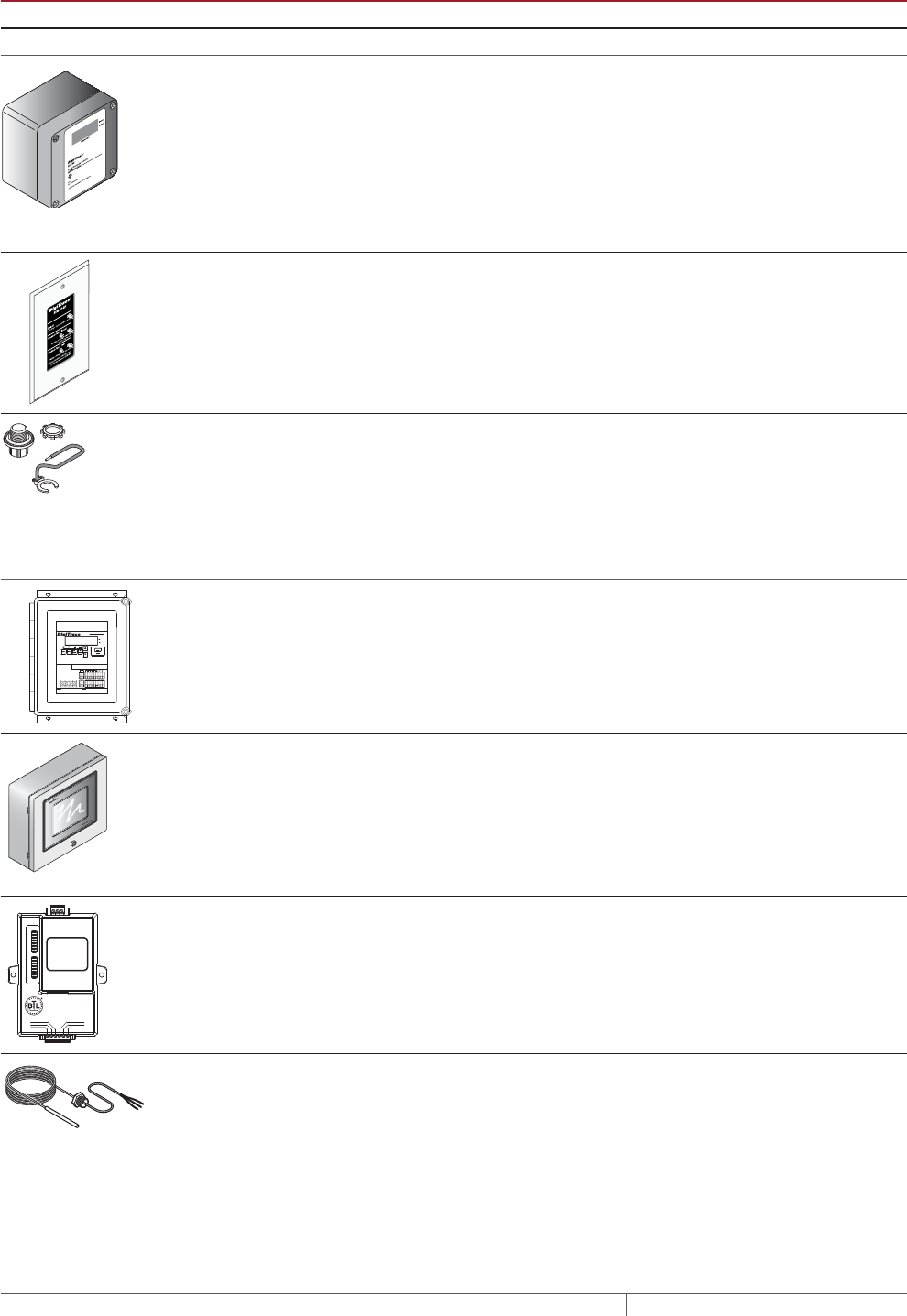
THERMAL MANAGEMENT SOLUTIONS
EN-FloorHeatingSystem-DG-H58157 11/13
306
TABLE 19 CONTROL SYSTEMS
Catalog number
Description
Electronic thermostats and accessories
ECW-GF Electronic ambient sensing controller with 30-mA ground-fault protection. The control-
ler can be programmed to maintain temperatures up to 200°F (93°C) at voltages from
100 to 277 V and can switch current up to 30 Amperes. The ECW-GF is complete with
a 25-ft (7.6-m) temperature sensor and is housed in a Type 4X rated enclosure. The
controller features an AC/DC dry alarm contact relay.
An optional ground-fault display panel (ECW-GF-DP) can be added to provide ground-
fault or alarm indication in applications where the controller is mounted in inaccessible
locations.
ECW-GF-DP An optional remote display panel (ECW-GF-DP) that can be added to provide ground-
fault or alarm indication in applications where the controller is mounted in inacces-
sible locations.
MI-GROUND-KIT Grounding kit for nonmetallic enclosures (for MI only)
Electronic controllers and sensors
C910-485 The C910-485 is a compact, full-featured microprocessor-based single-point heat-
trace controller. The C910-485 provides control and monitoring of electrical heat-
tracing circuits for both freeze protection and temperature maintenance, and can
be set to monitor and alarm for high and low temperature, high and low current,
ground-fault level, and voltage. The DigiTrace C910-485 controller is available with an
electromechanical relay (EMR) for use in ordinary areas. The C910-485 comes with an
RS-485 communication module.
ACS-UIT2
ACS-PCM2-5
The DigiTrace ACS-30 Advanced Commercial Control System is a multipoint electronic
control and monitoring system for heat-tracing used in various commercial applica-
tions such as pipe freeze protection, roof and gutter de-icing, surface snow melting,
hot water temperature maintenance and floor heating. The DigiTrace ACS-30 system
can control up to 260 circuits with multiple networked ACS-PCM2-5 panels, with a
single ACS-UIT2 user interface terminal. The ACS-PCM2-5 panel can directly control
up to 5 individual heat-tracing circuits using electromechanical relays rated at 30 A up
to 277 V.
By FieldServer Technologies
www.ProtoCessor.com
PROTOCESSOR
SERIAL ETHERNET
PROTONODE
FRAME GND
- PWR
+PWR
RS 485+
RS 485 -
RS 485 GND
S3
S2
S1
S0
B3
B2
B1
B0
A7
A6
A5
A4
A3
A2
A1
A0
ProtoNode-LER
ProtoNode-RER
The DigiTrace ProtoNode is an external, high performance multi-protocol gateway
for customers needing protocol translation between Building Management Systems
(BMS) and the DigiTrace ACS-30 or C910-485 controllers.
The ProtoNode-LER is for LonWorks® systems; and the ProtoNode-RER is for
BACnet® or Metasys® N2 systems.
RTD10CS
RTD-200
RTD50CS
Stainless steel jacketed three-wire RTD (Resistance Temperature Detector) used with
DigiTrace C910-485 and ACS-30 controllers.
RTD10CS: 10-ft (3 m) flexible armor, with 18-in (457 mm) lead wire and 1/2-inch NPT
bushing
RTD-200: 6-ft (1.8 m) fluoropolymer with 1/2-in NPT bushing
RTD-50: 50-ft (3 m) flexible armor with 1/2-in NPT bushing
FLOOR HEATING RAYSOL, MINERAL INSULATED, AND QUICKNET HEATING SYSTEMS

307 THERMAL MANAGEMENT SOLUTIONS EN-FloorHeatingSystem-DG-H58157 11/13
Pipe Freeze Protection
and Flow Maintenance
Fire Sprinkler System
Freeze Protection
Roof and Gutter
De-Icing
Surface Snow
Melting – MI
Surface Snow
Melting – ElectroMelt
Freezer Frost
Heave Prevention
Floor Heating Technical Data
Sheets
Example: RaySol heating cables for heat loss replacement
Multiple circuits, monitoring requested ACS-30
Quantity 1
Example: MI heating cables for heat loss replacement
Single circuit, monitoring requested ACS-30*
Quantity 1
* Use ACS-30 General part number (P000001232) for custom three-phase panels. Please
contact your Pentair Thermal Management representative for a custom ACS-PCM2-5
panel quotation.
Example: RaySol and MI heating cables for comfort floor heating
Multiple circuits, electronic thermostat requested ECW-GF
Quantity 1
Example: QuickNet heating mats for comfort floor heating
Multiple circuits, electronic thermostat QuickStat-TC
Quantity 1
Example: MI heating cables for radiant space heating
Multiple circuits, electronic thermostat requested¹ ECW-GF
Quantity 1
¹ Ambient control to be supplied by the contractor
Floor Heating Application Design

THERMAL MANAGEMENT SOLUTIONS
EN-FloorHeatingSystem-DG-H58157 11/13
308
Floor Heating System
Design Steps
1. Determine the
application
3. Determine the
floor configuration
4. Determine the
heating cable spacing,
layout and length
5. Determine the
electrical parameters
6. Select the
connection kits
and accessories
7. Select the control
system
8. Select the power
distribution
9. Complete the Bill
of Materials
2. Select the heating
cable system and
installation method
Step Select the power distribution
Power to the heating cables can be provided in several ways:
• Directly through the temperature controller
• Through external contactors activated by a temperature controller
• Through an HTPG power distribution panel
SINGLE CIRCUIT CONTROL
RaySol and MI heating cable circuits that do not exceed the current rating of the
selected control can be switched directly (Fig. 24). When the total electrical load
exceeds the rating of the controller, an external contactor is required.
The three-phase Delta and Wye configurations shown in Fig. 234 and Fig. 25 are
common wiring configurations for MI heating cables used to heat large areas. DO
NOT use these wiring configurations for RaySol heating systems. A single pole
temperature controller may be used to control a three-phase circuit through a
contactor.
The recommended method of controlling the QuickNet floor heating mats is through
the QuickStat-TC thermostat supplied with the QuickNet heating system. The
QuickStat-TC thermostat has built-in GFCI protection and can be used with a 20 A
maximum standard circuit breaker to directly control 120 V heating mats in areas up
to 140 ft² (13 m²) or 208/240 V heating mats in areas up to a 280 ft² (26 m²). If several
QuickNet mats are required to cover areas larger than 280 ft² (26 m²), then group
control should be used.
GROUP CONTROL
For group control, a single temperature controller may be used to control two or
more single-phase or three-phase circuits. Multiple single-phase RaySol or MI
heating cable circuits may be controlled by a single temperature controller, through
a contactor, as shown in Fig. 23. Multiple three-phase MI heating cable circuits may
be controlled in the same manner.
If several QuickNet mats are required to cover areas larger than 280 ft² (26 m²), then
the group control method, using an external contactor (Fig. 23), should be used. The
QuickStat-TC may be used to control the contactor, but the built-in GFCI protection
will not function. Each QuickNet heating mat circuit must be connected to a ground-
fault circuit breaker.
FLOOR HEATING RAYSOL, MINERAL INSULATED, AND QUICKNET HEATING SYSTEMS
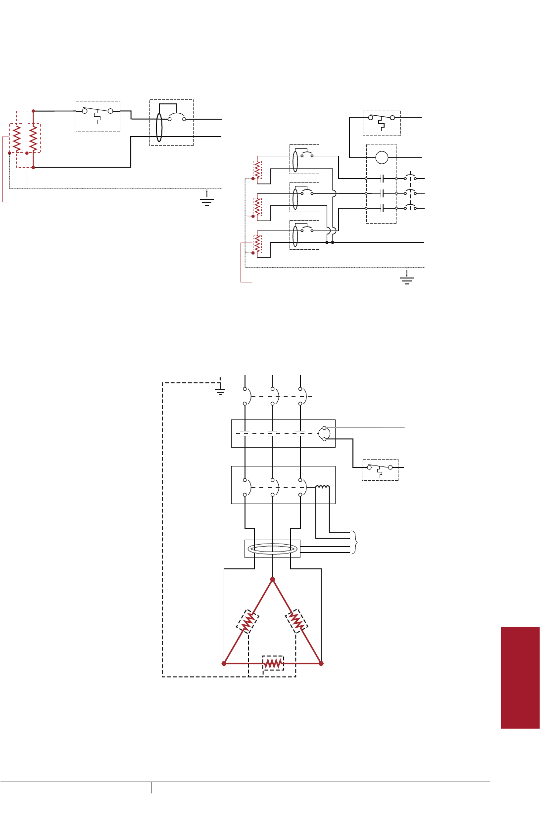
309 THERMAL MANAGEMENT SOLUTIONS EN-FloorHeatingSystem-DG-H58157 11/13
Pipe Freeze Protection
and Flow Maintenance
Fire Sprinkler System
Freeze Protection
Roof and Gutter
De-Icing
Surface Snow
Melting – MI
Surface Snow
Melting – ElectroMelt
Freezer Frost
Heave Prevention
Floor Heating Technical Data
Sheets
Single circuit control Group control
Temperature
controller 1-pole
GFEP breaker
1
N
G
Heating
cable
ø
øsupply
C
Temperature
controller
Contactor
1-pole
GFEP breaker
N
G
ø2
ø1
ø3
3-phase 4-wire
supply (WYE)
3-pole main
breaker
ø
ø
1 supply
N
Heating cable
sheath, braid
or ground
Heating cable
sheath, braid
or ground
Fig. 23 Single circuit and group control
To ground
fault module
3-pole circuit
breaker with shunt
trip/external ground-
fault sensor
3-pole contactor
120 volt coil
Ground-fault
sensor
A B C
A
B
C
C
Three-phase
4-wire supply
MCB
Note: For Delta connected
heating cables, the current
in the supply feeder,
contactor, and breaker is
equal to the “Heating Cable
Current” x 1.732.
Ground
Heating
cable sheath,
braid or ground
Temperature
controller
to
120 V
Note: Heating cable voltage is
the same as the phase-to-
phase voltage (VØ-Ø
)
Fig. 24 Typical single circuit control for three-phase delta connected cables
Floor Heating Application Design
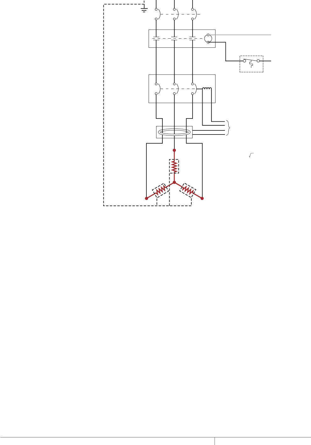
THERMAL MANAGEMENT SOLUTIONS
EN-FloorHeatingSystem-DG-H58157 11/13
310
A B C
A
B
C
N
C
MCB
To ground-
fault module
3-pole contactor
120 V coil
3-pole circuit
breaker with shunt
trip/external ground-
fault sensor
Ground-fault
sensor
Ground
Three-phase
4-wire supply
Heating cable
sheath, braid
or ground
Temperature
controller
to
120 V
Note: For Wye connected
heating cables, the current in
the supply feeder, contactor,
and breakers is equal to the
‘Heating Cable Current.’
(VØ-Ø / 3 ).
Note: Heating cable voltage is
the same as the phase-to-
neutral voltage
Fig. 25 Typical single circuit control for three-phase wye connected cables
Large systems with many circuits should use an HTPG power distribution panel. The
HTPG is a dedicated power-distribution, control, ground-fault protection, monitoring,
and alarm panel for broad temperature-maintenance heat-tracing applications. This
enclosure contains an assembled circuit-breaker panelboard. Panels are equipped
with ground-fault circuit breakers with or without alarm contacts. The group
control package allows the system to operate automatically in conjunction with a
temperature control system.
FLOOR HEATING RAYSOL, MINERAL INSULATED, AND QUICKNET HEATING SYSTEMS
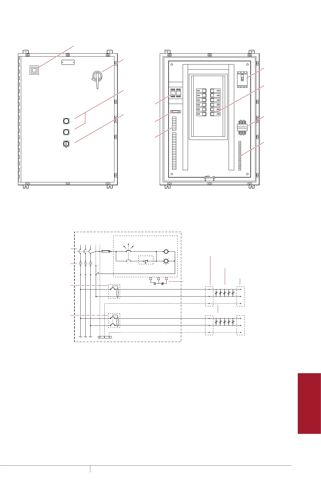
311 THERMAL MANAGEMENT SOLUTIONS EN-FloorHeatingSystem-DG-H58157 11/13
Pipe Freeze Protection
and Flow Maintenance
Fire Sprinkler System
Freeze Protection
Roof and Gutter
De-Icing
Surface Snow
Melting – MI
Surface Snow
Melting – ElectroMelt
Freezer Frost
Heave Prevention
Floor Heating Technical Data
Sheets
A
COMMON ALARM
PUSH TO ACKNOWLEDGE
HAND/OFF/AUTO
1
2
3
4
5
6
7
8
9
10
11
12
Main circuit
breaker
Main
contactor
Distribution
panelboard
Fuse holder
C
POWER ON
TB 1
TB 2
ARR
Ground
bus bar
Selector switch
Alarm relay
(optional)
Terminals
(optional)
Push button for
light testing
Alarm horn (optional)
Alarm option shown above
Door
disconnect
(optional)
Fig. 26 HTPG power distribution panel
N
Ø1
Three-pole main
circuit breaker
Panel
energized
Contactor
coil
C NC
External controller/
thermostat*
Hand Auto
Off
Three-pole main
contactor
Ø3
Ø2
Power
connection
Heating cable
One-pole with 30-mA
ground-fault trip
(120/277 Vac)
Two-pole with 30-mA
ground-fault trip
(208/240 Vac)
Alarm
remote
annunciation
(with alarm
option)
Heating
cable
circuit
Heating
cable
circuit
G
End seal
Heating cable shealth, braid or ground
Three-phase, 4 wire supply (Wye)
Fig. 27 HTPG power schematic
Floor Heating Application Design
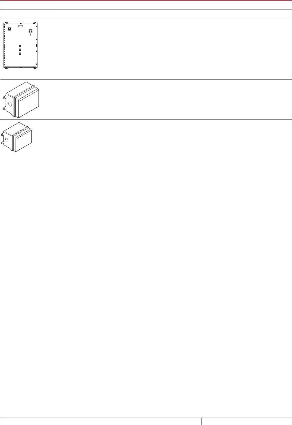
THERMAL MANAGEMENT SOLUTIONS
EN-FloorHeatingSystem-DG-H58157 11/13
312
TABLE 20 POWER DISTRIBUTION
Catalog number Description
Power Distribution and Control Panels
A
COMMON ALARM
PUSH TO ACKNOWLEDGE
HAND/OFF/AUTO
C
POWER ON
HTPG Heat-tracing power distribution panel with ground-fault and monitoring for group
control.
Contactors
E104 Three-pole, 100 A per pole, 600 V maximum contactor housed in UL Listed, CSA Certi-
fied, Type 4X enclosure with two 1-inch conduit entries. When ordering, select coil
voltage
(110–120, 208–240, 277 V).
Enclosure dimensions: 13-1/2 in x 9-1/5 in x 6-11/16 in (343 mm x 234 mm x 170 mm).
E304 Three-pole, 40 A per pole, 600 V maximum contactor housed in UL Listed, CSA Certified
Type 4X enclosure with two 1-inch conduit entries. When ordering, select coil voltage
(110–120, 208–240, 277 V).
Enclosure dimensions: 9-1/2 in x 7-1/5 in x 6-11/16 in (241 mm x 183 mm x 170 mm).
Example: RaySol heating cables for comfort floor heating
Contactor* E104
Quantity 1
* Required because total load current exceeds the maximum 30 A current rating of
ECW-GF thermostat.
Example: MI heating cables for comfort floor heating
Contactor* E304
Quantity 1
* Required because maximum current rating of the ECW-GF thermostat is 30 A and
total load current for this example is 32.6 A.
Example: MI heating cables for radiant space heating
Contactor* E104
Quantity 1
* Required because maximum current rating of the ECW-GF thermostat is 30 A and
total load current for this example is 48.9 A.
FLOOR HEATING RAYSOL, MINERAL INSULATED, AND QUICKNET HEATING SYSTEMS

313 THERMAL MANAGEMENT SOLUTIONS EN-FloorHeatingSystem-DG-H58157 11/13
Pipe Freeze Protection
and Flow Maintenance
Fire Sprinkler System
Freeze Protection
Roof and Gutter
De-Icing
Surface Snow
Melting – MI
Surface Snow
Melting – ElectroMelt
Freezer Frost
Heave Prevention
Floor Heating Technical Data
Sheets
Floor Heating System
Design Steps
1. Determine the
application
3. Determine the
floor configuration
4. Determine the
heating cable spacing,
layout and length
5. Determine the
electrical parameters
6. Select the
connection kits
and accessories
7. Select the control
system
8. Select the power
distribution
9. Complete the Bill
of Materials
2. Select the heating
cable system and
installation method
Step Complete the Bill of Materials
If you used the Design Worksheet to document all your design parameters, you
should have all the details necessary complete your Bill of Materials.
Floor Heating Application Design

THERMAL MANAGEMENT SOLUTIONS
EN-FloorHeatingSystem-DG-H58157 11/13
314
FLOOR HEATING PREDESIGN WORKSHEET
Step Determine the application (see page270)
Select the application that best describes your needs
❑ Heat loss replacement
❑ Comfort floor heating
❑ Radiant space heating
If you have selected the radiant space heating application, use the MI Heating Cable Floor Heating Design Worksheet on page323.
Step Determine the installation method
Select the installation you plan to use.
Heat loss replacement
❑ Attach to the bottom of the floor
❑ RaySol
❑ MI
Comfort floor heating
❑ Embed in concrete
❑ RaySol
❑ MI
❑ Embed in mortar bed
❑ RaySol
❑ MI
❑ Embed in thin set
❑ QuickNet
❑ Embed in self-levelling mortar
❑ QuickNet
Radiant space heating
❑ Embed in concrete
❑ RaySol*
❑ MI
❑ Embed in mortar bed
❑ RaySol*
❑ MI
* Please contact Pentair Thermal Management for design assistance.
FLOOR HEATING RAYSOL, MINERAL INSULATED, AND QUICKNET HEATING SYSTEMS

315 THERMAL MANAGEMENT SOLUTIONS EN-FloorHeatingSystem-DG-H58157 11/13
Pipe Freeze Protection
and Flow Maintenance
Fire Sprinkler System
Freeze Protection
Roof and Gutter
De-Icing
Surface Snow
Melting – MI
Surface Snow
Melting – ElectroMelt
Freezer Frost
Heave Prevention
Floor Heating Technical Data
Sheets
RAYSOL HEATING CABLE FLOOR HEATING DESIGN WORKSHEET
Heat Loss Replacement
Step 3 Determine the floor configuration (Steps 1 and 2 were completed in the pre-design worksheet)
Heat loss replacement (see Fig. 11 on page272)
Minimum
ambient
design
temperature
Insulation
R-value
Supply voltage
and phase
Control
requirements
X = Heated area
(ft
2
/m
2
)
Side A (length)
(ft/m)
Side B (width)
(ft/m)
_______°F/°C _____________
ft2·°F·hr/Btu
________Volts
________ Phase
____________
____________
Example: RaySol heating cables for heat loss
replacement
80 ft 40 ft 3200 ft2
X = Heated area
(ft2/m2)
Side A (length)
(ft/m)
Side B (width)
(ft/m)
–10°F R-20
(20 ft2·°F·hr/Btu)
208 V
Single phase
Electronic thermostat,
monitoring requested
Step 4 Determine the heating cable spacing, layout and length
4.1 Select the appropriate RaySol heating cable (see Table 3 on page275)
Supply voltage: ________________ (from Step 3)
Catalog number: ________________ (from Table 3)
Example: RaySol heating cables for heat loss replacement
Supply voltage: 208 V (from Step 3)
Catalog number: RaySol-2 (from Table 3)
4.2 Determine the RaySol heating cable spacing (see Table 4 on page276)
Minimum ambient temperature: ___________°F/°C (from Step 3)
Insulation R-value: ___________ (from Step 3)
Heating cable spacing: ___________in/cm (from Table 4)
Example: RaySol heating cables for heat loss replacement
Minimum ambient temperature: –10°F (from Step 3)
Insulation R-value: R-20 (from Step 3)
Heating cable spacing: 24 in (from Table 4)
4.3 Determine the RaySol heating cable layout and length
x /12 = Estimated heating cable lengthHeated area (ft2)
(from Step 3)
Heating cable spacing (in)
(from Step 4.2)
( )
x /100 = Estimated heating cable lengthHeated area (m2)
(from Step 3)
Heating cable spacing (cm)
(from Step 4.2)
( )
Imperial
Metric
3200 ft224 in
40 ft 24 in 20
1600 ft
Estimate the heating cable length
Example: RaySol heating cables for heat loss replacement
x /12 = Number of heating cable runsSide B
(from Step 3)
Heating cable spacing
(from Step 4.1)
( )
Determine the number of heating cable runs required
x /12 = Estimated heating cable lengthHeated area (ft2)
(from Step 3)
Heating cable spacing
(from Step 4.2)
( )
RaySol Heating Cable Floor Heating Design Worksheet

THERMAL MANAGEMENT SOLUTIONS
EN-FloorHeatingSystem-DG-H58157 11/13
316
Step 4 Determine the heating cable spacing, layout and length
4.4 Determine the maximum circuit length for the heating cable length (see Table 5 on page277)
/ = Number of circuitsEstimated heating cable length (ft/m)
(from Step 4.3)
Maximum circuit length (ft/m)
(from Table 5)
Round the number of circuits to the next larger whole number
Example: RaySol heating cables for heat loss replacement
/ = Number of circuits
1600 ft 410 ft 4 (rounded)
Estimated heating cable length
(from Step 4.3)
Maximum circuit length
(from Table 5)
Power supply: Four 30 A circuit breakers
FLOOR HEATING RAYSOL, MINERAL INSULATED, AND QUICKNET HEATING SYSTEMS

317 THERMAL MANAGEMENT SOLUTIONS EN-FloorHeatingSystem-DG-H58157 11/13
Pipe Freeze Protection
and Flow Maintenance
Fire Sprinkler System
Freeze Protection
Roof and Gutter
De-Icing
Surface Snow
Melting – MI
Surface Snow
Melting – ElectroMelt
Freezer Frost
Heave Prevention
Floor Heating Technical Data
Sheets
Step 4 Determine the heating cable spacing, layout and length
4.5 Determine the additional heating cable allowance (see Table 6 on page278)
End allowance
x =
End allowance (ft/m)ft/m per end
(from Table 6)
Number of circuits
(from Step 4.4)
x
Number of ends
Connection kit allowance
x =
Connection kit allowance (ft/m)ft/m per connection kit
(from Table 6)
Number of kits
Total heating cable allowance
+ =
Total heating cable
allowance (ft/m)
End allowance (ft/m) Connection kit allowance (ft/m)
Estimated total heating cable length
+ =
Estimated total heating
cable length (ft/m)
Estimated heating cable length (ft/m)
(from Step 4.3)
Total heating cable allowance (ft/m)
Example: RaySol heating cables for heat loss replacement
End allowance
x =
End allowance
4
44
4 2 32 ft
32 ft
1600 ft 48 ft 1648 ft
16 ft 48 ft
16 ft
ft/m per end
(from Table 6)
Number of circuits
(from Step 4.4)
x
Number of ends
Connection kit allowance
x =
Connection kit allowanceft/m per connection kit
(from Table 6)
Number of kits
Total heating cable allowance
+ =
Total heating cable
allowances (ft/m)
End allowance Connection kit allowance
Estimated total heating cable length
+ =
Estimated total heating
cable length (ft/m)
Estimated heating cable length
(from Step 4.3)
Total heating cable allowances (ft/m)
4.6 Locate the junction boxes for the RaySol heating cable (see Fig. 14 on page276 for examples of a typical system)
4.7 Lay out the heating cable runs, circuits, and junction boxes
4.8 Record the circuit information
Advance Step 5 on on page321.
RaySol Heating Cable Floor Heating Design Worksheet

THERMAL MANAGEMENT SOLUTIONS
EN-FloorHeatingSystem-DG-H58157 11/13
318
Comfort Floor Heating
Step 3 Determine the floor configuration (Steps 1 and 2 were completed in the pre-design worksheet)
Comfort floor heating (see Fig. 12 on page273)
Minimum
ambient
design
temperature
Insulation
R-value
Supply voltage
and phase
Control
requirements
– = Heated area
(ft2/m2)
Total area
(ft2/m2)
Permanent fixture
(ft2/m2)
_________°F/°C _____________
ft2·°F·hr/Btu
________Volts
________ Phase
____________
____________
x = Total area
(ft2/m2)
Side A (length)
(ft/m)
Side B (width)
(ft/m)
–=Heated area
(ft2/m2)
Total area
(ft2/m2)
Permanent fixture
space (ft2/m2)
x = Total areaSide A
(see Figure 12)
Side B
(see Figure 12)
– = Heated areaTotal area
Minimum ambient design temperature: 10°F
Insulation R-value: R-30
Supply voltage and phase: 208 V, single phase
Control requirements: Electronic thermostat
Permanent fixture space
(see Figure 12)
Example: QuickNet heating mats for comfort floor heating
34 ft 20 ft 680 ft2
680 ft2647 ft2
(22 ft2 counter + 11 ft2 columns)
Step 4 Determine the heating cable spacing, layout and length
4.1 Select the appropriate RaySol heating cable (see Table 3 on page275)
Supply voltage: ________________ (from Step 3)
Catalog number: ________________ (from Table 3)
Example: RaySol heating cables for comfort floor heating
Supply voltage: 208 V (from Step 3)
Catalog number: RaySol-2 (from Table 3)
4.2 Determine the RaySol heating cable spacing (see Table 7 on page279)
Minimum ambient design temperature: ___________°F/°C (from Step 3)
Insulation R-value: ___________ (from Step 3)
Heating cable spacing: ___________in/cm (from Table 7)
Example: RaySol heating cables for comfort floor heating
Minimum ambient design temperature: 10°F (from Step 3)
Insulation R-value: R-30 (from Step 3)
Heating cable spacing: 8 in (from RaySol Heating Cable Spacing for Comfort Floor Heating)
FLOOR HEATING RAYSOL, MINERAL INSULATED, AND QUICKNET HEATING SYSTEMS

319 THERMAL MANAGEMENT SOLUTIONS EN-FloorHeatingSystem-DG-H58157 11/13
Pipe Freeze Protection
and Flow Maintenance
Fire Sprinkler System
Freeze Protection
Roof and Gutter
De-Icing
Surface Snow
Melting – MI
Surface Snow
Melting – ElectroMelt
Freezer Frost
Heave Prevention
Floor Heating Technical Data
Sheets
Step 4 Determine the heating cable spacing, layout and length
4.3 Determine the RaySol heating cable layout and length (see Fig. 16 on page280)
x /12 = Estimated heating cable lengthHeated area (ft2)
(from Step 3)
Heating cable spacing (in)
(from Step 4.2)
( )
x /100 = Estimated heating cable lengthHeated area (m2)
(from Step 3)
Heating cable spacing (cm)
(from Step 4.2)
( )
Imperial
Metric
647 ft28 in
40 ft 24 in 20
971 ft
Estimate the heating cable length
Example: RaySol heating cables for comfort floor heating
x /12 = Number of heating cable runsSide B
(from Step 3)
Heating cable spacing
(from Step 4.1)
( )
Determine the number of heating cable runs required
x /12 = Estimated heating cable lengthHeated area (ft)
(from Step 3)
Heating cable spacing
(from Step 4.2)
( )
4.4 Determine the maximum circuit length for the heating cable length and layout (see Table 8 on page280)
/ = Number of circuitsEstimated heating cable length (ft/m)
(from Step 4.3)
Maximum circuit length (ft/m)
(from Table 8)
Round the number of circuits to the next larger whole number
Example: RaySol heating cables for comfort floor heating
/ = Number of circuits
971 ft 275 ft 4 (rounded)
Estimated heating cable length required
(from Step 4.3)
Maximum heating cable circuit length
(from Table 8)
Power supply: Four 30 A circuit breakers (from Table 8)
RaySol Heating Cable Floor Heating Design Worksheet

THERMAL MANAGEMENT SOLUTIONS
EN-FloorHeatingSystem-DG-H58157 11/13
320
Step 4 Determine the heating cable spacing, layout and length
4.5 Determine the additional heating cable allowance (see Table 6 on page278)
End allowance
x =
End allowance (ft/m)ft/m per end
(from Table 6)
Number of circuits
(from Step 4.4)
x
Number of ends
Connection kit allowance
x =
Connection kit allowance (ft/m)ft/m per connection kit
(from Table 6)
Number of kits
Total heating cable allowance
+ =
Total heating cable
allowance (ft/m)
End allowance (ft/m) Connection kit allowance (ft/m)
Estimated total heating cable length
+ =
Estimated total heating
cable length (ft/m)
Estimated heating cable length (ft/m)
(from Step 4.3)
Total heating cable allowance (ft/m)
Example: RaySol heating cables for comfort floor heating
End allowance
x =
End allowance
4
44
4 2 32 ft
32 ft
971 ft 48 ft 1019 ft
16 ft 48 ft
16 ft
ft/m per end
(from Table 6)
Number of circuits
(from Step 4.4)
x
Number of ends
Connection kit allowance
x =
Connection kit allowanceft/m per connection kit
(from Table 6)
Number of kits
Total heating cable allowance
+ =
Total heating cable
allowance (ft/m)
End allowance Connection kit allowance
Estimated total heating cable length
+ =
Estimated total heating
cable length (ft/m)
Estimated heating cable length
(from Step 4.3)
Total heating cable allowance (ft/m)
4.6 Locate the junction boxes for the RaySol heating cable (see Fig. 14 on page276 for examples of a typical system)
4.7 Lay out the heating cable runs, circuits, and junction boxes
4.8 Record the circuit information
FLOOR HEATING RAYSOL, MINERAL INSULATED, AND QUICKNET HEATING SYSTEMS

321 THERMAL MANAGEMENT SOLUTIONS EN-FloorHeatingSystem-DG-H58157 11/13
Pipe Freeze Protection
and Flow Maintenance
Fire Sprinkler System
Freeze Protection
Roof and Gutter
De-Icing
Surface Snow
Melting – MI
Surface Snow
Melting – ElectroMelt
Freezer Frost
Heave Prevention
Floor Heating Technical Data
Sheets
Step 5 Determine the electrical parameters
Circuit breaker load (kW)
30 A 208 V
0.8 1000 Rounded to 5 kW
Circuit breaker rating x x /( ) =
Total transformer load (kW)
5 kW 4 20 kW
Circuit breaker load (kW) x =
Determine transformer load:
Circuit breaker load (kW)
0.8 1000
Circuit breaker rating x x /( ) =
Supply voltage
Supply voltage
Determine transformer load
Calculate the circuit breaker load (CBL)
If the CBL is equal on all circuits, calculate the transformer load as:
If the CBL is NOT equal on all circuits, calculate the transformer load as:
Total transformer load (kW)Circuit breaker load (kW) x =
Number of breakers
Total transformer load (kW)CBL1 + CBL2 + CBL3... + CBLN
=
Example: RaySol cables for heat loss replacement and comfort floor heating
Number of breakers
Step 6 Select the connection kits and accessories
RaySol connection kits Quantity
❑ FTC-P
❑ FTC-XC
❑ FTC-HST
❑ RayClic-E
_____________
_____________
_____________
_____________
Example: RaySol heating cables for heat loss replacement
0 FTC-P (1 per cable run) 4
Example: RaySol heating cables for comfort floor heating
0 FTC-XC (1 per cable run) 4
Step 7 Select the control system (see Table 19 on page306)
Control system Quantity
❑ ECW-GF
T ECW-GF-DP
T MI-GROUND-KIT
❑ C910-485
❑ ACS-UIT2
❑ ACS-PCM2-5
❑ ProtoNode-LER
❑ ProtoNode-RER
❑ RTD10CS
❑ RTD-200
❑ RTD50
_____________
_____________
_____________
_____________
_____________
_____________
_____________
_____________
_____________
_____________
_____________
RaySol Heating Cable Floor Heating Design Worksheet

THERMAL MANAGEMENT SOLUTIONS
EN-FloorHeatingSystem-DG-H58157 11/13
322
Example: RaySol heating cables for heat loss replacement
0 DigiTrace ACS-30 1
Example: RaySol heating cables for comfort floor heating
0 ECW-GF 1
Step 8 Select the power distribution (see Table 20 on page312)
Power Distribution and Control Panels Quantity
❑ HTPG
Contactors
❑ E104
❑ E104
_____________
_____________
_____________
Example: RaySol heating cables for comfort floor heating
0 E104 1
Step 9 Complete the Bill of Materials
Use the information recorded in this worksheet to complete the Bill of Materials.
FLOOR HEATING RAYSOL, MINERAL INSULATED, AND QUICKNET HEATING SYSTEMS

323 THERMAL MANAGEMENT SOLUTIONS EN-FloorHeatingSystem-DG-H58157 11/13
Pipe Freeze Protection
and Flow Maintenance
Fire Sprinkler System
Freeze Protection
Roof and Gutter
De-Icing
Surface Snow
Melting – MI
Surface Snow
Melting – ElectroMelt
Freezer Frost
Heave Prevention
Floor Heating Technical Data
Sheets
MI HEATING CABLE FLOOR HEATING DESIGN WORKSHEET
Heat Loss Replacement
Step 3 Determine the floor configuration (Steps 1 and 2 were completed in the pre-design worksheet)
Heat loss replacement (see Fig. 11 on page272)
Minimum
ambient
design
temperature Insulation R-value
Supply voltage
and phase
Control
requirements
x = Heated area
(ft2/m2)
Side A (length)
(ft/m)
Side B (width)
(ft/m)
______°F/°C
_____________
ft2·°F·hr/Btu
_______Volts
_______ Phase
____________
____________
Example: MI heating cables for heat loss replacement
80 ft 40 ft 3200 ft2
X = Heated area
(ft2/m2)
Side A (length)
(ft/m)
Side B (width)
(ft/m) –10°F
R-20
(20 ft2·°F·hr/Btu)
208 V
Three-phase
Electronic thermostat,
monitoring requested
Step 4 Determine the heating cable spacing, layout and length
4.1 Select heating cable (For design power, see Table 9 on page283; for heating cable selection, see Table 10 on page286.)
Determine the design power
Heated area: ________________ (from Step 3)
Supply voltage and phase: ________________ (from Step 3)
Minimum ambient design temperature: ________________ (from Step 3)
Insulation R-value: ________________ (from Step 3)
Design power: ________________ (from Table 9 on page283)
Determine the power requirement:
x = Power required
(W)
Design power
(W/ft2) (W/m2)
Single-phase supply
Total area or
subsection area (ft2/m2)
x = Power required
(for each subsection) (W)
Design power
(W/ft2) (W/m2)
Three-phase supply
Subsection area
(ft2/m2)
x )
(/ = Power required
2.2 W/ft22347 W3200 ft2
Design power
Three-phase supply (see Fig.18)
Heated area
3
Number of
subsections
Select the heating cable
Heating cable catalog number: ________________ (from Table 10 on page286)
Cable wattage: ________________ (from Table 10 on page286)
Cable voltage: ________________ (from Table 10 on page286)
Heating cable length: ________________ (from Table 10 on page286)
Number of cables: ________________
MI Heating Cable Floor Heating Design Worksheet

THERMAL MANAGEMENT SOLUTIONS
EN-FloorHeatingSystem-DG-H58157 11/13
324
Step 4 Determine the heating cable spacing, layout and length
Example: MI heating cables for heat loss replacement
Determine the design power
Heated area: 3200 ft² (from Step 3)
Supply voltage and phase: 208 V, three-phase (from Step 3)
Minimum ambient design temperature: –10°F (from Step 3)
Insulation R-value: R-20 (from Step 3)
Design power: 2.2 W/ft² (from Table 9 on page283)
Determine the power requirement:
x = Power required
(W)
Design power
(W/ft2) (W/m2)
Single-phase supply
Total area or
subsection area (ft2/m2)
x = Power required
(for each subsection) (W)
Design power
(W/ft2) (W/m2)
Three-phase supply
Subsection area
(ft2/m2)
x )
(/ = Power required
2.2 W/ft22347 W3200 ft2
Design power
Three-phase supply (see Fig.18)
Heated area
3
Number of
subsections
Heating cable catalog number: HLR24 (from Table 10 on page286)
Cable wattage: 5150 W (from Table 10 on page286)
Cable voltage: 208 V (from Table 10 on page286)
Heating cable length: 420 ft (from Table 10 on page286)
Number of cables: 3 (one cable required for each subsection)
4.2 Determine the heating cable spacing
x 12 in ) / ( = Cable spacing (in)Area (ft2)
Imperial
Heating cable length (ft)
x 12 in ) / ( = Cable spacing (in)
1067 ft2420 ft 31 in (rounded)
Subsection area
Subsection area: 1067 ft2 (from Step 4.1)
Heating cable catalog number: HLR24 (from Step 4.1)
Heating cable length: 420 ft (from Step 4.1)
Heating cable length
x 100 cm ) / ( = Cable spacing (cm)Area (m2)
Metric
Heating cable length (m)
Example: MI heating cables for heat loss replacement
Advance Step 5 on on page328.
FLOOR HEATING RAYSOL, MINERAL INSULATED, AND QUICKNET HEATING SYSTEMS

325 THERMAL MANAGEMENT SOLUTIONS EN-FloorHeatingSystem-DG-H58157 11/13
Pipe Freeze Protection
and Flow Maintenance
Fire Sprinkler System
Freeze Protection
Roof and Gutter
De-Icing
Surface Snow
Melting – MI
Surface Snow
Melting – ElectroMelt
Freezer Frost
Heave Prevention
Floor Heating Technical Data
Sheets
Comfort Floor Heating
Step 3 Determine the floor configuration (Steps 1 and 2 were completed in the pre-design worksheet)
Comfort floor heating (see Fig. 12 on page273)
Minimum ambient
design
temperature
Insulation
R-value
Supply voltage
and phase
Control
requirements
– = Heated area
(ft2/m2)
Total area
(ft2/m2)
Permanent fixture
space (ft2/m2)
_________°F/°C _____________
ft2·°F·hr/Btu
_______ Volts
_______ Phase
____________
____________
x = Total area
(ft2/m2)
Side A (length)
(ft/m)
Side B (width)
(ft/m)
–=Heated area
(ft2/m2)
Total area
(ft2/m2)
Permanent fixture
space (ft2/m2)
x = Total areaSide A
(see Figure 12)
Side B
(see Figure 12)
– = Heated areaTotal area
Minimum ambient design temperature: 10°F
Insulation R-value: R-30
Supply voltage and phase: 208 V, single phase
Control requirements: Electronic thermostat
Permanent fixture space
(see Figure 12)
Example: MI heating cables for comfort floor heating
34 ft 20 ft 680 ft2
680 ft2647 ft2
(22 ft2 counter + 11 ft2 columns)
Step 4 Determine the heating cable spacing, layout, and length
4.1 Select the heating cable (see Table 11 on page289 and Table 12 on page290)
Heated area: ________________ (from Step 3)
Supply voltage and phase: ________________ (from Step 3)
Subsection area:
/ = Subsection area (ft2/m2)Number of subsectionsHeated area (ft2/m2)
Heating cable catalog number: ________________ (from Table 11 on page289 or Table 12 on page290)
Cable wattage: ________________ (from Table 11 on page289 or Table 12 on page290)
Cable voltage: ________________ (from Table 11 on page289 or Table 12 on page290)
Heating cable length: ________________ (from Table 11 on page289 or Table 12 on page290)
Number of cables: ________________
Example: MI heating cables for comfort floor heating
Note: In this example, the subsections are equal heated areas.
Supply voltage and phase: 208 V, single phase (from Step 3)
Subsection area: (see Fig. 19 on page288)
/ = Subsection area (ft2/m2)
647 ft22324 ft2
Heated area (ft2/m2) Number of subsections
Heating cable catalog number: FH21 (from Table 12 on page290)
Cable wattage: 3390 W (from Table 12 on page290)
Cable voltage: 208 V (from Table 12 on page290)
Heating cable length: 425 ft (from Table 12 on page290)
Number of cables: 2 (one cable required for each subsection)
MI Heating Cable Floor Heating Design Worksheet
THERMAL MANAGEMENT SOLUTIONS
EN-FloorHeatingSystem-DG-H58157 11/13
326
Step 4 Determine the heating cable spacing, layout, and length
4.2 Determine the heating cable spacing
x 12 in ) / ( = Cable spacing (in)Area (ft2)
Imperial
Heating cable length (ft)
x 12 in ) / ( = Cable spacing (in)
324 ft2425 ft 9 in (rounded)
Area Heating cable length
x 100 cm ) / ( = Cable spacing (cm)Area (m2)
Metric
Heating cable length (m)
Round to the nearest 1/2 in or 1cm.
Example: MI heating cables for comfort floor heating
Subsection area: 324 ft2 (from Step 4.1)
Heating cable catalog number: FH21 (from Step 4.1)
Heating cable length: 425 ft (from Step 4.1)
Advance Step 5 on page328.
Radiant Space Heating
Step 3 Determine the floor configuration (Steps 1 and 2 were completed in the pre-design worksheet)
Radiant space heating (see Fig. 13 on page274)
Btu requirement
(supplied by
engineer)
Supply voltage
and phase
Control
requirements
– = Heated area
(ft2/m2)
Total area
(ft2/m2)
Permanent fixture
space (ft2/m2)
_____________
Btu/hr
________Volts
________ Phase
____________
____________
x = Total area
(ft2/m2)
Side A (length)
(ft/m)
Side B (width)
(ft/m)
– = Heated area
(ft2/m2)
Total area
(ft2/m2)
Permanent fixture space
(ft2/m2)
x = Total areaSide A
(see Figure 13)
Side B
(see Figure 13)
– = Heated areaTotal area
Btu requirement: 34,800 Btu/hr (supplied by engineer)
Supply voltage and phase: 208 V, single phase
Control requirements: Electronic thermostat
Permanent fixture space
(see Figure 13)
Example: MI heating cables for radiant space heating
34 ft 20 ft 680 ft2
680 ft2647 ft2
(22 ft2 counter + 11 ft2 columns)
FLOOR HEATING RAYSOL, MINERAL INSULATED, AND QUICKNET HEATING SYSTEMS

327 THERMAL MANAGEMENT SOLUTIONS EN-FloorHeatingSystem-DG-H58157 11/13
Pipe Freeze Protection
and Flow Maintenance
Fire Sprinkler System
Freeze Protection
Roof and Gutter
De-Icing
Surface Snow
Melting – MI
Surface Snow
Melting – ElectroMelt
Freezer Frost
Heave Prevention
Floor Heating Technical Data
Sheets
Step 4 Determine the heating cable spacing, layout, and length
4.1 Select the heating cable
Heated area: ________________ (from Step 3)
Supply voltage and phase: ________________ (from Step 3)
Subsection area:
/ = Subsection area (ft2/m2)Number of subsectionsHeated area (ft2/m2)
Btu requirement: ________________ (from Step 3)
Power required:
/ 3.412 =
Power requirement (W)Btu/hr
Power per subsection: ________________
Heating cable catalog number: ________________ (from Table 11 on page289 or Table 12 on page290)
Cable wattage: ________________ (from Table 11 on page289 or Table 12 on page290)
Cable voltage: ________________ (from Table 11 on page289 or Table 12 on page290)
Heating cable length: ________________ (from Table 11 on page289 or Table 12 on page290)
Number of cables: ________________
Example: MI heating cables for radiant space heating
Note: In this example, the subsections are equal heated areas.
Heated area: 647 ft²
Supply voltage and phase: 208 V, single-phase (from Step 3)
Subsection area: (see Fig. 20 on page292)
x = Subsection area (ft2/m2)
10.8 ft 20 ft 216 ft2
Subsection length (ft/m) Subsection width (ft/m)
/ =
Subsection area (ft
2
/m
2
)
647 ft23216 ft2
Heated area (ft
2
/m
2
) Number of subsections
Btu requirement: 34,800 Btu/hr (from Step 3)
Power required: 34,800 Btu/hr / 3.412 = 10200 W
Power per subsection: 10200 W / 3 = 3400 W
Heating cable catalog number: FH21 (from Table 12 on page290)
Cable wattage: 3390 W (from Table 12 on page290)
Cable voltage: 208 V (from Table 12 on page290)
Heating cable length: 425 ft (from Table 12 on page290)
Number of cables: 3 (one cable required for each subsection)
MI Heating Cable Floor Heating Design Worksheet

THERMAL MANAGEMENT SOLUTIONS
EN-FloorHeatingSystem-DG-H58157 11/13
328
Step 4 Determine the heating cable spacing, layout, and length
4.2 Determine the heating cable spacing
x 12 in ) / ( = Cable spacing (in)Area (ft2)
Imperial
Heating cable length (ft)
x 12 in ) / ( = Cable spacing (in)
216 ft2425 ft 6 in (rounded)
Subsection area
Subsection area: 216 ft2
Catalog number: FH21
Heating cable length: 425 ft
Heating cable length
x 100 cm ) / ( = Cable spacing (cm)Area (m2)
Metric
Heating cable length (m)
Example: MI heating cables for radiant space heating
Step 5 Determine the electrical parameters
5.1 Determine the number of circuits
Single-phase circuits (see Fig. 23 on page309) __________________________
Three-phase circuits (see Fig. 24 on page309 and Fig. 25 on page310) __________________________
5.2 Select the branch circuit breaker rating
=
Heating cable current (A)
Single-phase circuit
=Load current (A)Heating cable current (for 3 cables in Wye configuration)
Wye-connected three-phase circuit
Delta-connected three-phase circuit
/ 0.8 =
Load current (A) Circuit breaker rating
Load Current (A)
/ 0.8 =
Load current (A) Circuit breaker rating
x 0.8 =
Load current (A) Circuit breaker rating
x1.732 = (for 3 cables in Delta configuration)
Heating cable current (A) Load current (A)
(for a single heating cable)
FLOOR HEATING RAYSOL, MINERAL INSULATED, AND QUICKNET HEATING SYSTEMS

329 THERMAL MANAGEMENT SOLUTIONS EN-FloorHeatingSystem-DG-H58157 11/13
Pipe Freeze Protection
and Flow Maintenance
Fire Sprinkler System
Freeze Protection
Roof and Gutter
De-Icing
Surface Snow
Melting – MI
Surface Snow
Melting – ElectroMelt
Freezer Frost
Heave Prevention
Floor Heating Technical Data
Sheets
Step 5 Determine the electrical parameters
5.3 Determine the transformer load
For cables of equal wattage
When cable wattages are not equal
Total transformer load (kW)Cable1 (W) + Cable2 (W) + Cable3 (W)... + CableN (W) =
Transformer load (kW)
1000
Cable (W) x /
1000
/
(
( )
)=
Number of cables
Example: MI heating cables for heat loss replacement
Heating cable catalog number: HLR24 (from Step 4.1)
Heating cable current: 24.8 A (from Table 10 on page286)
Load current:
x = Load current
24.8 A
5150 W 3
43 A (rounded)
15.5 kW (rounded)
1.732
Heating cable current
Delta-connected three-phase circuit
Transformer load
1000
Cable power output x /
( ) =
Number of cables
Circuit breaker size: 60 A breaker, 80% loading 48 A
Number of circuit breakers: 1 (3-pole breaker)
Cable power output: 5150 W (from Step 4.1)
Number of cables: 3 (from Step 4.1)
Transformer load:
x = Load current
24.8 A
5150 W 3
43 A (rounded)
15.5 kW (rounded)
1.732
Heating cable current
Delta-connected three-phase circuit
Transformer load
1000
Cable power output x /( ) =
Number of cables
Example: MI heating cables for comfort floor heating
Heating cable catalog number: FH21 (from Step 4.1)
Heating cable current: 16.3 A (from Table 12 on page290)
Load current: 16.3 A
Circuit breaker size: 25 A breaker, 80% loading 20 A
Number of circuit breakers: 2
Cable power output: 3390 W (from Step 4.1)
Number of cables: 2 (from Step 4.1)
Transformer load:
x = Load current
24.8 A
3390 W 2
43 A (rounded)
6.8 kW (rounded)
1.732
Heating cable current
Delta-connected three-phase circuit
Transformer load
1000
Cable power output x /( ) =
Number of cables
Example: MI heating cables for radiant space heating
Heating cable catalog number: FH21 (from Step 4.1)
Heating cable current: 16.3 A (from Table 12 on page290)
Load current: 16.3 A
Circuit breaker size 25 A breaker, 80% loading 20 A
Number of circuit breakers: 3
Cable power output: 3390 W (from Step 4.1)
Number of cables: 3 (from Step 4.1)
Transformer load:
x = Load current
24.8 A
3390 W 3
43 A (rounded)
10.2 kW (rounded)
1.732
Heating cable current
Delta-connected three-phase circuit
Transformer load
1000
Cable power output x /( ) =
Number of cables
MI Heating Cable Floor Heating Design Worksheet

THERMAL MANAGEMENT SOLUTIONS
EN-FloorHeatingSystem-DG-H58157 11/13
330
Step 6 Select the connection kits and accessories
MI accessories Quantity
❑ D1297TERM4
❑ HARD-SPACER-GALV-25MM-25M
❑ HARD-SPACER-SS-25MM-25M
Cast aluminum junction box
Galvanized steel prepunched strapping
Stainless steel prepunched strapping (use for Heat
Loss Replacement applications)
_____________
_____________
_____________
Example: MI heating cables for heat loss replacement
0 Junction Box (supplied by contractor)
0 HARD-SPACER-SS-25MM-25M 16
Example: MI heating cables for comfort floor heating
0 D1297TERM4
0 HARD-SPACER-GALV-25MM-25M
2
4
Example: MI heating cables for radiant space heating
0 D1297TERM4
0 HARD-SPACER-GALV-25MM-25M
3
4
Step 7 Select the control system (see Table 19 on page306)
Control system Quantity
❑ ECW-GF
T ECW-GF-DP
❑ C910-485
❑ ACS-UIT2
❑ ACS-PCM2-5
❑ ProtoNode-LER
❑ ProtoNode-RER
❑ RTD10CS
❑ RTD-200
❑ RTD50
_____________
_____________
_____________
_____________
_____________
_____________
_____________
_____________
_____________
_____________
Example: MI heating cables for heat loss replacement
0 DigiTrace ACS-30 1
Example: MI heating cables for comfort floor heating
0 ECW-GF 1
Example: MI heating cables for radiant space heating
0 ECW-GF 1
Step 8 Select the power distribution (see Table 20 on page312)
Power Distribution and Control Panels Quantity
❑ HTPG
Contactors
❑ E104
❑ E304
_____________
_____________
_____________
Example: MI heating cables for comfort floor heating
0 E304 1
Example: MI heating cables for radiant space heating
0 E104 1
Step 9 Complete the Bill of Materials
Use the information recorded in this worksheet to complete the Bill of Materials.
FLOOR HEATING RAYSOL, MINERAL INSULATED, AND QUICKNET HEATING SYSTEMS

331 THERMAL MANAGEMENT SOLUTIONS EN-FloorHeatingSystem-DG-H58157 11/13
Pipe Freeze Protection
and Flow Maintenance
Fire Sprinkler System
Freeze Protection
Roof and Gutter
De-Icing
Surface Snow
Melting – MI
Surface Snow
Melting – ElectroMelt
Freezer Frost
Heave Prevention
Floor Heating Technical Data
Sheets
QUICKNET FLOOR HEATING SYSTEM DESIGN WORKSHEET
Comfort Heating
Step 3 Determine the floor configuration (Steps 1 and 2 were completed in the pre-design worksheet)
Comfort floor heating (see Fig. 12 on page273)
Minimum
ambient
design
temperature
Insulation
R-value
Supply voltage
and phase
Control
requirements
– = Heated area
(ft2/m2)
Total area
(ft/m)
Permanent fixture
space (ft/m)
_________°F/°C _____________
ft2·°F·hr/Btu
________Volts
________ Phase
____________
____________
x = Total area
(ft2/m2)
Side A (length)
(ft/m)
Side B (width)
(ft/m)
–=Heated area
(ft2/m2)
Total area
(ft2/m2)
Permanent fixture
space (ft2/m2)
x = Total areaSide A
(see Figure 12)
Side B
(see Figure 12)
– = Heated areaTotal area
Minimum ambient design temperature: 10°F
Insulation R-value: R-30
Supply voltage and phase: 208 V, single phase
Control requirements: Electronic thermostat
Permanent fixture space
(see Figure 12)
Example: QuickNet heating mats for comfort floor heating
34 ft 20 ft 680 ft2
680 ft2647 ft2
(22 ft2 counter + 11 ft2 columns)
Step 4 Determine the heating cable spacing, layout, and length
4.1 Select the correct sized QuickNet heating mat (see Table 13 on page295)
Heated area: ________________ (from Step 3)
Supply voltage and phase: ________________ (from Step 3)
Required heating mats: ________________
________________
________________
Total heating mat area: ________________
Heating mat quantities: ________________
________________
________________
Example: QuickNet heating mats for comfort floor heating
Floor area: 647 ft² (from Step 3)
Supply voltage and phase: 208 V, single-phase (from Step 3)
Required heating mats – catalog numbers: 50 ft2 – QUICKNET-050-2 (from Table 13 on page295)
80 ft2 – QUICKNET-080X-2
100 ft2 – QUICKNET-100X-2
Total heating mat area: 630 ft2
Heating mat quantities: QUICKNET-050-2, qty 1 (from Table 13 on page295)
QUICKNET-080X-2, qty 1
QUICKNET-100X-2, qty 5
4.2 Locate the junction box
4.3 Lay out the heating mat (see Fig. 22 on page296)
QuickNet Floor Heating System Design Worksheet

THERMAL MANAGEMENT SOLUTIONS
EN-FloorHeatingSystem-DG-H58157 11/13
332
Step 4 Determine the heating cable spacing, layout, and length
4.4 Determine the maximum circuit area for the heating mat (see Table 14 on page296)
/ = Number of circuitsTotal heated area Maximum circuit area
Example: QuickNet heating mats for comfort floor heating
Maximum Circuit Area: 280 ft2 (from Table 14 on page296)
Number of circuits: 647 ft2 / 280 ft2 = 3 (rounded) (from Table 14 on page296)
Step 5 Determine the electrical parameters
5.1 Determine the number of circuits (see Step 4)
5.2 Determine the transformer load
For cables of equal wattage
When cable wattages are not equal
Total transformer load (kW)Cable1 (W) + Cable2 (W) + Cable3 (W)... + CableN (W) =
Transformer load (kW)
1000
Cable (W) x /
1000
/
(
(
)
)=
Number of cables
Example: QuickNet heating mats for comfort floor heating
Floor area: 647 ft² (from Step 3)
Supply voltage and phase: 208 V, single phase (from Step 3)
Heating mat quantities: QUICKNET-050-2 – Qty 1 (from Step 4.1)
QUICKNET-080X-2 – Qty 1
QUICKNET-100X-2 – Qty 5
Maximum circuit area: 280 ft² (from Step 4)
Number of circuits: 647 ft² / 280 ft² = 3 (rounded)
1-100 ft² circuit, 1-250 ft² circuit, 1-280 ft² circuits
Circuit breaker size: 20 A breaker, 80% loading 16 A
Number of circuit breakers 3
Cable power output 450 W + 720 W + (900 W x 5) = 5670 W
Total transformer load 5670 W / 1000 = 5.7 kW
Step 6 Select the accessories
QuickNet accessories Description Quantity
❑ QUICKNET-CHECK Monitor _____________
Example: QuickNet heating mats for comfort floor heating
0 QuickNet-Check 1
Step 7 Select the control system
Not applicable (QuickStat-TC thermostat provided with standard kits)
FLOOR HEATING RAYSOL, MINERAL INSULATED, AND QUICKNET HEATING SYSTEMS

333 THERMAL MANAGEMENT SOLUTIONS EN-FloorHeatingSystem-DG-H58157 11/13
Pipe Freeze Protection
and Flow Maintenance
Fire Sprinkler System
Freeze Protection
Roof and Gutter
De-Icing
Surface Snow
Melting – MI
Surface Snow
Melting – ElectroMelt
Freezer Frost
Heave Prevention
Floor Heating Technical Data
Sheets
Step 8 Select the power distribution
Power Distribution and Control Panels Quantity
❑ HTPG
Contactors
❑ E104
❑ E104
_____________
_____________
_____________
Step 9 Complete the Bill of Materials
Use the information recorded in this worksheet to complete the Bill of Materials.
QuickNet Floor Heating System Design Worksheet

THERMAL MANAGEMENT SOLUTIONS
EN-FloorHeatingSystem-DG-H58157 11/13
334
FLOOR HEATING RAYSOL, MINERAL INSULATED, AND QUICKNET HEATING SYSTEMS

Pipe Freeze Protection
and Flow Maintenance
Fire Sprinkler System
Freeze Protection
Roof and Gutter
De-Icing
Surface Snow
Melting – MI
Surface Snow
Melting – ElectroMelt
Freezer Frost
Heave Prevention
Floor Heating Technical Data
Sheets
This section provides individual technical data sheets for all of the Pentair Thermal
Management products. Each data sheet is also available in .pdf format on our web
site at www.pentairthermal.com
CONTENTS
Self-Regulating Heating Cables
XL-Trace Pipe freeze protection and flow maintenance heating cable ..................337
IceStop Roof and gutter de-icing heating cable .................................341
ElectroMelt Surface snow-melting and anti-icing heating cable .....................343
RaySol Floor heating and freezer frost heave prevention heating cable .................345
Mineral Insulated Heating Cables
MI Heating Cable for Commercial Applications
Engineered copper and HDPE jacketed copper sheathed heating cables ...............347
MI Heating Cable for Freezer Frost Heave Prevention
Standard HDPE jacketed copper and Alloy 825 sheathed heating cables ...............353
MI Heating Cable for Surface Snow Melting
Standard HDPE jacketed copper sheathed heating cables .........................359
MI Heating Cable for Heat Loss Replacement, Floor Heating and Radiant
Space Heating Standard copper and HDPE jacketed copper sheathed heating cables . .....364
Heating Mats
QuickNet Floor heating system ............................................372
Electronic Temperature Controls
ACS-30 Multipoint commercial heat-tracing system. . . . . . . . . . . . . . . . . . . . . . . . . . . . . . 376
C910-485 Series Single-point heat-tracing control system ........................383
ECW-GF Ambient, pipe and slab electronic thermostat ...........................387
HTPG Heat-tracing power distribution panel ...................................391
Snow Melting and Gutter Controls
SMPG1 Snow melting and de-icing power distribution and control panel ...............394
SMPG3 Snow melting and de-icing power distribution and control panel ...............398
APS-3C Snow melting and gutter de-icing controller .............................403
APS-4C Snow melting and gutter de-icing controller with ground-fault protection .........406
SC-40C Snow and ice melting satellite contactor ................................409
PD Pro Snow and ice melting controller ......................................412
GF Pro Snow and ice melting controller ......................................414
RM-3 Gutter de-icing controller ............................................416
RM-4 Gutter de-icing controller ............................................418
CIT-1, GIT-1, SIT-6E Snow sensor, gutter sensor, pavement sensor .................420
Technical DaTa SheeTS
335 THERMAL MANAGEMENT SOLUTIONS

Thermostats
EC-TS Ambient, pipe and slab electronic thermostat .............................422
AMC-F5 Fixed set point freeze protection mechanical thermostat ....................424
AMC-1A Ambient-sensing mechanical thermostat ..............................425
AMC-1B Line-sensing mechanical thermostat .................................426
Control and Monitoring Accessories
ProtoNode Multi-protocol device server ......................................427
RMM2 / RMM2-4X Remote temperature monitoring module ......................429
Temperature Sensors
RTD-200 RTD temperature sensor .........................................432
RTD3CS and RTD10CS RTD temperature sensors with stainless steel armor ..........433
RTD4AL RTD temperature sensor ..........................................434
Connection Kits and Accessories
RayClic Connection Kits and Accessories
For XL-Trace, IceStop and HWAT self-regulating heating cables .....................435
FTC Heat-Shrinkable Connection Kits
For XL-Trace, IceStop and RaySol self-regulating heating cables ....................438
ElectroMelt Connection Kits and Accessories
For ElectroMelt self-regulating heating cables ................................440
THERMAL MANAGEMENT SOLUTIONS336
Technical DaTa SheeTS
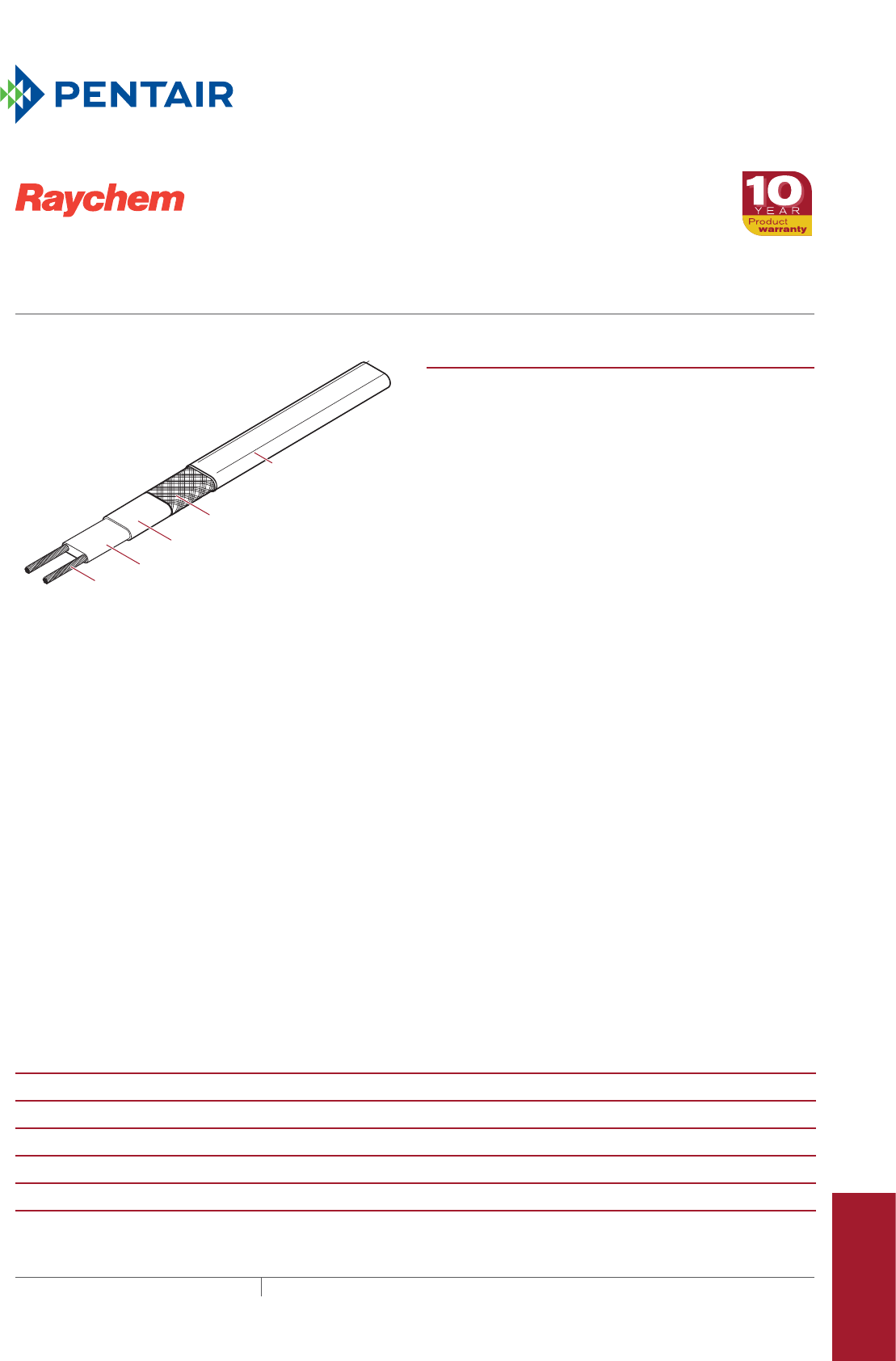
Pipe Freeze Protection
and Flow Maintenance
Fire Sprinkler System
Freeze Protection
Roof and Gutter
De-Icing
Surface Snow
Melting – MI
Surface Snow
Melting – ElectroMelt
Freezer Frost
Heave Prevention
Floor Heating Technical Data
Sheets
Modified polyolefin (-CR)
or fluoropolymer (-CT)
outer jacket
Tinned-copper braid
Modified polyolefin inner jacket
Self-regulating conductive core
Nickel-plated copper bus wire
Heating cable construction PRODUCT OVERVIEW
Raychem XL-Trace is designed for pipe freeze protection and
flow maintenance in the following applications:
• Freeze protection of general water piping (aboveground
and buried)
• Freeze protection of fire sprinkler system piping, includ-
ing sprinklers
• Flow maintenance of greasy waste lines (aboveground
and buried)
• Flow maintenance of fuel lines (aboveground)
The heating element in the XL-Trace heating cable consists
of a continuous core of conductive polymer extruded
between two copper bus wires. The XL-Trace heating cable
regulates its power output in response to pipe temperature
changes. This self-regulating technology allows XL-Trace
heating cable to be overlapped or installed on plastic pipes
without overheating.
Low total installed cost
The XL-Trace heating cable’s parallel circuitry allows it to
be cut to the exact length required, with no wasted cable. Its
flexibility allows it to be wrapped around complex fittings and
valves. All of these characteristics simplify and streamline
the design of a heat-tracing system. Installation is quick and
simple.
Low total operating cost
Building operators are assured of optimal energy efficiency
and low maintenance costs when an XL-Trace system is
specified.
The same features that make an XL-Trace system easy to
install the first time also simplify additions or changes to the
system during building renovations.
For additional information, contact your Pentair Thermal
Management representative or call (800) 545-6258.
CATALOG NUMBER
5XL1-CR/CT
5XL2-CR/CT
8XL1-CR/CT
8XL2-CR/CT
12XL2-CR/CT
VOLTAGE
120 V 208–277 V 120 V 208–277 V 208–277 V
MAXIMUM OPERATING TEMPERATURE
150°F (65°C) 150°F (65°C) 150°F (65°C) 150°F (65°C) 150°F (65°C)
MAXIMUM EXPOSURE TEMPERATURE
150°F (65°C) 150°F (65°C) 150°F (65°C) 150°F (65°C) 185°F¹ (85°C)¹
MINIMUM INSTALLATION TEMPERATURE
0°F (–18°C) 0°F (–18°C) 0°F (–18°C) 0°F (–18°C) 0°F (–18°C)
MINIMUM BEND RADIUS
1/2 in (12 mm) 1/2 in (12 mm) 1/2 in (12 mm) 1/2 in (12 mm) 1/2 in (12 mm)
¹ When the design requires 185°F (85°C) exposure temperature, all connections must be installed off the pipe.
XL-Trace
SELF-REGULATING HEATING CABLE
For pipe freeze protection and flow maintenance
337THERMAL MANAGEMENT SOLUTIONS EN-RaychemXLTracePipeFreezeProtection-DS-H51349 11/13
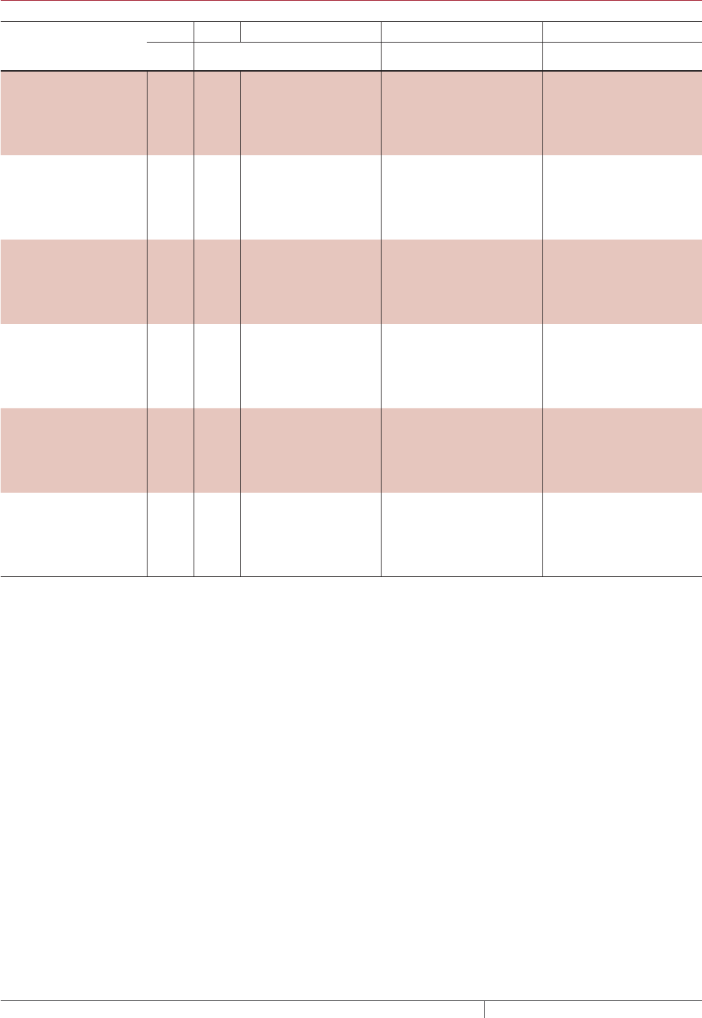
MAXIMUM CIRCUIT LENGTH IN FEET
40°F / 110°F Maintain*
Start-up
temperature
(°F)
CB size
(A)
5XL1 8XL1 5XL2 8XL2 12XL2
120 V 120 V 208 V 240 V 277 V 208 V 240 V 277 V 208 V 240 V 277 V
–20°F 15 101 76 174 178 183 131 138 146 111 114 117
20 134 101 232 237 245 175 184 194 148 151 156
30 201 151 349 356 367 262 276 291 223 227 234
40 270 201 465 474 478 349 368 388 297 303 312
0°F 15 115 86 199 203 209 149 157 166 120 122 126
20 153 115 265 271 279 199 209 221 160 163 168
30 230 172 398 406 419 298 314 331 239 244 252
40 270 210 470 490 530 370/399 390/420 420/443 319 326 336
20°F 15 134 100 232 237 244 173 182 192 126 129 133
20 178 133 309 315 325 231 243 257 169 172 177
30 270 200 464 473 488 346 365 385 253 258 266
40 270 210 470 490 530 370/462 390/486 420/513 340/349 344 355
40°F 15 160 119 278 283 292 206 217 229 142 145 150
20 214 159 370 378 390 275 290 306 190 194 200
30 270 210 470 490 530 370/416 390/438 420/462 285 291 300
40 270 210 470 490 530 370/554 390/584 420/616 340/398 360/406 380/419
50°F 15 –––––228 240 254 152 155 160
(buried) 20 –––––304 320 338 203 207 213
30 –––––457 481 507 304 310 320
40 –––––609 641 676 405 414 427
65°F 15 –––––272 286 302 169 172 178
(indoors grease) 20 –––––362 381 402 225 230 237
30 –––––543 572 603 338 345 356
40 –––––610 660 720 430 460 490
* When maximum circuit length is listed in:
– black type, the value is for applications with a 40°F maintain
– red type, the value is for applications with a 110°F maintain
XLTRACE
THERMAL MANAGEMENT SOLUTIONS
EN-RaychemXLTracePipeFreezeProtection-DS-H51349 11/13
338
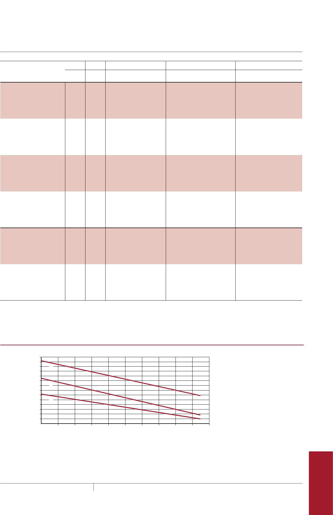
Pipe Freeze Protection
and Flow Maintenance
Fire Sprinkler System
Freeze Protection
Roof and Gutter
De-Icing
Surface Snow
Melting – MI
Surface Snow
Melting – ElectroMelt
Freezer Frost
Heave Prevention
Floor Heating Technical Data
Sheets
MAXIMUM CIRCUIT LENGTH IN METERS
4°C / 43°C Maintain*
Start-up
temperature
(°C)
CB size
(A)
5XL1 8XL1 5XL2 8XL2 12XL2
120 V 120 V 208 V 240 V 277 V 208 V 240 V 277 V 208 V 240 V 277 V
–29°C 15 31 23 53 54 56 40 42 44 34 35 36
20 41 31 71 72 75 53 56 59 45 46 48
30 61 46 106 108 112 80 84 89 68 69 71
40 82 61 142 145 149 106 112 118 90 92 95
–18°C 15 35 26 61 62 64 45 48 51 36 37 38
20 47 35 81 83 85 61 64 67 49 50 51
30 70 52 121 124 128 91 96 101 73 74 77
40 82 64 143 149 162 113 /122 119 /128 128 /135 97 99 102
–7°C 15 41 31 71 72 74 53 56 59 39 39 41
20 54 41 94 96 99 70 74 78 51 52 54
30 82 61 141 144 149 106 111 117 77 79 81
40 82 64 143 149 162 113 /141 119 /148 128 /156 104 /106 105 108
4°C 15 49 36 85 86 89 63 66 70 43 44 46
20 65 48 113 115 119 84 88 93 58 59 61
30 82 64 143 149 162 113 /127 119 /134 128 /141 87 89 91
40 82 64 143 149 162 113 /169 119 /178 128 /188 104 /121 110 /124 116 /128
10°C 15 ––––– 70 73 77 46 47 49
(buried grease) 20 ––––– 93 98 103 62 63 65
30 ––––– 139 147 155 93 95 98
40 ––––– 186 195 206 124 126 130
18°C 15 ––––– 83 87 92 52 53 54
(indoors grease) 20 ––––– 110 116 123 69 70 72
30 ––––– 166 174 184 103 105 108
40 ––––– 186 201 220 131 140 149
* When maximum circuit length is listed in:
– black type, the value is for applications with a 40°F maintain
– red type, the value is for applications with a 110°F maintain
NOMINAL POWER OUTPUT ON METAL PIPES AT 120 V/208 V
Pipe temperature
Power W/ft
5XL1-CR and 5XL1-CT (120 V)
5XL2-CR and 5XL2-CT (208 V)
8XL1-CR and 8XL1-CT (120 V)
8XL2-CR and 8XL2-CT (208 V)
12XL2-CR and 12XL2-CT (208 V)
50
(10)
30
(–1)
40
(5)
60
(15)
70
(21)
80
(27)
90
(32)
100
(38)
110
(43)
120
(49)
130
(54)
°F
(°C)
10
8
14
12
6
4
2
0
XL-Trace
339 THERMAL MANAGEMENT SOLUTIONS EN-RaychemXLTracePipeFreezeProtection-DS-H51349 11/13
BUS WIRES
16 AWG nickel-plated copper
BRAID/OUTER JACKET
Tinned-copper braid with modified polyolefin jacket (-CR) or fluoropolymer
jacket (-CT).
DIMENSIONS
5XL AND 8XL
12XL
Maximum width 0.56 in (14 mm) 0.62 in (16 mm)
Maximum thickness 0.24 in (6 mm) 0.24 in (6 mm)
NOMINAL WEIGHT
92 lb/1000 ft 104 lb/1000 ft
CONNECTION KITS
Raychem RayClic or FTC connection kits must be used with XL-Trace heating
cables. Refer to the Pipe Freeze Protection and Flow Maintenance Design Guide
(H55838) for proper connection kit selection.
APPROVALS
Refer to the Pipe Freeze Protection and Flow Maintenance Design Guide (H55838)
and the Fire Sprinkler Freeze Protections Design Guide (H58489) for specific
product approval details.
GROUNDFAULT PROTECTION
To minimize the danger of fire from sustained electrical arcing if the heating
cable is damaged or improperly installed, and to comply with the requirements
of Pentair Thermal Managementy, agency certifications, and national electrical
codes, ground-fault equipment protection must be used on each heating cable
branch circuit. Arcing may not be stopped by conventional circuit protection.
Many DigiTrace control and monitoring systems meet the ground-fault protection
requirement.
718K Pipe Heating Cable
-w
-w
XLTRACE
THERMAL MANAGEMENT SOLUTIONS
EN-RaychemXLTracePipeFreezeProtection-DS-H51349 11/13
340

Pipe Freeze Protection
and Flow Maintenance
Fire Sprinkler System
Freeze Protection
Roof and Gutter
De-Icing
Surface Snow
Melting – MI
Surface Snow
Melting – ElectroMelt
Freezer Frost
Heave Prevention
Floor Heating Technical Data
Sheets
Nickel-plated copper bus wire
Self-regulating conductive core
Modified polyolefin inner jacket
Tinned-copper braid
Fluoropolymer (-XT) or
modified polyolefin (-X)
outer jacket
Heating cable construction PRODUCT OVERVIEW
Raychem IceStop is a roof and gutter de-icing system that
provides drain paths for the following applications:
• Roofs made from standard roofing materials, including
shake, shingle, rubber, tar, wood, metal, and plastic.
• Gutters made from standard materials, including metal,
plastic, and wood.
• Downspouts made from standard materials, including
metal and plastic.
The heating element in the IceStop heating cable consists of
a continuous core of conductive polymer extruded between
two copper bus wires. As current flows through the core,
the IceStop heating cable regulates its own heat output in
response to ambient conditions.
This self-regulating feature eliminates hot spots and results
in better temperature control to protect roof and gutter
materials.
The IceStop heating cable is available with a fluoropolymer
outer jacket (-XT) that provides maximum abrasion,
chemical, and mechanical resistance; or a polyolefin outer
jacket (-X) that is more economical for less demanding
applications.
Low installed cost
The IceStop heating cable’s parallel circuitry allows it to be
cut to the exact length required, with no wasted cable.
All of these characteristics simplify and streamline the
design of a roof and gutter de-icing system. Installation is
quick and simple. The same features that make an IceStop
system easy to install the first time also simplify additions or
changes to the system during building renovations.
CATALOG NUMBER
GM-1XT and GM-1X GM-2XT and GM-2X
POWER OUTPUT NOMINAL
12 W/ft (39 W/m) in ice or snow 12 W/ft (39 W/m) in ice or snow
VOLTAGE
120 Vac 208–277 Vac
MINIMUM INSTALLATION TEMPERATURE
0°F (–18°C) 0°F (–18°C)
IceStop
Self-regulating roof and gutter de-icing heating cable
341THERMAL MANAGEMENT SOLUTIONS EN-RaychemIceStopRoofGutterDeIcing-DS-H56428 11/13
MINIMUM BEND RADIUS
5/8 in (16 mm) 5/8 in (16 mm)
MAXIMUM CIRCUIT LENGTH IN FEET METERS
Start-up
temperature
Circuit breaker size
15 A 20 A 30 A 40 A*
GM-1XT and GM-1X at 120 volts 32°F (0°C) 100 (30) 135 (41) 200 (61) —
20°F (–7°C) 95 (29) 125 (38) 185 (56) 200 (61)*
0°F (–18°C) 80 (24) 100 (30) 155 (47) 200 (61)*
GM-2XT and GM-2X at 208 volts 32°F (0°C) 190 (58) 250 (76) 380 (116) —
20°F (–7°C) 180 (55) 235 (72) 355 (108) 380 (116)*
0°F (–18°C) 145 (44) 195 (59) 290 (88) 380 (116)*
GM-2XT and GM-2X at 240 volts 32°F (0°C) 200 (61) 265 (81) 400 (122) —
20°F (–7°C) 190 (58) 250 (76) 370 (113) 400 (122)*
0°F (–18°C) 155 (47) 205 (62) 305 (93) 400 (122)*
GM-2XT and GM-2X at 277 volts 32°F (0°C) 215 (66) 290 (88) 415 (126) —
20°F (–7°C) 200 (61) 265 (81) 400 (122) 415 (126)*
0°F (–18°C) 165 (50) 225 (69) 330 (101) 415 (126)*
* Only FTC-P power connection kits may be used with 40-A circuits.
BUS WIRES
16 AWG nickel-plated copper
BRAID / OUTER JACKET
Tinned-copper braid with fluoropolymer (-XT) or modified polyolefin (-X) outer
jacket
DIMENSIONS
Maximum width 0.54 in (14 mm)
Maximum thickness 0.24 in (6 mm)
NOMINAL WEIGHT
92 lb/1000 ft (137 kg/1000 m)
CONNECTION KITS
Raychem RayClic or FTC connection kits must be used with IceStop heating
cables. Refer to the Roof and Gutter De-Icing Design Guide (H56070) for proper
connection kit selection.
APPROVALS
877Z De-icing and
Snow-Melting
Equipment
The IceStop heating cables are UL Listed, CSA Certified, and FM Approved only when used
with the appropriate agency-approved Pentair Thermal Management connection kits and
accessories.
Nonhazardous and Hazardous Locations
Class 1, Div. 2, Groups A, B, C, D*
* For GM-1XT and GM-2XT
-ws
GROUNDFAULT PROTECTION
To minimize the danger of fire from sustained electrical arcing if the heating
cable is damaged or improperly installed, and to comply with the requirements
of Pentair Thermal Management, agency certifications, and national electrical
codes, ground-fault equipment protection must be used on each heating cable
branch circuit. Arcing may not be stopped by conventional circuit protection.
Many DigiTrace control and monitoring systems meet the ground-fault protection
requirement.
ICESTOP
THERMAL MANAGEMENT SOLUTIONS
EN-RaychemIceStopRoofGutterDeIcing-DS-H56428 11/13
342
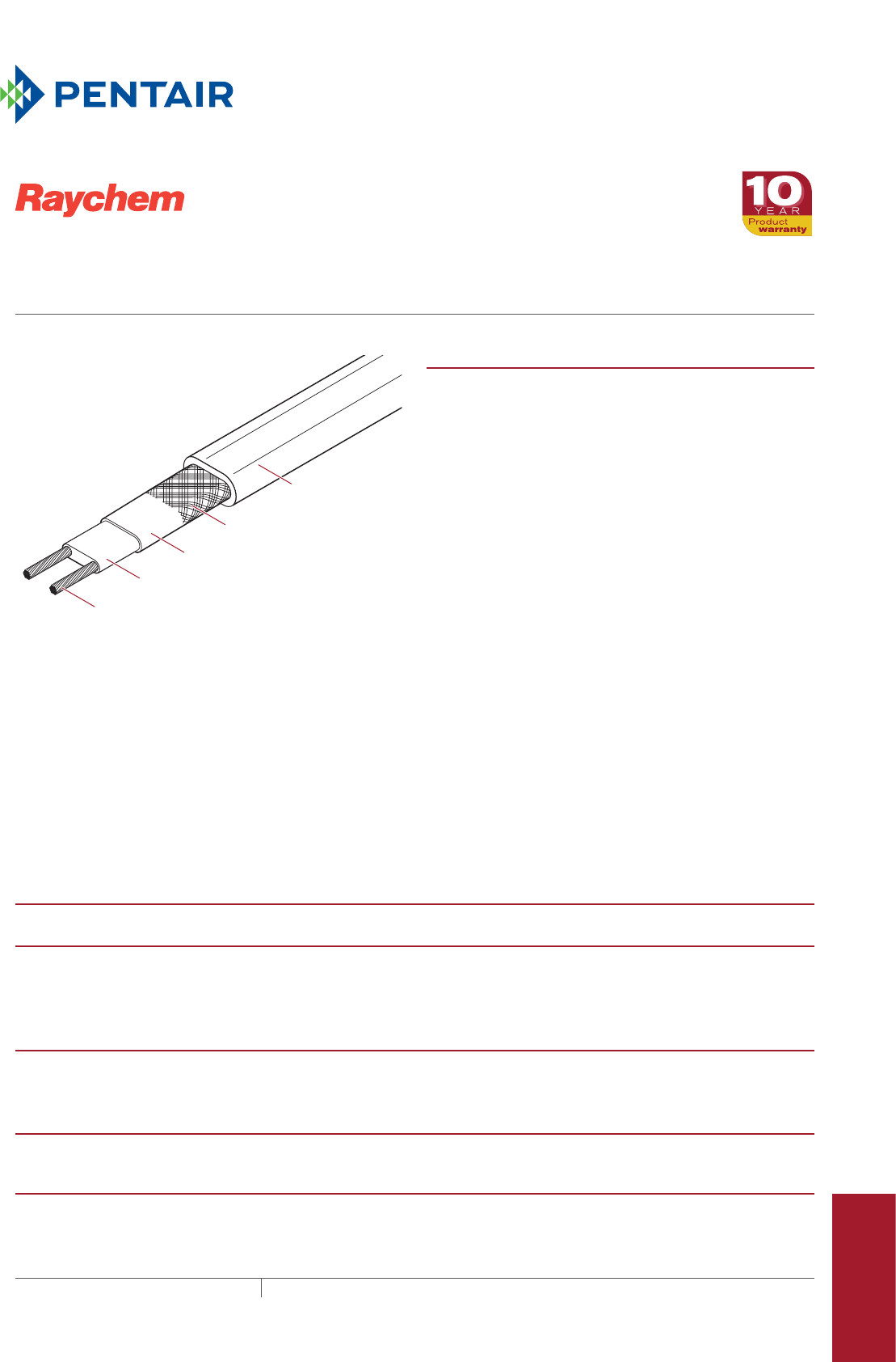
Pipe Freeze Protection
and Flow Maintenance
Fire Sprinkler System
Freeze Protection
Roof and Gutter
De-Icing
Surface Snow
Melting – MI
Surface Snow
Melting – ElectroMelt
Freezer Frost
Heave Prevention
Floor Heating Technical Data
Sheets
Nickel-plated copper bus wire
Self-regulating conductive core
Modified polyolefin inner jacket
Tinned-copper braid
Modified polyolefin
outer jacket
Heating cable construction PRODUCT OVERVIEW
Raychem ElectroMelt provides surface snow melting and
anti-icing in concrete pavement.
Self-regulating
The polymer core of an ElectroMelt heating cable
automatically adjusts power output at every point along its
length in response to concrete pavement temperature. This
response characteristic eliminates burnouts caused by
overlapping cable and provides improved energy efficiency
without the need for special controls.
Parallel circuitry
The crosslinked, conductive polymer core of the ElectroMelt
heating cable is extruded between two 14 AWG copper bus
wires, forming a parallel circuit. This allows ElectroMelt
heating cables to be cut to length and to be spliced and
repaired, if necessary, in the field.
Rugged
Specifically designed for direct burial in concrete,
ElectroMelt heating cables are protected by a tinned-copper
braid encased in a 70-mil modified polyolefin outer jacket.
With no exposed metal parts to corrode, no cold leads to
fail, and no burnout due to overlaps or hot spots, rugged
ElectroMelt heating cable offers an ideal solution for all
types of concrete pavement snow melting and anti-icing.
CATALOG NUMBER
EM2-XR EM3-XR
POWER OUTPUT W/FT W/M Voltage
Power Output
W/ft (W/m) Voltage
Power Output
W/ft (W/m)
208 30 (98) 347 24 (79)
240 32 (105)
277 34 (112)
DIMENSIONS
Maximum width 0.75 in (19 mm) 0.70 in (17.8 mm)
Maximum thickness 0.38 in (10 mm) 0.31 in (7.9 mm)
MINIMUM INSTALLATION TEMPERATURE
0°F (–18°C) 0°F (–18°C)
MINIMUM BEND RADIUS
2 in (50 mm) 2 in (50 m E-100-L-A m)
ElEctroMElt
Self-regulating Surface Snow-melting and
anti-icing heating cable
343THERMAL MANAGEMENT SOLUTIONS EN-RaychemElectroMeltSnowMelting-DS-H56831 11/13
MAXIMUM CIRCUIT LENGTH FOR STARTUP AT 20°F 7°C IN FEET METERS
Circuit breaker (A)
Heating cable supply voltage
208 V 240 V 277 V 347 V
15 80 (24) 85 (26) 100 (31) 120 (37)
20 105 (32) 115 (35) 130 (40) 165 (50)
30 160 (49) 170 (52) 195 (59) 250 (76)
40 210 (64) 230 (70) 260 (79) 330 (101)
50 265 (81) 285 (87) 325 (99) †
MAXIMUM CIRCUIT LENGTH FOR STARTUP AT 0°F 18°C IN FEET METERS
Circuit breaker (A)
Heating cable supply voltage
208 V 240 V 277 V 347 V
15 75 (23) 80 (24) 90 (27) 107 (33)
20 100 (31) 110 (34) 120 (37) 148 (45)
30 145 (44) 160 (49) 180 (55) 225 (69)
40 200 (61) 210 (64) 240 (73) 288 (88)
50 245 (75) 265 (81) 300 (91) †
† Not permitted
BUS WIRES
14 AWG nickel-plated copper
BRAID / OUTER JACKET
Heavy tinned-copper braid encased in a 70-mil modified polyolefin outer jacket
NOMINAL WEIGHT
180 lb/1000 ft (268 kg/1000 m)
CONNECTION KITS
Raychem ElectroMelt connection kits must be used to terminate ElectroMelt
heating cables. Refer to the Surface Snow Melting and Anti-Icing Design Guide –
ElectroMelt (H53393) for proper connection kit selection.
APPROVALS
877Z De-icing and
Snow-melting
Equipment
The EM2-XR and EM3-XR heating cables are UL Listed and CSA Certified only
when used with the appropriate agency-approved Pentair Thermal
Management connection kits and accessories.
(for EM2-XR only)
-w
GROUNDFAULT PROTECTION
To minimize the danger of fire from sustained electrical arcing if the heating
cable is damaged or improperly installed, and to comply with the requirements
of Pentair Thermal Management, agency certifications, and national electrical
codes, ground-fault equipment protection must be used on each heating cable
branch circuit. Arcing may not be stopped by conventional circuit protection.
Many DigiTrace control and monitoring systems meet the ground-fault protection
requirement.
ELECTROMELT
THERMAL MANAGEMENT SOLUTIONS
EN-RaychemElectroMeltSnowMelting-DS-H56831 11/13
344

Pipe Freeze Protection
and Flow Maintenance
Fire Sprinkler System
Freeze Protection
Roof and Gutter
De-Icing
Surface Snow
Melting – MI
Surface Snow
Melting – ElectroMelt
Freezer Frost
Heave Prevention
Floor Heating Technical Data
Sheets
Modified polyolefin inner jacket
Tinned-copper braid
Fluoropolymer
outer jacket
Nickel-plated copper bus wires
Self-regulating conductive core
Heating cable construction PRODUCT OVERVIEW
The Raychem RaySol system is designed for the following floor
heating applications.
Heat-loss replacement — replaces heat in concrete floors
built over garages, loading docks, arcades, and other cold
spaces. The cable is typically attached to the bottom of
concrete floors.
Comfort floor heating — warms concrete, tile, stone and
marble floors in lobbies, foyers, bathrooms, kitchens and
gymnasiums. The cable is typically embedded in a thick
mortar bed or concrete.
Radiant space heating – provides primary space heating for
rooms with concrete floors. The cable is typically embedded
in concrete or a thick mortar bed.
Freezer frost heave prevention — prevents heaving in
soils under freezers, refrigerated warehouses, and cold
rooms. The cable is placed in conduit buried in soil or in the
subflooring under the freezer floor.
Efficient and economical to operate
Because it’s self-regulating, a RaySol system will supply the
right heat only where and when it is needed. The radiant
heat provided by the RaySol heating cable allows you to feel
comfortable at lower air temperatures, resulting in lower
heating costs.
Pentair Thermal Management representatives can provide
design assistance and help you install the product that
meets your goals for an efficient, cost-effective floor heating
system.
CATALOG NUMBER
RAYSOL1
RAYSOL2
VOLTAGE
120 V 208–277 V
MINIMUM BEND RADIUS
5/8 in (16 mm) 5/8 in (16 mm)
Raysol
SELF-REGULATING HEATING CABLE
For floor heating and frost heave prevention applications
345THERMAL MANAGEMENT SOLUTIONS EN-RaychemRaySol-DS-H56821 11/13

MAXIMUM CIRCUIT LENGTH IN FEET METERS
Circuit
breaker
rating (A)
Cable operating voltage
120 V 208 V 240 V 277 V
Installed in conduit
(at 40°F start-up
temperature)
15 180 (54.9) 305 (93.0) 335 (102.1) 375 (114.3)
20 240 (73.2) 410 (125.0) 450 (137.2) 500 (152.4)
30 240 (73.2) 410 (125.0) 450 (137.2) 500 (152.4)
40 240 (73.2) 410 (125.0) 450 (137.2) 500 (152.4)
Surface mounted
(at 40°F start-up
temperature)
15 120 (36.6) 205 (62.5) 210 (64.0) 215 (65.5)
20 160 (48.8) 275 (83.8) 285 (86.9) 290 (88.4)
30 240 (73.2) 410 (125.0) 425 (129.5) 430 (131.1)
40 240 (73.2) 410 (125.0) 425 (129.5) 430 (131.1)
Embedded in concrete or
mortar (at 40°F start-up
temperature)
15 80 (24.4) 135 (41.1) 140 (42.7) 145 (44.2)
20 105 (32.0) 185 (56.4) 185 (56.4) 195 (59.4)
30 160 (48.8) 275 (83.8) 280 (85.3) 290 (88.4)
40 170 (51.8) 280 (85.3) 320 (97.5) 360 (109.7)
BUS WIRES
16 AWG nickel-plated copper
BRAID / OUTER JACKET
Tinned-copper braid with fluoropolymer outer jacket
DIMENSIONS
Maximum width 0.56 in (14 mm)
Maximum thickness 0.24 in (6 mm)
NOMINAL WEIGHT
92 lb/1000 ft (137 kg/1000 m)
CONNECTION KITS
Raychem RayClic-E, FTC-P, FTC-XC, and FTC-HST connection kits must be used
to connect and to terminate RaySol heating cables. Refer to the Freezer Frost
Heave Prevention Design Guide (H58139) and the Floor Heating Design Guide
(H58157) for proper connection kit selection.
APPROVALS
The RaySol system is UL Listed for heat loss replacement, comfort floor heating
and radiant space heating applications.
The RaySol system is CSA Certified for comfort floor heating and radiant
space heating applications. For heat loss replacement applications where the
cable is attached to the bottom of the concrete floor, contact Pentair Thermal
Management for additional information.
GROUNDFAULT PROTECTION
To minimize the danger of fire from sustained electrical arcing if the heating
cable is damaged or improperly installed, and to comply with the requirements
of Pentair Thermal Management, agency certifications, and national electrical
codes, ground-fault equipment protection must be used on each heating cable
branch circuit. Arcing may not be stopped by conventional circuit protection.
Many DigiTrace control and monitoring systems meet the ground-fault protection
requirement.
9J86 Radiant
Heating Cable
-w
RAYSOL
THERMAL MANAGEMENT SOLUTIONS
EN-RaychemRaySol-DS-H56821 11/13
346
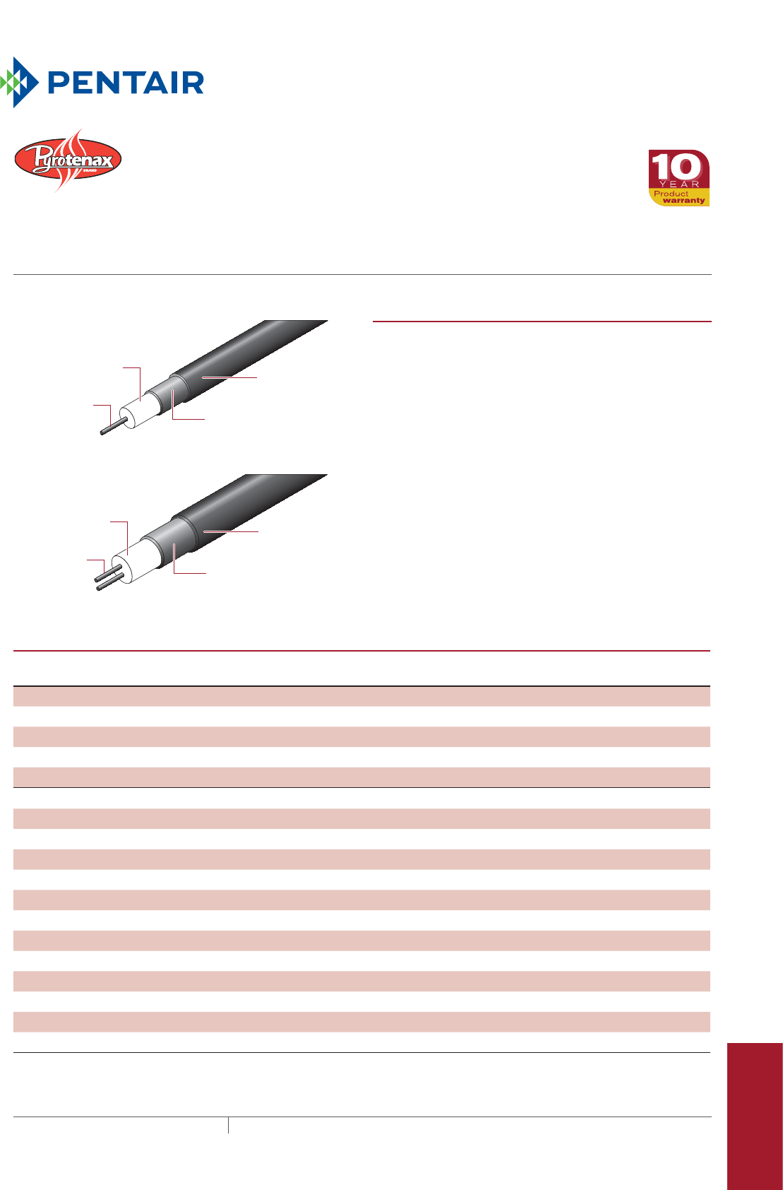
Pipe Freeze Protection
and Flow Maintenance
Fire Sprinkler System
Freeze Protection
Roof and Gutter
De-Icing
Surface Snow
Melting – MI
Surface Snow
Melting – ElectroMelt
Freezer Frost
Heave Prevention
Floor Heating Technical Data
Sheets
Heating
conductor
Dual-conductor cable (32, 62 series)
Copper sheath
Single-conductor cable (61 series)
Heating cable construction
Heating
conductors
HDPE jacket
(optional)
Copper sheath
HDPE jacket
(optional)
Insulation
(magnesium oxide)
Insulation
(magnesium oxide)
PRODUCT OVERVIEW
The copper sheath provides an ideal ground path and allows
for a rugged yet flexible heating cable that is easy to install.
Each heating cable includes a heated section that is joined
to a preterminated nonheating cold lead which is ready
to connect into a junction box. For corrosive or embedded
applications, such as concrete or asphalt snow melting,
a cable with a high-density polyethylene (HDPE) jacket is
required. Refer to the tables below for the complete list of
approved applications.
For additional information or applications requiring stainless
steel sheathed heating cables, contact your Pentair Thermal
Management representative or call (800) 545-6258.
APPROVED APPLICATIONS AND POWER OUTPUT FOR NONHAZARDOUS AREAS
Bare copper-sheathed heating cable
c-CSA-us FM UL
Max. power output
W/ft (W/m)
Snow melting on metal roofs Yes No No 15 (49)
De-icing of metal gutters and downspouts Yes No No 15 (49)
De-icing of nonmetallic gutters and downspouts Yes No No 5 (16)
Freeze protection of metal pipes and vessels²Yes Yes No 18 (59)
Process temperature maintenance (pipes and vessels)²Yes Yes No 18 (59)
HDPE jacketed copper-sheathed heating cable
Snow melting in concrete and mastic asphalt slab Yes Yes Yes 30 (99)
Snow melting in road-grade asphalt slab Yes Yes Yes 25 (82)
Snow melting in sand/limestone screenings (pavers) Yes1Yes Yes 20 (66)
Snow melting on nonmetal roof Yes No No 8 (26)
De-icing of metal gutters and downspouts Yes No No 8 (26)
De-icing of nonmetallic gutters and downspouts Yes No No 5 (16)
Floor heating in concrete slab Yes No No 10 (33)
Frost heave prevention in sand under freezer or arena floor Yes Yes No 7 (23)
Freeze protection of metal pipes and vessels – internal Yes No No 8 (26)
Freeze protection of metal pipes and vessels – external Yes Yes No 8 (26)
Freeze protection of nonmetallic pipes and vessels – internal Yes No No 4 (13)
Freeze protection of nonmetallic pipes and vessels – external Yes No No 4 (13)
1 Special permission for paver snow melting is required from the Authority Having Jurisdiction.
2 When designing heating cables for pipe and vessel tracing, the “Max. power output (W/ft)” values may have to be decreased to ensure that
the sheath temperature does not exceed the maximum exposure temperature (see page 2) of the cable.
mi heating cable
COPPER AND HDPE JACKETED COPPER SHEATHED MI CABLE
For commercial applications
347THERMAL MANAGEMENT SOLUTIONS EN-PyrotenaxMIcommercial-DS-H56990 11/13
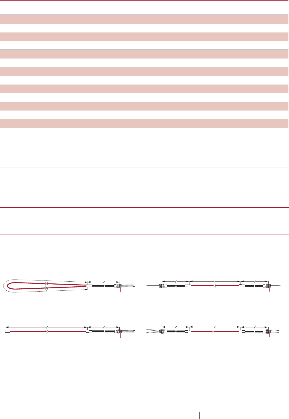
APPROVED APPLICATIONS AND POWER OUTPUT FOR HAZARDOUS AREAS
Bare copper-sheathed heating cable
c-CSA-us
CSA FM UL
Max. power output
W/ft (W/m)
Process temperature maintenance (pipes and vessels)3Yes Yes Yes No 18 (59)
Freeze protection of metal pipes and vessels3Yes Yes Yes No 18 (59)
De-icing of metal gutters and downspouts3No Yes No No 15 (49)
De-icing of nonmetallic gutters and downspouts No Yes No No 5 (16)
HDPE jacketed copper-sheathed heating cable
Snow melting in concrete and mastic asphalt slab No Yes Yes No 30 (99)
Snow melting in road-grade asphalt slab No Yes Yes No 25 (82)
HDPE jacketed copper-sheathed heating cable
De-icing of metal gutters and downspouts3No Yes No No 8 (26)
De-icing of nonmetallic gutters and downspouts No Yes No No 5 (16)
Frost heave prevention in sand under freezer or arena floor No Yes Yes No 7 (23)
Freeze protection of metal pipes and vessels – external3Yes Yes Yes No 8 (26)
Freeze protection of nonmetallic pipes and vessels – external Yes Yes No No 4 (13)
³ When designing heating cables for pipe and vessel tracing, and de-icing of metal gutters and downspouts, the “Max. power output (W/
ft)” values may have to be decreased to ensure that the sheath temperature does not exceed the maximum exposure temperature of the
cable (see below) or the autoignition temperature of gases and vapors present in the hazardous area. For assistance designing heating
cables for hazardous areas, contact Pentair Thermal Management Technical Support at (800) 545-6258.
MAXIMUM EXPOSURE TEMPERATUR
E
392°F (200°C) Bare copper-sheathed heating cable
194°F (90°C) HDPE-jacketed heating cable*
* HDPE-sheathed cables may be exposed to higher temperatures during
installation in asphalt.
TEMPERATURE ID NUMBER TRATING
To be established by calculating the maximum sheath temperature. Contact
Pentair Thermal Management for assistance.
BASIC HEATING CABLE DESIGN CONFIGURATIONS
Heating cables are supplied as complete factory-fabricated assemblies consisting
of the heated section joined to a length of nonheating cold lead section,
preterminated with an NPT-threaded connector and ready to connect into a
junction box.
Design A Design B
Design D
Design A: Single conductor cable (61 series only)
Design D: Dual conductor cable (32, 62 series only)
Design B: Single conductor cable (61 series only)
Design E: Dual conductor cable (32, 62 series only)
Cold lead length
Heated length Heated length
NPT threaded
connector
NPT threaded
connector
Cold lead length
Heated length Cold lead length
Cold lead length
Cold lead length
Heated length
Cold lead length
NPT threaded
connector
NPT threaded
connector
Design E
MI HEATING CABLE FOR COMMERCIAL APPLICATIONS
THERMAL MANAGEMENT SOLUTIONS
EN-PyrotenaxMIcommercial-DS-H56990 11/13
348

Pipe Freeze Protection
and Flow Maintenance
Fire Sprinkler System
Freeze Protection
Roof and Gutter
De-Icing
Surface Snow
Melting – MI
Surface Snow
Melting – ElectroMelt
Freezer Frost
Heave Prevention
Floor Heating Technical Data
Sheets
Pipe Freeze Protection
and Flow Maintenance
Fire Sprinkler System
Freeze Protection
Roof and Gutter
De-Icing
Surface Snow
Melting – MI
Surface Snow
Melting – ElectroMelt
Freezer Frost
Heave Prevention
Floor Heating Technical Data
Sheets
HEATING CABLE CATALOG NUMBER
To order an MI heating cable, it is
important to understand the format of our
catalog number.
In the above heating cable catalog number, the length of the heated section and the cold lead are in feet. For metric lengths,
the heating cable catalog number would include a suffix “M” after the length, as shown below. A HDPE jacket on the heated
section and a HDPE jacket on the cold lead have also been included in the following:
B/61HE4600/45.7M/1600/120/2.1M/H25A/Y/N12
Options
Add suffix “/PE” at the end of the catalog number for pulling eye (Design D cables only).
Add suffix “/RG1” at the end of the catalog number for 1" reverse gland (used to make a watertight seal) for Designs A and D
cables. Design D cables also available with 1/2" or 3/4" reverse gland (“/RG34” for 3/4" or “/RG12” for 1/2").
Examples
Snow melting for area 1200 sq ft (spacing 7")
6 cables B/61HE3150/343/7000/600/15/H25A/Y/N12
• Heating cable configuration is Design B
• 600 V rated single conductor HDPE jacketed cable, resis-
tance at 20°C is 0.150 /ft (0.492 /m)
• Each heating cable length is 343 ft (104.5 m)
• Each heating cable wattage is 7000 W at 600 V
• Cold lead is 15 ft (4.5 m) with HDPE jacket
• Cold lead code is H25A
• 1/2-in NPT gland connector
Pipe tracing for 2 in x 50 ft pipe
1 cable D/32CD3800/52/340/120/3/C22A/Y/N12
• Heating cable configuration is Design D
• 300 V rated two conductor cable, resistance at 20°C is
0.80 /ft (2.625 /m)
• Heating cable length is 52 ft (15.9 m)
• Heating cable wattage is 340 W at 120 V
• Cold lead is 3 ft (0.9 m)
• Cold lead code is C22A
• 1/2-in NPT gland connector
HEATING CABLE REFERENCE DECODING
Digit number Description
1 Maximum voltage rating 3 = 300 V, 6 = 600 V
61CD3610
1 2 3 4 5 6 7 8Digit
2 Number of conductors 1 or 2
3 Sheath material C = Copper,
H = HDPE jacketed copper
4 Conductor material C, D, or E
5 Move decimal point to left indicated
number of places
1, 2, 3, 4, 5, or 6 places
6 to 8 Cable resistance (/ft) to 3 whole numbers
(use with digit 5)
3610 = 0.610 /cable foot at 20°C
B/61CE4600/150/1600/120/7/C25A/Y/N12
Gland size
Hot-cold joint “Y” is standard for copper
MI heating cables
Cold lead code
Cold lead length (in feet)
Heating cable voltage
Heating cable wattage
Heating cable length (in feet)
Heating cable reference
Heating cable configuration (A, B, D, E)
mi heating cable for commercial applications
349 THERMAL MANAGEMENT SOLUTIONS EN-PyrotenaxMIcommercial-DS-H56990 11/13

COLD LEADS FOR COPPERSHEATHED HEATING CABLES
Cold leads for copper MI heating cables are available in bare copper or for superior mechanical and corrosion
resistance HDPE jacketed copper. Use HDPE jacketed copper for all embedded heating cable applications, such as
snow melting and floor heating.
Bare copper cold lead
code
HDPE jacketed cold lead
code
Maximum
voltage (V)
Maximum
current (A)
Gland size
(NPT)
Gland size
reference for
catalog number
Tail size
(AWG)
Design A, D, E
C22A H22A 600 22 1/2" N12 14
C29A H29A 600 29 1/2" N12 12
C38A H38A 600 38 3/4" N34 10
C50A H50A 600 50 3/4" N34 8
C67A H67A 600 67 3/4" N34 6
C90A H90A 600 90 1" N1 4
Design B
C25A H25A 600 25 1/2" N12 14
C30A H30A 600 30 1/2" N12 12
C40A H40A 600 40 1/2" N12 10
C60A H60A 600 60 1/2" N12 8
C80A H80A 600 80 1/2" N12 6
C105A H105A 600 105 1/2" N12 4
SERIES 61 MI HEATING CABLE SPECIFICATIONS 600 V, SINGLE CONDUCTOR
Heating cable
reference
Nom. cable resistance
at 20°C
Nominal cable
diameter
Max. unjointed cable
length
Nominal weight
/ft
/m
in
mm
ft
m
lb/1000 ft
kg/1000 m
61CD3610 0.610 2.00 0.120 3.0 11712 3571 35 52.1
61CD3390 0.390 1.28 0.132 3.4 9689 2954 45 67.0
61CD3300 0.300 0.984 0.160 4.1 6595 2011 45 67.0
61CD3200 0.200 0.656 0.168 4.3 5987 1825 56 83.3
61CE3150 0.150 0.492 0.148 3.8 7718 2353 49 72.9
61CE3105 0.105 0.344 0.174 4.4 5230 1594 52 77.4
61CE4800 0.0800 0.262 0.182 4.6 4948 1508 54 80.4
61CE4600 0.0600 0.197 0.194 4.9 4269 1301 56 83.3
61CE4400 0.0400 0.131 0.185 4.7 4686 1429 58 86.2
61CE4300 0.0300 0.0980 0.192 4.9 4340 1323 65 96.6
61CE4200 0.0200 0.0660 0.205 5.2 3564 1086 74 110.2
61CC4100 0.0100 0.0328 0.198 5.0 4624 1409 58 86.3
61CC5651 0.00651 0.0214 0.194 4.9 4187 1277 67 99.7
61CC5409 0.00409 0.0134 0.223 5.7 3394 1034 84 125.2
61CC5258 0.00258 0.00846 0.230 5.8 3076 938 98 146.1
61CC5162 0.00162 0.00531 0.246 6.2 2693 821 117 174.2
61CC5102 0.00102 0.00335 0.277 7.0 2056 627 154 229.1
61CC6641 0.000641 0.00210 0.298 7.6 1688 515 179 266.3
61CC6403 0.000403 0.00132 0.340 8.6 1331 406 236 351.1
Notes: 1) To specify an HDPE jacket on the heating cable, replace the C (first letter in reference) with H.
Example: 61CD3610 becomes 61HD3610 for jacketed version.
2) Tolerance on cable resistance is ± 10%.
MI HEATING CABLE FOR COMMERCIAL APPLICATIONS
THERMAL MANAGEMENT SOLUTIONS
EN-PyrotenaxMIcommercial-DS-H56990 11/13
350
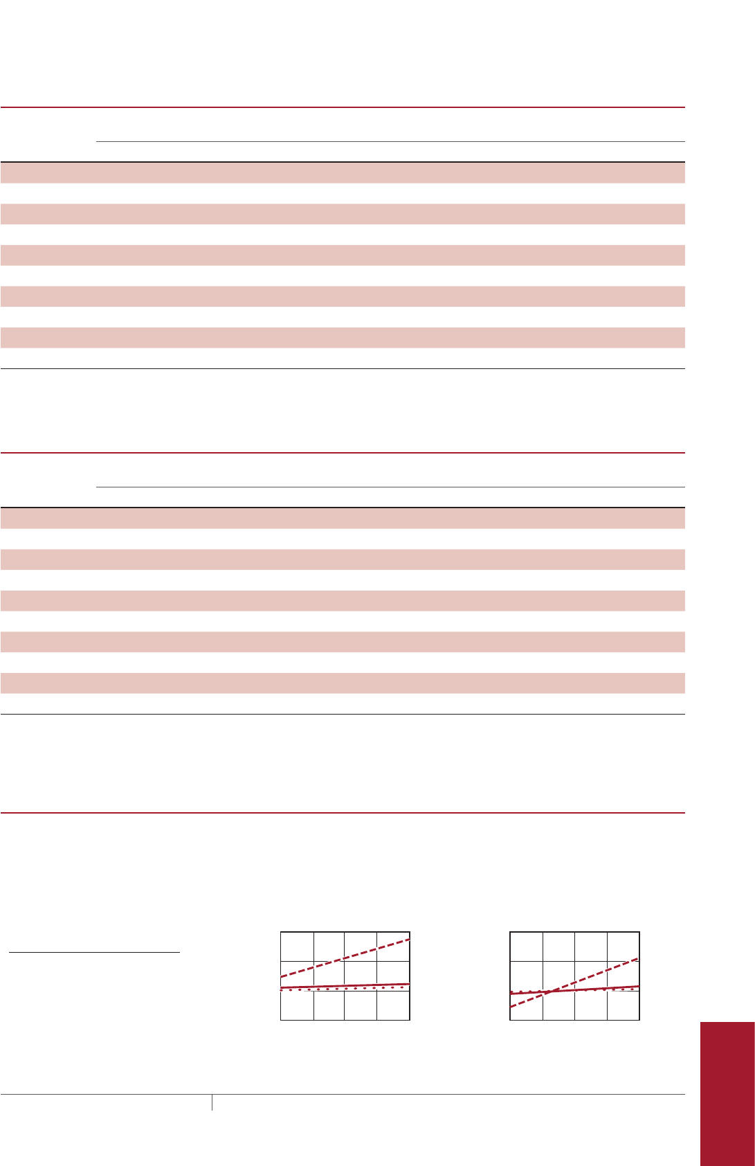
Pipe Freeze Protection
and Flow Maintenance
Fire Sprinkler System
Freeze Protection
Roof and Gutter
De-Icing
Surface Snow
Melting – MI
Surface Snow
Melting – ElectroMelt
Freezer Frost
Heave Prevention
Floor Heating Technical Data
Sheets
Pipe Freeze Protection
and Flow Maintenance
Fire Sprinkler System
Freeze Protection
Roof and Gutter
De-Icing
Surface Snow
Melting – MI
Surface Snow
Melting – ElectroMelt
Freezer Frost
Heave Prevention
Floor Heating Technical Data
Sheets
SERIES 32 MI HEATING CABLE SPECIFICATIONS 300 V, DUAL CONDUCTOR
Heating cable
reference
Nom. cable resistance
at 20°C
Nominal cable
diameter
Max. unjointed cable
length
Nominal weight
/ft
/m
in
mm
ft
m
lb/1000 ft
kg/1000 m
32CD3800 0.800 2.62 0.165 4.2 5800 1768 46 68.5
32CD3600 0.600 1.97 0.175 4.4 5676 1730 59 87.8
32CD3400 0.400 1.31 0.183 4.6 4686 1428 60 89.4
32CD3300 0.300 0.984 0.190 4.8 4158 1267 62 92.1
32CE3200 0.200 0.656 0.185 4.7 4686 1428 60 89.4
32CE3125 0.125 0.410 0.195 5.0 4026 1227 65 96.6
32CE3100 0.100 0.328 0.208 5.3 3564 1086 65 96.6
32CE4700 0.0700 0.230 0.230 5.8 3300 1006 110 163.7
32CE4440 0.0440 0.144 0.260 6.6 2244 684 140 208.2
32CE4280 0.0280 0.092 0.300 7.6 1782 543 182 270.8
Notes: 1) To specify a HDPE jacket on the heating cable, replace the C (first letter in reference) with H.
Example: 32CD3800 becomes 32HD3800 for jacketed version.
2) Tolerance on cable resistance is ± 10%.
SERIES 62 MI HEATING CABLE SPECIFICATIONS 600 V, DUAL CONDUCTOR
Heating cable
reference
Nom. cable resistance
at 20°C
Nominal cable
diameter
Max. unjointed cable
length
Nominal weight
/ft
/m
in
mm
ft
m
lb/1000 ft
kg/1000 m
62CE4950 0.0950 0.312 0.283 7.2 1890 576 129 192
62CE4700 0.0700 0.230 0.309 7.9 1400 427 150 223.2
62CE4440 0.0440 0.144 0.340 8.6 1170 357 181 269.4
62CE4280 0.0280 0.0920 0.371 9.4 965 294 224 333.8
62CC4200 0.0200 0.0656 0.290 7.4 2046 624 140 208.3
62CC4130 0.0130 0.0427 0.309 7.9 1647 502 150 223.2
62CC5818 0.00818 0.0268 0.340 8.6 1217 371 189 281.2
62CC5516 0.00516 0.0169 0.371 9.4 1062 324 236 351.1
62CC5324 0.00324 0.0106 0.402 10.2 876 267 275 409.1
62CC5204 0.00204 0.00669 0.449 11.4 706 215 353 525.3
Notes: 1) To specify a HDPE jacket on the heating cable, replace the C (first letter in reference) with H.
Example: 62CE4950 becomes 62HE4950 for jacketed version.
2) Tolerance on cable resistance is ± 10%.
RESISTANCE CORRECTION FACTOR
Various conductor materials behave differently. Based on the application, use
the table or graphs below for approximate adjustment of power and resistance
as a function of temperature. For detailed design, contact Pentair Thermal
Management for further assistance.
2.0
1.5
1.0
0.5
32
0
122
50
212
100
302
150
392°F
200°C
Pipe Temperature to be Maintained
Resistance Multiplier for
Conductor Materials
Resistance Multiplier for
Conductor Materials
2.0
1.5
1.0
0.5
–58
–50
32
0
122
50
212
100
302°F
150°C
Pipe Temperature to be Maintained
Power On Power Off
C
E
D
C
E
D
Conductor Correction
material factor
C 1.15
D 1.0
E 1.0
Applications: Freeze protection for pipes and vessels, process temperature maintenance for pipes
and vessels
Applications: Snow melting, floor warming,
roof and gutter de-icing, frost-heave prevention
mi heating cable for commercial applications
351 THERMAL MANAGEMENT SOLUTIONS EN-PyrotenaxMIcommercial-DS-H56990 11/13

APPROVALS
Also refer to application tables on
previous pages
GROUNDFAULT PROTECTION
To minimize the danger of fire from sustained electrical arcing if the heating
cable is damaged or improperly installed, and to comply with the requirements
of Pentair Thermal Management, agency certifications, and national electrical
codes, ground-fault equipment protection must be used on each heating cable
branch circuit. Arcing may not be stopped by conventional circuit protection.
Many DigiTrace control and monitoring systems meet the ground-fault protection
requirement.
Nonhazardous Locations
Hazardous Locations
Class I, Div 1 & 2, Groups A*, B, C, D
Class II, Div 1 & 2, Groups E, F, G
Class III
* HDPE jacket is required for
FM Group A approval
Nonhazardous Locations
Hazardous Locations
Class I, Div 1 & 2, Groups A, B, C, D
Class II, Div 1 & 2, Groups E, F, G
Class III
Nonhazardous Locations
421H
MI HEATING CABLE FOR COMMERCIAL APPLICATIONS
THERMAL MANAGEMENT SOLUTIONS
EN-PyrotenaxMIcommercial-DS-H56990 11/13
352

Pipe Freeze Protection
and Flow Maintenance
Fire Sprinkler System
Freeze Protection
Roof and Gutter
De-Icing
Surface Snow
Melting – MI
Surface Snow
Melting – ElectroMelt
Freezer Frost
Heave Prevention
Floor Heating Technical Data
Sheets
MI Heating Cable Configuration
Hot/cold
joint
NPT
threaded
connector
Hot/cold
joint
NPT
threaded
connector
Heated length
Heated length Cold lead length
Cold lead length
Cold lead length
NPT threaded
connector
Hot/cold
joint
Reversed
gland
Heated length Cold lead length
Pulling eye
Type SUA
Design A
Type SUB and FFHP
Design B
Type FFHPC
Design D
PRODUCT OVERVIEW
Types SUA, SUB, and FFHP heating cables have a copper
sheath that is extruded with high-density polyethylene
(HDPE) jacket and are suitable for applications where the
cable is directly embedded in the subfloor.
Type FFHPC heating cables are suitable for applications
where the cable is installed in conduit. These heating cables
are supplied with a copper sheathed cold lead and a heated
length made with either Alloy 825 or a copper sheath with an
extruded HDPE jacket.
MI heating cables for frost heave prevention applications are
supplied as complete factory fabricated assemblies ready
to fasten into a junction box. The copper or Alloy 825 sheath
allows for a rugged yet flexible heating cable which is easy
to install.
For additional information, contact your Pentair Thermal
Management representative or call (800) 545-6258.
CABLE CONSTRUCTION
Type SUA, SUB and FFHP heating cable
Sheath Seamless copper
Jacket HDPE
Insulation Magnesium oxide
Conductor type Alloy or copper
Number of conductors 1
Insulation voltage rating 600 V
Cable diameter (with jacket) 0.20 to 0.303 in (5.1 to 7.7 mm)
Type FFHPC heating cable
Sheath Alloy 825 or seamless copper
Jacket (for copper sheath cables) HDPE
Insulation Magnesium oxide
Conductor type Alloy
Number of conductors 2
Insulation voltage rating 300 V
Cable diameter
Alloy 825 sheath 0.130 to 0.174 in (3.3 to 4.4 mm)
Copper sheath (with jacket) 0.245 to 0.270 in (6.2 to 6.9 mm)
353THERMAL MANAGEMENT SOLUTIONS EN-PyrotenaxMIFreezerFrostHeavePrevention-DS-H58207 11/13
MI HeatIng Cable
HDPE JACKETED, COPPER AND ALLOY 825 SHEATHED MI CABLE
For freezer frost heave prevention applications
CABLE CONSTRUCTION
Cold lead
Sheath Seamless copper
Jacket (Type SUA/SUB/FFHP cables) HDPE
Insulation Magnesium oxide
Conductor type Copper
Number of conductors 1 or 2
Insulation voltage rating 600 V
Cable diameter
With jacket 0.310 to 0.420 in (7.9 to 10.7 mm)
Without jacket (Type FFHPC) 0.371 in (9.4 mm)
Gland size (NPT) 1/2 in
Tail length 12 in (30 cm)
Reversed gland size (Type FFHPC) 3/4 in NPT
MINIMUM INSTALLATION TEMPERATURE
–4°F (–20°C)
MINIMUM BENDING RADIUS
6 times cable diameter
SUA/SUB HEATING CABLE SPECIFICATIONS
Catalog
number
Design
Heating
cable
reference
Heated length Nominal
power
(watts)
Cable
voltage
(volts)
Cold lead
length 1 Cold
lead
code
Joint
type
Nominal heating
cable diameter Resist-
ance 2
(ohms)(ft) (m) (ft) (m) (in) (mm)
120 Volts and 208 Volts, 3-phase Wye
SUA3 A 61HD3200 140 42.7 500 120 7 2.1 H22A Y 0.248 6.3 28.0
SUA4 A 61HD3390 68 20.7 550 120 7 2.1 H22A Y 0.212 5.4 27.0
SUA7 A 61HD3200 95 29.0 750 120 7 2.1 H22A Y 0.248 6.3 18.8
SUA8 A 61HE3105 177 53.9 800 120 7 2.1 H22A Y 0.254 6.5 18.0
SUB1 B 61HE3105 132 40.2 1000 120 15 4.6 H25A Y 0.254 6.5 14.0
SUB2 B 61HE4600 240 73.1 1000 120 15 4.6 H25A Y 0.274 7.0 14.5
SUB3 B 61HE4400 280 85.3 1300 120 15 4.6 H30A Y 0.265 6.7 11.2
SUB4 B 61HE4300 320 97.5 1500 120 15 4.6 H30A Y 0.272 6.9 9.6
SUB5 B 61HE4300 260 79.2 1800 120 15 4.6 H40A Y 0.272 6.9 7.9
SUB6 B 61HE4200 375 114.3 1900 120 15 4.6 H40A Y 0.285 7.2 7.5
SUB7 B 61HE4200 310 94.5 2300 120 15 4.6 H40A Y 0.285 7.2 6.2
SUB8 B 61HC4100 550 167.6 2300 120 15 4.6 H60A Y 0.278 7.1 6.4
SUB9 B 61HC5651 630 192.0 3000 120 15 4.6 H60A Y 0.274 7.0 4.7
SUB10 B 61HC5409 717 218.5 4300 120 15 4.6 H80A Y 0.303 7.7 3.4
208 Volts
SUA1 A61HD3610 108 32.9 650 208 7 2.1 H22A Y 0.200 5.1 65.9
SUA6 A61HE3105 264 80.5 1560 208 7 2.1 H22A Y 0.254 6.5 27.7
SUB19 B61HD3200 245 74.7 885 208 15 4.6 H25A Y 0.248 6.3 49.0
SUB20 B61HE3105 340 103.6 1210 208 15 4.6 H25A Y 0.254 6.5 35.7
SUB21 B61HE4600 440 134.1 1640 208 15 4.6 H25A Y 0.274 7.0 26.5
SUB22 B61HE4400 525 160.0 2060 208 15 4.6 H25A Y 0.265 6.7 20.9
¹ To modify cold lead length, contact your Pentair Thermal Management sales representative.
² Resistance tolerance: +/– 10%
Tolerance on heating cable length: -0% to +3%
MI HEATING CABLE FOR FREEZER FROST HEAVE PREVENTION
THERMAL MANAGEMENT SOLUTIONS
EN-PyrotenaxMIFreezerFrostHeavePrevention-DS-H58207 11/13
354
Pipe Freeze Protection
and Flow Maintenance
Fire Sprinkler System
Freeze Protection
Roof and Gutter
De-Icing
Surface Snow
Melting – MI
Surface Snow
Melting – ElectroMelt
Freezer Frost
Heave Prevention
Floor Heating Technical Data
Sheets
SUA/SUB HEATING CABLE SPECIFICATIONS
Catalog
number
Design
Heating
cable
reference
Heated length Nominal
power
(watts)
Cable
voltage
(volts)
Cold lead
length 1 Cold
lead
code
Joint
type
Nominal heating
cable diameter Resist-
ance 2
(ohms)(ft) (m) (ft) (m) (in) (mm)
240 Volts
SUB19 B 61HD3200 245 74.7 1175 240 15 4.6 H25A Y 0.248 6.3 49.0
SUB20 B 61HE3105 340 103.6 1615 240 15 4.6 H25A Y 0.254 6.5 35.7
SUB21 B 61HE4600 440 134.1 2180 240 15 4.6 H25A Y 0.274 7.0 26.5
SUB22 B 61HE4400 525 160.0 2745 240 15 4.6 H25A Y 0.265 6.7 20.9
277 Volts and 480 Volts, 3-phase Wye
SUB19 B 61HD3200 245 74.7 1565 277 15 4.6 H25A Y 0.248 6.3 49.0
SUB20 B 61HE3105 340 103.6 2150 277 15 4.6 H25A Y 0.254 6.5 35.7
SUB21 B 61HE4600 440 134.1 2900 277 15 4.6 H25A Y 0.274 7.0 26.5
SUB22 B 61HE4400 525 160.0 3650 277 15 4.6 H25A Y 0.265 6.7 20.9
347 Volts and 600 Volts, 3-phase Wye
SUB11 B 61HD3390 225 68.6 1400 347 15 4.6 H25A Y 0.212 5.4 87.8
SUB12 B 61HD3200 310 94.5 1950 347 15 4.6 H25A Y 0.248 6.3 62.1
SUB13 B 61HE3105 428 130.5 2700 347 15 4.6 H25A Y 0.254 6.5 45.0
SUB14 B 61HE4600 548 167.0 3700 347 15 4.6 H25A Y 0.274 7.0 32.7
¹ To modify cold lead length, contact your Pentair Thermal Management sales representative.
² Resistance tolerance: +/– 10%
Tolerance on heating cable length: -0% to +3%
FFHP HEATING CABLE SPECIFICATIONS
Catalog
number
Design
Heating
cable
reference
Heated length
Nominal
power
(watts)
Cable
voltage
(volts)
Cold lead
length¹Cold
lead
code
Joint
type
Nominal heating
cable diameter Resist-
ance²
(ohms)(ft) (m) (ft) (m) (in) (mm)
120 Volts and 208 Volts, 3-phase Wye
FFHP1 B 61HD3610 58 17.7 405 120 15 4.6 H25A Y 0.200 5.1 35.6
FFHP2 B 61HD3390 72 22.0 510 120 15 4.6 H25A Y 0.212 5.4 28.2
FFHP3 B 61HD3300 83 25.3 580 120 15 4.6 H25A Y 0.240 6.1 24.8
FFHP4 B 61HD3200 102 31.1 705 120 15 4.6 H25A Y 0.248 6.3 20.4
FFHP5 B 61HE3150 117 35.7 820 120 15 4.6 H25A Y 0.228 5.8 17.6
FFHP6 B 61HE3105 140 42.7 980 120 15 4.6 H25A Y 0.254 6.5 14.7
FFHP7 B 61HE4800 160 48.8 1125 120 15 4.6 H25A Y 0.262 6.7 12.8
FFHP8 B 61HE4600 185 56.4 1300 120 15 4.6 H25A Y 0.274 7.0 11.1
FFHP9 B 61HE4400 226 68.9 1590 120 15 4.6 H25A Y 0.265 6.7 9.1
FFHP10 B 61HE4300 262 79.9 1830 120 15 4.6 H25A Y 0.272 6.9 7.9
FFHP11 B 61HE4200 320 97.6 2250 120 15 4.6 H25A Y 0.285 7.2 6.4
FFHP12 B 61HC4100 426 129.9 2965 120 15 4.6 H30A Y 0.278 7.1 4.9
FFHP13 B 61HC5651 528 161.0 3675 120 15 4.6 H40A Y 0.274 7.0 3.9
FFHP14 B 61HC5409 664 202.4 4650 120 15 4.6 H40A Y 0.303 7.7 3.1
¹ To modify cold lead length, contact your Pentair Thermal Management sales representative.
² Resistance tolerance: +/– 10%
Tolerance on heating cable length: -0% to +3%
mi heating cable for freezer frost heave prevention
355 THERMAL MANAGEMENT SOLUTIONS EN-PyrotenaxMIFreezerFrostHeavePrevention-DS-H58207 11/13

FFHP HEATING CABLE SPECIFICATIONS
Catalog
number
Design
Heating
cable
reference
Heated length
Nominal
power
(watts)
Cable
voltage
(volts)
Cold lead
length¹Cold
lead
code
Joint
type
Nominal heating
cable diameter Resist-
ance²
(ohms)(ft) (m) (ft) (m) (in) (mm)
208 Volts
FFHP15 B 61HD3610 101 30.8 700 208 15 4.6 H25A Y 0.200 5.1 61.8
FFHP16 B 61HD3390 126 38.4 880 208 15 4.6 H25A Y 0.212 5.4 49.2
FFHP17 B 61HD3300 144 43.9 1000 208 15 4.6 H25A Y 0.240 6.1 43.3
FFHP18 B 61HD3200 176 53.7 1230 208 15 4.6 H25A Y 0.248 6.3 35.2
FFHP19 B 61HE3150 203 61.9 1420 208 15 4.6 H25A Y 0.228 5.8 30.5
FFHP20 B 61HE3105 243 74.1 1700 208 15 4.6 H25A Y 0.254 6.5 25.4
FFHP21 B 61HE4800 278 84.8 1945 208 15 4.6 H25A Y 0.262 6.7 22.2
FFHP22 B 61HE4600 320 97.6 2250 208 15 4.6 H25A Y 0.274 7.0 19.2
FFHP23 B 61HE4400 394 120.1 2745 208 15 4.6 H25A Y 0.265 6.7 15.8
FFHP24 B 61HE4300 455 138.7 3170 208 15 4.6 H25A Y 0.272 6.9 13.7
FFHP25 B 61HE4200 557 169.8 3885 208 15 4.6 H25A Y 0.285 7.2 11.1
240 Volts
FFHP26 B 61HD3610 116 35.4 815 240 15 4.6 H25A Y 0.200 5.1 70.7
FFHP27 B 61HD3390 145 44.2 1020 240 15 4.6 H25A Y 0.212 5.4 56.5
FFHP28 B 61HD3300 166 50.6 1160 240 15 4.6 H25A Y 0.240 6.1 49.7
FFHP29 B 61HD3200 203 61.9 1420 240 15 4.6 H25A Y 0.248 6.3 40.6
FFHP30 B 61HE3150 234 71.3 1640 240 15 4.6 H25A Y 0.228 5.8 35.1
FFHP31 B 61HE3105 279 85.1 1965 240 15 4.6 H25A Y 0.254 6.5 29.3
FFHP32 B 61HE4800 320 97.6 2250 240 15 4.6 H25A Y 0.262 6.7 25.6
FFHP33 B 61HE4600 370 112.8 2600 240 15 4.6 H25A Y 0.274 7.0 22.2
FFHP34 B 61HE4400 452 137.8 3185 240 15 4.6 H25A Y 0.265 6.7 18.1
FFHP35 B 61HE4300 522 159.1 3680 240 15 4.6 H25A Y 0.272 6.9 15.7
FFHP36 B 61HE4200 640 195.1 4500 240 15 4.6 H25A Y 0.285 7.2 12.8
277 Volts and 480 Volts, 3-phase Wye
FFHP37 B 61HD3610 134 40.9 940 277 15 4.6 H25A Y 0.200 5.1 81.6
FFHP38 B 61HD3390 168 51.2 1170 277 15 4.6 H25A Y 0.212 5.4 65.6
FFHP39 B 61HD3300 191 58.2 1340 277 15 4.6 H25A Y 0.240 6.1 57.3
FFHP40 B 61HD3200 234 71.3 1640 277 15 4.6 H25A Y 0.248 6.3 46.8
FFHP41 B 61HE3150 270 82.3 1895 277 15 4.6 H25A Y 0.228 5.8 40.5
FFHP42 B 61HE3105 322 98.2 2270 277 15 4.6 H25A Y 0.254 6.5 33.8
FFHP43 B 61HE4800 370 112.8 2590 277 15 4.6 H25A Y 0.262 6.7 29.6
FFHP44 B 61HE4600 426 129.9 3000 277 15 4.6 H25A Y 0.274 7.0 25.6
FFHP45 B 61HE4400 525 160.1 3655 277 15 4.6 H25A Y 0.265 6.7 21.0
FFHP46 B 61HE4300 603 183.8 4240 277 15 4.6 H25A Y 0.272 6.9 18.1
FFHP47 B 61HE4200 740 225.6 5185 277 15 4.6 H25A Y 0.285 7.2 14.8
¹ To modify cold lead length, contact your Pentair Thermal Management sales representative.
² Resistance tolerance: +/– 10%
Tolerance on heating cable length: -0% to +3%
MI HEATING CABLE FOR FREEZER FROST HEAVE PREVENTION
THERMAL MANAGEMENT SOLUTIONS
EN-PyrotenaxMIFreezerFrostHeavePrevention-DS-H58207 11/13
356
Pipe Freeze Protection
and Flow Maintenance
Fire Sprinkler System
Freeze Protection
Roof and Gutter
De-Icing
Surface Snow
Melting – MI
Surface Snow
Melting – ElectroMelt
Freezer Frost
Heave Prevention
Floor Heating Technical Data
Sheets
FFHP HEATING CABLE SPECIFICATIONS
Catalog
number
Design
Heating
cable
reference
Heated length
Nominal
power
(watts)
Cable
voltage
(volts)
Cold lead
length¹Cold
lead
code
Joint
type
Nominal heating
cable diameter Resist-
ance²
(ohms)(ft) (m) (ft) (m) (in) (mm)
347 Volts and 600 Volts, 3-phase Wye
FFHP48 B 61HD3610 168 51.2 1175 347 15 4.6 H25A Y 0.200 5.1 102.5
FFHP49 B 61HD3390 210 64.0 1470 347 15 4.6 H25A Y 0.212 5.4 81.9
FFHP50 B 61HD3300 239 72.9 1680 347 15 4.6 H25A Y 0.240 6.1 71.7
FFHP51 B 61HD3200 294 89.6 2050 347 15 4.6 H25A Y 0.248 6.3 58.7
FFHP52 B 61HE3150 338 103.0 2375 347 15 4.6 H25A Y 0.228 5.8 50.7
FFHP53 B 61HE3105 405 123.5 2830 347 15 4.6 H25A Y 0.254 6.5 42.5
FFHP54 B 61HE4800 465 141.8 3240 347 15 4.6 H25A Y 0.262 6.7 37.2
FFHP55 B 61HE4600 535 163.1 3750 347 15 4.6 H25A Y 0.274 7.0 32.1
FFHP56 B 61HE4400 655 199.7 4600 347 15 4.6 H25A Y 0.265 6.7 26.2
FFHP57 B 61HE4300 755 230.2 5315 347 15 4.6 H25A Y 0.272 6.9 22.7
¹ To modify cold lead length, contact your Pentair Thermal Management sales representative.
² Resistance tolerance: +/– 10%
Tolerance on heating cable length: -0% to +3%
FFHPC HEATING CABLE SPECIFICATIONS
Catalog
number
Design
Heating
cable
reference
Heating length
Nominal
power
(watts)
Cable
voltage
(volts)
Cold lead
length ¹Cold
lead
code
Joint
type
Nominal heating
cable diameter Resist-
ance ²
(ohms)(ft) (m) (ft) (m) (in) (mm)
120 Volts
FFHPC1 D 32SF2900 15 4.6 105 120 7 2.1 C22A X 0.140 3.6 137.1
FFHPC2 D 32SA2600 20 6.1 120 120 7 2.1 C22A X 0.135 3.4 120.0
FFHPC3 D 32SA2400 25 7.6 145 120 7 2.1 C22A X 0.146 3.7 99.3
FFHPC4 D 32SA2275 30 9.1 175 120 7 2.1 C22A X 0.153 3.9 82.3
FFHPC5 D 32SA2170 35 10.7 240 120 7 2.1 C22A X 0.167 4.2 60.0
FFHPC6 D 32SB2114 40 12.2 315 120 7 2.1 C22A X 0.174 4.4 45.7
FFHPC7 D 32SB2114 45 13.7 280 120 7 2.1 C22A X 0.174 4.4 51.4
FFHPC8 D 32HD3800 50 15.2 360 120 7 2.1 C22A Y 0.245 6.2 40.0
FFHPC9 D 32HD3800 55 16.8 330 120 7 2.1 C22A Y 0.245 6.2 43.6
FFHPC10 D 32HD3600 60 18.3 400 120 7 2.1 C22A Y 0.255 6.5 36.0
FFHPC11 D 32HD3600 65 19.8 370 120 7 2.1 C22A Y 0.255 6.5 38.9
FFHPC12 D 32HD3400 70 21.3 515 120 7 2.1 C22A Y 0.263 6.7 28.0
FFHPC13 D 32HD3400 75 22.9 480 120 7 2.1 C22A Y 0.263 6.7 30.0
FFHPC14 D 32HD3400 80 24.4 450 120 7 2.1 C22A Y 0.263 6.7 32.0
FFHPC15 D 32HD3300 85 25.9 565 120 7 2.1 C22A Y 0.270 6.9 25.5
FFHPC16 D 32HD3300 90 27.4 535 120 7 2.1 C22A Y 0.270 6.9 26.9
FFHPC17 D 32HE3200 95 29.0 750 120 7 2.1 C22A Y 0.270 6.9 19.2
FFHPC18 D 32HE3200 100 30.5 720 120 7 2.1 C22A Y 0.265 6.7 20.0
¹ To modify cold lead length, contact your Pentair Thermal Management sales representative.
² Resistance tolerance: +/– 10%
Tolerance on heating cable length: –0% to +3%
Type FFHPC cables supplied with a 3/4 in NPT reversed gland connector and pulling eye.
mi heating cable for freezer frost heave prevention
357 THERMAL MANAGEMENT SOLUTIONS EN-PyrotenaxMIFreezerFrostHeavePrevention-DS-H58207 11/13

FFHPC HEATING CABLE SPECIFICATIONS
Catalog
number
Design
Heating
cable
reference
Heating length
Nominal
power
(watts)
Cable
voltage
(volts)
Cold lead
length ¹Cold
lead
code
Joint
type
Nominal heating
cable diameter Resist-
ance ²
(ohms)(ft) (m) (ft) (m) (in) (mm)
208 Volts
FFHPC19 D 32SF1110 25 7.6 155 208 7 2.1 C22A X 0.130 3.3 279.1
FFHPC20 D 32SF2750 30 9.1 190 208 7 2.1 C22A X 0.157 4.0 227.7
FFHPC21 D 32SA2600 35 10.7 205 208 7 2.1 C22A X 0.135 3.4 211.0
FFHPC22 D 32SA2400 40 12.2 270 208 7 2.1 C22A X 0.146 3.7 160.2
FFHPC23 D 32SA2275 45 13.7 350 208 7 2.1 C22A X 0.153 3.9 123.8
FFHPC24 D 32SA2275 50 15.2 315 208 7 2.1 C22A X 0.153 3.9 137.5
FFHPC25 D 32SA2200 55 16.8 390 208 7 2.1 C22A X 0.169 4.3 110.9
FFHPC26 D 32SA2170 60 18.3 425 208 7 2.1 C22A X 0.167 4.2 101.8
FFHPC27 D 32SA2170 65 19.8 390 208 7 2.1 C22A X 0.167 4.2 110.9
FFHPC28 D 32SB2114 70 21.3 540 208 7 2.1 C22A X 0.174 4.4 80.1
FFHPC29 D 32SB2114 75 22.9 505 208 7 2.1 C22A X 0.174 4.4 85.7
FFHPC30 D 32SB2114 80 24.4 475 208 7 2.1 C22A X 0.174 4.4 91.1
FFHPC31 D 32HD3800 85 25.9 635 208 7 2.1 C22A Y 0.245 6.2 68.1
FFHPC32 D 32HD3800 90 27.4 600 208 7 2.1 C22A Y 0.245 6.2 72.1
FFHPC33 D 32HD3800 95 29.0 570 208 7 2.1 C22A Y 0.245 6.2 75.9
FFHPC34 D 32HD3600 100 30.5 720 208 7 2.1 C22A Y 0.255 6.5 60.1
277 Volts
FFHPC35 D 32SF1110 30 9.1 230 277 7 2.1 C22A X 0.130 3.3 333.6
FFHPC36 D 32SF2900 35 10.7 240 277 7 2.1 C22A X 0.140 3.6 319.7
FFHPC37 D 32SF2750 40 12.2 255 277 7 2.1 C22A X 0.157 4.0 300.9
FFHPC38 D 32SA2600 45 13.7 285 277 7 2.1 C22A X 0.135 3.4 269.2
FFHPC39 D 32SA2400 50 15.2 380 277 7 2.1 C22A X 0.146 3.7 201.9
FFHPC40 D 32SA2400 55 16.8 350 277 7 2.1 C22A X 0.146 3.7 219.2
FFHPC41 D 32SA2275 60 18.3 465 277 7 2.1 C22A X 0.153 3.9 165.0
FFHPC42 D 32SA2275 65 19.8 430 277 7 2.1 C22A X 0.153 3.9 178.4
FFHPC43 D 32SA2275 70 21.3 400 277 7 2.1 C22A X 0.153 3.9 191.8
FFHPC44 D 32SA2200 75 22.9 500 277 7 2.1 C22A X 0.169 4.3 153.5
FFHPC45 D 32SA2200 80 24.4 480 277 7 2.1 C22A X 0.169 4.3 159.9
FFHPC46 D 32SA2170 85 25.9 530 277 7 2.1 C22A X 0.167 4.2 144.8
FFHPC47 D 32SA2170 90 27.4 500 277 7 2.1 C22A X 0.167 4.2 153.5
FFHPC48 D 32SB2114 95 29.0 700 277 7 2.1 C22A X 0.174 4.4 109.6
FFHPC49 D 32SB2114 100 30.5 670 277 7 2.1 C22A X 0.174 4.4 114.5
¹ To modify cold lead length, contact your Pentair Thermal Management sales representative.
² Resistance tolerance: +/– 10%
Tolerance on heating cable length: –0% to +3%
Type FFHPC cables supplied with a 3/4 in NPT reversed gland connector and pulling eye.
APPROVALS
GROUNDFAULT PROTECTION
To minimize the danger of fire from sustained electrical arcing if the heating
cable is damaged or improperly installed, and to comply with the requirements
of Pentair Thermal Management, agency certifications, and national electrical
codes, ground-fault equipment protection must be used on each heating cable
branch circuit. Arcing may not be stopped by conventional circuit protection.
Many DigiTrace control and monitoring systems meet the ground-fault protection
requirement.
MI HEATING CABLE FOR FREEZER FROST HEAVE PREVENTION
THERMAL MANAGEMENT SOLUTIONS
EN-PyrotenaxMIFreezerFrostHeavePrevention-DS-H58207 11/13
358

Pipe Freeze Protection
and Flow Maintenance
Fire Sprinkler System
Freeze Protection
Roof and Gutter
De-Icing
Surface Snow
Melting – MI
Surface Snow
Melting – ElectroMelt
Freezer Frost
Heave Prevention
Floor Heating Technical Data
Sheets
Type SUA
Type SUB
Cold lead length
Cold lead lengthCold lead length Heated length
Heated length
NPT threaded
connector
NPT threaded
connector
MI Heating Cable Configuration PRODUCT OVERVIEW
The copper-sheathed, mineral insulated heating cables are
covered with an extruded high-density polyethylene (HDPE)
jacket and are supplied as complete factory-assembled
cables ready to connect to a junction box. The series-type
technology, inherent to all mineral insulated heating cables,
provides a reliable and consistent heat source that is ideal
for embedded snow melting applications.
The copper sheath provides an ideal ground path and allows
for a rugged yet flexible heating cable that is easy to install.
For additional information, contact your Pentair Thermal
Management representative or call (800) 545-6258.
CABLE CONSTRUCTION
Heating cable
Jacket HDPE
Sheath Seamless copper
Insulation Magnesium oxide
Conductor type Alloy or copper
Number of conductors 1
Insulation voltage rating 600 V
Cable diameter (with jacket) 0.200 to 0.303 in (5.1 to 7.7 mm)
Cold lead
Jacket HDPE
Sheath Seamless copper
Insulation Magnesium oxide
Conductor type Copper
Number of conductors 1 or 2
Insulation voltage rating 600 V
Cable diameter (with jacket) 0.310 to 0.420 in (7.9 to 10.7 mm)
Gland size (NPT) 1/2 in
Tail length 12 in (30 cm)
MINIMUM INSTALLATION TEMPERATURE
–4°F (–20°C)
MINIMUM BENDING RADIUS
6 times cable diameter
359THERMAL MANAGEMENT SOLUTIONS EN-PyrotenaxMISurfaceSnowMelting-DS-H57796 11/13
MI HeatIng Cable
HDPE JACKETED, COPPER SHEATHED MI CABLE
For surface snow melting in concrete, asphalt, and pavers

SUA/SUB HEATING CABLE SPECIFICATIONS
Catalog
number
Config-
uration
Heating
cable
reference
Heated length
Nominal
power
(watts)
Cable
voltage
(volts)
Cold lead
length¹Cold
lead
code
Joint
type
Nominal cable
diameter Resis-
tance²
(ohms)
Tail
size
(AWG)(ft) (m) (ft) (m) (in) (mm)
120 Volts
SUA5 A 61HD3610 40 12.2 550 120 7 2.1 H22A Y 0.200 5.1 26.2 14
SUA9 A 61HD3200 66 20.1 1100 120 7 2.1 H22A Y 0.248 6.3 13.1 14
208 Volts
SUA4 A 61HD3390 68 20.7 1600 208 7 2.1 H22A Y 0.212 5.4 27.0 14
SUA7 A 61HD3200 95 29.0 2300 208 7 2.1 H22A Y 0.248 6.3 18.8 14
SUB1 B 61HE3105 132 40.2 3100 208 15 4.6 H25A Y 0.254 6.5 14.0 14
SUB3 B 61HE4400 280 85.3 3900 208 15 4.6 H30A Y 0.265 6.7 11.2 12
SUB5 B 61HE4300 260 79.2 5500 208 15 4.6 H40A Y 0.272 6.9 7.9 10
SUB7 B 61HE4200 310 94.5 7000 208 15 4.6 H40A Y 0.285 7.2 6.2 10
SUB9 B 61HC5651 630 192.0 9000 208 15 4.6 H60A Y 0.274 7.0 4.7 8
SUB10 B 61HC5409 717 218.5 13000 208 15 4.6 H80A Y 0.303 7.7 3.4 6
SUB1402 B 61HD3610 50 15.2 1400 208 15 4.6 H25A Y 0.232 5.9 30.9 14
SUB1702 B 61HD3390 64 19.5 1700 208 15 4.6 H25A Y 0.242 6.1 25.4 14
SUB2002 B 61HD3300 72 22.0 2000 208 15 4.6 H25A Y 0.240 6.1 21.6 14
SUB2402 B 61HD3200 90 27.4 2400 208 15 4.6 H25A Y 0.248 6.3 18.0 14
SUB2802 B 61HE3150 103 31.4 2800 208 15 4.6 H25A Y 0.250 6.4 15.5 14
SUB3402 B 61HE3105 121 36.9 3400 208 15 4.6 H25A Y 0.254 6.5 12.7 14
SUB3902 B 61HE4800 139 42.4 3900 208 15 4.6 H25A Y 0.262 6.7 11.1 14
SUB4502 B 61HE4600 160 48.8 4500 208 15 4.6 H25A Y 0.274 7.0 9.6 14
SUB5502 B 61HE4400 197 60.1 5500 208 15 4.6 H30A Y 0.265 6.7 7.9 12
SUB6402 B 61HE4300 226 68.9 6400 208 15 4.6 H40A Y 0.272 6.9 6.8 10
SUB7802 B 61HE4200 277 84.5 7800 208 15 4.6 H40A Y 0.285 7.2 5.5 10
SUB10302 B 61HC4100 368 112.2 10300 208 15 4.6 H60A Y 0.278 7.1 4.2 8
SUB12802 B 61HC5651 455 138.7 12800 208 15 4.6 H80A Y 0.274 7.0 3.4 6
SUB16102 B 61HC5409 576 175.6 16100 208 15 4.6 H80A Y 0.303 7.7 2.7 6
240 Volts
SUA3 A 61HD3200 140 42.7 2000 240 7 2.1 H22A Y 0.248 6.3 28.0 14
SUA8 A 61HE3105 177 53.9 3200 240 7 2.1 H22A Y 0.254 6.5 18.0 14
SUB2 B 61HE4600 240 73.1 4000 240 15 4.6 H25A Y 0.274 7.0 14.5 14
SUB3 B 61HE4400 280 85.3 5200 240 15 4.6 H30A Y 0.265 6.7 11.2 12
SUB4 B 61HE4300 320 97.5 6000 240 15 4.6 H30A Y 0.272 6.9 9.6 12
SUB5 B 61HE4300 260 79.2 7350 240 15 4.6 H40A Y 0.272 6.9 7.9 10
SUB6 B 61HE4200 375 114.3 7500 240 15 4.6 H40A Y 0.285 7.2 7.5 10
SUB7 B 61HE4200 310 94.5 9250 240 15 4.6 H40A Y 0.285 7.2 6.2 10
SUB8 B 61HC4100 550 167.6 9000 240 15 4.6 H60A Y 0.278 7.1 6.4 8
SUB9 B 61HC5651 630 192.0 12000 240 15 4.6 H60A Y 0.274 7.0 4.7 8
SUB10 B 61HC5409 717 218.5 17000 240 15 4.6 H80A Y 0.303 7.7 3.4 6
SUB1604 B 61HD3610 59 18.0 1600 240 15 4.6 H25A Y 0.200 5.1 36.0 14
SUB2004 B 61HD3390 74 22.6 2000 240 15 4.6 H25A Y 0.212 5.4 28.8 14
SUB2304 B 61HD3300 84 25.6 2300 240 15 4.6 H25A Y 0.240 6.1 25.0 14
SUB2804 B 61HD3200 103 31.4 2800 240 15 4.6 H25A Y 0.248 6.3 20.6 14
SUB3204 B 61HE3150 120 36.6 3200 240 15 4.6 H25A Y 0.228 5.8 18.0 14
1 To modify cold lead length, contact your Pentair Thermal Management sales representative.
2 Resistance tolerance: +/– 10%
Tolerance on heating cable length: –0% to +3%
MI HEATING CABLE FOR SURFACE SNOW MELTING
THERMAL MANAGEMENT SOLUTIONS
EN-PyrotenaxMISurfaceSnowMelting-DS-H57796 11/13
360

Pipe Freeze Protection
and Flow Maintenance
Fire Sprinkler System
Freeze Protection
Roof and Gutter
De-Icing
Surface Snow
Melting – MI
Surface Snow
Melting – ElectroMelt
Freezer Frost
Heave Prevention
Floor Heating Technical Data
Sheets
SUA/SUB HEATING CABLE SPECIFICATIONS
Catalog
number
Config-
uration
Heating
cable
reference
Heated length
Nominal
power
(watts)
Cable
voltage
(volts)
Cold lead
length¹Cold
lead
code
Joint
type
Nominal cable
diameter Resis-
tance²
(ohms)
Tail
size
(AWG)(ft) (m) (ft) (m) (in) (mm)
240 Volts, cont.
SUB3904 B 61HE3105 140 42.7 3900 240 15 4.6 H25A Y 0.254 6.5 14.8 14
SUB4504 B 61HE4800 160 48.8 4500 240 15 4.6 H25A Y 0.262 6.7 12.8 14
SUB5204 B 61HE4600 185 56.4 5200 240 15 4.6 H25A Y 0.274 7.0 11.1 14
SUB6404 B 61HE4400 225 68.6 6400 240 15 4.6 H30A Y 0.265 6.7 9.0 12
SUB7304 B 61HE4300 263 80.2 7300 240 15 4.6 H40A Y 0.272 6.9 7.9 10
SUB9004 B 61HE4200 320 97.6 9000 240 15 4.6 H40A Y 0.285 7.2 6.4 10
SUB11904 B 61HC4100 426 129.9 11900 240 15 4.6 H60A Y 0.278 7.1 4.8 8
SUB14704 B 61HC5651 528 161.0 14700 240 15 4.6 H80A Y 0.274 7.0 3.9 6
SUB18604 B 61HC5409 664 202.4 18600 240 15 4.6 H80A Y 0.303 7.7 3.1 6
277 Volts and 480 Volts, 3-phase Wye
SUA3 A 61HD3200 140 42.7 2740 277 7 2.1 H22A Y 0.248 6.3 28.0 14
SUA8 A 61HE3105 177 53.9 4100 277 7 2.1 H22A Y 0.254 6.5 18.7 14
SUB2 B 61HE4600 240 73.1 5300 277 15 4.6 H25A Y 0.274 7.0 14.5 14
SUB3 B 61HE4400 280 85.3 6850 277 15 4.6 H30A Y 0.265 6.7 11.2 12
SUB4 B 61HE4300 320 97.5 8000 277 15 4.6 H30A Y 0.272 6.9 9.6 12
SUB6 B 61HE4200 375 114.3 10200 277 15 4.6 H40A Y 0.285 7.2 7.5 10
SUB8 B 61HC4100 550 167.6 12200 277 15 4.6 H60A Y 0.278 7.1 6.4 8
SUB9 B 61HC5651 630 192.0 16400 277 15 4.6 H60A Y 0.274 7.0 4.7 8
SUB15 B 61HE4800 225 68.6 4250 277 15 4.6 H25A Y 0.262 6.7 18.1 14
SUB16 B 61HE4400 310 94.5 6180 277 15 4.6 H25A Y 0.265 6.7 12.4 14
SUB17 B 61HE4200 440 134.1 8700 277 15 4.6 H40A Y 0.285 7.2 8.8 10
SUB18 B 61HC4100 560 170.7 12000 277 15 4.6 H60A Y 0.278 7.1 6.4 8
SUB1807 B 61HD3610 70 21.3 1800 277 15 4.6 H25A Y 0.200 5.1 42.6 14
SUB2307 B 61HD3390 85 25.9 2300 277 15 4.6 H25A Y 0.212 5.4 33.4 14
SUB2707 B 61HD3300 95 29.0 2700 277 15 4.6 H25A Y 0.240 6.1 28.4 14
SUB3207 B 61HD3200 119 36.3 3200 277 15 4.6 H25A Y 0.248 6.3 24.0 14
SUB3807 B 61HE3150 135 41.2 3800 277 15 4.6 H25A Y 0.228 5.8 20.2 14
SUB4507 B 61HE3105 162 49.4 4500 277 15 4.6 H25A Y 0.254 6.5 17.1 14
SUB5207 B 61HE4800 184 56.1 5200 277 15 4.6 H25A Y 0.262 6.7 14.8 14
SUB6007 B 61HE4600 213 64.9 6000 277 15 4.6 H25A Y 0.274 7.0 12.8 14
SUB7307 B 61HE4400 262 79.9 7300 277 15 4.6 H30A Y 0.265 6.7 10.5 12
SUB8507 B 61HE4300 300 91.5 8500 277 15 4.6 H40A Y 0.272 6.9 9.0 10
SUB10307 B 61HE4200 372 113.4 10300 277 15 4.6 H40A Y 0.285 7.2 7.4 10
SUB13707 B 61HC4100 491 149.7 13700 277 15 4.6 H60A Y 0.278 7.1 5.6 8
SUB17207 B 61HC5651 600 182.9 17200 277 15 4.6 H80A Y 0.274 7.0 4.5 6
1 To modify cold lead length, contact your Pentair Thermal Management sales representative.
2 Resistance tolerance: +/– 10%
Tolerance on heating cable length: –0% to +3%
mi heating cable for surface snow melting
361 THERMAL MANAGEMENT SOLUTIONS EN-PyrotenaxMISurfaceSnowMelting-DS-H57796 11/13

SUA/SUB HEATING CABLE SPECIFICATIONS
Catalog
number
Config-
uration
Heating
cable
reference
Heated length
Nominal
power
(watts)
Cable
voltage
(volts)
Cold lead
length¹Cold
lead
code
Joint
type
Nominal cable
diameter Resis-
tance²
(ohms)
Tail
size
(AWG)(ft) (m) (ft) (m) (in) (mm)
347 Volts and 600 Volts, 3-phase Wye
SUB2305 B 61HD3610 85 25.9 2300 347 15 4.6 H25A Y 0.200 5.1 52.4 14
SUB2905 B 61HD3390 107 32.6 2900 347 15 4.6 H25A Y 0.212 5.4 41.5 14
SUB3405 B 61HD3300 119 36.3 3400 347 15 4.6 H25A Y 0.240 6.1 35.4 14
SUB4105 B 61HD3200 148 45.1 4100 347 15 4.6 H25A Y 0.248 6.3 29.4 14
SUB4705 B 61HE3150 171 52.1 4700 347 15 4.6 H25A Y 0.228 5.8 25.6 14
SUB5605 B 61HE3105 205 62.5 5600 347 15 4.6 H25A Y 0.254 6.5 21.5 14
SUB6505 B 61HE4800 231 70.4 6500 347 15 4.6 H25A Y 0.262 6.7 18.5 14
SUB7505 B 61HE4600 267 81.4 7500 347 15 4.6 H25A Y 0.274 7.0 16.1 14
SUB9205 B 61HE4400 327 99.7 9200 347 15 4.6 H30A Y 0.265 6.7 13.1 12
SUB10605 B 61HE4300 380 115.9 10600 347 15 4.6 H40A Y 0.272 6.9 11.4 10
SUB13005 B 61HE4200 463 141.2 13000 347 15 4.6 H40A Y 0.285 7.2 9.3 10
SUB17205 B 61HC4100 614 187.2 17200 347 15 4.6 H60A Y 0.278 7.1 7.0 8
480 Volts
SUB19 B 61HD3200 245 74.7 4700 480 15 4.6 H25A Y 0.248 6.3 49.0 14
SUB20 B 61HE3105 340 103.6 6450 480 15 4.6 H25A Y 0.254 6.5 35.7 14
SUB21 B 61HE4600 440 134.1 8700 480 15 4.6 H25A Y 0.274 7.0 26.5 14
SUB22 B 61HE4400 525 160.0 11000 480 15 4.6 H25A Y 0.265 6.7 20.9 14
SUB3208 B 61HD3610 118 36.0 3200 480 15 4.6 H25A Y 0.200 5.1 72.0 14
SUB4008 B 61HD3390 147 44.8 4000 480 15 4.6 H25A Y 0.212 5.4 57.6 14
SUB4708 B 61HD3300 163 49.7 4700 480 15 4.6 H25A Y 0.240 6.1 49.0 14
SUB5708 B 61HD3200 202 61.6 5700 480 15 4.6 H25A Y 0.248 6.3 40.4 14
SUB6608 B 61HE3150 233 71.0 6600 480 15 4.6 H25A Y 0.228 5.8 34.9 14
SUB7908 B 61HE3105 278 84.8 7900 480 15 4.6 H25A Y 0.254 6.5 29.2 14
SUB9008 B 61HE4800 320 97.6 9000 480 15 4.6 H25A Y 0.262 6.7 25.6 14
SUB10408 B 61HE4600 368 112.2 10400 480 15 4.6 H25A Y 0.274 7.0 22.2 14
SUB12808 B 61HE4400 450 137.2 12800 480 15 4.6 H30A Y 0.265 6.7 18.0 12
SUB14808 B 61HE4300 520 158.5 14800 480 15 4.6 H40A Y 0.272 6.9 15.6 10
SUB18008 B 61HE4200 640 195.1 18000 480 15 4.6 H40A Y 0.285 7.2 12.8 10
600 Volts
SUB11 B 61HD3390 225 68.6 4100 600 15 4.6 H25A Y 0.212 5.4 87.8 14
SUB12 B 61HD3200 310 94.5 5800 600 15 4.6 H25A Y 0.248 6.3 62.1 14
SUB13 B 61HE3105 428 130.5 8000 600 15 4.6 H25A Y 0.254 6.5 45.0 14
SUB14 B 61HE4600 548 167.0 11000 600 15 4.6 H25A Y 0.274 7.0 32.7 14
SUB4006 B 61HD3610 147 44.8 4000 600 15 4.6 H25A Y 0.200 5.1 90.0 14
SUB5106 B 61HD3390 181 55.2 5100 600 15 4.6 H25A Y 0.212 5.4 70.6 14
SUB5806 B 61HD3300 207 63.1 5800 600 15 4.6 H25A Y 0.240 6.1 62.1 14
SUB7106 B 61HD3200 254 77.4 7100 600 15 4.6 H25A Y 0.248 6.3 50.7 14
SUB8206 B 61HE3150 293 89.3 8200 600 15 4.6 H25A Y 0.228 5.8 43.9 14
SUB9806 B 61HE3105 350 106.7 9800 600 15 4.6 H25A Y 0.254 6.5 36.7 14
SUB11206 B 61HE4800 402 122.6 11200 600 15 4.6 H25A Y 0.262 6.7 32.1 14
SUB13006 B 61HE4600 462 140.9 13000 600 15 4.6 H25A Y 0.274 7.0 27.7 14
SUB15906 B 61HE4400 566 172.6 15900 600 15 4.6 H30A Y 0.265 6.7 22.6 12
1 To modify cold lead length, contact your Pentair Thermal Management sales representative.
2 Resistance tolerance: +/– 10%
Tolerance on heating cable length: –0% to +3%
MI HEATING CABLE FOR SURFACE SNOW MELTING
THERMAL MANAGEMENT SOLUTIONS
EN-PyrotenaxMISurfaceSnowMelting-DS-H57796 11/13
362

Pipe Freeze Protection
and Flow Maintenance
Fire Sprinkler System
Freeze Protection
Roof and Gutter
De-Icing
Surface Snow
Melting – MI
Surface Snow
Melting – ElectroMelt
Freezer Frost
Heave Prevention
Floor Heating Technical Data
Sheets
APPROVALS
GROUNDFAULT PROTECTION
To minimize the danger of fire from sustained electrical arcing if the heating
cable is damaged or improperly installed, and to comply with the requirements
of Pentair Thermal Management, agency certifications, and national electrical
codes, ground-fault equipment protection must be used on each heating cable
branch circuit. Arcing may not be stopped by conventional circuit protection.
Many DigiTrace control and monitoring systems meet the ground-fault protection
requirement.
Nonhazardous Locations
421H
mi heating cable for surface snow melting
363 THERMAL MANAGEMENT SOLUTIONS EN-PyrotenaxMISurfaceSnowMelting-DS-H57796 11/13
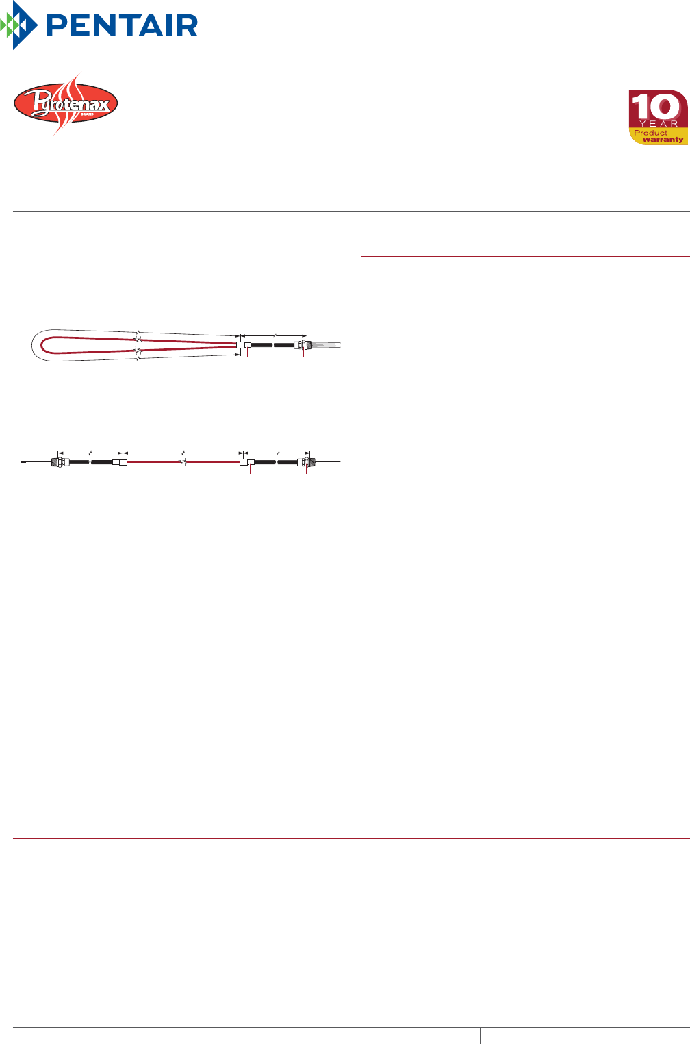
Hot/cold
joint
NPT threaded
connector
Hot/cold
joint
NPT threaded
connector
Heated length
Heated length Cold lead length
Cold lead length
Cold lead length
Type SUA
Design A
Type SUB, HLR and FH
Design B
MI Heating Cable Configuration PRODUCT OVERVIEW
Heat-loss replacement – replaces heat in concrete floors
built over garages, loading docks, arcades, and other cold
spaces. The cable is typically attached to the bottom of
concrete floors.
Comfort floor heating – warms concrete, tile, stone and
marble floors in lobbies, foyers, bathrooms, kitchens and
gymnasiums. The cable is typically embedded in concrete or
a thick mortar bed.
Radiant space heating – provides primary space heating for
rooms with concrete floors. The cable is typically embedded
in concrete or a thick mortar bed.
Type HLR heating cables are supplied with a copper sheath
and are ideally suited for heat loss replacement applications.
Types SUA, SUB and FH heating cables have a copper sheath
that is covered with an extruded high-density polyethylene
(HDPE) jacket and are suitable for applications where the
cable is directly embedded in concrete or mortar floors.
The heating cables are factory assembled with an HDPE
jacketed copper sheath cold lead, pre-terminated and ready
to connect to a junction box. The copper sheath provides
an ideal ground path and allows for a rugged yet flexible
heating cable that is easy to install.
The radiant heat provided by the Pyrotenax heating cable
allows you to feel comfortable at lower air temperatures,
resulting in lower heating costs.
Pentair Thermal Management representatives can provide
design assistance and help you install the product that
meets your goals for an efficient, cost-effective floor heating
system.
CABLE CONSTRUCTION
Type HLR heating cable
Sheath Seamless copper
Insulation Magnesium oxide
Conductor type Alloy or copper
Number of conductors 1
Insulation voltage rating 600 V
Cable diameter (without jacket) 0.120 to 0.205 in (3.0 to 5.2 mm)
MI HEATING CABLE
COPPER AND HDPE JACKETED COPPER SHEATHED MI CABLE
For heat loss replacement, floor heating and radiant space heating
THERMAL MANAGEMENT SOLUTIONS
EN-PyrotenaxMIfloorheating-DS-H58208 11/13
364
Pipe Freeze Protection
and Flow Maintenance
Fire Sprinkler System
Freeze Protection
Roof and Gutter
De-Icing
Surface Snow
Melting – MI
Surface Snow
Melting – ElectroMelt
Freezer Frost
Heave Prevention
Floor Heating Technical Data
Sheets
CABLE CONSTRUCTION
Types SUA, SUB and FH heating cable
Jacket HDPE
Sheath Seamless copper
Insulation Magnesium oxide
Conductor type Alloy or copper
Number of conductors 1
Insulation voltage rating 600 V
Cable diameter (with jacket) 0.200 to 0.303 in (5.1 to 7.7 mm)
Cold lead (Type SUA/SUB/HLR/FH cables)
Jacket HDPE
Sheath Seamless copper
Insulation Magnesium oxide
Conductor type Copper
Number of conductors 1 or 2
Insulation voltage rating 600 V
Cable diameter (with jacket) 0.310 to 0.420 in (7.9 to 10.7 mm)
Gland size (NPT) 1/2 in
Tail length 12 in (30 mm)
MINIMUM INSTALLATION TEMPERATURE
–4°F (–20°C)
MINIMUM BENDING RADIUS
6 times cable diameter
TYPE HLR HEAT LOSS REPLACEMENT CABLE SPECIFICATIONS
Catalog
number
Config-
uration
Heating
cable
reference
Heated length
Nominal
power
(watts)
Cable
voltage
(volts)
Cold lead
length ¹Cold
lead
code
Joint
type
Nominal cable
diameter Resis-
tance ²
(ohms)
Tail
size
(AWG)(ft) (m) (ft) (m) (in) (mm)
120 Volts and 208 Volts, 3-phase Wye
HLR1 B 61CD3610 70 21.3 330 120 15 4.6 H25A Y 0.120 3.0 43.6 14
HLR2 B 61CD3610 44 13.4 540 120 15 4.6 H25A Y 0.120 3.0 26.7 14
HLR3 B 61CD3390 55 16.8 670 120 15 4.6 H25A Y 0.132 3.4 21.5 14
HLR4 B 61CD3300 63 19.2 760 120 15 4.6 H25A Y 0.160 4.1 18.9 14
HLR5 B 61CD3200 77 23.5 935 120 15 4.6 H25A Y 0.168 4.3 15.4 14
HLR6 B 61CE3150 89 27.1 1080 120 15 4.6 H25A Y 0.148 3.8 13.3 14
HLR7 B 61CE3105 106 32.3 1295 120 15 4.6 H25A Y 0.174 4.4 11.1 14
HLR8 B 61CE4800 122 37.2 1475 120 15 4.6 H25A Y 0.182 4.6 9.8 14
HLR9 B 61CE4600 140 42.7 1715 120 15 4.6 H25A Y 0.194 4.9 8.4 14
HLR10 B 61CE4400 172 52.4 2100 120 15 4.6 H25A Y 0.185 4.7 6.9 14
HLR11 B 61CE4300 198 60.4 2425 120 15 4.6 H25A Y 0.192 4.9 5.9 14
HLR12 B 61CE4200 244 74.4 2950 120 15 4.6 H30A Y 0.205 5.2 4.9 12
HLR13 B 61CC4100 322 98.2 3925 120 15 4.6 H40A Y 0.198 5.0 3.7 10
¹ To modify cold lead length, contact your Pentair Thermal Management sales representative.
² Resistance tolerance: +/– 10%
Tolerance on heating cable length: –0% to +3%
mi heating cable for floor heating
365 THERMAL MANAGEMENT SOLUTIONS EN-PyrotenaxMIfloorheating-DS-H58208 11/13

TYPE HLR HEAT LOSS REPLACEMENT CABLE SPECIFICATIONS
Catalog
number
Config-
uration
Heating
cable
reference
Heated length
Nominal
power
(watts)
Cable
voltage
(volts)
Cold lead
length ¹Cold
lead
code
Joint
type
Nominal cable
diameter Resis-
tance ²
(ohms)
Tail
size
(AWG)(ft) (m) (ft) (m) (in) (mm)
208 Volts
HLR14 B 61CD3610 76 23.2 935 208 15 4.6 H25A Y 0.120 3.0 46.3 14
HLR15 B 61CD3390 95 29.0 1170 208 15 4.6 H25A Y 0.132 3.4 37.0 14
HLR16 B 61CD3300 109 33.2 1325 208 15 4.6 H25A Y 0.160 4.1 32.7 14
HLR17 B 61CD3200 133 40.5 1625 208 15 4.6 H25A Y 0.168 4.3 26.6 14
HLR18 B 61CE3150 154 47.0 1875 208 15 4.6 H25A Y 0.148 3.8 23.1 14
HLR19 B 61CE3105 184 56.1 2240 208 15 4.6 H25A Y 0.174 4.4 19.3 14
HLR20 B 61CE4800 211 64.3 2565 208 15 4.6 H25A Y 0.182 4.6 16.9 14
HLR21 B 61CE4600 243 74.1 2970 208 15 4.6 H25A Y 0.194 4.9 14.6 14
HLR22 B 61CE4400 296 90.2 3655 208 15 4.6 H25A Y 0.185 4.7 11.8 14
HLR23 B 61CE4300 345 105.2 4180 208 15 4.6 H25A Y 0.192 4.9 10.4 14
HLR24 B 61CE4200 420 128.0 5150 208 15 4.6 H30A Y 0.205 5.2 8.4 12
HLR25 B 61CC4100 560 170.7 6780 208 15 4.6 H40A Y 0.198 5.0 6.4 10
240 Volts
HLR26 B 61CD3610 88 26.8 1075 240 15 4.6 H25A Y 0.120 3.0 53.6 14
HLR27 B 61CD3390 110 33.5 1345 240 15 4.6 H25A Y 0.132 3.4 42.8 14
HLR28 B 61CD3300 125 38.1 1535 240 15 4.6 H25A Y 0.160 4.1 37.5 14
HLR29 B 61CD3200 153 46.6 1880 240 15 4.6 H25A Y 0.168 4.3 30.6 14
HLR30 B 61CE3150 177 54.0 2170 240 15 4.6 H25A Y 0.148 3.8 26.5 14
HLR31 B 61CE3105 212 64.6 2590 240 15 4.6 H25A Y 0.174 4.4 22.2 14
HLR32 B 61CE4800 243 74.1 2965 240 15 4.6 H25A Y 0.182 4.6 19.4 14
HLR33 B 61CE4600 280 85.4 3430 240 15 4.6 H25A Y 0.194 4.9 16.8 14
HLR34 B 61CE4400 345 105.2 4175 240 15 4.6 H25A Y 0.185 4.7 13.8 14
HLR35 B 61CE4300 395 120.4 4860 240 15 4.6 H25A Y 0.192 4.9 11.9 14
HLR36 B 61CE4200 485 147.9 5940 240 15 4.6 H30A Y 0.205 5.2 9.7 12
HLR37 B 61CC4100 640 195.1 7900 240 15 4.6 H40A Y 0.198 5.0 7.3 10
277 Volts and 480 Volts, 3-phase Wye
HLR38 B 61CD3610 102 31.1 1235 277 15 4.6 H25A Y 0.120 3.0 62.1 14
HLR39 B 61CD3390 127 38.7 1550 277 15 4.6 H25A Y 0.132 3.4 49.5 14
HLR40 B 61CD3300 145 44.2 1765 277 15 4.6 H25A Y 0.160 4.1 43.5 14
HLR41 B 61CD3200 177 54.0 2170 277 15 4.6 H25A Y 0.168 4.3 35.4 14
HLR42 B 61CE3150 205 62.5 2495 277 15 4.6 H25A Y 0.148 3.8 30.8 14
HLR43 B 61CE3105 245 74.7 2985 277 15 4.6 H25A Y 0.174 4.4 25.7 14
HLR44 B 61CE4800 280 85.4 3425 277 15 4.6 H25A Y 0.182 4.6 22.4 14
HLR45 B 61CE4600 325 99.1 3935 277 15 4.6 H25A Y 0.194 4.9 19.5 14
HLR46 B 61CE4400 396 120.7 4845 277 15 4.6 H25A Y 0.185 4.7 15.8 14
HLR47 B 61CE4300 460 140.2 5560 277 15 4.6 H25A Y 0.192 4.9 13.8 14
HLR48 B 61CE4200 560 170.7 6850 277 15 4.6 H30A Y 0.205 5.2 11.2 12
HLR49 B 61CC4100 740 225.6 9100 277 15 4.6 H40A Y 0.198 5.0 8.4 10
¹ To modify cold lead length, contact your Pentair Thermal Management sales representative.
² Resistance tolerance: +/– 10%
Tolerance on heating cable length: –0% to +3%
MI HEATING CABLE FOR FLOOR HEATING
THERMAL MANAGEMENT SOLUTIONS
EN-PyrotenaxMIfloorheating-DS-H58208 11/13
366

Pipe Freeze Protection
and Flow Maintenance
Fire Sprinkler System
Freeze Protection
Roof and Gutter
De-Icing
Surface Snow
Melting – MI
Surface Snow
Melting – ElectroMelt
Freezer Frost
Heave Prevention
Floor Heating Technical Data
Sheets
TYPE HLR HEAT LOSS REPLACEMENT CABLE SPECIFICATIONS
Catalog
number
Config-
uration
Heating
cable
reference
Heated length
Nominal
power
(watts)
Cable
voltage
(volts)
Cold lead
length ¹Cold
lead
code
Joint
type
Nominal cable
diameter Resis-
tance ²
(ohms)
Tail
size
(AWG)(ft) (m) (ft) (m) (in) (mm)
347 Volts and 600 Volts, 3-phase Wye
HLR50 B 61CD3610 127 38.7 1560 347 15 4.6 H25A Y 0.120 3.0 77.2 14
HLR51 B 61CD3390 160 48.8 1930 347 15 4.6 H25A Y 0.132 3.4 62.4 14
HLR52 B 61CD3300 182 55.5 2205 347 15 4.6 H25A Y 0.160 4.1 54.6 14
HLR53 B 61CD3200 222 67.7 2715 347 15 4.6 H25A Y 0.168 4.3 44.3 14
HLR54 B 61CE3150 258 78.7 3110 347 15 4.6 H25A Y 0.148 3.8 38.7 14
HLR55 B 61CE3105 306 93.3 3750 347 15 4.6 H25A Y 0.174 4.4 32.1 14
HLR56 B 61CE4800 350 106.7 4300 347 15 4.6 H25A Y 0.182 4.6 28.0 14
HLR57 B 61CE4600 405 123.5 4955 347 15 4.6 H25A Y 0.194 4.9 24.3 14
HLR58 B 61CE4400 495 150.9 6080 347 15 4.6 H25A Y 0.185 4.7 19.8 14
HLR59 B 61CE4300 575 175.3 6980 347 15 4.6 H25A Y 0.192 4.9 17.3 14
HLR60 B 61CE4200 700 213.4 8600 347 15 4.6 H30A Y 0.205 5.2 14.0 12
480 Volts
HLR61 B 61CD3610 175 53.4 2160 480 15 4.6 H25A Y 0.120 3.0 106.7 14
HLR62 B 61CD3390 220 67.1 2685 480 15 4.6 H25A Y 0.132 3.4 85.8 14
HLR63 B 61CD3300 250 76.2 3070 480 15 4.6 H25A Y 0.160 4.1 75.0 14
HLR64 B 61CD3200 306 93.3 3770 480 15 4.6 H25A Y 0.168 4.3 61.1 14
HLR65 B 61CE3150 355 108.2 4330 480 15 4.6 H25A Y 0.148 3.8 53.2 14
HLR66 B 61CE3105 424 129.3 5175 480 15 4.6 H25A Y 0.174 4.4 44.5 14
HLR67 B 61CE4800 485 147.9 5940 480 15 4.6 H25A Y 0.182 4.6 38.8 14
HLR68 B 61CE4600 560 170.7 6860 480 15 4.6 H25A Y 0.194 4.9 33.6 14
HLR69 B 61CE4400 690 210.4 8350 480 15 4.6 H25A Y 0.185 4.7 27.6 14
600 Volts
HLR70 B 61CD3610 220 67.1 2685 600 15 4.6 H25A Y 0.120 3.0 134.1 14
HLR71 B 61CD3390 275 83.8 3360 600 15 4.6 H25A Y 0.132 3.4 107.1 14
HLR72 B 61CD3300 313 95.4 3835 600 15 4.6 H25A Y 0.160 4.1 93.9 14
HLR73 B 61CD3200 384 117.1 4690 600 15 4.6 H25A Y 0.168 4.3 76.8 14
HLR74 B 61CE3150 443 135.1 5420 600 15 4.6 H25A Y 0.148 3.8 66.4 14
HLR75 B 61CE3105 530 161.6 6470 600 15 4.6 H25A Y 0.174 4.4 55.6 14
HLR76 B 61CE4800 605 184.5 7440 600 15 4.6 H25A Y 0.182 4.6 48.4 14
HLR77 B 61CE4600 700 213.4 8570 600 15 4.6 H25A Y 0.194 4.9 42.0 14
¹ To modify cold lead length, contact your Pentair Thermal Management sales representative.
² Resistance tolerance: +/– 10%
Tolerance on heating cable length: –0% to +3%
mi heating cable for floor heating
367 THERMAL MANAGEMENT SOLUTIONS EN-PyrotenaxMIfloorheating-DS-H58208 11/13

TYPE SUA/SUB FLOOR HEATING AND RADIANT SPACE HEATING CABLE SPECIFICATIONS
Catalog
number
Config-
uration
Heating
cable
reference
Heated length Nominal
power
(watts)
Cable
voltage
(volts)
Cold lead
length ¹Cold
lead
code
Joint
type
Nominal cable
diameter Resis-
tance ²
(ohms)
Tail
size
(AWG)(ft) (m) (ft) (m) (in) (mm)
120 Volts and 208 Volts, 3-phase Wye
SUA2 A 61HD3610 55 16.8 425 120 7 2.1 H22A Y 0.200 5.1 33.6 14
SUA3 A 61HD3200 140 42.7 500 120 7 2.1 H22A Y 0.248 6.3 28.0 14
SUA4 A 61HD3390 68 20.7 550 120 7 2.1 H22A Y 0.212 5.4 26.5 14
SUA7 A 61HD3200 95 29.0 750 120 7 2.1 H22A Y 0.248 6.3 19.0 14
SUA8 A 61HE3105 177 54.0 800 120 7 2.1 H22A Y 0.254 6.5 18.6 14
SUB1 B 61HE3105 132 40.2 1000 120 15 4.6 H25A Y 0.254 6.5 13.9 14
SUB2 B 61HE4600 240 73.2 1000 120 15 4.6 H25A Y 0.274 7.0 14.4 14
SUB3 B 61HE4400 280 85.4 1300 120 15 4.6 H30A Y 0.265 6.7 11.2 12
SUB4 B 61HE4300 320 97.6 1500 120 15 4.6 H30A Y 0.272 6.9 9.6 12
SUB5 B 61HE4300 260 79.3 1800 120 15 4.6 H40A Y 0.272 6.9 7.8 10
SUB6 B 61HE4200 375 114.3 1900 120 15 4.6 H40A Y 0.285 7.2 7.5 10
SUB7 B 61HE4200 310 94.5 2300 120 15 4.6 H40A Y 0.285 7.2 6.2 10
SUB8 B 61HC4100 550 167.7 2300 120 15 4.6 H60A Y 0.278 7.1 6.3 8
SUB9 B 61HC5651 630 192.1 3000 120 15 4.6 H60A Y 0.274 7.0 4.7 8
SUB10 B 61HC5409 717 218.6 4300 120 15 4.6 H80A Y 0.303 7.7 3.3 6
208 Volts
SUA1 A 61HD3610 108 32.9 650 208 7 2.1 H22A Y 0.200 5.1 65.9 14
SUA6 A 61HE3105 264 80.5 1650 208 7 2.1 H22A Y 0.254 6.5 27.7 14
SUB19 B 61HD3200 245 74.7 885 208 15 4.6 H25A Y 0.248 6.3 49.0 14
SUB20 B 61HE3105 340 103.7 1210 208 15 4.6 H25A Y 0.254 6.5 35.7 14
SUB21 B 61HE4600 440 134.1 1640 208 15 4.6 H25A Y 0.274 7.0 26.4 14
SUB22 B 61HE4400 525 160.1 2060 208 15 4.6 H25A Y 0.265 6.7 21.0 14
240 Volts
SUA1 A 61HD3610 108 32.9 900 240 7 2.1 H22A Y 0.200 5.1 65.9 14
SUA6 A 61HE3105 264 80.5 2100 240 7 2.1 H22A Y 0.254 6.5 27.7 14
SUB19 B 61HD3200 245 74.7 1175 240 15 4.6 H25A Y 0.248 6.3 49.0 14
SUB20 B 61HE3105 340 103.7 1615 240 15 4.6 H25A Y 0.254 6.5 35.7 14
SUB21 B 61HE4600 440 134.1 2180 240 15 4.6 H25A Y 0.274 7.0 26.4 14
SUB22 B 61HE4400 525 160.1 2745 240 15 4.6 H25A Y 0.265 6.7 21.0 14
277 Volts and 480 Volts, 3-phase Wye
SUB19 B 61HD3200 245 74.7 1565 277 15 4.6 H25A Y 0.248 6.3 49.0 14
SUB20 B 61HE3105 340 103.7 2150 277 15 4.6 H25A Y 0.254 6.5 35.7 14
SUB21 B 61HE4600 440 134.1 2900 277 15 4.6 H25A Y 0.274 7.0 26.4 14
SUB22 B 61HE4400 525 160.1 3650 277 15 4.6 H25A Y 0.265 6.7 21.0 14
347 Volts and 600 Volts, 3-phase Wye
SUB11 B 61HD3390 225 68.6 1400 347 15 4.6 H25A Y 0.212 5.4 87.8 14
SUB12 B 61HD3200 310 94.5 1950 347 15 4.6 H25A Y 0.248 6.3 62.0 14
SUB13 B 61HE3105 428 130.5 2700 347 15 4.6 H25A Y 0.254 6.5 44.9 14
SUB14 B 61HE4600 548 167.1 3700 347 15 4.6 H25A Y 0.274 7.0 32.9 14
¹ To modify cold lead length, contact your Pentair Thermal Management sales representative.
² Resistance tolerance: +/– 10%
Tolerance on heating cable length: –0% to +3%
MI HEATING CABLE FOR FLOOR HEATING
THERMAL MANAGEMENT SOLUTIONS
EN-PyrotenaxMIfloorheating-DS-H58208 11/13
368

Pipe Freeze Protection
and Flow Maintenance
Fire Sprinkler System
Freeze Protection
Roof and Gutter
De-Icing
Surface Snow
Melting – MI
Surface Snow
Melting – ElectroMelt
Freezer Frost
Heave Prevention
Floor Heating Technical Data
Sheets
TYPE FH FLOOR HEATING AND RADIANT SPACE HEATING CABLE SPECIFICATIONS
Catalog
number
Config-
uration
Heating
cable
reference
Heated length
Nominal
power
(watts)
Cable
voltage
(volts)
Cold lead
length ¹Cold
lead
code
Joint
type
Nominal cable
diameter Resis-
tance ²
(ohms)
Tail
size
(AWG)(ft) (m) (ft) (m) (in) (mm)
120 Volts and 208 Volts, 3-phase Wye
FH1 B 61HD3610 54 16.5 440 120 15 4.6 H25A Y 0.200 5.1 32.9 14
FH2 B 61HD3390 68 20.7 545 120 15 4.6 H25A Y 0.212 5.4 26.5 14
FH3 B 61HD3300 77 23.5 625 120 15 4.6 H25A Y 0.240 6.1 23.1 14
FH4 B 61HD3200 95 29.0 760 120 15 4.6 H25A Y 0.248 6.3 19.0 14
FH5 B 61HE3150 109 33.2 880 120 15 4.6 H25A Y 0.228 5.8 16.4 14
FH6 B 61HE3105 130 39.6 1055 120 15 4.6 H25A Y 0.254 6.5 13.7 14
FH7 B 61HE4800 150 45.7 1200 120 15 4.6 H25A Y 0.262 6.7 12.0 14
FH8 B 61HE4600 173 52.7 1390 120 15 4.6 H25A Y 0.274 7.0 10.4 14
FH9 B 61HE4400 210 64.0 1715 120 15 4.6 H25A Y 0.265 6.7 8.4 14
FH10 B 61HE4300 245 74.7 1960 120 15 4.6 H25A Y 0.272 6.9 7.4 14
FH11 B 61HE4200 300 91.5 2400 120 15 4.6 H25A Y 0.285 7.2 6.0 14
208 Volts
FH12 B 61HD3610 94 28.7 755 208 15 4.6 H25A Y 0.200 5.1 57.3 14
FH13 B 61HD3390 118 36.0 940 208 15 4.6 H25A Y 0.212 5.4 46.0 14
FH14 B 61HD3300 134 40.9 1075 208 15 4.6 H25A Y 0.240 6.1 40.2 14
FH15 B 61HD3200 164 50.0 1320 208 15 4.6 H25A Y 0.248 6.3 32.8 14
FH16 B 61HE3150 190 57.9 1520 208 15 4.6 H25A Y 0.228 5.8 28.5 14
FH17 B 61HE3105 225 68.6 1830 208 15 4.6 H25A Y 0.254 6.5 23.6 14
FH18 B 61HE4800 260 79.3 2080 208 15 4.6 H25A Y 0.262 6.7 20.8 14
FH19 B 61HE4600 300 91.5 2400 208 15 4.6 H25A Y 0.274 7.0 18.0 14
FH20 B 61HE4400 365 111.3 2960 208 15 4.6 H25A Y 0.265 6.7 14.6 14
FH21 B 61HE4300 425 129.6 3390 208 15 4.6 H25A Y 0.272 6.9 12.8 14
FH22 B 61HE4200 520 158.5 4160 208 15 4.6 H25A Y 0.285 7.2 10.4 14
240 Volts
FH23 B 61HD3610 108 32.9 875 240 15 4.6 H25A Y 0.200 5.1 65.9 14
FH24 B 61HD3390 135 41.2 1095 240 15 4.6 H25A Y 0.212 5.4 52.7 14
FH25 B 61HD3300 155 47.3 1240 240 15 4.6 H25A Y 0.240 6.1 46.5 14
FH26 B 61HD3200 190 57.9 1515 240 15 4.6 H25A Y 0.248 6.3 38.0 14
FH27 B 61HE3150 215 65.5 1785 240 15 4.6 H25A Y 0.228 5.8 32.3 14
FH28 B 61HE3105 260 79.3 2110 240 15 4.6 H25A Y 0.254 6.5 27.3 14
FH29 B 61HE4800 300 91.5 2400 240 15 4.6 H25A Y 0.262 6.7 24.0 14
FH30 B 61HE4600 345 105.2 2780 240 15 4.6 H25A Y 0.274 7.0 20.7 14
FH31 B 61HE4400 420 128.0 3430 240 15 4.6 H25A Y 0.265 6.7 16.8 14
FH32 B 61HE4300 490 149.4 3920 240 15 4.6 H25A Y 0.272 6.9 14.7 14
FH33 B 61HE4200 600 182.9 4800 240 15 4.6 H25A Y 0.285 7.2 12.0 14
¹ To modify cold lead length, contact your Pentair Thermal Management sales representative.
² Resistance tolerance: +/– 10%
Tolerance on heating cable length: –0% to +3%
mi heating cable for floor heating
369 THERMAL MANAGEMENT SOLUTIONS EN-PyrotenaxMIfloorheating-DS-H58208 11/13

TYPE FH FLOOR HEATING AND RADIANT SPACE HEATING CABLE SPECIFICATIONS
Catalog
number
Config-
uration
Heating
cable
reference
Heated length
Nominal
power
(watts)
Cable
voltage
(volts)
Cold lead
length ¹Cold
lead
code
Joint
type
Nominal cable
diameter Resis-
tance ²
(ohms)
Tail
size
(AWG)(ft) (m) (ft) (m) (in) (mm)
277 Volts and 480 Volts, 3-phase Wye
FH34 B 61HD3610 125 38.1 1005 277 15 4.6 H25A Y 0.200 5.1 76.3 14
FH35 B 61HD3390 155 47.3 1270 277 15 4.6 H25A Y 0.212 5.4 60.5 14
FH36 B 61HD3300 178 54.3 1440 277 15 4.6 H25A Y 0.240 6.1 53.4 14
FH37 B 61HD3200 218 66.5 1760 277 15 4.6 H25A Y 0.248 6.3 43.6 14
FH38 B 61HE3150 253 77.1 2020 277 15 4.6 H25A Y 0.228 5.8 38.0 14
FH39 B 61HE3105 300 91.5 2435 277 15 4.6 H25A Y 0.254 6.5 31.5 14
FH40 B 61HE4800 345 105.2 2780 277 15 4.6 H25A Y 0.262 6.7 27.6 14
FH41 B 61HE4600 400 122.0 3200 277 15 4.6 H25A Y 0.274 7.0 24.0 14
FH42 B 61HE4400 490 149.4 3915 277 15 4.6 H25A Y 0.265 6.7 19.6 14
FH43 B 61HE4300 564 172.0 4535 277 15 4.6 H25A Y 0.272 6.9 16.9 14
FH44 B 61HE4200 690 210.4 5560 277 15 4.6 H25A Y 0.285 7.2 13.8 14
347 Volts and 600 Volts, 3-phase Wye
FH45 B 61HD3610 155 47.3 1275 347 15 4.6 H25A Y 0.200 5.1 94.6 14
FH46 B 61HD3390 195 59.5 1585 347 15 4.6 H25A Y 0.212 5.4 76.1 14
FH47 B 61HD3300 220 67.1 1825 347 15 4.6 H25A Y 0.240 6.1 66.0 14
FH48 B 61HD3200 270 82.3 2230 347 15 4.6 H25A Y 0.248 6.3 54.0 14
FH49 B 61HE3150 315 96.0 2550 347 15 4.6 H25A Y 0.228 5.8 47.3 14
FH50 B 61HE3105 376 114.6 3050 347 15 4.6 H25A Y 0.254 6.5 39.5 14
FH51 B 61HE4800 430 131.1 3500 347 15 4.6 H25A Y 0.262 6.7 34.4 14
FH52 B 61HE4600 497 151.5 4040 347 15 4.6 H25A Y 0.274 7.0 29.8 14
FH53 B 61HE4400 610 186.0 4935 347 15 4.6 H25A Y 0.265 6.7 24.4 14
FH54 B 61HE4300 710 216.5 5650 347 15 4.6 H25A Y 0.272 6.9 21.3 14
480 Volts
FH55 B 61HD3610 215 65.5 1760 480 15 4.6 H25A Y 0.200 5.1 131.2 14
FH56 B 61HD3390 270 82.3 2190 480 15 4.6 H25A Y 0.212 5.4 105.3 14
FH57 B 61HD3300 310 94.5 2480 480 15 4.6 H25A Y 0.240 6.1 93.0 14
FH58 B 61HD3200 380 115.9 3030 480 15 4.6 H25A Y 0.248 6.3 76.0 14
FH59 B 61HE3150 435 132.6 3530 480 15 4.6 H25A Y 0.228 5.8 65.3 14
FH60 B 61HE3105 520 158.5 4220 480 15 4.6 H25A Y 0.254 6.5 54.6 14
FH61 B 61HE4800 600 182.9 4800 480 15 4.6 H25A Y 0.262 6.7 48.0 14
FH62 B 61HE4600 690 210.4 5565 480 15 4.6 H25A Y 0.274 7.0 41.4 14
600 Volts
FH63 B 61HD3610 270 82.3 2185 600 15 4.6 H25A Y 0.200 5.1 164.7 14
FH64 B 61HD3390 340 103.7 2715 600 15 4.6 H25A Y 0.212 5.4 132.6 14
FH65 B 61HD3300 385 117.4 3120 600 15 4.6 H25A Y 0.240 6.1 115.5 14
FH66 B 61HD3200 470 143.3 3830 600 15 4.6 H25A Y 0.248 6.3 94.0 14
FH67 B 61HE3150 545 166.2 4400 600 15 4.6 H25A Y 0.228 5.8 81.8 14
FH68 B 61HE3105 650 198.2 5275 600 15 4.6 H25A Y 0.254 6.5 68.3 14
¹ To modify cold lead length, contact your Pentair Thermal Management sales representative.
² Resistance tolerance: +/– 10%
Tolerance on heating cable length: –0% to +3%
MI HEATING CABLE FOR FLOOR HEATING
THERMAL MANAGEMENT SOLUTIONS
EN-PyrotenaxMIfloorheating-DS-H58208 11/13
370

Pipe Freeze Protection
and Flow Maintenance
Fire Sprinkler System
Freeze Protection
Roof and Gutter
De-Icing
Surface Snow
Melting – MI
Surface Snow
Melting – ElectroMelt
Freezer Frost
Heave Prevention
Floor Heating Technical Data
Sheets
APPROVALS
Note: For heat loss replacement applications where the cable
is attached to the bottom of the concrete floor, contact Pentair
Thermal Management for additional information.
GROUNDFAULT PROTECTION
To minimize the danger of fire from sustained electrical arcing if the heating
cable is damaged or improperly installed, and to comply with the requirements
of Pentair Thermal Management, agency certifications, and national electrical
codes, ground-fault equipment protection must be used on each heating cable
branch circuit. Arcing may not be stopped by conventional circuit protection.
Many DigiTrace control and monitoring systems meet the ground-fault protection
requirement.
mi heating cable for floor heating
371 THERMAL MANAGEMENT SOLUTIONS EN-PyrotenaxMIfloorheating-DS-H58208 11/13
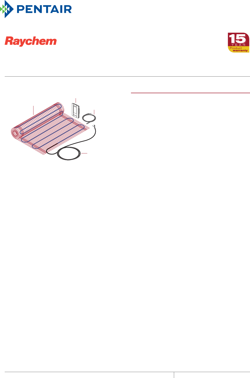
QuickNet floor
heating mat
QuickStat-TC
thermostat
Floor
temperature
sensor
Cold lead
For example:
If your bathroom is 9 ft x 10 ft = 90 sq ft
minus the cabinet area - 10 sq ft
minus the toilet space - 6 sq ft
minus the linen closet - 8 sq ft
minus the shower area - 15 sq ft*
Total area to be heated = 51 sq ft
Solution:
Choose the 50 sq ft QUICKNET (QuickNet-050-1).
If the shower area is to be heated, select a 15 sq ft
QUICKNET (QuickNet-015X-1) also.
*
10 ft
10 ft
9 ft
3 ft 6 in
6 in
5 ft
15 sq ft
Linens
T
Sample
Bathroom
PRODUCT OVERVIEW
Raychem QuickNet is an electric floor heating system for
installation under the following surfaces:
• Ceramic or porcelain tile
• Granite
• Marble (except cultured marble)
• Natural stone
• Laminate* wood flooring (floating only)
• Engineered* wood flooring (floating or gluedown)
* For laminate and engineered wood flooring, please
refer to the wood manufacturer’s recommendations to
determine which types are approved for use with floor
heating systems and any specific temperature limit set
points.
The QuickNet system provides comfort heating in
bathrooms, showers, kitchens, entryways and other living
areas. QuickNet’s compatibility with all standard sub-
flooring materials, and its low 3/16 inch (3 mm) profile, make
it ideal for renovation projects.
The QuickNet floor heating system includes a blue heating
cable attached to an adhesive-backed red fiberglass mesh
that allows for simple roll-out installation without worrying
about heating cable spacing.
The floor heating mats are pre-terminated for use with
120 V, 208 V, and 240 V and are available in various lengths
of 20-inch widths.
The QuickNet mats emit no measurable electromagnetic
fields due to the shielded dual conductor design. This dual
conductor cable requires only one cold lead connection
making it easy to layout and install the mat. The cold lead is
a black non-heating cord that runs in the wall and connects
the heating mat system to the thermostat.
The QuickStat-TC thermostat includes built-in GFCI
protection. It’s adaptive function automatically switches
the system on to ensure a comfortable floor temperature
when you want it. Depending upon the specifics of your
installation, the QuickNet floor heating system can maintain
floor temperatures up to 85°F or more.
Various sizes of floor heating mats are designed to fit the
heated area of any floor. The heated area is the area of the
floor where there are no permanent fixtures or furniture
such as tubs, toilets, vanities or cabinets.
QUICKNET
floor heating system
THERMAL MANAGEMENT SOLUTIONS
EN-RaychemQuickNetfloorheating-DS-H57703 11/13
372

Pipe Freeze Protection
and Flow Maintenance
Fire Sprinkler System
Freeze Protection
Roof and Gutter
De-Icing
Surface Snow
Melting – MI
Surface Snow
Melting – ElectroMelt
Freezer Frost
Heave Prevention
Floor Heating Technical Data
Sheets
KIT CONTENTS
1 QuickNet floor heating mat (with 10-foot cold lead)
1 QuickStat-TC thermostat
1 Floor temperature sensor (15-foot length)
Installation Instructions
APPROVALS
MAT SPECIFICATIONS
Operating voltage 120 V, 208 V, and 240 V
Power output 12 W/ft² (130 W/m²) ±10% at 120 V or 240 V
9 W/ft² (97 W/m²) ± 10% at 208 V
Minimum bending radius 1.25 in (30 mm)
Minimum cable spacing 3 in (80 mm)
Maximum ambient temperature 85°F (30°C)
Minimum installation temperature 40°F (5°C)
Heating cable 2-wire, grounded, fluoropolymer insulating jacket
Cold lead 2-wire 16 AWG plus ground braid; 10 ft (3 m) length
THERMOSTAT SPECIFICATIONS
Functions On/Off control, digital display, 7-day programmable, Class A, 5 mA GFCI
Supply voltage 120 V, 208 V, 240 V, 60 Hz
Maximum switching current 15 A
Ambient setpoint range (A/AF mode) 40 to 86°F (5 to 30°C)
Floor setpoint range (F mode) 40 to 104°F (5 to 40°C)
Floor limit setpoint range (AF mode) 40 to 104°F (5 to 40°C)
Floor temperature sensor 2-wire, 15-foot lead wire
-w
quicknet
373 THERMAL MANAGEMENT SOLUTIONS EN-RaychemQuickNetfloorheating-DS-H57703 11/13
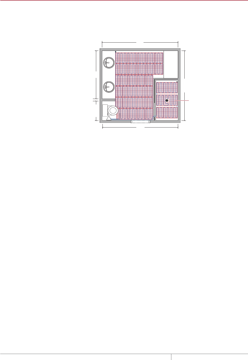
ORDERING DETAILS
Select the QuickNet floor heating mat that is no larger than the heated area. The
heated area is the area of the floor that does not include permanent fixtures such
as cabinets, toilets, sinks or tubs. The selected mat can be configured on the
jobsite to fit the shape of the area to be heated.
QuickNet floor
heating mat
QuickStat-TC
thermostat
Floor
temperature
sensor
Cold lead
For example:
If your bathroom is 9 ft x 10 ft = 90 sq ft
minus the cabinet area - 10 sq ft
minus the toilet space - 6 sq ft
minus the linen closet - 8 sq ft
minus the shower area - 15 sq ft*
Total area to be heated = 51 sq ft
Solution:
Choose the 50 sq ft QUICKNET (QuickNet-050-1).
If the shower area is to be heated, select a 15 sq ft
QUICKNET (QuickNet-015X-1) also.
*
10 ft
10 ft
9 ft
3 ft 6 in
6 in
5 ft
15 sq ft
Linens
T
Sample
Bathroom
Note: Extension Kits are available to accommodate larger heated areas. Unlike
Standard Kits, extension kits do not include the QuickStat-TC thermostat or floor
sensor. The maximum installation area is 140 ft² at 120 V and 280 ft² at 240 V.
For heated areas greater than 280 ft², contact Pentair Thermal Management for
design assistance.
QUICKNET
THERMAL MANAGEMENT SOLUTIONS
EN-RaychemQuickNetfloorheating-DS-H57703 11/13
374

Pipe Freeze Protection
and Flow Maintenance
Fire Sprinkler System
Freeze Protection
Roof and Gutter
De-Icing
Surface Snow
Melting – MI
Surface Snow
Melting – ElectroMelt
Freezer Frost
Heave Prevention
Floor Heating Technical Data
Sheets
Catalog number
Heated area
Mat dimensions
Power Output (W)
Current (A)
Resistance
(Ohms)
ft2m2120 V 208 V 240 V
120 V QuickNet Standard Kit (with thermostat)
QUICKNET-010-1 10 0.9 20 in x 6.2 ft 120 1 120
QUICKNET-015-1 15 1.4 20 in x 9.2 ft 180 1.5 80
QUICKNET-020-1 20 1.9 20 in x 12.1 ft 240 2 60
QUICKNET-025-1 25 2.3 20 in x 15.1 ft 300 2.5 48
QUICKNET-030-1 30 2.8 20 in x 18.4 ft 360 3 40
QUICKNET-035-1 35 3.3 20 in x 21.3 ft 420 3.5 35
QUICKNET-040-1 40 3.7 20 in x 24.3 ft 480 4 30
QUICKNET-045-1 45 4.2 20 in x 27.5 ft 540 4.5 27
QUICKNET-050-1 50 4.6 20 in x 30.5 ft 600 5 24
QUICKNET-060-1 60 5.6 20 in x 36.4 ft 720 6 20
QUICKNET-070-1 70 6.5 20 in x 42.7 ft 840 7 17
QUICKNET-080-1 80 7.4 20 in x 48.9 ft 960 8 15
QUICKNET-090-1 90 8.4 20 in x 55 ft 1080 9 13
QUICKNET-100-1 100 9.3 20 in x 61 ft 1200 10 12
120 V Extension Kit (without thermostat)
QUICKNET-010X-1 10 0.9 20 in x 6.2 ft 120 1 120
QUICKNET-015X-1 15 1.4 20 in x 9.2 ft 180 1.5 80
QUICKNET-020X-1 20 1.9 20 in x 12.1 ft 240 2 60
QUICKNET-025X-1 25 2.3 20 in x 15.1 ft 300 2.5 48
QUICKNET-030X-1 30 2.8 20 in x 18.4 ft 360 3 40
QUICKNET-035X-1 35 3.3 20 in x 21.3 ft 420 3.5 35
QUICKNET-040X-1 40 3.7 20 in x 24.3 ft 480 4 30
QUICKNET-045X-1 45 4.2 20 in x 27.5 ft 540 4.5 27
QUICKNET-050X-1 50 4.6 20 in x 30.5 ft 600 5 24
QUICKNET-060X-1 60 5.6 20 in x 36.4 ft 720 6 20
QUICKNET-070X-1 70 6.5 20 in x 42.7 ft 840 7 17
QUICKNET-080X-1 80 7.4 20 in x 48.9 ft 960 8 15
QUICKNET-090X-1 90 8.4 20 in x 55 ft 1080 9 13
QUICKNET-100X-1 100 9.3 20 in x 61 ft 1200 10 12
208 V or 240 V QuickNet Standard Kit (with thermostat)
QUICKNET-050-2 50 4.6 20 in x 30.5 ft 450 600 2.5 96
QUICKNET-060-2 60 5.6 20 in x 36.4 ft 540 720 3 80
QUICKNET-080-2 80 7.4 20 in x 48.9 ft 720 960 4 60
QUICKNET-100-2 100 9.3 20 in x 61 ft 900 1200 5 48
208 V or 240 V Extension Kit (without thermostat)
QUICKNET-050X-2 50 4.6 20 in x 30.5 ft 450 600 2.5 96
QUICKNET-060X-2 60 5.6 20 in x 36.4 ft 540 720 3 80
QUICKNET-080X-2 80 7.4 20 in x 48.9 ft 720 960 4 60
QUICKNET-100X-2 100 9.3 20 in x 61 ft 900 1200 5 48
ACCESSORIES
Catalog number Description
Repair Kit QuickNet-RK The QuickNet-RK repair kit is for repairing damaged QuickNet heating
cable. The kit incorporates SolderSleeve terminations, jumper wires,
and heat-shrinkable tubing.
QuickNet-Check QUICKNET-CHECK The QuickNet-Check monitor is used to verify the continuity of the
QuickNet heating cable and the integrity of its outer jacket during
the installation process. The monitor connects to the cold leads of
the cable and, if the heating cable is damaged, the alarm on the
monitor will sound. The monitor can also be re-used for subsequent
installations and to help troubleshoot any problems that may arise.
quicknet
375 THERMAL MANAGEMENT SOLUTIONS EN-RaychemQuickNetfloorheating-DS-H57703 11/13
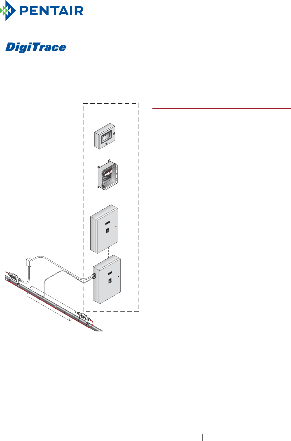
ACS30
multipoint commercial heat-tracing system
THERMAL MANAGEMENT SOLUTIONS
EN-DigiTraceACS30-DS-H58261 11/13
376
COMMON
ALARM
POWER CONTROL
MODULE
ACCSPCM5
COMMON
ALARM
POWER CONTROL
MODULE
ACCSPCM5
ACS-PCM-5
ACS-PCM-5
ACS-UIT
C910-485
ACS-30
System
Heat-tracing system
ALARM
C910 SERIES
SHIFT TEST BACK ENTER
STATUS
ALARM
OUTPUT
MONITOR CONFIG
PROGRAMMABLE SINGLE POINT
HEAT-TRACING CONTROLLER
PRODUCT OVERVIEW
The DigiTrace ACS-30 Advanced Commercial Control System
is a multipoint electronic control and monitoring system
for heat-tracing applications. These applications include
commercial freeze protection, surface snow melting, roof
and gutter de-icing, and flow and temperature maintenance.
The ACS-30 system can control up to 260 circuits with
multiple networked ACS-PCM2-5 panels, or DigiTrace C910-
485 controllers for single circuit system extension. The ACS-
PCM2-5 panel can directly control up to 5 individual heat-
tracing circuits using electromechanical relays rated at 30
A up to 277 V. Four Resistance Temperature Detector (RTD)
sensor inputs can be assigned for each heating cable circuit
providing a variety of temperature control, monitoring, and
alarm options. The ACS-30 can be fitted with 16 DigiTrace
RMM2s, providing an additional 128 temperature inputs to a
maximum of 388 inputs.
Control
The ACS-30 is pre-programmed with parameters for
commercial hot water temperature maintenance, pipe freeze
protection, flow maintenance, freezer frost heave prevention,
surface snow melting, roof and gutter de-icing prevention
and floor heating applications. The pre-programmed
application settings significantly simplify setting up multiple
heating cable circuits. Based on the application the ACS-30
can be configured for On/Off, Ambient Sensing, Proportional
Ambient Sensing (PASC), and timed duty cycle control
modes for HWAT applications.
The ACS-30 measures temperatures with 3-wire, 100-ohm
platinum RTDs connected directly to the unit, or through
optional Remote Monitoring Modules (RMM2). Each RMM2
accepts up to eight RTDs. Multiple RMM2s are networked
over a single cable to the ACS-30, significantly reducing the
cost of RTD wiring.
The built-in calendar function for hot water temperature
maintenance, floor heating and greasy waste applications
provides flexible timed set points providing energy savings.
Monitoring
To assist with energy management the ACS-30 monitors
the power consumption of each heating cable circuit for
up to five years of operation. The data may be graphically
displayed daily, weekly, monthly or yearly. The ACS-30
measures 12 control parameters including ground fault,
temperature, and current to ensure system integrity.
Configurable alarm settings provide options for local or

acs-30
377THERMAL MANAGEMENT SOLUTIONS EN-DigiTraceACS30-DS-H58261 11/13
Pipe Freeze Protection
and Flow Maintenance
Fire Sprinkler System
Freeze Protection
Roof and Gutter
De-Icing
Surface Snow
Melting – MI
Surface Snow
Melting – ElectroMelt
Freezer Frost
Heave Prevention
Floor Heating Technical Data
Sheets
remote alarms. These alarms can be programmed to send
notification of the alarm event by e-mail to user-selected
distribution. The system can be set to periodically check
for heating cable faults, alerting maintenance personnel
of a pending heat tracing problem. This helps avoid costly
downtime. Dry contact relays are provided for alarm
annunciation back to a Building Management System (BMS).
Ground-fault protection
National electrical codes require ground-fault equipment
protection on all heat-tracing circuits. The ACS-30
controller has integrated ground-fault equipment protection
and therefore does not require additional ground-fault
protection, simplifying installation and reducing costs.
Installation
The ACS-30 system is configured with the User Interface
Terminal (ACS-UIT2) that has an LCD color display with
touch-screen technology. The ACS-UIT2 provides an easy
user interface for programming without keyboards or cryptic
labels. The ACS-30 Program Integrator application tool is
available to program, edit and download circuit parameters
through the local USB port or from a remote location.
The ACS-UIT2 comes in a Type 4X enclosure suitable for
nonhazardous, indoor or outdoor locations and comes
complete with wiring terminals and an alarm signal light.
Communications
ACS-30 units support the Modbus® protocol and are
available with RS-232, RS-485 or 10/100Base-T Ethernet
communication interface. DigiTrace ProtoNode multi-
protocol gateways are available to integrate the ACS-30 into
BACnet®, Metasys® N2 and LonWorks® BMS systems.
Complete system
The ACS-30 is supplied as a complete modular system,
ready for field connections to convenient power distribution
panels and temperature sensor input, reducing the cost of
heating cable installation.
ACS30 SYSTEM
Multipoint temperature control with
ground-fault/current/temperature
monitoring when used with the
ACS-UIT2
The ACS-30 is a multipoint electronic control, monitoring, and power relay system
for heat-tracing cables used in commercial heat-tracing applications. The system
consists of a DigiTrace ACS-UIT2 and up to 52 ACS-PCM2-5 power control panels.
C910-485 controllers may also be connected to the system for multiple, single circuit
extensions. DigiTrace RMM2 heat-tracing remote monitoring modules may also be
used with the ACS-30 system to expand the number of temperature measurement
points.
The ACS-30 provides the following alarming features per control point.
• High/low temperature
• Ground fault
• High/low current fault
• RTD failure
The ACS-30 provides ground-fault monitoring and protection for every heat-tracing
circuit and fulfills the requirements of national electrical codes.
ACS30: HEATING CABLE APPLICATION PROGRAMMING SUMMARY
Control Mode Functions
Application
Heating cable
Control Mode
Control Settings
Hot Water Temperature
Maintenance
HWAT Preset power duty cycle
(HWAT Design Wizard)
• Constant temp
• Variable schedule
– Maintain
– Economy
– Off
– Heat Cycle (R2 only)
Floor Heating RaySol
MI heating cable
QuickNet
Floor sensing • Constant temp
• Variable schedule
– Maintain
– Economy
– Off
• Circuit override through RTD or
external device
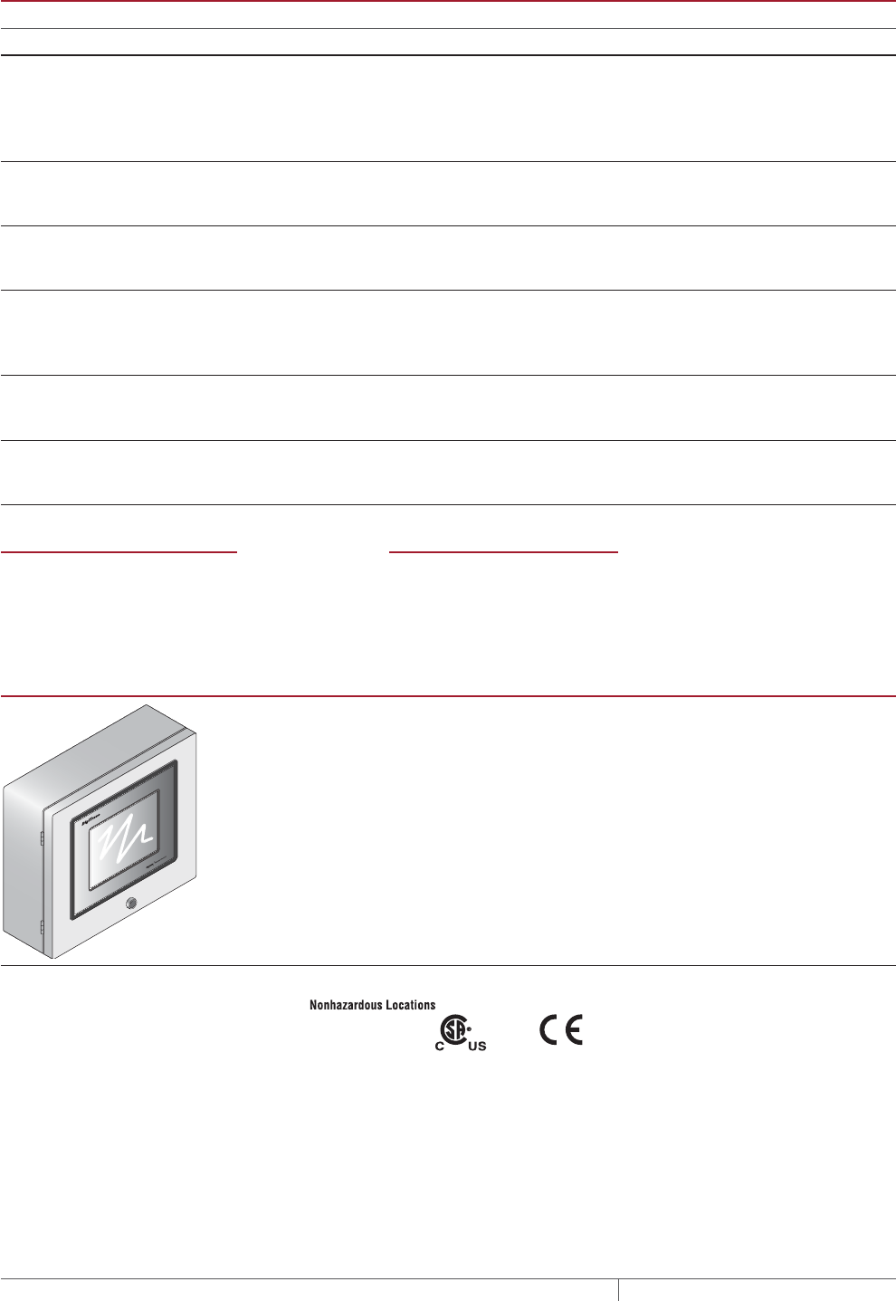
ACS30
THERMAL MANAGEMENT SOLUTIONS
EN-DigiTraceACS30-DS-H58261 11/13
378
ACS30: HEATING CABLE APPLICATION PROGRAMMING SUMMARY
Control Mode Functions
Application
Heating cable
Control Mode
Control Settings
Greasy Waste Disposal and
Temperature Maintenance
XL-Trace Line sensing • Constant temp
• Variable schedule
– Maintain
– Economy
– Off
Pipe Freeze Protection XL-Trace Ambient, PASC or
line sensing
• Constant temp
• Circuit override through external
device
Fuel Oil Flow Maintenance XL-Trace Ambient, PASC or
line sensing
• Constant temp
• Circuit override through RTD or
external device
Freezer Frost Heave Prevention • RaySol
• MI heating cable
Floor sensing • Constant temp
• Variable schedule
– Maintain
– Off
Surface Snow Melting • ElectroMelt
• MI Heating
Cable
Ambient or surface temp Constant temp
External controller External snow controller
Roof and Gutter De-icing • IceStop
• MI Heating
Cable
Ambient or surface temp Constant temp
External controller External snow controller
TEMPERATURE MONITOR ONLY VARIABLE SCHEDULE
Five temperature monitor only channels
Low and high temperature alarms
Setpoint calendar with:
• 7 days/week calendar
• 48 - 1/2 hr time blocks/day
• Daily schedule copy function
ACSUIT2 USER INTERFACE TERMINAL
The DigiTrace ACS-30 User Interface Terminal is a panel-mounted display for
use with the ACS panel. The ACS-UIT2 has an 8.4 inch (21.7 cm) VGA color
display with touch-screen technology, and provides an easy user interface for
programming without keyboards or cryptic labels. It has RS-485, RS-232, or
10/100Base-T Ethernet communications ports that allow communication with
external Distributed Control Systems or Building Management Systems. BACnet
and LonWorks to Modbus protocol gateways with the Modbus registries pre-
programmed are available. A USB interface is included for easy configuration and
firmware upgrades.
The ACS-UIT2 is designed for use on indoor or nonhazardous location
installations and is rated for NEMA 4 environments.
General
Approvals
LR67275
Area of use Nonhazardous, indoors and outdoors (IP65, Type 4)
Supply voltage 100 – 240 Vac +/–10%, 50/60 Hz
Operating temperature –25°C to 50°C (–13°F to 122°F)
Supply terminal 26–12 AWG
Storage temperature –25°C to 80°C (–13°F to 176°F)
Dimensions 386 mm W x 336 mm H x 180 mm D, (15.21 in. W x 13.21 in. H x 7.09 in. D)
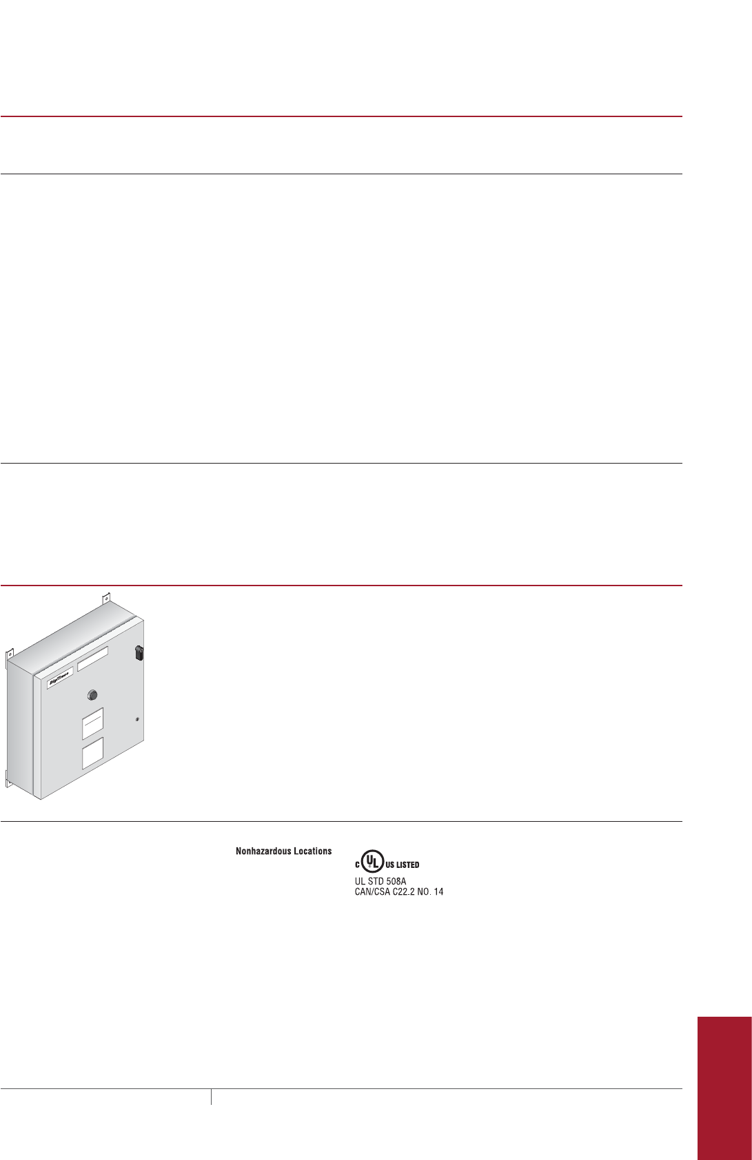
acs-30
379THERMAL MANAGEMENT SOLUTIONS EN-DigiTraceACS30-DS-H58261 11/13
Pipe Freeze Protection
and Flow Maintenance
Fire Sprinkler System
Freeze Protection
Roof and Gutter
De-Icing
Surface Snow
Melting – MI
Surface Snow
Melting – ElectroMelt
Freezer Frost
Heave Prevention
Floor Heating Technical Data
Sheets
ACSUIT2 USER INTERFACE TERMINAL
Alarm outputs
Relay outputs Three form C relays rated at 12 A 250 Vac. One relay used for common alarm
light. Relays may be assigned for alarm outputs.
Network connection
Local port/remote RS-232/RS-485 ports (RS-485, 2-wire isolated) may be used to communicate with
host BMS computers using the DigiTrace ProtoNode-RER or ProtoNode-LER.
(ACS-30 Program Integrator).
Local RS-232 A non-isolated, 9 pin D sub male
Remote RS-485 #2 10 pin terminal block, 24–12 AWG, (0.2 mm to 2.5 mm²) wire size
Data rate 9600 to 57600 baud
Maximum cable length For RS-485 not to exceed 1200 m (4000 ft). Cable to be shielded twisted pair.
Field port RS-485, 2-wire isolated. Used to communicate with external devices, such as
ACS-PCM2-5, DigiTrace C910-485, and RMM2. Maximum cable length not to
exceed 1200 m (4000 ft). Cable to be shielded twisted pair.
Field RS-485 #1 10 pin terminal block, 24–12 AWG, (0.2 mm to 2.5 mm²) wire size
Data rate To 9600 baud
LAN 10/100 Base-T Ethernet port with Link and Activity Status LEDs
USB port USB 2.0 Host port Type A receptacle (X2)
LCD display
Display LCD is a 8.4 inch (21.7 cm) VGA, color TFT transflective device with integral CCFL
backlight
Touch screen 4-wire resistive touch screen interface for user entry
ACSPCM25 POWER CONTROL PANEL
HEAT TRACE CONTROL PANEL
MODEL NO: ACCS-PCM2-5
ENCLOSURE: TYPE 4, 12
SERIAL NO: XXXXXXXX-XXXX
VOLTAGE: MAX 277 VAC, 1PHASE, 2 WIRE, 60 HZ
SHORT CIRCUIT CURRENT 5kA RMS SYMMETRICAL,
277 VAC MAXIMUM
DANGER
MAXIMUM
277 VOLTS
PENTAIR THERMAL MANAGMENT
7433 HARWIN DR
HOUSTON, TX 77036
The ACS-PCM2-5 enclosure is rated NEMA 4/12 and is approved for nonhazardous
indoor or outdoor locations. The ACS-PCM2-5 provides ground fault and line
current sensing, alarming, switching (electromechanical relays) and RTD inputs
for five heat tracing circuits when used with the ACS-UIT2.
ACS-30 General (RPN P000001232) panels are available to satisfy special
applications which require higher voltage, higher switching capacity, panel
heaters, etc. Contact Pentair Thermal Management at 1 (800) 545-6258 for
design assistance.
General
Approvals
Ambient operating temperature –13°F to 122°F (–25°C to 50°C)
Dimensions 24" W x 24" H x 6.75" D (610 mm W x 610 mm H x 171 mm D)
Enclosure rating NEMA 4/12 (indoor/outdoor locations)
Control supply voltage 90 - 280 V dropped to 12 V with switching power supply
Weight 70 lbs (31.75 kg)
Humidity 0–90% non-condensing
Fuse Bussman MDL
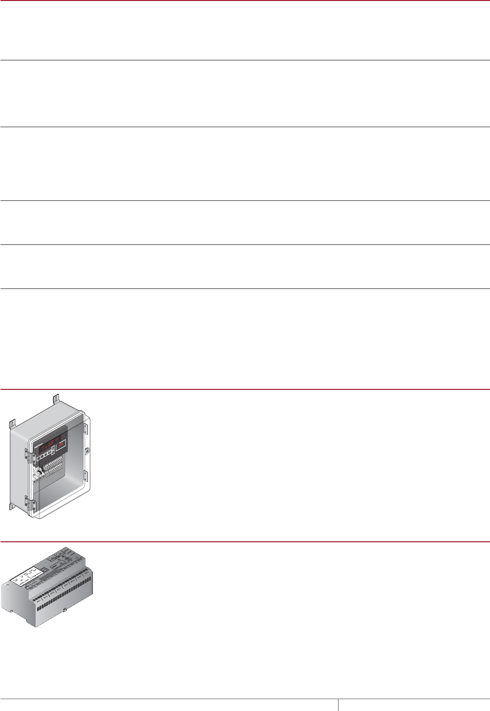
ACS30
THERMAL MANAGEMENT SOLUTIONS
EN-DigiTraceACS30-DS-H58261 11/13
380
ACSPCM25 POWER CONTROL PANEL
Heating cable circuit contactors
Rating 3-pole – 30 A/pole 277 Vac
Type Sprecher-Schuh CA7-16-10-12D
Quantity 5
Temperature sensors
Type 100-ohm platinum RTD, 3-wire, α = 0.00385 ohm/ohm/°C
Can be extended with a 3-conductor shielded cable of 20 ohm maximum per
conductor
Quantity Up to five wired directly to the ACS-CRM
Communication to ACS-UIT2, ACS-PCM2-5 panels, C910-485 and RMM2
Type 2-wire RS-485
Cable One shielded twisted pair
Length 4000 ft (1200 M) maximum
Quantity Up to 52 ACS-PCM2-5 panels may be connected to one ACS-UIT2
Line current sensors
Max current 60 A
Accuracy ± 2% of reading
Ground-fault sensors
Range 10–200 mA
Accuracy ± 2% of reading
Connection terminals
Power supply/line/load #22 – 8 AWG
RS-485 #24 – 12 AWG
RTD #24 – 12 AWG
C910485 ELECTRONIC CONTROLLER OPTIONAL
ALARM
C910 SERIES
SHIFT TEST BACK ENTER
STATUS
ALARM
OUTPUT
MONITOR CONFIG
PROGRAMMABLE SINGLE POINT
HEAT-TRACING CONTROLLER
The DigiTrace C910-485 controller Part No. 10170-026 is a compact, full-featured,
microprocessor-based, single-point commercial heating cable control system
with integrated equipment ground-fault protection. The C910-485 provides
control and monitoring of electric heating cable circuits for commercial heating
applications. The C910-485 can be set to monitor and alarm for high and low
temperature, low current, and ground-fault level. The C910-485 includes an
RS-485 communication module to remotely configure, control and monitor the
heating cable circuits through a building management system (BMS).
REMOTE MONITORING MODULE OPTIONAL
A Remote Monitoring Module (RMM2, Part No: 051778-000) is used to collect
additional temperatures for control and monitoring of the heat-tracing circuit by
the ACS-PCM2-5 control panel, through the ACS-UIT2 user interface terminal.
The RMM2 accepts up to eight RTDs that measure pipe, vessel, or ambient
temperatures. Multiple RMM2s communicate with a single ACS-UIT2 to provide
centralized monitoring of temperatures. A single twisted-pair RS-485 cable
connects up to 16 RMM2s for a total monitoring capability of 128 temperatures.
The RMM2s are placed near desired measurement locations. The RMM2 is
available for DIN rail mount or pre-installed inside a polycarbonate NEMA-4X
enclosure (Part No: 523420-000).
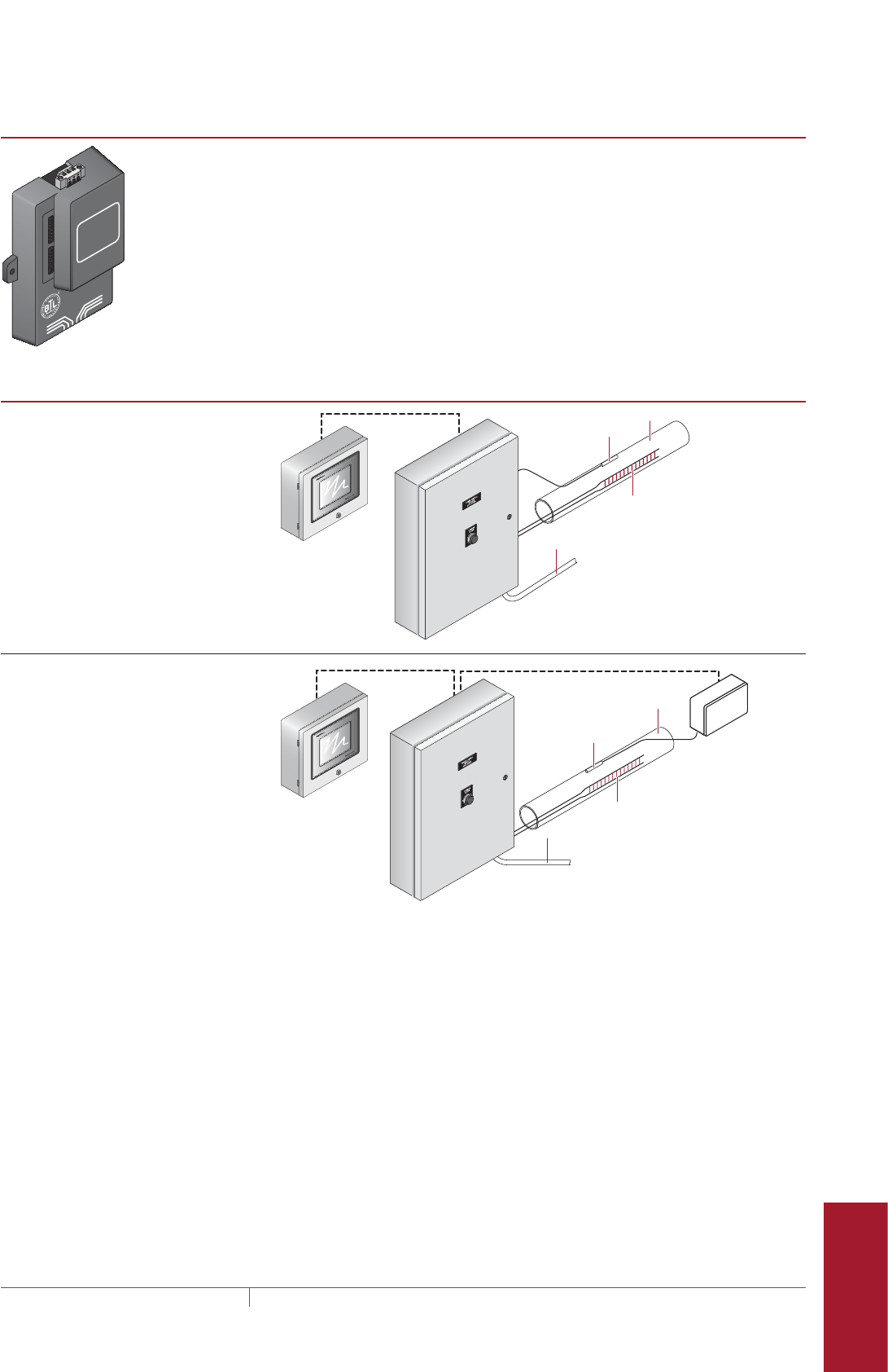
acs-30
381THERMAL MANAGEMENT SOLUTIONS EN-DigiTraceACS30-DS-H58261 11/13
Pipe Freeze Protection
and Flow Maintenance
Fire Sprinkler System
Freeze Protection
Roof and Gutter
De-Icing
Surface Snow
Melting – MI
Surface Snow
Melting – ElectroMelt
Freezer Frost
Heave Prevention
Floor Heating Technical Data
Sheets
PROTOCOL GATEWAY OPTIONAL
FRAME GND
- PWR
+PWR
RS 485+
RS 485 -
RS 485 GND
S3
S2
S1
S0
B3
B2
B1
B0
A7
A6
A5
A4
A3
A2
A1
A0
By FieldServer Technologies
www.ProtoCessor.com
P
ROTO
C
ESSOR
SERIAL ETHERNET
P
ROTO
N
ODE
The ProtoNode is an external, high performance multi-protocol gateway for
customers needing protocol translation between Building Management Systems
(BMS) and the DigiTrace ACS-30 controller.
The ProtoNode-LER (Part No. P000001228) is for LonWorks® systems; and the
ProtoNode-RER (Part No P000001227) is for BACnet® or Metasys® N2 systems.
TYPICAL CONFIGURATIONS FOR THE DIGITRACE ACS30 SYSTEM
Individual controls
• Monitors ground-fault current and
alarms/trip control contactor upon
fault
• Monitors heater current and alarms
upon low or high current conditions
• Monitors pipe temperature (via RTD
inputs wired back to the DigiTrace
ACS-PCM2-5 or RMM2)
ACS-UIT2
RTD
Heating
cable
Pipe
ACS-PCM2-5
RS-485
To heating cable power
distribution panel
Individual controls with RMM2
• Monitors ground-fault current and
alarms/trip control contactor upon
fault
• Monitors heater current and alarms
upon low or high current conditions
• Monitors pipe temperature (via RTD
inputs wired back to the DigiTrace
ACS-PCM2-5)
• Using optional RMM2 (remote
monitoring modules) mounted in the
field, up to 128 RTD inputs can be
added to the ACS-30 system
• The RMMs allow the RTD cables to
be terminated locally and only a sin-
gle RS-485 twisted wire pair brought
back to the panel. This results in a
significant reduction in field wiring.
RS-485RS-485
RMM2
Remote
monitoring
module
RTD
Heating
cable
Pipe
ACS-UIT2
ACS-PCM2-5
To heating cable power
distribution panel
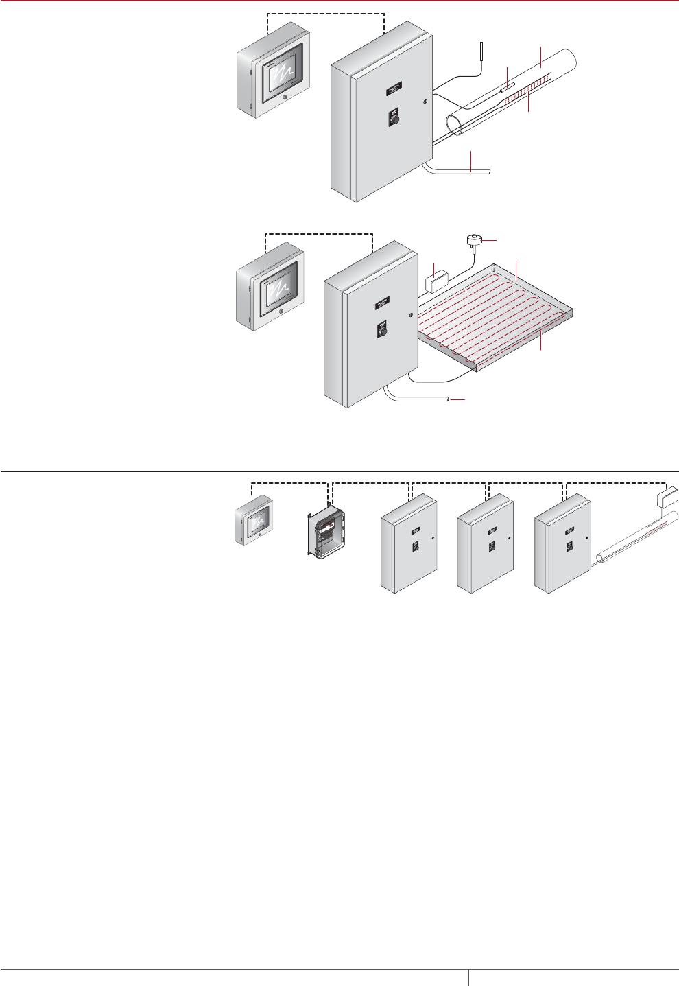
ACS30
THERMAL MANAGEMENT SOLUTIONS
EN-DigiTraceACS30-DS-H58261 11/13
382
TYPICAL CONFIGURATIONS FOR THE DIGITRACE ACS30 SYSTEM
Individual ambient control
• Monitors ground-fault current and
alarms/trip control contactor upon
fault
• Monitors heater current and alarms
upon low or high current conditions
• Monitors pipe temperature (via RTD
inputs wired back to the DigiTrace
ACS-PCM2-5 or RMM2) To heating cable power
distribution panel
ACS-UIT2
Ambient
RTD
RS-485
Heating
cable
Pipe
ACS-PCM2-5
RTD
Individual external control for surface
snow melting and roof & gutter
application
• Monitors ground-fault current and
alarms/trip control contactor upon
fault
• Monitors heater current and alarms
upon low or high current conditions
• Monitors pipe temperature (via RTD
inputs wired back to the DigiTrace
ACS-PCM2-5 or RMM2)
• Connects to snow controllers (via
RTD input) to power circuits when
snow/ice melting is required
To heating cable power
distribution panel
ACS-UIT2
RS-485
Heating
cable
Concrete
slab
ACS-PCM2-5
Snow sensor
Snow
controller
Multipanel configuration
• Multiple panels can be ganged
together for control using a single
DigiTrace User Interface Terminal
• Communications is accomplished
using RS-485 protocol
• Up to 260 heat trace circuits can be
supported using this architecture
ACS-UIT2
RS-485 RS-485RS-485 RS-485
ACS-PCM2-5
C910-485
RMM2 Remote
monitoring module
ACS-PCM2-5 ACS-PCM2-5
ALARM
C910 SERIES
SHIFT TEST BACK ENTER
STATUS
ALARM
OUTPUT
MONITOR CONFIG
PROGRAMMABLE SINGLE POINT
HEAT-TRACING CONTROLLER
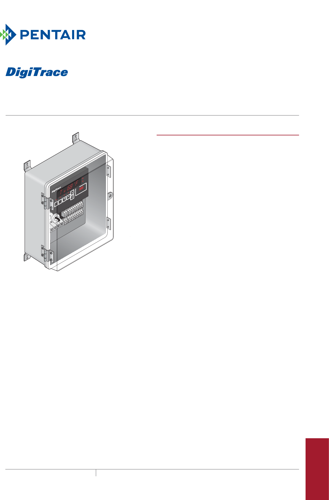
383THERMAL MANAGEMENT SOLUTIONS EN-DigiTraceC910series-DS-H58374 11/13
c910-485
Single-point heat-tracing control SyStem
Pipe Freeze Protection
and Flow Maintenance
Fire Sprinkler System
Freeze Protection
Roof and Gutter
De-Icing
Surface Snow
Melting – MI
Surface Snow
Melting – ElectroMelt
Freezer Frost
Heave Prevention
Floor Heating Technical Data
Sheets
PRODUCT OVERVIEW
The DigiTrace C910-485 is a compact, full-featured,
microprocessor-based, single-point commercial heating
cable control system with integrated equipment ground-fault
protection. The C910-485 provides control and monitoring
of electric heating cable circuits for commercial heating
applications. The C910-485 can be set to monitor and alarm
for high and low temperature, low current, and ground-fault
level. The C910-485 includes an RS-485 communication
module to remotely configure, control and monitor the
heating cable circuits through a building management
system (BMS).
Control
The C910-485 measures temperature with one or two 3-wire
100-ohm platinum RTD(s) connected directly to the unit. The
controller may be used in line-sensing, ambient-sensing and
proportional ambient-sensing control (PASC) modes. The
C910-485 may also be connected into the ACS-30 system
for single circuit extensions. When in the ACS-30 system
it is controlled by the ACS-UIT2 and has all the application
functionality of the ACS-30 system.
Monitoring
A variety of parameters are measured, including ground
fault, temperature, and current to ensure system integrity. The
system can be set to periodically check the heating cable
for faults, alerting maintenance personnel of a heat-tracing
problem.
Both an isolated solid-state triac relay and a dry contact
relay are provided for alarm annunciation back to a
building management system (BMS).
Ground-fault protection
National electrical codes require ground-fault equipment
protection on all heat-tracing circuits. The C910-485
controllers incorporate ground-fault sensing, alarm,
and trip functionality internally. Heating cable circuits
equipped with C910-485 controllers do not require additional
ground-fault protection equipment, simplifying installation
and reducing costs. The C910-485 automatically tests the
integrity of the integrated ground-fault circuitry, ensuring
protection in the event of a ground fault.
ALARM
C910 SERIES
SHIFT TEST BACK ENTER
STATUS
ALARM
OUTPUT
MONITOR CONFIG
PROGRAMMABLE SINGLE POINT
HEAT-TRACING CONTROLLER

C910485
THERMAL MANAGEMENT SOLUTIONS
EN-DigiTraceC910series-DS-H58374 11/13
384
Installation
The C910-485 unit comes ready to install right from the
box, eliminating the need for custom panel design or field
assembly. The NEMA 4X-rated enclosure is approved for
use in indoor and outdoor locations. Wiring is as simple as
connecting the incoming and outgoing power wiring (up to
277 Vac) and an RTD.
The C910-485 operator interface includes LED displays and
function keys that make it easy to use and program. No
additional handheld programming devices are needed. Alarm
conditions and programming settings are easy to interpret
on the full-text front panel. Settings are stored in nonvolatile
memory in the event of power failure.
Communications
The C910-485 supports Modbus® protocol and includes an
RS-485 communications interface. DigiTrace ProtoNode
multi-protocol gateways are available to integrate the C910-
485 or ACS-30 into BACnet®, Metasys® N2 and LonWorks®
BMS systems.
GENERAL
Area of use Nonhazardous locations
Approvals
Supply voltage 100 Vac to 277 Vac, +5 / –10%, 50/60 Hz
Common supply for controller and heat-tracing circuit
ENCLOSURE
Protection NEMA 4X
Materials FRP/Polycarbonate
Ambient operating temperature range –40°F to 140°F (–40°C to 60°C)
Ambient storage temperature range –40°F to 185°F (–40°C to 85°C)
Relative humidity 0% to 90%, noncondensing
CONTROL
Relay type Double-pole, mechanical
Voltage, maximum 277 Vac nominal, 50/60 Hz
Current, maximum 30 A 104°F (40°C) derated to 20 A 140°F (60°C)
Control algorithms EMR: On/off, proportional ambient sensing control (PASC)
Control range 0°F to 200°F (–18°C to 93°C)
Nonhazardous locations
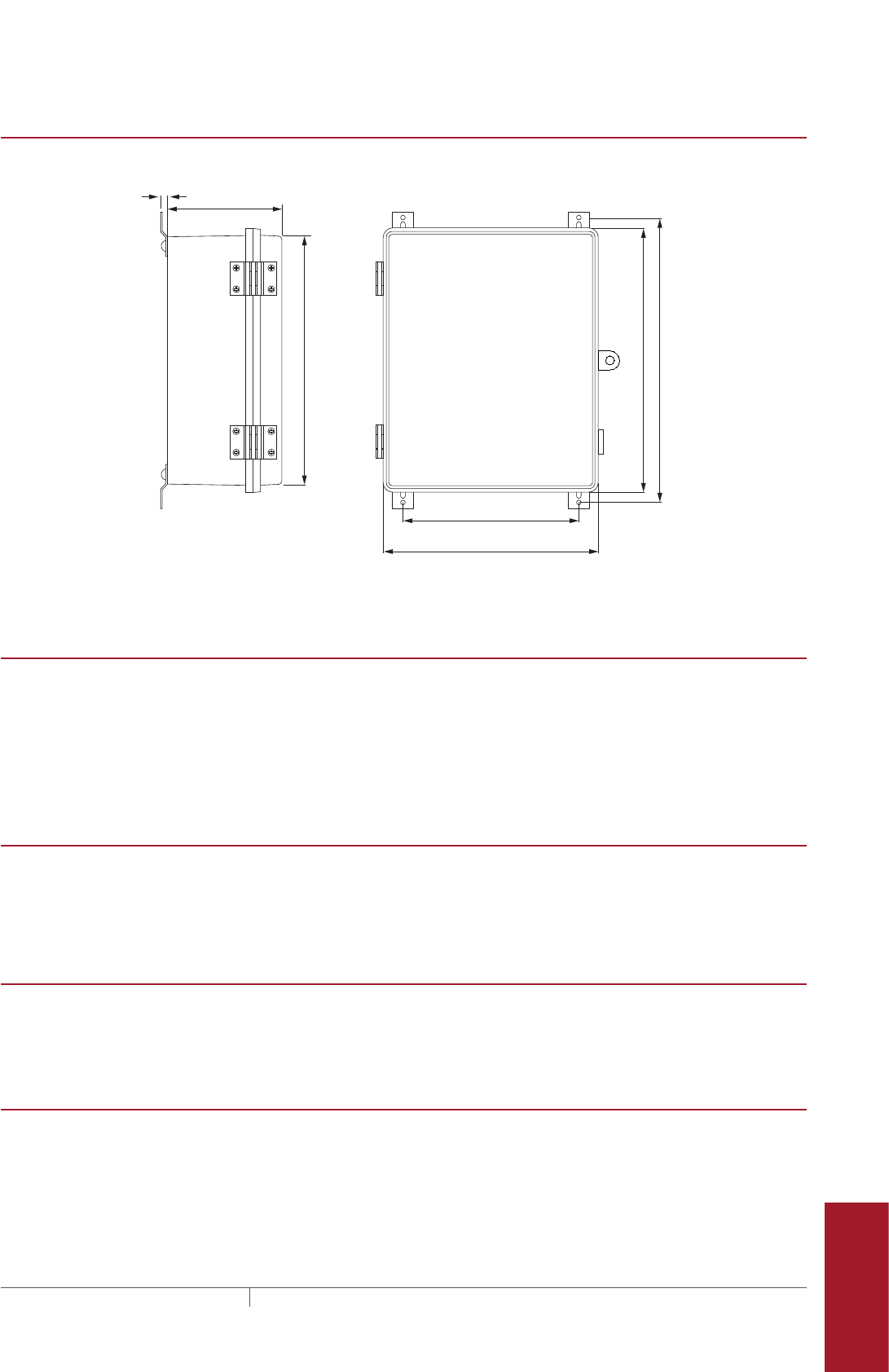
c910 -485
385 THERMAL MANAGEMENT SOLUTIONS EN-DigiTraceC910series-DS-H58374 11/13
Pipe Freeze Protection
and Flow Maintenance
Fire Sprinkler System
Freeze Protection
Roof and Gutter
De-Icing
Surface Snow
Melting – MI
Surface Snow
Melting – ElectroMelt
Freezer Frost
Heave Prevention
Floor Heating Technical Data
Sheets
TYPICAL ENCLOSURE DIMENSIONS INCHES
11.7
10.9
7.25
8.9
10.25
0.23 4.7
MONITORING
Temperature Low alarm range 0°F to 180°F (–18°C to 82°C) or OFF
High alarm range 0°F to 200°F (–18°C to 93°C) or OFF
Ground fault Alarm range 20 mA to 100 mA
Trip range 20 mA to 100 mA
Current Low alarm range 0.3 A to 30 A or OFF
Autocycle Diagnostic test interval adjustable from 1 to 240 minutes or 1 to 240 hours
TEMPERATURE SENSOR INPUTS
Quantity Two inputs standard
Types 100 platinum RTD, 3-wire, α = 0.00385 ohms/ohm/°C
Can be extended with a 3-conductor shielded cable of 20 ohms maximum per
conductor
ALARM OUTPUTS
AC relay Isolated solid-state triac, SPST, 0.75 A maximum, 100 Vac to 277 Vac nominal
Dry contact relay Pilot duty only, 48 Vac/dc, 500 mA maximum, 10 VA maximum resistive switching
Note: Outputs are configurable as “open on alarm” or “close on alarm”
PROGRAMMING AND SETTING
Method Programmable keypad
Units Imperial (°F, in.) or Metric (°C, mm)
Digital display Actual temperature, control temperature, heater current, ground fault,
programming parameter values, alarm values
LEDs Heater on, alarm condition, receive / transmit data
Memory Nonvolatile, restored after power loss, checksum data checking

C910485
THERMAL MANAGEMENT SOLUTIONS
EN-DigiTraceC910series-DS-H58374 11/13
386
PROGRAMMING AND SETTING
Stored parameters (measured) Minimum and maximum temperature, maximum ground-fault current, maximum
heater current, contactor cycle count, time in use
Alarm conditions Low / high temperature, low current
Ground-fault alarm, trip
RTD failure, loss of programmed values, or EMR failure
Other Password protection
CONNECTION TERMINALS
Power supply input Screw terminals, 22–8 AWG
Heating cable output Screw terminals, 22–8 AWG
Ground Two box lugs, 14–6 AWG
RTD/alarm/communications 28–12 AWG spring clamp terminals
MOUNTING
Enclosure Surface mounting with four fixing holes on 7.25 in x 11.7 in (184 mm x 297 mm) centers
Hole diameter: 0.31 in (8 mm)
COMMUNICATIONS WITH C910485
Protocol ModBus RTU / ASCI I
Topology Multidrop, daisy chain
Cable Single shielded twisted pair, 26 AWG or larger
Length 4000 ft (1.2km) maximum 9600 baud
Quantity Up to 32 devices without repeater
Address Programmable
ORDERING DETAILS
DigiTrace C910-485 Single-point Heat-Tracing Control System
Description Catalog number Part number Weight/lbs
DigiTrace C910-485 controller in an 8" x 10" FRP enclosure with
polycarbonate cover. 2-pole 30 A EMR. Controls a single circuit with
a 2-pole electromechanical relay. Includes isolated 2-wite RS-485
communication board. (Approved for nonhazardous locations only)
C910-485 10170-026 15
RTD Sensors
100-ohm platinum RTD with 10 foot stainless steel corrugated
sheath
RTD10CS RTD10CS 1.0
RTD, ambient, cable style RTD-200 254741 0.1
RTD, –100°F to 900°F, pipe mounted RTD4AL RTD4AL 1.2
Protocol Gateways
DigiTrace ProtoNode-RER:
BACnet MST/IP and Metasys N2 protocol gateway
ProtoNode-RER P000001227 1.3
DigiTrace ProtoNode-RER:
LonWorks protocol gateway
ProtoNode-LER P000001228 1.3
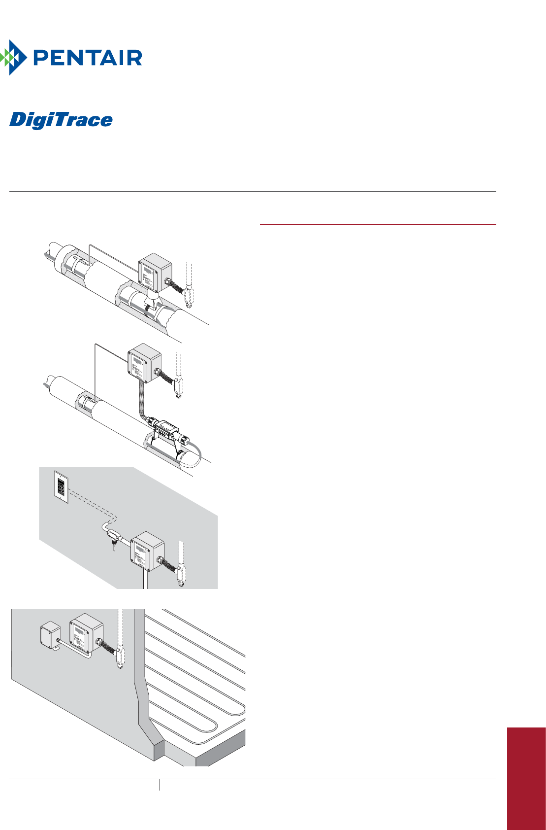
387THERMAL MANAGEMENT SOLUTIONS EN-DigiTraceECWFamily-DS-H58338 11/13
ECW-GF, ECW-GF-DP
Digital electronic controllers anD remote Display panel
Pipe Freeze Protection
and Flow Maintenance
Fire Sprinkler System
Freeze Protection
Roof and Gutter
De-Icing
Surface Snow
Melting – MI
Surface Snow
Melting – ElectroMelt
Freezer Frost
Heave Prevention
Floor Heating Technical Data
Sheets
ECW-GF with FTC-PSK pipe stand
and power connection kit
ECW-GF using RayClic power
connection kit
ECW-GF-DP remote display panel
available only with ECW-GF
ECW-GF-DP
ECW-GF using a separate junction box
PRODUCT OVERVIEW
The DigiTrace ECW-GF electronic controller provides
accurate temperature control with integrated 30-mA
ground-fault protection. The ECW-GF is ideal for pipe freeze
protection, flow maintenance, freezer frost heave, floor
heating and snow melting applications.
The ECW-GF is housed in a NEMA 4X enclosure designed to
be wall mounted or installed on a pipe with the optional Ray-
chem FTC-PSK pipe stand kit.
The controller includes a window and a digital display that
shows the measured temperature, set point temperature
and alarm conditions (temperature sensor failure, high or
low temperature and ground-fault) if detected.
Alarm conditions can be indicated via a Form C dry contact
connected to a building management system. Status LEDs
indicate whether the digital display is showing the set point
or actual temperature or if the controller is in an alarm
state.
The ECW-GF can be programmed to maintain temperatures
up to 200°F (93°C), at voltages from 100 to 277 V, and is
capable of switching current up to 30 amperes.
Programming the set point temperature, deadband, and the
high and low alarm thresholds on the controllers is accom-
plished using the built-in digital display and push buttons. A
9-V battery connector is supplied to allow programming the
controller before the heating cable circuit power is provided.
An optional remote display panel, the DigiTrace ECW-GF-DP,
is available. This remote display provides remote alarm
indication and ground-fault test and reset capability. The
ECW-GF-DP can be installed indoors in a standard duplex
box located up to 328 ft (100 m) from the controller.
The ECW-GF is supplied with a 25-foot thermistor for line,
slab or ambient sensing temperature control.
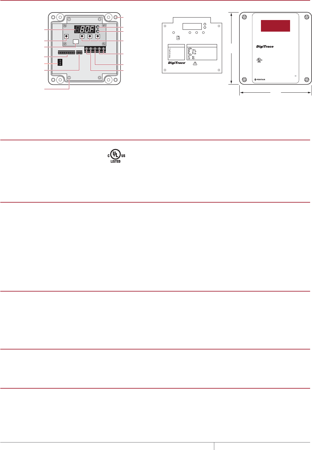
ECWGF, ECWGFDP
THERMAL MANAGEMENT SOLUTIONS
EN-DigiTraceECWFamily-DS-H58338 11/13
388
ECWGF CONTROLLER
ECW-GF without wire cover Wire cover Lid
6.3 in
(160 mm)
6.3 in
(160 mm)
Display
Alarm terminals
Thermistor terminals
Remote display panel
(ECW-GF-DP only)
Menu
Battery connection
Stand-offs
Actual temp LED
Set point temp LED
Next, Up, Down
Heating cable
power terminals
Ground terminal
Incoming power
terminals
Wall mounting
holes (typical 4)
Hold 3
Seconds
ECW-GF
Digital Controller
with Ground-Fault Protection
WARNING
Shock Hazard
Display: Alarms and Status
Ground-fault test mode
Ground-fault circuit failure
Ground-fault cable fault
Shorted or open sensor
Remote panel comm failure
High temp alarm
Low temp alarm
Do not remove cover while energized
Ne pas enlever le couvert tant que le
régulateur est sous tension
TEMPERATURE
WARNING
Shock Hazard
Display: Alarms and Status
Do not remove cover while energized
Ne pas enlever le couvert tant que le
régulateur est sous tension
Next
MENU
Battery
Connector
Up Down
Menu Settings:
Units (°F or °C)
Set Point
Dead Band
High Temp Alarm
Low Temp Alarm
Remote GF Panel
Hold for
GF TEST
GF
Reset
Note:
Next button is used for ground-fault test.
Down button is used for ground-fault reset.
Hold 3
Seconds
ECW-GF
Digital Controller
with Ground-Fault Protection
WARNING
Shock Hazard
Display: Alarms and Status
Ground-fault test mode
Ground-fault circuit failure
Ground-fault cable fault
Shorted or open sensor
Remote panel comm failure
High temp alarm
Low temp alarm
Do not remove cover while energized
Ne pas enlever le couvert tant que le
régulateur est sous tension
TEMPERATURE
WARNING
Shock Hazard
Display: Alarms and Status
Do not remove cover while energized
Ne pas enlever le couvert tant que le
régulateur est sous tension
Next
MENU
Battery
Connector
Up Down
ACTUAL
SETPOINT
Menu Settings:
Units (°F or °C)
Set Point
Dead Band
High Temp Alarm
Low Temp Alarm
Remote GF Panel
Hold for
GF TEST
GF
Reset
Actual
Setpoint
Temperature
ECW-GF
Digital electronic controller with equipment
ground-fault protection
Type 4X
Input: 100-277 Vac, 50/60 Hz, 30 A
Output: 100-277 Vac, 30 A
Maximum Ambient: 140˚F (60˚C)
For maintaining temperatures up to 200˚F (93˚C)
in nonhazardous locations.
Equipment Ground-Fault Protection: 30 mA
Use only with Raychem, XL-Trace, RaySol and IceStop heating cables
and Pyrotenax MI heating cables.
80BJ
Enclosed Energy
Management
Equipment
© 2013 Pentair Thermal Management LLC
WWW.PENTAIRTHERMAL.COM
H58407 07/13
GENERAL
Approvals
Nonhazardous locations
Supply voltage 100–277 Vac ±10% 50–60 Hz
Common supply for controller and heat tracing circuit
ENCLOSURE
Protection NEMA 4X
Material Fiberglass reinforced polyester plastic
Entries 1 x 3/4 in (19 mm) conduit entries for power
1 x 1 in (25 mm) conduit entry for heating cable
1 x 1/2 in (13 mm) conduit entry for RTD sensor
Relative humidity 0% to 90%, noncondensing
Ambient installation and usage
temperature
–40°F to 140°F (–40°C to 60°C)
CONTROL
Relay type Double-pole, mechanical
Control range 32°F to 200°F (0°C to 93°C)
Deadband Adjustable 2°F to 10°F (2°C to 6°C)
Accuracy ±3°F (1.7°C) of set point
INPUT POWER
Voltage 277 Vac nominal, 50/60 Hz maximum
Current 30 A maximum
MONITORING AND ALARM OUTPUT
Temperature Low alarm range: 20°F (–6°C) to set point minus deadband, or OFF
High alarm range: Set point plus (Deadband +5°F (3°C)) to 230°F, or OFF
RTD failure Shorted or open temperature sensor
Alarm relay Form C: 2 A at 277 Vac, 2 A at 48 Vdc
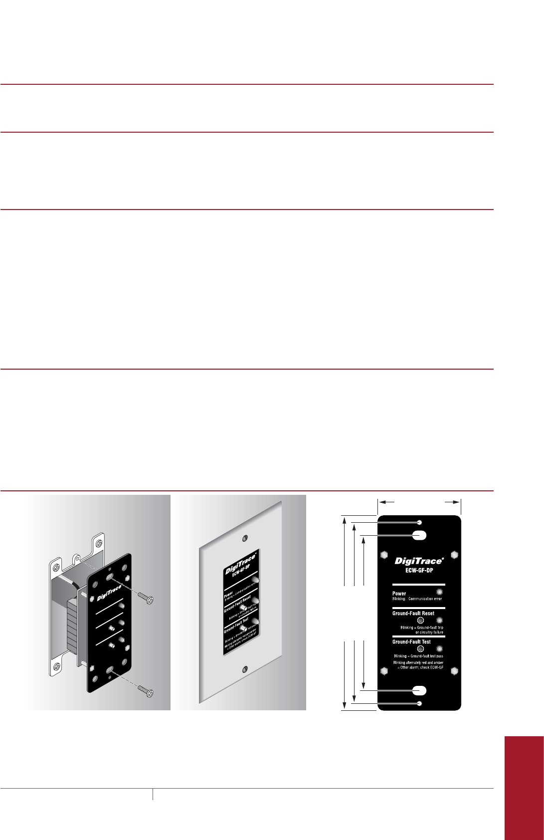
ecw-gf, ecw-gf-dp
389THERMAL MANAGEMENT SOLUTIONS EN-DigiTraceECWFamily-DS-H58338 11/13
Pipe Freeze Protection
and Flow Maintenance
Fire Sprinkler System
Freeze Protection
Roof and Gutter
De-Icing
Surface Snow
Melting – MI
Surface Snow
Melting – ElectroMelt
Freezer Frost
Heave Prevention
Floor Heating Technical Data
Sheets
TEMPERATURE SENSOR INCLUDED
Input type Thermistor 10K ohm 25C Type J
GROUNDFAULT
Ground-fault protection 30 mA fixed
Ground fault trip reset Reset button, manual
Ground-fault test Manual ground-fault circuitry test; automatic hourly circuitry test
PROGRAMMING AND SETTING
Method Programmable at controller – Push buttons on front panel
Units °F or °C
Digital display Four numeric display digits for parameter and error/alarm indication
LEDs Indicate actual and set point from display and alarm state
Memory Nonvolatile, restored after power loss
Stored parameters Parameters can be programmed without power supply (external battery) and
parameters are stored in nonvolatile memory.
Alarm conditions Low/high temperature and thermistor failure (open or shorted)
Ground-fault trip, ground-fault circuit failure and loss of power.
CONNECTION TERMINALS
Power supply input Screw rising cage clamp, 18–6 AWG
Heating cable output Screw rising cage clamp, 18–6 AWG
Ground Screw rising cage clamp, 18–6 AWG
Thermistor Screw rising cage clamp, 22–14 AWG
Alarm Screw rising cage clamp, 22–14 AWG
Remote display panel Screw rising cage clamp, 22–14 AWG
ECWGFDP REMOTE PANEL FOR ECWGF CONTROLLER ONLY
Power
Ground-Fault Reset
Ground-Fault Test
ECW-GF-DP
Blinking = Communication error
Blinking = Ground-fault trip
or circuitry failure
Blinking = Ground-fault test pass
Blinking alternately red and amber
= Other alarm; check ECW-GF
1.760 in. (44.7 mm)
4.110 in. (104.4 mm)
3.806 in. (96.7 mm)
3.275 in. (83.2 mm)

ECWGF, ECWGFDP
THERMAL MANAGEMENT SOLUTIONS
EN-DigiTraceECWFamily-DS-H58338 11/13
390
GENERAL
Approvals
Nonhazardous locations
Environment Indoors, dry area
Ambient operating temperature 32°F to 122°F (0°C to 50°C)
Humidity 90% noncondensing
FEATURES
LED 3 LEDs 1 green, 1 red, 1 amber
Buttons 2: Ground-fault reset, Ground-fault test
Power Power provided from ECW-GF controller
12 Vdc 100 mA
Connection 8 position terminal block
8 conductor 22 AWG shielded cable Alpha - Cat No. 1298C or equivalent
328 ft (100 m) maximum
ORDERING DETAILS
Description
Catalog number
Part number
Weight/lbs
Wall mounted digital electronic controller with ground fault ECW-GF P000000925 4.0
Remote display panel for ECW-GF ECW-GF-DP P000000926 0.3
Pipe mounting kit with power connection and end seal FTC-PSK P000000927 0.2
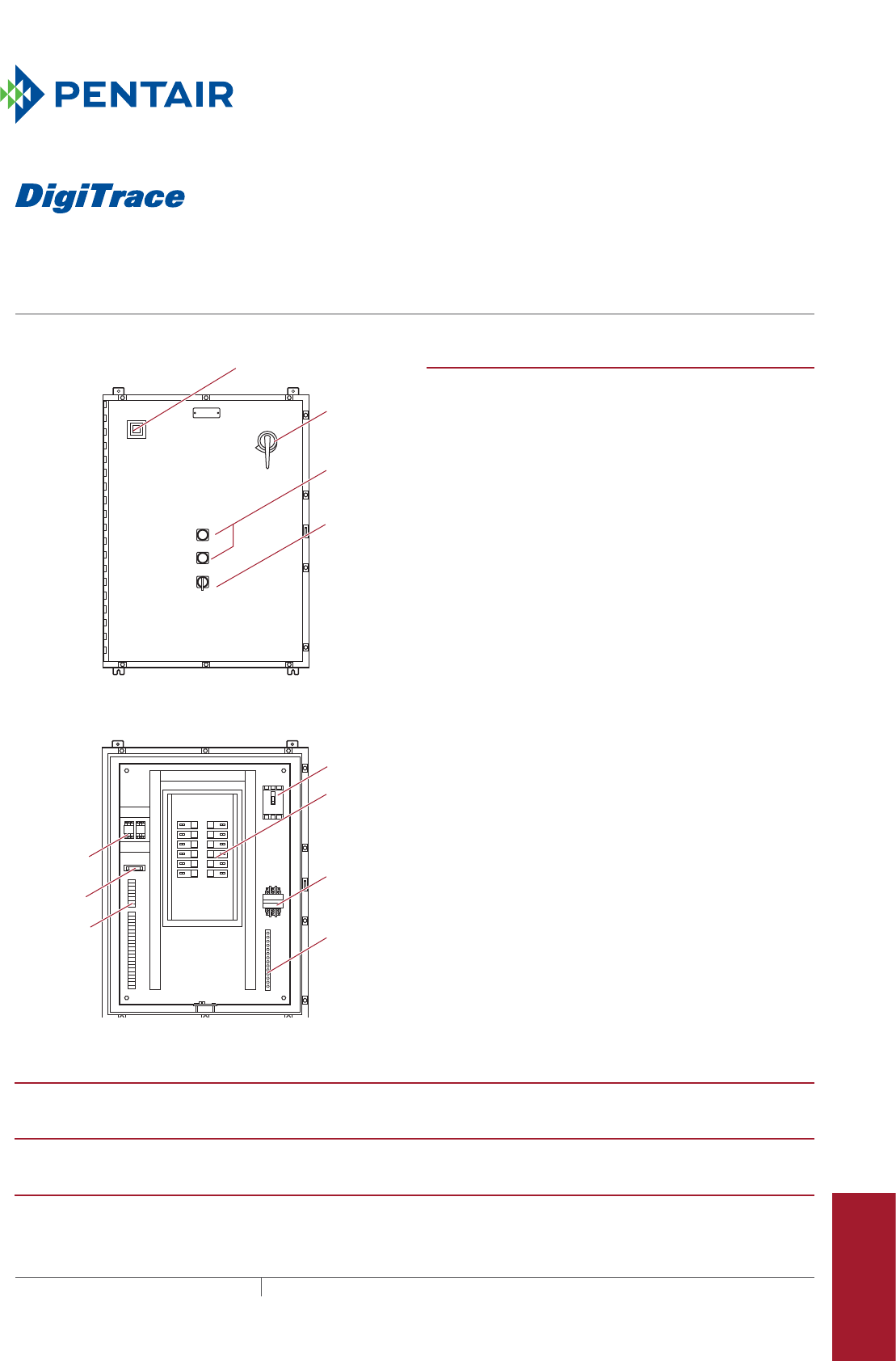
Pipe Freeze Protection
and Flow Maintenance
Fire Sprinkler System
Freeze Protection
Roof and Gutter
De-Icing
Surface Snow
Melting – MI
Surface Snow
Melting – ElectroMelt
Freezer Frost
Heave Prevention
Floor Heating Technical Data
Sheets
A
COMMON ALARM
PUSH TO ACKNOWLEDGE
HAND/OFF/AUTO
C
POWER ON
Selector
switch
Push button
for light
testing
Door
disconnect
(optional)
Alarm horn (optional)
Alarm option shown above
1
2
3
4
5
6
7
8
9
10
11
12
TB 1
TB 2
ARR
Main circuit
breaker
Main
contactor
Distribution
panelboard
Ground
bus bar
Fuse holder
Alarm relay
(optional)
Terminals
(optional)
PRODUCT OVERVIEW
The DigiTrace HTPG is a dedicated power distribution, control,
ground-fault protection, monitoring, and alarm panel for
freeze protection and broad temperature maintenance heat-
tracing applications. This wall-mounted enclosure contains
an assembled circuit-breaker panelboard.
Panels are equipped with circuit breakers with or without
alarm contacts.
The group control package allows the system to operate
automatically in conjunction with an external controller/
thermostat.
LOAD POWER
120 / 208 / 240 / 277 Vac
AMBIENT OPERATING TEMPERATURE
32°F (0°C) to 122°F (50°C) (without space heater option)
FIELD WIRE SIZE
14–8 AWG (15–30 A), 8–4 AWG (40–50 A)
HTPG
HEAT-TRACING POWER DISTRIBUTION PANEL FOR GROUP CONTROL
Ground-fault protection, monitoring, and optional alarm panel
391THERMAL MANAGEMENT SOLUTIONS EN-DigiTraceHTPG-DS-H55404 11/13
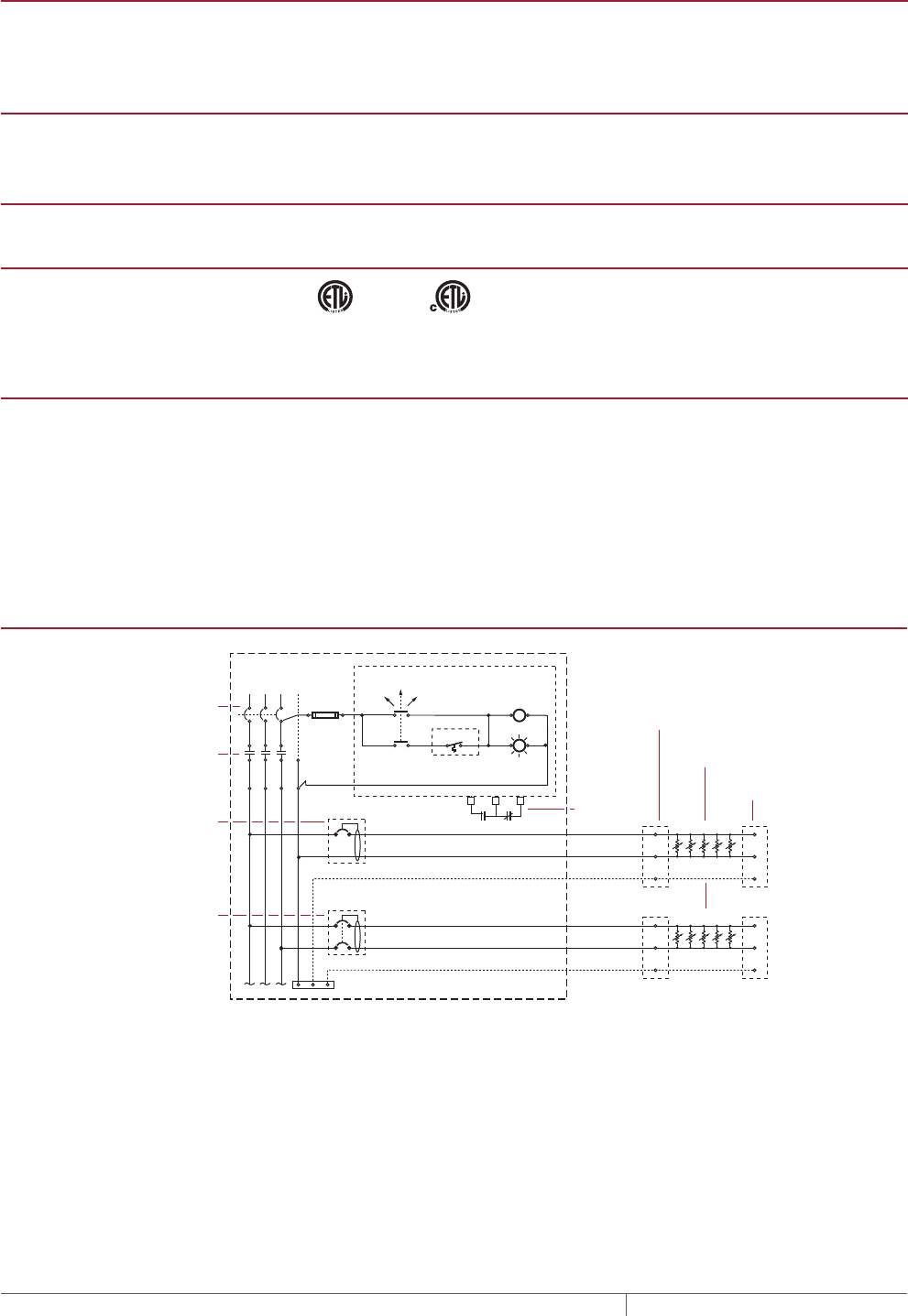
CIRCUIT BREAKER TYPES
To comply with NEC Article 427-55(a), circuit breakers are equipped with the
means for lockout in the “Off” position.
Ground-fault breaker Square D types QOB-EPD, EDB-EPD
CIRCUIT BREAKER AMPERAGE RATING
120 Vac 20 A, 30 A, 40 A, 50 A
208 / 240 / 277 Vac 20 A, 30 A, 40 A, 50 A
MAIN CONTACTOR
3 pole
APPROVALS
ETL LISTED
CONFORMS TO
ANSI/UL STD. 508
UL STD. 508A
CERTIFIED TO
CAN/CSA C22.2 NO. 14
9700701
GROUNDFAULT PROTECTION
To minimize the danger of fire from sustained electrical arcing if the heating
cable is damaged or improperly installed, and to comply with the requirements
of Pentair Thermal Management, agency certifications, and national electrical
codes, ground-fault equipment protection must be used on each heating cable
branch circuit. Arcing may not be stopped by conventional circuit protection.
Many DigiTrace control and monitoring systems meet the ground-fault protection
requirement.
HTPG TYPICAL FREEZEPROTECTION APPLICATION SCHEMATIC
N
Ø1
Three-pole main
circuit breaker
Panel
energized
Contactor
coil
C NC
External controller/
thermostat*
Hand Auto
Off
Three-pole main
contactor
Ø3
Ø2
Power
connection
Heating cable
One-pole with 30-mA
ground-fault trip
(120/277 Vac)
Two-pole with 30-mA
ground-fault trip
(208/240 Vac)
Alarm
remote
annunciation
(with alarm
option)
Freeze-
protection
circuit
Freeze-
protection
circuit
End seal
Braid/pipe
HTPG
THERMAL MANAGEMENT SOLUTIONS
EN-DigiTraceHTPG-DS-H55404 11/13
392

Pipe Freeze Protection
and Flow Maintenance
Fire Sprinkler System
Freeze Protection
Roof and Gutter
De-Icing
Surface Snow
Melting – MI
Surface Snow
Melting – ElectroMelt
Freezer Frost
Heave Prevention
Floor Heating Technical Data
Sheets
HTPG CATALOG NUMBER
HTPG comes in a variety of configurations. The following chart outlines the elements that constitute a configuration and the
corresponding catalog number.
HTPG - 277/480 - 30 - 2 - 14/1P (30) - 4X - 200 - H
HTPG - Voltage - Panelboard - C.B. type - # of C.B./# of poles (rating) - Enclosure - MCB - Options
Voltage
120/208 120/240* 277/480
Panelboard size
18 = 18 space panelboard (277 V only)
30 = 30 space panelboard
42 = 42 space panelboard
54 = 54 space panelboard (277 V only)
Circuit breaker type
2 = GFCB (30-mA trip) without alarm
3 = GFCB (30-mA trip) with bell alarm
4 = GFCB (30-mA trip) with relay alarm (includes
terminal block option). Not available for 277 V
Number of circuit breakers/number of
poles (circuit breaker rating) see prior page
# of breakers (no bell alarm option)
120 V 208 V 240 V 277V
(1P) (2P) (2P) (1P)
18 (1–18) (1–8) (1–8) (1–8)
30 (1–30) (1–14) (1–14) (1–14)
42 (1–42) (1–20) (1–20) (1–20)
54 – – – (1–26)
# of breakers (bell alarm option)
120 V 208 V 240 V 277 V
(1P) (2P) (2P) (1P)
18 (1–8) (1–6) (1–6) (1–8)
30 (1–14) (1–10) (1–10) (1–14)
42 (1–20) (1–14) (1–14) (1–20)
54 – – – (1–26)
Option
0 = None
A = Alarm horn (requires C.B. type 3 or 4)
B = Alarm beacon (requires C.B. type 3 or 4)
C = Heat-trace contactor failure light
D = Door disconnect
E = Environmental purge (NEMA 4 or 4X enclosures only)
G = Panel power-on light
H = Space heater and thermostat
L = Individual circuit breaker trip indication lights (requires C.B. type 4)
P = Heat-trace energized light
T = Terminal blocks (prewired)
W = Wired for ETI controller
Z = Z-purge system (NEMA 4 or 4X enclosures only)
SP = Special requirement: Must contain complete description of variance
MCB
Main circuit breaker and contactor
Panelboard
size 120/208 120/240 277/480
18 50, 100 50, 100 30, 50, 70, 125
30 50, 100, 150, 200, 225 50, 60, 80, 150, 175, 200, 225 50, 70, 125, 175, 225
42 50, 100, 150, 200, 225 50, 60, 80, 150, 175, 200, 225 50, 70, 125, 175, 225
54 – – 50, 70, 125, 175, 225
Enclosure
12 = NEMA 12 (indoors)
4 = NEMA 4 (outdoors)
4X = NEMA 4X (stainless steel–outdoors)
* Single phase
htpg
393THERMAL MANAGEMENT SOLUTIONS EN-DigiTraceHTPG-DS-H55404 11/13
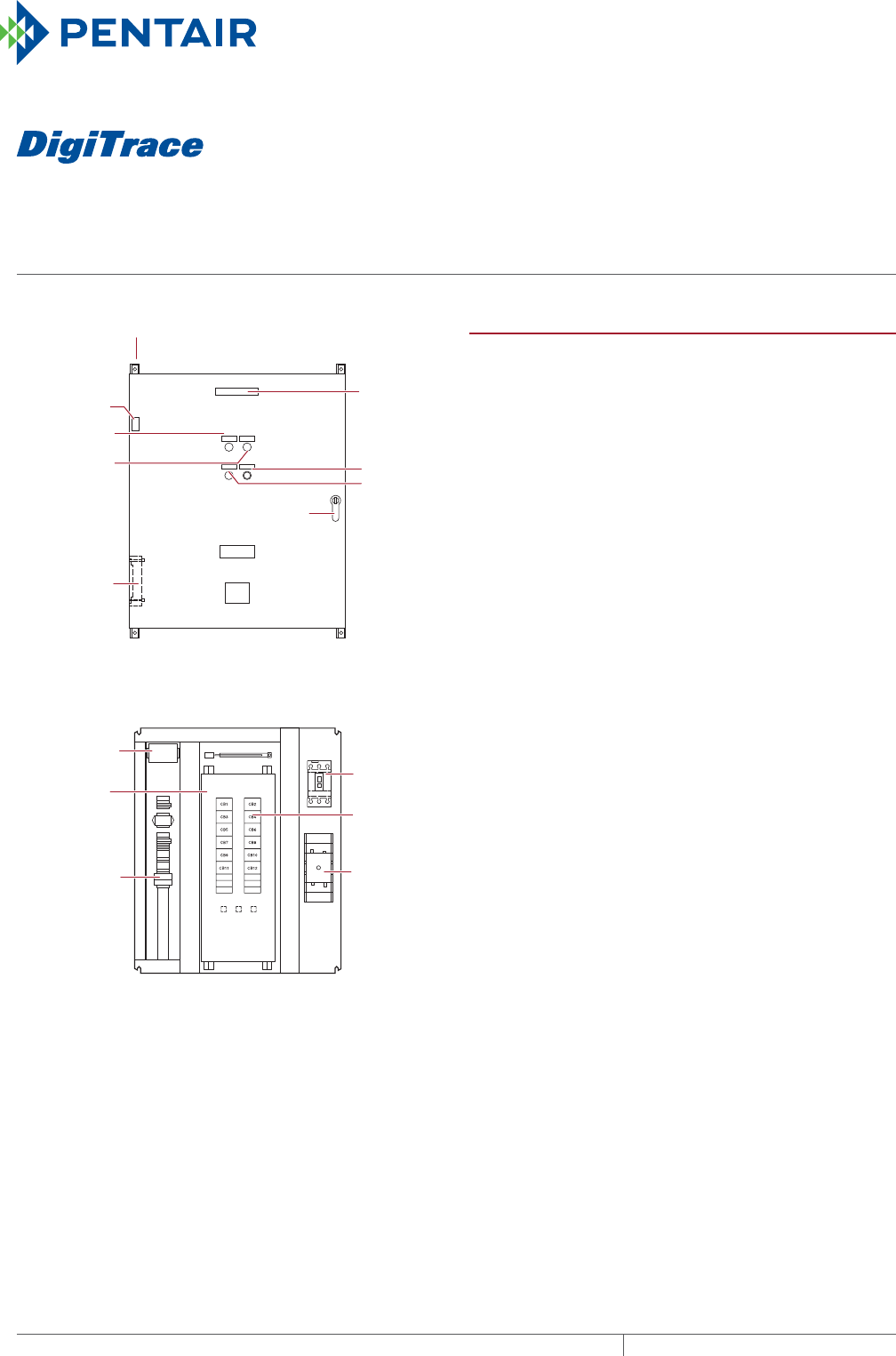
SMPG1
SNOW MELTING AND DE-ICING POWER DISTRIBUTION AND CONTROL PANEL
For single-phase heating cables
THERMAL MANAGEMENT SOLUTIONS
EN-DigiTraceSMPG1-DS-H57680 11/13
394
NP
NP
NP
NP
G
NP
NP
G
NP
R
NP
Ground bar
Panelboard
lugs
EUR - 5A
C.B. tripped
alarm
Heater cycle
timed
control
Door lock handle
Nameplate
Mounting brackets
Heater
thermostat
(3R only)
Power on light
HTC
energized light
Heater
(3R only)
Exterior View
Main
breaker
(optional)
Heat trace
contactor
Branch
breakers
(2 pole)
Interior View
Snow/Ice
melt controller
Control wiring
Panelboard
PRODUCT OVERVIEW
The DigiTrace SMPG1 is a three-phase power distribution
panel for single-phase heating cables that includes ground-
fault protection, monitoring and control for snow melting
or roof & gutter de-icing systems. The ETI
®
EUR-5A snow
melting and gutter de-icing controller is included with the
SMPG. When used with one or more compatible sensors,
the EUR-5A automatically controls surface snow melting
and roof and gutter de-icing heating cables for minimum
energy costs. Applications include pavement, sidewalk,
loading dock, roof, gutter, and down spout snow/ice melting
in commercial and industrial environments.
The adjustable hold-on timer continues heater operation for
up to 10 hours after snow stops to ensure complete melting.
The calibrated 40°F to 90°F (4°C to 32°C) high limit slab
sensor prevents excessive temperatures when using
constant wattage and MI heating cables. It also permits safe
testing at outdoor temperatures too high for continuous
heater operation. The temperature sensor is included.
The EUR-5A provides a complete interface for use in
environments supervised by an energy management
computer (EMC). This feature can also be used for general
purpose remote control and annunciation. All sensor and
communications wiring is NEC Class 2. This simplifies
installation while enhancing fire and shock safety. Multiple
sensors provide superior performance by better matching
the controller to site performance requirements. The EUR-
5A can interface up to six sensors.
For three-phase heating cable configurations, refer to the
SMPG3 data sheet (H57814). For additional information on
single-phase snow melting designs, contact your Pentair
Thermal Management representative.
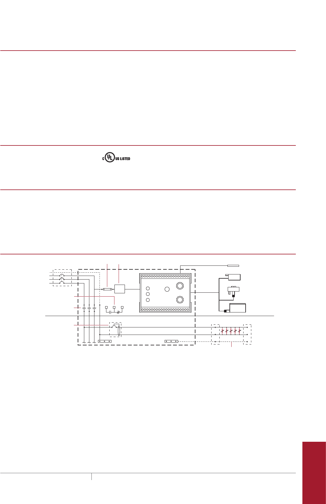
smpg1
395 THERMAL MANAGEMENT SOLUTIONS EN-DigiTraceSMPG1-DS-H57680 11/13
Pipe Freeze Protection
and Flow Maintenance
Fire Sprinkler System
Freeze Protection
Roof and Gutter
De-Icing
Surface Snow
Melting – MI
Surface Snow
Melting – ElectroMelt
Freezer Frost
Heave Prevention
Floor Heating Technical Data
Sheets
SMPG1
Ambient operating temperature Indoor installation (NEMA 1/12): 14°F (–10°C) to 122°F (50°C)
Outdoor installation (NEMA 3R/4): –40°F (–40°C) to 122°F (50°C)
(Includes space heater and thermostat)
Main contactor 3-pole 100 A or 200 A
Main circuit breaker (optional) Square D type HDL (15–150 A) 3-pole
Square D type JDL (150–200 A) 3-pole
Operating heating cable voltage 208 or 277 V, single phase
Branch ground-fault breaker Square D type QOB-EPD / EDB-EPD
Circuit breaker rating 15–50 A
Field wire size #12–8 AWG (15–30 A C.B.), #8–2 AWG (40–50 A C.B.)
APPROVALS
UL STD. 508A
CAN/CSA C22.2 NO. 14
GROUNDFAULT PROTECTION
To minimize the danger of fire from sustained electrical arcing if the heating
cable is damaged or improperly installed, and to comply with the requirements
of Pentair Thermal Management, agency certifications, and national electrical
codes, ground-fault equipment protection must be used on each heating cable
branch circuit. Arcing may not be stopped by conventional circuit protection.
Many DigiTrace control and monitoring systems meet the ground-fault protection
requirement.
SMPG1 SNOW MELTING AND ROOF AND GUTTER DEICING CONTROL SCHEMATIC
N
Three-pole main contactor
FuseMain circuit breaker (optional)
Incoming
power
GND
24 V
One-pole with 30-mA
ground-fault trip (277 V)
Remote annunciation alarm
(circuit breaker
with alarm type #3)
GIT-1
CIT-1
SIT-6E
Braid
Aerial
snow sensor
Gutter
ice sensor
Slab
temperature sensor
Pavement-mounted
sensor
Single Ø
connection
SNOW/ICE
SUPPLY
EUR-5A SNOW SWITCH
AUTOMATIC SNOW/ICE MELTING CONTROL PANEL
HEATER
HEATER
CYCLE
HOURS
0
45°F
50°F
55°F
60°F65°F70°F
75°F
80°F
85°F
2
4 6
8
10
TEMPERATURE
Control transformer
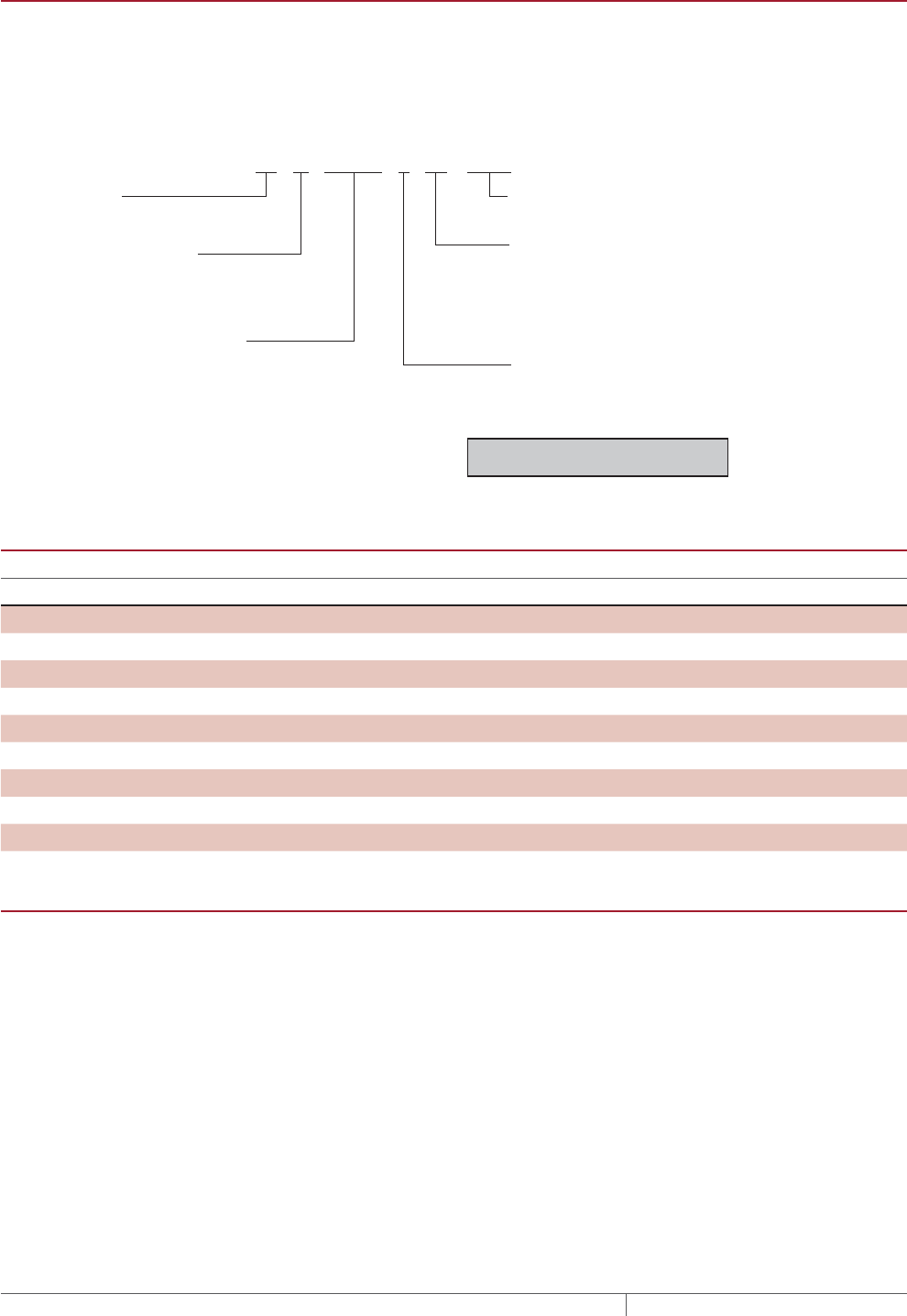
SMPG1
THERMAL MANAGEMENT SOLUTIONS
EN-DigiTraceSMPG1-DS-H57680 11/13
396
CATALOG NUMBER
SMPG1 comes in a variety of configurations. The following chart outlines the elements that constitute a configuration and
the corresponding catalog number. If standard configurations do not meet your needs, custom SMPG panels are available
and processed under the catalog number SMPG-GENERAL, part number P000000763. Please contact your Pentair Thermal
Management representative for a custom SMPG panel quotation. Non-standard configurations will carry ETL Certification,
not a UL Listing.
MAIN CIRCUIT BREAKERS
Installed in Control Panel
MCB rating
Voltage
Catalog number
Part number
50 A 120–600 V HDL36050 T1010097
100 A 120–600 V HDL36100 T1010101
110 A 120–600 V HDL36110 T1010102
125 A 120–600 V HDL36125 T1009792
150 A 120–600 V HDL36150 T1010087
175 A 120–600 V JDL36175 T1010053
200 A 120–600 V JDL36200 T1010103
225 A 120–600 V JDL36225 T1009945
250 A 480 or 600 V JDL36250 T1010104
EUR5A
Supply voltage/max current 21 to 28 Vac/2 A
Control transformer Included
Operating temperature –40°F (–40°C) to 140°F (60°C)
Hold on time adjustment 0 to 10 hours
High temperature limit adjustment 40°F (4°C) to 90°F (32°C)
Moisture/temperature sensors Up to six can be used simultaneously. Members of the CIT-1/GIT-1/SIT-6E family
in any combination. Locate up to 2,000 ft (609.6 m) for EUR-5A.
Ambient temperature sensor Included
Remote interface RCU-3 Remote Control Unit (can operate up to 500 ft [152 m] from panel)
Building/Energy management
computer interface
5 Vdc 10 mA
SMPG1 – 277 – 2 – 12/1P (40) – 1 – 200 – Options: (MCB)
SMPG1 – Voltage – Circuit breaker type – Number of circuit breakers/Number of poles (rating) – Enclosure – Contactor Size
Contactor Size
Contactor
size (A)
# of
breakers
100 6
200 12
200 18
Enclosure
1 = NEMA 1/12 (indoors)
3R = NEMA 3R/4 (outdoors) Includes heater
Voltage
208 V (Single phase)
Main Circuit Breaker
MCB = Optional Main Circuit Breaker Included
277 V (Single phase)
Circuit breaker type
2 = Ground-fault circuit breaker
(30-mA trip) without alarm
3 = Ground-fault circuit breaker
(30-mA trip) with alarm
*Number of circuit breakers/
Number of poles (circuit breaker rating)
208 V (2 pole) 277 V (1 pole)
# of Available # of Available
C.B. C.B. ratings (A) C.B. C.B. ratings (A)
6 15, 20, 25, 30, 40, 50 6 15, 20, 30, 40, 50
12 15, 20, 25, 30, 40, 50 12 15, 20, 30, 40, 50
18 15, 20, 30, 40, 50
*Warning: Confirm the total load (A)
does not exceed contactor rating.

smpg1
397 THERMAL MANAGEMENT SOLUTIONS EN-DigiTraceSMPG1-DS-H57680 11/13
Pipe Freeze Protection
and Flow Maintenance
Fire Sprinkler System
Freeze Protection
Roof and Gutter
De-Icing
Surface Snow
Melting – MI
Surface Snow
Melting – ElectroMelt
Freezer Frost
Heave Prevention
Floor Heating Technical Data
Sheets
POWER DISTRIBUTION
Catalog Number
Part Number
Description
SMPG1 Snow Melting and De-Icing Power Distribution and Control Panel - NEMA 1/12
208 V 2-pole NEMA 1 enclosure
SMPG1-208-2-6/2P(XX)-1-100 P000000456 SMPG with (6) 15–50 A ground-fault breakers, 100 A contactor
SMPG1-208-2-12/2P(XX)-1-200 P000000457 SMPG with (12) 15–50 A ground-fault breakers, 200 A
contactor
SMPG1-208-3-6/2P(XX)-1-100 P000000458 SMPG with (6) 15–50 A ground-fault breakers with alarm, 100
A contactor
SMPG1-208-3-12/2P(XX)-1-200 P000000459 SMPG with (12) 15–50 A ground-fault breakers with alarm, 200
A contactor
277 V 1-pole NEMA 1 enclosure
SMPG1-277-2-6/1P(XX)-1-100 P000000460 SMPG with (6) 15–50 A ground-fault breakers, 100 A contactor
SMPG1-277-2-12/1P(XX)-1-200 P000000461 SMPG with (12) 15–50 A ground-fault breakers, 200 A
contactor
SMPG1-277-2-18/1P(XX)-1-200 P000000462 SMPG with (18) 15–50 A ground-fault breakers, 200 A
contactor
SMPG1-277-3-6/1P(XX)-1-100 P000000463 SMPG with (6) 15–50 A ground-fault breakers with alarm, 100
A contactor
SMPG1-277-3-12/1P(XX)-1-200 P000000464 SMPG with (12) 15–50 A ground-fault breakers with alarm, 200
A contactor
SMPG1-277-3-18/1P(XX)-1-200 P000000465 SMPG with (18) 15–50 A ground-fault breakers with alarm, 200
A contactor
SMPG1 Snow Melting and De-Icing Power Distribution and Control Panel - NEMA 3R/4
208 V 2-pole NEMA 3R enclosure
SMPG1-208-2-6/2P(XX)-3R-100 P000000466 SMPG with (6) 15–50 A ground-fault breakers, 100 A contactor
SMPG1-208-2-12/2P(XX)-3R-200 P000000467 SMPG with (12) 15–50 A ground-fault breakers, 200 A
contactor
SMPG1-208-3-6/2P(XX)-3R-100 P000000468 SMPG with (6) 15–50 A ground-fault breakers with alarm, 100
A contactor
SMPG1-208-3-12/2P(XX)-3R-200 P000000469 SMPG with (12) 15–50 A ground-fault breakers with alarm, 200
A contactor
277 V 1-pole NEMA 3R enclosure
SMPG1-277-2-6/1P(XX)-3R-100 P000000470 SMPG with (6) 15–50 A ground-fault breakers, 100 A contactor
SMPG1-277-2-12/1P(XX)-3R-200 P000000471 SMPG with (12) 15–50 A ground-fault breakers, 200 A
contactor
SMPG1-277-2-18/1P(XX)-3R-200 P000000472 SMPG with (18) 15–50 A ground-fault breakers, 200 A
contactor
SMPG1-277-3-6/1P(XX)-3R-100 P000000473 SMPG with (6) 15–50 A ground-fault breakers with alarm, 100
A contactor
SMPG1-277-3-12/1P(XX)-3R-200 P000000474 SMPG with (12) 15–50 A ground-fault breakers with alarm, 200
A contactor
SMPG1-277-3-18/1P(XX)-3R-200 P000000475 SMPG with (18) 15–50 A ground-fault breakers with alarm, 200
A contactor
ACCESSORIES
ETI Sensors Catalog number Part number
Pavement-mounted sensor SIT-6E P000000112
Aerial snow sensor CIT-1 512289
Gutter ice sensor GIT-1 126795
Replacement Controller
Snow melting and gutter de-icing
controller
EUR-5A T0001527
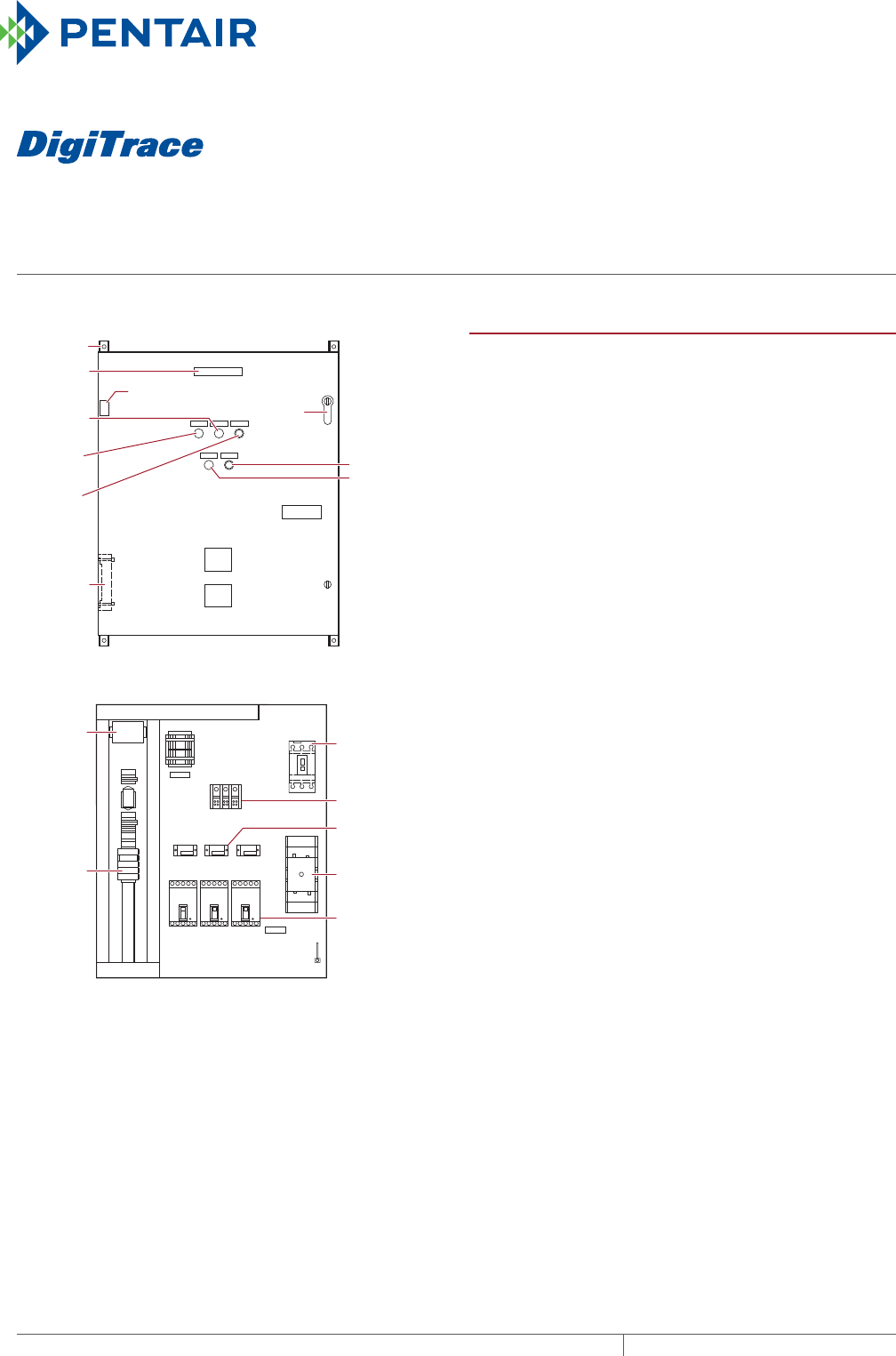
SMPG3
SNOW MELTING AND DE-ICING POWER DISTRIBUTION AND CONTROL PANEL
For three-phase heating cables
THERMAL MANAGEMENT SOLUTIONS
EN-DigiTraceSMPG3-DS-H57814 11/13
398
Exterior View
Interior View
NP
NP
NP
NP
NP
G
NP
NP
NP
PDB
G
NP
NP
R
NP
Nameplate
Mounting
brackets
Heater thermostat (3R only)
Power on
light
Heater
cycle
timed
control
HTC
energized
light Alarm
acknowledge
Heater
(3R only)
Door lock
handle
Snow/Ice
melt
controller
Ground bar
Control
wiring
C.B. tripped
alarm
EUR - 5A
Main breaker
(optional)
Control power
transformer
Heat trace
contactor
CB1
GFS1
CB2 CB3
Ground-fault
sensors
Power
distribution
block
Branch
breakers
(3 pole)
GFS2 GFS3 HTC
PRODUCT OVERVIEW
The DigiTrace SMPG3 is a three-phase power distribution
panel for three-phase heating cables that includes ground-fault
protection, monitoring and control for snow melting or roof
and gutter de-icing systems. The ETI® EUR-5A snow melting
and gutter de-icing controller is included with the SMPG.
When used with one or more compatible sensors, the EUR-5A
automatical
ly controls surface snow melting and roof and
gutter de-icing heating cables for minimum energy costs.
Applications include pavement, sidewalk, loading dock, roof,
gutter, and down spout snow/ice melting in commercial and
industrial environments.
The adjustable hold-on timer continues heater operation for
up to 10 hours after snow stops to ensure complete melting.
The calibrated 40°F to 90°F (4°C to 32°C) high limit slab
sensor prevents excessive temperatures when using
constant wattage and MI heating cables. It also permits safe
testing at outdoor temperatures too high for continuous
heater operation. The temperature sensor is included.
The EUR-5A provides a complete interface for use in
environments supervised by an energy management
computer (EMC). This feature can also be used for general
purpose remote control and annunciation. All sensor and
communications wiring is NEC Class 2. This simplifies
installation while enhancing fire and shock safety. Multiple
sensors provide superior performance by better matching
the controller to site performance requirements. The EUR-
5A can interface up to six sensors.
For single-phase heating cable configurations, refer to the
SMPG1 data sheet (H57680). For additional information on
three-phase snow melting designs, contact your Pentair
Thermal Management representative.
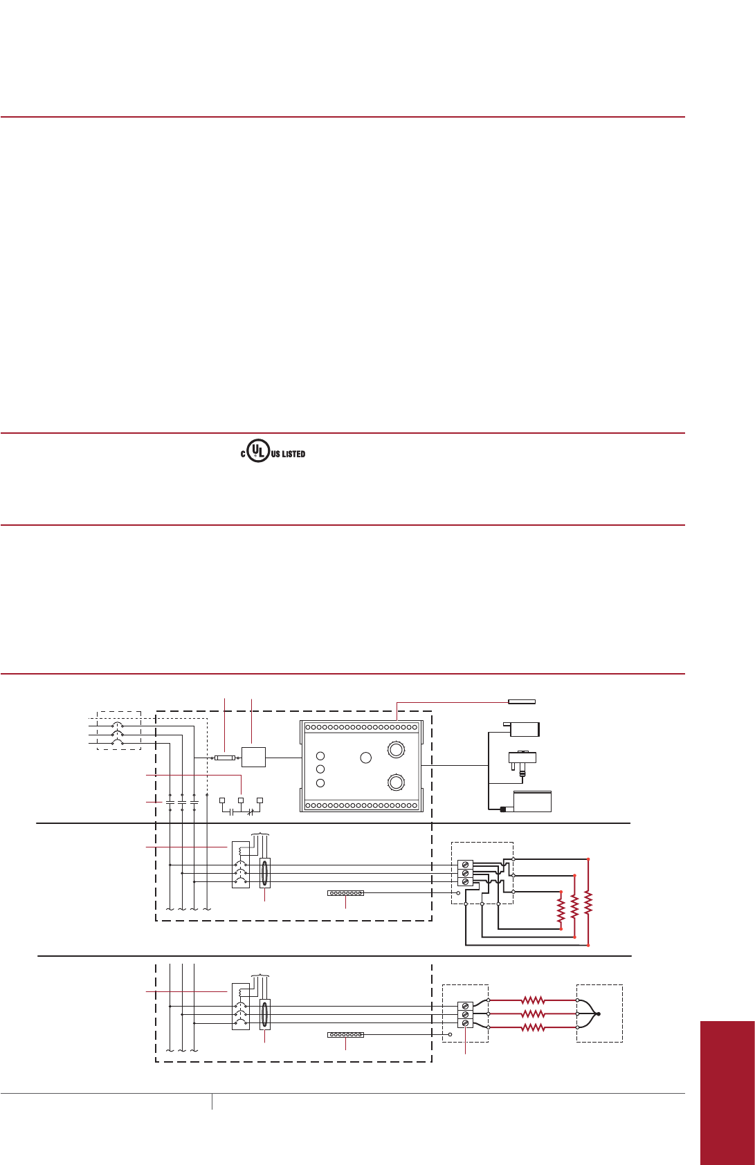
smpg3
399THERMAL MANAGEMENT SOLUTIONS EN-DigiTraceSMPG3-DS-H57814 11/13
Pipe Freeze Protection
and Flow Maintenance
Fire Sprinkler System
Freeze Protection
Roof and Gutter
De-Icing
Surface Snow
Melting – MI
Surface Snow
Melting – ElectroMelt
Freezer Frost
Heave Prevention
Floor Heating Technical Data
Sheets
SMPG3
Ambient operating temperature Indoor installation (NEMA 1/12): 14°F (–10°C) to 122°F (50°C)
Outdoor installation (NEMA 3R/4): –40°F (–40°C) to 122°F (50°C)
(Includes space heater and thermostat)
Main contactor 3-pole 100 A or 200 A
Main circuit (15–150 A) 3-pole
breaker (optional) (150–200 A) 3-pole
Square D type HDL (Installed in panel when ordered/needed)
Square D type JDL (Installed in panel when ordered/needed)
Operating heating cable voltage 208, 480, or 600 V, three phase
Branch ground-fault breaker Square D type QOB-1021 (15A–100 A) for 208 V
Square D type HDL-1021 (15A–150 A) for 600 V
JDL-1021 (160–200)
(All the above are Shunt trip C.B. with external ground-fault sensor)
Circuit breaker rating 15–150 A
Field wire size
(Copper wires)
#12–8 AWG (15–30 A C.B.), #8–2 AWG (40–50 A C.B.),
#6–1/0 AWG (60–100 A C.B.), #1/0 AWG–350 kcmil (150 A C.B.)
To comply with NEC Article 427-55(a), all circuit breakers are equipped with the
means for lockout in the “Off” position.
APPROVALS
UL STD. 508A
CAN/CSA C22.2 NO. 14
GROUNDFAULT PROTECTION
To minimize the danger of fire from sustained electrical arcing if the heating
cable is damaged or improperly installed, and to comply with the requirements
of Pentair Thermal Management, agency certifications, and national electrical
codes, ground-fault equipment protection must be used on each heating cable
branch circuit. Arcing may not be stopped by conventional circuit protection.
Many DigiTrace control and monitoring systems meet the ground-fault protection
requirement.
SMPG3 SNOW MELTING AND ROOF AND GUTTER DEICING CONTROL SCHEMATIC
N
Three-pole main contactor
Fuse
Main circuit breaker (optional)
Incoming
power
24 V
To ground-fault module
Current
transformers
Three-pole circuit breaker
with shunt trip/external
ground-fault sensor
Remote annunciation alarm
(circuit breaker
with alarm type #3)
GIT-1
CIT-1
SIT-6E
Three-pole circuit breaker
with shunt trip/external
ground-fault sensor
Ground
Aerial
snow sensor
Gutter
ice sensor
Slab
temperature sensor
Pavement-mounted
sensor
SNOW/ICE
SUPPLY
EUR-5A SNOW SWITCH
AUTOMATIC SNOW/ICE MELTING CONTROL PANEL
HEATER
HEATER
CYCLE
HOURS
0
45°F
50°F
55°F
60°F 65°F 70°F
75°F
80°F
85°F
2
4 6
8
10
TEMPERATURE
Control transformer
Junction box
To ground-fault module
Current
transformers Ground 3 Ø Wye connected
heating cables
3 Ø Delta
connected
heating
cables
Junction box Junction box
Heating
cables
Terminal block
Heating
cables
A
A1
C1
B1
B C
SMPG3
THERMAL MANAGEMENT SOLUTIONS
EN-DigiTraceSMPG3-DS-H57814 11/13
400
CATALOG NUMBER
SMPG3 comes in a variety of configurations. The following chart outlines the elements that constitute a configuration and
the corresponding catalog number. If standard configurations do not meet your needs, custom SMPG panels are available
and processed under the catalog number SMPG-GENERAL, part number P000000763. Please contact your Pentair Thermal
Controls representative for a custom SMPG panel quotation. Non-standard configurations will carry ETL Certification, not a
UL Listing.
EUR5A
Supply voltage/max current 21 to 28 Vac/2 A
Control transformer Included
Operating temperature –40°F (–40°C) to 140°F (60°C)
Hold on time adjustment 0 to 10 hours
High temperature limit adjustment 40°F (4°C) to 90°F (32°C)
Moisture/temperature sensors Up to six can be used simultaneously. Members of the CIT-1/GIT-1/SIT-6E family
in any combination. Locate up to 2,000 ft (609.6 m) for EUR-5A.
Ambient temperature sensor Included
Remote interface RCU-3 Remote Control Unit (can operate up to 500 ft [152 m] from panel)
Building/energy management
computer interface
5 Vdc 10 mA
MAIN CIRCUIT BREAKERS
Installed in Control Panel
MCB rating
Voltage
Catalog number
Part number
50 A 120–600 V HDL36050 T1010097
100 A 120–600 V HDL36100 T1010101
110 A 120–600 V HDL36110 T1010102
125 A 120–600 V HDL36125 T1009792
150 A 120–600 V HDL36150 T1010087
175 A 120–600 V JDL36175 T1010053
200 A 120–600 V JDL36200 T1010103
225 A 120–600 V JDL36225 T1009945
250 A 480 or 600 V JDL36250 T1010104
SMPG3 – 208 – 3 – 2/3P (80) – 3R – 200 – Options: (MCB)
SMPG3 – Voltage – Circuit breaker type – Number of circuit breakers/Number of poles (rating) – Enclosure – Contactor size
Contactor Size
Contactor # of Breakers
size (A) breakers size (A)
100 1 25, 30, 40, 50, 60, 70, 80, 100
200 1 150
100 2 25, 30, 40, 50
200 2 60, 70, 80, 100
100 3 25, 30
200 3 40, 50, 60
Enclosure
1/12 = NEMA 1/12 (indoors)
3R/4 = NEMA 3R/4 (outdoors)
Voltage
208 V (Three phase)
480 V (Three phase)
600 V (Three phase)
Circuit breaker type
3 = 3-pole circuit breaker w/shunt trip and
external ground-fault sensor -
with alarm
*Number of circuit breakers/
Number of poles (circuit breaker rating)
208 V (3 pole) 480 V or 600 V (3 pole)
# of Available # of Available
C.B. C.B. ratings (A) C.B. C.B. ratings (A)
1 15–100 1 15–100
2 15–150 2 15–150
3 15–150 3 15–150 *Warning: Confirm the total load (A) does not exceed contactor rating.
Main Circuit Breaker
MCB = Optional Main Circuit Breaker Included
smpg3
401THERMAL MANAGEMENT SOLUTIONS EN-DigiTraceSMPG3-DS-H57814 11/13
Pipe Freeze Protection
and Flow Maintenance
Fire Sprinkler System
Freeze Protection
Roof and Gutter
De-Icing
Surface Snow
Melting – MI
Surface Snow
Melting – ElectroMelt
Freezer Frost
Heave Prevention
Floor Heating Technical Data
Sheets
POWER DISTRIBUTION
Catalog Number
Part Number
Description
SMPG3 Snow Melting and De-Icing Power Distribution and Control Panel - NEMA 1/12
208 V 3-pole NEMA 1/12 Enclosure
SMPG3-208-3-1/3P(XX)-1-100 P000000476 SMPG with (1) 15–100 A breaker, GF sensor with alarm, 100 A
contactor
SMPG3-208-3-1/3P(XX)-1-200 P000000477 SMPG with (1) 15–150 A breaker, GF sensor with alarm, 200 A
contactor
SMPG3-208-3-2/3P(XX)-1-100 P000000478 SMPG with (2) 15–100 A breakers, GF sensor with alarm, 100 A
contactor
SMPG3-208-3-2/3P(XX)-1-200 P000000479 SMPG with (2) 15–150 A breakers, GF sensor with alarm, 200 A
contactor
SMPG3-208-3-3/3P(XX)-1-100 P000001381 SMPG with (3) 15–100 A breakers, GF sensor with alarm, 100 A
contactor
SMPG3-208-3-3/3P(XX)-1-200 P000000480 SMPG with (3) 15–150 A breakers, GF sensor with alarm, 200 A
contactor
480 V 3-pole NEMA 1/12 Enclosure
SMPG3-480-3-1/3P(XX)-1-100 P000000481 SMPG with (1) 15–100 A breaker, GF sensor with alarm, 100 A
contactor
SMPG3-480-3-1/3P(XX)-1-200 P000001382 SMPG with (1) 15–150 A breaker, GF sensor with alarm, 200 A
contactor
SMPG3-480-3-2/3P(XX)-1-100 P000000482 SMPG with (2) 15–100 A breakers, GF sensor with alarm, 100 A
contactor
SMPG3-480-3-2/3P(XX)-1-200 P000000483 SMPG with (2) 15–150 A breakers, GF sensor with alarm, 200 A
contactor
SMPG3-480-3-3/3P(XX)-1-100 P000001383 SMPG with (3) 15–100 A breakers, GF sensor with alarm, 100 A
contactor
SMPG3-480-3-3/3P(XX)-1-200 P000000484 SMPG with (3) 15–150 A breakers, GF sensor with alarm, 200 A
contactor
600 V 3-pole NEMA 1/12 Enclosure
SMPG3-600-3-1/3P(XX)-1-100 P000000494 SMPG with (1) 15–100 A breaker, GF sensor with alarm, 100 A
contactor
SMPG3-600-3-1/3P(XX)-1-200 P000001384 SMPG with (1) 15–150 A breaker, GF sensor with alarm, 200 A
contactor
SMPG3-600-3-2/3P(XX)-1-100 P000000495 SMPG with (2) 15–100 A breakers, GF sensor with alarm, 100 A
contactor
SMPG3-600-3-2/3P(XX)-1-200 P000000496 SMPG with (2) 15–150 A breakers, GF sensor with alarm, 200 A
contactor
SMPG3-600-3-3/3P(XX)-1-100 P000000497 SMPG with (3) 15–100 A breakers, GF sensor with alarm, 100 A
contactor
SMPG3-600-3-3/3P(XX)-1-200 P000000498 SMPG with (3) 15–150 A breakers, GF sensor with alarm, 200 A
contactor

SMPG3
THERMAL MANAGEMENT SOLUTIONS
EN-DigiTraceSMPG3-DS-H57814 11/13
402
POWER DISTRIBUTION
Catalog Number
Part Number
Description
SMPG3 Snow Melting and De-Icing Power Distribution and Control Panel - NEMA 3R/4
208 V 3-pole NEMA 3R/4 Enclosure
SMPG3-208-3-1/3P(XX)-3R-100 P000000485 SMPG with (1) 15–100 A breaker, GF sensor with alarm, 100 A
contactor
SMPG3-208-3-1/3P(XX)-3R-200 P000000486 SMPG with (1) 15–150 A breaker, GF sensor with alarm, 200 A
contactor
SMPG3-208-3-2/3P(XX)-3R-100 P000000487 SMPG with (2) 15–100 A breakers, GF sensor with alarm, 100 A
contactor
SMPG3-208-3-2/3P(XX)-3R-200 P000000488 SMPG with (2) 15–150 A breakers, GF sensor with alarm, 200 A
contactor
SMPG3-208-3-3/3P(XX)-3R-100 P000001385 SMPG with (3) 15–100 A breakers, GF sensor with alarm, 100 A
contactor
SMPG3-208-3-3/3P(XX)-3R-200 P000000489 SMPG with (3) 15–150 A breakers, GF sensor with alarm, 200 A
contactor
480 V 3-pole NEMA 3R/4 Enclosure
SMPG3-480-3-1/3P(XX)-3R-100 P000000490 SMPG with (1) 15–100 A breaker, GF sensor with alarm, 100 A
contactor
SMPG3-480-3-1/3P(XX)-3R-200 P000001386 SMPG with (1) 15–150 A breaker, GF sensor with alarm, 200 A
contactor
SMPG3-480-3-2/3P(XX)-3R-100 P000000491 SMPG with (2) 15–100 A breakers, GF sensor with alarm, 100 A
contactor
SMPG3-480-3-2/3P(XX)-3R-200 P000000492 SMPG with (2) 15–150 A breakers, GF sensor with alarm, 200 A
contactor
SMPG3-480-3-3/3P(XX)-3R-100 P000001387 SMPG with (3) 15–100 A breakers, GF sensor with alarm, 100 A
contactor
SMPG3-480-3-3/3P(XX)-3R-200 P000000493 SMPG with (3) 15–150 A breakers, GF sensor with alarm, 200 A
contactor
600 V 3-pole NEMA 3R/4 Enclosure
SMPG3-600-3-1/3P(XX)-3R-100 P000000499 SMPG with (1) 15–100 A breaker, GF sensor with alarm, 100 A
contactor
SMPG3-600-3-1/3P(XX)-3R-200 P000001388 SMPG with (1) 15–150 A breaker, GF sensor with alarm, 200 A
contactor
SMPG3-600-3-2/3P(XX)-3R-100 P000000500 SMPG with (2) 15–100 A breakers, GF sensor with alarm, 100 A
contactor
SMPG3-600-3-2/3P(XX)-3R-200 P000000501 SMPG with (2) 15–150 A breakers, GF sensor with alarm, 200 A
contactor
SMPG3-600-3-3/3P(XX)-3R-100 P000000502 SMPG with (3) 15–100 A breakers, GF sensor with alarm, 100 A
contactor
SMPG3-600-3-3/3P(XX)-3R-200 P000000503 SMPG with (3) 15–150 A breakers, GF sensor with alarm, 200 A
contactor
ACCESSORIES
ETI sensors Catalog number Part number
Pavement-mounted sensor SIT-6E P000000112
Aerial snow sensor CIT-1 512289
Gutter ice sensor GIT-1 126795
Replacement controller
Snow melting and gutter de-icing
controller
EUR-5A T0001527
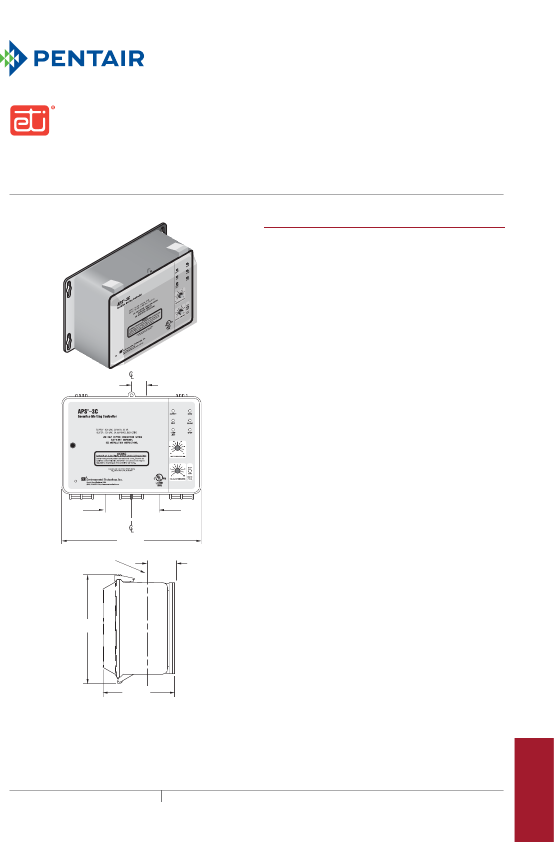
403THERMAL MANAGEMENT SOLUTIONS EN-ETIAPS3C-DS-H58111 11/13
Snow melting and gutter de-icing controller
APS-3C
Pipe Freeze Protection
and Flow Maintenance
Fire Sprinkler System
Freeze Protection
Roof and Gutter
De-Icing
Surface Snow
Melting – MI
Surface Snow
Melting – ElectroMelt
Freezer Frost
Heave Prevention
Floor Heating Technical Data
Sheets
2.125 in
(54mm) 2.125 in
(54mm)
2.3125 in
(59mm)
3 x 3/4 in (21mm)
Conduit Entry
11.500 in
(292mm)
9.125 in
(232mm)
6.562 in
(167mm)
1.3125 in
(33mm)
PRODUCT OVERVIEW
The ETI® APS–3C snow melting and gutter de-icing
controller when used with compatible sensors automatically
controls surface snow melting and roof and gutter de-icing
heating cables, ensuring minimum operating costs. Typical
applications include pavement, sidewalk, loading dock, roof,
gutter, and down spout snow/ice melting.
The adjustable hold-on timer continues heater operation for
up to 10 hours after snow stops to ensure complete melting.
The optional RCU–3 Remote Control Unit can be located
where system operation can be conveniently observed. It
duplicates many of the controls and indicators on the
APS-3C front panel. It is used to clear tracked and drifting
snow that may not land on a sensor.
The calibrated 40°F to 90°F (4°C to 32°C) high limit
thermostat prevents excessive temperatures when using
constant wattage and MI heating cables. It also permits safe
testing at outdoor temperatures too high for continuous
heater operation. The temperature sensor is included.
The APS–3C provides a relay closure interface for use
with energy management computers (EMC). This feature
can also be used for general purpose remote control and
annunciation and other advanced applications.
All sensor and communications wiring is NEC Class 2. This
simplifies installation while enhancing fire and shock safety.
Multiple sensors provide superior performance by better
matching the controller to site performance requirements.
The APS–3C can interface up to six sensors.
The APS-3C does not provide ground-fault protection for the
heating cable system. This protection is required and must
be provided by other devices such as ground-fault circuit
breakers or other control methods.
The APS–3C is an exceptionally capable surface snow
melting and roof and gutter de-icing controller. For complete
information describing its application, installation, and
features, please contact your Pentair Thermal Management
representative or visit our web site at www.pentairthermal.com.

APS3C
THERMAL MANAGEMENT SOLUTIONS
EN-ETIAPS3C-DS-H58111 11/13
404
GENERAL
Area of use Nonhazardous locations
Approvals
ENCLOSURE
Protection NEMA 3R
Cover attachment Hinged polycarbonate cover, lockable
Entries Three 1-1/16" entries
Material Polycarbonate
Mounting Wall mounted
CONTROL
Supply voltage APS-3C-120 V: 120 V 50/60 Hz
APS-3C-208/240 V: 208/240 V 50/60 Hz
Contact type Form C
Maximum ratings Voltage: 240 V
Current: 24 A
Heater hold-on timer 0 to 10 hours; actuated by snow stopping or toggle switch
System test Switch toggles the heater contact on and off. If temperature exceeds high limit,
heater cycles to prevent damage.
SNOW/ICE SENSORS
Sensor input Up to 6 sensors; CIT-1, GIT-1, SIT-6E
Circuit type NEC Class 2
Lead length Up to 500 ft (152 m) using 18 AWG 3-wire jacketed cable
Up to 2,000 ft (609 m) using 12 AWG 3-wire jacketed cable
HIGH LIMIT THERMOSTAT
Adjustment range 40°F to 90°F (4°C to 32°C)
Dead band 1°F (0.6°C)
Sensor type Thermistor
Circuit type NEC Class 2
Lead length Up to 500 ft (152 m) using 18 AWG 2-wire jacketed cable
Up to 1,000 ft (504 m) using 12 AWG 2-wire jacketed cable
ENERGY MANAGEMENT COMPUTER EMC INTERFACE
Inputs OVERRIDE ON (10 mA dry switch contact)
OVERRIDE OFF (10 mA dry switch contact)
Outputs SUPPLY (10 mA dry switch contact)
SNOW (10 mA dry switch contact)
HEAT (10 mA dry switch contact)
HIGH TEMP (10 mA dry switch contact)
REMOTE (10 mA dry switch contact)
ENVIRONMENTAL
Operating temperature –40°F to 160°F (–40°C to 71°C)
Storage temperature –50°F to 180°F (–45°C to 82°C)
109R
Type 873
Temperature Regulating Equipment

aps-3c
405 THERMAL MANAGEMENT SOLUTIONS EN-ETIAPS3C-DS-H58111 11/13
Pipe Freeze Protection
and Flow Maintenance
Fire Sprinkler System
Freeze Protection
Roof and Gutter
De-Icing
Surface Snow
Melting – MI
Surface Snow
Melting – ElectroMelt
Freezer Frost
Heave Prevention
Floor Heating Technical Data
Sheets
ORDERING DETAILS
Catalog number Part number Description
APS-3C-120V P000000781 APS-3C Snow Melting and De-Icing Controller, 120 V
APS-3C-208/240V P000000782 APS-3C Snow Melting and De-Icing Controller, 208/240 V
Snow/Ice Sensors
CIT-1 512289-000 CIT-1 Snow sensor
GIT-1 126795-000 GIT-1 Gutter sensor
SIT-6E P000000112 SIT-6E Pavement snow sensor
RCU-3 P000000883 RCU-3 Remote control unit
LIMITED WARRANTY
ETI’s two year limited warranty covering defects in workmanship and materials
applies.
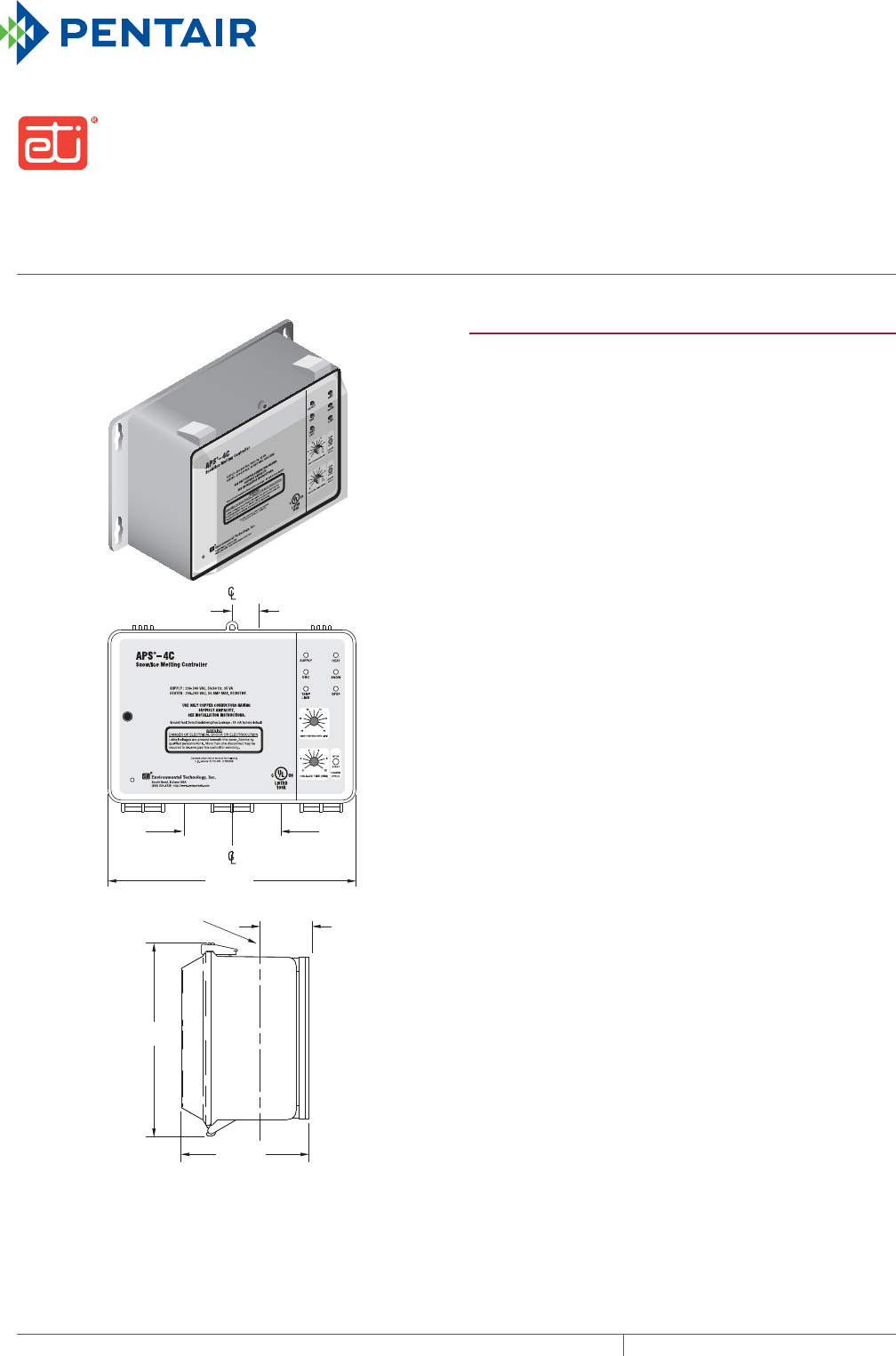
SNOW MELTING AND GUTTER DE-ICING CONTROLLER
With ground-fault protection
APS4C
THERMAL MANAGEMENT SOLUTIONS
EN-ETIAPS4C-DS-H58112 11/13
406
2.125 in
(54mm) 2.125 in
(54mm)
2.3125 in
(59mm)
3 x 3/4 in (21mm)
Conduit Entry
11.500 in
(292mm)
9.125 in
(232mm)
6.562 in
(167mm)
1.3125 in
(33mm)
PRODUCT OVERVIEW
The ETI® APS–4C snow melting and gutter de-icing
controller with ground-fault protection, when used with one
or more compatible sensors, automatically controls surface
snow melting and roof and gutter de-icing heating cables
for minimum energy costs. Applications include pavement,
sidewalk, loading dock, roof, gutter, and down spout snow/
ice melting in commercial and industrial environments.
The adjustable hold-on timer continues heater operation for
up to 10 hours after snow stops to ensure complete melting.
The optional RCU–4 Remote Control Unit can be located
where system operation can be conveniently observed. It
duplicates many of the APS–4C front panel functions.
The APS–4C provides advanced patented and patent pending
ground-fault equipment protection (GFEP) as required by
the national electrical codes. The GFEP automatically tests
itself every time the contactors operate and once every 24
hours. The trip current can be set at 60 or 120 mA via a DIP
an internal switch or retained at the 30 mA default value.
As an aid to troubleshooting heating cable ground faults,
the APS–4C provides an output that can indicate the ground
current on a service person’s portable DVM.
The calibrated 40°F to 90°F (4°C to 32°C) high limit
thermostat prevents excessive temperatures when using
constant wattage and MI heating cables. It also permits safe
testing at outdoor temperatures too high for continuous
heater operation. The temperature sensor is included.
The APS–4C provides a complete interface for use in
environments supervised by an energy management
computer (EMC). This feature can also be used for general
purpose remote control and annunciation.
All sensor and communications wiring is NEC Class 2. This
simplifies installation while enhancing fire and shock safety.
Multiple sensors provide superior performance by better
matching the controller to site performance requirements.
The APS–4C can interface up to six sensors.
The APS–4C is an exceptionally capable surface snow
melting and roof and gutter de-icing controller. For complete
information describing its application, installation and
features, please contact your Pentair Thermal Management
representative or visit our web site at www.pentairthermal.com.

aps-4c
407 THERMAL MANAGEMENT SOLUTIONS EN-ETIAPS4C-DS-H58112 11/13
Pipe Freeze Protection
and Flow Maintenance
Fire Sprinkler System
Freeze Protection
Roof and Gutter
De-Icing
Surface Snow
Melting – MI
Surface Snow
Melting – ElectroMelt
Freezer Frost
Heave Prevention
Floor Heating Technical Data
Sheets
GENERAL
Area of use Nonhazardous locations
Approvals
109R
Type 873
Temperature Regulating Equipment
ENCLOSURE
Protection NEMA 3R
Cover attachment Hinged polycarbonate cover, lockable
Entries One 1-1/16" entry (top) for NEC Class 2 connections
Two 1-11/16" entries (bottom) for supply and load power, except 277 V single phase
Two 1-1/16" entries (bottom) for supply and load power, 277 V single phase only
Material Polycarbonate
Mounting Wall mounted
CONTROL
Supply voltage APS-4C-208/240 V: 208–240 V 50/60 Hz 3-phase
APS-4C-277 V: 277 V 50/60 Hz single phase
APS-4C-277/480 V: 277/480 V 50/60 Hz 3-phase
APS-4C-600 V: 600 V 50/60 Hz 3-phase
Contact type 3 Form A
Maximum ratings Voltage: 600 V
Current: 50 A except 277 V single phase, 40 A for 277 V single phase
Heater hold-on timer 0 to 10 hours; actuated by snow stopping or toggle switch
System test Switch toggles the heater contact on and off. If temperature exceeds high limit,
heater cycles to prevent damage.
GROUNDFAULT EQUIPMENT PROTECTION GFEP
Set point 30 mA (default); 60 mA and 120 mA selectable by DIP switch
Automatic self-test Mode A: Verifies GFEP function before contactors operate
Mode B: Verifies GFEP and heaters every 24 hours
Manual test/reset Toggle switch provided for this function
Maintenance facility DC output proportional to ground current provided for troubleshooting the heater
system
SNOW/ICE SENSORS
Sensor input Up to 6 sensors: CIT-1, GIT-1, SIT-6E
Circuit type NEC Class 2
Lead length Up to 500 ft (152 m) using 18 AWG 3-wire jacketed cable
Up to 2,000 ft (609 m) using 12 AWG 3-wire jacketed cable
HIGH LIMIT THERMOSTAT
Adjustment range 40°F to 90°F (4°C to 32°C)
Dead band 1°F (0.6°C)
Circuit type Thermistor
Sensor interface NEC Class 2
Lead length Up to 500 ft (152 m) using 18 AWG 2-wire jacketed cable
Up to 1,000 ft (504 m) using 12 AWG 2-wire jacketed cable
APS4C
THERMAL MANAGEMENT SOLUTIONS
EN-ETIAPS4C-DS-H58112 11/13
408
ENERGY MANAGEMENT COMPUTER EMC INTERFACE
Inputs OVERRIDE ON (10 mA dry switch contact)
OVERRIDE OFF (10 mA dry switch contact)
Outputs SUPPLY (10 mA dry switch contact)
SNOW (10 mA dry switch contact)
HEAT (10 mA dry switch contact)
HIGH TEMP (10 mA dry switch contact)
REMOTE (10 mA dry switch contact)
ENVIRONMENTAL
Operating temperature –40°F to 160°F (–40°C to 71°C)
Storage temperature –50°F to 180°F (–45°C to 82°C)
ORDERING DETAILS
Catalog number Part number Description
APS-4C-208/240V P000000783 APS-4C Snow melting and de-icing controller with
ground-fault protection, 208-240 Vac 50/60 Hz three
phase
APS-4C-277V P000000784 APS-4C Snow melting and de-icing controller with
ground-fault protection, 277 Vac 50/60 Hz single phase
APS-4C-277V/480V P000000785 APS-4C Snow melting and de-icing controller with
ground-fault protection, 277/480 Vac 50/60 Hz three
phase
APS-4C-600V P000000786 APS-4C Snow melting and de-icing controller with
ground-fault protection, 600 Vac 50/60 Hz three phase
Snow/Ice Sensors
CIT-1 512289-000 CIT-1 Snow sensor
GIT-1 126795-000 GIT-1 Gutter sensor
SIT-6E P000000112 SIT-6E Pavement snow sensor
RCU-4 P000000884 RCU-4 Remote control unit
LIMITED WARRANTY
ETI’s two year limited warranty covering defects in workmanship and materials
applies.
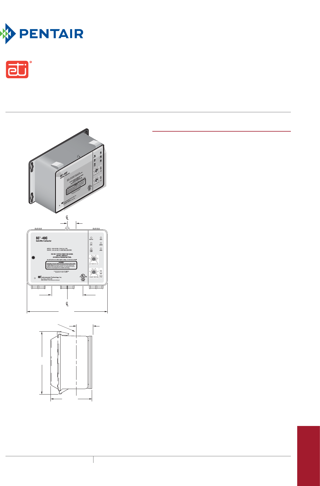
409 THERMAL MANAGEMENT SOLUTIONS EN-ETISC40C-DS-H58113 11/13
Snow and ice melting Satellite contactor
SC-40C
Pipe Freeze Protection
and Flow Maintenance
Fire Sprinkler System
Freeze Protection
Roof and Gutter
De-Icing
Surface Snow
Melting – MI
Surface Snow
Melting – ElectroMelt
Freezer Frost
Heave Prevention
Floor Heating Technical Data
Sheets
2.125 in
(54mm) 2.125 in
(54mm)
2.3125 in
(59mm)
3 x 3/4 in (21mm)
Conduit Entry
11.500 in
(292mm)
9.125 in
(232mm)
6.562 in
(167mm)
1.3125 in
(33mm)
PRODUCT OVERVIEW
The ETI® SC–40C snow and ice melting satellite contactor
answers the need for cost effective modular snow melting
heater control. One or more SC–40Cs, when used with an
APS–4C control panel acting as the master control, allow
for modular snow melting system design. There is no limit
to the number of SC–40Cs that can be interfaced in a single
system. This approach reduces front end design, hardware,
and installation costs while providing a number of useful
features that would be otherwise too expensive and complex
to implement.
The SC–40C provides Ground-Fault Equipment Protection
(GFEP) as required by the national electrical codes. Upon
sensing a ground-fault condition, the SC–40C inhibits
operation of its contactor until manually reset. Circuits
without a ground fault continue to operate normally, thus
partitioning defective heating cables.
The adjustable hold-on timer continues heater operation
on each SC–40C for up to 10 hours after snow stops to
ensure complete melting and to compensate for differences
between zones. The optional RCU–4 remote control unit
can be located where system operation can be conveniently
observed. It duplicates many of the controls and indicators
on the SC–40C front panel.
Each SC–40C provides a complete energy management
computer (EMC) interface. This feature provides remote
access for advanced applications requiring remote or zone
control along with remote annunciation.
Each SC–40C maintains communications to and from the
APS–4C using a 3-wire cable. Thus, the APS–4C alarms
ground faults occurring anywhere in the system. This
feature inserts a short time delay between the operation
of each contactor, thus improving power quality by limiting
the inrush current. The RCU–4 remote control unit supplied
permits overriding zone control in applications requiring the
capability.
For complete information describing its application,
installation and features, please contact your Pentair
Thermal Management representative or visit our web site at
www.pentairthermal.com.

SC40C
THERMAL MANAGEMENT SOLUTIONS
EN-ETISC40C-DS-H58113 11/13
410
GENERAL
Area of use Nonhazardous locations
Approvals
109R
Type 873
Temperature Regulating Equipment
ENCLOSURE
Protection NEMA 3R
Cover attachment Hinged polycarbonate cover, lockable
Entries One 1-1/16" entry (top) for NEC Class 2 connections
Two 1-11/16" entries (bottom) for supply and load power, except 277 V single phase
Two 1-1/16" entries (bottom) for supply and load power, 277 V single phase only
Material Polycarbonate
Mounting Wall mounted
COMMUNICATIONS BUS
Number of cascaded units Unlimited
Contactor delay 5 seconds
Bus-wire type 3-wire jacketed cable
Circuit type NEC Class 2
Lead length Up to 500 ft (152 m) using 18 AWG 3-wire jacketed cable
Up to 1,000 ft (504 m) using 12 AWG 3-wire jacketed cable
CONTROL
Supply voltage SC-40C 208/240 V: 208–240 V 50/60 Hz 3-phase
SC-40C 277 V: 277 V 50/60 Hz single phase
SC-40C 277/480 V: 277/480 V 50/60 Hz 3-phase
SC-40C 600 V: 600 V 50/60 Hz 3-phase
Contact type 3 Form A
Maximum ratings Voltage: 600 V
Current: 50 A except 277 V single phase, 40 A for 277 V single phase
Heater hold-on timer 0 to 10 hours; actuated by snow stopping or toggle switch
System test Switch toggles the heater contact on and off. If temperature exceeds high limit,
heater cycles to prevent damage.
GROUNDFAULT EQUIPMENT PROTECTION GFEP
Set point 30 mA (default); 60 mA and 120 mA selectable by DIP switch
Automatic self-test Mode A: Verifies GFEP function before contactors operate
Mode B: Verifies GFEP and heaters every 24 hours
Manual test/reset Toggle switch provided for this function
Maintenance facility DC output proportional to ground current provided for troubleshooting the heater
system
HIGH LIMIT THERMOSTAT
Adjustment range 40°F to 90°F (4°C to 32°C)
Dead band 1°F (0.6°C)
Sensor type Thermistor
Circuit type NEC Class 2
Lead length Up to 500 ft (152 m) using 18 AWG 2-wire jacketed cable
Up to 1,000 ft (504 m) using 12 AWG 2-wire jacketed cable
SC-40C
411 THERMAL MANAGEMENT SOLUTIONS EN-ETISC40C-DS-H58113 11/13
Pipe Freeze Protection
and Flow Maintenance
Fire Sprinkler System
Freeze Protection
Roof and Gutter
De-Icing
Surface Snow
Melting – MI
Surface Snow
Melting – ElectroMelt
Freezer Frost
Heave Prevention
Floor Heating Technical Data
Sheets
ENERGY MANAGEMENT COMPUTER EMC INTERFACE
Inputs OVERRIDE ON (10 mA dry switch contact)
OVERRIDE OFF (10 mA dry switch contact)
Outputs SUPPLY (10 mA dry switch contact)
SNOW (10 mA dry switch contact)
HEAT (10 mA dry switch contact)
HIGH TEMP (10 mA dry switch contact)
REMOTE (10 mA dry switch contact)
ENVIRONMENTAL
Operating temperature –40°F to 160°F (–40°C to 71°C)
Storage temperature –50°F to 180°F (–45°C to 82°C)
ORDERING DETAILS
Catalog number Part number Description
SC-40C 208/240V P000000787 SC-40C Satellite Contactor, 208-240 Vac 50/60 Hz three
phase
SC-40C 277V P000000788 SC-40C Satellite Contactor, 277 Vac 50/60 Hz single
phase
SC-40C 277/480V P000000789 SC-40C Satellite Contactor, 277/480 Vac 50/60 Hz three
phase
SC-40C 600V P000000790 SC-40C Satellite Contactor, 600 Vac 50/60 Hz three
phase
Snow/ice sensors (not included)
CIT-1 512289-000 CIT-1 Snow sensor
GIT-1 126795-000 GIT-1 Gutter sensor
SIT-6E P000000112 SIT-6E Pavement snow sensor
RCU-4 P000000884 RCU-4 Remote control unit
LIMITED WARRANTY
ETI’s two year limited warranty covering defects in workmanship and materials
applies.
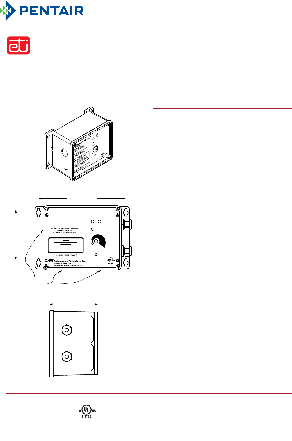
AutomAtic snow And ice melting controller
PD Pro
THERMAL MANAGEMENT SOLUTIONS
EN-ETIPDPro-DS-H58848 11/13
412
4 in
(102 mm)
7-7/16 in
(189 mm)
4-1/4 in
(108 mm)
1-1/16 in
(27 mm)
Conduit Entry
SUPPLY : 120 VAC, 50/60 Hz
LOAD : 120 VAC, 7 AMP MAX. INDUCTIVE
LOAD : 120 VAC, 30 AMP MAX. RESISTIVE
Snow Switch
®
PD Pro™
Snow & Ice Control
SUPPLY HEAT
SNOW
HOLD-ON TIME (HRS)
HEATER CYCLE
8
0
WARNING
DANGER OF ELECTRICAL SHOCK OR
ELECTROCUTION
Lethal voltages are present beneath this cover.
Service by qualified personnel only. More than
one disconnect may be required to de-energize
this control for servicing.
HEATER CYCLE
PRODUCT OVERVIEW
The ETI® PD Pro is an automatic snow and ice melting
controller for pavement, sidewalks, loading docks, roofs,
gutters and downspouts in commercial and residential
environments.
The PD Pro interfaces with up to two sensors, (any
combination of CIT-1, GIT-1 or SIT-6E) to meet site
requirements. The controller features automatic and
manual-override operator controls. The adjustable Hold-On
timer continues heater operation up to 8 hours after the
sensors stop detecting snow or ice to ensure the rest of the
slab has completely dried. The Heater Cycle control button
allows manual initiation or cancellation of a heating cycle.
The optional RCU–3 remote control unit can be located
for convenient monitoring and control. These flexible
control options provide complete snow melting and water
evaporation at a low operating cost.
The PD Pro is housed in an environmentally-sheltered
Type 4X enclosure and weighs only 3 pounds. The PD Pro
is a snow and ice controller for medium-sized applications
whose features and power requirements do not require an
APS or EUR Series control panel. For complete information
describing application, installation, and features, please
contact your Pentair Thermal Management representative or
visit www.pentairthermal.com.
GENERAL
Area of use Nonhazardous locations
Approvals
Type 873
Temperature Regulating Equipment
109R
Also evaluated by Underwriters Laboratories Inc in accordance
with UL 1053 Ground-Fault Sensing and Relaying Equipment
pd pro
413 THERMAL MANAGEMENT SOLUTIONS EN-ETIPDPRO-DS-H58848 11/13
Pipe Freeze Protection
and Flow Maintenance
Fire Sprinkler System
Freeze Protection
Roof and Gutter
De-Icing
Surface Snow
Melting – MI
Surface Snow
Melting – ElectroMelt
Freezer Frost
Heave Prevention
Floor Heating Technical Data
Sheets
ENCLOSURE
Protection Type 4X
Dimensions 5 1/2” (L) x 8 1/8” (W) x 4 3/8” (H)
140 mm (L) x 207 mm (W) x 112 mm (H)
Material Polycarbonate
Cover attachment Polycarbonate cover, machine screws
Weight 3 pounds (not including sensors)
Mounting Wall mount
Entries 2 x 3/4” entries (right) for NEC Class 2 connections
3 x 1-1/16” entries (bottom and left) for supply and load power
CONTROL
Supply voltage 120 Vac; 50/60 Hz
Load 30 A maximum resistive
7 A maximum inductive
Heater Hold-On timer 0 – 8 hrs; actuated by snow stopping or toggle switch
System test Switch toggles heater contact on and off. If temperature exceeds optional high limit
thermistor (45°F), heater shuts off to reduce costs and prevent damage
FRONT PANEL INTERFACE
Status indicators SUPPLY (green): Power on
HEAT (yellow): Heating cycle in progress
SNOW (yellow): Sensor(s) detect snow
ENVIRONMENTAL
Operating temperature –31°F to 130°F (–35°C to 55°C)
Storage temperature –67°F to 167°F (–55°C to 75°C)
ORDERING INFORMATION
Catalog number Part number Description
PD Pro* P000001508 Automatic Snow and Ice Melting Controller
CIT-1* 512289-000 Aerial Snow Sensor
GIT-1* 126795-000 Gutter Ice Sensor
SIT-6E* P000000112 Pavement Mounted Snow and Ice Sensor
* The PD Pro does not come with any sensors. Sensors must be ordered separately.
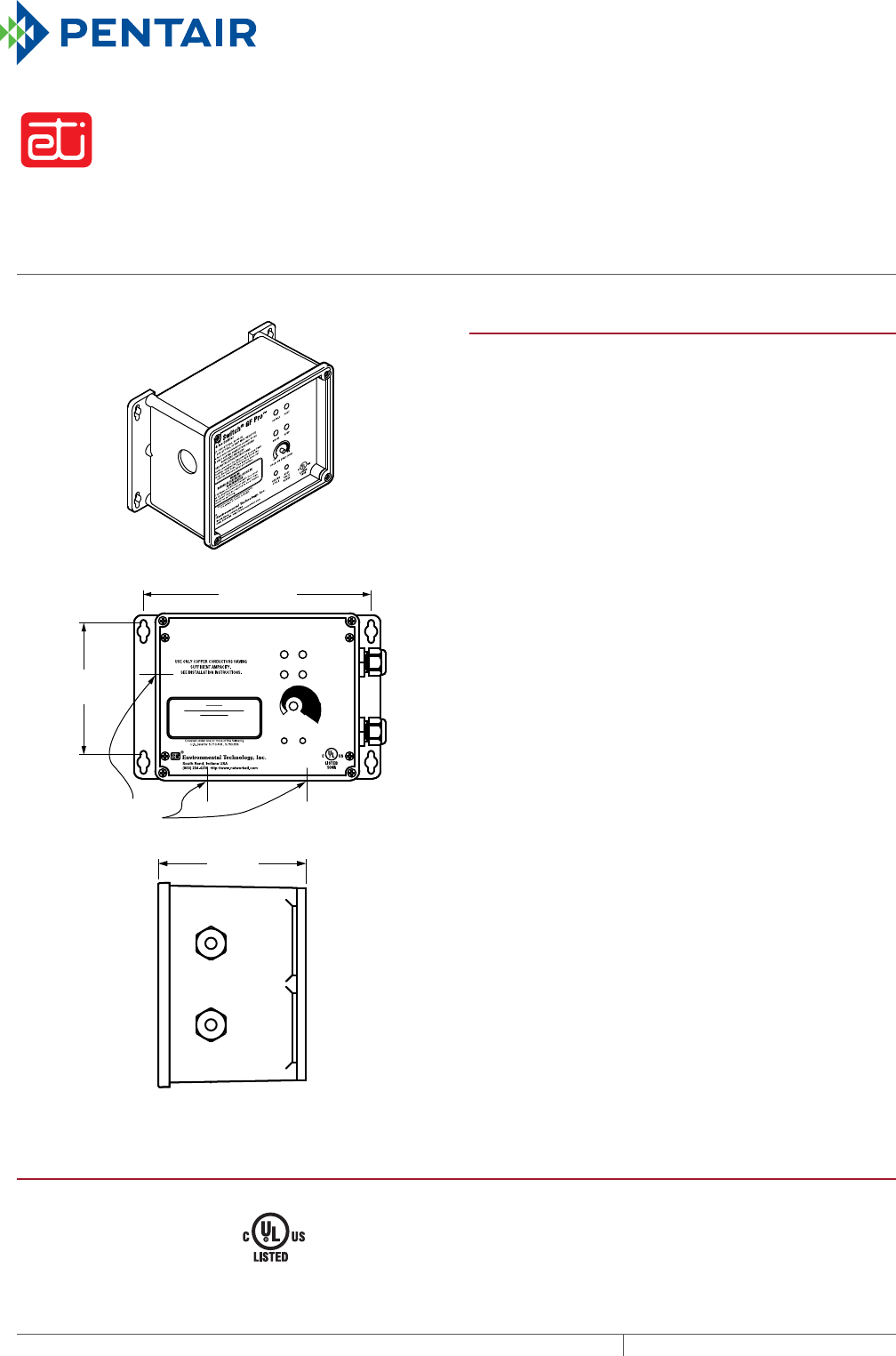
AutomAtic snow And ice melting controller
GF Pro
THERMAL MANAGEMENT SOLUTIONS
EN-ETIGFPro-DS-H58849 11/13
414
SUPPLY : 200-277 VAC, 50/60 Hz
LOAD : 200-277 VAC, 30 AMP MAX. RESISTIVE
Snow Switch
®
GF Pro™
Snow & Ice Control with GFEP
SUPPLY HEAT
SNOW GFEP
HOLD-ON TIME (HRS)
GFEP
TEST/
RESET
HEATER
CYCLE
8
0
Ground Fault Detection/Interuption Leakage: 30 mA
WARNING
DANGER OF ELECTRICAL SHOCK OR
ELECTROCUTION
Lethal voltages are present beneath this cover.
Service by qualified personnel only. More than
one disconnect may be required to de-energize
this control for servicing.
This device provides the Equipment Ground
Fault Protection required by Article 426.28 of
the National Electric Code. This Device does
not provide Personal GFCI protection.
7-7/16 in
(189 mm)
4"
(10 2 mm)
4-1/4 in
(108 mm)
1-1/16 in
(27 mm)
Conduit Entry
PRODUCT OVERVIEW
The ETI® GF Pro is an automatic snow and ice melting
controller for pavement, sidewalks, loading docks, roofs,
gutters and downspouts in commercial and residential
environments.
The GF Pro interfaces with up to two sensors, (any combination
of CIT-1, GIT-1 or SIT-6E) to meet site requirements. The
controller features automatic and manual-override operator
controls. The adjustable Hold-On timer continues heater
operation up to 8 hours after the sensors stop detecting snow
or ice to ensure the rest of the slab has completely dried.
The Heater Cycle control button allows manual initiation or
cancellation of a heating cycle. The optional RCU–4 remote
control unit can be located for convenient monitoring and
control. These flexible control options provide complete snow
melting and water evaporation at a low operating cost.
The GF Pro also features a built-in 30 mA, self-testing Ground-
Fault Equipment Protection (GFEP) capability, digitally filtered to
minimize false tripping. A ground-fault alarm must be manually
reset using the Test/Reset switch before heater operation can
continue.
The GF Pro is housed in an environmentally-sheltered Type 4X
enclosure and weighs only 3 pounds. The GF Pro is a snow and
ice controller for medium-sized applications whose features
and power requirements do not require an APS or EUR Series
control panel. For complete information describing application,
installation, and features, please contact your Pentair Thermal
Management representative or visit www.pentairthermal.com.
GENERAL
Area of use Nonhazardous locations
Approvals
Type 873
Temperature Regulating Equipment
109R
Also evaluated by Underwriters Laboratories Inc in accordance
with UL 1053 Ground-Fault Sensing and Relaying Equipment
gf pro
415 THERMAL MANAGEMENT SOLUTIONS EN-ETIGFPRO-DS-H58849 11/13
Pipe Freeze Protection
and Flow Maintenance
Fire Sprinkler System
Freeze Protection
Roof and Gutter
De-Icing
Surface Snow
Melting – MI
Surface Snow
Melting – ElectroMelt
Freezer Frost
Heave Prevention
Floor Heating Technical Data
Sheets
ENCLOSURE
Protection Type 4X
Dimensions 5 1/2” (L) x 8 1/8” (W) x 4 3/8” (H)
140 mm (L) x 207 mm (W) x 112 mm (H)
Material Polycarbonate
Cover attachment Polycarbonate cover, machine screws
Weight 3 pounds (not including sensors)
Mounting Wall mount
Entries 2 x 3/4” entries (right) for NEC Class 2 connections
3 x 1-1/16” entries (bottom and left) for supply and load power
CONTROL
Supply voltage 200 – 277 Vac; 50/60 Hz
Load 30 A maximum resistive
Heater Hold-On timer 0 – 8 hrs; actuated by snow stopping or toggle switch
System test Switch toggles heater contact on and off. If temperature exceeds optional high limit
thermistor (45°F), heater shuts off to reduce costs and prevent damage
FRONT PANEL INTERFACE
Status indicators SUPPLY (green): Power on
HEAT (yellow): Heating cycle in progress
SNOW (yellow): Sensor(s) detect snow
GFEP (red): Ground-Fault condition
GFEP (red, flashing): Failed
GFEP (red, rapid flashing): GFEP test in progress
GROUNDFAULT EQUIPMENT PROTECTION GFEP
Set point 30 mA
Automatic self-test GFEP verified before contactors operate; GFEP runs on start-up and every 24 hours
Manual Test/Reset Test/Reset switch on front panel
ENVIRONMENTAL
Operating temperature –31°F to 130°F (–35°C to 55°C)
Storage temperature –67°F to 167°F (–55°C to 75°C)
ORDERING INFORMATION
Catalog number Part number Description
GF Pro* P000001509 Automatic Snow and Ice Melting Controller
CIT-1* 512289-000 Aerial Snow Sensor
GIT-1* 126795-000 Gutter Ice Sensor
SIT-6E* P000000112 Pavement Mounted Snow and Ice Sensor
* The GF Pro does not come with any sensors. Sensors must be ordered separately.
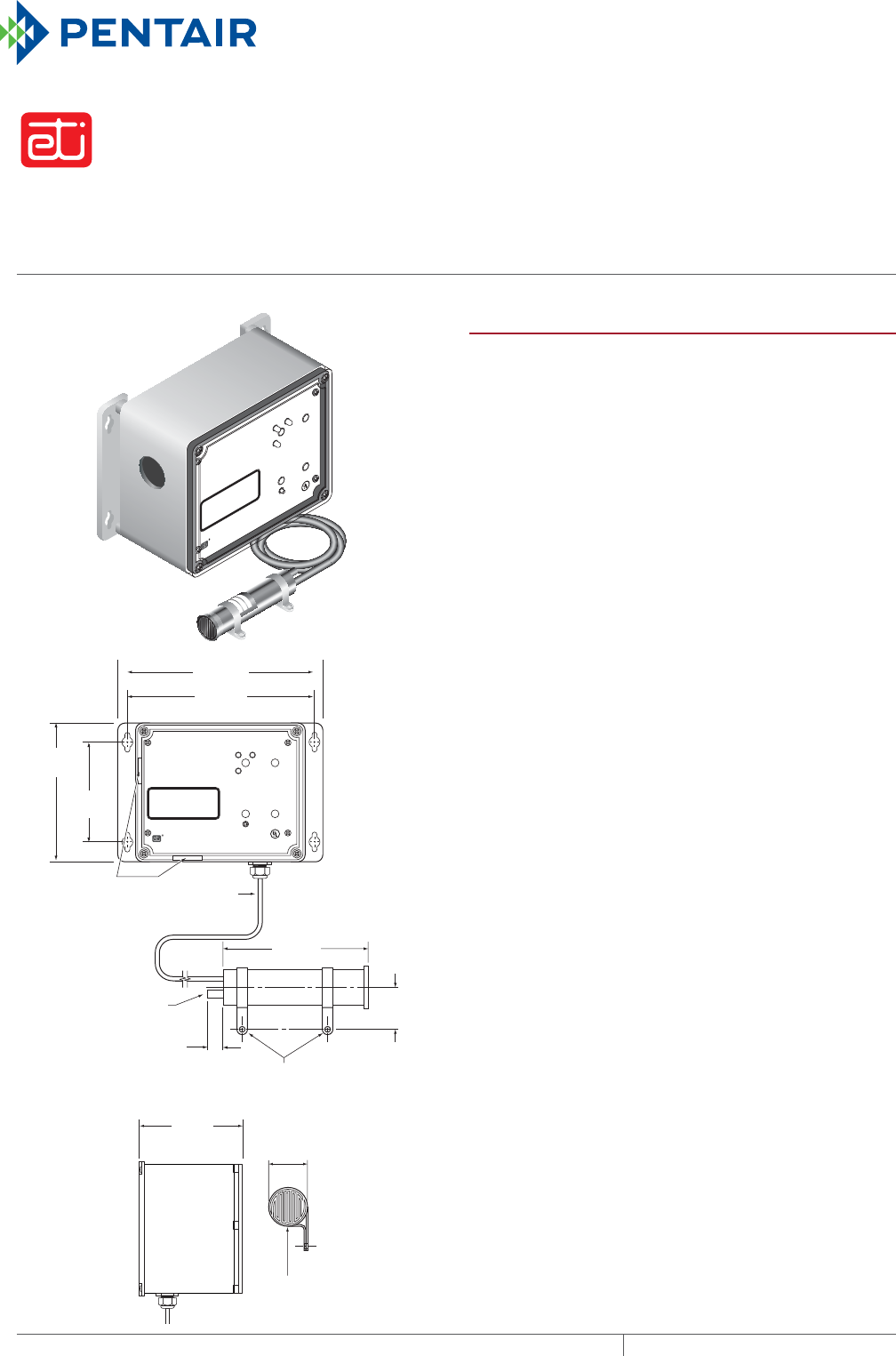
AutomAtic gutter de-icing controller
RM3
THERMAL MANAGEMENT SOLUTIONS
EN-ETIRM3-DS-H58747 11/13
416
SUPPLY
RM-3
Snow & Ice Control
SUPPLY: 120 VAC, 50/60 Hz
LOAD: 120 VAC, 7 AMP MAX. INDUCTIVE
LOAD: 120 VAC, 24 AMP MAX. RESISTIVE
HEAT
SNOW
HEATER CYCLE
LISTED
109R
C US
WARNING
DANGER OF ELECTRICAL SHOCK OR
ELECTROCUTION
USE ONLY COPPER CONDUCTORS HAVING
SUFFICIENT AMPACITY.
SEE INSTALLATION INSTRUCTIONS.
Environmental Technology, Inc.
5.5 in
(139.7 mm)
4.25 in
(108.0 mm)
8.125 in
(206.4 mm)
4.06 in
(103.2 mm)
5.56 in
(141.2mm)
0.81 in
(20.6mm)
Ambient air
temperature
sensor
1.12 in
(28.5mm)
1.50 in
(38.1mm)
Mounting clamp
(removable)
Heated moisture-
sensing grid
12 ft (3.6m) jacketed
3 conductor #18
AWG cable
1 in (25.4 mm)
cutout
SUPPLY
RM-3
Snow & Ice Control
SUPPLY: 120 VAC, 50/60 Hz
LOAD: 120 VAC, 7 AMP MAX. INDUCTIVE
LOAD: 120 VAC, 24 AMP MAX. RESISTIVE
HEAT
SNOW
HEATER CYCLE
LISTED
109R
C US
WARNING
DANGER OF ELECTRICAL SHOCK OR
ELECTROCUTION
USE ONLY COPPER CONDUCTORS HAVING
SUFFICIENT AMPACITY.
SEE INSTALLATION INSTRUCTIONS.
Environmental Technology, Inc.
7.375 in
(187.3 mm)
PRODUCT OVERVIEW
The RM-3 automatic gutter ice controllers include the
GIT®-1 gutter ice sensor to detect and melt snow and ice
from roofs, gutters, and downspouts.
The dual-action GIT-1 sensor detects both moisture and
temperature, so the heaters run only when moisture is
detected at or below 38°F (3.3°C). The built-in, fixed, 3-hour
Hold-On Timer provides for a heating cycle long enough
to fully melt snow and ice and keep them from refreezing.
The Heater Cycle toggle switch allows manual activation or
cancellation of heater operation. The included GIT-1 gutter
ice sensor detects ice and snow as moisture at or below
38°F (3.3°C), so the RM-3 system could save hundreds of
dollars a year compared to using just a simple thermostat
alone to control the system.
The RM-3 system is housed in an environmentally-sheltered
NEMA 4X enclosure to provide various installation options.
The RM-3 automatic gutter ice systems are designed
for years of maintenance-free operation and can save
thousands of dollars in unnecessary repairs, as well as
actual loss of use of the building, structure, or facility.
Features and benefits include:
• Energy efficient, automatic controls for gutter and down-
spout applications
• Heating based on snow & ice / temperature sensor input
for optimum efficiency
• Low cost operation compared to thermostat control alone
• Heater Cycle switch for manual activation or cancelation
of heater operation
For complete information describing application, installation
and features, please contact your Pentair Thermal
Management representative or visit
www.pentairthermal.com.
rm-3
417 THERMAL MANAGEMENT SOLUTIONS EN-ETIRM3-DS-H58747 11/13
Pipe Freeze Protection
and Flow Maintenance
Fire Sprinkler System
Freeze Protection
Roof and Gutter
De-Icing
Surface Snow
Melting – MI
Surface Snow
Melting – ElectroMelt
Freezer Frost
Heave Prevention
Floor Heating Technical Data
Sheets
GENERAL
Area of use Nonhazardous
Approvals
109R
Type 873
Temperature Regulating Equipment
ENCLOSURE
Protection IP66 NEMA 4X
Dimensions 5 1/2 in (L) X 8 1/8 in (W) X 4 3/8 in (H)
Material Polycarbonate
Cover attachment Polycarbonate cover, machine screws
Weight 3 pounds (control box alone);
3.8 pounds (with included GIT-1 sensor)
Mounting Wall mount
FRONT PANEL INTERFACE
Status indicator SUPPLY (green, solid) power on
HEAT (yellow) call for heat
SNOW (yellow) system sensor detects moisture
CONTROL
Supply voltage 120 Vac; 50/60 Hz
Heater 120 Vac;
24 A maximum resistive
7 A maximum inductive
ENVIRONMENTAL
Polycarbonate
Operating temperature –35°F to 130°F (–31°C to 55°C)
Storage temperature –67°F to 167°F (–55°C to 75°C)
ORDERING INFORMATION
Catalog number Part number Description
RM-3 P000001366 Gutter de-icing controller
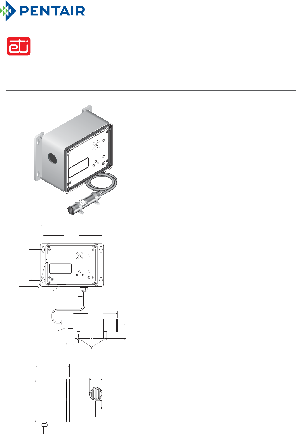
AutomAtic gutter de-icing controller
RM4
THERMAL MANAGEMENT SOLUTIONS
EN-ETIRM4-DS-H58748 11/13
418
SUPPLY
RM-4
Snow & Ice Control with GFEP
SUPPLY: 208-240 VAC, 50/60 Hz
HEATER: 208-240 VAC, 24 AMP MAX. RESISTIVE
HEAT
SNOW GFEP
HEATER
CYCLE
GFEP
TEST/
RESET
LISTED
109R
C US
WARNING
DANGER OF ELECTRICAL SHOCK OR
ELECTROCUTION
Ground Fault Detection/Interuption Leakeage: 30mA
USE ONLY COPPER CONDUCTORS HAVING
SUFFICIENT AMPACITY.
SEE INSTALLATION INSTRUCTIONS.
Environmental Technology, Inc.
5.5 in
(139.7 mm)
4.25 in
(108.0 mm)
8.125 in
(206.4 mm)
4.06 in
(103.2 mm)
5.56 in
(141.2mm)
0.81 in
(20.6mm)
Ambient air
temperature
sensor
1.12 in
(28.5mm)
1.50 in
(38.1mm)
Mounting clamp
(removable)
Heated moisture-
sensing grid
12 ft (3.6m) jacketed
3 conductor #18
AWG cable
1 in (25.4 mm)
cutout
SUPPLY
RM-4
Snow & Ice Control with GFEP
SUPPLY: 208-240 VAC, 50/60 Hz
HEATER: 208-240 VAC, 24 AMP MAX. RESISTIVE
HEAT
SNOW
HEATER
CYCLE
LISTED
109R
C US
WARNING
DANGER OF ELECTRICAL SHOCK OR
ELECTROCUTION
USE ONLY COPPER CONDUCTORS HAVING
SUFFICIENT AMPACITY.
SEE INSTALLATION INSTRUCTIONS.
Environmental Technology, Inc.
GFEP
GFEP
TEST/
RESET
7.375 in
(187.3 mm)
PRODUCT OVERVIEW
The RM-4 automatic gutter ice controllers include the
GIT®-1 gutter ice sensor to detect and melt snow and ice
from roofs, gutters, and downspouts.
The dual-action GIT-1 sensor detects both moisture and
temperature, so the heaters run only when moisture is
detected at or below 38°F (3.3°C). The built-in, fixed, 3-hour
Hold-On Timer provides for a heating cycle long enough
to fully melt snow and ice and keep them from refreezing.
The Heater Cycle toggle switch allows manual activation or
cancelation of heater operation. The included GIT-1 gutter
ice sensor detects ice and snow as moisture at or below
38°F (3.3°C), so the RM-4 system could save hundreds of
dollars a year compared to using just a simple thermostat
alone to control the system.
The RM-4 system is housed in an environmentally-sheltered
NEMA 4X enclosure to provide various installation options.
The RM-4 automatic gutter ice systems are designed
for years of maintenance-free operation and can save
thousands of dollars in unnecessary repairs, as well as
actual loss of use of the building, structure, or facility.
Features and benefits include:
• Energy efficient, automatic controls for gutter and down-
spout applications
• Heating based on snow & ice / temperature sensor input
for optimum efficiency
• Low cost operation compared to thermostat control alone
• Heater Cycle switch for manual activation or cancelation
of heater operation
• RM-4 Ground-fault Equipment Protection (GFEP) circuitry
performs an automatic self-test upon start-up and auto-
matically every 24 hours, eliminating the need to perform
manual ground-fault testing
For complete information describing application, installation
and features, please contact your Pentair Thermal
Management representative or visit
www.pentairthermal.com.

rm-4
419THERMAL MANAGEMENT SOLUTIONS EN-ETIRM4-DS-H58748 11/13
Pipe Freeze Protection
and Flow Maintenance
Fire Sprinkler System
Freeze Protection
Roof and Gutter
De-Icing
Surface Snow
Melting – MI
Surface Snow
Melting – ElectroMelt
Freezer Frost
Heave Prevention
Floor Heating Technical Data
Sheets
GENERAL
Area of use Nonhazardous
Approvals
109R
Type 873
Temperature Regulating Equipment
ENCLOSURE
Protection IP66 NEMA 4X
Dimensions 5 1/2 in (L) X 8 1/8 in (W) X 4 3/8 in (H)
Material Polycarbonate
Cover attachment Polycarbonate cover, machine screws
Weight 3 pounds (control box alone);
3.8 pounds (with included GIT-1 sensor)
Mounting Wall mount
FRONT PANEL INTERFACE
Status indicator SUPPLY (green, solid) power on
HEAT (yellow) call for heat
SNOW (yellow) system sensor detects moisture
GFEP (red) ground-fault condition
GFEP (red, flashing) failed
GFEP (red, flashing, rapid) GFEP test in progress
CONTROL
Supply voltage 208–240 Vac; 50/60 Hz
Heater 208–240 Vac;
24 A maximum resistive
GROUNDFAULT EQUIPMENT PROTECTION
Set point 30 mA
Automatic self-test GFEP verified before contactors operate; GFEP runs on power start-up and
automatically every 24 hours
Manual test/rest Test/rest switch on front panel
ENVIRONMENTAL
Polycarbonate
Operating temperature –35°F to 130°F (–31°C to 55°C)
Storage temperature –67°F to 167°F (–55°C to 75°C)
ORDERING INFORMATION
Catalog number Part number Description
RM-4 P000001367 Gutter de-icing controller with GFEP
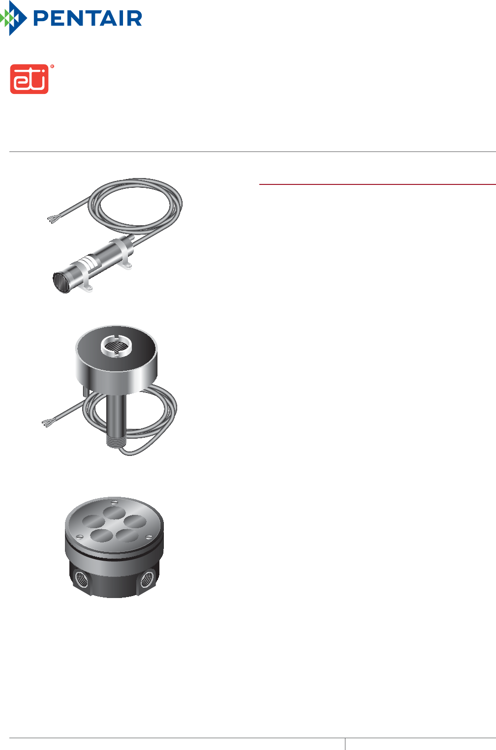
SNOW AND ICE MELTING SENSORS
CIT-1 snow sensor, GIT-1 gutter sensor, SIT-6E pavement sensor
CIT1, GIT1, SIT6E
THERMAL MANAGEMENT SOLUTIONS
EN-ETICIT1GIT1SIT6E-DS-H58114 11/13
420
GIT-1
CIT-1
SIT-6E
PRODUCT OVERVIEW
The ETI® CIT–1, GIT–1 and SIT–6E snow and ice melting
sensors combine to reliably detect moisture and
temperature for surface snow melting and roof and gutter
de-icing applications. The CIT–1 sensor may be paired with
either the GIT–1 sensor for gutter applications or the SIT–6E
sensor for pavement applications. These sensors detect
precipitation as snow at temperatures below 38°F (3.3°C).
Control panels are signaled only if moisture occurs below
this temperature, thus saving energy and ensuring reliable
ice melting. They provide the industry’s most versatile and
cost effective automatic snow melting control when used
with any APS or EUR series control panel.
Reliability and sensitivity are key features in the CIT–1, GIT–1
and SIT–6E sensors. The solid state design, combined with
a rugged housing and epoxy potting, ensure many years of
trouble free service. Precision precipitation and temperature
sensing provide the sensitivity required for effective
automatic control. All three are NEC Class 2 low voltage
device which simplifies installation.
The CIT–1, GIT–1 and SIT–6E’s unique microcontroller
design frees their moisture sensors from ice bridging. Ice
bridging happens if incomplete melting occurs near the
heater or sensor leaving an air space. The air insulates thus
preventing effective heater and sensor operation. Additional
features prevent heater operation under conditions
favorable to heater ice tunneling.
The CIT–1 aerial snow sensor detects falling or blowing
precipitation before snow or ice begin to accumulate. This
allows the control panel to begin managing the system. This
sensor may be roof or mast mounted.
The GIT–1 mounts directly in gutters and down spouts
sensing actual environmental conditions.
The SIT–6E accurately measures pavement temperature
while reliably detecting snow and ice conditions on pavement
surfaces. A built-in hold-on timer in the SIT–6E keeps
heaters operating for an hour after snow stops to help
ensure complete snow melting. Mounting these sensors
close to the deicing heaters ensures that pavement and
sensor become dry at about the same time.
An adjustable mounting system aligns the SIT–6E with the
pavement surface. Six conduit locations add to installation
flexibility. The sensor subassembly is field replaceable without
disturbing the pavement.
cit-1, git-1, sit-6e
421 THERMAL MANAGEMENT SOLUTIONS EN-ETICIT1GIT1SIT6E-DS-H58114 11/13
Pipe Freeze Protection
and Flow Maintenance
Fire Sprinkler System
Freeze Protection
Roof and Gutter
De-Icing
Surface Snow
Melting – MI
Surface Snow
Melting – ElectroMelt
Freezer Frost
Heave Prevention
Floor Heating Technical Data
Sheets
Sensors are easy to install and may be mounted up to 2000
ft (609 m) from a control panel. A combination of up to six
sensors may be used with a control panel to best match site
performance requirements.
For complete information describing applications,
installation and features, please contact your Pentair
Thermal Management representative or visit our web site
at www.pentairthermal.com.
GENERAL
Area of use
CIT–1 Gutters or pavement (in conjunction with GIT–1 or SIT–6E)
GIT–1 Gutters
SIT–6E Pavement
Heater hold-on time
CIT–1 None
GIT–1 None
SIT–6E 1 hour
Activation temperature 38°F (3.37°C)
CONNECTIONS
Circuit type NEC Class 2
Supply voltage 24 Vac (supplied by panel)
Output signal Voltage drop
Bus wire type 3-wire jacketed cable
Lead length Up to 2,000 ft (609 m) using 12 AWG 3-wire jacketed cable
Up to 500 ft (152 m) using 18 AWG 3-wire jacketed cable
ENVIRONMENTAL
Operating temperature –40°F to 160°F (–40°C to 71°C)
Storage temperature –50°F to 180°F (–45°C to 82°C)
ORDERING DETAILS
Catalog number Part number Description
CIT-1 512289-000 CIT-1 Snow sensor
GIT-1 126795-000 GIT-1 Gutter sensor
SIT-6E P000000112 SIT-6E Pavement snow sensor
LIMITED WARRANTY
ETI’s two-year limited warranty covering defects in workmanship and materials
applies.
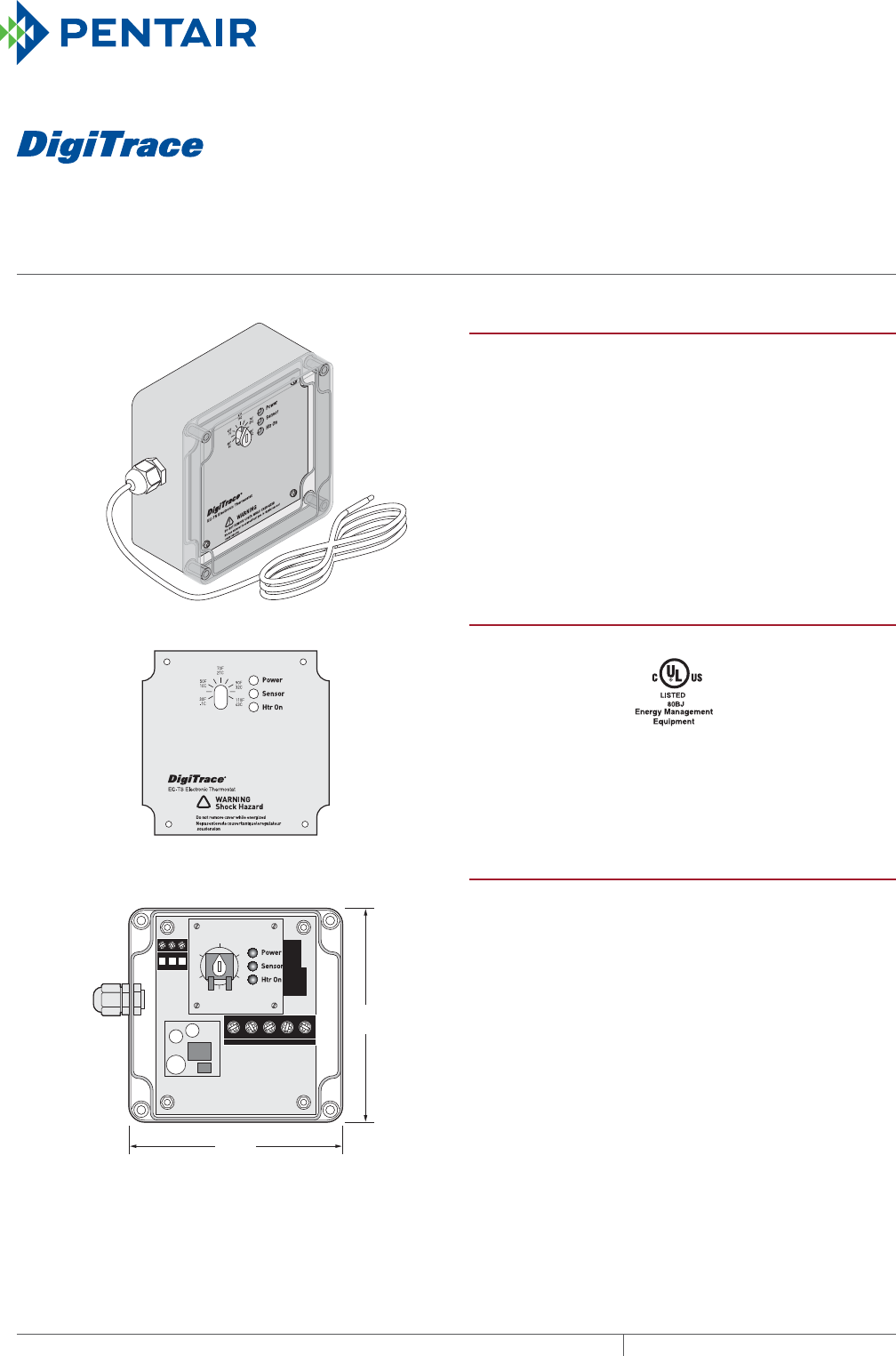
ECTS
AMBIENT, PIPE OR SLAB SENSING ELECTRONIC THERMOSTAT
With 25 foot temperature sensing lead
THERMAL MANAGEMENT SOLUTIONS
EN-DigiTraceECTS-DS-H57460 11/13
422
Wire Cover
est
!
EC-TS without Wire Cover
4.72 in
120 mm
4.8 in
122 mm
PRODUCT OVERVIEW
The DigiTrace EC-TS electronic thermostat is an ambient,
pipe or slab sensing thermostat that is ideal for pipe
freeze protection, flow maintenance, freezer frost heave,
floor heating and snow melting applications. The EC-TS
can be used to control a single heat-tracing -circuit or
as a pilot control of a contactor switching multiple heat-
tracing circuits. The temperature set point can be visually
checked through the clear lid, as can the LED indicators
for alarm, power and heating cable status. The stainless
steel temperature sensor makes it an ideal thermostat for
applications that require an embedded sensor.
GENERAL
Area of use Ordinary area, outdoor
Approvals
Supply voltage 100–277 Vac ±10% 50–60 Hz.
Auto ranging
Common supply for controller and
heat-tracing circuit
ENCLOSURE
Protection NEMA 4X
Cover attachment Captive stainless steel screws
Entries 2 x 1/2 in conduit entries for power
1 gland entry for the sensor
Material Polycarbonate
Mounting Wall mounted
Relative humidity 0% to 90%, noncondensing
Ambient installation
and usage
temperature
–40°F to 140°F (–40°C to 60°C)

ec-ts
423THERMAL MANAGEMENT SOLUTIONS EN-DigiTraceECTS-DS-H57460 11/13
Pipe Freeze Protection
and Flow Maintenance
Fire Sprinkler System
Freeze Protection
Roof and Gutter
De-Icing
Surface Snow
Melting – MI
Surface Snow
Melting – ElectroMelt
Freezer Frost
Heave Prevention
Floor Heating Technical Data
Sheets
CONTROL
Max. switching current 30 A, 277 Vac
Switch type SPST (normally open)
Deadband –0°F, +3°F (–0°C, +1.7°C)
Set point accuracy ±3°F (1.7°C)
Adjustable temperature range 30°F to 110°F (–1°C to 43°C)
MONITORING
Sensor failure Shorted or open sensor
Units °F and °C
LEDs Green LED for power available
Green LED for heating cable on
Red LED for sensor failure
TEMPERATURE SENSOR
Type Thermistor – 0.2°C, 10K ohm, Curve “A”
Construction 3 wire (twisted shielded pair plus ground)
Exposure temperature Minimum: –40°F (–40°C)
Maximum: 212°F (100°C)
Sensor sheath 304 stainless steel
Sensor diameter 0.25 in (0.63 cm)
Sensor length 2 in (5.1 cm)
Leads 20 AWG stranded, PVC overall jacket
Lead length 25 ft (7.6 m)
The sensor cable may be extended to a maximum of 100 ft (30 m) using a 3 wire (twisted shielded pair plus ground) with a
wire gauge size of 20AWG or larger.
CONNECTION TERMINALS
Power supply input Screw Rising Cage Clamp, 18 – 6 AWG
Heating cable output Screw Rising Cage Clamp, 18 – 6 AWG
Ground Screw Rising Cage Clamp, 18 – 6 AWG
Thermistor (sensor) Screw Rising Cage Clamp, 22 – 14 AWG
ORDERING DETAILS
Description Catalog number Part number Weight/lbs
Electronic thermostat with 25 ft sensing lead EC-TS P000001115 1.2
Spare Parts and Accessories
MI cable grounding kit (required if installing MI heating cable) MI-GROUND-KIT P000000279 0.2
Pipe support bracket SB-110 707366 1.0
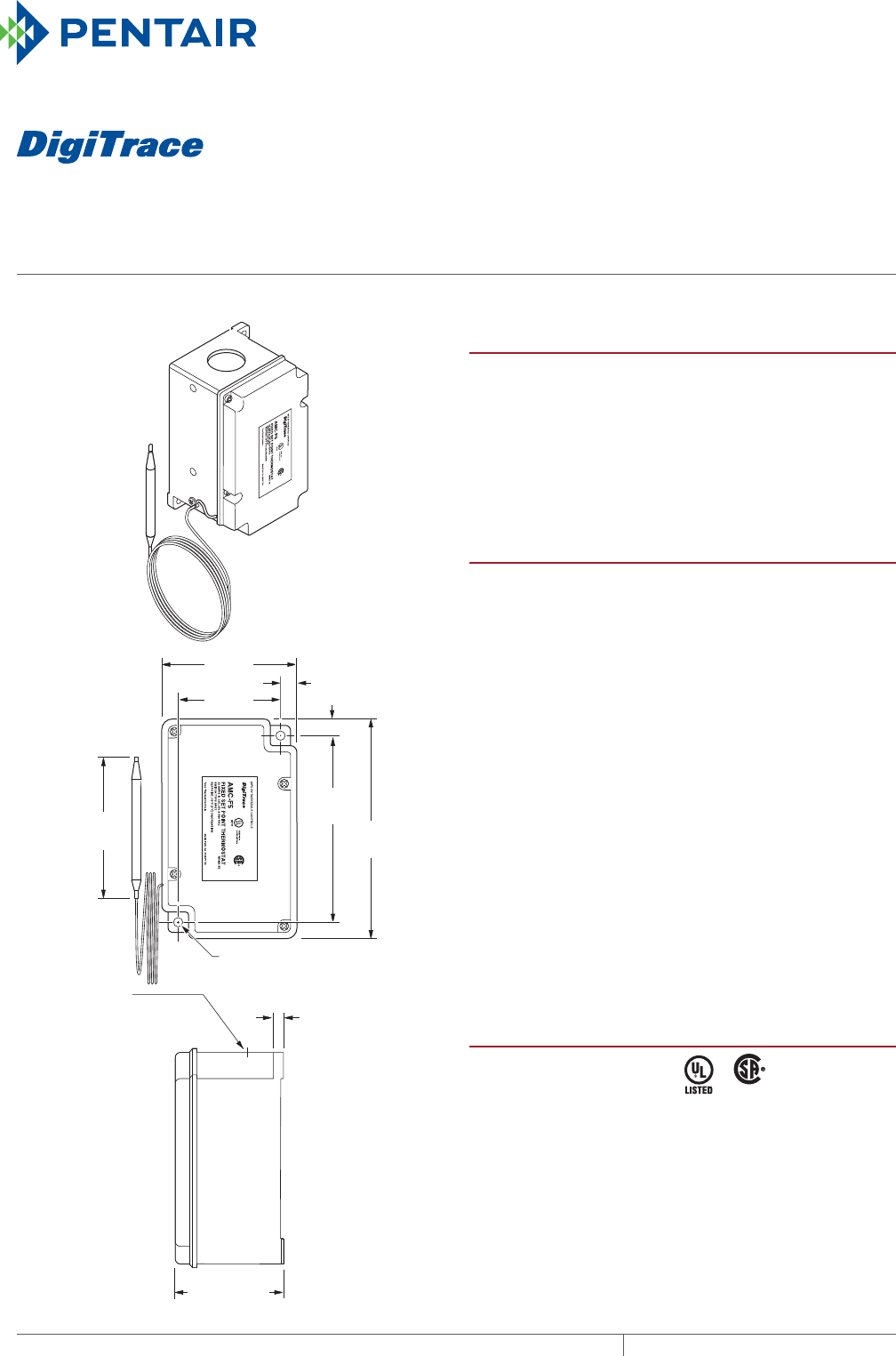
AMCF5
FIXED SET POINT FREEZE PROTECTION THERMOSTAT
For nonhazardous locations
THERMAL MANAGEMENT SOLUTIONS
EN-DigiTraceAMCF5-DS-H55203 11/13
424
R
3.1 in
(80 mm)
4.5 in
(114 mm)
5.2 in
(132 mm)
0.3 in
(8 mm)
0.3 in (8 mm)
3.2 in
(81 mm)
2.5 in
(64 mm)
2.5 in (64 mm)
0.2 in (6 mm)
(2X)
1.1 in (28 mm) hole
for 3/4-in (19 mm)
conduit top of box
0.2 in (6 mm)
mounting hole
(2X)
PRODUCT OVERVIEW
The DigiTrace AMC-F5 thermostat is designed to
control heat-tracing systems used for freeze protection
in nonhazardous locations. The thermostat has a fixed set
point of 40°F (5°C) and can be used for ambient-sensing or
line-sensing. It can be used to control a single heat-tracing
circuit or as a pilot control of a contactor switching multiple
heat-tracing circuits.
SPECIFICATIONS
Enclosure NEMA 4X, UV-resistant
thermoplastics
Entries One 3/4-in (19 mm) through hole
Set point 40°F (5°C) nonadjustable
Sensor exposure limits –30°F to 140°F (–34°C to 60°C)
Housing exposure limits –30°F to 140°F (–34°C to 60°C)
Switch SPST
Electrical rating 22 A at 125 / 250 / 480 Vac
Accuracy ±3°F (±1.7°C)
Deadband 2°F to 12°F (1.1°C to 6.7°C)
above actuation temperature
Set point repeatability ±3°F (±1.7°C)
Sensor type Fluid-filled (silicone) bulb and
2.5 ft (0.8 m) capillary
Sensor material Tin-plated copper
Connection Two 14 AWG (2 mm²) pigtails
One ground screw
APPROVALS
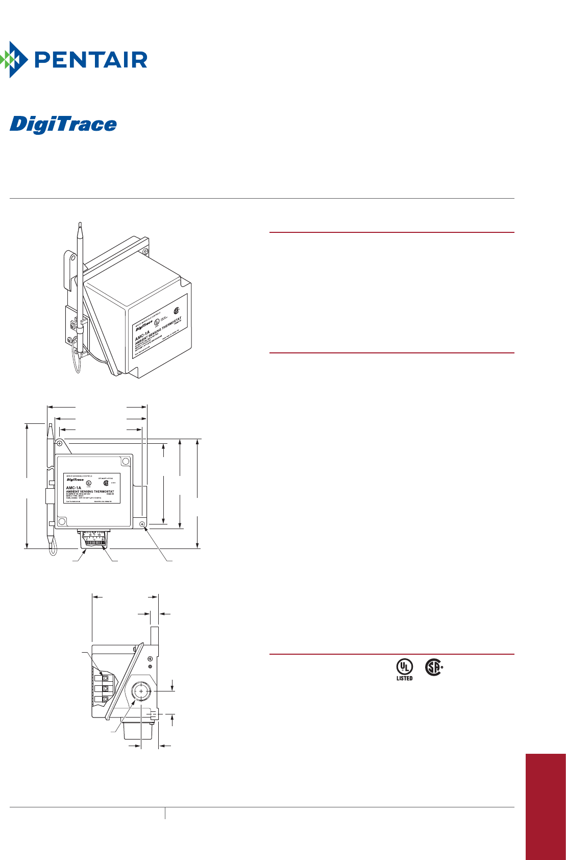
AMC-1A
ambient-sensing thermostat for nonhazardous locations
425THERMAL MANAGEMENT SOLUTIONS EN-DigiTraceAMC1A-DS-H55199 11/13
Pipe Freeze Protection
and Flow Maintenance
Fire Sprinkler System
Freeze Protection
Roof and Gutter
De-Icing
Surface Snow
Melting – MI
Surface Snow
Melting – ElectroMelt
Freezer Frost
Heave Prevention
Floor Heating Technical Data
Sheets
R
0.28 in (7 mm)
mounting holes (2X)
1.2 in
(30 mm)
4.0 in
(102 mm)
4.5 in
(114 mm)
5.6 in
(142 mm)
4.9 in (124 mm)
4.5 in (114 mm)
4.0 in (102 mm)
8.0 in
(202 mm)
3/4 in (19 mm)
NPT conduit entry
3.0 in (76 mm)
0.3 in (9 mm)
0.8 in
(20 mm)
Adjusting
knob
Terminal
block
Removable
knob cover
PRODUCT OVERVIEW
The DigiTrace AMC-1A ambient-sensing thermostat is
designed to control heat-tracing systems used for freeze
protection in nonhazardous locations. The thermostat
responds to ambient temperature changes and has an
adjustable set point. The AMC-1A can be used to control a
single heat-tracing circuit or as a pilot control of a
contactor switching multiple heat-tracing circuits.
SPECIFICATIONS
Enclosure NEMA 4X, polyurethane-coated
cast-aluminum housing,
stainless-steel hardware
Entries One 3/4-in (19 mm) NPT
conduit hub
Set point range 15°F to 140°F (–9°C to 60°C)
Sensor exposure limits –40°F to 160°F (–40°C to 71°C)
Housing exposure limits –40°F to 160°F (–40°C to 71°C)
Switch SPDT
Electrical rating 22 A at 125 / 250 / 480 Vac
Accuracy ±6°F (±3.3°C)
Deadband 2°F to 12°F (1.1°C to 6.7°C)
above actuation temperature
Set point repeatability ±3°F (±1.7°C)
Sensor type Fixed fluid-filled (silicone) bulb
and capillary
Sensor material 300 series stainless steel
Connection terminals Screw terminals, 10–14 AWG
(2–5 mm²)
APPROVALS
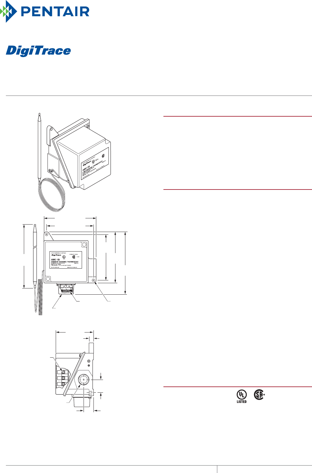
AMC1B
LINE-SENSING THERMOSTAT
For nonhazardous locations
THERMAL MANAGEMENT SOLUTIONS
EN-DigiTraceAMC1B-DS-H55200 11/13
426
R
0.28 in (7 mm)
mounting holes
(2X)
1.2 in
(30 mm)
4.0 in
(102 mm)
4.5 in
(114 mm)
5.6 in
(142 mm)
4.5 in (114 mm)
4.0 in (102 mm)
8.0 in
(202 mm)
3/4 in
NPT (19 mm)
conduit entry
3.0 in
(76 mm)
0.8 in
(20 mm)
Adjusting
knob
Terminal
block
Removable
knob cover
0.3 in
(9 mm)
PRODUCT OVERVIEW
The DigiTrace AMC-1B line-sensing thermostat is designed
to control heat-tracing systems in nonhazardous locations.
The AMC-1B senses pipe or tank wall temperatures and can
be used to control a single heat-tracing circuit or as a pilot
control of a contactor switching multiple heat-tracing
circuits. It can also be used to indicate low-temperature or
high-temperature alarm conditions.
SPECIFICATIONS
Enclosure NEMA 4X, polyurethane-coated cast-
aluminum housing, stainless steel
hardware
Entries One 3/4-in NPT conduit hub
Set point range 25°F to 325°F (–4°C to 163°C)
Sensor exposure
limits
–40°F to 420°F (–40°C to 215°C)
Housing exposure
limits
–40°F to 160°F (–40°C to 71°C)
Switch SPDT
Electrical rating 22 A at 125 / 250 / 480 Vac
Accuracy ±6°F (±3.3°C)
Deadband 2°F to 12°F (1.1°C to 6.7°C) above
actuation temperature
Set point
repeatability
±3°F (±1.7°C)
Sensor type Fluid-filled (silicone) bulb and 9 ft
(2.7 m) capillary
Sensor material 300 series stainless steel
Connection
terminals
Screw terminals, 10–14 AWG
(2–5 mm²)
APPROVALS
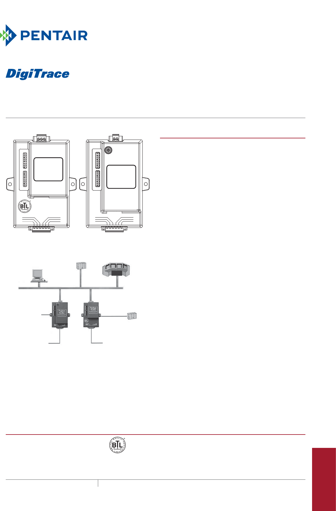
427 THERMAL MANAGEMENT SOLUTIONS EN-DigiTraceProtoNode-DS-H58621 11/13
Protonode
MULTI-PROTOCOL DEVICE SERVER
ProtoNode-RER and ProtoNode-LER
Pipe Freeze Protection
and Flow Maintenance
Fire Sprinkler System
Freeze Protection
Roof and Gutter
De-Icing
Surface Snow
Melting – MI
Surface Snow
Melting – ElectroMelt
Freezer Frost
Heave Prevention
Floor Heating Technical Data
Sheets
GUI BMS
Modbus TCP BACnet IP
Ethernet (TCP/IP)
Serial to
LonWorks
To C910-485 and
ACCS-30 controllers
BACnet MS/TP
Metasys N2 by JCI
LonWorks
Ethernet
to Serial
ProtoNode-RERProtoNode-LER
ProtoNode-LERProtoNode-RER
S3
S2
S1
S0
B3
B2
B1
B0
A7
A6
A5
A4
A3
A2
A1
A0
FRAME GND
- PWR
+PWR
RS 485+
RS 485 -
RS 485 GND
By FieldServer Technologies
www.ProtoCessor.com
PROTOCESSOR
LONWORKS ®
PROTONODE
By FieldServer Technologies
www.ProtoCessor.com
PROTOCESSOR
SERIAL ETHERNET
PROTONODE
S
e
r
v
i
c
e
P
i
n
FRAME GND
- PWR
+PWR
RS 485+
RS 485 -
RS 485 GND
S3
S2
S1
S0
B3
B2
B1
B0
A7
A6
A5
A4
A3
A2
A1
A0
To C910-485 and
ACCS-30
controllers
PRODUCT OVERVIEW
The DigiTrace ProtoNode is an external, high performance
multi-protocol gateway for customers needing protocol
translation between Building Management Systems (BMS)
using LonWorks®, BACnet® or Metasys® N2 and the
DigiTrace C910 or ACS-30 controllers.
Pentair Thermal Management and FieldServer Technologies
developed the DigiTrace ProtoNode-RER and DigiTrace
ProtoNode-LER pre-programmed with the C910 and ACS-30
Modbus® maps for simple integration into your BMS. The
field protocol, DigiTrace controller, Mac address, node ID
and baud rate are DIP switch selectable. One ProtoNode can
connect one ACS-30 system or up to eight C910 controllers.
ProtoNode-RER: Provides support for Modbus RTU to
BACnet MS/TP, BACnet IP (BTL Certified), and Metasys
N2 protocol translation. The gateway features an ARM9
processor for fast performance and includes two RS-485 and
one Ethernet ports.
ProtoNode-LER: Provides support for Modbus RTU to
LonWorks protocol translation. The gateway features an
ARM7 processor for fast performance and includes one
serial, one RS-485, one Ethernet and one LonWorks ports.
Features and benefits:
• The most flexible and versatile multiprotocol device serv-
er on the market
• BACnet International’s BTL Certification makes the
ProtoNode-RER the most reliable gateway on the market
• Dip switch selectable configuration files simplify the
ProtoNode installation
• Multi-client and multi-server support ensures interoper-
ability between any Industrial and or Building Automation
protocols
• Flash upgradable
For additional information, contact your Pentair Thermal
Management representative or call (800) 545-6258.
APPROVALS
BACnet Testing Labs (BTL) B-ASC on ProtoNode-RER

PROTONODE MULTIPROTOCOL DEVICE SERVER
THERMAL MANAGEMENT SOLUTIONS
EN-DigiTraceProtoNode-DS-H58621 11/13
428
SPECIFICATIONS
ProtoNode-RER ProtoNode-LER
Electrical connections • One 6-pin Phoenix connector, one
RS-485 +/- ground port, power +/-
frame ground port
• One 3-pin RS-485 Phoenix connec-
tor, one RS-485 +/- ground port
• One Ethernet-10/100 Ethernet port
• One 6-pin Phoenix connector, one
RS-485 +/- ground port, power +/-
frame ground port
• One Ethernet-10/100 Ethernet port
• One FTT-10 LonWorks port
Power requirements 9–30 Vdc or Vac, or 5 Vdc 9–30 Vdc or Vac, or 5 Vdc
Current draw 150 mA 12 V 279 mA 12 V
Supported field protocols • BACnet IP (Ethernet)
• BACnet MS/TP (RS-485)
• Metasys N2 open (RS-485)
LonWorks (serial FTT-10)
Operating temperature –40°F to 187°F (–40°C to 85°C) –40°F to 187°F (–40°C to 85°C)
Relative humidity 5–90% RH, noncondensing 5–90% RH, noncondensing
Enclosure dimensions 4.37 in L x 2.75 in W x 1.50 in H
(11.10 cm L x 7.00 cm W x 3.81 cm H)
4.37 in L x 2.75 in W x 1.50 in H
(11.10 cm L x 7.00 cm W x 3.81 cm H)
ORDERING DETAILS
Description Catalog number Part number Weight (lbs)
DigiTrace ProtoNode-RER:
BACnet MSTP/IP and Metasys N2
protocol gateway
ProtoNode-RER P000001227 1.3
DigiTrace ProtoNode-LER:
LonWorks protocol gateway
ProtoNode-LER P000001228 1.3
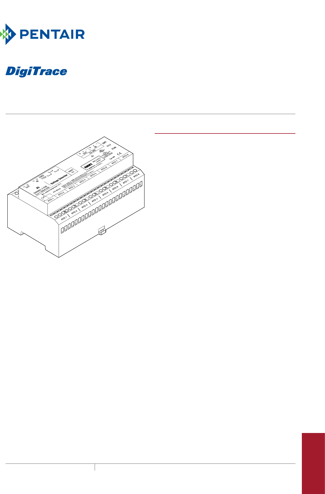
RMM2
heat-tracing remote monitoring module
429THERMAL MANAGEMENT SOLUTIONS EN-DigiTraceRMM2-DS-H56855 11/13
Pipe Freeze Protection
and Flow Maintenance
Fire Sprinkler System
Freeze Protection
Roof and Gutter
De-Icing
Surface Snow
Melting – MI
Surface Snow
Melting – ElectroMelt
Freezer Frost
Heave Prevention
Floor Heating Technical Data
Sheets
RMM2 without enclosure PRODUCT OVERVIEW
The DigiTrace remote monitoring module (RMM2) provides
temperature monitoring capability for the NGC heat-tracing
control and monitoring systems. The RMM2 accepts
up to eight RTDs that measure pipe, vessel, or ambient
temperatures in a heat-tracing system. Multiple RMM2s
communicate with a single NGC controller to provide
centralized monitoring of temperatures. A single, twisted
pair RS-485 cable connects up to 16 RMM2s for a total
monitoring capacity of 128 temperatures.
Control and monitoring
The RMM2 modules are used to aggregate RTD wires in one
remote location and send the information back to the control
system through a single twisted pair cable. This helps
reduce installation costs since only one conduit run returns
to the controller, rather than eight. The RMM2s are placed
near desired measurement locations in nonhazardous or
hazardous locations. Multiple temperature sensor inputs
are networked over a single cable, significantly reducing
installation cost.
Alarms
Each temperature sensor connected to a RMM2 may have
individual low- and high-temperature alarms. Alarm limits
are set and alarm conditions are reported at the control
panel. Additional alarms are triggered for failed temperature
sensors and communication errors. Alarms may be reported
remotely through an alarm relay in the control system
or through an RS-485 connection to a host computer
supporting the Modbus® protocol.
Configurations
The RMM2 clips to a DIN 35 rail and can be mounted
in a choice of enclosures, as required for the area
classification and environment. For aggressive
environments and Division 2 hazardous locations, Pentair
Thermal Management offers a glass-reinforced polyester
NEMA 4X enclosure.
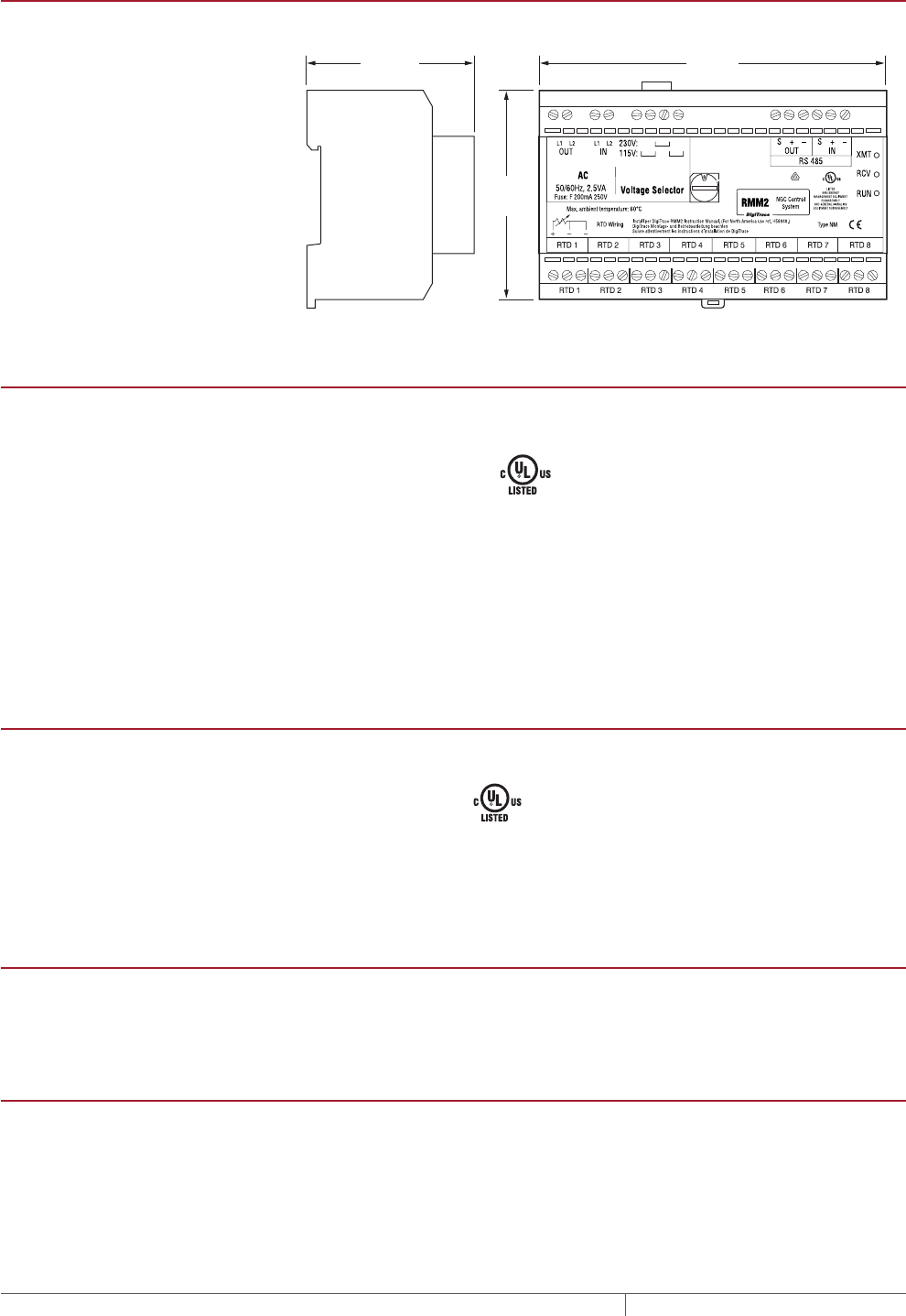
RMM2
THERMAL MANAGEMENT SOLUTIONS
EN-DigiTraceRMM2-DS-H56855 11/13
430
DIMENSIONS
2 3/8 in
(60 mm)
3 in
(75 mm)
5 in
(125 mm)
Figure 1
GENERAL
RMM2
Area of use (with appropriate
enclosure)
Nonhazardous or hazardous locations
Approvals Nonhazardous locations 80BJ ENERGY MANAGEMENT
EQUIPMENT SUBASSEMBLY
AND GENERAL SIGNALING
EQUIPMENT SUBASSEMBLY
Type NM
Ambient operating temperature range –40°F to 140°F (–40°C to 60°C)
Ambient storage temperature range –40°F to 140°F (–40°C to 60°C)
Relative humidity 5% to 95%, noncondensing
Supply voltage (nominal) 115/230 Vac, ±10%, jumper selectable. (The default voltage is 230 Vac. A jumper is
supplied to convert to 115 Vac.)
Internal power consumption < 3 W
RMM2 WITH DIVISION 2 ENCLOSURE
RMM2-4X
Protection Type 4X
Approvals Hazardous locations
9Z63 TEMPERATURE
INDICATING EQUIPMENT
FOR USE IN HAZARDOUS
LOCATIONS
Class I, Division 2, Groups A, B, C, D
Class II, Division 2, Groups F, G
Material Glass-reinforced polyester, silicone gasket, stainless steel hardware
Entries Six 3/4-in (19 mm) NPT conduit entrance holes, four plugged
Mounting Surface mounting dimensions are shown in Figure 2
TEMPERATURE SENSOR INPUTS
Type 100 platinum RTD, 3-wire, α =0.00385 //°C
Quantity per RMM2 Up to 8
RTDs can be extended with a 3-conductor shielded cable of 20 maximum per
conductor
COMMUNICATION TO NGC CONTROLLER
Type RS-485
Cable One shielded twisted pair
Length 4000 ft (1200 m) maximum
Quantity Up to 16 RMM2s may be connected to one NGC-30
Address Switch-selectable on RMM2, 16 addresses, 0–9, A-F
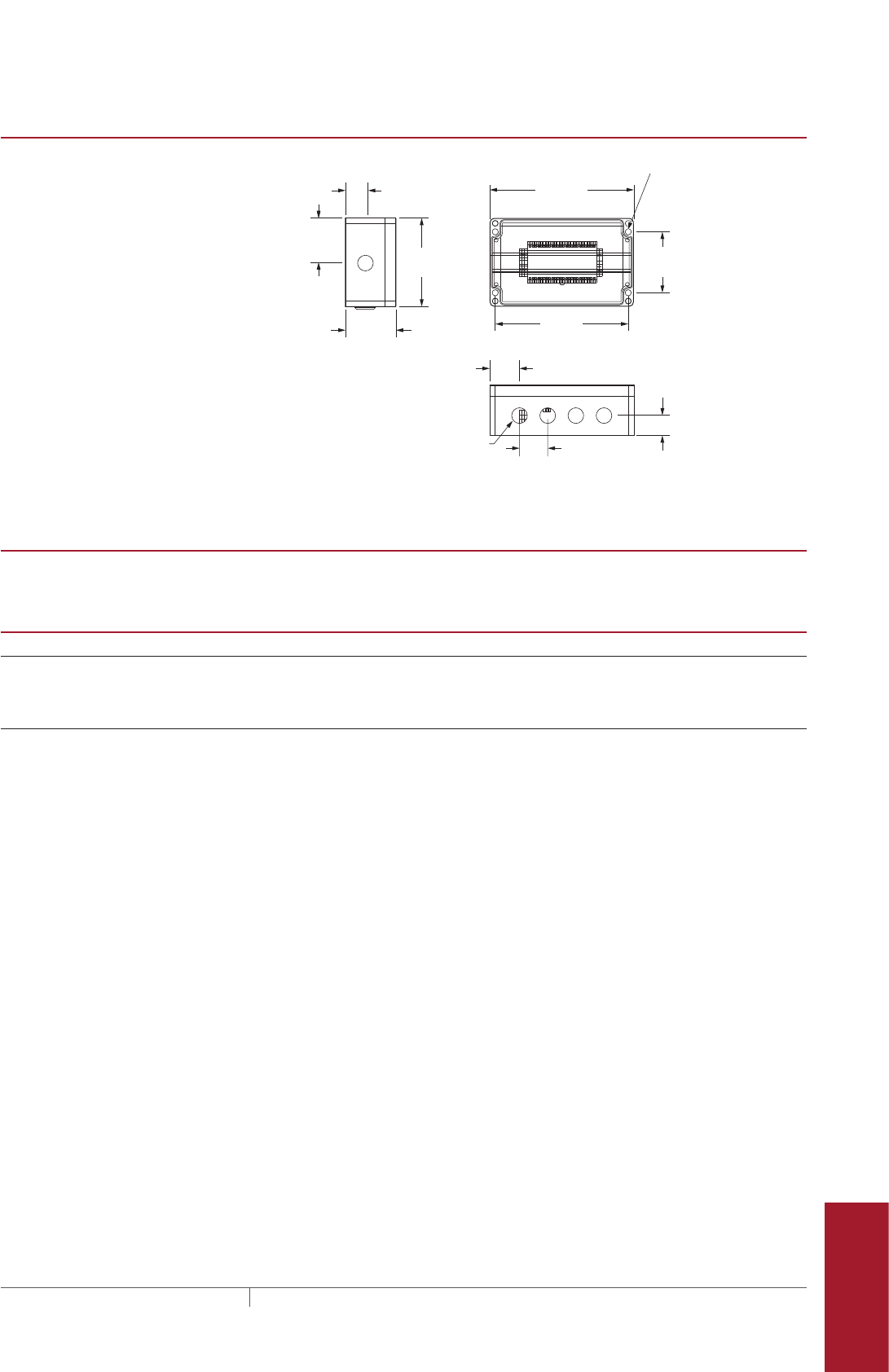
rmm2
431 THERMAL MANAGEMENT SOLUTIONS EN-DigiTraceRMM2-DS-H56855 11/13
Pipe Freeze Protection
and Flow Maintenance
Fire Sprinkler System
Freeze Protection
Roof and Gutter
De-Icing
Surface Snow
Melting – MI
Surface Snow
Melting – ElectroMelt
Freezer Frost
Heave Prevention
Floor Heating Technical Data
Sheets
ENCLOSURE DIMENSIONS
3.58 in
(91 mm)
2.13 in (54 mm)
3 X 2.00 in
(50.8 mm)
9.45 in
(240 mm)
10.24 in
(260 mm)
(cover not shown)
3.15 in
(80 mm)
1.61 in
(41 mm)
4.33 in
(110 mm)
1.4 in (35.6 mm)
6.30 in
(160 mm)
Division 2 enclosure
RMM2-4X
Figure 2 0.26 in
(06.5 mm)
1.08 in
(27.4 mm) 6 X
CONNECTION TERMINALS
Power supply 24–12 AWG
RTD, communications 24–12 AWG
ORDERING DETAILS
Catalog number Part number Weight
Remote monitoring module (RMM2)
RMM2, eight RTD inputs, no enclosure RMM2 051778-000 1.5 lb (0.7 kg)
RMM2 with NEMA 4X enclosure RMM2-4X 523420-000 4 lb (1.8 kg)
Cables
RTD extension cable, 1000-ft reel MONI-RTD-WIRE 962661-000 20 lb (9.1 kg)
RS-485 cable, 1000-ft reel MONI-RS485-WIRE 549097-000 17 lb (7.7 kg)
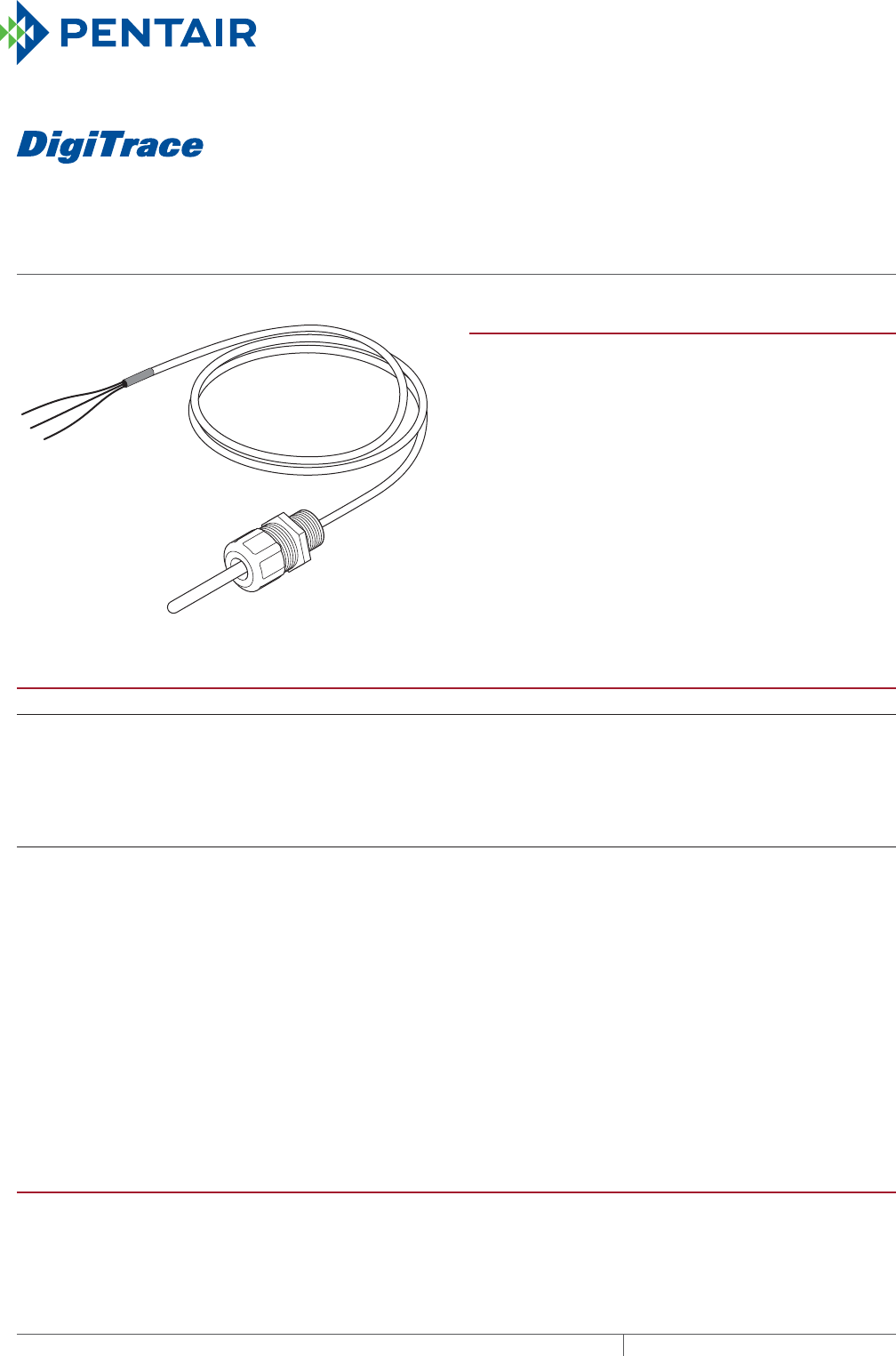
RTD200
rtd temperature sensor for ambient sensing
THERMAL MANAGEMENT SOLUTIONS
EN-DigiTraceRTD200-DS-H56997 11/13
432
PRODUCT OVERVIEW
The DigiTrace RTD-200 is a three-wire platinum RTD
(resistance temperature detector) typically used with
electronic control systems that require accurate ambient
temperature sensing. The RTD-200 comes with a 1/2" NPT
fitting that installs to the appropriate conduit box.
This allows mounting of the RTD in a typical ambient
location. This also allows for splicing of RTD extension wire
back to the controller.
SPECIFICATIONS
Sensor
Housing 316 stainless steel
Dimensions 3-in (7.6 mm) length, 1/4-in (6 mm) diameter
Accuracy ± 0.3°F (± 0.2°C)
Range –100°F to 300°F (–73°C to 149°C)
Resistance 100 ohms ± 0.25 ohm at 0°C α=0.00385 ohms/ohm/°C
Extension wire
Wire size (each of three) 22 AWG
Note: The length of RTD extension wires is determined by the wire gauge used. To
reduce the likelihood that electrical noise will affect temperature measurement,
keep RTD extension wires as short as possible. Use shielded instrument cable
such as DigiTrace MONI-RTD-WIRE (22 AWG, PVC insulation, –30°F to 140°F,
–20°C to 60°C) or Belden 83553(22 AWG, FEP insulation, –95°F to 395°F, –70°C to 200°C).
Wire dielectric strength 600 V
Length 6 ft (1.8 m)
Outer jacket Fluoropolymer
Maximum exposure temperature 300°F (149°C)
Sensor fitting 1/2-in (12.7 mm) NPT with sealing washer and nut
APPROVALS
.
Approvals associated with control device. Not to be used in Division 1 areas.
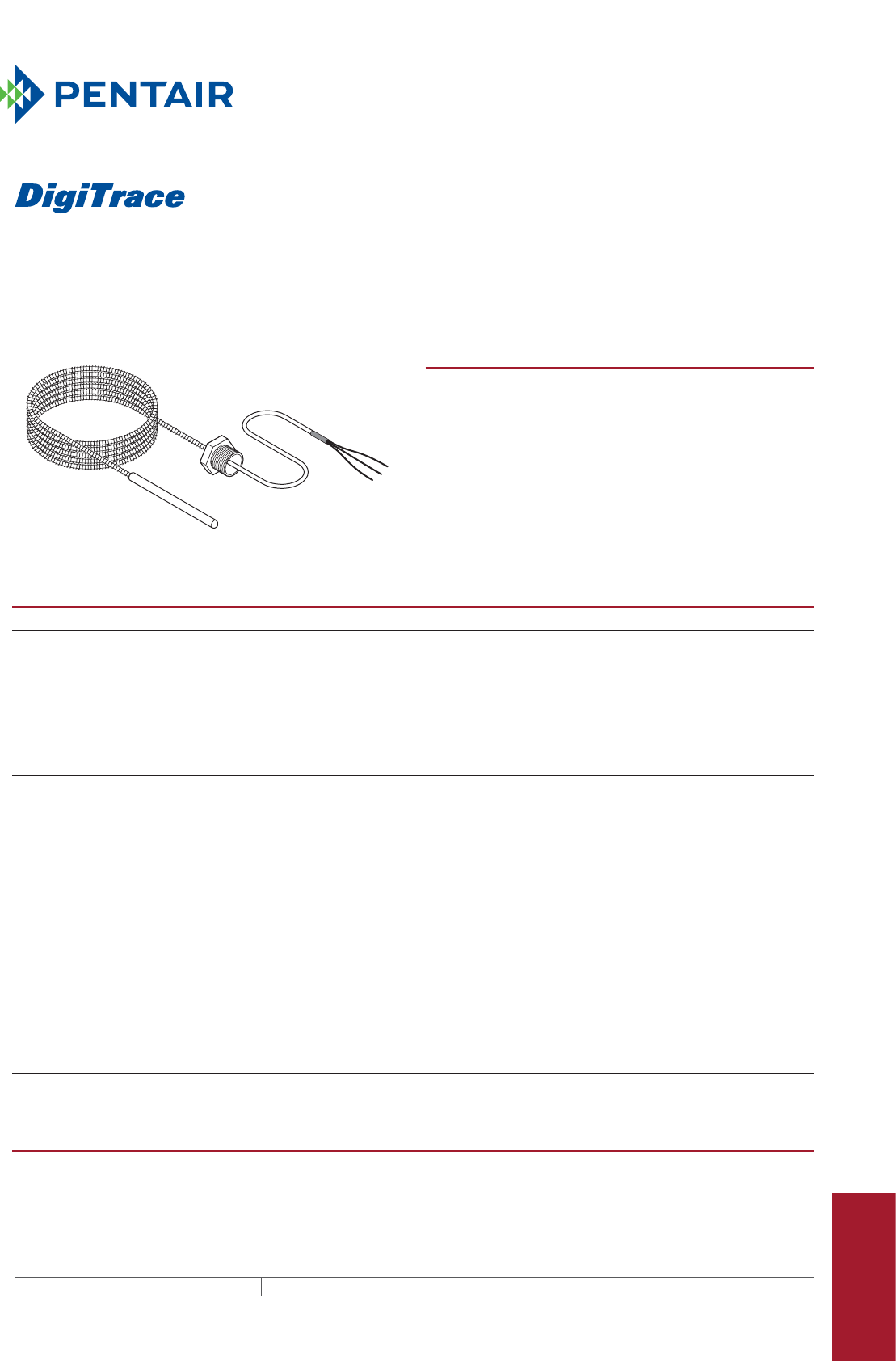
RTD3CS, RTD10CS, anD RTD50CS
rtd temperature sensors
433THERMAL MANAGEMENT SOLUTIONS EN-DigiTraceRTD3CSRTD10CS-DS-H56988 11/13
For temperature measurement up to 400°F (204°C)
Pipe Freeze Protection
and Flow Maintenance
Fire Sprinkler System
Freeze Protection
Roof and Gutter
De-Icing
Surface Snow
Melting – MI
Surface Snow
Melting – ElectroMelt
Freezer Frost
Heave Prevention
Floor Heating Technical Data
Sheets
PRODUCT OVERVIEW
The DigiTrace RTD3CS, RTD10CS and RTD50CS are three-
wire platinum RTD (resistance temperature detectors)
typically used with monitoring and control systems such as
the DigiTrace 910 controller when accurate temperature
control is required.
The RTD3CS, RTD10CS and RTD50CS can be installed
directly to the controller using the supplied 1/2" conduit
fitting or to an RTD junction box where RTD extension wire is
used.
SPECIFICATIONS
Sensor
Housing 316 stainless steel
Dimensions 3-in (76 mm) length 3/16-in (8 mm) diameter
Sensing area 1-1/2 in (38 mm)
Accuracy ±1°F (0.5°C) at 32°F (0°C)
Range –76°F to 400°F (–60°C to 204°C)
Resistance 100 ohms at 0°C α =0.00385 ohms/ohm/°C
Extension wires
Wire size (each of three) 20 AWG, stranded tinned copper
Note: The length of RTD extension wires is determined by the wire gauge used. To
reduce the likelihood that electrical noise will affect temperature measurement,
keep RTD extension wires as short as possible. Use shielded instrument cable
such as DigiTrace MONI-RTD-WIRE (22 AWG, PVC insulation, –30°F to 140°F,
–20°C to 60°C) or Belden 83553 (22 AWG, FEP insulation, –95°F to 395°F, –70°C to 200°C).
Wire insulation rating 300 V
Length RTD3CS: 3-ft (0.3 m) flexible armor, 18-in (457 mm) lead wire
RTD10CS: 10-ft (3 m) flexible armor, 18-in (457 mm) lead wire
RTD50CS: 50-ft (15.2 m) flexible armor, 18-in (457 mm) lead wire
Outer shield Stainless steel flexible armor (not suitable for underground applications)
Maximum exposure temperature 400°F (204°C)
Conduit bushing 1/2-in (12.7 mm) NPT
Additional materials required AT-180 aluminum tape
APPROVALS
Approvals associated with control device. Not to be used in Division 1 areas.
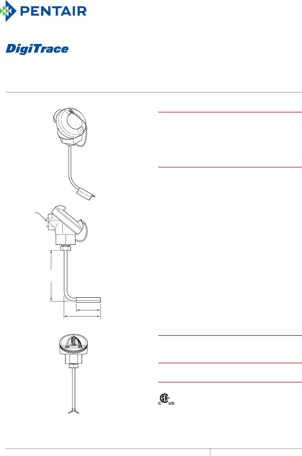
RTD4AL
RTD TEMPERATURE SENSOR
For temperature measurement up to 900°F (482°C)
THERMAL MANAGEMENT SOLUTIONS
EN-DigiTraceRTD4AL-DS-H56915 11/13
434
4.25 in
(108 mm)
3/4-in NPT
(19 mm)
conduit
opening
3 in (76 mm)
2 in (51 mm)
PRODUCT OVERVIEW
The DigiTrace RTD4AL is a three-wire platinum RTD
(resistance-temperature detector) typically used with
monitoring and control systems that require accurate
temperature control. The RTD4AL kit can be used with a
wide variety of DigiTrace monitoring and control systems.
SPECIFICATIONS
Sensor housing Aluminum; NEMA 4X
Sensor sheath 316 stainless steel
Range –100°F to 900°F (–73°C to 482°C)
maximum
Accuracy ±1°F (0.5°C) at 32°F (0°C)
Resistance 100 ohms at 0°C α =0.00385 ohms/
ohm/°C
Connection 3/4-in (19 mm) NPT conduit hub
Note: The length of RTD extension
wires is determined by the
wire gauge used. To reduce the
likelihood that electrical noise will
affect temperature measurement,
keep RTD extension wires as
short as possible. Use shielded
instrument cable such as DigiTrace
MONI-RTD-WIRE (22 AWG, PVC
insulation, –30°F to 140°F, –20°C to
60°C) or Belden 83553 (22 AWG, FEP
insulation, –95°F to 395°F, –70°C to
200°C).
ADDITIONAL MATERIALS REQUIRED
Pipe strap, conduit, 16–22 AWG
shielded instrument cable
KIT CONTENTS
One RTD temperature sensor
APPROVALS
The RTD4AL is CSA certified to U.S. and Canadian standards.
Class I, Div. 2, Groups A, B, C, D
Class II, Div. 2, Groups F, G
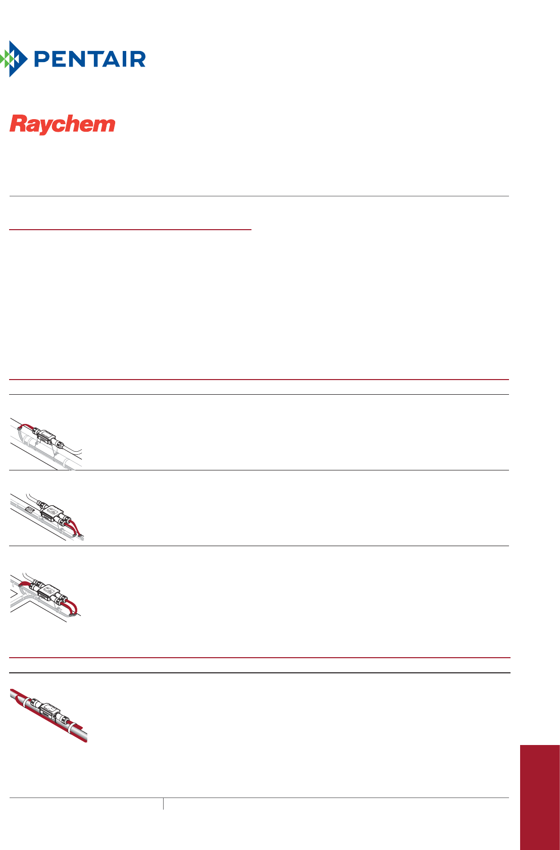
435THERMAL MANAGEMENT SOLUTIONS EN-RaychemRayClicConnectionKits-DS-H57545 11/13
RayCliC
CONNECTION KITS AND ACCESSORIES
For XL-Trace, IceStop and HWAT self-regulating heating cables
Pipe Freeze Protection
and Flow Maintenance
Fire Sprinkler System
Freeze Protection
Roof and Gutter
De-Icing
Surface Snow
Melting – MI
Surface Snow
Melting – ElectroMelt
Freezer Frost
Heave Prevention
Floor Heating Technical Data
Sheets
PRODUCT OVERVIEW
The Raychem RayClic connection system is a simple, fast
and reliable set of connection kits developed for select
XL-Trace, IceStop and HWAT self-regulating heating cables.
There is no wire stripping needed because the insulation
displacement connector makes the electrical connection.
The easy-to-install RayClic connection system reduces
installation time, lowering the total installed cost of the
heating cable system.
Simple
• No need for special tools
• Three-step installation
Reliable
• Intuitive installation
• Rugged, waterproof, UV-resistant enclosure
Cost-effective
• Quick installation
POWERED CONNECTION KITS
Catalog number Part number Description
RayClic-PC 233053-000 A RayClic-PC can supply power to one heating cable. Each kit contains one
RayClic-PC power connection, one RayClic-E end seal, and one SB-04 pipe
mounting bracket. The kit includes 5' power lead wires and a conduit fitting; the
junction box and flexible conduit required to make a complete connection are not
included.
Weight: 1.8 lb (0.8 kg)
RayClic-PS 861247-000 A RayClic-PS can be used as a power connection kit for supplying power to two
heating cables. Each kit contains one RayClic-PS powered splice connection,
two RayClic-E end seals, and one SB-04 pipe mounting bracket. The kit includes
5' power lead wires and a conduit fitting. The junction box and flexible conduit
required to make a complete connection are not included.
Weight: 2.0 lb (0.9 kg)
RayClic-PT 804231-000 A RayClic-PT can be used as a power connection kit for supplying power to three
heating cables. Each kit contains one RayClic-PT powered tee connection, three
RayClic-E end seals, and one SB-04 pipe mounting bracket. The kit includes
5' power lead wires and a conduit fitting. The junction box and flexible conduit
required to make a complete connection are not included.
Weight: 2.0 lb (0.9 kg)
UNPOWERED CONNECTION KITS
Catalog number
Part number
Description
RayClic-S
R
RayClic
WARNING: SHOCK HAZARD
Do not open while energized
R
LISTED DESIG. 3A, 3B, 3C, 2E
3
1
/
8
"
559871-000 Splice kits are installed as needed to connect two heating cables together at one
point. Each kit contains one RayClic-S splice.
Weight: 1.3 lb (0.6 kg)
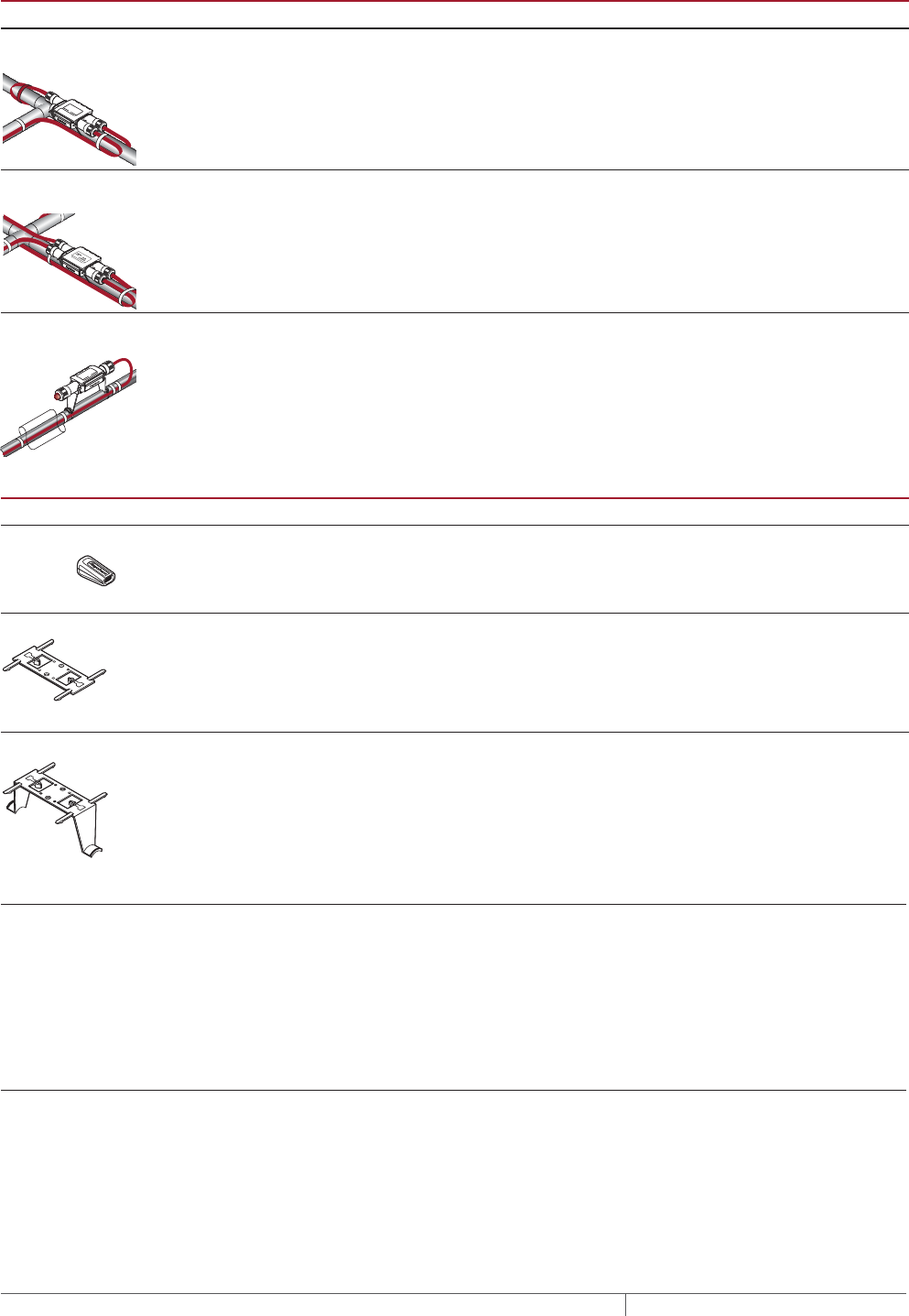
RAYCLIC CONNECTION KITS AND ACCESSORIES
THERMAL MANAGEMENT SOLUTIONS
EN-RaychemRayClicConnectionKits-DS-H57545 11/13
436
UNPOWERED CONNECTION KITS
Catalog number
Part number
Description
RayClic-T 014023-000 Tee kits are installed as needed to connect three heating cables together at one
point. Each kit contains one RayClic-T tee connection and one RayClic-E end seal.
Weight: 1.9 lb (0.9 kg)
RayClic-X
R
546349-000 RayClic-X kits are installed as needed to connect four heating cables together at
one point. Each kit contains one RayClic-X cross and two RayClic-E end seals.
Weight: 2.0 lb (0.9 kg)
RayClic-LE P000000770 Lighted end seal kits are installed wherever an end-of-line signal light is
required. Each kit contains one RayClic-LE lighted end seal and one RayClic-
SB-04 pipe mounting bracket.
Weight: 1.8 lb (0.8 kg)
ACCESSORIES
Catalog number Part number Description
RayClic-E 805979-000 The RayClic-E is a replacement end seal kit.
RayClic-SB-02 852001-000 The RayClic-SB-02 is a wall mounting bracket for use with any RayClic connection
kit.
RayClic-SB-04 616809-000 The RayClic-SB-04 is a pipe mounting bracket for use with any RayClic connection
kit. One pipe mounting bracket is included with each powered connection kit and
the RayClic-LE lighted end seal kit.
RayClic System Specifications
Rated voltage 120–277 V
Maximum circuit breaker size 30 A
Maximum exposure temperature 150°F (65°C)
Minimum installation temperature 0°F (–18°C)
Enclosure rating NEMA 4X
Applicable Products
XL-Trace 5/8XL1-CR/CT and 5/8/12XL2-CR/CT
IceStop GM-1XT, GM-1X, GM-2XT and GM-2X
HWAT HWAT-R2, HWAT-P1

rayclic connection kits and accessories
437 THERMAL MANAGEMENT SOLUTIONS EN-RaychemRayClicConnectionKits-DS-H57545 11/13
Pipe Freeze Protection
and Flow Maintenance
Fire Sprinkler System
Freeze Protection
Roof and Gutter
De-Icing
Surface Snow
Melting – MI
Surface Snow
Melting – ElectroMelt
Freezer Frost
Heave Prevention
Floor Heating Technical Data
Sheets
APPROVALS
718K Pipe Heating Cable
877Z De-Icing and Snow Melting
With XL-Trace and IceStop
heating cable only
For Class I, Div. 2,
Groups A,B,C,D
hazardous locations- GM-1XT
and GM-2XT only
DESIGN AND INSTALLATION
For proper design and installation of a RayClic connection system, use the
appropriate product design guide and the installation instructions included with
the connection kit.
GROUNDFAULT PROTECTION
To minimize the danger of fire from sustained electrical arcing if the heating
cable is damaged or improperly installed, and to comply with the requirements
of Pentair Thermal Controls, agency certifications, and national electrical codes,
ground-fault equipment protection must be used on each heating cable branch
circuit. Arcing may not be stopped by conventional circuit protection. Many
DigiTrace control and monitoring systems meet the ground-fault protection
requirement.
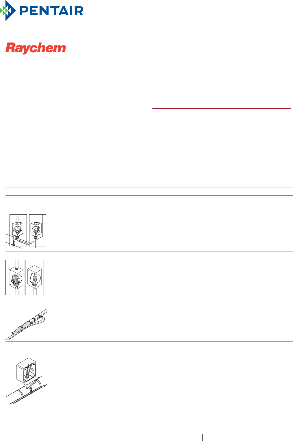
FTC
HEAT SHRINKABLE CONNECTION KITS
For XL-Trace, IceStop and RaySol self-regulating heating cables
THERMAL MANAGEMENT SOLUTIONS
EN-RaychemFTCheatshrinkablekits-DS-H58159 11/13
438
PRODUCT OVERVIEW
The Raychem FTC heat shrinkable connection kits are used
with XL-Trace, IceStop and RaySol self-regulating heating
cables.
The FTC connection kits are designed to provide low cost
power connection and low profile splice and tee kits.
The FTC power connection kits can be used for circuit
breakers rated up to 40 A.
POWERED CONNECTION KITS
Catalog number Part number Description
FTC-P
RaySol
IceStop
XL-
Trace
111711-000 Power connection kit with end seal:
The FTC-P power connection and end seal kit is for use with XL-Trace, RaySol
and IceStop heating cables. Materials for one power connection and end seal is
included in the kit.
FTC-XC 368979-000 Power connection kit with end seal:
The FTC-XC power connection and end seal kit is for use with XL-Trace and RaySol
heating cables that are run through conduit to a junction box. Materials for one
power connection and end seal is included in the kit.
FTC-HST 354169-000 Splice or Tee kit:
The FTC-HST splice or tee kit is for use with XL-Trace, RaySol and IceStop heating
cables. Material for two splice or tees included in each kit.
FTC-PSK P000000927 Pipe stand and power connection kit:
The FTC-PSK pipe stand and power connection kit is for use with XL-Trace heating
cables. The stand is designed specifically for the DigiTrace ECW-GF electronic
controllers and is compatible with other junction boxes that have 1 inch NPT
entries, threaded or non-threaded. Materials for one power connection and end
seal is included in the kit.

ftc heat shrinkable connection kits
439THERMAL MANAGEMENT SOLUTIONS EN-RaychemFTCheatshrinkablekits-DS-H58159 11/13
Pipe Freeze Protection
and Flow Maintenance
Fire Sprinkler System
Freeze Protection
Roof and Gutter
De-Icing
Surface Snow
Melting – MI
Surface Snow
Melting – ElectroMelt
Freezer Frost
Heave Prevention
Floor Heating Technical Data
Sheets
SPECIFICATIONS
Rated voltage 120–277 V
Maximum circuit breaker size 40 A
Maximum exposure temperature 150°F (65°C)
Minimum installation temperature 0°F (–18°C)
Enclosure rating NEMA 4X
APPLICABLE PRODUCTS
XL-Trace 5/8XL1-CR/CT and 5/8/12XL2-CR/CT
IceStop GM-1XT, GM-1X, GM-2XT and GM-2X
RaySol RaySol-1 and RaySol-2
APPROVALS
DESIGN AND INSTALLATION
For proper design and installation of a FTC connection kit, use the appropriate
product design guide and the installation instructions included with the
connection kit.
GROUNDFAULT PROTECTION
To minimize the danger of fire from sustained electrical arcing if the heating
cable is damaged or improperly installed, and to comply with the requirements
of Pentair Thermal Management, agency certifications, and national electrical
codes, ground-fault equipment protection must be used on each heating cable
branch circuit. Arcing may not be stopped by conventional circuit protection.
718K Pipe Heating Cable or
877Z De-Icing and Snow Melting
Equipment or 9J8 6 Radiant
Heating Cable
APPROVED
For XL-Trace heating cables
Certified with IceStop and
RaySol heating cables
With XL-Trace and IceStop heating cables
Hazardous locations:
Class I, Div 2. Groups A, B, C, D
GM-1XT and GM-2XT only
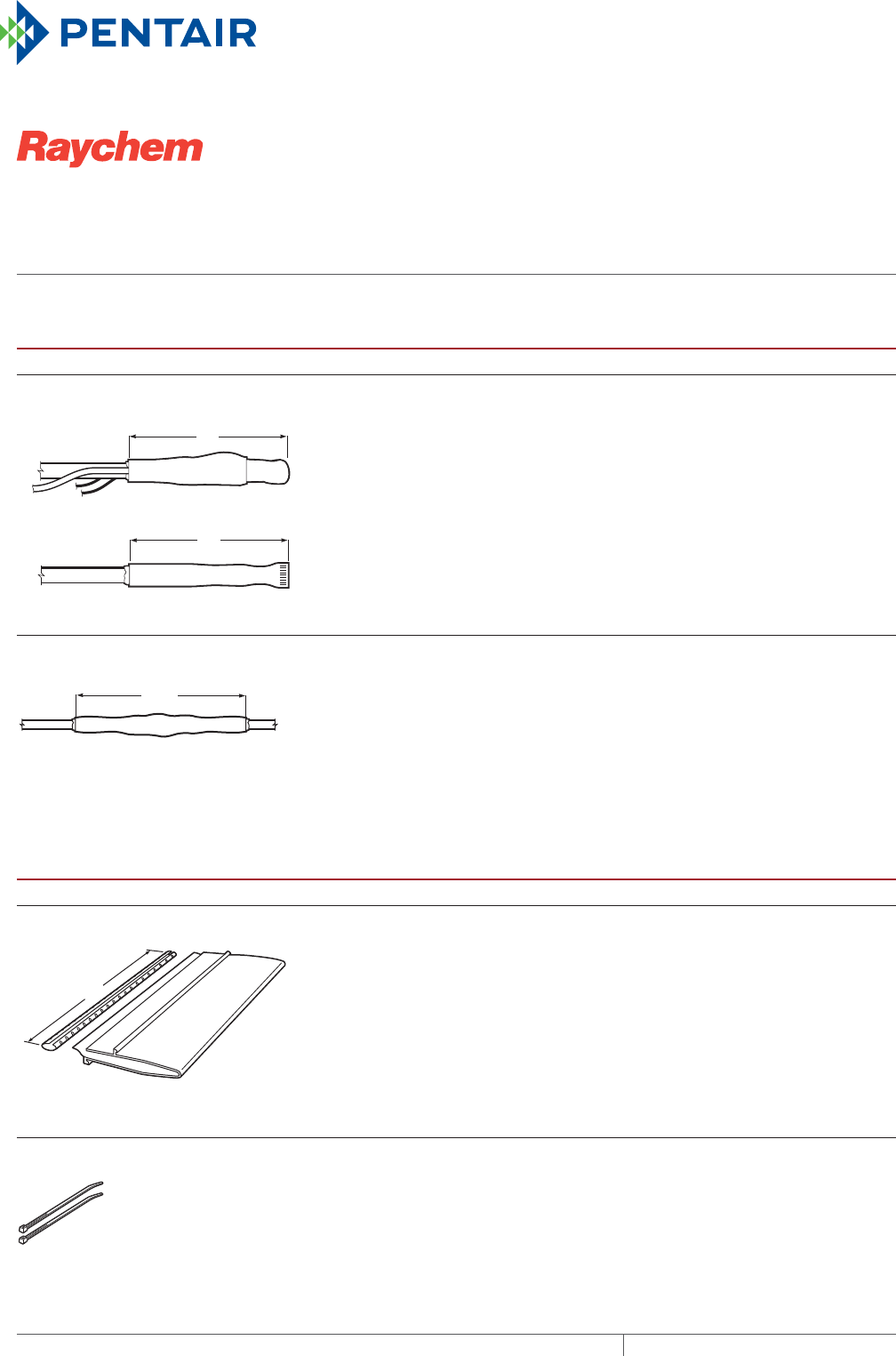
ConneCtion Kits and aCCessories
ELECTROMELT
THERMAL MANAGEMENT SOLUTIONS
EN-RaychemElectroMeltConnectionkits-DS-H58180 11/13
440
CONNECTION KITS
Catalog number Part number Description
EMK-XP
Power connection EMK-XP
End seal EMK-XP
6 in
15.25 cm
6 in
15.25 cm
579519 The power connection and end seal kit is a water-resistant
electrical assembly that is sealed with a proprietary adhesive and
protected by a crosslinked, modified polyolefin heat-shrinkable
tube.
Storage temperature: –40°F to 140°F (–40°C to 60°C)
Minimum installation temperature: 0°F (–18°C)
Power connection wire range: 14 to 4 AWG
Voltage rating: 600 V
Packaging: One power connection and one end seal per box
Shipping weight: 0.4 lb (182 g)
EMK-XS
10 in
25.4 cm
356667 The splice kit is a water-resistant electrical assembly that is
sealed with a proprietary adhesive and protected by a crosslinked,
modified polyolefin heat-shrinkable tube.
Storage temperature: –40°F to 140°F (–40°C to 60°C)
Minimum installation temperature: 0°F (–18°C)
Voltage rating: 600 V
Packaging: One splice kit per box
Shipping weight: 0.2 lb (91 g)
ACCESSORIES
Catalog number
Part number
Description
EMK-XJR
12 in
30.5 cm
Metal
closure ShrinkWrapTM
sleeve
693647 The jacket repair kit is a heat-shrinkable wrap-around sleeve for
covering a damaged outer jacket. The repair sleeve is adhesive-
lined and comes with a removable metal closure.
Nominal length: 12 in (30.5 cm)
Packaging: One repair sleeve per kit
Shipping weight: 0.8 lb (365 g)
EMK-CT 906441 The nylon cable ties are seven-inch nylon industrial cable ties.
Manufacturer: Panduit
Model number: PLT2S-C
Length: 7-3/8" ± 1/2" (18.74 cm ± 1.25 cm)
Width: 3/16" (0.48 cm)
Packaging: 100 per pack
Shipping weight: 0.5 lb (227 g)
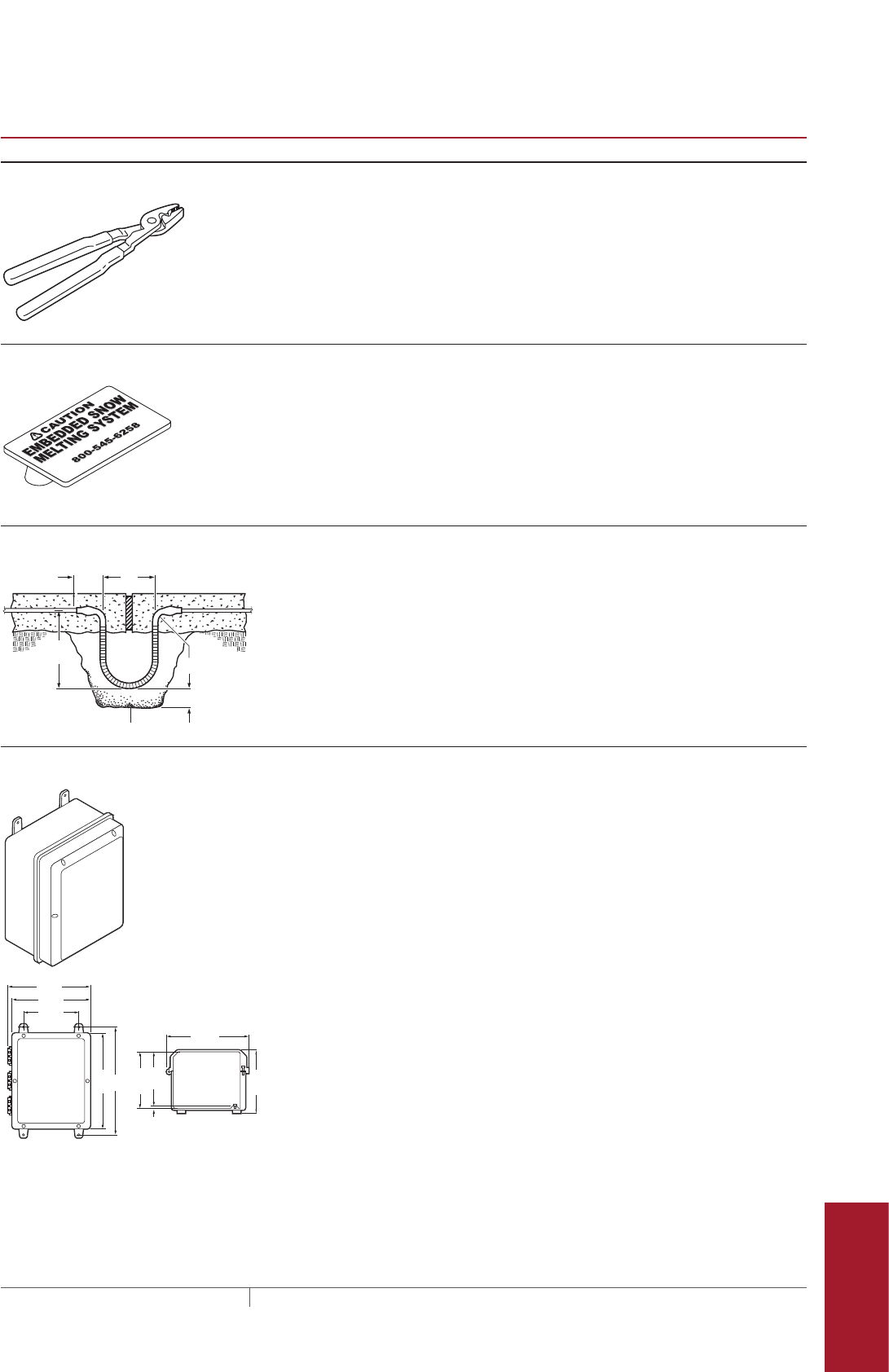
electromelt connection kits and accessories
441 THERMAL MANAGEMENT SOLUTIONS EN-RaychemElectroMeltConnectionkits-DS-H58180 11/13
Pipe Freeze Protection
and Flow Maintenance
Fire Sprinkler System
Freeze Protection
Roof and Gutter
De-Icing
Surface Snow
Melting – MI
Surface Snow
Melting – ElectroMelt
Freezer Frost
Heave Prevention
Floor Heating Technical Data
Sheets
ACCESSORIES
Catalog number
Part number
Description
EMK-XT 980631 The crimping tool is the correct size for the crimps in the
connection kit.
Manufacturer: Ideal
Model number: 30-425
Length: 10" (25.4 cm)
Packaging: One per kit
Shipping weight: 1.2 lbs (545 g)
SMCS Snow melt caution sign
Dimensions 6 x 4 in (150 x 100 mm)
EMK-XEJ
6in
15.25 cm
3 in
7.6 cm
3 in radius
2 in (5.1 cm)
9 in
22.8 cm
Sand fill
472207 The expansion joint kit provides physical protection for the heating
cable beneath slab joints. An expansion tube is used to form an
expansion loop for the heating cable.
Storage temperature: –40°F to 140°F (–40°C to 60°C)
Minimum installation temperature: 0°F (–18°C)
Packaging: One expansion joint per kit
Shipping weight: 0.3 lb (140 g)
EMK-XJB
0.31 in
10.5 in
11.75 in
11.75 in
12.5 in
6.88 in
6.44 in
6.88 in
15 in
8 in
052577 The junction box is a large, UL Listed weatherproof enclosure
suitable for terminating both ends of an ElectroMelt heating
cable circuit. This junction box is large enough for 2 circuits of
ElectroMelt heating cables. The enclosure is made of molded
structural foam and provides high impact strength, excellent
chemical resistance, high dielectric strength, and excellent
weathering capabilities.
Manufacturer: Carlon, model CJ12106
Inside dimensions: 12" x 10" x 6-7/8" (30.5 cm x 25.4 cm x 17.5 cm)
Inside volume: 825 cubic inches (13528 cm³)
Outside dimensions: 15-1/2" x 11-3/4" x 7-5/8"
(39.4 cm x 29.85 cm x 19.37 cm)
Temperature range: –40°F to 185°F (–40°C to 85°C)
UL Standard: UL508
NEMA rating: Types 1, 3, 3S, 3X, 3SX, 4, 4X, 12, 13 as indicated
Packaging: One junction box per kit
Shipping weight: 5.4 lbs (2.45 kg)
ELECTROMELT CONNECTION KITS AND ACCESSORIES
THERMAL MANAGEMENT SOLUTIONS
EN-RaychemElectroMeltConnectionkits-DS-H58180 11/13
442
ACCESSORIES
Catalog number
Part number
Description
FH-2616A-1 102049 The propane torch is suitable for heat shrinking the connection
kits. It includes a hose, a handle assembly, and comes equipped
with a regulating valve.
Packaging: One per kit
Shipping weight: 5 lbs (2.27 kg)
APPROVALS
DESIGN AND INSTALLATION
For proper design and installation of an Electromelt connection kit, use the
appropriate product design guide and the installation instructions included with
the connection kit.
GROUNDFAULT PROTECTION
To minimize the danger of fire from sustained electrical arcing if the heating
cable is damaged or improperly installed, and to comply with the requirements
of Pentair Thermal Management, agency certifications, and national electrical
codes, ground-fault equipment protection must be used on each heating cable
branch circuit. Arcing may not be stopped by conventional circuit protection.
Many DigiTrace control and monitoring systems meet the ground-fault protection
requirement.
877Z De-icing and
Snow-melting
Equipment
The EM2-XR and EM3-XR heating cables are UL Listed and CSA Certified only
when used with the appropriate agency-approved Pentair Thermal
Management connection kits and accessories.
(for EM2-XR only)
-w

EN-CommericalHeatTracingCatalog-SB-H58036 11/13
THERMAL MANAGEMENT SOLUTIONS
NORTH AMERICA
Tel: +1.800.545.6258
Fax: +1.800.527.5703
Tel: +1.650.216.1526
Fax: +1.650.474.7711
thermal.info@pentair.com
EUROPE, MIDDLE EAST, AFRICA
Tel: +32.16.213.511
Fax: +32.16.213.603
thermal.info@pentair.com
ASIA PACIFIC
Tel: +86.21.2412.1688
Fax: +86.21.5426.2917
cn.thermal.info@pentair.com
LATIN AMERICA
Tel: +1.713.868.4800
Fax: +1.713.868.2333
thermal.info@pentair.com
Pentair, 920, AMC-1A, AMC-1B, AMC-F5, C910-485, DigiTrace, ECW-GF, ElectroMelt, HotCap, HTPG, HWAT, IceStop, Pyrotenax, RayClic, RaySol,
RTD-200, RTD3CS, RTD4AL, RTD10CS, QuickNet, QuickStat, SnoCalc, XL-ERATE and XL-Trace are owned by Pentair or its global affiliates. All other
trademarks are the property of their respective owners. Pentair reserves the right to change specifications without prior notice.
© 2007-2013 Pentair.
WWW.PENTAIRTHERMAL.COM
