127419 Catalog 1
122660-Catalog 122660-Catalog 122660-Catalog Batch9 unilog cesco-content
2014-10-22
: Pdf 127419-Catalog 1 127419-Catalog_1 Batch9 unilog
Open the PDF directly: View PDF ![]() .
.
Page Count: 280 [warning: Documents this large are best viewed by clicking the View PDF Link!]
onlinecomponents.com
Bussmann manufacture a wide range of products for the protection of electrical and
electronic circuits....Fuse Links, Fuse Holders, and Fusegear, all readily available from
manufacturing sites in the United Kingdom, Denmark, United States, Brazil and Mexico.
Bussmann is a division of Cooper Industries Inc.,
a diversified world-wide manufacturer of electrical products and power equipment.
Bussmann has grown through both organic growth and acquisition.
Acquisitions have included the fusegear division of Lauritz Knudsen (LK-NES),
Beswick which added UK Domestic fuses as well as IEC and UL Electronic fuses,
Hawker Fusegear (formerly Brush Fusegear Ltd) which strengthened our range of
power fuses and Fusegear.
Bussmann circuit protection solutions comply with major international standards:
BS, IEC, DIN, UL, CSA.....Our manufacturing operations have earned ISO 9000
certification, ensuring the utmost quality across every product.
WORLD-WIDE CIRCUIT PROTECTION SOLUTIONS
onlinecomponents.com
•Low Voltage Fuse Links Page
• Cylindrical 1-4
• NH 5-24
• D & D0 25-27
• British Standard 28-50
• North American Standard 51-74
••High Speed Fuses
• Ferrule Style 75-79
• European Style Square Body 80-99
• Indicator System 100
• British Standard 101-102
• North American Standard 103-109
•Medium Voltage Fuse Links
• DIN fuse links 110-112
• Fuse links for Motor Protection 113-115
• Fuse links for Voltage & Auxiliary Transformers 116-117
• Current limiting fuse links for use in oil switchgear 118-119
• Current limiting fuse links for use in air 120-122
• Liquid fuse links 123-124
• Fuse clips 125
• Class R fuses for Motor Protection 126-129
•Telecommunications Protection 130-141
•Electronic Fuses & Accessories 142-162
•Fuseholders & Fusegear
• Modular fuse holders for Cylindrical fuse links 163
• Optima Overcurrent protection module 164-167
• NH DIN fuse bases, rails and accessories 168-191
• D & D0 fuse bases and accessories 192
• British Standard fuse holders and accessories 193-196
• North American Standard fuse holders and accessories 197-212
• High Speed fuse holders and indicators 213-215
•Electrical Characteristics
• Cylindricals 216-219
•NH 220-247
• D & D0 248-249
• British Standard 250-252
• North American 253-263
•Glossary 264-265
•Part Index 266-268
Contents
For more information visit our website at www.bussmann.com
onlinecomponents.com
Low Voltage Industrial Fuse Links
For more information visit our website at www.bussmann.com
1
Part Number
With Indicator
-
-
C08G2I
C08G4I
C08G6I
C08G8I
C08G10I
C08G12I
C08G16I
C08G20I
C08G25I
Voltage
(V AC)
400V
Breaking Capacity
(kA)
20 kA
Part Number
Without Indicator
C08G0.5
C08G1
C08G2
C08G4
C08G6
C08G8
C08G10
C08G12
C08G16
C08G20
C08G25
Rated
Current
0.5
1
2
4
6
8
10
12
16
20
25
Part Number
With Indicator
Voltage
(V AC)
500V
400V
Breaking Capacity
(kA)
120 kA
Part Number
Without Indicator
Rated
Current
0.5
1
2
4
6
8
10
12
16
20
25
32
Part Number
With Indicator
-
C14G2I
C14G4I
C14G6I
C14G8I
C14G10I
C14G12I
C14G16I
C14G20I
C14G25I
C14G32I
C14G40I
C14G50I
Voltage
(V AC)
690V
500V
400V
Breaking Capacity
(kA)
80 kA
120 kA
Part Number
Without Indicator
C14G1
C14G2
C14G4
C14G6
C14G8
C14G10
C14G12
C14G16
C14G20
C14G25
C14G32
C14G40
C14G50
Rated
Current
1
2
4
6
8
10
12
16
20
25
32
40
50
Part Number
With Indicator
C22G2I
C22G4I
C22G6I
C22G8I
C22G10I
C22G12I
C22G16I
C22G20I
C22G25I
C22G32I
C22G40I
C22G50I
C22G63I
C22G80I
C22G100I
C22G125I
Voltage
(V AC)
690V
500V
400V
Breaking Capacity
(kA)
80 kA
120 kA
Part Number
Without Indicator
C22G2
C22G4
C22G6
C22G8
C22G10
C22G12
C22G16
C22G20
C22G25
C22G32
C22G40
C22G50
C22G63
C22G80
C22G100
C22G125
Rated
Current
2
4
6
8
10
12
16
20
25
32
40
50
63
80
100
125
C10G0.5
C10G1
C10G2
C10G4
C10G6
C10G8
C10G10
C10G12
C10G16
C10G20
C10G25
C10G32
-
-
C10G2I
C10G4I
C10G6I
C10G8I
C10G10I
C10G12I
C10G16I
C10G20I
C10G25I
C10G32I
8X32
10X38
14X51
22X58
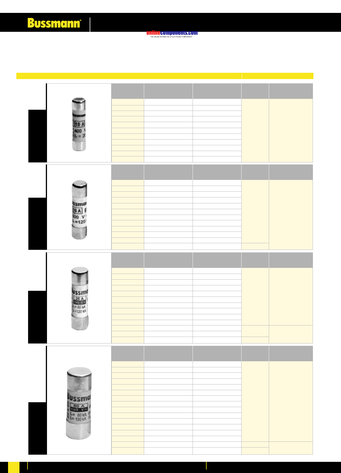
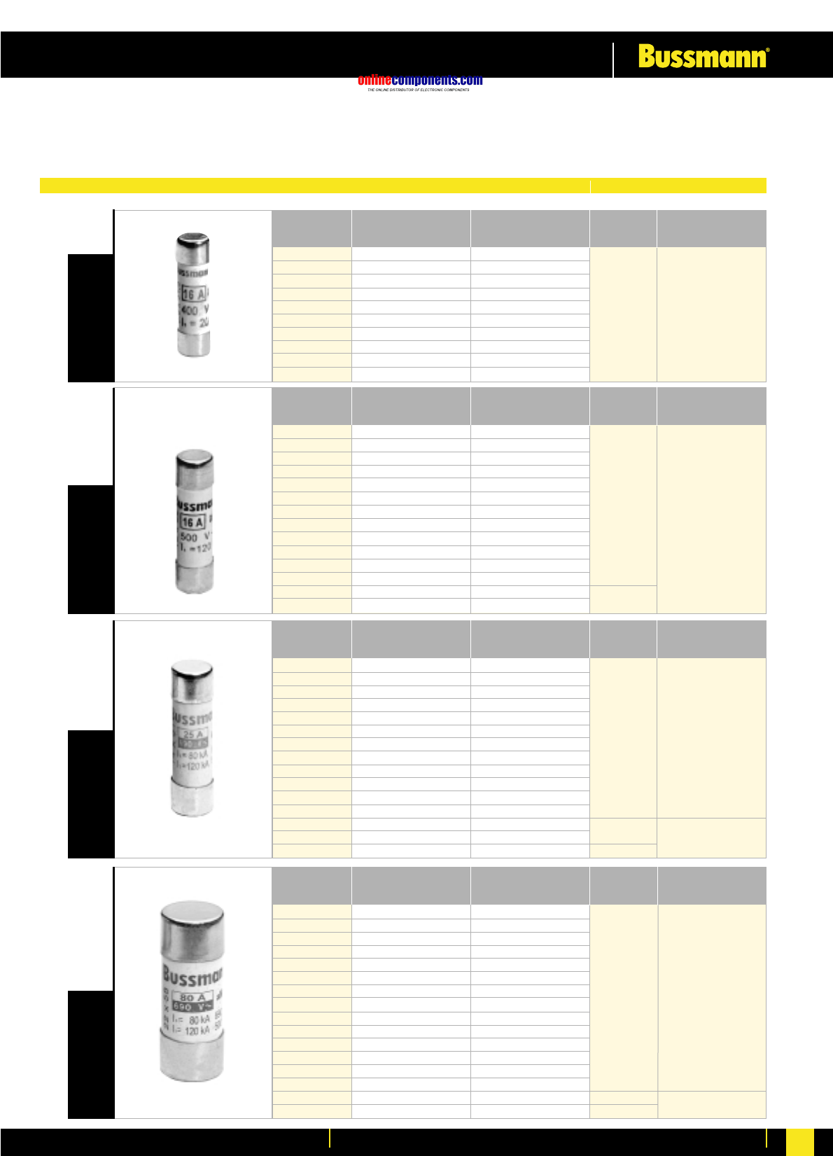
IEC Industrial Cylindrical Fuses 0.16A to 125A
Cooper Bussmann offers a comprehensive range of cylindrical fuselinks for industrial applications.
Class gG/gL Cylindrical Fuse Data Tables
Quantity per Pack
: 10 pcs
onlinecomponents.com
Low Voltage Industrial Fuse Links
For more information visit our website at www.bussmann.com 2
2
Part Number
With Indicator
C08M1I
C08M2I
C08M4I
C08M6I
-
C08M10I
C08M12I
C08M16I
C08M20I
-
Voltage
(AC)
400V
Breaking Capacity
(kA)
20 kA
Part Number
Without Indicator
C08M1
C08M2
C08M4
C08M6
C08M8
C08M10
C08M12
C08M16
C08M20
C08M25
Rated
Current
1
2
4
6
8
10
12
16
20
25
Part Number
With Indicator
-
-
-
C10M1I
C10M2I
C10M4I
C10M6I
C10M8I
C10M10I
C10M12I
C10M16I
C10M20I
C10M25I
C10M32I
Voltage
(AC)
500V
400V
Breaking Capacity
(kA)
120 kA
Part Number
Without Indicator
C10M0.16
C10M0.25
C10M0.5
C10M1
C10M2
C10M4
C10M6
C10M8
C10M10
C10M12
C10M16
C10M20
C10M25
C10M32
Rated
Current
0.16
0.25
0.5
1
2
4
6
8
10
12
16
20
25
32
Part Number
With Indicator
C22M2I
C22M4I
C22M6I
C22M8I
C22M10I
C22M12I
C22M16I
C22M20I
C22M25I
C22M32I
C22M40I
C22M50I
C22M63I
C22M80I
C22M100I
C22M125I
Voltage
(AC)
690V
500V
400V
Breaking Capacity
(kA)
80 kA
120 kA
Part Number
Without Indicator
C22M2
C22M4
C22M6
C22M8
C22M10
C22M12
C22M16
C22M20
C22M25
C22M32
C22M40
C22M50
C22M63
C22M80
C22M100
C22M125
Rated
Current
2
4
6
8
10
12
16
20
25
32
40
50
63
80
100
125
Part Number
With Indicator
-
-
C14M1I
C14M2I
C14M4I
C14M6I
C14M8I
C14M10I
C14M12I
C14M16I
C14M20I
C14M25I
C14M32I
C14M40I
C14M50I
Voltage
(AC)
690V
500
400
Breaking Capacity
(kA)
80 kA
120 kA
Part Number
Without Indicator
C14M0.25
C14M0.5
C14M1
C14M2
C14M4
C14M6
C14M8
C14M10
C14M12
C14M16
C14M20
C14M25
C14M32
C14M40
C14M50
Rated
Current
0.25
0.5
1
2
4
6
8
10
12
16
20
25
32
40
50
8X3210X38
14X51
22X58
Class gG/gL General Industrial Applications) and Class aM (Motor Protection) are available in
8x32,10x38,14x51 and 22x58mm sizes in ratings from 0.16 to 125A. Voltages are shown in the tables below.
Most fuses are are available with an operated fuse indicator.
Class aM Cylindrical Fuse Data Tables
Quantity per Pack
: 10 pcs
onlinecomponents.com
Low Voltage Industrial Fuse Links
For more information visit our website at www.bussmann.com
3
Rated
Current
2
4
6
8
10
12
16
20
25
32
40
50
Part No
With Striker
C14G2S
C14G4S
C14G6S
C14G8S
C14G10S
C14G12S
C14G16S
C14G20S
C14G25S
C14G32S
C14G40S
C14G50S
Voltage
(AC)
500V
400V
Breaking
Capacity (kA)
120 kA
Rated
Current
1
2
4
6
8
10
12
16
20
25
32
40
50
Part No
With Striker
C14M1S
C14M2S
C14M4S
C14M6S
C14M8S
C14M10S
C14M12S
C14M16S
C14M20S
C14M25S
C14M32S
C14M40S
C14M50S
Voltage
(AC)
500V
400V
Breaking
Capacity (kA)
120 kA
Rated
Current
2
4
6
8
10
12
16
20
25
32
40
50
63
80
100
125
Part No
With Striker
C22M2S
C22M4S
C22M6S
C22M8S
C22M10S
C22M12S
C22M16S
C22M20S
C22M25S
C22M32S
C22M40S
C22M50S
C22M63S
C22M80S
C22M100S
C22M125S
Voltage
(AC)
690V
500V
400V
Breaking
Capacity (kA)
80 kA
120 kA
Rated
Current
4
6
8
10
12
16
20
25
32
40
50
63
80
100
125
Part No
With Striker
C22G4S
C22G6S
C22G8S
C22G10S
C22G12S
C22G16S
C22G20S
C22G25S
C22G32S
C22G40S
C22G50S
C22G63S
C22G80S
C22G100S
C22G125S
Voltage
(AC)
690V
500V
400V
Breaking
Capacity (kA)
80 kA
120 kA
14X5122X5814X51
22X58
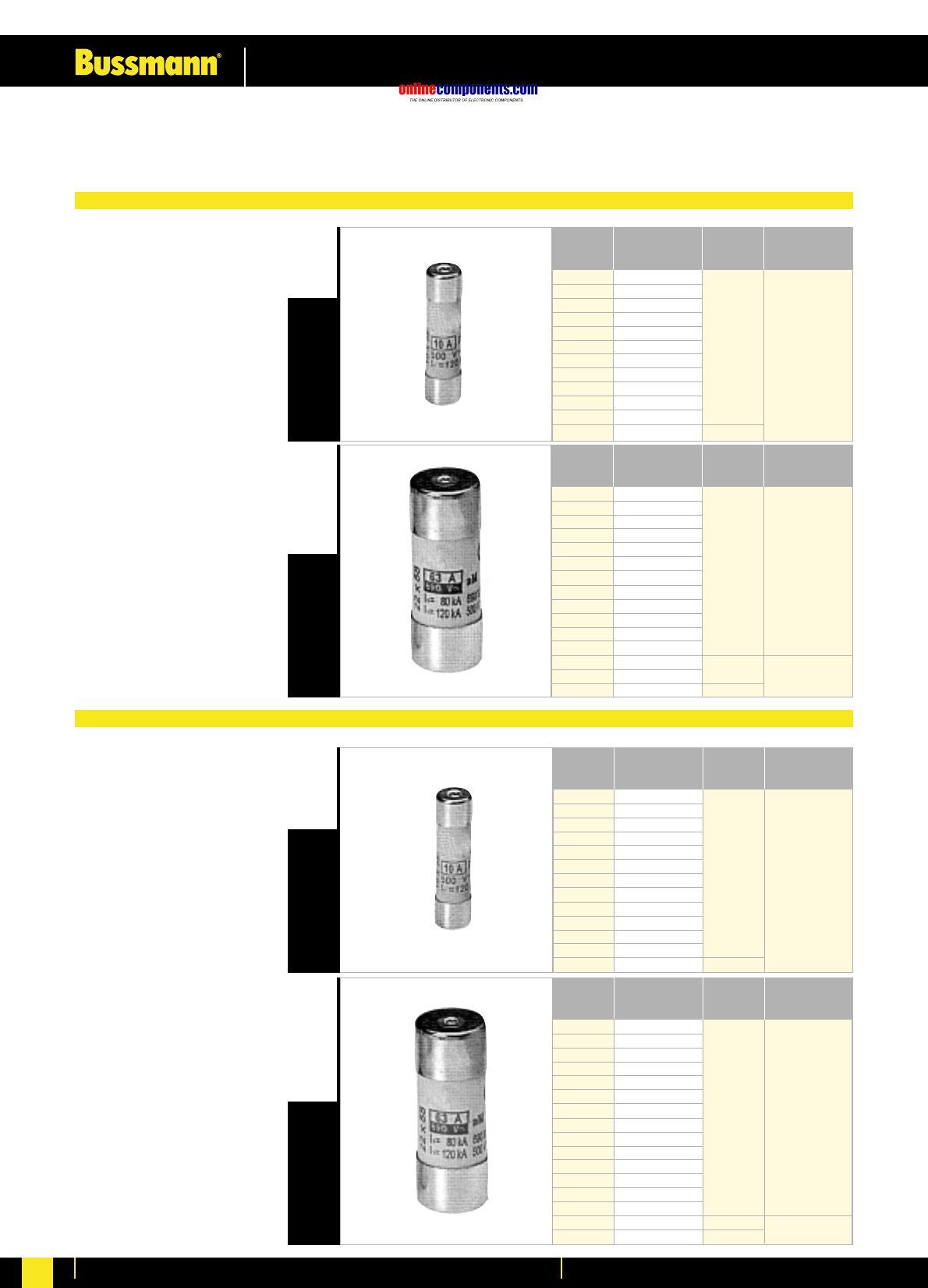
IEC Industrial Cylindrical Fuses with Striker
Cylindrical fuses in sizes 14x51 and 22x58mm offer the user the benefit of remote fuse indication when used in conjunction
with a microswitch. Fuses are available from 1-125A in Class gG/gL (General Industrial Applications) and aM (Motor Protection).
Class aM with Striker
Quantity per Pack
: 10 pcs
Class gG/gL with Striker
Quantity per Pack
: 10 pcs
onlinecomponents.com
Low Voltage Industrial Fuse Links
For more information visit our website at www.bussmann.com 4
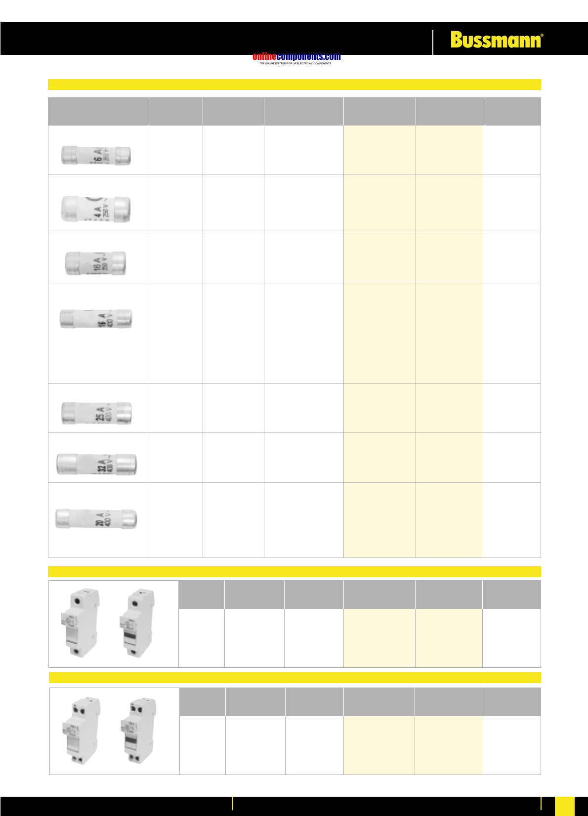
European Domestic Fuse Links - Class gG
European Domestic Modular Fuse Holders Single Pole
Rated Current Rated Voltage Interrupt Raing Part Number Part Number
InUn(kA) Without Indicator With Indicator Packaging
Max Max
Fuse Link Rated Current Rated Voltage Part Number Part Number
Size (mm) (A) (V AC) Without Indicator With Indicator Packaging
8x23mm 10A 250 CHD8231D CHD8231D I 12
10x25mm 16A 250 CHD10251D CHD10251D I 12
8x31mm 20A 400 CHD8311D CHD8311D I 12
10x31mm 25A 400 CHD10311D CHD10311D I 12
10x38mm 32A 400 CHD1038D CHD1038D I 12
Neutral 32A 400 CHDND - 12
6x23mm 2 250 CD0623G2 - 10
4 250 CD0623G4 - 10
6 250 6kA @ 250V AC CD0623G6 - 10
10 250 CD0623G10 - 10
8x23mm 2 250 CD0823G2 CD0823G2 I 10
4 250 CD0823G4 CD0823G4 I 10
6 250 6kA @ 250V AC CD0823G6 CD0823G6 I 10
10 250 CD0823G10 CD0823G10 I 10
16 250 CD0823G16 CD0823G16 I 10
10x25mm 6 250 CD1025G6 CD1025G6 I 10
10 250 CD1025G10 CD1025G10 I 10
16 250 6kA @ 250V AC CD1025G16 CD1025G16 I 10
8x31mm 0.5 400 CD0831G0.5 - 10
1 400 CD0831G1 - 10
2 400 CD0831G2 CD0831G2 I 10
4 400 CD0831G4 CD0831G4 I 10
6 400 CD0831G6 CD0831G6 I 10
8 400 20kA @ 400V AC CD0831G8 CD0831G8 I 10
10 400 CD0831G10 CD0831G10 I 10
12 400 CD0831G12 CD0831G12 I 10
16 400 CD0831G16 CD0831G16 I 10
20 400 CD0831G20 CD0831G20 I 10
25 400 CD0831G25 CD0831G25 I 10
10x31mm 16 400 CD1031G16 CD1031G16 I 10
20 400 CD1031G20 CD1031G20 I 10
25 400 20kA @ 400V AC CD1031G25 CD1031G25 I 10
10x38mm 25 400 CD1038G25 CD1038G25 I 10
32 400 CD1038G32 CD1038G32 I 10
20kA @ 400V AC
8x36mm 2 400 CD0836G2 CD0836G2 I 10
4 400 CD0836G4 CD0836G4 I 10
6 400 CD0836G6 CD0836G6 I 10
10 400 20kA @ 400V AC CD0836G10 CD0836G10 I 10
16 400 CD0836G16 CD0836G16 I 10
20 400 CD0836G20 CD0836G20 I 10
25 400 CD0836G25 CD0836G25 I 10
32 400 CD0836G32 CD0836G32 I 10
European Domestic Modular Fuse Holders Single Pole and Neutral
Max Max
Fuse Link Rated Current Rated Voltage Part Number Part Number
Size (mm) (A) (V AC) Without Indicator With Indicator Packaging
8x23mm 10A 250 CHD8231DN CHD8231DN I 12
10x25mm 16A 250 CHD10251DN CHD10251DN I 12
8x31mm 20A 400 CHD8311DN CHD8311DN I 12
10x31mm 32A 400 CHD10311DN CHD10311DN I 12
10x38mm 32A 400 CHD1038DN CHD1038DN I 12

onlinecomponents.com
Low Voltage Industrial Fuse Links
For more information visit our website at www.bussmann.com
5
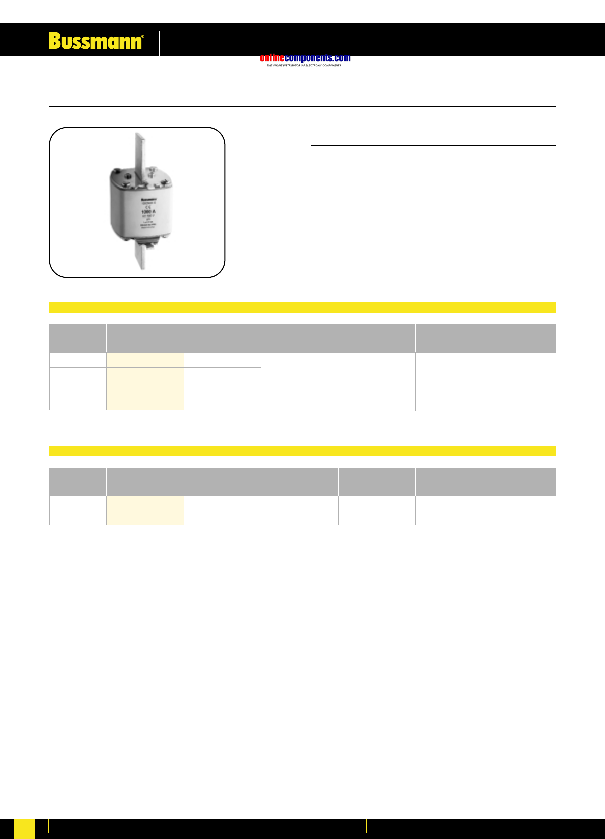
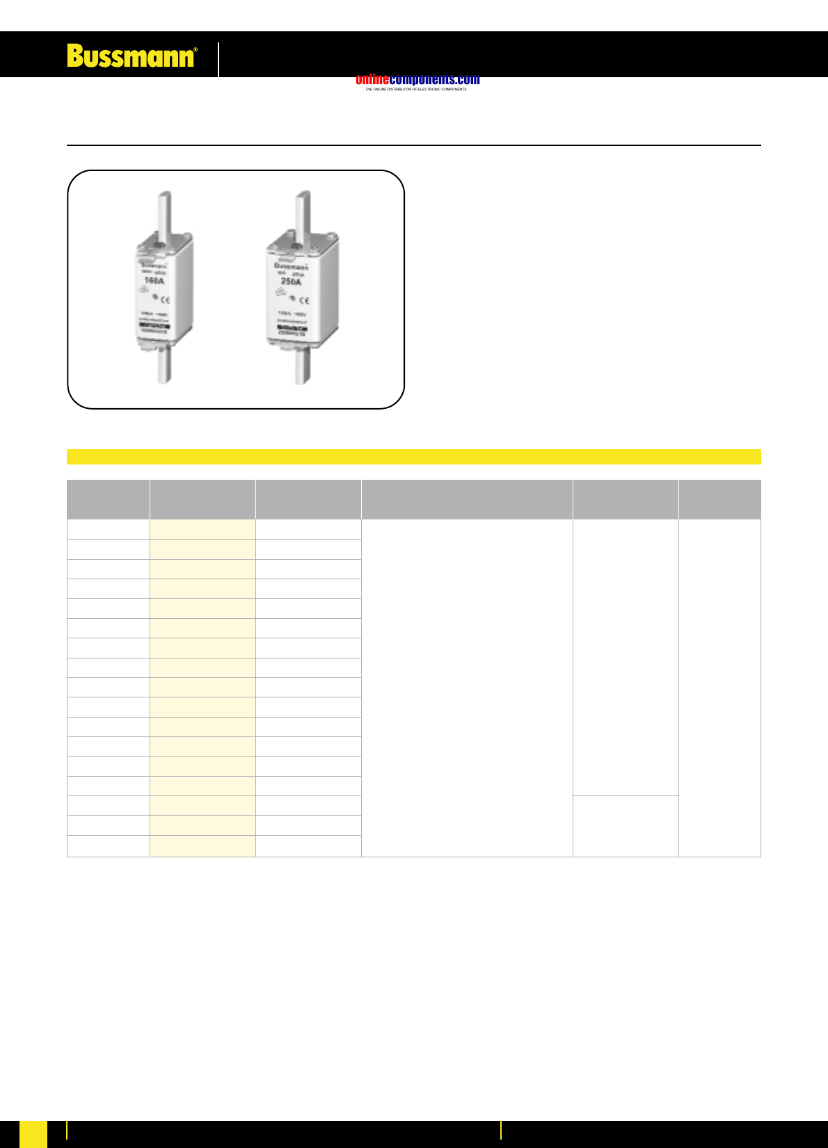
• From 2A to 1600A
• 400V AC, 500V AC and 690V AC
• Dual Indication
• Isolated Gripping Lugs
• IEC/DIN/EN 60269-2-1 –
Section 1 (VDE 0636 & DIN 43 620)
• Comprehensive range of accessories
Cooper Bussmann low voltage NH DIN fuse links are offered in the following sizes, current ratings and gG utilisation category -
General Purpose, cable and line protection:
Size 000/C00 2A to 100A
Size 00 125A & 160A
Size C0 & 0 6A to 160A
Size 01 6A to 160A
Size 1 200A to 250A
Size 02 35A to 250A
Size 2 315A to 400A
Size 03 250A to 400A
Size 3 500A & 630A
Size 4 630A to 1600A
Size 4a from 400A to 1600A }NH DIN fuse links with utilisation categories
aM, gTr, gR and aR are also available
(Please consult Bussmann for further details)
The NH DIN low voltage fuse system offered by Cooper Bussmann includes fuse links bearing the VDE mark:
Bussmann fuses are manufactured to meet the requirements of IEC 60269.
The Bussmann NH DIN low voltage fuse links are available at 400V AC, 500V AC and 690V AC.
Historically, the majority of NH-fuse links according to DIN 43 620 had two different types of indicator systems. The most
common type has the indicator located on the top end plate of the fuse link. In most cases this is used for visual indication,
although it can also be used to operate a micro-switch where remote indication is required. The second type of indicator is
located in the centre of the ceramic body of the fuse link.
When used in conjunction with NH open style fuse bases, the top indicator provides the end-user with effective visual
indication of operation of the fuse link. However, when used in fuse rails or fuse switch-disconnectors, it is extremely
difficult to identify the operated fuse link. This is when centre indication is required
The dual indicating NH fuse links from Bussmann incorporates the top and centre indicator systems, and is available at
500V AC for ratings from 6 to 630Amps.
Approvals
NH DIN Fuse Links with Dual Indication
Accessories
To complement the NH fuse link range, Bussmann offer a comprehensive range of holders, fuse-switch disconnectors and
fuse rails. For further details please contact Bussmann.
onlinecomponents.com
Low Voltage Industrial Fuse Links
For more information visit our website at www.bussmann.com 6
Fuselinks Selection Table
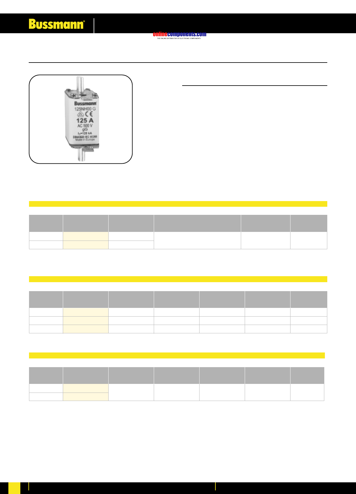
Fuseholder Selection Table for Size 000 Fuselinks
Fuse Switch-Disconnector Selection Table for SIZE C00 (000) Fuselinks
6
10
16
20
25
32
35
40
50
63
80
100
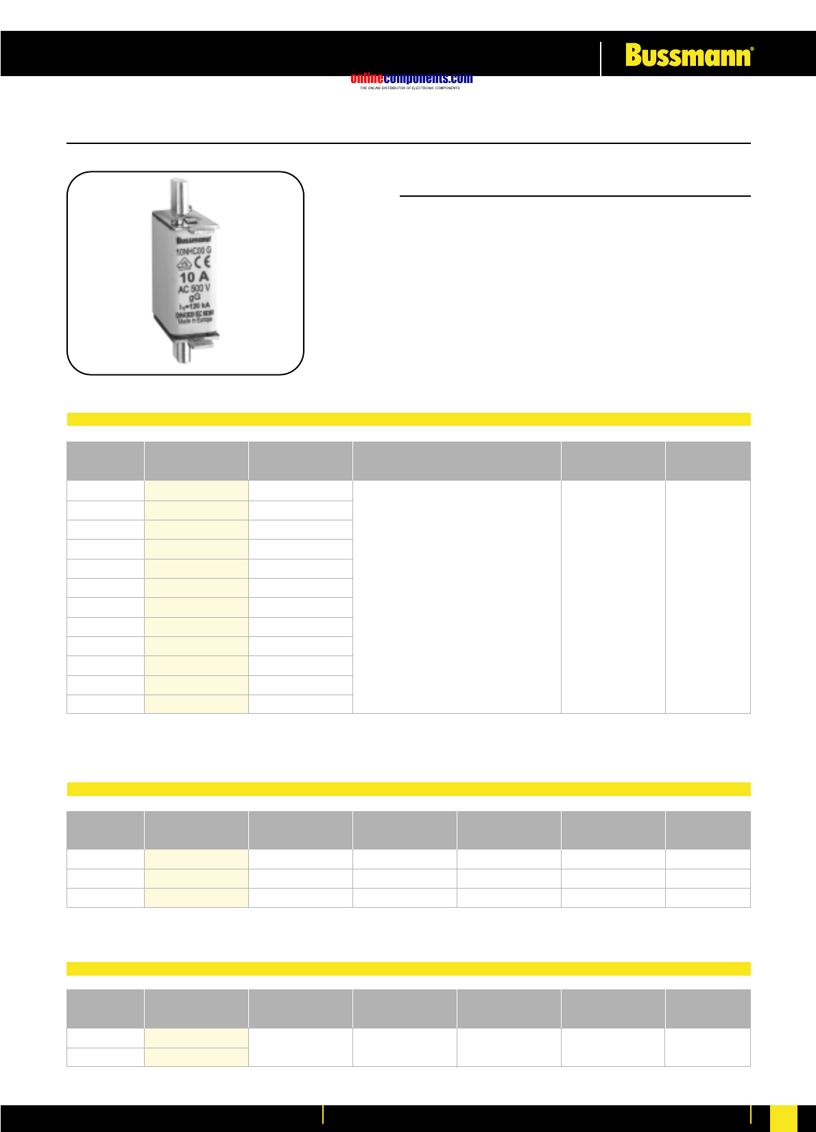
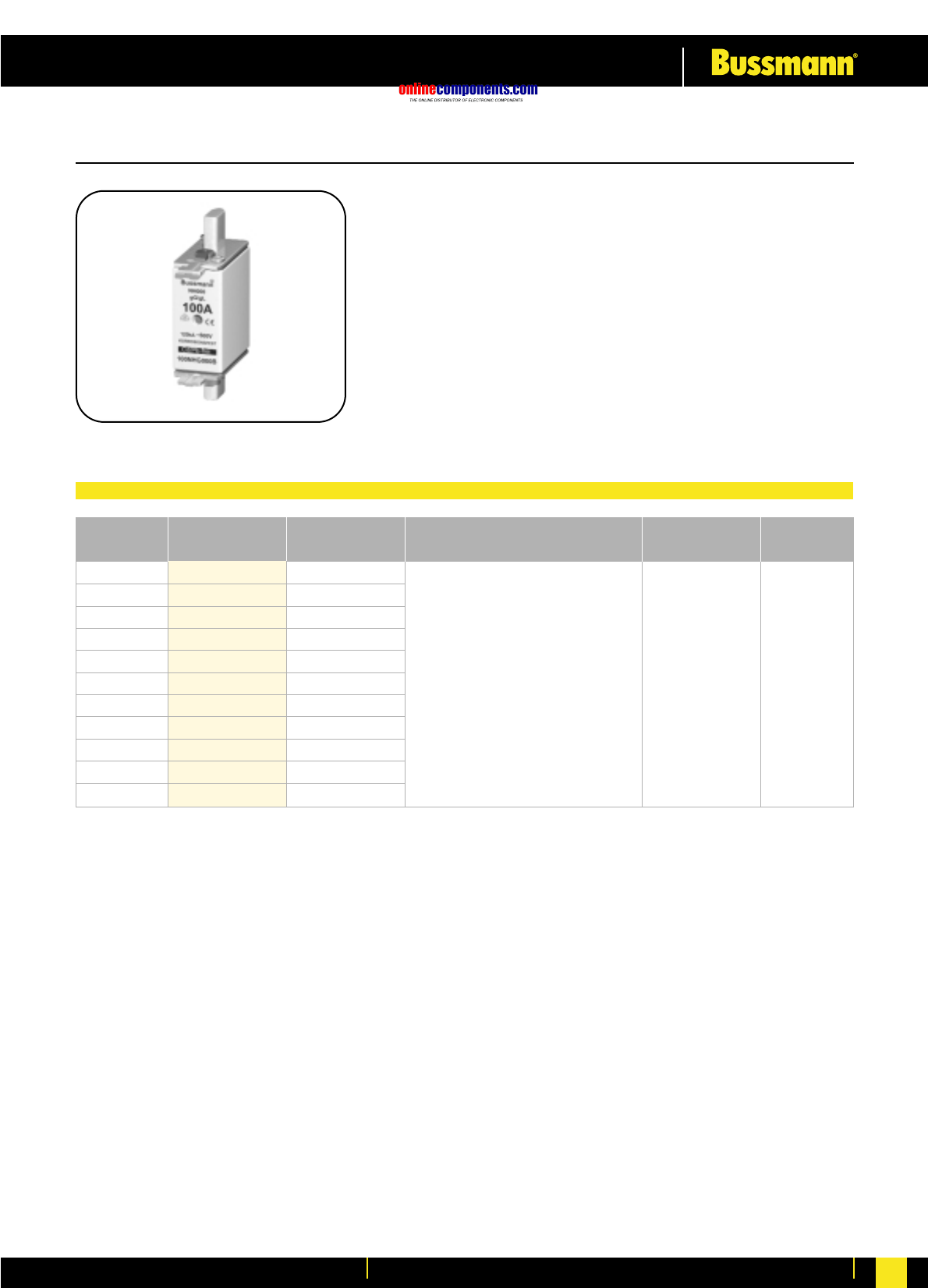
• General Industrial applications
• Full range breaking capacity
• Rated at 500V AC: 250V DC
• Approved to IEC 60269 & VDE 0636
• Other voltage ratings available,
contact Bussmann for further information
1
3160A 690V AC 0.720 kg 1 per Box
No.Poles Part Number Max Rated
Current of fuselinks
Rated
Voltage
Max Watts
Loss of Fuselink Weight Packaging
1
2
3
SB00
SBS00
TB00
Fibreglass
Steatite
Fibreglass
160A
160A
160A
12W
12W
12W
0.130 kg
0.280 kg
0.500 kg
3 per box
1 per box
1 per box
No.Poles Part Number Material Max Rated
Current
Max Watts
Loss of Fuselink Weight Packaging
6NHC00G
10NHC00G
16NHC00G
20NHC00G
25NHC00G
32NHC00G
35NHC00G
40NHC00G
50NHC00G
63NHC00G
80NHC00G
100NHC00G
1.1
1.3
2.0
2.2
3.1
3.5
3.8
4.0
5.3
6.1
6.9
7.2
120kA @ 500V AC
50kA @ 250V DC 0.130 kg 3 pcs per
Carton
Rated
Current Part Number Watts loss (W) Breaking Capacity Weight Packaging
SIZE: C00 (000) CLASS: gG/gL
Dimensional data on page 23
12W
LBS00/1
LBS00/3
500V AC
onlinecomponents.com
Low Voltage Industrial Fuse Links
For more information visit our website at www.bussmann.com
7
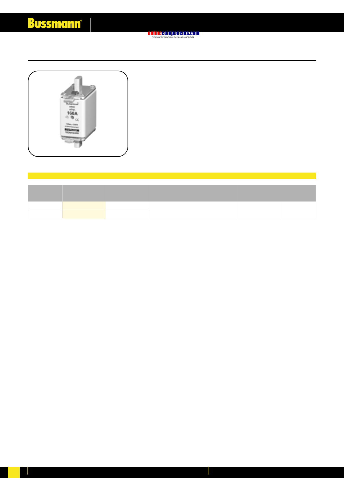
•General Industrial applications
•Full range breaking capacity
•Rated at 500V AC: 250V DC
•Approved to IEC 60269 & VDE 0636
•Other voltage ratings available,
contact Bussmann for further information
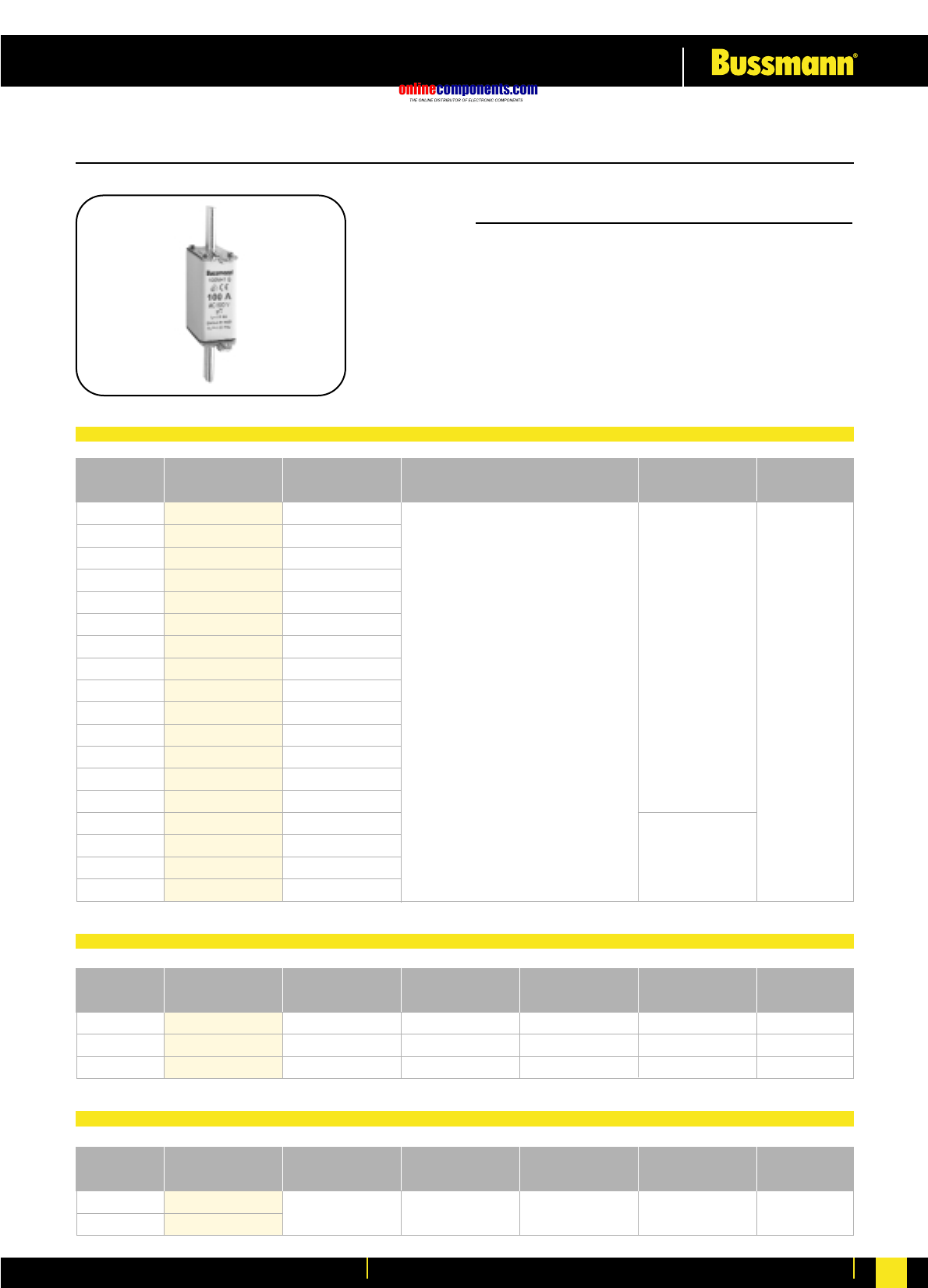
Rated
Current Part Number Watts loss (W) Breaking Capacity Weight Packaging
125
160
125NH00G
160NH00G
9.1
11.2
120kA @ 500V AC
50kA @ 250V DC 0.130 kg 3 pcs per
Carton
1
1
3
SB00
SBS00
TB00
Fibreglass
Steatite
Fibreglass
160A
160A
160A
12W
12W
12W
0.130 kg
0.280 kg
0.500 kg
3 per box
1 per box
1 per box
No.Poles Part Number Material Max Rated
Current
Max Watts
Loss of Fuselink Weight Packaging
1
3160A 690V AC 12W 0.720 kg 1 per Box
No.Poles Part Number Max Rated
Current of fuselinks
Rated
Voltage
Max Watts
Loss of Fuselink Weight Packaging
SIZE: 00 CLASS: gG/gL
Dimensional data on page 23
LBS00/1
LBS00/3
Fuselinks Selection Table
Fuseholder Selection Table for Size 00 Fuselinks
Fuse Switch-Disconnector Selection Table for Size 00 Fuselinks
500V AC
onlinecomponents.com
Low Voltage Industrial Fuse Links
For more information visit our website at www.bussmann.com 8
1
3
LBS1/1
LBS1/3 250A 690V AC 32W 2.500 kg 1 per Box
No.Poles Part Number Max Rated
Current of fuselinks
Rated
Voltage
Max Watts
Loss of Fuselink Weight Packaging
1
2
3
SB1
SBS1
TB1
Fibreglass
Steatite
Fibreglass
160A
160A
160A
32W
32W
32W
0.360 kg
0.700 kg
1.200 kg
3 per box
1 per box
1 per box
No.Poles Part Number Material Max Rated
Current
Max Watts
Loss of Fuselink Weight Packaging
Rated
Current Part Number Watts loss (W) Breaking Capacity Weight Packaging
6
10
16
20
25
32
35
40
50
63
80
100
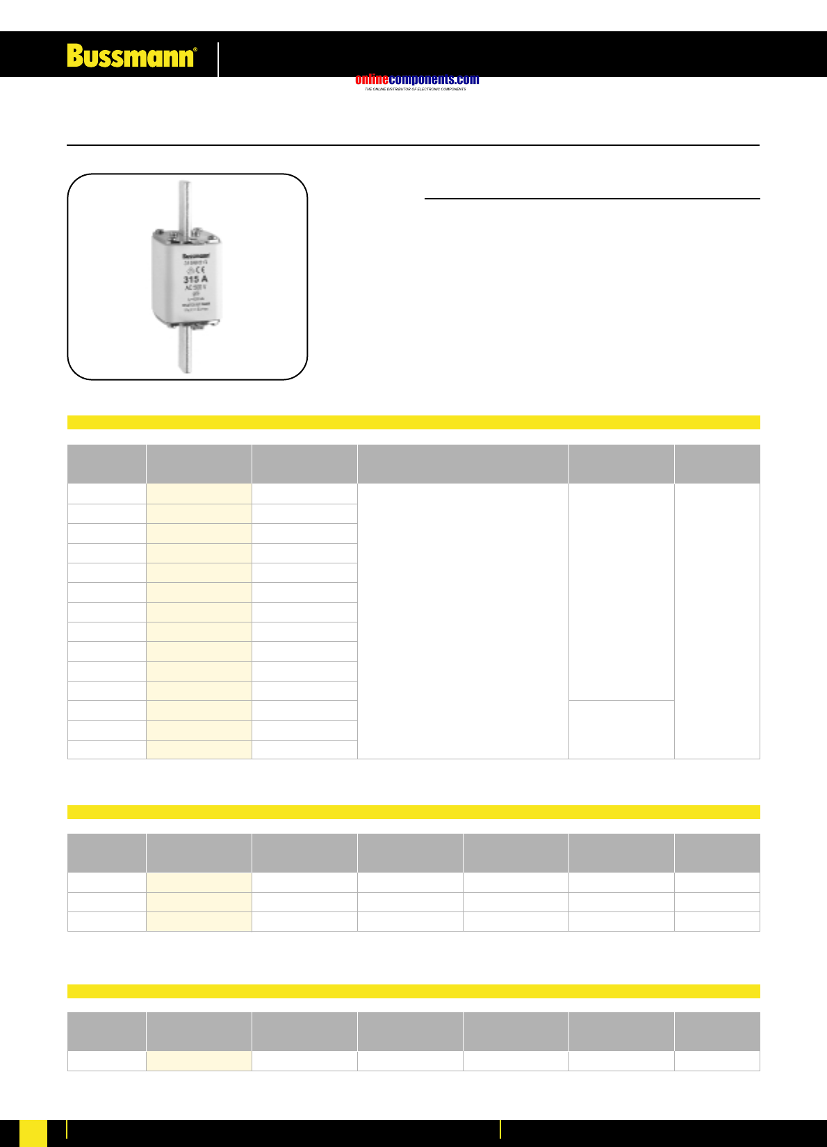
125
160
200
224
225
250
6NH1G
10NH1G
16NH1G
20NH1G
25NH1G
32NH1G
35NH1G
40NH1G
50NH1G
63NH1G
80NH1G
100NH1G
125NH1G
160NH1G
200NH1G
224NH1G
225NH1G
250NH1G
1.5
1.8
2.9
3.0
4.3
4.8
4.9
5.6
6.8
7.9
8.2
9.9
11.7
13.8
15.2
17.6
17.6
20.4
120kA @ 500V AC
50kA @ 250V DC
0.220 kg
0.430 kg
3 pcs per
Carton
SIZE: 1 CLASS: gG/gL
•General Industrial applications
•Full range breaking capacity
•Rated at 500V AC: 250V DC
•Approved to IEC 60269 & VDE 0636
•Reduced body size for ratings >160A
•Other voltage ratings available,
contact Bussmann for further information
Dimensional data on page 23
Fuselinks Selection Table
Fuseholder Selection Table for Size 01 (1S) & 1 Fuselinks
Fuse Switch-Disconnector Selection Table for Size 01 (1S) & 1 Fuselinks
500V AC
onlinecomponents.com
Low Voltage Industrial Fuse Links
For more information visit our website at www.bussmann.com
9
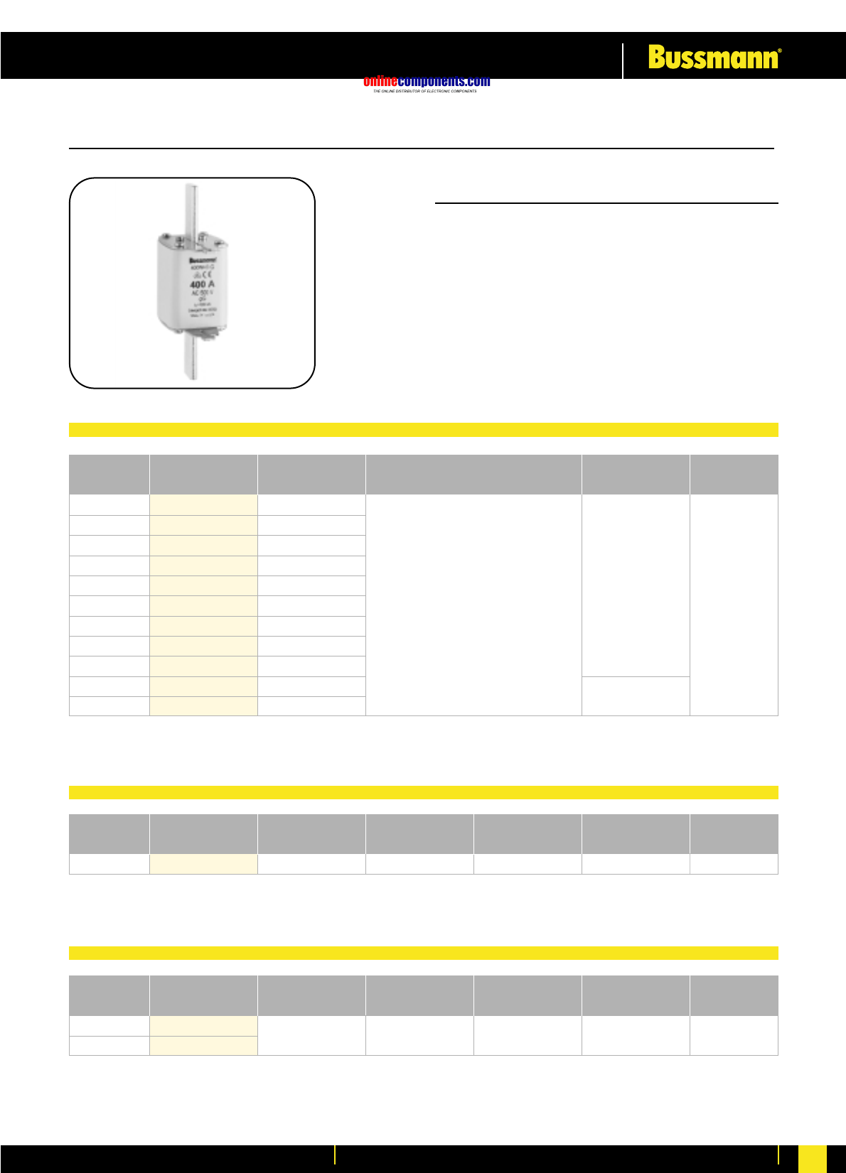
•General Industrial applications
•Full range breaking capacity
•Rated at 500V AC: 250V DC
•Approved to IEC 60269 & VDE 0636
•Reduced body size for ratings > 250A
•Other voltage ratings available,
contact Bussmann for further information
3LBS2/3 400A 690V AC 45W 3.100 kg 1 per Box
No.Poles Part Number Max Rated
Current of fuselinks
Rated
Voltage
Max Watts
Loss of Fuselink Weight Packaging
1
1
3
SB2
SBS2
TB2
Fibreglass
Steatite
Fibreglass
400A
400A
400A
45W
45W
45W
0.420 kg
0.810 kg
1.400 kg
3 per box
1 per box
1 per box
No.Poles Part Number Material Max Rated
Current
Max Watts
Loss of Fuselink Weight Packaging
Rated
Current Part Number Watts loss (W) Breaking Capacity Weight Packaging
35
40
50
63
80
100
125
160
200
224
250
315
350
400
35NH2G
40NH2G
50NH2G
63NH2G
80NH2G
100NH2G
125NH2G
160NH2G
200NH2G
224NH2G
250NH2G
315NH2G
350NH2G
400NH2G
4.0
4.6
5.7
6.8
7.2
8.5
11.4
13.0
15.9
20.0
20.5
26.0
29.0
32.0
120kA @ 500V AC
50kA @ 250V DC
3 pcs per
Carton
0.440 kg
0.590 kg
SIZE: 2 CLASS: gG/gL
Dimensional data on page 23
Fuselinks Selection Table
Fuseholder Selection Table for Size 02 (2S) & 2 Fuselinks
Fuse Switch-Disconnector Selection Table for Size 02 (2S) & 2 Fuselinks
500V AC
onlinecomponents.com
Low Voltage Industrial Fuse Links
For more information visit our website at www.bussmann.com 10
1
3
LBS3/1
LBS3/3 630A 690V AC 60W 4.800 kg 1 per Box
No.Poles Part Number Max Rated
Current of fuselinks
Rated
Voltage
Max Watts
Loss of Fuselink Weight Packaging
1SBS3 Steatite 630A 60W 0.870 kg 1 per box
No.Poles Part Number Material Max Rated
Current
Max Watts
Loss of Fuselink Weight Packaging
Rated
Current Part Number Watts loss (W) Breaking Capacity Weight Packaging
100
125
160
200
224
250
315
350
400
500
630
100NH3G
125NH3G
160NH3G
200NH3G
224NH3G
250NH3G
315NH3G
350NH3G
400NH3G
500NH3G
630NH3G
10.2
11.9
15.7
20.1
20.7
24.5
31.3
34.8
38.4
38.0
48.0
120kA @ 500V AC
50kA @ 250V DC
0.610 kg
1.080 kg
3 pcs per
Carton
SIZE: 3 CLASS: gG/gL
•General Industrial applications
•Full range breaking capacity
•Rated at 500V AC: 250V DC
•Approved to IEC 60269 & VDE 0636
•Reduced body size for ratings > 400A
•Other voltage ratings available,
contact Bussmann for further information
Dimensional data on page 23
Fuselinks Selection Table
Fuseholder Selection Table for Size 03 (3S) & 3 Fuselinks
Fuse Switch-Disconnector Selection Table for Size 03 (3S) & 3 Fuselinks
500V AC
onlinecomponents.com
Low Voltage Industrial Fuse Links
For more information visit our website at www.bussmann.com
11
Fuselinks Selection Table
1
3
LBS4/1
LBS4/3 1250A 690V AC 110W 5.600 kg 1 per Box
No.Poles Part Number Max Rated
Current of fuselinks
Rated
Voltage
Max Watts
Loss of Fuselink Weight Packaging
Rated
Current Part Number Watts loss (W) Breaking Capacity Weight Packaging
800
1000
1250
1600
800NH4AG
1000NH4AG
1250NH4AG
1600NH4AG
64.0
75.0
90.0
130.0
120kA @ 500V AC
50kA @ 250V DC 2.000 kg 3 pcs per
Carton
SIZE: 4a CLASS: gG/gL
•General Industrial applications
•Full range breaking capacity
•Rated at 500V AC: 250V DC
•Approved to IEC 60269 & VDE 0636
•Other voltage ratings available,
contact Bussmann for further information
Dimensional data on page 23
Fuse Switch-Disconnector Selection Table for Size 4a Fuselinks
500V AC
onlinecomponents.com
Low Voltage Industrial Fuse Links
For more information visit our website at www.bussmann.com 12
10
16
20
25
32
35
40
50
63
80
100
• General Industrial applications
• Full range breaking capacity
• Rated at 500V AC to IEC 60269-2-1 (VDE 0636)
• VDE Licence Mark
• Other voltage ratings available,
contact Bussmann for further information
10NHG000B
16NHG000B
20NHG000B
25NHG000B
32NHG000B
35NHG000B
40NHG000B
50NHG000B
63NHG000B
80NHG000B
100NHG000B
1.5
2.3
2.2
2.5
3.4
3.7
3.9
4.4
4.9
5.8
6.8
120kA @ 500V AC 0.125kg 3 pcs per
Carton
Rated
Current Part Number Watts loss (W) Breaking Capacity Weight Packaging
SIZE: C00 (000) CLASS: gG/gL with Dual Indication
Fuse Link Selection Table
For Fuse Base and Accessories, see page 168 - 191
500V AC
onlinecomponents.com
Low Voltage Industrial Fuse Links
For more information visit our website at www.bussmann.com
13
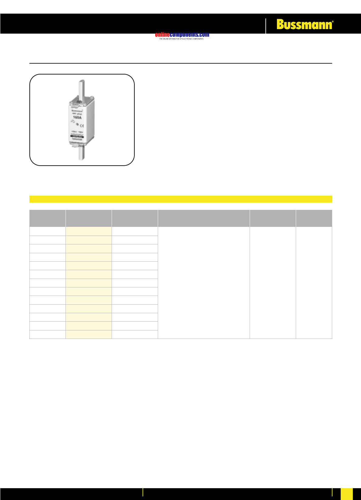
•General Industrial applications
•Full range breaking capacity
•Rated at 500V AC
•Approved to IEC 60269-2-1 (VDE 0636)
•Other voltage ratings available,
contact Bussmann for further information
Rated
Current Part Number Watts loss (W) Breaking Capacity Weight Packaging
125
160
125NHG00B
160NHG00B 120kA @ 500V AC 0.152kg 3 pcs per
Carton
SIZE: 00 CLASS: gG/gL with Dual Indication 500V AC
Fuse Link Selection Table
For Fuse Base and Accessories, see page 168 - 191
8.2
10.0
onlinecomponents.com
Low Voltage Industrial Fuse Links
For more information visit our website at www.bussmann.com 14
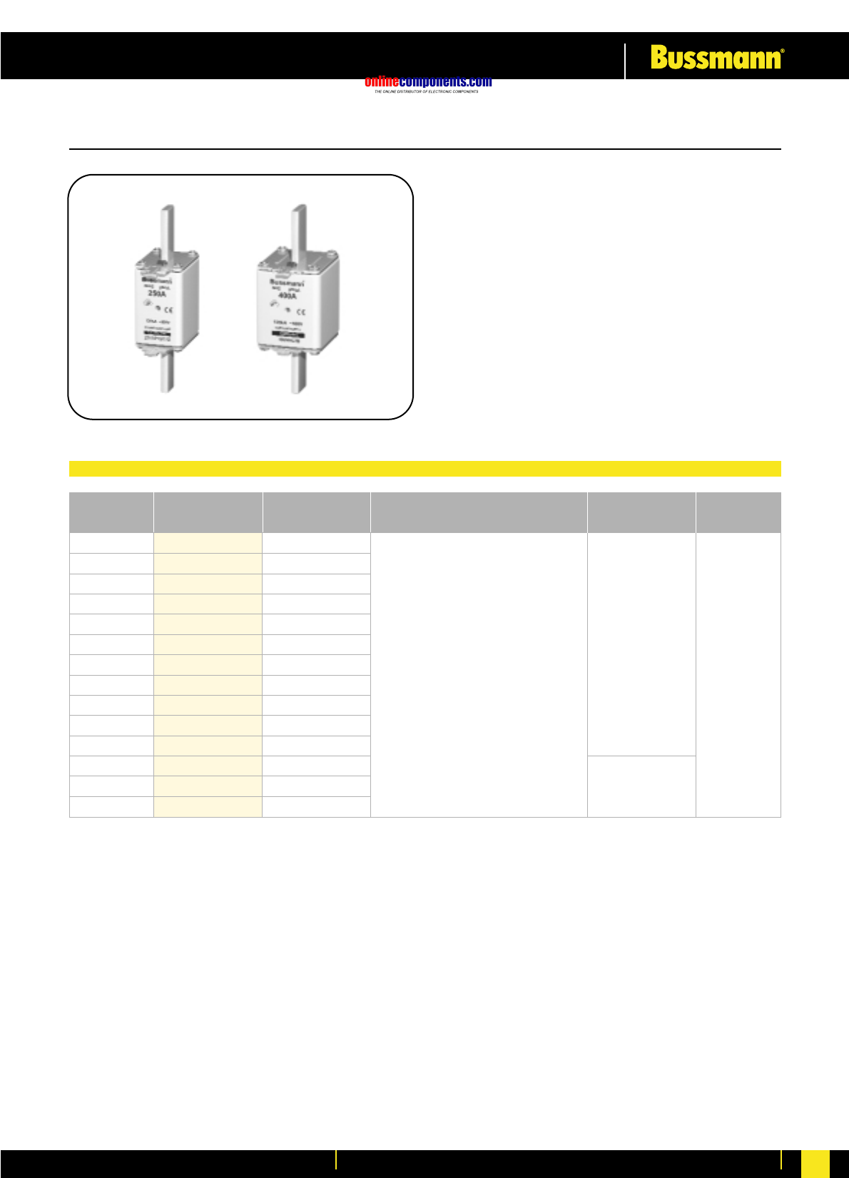
Rated Current Part Number Watts loss (W) Breaking Capacity Weight Packaging
10
16
20
25
32
35
40
50
63
80
100
125
160
10NHG0B
16NHG0B
20NHG0B
25NHG0B
32NHG0B
35NHG0B
40NHG0B
50NHG0B
63NHG0B
80NHG0B
100NHG0B
125NHG0B
160NHG0B
120kA @ 500V AC 0.262kg 3 pcs per
Carton
SIZE: 0 CLASS: gG/gL with Dual Indication 500V AC
•General Industrial applications
•Full range breaking capacity
•Rated at 500V AC
•Approved to IEC 60269-2-1 (VDE 0636)
•VDE Licence Mark
•Reduced body size for ratings <160A
•Other voltage ratings available,
contact Bussmann for further information
Fuse Link Selection Table
For Fuse Base and Accessories, see page 168 - 191
1.4
3.0
2.2
3.3
3.8
4.3
4.8
5.3
5.5
7.2
6.8
10.6
12.3
onlinecomponents.com
Low Voltage Industrial Fuse Links
For more information visit our website at www.bussmann.com
15
Rated Current Part Number Watts loss (W) Breaking Capacity Weight Packaging
6
10
16
20
25
32
35
40
50
63
80
100
125
160
200
224
250
6NHG01B
10NHG01B
16NHG01B
20NHG01B
25NHG01B
32NHG01B
35NHG01B
40NHG01B
50NHG01B
63NHG01B
80NHG01B
100NHG01B
125NHG01B
160NHG01B
200NHG1B
224NHG1B
250NHG1B
120kA @ 500V AC
0.264kg
0.450kg
3 pcs per
Carton
SIZE: 1 CLASS: gG/gL with Dual Indication 500V AC
•General Industrial applications
•Full range breaking capacity
•Rated at 500V AC
•Approved to IEC 60269-2-1(VDE 0636)
•VDE Licence Mark
•Reduced body size for ratings <160A
•Other voltage ratings available,
contact Bussmann for further
information
Fuse Link Selection Table
For Fuse Base and Accessories, see page 168 - 191
1.5
3.1
2.2
3.3
3.8
4.3
4.8
5.3
5.5
7.2
6.8
10.6
12.3
21.0
21.0
21.2
onlinecomponents.com
Low Voltage Industrial Fuse Links
For more information visit our website at www.bussmann.com 16
•General Industrial applications
•Full range breaking capacity
•Rated at 500V AC
•Approved to IEC 60269 (VDE 0636)
•Reduced body size for ratings <250A
•Other voltage ratings available,
contact Bussmann for further
information
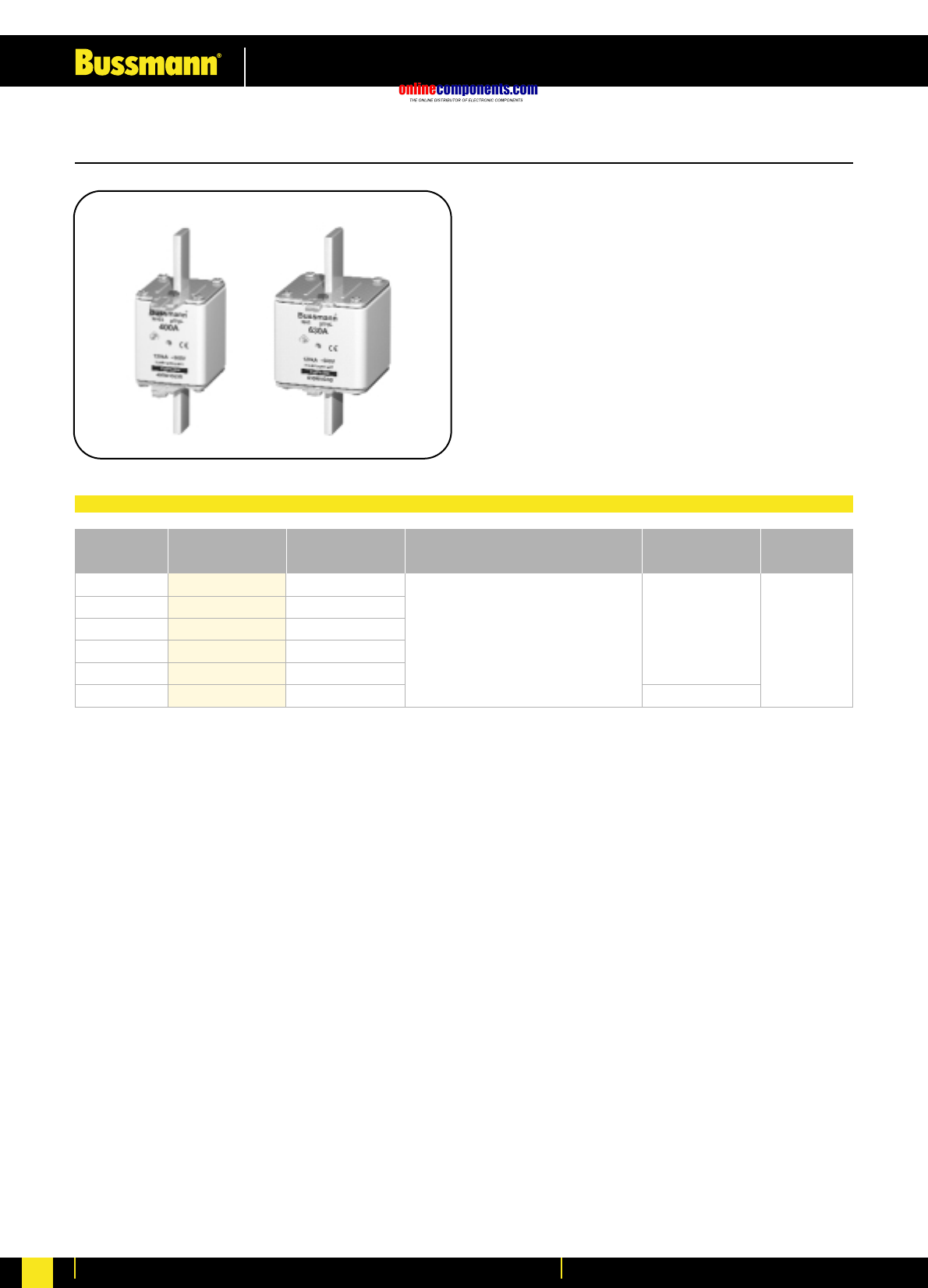
Rated Current Part Number Watts loss (W) Breaking Capacity Weight Packaging
35
40
50
63
80
100
125
160
200
224
250
315
355
400
35NHG02B
40NHG02B
50NHG02B
63NHG02B
80NHG02B
100NHG02B
125NHG02B
160NHG02B
200NHG02B
224NHG02B
250NHG02B
315NHG2B
355NHG2B
400NHG2B
120kA @ 500V AC 3 pcs per
Carton
0.450kg
0.602kg
SIZE: 2 CLASS: gG/gL with Dual Indication 500V AC
Fuse Link Selection Table
For Fuse Base and Accessories, see page 168 - 191
4.3
4.8
5.3
5.8
7.3
7.0
10.0
11.9
21.0
21.0
21.2
24.1
26.1
28.8
onlinecomponents.com
Low Voltage Industrial Fuse Links
For more information visit our website at www.bussmann.com
17
Rated Current Part Number Watts loss (W) Breaking Capacity Weight Packaging
250
315
355
400
500
630
250NHG03B
315NHG03B
355NHG03B
400NHG03B
500NHG3B
630NHG3B
120kA @ 500V AC 0.620kg
1.050kg
3 pcs per
Carton
SIZE: 3 CLASS: gG/gL with Dual Indication 500V AC
Fuse Link Selection Table
•General Industrial applications
•Full range breaking capacity
•Rated at 500V AC
•Approved to IEC 60269 (VDE 0636)
•Reduced body size for ratings <400A
•Other voltage ratings available,
contact Bussmann for further
information
For Fuse Base and Accessories, see page 168 - 191
24.0
24.1
26.1
28.8
36.5
46.5
onlinecomponents.com
Low Voltage Industrial Fuse Links
For more information visit our website at www.bussmann.com 18
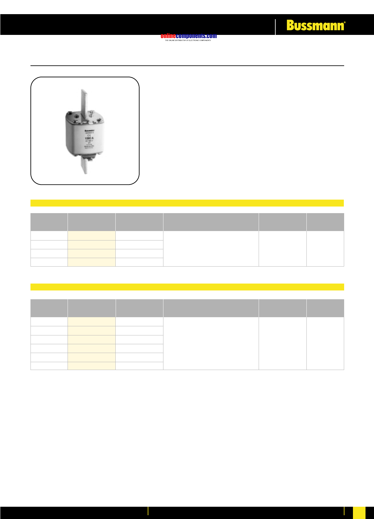
Rated Current Part Number Watts loss (W) Breaking Capacity Weight Packaging
800
1000
1250
1600
800NH4AG
1000NH4AG
1250NH4AG
1600NH4AG
64.0
75.0
90.0
130.0
120kA @ 500V AC 2.000 kg 3 pcs per
Carton
Rated Current Part Number Watts loss (W) Breaking Capacity Weight Packaging
500
630
800
1000
1250
1600
500NH4G
630NH4G
800NH4G
1000NH4G
1250NH4G
1600NH4G
35.0
40.0
50.0
70.0
90.0
110.0
120kA @ 500V AC 2.000 kg 1 pcs per
Carton
SIZE: 4a and 4 CLASS: gG/gL 500V AC
•General Industrial applications
•Full range breaking capacity
•Rated at 500V AC
•Approved to IEC 60269 (VDE 0636)
•Other voltage ratings available,
contact Bussmann for further information
Size 4a Fuse Link Selection Table
Size 4 Fuse Link Selection Table
onlinecomponents.com
Low Voltage Industrial Fuse Links
For more information visit our website at www.bussmann.com
19
Part Number
Part Number Class gL-gG with
Rated Part Number Class gL-gG with Central Indication and
Size Current (A) Class gL-gG Central Indication Isolated Gripping Lugs Packaging
2 2NH000G-400 2NH000GC-400 2NH000GC-400 I 3
4 4NH000G-400 4NH000GC-400 4NH000GC-400 I 3
6 6NH000G-400 6NH000GC-400 6NH000GC-400 I 3
10 10NH000G-400 10NH000GC-400 10NH000GC-400 I 3
16 16NH000G-400 16NH000GC-400 16NH000GC-400 I 3
20 20NH000G-400 20NH000GC-400 20NH000GC-400 I 3
25 25NH000G-400 25NH000GC-400 25NH000GC-400 I 3
32 32NH000G-400 32NH000GC-400 32NH000GC-400 I 3
35 35NH000G-400 35NH000GC-400 35NH000GC-400 I 3
40 40NH000G-400 40NH000GC-400 40NH000GC-400 I 3
50 50NH000G-400 50NH000GC-400 50NH000GC-400 I 3
63 63NH000G-400 63NH000GC-400 63NH000GC-400 I 3
80 80NH00G-400 80NH00GC-400 80NH00GC-400 I 3
100 100NH00G-400 100NH00GC-400 100NH00GC-400 I 3
125 125NH00G-400 125NH00GC-400 125NH00GC-400 I 3
160 160NH00G-400 160NH00GC-400 160NH00GC-400 I 3
35 35NH1G-400 35NH1GC-400 35NH1GC-400 I 3
40 40NH1G-400 40NH1GC-400 40NH1GC-400 I 3
50 50NH1G-400 50NH1GC-400 50NH1GC-400 I 3
63 63NH1G-400 63NH1GC-400 63NH1GC-400 I 3
80 80NH1G-400 80NH1GC-400 80NH1GC-400 I 3
100 100NH1G-400 100NH1GC-400 100NH1GC-400 I 3
125 125NH1G-400 125NH1GC-400 125NH1GC-400 I 3
160 160NH1G-400 160NH1GC-400 160NH1GC-400 I 3
200 200NH1G-400 200NH1GC-400 200NH1GC-400 I 3
224 224NH1G-400 224NH1GC-400 224NH1GC-400 I 3
250 250NH1G-400 250NH1GC-400 250NH1GC-400 I 3
40 40NH2G-400 40NH2GC-400 40NH2GC-400 I 3
50 50NH2G-400 50NH2GC-400 50NH2GC-400 I 3
63 63NH2G-400 63NH2GC-400 63NH2GC-400 I 3
80 80NH2G-400 80NH2GC-400 80NH2GC-400 I 3
100 100NH2G-400 100NH2GC-400 100NH2GC-400 I 3
125 125NH2G-400 125NH2GC-400 125NH2GC-400 I 3
160 160NH2G-400 160NH2GC-400 160NH2GC-400 I 3
200 200NH2G-400 200NH2GC-400 200NH2GC-400 I 3
224 224NH2G-400 224NH2GC-400 224NH2GC-400 I 3
250 250NH2G-400 250NH2GC-400 250NH2GC-400 I 3
315 315NH2G-400 315NH2GC-400 315NH2GC-400 I 3
355 355NH2G-400 355NH2GC-400 355NH2GC-400 I 3
400 400NH2G-400 400NH2GC-400 400NH2GC-400 I 3
315 315NH3G-400 315NH3GC-400 315NH3GC-400 I 3
355 355NH3G-400 355NH3GC-400 355NH3GC-400 I 3
400 400NH3G-400 400NH3GC-400 400NH3GC-400 I 3
425 425NH3G-400 425NH3GC-400 425NH3GC-400 I 3
500 500NH3G-400 500NH3GC-400 500NH3GC-400 I 3
630 630NH3G-400 630NH3GC-400 630NH3GC-400 I 3
000
00
01
1
02
2
3
400V AC
onlinecomponents.com
Low Voltage Industrial Fuse Links
For more information visit our website at www.bussmann.com 20
2 2NHC00GCI 2NHC00M 3
4 4NHC00GCI 4NHC00M 3
6 6NHC00GCI 6NHC00M 3
10 10NHC00GCI 10NHC00M 3
16 16NHC00GCI 16NHC00M 3
20 20NHC00GCI 20NHC00M 3
25 25NHC00GCI 25NHC00M 3
32 32NHC00GCI 32NHC00M 3
35 35NHC00GCI 35NHC00M 3
40 40NHC00GCI 40NHC00M 3
50 50NHC00GCI 50NHC00M 3
63 63NHC00GCI 63NH00M 3
80 80NHC00GCI 80NH00M 3
100 100NHC00GCI 100NH00M 3
125 125NH00GCI 125NH00M 3
160 160NH00GCI 160NH00M 3
6 6NH0GCI 6NH0M 3
10 10NH0GCI 10NH0M 3
16 16NH0GCI 16NH0M 3
20 20NH0GCI 20NH0M 3
25 25NH0GCI 25NH0M 3
32 32NH0GCI 32NH0M 3
35 35NH0GCI 35NH0M 3
40 40NH0GCI 40NH0M 3
50 50NH0GCI 50NH0M 3
63 63NH0GCI 63NH0M 3
80 80NH0GCI 80NH0M 3
100 100NH0GCI 100NH0M 3
125 125NH0GCI 125NH0M 3
160 160NH0GCI 160NH0M 3
6 6NH01GCI 6NH01M 3
10 10NH01GCI 10NH01M 3
16 16NH01GCI 16NH01M 3
20 20NH01GCI 20NH01M 3
25 25NH01GCI 25NH01M 3
32 32NH01GCI 32NH01M 3
35 35NH01GCI 35NH01M 3
40 40NH01GCI 40NH01M 3
50 50NH01GCI 50NH01M 3
63 63NH01GCI 63NH01M 3
80 80NH01GCI 80NH01M 3
100 100NH01GCI 100NH01M 3
125 125NH01GCI 125NH01M 3
160 160NH01GCI 160NH01M 3
200 200NH1GCI 200NH1M 3
224 224NH1GCI 224NH1M 3
250 250NH1GCI 250NH1M 3
35 35NH02GCI 35NH02M 3
40 40NH02GCI 40NH02M 3
50 50NH02GCI 50NH02M 3
63 63NH02GCI 63NH02M 3
80 80NH02GCI 80NH02M 3
100 100NH02GCI 100NH02M 3
125 125NH02GCI 125NH02M 3
160 160NH02GCI 160NH02M 3
200 200NH02GCI 200NH02M 3
224 224NH02GCI 224NH02M 3
250 250NH02GCI 250NH02M 3
315 315NH2GCI 315NH2M 3
355 355NH2GCI 355NH2M 3
400 400NH2GCI 400NH2M 3
250 250NH03GCI 250NH03M 3
315 315 315NH03GCI 315NH03M 3
355 355NH03GCI 355NH03M 3
400 400NH03GCI 400NH03M 3
450 450NH03GCI 450NH03M 3
500 500NH3GCI 500NH3M 3
630 630NH3GCI 630NH3M 3
0
1
02
03
3
01
000
&
00
2
Part Number
Class gL-gG with
Rated Central Indication and Part Number
Size Current (A) Isolated Gripping Lugs Class aM Packaging
500V AC
onlinecomponents.com
Low Voltage Industrial Fuse Links
For more information visit our website at www.bussmann.com
21
C00 & 00 2 - - 3
4- - 3
6 6NH00G-690 6NHC00M-690 3
10 10NH00G-690 10NHC00M-690 3
16 16NH00G-690 16NHC00M-690 3
20 20NH00G-690 20NHC00M-690 3
25 25NH00G-690 25NHC00M-690 3
32 32NH00G-690 32NHC00M-690 3
35 35NH00G-690 35NHC00M-690 3
40 40NH00G-690 40NHC00M-690 3
50 50NH00G-690 50NHC00M-690 3
63 63NH00G-690 63NH00M-690 3
80 80NH00G-690 80NH00M-690 3
100 100NH00G-690 100NH00M-690 3
125 125NH00G-690 125NH00M-690 3
160 160NH00G-690 160NH00M-690 3
C0 & 0 6 6NH0G-690 6NHC0M-690 3
10 10NH0G-690 10NHC0M-690 3
16 16NH0G-690 16NHC0M-690 3
20 20NH0G-690 20NHC0M-690 3
25 25NH0G-690 25NHC0M-690 3
32 32NH0G-690 32NHC0M-690 3
35 35NH0G-690 35NHC0M-690 3
40 40NH0G-690 40NHC0M-690 3
50 50NH0G-690 50NHC0M-690 3
63 63NH0G-690 63NH0M-690 3
80 80NH0G-690 80NH0M-690 3
100 100NH0G-690 100NH0M-690 3
125 125NH0G-690 125NH0M-690 3
160 NH0G-690 160NH0M-690 3
16 - - 3
10 - - 3
16 - - 3
20 - - 3
25 - - 3
32 - - 3
35 - - 3
40 40NH1G-690 - 3
50 50NH1G-690 - 3
63 63NH1G-690 - 3
80 80NH1G-690 80NH1M-690 3
100 100NH1G-690 100NH1M-690 3
125 125NH1G-690 125NH1M-690 3
160 160NH1G-690 160NH1M-690 3
200 200NH1G-690 200NH1M-690 3
224 224NH1G-690 - 3
250 250NH1G-690 - 3
235 - - 3
40 - - 3
50 - - 3
63 - - 3
80 - - 3
100 100NH2G-690 - 3
125 125NH2G-690 125NH2M-690 3
160 160NH2G-690 160NH2M-690 3
200 200NH2G-690 200NH2M-690 3
224 224NH2G-690 224NH2M-690 3
250 250NH2G-690 250NH2M-690 3
315 315NH2G-690 315NH2M-690 3
350 - - -
355 355NH2G-690 355NH2M-690 3
400 400NH2G-690 400NH2M-690 3
3 250 - 250NH3M-690 3
315 315NH3G-690 315NH3M-690 3
350 - - -
355 355NH3G-690 355NH3M-690 3
400 400NH3G-690 400NH3M-690 3
450 - 450NH3M-690 3
500 500NH3G-690 500NH3M-690 3
630 630NH3G-690 630NH3M-690 3
C00
& 00
C0 & 0
1
2
3
Rated Part Number Part Number
Current (A) Class gL-gG Class aM Packaging
Size
690V AC
onlinecomponents.com
Low Voltage Industrial Fuse Links
For more information visit our website at www.bussmann.com 22
Transformer
Rating
(kVA)
Rated
Current
(A)
Part Number
Class gTr Packaging
1 50 72 50NH2GTr 3
75 108 75NH2GTr 3
1 100 144 100NH2GTr 3
125 180 125NH2GTr 3
1 160 231 160NH2GTr 3
200 289 200NH2GTr 3
1 250 361 250NH2GTr 3
1 50 72 50NH3GTr 3
75 108 75NH3GTr 3
1 100 144 100NH3GTr 3
125 180 125NH3GTr 3
1 160 231 160NH3GTr 3
200 289 200NH3GTr 3
1 250 361 250NH3GTr 3
315 455 315NH3GTr 3
400 577 400NH3GTr 3
500 722 500NH3GTr 3
630 909 630NH3GTr 3
1 100 144 100NH4GTr 3
125 180 125NH4GTr 3
1 160 231 160NH4GTr 3
200 289 200NH4GTr 3
1 250 361 250NH4GTr 3
315 455 315NH4GTr 3
400 577 400NH4GTr 3
500 722 500NH4GTr 3
630 909 630NH4GTr 3
800 1155 800NH4GTr 3
1000 1443 1000NH4GTr 3
2
3
4a
Size
400V AC
Fuse Link for Transformer Protection
Fuse Link with Striker (gL-gG)
1 63 63NH1G-S 63NH1M-S 3
80 80NH1G-S 80NH1M-S 3
100 100NH1G-S 100NH1M-S 3
125 125NH1G-S 125NH1M-S 3
160 160NH1G-S 160NH1M-S 3
200 200NH1G-S 200NH1M-S 3
250 250NH1G-S 250NH1M-S 3
315 315NH1G-S - 3
355 355NH1G-S - 3
2 125 125NH2G-S 125NH2M-S 3
160 160NH2G-S 160NH2M-S 3
200 200NH2G-S 200NH2M-S 3
250 250NH2G-S 250NH2M-S 3
315 315NH2G-S 315NH2M-S 3
355 355NH2G-S 355NH2M-S 3
400 400NH2G-S 400NH2M-S 3
425 425NH2G-S - 3
500 500NH2G-S - 3
3 315 315NH3G-S - 3
355 355NH3G-S - 3
400 400NH3G-S 400NH3M-S 3
425 425NH3G-S 425NH3M-S 3
500 500NH3G-S 500NH3M-S 3
630 630NH3G-S 630NH3M-S 3
800 800NH3G-S - 3
4 500 500NH4G-S - 1
630 630NH4G-S - 1
800 800NH4G-S - 1
1000 1000NH4G-S - 1
1250 1250NH4G-S - 1
1
2
3
4
690
500
690
500
690
500
500
Voltage
(V AC)
Part Number
Class gL-gG
Part Number
Class aM Packaging
Rated
Current
(A)
Size
500V AC and 600V AC
onlinecomponents.com
Low Voltage Industrial Fuse Links
For more information visit our website at www.bussmann.com
23
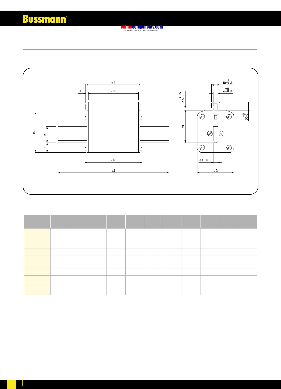
Dimensional Data for NH Fuses
fe2e1Dc1b (min)a4a3a2a1
In
(A)
Fuse Size
C00
00
01
1
02
2
03
3
4a
4a
63
160
160
250
250
400
400
630
1000
1600
78.5
78.5
135
135
150
150
150
150
200
200
53
53
69
69
69
70
70
73
84
84
45.5
45.5
62
61
61
61
61
61
84
84
49
49
67
67
67
67
68
68
90
90
15
15
15
20
20
25
25
32
50
50
35
35
40
40
48
48
60
60
85
85
1.7
1.7
2.5
3
3
3
3
3
3
3
39.5
38
45
50
50
58
58
73
102
110
20.5
29
29
44.5
44.5
50
50
71
87
95
7
7
12
12
12
12
12
15
30
30
Dimensions in millimetres
onlinecomponents.com
Low Voltage Industrial Fuse Links
For more information visit our website at www.bussmann.com 24
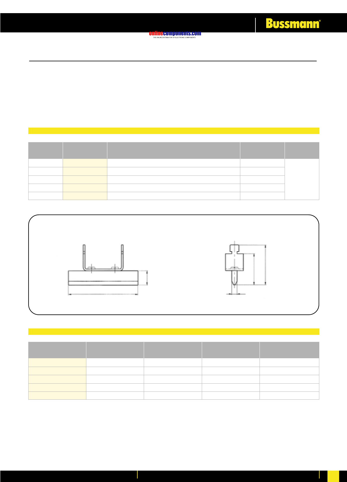
•For use with NH Fuse Switch-disconnectors and NH Fuse Bases
•Available in sizes 00 to Size 4
•Nickel plated copper
NH Neutral Links
Rated Current Part Number Size Weight Packaging
160
250
400
630
1000
SL00
SL1
SL2
SL3
SL4
0.090 kg
0.170 kg
0.230 kg
0.290 kg
0.351 kg
00
1
2
3
4
3
pcs per
carton
APart Number B C D
SL00
SL1
SL2
SL3
SL4
78.5
135
150
150
150
16
20
25
32
40
35
40
48
60
60
45
50
58
70
70
Dimensions of the disconnecting knifes
A
B
C
6
D
Dimensions in millimetres
Fuse Link Selection Table
Dimensional Data (Millimetres)
onlinecomponents.com
Low Voltage Industrial Fuse Links
For more information visit our website at www.bussmann.com
25
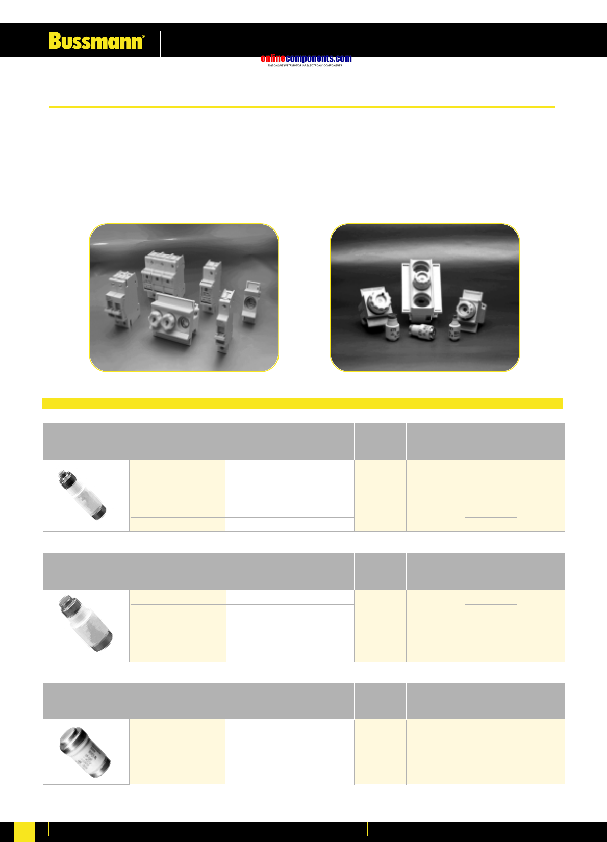
The D0 and D Type fuse systems consist of a fuse base, gauge ring, fuse link and screw cap.
D0 fuse links are manufactured in three sizes; D01, D02 & D03 in ratings from 2 to 100 Amps. They are
available in Time-Delay (Class gL/gG) and Ultra-Rapid (gR) characteristics rated at 400Vac. Similar to the D0
system - the D system is designed for a rated voltage of 500V AC. D-Type fuse links are available in 5 sizes -
E16, DII, DIII, DIV and DV. Both systems conform to IEC269 and VDE0636.
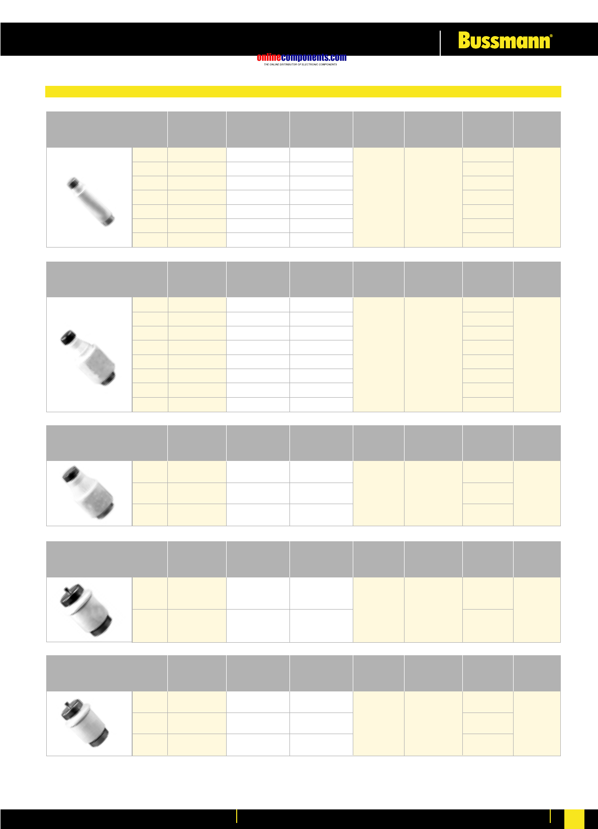
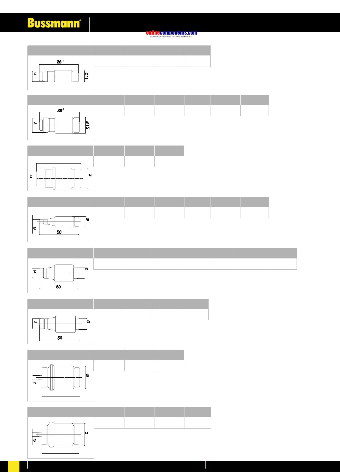
D01 Fuse Links
use with
fuse base E14
Rating
(A)
2
4
6
10
16
Colour Code
Pink
Brown
Green
Red
Grey
Time Delay
2NZ01
4NZ01
6NZ01
10NZ01
16NZ01
Ultra Rapid
2NZ01R
4NZ01R
6NZ01R
10NZ01R
16NZ01R
Body
Diameter
(mm)
11.0
Overall
Length
(mm)
36.0
Contact
Diameter
(mm)
7.3
7.3
7.3
8.5
9.7
Box
Quantity
10 pcs
D02 Fuse Links
use with
fuse base E18
Rating
(A)
20
25
35
50
63
Colour Code
Blue
Yellow
Black
White
Copper
Time Delay
20NZ02
25NZ02
35NZ02
50NZ02
63NZ02
Ultra Rapid
20NZ02R
25NZ02R
35NZ02R
50NZ02R
63NZ02R
Body
Diameter
(mm)
15.0
Overall
Length
(mm)
36.0
Contact
Diameter
(mm)
10.9
12.1
13.3
14.5
15.9
Box
Quantity
10 pcs
D03 Fuse Links
use with
fuse base M30 X 2
Rating
(A)
80
100
Colour Code
Silver
Red
Time Delay
80NZ03
100NZ03
Ultra Rapid
-
-
Body
Diameter
(mm)
22.5
Overall
Length
(mm)
43.0
Contact
Diameter
(mm)
21.4
24.4
Box
Quantity
10 pcs
D0 Fuse Links Selection Table
D & D0 Low Voltage Fuse System
onlinecomponents.com
Low Voltage Industrial Fuse Links
For more information visit our website at www.bussmann.com 26
DI Fuse Links
use with
fuse base E16
Rating
(A)
2
4
6
10
16
20
25
Colour Code
Pink
Brown
Green
Red
Grey
Blue
Yellow
Time Delay
2D16
4D16
6D16
10D16
16D16
20D16
25D16
Ultra Rapid
2D16R
4D16R
6D16R
10D16R
16D16R
20D16R
25D16R
Body
Diameter
(mm)
13.2
Overall
Length
(mm)
50.0
Contact
Diameter
(mm)
6.0
6.0
6.0
8.0
10.0
12.0
14.0
Box
Quantity
20 pcs
DII Fuse Links
use with fuse
base E27
Rating
(A)
2
4
6
10
16
20
25
30
Colour Code
Pink
Brown
Green
Red
Grey
Blue
Yellow
Black
Time Delay
2D27
4D27
6D27
10D27
16D27
20D27
25D27
-
Ultra Rapid
2D27R
4D27R
6D27R
10D27R
16D27R
20D27R
25D27R
30D27R
Body
Diameter
(mm)
21.5
Overall
Length
(mm)
50.0
Contact
Diameter
(mm)
6.0
6.0
6.0
8.0
10.0
12.0
14.0
14.0
Box
Quantity
5 pcs
DIII Fuse Links
use with
fuse base E33
Rating
(A)
35
50
63
Colour Code
Black
White
Copper
Time Delay
35D33
50D33
63D33
Ultra Rapid
35D33R
50D33R
63D33R
Body
Diameter
(mm)
27.0
Overall
Length
(mm)
50.0
Contact
Diameter
(mm)
16.0
18.0
20.0
Box
Quantity
5 pcs
DIV Fuse Links
use with
fuse base R11/4 ”
Rating
(A)
80
100
Colour Code
Silver
Red
Time Delay
80D125
100D125
Ultra Rapid
80D125R
100D125R
Body
Diameter
(mm)
33.0
Overall
Length
(mm)
56.0
Contact
Diameter
(mm)
5.0
7.0
Box
Quantity
10 pcs
DV Fuse Links
use with
fuse base R2”
Rating
(A)
125
160
200
Colour Code
Yellow
Copper
Blue
Time Delay
-
-
-
Ultra Rapid
125D200
160D200
200D200
Body
Diameter
(mm)
46.0
Overall
Length
(mm)
56.0
Contact
Diameter
(mm)
5.0
7.0
9.0
Box
Quantity
10pcs
D-Type Fuse Links Selection Table
onlinecomponents.com
Low Voltage Industrial Fuse Links
For more information visit our website at www.bussmann.com
27
43
22.5
A
D01 Fuse Links Dimension
ØA (mm)
2A to 6A
7.3
10A
8.5
16A
9.7
D03 Fuse Links Dimension
ØA (mm)
100A
21.6
80A
21.4
D02 Fuse Links Dimension
ØA (mm)
25A
12.1
35A
13.3
50A
14.5
63A
15.9
20A
10.9
DI Fuse Links Dimension
ØB(mm)
10A
8.0
16A
10.0
20A
12.0
25A
14.0
2A to 6A
6.0
DII Fuse Links Dimension
ØB (mm)
10A
8.0
16A
10.0
20A
12.0
25A
14.0
30A
14.0
2A to 6A
6.0
DIII Fuse Links Dimension
ØB (mm)
35A
16.0
50A
18.0
63A
20.0
DIV Fuse Links Dimension
ØB (mm)
100A
18.0
80A
16.0
DV Fuse Links Dimension
ØB (mm)
125A
5.0
160A
7.0
200A
9.0
AA
27
B
21.5
BB
13.2
BB
33
56
46
56
onlinecomponents.com
Low Voltage Industrial Fuse Links
For more information visit our website at www.bussmann.com 28
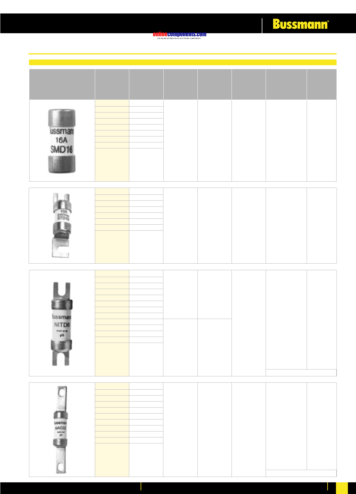
NITD2 2
NITD4 4
NITD6 6
NITD10 10
NITD16 16
NITD20 20 240 V AC 44.5 80 kA @ 500 V AC 20 pcs
NITD25 25
NITD32 32
NITD20M25 20M25
NITD20M32 20M32
NITD32M40 32M40
NITD32M50 32M50
NITD32M63 32M63
550 –
44 80 kA @ 550 V AC 20 pcs
STD2 2
STD4 4
STD6 6
STD10 10 240 V AC –35.0 33 kA @ 240 V AC 20 pcs
STD16 16
STD20 20
STD25 25
STD32 32
240 –35 33 kA @ 240 V AC 20 pcs
SMD2 2
SMD4 4
SMD6 6
SMD8 8
SMD10 10
SMD16 16
SMD20 20
SMD25 25
SMD32 32
415 ––80 kA @ 415 V AC 20 pcs
Part No. Current Rated Voltage Rated Voltage Fixing Centres Interrupting Box
Rating (AC) (DC) (mm) Rating Quantity
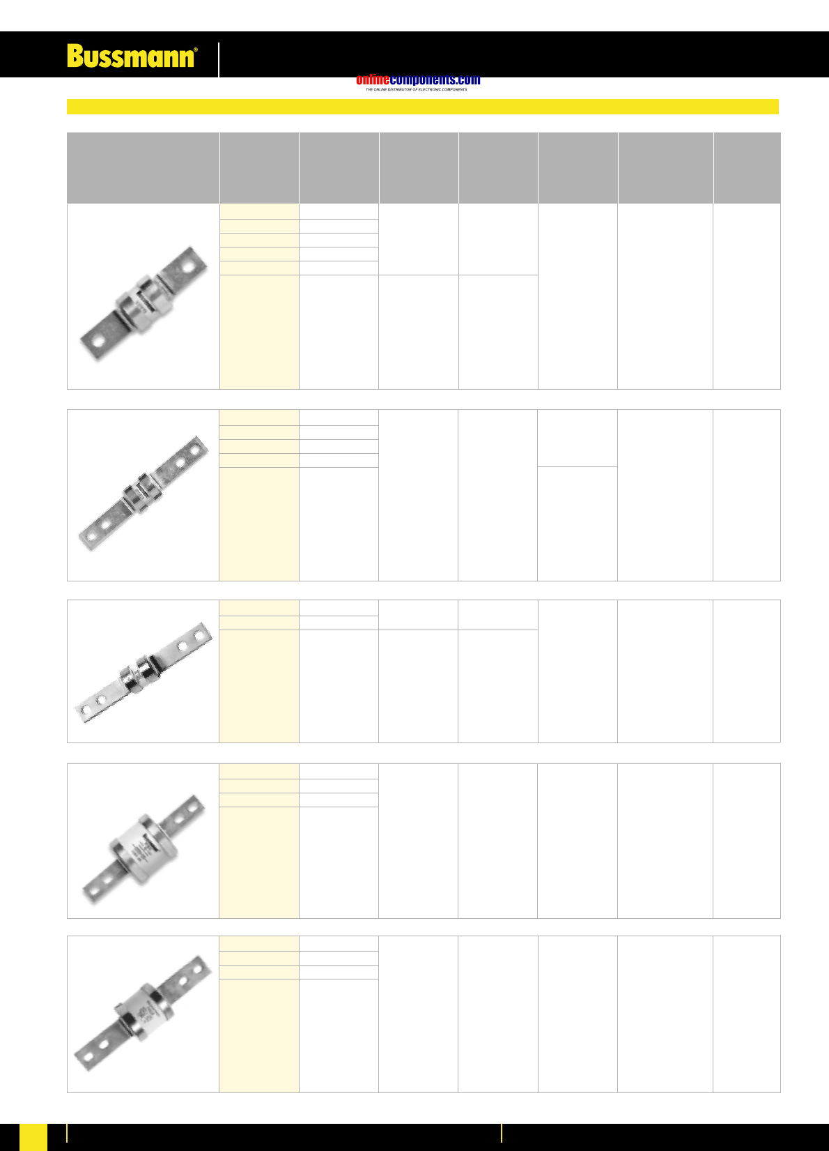
AAO2 2
AAO4 4
AAO6 6
AAO10 10
AAO16 16
AAO20 20 240 V AC 44.5 80 kA @ 500 V AC 20 pcs
AAO25 25
AAO32 32
AAO32M40 32M40
AAO32M50 32M50
AAO32M63 32M63
550 –73 80 kA @ 550 V AC 20 pcs
415 –
Offset Bolted Tag
See page 194 for Fuse Holders
See page 194 for Fuse Holders
Low Voltage Fuse Links to BS88 & IEC269
onlinecomponents.com
Low Voltage Industrial Fuse Links
For more information visit our website at www.bussmann.com
29
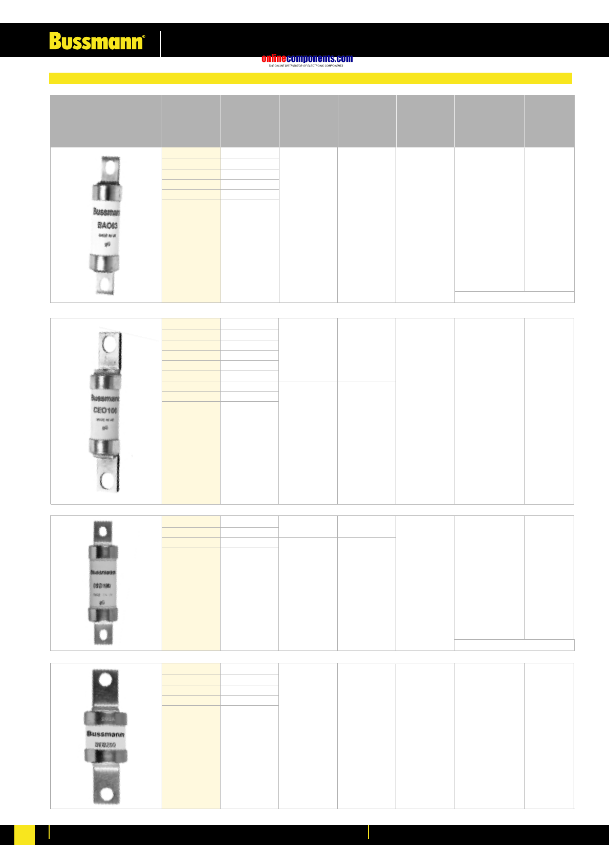
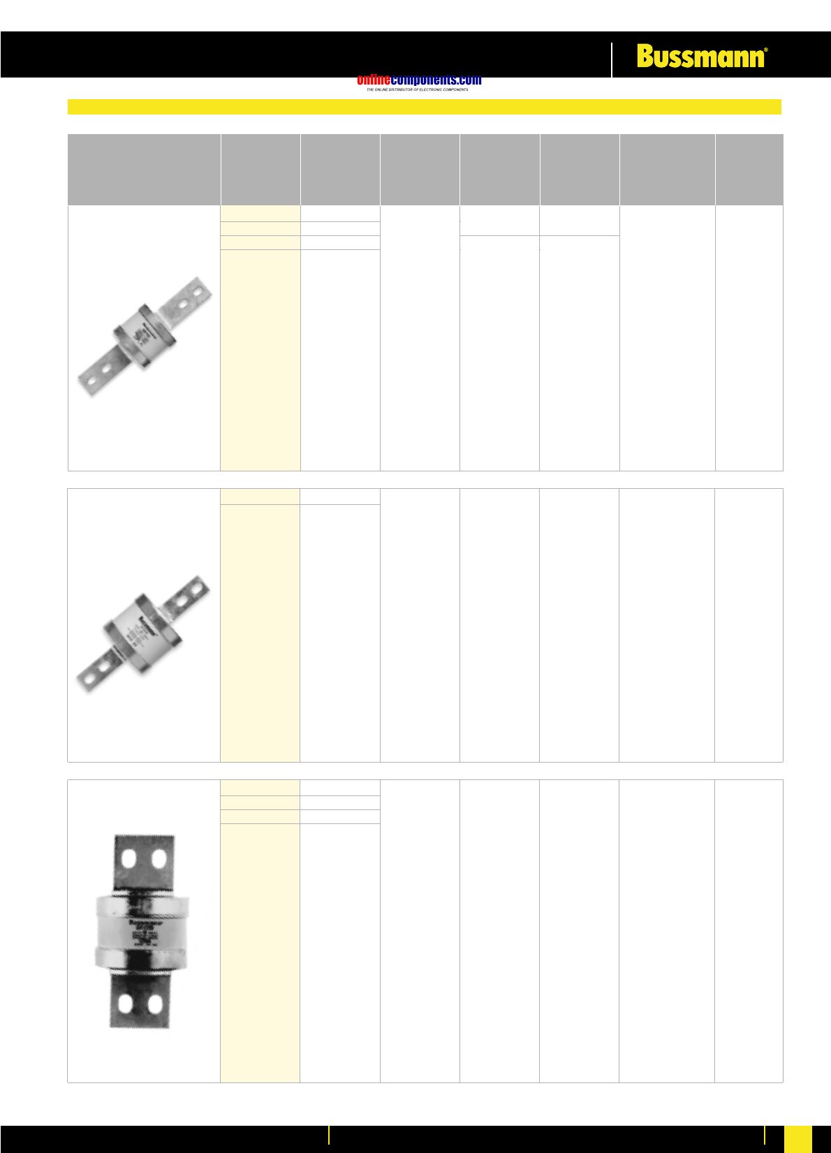
CEO32 32
CEO40 40
CEO50 50
CEO63 63
CEO80 80
CEO100 100
CEO100M125 100M125
CEO100M160 100M160
CEO100M200 100M200
415 –
BAO35 35
BAO40 40
BAO50 50
BAO63 63
BAO63M80 63M80
BAO63M100 63M100
550 –73 80 kA @ 550 V AC 20 pcs
Part No. Current Rated Voltage Rated Voltage Fixing Centres Interrupting Box
Rating (AC) (DC) (mm) Rating Quantity
BS Ref A3
550 –
94 80 kA @ 550 V AC 10 pcs
BS Ref A4
OSD80 80
OSD100 100
OSD100M125 100M125
OSD100M160 100M160 415 –
550 –
73 80 kA @ 550 V AC 20 pcs
DEO125 125
DEO160 160
DEO200 200
DEO200M250 200M250
DEO200M315 200M315
415 –94 80 kA @ 415 V AC 5 pcs
Offset Bolted Tag
See page 194 for Fuse Holders
See page 194 for Fuse Holders
onlinecomponents.com
Low Voltage Industrial Fuse Links
For more information visit our website at www.bussmann.com 30
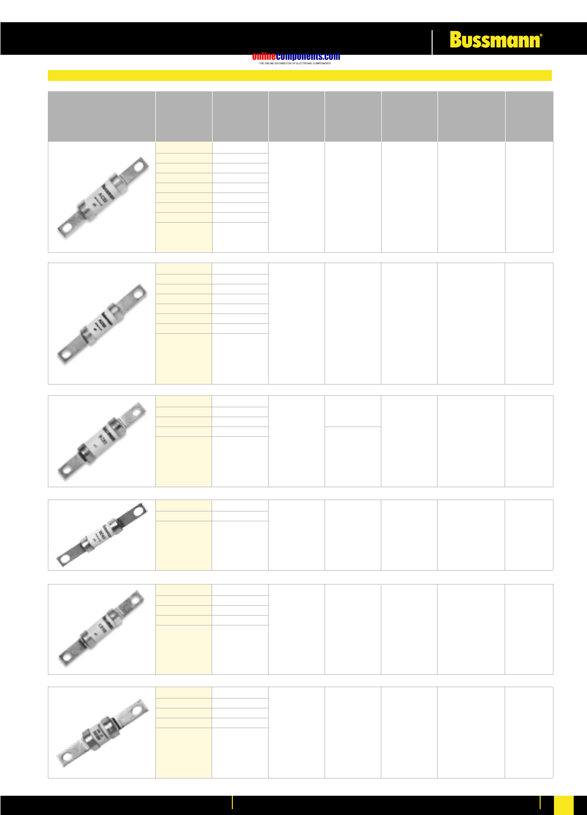
BC40 40
BC50 50
BC63 63
BC63M80 63M80
BC63M100 63M100
550
250
-
AD2 2
AD4 4
AD6 6
AD10 10
AD16 16
AD20 20
AD25 25
AD32 32
250
AC2 2
AC4 4
AC6 6
AC10 10
AC16 16
AC20 20
AC25 25
AC32 32
250
550 97.5 80 kA 20 pcs
@ 550 V AC
40 kA
@ 250 V DC
Part No. Current Rated Voltage Rated Voltage Fixing Centres Interrupting Box
Rating (AC) (DC) (mm) Rating Quantity
550 111 8 V AC 20 pcs
97.5 20 pcs
BD40 40
BD50 50
BD63 63
550 250 111 20 pcs
CD80 80
CD100 100
CD100M125 100M125
CD100M160 100M160
CD100M200 100M200
415 –111 80 kA @ 550 V AC 10 pcs
BS Ref B1
DD125 125
DD160 160
DD200 200
DD200M250 200M250
DD200M315 200M315
415 – 111 80 kA @ 550 V AC 5 pcs
BS Ref B2
80 kA
@ 550 V AC
40 kA
@ 250 V DC
80 kA
@ 550 V AC
40 kA
@ 250 V DC
80 kA
@ 550 V AC
40 kA
@ 250 V DC
Offset Bolted Tag
onlinecomponents.com
Low Voltage Industrial Fuse Links
For more information visit our website at www.bussmann.com
31
FF450 450
FF500 500
FF560 560
FF630 630
550 80 kA @ 550 V AC 1 pc400 134 / 184
EF355 355
EF400 400
EF400M500 400M500
415 –
550
ED250 250
ED315 315
ED355 355
ED400 400
ED315M400 315M400
ED400M500 400M500
415 –111 80 kA @ 415 V AC 1 pc
Part No. Current Rated Voltage Rated Voltage Fixing Centres Interrupting Box
Rating (AC) (DC) (mm) Rating Quantity
BS Ref B3/B4
550
EFS125 125
EFS160 160
EFS200 200
EFS250 250
EFS315 315
415 –133 80 kA @ 415 V AC 1 pc
80 kA @ 415 V AC 1 pc
BS Ref C1
BS Ref C2
FG450 450
FG500 500
FG560 560
FG630 630
550 80 kA @ 550 V AC 1 pc400 167 / 231
133 / 184
80 kA
@ 550 V AC
40 kA
@ 400 V DC
80 kA
@ 550 V AC
40 kA
@ 400 V DC
133 / 184
Centre Bolted Tag
onlinecomponents.com
Low Voltage Industrial Fuse Links
For more information visit our website at www.bussmann.com 32
GF710 710
GF800 800 550 133 / 184 80 kA @ 550 V AC 1 pc
250
GG710 710
GG800 800
GG1000 1000
GG1250 1250
550 80 kA @ 550 V AC 1 pc
Part No. Current Rated Voltage Rated Voltage Fixing Centres Interrupting Box
Rating (AC) (DC) (mm) Rating Quantity
BS Ref C3
GH710 710
GH800 800
GH1000 1000
GH1250 1250
80 kA @ 550 V AC 1 pc149
250
-
165 / 231.0
165 / 228.5
550 –
80 kA
@ 550 V AC
40 kA
@ 250 V DC
80 kA
@ 550 V AC
40 kA
@ 250 V DC
Centre Bolted Tag
onlinecomponents.com
Low Voltage Industrial Fuse Links
For more information visit our website at www.bussmann.com
33
ESD2 2
ESD4 4
ESD6 6
ESD10 10
ESD16 16
ESD20 20
ESD25 25
ESD32 32
ESD40 40
ESD50 50
ESD63 63
ESD63M80 63M80
ESD63M100 63M100 415
550 –80 kA @ 550 V AC 20 pcs
–
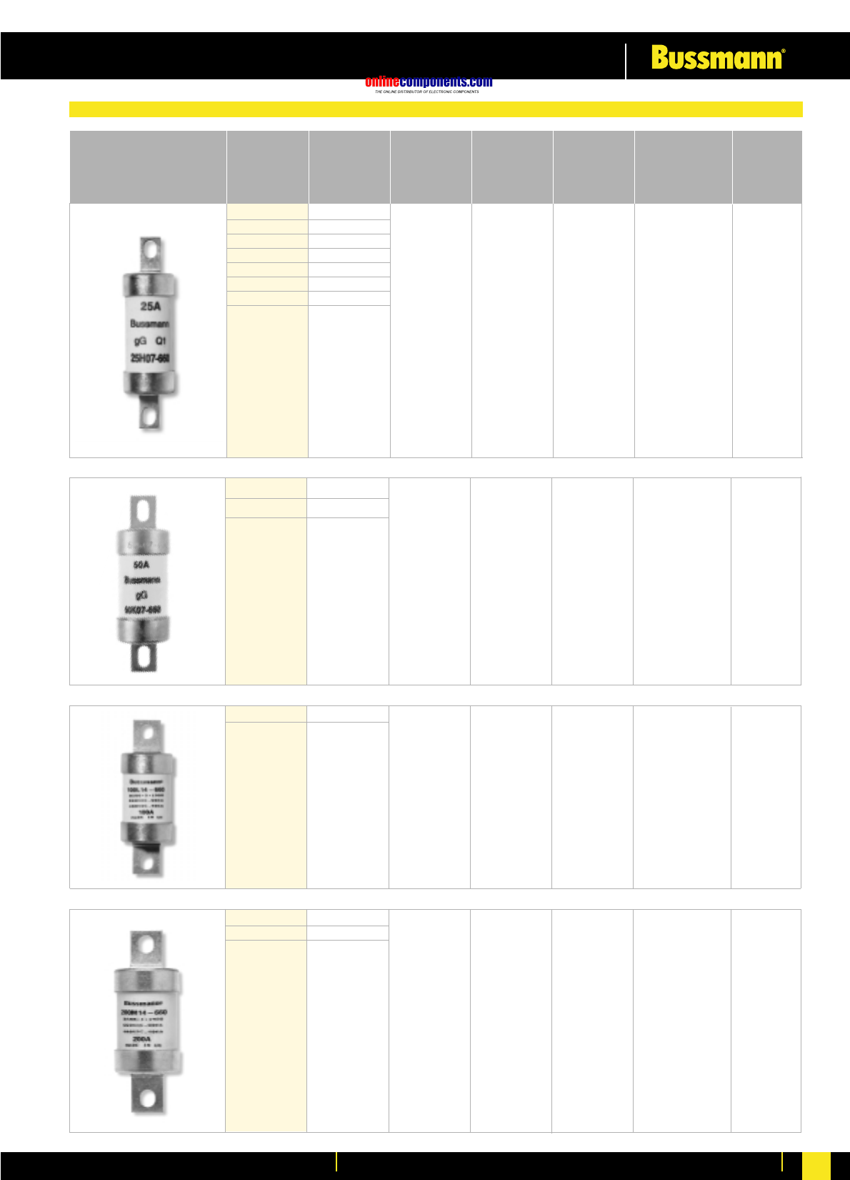
NSD2 2
NSD4 4
NSD6 6
NSD10 10
NSD16 16
NSD20 20
NSD25 25
NSD32 32
NSD20M25 20M25
NSD20M32 20M32
NSD20M36 20M36
NSD32M36 32M36
NSD32M40 32M40
NSD32M50 32M50
NSD32M63 32M63
415
550
–80 kA @ 550 V AC 20 pcs
–
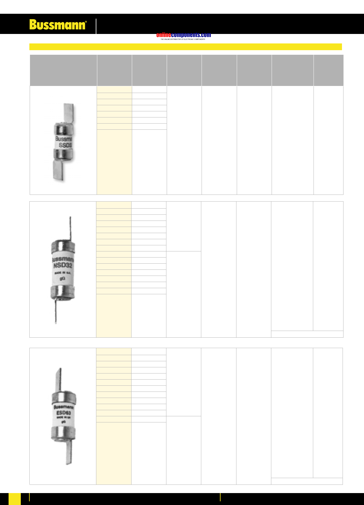
SSD2 2
SSD4 4
SSD6 6
SSD10 10
SSD16 16
SSD20 20
SSD25 25
SSD32 32
240 ––33 kA @ 240 V AC 20 pcs
Part No. Current Rated Voltage Rated Voltage Fixing Centres Interrupting Box
Rating (AC) (DC) (mm) Rating Quantity
BS Ref E1
BS Ref F1
BS Ref F2
Offset Bladed Tag
See page 196 for Fuse Holders
See page 196 for Fuse Holders
onlinecomponents.com
Low Voltage Industrial Fuse Links
For more information visit our website at www.bussmann.com 34
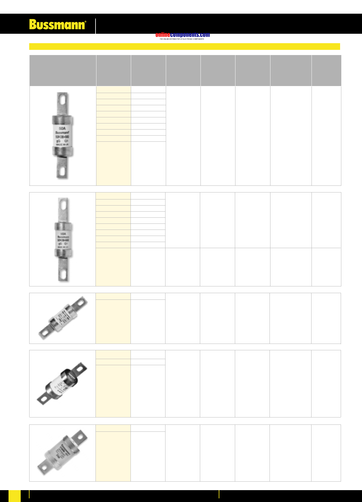
40K07-660 40
50K07-660 50
63K07-660 63
250
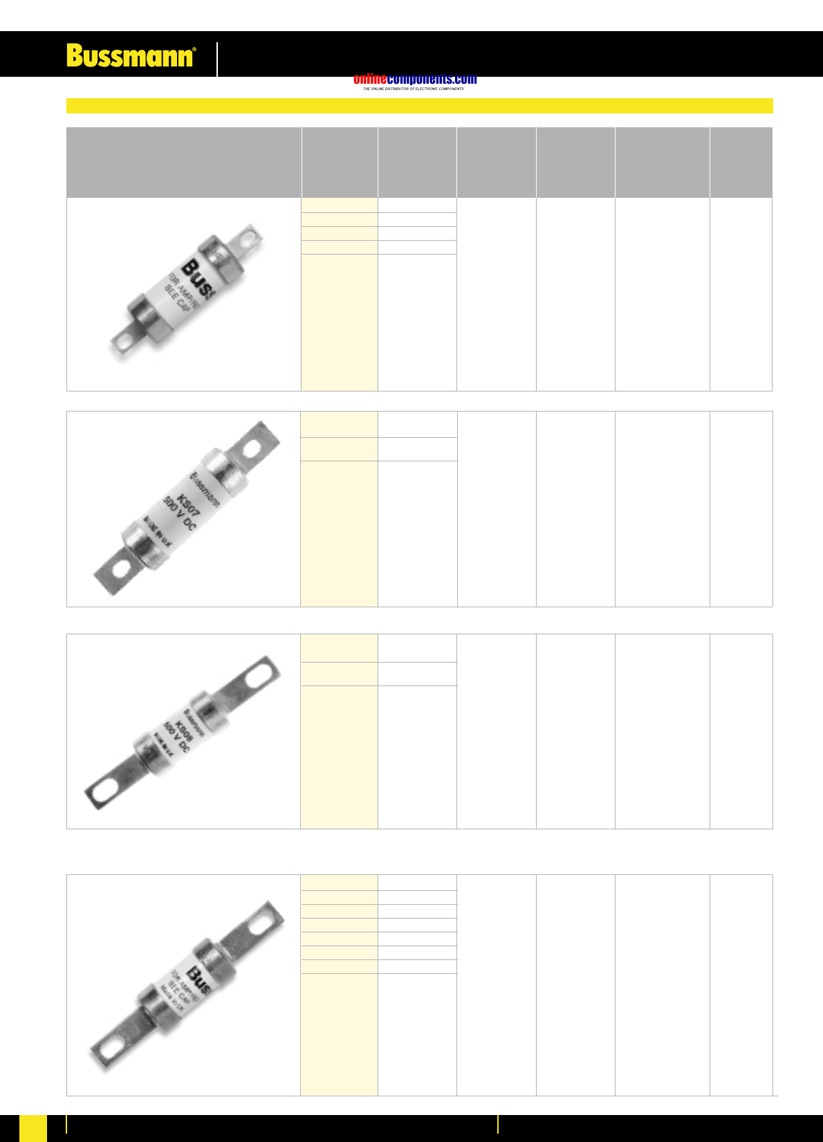
2H07-660 2
4H07-660 4
6H07-660 6
10H07-660 10
16H07-660 16
20H07-660 20
25H07-660 25
32H07-660 32
660 / 690 250 73 80 kA @ 660 V AC 20 pcs
Part No. Current Rated Voltage Rated Voltage Fixing Centres Interrupting Box
Rating (AC) (DC) (mm) Rating Quantity
BS Ref A2
73
660 / 690 80 kA @ 660 V AC 20 pcs
BS Ref A3
80L14-660 80
100L14-660 100 400 94
660 / 690 80 kA @ 660 V AC 10 pcs
BS Ref A4
125M14-660 125
160M14-660 160
200M14-660 200
400 94
660 / 690 80 kA @ 660 V AC 5 pcs
80 kA
@ 660 V AC
40 kA
@ 250 V DC
80 kA
@ 660 V AC
40 kA
@ 250 V DC
80 kA
@ 660 V AC
40 kA
@ 250 V DC
80 kA
@ 660 V AC
40 kA
@ 250 V DC
660/690V Offset Bolted Tag
onlinecomponents.com
Low Voltage Industrial Fuse Links
For more information visit our website at www.bussmann.com
35
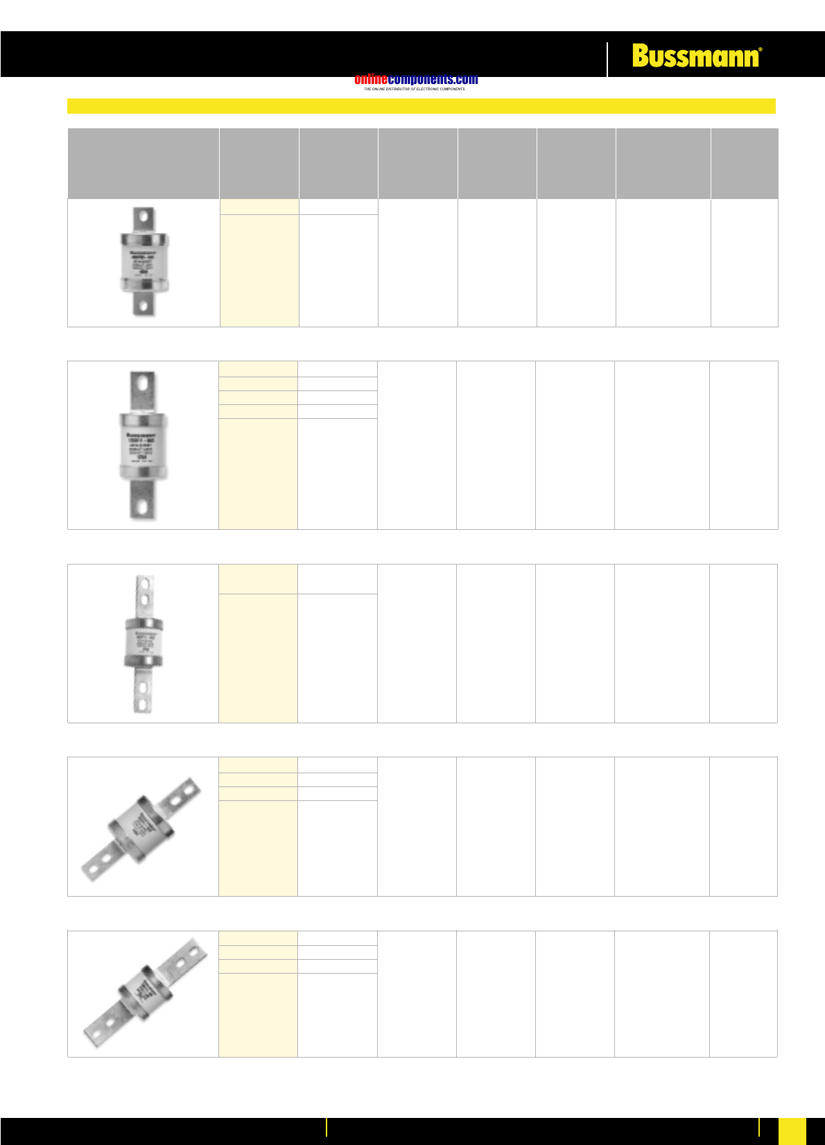
2K09-660 2
4K09-660 4
6K09-660 6
10K09-660 10
16K09-660 16
20K09-660 20
32K09-660 32
40K09-660 40
50K09-660 50
63K09-660 63
106.5
111 80 kA @ 660 V AC 20 pcs
660 / 690 250
2K08-660 2
4K08-660 4
6K08-660 6
10K08-660 10
16K08-660 16
20K08-660 20
32K08-660 32
40K08-660 40
50K08-660 50
63K08-660 63
660 / 690 250 71.5 80 kA @ 660 V AC 20 pcs
93
Part No. Current Rated Voltage Rated Voltage Fixing Centres Interrupting Box
Rating (AC) (DC) (mm) Rating Quantity
80L09-660 80
100L09-660 100 400 111
660 / 690 80 kA @ 660 V AC 10 pcs
BS Ref B1
125M09-660 125
160M09-660 160
200M09-660 200 400 111660 / 690 80 kA @ 660 V AC 5 pcs
BS Ref B2
250N09-660 250
315N09-660 315 400 111
660 / 690 80 kA @ 660 V AC 1 pc
80 kA
@ 660 V AC
40 kA
@ 250 V DC
80 kA
@ 660 V AC
40 kA
@ 250 V DC
80 kA
@ 660 V AC
40 kA
@ 400 V DC
80 kA
@ 660 V AC
40 kA
@ 400 V DC
80 kA
@ 660 V AC
40 kA
@ 400 V DC
BS Ref B3
660/690V Centre Bolted Tag
onlinecomponents.com
Low Voltage Industrial Fuse Links
For more information visit our website at www.bussmann.com 36
355P09-660 355
400P09-660 400 660 / 690 400 111 80 kA @ 660 V AC 1 pc
Part No. Current Rated Voltage Rated Voltage Fixing Centres Interrupting Box
Rating (AC) (DC) (mm) Rating Quantity
125N11-660 125
160N11-660 160
200N11-660 200
250N11-660 250
315N11-660 315
660 / 690 80 kA @ 660 V AC 1 pc
400 133
355P11-660 355
400P11-660 400
400 133 / 184660 / 690 80 kA @ 660 V AC 1 pc
BS Ref C1
450R11-660 450
500R11-660 500
560R11-660 560
630R11-660 630
660 / 690 80 kA @ 660 V AC 1 pc400 133 / 184
BS Ref C2
450R12-660 450
500R12-660 500
560R12-660 560
630R12-660 630
660 / 690 80 kA @ 660 V AC 1 pc400 167/ 231
80 kA
@ 660 V AC
40 kA
@ 400 V DC
80 kA
@ 660 V AC
40 kA
@ 400 V DC
80 kA
@ 660 V AC
40 kA
@ 400 V DC
80 kA
@ 660 V AC
40 kA
@ 400 V DC
80 kA
@ 660 V AC
40 kA
@ 400 V DC
BS Ref B4
660/690V Centre Bolted Tag
onlinecomponents.com
Low Voltage Industrial Fuse Links
For more information visit our website at www.bussmann.com
37
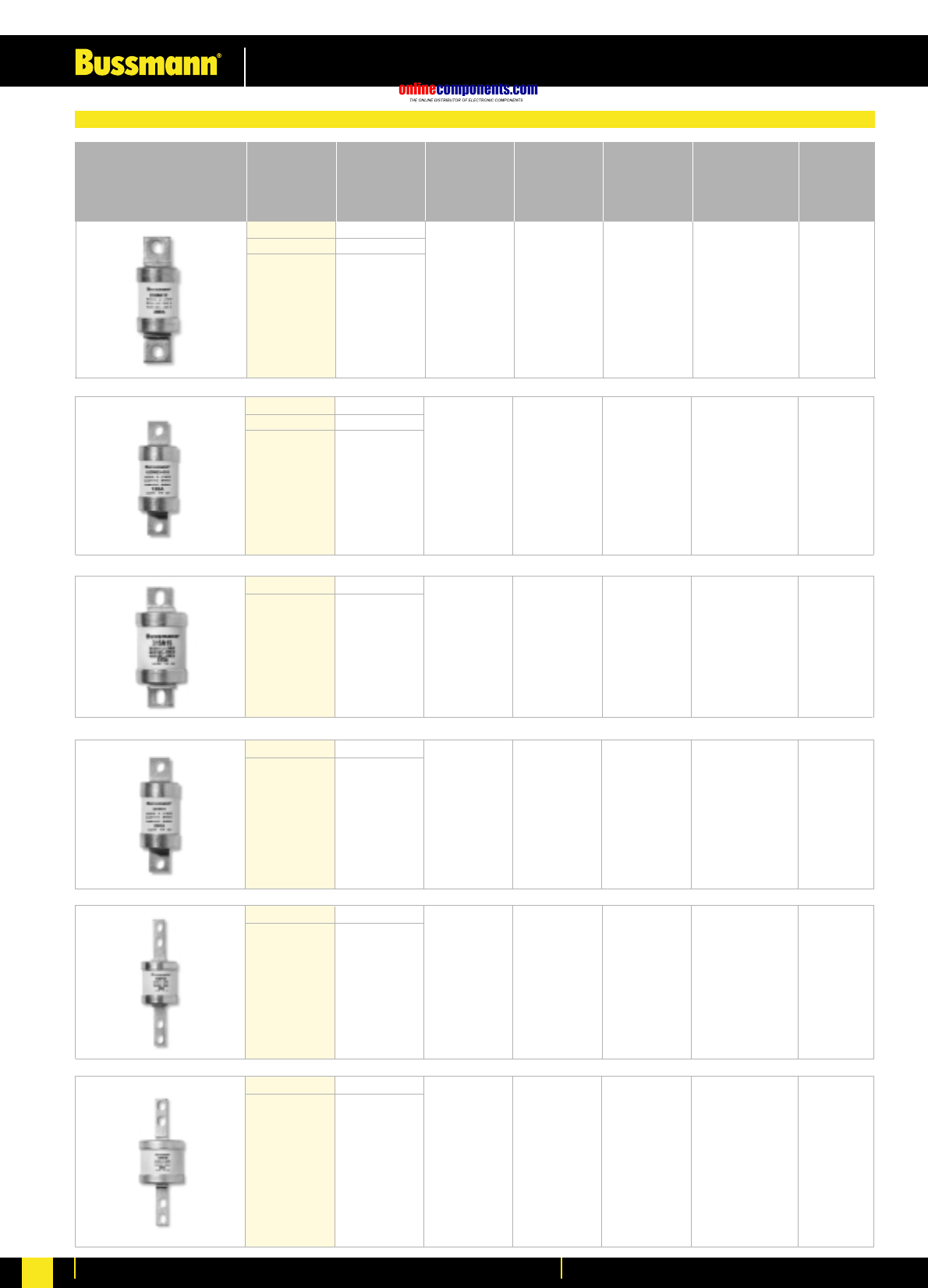
125M13 125
160M13 160
200M13 200
660 / 690 400 99 80 kA @ 660 V AC 5 pcs
Part No. Current Rated Voltage Rated Voltage Fixing Centres Interrupting Box
Rating (AC) (DC) (mm) Rating Quantity
125M23 125
160M23 160
200M23 200
400 231
660 / 690 80 kA @ 660 V AC 1 pc
250N15 250
315N15 315 400 100
660 / 690 80 kA @ 660 V AC 1 pc
250N34 250
315N34 315 400 113
660 / 690 80 kA @ 660 V AC 1 pc
355P35 355
400P35 400 400 133 / 184
660 / 690 80 kA @ 660 V AC 1 pc
450R40 450
500R40 500 400 133 / 184
660 / 690 80 kA @ 660 V AC 1 pc
80 kA
@ 660 V AC
40 kA
@ 400 V DC
80 kA
@ 660 V AC
40 kA
@ 400 V DC
80 kA
@ 660 V AC
40 kA
@ 400 V DC
80 kA
@ 660 V AC
40 kA
@ 400 V DC
80 kA
@ 660 V AC
40 kA
@ 400 V DC
80 kA
@ 660 V AC
40 kA
@ 400 V DC
660/690V Special Tag Arrangement
onlinecomponents.com
Low Voltage Industrial Fuse Links
For more information visit our website at www.bussmann.com 38
125N20 125
160N20 160
200N20 200
250N20 250
315N20 315
660 / 690 400 92.5 80 kA @ 660 V AC 1 pc
Part No. Current Rated Voltage Rated Voltage Fixing Centres Interrupting Box
Rating (AC) (DC) (mm) Rating Quantity
355P20 355
400P20 400 400 92.5
660 / 690 80 kA @ 660 V AC 1 pc
450R20 450
500R20 500
560R20 560
630R20 630
660 / 690 80 kA @ 660 V AC 1 pc400 94.0
710S20 710
800S20 800 – 94.0
550 80 kA @ 660 V AC 1 pc
80 kA
@ 660V AC
40 kA
@ 400V DC
80 kA
@ 660 V AC
40 kA
@ 400V DC
80 kA
@ 660V AC
40 kA
@ 400V DC
80 kA
@ 660V AC
660/690V Special Offset Tag
onlinecomponents.com
Low Voltage Industrial Fuse Links
For more information visit our website at www.bussmann.com
39
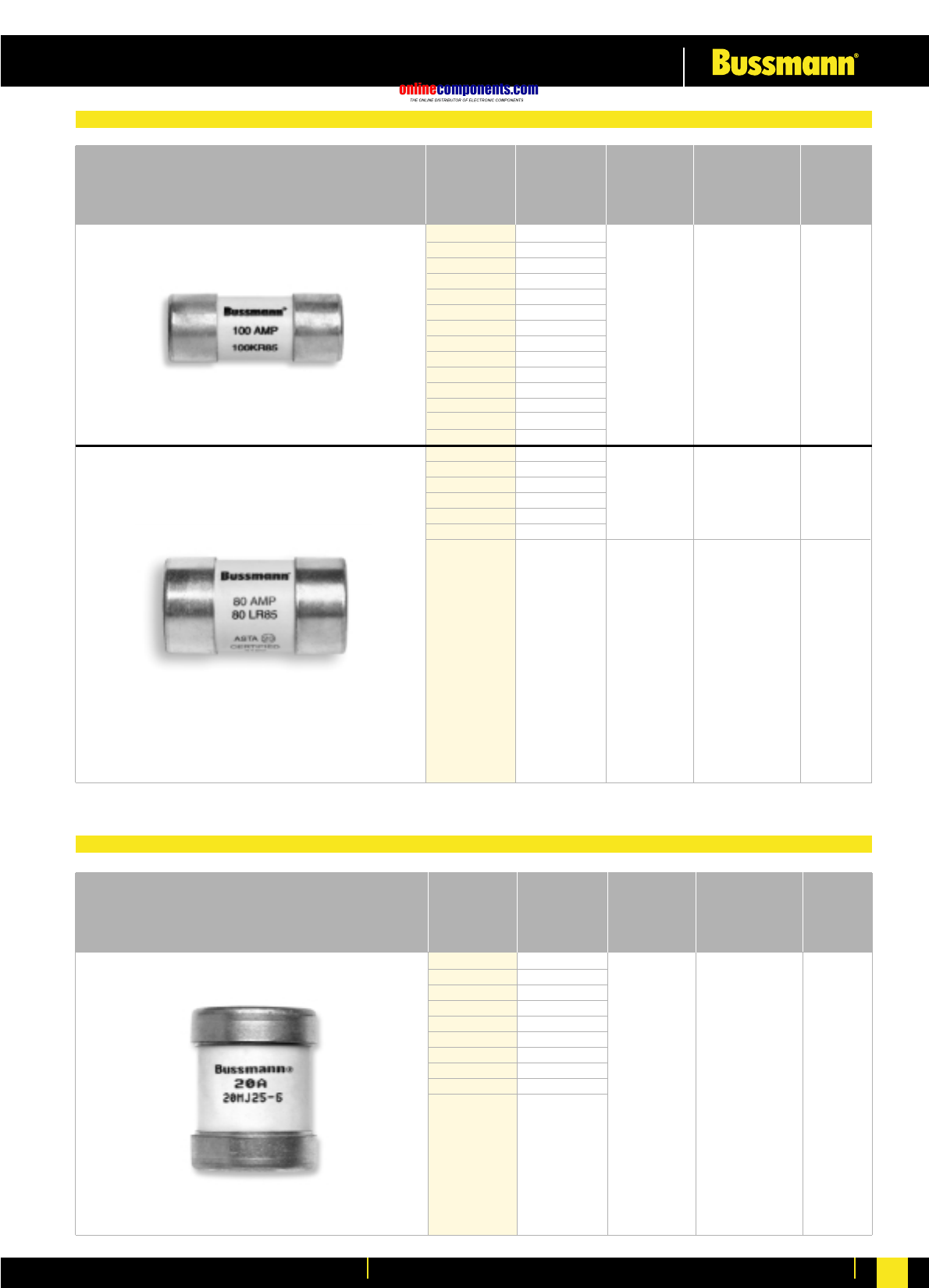
10HS07 10
16HS07 16
20HS07 20
25HS07 25
32HS07 32
500 73 40 kA @ 500V DC 20 pcs
Part No. Current Rated Voltage Fixing Centres Interrupting Box
Rating (DC) (mm) Rating Quantity
40KS07 40
50KS07 50
63KS07 63
500 73 40 kA @ 500V DC 20 pcs
40KS08 40
50KS08 50
63KS08 63
500 98 40 kA @ 500V DC 20 pcs
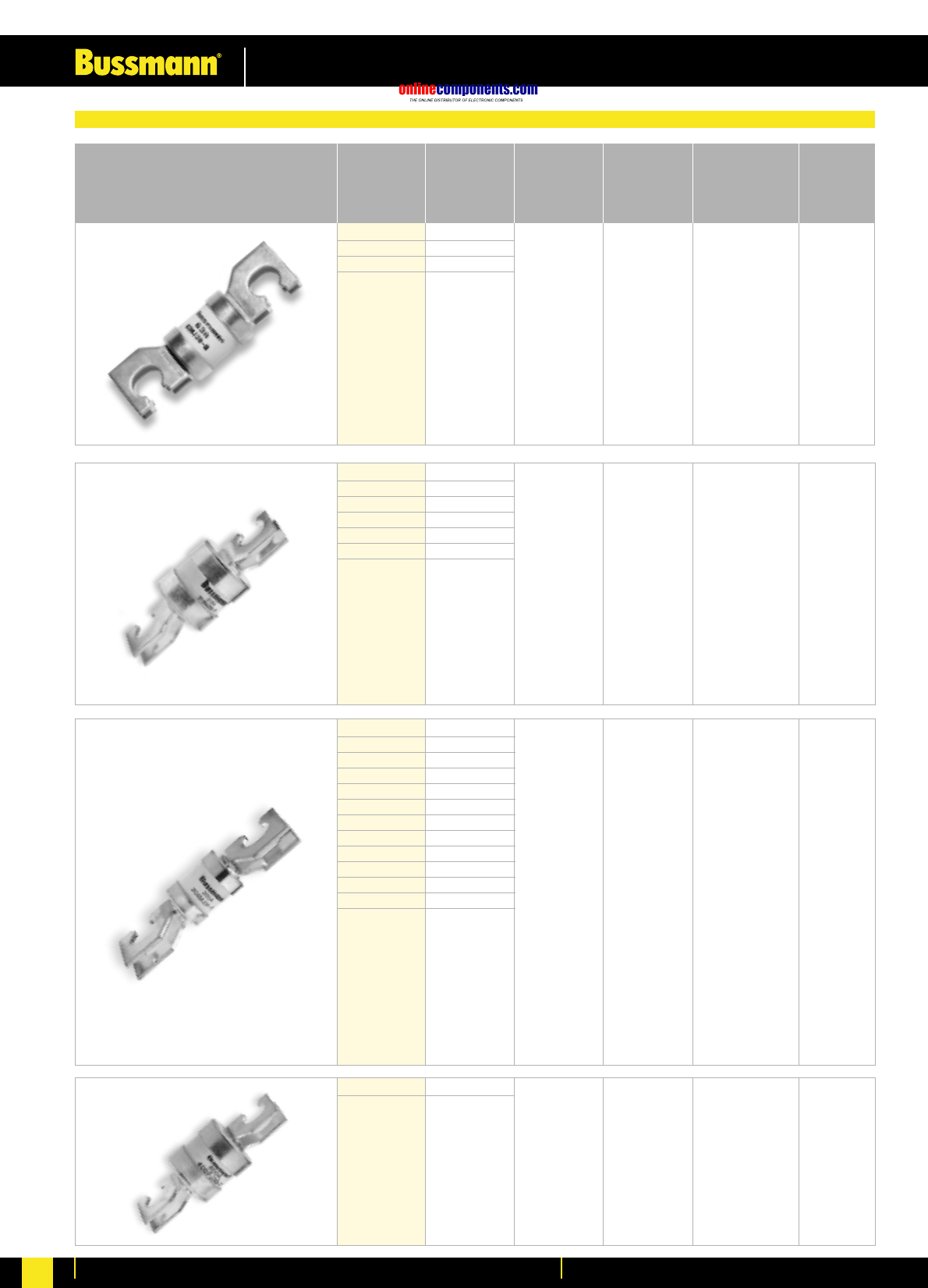
10KS09 10
16KS09 16
20KS09 20
25KS09 25
32KS09 32
40KS09 40
50KS09 50
63KS09 63
500 111 40 kA @ 500 V DC 20 pcs
Special 500V dc Range
onlinecomponents.com
Low Voltage Industrial Fuse Links
For more information visit our website at www.bussmann.com 40
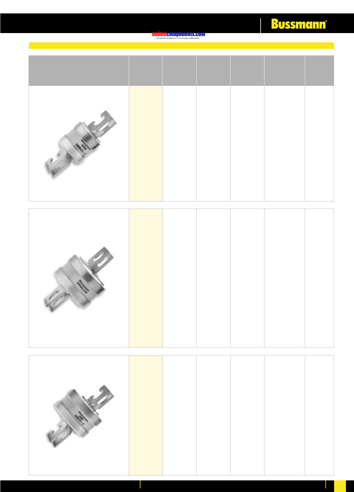
5KR85 5
10KR85 10
15KR85 15
20KR85 20
25KR85 25
30KR85 30
40KR85 40
45KR85 45
50KR85 50
60KR85 60
70KR85 70
80KR85 80
*90KR85 90
*100KR85 100
415 33 kA @ 415V AC 20 pcs
Part No. Current Rated Voltage Interrupting Box
Rating (AC) Rating Quantity
30LR85 30
40LR85 40
50LR85 50
60LR85 60
70LR85 70
80LR85 80
100LR85 100
415 33 kA @ 415V AC 20 pcs
*Check suitability of fuse holders before inserting these fuse links. Not suitable for UK applications.
20MJ25-6 20
32MJ25-6 32
40MJ25-6 40
63MJ25-6 63
80MJ25-6 80
100MJ25-6 100
125MJ25-6 125
160MJ25-6 160
200MJ25-6 200
250MJ25-6 250
415 80 kA @ 415V AC 10 pcs
Part No. Current Rated Voltage Interrupting Box
Rating (AC) Rating Quantity
House Service Cut out and J Type - Fuse Links to BS1361
J Type Fuse Links to BS88: Part 5
onlinecomponents.com
Low Voltage Industrial Fuse Links
For more information visit our website at www.bussmann.com
41
32MJ30-8 32
40MJ30-8 40
50MJ30-8 50
63MJ30-8 63
415 82 80 kA @ 415 V DC 10 pcs
Part No. Current Rated Voltage Fixing Centres Interrupting Box
Rating (AC) (mm) Rating Quantity
80MJ30-7 80
100MJ30-7 100
125MJ30-7 125
160MJ30-7 160
200MJ30-7 200
250MJ30-7 250
315MJ30-7 315
415 82 80 kA @ 415V AC 10 pcs
20MJ31-7 20
25MJ31-7 25
32MJ31-7 32
40MJ31-7 40
50MJ31-7 50
63MJ31-7 63
80MJ31-7 80
100MJ31-7 100
125MJ31-7 125
160MJ31-7 160
200MJ31-7 200
250PJ31-7 250
315PJ31-7 315
415 92 80 kA @ 415V AC 10 pcs
355PJ30-7 355
400PJ30-7 400 415 82 80 kA @ 415V AC 10 pcs
J Type Fuse Links for low Voltage Feeder Piller Protection - Fuse Links to BS88: Part 5 ‘J’ Type
onlinecomponents.com
Low Voltage Industrial Fuse Links
For more information visit our website at www.bussmann.com 42
Part No. Current Rated Voltage Fixing Centres Interrupting Box
Rating (AC) (mm) Rating Quantity
450RJ31-7 450
500RJ31-7 500 415 92 80 kA @ 415V AC 10 pcs
800SJ28 800 415 92 80 kA @ 415V AC 10 pcs
560SJ31-6 560
630SJ31-6 630 415 92 80 kA @ 415V AC 10 pcs
J Type Fuse Links for low Voltage Feeder Piller Protection - Fuse Links to BS88: Part 5 ‘J’ Type
onlinecomponents.com
Low Voltage Industrial Fuse Links
For more information visit our website at www.bussmann.com
43
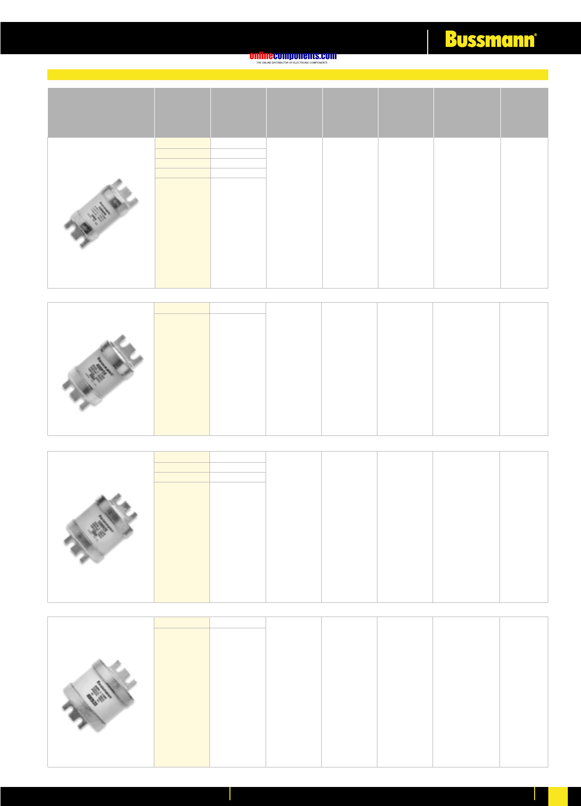
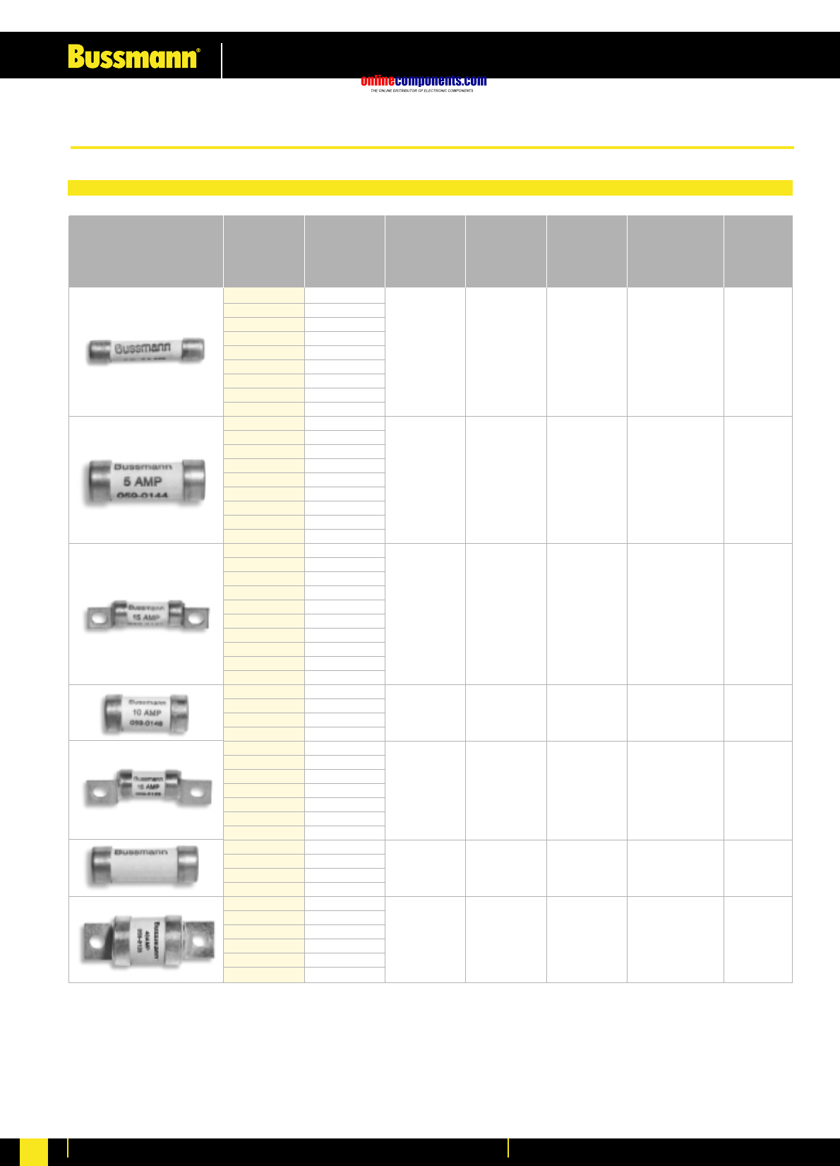
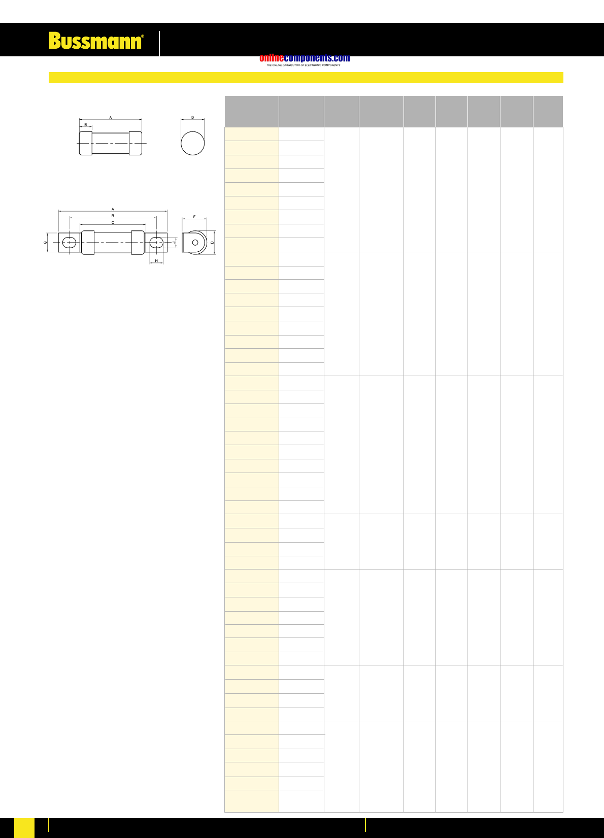
059-0107 0.25
059-0108 0.5
059-0109 1
059-0110 2
059-0111 3
059-0112 5
059-0113 7
011-9925 10
011-9926 15
059-0140 0.5
059-0141 1
059-0142 2
059-0143 3
059-0144 5
059-0145 7
059-0146 10
059-0147 15
011-9483 20
059-0114 0.5
059-0115 1
059-0116 2
059-0117 3
059-0118 5
059-0119 7
059-0120 10
059-0121 15
011-9679 20
012-0140 30
059-0148 10
059-0149 15
059-0150 20
059-0151 30
059-0122 10
059-0123 15
059-0124 20
059-0125 30
012-0067 40
011-9127 50
012-0141 60
059-0152 40
059-0153 60
059-0154 80
059-0155 100
059-0126 40
059-0127 60
059-0128 80
059-0129 100
011-9128 125
011-9129 150
1 440 44.65 33 kA @ 440V AC 25 pcs
1 440 –33 kA @ 440V AC 25 pcs
0 440 –33 kA @ 440V AC 10 pcs
2 440 –33 kA @ 440V AC 25 pcs
2 440 55.84 33 kA @ 440V AC 25 pcs
3 440 –33 kA @ 440V AC 25 pcs
3 440 69.77 33 kA @ 440V AC 25 pcs
Part No. Current Body Size Rated Voltage Fixing Centres Interrupting Box
Rating (AC) (mm) Rating Quantity
DEF Standard 59-96 (NATO Reference System)
Joint Service and Nato Fuse Links
onlinecomponents.com
Low Voltage Industrial Fuse Links
For more information visit our website at www.bussmann.com 44
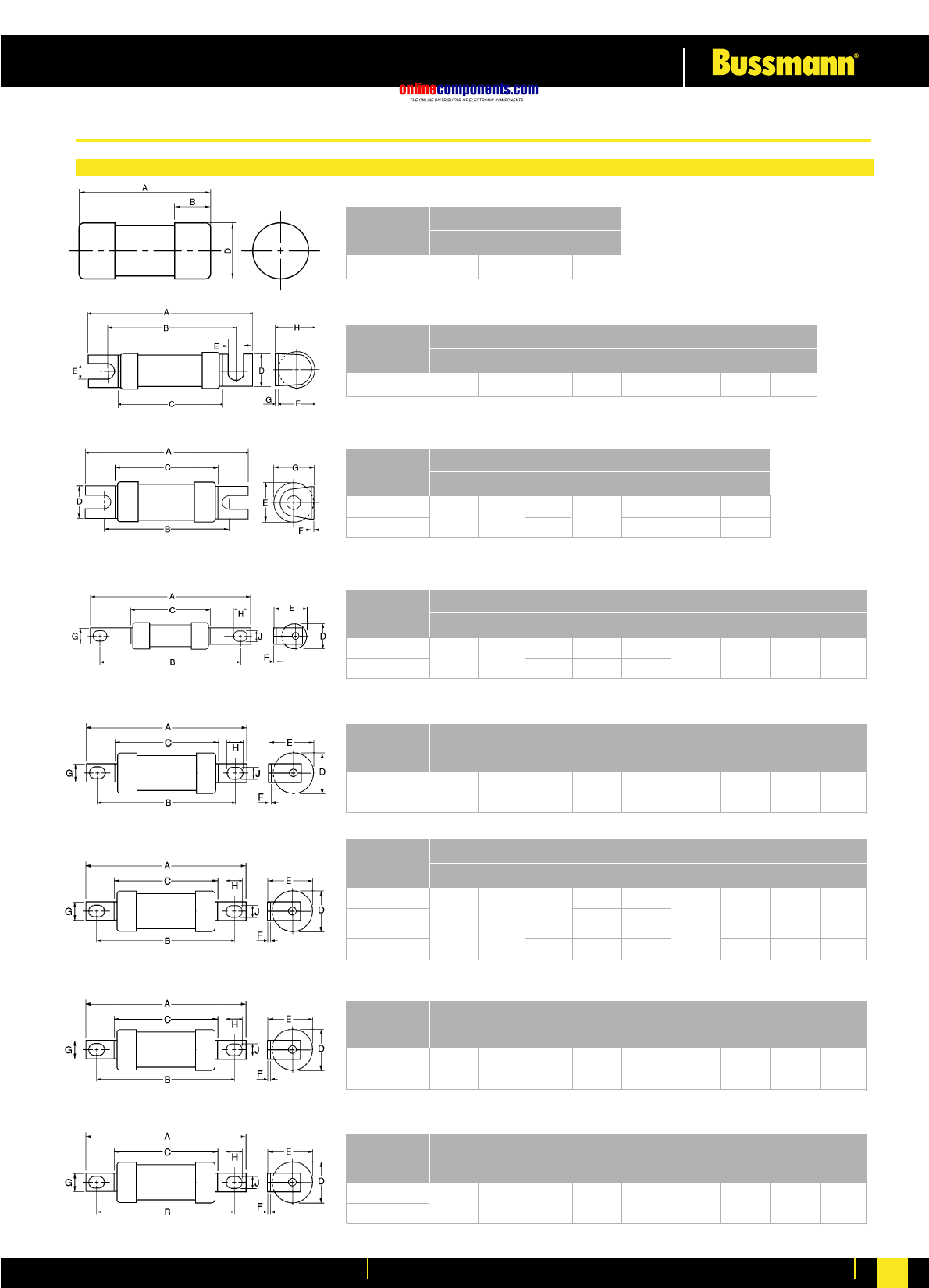
NITD
NITD32M
Part No.
AB C D E F G H J
Dimensions (mm)
SMD 29.0 ––12.7 F G H J I
Part No.
AB C D E F G H J
Dimensions (mm)
STD 47.0 35 24.0 11.0 4.7 12.0 0.8 13.0 I
Part No.
AB C D E F G H J
Dimensions (mm)
55.0 44
34.6
35.6 11.2
13.8 0.8 14.0
17.5 1.2 18.5
AAO
AAO32M
Part No.
AB C D E F G H J
Dimensions (mm)
85 73 35.5
54.5
14
22.3
13.7
21
1.2 8.7 8.0 5.5
BAO
BAO63M
Part No.
AB C D E F G H J
Dimensions (mm)
87 73 1.2 12.7 8.0 5.554.5 21 22.5
CEO
CEO100M125
& 160
CEO100M200
Part No.
AB C D E F G H J
Dimensions (mm)
110 94 3.2 14.3 11.0 8.758.5
21.0 24.5
47.0
25.8 26.8
31 29.5 19.0 10.0 9.0
OSD
OSD100M
Part No.
AB C D E F G H J
Dimensions (mm)
95.0 73 54.5 22.5
25.7
21.0
26.0
1.2 12.7 8.0 5.5
DEO
DEO200M
Part No.
AB C D E F G H J
Dimensions (mm)
110 94 47.0 29.531.0 3.2 19.0 10.0 9.0
Dimensional Data - Offset Bolted Tag
Low Voltage Fuse Links to BS88 & IEC269
onlinecomponents.com
Low Voltage Industrial Fuse Links
For more information visit our website at www.bussmann.com
45
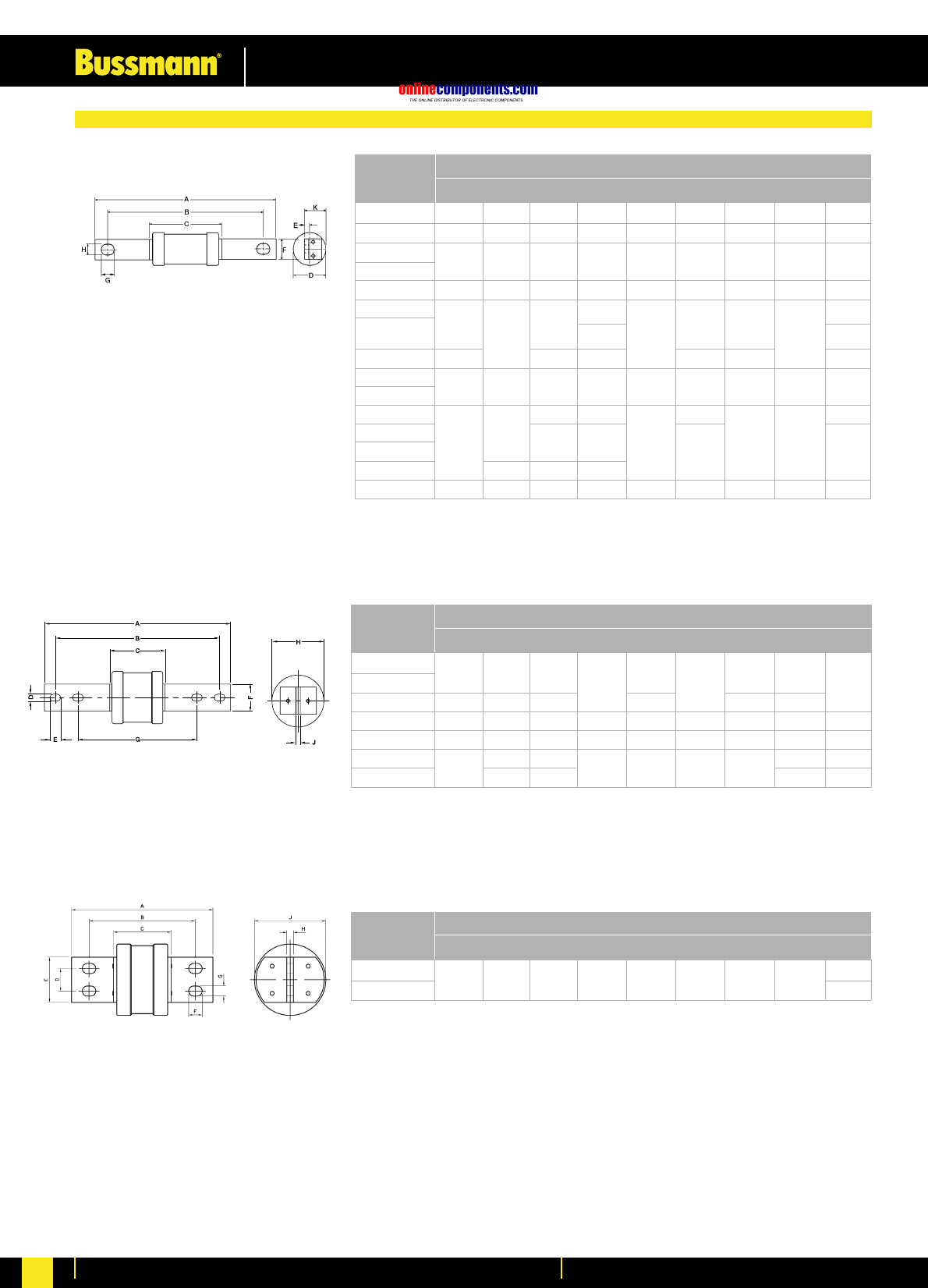
GH710
GH1000 & 1250
Part No.
AB C D E F G H J
Dimensions (mm)
AC 113.5 97.5 55.5 21.0 1.6 12.7 13.5 7.0 11.2
AD 128.5 111 55.0 21.0 1.4 14.2 11.8 8.7 11.2
BC
BC63M
BD 128.5 111 55.0 21.0 1.4 14.2 11.8 8.7 11.2
CD 21.0 19.5
CD100M125 &
CD100M160
CD100M200 136 47.0 31.0 19.0 12.5 22.5
DD
DD200M
ED250 47.0 31.0 19.0 22.5
ED315
ED315M400
ED400M500 111 75.0 59.0
EFS*158 133 47.0 31.0 3.2 19.0 12.5 10.5 22.5
Part No.
AB C D E F G H K
Dimensions (mm)
113.5 97.5 55.0 21.0 1.6 7.0 13.5 12.7 11.2
126 111 58.5
26.0 3.2 14.3 11.1
8.7 22.0
136 111 47.0 31.0 3.2 19.0 12.5 9.0 22.5
136 111 50.0 38.0 4.7 25.4 12.5 9.0 31.0
EFS315
EF355 & 400
EF400M500
FF 210 184 77.5 10.5 15.5 25.4 133 74.0 6.4
GF 210 184 80.5 10.5 15.5 25.4 133 83.0 9.5
GG710 & 800 231 77.5 83.0 6.4
GG1000 & 1250 228.5 84.0 100 12.7
Part No.
AB C D E F G H J
Dimensions (mm)
209 184 50.0 10.5 12.5 25.4 133 38.0 4.7
210 184 75.0 15.5 133 59.0
262 10.5 15.5 38.0 165
32.0 63.5 19.0 14.0 9.581.0149198 83.0
100
* Except 315A
Dimensional Data - Centre Bolted Tag
onlinecomponents.com
Low Voltage Industrial Fuse Links
For more information visit our website at www.bussmann.com 46
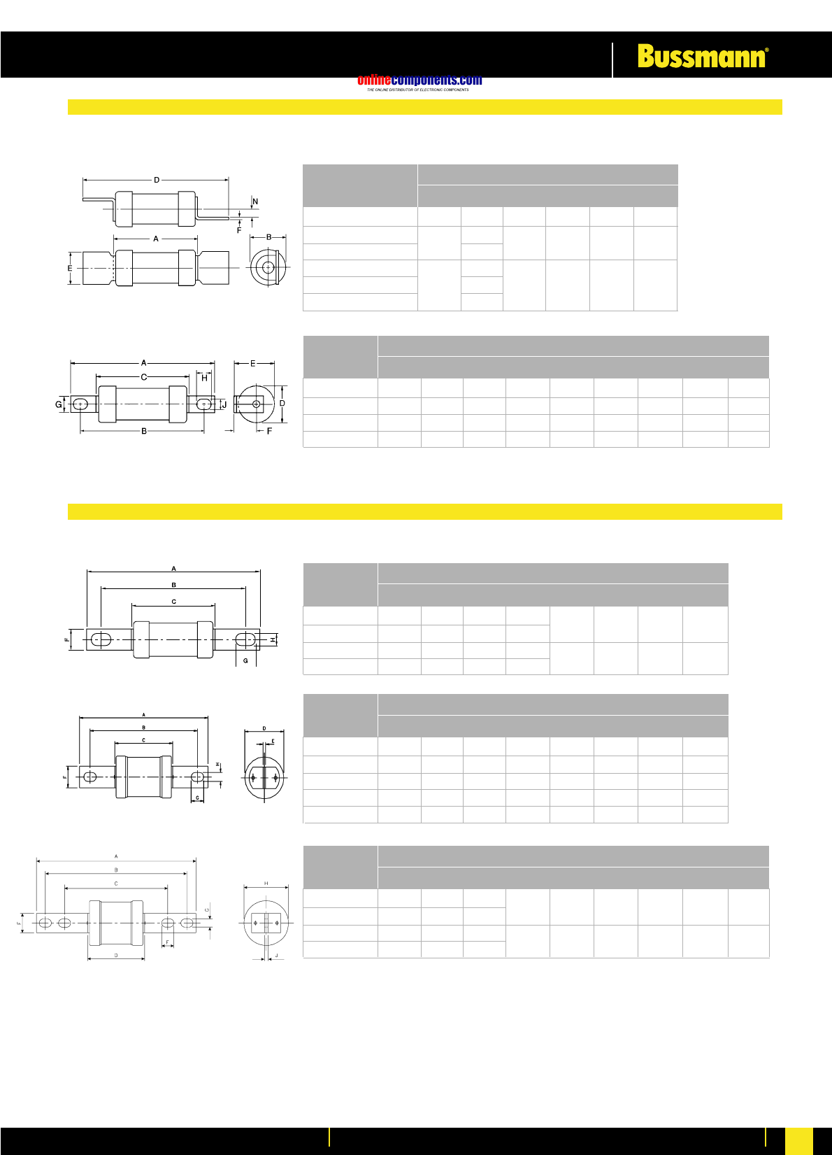
SSD 23.0 12.0 47.0 13.0 0.8 3.2
13.8
17.5
ESD - 32A 13.8
ESD40 - 63A 35.5 17.5 68.0 15.0 1.2 3.5
ESD63M 21.0
Part No.
AB D E F N N H J
Dimensions (mm)
34.5 58.5 12.7 0.8 3.5
NSD20M36 & NSD32M
NSD & NSD20M
H07-660 82.3 73 52.0 22.0 22.4 11.5 8.7 7.7 5.4
K07-660 86.0 73 54.2 25.8 26.9 14.0 12.7 10.5 5.5
L14-660 111.0 94 67.0 35.5 37.0 19.2 19.0 10.3 8.7
M14-660 112.0 94 66.0 38.0 38.0 19.0 19.0 10.0 8.5
Part No.
AB C D E F G H J
Dimensions (mm)
K08-660 2-32A 111.0 92.5 53.7 22.0
K08-660 40-63A 111.5 93.0 54.2 25.0
K09-660 2-32A 127.0 111 53.7 22.0
K09-660 40-63A 128.0 111 54.2 25.0
Part No.
AB C D E F G H J
Dimensions (mm)
2.4 12.7 13.0 7.5
2.4 14.0 15.2 8.7
L09-660 136.0 111 65.5 35.5 3.2 19.0 15.1 8.7
M09-660 135.0 111 65.0 37.0 3.2 19.0 15.0 8.7
N09-660 135.0 111 73.0 49.0 3.2 25.4 12.7 9.5
P09-660 135.5 111 75.0 58.5 4.7 25.4 12.7 9.5
N11-660 162.0 133 73.0 49.0 3.2 25.4 15.8 10.5
Part No.
AB C D E F G H J
Dimensions (mm)
P11-660 212.0 184 133
P12-660 262.0 231 167
R11-660 210.0 184 133
R12-660 262.0 231 167
Part No.
AB C D E F G H J
Dimensions (mm)
25.4 16.0 10.0 59.0
26.0 16.0 10.0 74.0
75.0
76.0
5.0
6.5
Dimensional Data - 660V Offset Bladed Tag
Dimensional Data - 660V Centre Bolted Tag
onlinecomponents.com
Low Voltage Industrial Fuse Links
For more information visit our website at www.bussmann.com
47
M13 120.0 99.0 70.0 27.0 8.0 12.0
M23 262.0 231.0 167.0 38.5 19.0 14.0
N15 120.0 100.0 79.0 49.0 41.0 16.5 15.0 9.8
Part No.
AB C D E F G H J
Dimensions (mm)
38.0 26.0 8.7
Part No.
AB C D E F G H J
Dimensions (mm)
N34 135.0 111 74.5 66.5 5.0 25.4 12.5 9.5
P35 59.0 5.0
R40 74.0 9.5
Part No.
AB C D E F G H J
Dimensions (mm)
210.0 16.0 10.0
19.0
N20 110.0 75.0 49.0 49.0
P20 111.0 76.0 47.0 59.0
R20 112.0 94.0 77.0 62.0 74.0
S20 112.0 77.0 66.0 83.0
Part No.
AB C D E F G H J
Dimensions (mm)
92.5
22.0 44.5 8.8 6.4
HS07 86.0 22.0 0.8 9.2 8.0
KS07 91.0 27.0 1.2 13.0 10.5
Part No.
AB C D F G H J
Dimensions (mm)
73 54.0 5.0
KS08 113.0 98 13.0 13.0 5.0
KS09 138.0 111 14.5 15.0 8.0
Part No.
AB C D E F G H
Dimensions (mm)
56.0 27.0 2.5
94.0
184 133 75.0
81.0
Dimensional Data - 660V Special Tag Range
Dimensional Data - Special 500V DC Range
onlinecomponents.com
Low Voltage Industrial Fuse Links
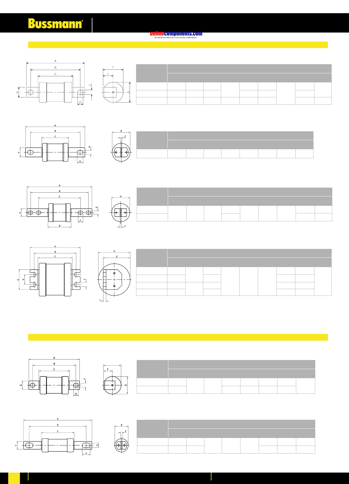
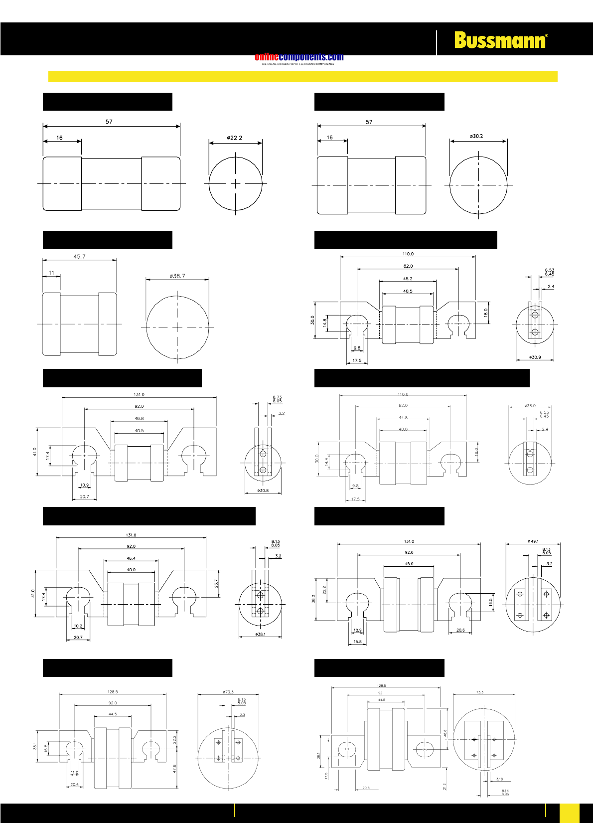
For more information visit our website at www.bussmann.com 48
Dimensions for KR85
Dimensions for MJ25-6
Dimensions for MJ31-7 up to 200A
Dimensions for PJ31-7 & MJ31-7 (250 & 315A)
Dimensions for SJ31-6
Dimensions for LR85
Dimensions for MJ30-7&-8 up to 200A
Dimensions for PJ30-7 & MJ30-7 (250 & 315A)
Dimensions for RJ31-7
Dimensions for SJ28
Dimensional Data - House Service & Feeder Piller Fuse Links
onlinecomponents.com
Low Voltage Industrial Fuse Links
For more information visit our website at www.bussmann.com
49
059-0107 0.25
059-0108 0.5
059-0109 1
059-0110 2
059-0111 3
059-0112 5
059-0113 7
011-9925 10
011-9926 15
059-0140 0.5
059-0141 1
059-0142 2
059-0143 3
059-0144 5
059-0145 7
059-0146 10
059-0147 15
011-9483 20
059-0114 0.5
059-0115 1
059-0116 2
059-0117 3
059-0118 5
059-0119 7
059-0120 10
059-0121 15
011-9679 20
012-0140 30
059-0148 10
059-0149 15
059-0150 20
059-0151 30
059-0122 10
059-0123 15
059-0124 20
059-0125 30
012-0067 40
011-9127 50
012-0141 60
059-0152 40
059-0153 60
059-0154 80
059-0155 100
059-0126 40
059-0127 60
059-0128 80
059-0129 100
011-9128 125
011-9129 150
Part No Current Body Tag Type A B C D E
Rating Size
0 Cyl. 32.05 ––6.37 5.55
1 Cyl. 33.6 ––11.86 7.14
1Offset
Bolted Tag 56.03 44.65 33.9 11.96 –
2 Cyl. 37.6 ––16.7 8.71
2Offset
Bolted Tag 70.7 55.84 37.4 16.7 –
3Cyl. 47.9 ––33.3 11.9
3Offset
Bolted Tag 88.6 69.77 47.4 33.3 –
Cylindrical (Cyl)
Offset Bolted Tag (O.B.T.)
Dimensional Data for Joint Service Fuse Links
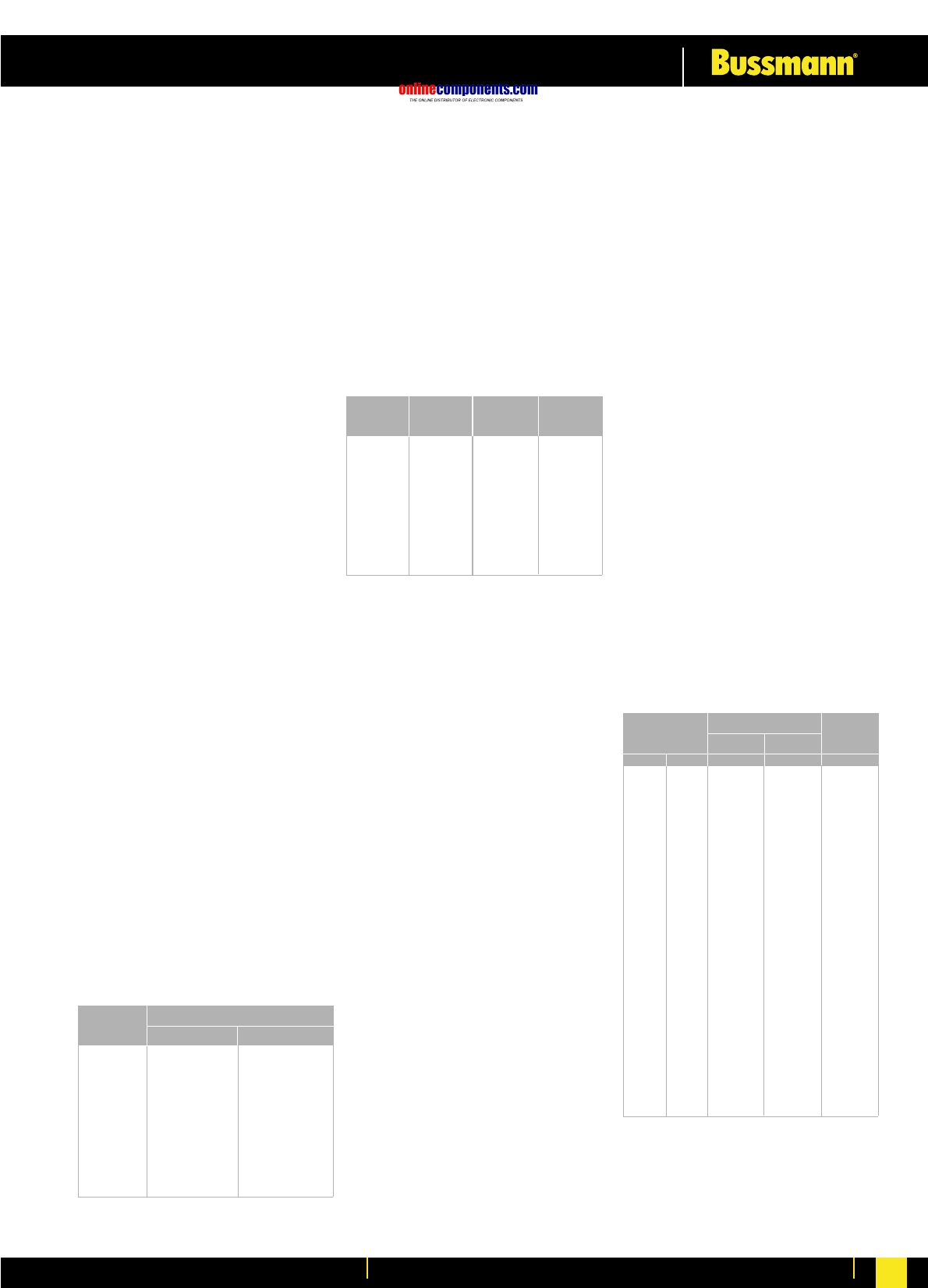
onlinecomponents.com
Low Voltage Industrial Fuse Links
For more information visit our website at www.bussmann.com 50
APPLICATION DATA
One of the long standing advantages of fuse protection
is that fuse selection is relatively simple and effective.
The following notes cover the majority of applications.
For further information contact Bussmann technical
services on 01509 882699.
Reference should also be made to the appropriate
Wiring Installation rules, in the UK the 16th Edition of
the IEE Wiring Regualtions for Electrical Installations
which aligns with IEC 60364.
CIRCUIT LOADING
The current rating of the fuse link should not be less
than the full load current of the circuit. The circuit
should be so designed that small overloads of long
duration will not be of frequent occurence.
CABLE RATINGS
There is an increasing move away from 70oC P.V.C.
insulation to materials which are more environmentally
friendly, for example 90oC XLPE. The ratings of fusegear,
switches, accessories etc. are generally based upon
the equipment being connected to conductors intended
to be operated at a temperature not exceeding 70oC
in normal service.
In view of the above it is recommended that the practice
of designs based upon conductor temperatures of
70oC be regarded as the norm. In accordance with
clause 512-02-01 of the Wiring Regulations the
equipment manufacturer should be consulted to
ascertain the reduction of nominal current rating of
the equipment if conductor temperatures exceeding
70oC are used. In addition an overriding factor is often
voltage drop consideration.
CABLE PROTECTION
Bussmann fuse links with gG characteristics protect
associated cables against both overload and short
circuit current, provided that the current rating of the
fuse link INis equal or less than the current carrying
capacity of the cable Iz.
In motor circuits, the motor starter will provide the
overload protection and the fuse links will provide the
short circuit protection. The maximum size of fuse link
that can be used depends upon the type of cable used
and is determined in accordance with the Wiring
Regulations using the appropriate K factor. The following
table gives maximum sizes of fuse links that are
recommended for two popular cables with copper
conductors, 70oC P.V.C. (K=115) and 90oC thermosetting
(K=143).
Zs OHMS IMPEDANCE VALUES
The rules for protection against indirect contact are
given in Chapter 413 of the Wiring Regulations.
For a TN System a disconnecting time not exceeding
5s is permitted for a distribution circuit. The maximum
values of earth fault loop impedance (Zs) corresponding
to a disconnecting tme of 5s for nominal voltage to
earth (Uo) of 240V for Bussmann gG fuse links.
AMBIENT TEMPERATURE
A de-rating in terms of current of 0.5% per oC above
an ambient of 35oC is recommended.
BREAKING CAPACITY
The standardised values of Breaking Capacity are
80kA for voltages of 415V a.c. and above, and 40kA
for d.c. applications.
DISCRIMINATION
All fuse links will give a discrimination ratio of 2:1 and
for most practical situations a ratio of 1.6:1 (two steps
in the R10 series). Example: an upstream fuse rated
at 160A will discriminate with a downstream fuse rated
at 100A.
CURRENT AND ENERGY LIMITATION
The Bussmann range of fuse links have pre-arcing I2t
values towards the bottom limits of the standards.
This ensures excellent current and energy limitation.
They also have lower power losses at rated current.
This assists in the appropriate interchangeability with
other makes of fuse links.
TRANSFORMERS
When fuse links are used on the primary side of
transformers the normal current rating of the fuse links
should be at least twice the nominal transformer primary
current.
FLUORESCENT LIGHTING
The normal current rating of the fuse link should be
at least twice the normal full load current of the maximum
number of lights to be switched simultaneously.
CAPACITOR CIRCUITS
In capacitor circuits, for example power factor correction,
the fuse link should be chosen with a current rating
greater than 1.5 times the rated capacitor current.
This takes account of the high transient inrush current,
circuit harmonics and capacitor tolerances.
MOTOR CIRCUITS
In motor circuits the fuse link has to withstand the
starting current of the motor and often requires a higher
rating than the full load current of the motor.
Co-ordination recommendations are made by the
manufacturers of motor starters in accordance with
IEC 60947-4-1. To give the desirable type 2 co-ordination
with fuse links, tests are performed with the latest gG
or gM fuse links, to BS88 or IEC60269 which have
pre-arcing I2t values toward the bottom specified limits.
This means that Bussmann fuse links are suitable to
give type 2 co-ordination.
Extended dual ratings of motor circuit protection fuse
links with gM characterstics are available in most
popular sizes of fuse links to extend the use of associated
equipment with appropriate economies. In the majority
of applications, gG fuse links are used. It is not essential
for gM fuse links to be used for motor circuit protection,
they simply extend the utilisation of standard equipment.
The attached table shows the recommended fuse links
at 415V. In most applications the run-up time is less
than five seconds and duty is infrequent - no more
than twice per house. The next larger rating should
be used for more arduous conditions.
Rating (A) Zs Ohms Rating (A) Zs Ohms
BRITISH STANDARD LOW VOLTAGE INDUSTRIAL FUSE LINK - APPLICATION INFORMATION
The Bussmann standard range of high breaking capacity fuse links for low voltage industrial and general purpose applications meet the requirements of BS88
and IEC60269. By using advanced fuse technology the current ratngs up to 400A have compact dimensions but still within the standardised dimensional and
performance requirements. These designs have been optimised for 415/240V systems. The standard range of fuse links are available from 2-1250A in the
following tag forms: OFFSET BLADED - OFFSET BOLTED - CENTRE BOLTED.
Supplementary ranges cover applications up to 690V a.c. and 500V d.c. including those with non-standard tag fixings.
Bussmann fuse links are manufactured under Quality Systems independently assessed to ISO 9001 and appropriate ratings carry the ASTA 20 endorsement.
Cable Size
mm2
116 16
1,5 20 25*
2,5 32* 32*
4 50* 50*
6 63* 63*
10 100* 125*
16 125* 160*
25 200* 250*
35 315* 355*
50 400* 500
70 560 630
95 710 800
120 800 1000
Max. Fuse Rating
K = 115
AK = 143
A
*Extended motor circuit dual ratings can be used
Rating (A)
260
427
6 14 100 0.44
10 7.7 125 0.35
16 4.3 160 0.27
20 3.0 200 0.20
25 2.4 250 0.16
32 1.9 315 0.13
40 1.4 400 0.096
50 1.1 500 0.073
63 0.86 630 0.054
80 0.60 800 0.044
Zs Ohms
ΩRating (A) Zs Ohms
Ω
Motor Rating
0.25 0.8 4 - 2
0.37 1.1 4 - 2
0.55 1.5 6 - 4
0.75 2.0 6 - 4
1.1 3.0 10 - 6
1.5 3.6 16 - 10
2.2 5.0 16 - 10
3.0 6.5 20 - 16
4.0 8.4 20 - 16
5.5 11 25 20M25 20
7.5 15 40 32M40 25
11.0 20 50 32M50 32
15.0 27 63 32M63 40
18.5 33 80 63M80 50
22.0 38 80 63M80 50
30.0 54 100 63M100 80
37.0 66 125 100M125 80
45.0 79 160 100M160 100
55.0 98 160 100M160 100
75.0 135 250 200M250 160
90.0 155 250 200M250 160
110.0 185 315 200M315 200
132.0 220 355 315M400 250
150.0 250 355 315M400 315
185.0 310 450 400M500 355
200.0 335 500 400M500 400
225.0 375 560 - 400
250.0 415 560 - 450
280.0 460 630 - 500
335.0 562 710 - 630
355.0 596 800 - 710
Direct On-line
Standard
(gG)
Asst Start
Standard
(gG)
Motor
Circuit (gM)
kW AA A A
onlinecomponents.com
Low Voltage Industrial Fuse Links
For more information visit our website at www.bussmann.com
51
200,000A or 300,000A Interrupting Rating (rms symmetrical)
Current Limiting
10,000–50,000 AIC
General
Purpose
(non-
current
limiting
fuses)
† Some ampere ratings are available as UL Class K5 with a 50,000A interrupting rating.
††RK1 and RK5 fuses fit standard switches, fuseblocks and holders; however, the rejection feature of class R switches and fuseblocks designed specifically for rejection type fuses
(RK1 and RK5) prevent the insertion of the non-rejection fuses (K1, K5, and H).
Circuit Load Ampere Fuse Symbol Voltage Interrupting Remarks Page
Rating Type Rating Class Rating
(a-c) (KA)
Conventional Dimensions—Class RK1, RK5 (0-600A), L (601-6000A)
All type loads 0-600A LOW-PEAK®LPN-RK_SP 250V RK1†† 300 All-purpose fuses. 59-61
(optimum (dual-element, LPS-RK_SP 600V Unequaled for combined
overcurrent time-delay) short-circuit and
protection). 601 to LOW-PEAK®KRP-C_SP 600V L 300 overload protection. 56-57
6000A (time-delay) (Specification grade product)
Motors, welder, 0 FUSETRON®FRN-R 250V RK5†† 200 Moderate degree of 62
transformers, to (dual-element, FRS-R 600V current limitation. Time-delay 63
capacitor banks 600A time-delay) passes surge currents.
(circuits with heavy 601 to LIMITRON®KLU 600V L 200 All-purpose fuse. Time- 58
inrush currents). 4000A (time-delay) delay passes surge-currents.
Main,
Feeder Non-motor loads KTN-R 250V RK1†† 200 Same short-circuit protection 64
and (circuits with no 0 KTS-R 600V as LOW-PEAK fuses but
Branch heavy inrush to must be sized larger for
currents). 600A LIMITRON®circuits with surge-currents;
LIMITRON fuses (fast-acting) i.e., up to 300%.
particularly suited 601 to KTU 600V L 200 A fast acting, high 58
for circuit breaker 6000A performance fuse.
protection.
Reduced Dimensions For Installation in Restricted Space—Class J(0-600A), T(0-1200A), CC(0-30A), G(0-60A)
All type loads LOW-PEAK®LPJ_SP 600V J 300 All-purpose fuses. 66
(optimum (dual-element Unequaled for combined
overcurrent time-delay) short-circuit and overload
protection). 0protection. (Specification
to grade product)
Non-motor loads 600A LIMITRON®JKS 600V J 200 Very similar to KTS-R 67
(circuits with no (quick acting) LIMITRON, but smaller.
heavy inrush 0 to T-TRONTM JJN 300V T 200 The space saver (⁄Ω£ the size 68
currents). 1200A JJS 600V of KTN-R/KTS-R).
Motor loads 0 to 30A LOW-PEAK®LP-CC 600V CC 200 Rejection feature 70
(circuits with (time-delay)
heavy in-rush
currents.)
Non-motor loads 0 to 30A LIMITRON®KTK-R 600V CC 200 Very compact (⁄‹Ω£™∑ ≈ 1⁄Ω™∑)71
(circuits with no (fast-acting) rejection feature.
heavy in-rush
Branch currents.)
Control transformer 0 to 30A TRON®FNQ-R 600V CC 200 Excellent for control 71
circuits and lighting (time-delay) transformer protection.
ballasts; etc.
General purpose; 1 to 20A SC SC 600V G 100 Current limiting; 69
i.e., lighting ⁄‹Ω£™∑ dia. ≈ varying
panel boards. 25 to 60A 480V lengths per amp rating.
Miscellaneous 0 to ONE-TIME NON 250V H or K5† 10 Forerunners of 65
600A NOS 600V the modern FRN and FRS fuses
Buss Fuse Selection Chart (600 Volts or Less)
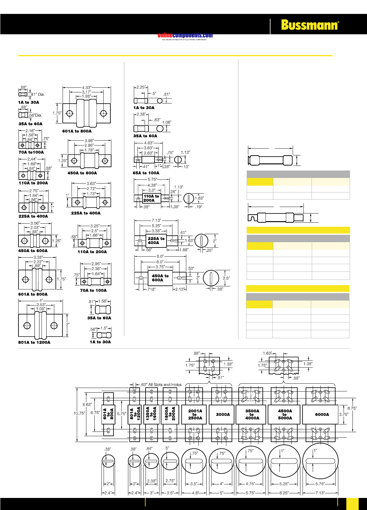
onlinecomponents.com
Low Voltage Industrial Fuse Links
For more information visit our website at www.bussmann.com 52
Class T
T-Tron™ Fuses
JJN (300V) JJS (600V)
Class J
Low-Peak®& Limitron®Fuses
LPJ & JKS (600V)
Class L Low-Peak®& Limitron®Fuses
KRP-C, KTU, & KLU (601 - 6000A) (600V)
NOTE: KRP-CL (150A to
600A) fuses have same
dimensions as 601A to
800A case size. KTU
(200A to 600A) have same
dimensions, except tube
3” lgth. x 2” dia.; terminal
1
5/8
” width x 1
1/4
” thick.
Class RK5 & RK1
Fusetron®, Low-Peak®&
Limitron®Fuses (250V & 600V)
FRN-R & FRS-R; LPN-RK &
LPS-RK; KTN-R & KTS-R
Basic dimensions are same as Class H (formerly
NEC) ONE-TIME (NON & NOS) and SUPERLAG
Renewable RES & REN fuses.
NOTE: These fuses can be used to replace
existing Class H, RK1 and RK5 fuses relating
to dimensional compatibility.
A
B
250V 600V
Ampere A B A B
1/10-30 2”.56”5”.81”
35-60 3”.81”5.5”1.06”
250V 600V
Ampere A B A B
70-100 5.88”1.06”7.88”1.34”
110-200 7.13”1.56”9.63”1.84”
225-400 8.63”2.06”11.63”2.59”
450-600 10.38”2.59”13.38”3.13”
Fusetron & Limitron
250V 600V
Ampere A B A B
70-100 5.88”1.16”7.88”1.16”
110-200 7.13”1.66”9.63”1.66”
225-400 8.63”2.38”11.63”2.38”
450-600 10.38”2.88”13.38”2.88”
Low-Peak
A
B
General Data - Dimensions (inches)
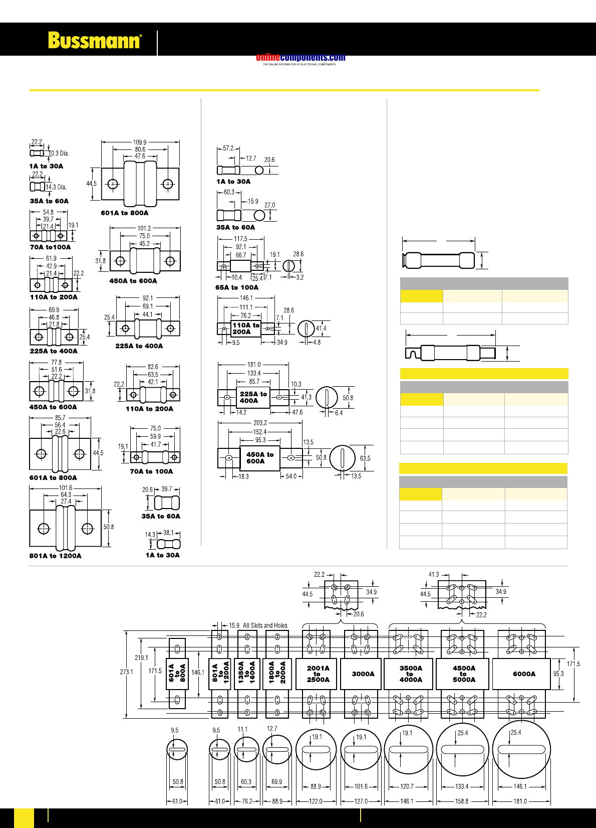
onlinecomponents.com
Low Voltage Industrial Fuse Links
For more information visit our website at www.bussmann.com
53 53
Class T
T-Tron™ Fuses
JJN (300V) JJS (600V)
Class J
Low-Peak®& Limitron®Fuses
LPJ & JKS (600V)
Class L Low-Peak®& Limitron®Fuses
KRP-C, KTU, & KLU (601 - 6000A) (600V)
NOTE: KRP-CL (150A to
600A) fuses have same
dimensions as 601A to
800A case size. KTU
(200A to 600A) have same
dimensions, except tube
76.2mm lgth. x 50.8mm
dia.; terminal 41.3mm
width x 31.8mm thick.
Class RK5 & RK1
Fusetron®, Low-Peak®&
Limitron®Fuses (250V & 600V)
FRN-R & FRS-R; LPN-RK &
LPS-RK; KTN-R & KTS-R
Basic dimensions are same as Class H (formerly
NEC) ONE-TIME (NON & NOS) and SUPERLAG
Renewable RES & REN fuses.
NOTE: These fuses can be used to replace
existing Class H, RK1 and RK5 fuses relating
to dimensional compatibility.
A
B
250V 600V
Ampere A B A B
1/10 -30 50.8 14.3 127.0 20.6
35-60 76.2 20.6 139.7 27.0
250V 600V
Ampere A B A B
70-100 149.2 26.9 200.0 34.0
110-200 181.0 39.6 244.5 46.7
225-400 219.1 52.3 295.3 65.8
450-600 263.5 65.8 339.7 79.5
Fusetron & Limitron
250V 600V
Ampere A B A B
70-100 149.2 29.5 200.0 29.5
110-200 181.0 42.2 244.5 42.2
225-400 219.1 60.5 295.3 60.5
450-600 263.5 73.2 339.7 73.2
Low-Peak
A
B
General Data - Dimensions (millimeters)
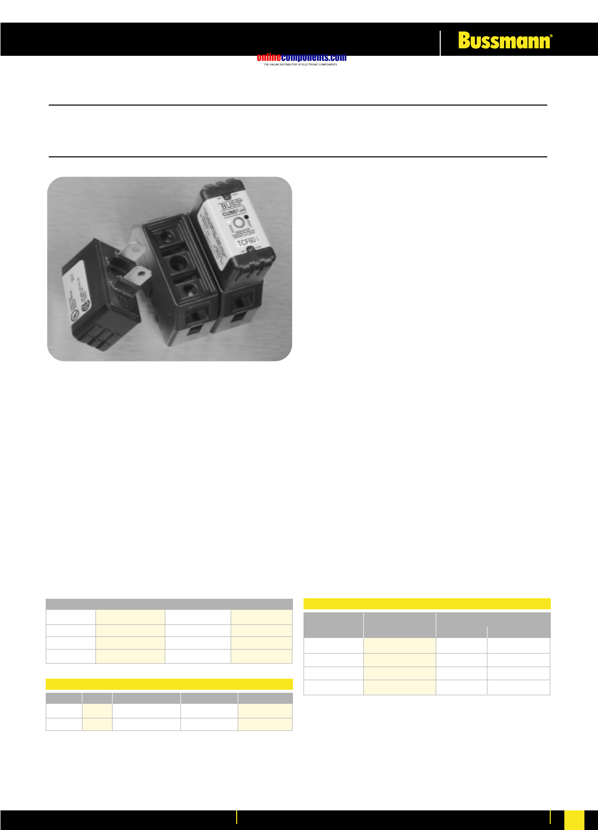
onlinecomponents.com
Low Voltage Industrial Fuse Links
For more information visit our website at www.bussmann.com 54
CUBEFUSE™ and Fuseholder TCF & TCFH
Finger-Safe Dual-Element Time-Delay Fuses
Indicating – 600 Volts or Less 1-60 Amps
Catalogue Symbol: TCF (Fuse) & TCFH (Holder)
Dual-Element, Time-Delay Fuse: 10 Seconds Minimum
Operating Time at 500% Rated Current
Ampere Rating: 1 to 60 Amperes
Voltage Rating: 600 Volts AC (or less)
DC Voltage Rating: 300 Volts DC (or less), 20,000AIR
Interrupting Rating: 300,000A RMS Symmetrical (UL)
200,000A RMS Symmetrical (CS
Agency Information:
U.L. Listed Special Purpose Fuse (UL 248-8) (1-60A)
CSA Certified Fuse (CSA-22.2 No. 106) (1-60A)
U.L. Listed Special Purpose Fuseholder
CSA Certified Fuseholder (C22.2 Nos. 39 & 65)
Other Electrical Certifications:
CE compliance for the European Union Low Voltage
Directive (50-1000V AC, 75-1500V DC)
•The world’s first finger safe industrial fuse system.
•True dual-element fuse construction with a minimum of
10 seconds time-delay at 500% of rating.
•Long time-delay minimises nuisance circuit openings due
to temporary overloads and transient surges.
•Meets UL Class J Time-Delay electrical performance re-
quirements.
•High interruption rating to safely interrupt faults up to
300,000 amperes.
•Faster response to damaging faults reduces destructive
thermal and magnetic forces.
•Permanent open fuse indication.
•Designed to be an internationally accepted and specified
world class product.
•Smallest footprint of any power class fuse including
Class J, CC, T and RK.
•Meets requirements of IEC 60529 for IP-20 finger safe
rating.
•No venting of arc or molten metal and gases during
opening.
•Robust cycling and inrush current withstand.
•Low let through currents under fault conditions.
•Provides TYPE 2 “no damage” protection for IEC motor
starters when properly sized.
•Low watt loss reduces power consumption and lowers
operating temperature.
•Conventional Class J fuse case sizes and ampere ratings.
•Dovetail fuseholder design for ganging multiple fuse
poles.
•30 and 60 Amp fuseholders can be ganged together.
•30 Amp fuses can be plugged into the 60A holder
without a reducer.
•35mm DIN rail and chassis mounting features.
•Fuseholder wire ports rated for dual wires.
* 75ºC (MIN) CU Wire Only
TCF1 TCF3 TCF6 TCF10
TCF15 TCF17-1/2 TCF20 TCF25
TCF30 TCF35 TCF40 TCF45
TCF50 TCF60
Catalogue Numbers
30 1 #14 - #8 Cu #14 Cu TCFH30
60 1 #14 - #4 Cu #10 Cu TCFH60
Amps Poles Wire * Dual Wire * Part Number
CUBEFuse™ Fuseholder Catalogue Data
Ampere Carton. Weight Per Carton
Rating Qty Lbs. Kg.
TCF1-30 12 1.39 .518
TCFH1-30 12 2.42 .902
TCF35-60 12 1.42 .530
TCFH35-60 12 2.57 .958
Carton Quantity and Weight
BIF document: 9000
Time-Current and Current Limitation Curves on page 55
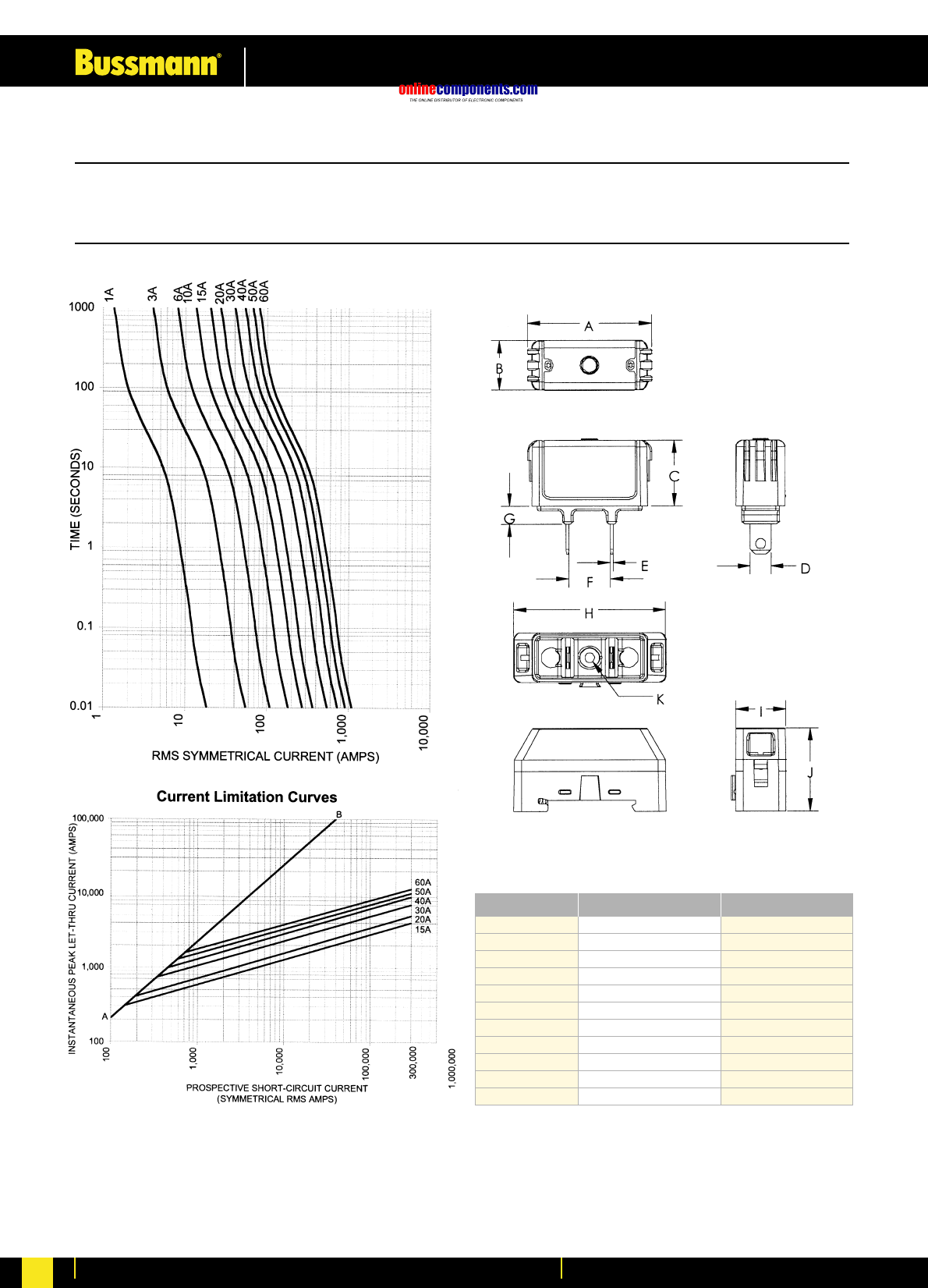
onlinecomponents.com
Low Voltage Industrial Fuse Links
For more information visit our website at www.bussmann.com
55
CUBEFUSE™ and Fuseholder TCF & TCFH
Finger-Safe Dual-Element Time-Delay Fuses
Indicating – 600 Volts or Less 1-60 Amps
Dimensional Data For TCF and TCFH
Dimension 30A in [mm] 60A in [mm]
A 1.88 [47.75] 2.13 [54.10]
B .75 [19.05] 1.00 [25.40]
C 1.00 [25.40] 1.13 [28.58]
D .31 [7.94] .44 [11.11]
E .04 [1.02] .04 [1.02]
F .63 [15.88] .63 [15.88]
G .27 [6.86] .38 [9.65]
H 2.30 [58.42] 2.60 [66.04]
I .76 [19.30] 1.03 [26.16]
J 1.27 [32.18] 1.53 [38.86]
K .15 [3.81] .17 [4.32]
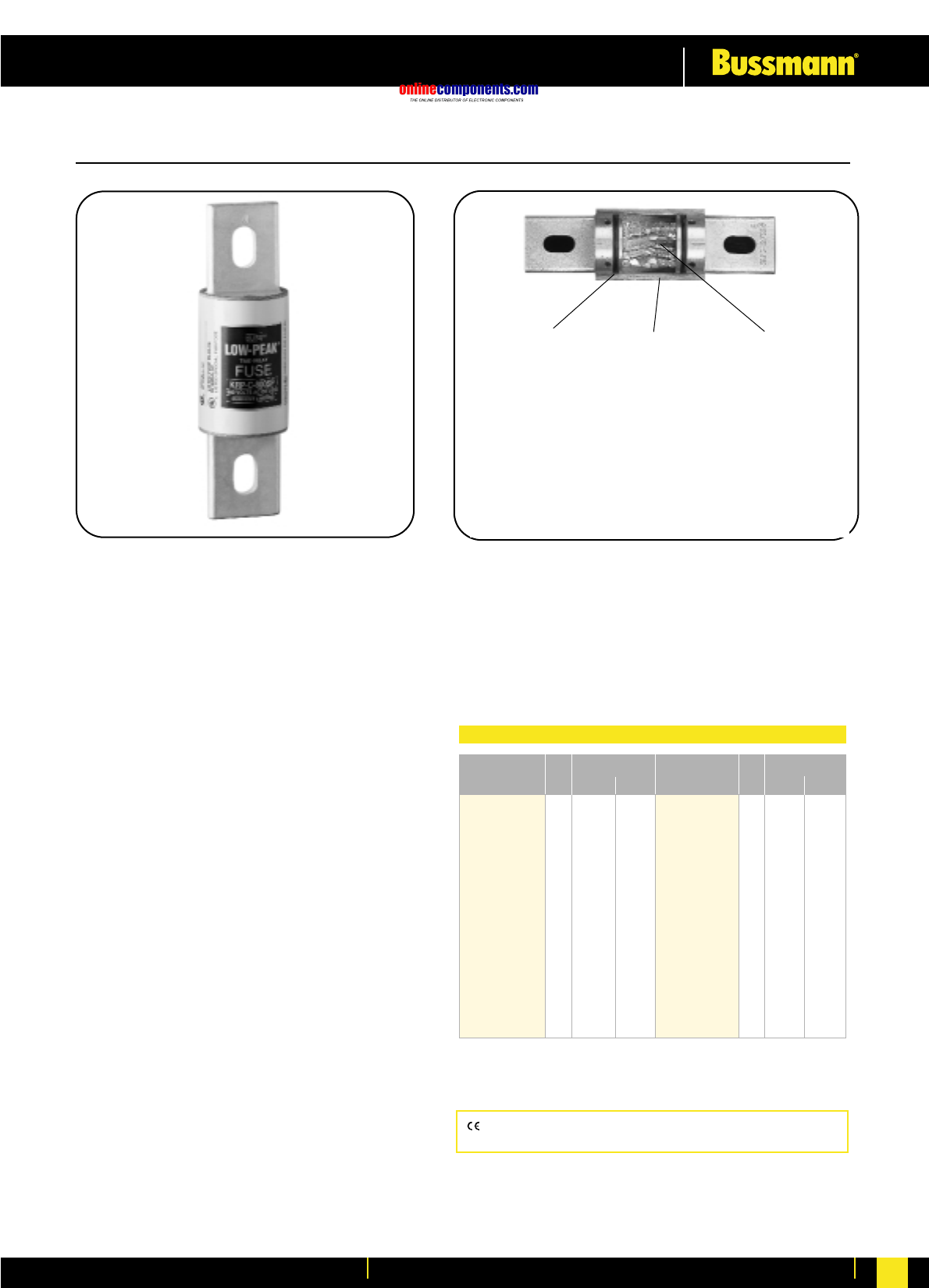
onlinecomponents.com
Low Voltage Industrial Fuse Links
For more information visit our website at www.bussmann.com 56
KRP-C_SP
Time-Delay 4 seconds (minimum) at 500% rated current
Ampere Ratings: 601-6000 Amps†
Voltage Rating: 600 Volts AC (or less), 300 Volts DC for
601-2000 amps.
Interrupting Rating: AC: 300,000A RMS Sym.
DC: 100,000A
Agency Information:
UL Listed-Special Purpose (meets all performance
requirements of UL Standard 248-10 for Class L fuses),
Guide JFHR, File E56412
CSA Certified (200,000 AIR), Class 1422-02, File 53787,
Class L per CSA C22.2, No. 248.10
Dimensions:
See pages 52-53 for Class L dimensional data.
•All-purpose silver linked fuse for both overload and short-
circuit protection for high capacity systems
(mains and large feeders).
•Time-delay (minimum of four seconds at five times amp
rating) for close sizing.
•Current limiting action of the fuse generally affords
considerable reduction in bus bracing.
•Interrupting rating of 300,000 amperes complies with
NEC Sections 110-9 and 230-65 for today’s large
capacity systems.
•O-ring seals maximize pressure build-up during current
limiting action and ensure filler retention.
•High grade silica-sand filler; accelerates response of fuse to
short-circuits by having quenching effect upon the fuse arc.
•99.9% pure silver fuselinks. The high conductivity of silver
gives low watt loss and low operating temperature at normal
current levels; minimizes total clearing I2t fault energy let-thru.
•Selective coordination (blackout prevention)
•Glass melamine tube.
•Silver plated end bells.
•Reducers not necessary.
O-RING SEALS
Formation of arc gas within
fuse body suppresses
arcing; lowers arcing I2t
energy. O-ring seals
maximize pressure build-up
during current limiting action.
Also volume of sand is
critical. Slight loss can
adversely impact on current
limiting action. O-ring seals
insure filler retention. They
compensate to a degree for
switchgear misalignment,
and expansion and con-
traction of mounting
surfaces with change in load
to no-load conditions.
SAND FILLER
High grade silica-sand filler.
Accelerates response of
fuse to short-circuits by
having quenching effect
upon the fuse arc.
Substantially contributes to
current limiting action.
99.9% PURE SILVER
FUSELINKS
Embody “silver-sand”
design. 99.9% pure silver
links; silica-sand filler. The
high conductivity of silver
gives low watt loss and low
operating temperature at
normal current levels;
minimizes total clearing I2t
fault energy let-thru…
state-of-art fuse design.
High degree of current
limitation holds down fault
currents and levels of
destructive energy. (Although
other link materials can
provide current limitation,
they do not equal that
of silver.)
Low-Peak®Time-Delay, CLASS L Fuses
Catalogue Ctn. Weight**
Number Qty. Lbs. Kg.
KRP-C-601SP
KRP-C-650SP
KRP-C-700SP 1 3.75 1.7
KRP-C-750SP
KRP-C-800SP
KRP-C-801SP
KRP-C-900SP
KRP-C-1000SP 1 4.5 2.041
KRP-C-1100SP
KRP-C-1200SP
KRP-C-1350SP
KRP-C-1400SP
KRP-C-1500SP 1 6.50 2.948
KRP-C-1600SP
Catalogue Ctn. Weight**
Number Qty. Lbs. Kg.
KRP-C-1800SP
KRP-C-1900SP 1 8.5 3.85
KRP-C-2000SP
KRP-C-2001SP
KRP-C-2400SP 1 17.25 7.824
KRP-C-2500SP
KRP-C-3000SP 1 18.25 8.278
KRP-C-3500SP
KRP-C-3800SP 1 23.50 10.659
KRP-C-4000SP
KRP-C-4500SP 1 29 13.154
KRP-C-5000SP
KRP-C-6000SP 1 36 16.329
Ordering Information
Special purpose rating of 300,000 AIR.
**Weight per carton.
†Use KRP-CL for current ratings below 601 Amps.
CE logo denotes compliance with European Union Low Voltage
Directive (50-1000V AC, 75-1500V DC). Refer to BIF document #8002.
BIF document: 1008 and 1009
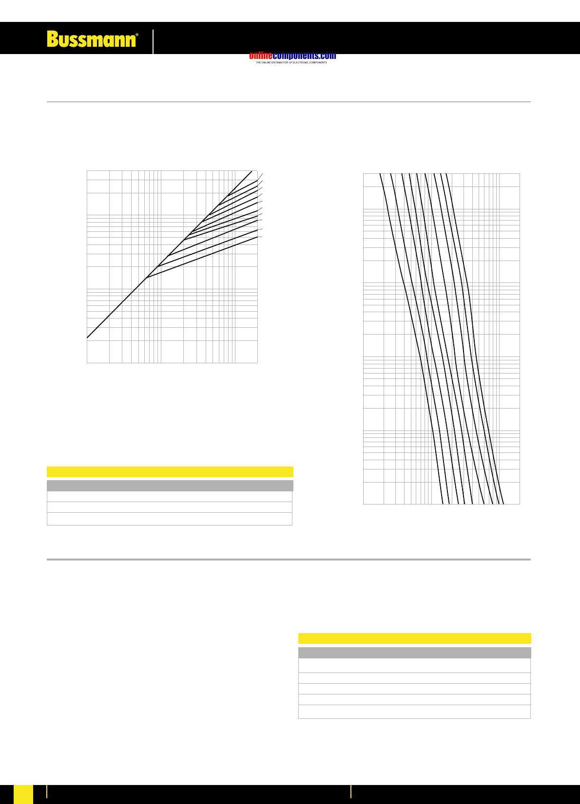
onlinecomponents.com
Low Voltage Industrial Fuse Links
For more information visit our website at www.bussmann.com
57
400,000
10,000
1,000
10,000
200,000
INSTANTANEOUS PEAK LET-THRU CURRENT IN AMPS
100,000
100,000
AMPERE
RATING
6,000
5,000
4,000
3,000
2,500
2,000
1,600
1,200
800
601
A
B
1,000
300
100
10
1
.1
.01
1,000
10,000
100,000
200,000
TIME IN SECONDS
800A
1200A
1600A
2000A
2500A
3000A
4000A
5000A
6000A
AMPERE
RATING
KRP-CL
Current Limiting, Time-Delay
Construction: Glass Melamine Tube
Ampere Ratings: 150-600 Amps.
Voltage Rating: 600 Volts AC (or less)
These fuses have the same performance characteristics as
KRP-C fuses. They are used in applications where there is a
need for Class L dimension fuses with 150-600 ampere
ratings. KRP-CL fuses have the same dimensions as
800 ampere Class L fuses.
Ordering Information
Catalogue Number (Symbol & Amps)
KRP-CL-150 KRP-CL-300 KRP-CL-500
KRP-CL-200 KRP-CL-350 KRP-CL-600
KRP-CL-225 KRP-CL-400
KRP-CL-250 KRP-CL-450
Weight of each is 3.75 lbs.
CURRENT IN
AMPERES
PROSPECTIVE SHORT CIRCUIT CURRENT
SYMMETRICAL RMS AMPERES
Current Limitation Curves—KRP-C Time-Current Characteristic Curves—Average Melt KRP-C
Recommended Fuseblocks for Class L: (601–1200 Amps)
Catalogue Number Poles
51215 1
51235 3
Use KRP-CL for current ratings below 601 Amps.
Dimensions: See pages 52-53 for Class L dimensional data.
BIF document: 1016
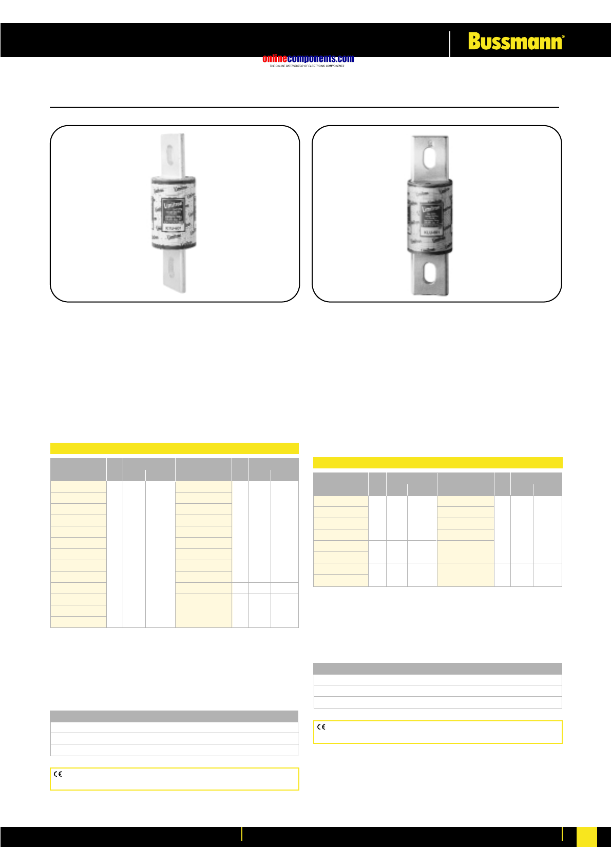
onlinecomponents.com
Low Voltage Industrial Fuse Links
For more information visit our website at www.bussmann.com 58
KTU
Fast Acting, Bolt Mount
Ampere Ratings: 601-6000 Amps.
Voltage Rating: 600 Volts AC (or less)
Interrupting Rating: 200,000 RMS Sym.
Agency Information: Std. 248-10, Class L
UL Listed, Guide JDDZ, File E4273
CSA Certified, Class 1422-02, File 53787
Dimensions: See pages 52-53 for Class L dimensional data.
**Weight per carton.
Recommended Fuseblocks for Class L: (601–1200 Amps)
Catalogue Number Poles
51215 1
51235 3
•For protection of circuit breakers with lower interrupting
ratings and non-inductive loads such as lighting and
heating circuits.
•99.9% pure silver-links.
•Reducers not necessary.
CE logo denotes compliance with European Union Low Voltage
Directive (50-1000V AC, 75-1500V DC). Refer to BIF document #8002.
KLU
Time-Delay – 5 seconds (minimum) at 500% rated current
Bolt Mount
Ampere Ratings: 601-4000 Amps.
Voltage Rating: 600 Volts AC (or less)
Interrupting Rating: 200,000A RMS Sym.
Agency Information: Std. 248-10, Class L
UL Listed, Guide JDDZ, File E4273
CSA Certified, CSA Class 1422-02, File 53787
Dimensions: See pages 52-53 for Class L dimensional data.
**Weight per carton.
•KLU Limitron® general purpose copper link fuses.
•Current limiting—provides component short-circuit protection.
•Fuse reducers not necessary.
•See KRP-CL for current ratings below 601 Amps.
CE logo denotes compliance with European Union Low Voltage
Directive (50-1000V AC, 75-1500V DC). Refer to BIF document #8002.
Limitron®CLASS L Fuses
Catalogue Ctn. Weight**
Number Qty. Lbs. Kg.
KTU-60 1
KTU-650
KTU-700 1 3.75 1.70
KTU-750
KTU-800
KTU-80 1
KTU-900
KTU-1100 1 4.25 1.927
KTU-1200
KTU-1350
KTU-1400
KTU-1500 1 6 2.721
KTU-1600
Catalogue Ctn. Weight**
Number Qty. Lbs. Kg.
KTU-1800
KTU-2000 1 8.5 3.855
KTU-2400
KTU-2500 1 17 7.711
KTU-3000 1 17.25 7.824
KTU-3001
KTU-4000 1 24 10.886
KTU-4500 1 31 14.061
KTU-5000
KTU-6000 1 34 15.422
Ordering Information
Catalogue Ctn. Weight**
Number Qty. Lbs. Kg.
KLU-601
KLU-650
KLU-700 1 3.75 1.70
KLU-800
KLU-1000 1 4.25 1.93
KLU-1200
KLU-1500 1 6.00 2.72
KLU-1600
Catalogue Ctn. Weight**
Number Qty. Lbs. Kg.
KLU-1800
KLU-2000
KLU-2500 1 8.50 3.86
KLU-3000
KLU-4000
Ordering Information
Recommended Fuseblocks (601–1200 Amps)
Catalogue Number Poles
51215 1
51235 3
BIF document: 1010 BIF document: 1013
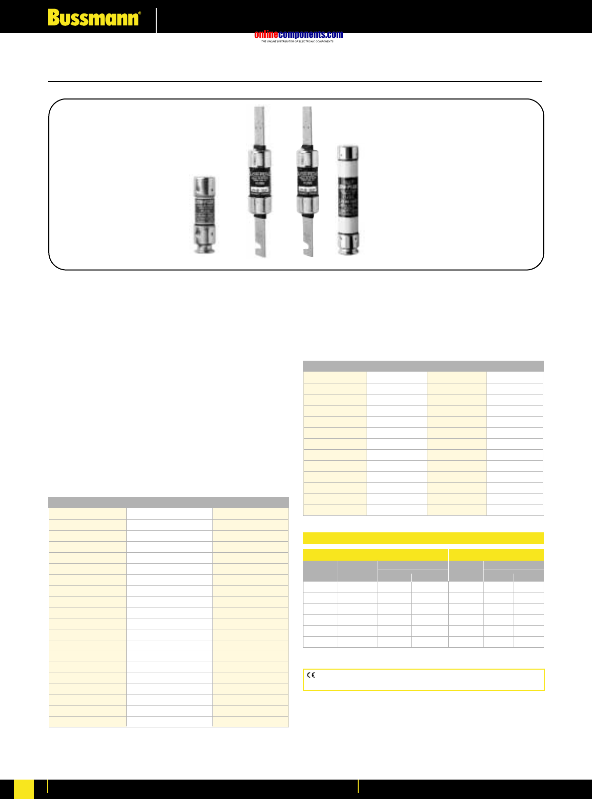
onlinecomponents.com
Low Voltage Industrial Fuse Links
For more information visit our website at www.bussmann.com
59
Low-Peak®Dual-Element, Time-Delay, CLASS RK1 Fuses
LPN-RK_SP (250V)
LPS-RK_SP (600V)
Dual-Element, Time-Delay – 10 seconds (minimum)
at 500% rated current (8 seconds for 0-30A sizes)
Ampere Ratings: ⁄Ω¡º-600 Amps.
Voltage Rating: LPN-RK: 250 Volts AC (or less),
125 Volts DC (⁄Ω¡º-60 A); 250V DC (70-600 A)
LPS-RK: 600 Volts AC (or less), 300 Volts DC
Current Limiting RK1 Fuse
Interrupting Rating:
AC: 300,000A RMS Sym.
DC: 100,000A
Agency Information:
UL Listed – Special Purpose**, Guide JFHR, File E56412
CSA Certified (200,000 AIR), Class RK1 per CSA C22.2,
No. 248.12, Class 1422-02, File 53787
Dimensions: See pages 52-53 for Class RK1 dimensional data.
CE logo denotes compliance with European Union Low Voltage
Directive (50-1000V AC, 75-1500V DC). Refer to BIF document #8002.
Catalogue Numbers (250V AC/125V DC)
LPN-RK-⁄Ω¡ºSP LPN-RK-3⁄Ω™SP LPN-RK-60SP
LPN-RK-⁄fiΩ¡ººSP LPN-RK-4SP LPN-RK-70SP
LPN-RK-¤Ω¡ºSP LPN-RK-4⁄Ω™SP LPN-RK-80SP
LPN-RK-‹Ω¡ºSP LPN-RK-5SP LPN-RK-90SP
LPN-RK-›Ω¡ºSP LPN-RK-5flΩ¡ºSP LPN-RK-100SP
LPN-RK-⁄Ω™SP LPN-RK-6SP LPN-RK-110SP
LPN-RK-flΩ¡ºSP LPN-RK-6⁄Ω¢SP LPN-RK-125SP
LPN-RK-°Ω¡ºSP LPN-RK-8SP LPN-RK-150SP
LPN-RK-1SP LPN-RK-9SP LPN-RK-175SP
LPN-RK-1⁄Ω•SP LPN-RK-10SP LPN-RK-200SP
LPN-RK-1⁄Ω¢SP LPN-RK-12SP LPN-RK-225SP
LPN-RK-1›Ω¡ºSP LPN-RK-15SP LPN-RK-250SP
LPN-RK-1flΩ¡ºSP LPN-RK-17⁄Ω™SP LPN-RK-300SP
LPN-RK-1°Ω¡ºSP LPN-RK-20SP LPN-RK-350SP
LPN-RK-2SP LPN-RK-25SP LPN-RK-400SP
LPN-RK-2⁄Ω¢SP LPN-RK-30SP LPN-RK-450SP
LPN-RK-2⁄Ω™SP LPN-RK-35SP LPN-RK-500SP
LPN-RK-2°Ω¡ºSP LPN-RK-40SP LPN-RK-600SP
LPN-RK-3SP LPN-RK-45SP
LPN-RK-3¤Ω¡ºSP LPN-RK-50SP
•Current limitation for maximum short-circuit protection.
High speed of response is highly sensitive to fault currents,
but insensitive to starting current and transient surges.
•Provides long time-delay for temporary motor start-up.
•Time-delay permits 125% FLA sizing for back-up, motor running
protection.
Catalogue Numbers (600V AC/300V DC)
LPS-RK-⁄Ω¡ºSP LPS-RK-2⁄Ω™SP LPS-RK-12SP LPS-RK-110SP
LPS-RK-¤Ω¡ºSP LPS-RK-2°Ω¡ºSP LPS-RK-15SP LPS-RK-125SP
LPS-RK-‹Ω¡ºSP LPS-RK-3SP LPS-RK-17⁄Ω™SP LPS-RK-150SP
LPS-RK-›Ω¡ºSP LPS-RK-3¤Ω¡ºSP LPS-RK-20SP LPS-RK-175SP
LPS-RK-⁄Ω™SP LPS-RK-3⁄Ω™SP LPS-RK-25SP LPS-RK-200SP
LPS-RK-flꭧSP LPS-RK-4SP LPS-RK-30SP LPS-RK-225SP
LPS-RK-°Ω¡ºSP LPS-RK-4⁄Ω™SP LPS-RK-35SP LPS-RK-250SP
LPS-RK-1SP LPS-RK-5SP LPS-RK-40SP LPS-RK-300SP
LPS-RK-1⁄Ω•SP LPS-RK-5flΩ¡ºSP LPS-RK-45SP LPS-RK-350SP
LPS-RK-1⁄Ω¢SP LPS-RK-6SP LPS-RK-50SP LPS-RK-400SP
LPS-RK-1›Ω¡ºSP LPS-RK-6⁄Ω¢SP LPS-RK-60SP LPS-RK-450SP
LPS-RK-1⁄Ω™SP LPS-RK-7SP LPS-RK-70SP LPS-RK-500SP
LPS-RK-1flꭧSP LPS-RK-8SP LPS-RK-80SP LPS-RK-600SP
LPN-RK (250 Volts AC) LPS-RK (600 Volts AC)
Ampere Carton Weight* Carton Weight*
Ratings Qty. Lbs. Kg Qty. Lbs. Kg
0-30 10 0.5 0.227 10 1.6 0.725
35-60 10 1.2 0.544 10 2.6 1.178
70-100 5 1.5 0.680 5 4.0 1.814
110-200 1 0.69 0.313 1 2.0 0.906
225-400 1 1.75 0.793 1 4.6 2.086
450-600 1 3.25 1.474 1 5.6 2.540
*Weight per carton.
Carton Quantity and Weight
**Meets all performance requirements of UL Standard 248-12 for Class RK1 fuses.
0-60 Amp fuses available with Nickel plate option. (Ex: LPSRK30SPNP)
70-600 Amp fuses available with Tin plate option. (Ex: LPS-RK-100SP-TP)
BIF document: (LPN-RK) 1003 (0-60) & 1004 (70-600) BIF document: (LPS-RK) 1001 (0-60) & 1002 (70-600)
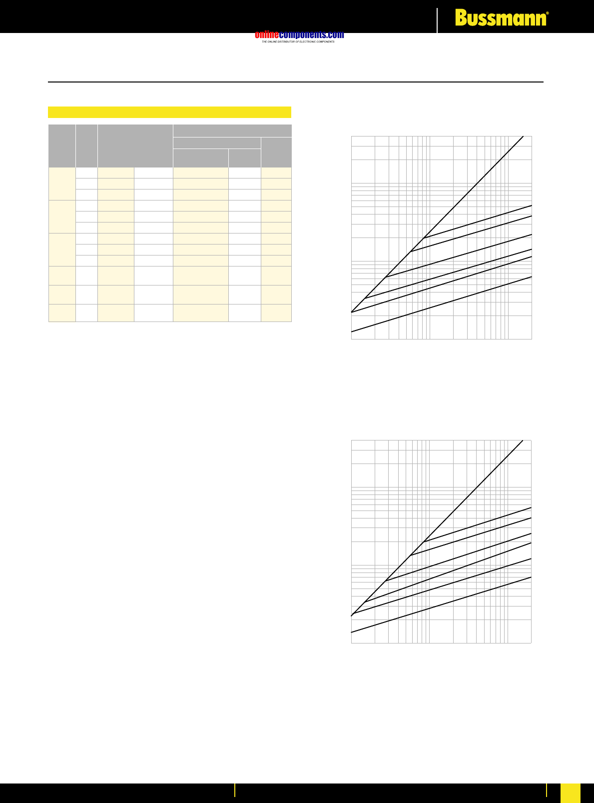
onlinecomponents.com
Low Voltage Industrial Fuse Links
For more information visit our website at www.bussmann.com 60
A
B
600
400
200
100
AMPERE
RATING
400,000
100,000
10,000
1,000
1,000
10,000
100,000
200,000
RMS SYMMETRICAL CURRENTS IN AMPERES
A–B=ASYMMETRICAL AVAILABLE PEAK (2.3 X SYMM RMS AMPS)
INSTANTANEOUS PEAK LET-THRU CURRENT IN AMPS
60
30
60
30
A
B
600
400
200
AMPERE
RATING
400,000
100,000
10,000
1,000
1,000
10,000
100,000
200,000
INSTANTANEOUS PEAK LET-THRU CURRENT IN AMPS
100
RMS SYMMETRICAL CURRENTS IN AMPERES
A–B=ASYMMETRICAL AVAILABLE PEAK (2.3 X SYMM RMS AMPS)
Current Limitation Curves—LPN-RK (250V)
Current Limitation Curves—LPS-RK (600V)
Low-Peak®Dual-Element, Time-Delay, CLASS RK1 Fuses
Terminal Type (Suffix No.)
Catalogue Screw w/ Box Lug w/ ⁄Ω¢∑
Number Pres. Clip Quick-
Amps Poles (250V) (600V) — Plate — CU only Connect
⁄Ω¡º 1 R25030-1 R60030-1 SR PR CR COR QR**
to 2 R25030-2 R60030-2 SR PR CR COR QR**
30 3 R25030-3 R60030-3 SR PR CR COR QR**
1 1 R25060-1 R60060-1 SR* PR CR COR —
to 2 R25060-2 R60060-2 SR* PR CR COR —
60 3 R25060-3 R60060-3 SR* PR CR COR —
61 1 R25100-1 R60100-1 ——CR COR —
to 2 R25100-2 R60100-2 ——CR COR —
100 3 R25100-3 R60100-3 ——CR COR —
to 200 1 R25200-1 R60200-1 ——CR COR —
R25200-3 R60200-3 ——CR ——
to 400 1 R25400-1 R60400-1 ——CR* COR* —
R25400-3 R60400-3 ——CR ——
to 600 1 R25600-1 R60600-1 ——CR ——
R25600-3 R60600-3 ——CR ——
*UL Recognized, No CSA Certification.
**Quick connect not available on 600V blocks.
Recommended Fuseblocks for Class RK1 fuses
BIF document: (LPN-RK) 1003 (0-60) & 1004 (70-600),
1110 (Fuseblock) BIF document: (LPS-RK) 1001 (0-60) & 1002
(70-600), 1111 (600V Fuseblock)
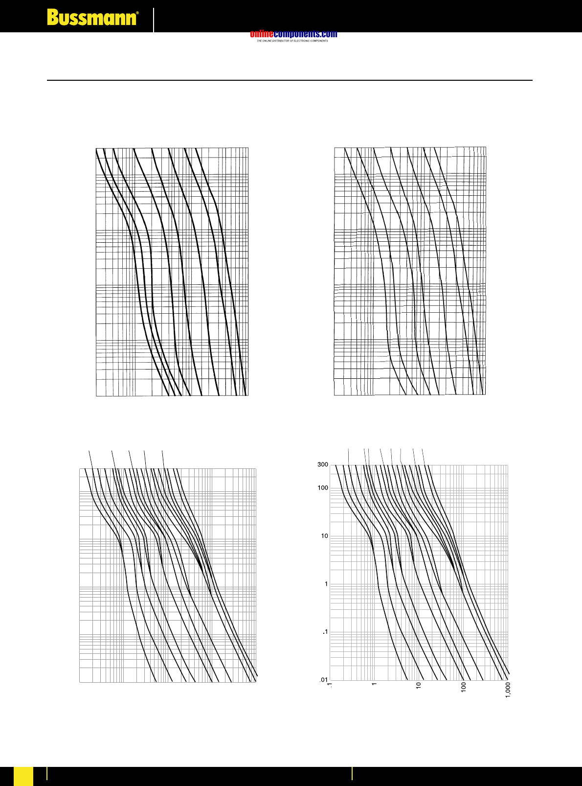
onlinecomponents.com
Low Voltage Industrial Fuse Links
For more information visit our website at www.bussmann.com
61
Low-Peak®Dual-Element, Time-Delay, CLASS RK1 Fuses
Time-Current Characteristic Curves—Average Melt
.1
.2 .15
.3
.4
.6 .5
.8
11.25
1.6
22.5
3.2
4
56.25
8
10
12
AMPERE RATING
300
100
10
1
.1
.01
.1
1
10
100
1,000
TIME IN SECONDS
RMS SYMMETRICAL CURRENT IN AMPERES
1/10
15/100 2/10
4/10
6/10
16/10
8/10
1
2
4
5
8
12 10
11/4
21/232/10
61/4
1/2
3/10
LPN-RK
250V LPS-RK
600V
TIME IN SECONDS
TIME IN SECONDS
TIME IN SECONDS
CURRENT IN AMPERES
CURRENT IN AMPERES
CURRENT IN AMPERES
CURRENT IN AMPERES
AMPERE
RATING AMPERE
RATING
AMPERE
RATING
300
100
10
1
.1
.01
300
100
10
1
.1
.01
20
100
1,000
10,000
20
100
1,000
10,000
15 20 30 60 100 200 400 600 20 30 60 100 200 400 600
BIF document: (LPS-RK) 1001 (0-60) & 1002 (70-600)BIF document: (LPN-RK) 1003 (0-60) & 1004 (70-600)
AMPERE
RATING
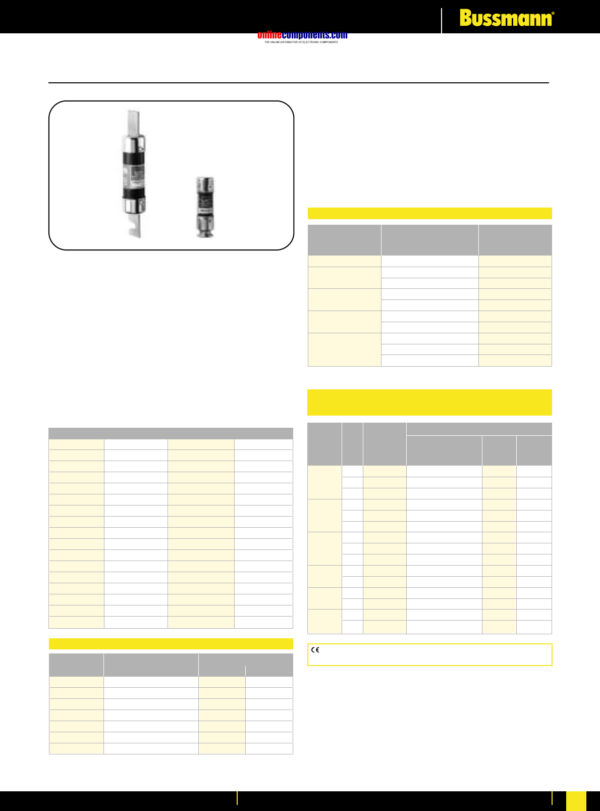
onlinecomponents.com
Low Voltage Industrial Fuse Links
For more information visit our website at www.bussmann.com 62
CE logo denotes compliance with European Union Low Voltage
Directive (50-1000V AC, 75-1500V DC). Refer to BIF document #8002.
Fusetron®Dual-Element, Time-Delay, CLASS RK5 Fuses
FRN-R (250V)
Dual-Element, Time-Delay – 10 seconds (minimum) at
500% rated current
Ampere Ratings: ⁄Ω¡º-600 Amps.
Voltage Rating: 250 Volts AC (or less), 125 Volts DC
Current Limiting RK5 Fuse
Interrupting Rating: 200,000A RMS Sym.
(20,000A @ 125V DC)
Agency Information: Std. 248-12, Class RK5
UL Listed, Guide JDDZ, File E4273
CSA Certified, Class 1422-01, File 53787
Dimensions: See pages 52-53 for Class RK5 dimensional data.
Catalogue Numbers (250V AC/125V DC)
FRN-R-⁄Ω¡º FRN-R-2 FRN-R-10 FRN-R-100
FRN-R-⁄Ω• FRN-R-2⁄Ω¢ FRN-R-12 FRN-R-110
FRN-R-⁄fiΩ¡ºº FRN-R-2⁄Ω™ FRN-R-15 FRN-R-125
FRN-R-¤Ω¡º FRN-R-2°Ω¡º FRN-R-17⁄Ω™ FRN-R-150
FRN-R-⁄Ω¢ FRN-R-3 FRN-R-20 FRN-R-175
FRN-R-‹Ω¡º FRN-R-3¤Ω¡º FRN-R-25 FRN-R-200
FRN-R-›Ω¡º FRN-R-3⁄Ω™ FRN-R-30 FRN-R-225
FRN-R-⁄Ω™ FRN-R-4 FRN-R-35 FRN-R-250
FRN-R-flΩ¡º FRN-R-4⁄Ω™ FRN-R-40 FRN-R-300
FRN-R-°Ω¡º FRN-R-5 FRN-R-45 FRN-R-350
FRN-R-1 FRN-R-5flꭧ FRN-R-50 FRN-R-400
FRN-R-1⁄Ω• FRN-R-6 FRN-R-60 FRN-R-450
FRN-R-1⁄Ω¢ FRN-R-6⁄Ω¢ FRN-R-70 FRN-R-500
FRN-R-1›Ω¡º FRN-R-7 FRN-R-75 FRN-R-600
FRN-R-1⁄Ω™ FRN-R-7⁄Ω™ FRN-R-80
FRN-R-1flꭧ FRN-R-8 FRN-R-85
FRN-R-1°Ω¡º FRN-R-9 FRN-R-90
Ampere Carton Weight*
Ratings Qty. Lbs. Kg.
0-15 10 0.40 0.181
17.5-30 10 .50 0.227
35-60 10 1.00 0.453
70-100 5 1.5 0.680
101-200 1 0.77 0.349
201-400 1 1.52 0.689
401-600 1 2.94 1.334
Carton Quantity and Weight
**Weight per carton.
•Provides motor overload, ground fault and short-circuit
protection when sized properly.
•Helps protect motors against burnout from overloads when
sized properly.
•Helps protect motors against burnout from single phasing
on three phase systems when sized properly.
•Simplifies and improves blackout prevention (selective
coordination) when sized properly.
Desired Catalogue Number
Equipment Fuse (Case) (Pairs)
Fuse Clips Size 250V
60A 30A No. 263-R
100A 30A No. 213-R
60A No. 216-R
200A 60A No. 226-R
100A No. 2621-R
100A No. 2641-R
400A 200A No. 242-R
100A No. 2661-R
600A 200A No. 2662-R
400A No. 2664-R*
*Single reducer only (pair not required).
Fuse Reducers For Class R Fuses
Terminal Type (Suffix No.)
Basic Screw w/ Box Lug ⁄Ω¢∑
Catalogue —Pres. —w/ Clip Quick-
Amps Poles Number Plate CU only Connect
⁄Ω¡º 1 R25030-1 SR PR CR COR QR
to 2 R25030-2 SR PR CR COR QR
30 3 R25030-3 SR PR CR COR QR
31 1 R25060-1 SR —CR COR —
to 2 R25060-2 SR —CR COR —
60 3 R25060-3 SR —CR COR —
70 1 R25100-1 ——CR COR —
to 2 R25100-2 ——CR COR —
100 3 R25100-3 ——CR COR —
to 200 1 R25200-1 ——CR ——
3 R25200-3 ——CR ——
to 400 1 R25400-1 ——CR ——
3 R25400-3 ——CR ——
to 600 1 R25600-1 ——CR ——
3 R25600-3 ——CR ——
Fuseblocks for Class R 250V Fuses
(Clip Retaining Spring Standard, Suffix “R”)
BIF document: 1019 (0-60), 1020 (70-600) & 1110 (Fuseblock)
onlinecomponents.com
Low Voltage Industrial Fuse Links
For more information visit our website at www.bussmann.com
63
Fusetron®Dual-Element, Time-Delay, CLASS RK5 Fuses
FRS-R (600V)
Dual-Element, Time-Delay – 10 seconds (minimum) at
500% rated current
Ampere Ratings: ⁄Ω¡º-600 Amps.
Voltage Rating: 600 Volts AC (or less), 300 Volts DC
Current Limiting RK5 Fuse
Interrupting Rating: 200,000A RMS Sym.
(20,000A @ 300V DC)
Agency Information: Std. 248-12, Class RK5
UL Listed, Guide JDDZ, File E4273
CSA Certified, Class 1422-02, File 53787
Dimensions: See pages 52-53 for Class RK5 dimensional data.
Catalogue Numbers (600V AC/ 300V DC)
FRS-R-⁄Ω¡º FRS-R-2 FRS-R-10 FRS-R-110
FRS-R-⁄Ω• FRS-R-2⁄Ω¢ FRS-R-12 FRS-R-125
FRS-R-⁄fiΩ¡ºº FRS-R-2⁄Ω™ FRS-R-15 FRS-R-150
FRS-R-¤Ω¡º FRS-R-2°Ω¡º FRS-R-17⁄Ω™ FRS-R-175
FRS-R-⁄Ω¢ FRS-R-3 FRS-R-20 FRS-R-200
FRS-R-‹Ω¡º FRS-R-3¤Ω¡º FRS-R-25 FRS-R-225
FRS-R-›Ω¡º FRS-R-3⁄Ω™ FRS-R-30 FRS-R-250
FRS-R-⁄Ω™ FRS-R-4 FRS-R-35 FRS-R-275
FRS-R-flΩ¡º FRS-R-4⁄Ω™ FRS-R-40 FRS-R-300
FRS-R-°Ω¡º FRS-R-5 FRS-R-45 FRS-R-325
FRS-R-1 FRS-R-5flꭧ FRS-R-50 FRS-R-350
FRS-R-1⁄Ω• FRS-R-6 FRS-R-60 FRS-R-400
FRS-R-1⁄Ω¢ FRS-R-6⁄Ω¢ FRS-R-70 FRS-R-450
FRS-R-1›Ω¡º FRS-R-7 FRS-R-75 FRS-R-500
FRS-R-1⁄Ω™ FRS-R-7⁄Ω™ FRS-R-80 FRS-R-600
FRS-R-1flꭧ FRS-R-8 FRS-R-90
Ampere Carton Weight*
Ratings Qty. Lbs. Kg.
0-15 10 0.40 0.181
17.5-30 10 0.50 0.227
35-60 10 3.10 1.406
65-100 1 0.54 0.245
101-200 1 1.22 0.544
201-400 1 3.00 1.359
401-600 1 5.00 2.268
*Weight per carton.
Carton Quantity and Weight
Desired Catalogue Number
Equipment Fuse (Case) (Pairs)
Fuse Clips Size 600V
60A 30A No. 663-R
100A 30A No. 216-R
60A No. 616-R
200A 60A No. 626-R
100A No. 2621-R
400A 100A No. 2641-R
200A No. 642-R
100A No. 2661-R
600A 200A No. 2662-R
400A No. 2664-R*
*Single reducer only (pair not required).
Fuse Reducers For Class R Fuses
CE logo denotes compliance with European Union Low Voltage
Directive (50-1000V AC, 75-1500V DC). Refer to Data Sheet #8002.
Data Sheet: 1017 (0-60), 1018 (70-600) & 1111 (Fuseblock)
⁄Ω¡º 1 R60030-1 SR PR CR COR
to 2 R60030-2 SR PR CR COR
30 3 R60030-3 SR PR CR COR
31 1 R60060-1 SR —CR COR
to 2 R60060-2 SR —CR COR
60 3 R60060-3 SR —CR COR
65 1 R60100-1 ——CR COR
to 2 R60100-2 ——CR COR
100 3 R60100-3 ——CR COR
to 200 1 R60200-1 ——CR —
R60200-3 ——CR —
to 400 1 R60400-1 ——CR —
R60400-3 ——CR —
to 600 1 R60600-1 ——CR —
R60600-3 ——CR —
Fuseblocks for Class R 600V Fuses
(Clip Retaining Spring Standard, Suffix “R”)
Terminal Type (Suffix No.)
Basic Screw w/ Box Lug
Catalogue Pres. w/ Clip
Amps Poles Number - Plate - CU only
onlinecomponents.com
Low Voltage Industrial Fuse Links
For more information visit our website at www.bussmann.com 64
Limitron®Fast Acting, CLASS RK1 Fuses
KTN-R (250V)
Fast Acting
Ampere Ratings: 1-600 Amps.
Voltage Rating: 250 Volts AC (or less).
Current Limiting RK1 Fuse (curves on page 260)
Interrupting Rating: 200,000A RMS Sym.
Agency Information: Std. 248-12, Class RK1
UL Listed, Guide JDDZ, File E54273
CSA Certified, Class 1422-02, File 53787
Dimensions: See pages 52-53 for Class RK1 dimensional data.
Catalogue Numbers (250V AC)
KTN-R-1 KTN-R-30 KTN-R-125
KTN-R-2 KTN-R-35 KTN-R-150
KTN-R-3 KTN-R-40 KTN-R-175
KTN-R-4 KTN-R-45 KTN-R-200
KTN-R-5 KTN-R-50 KTN-R-225
KTN-R-6 KTN-R-60 KTN-R-250
KTN-R-8 KTN-R-70 KTN-R-300
KTN-R-10 KTN-R-75 KTN-R-350
KTN-R-12 KTN-R-80 KTN-R-400
KTN-R-15 KTN-R-90 KTN-R-450
KTN-R-20 KTN-R-100 KTN-R-500
KTN-R-25 KTN-R-110 KTN-R-600
Ampere Carton Weight*
Ratings Qty. Lbs. Kg.
1-30 10 .45 0.204
40-60 10 1.82 0.824
70-100 5 1.85 0.838
110-200 1 1.05 0.476
225-400 1 2.38 1.078
450-600 1 3.50 1.587
*Weight per carton.
Carton Quantity and Weight
KTS-R (600V)
Fast Acting
Ampere Ratings: 1-600 Amps.
Voltage Rating: 600 Volts AC (or less).
Current Limiting RK1 Fuse (curves on page 260)
Interrupting Rating: 200,000A RMS Sym.
Agency Information: Std. 248-12, Class RK1
UL Listed, Guide JDDZ, File E54273
CSA Certified, Class 1422-02, File 53787
Dimensions: See pages 52-53 for Class RK1 dimensional data.
Catalogue Numbers (600V AC)
KTS-R-1 KTS-R-30 KTS-R-125
KTS-R-2 KTS-R-35 KTS-R-150
KTS-R-3 KTS-R-40 KTS-R-175
KTS-R-4 KTS-R-45 KTS-R-200
KTS-R-5 KTS-R-50 KTS-R-225
KTS-R-6 KTS-R-60 KTS-R-250
KTS-R-8 KTS-R-70 KTS-R-300
KTS-R-10 KTS-R-75 KTS-R-350
KTS-R-12 KTS-R-80 KTS-R-400
KTS-R-15 KTS-R-90 KTS-R-450
KTS-R-20 KTS-R-100 KTS-R-500
KTS-R-25 KTS-R-110 KTS-R-600
Ampere Carton Weight*
Ratings Qty. Lbs. Kg.
1-30 10 1.45 0.657
40-60 10 2.63 1.262
70-100 1 0.5 0.226
110-200 1 1.4 0.634
225-400 1 2.75 1.246
450-600 1 4.25 1.925
*Weight per carton.
Carton Quantity and Weight
CE logo denotes compliance with European Union Low Voltage
Directive (50-1000V AC, 75-1500V DC). Refer to BIF document #8002.
CE logo denotes compliance with European Union Low Voltage
Directive (50-1000V AC, 75-1500V DC). Refer to BIF document #8002.
BIF document: 1043 (0-600) BIF document: 1044 (0-600)
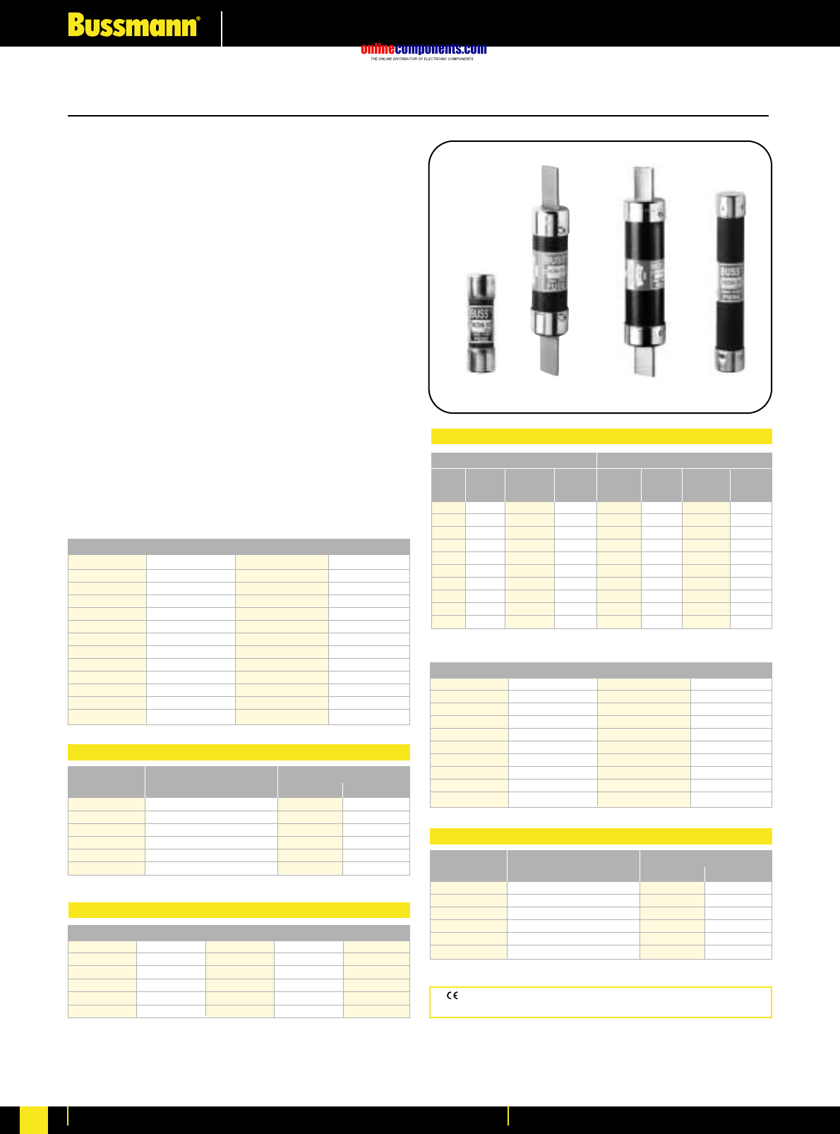
onlinecomponents.com
Low Voltage Industrial Fuse Links
For more information visit our website at www.bussmann.com
65
One-Time General Purpose Fuses
NON and NOS
General Purpose Application
Non-Current Limiting
Ampere Ratings: ⁄Ω•-600 Amps.
Voltage Rating: NON: 250 Volts AC, 125 Volts DC (0-100A);
NOS: 600 Volts AC
Interrupting Rating: 50,000A RMS Sym. (0-60A),
10,000A RMS Sym. (65-600A), 50,000A @ 125V DC
(NON 0-60),
10,000A @ 125V DC (NON 65-100A)
Agency Information:
UL Listed – 250V: Class K5 (0-60A), Std. 248-9
Class H (65-600A), Std. 248-6
(125V DC: Non 0-100)
600V: Class K5 (0-60A), Std. 248-9
Class H (70-600A), Std. 248-6
Guide JDDZ, File E4273
CSA Certified – 250V: (0-12, 65-600)
600V: (0-600)
Class 1421-01, File 53787
Dimensions: See pages 52-53 for dimensional data under
Class RK5/RK1.
Catalogue Numbers (250V AC)
NON-⁄Ω• NON-5 NON-40 NON-175
NON-⁄Ω™ NON-6 NON-45 NON-200
NON-‹Ω¢ NON-6⁄Ω¢ NON-50 NON-225
NON-°Ω¡º NON-7 NON-60 NON-250
NON-1 NON-8 NON-65 NON-300
NON-1⁄Ω¢ NON-9 NON-70 NON-350
NON-1⁄Ω™ NON-10 NON-75 NON-400
NON-1flꭧ NON-12 NON-80 NON-450
NON-2 NON-15 NON-90 NON-500
NON-2⁄Ω™ NON-20 NON-100 NON-600
NON-3 NON-25 NON-110 —
NON-3¤Ω¡º NON-30 NON-125 —
NON-4 NON-35 NON-150 —
Ampere Carton Weight*
Ratings Qty. Lbs. Kg.
NON ⁄Ω•-30 10 0.38 0.172
NON 35-60 10 1.00 0.453
NON 65-100 5 0.79 0.358
NON 110-200 1 0.79 0.358
NON 225-400 1 1.65 0.748
NON 450-600 1 2.76 1.25
*Weight per carton.
Carton Quantity and Weight
Catalogue Symbol & Current Ratings
250 Volt 600 Volt
Cat. Weight Cat. Weight
Clip Fuse No. Carton* Clip Fuse No. Carton*
Size Size (Pair) (lbs) Size Size (Pair) (lbs)
60A 30A No. 263 0.38 60A 30A No. 663 1.00
100A 30A No. 213 1.73 100A 30A No. 216 1.73
100A 60A No. 216 1.73 100A 60A No. 616 1.85
200A 60A No. 226 3.00 200A 60A No. 626 3.33
200A 100A No. 2621 1.63 200A 100A No. 2621 1.63
400A 100 No. 2641 4.90 400A 100 No. 2641 4.90
400A 200A No. 2642 3.50 400A 200A No. 2642 3.50
600A 100A No. 2661 8.70 600A 100A No. 2661 8.70
600A 200A No. 2662 6.85 600A 200A No. 2662 6.85
600A 400A No. 2664 4.45 600A 400A No. 2664 4.45
*Single reducer only (pair not required).
Recommended Fuse Reducers
Catalogue Numbers (600V AC)
NOS-1 NOS-12 NOS-70 NOS-200
NOS-2 NOS-15 NOS-75 NOS-225
NOS-3 NOS-20 NOS-80 NOS-250
NOS-4 NOS-25 NOS-90 NOS-300
NOS-5 NOS-30 NOS-100 NOS-350
NOS-6 NOS-35 NOS-110 NOS-400
NOS-7 NOS-40 NOS-125 NOS-450
NOS-8 NOS-45 NOS-150 NOS-500
NOS-9 NOS-50 NOS-175 NOS-600
NOS-10 NOS-60 ——
Ampere Carton Weight*
Ratings Qty. Lbs. Kg.
NOS 1-30 10 1.45 0.657
NOS 35-60 10 2.6 1.179
NOS 70-100 5 2.80 1.270
NOS 110-200 1 1.24 0.562
NOS 225-400 1 3.03 1.374
NOS 450-600 1 4.63 2.100
*Weight per carton.
Carton Quantity and Weight
CE logo denotes compliance with European Union Low Voltage
Directive (50-1000V AC, 75-1500V DC). Refer to Data Sheet: 8002.
Data Sheet: 1030
Symbol Rating Class Volt IR
NON 0-60 K5 250AC 50,000
65-600 H 250AC 10,000
0-60 K5 125DC 50,000
65-100 H 125DC 10,000
NOS 0-60 K5 600 50,000
70-600 H 600 10,000
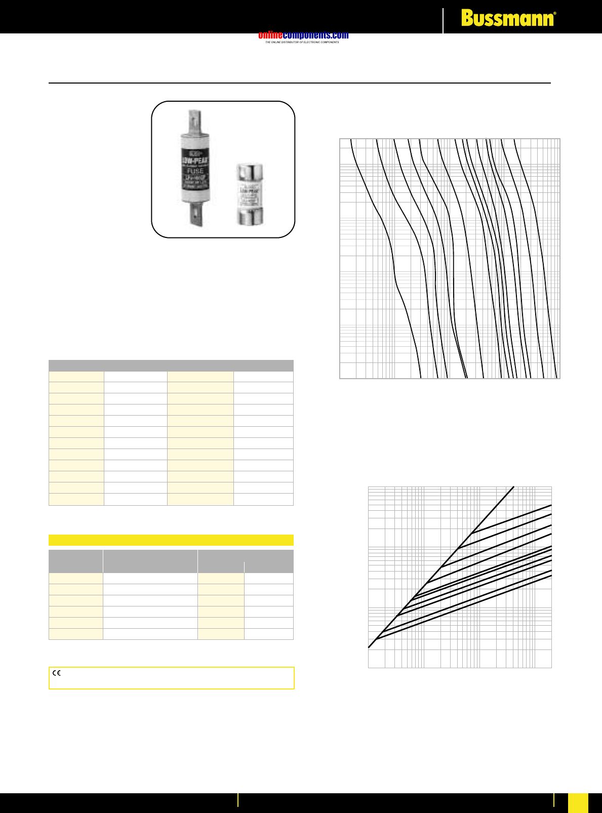
onlinecomponents.com
Low Voltage Industrial Fuse Links
For more information visit our website at www.bussmann.com 66
CE logo denotes compliance with European Union Low Voltage
Directive (50-1000V AC, 75-1500V DC). Refer to Data Sheet: 8002.
Low-Peak®Dual-Element, Time-Delay, CLASS J Fuses
LPJ_SP
Dual-Element,
Time-Delay –
10 seconds (minimum)
at 500% rated current
Ampere Ratings:
1-600 Amps.
Voltage Rating:
600 Volts AC (or less),
300 Volts DC (or less)
Current Limiting
Interrupting Rating:
AC – 300,000A RMS Sym.
DC – 100,000A
Agency Information:
UL Listed - Special Purpose**, Guide JFHR, File E56412
CSA Certified (200,000 AIR) Class J per CSA-22.2 No. 248.8,
Class 1422-02, File 53787
Dimensions: See pages 52-53 for Class J dimensional data.
Catalogue Numbers
LPJ-1SP LPJ-4⁄Ω™SP LPJ-25SP LPJ-125SP
LPJ-1⁄Ω¢SP LPJ-5SP LPJ-30SP LPJ-150SP
LPJ-1flꭧSP LPJ-5flꭧSP LPJ-35SP LPJ-175SP
LPJ-1°Ω¡ºSP LPJ-6SP LPJ-40SP LPJ-200SP
LPJ-2SP LPJ-7SP LPJ-45SP LPJ-225SP
LPJ-2⁄Ω¢SP LPJ-8SP LPJ-50SP LPJ-250SP
LPJ-2⁄Ω™SP LPJ-9SP LPJ-60SP LPJ-300SP
LPJ-2°Ω¡ºSP LPJ-10SP LPJ-70SP LPJ-350SP
LPJ-3SP LPJ-12SP LPJ-80SP LPJ-400SP
LPJ-3¤Ω¡ºSP LPJ-15SP LPJ-90SP LPJ-450SP
LPJ-3⁄Ω™SP LPJ-17⁄Ω™SP LPJ-100SP LPJ-500SP
LPJ-4SP LPJ-20SP LPJ-110SP LPJ-600SP
**Meets all performance requirements of UL Standard 248-8 for Class J fuses.
Available with silver plated terminals. Add SP/ in front of part number.
Ampere Carton Weight*
Ratings Qty. Lbs. Kg.
0-30 10 1.09 0.49
35-60 10 1.78 0.81
70-100 5 1.69 0.77
110-200 5 4.21 1.91
225-400 1 1.67 0.76
450-600 1 2.80 0.27
*Weight per carton.
Carton Quantity and Weight
AMPERE
RATING
1A
3A
6A
300
100
10
1
.1
.01
TIME IN SECONDS
10A
15A
30A
60A
100A
400A
1,000
100
CURRENT IN AMPERES
600A
125A
250A
200A
80A
200
10
10,000
1
INSTANTANEOUS PEAK LET-THRU CURRENT IN AMPS
100,000
10,000
1,000
100
B
A
100
1,000
10,000
100,000
200,000
600A
400A
200A
100A
60A
50A
40A
30A
20A
15A
AMPERE
RATING
LPJ Current Limitation Curves
Time-Current Classification Curves—Average Melt
Current Limitation Curves
Data Sheet: 1006 (0-60) and 1007 (70-600)
onlinecomponents.com
Low Voltage Industrial Fuse Links
For more information visit our website at www.bussmann.com
67
Limitron®Quick Acting, CLASS J Fuses
Catalogue Numbers
JKS-1 JKS-15 JKS-70 JKS-225
JKS-2 JKS-20 JKS-80 JKS-250
JKS-3 JKS-25 JKS-90 JKS-300
JKS-4 JKS-30 JKS-100 JKS-350
JKS-5 JKS-35 JKS-110 JKS-400
JKS-6 JKS-40 JKS-125 JKS-450
JKS-8 JKS-45 JKS-150 JKS-500
JKS-10 JKS-50 JKS-175 JKS-600
JKS-12 JKS-60 JKS-20
JKS
Quick Acting
Ampere Ratings: 1-600 Amps.
Voltage Rating: 600 Volts AC (or less)
Current Limiting
Interrupting Rating: 200,000A RMS Sym.
Agency Information: Std. 248-8, Class J
UL Listed, Guide JDDZ, File E4273
CSA Certified, Class 1422-02, File 53787
Dimensions: See pages 52-53 for Class J dimensional data.
Ampere Carton Weight*
Ratings Qty. Lbs. Kg.
1-30 10 0.95 0.43
35-60 10 1.175 0.53
70-100 5 0.28 0.13
110-200 1 0.86 0.39
225-400 1 1.78 0.81
450-600 1 3.07 1.39
*Weight per carton.
Carton Quantity and Weight
Mounting Catalogue Numbers
Screws with Box
Pressure Aluminum Copper
Plate Only
Panel JP60030-3PR JP60030-3CR JP60030-3COR
(#10-14 Cu (#2-8 Al or (#2-14 Cu)
Wire) #2-14 Cu)
With JP60030-3PRA JP60030-CRA JP60030-CORA
DIN-Rail (#10-14 Cu (#2-8 Al or (#2-14 Cu)
Adapter* Wire) #2-14 Cu)
*Adapter Only: Cat. No. JPA-3 (for use with 35mm symmetrical DIN-Rail).
Recommended Fuseblocks for Class J Fuses
Pyramid J Fuseblock;
30A, 600V; 3-Pole; Panel or 35mm DIN-Rail Mount
Catalogue Numbers
Pressure Box Box Lug w/ Max. Wire
Amps Screw Plate Lug Retaining Clip Size
1 J60030-1S J60030-1P J60030-1C J60030-1CR S, P, #10 Cu
1-30 2 J60030-2S J60030-2P J60030-2C J60030-2CR
3 J60030-3S J60030-3P J60030-3C J60030-3CR C #2 Cu Al
1——J60060-1C J60060-1CR
35-60 2 ——J60060-2C J60060-2CR #2 Cu Al
3——J60060-3C J60060-3CR
70-100 3 —— —J60100-3CR 1/0 Cu Al
110-200 1—— —J60200-1CR 250 MCM Cu Al
3—— —J60200-3CR
225-400 1—— —J60400-1CR 500 MCM Cu Al
3—— —J60400-3CR
450-600 1—— —J60600-1CR (2) 500 MCM Cu Al
3—— —J60600-3CR
Poles
Standard Class J Fuseblocks
250 Volt 600 Volt
Cat. Weight Cat. Weight
Clip Fuse No. Carton* Clip Fuse No. Carton*
Size Size (Pair) (lbs) Size Size (Pair) (lbs)
60A 30A J63 0.38 400A 100A J41 4.90
100A 30A J13 1.73 400A 200A J42 2.75
100A 60A J16 1.85 600A 400A J64 3.55
200A 60A J26 2.55 600A 200A J62 3.55
200A 100A J21 1.36 ————
*Carton quantity—10 pair.
Recommended Reducers for J Dimension Fuses
CE logo denotes compliance with European Union Low Voltage
Directive (50-1000V AC, 75-1500V DC). Refer to BIF document #8002.
BIF document: 1026 (1-60A), 1027 (70-600A)
BIF document: 1114
onlinecomponents.com
Low Voltage Industrial Fuse Links
For more information visit our website at www.bussmann.com 68
T-Tron®Very Fast Acting, CLASS T Fuses
JJN
Very Fast Acting
Ampere Ratings:
1-1200 Amps.
Voltage Rating:
300 Volts AC (or less),
(15-600A 160V DC;
601-1200 170V DC)
Current Limiting
(curves on page 263)
Interrupting Rating:
200,000A RMS Sym. (20,000A DC @ 160V DC)
Agency Information: Std. 248-15, Class T
UL Listed, Guide JDDZ, File E4273
CSA Certified, Class 1422-02, File 53787
Dimensions: See pages 52-53 for Class T dimensional data.
JJS
Very Fast Acting
Ampere Ratings:
1-800 Amps.
Voltage Rating:
600 Volts AC (or less)
Current Limiting
(curves on page 263)
Interrupting Rating:
200,000A RMS Sym.
Agency Information:
Std. 248-15, Class T
UL Listed, Guide JDDZ, File E4273
CSA Certified, Class 1422-02, File 53787
Dimensions: See pages 52-53 for Class T dimensional data.
Catalogue Numbers
JJN-1 JJN-35 JJN-110 JJN-400
JJN-2 JJN-40 JJN-125 JJN-450
JJN-3 JJN-45 JJN-150 JJN-500
JJN-6 JJN-50 JJN-175 JJN-600
JJN-10 JJN-60 JJN-200 JJN-700
JJN-15 JJN-70 JJN-225 JJN-800
JJN-20 JJN-80 JJN-250 JJN-1000
JJN-25 JJN-90 JJN-300 JJN-1200
JJN-30 JJN-100 JJN-350
**Meets all performance requirements of UL Standard 248-8 for Class J fuses.
Available with silver plated terminals. Add SP/ in front of part number.
Ampere Carton Weight*
Ratings Qty. Lbs. Kg.
1-30 10 0.12 0.054
35-60 10 0.23 0.104
70-100 5 0.36 0.163
110-200 1 0.14 0.063
225-400 1 0.25 0.113
450-600 1 0.44 0.200
700-800 1 0.80 0.363
1000-1200 1 1.45 0.658
*Weight per carton
Carton Quantity and Weight
Standard Class T Fuseblocks (300V) Catalogue Data
Catalogue Numbers
JJS-1 JJS-30 JJS-90 JJS-250
JJS-2 JJS-35 JJS-100 JJS-300
JJS-3 JJS-40 JJS-110 JJS-350
JJS-6 JJS-45 JJS-125 JJS-400
JJS-10 JJS-50 JJS-150 JJS-450
JJS-15 JJS-60 JJS-175 JJS-500
JJS-20 JJS-70 JJS-200 JJS-600
JJS-25 JJS-80 JJS-225 JJS-800
**Meets all performance requirements of UL Standard 248-8 for Class J fuses.
Available with silver plated terminals. Add SP/ in front of part number.
Ampere Carton Weight*
Ratings Qty. Lbs. Kg.
1-30 10 0.33 0.149
35-60 10 0.82 0.371
70-100 5 0.51 0.231
110-200 1 0.192 0.087
225-400 1 0.46 0.208
450-600 1 0.85 0.385
800 1 1.65 0.748
*Weight per carton.
Carton Quantity and Weight
Catalogue Numbers
Amps Poles Screw Box Lug
⁄Ω™ 2 T30030-2SR T30030-2CR
to 3 T30030-3SR T30030-3CR
30 4 T30030-4SR T30030-4CR
31 2 T30060-2SR T30060-2CR
to 3 T30060-3SR T30060-3CR
60 4 T30060-4SR T30060-4CR
61 1 —T30100-1CR
to 2 —T30100-2CR
100 3 —T30100-3CR
101 to 1 —T30200-1C
200 3 —T30200-3C
201 to 400 1 —T30400-1C
401 to 600 1 —T30600-1C
Standard Class T Fuseblocks (600V) Catalogue Data
Catalogue Numbers
Amps Poles Screw Box Lug
⁄Ω™ 1 T60030-1SR T60030-1CR
to 2 T60030-2SR T60030-2CR
30 3 T60030-3SR T60030-3CR
31 1 T60060-1SR T60060-1CR
to 2 T60060-2SR T60060-2CR
60 3 T60060-3SR T60060-3CR
61 1 —T60100-1C
to 2 —T60100-2C
100 3 —T60100-3C
101 to 1 —T60200-1C
200 3 —1B0089
201 to 400 1 —T60400-1C
401 to 600 1 —T60600-1C
CE logo denotes compliance with European Union Low Voltage
Directive (50-1000 VAC, 75-1500V DC). Refer to BIF document #8002.
CE logo denotes compliance with European Union Low Voltage
Directive (50-1000V AC, 75-1500V DC). Refer to BIF document #8002.
BIF document: 1025
BIF document: 1029
BIF document: 1115 (300V Fuseblock) and 1116 (600V Fuseblock)
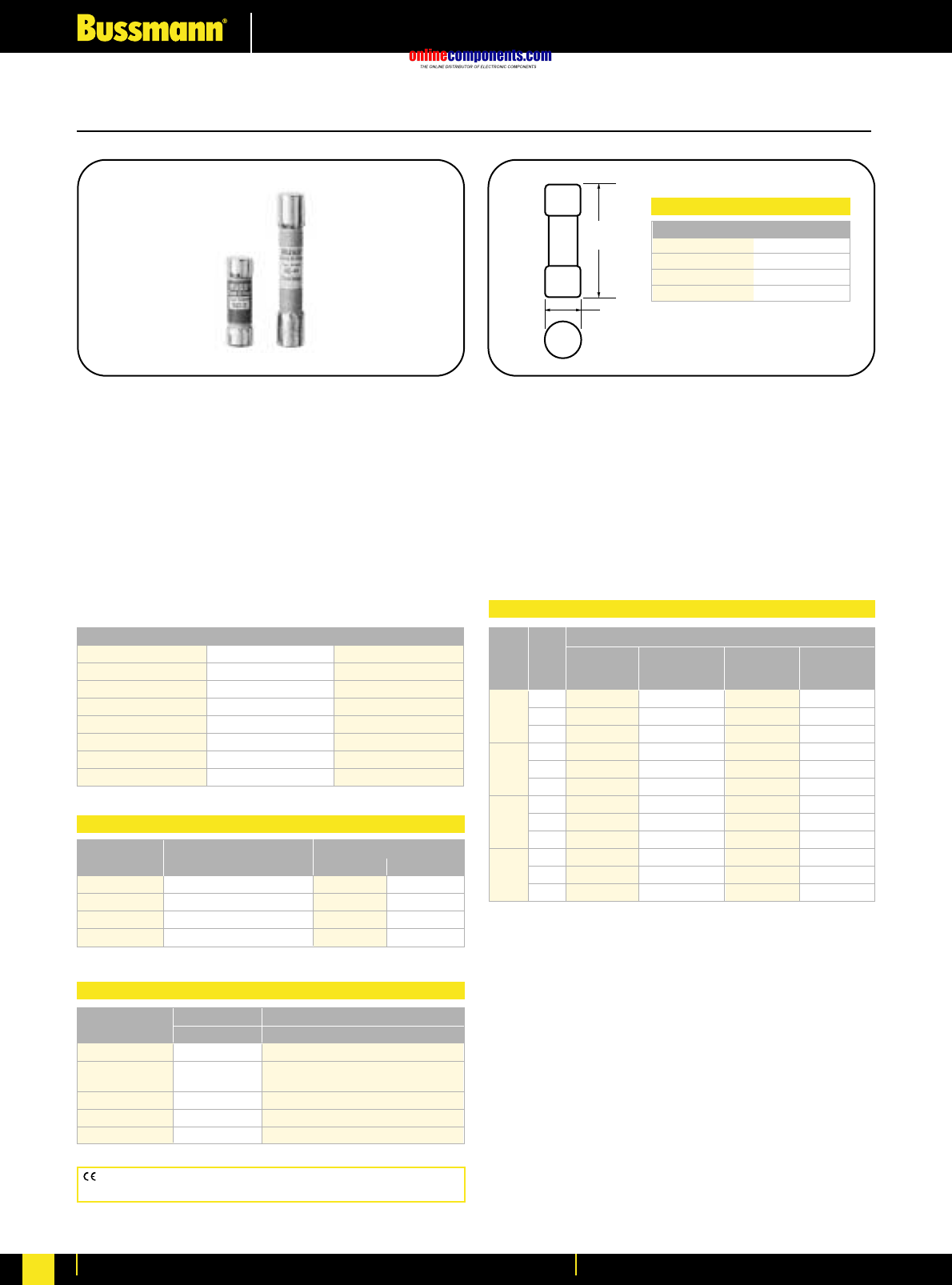
onlinecomponents.com
Low Voltage Industrial Fuse Links
For more information visit our website at www.bussmann.com
69
Time-Delay CLASS G Fuses
SC
Fast Acting (⁄Ω™-6A), Class G
Time-Delay (7-60A), Class G
Construction: Melamine Tube
Ampere Ratings: ⁄Ω™-60A
Voltage Rating: ⁄Ω™-20: 600V AC/170V DC
25-60: 480V AC/300V DC (only UL)
Interrupting Rating: 100,000A RMS Sym., 10,000A DC
Agency Information: Std. 248-5, Class G, UL Listed,
Guide JDDZ, File E4273
CSA Certified, Class 1422-01, File 53787
Catalogue Symbol & Current Ratings
SC-⁄Ω™ SC-6 SC-25
SC-1 SC-7 SC-30
SC-1⁄Ω™ SC-8 SC-35
SC-2 SC-9 SC-40
SC-2⁄Ω™ SC-10 SC-45
SC-3 SC-12 SC-50
SC-4 SC-15 SC-60
SC-5 SC-20 —
Ampere Carton Weight*
Ratings Qty. Lbs. Kg.
⁄Ω™-15 4 0.06 0.03
20 4 0.06 0.03
25-30 2 0.04 0.02
35-60 2 0.08 0.03
*Weight per carton
Carton Quantity and Weight
Catalogue Description
Number Fuse Size Terminal Type
HPF-EE 1-15A Solder (w/o leads)
HPF-FEE 1-15A Leads; 10∑#18 copper insul. wire
HPF-JJ 20A Solder (w/o leads)
HPF-FF 25-30A Solder (w/o leads)
HPS-EE 1-15A Solder (w/o leads)
Panel-mount Fuseholders for SC Fuses
A
(Length)
.41"
(10.3mm)
Fuse (Amps) (Length)
SC-⁄Ω™ to -15 1.319
SC-20 1.419
SC-25 to -30 1.639
SC-35 to -60 2.259
Physical Size:
•Compact branch-circuit units with high interrupting rating
and current limitation.
•With a 600 volt rating, they can be used in 120/208,
120/240 and 277/480 volt circuits.
•Length variations relative to case size make the “rejection”
type fuses.
•SC fuses with ampere ratings above 6 amps have a degree
of overload time-delay which permits them to pass
temporary overloads. At 200% load, they have a minimum
opening time of 12 seconds.
Terminal Type
Screw With Pressure Plate Box Lug
Amps Poles Quick w/Quick Box w/Retaining
Connect Connect Lug Clip
⁄Ω™ 1 BG3011SQ BG3011PQ BG3011B —
to 2 BG3012SQ BG3012PQ BG3012B —
15 3 BG3013SQ BG3013PQ BG3013B —
1 BG3021SQ BG3021PQ BG3021B —
20 2 BG3022SQ BG3022PQ BG3022B —
3 BG3023SQ BG3023PQ BG3023B —
25 1 BG3031S BG3031P BG3031B —
to 2 BG3032S BG3032P BG3032B —
30 3 BG3033S BG3033P BG3033B —
35 1 ———G30060-1CR
to 2 ———G30060-2CR
60 3 ——G30060-3C G30060-3CR
Standard SC Fuseblocks Catalogue Data
CE logo denotes compliance with European Union Low Voltage
Directive (50-1000V AC, 75-1500V DC). Refer to BIF document #8002.
BIF document: 1024 (0-60) and 1106 (Fuseblock)
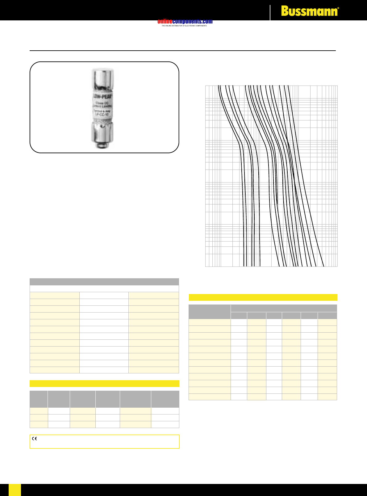
onlinecomponents.com
Low Voltage Industrial Fuse Links
For more information visit our website at www.bussmann.com 70
For more information visit our website at www.bussmann.com
70
Low-Peak®Time-Delay, CLASS CC Fuses
200
100
10
TIME IN SECONDS
1
.1
.01
⁄Ω™
flꭧ
°Ω¡º
1
1⁄Ω¢
3
3⁄Ω™
4
4⁄Ω™
6
8
10
12
15
20
25
30
AMPERE
RATING
.4
1
10
100
1000
CURRENT IN AMPERES
Time Current Characteristics—Average Melt
CE logo denotes compliance with European Union Low Voltage
Directive (50-1000V AC, 75-1500V DC). Refer to BIF document #8002.
LP-CC Low-Peak®Fuse
Time-Delay Current Limiting,
Class CC - Rejection Type
Physical Size:
⁄‹Ω£™∑ ≈ 1⁄Ω™∑
(10.3mm ≈38.1mm)
Ampere Ratings: ⁄Ω™ - 30 Amps.
Voltage Rating: 600 Volts AC (or less),
300V DC (⁄Ω™-2°Ω¡ºA
& 20-30A), 150V DC (3-15A)
Interrupting Rating: 200,000A RMS Sym; 20,000A DC
Construction: Melamine Tube
Agency Information: Std. 248-4, Class CC
UL Listed, Guide JDDZ, File E4273
CSA Certified; Class 1422-02, File 53787
Catalogue Symbol
600 Volts AC
LP-CC-⁄Ω™ LP-CC-2⁄Ω™ LP-CC-7⁄Ω™
LP-CC-flΩ¡º LP-CC-2°Ω¡º LP-CC-8
LP-CC-°Ω¡º LP-CC-3 LP-CC-9
LP-CC-1 LP-CC-3¤Ω¡º LP-CC-10
LP-CC-1⁄Ω• LP-CC-3⁄Ω™ LP-CC-12
LP-CC-1⁄Ω¢ LP-CC-4 LP-CC-15
LP-CC-1›Ω¡º LP-CC-4⁄Ω™ LP-CC-20
LP-CC-1⁄Ω™ LP-CC-5 LP-CC-25
LP-CC-1flꭧ LP-CC-5flꭧ LP-CC-30
LP-CC-1°Ω¡º LP-CC-6
LP-CC-2 LP-CC-6⁄Ω¢
LP-CC-2⁄Ω¢ LP-CC-7
Screw Pressure
No. of Screw Pressure Box Quick- Quick-
Poles Terminal Plate Terminal Connect Connect
1 BC6031S BC6031P BC6031B BC6031SQ BC6031PQ
2 BC6032S BC6032P BC6032B BC6032SQ BC6032PQ
3 BC6033S BC6033P BC6033B BC6033SQ BC6033PQ
Recommended Fuseblocks for Class CC Fuses
Prospective Short- *Let-Thru Current (Apparent RMS Symmetrical)
Circuit Current 1⁄Ω¢A2°Ω¡ºA 15A 20A 25A 30A
1000 100 135 240 305 380 435
3000 140 210 350 440 575 580
5000 165 255 420 570 690 710
10,000 210 340 540 700 870 1,000
20,000 260 435 680 870 1,090 1,305
30,000 290 525 800 1,030 1,300 1,520
40,000 315 610 870 1,150 1,390 1,700
50,000 340 650 915 1,215 1,520 1,820
60,000 350 735 1,050 1,300 1,650 1,980
80,000 390 785 1,130 1,500 1,780 2,180
100,000 420 830 1,210 1,600 2,000 2,400
200,000 525 1,100 1,600 2,000 2,520 3,050
*RMS Symmetrical Amperes Short-Circuit
NOTE: To calculate Ip(Ipeak) multiply IRMS value ≈2.3.
Current-Limiting Effects
BIF document: 1023 (0-30) and 1105 (Fuseblock)
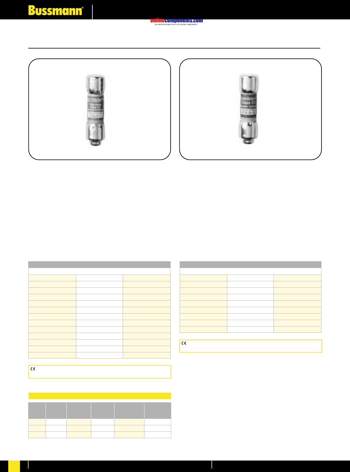
onlinecomponents.com
Low Voltage Industrial Fuse Links
For more information visit our website at www.bussmann.com
71
CLASS CC Rejection-Type Fuses
FNQ-R
Time-Delay, Rejection Type
Branch Circuit Fuse
Class CC
Physical Size:
⁄‹Ω£™∑ ≈ 1⁄Ω™∑ (10.3mm ≈38.1mm)
Construction: Melamine Tube
Ampere Ratings: ⁄Ω¢-30 Amps.
Voltage Rating: 600V AC or less
Interrupting Rating: 200,000A RMS Sym.
Agency Information: Std. 248-4, Class CC
UL Listed, Guide JDDZ, File E4273
CSA Certified, Class 1422-01, File 53787
KTK-R Limitron®Fuse
Fast Acting; Branch Circuit Fuse
Class CC - Rejection Feature
Physical Size:
⁄‹Ω£™∑ ≈ 1⁄Ω™∑ (10.3mm ≈38.1mm)
Construction: Melamine Tube
Ampere Ratings: ⁄Ω¡º-30 Amps.
Voltage Rating: 600 Volts AC (or less).
Interrupting Rating: 200,000A RMS Sym.
Agency Information: Std. 248-4, Class CC
UL Listed, Guide JDDZ, File E4273
CSA Certified, File 53787, Class 1422-02
Catalogue Symbol & Current Ratings
600 Volts AC
FNQ-R-⁄Ω¢ FNQ-R-1flΩ¡º FNQ-R-7
FNQ-R-‹Ω¡º FNQ-R-1°Ω¡º FNQ-R-7⁄Ω™
FNQ-R-›Ω¡º FNQ-R-2 FNQ-R-8
FNQ-R-⁄Ω™ FNQ-R-2⁄Ω¢ FNQ-R-9
FNQ-R-flΩ¡º FNQ-R-2⁄Ω™ FNQ-R-10
FNQ-R-‹Ω¢ FNQ-R-2°Ω¡º FNQ-R-12
FNQ-R-°Ω¡º FQN-R-3 FNQ-R-15
FNQ-R-1 FNQ-R-3¤Ω¡º FNQ-R-17⁄Ω™
FNQ-R-1⁄Ω• FNQ-R-3⁄Ω™º FNQ-R-20
FNQ-R-1⁄Ω¢ FNQ-R-4 FNQ-R-25
FNQ-R-1‹Ω¡º FNQ-R-5 FNQ-R-30
FNQ-R-1›Ω¡º FNQ-R-6 —
FNQ-R-1⁄Ω™ FNQ-R-6⁄Ω¢ —
Catalogue Symbol & Current Ratings
600 Volts AC
KTK-R-⁄Ω¡º KTK-R-1 KTK-R-7
KTK-R-⁄Ω• KTK-R-1⁄Ω™ KTK-R-8
KTK-R-¤Ω¡º KTK-R-2 KTK-R-9
KTK-R-⁄Ω¢ KTK-R-2⁄Ω™ KTK-R-10
KTK-R-‹Ω¡º KTK-R-3 KTK-R-12
KTK-R-›Ω¡º KTK-R-3⁄Ω™ KTK-R-15
KTK-R-⁄Ω™ KTK-R-4 KTK-R-20
KTK-R-flꭧ KTK-R-5 KTK-R-25
KTK-R-‹Ω¢ KTK-R-6 KTK-R-30
CE logo denotes compliance with European Union Low Voltage
Directive (50-1000V AC, 75-1500V DC). Refer to BIF document #8002.
CE logo denotes compliance with European Union Low Voltage
Directive (50-1000V AC, 75-1500V DC). Refer to BIF document #8002.
Screw Pressure
No. of Screw Pressure Box Quick- Quick-
Poles Terminal Plate Terminal Connect Connect
1 BC6031S BC6031P BC6031B BC6031SQ BC6031PQ
2 BC6032S BC6032P BC6032B BC6032SQ BC6032PQ
3 BC6033S BC6033P BC6033B BC6033SQ BC6033PQ
Recommended Fuseblocks for Class CC Fuses
BIF document: 1014 BIF document: 1015
BIF document: 1105
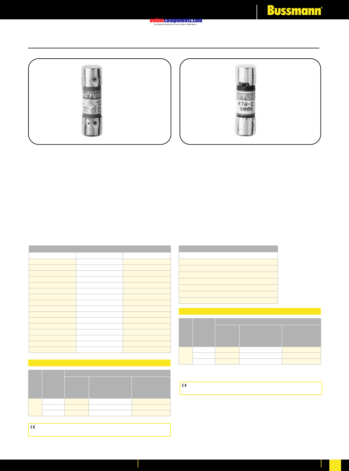
onlinecomponents.com
Low Voltage Industrial Fuse Links
For more information visit our website at www.bussmann.com 72
⁄‹Ω£™∑ x 1‹Ω•∑ Supplementary Fuses
BBS
Fast Acting
Physical Size:
⁄‹Ω£™∑ ≈ 1‹Ω•∑ (10.3mm ≈35mm)
Construction: Fibre Cartridge
Interrupting Rating: 10,000A RMS Sym.
Ampere Ratings: ⁄Ω¡º-30A
Voltage Rating: 600V AC (⁄Ω¡º-5A), 250V AC (6-10A),
48V AC (12-30A)
Agency Information: Std. 248-14
UL Listed, 0-5A/600V, Guide JDYX, File E19180
CSA Certified, 0-5A/600V, Class 1422-01, File 53787
KTQ
Fast Acting
Physical Size:
⁄‹Ω£™∑ ≈ 1‹Ω•∑ (10.3mm ≈34.9mm)
Construction: Fibre Cartridge
Ampere Ratings: 1-6A
Voltage Rating: 600V AC
Interrupting Rating: 10,000A RMS Sym.
Agency Information: Std. 248-14
UL Recognized, 4-6A, Guide JDYX2, File E19180
Catalogue Symbol & Current Ratings
600 Volts AC 250 Volts AC 48 Volts AC
BBS-
⁄Ω¡º BBS-6 BBS-12
BBS-¤Ω¡º BBS-7 BBS-15
BBS-⁄Ω¢ BBS-8 BBS-20
BBS-›Ω¡º BBS-10 BBS-25
BBS-⁄Ω™ —BBS-30
BBS-flΩ¡º ——
BBS-‹Ω¢ ——
BBS-°Ω¡º ——
BBS-1 ——
BBS-1⁄Ω™ ——
BBS-1flΩ¡º ——
BBS-1°Ω¡º ——
BBS-2 ——
BBS-3 ——
BBS-4 ——
BBS-5 ——
Terminal Type
Screw Pressure
with Plate w/
Quick Quick Box
Amps Poles Connect Connect Lug
⁄Ω¡º 1 BM6031SQ BM6031PQ BM6031B
to 2 BM6032SQ BM6032PQ BM6032B
30 3 BM6033SQ BM6033PQ BM6033B
Recommended Fuseblocks
Catalogue Symbol & Current Ratings
600 Volts AC
KTQ-1
KTQ-1flꭧ
KTQ-2
KTQ-3
KTQ-4
KTQ-5
KTQ-6
Terminal Type
Screw Pressure
with Plate w/
Quick Quick Box
Amps Poles Connect Connect Lug
⁄Ω¡º 1 BM6031SQ BM6031PQ BM6031B
to 2 BM6032SQ BM6032PQ BM6032B
30 3 BM6033SQ BM6033PQ BM6033B
Recommended Fuseblocks
CE logo denotes compliance with European Union Low Voltage
Directive (50-1000V AC, 75-1500V DC). Refer to BIF document #8002.
CE logo denotes compliance with European Union Low Voltage Directive
(50-1000V AC, 75-1500V DC). Refer to BIF document #8002.
BIF document: 2010 (0-30A) and 1104 (Fuseblock) BIF document: 2045 and 1104 (Fuseblock)
BIF document: 1104
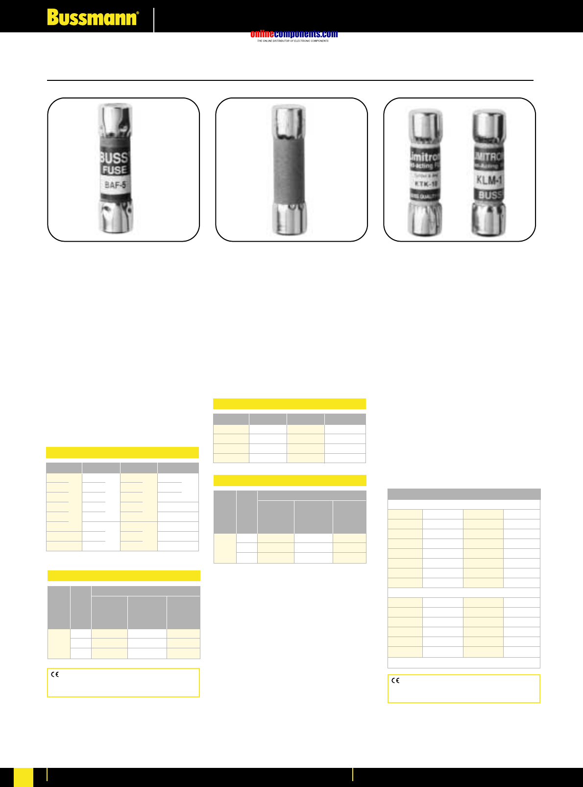
onlinecomponents.com
Low Voltage Industrial Fuse Links
For more information visit our website at www.bussmann.com
73
⁄‹Ω£™∑ x 1⁄Ω™∑ Supplementary Fuses
KTK and KLM
Fast Acting
Physical Size:
⁄‹Ω£™∑ ≈ 1⁄Ω™∑ (10.3mm ≈38.1mm)
Construction: Melamine Tube;
Nickel Plated Brass Endcaps
Voltage Rating:
KTK - 600V AC or less
KLM - ⁄Ω¡º-⁄Ω•A: 500VAC/600VDC
¤Ω¡º-10A: 500V AC/DC,
12-30A: 500VAC/600VDC
Interrupting Rating:
100,000A - KTK; 10,000A - KLM, RMS
SYM. (UL)
Agency Information: Std. 248-14
KTK-UL Listed, Guide JDYX,
File E19180
KLM-UL Recognized, Guide JFHR2,
File E56412
CSA Certified, File 53787, Class
1422-01, HRC-Misc
BAF
Fast Acting
Physical Size:
⁄‹Ω£™∑ ≈ 1⁄Ω™∑
(10.3mm ≈38.1mm)
Construction: Fibre Tube;
Nickel Plated Brass Endcaps
Voltage Rating: 250V AC
(¤Ω¡º-15A),125V AC (20-30A)
Interrupting Rating: 10,000A at
125V AC
Agency Information: Std. 248-14
UL 0-15/250V, Guide JDYX,
File E19180
CSA Certified, 0-15/250V,
Class 1422-01, File 53787
BAN
Fast Acting
Physical Size:
⁄‹Ω£™∑ ≈ 1⁄Ω™∑
(10.3mm ≈38.1mm) - 5AG
Construction: Fibre Tube
Voltage Rating: 250V AC
Interrupting Ratings: Military Tested
35A (1.1.-3.5A)
100A (3.6-10A)
200A (10.1-15A)
750A (15.1-30A)
CE logo denotes compliance with European
Union Low Voltage Directive (50-1000V AC,
75-1500V DC). Refer to Data Sheet: 8002. CE logo denotes compliance with European
Union Low Voltage Directive (50-1000V AC,
75-1500V DC). Refer to Data Sheet: 8002.
Catalogue Symbol & Current Ratings
BAF-¤Ω¡º
BAF-⁄Ω¢
BAF-⁄Ω™ IR
BAF-flꭧ 35A
BAF-°Ω¡º
BAF-1
—
—
BAF-1⁄Ω™
BAF-1°Ω¡º IR
BAF-2 100A
BAF-2⁄Ω™
BAF-3
BAF-4 IR
BAF-5 200A
BAF-6
BAF-6⁄Ω¢
BAF-7 IR
BAF-8 200A
BAF-9
BAF-10
BAF-12 IR
BAF-15 750A
—
BAF-20 IR
BAF-25
10000A
BAF-30
—
—
—
—
—
250 Volts IR* 250 Volts IR* 250 Volts IR* 125 Volts
*All have interrupting rating of 10,000A at 125V.
Terminal Type
Screw Pressure
with Plate w/
Quick Quick Box
Amps Poles Connect Connect Lug
⁄Ω¡º 1 BM6031SQ BM6031PQ BM6031B
to 2 BM6032SQ BM6032PQ BM6032B
30 3 BM6033SQ BM6033PQ BM6033B
Recommended Fuseblocks
Catalogue Symbol & Current Ratings
250 Volts IR* 250 Volts IR* 250 Volts IR* 125 Volts
BAN-1 BAN-5 BAN-12 BAN-30
BAN-2 BAN-6 BAN-15 —
BAN-3 BAN-8 BAN-20 —
BAN-4 BAN-10 BAN-25 —
Terminal Type
Screw Pressure
with Plate w/
Quick Quick Box
Amps Poles Connect Connect Lug
⁄Ω¡º 1 BM6031SQ BM6031PQ BM6031B
to 2 BM6032SQ BM6032PQ BM6032B
30 3 BM6033SQ BM6033PQ BM6033B
Recommended Fuseblocks
Catalogue Symbol & Current Ratings
600 Volts AC - UL Listed and C.S.A.
KTK-
⁄Ω¡º KTK-‹Ω¢ KTK-4 KTK-12
KTK-⁄Ω• KTK-1 KTK-5 KTK-15
KTK-¤Ω¡º KTK-1⁄Ω¢ KTK-6 KTK-20
KTK-⁄Ω¢ KTK-1⁄Ω™ KTK-7 KTK-25
KTK-‹Ω¡º KTK-2 KTK-7⁄Ω™ KTK-30
KTK-›Ω¡º KTK-2⁄Ω™ KTK-8 —
KTK-⁄Ω™ KTK-3 KTK-9 —
KTK-flΩ¡º KTK-3⁄Ω™ KTK-10 —
*500 Volts AC/DC - UL Recognized and C.S.A.
KLM-
⁄Ω¡º KLM-‹Ω¢ KLM-5 KLM-20
KLM-⁄Ω• KLM-1 KLM-6 KLM-25
KLM-¤Ω¡º KLM-1⁄Ω™ KLM-8 KLM-30
KLM-⁄Ω¢ KLM-2 KLM-10 —
KLM-‹Ω¡º KLM-3 KLM-12 —
KLM-⁄Ω™ KLM-4 KLM-15 —
*KLM-(⁄Ω¡º-⁄Ω• & 12-30): 500VAC/600VDC
Data Sheet: KTK-1011
KLM-2020
Data Sheet: 2046 (0-30) and
1104 (Fuseblock)
Data Sheet: 2011 (0-30) and
1104 (Fuseblock)
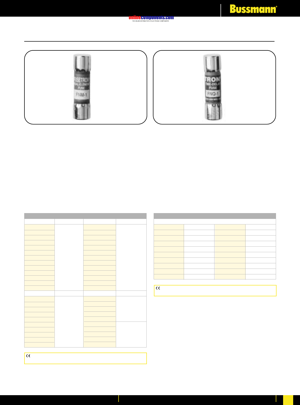
onlinecomponents.com
Low Voltage Industrial Fuse Links
For more information visit our website at www.bussmann.com 74
FNM Fusetron®Fuse
Time-Delay
Physical Size: ⁄‹Ω£™∑ ≈ 1⁄Ω™∑ (5 AG)
(10.3mm ≈38.1mm)
Construction: Fibre Tube
Ampere Ratings: ⁄Ω¡º - 30 Amps.
Voltage Rating: 250 Volts AC (or less).
Interrupting Rating: See Table Below.
Agency Information: Std. 248-14
UL Listed, 0-10/250V; 12-15/125V;
File E19180, Guide JDYX
CSA Certified, 1-10/250V; Class 1422-01, 12-15/125V;
File 53787
⁄‹Ω£™∑ x 1⁄Ω™∑ Supplementary Fuses
FNQ
Time-Delay
Physical Size:
⁄‹Ω£™∑ ≈ 1⁄Ω™∑ (5 AG)
(10.3mm ≈38.1mm)
Construction: Fibre Tube
Ampere Ratings: ⁄Ω¡º - 30 Amps.
Voltage Rating: 500V AC or less
Interrupting Rating: 10,000A RMS Sym.
Agency Information: Std. 248-14
UL Listed, Guide JDYX, File E19180
CSA Certified, Class 1422-01, File 53787
250 Volts AC IR 125 Volts AC IR
FNM-4
FNM-4⁄Ω™
FNM-5
FNM-5flꭧ 200A
FNM-6 @ 250V AC
FNM-6⁄Ω¢ 10,000A
FNM-7 @ 125V AC
FNM-8
FNM-9
FNM-10
FNM-12
FNM-15 10,000A
—@ 125V AC
—
32 Volts AC
FNM-20
FNM-25
FNM-30
—
—
Catalogue Symbol & Current Ratings
250 Volts AC IR 250 Volts AC IR
FNM-⁄Ω¡º
FNM-⁄Ω•
FNM-⁄fiΩ¡ºº
FNM-¤Ω¡º
FNM-⁄Ω¢ 35A
FNM-‹Ω¡º @ 250V AC
FNM-›Ω¡º 10,000A
FNM-⁄Ω™ @ 125V AC
FNM-flꭧ
FNM-‹Ω¢
FNM-°Ω¡º
FNM-1
—
FNM-1⁄Ω•
FNM-1⁄Ω¢
FNM-1›Ω¡º
FNM-1⁄Ω™
FNM-1flꭧ 100A
FNM-1°Ω¡º @ 250V AC
FNM-2 10,000A
FNM-2⁄Ω¢ @ 125V AC
FNM-2⁄Ω™
FNM-2°Ω¡º
FNM-3
FNM-3¤Ω¡º
FNM-3⁄Ω™
Catalogue Symbol & Current Ratings
500 Volts AC
FNQ-⁄Ω¡º FNQ-°Ω¡º FNQ-3¤Ω¡º FNQ-8
FNQ-⁄Ω• FNQ-1 FNQ-3⁄Ω™ FNQ-9
FNQ-⁄fiΩ¡ºº FNQ-1⁄Ω• FNQ-4 FNQ-10
FNQ-‹Ω¡§ FNQ-1⁄Ω¢ FNQ-4⁄Ω™ FNQ-12
FNQ-¤Ω¡º FNQ-1⁄Ω™ FNQ-5 FNQ-14
FNQ-⁄Ω¢ FNQ-1flΩ¡º FNQ-5flΩ¡º FNQ-15
FNQ-‹Ω¡º FNQ-2 FNQ-6 FNQ-20
FNQ-›Ω¡º FNQ-2⁄Ω¢ FNQ-6⁄Ω¢ FNQ-25
FNQ-⁄Ω™ FNQ-2⁄Ω™ FNQ-7 FNQ-30
FNQ-flΩ¡º FNQ-3 ——
CE logo denotes compliance with European Union Low Voltage
Directive (50-1000V AC, 75-1500V DC). Refer to BIF document #8002.
CE logo denotes compliance with European Union Low Voltage
Directive (50-1000V AC, 75-1500V DC). Refer to BIF document #8002.
BIF document: 2028 BIF document: 1012
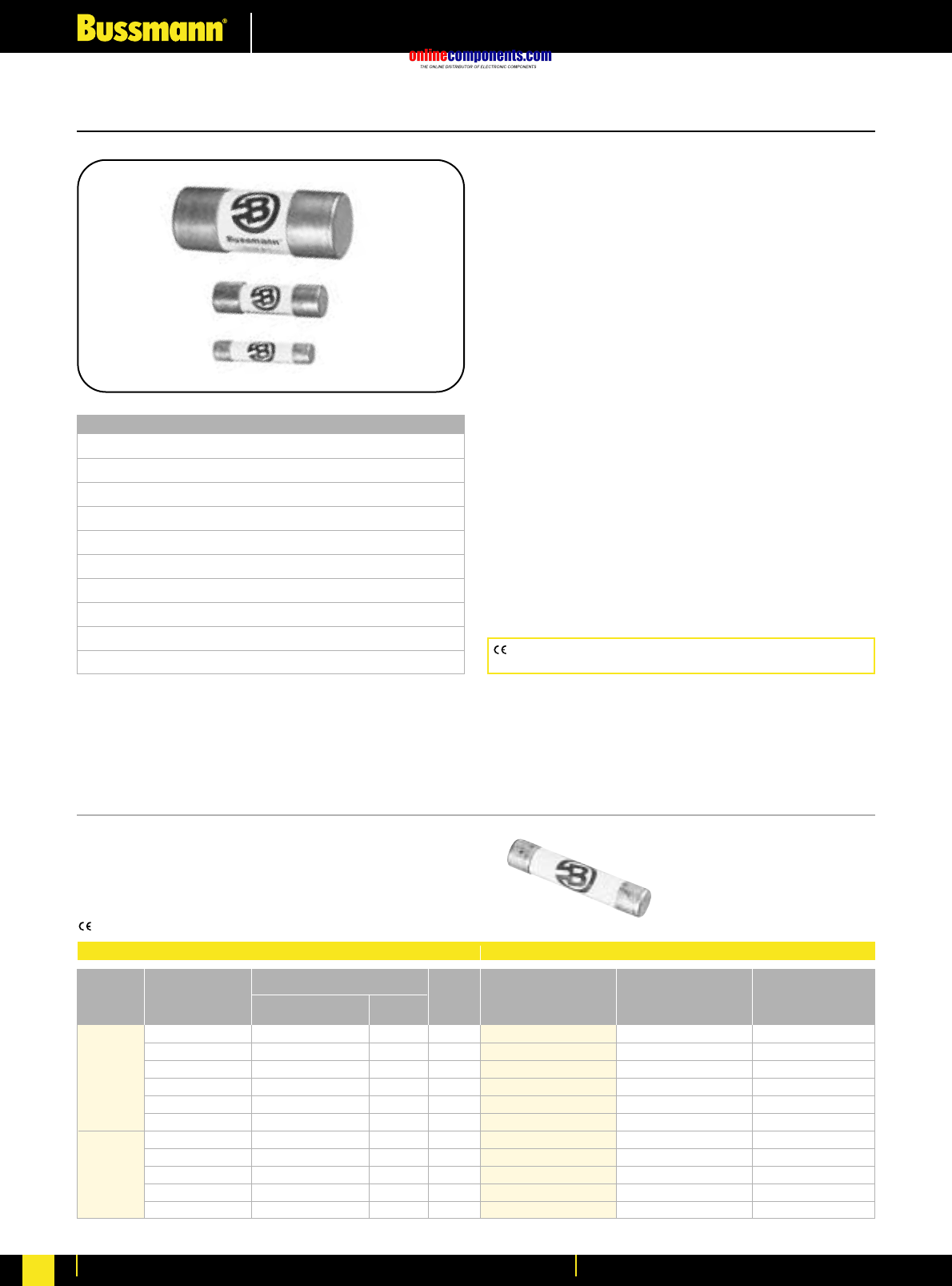
onlinecomponents.com
High Speed Fuses
For more information visit our website at www.bussmann.com
75
Ferrule Style
BIF document: 720003
Voltage Rating
150 Volt AC/DC 5 to 60 Amperes
250 Volt AC/DC 1 to 50 Amperes
500 Volt AC/DC* 0.25 to 30 Amperes
600 AC/400 DC 6 to 32 Amperes
700 Volt AC/DC†† 1 to 100 Amperes
750 Volt AC/DC 5 to 60 Amperes
1000 AC/800 DC 20 to 30 Amperes
1250 AC/1000 DC 20 to 30 Amperes
1500 AC/1000 DC 8 to 15 Amperes
2000/1000 Volt AC/DC 2 to 6 Amperes
*DC is for 5-30A
††DC is for 5-100A
All Bussmann Ferrule fuses—except 690 Volt—have been
tested at their rated voltage. The 690 Volt Ferrule fuse has
been tested to the IEC 269 standard, which requires clearing
at the rated voltage +10%.
Part Number Carton Qty. Carton Weight (Kg)
FWA-5A10F 10 0.100
FWA-10A10F 10 0.100
FWA-15A10F 10 0.100
FWA-20A10F 10 0.100
FWA-25A10F 10 0.100
FWA-30A10F 10 0.100
FWA-35A21F 10 0.600
FWA-40A21F 10 0.600
FWA-45A21F 10 0.600
FWA-50A21F 10 0.600
FWA-60A21F 10 0.600
Electrical Characteristics Ordering Information
I2t (A2SEC)
Rated Current Clearing Watts
Size RMS-Amps Pre-arc at 150V Loss
5 1.6 8 1
10 3.6 16 2.7
10 x 38 mm 15 14 55 3.3
(⁄‹Ω£™∑) 20 33 130 3.8
25 58 220 4.9
30 100 400 4.9
35 75 800 4.5
21 x 51 mm 40 100 1000 5.1
(⁄‹Ω¡§∑) 45 130 1300 6
50 170 1600 7.3
60 250 2400 8.0
Designed and tested to:
•IEC 269: Part 4
•UL Recognized, Std. 248-13
Bussmann offers a full line of Ferrule Style (cylindrical and
clip-mounted) fuses, designed and tested to meet standards
and requirements in various locations around the world. Their
unique design and construction provide:
•Superior cycling capability
•Low energy let-thru (I2t)
Ferrule fuses provide an excellent solution for small UPS,
small AC drives and other low power applications where
space is at a premium.
Accessories
Ferrule fuses may be mounted in fuse clips, fuseholders,
fuseblocks or fused switches. A variety of products are
available to suit most end-use requirements.
FWA 150V AC/150V DC
Interrupting Rating: 100kA RMS Symmetrical.
Agency Information: UL Recognized, 150V, Std. 248-13
Watts loss provided at rated current.
CE logo denotes compliance with European Union Low Voltage
Directive (50-1000V AC, 75-1500V DC). Refer to Data Sheet: 8002.
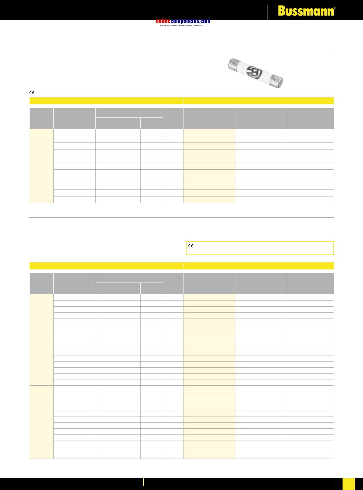
onlinecomponents.com
High Speed Fuses
For more information visit our website at www.bussmann.com 76
Ferrule Style
Data Sheet: 14mm ≈51mm, 720008 & 6mm ≈32mm, 720038
FWX 250V AC/250V DC (250V DC on 5 through 30)
Interrupting Rating: 200kA RMS Symmetrical.
Agency Information: UL Recognized, 250V, Std. 248-13
Watts loss provided at rated current
CE logo denotes compliance with European Union Low Voltage
Directive (50-1000V AC, 75-1500V DC). Refer to Data Sheet: 8002.
*UL Recognized at 500V DC & CSA Component Acceptance
Fuse Block: 1976 - (pole) BIF #1210
Part Number Carton Qty. Carton Weight (Kg)
FWX-1A14F 10 0.225
FWX-2A14F 10 0.225
FWX-3A14F 10 0.225
FWX-4A14F 10 0.225
FWX-5A14F 10 0.225
FWX-10A14F 10 0.225
FWX-15A14F 10 0.225
FWX-20A14F 10 0.225
FWX-25A14F 10 0.225
FWX-30A14F 10 0.225
FWX-50A14F 10 0.225
Electrical Characteristics Ordering Information
I2t (A2SEC)
Rated Current Clearing Watts
Size RMS-Amps Pre-arc at 250V Loss
1———
2———
3———
4———
14 ≈51mm 5 1.6 13 1.3
10 3.6 24 3.4
15 14 83 3.8
20 33 200 4.6
25 58 300 5.3
30 100 500 5.9
50 200 1800 5.7
FWH 500V AC/500V DC
Interrupting Rating: 6 mm ≈32 mm
(Interrupting rating varies—See Data Sheet for details)
14 mm x 51 mm (200kA RMS Symmetrical).
Agency Information: UL Recognized, 500V, Std. 248-13
Watts loss provided at rated current.
Part Number Carton Qty. Carton Weight (Kg)
FWH-.250A6F 10 0.03
FWH-.500A6F 10 0.03
FWH-001A6F 10 0.03
FWH-002A6F 10 0.03
FWH-3.15A6F 10 0.03
FWH-005A6F 10 0.03
FWH-6.30A6F 10 0.03
FWH-007A6F 10 0.03
FWH-010A6F 10 0.03
FWH-12.5A6F 10 0.03
FWH-015A6F 10 0.03
FWH-016A6F 10 0.03
FWH-020A6F 10 0.03
FWH-025A6F 10 0.03
FWH-030A6F 10 0.03
FWH-1A14F ——
FWH-2A14F ——
FWH-3A14F ——
FWH-4A14F ——
FWH-5A14F* 10 0.250
FWH-6A14F* ——
FWH-10A14F* 10 0.250
FWH-12A14F* ——
FWH-15A14F* 10 0.250
FWH-20A14F* 10 0.250
FWH-25A14F* 10 0.250
FWH-30A14F* 10 0.250
Electrical Characteristics Ordering Information
I2t (A2SEC)
Rated Current Clearing Watts
Size RMS-Amps Pre-arc at 500V Loss
0.25 0.01 0.05 2.7
0.5 0.05 0.25 1.2
1 0.4 2 1.7
2 1.3 3.5 3.2
3.15 3.1 7.7 2.9
5 15 40 2.1
6.3 36 90 2.3
6 x32 mm 7 50 125 2.5
(⁄Ω¢∑ ≈ 1⁄Ω¢∑) 10 9.9 139 2.86
12.5 20 60 3.53
15 44 146 3.08
16 48 177 4.48
20 75 259 4.26
25 126 345 —
30 145 430 —
1———
2———
3——2.3
4———
14 ≈51mm 5 1.6 6.4 1.5
(·Ω¡§∑) 6 1.6 6.4 1.5
10 3.6 13 4
12 ———
15 10 40 5.5
20 26 96 6
25 49 191 7
30 58 232 9
BIF document: 720003
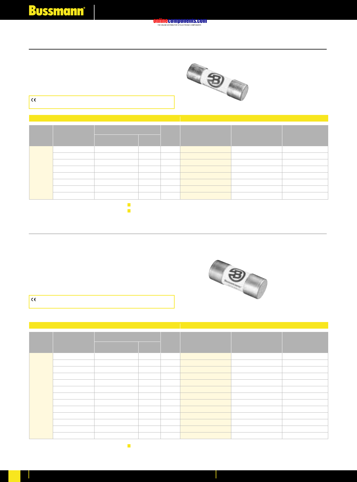
onlinecomponents.com
High Speed Fuses
For more information visit our website at www.bussmann.com
77
BIF document: 720025
Fuse Block: 1976 - (pole) BIF #1210 CSA Component Acceptance 5-30A
Fuse Block: BM Series BIF #1104 600V DC U.L. Recognition: 32A
700V DC U.L. Recognition: 6-25A
FWC 600V AC
Interrupting Rating: 200kA RMS Symmetrical.
Agency Information: UL Recognized, 600V, Std. 248-13
Watts loss provided at rated current.
FWP 700V AC/700V DC; 690V (IEC)/700V (UL)
Interrupting Rating: 200kA RMS Symmetrical.
Agency Information: UL Recognized, 700V, Std. 248-13
(700V DC ratings for 5 through 30 amperes only). Consult
Bussmann for other ratings.
Watts loss provided at rated current.
CE logo denotes compliance with European Union Low Voltage
Directive (50-1000V AC, 75-1500V DC). Refer to BIF document #8002.
CE logo denotes compliance with European Union Low Voltage Directive
(50-1000V AC, 75-1500V DC). Refer to BIF document #8002.
Part Number Carton Qty. Carton Weight (Kg)
FWC-6A10F 10 0.100
FWC-8A10F 10 0.100
FWC-10A10F 10 0.100
FWC-12A10F 10 0.100
FWC-16A10F 10 0.100
FWC-20A10F 10 0.100
FWC-25A10F 10 0.100
FWC-32A10F 10 0.100
Electrical Characteristics Ordering Information
I2t (A2SEC)
Rated Current Clearing Watts
Size RMS-Amps Pre-arc at 600V Loss
6 4 30 1.5
8 6 50 2.0
10 9 70 2.5
10 x 38 mm 12 15 120 3.0
(⁄‹Ω£™∑) 16 25 150 3.5
20 34 260 4.8
25 60 390 6.0
32 95 600 7.5
Part Number Carton Qty. Carton Weight (Kg)
FWP-1A14F 10 0.225
FWP-2A14F 10 0.225
FWP-3A14F 10 0.225
FWP-4A14F 10 0.225
FWP-5A14F 10 0.225
FWP-10A14F 10 0.225
FWP-15A14F 10 0.225
FWP-20A14F 10 0.225
FWP-25A14F 10 0.225
FWP-30A14F 10 0.225
FWP-32A14F 10 0.225
FWP-40A14F 10 0.225
FWP-50A14F 10 0.225
Electrical Characteristics Ordering Information
I2t (A2SEC)
Rated Current Clearing Watts
Size RMS-Amps Pre-arc at 690V Loss
1———
2———
3———
4———
5 1.6 4 1.5
10 3.6 10 4
14 x 51mm 15 10 22 5.5
(·Ω¡§∑) 20 26 60 6
25 44 130 7
30 58 150 9
32 95 800 7.6
40 110 980 8
50 220 1800 9
Ferrule Style
BIF document: 720011
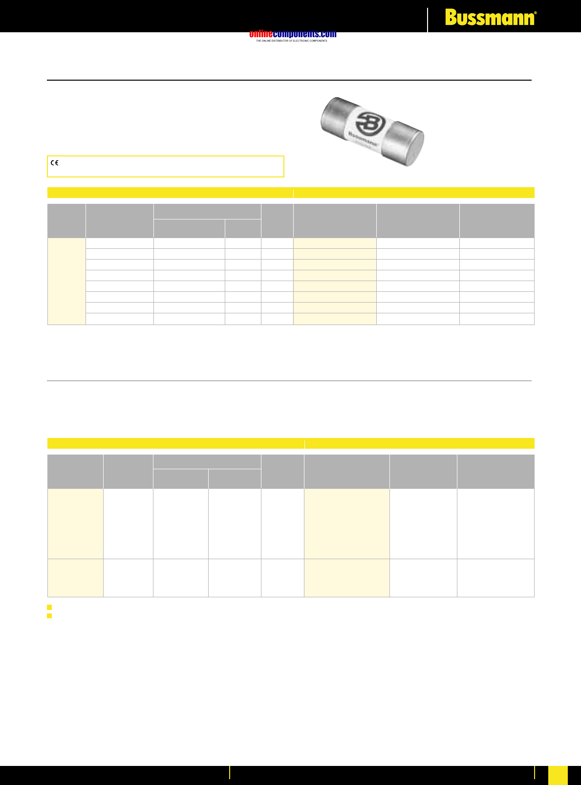
onlinecomponents.com
High Speed Fuses
For more information visit our website at www.bussmann.com 78
FWK 750V 5-60A
FWP 700V AC DC Rating
Interrupting Rating: 200kA RMS Symmetrical.
Agency Information: UL Recognized, 700V, Std. 248-13
Watts loss provided at rated current.
CE logo denotes compliance with European Union Low Voltage
Directive (50-1000V AC, 75-1500V DC). Refer to BIF document #8002.
Ferrule Style
BIF document: 720026
Fuse Block: J70100 - (pole) CR BIF #1211
Part Number Carton Qty. Carton Weight (Kg)
FWP-20A22F 10 0.450
FWP-25A22F 10 0.450
FWP-32A22F 10 0.450
FWP-40A22F 10 0.450
FWP-50A22F 10 0.450
FWP-63A22F 10 0.450
FWP-80A22F 10 0.450
FWP-100A22F 10 0.450
Electrical Characteristics Ordering Information
I2t (A2SEC)
Rated Current Clearing Watts
Size RMS-Amps Pre-arc at 660V Loss
20 34 370 4.6
25 60 560 5.6
32 95 850 7.0
22 ≈58 mm 40 185 1350 8.5
(‡Ω•∑) 50 155 1120 9.5
63 310 2700 11
80 620 5100 13.5
100 1250 10000 16
BIF document: 720039
Electrical Characteristics Ordering Information
Rated I2t (A2S)
Current Clearing Watts
Size RMS-Amps Pre-arc at 750V Loss Part Number Carton Qty. Carton Weight (Kg)
5 8.5 16 — FWK-5A20F
8 50 100 — FWK-8A20F
20 ≈ 127mm 10 95 200 — FWK-10A20F
(⁄‹Ω¡§∑) 15 100 240 — FWK-15A20F 10 0.95
20 125 315 — FWK-20A20F
25 400 1100 — FWK-25A20F
30 800 2600 — FWK-30A20F
35 1300 4300 — FWK-35A25F
25 ≈ 146mm 40 1600 5300 — FWK-40A25F 10 1.65
(1∑) 50 3100 12000 — FWK-50A25F
60 5900 24000 — FWK-60A25F
Interrupting rating 45kA RMS symmetrical.
750 Vdc rating for 5 through 60 amperes (Time constant = 10-15 mS). 1 kg = 2.2 lbs. 1 lb = 0.45 kg
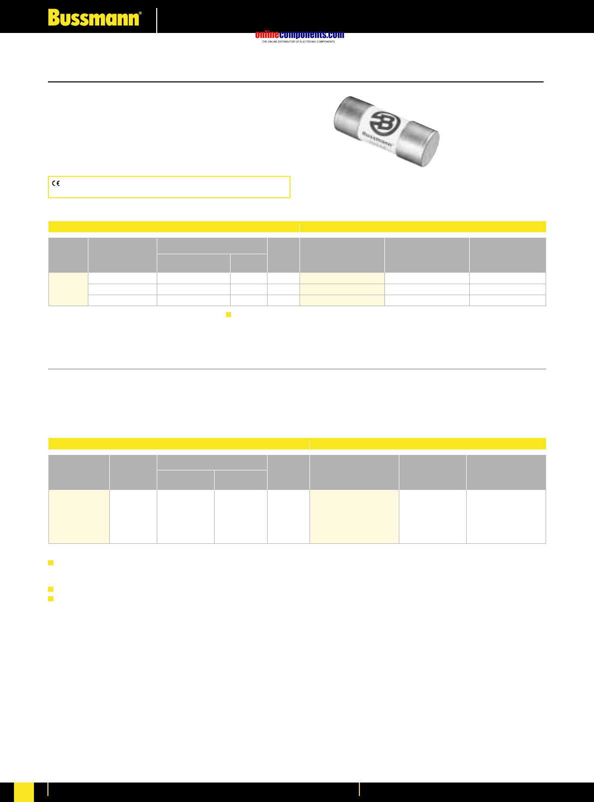
onlinecomponents.com
High Speed Fuses
For more information visit our website at www.bussmann.com
79
FWJ 1000V AC
Interrupting Rating: 25kA RMS Symmetrical.
Agency Information: UL Recognized, 1000V AC/800V DC,
Std. 248-13
Watts loss provided at rated current.
CE logo denotes compliance with European Union Low Voltage
Directive (50-1000V AC, 75-1500V DC). Refer to BIF document #8002.
Part Number Carton Qty. Carton Weight (Kg)
FWJ-20A14F 10 0.300
FWJ-25A14F 10 0.300
FWJ-30A14F 10 0.300
Electrical Characteristics Ordering Information
I2t (A2SEC)
Rated Current Clearing Watts
Size RMS-Amps Pre-arc at 1000V Loss
14 ≈67 mm 20 25 220 9
(·Ω¡§∑) 25 33 350 11
30 52 450 14
BIF document: 720028
FWL/FWS 1250V/1500V/2000V 2-30A
BIF document: 720040
Electrical Characteristics Ordering Information
Rated I2t (A2S)
Current Clearing Watts
Size RMS-Amps Pre-arc at 1000V Loss Part Number Carton Qty. Carton Weight (Kg)
†2 0.8 2.4 4.4 FWS-2A20F
†6 27 81 6.7 FWS-6A20F
20 ≈ 127mm †15 300 700 5 FWS-15A20F 10 1.00
(⁄‹Ω¡§∑) ‡20 675 1550 5.9 FWL-20A20F
‡30 1850 4300 7.5 FWL-30A20F
Interrupting rating 45kA RMS
Symmetrical.
1 kg = 2.2 lbs. 1 lb = 0.45 kg
Rated voltage (IEC) †1500V ‡1250V
1000 Vdc rating
Ferrule Style
800V DC UL Recognition
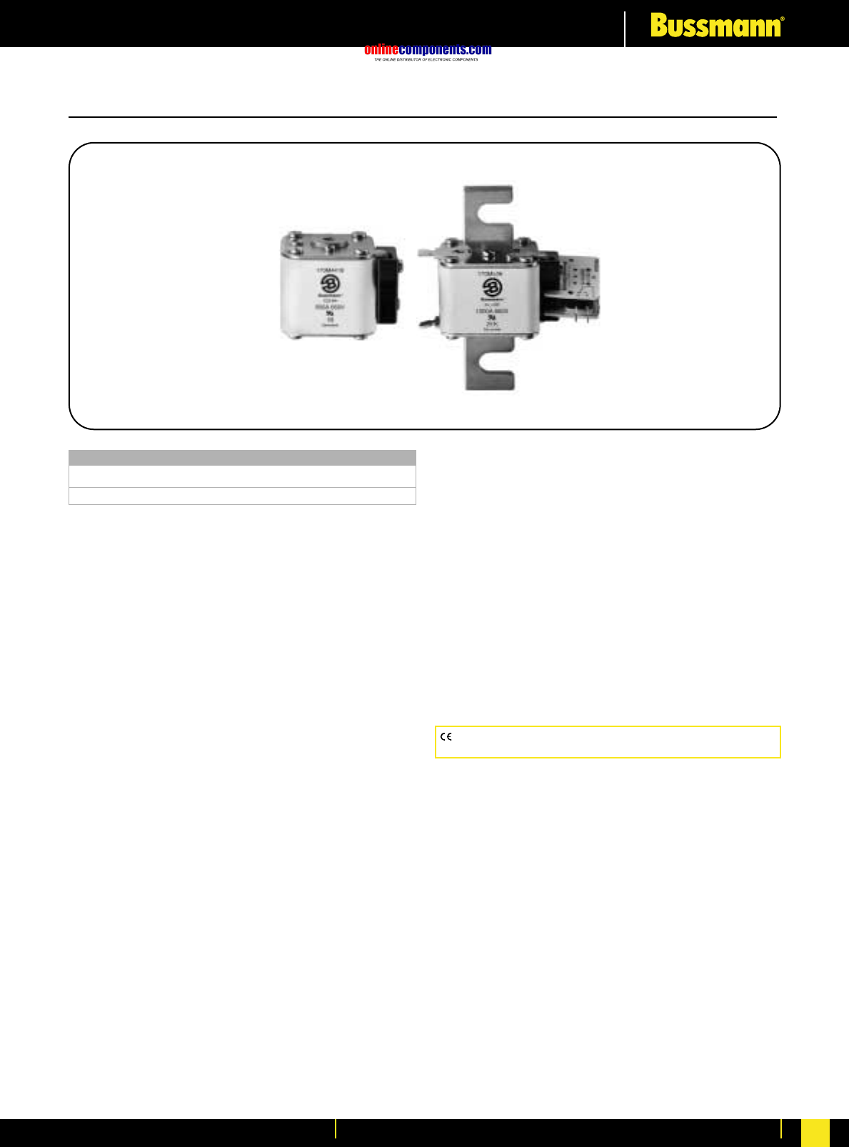
onlinecomponents.com
High Speed Fuses
For more information visit our website at www.bussmann.com 80
CE logo denotes compliance with European Union Low Voltage
Directive (50-1000V AC, 75-1500V DC). Refer to BIF document #8002.
European Style Square Body—General Information
All Bussmann European Style fuses are tested to IEC 60269,
Part 4. This standard requires a test voltage which is 10%
higher than the rated voltage. In North America, fuses are
required to clear only their rated voltage.
Characteristics
Designed and tested to:
•IEC 60269: Part 4
•UL Recognized
•Minimal energy let-thru (I2t)
•Low operating temperature
•Low Watts loss
General Information
Each European Style fuse is available with a number of
different end fittings. Options include:
•DIN 43 653
•North American Slotted Blade
•DIN 43 620
•Flush End (Metric/U.S.)
•French Style
Accessories
European Style fuses are available with three different open
fuse indicator systems. Options include visual indication and
indication utilizing a microswitch. Fuseblocks are also
available for most applications.
Voltage Rating
690 Volt AC 10 to 7500 Amperes
1250 Volt AC 50 to 1400 Amperes
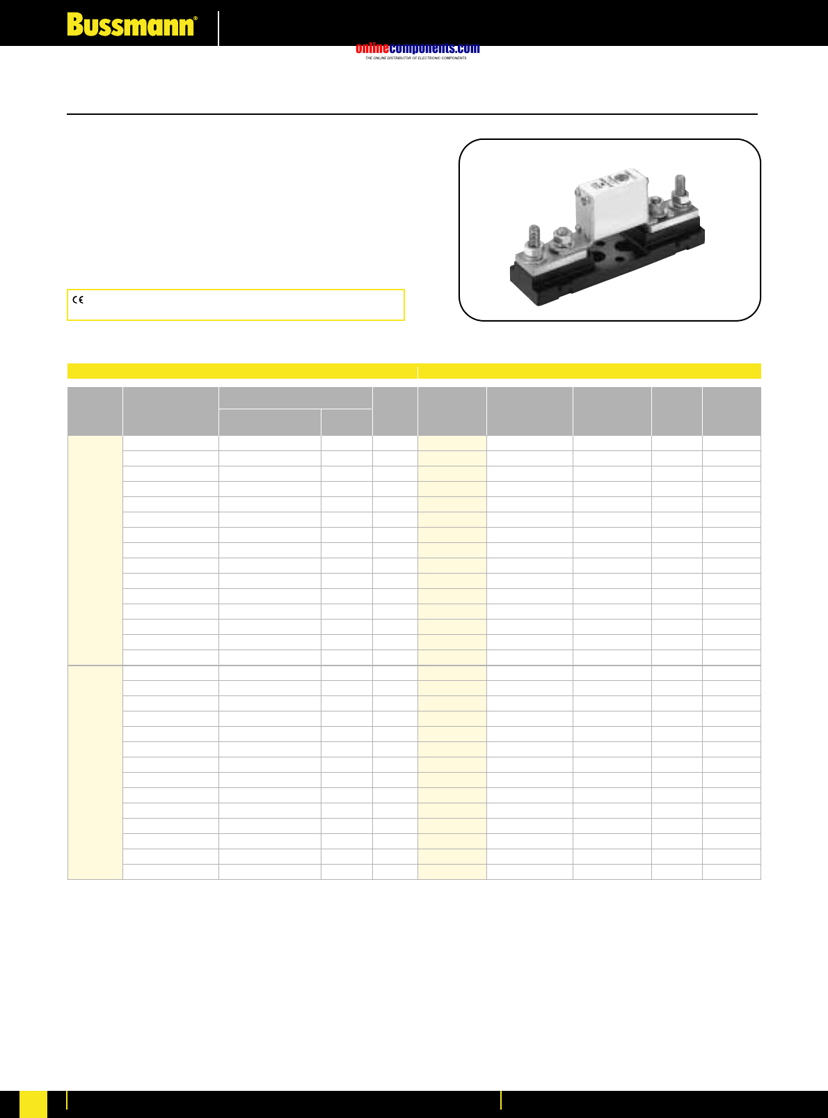
onlinecomponents.com
High Speed Fuses
For more information visit our website at www.bussmann.com
81
European Style Square Body
CE logo denotes compliance with European Union Low Voltage
Directive (50-1000V AC, 75-1500V DC). Refer to BIF document #8002.
DIN 43 653—10-400 Amps.
Voltage Rating: 690V (IEC/UL)
Interrupting Rating: 200kA (estimated 300kA) RMS Symmetrical
Agency Information:
UL Recognized, Std. 248-13
CSA Component Acceptance on Size 000
Watts loss provided at rated current.
Microswitch indicator ordered separately. See bottom of page 100.
Electrical Characteristics Ordering Information
I2t (A2s)
Rated Current Clearing Watts
Size RMS-Amps Pre-arc at 660V Loss
10 3.8 25.5 3.0
16 7.2 48 5.5
20 11.5 78 7
25 19 130 9
32 40 270 10
40 69 460 12
000 50 115 770 15
63 215 1450 16
80 380 2550 19
100 695 4650 24
125 1200 8500 28
160 2300 16000 32
200 4200 28000 37
250 7750 51500 42
315 12000 80500 52
25 19 130 6
32 28.5 195 7
40 50 360 9
50 95 640 10
63 170 1200 12
80 310 2100 15
00 100 620 4150 20
125 1000 6950 25
160 1900 13000 30
200 3400 23000 35
250 6250 42000 45
315 10000 68500 55
350 13500 91500 60
400 18000 125000 70
*UL Recognized on size 000.
-TN/80
-U/80 -/80 Type T Carton
Without Visual Indicator Carton Weight
Indicator Indicator for Micro Qty. (Kg)
170M1308* 170M1358* 170M1408* 10 1.34
170M1309* 170M1359* 170M1409* 10 1.34
170M1310* 170M1360* 170M1410* 10 1.34
170M1311* 170M1361* 170M1411* 10 1.34
170M1312* 170M1362* 170M1412* 10 1.34
170M1313* 170M1363* 170M1413* 10 1.34
170M1314* 170M1364* 170M1414* 10 1.34
170M1315* 170M1365* 170M1415* 10 1.34
170M1316* 170M1366* 170M1416* 10 1.34
170M1317* 170M1367* 170M1417* 10 1.34
170M1318* 170M1368* 170M1418* 10 1.34
170M1319* 170M1369* 170M1419* 10 1.34
170M1320* 170M1370* 170M1420* 10 1.34
170M1321* 170M1371* 170M1421* 10 1.34
170M1322* 170M1372* 170M1422* 10 1.34
—170M2608 170M2658 5 1.05
—170M2609 170M2659 5 1.05
—170M2610 170M2660 5 1.05
—170M2611 170M2661 5 1.05
—170M2612 170M2662 5 1.05
—170M2613 170M2663 5 1.05
—170M2614 170M2664 5 1.05
—170M2615 170M2665 5 1.05
—170M2616 170M2666 5 1.05
—170M2617 170M2667 5 1.05
—170M2618 170M2668 5 1.05
—170M2619 170M2669 5 1.05
—170M2620 170M2670 5 1.05
—170M2621 170M2671 5 1.05
BIF document: 720013
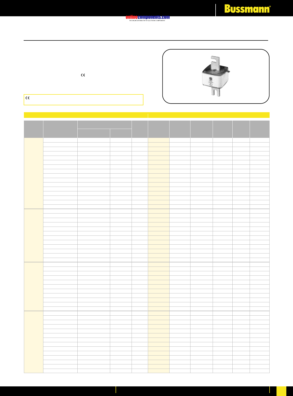
onlinecomponents.com
High Speed Fuses
For more information visit our website at www.bussmann.com 82
CE logo denotes compliance with European Union Low Voltage
Directive (50-1000V AC, 75-1500V DC). Refer to BIF document #8002.
European Style Square Body
DIN 43 653—40-2000 Amps.
Voltage Rating: 690V (IEC) & 700V (UL)
Interrupting Rating: 200kA (estimated 300kA) RMS Symmetrical
Agency Information: CSA Component Acceptance
UL Recognized, Std. 248-13
Watts loss provided at rated current.
Microswitch indicatorordered separately. See bottom of page 100.
Electrical Characteristics Ordering Information
I2t (A2s)
Rated Current Clearing Watts
Size RMS-Amps Pre-arc at 660V Loss
40 40 270 9
50 77 515 11
63 115 770 14
80 185 1250 18
100 360 2450 21
125 550 3700 26
160 1100 7500 30
200 2200 15000 35
1* 250 4200 28500 40
315 7000 46500 50
350 10000 68500 55
400 15000 105000 60
450 21000 140000 65
500 27000 180000 70
550 34000 230000 75
630 48500 325000 80
200 1650 11500 45
250 3100 21000 55
315 6200 42000 58
350 8500 59000 60
400 13500 91500 65
1450 17000 120000 70
500 25000 170000 72
550 34000 230000 75
630 52000 350000 80
700 69500 465000 85
800 105000 725000 95
‡900 155000 ‡850000 100
400 11000 74000 65
450 15500 105000 70
500 21500 145000 75
550 28000 190000 80
630 41000 275000 90
2 700 60500 405000 95
800 86000 575000 105
900 125000 840000 110
1000 180000 1250000 115
1100 245000 1600000 120
1250 365000 2400000 130
500 14000 95000 95
550 19500 135000 100
630 31000 210000 105
700 44500 300000 110
800 69500 465000 115
900 100000 670000 120
31000 140000 945000 125
1100 190000 1300000 130
1250 290000 1950000 140
1400 370000 2450000 155
1500 460000 3100000 160
1600 580000 3900000 160
†1800 880000 †5250000 165
‡2000 1150000 ‡6350000 175
*UL Recognized. Rated voltage †600V ‡550V
*UL Recognized on size 000.
-TN/80 -TN/110
-/80 Type T -/100 Type T Carton
Visual Indicator Visual Indicator Carton Weight
Indicator for Micro Indicator for Micro Qty. (Kg)
170M3008* 170M3058* 170M3158* 170M3208* 5 1.50
170M3009* 170M3059* 170M3159* 170M3209* 5 1.50
170M3010* 170M3060* 170M3160* 170M3210* 5 1.50
170M3011* 170M3061* 170M3161* 170M3211* 5 1.50
170M3012* 170M3062* 170M3162* 170M3212* 5 1.50
170M3013* 170M3063* 170M3163* 170M3213* 5 1.50
170M3014* 170M3064* 170M3164* 170M3214* 5 1.50
170M3015* 170M3065* 170M3165* 170M3215* 5 1.50
170M3016* 170M3066* 170M3166* 170M3216* 5 1.50
170M3017* 170M3067* 170M3167* 170M3217* 5 1.50
170M3018* 170M3068* 170M3168* 170M3218* 5 1.50
170M3019* 170M3069* 170M3169* 170M3219* 5 1.50
170M3020* 170M3070* 170M3170* 170M3220* 5 1.50
170M3021* 170M3071* 170M3171* 170M3221* 5 1.50
170M3022* 170M3072* 170M3172* 170M3222* 5 1.50
170M3023* 170M3073* 170M3173* 170M3223* 5 1.50
170M4008* 170M4058* 170M4158* 170M4208* 3 1.29
170M4009* 170M4059* 170M4159* 170M4209* (-/80) —
170M4010* 170M4060* 170M4160* 170M4210* ——
170M4011* 170M4061* 170M4161* 170M4211* 2 0.94
170M4012* 170M4062* 170M4162* 170M4212* (-/110) —
170M4013* 170M4063* 170M4163* 170M4213* ——
170M4014* 170M4064* 170M4164* 170M4214* ——
170M4015* 170M4065* 170M4165* 170M4215* ——
170M4016* 170M4066* 170M4166* 170M4216* ——
170M4017* 170M4067* 170M4167* 170M4217* ——
170M4018* 170M4068* 170M4168* 170M4218* ——
170M4019 170M4069 170M4169 170M4219 ——
170M5008* 170M5058* 170M5158* 170M5208* 2 1.20
170M5009* 170M5059* 170M5159* 170M5209* 2 1.20
170M5010* 170M5060* 170M5160* 170M5210* 2 1.20
170M5011* 170M5061* 170M5161* 170M5211* 2 1.20
170M5012* 170M5062* 170M5162* 170M5212* 2 1.20
170M5013* 170M5063* 170M5163* 170M5213* 2 1.20
170M5014* 170M5064* 170M5164* 170M5214* 2 1.20
170M5015* 170M5065* 170M5165* 170M5215* 2 1.20
170M5016* 170M5066* 170M5166* 170M5216* 2 1.20
170M5017* 170M5067* 170M5167* 170M5217* 2 1.20
170M5018* 170M5068* 170M5168* 170M5218* 2 1.20
170M6008* 170M6058* 170M6158* 170M6208* 2 1.66
170M6009* 170M6059* 170M6159* 170M6209* (-/80) —
170M6010* 170M6060* 170M6160* 170M6210* ——
170M6011* 170M6061* 170M6161* 170M6211* 1 0.89
170M6012* 170M6062* 170M6162* 170M6212* (-/110) —
170M6013* 170M6063* 170M6163* 170M6213* ——
170M6014* 170M6064* 170M6164* 170M6214* ——
170M6015* 170M6065* 170M6165* 170M6215* ——
170M6016* 170M6066* 170M6166* 170M6216* ——
170M6017* 170M6067* 170M6167* 170M6217* ——
170M6018* 170M6068* 170M6168* 170M6218* ——
170M6019* 170M6069* 170M6169 170M6219 ——
170M6020 170M6070 170M6170 170M6220 ——
170M6021 170M6071 170M6171 170M6221 ——
BIF document: 720014
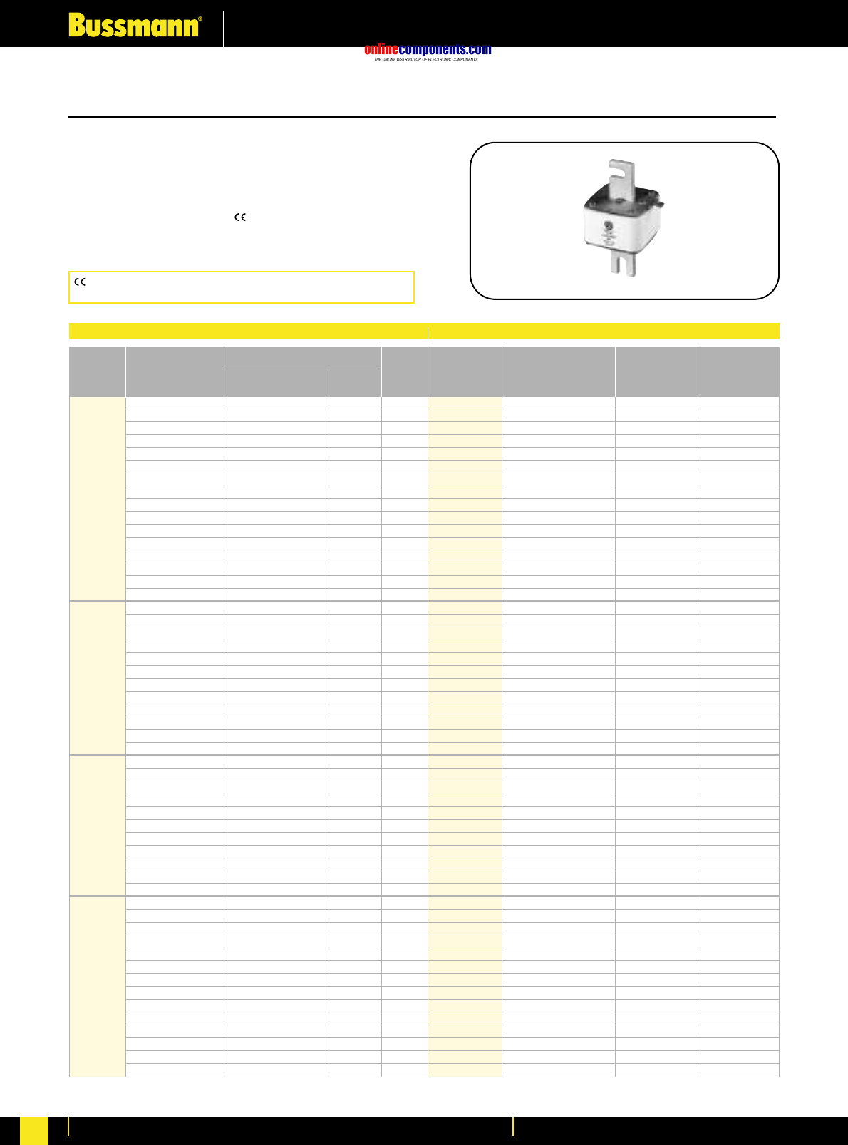
onlinecomponents.com
High Speed Fuses
For more information visit our website at www.bussmann.com
83
European Style Square Body
DIN 43 653—40-2000 Amps.
Voltage Rating: 690V (IEC) & 700V (UL)
Interrupting Rating: 200kA (estimated 300kA) RMS Symmetrical
Agency Information: CSA Component Acceptance
UL Recognized, Std. 248-13
Watts loss provided at rated current.
Microswitch indicator ordered separately. See bottom of page 100.
BIF document: 720015
Electrical Characteristics Ordering Information
I2t (A2s)
Rated Current Clearing Watts
Size RMS-Amps Pre-arc at 660V Loss
40 40 270 9
50 77 515 11
63 115 770 14
80 185 1250 18
100 360 2450 21
125 550 3700 26
160 1100 7500 30
200 2200 15000 35
1* 250 4200 28500 40
315 7000 46500 50
350 10000 68500 55
400 15000 105000 60
450 21000 140000 65
500 27000 180000 70
550 34000 230000 75
630 48500 325000 80
200 1650 11500 45
250 3100 21000 55
315 6200 42000 58
350 8500 59000 60
400 13500 91500 65
450 17000 120000 70
1500 25000 170000 72
550 34000 230000 75
630 52000 350000 80
700 69500 465000 85
800 105000 725000 95
‡900 155000 ‡850000 100
400 11000 74000 65
450 15500 105000 70
500 21500 145000 75
550 28000 190000 80
630 41000 275000 90
2 700 60500 405000 95
800 86000 575000 105
900 125000 840000 110
1000 180000 1250000 115
1100 245000 1600000 120
1250 365000 2400000 130
500 14000 95000 95
550 19500 135000 100
630 31000 210000 105
700 44500 300000 110
800 69500 465000 115
900 100000 670000 120
31000 140000 945000 125
1100 190000 1300000 130
1250 290000 1950000 140
1400 370000 2450000 155
1500 460000 3100000 160
1600 580000 3900000 160
†1800 880000 †5250000 165
‡2000 1150000 ‡6350000 175
*UL Recognized. Rated voltage †600V ‡550V
-KN/80 -KN/110
Type K Type K
Indicator Indicator Carton Carton
for Micro for Micro Qty. Weight (Kg)
170M3108* 170M3258* 5 1.60
170M3109* 170M3259* 5 1.60
170M3110* 170M3260* 5 1.60
170M3111* 170M3261* 5 1.60
170M3112* 170M3262* 5 1.60
170M3113* 170M3263* 5 1.60
170M3114* 170M3264* 5 1.60
170M3115* 170M3265* 5 1.60
170M3116* 170M3266* 5 1.60
170M3117* 170M3267* 5 1.60
170M3118* 170M3268* 5 1.60
170M3119* 170M3269* 5 1.60
170M3120* 170M3270* 5 1.60
170M3121* 170M3271* 5 1.60
170M3122* 170M3272* 5 1.60
170M3123* 170M3273* 5 1.60
170M4108* 170M4258* 3 1.38
170M4109* 170M4259* (-/80) —
170M4110* 170M4260* ——
170M4111* 170M4261* 2 1.00
170M4112* 170M4262* (-/110) —
170M4113* 170M4263* ——
170M4114* 170M4264* ——
170M4115* 170M4265* ——
170M4116* 170M4266* ——
170M4117* 170M4267* ——
170M4118* 170M4268* ——
170M4119 170M4269 ——
170M5108* 170M5258* 2 1.26
170M5109* 170M5259* 2 1.26
170M5110* 170M5260* 2 1.26
170M5111* 170M5261* 2 1.26
170M5112* 170M5262* 2 1.26
170M5113* 170M5263* 2 1.26
170M5114* 170M5264* 2 1.26
170M5115* 170M5265* 2 1.26
170M5116* 170M5266* 2 1.26
170M5117* 170M5267* 2 1.26
170M5118* 170M5268* 2 1.26
170M6108* 170M6258* 1 0.92
170M6109* 170M6259* 1 0.92
170M6110* 170M6260* 1 0.92
170M6111* 170M6261* 1 0.92
170M6112* 170M6262* 1 0.92
170M6113* 170M6263* 1 0.92
170M6114* 170M6264* 1 0.92
170M6115* 170M6265* 1 0.92
170M6116* 170M6266* 1 0.92
170M6117* 170M6267* 1 0.92
170M6118* 170M6268* 1 0.92
170M6119* 170M6269* 1 0.92
170M6120 170M6270 1 0.92
170M6121 170M6271 1 0.92
CE logo denotes compliance with European Union Low Voltage
Directive (50-1000V AC, 75-1500V DC). Refer to BIF document #8002.
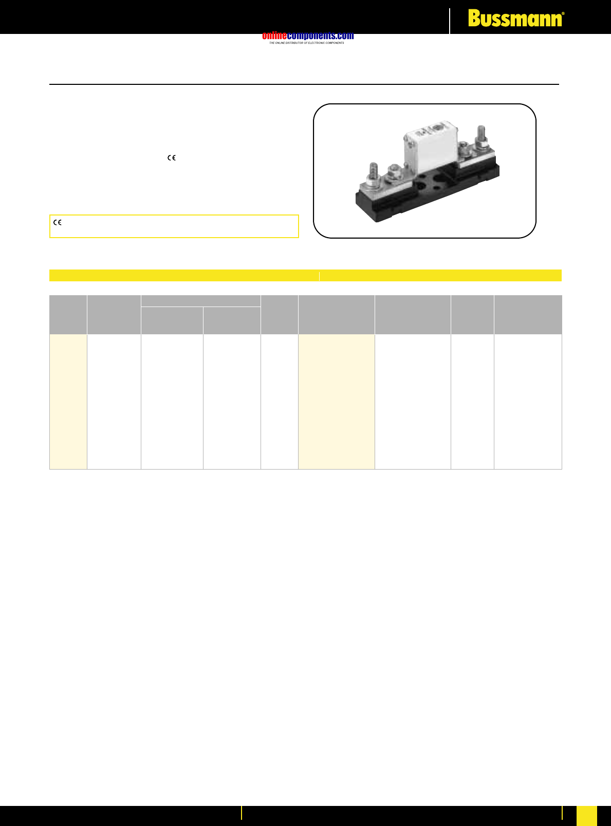
onlinecomponents.com
High Speed Fuses
For more information visit our website at www.bussmann.com 84
DIN 43 653—20-315 Amps.
Voltage Rating: 1000V (IEC)
Interrupting Rating: 150kA RMS Symmetrical
Agency Information: CSA Component Acceptance
UL Recognized, Std. 248-13
Watts loss provided at rated current.
Microswitch indicator ordered separately.
See bottom of page 100.
European Style Square Body
Electrical Characteristics Ordering Information
CE logo denotes compliance with European Union Low Voltage
Directive (50-1000V AC, 75-1500V DC). Refer to BIF document #8002.
Rated
Current
RMS-
Amps Watts
Loss
00/80
Visual
Indicator
00TN/80
Type T
Indicator for
Micro Carton
Qty.
Carton
Weight
(kg)
Pre-arc
Clearing
at Rated
Voltage
I2t (A2s)
Size
20 20 140 5 170M4802 170M4822
25 30 210 7 170M4803 170M4823
32 55 390 9 170M4804 170M4824
35 69 500 10 170M4805 170M4825
40 100 690 11 170M4806 170M4826
50 170 1200 13 170M4807 170M4827
00 63 280 2000 18 170M4808 170M4828 6 1.45
80 500 3500 22 170M4809 170M4829
100 950 6850 25 170M4810 170M4830
125 1500 11500 33 170M4811 170M4831
160 3000 22000 37 170M4812 170M4832
200 5600 40500 40 170M4813 170M4833
250 10000 74000 48 170M4814 170M4834
315 18000 115000 58 170M4815 170M4835
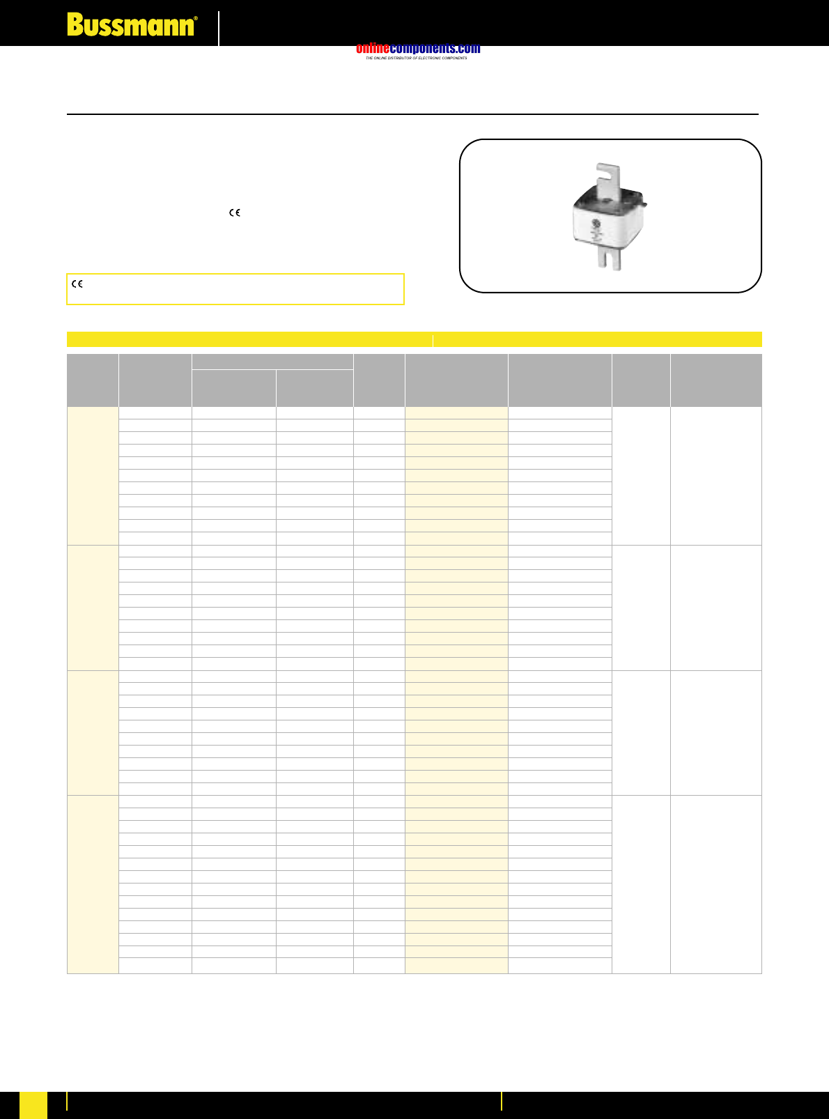
onlinecomponents.com
High Speed Fuses
For more information visit our website at www.bussmann.com
85
European Style Square Body
Electrical Characteristics Ordering Information
DIN 43 653—50-1400 Amps.
Voltage Rating: 1000V (IEC)
Interrupting Rating: 150kA RMS Symmetrical
Agency Information: CSA Component Acceptance
UL Recognized, Std. 248-13
Watts loss provided at rated current.
Microswitch indicator ordered separately. See bottom of page 100.
CE logo denotes compliance with European Union Low Voltage
Directive (50-1000V AC, 75-1500V DC). Refer to BIF document #8002.
Rated
Current
RMS-
Amps Watts
Loss
-KN/110
Type K
Indicator for
Micro
-TN/100
Type T
Indicator for
Micro Carton
Qty.
Carton
Weight
(kg)
Pre-arc
Clearing
at Rated
Voltage
I2t (A2s)
Size 50 135 815 20 170M3965 170M3981
63 215 1300 25 170M3966 170M3982
80 460 2750 30 170M3967 170M3983
100 860 5100 35 170M3968 170M3984
125 1450 8600 40 170M3969 170M3985
1* 160 2850 17500 45 170M3970 170M3986 6 2.7
200 4950 29500 48 170M3971 170M3987
250 9550 57000 50 170M3972 170M3988
315 21500 130000 60 170M3973 170M3989
350 29000 175000 65 170M3974 170M3990
400 42000 250000 70 170M3975 170M3991
160 2200 13500 40 170M4965 170M4980
200 4150 24500 45 170M4966 170M4981
250 7750 46000 52 170M4967 170M4982
315 16500 98500 60 170M4968 170M4983
350 21500 130000 65 170M4969 170M4984
1 400 31000 185000 70 170M4970 170M4985 3 2.1
450 44500 265000 80 170M4971 170M4986
500 63000 375000 85 170M4972 170M4987
550 84500 500000 90 170M4973 170M4988
630 125000 755000 98 170M4974 170M4989
250 6750 40000 65 170M5966 170M5981
315 13500 81500 75 170M5967 170M5982
350 16500 99000 80 170M5968 170M5983
400 26000 155000 85 170M5969 170M5984
2 450 35500 210000 90 170M5970 170M5985 3 2.7
500 49500 295000 95 170M5971 170M5986
550 66000 390000 100 170M5972 170M5987
630 93500 555000 110 170M5973 170M5988
700 130000 770000 115 170M5974 170M5989
800 195000 1200000 125 170M5975 170M5990
315 9200 54500 90 170M8614 170M8629
350 13000 77500 95 170M8615 170M8630
400 19000 115000 105 170M8616 170M8631
450 27000 160000 107 170M8617 170M8632
500 37500 225000 110 170M8618 170M8633
550 52000 310000 115 170M8619 170M8634
3 630 82500 490000 120 170M8620 170M8635 1 1.5
700 115000 700000 125 170M8621 170M8636
800 170000 1050000 135 170M8622 170M8637
900 250000 1500000 145 170M8623 170M8638
1000 340000 2050000 150 170M8624 170M8639
1100 460000 2750000 155 170M8625 170M8640
1250 575000 3400000 175 170M8626 170M8641
1400 795000 4200000 185 170M8627 170M8642
1 kg = 2.2 lbs. 1 lb = 0.45 kg
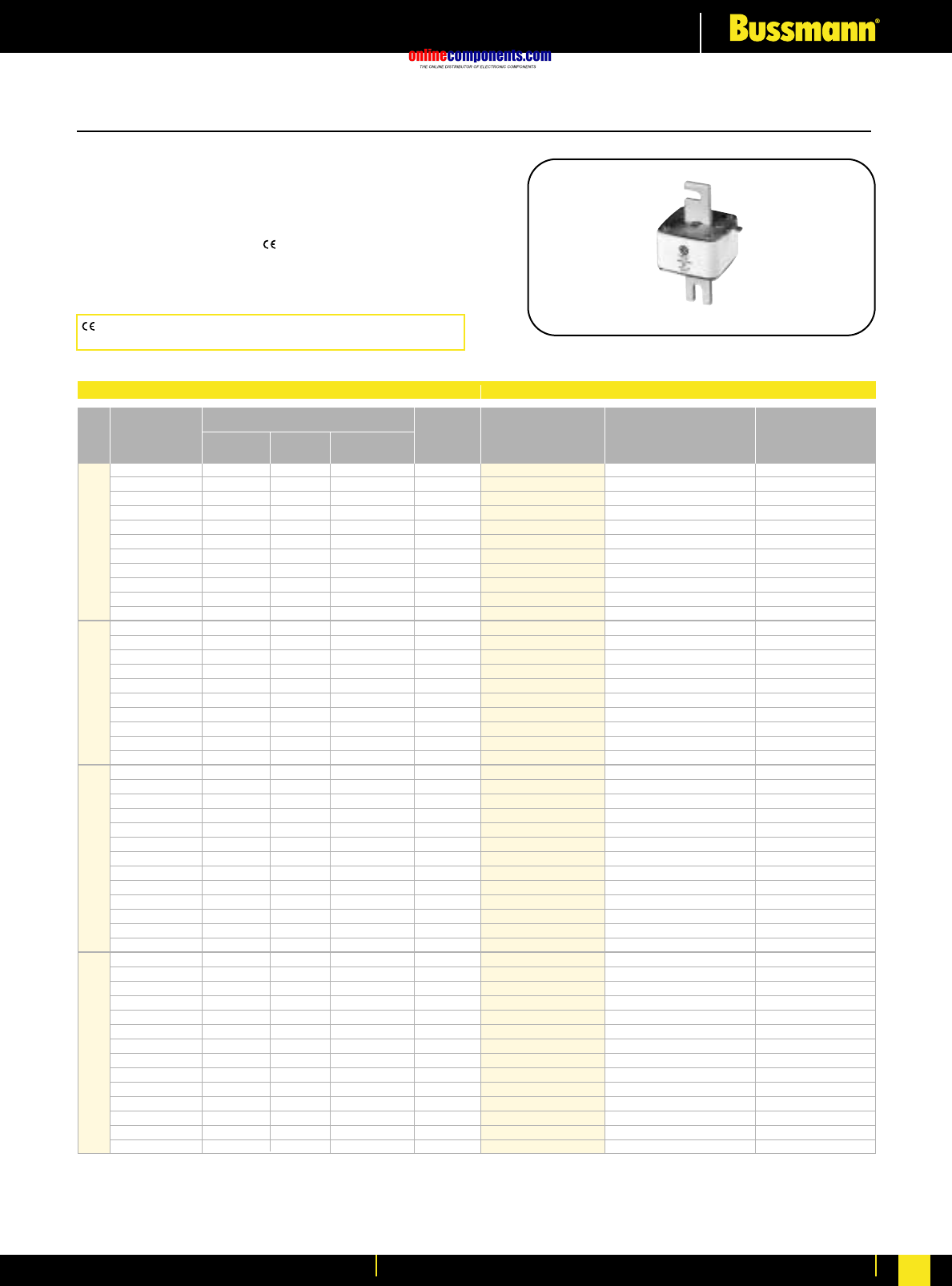
onlinecomponents.com
High Speed Fuses
For more information visit our website at www.bussmann.com 86
European Style Square Body
DIN 43 653—50-1400 Amps.
Voltage Rating: 1250V (IEC)/1300V (UL)
Interrupting Rating: 100kA RMS Symmetrical
Agency Information: CSA Component Acceptance
UL Recognized, Std. 248-13
Watts loss provided at rated current.
Microswitch indicator ordered separately. See bottom of page 100.
Electrical Characteristics Ordering Information
I2t (A2s)
Rated Current Clearing Clearing Watts
Size RMS-Amps Pre-arc at 1000V at 1250V Loss
50 135 815 1100 15
63 215 1300 1750 20
80 420 2500 3350 25
100 750 4450 5950 30
125 1450 9000 11500 35
1* 160 2600 16000 21000 40
200 5150 31000 41000 45
250 9200 54500 73000 55
315 18500 115000 150000 60
350 27000 165000 220000 65
400 53000 265000 335000 70
160 1900 11500 15500 45
200 3800 22500 30000 50
250 7750 46000 61500 60
315 15000 90000 120000 65
1 350 20000 125000 165000 70
400 29500 175000 235000 75
450 42000 250000 335000 80
500 69500 340000 435000 85
550 95000 465000 590000 95
†630 130000 †660000 —100
250 6500 38500 51500 65
280 9350 55500 74500 70
315 13000 77500 105000 75
350 16500 97500 135000 80
400 23000 140000 180000 85
2 450 34000 205000 270000 90
500 48000 285000 380000 95
550 62000 370000 495000 100
630 115000 575000 730000 110
700 160000 795000 1050000 115
800 245000 1200000 1550000 120
†900 360000 †1750000 —125
†1000 480000 †2350000 —135
315 9500 58000 77500 85
350 13500 81500 110000 90
400 19500 120000 160000 95
450 31000 185000 245000 100
500 39000 235000 310000 105
550 55000 325000 435000 110
630 83500 495000 665000 115
3 700 115000 705000 940000 120
800 205000 995000 1300000 125
900 305000 1500000 1900000 130
1000 450000 2150000 2750000 135
1100 575000 2800000 3600000 140
†1250 810000 †3950000 —145
†1400 1250000 †6000000 —150
*UL Recognized. Rated voltage †1100V
-KN/110 Type K Carton Carton
Indicator for Micro Qty. Weight (Kg)
170M3238* 2 0.84
170M3239* 2 0.84
170M3240* 2 0.84
170M3241* 2 0.84
170M3242* 2 0.84
170M3243* 2 0.84
170M3244* 2 0.84
170M3245* 2 0.84
170M3246* 2 0.84
170M3247* 2 0.84
170M3248* 2 0.84
170M4238* 2 1.26
170M4239* 2 1.26
170M4240* 2 1.26
170M4241* 2 1.26
170M4242* 2 1.26
170M4243* 2 1.26
170M4244* 2 1.26
170M4245* 2 1.26
170M4246* 2 1.26
170M4247 2 1.26
170M5238* 2 1.66
170M5239* 2 1.66
170M5240* 2 1.66
170M5241* 2 1.66
170M5242* 2 1.66
170M5243* 2 1.66
170M5244* 2 1.66
170M5245* 2 1.66
170M5246* 2 1.66
170M5247* 2 1.66
170M5248* 2 1.66
170M5249 2 1.66
170M5250 2 1.66
170M6238* 1 1.27
170M6239* 1 1.27
170M6240* 1 1.27
170M6241* 1 1.27
170M6242* 1 1.27
170M6243* 1 1.27
170M6244* 1 1.27
170M6245* 1 1.27
170M6246* 1 1.27
170M6247* 1 1.27
170M6248* 1 1.27
170M6249* 1 1.27
170M6250 1 1.27
170M6251 1 1.27
BIF document: 720030
CE logo denotes compliance with European Union Low Voltage
Directive (50-1000V AC, 75-1500V DC). Refer to BIF document #8002.
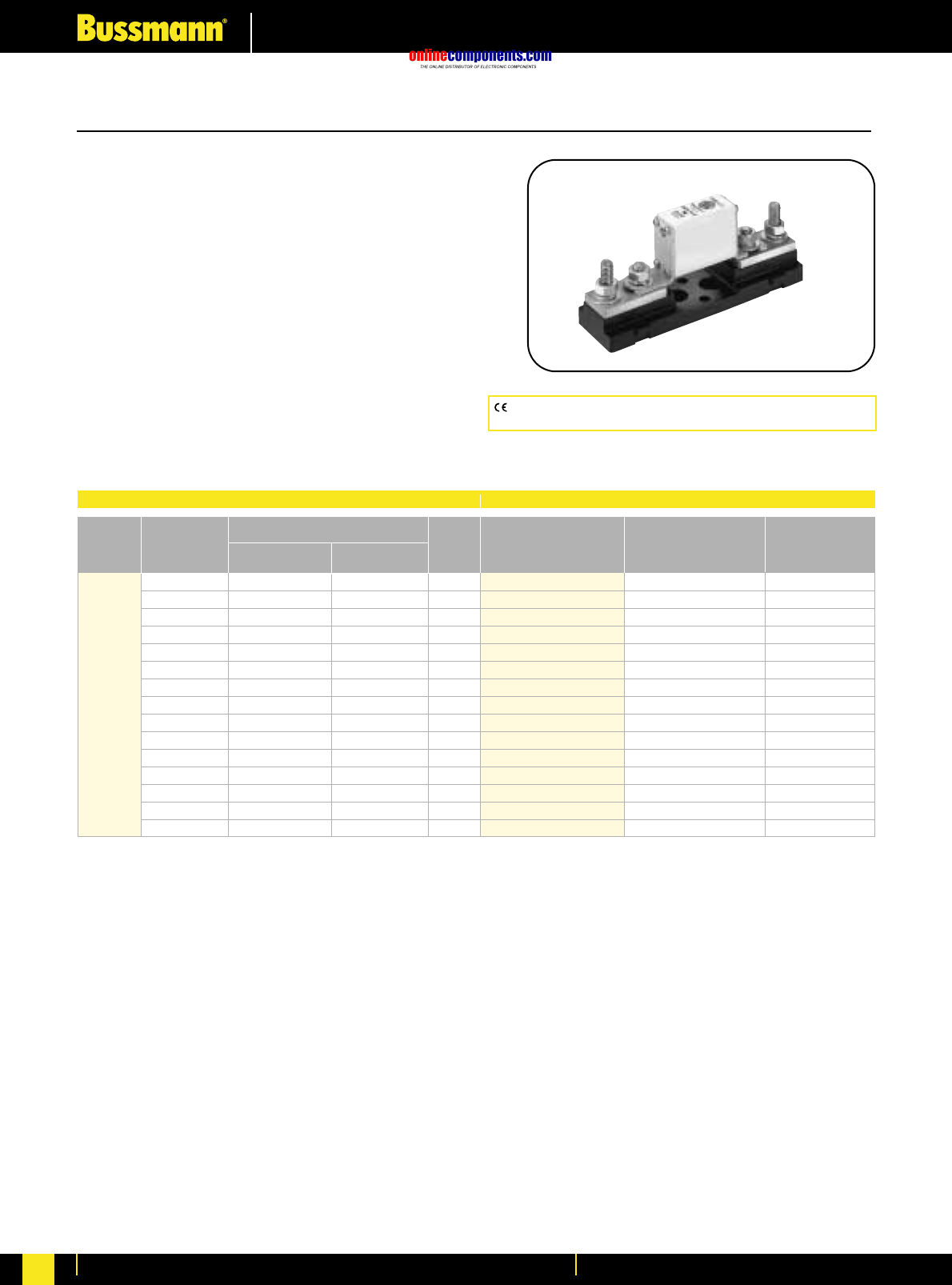
onlinecomponents.com
High Speed Fuses
For more information visit our website at www.bussmann.com
87
CE logo denotes compliance with European Union Low Voltage
Directive (50-1000V AC, 75-1500V DC). Refer to BIF document #8002.
European Style Square Body
DIN 43 620—10-315 Amps.
Voltage Rating: 690V (IEC/UL)
Interrupting Rating: 200kA (estimated 300kA) RMS Symmetrical
Agency Information:
UL Recognized, Std. 248-13
Rated Current: The rated current of this fuse range has
been given with copper conductors that have a current
density of 1.3 A/mm2(IEC 60269-4). For conductor cross
section according to IEC 60269-1, the fuses with a rated
current higher than 125A must be derated. Please contact Bussmann
for application assistance.
Watts loss provided at rated current.
Microswitch indicator ordered separately.
Watts loss provided at rated current.
See bottom of page 100.
Electrical Characteristics Ordering Information
I2t (A2s)
Rated Current Clearing Watts
Size RMS-Amps Pre-arc at 660V Loss
10 3.8 25.5 3.0
16 7.2 48 5.5
20 11.5 78 7
25 19 130 9
32 40 270 10
40 69 460 12
000 50 115 770 15
63 215 1450 16
80 380 2550 19
100 695 4650 24
125 1200 8500 28
160 2300 16000 32
200 4200 28000 37
250 7750 51500 42
315 12000 80500 52
*UL Recognized. Rated voltage †1100V
DIN 000 Type T Carton Weight
Indicator for Micro Qty. (Kg)
170M1558* 10 1.30
170M1559* 10 1.30
170M1560* 10 1.30
170M1561* 10 1.30
170M1562* 10 1.30
170M1563* 10 1.30
170M1564* 10 1.30
170M1565* 10 1.30
170M1566* 10 1.30
170M1567* 10 1.30
170M1568* 10 1.30
170M1569* 10 1.30
170M1570* 10 1.30
170M1571* 10 1.30
170M1572* 10 1.30
BIF document: 720016
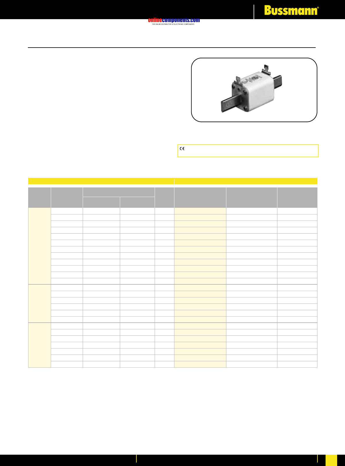
onlinecomponents.com
High Speed Fuses
For more information visit our website at www.bussmann.com 88
CE logo denotes compliance with European Union Low Voltage
Directive (50-1000V AC, 75-1500V DC). Refer to BIF document #8002.
European Style Square Body
DIN 43 620—40-1000 Amps.
Voltage Rating: 690V (IEC)/700V (UL)
Interrupting Rating: 200kA (estimated 300kA) RMS Symmetrical
Agency Information:
UL Recognized, Std. 248-13
Rated Current: The rated current of this fuse range has
been given with copper conductors that have a current
density of 1.3 A/mm2(IEC 60269-4). For conductor cross
section according to IEC 60269-1, the fuses with a rated
current higher than 125A must be derated. Please contact Bussmann
for application assistance.
Watts loss provided at rated current.
Microswitch indicator ordered separately.
See bottom of page 100.
Protection Class gR from 40 - 200Amps
Electrical Characteristics Ordering Information
I2t (A2s)
Rated Current Clearing Watts
Size RMS-Amps Pre-arc at 660V Loss
40 40 270 9
50 77 515 11
63 115 770 14
80 185 1250 18
100 360 2450 21
125 550 3700 26
1* 160 1100 7500 30
200 2200 15000 35
250 4200 28500 40
315 7000 46500 50
350 10000 68500 55
400 15000 105000 60
400 11000 74000 65
450 15500 105000 70
2500 21500 145000 75
550 28000 190000 80
630 41000 275000 90
700 60500 405000 95
500 14000 95000 95
550 19500 135000 100
630 31000 210000 105
3 700 44500 300000 110
800 69500 465000 115
900 100000 670000 120
1000 140000 945000 125
*UL Recognized. Rated voltage †1100V
DIN Type T Carton Carton
Indicator for Micro Qty. Weight (Kg)
170M3808* 5 1.85
170M3809* 5 1.85
170M3810* 5 1.85
170M3811* 5 1.85
170M3812* 5 1.85
170M3813* 5 1.85
170M3814* 5 1.85
170M3815* 5 1.85
170M3816* 5 1.85
170M3817* 5 1.85
170M3818* 5 1.85
170M3819* 5 1.85
170M5808* 5 3.00
170M5809* 5 3.00
170M5810* 5 3.00
170M5811* 5 3.00
170M5812* 5 3.00
170M5813* 5 3.00
170M6808* 1 1.15
170M6809* 1 1.15
170M6810* 1 1.15
170M6811* 1 1.15
170M6812* 1 1.15
170M6813* 1 1.15
170M6813* 1 1.15
BIF document: 720017
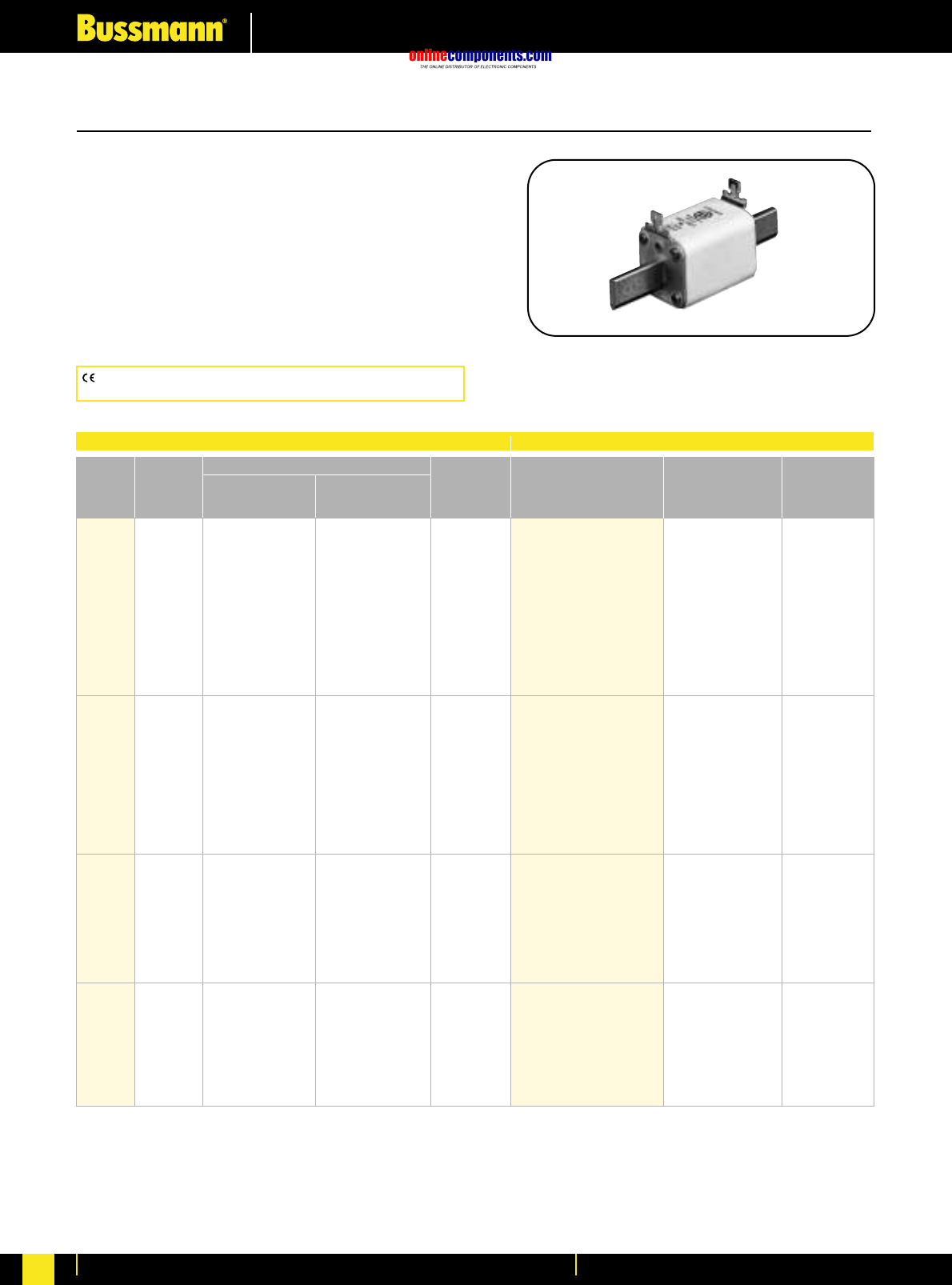
onlinecomponents.com
High Speed Fuses
For more information visit our website at www.bussmann.com
89
European Style Square Body
Rated
Current
RMS-
Amps Watts
Loss
Type T
Indicator for
Micro Carton
Qty.
Carton
Weight
(kg)
Pre-arc Clearing
at 690V
I2t (A2s)
Size
10 3.8 20 3.5 170M2691
16 7.2 38 5.5 170M2692
20 13 70 6 170M2693
25 24 125 8 170M2694
32 53 275 9 170M2695
DIN 00 40 95 490 10 170M2696 6 1.5
50 185 1000 11 170M2697
63 345 1800 14 170M2698
80 695 3600 16 170M2699
100 1250 6650 19 170M2700
125 2300 12000 23 170M2701
160 4350 22500 29 170M2702
50 135 705 12 170M4176
63 245 1300 15 170M4177
80 500 2600 17 170M4178
100 950 4850 20 170M4179
DIN 1 125 1850 9500 23 170M4180 3 2
160 3450 18000 28 170M4181
200 6750 34500 31 170M4182
250 13500 70500 35 170M4183
315 26000 135000 41 170M4184
350 34000 175000 45 170M4185
400 48500 250000 48 170M4186
200 5650 29000 33 170M5881
250 10000 52500 40 170M5882
315 19500 105000 46 170M5883
350 26000 135000 50 170M5884
DIN 2 400 39500 205000 53 170M5885 3 2.3
450 55500 290000 59 170M5886
500 73000 375000 66 170M5887
550 100000 515000 70 170M5888
630 150000 770000 79 170M5889
350 23000 120000 55 170M6080
400 34000 175000 59 170M6081
450 48500 250000 62 170M6082
DIN 3 500 64000 330000 67 170M6083 1 1.2
550 84500 435000 70 170M6084
630 125000 645000 85 170M6085
700 160000 840000 93 170M6086
800 245000 1300000 99 170M6087
Electrical Characteristics Ordering Information
DIN 43 620—10-800 Amps.
Voltage Rating: 690V (IEC)
Interrupting Rating: 200kA (estimated 300kA)
RMS Symmetrical
Agency Information:
UL Recognized, Std. 248-13
Rated Current: Protection Class gR
Watts loss provided at rated current.
Microswitch indicator ordered separately.
See bottom of page 100.
CE logo denotes compliance with European Union Low Voltage
Directive (50-1000V AC, 75-1500V DC). Refer to BIF document #8002.
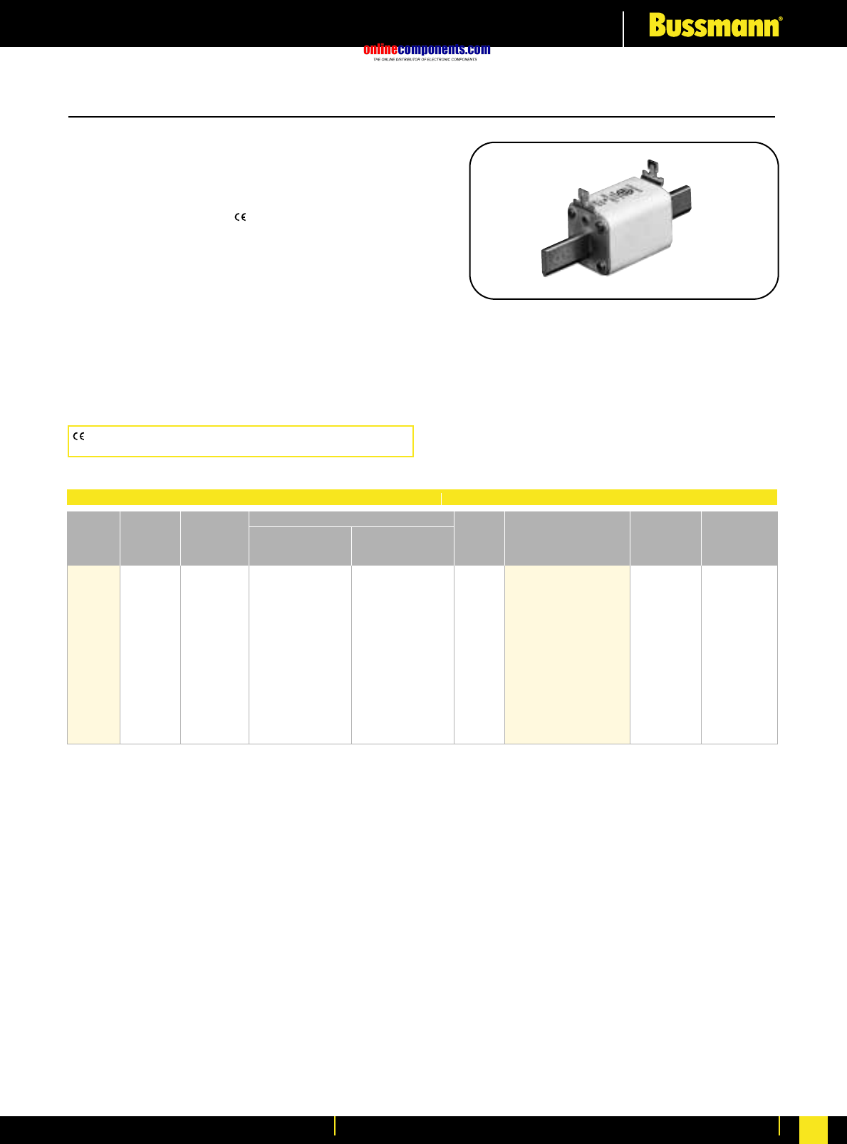
onlinecomponents.com
High Speed Fuses
For more information visit our website at www.bussmann.com 90
DIN 43 620—20-225 Amps.
Voltage Rating: 1000V (IEC)
Interrupting Rating: 300kA RMS Symmetrical
Agency Information:
UL Recognized, Std. 248-13
Rated Current
The rated current of this fuse range is given with open fuse
bases connected to copper conductors according to
IEC 60269 Part 1, table 10.
When used in enclosed fuse bases/disconnects,
derating factors have to be observed.
Please contact Bussmann for application assistance.
Watts loss provided at rated current.
Microswitch indicator ordered separately.
See bottom of page 100.
European Style Square Body
Rated
Votage Watts
Loss
Type T
Indicator for Micro Carton
Qty.
Carton
Weight
(kg)
Rated
Current
RMS-
Amps
Clearing
at Rated
Voltage
Pre-arc
I2t (A2s)
Size
1000 20 15 110 8.5 170M2673
1000 25 28.5 210 9.5 170M2674
1000 32 53 390 11 170M2675
1000 35 69 500 12 170M2676
1000 40 105 760 13 170M2677
1000 50 215 1550 14 170M2678 6 1.3
00 1000 63 380 2750 16 170M2679
1000 80 815 5900 18 170M2680
1000 100 1550 11500 21 170M2681
1000 125 3000 22000 23 170M2682
1000 160 6250 45000 26 170M2683
900 200 12000 86500 31 170M2684
900 225 18000 115000 33 170M2685
1 kg = 2.2 lbs. 1 lb = 0.45 kg
Electrical Characteristics Ordering Information
CE logo denotes compliance with European Union Low Voltage
Directive (50-1000V AC, 75-1500V DC). Refer to BIF document #8002.
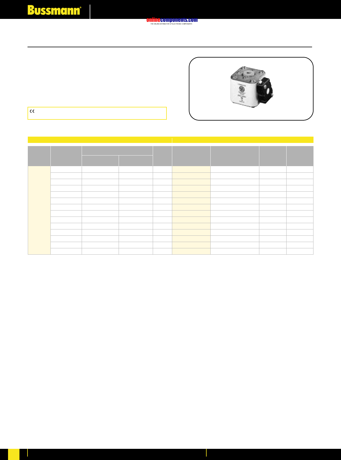
onlinecomponents.com
High Speed Fuses
For more information visit our website at www.bussmann.com
91
Bussmann®
European Style Square Body
Flush End Contact 25-400 Amps.
Voltage Rating: 690V (IEC)
Interrupting Rating: 200kA (estimated 300kA) RMS Symmetrical
Watts loss provided at rated current.
Microswitch indicator ordered separately.
See bottom of page 100.
Electrical Characteristics Ordering Information
I2t (A2s)
Rated Current Clearing Watts
Size RMS-Amps Pre-arc at 660V Loss
25 19 130 6
32 28.5 195 7
40 50 360 9
50 95 640 10
63 170 1200 12
80 310 2100 15
00 100 620 4150 20
125 1000 6950 25
160 1900 13000 30
200 3400 23000 35
250 6250 42000 45
315 10000 68500 55
350 13500 91500 60
400 18000 125000 70
*UL Recognized. Rated voltage †1100V
00BTN/60
00BTN/60 Type T
Visual Indicator for Carton Weight
Indicator Microswitch Qty. (Kg)
170M2708 170M2758 5 1.35
170M2709 170M2759 5 1.35
170M2710 170M2760 5 1.35
170M2711 170M2761 5 1.35
170M2712 170M2762 5 1.35
170M2713 170M2763 5 1.35
170M2714 170M2764 5 1.35
170M2715 170M2765 5 1.35
170M2716 170M2766 5 1.35
170M2717 170M2767 5 1.35
170M2718 170M2768 5 1.35
170M2719 170M2769 5 1.35
170M2720 170M2770 5 1.35
170M2721 170M2771 5 1.35
CE logo denotes compliance with European Union Low Voltage
Directive (50-1000V AC, 75-1500V DC). Refer to BIF document #8002.
BIF document: 720018
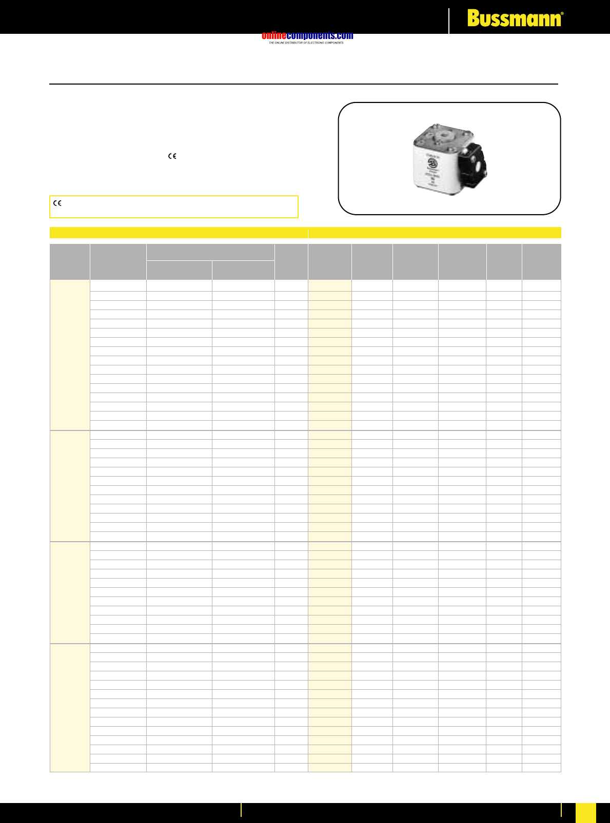
onlinecomponents.com
High Speed Fuses
For more information visit our website at www.bussmann.com 92
European Style Square Body
Flush End Contact 40-2000 Amps.
Voltage Rating: 690V (IEC) 700V (UL)
Interrupting Rating: 200kA (estimated 300kA) RMS Symmetrical
Agency Information: CSA Component Acceptance
UL Recognized, Std. 248-13
Watts loss provided at rated current.
Microswitch indicator ordered separately. See bottom of page 100.
Bussmann®
Electrical Characteristics Ordering Information
I2t (A2s)
Rated Current Clearing Watts
Size RMS-Amps Pre-arc at 660V Loss
40 40 270 9
50 77 515 11
63 115 770 14
80 185 1250 18
100 360 2450 21
125 550 3700 26
160 1100 7500 30
200 2200 15000 35
1* 250 4200 28500 40
315 7000 46500 50
350 10000 68500 55
400 15000 105000 60
450 21000 140000 65
500 27000 180000 70
550 34000 230000 75
630 48500 325000 80
200 1650 11500 45
250 3100 21000 55
315 6200 42000 58
350 8500 59000 60
400 13500 91500 65
450 17000 120000 70
1500 25000 170000 72
550 34000 230000 75
630 52000 350000 80
700 69500 465000 85
800 105000 725000 95
‡900 155000 ‡850000 100
400 11000 74000 65
450 15500 105000 70
500 21500 145000 75
550 28000 190000 80
630 41000 275000 90
2 00 60500 405000 95
800 86000 575000 105
900 125000 840000 110
1000 180000 1250000 115
1100 245000 1600000 120
1250 365000 2400000 130
500 14000 95000 95
550 19500 135000 100
630 31000 210000 105
700 44500 300000 110
800 69500 465000 115
900 100000 670000 120
3 1000 140000 945000 125
1100 190000 1300000 130
1250 290000 1950000 140
1400 370000 2450000 155
1500 460000 3100000 160
1600 580000 3900000 160
†1800 880000 †5250000 165
‡2000 1150000 ‡6350000 175
*UL Recognized.Rated voltage †600V ‡550V
BKN/- -GKN/-
-B/- Type K -G/- Type K Carton
Visual Indicator Visual Indicator Carton Weight
Indicator for Micro Indicator for Micro Qty. (Kg)
170M3408* 170M3458* 170M3508* 170M3558* 10 2.40
170M3409* 170M3459* 170M3509* 170M3559* (-B/-) —
170M3410* 170M3460* 170M3510* 170M3560* ——
170M3411* 170M3461* 170M3511* 170M3561* 10 2.40
170M3412* 170M3462* 170M3512* 170M3562* (-G/-) —
170M3413* 170M3463* 170M3513* 170M3563* ——
170M3414* 170M3464* 170M3514* 170M3564* 6 1.62
170M3415* 170M3465* 170M3515* 170M3565* (-BKN/-) —
170M3416* 170M3466* 170M3516* 170M3566* ——
170M3417* 170M3467* 170M3517* 170M3567* ——
170M3418* 170M3468* 170M3518* 170M3568* 6 1.62
170M3419* 170M3469* 170M3519* 170M3569* (-GKN/-) —
170M3420* 170M3470* 170M3520* 170M3570* ——
170M3421* 170M3471* 170M3521* 170M3571* ——
170M3422* 170M3472* 170M3522* 170M3572* ——
170M3423* 170M3473* 170M3523* 170M3573* ——
170M4408* 170M4458* 170M4508* 170M4558* 6 2.40
170M4409* 170M4459* 170M4509* 170M4559* 6 2.40
170M4410* 170M4460* 170M4510* 170M4560* 6 2.40
170M4411* 170M4461* 170M4511* 170M4561* 6 2.40
170M4412* 170M4462* 170M4512* 170M4562* 6 2.40
170M4413* 170M4463* 170M4513* 170M4563* 6 2.40
170M4414* 170M4464* 170M4514* 170M4564* 6 2.40
170M4415* 170M4465* 170M4515* 170M4565* 6 2.40
170M4416* 170M4466* 170M4516* 170M4566* 6 2.40
170M4417* 170M4467* 170M4517* 170M4567* 6 2.40
170M4418* 170M4468* 170M4518* 170M4568* 6 2.40
170M4419 170M4469 170M4519 170M4569 6 2.40
170M5408* 170M5458* 170M5508* 170M5558* 6 3.30
170M5409* 170M5459* 170M5509* 170M5559* 6 3.30
170M5410* 170M5460* 170M5510* 170M5560* 6 3.30
170M5411* 170M5461* 170M5511* 170M5561* 6 3.30
170M5412* 170M5462* 170M5512* 170M5562* 6 3.30
170M5413* 170M5463* 170M5513* 170M5563* 6 3.30
170M5414* 170M5464* 170M5514* 170M5564* 6 3.30
170M5415* 170M5465* 170M5515* 170M5565* 6 3.30
170M5416* 170M5466* 170M5516* 170M5566* 6 3.30
170M5417* 170M5467* 170M5517* 170M5567* 4 2.40
170M5418* 170M5468* 170M5518* 170M5568* 4 2.40
170M6408* 170M6458* 170M6508* 170M6558* 3 2.52
170M6409* 170M6459* 170M6509* 170M6559* 3 2.52
170M6410* 170M6460* 170M6510* 170M6560* 3 2.52
170M6411* 170M6461* 170M6511* 170M6561* 3 2.52
170M6412* 170M6462* 170M6512* 170M6562* 3 2.52
170M6413* 170M6463* 170M6513* 170M6563* 3 2.52
170M6414* 170M6464* 170M6514* 170M6564* 3 2.52
170M6415* 170M6465* 170M6515* 170M6565* 3 2.52
170M6416* 170M6466* 170M6516* 170M6566* 3 2.52
170M6417* 170M6467* 170M6517* 170M6567* 3 2.52
170M6418* 170M6468* 170M6518* 170M6568* 3 2.52
170M6419* 170M6469* 170M6519* 170M6569* 2 1.82
170M6420 170M6470 170M6520 170M6570 2 1.82
170M6421 170M6471 170M6521 170M6571 2 1.82
BIF document: 720019
CE logo denotes compliance with European Union Low Voltage
Directive (50-1000V AC, 75-1500V DC). Refer to BIF document #8002.
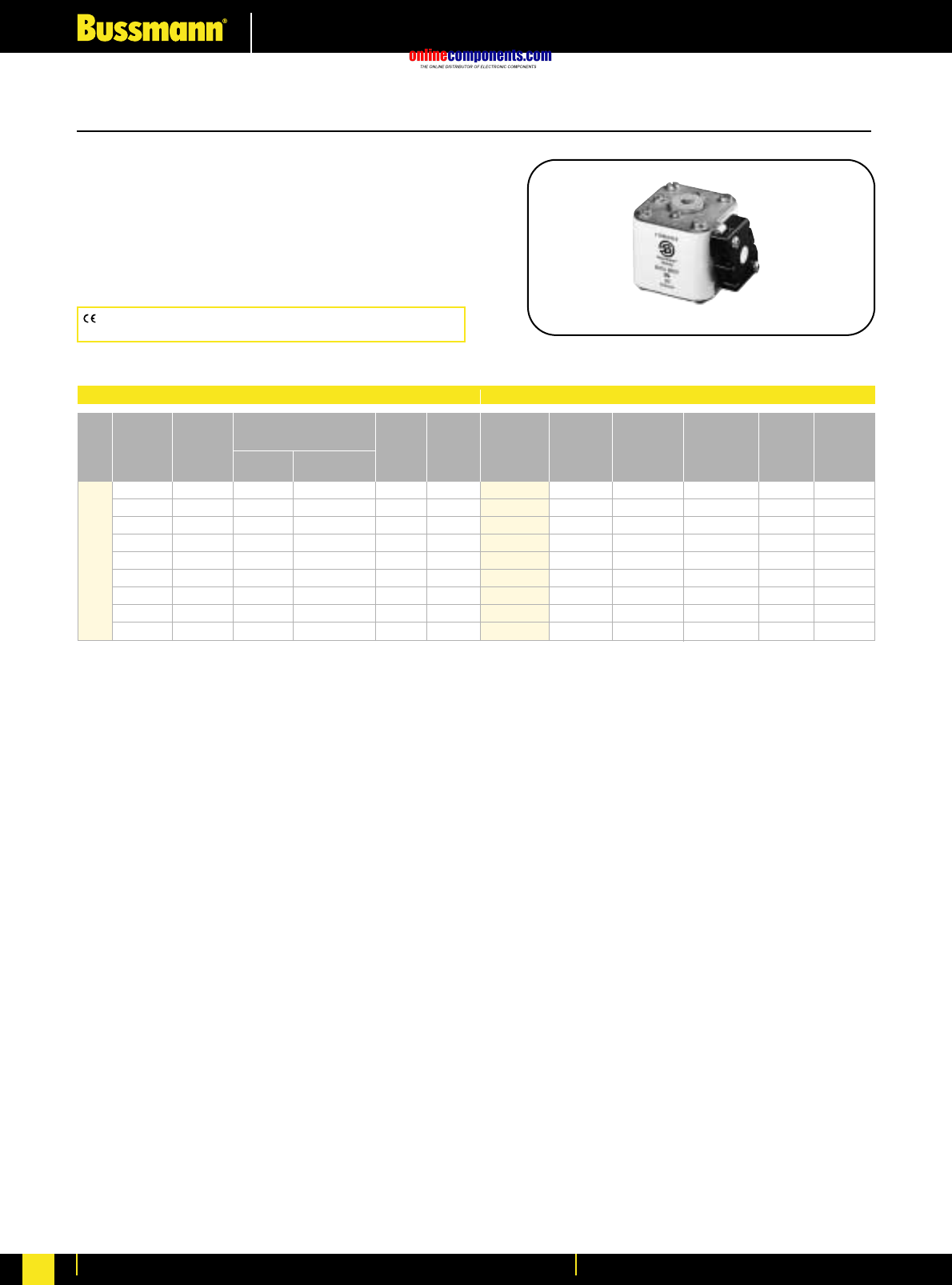
onlinecomponents.com
High Speed Fuses
For more information visit our website at www.bussmann.com
93
European Style Square Body
Flush End Contact —1000-4000 Amps.
Voltage Rating: 690V (IEC)
Interrupting Rating: 200kA (estimated 300kA) RMS Symmetrical
Watts loss provided at rated current.
Microswitch indicator ordered separately.
See bottom of page 100.
CE logo denotes compliance with European Union Low Voltage
Directive (50-1000V AC, 75-1500V DC). Refer to BIF document #8002.
Bussmann®
Electrical Characteristics Ordering Information
Rated Rated
Current Current Watts Watts
RMS- RMS- I2t (A2s) Loss Loss
Norm Liquid Clearing Norm. Liquid
Size Cool. Cool. Pre-arc at 660V Cool. Cool.
1000 1350 76000 505000 175 315
1250 1700 145000 965000 195 355
1400 1900 205000 1400000 205 375
1600 2200 305000 2050000 220 405
4 2000 2700 600000 3950000 245 445
2500 3400 1200000 7800000 275 495
3000 4100 2000000 13500000 305 555
3500 4700 3250000 22000000 325 585
†4000 †5400 4700000 †28000000 355 640
-BKN/- -GKN/-
-B/- Type K -G/- Type K Carton
Visual Indicator Visual Indicator Carton Weight
Indicator for Micro Indicator for Micro Qty. (Kg)
170M7058 170M7078 170M7098 170M7118 2 1.80
170M7059 170M7079 170M7099 170M7119 2 1.80
170M7060 170M7080 170M7100 170M7120 2 1.80
170M7061 170M7081 170M7101 170M7121 2 1.80
170M7062 170M7082 170M7102 170M7122 2 1.80
170M7063 170M7083 170M7103 170M7123 2 1.80
170M7064 170M7084 170M7104 170M7124 2 1.80
170M7065 170M7085 170M7105 170M7125 2 1.80
170M7066 170M7086 170M7106 170M7126 2 1.80
Rated voltage †600V.
Liq. Cool. - Liquid cooling. Temperature on the terminals not to exceed 60°C.
BIF document: 720020
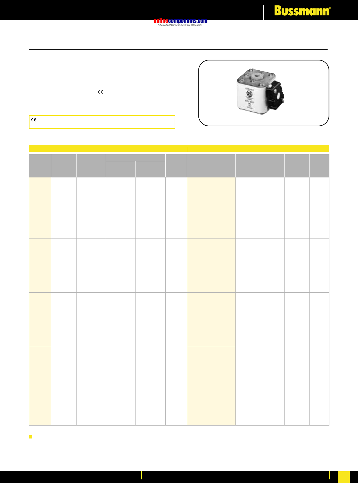
onlinecomponents.com
High Speed Fuses
For more information visit our website at www.bussmann.com 94
Flush End Contact 50-1400 Amps.
Voltage Rating: 1000V (IEC)
Interrupting Rating: 300kA RMS Symmetrical
Agency Information: CSA Component Acceptance
UL Recognized, Std. 248-13
Watts loss provided at rated current.
Microswitch indicator ordered separately. See bottom of page 100.
European Style Square Body
Rated
Current
RMS-
Amps
Rated
Voltage Watts
Loss
-BKN/
Type K
Indicator for
Micro
-GKN/
Type K
Indicator for
Micro Carton
Qty.
Carton
Weight
(kg)
Pre-arc
Clearing
at Rated
Voltage
I2t (A2s)
Size
1000 50 135 815 20 170M3951 170M3921
1000 63 215 1300 25 170M3952 170M3922
1000 80 460 2750 30 170M3953 170M3923
1000 100 860 5100 35 170M3954 170M3924
1000 125 1450 8600 40 170M3955 170M3925
1* 1000 160 2850 17500 45 170M3956 170M3926 6 2.35
1000 200 4950 29500 48 170M3957 170M3927
1000 250 9550 57000 50 170M3958 170M3928
1000 315 21500 130000 60 170M3959 170M3929
1000 350 29000 175000 65 170M3960 170M3930
1000 400 42000 250000 70 170M3961 170M3931
1000 160 2200 13500 40 170M4951 170M4921
1000 200 4150 24500 45 170M4952 170M4922
1000 250 7750 46000 52 170M4953 170M4923
1000 315 16500 98500 60 170M4954 170M4924
1 1000 350 21500 130000 65 170M4955 170M4925 6 3.5
1000 400 31000 185000 70 170M4956 170M4926
1000 450 44500 265000 80 170M4957 170M4927
1000 500 63000 375000 85 170M4958 170M4928
1000 550 84500 500000 90 170M4959 170M4929
1000 630 125000 755000 98 170M4960 170M4930
1000 250 6750 40000 65 170M5952 170M5922
1000 315 13500 81500 75 170M5953 170M5923
1000 350 16500 99000 80 170M5954 170M5924
1000 400 26000 155000 85 170M5955 170M5925
1000 450 35500 210000 90 170M5956 170M5926
2 1000 500 49500 295000 95 170M5957 170M5927 3 2.5
1000 550 66000 390000 100 170M5958 170M5928
1000 630 93500 555000 110 170M5959 170M5929
1000 700 130000 770000 115 170M5960 170M5930
1000 800 195000 1200000 125 170M5961 170M5931
1000 315 9200 54500 90 170M8600 170M8500
1000 350 13000 77500 95 170M8601 170M8501
1000 400 19000 115000 105 170M8602 170M8502
1000 450 27000 160000 107 170M8603 170M8503
1000 500 37500 225000 110 170M8604 170M8504
1000 550 52000 310000 115 170M8605 170M8505
3 1000 630 82500 490000 120 170M8606 170M8506 2 2.5
1000 700 115000 700000 125 170M8607 170M8507
1000 800 170000 1050000 135 170M8608 170M8508
1000 900 250000 1500000 145 170M8609 170M8509
1000 1000 340000 2050000 150 170M8610 170M8510
1000 1100 460000 2750000 155 170M8611 170M8511
1000 1250 575000 3400000 175 170M8612* 170M8512*
900 1400 795000 4200000 185 170M8613* 170M8513* 1 1.5
1 kg = 2.2 lbs. 1 lb = 0.45 kg
*Overall length is 90 mm, for all other fuses the overall length is 75 mm.
Electrical Characteristics Ordering Information
CE logo denotes compliance with European Union Low Voltage
Directive (50-1000V AC, 75-1500V DC). Refer to BIF document #8002.
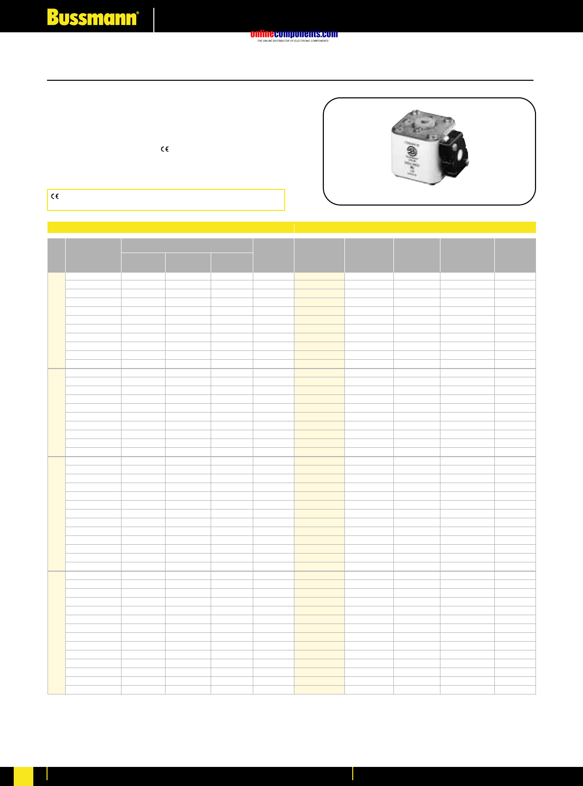
onlinecomponents.com
High Speed Fuses
For more information visit our website at www.bussmann.com
95
European Style Square Body
Flush End Contact—50-1400 Amps.
Voltage Rating: 1250V (IEC) 1300V (UL)
Interrupting Rating: 100kA RMS Symmetrical
Agency Information: CSA Component Acceptance
UL Recognized, Std. 248-13
Watts loss provided at rated current.
Microswitch indicator ordered separately. See bottom of page 100.
Bussmann®
Electrical Characteristics Ordering Information
I2t (A2s)
Rated Current Clearing Clearing Watts
Size RMS-Amps Pre-arc at 1000V at 1250V Loss
50 135 815 1100 15
63 215 1300 1750 20
80 420 2500 3350 25
100 750 4450 5950 30
125 1450 9000 11500 35
1* 160 2600 16000 21000 40
200 5150 31000 41000 45
250 9200 54500 73000 55
315 18500 115000 150000 60
350 27000 165000 220000 65
400 53000 265000 335000 70
160 1900 11500 15500 45
200 3800 22500 30000 50
250 7750 46000 61500 60
315 15000 90000 120000 65
1 350 20000 125000 165000 70
400 29500 175000 235000 75
450 42000 250000 335000 80
500 69500 340000 435000 85
550 95000 465000 590000 95
630 130000 660000 —100
250 6500 38500 51500 65
280 9350 55500 74500 70
315 13000 77500 105000 75
350 16500 97500 135000 80
400 23000 140000 180000 85
2 450 34000 205000 270000 90
500 48000 285000 380000 95
550 62000 370000 495000 100
630 115000 575000 730000 110
700 160000 795000 1050000 115
800 245000 1200000 1550000 120
†900 360000 1750000 —125
†1000 480000 2350000 —135
315 9500 58000 77500 85
350 13500 81500 110000 90
400 19500 120000 160000 95
450 31000 185000 245000 100
500 39000 235000 310000 105
550 55000 325000 435000 110
630 83500 495000 665000 115
3 700 115000 705000 940000 120
800 205000 995000 1300000 125
900 305000 1500000 1900000 130
1000 450000 2150000 2750000 135
1100 575000 2800000 3600000 140
†1250 810000 3950000 —145
†1400 1250000 6000000 —150
*UL Recognized. Rated voltage †1100 ‡1000V
Individual Fuse Weight: Size 1* = 0.380 Kg
Size 1 = 0.580 Kg
Size 2 = 0.900 Kg
Size 3 = 1.250 Kg
*UL Recognized. Rated voltage †600V ‡550V
-BKN/75 -BKN/80 -BKN/90 -GKN/75 -GKN/90
Type K Type K Type K Type K Type K
Indicator Indicator Indicator Indicator Indicator
for Micro for Micro for Micro for Micro for Micro
170M3388* 170M3438* —170M3488* —
170M3389* 170M3439* —170M3489* —
170M3390* 170M3440* —170M3490* —
170M3391* 170M3441* —170M3491* —
170M3392* 170M3442* —170M3492* —
170M3393* 170M3443* —170M3493* —
170M3394* 170M3444* —170M3494* —
170M3395* 170M3445* —170M3495* —
170M3396* 170M3446* —170M3496* —
170M3397* 170M3447* —170M3497* —
—170M3448* ———
170M4388* 170M4438* —170M4488* —
170M4389* 170M4439* —170M4489* —
170M4390* 170M4440* —170M4490* —
170M4391* 170M4441* —170M4491* —
170M4392* 170M4442* —170M4492* —
170M4393* 170M4443* —170M4493* —
170M4394* 170M4444* —170M4494* —
†170M4395 170M4445* —†170M4495 —
‡170M4396 170M4446* —‡170M4496 —
‡170M4397 †170M4447 —‡170M4497 —
170M5388* 170M5438* —170M5588* —
170M5389* 170M5439* —170M5589* —
170M5390* 170M5440* —170M5590* —
170M5391* 170M5441* —170M5591* —
170M5392* 170M5442* —170M5592* —
170M5393* 170M5443* —170M5593* —
170M5394* 170M5444* 170M5494* 170M5594* 170M5644*
170M5395* 170M5445* 170M5495* 170M5595* 170M5645*
†170M5396 170M5446* 170M5496* †170M5596 170M5646*
‡170M5397 †170M5447 170M5497* ‡170M5597 170M5647*
‡170M5398 ‡170M5448 170M5498* ‡170M5598 170M5648*
——170M5499 —170M5649
——170M5500 —170M5650
170M6338* 170M6538* —170M6588* —
170M6339* 170M6539* —170M6589* —
170M6340* 170M6540* —170M6590* —
170M6341* 170M6541* —170M6591* —
170M6342* 170M6542* —170M6592* —
170M6343* 170M6543* —170M6593* —
170M6344* 170M6544* 170M6494* 170M6594* 170M6644*
170M6345* 170M6545* 170M6495* 170M6595* 170M6645*
†170M6346 170M6546* 170M6496* †170M6596 170M6646*
‡170M6347 †170M6547 170M6497* ‡170M6597 170M6647*
‡170M6348 †170M6548 170M6498* ‡170M6598 170M6648*
‡170M6349 ‡170M6549 170M6499* ‡170M6599 170M6649*
——170M6500 —170M6650
——170M6501 —170M6651
1 kg = 2.2 lbs. 1 lb = 0.45 kg
BIF document: 720031
CE logo denotes compliance with European Union Low Voltage
Directive (50-1000V AC, 75-1500V DC). Refer to BIF document #8002.
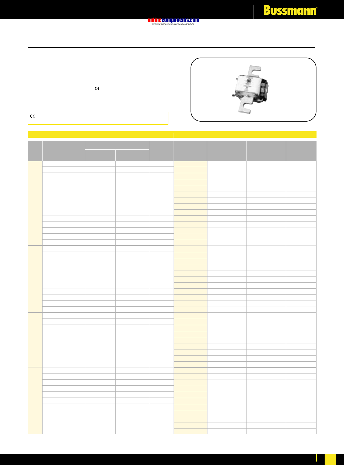
onlinecomponents.com
High Speed Fuses
For more information visit our website at www.bussmann.com 96
European Style Square Body
US Standard—50-1400 Amps.
Voltage Rating: 1000V (IEC)/700V (UL)
Interrupting Rating: 300kA RMS Symmetrical
Agency Information: CSA Component Acceptance
UL Recognized, Std. 248-13
Watts loss provided at rated current.
Microswitch indicator ordered separately. See bottom of page 100.
Bussmann®
Electrical Characteristics Ordering Information
I2t (A2s)
Rated Current Clearing Watts
Size RMS-Amps Pre-arc at 660V Loss
40 40 270 9
50 77 515 11
63 115 770 14
80 185 1250 18
100 360 2450 21
125 550 3700 26
1* 160 1100 7500 30
200 2200 15000 35
250 4200 28500 40
315 7000 46500 50
350 10000 68500 55
400 15000 105000 60
450 21000 140000 65
500 27000 180000 70
200 1650 11500 45
250 3100 21000 55
315 6200 42000 58
350 8500 59000 60
400 13500 91500 65
1 450 17000 120000 70
500 25000 170000 72
550 34000 230000 75
630 52000 350000 80
700 69500 465000 85
800 105000 725000 95
400 11000 74000 65
450 15500 105000 70
500 21500 145000 75
550 28000 190000 80
2 630 41000 275000 90
700 60500 405000 95
800 86000 575000 105
900 125000 840000 110
1000 180000 1250000 115
500 14000 95000 95
550 19500 135000 100
630 31000 210000 105
700 44500 300000 110
800 69500 465000 115
3 900 100000 670000 120
1000 140000 945000 125
1100 190000 1300000 130
1250 290000 1950000 140
1400 370000 2450000 155
1500 460000 3100000 160
*UL Recognized.
-E/ -EKN/
Type T Type K
Indicator Indicator Carton Carton
for Micro for Micro Qty. Weight (Kg)
170M3308* 170M3358* 1 0.300
170M3309* 170M3359* 1 0.300
170M3310* 170M3360* 1 0.300
170M3311* 170M3361* 1 0.300
170M3312* 170M3362* 1 0.300
170M3313* 170M3363* 1 0.300
170M3314* 170M3364* 1 0.300
170M3315* 170M3365* 1 0.300
170M3316* 170M3366* 1 0.300
170M331z7* 170M3367* 1 0.300
170M3318* 170M3368* 1 0.300
170M3319* 170M3369* 1 0.300
170M3320* 170M3370* 1 0.300
170M3321* 170M3371* 1 0.300
170M4308* 170M4358* 1 0.470
170M4309* 170M4359* 1 0.470
170M4310* 170M4360* 1 0.470
170M4311* 170M4361* 1 0.470
170M4312* 170M4362* 1 0.470
170M4313* 170M4363* 1 0.470
170M4314* 170M4364* 1 0.470
170M4315* 170M4365* 1 0.470
170M4316* 170M4366* 1 0.470
170M4317* 170M4367* 1 0.470
170M4318* 170M4368* 1 0.470
170M5308* 170M5358* 1 0.620
170M5309* 170M5359* 1 0.620
170M5310* 170M5360* 1 0.620
170M5311* 170M5361* 1 0.620
170M5312* 170M5362* 1 0.620
170M5313* 170M5363* 1 0.620
170M5314* 170M5364* 1 0.620
170M5315* 170M5365* 1 0.620
170M5316* 170M5366* 1 0.620
170M6308* 170M6358* 1 0.930
170M6309* 170M6359* 1 0.930
170M6310* 170M6360* 1 0.930
170M6311* 170M6361* 1 0.930
170M6312* 170M6362* 1 0.930
170M6313* 170M6363* 1 0.930
170M6314* 170M6364* 1 0.930
170M6315* 170M6365* 1 0.930
170M6316* 170M6366* 1 0.930
170M6317* 170M6367* 1 0.930
170M6318* 170M6368* 1 0.930
BIF document: 720022
CE logo denotes compliance with European Union Low Voltage
Directive (50-1000V AC, 75-1500V DC). Refer to BIF document #8002.
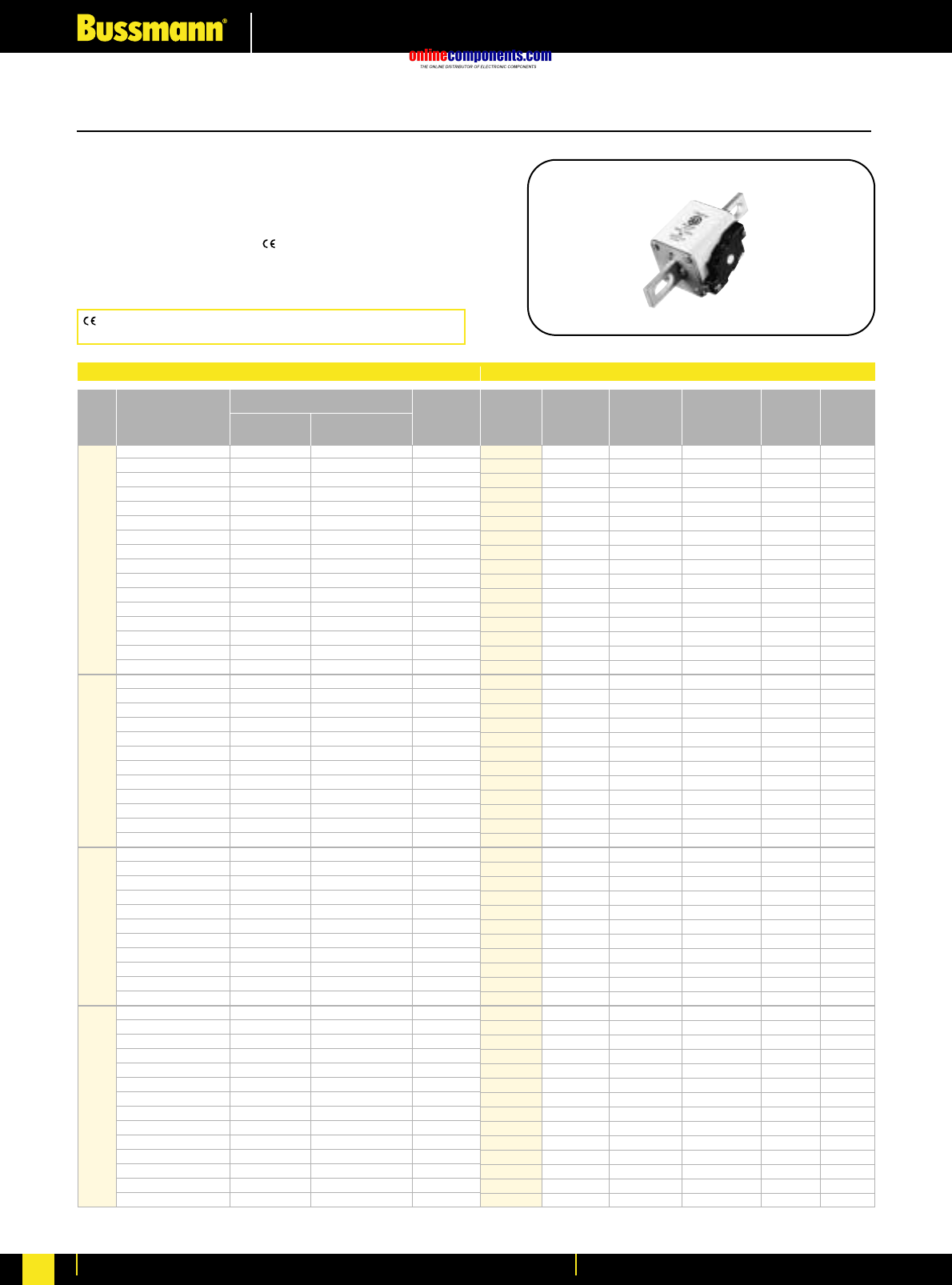
onlinecomponents.com
High Speed Fuses
For more information visit our website at www.bussmann.com
97
European Style Square Body
US Standard—40-2000 Amps.
Voltage Rating: 690V (IEC), 700V (UL)
Interrupting Rating: 200kA (estimated 300kA) RMS Symmetrical
Agency Information: CSA Component Acceptance
UL Recognized, Std. 248-13
Watts loss provided at rated current.
Microswitch indicator ordered separately. See bottom of page 100.
Bussmann®
Electrical Characteristics Ordering Information
I2t (A2s)
Rated Current Clearing Watts
Size RMS-Amps Pre-arc at 660V Loss
40 40 270 9
50 77 515 11
63 115 770 14
80 185 1250 18
100 360 2450 21
125 550 3700 26
160 1100 7500 30
200 2200 15000 35
1* 250 4200 28500 40
315 7000 46500 50
350 10000 68500 55
400 15000 105000 60
450 21000 140000 65
500 27000 180000 70
550 34000 230000 75
630 48500 325000 80
200 1650 11500 45
250 3100 21000 55
315 6200 42000 58
350 8500 59000 60
400 13500 91500 65
1450 17000 120000 70
500 25000 170000 72
550 34000 230000 75
630 52000 350000 80
700 69500 465000 85
800 105000 725000 95
‡900 155000 ‡850000 100
400 11000 74000 65
450 15500 105000 70
500 21500 145000 75
550 28000 190000 80
630 41000 275000 90
2 700 60500 405000 95
800 86000 575000 105
900 125000 840000 110
1000 180000 1250000 115
1100 245000 1600000 120
1250 365000 2400000 130
500 14000 95000 95
550 19500 135000 100
630 31000 210000 105
700 44500 300000 110
800 69500 465000 115
900 100000 670000 120
1000 140000 945000 125
31100 190000 1300000 130
1250 290000 1950000 140
1400 370000 2450000 155
1500 460000 3100000 160
1600 580000 3900000 160
†1800 880000 †5250000 165
‡2000 1150000 ‡6350000 175
*UL Recognized. Rated voltage †600V ‡550V
-FKE/- -FKE/115
-FU/- Type K -FU/115 Type K Carton
Without Indicator Without Indicator Carton Weight
Indicator for Micro Indicator for Micro Qty. (Kg)
170M3608* 170M3658* 170M3708* 170M3758* 1 0.340
170M3609* 170M3659* 170M3709* 170M3759* 1 0.340
170M3610* 170M3660* 170M3710* 170M3760* 1 0.340
170M3611* 170M3661* 170M3711* 170M3761* 1 0.340
170M3612* 170M3662* 170M3712* 170M3762* 1 0.340
170M3613* 170M3663* 170M3713* 170M3763* 1 0.340
170M3614* 170M3664* 170M3714* 170M3764* 1 0.340
170M3615* 170M3665* 170M3715* 170M3765* 1 0.340
170M3616* 170M3666* 170M3716* 170M3766* 1 0.340
170M3617* 170M3667* 170M3717* 170M3767* 1 0.340
170M3618* 170M3668* 170M3718* 170M3768* 1 0.340
170M3619* 170M3669* 170M3719* 170M3769* 1 0.340
170M3620* 170M3670* 170M3720* 170M3770* 1 0.340
170M3621* 170M3671* 170M3721* 170M3771* 1 0.340
170M3622* 170M3672* 170M3722* 170M3772* 1 0.340
170M3623* 170M3673* 170M3723* 170M3773* 1 0.340
170M4608* 170M4658* 170M4708* 170M4758* 1 0.500
170M4609* 170M4659* 170M4709* 170M4759* 1 0.500
170M4610* 170M4660* 170M4710* 170M4760* 1 0.500
170M4611* 170M4661* 170M4711* 170M4761* 1 0.500
170M4612* 170M4662* 170M4712* 170M4762* 1 0.500
170M4613* 170M4663* 170M4713* 170M4763* 1 0.500
170M4614* 170M4664* 170M4714* 170M4764* 1 0.500
170M4615* 170M4665* 170M4715* 170M4765* 1 0.500
170M4616* 170M4666* 170M4716* 170M4766* 1 0.500
170M4617* 170M4667* 170M4717* 170M4767* 1 0.500
170M4618* 170M4668* 170M4718* 170M4768* 1 0.500
170M4619 170M4669 170M4719 170M4769 1 0.500
170M5608* 170M5658* 170M5708* 170M5758* 1 0.630
170M5609* 170M5659* 170M5709* 170M5759* 1 0.630
170M5610* 170M5660* 170M5710* 170M5760* 1 0.630
170M5611* 170M5661* 170M5711* 170M5761* 1 0.630
170M5612* 170M5662* 170M5712* 170M5762* 1 0.630
170M5613* 170M5663* 170M5713* 170M5763* 1 0.630
170M5614* 170M5664* 170M5714* 170M5764* 1 0.630
170M5615* 170M5665* 170M5715* 170M5765* 1 0.630
170M5616* 170M5666* 170M5716* 170M5766* 1 0.630
170M5617* 170M5667* 170M5717* 170M5767* 1 0.630
170M5618* 170M5668* 170M5718* 170M5768* 1 0.630
170M6608* 170M6658* 170M6708* 170M6758* 1 0.950
170M6609* 170M6659* 170M6709* 170M6759* 1 0.950
170M6610* 170M6660* 170M6710* 170M6760* 1 0.950
170M6611* 170M6661* 170M6711* 170M6761* 1 0.950
170M6612* 170M6662* 170M6712* 170M6762* 1 0.950
170M6613* 170M6663* 170M6713* 170M6763* 1 0.950
170M6614* 170M6664* 170M6714* 170M6764* 1 0.950
170M6615* 170M6665* 170M6715* 170M6765* 1 0.950
170M6616* 170M6666* 170M6716* 170M6766* 1 0.950
170M6617* 170M6667* 170M6717* 170M6767* 1 0.950
170M6618* 170M6668* 170M6718* 170M6768* 1 0.950
170M6619* 170M6669* 170M6719* 170M6769* 1 0.950
170M6620 170M6670 170M6720 170M6770 1 0.950
170M6621 170M6671 170M6721 170M6771 1 0.950
BIF document: 720023
CE logo denotes compliance with European Union Low Voltage
Directive (50-1000V AC, 75-1500V DC). Refer to BIF document #8002.
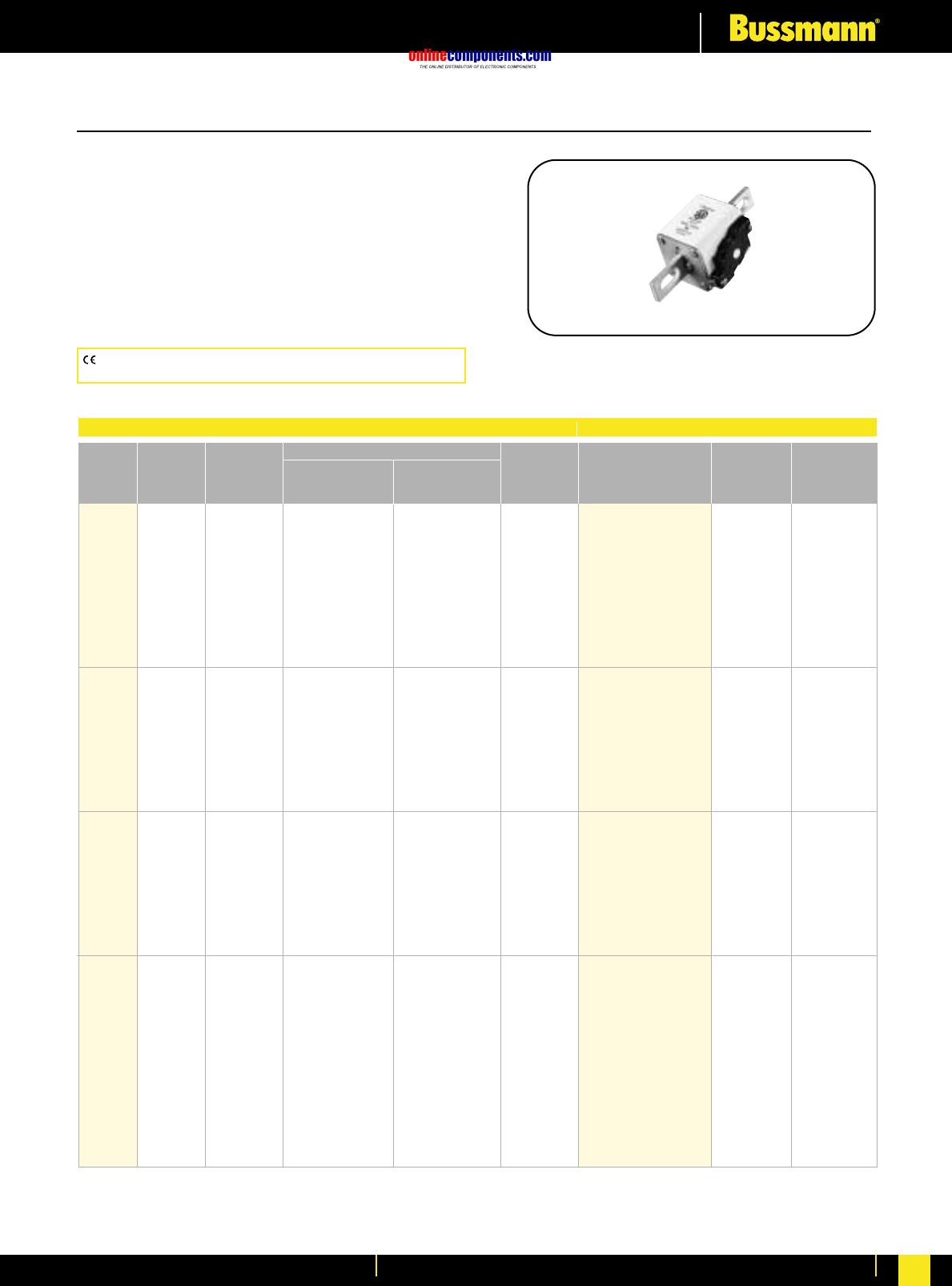
onlinecomponents.com
High Speed Fuses
For more information visit our website at www.bussmann.com 98
European Style Square Body
French Standard—40-1500 Amps.
Voltage Rating: 690V (IEC)
Interrupting Rating: 200kA (estimated 300kA) RMS
Symmetrical
Agency Information: CSA Component Acceptance
UL Recognized, Std. 248-13
Watts loss provided at rated current.
Microswitch indicator ordered separately.
See bottom of page 100.
Rated
Votage Watts
Loss
-FKE/115
Type T
Indicator for Micro Carton
Qty.
Carton
Weight
(kg)
Rated
Current
RMS-
Amps
Clearing
at Rated
Voltage
Pre-arc
I2t (A2s)
Size
1000 50 135 815 20 170M3531
1000 63 215 1300 25 170M3532
1000 80 460 2750 30 170M3533
1000 100 860 5100 35 170M3534
1000 125 1450 8600 40 170M3535
1* 1000 160 2850 17500 45 170M3536 2 0.85
1000 200 4950 29500 48 170M3537
1000 250 9550 57000 50 170M3538
1000 315 21500 130000 60 170M3539
1000 350 29000 175000 65 170M3540
1000 400 42000 250000 70 170M3541
1000 160 2200 13500 40 170M4531
1000 200 4150 24500 45 170M4532
1000 250 7750 46000 52 170M4533
1000 315 16500 98500 60 170M4534
1 1000 350 21500 130000 65 170M4535 2 1.4
1000 400 31000 185000 70 170M4536
1000 450 44500 265000 80 170M4537
1000 500 63000 375000 85 170M4538
1000 550 84500 500000 90 170M4539
1000 630 125000 755000 98 170M4540
1000 250 6750 40000 65 170M5531
1000 315 13500 81500 75 170M5532
1000 350 16500 99000 80 170M5533
1000 400 26000 155000 85 170M5534
2 1000 450 35500 210000 90 170M5535 2 1.5
1000 500 49500 295000 95 170M5536
1000 550 66000 390000 100 170M5537
1000 630 93500 555000 110 170M5538
1000 700 130000 770000 115 170M5539
1000 800 195000 1200000 125 170M5540
1000 315 9200 54500 90 170M8531
1000 350 13000 77500 95 170M8532
1000 400 19000 115000 105 170M8533
1000 450 27000 160000 107 170M8534
1000 500 37500 225000 110 170M8535
1000 550 52000 310000 115 170M8536
3 1000 630 82500 490000 120 170M8537 1 1.25
1000 700 115000 700000 125 170M8538
1000 800 170000 1050000 135 170M8539
1000 900 250000 1500000 145 170M8540
1000 1000 340000 2050000 150 170M8541
1000 1100 460000 2750000 155 170M8542
1000 1250 575000 3400000 175 170M8543
900 1400 795000 4200000 185 170M8544
1 kg = 2.2 lbs. 1 lb = 0.45 kg
Electrical Characteristics Ordering Information
CE logo denotes compliance with European Union Low Voltage
Directive (50-1000V AC, 75-1500V DC). Refer to BIF document #8002.
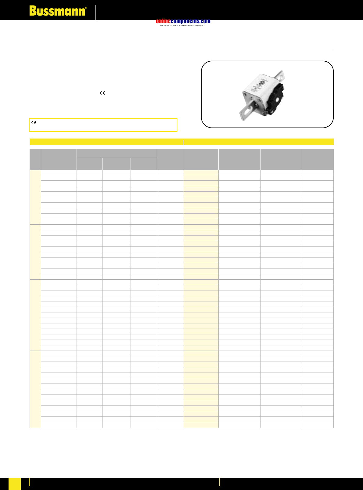
onlinecomponents.com
High Speed Fuses
For more information visit our website at www.bussmann.com
99
European Style Square Body
US Standard—50-1400 Amps.
Voltage Rating: 1250V (IEC), 1300V (UL)
Interrupting Rating: 100kA RMS Symmetrical
Agency Information: CSA Component Acceptance
UL Recognized, Std. 248-13
Watts loss provided at rated current.
Microswitch indicator ordered separately. See bottom of page 100.
Bussmann®
Electrical Characteristics Ordering Information
I2t (A2s)
Rated Current Clearing Clearing Watts
Size RMS-Amps Pre-arc at 1000V at 1250V Loss
50 135 815 1100 15
63 215 1300 1750 20
80 420 2500 3350 25
100 750 4450 5950 30
125 1450 9000 11500 35
1* 160 2600 16000 21000 40
200 5150 31000 41000 45
250 9200 54500 73000 55
315 18500 115000 150000 60
350 27000 165000 220000 65
160 1900 11500 15500 45
200 3800 22500 30000 50
250 7750 46000 61500 60
315 15000 90000 120000 65
1350 20000 125000 165000 70
400 29500 175000 235000 75
450 42000 250000 335000 80
†500 69500 340000 435000 85
†550 95000 465000 590000 95
‡630 130000 660000 —100
250 6500 38500 51500 65
280 9350 55500 74500 70
315 13000 77500 105000 75
350 16500 97500 135000 80
400 23000 140000 180000 85
450 34000 205000 270000 90
2 500 48000 285000 380000 95
550 62000 370000 495000 100
630 115000 575000 730000 110
†700 160000 795000 1050000 115
†800 245000 1200000 1550000 120
†900 360000 1750000 —125
‡1000 480000 2350000 —135
315 9500 58000 77500 185
350 13500 81500 110000 90
400 19500 120000 160000 95
450 31000 185000 245000 100
500 39000 235000 310000 105
550 55000 325000 435000 110
630 83500 495000 665000 115
3700 115000 705000 940000 120
800 205000 995000 1300000 125
900 305000 1500000 1900000 130
¥1000 450000 2150000 2750000 135
¥1100 575000 2800000 3600000 140
¥1250 810000 3950000 —145
¥1400 1250000 6000000 —150
*UL Recognized. Rated voltage †1100V ‡1000V ¥UL Recognized at 1000V
-FKE/115
-FU/115 Type K
Without Indicator Carton Carton
Indicator for Micro Qty. Weight (Kg)
170M3688* 170M3738* 1 0.425
170M3689* 170M3739* 1 0.425
170M3690* 170M3740* 1 0.425
170M3691* 170M3741* 1 0.425
170M3692* 170M3742* 1 0.425
170M3693* 170M3743* 1 0.425
170M3694* 170M3744* 1 0.425
170M3695* 170M3745* 1 0.425
170M3696* 170M3746* 1 0.425
170M3697* 170M3747* 1 0.425
170M4688* 170M4738* 1 0.675
170M4689* 170M4739* 1 0.675
170M4690* 170M4740* 1 0.675
170M4691* 170M4741* 1 0.675
170M4692* 170M4742* 1 0.675
170M4693* 170M4743* 1 0.675
170M4694* 170M4744* 1 0.675
170M4695 170M4745 1 0.675
170M4696 170M4746 1 0.675
170M4697 170M4747 1 0.675
170M5688* 170M5738* 1 0.740
170M5689* 170M5739* 1 0.740
170M5690* 170M5740* 1 0.740
170M5691* 170M5741* 1 0.740
170M5692* 170M5742* 1 0.740
170M5693* 170M5743* 1 0.740
170M5694* 170M5744* 1 0.740
170M5695* 170M5745* 1 0.740
170M5696* 170M5746* 1 0.740
170M5697 170M5747 1 0.740
170M5698 170M5748 1 0.740
170M5699 170M5749 1 0.740
170M5700 170M5750 1 0.740
170M6688* 170M6738* 1 1.250
170M6689* 170M6739* 1 1.250
170M6690* 170M6740* 1 1.250
170M6691* 170M6741* 1 1.250
170M6692* 170M6742* 1 1.250
170M6693* 170M6743* 1 1.250
170M6694* 170M6744* 1 1.250
170M6695* 170M6745* 1 1.250
170M6696* 170M6746* 1 1.250
170M6697* 170M6747* 1 1.250
†170M6698* †170M6748* 1 1.250
†170M6699* †170M6749* 1 1.250
‡170M6700* ‡170M6750* 1 1.250
‡170M6701* ‡170M6751* 1 1.250
BIF document: 720032
CE logo denotes compliance with European Union Low Voltage
Directive (50-1000V AC, 75-1500V DC). Refer to BIF document #8002.
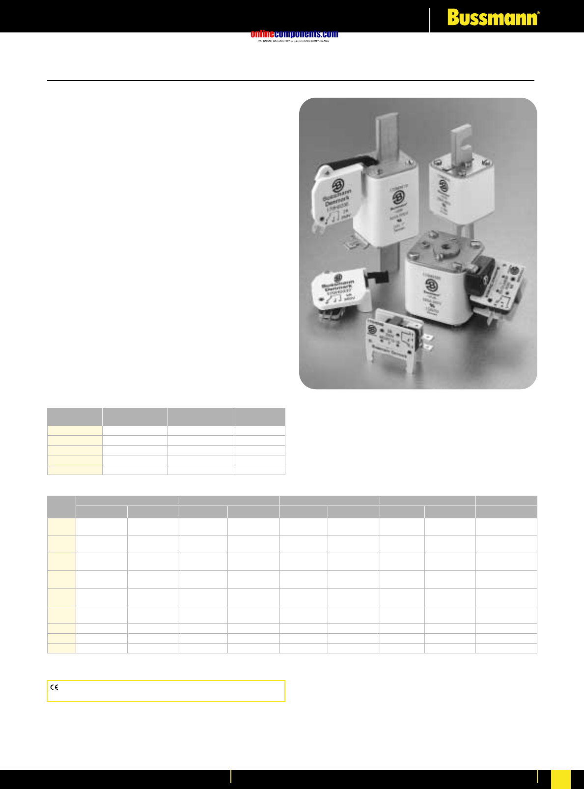
onlinecomponents.com
High Speed Fuses
For more information visit our website at www.bussmann.com 100
Indicator System
Indicators
Typower ZILOX fuses are available with three different
indicator systems.
Visual Indicator
The indicator situated in one cover plate is clearly visible as
soon as the fuse has operated. The minimum voltage for
operating the indicator is 20V.
Type T Indicator
The indicator is situated on one cover plate with a cover plate
tag to accommodate an auxiliary switch. The minimum
voltage for operating the indicator is 20V. A special low
voltage indicator (1.5V) is available on request.
Type K Indicator
This indicator is situated on the fuse body. It is covered by an
adaptor for snap-on mounting of an auxiliary switch. The
operating voltage of the indicator is 1.5V. As a matter of safety,
the factory mounted adaptor must not be removed from the
fuse.
Microswitch
The Typower ZILOX fuses with either type T indicator or
type K indicator can be equipped with a microswitch for
remote electrical indication of fuse operations. All micro-
switches have one normally open and one normally closed
contact. Ratings are 2A, 250 Vac.
6.3 x 0.8 mm 2.8 x 0.5 mm Indicator
Microswitch Lugs Lugs Type
170H0235 ≈T
170H0236 ≈T
170H0237 ≈T
170H0238 ≈T
170H0069 ≈K
DIN 43 653 DIN 43 620 French Style Flush End US Style
Size Type T Type K Type T Type K Type T Type K Type T Type K Type K
000 170H0236 170H0236
170H0238 170H0238
00 170H0235 170H0235
170H0237 170H0237
1* 170H0235 170H0069 170H0235 170H0236 170H0069 170H0069 170H0069
170H0237 170H0237 170H0238
1170H0235 170H0069 170H0236 170H0069 170H0069 170H0069
170H0237 170H0238
2170H0235 170H0069 170H0235 170H0236 170H0069 170H0069 170H0069
170H0237 170H0237 170H0238
3170H0235 170H0069 170H0236 170H0236 170H0069 170H0069 170H0069
170H0237 170H0238 170H0238
4170H0069
23 170H0069
24 170H0069
BIF document: 720034
CE logo denotes compliance with European Union Low Voltage
Directive (50-1000V AC, 75-1500V DC). Refer to BIF document #8002.
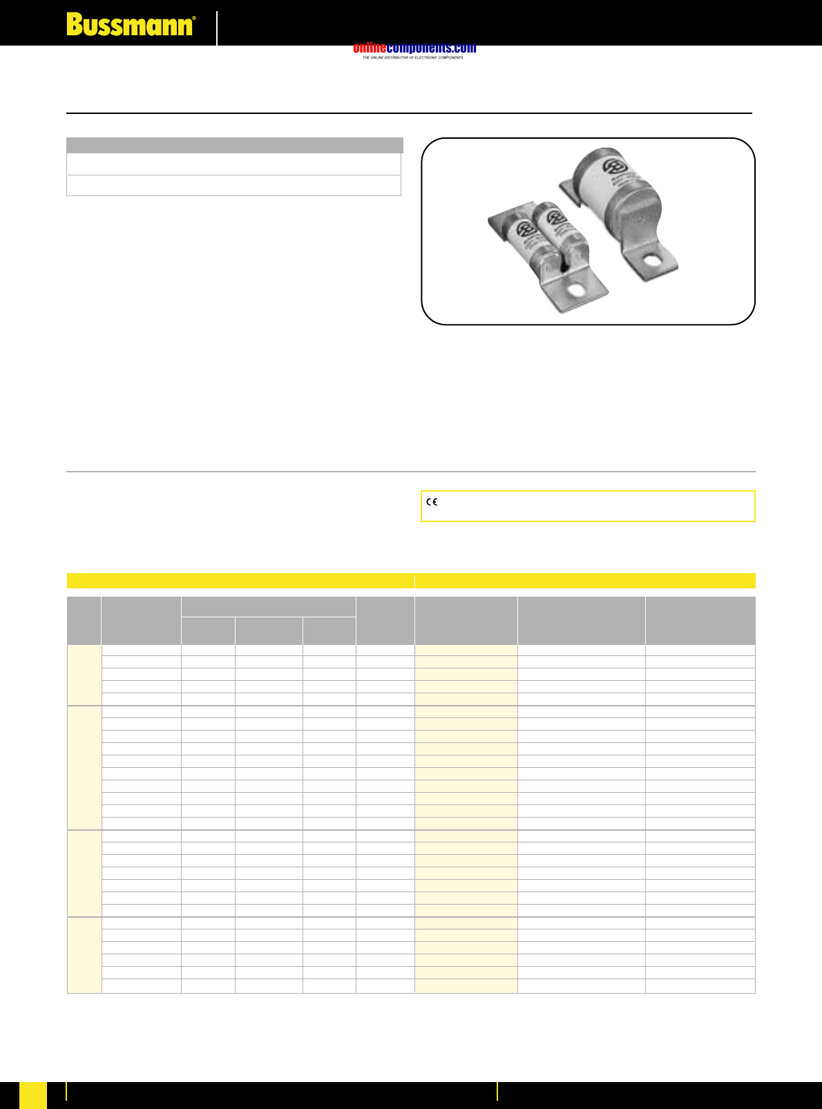
onlinecomponents.com
High Speed Fuses
For more information visit our website at www.bussmann.com
101
British Standard BS88: Part 4
Voltage Rating
240 Volt AC/150 Volt DC 6 to 900 Amperes
690 Volt AC/450 Volt DC 6 to 700 Amperes
All Bussmann British Style fuses are tested to IEC 269: Part
4. This standard requires a test voltage which is 10% higher
than the rated voltage. In North America, fuses are required
to clear only their rated voltage.
Designed and tested to:
•BS 88: Part 4
•IEC 269: Part 4
•UL Recognized, Std. 248-13
Bussmann British Style products use innovative arc
quenching techniques and high grade materials to provide:
•Minimal energy let-thru (I2t)
•Excellent DC performance
•Good surge withstand profile
Accessories
Trip-indicator fuses are available for use in parallel with the
main fuse. Indicator fuses can be attached to the associated
fuselink, or mounted separately in panel-mounted fuseclips.
In addition, a push-on adaptor and microswitch attachment
are available, to provide remote indication. Fuseblocks are
also available for most applications.
240V AC/150V DC - 6 to 900 Amps.
Interrupting Rating: 200kA RMS Symmetrical.
Agency Information: UL Recognized, Std. 248-13
Watts loss provided at rated current.
CE logo denotes compliance with European Union Low Voltage
Directive (50-1000V AC, 75-1500V DC). Refer to BIF document #8002.
Bussmann®
Electrical Characteristics Ordering Information
I2t (A2SEC)
Rated Current Pre-arc Clearing Clearing Watts
Size RMS-Amps at 120V at 240V Loss
6 2 6 9 1.0
10 3.8 12 22 2.5
LCT 12 7 22 32 2.5
16 20 50 100 2.5
20 25 80 160 4.0
25 18 120 250 4.0
32 32 200 450 5.0
35 50 320 600 5.0
50 100 500 1400 7.0
LET 63 180 1100 2200 9.0
80 300 1900 3800 10.0
100 600 3800 7500 10.0
125 600 3800 7500 16.0
160 1100 7000 16000 20.0
180 1600 12000 29000 21.0
160 1100 7000 16000 17.0
200 1500 10000 20000 28.0
250 3200 20000 40000 28.0
LMT 315 6000 35000 75000 35.0
355 8000 50000 100000 35.0
400 14000 70000 160000 40.0
450 18000 100000 220000 42.0
400 6000 35000 80000 60.0
500 14000 80000 170000 64.0
630 24000 150000 300000 75.0
LMMT 710 32000 200000 460000 77.0
800 52000 300000 600000 82.0
900 75000 400000 800000 97.0
Part Number Carton Qty. Carton Weight (Kg)
6LCT 20 0.110
10LCT 20 0.110
12LCT 20 0.110
16LCT 20 0.110
20LCT 20 0.110
25LET 10 0.310
32LET 10 0.310
35LET 10 0.310
50LET 10 0.310
63LET 10 0.310
80LET 10 0.310
100LET 10 0.310
125LET 10 0.310
160LET 10 0.310
180LETa 10 0.310
160LMT 1 0.180
200LMT 1 0.180
250LMT 1 0.180
315LMT 1 0.180
355LMT 1 0.180
400LMT 1 0.180
450LMT 1 0.180
400LMMT 1 0.370
500LMMT 1 0.370
630LMMT 1 0.370
710LMMT 1 0.370
800LMMT 1 0.370
900LMMT 1 0.370
Note: 7LET, 10LET, 12LET and 16LET are available for replacement purposes on existing equipment (not UL recognized).
BIF document: 720024
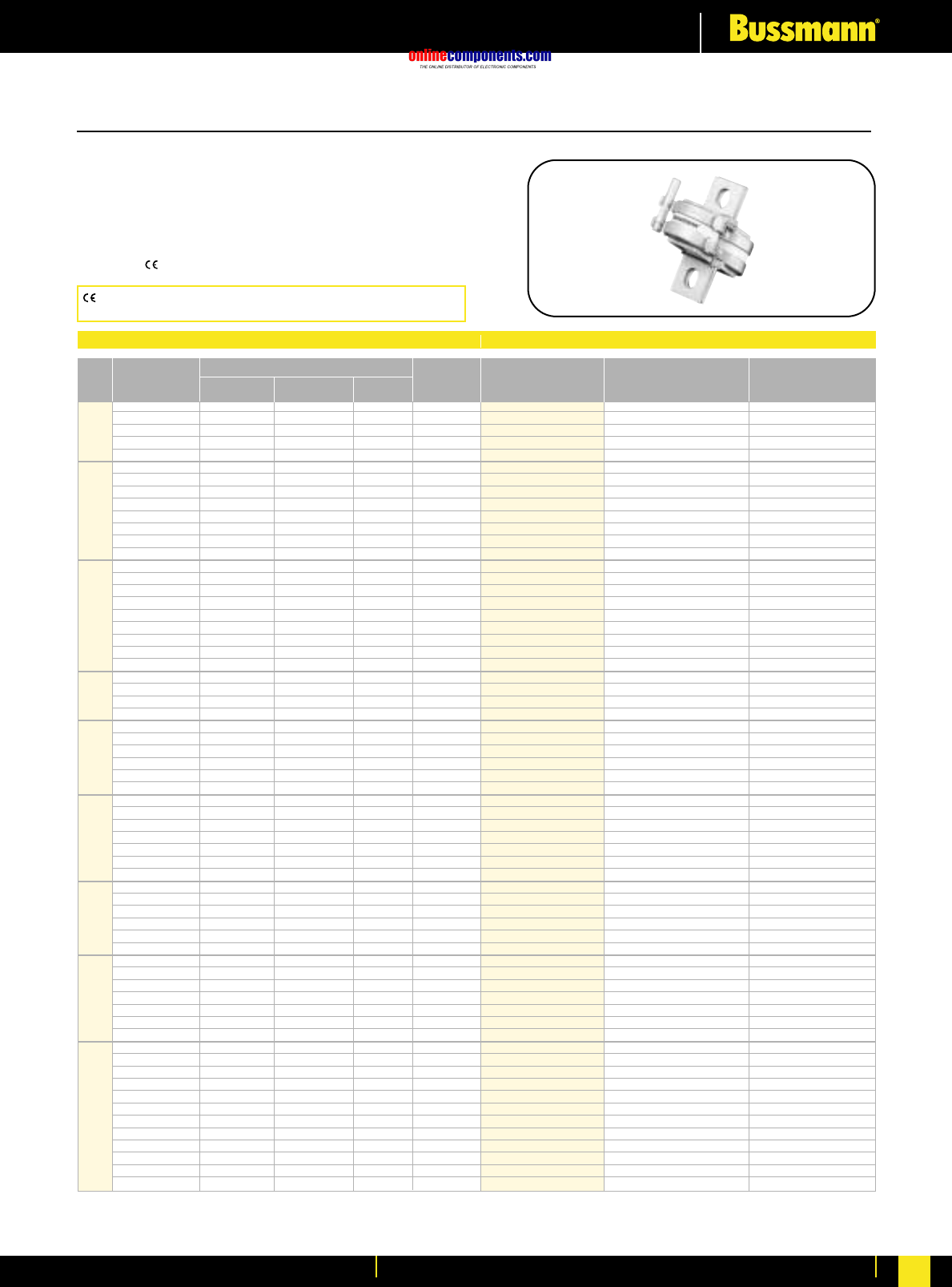
onlinecomponents.com
High Speed Fuses
For more information visit our website at www.bussmann.com 102
British Standard BS88: Part 4
660V AC/450V DC 6-700 Amps.
Interrupting Rating: 200kA RMS Symmetrical.
UL Recognized, Std. 248-13, Watts loss provided at rated current.
MT, MMT and additional ratings of ET and EET are available for
replacement purposes on existing equipment and are BS 88: Part 4
approved.
Bussmann®
Electrical Characteristics Ordering Information
I2t (A2SEC)
Rated Current Clearing Clearing Watts
Size RMS-Amps Pre-arc at 415V at 660V Loss
6 1.8 8.5 12 2
10 7 30 48 3
CT 12 10 40 65 3
16 16 66 110 7
20 32 150 220 7
25 25 150 250 7
32 32 190 350 11
35 52 310 500 11
40 103 600 900 9
ET 45 103 680 1100 11
56 135 950 1500 14
63 171 1200 2000 16
80 360 2500 4000 18
35 33 130 200 9
40 52 180 300 9
45 76 270 450 11
50 103 380 600 11
FE 63 135 480 750 12
71 210 600 950 17
80 250 900 1500 20
90 360 1300 2100 20
100 470 1800 2800 23
90 490 3000 4500 19
110 600 4000 6500 27
EET 140 1050 7000 12000 35
160 1500 10000 17000 39
100 400 1600 2400 24
120 540 1900 3100 32
140 850 2500 3800 36
FEE 160 1000 3700 5700 46
180 1400 5300 8400 46
200 1900 7100 11400 52
180 1400 7500 13500 40
200 2600 10500 18500 40
225 3700 14500 26500 44
FM 250 5200 20500 37500 48
280 7000 30500 55000 48
315 10000 40000 77000 55
350 15000 60000 105000 55
400 10000 40000 72500 85
450 15000 60000 105000 90
500 20000 82000 150000 100
FMM 550 30000 120000 215000 100
630 45000 180000 310000 100
700 60000 245000 420000 120
160 2400 15000 25000 26
180 3800 25000 38000 26
200 6000 40000 58000 27
MT†250 11500 80000 110000 32
280 16500 100000 150000 35
315 19000 125000 180000 42
355 22000 160000 200000 51
180 1650 12000 18000 42
200 2200 16000 23000 42
225 3700 26000 40000 42
280 6600 47000 70000 47
315 8600 62000 91000 51
MMT†355 13500 97000 140000 54
400 21000 150000 220000 60
450 30000 220000 320000 57
500 42000 300000 450000 64
560 60000 430000 640000 64
630 68500 500000 720000 86
710 78000 600000 850000 105
Part Number Carton Qty. Carton Weight (Kg)
6CT 20 0.160
10CT 20 0.160
12CT 20 0.160
16CT 20 0.160
20CT 20 0.160
25ET 10 0.420
32ET 10 0.420
35ET 10 0.420
40ET 10 0.420
45ET 10 0.420
56ET 10 0.420
63ET 10 0.420
80ET 10 0.420
35FE 10 0.420
40FE 10 0.420
45FE 10 0.420
50FE 10 0.420
63FE 10 0.420
71FE 10 0.420
80FE 10 0.420
90FE 10 0.420
100FE 10 0.420
90EET 5 0.450
110EET 5 0.450
140EET 5 0.450
160EET 5 0.450
100FEE 5 0.450
120FEE 5 0.450
140FEE 5 0.450
160FEE 5 0.450
180FEE 5 0.450
200FEE 5 0.450
180FM 1 0.240
200FM 1 0.240
225FM 1 0.240
250FM 1 0.240
280FM 1 0.240
315FM 1 0.240
350FM 1 0.240
400FMM 1 0.450
450FMM 1 0.450
500FMM 1 0.450
550FMM 1 0.450
630FMM 1 0.450
700FMM 1 0.450
160MT 1 0.260
180MT 1 0.260
200MT 1 0.260
250MT 1 0.260
280MT 1 0.260
315MT 1 0.260
355MT 1 0.260
180MMT 1 .0470
200MMT 1 .0470
225MMT 1 .0470
280MMT 1 .0470
315MMT 1 .0470
355MMT 1 .0470
400MMT 1 .0470
450MMT 1 .0470
500MMT 1 .0470
560MMT 1 .0470
630MMT 1 .0470
710MMT 1 .0470
Note: 8ET, 12ET, 15ET, 20ET, 65EET and 75EET are available for replacement purposes on existing equipment (not UL recognized).
† 500V DC (IEC) rating. No UL Recognition.
BIF document: 720024
CE logo denotes compliance with European Union Low Voltage
Directive (50-1000V AC, 75-1500V DC). Refer to BIF document #8002.
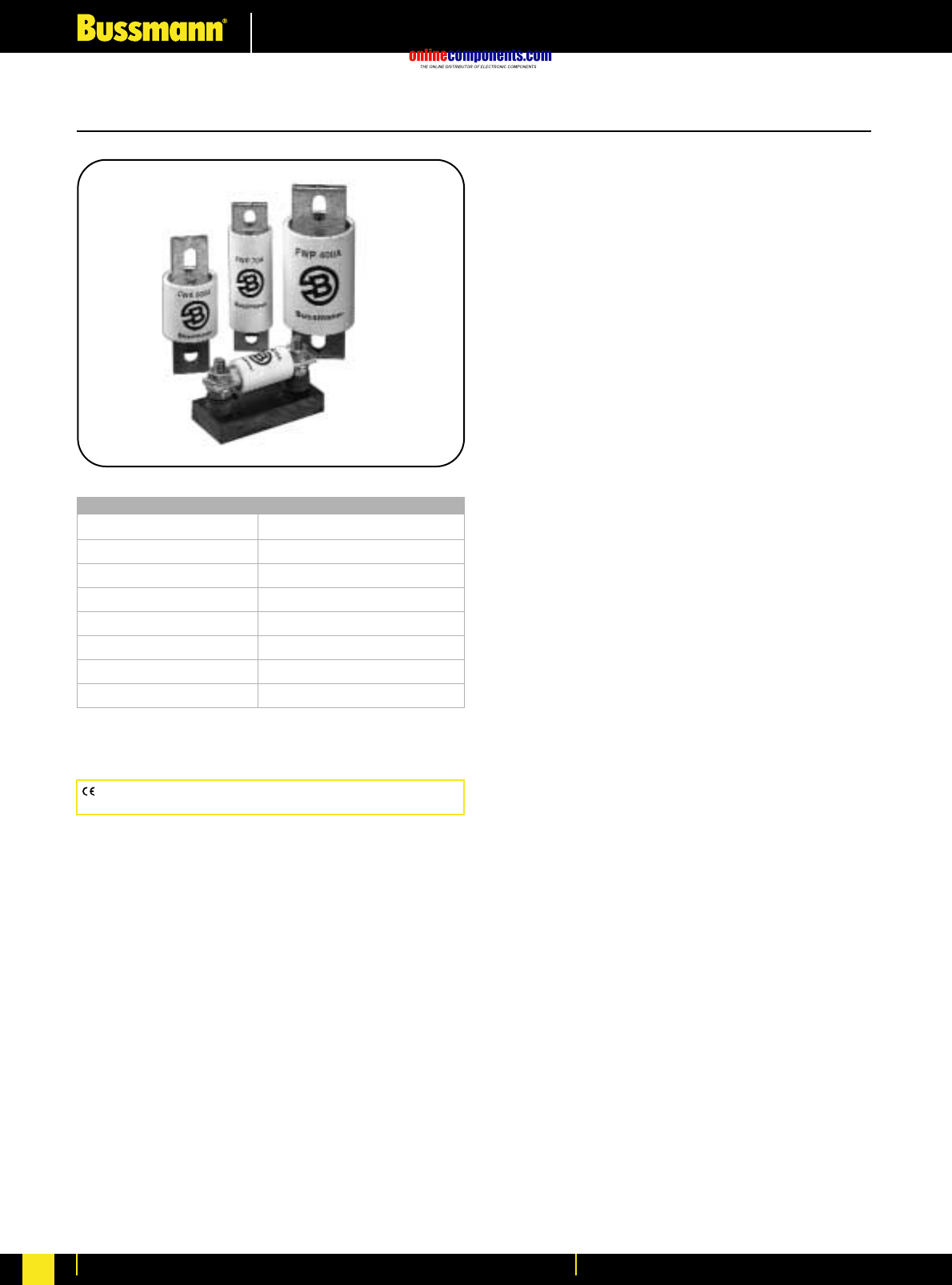
onlinecomponents.com
High Speed Fuses
For more information visit our website at www.bussmann.com
103
Characteristics:
•Low energy let-thru (I2t)
•Low watts loss
•Superior cycling capability
•Low arc voltage
•Excellent DC performance
North American style fuses provide an excellent solution for
medium power applications. While there are currently no
published standards for these fuses, the industry has
standardised on mounting centres that accept Bussmann fuses.
Accessories
Bussmann offers a comprehensive line of fuse bases that
provide the user with design and manufacturing flexibility.
North American Style—General Information
Voltage Rating
130V AC/DC 1000 to 4000 Amperes
150V AC/DC 70 to 1000 Amperes
250V AC/DC 35 to 2500 Amperes
500V AC/DC 35 to 1600 Amperes
600V AC 1 to 1000 Amperes
700V AC/DC 5 to 1200 Amperes
800V DC 35 to 600 Amperes
1000V AC, 700V DC 35 to 2000 Amperes
All Bussmann North American Style fuses are certified
for their rated voltage.
CE logo denotes compliance with European Union Low Voltage
Directive (50-1000V AC, 75-1500V DC). Refer to BIF document #8002.
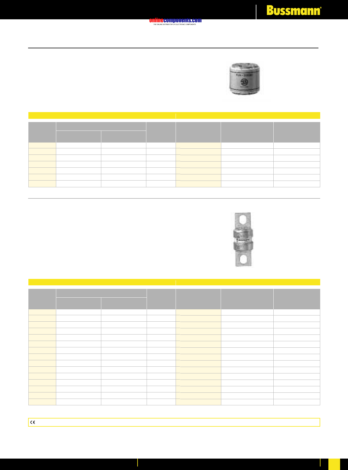
onlinecomponents.com
High Speed Fuses
For more information visit our website at www.bussmann.com 104
FWA 130V
Voltage Rating: 130V AC/130V DC (130V DC rating
applies to 1000 through 2000 amperes only.)
Interrupting Rating: 200kA RMS Symmetrical.
Agency Information: UL Recognized, Std. 248-13
Watts loss provided at rated current.
FWA 150V
Voltage Rating: 150V AC/150V DC (150V DC rating
applies to 70 through 800 amperes only.)
Interrupting Rating: 100kA RMS Symmetrical. (70-400A)
200kA RMS Symmetrical. (450-
1000A)
Agency Information: UL Recognized, Std. 248-13
Watts loss provided at rated current..
Part Number Carton Qty. Carton Weight (lbs)
FWA-1000AH 1 3.3
FWA-1200AH 1 3.3
FWA-1500AH 1 3.3
FWA-2000AH 1 3.3
FWA-2500AH 1 3.3
FWA-3000AH 1 3.3
FWA-4000AH 1 3.3
Electrical Characteristics Ordering Information
Rated I2t (A2SEC) @ 100kA
Current Clearing Watts
RMS-Amps Pre-arc at 130V Loss
1000 170000 460000 60.0
1200 270000 730000 70.0
1500 520000 1400000 78.0
2000 860000 2400000 108.0
2500 1500000 4100000 130.0
3000 2100000 5700000 150.0
4000 3400000 9200000 257.0
Part Number Carton Qty. Carton Weight (lbs)
FWA-70B 10 1.76
FWA-80B 10 1.76
FWA-100B 10 1.76
FWA-125B 10 1.76
FWA-150B 10 1.76
FWA-200B 10 1.76
FWA-250B 10 1.76
FWA-300B 10 1.76
FWA-350B 10 1.76
FWA-400B 10 1.76
FWA-500A 5 2.42
FWA-600A 5 2.42
FWA-700A 5 2.42
FWA-800A 5 2.42
FWA-1000A 5 2.42
Electrical Characteristics Ordering Information
Rated I2t (A2SEC) @ 100kA
Current Clearing Watts
RMS-Amps Pre-arc at 150V Loss
70 470 4000 6.9
80 670 6000 7.7
100 1200 12000 9.0
125 1870 18000 11.2
150 2700 26000 13.5
200 4780 45000 17.6
250 7470 70000 22.5
300 10760 100000 27.0
350 15700 140000 30.6
400 20300 180000 35.2
500 39000 120000 35.0
600 46000 140000 47.0
700 75000 220000 49.0
800 92000 280000 58.0
1000 170000 510000 60.0
North American Style
CE logo denotes compliance with European Union Low Voltage Directive (50-1000V AC, 75-1500V DC). Refer to BIF document #8002.
BIF document: 720002
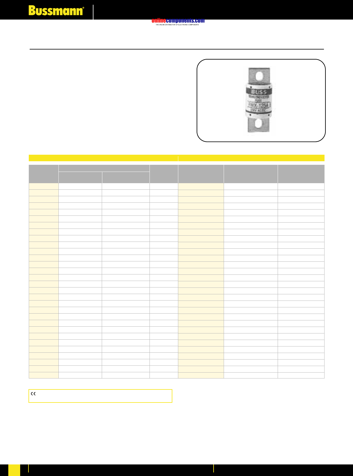
onlinecomponents.com
High Speed Fuses
For more information visit our website at www.bussmann.com
105
North American Style
FWX 250V
Voltage Rating: 250V AC/250V DC (250V DC rating on
35 through 800 amperes only.)
Interrupting Rating: 200kA RMS Symmetrical.
Agency Information:
UL Recognized, Std. 248-13
Watts loss provided at rated current.
Bussmann®
Electrical Characteristics Ordering Information
Rated I2t (A2SEC) @ 100kA
Current Clearing Watts
RMS-Amps Pre-arc at 250V Loss
35 50 230 4.2
40 60 310 5.2
45 80 390 5.7
50 100 520 6.0
60 140 740 8.1
70 330 1400 7.2
80 430 1850 8.1
90 570 2450 9.0
100 740 3150 10.0
125 1130 4850 12.5
150 1620 6950 15.7
175 2170 9300 18.5
200 2790 12000 22
225 3210 14700 24
250 3960 18100 27
275 4720 21600 31
300 6000 27300 32
350 10600 48600 39
400 14500 66100 44
450 22100 101000 49
500 28000 128000 54
600 41100 188000 62
700 48800 190000 72
800 59000 230000 84
1000 44000 360000 100
1200 92000 750000 103
1500 120000 880000 140
1600 160000 1200000 140
2000 320000 2300000 151
2500 670000 4700000 16
Part Number Carton Qty. Carton Weight (Kg)
FWX-35A 5 1.40
FWX-40A 5 1.40
FWX-45A 5 1.40
FWX-50A 5 1.40
FWX-60A 5 1.40
FWX-70A 1 0.32
FWX-80A 1 0.32
FWX-90A 1 0.32
FWX-100A 1 0.32
FWX-125A 1 0.32
FWX-150A 1 0.32
FWX-175A 1 0.32
FWX-200A 1 0.32
FWX-225A 1 0.52
FWX-250A 1 0.52
FWX-275A 1 0.52
FWX-300A 1 0.52
FWX-350A 1 0.52
FWX-400A 1 0.52
FWX-450A 1 0.52
FWX-500A 1 0.52
FWX-600A 1 0.52
FWX-700A 1 0.90
FWX-800A 1 0.90
FWX-1000AH 1 2.86
FWX-1200AH 1 2.86
FWX-1500AH 1 2.86
FWX-1600AH 1 2.86
FWX-2000AH 1 2.86
FWX-2500AH 1 2.86
CE logo denotes compliance with European Union Low Voltage
Directive (50-1000V AC, 75-1500V DC). Refer to BIF document #8002.
BIF document: 720005
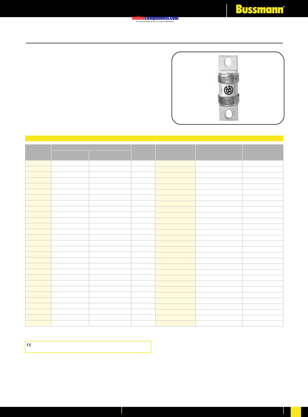
onlinecomponents.com
High Speed Fuses
For more information visit our website at www.bussmann.com 106
North American Style
FWH 500V
Voltage Rating: 500V AC/500V DC (500V DC rating applies
to 35 through 800 amperes only.)
Interrupting Rating: 200kA RMS Symmetrical.
Agency Information: UL Recognized, Std. 248-13,
35-1200A; CSA Component Acceptance 35-1600A
Watts loss provided at rated current.
Bussmann®
Electrical Characteristics Ordering Information
Rated I2t (A2SEC) @ 100kA
Current Clearing Watts
RMS-Amps Pre-arc at 500V Loss
35 34 150 .8
40 76 320 7.5
45 105 450 7.5
50 135 670 7.5
60 210 900 9.9
70 210 900 10.6
80 305 1400 12.7
90 360 1600 15
100 475 2000 17
125 800 3500 25
150 1100 4600 30
175 1450 6200 35
200 1900 8500 40
225 4600 23300 39
250 6300 32200 41
275 7900 40300 46
300 9800 49800 51
325 13700 63800 53
350 14500 72900 58
400 19200 96700 65
450 24700 127000 74
500 29200 149000 84
600 41300 206000 108
700 55000 298000 120
800 76200 409000 129
1000 92000 450000 145
1200 122000 600000 180
1400 200000 1000000 210
1600 290000 1400000 230
Part Number Carton Qty. Carton Weight (Kg)
FWH- 35B 10 1.34
FWH-40B 10 1.34
FWH-45B 10 1.34
FWH-50B 10 1.34
FWH-60B 10 1.34
FWH-70B 10 2.05
FWH-80B 10 2.05
FWH-90B 10 2.05
FWH-100B 10 2.05
FWH-125B 5 1.65
FWH-150B 5 1.65
FWH-175B 5 1.65
FWH-200B 5 1.65
FWH-225A 1 0.57
FWH-250A 1 0.57
FWH-275A 1 0.57
FWH-300A 1 0.57
FWH-325A 1 0.57
FWH-350A 1 0.57
FWH-400A 1 0.57
FWH-450A 1 1.00
FWH-500A 1 1.00
FWH-600A 1 1.00
FWH-700A 1 2.14
FWH-800A 1 2.14
FWH-1000A 1 4.62
FWH-1200A 1 4.62
FWH-1400A 1 11.66
FWH-1600A 1 11.66
CE logo denotes compliance with European Union Low Voltage
Directive (50-1000V AC, 75-1500V DC). Refer to BIF document #8002.
BIF document: 720007
onlinecomponents.com
High Speed Fuses
For more information visit our website at www.bussmann.com
107
North American Style
KAC 600V
Voltage Rating: 600V AC
Interrupting Rating: 200kA
RMS Symmetrical.
Agency Information:
UL Recognized, Std. 248-13,1-600A
•For new installations, Bussmann
recommends the 700 Volt FWP
series fuse. The 600V fuses are
supplied as replacements only.
KBC 600V
Voltage Rating: 600V AC
Interrupting Rating: 200kA
RMS Symmetrical.
Agency Information:
UL Recognized, Std. 248-13,
35-600A
•For new installations,Bussmann
recommends the 700 Volt FWP
series fuse. The 600V fuses are
supplied as replacements only.
Ordering Information
Part Number Carton Qty. Carton Weight (lbs)
KAC-1 10 0.50
KAC-2 10 0.50
KAC-3 10 0.50
KAC-4 10 0.50
KAC-5 10 0.50
KAC-6 10 0.50
KAC-7 10 0.50
KAC-8 10 0.50
KAC-9 10 0.50
KAC-10 10 0.50
KAC-12 10 0.50
KAC-15 10 0.50
KAC-17.5 10 0.50
KAC-20 10 0.50
KAC-25 10 0.50
KAC-30 10 0.50
KAC-35 10 1.40
KAC-40 10 1.40
KAC-45 10 1.40
KAC-50 10 1.40
KAC-60 10 1.40
KAC-70 5 1.56
KAC-80 5 1.56
KAC-90 5 1.56
KAC-100 5 1.56
KAC-110 1 0.78
KAC-125 1 0.78
KAC-150 1 0.78
KAC-175 1 0.78
KAC-200 1 0.78
KAC-225 1 1.92
KAC-250 1 1.92
KAC-300 1 1.92
KAC-350 1 1.92
KAC-400 1 1.92
KAC-450 1 3.16
KAC-500 1 3.16
KAC-600 1 3.16
KAC-700 1 3.16
KAC-800 1 3.16
KAC-1000 1 6.24
Ordering Information
Part Number Carton Qty. Carton Weight (lbs)
KBC-35 10 1.40
KBC-40 10 1.40
KBC-45 10 1.40
KBC-50 10 1.40
KBC-60 10 1.40
KBC-70 5 1.44
KBC-80 5 1.44
KBC-90 5 1.44
KBC-100 5 1.44
KBC-110 1 0.48
KBC-125 1 0.48
KBC-150 1 0.48
KBC-175 1 0.48
KBC-200 1 0.48
KBC-225 1 0.77
KBC-250 1 0.77
KBC-300 1 0.77
KBC-350 1 0.77
KBC-400 1 0.77
KBC-450 1 1.32
KBC-500 1 1.32
KBC-600 1 1.32
KBC-800 1 4.50
CE logo denotes compliance with European Union Low Voltage
Directive (50-1000V AC, 75-1500V DC). Refer to BIF document #8002.
CE logo denotes compliance with European Union Low Voltage
Directive (50-1000V AC, 75-1500V DC). Refer to BIF document #8002.
BIF document: 720009 BIF document: 720010
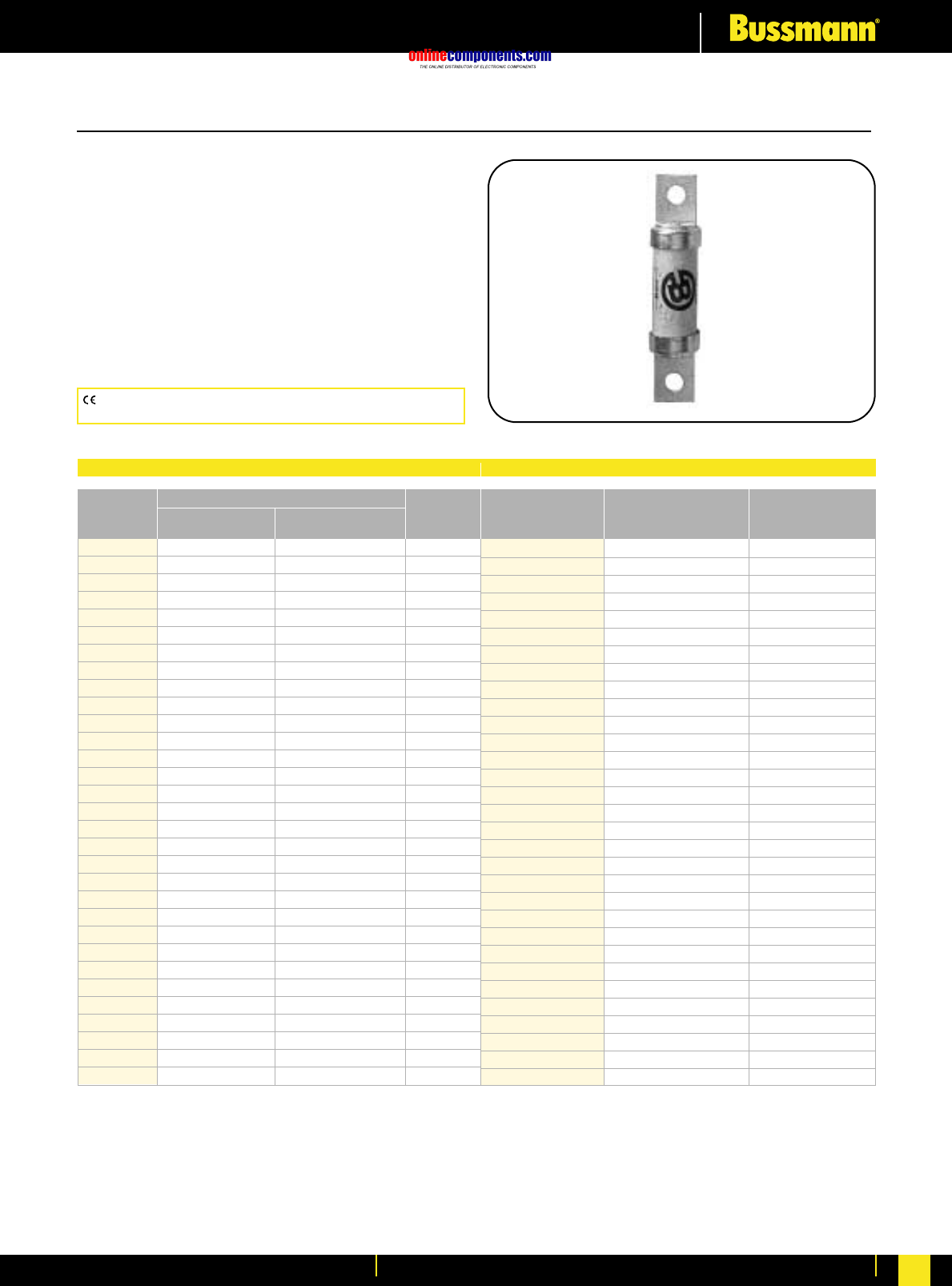
onlinecomponents.com
High Speed Fuses
For more information visit our website at www.bussmann.com 108
For more information visit our website at www.bussmann.com
North American Style
FWP 700V
Voltage Rating: 700V AC/700V DC
(700V DC rating applies to 5 through 800 amperes only.)
Interrupting Rating: 200kA RMS Symmetrical.
Agency Information: UL Recognized, Std. 248-13, 5-800A;
CSA Component Acceptance, 35-100A & 700-800A
Watts loss provided at rated current.
CE logo denotes compliance with European Union Low Voltage
Directive (50-1000V AC, 75-1500V DC). Refer to BIF document #8002.
Bussmann®
Electrical Characteristics Ordering Information
Rated I2t (A2SEC) @ 100kA
Current Clearing Watts
RMS-Amps Pre-arc at 700V Loss
5 1.6 10 1.5
10 3.6 20 4
15 10 75 5.5
20 26 180 6
25 44 340 7
30 58 450 9
35 34 160 12
40 76 320 12
50 135 600 12
60 210 950 15.5
70 305 1400 18
80 360 1600 21
90 415 1900 25
100 540 2500 27
125 1800 7300 28
150 2900 11700 32
175 4200 16700 35
200 5500 22000 43
225 7700 31300 45
250 10500 42500 48
300 17600 71200 58
350 23700 95600 65
400 31000 125000 78
450 36400 137000 94
500 45200 170000 107
600 66700 250000 122
700 54000 300000 125
800 78000 450000 140
900 91500 530000 150
1000 120000 600000 170
1200 195000 1100000 190
Part Number Carton Qty. Carton Weight (Kg)
FWP-5B 10 2.25
FWP-10B 10 2.25
FWP-15B 10 2.25
FWP-20B 10 2.25
FWP-25B 10 2.25
FWP-30B 10 2.25
FWP-35B 10 2.42
FWP-40B 10 2.42
FWP-50B 10 2.42
FWP-60B 10 2.42
FWP-70B 10 2.42
FWP-80B 10 2.42
FWP-90B 10 2.42
FWP-100B 10 2.42
FWP-125A 1 0.65
FWP-150A 1 0.65
FWP-175A 1 0.65
FWP-200A 1 0.65
FWP-225A 1 1.17
FWP-250A 1 1.17
FWP-300A 1 1.17
FWP-350A 1 1.17
FWP-400A 1 1.17
FWP-450A 1 2.39
FWP-500A 1 2.39
FWP-600A 1 2.39
FWP-700A 1 1.21
FWP-800A 1 1.21
FWP-900A 1 6.60
FWP-1000A 1 6.60
FWP-1200A 1 6.60
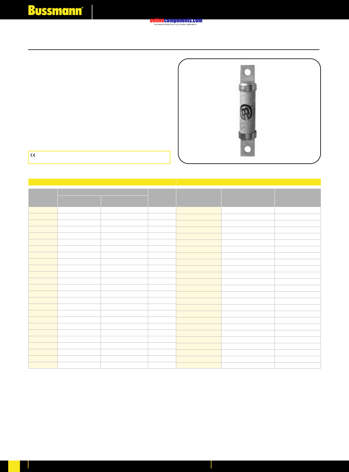
onlinecomponents.com
High Speed Fuses
For more information visit our website at www.bussmann.com
109
CE logo denotes compliance with European Union Low Voltage
Directive (50-1000V AC, 75-1500V DC). Refer to BIF document #8002.
North American Style
FWJ 1000V
Voltage Rating: 1000V AC/800V DC (Ampere ratings
35-200 and 500-600 rated up to 800V DC)
Interrupting Rating: 25kA for 35-200A,
100kA for 250-600A
Agency Information:
UL Recognition on 35 through 600 amperes only, Std. 248-13
Watts loss provided at rated current
Bussmann®
Electrical Characteristics Ordering Information
Rated I2t (A2SEC) @ 100kA
Current Clearing Watts
RMS-Amps Pre-arc at 130V Loss
35 210 2000 7
40 300 2500 8
50 470 3500 10
60 670 5000 11
70 1100 6900 12
80 1550 9700 13
90 1900 12000 14
100 2800 17500 15
125 4800 35000 16
150 6300 45000 25
175 7500 65000 30
200 11700 80000 32
250 9000 50000 50
300 15000 80000 56
350 22000 120000 62
400 32000 180000 67
500 28500 155000 95
600 46500 260000 105
800 87000 500000 182
1000 190000 1100000 206
1200 370000 2100000 240
1400 470000 2700000 248
1600 700000 4000000 267
1800 925000 5300000 239
2000 1330000 7600000 244
Part Number Carton Qty. Carton Weight (Kg)
FWJ-35A 10 4.18
FWJ-40A 10 4.18
FWJ-50A 10 4.18
FWJ-60A 10 4.18
FWJ-70A 10 4.18
FWJ-80A 10 4.18
FWJ-90A 10 4.18
FWJ-100A 10 4.18
FWJ-125A 1 4.40
FWJ-150A 1 4.40
FWJ-175A 1 4.40
FWJ-200A 1 4.40
FWJ-250A 1 4.84
FWJ-300A 1 4.84
FWJ-350A 1 4.84
FWJ-400A 1 4.84
FWJ-500A 1 4.84
FWJ-600A 1 4.84
FWJ-800A 1 5.28
FWJ-1000A 1 5.28
FWJ-1200A 1 5.28
FWJ-1400A 1 5.28
FWJ-1600A 1 5.28
FWJ-1800A 1 5.28
FWJ-2000A 1 5.28
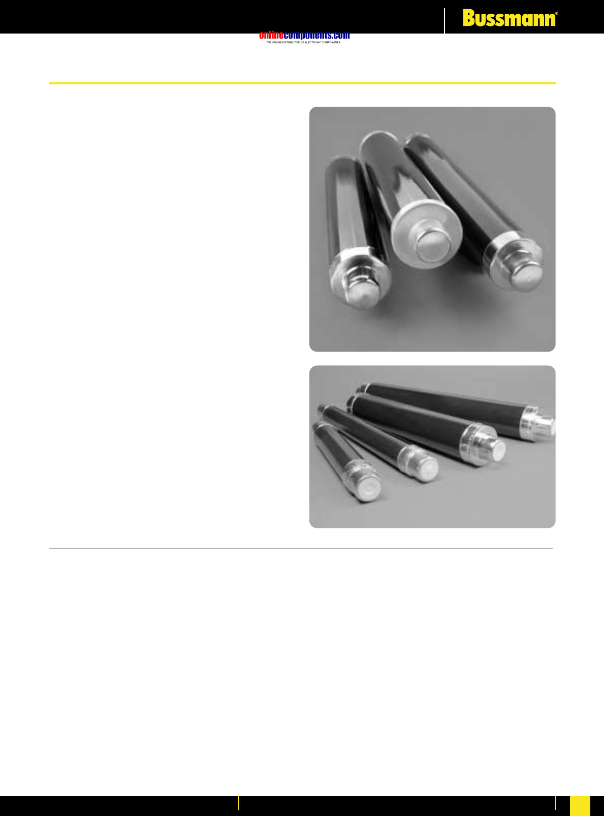
onlinecomponents.com
Medium Voltage Fuse Links
For more information visit our website at www.bussmann.com 110
• Fuse Links comply with DIN
dimensional standard DIN43625.
• ‘F’ range, high performance full range
fuse link.
• ‘S’ range, high performance back-up
fuse link, with striker tripping.
• ‘A’ range, including high current rating
back-up fuse link.
• Comply with IEC 60282-1 and VDE 0670
part 4.
• Wide variety of ratings, 3.6 kV to 36 kV.
• Versions suitable for indoor and
outdoor use.
• Motor circuit fuse link option.
DIN Fuse Links
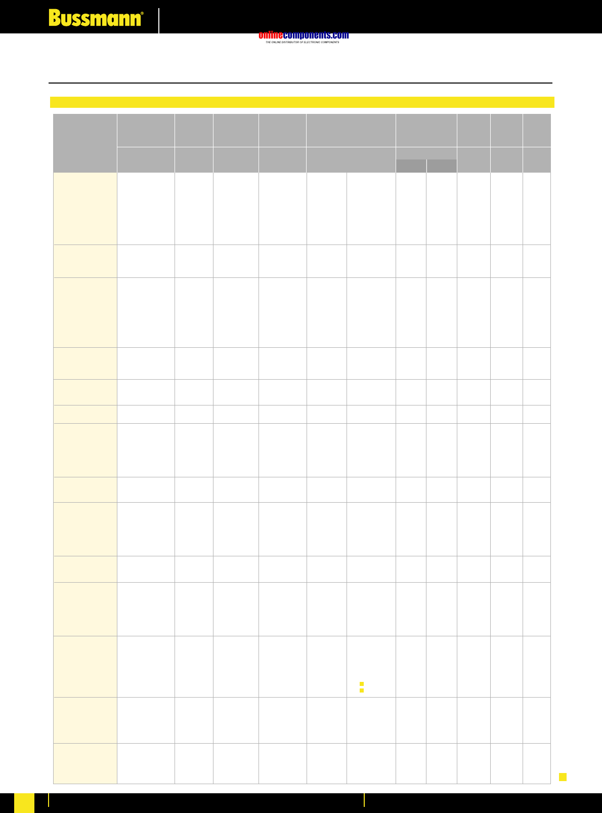
onlinecomponents.com
Medium Voltage Fuse Links
For more information visit our website at www.bussmann.com
111
Table of ratings for ‘S’ range 7.2 - 36kV to DIN dimensions
Rating at 64%
Selection Table
Part Number
Current
Rating Length Diameter
ø
Un
kV
In
A
I1
kA mm
m ΩW
A2s
mm
Weight
Breaking
Capacity
I3
A
Minimum
Breaking Current Cold resistance and watts loss
in free air at rated current Joule
Intergral
(I2t)
7.2SDLSJ6.3
7.2SDLSJ10
7.2SDLSJ16
7.2SDLSJ20
7.2SDLSJ25
7.2SDLSJ31.5
7.2SDLSJ40
7.2SDLSJ50
7.2SDLSJ63
7.2SFLSJ80
7.2SFLSJ100
7.2SFLSJ125
7.2SFLSJ160
12SDLSJ6.3
12SDLSJ10
12SDLSJ16
12SDLSJ20
12SDLSJ25
12SDLSJ31.5
12SDLSJ40
12SDLSJ50
12SDLSJ63
12SFLSJ50
12SFLSJ63
12SFLSJ80
12SFLSJ100
12SKLSJ125
12SXLEJ160
12SXLEJ200
15.5SFMSJ100
15.5SKMSJ125
17.5SDLSJ6.3
17.5SDLSJ10
17.5SDLSJ16
17.5SDLSJ20
17.5SDLSJ25
17.5SDLSJ31.5
17.5SDLSJ40
17.5SFLSJ31.5
17.5SFLSJ40
17.5SFLSJ50
17.5SDMSJ6.3
17.5SDMSJ10
17.5SDMSJ16
17.5SDMSJ20
17.5SDMSJ25
17.5SDMSJ31.5
17.5SDMSJ40
17.5SFMSJ50
17.5SFMSJ63
17.5SFMSJ80
24SDMSJ6.3
24SDMSJ10
24SDMSJ16
24SDMSJ20
24SDMSJ25
24SDMSJ31.5
24SDMSJ40
24SFMSJ40
24SFMSJ50
24SFMSJ63
24SFMSJ71
24SHMEJ80
24SHMEJ100
24SKMEJ125
24SXMEJ160
36SDQSJ3.15
36SDQSJ6.3
36SDQSJ10
36SDQSJ16
36SDQSJ20
36SDQSJ25
36SFQSJ31.5
36SFQSJ40
36SFQSJ50
36SXQEJ63
7.2
7.2
7.2
7.2
7.2
7.2
7.2
7.2
7.2
7.2
7.2
7.2
7.2
12
12
12
12
12
12
12
12
12
12
12
12
12
12
12
12
15.5
15.5
17.5
17.5
17.5
17.5
17.5
17.5
17.5
17.5
17.5
17.5
17.5
17.5
17.5
17.5
17.5
17.5
17.5
17.5
17.5
17.5
24
24
24
24
24
24
24
24
24
24
24
24
24
24
24
36
36
36
36
36
36
36
36
36
36
6.3
10
16
20
25
31.5
40
50
63
80
100
125
160
6.3
10
16
20
25
31.5
40
50
63
50
63
80
100
125
160
200
100
125
6.3
10
16
20
25
31.5
40
31.5
40
50
6.3
10
16
20
25
31.5
40
50
63
80
6.3
10
16
20
25
31.5
40
40
50
63
71
80
100
125
160
3.15
6.3
10
16
20
25
31.5
40
50
63
40
40
40
40
40
40
40
40
40
40
40
40
40
50
50
50
50
50
50
50
50
50
50
50
50
50
50
63
63
25
25
35.5
35.5
35.5
35.5
35.5
35.5
35.5
35.5
35.5
35.5
35.5
35.5
35.5
35.5
35.5
35.5
35.5
35
35
35
50
50
50
50
50
50
50
50
50
50
50
63
63
63
63
20
35.5
35.5
35.5
35.5
35.5
35.5
35.5
35.5
20
20
31
49
49
80
100
114
143
180
264
338
375
525
20
28
35
72
90
90
128
196
275
160
227
256
446
870
500
610
707
990
23
19
59
80
100
118
148
118
132
225
16
27
57
80
100
100
143
180
240
270
19
28
47
80
84
105
140
119
225
306
350
300
350
420
320
-
23
35
70
98
112
116
178
255
280
205
99.7
65.1
48.9
32.6
26.0
16.0
12.9
8.14
6.01
4.65
3.60
2.73
285
143
81.4
54.6
43.7
32.8
21.6
15.1
12.1
17.1
12.1
8.97
5.61
4.60
4.30
3.80
8.23
5.61
313
185
104
69.2
55.4
41.4
31.1
30.3
21.9
17.3
509
215
112
79.8
63.8
47.9
31.6
25.0
17.8
13.1
489
287
165
79.3
62.0
46.5
34.0
38.0
27.1
21.6
17.7
20.5
18.0
16.7
14.0
-
684
402
165
117
98.0
73.4
52.4
36.8
35.0
11
19
23
27
28
36
36
46
45
54
64
79
97
14
18
26
28
35
43
49
59
75
61
69
88
83
115
200
330
119
126
15
23
34
38
48
58
76
37
51
62
26
28
37
38
52
61
66
88
102
128
24
35
60
38
49
56
79
85
96
128
134
250
350
171
279
-
34
44
52
62
85
96
116
133
271
292
292
292
292
292
292
292
292
292
292
292
292
292
292
292
292
292
292
292
292
292
292
292
292
292
292
292
292
292
442
442
292
292
292
292
292
292
292
292
292
292
442
442
442
442
442
442
442
442
442
442
442
442
442
442
442
442
442
442
442
442
442
442
442
442
442
537
537
537
537
537
537
537
537
537
537
4.8X101
2.5X10²
5.5X10²
9.7X10²
5.7X10²
8.9X10²
2.0X10²
3.2X10²
8.0X10²
5.0X10³
9.1X10³
1.5X10⁴
3.0X10⁴
7.0X101
3.1X10²
9.8X10²
5.7X10²
8.9X10²
1.6X10³
3.2X10³
1.3X10³
2.3X10³
5.2X10³
1.0X10⁴
1.9X10⁴
1.4X10⁴
2.8X10⁴
1.1X10⁵
1.5X10⁵
1.2X10⁴
2.4X10⁴
4.8X101
2.8X10²
2.9X10²
5.7X10²
8.9X10²
5.1X10²
8.0X10²
2.6X10³
5.1X10³
8.1X10³
4.8X101
3.1X10²
2.9X10²
5.7X10²
8.9X10²
1.6X10³
3.2X10³
5.2X10³
1.0X10⁴
1.9X10⁴
8.1X101
3.1X10²
9.8X10²
8.1X10²
1.3X10³
2.1X10³
3.2X10³
5.1X10³
8.1X10³
3.8X10³
5.0X10³
1.7X10⁴
2.8X10⁴
2.4X10⁴
4.4X10⁴
-
1.0X10²
3.1X10²
4.6X10²
8.9X10²
1.2X10³
2.1X10³
4.1X10³
8.3X10³
1.1X10⁴
6.5X10²
2.7X10³
8.2X10³
1.1X10⁴
8.0X10³
1.0X10⁴
2.2X10⁴
3.2X10⁴
7.5X10⁴
6.5X10⁴
1.1X10⁵
1.7X10⁵
3.1X10⁵
6.5X10²
2.7X10³
8.6X10³
5.1X10³
8.1X10⁴
1.5X10⁴
2.7X10⁴
3.2X10⁴
5.7X10⁴
4.1X10⁴
8.8X10⁴
1.5X10⁵
2.2X10⁵
2.3X10⁵
5.0X10⁵
6.5X10⁵
1.4X10⁵
2.2X10⁵
6.1X10²
4.0X10³
2.0X10³
4.4X10³
6.6X10³
1.1X10⁴
1.8X10⁴
1.9X10⁴
3.8X10⁴
6.0X10⁴
6.0X10²
3.8X10³
1.2X10⁴
6.7X10³
1.1X10⁴
2.0X10⁴
3.6X10⁴
5.5X10⁴
1.2X10⁵
1.9X10⁵
1.3X10³
5.5X10³
1.5X10⁴
1.1X10⁴
2.0X10⁴
2.9X10⁴
4.4X10⁴
6.9X10⁴
9.0X10⁴
5.0X10⁴
6.6X10⁴
8.4X10⁴
9.3X10⁴
8.7X10⁴
1.7X10⁵
-
1.2X10³
3.6X10³
5.1X10³
8.2X10⁴
1.5X10⁴
2.3X10⁴
3.9X10⁴
8.1X10⁴
6.2X10⁴
50.8
50.8
50.8
50.8
50.8
50.8
50.8
50.8
50.8
76.2
76.2
76.2
76.2
50.8
50.8
50.8
50.8
50.8
50.8
50.8
50.8
50.8
76.2
76.2
76.2
76.2
76.2
88
88
76.2
76.2
50.8
50.8
50.8
50.8
50.8
50.8
50.8
76.2
76.2
76.2
50.8
50.8
50.8
50.8
50.8
50.8
50.8
76.2
76.2
76.2
50.8
50.8
50.8
50.8
50.8
50.8
50.8
76.2
76.2
76.2
76.2
64
64
78
88
50.8
50.8
50.8
50.8
50.8
50.8
76.2
76.2
76.2
88
1.63
1.63
1.63
1.63
1.63
1.63
1.63
1.63
1.63
3.1
3.1
3.1
3.1
1.63
1.63
1.63
1.63
1.63
1.63
1.63
1.63
1.63
3.1
3.1
3.1
3.1
3.1
3.7
3.7
4.5
4.5
1.63
1.63
1.63
1.63
1.63
1.63
1.63
3.1
3.1
3.1
2.2
2.2
2.2
2.2
2.2
2.2
2.2
4.5
4.5
4.5
2.2
2.2
2.2
2.2
2.2
2.2
2.2
4.5
4.5
4.5
4.5
3.1
3.1
3.7
4.2
2.9
2.9
2.9
2.9
2.9
2.9
6.0
6.0
6.0
6.5
Voltage
Rating
Maximum
Total Clearing
Minimum
Pre-Arcing kg
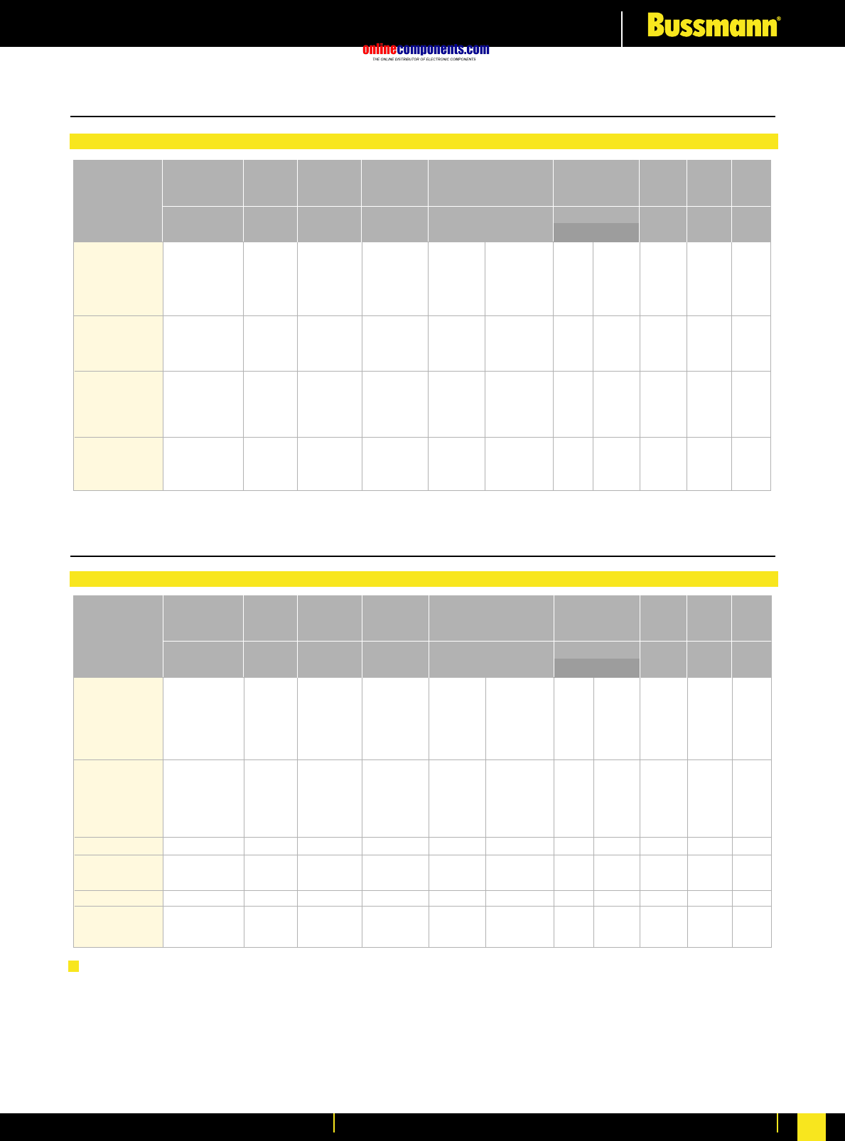
onlinecomponents.com
Medium Voltage Fuse Links
For more information visit our website at www.bussmann.com 112
Table of ratings for ‘F’ range 12 - 24kV to DIN dimensions
Selection Table
Notes
a) 17.5kV fuse links in 10/12 dimensions are offered, since some
switchgear in the 10/12 series is suitable for use at higher
voltages.
b) Fuse links listed are normally for indoor use but versions
suitable for outdoor use are also available in the same ratings
and dimensions. For outdoor versions of the ‘S’ range, replace
the ‘S’ with a ‘T’ when ordering - for example ‘TDLSJ’
c) * All the fuse link code references listed in the proceeding
tables are for striker fitted versions, for non-striker versions
please replace the letter ‘S’ with the letter ‘N’ in the code -
for example ‘SDLNJ’.
Table of ratings for ‘A’ range 3.6 - 24kV to DIN dimensions
Selection Table
12FDLSJ6.3
12FDLSJ10
12FDLSJ16
12FDLSJ20
12FDLSJ25
12FDLSJ31.5
12FFLSJ40
12FFLSJ50
12FFLSJ63
12FXLSJ80
12FXLSJ100
24FDMSJ6.3
24FDMSJ10
24FDMSJ16
24FDMSJ20
24FDMSJ25
24FDMSJ31.5
24FFMSJ25
24FFMSJ31.5
24FFMSJ40
24FFMSJ45
12
12
12
12
12
12
12
12
12
12
12
24
24
24
24
24
24
24
24
24
24
6.3
10
16
20
25
31.5
40
50
63
80
100
6.3
10
16
20
25
31.5
25
31.5
40
45
50
50
50
50
50
50
50
50
50
50
50
35.5
35.5
35.5
35.5
35.5
35.5
35.5
35.5
35.5
35.5
6.3
10
16
20
25
31.5
40
50
63
80
100
6.3
10
16
20
25
31.5
25
31.5
40
45
208
116
55.4
39.6
31.2
26.4
19.7
14.8
12.4
7.94
5.64
437
218
118
82.2
54.7
48.6
58.6
48.8
38.4
31.4
10
15
17
20
26
36
42
51
72
72
82
21
29
39
43
48
71
47
70
85
92
292
292
292
292
292
292
292
292
292
292
292
442
442
442
442
442
442
442
442
442
442
6.9X101
2.2X10²
8.8X10²
1.7X10³
2.8X10³
2.6X10³
3.8X10³
6.8X10³
5.1X10³
2.2X10⁴
4.2X10⁴
6.8X101
2.7X10²
8.2X10²
1.6X10³
3.4X10³
3.2X10³
3.4X10³
4.7X10³
7.6X10³
7.2X10³
6.3X10²
2.1X10³
3.9X10³
7.6X10³
1.3X10⁴
1.3X10⁴
3.8X10⁴
5.6X10⁴
5.4X10⁴
1.1X10⁵
2.0X10⁵
5.4X10²
2.1X10³
2.7X10³
5.1X10³
1.2X10⁴
1.2X10⁴
1.1X10⁴
1.5X10⁴
2.5X10⁴
3.0X10⁴
50.8
50.8
50.8
50.8
25.8
50.8
76.2
76.2
76.2
88
88
50.8
50.8
50.8
50.8
50.8
50.8
76.2
76.2
76.2
76.2
1.63
1.63
1.63
1.63
1.63
1.63
3.16
3.16
3.16
4
4
2.2
2.2
2.2
2.2
2.2
2.2
4.5
4.5
4.5
4.5
Part Number
Current
Rating Length Diameter
ø
Un
kV
In
A
I1
kA mm
m ΩW
A2s
mm
Weight
Breaking
Capacity
I3
A
Minimum
Breaking Current Cold resistance and watts loss
in free air at rated current Joule
Intergral
(I2t)
Voltage
Rating
Maximum
Total Clearing
Minimum
Pre-Arcing kg
3.6ADOSJ6.3
3.6ADOSJ10
3.6ADOSJ16
3.6ADOSJ20
3.6ADOSJ25
3.6ADOSJ31.5
3.6ADOSJ40
3.6ADLSJ6.3
3.6ADLSJ10
3.6ADLSJ16
3.6ADLSJ20
3.6ADLSJ25
3.6ADLSJ31.5
3.6ADLSJ40
12AILSJ100
17.5AILSJ40
17.5AILSJ50
17.5AILSJ63
17.5AIMSJ100
24AFMSJ50
24AFMSJ63
24AIMSJ71
3.6
3.6
3.6
3.6
3.6
3.6
3.6
3.6
3.6
3.6
3.6
3.6
3.6
3.6
12
17.5
17.5
17.5
17.5
24
24
24
6.3
10
16
20
25
31.5
40
6.3
10
16
20
25
31.5
40
100
40
50
63
100
50
63
71
40
40
40
40
40
40
40
40
40
40
40
40
40
40
31.5
25
25
25
25
20
20
20
13
31
49
49
106
106
106
13
13
20
31
106
106
106
176
78
98
156
176
137
125
176
158
79.2
50.8
38.1
28.9
19.2
11.6
158
95.6
63.3
45.9
28.7
19.1
11.4
5.03
26.3
21.1
12.3
7.33
29.5
23.6
15.1
9
11
18
21
25
26
26
9
13
22
25
25
26
25
70
58
73
68
102
102
130
106
192
192
192
192
192
192
192
292
292
292
292
292
292
292
292
292
292
292
442
442
442
442
4.5X101
2.3X10²
5.5X10²
9.8X10²
1.3X10²
2.9X10²
8.0X10²
4.5X101
1.3X10²
3.0X10²
6.3X10²
1.3X10²
2.9X10²
8.0X10²
1.4X10⁴
1.3X10³
2.0X10³
5.0X10³
1.4X10⁴
1.8X10³
3.2X10³
6.3X10³
1.9X10²
9.7X10²
2.4X10³
4.2X10³
1.2X10³
2.7X10³
7.5X10³
1.9X10²
5.4X10²
1.3X10³
2.7X10³
1.2X10³
2.7X10³
7.5X10³
2.0X10⁵
1.8X10⁴
2.7X10⁴
7.0X10⁴
2.0X10⁵
2.9X10⁴
4.5X10⁴
8.5X10⁴
50.8
50.8
50.8
50.8
50.8
50.8
50.8
50.8
50.8
50.8
50.8
50.8
50.8
50.8
76.2
76.2
76.2
76.2
76.2
76.2
76.2
76.2
1.1
1.1
1.1
1.1
1.1
1.1
1.1
1.63
1.63
1.63
1.63
1.63
1.63
1.63
3.3
3.3
3.3
3.3
4.5
4.5
4.5
4.5
Part Number
Current
Rating Length Diameter
ø
Un
kV
In
A
I1
kA mm
m ΩW
A2s
mm
Weight
Breaking
Capacity
I3
A
Minimum
Breaking Current Cold resistance and watts loss
in free air at rated current Joule
Intergral
(I2t)
Voltage
Rating
Maximum
Total Clearing
Minimum
Pre-Arcing kg
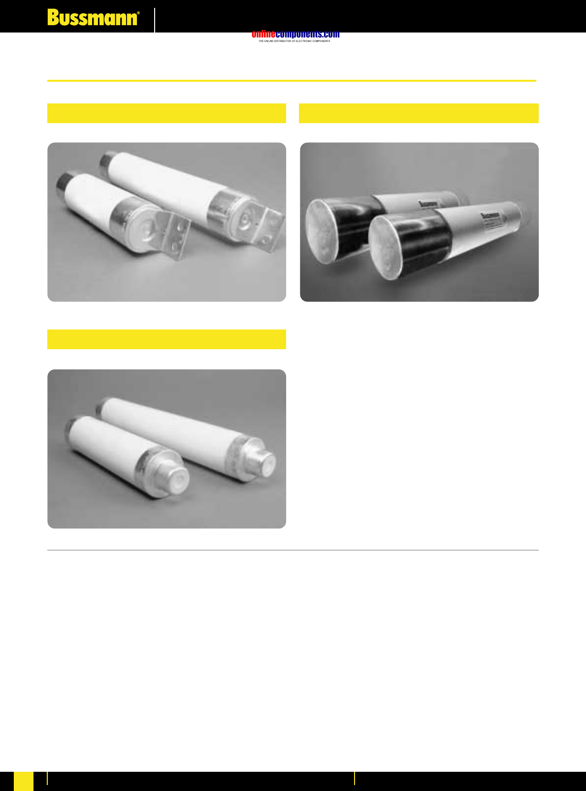
onlinecomponents.com
Medium Voltage Fuse Links
For more information visit our website at www.bussmann.com
113
•Motor fuse links comply with
IEC60282-1, IEC644 and BS5907.
•Available in DIN 43625 and BS2692
dimensions.
•Sold in a wide range of ratings from:
3.6 kV – 5 to 450 A
7.2 kV – 5 to 355 A
•North American dimensioned products
also available. 2R to 24R ratings.
British Standard Motor Fuse Links
DIN Dimensioned Motor Fuse Links
North American Motor Fuse Links
Fuse Links for Motor Protection
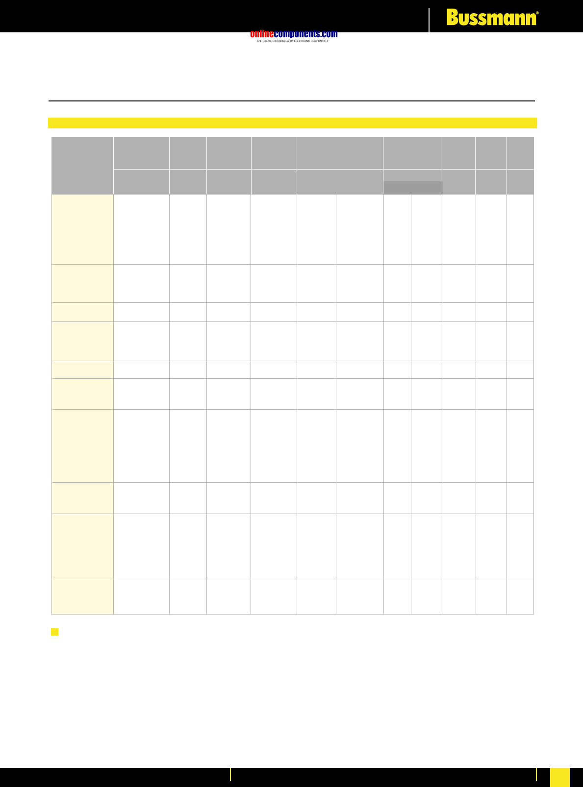
onlinecomponents.com
Medium Voltage Fuse Links
For more information visit our website at www.bussmann.com 114
Table of ratings for motor fuses
3.6 - 7.2kV to British Standard dimensions
Selection Table
WDOH6 fuse links also available in the range 6.3 to 40A as code ADOH6.
3.6WJON65
3.6WJON66.3
3.6WJON610
3.6WJON616
3.6WJON620
3.6WJON625
3.6WJON631.5
3.6WJON640
3.6WJON650
3.6WDOH650
3.6WDOH663
3.6WDOH680
3.6WDOH6100
3.6WDOH6125
3.6WFOH6160
3.6WFOH6200
3.6WDFHO50
3.6WDFHO63
3.6WDFHO80
3.6WDFHO100
3.6WDFHO125
3.6WFFHO160
3.6WFFHO200
3.6WKFHO250
3.6WKFHO315
3.6WKFHO355
3.6WKFHO400
3.6WFGHO31.5
3.6WFGHO40
3.6WFGHO50
3.6WFGHO63
3.6WFGHO80
3.6WFGHO100
3.6WFGHO125
3.6WFGHO160
3.6WFGHO200
3.6WFGHO250
3.6WKGHO315
3.6WKGHO355
3.6WKGHO400
3.6WKGHO450
7.2WFNHO25
7.2WFNHO31.5
7.2WFNHO40
7.2WFNHO50
7.2WFNHO63
7.2WFNHO80
7.2WFNHO100
7.2WFNHO125
7.2WFNHO160
7.2WKNHO200
7.2WKNHO224
7.2WKNHO250
7.2WKNHO315
3.6
3.6
3.6
3.6
3.6
3.6
3.6
3.6
3.6
3.6
3.6
3.6
3.6
3.6
3.6
3.6
3.6
3.6
3.6
3.6
3.6
3.6
3.6
3.6
3.6
3.6
3.6
3.6
3.6
3.6
3.6
3.6
3.6
3.6
3.6
3.6
3.6
3.6
3.6
3.6
3.6
7.2
7.2
7.2
7.2
7.2
7.2
7.2
7.2
7.2
7.2
7.2
7.2
7.2
5
6.3
10
16
20
25
31.5
40
50
50
63
80
100
125
160
200
50
63
80
100
125
160
200
250
315
355
400
31.5
40
50
63
80
100
125
160
200
250
315
355
400
450
25
31.5
40
50
63
80
100
125
160
200
224
250
315
50
50
50
50
50
50
50
50
50
50
50
50
50
50
50
50
50
50
50
50
50
50
50
50
50
50
50
50
50
50
50
50
50
50
50
50
50
50
50
50
50
40
40
40
40
40
40
40
40
40
40
40
40
40
13
24
24
56
56
70
112
112
140
180
225
288
360
450
600
600
152
171
190
190
190
300
300
520
650
820
820
151
151
151
151
170
212
212
300
300
500
852
852
960
1150
84
96
107
122
133
133
262
300
337
500
500
960
960
148
56.3
56.3
33.1
22.1
17.7
10.1
7.54
6.03
5.36
3.68
2.88
2.16
1.73
1.28
0.938
6.61
5.03
3.52
2.87
2.44
1.53
1.24
0.653
0.435
0.345
0.345
18.4
13.9
9.24
6.93
5.47
4.40
3.60
2.16
1.77
1.13
0.646
0.512
0.454
0.379
38.7
25.5
18.2
13.3
10.4
7.30
4.92
2.94
2.05
1.63
1.44
1.11
0.779
5
8
8
12
12
15
14
17
21
20
21
27
31
39
47
52
21
28
31
39
53
54
67
57
60
59
76
25
31
32
38
48
62
79
75
95
96
89
90
100
108
34
35
40
46
56
65
69
63
72
90
98
105
107
192
192
192
192
192
192
192
192
192
192
192
192
192
192
192
192
254
254
254
254
254
254
254
254
254
254
254
359
359
359
359
359
359
359
359
359
359
359
359
359
359
403
403
403
403
403
403
403
403
403
403
403
403
403
2.0X101
1.6X10²
1.6X10²
1.7X10²
3.9X10²
6.1X10²
1.2X10³
2.1X10³
3.2X10³
1.8X10³
3.8X10³
6.3X10³
9.8X10³
1.5X10⁴
3.1X10⁴
5.7X10⁴
1.8X10³
3.1X10³
6.3X10³
9.5X10³
1.3X10⁴
3.4X10⁴
5.1X10⁴
1.8X10⁵
4.1X10⁵
6.4X10⁵
6.4X10⁵
4.5X10²
8.0X10²
1.8X10³
3.2X10³
5.1X10³
7.9X10³
1.2X10⁴
3.4X10⁴
5.1X10⁴
1.3X10⁵
4.5X10⁵
6.4X10⁵
8.2X10⁵
1.2X10⁶
1.4X10²
3.1X10²
6.1X10²
1.2X10³
1.9X10³
3.8X10³
9.8X10³
2.4X10⁴
5.0X10⁴
8.8X10⁴
1.1X10⁵
2.2X10⁵
4.5X10⁵
1.6X10³
1.3X10³
1.3X10³
1.4X10³
3.2X10³
4.9X10³
9.8X10³
1.7X10⁴
2.6X10⁴
2.4X10⁴
4.5X10⁴
8.0X10⁴
1.1X10⁵
2.2X10⁵
6.2X10⁵
1.1X10⁶
2.4X10⁴
4.5X10⁴
8.0X10⁴
1.2X10⁵
1.8X10⁵
4.1X10⁵
7.2X10⁵
2.4X10⁶
5.0X10⁶
7.0X10⁶
7.0X10⁶
6.0X10³
1.2X10⁴
2.2X10⁴
4.5X10⁴
7.5X10⁴
1.2X10⁵
1.7X10⁵
4.2X10⁵
7.0X10⁵
1.9X10⁶
6.0X10⁶
8.5X10⁶
1.1X10⁷
1.5X10⁷
2.1X10³
4.7X10³
8.0X10³
1.5X10⁴
3.0X10⁴
5.8X10⁴
1.3X10⁵
2.4X10⁵
7.0X10⁵
1.3X10⁶
1.6X10⁶
1.6X10⁶
3.1X10⁶
35
35
35
35
35
35
35
35
35
51
51
51
51
51
76
76
51
51
51
51
51
76
76
76
76
76
76
76
76
76
76
76
76
76
76
76
76
76
76
76
76
76
76
76
76
76
76
76
76
76
76
76
76
76
0.54
0.54
0.54
0.54
0.54
0.54
0.54
0.54
0.54
1.1
1.1
1.1
1.1
1.1
2.1
2.1
1.46
1.46
1.46
1.46
1.46
3.2
3.2
3.2
3.2
3.2
3.2
4.1
4.1
4.1
4.1
4.1
4.1
4.1
4.1
4.1
4.1
3.9
3.9
3.9
3.9
4.4
4.4
4.4
4.4
4.4
4.4
4.4
4.4
4.4
4.4
4.4
4.4
4.4
Part Number
Current
Rating Length Diameter
ø
In
A
Un
kV
I1
kA mm
m ΩW
A2s
mm
Weight
Breaking
Capacity
I3
A
Minimum
Breaking Current Cold resistance and watts loss
in free air at rated current Joule
Intergral
(I2t)
Voltage
Rating
Maximum
Total Clearing
Minimum
Pre-Arcing kg
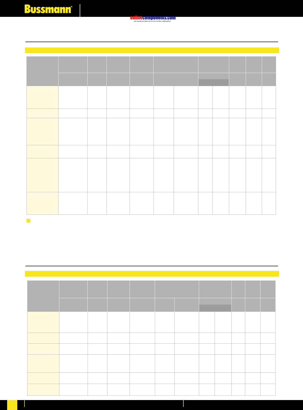
onlinecomponents.com
Medium Voltage Fuse Links
For more information visit our website at www.bussmann.com
115
Table of ratings for motor fuses 3.6 - 7.2kV to DIN dimensions
Selection Table
Table of ratings for motor fuses 2.75 - 5.5kV to USA dimensions
Selection Table
Higher Current Ratings
Higher ratings than those tabulated above can be obtained by using fuse links connected in parallel. Special fixing arrangements
for connecting up to 3 fuse links in parallel, are available. Please contact Bussmann application engineers for more details.
2.75VFRHA*R
2.75VFRHA*R
2.75VFRHA*R
2.75VFRHA*R
2.75VKRHA*R
2.75VKRHA*R
2.75VKRHK*R
2.75VKRHK*R
5.5VFNHA*R
5.5VFNHA*R
5.5VFNHA*R
5.5VFNHA*R
5.5VKNHA*R
5.5VKNHA*R
5.5VKNHK*R
5.5VKNHK*R
2.75
2.75
2.75
2.75
2.75
2.75
2.75
2.75
5.5
5.5
5.5
5.5
5.5
5.5
5.5
5.5
2R
3R
4R
6R
9R
12R
18R
24R
2R
3R
4R
6R
9R
12R
18R
24R
60
60
60
60
60
60
60
60
60
60
60
60
60
60
60
60
180
229
257
525
500
500
500
500
180
229
257
525
500
500
500
500
6.15
4.04
2.69
1.62
1.15
1.03
0.577
0.514
8.35
5.48
3.65
2.31
1.63
1.45
0.815
0.725
52
57
62
65
70
80
140
156
70
77
85
91
99
110
198
220
276
276
276
276
276
276
276
276
403
403
403
403
403
403
403
403
8.1x10³
1.9x10⁴
4.2x10⁴
3.9x10⁴
8.8x10⁴
1.1x10⁵
3.5x10⁵
4.5x10⁵
8.1x10³
1.9x10⁴
4.2x10⁴
3.9x10⁴
8.8x10⁴
1.1x10⁵
3.5x10⁵
4.5x10⁵
2.8x10⁴
7.5x10⁴
1.4x10⁵
3.4x10⁵
8.4x10⁵
1.2x10⁶
3.2x10⁶
5.5x10⁶
2.8x10⁴
7.9x10⁴
1.6x10⁵
3.6x10⁵
8.8x10⁵
1.3x10⁶
3.4x10⁶
5.8x10⁶
76
76
76
76
76
76
76
76
76
76
76
76
76
76
76
76
2.5
2.5
2.5
2.5
2.5
2.5
5.2
5.2
3.8
3.8
3.8
3.8
3.8
3.8
7.8
7.8
Part Number
Current
Rating Length Diameter
ø
In
A
Un
kV
I1
kA mm
m ΩW
A2s
mm
Weight
Breaking
Capacity
I3
A
Minimum
Breaking Current Cold resistance and watts loss
in free air at rated current Joule
Intergral
(I2t)
Voltage
Rating
Maximum
Total Clearing
Minimum
Pre-Arcing kg
3.6WDOSJ50
3.6WDOSJ63
3.6WDOSJ80
3.6WDOSJ100
3.6WDOSJ125
3.6WFOSJ160
3.6WFOSJ200
3.6WDLSJ50
3.6WDLSJ63
3.6WDLSJ80
3.6WDLSJ100
3.6WDLSJ125
3.6WFLSJ160
3.6WFLSJ200
3.6WKLSJ250
3.6WKLSJ315
3.6WKLSJ400
7.2WFMSJ25
7.2WFMSJ31.5
7.2WFMSJ40
7.2WFMSJ50
7.2WFMSJ63
7.2WFMSJ80
7.2WFMSJ100
7.2WFMSJ125
7.2WFMSJ160
7.2WKMSJ200
7.2WKMSJ224
7.2WKMSJ250
7.2WKMSJ315
7.2WKMSJ355
3.6
3.6
3.6
3.6
3.6
3.6
3.6
3.6
3.6
3.6
3.6
3.6
3.6
3.6
3.6
3.6
3.6
7.2
7.2
7.2
7.2
7.2
7.2
7.2
7.2
7.2
7.2
7.2
7.2
7.2
7.2
50
63
80
100
125
160
200
50
63
80
100
125
160
200
250
315
400
25
31.5
40
50
63
80
100
125
160
200
224
250
315
355
50
50
50
50
50
50
50
50
50
50
50
50
50
50
50
50
50
63
63
63
63
63
63
63
63
63
63
63
63
63
63
180
225
288
360
450
600
600
152
171
190
190
190
300
300
820
820
820
84
96
107
122
133
133
262
300
337
500
500
960
960
1000
5.36
3.68
2.88
2.16
1.73
1.28
0.938
7.73
5.9
4.12
3.38
2.85
1.74
1.42
0.741
0.507
0.401
33.9
25.4
17.8
14.8
11.6
8.12
5.33
3.19
2.23
1.79
1.59
1.23
0.869
0.724
20
21
27
31
39
47
52
27
32
37
46
61
61
80
67
69
90
33
40
56
53
61
72
74
70
79
99
110
107
120
125
192
192
192
192
192
192
192
292
292
292
292
292
292
292
292
292
292
442
442
442
442
442
442
442
442
442
442
442
442
442
442
1.8X10³
3.8X10³
6.3X10³
9.8X10³
1.5X10⁴
3.1X10⁴
5.7X10⁴
1.8X10³
3.1X10³
6.3X10³
9.5X10³
1.3X10⁴
3.4X10⁴
5.1X10⁴
1.9X10⁵
4.0X10⁵
6.4X10⁵
1.4X10²
3.1X10²
6.1X10²
1.2X10³
1.9X10³
3.8X10³
9.8X10³
2.4X10⁴
5.0X10⁴
8.8X10⁴
1.1X10⁵
2.2X10⁵
4.5X10⁵
6.4X10⁵
2.4X10⁴
4.5X10⁴
8.0X10⁴
1.1X10⁵
2.2X10⁵
6.2X10⁵
1.1X10⁶
2.4X10⁴
4.5X10⁴
8.0X10⁴
1.2X10⁵
1.8X10⁵
4.1X10⁵
7.2X10⁵
2.4X10⁶
5.0X10⁶
7.0X10⁶
2.1X10³
4.7X10³
8.0X10³
1.5X10⁴
3.0X10⁴
5.8X10⁴
1.3X10⁵
2.4X10⁵
7.0X10⁵
1.3X10⁶
1.6X10⁶
1.6X10⁶
3.1X10⁶
3.9X10⁶
51
51
51
51
51
76
76
51
51
51
51
51
76
76
76
76
76
76
76
76
76
76
76
76
76
76
76
76
76
76
76
1.1
1.1
1.1
1.1
1.1
2.1
2.1
1.63
1.63
1.63
1.63
1.63
3.16
3.16
3.16
3.16
3.16
5.2
5.2
5.2
5.2
5.2
5.2
5.2
5.2
5.2
5.2
5.2
5.2
5.2
5.2
Part Number
Current
Rating Length Diameter
ø
In
A
Un
kV
I1
kA mm
m ΩW
A2s
mm
Weight
Breaking
Capacity
I3
A
Minimum
Breaking Current Cold resistance and watts loss
in free air at rated current Joule
Intergral
(I2t)
Voltage
Rating
Maximum
Total Clearing
Minimum
Pre-Arcing kg
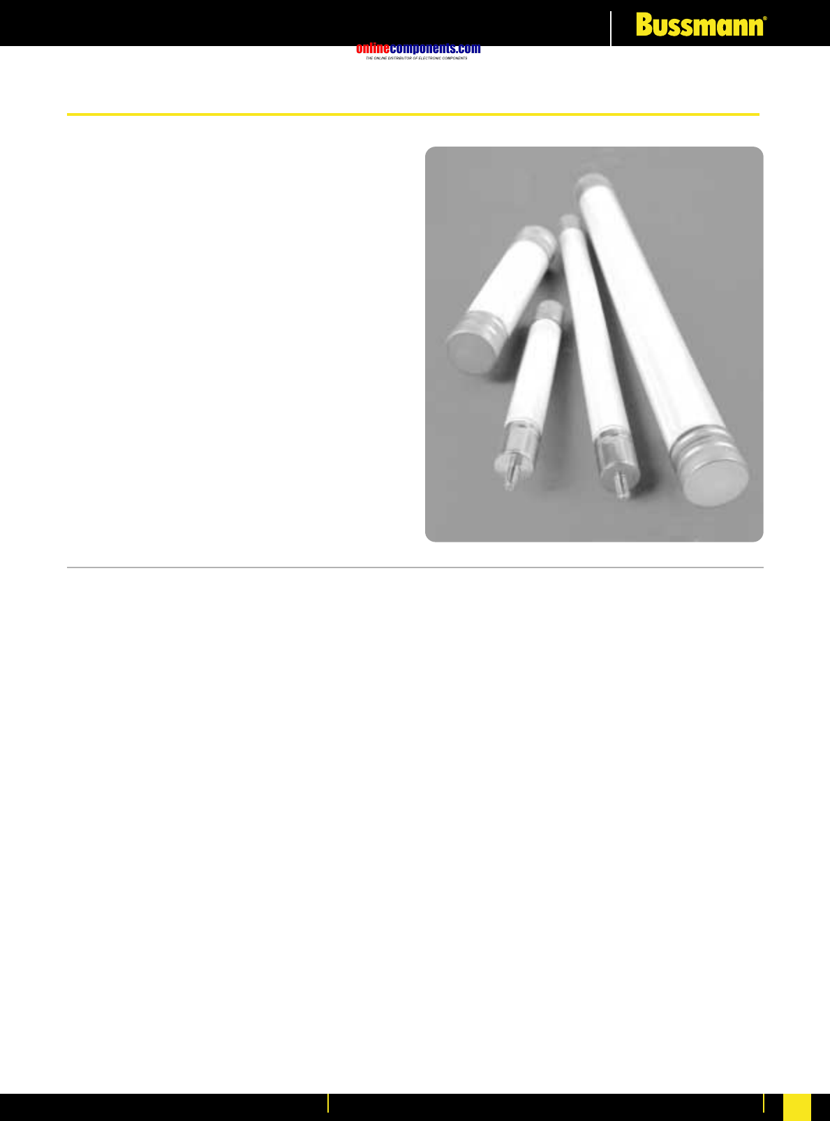
onlinecomponents.com
Medium Voltage Fuse Links
For more information visit our website at www.bussmann.com 116
• British Standard VT Fuse Links.
• A range of voltage transformer primary
Fuse Links to BS2692-1 and IEC60282-1.
• Wide range of ratings from 1 kV to 36 kV.
• 3.15 Amp industry standard current
ratings.
• CAV range with ratings from 3.6kV to
38kV.
Fuse Links for Voltage and Auxiliary Transformers
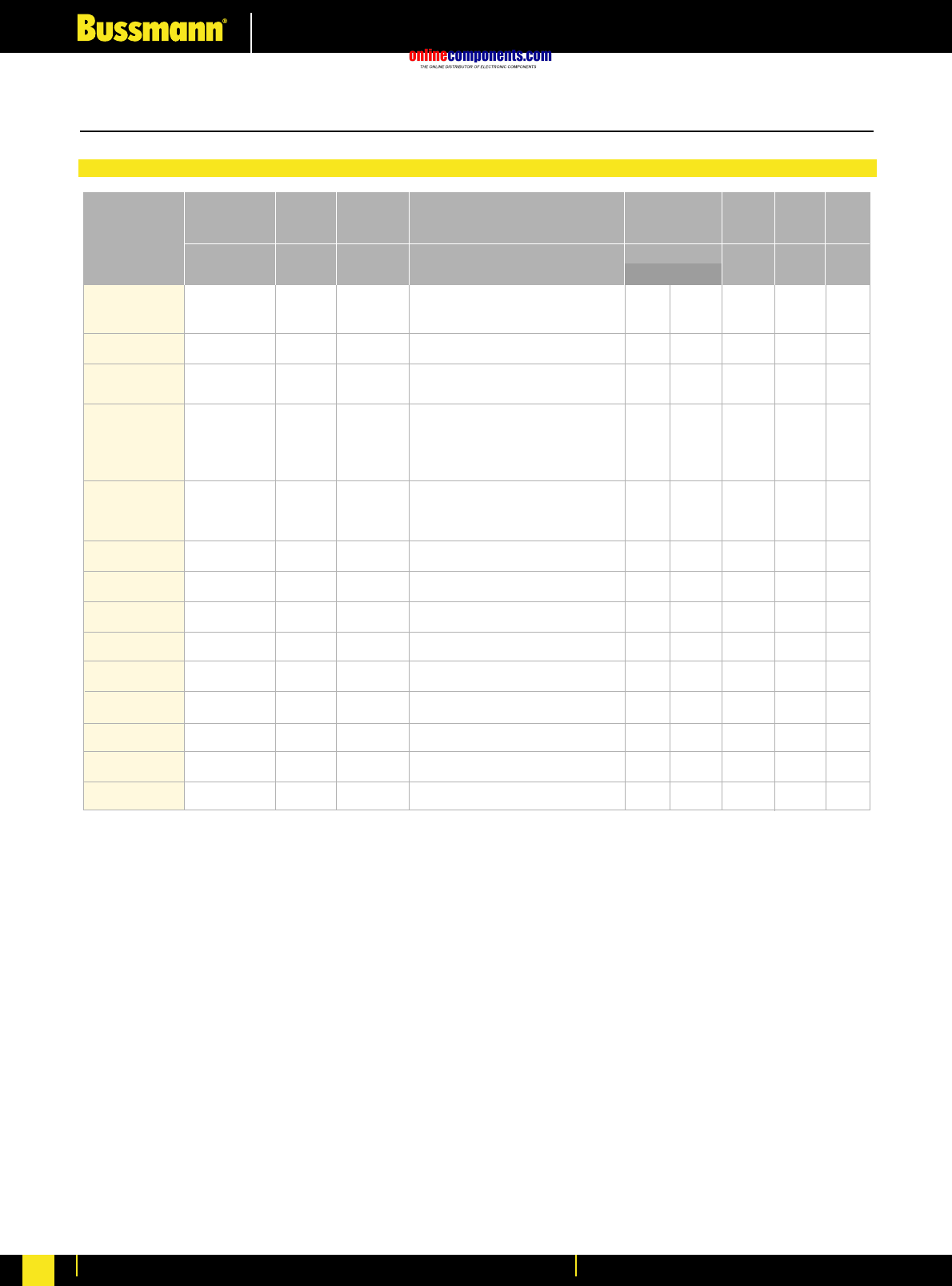
onlinecomponents.com
Medium Voltage Fuse Links
For more information visit our website at www.bussmann.com
117
The last letter of the ordering code on these items is normally either ‘A’ or ‘22’.
A 36kV AGBN* 3.15A is also available for certain indoor applications. Please contact Bussmann’s application engineers
for further information.
*
Table of ratings for voltage transformer fuses 1.1 - 36kV
Selection Table
1.1NBUN*2
1.1NBUN*3.15
1.1NBUN*6.3
3.6ABWN*3.15
3.6ABWN*6.3
3.6ABCN*3.15
3.6ABCN*6.3
3.6ABCN*10
5.5AMWNA0.5E
5.5AMWNA1E
5.5AMWNA2E
5.5AMWNA3E
5.5AMWNA4E
5.5AMWNA5E
5.5ABWNA0.5E
5.5ABWNA1E
5.5ABWNA2E
5.5ABWNA3E
5.5ABWNA5E
7.2ABWN*3.15
7.2ABWN*6.3
7.2ABCN*3.15
7.2ABCN*6.3
7.2OBCN*3.15
7.2OBCN*6.3
7.2OBWN*3.15
7.2OBWN*6.3
12ABCN*3.15
12OBCN*3.15
15.5ABFN*3.15
15.5OBFN*3.15
17.5ABGN*3.15
17.5OBGN*3.15
24ABGN*3.15
24OBGN*3.15
36OBGN*3.15
1.1
1.1
1.1
3.6
3.6
3.6
3.6
3.6
5.5
5.5
5.5
5.5
5.5
5.5
5.5
5.5
5.5
5.5
5.5
7.2
7.2
7.2
7.2
7.2
7.2
7.2
7.2
12
12
15.5
15.5
17.5
17.5
24
24
36
2
3.15
6.3
3.15
6.3
3.15
6.3
10
0.5
1
2
3
4
5
0.5
1
2
3
5
3.15
6.3
3.15
6.3
3.15
6.3
3.15
6.3
3.15
3.15
3.15
3.15
3.15
3.15
3.15
3.15
3.15
50
50
50
50
50
50
50
50
50
50
50
50
50
50
50
50
50
50
50
45
45
45
45
45
45
45
45
45
45
32
32
35
35
25
25
31.5
0.145
0.107
0.065
0.358
0.120
0.358
0.120
0.080
32.5
16.0
0.584
0.320
0.190
0.147
50.2
25.1
1.08
0.469
0.199
0.614
0.240
0.614
0.240
0.614
0.240
0.614
0.240
1.21
1.21
1.24
1.24
1.45
1.45
2.00
2.00
2.05
86
86
86
142
142
195
195
195
142
142
142
142
142
142
142
142
142
142
142
142
142
195
195
195
195
142
142
195
195
254
254
359
359
359
359
359
6.3X100
1.2X101
3.2X101
6.3X100
4.8X101
6.3X100
4.8X101
1.1X10²
1.2X100
5.0X100
4.0X100
1.8X101
4.6X101
7.9X101
0.49X100
2.0X100
1.2X100
6.3X100
3.2X101
6.3X100
4.8X101
6.3X100
4.8X101
6.3X100
4.8X101
6.3X100
4.8X101
6.3X100
6.3X100
6.3X100
6.3X100
6.3X100
6.3X100
6.3X100
6.3X100
1.2X101
1.8X101
3.4X101
9.2X101
1.8X101
3.1X10²
1.8X101
3.1X10²
7.0X10²
3.5X100
1.4X101
1.2X101
1.1X10²
3.0X10²
5.1X10²
1.4X100
5.7X100
3.4X100
1.8X101
2.0X10²
4.0X101
3.1X10²
4.0X101
3.1X10²
4.0X10
3.1X10²
4.0X10
3.1X10²
1.8X101
1.8X101
4.0X101
4.0X101
4.0X101
4.0X101
4.0X101
4.0X101
7.7X101
25.4
25.4
25.4
25.4
25.4
25.4
25.4
25.4
20.6
20.6
20.6
20.6
20.6
20.6
25.4
25.4
25.4
25.4
25.4
25.4
25.4
25.4
25.4
25.4
25.4
25.4
25.4
25.4
25.4
25.4
25.4
25.4
25.4
25.4
25.4
25.4
0.12
0.12
0.12
0.19
0.19
0.245
0.245
0.245
0.114
0.114
0.114
0.114
0.114
0.114
0.19
0.19
0.19
0.19
0.19
0.19
0.19
0.245
0.245
0.245
0.245
0.19
0.19
0.245
0.245
0.31
0.31
0.43
0.43
0.43
0.43
0.43
Part Number
Current
Rating Length Diameter
ø
In
A
Un
kV
I1
kA mm
Ω
A2s
mm
Weight
Breaking
Capacity Cold Resistance Joule
Intergral
(I2t)
Voltage
Rating
Maximum
Total Clearing
Minimum
Pre-Arcing kg
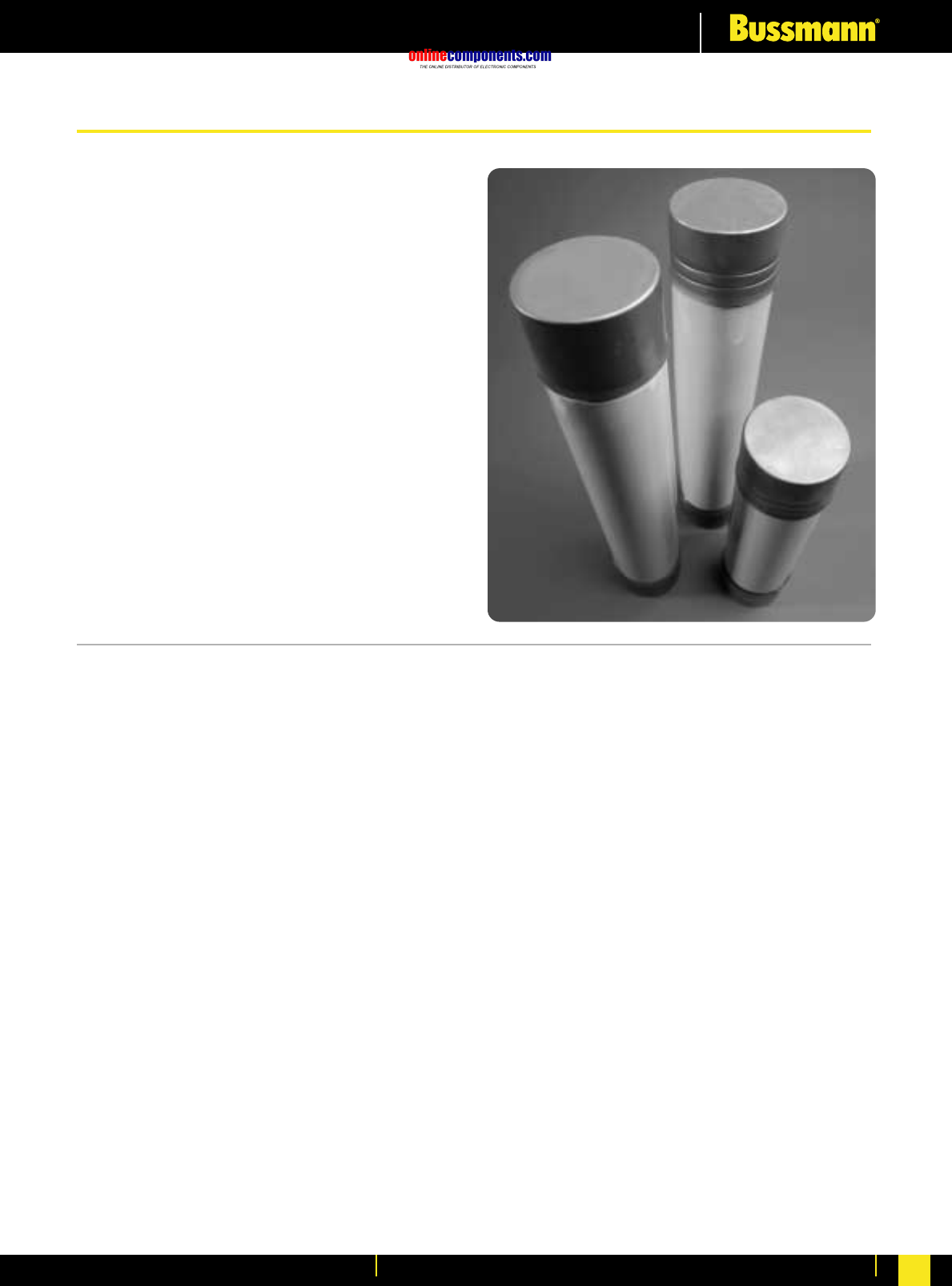
onlinecomponents.com
Medium Voltage Fuse Links
For more information visit our website at www.bussmann.com 118
• Fuse Links comply with IEC 282-1,
BS2692-1 and ESI Standard 12-8.
• 7.2 and 12kV Fuse Links tested at
highest system voltage and approved
by the UK Electricity Association
approvals panel.
• Voltage ranges 3.6 to 24kV.
• Fitted with powerful pyrotechnic
striker pin.
Current Limiting Fuse Links for use in Oil Switchgear
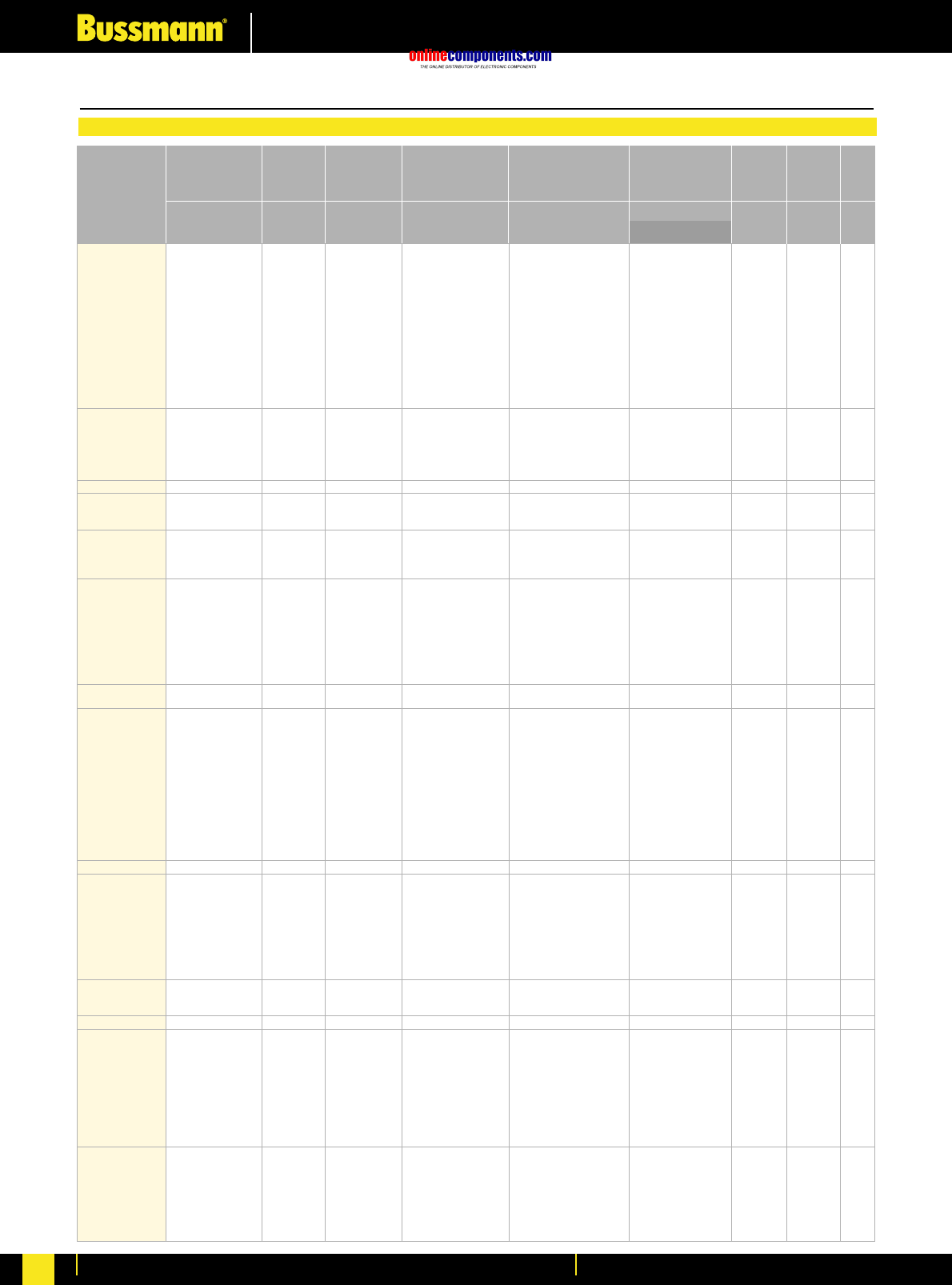
onlinecomponents.com
Medium Voltage Fuse Links
For more information visit our website at www.bussmann.com
119
Part Number
Current
Rating Length Diameter
ø
In
A
Un
kV
I1
kA mm
m Ω
A2s
mm
Weight
Breaking
Capacity Cold resistance in free
air at rated current
Dimensional Reference
BS 2692
Joule
Intergral
(I2t)
Voltage
Rating
Maximum
Total Clearing
Minimum
Pre-Arcing kg
3.6OEFMA6.3
3.6OEFMA10
3.6OEFMA16
3.6OEFMA20
3.6OEFMA25
3.6OEFMA31.5
3.6OEFMA40
3.6OEFMA50
3.6OEFMA63
3.6OEFMA80
3.6OEFMA100
3.6OEFMA125
3.6OEFMA160
3.6OEFMA200
3.6OEGMA63
3.6OEGMA80
3.6OEGMA100
3.6OEGMA125
3.6OEGMA160
3.6OEGMA200
3.6OLGMA250
7.2OEFMA80
7.2OEFMA100
7.2OEFMA112
7.2OHGMA100
7.2OHGMA125
7.2OHGMA140
7.2OHGMA160
12OEFMA6.3
12OEFMA10
12OEFMA16
12OEFMA20
12OEFMA25
12OEFMA31.5
12OEFMA40
12OEFMA50
12OEFMA63
12OHFMA71
12OHFMA80
12OHGMA6.3
12OHGMA10
12OHGMA16
12OHGMA20
12OHGMA25
12OHGMA31.5
12OHGMA40
12OHGMA50
12OHGMA63
12OHGMA71
12OHGMA80
12OHGMA90
12OHGMA100
12OLGMA125
15.5OEFMA6.3
15.5OEFMA10
15.5OEFMA16
15.5OEFMA20
15.5OEFMA25
15.5OEFMA31.5
15.5OEFMA40
15.5OEFMA50
15.5OEFMA63
15.5OHGMA71
15.5OHGMA80
15.5OHGMA90
15.5OLGMA100
17.5OHGMA6.3
17.5OHGMA10
17.5OHGMA16
1 7.5OHGMA20
17.5OHGMA25
17.5OHGMA31.5
17.5OHGMA40
17.5OHGMA50
17.5OHGMA63
17.5OHGMA80
24OEGMA6.3
24OEGMA10
24OEGMA16
24OEGMA20
24OEGMA25
24OEGMA31.5
24OEGMA40
24OEGMA50
3.6
3.6
3.6
3.6
3.6
3.6
3.6
3.6
3.6
3.6
3.6
3.6
3.6
3.6
3.6
3.6
3.6
3.6
3.6
3.6
3.6
7.2
7.2
7.2
7.2
7.2
7.2
7.2
12
12
12
12
12
12
12
12
12
12
12
12
12
12
12
12
12
12
12
12
12
12
12
12
12
15.5
15.5
15.5
15.5
15.5
15.5
15.5
15.5
15.5
15.5
15.5
15.5
15.5
17.5
17.5
17.5
17.5
17.5
17.5
17.5
17.5
17.5
17.5
24
24
24
24
24
24
24
24
6.3
10
16
20
25
31.5
40
50
63
80
100
125
160
200
63
80
100
125
160
200
250
80
100
112
100
125
140
160
6.3
10
16
20
25
31.5
40
50
63
71
80
6.3
10
16
20
25
31.5
40
50
63
71
80
90
100
125
6.3
10
16
20
25
31.5
40
50
63
71
80
90
100
6.3
10
16
20
25
31.5
40
50
63
80
6.3
10
16
20
25
31.5
40
50
50
50
50
50
50
50
50
50
50
50
50
50
50
50
50
50
50
50
50
50
50
45
45
45
45
45
45
45
40
40
40
40
40
40
40
40
40
45
45
40
40
40
40
40
40
40
40
40
40
40
40
40
40
40
40
40
40
40
40
40
40
40
40
40
40
40
35
35
35
35
35
35
35
35
35
35
25
25
25
25
25
25
25
25
207
83.6
42.5
33.9
26.5
17.6
15.4
11.5
7.60
6.03
4.02
3.02
2.21
1.74
11.0
8.70
5.50
4.59
3.44
2.29
1.72
8.36
5.59
4.57
6.09
5.08
4.35
3.81
520
214
108
77.0
57.8
38.5
28.2
20.1
15.1
12.3
10.9
520
214
108
77.0
57.8
38.5
28.2
22.6
17.0
16.6
13.4
12.2
8.75
7.09
392
188
101
78.7
55.3
36.9
29.5
22.1
17.8
17.7
15.5
11.6
10.0
665
282
139
100
74.7
49.8
36.5
26.0
19.5
15.5
605
290
153
119
84.5
55.9
44.7
34.0
F01
F02
F02
F01
F02
F01
F01
F02
F02
F01
F02
F02
F02
F02
254
254
254
254
254
254
254
254
254
254
254
254
254
254
254
254
254
254
254
254
254
254
254
254
359
359
359
359
254
254
254
254
254
254
254
254
254
254
254
359
359
359
359
359
359
359
359
359
359
359
359
359
359
254
254
254
254
254
254
254
254
254
359
359
359
359
359
359
359
359
359
359
359
359
359
359
359
359
359
359
359
359
359
359
63.5
63.5
63.5
63.5
63.5
63.5
63.5
63.5
63.5
63.5
63.5
63.5
63.5
63.5
63.5
63.5
63.5
63.5
63.5
63.5
63.5
63.5
63.5
63.5
63.5
63.5
63.5
63.5
63.5
63.5
63.5
63.5
63.5
63.5
63.5
63.5
63.5
63.5
63.5
63.5
63.5
63.5
63.5
63.5
63.5
63.5
63.5
63.5
63.5
63.5
63.5
63.5
63.5
63.5
63.5
63.5
63.5
63.5
63.5
63.5
63.5
63.5
63.5
63.5
63.5
63.5
63.5
63.5
63.5
63.5
63.5
63.5
63.5
63.5
63.5
63.5
63.5
63.5
63.5
63.5
63.5
63.5
63.5
63.5
1.9
1.9
1.9
1.9
1.9
1.9
1.9
1.9
1.9
1.9
1.9
1.9
1.9
1.9
2.6
2.6
2.6
2.6
2.6
2.6
2.6
1.9
1.9
1.9
2.6
2.6
2.6
2.6
1.9
1.9
1.9
1.9
1.9
1.9
1.9
1.9
1.9
1.9
1.9
2.6
2.6
2.6
2.6
2.6
2.6
2.6
2.6
2.6
2.6
2.6
2.6
2.6
2.6
1.9
1.9
1.9
1.9
1.9
1.9
1.9
1.9
1.9
2.6
2.6
2.6
2.6
2.6
2.6
2.6
2.6
2.6
2.6
2.6
2.6
2.6
2.6
2.6
2.6
2.6
2.6
2.6
2.6
2.6
2.6
2.0X101
1.4X10²
1.7X10²
2.7X10²
4.5X10²
1.0X10³
8.9X10³
1.6X10³
3.3X10³
5.2X10³
1.2X10⁴
2.1X10⁴
1.5X10⁴
2.4X10⁴
3.2X10³
5.2X10³
5.0X10³
7.2X10³
1.3X10⁴
2.9X10⁴
5.1X10⁴
3.2X10³
6.3X10³
9.1X10³
5.0X10³
7.2X10³
9.8X10³
1.3X10⁴
2.0X101
1.4X10²
1.7X10²
3.4X10²
4.0X10²
8.9X10²
1.5X10³
2.9X10³
5.1X10³
3.2X10³
4.1X10³
2.0X101
1.4X10²
1.7X10²
3.4X10²
4.0X10²
8.9X10²
1.5X10³
2.3X10³
4.1X10³
2.0X10³
3.2X10³
3.8X10³
6.3X10³
1.0X10⁴
4.8X101
4.0X101
2.7X101
4.5X101
5.2X101
1.2X10³
1.8X10³
3.3X10³
2.0X10³
2.5X10³
3.2X10³
5.0X10³
7.2X10³
2.0X101
1.4X10²
1.7X10²
3.4X10²
4.0X10²
9.0X10²
1.5X10³
2.9X10³
5.2X10³
3.8X10³
4.8X101
2.5X10²
2.7X10²
4.4X10²
5.2X10²
1.2X10³
1.8X10³
1.2X10³
4.9X10²
1.4X10³
2.4X10³
3.6X10³
4.8X10³
8.8X10³
1.0X10⁴
1.4X10⁴
2.4X10⁴
3.4X10⁴
6.2X10⁴
9.6X10⁴
1.6X10⁵
2.3X10⁵
1.9X10⁴
2.7X10⁴
4.9X10⁴
6.4X10⁴
1.0X10⁵
1.8X10⁵
2.7X10⁵
5.8X10⁴
9.0X10⁴
1.3X10⁵
7.5X10⁴
9.6X10⁴
1.4X10⁵
1.8X10⁵
6.1X10²
1.8X10³
3.0X10³
5.0X10³
6.5X10³
1.2X10⁴
1.8X10⁴
2.8X10⁴
4.3X10⁴
5.4X10⁴
7.0X10⁴
6.1X10²
1.8X10³
3.0X10³
5.0X10³
6.5X10³
1.2X10⁴
1.8X10⁴
2.4X10⁴
3.7X10⁴
3.9X10⁴
5.5X10⁴
6.2X10⁴
8.9X10⁴
1.7X10⁵
1.0X10³
3.4X10³
3.4X10³
4.9X10³
1.1X10⁴
1.5X10⁴
2.0X10⁴
3.0X10⁴
3.9X10⁴
4.4X10⁴
5.4X10⁴
7.5X10⁴
9.6X10⁴
6.1X10²
1.8X10³
3.0X10³
5.0X10³
6.5X10³
1.2X10⁴
1.9X10⁴
2.9X10⁴
4.5X10⁴
5.7X10⁴
1.0X10³
3.4X10³
3.4X10³
4.9X10³
1.1X10⁴
1.5X10⁴
2.0X10⁴
2.4X10⁴
Table of ratings for British Standard Oil tight fuses 3.6 - 24kV
Selection Table
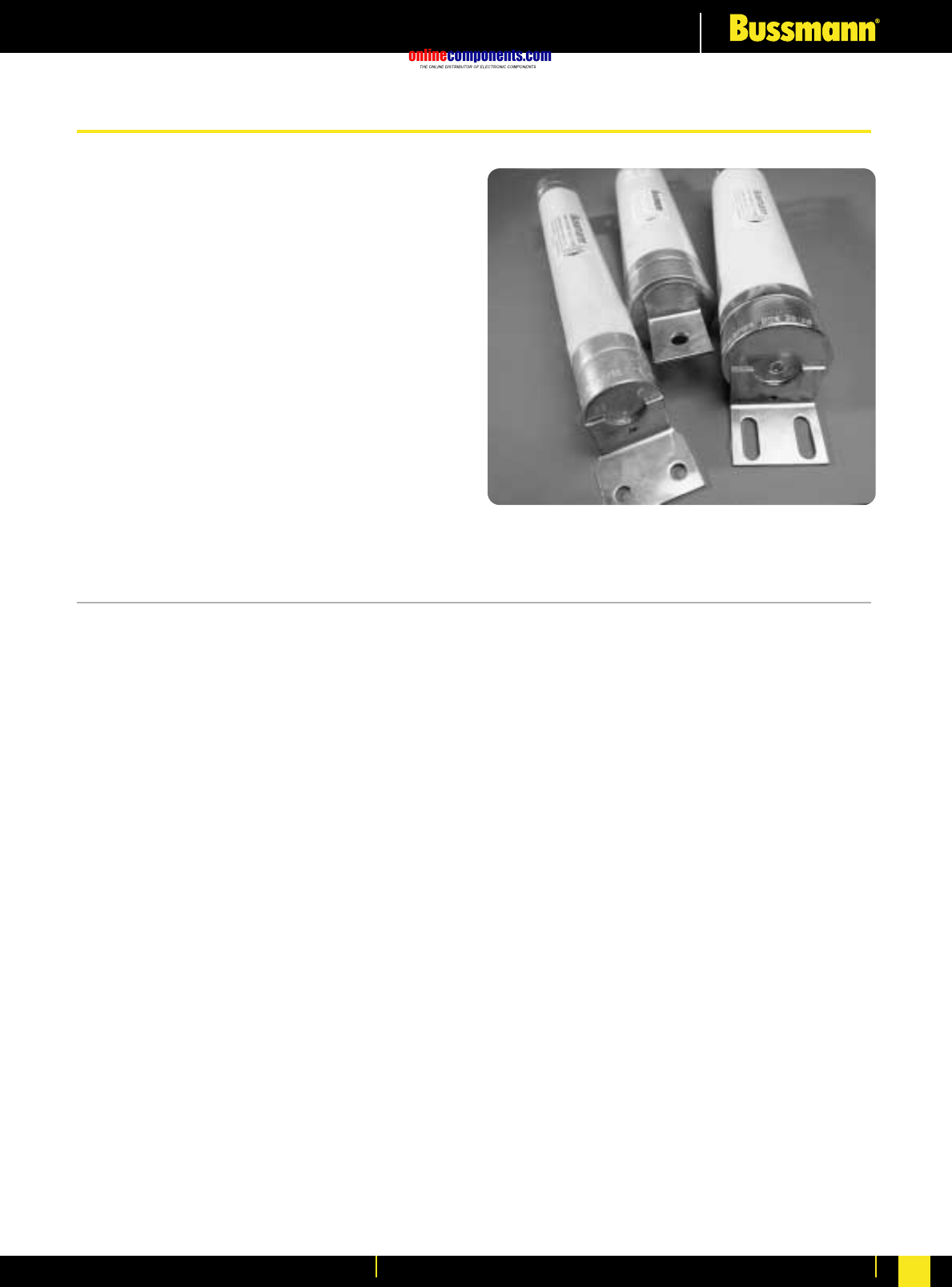
onlinecomponents.com
Medium Voltage Fuse Links
For more information visit our website at www.bussmann.com 120
• High Voltage fuse links for use in Air,
comply with BS 2962-1 dimensions
• Available in voltage ranges 3.6 to 72.5kV
• Full range performance option available
at 12kV and 24kV.
• Wide variety of fixing arrangements
available.
• Powerful pyrotechnic striker fitted.
• E-rated North American dimension
products also available.
• Suitable for indoor or outdoor use.
Current Limiting Fuse Links for use in Air
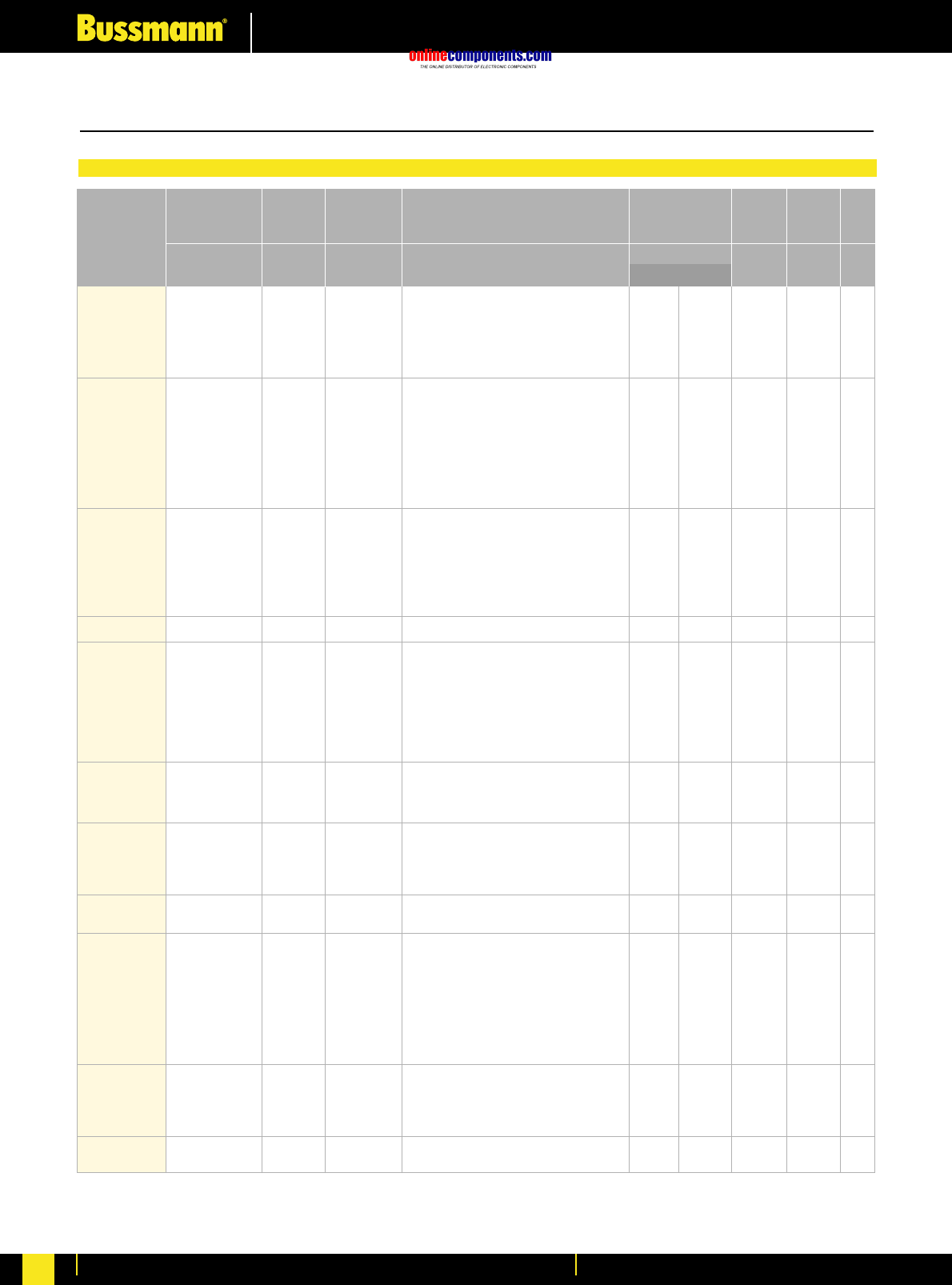
onlinecomponents.com
Medium Voltage Fuse Links
For more information visit our website at www.bussmann.com
121
Part Number *
Current
Rating Length Diameter
ø
In
A
Un
kV
I1
kA mm
m Ω
A2s
mm
Weight
Breaking
Capacity Cold resistance in free
air at rated current Joule
Intergral
(I2t)
Voltage
Rating
Maximum
Total Clearing
Minimum
Pre-Arcing kg
3.6ADFH*6.3
3.6ADFH*10
3.6ADFH*16
3.6ADFH*20
3.6ADFH*25
3.6ADFH*31.5
3.6ADFH*40
3.6ADGH*6.3
3.6ADGH*10
3.6ADGH*16
3.6ADGH*20
3.6ADGH*25
3.6ADGH*31.5
3.6ADGH*40
3.6ADGH*50
3.6ADGH*63
3.6ADGH*80
3.6ADGH*100
7.2ADFH*6.3
7.2ADFH*10
7.2ADFH*16
7.2ADFH*20
7.2ADFH*25
7.2ADFH*31.5
7.2ADFH*40
7.2ADFH*50
7.2ADFH*63
7.2AFFH*80
7.2AFFH*100
7.2BDGH*6.3
7.2BDGH*10
7.2BDGH*16
7.2BDGH*20
7.2BDGH*25
7.2BDGH*31.5
7.2BDGH*40
7.2BDGH*50
7.2BDGH*63
7.2BDGH*80
7.2BFGH*90
7.2BFGH*100
7.2BFGH*125
7.2BFGH*140
7.2BFGH*160
12ADFH*6.3
12ADFH*10
12ADFH*16
12ADFH*20
12ADFH*25
12ADFH*31.5
12AFFH*40
12AFFH*50
12AFFH*63
12BDGH*6.3
12BDGH*10
12BDGH*16
12BDGH*20
12BDGH*22.4
12BDGH*25
12BDGH*31.5
12BDGH*35.5
12BDGH*40
12BDGH*45
12BDGH*50
12BFGH*56
12BFGH*63
12BFGH*71
12BFGH*80
12BFGH*90
12BFGH*100
12AKGH*112
12AKGH*125
3.6
3.6
3.6
3.6
3.6
3.6
3.6
3.6
3.6
3.6
3.6
3.6
3.6
3.6
3.6
3.6
3.6
3.6
7.2
7.2
7.2
7.2
7.2
7.2
7.2
7.2
7.2
7.2
7.2
7.2
7.2
7.2
7.2
7.2
7.2
7.2
7.2
7.2
7.2
7.2
7.2
7.2
7.2
7.2
12
12
12
12
12
12
12
12
12
12
12
12
12
12
12
12
12
12
12
12
12
12
12
12
12
12
12
12
6.3
10
16
20
25
31.5
40
6.3
10
16
20
25
31.5
40
50
63
80
100
6.3
10
16
20
25
31.5
40
50
63
80
100
6.3
10
16
20
25
31.5
40
50
63
80
90
100
125
140
160
6.3
10
16
20
25
31.5
40
50
63
6.3
10
16
20
22.4
25
31.5
35.5
40
45
50
56
63
71
80
90
100
112
125
40
40
40
40
40
40
40
25
25
25
25
25
25
25
25
25
25
25
20
20
20
20
20
20
20
20
20
20
20
40
40
40
40
40
40
40
40
40
40
40
40
40
40
40
12
12
12
12
12
12
12
12
12
40
40
40
40
40
40
40
40
40
40
40
40
40
40
40
40
40
20
20
208
91.8
31.1
24.9
18.6
14.9
10.0
185
77.1
58.6
44.0
36.9
24.6
13.9
9.91
7.05
4.94
3.96
206
83.0
52.3
41.8
31.5
22.8
15.6
11.8
8.41
5.83
4.38
206
83.0
52.3
41.8
31.4
22.8
15.7
11.8
7.48
5.82
4.72
4.05
3.15
2.57
2.35
356
89.8
56.5
36.2
28.3
22.6
21.8
15.7
12.5
356
138
87.0
63.3
49.7
43.5
32.6
24.5
21.8
17.5
14.5
14.6
12.8
10.6
9.73
8.37
6.88
5.25
4.92
50.8
50.8
50.8
50.8
50.8
50.8
50.8
50.8
50.8
50.8
50.8
50.8
50.8
50.8
50.8
50.8
50.8
50.8
50.8
50.8
50.8
50.8
50.8
50.8
50.8
50.8
50.8
76.2
76.2
50.8
50.8
50.8
50.8
50.8
50.8
50.8
50.8
50.8
50.8
76.2
76.2
76.2
76.2
76.2
50.8
50.8
50.8
50.8
50.8
50.8
76.2
76.2
76.2
50.8
50.8
50.8
50.8
50.8
50.8
50.8
50.8
50.8
50.8
50.8
76.2
76.2
76.2
76.2
76.2
76.2
76.2
76.2
254
254
254
254
254
254
254
359
359
359
359
359
359
359
359
359
359
359
254
254
254
254
254
254
254
254
254
254
254
359
359
359
359
359
359
359
359
359
359
359
359
359
359
359
254
254
254
254
254
254
254
254
254
359
359
359
359
359
359
359
359
359
359
359
359
359
359
359
359
359
359
359
4.8x101
2.3x10²
7.2x101
1.1x10²
2.0x10²
3.1x10²
7.1x10²
4.8x101
3.1x10²
5.5x10²
9.8x10²
1.3x10²
2.9x10²
8.0x10²
1.6x10³
3.1x10³
6.3x10³
9.8x10³
4.8x101
7.2x101
7.2x101
1.1x10²
2.0x10²
3.8x10²
8.0x10²
1.3x10³
2.5x10³
6.3x10³
9.8x10³
5.1x101
1.0x10²
8.4x101
1.1x10²
2.0x10²
4.6x10²
8.0x10²
1.6x10³
3.6x10³
6.4x10³
1.0x10⁴
1.3x10⁴
1.6x10⁴
2.4x10⁴
2.9x10⁴
4.8x101
1.3x10²
1.3x10²
3.1x10²
5.1x10²
8.0x10²
1.2x10³
2.0x10³
3.1x10³
5.2x101
6.4x101
6.4x101
1.6x10²
2.4x10²
3.2x10²
5.8x10²
9.0x10²
1.2x10³
1.8x10³
2.5x10³
2.9x10³
3.4x10³
4.6x10³
6.1x10³
8.1x10³
1.1x10³
1.5x10⁴
2.1x10⁴
7.2x10²
2.3x10³
1.0x10³
1.5x10³
2.1x10³
2.8x10³
7.7x10³
7.2x10²
4.7x10³
8.3x10³
1.5x10⁴
1.5x10³
3.5x10³
9.6x10³
1.9x10⁴
3.7x10⁴
7.6x10⁴
1.2x10⁵
5.6x10²
9.4x10²
8.6x10²
1.5x10³
2.6x10³
4.8x10³
1.1x10⁴
1.4x10⁴
2.9x10⁴
6.9x10⁴
1.4x10⁵
6.0x10²
1.3x10³
1.0x10³
1.5x10³
2.6x10³
5.8x10³
1.1x10⁴
1.8x10⁴
4.3x10⁴
7.0x10⁴
1.4x10⁵
1.9x10⁵
1.9x10⁵
3.3x10⁵
4.0x10⁵
5.0x10²
2.0x10³
2.0x10³
3.5x10³
6.1x10³
9.0x10³
1.5x10⁴
2.5x10⁴
3.9x10⁴
5.0x10²
1.0x10³
1.0x10³
1.8x10³
3.0x10³
3.8x10³
6.5x10³
1.1x10⁴
1.5x10⁴
2.3x10⁴
3.2x10⁴
3.7x10⁴
4.5x10⁴
6.3x10⁴
7.8x10⁴
1.0x10⁵
1.4x10⁵
1.9x10⁵
2.4x10⁵
1.5
1.5
1.5
1.5
1.5
1.5
1.5
2.1
2.1
2.1
2.1
2.1
2.1
2.1
2.1
2.1
2.1
2.1
1.5
1.5
1.5
1.5
1.5
1.5
1.5
1.5
1.5
2.8
2.8
2.1
2.1
2.1
2.1
2.1
2.1
2.1
2.1
2.1
2.1
4.2
4.2
4.2
4.2
4.2
1.5
1.5
1.5
1.5
1.5
1.5
2.8
2.8
2.8
2.1
2.1
2.1
2.1
2.1
2.1
2.1
2.1
2.1
2.1
2.1
4.2
4.2
4.2
4.2
4.2
4.2
4.3
4.3
*The last letter of the ordering code on these items describes the tag required.
Table of ratings for British Standard air fuses 3.6 - 72.5kV
Selection Table
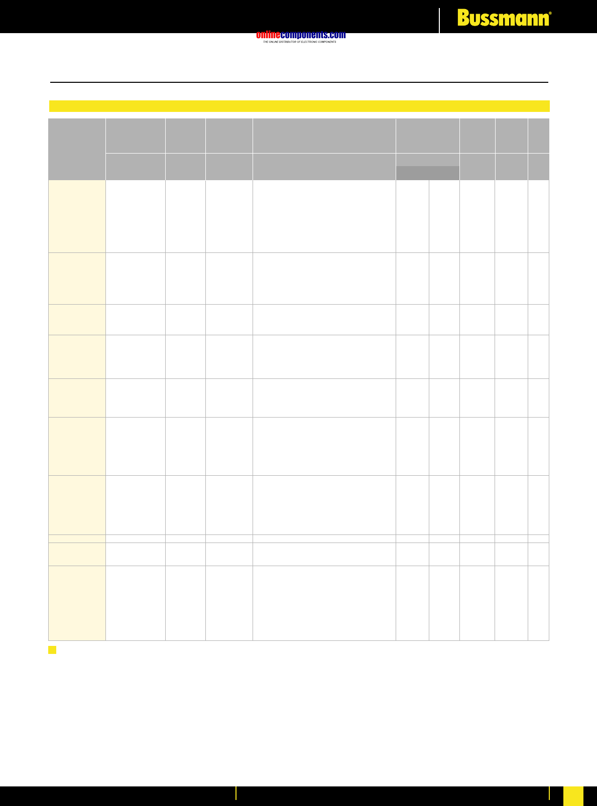
onlinecomponents.com
Medium Voltage Fuse Links
For more information visit our website at www.bussmann.com 122
Table of ratings for British Standard air fuses 3.6 - 72.5kV
Selection Table
Full range
12FFGN4910
12FFGN4916
12FFGN4920
12FFGN4925
12FFGN4931.5
12FFGN4940
12FFGN4950
12FFGN4963
15.5BDGH*6.3
15.5BDGH*10
15.5BDGH*16
15.5BDGH*20
15.5BDGH*25
15.5BDGH*31.5
15.5BDGH*40
15.5BFGH*50
15.5BFGH*63
15.5BFGH*80
15.5BFGH*85
24ADIHA6.3
24ADIHA10
24ADIHA16
24ADIHA20
24ADIHA25
24ADIHA31.5
24AFIHA40
24AFIHA50
24AFIHA63
24AFIHA80
24AFIHA90
Fullrange
24FDIHA3.15
24FDIHA5
24FDIHA6.3
24FDIHA10
24FDIHA16
24FDIHA20
24FDIHA31.5
36ADIHA3.15
36ADIHA5
36ADIHA6.3
36ADIHA10
36ADIHA16
36ADIHA20
36ADIHA25
36ADIHA31.5
36AFIHA40
36AFKHA50
36AFKHA63
36AFKHA71
72.5AFKHA3.15
72.5AFKHA5
72.5AFKHA6.3
72.5AFKHA10
72.5AFKHA16
72.5AFKHA20
72.5AFKHA25
72.5AFKHA31.5
72.5AFKHA40
12
12
12
12
12
12
12
12
15.5
15.5
15.5
15.5
15.5
15.5
15.5
15.5
15.5
15.5
15.5
15.5
15.5
15.5
15.5
15.5
15.5
24
24
24
24
24
24
24
24
24
24
24
24
36
36
36
36
36
36
36
36
36
36
36
36
72.5
72.5
72.5
72.5
72.5
72.5
72.5
72.5
72.5
10
16
20
25
31.5
40
50
63
6.3
10
16
20
25
31.5
40
50
63
80
85
6.3
10
16
20
25
31.5
40
50
63
80
90
3.15
5
6.3
10
16
20
31.5
3.15
5
6.3
10
16
20
25
31.5
40
50
63
71
3.15
5
6.3
10
16
20
25
31.5
40
40
40
40
40
40
40
40
40
20
20
20
20
20
20
20
20
20
20
20
12
12
12
12
12
12
16
16
16
16
16
35.5
35.5
35.5
35.5
35.5
35.5
35.5
16
16
16
16
16
16
16
16
25
25
25
25
12
12
12
12
12
12
12
12
12
90.6
69.1
45.6
36.5
25.4
19.7
14.7
12.6
485
158
99.1
74.6
54.2
38.2
27.2
22.2
15.5
9.73
9.45
520
173
129
104
82.7
66.2
46.5
33.2
23.5
17.9
14.7
893
412
412
205
103
88.2
56.0
1460
973
781
378
190
142
115
81.5
61.5
54.5
40.6
32.5
4230
1600
1200
519
389
249
195
130
92.7
76.2
76.2
76.2
76.2
76.2
76.2
76.2
76.2
76.2
50.8
50.8
50.8
50.8
50.8
50.8
50.8
76.2
76.2
76.2
76.2
50.8
50.8
50.8
50.8
50.8
50.8
76.2
76.2
76.2
76.2
76.2
50.8
50.8
50.8
50.8
50.8
50.8
50.8
50.8
50.8
50.8
50.8
50.8
50.8
50.8
50.8
76.2
76.2
76.2
76.2
76.2
76.2
76.2
76.2
76.2
76.2
76.2
76.2
359
359
359
359
359
359
359
359
359
359
359
359
359
359
359
359
359
359
359
359
565
565
565
565
565
565
565
565
565
565
565
565
565
565
565
565
565
565
565
565
565
565
565
565
565
565
565
914
914
914
914
914
914
914
914
914
914
914
2.7x10²
4.2x10²
9.5x10²
1.6x10³
3.1x10³
4.7x10³
8.4x10³
6.3x10³
4.8x101
7.2x101
7.2x101
1.3x10²
2.4x10²
4.9x10²
9.6x10²
1.6x10³
3.2x10³
7.2x10³
7.2x10³
7.9x101
7.2x101
1.3x10²
2.0x10²
3.1x10²
4.9x10²
1.2x10³
2.4x10³
3.2x10³
5.5x10³
7.2x10³
3.1x101
5.9x101
5.9x101
2.7x10²
1.1x10³
1.3x10³
5.3x10³
2.0x101
4.4x101
7.1x101
7.2x101
1.1x10²
2.0x10²
3.1x10²
6.1x10²
1.2x10³
1.9x10³
3.5x10³
5.5x10³
1.4x101
1.1x10²
1.9x10²
7.2x101
1.3x10²
3.1x10²
5.1x10²
1.0x10³
2.0x10³
4.7x10³
6.1x10³
1.1x10⁴
1.5x10⁴
2.5x10⁴
3.8x10⁴
5.6x10⁴
5.4x10⁴
8.5x10²
1.2x10³
1.2x10³
2.8x10³
4.3x10³
7.0x10³
1.2x10⁴
3.2x10⁴
4.6x10⁴
1.0x10⁵
1.0x10⁵
8.5x10²
1.1x10²
1.7x10³
2.8x10³
4.1x10³
6.8x10³
1.1x10⁴
2.2x10⁴
5.2x10⁴
8.2x10⁴
1.0x10⁵
9.8x101
4.5x10²
4.5x10²
2.1x10³
8.3x10³
4.8x10³
2.0x10⁴
2.5x10²
5.5x10²
8.9x10²
1.1x10³
1.7x10³
2.8x10³
4.5x10³
8.1x10³
1.9x10⁴
2.8x10⁴
5.0x10⁴
8.2x10⁴
1.8x10²
1.4x10³
2.5x10³
9.3x10²
1.7x10³
4.0x10³
6.6x10³
1.3x10⁴
2.6x10⁴
4.1
4.1
4.1
4.1
4.1
4.1
4.1
4.1
4.1
2.1
2.1
2.1
2.1
2.1
2.1
2.1
4.2
4.2
4.2
4.2
3.0
3.0
3.0
3.0
3.0
3.0
6.1
6.1
6.1
6.1
6.1
3.0
3.0
3.0
3.0
3.0
3.0
3.0
3.0
3.0
3.0
3.0
3.0
3.0
3.0
3.0
6.1
9.7
9.7
9.7
9.7
9.7
9.7
9.7
9.7
9.7
9.7
9.7
Part Number
Current
Rating Length Diameter
ø
In
A
Un
kV
I1
kA mm
m Ω
A2s
mm
Weight
Breaking
Capacity Cold resistance in free
air at rated current Joule
Intergral
(I2t)
Voltage
Rating
Maximum
Total Clearing
Minimum
Pre-Arcing kg
Notes
a) The fifth letter or number of the part reference denotes the end fixing arrangement.
b) There are a wide variety of end terminations available, the most popular types, some of which have dimensional
references to BS2692: Part 1, are:
ANo Tags - Ferrule - BS Ref. FA3 - ADIHA / BS Ref. FA4 - AFIHA / BS Ref. FA5 - AFKHA
BOffset Tag, single bolt fixing
C & D Special Offset Tags, two hole fixings for Brush fuse switch equipment, BS Ref. TA3.
F & O Offset Tags two bolt fixing.
49 Centre Tags, single bolt fixing for use in Fused End Boxes.
6Tags to BS2692-1 ref. TA3
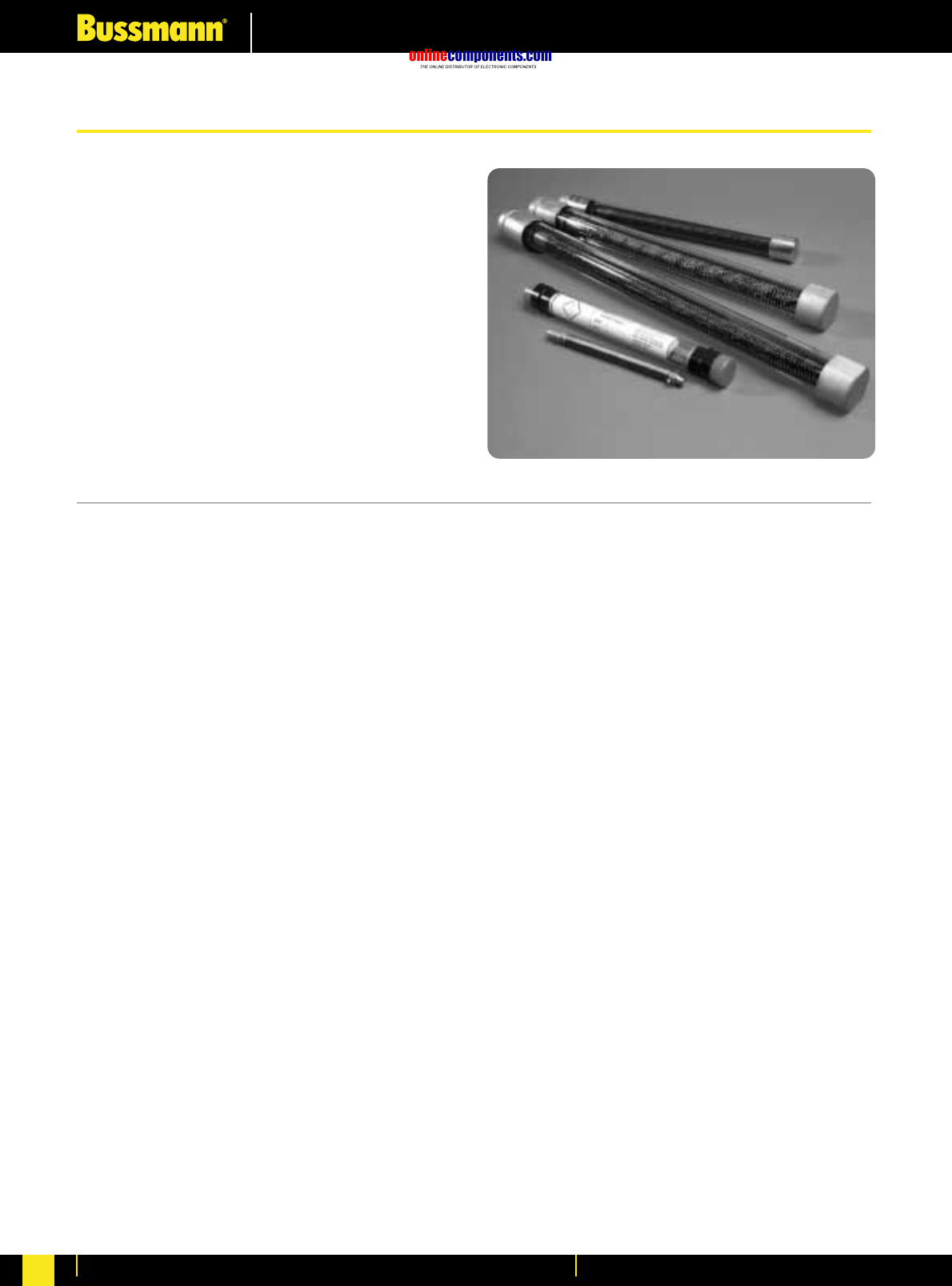
onlinecomponents.com
Medium Voltage Fuse Links
For more information visit our website at www.bussmann.com
123
•Replacement liquid fuse links sizes 1, 2 and 3.
•Wide range of voltages 6.6kV up to 75kV.
•Current ratings from 2 up to 75 amps
(including‚ ‘E’ rated option).
•Standard and slow blow elements available.
•Rewiring kits available for sizes 2 and 3.
•Size 1 full range cartridge fuse available
type FDSH48.
Liquid Fuse Links
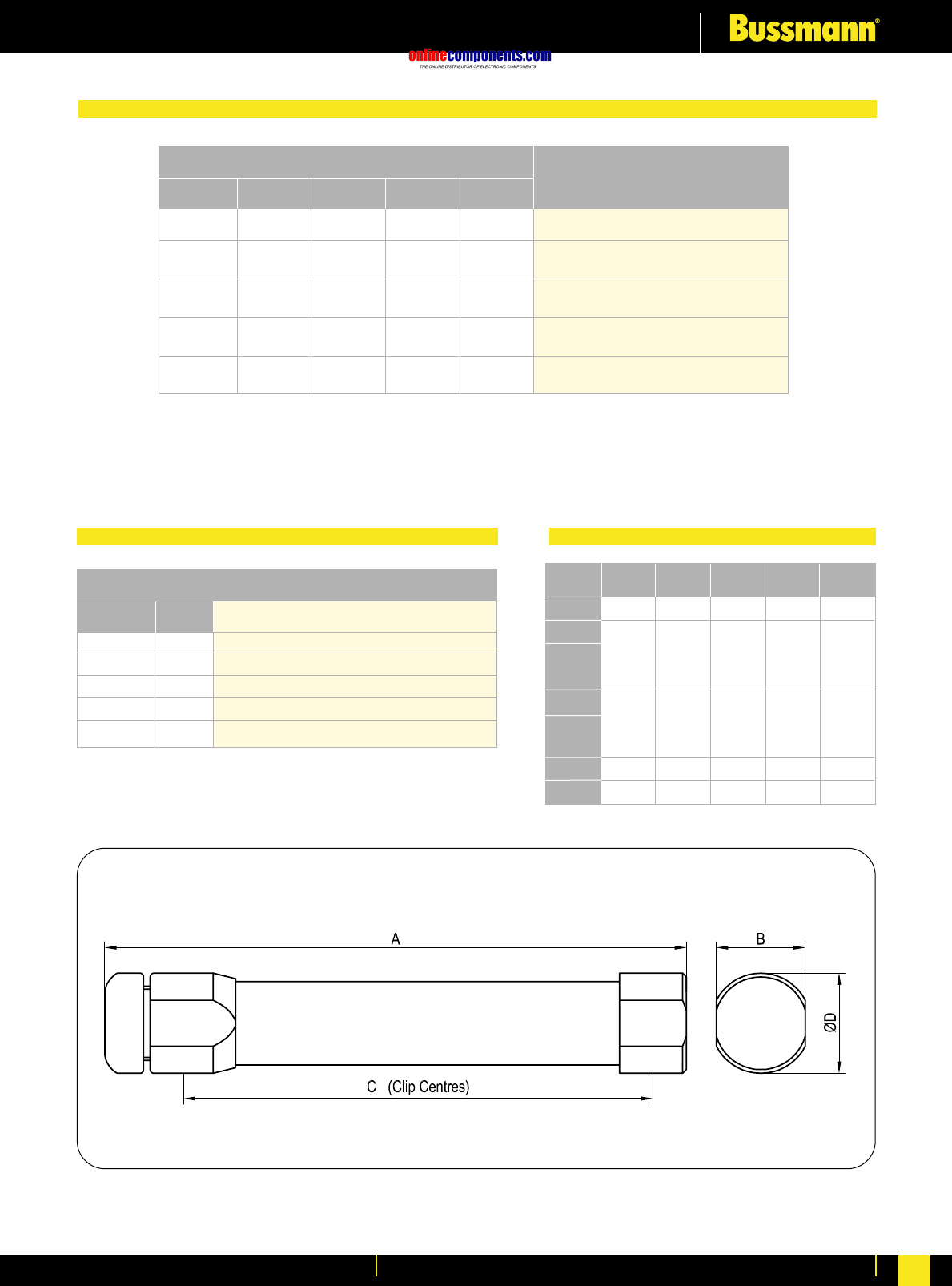
onlinecomponents.com
Medium Voltage Fuse Links
For more information visit our website at www.bussmann.com 124
The part number would be 33L3S25 meaning a fuse with a rated voltage of 33kV;
L denoting a Liquid type fuse; 3 denoting size; S denoting slow blow and 25 indicating rated current in Amps.
33
-
-
-
-
Rating Voltage Liquid Fuse
Designation SIze Characteristic Current Meaning
Symbol
-
L
-
-
-
-
-
3
-
-
-
-
-
S
-
-
-
-
-
25
Fuse is rated at 33kV for use on 33kV systems
Denotes a Liquid fuse link
Indicates size
Indicates characteristics (F = standard; S = slow blow)
Current rating of the fuse link in Amps
1
2
2
3
3
Size Type Current Rating (Amps)
Table of Ratings
Standard
Standard
Slow
Standard
Slow
2E 3E 5E 7E 10E 20E
3 5 10 15 20 25
5 10 15 20 25
3 5 10 15 20 25 30 40 50 60 75
5 10 15 20 25 30 40 50 60 75
Ordering Code
Selection Table Dimensions
SizekV A B C ØD
6.6
7.5
11/12
15/23
33
44
66
3
1
2
3
1
2
3
3
3
249
238
338
338
327
427
427
503
655
38.1
-
-
38.1
-
-
38.1
38.1
38.1
203
203
292
292
292
381
381
457
609
42.8
23.9
30.2
42.8
23.9
30.2
42.8
42.8
42.8
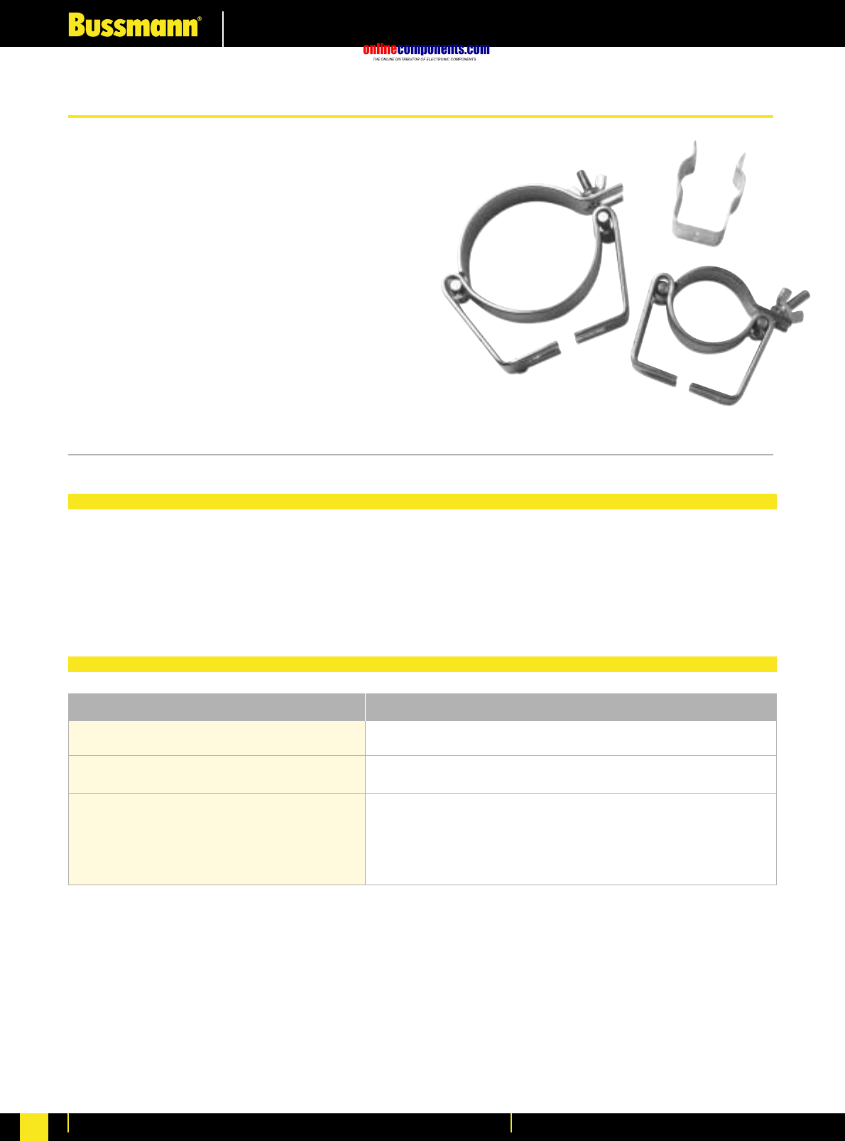
onlinecomponents.com
Medium Voltage Fuse Links
For more information visit our website at www.bussmann.com
125
To complement the range of tag fixings offered by Bussmann, a range of fuse clips. These are suitable for use with
British Standard, DIN dimensioned and VT ferrule style fuse links. The BS and DIN clips are rated up to 200 Amps.
They are designed to be fitted onto insulated studs or directly onto a busbar.
DIN fuse links to 43 625
Voltage transformer and auxiliary
type fuse links
British standard fuse links
50.8mm (2”) dia
63.5mm (2.5”) dia
76.2mm (3”) dia
270303 or A3354745
A3354705
A3354710
A3354720
A3354730
Fuse Type Clip Reference
•VT Fuse Clips for 25.4mm diameter.
•DIN Standard Clips for ‘F’ and‚ ‘S’ range
fuse links.
•BS Mounting Clips suitable for 50.8mm and
76.2mm Oil, Air and Motor Fuse Links up to
200A.
Selection Table
Bussmann Fuse Clips
Fuse Clips
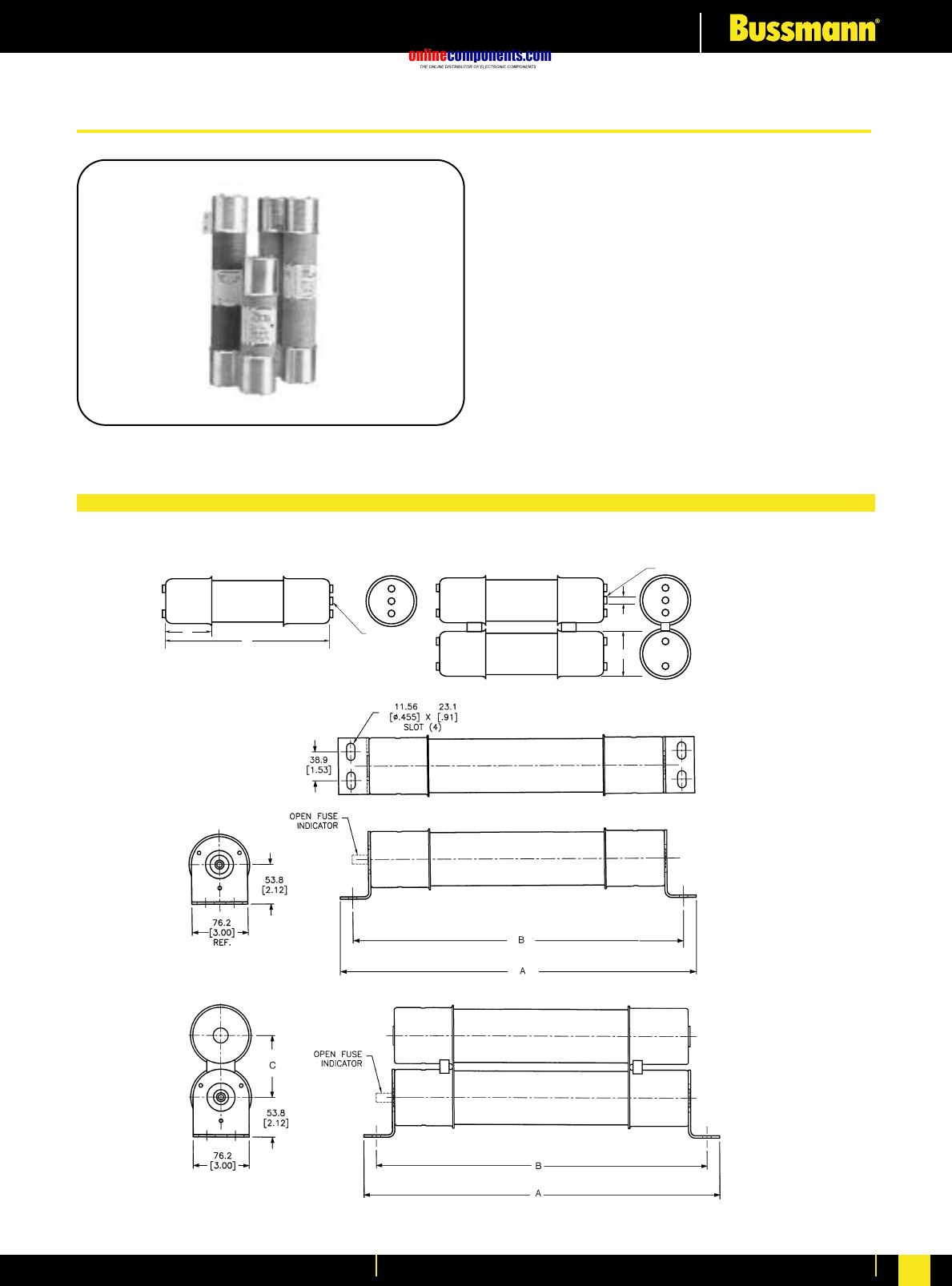
onlinecomponents.com
Medium Voltage Fuse Links
For more information visit our website at www.bussmann.com 126
Dimensional Data
BIF document: 6001
0.38"
(9.5mm)
B
INDICATOR
Showing Fuse is Open
INDICATOR
Showing Fuse
is Open
A
C
Figure 1
Figure 2
JCK, JCK-A, JCK-B, JCH, JCL, JCL-A,
JCL-B, JCG, JCR, & JCR-B
R-Rated
Medium Voltage
Current Limiting
2400V AC — JCK, JCK-A, JCK-B, JCH
4800V AC — JCL, JCL-A, JCL-B, JCG
7200V AC — JCR, JCR-B
Max. Design Voltage: 2540V AC — JCK, JCK-A,
JCK-B, JCH
5080V AC — JCL, JCL-A
JCL-B, JCG
8300V AC — JCR, JCR-B
Agency Approvals:
UL Recognized : 2540V AC — JCK, JCK-A
5080V AC — JCL, JCL-A
UL Recognized (Guide #MSSS2, File #E96676)
R-Rated Fuses for Motor Circuit Protection
onlinecomponents.com
Medium Voltage Fuse Links
For more information visit our website at www.bussmann.com
127
R-Rated Fuses for Motor Circuit Protection
Buss Maximum Dimensions (Inches) Max. Int. Cap. Min. Int. Cap.
Catalogue No. Amperage Design Voltage A B C Construction Amps (Asym.) Amps (Sym.) Amps (Sym.)
2400V; R-Rated; Indoor/Enclosure (See Figure 1)
JCK-2R 70 2R 2540V 11.24 3.0 3.0 Single 80,000 50,000 165
JCK-3R 100 3R 2540V 11.24 3.0 3.0 Single 80,000 50,000 220
JCK-4R 130 4R 2540V 11.24 3.0 3.0 Single 80,000 50,000 320
JCK-5R 150 5R 2540V 11.24 3.0 3.0 Single 80,000 50,000 410
JCK-6R 170 6R 2540V 11.24 3.0 3.0 Single 80,000 50,000 480
JCK-9R 200 9R 2540V 11.24 3.0 3.0 Single 80,000 50,000 720
JCK-12R 230 12R 2540V 11.24 3.0 3.0 Single 80,000 50,000 970
JCK-18R 390 18R 2540V 11.24 3.0 3.0 Double 80,000 50,000 1,430
JCK-24R 450 24R 2540V 11.24 3.0 3.0 Double 80,000 50,000 1,880
2400V; R-Rated; Indoor/Enclosure; With Westinghouse Ampguard Hookeye (See Figure 1)
JCK-A-2R 70 2R 2540V 11.24 3.0 3.0 Single 80,000 50,000 165
JCK-A-3R 100 3R 2540V 11.24 3.0 3.0 Single 80,000 50,000 220
JCK-A-4R 130 4R 2540V 11.24 3.0 3.0 Single 80,000 50,000 320
JCK-A-5R 150 5R 27540V 11.24 3.0 3.0 Single 80,000 50,000 410
JCK-A-6R 170 6R 2540V 11.24 3.0 3.0 Single 80,000 50,000 480
JCK-A-9R 200 9R 2540V 11.24 3.0 3.0 Single 80,000 50,000 720
JCK-A-12R 230 12R 2540V 11.24 3.0 3.0 Single 80,000 50,000 970
JCK-A-18R 390 18R 2540V 11.24 3.0 3.0 Double 80,000 50,000 1,430
JCK-A-24R 450 24R 2540V 11.24 3.0 3.0 Double 80,000 50,000 1,880
2400V; R-Rated; Indoor/Enclosure; Bolt-On (See Figure 2)
JCK-B-30 25 2540V 14.18 12.81 - Single 80,000 50,000 90
JCK-B-2R 70 2R 2540V 14.18 12.81 - Single 80,000 50,000 170
JCK-B-3R 100 3R 2540V 14.18 12.81 - Single 80,000 50,000 245
JCK-B-4R 130 4R 2540V 14.18 12.81 - Single 80,000 50,000 340
JCK-B-5R 150 5R 2540V 14.18 12.81 - Single 80,000 50,000 430
JCK-B-6R 170 6R 2540V 14.18 12.81 - Single 80,000 50,000 500
JCK-B-9R 200 9R 2540V 14.18 12.81 - Single 80,000 50,000 1,000
JCK-B-12R 230 12R 2540V 14.18 12.81 - Single 80,000 50,000 1,250
JCK-B-18R 390 18R 2540V 14.18 12.81 3.56 Double 80,000 50,000 1,700
JCK-B-24R 450 24R 2540V 14.18 12.81 3.56 Double 80,000 50,000 1,210
2400V; R-Rated; Indoor; Hermetically Sealed, Class 1, Group D, Div. 2, Hazardous Locations; For Use with Ampgard Motor Starters (See Figure 1)
JCH-30 25 2540V 10.81 3.0 3.0 Single 80,000 50,000 90
JCH-2R 70 2R 2540V 10.81 3.0 3.0 Single 80,000 50,000 170
JCH-3R 100 3R 2540V 10.81 3.0 3.0 Single 80,000 50,000 245
JCH-4R 130 4R 2540V 10.81 3.0 3.0 Single 80,000 50,000 340
JCH-5R 150 5R 2540V 10.81 3.0 3.0 Single 80,000 50,000 430
JCH-6R 170 6R 2540V 10.81 3.0 3.0 Single 80,000 50,000 500
JCH-9R 200 9R 2540V 10.81 3.0 3.0 Single 80,000 50,000 1,000
JCH-12R 230 12R 2540V 10.81 3.0 3.0 Single 80,000 50,000 1,250
JCH-18R 390 18R 2540V 10.81 3.0 3.0 Double 80,000 50,000 1,700
JCH-24R 450 24R 2540V 10.81 3.0 3.0 Double 80,000 50,000 2,100
4800V; R-Rated; Indoor/Enclosure (See Figure 1)
JCL-2R 70 2R 5080V 15.76 3.0 3.0 Single 80,000 50,000 165
JCL-3R 100 3R 5080V 15.76 3.0 3.0 Single 80,000 50,000 220
JCL-4R 130 4R 5080V 15.76 3.0 3.0 Single 80,000 50,000 320
JCL-5R 150 5R 5080V 15.76 3.0 3.0 Single 80,000 50,000 410
JCL-6R 170 6R 5080V 15.76 3.0 3.0 Single 80,000 50,000 480
JCL-9R 200 9R 5080V 15.76 3.0 3.0 Single 80,000 50,000 720
JCL-12R 230 12R 5080V 15.76 3.0 3.0 Single 80,000 50,000 970
JCL-18R 390 18R 5080V 15.76 3.0 3.0 Double 80,000 50,000 1,430
JCL-24R 450 24R 5080V 15.76 3.0 3.0 Double 80,000 50,000 1,880
Specifications
onlinecomponents.com
Medium Voltage Fuse Links
For more information visit our website at www.bussmann.com 128
R-Rated Fuses for Motor Circuit Protection
Buss Maximum Dimensions (Inches) Max. Int. Cap. Min. Int. Cap.
Catalogue No. Amperage Design Voltage A B C Construction Amps (Asym.) Amps (Sym.) Amps (Sym.)
4800V; R-Rated; Indoor/Enclosure; With Westinghouse Ampguard Hookeye (See Figure 1)
JCL-A-2R 70 2R 5080V 15.76 3.0 3.0 Single 80,000 50,000 165
JCL-A-3R 100 3R 5080V 15.76 3.0 3.0 Single 80,000 50,000 220
JCL-A-4R 130 4R 5080V 15.76 3.0 3.0 Single 80,000 50,000 320
JCL-A-5R 150 5R 5080V 15.76 3.0 3.0 Single 80,000 50,000 410
JCL-A-6R 170 6R 5080V 15.76 3.0 3.0 Single 80,000 50,000 480
JCL-A-9R 200 9R 5080V 15.76 3.0 3.0 Single 80,000 50,000 720
JCL-A-12R 230 12R 5080V 15.76 3.0 3.0 Single 80,000 50,000 970
JCL-A-18R 390 18R 5080V 15.76 3.0 3.0 Double 80,000 50,000 1,430
JCL-A-24R 450 24R 5080V 15.76 3.0 3.0 Double 80,000 50,000 1,880
4800V; R-Rated; Indoor/Enclosure; Bolt-On (See Figure 2)
JCL-B-30 30 5080V 19.25 17.88 - Single 80,000 50,000 95
JCL-B-2R 70 2R 5080V 19.25 17.88 - Single 80,000 50,000 180
JCL-B-3R 100 3R 5080V 19.25 17.88 - Single 80,000 50,000 270
JCL-B-4R 130 4R 5080V 19.25 17.88 - Single 80,000 50,000 350
JCL-B-5R 150 5R 5080V 19.25 17.88 - Single 80,000 50,000 450
JCL-B-6R 170 6R 5080V 19.25 17.88 - Single 80,000 50,000 540
JCL-B-9R 200 9R 5080V 19.25 17.88 - Single 80,000 50,000 700
JCL-B-12R 230 12R 5080V 19.25 17.88 - Single 80,000 50,000 1,000
JCL-B-18R 390 18R 5080V 19.25 17.88 3.31 Double 80,000 50,000 1,450
JCL-B-24R 450 24R 5080V 19.25 17.88 3.31 Double 80,000 50,000 2,000
4800V; R-Rated; Indoor; Hermetically Sealed, Class 1, Group D, Div. 2, Hazardous Locations; For Use with Ampgard Motor Starters (See Figure 1)
JCG-30 30 5080V 15.91 3.0 3.0 Single 80,000 50,000 95
JCG-2R 70 2R 5080V 15.91 3.0 3.0 Single 80,000 50,000 180
JCG-3R 100 3R 5080V 15.91 3.0 3.0 Single 80,000 50,000 270
JCG-4R 130 4R 5080V 15.91 3.0 3.0 Single 80,000 50,000 350
JCG-5R 150 5R 5080V 15.91 3.0 3.0 Single 80,000 50,000 450
JCG-6R 170 6R 5080V 15.91 3.0 3.0 Single 80,000 50,000 540
JCG-9R 200 9R 5080V 15.91 3.0 3.0 Single 80,000 50,000 700
JCG-12R 230 12R 5080V 15.91 3.0 3.0 Single 80,000 50,000 1,000
JCG-A-18R 390 18R 5080V 15.91 3.0 3.0 Double 80,000 50,000 1,450
JCG-A-24R 450 24R 5080V 15.91 3.0 3.0 Double 80,000 50,000 2,000
7200V; R-Rated; Indoor/Enclosure; With Ampgard Hookeye (See Figure 1)
JCR-A-2R 70 2R 8300V 15.85 3.0 3.0 Single 80,000 50,000 160
JCR-A-3R 100 3R 8300V 15.85 3.0 3.0 Single 80,000 50,000 250
JCR-A-4R 130 4R 8300V 15.85 3.0 3.0 Single 80,000 50,000 325
JCR-A-5R 150 5R 8300V 15.85 3.0 3.0 Single 80,000 50,000 390
JCR-A-6R 170 6R 8300V 15.85 3.0 3.0 Single 80,000 50,000 500
JCR-A-9R 200 9R 7200V 15.85 3.0 3.0 Single 80,000 50,000 750
JCR-A-12R 230 12R 7200V 15.85 3.0 3.0 Single 80,000 50,000 1,000
JCR-A-18R 390 18R 7200V 15.85 3.0 3.0 Double 80,000 50,000 1,450
JCR-A-24R 450 24R 7200V 15.85 3.0 3.0 Double 80,000 50,000 2,500
7200V; R-Rated; Indoor/Enclosure; Bolt-On (See Figure 2)
JCR-B-2R 70 2R 8300V 19.25 17.88 - Single 80,000 50,000 160
JCR-B-3R 100 3R 8300V 19.25 17.88 - Single 80,000 50,000 250
JCR-B-4R 130 4R 8300V 19.25 17.88 - Single 80,000 50,000 325
JCR-B-5R 150 5R 8300V 19.25 17.88 - Single 80,000 50,000 390
JCR-B-6R 170 6R 8300V 19.25 17.88 - Single 80,000 50,000 500
JCR-B-9R 200 9R 7200V 19.25 17.88 - Single 80,000 50,000 750
JCR-B-12R 230 12R 7200V 19.25 17.88 - Single 80,000 50,000 1,000
JCR-B-18R 390 18R 7200V 19.25 17.88 3.31 Double 80,000 50,000 1,450
JCR-B-24R 450 24R 7200V 19.25 17.88 3.31 Double 80,000 50,000 2,500
Specifications
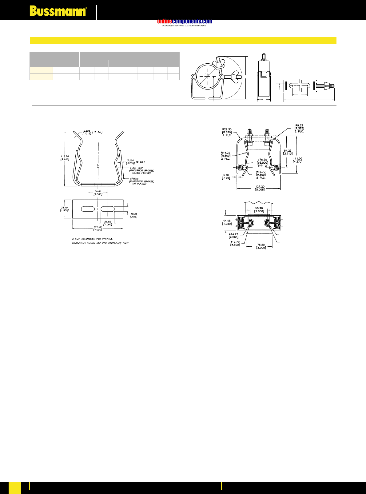
onlinecomponents.com
Medium Voltage Fuse Links
For more information visit our website at www.bussmann.com
129
Recommended Fuse Clips for Medium Voltage Fuses
C
B
A
G
E
F
D
Part Fuse Clip Dimensions
No. Diameter A B C D E F G
A3354710 23.741.972.001.184.531.50.39
A3354730 34.132.443.001.185.631.50.39
Fuseclips are for single barrel applications only. Are not sold in pairs.
1A0065
3” Diameter Clip 9078A67G04
3” Diameter Clip
2 CUP ASSEMBLIES PER
PACKAGE.DIMENSIONS
SHOWN ARE FOR
REFERENCE ONLY.
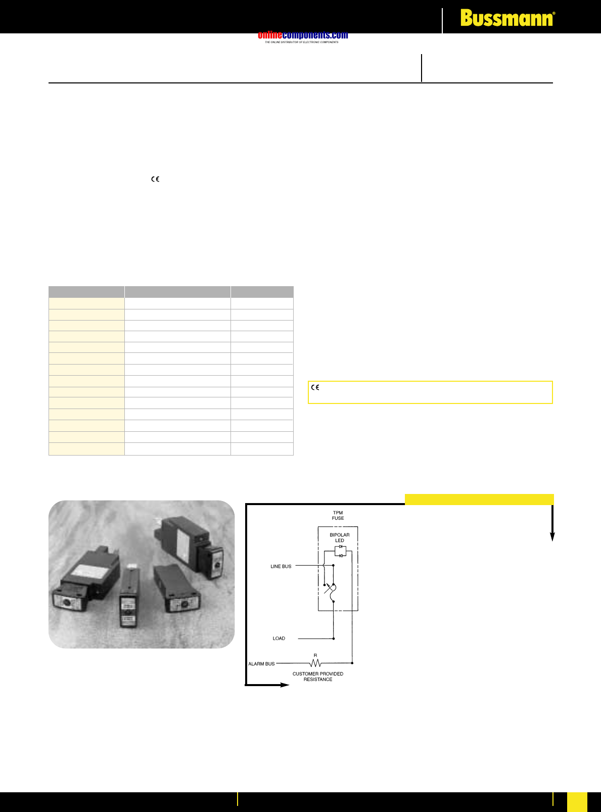
onlinecomponents.com
Telecommunications Protection
For more information visit our website at www.bussmann.com 130
TPM & TPMDS
TPM & TPMDS
TPMDS - Telpower®Miniature Fused Disconnect Switch
TPM - Telpower®Miniature Fuse - Current Limiting
Ampere Ratings: 3-30 Amperes
Voltage Rating: 80 Volts DC
Interrupting Rating: 20,000 Amperes
Agency Information:
UL Recognized (investigated to UL 1801) as a
disconnect switch for the interruption of load current
by means of withdrawing the fuse pullout.
Recognized to U.S. and Canadian requirements under the
component recognition program of Underwriters
Laboratories Inc.
Files E219046 and E56412.
General Information:
• Smallest and most versatile fused disconnect
switch available.
• Small size allows for assembly into 1 U (1.75 inch /
44.5 mm) panel.
• AmpColor ID™ System for easy fuse replacement.
• Switch design provides for easy panel mounting by single
captive 4-40 (M3) nut and panel notch integral to switch
footprint.
• Local and remote open fuse indication. Local alarm
indication provided by LED on TPM fuse.
• Current-limiting capability
• Complete system coordination capability
• Load connection: 1/4 inch quick-connect or bolted
connection with 10-32 (M5) captive nut.
• Line connection: 1/4 inch quick-connect or screw
connection with clearance hole for #10 (M5) bolt.
• Maximum alarm circuit current: 20 mA
• Materials:
Fuse housing - black thermoplastic, UL 94 V-0, 170ºC RTI
Switch housing - black thermoplastic, UL 94 V-0, 140ºC RTI
The only controlled copy of this Data Sheet is the electronic read-only version located on the Bussmann Network Drive. All other copies of this document are definition uncontrolled. This bulletin
is intended to clearly present comprehensive product data and provide technical information that will help the end user with design applications. Bussmann reserves the right, without notice, to change
design or construction of any products and to discontinue or limit distribution of any products. Bussmann also reserves the right to change or update, without notice, any technical information contained
in this bulletin. Once a product has been selected, it should be tested by the user in all possible applications.
NOTES:
1. The resistance, R, must be provided by the end-user
to limit the alarm output current to a maximum of
20 mA. The value, R, should be calculated using the
system voltage value.
•If remote alarm functionality is not required,
the END-USER CIRCUITRY must still be supplied
to provide a resistive path to the return for the
local alarm to properly function.
2. The fuse is polarized to maintain proper orientation with
the switch housing. The line and load terminals are
identified on the switch housing.
Form No. TPM & TPMDS
Data Sheet: 5022
Telpower®Miniature Fused Disconnect Switch
TPM Alarm Schematic
CE logo denotes compliance with European Union Low Voltage Directive
(50-1000V AC, 75-1500V DC). Refer to BIF document #8002.
Catalogue Number Description Ampere Rating
TPM-3 Miniature Fuse 3 Amp
TPM-4 Miniature Fuse 4 Amp
TPM-5 Miniature Fuse 5 Amp
TPM-6 Miniature Fuse 6 Amp
TPM-7 Miniature Fuse 7 Amp
TPM-8 Miniature Fuse 8 Amp
TPM-10 Miniature Fuse 10 Amp
TPM-12 Miniature Fuse 12 Amp
TPM-15 Miniature Fuse 15 Amp
TPM-20 Miniature Fuse 20 Amp
TPM-25 Miniature Fuse 25 Amp
TPM-30 Miniature Fuse 30 Amp
TPMDS-E
Miniature Disconnect, English
3-30 Amp
TPMDS-M
Miniature Disconnect, Metric
3-30 Amp
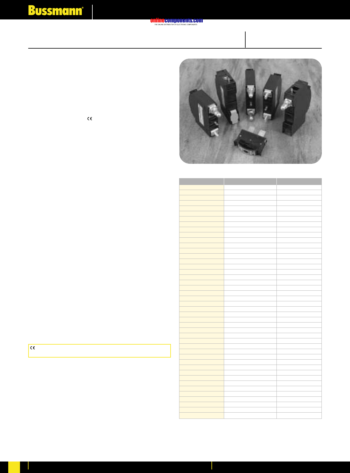
onlinecomponents.com
Telecommunications Protection
For more information visit our website at www.bussmann.com
131
CE logo denotes compliance with European Union Low Voltage Directive
(50-1000V AC, 75-1500V DC). Refer to BIF document #8002.
TPC & TPCDS
Telpower®Compact Fused Disconnect Switch
Form No. TPC & TPCDS
Data Sheet: 5023
TPC & TPCDS
TPCDS - Telpower®Compact Fused Disconnect Switch
TPC - Telpower®Compact Fuse - Current Limiting
Ampere Ratings: 3-125 Amperes
Available Ratings: 3, 4, 5, 6, 7, 8, 10, 12, 15, 20, 25, 30,
40, 50, 60, 75, 90, 100, 125 Amps
Voltage Rating: 80 Vdc
Interrupting Rating: 100,000 Amperes
Agency Information:
UL Recognized (investigated to UL 1801) as a
disconnect switch for the interruption of load current
by means of withdrawing the fuse pullout.
Recognized to U.S. and Canadian requirements under the
component recognition program of Underwriters
Laboratories Inc.
Files E219046 and E56412.
General Information:
• Fusible solution for replacement of existing dc Telecom
circuit breakers.
• Compact size fused disconnect switch.
• AmpColor ID™ System for easy fuse replacement.
• Available in two disconnect switch profiles in addition to a
variety of terminal styles.
• Local and remote open fuse indication.
Local alarm indication provided by LED on TPC fuse.
• Remote alarm terminal available in three positions
commonly found in dc circuit protection devices.
• Recommended .75 inch center-to-center product spacing.
• Current-limiting capability
• Complete system coordination capability.
• Highest interrupting rating (100,000 Amps) available
for dc circuit protection of this footprint.
• No venting of arc or molten metals and gases during
fuse opening.
• Fuse material: Black thermoplastic, UL rated 94 V-O,
170°C RTI.
• Housing material: Black thermoplastic, UL rated 94 V-O,
120°C RTI.
*Not investigated to Canadian Requirements.
Catalogue Number Description Ampere Rating
TPC-3 Compact Fuse 3 Amp
TPC-4 Compact Fuse 4 Amp
TPC-5 Compact Fuse 5 Amp
TPC-6 Compact Fuse 6 Amp
TPC-7 Compact Fuse 7 Amp
TPC-8 Compact Fuse 8 Amp
TPC-10 Compact Fuse 10 Amp
TPC-12 Compact Fuse 12 Amp
TPC-15 Compact Fuse 15 Amp
TPC-20 Compact Fuse 20 Amp
TPC-25 Compact Fuse 25 Amp
TPC-30 Compact Fuse 30 Amp
TPC-40 Compact Fuse 40 Amp
TPC-50 Compact Fuse 50 Amp
TPC-60 Compact Fuse 60 Amp
TPC-75 Compact Fuse 75 Amp
TPC-90 Compact Fuse 90 Amp
TPC-100 Compact Fuse 100 Amp
TPC-125 Compact Fuse 125 Amp
TPCDS-BBE-1 Compact Disconnect 3-125 Amp
TPCDS-BBE-2 Compact Disconnect 3-125 Amp
TPCDS-BBE-3 Compact Disconnect 3-125 Amp
TPCDS-BBM-1 Compact Disconnect 3-125 Amp
TPCDS-BBM-2 Compact Disconnect 3-125 Amp
TPCDS-BBM-3 Compact Disconnect 3-125 Amp
TPCDS-BSE-1 Compact Disconnect 3-125 Amp
TPCDS-BSE-2 Compact Disconnect 3-125 Amp
TPCDS-BSE-3 Compact Disconnect 3-125 Amp
TPCDS-BSM-1 Compact Disconnect 3-125 Amp
TPCDS-BSM-2 Compact Disconnect 3-125 Amp
TPCDS-BSM-3 Compact Disconnect 3-125 Amp
TPCDS-SSE-1 Compact Disconnect 3-125 Amp
TPCDS-SSE-2 Compact Disconnect 3-125 Amp
TPCDS-SSE-3 Compact Disconnect 3-125 Amp
TPCDS-SSM-1 Compact Disconnect 3-125 Amp
TPCDS-SSM-2 Compact Disconnect 3-125 Amp
TPCDS-SSM-3 Compact Disconnect 3-125 Amp
TPCDS-D-BC1* Compact Disconnect 3-125 Amp
TPCDS-D-BC2* Compact Disconnect 3-125 Amp
TPCDS-D-CC1* Compact Disconnect 3-125 Amp
TPCDS-D-SEC1* Compact Disconnect 3-125 Amp
TPCDS-D-SEC2* Compact Disconnect 3-125 Amp
TPCDS-D-SMC1* Compact Disconnect 3-125 Amp
TPCDS-D-SMC2* Compact Disconnect 3-125 Amp
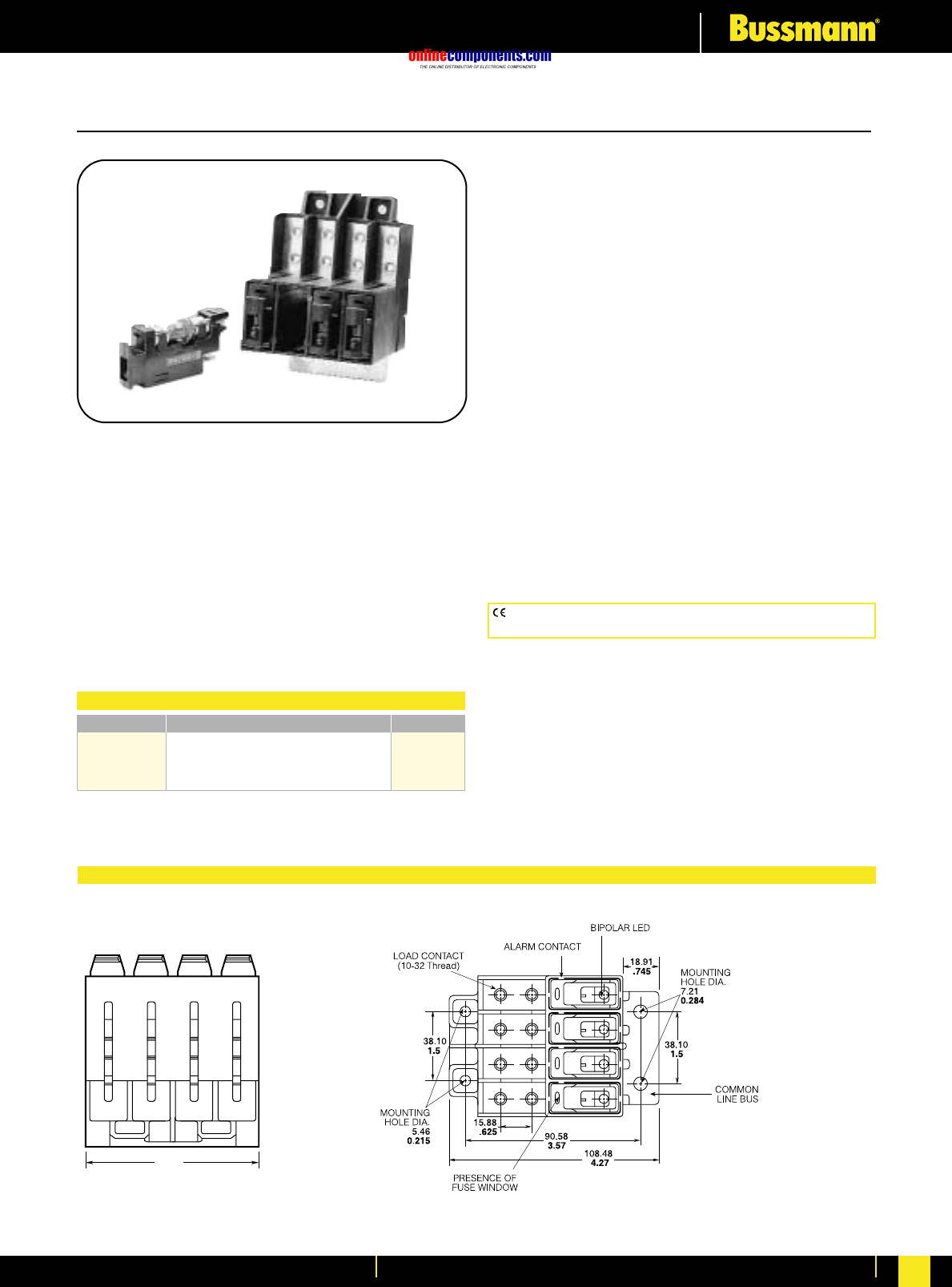
onlinecomponents.com
Telecommunications Protection
For more information visit our website at www.bussmann.com 132
Fused Disconnect Switch
Fuse
Dimensional Data
MM
Inches
General Information:
•Front access load and line connection standard—double
lug load connections 8 AWG wire.
•Recognized branch circuit protection device.
•Modular design—4 poles per module up to four modules
banked together.
•Ease of installation—Connection directly to bus bar.
•Reduces external wiring—per pole.
•LED alarm signaling (LED current 30mA max.).
•Blown fuse indication.
•Alarm test probe point, to allow on-site checking of alarm
circuitry.
•Snap into alarm bus.
•Bi-polar LED provides capability for both –48V DC
and +24V DC applications.
•Fuse presence indication.
•Fuse orientation rejection feature.
•Totally enclosed module.
•Spare fuseholders: Part No. 5TPH and TPSFH-A
•Remote alarm.
•Contact Bussmann for options on standard module
(Hardware, Colour, Front line connection, Mounting bezel).
76.07
3.0
TOP
CE logo denotes compliance with European Union Low Voltage Directive
(50-1000V AC, 75-1500V DC). Refer to BIF document #8002.
Fuse Type TPA TPA-B
Current 3, 5, 10, 15, 20, 25, 30, 40, 50 20, 25
Voltage 170V DC 65V DC
Interrupting 100 kA 20 kA
UL Recognized, Guide JFHR2, File E56412
CSA Certified, Class 1422-30, File 53787
TP15914
4 Pole Disconnect Switch and TPA Series Fuses
Ampere Rating: 50A per pole
Voltage Rating: 145V DC
Agency Information:
UL recognized as a disconnect switch for interruption of
load current by means of withdrawing the fuse carrier.
UL recognized as a component for telecommunication
power distribution equipment (UL category QPQYZ).
UL recognized fuses for branch circuit protection.
CSA component acceptance for the system.
Material: UL rated 94V-0, 140°C rated
BIF document: 5011
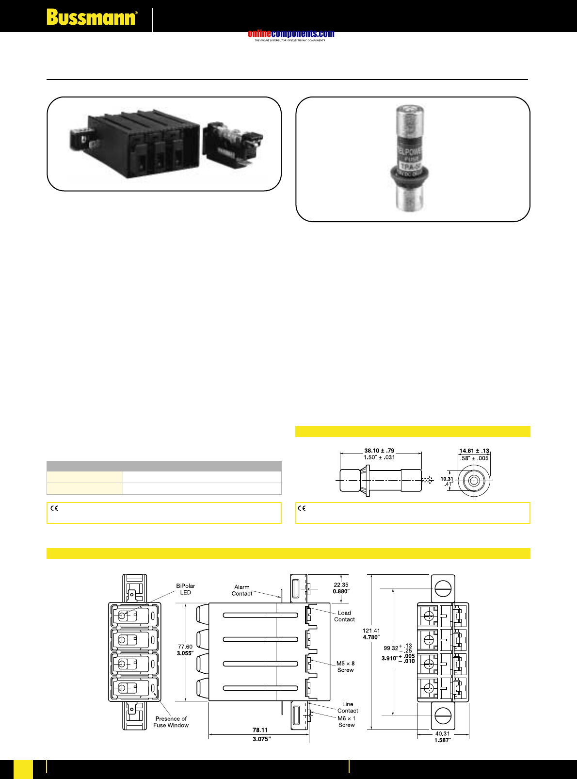
onlinecomponents.com
Telecommunications Protection
For more information visit our website at www.bussmann.com
133
Fused Disconnect Switch & TPA Fuses
BIF document: 5001 BIF document: 5012
CE logo denotes compliance with European Union Low Voltage Directive
(50-1000V AC, 75-1500V DC). Refer to BIF document #8002.
CE logo denotes compliance with European Union Low Voltage Directive
(50-1000V AC, 75-1500V DC). Refer to BIF document #8002.
TP15900-4
4-Pole Disconnect Switch
For use with Telpower®fuses Type TPA & TPA-B.
Electrical Ratings: 40A per pole at 145V DC
50A per pole at 80V DC
Agency Information:
U.L. Recognized as a disconnect switch for interruption of
load current by means of withdrawing the fuse carrier.
U.L. Recognized as a component for telecommunication
power distribution equipment (U.L. category QPQY2).
U.L. Recognized fuses for branch circuit protection.
CSA Component Acceptance for the system.
General Information:
•Ease of installation - connection directly to bus bar.
•Reduces external wiring per pole.
•LED alarm signaling (LED current 30mA max.).
•Local and remote open-fuse indication.
•Alarm test probe point, to allow on-site checking of alarm
circuitry.
•Fuse presence indication.
•Fuse orientation rejection feature.
•Rear accessibility for line and load terminations.
Material: U.L. rated 94V-0, 140°C rated
TPA & TPA-B
DC Power Distribution Indicating Fuses
Ampere Rating: TPA: 3, 5, 10, 15, 20, 25, 30, 40, 50
TPA-B: 20, 25, 30
Voltage Rating: TPA, 170 Vdc; TPA-B, 65 Vdc
Interrupting Rating: TPA, 100 kA; TPA-B, 20 kA
Agency Information:
U.L. Recognized, Guide JFHR2, File E56412
CSA Certified, Class 1422-30, File 53787
Construction:
•Silver-plated brass ferrules and indicator pin on TPA 3-15
and TPA-B. Tin-plated brass on TPA 20-50 on indicator
end.
•Glass melamine tube.
•Spare fuseholders: 5 position holder; 5TPH;
6 position holder; TPSFH-AS
mm
inches
Catalogue Numbers
TP15900-4
TP15900-41 Split Alarm, Split Line
Dimensional Data
Dimensional Data
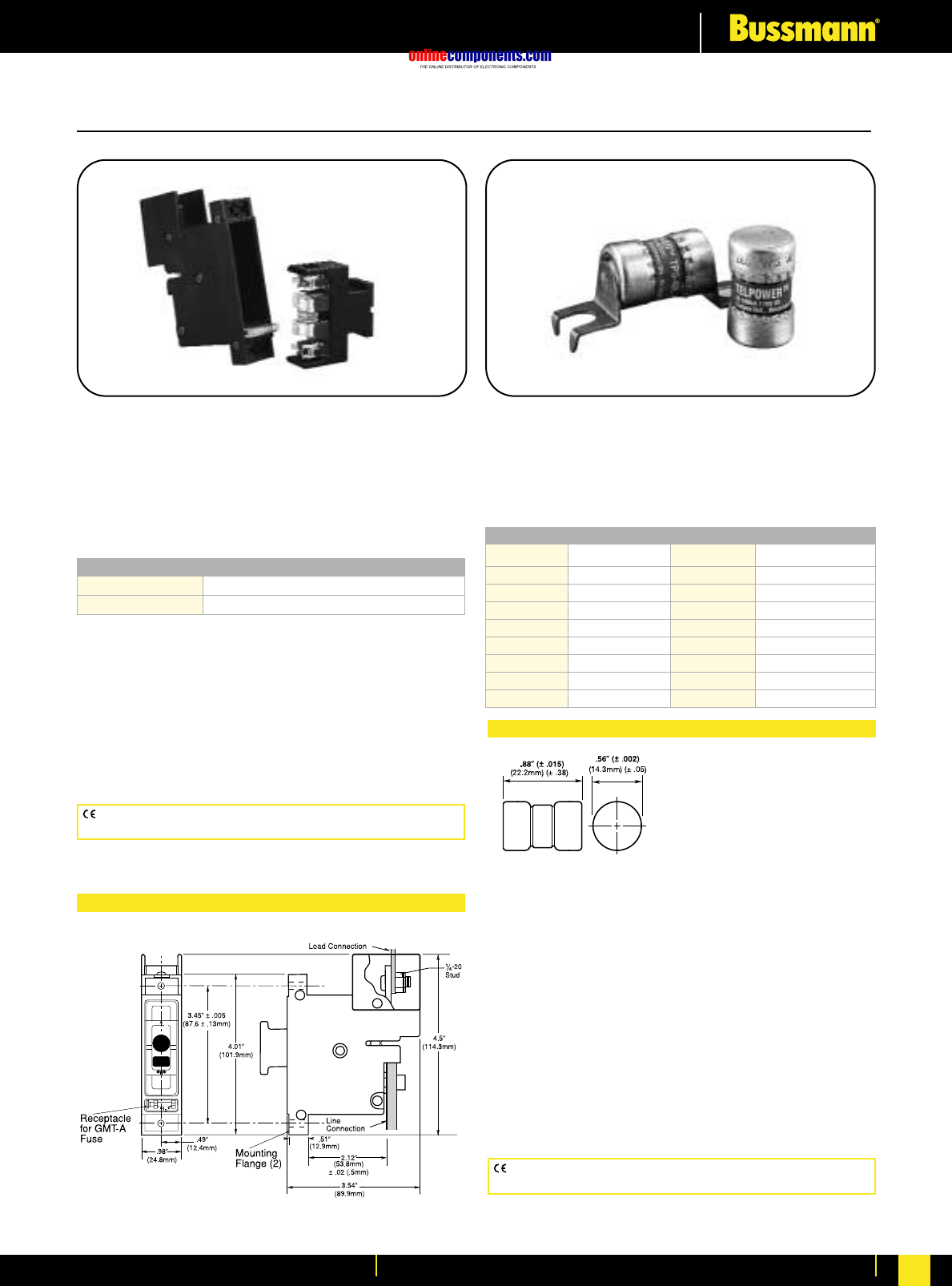
onlinecomponents.com
Telecommunications Protection
For more information visit our website at www.bussmann.com 134
Fused Disconnect Switch
•For use with the following fuses only:
Main: Telpower®TPS 3 to 70 Amp
Alarm: Bussmann GMT-A only (page 141).
Recommend GMT-X Cover (page 141).
•Alarm output with wire wrap terminal or connection to .063”
thick common alarm bus.
•Thermoplastic housing material U.L. rated
94V-0, 150°C.
•Spare alarm and power fuse compartment.
•Mounting hardware included.
•TELPOWER fuse line is the first to be specifically designed
to meet the unique needs of DC Power Distribution
Systems.
•The UL Recognized ratings of 170 Volts DC and 100,000
Amps interrupting rating along with the fuse’s current
limiting capability make this fuse ideal for cable protection
on existing DC Distribution Systems.
•A unique BLUE label is used on all TELPOWER fuses to
designate their DC capability.
•Circuit board applications available.
•Silver-plated brass ferrules.
•Glass melamine tube.
•For use with Bussmann Fused Disconnect Switch 15800.
•Printed circuit board variations available.
CE logo denotes compliance with European Union Low Voltage Directive
(50-1000V AC, 75-1500V DC). Refer to BIF document #8002.
CE logo denotes compliance with European Union Low Voltage Directive
(50-1000V AC, 75-1500V DC). Refer to BIF document #8002.
15800-R-200
15800
Fused Disconnect Switch
Ampere Ratings: 3 to 70 Amps.
Voltage Rating: 60 Volts DC
Agency Information:
UL Recognized, Guide QPQY2, File E97649
UL Withstand Rating: 100,000 Amps.,
Catalogue Numbers
15800-R-200 Rear Access Panel Mounting
15800-F-200 Front Access Panel Mounting
Dimensional Data
TPS
Ampere Ratings: 1 to 70 Amps.
Voltage Rating: 170 Volts DC
Agency Information:
UL Recognized, Guide JFHR2, File E56412
Catalogue Numbers
TPS-1 TPS-6L TPS-30 TPS-50V
TPS-1L TPS-10 TPS-30L TPS-60
TPS-2 TPS-10L TPS-35 TPS-60L
TPS-2L TPS-15 TPS-35L TPS-70
TPS-3 TPS-15L TPS-40 TPS-70L
TPS-3L TPS-20 TPS-40L TPS-70LB
TPS-5 TPS-20L TPS-40V —
TPS-5L TPS-25 TPS-50 —
TPS-6 TPS-25L TPS-50L —
Dimensional Data
BIF document: 5002 BIF document: 5009
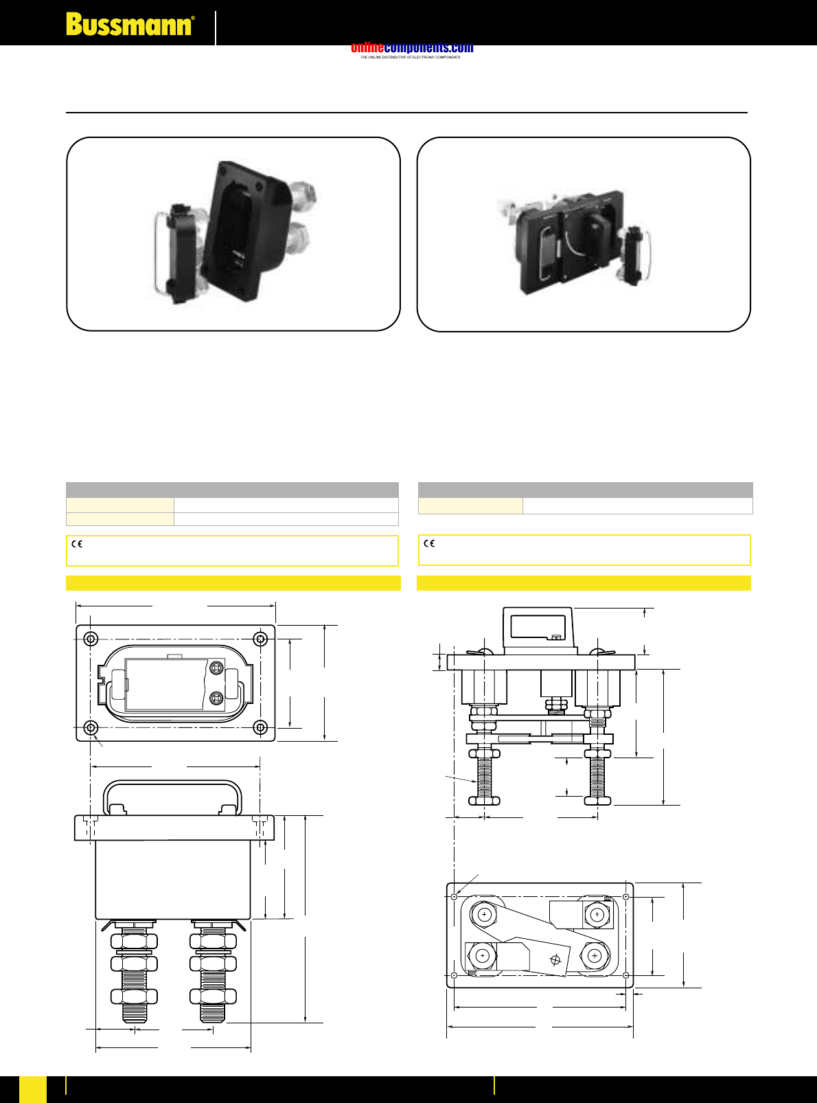
onlinecomponents.com
Telecommunications Protection
For more information visit our website at www.bussmann.com
135
Fused Disconnect Switch
Catalogue Numbers
15100-401 For Use With TPL series fuses 70-400 Amp
15100-601 For Use With TPL series fuses 300-800 Amp
Dimensional Data Dimensional Data
15100
Fused Disconnect System
For use with Telpower®Fuses Type TPL.
Ampere Ratings: 70-800 Amps.
Voltage Rating: 60 Volts DC
UL Withstand Rating: 100,000A
Agency Information:
UL Recognized, Guide QPQY2, File E97649
CE logo denotes compliance with European Union Low Voltage Directive
(50-1000V AC, 75-1500V DC). Refer to BIF document #8002.
0.27" (6.75mm) Dia. Hole with 0.5" (12.7mm)
Dia. x 0.16" (3.97mm) Deep C'bore (4 Holes)
2.63"
(66.67mm)
1.31"
(33.33mm)
4"
(101.6mm)
3"
(76.2mm)
5.25"
(133.35mm)
7.13"
(181.10mm)
3.63"
(92.07mm)
2.75"
(69.85mm)
6.75"
(171.45mm)
5.75"
(146.05mm)
15200
Fused Disconnect System
For use with Telpower®Fuses Type TPL.
Ampere Ratings: 70-800 Amps.
Voltage Rating: 60 Volts DC
UL Withstand Rating: 100,000A
Agency Information:
UL Recognized, Guide QPQY2, File E97649
Catalogue Numbers
15200-602 For Use With TPL 70 to 800 Amp
CE logo denotes compliance with European Union Low Voltage Directive
(50-1000V AC, 75-1500V DC). Refer to BIF document #8002.
7.25"
(184.15mm)
0.88"
(22.22mm)
#14 Thd.
0.31" (7.93mm) #18 Tap x 0.5" (12.7mm) Deep (4 Holes)
11"
(279.4mm)
0.5"
(12.7mm)
12"
(304.8mm)
1"
(25.4mm)
8.69"
(220.66mm)
5.86"
(149.22mm)
3"
(76.2mm)
2"
(50.8mm)
1.88"
(47.62mm)
6.75"
(171.45mm)
5"
(127.0mm)
15200-602
BIF document: 5004BIF document: 5003
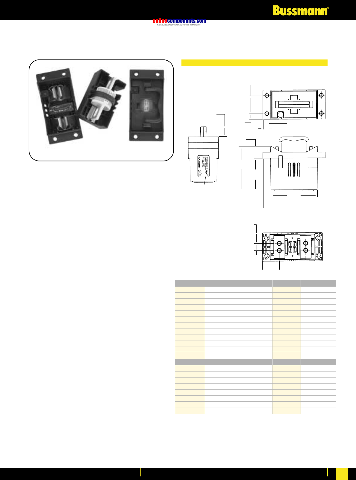
onlinecomponents.com
Telecommunications Protection
For more information visit our website at www.bussmann.com 136
BIF document: 5020
TPHCS
Telpower®High Current Switch
For use with Telpower®Fuses Type TPL-B, TPL-C
and TPH.
Ampere Ratings: 70 to 800 Amperes
Voltage Rating: 80 Volts DC
U.L. Withstand Rating: 100,000A
Agency Information:
U.L. Recognized (investigated to U.L. 1801) as a
disconnect switch for the interruption of load current
by means of withdrawing the fuse carrier.
U.L. Recognized to meet the requirements for
Canadian Standards.
General Information:
•Innovative new design eliminates need for tools to
replace the Telpower®type TPL-B, TPL-C or
TPH fuse.
•Easy to install–captive fasteners allow for direct
busbar mounting (bolts not included).
•Optional new electronic alarm provides both local
and remote open-fuse indications.
—Bipolar alarm designed for both Central Office and
Radio applications.
—Local LED alarm indication for ease-of-viewing.
—Standard ⁄Ω¢∑ male quick-connect terminal for
effortless remote alarm connection (Maximum
remote alarm current: 20mA).
—Eliminates need for parallel indicating fuses.
•Fuse presence window allows for easy viewing of
installed fuse ampere rating.
•Compact design for today’s high power, high-density
cabinets.
•Available as complete switch or pullout and base
may be purchased separately.
Catalogue Numbers-Switches (Pullout and Base) Series Fuse Ampere Rating
TPHCS250-M High Current Switch, Metric TPL-B 70 to 250 Amp
TPHCS250-E High Current Switch, English TPL-B 70 to 250 Amp
TPHCS250-ML High Current Switch, Metric, LED TPL-B 70 to 250 Amp
TPHCS250-EL High Current Switch, English, LED TPL-B 70 to 250 Amp
TPHCS250-MAV High Current Switch, Metric, Alarm TPL-B 70 to 250 Amp
TPHCS250-EAV High Current Switch, English, Alarm TPL-B 70 to 250 Amp
TPHCS800-M High Current Switch, Metric TPL-C or TPH 300 to 800 Amp
TPHCS800-E High Current Switch, Englis TPL-C or TPH 300 to 800 Amp
TPHCS800-ML High Current Switch, Metric, LED TPL-C or TPH 300 to 800 Amp
TPHCS800-EL High Current Switch, English, LED TPL-C or TPH 300 to 800 Amp
TPHCS800-MAV High Current Switch, Metric, Alarm TPL-C or TPH 300 to 800 Amp
TPHCS800-EAV High Current Switch, English, Alarm TPL-C or TPH 300 to 800 Amp
Catalogue Numbers – Components
Series Fuse Ampere Rating
TPHCS250-P Pullout only – 250 A TPL-B 70 to 250 Amp
TPHCS800-P Pullout only – 800 A TPL-C or TPH 300 to 800 Amp
TPHCS-B-M Base only, Metric — 800 Amp Max.
TPHCS-B-E Base only, English — 800 Amp Max.
TPHCS-B-ML Base only, Metric, LED — 800 Amp Max.
TPHCS-B-EL Base only, English, LED — 800 Amp Max.
TPHCS-B-MAV Base only, Metric, Alarm — 800 Amp Max.
TPHCS-B-EAV Base only, English, Alarm — 800 Amp Max
.
NOTES:
1. TPHCS250 and
TPHCS800
pullouts and bases
are the same with
exception to the
type of fuse, TPL-B,
TPL-C or TPH the
pullout will carry.
2. Plastic rated UL94
V-0, 140°C RTI.
22.2
(0.88)
41.02
(1.615)
Ø
7.62
(0.300)
Typ. 4
12.7
(0.50)
74.6
(2.94)
25.9
(1.02)
122.43
(4.820)
8.8
(0.34)
See table for part
number format
▲
▲
▲
▲
▲
▲
▲
▲
▲
▲
▲
▲
100.5 REF
(3.96)
▲
▲
▲
▲
▲
▲
105.2
(4.14)
▲
▲
Threaded Insert, 4 Places
M8x1.25 (-M Series) 5/16-18 (-E Series)
Recommended Torque 15N• m (11 Ft-lb)
▲
▲
▲
139.7
(5.50)
24.8 REF
(0.98)
39.2 REF
(1.54)
16.76
(0.660)
▲
▲
61.47
(2.420)
Telpower®High Current Switch
TPHCS800-MAV (shown)
TPHCS-Dimensional Data
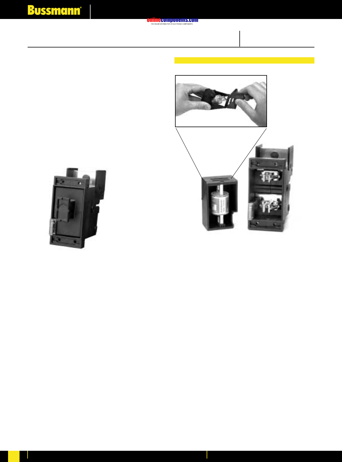
onlinecomponents.com
Telecommunications Protection
For more information visit our website at www.bussmann.com
137
Easy Fuse Replacement
TP158HC
Fused Disconnect Switch
For use with Telpower® Fuses Type TPL-B.
Ampere Ratings: 70-250 Amperes
Voltage Rating: 80 Volts DC
U.L. Withstand Rating: 100,000A
Agency Information:
U.L. Recognized (investigated to U.L. 1801) as a
disconnect switch for the interruption of load current
by means of withdrawing the fuse pullout.
Guide QPQY2, File E97649.
Catalogue Numbers:
TP158HC: Rear Access, Panel Mounting, English
TP158HC: Rear Access, Panel Mounting, Metric
BIF document: 5021
TP158HC
Fused Disconnect Switch
•Thermoplastic housing material U.L. rated 94V-0, 150°C.
•Application Note: The line connection uses a 1/4-20 bolt
(metric – M6X1) that threads into the line terminal. The line
terminal is designed with a float of ±.02 in. (± .50mm) to
allow for variation in the distance between the TP158HC
mounting flange and the line bus bar (see dimensional
data). Equipment should be designed to eliminate any
relative movement between the TP158HC mounting flange
and the line bus bar.
• Application Note: The alarm circuit is not intended for
precharging of capacitive circuits. Alarm circuit current
1 Ampere maximum.
General Information:
• High amp version of Bussmann 15800 series
Fused Disconnect Switch.
• Similar profile, mounting method, and backplane
configuration as 15800 Series. The TP158HC
can be installed into existing 15800 Series panels
using the space of two 15800 disconnects.
• Innovative new fuse pullout design eliminates
need for tools to replace the Telpower® type
TPL-B fuse.
•For use with the following fuses only:
Main: Telpower®TPL-B 70-250 Amperes.
Alarm: Bussmann GMT-A only.
•Alarm output with wire wrap terminal or connection to
.063” thick common alarm bus.
• Hardware included:
Load: washer, split lockwasher, and 5/16 _18 nut.
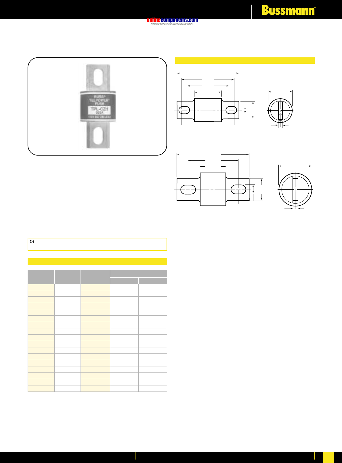
onlinecomponents.com
Telecommunications Protection
For more information visit our website at www.bussmann.com 138
TPL
DC Power Distribution Fuses
Ampere Ratings: 70-800 Amps.
Voltage Rating: 170 Volts DC
Current Limiting
Interrupting Rating: 100,000A
Construction: Silver-Plated Terminals
Agency Information:
UL Recognized Guide JFHR2, File E56412
Bellcore
Telpower®Fuses, 70-800 Amps, 170 Volts DC
Dimensional Data
BIF document: 5005
.33"
(8.3mm)
2.66"
(67.5mm)
2.19"
(55.6mm)
1.91"
(48.4mm)
1.16"
(29.4mm)
BUSS
TPL–BL
.75"
(19.1mm)
.19"
(4.8mm)
1.0"
(25.4mm)
.25"
(6.4mm)
1.50"
(38.1mm)
TPL-BA, TPL-BD, TPL-BF, TPL-BH, TPL-BK, AND TPL-BL
TPL-CN, TPL-CR, TPL-CV, AND TPL-CZ
3.50"
(88.9mm)
2.44"
(61.9mm)
1.25"
(31.8mm)
1.00"
(25.4mm)
.41"
(10.3mm)
BUSS
TPL–CZ
CE logo denotes compliance with European Union Low Voltage Directive
(50-1000V AC, 75-1500V DC). Refer to BIF document #8002.
Ordering Information: TPL Telpower®(170 Volts DC)
Catalogue Ampere Carton Weight*
Number Rating Qty. Lbs. Kg.
TPL-BA 70 5 .93 .42
TPL-BB 80 5 .93 .42
TPL-BC 90 5 .93 .42
TPL-BD 100 5 .93 .42
TPL-BE 125 5 .93 .42
TPL-BF 150 5 .93 .42
TPL-BG 175 5 .93 .42
TPL-BH 200 5 .93 .42
TPL-BK 225 5 .93 .42
TPL-BL 250 5 .93 .42
TPL-CN 300 1 .49 .22
TPL-CO 350 1 .49 .22
TPL-CR 400 1 .49 .22
TPL-CU 450 1 .49 .22
TPL-CV 500 1 .49 .22
TPL-CZ 600 1 .49 .22
TPL-CZH 800 1 .49 .22
*Weight per carton.
•Designed for DC power distribution systems.
•Recognized branch circuit protection.
•Current-limiting capability.
•Complete system coordination capability.
•Energy savings with low watts loss, low operating
temperatures, and minimum I2t levels.
•Use with Telpower 15100, 15200, TP158HC and TPHCS
disconnect systems.
•For replacement of Bussmann’s UBO fuses a TPL-TA
adaptor kit is necessary.
•Spare fuseholders:
TPSFH-LB (for TPL-B fuses)
TPSFH-LC (for TPL-C fuses)
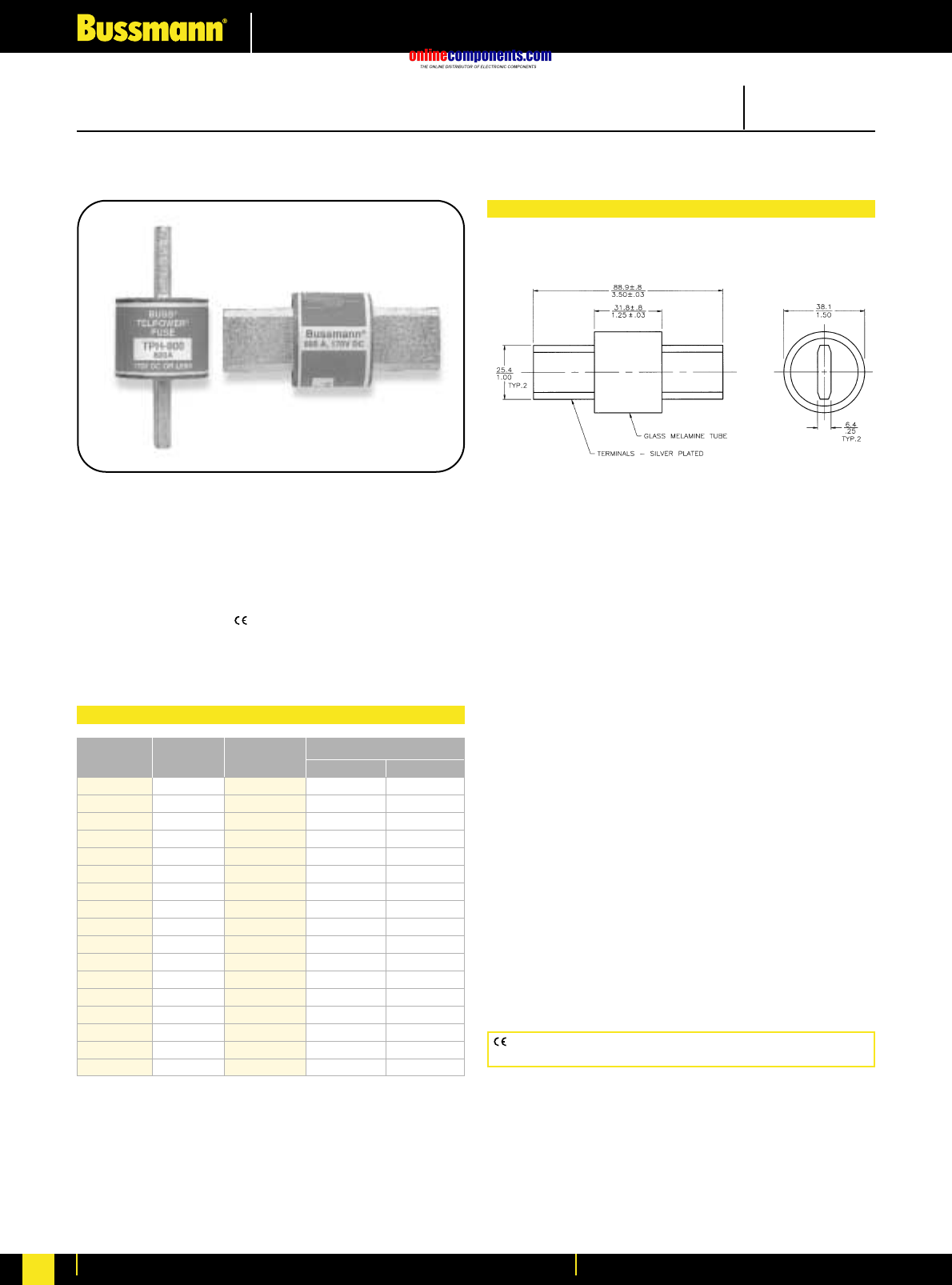
onlinecomponents.com
Telecommunications Protection
For more information visit our website at www.bussmann.com
139
Dimensional Data
CE logo denotes compliance with European Union Low Voltage Directive
(50-1000V AC, 75-1500V DC). Refer to BIF document #8002.
Catalogue Numbers, Carton Quantity and Weight
Catalogue Ampere Carton Weight*
Number Rating Qty. Lbs. Kg.
TPH-70 70 1 .55 .25
TPH-80 80 1 .55 .25
TPH-90 90 1 .55 .25
TPH-100 100 1 .55 .25
TPH-125 125 1 .55 .25
TPH-150 150 1 .55 .25
TPH-175 175 1 .55 .25
TPH-200 200 1 .55 .25
TPH-225 225 1 .55 .25
TPH-250 250 1 .55 .25
TPH-300 300 1 .55 .25
TPH-350 350 1 .55 .25
TPH-400 400 1 .55 .25
TPH-450 450 1 .55 .25
TPH-500 500 1 .55 .25
TPH-600 600 1 .55 .25
TPH-800 800 1 .55 .25
*Weight per carton.
TPH
Telpower®DC Power Distribution Fuses
Form No. TPH
Data Sheet #5024
Catalogue Symbol: TPH
DC Power Distribution Fuses
Current-Limiting
Ampere Rating: 70 to 800 Amperes
Voltage Rating: 170 Vdc
Interrupting Rating: 100,000A
Agency Information:
UL Recognized, Guide JFHR2, File E56412
The only controlled copy of this Data Sheet is the electronic read-only version located on the Bussmann Network Drive. All other copies of this document are by definition uncontrolled. This bulletin
is intended to clearly present comprehensive product data and provide technical information that will help the end user with design applications. Bussmann reserves the right, without notice, to change
design or construction of any products and to discontinue or limit distribution of any products. Bussmann also reserves the right to change or update, without notice, any technical information
contained
in this bulletin. Once a product has been selected, it should be tested by the user in all possible applications.
170 Volts, DC, 70-800 Amps
General Information:
•Designed specifically for use with the
TELPOWER® TPHCS Disconnect Switch series.
•Low watts loss design provides lower operating
temperatures.
•Same size as TELPOWER® TPL-C style fuses.
•Spare fuseholder: TPSFH-LC
•TELPOWER® BLUE™ label fuses are specifically
designed for dc power distribution systems.
•Minimum I2t short-circuit let-through levels.
•Current-limiting capability.
•Complete system coordination capability.
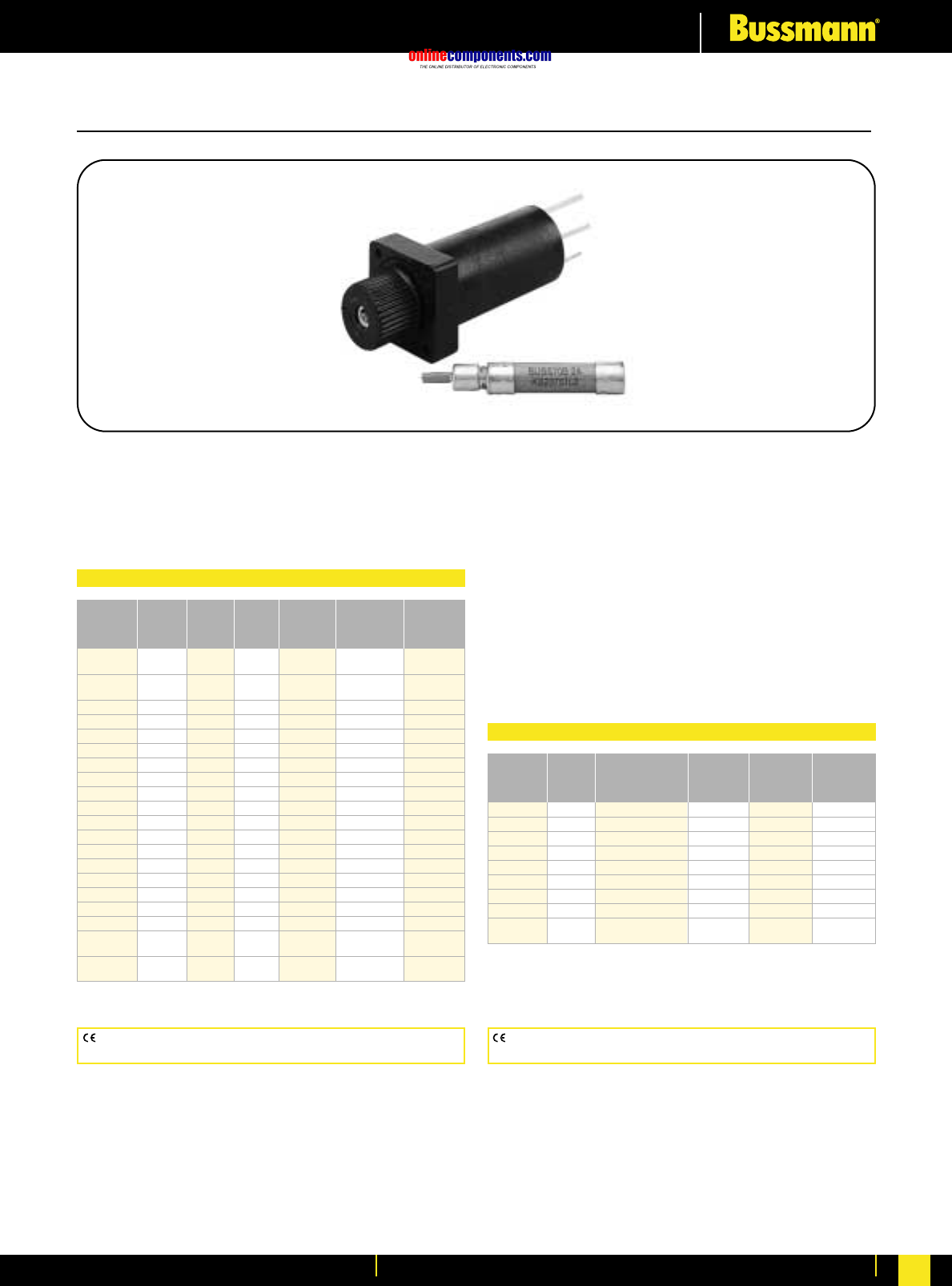
onlinecomponents.com
Telecommunications Protection
For more information visit our website at www.bussmann.com 140
70 Series
Indicating Type Fuse
Voltage Rating: 125 Volts AC; 300 Volts DC
Agency Information:
UL Recognized, Guide JDYX2, File E19180
Bellcore
Indicating Fuse & Holder
BIF document: 5007 BIF document: 5007
CE logo denotes compliance with European Union Low Voltage Directive
(50-1000V AC, 75-1500V DC). Refer to BIF document #8002.
Lucent
Catalogue Ampere Voltage Rating Colour Comcode Code/
Number Rating AC DC Code Ref. No. List No.
70P-⁄Ω¡ºA* ⁄Ω¡º 125V 300V Gray/Wh 100203413 KS23751-
L10
70R-⁄fiΩ¡ººA* ⁄fiΩ¡ºº 125V 300V Red/Wh 101384550 KS23751-
L11
70E-⁄°Ω¡ººA* ⁄°Ω¡ºº 125V 300V Yellow 100203363 KS23751-L5
70X-¤Ω¡ºA¤Ω¡º 125V 300V Black ——
70F-⁄Ω¢A* ⁄Ω¢ 125V 300V Violet 100203371 KS23751-L6
70K-⁄Ω¢A* ⁄Ω¢ 125V 300V Violet/Wh 100203405 KS23751-L9
70G-⁄Ω™A* ⁄Ω™ 125V 300V Red 100203389 KS23751-L7
70H-‹Ω¢A* ‹Ω¢ 125V 300V Brown 100203397 KS23751-L8
70I-1A 1 125V 300V Pink ——
70A-1-⁄Ω£A* 1⁄Ω£ 125V 300V White 100203322 KS23751-L1
70B-2A* 2 125V 300V Orange 100203330 KS23751-L2
70C-3A* 3 125V 300V Blue 100203348 KS23751-L3
70J-3⁄Ω™A3⁄Ω™ 125V 300V Black/Wh ——
70D-5A* 5 125V 300V Grn/Blk 100203355 KS23751-L4
70L-6A 6 125V 300V Grn/Wh ——
70M-8A 8 125V 300V Brown/Wh ——
70N-10A 10 125V 300V Violet/Yel ——
GKB-10A 10 125V 300V Violet/Yel ——
72A Dummy ———100203421 —
Plastic Case
72B Dummy ———103757977 —
Blister Pack
*Product designed to comply with Bellcore Technical Reference TR-TSY-000799 Issue 1,
December 1988.
70 Series Telpower (125 Volts AC, 300 Volts DC)
15087 Fuseholder
For 70 Series Fuses
Ampere Ratings: 12 Amps.
Voltage Rating: 300 Volt DC
Agency Information:
UL Recognized, Guide IZLT2, File E14853
Construction:
Body: Thermoplastic, UL 94VO flammability rating
Terminals: Copper alloy, tin plating
Screws: 3-24 ≈ ‹Ω•∑ steel, zinc plated
•Panel mount fuseholder for 70 Type fuses supplied with
two screws.
•Remote alarm capability.
Amp Amp
Catalogue Rating Colour Catalogue Rating Colour
Symbol Ref. Code Symbol Ref. Code
1A1706-01 ⁄°Ω¡ºº Yellow 1A1706-10 3 Blue
1A1706-02 ¤Ω¡º Black 1A1706-11 5 Green/Black
1A1706-03 ⁄Ω¢ Violet 1A1706-12 6 Green/White
1A1706-04 ⁄Ω¢ Violet/White 1A1706-13 8 Brown/White
1A1706-05 ⁄Ω™ Red 1A1706-14 10 Violet/Yellow
1A1706-06 ‹Ω¢ Brown 1A1706-15 ⁄Ω¡º Gray/White
1A1706-07 1 Pink 1A1706-16 3⁄Ω™ Black/White
1A1706-08 1⁄Ω£ White 1A1706-17 ⁄fiΩ¡ºº Red/White
1A1706-09 2 Orange ———
Blister Pack
Optional Colour Code Eyelets (order separately)
CE logo denotes compliance with European Union Low Voltage Directive
(50-1000V AC, 75-1500V DC). Refer to BIF document #8002.
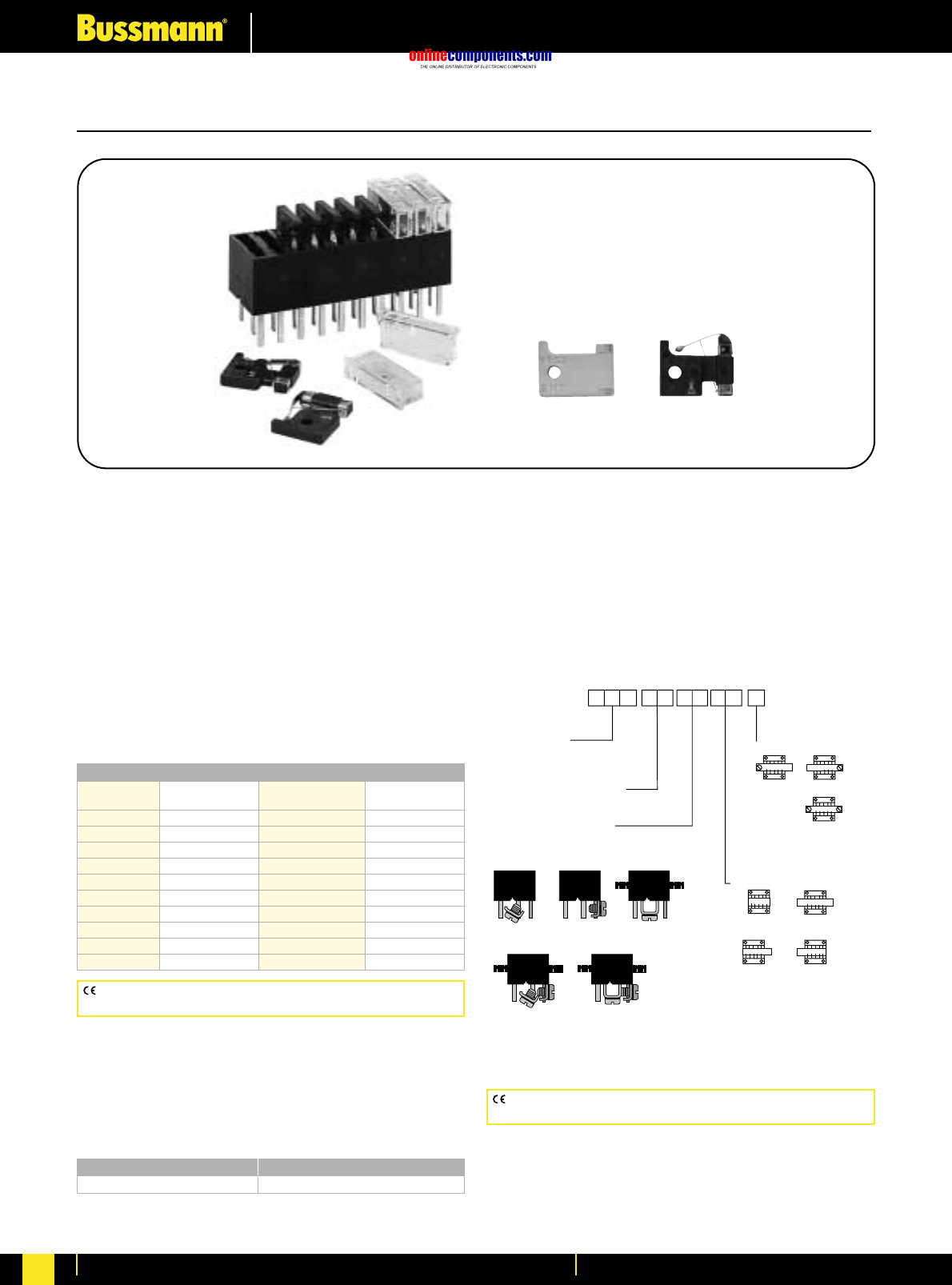
onlinecomponents.com
Telecommunications Protection
For more information visit our website at www.bussmann.com
141
GMT
Fast Acting Fuses
Voltage Rating: 60V DC; 125V AC
Interrupting Rating: 450 Amps., 60 Volt DC;
300 Amps., 125 Volt AC
Agency Information:
UL Recognized, Guide JFHR2, File E56412
Materials:
Body: Thermoplastic, UL 94VO flammability rating
Terminals: Tin-plated Beryllium copper
Carton Qty. and Weight: 100 Fuses per carton;
0.33 lbs. (150g)
Fuseholders: Catalogue No. HLT, HLS, and PCT
Spare Fuseholder: TPSFH-T
Indicating Fuses & Holders
GMT - Dummy GMT - A (Alarm)
Catalogue Numbers
Catalogue Colour Catalogue Colour
Symbol Code Symbol Code
GMT-⁄°Ω¡ººA Yellow GMT-3A Blue
GMT-⁄Ω¢A Violet GMT-3⁄Ω™A White/Blue
GMT-‹Ω•A White/Gray GMT-4A White/Brown
GMT-⁄Ω™A Red GMT-5A Green
GMT-flfiΩ¡ººA Black GMT-7⁄Ω™A Black/White
GMT-‹Ω¢A Brown GMT-10A Red/White
GMT-1A Gray GMT-12A Yellow/Green
GMT-1⁄Ω£A White GMT-15A Red/Blue
GMT-1⁄Ω™A White/Yellow GMT-Dummy Gray Body
GMT-2A Orange GMT-X Clear Cover
CE logo denotes compliance with European Union Low Voltage Directive
(50-1000V AC, 75-1500V DC). Refer to BIF document #8002.
Some GMT sizes may be sold in bulk pack only.
GMT-A
• The GMT-A is designed specifically for use in the Telpower®
series 15800 Fused Disconnect Switch (page 134).
• The GMT-A has the same ratings and agency approvals
as the standard GMT fuses as shown above.
Catalogue Symbol Colour Code
GMT-AYellow
BIF document: 5008
HLS, HLT, PCT
Fuseholders for GMT Type Indicating Fuses
Voltage Rating: 60V DC; 125V AC
Agency Information:
UL Recognized, Guide IZLT2, File E14853, 15 Amps (60V
DC)
Materials:
Body: Thermoplastic, UL 94VO flammability rating
Multiple Fuseholders with bus bars
Ordering Information— Catalog No.
Type of bus bars used
B1*, B2, B3,
B4, B5, SL** (Short Leads .135")
ML** (Medium Leads .250")
** Not available with bus bars
Bus Bar Position
P4
(Outside—
Left Only)
P3
(Outside—
Right Only)
P2
(Outside—
Both Sides)
P1†
(Inside—
Both Sides)
B3
(“U” Bar Only)
B2
(“L” Bar Only)
B1
(Angle Bar Only)*
B5
(“L” & “U” Bars)
B4
(Angle & “L” Bars)
Body Style HLT
HLS (No flanges)
No. of Poles 01 thru 25
(Min. of 2 poles required for bus bars)
Termination Location
B
(Both ends)
L
(Left only)
R
(Right only)
*Angle Bar mounts on common or center terminals only.
**SL Version is not available with bus bars.
†Minimum of 4 Poles Required.
CE logo denotes compliance with European Union Low Voltage Directive
(50-1000V AC, 75-1500V DC). Refer to BIF document #8002.
BIF document: 5010
Multiple Fuseholders with bus bars
Ordering Information - Catalogue No.
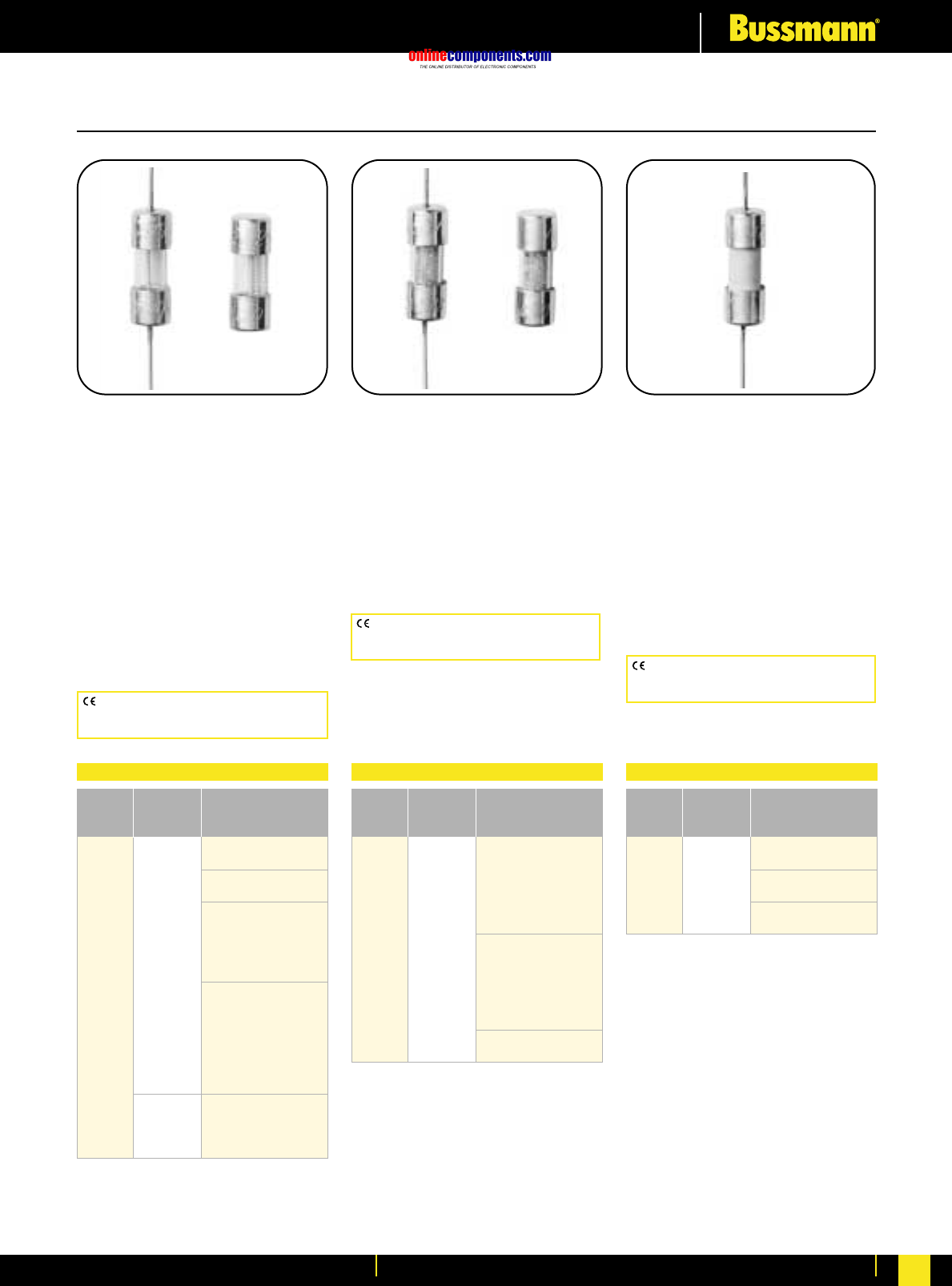
onlinecomponents.com
Electronic Fuses & Accessories
For more information visit our website at www.bussmann.com 142
BIF document: 2025
BIF document: 2026 (C518)
& 2027 (C520)
BIF document: 2006 (C515)
& 2007 (C519)
5mm x 15mm Fuses
C517 (Axial Leads)
Fast-Acting, Light Ballast
Protection
Physical Size:
0.197∑ ≈ 0.591∑ (5mm ≈15mm)
Construction: Ceramic
Agency Information:
UL Listing File E19180, Guide JDYX
CSA Certification File LR65063,
Class 1422-01
UL Recognized, File E19180,
Guide JDYX2
C515 (Axial Leads)
C519
Time-Delay
Physical Size:
0.197∑ ≈ 0.591∑ (5mm ≈15mm)
Construction: Glass Tube
Agency Information:
UL Listing File E19180, Guide JDYX
125mA-250mA and 375mA-3A
CSA Certification File LR65063,
Class 1422-01, 125mA-250mA and
375mA-3A
UL Recognized, File E19180,
Guide JDYX2, 350mA and 3.5A-7A
C518 (Axial Leads)
C520
Fast-Acting
Physical Size:
0.197∑ ≈ 0.591∑ (5mm ≈15mm)
Construction: Glass Tube
Agency Information:
UL Listing File E19180, Guide JDYX
CSA Certification File LR65063,
Class 1422-01
CE logo denotes compliance with European
Union Low Voltage Directive (50-1000V AC,
75-1500V DC). Refer to BIF document #8002.
CE logo denotes compliance with European
Union Low Voltage Directive (50-1000V AC,
75-1500V DC). Refer to BIF document #8002. CE logo denotes compliance with European
Union Low Voltage Directive (50-1000V AC,
75-1500V DC). Refer to BIF document #8002.
Electrical Characteristics
125mA 35A/250V 10kA/125V
250mA p.f. = 0.7 - 0.8
350mA 35A/250V 10kA/125V
25A/600V p.f. = 0.7 - 0.8
375mA
500mA 35A/250V
600mA 10kA/125V
750mA 250V p.f. = 0.7 - 0.8
1A
1.25A
1.5A
1.6A 100A/250V
2A 10kA/125V
2.25A p.f. = 0.7 - 0.8
2.5A
3A
3.5A
4A 400A/125V
5A 125V p.f. = 1.0
7A
Rated
Current Voltage Interrupting
Rating AC Rating
Electrical Characteristics
100mA
125mA 35A/250V
250mA 10kA/125V
375mA p.f. = 0.7 - 0.8
500mA
750mA 250V
1A
1.5A
2A 100A/250V
2.5A 10kA/125V
3A p.f. = 0.7 - 0.8
3.5A
4A 200A/250V 10kA/125V5A
5A p.f. = 0.7 - 0.8
Rated
Current Voltage Interrupting
Rating AC Rating
Electrical Characteristics
100A/350V AC
p.f. = 1.0
3A 350V 100A/250V AC
p.f. = 0.7 - 0.8
10kA/125V AC
p.f. = 0.7 - 0.8
Max. Rated
Current Voltage Interrupting
Rating AC Rating
onlinecomponents.com
Electronic Fuses & Accessories
For more information visit our website at www.bussmann.com
143
5mm x 20mm - IEC Standards
GDC
GDC-V
(Axial Leads)
Time Delay,
Low Breaking
Capacity
Physical Size:
0.197∑ ≈ 0.788∑
(5mm ≈20mm)
Construction:
Glass Tube
End caps: Nickel plated brass
Voltage Rating: 250V AC or less
Interrupting Rating: 35A @ 250V AC
Agency Information:
Designed to IEC (Pub 127) Sheet III
British Standard Approval
SEMKO Approval
VDE Approval, IMQ
UL Recognized, Guide JDYX2,
File E19180, 32mA-6.3A
GDA
GDA-V
(Axial Leads)
Fast-Acting,
High Breaking
Capacity
Physical Size:
0.197∑ ≈ 0.788∑
(5mm ≈20mm)
Construction:
Ceramic Tube
End caps: Nickel plated brass
Voltage Rating: 250V AC or less
Interrupting Rating: 1500A @
250V AC
Agency Information:
UL Recognized, Guide JDYX2,
File E19180, 50mA and 315mA-6.3A
SEMKO Approval 50mA, 200mA and
315mA-6.3A
IEC 127-SI
GDB
GDB-V
(Axial Leads)
Fast-Acting,
Low Breaking
Capacity
Physical Size:
0.197∑ ≈ 0.788∑
(5mm ≈20mm)
Construction:
Glass Tube
End caps: Nickel plated brass
Voltage Rating: 250V AC or less
Interrupting Rating: 35A @ 250V AC
Agency Information:
Designed to IEC (Pub 127) Sheet II
British Standard Approval
SEMKO Approval
VDE Approval, IMQ
UL Recognized, Guide JDYX2,
File E19180, 32mA-6.3A
CE logo denotes compliance with European
Union Low Voltage Directive (50-1000V AC,
75-1500V DC). Refer to BIF document #8002.
CE logo denotes compliance with European
Union Low Voltage Directive (50-1000V AC,
75-1500V DC). Refer to BIF document #8002.
CE logo denotes compliance with European
Union Low Voltage Directive (50-1000V AC,
75-1500V DC). Refer to BIF document #8002.
Electrical Characteristics
50mA 0.0017 9000
63mA 0.0005 3300
80mA 0.0011 2600
100mA 0.0018 2300
125mA 0.0037 1900
160mA 0.008 1600
200mA 0.020 1350
250mA 0.027 1300
315mA 0.010 1400
400mA 0.018 1200
500mA 0.038 1050
630mA 0.064 1200
800mA 0.097 490
1A 0.480 230
1.25A 0.9 200
1.6A 1.9 180
2A 2.0 205
2.5A 3.9 190
3.15A 8.1 160
4A 14 160
5A 25 155
6.3A 48 150
Current Max Voltage
Rating I2t Drop (mV)
Electrical Characteristics
32mA 0.000047 10000
40mA 0.00011 8000
50mA 0.00020 3200
63mA 0.00057 2500
80mA 0.0012 2200
100mA 0.003 2100
125mA 0.005 2000
160mA 0.008 1950
200mA 0.016 1600
250mA 0.028 1400
315mA 0.058 1150
400mA 0.018 950
500mA 0.018 220
630mA 0.035 220
800mA 0.067 180
1A 0.60 200
1.25A 0.84 200
1.6A 1.6 190
2A 4.2 160
2.5A 6.1 145
3.15A 13 130
4A 22 120
5A 42 115
6.3A 69 110
8A* ——
10A* ——
12A* ——
16A* ——
*IEC Standard 127 Sheet II does not include ratings above
6.3 amps.
Current Max Voltage
Rating I2t Drop (mV)
Electrical Characteristics
32mA 0.0014 1050
40mA 0.0034 920
50mA 0.006 800
63mA 0.012 760
80mA 0.015 580
100mA 0.022 490
125mA 0.034 390
160mA 0.052 320
200mA 0.078 340
250mA 0.17 270
315mA 0.41 250
400mA 0.61 210
500mA 0.75 168
630mA 1.3 158
800mA 3.1 132
1A 3.6 85
1.25A 7 80
1.6A 10 80
2A 17 80
2.5A 34 80
3.15A 56 75
4A 91 75
5A 133 75
6.3A 270 6
Current Max Voltage
Rating I2t Drop (mV)
BIF document: 2016BIF document: 2015BIF document: 2014
onlinecomponents.com
Electronic Fuses & Accessories
For more information visit our website at www.bussmann.com 144
5mm x 20mm – N. American Standards
GMD
GMD-V
(Axial Leads)
Time-Delay
Physical Size:
0.197∑ ≈ 0.788∑
(5mm ≈20mm)
Construction:
Glass Tube
End Caps;
nickel plated brass
Agency
Information:
Std. 248-14
UL Listed Guide JDYX, File E19180, 0-3A
UL Recognized, Guide JDYX2,
File E19180, 4A
CSA Certified, Class 1422-01,
File 65063, 0-3A
GMA
GMA-V
(Axial Leads)
Fast Acting
Physical Size:
0.197∑ ≈ 0.788∑
(5mm ≈20mm)
Construction:
Glass Tube
End Caps; nickel
plated brass
Agency
Information:
Std. 248-14
UL Listed Guide JDYX, File E19180, 0-6A
UL Recognized, Guide JDYX2,
File E19180, 7-15A
CSA Certified, Class 1422-01,
File E65063, 0-6A
GMC
GMC-V
(Axial Leads)
Medium Time-
Delay
Physical Size:
0.197∑ ≈ 0.788∑
(5mm ≈20mm)
Construction:
Glass Tube
End Caps; nickel
plated brass
Agency
Information:
Std. 248-14
UL Listed Guide JDYX, File E19180, 0-6.3A
UL Recognized, Guide JDYX2,
File E19180, 7-8A
CSA Certified, Class 1422-01,
File 65063, 0-6.3A
CE logo denotes compliance with European
Union Low Voltage Directive (50-1000V AC,
75-1500V DC). Refer to BIF document #8002.
CE logo denotes compliance with European
Union Low Voltage Directive (50-1000V AC,
75-1500V DC). Refer to BIF document #8002.
CE logo denotes compliance with European
Union Low Voltage Directive (50-1000V AC,
75-1500V DC). Refer to BIF document #8002.
Electrical Characteristics
63mA
100mA
125mA
200mA
250mA 35A/250V
300mA 10kA/125V
315mA p.f. = 0.7 – 0.8
500mA
600mA
750mA 250
800mA
1A
1.25A
1.5A 100A/250V
1.6A 10kA/125V
2A p.f. = 0.7 – 0.8
2.5A
3.15A
3.5A 10kA/125V
4A p.f. = 0.7 – 0.8
5A
6A 125
7A 200A/125V
8A p.f. = 1.0
10A
15A 150A/125V
p.f. = 1.0
Rated
Current Voltage Breaking
Rating (V AC) Capacity
Electrical Characteristics
63mA
80mA
100mA
125mA
150mA
200mA 35A/250V
250mA 10kA/125V
300mA p.f. = 0.7 – 0.8
315mA
400mA
500mA 250
600mA
630mA
750mA
800mA
1A
1.25A
1.5A
1.6A 100A/250V
2A 10kA/125V
2.5A p.f. = 0.7 – 0.8
3A
3.15A
3.5A
4A 10kA/125V
5A p.f. = 0.7 – 0.8
6A 125
6.3A
7A 200A/125V
8A p.f. = 1.0
10A
Rated
Current Voltage Breaking
Rating (V AC) Capacity
Electrical Characteristics
125mA
150mA
200mA
250mA
300mA
315mA
400mA 100A/250V
500mA 10kA/125V
600mA 250 p.f. = 0.7 – 0.8
630mA
750mA
800mA
1A
1.2A
1.25A
1.5A
1.6A
2A
2.5A
3A
4A 200A/250V
10kA/125V, p.f. = 1
Rated
Current Voltage Breaking
Rating (V AC) Capacity
BIF document: 2019BIF document: 2018BIF document: 2017
onlinecomponents.com
Electronic Fuses & Accessories
For more information visit our website at www.bussmann.com
145
⁄Ω¢∑ Diameter x fiΩ• ∑ to 1∑Lengths
AGX
AGX-V (Axial Leads)*
Fast Acting
Physical Size:
⁄Ω¢∑ ≈ 1∑ (8AG)
(6.4mm ≈25.4mm)
Construction: Glass Tube
Voltage Rating: See table below.
Agency Information: Std. 248-14
UL File E19180
UL Listed, Guide JDYX, 0-5A
UL Recognized, Guide JDYX2, 6-20A
AGA
AGA-V* (Axial Leads)
Fast Acting
Physical Size:
⁄Ω¢∑ ≈ fiΩ•∑ (1AG)
(6.4mm ≈15.9mm)
Construction: Glass Tube
Voltage Rating: See table below.
Agency Information: Std. 248-14
UL File E19180,
UL Listed, Guide JDYX 0-1⁄Ω™A
UL Recognized, Guide JDYX2 2-12A,
AGW
Fast Acting
Physical Size:
⁄Ω¢∑ ≈ ‡Ω•∑ (7AG)
(6.4mm ≈22.2mm)
Construction: Glass Tube
Voltage Rating: 32V
Catalogue Symbol & Current Ratings
125V AC
AGA-⁄Ω¡§ AGA-⁄Ω™ AGA-2
AGA-⁄Ω¡º AGA-flΩ¡º AGA-2⁄Ω™
AGA-⁄Ω• AGA-‹Ω¢ AGA-3
AGA-⁄Ω¢ AGA-1AGA-5
AGA-‹Ω• AGA-1⁄Ω™ —
32V AC
AGA-6 AGA-10 AGA-25
AGA-7 AGA-15 AGA-30
AGA-7⁄Ω™ AGA-20 —
Catalogue Symbol & Current Ratings
32V AC
AGW-1 AGW-4 AGW-15
AGW-1⁄Ω™ AGW-5 AGW-20
AGW-2 AGW-6 AGW-25
AGW-2⁄Ω™ AGW-7⁄Ω™ AGW-30
AGW-3 AGW-10 —
Catalogue Symbol & Current Ratings
250V AC
AGX-⁄Ω∞ºº AGX-‹Ω¡§ AGX-‹Ω¢
AGX-⁄Ω™ºº AGX-¤Ω¡º AGX-1
AGX-⁄Ω¡ºº AGX-⁄Ω¢ AGX-1⁄Ω¢
AGX-⁄Ω£™ AGX-‹Ω¡º AGX-1⁄Ω™
AGX-⁄Ω¡§ AGX-‹Ω• AGX-2
AGX-⁄Ω¡º AGX-›Ω¡º —
AGX-⁄Ω• AGX-⁄Ω™ —
125V AC
AGX-2⁄Ω™ AGX-4 AGX-6
AGX-3 AGX-5 AGX-7
32 Volts
AGX-8 AGX-15 AGX-25
AGX-10 AGX-20 AGX-30
CE logo denotes compliance with European
Union Low Voltage Directive (50-1000V AC,
75-1500V DC). Refer to BIF document #8002.
CE logo denotes compliance with European
Union Low Voltage Directive (50-1000V AC,
75-1500V DC). Refer to BIF document #8002.
BIF document: 2041BIF document: 2040BIF document: 2039
*AGA-V is UL Listed 0-5A, UL Recognized 6-12A
* AGX-V is UL Recognized from 6-20A @ 32V AC
onlinecomponents.com
Electronic Fuses & Accessories
For more information visit our website at www.bussmann.com 146
BIF documents: 720038 (Fuse)
Time-Current 35785256, 50955
BIF document: 2081BIF document: 2042
CE logo denotes compliance with European
Union Low Voltage Directive (50-1000V AC,
75-1500V DC). Refer to BIF document #8002.
CE logo denotes compliance with European
Union Low Voltage Directive (50-1000V AC,
75-1500V DC). Refer to BIF document #8002.
CE logo denotes compliance with European
Union Low Voltage Directive (50-1000V AC,
75-1500V DC). Refer to BIF document #8002.
⁄Ω¢∑ Diameter x 1∑Lengths
FWH
Semiconductor Fuse
Physical Size:
⁄Ω¢∑ ≈ 1⁄Ω¢∑
(6.3mm ≈ 32mm)
Construction: Ceramic Tube
Voltage Rating: 500V AC
Agency Information: Std. 248-14
UL Recognized .25-7, 500V AC,
File E91958, Guide JFHR2
UL Recognized 10-30, 500V AC,
File E56412, Guide JFHR2
TDC180
British Household Plug Fuse
Fast/Medium
Physical Size:
⁄Ω¢∑ ≈ 1∑
(6.4mm ≈ 25.4mm)
Construction: Ceramic Tube
End Caps: Silver-plated copper
Agency Information:
BS1362, IEC 269-3A
TDC600
Fast Acting
Physical Size:
⁄Ω¢∑ ≈ 1∑
(6.3mm ≈ 25.4mm)
Construction: Ceramic Tube
Voltage Rating: 600V AC
Agency Information:
UL Recognized, Std. 248-14, BS1362
Catalogue Symbol & Current Ratings
240V AC
TDC180-1 TDC180-5 TDC180-13
TDC180-2 TDC180-7 —
TDC180-3 TDC180-10 —
Catalogue Symbol & Current Ratings
TDC600-2A TDC600-10A
Catalogue Symbol & Current Ratings
FWH-.250A6F FWH-010A6F
FWH-.500A6F FWH-12.5A6F
FWH-001A6F FWH-015A6F
FWH-002A6F FWH-016A6F
FWH-3.15A6F FWH-020A6F
FWH-005A6F FWH-025A6F
FWH-6.30A6F FWH-030A6F
FWH-007A6F
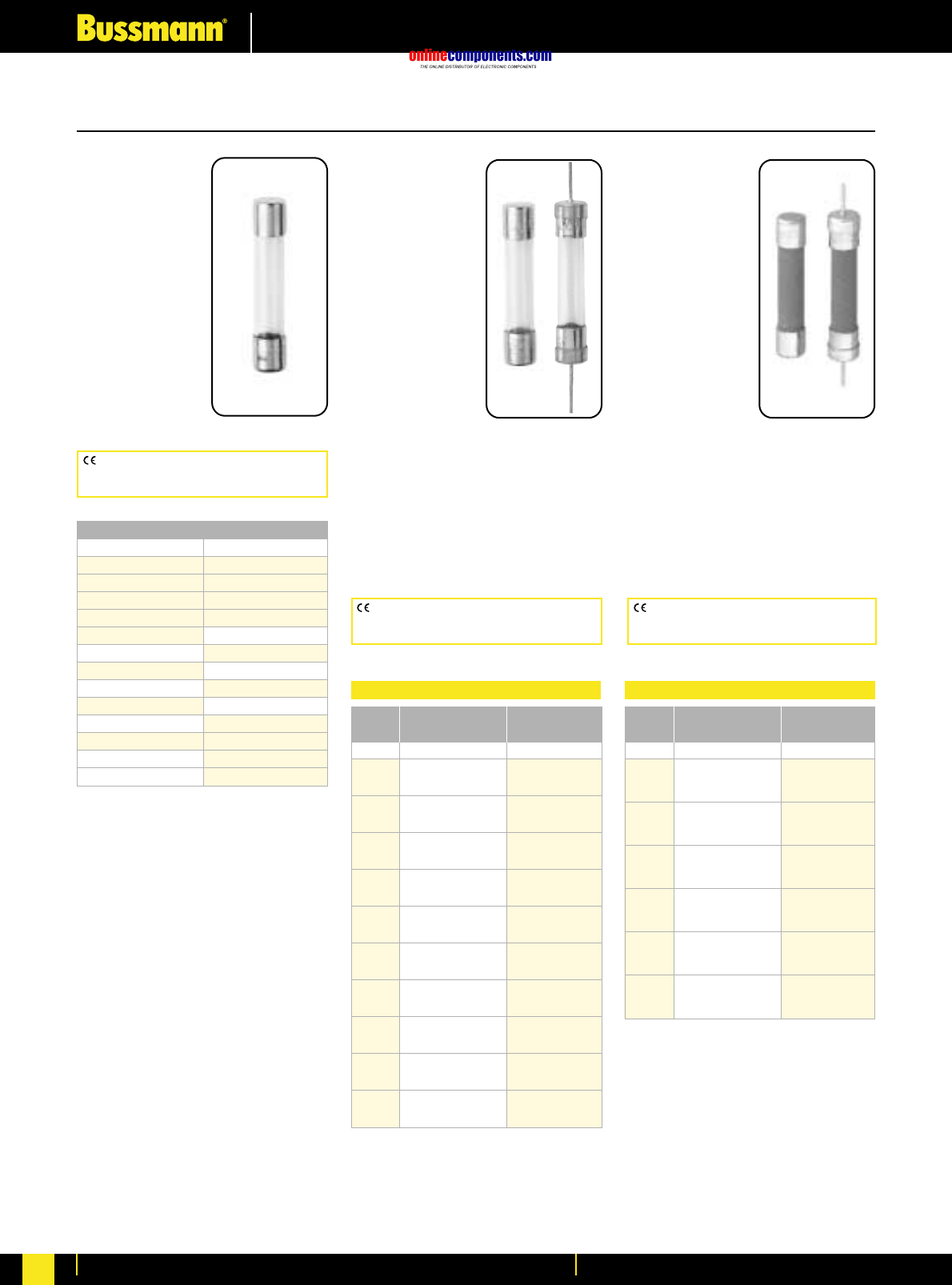
onlinecomponents.com
Electronic Fuses & Accessories
For more information visit our website at www.bussmann.com
147
⁄Ω¢
∑x 1
⁄Ω¢
∑Fast Acting Fuses
ABC
ABC-V (Axial
Leads)
Fast Acting
Physical Size:
⁄Ω¢∑ ≈ 1⁄Ω¢∑ (3AB)
(6.3mm ≈32mm)
Construction:
Ceramic Tube
Nickel Plated Brass
End Caps
Voltage Rating:
See Below
Interrupting
Rating: See Below
Agency Information: Std. 248-14
UL Listed, Guide JDYX File E19180, 0-15A
UL Recognized, Guide JDYX2,
File E19180, 20-25A
CSA Certification, Class 1422-01,
File 53787, 0-15A, Class 1422-30,
File 53787, 20-25A
TDC10
Fast Acting
Physical Size:
⁄Ω¢∑ ≈ 1⁄Ω¢∑ (3AG)
(6.3mm ≈32mm)
Construction:
Glass Tube
Voltage Rating:
See Below
Agency
Information:
Conforms to British
Standard BS-2950A,
I.R. 10Im@Vm.
AGC
AGC-V
(Axial Leads)
Fast Acting
Physical Size:
⁄Ω¢∑ ≈ 1⁄Ω¢∑ (3AG)
(6.3mm ≈32mm)
Construction:
Glass Tube
Nickel Plated Brass
End Caps
Voltage Rating:
See Below
Interrupting
Rating: See Below
Agency Information: Std. 248-14
UL Listed, Guide JDYX, File E19180, 0-10A
UL Recognized, Guide JDYX2,
File E19180, 15-30A
CSA Certification, Class 1422-01,
File 53787
Electrical Characteristics
AC (Max.) DC (Max.)2AC DC2
⁄Ω™º 250V 250V 35A 35A
⁄Ω¡§ 250V 250V 35A 35A
⁄Ω¡º 250V 250V 35A 35A
⁄Ω• 250V 250V 35A 35A
‹Ω¡§ 250V 250V 35A 35A
¤Ω¡º 250V 250V 35A 35A
⁄Ω¢ 250V 250V 35A 35A
‹Ω¡º 250V 250V 35A 35A
‹Ω• 250V 250V 35A 35A
›fiΩ¡ºº 250V 250V 35A 35A
⁄Ω™ 250V 250V 35A 35A
‹Ω¢ 250V 250V 35A 35A
1250V 250V 35A 35A
1⁄Ω¢ 250V 250V 100A 100A
1⁄Ω™ 250V 250V 100A 100A
2250V 250V 100A 100A
2⁄Ω¢ 250V 250V 100A 100A
2⁄Ω™ 250V 250V 100A 100A
3250V 250V 100A 100A
4250V 250V 200A 200A
5250V 250V 200A 200A
6250V 250V 200A 200A
7250V 250V 200A 200A
8250V 250V 200A 200A
9250V 250V 200A 200A
10 250V 250V 200A 200A
15 32V 32V 1000A 1000A
20 32V 32V 1000A 1000A
25 32V 32V 1000A 1000A
30 32V 32V 1000A 1000A
Current Rated Interrupting
Rating Voltage Rating1
Catalogue Symbol & Current Ratings
1000 Volts AC
TDC10-50mA
TDC10-60mA
TDC10-100mA
TDC10-150mA
TDC10-250mA
750 Volts AC
TDC10-500mA
500 Volts AC
TDC10-750mA
350 Volts AC
TDC10-1A
—
—
250 Volts AC
TDC10-1.5A
TDC10-2A
TDC10-3A
TDC10-5A
150 Volts AC
TDC10-7A
100 Volts AC
TDC10-10A
32 Volts AC
TDC10-12A
TDC10-15A
TDC10-20A
TDC10-25A
Electrical Characteristics
AC (Max.) DC (Max.) AC DC
⁄Ω¢ 250V 250V 35A 35A
⁄Ω™ 250V 250V 35A 35A
‹Ω¢ 250V 250V 35A 35A
1250V 250V 35A 35A
1⁄Ω™ 250V 250V 100A 100A
2250V 250V 100A 100A
2⁄Ω™ 250V 250V 100A 100A
3250V 250V 100A 100A
4250V 250V 200A 200A
5250V 250V 200A 200A
6250V 250V 200A 200A
7250V 250V 200A 200A
8250V 250V 200A 200A
10 250V 250V 200A 200A
15 250V 250V 750A 200A
20 250V 250V 400A 200A
25 125V 125V 1000A 1000A
30 125V 125V 1000A 1000A
1Interrupting ratings were measured at 70% – 80% power
factor on AC, and at a time constant described in UL
198L.
Current Rated Interrupting
Rating Voltage Rating1
CE logo denotes compliance with European
Union Low Voltage Directive (50-1000V AC,
75-1500V DC). Refer to BIF document #8002.
CE logo denotes compliance with European
Union Low Voltage Directive (50-1000V AC,
75-1500V DC). Refer to BIF document #8002.
CE logo denotes compliance with European
Union Low Voltage Directive (50-1000V AC,
75-1500V DC). Refer to BIF document #8002.
BIF document: 2000BIF document: 2001BIF document: 2043
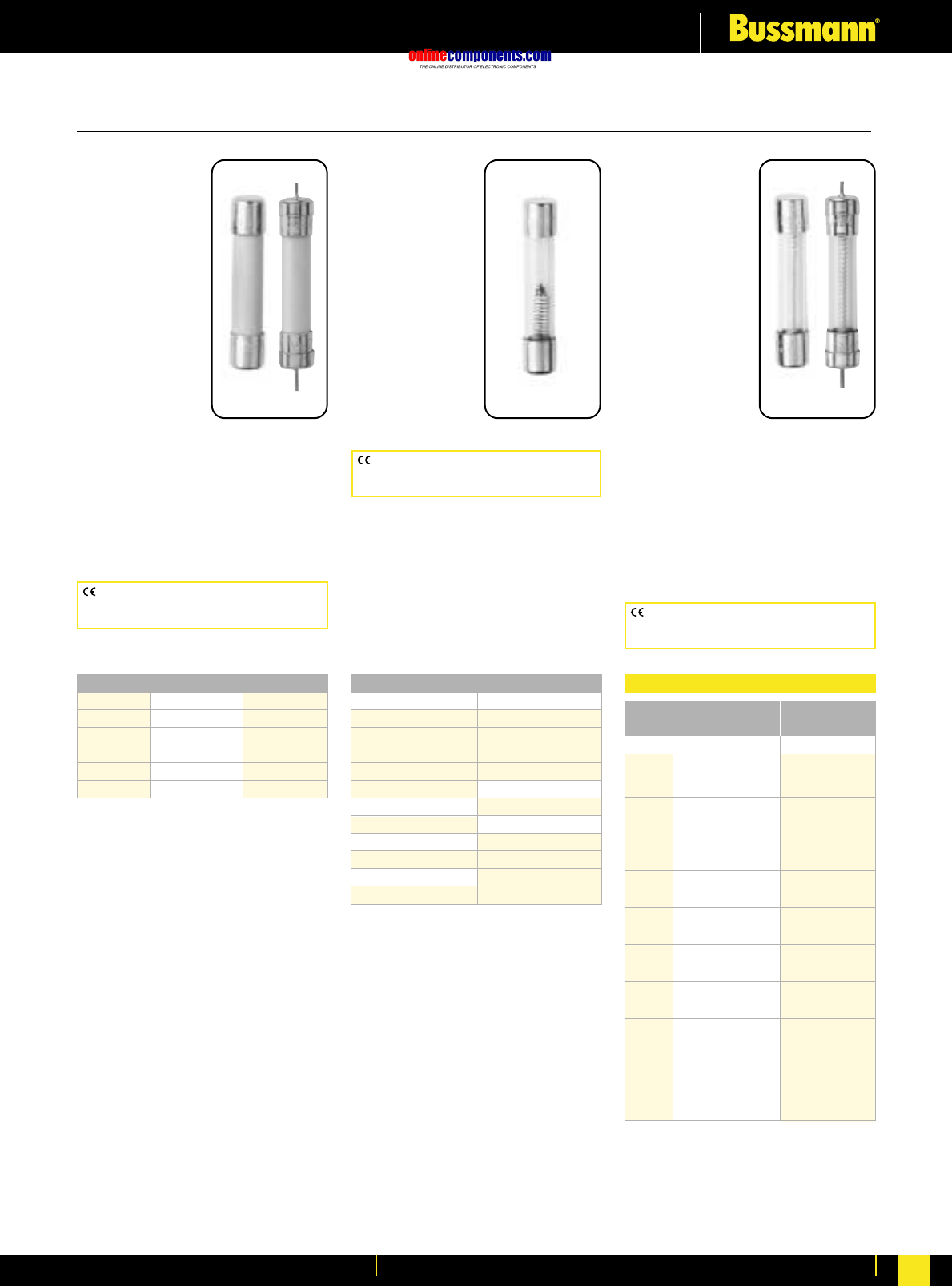
onlinecomponents.com
Electronic Fuses & Accessories
For more information visit our website at www.bussmann.com 148
BIF document: 2004BIF document: 2043BIF document: 2013
⁄Ω¢
∑x 1
⁄Ω¢
∑Fuses
MDL
MDL-V
(Axial Leads)
Time-Delay
Physical Size:
⁄Ω¢∑ ≈ 1⁄Ω¢∑ (3AG)
(6.3mm ≈32mm)
Construction:
Glass Tube
Nickel Plated
Brass End Caps
Voltage Rating:
See Below
Interrupting
Rating: See Below
Agency Information: Std. 248-14
UL Listed, Guide JDYX, File E19180;
⁄Ω¡§ -8A
CSA Certification Class 1422-01,
File 53787, ⁄Ω¡§ -8A
UL Recognized, Guide JDYX2,
File E19180, 8.1-30A
GBB
GBB-V
(Axial Leads)
Very Fast Acting
Physical Size:
⁄Ω¢∑ ≈ 1⁄Ω¢∑ (3AB)
(6.3mm ≈32mm)
Construction:
Ceramic Cartridge
Nickel Plated
Brass End Caps
Voltage Rating:
250V AC/125V DC
Interrupting
Rating:
200A @ 250V 10kA @ 125V
Agency Information: Std. 248-14
UL Recognized, 1-30, 125V DC/250V
AC, File E56412, Guide JFHR2
CSA Certified, 1-10, 125V DC/250V
AC, File 53787, Class 1422-01
TDC11
Time Lag
Physical Size:
⁄Ω¢∑ ≈ 1⁄Ω¢∑ (3AG)
(6.3mm ≈32mm)
Construction:
Glass Tube
Voltage Rating:
See Below
Interrupting
Rating: 10 times
rated current @ Vm.
CE logo denotes compliance with European
Union Low Voltage Directive (50-1000V AC,
75-1500V DC). Refer to BIF document #8002.
CE logo denotes compliance with European
Union Low Voltage Directive (50-1000V AC,
75-1500V DC). Refer to BIF document #8002.
CE logo denotes compliance with European
Union Low Voltage Directive (50-1000V AC,
75-1500V DC). Refer to BIF document #8002.
Catalogue Symbol & Current Ratings
GBB-1 GBB-6 GBB-15
GBB-1⁄Ω¢ GBB-7 GBB-20
GBB-2 GBB-8 GBB-25
GBB-3 GBB-9 GBB-30
GBB-4 GBB-10 —
GBB-5 GBB-12 —
Catalogue Symbol & Current Ratings
1000 Volts AC
TDC11-50mA
TDC11-60mA
TDC11-100mA
TDC11-150mA
TDC11-250mA
750 Volts AC
TDC11-500mA
500 Volts AC
TDC11-750mA
350 Volts AC
TDC11-1A
250 Volts AC
TDC11-1.5A
TDC11-2A
TDC11-3A
TDC11-5A
150 Volts AC
TDC11-7A
100 Volts AC
TDC11-10A
—
—
—
Electrical Characteristics
AC (Max.) DC (Max.)2AC DC2
⁄Ω¡§ 250V 250V 35A 35A
⁄Ω¡º 250V 250V 35A 35A
⁄Ω• 250V 250V 35A 35A
¤Ω¡º 250V 250V 35A 35A
‹Ω¡§ 250V 250V 35A
⁄Ω¢ 250V 250V 35A 35A
‹Ω¡º 250V 250V 35A 35A
‹Ω• 250V 250V 35A 35A
⁄Ω™ 250V 250V 35A 35A
‹Ω¢ 250V 250V 35A 35A
1250V 250V 35A 35A
1⁄Ω¢ 250V 250V 100A 100A
1⁄Ω™ 250V 250V 100A 100A
2250V 250V 100A 100A
2⁄Ω¢ 250V 250V 100A 100A
2⁄Ω™ 250V 250V 100A 100A
3250V 250V 100A 100A
4250V 250V 200A 10,000A
5250V 250V 200A 10,000A
6250V 250V 200A 10,000A
7250V 250V 200A 10,000A
8250V 250V 200A 200A
932V 250V 1000A 10,000A
10 32V 250V 1000A 10,000A
MDL-12
15 32V 1000A
20 32V 1000A
25 32V 1000A
30 32V 1000A
1Interrupting ratings were measured at 70% – 80% power
factor on AC, and at a time constant described in UL
198L.
2DC ratings are self certified.
30-8A is UlL listed for 125VDC.
Current Rated Interrupting
Rating Voltage Rating1
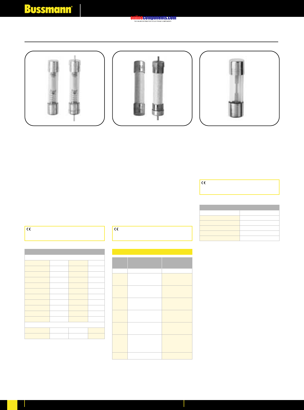
onlinecomponents.com
Electronic Fuses & Accessories
For more information visit our website at www.bussmann.com
149
BIF document: 2008BIF document: 2002BIF document: 2044
⁄Ω¢
∑x 1
⁄Ω¢
∑and
⁄‹Ω£™
∑x 1
⁄Ω™
∑Fuses
AGU
Fast Acting
Physical Size:
⁄‹Ω£™∑ ≈ 1⁄Ω™∑ (5 AG)
(10.3mm ≈38.1mm)
Construction: Glass Tube
No Agency Listings
MDQ
MDQ-V (Axial Leads)
Dual Element Time-Delay
Physical Size:
⁄Ω¢∑ ≈ 1⁄Ω¢∑ (3AG)
(6.3mm ≈32mm)
Construction: Glass Tube; Nickel
Plated Brass End Caps
Agency Information: Std. 248-14
UL Listed, File E19180; Guide JDYX,
⁄Ω¡§-7A
CSA Certification, File 47233,
Class 1422-01, ⁄Ω¡§-7A
UL Recognized, Guide JDYX2,
File E19180, 7.1-30A
MDA
MDA-V (Axial Leads)
Time-Delay
Physical Size:
⁄Ω¢∑ ≈ 1⁄Ω¢∑ (3AB)
(6.3mm ≈32mm)
Construction: Ceramic Tube; Nickel
Plated Brass End Caps
Agency Information: Std. 248-14
UL Listed, Guide JDYX, File E19180,
0-15A
CSA Certification, Class 1422-01,
File 53787, 0-15A
Catalogue Symbol & Current Ratings
250 Volts AC
MDQ-⁄Ω¡ºº MDQ-‹Ω• MDQ-1°Ω¡º MDQ-7
MDQ-⁄Ω£™ MDQ-›Ω¡º MDQ-2
MDQ-⁄Ω¡§ MDQ-⁄Ω™ MDQ-2⁄Ω¢
MDQ-⁄Ω¡º MDQ-flΩ¡º MDQ-2⁄Ω™
MDQ-⁄Ω• MDQ-‹Ω¢ MDQ-2°Ω¡º
MDQ-⁄fiΩ¡ºº MDQ-°Ω¡º MDQ-3
MDQ-⁄‡fiΩ¡ººº MDQ-1MDQ-3¤Ω¡º
MDQ-‹Ω¡§ MDQ-1¤Ω¡º MDQ-4
MDQ-¤Ω¡º MDQ-1⁄Ω¢ MDQ-5
MDQ-⁄Ω¢ MDQ-1⁄Ω™ MDQ-6
MDQ-‹Ω¡º MDQ-1flΩ¡º MDQ-6⁄Ω¢
32 Volts AC
MDQ-7⁄Ω™ MDQ-9 MDQ-12
MDQ-8 MDQ-10MDQ-15
Electrical Characteristics
AC (Max.) DC (Max.) AC DC
¤Ω¡º 250V 250V 35A 35A
⁄Ω¢ 250V 250V 35A 35A
⁄Ω™ 250V 250V 35A 35A
‹Ω¢ 250V 250V 35A 35A
1250V 250V 35A 35A
1⁄Ω™ 250V 100A
2250V 100A 100A
2⁄Ω™ 250V 100A
3250V 250V 100A 100A
4250V 200A
5250V 200A
6250V 200A
7250V 200A
8250V 200A
10 250V 250V 200A 200A
MDA-12
15 250V 250V 1500A
20 250V 1500A
25 250V 1000A
30 250V 1000A
1Interrupting ratings were measured at 70% – 80% power
factor on AC, and at a time constant described in UL 248.
Current Rated Interrupting
Rating Voltage Rating1
Catalogue Symbol & Current Ratings
250 Volts AC 32 Volts AC
AGU-1 AGU-4 AGU-20 AGU-50
AGU-2 AGU-5 AGU-25 AGU-60
AGU-3 AGU-8 AGU-30 —
—AGU-10 AGU-35 —
—AGU-15 AGU-40 —
CE logo denotes compliance with European
Union Low Voltage Directive (50-1000V AC,
75-1500V DC). Refer to BIF document #8002.
CE logo denotes compliance with European
Union Low Voltage Directive (50-1000V AC,
75-1500V DC). Refer to BIF document #8002.
CE logo denotes compliance with European
Union Low Voltage Directive (50-1000V AC,
75-1500V DC). Refer to BIF document #8002.
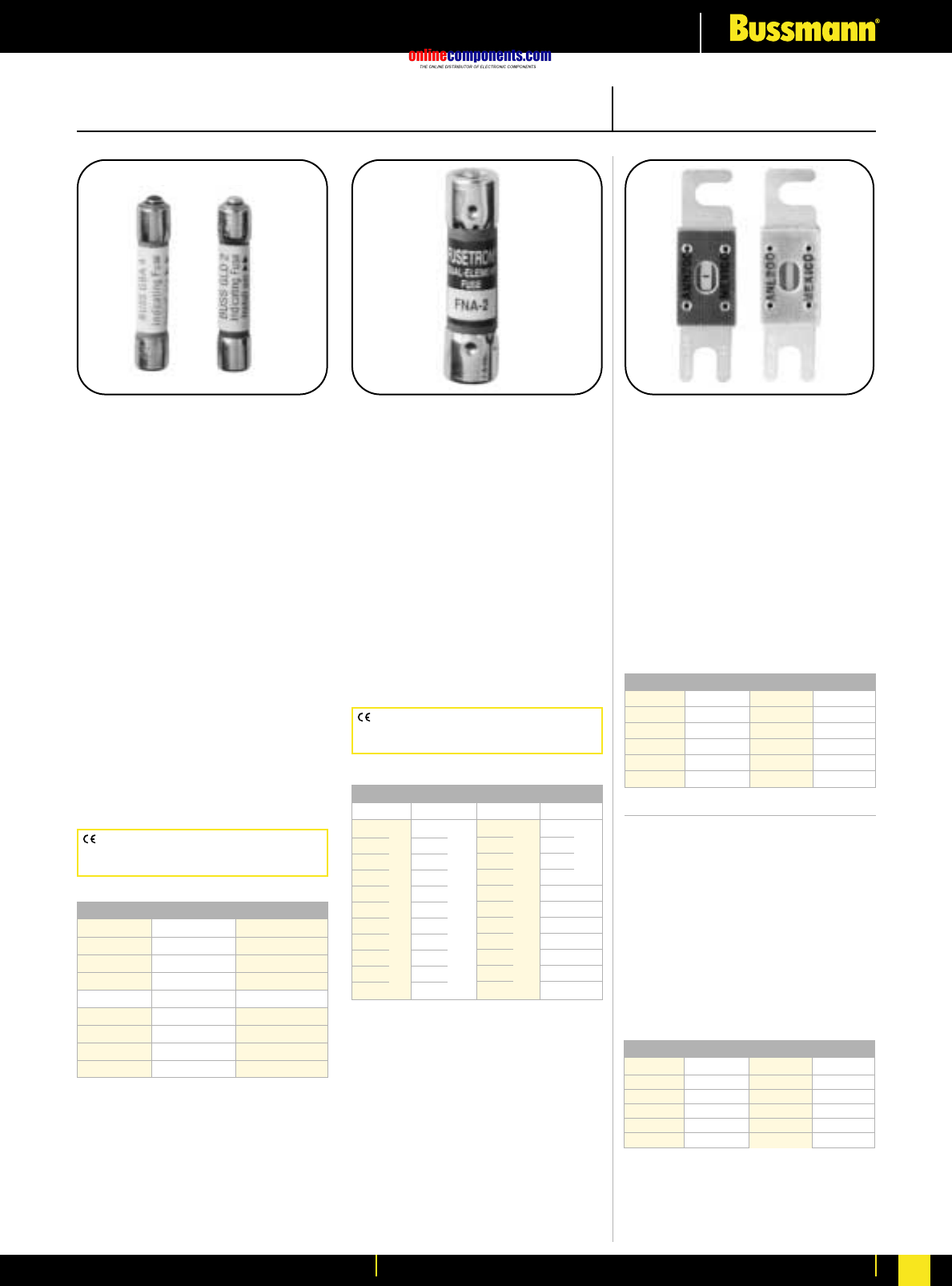
onlinecomponents.com
Electronic Fuses & Accessories
For more information visit our website at www.bussmann.com 150
CE logo denotes compliance with European
Union Low Voltage Directive (50-1000V AC,
75-1500V DC). Refer to Data Sheet: 8002.
CE logo denotes compliance with European
Union Low Voltage Directive (50-1000V AC,
75-1500V DC). Refer to Data Sheet: 8002.
Pin Indication Type Actuators/Limiters
ANN Limiter
Very Fast Acting
Physical Size:
‡Ω•∑ ≈ 3‹Ω¡§∑
(22.2mm ≈81.0mm)
Voltage Rating: 125V AC IR = 2500A
80V DC IR = 2700 A
Agency Information: 35-400A @
125V AC, IR=2500A and 80V DC,
IR=2700A: UL Recognized Guide
JFHR2, File E56412; CSA Certified Class
1422-30, File 53787
CE for 35-400A
Fuseholder: 4164
GBA and GLD
Fast Acting
Physical Size:
⁄Ω¢∑ ≈ 1⁄Ω¢∑ (3AG)
(6.6mm ≈31.8mm)
Agency Information: Std. 248-14
UL Listed, 0-5A/125V AC,
10,000 AIC, Guide JDYX,
File E19180
UL Recognized,
6A/125V AC, 1000AIC
8-15A/50V AC/DC, 300 AIC
Guide JDYX2, File E19180
CSA Certified:
0-5A/125V AC, 10,000 AIC
Class 1422-01, File 53787
General Information: Type GBA
has a “red” pin for high visibility. Type
GLD has an Albaloy-plated pin for
positive, electrical signal circuit
activation.
FNA
Time-Delay
Physical Size:
⁄‹Ω£™∑ ≈ 1⁄Ω™∑
(10.3mm ≈38.1mm)
Agency Information: Std. 248-14
UL Listed 0-°Ω¡ºA, IR 35A@ 250V
IR 10kA@ 125V
1-15A, IR 10kA@ 125V
Guide JDYX, File 19180
CSA Certified, 0-°Ω¡º A/250V,
1-10A/125V, Class 1422-01,
File 53787
General Information: Fuses above
10A have dual-tube construction.
Catalogue Symbol & Current Ratings
GLD-⁄Ω™ GLD-2 GLD-6
GLD-‹Ω¢ GLD-3 GLD-10
GLD-1GLD-4 GLD-12
GLD-1⁄Ω™ GLD-5 GLD-15
GBA-⁄Ω™ GBA-2 GBA-8
GBA-‹Ω¢ GBA-3 GBA-10
GBA-1GBA-4 GBA-15
GBA-1⁄Ω™ GBA-5
Catalogue Symbol & Current Ratings
250V AC IR* 125V AC IR 125V AC IR 125V AC
FNA-⁄Ω¡º
FNA-⁄Ω•
FNA-⁄fiΩ¡ºº
FNA-¤Ω¡º
FNA-⁄Ω¢ IR
FNA-‹Ω¡º 35A
FNA-›Ω¡º
FNA-⁄Ω™
FNA-flꭧ
FNA-‹Ω¢
FNA-°Ω¡º
FNA-1
FNA-1⁄Ω•
FNA-1⁄Ω¢
FNA-1›Ω¡º
FNA-1⁄Ω™ IR
FNA-1flꭧ
10,000A
FNA-1°Ω¡º
FNA-2
FNA-2⁄Ω¢
FNA-2⁄Ω™
FNA-2°Ω¡º
FNA-3
FNA-3¤Ω¡º
FNA-3⁄Ω™
FNA-4
FNA-4⁄Ω™ IR
FNA-5
10,000A
FNA-5flꭧ
FNA-6
FNA-6⁄Ω¢
FNA-7
FNA-8
FNA-9
FNA-10 IR
FNA-12 10,000A
FNA-15
32 Volts
†
FNA-20
FNA-25
FNA-30
—
—
—
*Interrupting rating of 10,000A at 125V.
†
Interrupting rating of 1,000A at 32V.
BIF document: 2012 BIF document: 2047 BIF document: 2024 & 2133
Catalogue Symbol & Current Ratings
ANN-10 ANN-90 ANN-225 ANN-400
ANN-35 ANN-100 ANN-250 ANN-500
ANN-40 ANN-125 ANN-275 ANN-600
ANN-50 ANN-150 ANN-300 ANN-700
ANN-60 ANN-175 ANN-325 ANN-800
ANN-80 ANN-200 ANN-350
ANL
Non-Time Delay
Voltage Rating: 80V DC
Agency Information:
UL Recognized, CSA Certified,
35-750A @ 80V DC, IR = 2700A
Guide JFHR2, File E56412
Class 1422-30, File 53787
Fuseholder: 4164
Catalogue Symbol & Current Ratings
ANL-35 ANL-125 ANL-250 ANL-500
ANL-40 ANL-130 ANL-275 ANL-600
ANL-50 ANL-150 ANL-300 ANL-675
ANL-60 ANL-175 ANL-325 ANL-750
ANL-80 ANL-200 ANL-350 —
ANL-100 ANL-225 ANL-400
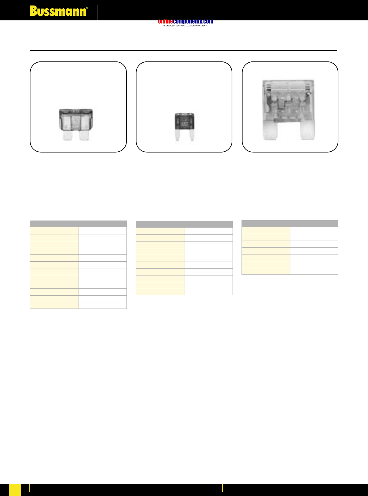
onlinecomponents.com
Electronic Fuses & Accessories
For more information visit our website at www.bussmann.com
151
Blade-Type Fuses
MAX Maxi–Fuse®
Fast Acting
Voltage Rating: 32V DC
Interrupting Rating: 1,000A
ATC®Blade-Type Fuse
Fast Acting
Voltage Rating: 32V DC
Interrupting Rating: 1,000A
Agency Information:
UL Recognized, (3-40A)
(Guide JFHR2, File E56412)
ATM Mini–Fuse®
Fast Acting
Voltage Rating: 32V DC
Interrupting Rating: 1,000A
Catalogue Symbol & Current Ratings
ATC-1 Black
ATC-2 Gray
ATC-3 Violet
ATC-4 Pink
ATC-5 Tan
ATC-7
⁄Ω™ Brown
ATC-10
Red
ATC-15
Blue
ATC-20
Yellow
ATC-25
Clear
ATC-30
Green
ATC-40
Orange
Catalogue Symbol & Current Ratings
ATM-2 Gray
ATM-3 Violet
ATM-4 Pink
ATM-5 Tan
ATM-7
⁄Ω™
Brown
ATM-10 Red
ATM-15
Blue
ATM-20
Yellow
ATM-25
Clear
ATM-30
Green
Catalogue Symbol & Current Ratings
MAX-20
Yellow
MAX-30
Green
MAX-40
Orange
MAX-50
Red
MAX-60
Blue
MAX-70
Tan
MAX-80
Clear
BIF document: 2049BIF document: 2048BIF document: 2009
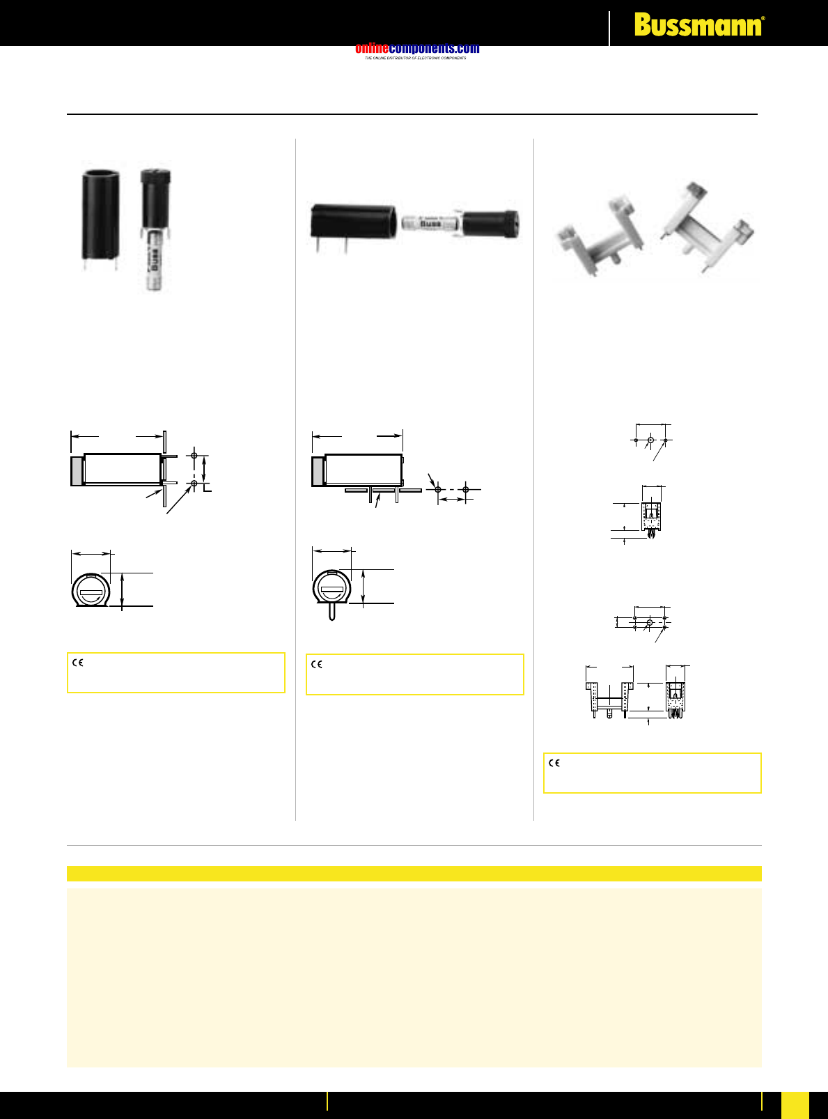
onlinecomponents.com
Electronic Fuses & Accessories
For more information visit our website at www.bussmann.com 152
.197"
(5.0mm)
.102" Dia. Hole
(2.6mm) .051" Dia. Hole
(1.3mm)
.591"
(15.0mm)
.886"
(22.5mm)
.138"
(3.5mm)
.354"
(9.0mm)
.551"
(14.0mm)
.102" Dia. Hole
(2.6mm) .051" Dia. Hole
(1.3mm)
.591"
(15.0mm)
.138"
(3.5mm)
.354"
(9.0mm)
.512"
(13.0mm)
F
U
S
E
.461"
(11.7mm)
1.303"
(33.1mm)
.512"
(13.0mm)
Printed Circuit
Board
.394"
(10.0mm)
Mounting Holes
.051" + .002" Dia. (Typ.)
_
(1.30 + .05mm)
_
F
U
S
E
.461"
(11.7mm)
1.303"
(33.1mm)
.512"
(13.0mm)
Printed Circuit
Board .051" + .002" Dia. (Typ.)
_
(1.30 + .05mm)
_
.394"
(10.0mm)
Mounting Holes
BIF document: 2110BIF document: 2110BIF document: 2110
Printed Circuit Board Mount for 5mm x 20mm Fuses
HTC-45M
PCB Vertical Mount
250V, 6.3A, 2.5W
Bayonet Cap/Carrier
See specifications below
HTC-50M
PCB Horizontal Mount
250V, 6.3A, 2.5W
Bayonet Cap/Carrier
See specifications below
HTC-60M, HTC-65M
250V, 6.3A
Body Material: Valox DR48
Terminals: Phosphor bronze
Terminals: For HTC-45M, HTC-50M Tin-plated.
Molded Materials: High temperature thermoplastic that meets the flammability ratings of UL 94VO;
Glow Wire Test: 960°C per IEC 695-2-1.
Solderability: In accordance with IEC 68-2-20.
Electrical: Contact Resistance: ≤10mΩ; Insulation Resistance: ≥10mΩ; Dielectric Strength ≥2000 VAC.
Shock Safety: PC2 (fuseholders).
Agency Information:
HTC-45M, HTC-50M UL Recognized, (Guide IZLT2, File E14853; 6.3A, 250V; CSA Certified,
(Class 6225-01, File 47235; 10A, 250V) SEMKO: (9226032; 6.3A, 250V).
Packaging: Standard Qty 10 (No Prefix), Bulk Qty 100 (Prefix Catalogue Number with BK/).
HTC-60M (2 Legs)
HTC-65M (4 Legs)
CE logo denotes compliance with European
Union Low Voltage Directive (50-1000V AC,
75-1500V DC). Refer to BIF document #8002.
CE logo denotes compliance with European
Union Low Voltage Directive (50-1000V AC,
75-1500V DC). Refer to BIF document #8002.
CE logo denotes compliance with European
Union Low Voltage Directive (50-1000V AC,
75-1500V DC). Refer to BIF document #8002.
Specifications
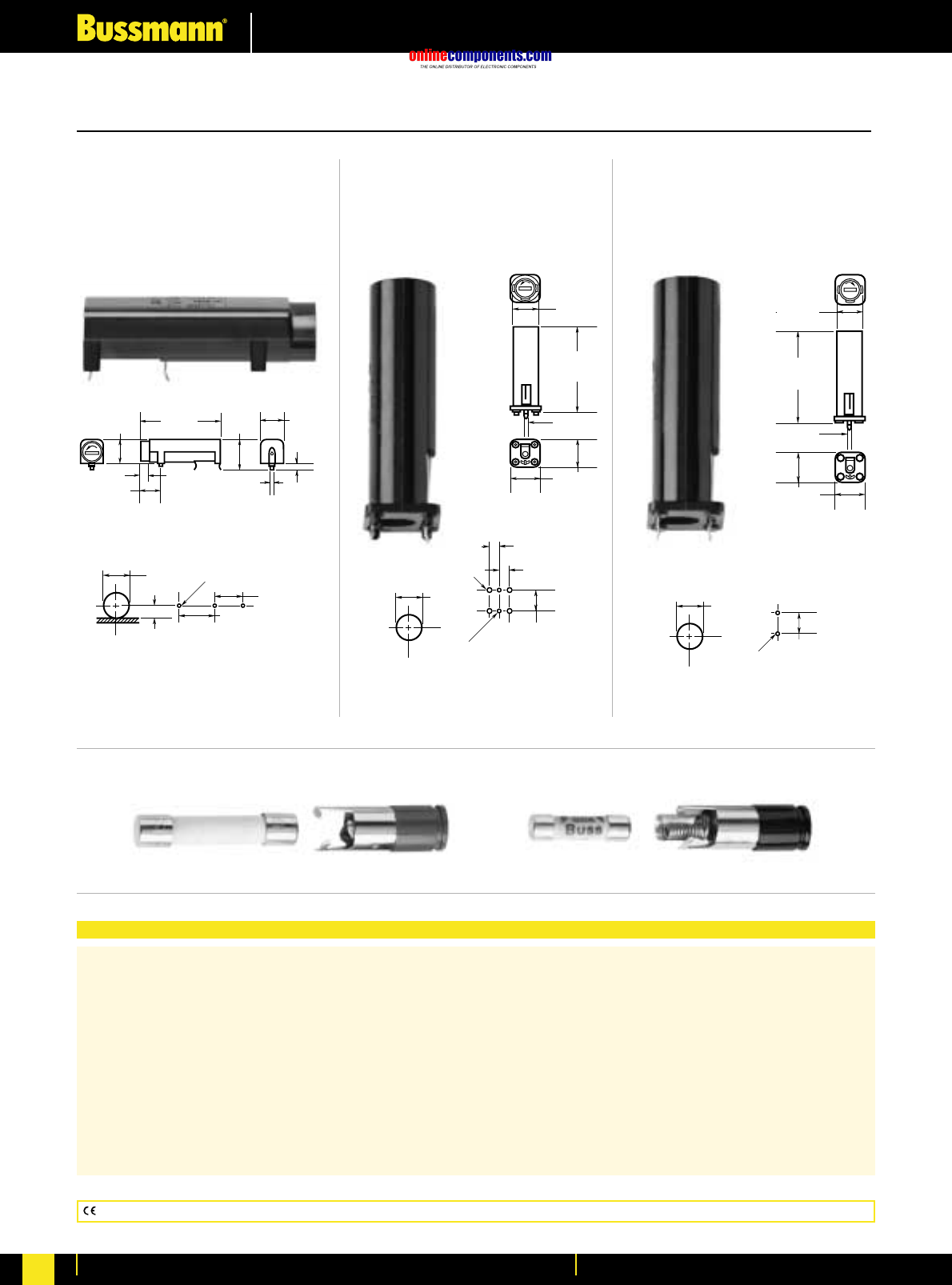
onlinecomponents.com
Electronic Fuses & Accessories
For more information visit our website at www.bussmann.com
153
Specifications
PC Board Mount for 5mm x 20mm and
⁄Ω¢∑
x 1
⁄Ω¢∑
Fuses
Electrical Ratings: UL — 16A @ 250V; CSA — 12A @ 250V; VDE — 6.3A @ 250V; SEMKO — 6.3A @ 250V
Insulation resistance — 10,000 megohm at 500 VDC. Contact resistance — less than 0.005 ohms
@ 20mV. Dielectric strength — over 200 volts/mil.
Molded Material: High dielectric molded phenolic with a UL 94VO flammability rating.
Fuse Carrier & Knob: Spring-loaded, bayonet type. Tin plated brass. Screwdriver slotted.
Mounting: “Kicked” terminals (all models) and stabilizer pins on HBV model for increased stability.
Environmental: Maximum operating temperature — (-40°C to +85°C).
Agency Information: UL Recognized — Guide IZLT2, File EI4853;
CSA Certified — Class 6225-01, File 47235
VDE — 41421
SEMKO — 9308147 (HBH, HBV) 9222106 (HBW)
0.200"
(5.0mm)
0.200"
(5.0mm)
0.100" Dia. 4 Holes
(2.54mm)
Panel PC Board
0.531"
(13.5mm)
0.400"
(10.0mm)
0.050" Dia. 2 Holes
(1.3mm)
BIF document: 2118BIF document: 2118BIF document: 2118
HBH-I (for ⁄Ω¢∑ ≈ 1⁄Ω¢∑ fuses)
HBH-M (for 5mm ≈ 20mm fuses)
Horizontal Mount
HBV-I (for ⁄Ω¢∑ ≈ 1⁄Ω¢∑ fuses)
HBV-M (for 5mm ≈ 20mm fuses)
Vertical Mount with
Stability Pins
HBW-I (for ⁄Ω¢∑ ≈ 1⁄Ω¢∑ fuses)
HBW-M (for 5mm ≈20mm fuses)
Vertical Mount without
Stability Pins
Panel PC Board
0.531"
(13.5mm)
0.400"
(10.0mm)
0.050"
Dia. 2 Holes
(1.3mm)
HBV
0.510"
(13.0mm
)
1.855"
(47.0mm
)
0.040"
(1.05mm
)
0.580"
(14.9mm
)
HBW
0.510"
(13.0mm)
1.855"
(47.0mm)
0.040"
(1.05mm)
0.580"
(14.9mm)
0.469"
(12.0mm)
0.250"
(6.4mm)
Panel
0.700"
(17.8mm)
0.600"
(15.2mm)
0.050" Dia. 3 Holes
(1.3mm)
PC Board
Fuseholder Caps (Fit all three shown above)
0.437"
(11.1mm)
0.197"
(5.0mm)
0.244"
(6.2mm)
1.77"
(45.0mm)
0.480"
(12.2mm) 0.490"
(12.4mm)
0.040"
(1.0mm) 0.140"
(3.5mm)
FBI FBM
CE logo denotes compliance with European Union Low Voltage Directive (50-1000V AC, 75-1500V DC). Refer to BIF document #8002.
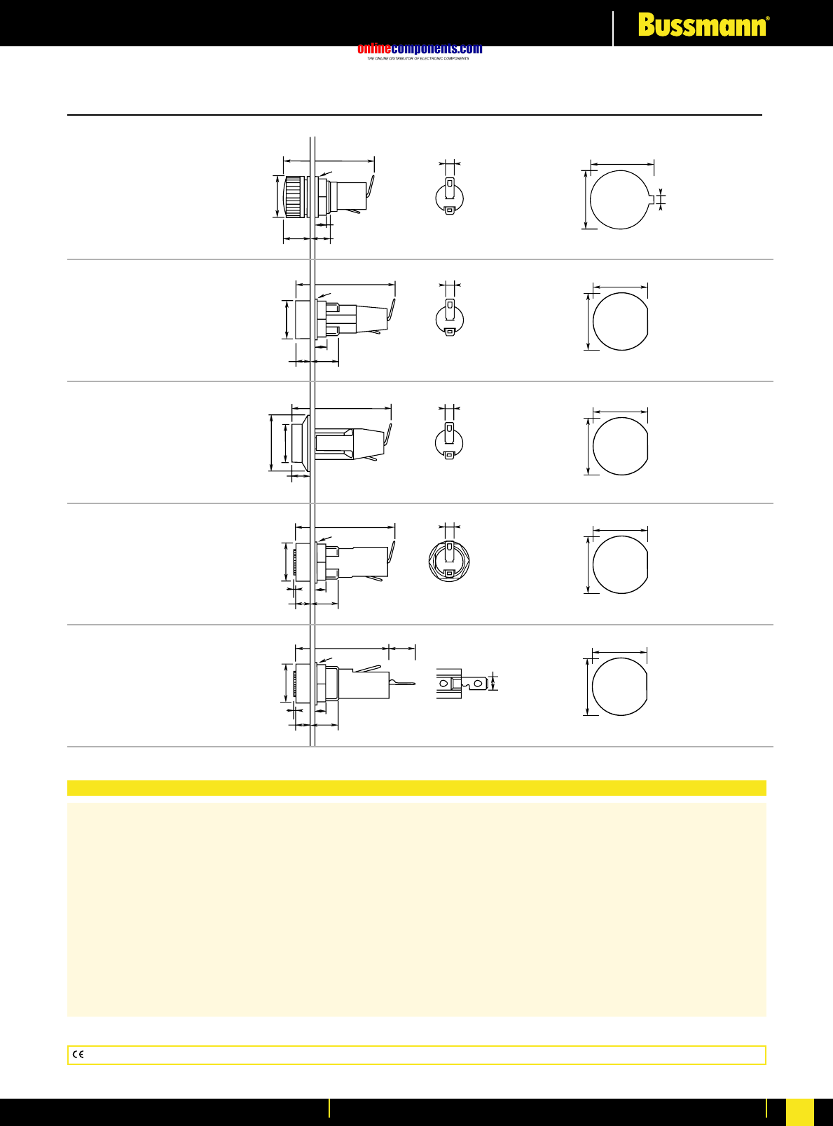
onlinecomponents.com
Electronic Fuses & Accessories
For more information visit our website at www.bussmann.com 154
3.0x0.51mm
34.2mm
6.8mm
4mm
Ø16mm
Ø16mm 3.0x0.51mm 14.00mm
1.8mm
13.0mm
12.00mm+0.0
–0.1
12.70mm+0.0
–0.1
12.00mm+0.0
–0.1
12.70mm+0.0
–0.1
12.00mm+0.0
–0.1
12.70mm+0.0
–0.1
12.00mm+0.0
–0.1
12.70mm+0.0
–0.1
3.0x0.51mm
3.0x0.51mm
4.8x0.51mm
11mm
37.5mm
4mm
Ø15mm
Ø16mm
11mm
5.5mm
Ø22mm
6.5mm
Ø15mm
37.5mm
36mm
4mm
Ø15mm
Ø16mm
11mm
5.5mm
0.5mm
35.5mm
4mm
Ø15mm
Ø16mm
11mm
5.5mm
0.5mm
10.2mm
Specifications
HTC-30M
Ratings: 250V, 6.3A, 2.5W
Screwdriver slot
HTC-35M
Ratings: 250V, 6.3A, 2.5W
Threaded cap
HTC-40M
Ratings: 250V, 6.3A, 2.5W
Screwdriver slot
HTC-55M
Ratings: 250V, 6.3A, 2.5W
Fuse carrier: bayonet type
BIF document: 2110
BIF document: 2110
BIF document: 2110
BIF document: 2110
BIF document: 2110
HTC-70M
Ratings: 250V, 10A, 2.5W
Fuse carrier: bayonet type
CE logo denotes compliance with European Union Low Voltage Directive (50-1000V AC, 75-1500V DC). Refer to BIF document #8002.
PC Board Mount for 5mm x 20mm and
⁄Ω¢∑
x1
⁄Ω¢∑
Fuses
Terminals: Brass, tin-plated.
Molded Materials: High temperature thermoplastic that meets the flammability ratings of UL 94VO; Glow Wire Test:
960°C per IEC 695-2-1.
Solderability: In accordance with IEC 68-2-20.
Agency Information:
UL Recognized — Guide IZLT2, File E14853;
CSA Certified — Class 6225-01, File 47235;
SEMKO — 9226031 (HTC-30M, HTC-35M); 9226032 (HTC-40M); 9226033 (HTC-55M);
9226034 (HTC-70M)
Electrical: Contact Resistance: ≤10mΩ; Insulation Resistance: ≥10mΩ; Dielectric Strength ≥2000 VAC.
Shock Safety: PC2 (fuseholders).
Packaging: Standard Qty 10 (No Prefix), Bulk Qty 100 (Prefix Catalogue Number with BK/).
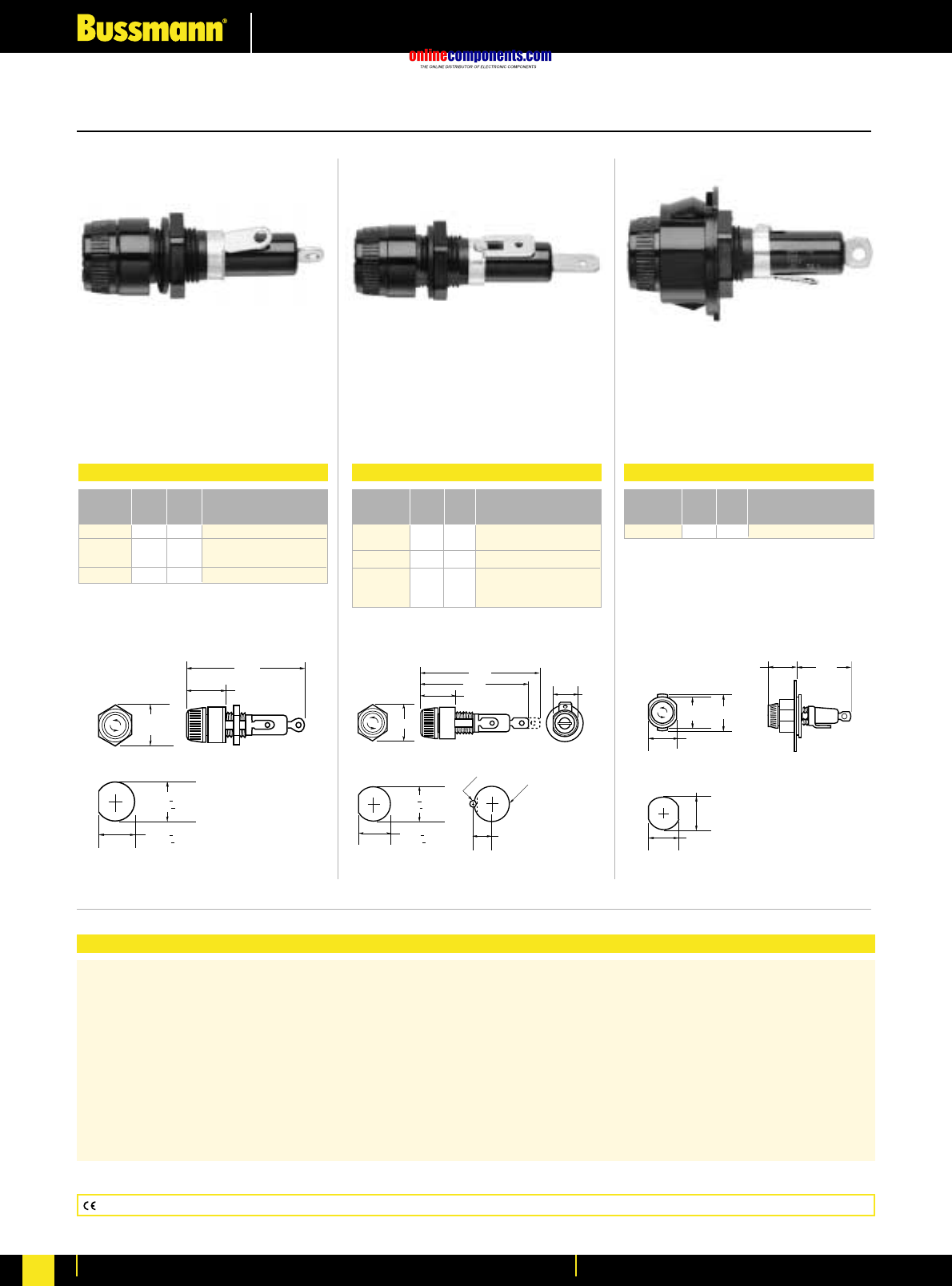
onlinecomponents.com
Electronic Fuses & Accessories
For more information visit our website at www.bussmann.com
155
Specifications
Panel Mounted for
⁄Ω¢
∑x 1
⁄Ω¢
∑Fuses
Terminals: Bayonet-type knob.
Vibration resistant.
For panels up to fiΩ¡§∑ (7.9mm) thick.
Agency Information: UL Recognized — Guide IZLT2, File E14853
CSA Certified — Class 6225-01, File 47235
Replacement Parts: Knob: 9435-⁄/™∑
Plastic Nut: BK/1A4287
Metal Nut: BK/1A4806-2
Washer: 9732
BIF document: 2106BIF document: 2106BIF document: 2106
HKP, HKP-L, HKP-W
Standard Fuseholders HKP-BBHH, HKP-HH
and HKP-LW-HH
Fuseholders with
⁄/¢
∑
Quick-connects
HKP-OO
Snap-Lock Fuseholders
0.69"
(17.5mm)
0.75"
(19.1mm)
2.31"
(58.7mm)
.473" + .005"
(12.0mm + .13mm)
.505" + .005"
(12.8mm + .13mm)
Punched Mounting Hole
F
U
S
E
F
U
S
E
F
U
S
E
0.463"
REF.
.473" + .005"
(12.0mm + .13mm)
.505" + .005"
(12.8mm + .13mm)
Punched Mounting Hole
0.27"
0.5" DRILL
#41 DRILL
Drilled Mounting Hole
0.69"
2.64"
2.44"
WHEN FUSE IS INSERTED
0.69"
.800"
(20.3mm)
Punched Mounting Hole
.811"
(20.6mm)
.890"
(22.6mm)
1.56"
(39.7mm)
.75"
(19.1mm)
.855"
(21.7mm) 1.17"
F
U
S
E
F
U
S
E
F
U
S
E
Electrical Ratings for HPF Series
Catalogue
Symbol Amps Volts Fuse Description
HKP 30 250 —
HKP-L 30 250 HKP with 2250V stand-off
barrier.
HKP-W 30 250 HKP with drip-proof knob.
Electrical Ratings for HPF Series
Catalogue
Symbol Amps Volts Fuse Description
HKP-BBHH 15 250 HKP with ⁄Ω¢∑ quick connects,
nut and washer assembled.
HKP-HH 15 250 HKP with ⁄Ω¢∑ quick-connect.
HKP-LW-HH 15 250 HKP with drip-proof knob,
2250V stand-off barrier and
quick-connects.
Electrical Ratings for HPF Series
Catalogue
Symbol Amps Volts Fuse Description
HKP-OO 30 250 HKP with snap-lock
CE logo denotes compliance with European Union Low Voltage Directive (50-1000V AC, 75-1500V DC). Refer to BIF document #8002.
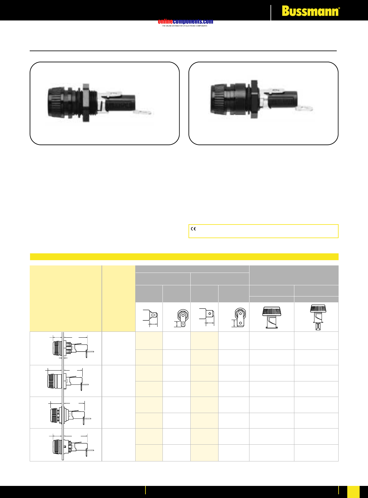
onlinecomponents.com
Electronic Fuses & Accessories
For more information visit our website at www.bussmann.com 156
Panel Mounted for 5mm x 20mm and
⁄Ω¢∑
x 1
⁄Ω¢∑
Fuses
HTB Series
Fuseholders with Knob-Type Carriers
Agency Information:
UL Recognized — Guide IZLT2, File E14853
20A (‹Ω¡§quick-connect 15A) @ 250V
CSA — 16A @ 250V Class 6225-01 File 47235;
VDE* — 6.3A @ 250V, 49890
SEMKO* — 6.3A @ 250V, 8945092, 9005230
*Screwdriver slot carrier only
Electrical Data: Insulation resistance (per IEC #257) —
10,000 ohms @ 500VDC; contact resistance (per IEC #257)
— 0.005 ohms max. @ 1A; standoff voltage (per IEC #257) —
480V/Mil @ .125 in. thickness.
Environmental: Maximum operating temperature
-55°C to 85°C.
Molded Components: High temperature, flame retardant,
thermoplastic; UL Component Recognized; 94VO; mounting
nut, spacer-black polycarbonate.
Terminals: Tin-plated brass.
Mounting: Withstands 15 to 20 lbs-ins torque to mounting
nut when mounting fuseholder to panel. Maximum panel
thickness 0.300 inches.
CE logo denotes compliance with European Union Low Voltage Directive
(50-1000V AC, 75-1500V DC). Refer to BIF document #8002.
HTB-8
HTB-6
HTB-2
HTB-4
Terminal Options
Knob Type Carrier Solder/ Carrier Options
‹Ω¡§∑ Quick-Connect ⁄Ω¢∑ Quick-Connect
⁄Ω¢∑ x 1⁄Ω¢∑ 5mm x 20mm
In-Line Rt. Angle In-Line Rt. Angle (“I” Equals Inches) (“M” Equals Metric)
Common Dimensional Data: Knob Knob
Length (Knob Type) - 1.69∑
(42.9mm) Plus In-Line Terminal
(Screwdriver Slotted)
1.75∑(44.5mm)
NOTE: Plus In-Line Terminal
HTB-22I HTB-24I HTB-26I HTB-28I ✓—
HTB-22M HTB-24M HTB-26M HTB-28M —✓
HTB-42I HTB-44I HTB-46I HTB-48I ✓—
HTB-42M HTB-44M HTB-46M HTB-48M —✓
HTB-62I HTB-64I HTB-66I HTB-68I ✓—
HTB-62M HTB-64M HTB-66M HTB-68M —✓
HTB-82I HTB-84I HTB-86I HTB-88I ✓—
HTB-82M HTB-84M HTB-86M HTB-88M —✓
1.125"
(28.6mm)
0.47"
(11.9mm)
0.09" NOM.
(2.4mm)
1.125"
(28.6mm)
0.47"
(11.9mm)
0.92"
(23.4mm)
0.67"
(17.1mm)
0.91"
(23.0mm)
0.69"
(17.5mm)
0.34"
(8.7mm)
0.33"
(8.3mm)
0.47"
(11.9mm)
0.45"
(11.5mm)
Fuseholders and fuse carriers may be ordered separately.
0.30∑
7.62mm
0.125∑
3.18mm
0.30∑
7.62mm
0.125∑
3.18mm
Maximum
Panel
Thickness
Low Profile
Rear Hex Nut
High
Profile
Rear Hex Nut
Front
Hex Nut
Low Profile
Snap-In
Ordering Information
BIF document: 2119
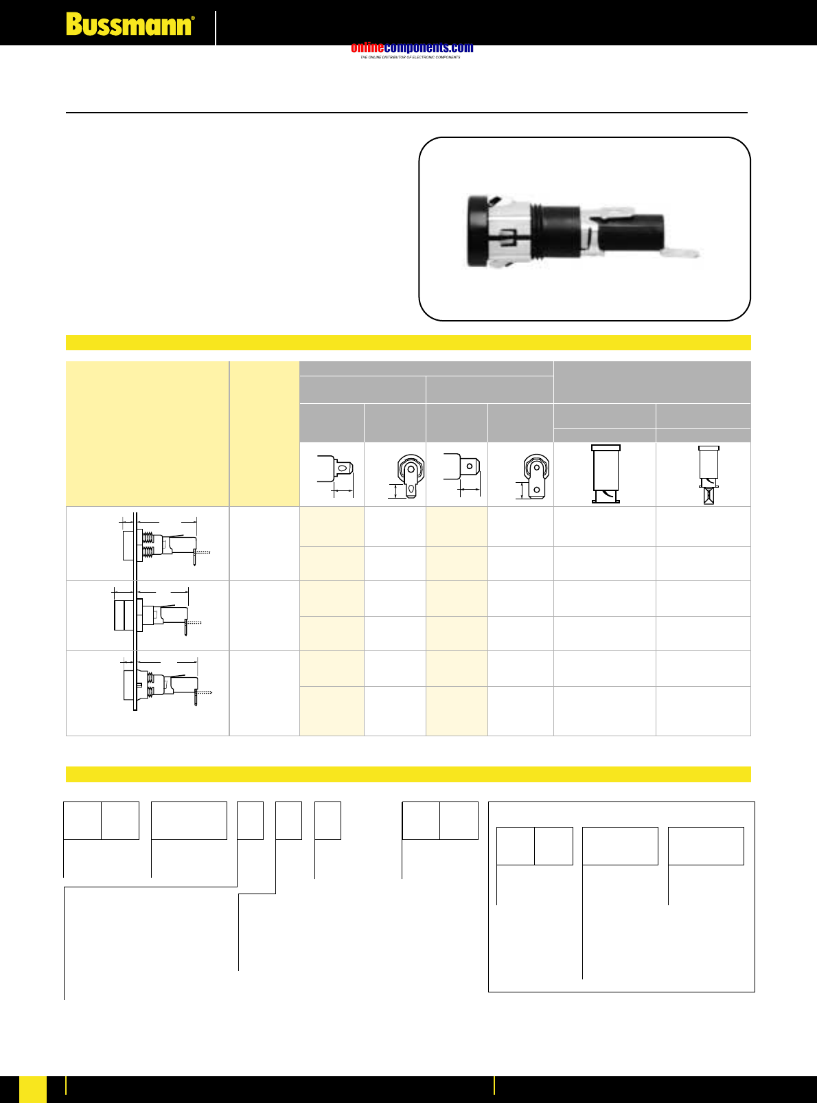
onlinecomponents.com
Electronic Fuses & Accessories
For more information visit our website at www.bussmann.com
157
Panel Mounted for 5mm x 20mm and
⁄Ω¢∑
x 1
⁄Ω¢∑
Fuses
BIF document: 2119
HTB Series
Fuseholders with Screwdriver Slotted Carriers
Ordering Information
Ordering Information
HTB-3
HTB-5
HTB-9
0.17"
(4.37mm) 1.58"
(40.03mm)
0.17"
(4.37mm) 1.59"
(40.08mm)
0.41"
(10.31mm) 1.34"
(34.13mm)
0.34"
(8.7mm)
0.33"
(8.3mm)
0.47"
(11.9mm)
0.45"
(11.5mm)
Terminal Options
Knob Type Carrier Solder/ Carrier Options
‹Ω¡§∑ Quick-Connect ⁄Ω¢∑ Quick-Connect
⁄Ω¢∑ ≈ 1⁄Ω¢∑ 5mm ≈20mm
In-Line Rt. Angle In-Line Rt. Angle (“I” Equals Inches) (“M” Equals Metric)
Common Dimensional Data: Screwdriver Screwdriver
Length (Knob Type) - 1.69∑
(42.9mm) Plus In-Line Terminal
(Screwdriver Slotted)
1.75∑(44.5mm)
NOTE: Plus In-Line Terminal
HTB-32I HTB-34I HTB-36I HTB-38I ✓—
HTB-32M HTB-34M HTB-36M HTB-38M —✓
HTB-52I HTB-54I HTB-56I HTB-58I ✓—
HTB-52M HTB-54M HTB-56M HTB-58M —✓
HTB-92I HTB-94I HTB-96I HTB-98I ✓—
HTB-92M HTB-94M HTB-96M HTB-98M —✓
Fuseholders and fuse carriers may be ordered separately.
0.30∑
7.62mm
0.125∑
3.18mm
0.125∑
3.18mm
Maximum
Panel
Thickness
Low Profile
Rear Hex Nut
High Profile
Rear Hex Nut
Low-Profile
Snap-In
S
Packing
(Blank) – Std.
BK/ – Bulk
Rear Terminal Configuration
2 — Solder / ‹Ω¡§∑ Quick-Connect
Solder / ‹Ω¡§∑ Quick-Connect
(In-Line)
4 — (Right Angle)
6 — ⁄Ω¢∑ Quick-Connect (In-Line)
8 — ⁄Ω¢∑ Quick-Connect (Right Angle)
Fuse Carrier
I — ⁄Ω¢∑ x 1-1⁄Ω¢∑
M — 5mm x 20mm
Splash Proof
(Optional on -2,
-4, -6, and -8)
Body Configuration and Mounting
Finger Grip Holders
2 — Low Profile (Rear Panel Hex-Nut)
4 — High Profile
*6 — (Front Panel Hex-Nut)
8 — Low Profile (Snap-In)
Screwdriver Slotted Holders
3 — Low Profile
5 — High Profile
9 — Low Profile (Snap-In)
Product
Symbol
HTB-
Packaging
(Blank) – Std.
BK/ – Bulk
Fuse Carrier
I — ⁄Ω¢∑ x 1⁄Ω¢∑
M — 5mm x 20mm
Product
Symbol
FT — Knob Type
(For 20, 40, 60,
and 80 Series
Only)
ST —Screwdriver
Slotted (For 30,
50, and 90 Series
Only)
P
*Profile varies with panel thickness. Holder installs thru rear of panel.
FUSE CARRIER ONLY
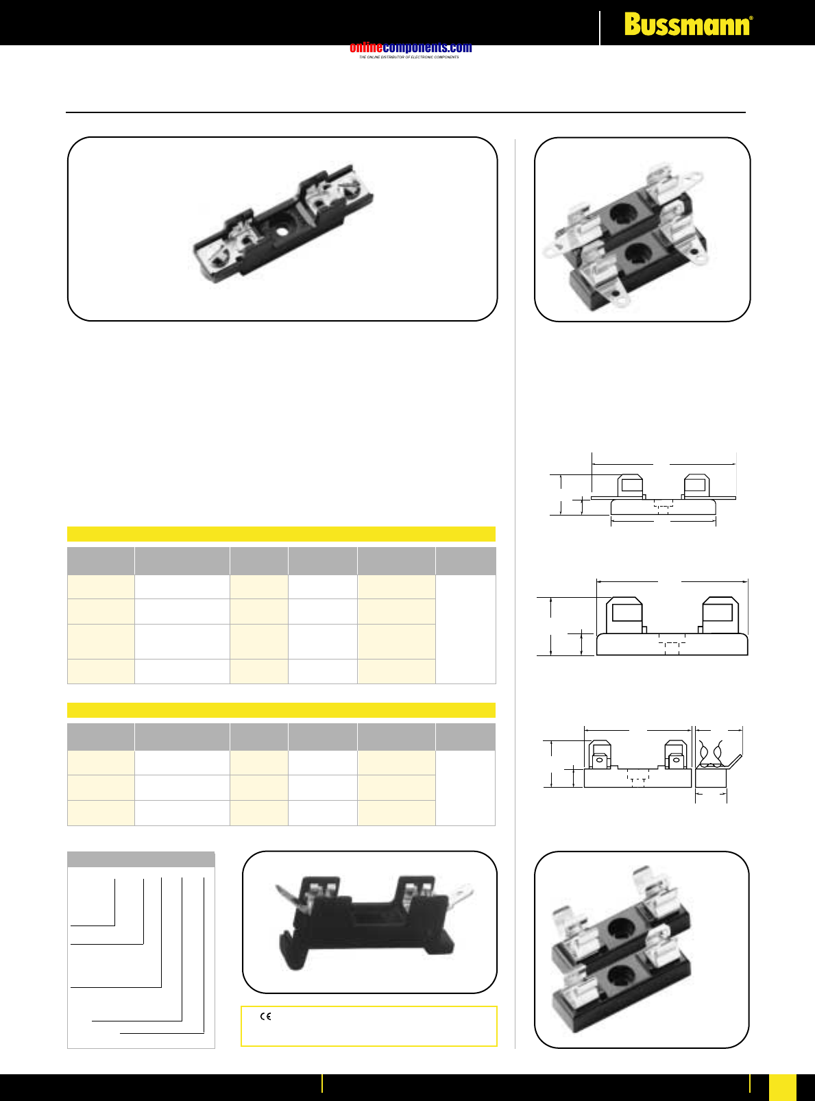
onlinecomponents.com
Electronic Fuses & Accessories
For more information visit our website at www.bussmann.com 158
BIF document: 2101
For
⁄Ω¢
∑x 1
⁄Ω¢
∑Fuses
Series 8000
Bolt-in and Snap-in Mounting for ⁄Ω¢∑ ≈1⁄Ω¢∑ Fuses
Construction: Blocks are molded flame retarded thermoplastic. Clips are spring-bronze.
Voltage Rating: 300V
Agency Information:
UL Recognized ; File E14853A, Guide IZLT2
CSA Certified Class 6225-01, File 47235
Anti-Rotation Pin: Single pole blocks may be ordered without the antirotational pin simply
by adding an “X” to the number of poles (Example: BK/S-8000-1X).
Carton Quantity: 10; shelf package: 100.
Bulk Carton: Single-pole and 2-pole fuse blocks–1,000; Multiple-pole fuse blocks–3-8 pole:
200; 9-12 pole: 50. When ordering bulk quantities, prefix “BK/” to catalogue number: (Example:
BK/S-8001-1-SNP).
⁄Ω¢∑ ≈1⁄Ω¢∑ Single Pole
(6.4mm ≈31.8mm)
Bakelite base; spring-bronze, bright
tin-lead plate clips; 30 amperes, 250
volts; base width ⁄Ω™∑ (12.7mm).
No. 4405—0°Solder Terminals.
Integral terminal and clip.
No. 4406—Side Solder Terminal
No. 4574—Spare Fuseblock
No. 2499—Side Quick-Connect
Terminals. ⁄Ω¢∑ (6.4mm); 15 amperes,
250 volts. UL Recognized,
Guide IZLT2, File E14853.
Note—Mounting screw hole diameter is 0.147∑
(3.7mm). Counterbore diameter, 0.636∑(8.0mm).
Max. Mounting Screw No. 6.
1.63"
(41.3mm)
0.27"
(6.7mm)
0.69"
(17.5mm)
2.31"
(58.7mm)
1.63"
(41.3mm)
0.27"
(6.7mm)
0.69"
(17.5mm)
0.27"
(6.7mm)
0.75"
(19.1mm)
0.5"
(12.7mm)
0.72"
(18.3mm)
1.63"
(41.3mm)
4574
2499
4406
4405
Poles
Series Terminal Angle Cat. No. Amperes (Suffix)
8000 Solder 0°S-8001- UL 25A
40°S-8002- CSA 21A
8100 ‹Ω¡§∑ Quick 0°S-8101- UL 20A
Connect 40°S-8102- CSA 13A
⁄Ω¢∑ Quick 0°S-8201- UL 20A 1 - 12
8200 40°S-8202-
Connect Side S-8203- CSA 16A
8300 Screw —S-8301- UL 30A
CSA 25A
Bolt-in Mounting
Poles
Series Terminal Angle Cat. No. Amperes (Suffix)
8000 Solder 0°S-8001-1-SNP UL 25A
40°S-8002-1-SNP CSA 21A
8100 ‹Ω¡§∑ Quick 0°S-8101-1-SNP UL 20A
Connect 40°S-8102-1-SNP CSA 13A
8200 ⁄Ω¢∑ Quick 0°S-8201-1-SNP UL 20A
Connect Side S-8203-1-SNP CSA 16A
Bolt-in Mounting
Available
only in
single
pole
BK/ S-8 0 00 -00
Prefix for
Bulk
Packing
Series 8000
Product Line
Terminal Angle
“01” - straight (0°,)
“02”- 40°
“03” - side*
Type Terminal
“0”-Solder
“1”-‹Ω¡§∑
Quick Connect
“2” - ⁄Ω¢∑ Quick Connect
“3” - Screw
Number of Poles (1-12)
*Available only in single pole
Catalogue Code
CE logo denotes compliance with European Union
Low Voltage Directive (50-1000V AC, 75-1500V DC).
Refer to BIF document #8002.
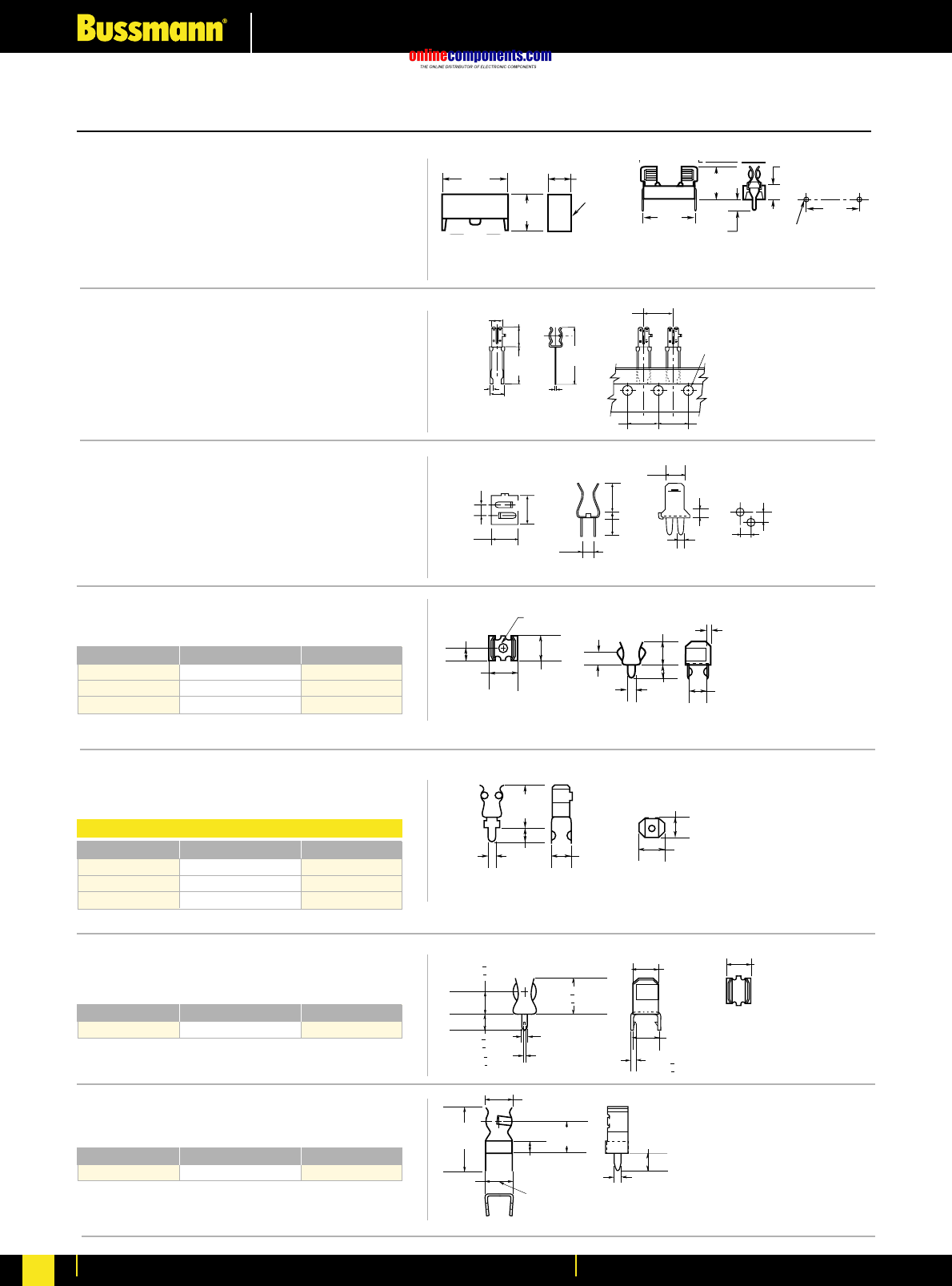
onlinecomponents.com
.250"
(6.35mm)
.060"
(1.5mm)
.246"
(6.3mm)
.344" + .015"
(8.73mm + 0.38mm)
.266"
(6.75mm)
.344" + .015"
(8.73mm + 0.38mm)
.141" + .015"
(3.58mm + 0.38mm)
.022" + .002"
(0.56mm + 0.05mm) .032" + .002"
(.81mm + .05mm)
2.54mm
1.46mm
2.29mm
4.32mm
8.73mm
3.91mm
2.85mm
6.26mm
6.22mm
2.54mm 2.54mm
Electronic Fuses & Accessories
For more information visit our website at www.bussmann.com
159
Printed Circuit Board for 5mm Diameter Fuses
High Profile
BIF document: 2110
BIF document: 2110
BIF document: 2110
BIF document: 2131
BIF document: 2131
BIF document: 2131
BIF document: 2131
HTC-15M, HTC-140M
PCB Fuseblock and Snap-On Cover
Voltage Rating: 250V, 6.3A, 1.6W
HTC-15M (Fuseholder), HTC-140M (Natural Cover),
HTC-150M* (Transparent Cover)
*Available in bulk only. Use this format: BK/HTC-150M
HTC-200M
PC Board Mount Fuseclip
Construction: Tin plated bronze
Tape and Fan Fold packed
Ammo Pack (AP/HTC-200M) 1000 pieces per box
HTC-210M
PC Board Mounted Fuseclip with End Stops
1A3399 Series
Fuseclips with End Stops and Straight Leads
1A5018 Series
Fuseclips with End Stops and Straight Leads
1A5601 Series
Fuseclips (0-7 amps)
1A5602 Series
Fuseclips (0-7 amps)
Catalogue Number Clip Material* Finish
1A3399-01 Beryllium Copper* Silver
1A3399-04 Beryllium Copper* Bright Tin
1A3399-10 Spring Bronze Bright Tin
*Beryllium copper recommended for currents higher than 15 amps (⁄Ω¢∑ clips).
.031"
(.79mm) .217"
(5.5mm)
.012"
(.3mm)
.177"
(4.5mm)
.319"
(8.1mm)
BUSS
.61"
(15.5mm)
.929"
(23.6mm)
BUSS
BUSS
.50"
(12.7mm) .50"
(12.7mm)
.50"
(12.7mm)
.157"
(3.99mm)
.115"
(2.9mm)
.062"
(1.6mm)
.254"
(6.5mm) .237"
(6.0mm)
.125"
(3.2mm)
.225"
(5.7mm)
.125"
(3.2mm)
.060"
(1.5mm) .188"
(4.8mm)
.030"
(1.6mm)
.180"
(4.57mm)
.230"
(5.84mm)
()
.440"
(11.2mm)
.140"
(3.7mm)
.047"
(1.2mm) .180"
(4.6mm)
.216"
(5.48mm) LEGS TO FIT
IN .052" (1.3mm) DIA.
HOLES ON CENTER
.219"
(5.57mm)
.047"
(1.19mm)
.093"
(2.36mm)
.500"
(12.70mm) .250"
(6.35mm) .140"
(3.56mm)
HTC-140M
Cover
1.047"
(26.6mm)
217
"
.345"
(9.0mm)
.571"
(14.5mm) .866"
(22.0mm)
.217"
(5.5mm)
.177"
(4.5mm)
.890"
(22.60mm)
Mounting Holes
.059" + .002" Dia. (Typ.)
_
(1.50 + .05mm)
_
.531"
(13.5mm)
Catalogue Number Clip Material* Finish
1A3399-01 Beryllium Copper* Silver
1A3399-04 Beryllium Copper* Bright Tin
1A3399-10 Spring Bronze Bright Tin
*Beryllium copper recommended for currents higher than 15 amps (⁄Ω¢∑ clips).
Catalogue Number Clip Material* Finish
1A5601 Cartridge Brass Bright Tin
Catalogue Number Clip Material* Finish
1A5602 Cartridge Brass Bright Tin
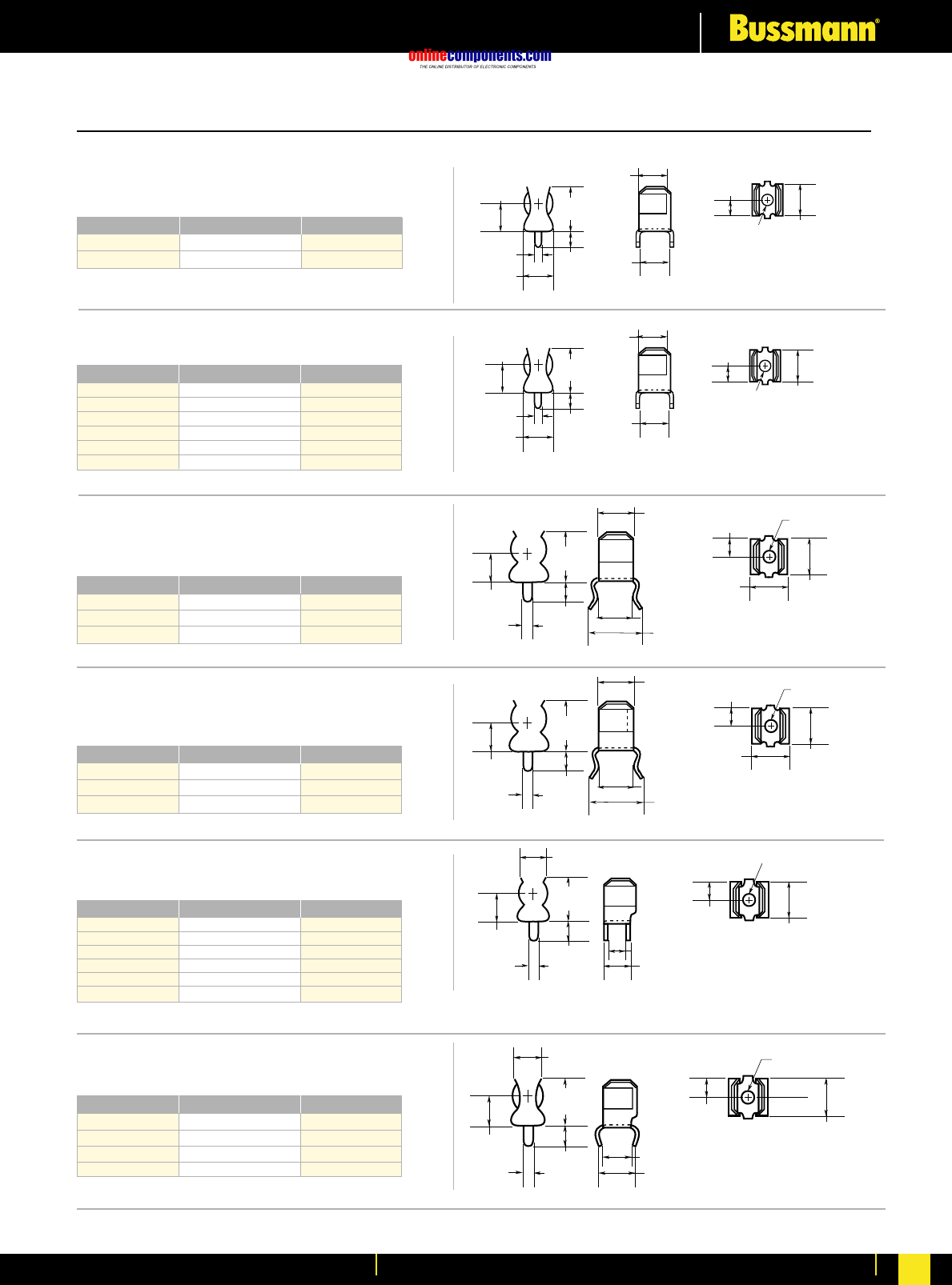
onlinecomponents.com
Electronic Fuses & Accessories
For more information visit our website at www.bussmann.com 160
1A3398 Series
Fuseclips without End Stops and Straight Leads
1A4533 Series
Fuseclips without End Stops and
Angled Out Leads
BIF document: 2131
BIF document: 2131
.280"
(7.1mm)
.155"
(3.94mm)
.102" Dia.
(
2.6mm
)
.245"
(6.2mm)
.280"
(7.1mm)
.
280"
(7.1mm)
.410"
(10.4mm)
.140"
(3.6mm)
.060"
(1.5mm)
.320"
(8.13mm)
.
102"
Dia
.
(2.6mm)
.255"
(6.5mm)
.255"
(6.5mm)
.410"
(10.4mm)
.060"
(1.5mm)
.150"
(3.81mm)
.245"
(6.2mm)
.228"
(5.79mm)
.323"
(8.20mm)
.280"
(7.11mm)
.102"
(2.6mm)
.155"
(3.94mm)
.320"
(8.13mm)
1A1907 Series
Fuseclips with End Stops and Straight Leads
1A1119 Series
Fuseclips with End Stops and Angled In Leads
1A4534 Series
Fuseclips with End Stops and
Angled Out Leads
1A1120 Series
Fuseclips without End Stops and Angled In Leads
BIF document: 2131
BIF document: 2131
BIF document: 2131
BIF document: 2131
.255"
(6.5mm)
.410"
(10.4mm)
.060"
(1.5mm)
.150"
(3.81mm)
.245"
(6.2mm)
.228"
(5.79mm)
.323"
(8.20mm)
.280"
(7.11mm)
.102"
(2.6mm)
.155"
(3.94mm)
.320"
(8.13mm)
.250"
(6.5mm)
.420"
(10.67mm)
.080"
(
2.03mm
)
.285"
(7.24mm)
.155"
(3.9mm)
.290"
(7.4mm)
.360"
(
9.14mm
)
.132"
(3.4mm)
.187"
(4.8mm) .312"
(7.9mm)
.245"
(6.2mm)
.280"
(7.1mm)
.
280
(7.1mm)
.410"
(10.4mm)
.140"
(3.6mm)
.060"
(1.5mm)
.320"
(8.13mm)
.
102
Dia
.
(2.6mm)
.255"
(6.5mm)
.280"
(7.1mm)
.155"
(3.94mm)
.102" Dia.
(2.6mm)
.255"
(6.5mm)
.410"
(10.4mm)
.080"
(2.03mm)
.265"
(6.7mm)
.155"
(3.9mm)
.290"
(7.4mm)
.360"
(9.14mm)
.312"
(7.9mm)
.132"
(3.4mm)
.187"
(4.8mm)
Printed Circuit Board for
⁄Ω¢
∑Diameter Fuses
Catalogue Number Clip Material* Finish
1A3398-07 Cartridge Brass Bright Tin
1A3398-08 Spring Bronze Bright Tin
Catalogue Number Clip Material* Finish
1A1907-02 Cartridge Brass None/Bright Dipped
1A1907-03 Beryllium Copper* Bright Tin
1A1907-05 Beryllium Copper* Silver
1A1907-06 Cartridge Brass Bright Tin
1A1907-08 Spring Bronze None/Bright Dipped
1A1907-09 Spring Bronze Bright Tin
*Beryllium copper recommended for currents higher than 15 amps (⁄Ω¢∑ clips).
Catalogue Number Clip Material* Finish
1A4533-01 Beryllium Copper* Bright Tin
1A4533-06 Cartridge Brass Bright Tin
1A4533-07 Spring Bronze Bright Tin
*Beryllium copper recommended for currents higher than 15 amps (⁄Ω¢∑ clips).
Catalogue Number Clip Material* Finish
1A4534-01 Beryllium Copper* Bright Tin
1A4534-06 Cartridge Brass Bright Tin
1A4534-07 Spring Bronze Bright Tin
*Beryllium copper recommended for currents higher than 15 amps (⁄Ω¢∑ clips).
Catalogue Number Clip Material* Finish
1A1120-02 Cartridge Brass None/Bright Dipped
1A1120-05 Beryllium Copper* Silver
1A1120-06 Beryllium Copper* Bright Tin
1A1120-09 Cartridge Brass Bright Tin
1A1120-11 Spring Bronze None/Bright Dipped
1A1120-12 Spring Bronze Bright Tin
*Beryllium copper recommended for currents higher than 15 amps (⁄Ω¢∑ clips).
Catalogue Number Clip Material* Finish
1A1119-04 Beryllium Copper* Bright Tin
1A1119-05 Beryllium Copper* Silver
1A1119-10 Cartridge Brass Bright Tin
1A1119-13 Spring Bronze Bright Tin
*Beryllium copper recommended for currents higher than 15 amps (⁄Ω¢∑ clips)
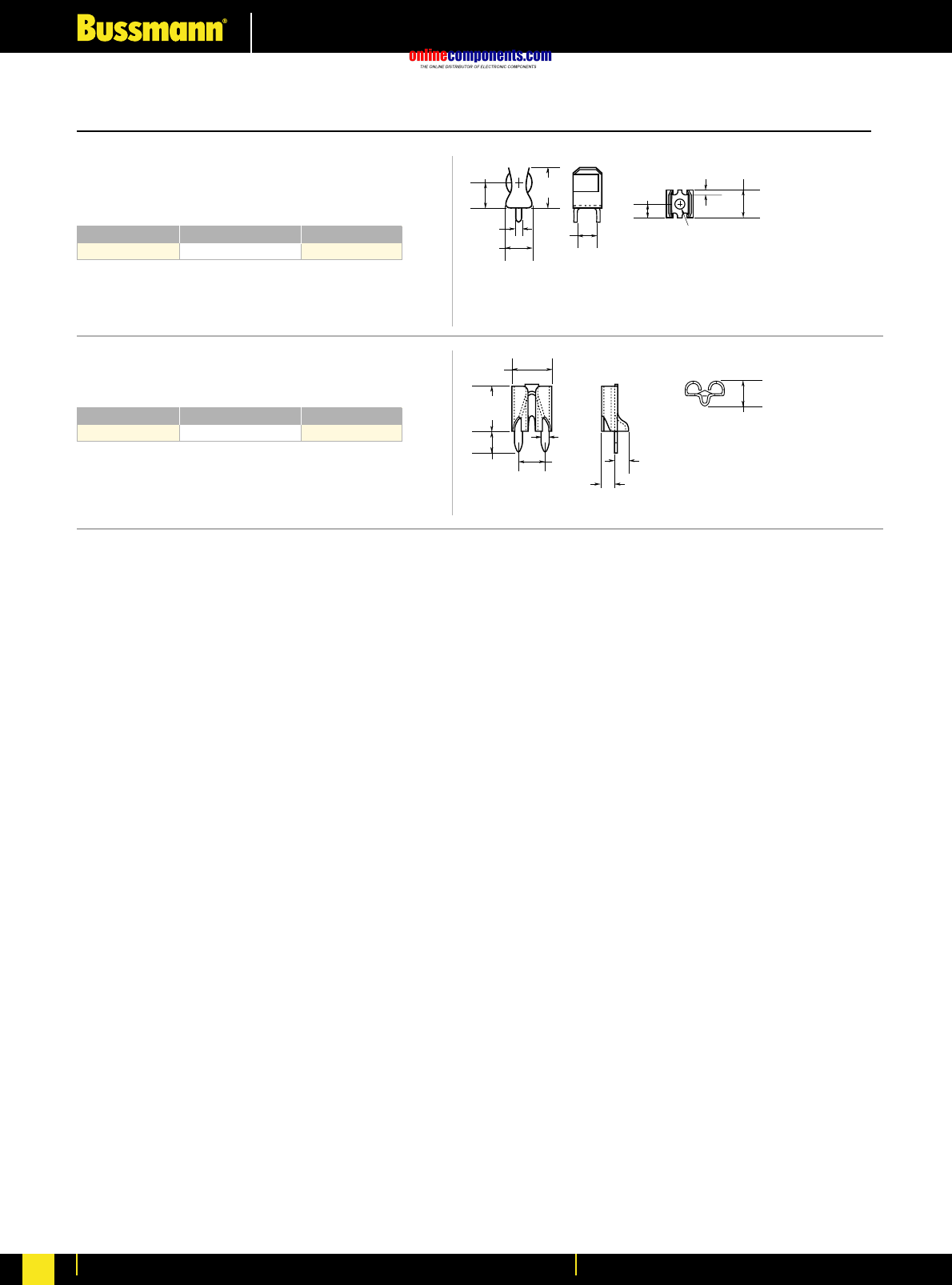
onlinecomponents.com
Electronic Fuses & Accessories
For more information visit our website at www.bussmann.com
161
Printed Circuit Board Fuseclips
1A3400 Series
Fuseclips for ⁄‹Ω£™∑ diameter fuses with
End Stops and Straight Leads
1A5600 Series
Fuseclips for ATC®Fuses (0-20 Amps)
.710"
(18.0mm)
.080"
(2.0mm)
.470"
(11.9mm)
()
.470"
(11.9mm)
.380"
(9.7mm)
.218"
(5.5mm)
.142" Dia.
(3.6mm)
.050"
(1.27mm) .437"
(11.1mm)
.150"
(3.81mm)
.330"
(8.38mm)
.295"
(7.49mm)
.200"
(5.08mm)
.053"
(1.35mm)
.090"
(2.29mm)
.090"
(2.29mm)
.180"
(4.57mm)
Catalogue Number Clip Material* Finish
1A3400-09 Spring Bronze Bright Tin
20 Amps Maximum
Catalogue Number Clip Material* Finish
1A5600 Brass Satin Finish Tin
BIF document: 2131
BIF document: 2131
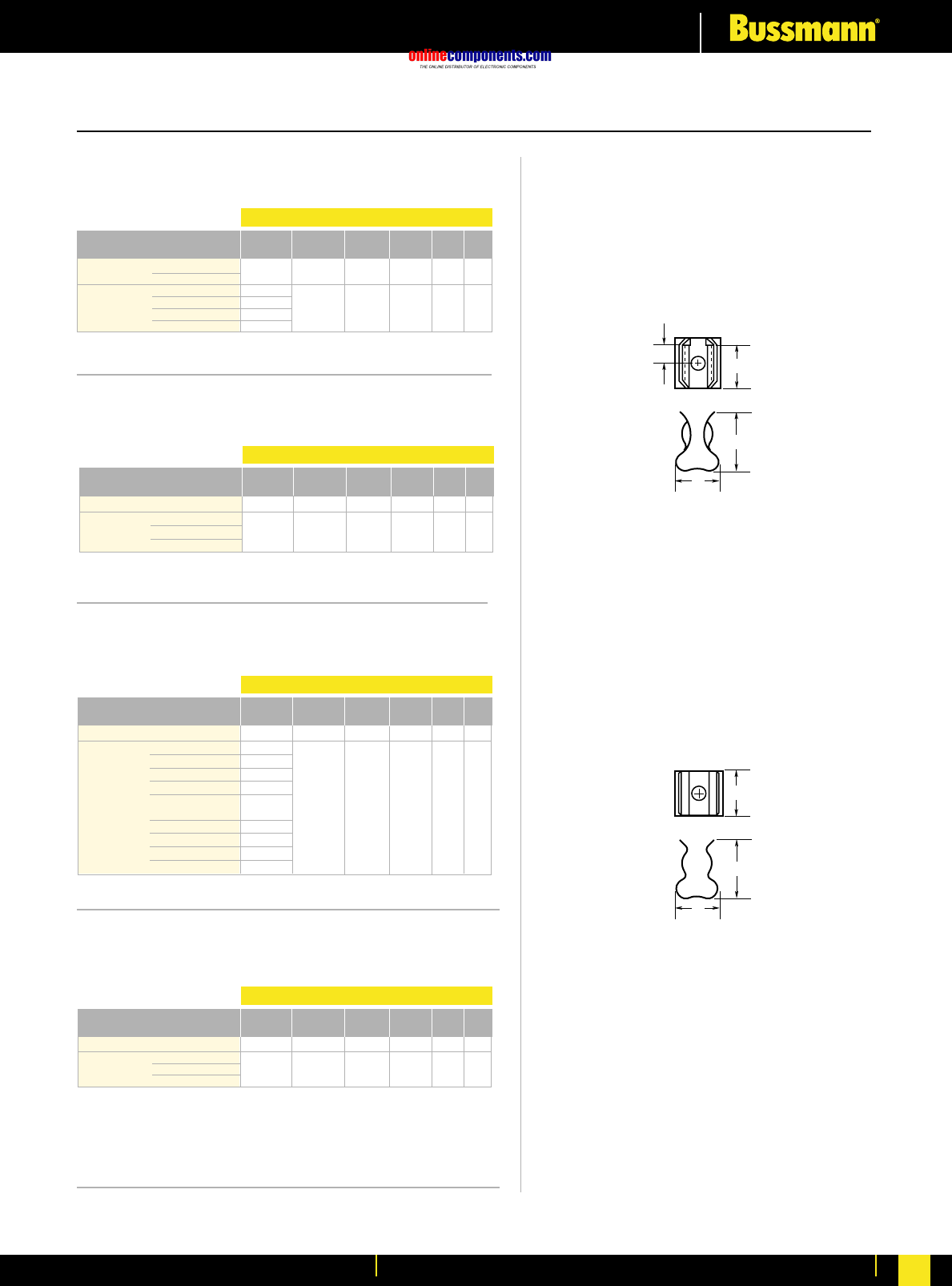
onlinecomponents.com
Electronic Fuses & Accessories
For more information visit our website at www.bussmann.com 162
BIF document: 2132
5681 & 5682 Series
Fuseclips with Mounting Holes For ⁄Ω¢∑ Diameter Fuses
5672 & 5674 Series
Fuseclips with Mounting Holes For ·Ω£™∑ Diameter Fuses
BIF
document:
2132
BIF
document:
2132
BC
D
E
FIGURE 1
C
D
E
FIGURE 2
5956 & 5960 Series
Fuseclips with Mounting Holes For ⁄‹Ω£™∑ Diameter Fuses
5591 & 5592 Series
Fuseclips with Mounting Holes For ·Ω¡§∑ Diameter Fuses
BIF
document:
2132
.172 1
.200
.200 2
.172
Printed Circuit Board for
⁄Ω¢
∑Diameter Fuses
5681-08 No
5681-15
5682-01
5682-02 Yes
5682-41
5682-44
Catalogue End Clip B (To C D E Hole Fig.
Number Stop Mat.** Finish End Stop) (Contact) (Height) (Width) Dia. Ref.
Spg. Br. Nickel †.265 .410 .320 .132 2
Spg. Br. Bright Tin
BeCu Silver .106
BeCu Silver .132
Spg. Br. Bright Tin .106 .260 .410 .320 .132 1
Spg. Br. Bright Tin .132
Dimensions (inches)
Catalogue End Clip B (To C D E Hole Fig.
Number Stop Mat.** Finish End Stop) (Contact) (Height) (Width) Dia. Ref.
5672-11 No Spg. Br. Bright Tin
†
.362 .520 .380 .172 2
5674-01 BeCu Silver
5674-10 Yes BeCu Albaloy .168 .356 .520 .380 .172 1
5674-41 Spg. Br. Bright Tin
Dimensions (inches)
Catalogue End Clip B (To C D E Hole Fig.
Number Stop Mat.** Finish End Stop) (Contact) (Height) (Width) Dia. Ref.
5956-16 No Spg. Br. Bright Tin †.312 .710 .470 .172 2
5960-07 BeCu Silver .168 .196
5960-09 BeCu Silver .200 .172
5960-23 BeCu Albaloy .168 .196
5960-51 Yes Spg. Br. Bright Dip* .168 .389 .710 .470 .196 1
5960-53 Spg. Br. Bright Dip* .200 .172
5960-61 Spg. Br. Bright Tin .168 .196
5960-62 Spg. Br. Bright Tin .168 .132
5960-63 Spg. Br. Bright Tin .200 .172
5960-64 Spg. Br. Bright Tin .200 .128
Dimensions (inches)
5591-42 Yes
5592-01
5592-11 No
5592-33
Catalogue End Clip B (To C D E Hole Fig.
Number Stop Mat.** Finish End Stop) (Contact) (Height) (Width) Dia. Ref.
Spg. Br. Bright Dip* .260 .510 .890 .600
BeCu Silver
Spg. Br. Silver †.505 .890 .600
Spg. Br. Bright Dip*
Dimensions (inches)
* Bright Dip is actually treated bare metal with no plating.
** Spg. Br. — Spring Bronze; BeCu — Beryllium Copper.
†Hole in centre of both clip and contact area.
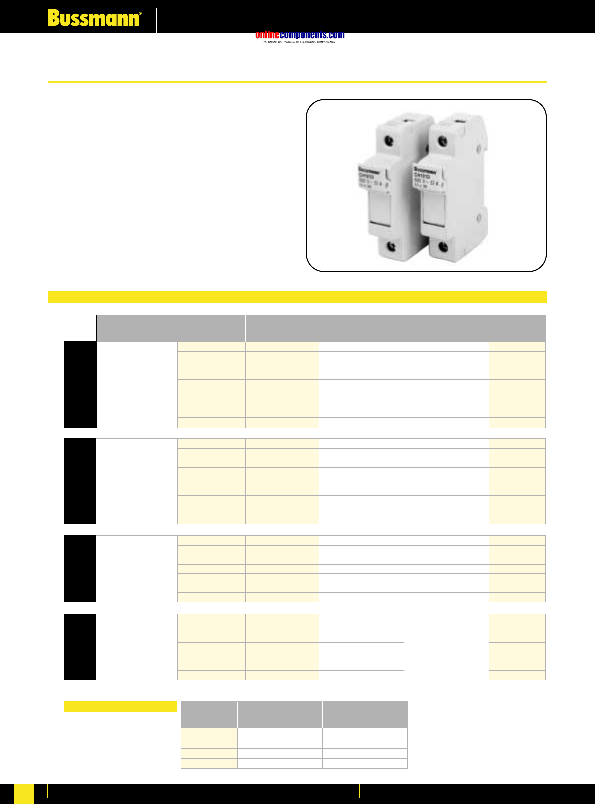
onlinecomponents.com
Fuseholders & Fusegear
For more information visit our website at www.bussmann.com
163
• Multiple pole configurations available
• Finger safe protection
• LED option available for open indication
• 14x51 & 22x58 variants available with micro-switches for
remote indication
• Self-extinguishable V0 rating polyester material
• Multi-phase connections available
The CH range of Modular Fuse Holders is designed to
accommodate IEC Industrial Cylindrical fuses in four sizes: 8x32,
10x38, 14x51 and 22x58mm.
Products are manufactured in accordance with IEC 60269 and IEC
60947-3. 10X38mm design is also UL Recognised. Key features
and benefits include:-
No. of 17.5mm
Modules
1
1
1
2
2
3
3
4
4
Box
Quantity
12
12
12
6
6
4
4
3
3
Configuration
1 Pole
1 Neutral Pole
1 Pole + Neutral
1 Pole + Neutral
2 Pole
3 Pole
3 Pole + Neutral
3 Pole + Neutral
4 Pole
Max Voltage (Vac)
400V AC / 25A
8X32
Without Indicator
CH081D
CH081DNX
CH081DNS
CH081DN
CH082D
CH083D
CH083DNS
CH083DN
CH084D
With Indicator
CH081DI
-
CH081DNSI
CH081DNI
CH082DI
CH083DI
CH083DNSI
CH083DNI
CH084DI
Fuse Holder Part Number
1
1
1
2
2
3
3
4
4
12
12
12
6
6
4
4
3
3
1 Pole
1 Neutral Pole
1 Pole + Neutral
1 Pole + Neutral
2 Pole
3 Pole
3 Pole + Neutral
3 Pole + Neutral
4 Pole
690V AC / 32A
10X38
CH101D
CH101DNX
CH101DNS
CH101DN
CH102D
CH103D
CH103DNS
CH103DN
CH104D
CH101DI
-
CH101DNSI
CH101DNI
CH102DI
CH103DI
CH103DNSI
CH103DNI
CH104DI
1.5
1.5
3
3
4.5
6
6
6
6
3
3
2
1
1
1 Pole
1 Neutral Pole
1 Pole + Neutral
2 Pole
3 Pole
3 Pole + Neutral
4 Pole
690V AC / 50A
14X51
CH141D
CH141DNX
CH141DN
CH142D
CH143D
CH143DN
CH144D
CH141DI
-
CH141DNI
CH142DI
CH143DI
CH143DNI
CH144DI
2
2
4
4
6
8
8
6
6
3
3
2
1
1
1 Pole
1 Neutral Pole
1 Pole + Neutral
2 Pole
3 Pole
3 Pole + Neutral
4 Pole
690V AC / 125A
22X58
CH221D
CH221DNX
CH221DN
CH222D
CH223D
CH223DN
CH224D
Not Available
with Indication
Pack
Quantity
10pcs
10pcs
10pcs
10pcs
For Use in
Fuseholder Type
CH08 Series
CH10 Series
CH14 Series
CH22 Series
Part
Number
C08NL
C10NL
C14NL
C22NL
Solid Neutral Links
Modular Fuse Holders Data Tables
Modular Fuse Holder for Cylindrical Fuse Links
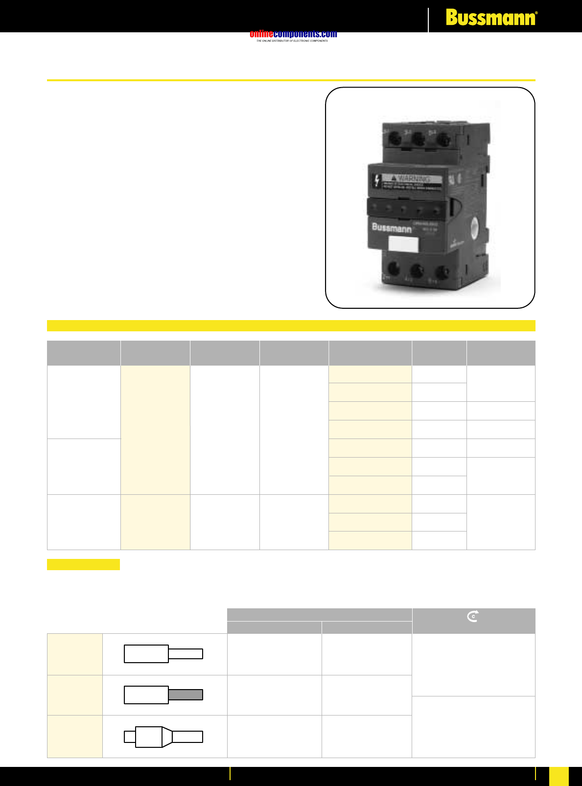
onlinecomponents.com
Fuseholders & Fusegear
For more information visit our website at www.bussmann.com For more information visit our website at www.bussmann.com 164
The OPM-NG is the third generation within the Optima™ series.
Features and benefits of the OPM-NG include:
•45mm width matches IEC starters
•IP20 finger safe to IEC 60529
•Pressure plate terminations
•Phil-slot screws
•Integrated collapsible handle
•Fuse carrier cannot be removed from holder base
•Optional auxiliary contacts
•Dual-wire rated terminals (see Wire Range table below)
•35mm DIN rail or panel mounting. Max. Screw size M4 (#8)
•Padlockable
Agency Information
OPM-NG-SM3 IEC 60947-3 Utilisation Category AC20B
UL Recognised, UL512 File E14853, Guide IZLT2 CSA
Certified, C22.2 No.39, Class C6225-01, File 47235
OPM-NG-SC3 IEC 60947-3 Utilisation Category AC20B
UL Listed, UL512 File E14853, Guide IZLT
CSA Certified C22.2 No.39 Class C6225-01, File 47235
Optima™ Overcurrent Protection Module Selection Table
Wire Range
10,3 x 38.1mm
Fuse Size Optima™
Part Number Max Current
Rating Voltage
Rating Bussmann Fuse
Accomodated Fuse
Type Fuse
Interrupt Rating
13/32” x 11/2”
Class CC
OPM-NG-SM3
OPM-NG-SC3
IEC
32A
UL/CSA
30A
IEC
690V AC
(or less)
UL/CSA
600V AC
(or less)
C10G - -
C10M - -
FWA
FWC
KTK
FNQ
KLM
LP-CC
FNQ-R
KTK-R
gG
aM
aR
aR
Fast Acting
Time Delay
Fast Acting
Time Delay
Time Delay
Fast Acting
120kA
200kA
100kA
10kA
200kA
100kA
UL/CSA
30A
UL/CSA
600V AC
(or less)
75ºCU only
#18-12 AWG (1–3.5mm2) Single/Dual, torque 15lb: in (1.7 Nm)
#10-8 AWG (4–6mm2) Single/Dual, torque 20lb: in (2.3 Nm)
Dual Wire. Wire with same gauge and type.
( )
( )
Solid
Stranded
Ferrules
18-8 x1
18-8 x2
18-8 x1
18-8 x2
1..6 x1
1..6 x2
1.5..6 x1
1.5..6 x2
1..4 x1
1..4 x2
18-12 AWG (1–3.5mm2)
Single/Dual
1.7
Nm 15lb in
10-8 AWG (4–6mm2)
Single/Dual
2.3
Nm 20lb in
75º CU Only
AWG (mm2)(Nm)/lb in
Optima™ Overcurrent Protection Module
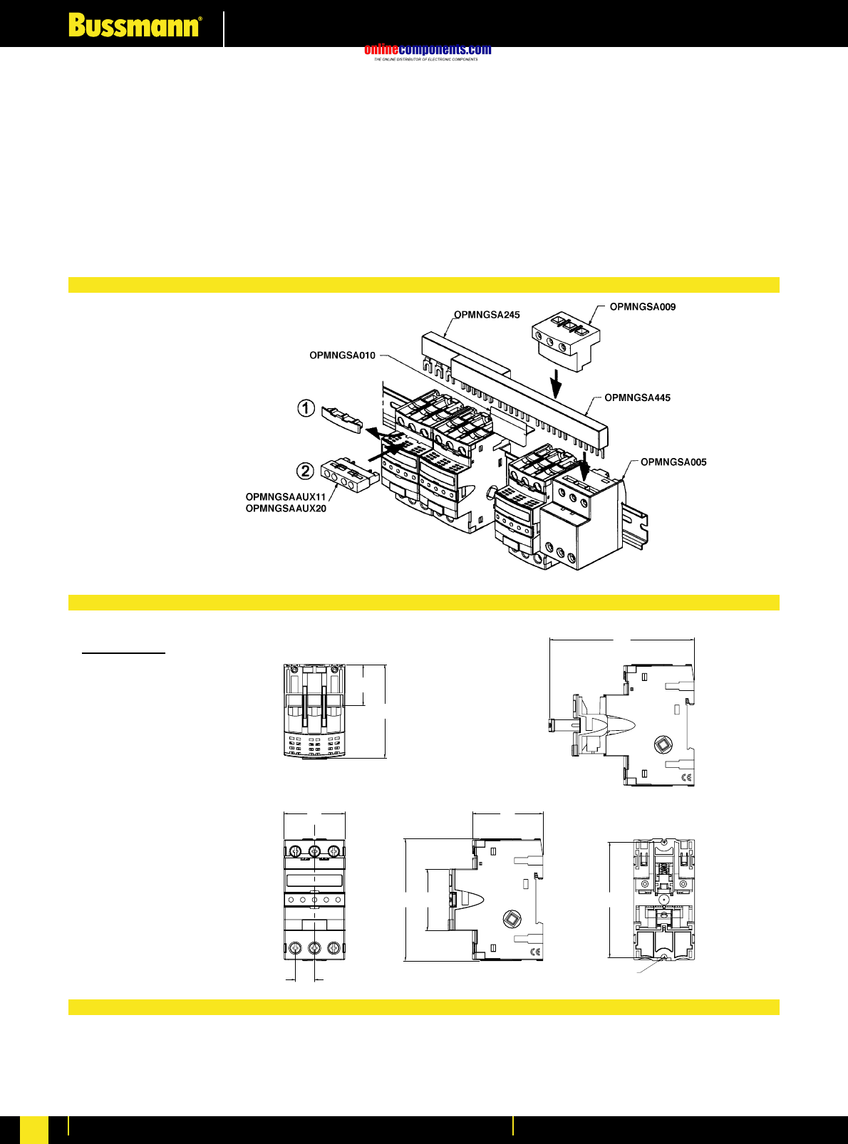
onlinecomponents.com
Fuseholders & Fusegear
For more information visit our website at www.bussmann.com
165
Accessories for OPM-NG
Comb Bar (Max current rating = 63A) Auxiliary Contacts
OPMNGSA245 2 circuit, 45mm between same phases OPMNGSAAUX11 NO / NC
OPMNGSA254 2 circuit, 54mm between same phases OPMNGSAAUX20 NO / NO
OPMNGSA272 2 circuit, 72mm between same phases
OPMNGSA345 3 circuit, 45mm between same phases Marking Tabs
OPMNGSA354 3 circuit, 54mm between same phases OPMNGSA101 Marking Tab – Mounts to
OPMNGSA445 4 circuit, 45mm between same phases front of carrier
OPMNGSA454 4 circuit, 54mm between same phases (Pack Qty 100)
OPMNGSA472 4 circuit, 72mm between same phases
OPMNGSA554 5 circuit, 54mm between same phases
OPMNGSA005 Terminal block
OPMNGSA009 Terminal block
OPMNGSA010 Protective cover
Millimetres (±0.38)
Inches (±0.15)
Housing Thermoplastic UL 94V-2 Packaging Weight 0.18Kg (0.39lb)
Clip Tin plated copper alloy
Contact Lubricant Fluoroether grease Storage Temperature -10°C to 65°C
Saddle Screw Plated steel
DIN rail springs Stainless steel
44.5
44.5
1.8
1.8
.6
.6
14.0
14.0
4.2
4.2
105.6
105.6
2.0
2.0
51.5
51.5
30.0
30.0
1.2
1.2
68.2
68.2
2.7
2.7
C
L
89.0
89.0
3.5
3.5
ø4.57
4.57
ø.18
.18
84.02
84.02
3.31
3.31
44.96
44.96
1.77
1.77
Centre
Line
of
Panel
Mount
Holes
Optional Accessories
Dimensional Data
Supplementary Information
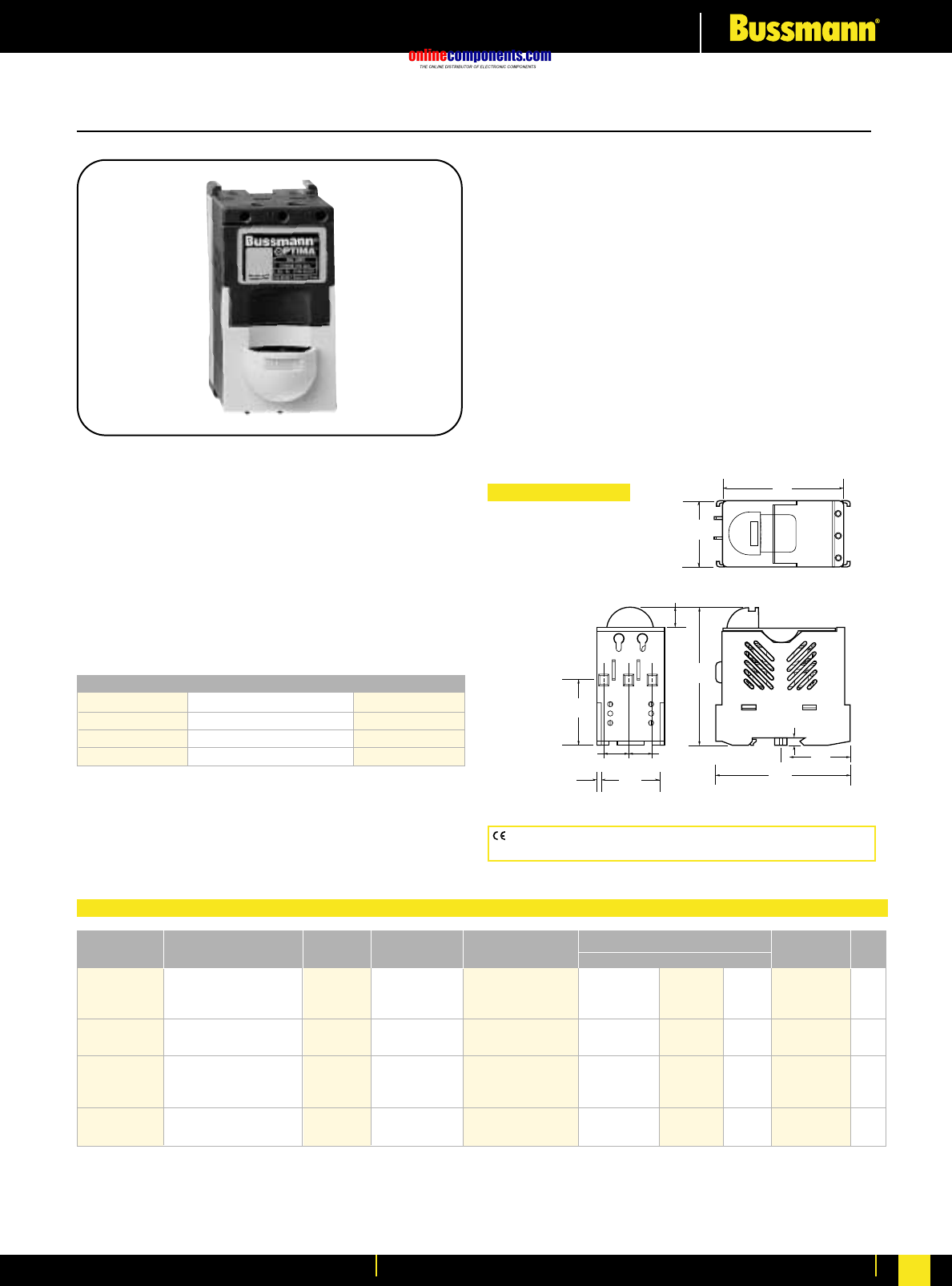
onlinecomponents.com
BUSS
3.74"
(95.0mm)
3.22"
(81.8mm)
0.593"
(15.06mm)
TYP (2)
0.593"
(15.06mm)
TYP (2)
0.57"
(14.5mm)
0.23"
(5.8mm)
1.76"
(44.7mm)
1.65"
(41.9mm)
3.60"
(91.4mm)
1.86"
(47.3mm)
.224"
(5.6mm) 1.312"
(33.3mm)
Panel Mount
Hole Location
Fuseholders & Fusegear
For more information visit our website at www.bussmann.com 166
Optima®Overcurrent Protection Module
OPM-1038__ __
Non-Switch Series
for ⁄‹Ω£™∑ ≈ 1⁄Ω™∑ (10mm x 38mm) Fuses
Materials: Grey Thermoplastic
UL Flammability: UL 94V0
Agency Information:
UL (see table)
CSA Certified, C22.2 No. 39, Class 6225-01, File 47235
IEC (see table)
Shipping Weight: Approximately 213g/.47 lb.
Carton Quantity: 1
Recommended Fuse Types
Class CC Midget (Non-Rejection) European
LP-CC KTK C10M
KTK-R FNM C10G
FNQ-R FNQ
Physical Characteristics
•Small size matches 45mm IEC starter width.
•Accepts #8-18 AWG stranded, #10-18 AWG solid wire.
•3-pole.
Product Features
•“Open” fuse indication lights.
•Cam action handle for easy removal.
•Finger safe terminals. (Qualified as IP20 per IEC 529)
•Removable module for convenient fuse loading.
•35mm DIN-rail or screw panel mounting (#8 screw,
1⁄Ω¢” long).
•Dead-front construction.
•Padlockable.
Additional Features
•Option for remote “open fuse” status indication feature
available (less downtime!). See BIF document for additional
wiring details.
•Offered with Class CC rejection clips or European
10 ≈38mm clips to meet global needs.
•Wire ready: Saves time as terminals are ready to
accept wires.
Dimensional Data
CE logo denotes compliance with European Union Low Voltage Directive
(50-1000V AC, 75-1500V DC). Refer to BIF document #8002.
Catalogue SC Remote Open U.L. Information
Number Electrical Rating Rating Clips Fuse Indication Std. File Guide IEC CE
OPM-1038 30A, 600V U.L./CSA** * Non-rejection No Recognized
(Max. 3 Watts per fuse)
32A, 660V IEC U.L. 512 E14853 IZLT2 IEC 269-2-1 Yes
OPM-1038R 30A, 600V U.L./CSA** 200kA Rejection No Listed
U.L. 512 E14853 IZLT Yes
OPM-1038C 30A, 600V U.L./CSA** * Non-rejection Yes Recognized
(Max. 3 Watts per fuse)
32A, 660V IEC U.L. 512 E14853 IZLT2 IEC 269-2-1 No
OPM-1038RC 30A, 600V U.L./CSA** 200kA Rejection Yes Listed
U.L. 512 E14853 IZLT No
*Rating varies depending on fuse used in module.
Non-Switch Series
BIF document: 1102
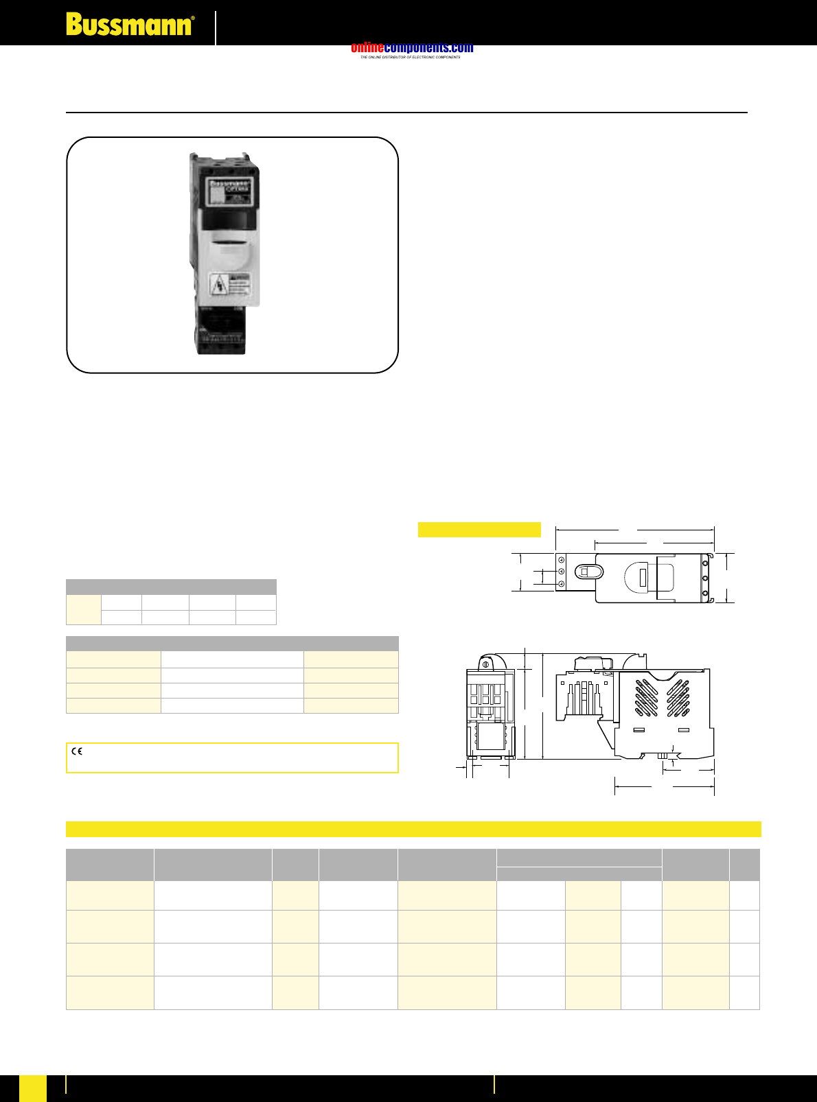
onlinecomponents.com
Fuseholders & Fusegear
For more information visit our website at www.bussmann.com
167
0.23"
(5.8mm)
1.312"
(33.31mm)
Mounting Holes
3.74"
(95.0mm)
3.17"
(80.5mm)
0.57"
(14.5mm)
4.25"
(108.0mm)
BUSS
5.72"
(145.3mm)
0.43"
(11.0mm)
1.38"
(35.0mm)
3.60"
(91.4mm)
(47.3mm)
1.86"
1.76"
(44.7m
m
.224"
(5.6mm)
Optima®Overcurrent Protection Module
Physical Characteristics
•Small size matches 45mm IEC starter width.
•Accepts #8-18 AWG stranded, #10-18 AWG solid wire.
•3 pole.
•Handle and shaft required for through the door operation.
See BIF document for details.
Product Features
•“Open” Fuse indication lights.
•Finger safe terminals.(Qualified as IP20 per IEC 529)
•Cam action handle for easy module removal.
•35mm DIN-rail or screw panel mounting (#8 screw,
1⁄Ω¢” long).
•Dead front construction. No exposed contacts for added
safety.
•Padlockable.
•Option for remote “open fuse” status indication feature
available (reduces downtime!). See BIF document for
additional wiring details.
•Offered with Class CC rejection clips or European
10 ≈38mm clips to meet global needs.
•Wire ready: Saves time as terminals are ready to
accept wires.
Dimensional Data
OPM-1038__SW__
Load Break Disconnect Switch
for ⁄‹Ω£™∑ ≈ 1⁄Ω™∑ (10mm x 38mm) Fuses
Materials: Grey Thermoplastic
UL Flammability: UL 94V0
Agency Information:
UL (see table)
CSA Certified, C22.2 No. 39, Class 6225-01, File 47235
IEC (see table)
Shipping Weight: Approximately 335g/.74 lb.
Carton Quantity: 1
Horsepower Rating of Switch
3PH V 240 480 600
HP 5 10 15
Recommended Fuse Types
Class CC Midget (Non-Rejection) European
LP-CC KTK C10M
KTK-R FNM C10G
FNQ-R FNQ
CE logo denotes compliance with European Union Low Voltage Directive
(50-1000V AC, 75-1500V DC). Refer to BIF document #8002.
Catalogue SC Remote Open U.L. Information
Number Electrical Rating Rating Clips Fuse Indication Std. File Guide IEC CE
OPM-1038SW 30A, 600VAC U.L./CSA * Non-rejection No Recognized
32A, 660V IEC U.L. 508 E161278 NLRV2 IEC 947-3 Yes
OPM-1038RSW 30A, 600VAC U.L./CSA 100kA Rejection No Listed
U.L. 508 E161278 NLRV Yes
OPM-1038SWC 30A, 600VAC U.L./CSA * Non-rejection Yes Recognized
32A, 660V IEC U.L. 508 E161278 NLRV2 IEC 947-3 No
OPM-1038RSWC 30A, 600VAC U.L./CSA 100kA Rejection Yes Listed
U.L. 508 E161278 NLRV No
*Rating varies depending on fuse used in module.
Switch Series
BIF document: 1103
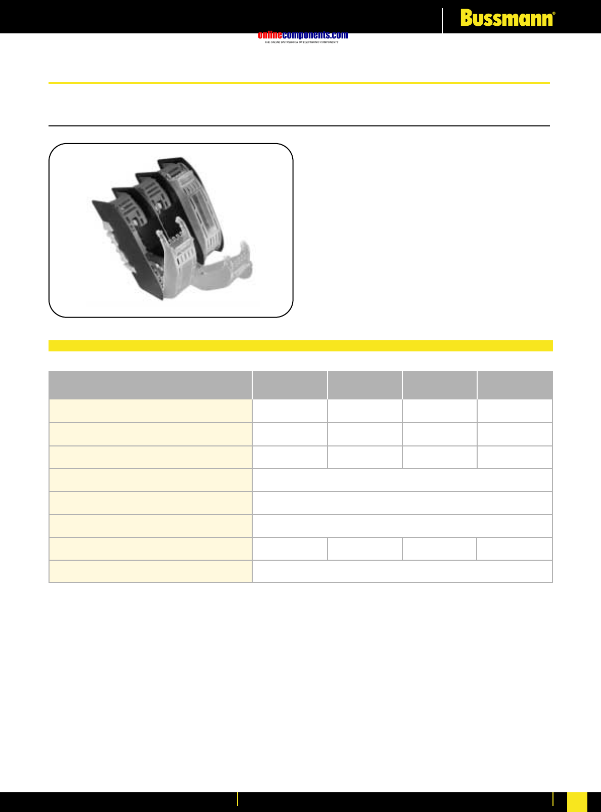
onlinecomponents.com
Fuseholders & Fusegear
For more information visit our website at www.bussmann.com 168
1 Pole Fuse Bases for NH Fuses
•For use with size C00 to Size 3 fuse links
•Fibreglass reinforced Polyester material
•Rated at 690V AC
•Approved to IEC 60269 (VDE 0636)
•Comprehensive range of accessories
are available
Part Number SB00
C00 (000)
160A
12W
01 (1S) & 1
250A
32W
690V AC
IP 20
Tropical
0.360 kg 0.420 kg0.130 kg
3 pieces per box
02 (2S) & 2
400A
45W
SB1 SB2
03 & 3
630A
60W
SB3
Size of Fuse links Accommodated
Rated Current
Maximum power loss of fuse links
Rated Voltage
Degree of Protection
Resistance to Climatic conditions
Weight
Packing
Fuse Base Technical Data
For Fuse Base Accessories, see page 171-172
NH DIN Fuse Bases, Rails and Accessories
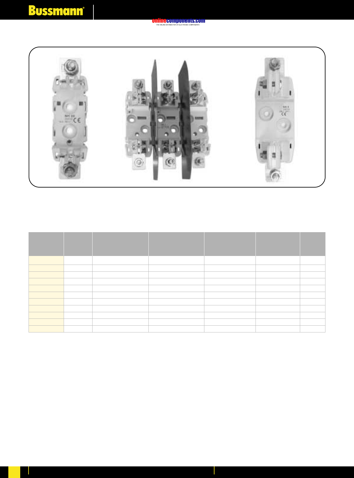
onlinecomponents.com
Fuseholders & Fusegear
For more information visit our website at www.bussmann.com
169
Size Poles
Rated
Current
(A)
Rated
Voltage
(V)
DIN Rail
Fixing
Part No.
Screw
Mounting
Part No. Packing
NH00
NH0
NH1
NH2
NH3
NH4
1 P
3 P
1 P
3 P
1 P
3 P
1 P
3 P
1 P
3 P
1 P
3
1
3
1
3
1
3
1
3
1
1
160
160
160
160
250
250
400
400
630
630
1600
690
690
690
690
690
690
690
690
690
690
690
SB00-D
TB00-D
SB0-D
TB0-D
SB1-D
TB1-D
SB2-D
TB2-D
SB3-D
TB3-D
-
SB00-S
TB00-S
SB0-S
TB0-S
SB1-S
TB1-S
SB2-S
TB2-S
SB3-S
TB3-S
SB4-S
STANDARDS
IEC 60269-I IEC 60269-2 IEC 60269-I IEC 60269-2-1 IEC 60269-2 VDE 0636 - DIN 43620
For Fuse Base Accessories, see page 171-172
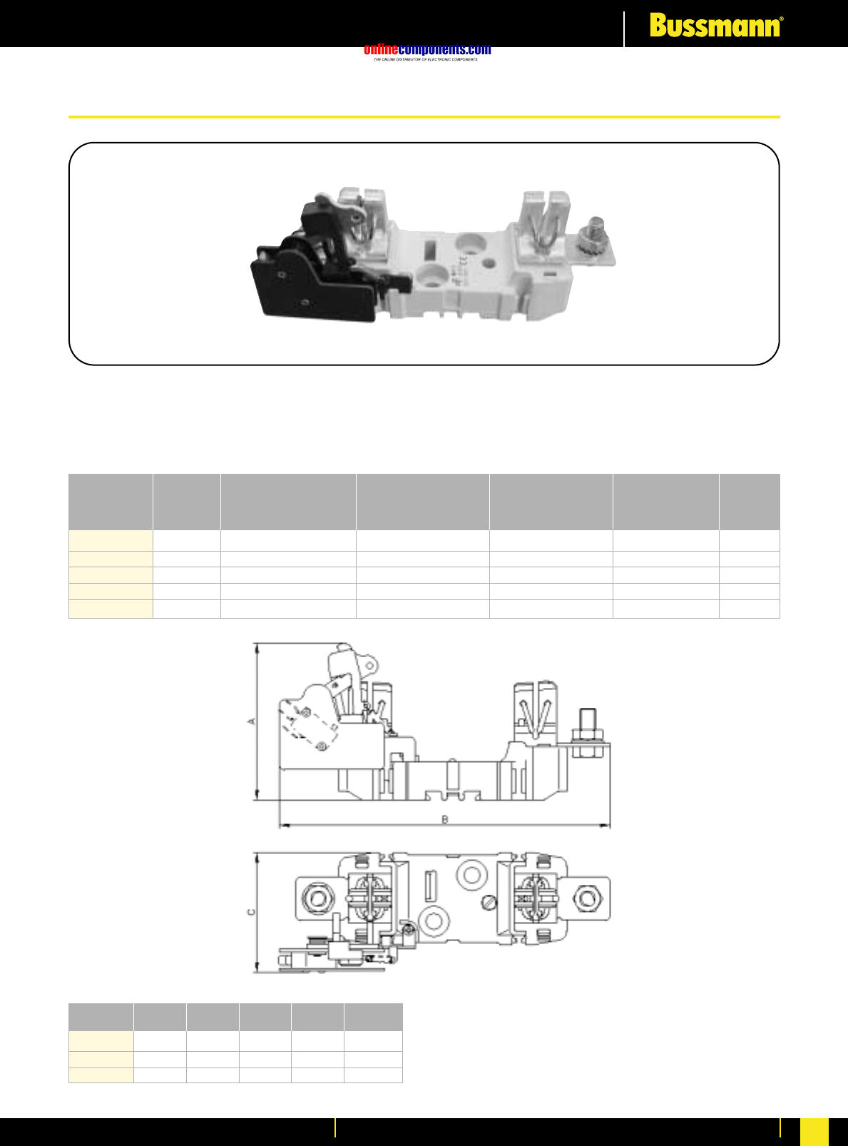
onlinecomponents.com
Fuseholders & Fusegear
For more information visit our website at www.bussmann.com 170
STANDARDS
IEC 60269-I IEC 60269-2 IEC 60269-I IEC 60269-2-1 IEC 60269-2 VDE 0636 - DIN 43620
For use with NH Fuse Links fitted with Strikers
Size Poles
Rated
Current
(A)
Rated
Voltage
(V)
DIN Rail
Fixing
Part No.
Screw
Mounting
Part No. Packing
1 P
1 P
1 P
1 P
1 P
NH0
NH1
NH2
NH3
NH4
1
1
1
1
1
160
250
400
630
1250
690
690
690
690
690
SB0-DMS
SB1-DMS
SB2-DMS
SB3-DMS
-
-
-
-
-
SB4-SMS
NH0 NH1 NH2 NH3 NH4
90
193
65.5
98
215
76
102
227
76
102
235
76
140
284
113
A
B
C
NH Fuse with Micro Switch
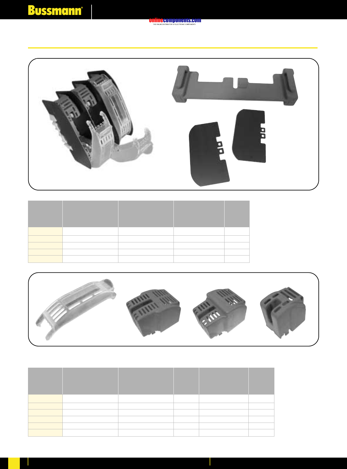
onlinecomponents.com
Fuseholders & Fusegear
For more information visit our website at www.bussmann.com
171
Size
Max Rated
Current
In
(A)
Separating
Plates
Part No. Connector
Part No. Packing
NH00
NH0
NH1-2
NH3
NH4
2
2
2
2
2
160
160
250/400
630
1250
SP00
SP0
SP1-2
SP3
SP4
BC00
BC0
BC1-2
BC3
-
Size
Max Rated
Current
In
(A)
Fuse
Cover
Part No.
Terminal
Shields
Part No.
Packing Packing
NH00
NH0
NH1
NH2
NH3
NH4
6
-
6
6
-
-
160
160
250
400
630
1000
FC00
FC0
FC1
FC2
FC3
FC4
CS00
CS0
CS1
CS2
CS3
CS4
3
-
-
-
-
-
FUSE COVERS AND TERMINAL SHIELDS
NH Fuse Bases Accessories
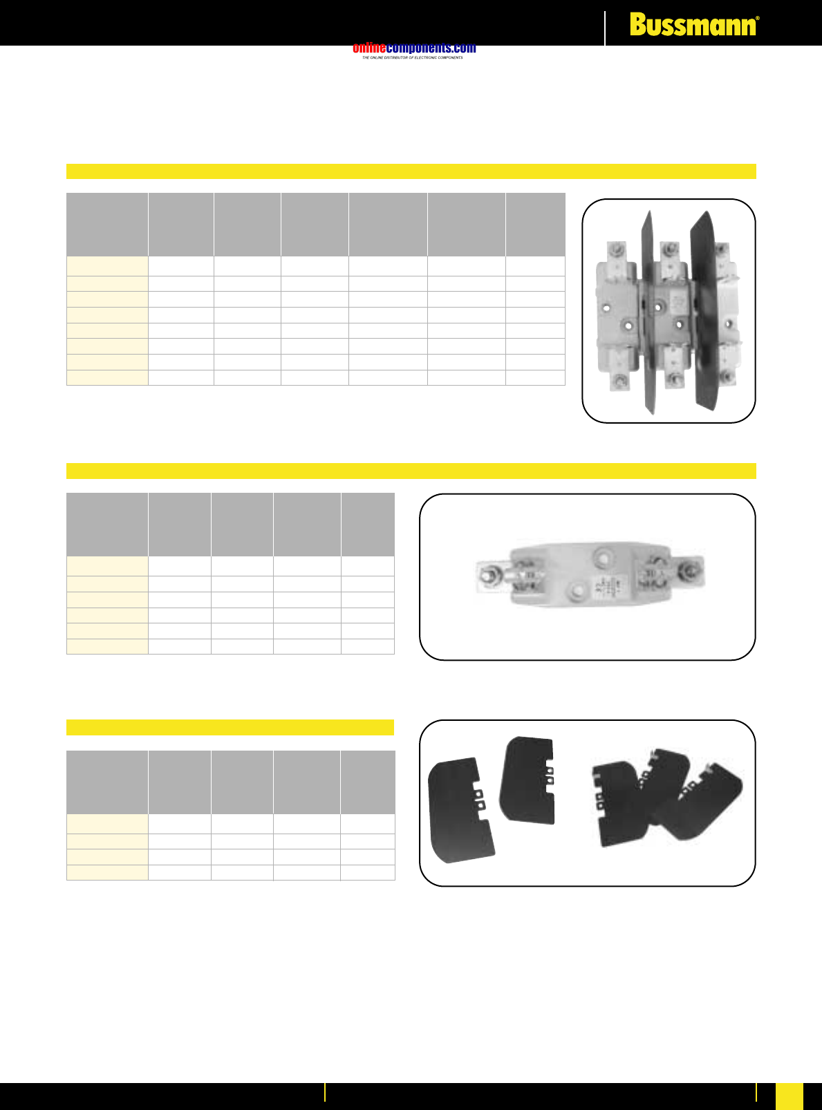
onlinecomponents.com
Fuseholders & Fusegear
For more information visit our website at www.bussmann.com 172
Size Poles
Rated
Current
In
(A)
Rated
Voltage
U
(V)
DIN Rail
Fixing
Part No.
Screw
Fixing
Part No. Packing
1 P
3 P
1 P
3 P
1 P+N
3 P
1 P
3 P
NH00
NH0
NH1
NH2
3
1
3
1
3
1
3
1
160
160
160
160
160
160
160
160
690
690
690
690
690
690
690
690
SB00-EC
TB00-EC
SB0-EC
TB0-EC
-
-
-
-
SB00-EC
TB00-EC
SB0-EC
TB0-EC
SB1-ECS
TB1-ECS
SB2-ECS
TB2-ECS
Size Poles
Rated
Voltage
U
(V)
Screw
Fixing
Part No. Packing
1 P
3 P
1 P
3 P
1 P
3 P
NH1
NH2
NH3
3
1
3
1
3
1
690
690
690
690
690
690
SB1-ECSS
TB1-ECSS
SB2-ECSS
TB2-ECSS
SB3-ECSS
TB3-ECSS
Size Pressure
Fixing
Square
Fixing
Part No. Packing
NH00
NH0
NH1-2
NH3
2
2
2
2
Rated
Current
In
(A)
160
160
250/400
630
SP00
SP0
SP1-2
SP3
SP00-SQ
SPO-SQ
SP1-2-SQ
SP3-SQ
Square Contact
Spring Contact
Separating Plates
FUSE BASES WITH SQUARE CONTACTS
IEC 60269-I IEC 60269-2 IEC 60269-I IEC 60269-2-1 IEC 60269-2 VDE 0636 - DIN 43620
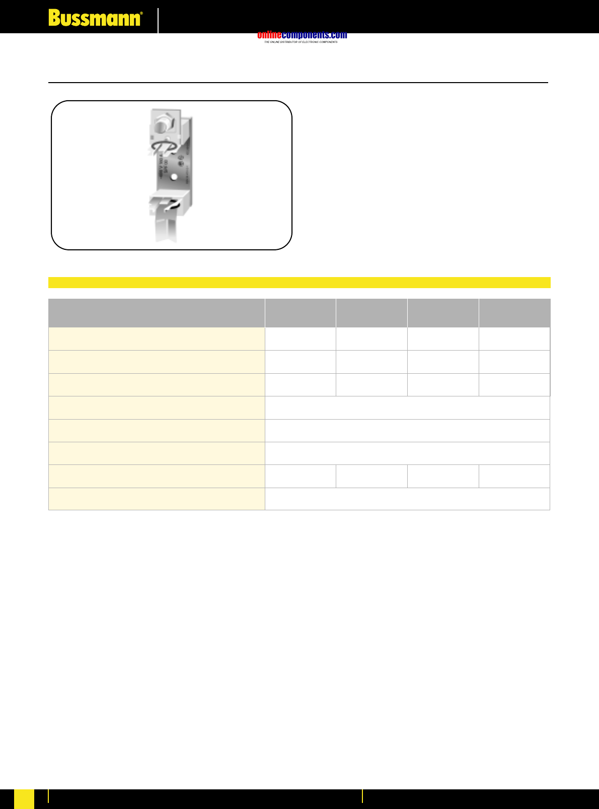
onlinecomponents.com
Fuseholders & Fusegear
For more information visit our website at www.bussmann.com
173
1 Pole Fuse Bases for NH Fuses
Part Number SBS00
01 (1S) & 1
250A
32W
02 (2S) & 2
400A
45W
690V AC
IP 00
Normal and Tropical
3 pieces per box
03 (3S) & 3
630A
60W
SBS1 SBS2 SBS3
Size of Fuse links Accommodated
Rated Current
Maximum power loss of fuse links
Rated Voltage
Degree of Protection
Resistance to Climatic conditions
Weight
Packing
C00 (000)
160A
12W
0.700 kg 0.810 kg 0.870 kg0.280 kg
•For use with size C00 to Size 3 fuse links
•Steatite material
•Rated at 690V AC
•Approved to IEC 60269 (VDE 0636)
•Comprehensive range of accessories
are available
Fuse Base Technical Data
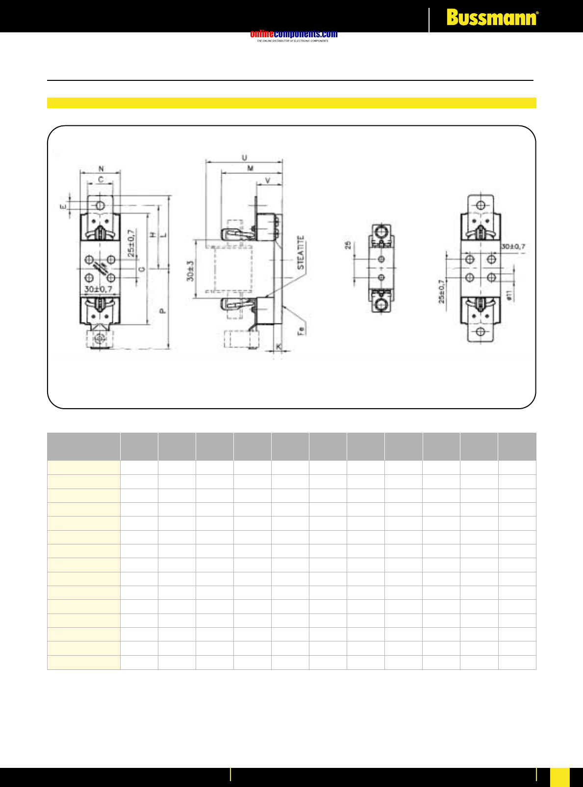
onlinecomponents.com
Fuseholders & Fusegear
For more information visit our website at www.bussmann.com 174
1 Pole Fuse Bases for NH Fuses
V
Bussmann
Part Number
25
25
25
35
35
35
35
35
35
35
35
35
35
35
35
U
84
84
84
108
108
108
108
108
116
116
116
116
116
122
122
P
-
-/80,5
80,5
-
-
110
-/110
-/110
-
-
114
-/114
-/114
-
-
N
34
34
34
55
55
55
55
55
55
55
55
55
55
55
55
M
58,5
58,5
58,5
84
84
84
84
84
90
90
90
90
90
92
92
L
60,2
60,2/-
-
100
100
-
100/-
100/-
114
114
-
114/-
114/-
119
119
K
5,5
5,5
5,5
11
11
11
11
11
11
11
11
11
11
11
11
H
50
50/-
-
87,5
87,5
-
87,5/-
87,5/-
100
100
-
100/-
100/-
105
105
G
90
90
90
153
153
153
153
153
153
153
153
153
153
153
153
E
M8
M8/-
-
M10
M10
-
M10/-
M10/-
M10
M10
-
M10/-
M10/-
M10
M10
C
25
25/-
-
35
35
-
35/-
35/-
35
35
-
35/-
35/-
40
40
SBS00
SBS00-MV
SBS00-VV
SBS-1
SBS1-MM
SBS1-WW
SBS1-SW
SBS1-MW
SBS2
SBS2-MM
SBS2-WW
SBS2-SW
SBS2-MW
SBS3
SBS3-MM
all dimensions in millimetres
Dimensions in millimetres
Dimensional Data

onlinecomponents.com
Fuseholders & Fusegear
For more information visit our website at www.bussmann.com
175
Fuse Extraction Handle
•For use with size C00 to Size 3 fuse links
•Rated at 690V AC
Part Number FEH
Basic Handle FEH-S
Sleeved
FEH-IB
With Insulated Barriers
0.520 kg
1 piece per carton
0.520 kg0.220 kg
Size of Fuse links to be used with
Insulating Voltage
Resistance to Climatic Conditions
Weight
Packaging
C00, 00, 0, 01, 1, 02, 2, 03, 3
690V AC
Normal and Tropical
FEH-IB FEH
FEH-S
Dimensions in millimetres
Fuse Extraction Handle Technical Data
onlinecomponents.com
Fuseholders & Fusegear
For more information visit our website at www.bussmann.com 176
3 Pole Fuse Rail for NH Fuses
Part Number BFR00 Series
01 (1S) & 1
250A
32W
02 (2S) & 2
400A
45W
690V AC
03 (3S) & 3
630A
60W
BFR1 Series BFR2 Series BFR3 Series
Size of Fuse links Accommodated
Rated Current
Maximum power loss of fuse links
Rated Voltage
C00 (000)
160A
12W
•For use with size C00 to Size 3 fuse links
•Fully shrouded 3 pole contacts
•Rated at 690V AC
•Comprehensive range of accessories
•Contact Bussmann for part number
information
Fuse Base Technical Data
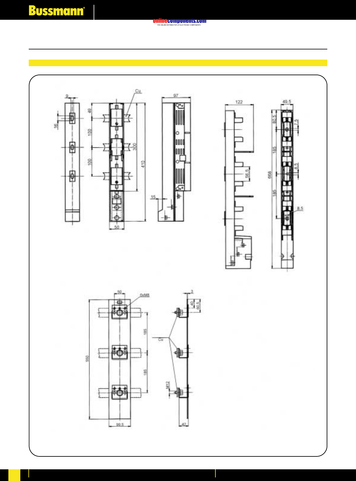
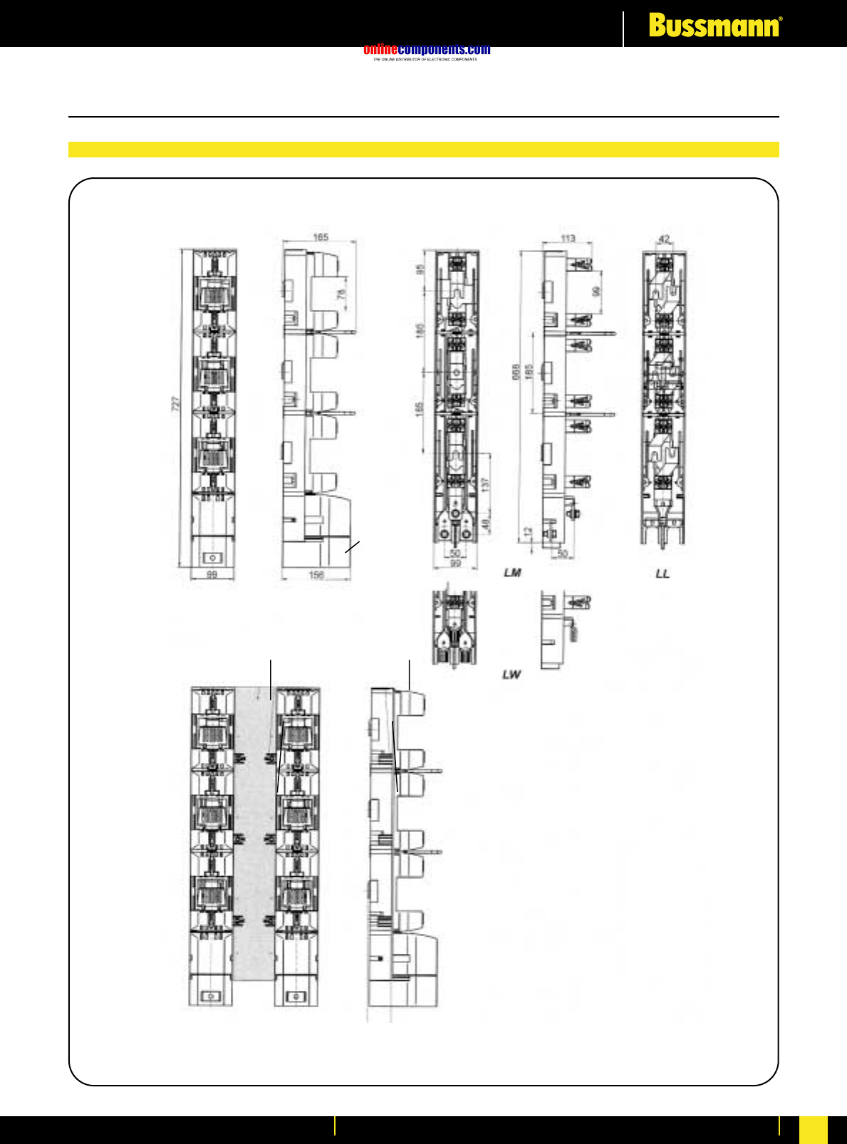
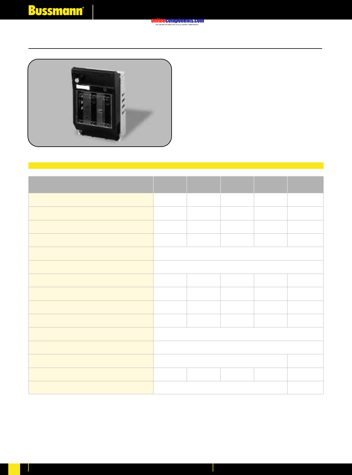
onlinecomponents.com
Fuseholders & Fusegear
For more information visit our website at www.bussmann.com
179
Horizontal Fuse Switch - Disconnectors
•For use with size C00 to Size 3 fuse links
•Rated at 690V AC
•Comprehensive range of accessories
Part Number LBS00
01 (1S) & 1
1,2,3,& 4
02 (2S) & 2
3
690V AC
50 kA
IP 20
-25ºC to +55ºC
3g / 8 to 50Hz
03 (3S) & 3 4a
LBS1 LBS2 LBS4aLBS3
Size of Fuse links Accommodated
Number of Poles Available
Maximum power loss of fuse links
Rated Current
Rated Voltage
Conditional Short-circuit Current
Utilisation Category
Rated Making Capacity @ 690Vac
Mechanical Durability (cycles)
Weight
Degree of Protection
Permissible Ambient Temperature
Altitude Limit (metres)
Overvoltage Category
Seismic Withstand Capability
C00 (000)
1,2,3,& 4 1 & 31,2,3,& 4
23W 34W12W 110W48W
250A 400A160A 1250A630A
AC22B AC22BAC22B AC21-
750A 1200A480A 1875A1500A
1400 8001700 1000
800
2.500 kg 3.100 kg0.720 kg 16.800 kg
Up to 3000m
Up to 2000m
AC III
-
AC IIIAC IIIAC IIIAC III
4.800 kg
Fuse Base Technical Data
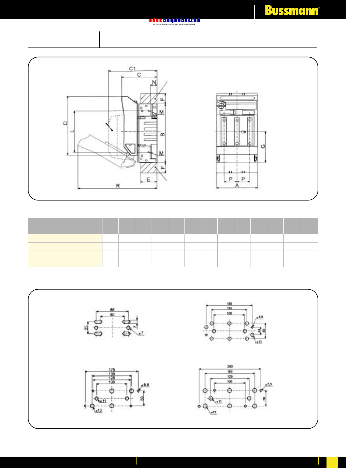
onlinecomponents.com
Fuseholders & Fusegear
For more information visit our website at www.bussmann.com 180
Horizontal Fuse Switch - Disconnectors
Dimensional Data
LBS00
LBS1
LBS2
LBS3
all dimensions in millimetres
P
mm
M
mm
N
mm
L
mm
R
mm
G
mm
F
mm
E
mm
D
mm
C1
mm
C
mm
B
mm
A
mm
105,5
184
210
254
149
230
256
270
90
120
135
145
132
158
171
185
151
216
241
241
43
64
79
93,5
25
44
70
93,5
79
110
128
138
196
295
335
348
120
177
205
219,5
17
24
24
30,5
M8
M10
M10
M10
33
58
66
82
Type
Size 00
Size 2
Size 1
Size 3
Vel.00 -EM69
Vel.1-3 -EM62
GO
GU
Dimensions in millimetres
Dimensions in millimetres
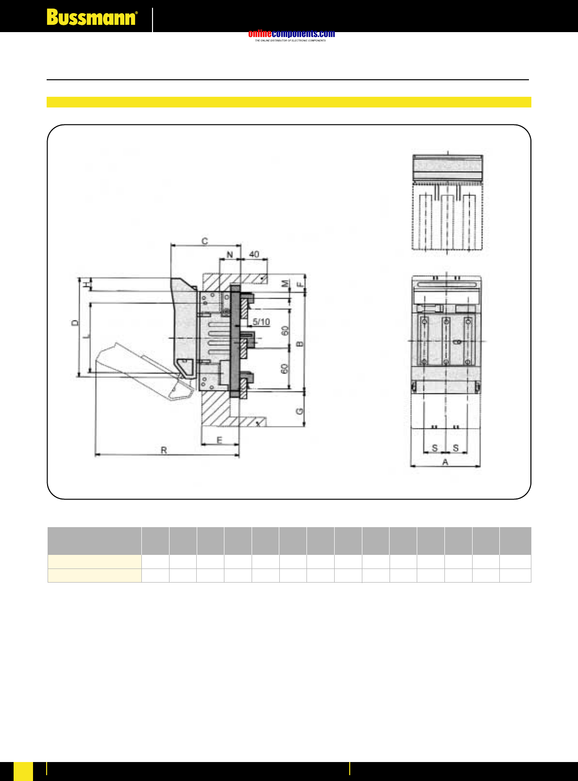
onlinecomponents.com
Fuseholders & Fusegear
For more information visit our website at www.bussmann.com
181
LBS00+AL06030/..
LBS1+AL16030/..
all dimensions in millimetres
S
mm
R
mm
M
mm
N
mm
L
mm
H
mm
G
mm
F
mm
E
mm
D
mm
C1
mm
C
mm
B
mm
105,5
184 149
230 102
138 135
173 151
220 58
79 27,5
44 53
44 21
17 120
177 10
50 32
39,5 215
312 33
58
A
mm
Type
Fuse switch-disconnector LBS00 with
adapter for busbar systems
Dimensions in millimetres
Horizontal Fuse Switch - Disconnectors
Dimensional Data
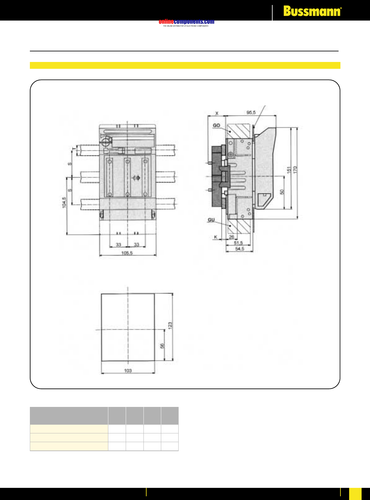
onlinecomponents.com
Fuseholders & Fusegear
For more information visit our website at www.bussmann.com 182
Horizontal Fuse Switch - Disconnectors
5-101240
LBS00-3/9/4012/..
LBS00-3/9/5020/..
LBS00-3/9/6030/..
K
mm
26
5-152050 33
5-1030
60 26
X
mm
T
mm
S
mm
Type
Switchboard front panel
Cut-out in front desk of a switchboard
Dimensions in millimetres
Dimensional Data
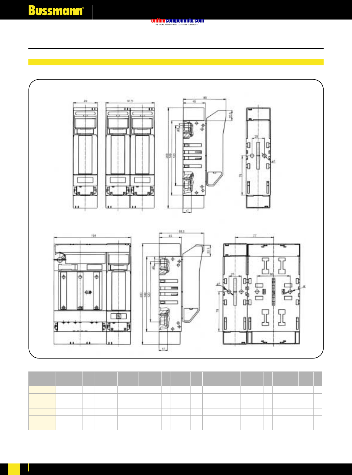
onlinecomponents.com
Fuseholders & Fusegear
For more information visit our website at www.bussmann.com
183
Horizontal Fuse Switch - Disconnectors
-
-
11
-
-
11
-
-
126
-
-
173,5
1
2
4
1
2
4
LBS1-1/9/U
LBS1-2/9/U
LBS1-4/9/U
LBS3-1/9/U
LBS3-1/9/U
LBS3-1/9/U
X
mm
W
mm
-
-
5,5
-
-
5,5
V
mm
-
-
11
-
-
13
U
mm
-
-
50
-
-
50
T
mm
-
-
25
-
-
25
-
30
-
-
30
-
-
68
-
-
96
-
S
mm
-
-
114
-
-
160
R
mm
-
-
100
-
-
125
P
mm
-
69
150
-
91
200
O
mm
-
25
-
-
30,5
-
N
mm
-
177
-
-
220,5
-
M
mm
-
10,5
-
-
10,5
-
L
mm
-
10,5
-
-
10,5
-
K
mm
I
mm
-
25
-
-
25
-
H
mm
-
102,5
-
-
122,5
-
G
mm
-
102,5
-
-
122,5
-
F
mm
119
123,5
123,5
147
151,5
153,5
E
mm
D
mm
-
317
-
-
431
-
C
mm
-
230
-
-
270
-
B
mm
69
138
252,5
91
182
347
A
mm
Number of
poles
Dimensions in millimetres
LBS00 1 Pole and 2 Pole
LBS00 3 Pole
Dimensional Data
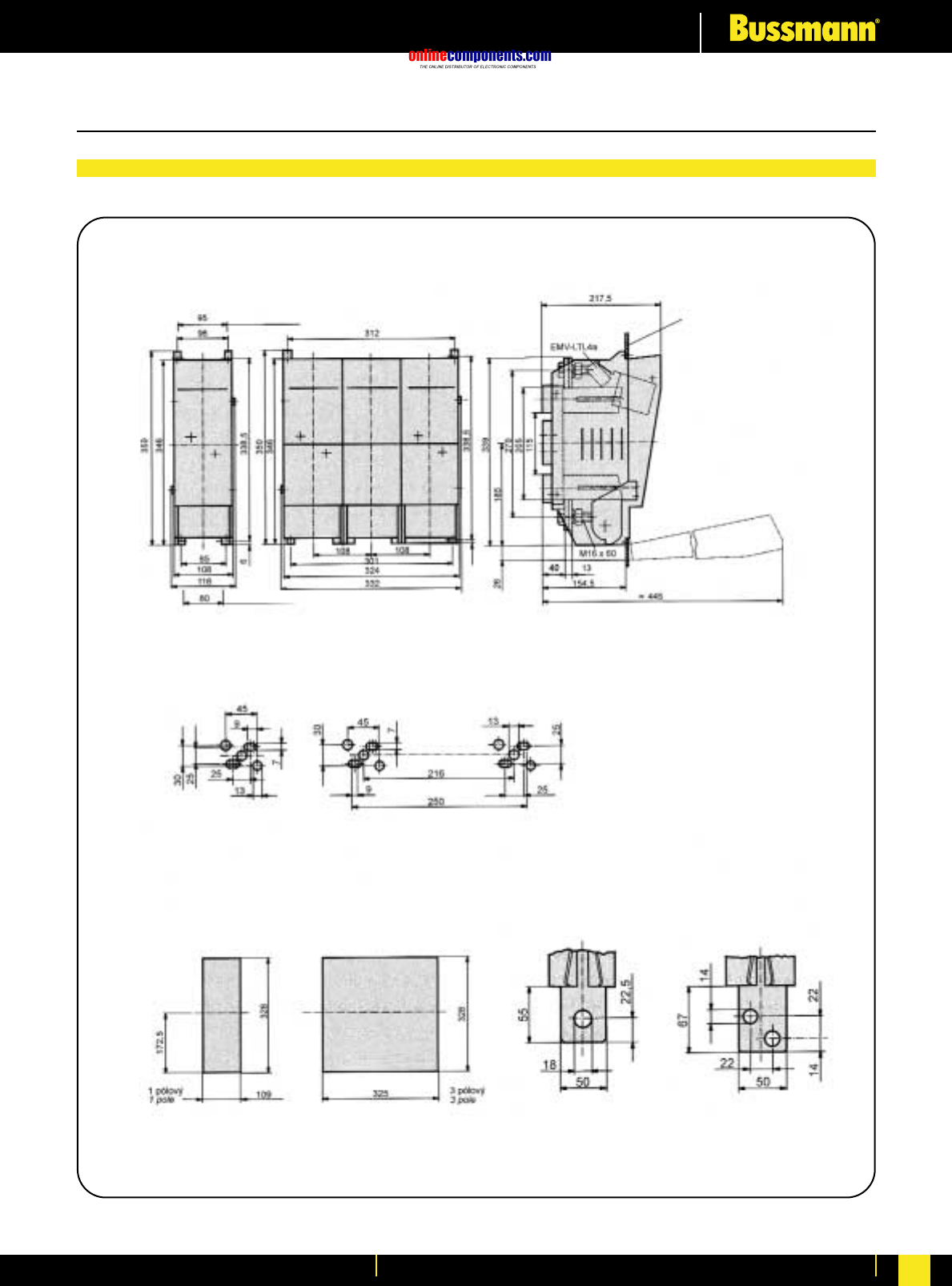
onlinecomponents.com
Fuseholders & Fusegear
For more information visit our website at www.bussmann.com 184
Horizontal Fuse Switch - Disconnectors
Fuse switch-disconnector LBS4a
Fixing holes
Switchboard front panel
Panel apertures Terminals
LBS4a-3x and LBS4a-3x3
have the same dimensions
Dimensions in millimetres
Dimensional Data
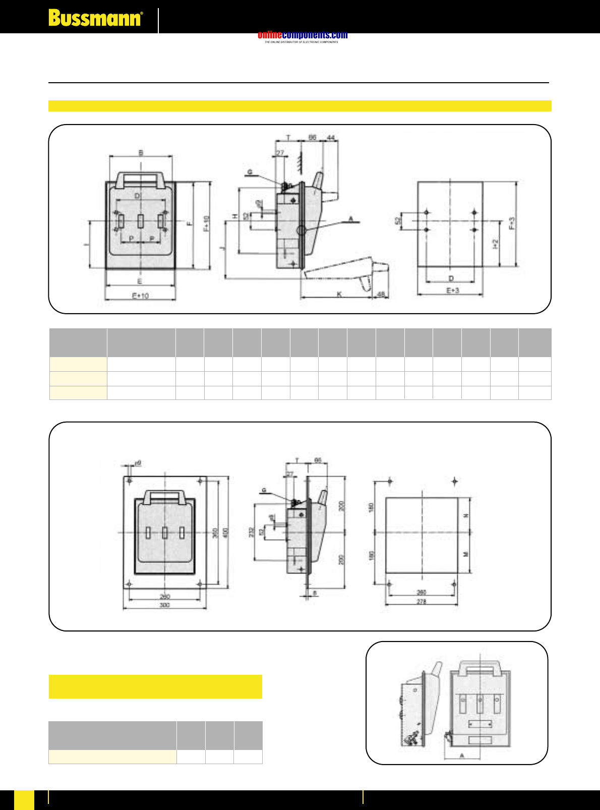
onlinecomponents.com
Fuseholders & Fusegear
For more information visit our website at www.bussmann.com
185
M10
M12
M12
82
86
93
60
60
60
126
135
135
142
162
162
220
254
254
M10
M12
M12
175
195
195
186
214
224
260
290
290
200
260
260
150
174
174
194
254
254
250 A
400 A
630 A
LBS4a
LBS4a
LBS4a
all dimensions in millimetres
TG
mm
P
mm
N
mm
M
mm
K
mm
J
mm
I
mm
H
mm
F
mm
E
mm
D
mm
B
mm
mmType Rated Current
159159128A
3ST42ST41ST4
Size
Fuse switch-disconnector LBS4a
with auxiliary switch DS
Fixing holes
Fixing holes
Fuse switch-disconnector LBS4a
Fuse switch-disconnector LBS4a with shield for front fixing Dimensions in millimetres
Dimensions in millimetres
Fuse Bases for NH Fuse Links
Dimensional Data
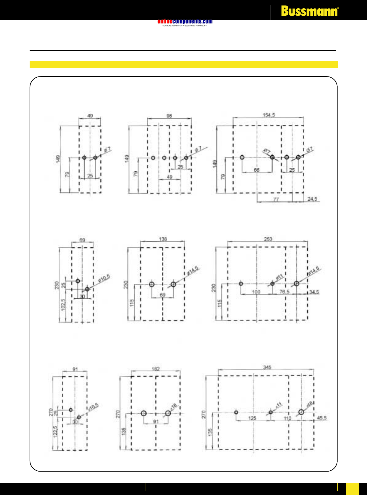
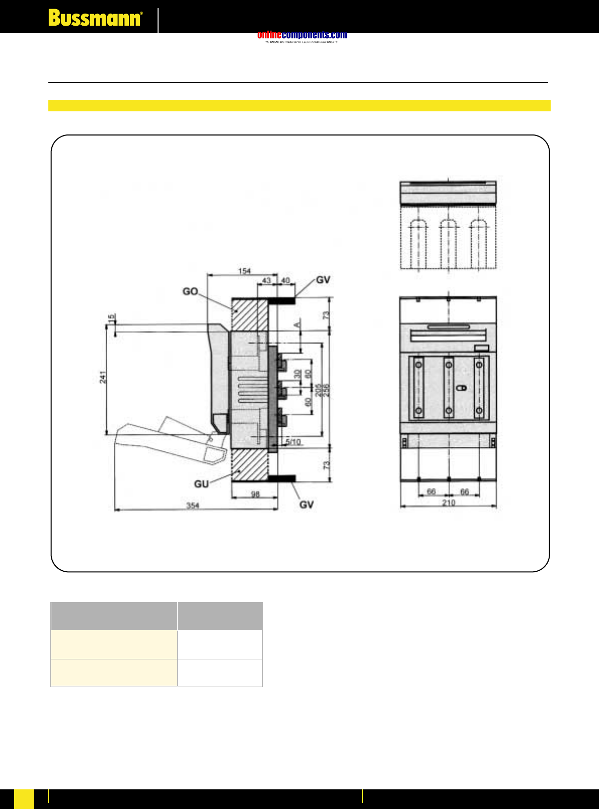
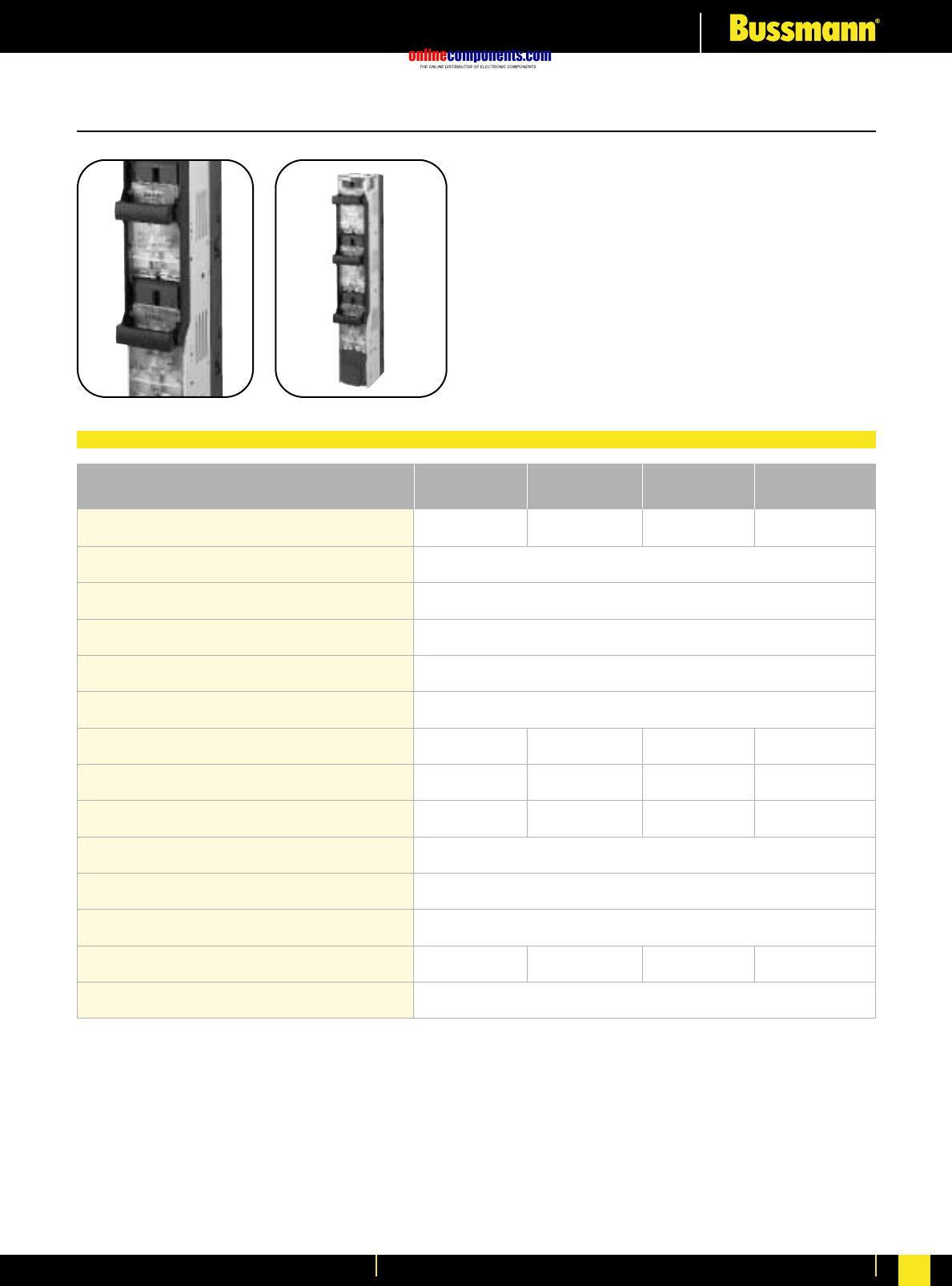
onlinecomponents.com
Fuseholders & Fusegear
For more information visit our website at www.bussmann.com 188
Vertical Fuse Switch - Disconnectors
IP 20
1.5g / 8 to 50Hz
•For use with size C00 to Size 3 fuse links
•Rated at 690V AC
•Fully Shrouded
•Comprehensive range of accessories
•Contact Bussmann for further information
Part Number BLOO
Series
01 (1S) & 1 02 (2S) & 2
3 Pole ONLY
690V AC
50 kA
-25ºC to +55ºC
03 (3S) & 3
BFD1
Series BFD2
Series BFD3
Series
Size of Fuse links Accommodated
Number of Poles Available
Maximum power loss of fuse links
Rated Current
Rated Voltage
Conditional Short-circuit Current
Utilisation Category
Mechanical Durability (cycles)
Weight
Degree of Protection
Permissible Ambient Temperature
Altitude Limit (metres)
Overvoltage Category
Seismic Withstand Capability
C00 & 00
23W 34W12W 48W
250A 400A160A 630A
AC22B AC22BAC22B AC22B
1400 8001700 800
5.500 kg 5.500 kg1.400 kg
Up to 2000m
AC IIIAC IIIAC IIIAC III
6.000 kg
Fuse Switch-Disconnector Technical Data
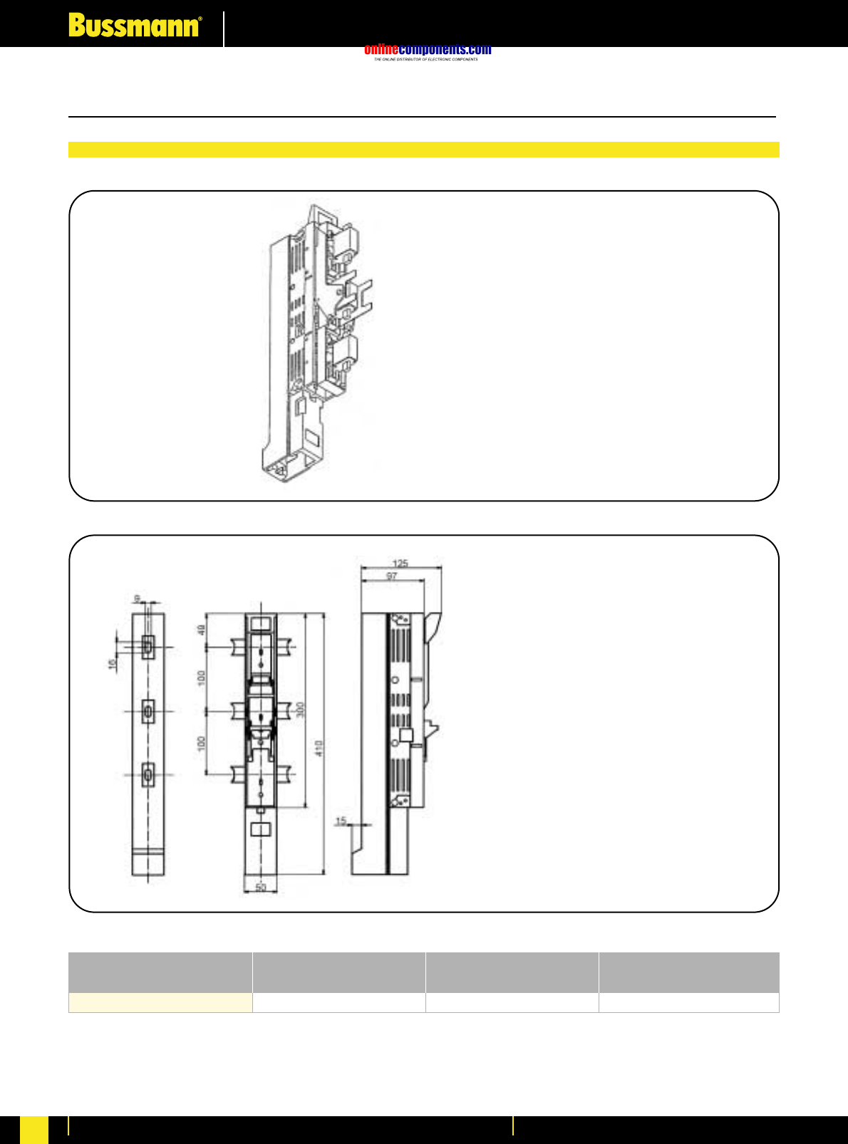
onlinecomponents.com
Fuseholders & Fusegear
For more information visit our website at www.bussmann.com
189
160
VLB00 Series
In
A
3-pole
Control
terminal screws M8F00/3
Outgoing Terminals
Type
Visible circuit disconnection
by disconnector is indicated
by parked position
Standard delivery:
- switch-disconnector is equipped
with terminal screws M8 F00/3 on
the cable outlet
Dimensions in millimetres
Dimensions in millimetres
Vertical Fuse Switch - Disconnectors
Dimensional Data
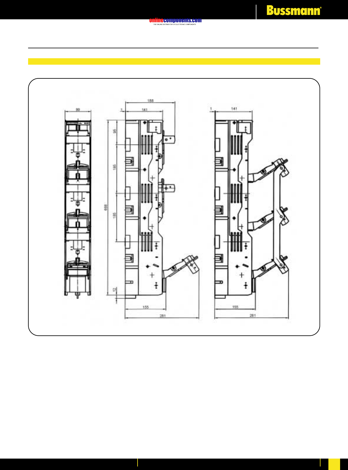
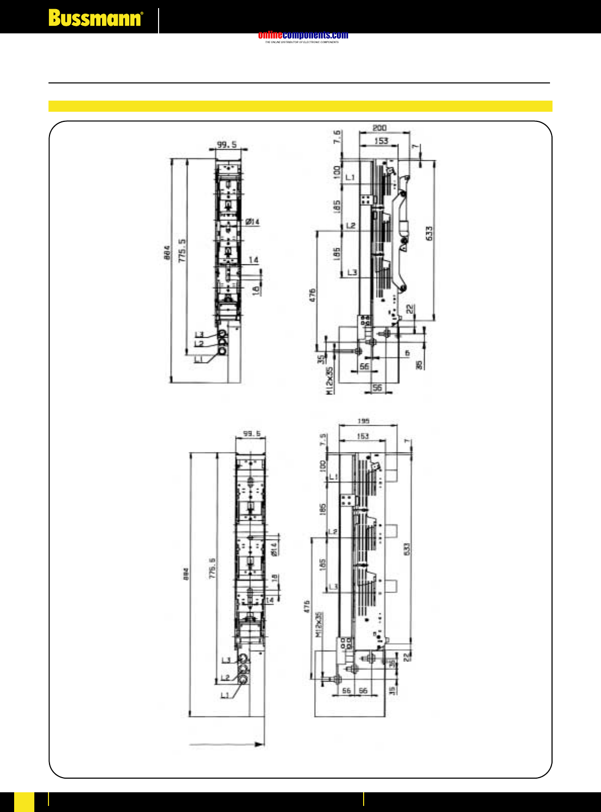
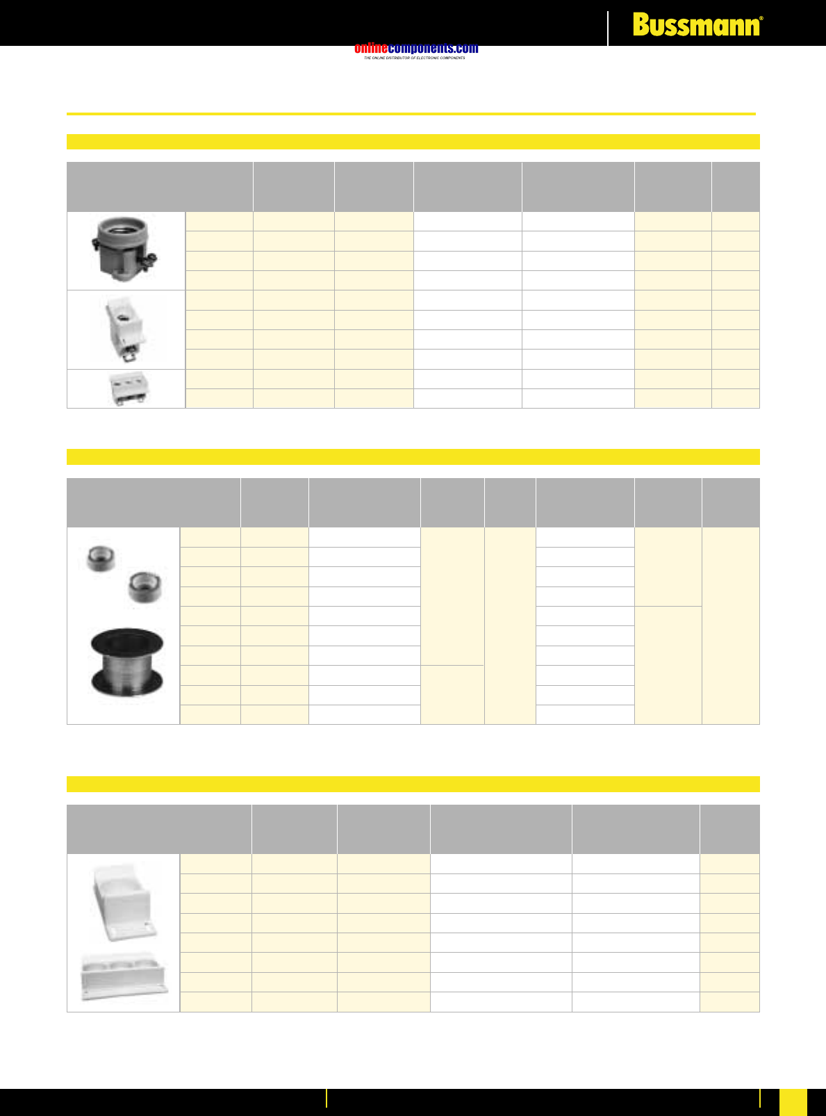
onlinecomponents.com
Fuseholders & Fusegear
For more information visit our website at www.bussmann.com 192
Fuse Base and Fuse Cap Selection Table
Gauge Pieces
D-Type and N-Type Fuse Base Covers
Fuse
System
DII
DIII
DII
DIII
D01
D02
D03
D01
D02
D03
Maximum
Rating (A)
25A
63A
25A
63A
16A
63A
100A
16A
63A
100A
Number
of Poles
1
1
3
3
1
1
1
3
3
3
Fuse Base
Part Number
Panel Mount
SFD27
SFD33
TFD27
TFD33
FN01C
FN02C
FN03C
TFN01C
TFN02C
TFN03C
Fuse Base
Part Number
DIN Rail Mounting
SFRD27
SFRD33
TFRD27
TFRD33
FRN01C
FRN02C
FRN03C
TFRN01C
TFRN02C
TFRN03C
Fuse Cap
Part Number
CD27
CD33
CD27
CD33
CN01
CN02
CN03
CN01
CN02
CN03
Box
Quantity
15
15
4
6
15
15
15
5
5
5
Ratings
(A)
2
4
6
10
16
20
25
35
50
63
Colour
Code
Pink
Brown
Green
Red
Grey
Blue
Yellow
Black
White
Copper
D Type
DI & DIII
2GD27
4GD27
6GD27
10GD27
16GD27
20GD27
25GD27
35GD33
50GD33
63GD33
Use with
Fuse Base
E27
E33
Box qty
D Type
25pcs
Box
Quantity
D0 Type
50pcs
D0 Type
D01 & DO2
2GN01
4GN01
6GN01
10GN01
16GN02
20GN02
25GN02
35GN02
50GN02
-
Use with
Fuse Base
E14
E18
Fuse
System
DII
DIII
DII
DIII
D01
D02
D01
D02
Maximum
Rating (A)
25A
63A
25A
63A
16A
63A
16A
63A
Number
of Poles
1
1
3
3
1
1
3
3
Finger Protection Ring
SFPRD27
SFPRD33
-
-
-
-
-
-
Finger Protection
Covers
-
-
TFPCD27
TFPCD33
SFPCD01
SFPCD02
TFPCD01
TFPCD02
Box
Quantity
15
15
4
4
50
50
30
30
D & D0 Low Voltage Fuse System
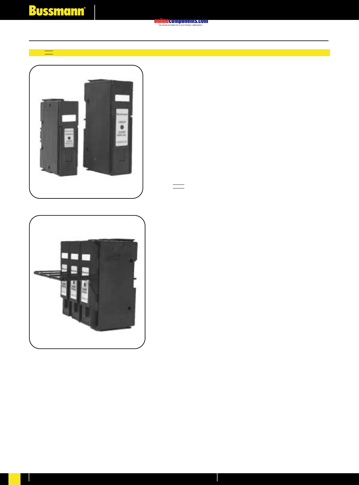
onlinecomponents.com
Fuseholders & Fusegear
For more information visit our website at www.bussmann.com
193
CAM HRC Fuse Holders - Introduction
ASTER
A patented range of fully shrouded HRC Fuse Holders designed to
accomodate offset bolted tag HRC fuse links to BS88: Parts 1 & 2;
IEC 60269-1 & 2. All Camasters are rated at 690Vac.
The compact dimensioned 32A Fuse Holder, type CM32FC and
CM20F accept the A1 size fuse link NITD 2 to 32 Amps. The standard
32A Fuse Holder, type CM32F and CM20F accept the A2 size fuse
link AAO 2 to 32 Amp. The 63A unit, type CM63F accepts the A3 size
fuse link BAO 40 to 63 Amp and the 100 Amp unit,type CM100F
accepts fuse link type OSD 80 to 100 Amps, which has compact A3
fixing centres.
The Fuse Holders are supplied as front connecting as standard but
can be readily converted to front/back stud or double back stud
connection types at the point of installation, using the appropriate
size back stud accessories.
CAMASTER Fuse Holders are offered with the following features:
•Advanced patented design incorporating a high level of innovation
with enhanced performance characteristics.
•Camaster Fuse Holders fully comply with the requirements of BS88
section 2.2 (IEC60269-2-1, section 2) and the 16th edition of the
IEE Wiring Regulations (BS7671).
•The fuse carriers are fitted with a ‘cam’ action for ease of removal
from the fuse base. The design ensures high contact pressure
between the fuse carrier contacts and the base contacts, with a
corresponding enhanced electrical performance level.
•Camaster Fuse Holders have a unique channel and guide
arrangement which prevents any tilting of the fuse carrier when it is
being inserted or removed, eliminating any likelihood of inadvertent
contact with live metal.
•Fixing screws to the fuse carrier are held in captive hinges,
providing ease of fixing and preventing loss during installation.
The hinges also act as pressure plates thereby reducing the contact
resistance between the fuse link tags and the carrier contact.
•Cable terminations fully meet the requirements of sub-clause 7.1.7
terminals of IEC60947: Part 1 Low Voltage Switchgear and
Controlgear.
•Camaster Fuse Holders, as standard, provide both bolted panel
and DIN rail mounting features. When DIN rail mounted all ratings of
fuse holder give equal height and depth above and below the DIN rail.
•Non removable full shrouding of live parts within the fuse base
provided by the use on hinged shields which cannot be omitted
during installation and are designed so that insertion of the fuse
carrier can only be made with them correctly positioned.
•Neon clip-in indicator accessories are available, the neon being lit
when the fuse link has operated. (Minimum system operation 90V).
•The fuse carrier has a marking label for ease of circuit identification.
•Ganging can be readily achieved by the use of standard
accessories, providing improved safety related to isolation and
protection of 2 and 3 pole electrical circuits.
British Standard Fuse Holders and Accessories
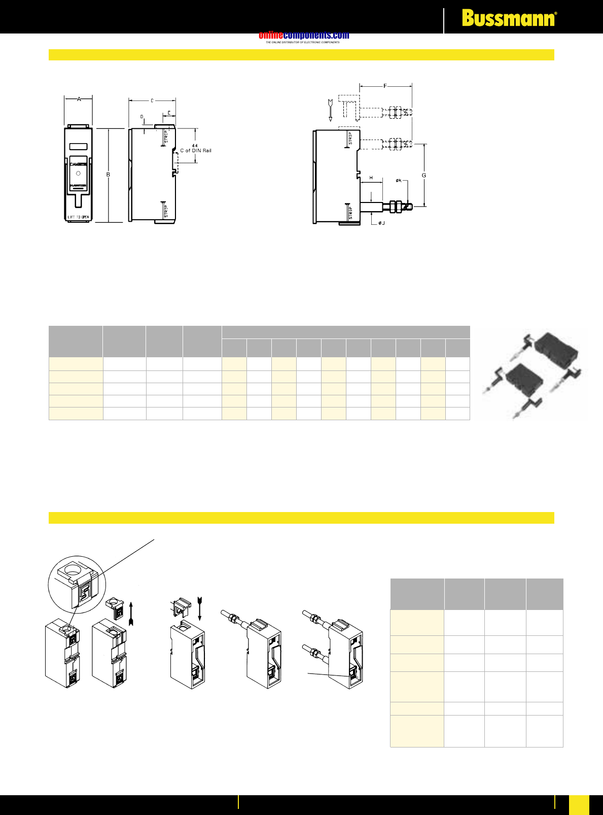
onlinecomponents.com
Fuseholders & Fusegear
For more information visit our website at www.bussmann.com 194
Standard front connected unit. Suitable for either bolted panel
or DIN rail mounting. Front/Back stud and double back stud connected units.
These allow easy customer conversion (illustrated below right)
to either Front/Back or double back configuration, by use of
Back stud assembly packs, using only a screwdriver.
Rating (A) ABCDE FG H JK
Dimensions (mm)
Part No. Max
Cable
mm2
Rec.
Fuse
Link
20 CM20F 16 NITD 25.4 93.7 60 3.2 17.5 66.0 58.0 28.6 11.9 M6
32 CM32FC 16 NITD 25.4 93.7 60 3.2 17.5 66.0 58.0 28.6 11.9 M6
32 CM32F 16 AAO 31.8 117.5 60 3.2 17.5 66.0 74.0 28.6 11.9 M6
63 CM63F 70 BAO 35.6 125 60 4.75 16.4 86.5 81 28.6 11.9 M8
100 CM100F 70 OSD 35.6 125 60 4.75 16.4 86.5 81 28.6 11.9 M8
Accessory Rating (A) Part no. Carton
Qty.
32 32BSC 10
Back stud 32 32BS 10
63/100 63/100BS 5
Ganging Links –GLP 1 Set
Neon Indicator 90-660 NI 3
V ac
Lockable –32LSCC 3
Safety Carriers 32LSC 3
63/100LS 3
Security Clip –CMSC 20
Neutral 32 32CMLC
Links 32 32CML 1
63 /100 63/100CML
Notes.
1. Type CM32FC is also available rated at 20A, catalogue number CM20F
2. For colours other than Black (standard) add the appropriate letter code: W = White; G = Green; GY = Grey
3. Care must be taken when fitting solid single or stranded cables of small cross-sectional area to ensure correct clamping.
Multi-stranded cables must be terminated with bootlace ferrules to ensure correct clamping.
A
1. Remove carrier
using the Cam
Lever. Insert
screwdriver at
position ‘A’ gently
lever and push
ferrule upwards
to remove.
2. Insert Back
Stud accessory. 3. Raise contact
shield by inserting
screwdriver at
position ‘B’.
Tighten terminal
screw.
4. Repeat steps 1,
2 & 3 at opposite
end to give
Double Back
Stud connection.
Ratings, Catalogue Numbers & Dimensions
Conversion Sequence
B
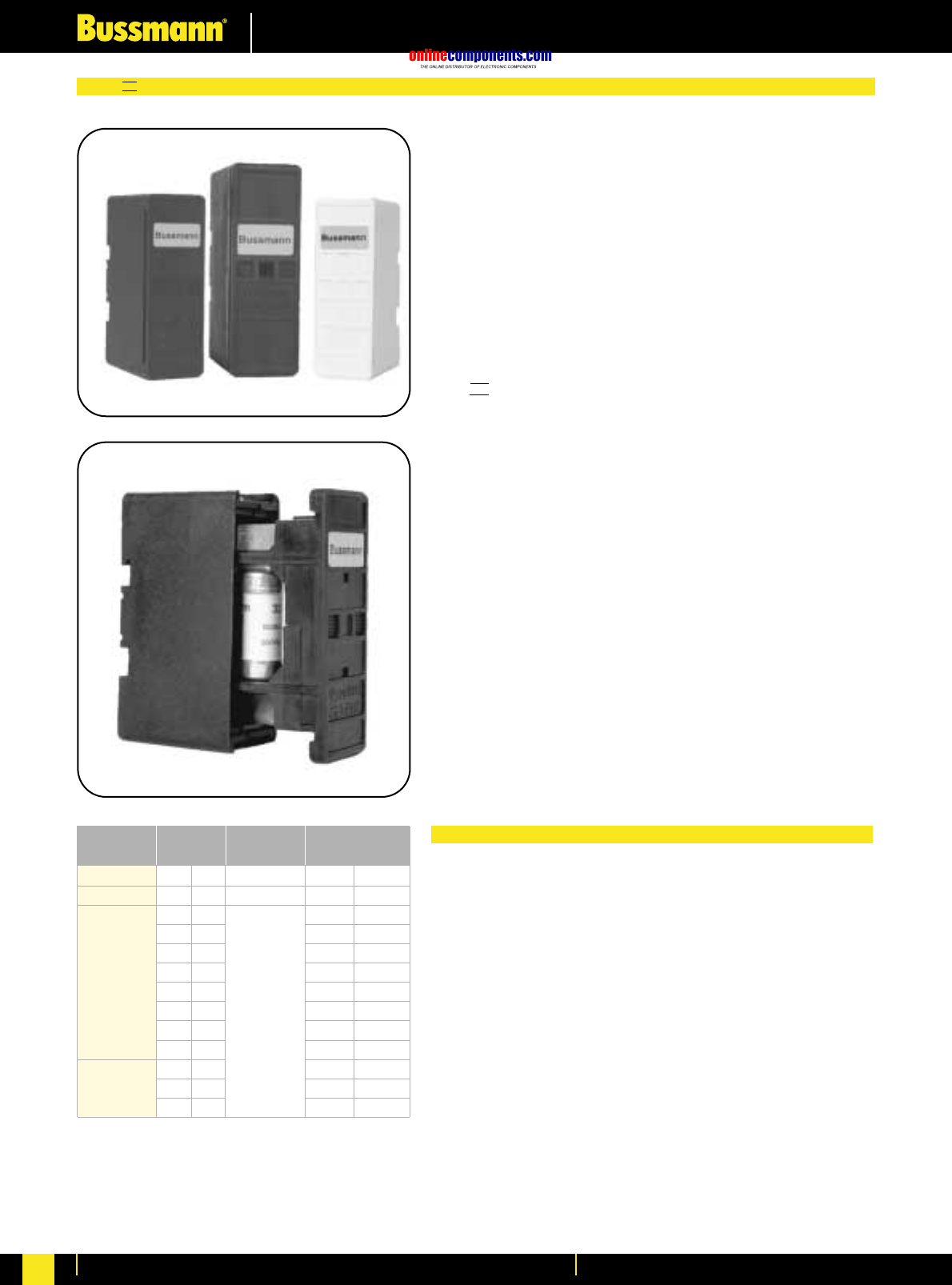
onlinecomponents.com
Fuseholders & Fusegear
For more information visit our website at www.bussmann.com
195
Fuse Link
Ratings
Safeloc Type NNS ENS Safeloc Type NNS ENS
Fuse Link Type NSD ESD Fuse Link Type NSD ESD
2 2 20M25 63M80
4 4 20M32 63M100
6 6 20M36 -
10 10 32M36 -
16 16 32M40 -
20 20 32M50 -
25 25 32M63 -
32 32 - -
-40 - -
- 50 - -
-63 - -
Motor Fuse
Link Ratings
550 Vac
NSD 415 V AC
ESD 415 V AC
415 Vac
LOC
SAFE HRC Fuse Holders - Introduction
The patented Safeloc fuse holders provide a simple, safe range,
designed to accommodate the compact range of offset blade tag
fuse links to BS88 part 6 and IEC 60269-2-1 section IV.
The combination offers significant savings in volume and cost as
well as a reduction in fitting time and power loss. They provide a
safe and easy method of protecting a wide range of electrical
equipment such as lighting, heating, motor and control equipment
circuits.
The NNS fuse holder accomodates the NSD 2-32A range of
compact HRC fuse links whilst the slightly larger ENS fuse holder
accomodates the ESD 2-63A range of compact HRC fuse links.
Both holders are available in front connection or back stud
arrangements or combinations of these.
SAFELOC Fuse Holders are offered with the following features:
•Compact fuse link and fuse holder dimensions.
•Fuse holders employ a unique slide/snap carrier action for positive
and secure insertion and removal of the fuse link. This provides
positive, stress free fitting of fuse links and locks the fuse link in
position ensuring safe insertion and withdrawal from the base.
•The direct contact between fuse link blades and the plated base
contacts provides low watts loss with increased reliability.
•The compact range of fuse links (i.e. NSD & ESD) fitted into the
Safeloc fuse holders, have an excellent ability to protect induction
motor circuits.
•Complete internal personal protection against direct contact
electric shock is obtained by fully insulated and shrouded fuse
holder base contacts.
•The fuse base utilises glass filled, high impact resistant,
thermoplastic polyester and incorporates a 35mm DIN rail
mounting facility as well as a single screw fixing.
Notes on Motor Circuits
All of the compact range of fuse links have an excellent ability to
protect induction motor circuits. The unique design of the Safeloc
Fuse Holders has enabled the design of dual rated fuse links which
offer protection for motor ratings up to 30kW.
Type gM fuse links for the protection of motor circuits have dual
rated characteristics. For example, an ESD63M100 has a
continuous current carrying capability of 63A, coupled with the time
current characteristic and the capabilities of a 100A fuse link.
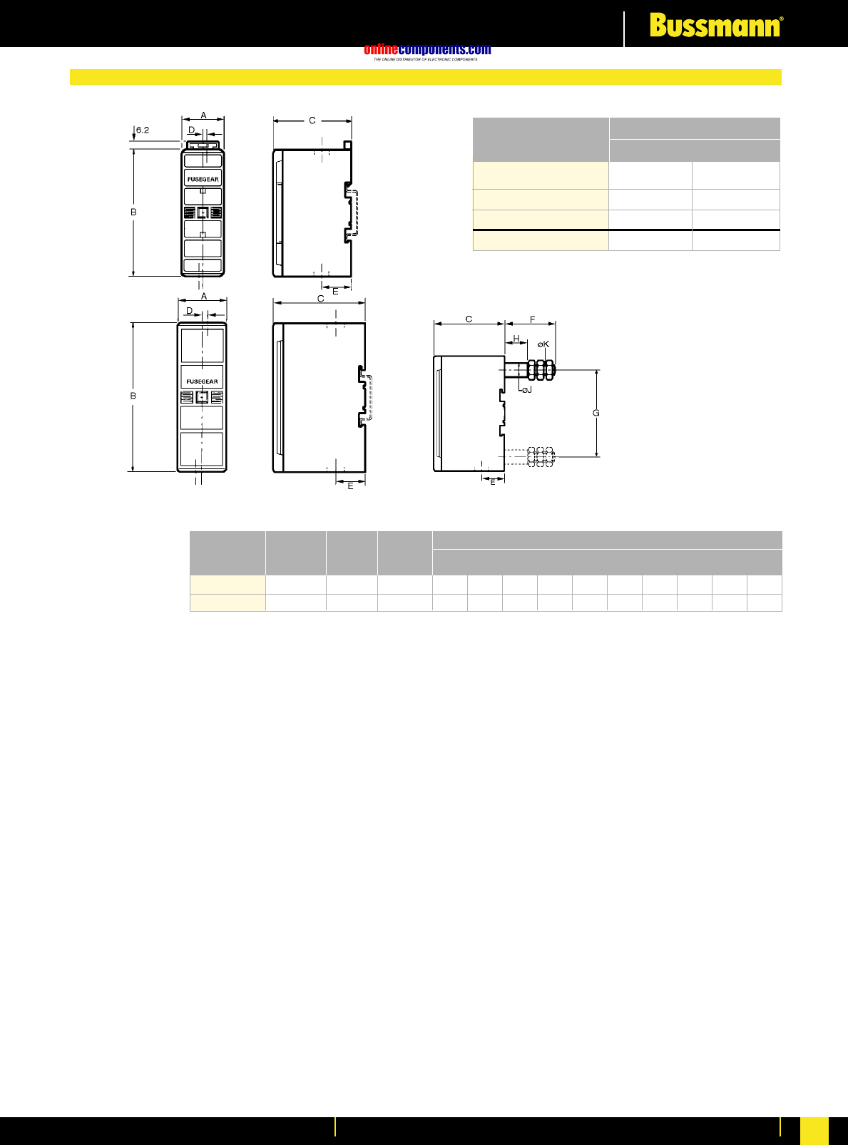
onlinecomponents.com
Fuseholders & Fusegear
For more information visit our website at www.bussmann.com 196
32ENS
63ENS
Ratings, Catalogue Numbers & Dimensions
Available Variants NNS
Front Connected/Front 32NNSF 63ENSF
Connected
Back Stud/Back/Stud 32NNSBS 63ENSBS
Front Connected/Back Stud 32NNSFBS 63ENSFBS
Neutral Links 32NNL 63ENL
NNS
Catalogue Reference
Suitable for either Bolted Panel or DIN rail mounting.
Rating (A) ABCDE FG H JK
Dimensions (mm)
Part No. Max
Cable
mm2
Rec.
Fuse
Link
32 NNS 16 NSD 25.4 80.3 48.5 2.3 16.0 39.2 57.7 17.0 9.7 M6
63 ENS 35 ESD 29.1 90.0 55.0 3.3 17.7 75.0 67.9 39.2 11.0 M8
BACK STUD OPTION
For colours other than
Black (standard), add the
appropriate letter code:
W = White; G = Green;
GY = Grey, at the end of
the catalogue reference.
Security seal (ref. 32551)
available for 32A Safeloc.
Care must be taken when
fitting solid single or
stranded cables of small
cross-sectional area to
ensure correct clamping.
Multi-stranded cables
must be terminated with
bootlace ferrules to ensure
correct clamping.
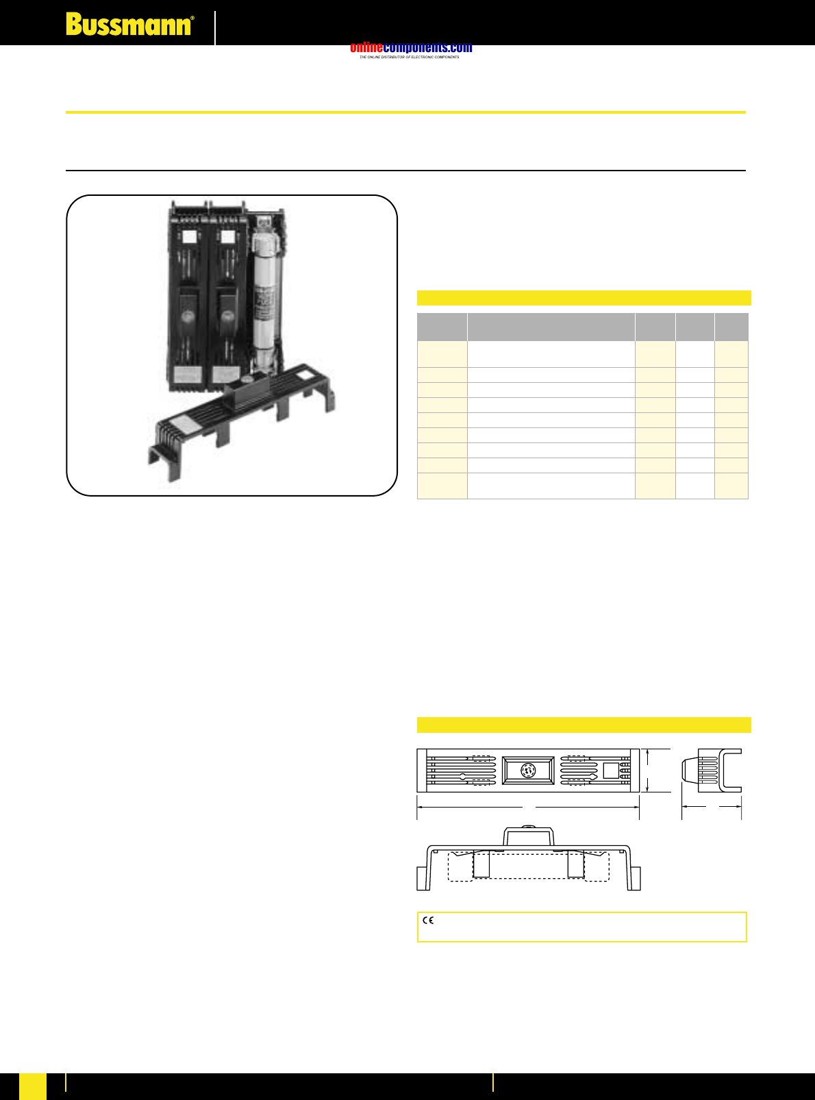
onlinecomponents.com
Fuseholders & Fusegear
For more information visit our website at www.bussmann.com
197
SAMI Fuse Covers
SAMI Series
For Class J, RK1, RK5, H, K5, CC, G (0-30A) and
Midget type fuses.
Voltage Rating:
Non-Indicating - 0-600 Volt AC/DC
Indicating - 90 to 600 Volt AC
-115 to 600 Volt DC
Ampere Rating: 0-100 Amps
Agency Information: UL Listed; SAMI-1I through SAMI-6I
SAMI-8I and SAMI-9I, SAMI-1N through SAMI-6N, SAMI-8N
and SAMI-9N
UL Recognized; SAMI-7I and SAMI-7N
CSA Certified, File LR47235-93C
•Innovative design, covers exposed terminals and contacts
of Bussmann fuseblocks.
•Fits most competitive fuseblocks.
•Buss Yellow light on indicating SAMI shows when the fuse
is open—helps trouble shoot the system and reduces
downtime.
•All versions are reusable—no need to pay for indication
every time a fuse opens.
•Indication contacts have teeth to break oxidation layer on
the existing fuse endcap to provide a clear signal path.
•Less than .6mA leakage current at 600 volt.
•Visual marking of line and load side.
•SAMI cover ends can easily be cut away if necessary, to fit
cover over existing wiring or to fit most safety switches.
•Dead front construction provides added protection against
accidental contact by maintenance personnel.
LINE
Buss
SAMI -2
LOAD
TEST PROBE TEST PROBE
C
B
A
FUSE
CE logo denotes compliance with European Union Low Voltage Directive
(50-1000V AC, 75-1500V DC). Refer to BIF document #8002.
BIF document: 1204 (Trimming Guides: 12041, 12042, 12043,
12044, 12045, 12046, 12048, 12049)
Catalogue
Number** Description A B C
SAMI-1_ 600V, J (0-30A) and 600V, T (35-60A)*
250V, RK, K5, H (35-60A) 5.02 1.03 1.94
SAMI-2_ 600V, RK, K5, H (0-30A) 7.03 1.30 2.07
SAMI-3_ 600V, J (65-100A) 7.03 1.30 2.33
SAMI-4_ 250V, RK, K5, H (65-100A) 8.20 1.30 2.18
SAMI-5_ 600V, RK, K5, H (35-60A) 8.20 1.30 2.18
SAMI-6_ 600V, J (35-60A) 4.98 1.17 2.14
SAMI-7_ 600V, Midget, Class CC, G (0-30A) 3.82 0.75 1.72
SAMI-8†_ 600V, RK, K5, H (65-100A) 10.38 1.50 2.33
SAMI-9_ 250V, RK, K5, H (0-30A) and 600V,
T (0-30A) 3.82 0.75 1.72
Dimensional Data (inches)
Dimensional Data (inches)
*Available in non-indicating only.
†SAMI-8A adapter available for small fusetron body design. SAMI-8I and SAMI-8N come
standard with adapter (SAMI-8A).
**Catalogue Numbers
For Indicating Cover, add suffix I.
For Non-indicating cover, add suffix N.
Example: SAMI-7I = Indicating
SAMI-7N = Non-indicating
Indicating feature requires a minimum of 90VAC or 115V DC to illuminate lamp.
WARNING: To avoid electrical shock, turn power off before
installing, removing or servicing.
•Labels are provided with the SAMI fuse cover for writing in
circuit or fuse information.
•One cover is required for each pole.
North American Standard Fuse Holders and Accessories
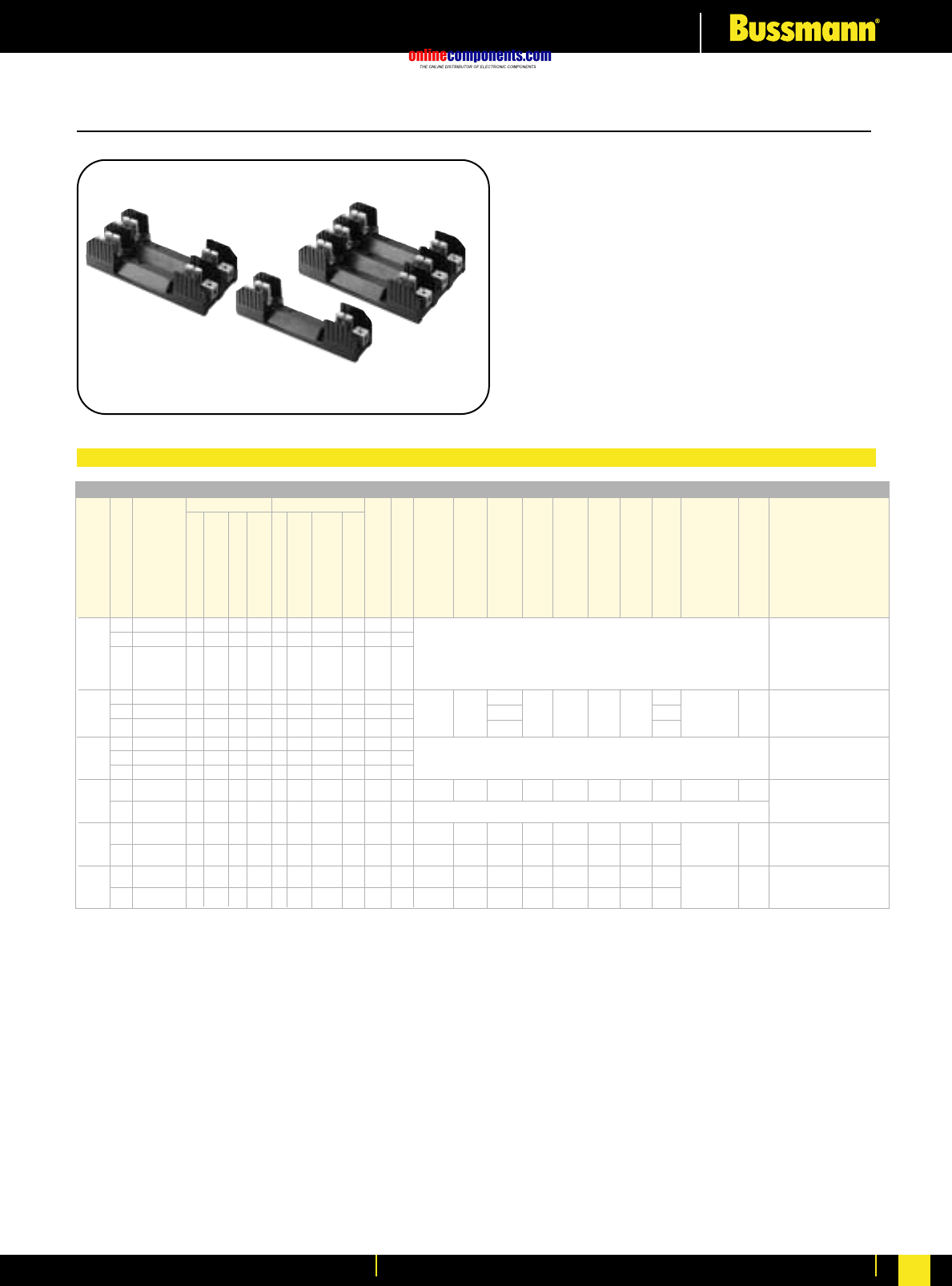
onlinecomponents.com
Fuseholders & Fusegear
For more information visit our website at www.bussmann.com 198
Class H(K) and R Fuseblocks – 250V Bussmann®
BIF document: H250 Series,1112; R250 Series, 1110
H250 Series For use with Class H Fuses
(Bussmann NON and REN).
R250 Series For use with Class R Fuses
(Bussmann LPN-RK and FRN-R, DLN-R and KTN-R).
Construction: Thermoplastic, UL Flammability: 94VO
Ampere Ratings: ⁄Ω¡º-600 Amps.
Withstand Ratings: H250 Series - 10,000A RMS Sym.;
R250 Series - 200,000A RMS Sym.
Voltage Rating: H250, 250 Volts; R250, 250 Volts
Agency Information: UL Listed UL512, Guide IZLT,
File E14853; CSA Certified, Class 6225-01, File 47235
Class H Fuseblocks (250V) Catalogue Data (for NON and REN Fuses)
Terminal Type (Suffix No.) Dimensions (Inches) – See Next Page For Figures
Screw Box Lug w/
Basic J Dia.
Catalogue Fig. x Wire
Number No. A B C D E F G H C’ Bore K Range
⁄Ω¡º 1 H25030-1 S SR P PR C CR COR CO Q 1 C, CR #2-14 CU, #2-12 AL
to 2 H25030-2 S SR P PR C CR COR CO Q 2 (See Figures) CO, COR #6-14 CU ONLY
30 3 H25030-3 S SR P PR C CR COR CO Q 3 P, PR #10-18 CU ONLY
Q N/A
S, SR #10-18 CU ONLY
31 1 H25060-1 ————C CR COR CO —4 1.5 —C, CR #2-14 CU, #2-8 AL
to 2 H25060-2 — —— —C CR COR CO —5 4.25 1.73 2.81 1.5 0.5 0.5 1.25 1.31 0.22 ≈0.41 0.27 CO, COR #2-14 CU ONLY
60 3 H25060-3 — —— —C CR COR CO —6 4.125 1.31 CU ONLY
61 1 H25100-1 — SR — —— CR COR —— 7COR #1/0-8 CU ONLY
to 2 H25100-2 — SR — —— CR COR —— 8 (See Figures) CR #1/0-8 CU/AL
100 3 H25100-3 — SR — —— CR COR —— 9SR #8W/ Ring Terminal
101 1H25200-1 — —— ——CR — ——10 7.125 3.09 3.0 2.06 0.5 2.0 3.0 0.75 —0.31 CR 250kcmil-6 CU/AL
to
200 3H25200-3 — —— —— CR — ——11 (See Figures)
201 1 H25400-1 — —— —— CR* — ——10 9.06 4.0 3.0 3.02 0.63 1.75 3.0 1.0 CR 500kcmil-4 CU/AL
to —0.31
400 3 H25400-3 — —— ——CR†— ——12 9.06 4.0 4.0 2.50 0.82 9.25 10.88 1.0
401 1 H25600-1 — —— —— CR — ——10 11.0 4.97 3.0 4.0 1.125 1.75 4.0 1.00 CR 500kcmil-4/0 CU/AL
to —0.31
600 3 H25600-3 — —— —— CR†— ——12 11.0 4.97 5.0 3.0 1.87 11.0 14.74 1.00
*U.L. Recognized, No CSA Certification.
†No UL, No CSA Certification.
Amps
—
Clip with
Reinforced Spring
Pressure Plate
Pressure Plate & Clip
with Reinforced Spring
—
Clip with
Reinforced Spring
Clip w/ Reinforced
Spring (Copper Only)
Copper Only
0.25∑Quick Connect
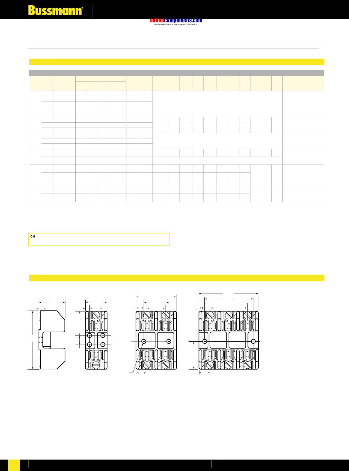
onlinecomponents.com
Fuseholders & Fusegear
For more information visit our website at www.bussmann.com
199
1.41"
0.22"
1.09"
3.03"
0.5"
0.17" 0.75" 0.25"
1.25"
0.95"
0.22" DIAMETER
0.41"
2.05"
2 SPACES AT
0.95" - 1.91"
2.5"
3"
0.55"
1.27"
1.52"
0.55"
Terminal Type (Suffix No.) Dimensions (Inches)
Basic Screw w/ Box Lug w/ 0.259 J Dia.
Catalogue Pres. Clip Quick- Fig. x Wire
Number —Plate —Cu Only Connect No. A B C D E F G H C’ Bore K Range
⁄Ω¡º 1 R25030-1 SR PR CR COR QR 1 COR #6-14 CU ONLY
to 2 R25030-2 SR PR CR COR QR 2 CR #2-14 CU, #2-12 AL
30 3 R25030-3 SR PR CR COR QR 3 (See Figures) PR #10-18 CU ONLY
QR N/A
SR #10-18 CU ONLY
31 1 R25060-1 ——CR COR —4 1.5 —COR #2-14 CU ONLY
to 2 R25060-2 ——CR COR —5 4.25 1.73 2.81 1.5 0.5 0.5 1.25 1.31 0.22 x 0.41 0.27 CR #2-14 CU, #2-8 AL
60 3 R25060-3 ——CR COR —6 4.125 1.31
61 1 R25100-1 ——CR†COR —7
to 2 R25100-2 ——CR†COR —8 (See Figures) COR 1/0-8 CU ONLY
100 3 R25100-3 ——CR†COR —9CR 1/0-8 CU/AL
101 1 R25200-1 ——CR ——10 7.125 3.15 3.0 2.06 0.5 2.0 3.0 0.75 —0.31 CR 250kcmil-6
to
200 3 R25200-3 ——CR ——11 (See Figure)
201 1 R25400-1 ——CR‡COR‡—10 9.06 4.0 3.0 3.02 0.91 1.75 3.0 1.0 COR 500kcmil-4/0
to CU ONLY
400 — 0.56
3 R25400-3 ——CR†COR†—12 9.06 4.0 4.0 2.5 0.82 9.25 10.88 1.0 CR 500kcmil-4/0 CU/AL
401 1 R25600-1 ——CR ——10 11.0 4.97 3.0 4.0 1.125 1.75 4.0 1.0
to —0.56 CR 500kcmil-4/0 CU/AL
600 3 R25600-3 ——CR†— — 12 11.0 4.97 5.0 3.0 1.87 11.0 14.74 1.0
*U.L. Recognized, No CSA Certification.
†No UL, No CSA Certification.
‡UL Recognized, CSA Certification
Poles
Amps
Class R Fuseblocks (250V) Catalogue Data (for LPN-RK, FRN-R, DLN-R and KTN-R Fuses)
Class H(K) and R Fuseblocks – 250V
CE logo denotes compliance with European Union Low Voltage Directive
(50-1000V AC, 75-1500V DC). Refer to BIF document #8002.
BIF document: H250 Series,1112; R250 Series, 1110
Dimensional Data 250V ⁄Ω¡ºA to 30A
FIGURE 1. FIGURE 2. FIGURE 3.
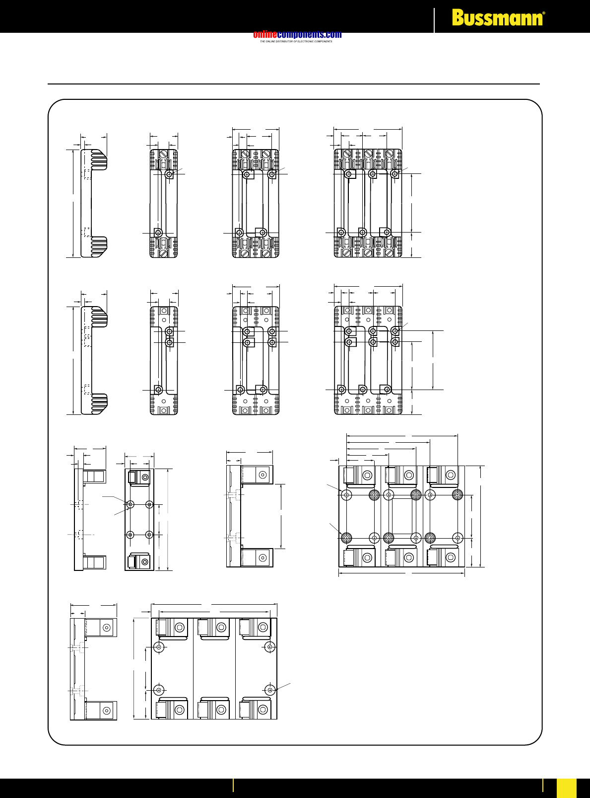
onlinecomponents.com
Fuseholders & Fusegear
For more information visit our website at www.bussmann.com For more information visit our website at www.bussmann.com 200
C.34" DIA.
HOLE
THRU
A
B
H
G
F
E
D
BH
KEF
0.75"
C'BORE
0.34
DIAMETER
G
C
D
A
3.4"
4.5"
1" .5"
EYELETS
TO ACCEPT
.25" DIA.
SCREW
.34" DIA.
HOLE
THROUGH
8"
6"
5"
3"
2"
3"
2.06"
7.13"
9"
A
K
BC
F
C
EH
F
H
C
G
D
F
HE
J
JJ
7.36"
0.25"
2.06" 1.81"
0.62"
3.38"
0.59"
0.62"
4.94"
2.38"
2.125"
0.62"
0.28" DIA. x
0.5" C'BORE
0.59"
1.56" 1.56"1.56"
3.125"
BIF document: H250 Series,1112; R250 Series, 1110
Class H(K) and R Fuseblocks – 250V
250V, 31A to 60A
FIGURE 4. FIGURE 5. FIGURE 6.
250V, 61A to 100A
FIGURE 7. FIGURE 8. FIGURE 9.
250V, 101A to 600A
250V, 201A to 600A
250V, 101A to 200A
FIGURE 10. FIGURE 11.
FIGURE 12.
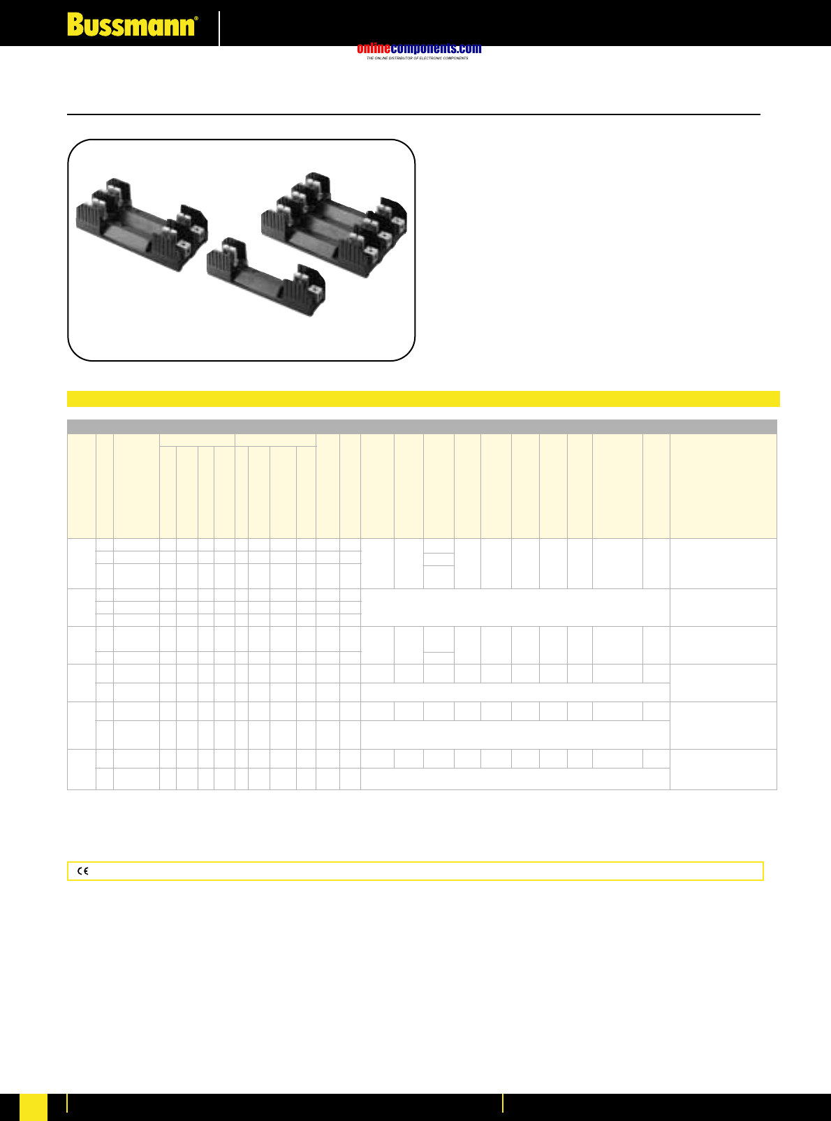
onlinecomponents.com
Fuseholders & Fusegear
For more information visit our website at www.bussmann.com
201
Data Sheet: H600 Series, 1113; R600 Series, 1111
H600 Series For use with Class H Fuses
(Bussmann NOS and RES).
R600 Series For use with Class R Fuses
(Bussmann LPS-RK, FRS-R, DLS-R and KTS-R).
Construction: Thermoplastic, UL Flammability: 94VO
Ampere Ratings: ⁄Ω¡º-600 Amps.
Withstand Ratings: H600Series - 10,000A RMS Sym.;
R600 Series - 200,000A RMS Sym.
Voltage Rating: H600, 600 Volts; R600, 600 Volts
Agency Information: UL Listed UL512, Guide IZLT, File
E14853; CSA Certified, Class 6225-01, File 47235
CE logo denotes compliance with European Union Low Voltage Directive (50-1000V AC, 75-1500V DC). Refer to Data Sheet #8002.
Terminal Type (Suffix No.) Dimensions (Inches) – See Next Page For Figures
Screw Box Lug w/
Basic J Dia.
Catalogue Fig. ≈Wire
Number No. A B C D E F G H C’ Bore K Range
⁄Ω¡º 1 H60030-1 S SR P PR C CR COR CO —1 1.54 C, CR #2-14 CU, #2-12 AL
to 2 H60030-2 S SR P PR C CR COR CO —2 6.25 1.73 2.90 1.56 .25 0.62 3.13 1.56 0.28 ≈0.5 .26 CO, COR #6-14 CU ONLY
30 3 H60030-3 S SR P PR C CR COR CO —3 4.25 P, PR, S, SR #10-18
CU ONLY
31 1 H60060-1 — —— —C CR COR CO —4C, CR #2-14 CU, #2-8 AL
to 2 H60060-2 — —— —C CR COR CO —5 (See Figures) CO, COR #4-14 CU ONLY
60 3 H60060-3 — —— —C CR COR CO —6
61 1 H60100-1 — SR*— —— CR COR —— 1 2.22 COR 1/0-8 CU ONLY
to 2 H60100-2 — SR*— —— CR COR —— 2 9.5 2.38 4.03 2.63 0.67 0.88 4.25 1.81 0.28 ≈ 0.50 .34 CR 1/0-8 CU/AL
100 3 H60100-3 — SR*— —— CR COR —— 3 5.84 SR #8w/ Ring Terminal
101 1 H60200-1 — —— ——CR — —— 7 9.63 3.09 3.0 3.31 0.5 2.0 3.0 0.75 —0.31 CR 250kcmil-6 CU/AL
to
200 3 H60200-3 — —— —— CR — —— 8 (See Figures)
201 1 H60400-1 — —— —— CR‡COR† —— 7 12.0 4.0 3.0 4.5 0.63 1.75 3.0 1.0 —0.56 COR 500kcmil-4/0
to CU ONLY
400 3 H60400-3 — —— ——CR — —— 9 (See Figures) CR 500kcmil-4/0 CU/AL
401 1 H60600-1 — —— —— CR — —— 7 14.0 4.97 3.0 5.5 1.125 1.75 4.0 1.0 —0.56 CR 500kcmil-4/0 CU/AL
to
600 3 H60600-3 — —— —— CR†— ——10 (See Figures)
*U.L. Recognized, No CSA Certification.
†No UL, No CSA Certification.
‡UL Recognized, CSA Certification
Poles
Amps
—
Clip with
Reinforced Spring
Pressure Plate
Pressure Plate & Clip
with Reinforced Spring
—
Clip with
Reinforced Spring
Clip w/ Reinforced
Spring (Copper Only)
Copper Only
0.25∑Quick Connect
Class H(K) and R Fuseblocks – 600V
Class H Fuseblocks (600V) Catalogue Data (for NOS and RES Fuses)
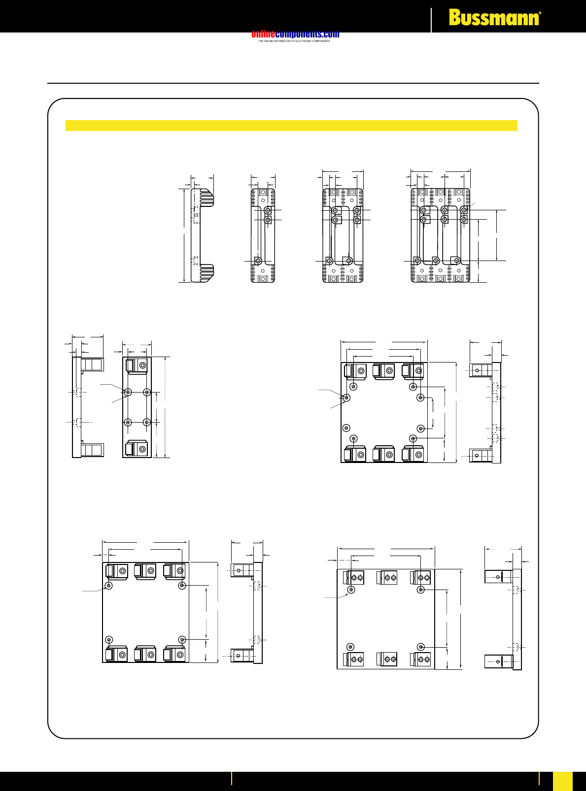
onlinecomponents.com
Fuseholders & Fusegear
For more information visit our website at www.bussmann.com 202
Class H(K) and R Fuseblocks – 600V
Dimensional Data (inches)
7.36"
0.25"
2.06" 1.81"
0.62"
3.38"
0.59"
0.62"
4.94"
2.38"
2.125"
0.62"
0.28" DIA. x
0.5" C'BORE
0.59"
1.56" 1.56"1.56"
3.125"
600V, 31A to 60A
FIGURE 4 FIGURE 5 FIGURE 6
BH
KEF
0.75"
C'BORE
0.34
DIAMETER
G
C
D
A
600V, 101A to 600A
6.5"
8.0"
0.75" DIA.
C'BORE
.50" Deep
0.34
DIAMETER
9.0"
5.5"
9.63"
3.0"
2.065"
3.15"
.75"
600V, 101A to 200A
11.0"
0.34
DIAMETER
0.75" DIA.
C'BORE
.67" Deep 14.00"
2.5"
4.987"
1.00"
2.13"
15.26"
8.00"
9.25"
0.75" DIA.
C'BORE
.67" Deep
0.34
DIAMETER
11.63"
7.00"
12.00"
2.5"
4.02"
1.00"
1.19"
600V, 201A to 400A 600V, 401A to 600A
FIGURE 7 FIGURE 8
FIGURE 9 FIGURE 10
BIF document: H600 Series - 113; R600 Series - 111
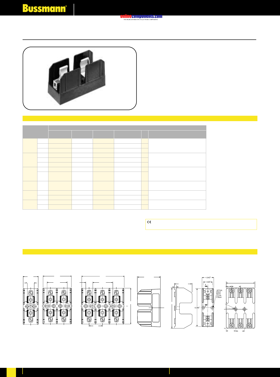
onlinecomponents.com
Fuseholders & Fusegear
For more information visit our website at www.bussmann.com
203
Class J Fuseblocks
BIF document: 1114
J600 Series For use with Class J Fuses
(Bussmann® LPJ and JKS).
Catalog Symbol: J600 Series
Ampere Rating: ⁄Ω™-600 Amperes
Voltage Rating: 600 Volts
Withstand Rating: 200,000 RMS Sym. Amps
Agency Information:
U.L. Listed, U.L. 512, Guide IZLT, File E14853
CSA Certified, C22.2 No. 39, Class 6225-01, File 47235
Materials: Thermoplastic
UL Flammability: UL 94V0
.30"
2.28"
6.28"
.94"
.22"
Dia.
.5"
C'Bore
1.583" 5"
3.14"
1.75" 1.5"
⁄Ω™-60A 61-100A
Catalogue Numbers
Pressure Box Box Lug w/ Fig. Wire
Amps Poles Screw† Plate† Lug Retaining Clip No. Range
1 J60030-1S†(2) J60030-1P†J60030-1C J60030-1CR†† 1 C, CR #2-14 CU, #2-8 AL
⁄Ω™-30 2 J60030-2S†(2) J60030-2P†J60030-2C J60030-2CR†† 2 COR #2-14 CU ONLY
3 J60030-3S†(2) J60030-3P†J60030-3C J60030-3CR†† 3 P, PQ, PR, S, SR #10-14 CU ONLY
1——J60060-1C J60060-1CR†† 1 C, CR, CRQ #2-14 CU/AL
31-60 2 ——J60060-2C J60060-2CR†† 2 COR #4-14 CU ONLY
3——J60060-3C J60060-3CR†† 3
61-100 1———J60100-1CR 11 COR 1/0-8 CU ONLY
3———J60100-3CR†† 4 CR, CRQ 1/0-8 CU/AL
STR 60°C /75°C W/ Ring Terminal
101-200 1———J60200-1CR 5 CR 250kcmil-6 CU/AL
3———J60200-3CR 6 STR 60°C /75°C W/ Ring Terminal
201-400 1———J60400-1CR(3) 7 CR 500kcmil -4 CU/AL
3———J60400-3CR(2) 8 STR 60°C /75°C W/ Ring Terminal
401-600 1———J60600-1CR(2) 9 CR 500kcmil-4/0 CU/AL
3———J60600-3CR 10 STR 75°C W/ Ring Terminal
†Clip reinforcing springs are standard on fuseblocks rated 100A and above. Available on 30A and 60A blocks by adding the letter “R” to the end of
the part number.
††Copper only connections available by changing “CR” suffix to “COR”.
†No UL, No CSA Certification.
‡UL Recognized, CSA Certification
(2)No UL, No CSA Certification
(3)UL Recognized, CSA Certification
CE logo denotes compliance with European Union Low Voltage
Directive (50-1000 Vac, 75-1500 Vdc). Refer to BIF document #8002.
2.250
3.202
.750
4.702
2.250
C
LL
1.500
4.005
C
2.415"
.750
1.702
FIGURE 1. FIGURE 2. FIGURE 3. FIGURE 11. FIGURE 4.
Standard J Fuseblocks (600V) Catalogue Data
Dimensional Data All dimensions (±0.015)
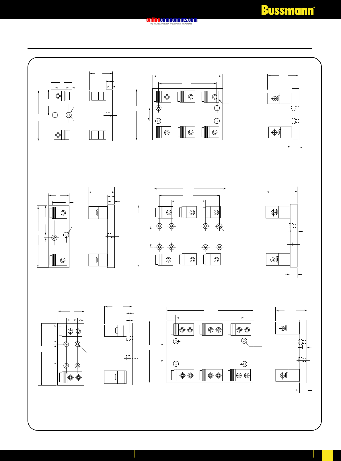
onlinecomponents.com
Fuseholders & Fusegear
For more information visit our website at www.bussmann.com 204
BIF document: 1114
Class J Fuseblocks
3.5"
1.75"
3"
.625"
.75"
C'Bore
.34"
DIA.
.5"
7.5"
1"
4"
.56"
.75"
3.1"
.31"
6.125"
3.06"
2"
3"
.5"
.75"
C'Bore
.34"
DIA.
FIGURE 5.
101-200A
201-400A
6.125"
7.00"
8.31"
1.69"
.344" Dia. hole thru
.750 Dia. c'bore
3.15"
.750"
FIGURE 6.
9.00"
10.51"
7.50"
2.00"
.344" Dia. hole thru
.750 Dia. c'bore
4.00"
1.00"
6.00"
.50
"
FIGURE 7. FIGURE 8.
.56"
8.875"
3.25"
1.75"
.75"
C'Bore
.34" Dia.
4"
2.375"
1.125"
1"
4.99"
401-600A
FIGURE 9.
8.875"
11.00"
14.144"
.344" Dia.
hole thru
.750 Dia.
c'bore
2.88"
4.987"
1.00"
.50"
FIGURE 10.
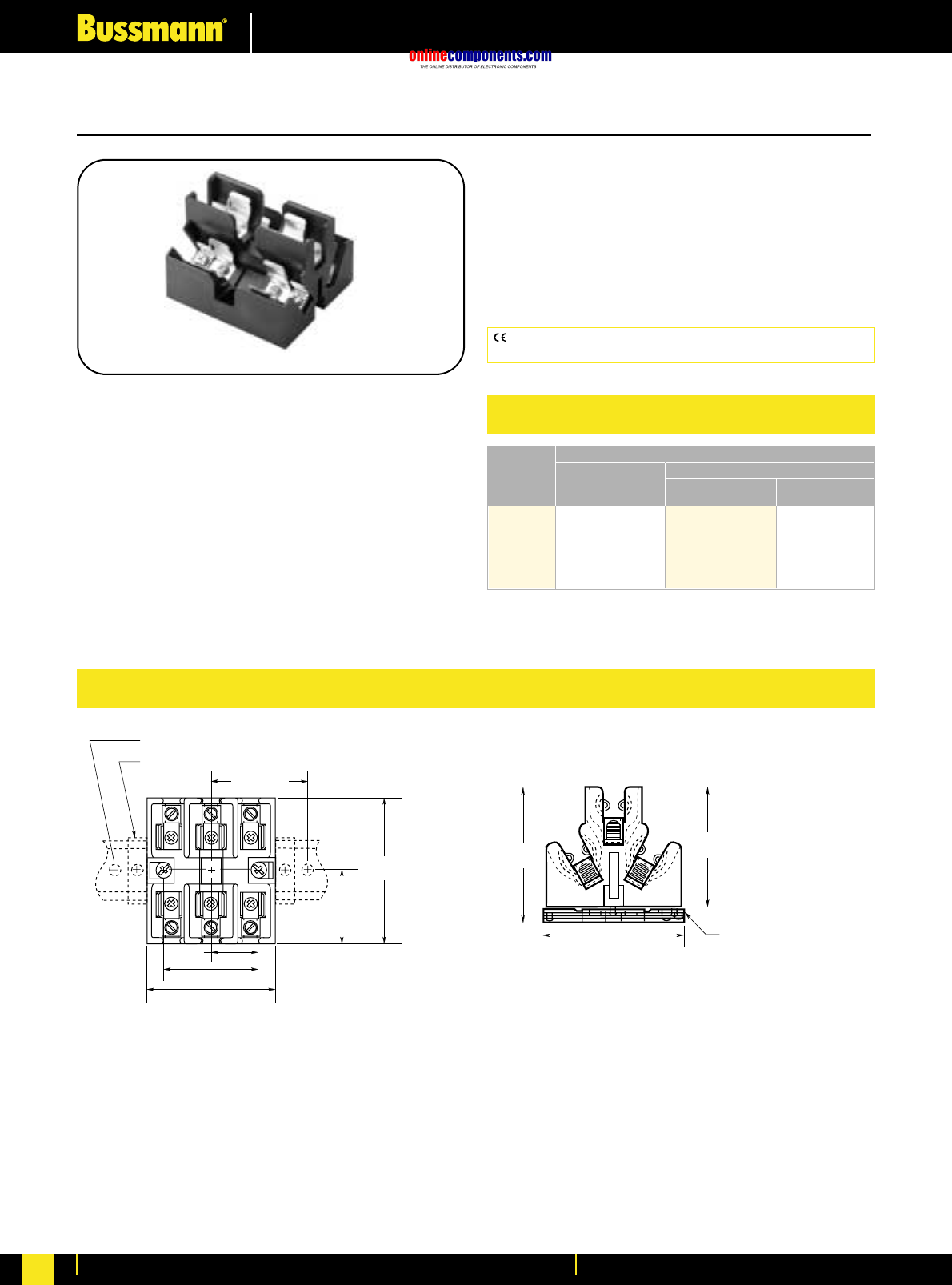
onlinecomponents.com
Fuseholders & Fusegear
For more information visit our website at www.bussmann.com
205
BIF document: 1108
Class J Fuseblocks
JP Series For use with Class J Fuses
(Bussmann LPJ,JKS).
Pyramid Style Fuseblock
Ampere Rating: 30 Amperes
Voltage Rating: 600 Volts
Withstand Rating: 200,000 RMS Sym. Amps
Agency Information:
U.L. Listed, U.L. 512, Guide IZLT, File E14853
CSA Certified, C22.2 No. 39, Class 4225-04, File 47235
Material: Thermoplastic
UL Flammability: UL 94V0
CE logo denotes compliance with European Union Low Voltage
Directive (50-1000 Vac, 75-1500 Vdc). Refer to BIF document #8002.
Mounting Catalogue Numbers
Screws with Box
Pressure Copper
Plate Aluminum Only
Panel JP60030-3PR JP60030-3CR JP60030-3COR
(#10-14 CU ONLY) (#2-14 CU/AL) (#2-14 CU ONLY)
With JP60030-3PRA JP60030-3CRA JP60030-CORA
DIN-Rail (#10-14 CU ONLY) (#2-14 CU/AL) (#2-14 CU ONLY)
Adapter*
*Adapter Only for DIN-Rail - Cat No. JPA-3.
Pyramid®J Fuseblock; 30A, 600V; 3-Pole; Panel or
35mm DIN-Rail Mount; Clips with Reinforcing Springs
ADAPTOR FOR 35mm
SYMMETRICAL DIN-RAIL MOUNTING
2.78"
(70.6mm)
3.06"
(77.8mm)
3.13"
(79.5mm)
3.29"
(83.6mm)
END STOPS - PREVENT BLOCK MOVEMENT WHEN CHANGING FUSES
DIN-RAIL MOUNTING SCREW 8" (203.2mm) APART
4.00" MAX.
(101.6mm)
1.19"
(30.2mm)
3.75" (±0.02)
(95.3mm (±0.50)
1.88"
(47.6mm)
2.38"
(60.4mm)
Dimensional Data *All other dimensions (± 0.015∑)
(± 0.40mm)
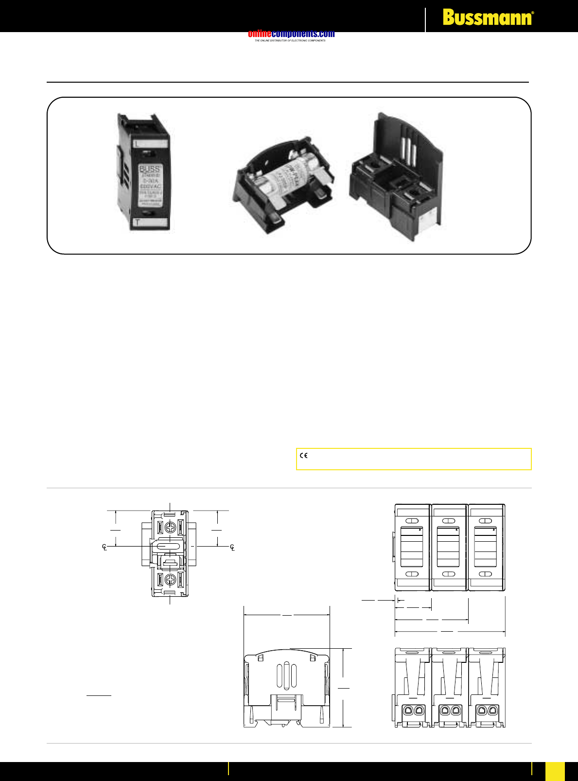
onlinecomponents.com
Fuseholders & Fusegear
For more information visit our website at www.bussmann.com 206
Listed to UL 512: Guide IZLT, File 14853
CSA Certified: Class 6225-01, File 47235
Indication: Min. voltage: 90 VAC, 115 VDC; Neon Lamp
“ON” when fuse opens, voltage source and current path
are present*
Finger-Safe: IP20 per IEC 60529
Terminations: 30A Dual Port Torque 20 lb. in.,
60A Single Port Torque 45 lb. in., Terminal Construction,
Tin plated Copper Alloy
Wire Size: JT(N)60030 - Rated for 75°C, AWG#18-#8;
CU only, JT(N)60060 - Rated for 75°C, AWG#14-#4;
CU only.
(Note: For JT(N)60030 use both stranded or solid, in a variety of
dual wire combinations of same wire type.)
Packaging: 12 in a carton
1.14
(29.0)
1.05
(26.7)
Slot
MOUNTING
Shown without fuse
pullout cover
BUSS
0 – 30A
600VAC
USE CLASS J
FUSES
DO NOT REMOVE
UNDER LOAD
JT60030
BUSS
0 – 30A
600VAC
USE CLASS J
FUSES
DO NOT REMOVE
UNDER LOAD
JT60030
BUSS
0 – 30A
600VAC
USE CLASS J
FUSES
DO NOT REMOVE
UNDER LOAD
JT60030
3.60
(91.4)
2.42
(61.3)
1.23
(31.2)
.07
(1.8)
1 pole
2 pole
3 pole
2.75
(69.9)
2.52
(64.1)
Din-rail
Dim. = in.
(mm.) JT60030
JTN60030
CE logo denotes compliance with European Union Low Voltage
Directive (50-1000V AC, 75-1500V DC). Refer to BIF document #8002.
Class J (Touch Safe) Fuseholders
JT(N)60030 and JT(N)60060
For use with Bussmann Class “J” fuses - (Bussmann LPJ, JKS)
Catalogue Numbers:
JT60030 and JT60060 - Non-Indicating
JTN60030 and JTN60060 - Indicating (Neon)
Construction: Thermoplastic, UL Flammability; 94VO
Voltage Ratings: 600 Volts
Amperage Rating: JT(N)60030 - 30 Amps.,
JT(N)60060 - 60 Amps
Withstand Rating: 200,000 Amps RMS Sym.
(Self Certified at 300,000 Amps using Bussmann
LPJ_SP fuses)
Agency Information:
Listed to UL 512: Guide IZLT, File 14853
BIF document: 1152
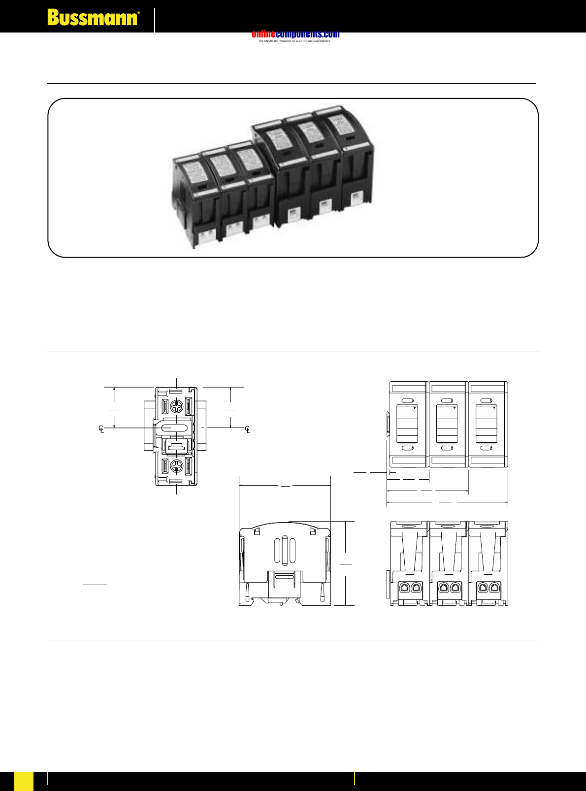
onlinecomponents.com
Fuseholders & Fusegear
For more information visit our website at www.bussmann.com
207
Class J (Touch Safe) Fuseholders
JT(N)600 Series fuseblocks can be dovetailed together within the same current rating to provide multiple pole block
configurations.
NOTE: JT(N)60030 cannot be dovetailed to JT(N)60060.
JT60060
Dim. = in.
3.10
(78.7)
3.06
(77.7)
1.31
(33.3)
1.25
(31.8)
Din-rail
Slot
MOUNTING
Shown without fuse
pullout cover
4.40
(111.7)
2.96
(75.2)
1.52
(38.1)
.10
(2.6)
BUSS
BUSS
35 – 60A
600VAC
USE CLASS J
FUSES
DO NOT REMOVE
UNDER LOAD
JT60060
BUSS
BUSS
35 – 60A
600VAC
USE CLASS J
FUSES
DO NOT REMOVE
UNDER LOAD
JT60060
BUSS
BUSS
35 – 60A
600VAC
USE CLASS J
FUSES
DO NOT REMOVE
UNDER LOAD
JT60060
1 pole
2 pole
3 pole
BIF document: 1152
JT60060
JTN60060
Dim. = in.
(mm.)
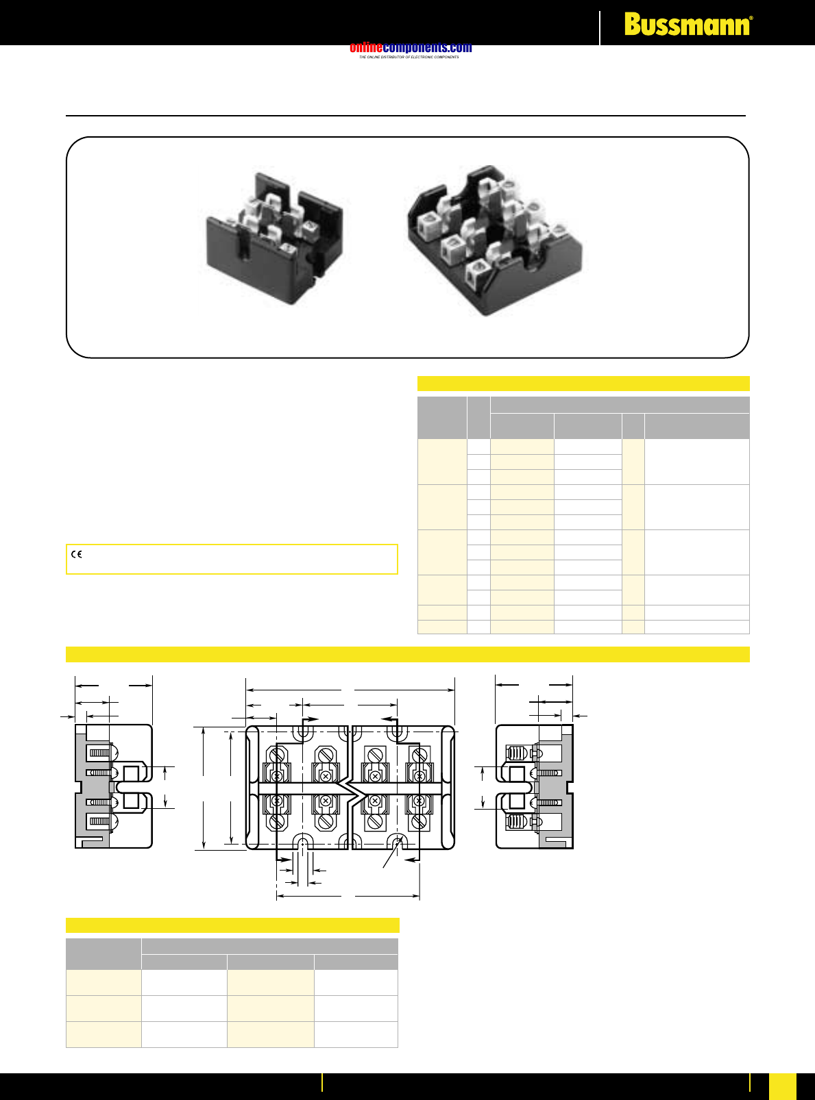
onlinecomponents.com
Fuseholders & Fusegear
For more information visit our website at www.bussmann.com 208
BIF document: 1115
Class T Fuseblocks - 300V
T30030-S
SECTION X-X
0.91"
1.63"
0.72"
0.16"
Z
XFull
Radius
ZX
0.44"
0.20"
C
B
1.20" A
0.69"
2.5"
2.75"
T30060-C
SECTION Z-Z
0.91"
1.63"
0.72"
0.16"
T300 (300V) For use with Class T Fuses
(Bussmann JJN)
Construction: Glass Polyester, Phenolic on 600A,
UL Flammability: 94VO
Rating: ⁄Ω™-600 Amps.
Withstand Rating: 200,000A RMS Sym.
Agency Information:
UL Listed UL512, Guide IZLT, File E14853
CSA Certified, Class 6225-01, File 47235.
Catalogue Numbers
Box Fig. Wire
Amps Screw Lug No. Range
2 T30030-2SR T30030-2CR SR #10-18 CU
⁄Ω™-30 3 T30030-3SR T30030-3CR 1
4 T30030-4SR T30030-4CR CR #6-14 CU-Al
2 T30060-2SR T30060-2CR
31-60 3 T30060-3SR T30060-3CR 1 CR #2-14 CU-Al
4 T30060-4SR T30060-4CR SR #10-18 CU ONLY
1—T30100-1CR
61-100 2 —T30100-2CR 2 1/0-8 CU-Al
3—T30100-3CR
1—T30200-1C 3 250kcmil-6 CU-Al
101-200 3—T30200-3C 4
201-400 1 —T30400-1C 5 600kcmil-2/0 CU-Al
401-600 1 —T30600-1C 6 (2) 600kcmil-4/0 CU-Al
CE logo denotes compliance with European Union Low Voltage
Directive (50-1000V AC, 75-1500V DC). Refer to BIF document #8002.
Block Dimensions (Inches)
Type A B C
T30030-2 2.41 —1.03
T30060-2
T30030-3 3.44 1.03 2.06
T30060-3
T30030-4 4.47 2.06 3.09
T30060-4
Class T Fuseblocks (300V) Catalogue Data
Dimensional Data Figure 1.⁄Ω™A to 60A
Class T Fuseblocks (300V) Catalogue Numbers
Poles
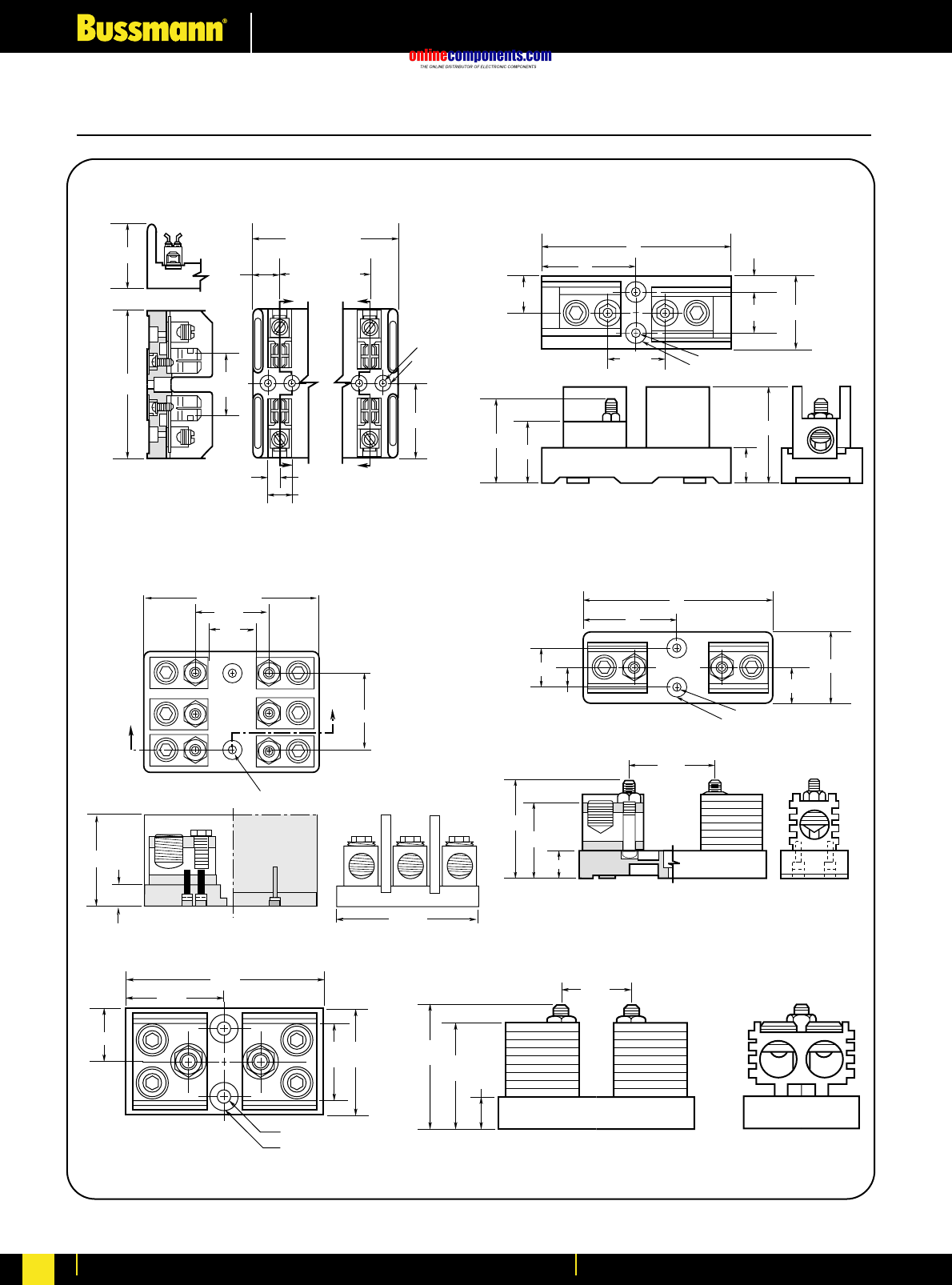
onlinecomponents.com
Fuseholders & Fusegear
For more information visit our website at www.bussmann.com
209
Class T Fuseblocks – 300V
BIF document: 1115
Z
Z
0.52" C'BORE
0.55" DEEP
0.22" DIA.
X
X
2.39"
2.25"
REF.
4.78"
2.06"
1.69" (1 POLE)
3.09" (2 POLE)
4.5" (3 POLE)
1.41" (2 POLE)
2.81" (3 POLE)
0.84"
0.38"
0.75"
0.625" C'BORE 0.438" DEEP
0.282" DIAMETER THRU HOLE
.996"
A
A2.75"
1.695"
4.87"
0.625"
2.375"
4.46"
Figure 2. 61A to 100A
3"
6"
0.28" DIAMETER
0.63" C'BORE 0.5" DEEP
1.125"
2.56" 1.94" 0.81"
3.06"
1.69"
0.05"
1.25" 2.25"
Figure 3. 101A to 200A
Figure 4. 200A
0.63" C'BORE 0.5" DEEP
6"
0.28" DIAMETER
1.125"
2.25"
0.63"
3"
1.25"
1.84"
0.81"
2.38"
3.06"
Figure 5. 201A to 400A
3.44"
0.75"
3"
2.03"
3"2"
1.5"
5.75"
2.88"
0.33" DIAMETER
0.75" C'BORE 0.5" DEEP
Figure 6. 401A to 600A
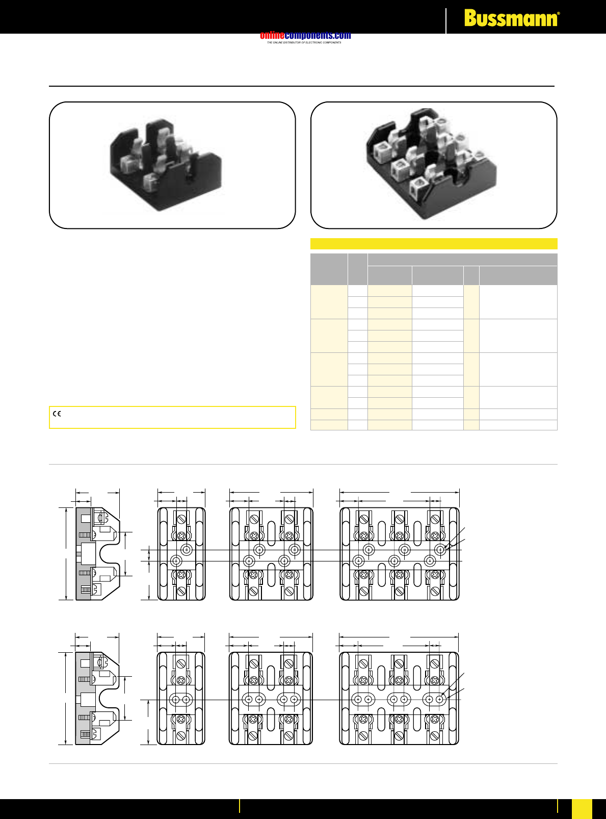
onlinecomponents.com
Fuseholders & Fusegear
For more information visit our website at www.bussmann.com 210
BIF document: 1116
Figure 1. ⁄Ω™A to 30A
3.19"
1.44"
1.563"
0.33"
1.42"
0.5"
1.44"
0.55" 0.33" 0.55"
2.59"
1.16" 0.33" 0.55"
3.75"
2.31" 0.33"
0.22" DIAMETER
0.5" C'BORE
2.94"
1.75"
1.63"
1.47"
0.5"
1.81"
0.59" 0.63" 0.59"
3.34"
1.53" 0.63" 0.59"
4.86"
3.06" 0.63"
0.22" DIAMETER
0.5" C'BORE
Figure 2. 31A to 60A
Class T Fuseblocks – 600V
T600 (600V) For use with Class T Fuses
(Bussmann JJS)
Construction: Glass Polyester, Phenolic on 600A,
UL Flammability: 94VO
Rating: ⁄Ω™-600 Amps.
Withstand Rating: 200,000A RMS Sym.
Agency Information:
UL Listed UL512, Guide IZLT, File E14853
CSA Certified, Class 6225-01, File 47235.
Catalogue Numbers
Box Fig. Wire
Amps Screw Lug No. Range
1 T60030-1SR T60030-1CR SR #10-18 CU
⁄Ω™-30 2 T60030-2SR T60030-2CR 1
3 T60030-3SR T60030-3CR CR #2-14 CU-AL
1 T60060-1SR T60060-1CR CR #2-14 CU-AL
31-60 2 T60060-2SR T60060-2CR 2
3 T60060-3SR T60060-3CR SR #10-18 CU ONLY
1—T60100-1C
61-100 2 —T60100-2C 3 2/0-14 CU-AL
3—T60100-3C
101-200 1—T60200-1C 4 250kcmil-6 CU-AL
3—1B0089*
201-400 1 —T60400-1C 5 600kcmil-2/0 CU-AL
401-600 1 —T60600-1C 6 (2) 600kcmil-4/0 CU-AL
* UL Listed, Guide IZLT, File E14853,
CSA Certified Class 6225-01, File 21455M18
CE logo denotes compliance with European Union Low Voltage
Directive (50-1000V AC, 75-1500V DC). Refer to BIF document #8002.
Class T Fuseblocks (600V) Catalogue Data
Poles
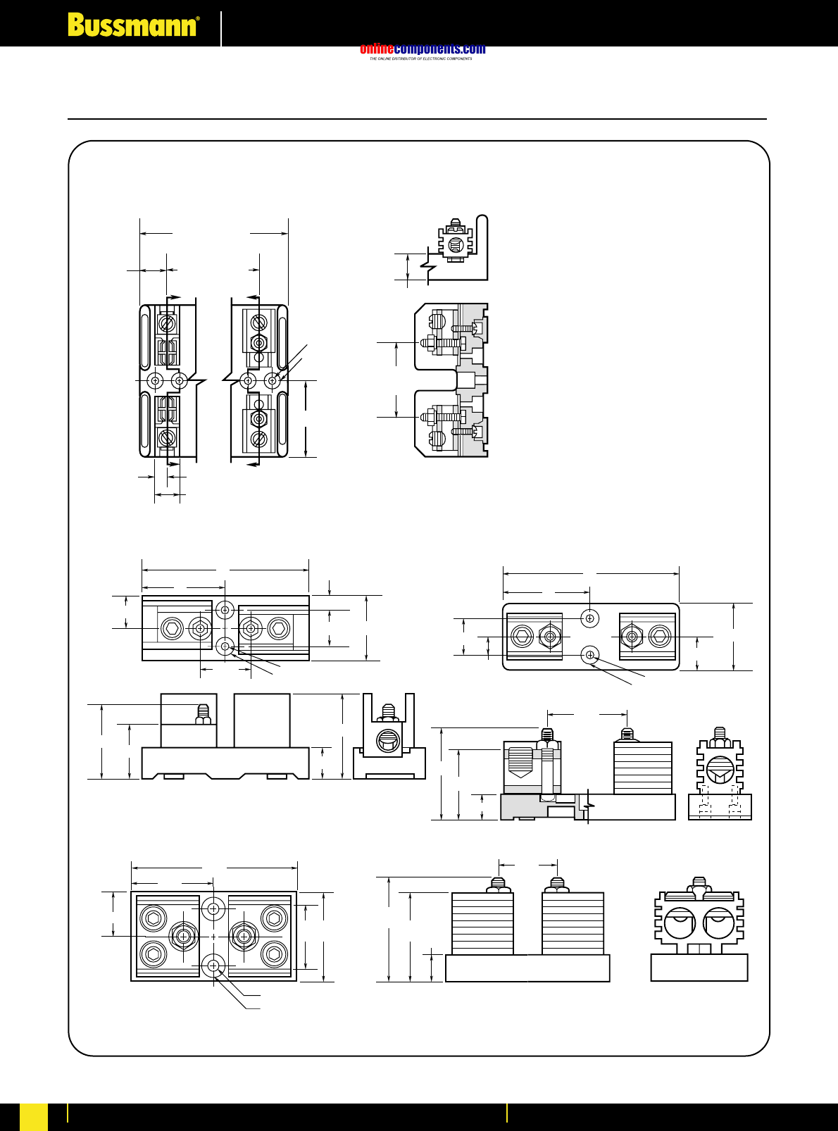
onlinecomponents.com
Fuseholders & Fusegear
For more information visit our website at www.bussmann.com
211
Class T Fuseblocks – 600V
BIF document: 1116
Figure 5. 201A to 400A
0.63" C'BORE 0.5" DEEP
6"
0.28" DIAMETER
1.125"
2.25"
0.63"
3"
1.25"
1.84"
0.81"
2.38"
3.06"
Figure 4. 101A to 200A
3"
6"
0.28" DIAMETER
0.63" C'BORE 0.5" DEEP
1.125"
2.56" 1.94" 0.81"
3.06"
2.5"
0.05"
1.25" 2.25"
Figure 3. 61A to 100A
Z
Z
0.52" C'BORE
0.55" DEEP
0.22" DIA.
X
X
2.39"
1.69" (1 POLE)
3.09" (2 POLE)
4.5" (3 POLE)
1.41" (2 POLE)
2.81" (3 POLE)
0.84"
0.38" SECTION Z-Z
0.78"
2.34"
REF.
0.75"
Figure 6. 401A to 600A
3.44"
0.75"
3"
2.95"
3"2"
1.5"
6.75"
3.38"
0.33" DIAMETER
0.75" C'BORE 0.5" DEEP
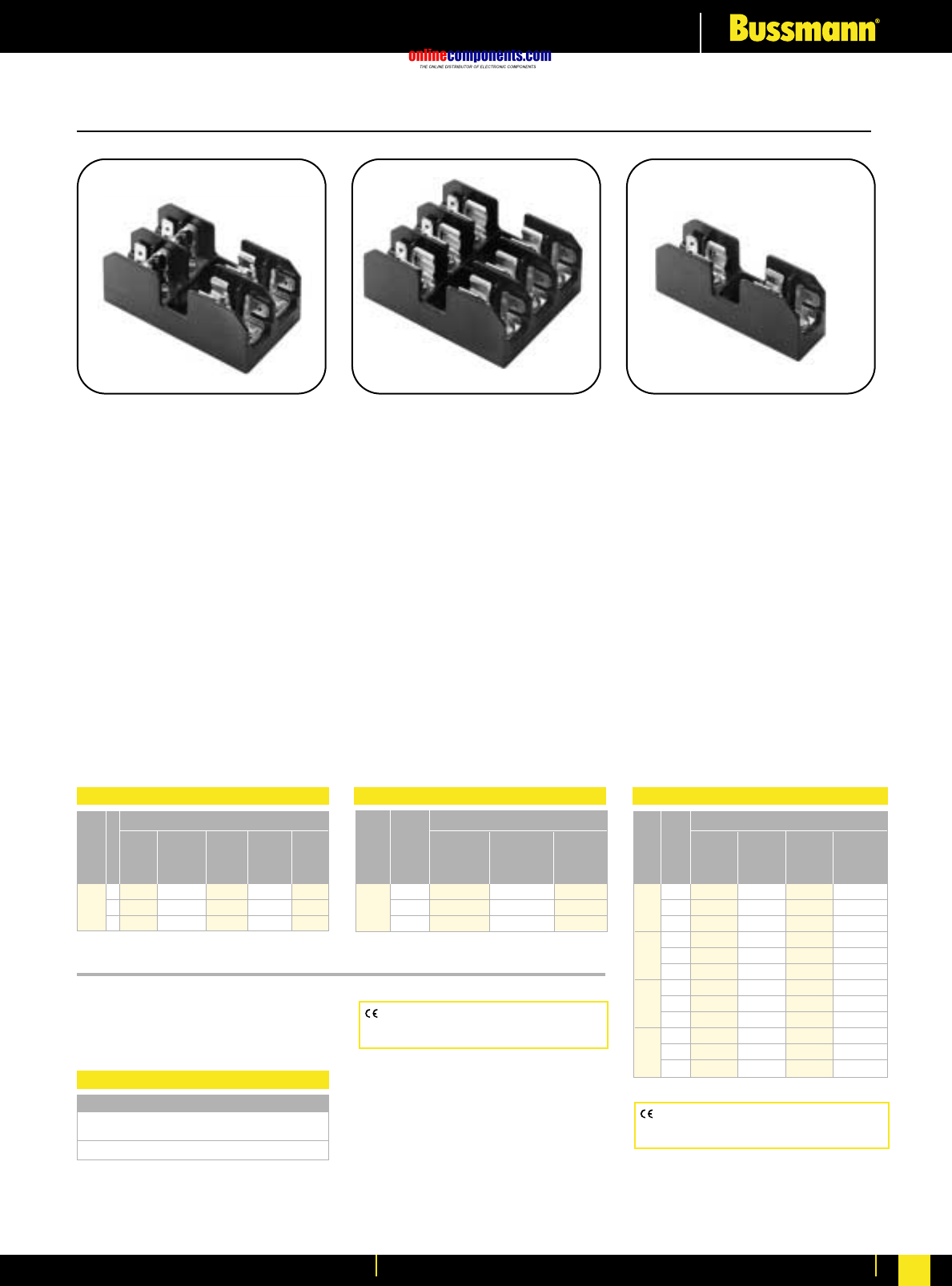
onlinecomponents.com
Fuseholders & Fusegear
For more information visit our website at www.bussmann.com 212
BIF document: 1104
BIF document: 1105
BIF document: 1106
Class CC, Type M and Class G Fuseblocks
BC Series
Class CC Fuseblocks
For use with Class CC Fuses
(Bussmann LP-CC, KTK-R, and FNQ-R)
Construction:
Base - Thermoplastic
Clips - Bright tin-plated bronze
Ratings: 600V, 30A
Withstand Rating:
200,000A RMS Sym.
Agency Information:
UL Listed (Guide IZLT,
File E14853)
CSA (Class 6225-01, File 47235)
UL Flammability: 94VO
Dimensional Data:
See BIF document.
BM Series Type M
Supplementary Fuseblocks
For use with any ⁄‹Ω£™∑ ≈ 1⁄Ω™∑ Fuses
(Bussmann KTK, FNQ, FNM, BAF,
BAN, and AGU)
Construction: Thermoplastic
Ratings: 600V, 30A
Withstand Rating:
10,000A RMS Sym.
Agency Information:
UL Recognized (Guide IZLT2,
File E14853)
CSA (Class 6225-01, File 47235)
UL Flammability: 94VO
Dimensional Data:
See BIF document.
BG Series and G Series
Class G Fuseblocks
For use with Class G Fuses
(Bussmann SC)
Construction: (0-30) Thermoplastic
(35-60) Phenolic
Ratings: 600V or less, 0-20A
480V or less, 25-60A
Withstand Rating:
100,000A RMS Sym.
Agency Information:
UL Listed 35-60A (Guide IZLT,
File E14853)
UL Recognized 1-30A, (Guide IZLT2,
File E14853)
CSA (Class 6225-01, File 47235)
Dimensional Data:
See BIF document.
Catalogue Data
Catalogue Data
Catalogue Data Catalogue Data
Terminal Type
Screw Pressure
with Plate w/
Quick Pressure Quick Box
Amps Screw Connect* Plate Connect* Lug
⁄Ω¡º 1 BC6031S BC6031SQ BC6031P BC6031PQ BC6031B
to 2 BC6032S BC6032SQ BC6032P BC6032PQ BC6032B
30 3 BC6033S BC6033SQ BC6033P BC6033PQ BC6033B
Poles
Terminal Type
Screw Pressure
with Plate w/
Quick Quick Box
Amps Poles Connect
*
Connect
*
Lug
⁄Ω¡º 1 BM6031SQ BM6031PQ BM6031B
to 2 BM6032SQ BM6032PQ BM6032B
30 3 BM6033SQ BM6033PQ BM6033B
Terminal Type
Screw Pressure
with Plate w/
Quick Quick Box Box Lug
Amps Poles Connect* Connect* Lug w/clip
1 1 BG3011SQ BG3011PQ BG3011B —
to 2 BG3012SQ BG3012PQ BG3012B —
15 3 BG3013SQ BG3013PQ BG3013B —
1 BG3021SQ BG3021PQ BG3021B —
20 2 BG3022SQ BG3022PQ BG3022B —
3 BG3023SQ BG3023PQ BG3023B —
25 1 BG3031S BG3031P BG3031B —
to 2 BG3032S BG3032P BG3032B —
30 3 BG3033S BG3033P BG3033B —
35 1 ———G30060-1CR
to 2 ———G30060-2CR
60 3 ——G30060-3C G30060-3CR
CE logo denotes compliance with European
Union Low Voltage Directive (50-1000V AC,
75-1500V DC). Refer to BIF document #8002.
CE logo denotes compliance with European
Union Low Voltage Directive (50-1000V AC,
75-1500V DC). Refer to BIF document #8002.
Terminal Type
Screw with Pressure Plate
Quick Connect* w/Quick Connect*
BCCM6033SQ BCCM6033PQ
BCCM Series
For use with (2) Class CC Fuses and
(1) ⁄‹Ω£™x 1⁄Ω™Fuse.
*Quick connect terminal rated for 20A max.
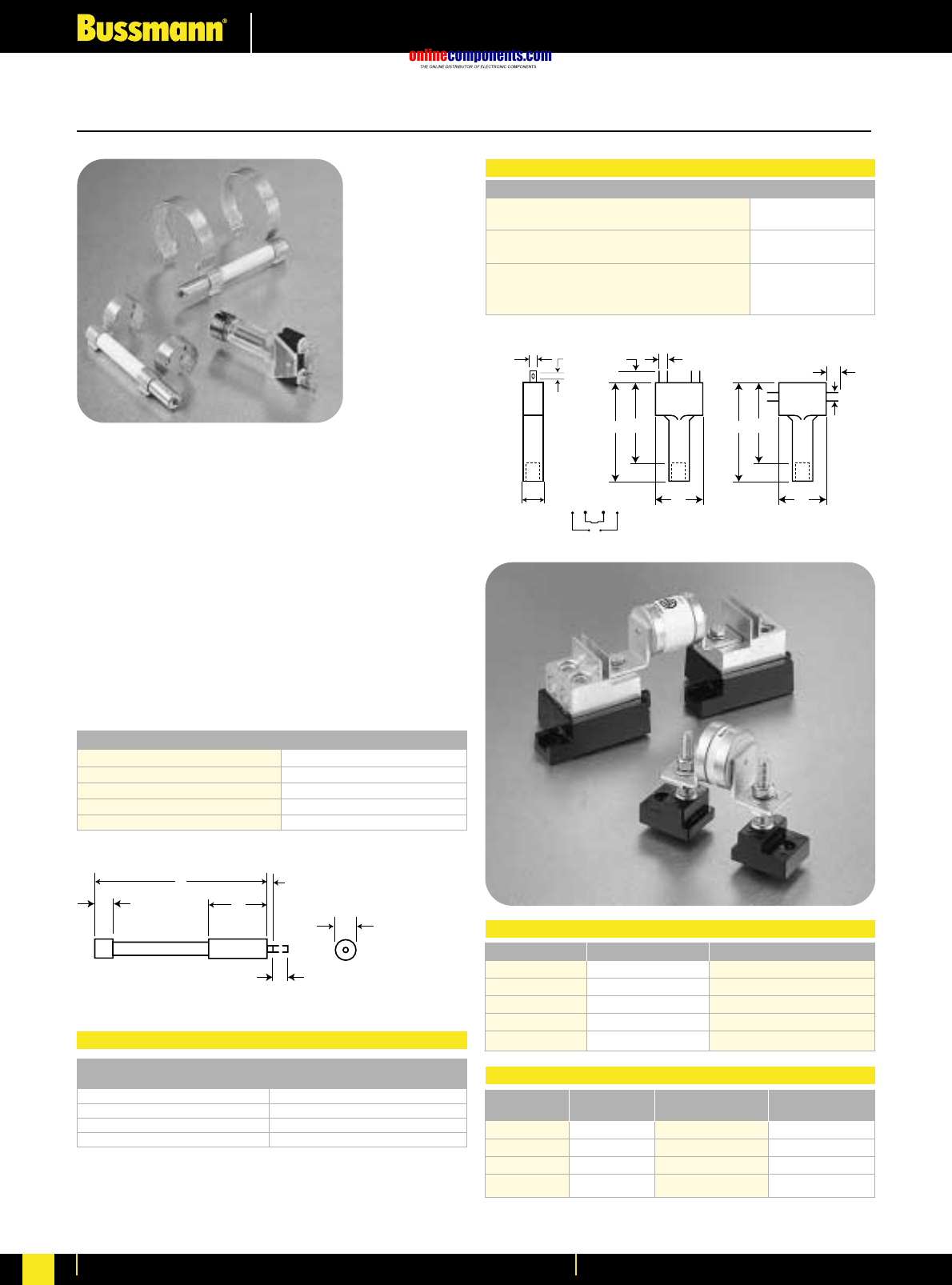
onlinecomponents.com
Fuseholders & Fusegear
For more information visit our website at www.bussmann.com
213
BIF document: 720037
High Speed Fuseholder and Indicators
Trip-indicator fuselinks are available for use in parallel
with the main fuselinks. They can either be attached to
the associated fuselink or mounted separately in panel
mounted fuse clips, Part No. CL1. A push-on adaptor
and microswitch attachment is available for use with the
trip indicator to give the facility of remote indication,
reference MAI or MBI.
Fuse ratings of 20A and below cannot usually accommodate
a trip fuselink in parallel.
Where trip indicator fuselinks are to be attached to the main
fuselink, an accessory pack comprising a pair of mounting
clips and an appropriate trip indicator fuselink
will be required.
The ordering code references for these packs are listed
below:
621
A0.8
6.35
6
2.8 2.4 3.6
3.6
5.2
5.2
21 21
36
44 36
44
9.5
NC NC NONO MAI or MBI
Fuse Type Order Ref. Fuse Type Order Ref.
ET EC-600 FM MC-600
EET EC-600 FMM MC-600
FE EC-600 LMT MC-250
FEE EC-600 LMMT MC-250
LET EC-250
Dim. ‘A’ Voltage Dim. ‘A’ Voltage
Type Max. Rating Type Max. Rating
TI250 37.6 250 TI1100 98.4 1100
TI500 47.5 500 TI1500 120.8 1500
TI600 55.7 600 TI2000 147.5 2000
TI700 61.8 700 TI2500 198.3 2500
Part No. Stud Height Stud Dia. & Threads
C5268-1 1.00∑ fiΩ¡§-18
C5268-2 1.75∑ fiΩ¡§-18
C5268-3 0.75∑ fiΩ¡§-18
C5268-4 1.00∑ ⁄Ω¢-20
C5268-5 1.75∑ ⁄Ω¢-20
Dimensions in mm.
1mm = 0.0394∑ 1∑ = 25.4mm
Trip Indicator
Universal and Stud Fuseblocks
MAI or MBI
Trip-indicator Fuselink Data
Microswitch and Adaptor Type MAI
Current Rating:
AC 50/60Hz resistive load @ 250 VRMS 4A
AC 50/60Hz resistive load @ 127 VRMS 6A
DC, resistive load @ 110 Vdc 0.7
DC, resistive load @ 30 Vdc 2
Maximum Working Voltage:
Contact-to-contact (RMS) 1000V
Contact-to-contact (RMS) 1500V
Stud Fuseblocks
Modular Max. Max. Fuse BIF
Base Voltage Current Rating Document
1BS101 600V 100A 1206
1BS102 600V 400A 1207
1BS103 600V 400A 1208
1BS104 600V 600A 1209
Universal Fuseblocks
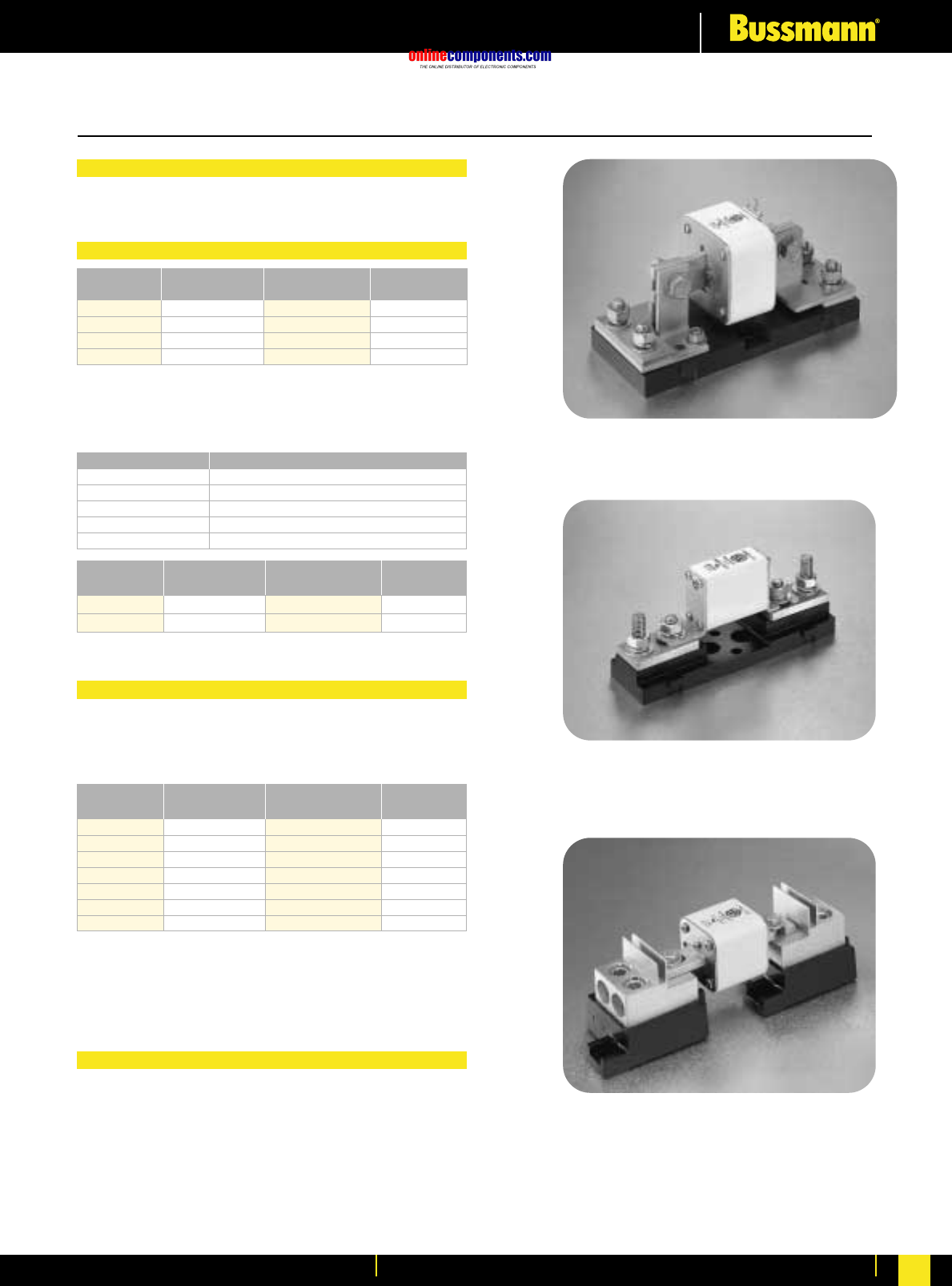
onlinecomponents.com
Fuseholders & Fusegear
For more information visit our website at www.bussmann.com 214
1BS104
170H3003
170H1007
Fuse Bases (Blocks)
Part Max. Rated Centre
Number Voltage Current Distance
170H3003 1000V 630A 80mm
170H3004 1000V 1250A 80mm
170H3005 1400V 630A 110mm
170H3006 1400V 1250A 110mm
Universal Fuseblocks
Universal Fuse Bases
DIN 43 620 Fuse Bases
For the Typower ZILOX fuses according to DIN 43 653,
the following fuse bases are available:
DIN 43 653 Fuse Bases
The fuse bases rated 1250A can also be used for the fuses
with higher rated current if the maximum load current is
derated according to the table below:
Fuse Rating Max. Load Current In Fuse Base
1400A 1325A
1500A 1400A
1600A 1500A
1800A 1650A
2000A 1800A
Fixed Center Max. Fuse Fuse
Base Style Max. Voltage Current Rating Size
170H1007 1000V 400A 00, 000
170H1013 660V 200A 0000,000
U.L. Recognized to U.L. 512.
Modular Max. Fuse BIF
Base Style Max. Voltage Current Rating Document
1BS101 600V 100A 1206
1BS102 600V 400A 1207
1BS103 600V 400A 1208
1BS104 600V 600A 1209
BH-0XXX 700V 100A 1200
BH-1XXX 2500V 400A 1201
BH-2XXX 5000V 400A 1202
For the Typower ZILOX fuses according to DIN 43 653,
French style and North American style, the following fuse
bases are available:
Modular fuse bases are U.L. Recognized to U.L. 512 and
meet the spacing requirements of U.L. 347. Contact
Bussmann sales representative for more complete ordering
information.
For fuse bases used with Typower ZILOX fuses according to
DIN 43 620, please contact your local Bussmann sales
representative.
BIF document: 720036
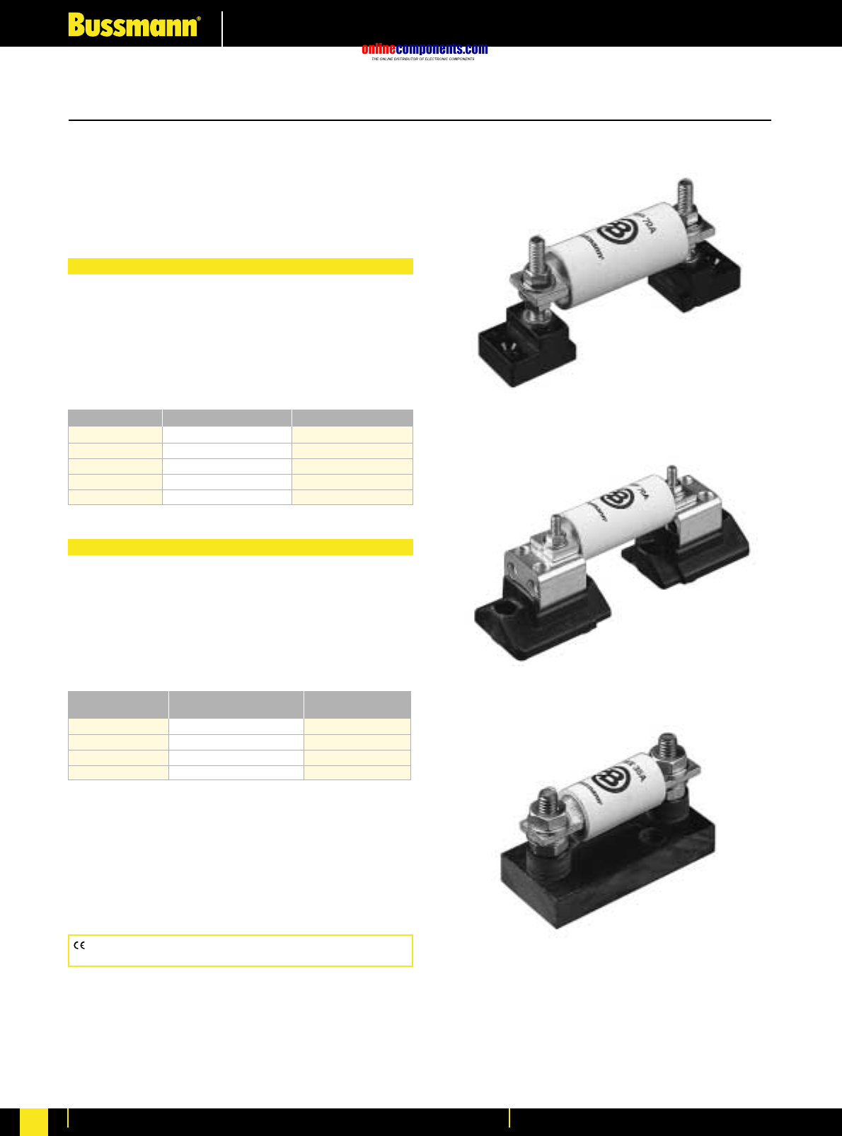
onlinecomponents.com
Fuseholders & Fusegear
For more information visit our website at www.bussmann.com
215
North American Style Fuseblocks
Stud Type
Connector Type
BIF document: 720033
Fixed Centre Base Style
Bussmann offers a comprehensive line of fixed mount style fuse
bases under the trademark TRON®Rectifier Fuseblocks. The
cable and fuse connections are similar to the Stud Type fuse
base — both are mounted on the same stud. Consult
Bussmann for complete product details.
CE logo denotes compliance with European Union Low Voltage Directive
(50-1000V AC, 75-1500V DC). Refer to BIF document #8002.
Modular Style
Bussmann offers a comprehensive line of fuse bases that
provide the user with design and manufacturing flexibility. Two
identical half bases make up a Buss Modular fuse base.
These “split” units can be panel mounted any distance
apart to accommodate any length fuse.
The simpler design is the C5268 Series Modular fuse
base. With this design, the fuse terminal and cable (with
termination) are mounted on the same stud, minimizing labor
needed for installation. The stud Type Base is available in the
configuration shown in the table below. (Must order 2 pieces
per fuse, they do not come in pairs.)
Part No. Stud Heights Stud Dia. & Threads
C5268-1 1.00∑fiΩ¡§-18
C5268-2 1.75∑fiΩ¡§-18
C5268-3 0.75∑fiΩ¡§-18
C5268-4 1.00∑⁄Ω¢-20
C5268-5 1.75∑⁄Ω¢-20
Bussmann also offers a modular style fuse base that
utilizes a tin plated connector (for wire termination and heat
dissipation) and a plated steel stud (for fuse mounting). The
connector type fuse base is available in the configurations
shown below. Consult Bussmann for additional product
details. (Order 1 piece per fuse, parts come in pairs.)
Modular Max. Fuse
Base Style Max. Voltage Current Rating
BH-0 Series 700V 100A
BH-1 Series 2500V 400A
BH-2 Series 5000V 400A
BH-3 Series 1250V 700A
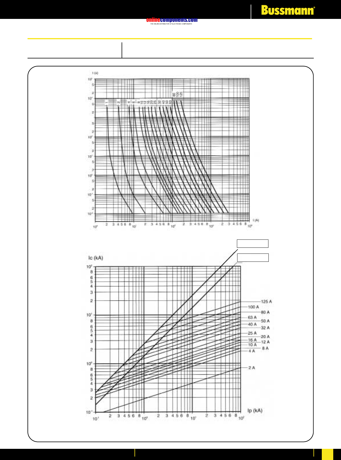
onlinecomponents.com
Electrical Characteristics
For more information visit our website at www.bussmann.com 216
1A to 125A CLASS: gG
Time/Current Characteristics
PRE-ARCING TIME (S)
MAXIMUM VALUE OF CURRENT (kA PEAK)
Ic = √2.Ip
Ic = √2.Ip.1.8
PROSPECTIVE CURRENT (R.M.S. A)
PROSPECTIVE CURRENT (R.M.S. A)
Cut-off Characteristics
IEC Cylindrical Fuse Links: Performance Data
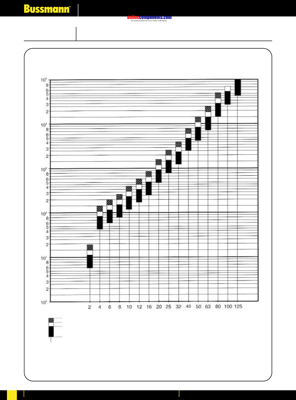
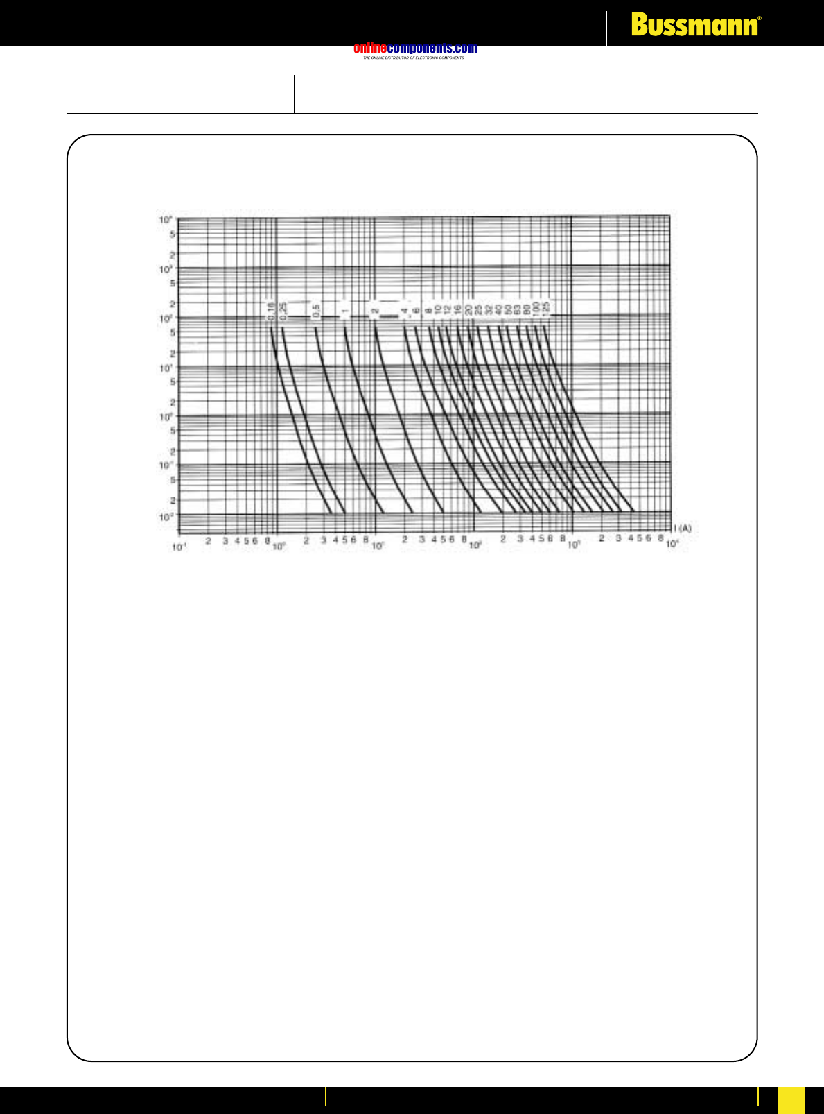
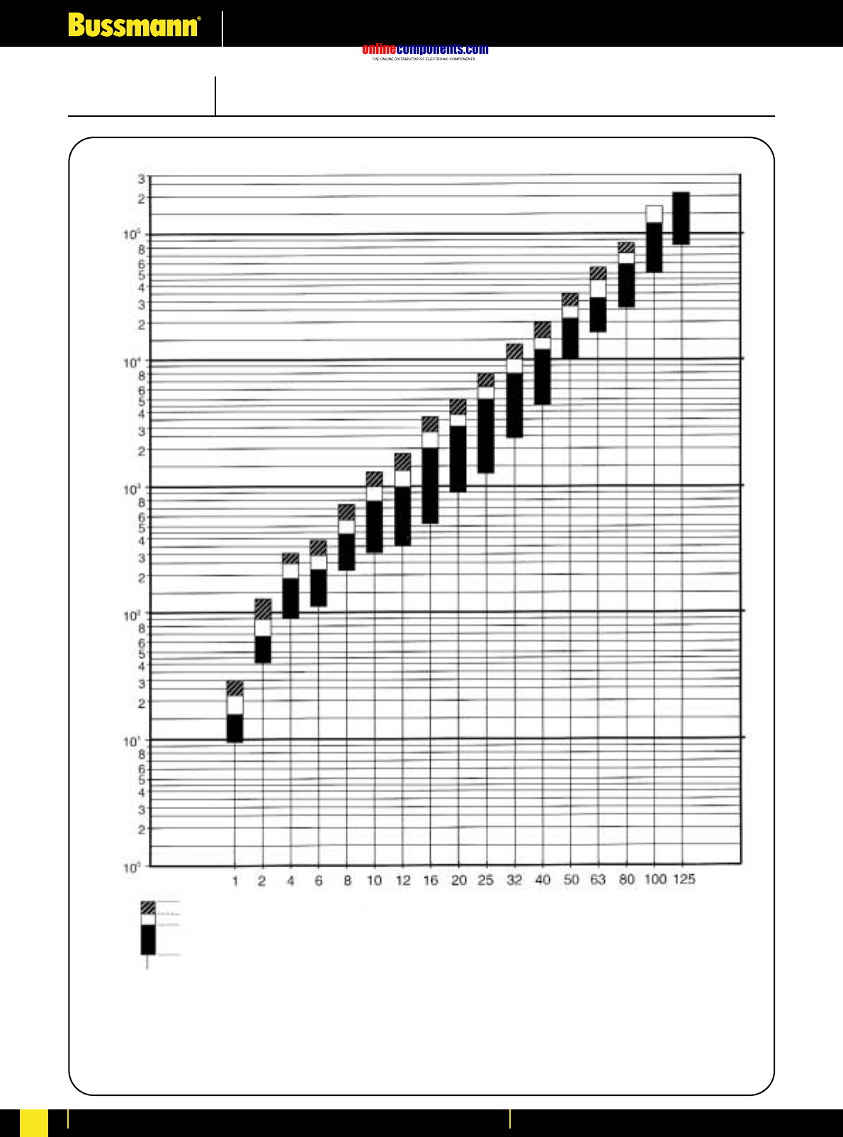
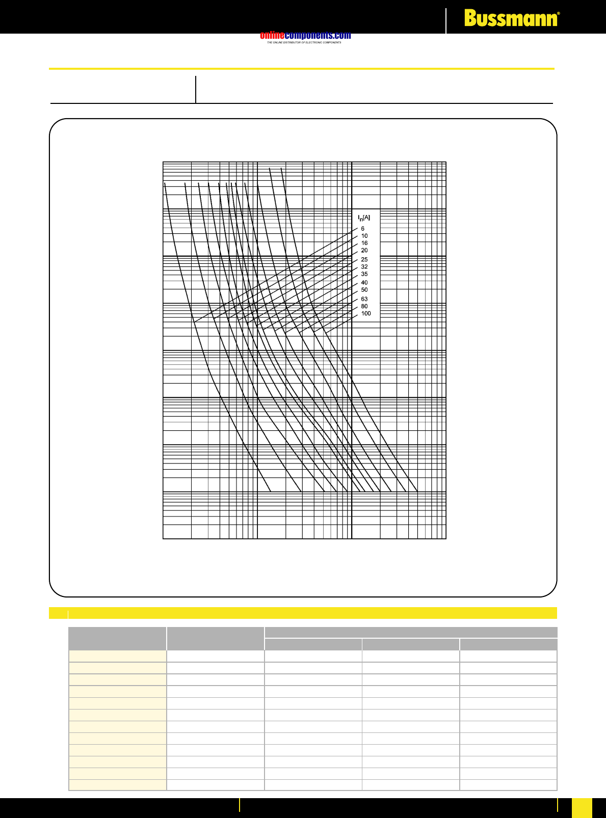
onlinecomponents.com
Electrical Characteristics
For more information visit our website at www.bussmann.com 220
350
1100
2200
4100
6300
10500
12000
18000
25000
42000
80000
130000
6
10
16
20
25
32
35
40
50
63
80
100
6NHC00G
10NHC00G
16NHC00G
20NHC00G
25NHC00G
32NHC00G
35NHC00G
40NHC00G
50NHC00G
63NHC00G
80NHC00G
100NHC00G
20
110
230
650
1200
2000
3500
4500
4850
6100
7000
14000
140
500
1100
1900
3000
5000
6000
8000
14000
29000
39000
55000
Bussmann
Part Number Rated Current
RMS-Amps Pre Arcing at 500Vac 20 x Inat 500Vac
I2t (A2S)
PRE-ARCING TIME IN SECONDS
RMS SYMMETRICAL PROSPECTIVE CURRENT IN AMPERES
Time Current Characteristics
104
103
102
10
1
10-1
10-4
10 100 1000 10000
10-3
10-2
I1120kA at 500Vac
SIZE: C00 (000) CLASS: gG/gL 500V AC
Electrical Characteristics
I2tCharacteristics
NH Low Voltage Industrial Fuse Links
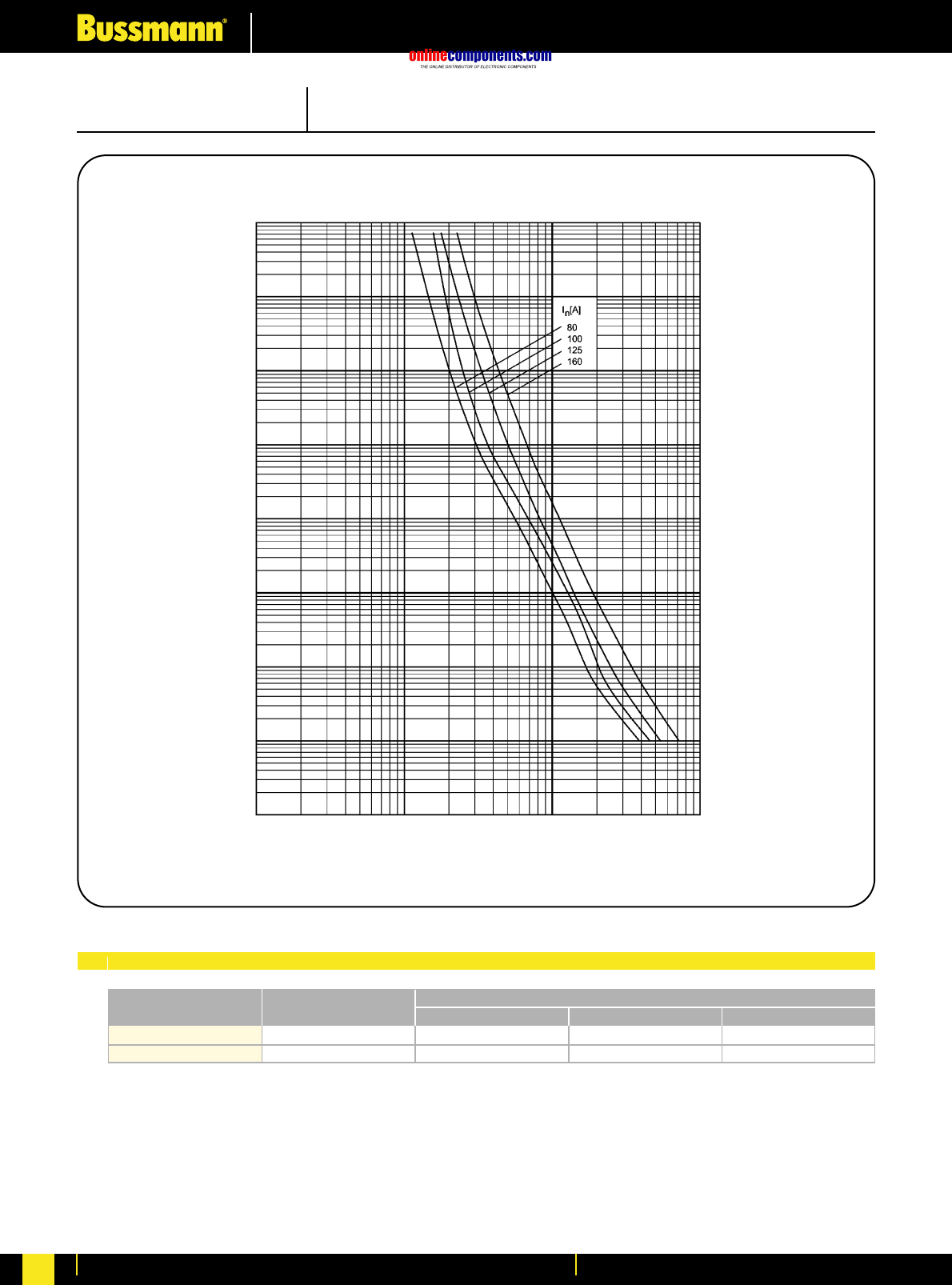
onlinecomponents.com
Electrical Characteristics
For more information visit our website at www.bussmann.com
221
SIZE: 00 CLASS: gG/gL 500V AC
Electrical Characteristics
PRE-ARCING TIME IN SECONDS
RMS SYMMETRICAL PROSPECTIVE CURRENT IN AMPERES
Time Current Characteristics
104
103
102
10
1
10-1
10-4
10 100 1000 10000
10-3
10-2
190000
230000
125
160
125NH00G
160NH00G
31000
40000 88000
140000
Bussmann
Part Number Rated Current
RMS-Amps Pre Arcing at 500Vac 20 x Inat 500Vac
I2t (A2S)
I1120kA at 500Vac
I2tCharacteristics
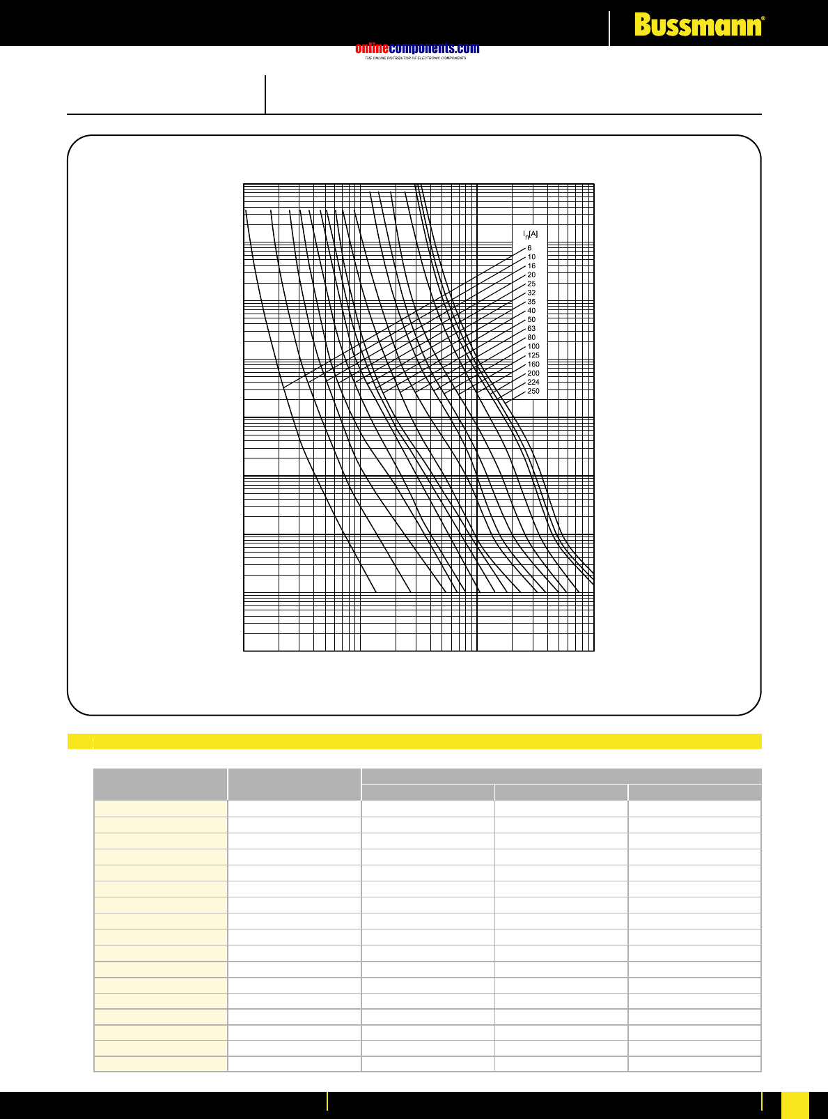
onlinecomponents.com
Electrical Characteristics
For more information visit our website at www.bussmann.com 222
SIZE: 1 CLASS: gG/gL 500V AC
Electrical Characteristics
PRE-ARCING TIME IN SECONDS
RMS SYMMETRICAL PROSPECTIVE CURRENT IN AMPERES
Time Current Characteristics
104
103
102
10
1
10-1
10-4
10 100 1000 10000
10-3
10-2
350
1100
2200
4100
6300
10500
12000
18000
25000
42000
80000
130000
190000
230000
390000
460000
580000
6
10
16
20
25
32
35
40
50
63
80
100
125
160
200
224
250
6NH1G
10NH1G
16NH1G
20NH1G
25NH1G
32NH1G
35NH1G
40NH1G
50NH1G
63NH1G
80NH1G
100NH1G
125NH1G
160NH1G
200NH1G
224NH1G
250NH1G
20
140
330
820
1350
2000
2700
4500
5000
9000
13000
21000
26000
55000
95000
120000
140000
140
500
1100
1900
3000
5000
6000
8000
14000
29000
39000
55000
88000
120000
210000
270000
390000
Bussmann
Part Number Rated Current
RMS-Amps Pre Arcing at 500Vac 20 x Inat 500Vac
I2t (A2S)
I1120kA at 500Vac
I2tCharacteristics
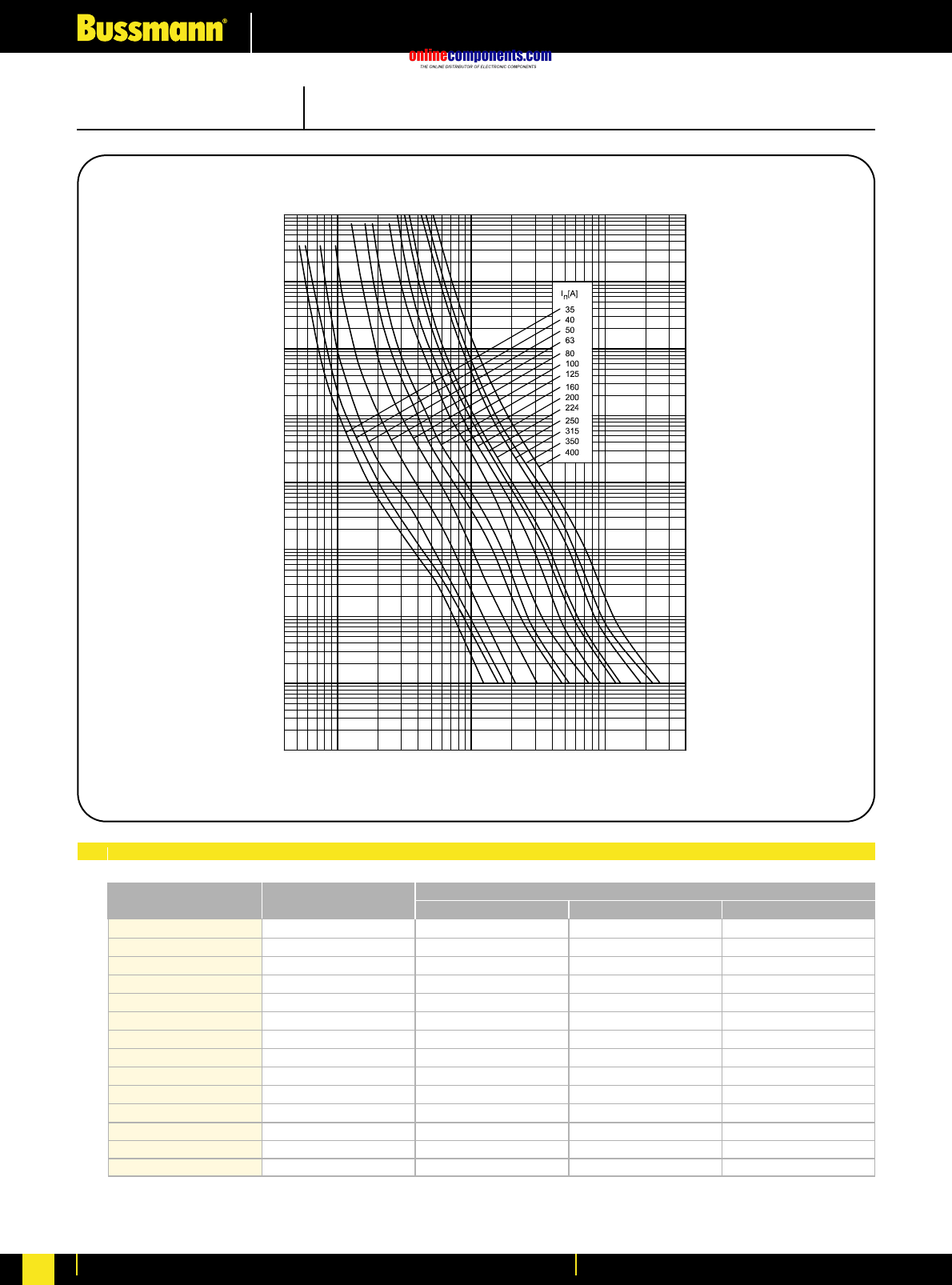
onlinecomponents.com
Electrical Characteristics
For more information visit our website at www.bussmann.com
223
SIZE: 2 CLASS: gG/ggL 500V AC
Electrical Characteristics
12000
18000
25000
42000
80000
130000
190000
230000
390000
460000
580000
1150000
1350000
2000000
35
40
50
63
80
100
125
160
200
224
250
315
350
400
35NH2G
40NH2G
50NH2G
63NH2G
80NH2G
100NH2G
125NH2G
160NH2G
200NH2G
224NH2G
250NH2G
315NH2G
350NH2G
400NH2G
2700
4000
4500
7100
11000
17000
24000
50000
95000
120000
140000
290000
400000
600000
6000
8000
14000
29000
39000
55000
88000
140000
210000
270000
390000
800000
1050000
1500000
Bussmann
Part Number Rated Current
RMS-Amps Pre Arcing at 500Vac 20 x Inat 500Vac
I2t (A2S)
I1120kA at 500Vac
PRE-ARCING TIME IN SECONDS
RMS SYMMETRICAL PROSPECTIVE CURRENT IN AMPERES
Time Current Characteristics
104
103
102
10
1
10-1
10-4
10 100 1000 10000
10-3
10-2
I2tCharacteristics
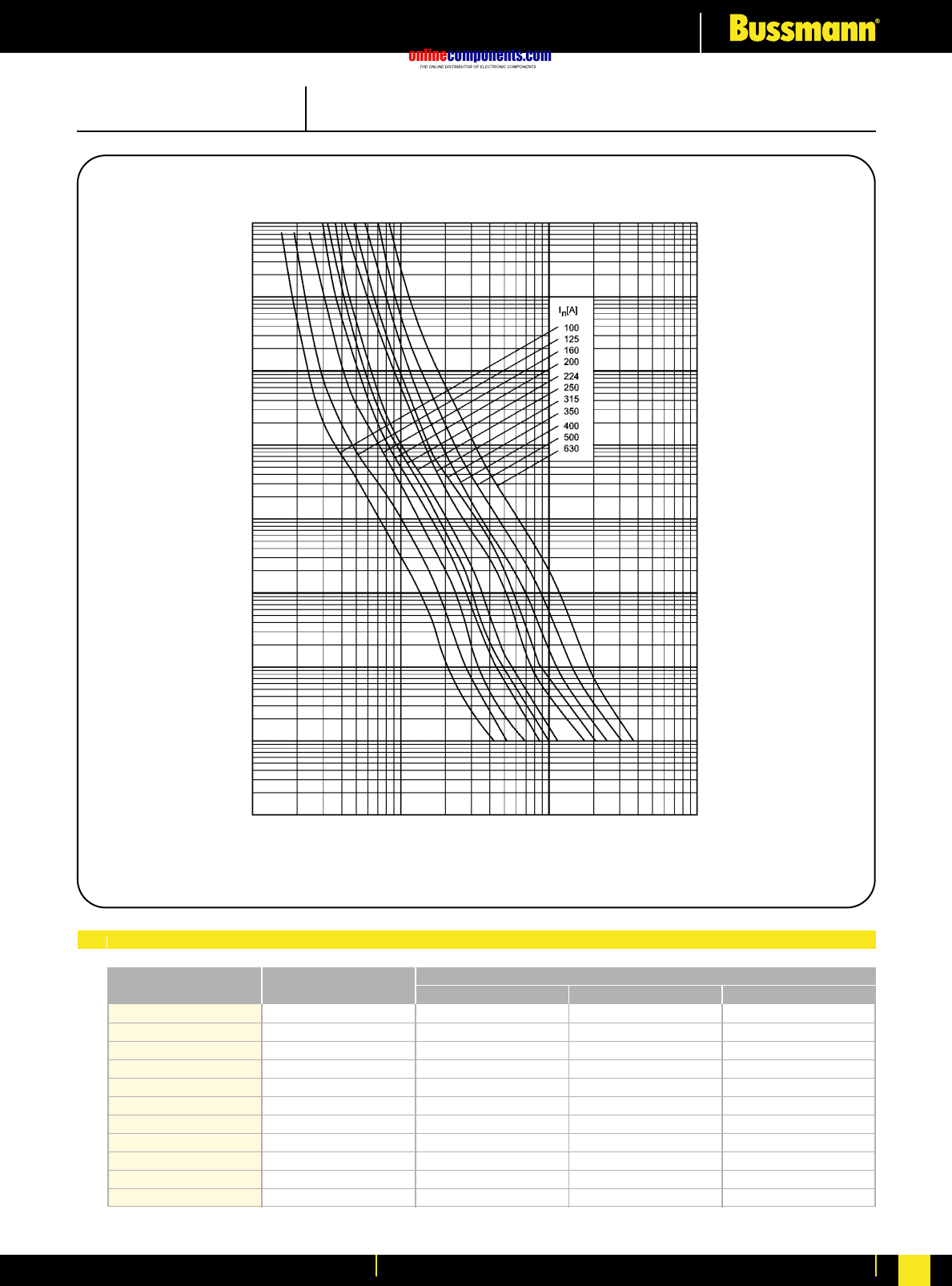
onlinecomponents.com
Electrical Characteristics
For more information visit our website at www.bussmann.com 224
SIZE: 3 CLASS: gG/gL 500V AC
Electrical Characteristics
PRE-ARCING TIME IN SECONDS
RMS SYMMETRICAL PROSPECTIVE CURRENT IN AMPERES
Time Current Characteristics
104
103
102
10
1
10-1
10-4
100 1000 10000 100000
10-3
10-2
130000
190000
230000
390000
460000
580000
1150000
1350000
2000000
2800000
4300000
100
125
160
200
224
250
315
350
400
500
630
100NH3G
125NH3G
160NH3G
200NH3G
224NH3G
250NH3G
315NH3G
350NH3G
400NH3G
500NH3G
630NH3G
20000
40000
49000
82000
120000
140000
290000
400000
600000
770000
940000
55000
88000
140000
210000
270000
390000
800000
1050000
1500000
2050000
3800000
Bussmann
Part Number Rated Current
RMS-Amps Pre Arcing at 500Vac 20 x Inat 500Vac
I2t (A2S)
I1120kA at 500Vac
I2tCharacteristics
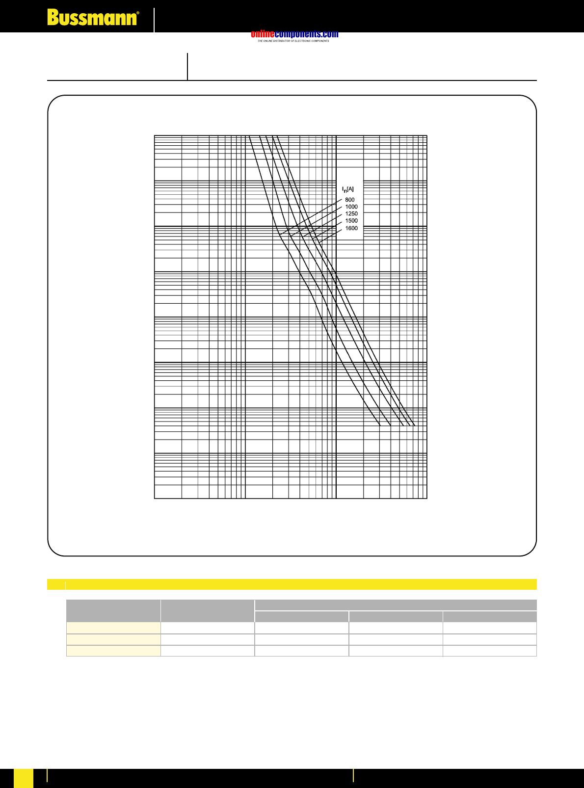
onlinecomponents.com
Electrical Characteristics
For more information visit our website at www.bussmann.com
225
PRE-ARCING TIME IN SECONDS
RMS SYMMETRICAL PROSPECTIVE CURRENT IN AMPERES
Time Current Characteristics
104
103
102
10
1
10-1
10-4
100 1000 10000 100000
10-3
10-2
18000000
34000000
65000000
800
1000
1250
800NH4AG
1000NH4AG
1250NH4AG
3500000
6000000
14000000
15000000
30000000
58000000
Bussmann
Part Number Rated Current
RMS-Amps Pre Arcing at 500Vac 20 x Inat 500Vac
I2t (A2S)
I1120kA at 500Vac
SIZE: 4a CLASS: gG/gL 500V AC
Electrical Characteristics
I2tCharacteristics
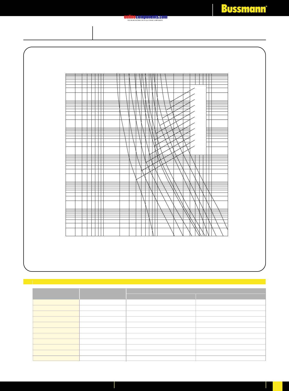
onlinecomponents.com
Electrical Characteristics
For more information visit our website at www.bussmann.com 226
SIZE: C00 (000) CLASS: gG/gL 500V AC
Electrical Characteristics
10
16
20
25
32
35
40
50
63
80
100
86
280
550
1500
1800
2200
3200
3700
5500
9400
21000
425
1400
2800
7500
8900
10900
15900
21700
31500
46500
103800
10NHG000B
16NHG000B
20NHG000B
25NHG000B
32NHG000B
35NHG000B
40NHG000B
50NHG000B
63NHG000B
80NHG000B
100NHG000B
Bussmann
Part Number Rated Current
RMS-Amps Pre Arcing at 500Vac
I2t (A2S)
I1120kA at 500Vac
I2tCharacteristics
10
000
100
CURRENT (Amperes)
610
82 648 24 1000
68 2
0.01
TIME (Seconds)
0.1
10
100
1 000
6
2
4
2
4
6
4
2
6
6
1
2
4
6
4
6
2
4
2
16
10
20
35
25
32
80
50
40
63
100
42
Time Current Characteristics
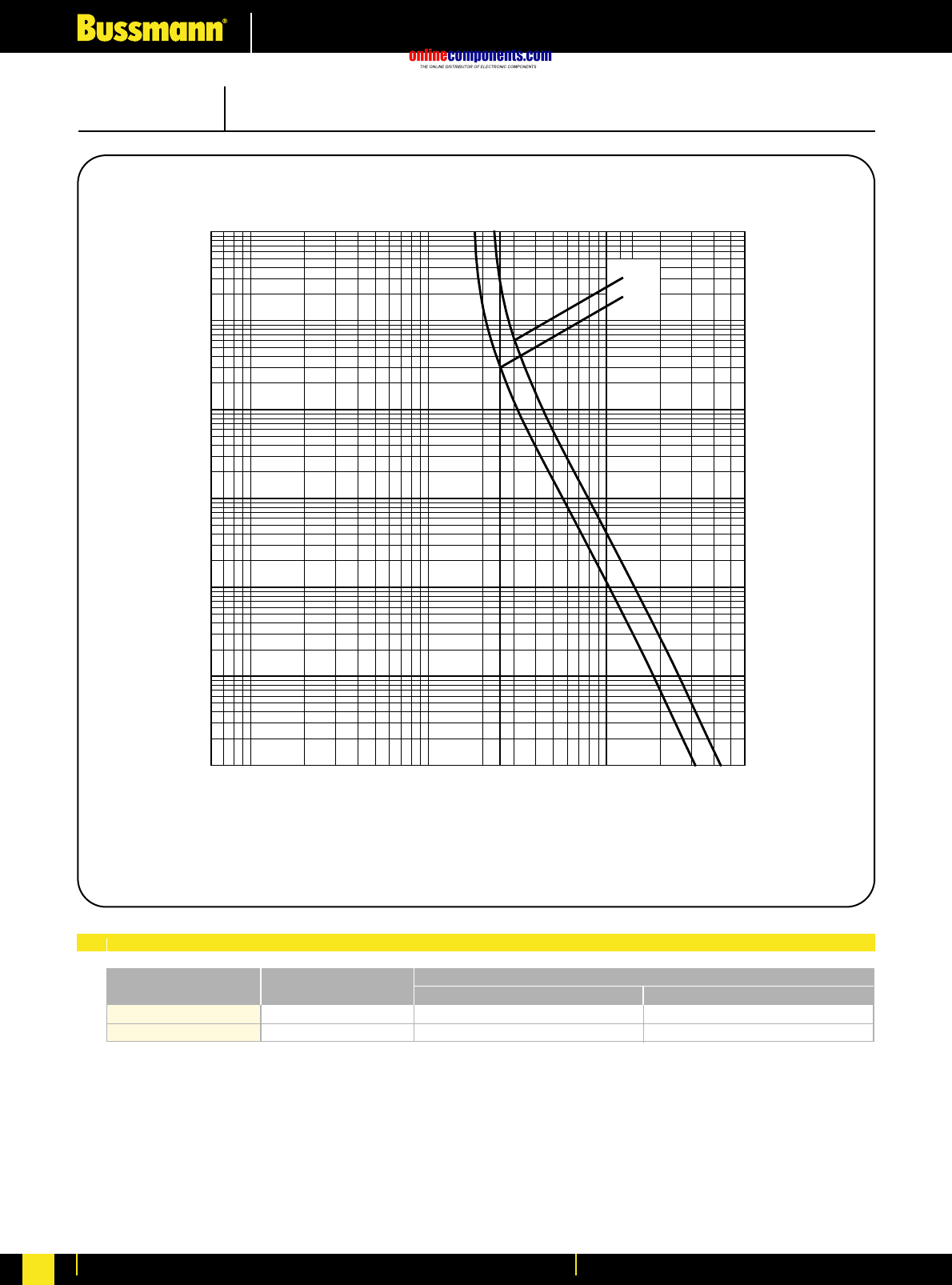
onlinecomponents.com
Electrical Characteristics
For more information visit our website at www.bussmann.com
227
125
160 32000
62000 166400
322400
125NHG00B
160NHG00B
Bussmann
Part Number Rated Current
RMS-Amps Pre Arcing at 500Vac
I2t (A2S)
I1120kA at 500Vac
SIZE: 00 CLASS: gG/gL 500V AC
Ele0racteristics
I2tCharacteristics
100
CURRENT (Amperes)
610
82 648 24 1000
68 2 4
160
125
10
000
0.01
2
4
6
TIME (Seconds)
6
0.1
2
4
1
2
4
4
10
6
2
100
6
2
2
1 000
4
6
6
4
6
Time Current Characteristics
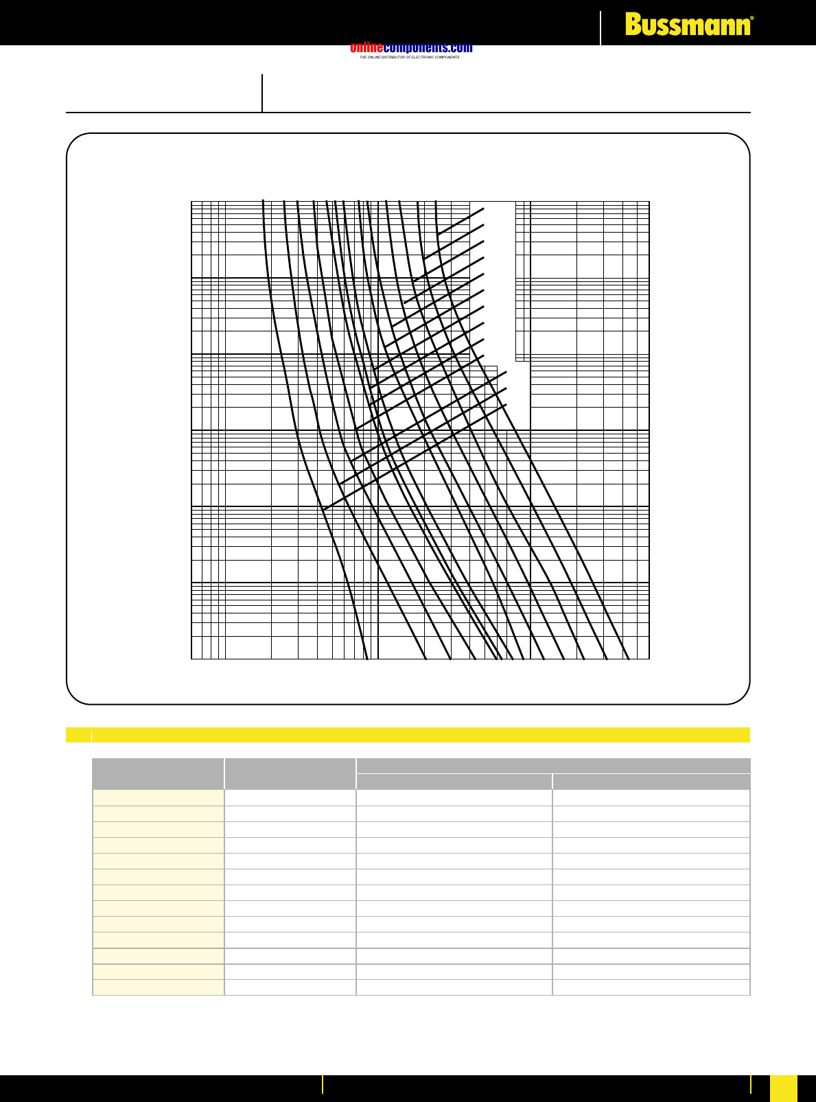
onlinecomponents.com
Electrical Characteristics
For more information visit our website at www.bussmann.com 228
SIZE: 0 CLASS: gG/gL 500V AC
Electrical Characteristics
10
16
20
25
32
35
40
50
63
80
100
125
160
112
280
550
1500
1800
2200
3200
3700
5500
9400
21000
32000
62000
600
1400
2800
7500
8900
10900
15900
21700
31500
46500
103800
166400
322400
10NHG0B
16NHG0B
20NHG0B
25NHG0B
32NHG0B
35NHG0B
40NHG0B
50NHG0B
63NHG0B
80NHG0B
100NHG0B
125NHG0B
160NHG0B
Bussmann
Part Number Rated Current
RMS-Amps Pre Arcing at 500Vac
I2t (A2S)
I1120kA at 500Vac
I2tCharacteristics
TIME (Seconds)
CURRENT (Amperes)
684268 2 648 246
10 100 1000
2
6
4
0.1
0.01
1
6
4
2
6
2
4
10
100
6
4
2
6
4
2
6
4
2
1 000
32
35
40
50
63
80
100
125
160
16
10
20
25
10 000
Time Current Characteristics
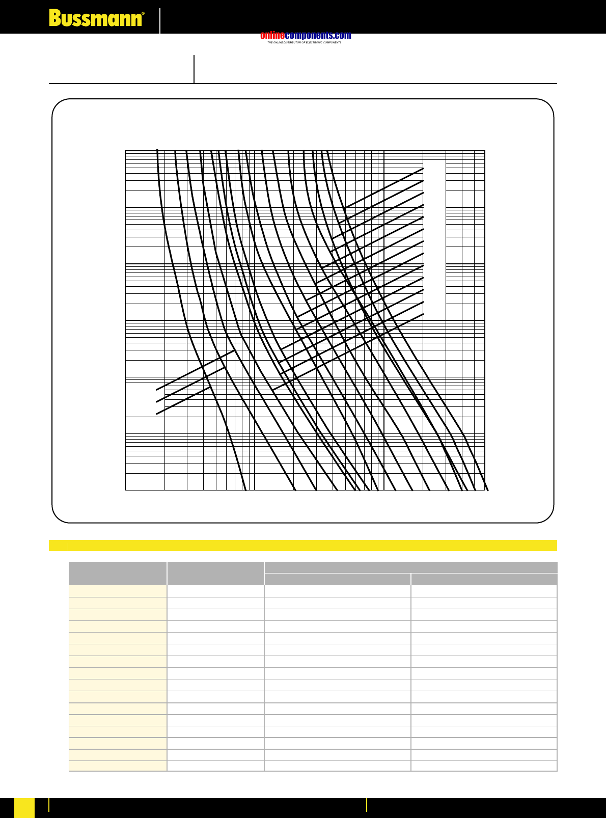
onlinecomponents.com
Electrical Characteristics
For more information visit our website at www.bussmann.com
229
280
550
1500
1800
2200
3200
3700
5500
9400
21000
32000
62000
96900
151300
217900
1400
2800
7500
8900
10900
15900
21700
31500
46500
103800
166400
322400
302100
472000
679700
SIZE: 1 CLASS: gG/gL 500V AC
Electrical Characteristics
10
16
20
25
32
35
40
50
63
80
100
125
160
200
224
250
10NHG01B
16NHG01B
20NHG01B
25NHG01B
32NHG01B
35NHG01B
40NHG01B
50NHG01B
63NHG01B
80NHG01B
100NHG01B
125NHG01B
160NHG01B
200NHG1B
224NHG1B
250NHG1B
Bussmann
Part Number Rated Current
RMS-Amps Pre Arcing at 500Vac
I2t (A2S)
I1120kA at 500Vac
I2tCharacteristics
TIME (Seconds)
68422648 246
10 100 1000
2
6
4
0.1
0.01
1
6
4
2
6
2
4
10
100
6
4
2
6
4
2
6
4
2
1 000
10
000
32
35
40
50
63
80
100
125
160
16
10
20
25
250
224
200
CURRENT (Amperes)
Time Current Characteristics
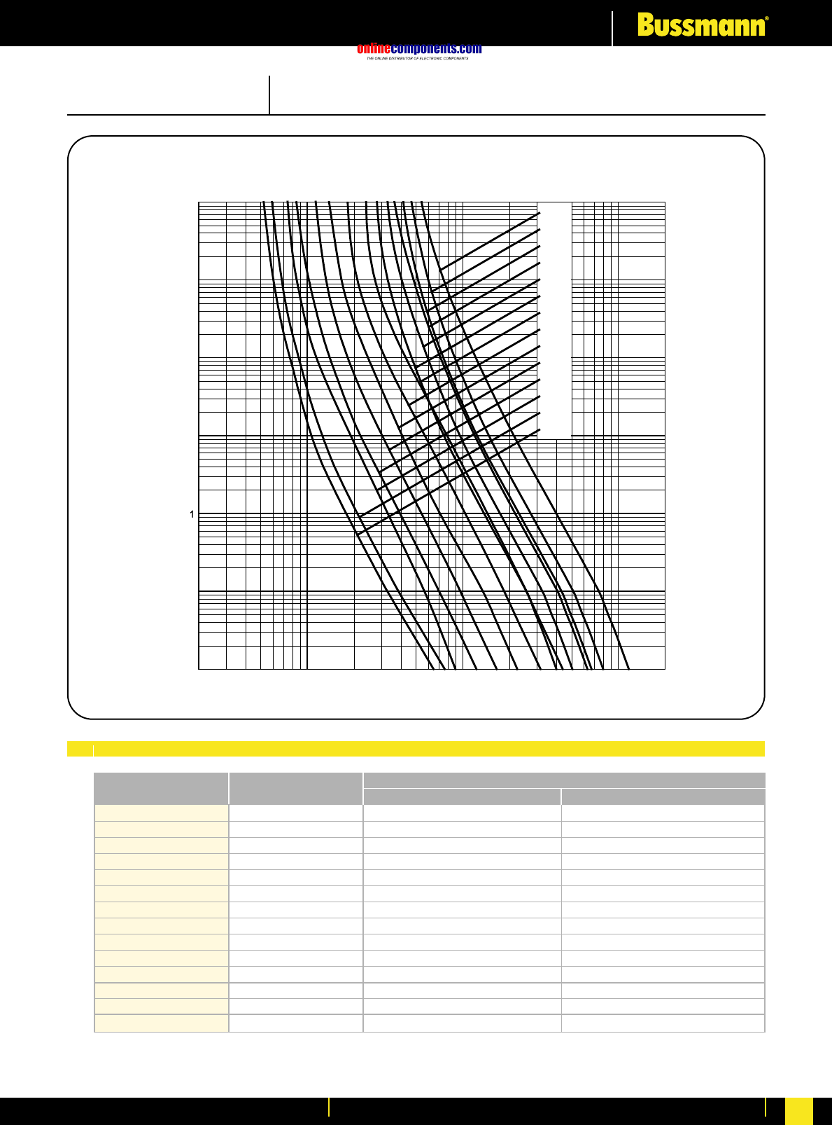
onlinecomponents.com
Electrical Characteristics
For more information visit our website at www.bussmann.com 230
35
40
50
63
80
100
125
160
200
224
250
315
355
400
35NHG02B
40NHG02B
50NHG02B
63NHG02B
80NHG02B
100NHG02B
125NHG02B
160NHG02B
200NHG02B
224NHG02B
250NHG02B
315NHG2B
355NHG2B
400NHG2B
Bussmann
Part Number Rated Current
RMS-Amps Pre Arcing at 500Vac
I2t (A2S)
I1120kA at 500Vac
SIZE: 2 CLASS: gG/gL 500V AC
Electrical Characteristics
I2tCharacteristics
100
CURRENT
(
Am
p
eres
)
68 2 6
482
4
1000 68 2
355
315
400
0.01
2
4
6
TIME (Seconds)
6
0.1
2
4
1
2
4
4
10
6
2
100
6
10 000
2
2
1 000
4
6
6
4
10 000
250
224
200
160
125
100
80
63
50
40
35
112
280
550
1500
1800
2200
3200
3700
5500
9400
21000
361700
446500
642900
600
1400
2800
7500
8900
10900
15900
21700
31500
46500
103800
940300
1160800
1671500
Time Current Characteristics
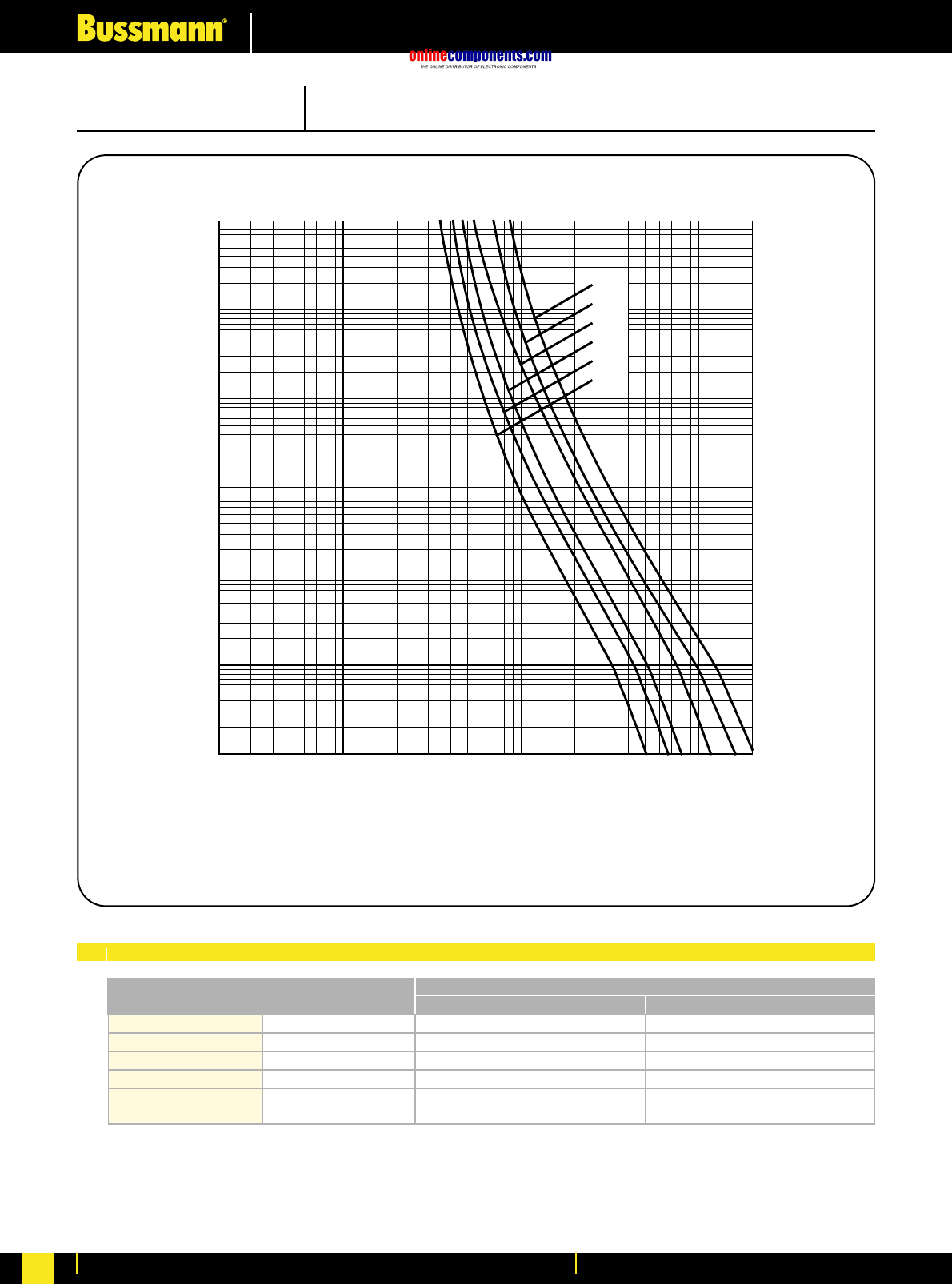
onlinecomponents.com
Electrical Characteristics
For more information visit our website at www.bussmann.com
231
Time Current Characteristics
250
315
355
400
500
630
160800
361700
446500
642900
886000
1576000
417900
940300
1160800
1671500
2994700
5326900
250NHG03B
315NHG03B
355NHG03B
400NHG03B
500NHG3B
630NHG3B
Bussmann
Part Number Rated Current
RMS-Amps Pre Arcing at 500Vac
I2t (A2S)
I1120kA at 500Vac
SIZE: 3 CLASS: gG/gL 500V AC
Electrical Characteristics
I2tCharacteristics
100
CURRENT (Amperes)
2648 24 1000
68 2 4 6
0.01
2
4
6
TIME (Seconds)
6
0.1
2
4
1
2
4
4
10
6
2
100
6
10 000
2
2
1 000
4
6
6
4
10,000 2
315
250
400
355
630
500
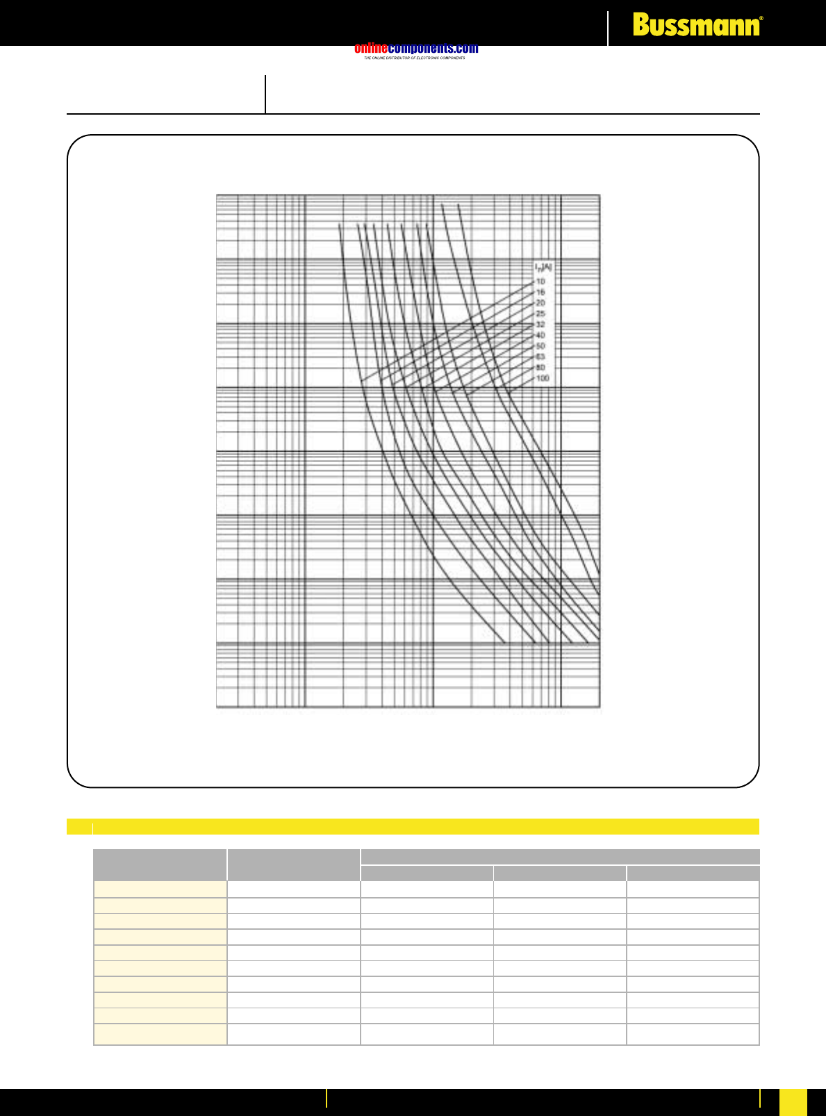
onlinecomponents.com
Electrical Characteristics
For more information visit our website at www.bussmann.com 232
PRE-ARCING TIME IN SECONDS
RMS SYMMETRICAL PROSPECTIVE CURRENT IN AMPERES
Time Current Characteristics
104
103
102
10
1
10-1
10-4
10 100 1000
10-3
10-2
1200
2800
5100
9000
11000
21000
27000
54000
110000
180000
10
16
20
25
32
40
50
63
80
100
10NH00G-690
16NH00G-690
20NH00G-690
25NH00G-690
32NH00G-690
40NH00G-690
50NH00G-690
63NH00G-690
80NH00G-690
100NH00G-690
170
440
800
1400
2500
4500
4850
6100
7000
14000
500
1700
2600
4800
7300
13000
18000
31000
60000
95000
Bussmann
Part Number Rated Current
RMS-Amps Pre Arcing at 690Vac 20 x Inat 690Vac
I2t (A2S)
I1120kA at 690Vac
SIZE: 00 CLASS: gG/gL 690V AC
Electrical Characteristics
I2tCharacteristics

onlinecomponents.com
Electrical Characteristics
For more information visit our website at www.bussmann.com
233
PRE-ARCING TIME IN SECONDS
RMS SYMMETRICAL PROSPECTIVE CURRENT IN AMPERES
Time Current Characteristics
104
103
102
10
1
10-1
10-4
10020 1000 10,000
10-3
10-2
11000
20000
30000
45000
95000
160000
220000
330000
540000
630000
750000
32
40
50
63
80
100
125
160
200
224
250
32NH1G-690
40NH1G-690
50NH1G-690
63NH1G-690
80NH1G-690
100NH1G-690
125NH1G-690
160NH1G-690
200NH1G-690
224NH1G-690
250NH1G-690
2600
4500
5800
9500
14000
22000
38000
65000
110000
160000
190000
5500
9500
16000
32000
43000
70000
110000
170000
280000
340000
400000
Bussmann
Part Number Rated Current
RMS-Amps Pre Arcing at 690Vac 20 x Inat 690Vac
I2t (A2S)
I1120kA at 690Vac
SIZE: 1 CLASS: gG/gL 690V AC
Electrical Characteristics
I2tCharacteristics

onlinecomponents.com
Electrical Characteristics
For more information visit our website at www.bussmann.com 234
PRE-ARCING TIME IN SECONDS
RMS SYMMETRICAL PROSPECTIVE CURRENT IN AMPERES
Time Current Characteristics
104
103
102
10
1
10-1
10-4
100 1000 10000
10-3
10-2
180000
270000
320000
420000
630000
830000
1400000
1800000
2300000
100
125
160
200
224
250
315
350
400
100NH2G-690
125NH2G-690
160NH2G-690
200NH2G-690
224NH2G-690
250NH2G-690
315NH2G-690
350NH2G-690
400NH2G-690
29000
39000
66000
110000
170000
190000
310000
480000
590000
100000
120000
210000
300000
450000
550000
1250000
1400000
1700000
Bussmann
Part Number Rated Current
RMS-Amps Pre Arcing at 690Vac 20 x Inat 690Vac
I2t (A2S)
I1120kA at 690Vac
SIZE: 2 CLASS: gG/gL 690V AC
Electrical Characteristics
I2tCharacteristics
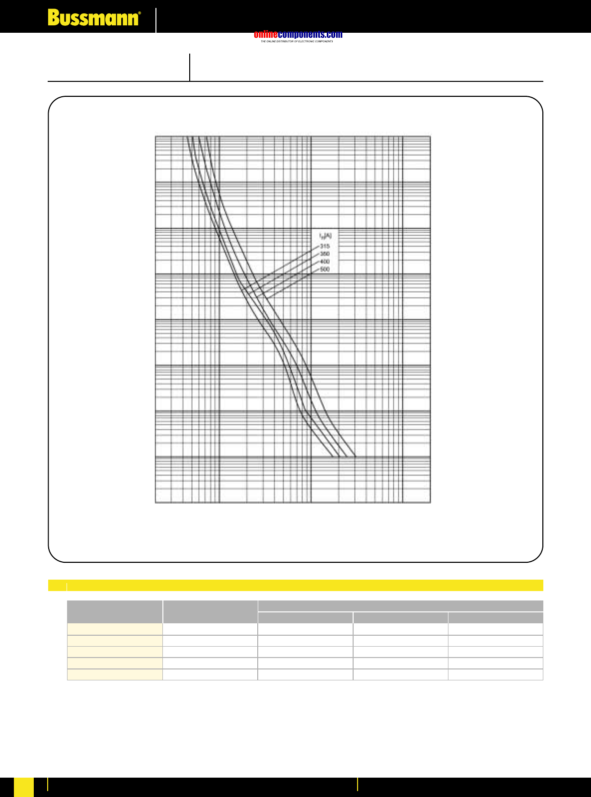
onlinecomponents.com
Electrical Characteristics
For more information visit our website at www.bussmann.com
235
PRE-ARCING TIME IN SECONDS
RMS SYMMETRICAL PROSPECTIVE CURRENT IN AMPERES
Time Current Characteristics
104
103
102
10
1
10-1
10-4
200 1000 10000 100000
10-3
10-2
1600000
2200000
2800000
3900000
315
350
400
500
630
315NH3G-690
350NH3G-690
400NH3G-690
500NH3G-690
630NH3G-690
350000
470000
590000
990000
-
1300000
1600000
2300000
3000000
-
Bussmann
Part Number Rated Current
RMS-Amps Pre Arcing at 690Vac 20 x Inat 690Vac
I2t (A2S)
I1120kA at 690Vac
SIZE: 3 CLASS: gG/gL 690V AC
Electrical Characteristics
I2tCharacteristics
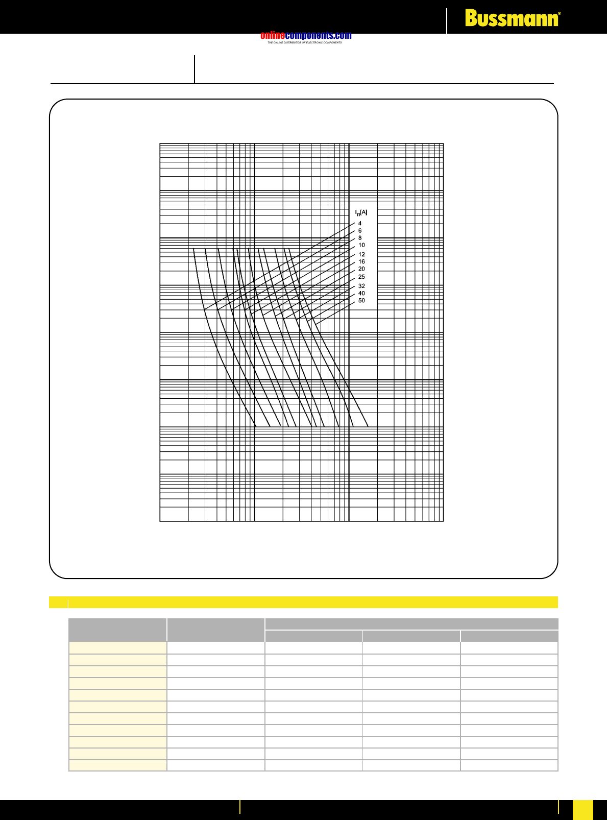
onlinecomponents.com
Electrical Characteristics
For more information visit our website at www.bussmann.com 236
PRE-ARCING TIME IN SECONDS
RMS SYMMETRICAL PROSPECTIVE CURRENT IN AMPERES
Time Current Characteristics
104
103
102
10
1
10-1
10-4
10 100 1000 10000
10-3
10-2
330
820
1500
3700
4900
6900
8300
11000
21000
32000
47000
4
6
8
10
12
16
20
25
32
40
50
4NHC00M
6NHC00M
8NHC00M
10NHC00M
12NHC00M
16NHC00M
20NHC00M
25NHC00M
32NHC00M
40NHC00M
50NHC00M
31
64
93
290
290
700
860
1300
3000
6000
10000
80
210
390
1100
1600
2100
2700
3700
8000
12000
20000
Bussmann
Part Number Rated Current
RMS-Amps Pre Arcing at 500Vac 20 x Inat 500Vac
I2t (A2S)
I1120kA at 500Vac
SIZE: C00 (000) CLASS: aM 500V AC
Electrical Characteristics
I2tCharacteristics
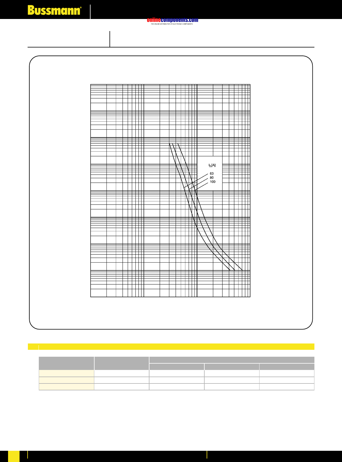
onlinecomponents.com
Electrical Characteristics
For more information visit our website at www.bussmann.com
237
PRE-ARCING TIME IN SECONDS
RMS SYMMETRICAL PROSPECTIVE CURRENT IN AMPERES
Time Current Characteristics
104
103
102
10
1
10-1
10-4
10 100 1000 10000
10-3
10-2
75000
110000
190000
63
80
100
63NH00M
80NH00M
100NH00M
1700
3400
16800
35000
50000
100000
Bussmann
Part Number Rated Current
RMS-Amps Pre Arcing at 500Vac 20 x Inat 500Vac
I2t (A2S)
I1120kA at 500Vac
SIZE: 00 CLASS: aM 500V AC
Electrical Characteristics
I2tCharacteristics
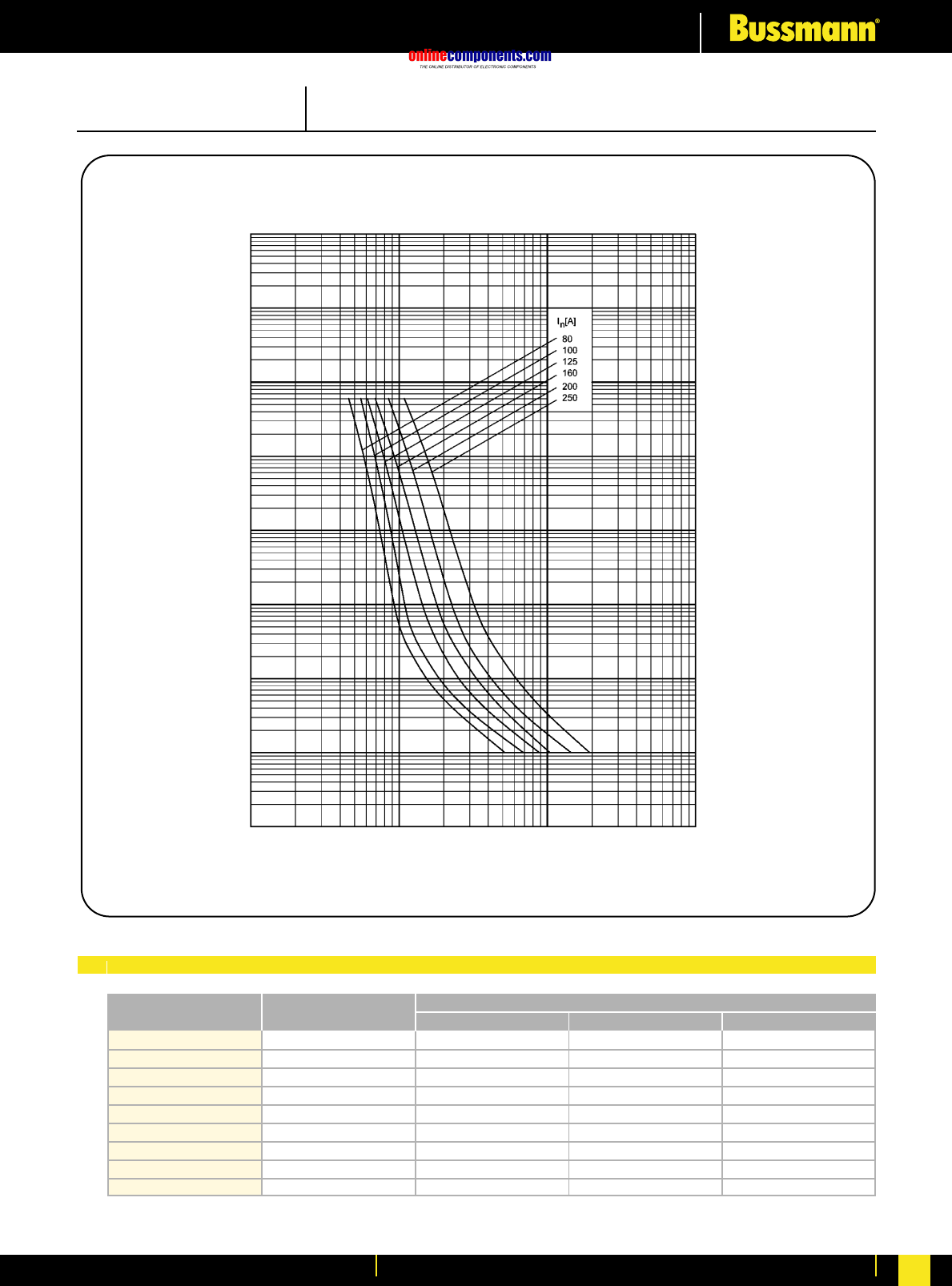
onlinecomponents.com
Electrical Characteristics
For more information visit our website at www.bussmann.com 238
PRE-ARCING TIME IN SECONDS
RMS SYMMETRICAL PROSPECTIVE CURRENT IN AMPERES
Time Current Characteristics
104
103
102
10
1
10-1
10-4
100 1000 10000 100000
10-3
10-2
32000
47000
75000
110000
190000
220000
310000
500000
850000
40
50
63
80
100
125
160
200
250
40NH1M
50NH1M
63NH1M
80NH1M
100NH1M
125NH1M
160NH1M
200NH1M
250NH1M
1200
1850
2100
3200
7000
11100
20800
29000
56000
12000
20000
35000
50000
100000
120000
190000
300000
510000
Bussmann
Part Number Rated Current
RMS-Amps Pre Arcing at 500Vac 20 x Inat 500Vac
I2t (A2S)
I1120kA at 500Vac
SIZE: 1 CLASS: aM 500V AC
Electrical Characteristics
I2tCharacteristics
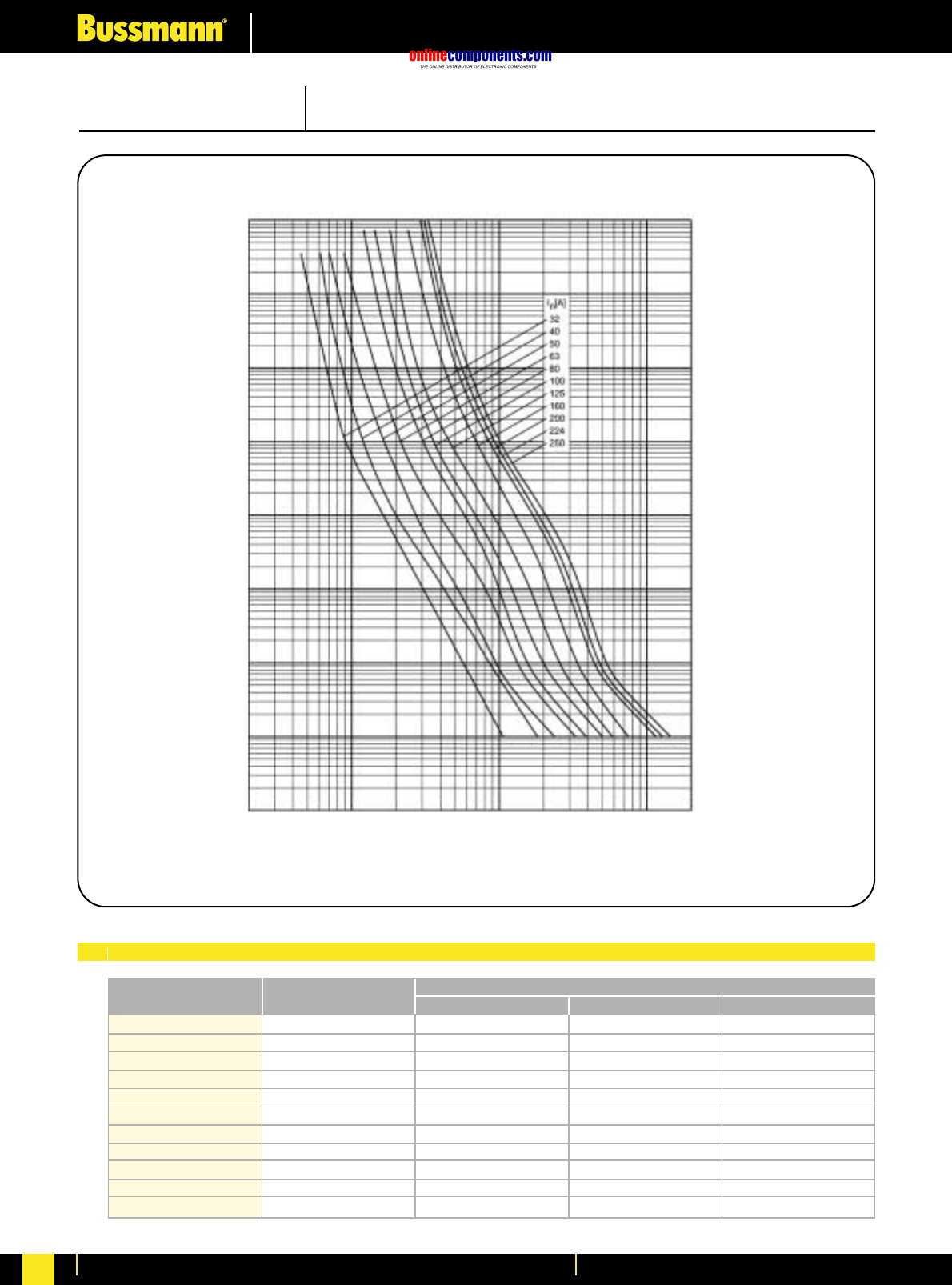
onlinecomponents.com
Electrical Characteristics
For more information visit our website at www.bussmann.com
233
PRE-ARCING TIME IN SECONDS
RMS SYMMETRICAL PROSPECTIVE CURRENT IN AMPERES
Time Current Characteristics
104
103
102
10
1
10-1
10-4
10020 1000 10,000
10-3
10-2
11000
20000
30000
45000
95000
160000
220000
330000
540000
630000
750000
32
40
50
63
80
100
125
160
200
224
250
32NH1G-690
40NH1G-690
50NH1G-690
63NH1G-690
80NH1G-690
100NH1G-690
125NH1G-690
160NH1G-690
200NH1G-690
224NH1G-690
250NH1G-690
2600
4500
5800
9500
14000
22000
38000
65000
110000
160000
190000
5500
9500
16000
32000
43000
70000
110000
170000
280000
340000
400000
Bussmann
Part Number Rated Current
RMS-Amps Pre Arcing at 690Vac 20 x Inat 690Vac
I2t (A2S)
I1120kA at 690Vac
SIZE: 1 CLASS: gG/gL 690V AC
Electrical Characteristics
I2tCharacteristics
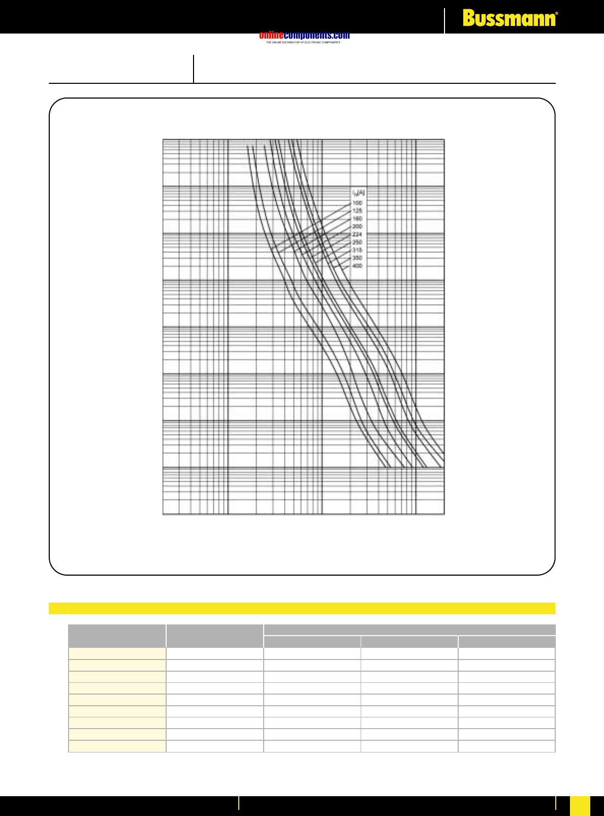
onlinecomponents.com
Electrical Characteristics
For more information visit our website at www.bussmann.com 234
PRE-ARCING TIME IN SECONDS
RMS SYMMETRICAL PROSPECTIVE CURRENT IN AMPERES
Time Current Characteristics
104
103
102
10
1
10-1
10-4
100 1000 10000
10-3
10-2
180000
270000
320000
420000
630000
830000
1400000
1800000
2300000
100
125
160
200
224
250
315
350
400
100NH2G-690
125NH2G-690
160NH2G-690
200NH2G-690
224NH2G-690
250NH2G-690
315NH2G-690
350NH2G-690
400NH2G-690
29000
39000
66000
110000
170000
190000
310000
480000
590000
100000
120000
210000
300000
450000
550000
1250000
1400000
1700000
Bussmann
Part Number Rated Current
RMS-Amps Pre Arcing at 690Vac 20 x Inat 690Vac
I2t (A2S)
I1120kA at 690Vac
SIZE: 2 CLASS: gG/gL 690V AC
Electrical Characteristics
I2tCharacteristics

onlinecomponents.com
Electrical Characteristics
For more information visit our website at www.bussmann.com
235
PRE-ARCING TIME IN SECONDS
RMS SYMMETRICAL PROSPECTIVE CURRENT IN AMPERES
Time Current Characteristics
104
103
102
10
1
10-1
10-4
200 1000 10000 100000
10-3
10-2
1600000
2200000
2800000
3900000
315
350
400
500
630
315NH3G-690
350NH3G-690
400NH3G-690
500NH3G-690
630NH3G-690
350000
470000
590000
990000
-
1300000
1600000
2300000
3000000
-
Bussmann
Part Number Rated Current
RMS-Amps Pre Arcing at 690Vac 20 x Inat 690Vac
I2t (A2S)
I1120kA at 690Vac
SIZE: 3 CLASS: gG/gL 690V AC
Electrical Characteristics
I2tCharacteristics

onlinecomponents.com
Electrical Characteristics
For more information visit our website at www.bussmann.com 236
PRE-ARCING TIME IN SECONDS
RMS SYMMETRICAL PROSPECTIVE CURRENT IN AMPERES
Time Current Characteristics
104
103
102
10
1
10-1
10-4
10 100 1000 10000
10-3
10-2
330
820
1500
3700
4900
6900
8300
11000
21000
32000
47000
4
6
8
10
12
16
20
25
32
40
50
4NHC00M
6NHC00M
8NHC00M
10NHC00M
12NHC00M
16NHC00M
20NHC00M
25NHC00M
32NHC00M
40NHC00M
50NHC00M
31
64
93
290
290
700
860
1300
3000
6000
10000
80
210
390
1100
1600
2100
2700
3700
8000
12000
20000
Bussmann
Part Number Rated Current
RMS-Amps Pre Arcing at 500Vac 20 x Inat 500Vac
I2t (A2S)
I1120kA at 500Vac
SIZE: C00 (000) CLASS: aM 500V AC
Electrical Characteristics
I2tCharacteristics

onlinecomponents.com
Electrical Characteristics
For more information visit our website at www.bussmann.com
237
PRE-ARCING TIME IN SECONDS
RMS SYMMETRICAL PROSPECTIVE CURRENT IN AMPERES
Time Current Characteristics
104
103
102
10
1
10-1
10-4
10 100 1000 10000
10-3
10-2
75000
110000
190000
63
80
100
63NH00M
80NH00M
100NH00M
1700
3400
16800
35000
50000
100000
Bussmann
Part Number Rated Current
RMS-Amps Pre Arcing at 500Vac 20 x Inat 500Vac
I2t (A2S)
I1120kA at 500Vac
SIZE: 00 CLASS: aM 500V AC
Electrical Characteristics
I2tCharacteristics

onlinecomponents.com
Electrical Characteristics
For more information visit our website at www.bussmann.com 238
PRE-ARCING TIME IN SECONDS
RMS SYMMETRICAL PROSPECTIVE CURRENT IN AMPERES
Time Current Characteristics
104
103
102
10
1
10-1
10-4
100 1000 10000 100000
10-3
10-2
32000
47000
75000
110000
190000
220000
310000
500000
850000
40
50
63
80
100
125
160
200
250
40NH1M
50NH1M
63NH1M
80NH1M
100NH1M
125NH1M
160NH1M
200NH1M
250NH1M
1200
1850
2100
3200
7000
11100
20800
29000
56000
12000
20000
35000
50000
100000
120000
190000
300000
510000
Bussmann
Part Number Rated Current
RMS-Amps Pre Arcing at 500Vac 20 x Inat 500Vac
I2t (A2S)
I1120kA at 500Vac
SIZE: 1 CLASS: aM 500V AC
Electrical Characteristics
I2tCharacteristics
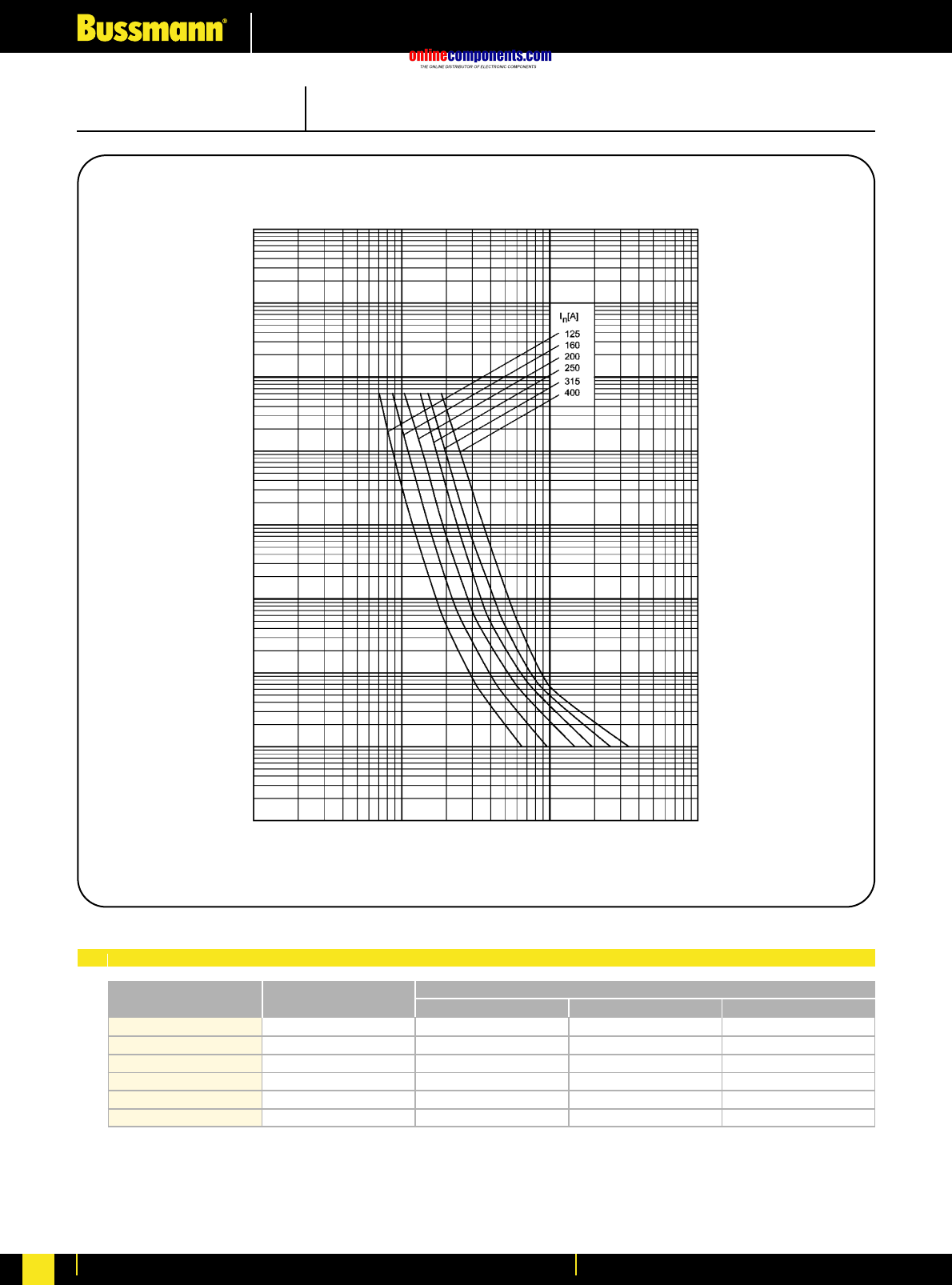
onlinecomponents.com
Electrical Characteristics
For more information visit our website at www.bussmann.com
239
PRE-ARCING TIME IN SECONDS
RMS SYMMETRICAL PROSPECTIVE CURRENT IN AMPERES
Time Current Characteristics
104
103
102
10
1
10-1
10-4
100 1000 10000 100000
10-3
10-2
220000
310000
500000
850000
1100000
1900000
125
160
200
250
315
400
125NH2M
160NH2M
200NH2M
250NH2M
315NH2M
400NH2M
12700
19800
29000
56000
83000
160000
120000
190000
300000
510000
690000
1200000
Bussmann
Part Number Rated Current
RMS-Amps Pre Arcing at 500Vac 20 x Inat 500Vac
I2t (A2S)
I1120kA at 500Vac
SIZE: 2 CLASS: aM 500V AC
Electrical Characteristics
I2tCharacteristics
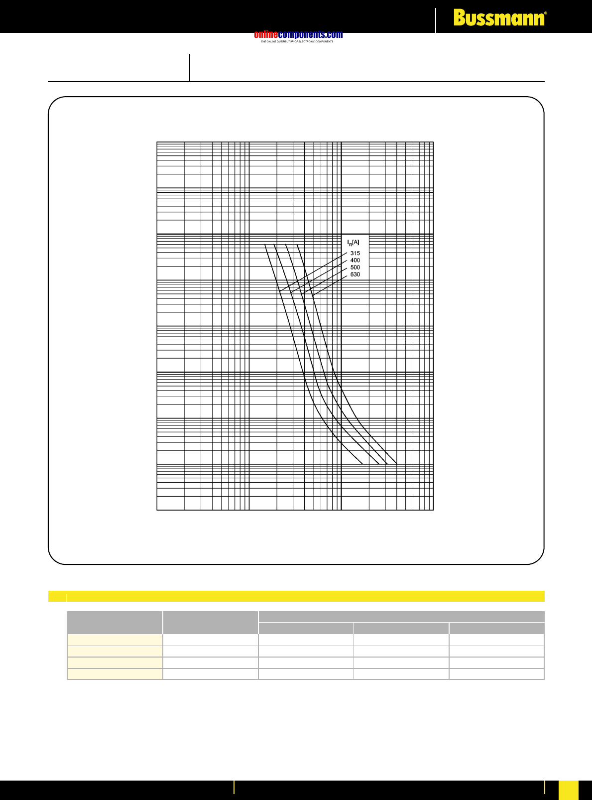
onlinecomponents.com
Electrical Characteristics
For more information visit our website at www.bussmann.com 240
PRE-ARCING TIME IN SECONDS
RMS SYMMETRICAL PROSPECTIVE CURRENT IN AMPERES
Time Current Characteristics
104
103
102
10
1
10-1
10-4
100 1000 10000 100000
10-3
10-2
1100000
1900000
2100000
4100000
315
400
500
630
315NH3M
400NH3M
500NH3M
630NH3M
83000
160000
200000
370000
690000
1200000
1900000
3200000
Bussmann
Part Number Rated Current
RMS-Amps Pre Arcing at 500Vac 20 x Inat 500Vac
I2t (A2S)
I1120kA at 500Vac
SIZE: 3 CLASS: aM 500V AC
Electrical Characteristics
I2tCharacteristics
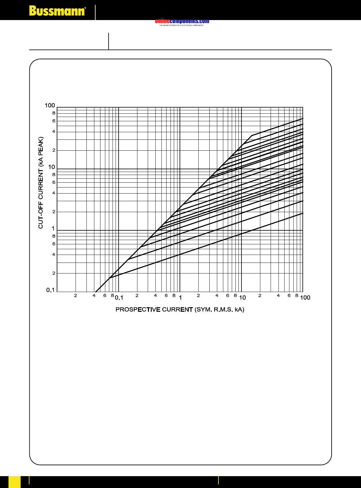
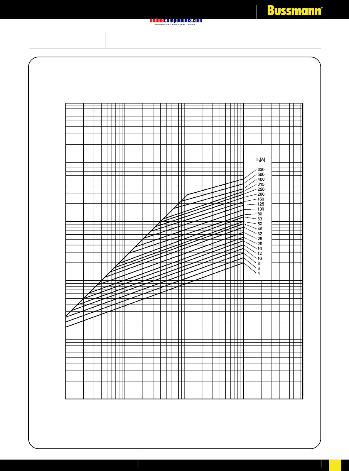
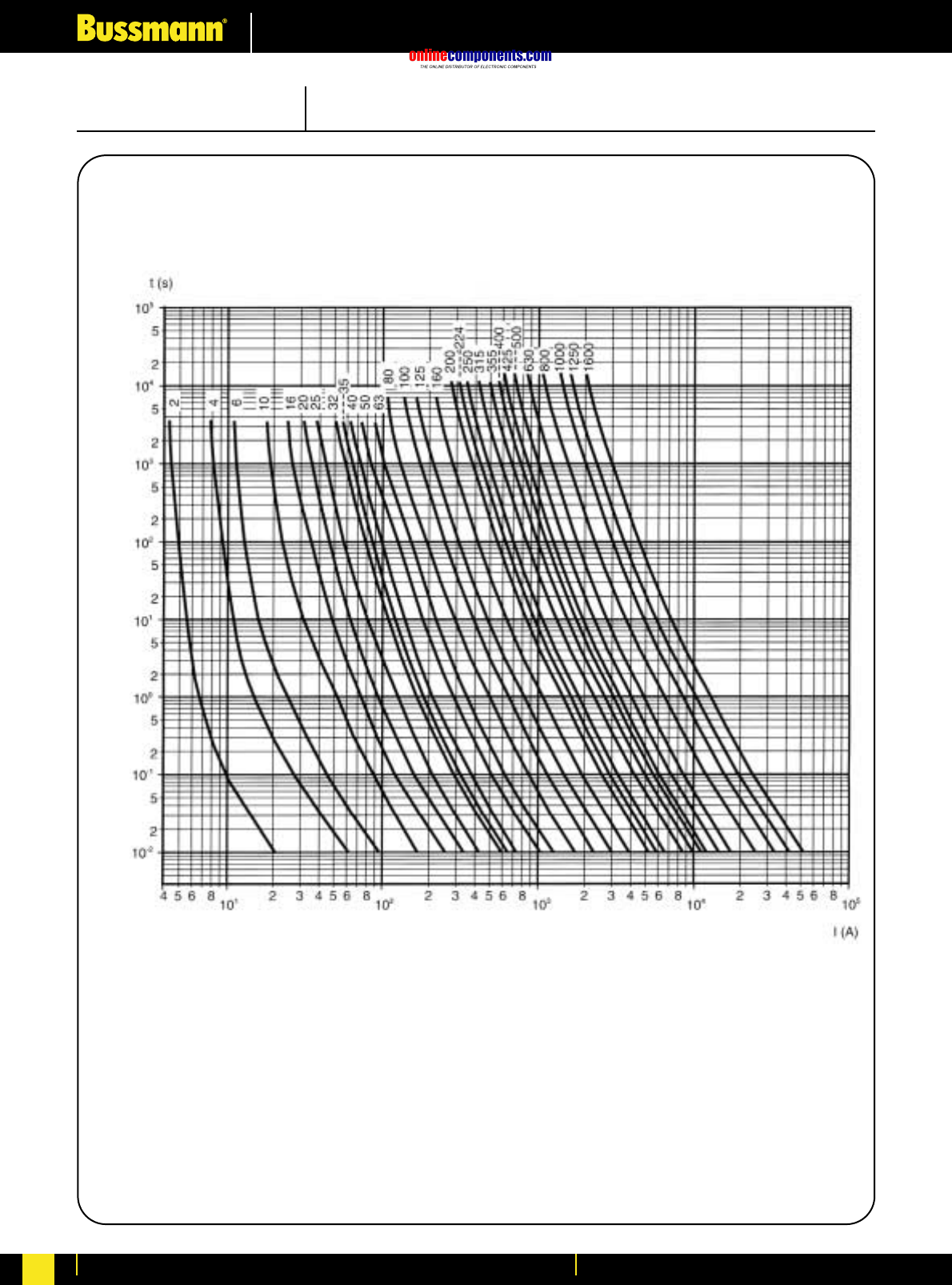
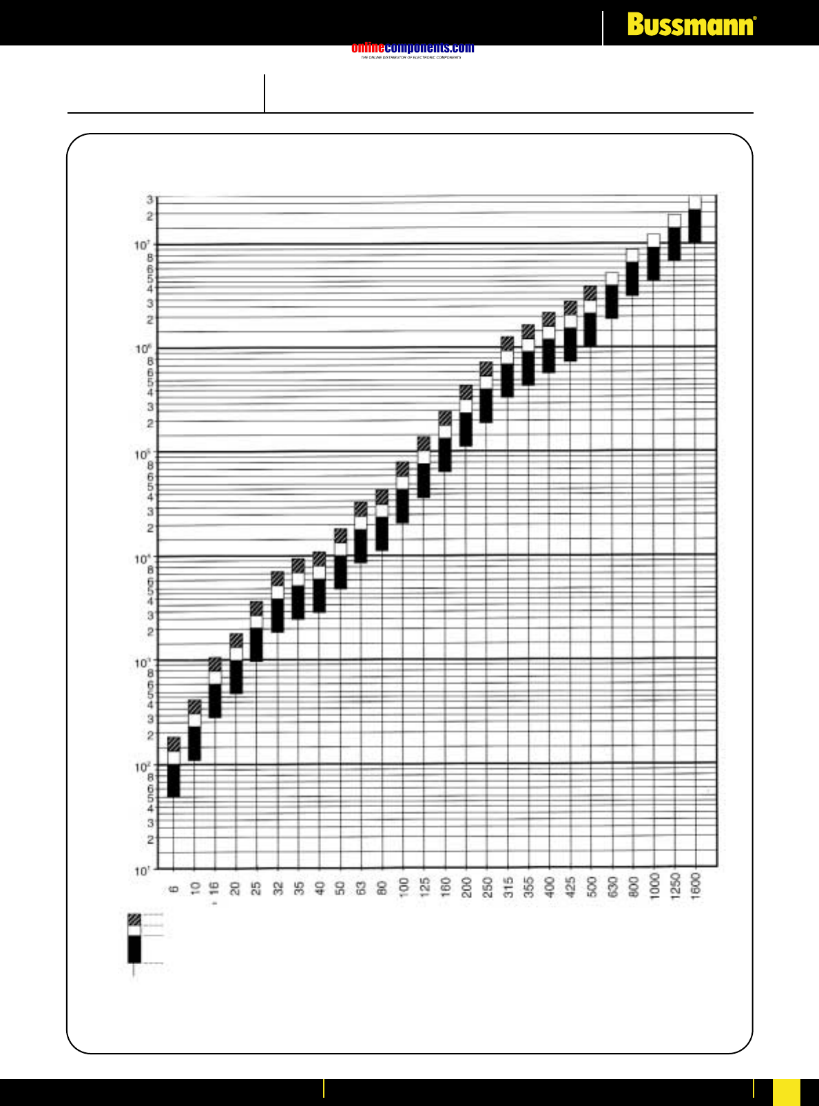
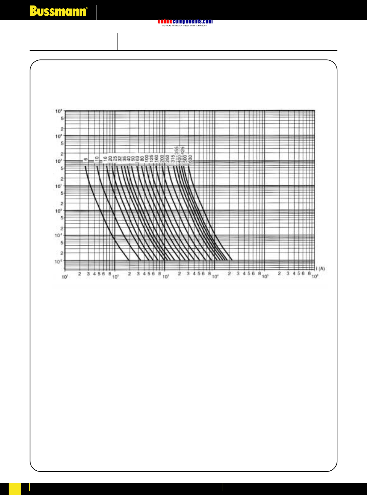
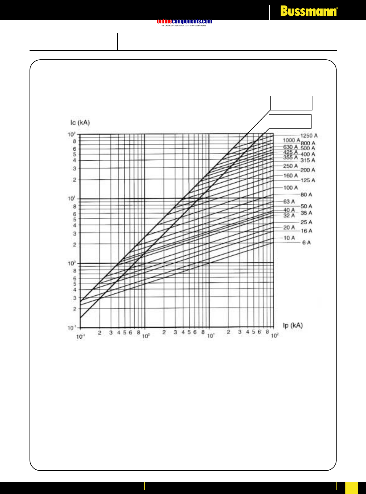
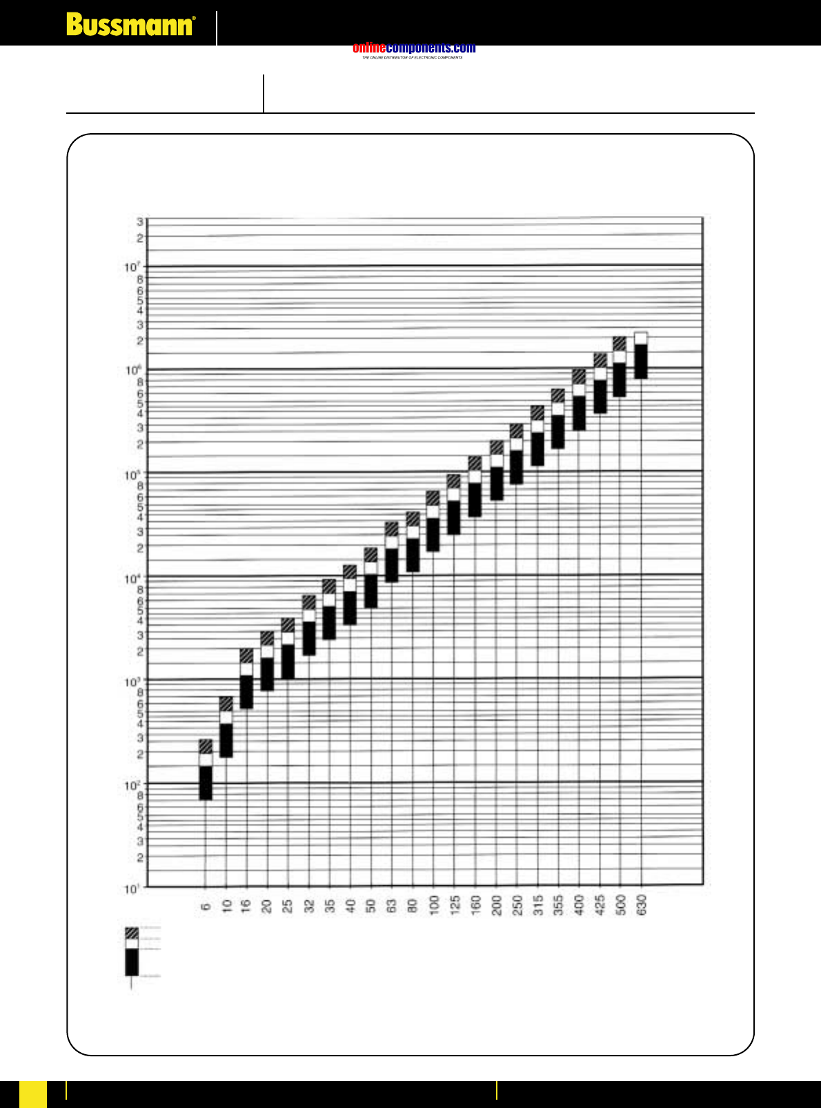
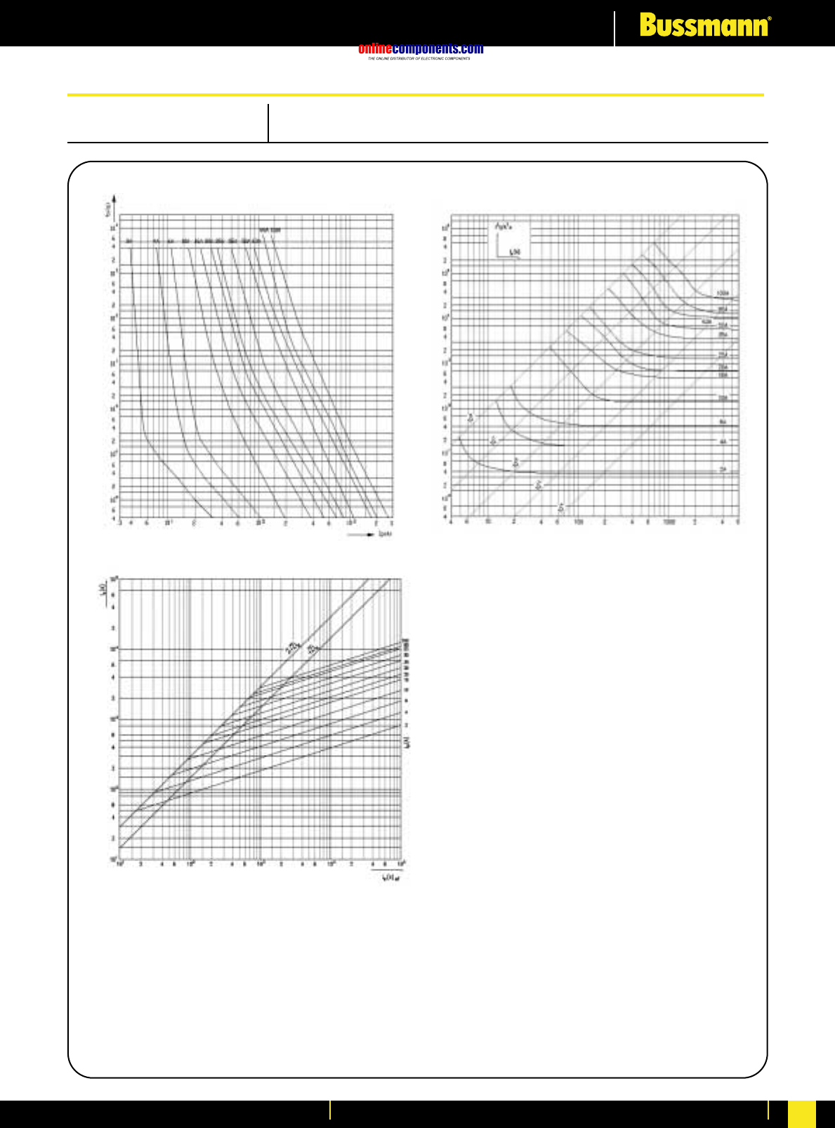
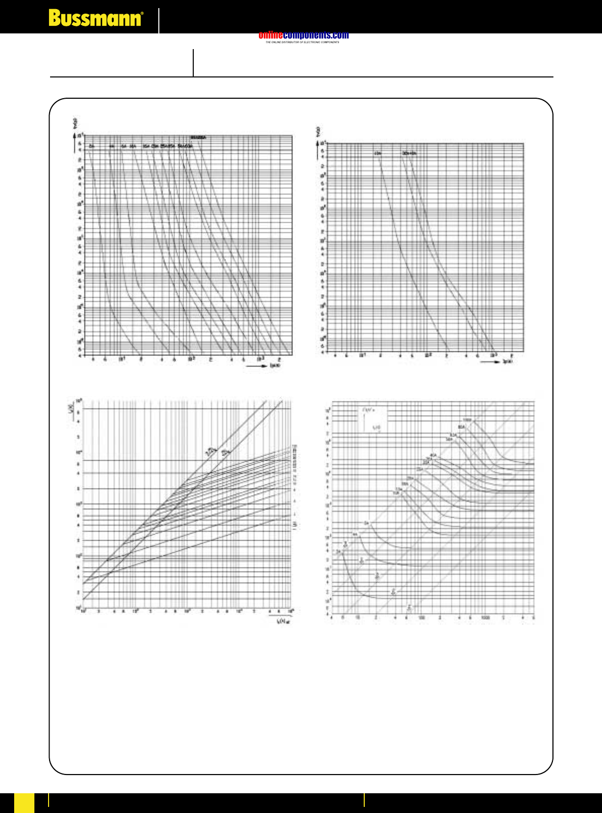
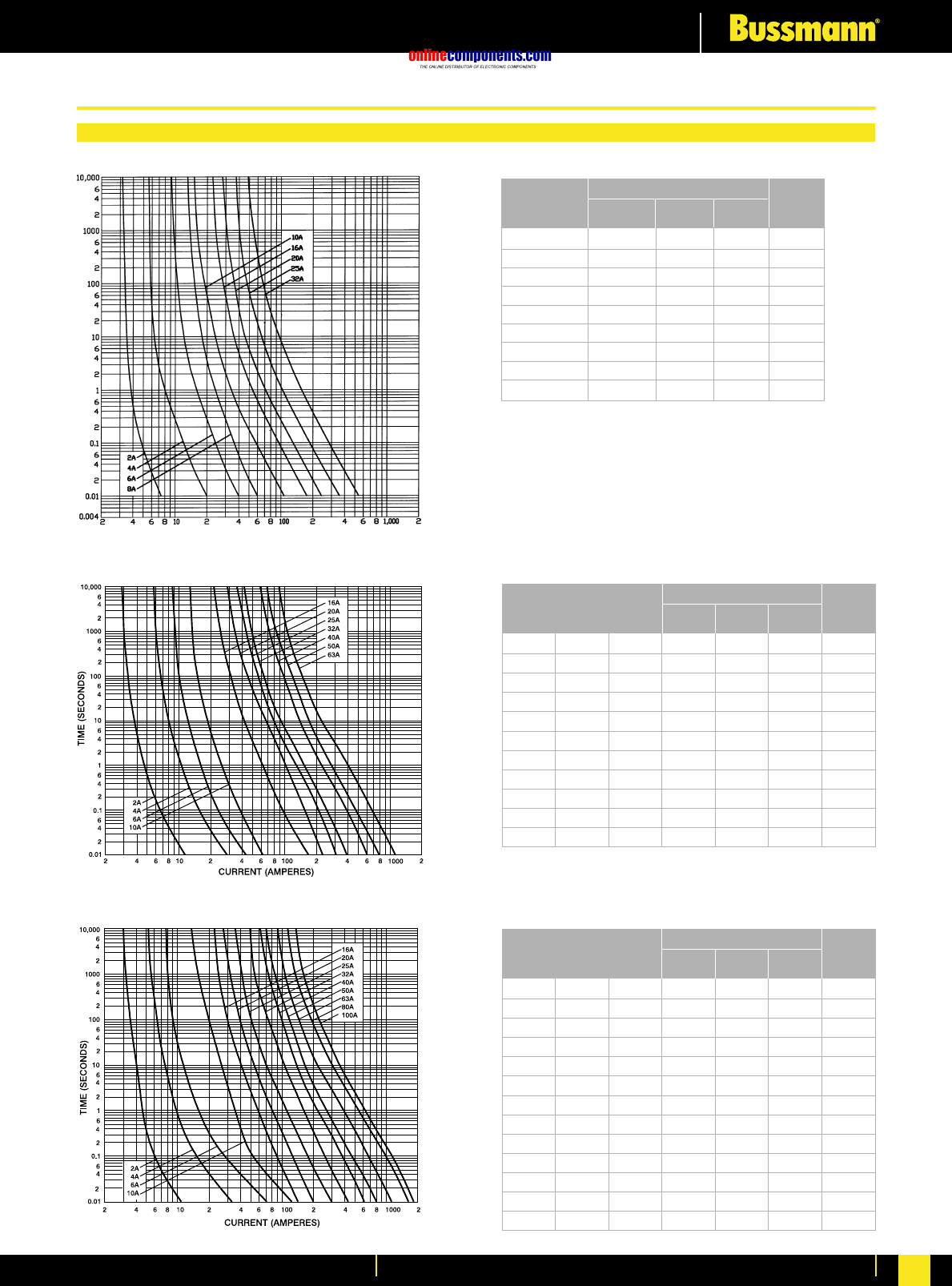
onlinecomponents.com
Electrical Characteristics
For more information visit our website at www.bussmann.com 250
Part No. Amp Pre- Total at
Ratings Arcing 415V
I2t (Amps2 Seconds) Nom.
Watts
Loss
Part No. Amp Pre- Total at
Ratings Arcing 415V
I2t (Amps2 Seconds) Nom.
Watts
Loss
––AAO 2 1.4 4.7 0.9
––AAO 4 7.8 26 1.4
––AAO 6 28 100 1.8
––AAO 10 125 400 2.1
––AAO 16 120 470 1.8
––AAO 20 260 1000 1.8
––AAO 25 570 2300 2.0
––AAO 32 710 3000 2.9
BAO BC BD 40 1400 3600 4.7
BAO BC BD 50 3000 8000 4.9
BAO BC BD 63 6700 18000 5.6
Part No. Amp Pre- Total at
Ratings Arcing 415V
I2t (Amps2 Seconds) Nom.
Watts
Loss
–AC AD 2 1.2 3.1 1.2
–AC AD 4 11 31 1.4
–AC AD 6 32 90 1.8
–AC AD 10 20 60 2.4
–AC AD 16 85 240 2.9
–AC AD 20 220 580 3.1
–AC AD 25 500 1400 3.2
CEO AC AD 32 1000 2760 3.5
CEO ––40 1400 3750 4.7
CEO ––50 3000 8350 4.9
CEO ––63 7000 18800 5.6
CEO CD OSD 80 13000 35200 7.2
CEO CD OSD 100 25000 765000 8.5
Time Current Curves for AAO, BAO, BC and BD Fuse Links
Time Current Curves for AC, AD, CD, CEO and OSD Fuse Links
Time Current Curves for SMD Fuse Links
Technical Data
SMD2 2 0.6 2.5 1.0
SMD4 4 4.5 12.5 1.5
SMD6 6 16.5 45 1.9
SMD8 8 40 105 2.1
SMD10 10 67 180 1.2
SMD16 16 185 500 1.8
SMD20 20 370 1000 2.0
SMD25 25 750 2000 2.2
SMD32 32 1700 4500 2.4
Low Voltage Industrial Fuses: Performance Data
CURRENT (AMPERES)
TIME (SECONDS)
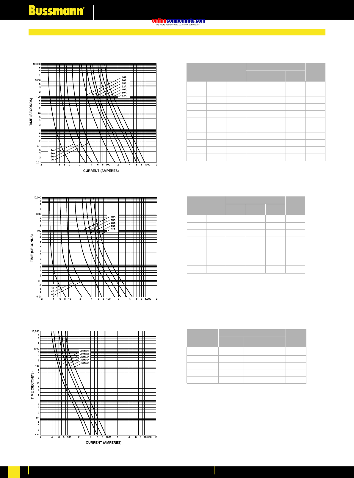
onlinecomponents.com
Electrical Characteristics
For more information visit our website at www.bussmann.com
251
Part No. Amp Pre- Total at
Ratings Arcing 415V
I2t (Amps2 Seconds) Nom.
Watts
Loss
Part No. Amp Pre- Total at
Ratings Arcing 415V
I2t (Amps2 Seconds) Nom.
Watts
Loss
SSD STD 2 0.8 1 0.5
SSD STD 4 5.5 8 1.0
SSD STD 6 15 22 1.6
SSD STD 10 28 42 1.2
SSD STD 16 160 250 1.5
SSD STD 20 290 450 1.7
SSD STD 25 800 1300 1.8
SSD STD 32 1600 2500 2.4
Part No. Amp Pre- Total at
Ratings Arcing 415V
I2t (Amps2 Seconds) Nom.
Watts
Loss
NITD 20M25 575 2300 1.6
NITD 20M32 720 3000 1.1
NITD 32M40 1500 6000 1.9
NITD 32M50 2700 8600 1.4
NITD 32M63 5000 13400 1.0
Time Current Curves for NSD, NITD and ESD Fuse Links
Time Current Curves for SSD and STD Fuse Links
Time Current Curves for NITD Motor Rated Fuse Links
NSD NITD ESD 2 1.3 4.6 0.9
NSD NITD ESD 4 8 27 1.4
NSD NITD ESD 6 29 100 1.8
NSD NITD ESD 10 120 400 2.1
NSD NITD ESD 16 120 470 1.8
NSD NITD ESD 20 260 1070 1.8
NSD NITD ESD 25 560 2300 2.0
NSD NITD ESD 32 710 3000 2.9
––ESD 40 1500 6000 3.2
––ESD 50 2700 8000 3.9
––ESD 63 5000 13300 4.6
Technical Data
CURRENT (AMPERES)
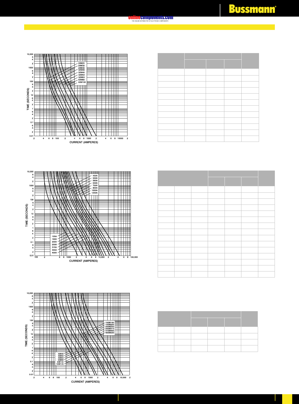
onlinecomponents.com
Electrical Characteristics
For more information visit our website at www.bussmann.com 252
Part No. Amp Pre- Total at
Ratings Arcing 415V
I2t (Amps2 Seconds) Nom.
Watts
Loss
NSD 20M25 570 2350 1.2
NSD 20M32 770 3000 0.95
NSD 20M36 1150 5000 0.88
NSD 32M36 1150 5000 2.4
NSD 32M40 1500 6000 1.9
NSD 32M50 2700 8700 1.4
NSD 32M63 5000 13550 1.0
AAO 32M40 1400 3800 3.0
AAO 32M50 3000 8500 2.0
AAO 32M63 7000 18000 1.4
BAO 63M80 12600 12600 4.4
BAO 63M100 24000 24000 3.4
Part No. Amp Pre- Total at
Ratings Arcing 415V
I2t (Amps2 Seconds) x 103Nom.
Watts
Loss
DD DEO EFS 125 29.5 71 11
DD DEO EFS 160 57 135 13
DD DEO EFS 200 120 290 14
ED - EFS 250 200 480 18
ED - EFS 315 265 635 22
ED EF - 355 360 865 24
ED EF - 400 475 1150 29
- FF FG 450 880 1600 32
- FF FG 500 1100 2000 38
- FF FG 560 1400 2400 43
- FF FG 630 2000 3500 50
GF GG GH 710 3500 8100 53
GF GG GH 800 5000 11500 64
- GG GH 1000 6800 16000 69
- GG GH 1250 14000 30000 85
Part No. Amp Pre- Total at
Ratings Arcing 415V
I2t (Amps2 Seconds) x 103Nom.
Watts
Loss
DD DEO 200M250 200 480 11
DD DEO 200M315 265 635 9
ED - 315M400 475 1150 15
ED EF 400M500 1200 2700 27
Time Current Curves for NSD, AAO and BAO Motor Fuse Links
Time Current Curves for DD, DEO, ED, EFS, EF, FF, FG, GF, GG and GH Fuse Links
Time Current Curves for DD, DEO, ED and EF Motor Fuse Links
Technical Data
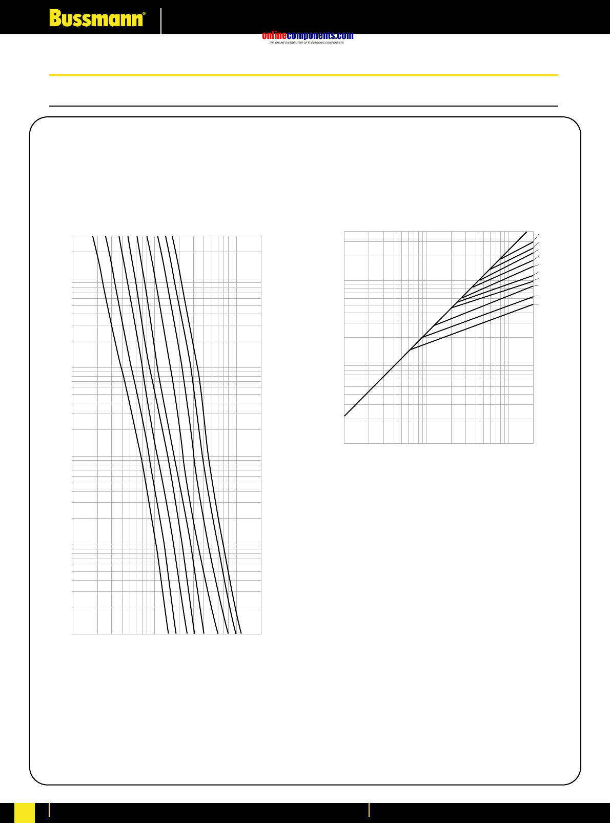
onlinecomponents.com
Electrical Characteristics
For more information visit our website at www.bussmann.com
253
KRP-C, CLASS L Fuses
300
100
10
1
.1
.01
1,000
10,000
100,000
200,000
CURRENT IN AMPERES
TIME IN SECONDS
800A
1200A
1600A
2000A
2500A
3000A
4000A
5000A
6000A
AMPERE
RATING
400,000
10,000
1,000
10,000
200,000
INSTANTANEOUS PEAK LET-THRU CURRENT IN AMPS
100,000
100,000
AMPERE
RATING
6,000
5,000
4,000
3,000
2,500
2,000
1,600
1,200
800
601
A
B
1,000
KRP-C Time-Current Characteristic
Curves—Average Melt KRP-C Current Limitation Curves
PROSPECTIVE SHORT-CIRCUIT CURRENT
SYMMETRICAL RMS AMPERES
Time-Current & Current Limitation Curves: Performance Data
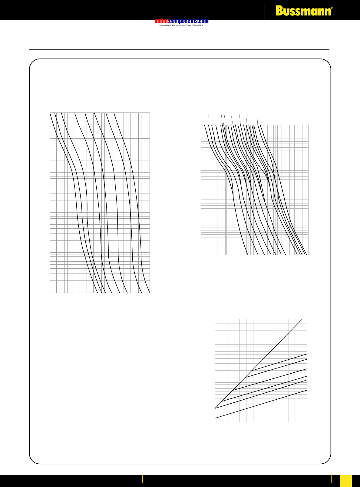
onlinecomponents.com
Electrical Characteristics
For more information visit our website at www.bussmann.com 254
LPN-RK_SP (250V)
300
100
10
1
.1
.01
20
100
1,000
10,000
RMS SYMMETRICAL CURRENT IN AMPERES
TIME IN SECONDS
20A
60A
100A
200A
30A
400A
600A
15A
AMPERE
RATING
LPN-RK_SP (250V)
1/10
2/10 15/100
3/10
4/10
6/10
1/2
8/10
1 1-1/4
1-6/10
22-1/2
3-2/10
4
56-1/4
810
12
AMPERE
RATING
300
10
1
.1
.01
TIME IN SECONDS
.1
1
10
100
1,000
CURRENT IN AMPERES
A
B
600
400
200
100
AMPERE
RATING
400,000
100,000
10,000
1,000
1,000
10,000
100,000
200,000
RMS SYMMETRICAL CURRENTS IN AMPERES
A–B=ASYMMETRICAL AVAILABLE PEAK (2.3 X SYMM RMS AMPS)
INSTANTANEOUS PEAK LET-THRU CURRENT IN AMPS
60
30
LPN-RK_SP (250V)
LPN-RK (250V) CLASS RK1 Fuses
Time-Current Characteristic
Curves—Average Melt Time-Current Characteristic
Curves—Average Melt
Current Limitation Curves
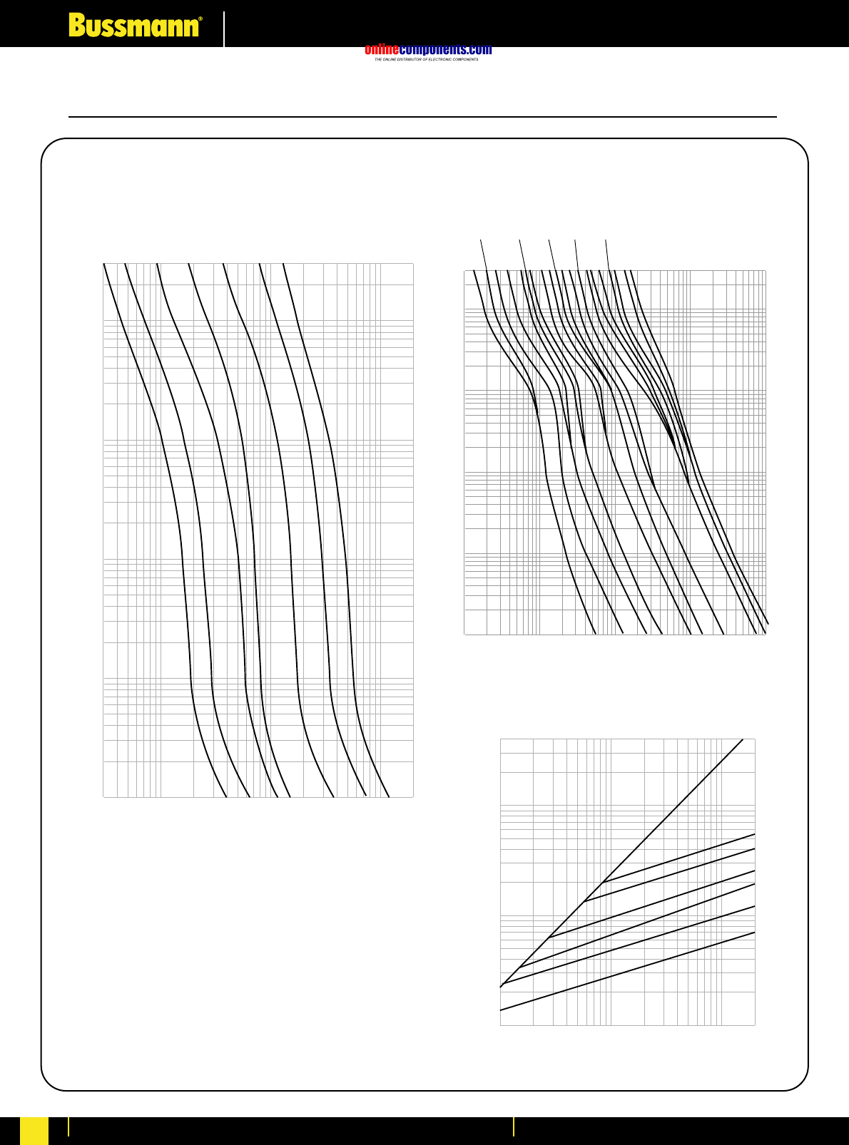
onlinecomponents.com
Electrical Characteristics
For more information visit our website at www.bussmann.com
255
LPS-RK (600V) CLASS RK1 Fuses
20A
60A
100A
200A
30A
400A
AMPERE
RATING
600A
LPS-RK
(600V)
30
100
1,000
10,000
20,000
300
100
10
1
.1
.01
CURRENT IN AMPERES
TIME IN SECONDS
.1
.2 .15
.3
.4
.6 .5
.8
11.25
1.6
22.5
3.2
4
56.25
8
10
12
AMPERE RATING
300
100
10
1
.1
.01
.1
1
10
100
1,000
TIME IN SECONDS
RMS SYMMETRICAL CURRENT IN AMPERES
60
30
A
B
600
400
200
AMPERE
RATING
400,000
100,000
10,000
1,000
1,000
10,000
100,000
200,000
INSTANTANEOUS PEAK LET-THRU CURRENT IN AMPS
100
LPS-RK
(600V)
Time-Current Characteristic
Curves—Average Melt Time-Current Characteristic
Curves—Average Melt
Current Limitation Curves
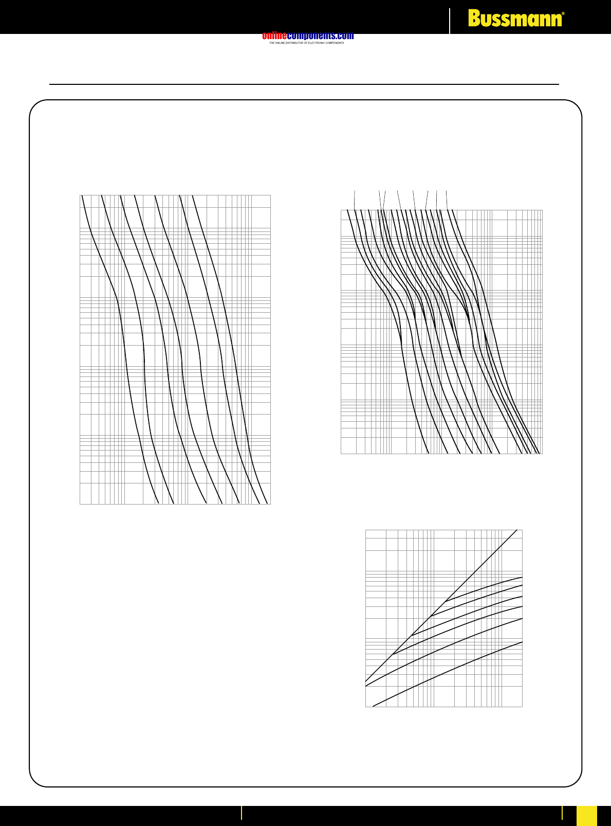
onlinecomponents.com
Electrical Characteristics
For more information visit our website at www.bussmann.com 256
20
100
1,000
10,000
20,000
10
1
.1
.01
TIME IN SECONDS
CURRENT IN AMPERES
FRN-R
(250V)
60A
100A
200A
30A
400A
AMPERE
RATING
600A
15A
300
100 FRN-R (250V)
1/10
2/10 15/100
3/10
4/10
6/10
1/2
8/10
1 1-1/4
1-6/10
22-1/2
3-2/10
4
56-1/4
810
12
AMPERE
RATING
300
100
10
1
.1
.01
TIME IN SECONDS
.1
1
10
100
1,000
CURRENT IN AMPERES
INSTANTANEOUS PEAK LET-THRU CURRENT AMPERES
PROSPECTIVE SHORT CIRCUIT CURRENT
SYMMETRICAL RMS AMPERES
400,000
100,000
10,000
1,000
1,000
10,000
100,000
200,000
60
600
100
AMPERE
RATING
400
200
B
A
30
FRN-R (250V)
FRN-R (250V) CLASS RK5 Fuses
Time-Current Characteristic
Curves—Average Melt Time-Current Characteristic
Curves—Average Melt
Current Limitation Curves
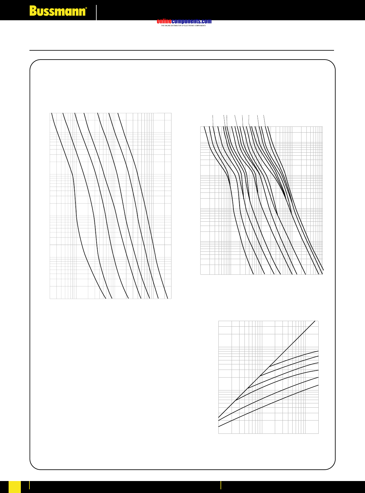
onlinecomponents.com
Electrical Characteristics
For more information visit our website at www.bussmann.com
257
FRS-R (600V) CLASS RK5 Fuses
CURRENT IN AMPERES
20
100
1,000
10,000
30,000
300
100
10
1
.1
.01
TIME IN SECONDS
60A
100A
200A
30A
400A
AMPERE
RATING
600A
15A
FRS-R
600V
1/10
2/10
15/100
3/10
4/10
6/10
1/2
8/10
11-1/4
1-6/10
2
2-1/2 3-2/10
4
56-1/4
810
12
AMPERE
RATING
FRS-R
(600V)
300
100
10
1
.1
TIME IN SECONDS
.01
.1
1
10
100
1
,
000
CURRENT IN AMPERES
600
100
AMPERE
RATING
400
200
30
60
INSTANTANEOUS PEAK LET THRU CURRENT AMPERES
PROSPECTIVE SHORT CIRCUIT CURRENT
SYMMETRICAL RMS AMPERES
B
A
400,000
100,000
10,000
1,000
1,000
10,000
100,000
200,000
FRS-R (600V)
Time-Current Characteristic
Curves—Average Melt Time-Current Characteristic
Curves—Average Melt
Current Limitation Curves
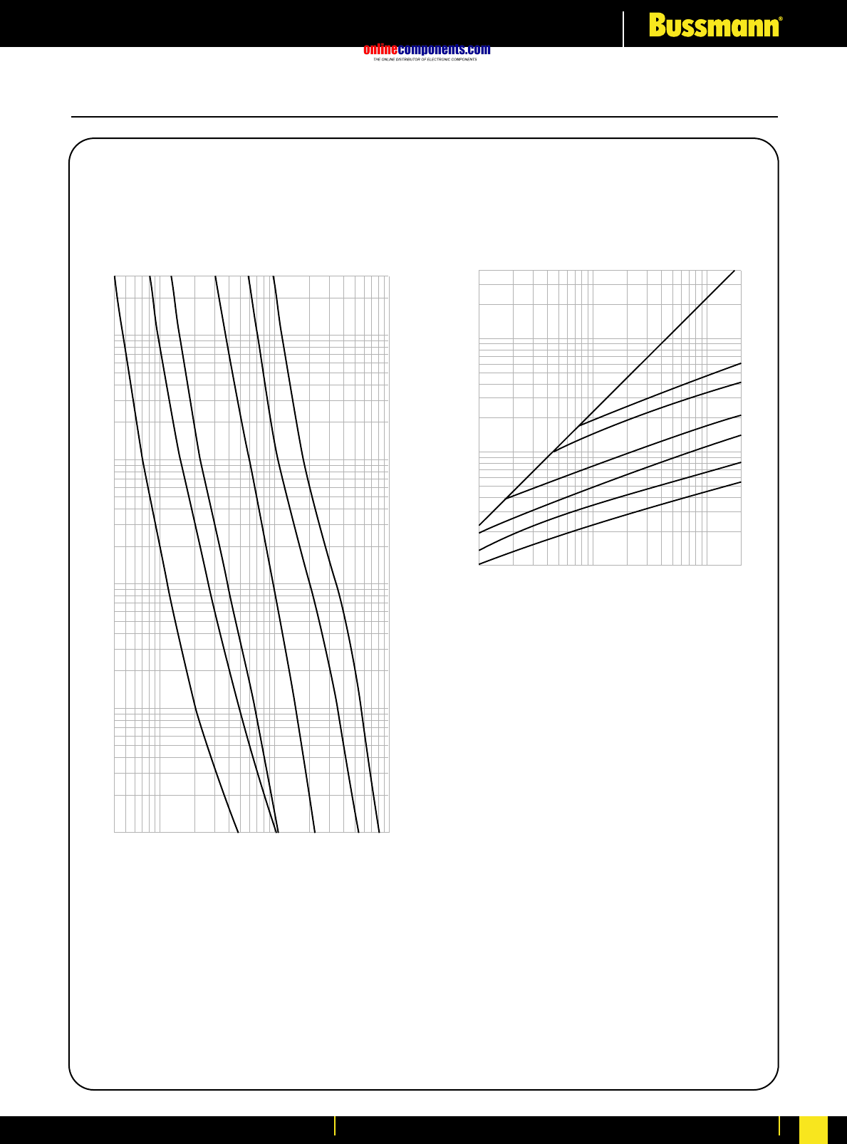
onlinecomponents.com
Electrical Characteristics
For more information visit our website at www.bussmann.com 258
RMS SYMMETRICAL CURRENT IN AMPERES
TIME IN SECONDS
300
100
10
1
.1
.01
40
100
1,000
10,000
30A
60A
100A
200A
400A
600A
AMPERE
RATING
600
100
60
AMPERE
RATING
30
400
200
INSTANTANEOUS PEAK LET-THRU CURRENT IN AMPS
400,000
100,000
10,000
1,000
1,000
10,000
100,000
200,000
RMS SYMMETRICAL CURRENTS IN AMPERES
A–B=ASYMMETRICAL AVAILABLE PEAK (2.3 X SYMM RMS AMPS)
A
B
KTN-R
(250V)
KTN-R
(250V)
KTN-R (250V) CLASS RK1 Fuses
Time-Current Characteristic
Curves—Average Melt Time-Current Characteristic
Curves—Average Melt
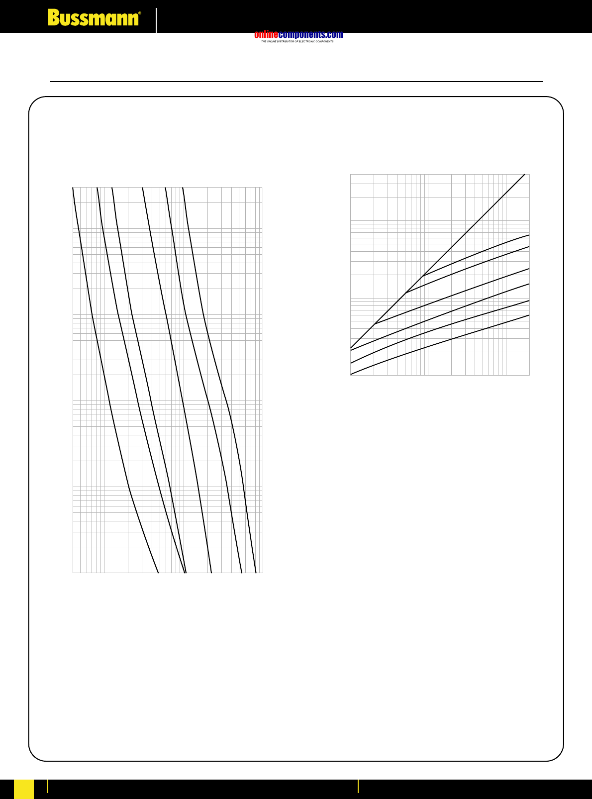
onlinecomponents.com
Electrical Characteristics
For more information visit our website at www.bussmann.com
259
KTS-R (600V) CLASS RK1 Fuses
RMS SYMMETRICAL CURRENT IN AMPERES
TIME IN SECONDS
300
100
10
1
.1
.01
40
100
1,000
10,000
30A
60A
100A
200A
400A
600A
AMPERE
RATING
600
100
60
AMPERE
RATING
30
400
200
200,000
100,000
10,000
1,000
1,000
INSTANTANEOUS PEAK LET-THRU CURRENT IN AMPS
400,000
100,000
10,000
RMS SYMMETRICAL CURRENTS IN AMPERES
A–B=ASYMMETRICAL AVAILABLE PEAK (2.3 X SYMM RMS AMPS)
B
A
KTS-R
(600V)
KTS-R
(600V)
Time-Current Characteristic
Curves—Average Melt Time-Current Characteristic
Curves—Average Melt
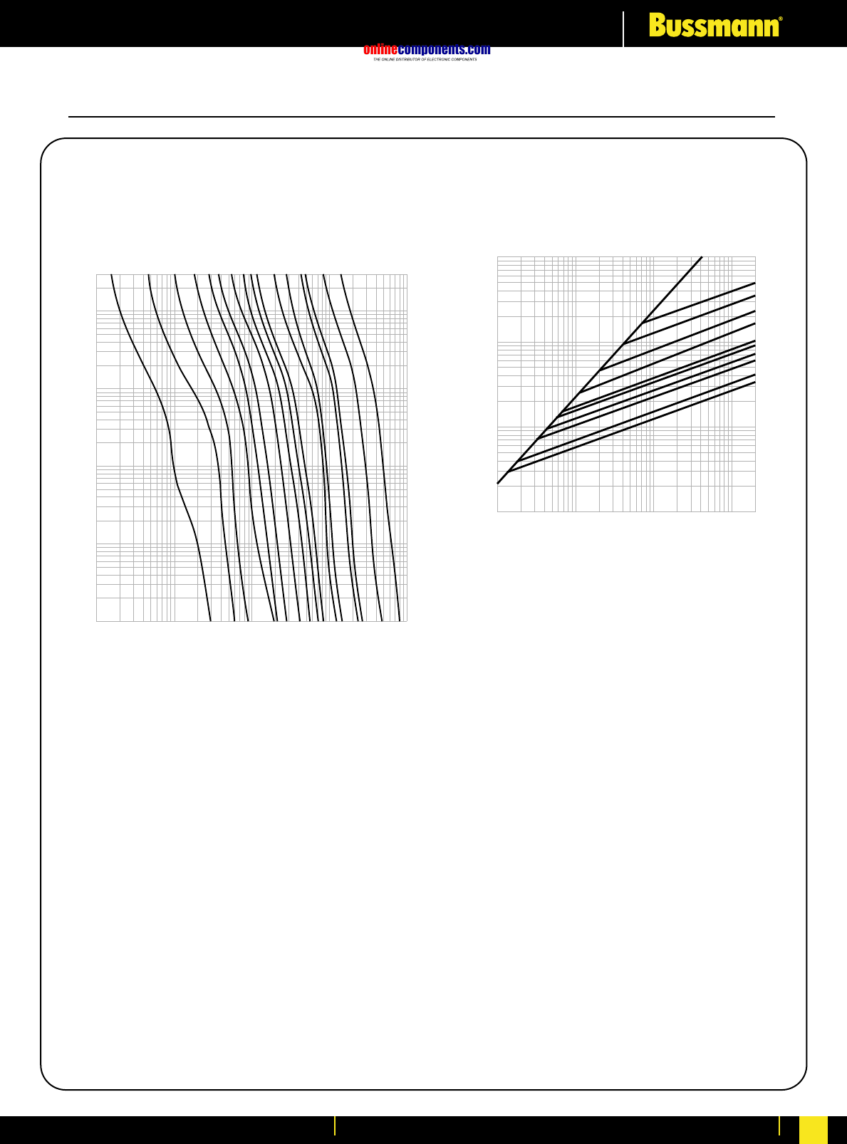
onlinecomponents.com
Electrical Characteristics
For more information visit our website at www.bussmann.com 260
AMPERE
RATING
1A
3A
5A
10A
15A
20A
30A
40A
50A
60A
300
100
10
1
.1
.01
TIME IN SECONDS
10,000
1,000
100
10
1
RMS SYMMETRICAL CURRENT IN AMPERES
100A
125A
200A
225A
400A
600A
INSTANTANEOUS PEAK LET-THRU CURRENT IN AMPS
100,000
10,000
1,000
100
B
A
PROSPECTIVE SHORT-CIRCUIT CURRENT
SYMMETRICAL RMS AMPS
100
1,000
10,000
100,000
200,000
600A
400A
200A
100A
60A
50A
40A
30A
20A
15A
AMPERE
RATING
LPJ LPJ
LPJ (600V), CLASS J Fuses
Time-Current Characteristic
Curves—Average Melt Time-Current Characteristic
Curves—Average Melt
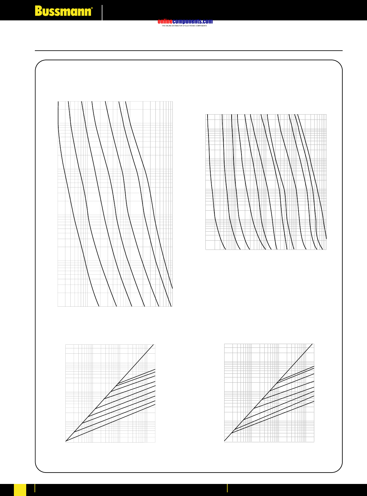
onlinecomponents.com
Electrical Characteristics
For more information visit our website at www.bussmann.com
261
600
400
200
100
60
30
AMPERE
RATING
800
1200
INSTANTANEOUS PEAK LET-THRU CURRENT IN AMPS
100,000
10,000
1,000
200
100
1,000
10,000
100,000
200,000
400,000
B
A
RMS SYMMETRICAL CURRENTS IN AMPERES
A–B=ASYMMETRICAL AVAILABLE PEAK (2.3 X SYMM RMS AMPS)
Time-Current Characteristic
Curves—Average Melt Time-Current Characteristic
Curves—Average Melt
Current Limitation Curves
JJN & JJS, CLASS T Fuses
600
400
200
100
60
30
15
AMPERE
RATING
800
1200
INSTANTANEOUS PEAK LET-THRU CURRENT IN AMPS
RMS SYMMETRICAL CURRENTS IN AMPERES
A-B = ASYMMETRICAL AVAILABLE PEAK (2.3 x SYMM RMS AMPS)
100,000
10,000
1,000
200
100
1,000
10,000
100,000
200,000
400,000
B
A
RMS SYMMETRICAL CURRENT IN AMPERES
TIME IN SECONDS
20
100
1,000
10,000
300
100
10
1
.1
.01
60A
100A
200A
30A
400A
AMPERE
RATING
600A
15A
JJN
1A
3A
5A
10A
30A
15A
60A
200A
400A
500A
100A
800A
AMPERE
RATING
10,000
1,000
100
10
1
300
100
10
1
.1
.01
CURRENT IN AMPERES
TIME IN SECONDS
(300V) JJS
(600V)
JJS
(600V)
JJN
(300V)
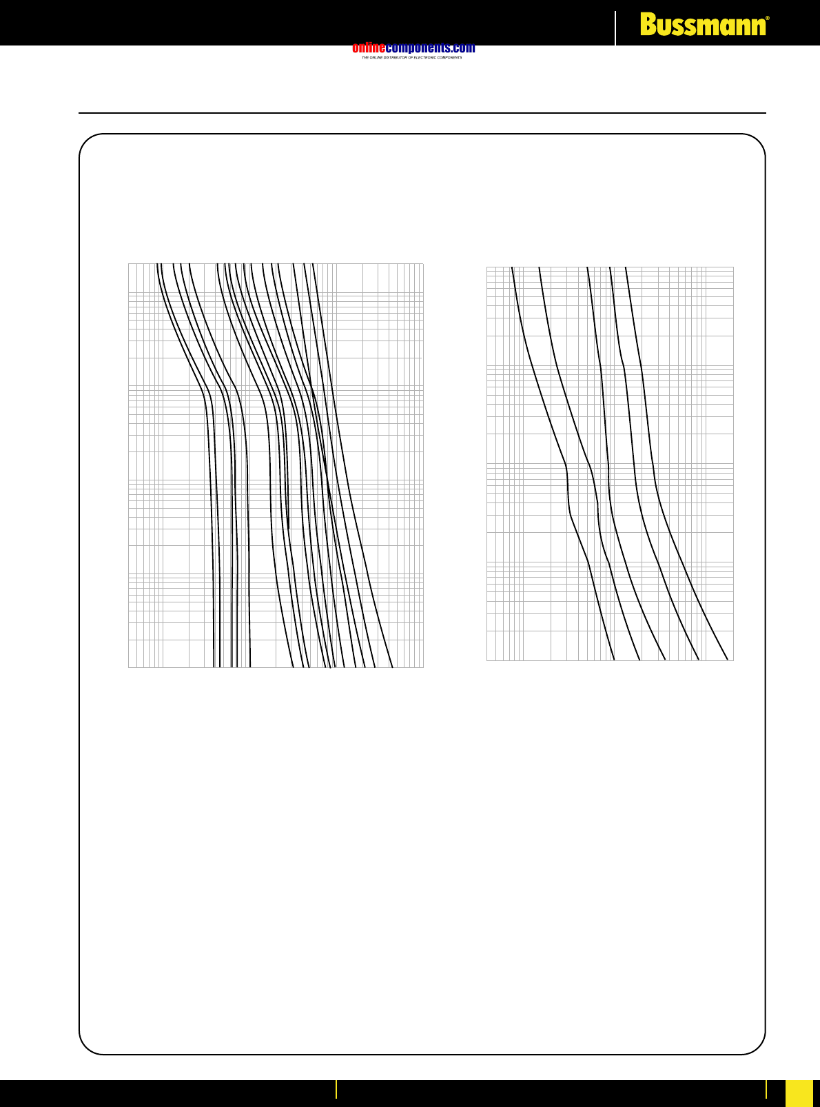
onlinecomponents.com
Electrical Characteristics
For more information visit our website at www.bussmann.com 262
LP-CC & FNQ-R CLASS CC Fuses
200
100
10
TIME IN SECONDS
1
.1
.01
⁄Ω™
flꭧ
°Ω¡º
1
1⁄Ω¢
3
3⁄Ω™
4
4⁄Ω™
6
8
10
12
15
20
25
30
AMPERE
RATING
.4
1
10
100
1000
CURRENT IN AMPERES
.4
1
10
100
200
RMS SYMMETRICAL CURRENT IN AMPERES
100
10
1
.1
.01
TIME IN SECONDS
1/2
1
3
5
7-1/2
AMPERE
RATING
LP-CC FNQ-R
Time-Current Characteristic
Curves—Average Melt Time-Current Characteristic
Curves—Average Melt
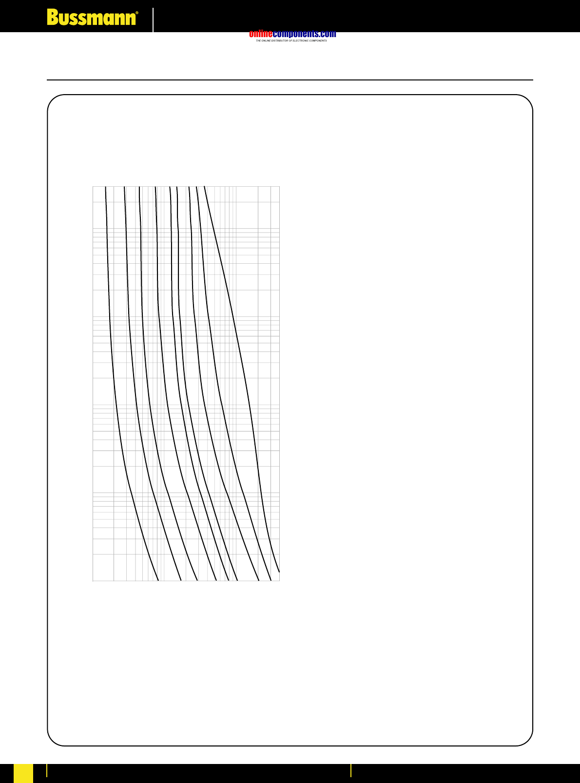

onlinecomponents.com
Glossary of Terms
For more information visit our website at www.bussmann.com 264
Ampere
The measurement of intensity of rate of flow of
electrons in an electric circuit. An ampere is
the amount of current that will flow through a
resistance of one ohm under a pressure of one
volt.
Ampere Rating
The current-carrying capacity of a fuse. When
a fuse is subjected to a current above its
ampere rating, it will open the circuit after a
predetermined period of time.
Ampere Squared Seconds, l2t
The measure of heat energy developed within
a circuit during the fuse’s clearing. It can be
expressed as “melting l2t”, “arcing l2t” or the
sum of them as “Clearing l2t”. “l” stands for
effective let-through current (RMS), which is
squared, and “t” stands for time of opening, in
seconds.
Arcing Time
The amount of time from the instant the fuse
link has melted until the overcurrent is
interrupted, or cleared.
Breaking Capacity
(See Interrupting Rating)
Cartridge Fuse
A fuse consisting of a current responsive
element inside a fuse tube with terminals on
both ends.
Class CC Fuses
600V, 200,000 ampere interrupting rating,
branch circuit fuses with overall dimensions of
⁄‹Ω£™∑ ≈ 1⁄Ω™∑. Their design incorporates a
rejection feature that allows them to be
inserted into rejection fuse holders and fuse
blocks that reject all lower voltage, lower
interrupting rating ⁄‹Ω£™∑ ≈ 1⁄Ω™∑ fuses. They are
available from ⁄Ω¡º amp through 30 amps.
Class G Fuses
480V, 100,000 ampere interrupting rating
branch circuit fuses that are size rejecting to
eliminate overfusing. The fuse diameter is
⁄‹Ω£™∑ while the length varies from 1fiΩ¡§∑ to 2⁄Ω¢∑.
These are available in ratings from 1 amp
through 60 amps.
Class H Fuses
250V and 600V, 10,000 ampere interrupting
rating branch circuit fuses that may be
renewable or non-renewable. These are
available in ampere ratings of 1 amp through
600 amps.
Class J Fuses
These fuses are rated to interrupt a minimum of
200,000 amperes AC. They are labelled
as “Current-Limiting”, are rated for 600 volts AC,
and are not interchangeable with other classes.
Class K Fuses
These are fuses listed as K-1, K-5, or K-9
fuses. Each subclass has designated I2t and
lpmaximums. These are dimensionally the
same as Class H fuses, and they can have
interrupting ratings of 50,000, 100,000, or
200,000 amps. These fuses are current-
limiting. However, they are not marked
“current-limiting” on their label since they do
not have a rejection feature.
Class L Fuses
These fuses are rated for 601 through 6000
amperes, and are rated to interrupt a minimum
of 200,000 amperes AC. They are labelled
“
Current-Limiting” and are rated for 600 volts
AC. They are intended to be bolted into their
mountings and are not normally used in clips.
Some Class L fuses have designed in time-delay
features for all purpose use.
Class R Fuses
These are high performance fuses rated ⁄Ω¡º-
600 amps in 250 volt and 600 volt ratings. All
are marked “Current Limiting” on their label
and all have a minimum of 200,000 amp
interrupting rating. They have identical outline
dimensions with the Class H fuses but have a
rejection feature which prevents the user from
mounting a fuse of lesser capabilities (lower
interrupting capacity) when used with special
Class R Clips. Class R fuses will fit into either
rejection or non-rejection clips.
Class T Fuses
An industry class of fuses in 300 volt and 600
volt ratings from 1 amp through 1200 amps.
They are physically very small and can be
applied where space is at a premium. They are
fast acting and time-lag fuses, with an
interrupting rating of 200,000 amps RMS.
Classes of Fuses
The industry has developed basic physical
specifications and electrical performance
requirements for fuses with voltage ratings of
600 volts or less. These are known as
standards. If a type of fuse meets the
requirements of a standard, it can fall into that
class. Typical classes are K, RK1, RK5, G, L, H,
T, CC, and J.
Clearing Time
The total time between the beginning of the
overcurrent and the final opening of the circuit
at rated voltage by an overcurrent protective
device. Clearing time is the total of the melting
time and the arcing time.
Current Limitation
A fuse operation relating to short circuits only.
When a fuse operates in its current-limiting
range, it will clear a short circuit in less than ⁄Ω™
cycle. Also, it will limit the instantaneous peak
let-through current to a value substantially
less than that obtainable in the same circuit if
that fuse were replaced with a solid
conductor of equal impedance.
Dual Element Fuse
Fuse with a special design that utilizes two
individual elements in series inside the fuse
tube. One element, the spring actuated
trigger assembly, operates on overloads up to
5-6 times the fuse current rating. The other
element, the short circuit section, operates on
short circuits up to their interrupting rating.
Electrical Load
That part of the electrical system which actually
uses the energy or does the work required.
Fast Acting Fuse
A fuse which opens on overload and short
circuits very quickly. This type of fuse is not
designed to withstand temporary overload
currents associated with some electrical loads.
Fuse
An overcurrent protective device with a fusible
link that operates and opens the circuit on an
overcurrent condition.
High Speed Fuses
Fuses with no intentional time-delay in the
overload range and designed to open as
quickly as possible in the short-circuit range.
These fuses are often used to protect solid-
state devices.
Inductive Load
An electrical load which pulls a large amount
of current—an inrush current—when first
energized. After a few cycles or seconds the
current “settles down” to the full-load running
current.
Interrupting Capacity
See Interrupting Rating
Interrupting Rating
(Breaking Capacity)
The rating which defines a fuse’s ability to
safely interrupt and clear short circuits. This
rating is much greater than the ampere rating
of a fuse. The NEC®defines Interrupting Rating
as “The highest current at rated voltage that
an overcurrent protective device is intended
to interrupt under standard test conditions.”
Melting Time
The amount of time required to melt the fuse
link during a specified overcurrent. (See
Arcing Time and Clearing Time.)
“NEC” Dimensions
These are dimensions once referenced in the
National Electrical Code. They are common to
Class H and K fuses and provide
interchangeability between manufacturers for
fuses and fusible equipment of given ampere
and voltage ratings.
Ohm
The unit of measure for electric resistance. An
ohm is the amount of resistance that will allow
one ampere to flow under a pressure of one
volt.
Ohm’s Law
The relationship between voltage, current, and
resistance, expressed by the equation E = IR,
where E is the voltage in volts, I is the current
in amperes, and R is the resistance in ohms.
One Time Fuses
Generic term used to describe a Class H
nonrenewable cartridge fuse, with a single
element.
Overcurrent
A condition which exists on an electrical
circuit when the normal load current is
exceeded. Overcurrents take on two separate
characteristics—overloads and short circuits.
Overload
Can be classified as an overcurrent which
exceeds the normal full load current of a circuit.
Also characteristic of this type of overcurrent is
that it does not leave the normal current car-
rying path of the circuit—that is, it flows from
the source, through the conductors, through
the load, back through the conductors, to the
source again.

onlinecomponents.com
Glossary of Terms
For more information visit our website at www.bussmann.com
265
Threshold Current
The symmetrical RMS available current at the
threshold of the current-limiting range, where
the fuse becomes current-limiting when
tested to the industry standard. This value
can be read off of a peak let-through chart
where the fuse curve intersects the A-B line.
A threshold ratio is the relationship of the
threshold current to the fuse’s continuous
current rating.
Time-Delay Fuse
A fuse with a built-in delay that allows
temporary and harmless inrush currents to
pass without opening, but is so designed to
open on sustained overloads and short
circuits.
Voltage Rating
The maximum open circuit voltage in which a
fuse can be used, yet safely interrupt an
overcurrent. Exceeding the voltage rating of a
fuse impairs its ability to clear an overload or
short circuit safely.
Withstand Rating
The maximum current that an unprotected
electrical component can sustain for a
specified period of time without the
occurrence of extensive damage.
Short Circuit
Can be classified as an overcurrent which
exceeds the normal full load current of a
circuit by a factor many times (tens, hundreds
or thousands greater). Also characteristic of
this type of overcurrent is that it leaves the
normal current carrying path of the circuit—it
takes a “short cut” around the load and back
to the source.
Short-Circuit Rating
The maximum short-circuit current an
electrical component can sustain without the
occurrence of excessive damage when
protected with an overcurrent protective
device.
Short-Circuit Withstand Rating
Same definition as short-circuit rating.
Single Phasing
That condition which occurs when one phase
of a three phase system opens, either in a low
voltage (secondary) or high voltage (primary)
distribution system. Primary or secondary
single phasing can be caused by any number
of events. This condition results in
unbalanced currents in polyphase motors and
unless protective measures are taken, causes
overheating and failure.
Peak Let-Through Current, lp
The instantaneous value of peak current let-
through by a current-limiting fuse, when it
operates in its current-limiting range.
Renewable Fuse (600V & below)
A fuse in which the element, typically a zinc
link, may be replaced after the fuse has
opened, and then reused. Renewable fuses
are made to Class H standards.
Resistive Load
An electrical load which is characteristic of
not having any significant inrush current.
When a resistive load is energized, the current
rises instantly to its steady-state value,
without first rising to a higher value.
R.M.S. Current
The R.M.S. (root-mean-square) value of any
periodic current is equal to the value of the
direct current which, flowing through a
resistance, produces the same heating effect
in the resistance as the periodic current does.
Semiconductor Fuses
Fuses used to protect solid-state devices.
See “High Speed Fuses”.

onlinecomponents.com
Index
For more information visit our website at www.bussmann.com 266
PART NO. PAGEPART NO. PAGE PART NO. PAGE
15100 135
15200 135
15800 134
011- 43
012- 43
059- 43
11L2 124
11L3 124
15L1 124
15087 SERIES 140
170H--- 214
170H00-- 100
170H02-- 100
170M13- 81
170M14- 81
170M15- 87
170M26- 81/89/90
170M27- 89
170M30- 82
170M31- 82/83
170M32- 82/83/86
170M33- 95/96
170M34- 92/95
170M35- 92
170M36- 97/99
170M37- 97/99
170M38- 88
170M39- 85/94
170M40- 82
170M41- 82/83/89
170M42- 82/83/86
170M43- 95/96
170M44- 92/95
170M45- 92/98
170M46- 97/99
170M47- 97/99
170M48- 84
170M49- 85/94
170M50- 82
170M51- 82/83/96
170M52- 82/89/95
170M53- 95
170M54- 92
170M55- 92/95/98
170M56- 95/97/99
170M57- 97/99
170M58- 88
170M59- 85/94
170M60- 82/89
170M61- 82/83
170M62- 82
170M63- 95
170M64- 92
170M65- 92
170M66- 95/97/99
170M67- 97/99
170M68- 88
170M70- 93
170M71- 93
170M85- 94/98
170M86- 85
170M86- 85
1A1119 SERIES 160
1A1120 SERIES 160
1A1907 SERIES 160
1A3398 SERIES 160
1A3399 SERIES 159
1A3400 SERIES 161
1A4533 SERIES 160
1A4534 SERIES 160
1A5018 SERIES 1591
A5600 SERIES 161
1A5601 SERIES 159
1A5602 SERIES 159
1BS-- 214
1BS1-- 213
32BCS 194
32BS 194
32LS 194
32LSC 194
32LSCC 194
32NNSBS 196
32NNSF 196
32NNSFBS 196
33L2 124
33L3 124
44L3 124
5591 SERIES 162
5592 SERIES 162
5672 SERIES 162
5674 SERIES 162
5681 SERIES 162
5682 SERIES 162
5956 SERIES 162
5960 SERIES 162
6.6L3 124
63/100BS 194
63ENSBS 196
63ENSF 196
63ENSF 196
63ENSFBS 196
66L3 124
7.5L1 124
70 SERIES 140
A33547 129
AAO 28
ABC 147
ABCN 117
ABFN 117
ABGN 117
ABWIN 117
ABWN 117
ABWNA 117
AC 30
AD 30
ADFH 121
ADFH 121
ADGH 121
ADIHA 122
ADLSJ 112
ADOSJ 112
AFFH 121
AFIHA 122
AFKHA 122
AFMSJ 112
AGA 145
AGC 147
AGU 149
AGW 145
AGX 145
AILSJ 112
AIMSJ 112
AKGH 121
AMWNA 117
ANL 150
ANN 150
ATC 151
ATM 151
BAF 73
BAL-SL00 177
BAN 73
BAO 29
BBS 72
BC 30
BC0 171
BC00 171
BC1-2 171
BC3 171
BC60-- SERIES 212
BCCM SERIES 212
BCM-F123 178
BD 30
BDGH 121/122
BFD_ SERIES 188/190
BFGH 121/122
BFR_ 176/178
BG30-- SERIES 212
BH-- 215
BKM-F123 178
BKP-F123 178
BL00 SERIES 188
BL00-3_ 177
BM60--SERIES 212
C08G-- 1
C08M-- 2
C10G-- 1
C10M-- 2
C14G-- 1
C14G--S 3
C14M-- 2
C14M--S 3
C22G-- 1
C22G--S 3
C22M-- 2
C22M--S 3
C515 142
C517 142
C518 142
C519 142
C520 142
C5268-- 213/215
CD 30
CD0623G-- 4
CD0823G-- 4
CD0831G-- 4
CD0836G-- 4
CD1025G-- 4
CD1031G-- 4
CD1038G-- 4
CEO 29
CH08 SERIES 163
CH10 SERIES 163
CH14 SERIES 163
CH22 SERIES 163
CHD-- 4
CM100F 194
CM32F 194
CM32FC 194
CM63F 194
CML 194
CMLC 194
CMSC 194
CS0 171
CS00 171
CS1 171
CS2 171
CS3 171
CS4 171
CT 102
D125 26
D125R 26
D16 26
D16R 26

onlinecomponents.com
Index
For more information visit our website at www.bussmann.com
267
D200 26
D27 26
D27R 26
D33 26
D33R 26
DD 30
DEO 29
EC-250 213
EC-600 213
ED 31
EET 102
EF 31
EFS 31
ESD 33
ET 102
FBI 153
FBM 153
FC0 171
FC00 171
FC1 171
FC2 171
FC3 171
FC4 171
FDIH 122
FDLSJ 112
FDMSJ 112
FE 102
FEE 102
FEH 175
FF 31
FFGN 122
FFLSJ 112
FFMSJ 112
FG 31
FHW 146
FM 102
FMM 102
FN01C 192
FN02C 192
FN03C 192
FNA 150
FNM 74
FNQ 74
FNQ-R 71
FRN01C 192
FRN02C 192
FRN03C 192
FRN-R 62
FRS-R 63
FUSE CLIPS 125
FWA_F 75
FWA_A 104
FWA_AH 104
FWA_B 104
FWC_F 77
FWH_A 106
FWH_B 106
FWH_F 76
FWJ_A 109
FWJ_F 79
FWK_F 78
FWL_F 79
FWP_A 108
FWP_B 108
FWP_F 77/78
FWS_F 79
FWX_A 105
FWX_AH 105
FWX_F 76
G30060- SERIES 212
GBA 150
GBB 148
GD27 192
GD33 192
GDA 143
GDB 143
GDC 143
GF 32
GG 32
GH 32
GLD 150
GLP 194
GMA 144
GMC 144
GMD 144
GMT 141
GMT-A 141
GN01 192
GN02 192
H07-660 34
H250 SERIES 198/199/200
H600 SERIES 201
HBH 153
HBV 153
HBW 153
HKP 155
HLS 141
HLT 141
HS07 39
HTB 156/157
HTC 152/154/159
J600 SERIES 203
JCG 128
JCG_R 128
JCH_R 127
JCK_A_R 127
JCK_B_R 127
JCK_R 127
JCL_A_R 128
JCL_B 128
JCL_B_R 128
JCL_R 127
JCR_A_R 128
JCR_B_R 128
JJN 68
JJS 68
JKS 67
JP SERIES 205
JT(N)60030 206
JT(N)60060 206
K07-660 34
K08-660 35
K09-660 35
KAC 107
KBC 107
KLM 73
KLU 58
KR85 40
KRP-CL 57
KRP-C--SP 56
KS07 39
KS08 39
KS09 39
KTK 73
KTK-R 71
KTN-R 64
KTQ 72
KTS-R 64
KTU 58
L09-660 35
L14-660 34
LBS_ 179/180
LBS00+AL06030 181
LBS00-3/9/_ 182
LBS1 + AL16030 181
LBS1-1/9/U 183
LBS1-2/9/U 183
LBS1-4/9/U 183
LBS3-1/9/U 183
LBS4A 184/185
LCT 101
LET 101
LMMT 101
LMT 101
LP-CC 70
LPJ-_SP 66
LPN-RK_SP 59
LPS-RK_SP 59
LR85 40
M09-660 35
M13 37
M14-660 34
M23 37
MAXI-FUSE 151
MC_ 213
MDA 149
MDL 148
MDQ 149
MJ25-6 40
MJ30-7 41
MJ30-8 41
MJ31-7 41
MMT 102
MT 102
N09-660 35
N11-660 36
N15 37
N20 38
N34 37
NBUN 117
NH000G-400 19
NH000GC-400 19
NH000GC-400 I 19
NH00G 7
NH00G-400 19
NH00G-690 21
NH00GC-400 19
NH00GC-400 I 19
NH00M 20
NH00M-690 21
NH01GCI 20
NH01M 20
NH02GCI 20
NH02M 20
NH03GCI 20
NH03M 20
NH0G-690 21
NH0M 20
NH0M-690 21
NH1G 8
NH1G-400 19
NH1G-690 21
NH1GC-400 19
NH1GC-400 I 19
NH1G-S 22
NH1M 20
NH1M-690 21
NH1M-S 22
NH2G 9
NH2G-400 19
NH2G-690 21
NH2GC-400 19
NH2GC-400 I 19
PART NO. PAGEPART NO. PAGE PART NO. PAGE

onlinecomponents.com
Index
For more information visit our website at www.bussmann.com 268
PART NO. PAGEPART NO. PAGE PART NO. PAGE
NH2GCI 20
NH2G-S 22
NH2GTr 22
NH2M 20
NH2M-690 21
NH2M-S 22
NH3G 10
NH3G-400 19
NH3G-690 21
NH3GC-400 19
NH3GC-400 I 19
NH3GCI 20
NH3G-S 22
NH3GTr 22
NH3M 20
NH3M-660 21
NH3M-S 22
NH4AG 11/18
NH4G 18
NH4G-S 22
NH4GTr 22
NHC00G 6
NHC00GCI 20
NHC00M 20
NHC00M-690 21
NHC0GCI 20
NHC0M 21
NHG000B 12
NHG00B 13
NHG01B 15
NHG02B 16
NHG03B 17
NHG0B 14
NI 194
NITD 28
NON 65
NOS 65
NSD 33
NZ01 25
NZ01R 25
NZ02 25
NZ02R 25
NZ03 25
OBCN 117
OBFN 117
OBGN 117
OBWN 117
OEFMA 119
OEGMA 119
OHFMA 119
OHGMA 119
OLGMA 119
OPM-1038 166
OPM-1038_SW_ 167
OPM-NG 165
OPM-NG-SC3 164
OPM-NG-SM3 164
OSD 29
P09-660 36
P11-660 36
P20 38
P35 37
PCT 141
PJ30-7 41
PJ31-7 41
R11-660 36
R12-660 36
R20 38
R250 SERIES 198/199/200
R40 37
R600 SERIES 201
RJ31-7 42
S20 38
SAMI SERIES 197
SB00-D 169
SB00-EC 172
SB00-S 169
SB0-D 169
SB0-DMS 170
SB0-EC 172
SB0-S 169
SB1-D 169
SB1-DMS 170
SB1-ECS 172
SB1-ECSS 172
SB1-S 169
SB2-D 169
SB2-DMS 170
SB2-ECS 172
SB2-ECSS 172
SB2-S 169
SB3-D 169
SB3-DMS 170
SB3-ECSS 172
SB3-S 169
SB4-DMS 170
SB4-S 169
SBS_ 173
SBS_MM 174
SBS_MV 174
SBS_MW 174
SBS_VV 174
SBS1 174
SBS2 174
SBS3 174
SC 69
SDLSJ 111
SDMSJ 111
SDQSJ 111
SERIES 8000 158
SFD27 192
SFD33 192
SFLSJ 111
SFMSJ 111
SFPCD01 192
SFPCD02 192
SFPRD27 192
SFPRD33 192
SFQSJ 111
SFRD27 192
SFRD33 192
SJ28 42
SJ31-6 42
SKLSJ 111
SL 24
SMD 28
SP0 171/172
SP00 171/172
SP00-SQ 172
SP0-SQ 172
SP1-2 171/172
SP1-2-SQ 172
SP3 171/172
SP3-SQ 172
SP4 171
SSD 33
STD 28
SXLEJ 111
T300 208
T600 210
TB00-D 169
TB00-EC 172
TB00-S 169
TB0-D 169
TB0-EC 172
TB0-S 169
TB1-D 169
TB1-ECS 172
TB1-ECSS 172
TB1-S 169
TB2-D 169
TB2-ECS 172
TB2-ECSS 172
TB2-S 169
TB3-D 169
TB3-ECSS 172
TB3-S 169
TCF 54/55
TCFH 54/55
TDC10 147
TDC-11 148
TDC180 146
TDC600 146
TFD27 192
TFD33 192
TFN01C 192
TFN02C 192
TFN03C 192
TFPCD01 192
TFPCD02 192
TFPCD27 192
TFPCD33 192
TFRD27 192
TFRD33 192
TFRN01C 192
TFRN02C 192
TFRN03C 192
TI-- 213
TP158HC 137
TP15900--4 133
TP15914 132
TPA 133
TPA-B 133
TPC 131
TPCDS 131
TPH 139
TPHCS 136
TPL 138
TPM 130
TPMDS 130
TPS 134
VFNHA*R 115
VFRHA*R 115
VKNHA*R 115
VKNHK*R 115
VKRHA*R 115
VKRHK*R 115
VLB00 SERIES 189/191
WDFHO 114
WDLSJ 115
WDOH 114
WDOSJ 115
WFFHO 114
WFGHO 114
WFMSJ 115
WFNHO 114
WFOH 114
WFOSJ 115
WJON 114
WKFHO 114
WKGHO 114
WKLSJ 115
WKMSJ 115


onlinecomponents.com
HEADQUARTERS
Cooper Industries
Bussmann Division
P.O. Box 14460
St. Louis, Missouri 63178-4460, USA
Telephone: 636 394 2877
Facsimile : 800 544 2570
International: 636 527 1413
Email: fusebox@buss.com
COOPER BUSSMANN CHICAGO
7300 West Wilson Avenue
Chicago, IL 60656-4793
Telephone: 708 867 4600
Facsimile : 708 867 2211
Email: info@busscc.com
EUROPEAN HEADQUARTERS
Cooper (UK) Limited
Burton-on-the-Wolds
Leicestershire · LE12 5TH UK
Telephone: 44 (0)1509 882 737
Facsimile : 44 (0)1509 882 786
Email: info@bussmann.co.uk
www.bussmann.com
BUSSMANN ASIA-PACIFIC
1 Jalan Kilang Timor
# 06-01 Pacific Tech Centre
Singapore 159303
Republic of Singapore
Telephone: 65 6278 6151
Facsimile : 65 6278 3151
Email: bussmann@bussasiapac.com.sg
BUSSMANN AUSTRALIA
Block X
391 Park Road
P.O. Box 257
Regents Park, Sydney
NSW 2143, Australia
Telephone: 612 9743 8333
Facsimile : 612 9743 8070
BUSSMANN BRASIL
Bussmann do Brasil Ltda
Rodovia Santos Dumont, Km 23
13 300-000 Cruz das Almas
Cabra Postal 95 - Itu
Sao Paulo
Brasil
Telephone: 55 11 7824 1856
Facsimile : 55 11 7824 1721
BUSSMANN DENMARK
5 Literbuen
DK-2740 Skovlunde
Copenhagen, Denmark
Telephone: 45 4485 0900
Facsimile : 45 4485 0901
Email: bussmann@bussmann.dk
BUSSMANN INDIA
2nd Floor, Unit #5
White House
23-29, St. Marks Road
Bangalore-560 001
India
Telephone: 91 80 227 0893
Facsimile : 91 80 224 0124
BUSSMANN MEXICO
Arrow-Hart, S.A. de C.V.
Poniente 148, No 933
02300 Mexico, D.F. Mexico
Telephone: 52 5 587 0211
Facsimile : 52 5 567 4049
COOPER ELECTRONIC TECHNOLOGIES, INC
6000 Park of Commerce Blvd
Boca Raton, FI 33487
Telephone: 561 241 7876
Facsimile : 561 241 9339
ENBRAY CONTACTORS
Cooper (UK) Limited
Unit 5C, Clay Flatts
Industrial Estate
Workington, Cumbria
CA1 3YD
United Kingdom
Telephone: +44 0 1900 870088
Facsimile : +44 0 1900 870099
Cooper (UK) Limited · Burton-on-the-Wolds · Leicestershire · LE12 5TH UK
Telephone: 44 (0)1509 882 737 · Facsimile: 44 (0)1509 882 786
www.bussmann.com
© Cooper Bussmann 2003. Printed in April 2003
Worldwide Circuit Protection Solutions
onlinecomponents.com
This innovative dual-indication NH Fuse Link is the first
to feature, what is considered to be, one of the most
reliable combined top and centre fuse status indicators
available today, demonstrating the sort of applied
technology that only a company with the global reach
of Cooper Bussmann can provide.
Previously, according to DIN 43 620, in most cases
manufacturers have applied one or the other type of
indication to NH-fuse links. Alternatively, where both
have been applied together, reliability often has been
compromised.
Cooper Bussmann's new NH fuse overcomes such
difficulties and gives exactly what is wanted: reliable
dual indication of fuse operation.
This is because its indicator mechanism uses fewer
parts than a standard centre indication fuse link, so
improving mechanical reliability.
NH Fuse Links with Dual Indication
TECHNICAL DATA
Current ratings: 10 to 630A
Voltage rating: 500V CA
Interrupting rating: 120kA
Utilisation Class: gL-gG
Standards & Approvals: EC60269 & VDE0636
COOPER BUSSMANN
COOPER UK
BURTON-ON-THE-WOLDS
LEICESTERSHIRE
LE12 5TH UK
TEL: +44 (0)1509 882 737
FAX: +44 (0)1509 882 786
www: bussmann.com
email: sales@bussmann.co.uk
FLC - 2003 / Cooper Bussmann 2003. Printed October 2003
CIRCUIT PROTECTION SOLUTIONS
